
Commercial Multiprocessing Systems*
22
Multiprocessing has distinct advantages-and unique constraints with implications for performance. This survey highlights the architectural strategies of five multiprocessor systems. SPECIAL FEATURE: Commercial Multiprocessing Systems* M. Satyanarayanan Carnegie-Mellon University In the decade and a half since the advent of third- generation computers, many multiprocessing systems have been built by both universities and in- dustry. Unfortunately, there seems to be little public- ly accessible information on commercially available multiprocessing systems. This survey describes the architectures, system organizations, error recovery facilities, operating systems, and other features of multiprocessing systems made by five major US mainframe manufacturers. Unless dictated by the need for understandability, I have avoided material not directly related to the multiprocessing aspects of these systems. With the exception of the Honeywell 60/66, unclassified quantitative data on performance is unavailable and therefore cannot be given. The con- cluding section discusses general issues in multi- processing, drawing upon the information presented in the survey. Before setting out to study each system in detail, it is appropriate to ask ourselves two questions: * What is multiprocessing? * Why is multiprocessing done? This introduction answers these questions. What is multiprocessing? The attribute that characterizes a multiprocessing system is the shar- ing of global memory by the processors making up the system. "Sharing" in this context means that the memory should be addressable by all the processors. Mere linking together of a number of computer systems, as in a computer network, does not result in a multiprocessing system. *This article is taken from a monograph, Multiprocessors: A Com- parative Study, by M. Satyanarayanan, to be published by Prentice- Hall Inc. To refine our definition, we include two further criteria. First, the processors constituting the multi- processing system should not be highly specialized. I/O channels, front ends, and other similar special- ized processing units often share main memory with a central processor, but such configurations do not fit within our notion of a multiprocessing system. "Highly specialized" is clearly a subjective term. How does one determine whether a processor is highly specialized or not? The view taken here is that a processor is not highly specialized if it can do significant computation on its own, without external assistance.** Independent processing is our second criterion, therefore, and it permits us to classify a system such as the Cyber 170 as a multiprocessing system, even though its central processors and peripheral processors differ radically from each other. The peripheral processors share main memory with the central processors and, in fact, are capable of running the operating system by themselves. In short, we define a multiprocessor configuration as one which consists of at least two processors satis- fying the following conditions: * the processors share global memory, * they are not highly specialized, and * each of the processors can do significant com- putation individually. Why use multiprocessing? That multiprocessing is not just an intellectual curiosity but a technique of practical value is clearly demonstrated by the **What is "significant computation" and what is not is once again debatable. In the absence of quantitative criteria, one has to use value judgments at some point. Rather than going through further levels of recursion in this definition, I prefer to appeal to the reader's intuitive notion of "significant computation." 0018-9162/80/0500-0075$00.75 © 1980 IEEE 75 May 1980
-
Upload
khangminh22 -
Category
Documents
-
view
0 -
download
0
Transcript of Commercial Multiprocessing Systems*
Multiprocessing has distinct advantages-and unique constraintswith implications for performance. This survey highlights the
architectural strategies of five multiprocessor systems.
SPECIAL FEATURE:
CommercialMultiprocessingSystems*M. SatyanarayananCarnegie-Mellon University
In the decade and a half since the advent of third-generation computers, many multiprocessingsystems have been built by both universities and in-dustry. Unfortunately, there seems to be little public-ly accessible information on commercially availablemultiprocessing systems. This survey describes thearchitectures, system organizations, error recoveryfacilities, operating systems, and other features ofmultiprocessing systems made by five major USmainframe manufacturers. Unless dictated by theneed for understandability, I have avoided materialnot directly related to the multiprocessing aspects ofthese systems. With the exception of the Honeywell60/66, unclassified quantitative data on performanceis unavailable and therefore cannot be given. The con-cluding section discusses general issues in multi-processing, drawing upon the information presentedin the survey.Before setting out to study each system in detail, it
is appropriate to ask ourselves two questions:* What is multiprocessing?* Why is multiprocessing done?
This introduction answers these questions.
What is multiprocessing? The attribute thatcharacterizes a multiprocessing system is the shar-ing of global memory by the processors making upthe system. "Sharing" in this context means that thememory should be addressable by all the processors.Mere linking together of a number of computersystems, as in a computer network, does not result ina multiprocessing system.
*This article is taken from a monograph, Multiprocessors: A Com-parative Study, by M. Satyanarayanan, to be published by Prentice-Hall Inc.
To refine our definition, we include two furthercriteria. First, the processors constituting the multi-processing system should not be highly specialized.I/O channels, front ends, and other similar special-ized processing units often share mainmemory with acentral processor, but such configurations do not fitwithin our notion of a multiprocessing system."Highly specialized" is clearly a subjective term.How does one determine whether a processor ishighly specialized or not? The view taken here is thata processor is not highly specialized if it can dosignificant computation on its own, without externalassistance.** Independent processing is our secondcriterion, therefore, and it permits us to classify asystem such as the Cyber 170 as a multiprocessingsystem, even though its central processors andperipheral processors differ radically from eachother. The peripheral processors share main memorywith the central processors and, in fact, are capable ofrunning the operating system by themselves.In short, we define a multiprocessor configuration
as one which consists of at least two processors satis-fying the following conditions:
* the processors share global memory,* they are not highly specialized, and* each of the processors can do significant com-putation individually.
Why use multiprocessing? That multiprocessing isnot just an intellectual curiosity but a technique ofpractical value is clearly demonstrated by the
**What is "significant computation" and what is not is once againdebatable. In the absence of quantitative criteria, one has to usevalue judgments at some point. Rather than going through furtherlevels of recursion in this definition, I prefer to appeal to the reader'sintuitive notion of "significant computation."
0018-9162/80/0500-0075$00.75 © 1980 IEEE 75May 1980

Figure 1. A uniprocessor IBM 3701168 system.
Figure 2. An attached processing IBM 370/168 configura-tion.
Figure 3. A true multiprocessing IBM 370/168 configuration.
number of commercially available multiprocessingsystems. Given such a "proof by existence," it islegitimate to ask the question: "What problems dothese multiprocessing systems successfully solve?"
First, given a job which taxes the resources of thelargest computers available, it may be possible tosplit up the job into a number of tasks (or processes)and run each on a different processor, reducing theoverall execution time. Unfortunately, given thepresent state of the art in parallel processing, theprognosis for the success of this kind of application,at least in the near future, seems bleak. In most cases,the amount of time and effort needed to recode a pro-gram so that it can be executed faster on a multi-processor, far outweighs the gains in execution time.Significant advances in the automatic decompositionof sequential programs into parallelly executabletasks are needed before the benefits of parallel pro-cessing can stand as the primary reason for usingmultiprocessing systems.A second, more commonly cited reason for using a
multiprocessing system is increased throughput.Given that the workload at an installation is largerthan what the largest uniprocessor can handle, amultiprocessor seems to be a good idea. For example,using two processors as a multiprocessor is usuallybetter than configuring them as uniprocessorsystems and partitioning the workload betweenthem. This is true because in a multiprocessor thesharing of hardware resources and processor timetends to smooth out effects due to stochastic varia-tions in job characteristics. To give a trivial example,suppose there are 10 jobs to be run. Splitting them in-to two groups of five each and running one group oneach uniprocessor may, in a pathological case, resultin five CPU-bound jobs being run on one processorand five I/O-bound jobs on the other, implying thatthe former processor will be overloaded and the latterunderutilized. Running all 10 jobs on an equivalentmultiprocessor configuration, however, will usuallyresult in better performance. This occurs eventhough each processor in a multiprocessing con-figuration performs worse than when it is in a uni-processing configuration-a point I will discuss inthe conclusion. Whether or not it is worthwhile to runthe processors in a multiprocessing, configurationgreatly depends on the extent of this degradation aswell as on the job characteristics.
Finally, because of the redundancy inherent in amultiprocessor system, it is usually morerobust thana uniprocessor system. Failure in any one redundantcomponent (e.g. one processor) is usually noncrit-ical-the system can continue processing with the re-maining hardware. The performance in such a casewill obviously be degraded. Serviceability is also im-proved since repairs can be made on defective com-ponents while the rest of the system is operating. Amajor advantage of a multiprocessor over a unipro-cessor is that, given the right hardware and softwaresupport, a program on a failed processor can berestarted on another processor and continued from apoint close to the point atwhich failure occurred. Thisimplies that the frequency of software checkpoints
COMPUTER76

can be greatly reduced-no small gain, since check-pointing is notorious for its hogging of computerresources.In addition to these technical advantages, there are
often economic reasons for using multiprocessingsystems. Whatever one's favorite reason for multi-processing is, multiprocessing systems will play anundeniably important role in the computer systemsof the future.
The IBM 370 Model 168
The System 370 is a family of computers com-prising a wide range of implementations but having asingle architectural specification. Case and Padegs2describe the S/370 architecture and discuss its evolu-tion. The Model 168, discussed in detail'here, is one ofthe implementations of the S/370 architecture thatsupport multiprocessing. Multiprocessing in the370/168 comes in two flavors, designated MP, formultiprocessing, and AP, for attached processing.Architecturally these are identical-the same pro-cessor instructions are available to handle both situa-tions. From a system organization point of view,however, they differ significantly. For lack of a betterterm we refer to both of them generically as "MP"and use the term "true MP" when we wish to specifythe special subcase.
Overview. Figure 1 shows a uniprocessor 370/168configuration. The central processing unit containsthe instruction decoding and execution units as wellas a cache. Main storage'is equally divided betweenfour units referred to as logical storage units, andfour-way interleaving is present between the LSUs.Peripherals are connected to the system via chan-nels-highly specialized processing units with verysimple instruction sets-which operate asynchronous-ly with the CPU.Figure 2 shows anAP configuration. The' structure
is very similar to that of a uniprocessor system, withthe addition of an attached processing unit. ThisAPU is a processor that is almost identical to thestandard 370/168 CPU and differs from the latter on-ly in that channels cannot be attached to it. Since theAPU has its own cache, a cache invalidate line is pres-ent between the APU and the CPU, to ensure con-sistency of cache contents. Also present is an inter-processor communication line, used by the APU andCPU to communicate with each other. The term "pro-cessor" in the rest of this section will refer to bothAPUs and CPUs.A true MP configuration is shown in Figure 3. It
can be viewed as being made up of two independentuniprocessor systems, each with its- own CPU mem-ory and channels, connected through a multisystemcontrol unit.' The MCU handles the routing ofmemory requests to the appropriate LSU and alsocontains controls for reconfigur-ing the system. Acache invalidate interface and interprocessor com-munication line are present in this configuration aswell. Channels are associated with a specificCPU and
consequently cannot communicate with anotherCPU or APU.
The proces'sor. The S/370 has a 32-bit word dividedinto four eight-bit bytes and a comprehensive in-struction set encompassing fixed-point, floating-point, character manipulation, and decimal arith-metic instructions as well as instructions for systemcontrol. The architecture is register-oriented, with 16GPRs-general-purpose registers-and four float-ing-point registers. Besides these, there are 16 con-trol registers containing control information ofrelevance to the operating system and the hardware.The state of a processor is defined at any instant byall these registers, together with a 64-bit registercalled the program status word. The PSW containsstatus information of interest to user programs-whether interrupts are enabled or not, whether theresult of the previous instruction resulted in anoverflow or underflow, and so on. Half of the PSWcontains the address of the next instruction to be ex-ecuted and hence plays the role of a program counter.The S1370 uses a virtualmemory scheme which per-
mits programs to address up to 16Mbytes regardlessof the amount of physical memory present. Transla-tion of virtual addresses to physical addresses is doneby the hardware, usingpage tables setupby operatingsystem software. To speed up the translation process,a cache for page table entries-called the TLB, fortranslation lookaside buffer-is present. In an MPsystem, each processor has itsownmemory-mappinghardware, and the programs runningon different pro-cessors usually have different virtual address spaces.
Interrupts in the S/370 are grouped into five majorclasses:
* program interrupts,* I/O interrupts,* external interrupts,* machine check interrupts, and* SVC-supervisor call-interrupts.Program interrupts are caused by program-
originated conditions such as overflows, invalid ad-dresses, and page faults. 1/0 interrupts are caused bychannels and signify the successful or unsuccessfulending'of an I/O operation. Events such as timer in-terrupts and operator intervention interrupts are-classified as external interrupts. One external inter-rupt that is of special interest in multiprocessing, andwhich we shall discuss shortly, is an interprocessorinterrupt by means of which one processor can causean interrupt in another processor. An SVC interruptarises as the result of the execution of a processor in-struction, the supervisor call, which is the primarymechanism a program uses to communicate with theoperating system.
Regardless of the class, the hardware treats theseinterrupts in a uniform manner. When an interruptoccurs, the current PSW is stored in a predefinedlocation in mainmemory (called the old PSW locationfor that class) and a new PSW is loaded from anotherpredefined location for the new interrupt class. Byvirtue of this switch in PSWs, the program counter
May 1980 77
(which is part of the PSW) is set to a new value-i.e.,that of the interrupt handling routine. Informationregarding the specific cause of each interrupt isstored by the hardware at predefined locations inmemory. The interrupt handling routines use this in-formation to decide on the course of further action.External, I/O, and machine check interrupts can be
disabled by bit settings in the PSW. Interrupts aris-ingwhen theprocessor is disabled for thecorrespond-ing interrupt class remain pending until the pro-cessor becomes enabled for that class. Within theseclasses, individual interrupt types can be disabled,e.g., individual I/O channels, specific types of exter-nal interrupts. A subset of the program interruptscan also be individually disabled. SVC interrupts can-not, however, be disabled.The interprocessor communication mechanism
mentioned earlier is based on a processor instructioncalled SIGP, for signal processor. Each processor hasassociated with it a unique, permanent 16-bit ad-dress. The value of this address can be obtainedby aninstruction called SPAD, for store processor address.The SIGP is a three-operand instruction. The firstoperand specifies a GPR, the second the address ofthe processor with which communication is desired,and the third an opcode which signifies the nature ofthe communication. The philosophy behind the SIGPinstruction is that a processor PA executing it shouldbe-able to play the role of a (human) operator withrespect to the processor PB with which communica-tion is attempted. Consequently, most of the opcodesserve to perform the functions provided at thesystem console-e.g., system reset, start, stop, sense.Analogous to information displayed on a console,eight status bits are returned by PB in the GPRspecified by PA. Most of the order codes are actedupon byPB without any ensuing interrupt; in fact, aprogram running on PB will be totally unaware that aSIGP instruction was executed with its processor asthe target. Two of the order codes do cause interruptson PB and are handled as external interrupts by PB.The more commonly used of these is called externalcall, and is meant to be the primary interprocessor in-terrupt mechanism. The other, called emergencyalert, is generated by the failure recovery componentof the operating system only when that componentrecognizes that recovery is impossible on a processor.An interest-ing feature of the interprocessor com-munication mechanism is the presence of a malfunc-tion alert interrupt. A processor automaticallygenerates this interrupt when it encounters a hard-ware error too severe to execute even error recoveryroutines. In such a catastrophe, the processor haltsand sends a malfunction alert signal to all processorsin the system, causing an external interrupt in all ofthem.One feature present in the S/370, but-not in any of
the other systems surveyed here, is a mechanismcalled "prefixing." The real address range 0-4K is ofspecial significance to the Sf370 hardware becausethe interrupt-related, I/O-related, and error-handling-related storage areas are in this address range.Rather than having such a 4K block held in common
for all processors in the system, the S/370 designerschose to have a separate block for each-processor inthe MP configuration. As a result, real addresses0-4K have to be mapped to different physical storagelocations for each processor. To do this, a registercalled the prefix register is associated with each pro-cessor, and special instructions are provided to readand write it. The contents of a prefix register specifythe physical address of a 4K block of memory intowhich the address 0-4K is to be mapped. Conversely,real addresses within this 4K range are mapped tophysical addresses 0-4K. Since each processor has itsown prefix register, it follows thatby suitably settingeach such register, the real address range 0-4K can bemade to correspond in each case to a differentphysical storage block.
Protection in the S/370 is achieved through two in-dependent but complementary mechanisms. Sen-sitive instructions such as those relating to I/O areclassified as privileged instructions. A bit in the PSWdetermines whether these instructions may be ex-ecuted. Memory protection is achieved by comparinga four-bit key in the PSW to a four-bit lock settableonly by a privileged instruction and associated witheach 2K block of memory; if a mismatch occurs, ac-cess is denied.Each processor has three clocks for timing pur-
poses. Two are run independently of their counter-parts in other processors. The third clock, called thetime-of-day clock, is synchronized so that all time-of-day clocks in an MP environment run in step, thusguaranteeing a unique time stamp for the system.
Channels and I/O. As was mentioned earlier, I/O inthe S/370 is performed via channels, which executecommands set up in main memory by the CPU butrun asynchronously with the latter. The commandsexecuted by a channel are referred to as channel com-mand words. A number of CCWs may be con-catenated to form a channel program; a channel pro-gram specifies a sequence of operations to be carriedout on one device. To perform I/O on a device, theCPU sets up a. channel program in main storage,places a pointer to it in a predefinedmemory location,and issues a start I/O instruction. The channel thenfetches CCWs from the channel program and carriesout the desired operations on the device. When thechannel program terminates, or when an error is en-countered, the channel delivers an I/O interrupt tothe CPU and places status information in a prede-fined memory location. The CPU's I/O interruptroutine handles the termination of this I/O requestand initiates the next I/O operation on the device.Since channels are associated with a specific CPU,
it is clear that in anMP situation, oneCPU cannot doI/O on channels associated with other CPUs. Toeliminate this asymmetry, a mechanism called a two-channel switch can be attached to a peripheral device.This permits the device to be attached to two dif-ferent channels, possibly on different CPUs. AspecialCCW permits a data path to be set up betweenone of the channels and the device; once set up, thispath is retained until explicitly released. Thus both
COMPUTER78

channels can communicate with the device, thoughonly one can do so at a time. In a true MP configura-tion, two-channel switches can be used to allow bothCPUs to have access to shared devices.
I/O interrupts are always handled by the CPUwhich initiated the corresponding I/O operation. Thisis true even if the interrupting device is connected viaa two-channel switch in an MP configuration-i.e.,there is no passing of interrupts between CPUs.Another important point is that only CPUs havechannels associated with them; APUs do not. In anAP environment, therefore, all I/O has to be handledby the CPU.
The operating system. Multiprocessing in theS/370 is supported by one of IBM's operatingsystems called OSIVS2 Multiple Virtual Systems-MVS, for short. UnderMVS, each user operates in hisown 16M-byte virtual address space independent ofall other users in the system. Userprograms are total-ly unaware of the number of processors in the systemand of the system configuration-i.e., whether it is auniprocessing, AP, or true MP configuration. Thereis one copy of the operating system, part of it residentin real memory and the rest paged in on demand. Theoperating system occupies a part of every user's ad-dress space and manages that space completely-onepage table-per user is maintained for that purpose.User programs request operating system services
by executing an SVC instruction specifying an eight-bit number as an operand. Memory protection isachieved by ensuring that a given page frame is in nomore than one user's address space at a time. Thehardware lock and key protection mechanismdescribed earlier is used within the operating systemto ensure that failure in one component will not con-taminate other components.To perform I/O on a device, auserprogram setsup a
control block containing necessary information andissues an SVC. The interrupt handlingroutine checksto see if there is a path from the issuing CPU to thedevice; if so, the CPU queues the I/O request for ex-ecution. If a path to the device is not available, the,user ta§k is marked as being dispatchable only by theotherCU (a condition called "CPU affinity") and isthen suspended. At some future time the other CPUwill activate this task and handle its I/O request. Ontermination of the I/O request, the task is marked asbeing once again dispatchable on either processor.CPU affinity may also become necessary if a taskneeds hardware features found only on one processor.User tasks may create subtasks, and this process
may be recursively repeated. Subtasks of a user's job'compete for resources with each other, and two sub-tasks belonging to a user may be running at the sametime on two processors, thus reducing the overall ex-ecution time of the job.There are extensive software and hardware error
recovery mechanisms specially designed to make useof the inherent redundancy available in MP con-figurations. When an error is detected on a processor,a machine check interrupt is generated on that pro-cessor and the corresponding interrupt handler tries
to perform whatever recovery it can. Forexample, if amemory bank fails, the page tables'can be adjusted sothat that memory bank is not used any more. If themachine check interrupt handler realizes thatrecovery is impossible, it issues a SIGP instructionspecifying an emergency alert as the order code. Thetarget processor's interrupt handling routine thentries to salvage the job that was running on the failedprocessor. Sometimes the hardware error is so severethat even the machine check interrupt handler can-not be successfully executed. In that case, the hard-ware automatically ge'nerates a SIGP instruction toall other processors in the system, specifying a mal-function alert as the order code.The operating system uses a simple linear ordering
scheme8 to avoid deadlock. This scheme works on theassumption that all tasks holding locks proceed at anon-zero speed. If a task holdinglocks is executing ona processor when the processor fails, a deadlock mayexist. The error recovery software is clever enough toincrementally execute all tasks holding locks, in asuitable order, until a sufficient number of locks arereleased to remove the threat of deadlock.6Certain parts of MVS code must wait for a lock
while in a disabled state; i.e., they will have all inter-rupts masked. As a result, a processor running thatpiece of MVS code will not respond to emergency ormalfunction alert signals, once again leading to apossible deadlock in the case of processor failure. Toavoid this, every part of MVS'using a disabled waitperiodically enables emergency and malfunctionalert interrupts for a brief period, guaranteeing that afailing processor's cry for help will not go unheeded.
Reconfiguration of the system is possible, but onlywith operator intervention. A trueMP system can bepartitioned into two totally independent unipro-cessor systems. In that case, there is no sharing ofmemory, but part of the memory associated with oneCPU can be used by the other CPU. AP configura-tions cannot be partitioned. Failure of the APU isnoncritical, but failure of the CPU results in thefailure of the'entire system, since APUs cannot doI/O.
The CDC Cyber 170
The Cyber 170 series is a descendant of the CDC6600, one of the first systems to embody the principleof functional partitioning. By the latter term I meanthe splittingup ofcomputing activities intoa numberof functions and the assigning of different processorsto different functions. Such a partitioning usually(but not necessarily) results in significant asym-metry among the processors---the Cyber 170 is no ex-ception to this.The Cyber 170 series consists of a number of dif-
ferent models, architecturally and structurallysimilar to each other but differing in performance.The organization of the series' high-end machine, theCyber 176, differs slightly from that of the rest of theseries. The differences, however, do not affect thoseaspects of the system that are of interest to us, and
May 1980 7979
hence, for explanatory purposes, we will ignore thesedifferences.
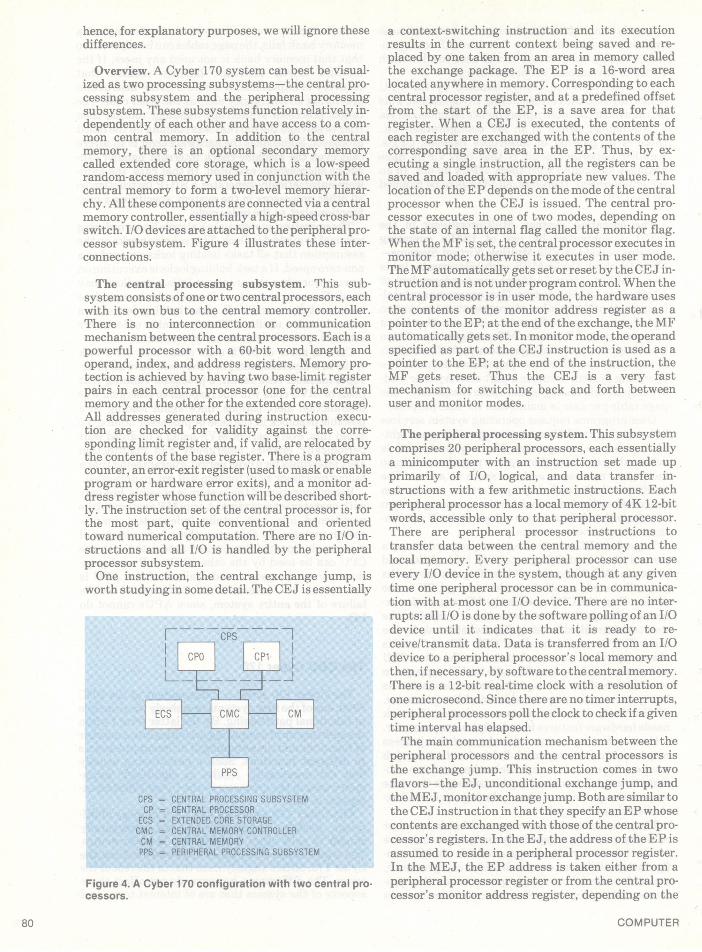
Overview. A Cyber 170 system can best be visual-ized as two processing subsystems-the central pro-cessing subsystem and the peripheral processingsubsystem.lThese subsystems function relatively in-dependently of each other and have access to a com-mon central memory. In addition to the centralmemory, there is an optional secondary memorycalled extended core storage, which is a low-speedrandom-access memory used in conjunction with thecentral memory to form a two-level memory hierar-chy. All these components are connected via a centralmemory controller, essentially a high-speed cross-barswitch. I/O devices are attached to the peripheral pro-cessor subsystem. Figure 4 illustrates these inter-connections.
The central processing subsystem. This sub-system consists of one or two central processors, eachwith its own bus to the central memory controller.There is no interconnection or communicationmechanism between the central processors. Each is apowerful processor with a 60-bit word length andoperand, index, and address registers. Memory pro-tection is achieved by having two base-limit registerpairs in each central processor (one for the centralmemory and the other for the extended core storage).All addresses generated during instruction execu-tion are checked for validity against the corre-sponding limit register and, if valid, are relocated bythe contents of the base register. There is a programcounter, an error-exit register (used to mask or enableprogram or hardware error exits), and a monitor ad-dress register whose function will be described short-ly. The instruction set of the central processor is, forthe most part, quite conventional and orientedtoward numerical computation. There are no I/O in-structions and all I/O is handled by the peripheralprocessor subsystem.One instruction, the central exchange jump, is
worth studying in some detail. The CEJ is essentially
F----PS-7-
EC EXTENDED CORE STORAGECMC = CENTRAL MEMORY CONTROLLERCM' CENTRAL MEMORYPPS PERNTPERAL PROCESSING SUBSYSTEM
Figure 4. A Cyber 170 configuration with two central pro-cessors.
a context-switching instruction and its executionresults in the current context being saved and re-placed by one taken from an area in memory calledthe exchange package. The EP is a 16-word arealocated anywhere in memory. Corresponding to eachcentral processor register, and at a predefined offsetfrom the start of the EP, is a save area for thatregister. When a CEJ is executed, the contents ofeach register are exchanged with the contents of thecorresponding save area in the EP. Thus, by ex-ecuting a single instruction, all the registers can besaved and loaded with appropriate new values. Thelocation of the EP depends on the mode of the centralprocessor when the CEJ is issued. The central pro-cessor executes in one of two modes, depending onthe state of an internal flag called the monitor flag.When theMF is set, the central processor executes inmonitor mode; otherwise it executes in user mode.The MF automatically gets set or reset by the CEJ in-struction and is not under program control. When thecentral processor is in user mode, the hardware usesthe contents of the monitor address register as apointer to the E P; at the end of the exchange, theMFautomatically gets set. In monitor mode, the operandspecified as part of the CEJ instruction is used as apointer to the EP; at the end of the instruction, theMF gets reset. Thus the CEJ is a very fastmechanism for switching back and forth betweenuser and monitor modes.
The peripheral processing system. This subsystemcomprises 20 peripheral processors, each essentiallya minicomputer with an instruction set made upprimarily of I/O, logical, and data transfer in-structions with a few arithmetic instructions. Eachperipheral processor has a local memory of 4K 12-bitwords, accessible only to that peripheral processor.There are peripheral processor instructions totransfer data between the central memory and thelocal memory. Every peripheral processor can useevery I/O device in the system, though at any giventime one peripheral processor can be in communica-tion with at most one I/O device. There are no inter-rupts: all I/O is done by the software polling of an I/Odevice until it indicates that it is ready to re-ceive/transmit data. Data is transferred from an I/Odevice to a peripheral processor's local memory andthen, ifnecessary, by software to the central memory.There is a 12-bit real-time clock with a resolution ofone microsecond. Since there are no timer interrupts,peripheral processors poll the clock to check if a giventime interval has elapsed.The main communication mechanism between the
peripheral processors and the central processors isthe exchange jump. This instruction comes in twoflavors-the EJ, unconditional exchange jump, andthe MEJ, monitorexchange jump. Both are similartothe CEJ instruction in that they specify anEP whosecontents are exchanged with those of the central pro-cessor's registers. In the EJ, the address of the EP isassumed to reside in a peripheral processor register.In the MEJ, the EP address is taken either from aperipheral processor register or from the central pro-cessor's monitor address register, depending on the
COMPUTER80

MEJ's opcode. The MEJ causes an exchange only ifthe central processor is in user mode; in monitor modethe MEJ is treated as a no-op.When more than one central processor exists, the
one to be interrupted is specified as part of the in-struction. If, in a dual-processor configuration, onecentral processor is executing in monitor mode, aCEJ will remain pending until both processors are inuser mode. Under the same circumstances, an MEJby a peripheral processor to either central processoris treated as a no-op. An unconditional EJ executed atthe same time as anMEJ or CEJ can cause both cen-tral processors to enter monitor state, and hence cancause them to deadlock. Though a peripheral pro-cessor can interrupt either central processor using anEJ, it cannot reset the MF on either. Consequently,once deadlocked, both central processors are doomedto execute in monitor mode unless the system ismanually restarted.
The operating system. Three CDC/Cyber operatingsystems have evolved over the last 15 years-Scope,Kronos, and Nos. The description below pertains toKronos.One peripheral processor, designated PPO, is
dedicated to the operating system and spends all itstime handling supervisor requests from user pro-grams. Another peripheral processor is dedicated tocommunication with the operator's display console.The remaining peripheral processors form a pool andhandle I/O requests. User programs run on the cen-tral processors and do not refer directly to theperipheral processors-they are in fact unaware oftheir presence.A part of the operating system which does schedul-
ing of central processors and peripheral processorsresides in the central memory and is executed byeither central processor in monitor mode. Much of theoperating system's control information resides incentral memory and is used either by a central pro-cessor in monitor mode, or by a peripheral processorwhich transfers it to its local memory before use.Communication among the various operating sys-
tem components residing in different central orperipheral processors is done by a message handlingsystem resident in the central memory. Eachperipheral processor has an I/O buffer pair per-manently assigned to it in central memory. Messagesto it are placed in its input buffer and it, in turn,places outward messages in its output buffer. PPOperiodically examines all output buffers to see if anyperipheral processors have requested its services.Since there are no interrupts, all I/O is done via soft-
ware polling. Direct communication among peripher-al processors is done by simulating a peripheral pro-cessor-to-I/O device transaction: the responding pe-ripheral processor behaves like an I/O device andtransfers data between its local memory and the I/Ochannel connecting it with the peripheral processorthat initiated the conversation.
Performance. The central processor's 60-bit wordlength and arithmetic instructions make the Cyber
170 eminently suited for scientific computation,where numerical accuracy is vital. The fast context-switching capability makes it good for situationswhere frequent task switching occurs.Quantitative performance measures are hard to
come by in the literature. One source9 states that theperformance of the Cyber 170 series varies from 0.8MIPs for the Cyber 171 to 15 MIPs for the Cyber 176.Symmetric dual-processor configurations are statedto have about 1.5 times the MIPs of correspondingsingle-processor systems.
The Honeywell Series 60:Level 66
The Honeywell Series 60 does not represent onecomputer system or a family of systems. Rather, itrepresents a set of families, each referred to as a level,with members ofa family referred to as models ofthatfamily. There are broad architectural differencesamong the various levels; however, models of a givenlevel are architecturally similar and differ only in im-plementation and performance. The level chosen hereis Level 66, close to the top of the Series 60 line.For convenience, we shall refer to the Honeywell
Series 60 Level 66 system as the 60/66 throughoutthe rest of this section.
Overview. The basic structure of a uniprocessor60/66 system consists of a central processor, an I/Omultiplexer with peripherals attached, and a systemcontroller connecting a pair of memory modules tothe rest of the system (Figure 5). The system control-ler acts as a coordinator and plays a crucial role in therouting of memory accesses, interrupts, and othercommunications among the various system com-ponents.A multiprocessor 60/66 can be visualized as a num-
ber of uniprocessor systems connected to each othervia their system controllers (Figure 6). As the figureindicates, the connections form a hetwork in whichevery central processor and every I/O multiplexer isconnected to every system controller. In such asystem, one central processor is nominated as pro-
Figure 5. A uniprocessor Honeywell 60166 system.
May 1980 81

Figure 6. A multiprocessor Honeywell 60/66 system.
cessor 0-CPO-and is distinguished from the othersin that all external interrupts are routed to it by thehardware; this solves the problem of each peripheralhaving to decide which central processor it should in-terrupt. Up to a maximum of four central processors(and the corresponding number of I/O multiplexersand system controllers) can be included in a multi-processor system.Since it plays such a pivotal role in the system
organization, we should begin our examination withthe system controller.
The system controller. This component has twomain functions: it acts as a storage controller for aspecific pair of memory modules, and it acts as an in-telligent switch for the various components con-nected to it.Each system controller has eight ports to which are
connected two memory modules, three central pro-cessors, and three I/O multiplexers, one to a port.Every system element attached to a port can accessthe memory associated with that port's system con-troller. When more than one element tries to accessthe same memory module, the corresponding systemcontroller resolves the conflict.Each system controller has 32 interrupt cells
associated with it, each ofwhich may be set by an ele-ment attached to a port. When an interrupt cell is set,the system controller causes an interrupt in CPO.Associated with every interrupt cell is a unique pairof locations in main memory used as the interruptvector when the corresponding interrupt occurs.The system controller also has a calendar clock
with a period of 142 years and a resolution of onemicrosecond; this clock may be read or set byprivileged central processor instructions.
Central processor. The 60/66 processor has a 36-bitword length and a fairly commonplace set ofarithmetic, logical, character, and data movement in-structions. There is a quotient-accumulator registeras well as index and address registers. A fairlysophisticated address modification scheme with in-direction and two levels of indexing is present. An in-dicator register contains all the relevant processorstatus bits such as condition codes from the previous
instruction and what program events are enabled.The processor can be in either master or slave
mode. In master mode, all instructions may be ex-ecuted, whereas in slave mode an attempt to executecertain instructions results in an illegal procedurefault (faults and their processing are describedbelow). Address relocation procedures also differ inthe two modes.Events that disrupt the normal sequence of in-
struction execution are classified in two catego-ries-interrupts and faults. An interrupt is a requestby a system controller for service. A fault is a condi-tion, usually arising in the processor itself, which re-quires special handling. A signal from an I/O deviceon completion of a previously requested I/O opera-tion is an example of an interrupt, while overflow inan arithmetic instruction is an instance of aprocessor-originated fault requiring special process-ing. Interrupts and faults are handled in an identicalmanner by the central processor. Corresponding toevery type of interrupt or fault is a unique pair ofloca-tions in main memory called the interrupt vector.When an interrupt or fault occurs, the central pro-cessor enters master mode and executes the instruc-tions stored in the corresponding interrupt vector.The program counter is not altered unless an explicittransfer instruction is one of the instructions in theinterrupt vector. At the end of the interrupt se-quence, execution resumes at the location pointed toby the program counter. The central processor moderemains what it was before the interrupt or fault oc-curred, unless it was explicitly altered in the inter-rupt sequence or a transfer was present in the inter-rupt vector, in which case the central processor re-mains in master mode. The above procedure is thusequivalent to a hardware-initiated two-instructionsubroutine call in which one can examine an interruptor fault and decide whether further processing isnecessary.Protection and isolation in the 60/66 are achieved
by a base/limit register mechanism. Though the 60/66can have up to 1M words of physical memory, its18-bit addressing structure allows only 256K of thatmemory to be addressable at a time. The specific256K "window" that is addressable is determined bya base register whose contents are added to every ad-dress generated by the processor. There are, in fact,three base address registers-one for use in slavemode and the othertwo for master mode, thus permit-ting aprogram in master mode to access two different256K windows.In a multiprocessor configuration there is only one
contiguous, real address space for the entire system.Each central processor has its own set of base ad-dress registers. Thus programs executing on dif-ferent central processors can refer to different ex-tents ofthe real address space, or, if desired, share thesame (or overlapping) parts of it by appropriately set-ting the respective base registers. Each system con-troller has a different set of interrupt vectors corre-sponding to it, thus ensuring that each interrupt cellin a multiprocessor system is indeed associated witha unique interrupt vector.
COMPUTER82

I/O operations are done using the CIOC-connectI/O channel-instruction. A channel is a connectionbetween an I/O multiplexerand a peripheral device orsubsystem. Corresponding to every channel in thesystem is a unique location in memory called-a chan-nel mailbox. To initiate I/O on a channel, a centralprocessor first fills this mailbox with pertinent infor-mation for the channel and then issues a CIOC forthat channel. The channel reads its mailbox, per-forms the operations requested, and presents an in-terrupt (via the I/O multiplex and system controllerto which it is connected) to CPO.Communication between processors is possible in a
multiprocessor system since processors themselvescan be attached to channels. Consider two centralprocessors, P1 and P2, connected to channels C1 andC2. If P1 wishes to pass a message to P2, it can place amessage in C2's mailbox and issue a CIOC for C2. Thehardware recognizes this as an interprocessor com-munication and causes a special fault (connect fault)to occur in P2. P2 now executes the correspondingfault service routine and reads the message sent to it.It can send a reply by a method symmetric to theabove.Each central processor has an interval timer which
can be set in master mode and which causes a timerfault when the specified time has elapsed. The faultoccurs only in slave mode; ifthe central processor is inmaster mode, the fault remains pending until itenters slave mode.
I/O multiplexer. This component is connected,through I/O channels,* to every system controllerand to a variable number of peripherals or peripheralsubsystems. Eachmemory access requiredby a chan-nel is performed via the I/O multiplexer, which routesit to the appropriate memory module and performsbounds checking on it.The I/O multiplexer permits scatter-gather of da-
ta-i.e., the ability to read/write a block of datafrom/to noncontiguous locations in memory. An I/Omultiplexer can set an interrupt cell in a system con-troller and hence cause an I/O interrupt in CPO. Inshort, the I/O multiplexer acts as an intelligent inter-face between the I/O channels and the system con-trollers.
Operating system. The 60/66's operating system iscalled GCOS-General Comprehensive OperatingSystem. GCOS is a multiprogranuning operatingsystem and, on the 60/66, supports multiprocessing.Under GCOS each job executes in its own addressspace; the relocation ofa job's address space to its im-age in real memory is done by the base addressregister, as described before. GCOS gives a job auniprocessor view of the system, regardless ofwhether the system is really a uniprocessor ormultiprocessor-i.e., a job will be unaware of thenumber of central processors in the system on which
*These I/O channels are essentially direct memory access con-trollers.
it is running. Scheduling is done on a time-sliced basisusing each central processor's interval timer.User programs execute in slave mode. Requests for
operating system services are made by executing theMME-master mode entry-instruction; MME isvery similar to the SVC instruction in the S/370 andcauses a program-generated fault to appear on thecentral processor which executed the instruction.The operating system'sMME fault handling routineroutes the request to the appropriate service routine,which, on completion, returns control to the user pro-gram in slave mode.
Resource management and scheduling are done ona system-wide basis. There is one copy of theoperating system code resident in memory and rele-vant parts of it are executed by any of the central pro-cessors when needed. The asymmetry in hardware(i.e., the fact that one central processor is the controlprocessor) is reflected in the software only in I/Ohandling. I/O operations may be initiated by any cen-tral processor. For each channel there exists a globalqueue of I/O requests awaiting attention on thatchannel. When a channel becomes free, the controlprocessor schedules a request from the queue andissues a CIOC. When the channel completes the re-quest and interrupts CPO, the latter fields the inter-rupt and marks the request as satisfied; taskswaiting for this event are enabled and will be sched-uled in the usual manner the next time the dispatcheris activated. The fact that only CPO can handle inter-rupts does not significantly complicate'the operatingsystem code. There is, after all, only one copy of thecode, and asymmetry in hardware-will be reflectedonly in the fact that certain parts of the code arealways executed by only one central processor (i.e.,CP0) and not by the others. The routing of interruptsto CPO applies only to (external) interrupts; faults arehandled on the processors on which they aregenerated.Mutual exclusion among critical sections of oper-
ating system code and data structures is obtainedthrough locks. Certain central processor instructionsare designed for this purpose: examples are theLDAC, load accumulator and clear memory location;the LQAC, load quotient and clear memory location;and the SZNC, set zero and negative indicators andclear location. All of these access and then clear amemory location in one, indivisible sequence.Communication among' various tasks is accom-
plished by an "intercom" system, a component ofGCOS that does virtual I/O between two tasks. Atask T1 wishing to send a message to a task T2 does awrite operation via intercom. When T2 issues a readto intercom it receives the message sent by T1.
On-line reconfiguration of a 60/66 system is possi-ble through operator commands. Central processors(with their system controllers and I/O multiplexers)can be added to or deleted from the system, and amultiprocessor system can be partitioned into two ormore uniprocessor or multiprocessor systems. Allsuch reconfigurations require operator intervention;the system cannot automatically reconfigure itself inthe event of a failing element. Such automatic recon-
May 1980 83

figuration would be especially difficult in thissystem, since the control processor has to be manual-ly designated and switches set accordingly.
Performance. A reasonably exhaustive search ofthe literature failed to turn up any information on theperformance of the multiprocessor 60/66 systems.However, a study for the Series 60's predecessor, theSeries 6000, does exist. The organization of the 6060is similar to that of the 60/66. Although the absolutemeasures of performance are likely to be different,this similarity makes it possible to show the relativeimprovement one might expect in going from auniprocessor to a multiprocessor system. Thestudy22 measured throughput as a function of thenumber ofprocessors in the system, with and withoutmemory interleaving (Figures 7 and 8). The evalua-tion was done using a synthetic job mix in which theI/O-to-CPU time proportion for a job could be varied.Thecurves clearly indicate the ineffectiveness of add-ing more processors in I/O-bound situations, but thevalue of such additions in CPU-bound cases. Thesame study quotes the following (previously un-published) Honeywell figures for relativethroughputs of 6060 multiprocessor systems:
No. ofCPUs Relative throughput1 1.02 1.83 2.4
The Univac 1100 Model 80
The Univac 1100 series is a descendant of thevenerable 1106, 1107, and 1108 systems and, conse-quently, retains most of their architectural features.The survey by Borgerson et al.23 gives an excellentdescription of Univac system evolution from the1107 to the present-day 1100 series. This series com-prises many models, architecturally identical but dif-fering in performance. The Model 80, discussed here,supports up to four central processors.
Overview. Figure 9 shows a maximally configured,single-processor 1100/80 system. The system isorganized along fairly conventional lines, with a cen-tral processor and an I/O unit attached to mainstorage units through a storage interface unit. Thestorage interface unit contains a cache to speed upmemory references. Peripherals are connected to thestorage interface unit through channels (similar toIBM channels) housed in the I/O units.The configuration shown in Figure 9 is called a lX 1
system, since there is one processor and one I/O unit.In general, 1100/80 systems are designated asMXNconfigurations, whereMis the number of processorsandN the number of I/O units. Configurations in therange lXl to 4X4 are possible, though not all com-binations ofMandN are permitted.In a 2X2 system (Figure 10), two processors and
two I/O units are connected to a storage interface
COMPUTER

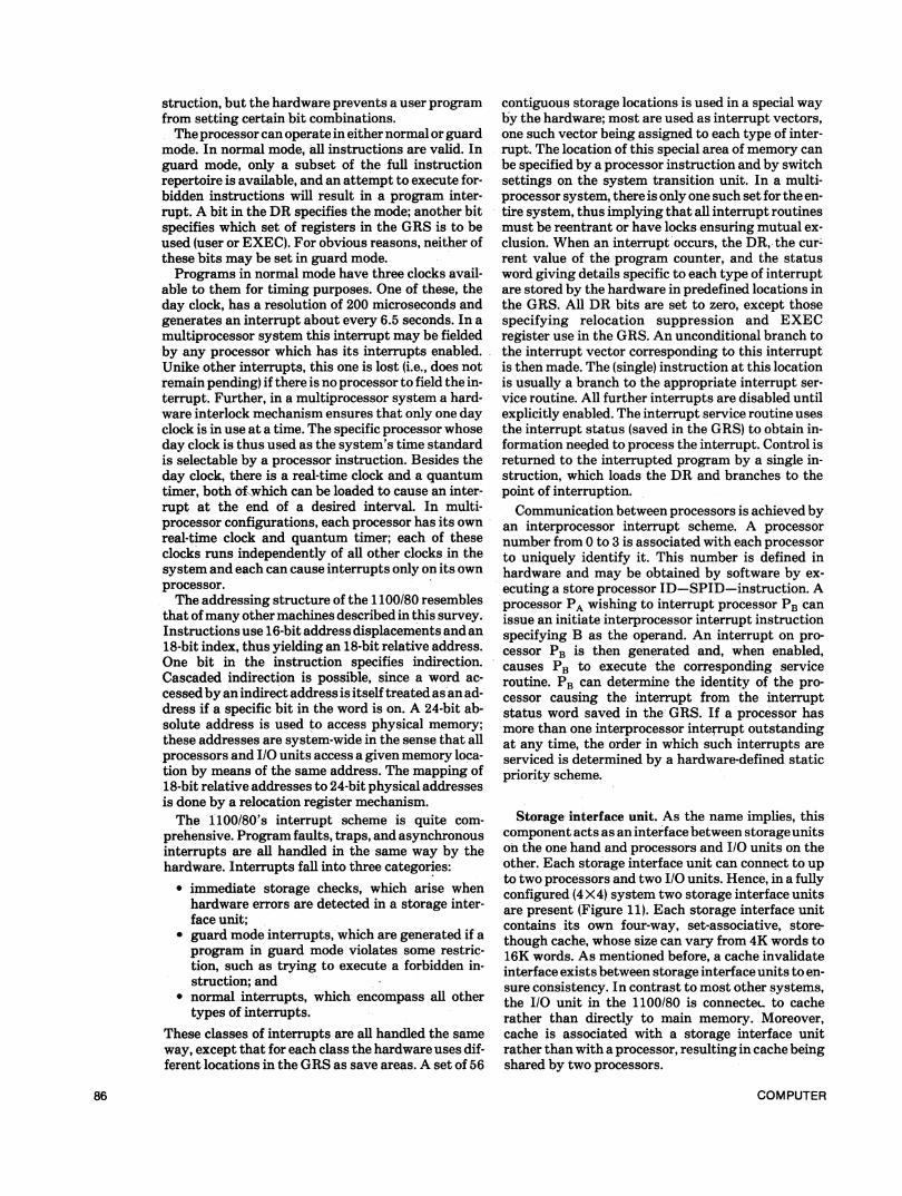
unit. There is still only one cache, common to bothprocessors and located in the storage interface unit.Figure 11 depicts a 4 X4 system. A second storage
interface unit, with its own independent cache, isnowpresent and connected to the two additional pro-cessors and I/O units. The two storage interface unitshave a cache invalidate interface which ensures thatif both caches contain copies of the same data, alter-ing the copy in one cache will cause the correspondingcopy in the other to be marked as invalid.As the figures show, main memory is a common
resource for all processors and I/O units and is ac-cessed by them via the corresponding storage inter-face units. There can beup to four main storage units,each containing from 512K to 1M words of memory.Each main storage unit is connected to both storageinterface units (if two exist) and can be two-way in-terleaved.Processors are connected to each other by inter-
processor interrupt interfaces, which permit a pro-cessor to cause an interrupt in any other processor.An I/O unit is electrically connected to only onestorage interface unit and to the processors on thatstorage interface unit. As a result, a processor canhandle I/O only on I/O units connected to the samestorage interface unit as itself.In addition to the components mentioned above is a
stand-alone unit (not shown in the figures) called thesystem transition unit, which contains controlsnecessary for system reconfiguration.
Central processor. The 1100/80 processor has a36-bit word length and a reasonably rich repertoire offixed-point, floating-point, data movement, andcharacter manipulation instructions. The architec-ture is essentially register-oriented, with separate in-dex registers and accumulators. Most double-operand instructions have one operand in a registerand one in memory.
Central to the architecture of this system is a set of128 36-bit words called the GRS-general registerset. Programs canl address 16 index registers and 16accumulators. There are two sets of each-one for useby user programs (the user set) and the other for useby the operating system (the EXEC set). There arealso two sets of miscellaneous registers used forspecifying masks, repeat counts, etc. Besides theseregisters, the GRS contains a number of elementsused only by the operating system: a real-time clock,pointers to descriptor tables (described later), andareas used by the hardware to save informationduring interrupts.Included in the processor, but not as a part of the
GRS, is a register called theDR-designator register.The DR is a collection of miscellaneous bits, some ofinterest to user programs, others used only by theoperating system. In addition to condition code bits(indicating the results of the previous instruction),the DR contains a number of control bits indicatingcertain program conditions such as overflow anddivide check, enabling or disabling interrupts, speci-fying whether user or EXEC registers are to be used,and so on. The DR may be loaded by a processor in-
Figure 9. A 1Xl Univac 1100/80 configuration.
Figure 10. A 2x2 Univac 1100180 configuration.
Figure 11. A 4X4 Univac 1100/80 configuration.
May 1980 85
struction, but the hardware prevents a user programfrom setting certain bit combinations.The processor can operate in either normal or guard
mode. In normal mode, all instructions are valid. Inguard mode, only a subset of the full instructionrepertoire is available, and an attempt to execute for-bidden instructions will result in a program inter-rupt. A bit in the DR specifies the mode; another bitspecifies which set of registers in the GRS is to beused (user or EXEC). For obvious reasons, neither ofthese bits may be set in guard mode.Programs in normal mode have three clocks avail-
able to them for timing purposes. One of these, theday clock, has a resolution of 200 microseconds andgenerates an interrupt about every 6.5 seconds. In amultiprocessor system this interrupt may be fieldedby any processor which has its interrupts enabled.Unike other interrupts, this one is lost (i.e., does notremain pending) if there is no processor to field the in-terrupt. Further, in a multiprocessor system a hard-ware interlock mechanism ensures that only one dayclock is in use at a time. The specific processor whoseday clock is thus used as the system's time standardis selectable by a processor instruction. Besides theday clock, there is a real-time clock and a quantumtimer, both oifwhich can be loaded to cause an inter-rupt at the end of a desired interval. In multi-processor configurations, each processor has its ownreal-time clock and quantum timer; each of theseclocks runs independently of all other clocks in thesystem and each can cause interrupts only on its ownprocessor.The addressing structure of the 1100/80 resembles
that ofmany other machines described in this survey.Instructions use 16-bit address displacements and an18-bit index, thus yielding an 18-bit relative address.One bit in the instruction specifies indirection.Cascaded indirection is possible, since a word ac-cessed by an indirect address is itself treated as an ad-dress if a specific bit in the word is on. A 24-bit ab-solute address is used to access physical memory;these addresses are system-wide in the sense that allprocessors and I/O units access a given memory loca-tion by means of the same address. The mapping of18-bit relative addresses to 24-bit physical addressesis done by a relocation register mechanism.The 1100/80's interrupt scheme is quite com-
prehensive. Program faults, traps, and asynchronousinterrupts are all handled in the same way by thehardware. Interrupts fall into three categories:
* immediate storage checks, which arise whenhardware errors are detected in a storage inter-face unit;
* guard mode interrupts, which are generated if aprogram in guard mode violates some restric-tion, such as trying to execute a forbidden in-struction; and
* normal interrupts, which encompass all othertypes of interrupts.
These classes of interrupts are all handled the sameway, except that for each class the hardware uses dif-ferent locations in the GRS as save areas. A set of 56
contiguous storage locations is used in a special wayby the hardware; most are used as interrupt vectors,one such vector being assigned to each type of inter-rupt. The location of this special area of memory canbe specified by a processor instruction and by switchsettings on the system transition unit. In a multi-processor system, there is only one such set for the en-tire system, thus implying that all interrupt routinesmust be reentrant or have locks ensuring mutual ex-clusion. When an interrupt 'occurs, the DR, the cur-rent value of the program counter, and the statusword giving details specific to each type of interruptare stored by the hardware in predefined locations inthe GRS. All DR bits are set to zero, except thosespecifying relocation suppression and EXECregister use in the GRS. An unconditional branch tothe interrupt vector corresponding to this interruptis then made. The (single) instruction at this locationis usually a branch to the appropriate interrupt ser-vice routine. All further interrupts are disabled untilexplicitly enabled. The interrupt service routine usesthe interrupt status (saved in the GRS) to obtain in-formation needed to process the interrupt. Control isreturned to the interrupted program by a single in-struction, which loads the DR and branches to thepoint of-interruption.Communication between processors is achieved by
an interprocessor interrupt scheme. A processornumber from 0 to 3 is associated with each processorto uniquely identify it. This number is defined inhardware and may be obtained by software by ex-ecuting a store processor ID-SPID-instruction. Aprocessor PA wishing to interrupt processor PB canissue an initiate interprocessor interrupt instructionspecifying B as the operand. An interrupt on pro-cessor PB is then generated and, when enabled,causes PB to execute the corresponding serviceroutine. PB can determine the identity of the pro-cessor causing the interrupt from the interruptstatus word saved in the GRS. If a processor hasmore than one interprocessor interrupt outstandingat any time, the order in which such interrupts areserviced is determined by a hardware-defined staticpriority scheme.
Storage interface unit. As the name implies, thiscomponent acts as an interface between storage unitson the one hand and processors and I/O units on theother. Each storage interface unit can connect to upto two processors and two I/O units. Hence, in a fullyconfigured (4 X4) system two storage interface unitsare present (Figure 11). Each storage interface unitcontains its own four-way, set-associative, store-though cache, whose size can vary from 4K words to16K words. As mentioned before, a cache invalidateinterface exists between storage interface units to en-sure consistency. In contrast to most other systems,the I/O unit in the 1100/80 is connecteL to cacherather than directly to main memory. Moreover,cache is associated with a storage interface unitrather than with a processor, resulting in cache beingshared by two processors.
COMPUTER86
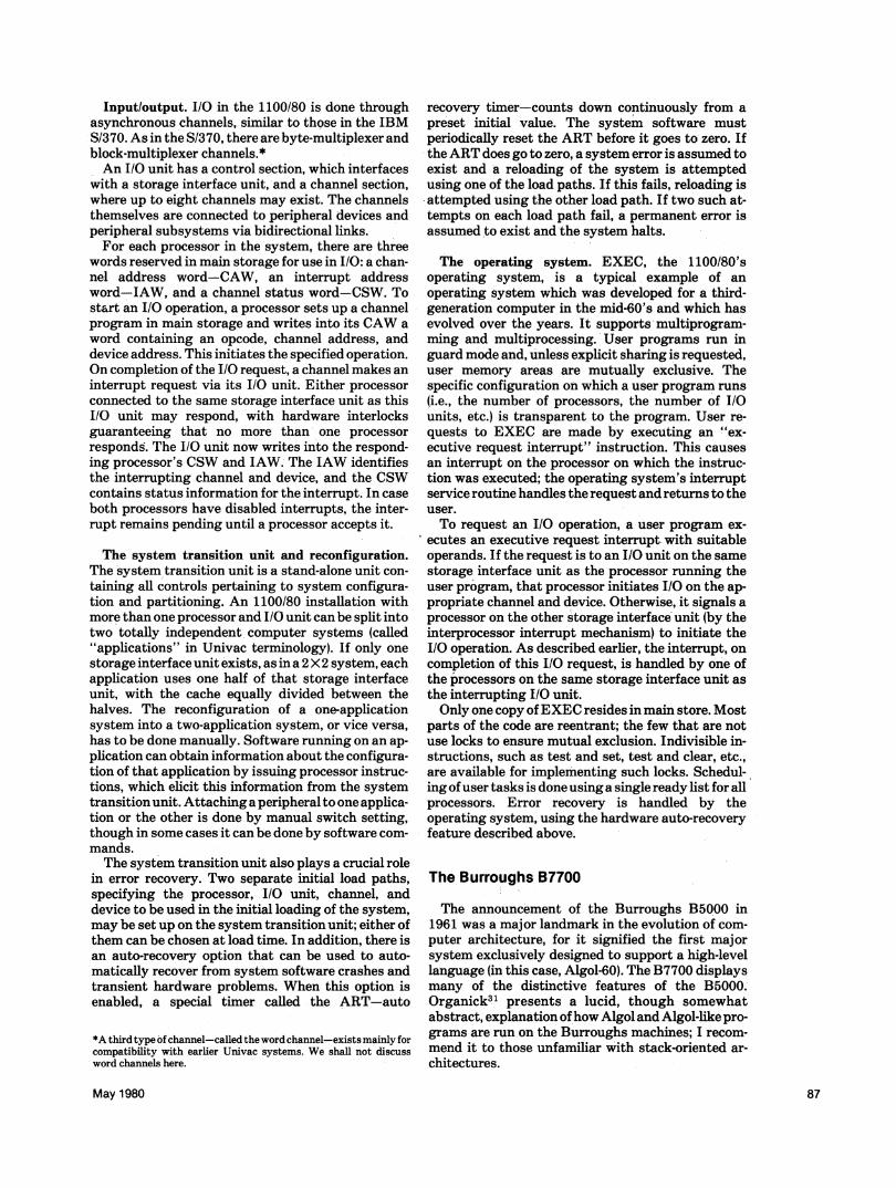
Input/output. I/O in the 1100/80 is done throughasynchronous channels, similar to those in the IBMS/370. As in the S/370, there are byte-multiplexer andblock-multiplexer channels.*An I/O unit has a control section, which interfaces
with a storage interface unit, and a channel section,where up to eight channels may exist. The channelsthemselves are connected to peripheral devices andperipheral subsystems via bidirectional links.For each processor in the system, there are three
words reserved in main storage for use in I/O: a chan-nel address word-CAW, an interrupt addressword-IAW, and a channel status word-CSW. Tostart an I/O operation, a processor sets up a channelprogram in main storage and writes into its CAW aword containing an opcode, channel address, anddevice address. This initiates the specified operation.On completion of the I/O request, a channel makes aninterrupt request via its I/O unit. Either processorconnected to the same storage interface unit as thisI/O unit may respond, with hardware interlocksguaranteeing that no more than one processorresponds. The I/O unit now writes into the respond-ing processor's CSW and IAW. The IAW identifiesthe interrupting channel and device, and the CSWcontains status information for the interrupt. In caseboth processors have disabled interrupts, the inter-rupt remains pending until a processor accepts it.
The system transition unit and reconfiguration.The system transition unit is a stand-alone unit con-taining all controls pertaining to system configura-tion and partitioning. An 1100/80 installation withmore than one processor and I/O unit can be split intotwo totally independent computer systems (called"applications" in Univac terminology). If only onestorage interface unit exists, as in a 2X2 system, eachapplication uses one half of that storage interfaceunit, with the cache equally divided between thehalves. The reconfiguration of a one-applicationsystem into a two-application system, or vice versa,has to be done manually. Software running on an ap-plication can obtain information about the configura-tion of that application by issuing processor instruc-tions, which elicit this information from the systemtransition unit. Attaching a peripheral to one applica-tion or the other is done by manual switch setting,though in some cases it can be done by software com-mands.The system transition unit also plays a crucial role
in error recovery. Two separate initial load paths,specifying the processor, I/O unit, channel, anddevice to be used in the initial loading of the system,may be set up on the system transition unit; either ofthem can be chosen at load time. In addition, there isan auto-recovery option that can be used to auto-matically recover from system software crashes andtransient hardware problems. When this option isenabled, a special timer called the ART-auto
*A third type of channel-called the word channel-exists mainly forcompatibility with earlier Univac systems. We shall not discussword channels here.
recovery timer-counts down continuously from apreset initial value. The system software mustperiodically reset the ART before it goes to zero. Ifthe ART does go to zero, a system error is assumed toexist and a reloading of the system is attemptedusing one of the load paths. If this fails, reloading isattempted using the other load path. If two such at-tempts on each load path fail, a permanent error isassumed to exist and the system halts.
The operating system. EXEC, the 1100/80'soperating system, is a typical example of anoperating system which was developed for a third-generation computer in the mid-60's and which hasevolved over the years. It supports multiprogram-ming and multiprocessing. User programs run inguard mode and, unless explicit sharing is requested,user memory areas are mutually exclusive. Thespecific configuration on which a user program runs(i.e., the number of processors, the number of I/Ounits, etc.) is transparent to the program. User re-quests to EXEC are made by executing an "ex-ecutive request interrupt" instruction. This causesan interrupt on the processor on which the instruc-tion was executed; the operating system's interruptservice routine handles the request and returns to theuser.To request an I/O operation, a user program ex-
ecutes an executive request interrupt with suitableoperands. If the request is to an I/O unit on the samestorage interface unit as the processor running theuser program, that processor initiates I/O on the ap-propriate channel and device. Otherwise, it signals aprocessor on the other storage interface unit (by theinterprocessor interrupt mechanism) to initiate theI/O operation. As described earlier, the interrupt, oncompletion of this I/O request, is handled by one ofthe processors on the same storage interface unit asthe interrupting I/O unit.Only one copy ofEXEC resides in main store. Most
parts of the code are reentrant; the few that are notuse locks to ensure mutual exclusion. Indivisible in-structions, such as test and set, test and clear, etc.,are available for implementing such locks. Schedul-ing ofuser tasks is done using a single ready list for allprocessors. Error recovery is handled by theoperating system, using the hardware auto-recoveryfeature described above.
The Burroughs B7700
The announcement of the Burroughs B5000 in1961 was a major landmark in the evolution of com-puter architecture, for it signified the first majorsystem exclusively designed to support a high-levellanguage (in this case, Algol-60). The B7700 displaysmany of the distinctive features of the B5000.Organick31 presents a lucid, though somewhatabstract, explanation ofhow Algol and Algol-like pro-grams are run on the Burroughs machines; I recom-mend it to those unfamiliar with stack-oriented ar-chitectures.
May 1980 87

Figure 12. B7700 configuration with minimum number ofrequesters.
Figure 13. B7700 configuration with one CPU and two 1/0modules.
Figure 14. Maximally configured B7700 system.
Overview. A simple B7700 system comprises threemajor units-the central processor, the input-outputmodule, and the memory module (Figure 12). Therecan be one to eight memory modules, each containingits own control unit and either 128K words or 256Kwords of memory (up to a system maximum of 1Mwords). Peripheral devices are connected to thesystem via an I/O module.The system in Figure 13 has one CPU but two I/O
modules. Each I/O module and CPU is connected toevery memory module by a separate memory bus.There is a single interrupt bus, to which are con-nected both I/O modules and the CPU. Since bothCPUs and I/O modules can access memory, Bur-roughs refers to them collectively as "requesters ofmemory." Note, in Figure 13, the presence of an ex-change, essentially a circuit switching unit whichsets up data and control paths between any of the I/Omodules and any of the devices connected to the ex-change. The exchange thus permits sharing ofdevices across I/O modules. Obviously, at any giveninstant a peripheral can be operated only under thecontrol of one I/O module.Figure 14 shows a maximally configured B7700
system. Up to eight requesters of memory (with atleast one CPU and one I/O module) may be present,each connected to every memory module. However,there is still only one interrupt bus. This bus is sym-metric; i.e., any requester can interrupt any other re-quester.Unlike some of the other multiprocessor systems
examined here, there is no central facility for routingmemory requests to the appropriate memory module.Such routing is doneby each requester, with conflictsresolved at the memory modules.
Central processor. The B7700 is based on a 48-bitword size, subdivided into six eight-bit bytes. Op-codes* are of variable length (from one to 12 bytes),with each byte referred to as a program "syllable."Every word in main memory is associated with athree-bit tag identifying the generic type of the con-tents of that word.-These tagbits are not present justfor use by software, but are interpreted and implicitlyused by the hardware during program execution.Program execution in the B7700 uses stacks exten-
sively. At any instant there is a unique stackassociated with the job being executed on a pro-cessor. This stack consists of three sections,**physically disjoint in memory but forming a singlelogical entity (Figure 15). The lowest of these sec-tions, common to all jobs in the system, is called theMCP stack since its contents are used by theoperating system. (MCP, for Master Control Pro-gram, is the name Burroughs applies to its variousoperating systems.) The second section contains adescriptor (called a segment descriptor) for every seg-ment that will ever be used by the currently ex-ecuting program and is therefore called the "descrip-
*"Operators" in Burroughs terminology.**This statement and the corresponding discussion are strictly validonly as long as the job does not do multitasking. If multitasking isdone, the stack structure will resemble a "cactus stack."30
COMPUTER88
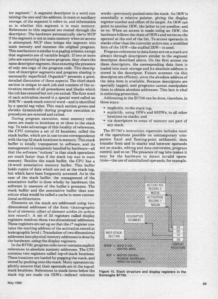
tor segment." A segment descriptor is a word con-taining the size and the address, in main or auxiliarystorage, of the segment it refers to, and informationas to whether this segment is in main memory.References to this segment are routed through thedescriptor. The hardware automatically alerts MCPif the segment is not in main memory when an accessis attempted; MCP then brings the segment intomain memory and resumes the original program.This mechanism is similar to a paging scheme, exceptthat segments are of variable length. If two or morejobs are executing the same program, they share thesame descriptor segment, thus ensuring the presenceof only one copy of the program code. This descrip-tion of descriptor segments and program sharing isnecessarily superficial; Organick31 presents a good,detailed discussion of these aspects. The third stacksection is unique to each job and consists of the ac-tivation records of all procedures and blocks whichthe job has entered but not yet exited. The first wordof each activation record is a special word called anMSCW-mark stack control word-and is identifiedby a special tag value. This stack section grows andshrinks dynamically during program execution asprocedures are entered and exited.During program execution, most memory refer-
ences are made to locations at or close to the stacktop. To take advantage of this locality of references,the CPU contains a set of 32 locations, called thestack buffer, which are in one-to-one correspondencewith the top 32 stack locations in memory. This stackbuffer is totally transparent to software, and itsmanagement is completely handled by hardware-allthat the software "notices" is that stack operationsare much faster than if the stack top was in mainmemory. Besides the stack buffer, the CPU has a16-word associative memory buffer. This bufferholds copies of data which are not at the stack top,but which have been frequently accessed. As in thecase of the stack buffer, the management of theassociative buffer is done wholly by hardware; thesoftware is unaware of the buffer's presence. Thestack buffer and the associative buffer thus con-stitute what would be called a cache in more conven-tional architectures.Elements on the stack are addressed using two-
dimensional addresses of the form <lexicographiclevel of element, offset of element within its activa-tion record>. A set of 32 registers called displayregisters resolves these two-dimensional addresses.These registers are set up so that the ith register con-tains the starting address of the activation record atlexicographic level i. Translation of two-dimensionaladdresses into physical memory addresses is done bythe hardware, using the display registers.In the B7700, program code never contains explicit
references to absolute memory addresses. The CPUcontains two registers called top-of-stack locations.These locations are loaded by popping the stack, andstoredby pushing onto the stack. Many operators im-plicitly assume that their operands are in the top-of-stack locations. References to stack items below thestack top are made via IRWs-indirect reference
words-previously pushed onto the stack. An IRW isessentially a relative pointer, giving the displayregister number and offset of its target. An IRW canpoint to another IRW, the latter to yet another, andso on. When an access is made using an IRW, thehardware follows the chain of IRWs and retrieves theoperand at the end of the list. To access operands instacks other than the currently active one, a modifiedform of the IRW-the stuffed IRW-is used.Program references to data items not on a stack are
always through descriptors similar to the segmentdescriptor described above. On the first access viathese descriptors, the corresponding data item isloaded into main storage and its absolute address isstored in the descriptor. Future accesses via thisdescriptor are efficient, since the absolute address ofthe data item is available. Because descriptors arespecially tagged, user programs cannot manipulatethem to obtain absolute addresses. This fact is vitalin enforcing protection.Addressing in the B7700 can be done, therefore, in
three ways:* implicitly, to the stack top,* explicitly, using IRWs and SIRWs, to all other
locations on stacks, and* via descriptors to areas of memory not part ofany stack.
The B7700's instruction repertoire includes mostof the operations possible on contemporary com-puters: fixed- and floating-point arithmetic, datatransfer from and to stacks and between operandsnot on stacks, editing and data conversion, programcontrol, and so on. The presence of tag bits makes iteasy for the hardware to detect invalid opera-tions-the use of uninitialized operands, for example.
Figure 15. Stack structure and display registers in theBurroughs B7700.
May 1980 89

Procedure entry and exit are extremely efficient. Toenter a procedure, a user program pushes onto thestack an MSCW, the identity and starting address ofthe procedure being called, and any parameters to bepassed. An ENTER operator is then executed. Thehardware uses the contents of the stack top to per-form procedure linkages and sets up the displayregisters appropriately. Procedure exit is ac-complished by reversing these steps.A variety of mechanisms provide protection. First
of all, a limit-of-stack register and base-of-stackregister are set for the currently active stack, to pre-vent stack overflow and underflow. Every descriptorcontains the size of the data item it refers to; eachmemory access via the descriptor is checked to en-sure that only memory locations within the cor-responding data item are being accessed. Tag bits at-tached to each word provide a third dimension of pro-tection, since invalid operations can then be detected.As in all other computer systems discussed in thissurvey, the B7700 has two states of operation-nor-mal (in which user programs execute and in which cer-tain operators cannot be executed) and control (inwhich all operators are valid).The B7700 has a comprehensive interrupt scheme
which fits in neatly with its stack-oriented architec-ture. Interrupts fall into four categories, listed belowin descending order of priority:
* Alarm, e.g., memory parity errors, processor hard-ware errors;
* Syllable, e.g., invalid program operations, arith-metic overflows;
* Special, e.g., timer interrupts, stack overflow;and.
* External, e.g., interrupts by I/O modules or otherCPUs.
The first two categories are always enabled,whereas the other two can be disabled. A CPU treatsan interrupt as an unexpected procedure call. Thehardware pushes onto the current stack an MSCW, apointer to the interrupt handling routine, andparameters identifying the type of and reason for theinterrupt. The hardware then executes an implicitENTER, as a result of which the interrupt handlingroutine is entered. Exit from this routine causes theresumption of the interrupted program. Since pro-cedure entry and exit are efficiently handled in thissystem, interrupt handling is also (potentially) effi-cient.An external interrupt, called channel interrupt,permits a CPU to interrupt any other CPU or I/Omodule. This feature is used to implementMCP inter-processor communication facilities. Interrupts maybe nested to a depth of four. The level of interruptnesting is maintained as part of the processor state,and at level i, a processor is said tobe in control mode i.There is one interval timer per CPU, with a resolu-
tion of 512 microseconds and a maximum period ofone second. It can be loaded with a value and willcause an interrupt on itsCPU when this time intervalhas elapsed.In all the cases described above, the CPU to be in-
terrupted is decided by the originator of the inter-
rupt. There is no competition among CPUs for inter-rupt servicing, as is the case in the Univac 1100/80,for example.
Memory modules. The memory modules in the37700 not only physically house memory but alsocontain logic to perform the functions of storage con-trol and conflict resolution. There are eight ports permemory module, and one requester can be connectedto each port. Each port is assigned a priority level,which is used by the memory module to resolvememory request conflicts. I/O modules are given thehighest priority so that latency times can be mini-mized for I/O devices trying to access memory. Theconflict resolution algorithm used by the memorymodule guarantees starvation-free service to all re-questers.Each memory module can be two- or four-way in-
terleaved. The address range corresponding to eachmemory module is set in memory limit registers inthat memory module. These registers can be setunder program control. Each requester's- mainmemory interface has the contents of all limitregisters available to it; this information is used todecide which memory module a memory requestshould be routed to.A request inhibit register is present in every
memory module and has a bit corresponding to eachrequester. The register can be read or written underprogram control by all CPUs. If bit i is set to 1,memory requests from requester i are ignored by thatmemory module. This feature is useful in errorrecovery, where a requester suspected of being faultycan be isolated under program control.
I/O modules. The I/O module in the B7700 per-forms a function that can best be described as beingmidway between that of a peripheral processor (as inthe Cyber 170) and that of a channel (as in the IBM370). Like the latter, the I/O module is not program-mable and executes commands set up by a CPU.However, it does not have to interrupt a CPU aftercompletion of an I/O operation; like a peripheral pro-cessor, it can service a number of requests beforesignaling its completion.Crucial to the I/O scheme is a data structure located
in main memory called the I/O subsystem map. Thismap's location and substructures are defined for allI/O modules at system initialization. All requestersin the system share this single map, which containsinformation such as device status, paths available toeach device, etc.When MCP receives a program's I/O request, a
data structure called an IOCB-input-output controlblock-is created and linked onto the I/O queue forthe appropriate device. If an I/O module is currentlyservicing this queue, nothing more needs to be doneby the CPU. Otherwise, when a reasonable number ofrequests have accumulated in the queue, a CPUwrites a start I/O command for the device into the I/Omap and interrupts the device. The I/O module thenreads the command and begins processing the firstIOCB on the queue. On completion, the IOCB is de-
COMPUTER90

linked from the original list and placed in a queuecalled the status queue. The I1O module then beginsprocessing the second request and continues in thismanner until it exhausts the queue, encounters. afatal error, or is interrupted by a CPU. The removal ofIOCBs from the status queue can be done by anyCPU at any time. Concurrent manipulation of dif-ferent parts of the I/O map by different requesters ispossible; each substructure has lock bits to. ensuremutual exclusion in critical regions.
I/O errors, unless internal to an I/O module, do notcause the I/O module to signal an interrupt. An IOCBfor whichan I/O error has occurred is treated just as ifit were successful-it is delinked and placed in thestatus queue. However, the I/O module does placediagnostic information specifying the nature andcause of the error in the offending IOCB.When more than one path is available to a device,
an I/O module uses information from the I/O map tochoose an appropriate path and to try alternate pathsif the first is busy. Besides the standard method ofperformning I/O (described above), special I/O com-mands are available and are used, for instance, insystem initialization, error recovery, and other suchsituations. I/O can also be done on an interrupt-driven rather than a queue-driven basis if a CPU sodesires.
The master control program. MCP for the B7700 isa compatible version of MCPs for earlier Burroughsmachines and supports both multiprogramming andmultiprocessing. Jobsexecute in a segmented virtualaddress space and share programs with other jobs.Multitasking is possible; each time a job creates asubtask, a new branch of the current task's stack iscreated. The original task and subtask share thestack contents up to this point, but have individual,non-shared branches above. Logically, however, eachsees a monolithic stack. This procedure may berepeated recursively, yielding a "cactus stack"(Figure 16).
User programs use MCP facilities via procedurecalls to appropriate routines located in the MCPstack section. Unlikemost other systems, which haveto execute a special trap instruction for calls to theoperating system (e.g., the SVC instruction in theS/370), the B7700 uses the sameENTER operator forcalling both user and MCP routines.Communication facilities between tasks are im-
plemented by means of software interrupts. A taskmay ask to be interrupted byMCP if a certain event,usually caused by some other task, occurs. Thisfeature is extremely useful in synchronization andcoordination of subtasks within a job. Software inter-rupts appear as unexpected procedure calls to the cor-responding interrupt service routines. Whileawaiting an event, a task may choose to either con-tinue processing or enter a blocked state-MCP pro-vides both options.MCP has extensive error recovery facilities.
Dynamic system reconfiguration is possible withoutreinitialization. I/O modules or CPUs can be effec-tively isolated by setting the requester inhibitregisters appropriately. The possibility of recoveryfrom software errors withinMCP is greatly enhancedbecause each control mode (from CM1 to CM3) has adifferent MCP stack section and hence different in-terrupt handling routines (the hardware being awareof the location of each such stack section). If an erroroccurs in an MCP interrupt handling routine, the en-suing interrupt can be routed to a different interrupthandling procedure, even if this interrupt is of thesame type as the first one. This can be recursivelyrepeated up to three times. Hence MCP can limit thepropagation of software errors, since different inter-rupt handling procedures are used in each controlmode. The presence of multiple paths to a device per-mits MCP to continue operations on that device evenif one of the paths becomes unusable.MCP is written almost entirely in a high-level
language called Espol, a Burroughs dialect of Algol.All user programs are also written in high-level
Figure 16. The "cactus-stack," a shared stack structure in the Burroughs B7700.
May 1980

languages. Since code generated by the compilersdoes not contain sensitive or potentially malignantoperators, such operators do not need tobe marked as
privileged. This accounts for the B7700's extremelysmall privileged instruction set. As mentionedearlier, all programs are reentrant, and code sharingis done as much as possible.
General observations
Having studied five multiprocessing systems indetail, we can now look back and see ifwe can find anycommon threads running through the designs ofthese systems. Although multiprocessing systemsgive rise to many problems, they also offer many op-
portunities which, if successfully exploited, canmakemultiprocessing worthwhile.
Interconnections in a multiprocessor. There are
two basic perceptions of the relationship betweenuniprocessors and multiprocessors. One views a
multiprocessor as a number of connected uni-processors. The other thinks of a uniprocessor as a
degenerate case of a multiprocessor. In a simplesense, the first is the worm's eye view-and the sec-
ond the bird's eye view-of multiprocessing. It is notsurprising that the designer's choice of a connectingscheme depends greatly on which of the two views hetakes. The IBM 370/168 and the Honeywell 60/66 are
examples of the first viewpoint, while the BurroughsB7700 and C.mmp36'37 are instances of the second.The most important connections in a multi-
processor are those between the individual pro-
cessors and the shared memory. The conceptuallysimplest way to make these connections (though cer-
tainly not the most common) is to use a crossbarswitch as in the C.mmp. This requires the switch tohave one connection from every processor andmemory module. The total number of such connec-
tions will therefore vary linearly according to thenumber of processors and memory modules.* Analternate way to connect memory to processors is ex-emplified by the Honeywell 60/66. Here, each ad-ditional processor has its own share of globalmemory, and so every such processor has to be con-
nected to every other processor in the system. Thisgives rise to an 0(N2) number of connections, whereN is the number of processors. A third alternative isseen in the B7700, where the number of memorymodules is independent of the number of processors.Each additional processor has to be connected only toa fixed number of memory modules. The number ofconnections in this case is 0(N). Multiprocessorswith a single shared bus have been built,34 but theamount of processor-memory traffic in such a struc-ture makes it unattractive for large multiprocessorsystems.
*Thenumber ofconnections within the switch will obviously vary asO(N2). But all these connections could be placed on a chip, or on a
single board, and so the number of external connections would be on-
ly 0(N).
Besides connections to shared memory, a multi-processing system usually has two other types of con-nections. One is a connection among processors tofacilitate interprocessor communication. The Univac1100/80 and the Honeywell 60/66 have one such con-nection between every pair of processors, giving anO(N2) number of connections. The B7700, however,has a single interrequester interrupt bus for the en-tire system. Every requester is connected to this busand shares it with every other requester. While bussharing does introduce problems such as contentionand delays due to bus arbitration logic, the frequencyof interprocessor communications is usually lowenough to make the single shared bus feasible.Most of the systems studied here have a cache
associated with each processor. In order to ensure theconsistency of (possibly) multiple copies of data inthe different caches, every cache must communicatewith every other cache. Systems such as the Univac1100/80 and the Honeywell 60/66 have a cache in-validate interface between every pair of caches, thusrequiring an O(N2) number of connections. A sharedcache invalidate bus could reduce the number of in-terconnections, although the high bandwidth such abus would require probably explains why no multi-processing system uses such an approach.To correctly route memory accesses to the ap-
propriate memory modules, a number of systemshave one or more coordinating elements. The cross-bar switch in the C.mmp, the system controller in theHoneywell 60/66, the system interface unit in theUnivac 1100/80, and the multisystem control i4nit inthe IBM 370/168 are examples of this. However, suchcoordinating elements are not essential, asdemonstrated by the B7700, where each requesterdoes its own routing of memory and interrupt re-quests.
Symmetry. The processors used in a multiprocess-ing system may or may not be identical. TheHoneywell 60/66, the Univac 1100/80, and the truemultiprocessor 370/168 are systems having identical(symmetric) processors. The Cyber 170 (in whichperipheral processors and central processors are verydifferent from each other) and the attached processor370/168 are systems with asymmetric processors.Except in a few cases (as in the ability of a user tospecify "task affinity" to the 370/168 MVS operatingsystem), the symmetry or asymmetry among pro-cessors is of interest only to the operating system-andis usually transparent to user programs. From an er-ror recovery point of view, the symmetric situation ispreferable.
I/O structure. Most third generation architectureshandle I/O via highly specialized auxiliary pro-cessors, such as channels in the S/370 and I/Omodules in the B7700. In multiprocessing systemsbased on these architectures, these auxiliary pro-cessors differ mainly in the amount of symmetrypresent in the connections between them and the cen-tral processor.
COMPUTER92

In a fully symmetric situation, there is no a prioricorrespondence between the central processor(s) andthe auxiliary processors. Each auxiliary processorcan communicate with any central processor, andeach central processor can do I/O via any auxiliaryprocessor. Such a structure is found in the B7700, inwhich central processors and I/O modules are treatedequally as "requesters of memory," with every re-quester able to communicate with every other re-quester.The diametrically opposite approach is found in
systems where there is a permanent correspondencebetween auxiliary processors and central processors.In the 370/168, for example, every channel is per-manently associated with a CPU, and a CPU cannotdo I1/0 via a channel attached to another CPU.Between these-extremes, one can have I/O struc-
tures with varying degrees of symmetry. The max-imally configured Univac 1100/80, for example, hastwo storage interface units, each attached to two cen-tral processors and two I/O modules. An I/O moduleattached to one storage interface unit cannot com-municate with a CPU attached to the other storageinterface unit. BothCPUs attached to a storage inter-face unit can, however, communicate with and per-form I/O on both the I/O modules connected to thesame storage interface unit.For numerous reasons, the fully symmetric situa-
tion is the most desirable. First, a system with a fullysymmetric I/O structure can continue operating inspite of failure in a central or auxiliary processor. Inan asymmetric situation, failure in a central pro-cessor disables the auxiliary processors associatedwith that central processor. Second, interrupt laten-cy times (i.e., the time between the sending of an in-terrupt signal by an auxiliary processor and its beingaccepted by some central processor) are likely to beless in the fully symmetric case, mainly because theprobability of all central processors being disabledforinterrupts is much less than the probability ofanyone central processor being disabled. Finally, taskswitching and interprocessor communicationoverheads are likely to be much smaller in a fully-sym-metric situation. In an asymmetric situation, a pro-gram's request to do I/O via an auxiliary processorcan only be handled by the central processorassociated with that auxiliary processor. This cancause significant overheads in task switching and incommunications between the central processor run-ning the program and the central processor servicingthe I/O request.
Interrupts. Interrupts can be classed into twotypes: internal interrupts, such as arithmeticoverflows, divide checks, and protection violations;and external interrupts, such as I/O interrupts andtimer interrupts. In all the systems discussed here,internal interrupts are handled on the processor onwhich they originated. The systems vary, however, intheir handling of external interrupts, the major dif-ference being the extent to which interrupts areshared by the processors. In the Honeywell 60/66, all-interrupts are routed to one processor labeled the
"control processor." While probably the simplest toimplement in hardware, this scheme suffers frompoor recoverability and long latency times, asdiscussed earlier.In the Univac 1100/80, all external interrupts (ex-
cept I/O interrupts) are shared by all the processors.Each interrupt is given to every processor, one afterthe other, for a predefined time period. The first pro-cessor to respond during its time slot gets the inter-rupt. Such a scheme obviously will have excellentrecoverability and short latency times.A variation of the previous scheme is to let the in-
terrupter choose which processor it wishes to inter-rupt. The SIGP interrupt in the S/370 and the inter-rupt mechanism used by the I/O modules in -theB7700 fall within this category. To overcome the pro-blem of long latency times, the interrupter couldchange its target if the original target did not respondwithin a reasonable time. From a recoverability pointof view, this scheme is as good as the previous one.
Interprocessor communication mechanisms. Thereare a number of reasons why a hardware interproces-sor mechanism is necessary in a multiprocessing sys-tem. If the structure of the system is asymmetric,there will be frequent service requests exchangedbetween the different processors. A hardware inter-processor communication mechanism, to draw the at-tention of the target processor, would be very usefulin such cases. The mechanism also facilitates syn-chronization between processors. For instance,during a checkpoint all processors except the one ex-ecuting the checkpoint task could be halted. An inter-processor communication facility'would permit suchinformation to be easily and quickly broadcastthroughout the system. Also, in the event of failure, ahardware-initiated signal to all functioning proces-sors would inform them of the failure.Since processors share memory, it is clearly possi-
ble to have software communication without explicithardware assistance. Doing that, however, intro-duces a number of problems. First, all processors willhave to periodically check to see if there is a messagefor them. Second, since a processor only recognizesrequests when it does its next polling of messages,response times to requests can become intolerablylong. Further, if a processor fails when a job holdinglocks is running on it, and if there is no way for otherprocessors to be aware of this, a deadlock can occur.
Interprocessor communication mechanisms havevarious' levels of sophistication. The Cyber 170doesn't have such a mechanism at all. The Univac1100/80 and the Honeywell 60/66 have a simple,software-initiated interprocessor interrupt. TheS/370 has a more sophisticated mechanism, theSIGP, which enables one processor to act virtually asan operator for another processor. The SIGP also hasthe unique, hardware-initiated emergency malfunc-tion, discussed earlier.
Reserved storage areas. In most of the architec-tures discussed here, certain areas of main storageare reserved for special use by the hardware. In the
May 1980 93

S1370, for instance, addresses 0-4K contain dataareas related to I/O, the interrupt vectors (i.e., the oldand new program status words for all- interruptclasses), and areas used by the hardware to recorddiagnostic information when- failure occurs. In amultiprocessing-situation, there are a number of pro-cessors, each with a set of reserved addresses; thisleads to a potential clash of reserved areas, one whichcan be resolved in three ways.One method-used in the Univac 1100/80-makes
the physical storage areas corresponding to thereserved addresses the same in all the processors.The Univac 1100/80 allows this because the reservedarea mainly contains interrupt vectors; each inter-rupt handling routine therefore has to either be reen-trant or have locks that ensure mutual exclusion.The Honeywell 60166 solves the problem in a dif-
ferent way: the address of the reserved storage area isdifferent for each processor. As a result, the physicalstorage locations corresponding to the reservedstorage addresses is different in each case.In the S/370, the processors treat addresses 0-4K as
reserved addresses. However, the physical storagecorresponding to this address range is different foreach processor. This is accomplished by the previous-ly mentioned "prefixing" mechanism.The last two techniques achieve the same effect,
and consequently there is really little to choose be-tween them.
The operating system. Surprisingly, in spite of thelarge differences in architecture and systemorganization, the operating systems discussed hereare similar in the way they handle multiprocessing.In all cases, the operating system screens users fromthe specific hardware configuration-as far as theyare concerned, the system is a uniprocessor whetherthere are in fact two, three, or more processors. Eachuser task can create independently schedulable sub-tasks, which compete for resources with the parenttask. The operating system normally provides theuser with software mechanisms to synchronize tasksand to permit communication between them. Lock-ing mechanisms (built using indivisible hardware in-structions such as the test-and-set or compare-and-swap) are provided to permit strictly serial access tocritical sections of shared code and data. There isusually only one copy of the operating system, withdifferent parts reentrant or serially reusable. Since allthese operating systems support multiprocessing,the usual issues arising in a multiprogramming con-text are also present: address space management,scheduling, protection, etc.Probably the two greatest sources of variation
among the operating systems are their locations andthe relationships they set up between the processors.In the Cyber 170, for example, the operating systemis executed by one peripheral processor, P0. All theother processors, whether central or peripheral, aretreated as slaves to P0. A similar situation, involvingsymmetric rather than asymmetric processors, isfound in the DECsystem-10.33 Here, there are twoidentical central processors, one designated as
master and the other as slave. The operating systemruns only on the master, with the slave treated just asa schedulable resource. The most common approach,however, is a distributed operating system, in whichall processors may execute parts of the operatingsystem as necessary. MVS35 on the S/370 andHydra37 on the C.mmp are examples. This approachis certainly the-most symmetric, the most immune toindividual processor failure, and the most aesthet-ically pleasing.
Error recovery. In the introduction I mentionedthat one advantage of a multiprocessing system is itssuperior error recovery capability. Note thatrecoverability is not synonymous with reliability.Because of the interconnections and extra units pres-ent, the probability of failure may in fact be higher ona multiprocessor than on a uniprocessor. On the otherhand, the inherent redundancy of a multiprocessorprobably increases its ability to carry on in spite offailure. The mechanisms assisting error recoveryspan a wide range. The S/370 has a hardware-generated malfunction alert, which informs all otherprocessors of a failure in one processor. The Univac1100/80's auto recovery timer assists in recoveryfrom software crashes and transient hardwarefailures. The B7700's requester inhibit registers per-mit recovery software to logically isolate faulty re-questers.Even with such features, software for error recov-
ery is likely to be complex. For example, saving a pro-gram on a failed processor involves backtracking theexecution of the program to a point before in-termediate results were corrupted by the failure, andcontinuing execution from there. This can be dif-ficult, especially in a processor with a pipelined ex-ecution unit. Another problem is that the program onthe failed processor may be holding some locks. Theerror recovery procedure has to be smart enough toensure that deadlocks are not introduced as a resultof the recovery process itself!
Performance. As stated earlier, there is little quan-titative data on the performance of the computersystems surveyed. However, one can make somegeneral statements about the performance of multi-processing systems.
Invariably, the scaling in performance of a multi-processing system is sublinear. That is, using anN-processor multiprocessing system always yieldsless than N times the performance of the corre-sponding single-processor-based system.*Contention among processors for memory and
delays involved in ensuring cache validity are two
*This statement is strictly true only if "performance" means "max-iinum performance." All parameters other than the number of pro-cessors (amount of storage, I/O configuration, etc.) should be ad-justed in each case for optimal performance. Not doing so can yieldanomalous results, indicating that a multiprocessor does indeedhave better performance than the sum of theperformances ofits pro-cessors running as uniprocessors. Stated more accurately, therefore,a multiprocessor's maximum performance is always less than thesum of the maximum performances of its corresponding uni-processors.
COMPUTER94
major factors in this performance degradation.Besides these hardware overheads, a multiprocessorhas certain unique software overheads. Scheduling ismore complex because of the presence of more thanone processor, and this can contribute significantlyto the extra overheads. Locks are required in a multi-processor, although they can be avoided in auniprocessor by disabling interrupts whenevercritical sections of the operating system are being ex-ecuted. The time spent waiting at these locks con-tributes to the loss in performance. Finally, thegreater computational power of a multiprocessor im-plies a correspondingly higher level of multiprogram-ming. At high levels of multiprogramming, certain"large system effects" are felt-queues get longer,hash tables become fuller, certain data structuresbecome too large to be stored in main memory, etc.All these factors cause multiprocessor performanceto obey the law of diminishing marginal utility-i.e.,each added processor contributes relatively less tooverall performance.U
Bibliography
IBM 370 Model 168
1. Arnold, J. S., et al., "Design of Tightly-Coupled Multi-processing Programming," IBM Systems J., Vol. 13,No. 1, 1974, pp. 60-87. A good description of the com-ponents of MVS that play a role in multiprocessing.The sections on alternate CPU recovery, CPU affinity,and locking are particularly interesting. This paper isworth reading, at least to gain an appreciation of thedifficulties involved in designing an operating systemfor multiprocessor environments.
2. Case, R. P., and A. Padegs, "Architecture of the IBMSystem /370," Comm. ACM, Vol. 21, No. 1, Jan. 1978,pp. 73-96. A readable account of the architecture of theS/370 and of its evolution from its predecessor, theS/360. Includes a section on multiprocessing. Highlyrecommended.
3. Brinch Hansen, P., Operating System Principles,Prentice-Hall, Englewood Cliffs, N.J., 1973. Section3.5 discusses deadlocks and their prevention. MYSuses the linear ordering technique described in thatsection.
4. IBM Corp., IBM System/370 Principles of Operation,Form no. GA22-7000-5, Aug. 1976. The definitivework on the S/370 architecture. Reads at times like alegal document, but is unsurpassed in its precision andunambiguity. Includes a separate chapter on multi-processing.
5. IBM Corp., IBM System/370 Model 168 FunctionalCharacteristics, Form no. GA22-22-7010-4, Jan. 1976.Gives information specific to the 370/168. Details suchas processor speed, channel data rates, and maximummemory available can be found here. Appendix E, ex-clusively devoted to multiprocessing, describes re-configuration controls.
6. MacKinnon, R. A., "Advanced Function Extendedwith Tightly-Coupled Multiprocessing," IBMSystems J., Vol. 13, No. 1, 1974, pp. 32-59. Describesthe S/370 hardware features used in multiprocessing.Includes comparison of past and present multi-processor systems supported by IBM.
7. Scherr, A. L., "OS/VS2-2 Concepts and Philosophies,"IBM Systems J., Vol. 12, No. 4, 1973, pp. 368-381.Discusses the structure and design of MVS.
Control Data Cyber 170 Series
8. Atwood, J. W., "Concurrency in Operating Systems,"Computer, Vol. 9, No: 10, Oct. 1976, pp. 18-26. Has agood description of Kronos. The structure of theoperating system and the implementation of variousfunctions are explained well. Quite readable.
9. Auerbach Publishers Inc., "CONTROL DATACORP. CYBER 170 Series," Auerbach ComputerTechnology Reports, 1977.
10. Control Data Corp., Cyber 170 Hardware ReferenceManual; Form no. 60420000F, Apr. 1977. Describesthe hardware details of the Cyber machines.
11. Control Data Corp., 6000 Series Reference Manual,Form no. 60100000W, Jan. 1973. Describes the CDC6000 series, the predecessor of the Cyber 170.
12. Control Data Corp. SCOPE General InformationManual. An overview of Scope, CDC's earliestoperating system.
13. Control Data Corp., SCOPE 2 Reference Manual;Form no. 60342600D, Aug. 1973. Treats Scope ingreater detail than the above;
14. Control Data Corp., KRONOS 2.1 Reference Manual;Vol. I, Form no. 60407000D, June 1975. DescribesCDC's second operating system.
15. Control Data Corp., NOS1.OReferenceManuals Vol. I,Form no. 60435400A, June 1975. Describes CDC'slatest operating system, which supports networking.
16. Thornton, J. E., Design of a Computer: The ControlData 6600, Scott, Foresman and Co., Glenview, Ill.,1970. Has an illuminating discussion of the designprinciples involved in the CDC 6600, much of which isrelevant to the Cyber 170. The sections on technologyand physical construction are obsolete, but the rest ofthe book makes good (and worthwhile) reading.
Honeywell Series 60 Level 66
17. Honeywell Inc., General Comprehensive OperationSupervisor (GCOS), Order no. DD19, Apr. 1974.Describes GCOS and its functions. Section I is par-ticularly relevant to our discussion.
18. Honeywell Inc., Series 60 Level 66Summary Descrip-tion, Order no. DC64, 1975. Gives an overview of the60/66 and a description of its major hardware and soft-ware components. Chapters 1,2,4,8,9,10 are par-ticularly informative.
19. Honeywell Inc., Macro Assembler Program (GMAP),Order no. DD08, July 1974. Section I gives an over-view of the hardware. Sections IV and VIII describethe instruction set; Section V details the addressmodification scheme.
20. Honeywell Inc., System Operation Techniques, Orderno. DD50 Rev. 1, Oct. 1976. Section VIII describessystem reconfiguration techniques.
21. Honeywell Inc., System Startup, Order no. DD33 Rev.2, July 1976. Sections I and II describe the bootstraploading techniques. Section VI describes the systemrecovery facilities. Appendix C gives information onhardware reconfiguration.
May 1980 95

22. Mitre Corp., WWMCCSH6000MultiprocessorPerfor-mance Evaluation, NTIS report no. ADA 039111(Vols. I & II), National Technical Information Service,Springfield, Va., Feb. 1977. A study of H6000multiprocessor systems conducted for the Air Force;gives the performance figures and graphs cited in thissurvey.
Univac 1100 Model 80
23. Borgerson, B.R., et al., "The Evolution of the SperryUnivac 1100 Series: A History, Analysis, and Projec-tion," Comm. ACM, Vol. 21, No. 1, Jan. 1978, pp.25-43. Excellent description of the evolution of the110.0 series. Gives a broader and more generalperspec-tive of the Univac 1100 series than this survey; alsocovers a number of details, such as application soft-ware, which have been ignored here since they are notgermane to multiprocessing. Highly recommended.
24. Sperry Univac, 1100/80 Systems: Processor and Stbr-age, Form no. UP-8492. Gives a detailed description ofthe processor, main storage unit, and storage interfaceunit; discusses the instruction set, addressing and in-terrupt schemes, and other hardware details.
25. Sperry Univac, 1100/80 System Hardware (4x4 Capa-bility) System Description, Form no. UP-8568. Anoverview of the 1100/80 system, its hardware com-ponents, its interconnection scheme, etc. Less detailedlevel than the above.
26. Sperry Univac, 1100/80 System: System TransitionUnit. Programmers 'Reference, Form no. UP-8409. Adetailed description of the system transition unit andthe program commands available to interrogate andcontrol it. The auto recovery mechanism and thesystem transition unit's role in it are also discussed.
27. Sperry Univac, 1100 Series Executive, Volume 2,EXEC Level 33R1, Programmer Reference, Form no.UP-4144.21. Part of a four-volume reference on theEXEC operating system, this volume describes theoverall control of the 1100 series byEXEC and is validfor all models of the 1100 series (1100/10 to 1100/80). Inrefreshing contrast to most computer manuals, thisone gives a readable account of EXEC's designphilosophy and internal details.
Burroughs B7700
28. Burroughs Corp., B7700 Information ProcessingSystems: Characteristics Manual, Form no. 1059979,1973. An elementary description ofthe B7700, its com-ponents, and their interrelationships. Includes detailssuch as maximum memory capacity, device speeds,and processor cycle times.
29. Burroughs Corp., B7700 Information ProcessingSystems: Reference Manual, Form no. 1060233, 1973.Encyclopedic description of the B7700. Extremelydetailed descriptions of each component. This is onecomputer manual with too much information ratherthan too little-one can easily get lost in the details.
30. Chu, Y., High Level Language Computer Architec-ture, Academic Press, New York, 1975. Containspapers on those aspects of computer architecture per-tinent to high-level languages. Chapter 4 is particular-ly relevant, since it discusses stack architectures. Thischapter also includes a discussion of tagged memoryand of stack structures when parts of the stack areshared (i.e., the "cactus stack").
31. Organick, E. I., Computer System Organization: TheB5700/6700 Series, Academic Press, New York, 1973.Excellent explanation of how programs are run on theBurroughs architecture. Deals with the predecessorsof the B7700, but the material discussed is equallyvalid for the B7700. Organick's inimitable style makesthis book well worth reading.
32. Wegner, P., Programming Languages, InformationStructures and Machine Organization, McGraw-Hill,New York, 1968. Chapter 4 contains a good discussionof block-structured languages and the run-time sup-port they require.
General observations
33. Digital Equipment Corp., DECsystem-10 TechnicalSummary, Maynard, Mass., 1977.
34. Kraley, M. F., "The Pluribus Multiprocessor," Digestof Papers-1975 Int'l Symp. Fault-Tolerant Com-puting, June 1975, p. 251.*
35. Scherr, A. L., "OS/VS-2 Concepts and Philosophies,"IBM Systems J., Vol. 12, No. 4, 1973, pp. 368-381.
36. Wulf, W. A. and C. G. Bell, "C.mmp-A Multi-Mini-Processor," AFIPS Conf. Proc., Vol. 41, Part II, 1972FJCC,.pp. 765-777.
37. Wulf, W. A. et al., "Hydra: The Kernel of a Multipro-cessor Operating System," Comm. ACM, Vol. 17, No.6, June 1974, pp. 387-345.
*This digest is available from the IEEE Computer Society Publica-tions Office, 5855 Naples Plaza, Suite 301, Long Beach, CA 90803.
RI- M. Satyanarayanan is currently atCarnegie-Mellon University, workingtowards a doctorate in computerscience. His research interests includecomputer architecture, operatingsystems, and the hardware and soft-ware of parallel processing systems. Amember of the ACM, he has worked forIBM and Digital Equipment Corpora-tion. He graduated with a bachelor's
degree in electrical engineering from the Indian Institute ofTechnology, Madras. He also holds master's degrees incomputer science from the Indian Institute of Technology,Madras, and Carnegie-Mellon University.
COMPUTER