Experimental evaluation of commercial heat exchangers for use as PCM thermal storage systems
31
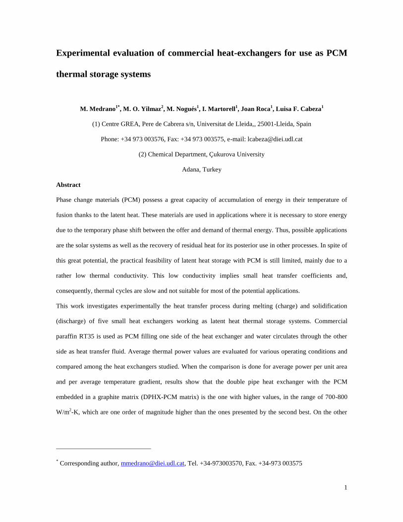
1 Experimental evaluation of commercial heat-exchangers for use as PCM thermal storage systems M. Medrano 1* , M. O. Yilmaz 2 , M. Nogués 1 , I. Martorell 1 , Joan Roca 1 , Luisa F. Cabeza 1 (1) Centre GREA, Pere de Cabrera s/n, Universitat de Lleida,, 25001-Lleida, Spain Phone: +34 973 003576, Fax: +34 973 003575, e-mail: [email protected] (2) Chemical Department, Çukurova University Adana, Turkey Abstract Phase change materials (PCM) possess a great capacity of accumulation of energy in their temperature of fusion thanks to the latent heat. These materials are used in applications where it is necessary to store energy due to the temporary phase shift between the offer and demand of thermal energy. Thus, possible applications are the solar systems as well as the recovery of residual heat for its posterior use in other processes. In spite of this great potential, the practical feasibility of latent heat storage with PCM is still limited, mainly due to a rather low thermal conductivity. This low conductivity implies small heat transfer coefficients and, consequently, thermal cycles are slow and not suitable for most of the potential applications. This work investigates experimentally the heat transfer process during melting (charge) and solidification (discharge) of five small heat exchangers working as latent heat thermal storage systems. Commercial paraffin RT35 is used as PCM filling one side of the heat exchanger and water circulates through the other side as heat transfer fluid. Average thermal power values are evaluated for various operating conditions and compared among the heat exchangers studied. When the comparison is done for average power per unit area and per average temperature gradient, results show that the double pipe heat exchanger with the PCM embedded in a graphite matrix (DPHX-PCM matrix) is the one with higher values, in the range of 700-800 W/m 2 -K, which are one order of magnitude higher than the ones presented by the second best. On the other * Corresponding author, [email protected] , Tel. +34-973003570, Fax. +34-973 003575
-
Upload
damiavericat -
Category
Documents
-
view
3 -
download
0
Transcript of Experimental evaluation of commercial heat exchangers for use as PCM thermal storage systems
1
Experimental evaluation of commercial heat-exchangers for use as PCM
thermal storage systems
M. Medrano1*
, M. O. Yilmaz2, M. Nogués
1, I. Martorell
1, Joan Roca
1, Luisa F. Cabeza
1
(1) Centre GREA, Pere de Cabrera s/n, Universitat de Lleida,, 25001-Lleida, Spain
Phone: +34 973 003576, Fax: +34 973 003575, e-mail: [email protected]
(2) Chemical Department, Çukurova University
Adana, Turkey
Abstract
Phase change materials (PCM) possess a great capacity of accumulation of energy in their temperature of
fusion thanks to the latent heat. These materials are used in applications where it is necessary to store energy
due to the temporary phase shift between the offer and demand of thermal energy. Thus, possible applications
are the solar systems as well as the recovery of residual heat for its posterior use in other processes. In spite of
this great potential, the practical feasibility of latent heat storage with PCM is still limited, mainly due to a
rather low thermal conductivity. This low conductivity implies small heat transfer coefficients and,
consequently, thermal cycles are slow and not suitable for most of the potential applications.
This work investigates experimentally the heat transfer process during melting (charge) and solidification
(discharge) of five small heat exchangers working as latent heat thermal storage systems. Commercial
paraffin RT35 is used as PCM filling one side of the heat exchanger and water circulates through the other
side as heat transfer fluid. Average thermal power values are evaluated for various operating conditions and
compared among the heat exchangers studied. When the comparison is done for average power per unit area
and per average temperature gradient, results show that the double pipe heat exchanger with the PCM
embedded in a graphite matrix (DPHX-PCM matrix) is the one with higher values, in the range of 700-800
W/m2-K, which are one order of magnitude higher than the ones presented by the second best. On the other
* Corresponding author, [email protected], Tel. +34-973003570, Fax. +34-973 003575

2
hand, the compact heat exchanger (CompHX-PCM) is by large the one with the highest average thermal
power (above 1 kW), as it has the highest ratio of heat transfer area to external volume.
Keywords: PCM, heat exchangers, heat transfer enhancement, latent heat storage
Nomenclature
A Effective heat transfer area (m2)
Cp Specific heat capacity (kJ/kg-K)
E Charge or discharge energy (kJ)
h Average specific enthalpy (kJ/kg)
H Phase change enthalpy (kJ/kg)
HX Heat exchanger (-)
m Mass flow rate (kg/s)
M Mass(kg)
Q Average thermal power (kW)
t Time (s)
T Temperature (K)
Subscripts
end Final time of experiment
H2O Water
high Higher temperature of phase change interval
In Water inlet
ini Initial time of experiment
l Liquid state
low Lower temperature of phase change interval
norm Normalized
out Water outlet
PC Phase Change

3
PCM Phase Change Material
s Solid state
Introduction
Thermal energy storage plays an important role in the rationale use of energy, as it allows the decoupling
between production and demand of energy. In applications with intermittent energy generation, such as solar
thermal systems or waste heat recovery, an appropriate thermal storage system is essential. The thermal
storage technology based on the use of phase change materials (PCM) has recently raised an important
practical interest. This is mainly due to the high energy storage density during phase change within a very
narrow temperature range. To give an illustrative example, eighty times more heat is required to melt certain
amount of ice at 0ºC than to heat up one ºC the same amount of water.
The main criteria to select a PCM for a particular application is its phase change temperature (melting point).
However, other important parameters must be also taken into account for a correct decision. These parameters
include: latent heat, stability to cycling, and thermal conductivity ([1-2])
Latent heat applications with PCM can be classified in two main fields: protection or thermal inertia and heat
storage. One main difference between these two fields is related to the PCM thermal conductivity. In many
cases of thermal protection a low conductivity is desirable. On the other hand, in thermal storage systems
these low conductivity values are a disadvantage, since the adequate amount of energy may be available but
the system may not be able to use it at the required rate.
With regard to the low thermal conductivity problem of PCM, several ideas and systems have been proposed
in the literature to enhance heat transfer, both numerically and experimentally. These heat transfer
enhancement studies can be grouped in the following categories: (1) having the PCM inserted in a metal ([3-
6]); (2) adding metallic particles with higher thermal conductivity than the PCM [7]; (3) macro and micro
encapsulating the PCM ([5], [8-10]); (4) using a PCM-graphite composite material ([11-14]); and (5) using
finned tubes with different configurations ([7], [15-22]¡Error! No se encuentra el origen de la referencia.).
Several authors have investigated both numerically and experimentally heat exchanger configurations with
PCM in one side, as latent heat thermal storage systems. Ismail et al. [16] studied the solidification process of

4
a PCM in the annular space of a concentric tube heat exchanger with axial fins as a function of several
parameters, namely the fin length, fin thickness, number of fins, the aspect ratio of the annular space and the
temperature difference between the phase change temperature and the wall temperature of the tube. Numerical
predictions agreed generally well with the experimental results. Results indicated that heat transfer was
controlled by conduction. Trp et al [19-20] investigated melting and solidification on a paraffin in a shell and
tube heat exchanger with the heat transfer fluid circulating inside the tube and the PCM filling the shell side,
for various operating conditions and geometric parameters. Numerical and experimental results were
presented. Erek et al. (2005) [21], and Erek et al. (2007) [22] investigated solidification and melting of ice,
respectively, developing numerical models and realizing experimental tests for an energy storage system
consisting of PCM around a tube with radial fins. They performed parametric studies with several fin
parameters and flow parameters (Reynolds number and inlet temperature of heat transfer fluid). Ermis et al.
[23] used the experimental results for solidification of Erek et al. [21] to develop a feed-forward back-
propagation artificial neural network (ANN) algorithm. Results showed a better agreement with experimental
data than previous numerical model results. An extensive review of PCM technology with a section on heat
exchanger designs for thermal energy storage can be found elsewhere [24].
The main goal of this study is the experimental heat transfer characterization of various small PCM storage
systems during the melting (charge) and solidification (discharge) processes in order to assess their potential
implementation in small-sized systems, such as telecommunication devices or home appliances, for making
them more energy efficient. These thermal storage systems consist of different configurations of typical
commercial heat exchangers of small size that have one side filled with a PCM as latent storage, and water
circulates through the other side as heat transfer fluid. The application temperature range is 35-40 ºC and the
selected PCM is the commercial paraffin RT35. The main physical properties of this PCM are shown in Table
1.
Comparison of selected heat exchangers
Three different types of heat exchangers were selected, namely, the concentric tube heat exchanger, the
compact tube-fin heat exchanger, and the plate heat exchanger (Table 2). For the first type, three variations of
heat stores were studied: (1) a simple double pipe copper tube heat exchanger with the PCM in the annular

5
space (DPHX-PCM), (2) the same double pipe heat exchanger but with the PCM embedded in a graphite
matrix to increase heat transfer (DPHX-PCM matrix), and (3) a double pipe heat exchanger with thirteen
radial copper fins and the same PCM in the annular space (DPHX fins-PCM). These three concentric tube
heat exchangers have a transparent outer pipe of methacrylate that enables visual inspection of the phase
change. The second type, (4) the compact heat exchanger (CompHX-PCM), is the typical aluminium-fins-
and-copper-tubes heat exchanger used as evaporator or condenser in small air conditioning units, which offers
a large heat transfer area per unit volume. PCM was filled in the space between tubes and fins and the heat
exchanger was encapsulated in a transparent methacrylate box. The third type tested is (5) a small Alfa Laval
gasketed plate and frame heat exchanger (T2-BFG model) (PlateHX-PCM), which consists of 20 corrugated
stainless steel plates inside two steel frames. Therefore, a total of 5 different heat storage systems with the
same RT35 PCM were tested. This RT35 PCM has a melting point of 35 ºC, a thermal conductivity of 0.2
W/(m·K) and a phase change enthalpy of 157 kJ/kg (Table 1). All heat exchangers were selected with similar
external volumes to be able to be fitted in the same experimental set-up. In all cases, water was used as the
heat transfer fluid, passing through the other side of the heat exchanger.
Prior to any heat transfer test with the PCM-heat exchangers, several useful parameters can be identified and
compared among the different heat exchangers selected in the study. From a point of view of the compactness
of final application, the total mass and the total volume of the storage system are of crucial importance. From
the perspective of the heat transfer process, the following parameters are of interest: heat transfer area, PCM
mass and associated heat capacity, and empty heat exchanger weight and associated average heat capacity
(considering the contributions of the different materials of the heat exchanger). Heat capacity is defined here
as the product of the mass by the specific heat, for sensible heat cases; and as the product of mass by the
phase change enthalpy divided by the temperature range for phase change, for latent heat cases. Heat
capacities for latent heat storage in this study are calculated over the phase change temperature range (15 ºC,
from 27 to 42 ºC) given by the PCM manufacturer.
Table 2 presents the comparison of the above-mentioned parameters for the five heat exchangers in study.
From the point of view of compactness, the compact fin-tube (4) and the plate heat exchangers (5) offer the
best ratios of heat transfer area to external volume, with 209 and 89 m2/m
3, respectively. The concentric tube

6
with fins heat storage system (3) is also well positioned, because its slightly lower area to volume ratio (70
m2/m
3 ) may be compensated with a smaller weight of 1.8 kg. The plate heat exchanger (5) is relatively heavy
(15 kg) and may be a real problem for some applications, whereas the compact one (4) is only a little more
than two-fold heavier than the double-pipe with fins heat exchanger (3). Heat stores (1) and (2), with
concentric tubes and no fins are as light as heat store (3), but present very low heat transfer areas per volume.
Heat store (2), though, might compensate this lack of area with the considerable heat transfer enhancement in
the PCM side due to the graphite matrix. The best PCM heat storage capacity (11.5 kJ/ºC) is reached in heat
store (5), the compact heat exchanger, as it can be filled up with 1.1 kg of PCM between fins and tubes. About
40-50% of this heat capacity is achieved in the three variations of the concentric tube heat storage system. The
plate heat exchanger is only able to be filled with 0.35 kg of PCM, reaching a heat capacity of just 3.7 kJ/ºC,
which means a 32% reduction with respect to the compact one. As we are interested in the transient charging
or discharging process, the heat capacity of the empty heat exchanger used for the storage system is also
important. The last column of Table 2 shows this value, which has been determined based on the weights and
specific heats of the various materials integrating the heat exchanger. A maximum ratio of PCM heat capacity
over empty heat exchanger heat capacity is desirable, as in that way we can take advantage of the latent heat
storage properties. These ratios range between 4 and 6 for the three concentric heat exchanger configurations,
followed by the compact heat exchanger with 2.7. The plate heat exchanger is far below these values (0.5),
meaning that most of the energy exchanged in a charging or discharging process is given to or taken from the
metal parts and not from the PCM. Based on this first experiments discussion, we conclude that heat
exchangers (1) and (5) are not adequate as PCM heat storage systems to be implemented in real applications.
However, for the sake of completeness, the five heat exchangers were tested and analysed.
Description of experimental set-up
An experimental set-up was designed and built in order to investigate the charging and discharging processes
of various small latent heat storage systems. Figure 1 shows a picture of the experimental set-up. The set-up
consists of a thermostatic bath HUBER K25 that controls water inlet temperature; a water pump WILO and a
series of valves to regulate water flow rate; a digital flow meter Badger Metter Prime Advanced (range of
0.85-17 L/min, accuracy of 0.25% for velocities below 5 m/s and 1.25% for higher values); and the heat

7
storage system. The set-up allows replacing readily the heat exchanger with no changes in the rest of
equipment. Temperature measurements are made with Pt100 DIN-B probes. Both temperature and flow rate
readings are collected in a computer via the data acquisition system STEP DL01-CPU.
For the three concentric tube heat exchangers and the compact one the following temperatures measurements
were taken: water inlet and outlet temperature; copper wall temperature close to water inlet and outlet; PCM
temperature in a centered position, far away from both the copper and the methacrylate walls in the radial
direction, and half way between inlet and outlet in the axial direction; and outer wall temperature in a middle
position. This latter temperature probe was used to estimate heat losses or gains to or from ambient. In cases
where this heat losses where estimated higher than 2% of the exchanged heat during PCM melting or
solidification, the heat exchanger external surface was totally covered with insulation foam and further tests
were carried out with this new configuration. This was the case for heat storage systems 1 (DPHX-PCM) and
5 (PlateHX-PCM ). In the case of the plate heat exchanger, besides inlet and outlet temperature readings, four
more temperature probes were located in two central PCM passages, two probes at the bottom part of the
channels and two more on the top part. These measurements were performed to ensure that the PCM was well
distributed within all the plate.
Methodology of tests
Charging and discharging tests were realized for the five heat storage systems with two different temperature
gradients between water and PCM and two different flow rates. At least two repetitions were carried out for
each test, giving a total of 92 experiments. Working conditions were chosen to achieve temperature gradients
of 25 and 15 ºC between water inlet and PCM melting point, and to have laminar and turbulent regimes. The
specific conditions used in the experiments are presented in Table 3. The air temperature of the test lab was
maintained at 22-24 ºC during experiments using an air conditioning system and the experimental set-up was
located away from the air conditioning ducts to avoid convection disturbances.
After the heat exchangers were filled up with liquid PCM and no leakage was observed, charging and
discharging experiments were always realized with the same sequence: (1) first, a charging experiment is
started in the morning, with the solid PCM at thermal equilibrium with the conditioned lab temperature (22-24
ºC). Hot water from the bath is circulated through the heat exchanger until no solid PCM is observed (or, in

8
the cases with external insulation, when temperature reaches 45 ºC); (2) second, a discharging experiment is
started, just after the charging test is finished. Cold water from the bath is pumped to the heat exchanger with
liquid PCM, which starts to solidify. The experiment finishes when no liquid PCM is observed (or, in the
cases with external insulation, when PCM temperature is below 24 ºC). Temperature readings are taken every
10 seconds to be able to capture fast changes at the beginning of the process.
Calculation method
The average thermal power given to the PCM during a charging process can be written as:
t
TTcpMHMTTcpM
t
EQ
highPCendPCMlPCMPCiniPCMlowPCsPCMPCM)()( ,,,,,,
(1)
where Q is the average thermal power, EPCM is the thermal energy given to the PCM, t is the time of a
charging process until complete melting, M is the weight of PCM, cpPCM,s and cpPCM,l are specific heats for
solid and liquid PCM, TPC,low and TPC,high are the lower and upper values of the PCM phase change interval,
TPCM,ini and TPCM,end are the PCM temperatures at the start and end of the process, respectively, and HPC is the
PCM phase change enthalpy.
For the selected PCM, TPC,low and TPC,high values are 27 and 42ºC, respectively; and the enthalpy of fusion HPC
is 157 kJ/kg. A symmetric mathematical expression can be deduced for the average power of a discharging
process.
Actually, thermal power given to the PCM during charging or discharging is not constant over time. At the
beginning of the process heat transfer is higher as the driving temperature gradient between water and PCM is
higher, and then thermal power decreases gradually as PCM temperature gets closer to water temperature.
Thermal energy given or gained by water is evaluated by integrating the energy balance in the water side for
every time interval during the phase change process. For a charging process this integration can be expressed
by:
end
ini
t
t
outinOH hhmE 2
(2)
where EH2O is the energy given by water to PCM, m is the water mass flow rate, and inh and outh the average
enthalpies of water inlet and outlet for each time interval, respectively.

9
Contrary to the common use rule in steady state heat exchangers, in this transient process EH2O and EPCM are
not equal, as part of the heat is exchanged by the materials of the empty heat exchanger. In most of the heat
storage systems studied, this difference is relatively small, around 20-30 %, with the exception of the plate
heat exchanger, where differences above 100% are reached, due to the much larger thermal capacity of this
heat exchanger (see Table 2).
To be able to compare average thermal powers for the various heat exchangers with PCM per unit of heat
transfer area and for different heat transfer driving potentials, a normalized power is defined, dividing the
average thermal power obtained in (Eq. 1) by the average temperature difference between water and the PCM,
T ,and by the effective heat transfer area, A:
TA
QQnorm
(3)
This average temperature difference takes a value of about 15 ºC for experiments with lower heat transfer
temperature gradient; and about 25 ºC for the ones with higher heat transfer gradient.
Results and discussion
To illustrate repeatability and the effect of flow rate and temperature gradient on the heat transfer process of
the studied heat storage systems, results with heat store (3) (DPHX fins-PCM) are presented. Similar trends
are found in the other heat storage systems (not shown). Figure 2 shows PCM temperature profiles and inlet-
outlet water temperature difference profiles for 4 repetitions of a discharging process (PCM solidification)
using a flow rate of 0.4 m3/h and an inlet temperature of 20 ºC. A very good repeatability is observed.
The effect of the water flow rate was also studied for the different heat exchangers with PCM. As expected,
results show that heat transfer is enhanced when turbulent regime is achieved in the water side, as the total
heat transfer resistance from water to PCM is decreased. Actually, using low flow rates the contribution of the
water side to the total thermal resistance is about 40-50%, whereas with a turbulent regime most of the
resistance is in the PCM side (about 90-95%). The well-known correlations of Sieder and Tate (laminar flow)
and of Gnielinsky (turbulent flow) were used to evaluate the water side heat transfer film coefficients. . Thus,
the total time for melting or solidification the PCM is considerably shortened when high water flow rates with
turbulent Reynolds are used. Figure 3 shows instantaneous power (calculated in the water side) and PCM

10
temperature over time for a melting experiment at 60 ºC, comparing results for high and low flow rate cases.
The time to achieve full melting is almost doubled (14 versus 27 min) due to the higher thermal power
occurred in the high water flow rate case. From now on, only results for cases with high flow rates will be
presented and analyzed, as this turbulent regime in the water side will be the one chosen in most of the
practical applications.
Figure 4 presents the influence of the driving force for heat transfer, i.e. the temperature difference between
water temperature and PCM temperature, on the resulting thermal power and the time for complete phase
change process. Results are presented for both melting and solidification experiments at two different
temperature gradients with the heat store (3) (DPHX fins-PCM). Temperature gradients correspond to
charging tests with inlet water at 60 ºC and 50 ºC, and for discharging tests at 10ºC and 20ºC. For melting
tests, the comparison shows that 10 ºC more of temperature difference between water and PCM results in a 30
% decrease in time. In the solidification tests the increase in time when the temperature difference is reduced
in 10 ºC is much more important (53%). The comparison between charging and discharging tests using the
same temperature gradient for the different heat exchanger studied is in most cases similar to the example
here presented (Figure 4): the solidification process tends to spend more time for complete phase change than
the melting process, specially at lower temperature gradients. This can be explained due to the different nature
of the heat transfer phenomena that take place when a PCM is melted or when it is frozen. Convection heat
transfer has a higher contribution in melting and helps in reducing the heat transfer coefficient in the PCM
side. The only exception are in charging and discharging processes for heat store systems 2 (DPHX-PCM
matrix) and 4 (PlateHX-PCM) , since in these cases heat transfer occurs basically by pure conduction. In these
cases the times for melting and solidifying are very similar (see Figure 5).
Figure 5 presents the obtained average thermal power (see equation 1) for charging (melting) and discharging
(solidification) processes at two different temperature differences between water and PCM and for the five
heat stores studied. Results demonstrate what was already anticipated in the section comparing the
characteristics of the heat exchangers, i.e., heat exchangers (1 - DPHX-PCM) and (5 - PlateHX-PCM) are not
adequate as PCM heat storage systems to be implemented in real applications. This is especially true for the

11
double pipe heat exchanger with no fins (1 - DPHX-PCM), as the observed heat transfer is unacceptably low.
The plate heat exchanger, heat store 5 (PlateHX-PCM), is the second with the smallest average thermal
power, with comparable power values for solidification to the heat exchanger 3 (DPHX fins-PCM), the
double pipe with fins one. However, for melting tests, heat store 3 (DPHX fins-PCM) performs better than
heat store 4 (CompHX-PCM), with about 100% more power, both for 60 and 50 ºC cases. The plate heat
exchanger is not suited as a PCM heat store not only for the observed low power values, but mainly because it
is able to store a very small amount of PCM and it is very heavy, as it was discussed before. The third
position in terms of power performances is for heat store 3 (DPHX fins-PCM), the double pipe with fins one.
The highest average thermal power (110 W) for this heat store is achieved for the melting process with inlet
water at 60 ºC. Heat store 2 (DPHX-PCM matrix), the double pipe heat exchanger with the PCM embedded in
a graphite matrix, presents the second better performance, with average powers around 200 W for both
melting and solidification processes at the higher temperature gradient cases. As explained before, the
decrease observed for the other heat stores studied in the heat transfer process for solidification cases, when
compared with melting cases, is not seen in this heat store. This is because conduction is the main heat
transfer mechanism through the embedded PCM matrix, whereas for the other stores convection plays a role,
which has a different nature for melting and for solidification. Heat store 4 (CompHX-PCM), the compact
heat exchanger, is by large the one with the highest thermal power, with values above 1 kW for both charging
and discharging processes for the cases with larger temperature differences. Even for the cases with lower
temperature differences, average thermal power values are three-fold higher than the highest power values
achieved with the second best heat store. These excellent results in heat transfer, together with the previous
finding that this heat exchanger is also the one with the best PCM heat storage capacity, makes the compact
heat exchanger the best candidate to be used in small PCM storage applications, among the heat stores
selected and tested in this work.
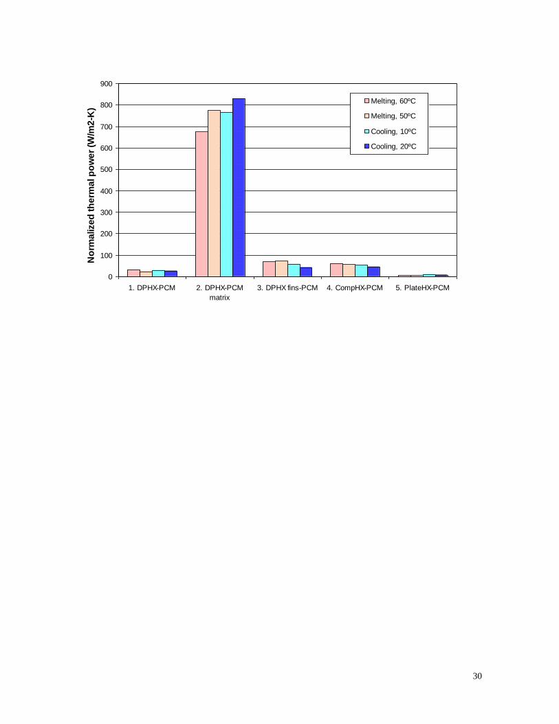
From a more practical point of view, it is also interesting to compare heat stores in terms of average power per
unit area and per average temperature gradient during the process. Making the analogy with the typical steady
state heat transfer process in a heat exchanger this normalized power would be equivalent to the overall heat
transfer coefficient between the two sides of the heat exchanger. Figure 6 illustrates this comparison,
including both melting and solidification experiments at two temperature gradients for the five heat stores

12
studied. Using this other parameter, heat store 2 (DPHX-PCM matrix), the double pipe heat exchanger with
the PCM embedded in a graphite matrix, performs much better than the others, with normalized powers in the
range 700-800 W/m2-K, which are an order of magnitude higher than the ones presented by the second best.
This second position is shared by heat stores 3 (DPHX fins-PCM ) and 4 (CompHX-PCM), with similar
values in the range 40-70 W/m2-K. This can be explained by the important increase of the heat transfer
coefficient in the PCM side when the PCM is embedded in graphite, but with no associated increase of heat
transfer area.
Conclusions
Melting and solidification of PCM RT-35 were experimentally investigated in this work, using five different
heat exchangers as heat storage systems and working at two different flow rates and two different water inlet
temperatures. Results show that Reynolds numbers in the turbulent regime are desirable for faster phase
change processes, reducing the phase change time in about half. The increase of the driving force for heat
transfer, i.e. the difference between water inlet temperature and PCM phase change temperature, from 15 to
25 ºC results in a considerable decrease of the phase change time (between 30 and 60% decrease) and
consequently, an increase of the average phase change power.
A priori analysis of the different configurations of latent heat thermal energy systems to be used in real
applications leads to a conclusion that heat exchangers 1 (DPHX-PCM), the double pipe heat exchanger and 5
(PlateHX-PCM ), the plate heat exchanger, are not adequate as heat store. Heat store 1 (DPHX-PCM) presents
a very low heat transfer area and heat store 5 (PlateHX-PCM ) has a very low ratio of PCM heat capacity over
empty heat exchanger heat capacity. Heat stores 2 (DPHX-PCM matrix), 3 (DPHX fins-PCM), and 4
(CompHX-PCM), (the double pipe heat exchanger with the PCM embedded in a graphite matrix, the double
pipe heat exchanger with fins, and the compact heat exchanger, respectively) possess better values and are
more promising for real applications.
Heat store 4 (CompHX-PCM ) is by large the one with the highest average thermal power, with values above
1 kW for both charging and discharging tests at cases with larger temperature differences between PCM and
water. Even for the cases with lower temperature differences, average thermal power values are three-fold
higher than the highest power values achieved by the second best heat store. When the comparison is done for

13
average power per unit area and per average temperature gradient different results are found. Heat store 2
(DPHX-PCM matrix) is now the one with higher values, in the range of 700-800 W/m2-K, which are one
order of magnitude higher than the ones presented by the second best.
Acknowledgments
Marc Medrano would like to thank the Spanish Ministry of Education and Science for his Ramon y Cajal
research appointment. Metin Yilmaz would like to thank his Erasmus fellowship. The work was partially
funded with the project ENE2005-08256-C02-01/ALT and the project 2005-SGR-00324.
References
[1] Zalba B, Marín JM, Cabeza LF, Mehling H. Review on thermal energy storage with phase change:
Materials, heat transfer analysis and applications, Appl.Thermal Eng. 2003; 23:251-283.
[2] Mehling H, Cabeza LF. Phase Change Materials and their basic properties. In: H. Paksoy, Ed.
Thermal energy storage for sustainable energy consumption; 2003, p. 257-277.
[3] Hoogendoorn CJ., Bart GCJ. Performance and modeling of latent heat stores, Solar Energy 1992;
48:53-8.
[4] Tong X, Khan JA, Amin MR. Enhancement of heat transfer by inserting a metal matrix into a phase
change material, Numer. Heat Transfer 1996; Part A 30:125-141.
[5] Chow LC, Zhong JK, Beam JE. Thermal conductivity enhancement for phase change storage media,
Int. Comm. Heat Mass Transfer 1996; 23:91-100.
[6] Khan MA., Rohatgi PK. Numerical solution to a moving boundary problem in a composite medium.
Numerical Heat Transfer 1994; 25: 209-221.
[7] Velraj R, Seeniraj RV, Hafner B, Faber C, Schwarzer K. Heat transfer enhancement in a latent heat
storage systems, Solar Energy 1999; 65 (3):171-180.
[8] .Bédécarrats JP, Strub F, Falcon B, Dumas JP. Phase-change thermal energy storage using spherical
capsules: performance of a test plant, Int. J. Refrig. 1996; 19 (3):187-196.
[9] Mulligan JC, Colvin DP, Bryant YG. Microencapsulated phase change material suspensions for heat
transfer in spacecraft thermal systems, J. Spacecraft Rockets 1996; 33 (2):278-284.

14
[10] Marín JM, Zalba B, Cabeza LF, Mehling H. Improvement of a thermal energy storage using plates
with paraffin-graphite composite, Int. J. Heat Mass Transfer 2005;48:2561-2570.
[11] Cabeza LF., Mehling H, Hiebler S, Ziegler F, Heat transfer enhancement in water when used as PCM
in the thermal energy storage, Appl. Thermal Eng 2002; 22(10):1141-1151.
[12] Mehling H, Hiebler S, Ziegler F. Latent heat storage using a PCM-graphite composite material,
Proceedings of Terrastock 2000-8th International Conference on Thermal Energy Storage, Stuttgart,
(Germany) 2000, p. 375-380.
[13] Py X, Olives R, Mauran S. Paraffin/porous-graphite-matrix composite as a high and constant power
thermal storage material, Int. J. Heat Mass Transfer 2001; 44:2727-2737.
[14] Xiao M, Feng B, Gong K. Thermal performance of a high conductive shape-stabilized thermal
storage material, Solar Energy Mater. Solar Cells 2001; 69:293-6.
[15] Velraj R, Seeniraj RV, Hafner B, Faber C, Schwarzer K. Experimental analysis and numerical
modeling of inward solidification on a finned vertical tube for a latent heat storage unit, Solar Energy
1997; 60:281–290.
[16] Ismail KAR, Alves CLF, Modesto MS. Numerical and experimental study on the solidification of
PCM around a vertical axially finned isothermal cylinder. Appl.Thermal Eng. 2001; 21:53-77.
[17] Sparrow EM, Larsen ED, Ramsey JW. Freezing on a finned tube for either conduction-controlled or
natural-convection-controlled heat transfer, Int. J. Heat Mass Transfer 1981; 24: 273–284.
[18] Stritih U. An experimental study of enhanced heat transfer in rectangular PCM thermal storage. Int.
J. Heat Mass Transfer 2004, 47:2841-7.
[19] Trp A. An experimental and numerical investigation of heat transfer during technical grade paraffin
melting and solidification in a shell-and-tube latent thermal energy storage unit, Solar Energy 2005;
79:648–660.
[20] Trp A, Lenic K, Frankovic B. Analysis of the influence of operating conditions and geometric
parameters on heat transfer in water-paraffin shell-and-tube latent thermal energy storage unit,
Appl.Thermal Eng. 2006; 26: 1830–9.
[21] Erek A, Ilken Z, Acar MA. Experimental and numerical investigation of thermal energy storage with
a finned tube, Int. J. Energy Res. 2005; 29:283–301.

15
[22] Erek A, Ezan MA. Experimental and numerical study on charging processes of an ice-on-coil
thermal energy storage system, Int. J. Energy Res. 2007; 31:158–176.
[23] Ermis K, Erek A, Dincer, I. Heat transfer analysis of phase change process in a finned-tube thermal
energy storage system using artificial neural network, . J. Heat Mass Transfer 2007; 50: 3163–3175.
[24] Sharma A, Tyagi VV, Chen CR, Buddhi D. Review on thermal energy storage with phase change
materials and applications, Renewable and Sustainable Energy Reviews 2008; in press, available online.

16
Figure Captions
Figure 1: Pictures of the experimental set-up with two of the five heat exchangers tested: (a) 2. DPHX-PCM
matrix; (b) 4. CompHX-PCM
Figure 2. Repeatability of the temperature profile for cooling experiments using a flow rate of 0.4 m3/h and
inlet water at 20ºC
Figure 3. Evolution of thermal power and PCM temperature over time for a melting experiment for low and
high water flow rates, and water inlet at 60ºC..
Figure 4. Evolution of thermal power over time for melting and solidification experiments at high water flow
rates, and for different inlet water-PCM temperature gradients.
Figure 5. Average thermal power for charging (melting) and discharging (solidification) processes at two
different temperature differences between water and PCM and for the five heat stores studied.
Figure 6. Normalized thermal power (W/m2-K) for charging (melting) and discharging (solidification)
processes at two different temperature differences between water and PCM and for the five heat stores
studied.

17
Tables
Table 1: Physical properties of the PCM used in the experiments: Rubitherm RT35
Physical properties RT 35
Melting point C 35
Heat storage capacity kJ/(kg) 157
Density liquid kg/l 0.88
Volume expansion % 10
Heat conductivity W/(mK) 0.2
Table 2: Main characteristics of latent heat storage systems selected
Heat
store #
and name
Photo of heat exchanger (No PCM yet)
Heat
exchanger
description
Total
Weight
with
PCM
(kg)
External
volume
(l)
Heat
transfer
area
(m2)
Weight
PCM
(kg)
Heat
capacity
PCM
(kJ/ºC)
Average
Heat
capacity
HX
(kJ/ºC)
1. DPHX-
PCM
Double
pipe HX
with PCM
in the
annular
space 1.5 0.93 0.011 0.55 5.8 1.0
2. DPHX-
PCM
matrix
Same as 1,
but with
PCM
embedded
in graphite
matrix 1.8 0.93 0.011 0.44 4.6 1.1
3. DPHX
fins-PCM
Same as 1,
but with
external
fins on the
copper tube 1.8 0.93 0.065 0.50 5.2 1.1

18
4.
CompHX-
PCM
Compact
HX, with
PCM
between
coil and
fins 4.3 4.4 0.850 1.10 11.5 2.7
5.
PlateHX-
PCM
Plate and
frame HX,
with PCM
in half of
the
passages 15 4.5 0.400 0.35 3.7 6.9

19
Table 3: Summary of charging and discharging experiments carried out.
Process Heat storage
system
Temperature conditions Flow rate conditions (water side)
Water inlet (ºC) PCM at start (ºC)
Volumetric flow rate
(m3/h) Reynolds number
Charge (Melting
of PCM)
1. DPHX-PCM 50 24 0.03 and 0.4 1.6 103 and 2.2 104
60 24 0.03 and 0.4 1.9 103 and 2.6 104
2. DPHX-PCM
matrix
50 24 0.03 and 0.4 1.6 103 and 2.2 104
60 24 0.03 and 0.4 1.9 103 and 2.6 104
3. DPHX fins-PCM
50 24 0.03 and 0.4 1.6 103 and 2.2 104
60 24 0.03 and 0.4 1.9 103 and 2.6104
4. CompHX-PCM 50 24 0.03 and 0.24* 2.5 103 and 2.0 104
60 24 0.03 and 0.24* 2.8 103 and 2.3 104
5. PlateHX-PCM 50 24 0.03 and 0.3* 3.8 101 and 3.9 102 **
60 24 0.03 and 0.3* 4.3 101 and 4.6 102 **
Discharge
(Solidification
of PCM)
1. DPHX-PCM 20 45 0.03 and 0.4 1.0 103 and 1.1 104
10 45 0.03 and 0.4 0.9 103 and 1.0 104
2. DPHX-PCM
matrix
20 45 0.03 and 0.4 1.0 103 and 1.1 104
10 45 0.03 and 0.4 0.9 103 and 1.0 104
3. DPHX fins-PCM
20 45 0.03 and 0.4 1.0 103 and 1.1 104
10 45 0.03 and 0.4 0.9 103 and 1.0 104
4. CompHX-PCM 20 45 0.03 and 0.24* 1.5 103 and 1.2 104
10 45 0.03 and 0.24* 1.2 103 and 0.9 104
5. PlateHX-PCM 20 45 0.03 and 0.3* 2.3 101 and 2.2 102 **
10 45 0.03 and 0.3* 2.0 101 and 1.7 102 ** * Maximum flow rate achievable with the experimental water pump (more pressure drop in this heat exchanger, compared to the double pipe one), which
still assures turbulent regime
** Transition to turbulence in plate heat exchangers occurs at low Reynolds numbers of 10 to 400. So, this value can be considered in the turbulent regime

20
(a) (b)

21
Figure 1, Marc Medrano et al.

22
0
10
20
30
40
50
60
0 500 1000 1500 2000 2500
Time (s)
PC
M t
em
pe
ratu
re (
ºC)
0
0.5
1
1.5
Wa
ter
tem
pe
ratu
re d
iffe
ren
ce
(O
utl
et-
Inle
t),
ºCTPCM Exp1
TPCM Exp2
TPCM Exp3
TPCM Exp4
(Tout-Tin) Exp1
(Tout-Tin) Exp2
(Tout-Tin) Exp3
(Tout-Tin) Exp4

23
Figure 2, Marc Medrano et al.

24
0
0.1
0.2
0.3
0.4
0.5
0.6
0 200 400 600 800 1000 1200 1400 1600
Time (s)
Th
erm
al p
ow
er
(kW
)
0
10
20
30
40
50
60
PC
M t
em
pera
ture
(ºC
)
Q Low Flow (kW)
Q High flow (kW)
TPCM High Flow
TPCM Low Flow

25
Figure 3, Marc Medrano et al.

26
0
0.1
0.2
0.3
0.4
0.5
0.6
0 200 400 600 800 1000 1200 1400 1600 1800 2000 2200
Time (s)
Th
erm
al p
ow
er
(kW
)
Q melt, 60ºC (kW)
Q melt, 50ºC (kW)
Q solid, 10ºC (kW)
Q solid, 20ºC (kW)

27
Figure 4, Marc Medrano et al.

28
0
100
200
300
400
500
600
700
800
900
1000
1100
1200
1. DPHX-PCM 2. DPHX-PCM
matrix
3. DPHX fins-PCM 4. CompHX-PCM 5. PlateHX-PCM
Av
era
ge
th
erm
al p
ow
er
(W)
Melting, 60ºC
Melting, 50ºC
Solidification, 10ºC
Solidification, 20ºC

29
Figure 5, Marc Medrano et al.
30
0
100
200
300
400
500
600
700
800
900
1. DPHX-PCM 2. DPHX-PCM
matrix
3. DPHX fins-PCM 4. CompHX-PCM 5. PlateHX-PCM
No
rma
lize
d t
he
rma
l p
ow
er
(W/m
2-K
)Melting, 60ºC
Melting, 50ºC
Cooling, 10ºC
Cooling, 20ºC

31
Figure 6, Marc Medrano et al.