
Development of a thermally activated ceiling panel with PCM ...
12
Energy and Buildings 36 (2004) 567–578 Development of a thermally activated ceiling panel with PCM for application in lightweight and retrofitted buildings Markus Koschenz ∗ , Beat Lehmann Laboratory for Energy Systems/Building Equipment, Swiss Federal Laboratories for Materials Testing and Research (EMPA), Ueberlandstrasse 129, CH-8600 Duebendorf, Switzerland Received 1 June 2003; received in revised form 17 December 2003; accepted 10 January 2004 Abstract This paper describes the development of a thermally activated ceiling panel for incorporation in lightweight and retrofitted buildings. The system allows use of renewable energy sources for the heating and cooling of office and industrial buildings. The design for the new ceiling panel exploits the properties of the phase change material (PCM) paraffin. Its high thermal storage capacity during phase change—up to 300 Wh/(m 2 day)—enables the overall panel thickness to be limited to a mere 5 cm. Active control of the thermal storage is achieved by means of an integrated water capillary tube system. The research project also included the development of a numerical model for computation of the thermal behavior of wall and ceiling systems incorporating PCMs. Simulation calculations were performed to determine the necessary thermal properties of the ceiling panels and specify requirements for the materials to be used. Laboratory tests were performed to verify the system’s performance and a pilot application is soon to be tried out in practice. © 2004 Elsevier B.V. All rights reserved. Keywords: Latent heat thermal energy storage; Thermally activated building systems; Cooling of buildings with renewable energy sources; Phase change material; PCM 1. Introduction Even today, refurbishment schemes account for a signifi- cant proportion of construction activity in the commercial sector (office and industrial buildings), and the increasing shortage of development sites in urban centers looks set to consolidate this trend in future. Any breakthrough in the application of sustainable energy systems to both retrofit and new-build schemes will depend on a wider use of renewable energy sources in the operation of building technologies, particularly heating and cooling. Both the enhanced technical installation requirements of workplaces and the increased use of fully glazed facades favored by contemporary architecture have forced up the internal and external thermal loads in modern office build- ings. As a result, such facilities now require cooling for much of the year. To prevent an unacceptable rise in the in- door temperature, thermal gains have to be removed from the building interior. Conventional systems rely on ventila- tion or chilled ceiling panels. While, at present, compres- sion refrigerators generally provide the necessary cooling ∗ Corresponding author. Tel.: +41-1-823-4175; fax: +41-1-823-4020. E-mail address: [email protected] (M. Koschenz). energy, forward-looking solutions will increasingly seek to exploit natural cooling sources. These may involve the use of ground-coupled heat exchangers, groundwater or outside air. However, these renewable energy sources are frequently unable to provide the necessary heating or cooling power or the energy supply is non-concurrent in time with demand. Though outside air is universally available, for instance, its temperature in summer is usually only low enough at night to serve as a cooling medium. A suitable thermal storage is therefore needed to over- come this time lag. Standard water systems may be dis- counted due to the excessive plant size and space allocation needed to store sufficient energy for daily needs. Thermally activated building systems (tabs) [1], which use the building structure as a heat sink, are a more recent approach. Heat gains during the day are stored in solid floors and slabs, which are then recooled at an appropriate time by means of a water pipe system—the extracted energy being rejected to the outside, e.g. via cooling tower. This system lends itself to incorporation in new buildings, where provision can be made in the design for casting the necessary pipework into the floor slabs. The retrofitting of pipes as part of an alter- ation scheme, on the other hand, is problematic. Moreover, retrofitted service installations like air ducts are commonly 0378-7788/$ – see front matter © 2004 Elsevier B.V. All rights reserved. doi:10.1016/j.enbuild.2004.01.029
-
Upload
khangminh22 -
Category
Documents
-
view
0 -
download
0
Transcript of Development of a thermally activated ceiling panel with PCM ...
Energy and Buildings 36 (2004) 567–578
Development of a thermally activated ceiling panel with PCM forapplication in lightweight and retrofitted buildings
Markus Koschenz∗, Beat LehmannLaboratory for Energy Systems/Building Equipment, Swiss Federal Laboratories for Materials Testing and Research (EMPA),
Ueberlandstrasse 129, CH-8600 Duebendorf, Switzerland
Received 1 June 2003; received in revised form 17 December 2003; accepted 10 January 2004
Abstract
This paper describes the development of a thermally activated ceiling panel for incorporation in lightweight and retrofitted buildings.The system allows use of renewable energy sources for the heating and cooling of office and industrial buildings. The design for thenew ceiling panel exploits the properties of the phase change material (PCM) paraffin. Its high thermal storage capacity during phasechange—up to 300 Wh/(m2 day)—enables the overall panel thickness to be limited to a mere 5 cm. Active control of the thermal storageis achieved by means of an integrated water capillary tube system. The research project also included the development of a numericalmodel for computation of the thermal behavior of wall and ceiling systems incorporating PCMs. Simulation calculations were performedto determine the necessary thermal properties of the ceiling panels and specify requirements for the materials to be used. Laboratory testswere performed to verify the system’s performance and a pilot application is soon to be tried out in practice.© 2004 Elsevier B.V. All rights reserved.
Keywords:Latent heat thermal energy storage; Thermally activated building systems; Cooling of buildings with renewable energy sources; Phase changematerial; PCM
1. Introduction
Even today, refurbishment schemes account for a signifi-cant proportion of construction activity in the commercialsector (office and industrial buildings), and the increasingshortage of development sites in urban centers looks set toconsolidate this trend in future. Any breakthrough in theapplication of sustainable energy systems to both retrofit andnew-build schemes will depend on a wider use of renewableenergy sources in the operation of building technologies,particularly heating and cooling.
Both the enhanced technical installation requirements ofworkplaces and the increased use of fully glazed facadesfavored by contemporary architecture have forced up theinternal and external thermal loads in modern office build-ings. As a result, such facilities now require cooling formuch of the year. To prevent an unacceptable rise in the in-door temperature, thermal gains have to be removed fromthe building interior. Conventional systems rely on ventila-tion or chilled ceiling panels. While, at present, compres-sion refrigerators generally provide the necessary cooling
∗ Corresponding author. Tel.:+41-1-823-4175; fax:+41-1-823-4020.E-mail address:[email protected] (M. Koschenz).
energy, forward-looking solutions will increasingly seek toexploit natural cooling sources. These may involve the useof ground-coupled heat exchangers, groundwater or outsideair. However, these renewable energy sources are frequentlyunable to provide the necessary heating or cooling power orthe energy supply is non-concurrent in time with demand.Though outside air is universally available, for instance, itstemperature in summer is usually only low enough at nightto serve as a cooling medium.
A suitable thermal storage is therefore needed to over-come this time lag. Standard water systems may be dis-counted due to the excessive plant size and space allocationneeded to store sufficient energy for daily needs. Thermallyactivated building systems (tabs)[1], which use the buildingstructure as a heat sink, are a more recent approach. Heatgains during the day are stored in solid floors and slabs,which are then recooled at an appropriate time by means ofa water pipe system—the extracted energy being rejected tothe outside, e.g. via cooling tower. This system lends itselfto incorporation in new buildings, where provision can bemade in the design for casting the necessary pipework intothe floor slabs. The retrofitting of pipes as part of an alter-ation scheme, on the other hand, is problematic. Moreover,retrofitted service installations like air ducts are commonly
0378-7788/$ – see front matter © 2004 Elsevier B.V. All rights reserved.doi:10.1016/j.enbuild.2004.01.029

568 M. Koschenz, B. Lehmann / Energy and Buildings 36 (2004) 567–578
Nomenclature
a thermal diffusivity (m2/s)Bi Biot numberc specific heat capacity (J/kg K)dm melting range (K)e enthalpy (J/kg)h convective heat transfer coefficient (W/m2 K)L latent heat of fusion (J/kg)M modulusSt Stefan numbert time (s)λ conductivity (W/mK)Θ parameter of timeρ density (kg/m3)ϑ temperature (◦C)x space coordinate (m)X interface location (m)
Indicesb boundaryi node number in spacein initiall liquidm meltingn node number in times solidsu supplytubes capillary tube system0 surface1 side 12 side 2∞ fluid
located above a suspended ceiling, which prevents the trans-fer of heat from its source to the structural elements.
This explains the present lack of thermal storage unitssuitable for local installation in altered or refurbished build-ings, which permit use of renewable energy sources for heat-ing and cooling.
This report outlines the development of a thermally acti-vated ceiling panel by means of model-based computationalsimulations and laboratory tests, and describes the prototypemodules due to be tested in a pilot building.
2. Concept for a new ceiling panel
2.1. Requirements and principle
As mentioned above, the aim was to design a thermally ac-tivated ceiling panel permitting the use of alternative energysources. An initial priority was to achieve a thermal storagecapacity approximately equal to the heat gains within the
space during the daily cycle. Furthermore, due to the par-ticular constraints imposed by alteration and refurbishmentschemes, the thermal storage had to be assembled afterwardsin the building interior while occupying minimum space.
The above requirements coupled with the fact that ceil-ings offer the most appropriate location in buildings for thistype of installation prompted the choice of ceiling panels asthe thermal storage early in the concept design phase. Thekey issue was how to provide adequate thermal mass withina small panel thickness. Phase change materials (PCMs)emerged as the prime option as the phase change undergoneby these materials allows storage and release of substantialquantities of heating or cooling energy. The PCM in the ceil-ing panels melts during the daytime upon exposure to thethermal loads and freezes overnight when cooled by meansof an integrated water pipe system. The interim storage ofthermal energy in the PCM damped the temperature ampli-tude within the building while enabling the heat rejectionprocess to be non-concurrent with heat gain.
2.2. Realization of the concept
An investigation into the different ways of incorporatingPCM in the ceiling panels revealed difficulties in the use ofpure PCM. Such an assembly would necessitate stringentfire precautions to prevent the escape of liquid paraffin.Instead, microencapsulated paraffin bedded in a suitablecarrier material—in this case gypsum—was selected. Pas-sive applications of this technology in composite wallsystems and plaster coats have recently been investigated[2,3]. Through the gypsum, the PCM is encased in a stablestructure while the constitutional water contained in thegypsum retards flame spread in the event of fire.
The overall concept for the ceiling panels adopts the fol-lowing arrangement (seeFig. 1): a sheet steel tray serves asa container for the PCM/gypsum composite while provid-ing the panels with the required mechanical stability. A mixcomprising microencapsulated PCM and gypsum is pouredinto the tray. Active control of the thermal mass is achievedby incorporation of a capillary water tube system in the
Fig. 1. Schematic drawing of thermally activated ceiling panel with PCM.

M. Koschenz, B. Lehmann / Energy and Buildings 36 (2004) 567–578 569
Fig. 2. Installation of ceiling panels in building interior as suspendedceiling.
gypsum compound. If required, thermal conduction in thecomposite may be improved by the inclusion of aluminumfins. While the panel is primarily designed for ceiling in-stallation, fitting to walls is equally straightforward (Fig. 2).An international patent application has been filed for thesystem.
3. Method
To minimize effort, development work was as far aspossible computer-based. This allowed definition of thethermal and material-related requirements for the ceilingpanels together with an approximate sizing of the system.For the purposes of computational simulation, a specialthermal model was developed which, through integration inthe TRNSYS building and system simulation environment[4], allowed similar calculations to be performed for realbuildings with integrated PCM ceiling panels. The labo-ratory tests performed concurrently with the calculationsprompted a number of optimizations while supplying em-pirical data to validate the concept and thermal design ofthe PCM ceiling panels. Prototype modules installed in apilot building will provide a further check on the practica-bility of the solution. The following sections offer a detaileddescription of the individual development stages.
4. Properties of phase change materials
4.1. General properties of PCMs
In addition to the sensible heat of PCMs, the latent heatstored during melting and freezing offers particular benefits.The key asset of PCMs is their high thermal storage capacity,
which, for unit thickness, is many times that of conventionalbuilding materials like concrete, etc.
Common PCMs include paraffins, salt hydrates, alcohols,fatty acids, and synthetic materials. By virtue of their chemi-cal composition, the wax-like paraffins exhibit high cyclestability, low reactivity, low hysteresis and are classed asnon-toxic–properties that make them ideal for use in buildingapplications. Moreover, their thermal properties, specificallythe melting point range, may be substantially adjusted byblending pure materials. The main drawback of paraffins, aby-product of petroleum distillation, is their combustibility.
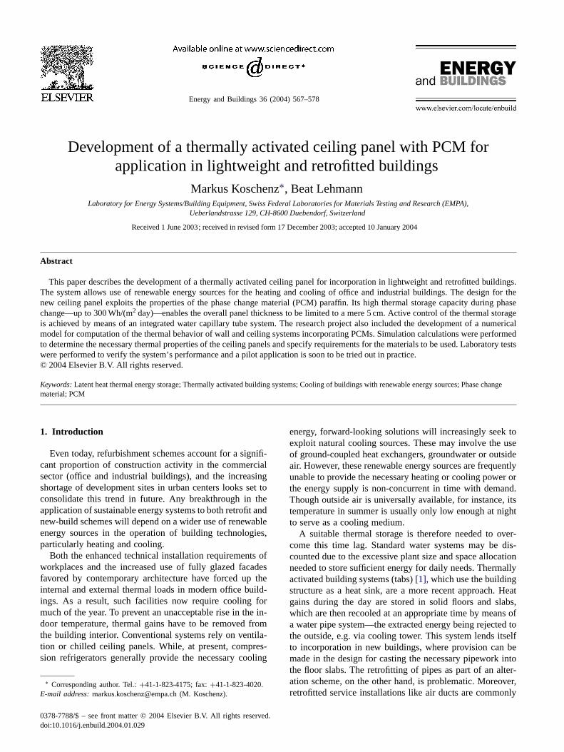
Fig. 3 shows the general behavior of the two most im-portant PCM groups in terms of melting point and range,specific heat and enthalpy. As can be seen, inorganic PCMs,such as salt hydrates, exhibit a relatively narrow meltingrange, and therefore, remain at a constant temperature dur-ing the entire melting or freezing process. Organic PCMssuch as paraffins, by contrast, display a wider melting range(“mushy region”) that varies according to purity, togetherwith an increased rise in thermal capacity within this range.Hysteresis, as a measure of the divergence of melting andfreezing curves, is a further characteristic feature, particu-larly marked in the case of inorganic PCMs.
4.2. Physical properties of paraffins
So-called normal paraffins are commonly used in thermalapplications. These comprise long-chain molecules of thegeneral formula CnH2n+2. The value ofn for paraffins witha melting point between 18 and 90◦C ranges from 16 to50—the longer the molecular chain or greater the molecularmass, the higher the melting point.
Inside room temperatures of between 21 and 28◦C, andthus, surface temperatures of 21–24◦C, are a prerequisitefor thermal comfort in buildings. Hence, to fully exploit thephase change of PCMs, the melting range of the selectedPCM must also lie within this region. This basic requirementis met by the paraffins listed inTable 1, [5], or mixtures ofthese substances.
The listed values of latent heat are valid for chemicallypure substances and all their occuring melting ranges. Tech-nical grade materials show clearly lower values dependingon their purity. According to the planned operating rangemay be only a certain part of the latent heat will be usabledepending on the distribution of the different melting ranges.In addition, the mixing of different types of paraffin to ad-just the melting point further reduces the useful latent heatof fusion as this is spread over a bigger number of meltingranges in the mix.
As described inSection 2.2, the ceiling panels incorpo-rate paraffin in microencapsulated form. This ensures thatminute quantities of the phase change material will remainpermanently enclosed in the capsules even when subjectedto frequent cyclical loads, what has been determined as aproblem with PCM-impregnated wallboards. Some 10�min diameter, the plastics capsules are manufactured from a
570 M. Koschenz, B. Lehmann / Energy and Buildings 36 (2004) 567–578
Specificheat
freezing/melting point Temperature
Enthalpy
freezing range
melting range
csolidcliquid
Temperature
Enthalpy
melting / freezing range
Temperature
Specificheat
freezing/melting point Temperature
csolidcliquid
Hysteresis
Fig. 3. General behavior of inorganic and organic phase change materials in terms of specific heat and enthalpy.
Table 1Physical properties of pure paraffins with melting points between 18 and 28 ◦C
Paraffin Molecular formula Meltingpoint (◦C)
Latent heat offusion (J/kg)
Specific heatsolid (J/kgK)
Specific heatliquid (J/kgK)
Thermal conductivity(W/mK)
Density(kg/m3)
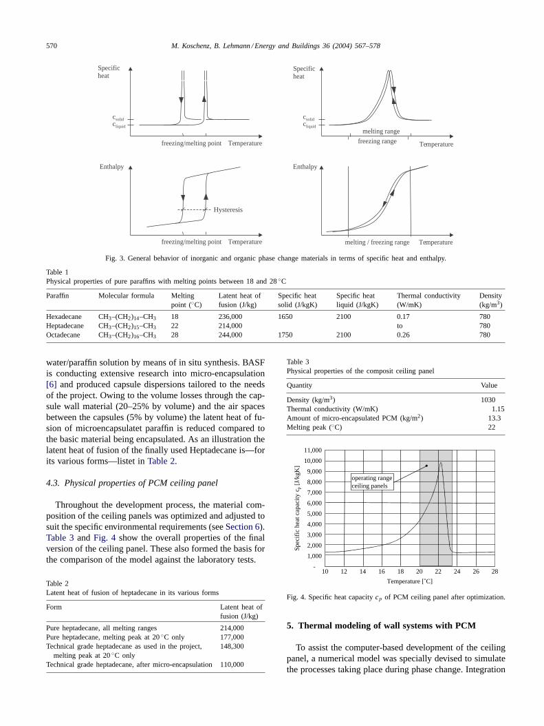
Hexadecane CH3–(CH2)14–CH3 18 236,000 1650 2100 0.17 780Heptadecane CH3–(CH2)15–CH3 22 214,000 to 780Octadecane CH3–(CH2)16–CH3 28 244,000 1750 2100 0.26 780
water/paraffin solution by means of in situ synthesis. BASFis conducting extensive research into micro-encapsulation[6] and produced capsule dispersions tailored to the needsof the project. Owing to the volume losses through the cap-sule wall material (20–25% by volume) and the air spacesbetween the capsules (5% by volume) the latent heat of fu-sion of microencapsulatet paraffin is reduced compared tothe basic material being encapsulated. As an illustration thelatent heat of fusion of the finally used Heptadecane is—forits various forms—listet in Table 2.
4.3. Physical properties of PCM ceiling panel
Throughout the development process, the material com-position of the ceiling panels was optimized and adjusted tosuit the specific environmental requirements (see Section 6).Table 3 and Fig. 4 show the overall properties of the finalversion of the ceiling panel. These also formed the basis forthe comparison of the model against the laboratory tests.
Table 2Latent heat of fusion of heptadecane in its various forms
Form Latent heat offusion (J/kg)
Pure heptadecane, all melting ranges 214,000Pure heptadecane, melting peak at 20 ◦C only 177,000Technical grade heptadecane as used in the project,
melting peak at 20 ◦C only148,300
Technical grade heptadecane, after micro-encapsulation 110,000
Table 3Physical properties of the composit ceiling panel
Quantity Value
Density (kg/m3) 1030Thermal conductivity (W/mK) 1.15Amount of micro-encapsulated PCM (kg/m2) 13.3Melting peak (◦C) 22
-
1,000
2,000
3,000
4,000
5,000
6,000
7,000
8,000
9,000
10,000
11,000
10 12 14 16 18 20 22 24 26 28
Temperature [˚C]
Spec
ific
hea
t cap
acity
cp
[J/k
gK]
operating rangeceiling panels
Fig. 4. Specific heat capacity cp of PCM ceiling panel after optimization.
5. Thermal modeling of wall systems with PCM
To assist the computer-based development of the ceilingpanel, a numerical model was specially devised to simulatethe processes taking place during phase change. Integration

M. Koschenz, B. Lehmann / Energy and Buildings 36 (2004) 567–578 571
of the model in the TRNSYS building and system simulationprogram [4] also allowed investigation of the behavior ofreal buildings with PCM ceiling panels.
5.1. Theoretical background
5.1.1. Basic equationBackground literature identifies two general methods for
dealing with solid–liquid phase change heat transfer as intro-duced in Section 4.1: (1) where the substance has a discretephase change temperature and a sharply defined interface(inorganics, e.g. salt hydrates) and (2) where the substanceundergoes phase change over a range of temperatures, witha mushy region existing between the solid and liquid phases(organics, e.g. paraffin). As paraffin is the PCM investigatedin this study, the focus will be on the second method. Forcontinuous phase change materials a modeling approach wasdeveloped by [7]. Yet, as shown in Section 5.2.2, consid-ered in the context of the Stefan problem, the model alsoprovides good results for small mushy regions.
First, the energy conservation equation is formulated:
ρ∂e
∂t+ ∂
∂x
(−λ (ϑ)
∂ϑ
∂x
)= 0 (1)
In Eq. (1), density ρ is considered as constant whereas con-ductivity λ is a function of temperature. By performing theinner derivative on Eq. (1) and applying the product law ofcalculus to both ∂e/∂t and ∂λ/∂x we arrive at:
ρde
dϑ
∂ϑ
∂t− λ (ϑ)
∂2ϑ
∂x2− dλ
dϑ
(∂ϑ
∂x
)2
= 0 (2)
The enthalpy derivative de/dϑ describes the specific heat:
c(ϑ) = de
dϑ(3)
and, assuming constant density, thermal diffusivity is definedas follows:
a(ϑ) = 1
ρ
λ(ϑ)
c(ϑ)(4)
By applying Eqs. (3) and (4) to (2), we arrive at:
∂ϑ
∂t= a(ϑ)
[∂2ϑ
∂x2+ 1
λ(ϑ)
dλ
dϑ
(∂ϑ
∂x
)2]
(5)
Assuming constant conductivity λ, an issue given furtherconsideration below, Eq. (5) may be simplified to:
∂ϑ
∂t= a(ϑ)
∂2ϑ
∂x2(6)
5.1.2. Numerical methodExplicit and approximate solutions for PCM processes are
obtained only for simple problems with specific boundaryconditions. As most realistic phase change processes do notfall into this category, the mathematical problems modelingsuch processes may only be solved numerically.
In our study we use the finite-difference (FD) method tonumerically approximate the partial differential equations(PDE) similar to the investigations in [8]. All PDE terms inEq. (6) will be replaced by algebraic equations at discretepoints in the space–time domain. The grid points are refer-enced by an index i for the space coordinate and n for thetime coordinate.
The derivative ∂ϑ/∂t in Eq. (6), can be formulated by analgebraic equation through a first-order forward differenceexpression:(
∂ϑ
∂t
)n
i
= ϑn+1i − ϑn
i
�t+ O(�t) (7)
The second derivative ∂2ϑ/∂x2 can be formulated for the gridpoint i at time n + Θ by a second-order central differenceexpression:(
∂2ϑ
∂x2
)n+Θ
i
= ϑn+Θi+1 − 2ϑn+Θ
i + ϑn+Θi−1
�x2+ O(�x)2 (8)
where 0 ≤ Θ ≤ 1. The usual choices are Θ = 0, 1/2, or 1and this will be discussed later.
Now we replace the left-hand side of Eq. (6) with thealgebraic Eq. (7) and the right-hand side with Eq. (8). Finallywe obtain the general finite-difference scheme for Eq. (6)
ϑn+1i = ϑn
i + Mni
[(1 − Θ)(ϑn
i+1 − 2ϑni + ϑn
i−1)
+ Θ(ϑn+1i+1 − 2ϑn+1
i + ϑn+1i−1 )
](9)
where the modulus is defined as:
Mni = a(ϑn
i )�t
�x2(10)
If we set Θ = 0, we obtain the explicit calculation method.The temperature at time n + 1 can be calculated directlyfrom the known temperatures at time n. With Θ = 1/2,we obtain the Crank–Nicolson method and with Θ = 1 thefully implicit method. The temperature variation for the threedifferent schemes is shown in Fig. 5. Choosing the parameter
Time
explicit
ϑ in
ϑ in+1
t t + t∆
fully implicit
Crank-Nicolson
Temperature
Fig. 5. Variation of temperature with time for three different schemes [9].

572 M. Koschenz, B. Lehmann / Energy and Buildings 36 (2004) 567–578
ϑ i-1n
node i-1 i i+1
ϑ i+1n
node -1 0 1
ϑ 1n
ϑ in
ϑ -1,n
ϑn
ϑ 0n
h
Fig. 6. Three-node example for imposed temperatures (left) or convectiveboundary conditions (right).
Θ > 0, results in a system of simultaneous equations forthe unknown temperatures at ϑn+1
i . The advantage of theimplicit methods lies in their higher numerical stability asdiscussed in the following section.
5.1.3. Heuristic arguments of stabilityIn numerical solutions to finite-difference equations,
round-off errors are introduced during calculations. Themathematical analysis of stability is concerned with theexamination of the growth of errors while computations arebeing performed. Various rigorous mathematical methods,such as the Fourier or Neumann method, exist to analyzestability criteria for finite-difference equations. However, anumber of more straightforward heuristic arguments mayserve to define stability criteria.
5.1.4. Imposed temperaturesFirst we will study the case of known temperatures at the
boundary nodes.Let us assume the following boundary conditions where
ϑb is a fixed temperature at node i−1 and i+1 respectivelyand ϑin is the initial temperature of node i, which has a lowervalue than ϑb (Fig. 6, left side).
ϑni−1 = ϑn
i+1 = ϑn+1i−1 = ϑn+1
i+1 = ϑb
ϑni = ϑin
The physical situation requires that the unknown tempera-ture ϑn+1
i cannot exceed the fixed boundary temperature ϑb.We therefore, propose the following condition:
ϑn+1i ≤ ϑb
Now we put Eq. (10) into Eq. (9) and rearrange for modu-lus Mn
i :
Mni =
ϑn+1i − ϑn
i
(1 − Θ) · (ϑni+1 − 2 · ϑn
i + ϑni−1) + Θ · (ϑn+1
i+1 − 2 · ϑn+1i + ϑn+1
i−1 )
(11)
Given the specific boundary conditions defined above, weobtain the general stability criteria:
Mni ≤ 1
2(1 − Θ)(12)
which for the explicit calculation scheme with Θ = 0 is:
Mni ≤ 1
2 (13)
for Crank–Nicolson with Θ = 1/2:
Mni ≤ 1 (14)
and for the implicit calculation scheme with Θ = 1:
Mni ≤ ∞ (15)
The accuracy for the explicit as well as for the implicitcalculation scheme is of first order in time O(�t) where theCrank–Nicolson scheme is of second order O(�t2) [10]. Theadvantage of the implicit schemes lies in their superior sta-bility properties. Indeed, Eq. (9) with 1/2 ≤ Θ ≤ 1 is knownto be unconditionally stable, thus imposing no restrictionson the time step. As described in [9], an inexperienced useroften interpretes this to imply that a physically realistic so-lution will result no matter how large the time step, and sucha user is, therefore, surprised to encounter oscillatory solu-tions. The “stability” in a mathematical sense simply ensuresthat these oscillations will eventually die out, but it does notguarantee physically plausible solutions. Some examples ofunrealistic solutions given by the Crank–Nicolson schemecan be found in [11].
To obtain stability in the whole calculation domain themodulus has to satisfy the following condition:
M ≤ max {ani }
�t
�x2(16)
Using Eqs. (12) and (16), the relation between the time-step�t and the grid-spacing �x is given by:
�t
�x2≤ 1
2(1 − �) max{ani }
(17)
5.1.5. Convective boundary conditionsThe convective heat transfer at the surface is given as
(Fig. 6, right side):
−λ∂ϑ
∂x+ hϑ0 = hϑ∞ (18)
where ϑn0 is the unknown temperature.
The algebraic equation for the boundary surface nodeϑn+1
0 can be calculated in a similar way as described forEq. (9). The boundary condition Eq. (18) is discretized bycentral second-order differencing. To apply central differ-encing, we consider a fictitious node “−1” at a fictitioustemperature ϑn
−1 obtained by extending the region by �x tothe left, as illustrated in Fig. 6:
−λϑn
1 − ϑn−1
2�x+ hϑn
0 = hϑn∞ (19)
M. Koschenz, B. Lehmann / Energy and Buildings 36 (2004) 567–578 573
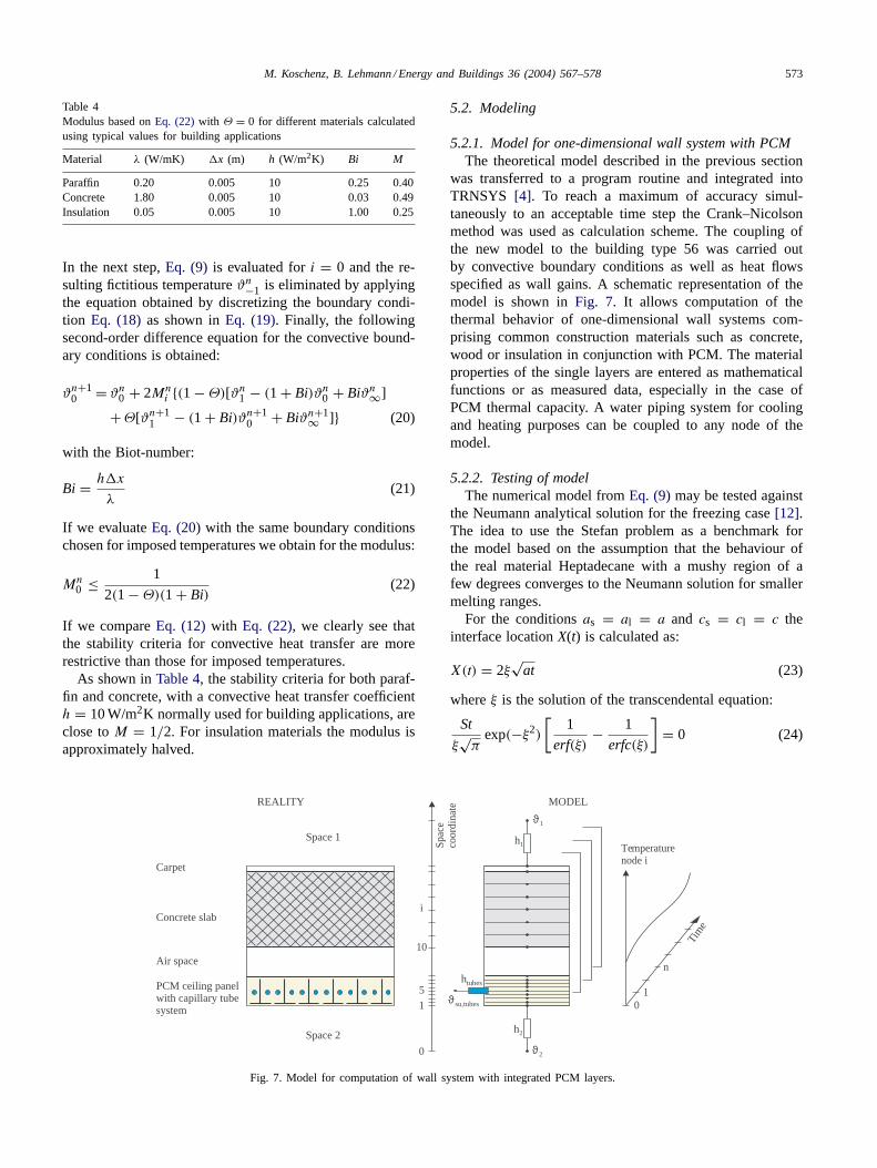
Table 4Modulus based on Eq. (22) with Θ = 0 for different materials calculatedusing typical values for building applications
Material λ (W/mK) �x (m) h (W/m2K) Bi M
Paraffin 0.20 0.005 10 0.25 0.40Concrete 1.80 0.005 10 0.03 0.49Insulation 0.05 0.005 10 1.00 0.25
In the next step, Eq. (9) is evaluated for i = 0 and the re-sulting fictitious temperature ϑn
−1 is eliminated by applyingthe equation obtained by discretizing the boundary condi-tion Eq. (18) as shown in Eq. (19). Finally, the followingsecond-order difference equation for the convective bound-ary conditions is obtained:
ϑn+10 = ϑn
0 + 2Mni {(1 − Θ)[ϑn
1 − (1 + Bi)ϑn0 + Biϑn
∞]
+ Θ[ϑn+11 − (1 + Bi)ϑn+1
0 + Biϑn+1∞ ]} (20)
with the Biot-number:
Bi = h�x
λ(21)
If we evaluate Eq. (20) with the same boundary conditionschosen for imposed temperatures we obtain for the modulus:
Mn0 ≤ 1
2(1 − Θ)(1 + Bi)(22)
If we compare Eq. (12) with Eq. (22), we clearly see thatthe stability criteria for convective heat transfer are morerestrictive than those for imposed temperatures.
As shown in Table 4, the stability criteria for both paraf-fin and concrete, with a convective heat transfer coefficienth = 10 W/m2K normally used for building applications, areclose to M = 1/2. For insulation materials the modulus isapproximately halved.
Space 1
Carpet
Concrete slab
PCM ceiling panelwith capillary tubesystem
Air space
REALITY
Space 2
MODEL
htubes
ϑ su,tubes
ϑ2
ϑ1
h2
h1Spac
eco
ordi
nate
0
15
10
i
Tim
e
01
n
Temperaturenode i
Fig. 7. Model for computation of wall system with integrated PCM layers.
5.2. Modeling
5.2.1. Model for one-dimensional wall system with PCMThe theoretical model described in the previous section
was transferred to a program routine and integrated intoTRNSYS [4]. To reach a maximum of accuracy simul-taneously to an acceptable time step the Crank–Nicolsonmethod was used as calculation scheme. The coupling ofthe new model to the building type 56 was carried outby convective boundary conditions as well as heat flowsspecified as wall gains. A schematic representation of themodel is shown in Fig. 7. It allows computation of thethermal behavior of one-dimensional wall systems com-prising common construction materials such as concrete,wood or insulation in conjunction with PCM. The materialproperties of the single layers are entered as mathematicalfunctions or as measured data, especially in the case ofPCM thermal capacity. A water piping system for coolingand heating purposes can be coupled to any node of themodel.
5.2.2. Testing of modelThe numerical model from Eq. (9) may be tested against
the Neumann analytical solution for the freezing case [12].The idea to use the Stefan problem as a benchmark forthe model based on the assumption that the behaviour ofthe real material Heptadecane with a mushy region of afew degrees converges to the Neumann solution for smallermelting ranges.
For the conditions as = al = a and cs = cl = c theinterface location X(t) is calculated as:
X(t) = 2ξ√
at (23)
where ξ is the solution of the transcendental equation:
St
ξ√
πexp(−ξ2)
[1
erf(ξ)− 1
erfc(ξ)
]= 0 (24)
574 M. Koschenz, B. Lehmann / Energy and Buildings 36 (2004) 567–578
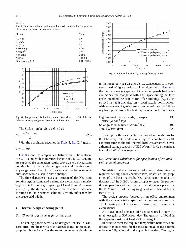
Table 5Initial boundary conditions and material properties chosen for comparisonof the model against the Neumann solution
Quantity Value
ϑm (◦C) 22ϑs (◦C) 17ϑl (◦C) 27λ (W/mK) 0.20ρ (kg/m3) 780c (J/kgK) 2,000L (J/kg) 148,300Grid spacing (m) 0.001/0.002
17
18
19
20
21
22
23
24
25
26
27
0 0.005 0.01 0.015 0.02 0.025 0.03
Position x [m]
Tem
pera
ture
[˚C
]
dm=5 Kdm=1 Kdm=0.1 KNeumann-Solution
Fig. 8. Temperature distribution in the material at t = 10, 800 s fordifferent melting ranges and Neumann solution for this case.
The Stefan number St is defined as:
St= c(ϑm − ϑs)
L(25)
With the conditions specified in Table 5, Eq. (24) gives:
ξ = 0.1608
Fig. 8 shows the temperature distribution in the materialat t = 10,800 s with an interface location at X(t) = 0.012 m.As expected the simulation results converge to the Neumannsolution for smaller melting ranges. A material with a melt-ing range lower than 1 K shows almost the behavior of asubstance with a discrete phase change.
The time dependent interface location of the Neumannsolution X(t) is compared against the model with a mushyregion of 0.1 K and a grid spacing of 1 and 2 mm. As shownin (Fig. 9), the difference between the calculated interfacelocation and the Neumann solution is mainly influenced bythe space grid width.
6. Thermal design of ceiling panel
6.1. Thermal requirements for ceiling panel
The ceiling panels were to be designed for use in stan-dard office buildings with high thermal loads. To reach ap-propriate thermal comfort the room temperature should be
0.000
0.002
0.004
0.006
0.008
0.010
0.012
0.014
0.016
0.018
0.020
- 3,600 7,200 10,800 14,400 18,000Time t [s]
Inte
rfac
e lo
catio
n X
(t)
[m]
Neumann solutionFD-model grid spacing 1 mmFD-model grid spacing 2 mm
Fig. 9. Interface location X(t) during freezing process.
in the range between 21 and 28 ◦C. Consequently, to over-come the day/night time lag problem described in Section 1,the thermal storage capacity of the ceiling panels had to ac-commodate the heat gains within the space during the dailycycle. Standard use profiles for office buildings (e.g. as de-scribed in [13]) and data on typical facade constructionswith large areas of glazing were used to estimate the follow-ing heat gains inside the building in relation to floor area:
High internal thermal loads, open-planoffice (Wh/m2 day)
130
Solar gains in summer (Wh/m2 day) 190Total (Wh/m2 day) 320
To simplify the specification of boundary conditions forthe laboratory tests while simulating real conditions, an 8 hexposure time to the full thermal load was assumed. Givena thermal storage capacity of 320 Wh/(m2 day), a mean heatload of 40 W/m2 was required.
6.2. Simulation calculations for specification of requiredceiling panel properties
Simulation calculations were performed to determine therequired ceiling panel characteristics, based on the prop-erties of the basic materials. Key parameters included thethickness of the PCM/gypsum composite layer, the propor-tion of paraffin and the minimum requirements placed onthe PCM in terms of melting range and latent heat of fusion(see Fig. 1).
The design process focused on an office environmentwith the characteristics specified in the previous section.The following conclusions were drawn from the simulationcalculations:
An overall panel thickness of 5 cm is required to store thetotal heat gain of 320 Wh/m2 day. The quantity of PCM inthe gypsum must be at least 25% by weight.
In order to meet the required temperature boundary con-ditions, it is important for the melting range of the paraffinto be carefully adjusted to the specific situation. The region

M. Koschenz, B. Lehmann / Energy and Buildings 36 (2004) 567–578 575
Table 6Building data and boundary conditions for building simulation
BuildingFacade orientation West-south-westGlazed area (m2) 8Thermal transmittance (U), glazing (W/m2K) 0.7Solar heat gain coefficient (SHGC), glazing 0.5Solar heat gain coefficient (SHGC),
glazing with solar control0.05
Floor area (m2) 24Concrete floor/slab thickness (cm) 25Maximum internal heat load (W/m2) 18
Thermally activated ceiling systemPCM ceiling panel thickness (cm) 5Percentage PCM in ceiling panel (% by weight) 25Capillary tube internal/external diameter (mm) 2/3Tube spacing (cm) 3Flow temperature (◦C) 18Specific water mass flow rate in
relation to ceiling area (kg/hm2)15
Operating time for recooling (h) 22:00–06:00
with maximum values of specific heat must therefore corre-spond to 21–22 ◦C.
To avoid large temperature gradients inside the material,the ceiling panels must exhibit good thermal conductivityover the entire cross-section. Here, the simulation calcula-tions showed a mean target value of λ = 1.2 W/mK to bepracticable.
6.3. Building-integrated simulation calculations
To check that ceiling panels with the above propertieswould perform satisfactorily under real load and weatherconditions, computational simulations were carried out us-ing building-integrated ceiling modules. The building dataand boundary conditions selected for the computations aresummarized in Table 6. The assumed environment (building
17
18
19
20
21
22
23
24
25
26
27
Tem
pera
ure
[˚C
]
10
20
30
40
50
60
70
80
90
100
110
Out
door
tem
pera
ture
[˚C
]
Space with PCM-ceiling panelMedium temperature PCM-ceiling panelSpace with pipes in the slab and sheet metal suspended ceilingOutdoor temperature
Jun 27 Jun 28 Jun 29 Jun 30 Jul 01 Jul 02 Jul 03
Fig. 10. Temperature profiles in real environment with integrated ceiling panels during summer week.
use) is one with high internal thermal loads plus high solargains due to the almost fully glazed facade.
As the graph in Fig. 10 shows, the thermally activatedceiling system ensures that the room temperature remainswithin a comfortable range even when outdoor temperaturesare high. The mean ceiling temperature also indicates thatthe melting range of the paraffin is fully exploited.
For reasons of comparison the same building was calcu-lated without PCM ceiling panels. Thereby the conventionalpiping system was assumed to be placed in the center of theslab and a sheet steel panel as suspended ceiling guaran-teed equal boundary conditions like in the case with PCM.From the corresponding curve it can be seen that with thisclassical tabs-setup in conjunction with a suspended ceilingsignificantly higher temperatures would arise than with thePCM system.
7. Experimental study
7.1. Production of prototypes
The results from the design process were used to produceprototype modules for the laboratory tests. As values of ap-prox. 0.8–1.0 W/mK are quoted in background literature forthe thermal conductivity of gypsum, no preliminary mea-sures were implemented to increase the thermal conductiv-ity of the unit. However, conductivity readings from the firstprototype indicated a value as low as 0.2 W/mK—a resultof the higher porosity of the gypsum/PCM composite com-pared to normal gypsum. To achieve the necessary increasein conductivity by a factor 6, aluminum fins were incorpo-rated in the ceiling element. Theoretical estimates put therequired spacing at around 3 cm, with fins extending acrossthe full cross-section. The assembly selected for the proto-type is shown in Fig. 11. The effectiveness of the measure

576 M. Koschenz, B. Lehmann / Energy and Buildings 36 (2004) 567–578
Fig. 11. Aluminum fins to increase the conductivity in the PCM/Gyp- sum-composit.
was confirmed by the laboratory tests, which recorded val-ues of 1.1–1.2 W/mK.
The initial paraffin mix used as PCM comprised hexade-cane and octadecane. First tests showed the melting curve tobe some 3 K too high. The new heptadecane-based paraffinmix subsequently produced and encapsulated proved to beideal in terms of temperature distribution for the followingtests.
Fig. 12 shows a complete ceiling panel prior to mountingin the test stand. The capillary tube system cast into thecomposite is clearly visible in the foreground.
7.2. Design of laboratory tests
The aim of the laboratory tests was to verify the perfor-mance of the system prototypes following their optimizationin the simulation process. The test set-up shown in Fig. 13served to provide a realistic simulation of the processes oc-curring in both room and ceiling panel. The hot box testswere designed to allow cyclical heating and cooling of theceiling panels and collection of data on temperature condi-tions and energy storage capacity.
Fig. 13. Laboratory test set-up with prototype ceiling panel.
Fig. 12. Prototype of 0.25 m2 ceiling panel for laboratory test.
An electrical heating plate (a) was used to simulatethe environmental thermal loads. The adjacent neoprenelayer (b) has a thermal resistance of 0.1 m2K/W, equiva-lent to a realistic combined heat transfer coefficient be-tween the room temperature and the surface temperatureof approx. 10 W/m2K. The temperature measured on theheating plate (c) was therefore, roughly equivalent to thecorresponding room temperature. Additional temperaturesensors were used to measure the mean surface tempera-tures on the lower (d), and upper faces (e) of the panel.Circulation of cold water through the capillary tube system(f) allowed the ceiling panel to be recooled after a heatingcycle.
7.3. Performance of laboratory tests
Fig. 14 shows a measurement cycle for the optimizedceiling panel. The PCM accounts for some 23% by weightof the ceiling panel, equivalent to a PCM mass of approx.13 kg/m2 ceiling area. The ceiling panel was subjected toa constant heat load of approx. 40 W/m2. The graph showsthe temperature curves for the room-side (d) and rear (e)ceiling panel surfaces as well as the temperature measured

M. Koschenz, B. Lehmann / Energy and Buildings 36 (2004) 567–578 577
8
12
16
20
24
28
32
36
40
0 6 12 18 24 30
Time [h]
Tem
pera
ture
[˚C
]
Phase changeregion:
7.5 h / 39 W/m2
290 Wh/m2
Panel lower face (d)
Panel upper face (e)
Heating plate (c), "room temperature"
Fig. 14. Temperature profiles for test cycle recorded in laboratory.
between heating plate and neoprene (c), equivalent to thecorresponding room temperature.
The phase change process undergone by the PCM inthe ceiling panel is clearly reflected by the leveling off ofthe heating curves after 8 h. The required operating rangein the real application is limited to this phase change re-gion as the energy storage here slows down the rise intemperature. In this particular case, subject to an aver-age load of 39 W/m2, the melting process lasted for 7.5 h,during which a total of 290 Wh/m2 thermal energy wasstored. That the storage capacity fell short of the pro-jected 320 Wh/m2 is due to the lower absolute quantityof paraffin incorporated in the panel, as dictated by theultimate porosity and, hence, density of the composite—properties not fully controllable during the mixing andfilling process.
The fact that phase change commences at 20 ◦C confirmsthat the paraffin’s melting range was ideally adjusted to re-quirements. The paraffin contained in the ceiling panel, istherefore, completely solid at the start of the daily cycle,allowing its full storage capacity to be exploited.
At the end of phase change, the panel temperature isup by 4 K to 24 ◦C. During this period, the (virtual) roomtemperature rises to approx. 28 ◦C. A continued supplyof energy subsequently triggers a sharper temperature in-crease as all the paraffin is now in a liquid state with acorrespondingly lower specific heat capacity. Due to thelow thermal capacity (product of density and specific heatcapacity), the performance of the PCM system outsidethe operating (melting) range is therefore more criticalthan that of heavily constructed buildings with solid el-ements. This factor warrants particular attention in thedesign of PCM based thermally activated wall and ceilingsystems.
A simulation calculation using boundary conditions trans-ferred from the laboratory test to the model yielded the re-sults shown in Fig. 15. The fact that these largely agreewith the measured values is further proof of the model’s
8
12
16
20
24
28
32
36
40
0 6 12 18 24 30
Time [h]
Tem
pera
ture
[˚C
]
Panel lower face
Panel upper face
Heating plate boundary condition
Fig. 15. Temperature profiles for test cycle calculated with model.
accuracy in simulating the thermal behavior of the ceilingpanels.
8. Application
8.1. Prototype building
Following verification in laboratory tests and simula-tion calculations of the panel’s thermal performance, detaildesign work commenced on the pilot application for thenew-build administrative facility of BASF AG’s hous-ing company “Ludwigshafener WohnungsunternehmenLUWOGE/GEWOGE” (Fig. 16). This primarily entailedthe detailing and production of units (Fig. 17) for incorpo-ration in the ceiling of the 200 m2 exhibition hall.
The pilot system is scheduled for launch in June 2003. Aseparate monitoring project will be implemented as of thisdate to further check the practicability of the concept.
The combustibility of paraffin and its high fire loadmay negatively impact the development of any fire in the
Fig. 16. Interior of new-build administrative facility of the “Lud-wigshafener Wohnungsunternehmen LUWOGE/GEWOGE” .
578 M. Koschenz, B. Lehmann / Energy and Buildings 36 (2004) 567–578
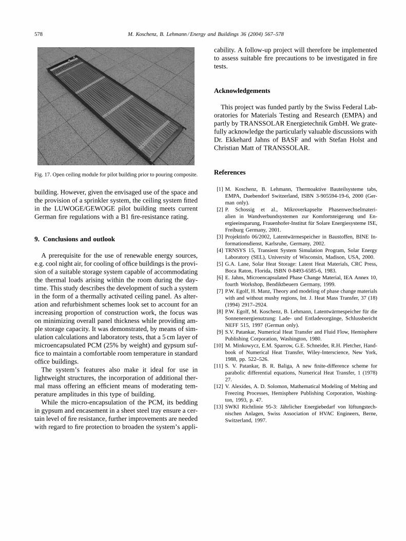
Fig. 17. Open ceiling module for pilot building prior to pouring composite.
building. However, given the envisaged use of the space andthe provision of a sprinkler system, the ceiling system fittedin the LUWOGE/GEWOGE pilot building meets currentGerman fire regulations with a B1 fire-resistance rating.
9. Conclusions and outlook
A prerequisite for the use of renewable energy sources,e.g. cool night air, for cooling of office buildings is the provi-sion of a suitable storage system capable of accommodatingthe thermal loads arising within the room during the day-time. This study describes the development of such a systemin the form of a thermally activated ceiling panel. As alter-ation and refurbishment schemes look set to account for anincreasing proportion of construction work, the focus wason minimizing overall panel thickness while providing am-ple storage capacity. It was demonstrated, by means of sim-ulation calculations and laboratory tests, that a 5 cm layer ofmicroencapsulated PCM (25% by weight) and gypsum suf-fice to maintain a comfortable room temperature in standardoffice buildings.
The system’s features also make it ideal for use inlightweight structures, the incorporation of additional ther-mal mass offering an efficient means of moderating tem-perature amplitudes in this type of building.
While the micro-encapsulation of the PCM, its beddingin gypsum and encasement in a sheet steel tray ensure a cer-tain level of fire resistance, further improvements are neededwith regard to fire protection to broaden the system’s appli-
cability. A follow-up project will therefore be implementedto assess suitable fire precautions to be investigated in firetests.
Acknowledgements
This project was funded partly by the Swiss Federal Lab-oratories for Materials Testing and Research (EMPA) andpartly by TRANSSOLAR Energietechnik GmbH. We grate-fully acknowledge the particularly valuable discussions withDr. Ekkehard Jahns of BASF and with Stefan Holst andChristian Matt of TRANSSOLAR.
References
[1] M. Koschenz, B. Lehmann, Thermoaktive Bauteilsysteme tabs,EMPA, Duebendorf Switzerland, ISBN 3-905594-19-6, 2000 (Ger-man only).
[2] P. Schossig et al., Mikroverkapselte Phasenwechselmateri-alien in Wandverbundsystemen zur Komfortsteigerung und En-ergieeinsparung, Frauenhofer-Institut für Solare Energiesysteme ISE,Freiburg Germany, 2001.
[3] Projektinfo 06/2002, Latentwärmespeicher in Baustoffen, BINE In-formationsdienst, Karlsruhe, Germany, 2002.
[4] TRNSYS 15, Transient System Simulation Program, Solar EnergyLaboratory (SEL), University of Wisconsin, Madison, USA, 2000.
[5] G.A. Lane, Solar Heat Storage: Latent Heat Materials, CRC Press,Boca Raton, Florida, ISBN 0-8493-6585-6, 1983.
[6] E. Jahns, Microencapsulated Phase Change Material, IEA Annex 10,fourth Workshop, Bendiktbeuern Germany, 1999.
[7] P.W. Egolf, H. Manz, Theory and modeling of phase change materialswith and without mushy regions, Int. J. Heat Mass Transfer, 37 (18)(1994) 2917–2924.
[8] P.W. Egolf, M. Koschenz, B. Lehmann, Latentwärmespeicher für dieSonnenenergienutzung: Lade- und Entladevorgänge, SchlussberichtNEFF 515, 1997 (German only).
[9] S.V. Patankar, Numerical Heat Transfer and Fluid Flow, HemispherePublishing Corporation, Washington, 1980.
[10] M. Minkowycz, E.M. Sparrow, G.E. Schneider, R.H. Pletcher, Hand-book of Numerical Heat Transfer, Wiley-Interscience, New York,1988, pp. 522–526.
[11] S. V. Patankar, B. R. Baliga, A new finite-difference scheme forparabolic differential equations, Numerical Heat Transfer, 1 (1978)27.
[12] V. Alexides, A. D. Solomon, Mathematical Modeling of Melting andFreezing Processes, Hemisphere Publishing Corporation, Washing-ton, 1993, p. 47.
[13] SWKI Richtlinie 95-3: Jährlicher Energiebedarf von lüftungstech-nischen Anlagen, Swiss Association of HVAC Engineers, Berne,Switzerland, 1997.