CHROMOSOME BANDING OF SIX DENDROBATID FROGS (COLOSTETHUS, MANNOPHRYNE
Upload
khangminh22Category
view
2download
0
AN ABSTRACT OF THE THESIS OF
Utkarsh Kansal for the degree of Master of Science in Mechanical EngineerinF,
presented on January 21,1992.
Title: Microstructural Banding in Thermally and Mechanically Processed Titanium 6242.
Abstract approved: ,Redacted for Privacy
Prof. M.E.Kassner
Ti-6A1-2Sn-4Zr-2Mo-0.1Si specimens were shaped by repeated cycles of heating
(to 954 °C) and hammer or press forging followed by a solution anneal that varied from
968 to 998 °C. The coupons were originally extracted from billets forged below the beta
transus (1009 °C) and slow cooled to ambient temperature. Macroscopic and
microstructural banding is observed in some forged and solution annealed coupons, that
consists of regions of elongated primary alpha. More significant banding is observed
subsequent to annealing at lower temperatures (968 °C), whereas much less microstructural
banding is present after annealing at higher temperatures (998 °C). About the same level of
banding is observed in hammer forged and press forged coupons. The observation of these
bands is significant since they may lead to inhomogeneous mechanical properties.
Specifically, at least some types of banding are reported to affect the high temperature creep
properties of this alloy. The origin of these bands was therefore researched. Classically,
banding in Ti-6242-0.1Si has been regarded as a result of adiabatic shear, chill zone
formation or compositional inhomogeneity. High and low magnification metallography,

electron microprobe analysis and microhardness tests were performed on forged and
annealed specimens in this investigation. The composition inside the bands appears
identical to that outside of the bands. The fraction of primary alpha is also found to be
identical. The bands have higher microhardness. These results suggest that the bands are
not related to composition gradients. The bands also do not appear to be a result of
adiabatic shear or other localized deformation. The bands of this study appear to originate
from the elongated primary alpha microstructure of the forged billet (from which test
coupons were extracted). The deformation of the extracted coupon may be neither fully
homogeneous nor sufficiently substantial and the coupon is only partly statically restored
after a solution anneal. Areas not fully restored appear as "bands" with elongated primary
alpha, that are remnant of the starting billet microstructure. Therefore, a source of banding
in Ti-6242-0.1Si alloy, additional to the classic sources, is evident. This type of banding is
likely removed by relatively high solution treatment temperatures and perhaps greater
plastic deformation during forging.

Microstructural Banding in
Thermally and Mechanically Processed Titanium 6242
by
Utkarsh Kansal
A THESIS
submitted to
Oregon State University
in partial fulfillment of
the requirements for the
degree of
Master of Science
Completed January 21, 1992
Commencement June 1992

APPROVED:
Redacted for Privacy
Professor of Mechanical Engineering in charge of major
Redacted for Privacy-lead of department of Mechanical Engineering
Redacted for Privacy
7Dean of Graa Jcnooi 1
Date thesis is presented January 21. 1992
Typed by Utkarsh Kansal for Utkarsh Kansal
ACKNOWLEDGEMENTS
I would like to acknowledge financial support from U.S. Bureau of Mines, the Oregon
Economic Development Department and OREMET Titanium, through the Oregon Metals
Initiative for making this research possible. In addition, I am thankful to Dr. Roger Neilsen
for the microprobe analysis and Mr. Al Soldner for SEM work . Discussions and help from
Prof. Bill Warnes, Mr. Michael Tolle and Mr. Kurt Thiehsen are highly appreciated.
Finally, I am extremely thankful to Prof.M.E. Kassner for his guidance, motivation and all
help to me with which this thesis was made possible.

TABLE OF CONTENTS
INTRODUCTION
EXPERIMENTAL PROCEDURE
RESULTS
DISCUSSION
CONCLUSIONS
1
11
18
32
35
REFERENCES 36
LIST OF FIGURES
Figure Page
1. Phase diagram showing a, f3, a+13 regions in titanium alloys. 2
2. Constant load 510 °C (950 °F) creep data for samples cut from 003
preform microstructure forgings in which (a) shear bands were present
(b) there were no shear bands. [9] 3
3. Upset and sidepress forging of a cylindrical bar [3]. 4
4. Shear band formation during forging(isothermal and non-isothermal) as
reported by Semiatin [13]. 7
5(a). Orientation of the coupons that were cut from the ingots. 13
5(b). Microstructure of the plane sections of 5(a). 14
6. Hammer and press forging on faces B and C of coupons. 16
7. Bands observed macroscopically on faces B and C in a set 1 hammer
forged coupon (annealed at 968 °C (T(3 41 °C)). 19
8(a). The final shape of the forged coupon and the plane-sections from which
micrographs (shown in Figure 8(b) and Figure 8(c)) were extracted from
two hammer forged coupons (from a set 1 coupon (annealed at 968 °C)
and from a set 2 coupon (annealed at 998 °C 11 °C))). 20
8(b). Microstructural banding observed in a set 1 hammer forged coupon
(annealed at 968 °C). Banded structures observed here on face B are
parallel to the z-direction. 21
8(c). Micrograph from face B in a set 2 hammer forged coupon (annealed
at 998 °C). Bands do not appear to be present. 21
9(a). Micrograph from face B in a set 3 press forged coupon (annealed at
968 °C). Some banding is evident. 22

9(b). Microstructure from face B in a set 4 press forged coupon (annealed at
993 °C). Banding is not evident.
10. Microstructure of face A in a set 1 hammer forged coupon (annealed at
968 °C).
11. Schematic of the bands observed subsequent to forging on face B and
face C in a set 1 hammer forged coupon (annealed at 968 °C).
12. SEM micrograph of bands observed on face B in a set 1 hammer forged
coupon (annealed at 968 °C). The band is surrounded by microhardness
indentations.
13. Microstructure of the coupon before hammer or press forging but
subsequent to heating for 2 hours at 954 °C (TO 55 °C).
22
24
25
26
33

LIST OF TABLES
Table Page
1. Processing conditions evaluated for development of shear bands [9]. 8
2. Chemical composition of the tested Ti-6242-01.Si. 12
3. Forging and heat treatments summaries. 15
4 A. Results of electron microprobe analysis performed on a set 1 hammer
forged coupon (annealed at 968 °C). 28
4B. Normalized values of electron microprobe results of a set 1 hammer
forged coupon (annealed at 968 °C) described in Table 4 A. 29
5. The fraction of primary alpha inside and outside the banded structure in
a set 1 hammer forged coupon (annealed at 968 °C). 30
6. Microhardness values inside and outside the bands of face B in a set 1
hammer forged coupon (annealed at 968 °C). 31

MICROSTRUCTURAL BANDING IN THERMALLY AND MECHANICALLY
PROCESSED TITANIUM 6242
INTRODUCTION
Titanium alloys are widely used in different technical applications because of their
light weight, high temperature strength and favorable corrosion properties. In gas turbine
engines, compressor blades are made of Ti-6242-0.1Si and are capable of operating at
temperatures up to 480-510 °C. Pure titanium undergoes a phase change from the a phase
(hcp) to the 13 phase (bcc) when heated above 882.5 °C. This transition temperature is
shifted with different alloying elements. The elements (e.g. Al, Ga etc.) which increase the
transition temperature are known as a stabilizers. Titanium alloys containing these elements
and have a hcp structure at ambient temperatures are known as a alloys. The elements (e.g.
Mo, V, Nb etc.) which decrease the transition temperature are known as p stabilizers, and
alloys that have a bcc structure at ambient temperature are known as p alloys. Titanium
alloys containing both a and p stabilizers are known as a/13 alloys. These alloys may
consist of a mixture of a and p phases at ambient temperature. Usually a/13 alloys contain
10 to 50% p phase at ambient temperature. In Ti 6242, the 0.1Si and 6% Al are a
stabilizers, 2% Mo acts as 13 stabilizer, 2% Sn and 4% Zr are added for solid solution
strengthening. The 0.1% Si is principally added to improve the creep properties of the
alloy. The phase change from a to 13 in Ti - 6242 0.1% Si occurs at approximately 990 °C
[4].
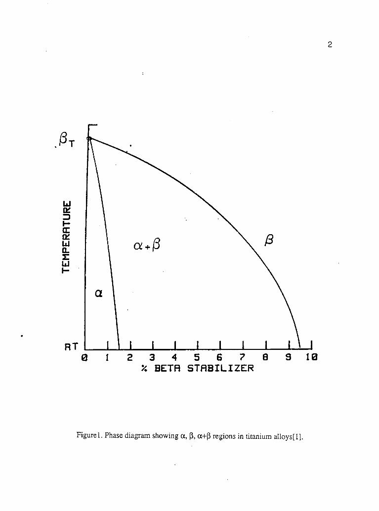
Figure 1 shows the phase diagram with a, 13 and a+13 regions in a general titanium
alloy. As the alloy is cooled from above the transition temperature the transformed p
structure varies from martensitic to Widmanstatten depending upon the cooling rate
(varying from water quenching to air cooling). Slow cooling results in equiaxed a ( plus
2
a + 0
RT 1 1111111 1 I
0 1 2 3 4 5 6 7 8 9 10% BETA STABILIZER
Figurel. Phase diagram showing a, (3, a-ffi regions in titanium alloys[1].

3
24
0
24
C
C0
16
a
3C
OZ 8O0
0
A
...
8
0
C
-Cf... sHess : so KS1 (352 loPo)
(I) Forgioo Contlirions:a /3 PHII/MH MiCrOSIrUCtufPreform Tnuftretero: 1673F (9t3C)01. Ternototter: 373 F (191C)ouH Time: 10 SC0.411
...(2) Solution Trat...es Teenporetere
.-e : isso F (699C1C. 0: um, (954C)
(3) Loorheo Oirectioea. C : L ILe411.4.1S, 0: Tames...sal
_
11 1 1 , I
80 160 240Time (Hours)
(a)
320 400
8
A
C.reo Stress: 60 KS1 (352 HPel
(982C)
(954C)
(11 Forging/Conditions :
a / Preform microstrwcturePH.fefft Temp.'s:stun. : mooeOte Tens ***** ut: 700F (371C)Onell rune: 0 Seconds
12/ Solution TrAtallue.. Tempura...H.:1750f131 Leeding 0(tset(ou
: L (Long(tuctmall8: T (T I
..
... -- ( -3 1 1 I(60 240
Time (Hours)
b )
320 400
Figure 2. Constant load 510 °C (950 °F) creep data for samples cut from cc/f3 preform
microstructure forgings in which (a) shear bands were present (b) there were
no shear bands. [9]

Upsetting Sidepressing
Figure 3. Upset and sidepress forging of a cylindrical bar [3].

510% (3 for titanium 6242). A solution anneal below the 13 transus followed by relatively
rapid cooling gives a microstructure of equiaxed a in the matrix of transformed (3 (usually
Widmanstatten) microstructure. Ti- 6 %Al- 2 %Sn- 4 %Zr- 2 %Mo- 0.1 %Si is commonly used
with two different microstructures [4]. The first microstructure consists of equiaxed a
phase in a matrix of transformed p phase. This can be obtained by forging and annealing
the alloy at temperatures below the beta transus, T13, followed by a relatively rapid cooling.
This is known as a/13 microstructure. The second is a completely transformed 0 or
basketweave (Widmanstatten) microstructure, which can be obtained by forging and
annealing the alloy above To, followed by a relatively rapid cooling. This study
emphasized the former microstructure.
The fabrication of a/I3 titanium alloys usually consists of a forging or forming
operation at elevated temperature below Ti3 followed by a solution anneal (also below T13)
followed by a stabilization treatment at 593 °C for 8 hours. At relatively low annealing
temperatures (e.g. T = 968 °C or T(3 41 °C) we observed some "banding" in the
microstructure of our forged specimens. Such inhomogeneities would usually be
considered undesirable because of an expected non-uniform mechanical behavior.
Furthermore, Semiatin reported that "shear" bands can degrade the creep properties of Ti-
6242-0.1Si. He found that specimens with many shear bands showed poor high
temperature creep resistance in comparison to the specimens with fewer bands. Creep rates
of specimens with and without shear bands, as reported by Semiatin [9], are shown in
Figure 2. Diffusion has been believed to be responsible for elevated temperature creep [5].
Enhanced diffusion within these high dislocation density bands was suggested as the
reason for enhanced creep. Therefore, in this work, research was performed to understand
the origin of the bands in our cc/13 Ti-6242-0.1Si . Once the source had been identified,
mitigative steps could be taken.
The formation of shear or deformation bands during high strain rate forging has
been reported by Semiatin [10,11,12,13] in Ti-6242-0.1Si. He found that as the coupons

6are forged at elevated temperatures, thin regions of localized deformation crossing many
grains were observed for 50% or higher reduction in non-isothermal upsetting and
sidepressing of the coupons (see Figure 3 for the description of two processes). These
bands were increasingly "diffused" as the coupons were solution annealed above 954 °C
(T13 55 °C). Semiatin explained the formation of shear bands in different forging
conditions as follows.
Semiatin concluded that in the case of the non-isothermally upset coupons (forging
during which the workpiece cools because of the contact with the cooler dies), chill zones,
resulting from the coupon coming into contact with die, were formed because of the
temperature difference between the forged coupon and the die. Bands of localized shear
formed between the chill caps led to bulge formation. Forging was performed using a
strain rate 10 s-1 at a forge temperature = 913 °C (T(3 96 °C) and die temperature = 191
°C. Therefore, in this case, shear bands are, at least partly, a result of flow localization due
to a temperature gradient. In the "non-isothermally" sidepressed coupons, at high forging
rates, bands were observed on face A (see Figure 4) forming an 'X', as the coupon was
forged on face B. These bands initially form at an angle of roughly 45° to the forging
direction. With larger deformation, some of these bands form a larger angle with the
forging direction. If the forging is performed at low strain rates, any heat developed from
deformation is dissipated. At high strain rates, there is local heating of the metal due to
plastic work (because of short deformation times). The heat locally raises the temperature
and causes thermal softening. The heat from deformation exceeds the strain hardening rate
of the material. Thus, flow localization occurs in the material. At high forging rates (strain
rate 30 s4), the high rate of deformation within the bands may prevent the dissipation of
the heat that is produced by plasticity. As a consequence an instability may develop and
flow localization can continue. No chill caps or bulging was observed in sidepressing of
the coupon since the contact area between die and the workpiece is small and time of
forging was too short for any significant heat exchange to occur between the die and the

x
Forging Direction
7
Forging Direction Forging Direction
initial coupon Shear bands form on face A
Figure 4. Shear band formation during forging(isothermal and non-isothermal) as reported
by Semiatin [13].

8
TABLE 1. Processing conditions evaluated for development of shear bands [9].
PreformMicro-structure
Forging Temp. Die Temp. Shear Band Rating after Heat Treatment
F ABC D
a+13 913 °C 191 °C 1 1.5 2 3 3
a+I3 913 °C 371 °C 1 1 2 2.75 3
a+13 982 °C 191 °C 3 3 3 3 3
a+I3 982 °C 371 °C 3 3 3 3 3
Strain rate --- 30 s-1
Qualitative shear band rating:
1 Intense shear bands; 2 Weak shear bands; 3 - No shear bands
Heat Treatments code:
F - As forged (no heat treatment)
A 898 °C/ 1 hour + 593 °C/ 8 hours; B - 954 °C/ 1 hour + 593 °C/ 8 hours; C - 979 °C/ 1
hour + 593 °C/ 8 hours; D - 1010 °C/ 1 hour + 593 °C/ 8 hours

9workpiece.
In sidepressed coupons, the effects of forging temperature, strain rate and the
solution anneal temperature on band formation/presence have been reported by Semiatin.
Table 1 shows which processing conditions are associated with shear bands [9].
Specimens forged (strain rate 30 s-1) at 913 °C (T13 - 96 °C) showed intense shear
banding whereas no shear bands were observed when the coupons were forged at 982 °C
(Tp 27 °C) at the same strain rate. Further, no shear bands were observed in coupons
forged at 913 °C (T(3 96 °C) as the solution anneal temperature was increased from 954
°C 55 °C) to 979 °C (T13 30 °C). These bands were obvious on etched surfaces at
low (<10 X) magnification. The microstructural details of these bands were not
investigated by Semiatin.
Macroscopic banding was reported by Woodward [16] and Me Bar et al. [7] in Ti-
6A1-4V (also of a a/(3 microstructure). In Woodward's work, high velocity projectiles
impacted Ti-6A1-4V targets and thin bands were observed with metallographic examination.
Again, it was suggested that banding occurs because the high rate of deformation prevents
the dissipation of the heat produced by the plastic flow. Here, again, a negative strain
hardening phenomenon (i.e. thermal softening exceeding the rate of strain hardening of the
material) is observed. The thin deformation bands were described as "adiabatic shear
bands". Elongated cavities as wide as the shear bands were observed and were believed to
result from liquification. Me Bar et. al. [7] also reported the formation of bands in Ti -6A1-
4V resulting from the impact of high velocity projectiles. Elliptical cavities were also found
in these bands. It is not clear whether these bands are an extreme case of the bands in
sidepressed specimens observed by Semiatin. Woodward [16] reported microstructural
banding in Ti-6A1-4V that was suggested not to be a result of adiabatic shear. Segregation
of alpha- phase stabilizers in banded areas was observed and these regions were associated
with a higher volume-fraction of alpha phase. Microstructural banding was observed in the
plane of rolling in the deformed coupons.

10The purpose of the present study was to determine the source of banding in our
forged Ti-6242-0.1 Si alloy. This included a determination as to whether the above
"classic" (e.g. chill caps, adiabatic shear, compositional inhomogeneity) explanations are
appropriate. Alternatively, a different explanation may be valid.

11
EXPERIMENTAL PROCEDURE
Ti-6242-0.1Si, coupons were supplied by OREMET and the composition is listed
in Table 2 [8]. The beta transus (T13) of the material used was found to be 1009 °C using
differential thermal analysis (DTA). Ti-6242-0.1Si ingots were cast as 0.762 m (30 inches)
diameter cylinders at OREMET. These ingots were press forged at 971 °C to 0.2032 m (8
inches) diameter cylinders and air cooled to ambient temperature. Figure 5(a) describes the
orientation of the coupons cut from the ingot. Figure 5(b) shows the microstructure of the
forged ingot in the plane sections delineated in Figure 5(a). Elongated primary alpha phase
is the dominating feature due to relatively slow cooling and the plastic deformation of the
ingot.
Coupons of dimensions listed in Table 3 were cut from a forged ingot along the z-
axis of the ingot (as in figure 5) and heated at 954 ± 15 °C for 2 hours. The couponswere
then either hammer or press forged. Hammer forging (using a Chambersburg Series 2 type
forging machine with a reported strain rate between 63 and 252 5-1[5]) was performed at
OREMET. Press forging (using a 500 ton capacity HPM hydraulic forging press
(approximate strain rate between 16 and 63 s-1[15]) was performed at the US Bureau of
Mines, Albany Research Center, Albany, OR. Forging proceeded until the flow resistance
was excessive. At this point, the temperature of the coupons, determined using an optical
pyrometer, dropped to between 901 °C and 814 °C. The coupons were then returned to the
furnace and reheated to 954 ± 15 °C. Coupons were rotated during forging on faces "B"
and "C" (Figure 6).
The coupon face with the larger width is denoted "B". Four sets of coupons were
forged and annealed. The first two sets of coupons were hammer forged, one in three
passes and the second in six passes, then annealed at 968 °C (T(3 41 °C) and 998 °C (T(3 -
11 °C), respectively, for 1 hr and air cooled to ambient temperature. The third and fourth
sets of coupons were press forged in three passes and annealed, one at 968 (T(3 - 41 °C)

12
TABLE 2. Chemical composition of the tested Ti-6242-01.Si [8]
(weight %)
Ti Al Mo Sn Zr Si Fe Cr Ni N 0 Others
85.69 5.97 2.0 2.02 3.99 0.08 0.08 0.01 0.004 0.011 0.119 0.03

Diameter = 0.762 m
Cast Ingot
13
Coupon
Diameter = 0.2032 m
Forged Ingot
Figure5(a). Orientation of the coupons that were cut from the ingots.

14
Face A
Face B
Figure 5(b). Microstructure of the plane sections of 5(a).

15
TABLE 3. Forging and heat treatment summaries
Type Initial Size Final Size Anneal Temp Passes Bands Straine c
Set 1 0.0635 m x 0.041275 m x 968 °C 3 1.5 5.0 1.79HF 0.0635 m x 0.015875 m x
0.038 m 0.228 m
Set 2 0.0635 m x 0.041275 m x 998 °C 6 2.75 5.1 1.81HF 0.0635 m x 0.015875 m x
0.095 m 0.5842 m
Set 3 0.0635 m x 0.041275 m x 968 °C 3 1.5 5.0 1.79PF 0.0635 m x 0.015875 m x
0.038 m 0.228 m
Set 4 0.0635 m x 0.041275 m x 993 °C 3 3 5.0 1.79PF 0.0635 m x 0.015875 m x
0.038 m 0.228 m
Bands: 1 - Many, 2 few, 3 None
Pass: Deformation sequence between reheating
HF: Hammer forged
PF: Press forged
e: Engineering strain
e: True strain

Forging Direction Forging Direction Forging Direction
Figure 6. Hammer and press forging on faces B and C of coupons.
x
16

17and the other at 993 °C (TO, 16 °C) for 1 hr and air cooled to the ambient temperature.
Finally, all the coupons were aged at 593 °C for 8 hours ("stabilization" treatment) and air
cooled to ambient temperature. Metallographic samples were prepared from these coupons.
Grinding was performed using 240, 320, 400 and 600 grit silicon carbide grinding papers.
The specimens were then polished using 5, 0.3 and 0.05 inn alumina powder slurries. The
samples were etched using a solution of 10 ml HF, 15 ml HNO3 and 75 ml of water. The
microcomposition of banded and unhanded regions was determined using a Cameca SX
50 electron microprobe. Microhardness studies inside and outside the banded regions were
performed using a Leco M-400 A microhardness testing machine. The fraction of primary
alpha inside and outside the banded structures was calculated using an optical microscope
equipped with an Automatix Inc.version 7.2 image analyzer. Higher magnification
metallography was performed using an AmRAY 1000A scanning electron microscope
(SEM).
18RESULTS
As stated earlier, large billets were forged below the beta transus and (slow) cooled
to ambient temperature leaving a microstructure that consists of elongated primary alpha
(about 10% beta phase is probably present between the elongated alpha). Coupons were cut
from the ingot, heated and then press or hammer forged. This is followed by a solution
anneal below the beta transus, Tp. Metallographic examination of our specimens frequently
revealed thin bands, that could be observed macroscopically (< 10 X) subsequent to
prolonged etching. Obvious banding was observed in set 1 (hammer forged) and set 3
(press forged) coupons annealed at the relatively low temperatures of 968 °C (T(3 41 °C).
The coupons from set 2 and set 4, forged and then annealed at higher temperatures of 993
°C (Tp 16 °C) and 998 °C (T(3 11 °C) showed little or no banding. Figure 7 shows the
macrographs of these bands on faces B and C of a hammer forged specimen subsequently
annealed at 968 °C.
Microstructural examination of these coupons was consistent with the macroscopic
analysis. Our specimens revealed banding of primary alpha in set 1 coupons (hammer
forged at the standard temperature and annealed at 968 °C) and set 3 coupons (press forged
at the standard temperature and annealed at 968 °C). The banding observed on both faces B
and C and were primarily aligned in the z-direction. Set 2 coupons (hammer forged at the
standard temperature and annealed at 998 °C) showed very little banding whereas no
banding was observed in the set 4 coupons (press forged and annealed at 993 °C). Figure
8(a) shows the final shape of hammer forged coupons of Ti-6242-0.1Si and the plane
sections from which the micrographs shown in Figure 8(b) and Figure 8(c) were extracted
from a set 1 (annealed at 968 °C) and from a set 2 (annealed at 998 °C) coupon. Figures 9
(a) and 9 (b) show the microstructure of press forged coupons annealed at 968 (set 3) and
993 °C (set 4) respectively. These micrographs are taken from face B of the forged
coupons. The banding is, perhaps, best described as regions or bundles of elongated

19
0.75 cm
FACE B
21111111111111111111=111
0.75 cm
FACE C
Figure 7. Bands observed macroscopically on faces B and C in a set 1 hammer forged
coupon (annealed at 968 °C (T(3 41 °C)).

x
20
Forging direction
Plane-section of the micrograph in figure 8(b)
Plane-section of the micrograph in figure 8(c)
Figure 8(a). The final shape of the forged coupon and the plane-sections from which
micrographs (shown in Figure 8(b) and Figure 8(c)) were extracted from two hammer
forged coupons (from a set 1 coupon (annealed at 968 °C (Tp-41 °C)) and from a set 2
coupon (annealed at 998 °C (T(3 11 °C))).

21
Figure 8(b). Microstructural banding observed in a set 1 hammer forged coupon (annealed
at 968 °C). Banded structures observed here on face B are parallel to the z-direction.
Figure 8(c). Micrograph from face B in a set 2 hammer forged coupon (annealed at 998
°C). Bands do not appear to be present.

22
Figure 9(a). Micrograph from face B in a set 3 press forged coupon (annealed at 968 °C).Some banding is evident.
Figure 9(b). Microstructure from face B in a set 4 press forged coupon (annealed at 993
°C). Banding is not evident.

23primary alpha surrounded by areas of more equiaxed alpha. No bands were revealed on
face A (perpendicular to the axis of the coupon or ingot) of the coupon. Figure 10 shows
the microstructure of face A in a set 1 hammer forged coupon (annealed at 968 °C).
Based on the literature [7,10-13,16], and as discussed in the introduction, there
appears to be several possible "classic" explanations for the formation of the observed
banded structures. One possibility is localized deformation (sometimes "adiabatic") as a
result of a temperature gradient (chill zones) in the specimen or due to high strain rates.
Compositional variation leading the inhomogeneties is another possible explanation.
Figure 11 shows a schematic of the bands observed subsequent to forging on face
B and face C in a set 1 hammer forged coupon (annealed at 968 °C). These findings may be
significant because the shear bands observed by Semiatin often form angles near 45° to the
forging direction. Therefore, there was some suspicion as to whether the bands of our
study were the result of the same shearing process observed by Semiatin. Our bands were
also examined using a scanning electron microscope (SEM). The SEM was used to reveal
whether cavities had formed in the bands, as observed by Woodward and Me Bar et al. No
microvoid formation was observed in our specimens, consistent with the proposition that
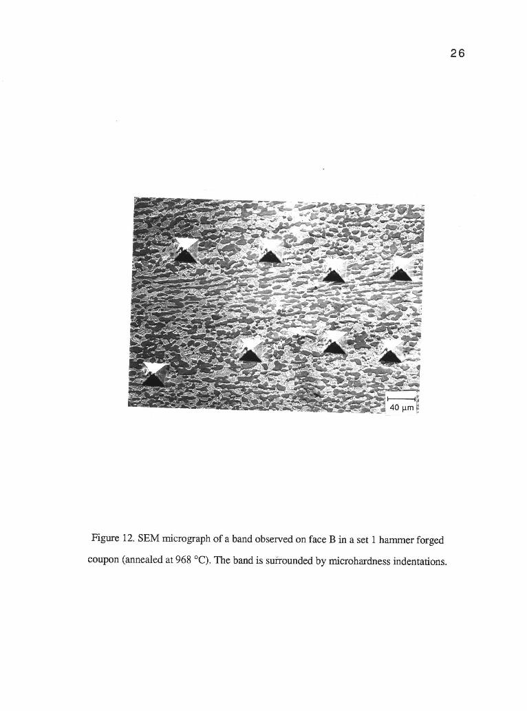
the bands are not a result of an adiabatic shear process. Figure 12 shows an SEM
micrograph of bands observed in a set 1 hammer forged coupon (annealed at 968 °C).
Again, microscopically, these bands consist of elongated primary alpha, observable only at
relatively high magnifications.
Electron microprobe analysis was performed by Woodward [16] to understand the
formation of microstructural banding observed in Ti-6A1-4V which was not believed to be a
result of adiabatic shear. The concentration of Al (an a stabilizer) within the band was
found to be 5% higher than the mean concentration in the sample while concentration of V
(a (3 stabilizer) was found to be 20% lower than the mean composition. A higher volume of
a phase was apparent with a higher concentration of a stabilizer within the bands.

24
Figure 10. Microstructure of face A in a set 1 hammer forged coupon (annealed at 968 °C).

Forging Direction
Initial Coupon
Forging Direction Forging Direction
Bands form on face C Bands form of face B
z
25
Y
/
Figure 11. Schematic of the bands observed subsequent to forging on face B and face C ina set 1 hammer forged coupon (annealed at 968 °C).
26
Figure 12. SEM micrograph of a band observed on face B in a set 1 hammer forged
coupon (annealed at 968 °C). The band is surrounded by microhardness indentations.
27Electron microprobe analysis was performed across the microstructural bands in
our samples. Table 4A reports the electron microprobe composition results inside (I) and
outside (0) the banded areas in a hammer forged coupon (annealed at 968 °C). These
results were normalized in IVB because of the scattering (due to pitting, fine scratches etc.)
during the microprobe analysis. The percent error for counting statistics (due to back
scattering) in the analysis is ± 0.19% for Ti, ± 0.04% for Al, ±.004% for Si, ±0.15% for
Zr, ±0.013% for Fe, ±0.08% for Mo and ±0.056% for Sn. We conclude, from Table 4B,
that there is not a significant compositional difference between banded and unbanded
regions.
Image analysis was used to calculate the volume fraction of a present inside and
outside the bands. Table 5 reports the results from four different bands in a set 1 hammer
forged coupon (annealed at 968 °C). As expected from microprobe analysis, the fraction of
primary alpha phase is found to be essentially the same inside and outside the bands.
Therefore, further, we do not believe that the bands are a result of any compositional
variation.
In other investigations of Ti-6242-0.1Si and Ti-6A1-4V [9,16], the bands, when
observed, were found to be harder than the material outside these bands. Semiatin suggests
that the "finer microstructure" of these bands causes the higher hardness [9]. We
discovered that the banded structures observed in the set 1 hammer forged coupon
(annealed at 968 °C), were harder than the surrounding areas of the bands. These results
are reported in Table 6. Hardness values with a load of 500 g for 30 seconds (ASTM
standard) gives the best result. The disparity in hardness may be yet greater than indicated
in Table 6 since some hardening of the polished surface may have occured during
mechanical polishing. This could both increase the "true" hardness somewhat and reduce
the difference between the banded and unbanded regions.

28
TABLE 4 A: Results of electron microprobe analysis performed on a set 1 hammer forged
coupon (annealed at 968 °C)
(In wt %)
Ti Al Si Zr Fe Mo S n
Band 1 I 82.8 5.39 0.09 3.8 0.09 1.9 2.0O 83.0 5.38 0.08 3.8 0.09 1.8 2.0
Band 2 I 83.4 5.41 0.1 4.2 0.09 1.9 2.1O 82.5 5.37 0.1 4.1 0.1 2.0 2.1
Band 3 I 83.0 5.34 0.09 3.9 0.08 1.9 2.1O 82.9 5.52 0.1 4.7 0.09 1.7 2.1
Band 4 I 82.6 5.52 0.1 4.0 0.09 1.9 2.1O 83.5 5.54 0.09 4.1 0.1 2.0 2.1
Band 5 I 79.2 5.39 0.1 4.2 0.07 1.8 2.1O 80.4 5.44 0.09 4.0 0.09 2.0 2.1
Band 6 I 82.7 5.31 0.07 4.0 0.08 2.0 2.1O 82.9 5.31 0.09 4.1 0.09 1.9 2.0
Av I 82.3 5.39 0.07 4.0 0.08 1.9 2.09(Overall)
Av 0 82.8 5.31 0.08 4.1 0.08 1.9 2.0(Overall)
I Inside band, 0 Outside band

29
TABLE 4 B. Normalized values of electron microprobe results ofa set 1 hammer forged
coupon (annealed at 968 °C) described in Table 4 A
Average Inside Bands (In wt %)
Ti Al Si Zr Fe Mo Sn
Bandl I 86.5 5.63 0.09 4.0 0.09 1.9 2.1Band2 I 85.9 5.60 0.09 4.3 0.09 2.0 2.2Band3 I 86.0 5.54 0.09 4.1 0.09 1.9 2.1Band4 I 86.0 5.75 0.09 4.1 0.09 1.9 2.2Band5 I 84.7 5.77 0.10 4.5 0.08 1.9 2.2Band6 I 86.1 5.53 0.07 4.2 0.08 2.0 2.2
Av 85.9 5.64 0.09 4.2 0.09 2.0 2.2Sd Dv 0.61 0.10 0.01 0.1 0.00 0.03 0.04
Average Outside Bands (In wt%)
Ti Al Si Zr Fe Mo Sn
Bandl 0 86.4 5.60 0.09 4.0 0.09 1.9 2.0Band2 0 85.4 5.56 0.1 4.3 0.1 2.0 2.1Band3 0 85.4 5.68 0.1 4.8 0.09 1.8 2.1Band4 0 85.2 5.68 0.09 4.2 0.09 2.0 2.2Band5 0 85.0 5.76 0.09 4.3 0.09 2.0 2.2Band6 0 86.3 5.53 0.09 4.3 0.09 1.9 2.1
Av 85.6 5.63 0.10 4.3 0.09 1.9 2.1Sd Dv 0.60 0.08 0.03 0.28 0.004 0.1 0.07
I - Inside band, 0 Outside band

30
TABLE 5. The fraction of primary alpha inside and outside the banded structure in a set 1
hammer forged coupon (annealed at 968 °C)
(Percentage primary alpha)
(a)Band 1 Band 2 Band 3 Band 4
Inside 50.1% 49.9% 49.9% 49.7%Outside 49.9% 49.9% 49.8% 49.8%

31
TABLE 6. Microhardness values inside and outside the bands of face B in a set 1 hammer
Position
forged coupon (annealed at 968 °C)
Setting: 300 g, 15 sec
Inside 3 Indents
Outside 3 Indents
Setting: 500 g, 30 sec
Inside 3 Indents
Outside 3 Indents
Setting: 1000g, 30 sec
Vicker's Hardness
(average)
415.5
360.0
435.0
416.0
Inside 3 Indents 396.0
Outside 3 Indents 368.0

32DISCUSSION
From the above results, the bands observed in our work may be explained as
follows. Based on Figure 5(b), the forged ingot initially consists, principally, ofprimary a
grains, elongated along the z-direction (axes) of the forged ingot. Interestingly, the banded
structures were still observed in these coupons after heating at 954 °C for 2 hours (before
the coupons were forged), as shown in Figure 13. Transformed 13 is seen as darker areas in
the micrograph, which is not observed in Figure 5 (a) due to slower cooling of the ingot.
Apparently the regions with elongated a microstructure of our forged coupons did
not completely recrystallize to equiaxed primary a (in a transformed 13 matrix) after
repeated forging and reheating to 968 °C. The coupon forging would tend to elongate the
primary a to a direction coincident with the ingot forging step. The unrecrystallized
elongated primary a would have a higher dislocation density and, therefore, higher
hardness, as observed. When annealing at 968 °C, the more heavily deformed regions
undergo restoration (i.e. recovery and recrystallization) and this structure becomes
relatively equiaxed. The remaining structure consists of elongated primary a grains that is
similar to the starting ingot microstructure. The final microstructure consists ofelongated a
surrounded by equiaxed a and transformed 13 grains. These deformed a grains that did not
restore, etch differently than the rest of the microstructure and can be seen macroscopically.
No microvoid formation was seen in our work as confirmed by SEM. The fact that there is
not a pronounced dependence of banding on strain-rate (press forged vs. hammer forged)
suggests that these may not be a result of a shear banding phenomena. On annealing at
998°C, most of the microstructure restores to an equiaxed shape and little microstructural
banding is observed. With these higher annealing temperatures, the banding that is present
is at least partially obscured by a low volume fraction of primary alpha. Also, fewer bands
are seen macroscopically and as discussed earlier, the composition in banded and unbanded
areas is essentially identical.

33
Figure 13. Microstructure of the coupon before hammer or press forging but subsequent toheating for 2 hours at 954 °C (TO - 55 °C).
34Therefore, with the analysis of the above results, we believe that the bands
observed in this study are not a consequence of compositional variation or shear bands but
rather areas of incomplete static restoration together with a starting microstructure of
elongated primary alpha grains. Although others [2] have observed that our utilized strain
levels during forging (see Table 3) might preclude the proposed type of banding, we
nonetheless believe that "remnant" bands are evident in our work . Presumably with greater
forging (higher plastic strains) the elongated alpha is increasingly "broken up" and there
would be a higher "driving force" for the restoration mechanisms that would mitigate the
banding. Higher annealing temperatures would also encourage the restoration. As
presented earlier, higher annealing temperatures (T13-14 °C) appears to eliminate the bands.
The effect of these particular bands on the creep properties has not been established [14].
As these bands may lead to inhomogeneous mechanical properties, the above steps may be
recommended. Therefore an additional source of banding is documented and should be
considered in thermal and mechanical processing.

35CONCLUSIONS
1. Banding was observed in Ti-6242-0.1Si coupons that were forged (using hammer and
press forges) and annealed at low annealing temperatures (954 °C (T13 55 °C) and 968 °C
(To 41 °C)). Microscopically these bands are "bundles" of elongated primary a and
transformed 13 grains. Substantially fewer bands are observed at higher annealing
temperatures (998 °C (T(3 11 °C)).
2. The observed bands are not believed to be classic "shear bands", as the bands did not
become more pronounced at higher strain-rate. Furthermore, the bands never appeared at
expected angles (e.g. 45°) to the forging direction. Also, microvoids, often associated with
adiabatic shear bands, were not observed.
3. No compositional change is found to occur in the microstructural bands. Hence, the
phenomenon of deformation banding due to compositional variation is not observed as
reported in some other 043 titanium alloy investigations.
4. It appears that the observed bands have ancestry to the starting ingot microstructure that
consists of elongated primary alpha resulting from forging and slow cooling. Subsequent
heating and forging sequences restores (recrystallizes and/or recovers) most, but not all, of
the substructure. The remnant alpha is elongated and relatively hard.
5. Larger strain deformation and/or higher annealing temperatures would probably restore
nearly all of the substructure, and the inhomogeneities of bands should disappear.
36REFERENCES
1. Bania P.J., Metallurgy of Advanced Titanium alloys, Short course, ASM InternationalMaterials Park, OH, 10-11 Oct 1990 Detroit, MI.
2. Bania P. J., Private communication, Sept. 1991.
3. Byrer T.G., Semiatin S.L. and Vollmer D.C., Forging Handbook, p. 95 & p. 156,ASM, Metals Park, OH, 1985.
4. Collings E.W., The Physical Metallurgy of Titanium alloys, p. 2, ASM, Metals Park,OH, 1984.
5. Lurthy H., Miller A.K. and Sherby 0.D., Acta Metallurgica, Vol 18, 1979, pp 169-178.
6. Manufacturer's Specification, Chamberburg Engineering Company, Chamberburg,PA.
7. Me Bar Y. and Shechtman D., Materials Science & Engineering, Vol 58, 1983, pp.181 188.
8. OREMET Titanium Company, Albany, Oregon, 9 June 1989.
9. Semiatin S.L. and Lahoti G.D., Metallurgical Transactions, Vol 14 A, 1983, pp. 743750.
10. Semiatin S.L. and Lahoti G.D., Metallurgical Transactions, Vol 14 A, 1983, pp. 105 -115.
11. Semiatin S.L. and Lahoti G.D., Metallurgical Transactions, Vol 12 A, 1981, pp. 17051717.
12. Semiatin S.L., Thomas Jr. J.F. and Dadras P., Metallurgical Transactions, Vol 14 A,1983, pp. 2363 2374.
13. Semiatin S.L.and Jonas J.J., Formability and workability of Metals, ASM, MetalsPark, OH, 1984.
14. Thiehsen K.E., Kassner M.E., Hiatt D. and Bristow B., to be published.
15. US Bureau of Mines, Albany Research Center, Albany, OR.
16. Woodward R.L., Metallurgical Transactions, Vol. 10 A, 1979, pp. 569 573.
Copyright © 2022 FDOKUMEN