Evolution of Microstructural Banding during the Manufacturing Process of Dual Phase Steels
8
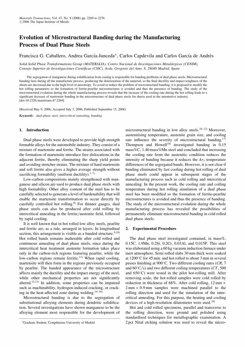
Evolution of Microstructural Banding during the Manufacturing Process of Dual Phase Steels Francisca G. Caballero, Andrea Garcı ´a-Junceda * , Carlos Capdevila and Carlos Garcı ´a de Andre ´s Solid-Solid Phase Transformations Group (MATERALIA), Centro Nacional de Investigaciones Metalu ´rgicas (CENIM), Consejo Superior de Investigaciones Cientı ´ficas (CSIC), Avda. Gregorio del Amo, 8, 28040 Madrid, Spain The segregation of manganese during solidification from casting is responsible for banding problems of dual phase steels. Microstructural banding lasts during all the manufacture process, producing the deterioration of the material, so the final ductility and impact toughness of the sheets are decreased due to the high level of anisotropy. To avoid or reduce the problem of microstructural banding, it is proposed to modify the hot rolling parameters so the formation of ferrite-pearlite microstructures is avoided and thus the presence of banding. The study of the microstructural evolution during the whole manufacturing process reveals that the increase of the cooling rate during the hot rolling leads to a significant decrease of martensite banding in the microstructure of dual phase steels for sheets used in the automotive industry. [doi:10.2320/matertrans.47.2269] (Received May 9, 2006; Accepted July 3, 2006; Published September 15, 2006) Keywords: dual-phase steel, intercritical annealing, banding 1. Introduction Dual phase steels were developed to provide high strength formable alloys for the automobile industry. They consist of a mixture of martensite and ferrite. The strains associated with the formation of martensite introduce free dislocations in the adjacent ferrite, thereby eliminating the sharp yield points and avoiding stretcher strains. The mixture of hard martensite and soft ferrite also gives a higher average strength without sacrificing formability (uniform ductility). 1–7) Low-carbon compositions mainly strengthened with man- ganese and silicon are used to produce dual phase steels with high formability. Other alloy content of the steel has to be carefully selected to generate a level of hardenability that will enable the martensite transformation to occur directly by carefully controlled hot rolling. 8) For thinner gauges, dual phase steels can also be produced after cold rolling by intercritical annealing in the ferrite/austenite field, followed by rapid cooling. It is well known that in hot rolled low alloy steels, pearlite and ferrite are, as a rule, arranged in layers. In longitudinal section, this arrangement is visible as a banded structure. 9,10) Hot rolled bands remains inalterable after cold rolled and continuous annealing of dual phase steels, since during the intercritical heat treatment austenite formation takes place only in the carbon-rich regions featuring pearlite, while the low-carbon regions remain ferritic. 11) When rapid cooling, martensite will then form in the regions previously occupied by pearlite. The banded appearance of the microstructure affects mainly the ductility and the impact energy of the steel, while other mechanical properties are not significantly altered. 12,13) In addition, some properties can be impaired such as machinability, hydrogen-induced cracking, or crack- ing in the heat-affected zone during welding. 14–16) Microstructural banding is due to the segregation of substitutional alloying elements during dendritic solidifica- tion. Several investigations have shown manganese to be the alloying element most responsible for the development of microstructural banding in low alloy steels. 10–12) Moreover, austenitising temperature, austenite grain size, and cooling rate influence the severity of microstructural banding. 17) Thompson and Howell 18) investigated banding in 0.15 mass%C, 1.40 mass%Mn steel and concluded that increasing the cooling rate from the austenitic condition reduces the intensity of banding because it reduces the Ar 3 temperature differences of the segregated bands. However, it is not clear if banding eliminated by fast cooling during hot rolling of dual phase steels could appear in subsequent stages of the manufacturing process such as cold rolling and intercritical annealing. In the present work, the cooling rate and coiling temperature during hot rolling simulation of a dual phase steel has been modified so the formation of ferrite-pearlite microstructures is avoided and thus the presence of banding. The study of the microstructural evolution during the whole manufacturing process has revealed the possibilities of permanently eliminate microstructural banding in cold rolled dual phase steels. 2. Experimental Procedure The dual phase steel investigated contained, in mass%, 0.15C, 1.9Mn, 0.2Si, 0.2Cr, 0.03Al, and 0.015P. This steel was elaborated using a 60 kg vacuum induction furnace under inert atmosphere. Semi rolled slabs 30 mm thick were soaked at 1200 C for 45 min. and hot rolled to about 3 mm in several passes finishing at 900 C. Two different cooling rates (CR,7 and 60 C/s) and two different coiling temperatures (CT , 500 and 650 C) were tested in the pilot hot-rolling mill. After removing scale, the hot-rolled samples were cold rolled by reduction in thickness of 68%. After cold rolling, 12 mm 2 mm 0:9 mm samples were machined parallel to the rolling direction and used for the simulation of the inter- critical annealing. For this purpose, the heating and cooling devices of a high-resolution dilatometer were used. 19) Hot and cold rolled specimens, parallel and transverse to the rolling direction, were ground and polished using standardised techniques for metallographic examination. A 2 pct Nital etching solution was used to reveal the micro- * Graduate Student, Complutense University of Madrid Materials Transactions, Vol. 47, No. 9 (2006) pp. 2269 to 2276 #2006 The Japan Institute of Metals
-
Upload
itspozarica -
Category
Documents
-
view
1 -
download
0
Transcript of Evolution of Microstructural Banding during the Manufacturing Process of Dual Phase Steels
Evolution of Microstructural Banding during the Manufacturing
Process of Dual Phase Steels
Francisca G. Caballero, Andrea Garcıa-Junceda*, Carlos Capdevila and Carlos Garcıa de Andres
Solid-Solid Phase Transformations Group (MATERALIA), Centro Nacional de Investigaciones Metalurgicas (CENIM),Consejo Superior de Investigaciones Cientıficas (CSIC), Avda. Gregorio del Amo, 8, 28040 Madrid, Spain
The segregation of manganese during solidification from casting is responsible for banding problems of dual phase steels. Microstructuralbanding lasts during all the manufacture process, producing the deterioration of the material, so the final ductility and impact toughness of thesheets are decreased due to the high level of anisotropy. To avoid or reduce the problem of microstructural banding, it is proposed to modify thehot rolling parameters so the formation of ferrite-pearlite microstructures is avoided and thus the presence of banding. The study of themicrostructural evolution during the whole manufacturing process reveals that the increase of the cooling rate during the hot rolling leads to asignificant decrease of martensite banding in the microstructure of dual phase steels for sheets used in the automotive industry.[doi:10.2320/matertrans.47.2269]
(Received May 9, 2006; Accepted July 3, 2006; Published September 15, 2006)
Keywords: dual-phase steel, intercritical annealing, banding
1. Introduction
Dual phase steels were developed to provide high strengthformable alloys for the automobile industry. They consist of amixture of martensite and ferrite. The strains associated withthe formation of martensite introduce free dislocations in theadjacent ferrite, thereby eliminating the sharp yield pointsand avoiding stretcher strains. The mixture of hard martensiteand soft ferrite also gives a higher average strength withoutsacrificing formability (uniform ductility).1–7)
Low-carbon compositions mainly strengthened with man-ganese and silicon are used to produce dual phase steels withhigh formability. Other alloy content of the steel has to becarefully selected to generate a level of hardenability that willenable the martensite transformation to occur directly bycarefully controlled hot rolling.8) For thinner gauges, dualphase steels can also be produced after cold rolling byintercritical annealing in the ferrite/austenite field, followedby rapid cooling.
It is well known that in hot rolled low alloy steels, pearliteand ferrite are, as a rule, arranged in layers. In longitudinalsection, this arrangement is visible as a banded structure.9,10)
Hot rolled bands remains inalterable after cold rolled andcontinuous annealing of dual phase steels, since during theintercritical heat treatment austenite formation takes placeonly in the carbon-rich regions featuring pearlite, while thelow-carbon regions remain ferritic.11) When rapid cooling,martensite will then form in the regions previously occupiedby pearlite. The banded appearance of the microstructureaffects mainly the ductility and the impact energy of the steel,while other mechanical properties are not significantlyaltered.12,13) In addition, some properties can be impairedsuch as machinability, hydrogen-induced cracking, or crack-ing in the heat-affected zone during welding.14–16)
Microstructural banding is due to the segregation ofsubstitutional alloying elements during dendritic solidifica-tion. Several investigations have shown manganese to be thealloying element most responsible for the development of
microstructural banding in low alloy steels.10–12) Moreover,austenitising temperature, austenite grain size, and coolingrate influence the severity of microstructural banding.17)
Thompson and Howell18) investigated banding in 0.15mass%C, 1.40mass%Mn steel and concluded that increasingthe cooling rate from the austenitic condition reduces theintensity of banding because it reduces the Ar3 temperaturedifferences of the segregated bands. However, it is not clear ifbanding eliminated by fast cooling during hot rolling of dualphase steels could appear in subsequent stages of themanufacturing process such as cold rolling and intercriticalannealing. In the present work, the cooling rate and coilingtemperature during hot rolling simulation of a dual phasesteel has been modified so the formation of ferrite-pearlitemicrostructures is avoided and thus the presence of banding.The study of the microstructural evolution during the wholemanufacturing process has revealed the possibilities ofpermanently eliminate microstructural banding in cold rolleddual phase steels.
2. Experimental Procedure
The dual phase steel investigated contained, in mass%,0.15C, 1.9Mn, 0.2Si, 0.2Cr, 0.03Al, and 0.015P. This steelwas elaborated using a 60 kg vacuum induction furnace underinert atmosphere. Semi rolled slabs 30mm thick were soakedat 1200�C for 45min. and hot rolled to about 3mm in severalpasses finishing at 900�C. Two different cooling rates (CR, 7and 60�C/s) and two different coiling temperatures (CT , 500and 650�C) were tested in the pilot hot-rolling mill. Afterremoving scale, the hot-rolled samples were cold rolled byreduction in thickness of 68%. After cold rolling, 12mm�2mm� 0:9mm samples were machined parallel to therolling direction and used for the simulation of the inter-critical annealing. For this purpose, the heating and coolingdevices of a high-resolution dilatometer were used.19)
Hot and cold rolled specimens, parallel and transverse tothe rolling direction, were ground and polished usingstandardised techniques for metallographic examination. A2 pct Nital etching solution was used to reveal the micro-*Graduate Student, Complutense University of Madrid
Materials Transactions, Vol. 47, No. 9 (2006) pp. 2269 to 2276#2006 The Japan Institute of Metals
structure by optical and electron microscopy. The volumefraction of pearlite, VP, in microstructures consisting offerrite and pearlite was estimated by a systematic manualpoint counting procedure on optical micrographs.20)
To reveal more in detail the microstructure of the steel,scanning electron microscopy (SEM) was carried out on aJEOL JSM-6500F Field Emission Scanning Electron Micro-scope operating at 7 kV. Thus, it was possible to characterisethe lamellar microstructure of pearlite. Two parameters, themean true interlamellar spacing, �0, and the area per unitvolume of the pearlite colonies interface, SPPv , are measuredto fully characterise the lamellar microstructures. The valuesof �0 were derived from electron micrographs according toUnderwood’s intersection procedure.20) Moreover, the valuesof SPPv are obtained by counting the number of intersectionsof the pearlite colony boundaries with the circular test grid asreported by Roosz et al.21)
Annealing was carried out within the intercritical temper-ature range, which was determined experimentally bymonitoring the fractional change in dilatation with temper-ature in cold rolled samples heated up to 1000�C at a rateof 5�C/s. Table 1 lists the Ac1 and Ac3 temperatures of thedifferent samples tested. Cold rolled specimens were inter-critical annealed at three different soaking temperatures (750,800 and 850�C) for different times (1, 20 and 100 s) beforegas quenching. The heating rate selected for the intercriticalannealing experiments was 5�C/s. Austenite, which isformed during intercritical annealing, transforms to marten-site during quenching. Thus, the progress of austenitisation isdetermined throughout the evolution of the volume fractionof martensite. In this sense, annealed specimens werepolished in the usual way for metallographic examination.LePera’s reagent22) was used to reveal martensite formedduring quenching. The quantitative measurement of marten-site volume fraction was carried out by point-countingmethod20) in longitudinal sections. Likewise, a reagent basedon saturated aqueous picric acid plus a wetting agent wasused to reveal the austenite grain boundaries on annealedsamples.23) The austenite grain size (AGS) was determined onoptical micrographs with the help of an image analyser andresults were analysed in terms of mean values of theequivalent circle diameter.
The Standard Practice ASTM E 1268-99 for ‘‘Assessingthe Degree of Banding or Orientation of Microstructures’’gives the following definition of banded microstructure basedon its morphological appearance: ‘separation, of one or morephases or constituents in a two-phase or multiphase micro-structure, into distinct layers parallel to the deformation axisdue to elongation of microsegregation’.24) The practiceproposes the characterisation of the degree of banding in
the microstructure by the anisotropy index, AI, and the meanedge-to-edge spacing of the bands, � , which rely on simplestereological methods. The anisotropy AI is estimated fromthe following equation,
AI ¼ �NNL?= �NNLk ð1Þ
where �NNL? is the mean number of feature interceptions withtest lines perpendicular to the deformation direction per unitlength of the test lines, and �NNLk is the mean number of featureinterceptions with test lines parallel to the deformationdirection per unit length of the test lines. For a randomlyoriented, non-banded microstructure, AI has a value of one.As the degree of orientation or banding increases, theanisotropy index increases.
The mean free path spacing, � , is determined as follows,
� ¼ ð1� VV Þ= �NNL? ð2Þ
where VV is the volume fraction of the banded or the orientedphase.
3. Results and Discussion
3.1 Microstructure of hot and cold rolled samplesOptical and scanning electron micrographs of hot rolled
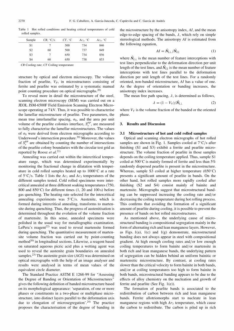
samples are shown in Fig. 1. Samples cooled at 7�C/s afterfinishing (S1 and S3) exhibit a ferrite and pearlite micro-structure. The volume fraction of pearlite in those samplesdepends on the coiling temperature applied. Thus, sample S1coiled at 500�C is mainly formed of ferrite and less than 5%randomly dispersed pearlite is present in the microstructure.Whereas, sample S3 coiled at higher temperature (650�C)presents a significant amount of pearlite in bands. On theother hand, hot rolled samples more rapidly cooled afterfinishing (S2 and S4) consist mainly of bainite andmartensite. Micrographs suggest that microstructural band-ing can be suppressed increasing the cooling rate and/ordecreasing the coiling temperature during hot rolling process.This confirms that avoiding the formation of a significantamount of pearlite during cooling, it is possible to prevent thepresence of bands on hot rolled microstructures.
As mentioned above, the underlying cause of micro-structural banding is compositional segregation mainly in theform of alternating rich and lean manganese layers. However,as Figs. 1(a), 1(c) and 1(g) demonstrate, microstructuralbanding does not always appear in steel with compositionalgradient. At high enough cooling rates and/or low enoughcoiling temperatures to form bainite and/or martensite inboth rich and lean manganese bands, the underlying patternof segregation can be hidden behind an uniform bainitic ormartensitic microstructure. By contrast, at cooling ratesslower than the critical velocity to form bainite in both bands,and/or at coiling temperatures too high to form bainite inboth bands, microstructural banding appears to be due to theeffects of alloy chemistry on the nucleation and growth offerrite and pearlite (See Fig. 1(e)).
The formation of pearlite bands is associated to theredistribution of carbon between rich and lean manganesebands. Ferrite allotriomorphs start to nucleate in leanmanganese regions with high Ar3 temperature, which causethe carbon to redistribute. The carbon is piled up in rich
Table 1 Hot rolled conditions and heating critical temperatures of cold
rolled samples.
Sample CR, �C/s CT , �C Ac1,�C Ac3,
�C
S1 7 500 734 846
S2 60 500 737 849
S3 7 650 734 856
S4 60 650 738 853
CR Cooling rate; CT Coiling temperature
2270 F. G. Caballero, A. Garcıa-Junceda, C. Capdevila and C. Garcıa de Andres
manganese regions with a low Ar3 temperature. This increasein carbon content in the adjacent austenite will lower thelocal Ar3 temperature even further. Eventually, the compo-sition in these regions becomes the level required for pearlitenucleation and pearlite will form if the temperature is belowthe Ar1 temperature. The growth of pearlite layer can be onlylimited by decreasing carbon diffusion with decreasingtransformation temperatures.
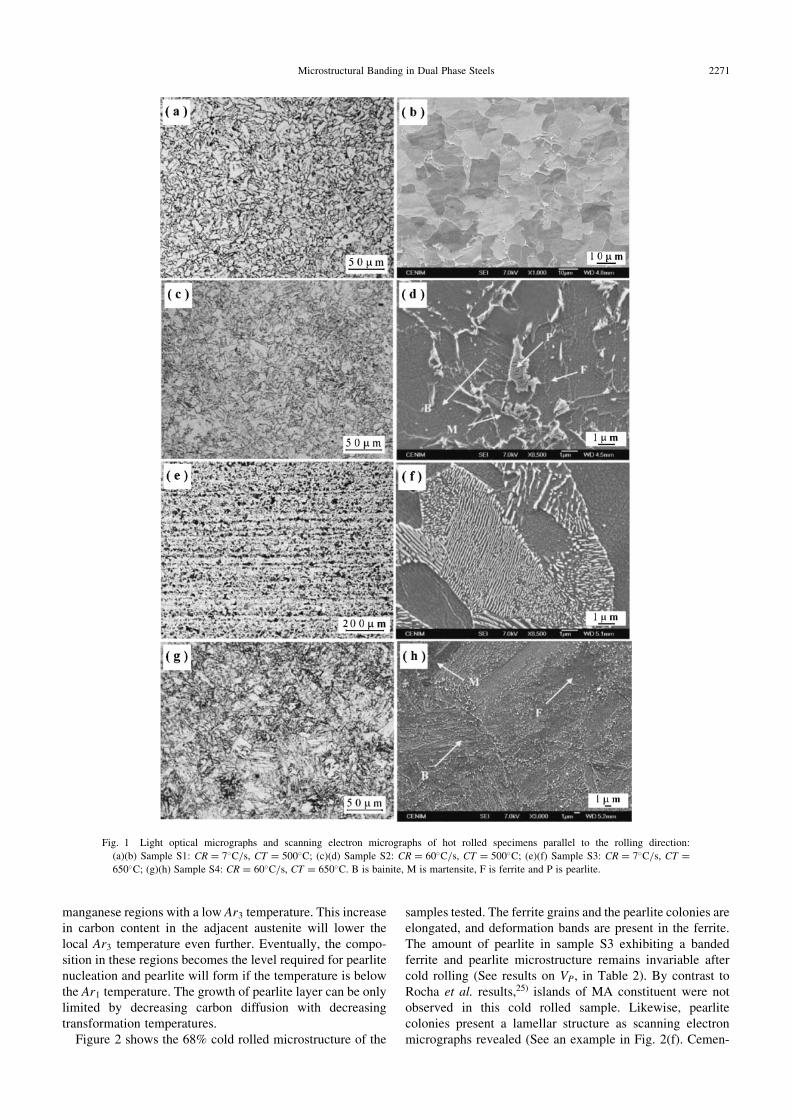
Figure 2 shows the 68% cold rolled microstructure of the
samples tested. The ferrite grains and the pearlite colonies areelongated, and deformation bands are present in the ferrite.The amount of pearlite in sample S3 exhibiting a bandedferrite and pearlite microstructure remains invariable aftercold rolling (See results on VP, in Table 2). By contrast toRocha et al. results,25) islands of MA constituent were notobserved in this cold rolled sample. Likewise, pearlitecolonies present a lamellar structure as scanning electronmicrographs revealed (See an example in Fig. 2(f). Cemen-
Fig. 1 Light optical micrographs and scanning electron micrographs of hot rolled specimens parallel to the rolling direction:
(a)(b) Sample S1: CR ¼ 7�C/s, CT ¼ 500�C; (c)(d) Sample S2: CR ¼ 60�C/s, CT ¼ 500�C; (e)(f) Sample S3: CR ¼ 7�C/s, CT ¼650�C; (g)(h) Sample S4: CR ¼ 60�C/s, CT ¼ 650�C. B is bainite, M is martensite, F is ferrite and P is pearlite.
Microstructural Banding in Dual Phase Steels 2271
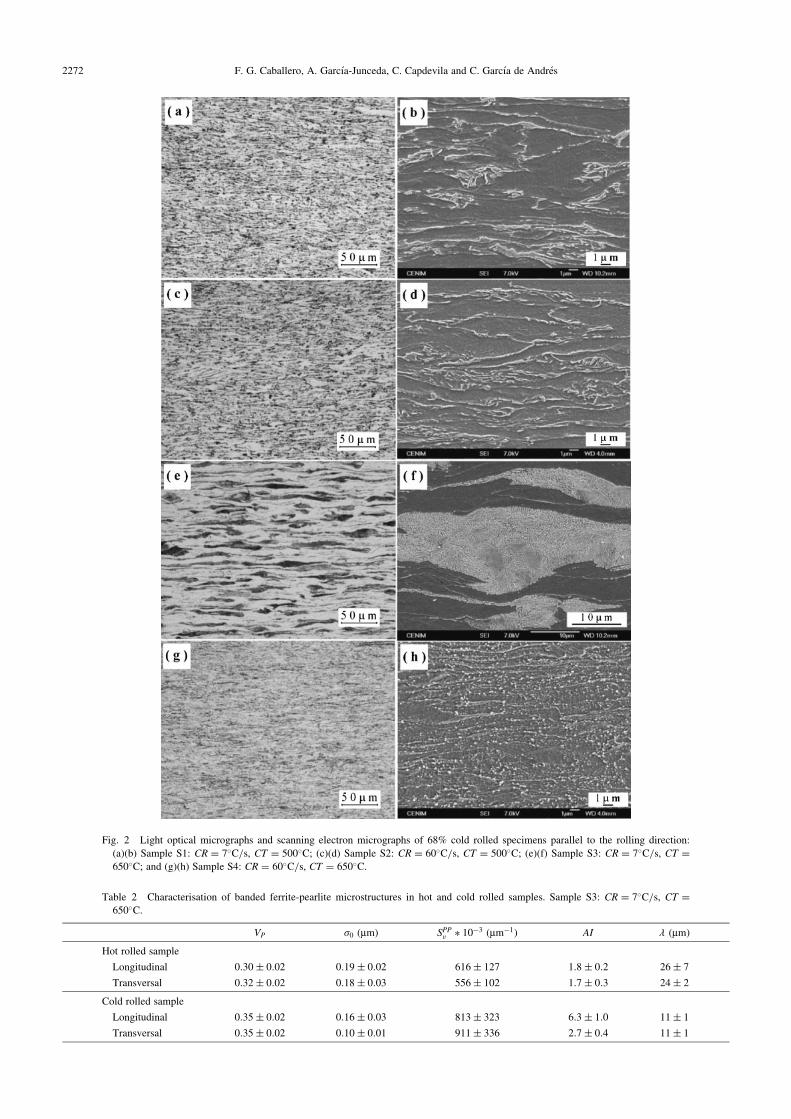
Fig. 2 Light optical micrographs and scanning electron micrographs of 68% cold rolled specimens parallel to the rolling direction:
(a)(b) Sample S1: CR ¼ 7�C/s, CT ¼ 500�C; (c)(d) Sample S2: CR ¼ 60�C/s, CT ¼ 500�C; (e)(f) Sample S3: CR ¼ 7�C/s, CT ¼650�C; and (g)(h) Sample S4: CR ¼ 60�C/s, CT ¼ 650�C.
Table 2 Characterisation of banded ferrite-pearlite microstructures in hot and cold rolled samples. Sample S3: CR ¼ 7�C/s, CT ¼650�C.
VP �0 (mm) SPPv � 10�3 (mm�1) AI � (mm)
Hot rolled sample
Longitudinal 0:30� 0:02 0:19� 0:02 616� 127 1:8� 0:2 26� 7
Transversal 0:32� 0:02 0:18� 0:03 556� 102 1:7� 0:3 24� 2
Cold rolled sample
Longitudinal 0:35� 0:02 0:16� 0:03 813� 323 6:3� 1:0 11� 1
Transversal 0:35� 0:02 0:10� 0:01 911� 336 2:7� 0:4 11� 1
2272 F. G. Caballero, A. Garcıa-Junceda, C. Capdevila and C. Garcıa de Andres

tite lamellae do not seem to be evidently fragmented andirregularly spaced as Yang et al. reported.26) The determi-nation of the morphological parameters of pearlite before andafter cold rolling, listed in Table 2, demonstrated thatdeformed pearlite exhibits finer interlamellar spacing, �0,and higher area per unit volume of colonies interface, SPPv i.e.smaller pearlite colonies. This refinement is related to theapproach of neighbouring cementite lamellae due to coldwork, more noticeable in transverse section.
Regarding microstructural banding, only those hot rolledsamples with bands were found to have banding problemsafter cold rolling. Quantitative characterisation of bandingrevealed that cold rolling significantly increases the aniso-tropy index, AI, and reduces the mean free path spacing, �(See results in Table 2). AI values measured in longitudinalcold rolled samples were found to be much higher that thosemeasured in transversal samples. Such difference was notdetected in the corresponding hot rolled sample. On the otherhand, � value gives us an idea of the distance between bands.In this sense, it is not surprising that � value is reduced duringcold rolling.
3.2 Microstructure of annealed samplesFigure 3 shows microscopic evidences of how austenite
formation occurs in cold rolled sample S3 (CR ¼ 7�C/s,CT ¼ 650�C) throughout optical micrographs from intercrit-ical annealing specimens at different temperatures and times.LePera’s reagent reveals pearlite and ferrite as darker phasesin the microstructure, whereas martensite formed duringquenching appears as lighter regions in the micrographs.When a specimen contains more than 60% martensite,contrast between ferrite and martensite begins to degrade.22)
In that case, ferrite appears as the lightest grey regions (See
micrographs in Figs. 3(e), 3(f) and 3(g)). Microstructurein Fig. 3(a) is formed mainly of ferrite, pearlite and somegrains of martensite. At this quench-out time, the pearlite-to-austenite transformation has already started. Once pearlitedissolution has finished annealed microstructure consists ofa mixture of ferrite and martensite (Figs. 3(b) and 3(c)).Increasing the soaking temperature from 750 to 800�Cresulted in lower amounts of ferrite in the microstructure(Figs. 3(d), 3(e) and 3(f)). This is due to the larger amount ofaustenite formed at higher temperatures, which transformsinto martensite on quenching. At 850�C, when the intercrit-ical soaking is reached, a few ferrite grains remain un-transformed (Fig. 3(g)). But, it takes less than 20 s tocompleted the transformation to austenite, as a consequencea fully martensitic microstructure is formed on quenching(See Figs. 3(h) and 3(i)).
At 750�C and 1 s of soaking time, austenitisation processhas already started for all the initial microstructures.Figure 4 shows electron micrographs corresponding to thebeginning of the transformation in annealed samples. It isclear from those micrographs that in samples consisting onferrite and pearlite (samples S1 and S3), the nucleation ofaustenite takes place inside pearlite preferentially at thepoints of intersection of cementite with the edges of thepearlite colony (See Fig. 4(c). Likewise, in samples mainlyformed by bainite (samples S2 and S4), austenite nucleates atthe interface between the plates of ferrite in the sheaves ofbainite (Figs. 4(b) and 4(d)). Moreover, carbides at grainboundaries and inside ferritic grains are an importantnucleation site for austenite in cold rolled samples.
Ferrite recrystallisation was completed during heating inall the tested samples (See Fig. 4). In all the cases when theintercritical annealing stage is reached, the ferrite grains are
Fig. 3 Optical micrographs from intercritical annealed samples: (a) at 750�C for 1 s; (b) at 750�C for 20 s; (c) at 750�C for 100 s;
(d) at 800�C for 1 s; (e) at 800�C for 20 s; (f) at 800�C for 100 s; (g) at 850�C for 1 s; (h) at 850�C for 20 s; (i) at 850�C for 100 s. Initial
microstructure: cold rolled sample S3 (CR ¼ 7�C/s, CT ¼ 650�C). LePera reagent.
Microstructural Banding in Dual Phase Steels 2273
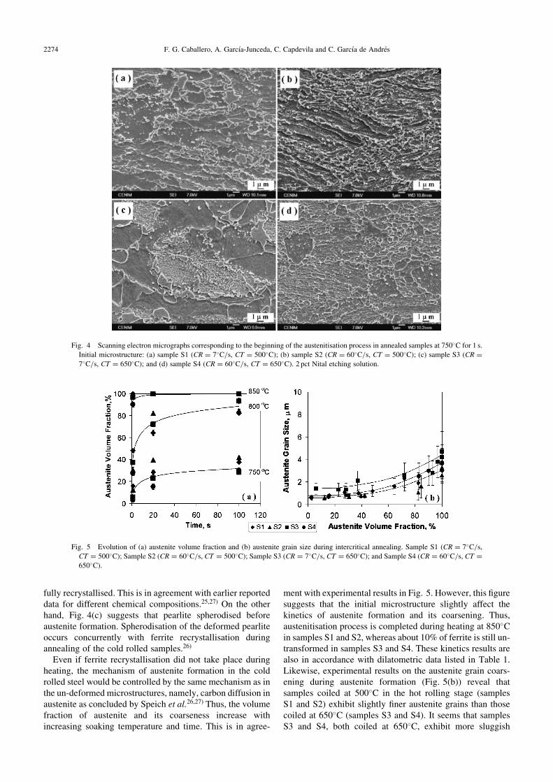
fully recrystallised. This is in agreement with earlier reporteddata for different chemical compositions.25,27) On the otherhand, Fig. 4(c) suggests that pearlite spherodised beforeaustenite formation. Spherodisation of the deformed pearliteoccurs concurrently with ferrite recrystallisation duringannealing of the cold rolled samples.26)
Even if ferrite recrystallisation did not take place duringheating, the mechanism of austenite formation in the coldrolled steel would be controlled by the same mechanism as inthe un-deformed microstructures, namely, carbon diffusion inaustenite as concluded by Speich et al.26,27) Thus, the volumefraction of austenite and its coarseness increase withincreasing soaking temperature and time. This is in agree-
ment with experimental results in Fig. 5. However, this figuresuggests that the initial microstructure slightly affect thekinetics of austenite formation and its coarsening. Thus,austenitisation process is completed during heating at 850�Cin samples S1 and S2, whereas about 10% of ferrite is still un-transformed in samples S3 and S4. These kinetics results arealso in accordance with dilatometric data listed in Table 1.Likewise, experimental results on the austenite grain coars-ening during austenite formation (Fig. 5(b)) reveal thatsamples coiled at 500�C in the hot rolling stage (samplesS1 and S2) exhibit slightly finer austenite grains than thosecoiled at 650�C (samples S3 and S4). It seems that samplesS3 and S4, both coiled at 650�C, exhibit more sluggish
Fig. 4 Scanning electron micrographs corresponding to the beginning of the austenitisation process in annealed samples at 750�C for 1 s.
Initial microstructure: (a) sample S1 (CR ¼ 7�C/s, CT ¼ 500�C); (b) sample S2 (CR ¼ 60�C/s, CT ¼ 500�C); (c) sample S3 (CR ¼7�C/s, CT ¼ 650�C); and (d) sample S4 (CR ¼ 60�C/s, CT ¼ 650�C). 2 pct Nital etching solution.
Fig. 5 Evolution of (a) austenite volume fraction and (b) austenite grain size during intercritical annealing. Sample S1 (CR ¼ 7�C/s,
CT ¼ 500�C); Sample S2 (CR ¼ 60�C/s, CT ¼ 500�C); Sample S3 (CR ¼ 7�C/s, CT ¼ 650�C); and Sample S4 (CR ¼ 60�C/s, CT ¼650�C).
2274 F. G. Caballero, A. Garcıa-Junceda, C. Capdevila and C. Garcıa de Andres

formation of austenite associated with a higher amount ofdispersed carbides in the cold rolled microstructure (SeeFigs. 4(c) and 4(d) of both samples. This is consistent withmanganese partitioning as observed by other investiga-tors.28,29)
It is clear from Fig. 3 that cold rolled bands do not vanishduring intercritical annealing, since austenite formation startsin the carbon-rich regions featuring pearlite. Thus, martensitebands will form during quenching in the regions previouslyoccupied by pearlite. However, it is not clear if martensitebands will reappear during intercritical annealing oncebanding was eliminated by fast cooling during hot rolling.Figure 6 shows the evolution of the anisotropy index, AI,and the mean edge-to-edge spacing of the bands, � , duringintercritical annealing. Both parameters characterise thedegree of martensite banding on longitudinal sections. Thosesamples with a non-banded microstructure present a AI valueof one. That is the case of samples annealed at 850�Cconsisted mainly of martensite whose AI values have notbeen included here.
Only samples S1 and S3, both slowly cooled duringrolling, present microstructural banding at 750�C, moresevere in sample S3 initially consisted of ferrite-pearlitebands. Martensite bands did not appear in samples S2 and S4,both rapidly cooled during rolling, at the same soakingtemperature. However, all the samples that originally did notpresent banding (samples S1, S2 and S4), exhibit a bandedmartensitic microstructure after an intercritical annealingat 800�C (See micrographs in Fig. 7). At this temperaturethe AI value increases as the transformation proceeds withtime, approaching an AI value close to that measured on theinitial hot rolled banded ferrite and pearlite microstructure
(about 2). This is not surprising since hot rolled pearlite bandsroughly resemble original manganese segregation. On theother hand, � values decrease as transformation proceeds(Fig. 6(c)) since bands of austenite get closer.
It seems that decreasing the coiling temperature during hotrolling is not an efficient practice to suppress microstructuralbanding, although an attenuation of the problem was detectedafter intercritical annealing at 750�C. By contrast, rapidcooling during hot rolling has proved to be successfulavoiding bands formation during intercritical annealing at thesame temperature.
In general, samples rapidly cooled during hot rolling stage(samples S2 and S4), consisting mainly of bainite andmartensite, exhibit the lowest degree of banding afterintercritical annealing. It is also remarkable that, annealedsamples at 750�C for 100 s present much less severe bandingproblem that those annealed at 800�C for 1 s, although thevolume fraction of austenite formed in both cases is quitesimilar (around 30%) as Fig. 7 illustrates. A more homoge-neous nucleation site distribution of smaller austenite grainsat the lowest soaking temperature, would explain the lessseverity of banding observed at 750�C for 100 s in compar-ison to 800�C for 1 s. Therefore, increasing the cooling rateduring hot rolling, and using low intercritical annealingtemperatures and longer soaking time is possible to perma-nently eliminate microstructural banding in cold rolled dualphase steels.
4. Conclusions
The study of the microstructural evolution during thewhole manufacturing process of a dual phase steel has
Fig. 6 Evolution of microstructural banding during intercrit-
ical annealing: Anisotropy index (a) at 750�C and (b) at
800�C of soaking temperature; and (c) mean edge-to-edge
spacing of the bands, � . Sample S1 (CR ¼ 7�C/s, CT ¼500�C); Sample S2 (CR ¼ 60�C/s, CT ¼ 500�C); Sample S3
(CR ¼ 7�C/s, CT ¼ 650�C); and Sample S4 (CR ¼ 60�C/s,
CT ¼ 650�C).
Microstructural Banding in Dual Phase Steels 2275
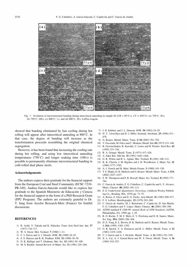
showed that banding eliminated by fast cooling during hotrolling will appear after intercritical annealing at 800�C. Inthat case, the degree of banding will increase as thetransformation proceeds resembling the original chemicalsegregation.
However, it has been found that increasing the cooling rateduring hot rolling, and using low intercritical annealingtemperatures (750�C) and longer soaking time (100 s) ispossible to permanently eliminate microstructural banding incold rolled dual phase steels.
Acknowledgements
The authors express their gratitude for the financial supportfrom the European Coal and Steel Community (ECSC-7210-PR-349). Andrea Garcıa-Junceda would like to express hergratitude to the Spanish Ministerio de Educacion y Cienciafor the financial support in the form of a PhD Research Grant(FPU Program). The authors are extremely grateful to Dr.T. Iung from Arcelor Research-Metz (France) for fruitfuldiscussions.
REFERENCES
1) K. Araki, Y. Takada and K. Nakaoka: Trans. Iron Steel Inst. Jpn. 17
(1977) 710–717.
2) W. S. Owen: Met. Technol. 7 (1980) 1–13.
3) C. I. Garcia and A. J. Deardo: JOM. 32 (1980) 24–25.
4) S. S. Hansen and R. R. Pradhan: JOM. 32 (1980) 30–30.
5) N. K. Balliger and T. Gladman: Met. Sci. 15 (1981) 95–108.
6) M. S. Rashid: Annual Review of Mater. Sci. 11 (1981) 245–266.
7) J. D. Embury and J. L. Duncan: JOM. 34 (1982) 24–29.
8) D. T. Llewellyn and D. J. Hillis: Ironmak. Steelmak. 23 (1996) 471–
478.
9) G. Krauss: Metall. Mater. Trans. B 34 (2003) 781–792.
10) V. Faccenda, M. Falco and C. Modena: Metall. Ital. 65 (1973) 133–140.
11) R. Grossterlinden, R. Kawalla, U. Lotter and H. Pircher: Steel Res. 63
(1992) 331–336.
12) R. A. Grange: Metall. Trans. 2 (1971) 417–426.
13) A. Sakir Bor: ISIJ Int. 31 (1991) 1445–1446.
14) G. R. Wilms and R. L. Aghan: Met. Technol. 8 (1981) 108–112.
15) K. K. Chawla, J. M. Rigsbee and J. B. Woodhouse: J. Mater. Sci. 21
(1986) 3777–3782.
16) A. J. Gouch and H. Muir: Metals Forum. 3 (1980) 143–150.
17) T. F. Majka, D. K. Matlock and G. Krauss: Metall. Mater. Trans. A 33A
(2002) 1627–1637.
18) S. W. Thompson and P. R. Howell: Mater. Sci. Technol. 8 (1992) 777–
784.
19) C. Garcıa de Andres, F. G. Caballero, C. Capdevila and L. F. Alvarez:
Mater. Charact. 48 (2002) 101–111.
20) E. E. Underwood: Quantitative Stereology, (Addison-Wesley Publish-
ing Co., Reading, MA, 1970) pp. 73–75.
21) A. Roosz, Z. Gacsi and E. G. Fuchs: Acta Metall. 31 (1983) 509–517.
22) F. S. LePera: Metallography. 12 (1979) 263–268.
23) C. Garcıa de Andres, M. J. Bartolome, C. Capdevila, D. San Martın,
F. G. Caballero and V. Lopez: Mater. Charact. 46 (2001) 389–398.
24) ASTM standard E 1268-99: Annual Book of ATM Standard, (ASTM,
Philadelphia, PA, 1999) pp. 1–29.
25) R. O. Rocha, T. M. F. Melo, E. V. Pereloma and D. B. Santos: Mater.
Sci. Eng. 39A (2005) 296–304.
26) D. Z. Yang, E. L. Brown, D. K. Matlock and G. Krauss: Metall. Trans.
A 16A (1985) 1385–1392.
27) G. R. Speich, V. A. Demarest and R. L. Miller: Metall. Trans. A 12
(1981) 1419–1428.
28) C. I. Garcia and A. J. DeArdo: Metall. Trans. A 12 (1981) 521–530.
29) X. L. Cai, A. J. Garratt-Reed and W. S. Owen: Metall. Trans. A 16
(1985) 543–557.
Fig. 7 Evolution of microstructural banding during intercritical annealing in sample S4 (CR ¼ 60�C/s, CT ¼ 650�C): (a) 750�C, 20 s;
(b) 750�C, 100 s; (c) 800�C, 1 s; and (d) 800�C, 20 s. LePera reagent.
2276 F. G. Caballero, A. Garcıa-Junceda, C. Capdevila and C. Garcıa de Andres