Weldability and Damage Evaluations of Fresh-to-Aged ... - MDPI
Upload
khangminh22Category
view
0download
0
Weldability offerritic steels
NORMAN BAILEYBMet. Cl.ng. FlM. FWefdl
ABINGTON PUBLISHINGWoodhead Publishing Ltd in association with The Welding Institute
Cambridge England
Published by Abington Publishing, Abington Hall. Abington. CambridgeCBI 6AH. England
First published 1994. Abington Publishing
o Woodhead Puhlishing Ltd
Conditions of saleAll rights reserved. No part of this publication may he reproduced or transmittedin any form or hy any means. electronic or mechanical. including photocopy.recording. or any information storage and retrieval system. without permission inwriting from the publisher.
The views expressed in this hook 00 not necessarily represent those of TWI.
British Library Cataloguing in Publication DataA catalogue record for this hook is available from the British Library.
ISBN I ~5573 09~ ~
Designed hy Geoff Green (text) and Chris Feely (jacket).Typeset by BookEns Ltd. Baldock. Herts.Printed hy Galliard (Printers) Ltd. CIt Yarmouth. England.
Introduction
The topic of weldability is fascinating, ranging as it does from the simpleability to tack two pieces of metal together without having them comeapart. to meeting the very sophisticated needs of modern specificationsfor offshore platforms, high temperature components and pressure vesselsfor nuclear, petrochemical and other applications. An earlier booklet onthe topic' was produced by Ken Richards at the British WeldingResearch Association (BWRA) - the precursor of The Welding Institute(TWI) - over 25 years ago. Although TWI has produced severalspecialised booklets>" in the interim, as well as many papers on mostaspects of weldabiliry, no general book has been produced from thatsource, although the Institute has been a leading organisation in studyingthe topic in its broadest sense for many years and books on variousaspects of weldability have appeared over the years from other sources."!"
The present book is intended to complement the revised version of thehydrogen cracking hook,' to update and expand the texts on lamellartearing- and solidification cracking,' and to include the other topics relevantto the weldability offerritic steels. It is heyond the author's competence totackle the prohlems of the weldahility of stainless steels, cast irons' andnon-ferrous metals, nor do the numerous, and often confusing, methodsof testing for weldabilitys fall within the book's scope. The book. being tosome extent a reflection of the author's interests while at TWL is mainlyconcerned with the conventional fusion welding processes and theirproblems.
As indicated in the opening paragraph, the definition of weldabilitycan he elastic and, in effect. depends on the application. Weldability isthe ahility to weld a metal without introducing cracks or other harmfuldefects and, at the same time. to achieve the properties required hy theapplication. In fact. a onetime colleague has claimed that people are notinterested in weldahility - only in unweldahility!
In considering the weldability of a steel. several types of cracking need
V1l1
Introduction IX
to be avoided, several welding processes may be involved, variousweldment properties need to be achieved and the restraint and thicknessof the metals under consideration may vary considerably. Hence, it isimpossible to use a simple number to characterise weldability. As a furthercomplication, the composition of metals supplied to a single specificationmay vary considerably and at least one type of cracking is influenced mainlyby the processing route of the steel.
Although the major problem in welding ferritic steels (and many othermetals) is to avoid cracking of one type or another, other types of faults(often described as 'welder-induced' or 'process-induced' as opposed to 'metallurgical') and how they interact with precautions taken to avoid crackingare briefly described. Such faults should only be referred to as defects if theyare sufficient to make the weld unacceptable to the standard used for theinspection. Lesser faults may be referred to as 'imperfections" althoughthe term 'discontinuities' is also used.
Unfortunately there is only one term for a crack - and by nearly allinspection standards, a crack is not acceptable, even though, over a quarterof a century ago, techniques of fracture mechanics were developed whichallow cracks to be accepted if they have been analysed and shown to beharmless for the intended service conditions. Sometimes the terms'rnicrocrack' and 'tear' have been used to try to overcome this barrier, butthey are not widely accepted and, in fact. 'tearing' should be strictlyrestricted to ductile fracture by microvoid coalescence, either in service orby such processes as lamellar tearing (Chapter 4).
One aim of this book is to try to unravel the confusion over the differentnames and types of cracking that are possible when welding steels, andreduce them to a fewdistinct types, thus making rectification and avoidanceof future cracking easier.
The book will be of interest to students studying welding engineeringand welding metallurgy, as well as to practical welding engineers, inspectorsand metallurgists. In addition to those people concerned with actual fabrication and manufacture, it will also be of importance to those concerned with design and specification. It is always more satisfactory andeconomical to foresee any problems and deal with them at the designstage, rather than to go through the trauma of detecting and rectifyingfaults, coping with the resultant delays and disputing the rights andwrongs of the resultant problems. I can recall arguments in the past overwhether cracks discovered after post-weld heat treatment were hydrogencracks (and thus the fault of the fabricator) or reheat cracks and therefore- with the steel in question - an 'Act of God' (because reheat cracking waspreviously unknown with that steel).

x Introduction
References
1 Richards. K.G.. Weldability of Steel. BWRA Cambridge. 1967.2 Farrar. J.CM. and Dolby. R.E.. Lamellar Tearing in Welded Steel Fabrication.
TWI. Cambridge. 1972.3 Bailey. N.. Coe. F.R.. Gooch, T.G .. Hart. P.H.M., Jenkins. N. and Pargeter. RJ.,
Welding Steels Without Hydrogen Cracking. Abington Publishing, Cambridge,1993.
4 Bailey. N. and Jones, S.B.. Solidification Cracking of Ferritic Steels duringSubmerged-arc Welding. TWI. Cambridge. 1977.
5 Cottrell. CL.M.. Welding Cast Irons. TWI. Cambridge. 1985.6 Pargeter. RJ. (ed.), Quantifying Weldability. Abington PUblishing. Cambridge.
1988.7 Graville. B.A., The Principles of Cold Cracking Control in Welding. Dominion
Bridge. Montreal. 1975.8 Easterling, K.. Introduction to the Physical Metallurgy of Welding. Butterworth.
London. 1983.9 I1W. 'Guide to the welding and weldability ofC-Mn and C-Mn microalloyed
steels'. IIW-382-7 I. International Institute of Welding. 1971.10 IIW. 'Guide to the welding and weldability of quenched and tempered C-Mn
and C-Mn microalloyed steels'. IIW DOC IX-1036-77. International Instituteof Welding. 1977.
II I1W. 'Guide to the welding and weldability of pearlite-reduced and pearlitefree steels'. llW DOC IX-1305-83. International Institute of Welding, 1983.
12 IIW, 'Guide to the welding and weldability of cryogenic steels', I1W1115-844-87TWI for llW. 1987.
13 Lancaster. IF.. Metallurgyof Welding. 4th edn, George Allen and Unwin. London.1987.
14 Lancaster. J.F., Welding Structural and Corrosion Resistant Steels. Abington Publishing. Cambridge, 1992.
15 Stout. R.D .. Weldability of Steels. WRC 1987.16 Granjon. H.. Fundamentals of Welding Metallurgy. Abington Publishing. Cam
bridge. 1991.

Acknowledgements
Although middle aged at the time. I came to the old BWRA as a 'new boy'in 1966. and owe a great debt to Bob Baker. Frank Watkinson and BrianGraville, who gave me such a good grounding and set me in pursuit of theelusive goal of weldability. Subsequently other colleagues at TWI, particularly Peter Hart. Richard Dolby. Trevor Gooch. Louise Davis. FrankCoe, Norman Jenkins, Graham Carter. Phil Threadgill. Richard Pargeterand David Abson, have tried to keep me on the straight and narrow. butmy biggest debt goes to the technicians who actually carried out the weldingand assessment of many experiments. I would particularly like to compliment Peter Kerr and others responsible for the high quality of themicrographs. Thanks are also due to those in industry whose problemshave contributed to my understanding of the practical aspects ofweldability. It is one thing to study various cracking problems in the laboratory. but it is far harder to restore a cracked component to workingorder with the minimum cost and delay to a multi-million pound project.Finally I must thank the Awards Committee of the American WeldingSociety. who boosted my confidence by awarding me their Lincoln GoldMedal in 1973 for reference 16 in Chapter 1.Thanks are due to TWI forpermission to use the illustrations in the book.
Xl

1 Factors influencing weldability
The welding process
Achieving the required soundness and properties in a fusion weld requires the weld metal to be sound and to have a composition. properties and a microstructure that are adequate for the purpose. The heat-affected zone (HAZ) should also be uncracked and have the required properties: this requirement applies to both the visible H A Z and the region beyond it - the sub-critical HAZ. which can suffer loss of hardness and strength in a very strong quenched and tempered steel. A non-fusion weld obviously cannot contain defects associated with fusion (such as solidification cracks and entrapped slag). but defects may still occur. associated with included oxides at the bond line. incomplete bonding and pores in diffusion bonds. whilst care may be needed to achieve adc- quate properties in the bond area.
In both fusion and non-fusion welds the need to provide adequate heat for fusion must be balanced against the detrimental effects of heating. Heating a parent steel will inevitably coarsen its prior austenite grain size if the temperature much exceeds about 1100 "C. as is inevitable in the parts of the H A Z of any fusion weld near the fusion boundary. Suffi- ciently rapid cooling from maximum temperature will give a martensitic microstructure. which is likely to be very hard. with poor toughness and at risk of cracking if the steel has a medium to high carbon content. i.e. above about 0.17%. On the other hand. a very slow cooling rate can give a coarse transformed microstructure largely of bainite which. although softer than martensite. is often less tough.
The cooling rate. which is governed by a number of factors including weld bead size. also governs the weld metal properties of fusion welds. Martensitic and bainitic microstructures occur less often in weld metals than in HAZs: nevertheless a coarse microstructure. resulting from slow cooling. is less tough than a fine one of similar strength and hardness.
1

I 7 Weldability of ferritic steels
Effect of process on weldability Texts on welding engineering should be consulted for details of the different welding processes. This section gives a brief idea of the effect of changing welding processes on likely metallurgical problems. The processes are listed roughly in the order of steel thickness which can be welded with one pa
Liquation cracking. lamellar tearing and reheat cracking are little affected by the welding process. except that the consumable should always be chosen to minimise weld strength above that required to match the parent metal yield strength by a small margin. The toughnesses of the HAZ and (to some degree) the weld metal are more affected by heat input than welding process. although some processes can give higher heat i n p u t s t h a n o t h e rs .
Manual metal arc (MMA) welding gives a relatively high risk of hydrogen cracking. unless basic electrodes are used correctly. i.e. properly stored. dried and issued. Risks of solidification cracking are low. and MMA welding with basic electrodes is a good way of coping with the sulphur in free-cutting steels. Toughness can be good. provided suitable electrodes and heat inputs are used.
Tungsten inert gas (TIC), laser and plasma welding all give very low risks of hydrogen cracking and. provided welding speeds are not too high. of solidification cracking. Plasma and TIC welding with filler are capable of giving high toughness. provided multipass welding is used to maximise grain refinement. For autogenous TIC and laser. weld metal toughness depends on the steel being welded. particularly for single pass welding.
COz welding gives a low risk of hydrogen cracking: solidification cracking behaviour depends on welding speed: toughness is moderate. as the weld metal is of too high an oxygen content to give the best upper shelf toughness.
Metal active gas (MAG) welding (solid or cored wires) is similar to C 0 2 welding. except that better weld metal toughness is possible with shielding gases of low oxygen and low CO, contents: cored wires can vary consider ably in their hydrogen potential. giving hydrogen cracking risks ranging from low to moderate.
Self-shielded welding gives moderate resistance to both hydrogen cracking and toughness. provided a multirun technique to maximise weld metal refinement is used when reasonable toughness is required.
Submerged arc welding gives a moderate to slight risk of hydrogen cracking. including the weld metal type. depending particularly on the flux and its condition. Fast welding speeds give a risk of solidification cracking. and poor toughness is possible at high heat inputs and with less basic fluxes.
Electron beam welding gives a very low risk of hydrogen cracking. but some risk of solidification cracking. Toughness depends entirely on the steel being welded. as the process is autogenous and single pass.

Factors influencing weldability 3
Electrogas, electroslag and consumable guide welding give low risks of hydrogen cracking (although fine weld metal cracking is possible). Solid- ification cracking limits possible welding speeds. Toughness is usually poor in the HAZ. owing to very slow cooling. so that normalising may be required to achieve acceptable values.
Steel types
In describing the weldability of steels. i t is essential to have some under- standing of the types of steel which may have to be welded. Apart from different standards - international. European. national. industry-wide. military and private - steels are often referred to by their type. Steels can be classified by their compositional type ( e g C:Mn, Cr:Mo), by their end use (tool steel. rail steel), by their characteristics (high temperature, stain- less). by their method of manufacture (semi-killed. calcium-treated), by a descriptive or trade name (maraging, Corten). by their microstructural type (bainitic. martensitic) or by a combination of these (austenitic stainless. rare-earth-treated C:Mn).
High alloy and austenitic stainless steels. together with the cast' and wrought irons. are outside the scope of this book.
Although some guidance is given below. the welding engineer must often seek advice from organisations such as libraries. trade associations or TWI if encountering an unfamiliar designation. particularly if i t is part of a once well-known. but now obsolete. specification. A typical example of this is the persistence of the old (pre-1970) designations for British engineering steels. e.g. En24. which were part of the old British Standard BS970: 1955 and which were many years ago superseded by a six-digit designation. e.g. 817M40. in the revised version of the same standard: a further complication is that now some of the British BS Standards have been replaced by European EN Standards: En24 becomes 34 CrNiMo 6 i n EN 10083-1: 1990. Another common failing is not to be given the strength level of the steel: this is essential in order to be able to select a welding consumable to give the appropriate strength. For example. the 817M40 steel was available in eight strength levels. whose minimum yield strengths varied by a factor of nearly two. from 650 to 1235 N/mmz. Matching the lower yield strength levels is not difficult: few fillers. if any. will be found to meet the upper strength levels in the as-welded condition.
Compositional types Carbon steels are alloyed with anything up to about 1% C. and most con- tain about 0.6% Mn. unless they are of the free-cutting type. when up to about 0.25% S and 1.2% Mn may be present. When carbon steels have carbon levels below about 0.2%. they are referred to as mild steels. The carbon steels are by far the more common (and cheap) type. mild steel

4 Weldability 01 lcrritic steels
being the commonest anci the easiest to weld. Weldability of carbon and other steel types becomes more difficult as the carbon content is i n c re it s e d .
Alloy s tee1 s co t i t ai t i additions w h ic h u SLI a I 1 y i m p rove h a rden a bi I i ty and. hence. strength in heavier sections. In addition. alloying confers other advantages in resisting service environments. such a s corrosion. oxicintion. high pressure hydrogen and high temperature creep. Alloy steels are divitied into several types.
Carbon : manganese (C:Mn) steels. contain 1-2'36 Mn and are so wide- spread ( M n provides the cheapest method of improving hardenability after carbon) that they may be regarded as forming a major steel type. Micro-alloyed steels are usually of the C:Mn type with small additions (generally <0.2'%) of elements such a s Nb. V. Ti or B. usually to confer the advantages of alloying without seriously impairing weldahility: many are a sub-category of the C:Mn type.
Low alloy steels contain a few per cent (typically between 1 and 7%) of elements such as Cr. Ni. Mo and V. with carbon contents within the same range as C steels. This category includes several sub-types. such as C:Mn (which may be micro-alloyed) and which forms the major category of high strength constructional steels. used. i n t c ~ cilia. for bridges and offshore structures. Other types are chromium steels. which are used for resisting high temperature oxidation. creep and hydrogen and contain up to 596 C r with usually 0.5 or 1%) Mo. Chromium steels continue into the high alloy category and the stainless steels with the 9%) C r and higher C r steels. Steels of the Ni:Cr:Mo type are typical engineering steels. with between about 1 and 7% of these elements in total. With low carbon contents these provide the highest strength. commonly used weldable steels. The nickel steels are used at low temperatures: the low alloy types contain 3.5 and 5% Ni whilst 9% Ni steel is in the high alloy classification.
High alloy steels contain larger amounts of alloying elements, and merge into the stainless steels. which are outside the scope of this text. Apart from those previously mentioned. high alloy steels usually contain C r and M o with additions of such elements a s V and W. and are used for resisting abrasion and for making tools. They usually have relatively high carbon contents and poor weldability. Some specialised. very high strength. low carbon weldable steels. such as the maraging and 9Ni:4Co steels. fall into the high alloy steel category.
Method of manufacture The steelmaking method is not particularly useful in judging weldability. hut ifan electric steelmaking method is not used (e.g. open hearth). i t suggests that the steel was made by an older technique and may be of uncertain quality. particularly with regard to non-metallic inclusions (Chapter 4).

Factors influencing weldability 5
Steels made using the older techniques may be of the rimming. semi- killed (or balanced). Si-killed or Al-treated types. In the order given. the steels are of decreasing oxygen content. within the approximate range 0.2-0.001 % 0.
Modern steels are usually electrically melted and continuously cast (concast) and for this process need aluminium to be added. Further addi- tions at the molten steel stage include Ca treatment and treatment with rare earth metals (RE-treated). These treatments are generally known as inclusion shape control and are used for steel intended to be rolled to plate. which requires an inclusion population not likely to give rise to lamellar tearing (Chapter 4) when the plate is welded or ‘hydrogen-induced crack- ing‘ (HIC) when used in water containing hydrogen sulphide (Chapters 9 and 10). Electric melting can be sub-divided into various types. ranging from the normal arc melting to VIM-VAR (vacuum induction melting- vacuum arc remelting) and electroslag melting. both of which are intended to give very low inclusion levels.
Cast steel may be subsequently processed by hot rolling to plate or sections. it may be forged. extruded or used as castings. Subsequent processing includes cold rolling to sheet or strip. rod as well as wire drawing. and deep drawing of sheet to forms. Hot rolling may be carried with o r without strict temperature control (controlled rolling and TMCP (thermomechani- cally controlled processing) fall into this category). The T M C P steel relies on a strict rolling schedule for its mechanical properties and does not require further heat treatment such as is given to most other types of steel.
Descriptive steel types Weldable steels have low carbon contents. i.e. less than about 0.2% C. gen- erally decreasing as the amount of alloying elements is increased. They range from mild steels to very high strength high alloy steels.
Structural or constructional steels are mild steel types: within this category the term ‘high strength’ denotes the use of C:Mn steels (including microalloyed and weather-resistant steels). rather than any form of alloy steel. Such steels are used for general construction of buildings. bridges. ships. harbour works. etc.
Weather-resistant steels. sometimes known by the trade name Corten. are a version of structural steel containing small additions of elements such as Cr. Cu and P to improve corrosion resistance in normal atmos- pheric conditions (i.e. not so severe as marine atmospheres containing salt spray). Weldability is similar to the C:Mn steels.
Engineering steels. frequently in bar form. may be of any type from mild steel (e.g. bright mild steel) to high alloy types with high carbon con- tents and poor weldability. They are mostly covered in the UK by the steels in BS970 (including the old ‘En steels’) and its successor EN 10083-1

6 Weldability 0 1 lcrritic stccls
and -2: 1991 and in the USA by the AISI/SAE steels. They may be also of the free-cutting type. Engineering steels are usually quenched and tem- pered ( Q T or Q&T: the terms oil hardening and air hardening refer to the quenching medium required to achieve the required hardness) so that care is needed in selecting post-weld heat treatment (PWHT) temperatures to avoid over-tempering and softening the parent steel. I n some cases preheat temperatures and heat inputs may need to be controlled to avoid softened HAZs.
Free-cutting(or free-machining) steels contain up to about 0.25% S with about 1.2'k Mn. possibly with additional elements such as Pb or Se. and range from mild steels t o the low and high alloy engineering steels. Such steels require special precautions during welding to minimise the risks of solidilication and liquation cracking (ace Chapter 3 ) . For this reason i t is important t o check whether a steel is of the free-machining type. particularly when re pa i ri iig erigi neeri iig and si in i 1 a r coin ponen t s.
High strength steels in any o f the above categories may range from structural C:Mn steels of 350 N/mm' yield strength to maraging steels with a yield or proof strength approaching 2000 N/mm'. The Q&T weldable high strength steels are an important category. because of their relatively good wclciability in relation to their strength. Such steels include the so-called HY steels ( the number following 'HY' denotes the minimum yield strength in h i * ) . and a range of trade names. including the British RQT steels. the American TI series. the OX series. the AX steels and m a n y others. Frequently. precautions are required to minimise loss of HAZ and weld metal properties by restricting preheat and interpass temperaturcs and heat inputs and guidance should be sought from the steelmaker for recommended welding parameters.
An important sub-category of the high strength steels is the high strength. low alloy (HSLA) types. which typically have minimum yield strengths of550 or 690 N/mm?. I n fact. high strength low curhot? would be ii better description of the type. a s several of these steels contain less than 0.05% C : i.e. often at a lower level than those of the weld metals needed to achieve matching strength. Such steels are verq weldable a s regards HAZ properties - the danger is that the wckit?wtrrls will suffer hydrogen cracking i f this risk is not taken into account when devising welding procedures.
Heat and creep-resisting steels are of the Cr:Mo type. generally with low carbon contents (<0.20% C). although some authorities restrict the term to high alloy steels with 9%) or more Cr. Chromium additions confer good resistance to high temperature oxidation and creep: these steels also have a good resistance to hydrogen attack at high temperatures and pressures. The 0.5 Cr:0.5 Mo:0.25 V steel. the 0.5% Mo and several other steels also

Factors influencing weldability 7
fall into this category. These steels require care when being welded, because of their high hardenability.
Tool steels are usually of high carbon. low to high alloy content and are quenched and tempered. Weldability is likely to be poor in terms of likeli- hood of cracking during welding: precautions may also be needed to avoid general o r local softening.
Rail steels are of two types. For normal use a carbon steel containing about 0.6% C is used. although a version of this containing about 1% C r is also available. as well as a low carbon bainitic steel. For very heavy wear resistance. a 12% Mn austenitic steel (Hadfield's Mn steel) is used. The two types have such different weldabilities that joining them by normal fusion welding techniques is virtually impossible.
Armour steels are of the low to medium alloy type. generally with about 0.3% C. For thin-sectioned armour. low alloy-microalloy types have been developed. Weldability is usually not good. and control of welding proce- dures may be needed to minimise softening of HAZs.
Deep drawing steels are sheet steels. usually of very low carbon content and not alloyed. Weldability is good. although the H A Z may be softened if the strength of the steel has been enhanced by heavy cold working. par- ticularly at bends of sharp radius.
Surface hardening steels are steels. usually of the low alloy type. with a fairly wide possible range of carbon contents. which are suitable for surface hardening by different techniques. Steels which are surface hardened by induction or laser hardening are not of any specific type: the surface hardness will depend on the carbon content of the steel. For carburising or nitriding. special compositions are normally used. most of which have fairly low carbon contents and are reasonably weldable. although consid- eration has to be given to the influence of the hardened layer. In fusion welding. this has R negligible effect on the composition and properties of the weld metal. but it will lead to a H A Z which is harder at the surface than expected.
Microstructural types of steel have a name indicative of their microstructure. which does not normally give much indication of their likely weldability. Such steels may be of the bainitic. martensitic or acicular fer- rite types. One special version is the maraging steel category of very low carbon. high alloy type. These steels are of very high strength. relatively good weldability and derive their strength from an age hardening treat- ment within a martensitic microstructure produced by air hardening.
Heat treatment The major heat treatments applied to ferritic steels are as follows. Homogenising is normally carried out above about IO(M) "C to homogenise the as-cast microstructure. which is not uniform because of the segregation

x Weldability of ferritic steels
which took place during solidification. I t gives a coarse prior austenite grain size. leading to poor toughness and is. therefore. followed by one of the high temperature austenitising treatments given below.
Normalising involves heating the steel within the austenite range between about 800 and 1000 "C and cooling in still air. The austenitising temperature should be controlled to give ;I line grain size and reasonable toughness. Some rolling mills incorporate a schedule which allows the steel to be described as normalised rolled: unless the steel composition contains an adequate Ti content. normalised rolled steels may be suscep- tible to strain ageing.
Annealing is similar to normalising. except that cooling is in the furnace. so that the steel is a s soft as possible.
Quenching and tempering is similar to normalising. except that the cooling is speeded up t o ensure that the steel is hardened through the full section thickness. Quenching may be into water (cold or hot liquid or spray) or oil: however. air cooling may be adequate for steels described a s air-harden- ing. The steel is then tempered (softened) by reheating within the temper- ature range 100-750 "C: the upper part of the range may be the same a s for the post-weld heat treatment (PWHT) of welds. When the quenching is carried out directly at the rolling mill, a more efficient quench is possible and the steel is referred to as roller quenched: such steels should not be reheated within the austenitising range (e.g. for hot forming). as their properties cannot be recovered.
Steel types and welding problems Lamellar tearing is possible with all types o f steel plate (except those made with inclusion shape control). depending on inclusion content and joint type. For the same inclusion content. risks are greater for steels o f higher strength. The actual risk of welding problems generally depends very much on the actual composition. a s most specifications are so wide that a wide range ofweldability behaviour is sometimes possible for com- positions provided to the s a me spec i fi ca t i o n .
Mild steels give few problems: hydrogen cracking is unlikely with thicknesses below about 50 mm. unless restraint is very high: solidification cracking is possible at high welding speeds or with high dilution.
Carbon:manganese steels are more prone to hydrogen cracking. but are otherwise similar to mild steels.
Microalloyed weldable steels exhibit a resistance to hydrogen cracking depending on carbon content: heat input may need to be restricted to in ii i n ta i t i tough n ess: so m e compositions con t a i n i t i g ho r o n and ni o I yh- denum may be prone to reheat cracking.
Quenched and tempered weldable steels are similar to the previous group but with a greater risk ofcracking due to their higher strength: with

Factors influencing weldabili ty 9
low carbon contents hydrogen cracking in the weld metal may be a problem. Low alloy weldable (pressure vessel) steels will need preheating to avoid
hydrogen cracking. and may be prone to reheat cracking if they contain vanadium with molybdenum.
Engineering steels (medium to high carbon. with or without alloying elements) have a high risk of hydrogen cracking.: liquation cracking is likely. as is solidification cracking with automatic welding at relatively high speeds.
Tool steels have an extremely high risk of hydrogen cracking. which needs an understanding of the steel's metallurgy to overcome.
Free-cutting steels will contain liquation cracks and pose a high risk of solidification cracking unless low dilution welding procedures are used.
Weld cooling cycle
Heat input The microstructures of the weld and the HAZ. as for any steel. are con- trolled by their compositions and heat treatment. In an as-deposited weld. the heat treatment is that given to each weld run by the heating and cooling applied when that run was deposited and modified by heating from any subsequent weld runs. The effects of this heat treatment may be subsequently modified by any PWHT given to the weld. as is discussed later in this chapter.
The main influences on the cooling of the weld are the heating produced by the welding process. the thickness of the steel being welded and the temperature of the steel as each weld run is deposited: ambient conditions usually have only a minor influence.
The heating produced by welding is normally described in terms of the heat input per unit length of weld run. usually in units of kJ/mm if the welding speed is measured in mm/min. However. kJ/cm or kJ/in are also in use if welding speeds are in cm/min or in/min. Heat input is derived from arc energy. which is calculated (in the same units as heat input) from the welding current, arc voltage and welding (travel) speed as follows:
arc volts X welding current x 60
loo0 X welding speed (mm/min) arc energy = 11.11
The value '60' is required because welding speed is conventionally meas- ured in mm/min. whereas the welding power. amps X volts. is in watts/ sec. The value of 1000 is to convert joules to kilojoules. Should multiarc welding be used to give a single weld pool. the individual arc energies for each arc are totalled. Where alternating current (ax.) welding is used. the values should preferably be the root mean square values.
Because of inevitable heat losses. mainly due to radiation. in transferring

10 Weldability of ferritic steels
Krhlc 1.1
Proccs\ Relative arc efficicncq
M M A MAC;
I .o 1 .o
Corctl Mirc I .o TIC; 0 . X
S ti h m ergctl ii rc 1.25
the heat to the steel being welded. the value given by Eq 11.11 is factored by the arc efficiency to obtain the heat input to the steel being welded. However. in practice. measurements of arc efficiency are rarely made and the term 'arc energy' is not commonly used. Currently. the term 'heat input' is being used in current European standards concerned with weld- ing and national standards in Europe will presumably follow. although i t is not always clear whether arc energy or heat input is intended. When using controlled heat inputs. care should always be taken to deduce from the standard or specification being used whether the value given is unfactored. i.e. arc energy. or factored. i.e. heat input.
The arc efficiency o f the different welding processes in transferring heat to the steel being welded varies: thc values i n Table 1 . 1 . taken from the current British Standarci.' give an approximate idea o f arc efficiencies of other processes in comparison with MMA welding.
Steel thickness For the HAZ. welding is a heat treatment process. but the effect o f steel thickness on the cooling of the steel is the direct opposite of its effect during conventional heat treatment. where an increase in section thickness reduces the cooling rate. When welding. the cooling of the stcel is not externally imposed. but results from cooling by conduction from nearby steel which has not been heated by welding. Hence. the rate of cooling of ;I weld made at a constant heat input is i t i c w t r . v c d when the thickness being welded is increased. For single- and two-pass welds. the heat input needed to complete the joint is roughly proportional to the thickness being welded. so that the cooling of such welds is roughly independent of thickness.
Although the cooling rate can be calculated from a knowledge of the relevant welding parameters. the calculation is complicated by the onset

Factors i 11 tl 11 e nci ng we I dab i I it y 11
of three-dimensional cooling. which usually operates at thicknesses greater than a value between 20 and 50 mm. The actiial value depends on ii number of factors: the thicknesses given above apply to cooling through 300 "C. at which temperature transformation from austenite is usually complete. At very small thicknesses the cooling is controlled by steel in the same plane a s the weld. i.e. in the .Y and j' directions. In very thick steel. cooling occurs equally from above (and below) the plane of the weld run (the 2 direction). Hence. for constant heat input and preheat. the cooling rate at a given temperature increases as steel thickness is increased lip to a maxi mum value. a bove which three-dimensional cooling operates and no further change occurs.
Only the weld cooling rate has been mentioned so far. a s i t was used for many years in the early days of welding. Current practice is to use the cooling time between two given temperatures. as i t is R value which can be
4 4
Combined thickness = 30 + 30 + 20 = 80 m m Heat flow paths arrowed
Combined thickness = t l+ t z+ t3
t3=O
tl = average thickness over a length of 75 mm
k-- t2 75 m m
tl
t2
For directly opposed
combined twin fillet welds
= %( tl + t* + t 3 )
tl t2 ( = tl 1 (b)
1.1 (b) treatment of different joint configurations.
Heat f low paths and combined thickness: ( a ) typical example:

12 Weldability of ferritic steels
directly measured. The most common temperatures are from 800 to 500 "C. which is the temperature range within which most C and C:Mn steel HAZs transform on cooling from austenite. This cooling time, Tx(w)-(K) or T8,i . is most commonly used when the transformation of the steel. par- ticularly in the weld HAZ. is under consideration. For lower temperature cooling. i.e.. when diffusion of hydrogen out of the welded area is the important factor. Till is sometimes used.
The cooling of a welded joint depends on the number of heat flow paths available. A fillet weld may give two or three paths. depending on its configuration. whereas a simple butt weld has two paths (Fig. 1 .1 ) . When the pieces being joined are of different or varying thickness. the thicknesses of those parts which provide the heat flow paths at the joint are added together to obtain the 'combined thickness' value. as illustrated in Fig. 1 . 1 . Varying thicknesses are conventionally averaged over a dis- tance of 7 5 mm from the weld line. This convention can also be used if one of the pieces is shorter than 7 5 mm. For example. if a flange 15 mm thick and 50 mm wide is being joined along its length to a web (Fig. 1.2). its contribution to the combined thickness is 2 X (50 /75 X 15) = 20 mm.
1.3 Combined thickness for flange o f limited width.

Factors i n flue iic i ng we1 dab il i t y 13
Preheat and interpass temperature The temperature of steel immediately a weld run is started is the third major factor affecting weld cooling: for the first run this is the preheat temperature. for subsequent runs the interpass temperature. To avoid hydrogen cracking (Chapter 5) . steels are often preheated to temperatures up to 250 "C before welding. To control weldment properties (Chapter 9). maximum interpass temperatures (usually up to 300 "C) may also be specified. These temperatures should be measured close (-50 mm) to the weld line immediately before a weld run is deposited. I f the preheating is applied from one side only. e.g. by a gas flame. temperatures should pre- ferably lie measured on the side that is not heated. I f this is not possible. the flame should be removed shortly before the temperature is measured: R waiting time of 1 m i d 2 5 mm of individual steel thickness is recommended.?
Preheat and interpass temperatures within the ranges given above have less effect on the cooling rates at high temperatures than at low. Conse- quently. preheating a simple C or C:Mn steel. which transforms at a rela- tively high temperature. will not have much effect on the cooling rate through the transformation range. and hence on the resultant microstructure
However. i t will considerably slow up the cooling at lower temperatures when hydrogen diffusion from the steel will be a major con- sideration in avoiding hydrogen cracking.
O n the other hand. low alloy steels. transforming at lower temperatures. can undergo significant changes to their HAZ microstructures and properties (not always favourably) by preheating to a higher temperature. Adverse effects on HAZ microstructure and properties may require maxi- mum controls on preheat and interpass temperatures: the latter may lead to slower joint completion rates than are economically desirable and can give problems. for example when automatically welding circumferential seams in small diameter. thick-walled pipes.
External influences Although the cooling of a joint by cold metal in the vicinity of a joint. but beyond the arbitrary limit of 7 5 mm given in the previous section. will not affect HAZ and weld metal transformation behaviour and properties. i t may well hasten cooling at low temperatures. at which hydrogen diffusion is important. Although there is. as yet. no formalised way of taking this into account. care is needed in such situations. This effect may be enhanced where water is lying on the steel (or the steel is immersed in water) a few centimetres away from the weld line. even though the site of the weld itself has been adequately dried off.
For completeness. two further cases should be borne in mind. One is when welding on to pipelines containing liquids or gas under pressure (a

14 Weldability of ferritic steels
practice known as hot tapping. Chapter 1 I ) . Obviously. special precautions are needed to avoid the risk of burning through. and guidance is available in this area.
The other example is in the specialised area of underwater welding (Chapter 1 I ) . Welding in water (wet welding) gives extremely fast cooling. and special precautions are needed to avoid cracking. Underwater welding in a dry atmosphere (hyperbaric welding) a!so gives an increase in weld cooling because of increased thermal conductivity of the (compressed) hyperbaric atmosphere. The resultant increase in cooling rate is much less than with wet welding. but should be taken into account. particularly when welding thin-sectioned steel.
The heat-affected zone
Description The HAZ is the crucial area in welding because. once the steel has been selected. the HAZ and its properties have to be accepted. whereas a weld metal can be changed if necessary. In welding steels. the HAZ is important as an area where cracking can occur as well as a region whose properties can he reduced by welding. The parent steel may have undergone a complex cycle of thermomechanical processing and heat treatments to achieve its required properties. The HAZ must retain sufficient of those properties after a rapid heating to temperatures up to its melting temperature fol- lowed by fairly rapid cooling and. if the weld is multipass. by a series of reheatings to successively lower temperatures. Despite these rehearings. some of the HAZ will be in the as-welded condition (ix. not reheated by more than a few hundred degrees Celsius). unless a PWHT is given.
Although i t is possible to heat treat welds. the usual steel heat treatment c yc 1 e of a u s te n it i s i n g. cool i ng a n d t e m pe ri ng i s genera I 1 y i m p rac t ica b 1 e. Distortion would be difficult and expensive to avoid and the weld metal would need to match the parent steel i n composition (particularly in carbon content) as well as in properties. and this will normally increase the risk of cracking to an unacceptable degree. Post-weld heat treatment is the usual option which. although expensive. is often required but can still give problems. as discussed in a later section of this chapter.
The HAZ can be divided into several regions. as shown in Fig. 1.3. Slight compositional changes at the fusion boundary itself. i.e. at the boundary between the molten weld metal and the unmelted parent steel. are described towards the end of the section on the weld metal. These nor- mally result in the HAZ within one grain diameter or so of the boundary being very slightly leaner in composition and softer than the grains slightly further from the boundary. However. i f the weld metal is richer in zomposition than the parent steel (as is likely if stainless steel tillers are
Factors influencing weldability 15
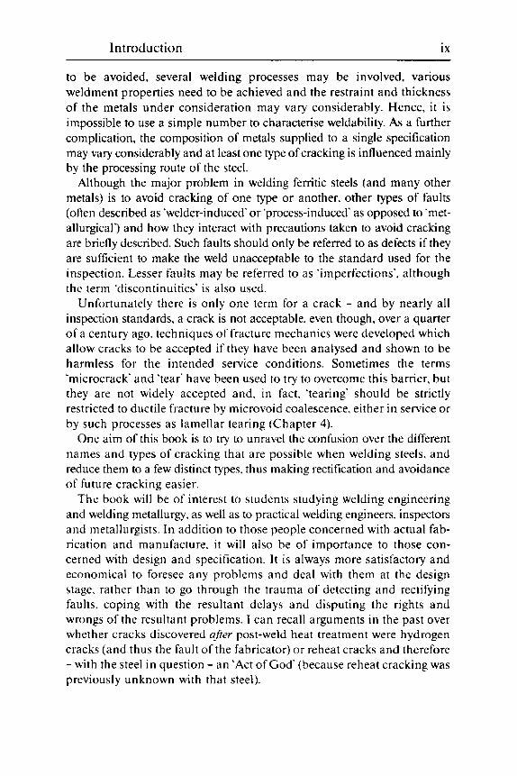
1.3 hydrogen crac king). dark-etch i ng ti negai ned H AZ and I igh ter-etch i ng intercritical region.
Macrosection of fillet weld showing coarse-grained HAZ (with
used). the reverse is likely to be the case. Near the fusion boundary the HAZ has been heated momentarily to its melting temperature. i.e. to about 1500 "C. This heating transforms the microstructure to the high temperature form. austenite. and coarsens its grain size to 100 pm or more. compared with 10-30 pm in a tine grained steel. O n cooling. the austenite transforms to martensite. bainite. ferrite + pearlite. or mixtures of these constituents. depending on the cooling rate (Fig. 1.4). Unless heat inputs are unusually high (Fig. I . ~ ( c ) ) . cooling is too rapid for pearlite to be formed. even in mild steel HAZs.
Because of the coarse prior austenite grain size. this region of the HAZ is more hardenable than would be expected from a conventional continuous cooling transformation (CCT) diagram of the steel. i.e. hard martensite forms more readily and soft ferrite less readily. Also the coarse prior austenite grain size results in coarse transformation products. which are inherently less tough than fine-grained ones, so that problems of poor HAZ toughness. and an increased liability to cracking. are readily under- s t a nd a bl e.
Further from the fusion boundary. the HAZ is heated to lower temper- atures ( I 100 down to about 700 "C) and is therefore less coarse. so that i t is less hardenable and the transformation products usually tougher. The

16 Weldability of l’erritic steels
1.4 Typical HAZ microstructures: ( a ) C:Mn steel 25 m m thick welded at 2 kJ/mm showing mainly fine and coiirse ferrite with aligned second phase and smaller amounts o f interphase carbide. inartensite and primary ferrite: ( b ) C:Mn:Nb steel 25 inm thick welded a t 1 kJ/mrn. predominantly miirtensite: (c) mild steel 25 mm thick welded at 7 kJ/mm. grain boundary ferrite. coiirse ferrite with aligned second phase and finer ferrite with interphase carbide and some pearlite: ( d ) section through (nickel-plated) fracture surface in a low alloy Q&T steel HAZ showing dimpled ductile fracture through the lighter martensite regions iind straighter cleawge fracture through the darker hai n i tic regio t i s.
fine-grained HAZ. which is readily distinguishable on an etched macrosection ol’a weld (Fig. 1.3). is less o f a problem area than the coarse HAZ. In fact. techniques have been developed to ensure that in multipass welds. all HAZ regions except those of the final run(s ) are fine grained. These techniques are discussed in Chapters 6. 9 and 1 1 .
The linal region of the HAZ visible in an etched weld cross section is the intercritically heated region. Bec;i~ise the first two regions are heated a hove the trans fo rm atio n tem pera t u re of the steel. they a re sii id to have been ‘critically‘ heated. Outside the visible HAZ. none of the steel has been heated into the austenite region. I n between these regions steel has been heated to ;I temperature where i t is partly transformed to austenite (i.e. intercritically heated). In the intercritical region. microscopically small regions of higher carbon content transform on heating to austenite and on cooling transform to martensite or, less frequently. to pearlite.

Factors influencing we 1 dab i 1 it y 17
Outside the visible HAZ. steel is heated to temperatures below about 700 "C. The upper end of this range is sufficient to give tempering if the steel is martensitic. but otherwise there is little obvious change in microstructure or hardness. However. in certain steels - those that are not fully killed with aluminium - heating to around 250 "C can give strain- ageing embrittlement. which can be very harmful if the tip of ii sharp planar defect lies in or close to such a region. The steels in question. of the rimming. semi-killed. balanced and silicon-killed types, are not frequently made these days. because the current technique of continuous casting requires an aluminium addition to the steel. However. older fabrications may need welding for repair o r modification. and weld metals (which d o not normally contain sufficient aluminium to prevent strain ageing) are also prone to this problem.
A recent finding is that. to avoid the problem of strain-ageing. sufficient time is required at. and during cooling from. the normalising temperature to allow aluminium to combine with nitrogen (one of the elements responsible for strain-ageing). With a normalising heat treatment this condition is met. but if the steel is normalised rolled. and does not also contain an appropriate addition of the element titanium. strain-ageing is still possible.
Reheating The above description of a HAZ is essentially that of a single-run weld. Reheating by subsequent passes modifies this description. because each HAZ overlaps that of the previous weld run and reheats it. Consequently some of the earlier HAZ is fully heated to give a new coarse-grained region, some is refined. some is reheated intercritically and some sub-criti- cally. The refinement is normally beneficial and can be used to advantage. Intercritical reheating. particularly of original coarse HAZ regions. can. however. be harmful. This is because intercritical reheating does not give
1.5 Microstructure of intercritically reheated coarse-grained HAZ in a weldable C:Mn:Nb steel: (a) showing small dark. re-transformed particles mainly at prior austenite boundaries: (b) detail of dark particle in SEM with a very fine pearlitic structure.

18 Weldability of ferritic steels
any refinement. so that the high carbon martensitic or pearlitic regions (Fig. 1.5) which result from the intercritical heating are larger and occur in coarser-grained microstructures than the intercritical region of a refined HAZ.
Problems of poor HAZ toughness encountered in this type of region are one cause of the so-called 'local brittle zones' (LBZs). With certain types of steel. sub-critical reheating can also give hard regions (and probably LBZs) by secondary hardening or precipitation hardening processes.
The weld metal
Composition The composition o f a weld metal depends not only on the composition of the filler used ( i f any) but also on the dilution (i.e. the incorporation of base metal into the weld pool) and the influence of the flux and/or shielding gas used. Unless the weldment is to be heat treated within the normalising temperature range. i t is usual to aim for a s low a carbon content as is compatible with the properties required. The reasons for this will become more apparent in later chapters. but they are essentially to reduce the risks of cracking nnd to improve toughness. Rimming steels of low carbon content were originally used for most welding wires and even today they a re p re fe r red for in a n y a p p 1 i cation s : t h e i r re I a t i vt.1 y h i g h oxygen con ten t s are not a disadvantage and the normally low levels of impurities (particu- larly nitrogen) are advantageous. I n fact. apart from oxygen and hydrogen. any impurity will strengthen the weld metal (excessively in many cases) and will often increase the risk of cracking and/or reduce toughness. The most harmful impurity is hydrogen. which is fu l ly discussed in Chapter 5. as well a s being mentioned in several others.
Apart from low carbon and low impurity levels. most welding con su in a bl es con t a i n man ga t i esc a n d s i 1 icon as deo x i ti a n t s. Ma n ga n es e is also important in reducing solidification cracking (Chapter 3 ) a s well a s in conferring strength and toughness in the weld metal. with additions us i t al l y below 2%. Further strength e t i i ng add i t io t i s ii re moly bde t i u m and nickel. which can also improve toughness: chromium is added to confer resistance to high temperature oxidation and creep. as well a s resistance to attack by hydrogen at high temperature and pressure (Chapter 10). In some cases boron is added to improve toughness at the same time as avoiding excessive hardness.
When no filler is added (as in autogenous welding) the parent steel pro- vides all the weld metal and. with the usual autogenous welding processes (TIG. plasma. electron beam and laser). the composition is scarcely changed by the welding process. I f two different steels ;ire being joined. the resultant composition will depend on the proportions of each that are melted.

Factors in fl u e iic i ng we 1 dab i 1 it y 19
Even with added filler. a proportion of parent metal is always incorpo- rated into the weld pool. This varies considerably with the welding process and the actual welding parameters. Manual metal arc welding will usually give a dilution of about 30% of parent steel into the weld pool: submerged arc welding may incorporate as much as 75%. With the TIG process. dilu- tion can vary from about 20% to as much as 100% (i.e. if no tiller is used). In multipass welding. some of the material diluted into the second and subsequent runs is weld metal deposited earlier. I t is very difficult in a fusion welding process to maintain low dilution levels. even when this is required. as in surfacing with a material whose properties are impaired by iron. because of the difficulty of avoiding defects of welding. Non- fusion processes. such as friction welding. diffusion bonding. and also hrazing and soldering. give no dilution.
The amount of dilution can be altered by varying the welding parameters. Welding current density has the greatest influence: increasing current or decreasing wire diameter increases both penetration and dilution. A large increase in the preheat or interpass temperature. as well as an increase i n hydrogen input. will also increase dilution. In the case of submerged arc welding. the addition of metal or iron powder reduces penetration and dilution to a small degree. In most welding processes. dilution and pene- tration decrease when the current type is changed from d.c. positive to a.c. to d.c. negative.
All fluxes. even the so-called neutral submerged arc fluxes. produce some changes in composition between the added metal and the weld metal. The chemical reactions involved are complex: ref. 3 provides a useful and simple guide to flux types for fusion welding processes.
Fluxes and electrode coverings help in shaping the weld head. as well as in providing shielding from the atmosphere and influencing weld metal composition. They are usually mixtures of minerals such as rutile. silica. silicates. bauxite. magnesia. fluorite. chalk and clays. The more 'acid' of these (silica. rutile and bauxite) result in relatively high weld metal oxygen contents and loss of Mn. Si. C and other readily oxidised elements from the weld metal. The more 'basic' minerals. such as fluorite. magnesia and chalk. result in smaller losses of these elements. lower weld oxygen contents and some removal of sulphur. Some minerals add appreciable amounts of alloying elements to the weld pool: for example. manganese is added from manganese silicate. Other elements may be added to the weld metal as such. or as ferro-hardeners. from the electrode covering or the flux.
Normally. because of the good mixing within the weld pool. the com- position of each weld bead is uniform on a macroscopic scale over most of its volume. even though segregation on a microscopic scale is evident. as in all cast structures. However.the composition of adjacent weld beads may differ from each other because of differences in dilution and possibly

Co u n ts/s x100
6-
4-
2-
0
18-
12-
6-
0 24-
18-
12-
6-
0
80-
60-
40-
20-
0
Ti
Ni
1.6 between ;I nickel alloy weld metal irnd 9% Ni steel showing two regions between parent steel and weld metal.
Steps in Ti. Cr. Ni a n d Fe contents x r o s s the fusion boundary

Factors influencing weldability 21
shielding. even though the wire and parent steel may be of uniform com- position. Between the weld metal and the parent steel there appear to be two compositional steps. The first step is the result of the essentially laminar flow of weld metal across the surface of the parent steel preventing full mixing of weld metal with melted parent steel near the fusion boundary. It consists of melted parent steel into which weld metal has diffused fairly rapidly while both were still in the liquid state. The second step is of parent steel that has not melted but into which less weld metal has diffused more slowly (Fig. 1.6).
Apart from this stepwise gradation of composition. tongues of melted parent steel can project into the weld metal (Fig. 1.7). with insufficient time before solidification and cooling for diffusion to even out the com- position. When austenitic stainless steel tillers are used to weld ferritic steels. such regions can be highly alloyed. with hard martensitic microstructures. and are therefore at risk of cracking (see Chapter 5) .
Although mixing of alloying ingredients added from electrode coverings and fluxes is normally uniform. occasions are known where alloying ingredients have not had time to dissolve into the weld pool and give a homogeneous microstructure. An addition at particular risk is ferro- molybdenum hardener. whose melting temperature is relatively high: Fig. 1.8 shows a particle of ferro-molybdenum which has started to dissolve in the weld pool. Such partially dissolved particles are usually relatively harmless.
In some cases. however. the alloying particle has dissolved, but insuffi- cient time has been available for complete mixing and diffusion. After
1.7 Tongue of unmixed parent metal in a non-matching weld pool.

22 Weldability of ferritic steels
l . X scallopect edges to particle. which has started to dissolve.
Partially dissolved Fe-Mo particle in M M A weld metal: note
1.9 marked by small microhardness indentations within square o f full size hardness indents.
Site of partially dissolved Mn or Fe-Mi1 particle in weld metal

Factors influencing weldability 23
cooling. the sites of such particles become tiny regions more highly alloyed than the bulk of the weld metal (Fig. 1.9). often with hard martensitic microstructures which can give problems in service with stress corrosion cracking (Chapters 9 and 10). This type of 'hard spot' has given problems in submerged arc welds: when manganese has been alloyed by the use of ferro-manganese added to the flux. Presumably in this case. some particles of Fe-Mn from the molten slag entered the weld pool just as it was starting to solidify. Occasionally, similar problems have occurred with MMA electrodes and cored wires. as well as the opposite problem - iron powder particles incompletely mixed: these tend to give soft spots which are less harmful.
Microstructure Because the bulk of the weld metal solidifies from the HAZ. the widths of the solidifying grains are initially those of the coarse grains in the high temperature HAZ from which they have grown. as can be seen in Fig. 1.3. 5.7(a) and other illustrations in the text. However. their length is governed by the width of the weld and the direction of solidification. Except in rare cases (electroslag and similar welds of high heat input in which solidifying grains can be nucleated within the weld) most weld metal grains continue growing until they either meet grains growing from the opposite direction at the weld centre-line or until they reach the weld surface. Occasionally. in a weld metal of low impurity content and deposited with a high heat input (particularly by submerged arc and rnost types of electroslag welding) the weld grains can grow as in Fig. 1.10. This type of coarse grain size is not in itself detrimental to toughness. which depends on the grain size of the transformation product. I f the latter is predominantly of acicular ferrite. then a coarse prior austenite grain size as shown in Fig. 1 . 1 0 will have no effect on toughness.
With the exception of the formation of acicular ferrite. weld metal
1.10 weld metal on right: (b) detail.
Grain growth in submerged arc weld metal: (a) general view.

24 Weldability of ferritic steels
microstructuresS resemble those of the HAZ. With a low content of carbon and alloying elements. the microstructure is predominantly of soft primary ferrite and a constituent called ferrite with aligned second phase (some- times known earlier as ‘ferrite sideplates’ or ‘ferrite with aligned MAC’ - meaning martensite. austenite and carbides). Fig. 1.1 l(a). Although the ‘second phase’ is mainly the iron carbide cementite. other constituents. such as martensite and retained austenite (these two are sometimes known collectively as ‘retained phases’) are usually present in small quantities: Fig. 1 . 1 I(b).
1 .1 1 low Mn submerged arc: primary ferrite with some ferrite with some aligned second phase: (b) submerged arc. so-called retained phases (SASPA-NANSA etch): (c) predominantly ferrite with aligned second phase in submerged arc weld: (d) bainite in 2.25YhCr:lMo MMA weld metal: (e) martensite in high strength. low alloy MMA weld metal: (0 refined submerged arc weld metal.
Selection of as-welded weld metal microstructures: (a ) low carbon.

Factors influencing weldability 25
Admixture of alloying elements increases the proportion of ferrite with aligned second phase at the expense of primary ferrite (Fig. 1.1 l(c)) until lower temperature transformation products appear. The first of these is bainite. typified by the microstructure of 2.25% Cr:l% Mo weld metal (Fig. 1.1 I(d)). and the second is martensite.common in very high strength low alloy weld metals (Fig. 1.1 I(e)). All of the constituents so far men- tioned are preferentially nucleated at prior austenite boundaries. or stop their growth at such boundaries. Hence the coarser the prior austenite grain size. the coarser and less tough is the resultant microstructure.
Within the region where ferrite with aligned second phase occurs. it is possible for it to be replaced by acicular ferrite. which nucleates within the grains and - because so many more grains can be nucleated within a large grain than can be nucleated at its boundaries - the grain size of the acicular ferrite is fine in comparison with the other constituents. Its toughness. therefore. is very much better than that of any other constituent except perhaps low carbon martensite containing nickel or very soft ferrite.
The prior conditions for the formation of acicular ferrite are complex, as they appear to depend on the structure of non-metallic inclusions in the microstructure (Fig. 1.12). These inclusions, consisting mainly of deoxidation products (manganese silicates and alumina) and MnS are spherical and typically <I0 pm in diameter. When coated (at least in part) with an oxide of titanium they appear to nucleate easy transformation of ferrite from austenite within the prior austenite grains. These so-called acicular ferrite grains cannot grow far before their growth is stopped by the presence of other growing grains. This blocking of grain growth by closely adjacent grains is the reason for the fine grain size of acicular ferrite
1.12 Typical inclusions shown in TEM replica of section. which has been prepared to emphasise the inclusions by shadowing.

26 Weldability of ferritic steels
and is in contrast to the behaviour of primary ferrite grains. usually growing from the prior austenite boundaries. as well as bainite and martensite.
Titanium is an essential constituent of inclusions that nucleate acicular ferrite. as i t has been shown that if pure (i.e. titanium-free) chemicals are used to make a flux or electrode covering. the formation of acicular ferrite is prevented in otherwise favourable circumstances.h Other experiments have shown that additions of titaniiim compounds to a flux. giving as little as 0.003%1 Ti in an otherwise unfavourable weld metal. can induce the for- mation of acicular ferrite.: The only other element known to favour the formation of acicular ferrite is vanadium. an element not usually added to weld metals (partly because of its tendency to promote reheat cracking). and one whose effect is less efficient than that of titanium. However. the presence of vanadium can lead to the formation of some acicular ferrite in HAZs.
The titanium needed to promote acicular ferrite must be in the form of an oxide. because the presence of too much aluminium - an element which oxidises preferentially to titanium - is known to inhibit the formation of acicular ferrite.x as shown in Fig. 1.13. This inhibition occurs more easily if the weld oxygen content is low (Fig. l.l3(b)). particularly if i t is below about 0.020%~ 0. An excess of aluminium in this context means that suffi-
1.13 Effect of aluminium and oxygen on acicular ferrite content of similar C:Mn weld metals: (a) 0.008% Al. 0.020% 0. 58% acicular ferrite. 35 J Charpy at -62 "C: ( b ) 0.029% Al. 0.017% 0. 15% acicular ferrite. 35 J Charpy at +28 "C: (c)0.02X%, Al. 0.047% 0. 49% acicular ferrite. 35 J at -50 "C.
Factors influencing weldability 27
cient aluminium is present for it to combine with all of the oxygen available in the weld metal to form AI,O,, thus leaving no oxygen to form titanium oxide. If an accurate weld metal analysis is known. then the aluminium content should not exceed 9/8ths of the oxygen content by more than about 0.002%’ to allow acicular ferrite to be nucleated.
I f the weld metal oxygen content exceeds about 0.055% 0. the presence of acicular ferrite is unusual because conditions will have been so oxidising that most titanium will have been oxidised out of the weld metal into the slag. unless special consumables have been used that deliberately add titanium.’ In marginal cases the nucleation of acicular ferrite can be uncertain because titanium may or may not be present as impurities in welding wire. parent steel or flux but. if present. may find its way into the weld metal. Sufficient titanium will always be present where minerals such as rutile (TiO,) are constituents of the flux or electrode COV-
ering. With mild and C:Mn steel weld metals. acicular ferrite is most likely in those made from basic MMA electrodes. basic and alumina- basic submerged arc fluxes and in MAG welds made using low oxidising shielding gases. Although conditions are just about suitable for acicular ferrite nucleation with rutile and cellulosic electrodes. the degree of alloying is normally insufficient to permit extensive formation of acicular ferrite. It should be noted that excessive amounts of titanium (i.e. >0.1%) can give weld metals having bainitic microstructures with very poor toughness.
Aluminium to inhibit acicular ferrite nucleation can originate from the same three sources as titanium. although it is rarely present in MMA electrode coverings and not at all in rimming steel wire which was once used exclusively for all MMA electrodes. However. aluminium metal is added as a major constituent to many self-shielded flux cored wires and is transferred to the weld metal in quantities sufficient to prevent the nucleation of acicular ferrite. Such weld metals achieve their toughness by the use of multipass refining techniques resulting in a fine ferrite microstructure.
Although alumina-rutile and alumina-basic submerged arc fluxes transfer aluminium to the weld metal. they do not give sufficiently low oxygen contents to prevent acicular ferrite nucleation. However. aluminium transfers readily from parent steel to the weld pool. so that high dilution welding processes. such as submerged arc when used with very basic fluxes (i.e. those that give weld metal oxygen contents well below 0.025% 0). can make acicular ferrite nucleation difficult - especially in any weld runs that are more highly diluted with parent steel than usual. Such high dilution may occur in root runs and in any misplaced runs that dig into the parent steel at the side of the weld preparation.
Low oxygen welding processes such as TIC and plasma do not require much aluminium to be diluted from the parent steel to inhibit the formation of acicular ferrite. because of the very low oxygen contents associated

28 Weldability of ferritic steels
with these processes. However. because the TIC welding process usually gives a high proportion of refined weld metal in multipass welds. the problem of uncertain acicular ferrite formation is less serious than might at first appear. This technique of adjusting the welding process to deposit a highly refined microstructure has been adapted for other welding processes where acicular ferrite is not usually produced. notably self- shielded cored wire welding.
As with the HAZ. the weld metal is reheated and transformed by subse- quent weld runs. At the highest temperatures. the coarse columnar prior austenite grains are replaced by more or less equiaxed coarse grains with similar transformation products to the original as-welded grains. At lower temperatures. the grain size is considerably refined and the microstructure is usually of equiaxed tine ferrite with carbides at the ferrite grain boundaries - generally a tough microstructure. At still lower temperatures of reheating. the original as-deposited macrostructure persists, with little obvious change in the microstructure.
Cutting and gouging
Cutting and gouging are necessary adjuncts to the welding process. and should be treated with respect when used on many steels. Even mechanical methods - particularly grinding and chipping - can severely cold work. tear and leave residual stresses adjacent to the cut surface. which can be damaging in subsequent service. Thermal cutting and gouging leave thin heated and hardened surface layers. which have martensitic microstructures. whose hardness depends solely on the carbon content of the steel. I f mis- handled. both processes - but particularly carbon arc gouging - can also result in carbon pick-up. which exacerbates this problem.
However. if a cut surface is to be directly welded on. the damaged layer will be melted into the weld pool and will not thereafter be harmful. I t is only where the cut or gouged surface is left o n an unwelded area of the steel (or worse. on a region that will become a HAZ) are serious problems likely. However. i t is possible for a badly mis-handled carbon arc gouging electrode to give sufficient carbon pick-up to harmfully raise the carbon content of any weld metal deposited on it.
Thermally cut and gouged surfaces should. therefore. be ground off to a sufficient depth to remove any damaged material and hardened layers unless they are going to be fully incorporated into a weld. With sensitive steels. preheat (less than that used for welding) is recommended in order to reduce hardness and avoid hydrogen cracking directly after thermal cut- ting - the hydrogen originating mainly from the flame or arc atmosphere.
Factors influencing weldability 29
Residual stresses
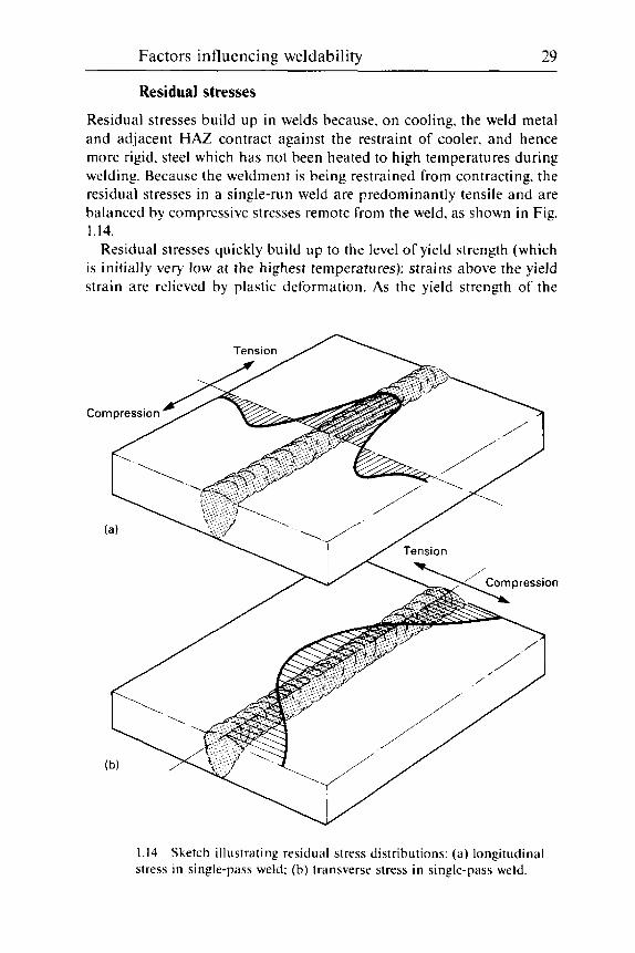
Residual stresses build up in welds because. on cooling. the weld metal and adjacent HAZ contract against the restraint of cooler. and hence more rigid. steel which has not been heated to high temperatures during welding. Because the weldment is being restrained from contracting, the residual stresses in a single-run weld are predominantly tensile and are balanced by compressive stresses remote from the weld. as shown in Fig. 1.14.
Residual stresses quickly build up to the level of yield strength (which is initially very low at the highest temperatures): strains above the yield strain are relieved by plastic deformation. As the yield strength of the
1.14 Sketch illustrating residual stress distributions: (a) longitudinal stress in single-pass weld: (b) transverse stress in single-pass weld.

30 Weldability of ferritic steels
metal builds up on cooling. residual stresses also build up. In a single- pass butt weld. where the heated zone and resultant contraction strain is usually wider at the face of the weld than at the root. this can result in the plates deforming upwards or 'winging' unless the weld is heavily restrained. I f the weld is restrained. the deformation is accommodated by elastic and plastic cleformation within the heated area. Contraction strains are greatest along the axis of a weld and least in the transverse directions.
In a simple metal. like aluminium or austenitic stainless steel. residual stresses continue to build up as the temperature falls and can be considered to be at the elastic limit ( i t . close to the proof stress) at ambient temperature. Any excess strain over the yield strain is accommodated by plastic defor- mat i o n .
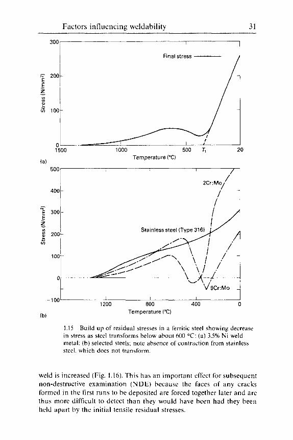
The behaviour of a ferritic steel is complicated by its transformation on cooling. Transformation from high temperature austenite to lower tem- pe ra t u re t ra n s fo rni H t io n prod 11 c t s ( in art e n s i re. b a i n i te and fe r ri re) is accompanied by an expansion. which works in the opposite direction to the contraction resulting from cooling. This means that the build up o f the ambient temperature residual stresses in a ferritic steel essentially starts from the transformation temperature. a s shown in Fig. l . l5(a).
Although most steels have sufficiently high transformation temperatures for the yield stress to be reached on cooling from the transformation tem- perature. some highly alloyed steels have such low transformation tempera- tures that residual stresses do not reach yield stress level (Fig. l . l5(b)). Hence steels such a s the 9% Cr steel4 may have a lower risk of cracking and a higher defect tolerance than steels of similar strength and tough- ness. but of lower alloy content and higher transformation temperature.
An important metallurgical result of the considerable plastic deformation undergone by a weld metal on cooling is that this plastic deformation leads to a very dense network of dislocations. This dislocation network is responsible for the yield strengths of ferritic steel weld metals being much h i g h e r t h a n wou I ti be expected fro in t h e i r co m positions a n d gra i n sizes. Th is network. toget h e r with t rii n s fo r ni a t i o n h a rd en i n g. a ccoii n t s for the ease with which ferritic steel weld mctals overmatch parent steels in strength. i n contrast to most non-ferrous systems.
The dislocation network is little changed by tempering during PWHT but is destroyed when the weld metal is subjected to high temperature heat treatments within the austenite range. such a s normalising or hard- ening a n d quenching. Because of this. considerable care in the selection of consumables is needed i f a weld metal has to survive high temperature heat treatment (or hot working within the austenite temperature range) and retain strength properties to match the parent steel.
As a multipass weld is built up. the residual stresses in the first runs are altered and may be replaced by compressive stresses a s the depth of the
Factors influencing weldability 31
/ 2Cr:Mo/ - 400 -
E *Oar 2 1 *
GI 100 ? i
ry - E 300- E z * 200- 2 G
. v)
100-
0
-100-
0 - i 1500
/ Stainless steel (Type 316)
- b",J' 9Cr:Mo -
800 400 0 I I I
1200
(a)
Final stress 1
I I I I __I
100 10 500 Tt 20 Temperature ("C)
weld is increased (Fig. 1.16). This has an important effect for subsequent non-destructive examination (NDE) because the faces of any cracks formed in the first runs to be deposited are forced together later and are thus more difficult to detect than they would have been had they been held apart by the initial tensile residual stresses.

32 Weldability of ferritic steels
Tension 4 7 ~ Compression
1.16 Final residual stress distribution in multipass weld.
A knowledge of residual stresses is essential when carrying out fracture mechanics analyses to establish the fitness for purpose of welded joints. For such analysis. the most important single parameter is the maximum value of tensile residual stress. as this. when related to the fracture tough- ness of the appropriate region. determines the maximum tolerable defect size that will not lead to failure when subjected to the maximum likely stress.
Although i t might seem that the residual stress cannot exceed that of the parent steel (which is nearly always lower than that of the weld metal or HAZ). detailed measurements using the hole drilling technique" have shown that residual stresses near the surface in weld metal can approach the yield stress of the weld metal itself. even when this is higher than that of the parent steel. In weld metal. the residual stress varies over quite short distances. being higher within a weld bead than near the junction of two weld beads."
Unless existing knowledge or future research shows otherwise. i t is important to use the weld metal yield stress in estimating the maximum residual stress levels for fracture mechanics calculations involving weldments. Consequently. there is benefit in using weld metals with the lowest possible yield strength consistent with just overmatching that of the parent steel in situations where the best toughness is required. The reduction of residual stresses by PWHT is covered in the next section.
Post-weld heat treatment
Post-weld heat treatment is frequently needed for weldments in alloy steels and in C and C:Mn steels in section thicknesses typically in excess of about 40 mm. Generally. PWHT reduces residual stress levels and tem-

Factors influencing weldability 33
pers. i.e. softens and reduces the hardness of any hard regions, particularly in the HAZ. After PWHT. a weldment should be tougher and also should resist such service hazards as stress corrosion cracking (SCC) and in- service hydrogen cracking more readily than in the as-welded condition.
The selection of PWHT temperatures is often aided or limited by the appropriate application standard, and is usually within the temperature range 550-750 "C. It should be remembered that PWHT at a lower tem- perature will not undo any excessive softening which may have resulted from the use of too high a temperature. However. if a weldment has been under-tempered by PWHT. a further heat treatment at a higher temperature is always possible.
Carbon. C:Mn and Ni steels are usually treated in the range 550- 650 "C. more usually at about 600 "C. However. the lower end of this range is now known to give inadequate relief of residual stresses and tem- peratures around 600 "C are preferred. The reduction in residual stress of a simple C:Mn weldment after PWHT at 600 "C is approximately 70%. and a reduction of this extent gives a very useful improvement in the toughness of the joint in terms of fitness for purpose, i.e. its ability to tol- erate cracks and other faults. However C:Mn steels microalloyed with Nb. V and, most particularly Nb + V. are known to give a slower tempering than a simple C or C:Mn steel. In fact. as a result of secondary hardening, the HAZs of C:Mn:V and C:Mn:V:Nb steels can exhibit increases in hardness and reductions in Charpy toughness when subject to PWHT at about 600 "C.
Low alloy steels containing chromium generally require PWHT tem- peratures at or above 650 "C. the temperature depending on the required properties and the application. The lower temperatures are used when the highest strength is required: optimum creep resistance results from an intermediate temperature. whilst the highest temperature within the range is used to obtain maximum softening and stress relaxation.
With other alloy steels. two important points should be noted. Firstly. the selected temperature should always be below the A,, temperature of the steel. that is the temperature above which the steel begins to transform to austenite. Here it should be noted that the addition of chromium progres- sively increases the A,, temperature and the addition of nickel progressively lowers it.
Secondly. when welding quenched and tempered steels which have been tempered to particular strength or hardness levels, it is important not to exceed the tempering temperature which was originally used, other- wise the whole component will be softened and weakened below its required level. I t is normal to set the maximum of the PWHT temperature some 20 "C below the actual tempering temperature.
Unfortunately it is not always easy to discover the previous heat treat-

34 Weldability of ferritic steels
ment history of a piece of steel. although i t should be on the mill sheet. Some steelmakers give such a wide range for the tempering temperature of a particular steel as to be useless. for example 530-680 "C. In such cases. the supplier or steelmaker should be carefully questioned. I f this fails to provide the actual tempering temperature. the only action is to remove a small piece of steel from an unimportant area and subject i t to careful hardness measurements after laboratory heat treatments at pro- gressively higher temperatures in order to estimate the original tempering temperature. These tests should start at the bottom of the steelmakers' range and finish either where the steel starts softening. or at a temperature such as 650 "C where a high degree of stress relief will be obtained.
During PWHT. care should be taken to ensure uniform heating of the components. which may be of a very complex structure. Most heat treat- ment specifications give guidance on heating and cooling rates and tem- perature differentials. The penalties for exceeding these limits include distortion. cracking and also the re-imposition of residual stresses (albeit not in exactly the same configuration. but possibly up to the same maxi- mum level) which the PWHT is intended to reduce.
Although PWHT is preferably applied to completed fabrications. there are times when this is not possible. For example. available furnaces may be too small. the weld may be a repair in a structure too large to heat treat or there may be a component in the neighbourhood which would be damaged by the heating. Local PWHT is acceptable in such cases. always provided precautions are taken to maintain low temperature gradients between the heated and unheated regions and to avoid distortion or build up of high local stresses on cooling. Again. guidance is usually given in the appropriate application standard.
Other heat treatments Heating of welds in ferritic steels is often carried out within the range 150-300 "C. This is not usually a tempering heat treatment (although it could be so for a high strength Q&T steel originally tempered at a low temperature). but is used to allow the diffusion of hydrogen out of the joint in order to avoid the risk of hydrogen cracking. As such. this topic is covered in Chapter 5 .
Sometimes there is a requirement to give a welded joint a full heat treatment such as normalising or Q&T. Such heat treatment is common for electroslag. electrogas and consumable guide welds in order to achieve acceptable toughness in the HAZ. Except when welding certain low carbon steels (for example. some of the Cr:Mo types used for high temperature service in which weld metal and parent steel are of similar carbon content). consumables for other types of welding should be selected to ensure that the heat treated weld metal is of adequate strength

Factors influencing weldability 35
and toughness. This is because the application of an austenitising heat treatment to a weld metal gives a drastic reduction of the as-welded weld metal strength to levels well below the as-welded or PWHT values.
Preheating is not a heat treatment.
Weldability formulae
Over the years. attempts have been made to provide single numbers to characterise the weldability of steels. either in general terms. or to cover specific types of cracking or other important aspects of welding behav- iour. The earliest. and most important of these. cover HAZ hardenability and HAZ hydrogen cracking. In fact. these two problems are so closely related that users are not always clear which aspect some formulae cover.
Other formulae cover solidification cracking. reheat cracking. maximum martensite hardness and temper embrittlement. as well as weld metal properties, such as yield strength. tensile strength. hardness and microstructural constituents. Further formulae relate hardness to yield strength for HAZ and weld metal. The most significant of these will be summarised in this section. Unless otherwise stated. the use of the symbol for a chemical element in a formula denotes its content in mass percentage in the steel or weld metal.
Hardenability and hydrogen cracking The first of the many weldability formulae was developed by Dearden and O’Neill over 50 years ago.12 and the whole topic was recently reviewed in a seminar held to commemorate the golden jubilee of that paper.” Dearden and O’Neill developed formulae. based on steel chemi- cal compositions. for yield and tensile strength. as well as for hardness: all were complicated by some of the divisors depending on the levels of elements present. Over 25 years later. the most useful of their formulae. that for hardenability. was simplified by a sub-committee of the Interna- tional Institute of welding (IIW) into the generally accepted version - often known as the IIW formula - giving a ‘carbon equivalent’ (CE or C h w ) :
Mn C r + M o + V N i + C u CElIw=C + - + + - [ 1.21
6 5 I S
This formula has been adopted into several standards and codes. e.g. ref. 2 and 14.
Other formulae were developed in the 1950s. 1960s and 1970s but the only ones which have gained wide acceptance are P,,, due to Ito and Bessho in Japan (quoted by Yurioka in ref. 13) and that of Duren in Ger- many.13 which have been specially developed for low carbon steels for

36 Weldability of ferritic steels
which the CEllw formula is not entirely suitable. Both these authorities consider that HAZ behaviour should be divided into three distinct types:
1 The fully hardened HAZ. i.e. with a fully martensitic microstructure. 2 An intermediate microstructure. 3 An unhardened HAZ. generally with a bainitic. or even a ferrite +
pearlite microstructure.
The formulae for modern steels, particularly those used for pipeline manufacture. are intended for carbon contents no more than -0.1 1%. Of these. the most well-known hardenability formulae is:
Si Mn+Cu+Cr +% + E o + _V + 5 B 3 0 20 60 15 10
P,,,= c + - +
Duren’s formula for this range is similar:
[ 1.41 Si Mn+Cu + + L r + Mo + 1 25 16 40 10 15 10
C E q = C + - + -
Although CEllw was originally developed as a hardenability formula. i t has come to be used as a hydrogen cracking formula. and is the basis of the nomograms to avoid cracking in ref. 2 and 15. The principal reason for this is that the original Dearden and O’Neill formula was developed for semi-killed. balanced and rimming steels with very low silicon con- tents. Subsequent research showed that. although silicon had an effect on hardenability similar to that of manganese.I6 its effect on weldability in terms of cracking behaviour was negligible.lS so that its presence could be ignored when considering weldability.
I t is important to understand this distinction, because if the CEl lw is used to estimate the HAZ hardness of a single-pass weld in a steel con- taining silicon. a low result will be obtained. A more accurate estimate will be obtained if the factor of Si/6 is added to the CEl lw formula.I6 i.e.:
Mn+Si + Cr+Mo+V Ni+Cu 6 5 15
C E H = C +- +- 1.51
In recent years. complicated formulae (e.g. ref. 13 and 17) have been developed. which include welding parameters. and the effects of inclusions. as well as chemical composition, on hardenability and/or weldability. The general view is that such formulae. although of scientific interest. are not practical for normal industrial use where a welding engineer needs to look at a mill sheet and quickly decide whether the steel is suitable for the welding required. However. this view may well change as the use of per- sonal computers extends into industry.
Other formulae relevant in this area are those developed for calculating
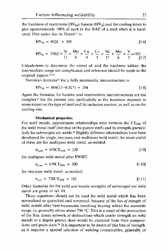
Factors influencing weldability 37
the hardness of martensite (HVM). bainite (HV,) and the cooling times to give approximately 100% of each in the HAZ of a steel when it is hard- ened. One series due to Durenl-' is:
HVM = 802C + 305 [ 1.61
Si Mn Cu Cr Ni Mo V HVR = 3SO(C+- + - + - + - + - + - +-)+I01 I 1 8 9 s 17 6 3 11.71
Calculations to determine the extent of. and the hardness within. the intermediate range are complicated and reference should be made to the original papers. 13.1X
Yurioka's formula1-' for a fully martensitic microstructure is:
HVM = 884C(1-0.3C2) + 294 [ 1 .Sl Again the formulae for bainitic and intermediate microstructures are too complex'-' for the present text. particularly as the hardness depends to some extent on the type of steel and its inclusion content. as well as on the cooling rate.
Mechanical properties For weld metals. approximate relationships exist between the CEllw of the weld metal itself (not that of the parent steel) and its strength. particu- larly for submerged arc welds." Slightly different relationships have been developed for single. two-pass and multipass weld metal: the most useful of these are for multipass weld metal. as-welded:
oyam = 670CEl1w + 230 [ 1.91
for multipass weld metal after PWHT:
oyFm = 670CE11w + 200
oya? = 720CE11~ + 182
[1.10]
[1 .11]
for two-pass weld metal, as-welded:
Other formulae for the yield and tensile strengths of submerged arc weld metal are given in ref. 19.
These equations should not be used for weld metal which has been normalised or quenched and tempered, because of the loss of srrengrh of weld metals after heat treatments involving heating within the austenite range. i.e. generally above about 750 "C. This is a result of the destruction of the fine, dense network of dislocations which confer strength on weld metals to a degree greater than would be expected from their composi- tions and grain sizes.'" It is important to be aware of this loss of strength. as it requires a special selection of welding consumables, generally of

38 Wcldability of ferritic stcels
similar carbon content to that of the parent steel. Situations where this is liable to occur include the foundry repair of castings before they are heat treated. the hot working of partly fabricated (welded) components within the austenite range. and any unexpected or unauthorised heating (e.g. in fires) to excessively high temperatures.
Formulae have also been developed for estimating the yield strength of weld metals and HAZs from their hardness.?O.?l These yield strength formu- lae are particularly important as they allow fracture mechanics calculations of defect tolerance to be carried out on structures where insufficient mate- rial can be spared for a tensile test to be carried out.
For weld metal:
oh,,,, = 3.15HV - 16X
C J ! H ~ ~ = 3.25HV - 340
[1.12]
[1.13]
For the HAZ:
Although Eq. 11.121 gives reasonably accurate results. there is appreciable scatter in the values obtained from Eq. [ 1.131 because of the paucity of the data on which it was based.
Estimation of toughness from carbon equivalent formulae is not simple because of the complications of the d rent weld metal microstructures and microstructural refinement by reheating in multipass welds. and how these impinge on what would otherwise be a simple inverse linear rela- tionship between toughness and strength (or hardness). For example. in the absence of conditions favouring acicular ferrite formation. manganese is harmful because i t increases strength whilst reducing toughness. How- ever. i f acicular ferrite can form. then manganese is beneficial up to about I . X % (in the absence of other alloying elements). because i t replaces coarse primary ferrite by fine acicular ferrite and thus increases both toughness and strength. However. a direct inverse relationship has been found between Charpy upper shelf energy (u) (and also the slope of the transition part of the Charpy curve) and the weld metal inclusion content (I) of submerged arc weldsly which. in turn. can be calculated from the weld metal composition:
u;,,,, = IS8 - 831
I/,,,, = 173 - X31
u;,: = 138 - x3/
(1.141
[1.15]
11.161
where the same notation is used as in Eq. [1.0-1.111. Additional relation- ships are given in ref. 19.
The inclusion content. 1 as a volume fraction. is estimated by assuming that the oxygen content of the weld metal first combines with Al to form

Factors influencing weldability 39
AI,O,. then with Ti to form TiO, and finally with Mn and Si to produce 2MnO.Si0,: S forms MnS. Factors for wt% element to vol% inclusions are 4.09 for Al. 3.67 for Ti. 5.3 for Mn to MnS. 6.2 for remaining 0 to 2Mn0.Si02: 1% oxygen is equivalent to 0.89% Al and 0.67% Ti. These relationships appear to be valid for all types of fusion weld.
Microstructure The proportion of primary or grain boundary ferrite in submerged arc weld metals can be estimated from the weld metal CEllw as a volume per- centage:lv
GBF,,,T = 81 - 173CE~ [1.17]
GBF,,,R = 96 - 197CER [1.18]
where the subscripts R and T refer to the root and cap runs. respectively. Unless microalloying elements such as Nb are absent from the weld metal. these equations are limited to ferrite contents up to about 60%: additional relationships are in ref. 19. From these relationships. zero grain boundary ferrite would be expected at a CEllw of about 0.48. Refer- ence 19 indicates that (in the absence of Nb. Mo. etc.) weld metal microstructures tend to become fully martensitic when CETIW exceeds about 0.6-0.7.
Solidification cracking These formulae inevitably relate to the composition of the weld metal under consideration. rather than to the parent steel. This is not a problem when considering well-shielded. autogenous processes Such as TIC. laser and electron beam welding. where the composition of the parent steel approximates to that of the weld metal. A further step. however. is required for flux and active gas-shielded processes. particularly when they are used to deposit multipass welds. and the cracking is in the root region. This is because of the influence of the flux or shielding gas on the weld composition. because of the dilution of parent steel into the weld metal and because analyses of multipass welds are usually carried out on samples from the cap regions of low dilution.
In using any solidification cracking formula. care is needed to ensure that all the welds used to develop the formula are as nearly as possible identical in shape. In the type of test normally used to establish compositional effects. altering the welding parameters also alters the test conditions.
In all the formulae. the elements S. C and P promote cracking. whilst Mn is beneficial. One of the early attempts to develop a formula for TIG weldingzz led to a crack susceptibility factor (CSF):

40 Weldability of ferritic steels
CSF = SO1C + 1560 (Mn . S) - 82.8Mn - 47.9 [1.19]
for steels having carbon contents between 0.14 and 0.3 1%. Later work along similar lines showed that oxygen (the term (0) repre-
sents the weld metal oxygen content) had a beneficial effect on cracking at the low levels present in TIG welds. and a CSF for autogenous T I C welds in medium carbon engineering steelsz3 was:
CSF = 42C + 847s + 265P - 10M0 - 3042(0) + 19 [ 1.201
Submerged arc welding is probably the process most prone to give solidification cracking and a formula was developed.24 using the British Transvarestraint test. in units of crack susceptibility (UCS) using standardised welding conditions: this formula has been adopted in the relevant British Standard:?
UCS = 23OC + 100s + 7SP + 4SNb - 12.3Si - 4.SMn - 1 [1.21]
In this formula. values of C<O.08%, are taken as being equal to 0.08%C: the reasons for this. together with the compositional limits within which Eq. [1.211 can be used. are discussed in Chapter 3 and ref. 24.
Unlike solidification cracking. there has been little effort to quantify compositional effects on liquation cracking in the HAZ. because it is nor- mally a minor problem.
Reheat cracking Reheat or stress relief cracking is limited to a few steels and no attempts appear to have been made to develop universal formulae for this type of cracking.
However some formulae have been developed for parameters (AG and PSR) showing the susceptibility to cracking of ferritic steels when clad with austenitic stainless steels and then subjected to PWHT. For the Cr:Mo:V types used for such pressure vessels. the formulae include:
AG = C r + 3.3Mo + 8.1V - 2 [ 1.221
The steel is not susceptible if AG<O.Zs A modification of this formula, to take account of the carbon content of the steel. and where AG<2 to avoid cracking. is:Zh
AGI = C r + 3.3Mo + X.1V + 1OC - 2 [ 1.231
A different formula. due to Ito and NakanishLZ7 is:
PSR = C r + Cu + 2Mo + 10V + 7Nb + STi - 2 [ 1.241
The steel is susceptible if PsR>O.
Factors influencing weldability 41
For the other major type of cracking, lamellar tearing. no formulae have been developed because. as explained in Chapter 4, the problem is one of inclusion population. rather than steel composition.
Embrittlement and other formulae Types of embrittlement can also be characterised to some degree by chemical formulae. In addition. standard metallurgical formulae. given in appropriate textbooks and compilations of transformation data. can be used to estimate such parameters as transformation start and finish temperatures which may be required when determining weldability. welding conditions and/or heat treatments.
Strain ageing is caused by any free nitrogen and carbon dissolved in solid solution in the ferrite lattice interfering with the movement of dis- locations (which allow plastic deformation) and thus embrittling the steel. Most attention has been concentrated on free nitrogen. the presence of which is likely in as-rolled and possible in normalised rolled steels (but not in steels that have been normalised and tempered) and in weld metals if the 'free' Al content is less than twice the nitrogen content. i.e. if:
[ 1.251
If a 'free' Al figure is not available. the following approximation should be used (but not for weld metals) to avoid the risk of strain-ageing:
[ 1.261
Attempts have been made to modify Eq. [ 1.251 and [ 1.26) to allow for the beneficial effects of Ti and B as nitride formers. As these depend on the elements being in the 'free' state, they are not included here because they are not relevant to weld metals.
To avoid the risk of temper embrittlement. the so-called J-factor28 has been used. particularly for the 2%Cr:IMo steel. which is particularly sus- ceptible to this problem:
J = (Si + Mn) X (P + Sn) X 104 [ 1.271
Values of J should be kept below a predetermined value (e.g. 180). However. this formula is a simplified one. as other impurities such as
As and Sb are also important. A more general parameter PE. has been proposed for weld metakZy
PE= C + Mn + Mo +Cr/3 + Si/4 + 3.5 (1OP + 5Sb +4Sn + As) [ 1.281
The maximum value to avoid serious embrittlement depends to some degree on the welding process.zy but it is apparent that values should be below about 2.8-3.0 where coarse grained weld metal is present.

42 Weldability of fcrritic steels
Bruscato”’ has developed several slightly different formulae for differ- ent steel types. These all relate the ( M n + Si) value (in wt %) to different impurity parameters a. or z: all with impurity contents in ppm). For
_ _
the 2%Cr : IMo steels: - - X = (IOP + 5Sb + 4Sn + As)/100
For 3.5Ni : 1.75Cr : 0.SMo : 0.1V steels: - - Y = (10Sb + SSn + 2P + As)/100
For 3.5% Ni steel:
1.29al
1.29bI
- z = (4.5Sn + 2.5Sb + ZP + As)/100 [ 1.29cJ
Low values of each parameter give low degrees of embrittlement on pro- longed exposure to temper embrittling temperatures as described in Chapter 10.
Heat treatment and creep The generally accepted method for comparing the possible effects of two different heat treatments. which differ not only in time but also in tem- perature. is to use a parameter that combines the two. such as the H ol I o man -3 a ffe or La rso n-M i I 1 e r pa ra meter:
H p = T ( 2 0 + log I ) X 10-j [ 1.30)
where T is the temperature. in K (=“C+273). and t the time in hours. Such parameters are useful to compare heat treatments. and also creep
service and testing data. However. they should be used with some caution whenever there is the possibility of the onset ofa metallurgical reaction at a temperature between those being compared.
Slags and fluxes The chemistry of welding fluxes and slags is a complex subject. and refer- ence should be made to ref. 3 for a simple introduction. There some of the more commonly used chemical compounds or mineral ingredients have been listed in order of increasing basicity. That list is reproduced in Table 1.2.
In much the same way as a carbon equivalent formula was developed to characterise the weldability of a steel in a single number. the basicity index was developed31 as a simple way of characrerising the chemical behaviour of welding fluxes for ferritic steels. and their slags. The basicity index (BI). which is in most widespread current use is:
CaO + CaF, + MgO + K,O + Na,O + 0.5 ( M n O + FeO) BI = SiOz + 0.5(A1,03+Ti0,+Zr0,) [ 1.31

Factors influencing weldability 43
Table 1.2 Compounds in order of increasing basicity
SiO, Silica AlzO, Alumina TiO, Rutile ZrO, Zirconia (often Zr silicate) FeO Iron oxide (common impurity)
MgO MnO CaO Na,O
K,O
Magnesia (usually in MgCO, or (Mg. Ca) CO, Manganese oxide (usually in Mn silicate) Lime (usually CaCO, or other compounds) Sodium oxide (in binder as silicate) Potassium oxide (in binder a s silicate)
Although this formula has some disadvantages. particularly with the alu- mina type of submerged arc fluxes (in which the AI,O, is less acidic than indicated by the BI formula). it has advantages of fairly widespread acceptance and simplicity. in that the compounds are in weight percen- tages. which are easier to obtain than the molar fractions which would be used on purely chemical grounds.
The major 'competitor' to the basicity index is the use of oxidation potentials. which are useful to welding chemists. studying chemical reac- tions during welding. but less easy for the welding engineer to use.
References 1 Cottrell. C.L.M.. Wolilirig Cust Irons. TWI. Cambridge. 1985. 2 British Standard BS 5135: 1984. 'Arc welding of C and C-Mn steels'. BSI. Lon-
don. 1984. 3 Davis. M.L.E.. Itirrocluctiori tu W2klirig F1use.s. TWI. Cambridge. 1981. 4 Kotecki. D.J. and Howden. D.G.. 'Submerged-arc weld hardness and cracking
in wet sulfide service'. WRC Bull. No. 184. June 1973. 5 Anon.. Cotnpeticliurn of Weld Metal Micro.struc,ture.s atiel Proprrties. published by
TWI for IIW. Cambridge. 1985. 6 Evans. G.M.. 'The effect o fTi in SMA [MMAl C-Mn steel multipass deposits'.
7 Bailey. N.. 'Ferritic steel weld metal microstructures and toughness'. in Proceecling.~ of the Confirerice or1 'Pr.rsprcthv.s in Metallurgicul De~~e1uprnent.s'. Sheffield Uni- versity 1984. Metals Society. London. 1984.
8 Terashima. H. and Hart. P.H.M.. 'Effect of aluminum in C-Mn-Nb steel sub- merged arc welds', Well. J.. 1984. 63. 173s-183s.
9 Jones. W.K.C. and Alberry. P.J.. 'A model for stress accumulation in steels during welding'. in TWI Conference on Residual Stresses arid their Efects in Welcled Cotistrucriori. London. Nov. 1977. TWI. Cambridge. pp. 15-26,
10 Wheatley. J.M. and Baker. R.G.. 'Factors governing the yield strength of a mild steel weld metal deposited by the metal arc process'. Brit. Wkl. J.. 1963. 10.23-28.
1 1 Leggatt. R.. 'Residual stress measurements at repair welds in pressure vessel steels in the as-welded condition'. TWI Res. Report 315/1986. Oct. 1986.
Weld. 1. 1992. 71. 447s-454s.

44 Weldability 0 1 lerritic steels
I2
13
14
15
16
17
18
19
20
21
22
23
24
25
26
27 28
29
30
31
Dearden. J. and O’Neill. H. ‘A guide to the selection and welding of low alloy structural steel‘. Trutis. Inst. Wellitig. 1940. 3. 203-214. Bailey. N. (ed.). Harrl~~tiubilit~v of Steels. (I Select Cot!jwticu. TWI. Cambridge. 1990. AWS. Structural Wtdrlitig Coda - Steel. ANSI/AWS D1.1-92. AWS. Miami. FI.. 1992. Bailey. N.. Coe. F.R.. Gooch. T.G.. Hart. P.H.M..Jenkins. N. and Pargeter. R.J.. Wchlirig Stc.c.l.s Without Hvrlrogeti Cruc k ing. A b i ngt o n Pub I i s h i ng . Cam b ri dge. 1993. Bailey. N.. ‘The establishment of safe welding procedures for four low alloy
Cottrell. C.L.M.. ‘Hardness equivalent may lead to a more critical measure of weldability‘. Mcml Cotistructioti. 1984. 16. 740-744. Duren. C.. ’Equations for the prediction of cold cracking resistance on field- welding large diameter pipes’. 3R Ititl. 1985. 24. 434-439: also IIW Doc. 1X-
Bailey. N. and Pargeter, R.J.. ’The influence of flux type on the strength and toughness of submerged arc weld metal’. TWI Report Series. Cambridge. 1988. Pargeter. R.J.. ’Yield strength from hardness - a reappraisal’. 7 W I Cor~ficlt.ntial
Hart. P.H.M.. ‘Yield strength from hardness data’. W I Cotijrletitiul Re.s. Bull.. 1975. 16. 176. Huxley. H.V.. ‘The influence of composition on weld solidification cracking in C-Mn steel’. Metullurgia. 1970. 82. 167-174. Morgan-Warren. E.J. and Jordan. M.F.. ’A quantitative study of the effect of composition on weld solidification cracking in low alloy steels’, Meta1.s Tech..
Bailey. N. and Jones. S.B.. ’The solidification cracking of ferritic steel during submerged arc welding‘. Weld. J. . 1978, 57. 217s-231s. Nakamura. H. et ul.. Proceeditigs ofthe 1st Internatioticrl Cor!firericcJ on Fracturr. 2. Sendai. Japan. 1965. p. 863. Haure. J . and Bocquet. P.. ‘Underclad cracking of pressure vessel compo- nents’. Convention CECA 6210-75-3/303. Creusot-Loire. final report. Sept. 1975. Ito. Y. and Nakanishi.M.. IIW Doc. X-668-72. IIW. 1972. Ishiguo. T.. Murakami. Y.. Ohnishi. K. and Watanabe. J.. ‘2.25%Cr-I%Mo pressure vessel steel with improved creep rupture strength‘. in PL0cec~ditig.s ofthe Svmposium oti Applications qf 2.25%Cr-I %Mo steel for thick-wall pre.ssurr ve.s.se1.s. Denver. Col.. 1980. ASTM STP 755. ASTM. Philadelphia. PA. pp. 129-147. 1982. Sugiyama. T.. Hatori. N.. Yamamoto. S.. Yoshino. F. and Kiuchi. A.. ‘Temper embrittlement of Cr-Mo weld metals’. IIW Doc. XII-E-6-81. IIW. 1981. Bruscato. R.M.. ‘Embrittlement factors for estimating temper embrittlement in 2YiCr: IMo. 3.5Ni-l.75Cr-0.5Mo-O.lV and 3.5Ni steels’. ASTM Conference. Miami, Florida. Nov. 1987. Tuliani. S.S., Boniszewski, T. and Eaton. N.F.. ‘Notch toughness of commercial submerged arc weld metals’. Wrll. Metal Fabrication. 1969. 37. 327-329.
steels‘. Weltl. J.. 1972. 51. 169s-177s.
1458-87.
R ~ S . Bull.. 1978. 19. 325-326.
1974. 1. 271-278.
2 Potential welding problem areas
Six potential problem areas which need to be considered in welding are summarised below and discussed in more detail in the chapters men- tioned.
Cracking (Chapters 3-6)
Although cracking comes under many names. there are basically only four types to be considered. of which two are restricted to limited types of steels. However. because welding itself is a complicated process. their understanding and control is not always straightforward.
1
The four types are:
Cracking occurring at the late stages of solidification of the weld - solidification cracking of weld metal and liquation cracking. usually restricted to the HAZ in ferritic steels.
2 Lamellar tearing - restricted to plate steels. 3 Hydrogen cracking in both HAZ and weld metal. 4 Cracking during PWHT - restricted to a limited range of steels and
weld metals and only when subjected to PWHT.
Other types of cracking have not yet been firmly distinguished from other more likely types ( e g the term 'strain ageing cracking' is likely to be a variant of hydrogen cracking in which strain ageing is unusually signifi- cant), or are insignificant in the context of welding ferritic steels (i.e. ductility dip cracking. which is discussed in Chapter 3) .
Welding faults (Chapter 7)
Although the control of welding faults is a matter of welding engineering, i.e. selection. control and maintenance of correct operating parameters. there are metallurgical aspects in the formation. presence and subsequent
45
46 Weldability of ferritic steels
identification of welding imperfections and defects. These are discussed. as well as how measures taken to deal with metallurgical problems may i n fl uence welding faults.
Inspection for defects (Chapter 8)
The correct selection and operation of NDE is strictly outside the scope of this book. Nevertheless. certain aspects are discussed because some details of inspection techniques are very much related to the types of defect likely to be present, whilst the requirements of the inspection imposed may impinge on the selection of welding methods. Also. a good metallurgical understanding of the types of defects likely to be present influences the type. scale and time of NDE required. as well as the inter- pretation of it5 results.
Joint integrity (Chapter 9)
Joint integrity is concerned with the selection of consumables and welding parameters to meet the requirements imposed on weldments. The properties of most importance are weldment strength and toughness. The principles behind the selection of these features are discussed in the chapter. Other properties. such as resistance to creep. corrosion. oxidation and hydrogen content are more especially related to service conditions.
Problems associated with PWHT (Chapters 6, 9 and 10)
The most common problem in heat treatment is that of distortion. Careful control of heating and cooling. with jigging in difficult cases. is important. Reheat or stress relief cracking is a problem restricted to a limited num- ber of steels when they are subjected to conventional PWHT. and is dis- cussed in Chapter 6.
Temper embrittlement is a progressive embrittlement of steels when they are subjected to (often prolonged) heating within the temperature range 350-600 "C. The problem is confined to low alloy steels which con- tain relatively high levels of Mn. Si and the impurities P. Sn. Sb and As. Temper embrittlement is discussed as a service problem in Chapter 10. but it should be noted that steels with very susceptible compositions. and which are in thick sections, may cool so slowly through the sensitive tem- perature range after PWHT that they become embrittled.
Strain ageing is a problem of as-welded joints and its effects are com- pletely removed by PWHT.

Potential welding problem areas 47
Service problems (Chapter 10)
In selecting steels. welding consumables and welding parameters, a fairly detailed knowledge of service conditions is needed. particularly where corrosion. high temperatures and/or the presence of high pressure hydro- gen are involved.
Repair (Chapter 11)
Much welding is carried out to modify or repair components that have been in service. and that need to be welded under conditions which are less favourable to achieving an ideal weld than the shop conditions where the component was originally welded. The possibility of such repair welding should be borne in mind at the original design stage.
Difficulties may take the form of the need for positional welding. the inability to deploy the ideal welding process because of space limitations. restrictions on heating (either preheating temperatures or the inability to apply PWHT). because of nearby heat-sensitive material which cannot be moved or the location of the repair. In some cases there may be a require- ment to weld pipework containing fluids (hot tapping) or to weld under water or in vacuum (e.g. in space).
Joining dissimilar steels
The selection of welding consumables and procedures when joining dis- similar steels is normally a relatively simple matter. However. the selection of PWHT temperatures can pose problems. This section is concerned solely with joining of two ferritic steels: joints involving austenitic stainless steels or cast irons are discussed in the next section. along with joining ferritic steels to other metals.
When joining two ferritic steels of different strength levels and different toughness requirements. simple considerations will show that only the strength of the weaker steel and the toughness of the less tough steel will be required at the joint. For example. when joining a 700 N/mm2 yield strength steel. requiring Charpy toughness at -50 "C. to a mild steel with toughness requirements at ambient temperature. the properties required at the joint itself should be those of the mild steel. Similarly. if a steel selected for its oxidation and creep resistance has to be joined to a simple C or C:Mn steel. the consumable does not require any alloying additions. other than those necessary to achieve the strength of the weaker steel.
The selection of welding procedures. particularly preheat and interpass temperature and heat input. will riormally depend on the requirements

48 Weldability of ferritic steels
for the more highly alloyed of the two steels. bearing in mind the impor- tance of carbon as an alloying element. Thus. in the previous example. preheat requirements and so forth should be in accordance with the needs of the high strength. alloyed steel.
If. however. the high strength steel (assuming i t to be of low carbon content. e.g. <0.1.5%) is being joined to a simple medium carbon steel. then the requirements of the latter for preheat to avoid hydrogen cracking need to be taken into consideration. although some degree of compromise may be required. I t will usually be helpful to use consumables giving ultra-low hydrogen levels. I t may also be necessary to allow higher preheat and interpass temperatures than are normally acceptable for the tougher steel. on the grounds that full HAZ toughness of the higher strength steel will not be required at the dissimilar joint. In cases where a compromise is not possible. consideration should be given to the use of austenitic stainless steel o r nickel alloy fillers. as discussed in the next section and in Chapter 5. because such fillers allow the use of low preheat temperatures (which are likely to be needed for the strong tough steels) for higher carbon steels.
The PWHT of dissimilar joints requires some care. Firstly. there is a need to avoid over-tempering and weakening any quenched and tem- pered or similar steel. Secondly. there is a need to avoid impairing the HAZ toughness (and other properties) of either steel. Some guidance in these matters is given in the British pressure vessel standard BS5500.I The basic principle is that one of the two steels must be the more important and the PWHT temperature range should be selected to ensure that its correct properties are achieved. Then the temperature is selected within that range to be as close as possible to what is required for the secondary steel. For example if a C:Mn steel (PWHT temperature 570-630 "C) is being welded to a major low alloy steel component (PWHT 620-680 "C) the aim PWHT temperature will be 630 "C. although particular care will be needed to achieve better than normal temperature control.
If. on the other hand. a Cr:Mo steel (requiring PWHT at 700-7.50 "C) is welded to the C:Mn steel. then an alternative strategy is needed. This involves buttering the weld preparation with two layers of the weld metal selected for the joint (usually a C:Mn weld metal) and applying PWHT at 72.5 "C. The joint to the C:Mn steel is then completed and the whole is given a PWHT at 600 "C.
The higher temperature will temper the Cr:Mo steel HAZ. and will not unduly harm the two layers of weld metal. which will have picked up some C r and Mo by dilution from the parent steel and will also be partly melted out when the joint is completed. The subsequent 600 "C treatment will not harm the Cr:Mo steel and will be suitable for both the C:Mn steel and the weld metal. During this procedure. great care should be taken when the joint
Potential welding problem areas 49
is being completed not to weld too close to the Cr:Mo steel after it has been buttered and given its higher temperature heat treatment. Low current. low dilution techniques should be used for the first few runs on to the Cr:Mo steel side of the complete joint, and the weld toes should approach it no closer than 2-3 mm. Such dissimilar steel joints must always be made afier all of the joints requiring the higher temperature PWHT have been welded and heat treated.
Free-cutting steels Although the use of such steels does not normally increase the risk of hydrogen cracking. their high sulphur contents give a serious risk of weld metal solidification cracking and of minute liquation cracks (also known as hot tears -Chapter 3 ) in the HAZ of the free cutting steel. Little can be done about the latter. but the risk of the potentially more serious solidifi- cation cracking can be considerably reduced by welding with a low dilution (i.e. low current) technique on to the free cutting steel and by using basic covered manual electrodes. The latter help to reduce the risk of cracking by removing some of the sulphur (an element which confers good machinability to steels) from the weld metal into which it has been diluted from the free-cutting steel.
Where large welds need to be made. it may be necessary to use MMA welding as a buttering technique on to the free-cutting steel before com- pleting the joint with more efficient welding processes. such as MIG or submerged arc. When this approach is used. care should be taken to ensure that the more efficient welding process does not burn through the layer of buttering and pick up sulphur from the free-cutting steel.
Plated and coated steels When welding plated and coated steels. the amounts of coating which enter the weld metal are sufficiently small to be ignored. Nevertheless. when welding these materials there can be problems. which tend to be more serious as the strength and degree of alloying of the steel are increased.
When welding painted steels. the main problem is that of hydrogen cracking in the HAZ. resulting from hydrogen picked up when the paint is heated and decomposed. Safe practice is to remove the paint within at least 3 mm of the weld preparation. although weld-through priming paints are available. which give little significant pick-up of hydrogen so that they can be safely welded over (except perhaps when welding high strength. medium to high carbon steels).
With two exceptions. steels coated with zinc can be welded without metallurgical problems. because the zinc usually boils off and is not picked up by the hot HAZ. However. welding such steels increases the

50 Weldabili ty of ferritic steels
amount of welding fume and may also affect the welding characteristics, for example by reducing penetration and increasing undercut and spatter. Problems may be expected if the zinc is trapped. e.g. between the two fillet welds of a T--joint. or if the steel is of high strength. medium to high car- bon content and/or alloyed. In both these cases. i t is possible for the zinc to penetrate the HAZ (and weld metal) by a mechanism of liquid metal penetration. Such penetration is not acceptable because of likely reductions in strength and toughness. as well a s cracking occurring directly or later. In such cases the coating within about 3 mm of the weld preparation should be removed before welding. Alternatively. in the case of fillet welds. ;i deliberate root gap is helpful in reducing the likelihood of zinc penetration.
I t has been claimed that weld metal o f low Si content is particularly resistant to liquid metal penetration. although this effect in the original tests could alternatively have been due to a reduction in weld metal strength and. hence. residual stress level.
Similar precautions are advisable in the case of coatings of other low meltin2 point metals. unless trials and previous experience have shown that removal is not necessary. In any event. a change to a higher strength steel should always require that the procedure should be checked.
Steels which have been case-hnrclened. either by carburising or nitriding. will not lead to iri.iiirious pick-up into the weld metal. Nevertheless. excessive hardening of the HAZ surface may occur. and this should be taken into account when devising welding procedures (including the need for PWHT).
Joining dissimilar metals
The joining o f dissimilar metals is a large topic. because of the vast numbers of possible materials. and the large number of available joining techniques. which include brazing a n d soldering. bolting. riveting and adhesives. as well ;is welding. Most of the subject area is really the subject of a text on non-ferrous joining metallurgy. but some guidance is given here in the more likely areas where ferritic steels are to be welded to other metals. For further guidance. reference should be made to standard textbooks. and also the proceedings of a TWI seminar on the subject.?
Using fusion welding techniques. materials that have melting tempera- tures and general characteristics similar to ferritic steels can usually be welded to them. Such metals include austenitic stainless steels. weldable cast irons. many nickel alloys and some copper alloys. For other metals. non- fusion processes such as friction welding and diffusion bonding. as well as non-welding processes should be considered. In some cases. i t is possible to prefabricate transition pieces by these means which can then
Potential welding problem areas 51
be fusion welded. on site if necessary. into the rest of the structure. One example of this technique is the use of friction welded transition pieces between aluminium and mild steel in order to join aluminium bus bars to mild steel anode holders.
Major considerations in dissimilar metal welded joints are corrosion and mechanical properties (including creep and toughness) at and near the joint line. where unexpected deterioration in properties may occur as a result of diffusion of elements (particularly carbon) across the interface. Such hehaviour is particularly likely as a result of PWHT or other heat treatments. or during high temperature service. These effects can give rise to low toughness at lower temperatures and low creep ductility at high temperatures.
In corrosion service. accelerated corrosion of the more anodic metal should be considered where service conditions make this likely. particu- larly where the exposed area of the anodic material is smaller than the cathode.
Austenitic stainless steels Joints to stainless steel are usually welded using fillers of the 29Cr:9Ni:3Mo. or similar type, designed for welding ‘difficult’ steels without preheat. although a filler appropriate to the stainless steel being wdded may be a better option. Risks are posed by:
Hydrogen cracking of the ferritic steel. This is considered in Chapter 5, p
The formation of the embrittling sigma phase during any PWHT required for the ferritic steel. The consequences of the differences in coefficients of thermal expan- sion between the two types of steel. particularly during PWHT and in high temperature service and especially where thermal fatigue is likely. These effects can sometimes be minimised by the selection of a nickel alloy filler having an expansion coefficient intermediate between the two steels. Deterioration of properties near the fusion boundary or joint line as a result of the diffusion of carbon and other elements during PWHT or high temperature service.
152- 155.
Cast irons Not all cast irons can be welded. and most require careful. low current welding techniques. designed to minimise cracking and excessive hard- ening in the HAZ.-’ Frequently. pure nickel or its alloys are used as fillers. and these are normally used when welding cast irons to ferritic steels. Where low heat input techniques are necessary for the cast iron. such

52 Weldability of ferritic steels
nickel-based fillers will ensure that preheating will not be required for the steel. On the other hand, some cast irons require such high preheat tem- peratures (up to 330 "C with MMA and MAG and 600 "C with gas fusion welding - ref. 3 ) that adequate HAZ properties may not always be possible in the steel.
Because of the high hardenability of cast irons. very hard HAZs can be expected, although these can be reduced by PWHT around 620 "C fol- lowed by furnace cooling to about 300 "C. However some cast irons will develop a white iron structure. which requires heating to 900-950 "C: such temperatures may irretrievably damage the properties of some steels and weld metals.
Wrought iron Wrought iron is normally of very low carbon and alloy contents but con- tains much rolled-in slag. This slag can give rise to defects in the weld metal if too much parent metal is incorporated in the joint. To minimise dilution. a low current technique should be used on the wrought iron itself. As the carbon content is low enough to make hydrogen cracking unlikely. MMA welding with rutile electrodes is the preferred option. pro- vided this does not conflict with the requirements for the steel being welded to the wrought iron. In such cases. basic iron powder electrodes of the lowest available strength should be used.
Nickel and its alloys Most weldable nickel alloys can be welded to ferritic steels. using nickel alloy fillers. with little risk of hydrogen cracking. even though preheat may not be used. Solidification cracking is a major risk if the ferritic steel contains a significant sulphur content. and i t may be necessary to select a filler with a sufficiently high niobium content to cope with this. provided it is compatible with the nickel alloy being welded. and also use low dilution welding techniques. Although many nickel alloys have thermal expansion characteristics similar to ferritic steels. diffusion across the interface may pose problems during heat treatment and in high temperature service.
Copper and its alloys The major risk in fusion welding copper alloys to steels. using copper alloy fillers. is that. because of its low freezing temperature. the copper alloy can penetrate an appreciable way into the HAZ of the steel (Chapter 3 ) . Although this may not lead to cracking directly. i t weakens the joint. and such fusion welds are only suitable for lightly stressed service.
Light alloys Aluminium. magnesium. beryllium and their alloys cannot be fusion

Potential welding problem areas 53
welded to ferritic steels, nor are brazing and soldering advisable. Friction welding and. in some cases, diffusion bonding are possible. but riveting and the use of adhesives probably provide more general solutions. Special precautions are also necessary when handling beryllium, because of the poisonous nature of many of its compounds.
Clad steels Steels clad with austenitic stainless steels or nickel alloys are usually welded so that the bulk of the ferritic steel (which is normally the thicker material) is welded first and the final runs (where the cladding is incorpo- rated into the joint) are carried out using appropriate stainless steel or nickel alloy tillers.
Single-sided closing welds. and full thickness repairs which can only be made from the unclad side. provide a problem. in that the alloy filler must be used for the whole weld. This is because welding with a mild or low alloy steel filler on to the stainless steel or nickel alloy weld metal used to weld the cladding will. because of dilution. produce a highly alloyed layer of weld metal. This layer has poor properties and is at serious risk of cracking.
Other materials Few rules can be given here. as the potential range of materials, joining processes and steels is too great. Major problems are particularly likely where one of the materials is of poor toughness. where properties (partic- ularly expansion coefficients and elastic moduli) differ appreciably. and where relatively high temperatures are needed for the joining process.
References
1 British Standard BS5500: 1991. 'Unfired fusion welded pressure vessels'. BSI. London. 1991.
2 Bailey. N. (ed.). 'Welding dissimilar metals'. TWI Seminar. TWI. Cambridge. 1986.
3 Cottrell. C.L.M.. Wrkling Cast Irons. TWI. Cambridge. 1985.
3 Solidification cracking
In addition to solidification cracking. which occurs exclusively in the weld metal, this chapter contains brief descriptions of liquation cracking - a HAZ phenomenon in ferritic steels - and ductility dip cracking. The last named is a type of high temperature cracking which is little more than a theoretical possibility in ferritic steels. although i t has been identified in certain stainless steels.
Description
When the liquid weld metal solidifies. i t contracts. The earliest stages of contraction are taken up by hotter liquid metal from near the arc moving against the direction of welding into the solidifying weld metal. As more metal solidifies. this flow is impeded and further contraction occurs by the partially solid weld metal settling down as its volume is reduced. At the end of a weld run - the weld crater - contraction takes place without any feed of hotter metal from elsewhere unless special crater filling tech- niques are used at this stage. The crater sinks appreciably below the nor- mally fed weld metal elsewhere. as can be seen in Fig. 3.1. and usually contains shrinkage. porosity and/or solidification cracking (Fig. 3.1(c)). as the sinking of the surface is not usually able to compensate fully for the solidification contraction at the end of the weld.
Away from the weld crater. cracking is less likely. except when the weld metal has a long freezing range. particularly when most of the weld metal solidifies at high temperatures within this long freezing range. Such cracking is usually known as solidification cracking. although the term 'hot cracking' is also widely used.
When cracking does occur. i t is because a fairly rigid structure has formed late in solidification. with only narrow channels between the solid grains through which any liquid metal can flow and counteract (or feed) the contraction which takes place on solidification and subsequent
54
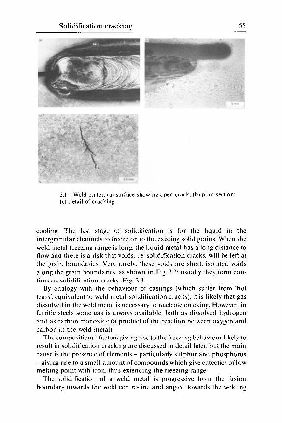
Solidification cracking 55
3.1 (c) detail of cracking.
Weld crater: (a) surface showing open crack: (b) plan section:
cooling. The last stage of solidification is for the liquid in the intergranular channels to freeze on to the existing solid grains. When the weld metal freezing range is long. the liquid metal has a long distance to flow and there is a risk that voids. i.e. solidification cracks. will be left at the grain boundaries. Very rarely. these voids are short. isolated voids along the grain boundaries, as shown in Fig. 3.2: usually they form con- tinuous solidification cracks. Fig. 3.3.
By analogy with the behaviour of castings (which suffer from 'hot tears'. equivalent to weld metal solidification cracks), i t is likely that gas dissolved in the weld metal is necessary to nucleate cracking. However. in ferritic steels some gas is always available. both as dissolved hydrogen and as carbon monoxide (a product of the reaction between oxygen and carbon in the weld metal).
The compositional factors giving rise to the freezing behaviour likely to result in solidification cracking are discussed in detail later. but the main cause is the presence of elements - particularly sulphur and phosphorus - giving rise to a small amount of compounds which give eutectics of low melting point with iron. thus extending the freezing range.
The solidification of a weld metal is progressive from the fusion boundary towards the weld centre-line and angled towards the welding

56 Weldability of ferritic steels
3.2 crack: ( h ) SEM fractograph showing mixture of smooth solidification cracking and dimpled ductile tearing (microvoid coalescence) which occurred when the crack was broken open at ambient temperature: (c) macrosection of complete crack.
Discontinuous solidification crack: ( a ) microsection of part of
direction and to the face of the weld: any deficiency in feeding liquid metal to compensate for the contraction o n solidification is likely to lead to a solidification crack at the weld centre-line. Provided the welding speed is not too fast. the contraction on solidification is made up by liquid metal fed from the hotter parts of the weld pool towards the solidifying weld metal.
I f the welding speed is too fast. the growing grains. and the channels between them. become longer and narrower. thus making feeding more difficult. Similarly. if the weld pool is deep and narrow (i.e. i t has a high depth/width ratio - see Fig. 3.4). or is very wide and shallow. feeding also becomes more difficult. and cracking is more likely than if the depth/ width ratio is near the optimum. In addition. the solidification of a weld with a high depth/width ratio tends to be inwards from the sides. and this increases the severity of segregation of low melting material to the weld centre-line. With a less deep pool. the solidification tends to be upwards as well as inwards. thus reducing the severity of centre-line segregation

Solidification cracking 57
3.3 Typical continuous solidification cracks: ( a ) section through open centre-line and subsurface cracks (also HAZ hydrogen crack) in fillet weld with root gap: ( h ) SEM fractograph of well-developed suh- surface crack.
and allowing more contraction to be taken up by sinking of the weld sur- face. Although a complete survey of the ideal values for the d e p t h h i d t h ratio does not appear to have been made. a figure of about 0.5 is likely to be somewhere near the optimum.
As the weld solidifies towards its centre-line. anything which locally delays solidification there is likely to encourage cracking. because this delay in solidification will hold back the solidification front at the weld centre from reaching the free surface. where the contraction is free. The most likely cause of delayed centre-line solidification is a root gap (Fig. 3.3(a). although severe root defects (Fig. 3.5) can have similar effects. A root gap is a very common cause of cracking and. unlike hydrogen crack- ing (Chapter 5) . the effect becomes greater if the width of the root gap is increased. Other delays to solidification at the weld centre can be caused by lack of root fusion (Fig. 3.6) and. to a lesser degree. by the use of ceramic or very thin steel backing strips in square edged butt welds. These types of backing cause the weld to solidify directly inwards from the two sides. instead of inwards and upwards when efficient heat extraction from a thick steel backing is used.

58 Weldability of ferritic steels
3.4 Depth to width (DIW) ratios: ( a ) conventional butt weld: (b) modified ratio. (D-X)IW. to take account of convexity or concavity of fillet weld shape.
Welds having long. narrow weld pools (associated with the use of fast welding travel speeds) are particularly at risk of cracking, and the influence ofwelding conditions on weld pool shape and cracking is discussed later.
Because welds normally solidify inwards from the parent metals being welded. the most likely location for solidification cracking is the weld centre-line. as shown in Fig. 3.3 and 3.5. The centre-line is that of heat extraction. rather than the geometric centre-line. This can be seen in Fig. 3.7. where an attempt has been made to weld two plates of different thick- ness with a single pass. Heat extraction during solidification has been predominantly through the thicker plate. The heat needed to achieve ade- quate fusion to the thicker steel has melted back the thinner steel so that the root gap has widened from near zero to almost 6 mm. This has led to a solidification crack at the heat centre. which is near to the fusion boundary on the thin plate. Welding was successfully carried ou t in two passes. because the small root pass did not involve fusing on to such a large area of the thicker steel and. hence. the thinner plate was melted back less.
As cracks occur in the last stages of solidification. they are often open to the surface. unless the weld metal forms a thin. solid skin during solidi-

Solidification cracking 59
3.5 Macrosection of weld with root defect and crack.
fication (Fig. 3.8) or is so deep that the surface bridges over before the underlying weld metal solidifies (Fig. 3.9).
The resistance to cracking of welds made with convex surfaces is better than if made with sunken tops (compare Fig. 3.10 and 3.3(a) and Fig. 3.11(a) and (b)). even though the latter appear to have smaller depth/ width ratios. In fact. for fillet welds. the depth/width ratio should be measured from a line joining the weld toes as shown in Fig. 3.4(b). rather than from the weld surface.

60 Weldability of ferritic steels
3.6 Solidification cracking in wide. shallow root run of butt weld.
Consequences of cracking In ferritic steels. i t is unusual for solidification cracks to extend by frac- ture of the solidified weld metal. as can be seen in the fractograph in Fig. 3.2(b) and by the macrograph. Fig. 3.8. Even where a second run of weld metal is deposited over a previous run containing a solidification crack. the first crack will not initiate a second. Fig. 3.12. unless those portions of the two runs that are the last to solidify are in line with each other. Because the crack tips are usually rounded on a microscopic scale (Fig. 3.13), they are less damaging than hydrogen cracks. fatigue cracks and other cracks which have occurred through solid metal.
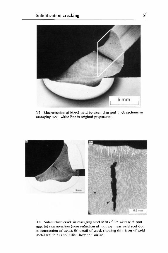
Solidification cracking 61
3.7 maraging steel. white line is original preparation.
Macrosection of MAG weld between thin and thick sections in
3.8 gap: (a ) macrosection (note reduction of root gap near weld root due to contraction of weld): (b) detail of crack showing thin layer of weld metal which has solidified from the surface.
Sub-surface crack in maraging steel MAG fillet weld with root

62 Weldability of ferritic steels
3.9 in deep. narrow submerged arc weld.
Centre-line and intercolumnar subsurface solidilkation cracking

Solidification cracking 63
3.10 sub-surface solidification cracking.
Convex-topped submerged arc fillet weld showing minor
3.1 1 ( h ) concave top with solidification crack.
Similar submerged arc butt weld runs having: ( a ) convex top:

64 Weldability of ferritic steels
3.12 that crack 2 wiis not initiated from the earlier crack I .
Section of part of a heavy submerged arc fillet weld showing

Solidification cracking 65
3.13 Detail of cracks of Fig. 3.9 showing relatively blunt crack tips.

66 Weldabili ty of' ferritic steels
Role of composition
In any alloy system. the risk of solidification cracking is very low when welding a pure metal and using the same pure metal as filler. Any alloying element that lowers the melting temperature and increases the freezing range will increase the risk of cracking. I f a eutectic system is formed. the risk of cracking will be reduced after the melting temperature range has reached a maximum. until the eutectic point is reached (Fig. 3.14(a)). Although the behaviour of steels is complicated by high temperature phase changes (i.e. the delta to gamma peritectic). this classical type of behaviour is shown by steels containing different amounts of boron' (Fig. 3.14(b)) or niobium. Additions of either element initially increase the risk of solidification cracking whilst further additions then reduce the risk. In general. elements that give a sharp drop in melting temperature to a low minimum (eutectic) value are the most dangerous. These elements arc usually the ones with low solid solubilities. i.e. those that form a second phase. so that only ;I small addition is needed to give a long freezing r;i nge.
In steels. the presence of the peritectic (Fig. 3.15) complicates the situation. because most elements have different solubilities in the two solid phases. high temperature (delta) ferrite and austenite (gamma). This is particu- larly the case for sulphur ( a very common impurity in steels) which is much less soluble in austenite than in ferrite. Hence. elements that pro- mote solidification a s austenite. rather than ferrite. generally increase the risk of solidification cracking. The most influential of these elements is carbon (Fig. 3.15): only 0.08% C is needed for solidification to be com- pleted with some austenite. and carbon additions above 0.18% C also lead to an increase in the freezing range.
However. if the carbon content is so low that solidification is completely to delta ferrite. i t has been claimed' that the subseqiient transformation to austenite (with its volume contraction) adds to the existing contraction strains sufficiently to increase the risk of cracking with very low carbon weld metals (i.e. 0.09% C clown to about 0.04% C).
Ferrite formers. such a s Cr. Mo and V. reduce the risk of cracking. Nickel is the only significant austenite former generally to promote solid- ification cracking: although at very low carbon levels. the influence of nickel on preventing solidification a s delta ferrite (with its subsequent contraction on transformation to austenite) appears to reverse this trend.' but only with weld metals of very low carbon content.
The other important austenite former is manganese and its behaviour is complicated by its interaction with sulphur. Without the presence of manganese. iron forms a eutectic with iron sulphide (FeS). which has a particularly low melting point - about 990 "C. Addition of sufficient

Solidification cracking 67
3. I4 how the risk of cracking (chain-dotted line) increases as the freezing range increases; (b) Fe-B system showing low-melting eutectic. present at very low boron contents.
Parts of typical phase diagrams containing eutectics: ( a ) showing

68 Weldability of ferritic steels
0.035% \ I I Ferrite + austenite
I
Ferrite +
-0.007%
160(
140(
120(
- 9 - loo( ??
I
a 80C I-
3 w
a,
: 600
400
200
0
cementite
3.15 Part of phase diagram of Fe-C system
manganese to the weld metal replaces FeS by a mixed sulphide. (Mn.Fe)S. and this beneficially raises the eutectic temperature if suffi- cient is present. I t is claimed3 that in TIC weld metal and in the absence of carbon. FeS occurs up to a Mn3:S ratio of about 0.83:l. With ratios from about 0.83 to 3.0 the (Mn.Fe)S is film-like whilst above a ratio of about 3.0 solidification is completed with a high melting eutectic and cracking is much reduced. With about 0.12% C in the weld metal. the ratio for the appearance of (Mn.Fe)S is unchanged but the film-like appearance only disappears with Mn3 : S ratios above 6.7. If 0.2% C or 2- 7% Ni are present. as much as 2-3% Mn is needed to avoid cracking3

Solidification cracking 69
Because of the formation of a peritectic and of the different solubilities of sulphur in ferrite and austenite. the behaviour of carbon is quite com- plex. Although carbon is generally regarded as promoting solidification cracking. several investigators ( c g ref. 4) have noticed that reducing the carbon content below some level (values have been quoted between 0.08 and 0.14% C ) does not further reduce the risk of cracking. and may. in fact, worsen it.* However. on approaching a zero carbon content the resistance to cracking probably improves again.
Another element which interacts with sulphides is oxygen. At very low levels (probably up to about 0.010%) of oxygen, the sulphide (Fe.Mn) S is in the type I1 form. which has a low surface tension and spreads easily along the grain boundaries. thus making solidification cracking easy. Higher oxygen contents promote the formation of the Type 1 sulphide with a higher surface tension. making penetration of the grain boundaries. and hence cracking. more difficult. This effect of oxygen is only important with the low oxygen welding processes. such as TIG.' plasma. electron beam and laser welding. No effect has been found with the flux and active gas welding processes MMA. MAG. submerged arc and electroslag.
Several attempts have been made to quantify the effects of different ele- ments on solidification cracking of steels. These have usually been devel- oped for specific welding processes. and are discussed below for submerged arc welding. which has given the most serious problems in practice. and for TIG. which is often used for the most 'difficult' steels.
Submerged arc welding A systematic study of the influence of compositional variables on solidifi- cation cracking was made some years ago." and the results have been incorporated into the British Standard for structural steel welding6 This work led to a formula which relates the risk of cracking. when carrying out Transvarestraint tests under carefully standardised conditions. to the composition of the weld metal. Because submerged arc welding involves considerable dilution of the parent steel into the weld pool. and also involves widely different fluxes. which modify the weld metal composition from that simply calculated ( i t . from a knowledge of the base metal and wire compositions and dilution). guidance was given4 on how to allow for these factors.
The formula relates crack susceptibility (in terms of units of crack sus- ceptibility. UCS) to the composition of the weld metal (mass %):
UCS = 230C + 190s + 75P + 45Nb - 12.3Si - 5.4Mn - 1 [3.1]
The equation is valid for the following range of weld metal compositions:

70 Weldability of ferritic steels
O.OX*-O.23%, C: 0.0 10-0.050%, S: 0.0 lO-O.O4S%) P: 0.15-0.65% t Si: 0.45- 1.6% Mn: 0-0.07'% Nb.
The presence of elements up to the following amounts do not signifi- cantly inlluencc the risk of cracking: 1% Ni: 0.5% Cr: 0.4% Mo: 0.07% V: 0.3% Cu: 0.02% Ti: 0.03%) Al: 0.002'% B: O.OI'%, Ph: 0.03% Co.
The significance of the values calculated from the formula is that. with submerged arc welding. values up t o 10 UCS represent a very low risk of cracking and values of 3 0 and greater. a high risk. In a standardised restrained 19 mm thick. single-pass. T-fillet weld test. 20 UCS was just above the threshold for cracking when the weld depth/width ratio was approximately 1.0. In butt welds. the results were affected by root gaps. tis well a s by weld shape. hut cracking became relatively common when the UCS exceedeci 23 for welds with ;I depth/width ratio o f ahout 0.X.4
Because the accuracy of analysis for carbon is ~ i ~ ~ i : i l l y no hetter than kO.Ol(%, C. and this is equivalent to 2.3 UCS. differences of <3 UCS are not significant when comparing the likely cracking behaviour of weld metals. For this reason. LICS values should be given to the nearest whole nu in her.
Although the amounts of the elements listed above have no significant effect on cracking. nickel and horon i n amounts greater than those given can certainly increase the risk o f cracking. I t is also likely that the ferrite stabilisers Cr. Mo and V can reduce the risk of cracking. To a first approximation. i t can he stated that elements present in the quantities given above have an effect on solidilication cracking no greater than 3 UCS. i.e. similar to the influence of ahout 0.01% C (2.3 UCS).
Some of the elements not included in Eq. 13.1) are discussed in more detail i n the next section. Of these. aluminium should have a mildly ben- eficial effect. but its variation during normal submerged arc welding is not su fticient to have ii detcctahle effect. Oxygen is known to he henelicial to so I id i li cii t i o n c r;t c k i ng resist a nce. but t h e ii m ou n t s p rese n t i n s u h- merged arc deposits are all above the level at which henelit can be obtained hy increasing oxygen levels. Boron is known to be harmful. but the amounts known to be detrimental - 0.01% B is known to give cracking in bead-on-plate deposits7 - are well above the levels added to submerged arc weld metal.
Nickel is known to be harmful. anti i t is likely to givc prohleins if high speed welding procedures for clean C:Mn steels are adopted unchanged for 3% and 5% Ni weld metals. However. with the high strength weld metals of the Ni:Mo. Ni:Cr:Mo and similar types. the amounts of Ni are smaller and are. to some extent. counterbalanced by those of the other. ferrite-
*C';irhon contents <O.OX"O should he taken 21s equal to O.OX%. -t Silicon content\ ahow 0.65% n i a y imnww. rather than reduce thc ri\k of cracking.

Soliditicatioii cracking 71
+0.02 T I 0 .-
Neutral bauxite 1 Highly basic .. -
-
1. \. Manganese silicate 1. 1.
(0 6 -0.08
0.1 0.2 0.3 Expected C content (%)
(a)
+0.2
0
-0.2
Manganese silicate and M n alloying 1 e p p r o x i m a t e curve)
t 1 -0.41 I I I ! I I I I I I -1I
0.5 1 .o 1.5 2.0 Expected Mn content (%)
(b)
3.16 Effect of flux type on compositional changes during welding: (a) carbon (calcium silicate flux is intermediate between neutral bauxite and highly basic types): (b) manganese (for flux types not given in Table 3.1).
stabilising alloying elements present in such weld metals. The effect of nickel at very low weld metal carbon levels was discussed earlier in the chapter.
When the values that can be obtained from Eq. (3.11 are related to the normal compositional variations likely in submerged arc weld metal. it will be seen that the most harmful element is carbon. Whereas increasing sulphur from 0.010 to 0.0500/0 (an increase that would be very difficult with present-day structural steels and consumables!) would give an increase of less than 8 UCS. this increase is less than occurs if the carbon content is increased by 0.04% - well within the likely variation in different runs of a mu1 t i pass sub merged weld.
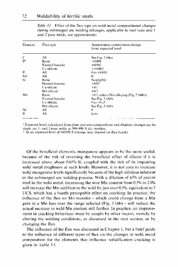
72 Weldability of ferritic steels
Eiblr 3.1 Effect of the flux type on weld metal compositional changes during submerged arc welding (changes. applicable to root runs and 1 and 2 pass welds. are approximate)
Element Flux type Approximate composition change from 'expected' levela
c- S"
P Nh Si
M n
Ni B
All B, :. Neutral hauxite Ca silicate All All
Neu trol ha uxite Ca silicate Mn silicate
Neutral ha ti xi te Ca silicate M n silicate All All
dblL
B. :. 'ISIC
B. . ' . dSlC
See Fig. ?.16(a) -0.004 +0.002 >+0.002 0 to +O.OlO 0 Negligihle +0.05 +o. I +0.2 -0.1. unless Mn-alloying (Fig. ?.16(h)) See Fig. ?.16( h ) 0 t o -0.15 Scc Fig. ?.16( h) 0 LO\ \
Expected levels calculated from plate a n d wire compositions and dilution: changes are for
At a n expected level of 0.020%) S (change may depend on flux hatch). single arc I - and 2-pass welds at 500-900 A t1.c. positive.
Of the beneficial elements. manganese appears to be the more useful. because of the risk of reversing the beneficial effect of silicon i f i t is increased above about 0.65% Si. coupled with the risk of its impairing weld metal toughness at such levels. However. i t is not easy to increase weld manganese levels significantly because of the high dilution inherent in the submerged arc welding process. With a dilution of 65% of parent steel in the weld metal. increasing the wire Mn content from 0.5% to 2.0Y0 will increase the Mn addition to the weld by just over 0.5%. equivalent to 3 UCS. which has a barely perceptible effect on cracking. In practice. the influence of the flux on Mn transfer - which could change from a Mn gain to a Mn loss over the range selected (Fig. 3.16b) - will reduce the actual increase in weld Mn content still further. In practice. an improve- ment in cracking behaviour must be sought by other means. namely by altering the welding conditions. a s discussed in the next section. or by changing the flux.
The influence of the flux was discussed in Chapter 1. but a brief guide to the influence of different types of flux on the changes in weld metal composition for the elements that influence solidification cracking is given in Table 3.1.

Solidification cracking 73
Other welding processes Of the flux welding processes. submerged arc welding is the most likely to give solidification cracking problems. partly because of the high welding speeds which can be used and partly because of the high dilutions, which can give high weld carbon contents when welding normal structural steels. However. the latter problem is much less acute with many modern weldable steels - particularly of the line pipe type (which are manufac- tured by high speed submerged arc welding) and with some of the high strength low alloy (HSLA) steels - because their carbon contents are no higher than those of many undiluted weld metals.
The manual welding processes MMA and manual TIC with filler give least risk of cracking when welding comparable steels because welding speeds and dilution levels are both low. However. these are the processes that are most likely to be used for welding medium and high carbon steels. which are at particular risk of cracking because of their high car- bon contents. Manual metal arc welding has certain advantages over TIG in welding medium-high carbon steels to avoid solidification cracking (but not other types of cracking) because weld metal carbon contents tend to be low (unless fillers of matching carbon content are used) and sulphur contents are reduced when basic electrodes are used.
Many of the earlier solidification cracking formulae were developed in this area. particularly for autogenous TIC welding. where the composition of the weld metal can be taken as being the same as that of the parent steel.
Huxley’s crack susceptibility factor?
CSF = SOIC + IS60 (Mn . S) - 82.8Mn - 47.9 l3.21
was developed for autogenously TIC welded C:Mn steels containing 0.15-0.3% C. but having a relatively limited range of 0.025-0.038% P. so that phosphorus does not appear in this formula. Despite the interaction between Mn and S. Mn is regarded as beneficial within the range exam- ined (0.31-1.69%).
Morgan-Warren and Jordan’ covered a wider range of alloyed steel compositions. also using autogenous TIC welding. and developed the form u 1 a :
CSF = 42C + 847s + 26SP - IOMO - 3042(0) + 19 P.31
The steels contained 0.08-0.4% C. 0.4-1.S% Mn. O.I-l.S% Si, 0.2-2% Mo, with up to 0.03% S. 0.03% P. 2% Ni. 5% Cr. 0.5% V. 6% Co. 2.1% Cu and 6.7% W. Other than the special case of manganese. molybdenum appears as the only alloying element which affects solidification cracking. although most people acknowledge that nickel is harmful in amounts greater than the 2% included in this study.
For electron beam welding. a cracking index (CI) has been developed

74 Weldability of ferritic steels
for simple C:Mn steels. based on the composition of the steel being welded. and related to the ease of producing cracking in a standard test:y
CI= 52.6C+1972S+P(4268C-285)-Mn( 1135S-9)-21 . I 13.41
The steels contained 0.09-0.31%C , 0.26+0.02% Si. 0.77-1 34% Mn. 0.005- 0.055%) S. O.OOS-0.OS8% P with other elements <0.1%. All the important elements for this type of steel were varied over a significantly large range except Si. Although the equation has a family resemblance to other solid- ification cracking formula. guidance is not yet available on values to avoid for different welding situations.
Solidification cracking and the welding process
Translating the ideal weld shape factors (i.e. a weld pool which is not too deep o r shallow. and which solidifies uniformly from root to cap) into welding parameters suggests that. where weld metal compositions are likely to crack. high welding speeds should be avoided and welding currents kept low enough to avoid high depth/width ratios. In avoiding a deeply penetrating weld pool. the dilution of parent steel is niinimised. and this is usually advantageous because (except in some modern. very low carbon steels) the parent steel is usually of a composition more susceptible to cracking than the weld metal.
Depth/width ratio Although the effect ofvarying depth/width ratio on cracking has not been fully explored. some guidance can be given for submerged arc welds. using the UCS values obtained from Eq. 13.11. For butt welds with a ratio of about 0.8. cracking is not apparent until a UCS value of approximately 93 is reached. However. the weld root run illustrated in Fig. 3.17 cracked with a UCS of only 13. but its depth/width ratio probably exceeded 1.5. This example highlights the importance of controlling root run welding procedures. especially on the second side of a butt weld. There is a natural tendency to deposit the second side root run with a high current in order t o ensure good root fusion and lack of welding faults. The risk of over- doing this is obvious from the figure: the current had been deliberately increased because i t was known that a large root face had to be pene- t ra ted.
For T-lillet welds. i t has been found that decreasing the depth/width ratio from 1.0 to 0 .8 beneficially increased the critical UCS value by approximately 9 UCS (Fig. 3.18). Even further increases in the acceptable UCS value are apparent with MMA and TIC welding. where much higher UCS values can be tolerated without solidification cracking in

Solidification cracking 75
3.17 weld in 60 mm thick plate. in which the welding current wits increased considerably in order to achieve penetration.
Solidification crack in root pass. second side of submerged arc
weld beads with depth/width ratios of about 0.5. When changing welding parameters to reduce the risk of cracking by altering the depth/width ratio in fillet welds. i t is important to determine this ratio by measuring from a line through the weld toes, rather than from the centre of the face of the weld. as shown in Fig. 3.4. in case the convexity of the weld is altered by the change in welding procedures.
The convexity of a weld bead can be increased by a limited extent to reduce the likelihood of cracking (Fig. 3.1 I) . However. too convex a bead shape may be undesirable on other grounds. for example the difficulty of tying-in adjacent beads or the adverse effect on fatigue and other types of cracking due to the higher stress concentration factor.
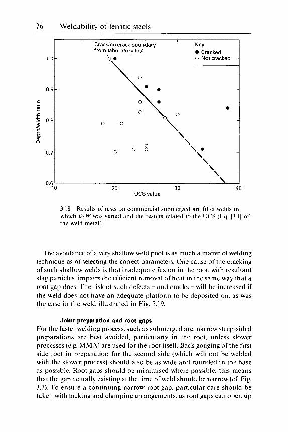
76 Weldability of ferritic steels
UCS value
3.18 which DIW was varied and the results related to the UCS (Eq. 13.11 of the weld metal).
Results of tests on commercial submerged arc fillet welds in
The avoidance of a very shallow weld pool is as much a matter of welding technique as of selecting the correct parameters. One cause of the cracking of such shallow welds is that inadequate fusion in the root. with resultant slag particles. impairs the efficient removal of heat in the same way that a root gap does. The risk of such defects - and cracks - will be increased if the weld does not have an adequate platform to be deposited on. as was the case in the weld illustrated in Fig. 3.19.
Joint preparation and root gaps For the faster welding process. such as submerged arc. narrow steep-sided preparations are best avoided. particularly in the root. unless slower processes (e.g. MMA) are used for the root itself. Back gouging of the first side root in preparation for the second side (which will not be welded with the slower process) should also be as wide and rounded in the base as possible. Root gaps should be minimised where possible: this means that the gap actually existing at the time of weld should be narrow (cf. Fig. 3.7). To ensure a continuing narrow root gap. particular care should be taken with tacking and clamping arrangements. as root gaps can open up

Solidification cracking 77
3.19 Solidification crack in cored wire MAG weld: owing to inadequate support for the weld. a shallow wide weld was inevitable and root defects resulted.
during the welding of long seams and this can lead to cracking towards the end of the weld. Sudden fracture or melting of tack welds throws a sudden strain on the solidifying weld which can accentuate this problem.'" Care in clamping is particularly important in welding higher strength steels. as the forces to be resisted increase with the strength of the steel.
When welding sections of different thickness it is unwise to try to com- plete the joint with too large a root pass (or to try to make a single-pass weld where this is only just practicable), because there is a serious risk of the thinner component melting back. opening up the root gap and inducing cracking," as in Fig. 3.7.
Other parameters Weld size is a minor parameter compared with depth/width ratio, but increasing weld size in terms of the weld cross-section tends to increase

78 Weldabili ty of ferritic steels
the risk of cracking. However. when weld size is changed. the alteration in welding parameters needed to give the change will usually have other effects. e.g. a change in dilution and hence weld metal composition. which will outweigh the simple effect of changing the weld size.
Weld pool length is a major factor. I t has long been known that increasing the length of the weld pool from an oval shape (typical of TIC welding) to a long tear-drop shape (more typical of MAG and submerged arc) helps to promote cracking. This is because. as the weld pool is lengthened. the weld metal grains tend to grow more inwards and forwards than directly upwards. thus increasing the feeding distance for the molten weld metal to counteract solidification contraction. If. however. the pool is lengthened by using multiple arcs. then the adverse influence of a long weld pool is nullified by providing a new source of molten weld metal for feeding the solidification shrinkage and also by reducing the dilution of parent steel into the weld.
Welding speed. because of its effect on depth/width ratio and weld pool length. has a marked effect. increasing speed giving an increased risk of cracking.
Weld strain is difficult to visualise and to quantify. because the strains of concern are the local strains on the weld pool at a late stage in its solid- ification. These strains result from both large scale physical movement ( i t . distortion) and locally induced solidification and contraction strains. Such strains are continually changing as the weld is made. T h e local strain on the weld results from contraction of the weld metal during its
Tension
Temperature I I
rising
t Direction of welding t
Weld
1 falling
Compression
3.20 Stress distributions about moving heat source during welding.

Solidification cracking 79
solidification, induced by the restraint imposed by cooler parts of the joint as shown schematically in Fig. 3.20.
Restraint is needed to prevent the joint ahead of the welding arc opening up to such an extent that the weld shape would be affected. even allowing the weld to drop through. This opening up promotes solidification cracking. particularly in very long welds. In addition. however. the parts being joined would lift if not restrained: this lifting will reduce the tendency to crack, whereas restraining the tendency to lift will tend to promote cracking. After the first run has been deposited. the underlying weld metal restrains the upward contraction to some extent so that it is unlikely that increasing the restraint at this stage to prevent further distortion will have much effect on cracking.
Plate thickness is a minor variable: an increase in plate thickness. par- ticularly for fillet welds. is likely to increase the risk of cracking because of the increased restraint. I f the carbon content of the steel itself has been increased to maintain its strength as the thickness is increased. this will further increase the risk of cracking.
Parent metal strength also has a minor effect on cracking. an increase in strength increasing the risk of cracking because of the greater restraint offered by the stronger steel. This effect is noticeable. even if the weld metal strength is unchanged. which supports the view that the effect is due to the stronger parent steel being less able to yield to accommodate thermal strains.
Welding sequence and practice is most important: in multipass (and also two pass) butt welding. cracking is most likely in the root pass of the second side to be welded. This is partly because of the increased restraint but also because of a strong tendency to increase welding currents for this pass to ensure good inter-run fusion (Fig. 3.17). Little is known about the correct sequence to minimise cracking in multipass butt welds. It is believed that a balanced technique should be used. although it is probable that the deposition of several runs on the first side reduces the risk of cracking of the second side root run. provided distortion can be adequately handled.
A particularly difficult situation occurs when depositing simultaneous double fillet welds (e.g. T-joints and other stiffeners). If the arc on the first side leads by 100-200 mm (particularly in submerged arc welding). the first fillet may be solid and contracting and pulling on the second side bead when the latter is at a late stage of solidification. and thus most vulnerable to cracking.
Preheat has somewhat complex effects on solidification cracking. If the joint is clamped sufficiently to avoid distortion. preheat is beneficial. par- ticularly if it is general rather than local. In less well-restrained structures, preheat can add to the level of distortion and thus increase the risk of

80 Weldability of ferritic steels
cracking, particularly if it tends to open up the joint ahead of the welding arc. Very high levels of preheat will tend to increase dilution of parent steel into the joint, and this will usually increase the risk of cracking.
Although grain refinement of the as-deposited (columnar) weld metal grain structure is potentially capable of reducing the risk of solidification cracking. techniques for such refinement are as yet not available and are likely to be very difficult to achieve in any steel. Refinement of the grain size in the solid state has no effect on cracking.
Control and avoidance of cracking
Control of weld metal composition is not always the easiest option. partic- ularly with high dilution processes such as submerged arc welding, because with them the weld metal composition depends more on the parent steel composition and the flux system (often selected to achieve toughness and/or weldability) than on the wire. In submerged arc welding. it is recommended to aim for UCS values (Eq. [3.1]) in the root runs below 25 UCS for butt welds and below 19 UCS for fillets. Higher values can be tol- erated for other welding processes. probably in the order MAG (spray). MAG (dip). self-shielded FCAW. MMA and TIC. Experience is needed to decide on limits for these processes. although Eq. [3.2] and [3.3] may be used when TIG welding the higher carbon engineering steels.
In the parent plate. the elements carbon and sulphur are the dangerous ones. e.;pecially in the root region where dilution of the parent steel into the weld is high. Manganese and (to a limited extent) silicon are beneficial and the routine scrutiny of mill sheets for these elements is recommended where there is a known risk of cracking.
The effect of the composition of the wire on that of the root region is quite small when using high dilution welding processes. Nevertheless. good practice is to use wires of low C. S and P contents. together with the highest Mn content compatible with the mechanical properties required. It should also be borne in mind that excessively high strength levels (which could result from high weld metal manganese contents) can give rise to other problems. such as high residual stresses and an increased risk of weld metal hydrogen cracking; such problems are potentially more serious than solidification cracking. which is usually easy to detect and to remedy.
The flux also influences weld metal composition. The so-called acid fluxes. because they remove carbon and give moderately high silicon levels. are beneficial in avoiding cracking. provided that they are not so 'acid' that excessively high silicon levels (i.e. >0.6%) result. The acid fluxes can. however. increase weld metal sulphur and phosphorus contents. and
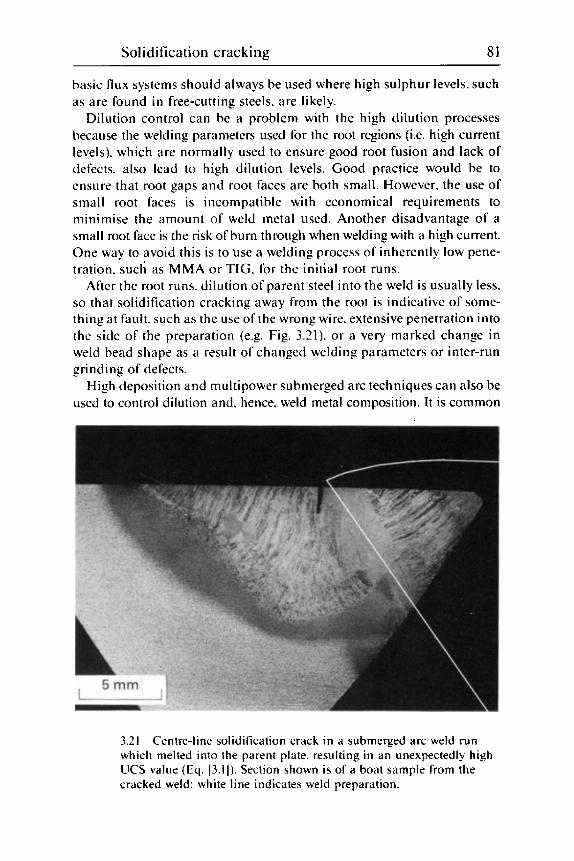
Solidification cracking 81
basic flux systems should always be used where high sulphur levels, such as are found in free-cutring steels. are likely.
Dilution control can be a problem with the high dilution processes because the welding parameters used for the root regions (i.e. high current levels). which are normally used to ensure good root fusion and lack of defects. also lead to high dilution levels. Good practice would be to ensure that root gaps and root faces are both small. However. the use of small root faces is incompatible with economical requirements to minimise the amount of weld metal used. Another disadvantage of a small root face is the risk of burn through when welding with a high current. One way to avoid this is to use a welding process of inherently low pene- tration. such as MMA or TIG. for the initial root runs.
After the root runs. dilution of parent steel into the weld is usually less, so that solidification cracking away from the root is indicative of some- thing at fault. such as the use of the wrong wire. extensive penetration into the side of the preparation (e.g. Fig. 3.21). or a very marked change in weld bead shape as a result of changed welding parameters or inter-run grinding of defects.
High deposition and multipower submerged arc techniques can also be used to control dilution and. hence. weld metal composition. It is common
3.21 Centre-line solidification crack in a submerged arc weld run which melted into the parent plate. resulting in an unexpectedly high UCS value (Eq. [3.1]). Section shown is of a boat sample from the cracked weld: white line indicates weld preparation.
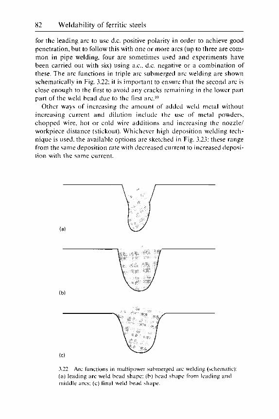
82 Weldability of ferritic steels
for the leading arc to use d.c. positive polarity in order to achieve good penetration, but to follow this with one or more arcs (up to three are com- mon in pipe welding, four are sometimes used and experiments have been carried out with six) using ax.. d.c. negative or a combination of these. The arc functions in triple arc submerged arc welding are shown schematically in Fig. 3.22: i t is important to ensure that the second arc is close enough to the first to avoid any cracks remaining in the lower part part of the weld bead due to the first arc.")
Other ways of increasing the amount of added weld metal without increasing current and dilution include the use of metal powders. chopped wire. hot or cold wire additions and increasing the nozzle/ workpiece distance (stickout). Whichever high deposition welding tech- nique is used. the available options are sketched in Fig. 3.23: these range from the same deposition rate with decreased current to increased deposi- tion with the same current.
3.22 ( a ) leading arc weld bead shape: ( b ) bead shape from leading and middle arcs: (c) final weld bead shape.
Arc functions in multipower submerged arc welding (schematic):

Solidification cracking 83
I I I I 400 500 600 700 800 900 1000 1100
Welding current (A)
3.23 high deposition welding technique. curve Y. Conventional technique is curve X and original welding condition. point 0. Alternatives are: (a ) same deposition rate with reduced welding current: (b) increased deposition rate with same welding current: (c) compromise with increased deposition rate but reduced current.
Schematic approach to control of dilution and heat input using
Control of solidification pattern is often a more successful way of con- trolling solidification cracking than attempting to improve the weld metal composition. Differences in solidification pattern usually accompany several of the methods of reducing dilution discussed in the previous sec- tion. Reducing the welding current is the easiest way of reducing the depth/width ratio. although it inevitably leads to a loss of productivity and. if carried to excess. can lead to such defects as lack of fusion (which may even bring back solidification cracking as a result of root defects plus too shallow a weld pool). Reducing welding speed also has similar beneficial effects on cracking to reducing welding current - and is also coupled with a loss of productivity.
Changing polarity, if this is possible. from d.c. positive to a.c. to d.c. negative. and the use of increased stick-out will both reduce weld depth/ width ratios without reducing deposition rates. Also. where possible. the use of cold metal additions (hot or cold wire at the back of the weld pool or metal powder additions with submerged arc) tend to reduce depth/ width ratios without penalising efficiency (Fig. 3.23).
In addition to altering the welding parameters, it is also possible to reduce the steepness of the weld preparation, although this usually has

84 Weldability of ferritic steels
economic penalties. either by increasing the amount of weld metal needed or by the increased machining costs if a compound preparation is used.
Avoidance of root gaps is also important to achieve a weld shape resis- tant to solidification cracking. Where root gaps cannot be avoided. back- ing strips are used. Although no supporting work is known. it is likely that the use of high conductivity backings. such as steel or copper. will give less risk of cracking than ceramic or other non-metallic backings.
Control of strain by using lower strength parent steel or weld metal is rarely within the control of the fabricator. Nevertheless he or she should be aware of the increased risks when using the higher strength materials. Distortion during welding. which may occur as a result of preheating. inadequate restraint o r the fabrication sequence. is certainly under the fabricator's control.
Preheating causes most distortion when applied locally. and a narrow band is heated. Consideration should always be given to using very low hydrogen consumables to avoid the need for preheat. otherwise wide areas. preheated with electrical heating mats. are preferred. If preheat is essential and is causing solidification cracking. it may be possible to use subsidiary heating units to counteract distortion produced by preheating mats.
Restraint must be considered in two senses. Firstly. sufficient restraint must be applied when welding the first pass to avoid the two pieces moving apart and thus cracking. Once the first pass has been completed. further restraint hinders free contraction and thus makes cracking more likely.
When welding the first run of very long welds (i.e. >20 m or so). very high forces are needed to prevent the weld gap opening. and the use of multipower techniques is advantageous. so that the leading arc achieves adequate penetration and the trailing arc(s) adds weld metal of low crack susceptibility and completes the pass with a good weld shape. i.e. slightly convex (Fig. 3.22~). Run-off blocks also play their part in avoiding any of the crater cracking at the end of the weld run remaining in the joint itself. providing that they are sufficiently long to accommodate the weld pool completely: this may be longer than 300 mm when multiarc-welding. I t is also important that tack welds and clamping do not fail suddenly when welding the first seam. as the sudden shock is more likely to give cracking than the slow application to the solidifying weld of a similar strain."'
The restraint offered by the rest of the fabrication usually builds up during welding and can lead to cracking if the welding sequence is not selected to minimise this build-up. Nevertheless. i t may be necessary to reduce welding currents for particularly critical seams (especially if sensitive steels are involved) or even change to a less sensitive welding process. such as MMA or TIC if the bulk of the welding is by submerged arc or MAG. for example.

Solidification cracking 85
Remedial measures If cracking is discovered before a joint is too deeply buried by later weld runs. it is usually a simple matter to repair it. When automatic welding processes have been used. repair is often by means of MMA or TIC. the slower speed of which. coupled with an appropriate choice of consumables. will make solidification cracking during the repair much less likely. A long solidification crack can be repaired by gouging it out and re-welding with the original process, provided the reasons for the cracking are suffi- ciently well understood for the welding parameters to be correctly modified.
In practice. i t is likely that many solidification cracks occur in root runs and are unknowingly 'repaired' by melting out when the second run is deposited. without anyone being aware of their brief existence. However. if one is aware of such cracks. their repair by gouging and re-welding (followed by modification of the welding procedure for subsequent similar welds) is a safer option than hoping that they will always be removed by the next weld run: such removal depends very much on consistent adher- ence to the welding procedures.
Once solidification cracking has been detected. it is important to estab- lish the likely reason for the cracking. so that the necessary remedial measures will be both appropriate and economical. A common cause of such cracking is that the welding procedures have deviated from what was originally used successfully. I f restoration of the original welding parameters fails to eliminate cracking. some fairly simple remedial measures are possible:
Change welding parameters to reduce penetration. and hence depth/ width ratio and dilution (unless the cracking is associated with a very low depth/width ratio). Reduce welding speed to give a shorter weld pool. Improve weld metal composition by reducing C and S levels within the wire specification. Improve clamping for cracking in the first pass. reduce root gaps. using gap filling techniques if necessary. In severe cases it may be necessary to re-qualify the procedure by using. for instance. MMA for the root run(s) or buttering one half of a joint involving a high carbon steel.
Check list
Design Check that weld preparations are not too steep: that root faces are not so large that they require very high currents to penetrate: check whether steel and weld metal strengths are no greater than have been used pre- viously. as this itself will increase the risk of cracking: check that there is
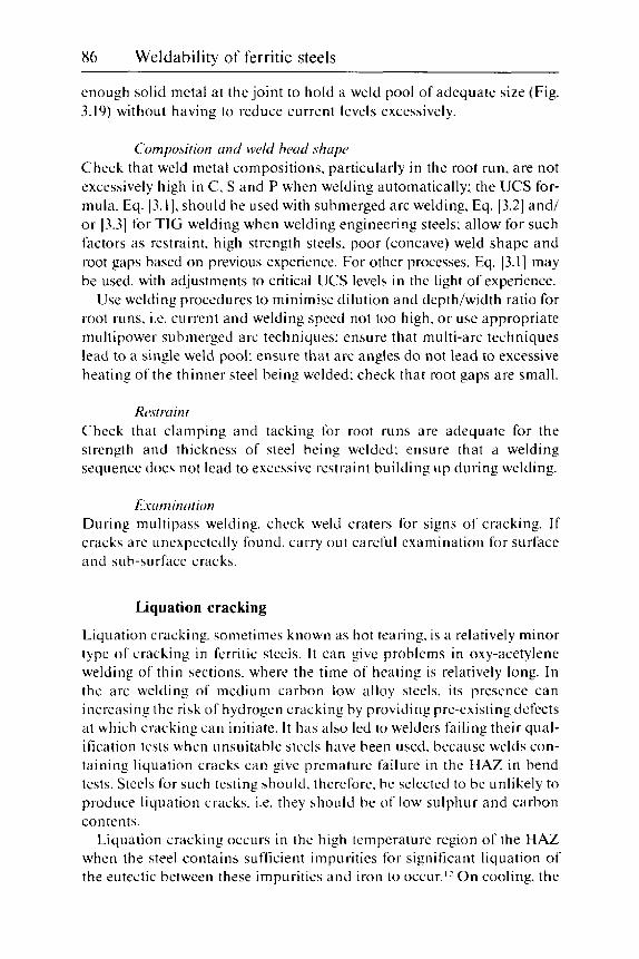
86 Weldability of ferritic steels ~
enough solid metal at the joint to hold a weld pool of adequate size (Fig. 3.19) without having to reduce current levels excessively.
Composition and weld bend shnpr Check that weld metal compositions. particularly in the root run, are not excessively high in C, S and P when welding automatically: the UCS for- mula. Eq. [3.l]. should be used with submerged arc welding. Eq. [3.2] and/ or [3.3) for TIC welding when welding engineering steels: allow for such factors as restraint. high strength steels. poor (concave) weld shape and root gaps based on previous experience. For other processes. Eq. [3.1] may be used. with adjustments to critical UCS levels in the light of experience.
Use welding procedures to minimise dilution and depth/width ratio for root runs. i.e. current and welding speed not too high. or use appropriate multipower submerged arc techniques: ensure that multi-arc techniques lead to a single weld pool: ensure that arc angles d o not lead to excessive heating of the thinner steel being welded: check that root gaps are small.
Rcwoint Check that clamping and tacking for root runs are adequate for the strength and thickness of steel being welded: ensure that a welding sequence does not lead to excessive restraint building up during welding.
E.wminntion During multipass welding. check weld craters for signs of cracking. If cracks are unexpectedly found. carry out careful examination for surface and sub-surface cracks.
Liquation cracking
Liquation cracking. sometimes known as hot tearing. is a relatively minor type of cracking in ferritic steels. I t can give problems in oxy-acetylene welding of thin sections. where the time of heating is relatively long. In the arc welding of medium carbon low alloy steels. its presence can increasing the risk of hydrogen cracking by providing pre-existing defects at which cracking can initiate. I t has also led to welders failing their qual- ification tests when unsuitable steels have been used. because welds con- taining liquation cracks can give premature failure in the HAZ in bend tests. Steels for such testing should. therefore. be selected to be unlikely to produce liquation cracks. i.e. they should be of low sulphur and carbon contents.
Liquation cracking occurs in the high temperature region of the HAZ when the steel contains sufficient impurities for significant liquation of the eutectic between these impurities and iron to occur.Iz O n cooling. the

Solidification cracking 87
liquid formed at the high temperature grain boundaries is unable to accommodate tensile strains caused by the contraction, and small cracks result. The cracks are identical in their formation with weld metal solidi- fication cracks and, if significant segregation of the responsible impurities is present in the parent steel. liquation cracks can continue from segregate bands in the parent steel into the weld metal as solidification cracks (Fig. 3.24). provided that the weld metal is susceptible to solidification cracking. In submerged arc welds and those of similar profile. cracking often occurs in the so-called bay area. Fig. 3.25. where the finger penetration joins the upper part of the weld bead. because this is the region of the HAZ which is at a high temperature for the longest time.
Although it is possible that some of the solidification cracking formulae discussed earlier could be used to forecast the likelihood of liquation cracking, the diagrams due to D. J. Widgery reproduced in ref. 13 and here in Fig. 3.26. are useful for assessing the likelihood of liquation cracking in relation to the S. C and Mn contents of the parent steel. Although it is likely that P and the Mn/Si ratio can also influence liquation cracking. their roles are minor and can usually be ignored.
3.24 Section of submerged arc weld showing segregate band (arrowed) from which a liquation crack and a solidification crack have initiated; fusion boundary is shown by a broken line.

88 Weidability of ferritic steels
3 . 3 hencl.
Liquation crack (a r rowed) in hay irrew o f suhmerged a rc weld
I t can be seen from the diagrams that liquation cracking is not possible with sulphur levels below about 0.010'%, S at any level of carbon. but with 0.2% C. there is a risk ofcracking with >0.010%, S and a strong likelihood with >0.05% S. unless the Mn/S ratio exceeds 40 (this last combination of circumstances is unlikely for most steels as i t would imply a M n content of >2% when O.OS% S was present). Hence free-cutting steels. containing anything up to 0.35% S (BS970: Part 3: 1991: 230M07) will usually suffer liqiiation cracking when welded and should not be used for welder quali- fication tests where bend tests are required.
Because liquation cracks are restricted to the high temperature HAZ and are a l i p e d roughly perpendicular to the fusion boundary. they are never more than 1-2 mm long. By themselves they are insignificant for most practical purposes. particularly as their tips are blunt like solidification cracks and unlike most low temperature cracks. However, they can increase the likelihood of subsequent hydrogen cracking (and probably also reheat cracking in susceptible steels). and for this reason it is not good practice to select steels with a deliberate sulphur addition when there is a risk of hydrogen cracking during welding. T h e risk of low duc- tility and toughness in the high temperature HAZ can also be important. particularly i n high heat input welds. in which liquation cracks are likely

Solidification cracking 89
A1
0.02 0.04 0.06 0 20 40 60 Sulphur content (wt %)
(a) (b) M n/S
3.26 Relationship between steel composition and occurrence of liquation cracking in HAZs of welds made with heat inputs of 2 kJ/mni.
to be larger than i f the heat input is low. In machined components. liquation cracks may also initiate fatigue cracking if present in areas of high stress.12
Liqiiation cracks are dependent o n the steel composition itself so that little can be done to minimise their presence. Welding on to the susceptible steel using a low heat input is mildly beneficial. a s i t slightly reduces the size of any cracks formed because of the reduced size of the high temper- ature HAZ. However. there is no evidence that a low heat input reduces the risk of liquation cracking occurring. One technique of minimising the risk of tearing is to use weld metals of low solidification temperatures. If a low heat input is used. a weld metal freezing temperature of -1100 "C would be needed.'? but at high heat inputs stainless steel o r nickel alloy consumables may have enough time for the liquid weld metal to be drawn into the liquation cracks as they form. thus healing them.
As with solidification cracks. high sulphur contents (particularly when associated with medium to high carbon and low manganese levels) pro- mote cracks. and these are associated with MnS films along prior austenite grain boundaries. Because the MnS inclusions in the steel start dissolving at the very high temperatures involved. chains of very small inclusions appear in a micro-section close to the major MnS inclusions (Fig. 3.27). However. i f the region containing liquation cracks is opened and examined by fractographic techniques. the small chains of inclusions are seen to be sections through a eutectic structure along the prior austenite boundaries (Fig. 3.28): these are sometimes described as chrysanthemum- shaped.
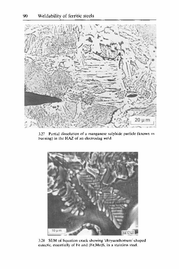
90 Weldability of ferritic steels
3.27 burning) in the HAZ of an electroslag weld.
Partial dissolution of a manganese sulphide particle (known as
3.28 SEM of liquation crack showing 'chrysanthemum'-shaped eutectic. essentially of Fe and (Fe.Mn)S. in a stainless steel.

Solidification cracking 91
WM (c) Normal transverse section
A-A
B
(d) B-B Oblique horizontal section
BM
HAZ
WM
- .- - - - - - - -
- - - - - - - - -
3.29 Taper sectioning used when examining for liquation cracks. BM. base metal; WM. weld metal: FB. fusion boundary; HAZ. heat- affected zone.
The most useful test for assessing liquation cracking is to make a bead-on- plate MMA deposit on the steel of interest and to examine a plan section made at a taper to the weld surface (Fig. 3.29). thus examining all regions of the HAZ from root to cap. This technique is preferred to simple trans- verse sections. as the latter can miss most liquation cracks present.12 Examination of the taper sections should be carried out at a magnification of at least X300 after normal polishing and etching.
Copper pick-up
Akin to liquation cracking is the penetration of copper into the HAZ (and occasionally the weld metal) when the copper, usually from a contact tip, inadvertently comes into contact with the workpiece during automatic welding. If small amounts of copper touch the molten weld metal there is no problem, as copper dissolves directly into the weld pool and, in small quantities. is not harmful. However. copper has a freezing point of
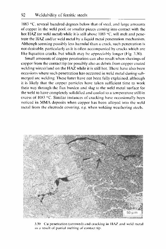
92 Weldability of ferritic steels
1083 "C. several hundred degrees below that of steel. and large amounts of copper in the weld pool, or smaller pieces coming into contact with the hot HAZ (or weld metal) while it is still above 1083 "C. will melt and pene- trate the HAZ and/or weld metal by a liquid metal penetration mechanism. Although seeming possibly less harmful than a crack. such penetration is not desirable. particularly as it is often accompanied by cracks which are like liquation cracks. but which may be appreciably longer (Fig. 3.30).
Small amounts of copper penetration can also result when shavings of copper from the contact tip (or possibly also as debris from copper coated welding wires) land o n the HAZ while it is still hot. There have also been occasions where such penetration has occurred in weld metal during sub- merged arc welding. These latter have not been fully explained. although it is likely that the copper particles have taken sufficient time to work their way through the flux burden and slag to the weld metal surface for the weld to have completely solidified and cooled to a temperature still in excess of 1083 "C. Similar instances of cracking have occasionally been noticed in MMA deposits when copper has been alloyed into the weld metal from the electrode covering. e.g. when welding weathering steels.
3.30 a s ii result of partial melting of contact tip.
Cu penetration (arrowed) and cracking in HAZ and weld metal

Solidification cracking 93
Ductility dip cracking
This is a type of cracking which is theoretically possible at elevated tem- peratures when the ductility of face-centred cubic metals is reduced as a result of harmful amounts of certain impurities. The temperature range for the ductility dip in ferritic steels is within that in which face-centred cubic austenite is the stable phase. Experiments14 have shown that. even with susceptible ferritic steel compositions, the amounts of strain needed to give cracking are beyond those present in normal welding. unless very large strains are superimposed on the weld as it is cooling. Furthermore, no cases of ductility dip cracking have been found, either in service or in tests to produce various types of weld cracking in the laboratory, with the possible exception of test welds made under fluctuating stresses (see Chapter 11). It is concluded. therefore. that ductility dip cracking is not a problem of any importance in the welding of ferritic steels.
Apart from welding under fluctuating stresses. the only other problems within the ductility dip range have occasionally occurred when hot working welded parts in which the minimum ductility temperatures of parent steel and weld metal were so different that it was difficult to select a temperature suitable for both materials. However. such instances have not been docu- mented in the published literature. hence no guidance can be given as to the impurity levels or temperatures involved.
Detection and identification
Detection Many solidification cracks are detected by visual examination. when the cracks are well developed and open to the surface. Most sub-surface centre- line cracks are detected by radiography. provided they are also well developed and roughly aligned with the beam. For intermittent. sub-surface cracks. as in Fig. 3.2(c). ultrasonic examination is necessary.
Liquation cracks are much harder to detect - indeed the only sure way is by destructive sectioning. However. ultrasonic examination may reveal multiple fine reflections close to the fusion boundary. and this could provide a clue to their possible presence.
Identification Well-developed solidification cracks are easy to identify in either pol- ished weld sections or by fractography: when located on the weld centre- line they can usually be recognised visually or even on radiographs (Fig. 3.31). Because of their small size. liquation cracks require some form of microscopic examination for their identification. A solidification crack which has been broken open will be oxidised if i t was open to the surface
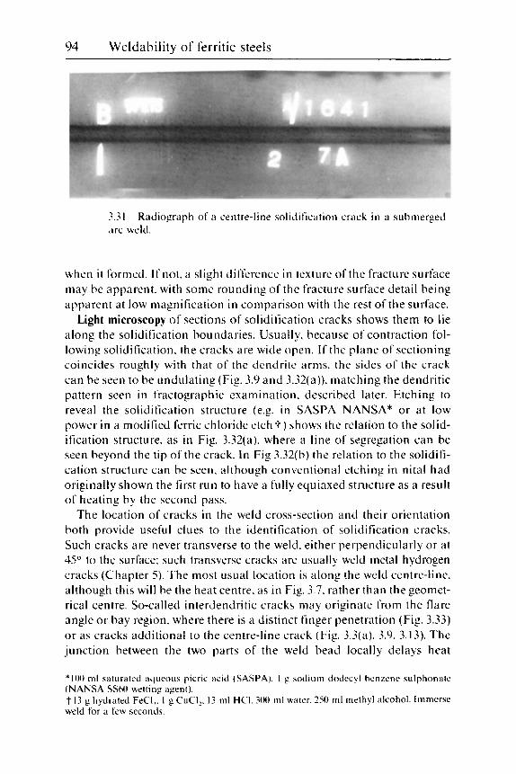
94 Weldability of ferritic steels
3.3 1 a r c weld.
R a d i o g r a p h of ii cent re - l ine sol idif icat ion c r a c k in a s u b m e r g e d
when i t formed. I f not. a slight difference in texture of the fracture surface may be apparent. with some rounding of the fracture surface detail being apparent at low magnification in comparison with the rest of the surface.
Light microscopy of sections of solidification cracks shows them to lie along the solidification boundaries. Usually, because of contraction fol- lowing solidification. the cracks are wide open. I f the plane of sectioning coincides roughly with that of the dendrite arms. the sides of the crack can be seen to be undulating (Fig. 3.9 and 3.32(a)). matching the dendritic pattern seen in fractographic examination. described later. Etching to reveal the solidification structure (e.g. in SASPA NANSA* or at low power in a modified ferric chloride etch f ) shows the relation to the solid- ification structure. as in Fig. 3.32(a). where a line of segregation can be seen beyond the tip of the crack. I n Fig 3.32(b) the relation to the solidifi- cation structure can be seen. although conventional etching in nital had originally shown the first run to have a fully equiaxed structure as a result of heating by the second pass.
The location of cracks in the weld cross-section and their orientation both provide useful clues to the identification of solidification cracks. Such cracks are never transverse to the weld. either perpendicularly or at 45" to the surface: such transverse cracks are usually weld metal hydrogen cracks (Chapter 5) . The most usual location is along the weld centre-line. although this will be the heat centre. as in Fig. 3.7. rather than the geomet- rical centre. So-called interdendritic cracks may originate from the flare angle or bay region. where there is a distinct finger penetration (Fig. 3.33) or as cracks additional to the centre-line crack (Fig. 3.3(a). 3.9. 3.13). The junction between the two parts of the weld bead locally delays heat
*I00 ml saturated aqueous picric acid (SASPA). 1 g sodium dodecyl benzene sulphonate (NANSA SS60 wetting agent). t 13 g hydrated FeCI,. I g CuCIz. 13 ml HCI. 300 ml water. 250 ml methyl alcohol. Immerse weld for a few seconds.

Solidification cracking 95
3.32 Sections through solidification cracks in submerged arc welds etched to reveal segregation pattern: (a) centre-line crack with heavy segregate beyond crack tip. SASPA-NANSA etch: (b) crack in first submerged arc run. modified ferric chloride to show solidification structure in a run in which nital etch showed a refined transformation structure.
3.33 Solidification crack in subnierged arc bead from flare angle.

96 Weldability of fcrritic steels
3.34 examined on TEM.
Thermal fxeting on replica o f solidification crack surface
extraction. ;is can be seen from the wider HAZ. and thus makes feeding of any incipient cracks difficult. Cracks can also initiate in susceptible weld metals from isolated liquation cracks at segregate bands. a s in Fig. 3.24.
Occasionally. if formed late in solidilication from material with a low susceptibility to cracking. the cracks are very narrow and undulating and less recognisable ;is solidification cracks (Fig. 3 .2 (a ) ) .
Electron microscopy can be used to examine buried. i.e. unoxidised. solidification and liquation crack surfaces. but the finer detail is irretrievably lost i f the surfaces are oxidised. Scanning electron micro- scopic (SEM) examination is adequate for most details. although it will not show thermal striations or faceting. which can be found on the surfaces of unoxidised solidification and liquation cracks. and for which trans- mission electron microscopic (TEM) examination is necessary (Fig. 3.34). Segregation associated with cracking is normally beyond the surface ana- lytical capabilities available on many SEMs: true surface analytical tech- niques. such a s Auger and ESCA (electron spectroscopy for chemical analysis). are required to detect such segregation. However. second phase particles in the eutectics associated with cracking can be seen by both SEM and TEM and occasionally in the light microscope.
In the SEM. well-developed solidification crack surfaces show a typical well-rounded dendrite structure (Fig. 3.3(b) and 3.35). Even at low magni- fication. the linear pattern of the dendrite tips is unmistakable (Fig. 3.3(b)) and the encis of dendrites growing inwards and be distinguished

Solidification cracking 97
3.35 Typical solidification crack surfaces in SEM: (ri) well-developed crack: ( b ) upwards dendrite growth from backing bar o n left. inwards growth from fusion boundary on right: (c): detail o f inwards growth: ( d ) detail of upwards growth.
from cracking parallel to the dendrite growth direction (Fig. 3.35(c) and (d)). Less well-developed cracks form at lower temperatures. when the spaces between the dendrites are more nearly filled with solid metal and the crack surfaces are considerably flatter (Fig. 3.36). Even so. the surfaces are slightly undulating. Very late-developing solidification cracks (Fig. 3.2(b)) may contain a mixture of solidification cracking and the dimpled ductile fracture (microvoid coalescence) produced when the specimen was broken open. Fracture just beyond the tip of a solidification crack can show linear markings from the segregated region (Fig. 3.37). Oxidised solidification crack surfaces show these features less well (Fig. 3.38). par- ticuiarly if the oxidation is heavy (Fig. 3.38(b) and (c)).

98 Weldability of ferritic steels
3.36 llatter surface with slight dendritic markings: ( b ) smooth undulating surface.
Less well-developed solidification crack surfaces in SEM: ( a )
3.37 cracks: ( ; I ) on flattish crack surface: (b ) in microvoids in segregated region ahead of crack tip.
Striations associated with less well-developed solidification
Occasionally. spikes are seen on fracture surfaces. as in Fig. 3.38(a). These were believed to be bridges of solid metal formed across a solidifi- cation crack and then pulled down as the crack faces were pulled apart. More recent work has shown them to lie opposite to cavities o n the other side of the crack and that they are segregates rich in phosphorus.Is With SEM examination. signs of MnS or other inclusions are quite rare. although a n example is shown in Fig. 3.39. Small globules of lead seen on
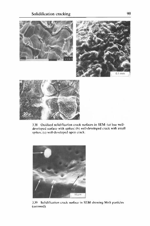
Solidification cracking 99
3.38 Oxidised solidification crack surfaces in SEM: (a ) less well- developed surface with spikes: (b) well-developed crack with small spikes: (c) well-developed open crack.
3.39 Solidification crack surface in SEM showing MnS particles (arrowed).

100 Weldability of ferritic steels
3.40 Solidification crack surface in SEM. three small particles in centre were identified as rich in lead.
3.41 crack surface: (b) a-MnS in weld metal ahead of crack tip.
Crack surfaces in TEM showing: (a ) Nh,C, on solidification
a submerged arc crack surface are shown in Fig. 3.40. although it is not known whether they took any part in the formation of the crack. or whether they formed subsequently.
Using the TEM. it is possible to detect and identify (by local area dif- fraction) constituents that took part in solidification or liquation cracking. Compounds. usually in eutectic form (Fig. 3.41). such as MnS. Nb,C3 and Ti(C.S) have been identified by these means. often in the segregated region just beyond the crack tip. and have made it possible to identify the cause of cracking. The detection of thermal faceting on solidification crack surfaces in the TEM (Fig. 3.34) is evidence that the surface has been present at a high temperature: however such striations have also been found on cold (e.g. hydrogen) crack surfaces that have been heated (e.g. by PWHT) subsequent to their formation.
Solidification cracking 101
References
1 Dixon. B.F.. ‘Weld metal solidification cracking in ferritic steels - a review’. Australian Weld. J . . 198 I , 24(4). 23-30.
2 Ohshita. 0.. Yurioka. N.. Mori. N. and Kimura. T.. ‘Prevention of solidification cracking in very low carbon steel welds’. Weld. J . . 1983. 62. 129s-136s.
3 Nakagawa. H.. Matsuda. F. and Senda. T.. ‘Effect of sulphur o n solidification cracking in weld metal of low carbon and low nickel alloy steels’. Trans. Jap. Weld. Soc. 1974. 5(1). 39-45; 5(2). 18-33. 84-89; 1975. 6(1). 3--16. Bailey. N. and Jones. S.B.. ‘The solidification cracking of ferritic steel during submerged arc welding’. Weld J . . 1978. 57. 217s-231s. Morgan-Warren. E.J. and Jordan. M.F.. ‘Quantitative study of the effect of composition on weld solidification cracking in low alloy steels’. Metals Techno/.. 1974. l(6). 271-278 .
6 British Standard BS5135: 1984. ‘Arc welding of C and C-Mn steels’, BSI. London. 1984.
7 Davis. M.L.E.. Pargeter. R.J. and Bailey. N.. ’The effects of titanium and boron additions to submerged-arc fluxes’. Metal Construction. 1983. 15. 338-344.
8 Huxley. H.V.. ‘The influence of composition on weld solidification cracking in C: Mn steel’. Metullurgiu. 1970. 82. 167-174.
9 Russell. J.D.. ’The development of an electron beam weld solidification cracking test’, Welding Res. h t l . . 1979. 9(6). 1-21.
10 Fujita. Y.. Terai. K.. Yamada. S.. Suzuwa. R. and Matsumara. H.. ‘Prevention of end cracking in automatic one-side welding’. J. SOC. Naval Architects Jpn. 1973. 133. 267-274. (TWI Translation No 330.)
11 Bailey. N. and Roberts. C.. ’Maraging steel for structural welding’. Weld J..
12 Boniszewski. T. and Watkinson. F.. ‘Examination of hot tearing in the weld HAZ of ferritic steels’. Brit. Well. J.. 1964. 11. 610-619.
13 Baker. R.G. and Watkinson. F.. ‘The assessment of cracking problems’. TWI Conference on ‘Weldability of Structural and Pressure Vessel Steels’. Loiidon. Nov. 1970.
14 Keville. B.R. and Cochrane. R.C.. ‘Strain-induced hot cracking in ferritic weld metal’. in hoceedings of the TWI Conference ‘Trends in Steels and Consumables
for Welding’. London, Nov. 1978. TWI. Cambridge. 1979. I5 Dixon. B.F.. ‘Cracking in the Transvarestraint test’. Metul Con.srruc~tion. 1984.
4
5
1078. 57. 15-28.
16. 86-90. 156- 160. 232-237.

4 Lamellar tearing
Description
Lamellar tearing is confined to plates (and perhaps extrusions) when they have inadequate ductility in the short transverse direction (also known as the through-thickness or Z-direction). Steel plate can contain a population of non-metallic inclusions sufficient to reduce its short trans- verse ductility to a considerable extent. When such steel is welded. tearing or cracking can result i f the ductility in the short transverse direction is not sufficient to accommodate the welding contraction strains. Such strains result from welding stresses. which are at a maximum in the short transverse direction when a fusion boundary is parallel to the plate surface (Fig. 4.1). i.e. to the planes into which inclusions have been rolled to their ma xi mu m di mensions.
Such stressing occur5 when a weld in a rigid structure is made on the surface of a plate as shown in Fig. 4.1. The stresses are set up when the free contraction of the weld on solidifying and cooling is restrained by the rest of the structure. The tearing process takes place in two distinct stages (Fig. 4.2). Firstly. non-metallic inclusions 'decohere'. i.e. they separate from the matrix of steel in which they lie and thus form minute cracks between themselves and the steel. The second stage is for the minute cracks at the decohered inclusions to join up. jumping from one plane in the steel to another to link up with similar decohered inclusions on adjacent planes. I t should be noted that the decohesion of inclusions can sometimes occur as a result of cold working operations (particularly when they involve bending) and PWHT.
Unlike hydrogen cracking. discussed in the next chapter. the stresses needed to produce lamellar tearing are long range. Also in contrast to hydrogen cracking. cracking usually extends well beyond the visible HAZ into the parent plate and it cannot occur in weld metal. Tearing may also start at a higher temperature than is possible for hydrogen cracking (perhaps as high as 300 "C).
102

Lamellar tearing 103
4.1 plate with inadequate ductility in the through-thickness direction.
Lamellar tear under a restrained weld made on the surface of a
Despite the need for low ductility in the steel for cracking to occur. lamellar tearing occurs by a ductile and not a brittle fracture mechanism. the cracks being initiated by inclusions in the base plate which have been rolled and extended by the steel rolling process. Nowadays. grades of plate containing low levels of inclusions are available which are very resistant to lamellar tearing. Because these have good ductility in the short transverse or Z-direction. they are frequently known by a name which includes the letter Z . e.g. 'Z quality' or 'Z grade'.
Lamellar tears. unlike hydrogen cracks. form directly on cooling. although they may extend when welding elsewhere on the structure if this welding builds up and increases the long range stresses. Cracks are usually seen at weld toes. and remedial measures usually involve a repair with buttering of the susceptible plate by soft weld metal. Although the inclusions in the weld metal may be much larger in number than in the plate. they are spherical. very small and not oriented parallel to any surface. so that their effect on ductility is small and isotropic.
Much of the present knowledge of lamellar tearing was obtained from research carried out at TWI in the early 1970s. Details of these investigations, including a bibliography up to 1974. are given in ref. I .
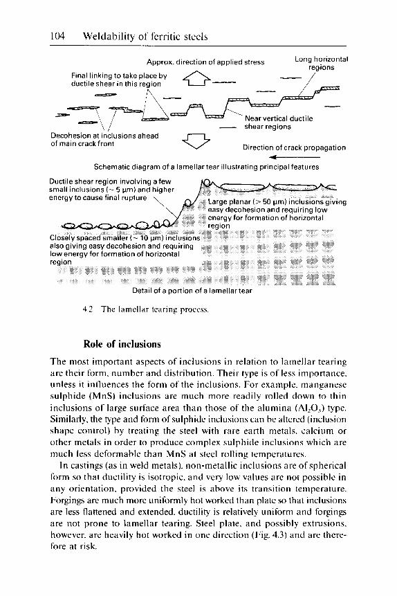
104 Weldability of ferritic steels
Approx. direction of applied stress Long horizontal
Final linking to take place by
- shear regions
0 Direction of crack propagation Decohesion at inclusions ahead of main crack front -
Schematic diagram of a lamellar tear illustrating principal features
Ductile shear region involving a few small inclusions ( - 5 Mm) and higher energy to cause final rupture
Detail of a portion of a lamellar tear
4.2 The lamellar tearing process.
Role of inclusions
The most important aspects of inclusions in relation to lamellar tearing are their form, number and distribution. Their type is of less importance. unless i t influences the form of the inclusions. For example. manganese sulphide (MnS) inclusions are much more readily rolled down to thin inclusions of large surface area than those of the alumina (AI,O,) type. Similarly. the type and form of sulphide inclusions can be altered (inclusion shape control) by treating the steel with rare earth metals. calcium or other metals in order to produce complex sulphide inclusions which are much less deformable than MnS at steel rolling temperatures.
In castings (as in weld metals). non-metallic inclusions are of spherical form so that ductility is isotropic. and very low values are not possible in any orientation. provided the steel is above its transition temperature. Forgings are much more uniformly hot worked than plate so that inclusions are less flattened and extended, ductility is relatively uniform and forgings are not prone to lamellar tearing. Steel plate. and possibly extrusions. however. are heavily hot worked in one direction (Fig. 4.3) and are there- fore at risk.

Lamellar tearing 105
4.3 Typical large silicate inclusions.
An increase in the number of inclusions usually increases the risk of lamellar tearing, particularly if size distribution and position are not sig- nificantly altered. The spatial distribution of inclusions is also important. If most of the inclusions are just below the plate surface. lamellar tearing will be very easy, particularly if welded with a technique which does not penetrate far enough to melt through the inclusion-rich region, as in Fig. 4.1. Inclusions concentrated along the plate centre-line. as is likely in con- tinuously cast plate, require a high degree of restraint and a relatively long-range stress system to be damaging. However, if such concast plate is relatively thin and/or the welding process is penetrating. then a central region of inclusions can be very harmful. particularly if it is associated with heavy segregation likely to give lower toughness than the bulk of the steel.
Even when centrally segregated. inclusions do not lie in a single plane but in parallel planes separated by fractions of a millimetre. The second stage of lamellar tearing depends on the ease with which the first stage cracks can jump from one of these planes to another.
The ease with which the first stage of lamellar tearing (decohesion of inclusions from the steel matrix) occurs, depends on how well the inclusions are bonded to the steel matrix. This depends. in turn, on the relative coef- ficients of thermal expansion and the ease of deformability of inclusions and steel.

106 Wcldabili ty of ferritic steels
Manganese sulphide inclusions tend to contract away from the steel matrix when the steel cools from high temperature during its manufacture. and thus decohere readily. Other types of inclusions contract less than steel. which therefore tends to contract o n to the inclusions. Aluminium- treated steel plate (provided i t has not been produced with inclusion shape control) contains compact angular A120, inclusions and separate leafy MnS. The MnS inclusions easily decohere and. if the population is suitable. readily produce lamellar tearing. Silicon-killed and other types of steel contain inclusions which are mixtures of manganese sulphides and silicates. Because these mixed inclusions have a mean thermal expansion coefficient closer to that of steel than MnS by itself. they decohere less readily than MnS alone. so that a given inclusion population should be less likely to start a lamellar tear in a Si-killed steel than a simi- lar population of inclusions in a steel which is Al-treated.
Even though plate may be cross-rolled. the compressive deformation always occurs in the direction which undergoes a reduction in thickness. As a result. deformable inclusions. such as manganese sulphides and sili- cates. finish up shaped like broad leaves. being of large surface area and thin cross-section. Their widths depend on the degree of cross-rolling to which the plate has been given. Such thin inclusions naturally occupy a much larger area in planes parallel to the plate surface than the more compact inclusions in castings and forgings. o r the less deformable alu- mina or calcium oxide/silicate inclusions in Al- or Ca-treated steels after roll i ng.
In steels generally. the inclusion content depends mainly o n two compositional parameters. its oxygen and its sulphur contents. although the precise content ( in terms of volume or weight percentage) and size distribution will depend o n the actual oxides and sulphides present and the thermal and mechanical history of the steel. i.e. on the way the steel has been made.
Furthermore. very low oxygen contents in steel (i.e. in Al-treated steels) tend to give Type I1 sulphide inclusions. which are more flattened. and therefore more damaging for a given sulphur content. than the Type I sul- phide inclusions found in the older Si-killed and semi-killed steels. Most current steels are made by continuous casting. which requires an aluminium addition. and hence ensures low oxygen contents. together with Type I1 MnS inclusions. unless inclusion shape control additions have been made. in which case more complex sulphides of higher melting temperature will be present. Even for one type of plate steel. in terms of composition and deoxidation practice and other treatments. the susceptibility to lamellar tearing depends on other factors. such as the degree of rolling from the cast ingot to the finished plate. the position of the plate in the original ingot and the distribution of the inclusions within the plate.

Lamellar tearing 107
The degree of rolling increases the flattening of the inclusions and their final potency as initiators of lamellar tearing. Unless [he ingot size has been selected in relation to the plate size to minimise rolling. the most susceptible plate thickness is probably between about 25 and 65 mm. It is difficult to give very heavy rolling reductions when making plate thicker than this range, whereas thinner plates tend to be more flexible and can accommodate some of the through-thickness stressing by distortion of the whole plate. However. cases of lamellar tearing in plate as thin as 8 mm are known to have occurred in very rigid structures.
The position of the plate in the original ingot is perhaps less important now than in the past. because of the advent of continuous casting. In ingots the distribution of inclusions is far from uniform. as a result of the different types of segregation which can occur. Such variability in inclusion distribution inevitably leads to a considerable scatter in the results of whatever tests are used to assess lamellar tearing behaviour. and it is unwise to scrap or accept a plate or a batch of plates on the results of a single test or test series taken from one location.
The distribution of inclusions within the plate has a profound effect on the likelihood of lamellar tearing. If relatively small fillet welds are made on the surface of thick plate (e.g. 100 mm). the presence of very severe centre-line segregation will not be of much consequence. The long range stresses. at a high level close to the fusion boundary. will have fallen to a relatively low level at the centre of the plate and any distortion will have been accommodated in the relatively clean steel close to the surface.
In thinner plate (e.g. 20 mm thick). with a larger weld size. the weld will penetrate an appreciable fraction of the distance to the plate centre-line. so that stresses will still be high in that region and tearing is possible. A high density of inclusions near the plate surface is likely to give lamellar tearing problems. regardless of plate thickness. but such a population is less likely with continuously cast than with ingot cast steel.
Despite all these factors leading to variability of tearing behaviour. rough correlations for Al-treated steels have been provided to estimate the effect of sulphur on the risk of lamellar tearing. as assessed by the short transverse tensile test. This test. described in a later section. gives a value of the short transverse reduction of area (STRA): the effect of sul- phur on this value2 is shown for different thicknesses of plate in Fig. 4.4. Under conditions of highest likely restraint. a minimum value of 20% STRA is usually recommended. and Fig. 4.4 shows that this can be achieved comfortably i f the sulphur content of the steel is kept below 0.005%.
The individual points on the figure represent TWI results. mainly on ingot cast steels. and these mainly fall within scatter bands which had been proposed for this type of steel in an IIW d o c ~ m e n t . ~ It is significant

108 Weldability of ferritic steels
60
50
8 40-
2 F 30
2 0 -
10
0
\ \
- \.\\\ TWI data
\\ Scatterband from data \ of Kanazawa et al.3 ' Mean line for continuously '\ cast steels after Roberts4
-
\
-'\ \ "\
\.
'. *\:
\ \ \
\ '\
\ -
'\ 8 I \ - I *--u
n nqn n n A n
I I
0.01 0 0.020 V.VJU v.vL)u
Sulphur content, wt%
0
(b)
4.4 Influence of plate sulphur content on STRA values in short transverse tensile test: ( a ) plate < I 2 5 m m thick: (b) plate 12.5-50 m m thick: (c) plate >50 m m thick.

Lamellar tearing 109
S F 30 \, I '\
* o r
l o t
u.u I W U.ULU 0.030 I 0.040
Sulphur content, wt% (C)
4.4 cont'd
that the only values outside the proposed scatter band lie above it (i.e. on the safe side) and are for thick-sectioned steels. which tend to be less prone to lamellar tearing because of the normally lower degree of rolling given. The mean values for continuously cast steels given by Roberts4 lie just below the upper scatter band. This supports the reportedly good behaviour of such steels (except. presumably. where the stress fields associ- ated with any deeply penetrating welds approach any centre-line segregates). It should be emphasised that the results in Fig. 4.4 relate to normal steels and not to those with shape control additions.
Susceptible joint types
Lamellar tearing may occur in both fillet and butt welds. The susceptible joint types are those in which one of the fusion boundaries is parallel to the rolling plane of the plate. The risk of tearing depends on the quality of the plate. and normally a high degree of restraint is necessary in a fabri- cation before any tearing occurs. Nevertheless. if the plate quality is very poor. lamellar tearing can occur (and has occurred) in such lightly restrained fabrications as lifting lugs and fillet-welded I-beams.
With high to moderate restraint present, three types ofjoint are most likely to give rise to lamellar tearing problems: they are T-fillets, T-butts and
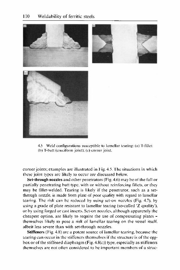
110 Weldability of ferritic steels
4.5 (b) T-butt (cruciform joint): (c) corner joint.
Weld configurations susceptible to lamellar tearing: (a) T-fillet:
corner joints: examples are illustrated in Fig. 4.5. The situations in which these joint types are likely to occur are discussed below.
Set-through nozzles and other penetrators (Fig. 4.6) may be of the full or partially penetrating butt type. with or without reinforcing fillets. o r they may be fillet-welded. Tearing is likely if the penetrator. such as a set- through nozzle. is made from plate of poor quality with regard to lamellar tearing. The risk can be reduced by using set-on nozzles (Fig. 4.7). by using a grade of plate resistant to lamellar tearing (so-called ‘ Z quality’). or by using forged or cast inserts. Set-on nozzles. although apparently the cheapest option. are likely to require the use of compensating plates - themselves likely to pose a risk of lamellar tearing on the vessel itself. albeit less severe than with set-through nozzles.
Stiffeners (Fig. 4.8) are a potent source of lamellar tearing, because the tearing can occur in the stiffeners themselves if the structure is of the egg- box or of the stiffened diaphragm (Fig. 4.8(c)) type. especially as stiffeners themselves are not often considered to be important members of a struc-

Lamellar tearing 111
4.6 Joint types susceptible to lamellar tearing: (a) set-through nozzle; (b) Vierendeel girder.
4.7 Set-on nozzle. less prone to lamellar tearing than set-through type.
ture. Stiffeners inside cylinders (Fig. 4.8(a)) are particularly likely to cause tearing in the cylinder itself. and nowadays steel plate of a lamellar tearing- resistant grade is nearly always specified for such duty, although forgings or castings are equally suitable.
Joint design Although nowadays it is common to specify grades of steel resistant to lamellar tearing where the risk of tearing is known to be present, the suscep- tibility of different joint types can be varied by altering their configuration.
T-joints with simple fillets give fewer problems than joints with full
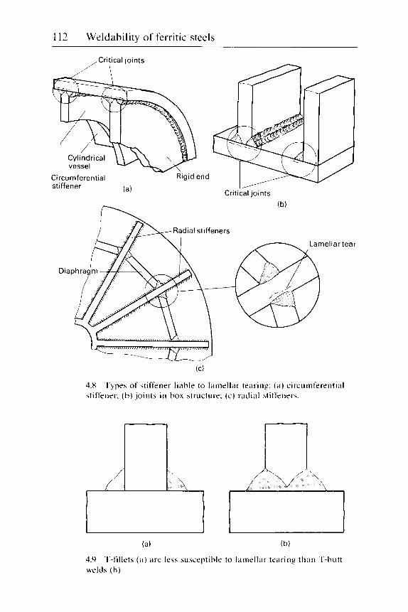
112 Weldability of ferritic steels
,,Critical joints
Circumferential Rigid end
(a) stiffener critical joints
(b)
Radial stiffeners
4.X stiffener: ( b ) joints in box structure: (c ) rndial stiffeners.
Types of stiffener liable to lamellar tearing: ( a ) circumferential
(a) (b)
4.9 welds (h).
T-fillets ( a ) are less susceptible t o lamellar tearing than T-butt

Lamellar tearing 113
4.10 electroslag or similar welds with no risk of tearing.
Conventional vertically welded T-joints may he replaced with
4.1 1 risk of tearing.
Castings or forgings can replace conventional T-joints with no

114 Weldability of ferritic steels
penetration (Fig. 4.9). The most severe form of the T-joint is the cruciform joint. particularly where full penetration welds are employed (Fig. 4.5(b)). In both fillet and full penetration joints, a balanced. double-sided weld provides less risk of tearing than a single-sided weld. The improvement is largely due to the smaller amount of weld metal deposited. but some risk of tearing still remains. even with a T-fillet joint welded with small fillets in a balanced manner. It is possible to redesign this type of joint. possibly using electroslag or electrogas welding. to eliminate all risk of lamellar tearing (Fig. 4.10). The use of forgings or castings is also possible. although this can increase the amount of welding. as shown in Fig. 4.1 1.
Corner joints (Fig. 4.12) can also give rise to lamellar tearing if suitable steel grades are not used. The risk can be reduced by putting the joint angle on the surface of the plate at risk. instead of on the end of the other plate. However. this is more costly. particularly i f a large angle is used. as it increases the amount of weld metal needed to f i l l the joint.
4.12 Bevel on corner joints modified to reduce risk of tearing.

Lamellar tearing 115
Other factors
Steel plate type Many of the factors associated with steel type were discused earlier. These can be briefly summarised:
1 Only plate (and possibly extrusions) are prone to lamellar tearing. 2 Al-treated steel is more susceptible than a similar steel that is Si- or
semi-killed. 3 Inclusion shape control. low sulphur contents and (usually) continuous
casting reduce the likelihood of problems.
One factor not discussed earlier is the inherent strength of the steel. Tests have suggested that with very high strength steels (i.e. with minimum yield strengths of about 900 N/mm*) low STRA values can occur with sul- phur contents of 0.005% S and less.s so that the yield strength of plate itself is a factor to consider when assessing the lamellar tearing suscepti- bility of high strength plate steels. Certainly. lamellar tearing problems occurred during the development in the UK of weldable steels of 550 N/ mmz yield strength. before lamellar tearing behaviour was adequately understood.
Direction of residual stress To reduce the risk of tearing. it can be helpful to reduce the angle on the plate at risk from 90". This is most easy to carry out in corner joints (Fig. 4.12). This technique is only practicable on the type of corner joint illus- trated. as its use on the other types of susceptible joints would involve gouging out or machining into the major component of. for example. a T- joint. which would not be acceptable in most circumstances.
Hydrogen Although lamellar tearing and hydrogen cracking (Chapter 5 ) are normally distinguishable, it is known that hydrogen introduced during welding (or even present in the steel to be welded). can increase the risk of tearing. because it reduces the ductility of the steel. Nevertheless. not all the tech- niques ,that can reduce the risk of hydrogen cracking are of benefit in combating lamellar tearing. Preheating (or increasing the preheat tem- perature) is not always a good option, particularly when a set-through nozzle or penetrator is being welded into a hole in a vessel. In such circum- stances, the increased temperature gives an increased risk of a significant temperature difference between the two components being welded and, hence. of increased stresses on cooling after welding. The use of consumables of lower hydrogen potential or post-heating may well be of

116 Weldability of ferritic steels
benefit. as these options are not known to increase the risk of lamellar tearing.
With continuously cast plate of relatively thin section. any centre-line segregates are likely to lie close to the visible weld HAZ. This proximity to the HAZ (making diffusion of weld hydrogen to this area easy). coupled with their increased composition (making them more susceptible to hydrogen cracking) as a result of segregation. makes such regions partic- ularly prone to lamellar tearing. hydrogen cracking or a combination of the two.
Welding parameters Apart from the influence of hydrogen discussed in the previous section. welding variables have a minor influence on lamellar tearing. However. the use of lower strength weld deposits is helpful. although the scope for variation is often limited. Nevertheless. basic manual electrodes of low strength have been developed to help to cope with lamellar tearing prob- lems. These have yield strengths around the 350 N/mm2 level. The use of lower strength consumables is. however. nor recommended where i t would mean increasing the fillet weld size to maintain the strength of a joint.
The use of high heat input processcs reportedly gives less risk of cracking. but changing heat input within a single process is said to be without effect on the likelihood of tearing. Indeed. reducing heat input within a process can actually have a beneficial influence. when i t is reduced in order to decrease the size of a fillet weld under which tearing is likely.
Welding technique Although varying the actual welding parameters is likely to have little effect on lamellar tearing. the technique with which a joint is made can have a profound effect. and special methods are used both to avoid tearing in difficult situations and to repair tearing which has occurred. The two techniques that have been used successfully are buttering and balanced welding. Among those tried unsuccessfully are the peening of weld runs at an intermediate stage and intermediate PWHT for stress relief. The latter may. however. have been unsuccessful because it produced decohesion of inclusions (i.e. the first stage of lamellar tearing) to a sufficient extent as to increase the incidence of unacceptable ultrasonic indications and not because of the increased amount of actual lamellar tearing.
The simplest method of buttering is to deposit two layers of weld metal (preferably of low strength) o n the surface at risk (Fig. 4.13(a)). This prod- uces a surface of high resistance to lamellar tearing o n which the joint can be completed in a manner which removes the suspect region of plate to a region of somewhat lower stress. I f the plate is of very poor quality

Lamellar tearing 117
1 4.13 Risk of lamellar tearing can be reduced by: (a) buttering before welding; (b) removing susceptible plate material and buttering: (c) in siru buttering; (d) balanced welding when tearing originates from original weld root of type shown in (c).

118 Weldability of ferritic steels
close to the surface. this buttering technique may not be successful and it may be necessary to groove out the plate and fi l l the groove with weld metal. as in Fig. 4.13(b). before proceeding. Figure 4.13(c) shows how a more limited buttering may be incorporated into the joint. This technique may also be used to effect a repair of a torn weld: it aims to avoid increas- ing the weld size. and hence the amount of metal influenced by high through-thickness stresses.
A balanced welding technique is particularly recommended for T-butt joints. as shown in Fig. 4.13(d). Here. several runs are alternately made at each side of the joint so that the joint is built up in a symmetrical manner.
Any repair of lamellar tearing will involve removal of the cracked area, cleaning by gouging or grinding to clean metal (preferably clean with regard to harmful non-metallic inclusions). buttering with weld metal to the original plate profile before welding of the joint itself is started. and remaking the joint.
Control and avoidance of cracking
Selection of joint design The selection of joint design is inevitably an interactive process with the selection of steel quality. If high quality. 'Z grade' plates. forgings or castings are to be used. the selection ofjoint type need not consider lamellar tearing. If prime quality grades of plate are not selected. then the fabrication must be assessed to consider the degree of restraint. particularly during the later stages of welding the component. If restraint is likely to be high. joints should be selected that avoid residual stresses being applied directly perpendicular to the plate surface. bearing in mind that the severity of the situation is increased going from two-sided T-fillets to single-sided T-fillets to T-butts to buti-welded cruciform joints. Corner joints cannot be directly fitted into this scale: they can also be made less severe by angling the preparation as shown in Fig. 4.12.
Selection of steel Together with an assessment of the joint types present. the grades of steel plate to be used should be selected. bearing in mind that only plates (and possibly extrusions) are likely to give problems. and that the stronger the steel, the cleaner it has to be to avoid any risk of lamellar tearing. I f machinable or free-cutting grades of steel plate, particularly with very high sulphur contents (i.e. >0.05% S). are to be used. welds should never be deposited on the plate surface without buttering with at least two layers of weld metal. and then only if the level of restraint is low.

Lamellar tearing 119
Because most steels are currently cast continuously. it is assumed that the steel will have been Al-treated. and that its resistance to lamellar tearing may be poor if it contains more than about 0.005% S. Although steels with such low sulphur contents may sometimes increase the risk of HAZ hydrogen cracking (Chapter 5). hydrogen cracking is easier to overcome than lamellar tearing. and the low sulphur levels have advantages in other directions. such as better HAZ and weld metal toughness. A fuller appreciation of tolerable sulphur levels in relation to restraint levels is given below in the section dealing with destructive control tests.
The welding process The welding process has little direct influence on lamellar tearing. the higher heat input processes are said to provide less risk. On the other hand. small overall weld sizes reduce the level of long-range stresses and give less risk of tearing. Low hydrogen processes are of some advantage, but high preheat may be harmful. particularly when welding set-in nozzles and other penetrators.
Control tests
Non-destructive control tests Considerable use is made of ultrasonic examination of plate to assess its suitability for applications where there is considered to be a risk of tearing. These tests are often called for in specifications and can also be used on plate of variable quality in order to select areas which should or should not be used for weld details prone to lamellar tearing. If these tests are used on plate that has been cold worked. particularly by cold-forming techniques. it must be realised that cold-forming operations can cause decohesion of inclusions. and thus enhance their detectability to ultra- sonics. This phenomenon of decohesion has. in the past. led to doubts as to the usefulness of ultrasonics for assessing plate quality. It is possible for plate to pass the initial ultrasonic examination when manufactured and later give rise to apparently unacceptable ultrasonic reflections after cold-forming or even a PWHT. In such cases i t is advisable to carry out small-scale tests, such as the short transverse tensile test (see below). before rejecting such plate.
Destructive control tests Two types of test have been used to investigate lamellar tearing. the small- scale tests intended to assess plate quality. and the larger tests intended to reproduce lamellar tearing in the laboratory in a controlled manner. The mechanical property tests to examine plate susceptibility to lamellar tearing are mainly considered here.
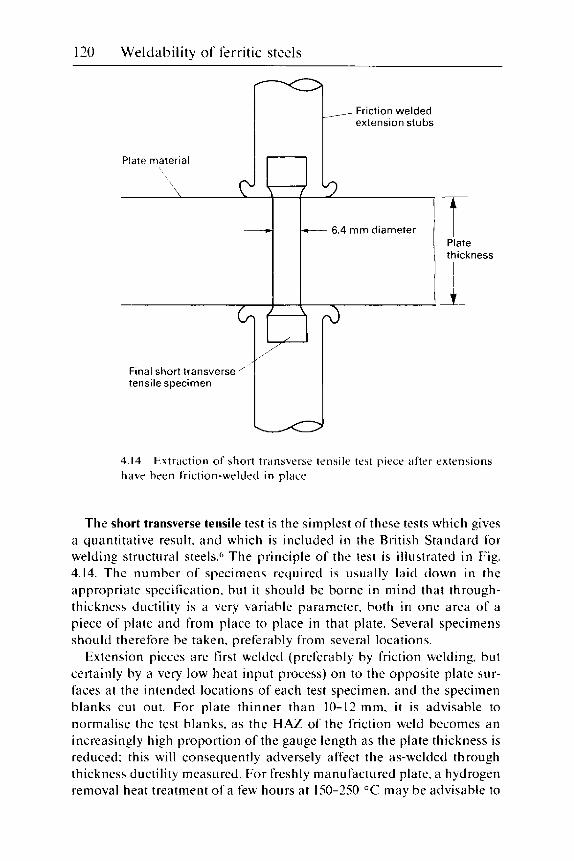
120 Weldabili ty of ferritic steels
- - 6.4 mm diameter Plate thickness
I A- I
4. I4 have been friction-welded in place.
Extraction of short transverse tensile test piece after extensions
The short transverse tensile test is the simplest of these tests which gives a quantitative result. and which is included in the British Standard for welding structural steelsh The principle of the test is illustrated in Fig. 4.14. The number of specimens required is usually laid down in the appropriate specification. but i t should be borne in mind that through- thickness ductility is a very variable parameter. both in one area of a piece of plate and from place to place in that plate. Several specimens should therefore be taken. preferably from several locations.
Extension pieces are first welded (preferably by friction welding. but certainly by a very low heat input process) o n to the opposite plate sur- faces at the intended locations of each test specimen. and the specimen blanks cut out. For plate thinner than 10-12 mm. it is advisable to normalise the test blanks. as the HAZ of the friction weld becomes an increasingly high proportion of the gauge length as the plate thickness is reduced: this will consequently adversely affect the as-welded through thickness ductility measured. For freshly manufactured plate. a hydrogen removal heat treatment of a few hours at 150-250 "C may be advisable to

Lamellar tearing 121
avoid any hydrogen (remaining from the steel melting process) reducing ductility. particularly if the steel is of thick section and has not been given a separate normalising or tempering heat treatment. Otherwise, no heat treatment is necessary. as the HAZ of the friction weld (1-2 mm in width on plate thicker than 10-12 mm) is too narrow to affect the test results significantly.
Test specimens are machined out. normally with a gauge diameter of 6.4 mm, and a gauge length sufficient to include the full plate thickness if this is practicable. For very thick plate, it may be more convenient to extract two or more specimens. slightly overlapping. to cover the full plate thickness. Tensile tests are then carried out at ambient temperature. the reduction of area (RA) measured and the location of the fracture noted. The tensile strength may also be measured. but this is only significant where there may be some doubt as to the origin of the test specimens. or when the results are very poor.
The assessment of the results depends on STRA values which have. in the past. given problems of lamellar tearing in practice with normal struc- tural steels. Figure 4.15 shows that STRA values in excess of 20% have been found to give no lamellar tearing. even in the most highly restrained situations. It should be noted that plate steels tested in the longitudinal and long transverse directions are regularly capable of giving 65% RA values. but to achieve these levels in the short transverse direction requires a very low inclusion content and sulphur contents well below 0.005% s.
A minimum STRA value of 15% has been found to give freedom from lamellar tearing in all except the most highly restrained situations. That is to say. 15% minimum STRA would not guarantee freedom from tearing in highly restrained nozzles. but would be acceptable for box fabrications and other less severely restrained cases. A minimum of 10% STRA would only ensure freedom from tearing in lightly restrained T-joints. such as web to flange joints. Values of 5% STRA and lower would give high risks of tearing when welding lightly restrained, but large section joints. such as lifting lugs. on to plate. Although the latter may not sound particularly serious. failure of such a joint in service could lead to loss of life.
Inevitably. the scatter of STRA results requires some care in their inter- pretation. Uniformly high or low values. within the designations in Fig. 4.15. are unambiguous. However. an odd low result. or a scattered level of values. could require either more testing to clarify the situation. or the ultrasonic examination of the plate. so that poor areas can be detected and used only where risks of lamellar tearing are very low. Correlations between STRA results and plate sulphur contents has already been dis- cussed in Fig. 4.4.
The slice bend test is a semi-quantitative test. which allows the short

122 Weldability of ferritic steels
STRA %
3
Some risk in most highly restrained situations, e.g. nozzle
L I
Some risk in moderately restrained situations, e.g. box fabrications
10.
Some risk in lightly restrained T-joints, e.g. web/flange joint
0
4.15 transverse tensile test.
Risk of lamellar tearing in relation to reduction of area in short
transverse ductility to be assessed from the bend angle to the onset of cracking. The completed test provides a macrosection through the plate thickness showing the distribution of harmful inclusions. and how easily inclusions o n different planes link up to form a continuous tear. The test was intended to overcome early objections to the short transverse tensile test that. without the use of the friction-welded endpieces included in Fig. 4.14. it was not possible to assess plate near to its surfaces. i.e. where lamellar tearing is most common.' A further advantage claimed is that a bigger volume of steel is sampled in a single test. O n the other hand. the test is more complicated and probably more expensive than the short transverse tensile test.
The sequence of manufacture of test specimens developed at TWI is illustrated in Fig. 4.16 (an alternative version of the test is given in ref. 7).

Lamellar tearing 123
Rolling direction
B B
rnrn
I
4.16 bend test.
Manufacture. testing sequence and dimensions of W I slice
A thin. 1.5 mm. slice through the thickness of the test plate is fillet-welded to a standard bend test specimen 12.5 mm thick and about 50 mm wide. Welding is by MMA using 2.5 mm electrodes. although TIC (using a suit- able filler) would be equally suitable. Good quality is needed for this weld: adequate fusion. no lack-of-fusion defects. no crater cracks and no overlapping on to the upper surface of the test specimen. After welding, the test surface is ground to a controlled surface finish. For research purposes. 32 CLA may be needed. but for routine testing 125 CLA is adequate.
Test specimens are tested in three-point bending. with a span 10X the original test plate thickness (assuming the full thickness is being tested) in order to keep the bending moment reasonably constant over the full test thickness. Bending is continued until the first signs of cracking are seen by eye. Good quality plate may not crack. and failure will then occur in the attachment weld. In such cases the quality of this weld needs to be checked: if defects are found, the test should be repeated.
The deflection at the onset of cracking can be related to the surface strain and this. rather than the bend angle, is the parameter best related to lamellar tearing behaviour.' Certainly cracking at 2% surface strain or less. as in Fig. 4.17. is cause for concern. Cracking at 2% surface strain is very roughly equivalent to 5% STRA in the short transverse tensile test.
The tab test is a simple qualitative workshop test that can be carried out in the field. as it requires no laboratory equipment. Various forms have been proposed. and the version developed by TWP is illustrated in Fig. 4.18.

124 Weldability of ferritic steels
4.17 Cracking in slice bend test after -1% strain.

Lamellar tearing 125
Tab hammered in
\
4.18 Sketch of tab test.
A mild steel plate approximately 70X70X15 mm, with a 40" angle prep- aration and a 2 mm root face. is angled back about 20" and welded to the plate to be tested, welding on to the surface of interest. To minimise hydrogen from the welding operation adversely affecting the results, it is recommended that a minimum preheat of 150 "C is used together with very low hydrogen basic electrodes (i.e. dried, if necessary, at 400-450 "C), appropriate to the plate being tested. Two runs are deposited, both with 4 mm diameter electrodes. leaving the root gap (resulting from the use of the 2 mm root face) to start fracture when the specimen is tested. The pur- pose of the second run is to temper and improve the toughness of the HAZ of the first. to avoid obtaining misleading results.
To test, the tab is hammered off with blows on the underneath of the angled plate. Plate susceptible to lamellar tearing will show a predominantly woody fracture (Fig. 4.19) typical of lamellar tearing. Plate which is of good quality will usually fracture through the weld metal and give a fine, usually ductile, fracture.
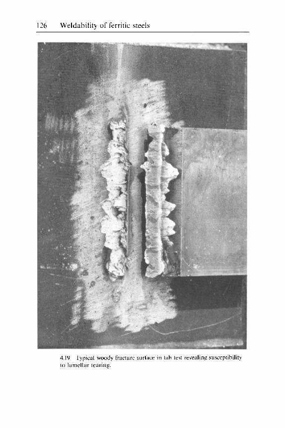
126 Weldability of ferritic steels
4. I9 Typical woody fracture surface in tab test revealing susceptibility to lamellar tearing.
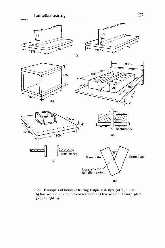
Lamellar tearing 127
41 U section^^
(C)
Base plate Stem plate
Usual site for / lamellar tearing
4.20 Examples of lamellar tearing testpiece design: (a) T-joints; (b) box section: (c) double corner joint: (d) box section through plate; (e) Cranfield test.
128 Weldability of ferritic steels
When interpreting the results. two facts should be remembered. Firstly, the test is not capable of differentiating between moderately poor and very poor plate: the transition from woody to fully ductile fracture takes place at the equivalent of 12-20% STRA in the short transverse tensile test. Secondly. the test only samples a surface layer no more than 2-3 mm thick. I f heavy welds are being made on to fairly thick plate with high restraint. segregation deeper than this can give lamellar tearing, but would not be detected in the tab test.
All large-scale tests which are intended to reproduce lamellar tearing in such a way that. for example. the controlling factors can be studied. are relatively expensive. because of the need to build a high degree of restraint into the testpiece. These include the Cranfield and window tests.’ However. as shown in ref. 1. tests can rapidly be devised to meet the needs of the particular problem under investigation. the quality of the plate and the restraint needed. Some examples of these tests are illus- trated in Fig. 4.21. from which their areas of application can readily be appreciated.
Detection and identification
Detection Any surface technique. i.e. visual. magnetic particle inspection (MPI) and dye penetrant examination. is capable of revealing lamellar tears open to the surface. Sub-surface cracking can only be detected by a suitable ultra- sonic examination technique: radiography is of little use.
Some care is needed in the interpretation of the results of ultrasonic examination. I f the conditions are too sensitive. i t is possible to detect clusters of inclusions. or even bands of different microstructures. To be sure of identifying lamellar tearing. the position of any suspect region should be checked to confirm that the joint is of a susceptible type and that the boundaries of the suspect region are related in a sensible way to the likely position of a lamellar tear. (The solidification cracks illustrated in Fig. 3.12 were originally incorrectly identified as lamellar tearing!) If the plate is originally suspect, the position of any doubtful areas should be noted. and their ultrasonic response checked after welding to see whether there has been a change or not.
Some of any increase in response could be due to the decohesion of inclusions from the steel matrix - such behaviour is also possible after PWHT and cold working - and a careful examination should be made for tears which have broken surface. as these would provide positive con- firmation of cracking. Any ultrasonic examination of thick. dirty plates is liable to be difficult because heavy attenuation of the ultrasonic signal is likely.

Lamellar tearing 129
4.21 tearing.
Typical woody fracture produced by steel susceptible to lamellar
4.22 susceptible to lamellar tearing.
Magnified view of short transverse fracture surface of steel

130 Weldability of ferritic steels
4.23 to lamellar tearing: (a ) from Fig. 4.22. steel with 7% STRA: (b ) steel with 16% STRA.
Type-I1 MnS inclusions on fracture surfaces of steels susceptible
Identification Of the types of cracking liable to be encountered when welding steels. lamellar tearing is usually the easiest to identify. I f an open crack surface is available for visual examination. the characteristic woody fracture sur- face (Fig. 4.21). is unmistakable. This structure is reflected in low power fractographic examination in the SEM (Fig. 4.22). where the large inclu- sions. whose decohesion from the matrix starts lamellar tearing. can be clearly seen. usually separated by walls of shear fracture. Examination at higher magnification in the SEM (Fig. 4.23) will reveal more detail of the inclusions (which can be identified. if needed. by selective area analysis (Fig. 4.24)).
Examinations of prepared sections by standard macro- and microscopical techniques will show the path of the tear alternately running along long flattened inclusions (usually of the MnS or mixed silicate type) and then cutting across to inclusions in different planes. Examples of macrosections of typical tears are illustrated in Fig. 4.1 and 4.5 and in the microsection in Fig. 4.25. I t will be seen that in all the examples shown. lamellar tearing is not confined to the visible HAZ but always extends into the parent plate. Its general direction is parallel to the nearest fusion boundary. Lamellar tearing can only be positively identified i f cracking is found to extend outside the visible HAZ.

Lamellar tearing, 131
MnK,,
1 - - 1 1 _ 1 - L - U U 0 1 2 3 4 5 6 7 8 9 1 0
keV - (a)
I
SiK,,
Ti K,,
I 1 I I I I I I I I L 1 2 3 4 5 6 7 8 9 10
keV - 4.24 analysis traces: ( a ) Type-I MnS: (b) complex silicate.
Typical inclusions associated with lamellar tearing and SEM

132 Weldability of ferritic steels
4.25 bands and narrow cracks with plastic deformation between them.
Mosaic of microsections showing wide cracks along inclusion
References
1
2
3
Farrar. J.C.M. and Dolby. R.E.. ‘Investigations into lamellar tearing’. TWI Report Series. TWI. Cambridge. March 1975. Davey. T.G.. ’Sulphur content and lamellar tearing susceptibility’. T W I Rev.
Kanazawa. S.. Kawamura. K.. Yamato, K.. Haze. T.. Inoue. T.. Fukuda. I . and Niube. T.. ‘Lamellar tearing resisting steels and the directions for the use of them’. IIW Doc. 1X-873-74. IIW. 1974.
4 Roberts. J.E.. ‘Development of normalised structural steels’. Rosenhain Cente- nary Conference. 1975. Sept.. The Royal Society. London. 1976, 277-288.
5 Bailey. N.. ‘Aspects of the weldability of HY 130’. Mcml Comrruction. 1970. 2. 339-344.
6 British Standard BS5 135: 1984. ‘Arc welding of C and C-Mn steels‘. BSI. London. 1984.
7 Jubb. J.E.M.. ‘Lamellar tearing’. WRC Bull.. No. 168. Dec. 1971. 8 Davey. T.G. and Dolby. R.E.. ‘The tab test for lamellar tearing susceptibility‘.
Bull.. 1979. 20. 169-171.
TWI R ~ . s . Bull.. 1978. 19. 170-173.
5 Hydrogen cracking
Description
Hydrogen cracking has been, and still is. the most likely cause of metal- lurgical problems when welding ferritic steels. As such, it is the subject of a companion book, Welding Steels Without Hydrogen Cracking,' which contains detailed recommendations for ferritic steels. The present chapter is, therefore. less detailed than those on the other types of cracking and describes how hydrogen cracking occurs, its detection and identification and the principles of the methods taken to avoid it. In addition, other interactions between hydrogen and steels are mentioned. several of which are discussed more thoroughly in Chapter 10 and elsewhere.
Hydrogen cracking occurs because hydrogen embrittles ferritic steels at and near ambient temperature by a mechanism. the details of which are still obscure. One hypothesis is that the atoms of hydrogen, which are interstitially dissolved in the ferrite lattice, interfere with the movement of dislocations (i.e. the imperfections in the atomic lattice which allow plastic deformation). Because hydrogen atoms in steel move more slowly as the temperature is reduced, they can only move at the correct speed to inter- fere with dislocations within a limited temperature range of one or two hundred degrees above and below normal ambient temperature. Further- more, the interference only occurs when the steel is deformed at slow strain rates: hydrogen embrittlement is not normally perceptible in high speed tests. such as the Charpy impact test.
This slow movement of hydrogen in steel means that hydrogen cracking is a slow process. Time is needed for hydrogen to diffuse to high stress concentrations, and to move to the crack tip as the crack slowly grows. Cracking appears to be particularly slow and protracted if the conditions are borderline for cracking, so that not all of the hydrogen needed to start cracking is immediately available at the correct site. In effect, there is a race between hydrogen diffusing locally to possible sites of crack initiation
133

134 Weldability of ferritic steels
and hydrogen diffusing on a larger scale out of the steel and out of harm’s way. A practical consequence of this slow crack growth is that time is needed before any cracks can grow to a detectable size and a structure can he inspected and declared free from cracks.
Cracking may occur in HAZ. weld metal or both. For cracking to occur. four simultaneous conditions are necessary:
1 Sufficient hydrogen must be present. 2 The microstructure mu!it be susceptible to hydrogen embrittlement. 3 Sufficient stress must be present. 4 The temperature must be within the sensitive range while all the other
con d i t i on s a re operative .
Each of these topics will be discussed separately: the way they interrelate will become apparent in a later section dealing with the techniques of avoiding hydrogen cracking.
Hydrogen
Sources of hydrogen Hydrogen must be assumed to be always present during welding. although the amounts can be controlled. Because hydrogen can diffuse within (and escape from) steel at ambient temperatures. special methods have been devised t o measure the amount of hydrogen put into a weld by welding. The usual test consists of a single wcld bead deposited under exactly controlled conditions and. because i t is cooled rather faster than in most real welds. the results tend to be higher than those measured (with some difficulty) from actual welds. Whereas hydrogen contents of most metals (including steels) are usually expressed a s parts per million (ppm) by mass. the hydrogen contents of welds are normally given in terms of millilitres of hydrogen at STP per 100 g r a m of weld metal (mL/ 100 g). For comparison:
1 mL/100 g = 0.89 ppni
The weld metal referred to may be either that added to make the test (the deposited metal) or the amount of fused metal. i.e. deposited weld metal plus melted parent steel. The relationship between the two depends on the welding process and the welding conditions (i.e. the dilution of parent steel into the wcld): for TIC welding without filler. the deposited metal would be zero: for submerged arc welding. about 30% of the total: and for M M A about 70%).
A further complication is that. whereas some tests measure the total hydrogen content. others measure the diffusible hydrogen. i.c. the amount
Hydrogen cracking 135
of hydrogen that diffuses out of the sample at ambient temperature (defined as 25k5 "C). the difference being the residual hydrogen. The dis- tinction is made because it is believed that only diffusible hydrogen can cause hydrogen embrittlement and cracking. In order to classify welding consumables. the following hydrogen levels. related to the diffusible hydrogen content of deposited metal. are in common use:
High: >15 mL/100 g: Medium: >I0 but <15 mL/100 g: Low: >5 but G10 mL/100 g: Very low: <5 mL/100 g.
In addition, an ultra-low level (<3 mL/100 g) has been proposed but. as the value has not yet been agreed. i t has not generally been used in this chapter.
1 The welding consumable. 2 The atmosphere. 3 The parent steel.
In most circumstances. the first is the most important. but sometimes cracking can occur because significant amounts of hydrogen have origi- nated from one of the other sources.
Three sources of hydrogen must he considered:
Hydrogen ,from the welding consumable The highest levels of weld hydrogen result from moisture. combined water and other hydrogen-containing compounds in electrode coverings or fluxes. These decompose in the high temperatures of the welding arc to give free hydrogen which can dissolve in the molten steel. In MMA elec- trodes. particularly of the cellulosic and rutile electrode types. this hydrogen is necessary for the correct welding behaviour of the electrodes and should not be reduced by drying or baking.
Basic electrodes. and most submerged arc fluxes. do not give high levels of weld hydrogen. but need careful storing and. if necessary. re-drying or baking (the term baking is often used for higher temperature drying. e.p. from 250 to 450 "C - possibly higher for fluxes) in order to maintain suit- ably low moisture contents to give low and very low hydrogen levels. Recent developments have led to improvements in the resistance of elec- trode coverings and fluxes to the pick-up of moisture, but care is still needed. particularly when welding in humid ambient conditions. Fluxes in cored wires vary considerably in their hydrogen levels from very low to medium. Fully sealed cored wires give very low hydrogen levels and are also resistant to pick up of moisture. Some. but not all. wires of the unsealed type contain fluxes resistant to the pick-up of moisture.

136 Weldability of ferritic steels
Current solid wires normally give very low weld hydrogen levels. although this was not always the case. Solid wires are unlikely to deteriorate on storage. unless conditions are so bad that they actually rust.
Hvdrogm ,from the atmosphere When expected hydrogen levels are very low. the contribution of moisture picked up from the atmosphere during welding and broken down to hydrogen in the welding arc should not be ignored. I t is likely that the absolute level of humidity is important. so that welding in a hot humid climate is more likely to increase weld hydrogen levels significantly (i.e. by 1 or 2 m1/100 g) than welding in a moist temperate or cool climate. Another circumstance where the humidity of the atmosphere is impor- tant is when welding underwater in a hyperbaric chamber. where the high pressure in the chamber increases the partial pressure of moisture.
Hvdrogen ,from the parent steel This is frequently neglected. because the hot working and heat treatments used to produce the steel often reduce hydrogen levels to insignificance. This is not always the case. however. particularly if the steel is of heavy section. and welding is being carried out away from a free surface that had been present during heat treatment. For example. if a large forging is heat treated and then bored out and welded within the bore. sufficient hydrogen can be picked up from the parent steel to give cracking prob- lems. even when welding with a very low hydrogen process. Problems from this source have been recorded with both TIC and friction welding. both of which are normally regarded as giving ultra-low hydrogen levels.
A far more usual source of hydrogen pick up from the steel is from sur- face moisture resulting from condensation. grease and oil. rust or paint. Some paints. e.g. weld-through primers. are acceptable as they give known. very small increases in weld hydrogen level.
Corrosion products (i.e. rust) are also typical sources of hydrogen pick- up when steels are welded after they have been in service or have been stored badly. More insidious sources are if the steel has been in sour (H,S) service or in high temperature. high pressure hydrogen service. In these cases steel can pick up sufficiently high levels of hydrogen to give cracking during welding. unless it is suitably heated to diffuse out dangerous amounts of hydrogen. or if tests and/or experience shows the practice to be safe.
Behaviour of hydrogen in steel Molten steel (including weld metal) has a high solubility for hydrogen. The equilibrium solubility depends on the concentration or partial pres- sure of hydrogen above the molten steel (Fig. 5.1): i t falls as liquid steel cools (Fig. 5.2) and then falls sharply as the steel solidifies.

Hydrogen cracking 137
u 5 10 Hydrogen in arc atmosphere (%)
5.1 1900 "C with hydrogen content of atmosphere surrounding welding
Variation in solubility of hydrogen in molten weld pool at about
/ Liquid Fe
O' 500 1000 1500 2000 Temperature ("C)
5.2 Solubility of hydrogen with temperature in a typical weld metal.
As the high temperature phase (austenite) cools. the equilibrium solu- bility of hydrogen (with an external hydrogen pressure of 1 bar) falls still further. reaching a value of about 5 m1/100 g at 800 "C. When the steel transforms to ferrite. hydrogen solubility again falls sharply and contin- pes to fall, reaching extremely low levels (a small fraction of a m1/100 g) in ferrite at ambient temperature. However, in a cooling weld. equilibrium is never reached. so that the amount of hydrogen retained in a solidified weld can reach quite high values if cooling is rapid - values as high as 80 m1/100 g have been reported for welds deposited from cellulosic elec-

138 Weldability of ferritic steels
1000/Twhere Tis temperature K 4 3 2 1 -7 I I - r - - - - - - - r - - r T I I I I I
Temperature ("C)
5.3 with temperature.
Variation o f overall diffuaivity coefficient of hydrogen i n steel
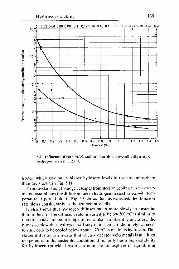
Hydrogen cracking 139
5.4 hydrogen i n steel at 20 "C.
Influence of carbon. X. and sulphur. 0 . on overall diffusivity of
trodes (which give much higher hydrogen levels in the arc atmosphere than are shown in Fig. 5.1).
To understand how hydrogen escapes from steel on cooling. it is necessary to understand how the diffusion rate of hydrogen in steel varies with tem- perature. A partial plot in Fig. 5.3 shows that. as expected. the diffusion rate slows considerably as the temperature falls.
I t also shows that hydrogen diffuses much more slowly in austenite than in ferrite. The diffusion rate in austenite below 500 "C is similar to that in ferrite at ambient temperature. whilst at ambient temperature. the rate is so slow that hydrogen will stay in austenite indefinitely. whereas ferrite needs to be cooled below about -70 "C to retain its hydrogen. This slower diffusion rate means that when a steel (or weld metal) is at a high temperature in the austenitic condition. i t not only has a high solubility for hydrogen (provided hydrogen is in the atmosphere in equilibrium
140 Weldability of ferritic steels
with the steel) but any hydrogen will only move very slowly. Thus. even if the furnace atmosphere is free from hydrogen (so that the equilibrium solubility is less than that shown in Fig. 5.2). hydrogen will not diffuse out of thick sections very quickly.
Figure 5.3 also shows that below about 200 "C, the diffusion rate in fer- rite begins to deviate below the theoretical line for lattice diffusion. This results in a spread of diffusion rates at ambient temperature of about three orders of magnitude! This disturbing result is largely a result of second phase particles (carbides and non-metallic inclusions. particularly sul- phides) in the steel (Fig. 5.4). Near ambient temperature, these particles act as traps for hydrogen - some temporary. some permanent - which slow its diffusion by a very large margin and making the removal of hydrogen a very slow process at and just above ambient temperature.
Susceptibility to embrittlement
The susceptibility of a steel to hydrogen embrittlement - parent steel. weld metal o r HAZ - depends on the inherent toughness of the steel. The tougher the material. the greater is the content of hydrogen needed to embrittle it sufficiently to cause i t to crack. As in many other materials. toughness usually decreases as strength. or hardness. is increased. This is true for HAZs and generally true for parent steels. but some weld metals are exceptional.
The likelihood of (or susceptibility to) hydrogen cracking in weld HAZs increases as their hardness increases. Cracking usually occurs in the as-deposited HAZ. so that its hardness before it is tempered and soft- ened by succeeding weld runs. or by PWHT. is the value of interest. Hard- ness measurements made on completed multipass welds are. therefore. of no u5e in assessing the likelihood of HAZ cracking in the weld root as the weld is being made. Also. because the hardness usually varies within any HAZ. i t is the maximum hardness that is of importance. not the mean value.
Heat-affected zone hardness depends on several factors. The HAZ is best considered as steel that has been heated to austenite and quenched. Unlike a conventional austenitising heat treatment. the HAZ close to the fusion boundary is coarsened as a result of heating to a temperature near to its melting temperature - up to perhaps 1500 "C - which coarsens the prior austenite grain size and thus increases its hardenability. Unlike steel quenched by immersion in water or oil. the HAZ is back-quenched by the steel which has not been heated by welding. so that the thicker the section. the faster the cooling (unlike when steel is cooled externally during heat treatment).
When a HAZ is cooled at a sufficiently fast rate. its hardness will be

Hydrogen cracking 141
that of martensite of the same composition, and will depend solely on its carbon content (Eq. [1.6] and [1.8]). The cooling rate needed to achieve a fully martensitic microstructure depends on the amount of alloying elements present, as well as on the carbon content. The higher the alloy content, the slower will be the cooling rate at which martensite is still formed and the greater will be the hardenability of the steel. For any particular welding situation. in terms of hydrogen level. restraint. preheat and/or interpass temperature and post-weld cooling conditions. there is a particular maxi- mum HAZ hardness at which there is a risk of cracking: this is termed the critical hardness.
The ease with which a HAZ can develop a particular hardness under a particular cooling regime can be related to a single compositional param- eter. usually termed the carbon equivalent (CE). The most common of these (although it strictly relates to the risk of cracking. rather than hardenability pure and simple) is termed the IIW carbon equivalent:
v.21 Mn C r + M o + V + N i + C u C E I I W = C + - + 6 5 I5
Values of CEllw below 0.42 denote a steel which is easy to weld without hydrogen cracking. whereas steels with CEllw values above 0.5 are diffi- cult. Although other CE formulae have been proposed. the only one of these which is widely used is the Japanese P,,, formula (Eq. 11.31). which is particularly applicable to low carbon steels: it places more weight on carbon itself than the CEllw formula. and includes a term for boron.
Application of the carbon equivalent is modified by the inclusion pop- ulation in a steel. as inclusions can affect hardenability and susceptibility to cracking. This was first appreciated when hardenable steels of low sul- phur contents were found to have cracked. while similar steels of higher sulphur level did not. The effect was found to be due. in part at least. to non-metallic inclusions (particularly sulphides) acting as nuclei for the formation of ferrite at temperatures higher than those at which it would have formed in the absence of such nuclei. Having formed at higher tem- peratures. the ferrite was softer than any of the lower temperature trans- formation products. so that removing the inclusions made the steel harder. However. in other situations. sulphides can be damaging if they are sufficient to form liquation cracks (Chapter 3 ) . which are believed to be capable of nucleating hydrogen cracks: they are also a potent cause of lamellar tearing (Chapter 4).
At one time. segregation in steel in terms of considerable variations between ladle and ingot composition. o r differences in the compositions of ingots from the same cast, caused considerable problems in devising safe welding procedures without analysing every piece of steel before it

142 Weldability of ferritic steels
5.5 regions at the centre of a Concast plate. The weld is at the top right.
HAZ hydrogen cracking in the segregate-rich (dark-etching)
was welded. Nowadays. these problems appear to have been replaced by other concerns. One is that some continuously cast (concast) plates can have regions close to the centre-line which are enriched in carbon and alloying elements to such an extent that. if conditions are somewhat mar- ginal for hydrogen cracking for the bulk of the weld. cracking can occur in the segregated regions (Fig. 5.5). Such cracking is often relatively benign. in that i t usually runs parallel to the plate surface and is well away from a free surface. so that i t is not potentially harmful.
Another current concern with modern steel is that those casts that have been made using a high proportion of scrap can contain a high proportion of alloying elements. When not declared in the mill sheet. these residual elements can unexpectedly increase the CEllw by as much as 0.08. i.e. much higher than the level of 0.03 that was recommended to be added to the CEllw if only the C and Mn contents were known.2
To reduce the hardness level below a critical value in order to avoid cracking. it is necessary to control HAZ cooling by adjusting the tem- perature of the steel being welded ( i t . the preheat and interpass tempera- tures) and also the amount it is heated during welding by adjusting the heat input of the welding process. The cooling of a weld bead depends on these factors, as well as on the thickness of the steel being welded. The thickness for this purpose is commonly referred to as the combined thickness
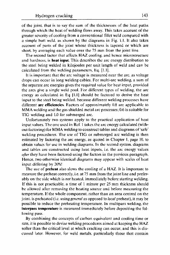
Hydrogen cracking 143
of the joint. that is to say the sum of the thicknesses of the heat paths through which the heat of welding flows away. This takes account of the greater severity of cooling from a conventional fillet weld compared with a simple butt weld. as shown by the diagrams in Fig. 1.1. It also takes account of parts of the joint whose thickness is tapered or which are short, by averaging each value over the 75 mm from the joint line.
The second factor that affects HAZ cooling, and hence microstructure and hardness. is heat input. This describes the arc energy distribution to the steel being welded in kilojoules per unit length of weld and can be calculated from the welding parameters, Eq. [1.1].
I t is important that the arc voltage is measured near the arc. as voltage drops can occur in long welding cables. For multi-arc welding, a sum of the separate arc energies gives the required value for heat input. provided the arcs give a single weld pool. For different types of welding. the arc energy as calculated in Eq 11.11 should be factored to derive the heat input to the steel being welded. because different welding processes have different arc efficiencies. Factors of approximately 0.8 are applicable to MMA welding and the gas shielded metal arc processes; 0.6 is suitable for T IC welding and 1.0 for submerged arc.
Unfortunately two systems apply to the practical application of heat input values. The one used in Ref. 1 takes the arc energy calculated (with- out factoring) for MMA welding to construct tables and diagrams of ‘safe’ welding procedures. The use of TIC or submerged arc welding is then estimated by factoring the arc energy, as quoted in Chapter 1, page 10, to obtain values for use in welding diagrams. In the second system, diagrams and tables are constructed using heat inputs. i.e. the arc energy values after they have been factored using the factors in the previous paragraph. Hence, two otherwise identical diagrams may appear with scales of heat i n pu t di fferi ng by 20%!
The use of preheat also slows the cooling of a HAZ. It is important to measure the preheat correctly, i.e. at 75 mm from the joint line and prefer- ably on the side which is not heated, immediately before starting welding. If this is not practicable. a time of 1 minute per 25 mm thickness should be allowed after removing the heating source and before measuring the temperature. If the whole component, rather than an area centred on the joint, is preheated (i.e. usinggenerul as opposed to local preheat), it may be possible to reduce the preheating temperature. In multipass welding, the interpass temperature is measured immediately before depositing the fol- lowing pass.
By combining the concepts of carbon equivalent and cooling time or rate, i t is possible to devise welding procedures aimed at keeping the HAZ softer than the critical level at which cracking can occur, and this is dis- cussed later. However, for weld metals, particularly those that contain

144 Weldability of ferritic steels
acicular ferrite in their microstructures. the situation is more compli- cated, because increasing the proportion of acicular ferrite in such microstructures can increase both strength and toughness. Furthermore, most weld metals are of compositions that do not form martensite as easily as in a HAZ. Thus, they show much smaller changes in hardness as cooling conditions are altered.
Stress to give cracking
In an as-deposited weld or weld bead, residual stresses up to the yield strength of the weld metal are nearly always present: these are tensile at and near the weld. Residual stresses are the driving force for hydrogen cracking. They can be intensified by stress concentrations, which may take the form of root gaps (Fig. 5.6). undercut (Fig. 5.7(a)) and associated intrusions at the weld toe (Fig. 5.7(b)). and stringers of inclusions in parent plate.
5.6 Effect of root gap on hydrogen cracking: ( a ) restrained fillet weld in low alloy steel with small root gap (<3 mm); (b) identical weld but with 1.6 mm root gap giving HAZ cracking: (c) root run of butt weld showing that cracking originates from sharp notch at right-hand side of 1.6 mm root gap.

Hydrogen cracking 145
5.7 Stress concentrations at weld toe: (a) hydrogen crack in HAZ of C : Mn steel originating from undercut at weld toe; (b) defects at toe of fillet weld exaggerated by taper-sectioning specimen preparation technique.
Because hydrogen embrittles steel at slow strain rates, and residual stresses build up slowly, stress conditions are eminently suitable for hydrogen cracking. Also, when a small root run may be all that is holding two large pieces of steel together. root runs are at particular risk.
Little can be done to reduce stress levels to prevent hydrogen cracking. Peening is difficult to control and may cause damage, grinding of weld toes is expensive and can do nothing for the roots of fillet welds, and the choice of a low strength weld metal, giving lower residual stress levels, is not usually allowable.
Temperature of embrittlement
The effect of temperature on hydrogen embrittlement is illustrated in Fig. 5.8. which compares the results of notched tensile tests on simulated HAZ material containing hydrogen with those on similar specimens containing no hydrogen. Embrittlement is apparent from just above 200 "C to a tem- perature well below -100 "C. For steels whose HAZs are very susceptible to embrittlement, hydrogen cracking has been found to occur at tempera- tures as high as 190 "C, even when the hydrogen level was at the ultra low levels of TIC welding. For other less susceptible steels, the upper limit for cracking is likely to be somewhat lower, so that maintaining such a steel at 150 "C, or even lower, can be used to avoid cracking.
The possibility of avoiding cracking by maintaining steels at a temper- ature below the sensitive range for cracking is somewhat academic: steels are not very tough at such temperatures and hydrogen would escape so slowly that it could be unsafe to bring the joint back to normal ambient temperatures. even after several years.

146 Weldability of ferritic steels
Hydrogen-free specimens
-100 0 100 200 Temperature ("C)
5.X Effect of temperature on hydrogen embrittlement of simulated HAZ material illustrated by the results of notched tensile tests on similar specimens with and without hydrogen.
Techniques for avoiding cracking
Consideration of the four factors needed for cracking shows how it is pos- sible to formulate strategies for its avoidance. As stress reduction is not a feasible option. the strategies revolve around control of hydrogen level, control of microstructure and avoiding the embrittling temperature range while the hydrogen content is high. The methods available are:
1 Direct control of hydrogen level. 2 Control of microstructure by control of cooling. 3 Temperature control method. 4 Control of microstructure by isothermal transformation 5 Use of austenitic or nickel alloy consumables.
For a range of conditions. the safe welding procedures for one steel may. in fact. involve several of these methods of control. hence nomograms devised to derive procedures intended to avoid cracking tend to be complex.
The direct control of hydrogen level is the most important method of avoiding hydrogen cracking. As the hydrogen level is reduced from high to very low. higher hardness levels can be tolerated in the HAZ without recourse to expensive pre- and post-heating. Weld metal cracking in the

Hydrogen cracking 147
so-called weldable C and C:Mn steels can usually be avoided by using consumables giving very low hydrogen levels. However. strict precautions are necessary. particularly with the welding process involving fluxes (MMA, submerged arc and cored wire welding), to maintain very low hydrogen levels. especially on site.
Manual electrodes and submerged arc fluxes need careful storing in warm stores and may need re-drying at relatively high temperature (up to 450 "C) if they are to be supplied for use in good condition. Very low hydrogen electrodes may not retain their hydrogen levels if welding is carried out in unusually humid conditions (i.e. in hot and humid climates or in hyperbaric chambers). Some batches or brands of cored wires may not retain their hydrogen levels if reels are kept on machines unprotected for several days in humid conditions.
Besides directly controlling the hydrogen level of the consumable when using low hydrogen procedures. i t is also important to maintain control of steel cleanliness, i.e. freedom from rust. oil. grease. paint on the weld preparation. as well as being sure that the steel itself does not contain hydrogen.
The control of microstructure by regulating cooling is intended to ensure that the HAZ is not too hard. This is achieved by maintaining a suffi- ciently high heat input and, where this is not practicable (for example. in positional welding). by using preheat. However. preheat has two other benefits: i t reduces the risk of cracking while the weld is actually at the preheat temperature and it allows more time for the weld hydrogen con- tent to be reduced by diffusion at temperatures where diffusion rates are faster than at ambient.
Use of welding diagrams. such as the examples shown in Fig. 5.9. allow different combinations of preheat temperature and heat input to be selected to suit the circumstances. In addition. these diagrams show the benefits of reducing the hydrogen input to the weld. Diagrams ofthis type are available in ref. 1 for C:Mn steels with CE values from 0.32 up to 0.58: for other types of steel. different strategies are needed.
The temperature control method is mainly used for hardenable alloy steels whose HAZs are not amenable to softening by slow cooling and the use of preheat. Although primarily intended for alloy steels. the temperature control method can equally well be used for C and C:Mn steels of such thick section that they are fully hardened by welding.
The method relies on the relatively rapid diffusion of hydrogen out of the steel at temperatures at which the steel will not crack. i.e. above 150- 200 "C. If the type of steel and its carbon content are known. the HAZ hardness can be determined from the lower part of Fig. 5.10. This can be used to estimate the minimum preheat and interpass temperature in the upper part. Some latitude is given in the figure so that account can be
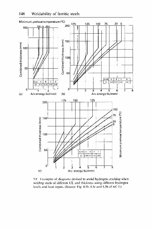
148 Weldability of ferritic steels
Minimum preheat temperature
(a) Arc energy (kJ/rnm) (b) Arc energy (kJ/mm)
(C) Arc energy (kJ/mm)
5.9 Examples of diagrams devised to avoid hydrogen cracking when welding steels of different CE and thickness using different hydrogen levels and heat inputs. (Source: Fig. 4.3b. 4.32 and 4.3h of ref. I . )

Hydrogen cracking 149
300r 200
25 F 150
100
:L 0.1
I lncreasinq alloy concent
L
350 400 450 500 550 600 650 700 Expected HAZ hardness (HV)
5.10 method (for explanation of steel types see ref'. I ) .
Diagram for welding alloy steels by the temperature control

150 Weldability of ferritic steels
taken of factors such as differing restraint and hydrogen levels. For example. the lower curve is applicable to bead-on-plate deposits made with relatively low hydrogen levels: the upper curve is for higher restraint and higher hydrogen. Methods for estimating HAZ hardness are described in ref. 1 and 3 .
I f either the expected HAZ hardness or the restraint is increased. preheat alone will not be sufficient to avoid cracking: the joint will need to be post-heated at the preheat temperature or higher in order to allow sufficient hydrogen to diffuse out before it can be cooled out.
One difficulty which can arise when making multipass welds in 'diffi- cult' steels is that the hydrogen level may build up during welding to a harmful level. particularly if the weld is short. and one run follows another with inadequate time for much hydrogen diffusion. In such cases. as well as minimising the hydrogen input to the weld. it is also helpful to allow a minimum interpass time. This can also be calculated from hydrogen diffusion data at the interpass temperature.' to allow suffi- cient time for diffusion of hydrogen out of each weld run before the next run is deposited.
When using the method. details of the steel need to be known so that the temperature selected is not so high that i t tempers the steel and soft- ens it. or is above the temperature above which the transformation to martensite is completed (the MI temperature). Details of MF temperatures can be found in appropriate reference books or calculated as described in ref. I . If the weld is held above the MI. the HAZ will retain some austenite at the preheat temperature. which will not lose its hydrogen until i t cools to ambient temperature. transforms and leaves the hydrogen it contained free to cause cracking. Even if the steel is taken up to a tempering (PWHT) temperature on completion of welding without intermediate cooling. such retained austenite will not transform during the PWHT. but will retain most of its hydrogen until i t is cooled and transforms.
Some steels may have Mftemperatures which are so low that they are well below the desired preheat level. In such cases. if neither of the methods described subsequently can be used. welding should be carried out at the preferred preheat temperature. using as low a hydrogen level as possible. On completion of welding. the temperature is reduced very slowly in order to give hydrogen from the transforming austenite as much oppor- tunity as possible to escape before it can do any harm.
A disadvantage of the temperature control method is that i t leaves a hard HAZ which. i f the joint is not to be given PWHT. is likely to have poor toughness and poor resistance to some types of stress corrosion. One method of achieving some degree of tempering is to use the temper bead technique. This requires a weld bead to be deposited. as in Fig. 5.1 1. at a fixed and closely controlled distance from the weld toe. This bead tem-

Hydrogen cracking 151 -
Temper bead Temper bead
Temper bead (a)
5.1 1 ( b ) multipass fillet weld where upstanding member is thinner than through member: (c) two-pass fillet weld.
Temper bead technique for: ( a ) multipass butt weld:
pers the hard HAZ on the parent steel of the final weld run and leaves its own HAZ in less hardenable weld metal. I f necessary. the temper bead can be ground off on completion. The method suffers from the disadvan- tage that if the temper bead approaches the weld toe too closely. it creates its own hard HAZ on the parent steel: also the underlying HAZ may still contain unacceptably hard regions. The next method provides an alter- native technique of avoiding cracking and excessively hard HAZs.
The control of microstructure by isothermal transformation is intended to produce a softer H A 2 than the previous technique. by carrying out the welding operation at a sufficiently high temperature for the HAZ to trans- form isothermally to bainite or a similar transformation product softer than martensite. For this method. it is necessary to use the isothermal

152 Weldability of ferritic steels
f Holding time
Time
5.12 Typical isothermal transformation diagram of the type used with the isothermal transformation technique: unless the diagram was produced for steel that had been austenitised at above about 12.50 "C. the holding times should be doubled.
transformation diagram for the steel being welded. Such diagrams can be found in standard reference works and will look something like Fig. 5.12.
The temperature selected should give a transformation to bainite in a reasonably short time. although it is advisable to use a time twice that indicated by the diagram. as the coarse regions of a weld HAZ will take longer to transform than the steel used for the construction of the dia- gram. which will probably have been austenitised at an appreciably lower temperature. This longer transformation time and a normal cool out should give sufficient time for damaging amounts of hydrogen to diffuse out of the joint.
Austenitic or nickel alloy consumables are used when the preheat levels necessary by other methods are unacceptably high. either because they would damage the steel (or nearby components) or are too high for the safety of the welders. With steels containing up to 0.2 to 0.3% C. preheat is not necessary. and for higher carbon levels 150 "C is adequate; welding alloy steels without adequate preheat can, as shown in Fig. 5.13. give rise to HAZ cracking. Figure 5.14 gives guidance on how the preheat level varies with carbon content and other factors when using austenitic stain- less steel electrodes.
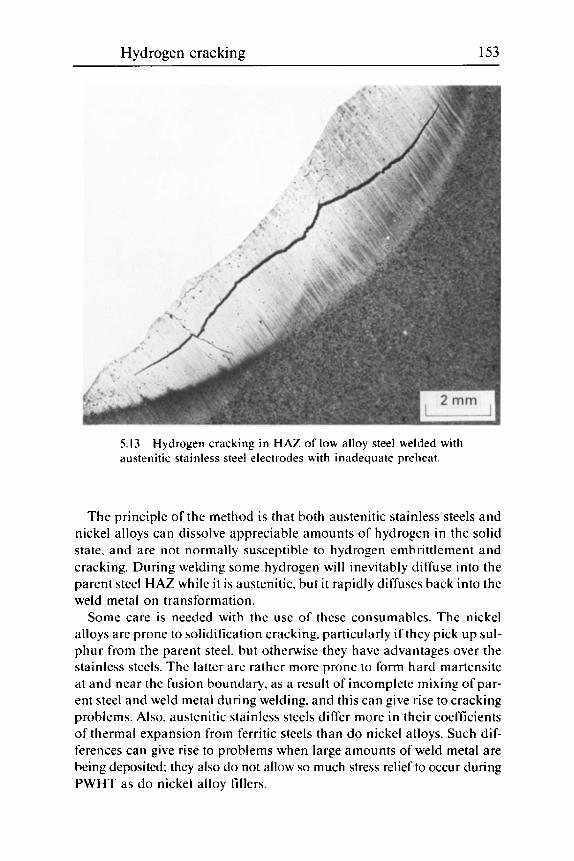
Hydrogen cracking 153
5.13 austenitic stainless steel electrodes with inadequate preheat.
Hydrogen cracking in HAZ of low alloy steel welded with
The principle of the method is that both austenitic stainless steels and nickel alloys can dissolve appreciable amounts of hydrogen in the solid state. and are not normally susceptible to hydrogen embrittlement and cracking. During welding some hydrogen will inevitably diffuse into the parent steel HAZ while it is austenitic. but it rapidly diffuses back into the weld metal on transformation.
Some care is needed with the use of these consumables. The nickel alloys are prone to solidification cracking. particularly if they pick up sul- phur from the parent steel. but otherwise they have advantages over the stainless steels. The latter are rather more prone to form hard martensite at and near the fusion boundary. as a result of incomplete mixing of par- ent steel and weld metal during welding. and this can give rise to cracking problems. Also. austenitic stainless steels differ more in their coefficients of thermal expansion from ferritic steels than do nickel alloys. Such dif- ferences can give rise to problems when large amounts of weld metal are being deposited; they also do not allow so much stress relief to occur during PWHT as do nickel alloy fillers.
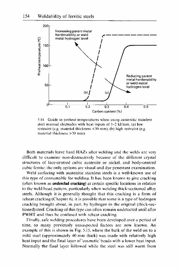
154 Weldability of ferritic steels
200
v - $ 150-
I a
I
Q)
c) : I g 100- .c
a F
50
0
- Increasing parent metal hardenability or weld metal hydrogen level
/--------
Reducing parent metal hardenability
q I I I or weld metal I -
(b) I I I I I I
0.1 0.2 0.3 0.4 0.5
Both materials leave hard HAZs after welding and the welds are very difficult to examine non-destructively because of the different crystal structures of face-centred cubic austenite or nickel. and body-centred cubic ferrite: the only options are visual and dye penetrant examination.
Weld surfacing with austenitic stainless steels is a well-known use of this type of consumable for welding. It has been known to give cracking (often known as underclad cracking) at certain specific locations in relation to the weld bead pattern. particularly when welding thick-sectioned alloy steels. Although it is generally thought that this cracking is a form of reheat cracking (Chapter 6). it is possible that some is a type of hydrogen cracking brought about. in part. by hydrogen in the original (thick-sec- tioned) steel. Cracking of this type can often remain undetected until after PWHT and thus be confused with reheat cracking.
Finally. safe welding procedures have been developed over a period of time, so many previously unsuspected factors are now known. An example of this is shown in Fig. 5.15. where the bulk of the weld on to a mild steel (approximately 40 mm thick) was made with relatively high heat input and the final layer of 'cosmetic' beads with a lower heat input. Normally the final layer followed while the steel was still warm from

Hydrogen cracking 155
5.15 Hydrogen crack in HAZ of first run of final layer of a compensating plate/shell weld in mild steel -40 mm thick. This has developed into a brittle fracture which arrested before the section was severed.
depositing the bulk of the weld. In the example illustrated, a delay of sev- eral days had resulted in the steel cooling to ambient temperature so that a crack formed in the HAZ of the first run of the final layer to be deposited. Unfortunately this crack initiated a brittle fracture when the steel cooled out and was then subject to an ambient temperature approaching zero. The brittle fracture fortunately arrested before the section was completely fractured.
Weld metal hydrogen cracking
The techniques for avoiding weld metal hydrogen cracking are less well developed than those for avoiding HAZ cracking, partly because crack- ing in the weld metal is less common than in the HAZ and partly because it has only recently been realised that control of hydrogen diffusion often plays a more important part than microstructural control. Weld metal hardness is much less important than HAZ hardness, because the possible

156 Weldability of ferritic steels
5.16 Microcracks in weld metal deposited from rutile manual electrodes.
range of variation is generally less. due to weld metal carbon contents usually being lower. However. with high hydrogen levels. cracking is pos- sible in weld metals with a maximum hardness just below 200 HV. whereas under similar circumstances. the critical hardness for HAZ cracking would be about 350 HV.
There are three distinct regimes where hydrogen cracking is possible. The first of these is when welding heavy sectioned C and C:Mn steels without preheat and with consumables giving high hydrogen levels. i.e. with rutile o r cellulosic electrodes: cracking often takes the form of fine microcracking (Fig. 5.16). Such cracking is rare today because of the widespread use of basic electrodes for welding thick sections. particularly if precautions are taken using welding diagrams. such as those in ref. 1.
The second likely cracking regime is with steels where a high degree of alloying is required in the weld metal. to achieve adequate resistance to creep. high temperature oxidation or hydrogen attack. or to achieve par- ticular strength levels. In the last case. the development of lean alloyed steels of low carbon levels (often below 0.05% C . as in the so-called HSLA steels) to avoid the risk of HAZ cracking has made weld metal cracking a major problem. particularly as the weld metals needed to achieve high

Hydrogen cracking 157
5.17 Weld metal hydrogen cracking in low alloy steel weld metal: (a) plan section (lightly etched) of 2.25% Cr : 1Mo weld bead showing transverse and longitudinal cracking: (b) longitudinal section. showing cracking to be perpendicular to weld surface.
strength will often have CEs appreciably higher than the parent steels. With the weldable high temperature steels. the disparities are not so great. as such steels do not usually have CEs below those of their weld metals.
In all these cases, any weld metal cracking is likely to be transverse to the weld length and perpendicular to the surface (Fig. 5.17). although lon- gitudinal cracking may also occur (as in Fig. 5.17(a)) in some circum- stances. Many of these steels have mandatory preheat temperatures in their applications standards. which should take care of hydrogen cracking in the weld metal, provided appropriate low hydrogen levels are used and well controlled.
The third type of weld metal hydrogen cracking is the so-called 'chevron cracking', which is transverse to the weld line. but at 45" to the surface (Fig. 5.18). Such cracking is most common in welds in relatively thick- sectioned C:Mn plate. welded with high heat input processes, such as submerged arc. Although 4.5" cracking has been seen in two-pass welds (in 40 mm thick plate), it is more usual in multipass welds. An important
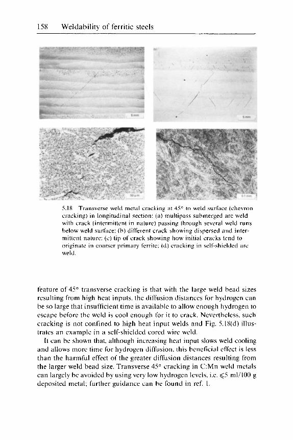
158 Weldability of ferritic steels
5.18 Transverse weld metal cracking at 45" to weld surface (chevron cracking) in longitudinal section: (a ) multipass submerged arc weld with crack (intermittent in nature) passing through several weld runs below weld surface: (b) different crack showing dispersed and inter- mittent nature: (c) tip of crack showing how initial cracks tend to originate in coarser primary ferrite: ( d ) cracking in self-shielded arc weld.
feature of 45" transverse cracking is that with the large weld bead sizes resulting from high heat inputs. the diffusion distances for hydrogen can be so large that insufficient time is available to allow enough hydrogen to escape before the weld is cool enough for it to crack. Nevertheless. such cracking is not confined to high heat input welds and Fig. 5.18(d) illus- trates an example in a self-shielded cored wire weld.
It can be shown that. although increasing heat input slows weld cooling and allows more time for hydrogen diffusion. this beneficial effect is less than the harmful effect of the greater diffusion distances resulting from the larger weld bead size. Transverse 45" cracking in C:Mn weld metals can largely be avoided by using very low hydrogen levels. i.e. 65 m1/100 g deposited metal: further guidance can be found in ref. 1.

Hydrogen cracking 159
Detection and identification
Detection Hydrogen cracks are normally very fine and difficult to detect. even when they break the surface. which they often do not. The consequences of not detecting hydrogen cracks can be disastrous. The example shown in Fig. 5.15 led to an arrested brittle fracture. For cracks which are present at the surface, magnetic particle inspection (MPI) is the preferred technique, although dye penetrant should be used if a non-ferritic filler (e.g. an austenitic stainless steel or a nickel alloy) has been used. The MPI tech- nique has the advantage that. when using d.c.. cracks just below the surface can be detected.
For buried cracks, ultrasonic examination is greatly preferred to radi- ography. Radiography is only capable of detecting those few cracks that are relatively wide and are almost parallel to the incident beam. However, even the use of ultrasonics is not always successful. If a crack has formed in the root region of a two-sided multipass butt weld, the residual stress pattern in the root on completion of welding (Fig. 1.16) will usually be such that the root region is in compression. This will tend to force together the faces of any root cracks. making them very difficult to detect until the weld has been give a PWHT. thus relaxing the stresses.
If i t is suspected that transverse 45" weld metal cracks may be present (Fig. 5.18). it is necessary to carry out an ultrasonic examination using a 45" probe in both directions along the top of the weld seam. The usual 90" probe is not capable of detecting such cracks.
A further common reason for not detecting cracks is when inadequate time is left for cracks to grow to a detectable size before examination. I t is still uncertain how long an incubation period is required for hydrogen cracks to start. and for how long they can continue growing. Several periods have been proposed. varying from overnight (16 hours) to 3 days (72 hours). There is some evidence that when a plentiful supply of hydrogen is available. cracks form soon after the weldment has cooled to near ambient temperature and grow to a detectable size within a few hours. That, however. is not the problem area. The greatest delay probably occurs when the welding conditions are close to a crackho-crack boundary. so that appreciable time is needed for hydrogen to diffuse to the sites of cracking in harmful quantities. Also. in very cold conditions. down to 0 "C and lower, still longer times will be necessary.
The difficulties of detecting buried cracks in as-welded joints make the use of safe welding procedures particularly important. The difficulties can also lead to incorrect identification of the type of crack that has been detected: cracks found after PWHT tend to be classified as reheat cracks (Chapter 6). even if the steel is known to be not susceptible to this type of cracking.

160 Weldability of ferritic steels
5.19 weld metal a s well as the fine-grained HAZ.
Heat-affected zone hydrogen crack which has extended into the
Identification The identification of hydrogen cracks is not simple. as they can occur in a variety of locations and orientations. and can be transgranular or intergranular. The latter are more likely if the steel or weld metal is of the alloyed type or is exceptionally hard. In the HAZ. hydrogen cracks are usually parallel to the weld (unless they are extensions of transverse weld metal cracks) and usually have a portion close to the fusion boundary. However. the cracks may divert into the fine-grained HAZ. as in Fig. 5.7(a). or also into the weld metal (Fig. 5.19).
Cracks will almost never extend beyond the visible HAZ unless they have been heavily stressed after welding. or unless the parent steel itself contains much hydrogen. Without post-weld stressing. cracks extending beyond the visible HAZ are likely to be lamellar tears.
When employing fractographic techniques for crack identification. crack surfaces in C and C:Mn steel HAZs are usually transgranular.

Hydrogen cracking 161
5.20 metal in SEM.
Predominantly intergranular crack surface of low alloy weld
being of a quasi-cleavage type. although some ductile tearing (microvoid coalescence) may also be present. In alloyed steel HAZs. intergranular cracking is the common type. Unlike reheat cracks. hydrogen cracks will never show cavitation along the prior austenite grain boundaries beyond the crack tips.
Similar comments are applicable to weld metal hydrogen cracks (e.g. Fig. 5.20). with the further observations that cracking in weld metals is frequently transverse to the weld and that in weld metals of the acicular ferrite type. cracking is common in the softer primary ferrite (if present) at the prior austenite grain boundaries. as in Fig. 5.18(c). This is because, when the weld metal starts to crack. deformation is accommodated in the lower yield stress (softer) microstructural constituent. whose ductility becomes exhausted before the harder acicular ferrite is stressed beyond its yield point. In relatively hard, alloyed weld metals (e.g. in the Cr:Mo steels) any transverse weld metal cracking is usually perpendicular to the weld surface (Fig. 5.17b). but in C:Mn weld metals the chevron type of cracking (Fig. 5.18) at about 45" to the surface is common. An unusual type of 'weld metal cracking' is when a weld metal of relatively high carbon
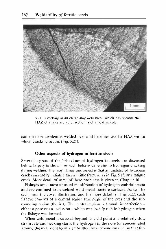
162 Weldability of ferritic steels
5.21 HAZ of a later arc weld: section is of ii boat sample.
Cracking in a n electroslag weld metal which has become the
content or equivalent is welded over and becomes itself a HAZ within which cracking occurs (Fig. 5.21).
Other aspects of hydrogen in ferritic steels
Several aspects of the behaviour of hydrogen in steels are discussed below. largely to show how such behaviour relates to hydrogen cracking during welding. The most dangerous aspect is that an undetected hydrogen crack can readily initiate either a brittle fracture. as in Fig. 5.15. or a fatigue crack. More detail of some of these problems is given in Chapter 10.
Fisheyes are a most unusual manifestation of hydrogen embrittlement and are confined to as-welded weld metal fracture surfaces. As can be seen from the cover illustration and (in more detail) in Fig. 5.22. each tisheye consists of a central region (the pupil of the eye) and the sur- rounding region (the iris). The central region is a small imperfection - either a pore or a n inclusion - which was locally rich in hydrogen when the fisheye was formed.
When weld metal is stressed beyond its yield point at a relatively slow strain rate and necking starts. the hydrogen in the pore (or concentrated around the inclusion) locally embrittles the surrounding steel so that fur-

Hydrogen cracking 163
5.22 pore and surrounding brittle fracture.
Fisheye on fracture surface as seen in SEM showing central
ther straining leads to a hydrogen-assisted brittle fracture - usually of the quasi-cleavage type. This fracture proceeds for a short distance and then stops for two reasons. Firstly. the plastic deformation heats the steel and. secondly. the local strain rate at the crack tip increases*. Both of these effects reduce the ability of hydrogen to embrittle the steel to such an extent that the brittle (hydrogen-assisted) fracture stops. Further straining leads to failure by a ductile process ( microvoid coalescence) in the normal way. It will be appreciated that the only 'defect' at a fisheye is the central 'pupil'. which is normally not much more than a millimetre or so across. It is nor the whole fisheye.
* The heating produced can be felt by (cautiously) touching the neck region of a tensile test specimen immediately after fracture. The increase in strain rate at a hydrogen crack tip causing the crack to stop growing is why hydrogen cracks grow so slowly.

164 Weldability of ferritic steels
Fisheyes are not normally seen for two reasons: firstly. tests on all-weld metal samples - which are carried out by manufacturers of consumables for quality control - are always carried out on samples that have been heat treated (usually for about 16 hours at 250 "C) in order to remove h y d r ~ g e n : ~ secondly. because ferritic steel weld metal usually over- matches the parent steel in strength. the fracture in a cross-weld tensile test normally occurs in the parent steel. Also. tests on weld metal that has been given a PWHT will not show fisheyes. because the heat treatment will remove sufficient hydrogen to avoid the problem.
The only time that fisheyes are likely is when the weld metal fails to overmatch the parent steel. This can happen if the parent steel is stronger (or the weld metal is weaker) than it should be. Fisheyes are also possible if tests are being made to establish the strength of a soft weld metal used to butter a high strength steel (even though the weld metal may be of very low hydrogen level).
In events such as those in the previous paragraph. i t is not permitted to apply a hydrogen removal heat treatment. I f the test specimen has given adequate strength (and. if called for. ductility) values. the presence of fisheyes is not a cause for rejection. unless the pores or particles at the pupils of the fisheyes are unacceptable. If ductility levels are adversely affected. the best advice is to extract further test specimens well before they are to be tested and let them stand in a warm part of the test house for as long as practicable. so that as much hydrogen as possible can escape. However. i t is not unknown for specimens extracted from a thick- sectioned weld several months after deposition to exhibit fisheyes when tested.
Hydrogen flaking can occur in heavy forging billets when they have been cooled from casting temperatures with too high a hydrogen content. The flakes are small cracks within the steel billet caused by the residual stresses developed on cooling acting on steel embrittled by hydrogen. They are. therefore. very similar to the hydrogen cracks which occur after welding. Normally. steel for such heavy forgings should be of low hydrogen content: if this is not achieved. the only way of preventing cracking or flaking is to give the steel a prolonged heat treatment within the tempering temperature range (say. 600-700 "C) to reduce its hydrogen content before i t is allowed to cool to ambient temperature.
Steel that is hot rolled to plate and sections is not normally thick enough for sufficient hydrogen to be retained to give a problem. although in the early days of continuous casting. cracking was occasionally found within centre-line segregates. which were sufficiently enriched in alloying elements to be easily embrittled.
The problem is a reminder that steel. particularly if it is alloyed and of medium or high carbon content, can contain sufficient hydrogen to give

Hydrogen cracking 165
welding problems. Such an example is that of a heavy forging bored out and welded inside the bore (without any prior tempering treatment) with a very low hydrogen welding process and consequently a low preheat level. The preferred solution is to rough machine out the bore. to temper the steel and only then to carry out welding.
High pressure hydrogen is normally stored in high strength steel cylinders at ambient temperatures, despite the well known embrittling effect of hydrogen on high strength steels. Although there are limits on the strength of steels that can be used for such service. the major factor in preventing cracking is that molecular hydrogen cannot enter steel that has even a thin oxide coating (rust) on its surface. If the steel vessel con- taining hydrogen is stressed beyond its elastic limit. the oxide is liable to crack and hydrogen can then enter the atomically clean steel surfaces thus presented. With very high strength steels. the oxide can crack before the steel reaches its elastic limit: hydrogen can then enter the steel, embrittle it and cause cracking without prior plastic deformation.
Similarly. when steel contains molecular hydrogen trapped in voids. this hydrogen cannot re-enter the steel lattice below about 250 "C: such trapped hydrogen is responsible for some of the residual hydrogen meas- ured in weld metal hydrogen analyses. and also for the reduced hydrogen diffusion rates measured near ambient temperature (Fig. 5.3).
Hydrogen attack or hydrogen damage occurs when steel containing hydrogen is exposed to high temperatures. The attack occurs because the hydrogen combines with carbon in the carbides in the steel (Fig. 5.23) to form methane. This destruction of the carbides reduces the strength of the steel and the methane can form internal blisters. Attack is most likely when steel is used (as in petrochemical plant) to contain gases which contain high proportions of hydrogen at high temperatures and pressures.
The presence of chromium in a steel increases its resistance to hydro- gen attack. and curves (the 'Nelson diagram') are available to show which steels can be safely used at different temperatures and partial pressures of hydrogen.'
Steel that has been in such hydrogen service above about 200 "C will contain high levels of hydrogen and plant is normally cooled down slowly to allow sufficient of this hydrogen to diffuse out to avoid cracking when the vessel has cooled to ambient temperature. However. it may still contain enough hydrogen to give cracking problems if the vessel has to be welded for repair or modification: reheating to diffuse out some of this hydrogen or other precautions may be required in such cases.
Sour service is a description of the use of pipework and the like to con- tain liquids (often slightly acidic) which contain hydrogen sulphide (H,S) in solution. Its significance is that molecular hydrogen cannot enter steels at or near ambient temperature because the oxide on the surface prevents
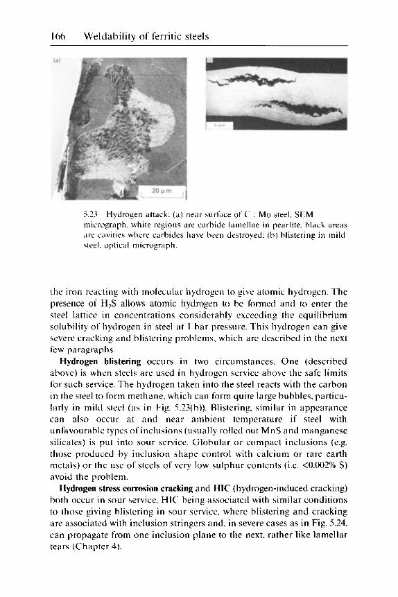
166 Weldability of ferritic steels
5.23 micrograph. white regions are carbide lamellae in pearlite. black areas iire cavitie\ where carbides have been destroyed: (b) blistering in mild \teel. optical micrograph.
Hydrogen attack: ( a ) near surface of C : Mo steel. SEM
the iron reacting with molecular hydrogen to give atomic hydrogen. The presence of H,S allows atomic hydrogen to be formed and to enter the steel lattice in concentrations considerably exceeding the equilibrium solubility of hydrogen in steel at 1 bar pressure. This hydrogen can give severe cracking and blistering problems. which are described in the next few paragraphs.
Hydrogen blistering occurs in two circumstances. One (described above) is when steels are used in hydrogen service above the safe limits for such service. The hydrogen taken into the steel reacts with the carbon in the steel to form methane, which can form quite large bubbles. particu- larly in mild steel (as in Fig. 5.23(b)). Blistering. similar in appearance can also occur at and near ambient temperature if steel with unfavourable types of inclusions (usually rolled out MnS and manganese silicates) is put into sour service. Globular or compact inclusions (e.g. those produced by inclusion shape control with calcium or rare earth metals) or the use of steels of very low sulphur contents (i.e. <0.002% S) avoid the problem.
Hydrogen stress corrosion cracking and HIC (hydrogen-induced cracking) both occur in sour service. HIC being associated with similar conditions to those giving blistering in sour service. where blistering and cracking are associated with inclusion stringers and. in severe cases as in Fig. 5.24, can propagate from one inclusion plane to the next. rather like lamellar tears (Chapter 4).

Hydrogen cracking 167
5.24 Hydrogen-induced cracking (HIC) after tests in a solution con- taining H,S: (a) susceptible 5 mm thick linepipe steel: (b) bead-on- plate deposit on susceptible steel.
This cracking is a type of stress corrosion cracking (SCC) which is most likely at regions of high tensile stress. and particularly with the residual stresses associated with welds. The cracks resemble hydrogen cracks occurring during welding. Where sour service conditions are severe. the recommendations of NACE6 should be followed. These include a maximum Rockwell hardness of 22 HRC (roughly equivalent to 248 HV) and man- datory PWHT for welds in alloyed steels. Beside their application to petro- chemical plant, these requirements are often imposed for service in pipelines and associated valves and other equipment in oil and gas fields if the field is likely to become sour later in its existence.

168 Weldability of ferritic steels
Hydrogen in heat treatment is often added to the furnace atmosphere in some form (e.g. exothermic gas with -15% H2 or cracked ammonia, with up to 75% H,) to protect the steel surfaces from oxidation. When the treat ment involves heating within the austenite range. i.e. during annealing. normalising or hardening. the steel will pick up hydrogen in proportion to its partial pressure in the furnace atmosphere, about 4 ppm (-4 mll 100 g) being picked up by heating in pure hydrogen at about 800 "C. With heat treatments involving slow cooling. most of this hydrogen has time to diffuse out during the cooling and gives no further problems. I f the treatment involves quenching. however. some hydrogen will be retained and. as well as being a probable cause of quench cracks. could give problems should the steel be welded without tempering. particularly in the circumstances outlined for welding in the bores of heavy forgings outlined in the section on hydrogen flaking. above.
Hydrogen in welding has other effects than in producing cracking. During welding it can be a source of porosity (Chapter 7). although its identification is difficult because it can react. while still hot. with carbon in the steel to leave methane. rather than hydrogen. in the pores.
Hydrogen in the arc atmosphere also increases penetration of the welding arc. This is most pronounced when welding with cellulosic electrodes (whose cellulose decomposes in the arc to give hydrogen) and during wet underwater welding. Its effects can. however, be noticed with more normal hydrogen levels. particularly i f a procedure involving two-sided welding that requires inter-run penetration is subsequently used for consumables dried to lower moisture levels. I t is always important. therefore. to check this aspect when procedures are modified to involve consumables of lower hydrogen potential. Lamellar tearing can be aggravated by using consumables of higher hydrogen level. as discussed in Chapter 4.
References
Bailey. N.. Coe. F.R.. Go0ch.T.G.. Hart. P.H.M.. Jenkins. N. and Pargeter. R.J.. Wc~lling Steeds Without Hvclrogen Cracking. Abi ngton Pu bl i s h i ng. C a mbridge. 1993. British Standard BS5135: 1984. 'Arc Welding of C and C-Mn steels'. BSI. London. 1984. Bailey. N. (ed.). Harclmahility q j Steels. a Select Cot!j2reviw. TWI. Cambridge. 1990. BS639: 1986. 'Covered C and C-Mn steel electrodes for MMA welding'. BSI. London. 1986. API 94 1. Steels for Hvdrogen Service at Elevated Emprraturev and Fre.s.sure.s iri
Petrochemical Rclfineries arid Pc>trochemical Plarit. American Petroleum Institute Publication 941. 4th ed.. API. Washington D.C.. Apr. 1990.

Hydrogen cracking 1 69
6 NACE Standard MR0175-92. 'Standard recommended practice for sulfide stress corrosion resistant-metallic materials for oilfield equipment'. NACE. Houston. TX. 1992.

6 Reheat cracking
Description
Reheat or heat-treatment cracking is one of the rarest types of cracking that occur during the welding operation. It is only possible in welds that are given PWHT: it appears to be restricted to steels or weld metals con- taining at least two of the elements Cr. Mo. V and B. and it is mainly found in relatively heavy sections. Two versions exist. structural weld cracking and underclad cracking. In both types. the cracking usually occurs in the HAZ. and is usually confined to the coarse-grained regions. However. reheat cracking is also possible in coarse grained weld metal and parent steel.
Cracking normally occurs as the weldment is being heated to the PWHT temperature, probably above about 565 "C. when the creep strength is still high and ductility in the HAZ is soon exhausted. Cracking depends on the grain boundary regions at elevated temperature being less ductile and/or slightly weaker than the grain interiors. A weaker grain boundary region means that any local deformation which accompanies the relief of residual stresses occurs predominantly along the grain boundary regions. A coarse-grained HAZ (or other region) has fewer grain boundaries to share this deformation. so that ductility is more rapidly exhausted in a coarse- than in a fine-grained region. Low ductility of grain boundaries by impurities still further reduces the capacity for grain boundary deformation. so that such impurities can make an otherwise heat-treatable steel liable to crack. A coarse grain size is again harmful because it provides less grain boundary region over which such impurities can be distributed.
The relationship between the strengths of HAZ and weld metal at elevated temperature is also important. If the HAZ is appreciably stronger (partic- ularly in creep) than the weld metal. the weld metal will start deforming first and the HAZ will not have to strain plastically. I f the weld metal is
170

Reheat cracking 171
6.1 cracking to be intergranular and in coarse-grained HAZ: (b) microsection near tips of cracking showing cavitation along prior austenite grain boundaries: (c) SEM fractograph showing intergranular cracking: (d) showing cavitation on grain facets.
Typical appearance of reheat cracking: ( a ) macrosection showing
stronger than the HAZ. plastic deformation is forced on the HAZ. which is then more likely to crack than if the strengths of HAZ and weld metal were more nearly equal. The latter situation is particularly likely when a ferritic steel is clad with a stainless steel (underclad cracking) because stainless steels are stronger at high temperatures than ferritic steels. especially when the ferritic steel is not particularly creep-resistant.

172 Weldability of ferritic steels
Reheat cracking takes place by the normal creep failure mechanism of cavities opening up along grain boundaries and then coalescing to form a continuous crack. Sectioning through a failure, or fractographic exami- nation in an SEM, will often show evidence of this creep cavitation (Fig. 6.1). Although not always present on the crack surfaces, creep cavitation is strong evidence that cracking is of the reheat cracking type, provided the weld has not been in creep service. when such cavitation can also occur.
For cracking to occur, as stated above, at least two of the elements Cr, Mo. V and B are necessary. In the Cr:Mo steel types, if vanadium is absent, at least 0.5% Mo is needed to give cracking: with vanadium pres- ent, only 0.2% Mo is needed. The elements Sb. As, Sn and P are also likely to increase the risk of cracking; these are also the elements which confer temper embrittlement (Chapter 10) on the same types of steels. Finally, carbon is generally thought to be harmful.
Nakamura er a/.' have rated the susceptibility to reheat cracking by the parameter AG. Eq. [1.22], and this was modified2 to include a term for carbon, Eq. [ 1.23). In both expressions values above zero denoted a risk of cracking. The AG formula is of limited use, as are Eq. [1.22] and [1.23] because, although they can indicate which types of steel are likely to be susceptible to reheat cracking, they do not allow the effect of the temper- embrittling impurities or (in two cases) that of carbon to be assessed. For the impurities. it could be useful to use one of the temper embrittlement parameters (Eq. [1.27]-[1.29]), discussed in Chapter 10, to be used. How- ever. a metal composition factor (MCF) has been developed3 for the 2.25% Cr: 1Mo steel which includes factors for impurities:
MCF = Si + 2Cu + 2P + IOAs + 15Sn + 20Sb P.11 It indicates that silicon and copper. as well as the impurities associated with temper embrittlement. increase the risk of cracking. In the tests to establish this formula. increasing heat input was noted as increasing grain boundary embrittlement.
If the steel contains segregate-rich bands. any cracking is more likely in these regions, because they are likely to contain more of the alloying. impurity elements and carbon than the bulk of the steel.
Role of composition The relative effects of the elements Cr. Mo and V can be assessed from the modified Nakamura formula? Eq. [1.23]. The effect of boron is less well understood. although it is likely to be needed in an 'active' form. When present as such, very small amounts (possibly just in excess of 0.0005%) are likely be detrimental. Carbon is also important (Eq. [1.23]);

Reheat cracking 173
certainly in the O.lCr:OSMo:0.25V high temperature steel, the carbon level in the British Standard Specification BS 1501: Part 2: 1988: Grade 6604 is kept below 0.13% to minimise problems. In the same steel the vanadium content is kept below 0.28% for the same reason. Nevertheless, steels with lower vanadium contents (and containing no chromium and with molybdenum less than 0.5%) have been found to be su~cept ible .~
The steels in which reheat cracking has been found include 0.5Cr:0.5Mo:0.25V. 0.5Mo:B. 2.25Cr: 1 Mo. 5Cr: IMo in descending order of susceptibility.6 However, the risk of cracking in the 2.25Cr: 1Mo steel is so low as to be of little practical importance. In addition. cracking has been identified or claimed in 2Cr:IMo weld metal, in some of the high strength structural steels covered by ASTM A517-1990 (Grades B, E and F, i.e. of the Cr:Mo type with microalloying additions of boron and titanium), Mn:Ni:Mo pressure vessel steels in the ASTM A508 and A533 specifications when they contain a few tenths of a percent of chromium and about 0.05% or more of vanadium. Cracking has also been seen in a high strength structural steel with approximately 0.1C: 1.5Mn:0.25Mo: 0.07V.5
The relationship for reheat cracking in 2.25Cr:lMo weld metal (Eq. [6.1]) is similar in many respects to those developed for temper embrittlement (such as J .Xand PE, Eq. [1.27]-[1.29]). The same deleterious impurities, Sb, As, Sn and P, are important. although Si and Cu, rather than Si and Mn are also harmful. Following the finding of reheat crack- ing in the Mn:Mo:V steel, i t would appear that the detrimental effect of Mn in regard to temper embrittlement is also relevant to reheat cracking in this type of steel.
Other influences
Of the other influences on reheat cracking, the most important is the prior austeniregrain size. This is because the coarser the grain size, the fewer are the grain boundary regions available both for deformation during stress relief and also to which any embrittling impurities can segregate. Hence. cracking is most likely to occur at regions with a coarse prior austenite grain size. The most likely of these is the coarse-grained, high tempera- ture HAZ. An exceptional case is known where a parent Cr:Mo:V steel of satisfactory composition was incorrectly normalised, giving i t a much coarser prior austenite grain size than its coarse HAZ; reheat cracking occurred in the parent steel hut not in the HAZ.
A consequence of this dependence on grain size is that, if a welding technique is used that avoids the presence of coarse-grained regions in the final weld. the risk of cracking can be considerably reduced and

174 Weldability of ferritic steels
cracking itself avoided. The use of such techniques is described in the next section.
The presence of notches, particularly at weld toes, can i n marginal cir- cumstances promote cracking. so that their elimination by grinding weld toes can be helpful.
Such weld toes occur at the weld surface. If the surface is the original surface of. for example. a normalised plate. then the decarburised layer at such a surface is less likely to suffer reheat cracking than the unaltered surface of a forging which has been machined all over. I t is believed that this effect is largely a result of the lower carbon content in the decarbu rised layer.
Other factors have less influence on cracking. The most important of these is the heating rate to the PWHT temperature. and the PWHT tem- perature itself. To reduce the risk of reheat cracking. the heating rate should be as fast as possible in order to heat the steel rapidly through the temperature range within which it is most brittle and can crack. However. the heating rate must be strictly controlled. not only because it is required by the relevant specification. but in order to avoid unequal heating of dif- ferent parts of the fabrication. particularly if they are of different thicknesses. Such uneven heating can lead to distortion andlor higher residual stress levels after PWHT than are acceptable. A relatively high PWHT is also beneficial: certainly for the Cr:Mo steels this should exceed 650 "C.
The effect of heat input during welding is minor. largely because its effect on HAZ grain size is relatively small. Similarly the hardness of the HAZ. which admittedly cannot be varied by a large amount in the more highly alloyed steels under consideration. has been found to be without effect.
Control techniques
Once details of the composition of a suspect steel have been worked out to allow it to be safely welded and heat treated without reheat cracking. then it is important to maintain a watch on mill sheets to ensure that the compositional limits are maintained. One such example is the 0.5Cr:0.5Mo:0.25V steel. in which the limits of 0.08-0.13% C and 0.22- 0.28% V in BS1501: Grade 6604 are most important. Exceeding those lim- its gives a serious risk of reheat cracking: falling below the minimum vanadium and carbon contents will give inadequate creep strength and a risk of premature failure in service.
When cladding a suspect steel with an austenitic stainless steel or a nickel alloy weld metal. the risk of cracking is reduced if a two layer cladding technique is used. so that the second layer refines the coarse-

Reheat cracking 175
/ Parent metal
(a)
ned
Welb cracking, usually normal to /
Grain-refined HA2 regions
Anale of attack II Refined HAZ
Coarse-grained HA2
I the fusion boundary
Coarse-grained HAZ
(C)
6.2 Ang.: of attack and HAZ refinement: (a) location of cracks in coarse-grained regions: (b) low angle of attack and high overlap increase refinement of HAZ: (c) high angle of attack and low overlap decrease refinement of HAZ: (d) macrosection of weld with high degree of HAZ refinement; (e) macrosection of weld with low degree of HAZ refinement ((d) and (e) overleaf).

176 Weldability of ferritic steels
6.2 cont'd
grained. high temperature HAZ of the first. Its own high temperature HAZ should be restricted to the first layer of cladding. where it is harmless.
When depositing structural welds. two possibilities are available for ensuring a fine-grained HAZ. The first, which is most suitable for auto- matic welding. consists of using a steep-sided preparation. as in Fig. 6.2. The coarse-grained region, in which cracking is most likely. is that which has been heated above about 1000 "C. When reheated by subsequent pas- ses to temperatures between about 800 and 1000 "C this coarse region is refined and. thus. made less susceptible to reheat cracking. When welding a multipass weld using constant welding conditions. the degree of refine- ment is greatest with a small angle of attack. as when using a steep-sided preparation (Fig. 6.2(b) and (d)). With such a technique. however. conditions must be held constant. because they are on the verge of giving defects such as lack-of-sidewall fusion. With a high angle of attack. as when car- rying out the horizontal portions of horizontal-vertical welds (Fig. 6.2(b)) with constant welding conditions. a much greater proportion of coarse grained HAZ results.
The second choice. known as the two-layer technique. was developed for MMA eld ding.^.^ although it can be used with semi-automatic and automatic processes. I t is suitable for welding in the horizontal position. as well as positionally. but requires different welding conditions for first
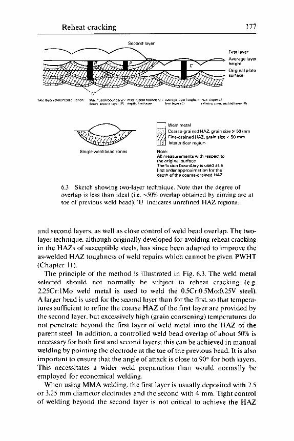
Reheat cracking 177
Second layer
First layer - - Average layer C- height
Original plate surface
'U' Two layer refinement criterion Max fusion boundary/< max fusion boundary + average layer height < max depth 01
depth second layer IFI depth first layer first layer iCI refining zone second layer IRI
Weld metal Coarse-grained HAZ, grain size 2 50 mm Fine-grained HAZ, grain size < 50 mm Intercritical region
Single weld bead zones Note All measurements with respect to the original surface The fusion boundary is used as a first order approximation for the depth of the coarse-grained HA2
6.3 Sketch showing two-layer technique Note that the degree of overlap is less than ideal (i.e. -50% overlap obtained by aiming arc at toe of previous weld bead). 'U' indicates unrefined HAZ regions.
and second layers. as well as close control of weld bead overlap. The two- layer technique. although originally developed for avoiding reheat cracking in the HAZs of susceptible steels. has since been adapted to improve the as-welded HAZ toughness of weld repairs which cannot be given PWHT (Chapter 1 I) .
The principle of the method is illustrated in Fig. 6.3. The weld metal selected should not normally be subject to reheat cracking (e.g. 2.25Cr:lMo weld metal is used to weld the 0.5Cr:O.SMo:0.25V steel). A larger bead is used for the second layer than for the first. so that tempera- tures sufficient to refine the coarse HAZ of the first layer are provided by the second layer. but excessively high (grain coarsening) temperatures do not penetrate beyond the first layer of weld metal into the HAZ of the parent steel. In addition. a controlled weld bead overlap of about 50% is necessary for both first and second layers; this can be achieved in manual welding by pointing the electrode at the toe of the previous bead. It is also important to ensure that the angle of attack is close to 90" for both layers. This necessitates a wider weld preparation than would normally be employed for economical welding.
When using MMA welding. the first layer is usually deposited with 2.5 or 3.25 mm diameter electrodes and the second with 4 mm. Tight control of welding beyond the second layer is not critical to achieve the HAZ
178 Weldability of ferritic steels
refinement needed to avoid reheat cracking, but should be consistent with good welding practice and the level of properties needed. This so- called two-layer technique has been adapted to TIC and. with more diffi- culty. to MAG welding. A high level of HAZ refinement is more easily achieved in the flat position than with vertical o r overhead welding. The degree of preheat required for susceptible steels (normally about 200 "C minimum) is helpful in ensuring a high degree of refinement.
Normalising the weld or cladding deposit. either by full-scale furnace normalising or by a local treatment. will also refine the HAZ grain size and reduce the likelihood of reheat cracking. Full-scale normalising is usually impracticable. but. if carried out. a check should be made that the treatment is not likely to damage the properties of any ferritic weld metal or embrittle any stainless steel cladding by precipitation of the sigma phase. Local normalising is probably most easily carried out o n cladding by a TIC remelting of the cladding surface. with the welding parameters selected so that the coarse grained HAZ on the ferritic steel is refined and not re-coarsened.
I f less onerous measures are required to reduce the risk of reheat cracking. the simplest is to grind the weld toes to remove any undercut and provide a smooth profile. This treatment is only useful o n butt welds where the weld toes at both surfaces can be ground. If done while the steel is still warm from welding. toe grinding can also reduce the risk of hydrogen cracking at weld toes. Peening of the weld toe region may also be helpful. but must be carried out with care to avoid damaging the material.
I t has been claimed that an intermediate PWHT for 2 hours at 500 "C can be helpful in some cases. Another option is to heat to the PWHT tem- perature in two stages with a hold at about 500 "C. sufficient to allow the temperature to equalise. and then heat to the final temperature at the maximum rate permitted by the appropriate specification. This reduces the time at the critical temperature where cracking can occur.
Detection and identification
The detection of reheat cracks is not easy in structural welds and is even more difficult under cladding. because of the different physical properties of the two materials involved. Furthermore. many reheat cracks are rela- tively short and. near their tips, discontinuous. For both types of reheat crack. appropriate ultrasonic examination is the only reliable test method.
Where reheat cracks come to the surface at the weld toe. MPI or (for cladding) dye penetrant can provide suitable techniques. although grinding is advisable to confirm that the cracks exist. Similarly. to confirm the existence of suspected underclad cracking detected ultrasonically. i t is

Reheat cracking 179
sometimes recommended that the cladding be ground off and the newly exposed surface of the underlying steel examined by MPI or by micro- scope after suitable preparation.
Unless cavitation is present near the extremities of cracks. differentiation between reheat cracks and hydrogen cracks is almost impossible. In the types of steel which are susceptible to reheat cracking. both hydrogen cracks (see Chapter 5 ) and reheat cracks are intergranular with respect to the prior austenite grain structure. The presence of cavitation. in either conventional microspecimens - Fig. 6.l(b) - or on fracture surfaces examined in an SEM - Fig. 6.l(d) - will confirm the presence of reheat cracking. although its absence does not rule i t out. Cracking in the fine grained regions of the HAZ would usually support a diagnosis of hydro- gen cracking. Careful metallographic or fractographic examination should reveal whether any liquation cracking (Chapter 3 ) is present. rather than (or even acting as an initiation site for) reheat cracking.
Both hydrogen and reheat cracking can be present in the same speci- men. as hydrogen cracks can provide suitable notches from which reheat cracks can grow during PWHT. Furthermore. the failure to have detected cracking by NDE before PWHT does not exclude the possibility that some or all of the cracking was hydrogen-induced but could not be detected until residual stresses had been relaxed sufficiently by PWHT (Chapter 5) .
References
Nakamura. H. rt al.. Procrt4itig.s of the I st Iiitrrnarional Confrrmcr oil Fracturr. 2. Sendai. Japan. 1965. p. 863. Haure. J. and Bocquet. P.. 'Underclad cracking of pressure vessel components'. Convention CECA 6210-75-3/303. Creusot-Loire. final report. Sept. 1975. Boniszewski. T. and Hunter. A.N.R.. 'Reheat cracking in 2.25%Cr: I%Mo sub merged arc weld metal. Technical note'. Metal Construction. 1982. 14.495-496. British Standard BS1501. 'Steels for pressure vessels: plates: Part 2: Specification for alloy steels: 1988'. BSI. London. 1988. Clark. J.N. and Meyers. J.. 'Stress relief cracking in high strength structural steel BS4360 grade 55F. Mat. Sci. Echnol.. 1988. 4. 610-612. (Despite its title. the steel covered by this paper is not to the Standard quoted. but is a modification which is outside both the compositional and the strength limits of Grade 55F.) Dolby. R.E.. Dhooge. A.. Sebille. J.. Steinmetz. R. and Vinckier. A.G.. 'Status on reheat cracking in nuclear vessel steels 1976. ERIW Report 3531/3/77 to CEC. April 1977. Alberry. P.J.. Myers. J. and Chew. B.. 'An improved welding technique for HAZ refinement'. Weld. Metal Fabrication. 1977. 45. 549-553. Albeny. PJ . and Jones. K.E.. 'Two layer refinement techniques for pipe welding'. 2nd International Conference on Pipe Welding. TWI. London. Nov. 1979.

7 Faults of welding
Faults and defects other than cracks in welds are often considered to be solely under the control of the welder and independent of metallurgical considerations. This is by no means the case and it is sometimes important to understand the metallurgical aspects of the problem. to realise that the solution to a cracking problem might unexpectedly introduce a fault. o r that the presence of a welding fault can sometimes cause cracking. Many welding faults. although relatively harmless by themselves. can make adequate inspection for other serious imperfections and defects difficult and sometimes impossible.
This section is not meant to be a comprehensive review of welding faults. defects and imperfections: reference should be made to texts on welding engineering. and particularly on the use of different welding processes. For a brief guide to defects. a TWI slide collection with notes' is useful for giving illustrations of defects. their usual causes and suggestions for prevention and rectification.
Welding faults can be divided into three major types: faults of shape. inclusions of solid material and voids.
Faults of shape
Faults of shape are serious if they cause a stress concentration. Besides reducing the fatigue resistance of a joint. they can also provide suffi- ciently high local stresses to induce cracking - particularly hydrogen and reheat cracking - where local regions of HAZ or weld metal are relatively brittle at some stage. Surface pocking (usually confined to submerged arc welds) and root concavity are relatively harmless in this respect. and excess metal and excess penetration are benign unless the excess metal produces angles sufficiently sharp to increase the stress concentration markedly. However. excess root penetration can also give unwanted and confusing reflections when ultrasonically testing joints.
180

Faults of welding 181
7.1 weld in 8.4 mm thick pipe as a result of linear misalignment.
Hydrogen cracking that originated at root of single-sided butt
Undercut. lack of fusion and incomplete penetration are all likely to give stress concentrations which can cause cracking. The degree of pene- tration can be decreased if consumables are dried to very low hydrogen levels to avoid hydrogen cracking; this can sometimes give rise to incom- plete root penetration, i.e. a lack of fusion between the weld runs made from opposite sides. or other root defects.
Overlap can either be confused with cracking during surface inspection or can conceal a HAZ crack which would be open to the surface and readily detectable in the absence of this fault.
Linear misalignment. which can produce stress concentrations sufficient to give cracking either during welding (Fig. 7.1). in service, or both, is easy to detect. Angular misalignment is more difficult in this respect. but can be equally harmful both where fatigue resistance is required and where there is a risk of hydrogen cracking (see Fig. 7.2).2
Stray arcing is a fault of shape only in that the arc has been struck in the wrong place and has locally heated (and possibly melted) a small amount of the parent steel. Because the time of arcing is usually very short, the effective heat input is small and it can be assumed that the heated steel will have been cooled so quickly that the resultant microstructure will be martensitic. hard and probably brittle. If not already cracked, an arc strike is likely to provide a region where cracking can readily occur in subsequent service. When grinding out, care must be
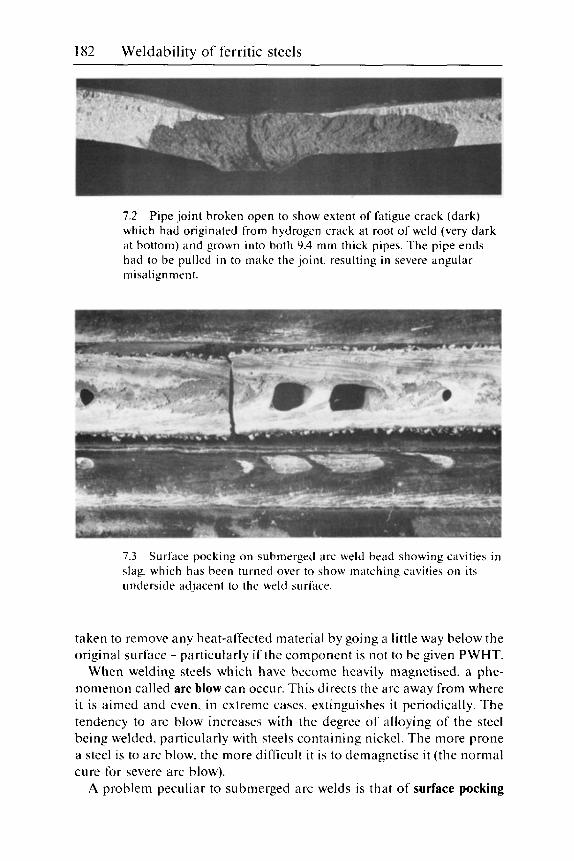
182 Weldability of ferritic steels
7.2 Pipe joint broken open to show extent of fatigue crack (dark) which had originated from hydrogen crack at root of weld (very dark at bottom) and grown into both 9.4 mm thick pipes. The pipe ends had to be pulled in to make the joint. resulting in severe angular misalignment.
7.3 slag. which has been turned over to show matching cavities on its underside adjacent to the weld surface.
Surface pocking on submerged arc weld bead showing cavities in
taken to remove any heat-affected material by going a little way below the original surface - particularly if the component is not to be given PWHT.
When welding steels which have become heavily magnetised. a phe- nomenon called arc blow can occur. This directs the arc away from where it is aimed and even. in extreme cases. extinguishes it periodically. The tendency to arc blow increases with the degree of alloying of the steel being welded. particularly with steels containing nickel. The more prone a steel is to arc blow. the more difficult i t is to demagnetise it (the normal cure for severe arc blow).
A problem peculiar to submerged arc welds is that of surface pocking
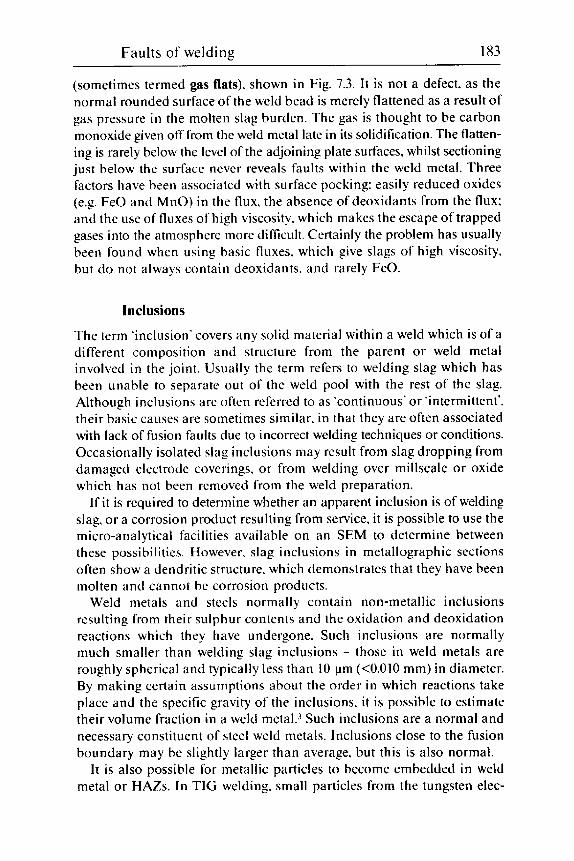
Faults of welding 183
(sometimes termed gas flats). shown in Fig. 7.3. It is not a defect, as the normal rounded surface of the weld bead is merely flattened as a result of gas pressure in the molten slag burden. The gas is thought to be carbon monoxide given off from the weld metal late in its solidification. The flatten- ing is rarely below the level of the adjoining plate surfaces, whilst sectioning just below the surface never reveals faults within the weld metal. Three factors have been associated with surface pocking: easily reduced oxides (e.g. FeO and MnO) in the flux. the absence of deoxidants from the flux: and the use of fluxes of high viscosity. which makes the escape of trapped gases into the atmosphere more difticult. Certainly the problem has usually been found when using basic fluxes. which give slags of high viscosity. but do not always contain deoxidants. and rarely FeO.
Inclusions
The term 'inclusion' covers any solid material within a weld which is of a different composition and structure from the parent or weld metal involved in the joint. Usually the term refers to welding slag which has been unable to separate out of the weld pool with the rest of the slag. Although inclusions are often referred to as 'continuous' or 'intermittent', their basic causes are sometimes similar. in that they are often associated with lack of fusion faults due to incorrect welding techniques or conditions. Occasionally isolated slag inclusions may result from slag dropping from damaged electrode coverings. o r from welding over millscale or oxide which has not been removed from the weld preparation.
If it is required to determine whether an apparent inclusion is of welding slag. or a corrosion product resulting from service. it is possible to use the micro-analytical facilities available on an SEM to determine between these possibilities. However, slag inclusions in metallographic sections often show a dendritic structure. which demonstrates that they have been molten and cannot be corrosion products.
Weld metals and steels normally contain non-metallic inclusions resulting from their sulphur contents and the oxidation and deoxidation reactions which they have undergone. Such inclusions are normally much smaller than welding slag inclusions - those in weld metals are roughly spherical and typically less than 10 pm (<0.010 mm) in diameter. By making certain assumptions about the order in which reactions take place and the specific gravity of the inclusions. it is possible to estimate their volume fraction in a weld metal.3 Such inclusions are a normal and necessary constituent of steel weld metals. Inclusions close to the fusion boundary may be slightly larger than average. but this is also normal.
I t is also possible for metallic particles to become embedded in weld metal o r HAZs. In TIG welding. small particles from the tungsten elec-

184 Weldability of ferritic steels
trode can be included in the weld metal. Although harmless. these show up very strongly under radiography and can interfere with detection of other faults.
Another type of metallic inclusion can occur when metallic particles (either deoxidants or alloying elements) do not fully dissolve in the weld pool. These usually originate from MMA electrode coverings or some- times from alloying submerged fluxes. Such particles may be harmless, as in the example of a partially dissolved cerro-molybdenum particle. shown in Fig. 1.8 and intended for a high strength weld metal. On the other hand. the area shown in Fig. 1.9 is of a manganese. or ferro-manganese particle which hns dissolved. but incompletely mixed in the weld metal leaving a harder region. which in sour service could provide a site from which stress corrosion cracking could initiate. Both types of particles result from a weld pool that had solidified too quickly for complete disso- lution and homogenisation. They can usually be avoided by increasing the weld pool temperature or its solidification time by such measures as increasing the welding current. reducing travel speed or reducing the width of weaving.
With automatic and semi-automatic welding. i t is possible for copper from the contact tip to touch the weld preparation and fall into the weld pool. Unless they interfere with welding. such particles are fairly harm- less if they can dissolve in the weld pool (most automatic weld metals already contain some copper from the coating on the welding wire). In some circumstances. however. fine particles abraded from the contact tip appear to be able to work their way through submerged arc slags on to the hot metal surface. Copper that comes into contact with the HAZ or solid weld metal that is hotter than the melting point of copper (1083 "C) can melt and penetrate along the grain boundaries (by a process usually known as liquid metal penetration). solidify there. and effectively embrittle the metal. often causing cracking (Fig. 3.30 and Chapter 3).
Welding over zinc-coated steel can. in some rather unusual circum- stances. also give liquid metal penetration and embrittlement. as was mentioned in the last section of Chapter 2. The full conditions for this have not been fully identified. although trapping the zinc so that i t can- not escape. as in a twin fillet weld. and welding on to high strength alloy steels appear to be two contributory factors.
A final form of unwanted metal. although not strictly in the form of inclusions. is weld metal spatter. This is unsightly but is not usually harmful. as the spatter is not usually hot enough to heat the underlying metal to a harmful degree.

Faults of welding 185
Cavities
Cavities in ferritic steel welds are usually a result of gas porosity. Shrinkage porosity usually manifests itself as solidification cracking (Chapter 3). except sometimes near the surface in deep. high speed submerged arc welds (Fig. 7.4). in which shrinkage porosity may sometimes be found near the centre-line at o r near the weld face. Crater pipes result from a mixture of shrinkage and gas being given off during the final stages of solidification.
Porosity, by itself, normally has a negligible effect on mechanical properties (including toughness) and can readily be detected by radiogra- phy, or by eye if it breaks surface. I t is. however. undesirable for a number of reasons. Firstly, porosity can mask the presence of more serious defects during NDE. Secondly, its cause might also be a cause of other faults in the weld. For example. porosity due to nitrogen indicates that the weld metal has a high nitrogen content and is likely to have poor toughness (Chapter 9).
Gas causing porosity comes from a variety of sources. Wormhole porosity usually results from contamination of the surfaces being welded, particularly if these are held so close together so that the gases produced by the decomposition of oils. grease and/or rust cannot easily escape except into the weld pool. so that they are trapped by the solidifying grains (or dendrites) of weld metal. In TIG welding. the absence of deoxidants. as when autogenously welding unkilled steels. can lead to porosity .
Lack of shielding is a common cause of both start porosity and uniform porosity. Likely causes are found at the start of an MMA weld if the incorrect technique is used. or if gas shielding is temporarily blown away by wind or a draught or is impeded by spatter on the shielding gas nozzle.
7.4 Fine shrinkage porosity at surface of submerged arc weld bead: (a) detail of porosity: (b) location (arrowed).

186 Weldability of ferritic steels
Uniform porosity may also be caused by consumables or the workpiece being damp.
Gas porosity is usually a result o f the solubility o f a gas dissolved in the weld metal falling rapidly as i t solidifies. a s was illustrated in the case of hydrogen in Chapter 5 (Fig. 5.2). Although hydrogen can give rise to porosity in ferritic steel weld metals. it is not the commonest cause. probably because its solubility on solidification is fairly high in relation to the amount likely to be present in the liquid. Nitrogen. picked up from the air when shielding is inadequate. is a far more usual cause. Nitrogen in excess of about 250-300 ppm invariably gives ;i porous weld. unless the welding has been carried out under high pressure (hyperbaric welding). when larger quantities can be retained in the solid weld metal. Porosity can also result from a chemical reaction in the molten weld metal between oxygen and carbon to give carbon monoxide:
c + o = c o 17.11
This reaction occurs when the oxygen content of the weld metal is high as a result of inadequate deoxidation.
Shielding gases can sometimes be physically trapped and unable to escape from the solidifying weld pool. Argon may be trapped during MIG welding and laser welds are frequently porous. probably because of their rapid solidification.
I t is possible, using a micro-analytical technique developed at TWI. to analyse the gases in weld pores as an aid to determining the cause of porosity. The results are unambiguous in some cases (e.g. when Ar is detected from the shielding gas). but if the porosity is a result of excessive hydrogen. the gas found is likely to be methane. resulting from hydrogen reacting with carbon in the steel:
C + 2H2 = CH, [7.21
Similar reactions are likely when carbon monoxide or dioxide is initially present in pores.
References
1
2
Bailey. N . (ed.). 'Faults in fusion welds in constructional steels'. TWI Slide Set No. 2. TWI. Cambridge.1986. Boulton. C.F. and Bailey. N. 'The influence ofgeometric weld defects on struc- tural integrity'. in Proceedings ofthe Cor?firc.tice 011 'Fahricatioti mid Reliability of P r o c m Plant'. London. 1976. TWI. Cambridge. 1977. 21 7-226. Bailey. N. and Pargeter. R.J. 'The influence of flux type on the strength and toughness of submerged arc weld metal'. TWI Report Series. TWI. Cambridge. 1988.
3
8 Inspection for defects
Details and techniques of in~pec t ionl -~ are not a subject of this book, but it is necessary to highlight areas where there are interactions between metallurgical behaviour and the ability to detect and identify defects and faults - particularly cracks. Because cracks are forbidden by many stand- ards, there is a tendency to overreact when linear defects are discovered by NDE. Because many fabrications are made to strict deadlines. there is also a tendency to gouge out and repair any 'cracks' without pausing to check what they are. whether they are cracks and. if so. of what type. Only when this is known can the correct remedial action can be taken. It is for this reason that each section of the book dealing with a type of cracking includes brief sections on detection and identification.
Added to the tendency to overreact when cracks are discovered is the fact that NDE techniques are constantly improving. so that smaller and smaller faults and cracks can be detected. However. techniques of frac- ture mechanics analysis have been developed4 to assess the safety of allowing structures containing cracks and other faults to go into, or to remain in. service. Such analysis can be used to determine whether possibly expensive and time-consuming remedial measures are needed at all. Fracture mechanics can also be used at an early stage in manufacture to determine what sizes of defects can be allowed without impairing the safety of the structure. This type of analysis also helps to assess the standards of inspection necessary. For fracture mechanics analysis. it is necessary to know the maximum applied and residual stresses and the minimum levels of toughness at various locations in the structure.
It is usually safer to investigate any NDE indications thoroughly and to assess whether it is possible to accept whatever is present - or possibly to reduce its harmfulness by superficial grinding. This is because weld repairs are always liable to introduce further defects - particularly if the repair is carried out hastily under the pressure of impending deadlines or delivery dates.
187

188 Weldability of ferritic steels
Inspection techniques
Visual examination. even if aided by magnifying lenses, low power microscopes. MPI or dye penetrant (DP) techniques. is only capable of detecting faults at the surface. The use of MPI with d.c. current gives a slight sub-surface capability. whilst careful visual surface examination may occasionally hint that something is amiss just below the surface. However, many faults and defects lie well below the surface and the most common techniques for their detection are ultrasonic examination and radiography. Several other techniques. such as stress wave (acoustic) emission. have been and are being developed. but their use is at present specialised and they are not common in the fabrication industry.
Visual examination is chiefly used for detecting defects of shape: undercut. under- or over-fill and misalignment. Surface porosity and open cracks (particularly solidification cracks) can also be detected. The use of MPI and DP allows fine cracks of other types at the surface to be detected. One risk. particularly with MPI. is that under certain conditions it is possible to obtain a marked response from weld fusion boundaries. or even the ripples on a weld surface, without anything being amiss. The fusion boundary effect is particularly troublesome. because it mainly results from the inevitable undercut at the weld toe (which admittedly should be controlled). but which could be mistaken for a hydrogen or reheat crack.
Radiography allows bulk faults to be detected. These include slag inclusions. porosity and wide solidification cracks. Fine cracks cannot be detected. except under very favourable circumstances when the plane of the crack is aligned with the X-ray or gamma-ray beam. Radiography will also detect many of the defects and faults found by visual examination. with the benefit that inaccessible areas. such as the root of a fillet weld. can be examined.
Ultrasonic examination is more suited to the detection of linear faults. such as cracks and lack of fusion. Care is needed to use the correct tech- nique, not to identify linear indication as cracks too readily. and not to use too high a sensitivity - which can produce 'defects' out of slight. harmless metal 1 u rgical variations in st ruc tu re.
Inspectability
Not all steels and weld metals can be non-destructively examined with equal facility, particularly when the technique used is ultrasonics or radio- graphy. Without special techniques, welds on ferritic steels made with austenitic stainless steel o r nickel alloy consumables are virtually impos- sible to examine. The fusion boundary acts like a defect (at the very place

Inspection for defects 189
where defects are likely!), because it separates two materials having widely different physical properties. The only techniques easily applicable to such welds are visual examination and surface examination using DP. Although difficulties with radiography might be expected to be minor. the normal coarse grain size of non-ferritic weld metals causes diffraction effects. which can mask many faults and defects.
Coarse-grained material of any sort will give difficulties with radiography. and inhomogeneity is liable to give problems when using ultrasonics or radiography. particularly when they are used at their most sensitive. A high inclusion content can give problems. particularly with ultrasonics: in fact. ultrasonic techniques are sometimes used to assess the suitability of plate to resist lamellar tearing (Chapter 4) resulting from a high popu- lation of inclusions. Further care is also needed because inclusions that have decohered from the matrix give a much greater ultrasonic response than from the same inclusions before they decohered. as they may have been at an earlier examination.
Consequences of metallurgical features
Apart from the difficulties experienced when examining welds made with non-ferritic fillers discussed in the previous section. the major effects to be considered result from hydrogen cracking and residual stresses.
Hydrogen cracks grow very slowly. and it is necessary to allow suffi- cient time for them to develop before carrying out NDE for this type of cracking. Although the usual delay period is 48 hours. this time require- ment is not well based. and recent evidence suggests that the nearer the welding conditions are to the c rackho crack boundary. the more slowly do hydrogen cracks develop. It is. therefore. most unsuitable to suggest that the time can be reduced by ensuring that. for example. a post-heating treatment is given to diffuse out hydrogen. This is because the post-heating is itself part of the procedure that needs to be monitored to ensure that it has not led to hydrogen cracking. Only if PWHT is used. or if hydrogen cracking is known to be impossible in the joint. steel and consumables under consideration. can this rule be relaxed.
The residual stress pattern in a completed multipass weld is such that some part of the weld will contain compressive residual stresses (Fig. 1.16). even in regions which. directly after they had been deposited, con- tained tensile residual stresses and in which cracks could have formed. The final compressive stresses push together the faces of any cracks formed earlier and make them more difficult to detect by any NDE method. The application of PWHT relaxes these stresses and makes cracking easier to discover. In addition. the surfaces of any cracks with access to air during PWHT will become oxidised. thus making the cracks

190 Weldability of ferritic steels
even more detectable. This improvement of crack detectability after PWHT is why specifications always call for NDE after PWHT. I t can. however. lead to the incorrect identification of hydrogen cracks as reheat cracks (Chapters 5 and 6).
References
1
2
3
4
Halmshaw. R.. Ititroductiori to the Nori-clevtruc,ti~,r Gstirig qf Weltled Joints. Abington Publishing. Cambridge. 1988. Anon.. Non-de.structive Trstirig Aspwts qf the SigtiIficrrricc~ qf Wc41 Defects. Abington Publishing. Cambridge. 1971. Anon.. Procedures untl Reeommi~~itlutiori.s,for the Ultrtrsotiic Trstirig qf Butt Wrlrls. Abington Publishing. Cambridge. 197 1. P D 6493: 1980. 'Guidance on some methods for the derivation of acceptance levels for defects in fusion welded joints'. BSI. London. 19x0.

9 Joint integrity
By a broad definition. adequate weldability includes the ability of a weld to serve its purpose as well as whether it can be made free from cracks and defects. These broader aspects of weldability are discussed below.
Strength and ductility
Unlike most other metals. it is easy to deposit ferritic steel weld metals that do not undermatch the strength of the parent metal. In fact. on the few occasions where undermatching is required. i t is difficult to do this with all but high strength steels.
There are two reasons for this. Firstly. a ferritic steel weld metal has a very dense network of dislocations in its microstructure.' These minute imperfections in the otherwise perfect crystal lattice serve to hamper plastic deformation and thus strengthen the weld metal. The dense dislocation network is a result of the weld cooling rapidly under the restraint of neighbouring cold metal and thus undergoing plastic deformation (warm and cold working). The network is resistant to heating up to PWHT tem- peratures. but is destroyed at normalising temperatures. so that a normalising heat treatment considerably reduces the strength of weld metals to the levels expected for parent steels of similar composition. grain size and heat treatment.
The second factor in the strength of ferritic weld metals is that their microstructures are relatively fine grained as a result of their transformation from austenite. It is well known that a fine grain size confers increased strength. and a particular microstructure peculiar to ferritic steel weld metals - acicular ferrite - is exceptionally fine-grained without any need for a refining heat treatment.
As in other metal systems. the strength of ferritic weld metal increases as the content of alloying elements is increased. The most important strengthening element is carbon but. because too high a carbon level is
191
192 Weldability of ferritic steels
often undesirable in a weld metal. other elements are usually added to confer increased strength. The use of the carbon equivalent formula. Eq. [1.2] (which is used for the parent steel in connection with hydrogen cracking. Chapter 5) is a useful way of estimating weld metal strength. For submerged arc weld metal it has been shown2 that yield and tensile strength both increase linearly with the CE of the weld metal. as in Eq. 11.91-
I t is useful for the strength of a weld metal to overmatch that of a parent metal. Overmatching ensures that if a structure is overloaded. the parent metal deforms before the weld. I t is. therefore. more important for the yield strength to overmatch than for the tensile strength. Again this is a common situation. because weld metals tend to have ratios of yield strength to tensile strength which are higher than for most wrought steels. Some degree of overmatching is advantageous because in most cases the parent metal (particularly in the wrought condition) is less likely to con- tain defects sufficient to cause premature failure than weld metal.
However. i t is not always easy in high strength steels to ensure overmatching and several instances are known where some undermatching. coupled with a high level of weld quality. has been shown to be acceptable. Deliberate undermatching when welding other types of ferritic steel is only employed when welding the 9% Ni steel for cryogenic applications. because the only weld metals capable of giving adequate toughness at the very low temperatures involved (i.e. down to -196 "C) are nickel alloys of lower strength than 9% Ni steel.
Despite its advantages. overmatching of weld metal strength has some drawbacks. The first of these is that the highest tensile residual stress in an as-welded joint is approximately equal to the yield strength of the weld metal itself. This means that the stronger the weld metal. the higher will be the maximum residual stress. with increased risks of cracking during welding and lower defect tolerances in service. The second disadvantage is that as the strength of weld metal is increased. the risk of its suffering weld metal hydrogen cracking is also increased. A further disadvantage is confined to service in environments where too hard a weld metal may result either in stress corrosion cracking or in hydrogen cracking in service.
Weld metal strength generally increases as the temperature falls and decreases as the temperature is increased until i t is vanishingly small as the weld metal starts to melt. I n the as-welded condition. the smooth fall in strength with increasing temperature from ambient is interrupted by the effects of strain ageing between about 100 "C and 200 "C. where ten- sile strength increases with temperature. Above this temperature range. the actual hot strength properties of a weld metal follow those of a parent steel of similar composition. and determine the design stress values, until the temperature is reached where creep becomes important.
11.1 11.

Joint integrity 1 93
Post-weld heat treatment generally reduces weld metal. HAZ and often parent metal ~trength?.~ so that repeated PWHT can reduce strength levels below specification values. However. this is not a marked effect, and most applications standards are sufficiently flexible for some low values to be acceptable.
Ductility is normally associated with tensile properties. but in the case of welds more significance is attached to the ductility in the presence of a sharp notch, i.e. to fracture toughness. In sound weld metals. normal ten- sile ductility at ambient temperature is not very variable. although it falls slightly as the strength of a weld metal is increased. It is difficult to show any embrittlement by hydrogen in a plane tensile test (although it is marked in a notched test: Fig. 5.8). However. in tests at elevated tempera- tures. ductility in the as-welded condition is reduced between about 150 "C and 300 "C because of strain ageing.
At much higher temperatures. when the weld metal is austenitic. there is a so-called ductility dip range. which can sometimes give problems during severe hot-forming operations (Chapter 3). particularly if weld and parent metal exhibit ductility dips over different temperature ranges.
Finally. close to the melting temperature. ductility falls to zero. If the ductility is lost at a temperature appreciably lower than that at which strength is lost. the weld metal is liable to liquation cracking (Chapter 3) . because of the presence of the liquid films responsible for liquation cracking at the grain boundaries. Such liquid films have measurable strength but no ductility.
Toughness As important as adequate strength. and harder to accomplish. is the achievement of satisfactory toughness in both HAZ and weld metal. Toughness is conventionally measured in two ways. impact tests on notched specimens - usually the Charpy test on 10 mm square specimens - and by slow strain rate tests using full-thickness notched and pre- cracked test specimens - fracture toughness tests. The former are much cheaper and simpler to carry out but give less meaningful results than fracture toughness tests. particularly as most welded structures are strained at slow strain rates. Both tests exhibit a transition from ductile to brittle behaviour as the test temperature is reduced.
In the case of full-thickness fracture toughness specimens. fracture toughness can be directly related to the behaviour of the structure in serv- ice. enabling sizes of allowable and unacceptable defects to be calculated. Although correlations between Charpy and fracture toughness test results exist. they are only applicable to the type of test conditions for which they were devised. That is to say, a correlation for HAZ results will not be
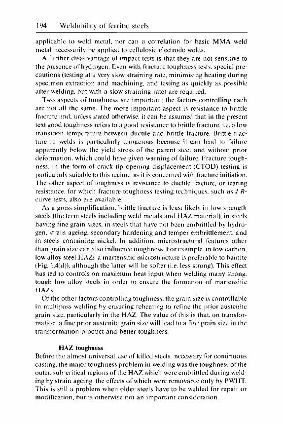
194 Weldability of ferritic steels
applicable to weld metal. nor can a correlation for basic MMA weld metal necessarily be applied to cellulosic electrode welds.
A further disadvantage of impact tests is that they are not sensitive to the presence of hydrogen. Even with fracture toughness tests. special pre- cautions (testing at a very slow straining rate. minimising heating during specimen extraction and machining. and testing as quickly as possible after welding. but with a slow straining rate) are required.
Two aspects of toughness are important: the factors controlling each are not all the same. The more important aspect is resistance to brittle fracture and. unless stated otherwise. it can be assumed that in the present text good toughness refers to a good resistance to brittle fracture. i.e. a low transition temperature between ductile and brittle fracture. Brittle frac- ture in welds is particularly dangerous because i t can lead to failure apparently below the yield stress of the parent steel and without prior deformation. which could have given warning of failure. Fracture tough- ness. in the form of crack tip opening displacement (CTOD) testing is particularly suitable to this regime. as it is concerned with fracture initiation. The other aspect of toughness is resistance to ductile fracture. or tearing resistance. for which fracture toughness testing techniques. such as J R- curve tests. also are available.
As a gross simplification. brittle fracture is least likely in low strength steels (the term steels including weld metals and HAZ material). in steels having fine grain sizes. in steels that have not been embrittled by hydro- gen. strain ageing. secondary hardening and temper embrittlement. and in steels containing nickel. In addition. microstructural features other than grain size can also influence toughness. For example. in low carbon. low alloy steel HAZs a martensitic microstructure is preferable to bainite (Fig. 1.4(d)). although the latter will be softer (i.e. less strong). This effect has led to controls on maximum heat input when welding many strong. tough low alloy steels in order to ensure the formation of martensitic HAZs.
Of the other factors controlling toughness. the grain size is controllable in multipass welding by ensuring reheating to refine the prior austenite grain size. particularly in the HAZ. The value of this is that. on transfor- mation. a fine prior austenite grain size will lead to a fine grain size in the transformation product and better toughness.
HAZ toughness Before the almost universal use of killed steels. necessary for continuous casting. the major toughness problem in welding was the toughness of the outer. sub-critical regions of the HAZ which were embrittled during weld- ing by strain ageing. the effects of which were removable only by PWHT. This is still a problem when older steels have to be welded for repair or modification. but is otherwise not a n important consideration.

Joint integrity 195
C
1
2
3
4 5
6
7
8
9
Where good toughness is currently required, steels of low carbon con- tent and designed to give good HAZ toughness are normally employed, so that the major area of concern is the weld metal. Nevertheless HAZ toughness is still an important concern and rules have been formulated5 to ensure both the selection of steel compositions to give good as-welded HAZ toughness and to ensure that this toughness is maintained by good welding practice. The first few of these rules are applicable generally to C.
1 . Mn. microalloyed and low alloy steels:
Select a low carbon content and, in the case of C and C:Mn steels con- taining 0.12% C or more, a low CE. Select a fine-grained steel, i.e. Al-treated, as this ensures a fine grain size and good toughness in the lower temperature regions of the HAZ. Ensure that both the total and interstitial (free) nitrogen contents are low. Ensure that the steel has inherently good toughness. Select a clean steel with a low content of non-metallic inclusions or. i f this not possible. one where the inclusion shapes are controlled. Use PWHT. Even if the measured toughness is reduced. the overall fracture resistance of the joint will be better because of lower residual stresses. For steels containing >0.12% C. avoid Nb and/or V if high heat inputs (above about 3.5 kJ/mm) are to be used. Microalloyed steels with <0.12% C are more tolerant of microalloying elements at high heat inputs. Steels with a deliberate titanium addi- tion to minimise HAZ grain growth are helpful at high heat inputs. Alloying intended to reduce the transformation temperature from austenite is helpful. unless very fast cooling times ( t x - 4 s) are expected. For low alloy steels. the alloy content should be sufficient to ensure a low carbon martensitic. rather than a bainitic. HAZ microstructure. Additions of nickel are beneficial.
The following recommendations5 relate to good welding practice. although some may conflict with the requirements to avoid cracking:
10
1 1
12
Reduce heat input and. if possible, increase welding (travel) speed in order to reduce HAZ width. Avoid very low heat inputs. particularly at weld toes, as they can give fully hardened martensitic HAZs. Adopt welding techniques that maximise refinement of multipass HAZs. These include allowing sufficient overlap of adjacent weld beads, steep-sided preparations (consistent with good fusion) when

196 Weldability of ferritic steels
welding in the flat and overhead positions or the use of the two-layer technique.6
13 Raise preheathnterpass temperatures (but not excessively) to increase. the proportion of refined HAZ in the microstructure.
14 Temper beads to refine and temper the HAZ of the final weld run should be adopted with caution. as they require very accurate posi- tioning of the weld toe with respect to the toe of the previous weld run (Fig. 5.1 1 ).
The final recommendations5 concern the fracture toughness testing of welds:
15 Match the test conditions. including the degree of restraint. to the service conditions. This may require the adoption of shallow notches if it is accepted that the most likely defect is a shallow crack and not a through-thickness defect.
16 Although slots. or machined notches. are easier to machine and position accurately than fatigue cracks. the results of such tests will require fac- toring in order to obtain a test result that can be used to assess the safety of welded structures likely to contain cracks.
17 Check the actual position of the crack tip after testing by appropriate fractographic examination and/or metallographic examination of sections through the fracture.
18 Simulate long term nitrogen ageing (strain-ageing) by heating test specimens for 2 hours at 100 "C before testing. or by using a standardised long time between welding and testing.
19 Consider whether the tests should be made with or without hydrogen resulting from welding. In the former case. the heat treatment to prod- uce nitrogen ageing will inevitably remove some hydrogen and it may. therefore. be prudent to omit it. In the latter case the hydrogen removal heat treatment will also serve as a strain-ageing treatment.
The recommendations about steel composition are aimed at obtaining a soft HAZ or. in a low alloy steel. one that has a low carbon martensitic microstructure rather than bainite. In addition. the presence of non- metallic inclusions has two detrimental effects. Firstly. inclusions lower the resistance of a steel to ductile fracture by aiding the tearing process. This normally proceeds by microvoids forming in the plastic zone ahead of the crack tip and then tearing back to the crack itself - hence the expression 'microvoid coalescence' for this type of failure. Such microvoids form preferentially at inclusions or other brittle features. Sec- ondly. the inclusions provide internal notches at which brittle fractures can start. The larger the inclusion. the easier the initiation. hence few small inclusions are the best to have but. if that is not possible. small
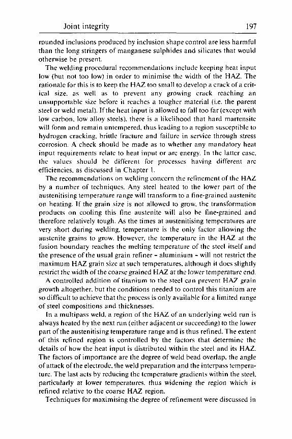
Joint integrity 197
rounded inclusions produced by inclusion shape control are less harmful than the long stringers of manganese sulphides and silicates that would otherwise be present.
The welding procedural recommendations include keeping heat input low (but not too low) in order to minimise the width of the HAZ. The rationale for this is to keep the HAZ too small to develop a crack of a crit- ical size. as well as to prevent any growing crack reaching an unsupportable size before it reaches a tougher material (i.e. the parent steel or weld metal). If the heat input is allowed to fall too far (except with low carbon. low alloy steels). there is a likelihood that hard martensite will form and remain untempered. thus leading to a region susceptible to hydrogen cracking. brittle fracture and failure in service through stress corrosion. A check should be made as to whether any mandatory heat input requirements relate to heat input or arc energy. In the latter case. the values should be different for processes having different arc efficiencies. as discussed in Chapter 1.
The recommendations on welding concern the refinement of the HAZ by a number of techniques. Any steel heated to the lower part of the austenitising temperature range will transform to a fine-grained austenite on heating. I f the grain size is not allowed to grow. the transformation products on cooling this fine austenite will also be fine-grained and therefore relatively tough. As the times at austenitising temperatures are very short during welding. temperature is the only factor allowing the austenite grains to grow. However. the temperature in the HAZ at the fusion boundary reaches the melting temperature of the steel itself and the presence of the usual grain refiner - aluminium - will not restrict the maximum HAZ grain size at such temperatures. although it does slightly restrict the width of the coarse grained HAZ at the lower temperature end.
A controlled addition of titanium to the steel can prevent HAZ grain growth altogether. but the conditions needed to control this titanium are so difficult to achieve that the process is only available for a limited range of steel compositions and thicknesses.
In a multipass weld. a region of the HAZ of an underlying weld run is always heated by the next run (either adjacent or succeeding) to the lower part of the austenitising temperature range and is thus refined. The extent of this refined region is controlled by the factors that determine the details of how the heat input is distributed within the steel and its HAZ. The factors of importance are the degree of weld bead overlap. the angle of attack of the electrode. the weld preparation and the interpass tempera- ture. The last acts by reducing the temperature gradients within the steel. particularly at lower temperatures, thus widening the region which is refined relative to the coarse HAZ region.
Techniques for maximising the degree of refinement were discussed in

198 Weldability of ferritic steels
Chapter 6. because a refined HAZ is also required in some steels to achieve a satisfactory resistance to reheat cracking. The two-layer technique (Fig. 6.3) has been developed at TWI as a means of carrying out as-welded repairs to C. C:Mn and Mn:Ni:Mo steels6 in thick sections when PWHT is impracticable. and is currently being examined for Cr:Mo steels. An alternative repair technique. known as the half-bead technique. involves grinding away half of the first layer of weld beads before depositing the second layer. However. it appears to be a more cumbersome way of achieving a fine-grained tough HAZ than the two-layer technique.
However. the two-layer technique is not the only way of achieving a high degree of HAZ refinement. as steep-sided weld preparations (as used in narrow gap welding) coupled with a shallow angle of attack to the side of the preparation (short of leading to lack of fusion defects) will also gave a highly refined HAZ. as shown in Fig. 6.2.
I f i t is called for. PWHT gives two advantages. Firstly. i t lowers residual stresses. so that less toughness is required for a given acceptable or tolerable defect size. Secondly. the softening of the HAZ of most steels accompanying PWHT improves toughness. Unfortunately. steels containing some of the microalloying elements (particularly Nb and V when present together). as well as Cr:Mo and similar steels. give secondary hardening at the usual PWHT temperatures for C:Mn steels (normally -600 "C). In such cases. the PWHT temperature can either be reduced to 550 "C or less (with con- siderably less relief of residual stresses). o r it can be increased to 650-675 "C (with some loss of strength) for the microalloyed steels. or appreciably higher for the Cr:Mo type. With alloy steels containing Ni as well as C r and Mo. care is needed that the PWHT temperature does not exceed the lower transformation temperature for the steel - the A,, - which is lowered by the presence of nickel.
A further threat to the toughness of the HAZs of multipass welds is posed by the presence of local brittle zones (sometimes termed LBZs). These have not yet been fully investigated. although it is known that some are regions of the HAZ which have been heated by a succeeding pass to a temperature just above the A,, (Fig. 1.5). Such heating causes the parts of the steel richest in carbon to transform to austenite. O n cooling. these transform back either to martensite or to pearlite. both of relatively high carbon content. Both these transformation products are harmful because of their low resistance to brittle fracture and their presence can give low test results (and the possibility of service failures) in fracture toughness tests. They are unlikely to be detected by conventional Charpy impact tests. which combine fracture initiation and its propagation over a larger volume of metal. Application of PWHT should normally temper. and thus remove the harmful effects of. martensitic LBZs. but is less likely to improve toughness when pearlitic regions are present.
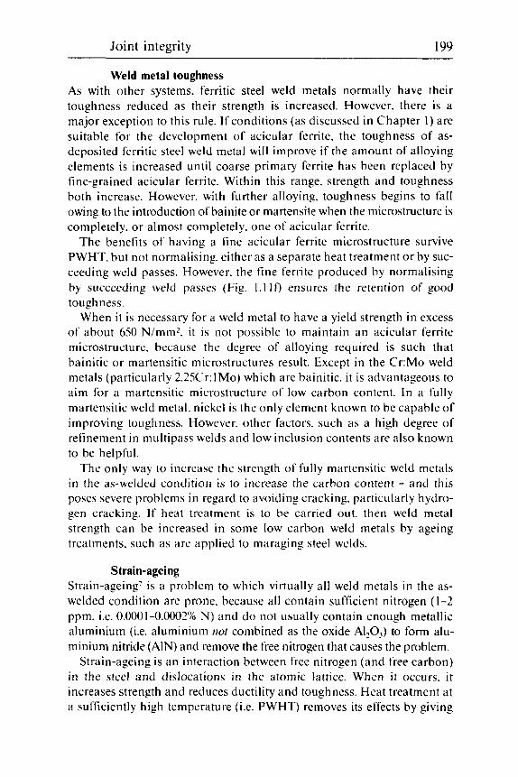
Joint integrity 199
Weld metal toughness As with other systems, ferritic steel weld metals normally have their toughness reduced as their strength is increased. However. there is a major exception to this rule. If conditions (as discussed in Chapter 1 ) are suitable for the development of acicular ferrite. the toughness of as- deposited ferritic steel weld metal will improve if the amount of alloying elements is increased until coarse primary ferrite has been replaced by fine-grained acicular ferrite. Within this range. strength and toughness both increase. However. with further alloying. toughness begins to fall owing to the introduction of bainite or martensite when the microstructure is completely. or almost completely. one of acicular ferrite.
The benefits of having a fine acicular ferrite microstructure survive PWHT. but not normalising. either as a separate heat treatment or by suc- ceeding weld passes. However. the fine ferrite produced by normalising by succeeding weld passes (Fig. 1 . 1 I f ) ensures the retention of good toughness.
When it is necessary for a weld metal to have a yield strength in excess of about 650 N/mmz. i t is not possible to maintain an acicular ferrite microstructure. because the degree of alloying required is such that bainitic or martensitic microstructures result. Except in the Cr:Mo weld metals (particularly 2.25Cr: 1Mo) which are bainitic. it is advantageous to aim for a martensitic microstructure of low carbon content. In a fully martensitic weld metal, nickel is the only element known to be capable of improving toughness. However. other factors. such as a high degree of refinement in multipass welds and low inclusion contents are also known to be helpful.
The only way to increase the strength of fully martensitic weld metals i n the as-welded condition is to increase the carbon content - and this poses severe problems in regard to avoiding cracking. particularly hydro- gen cracking. If heat treatment is to be carried out. then weld metal strength can be increased in some low carbon weld metals by ageing treatments. such as are applied to maraging steel welds.
Strain-ageing Strain-ageing’ is a problem to which virtually all weld metals in the as- welded condition are prone. because all contain sufficient nitrogen ( 1-2 ppm. i.e. 0.0001-0.0002% N) and do not usually contain enough metallic aluminium (i.e. aluminium not combined as the oxide A1203) to form alu- minium nitride (AIN) and remove the free nitrogen that causes the problem.
Strain-ageing is an interaction between free nitrogen (and free carbon) in the steel and dislocations in the atomic lattice. When i t occurs. i t increases strength and reduces ductility and toughness. Heat treatment at a sufficiently high temperature ( i t . PWHT) removes its effects by giving

200 Weldability of ferritic steels
time for the free nitrogen to combine with elements such as iron and manganese. which form nitrides slowly.
When weld metal cools. i t is constrained to deform plastically to accommodate contraction and, in cooling through the strain-ageing tem- perature range (from about 300 "C down to 1.50 "C or below). it undergoes strain-ageing. This ageing is most noticeable in the weld root. which is not only likely to pick up more nitrogen from the atmosphere than the rest of the weld but is also likely to be more heavily strained. Ageing of a steel (or weld metal) that has been previously strained is known as static strain-ageing.
When a completed weld is strained within the strain-ageing range. it undergoes dynamic strain ageing. Weld metal (and susceptible steel gen- erally) tested within the strain-ageing temperature range shows higher tensile strength and lower ductility than at ambient temperature. The maximum strength does not. however. coincide with the minimum ductility - probably because there is an interaction between strain rate and strain- ageing. so that the faster the strain rate. the higher is the temperature at which strain-ageing has its greatest effect. Various properties measured in the tensile test result from different stages during the test which. because of necking (which concentrates straining within a small length of the specimen and increases the local strain rate within that region), occur at different rates. The maximum load (and tensile strength) occurs before the onset of necking when the straining rate is uniform and relatively slow. Reduction of area occurs during necking. when the local straining rate is increased; hence. the maximum effect of strain-ageing on reduc- tion of area occurs at a higher temperature than the maximum effect on tensile strength. Tensile tests carried out in the strain-ageing range up to the temperature giving the maximum tensile strength show marked serrations (Fig. 9.1) in the stresdstrain curve as a result of discontinuous yielding. after the initial yielding.
Similar behaviour is shown by fracture toughness tests. These also exhibit serrated loading curves. with a minimum in (ductile) fracture toughness at about 225 "C. Charpy tests are not normally used to reveal dynamic strain-ageing. because the temperature of maximum effect is a few hundred degrees Celsius higher than in slow strain rate tests. Charpy tests are. however. often used to exhibit static strain-ageing by testing specimens that have been pre-compressed (by typically 5%) and then heated for a short time (usually at 2.50 "C) before testing in the usual way.
Because of the risk of poor toughness in the weld root caused by strain- ageing. it is customary. where a high level of toughness is required. to gouge or grind out the root region of multipass welds and re-weld with sound weld metal. If this is not practicable (for example. in one-sided welding), particular care should be taken in the selection of consumables

Joint integrity 20 1
160 "C
120 "C
180 "C
220 "C
9.1 Stresdstrain curves a t slow strain rate for Mn:Ni:Mo weld metal showing serrated appearance due to discontinuous yielding from 160 to 200 "C.
for root runs, possibly using a tougher weld metal for the root than else- where. One such approach has been the use of submerged arc weld metals containing boron, as 'free' boron can combine with nitrogen and possibly mitigate the effects of strain-ageing. as well as prove an inherently tougher weld metal which will thus retain a higher level of toughness after strain-ageing than a conventional C:Mn composition.
As stated earlier, strain-ageing is not a serious problem with the HAZs of modern steels. which are usually normalised (or given a similar heat treatment) and aluminium-treated if high toughness is required. However it .is possible that steels that are of the normalised rolled type may suffer strain-ageing if they do not contain a deliberate addition of titanium. This is because the normalising treatment in such steels can be too short to allow the combination of aluminium with nitrogen: titanium nitride fdrms much more readily.
Post-weld heat treatment The application of PWHT is generally beneficial to the toughness of weldments because of the reduction of the residual stress level, regardless

202 Weldability of ferritic steels
of whether the measured toughness is altered. For a useful reduction in residual stress levels within a n acceptable time of PWHT. a minimum nominal temperature of 600 "C should be used with conventional C and C : Mn steels. This temperature of 600 "C (at the rate of 1 hour per 25 mm thickness) reduces residual stress levels to about 30% of the parent plate yield strength.
PWHT at 600 "C is likely to improve the measured toughness of HAZs. unless they contain elements such as Cr. Mo. N b and V. which are likely to give secondary hardening. For such steels, higher temperatures. gener- ally at 650 "C or higher. are recommended and normally specified by a pp I ica t io n s st and a rd s.
Although a single PWHT is normally sufficient for any fabrication. there are some circumstances where two or even more heat treatments are necessary. This can happen when the fabrication is too large to fi t inside a furnace. so that the component requires heat treating in sections, and the overlapping sections receive two treatments. Also. i f repair welding is required to rectify defects found after the original PWHT. a subsequent treatment will be required for the repair welding. I t is not unknown. indeed. for several repairs and heat treatments to be carried in isolated cases. Each PWHT will reduce strength slightly. and guidance o n the likely change in properties can be found in ref. 3 and 4. Standards such as the British Pressure Vessel Standard. BSSSOO.X can make allowance for such occurrences.
Where two different steels require different PWHT temperatures. the temperature should be selected for the more important component and biased towards the less important. a s discussed in Chapter 2. In cases of extreme incompatibility. i t is possible to butter the steels requiring the higher temperature with two layers of weld metal. PWHT at the appropriate higher temperature. complete the joint and give the completed joint a PWHT at the lower temperature. This lower temperature PWHT will not harm the higher temperature steel.
For weld metals. PWHT does not always improve measured toughness. Deterioration in toughness may be a result of residual austenite in the weld metal transforming on PWHT to martensite or carbides. or to secon- d a ry ha rde t i i ng by a I 1 oy i n g or m ic roa I I o y i n g e I em e n t s. poss i hl y d i 1 u red into the weld metal. However. the removal of static strain-ageing damage. coupled with the reduction of residual stresses. is likely to improve the overall joint toughness and the PWHT will also prevent dynamic strain- ageing in service at slightly elevated temperatures.
A recently discovered problem associated with PWHT is the finding of poor toughness in weld metals and HAZs accompanied by intergranular fracture. This appears to be associated with phosphorus segregation. and thus to be a type of temper embrittlement (see next section and Chapter

Joint integrity 203
10). However. the steels and weld metals involved are not usually of the type associated with temper embrittlement. and some further ingredient appears to be necessary. This may be that one or more microalloying ele- ments (for example. titanium) could be acting to remove soluble carbon and thus allow the segregation of temper embrittling elements to the prior austenite grain boundaries.
Temper embrittlement This form of embrittlement more often results from service at elevated tem- peratures than from PWHT. and is dealt with in Chapter 10. However, some steels. particularly alloy steels such as the Ni:Cr:Mo, and 3-9% Ni types, with relatively high manganese and silicon contents (as are sometimes met with in castings) and also their weld metals and other (C:Mn) types - proba- bly with moderately high titanium contents - can be susceptible to temper embrittlement. Embrittlement can be so marked that heavy sectioned components in these steels can suffer embrittlement during PWHT unless the rate of cooling from the heat treatment temperature is rela- tively fast. Examples of such problems are in heavy-sectioned compo- nents in 9% Ni steel. on the rare occasions when it requires PWHT, and in some high strength Ni:Cr:Mo castings, where quenching may be necessary. even though the residual stress due to quenching may be almost as harmful as those left from welding.
Hydrogen embrittlement Hydrogen embrittlement reduces the ductility of most ferritic steel HAZs and weld metals to some degree after welding. For a given weld hydrogen level. embrittlement is most marked in the as-welded condition and in thick sections. where the time for diffusion of all the hydrogen from the centre of a section may take many years9 The hydrogen content. particu- larly near free surfaces. is considerably reduced by PWHT. although an appreciable proportion of that left after welding may still be present in the centre of welds thicker than about 50 mm.
When assessing the toughness of as-welded structures by fracture mechanics testing. i.e. when using slow strain rate tests (as opposed to Charpy impact tests. in which the effect of hydrogen is negligible), con- sideration should be given to whether the structure sees its full loading as soon as welding has been completed (when most hydrogen still remains). o r whether the structure will be in an unloaded condition for several weeks or months, when much hydrogen will be lost. Extreme examples of these two cases are cantilever bridge construction. when the loads may be higher during construction than in service. and submarine building. when the hull of the boat may be on the slipway with preheating mats
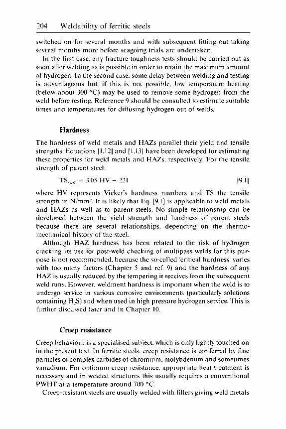
204 Weldability of ferritic steels
switched on for several months and with subsequent fitting out taking several months more before seagoing trials are undertaken.
In the first case. any fracture toughness tests should be carried out as soon after welding as is possible in order to retain the maximum amount of hydrogen. In the second case. some delay between welding and testing is advantageous but. if this is not possible. low temperature heating (below about 300 "C) may be used to remove some hydrogen from the weld before testing. Reference 9 should be consulted to estimate suitable times and temperatures for diffusing hydrogen out of welds.
Hardness
The hardness of weld metals and HAZs parallel their yield and tensile strengths. Equations [ 1.121 and I1.131 have been developed for estimating these properties for weld metals and HAZs. respectively. For the tensile strength of parent steel:
TS,,,,, = 3.05 HV - 221 (9.11
where HV represents Vicker's hardness numbers and TS the tensile strength in N/mmz. It is likely that Eq. [9.1] is applicable to weld metals and HAZs as well as to parent steels. No simple relationship can be developed between the yield strength and hardness of parent steels because there are several relationships. depending on the thermo- mechanical history of the steel.
Although HAZ hardness has been related to the risk of hydrogen cracking. its use for post-weld checking of multipass welds for this pur- pose is not recommended. because the so-called 'critical hardness' varies with too many factors (Chapter S and ref. 9) and the hardness of any HAZ is usually reduced by the tempering it receives from the subsequent weld runs. However. weldment hardness is important when the weld is to undergo service in various corrosive environments (particularly solutions containing H,S) and when used in high pressure hydrogen service. This is further discussed later and in Chapter 10.
Creep resistance
Creep behaviour is a specialised subject. which is only lightly touched on in the present text. In ferritic steels. creep resistance is conferred by fine particles of complex carbides of chromium. molybdenum and sometimes vanadium. For optimum creep resistance. appropriate heat treatment is necessary and in welded structures this usually requires a conventional PWHT at a temperature around 700 "C.
Creep-resistant steels are usually welded with fillers giving weld metals

Joint integrity 205
of roughly matching composition, although the 0.5%Cr:0.5%Mo:0.25V steel is normally welded with 2.25%Cr: 1%Mo tillers because Cr:Mo:V steel and weld metal are susceptible to reheat cracking (Chapter 6). The creep-resistant steels for welding are usually of relatively low carbon con- tent (usually <0.15%) and, although the weld metals are normally lower in carbon content. the difference is not great because weld metals need at least 0.05% C to achieve adequate creep resistance.
Creep failure in service may occur in a number of locations. but the most damaging is in the lower temperature HAZ and adjacent parent steel (so-called Type IV failure) because. even if the creep damage is cut out and re-welded. the HAZ and nearby parent steel will have suffered so much creep damage that failure may be expected after a relatively short life after repairing such damage by welding.
At high temperatures. austenitic stainless steels and some nickel alloys have superior creep resistance to ferritic steels. so that in complex high temperature constructions such as power station plants. there will be a need for transition joints between the femtic steels and these other metals. These need careful planning and design because of the differences in the coefficients of thermal expansion between the different metals; also the risk of carbon migration across the fusion line between the two materials gives risks of local precipitation and embrittlement. Fillers are usually of the nickel alloy type. preferably with expansion characteristics intermediate between ferritic and austenitic steels.
Corrosion resistance
Two aspects of corrosion require some consideration. and both are further discussed in Chapter 10. One is simple corrosion. the other is corrosion involving cracking. i.e. stress corrosion.
Simple corrosion occurs in gases and in liquids. although in the absence of moisture. significant oxidation (i.e. gaseous corrosion) only occurs at high temperatures. Such oxidation is best resisted by additions of chromium to the steel. with matching additions in the weld metal. No particular precautions are needed with regard to welding. other than the usual ones when welding chromium steels.
Corrosion in moist air - away from salt-laden marine atmospheres - has led to the development of special weldable weather-resistant steels containing small additions of elements such as chromium. copper and sometimes phosphorus. It should be emphasised that such steels have no better resistance to corrosion in marine atmospheres or in salt water than conventional C:Mn steels.
Because of the alloying additions, the weldability and strength of weathering steels is similar to the medium strength C:Mn structural

206 Weldability of ferritic steels
9.2 pass weld in 8 mm thick pipework.
Selective ‘tramline’ corrosion in coarse-grained HAZ of a single-
steels. They gradually build up an oxide coating which is adherent and resists further corrosion so that they may be used unpainted. If painted, the paint should last longer than i t would with conventional steels before re-painting is needed. When welded. any welds exposed to the atmos- phere should be made with appropriately alloyed fillers. otherwise the welds will not only corrode perceptibly faster but their location will always be apparent from the different colour of their oxide coating.
Aqueous corrosion involves electrolytes in the water. so that anodes and cathodes are always present. A small anodic area in electrical contact with a larger cathode will suffer accelerated corrosion. whereas a large anode will protect a smaller cathode from corrosion without having its corrosion rate unduly increased. Thus. small zinc anodes will be severely corroded in protecting the hull of a ship from corrosion. whereas a steel hull of a ship will not corrode perceptibly faster if i t is in electrical contact with a bronze propeller, which i t is helping to protect from corrosion. Even in the absence of a second metal. the mill scale on wrought steels is cathodic to the steel itself and can give rise to problems in welded fabri- cations. If the mill scale is present on the bulk of the steel, i t will be absent from the HAZ and weld metal, which will consequently corrode faster in water.
Anode/cathode reactions can also take place at welds because of small differences in composition between weld and parent metals. These can work both ways; for example, certain acidic mine waters can give rise to marked preferential attack (‘tramline corrosion’) in the HAZ (Fig. 9.2). whereas in other circumstances preferential corrosion of the weld metal
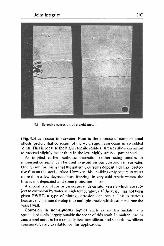
Joint integrity 207
9.3 Selective corrosion of a weld metal.
(Fig. 9.3) can occur in seawater. Even in the absence of compositional effects, preferential corrosion of the weld region can occur in as-welded joints. This is because the higher tensile residual stresses allow corrosion to proceed slightly faster than in the less highly stressed parent steel.
As implied earlier, cathodic protection (either using anodes or impressed currents) can be used to avoid serious corrosion in seawater. One reason for this is that the galvanic currents deposit a chalky, protec- tive film on the steel surface. However. this chalking only occurs in water more than a few degrees above freezing; in very cold Arctic waters, the film is not deposited and some protection is lost.
A special type of corrosion occurs in de-aerator vessels which are sub- ject to corrosion by water at high temperatures. If the vessel has not been given PWHT, a type of pitting corrosion can occur. This is serious because the pits can develop into multiple cracks which can penetrate the vessel wall.
Corrosion in non-aqueous liquids such as molten metals is a specialised topic. largely outside the scope of this book. In molten lead or zinc a steel needs to be essentially free from silicon. and suitable low silicon consumables are available for this application.
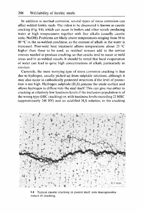
208 Weldability of ferritic steels
In addition to normal corrosion, several types of stress corrosion can affect welded ferritic steels. The oldest to be discovered is known as caustic cracking (Fig. 9.4). which can occur in boilers and other vessels producing water at high temperatures together with free alkalis (usually caustic soda, NaOH). Problems are likely above temperatures ranging from 50 to 80 "C in the as-welded condition. as the content of alkali in the water is increased. Post-weld heat treatment allows temperatures about 25 "C higher than these to be used, as residual stresses add to the service stresses needed to produce cracking, so that cracks tend to occur at weld areas and in as-welded vessels. I t should be noted that local evaporation of water can lead to quite high concentrations of alkali. particularly in crevices.
Currently, the most worrying type of stress corrosion cracking is that due to hydrogen, usually picked up from sulphide solutions, although it may also occur in cathodically protected structures if the level of protec- tion is too high. Hydrogen sulphide (H,S) poisons the oxide surface and allows hydrogen to diffuse into the steel itself. This can give rise either to cracking at relatively low hardness levels if the inclusion population is of the wrong type (HIC cracking) or, with hardness levels exceeding 22 HRC (approximately 248 HV) and an acidified H,S solution. to the cracking
9.4 Typical caustic cracking in parent steel: note transgranular nature of cracking.

Joint integrity 209
following a similar pattern to that encountered with hydrogen cracking during welding, as described in Chapter 5.
Conditions liable to give cracking are frequently met in oilfield systems when the oil goes sour. As high strength steels (e.g. up 700 N/mm2 minimum yield stress) are used for valves and fittings, the need to meet the severe maximum hardness requirement makes PWHT mandatory when welding such steels.'O and even then the hardness may be difficult to control.
Another form of stress corrosion can occur in liquid ammonia, when a trace of water (10-500 ppm, containing low oxygen levels of about 15-100 ppm) is present. Although cracking can be prevented by deliberate addi- tions of water (>0.1%), problems can occur in ammonia storage vessels (very large spheres, which are not amenable to PWHT). when ammonia evaporates and re-condenses within the sphere - but without sufficient water to inhibit cracking.
Other types of stress corrosion cracking may occur, but they are of very specialised application. and are not dealt with here. Any type of stress corrosion cracking which is sensitive to hardness can be initiated at local hard spots, such as were described on p. 21, 22 in Chapter 1.
References Wheatley. J.M. and Baker. R.G.. 'Factors governing the yield strength of a mild steel weld metal deposited by the metal arc process'. Brit. Weld. J.. 1963. 10.23-28. Bailey. N. and Pargeter. R.J.. 'The influence of flux type on the strength and toughness of submerged arc weld metal', TWI Report Series. TWI. Cambridge. 1988. Gulvin. T.F.. Scott. D.. Haddrill. D.M. and Glen. J.. 'The influence of stress relief on the properties of C and C-Mn pressure vessel steel plates'. J. West Scotland Iron Steel Inst.. 1972-3. 80, 149-175. Lochhead. J.C. and Speirs. A.. 'The effects of heat treatment on pressure vessel steels'. J. West Scotland Iron Steel Inst.. 1972-3. 80. 188-219. Dolby. R.E.. 'HAZ toughness of structural and pressure vessel steels - improvement and prediction'. Weld. J.. 1979. 59. 225s-238s. Jones. R.L.. 'Development of two-layer deposition techniques for the MMA repair welding of thick C:Mn steel plate without PWHT. TWI Res. Report 335/1987. TWI. Cambridge. April 1987. Baird. J.D.. 'The effects of strain ageing due to interstitial solutes on the mechanical properties of metals'. Metallurgical Review No. 149. Mat. Metals.
British Standard BS5500: 1991. 'Unfired fusion welded pressure vessels'. BSI. London. 199 1. Bailey. N..Coe. F.R.. Gooch. T.G.. Hart. P.H.M.. Jenkins, N. and Pargeter. R.J.. Welding Steels Without Hydrogen Cracking. Abington Publishing. Cambridge. 1993.
1971, 5(2). 1-18.
10 NACE Standard MROl75-92. 'Standard recommended practice for sulfide stress corrosion resistant-metallic materials for oilfield equipment'. NACE. Houston. Tx. 1992.

10 Senice problems
This chapter considers how service problems impact on welding require- ments: i t is not aimed at giving fully detailed descriptions of the problems involved. although sufficient information is given to appreciate when and why precautions arc necessary.
Fatigue and corrosion fatigue
Fatigue is still the most common mechanism of failure of welded joints.' This is because the stresses needed to produce fatigue failure are much lower than for simple tensile failures and also because fatigue is very sen- sitive to stress concentrations - which most welds contain in the form of both shape changes and welding faults (e.g. Fig. 5.7). Fatigue of welds is so much a result of built-in stress intensifiers that metallurgical consider- ations are unimportant and the long-life fatigue strength of weldments in high strength steels is no better than of those in mild steel. Only if short fatigue lives can be accepted. are high strength steels of advantage. The fatigue strengths of welded joints depend essentially o n the joint type. as exemplified by standards such as the British Code of Practice for fatigue in the design of bridges.*
Good fatigue resistance is obtained by avoiding defects and blending the weld profile to a smooth contour. This is possible for many butt welds but not for fillet welds and those single-sided butt welds whose undersides are inaccessible. Various grinding and re-melting techniques are available for improving fatigue resistance. but when applied to fillet welds they merely move the site of cracking from the weld toe. where detection of cracks is easy. to the weld root. where it is not.
Resistance to corrosion fatigue is lower than for fatigue in air. but follows similar rules. Cathodic protection can restore fatigue strength levels to the values in air. although care must be taken not to over-protect. because of the risk of introducing hydrogen into the steel (particularly at welded joints) and thus causing embrittlement.
210
Service problems 21 1
Corrosion
Several aspects of corrosion were dealt with in the previous chapter. Corro- sion is a major cost to industry - particularly as weldments tend to corrode faster than parent steels. Some of this is due to the residual stresses locked up in welds and some is due to inevitable differences in composition between weld and parent metals leading to galvanic effects.
Once a material has been chosen. ways of minimising corrosion include protective coatings. galvanic protection and avoiding water traps when components are subjected to occasional wetting. It is not appropriate to detail the benefits of different schemes - only to point out any compli- cations and precautions that need to be taken when welding.
If a steel is pre-coated, either primed or fully painted. the coating will be damaged by welding and will need to be made good for some distance from the weld. Advice should be taken as to whether the coating needs to be removed before welding. because welding over a thick paint film (as opposed to a weld-through primer) may lead to hydrogen cracking and/ or porosity. Welding on to galvanised or other zinc coatings is normally acceptable, Chapter 2). apart from any extra precautions which may be necessary to deal with the fumes. unless the zinc can build up in a con- fined space. such as between two opposing fillet welds. or if the steel is of very high strength. Welding on to carburised or nitrided coatings is simi- larly acceptable. although local hardened areas on the HAZ can be expected.
Stress corrosion
As discussed in the previous chapter. several types of stress corrosion are possible in ferritic steels. The most widespread of these is when sulphides are present. particularly in acidic solutions. and hydrogen can enter the steel and cause a type of cracking. The risk of cracking in service increases markedly with the maximum hardness, so that less and less H,S is needed to give cracking as the hardness is increased. An instance is known where an alloy steel plate was flame cut and stood outside in a damp. marine climate. Some days later. the flame-cut region was found to have completely cracked off. owing to its exceptionally high hardness of around 600-700 HV, rather than to the presence of H,S.
When the conditions are acid and the liquid saturated with H,S. then the maximum acceptable hardness in the parent steel or weldment is 22 HRC (approximately 248 HV). In addition. alloy steels need to be given a PWHT at a temperature exceeding 620 O C 3 There have been moves to relax this requirement when conditions are less severe. but such relaxations have not yet been universally accepted. Examples where some relaxation

212 Weldability of ferritic steels
may be sought are under biological fouling in seawater and other envi- ronments where the acidity and/or sulphide concentration are less severe than assumed for the NACE requirements.' Conditions can also be relaxed on the outside of pipework carrying H,S solutions. where the hydrogen content will be lower near the outside surface than near the inside. In the latter case, some specifications ( e g BS4515)4 allow the max- imum hardness to be increased from 250 HV on the inside of pipework to 275 HV o n the outside (with a possible increase in the future to 300 HV).S
In other cases where stress corrosion cracking is likely. the application of PWHT to give tempering of any particularly hard HAZ regions (or weld metal hard spots). coupled with appreciable reduction of residual stresses. is usually adequate.
Loss of toughness in service
Strai n-agei ng Strain-ageing is usually a more serious problem during welding itself than in subsequent service at moderately elevated temperatures. where it can only cause concern in the as-welded condition. At the temperatures involved (150-300 "C). the parent steel and all regions of weldments are operating at temperatures where the likely mode of fracture is ductile and not brittle. Nevertheless. at the most sensitive temperature (about 225 "C). the tearing resistance of a susceptible (as-welded) material can be roughly half of its ambient temperature value.
Although steels can be made immune to strain-ageing by immobilising free nitrogen and free carbon with aluminium. suitable alloying addi- tions and/or the correct heat treatment. this is not possible with most weld metals in the as-welded condition because they do not contain sufficient alu- minium (if any): if they did. sufficient time is not usually available in the welding cycle for the formation of AIN.h Strain-ageing in service can be avoided by the application of PWHT. if practicable. otherwise it is advi- sable to select consumables and welding conditions that will give a suffi- cient margin to allow for the lower ductile toughness at elevated tempera- tures.
Temper embrittlement Temper embrittlement is a serious form of embrittlement suffered by alloyed steels (i.e. steels that d o not contain,fke carbon) and containing certain impurities when they are exposed to temperatures within the range 350-600 "C. The impurity elements P. Sb. Sn and As are most damag- ing if the alloying elements Mn and Si are relatively high in content. The impurity elements segregate to the prior austenite boundaries at tempera-
Service problems 213
tures below about 600 "C and thus embrittle the steel. raising its transi- tion temperature - below which it fractures intergranularly. The embrittlement is fully reversible if the steel is reheat-treated at a tempera- ture above about 600 "C.
The amount of embrittlement is usually assessed by measuring the shift in Charpy transition temperature (usually the SO% shear FATT - fracture appearance transition temperature) before and after an embrittling heat treatment. such as the step ageing heat treatment. which consists of longer times at successively lower temperatures. One such treatment' consists of the following stages:
593 "C. hold for 1 hour. furnace cool to: 538 "C. hold for 15 hours. furnace cool to: 523 "C. hold for 24 hours. furnace cool to: 495 "C. hold for 48 hours. furnace cool to: 468 "C. hold for 72 hours. furnace cool to: 415 "C. remove from furnace.
Other authorities favour longer times (60 and 125 hours. respectively) at the two lowest temperatures. Charpy specimens are then prepared and tested either to determine the transition temperatures with and without step ageing or to ascertain whether the aged steel meets some arbitrary requirement. such as 55 J at 10 0C.7
In comparing the results of such tests with the chemical composition of the steel. two compositional parameters have been found useful. One is the sum of the manganese and silicon contents. (Mn + Si), in mass %. The other is the factored sum of the impurities. the factor varying slightly from one steel to another. The factor for the 2.2SCr: 1 Mo steel is termedx and is given in Eq. [1.29a).7
Factors for other steels are similar but vary in the weight given to the elements Sb. Sn and P (the least embrittling element is always As). Figure 10.l8 shows the degree of temper embrittlement on a plot of (Mn + Si) against the impurity parameter. Other workers multiply (Mn + Si) with a simplified version of the impurity parameter to give the J-factors as in Eq. [1.27], and recommend a maximum value. such as 200, for a particular application.
Because t h e x a n d J parameters are specific to particular steels, a more general parameter. PE. has been developed for both weld metals and parent steels? Eq. [1.28]. This study also claims that copper (a frequent constituent of weld metals originating from the copper coating on automatic welding wires) has no effect on temper embrittlement. In multipass weld metals, embrittlement is confined to the columnar and coarse reheated regions. worsening with the coarseness of the grain size?
The steels most at risk of temper embrittlement are the 2.25Cr:lMo

214 Weldability of ferritic steels
1.8!
1.6t
1.4E
._ cn + 1.2E 5
1 .OE
0.85
1 <23f t . Ib(31 J)
0.65
- x = - 1OP + 5Sb + 4Sn + As 100 -
10.1 Toughness (in ft Ib: I ft Ib = 1.357 J ) of different weld metals after step ageing in a plot of (Mn+Si) against X .
Temper emhrittlement of 2.2SCr : 1 M o weld metal from ref. 7
and 3Cr:Mo steels, nickel steels containing 3-9% Ni and many of the Ni:Cr:Mo high strength steels. Of these. only the Cr:Mo type are regularly used in high temperature service. although turbine rotor steels in some Ni and Ni:Cr:Mo steels can also be used at high temperatures and may sometimes require welding. I t has been shown that simple C and C:Mn steels with no carbon (or. strictly speaking. no.frre carbon) can also be prone to temper embrittlement.'O.ll There is a remote possibility that such

Service problems 215
steels could lose their free carbon in service at high temperatures (e.g. by graphitisation - see a later section) and thus become liable to temper embrittlement.
If a component has been embrittled in service. precautions are neces- sary to prevent failure. particularly if welding is needed for modification or repair. This is usually effected by maintaining the item at a moderately elevated temperature (e.g. above 150 "C) during and after welding and until PWHT can be applied. Particular care is needed if other embrittling or weakening mechanisms (such as hydrogen embrittlement or creep damage) are also likely to be present. Application of PWHT will remove the temper embrittlement - although it will occur again in service if con- ditions are unchanged.
Hydrogen embrittlement Hydrogen embrittlement during welding was discussed in Chapter 5 and. in more detail. in ref. 12: precautions to be taken when testing the tough- ness of steels and weld metals in the presence of hydrogen were outlined in Chapter 9: stress corrosion effects due to pick-up of hydrogen processes are also described in Chapter 9 and earlier in this chapter. and the phenomenon of hydrogen attack (or hydrogen damage) in a later sec- tion of this chapter. The present section discusses how hydrogen embrittles welded steels when the steel is used to contain gaseous hydro- gen at high pressure. Two cases are considered: ambient and high tem- perature behaviour. The two differ because hydrogen from gaseous. molecular hydrogen (HJ cannot enter dry oxidised steel at temperatures below about 250 "C but can at higher temperatures.
Hydrogen gas can. therefore. be contained in steels at about ambient temperature - provided the stresses are sufficiently low. If the steel is stressed too highly. the oxide film can crack and hydrogen can enter the steel through the exposed unoxidised steel surface. For steels of low and medium strength levels. this is only likely to occur when the steel starts to deform plastically - which should not happen in service. With very high strength steels. differences in elastic properties of the steel and the oxide mean that the strain required to cause cracking of the oxide can occur before the yield strength of the steel is reached. which is an unsafe situation. Such conditions are most likely at welds because of residual stresses and the inevitable stress concentrations.
At elevated temperatures. steels can readily absorb hydrogen from the molecular state. The amount of hydrogen absorbed increases with the partial pressure of hydrogen and the temperature (Fig. 10.2). Provided these parameters are not so high as to lead to hydrogen attack. there are no problems at elevated temperature. because steel is not embrittled by hydrogen at temperatures of 250 "C and higher. However. when the steel

216 Weldability of ferritic steels
Hydrogen (m1/100 g of iron at STP)
5 10 15 20 25 30 21OOr-- 1
t 0.1 atm. Liquic ,
Hydrogen (pprn)
10.3 at different pressure\. after ref. 14.
Influence of temperature o n the solubility of hydrogen i n iron
cools. much of the hydrogen will remain in the steel unless sufficient time is allowed for its removal during the cooling cycle. This hydrogen embrittles the steels progressively as the temperature falls below about 250 "C: the embrittlement can lead to cracking or failure o n stressing the component cold (e.g. by hydrotesting).
The precautions necessary to avoid these problems are to replace hydrogen in the vessel by an inert gas. such as nitrogen. and then hold at temperature or cool the component sufficiently slowly to allow most of the hydrogen to diffuse harmlessly away. I t is also important to ensure that regions of general o r locally high hardness are not present. by taking precautions if any welding is required and avoiding the use of steel of too high a strength. Some guidance on the tolerable strength levels for Cr:Mo pressure vessels is given in Fig. 10.3.13 Hardness values have been added to the original plot (using Eq. 19.11) so that the integrity of any hard weld zone regions can be assessed. Although the restriction o n strength or hardness may seem unwarranted, i t is a necessary precaution as it may
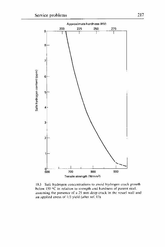
Service problems 217
L n - c
al C c
s P
C a, rn 73 1 r 0, m v)
Lc
10.3
Approximate hardness (HV)
Tensile strength (Nlmm*)
Safe hydrogen concentrations to avoid hydrogen crack growth below IS0 "C in relation to strength and hardness of parent steel. assuming the presence of a 25 mm deep crack in the vessel wall and an applied stress of 1/3 yield (after ref. 13).

218 Weldability of ferritic steels
not always be possible to follow the slow cooling requirements in a n emergency.
The type of plant containing high pressure hydrogen at elevated tem- peratures occurs in refineries and chemical plant - hydrotreating. re- forming and hydrocracking units and ammonia converters being typical examples of such plant. Normally on shutdown. the contents of such ves- sels are replaced with an inert gas and the plant cooled over several days. However. in an emergency. such precautions may not always be possible and the plant may cool naturally much faster.
High pressure hydrogen plant is unlikely to be operated at such a high temperature as to suffer creep damage. but temper embrittlement is always possible. particularly in older plant. and the presence of two simultaneous embrittling mechanisms calls for special precautions whenever the steel is near amhient temperature.
Welding of steel containing hydrogen for repair or modification should be carried out with care. Normally. the steel is heated for long enough to remove most of the hydrogen before welding starts. However. this may not always be necessary. particularly if the preheating temperature is suf- ficiently high to he above the hydrogen embrittlement temperature range. Post-heating - or direct heating to the PWHT temperature after welding - may then be advisable.
High temperature service problems
Several of the problems likely when welded fabrications are used at high temperatures are discussed elsewhere. Oxidation and creep resistance are outlined in Chapter 9. strain-ageing and temper embrittlement in Chapter 10 and in previous sections of this chapter and some of the problems of high temperature hydrogen in the previous section.
Hydrogen attack Hydrogen attack (or hydrogen damage) is distinct from hydrogen embrittlement and occurs at temperatures above about 220 "C. For any steel. the safe temperature decreases as the partial pressure of hydrogen is increased. Of the steel types likely to be used in hydrogen service. only those containing the element chromium appear to have enhanced resistance to hydrogen attack. Thus. as the required temperature and pressure are increased, the chromium content of the steel employed should also be increased. The requirements for safe hydrogen service are shown in the Nelson diagram (Fig. 10.4):14.15 the latest version of ref. 15 specified by the API should always be consulted.
Although the Nelson diagram has been in existence for nearly a quarter of a century.I4 it has been built up mainly from records of service failures. as

Hyd
roge
n pa
rtia
l pre
ssur
e (M
Pa,
abs
.) 3.
45
6.9
10.3
13
.8
17.2
20
7 3
4 5
48 3
62
1 75
8
1400
1200
--
1000
r:
0.5M
o st
eel
- !+ F 5 800
n
1
3
a i I-
600
400
\
-I 2
00
Car
bon
stee
l and
Cr:
0.5M
o st
eel-
.- I
8 (2
40 "F
) 0 L-.-
3000
5000 7000 9
0001
1,00013,000
-Sca
lech
ange
0
500
1000
15
00
2000
25
00
Hyd
roge
n pa
rtia
l pre
ssur
e (p
si A
) S
urfa
ce d
ecar
buri
zatio
n ------ -
Inte
rnal
dec
arbu
riza
tion
(Hyd
roge
n at
tack
)

220 Weldability of ferritic steels
no accepted laboratory test method for simulating hydrogen attack has been found - partly because the incubation time can be very long (over 10 000 hours. 13 months). This means that it has not been possible to study systematically the conditions leading to attack, and new evidence is still accumulating. It was originally thought that the C:O.S%Mo steel resisted hydrogen attack better than simple C or C:Mn steels, but this is no longer regarded as the case.15 Hence, revisions to the diagram are expected as knowledge grows.
Hydrogen attack occurs because hydrogen diffuses into steel (and weld metal) and reacts with the carbon in the steel to form methane (Eq. [7.2]). At high temperatures, above about 560 "C and at pressures below -13 bar, surface decarburisation is the usual form of attack. This attack weak- ens and lowers the ductility of the steel locally. With higher pressures, attack is not confined to the surface layers but occurs throughout the thickness of the steel.
Microscopic examination will reveal that the carbides in the pearlite (Fig. 5.23(a)) or elsewhere in the steel have been attacked and that small voids or microcracks have formed. The destruction of the carbides and the simultaneous formation of cracks reduces the strength, ductility and toughness of the steel. Hydrogen attack can also lead to blistering (Fig. 5.23(b)) if the steel has a population of stringers of inclusions of manga- nese sulphide or mixed sulphide and silicates. Creep resistance is also reduced. although for most steels the safe temperatures for exposure to hydrogen are well below those at which creep occurs.
Detection can be difficult without the extraction of test samples (i.e. for bend. crush or tensile tests), although careful microscopic examination. analysis for carbon (which will be reduced from its original level) and ultrasonic examination can all be helpful. The last will usually show scat- tered reflections characteristic of fine cracking.
Graphitisation
Graphitisation was originally found in petrochemical plant and steamlines. and this led to a thorough investigation at the time.16 It is not a current problem. because susceptible steel compositions are no longer allowed to be used within the dangerous temperature range. However, with current pressures to extend the life and/or efficiency of plant, it must not be ignored as a possible problem area.
In C. C:Mn and C:Mo steels, the true phase in equilibrium with iron is carbon (graphite) and not cementite (Fe,C). The approach to equilibrium is so slow that graphite is never seen under normal circumstances. However, with some steels. graphite nodules (Fig. 10.5; similar to those seen in spheroidal graphite cast irons) can form after very long periods at ele-

Service problems 22 1
10.5 Graphitisation in mild steel.
vated temperatures. The effect of the transformation from cementite to graphite is to reduce strength and, in some cases, toughness.
Graphitisation has only been seen in certain steels subjected to temper- atures in excess of 455 "C for periods of at least four years.16 Above the A C I temperature steels start transforming to austenite in which carbon is much more soluble than in ferrite. The reaction to graphite is most rapid at temperatures about 60 "C below theAC1.I7 Graphitisation is accelerated by prior plastic deformation, and is said to be more rapid in martensitic microstructures than in ferrite.17 It occurs in weld metal as well as in parent steel.16
Graphitisation has only been found in simple carbon and C:Mo ~ t e e l s . ' ~ . ~ ~ Steels containing about 0.5% Cr or more do not suffer this type of degradation, presumably because chromium forms more stable car- bides than do iron and molybdenum. Graphitisation is also retarded by the elements Mn, Mo, Ti and V. A combination of low aluminium (<0.003%) and high nitrogen (>0.03%) also appears to prevent graphitisation. Alu- minium and silicon are believed to accelerate the process.
The amount of carbon remaining in solid solution in equilibrium with graphite is much less than in the original condition, when Fe,C (cementite) is the quasi-equilibrium constituent. This may reduce the risk of carbon strain-ageing, but it could also make a plain C or C:Mo steel susceptible to temper embrittlement in the graphitised condition.
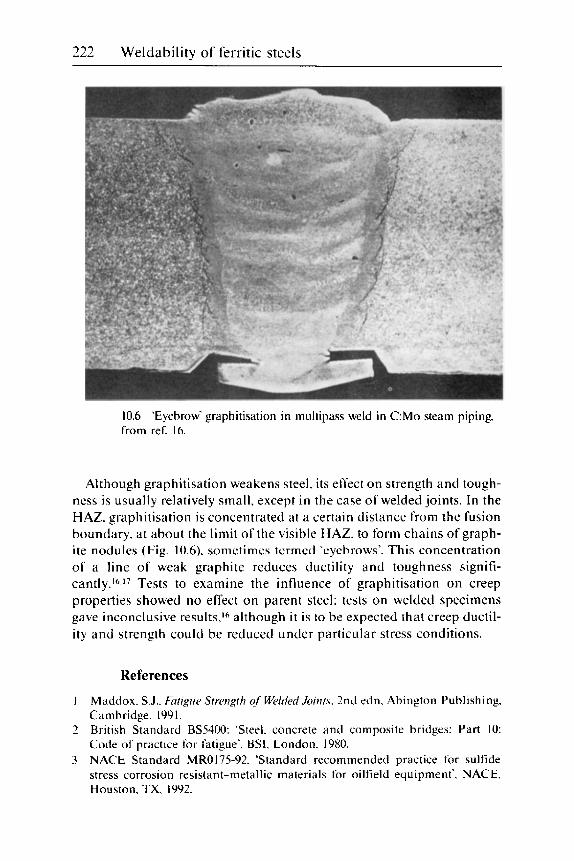
222 Weldability of ferritic steels
10.6 'Eyebrow' graphitisation in multipass weld in C:Mo steam piping, from ref. 16.
Although graphitisation weakens steel. its effect on strength and tough- ness is usually relatively small, except in the case of welded joints. In the HAZ. graphitisation is concentrated at a certain distance from the fusion boundary. at about the limit of the visible HAZ. to form chains of graph- ite nodules (Fig. 10.6). sometimes termed 'eyebrows'. This concentration of a line of weak graphite reduces ductility and toughness signifi- ~ a n t l y . ~ ~ . ~ ~ Tests to examine the influence of graphitisation on creep properties showed no effect on parent steel: tests on welded specimens gave inconclusive results,I6 although i t is to be expected that creep ductil- ity and strength could be reduced under particular stress conditions.
References
1
2
3
Maddox. S.J.. Fatigue Strength qf Welded Joinrs. 2nd edn. Abington Publishing. Cambridge. 1991. British Standard BS5400: 'Steel. concrete and composite bridges: Part 10: Code of practice for fatigue'. BSI. London. 1980. NACE Standard MROl75-92. 'Standard recommended practice for sulfide stress corrosion resistant-metallic materials for oilfield equipment'. NACE, Houston. TX. 1992.

Service problems 223
4 British Standard BS4515: 1984, 'Process of welding steel pipelines on land and offshore'. BSI, London, 1984.
5 Walker. R.A. et a / . 'The significance of local hard zones on the outside of pipe- line girth welds'. in Proceedings of the International Conference on 'The New Realities in Pipeline Design. Construction and Operation'. IIR. London. 1992.
6 Terashima. H. and Hart. P.H.M.. 'Effect of aluminium in C-Mn-Nb steel sub- merged arc welds'. Weld. J . 1984, 63. 173s-183s.
7 Bruscato. R.M.. 'Embrittlement factors for estimating temper embrittlement in 1 Mo. 3.5Ni-1.75Cr-O.SM0-0.1V and 3.5Ni steels'. ASTM Conference,
8 Ishiguo. T.. Murakami, Y.. Ohnishi. K. and Watanabe. J.. '2.25Cr-1% Mo pres- sure vessel steel with improved creep rupture strength', in Proceedings of the Symposium on ilpplications of 2.25%Cr-I % Mo steel for thick-wall pressure vessels'. Denver. Col., 1980. ASTM STP755. 1982, pp. 129-147.
9 Sugiyama. T.. Hatori. N.. Yamamoto. S.. Yoshino. F. and Kiuchi, A. 'Temper embrittlement of Cr-Mo weld metals', IIW Doc. XII-E-6-81. IIW. 1981.
10 Erhart, A. Grabke. H.J. and Onel. K.. 'Grain boundary segregation of phos- phorus in iron-base alloys: effects of C. Cr and Ti'. in Proceedings of the Metals Soc Conference on 'Advances in the Phvsical Metallurgv and Applications of Steels'. Liverpool. 1981. The Metals Society. London. 1982. pp. 282-285.
1 1 Weng Yu-Qing and McMahon. C.T.. 'Interaction of P. C. Mn and Cr in intergranular embrittlement of iron'. Mat. Sci. Ech.. 1987. 3. 207-216.
12 Bailey. N.. Coe. F.R.. Gooch. T.G.. Hart. P.H.M.. Jenkins. N. and Pargeter. R.J.. Welding Steels Without Hvdrogen Cracking. Abi ngton Publishing. Cambridge. 1993.
13 Erwin. W.E. and Kerr. J.G.. 'The use of quenched and tempered 2%Cr : 1Mo steel for thick wall reactor vessels in petroleum refinery processes: an interpre- tive review of 25 years research and application'. WRCBull. No. 275. Feb. 1982.
14 Nelson. G.A.. 'Interpretive report on effect of hydrogen in pressure vessel steels; Part 2: action of hydrogen on steel at high temperature and pressures..
15 API 941. Steels for Hydrogen Service at Elevated Temperatures and Bessures in Pet- rochemical Refineries and Petrochemical Plant. American Petroleum Institute Publication 941. 4th edn. API. Washington D.C.. Apr. 1990.
I6 Wilson. J.G.. 'Graphitisation of steel in petroleum equipment' and 'The effect of graphitisation of steel on stress-rupture properties'. WRC Bull.. No. 32. Jan. 1957.
17 Ternon. F.. 'Bibliographical study of graphitisation in low carbon. low alloy steels'. Electricite de France report No. HT/PV G 154 MAT/T 41. Oct. 1982.
, Florida, Nov. 1987.
WRC Bull.. NO. 145. pp. 33-42. Oct. 1969.

11 Repair
Analysis prior to repair
Repair welding (including the modification of equipment in service by welding) is no different in principle from ordinary welding. although extra care usually needs to be taken. either because welding may have to be carried out in conditions that are far from ideal or because the repair may be to rectify a weld failure. in which case the cause of the failure should be known to avoid a repetition of that failure. Before attempting a repair. five questions must be answered:
1 Why does the repair need to be made? 2 What are the composition and properties of the steel to be repaired'? 3 I f a weld is involved. what was the original welding procedure'? 4 Do any circumstances prevent the original welding procedure being
repeated? 5 How long must the repair last?
Once these questions have been answered. a repair welding procedure can be established. The reasons for these questions are detailed below.
Need for repair I f the repair was due to damage caused by a simple overload. there should be no problems in answering this question. unless there is a call for strengthening the component. A more likely cause of failure is by fatigue. and this could be a result of defects in the weld or of under-design. I f weld defects were the sole cause of failure. then a repair giving a better quality weld should avoid a future problem in this area. provided the defects were exceptionally large and are unlikely to exist i n similar welds else- where in the component or structure.
I f the defects are not large. then failure is probably due to overloading in fatigue. and there are two possibilities for a weld repair. One is to re- weld and grind or otherwise dress weld toes and any other stress
224

Repair 225
Two-sided weld to thicker tubular member
'Final closure weld
11.1 is required to increase fatigue strength of single-sided closing weld.
Sketch of repair to fractured tubular component when thickening
concentrators so that the joint fatigue classification is This may not be possible, however. if fillet or inaccessible one-sided butt welds cannot be avoided. In that eventuality. it may be necessary to cut out an area including the crack and replace it with thicker steel so that the stress on the critical joint is reduced. This could involve three new welds, two to attach thicker steel to the existing members (these would need to be two- sided in order to carry out any weld dressing on the otherwise inaccessible weld faces in order to improve their fatigue strength) and the third to join together the two thicker pieces by single-sided welding. i.e. by a weld of lower fatigue strength but with lower stresses because of the increased thickness. A sketch showing such a repair to a fatigue failure in a tubular construction is given in Fig. 11.1.
A third possibility is of brittle fracture. Although this will probably have originated from a defect. the failure indicates a lack of toughness in the original steel or weldment. If the poor toughness was in weld metal. then the safest action is to gouge out the existing weld metal and re-weld with a tougher grade. I n fact. partial replacement would be adequate if the problem is ascribed, for example. to the root or to the cap regions. or to an isolated run. A Fdilure due to poor HAZ toughness would again require removal of HA2 material (unless the application of PWHT could provide the solution) and the adoption of a different welding technique (Chapter 9). This might involve lower heat inputs. better control of interpass temperatures or the use of a HAZ-refining method, such as the two-layer technique. Consideration would also need to be given to other similar welds in the structure. Was the failure due to a lapse on a single weld or are there likely to be more similar failures'?
Other failure scenarios. involving such problems as stress corrosion cracking or creep failure. can be approached in a similar fashion.

226 Weldability of ferritic steels
Preferred repair method For locally undersize components. o r shallow defects. grinding out and blending the contour may be adequate - and much cheaper than repair welding - particularly if fatigue (rather than tensile strength) is the major con side ra t i o n .
For components in brittle materials and which are not welded. repair welding should be approached with considerable caution. as the repair could lead to worse problems than the original fault.
Underwater weld repairs are particularly difficult and expensive. and repairs are frequently carried out by transferring the load path to rein- forcing members. which are bolted or grouted in plastic.
Steel composition I t is important to have a good idea of the composition of the steel. and particularly of its carbon content. The best information to have is the mill sheet for the actual steel involved. Knowing the specification. and the grade within the specification. is also helpful - but these may have changed since the steel was supplied! Descriptions such as ‘mild steel’. ‘low alloy‘. ‘chrome-moly’. ‘rail steel’ and the like are not helpful. and serious consideration should then be given to having the steel analysed by a rep- utable concern. remembering that having an accurate figure for the car- bon content is of the utmost importance. For a standard spectrographic analysis. a sample weighing at least 30 grams is adequate, but establish- ments such as TWI are able to carry out useful analyses on much smaller samples.
Although the analysis will supply most of the assurance needed that a satisfactory repair can be effected. further tests may be advisable if the component is large. is of doubtful toughness (e.g. due to temper embrittlement) and is not known to have been previously welded. In such cases. limited Charpy testing on a piece of steel cut out from the compo- nent in an area which is redundant or can easily be replaced (e.g. taking a boat sample). might provide the necessary assurance that welding will not lead to an unexpected disaster!
Steel strength If a matching strength repair is necessary. the strength of the steel must be known so that appropriate consumables and welding procedures can be selected. However. the higher the strength required of the repair weld metal. the more difficult will i t be to avoid cracking and severe distortion. particularly if there are limitations on preheat levels and the use of PWHT. Furthermore. the stronger the steel. the less likely are sufficiently strong consumables to be available quickly or at all. I t may be quite ade- quate to carry out repairs with an undermatching weld metal. provided a

Repair 227
high quality repair is made. and proper precautions are taken to avoid cracking and welding faults.
If the steel strength is not known. it will normally be possible to esti- mate it from hardness testing. carried out on-site if necessary, using the correlations between hardness and strength in Eq. 19.11 and [1.12].
Original welding procedure I f the original welding procedure is known. then it should be used, i f pos- sible. as a basis for the repair, unless there is evidence (from cracking or lack of toughness or other properties) that it was inadequate. Any heat input limitations should be adhered to in the repair. bearing in mind that if the welding process for the repair differs from the original. the heat input limitations should be altered to reflect the difference in arc efficiencies of the two processes.
Limitations on repair welding technique It is not always possible to repeat the original welding procedure for a number of reasons. The component might be part of a structure that cannot be moved. thus preventing welding being carried out in the flat position or precluding the use of PWHT. The structure might be under water. thus requiring some type of underwater welding. If delicate components are fixed to the component. preheat (or PWHT) cannot be used and if the component contains liquids or gases under high pressure. hot tapping techniques will be needed.
Many of these limitations will necessitate the use of lower heat inputs than were originally used. That is not always a problem when considering the achievement of good toughness. although i t is likely to increase the risk of HAZ hydrogen cracking in most steels and it will probably increase the risk of welding faults. The most common processes for repair welding are MMA and TIC, as they are manual processes which are in widespread use. can be operated in confined spaces and out of position and are well understood in terms of achieving good toughness and avoiding cracking and welding faults. Manual metal arc welding is used for repairs to the more common weldable steels. TIC for the more difficult steels. such as the low alloy engineering steels with medium to high carbon con- tents.
The other process of major importance for repairs is MAG welding and its variants - particularly the use of cored wires. With gas shielding. care must be taken to avoid draughts and air currents sufficient to disrupt the gas shielding. The use of self-shielded wires avoids this problem. although if good toughness is needed. single-pass welds should be avoided and refining multipass techniques employed. Other processes are rarely used but may have applications in specialised cases, such as
228 Weldability of ferritic steels
the use of friction surfacing. submerged arc welding or surfacing for building up worn or corroded surfaces.
Expected life of a repair This factor has a major bearing on the level of quality required from the repair. In underwater repairs. wet welding will often be chosen for a tem- porary repair in preference to welding in the dry. If a fatigue or creep failure led to the repair. the original welding technique can be repeated if the life required is short. Similarly. lower levels of weld metal strength. of welding quality and of inspection could be acceptable - although these steps are likely to lead to a possibly catastrophic brittle fracture i f standards are allowed to fall too low.
Limitation of preheat
When preheat temperatures must be limited. or when preheat cannot be used at all. the first option is to use ferritic consumables giving low. very low or ultra-low weld hydrogen contents. These include TIG welding. MIG welding with solid wires and with certain cored wires (although probably not those of the self-shielded type) and very low hydrogen basic electrodes. These last may be used in the normal way and dried at high temperatures (350-450 " C . depending on the manufacturer's recommen- dations) or taken from specially wrapped vacuum packs containing small numbers of electrodes which should last for a shift under normal condi- tions without the need for re-drying.
I t must be emphasised that strict controls of cleanliness and dryness. together with control of the issue and correct use of consumables. are essential to the successful use of low hydrogen welding procedures.
If ferritic tillers cannot be selected to give freedom from hydrogen cracking when not preheating - and this is likely with low alloy steels of most types - i t should be possible to use non-ferritic electrodes. either of the austenitic stainless steel type or suitable nickel alloys. as detailed in Chapter 5. The austenitic stainless steel type is probably the easier to use - and is less liable to give problems with solidification cracking when welding steels not having low sulphur levels. However. preheat is recommended when welding steels containing above 0.2 to 0.3% C. (see Fig. 5.14). For such steels. nickel alloys are more suitable. and have been used reliably for repairs to large power station components in Cr:Mo and Cr:Mo:V steels.
Need for post-weld heat treatment
I t is most unlikely that a full PWHT can be carried out on-site. Despite many claims. the efficacy of vibratory stress relief has not been satisfactorily

Repair 229
demonstrated for welded constructions in general. or for repair welds in particular. Local stress relief may be possible. and the appropriate appli- cation code will usually give guidance on such matters as the maximum temperature gradients which can be allowed. If no appropriate guidance exists. one of the pressure vessel codes (e.g. Clause 4.4.4 of the latest edi- tion of BS550O3 should be consulted.
In the absence of any PWHT. it must be recognised that a high level of toughness will be required for as-welded repairs. because the level of residual stresses will be high. However. techniques are available for grain refinement. thus ensuring a reasonably high level of toughness in the HAZ. Consumables should be selected to give an acicular ferrite weld metal microstructure. or a welding technique should be used which gives a multipass refined structure. In any case. it is helpful to use the lowest strength of suitable filler. although it is recognised that this may not be compatible with achieving a tough acicular ferrite microstructure if a multipass refined structure is not possible. A fracture mechanics analysis should here be able to decide whether the best available weld metal toughness. the lowest possible weld metal yield stress (i.e. the lowest residual stress level) o r somewhere in between is the best option. Where high tem- perature steels are to be welded and not subject to PWHT. a low carbon filler is advised. provided it can achieve adequate creep strength.
As outlined in Chapter 6. there are three ways of obtaining a refined HAZ structure. The first. which is more suitable to the original welding (preferably using a mechanised technique. because it requires a high degree of process control) than to a repair. is to use a steep-sided weld preparation and a shallow angle of attack. The second method is the half- bead technique. which was the first to be adopted in the ASME Boiler Code4 and the third is the two-layer technique. originally developed for refining Cr:Mo:V steel HAZs in order to avoid reheat ~rackings.~ but since developed for the repair of C. C:Mn and Mn:Ni:Mo steels.’ Both these tech- niques require a fairly high level of control and understanding by welding personnel of what the objectives are.
In the half-bead technique. the first layer of weld metal is deposited on to the repair cavity and the top half of this layer is ground off. Welding of the second (and subsequent layers) is continued using the same welding parameters as for the first layer.
The two-layer technique requires no inter-layer grinding (thus removing a difficult variable to control) but requires the second layer to be deposited with a higher heat input than the first layer. so that the heat to produce refinement of the first layer HAZ penetrates as far as the limits of the coarse-grained HAZ (Fig. 6.3). To assist in this refinement. the angle of attack should be steep and the overlap of adjacent weld beads controlled to about 50% by aiming the welding arc at the toe of the previous bead. As with any critical repair. low hydrogen consumables should be used to
230 Weldability of ferritic steels
minimise any risk of hydrogen cracking, although preheat is helpful in achieving a fully refined microstructure.
Weld metal adjacent to the HAZ will probably be fully refined. but the repair process cannot be continued with ever-increasing heat inputs in order to achieve a fully refined weld metal microstructure. It is, therefore. essential to select consumables that give good as-welded toughness with normal welding techniques at relatively low heat inputs; the welding con- ditions for the second layer are usually continued to completion of the repair. with the adoption of a temper bead layer (Fig. 5.1 1 ) to reduce the risk of a hard HAZ from the final run. The technique can be used with several welding processes. With MMA the first layer is deposited with 2.5 or 3.2 mm diameter electrodes and the second layer with 4.0 mm. The MAG process has been used. but not fully developed. TIC can readily be adapted. and has the advantage that a refined weld metal microstructure is easier to obtain than with the other processes.
Considerable pilot plant experience has been accumulated in the use of the two-layer technique for the repair of C. C:Mn and Mn:Ni:Mo steels; current research effort at TWI and elsewhere is studying its application for as-welded repairs in Cr:Mo and similar steels, and it is regularly used for Cr:Mo:V steels where HAZ refinement is essential to avoid reheat cracking during PWHT.
Special circumstances
Presence of hydrogen Repair welding of steels containing hydrogen is likely when the compo- nent has hecn in hydrogen service or in sour service in the oil industry. One way to avoid problems is to heat the steel sufficiently for damaging amounts of hydrogen to diffuse out: guidance on diffusion times can he found in ref. 8. This approach is particularly useful i f circumstances make the use of high preheat temperatures during welding impracticable as. for instance. when welding must be carried out inside a component within a restricted space.
However. hydrogen will only cause cracking when the steel is below about 200 "C (and also when other circumstances are favourable - see Chapter 5). I f the component is maintained ahove that temperature during welding and for some time after welding. sufficient hydrogen will diffuse out to avoid problems. Because the diffusion times for complete removal of hydrogen are long. work is being carried out at TWI to investigate the problem more thoroughly.
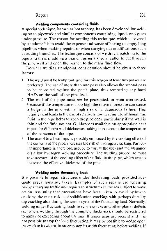
Repair 23 1 ~ ~~~ ~~ ~
Welding components containing fluids A special technique. known as hot tapping, has been developed for weld- ing on to pipework and similar components containing liquids and gases under pressure. The reason for needing this technique, which is covered by standards.') is to avoid the expense and waste of having to empty long pipelines when making repairs. or when carrying out modifications such as adding branches. The technique consists of welding a patch on to the pipe and then. if adding a branch. using a special cutter to cut through the pipe wall and open the branch to the main fluid flow.
From the welding standpoint. consideration should be given to three factors:
The weld must be leakproof. and for this reason at least two passes are preferred. The use of more than one pass also allows the second pass to be deposited against the patch plate. thus tempering any hard HAZs on the wall of the pipe itself. The wall of the pipe must nor be penetrated. or even overheated. because i f the temperature is too high the internal pressure can cause a bulge in the pipe with a high risk of a dangerous failure. This requirement leads to the use of relatively low heat inputs. although the fluid in the pipe helps to keep the pipe cool. particularly if the wall is thin and the fluid not hot. Guidance is available on appropriate heat inputs for different wall thicknesses. taking into account the temperature of the contents of the pipe. The use of low heat inputs. possibly enhanced by the cooling effect of the contents of the pipe. increases the risk of hydrogen cracking. Particu- lar importance is, therefore. needed to ensure the use (and maintenance of) a low hydrogen welding procedure. The welding procedure must take account of the cooling effect of the fluid in the pipe. which acts to increase the effective thickness of the pipe.
Welding under fluctuating loads is possible to repair structures under fluctuating loads. provided ade-
quate precautions are taken. Examples of such repairs are repairing bridges carrying traffic and repairs to structures in the sea subject to wave action. Assuming that precautions have been taken to avoid hydrogen cracking. the main risk is of solidification cracking. with perhaps ductility dip cracking also. during the tensile cycle of the fluctuating load. Normally. welding under fluctuating loads to repair cracks and other planar defects (i.e. where welding through the complete thickness). should be restricted to gaps not exceeding about 0.8 mm. If larger gaps are present and it is not possible to stop the load fluctuating. i t may be possible to wedge open the crack at its widest. in order to stop its width fluctuating. before welding. If

232 Weldability of ferritic steels
this is not possible. welding a length of about 100 mm at each end of the crack (where the deflection is least) should reduce the deflection at the middle of the crack to an acceptable level.
Because of its better resistance to solidification cracking. MMA welding would normally be preferred to automatic or semi-automatic processes (except TIG). Electrodes have been specially developed'" to cope with the problem. It is claimed that. besides having a good resistance to solidification cracking. such electrodes should give low contents of Ni. B and P in the weld metal to minimise risks of ductility dip cracking.
Underwater repairs In practice. welding for repairs and modifications of structures under the water can be divided into welds that are critical and those that are not. For the former. by far the most are carried out in the dry. either by building a caisson or dam and pumping out the water. or by building a pressurised (hyperbaric) chamber around the site of the repair and displacing the water with the gas under pressure. which acts as the atmosphere for the hyperbaric habitat chamber. Less critical welds may be made in the water - wet welding - provided circumstances are favourable. Any underwater welding is expensive but (unless existing hyperbaric chambers are available without much modification) hyperbaric welding repairs are particularly costly.
Hyperbaric welding Welding can be carried out at depths down to about 550 m. and experi- mental welding has been carried out at twice that depth. The atmospheres of hyperbaric chambers must be at a pressure to support the depth of water (the floors of the chambers are open) so that the pressure (in bars) is approximately one tenth of the depth in metres. The atmosphere is usually selected to be breathable by the welders and can be of compressed air down to about 20 m. but for greater depths helium-oxygen mixtures (sometimes with nitrogen) are used. The oxygen content is aimed to be close to 0.2 bar partial pressure (as at the surface) so the percentage of oxygen can be low.
Because of the open floors of the chambers. the atmosphere is very humid and. although deep-sea water is cold. the temperature inside can be high due to the heat generated by welding. preheating and any other electrical equipment in the chamber. Consequently. the absolute humidity is high and needs to be allowed for when devising welding procedures.
Welding itself is affected by the high pressure, which constricts the arc. Also. for shallow repairs the welding sets may be at the surface. in which case heavy voltage drops will occur along the leads. The usual processes for repair welding can be carried out hyperbarically. namely TIC. MAG

Repair 233
(including the use of cored wires with gas shielding) and MMA. Special consumables are usually required because the pressure in hyperbaric chambers alters element transfer during welding, so that welds tend to have higher carbon contents than when deposited at surface pressure. With gas-shielded processes, there is a preference for using shielding gases based on helium, rather than argon. because large quantities of the latter are not suitable for breathing. A further factor that needs to be taken into account is that the ability of welder-divers decreases as the depth increases, so that everything needs to be as foolproof as possible. This has led to the development of fully automatic welding techniques, which can be employed for some repairs, particularly when they consist of cutting out a length of pipe and replacing it in a manner similar to that used for the original tie-in.
Wet welding Although wet welding is sometimes regarded as a last desperate method of patching up a component until it can be dried out and repaired 'prop- erly'. it can be. and is. used as a satisfactory method of fixing 'secondary' structures. i.e. those where failure of one component is tolerable. Wet welding is regularly used to replace mild steel anode holders with new ones by welding to the mild steel brackets at depths down to at least 85 m in the North Sea.
Welding by MMA is by far the most common method, as it obviates the need for wire feeders, a supply of shielding gas and other complications that are required for MAG welding. The use of MAG. with a shielding gas curtain to displace the water. has been examined experimentally. How- ever. most underwater wet welds for repair are of the patch type and the step at the edge of a patch could give difficulties with the gas curtain.
Of the other welding processes, friction welding has been used success- fully to weld studs at considerable depths" and is being experimented with at TWI to assess the feasibility of making 'stitch welds' to repair cracks.'* With friction welding. some form of plastic shroud is used to delay cooling of the joint and so avoid the hard martensitic structures that would otherwise form (due to the quenching effect of the water) and probably reduce toughness and stress corrosion resistance or even give cracking problems during welding. Tests on flux cored. self-shielded wires have also given promising results in the Ukraine.
The major problem with wet welding is that of hydrogen cracking due to the very high hydrogen levels brought about by electrolysis of the water in which welding is carried out, and exacerbated by the very fast cooling rates due to quenching by the water: 800-500 "C cooling times as fast as 1.5 seconds have been measured. Basic electrodes do not run well in water and are certainly not low hydrogen! Rutile ferritic electrodes run

234 Weldability of ferritic steels
the best. but again are not low hydrogen: nevertheless. they are used for the bulk of wet welding - provided the steels being welded have CEs below about 0.40. One semi-experimental repair has been made using a temper bead technique on a steel with a slightly higher CE. but the tem- per bead technique is difficult to carry out properly in air and so is unlikely to find favour for more than a few special repairs.
Better resistance to hydrogen cracking has been claimed for the use of ferritic electrodes with oxidising coverings'3 and with nickel alloy elec- trodes.I3.l4 However, despite their availability. the former have not found favour owing to their inferior running characteristics. whilst the latter are not yet developed to the point of being a commercial product. One type of electrode. often used for repairing difficult steels in the dry. but which is nor recommended for use when welding ferritic steels in water is the austenitic stainless steel type. as such electrodes invariably give fusion boundary hydrogen cracking.
Wet welding is best carried out with electrodes which have been water- proofed. using d.c. positive polarity. A variety of waterproofing tech- niques is employed, ranging from paraffin wax to complex multilayer schemes involving synthetic varnishes. aluminium paint, etc. Although d.c. positive gives better running characteristics than electrode negative (a.c. must nor be used on grounds of safety), it does give high penetration (which is increased by hydrogen from the water). High levels of dilution of the parent steel into the weld pool must. therefore. be taken into account - particularly when using nickel alloy electrodes which can give solidification cracking if the sulphur content of the weld metal is too high.
Provided welds are made that are free from defects. mechanical and corrosion properties are not significantly different from those of welds made on the surface.I3 Repair by underwater welding at depths down to 10 m can be regarded as routine; such depths are adequate for most repairs to ships. harbour defences and coast protection work. Welding down to at least 85 m has been carried out commercially: experiments at deeper depths have shown that severe porosity is likely to be a major problem at much deeper depths. e.g. 550 m, although experiments have been carried out at simulated depths of 1000 m.
Welding in space Little is available on this topic in the usual welding literature. except that the major problems are the very low gravity (micro-gravity). the near- absolute vacuum in space itself and the very high visual contrast between light and dark, with no intermediate shades. The first greatly alters the balance between gravity and surface tension in forming a weld pool - and makes the term 'positional welding' redundant. although thermal cutting
Repair 235
is likely to provide problems. The high vacuum means that arc welding is not possible and the processes likely to be used are electron beam, laser, soldering. brazing and the solid state processes. High visual contrast can give serious problems for the operators.
References
1 Maddox. S.J.. Fatigue Strength of Welded Joints. 2nd edn. Abington Publishing. Cambridge. 1991.
2 British Standard BS5400: ‘Steel. concrete and composite bridges: Part 10: Code of practice for fatigue’. BSI. London. 1980.
3 British Standard BS5500: 1991. ‘Unfired fusion welded pressure vessels’. BSI. London. 1991.
4 ASME Boiler and Pressure Vessel Code. Section XI. ‘Rules for Inservice Inspection of Nuclear Power Plant Components’. Article IWA-4000. Para. IWA-4513 ‘Repair welding process. -A. SMA‘. ASME. New York. July 1992.
5 Alberry. P.J. and Jones. K.E.. ‘Two layer refinement techniques for pipe weld- ing’. 2nd International Conference on Pipe Welding. TWI. London. Nov. 1979.
6 Alberry. P.J.. Myers. J. and Chew. B.. ‘An improved welding technique for HAZ refinement’, Weld Metal Fabrication. 1977. 45, 549-553.
7 Jones. R.L., ‘Development of two-layer deposition techniques for the MMA repair welding of thick C:Mn steel plate without PWHT. TWI Res. Report 335/1987. TWI. Cambridge. Apr. 1987.
8 Bailey. N.. Coe. F.R.. Gooch. T.G.. Hart. R.H.M.. Jenkins. N. and Pargeter. R.J.. Welding Steels Without Hvdrogen Cracking. Abington Publishing for TWI. Cambridge. 1993.
9 API 1107. Pipeline Maintenance Welding Practices. 2nd edn. API. Washington D.C.. 1991.
10 Nakanishi. Y.. Nakamura. Y.. Sakai. K.. Kohno, T.. Satoh. K.. Kawai. Y.. Yamaguchi. T. and Nishiyama. N.. ‘A study on welding in service conditions - development of electrodes for welding under pulsating stress’. IIW Doc. XV- 634-87. IIW. 1987.
1 1 Nicholas. E.D.. ‘Friction welding under water’. in the Proceedings of the Inter- national Conference on Underwater Welding. Oslo. June 1983. Pergamon Press. Oxford. pp. 355-362.
12 Andrews. R.E. and Mitchell, J.S.. ‘Underwater repairs by friction stitch weld- ing’. Metals Mat.. 1990. 6. 796-797.
13 Gooch. T.G.. ‘Properties of underwater welds’, Metal Construction. 1983. 15.
14 Bailey. N.. ‘Exploratory tests on Ni-based wet welding electrodes for ferritic steels’. in Proceedings of TWI Conference on Advances in Joining and Cutting Processes. Harrogate. 1989. Abington Publishing. Cambridge. 1990. 135-150.
pp. 1 64- 1 67. 206-2 1 5 .

~
Further reading
In addition to the references given at the end of each chapter. the following puhlications from Abington Publishing. mostly authored by staff or con- sultants of TWI. provide useful supplementary information.
Weldability Bailey. N.. Coe. F.R.. Gooch.T.G.. Hart. P.H.M.. Jenkins.N. and Pargeter,
Bailey. N. (4.). Faults in Fusion W(4d.s in Constructionol Steels (with slide
Bailey. N. (ed.). Welding Dissimilar Metrils. 1986. Bailey. N. and Pargeter. R.J.. Influence of Flus Tvpr on Strength and
Toughness 0fSubmergc.d Arc Weld Metal. 1988. Cottrell. C.L.M.. WNding Cast Irons. 1985. Granjon. H.. Firndomento1.s of Welding Metollurgv. 1991. Lancaster. J.F.. Handbook of Structurol Welding, 1992. Pargeter. R.J. (4.). Quantijjing WeIdahilip. 1988. T W I Con jmm,e on the Hardenability of Strels. 1990. T W I Seminar on The Effects of Re.sidua1. Impurity and Microollo.virig Ele-
mentx on Weldobilit?, ond Weld Prqwtios. 1984.
R.J.. Welding Steels Without Hydrogm Crocking. 1993.
set). 1986.
Welding processes and consumables Boniszewski. T.. Self-shielded Arc Welding. 1992. Dawes. C.T.. Laser Welding. 1992. Dolby. R.E. and Kent. K.G. (ed.), Repoir and Rrclomotion. IoM/TWI Con-
Houldcroft. P.T.. Submerged-lire Welding. 1989. Houldcroft. P.T.. Which Proce.s.s:’ A Guide to the S c k t i o n o f Welding and
IIW. Compendium of Weld Metal Microstructures. IIW. 1985. Keats. D.. Profe.ssiona1 Diver‘s Manual. 1990.
ference. 1986.
Related Proce.sse.s. 1989.
236

Further reading 237
Larbey, M. et al., International Standards Index, 1991. Lucas. W.. TIG and Plasma Welding. 1990. Lucas, W. (ed.). Process Pipe and Tube Welding, 1991. Muncaster, P.W., A Practical Guide to TIG (GTA) Welding, 1991. Pokhodnya, I.K. (ed.). Metallurgv of Arc Welding, 1991. Street. J.A.. Pulsed Arc Welding - An Introduction, 1990. Widgery, D.J., Tubular Wire Welding, to be published 1994. Yeo. R.B.G., Spec(fications for Steel Welding Consumables. 1988. TWI, Standard Data .for Welding, 1915.
Engineering and design Gurney, T.. The Fatigue Strength of Trnnsverse Fillet Welded Joints. 1991. Halmshaw, R., Introduction to the Non-destructive Esting of Welds, 1988. Harrison. J.D. (ed.). Weld Failures. TWI International Conference. 1989. Hicks. J., A Guide to Designing Welds. 1989. Maddox. S.J., Fatigue Strength of Welded Structures. 1991. T W I International Conference on the Effects of Fabrication Related Stresses on
T W I International Conference on the Fatigue of Welded Structurrs. 1988. Product Manufacture and Performance. 1987.
Abington Publishing also supply directories (1988) of
Covered electrodes for C and C : Mn steels. Covered electrodes for low alloy steels. Welding consumables' tradenames. Welding manufacturers and suppliers.

Glossary
This glossary contains a number of terms used in the book. Those extracted from BS499. Part 1: 1991. ’Welding terms and symbols’ are in italics and are reproduced by permission of the British Standards Institute. 2 Park Street. London WIA 2BS. from whom copies of the Standard may be obtained. A few terms (denoted by an asterisk. * ) are based on definitions given in the NACE Corrosion Engincws’ Handbook (ed. R.S. Treseder. NACE. Houston, TX. 1980). Terms are not necessarily fully defined, but are described in sufficient detail to understand them in the text.
A d The temperature at which lower temperature transformation products start to transform to austenite o n heating. (The Ac3 is the temperature at which this transformation is completed: A,, and Ar3 are the corresponding temperatures on cooling: A , and A , are used when heating or cooling is not re1 eva nt.)
Acicular ferrite A type of weld metal microstructure comprising Widmanstatten ferrite grains formed intergranularly: also isolated laths of ferrite of high aspect ratio.
API American Petroleum Institute: a source of specifications and recommended practices. including guidance in steels suitable for high temperature hydrogen service (API 941) and hot tapping (API 1107).
A r I see A,,
Arc atmosphere The atmosphere surrounding the welding arc during welding.
238

Glossary 239
Arc blow A lengthening or deflection of the welding arc caused by asymmetric distribution of magnetic,flux around the arc.
Arc ef ic iency The efficiency of transfer of heat from the arc to the material being welded.
Arc energy (see also Heat input) The amount of heat introduced by the welding process per unit length of weld, defined (for manunl metal arc welding with covered electrodes) as:
- vz x 10-3 w
where w is the welding speed in m m h Arc energy can be used to estimate the cooling cycle of a weld and its
HAZ in order to estimate the microstructure of the HAZ and, hence its risk of suffering hydrogen cracking. When multi-arc techniques are used, the separate arc energies should be added together. provided that a single weld pool is produced.
Arcing, stray (stray flash) The accidental striking of an arc awajj.from the weld and/or the damage on the pcrrent metal resulting .from the accidental striking of an arc awav ,from the weld.
Arc strike see Arcing, stray
As-deposited A weld. single or multipass. after deposition at whatever preheat and interpass temperatures were used: a weld is often considered to be in the as-deposited condition if it has been post-heated at a temperature appre- ciably below the normal PWHT temperature for that steel.
Austenite (gamma. y) The solid solution of carbon in the face-centred cubic crystal structure of iron. Austenite is only stable at high temperatures in ferritic steels but may be retained by fast cooling (retained nustmite). In austenitic stainless steels it is stabilised at ambient and lower temperatures by the nickel in the steels.

240 Weldability of ferritic steels
Autogenous welding Welding without the addition of filler: the weld metal consists of melted parent metal.
Automatic welding Welding in which all thr welding parameters are controlled. Manual adjustments m0-v br made between welding opewitions but not during welding.
Back gouging Removal of all o r most of the first side root run by carbon arc gouging before depositing the root run on the second side to be welded.
Backing strip A strip or bar of steel. usually of similar composition to the parent steel. which is held under the joint before welding to hold the weld pool. It is welded to the weldment and may be ground or chipped off or left in place.
Bainite A transformation product of austenite formed during moderately slow cooling. and comprising a fine mixture of ferrite and iron carbide with a particular configuration.
Baking Often used when MMA electrodes and submerged-arc fluxes are dried at high temperatures. e.g. above about 250 "C. to remove moisture. When fluxes are dried at temperatures above about 800 "C the term prr-sintrring is sometimes used.
Balanced welding Welding a two-sided weld so that one or more passes on one side are fol- lowed by one or more passes on the other side: this type of sequence is followed to the completion of the weld. Balanced welding evens up the distortion and longer range residual stresses.
Basic electrode (basicity) A c0wrc.C-l elrctrodc in uvhich the cowring is hri.wd on crilcium c.rirhoncitr mid fluoride
A basic (submerged arc) flux or MMA cover contains a high proportion of basic oxides. and gives a weld metal of relatively low oxygen content. which is usually associated with good weld metal toughness. With MMA electrodes. the term is almost synonymous with hydrogen controlled: how- ever. basic submerged arc fluxes d o not necessarily give lower weld hydrogen contents than other types.
Glossary 24 1
Basic flux A flux (usually for submerged arc welding) with a high proportion of basic minerals such as calcium fluoride.
Bay region The wide region of a HAZ where the finger penetration ( i f present) joins the upper part of the weld bead.
Bead-on-plate A single weld bead deposited on a flat surface of metal and not in a joint prep a ra t io n.
Biological fouling Growth. on steel structures in (sea) water. of marine organisms: their death and decomposition can give local concentrations of sulphides in the water which can lead to sulphide stress cracking of the steel and its weld men ts.
Body-centred cubic (BCC) A type of crystal structure in which atoms occur in the crystal lattice at the corners and at the centre of a cube. Ferrite is the BCC form of iron.
Brittle fracture Fracture by a brittle mechanism. such as cleavage or intergranular frac- ture. without significant plastic deformation. Such fracture is particularly dangerous in weldments. because the presence of residual stresses and stress concentrations can increase the local stress above the yield stress of the parent steel. even if the applied stresses are low. thus making such fracture easier.
Buttering Depositing weld metal on to the weld preparation of one or both sides of a joint so that the actual weld is deposited on to weld metal. This can be a technique for reducing the risk of lamellar tearing or. if the buttered half of the joint is given a PWHT. for giving PWHT at different temperatures to the HAZs on two different parent steels.
Carbon arc gouging Thermal cutting h-v melting using the heat of an arc between N carbon electrode and the metal to he cut.
A competent operator can usually detect when a defect has been re moved.
242 Weldability of ferritic steels
Carbon equivalent (CE) value A number. calculated from the chemical composition of the steel by means of an empirical formula. which summarises some aspect of the steel's behaviour. particularly its hardenability or its resistance to hydrogen cracking. T h e term may also be used for weld metals.
Cathodic protection* Shifting the corrosion potential of a metal to a less oxidising potential by applying an external E M F (electromagnetic force: voltage) in order to reduce the rate of corrosion.
Cellulosic electrode A covered &ctrodc> in which the covering contciins n high proportion of crllulose.
Cellulose contains a high proportion of hydrogen. which helps to con- fer high penetration during welding.
Cementite A compound. Fe,C. between iron and carbon which is in quasi-equilibrium with iron in C and C:Mn steels at temperatures below the transformation from austenite.
Combined aluminium Aluminium that is chemically combined with oxygen.
Combined carbon Carbon that is in the form of carbides and. thcrefore not able to participate in strain-ageing.
Combined nitrogen Nitrogen that is combined with nitride-forming elements. particularly Al. Ti and B. and that cannot participate in strain-ageing.
Combined thickness The sum of the thicknesses (in mm) of the metal through which the heat produced during welding can tlow away from the joint. In texts before about 1970, the term thermril sewriv number (TSN). measured in ?h inch (6.35 mm) units was used in Britain.
Consumable guide A wire guide. w7hic.h mciy he coated or unconted. mcide of mntcvinl similnr in composition to thot heing wc4ded and progressivc~lv consumc.d 10 ,form pa^ of the weid m m l .
Consumable guide welding is a variant of electroslag welding.

Glossary 243
Continuous cooling transformation (CCT: see also Transformation) The transformation of austenite to lower temperature transformation products such as martensite, bainite. pearlite and ferrite in a steel that is being steadily cooled (as in a weld HAZ) as opposed to being trans- formed at a constant temperature (isothermal transjormation). Diagrams of the CCT and isothermal transformation behaviour for many types of steel are available in the literature.
Cored wire A consumable electrode having a core of.flux or other material.
It comprises an outer sheath of steel (usually mild steel) which contains flux and/or metallic ingredients. The sheath may be a fine hollow tube or a strip wrapped round the core. Cored wires are chiefly used for MAG. MIG or submerged-arc welding.
Covered electrode An electrode having a cover of.flux or other material. NOTE: the term ,flux in this context is used in its ordinary engineering sense. The covering is sometimes loosely described as ,flux, whether or not other materials are present.
Crater (Crater pipe) A depression due to shrinkage at the end of a weld run where the source of heat was removed.
Creep Deformation of a material at high temperatures under stress with time.
Critical hardness The lowest maximum HAZ hardness at which hydrogen cracking is found in the HAZ under the particular test conditions used. The critical hardness varies with weld hydrogen content, welding process, preheat level. joint geometry and steel type.
Decohesion The separation of inclusions. or other second phase particles. from the steel matrix: the first stage of lamellar tearing and microvoid coalescence.
Defect An imperfection or fault in a metal sufficiently large to give a risk of failure on testing or in service.
Defect tolerance A term used in fracture mechanics to denote the size of defect which can
244 Weldability of ferritic steels
be tolerated in a structure without giving a risk of unstable fracture under service or pre-service testing stresses.
Dendrite (dendritic) The usual mode of solidification of ferritic weld metals is for grains to start growing rapidly along an axis. for branches to grow perpendicularly from this axis and for secondary branches to grow from the primary branches. The skeleton existing early in solidification resembles the branches and twigs of a tree - hence dendritic (tree-like).
Deoxidant A material that combines with oxygen in liquid (weld) metal to form oxidc(s) which may or may not separate completely into the slag during solidification. The most common deoxidants added to ferritic steel weld metals are Si and Mn: Al. Ti. Mg and C a may also be used in various forms. the oxides of the last two usually separate completely into the slag.
Deposited metal Filler metal qfrer it has become port of a welded,joint.
The increase in weight of a parent material due to the deposition of tiller metal is particularly used in tests to measure weld hydrogen contents.
Depth/width ratio The ratio between the maximum depth and the maximum width of a single weld bead. The ratio is of importance in solidification cracking.
Diffusible hydrogen That portion of the hydrogen content of a ferritic steel which will be released by diffusion when the steel is held for several days at ambient ( 2 S + S "C) temperature.
Diffusion bonding (Diffusion welding) A joining process wherein all the,faces to be welded are held together hv a pres- sure insufficient to cause readilv detectable plastic,flow. at a temperature below tht. melting point of 0n.v of the ports. the resulting solid state diffusion. with or without th<..formation o f o liquid phase. causing welding to occur.
Dilution The altcwtion qf composition of the metal deposited, from a ,filler wire or elec- trode due to mixing with the melted parent metal. It is usually expressed as the percentogc' of parent metal in the weld mrtol.

Glossary 245
Dip transfer A method of metal-arc welding in which-fused particles of the electrode wire in contact with the molten weld pool are detached.from the electrode in rapid suc- cession by the short-circuit current which develops evey time the wire touches the weld pool.
Dislocation A mismatch on the atomic scale in the crystal structure of a metal. Dislo- cations hinder the plastic flow of a crystal and thus strengthen it. Plastic flow is hindered when dislocations interact with interstitially dissolved atoms (e.g. nitrogen and hydrogen). thus causing embrittlement.
Drying Heating of M M A electrodes or flux to remove moisture. The term is sometimes restricted to low temperature heating up to about 250 "C. which will remove only loosely bound water (see Baking).
Ductile (fracture) Fracture preceded by significant plastic deformation: however. in certain circumstances (e.g. creep. ductile grain boundary fracture and lamellar tearing) the overall deformation may by very small if it is confined to regions near the grain boundary. or if the number of inclusions is large.
Ductility dip Face-centred cubic metals (e.g. austenite) containing certain impurities can exhibit reduced ductility (called the ductility dip) within a temperature range below the melting point (see Hot cracking).
Dye penetrant A suitably coloured liquid of low surface tension applied for NDE which can enter a surface crack and which can be subsequently detected (after the excess on the surface has been removed). after it seeps out again. by staining a white 'developer'. or by fluorescing under ultraviolet light.
Electron beam welding Fusion welding in which the heat,for welding is generated b-v the impact ofa ,focused beam of electrons.
Electrogas welding Arc welding using a gas-shielded consumable electrode to deposit metal into a weld pool, retained in the ,joint by cooled shoes which move progressivelMv upwards as thejoint is made.

246 Weldability of ferritic steels
Electroslag welding Fusion welding using the combined effects of current and electrical resistance in a consumable electrode(s) and a conducting bath of molten slog. through which the electrodt.(s) passes into the molten pool. both the pool and the slag bath being retained in tht.,joint b-v cooled shoes which move progressively Upwards. Afier on initial arcing period, the end of the electrode is covered hv the rising .slag, and melting then continues [by resistive heating) until the,joint is com- pleted.
The process requires a high heat input. giving slow cooling and coarse microstructures. which may require normalising to achieve satisfactory toughness.
Embrittlement The reduction in the normal toughness of a material by the addition of other materials. heat treatment. deformation processes or a combination of these.
Eutectic In a series of alloys between two metals, a metal and a compound o r two compounds. if the metals are not fully soluble in the solid state. the addition of either metal to the other can reduce the melting point of the other so that a minimum value (the eutectic) is reached. at which point both metals solidify simultaneously. In a binary system the eutectic has an invariant temperature and composition. Similar behaviour in the solid state gives a eutectoid. an example of which occurs in the Fe:C system between austenite. ferrite and cementite at 730 "C and 0.8% C.
Excess penetration bead Excess weld metal protruding through the root of a,fusion weld modt.,frorn one side on I .
Excess weld metal Weld metal 1-ving outside the plane,joining the (weld) toes.
Face-centred cubic (FCC) A type of crystal structure in which atoms occur in the crystal lattice at the corners and at the centres of the faces of a cube. Austenite is the FCC form of iron.
Fatigue Continually variable stressing of a metal. Fatigue failure can occur at much lower stresses than the tensile strength of the metal and is very sen- sitive to stress concentrations.

Glossary 247
FATT Fracture appearance transition temperature, a term most frequently used in Charpy impact toughness testing. The transition temperature is defined as that at which the fracture surface contains a specified amount (frequently 50%) of ductile (or brittle) fracture.
Fault An indication found by NDE which originates from a feature smaller than an unacceptable defect. Sometimes called an ‘imperfection’.
Ferrite The solid solution of carbon in the body-centred cubic crystal structure of iron. The phase is stable at low temperatures (alpha. a) and also. in some low carbon ferntic steels. at temperatures close to the melting temperature. when it is called delta-ferrite (6) .
Ferrite with aligned second phase A type of weld metal microstructure comprising two or more parallel laths of ferrite whose aspect ratio is >4 : 1. The terms ferrite with aligned MAC (martensite. austenite and carbide). ferrite side plates. upper bainite. feathery bainite and lamellar product have also been used to describe this constituent.
Ferritic steel (weld metal) A ferritic steel or weld metal is one containing little (usually <lo% by volume) or no austenite. any austenite being of the residual type.
Filler metal Metal added during welding, braze welding. brazing or surfacing.
Fisheye A small bright area o f cleavagc.,fracture. caused by the presence o f hydrogen. that is visible only on the,fractured surface of weld metal.
The centre of the feature (the ‘pupil’) is a pore or inclusion. the area round it (the ‘iris’) is hydrogen-assisted brittle (cleavage) fracture and the remainder of the fracture is ductile.
Fitup The gap between the two faces of a joint immediately prior to welding. The terms close fit. machined fit, normal fit and poor fit are sometimes used.

248 Weldability of ferritic steels
Flare angle The angle formed between the finger penetration and the upper part of the weld bead (see Bay region).
Flux Material used during welding. brazing. braze welding or su facing to clean the sufaces of the.joint chemically. to prevent atmos;lheric oxidation and to remove impurities. In arc welding, many other substances, which peform special.functions. are added.
Although basic fluxes remove S. less basic fluxes may add certain impurities which they contain. including S and P. All fluxes give a quasi- equilibrium oxygen content to the weld metal which is appreciably higher than that of a killed steel.
Flux-cored wire A type of cored wire in which most of the core is of non-metallic, fluxing ingredients. although some iron powder. deoxidants and metallic alloying additions may also be present.
Fractography The study of fracture surfaces, which can be aided by microscopic exami- nation. particularly in an SEM. To examine cracks in ferritic steels and their welds. it is convenient to cool the specimen to a very low temperature (e.g. by immersing in liquid nitrogen) and break it open while still cold. Any existing crack surface can usually be easily distinguished from the brittle fracture produced on opening the crack.
Fracture toughness (see also Toughness) The ability of a material containing a sharp defect. such as a crack tip. to resist fracture (or crack growth) when stressed. The fracture toughness of steels (and weld metals) is reduced when the temperature is reduced and also near ambient temperature when they contain hydrogen. Parameters measured include K,. the critical stress intensity at the crack tip. and 6,. the critical crack tip opening displacement (CTOD).
Free-cutting steel A steel containing additions such as sulphur and lead to improve machineability.
Free nitrogen (Al, C, etc) The nitrogen (Al. C. etc.) which is not combined as stable compounds, such as nitrides. carbides and oxides. and which is in interstitial or normal solid solution in the ferrite matrix.

Glossary 249
Friction welding A welding process in which one component is moved relative to, and in pressure contact with, the mating components to produce heat at the faying surjaces, the weld being completed by the application of a forge force during or afier the ces- sation of relative motion.
Fused metal That part of a welded joint which has been melted during welding. It comprises added weld metal and fused parent metal. The term is particu- larly used in tests to measure weld hydrogen contents and it is usually estimated from the area of fused metal in a weld cross section which has been ground and etched.
Fusion boundary The boundary between the HAZ and the melted metal in a weld. Because grains usually grow epitaxially from the HAZ into the weld metal, the actual boundary may need careful examination to detect when examining a metallographic section. The presence of very small round inclusions is a good guide to the extent of the weld metal.
Fusion face The portion of a surface. or o f an edge, that is to be.fused in making a.fusion weld.
Fusion welding Welding in which the weld is made between surfaces brought to a molten state, with or without the addition of a.Fller metal, and without the application of pressure.
Galvanic corrosion* Corrosion in an ionized liquid (e.g. seawater) when two metals exhibit different electrical potentials: that which is anodic corrodes and protects the other.
Gas flat see Surface pocking
Grain refinement Refinement of the grain size of a metal by heat treatment or other means. In the case of a ferritic steel, heating to a low temperature within the austenite range and cooling refines the prior austenite grain size. This may or may not refine the transformed ferrite grain size.

2.50 Weldability of ferritic steels
Grain size The mean diameter of the grains that make up the microstructure of a material. When used of ferritic steels. the term often refers to the Prior austenite grain size. For the grain size of transformation products, terms such as ferrite grain size and martensite lath size are used.
Graphite (graphitisation) Graphite. and not cementite. is the phase in equilibrium with iron in C and C : Mn steels. However. the approach to equilibrium is so slow that the formation of graphite by decomposition of cementite to graphite and ferrite (graphitisation) takes several years at temperatures between 450 "C and the A , .
Half-bead technique A welding technique designed to produce a refined HAZ on the parent steel in order to achieve acceptable toughness in repair and other welds which cannot be given a PWHT. The first layer of weld metal is deposited on the steel to be repaired and is ground off to half its depth. Welding is then continued with the same welding parameters. This technique should ensure that the refining temperature range from the second layer of weld metal refines the coarse-grained HAZ on the parent steel left from deposi- tion of the first layer.
Hardenability The tendency of a ferritic steel to produce a hard microstructure as a result of heating and rapid cooling. typically in the HAZ during welding. The hardenability of a steel increases as its content of alloying elements (and. to a smaller degree. carbon) is increased.
Hardening, secondary After hardening by quenching. some steels (containing such elements as Cr. Mo. V and Nb) can harden further if they are tempered at temperatures around 60 "C as a result of processes (akin to precipitation hardening) leading to the formation of certain carbides.
Hardness (Hardness value) The resistance of a material to deformation. usually measured by pressing an indenter into the surface. Of the several types of hardness measurement. the Vicker'.~ hardness test (Hv) is most commonly used in the context of welding. as the small size of the impression produced by the indenter is suitable for measuring local variations in hardness found in a weld HAZ. whose hardness varies over short distances. When measuring HAZ hard- ness, i t is important to make sufficient measurements, particularly in the

Glossary 25 1
region close to the fusion boundary, to obtain a realistic idea of the maxi- mum hardness of the HAZ. In connection with hydrogen cracking during welding, the hardness of the HAZ associated with a weld bead before tempering (either by a subsequent weld pass or by PWHT) is the important para meter.
Heat-affected zone (HAZ) That parl of the parent metal that is metallurgically affected by the heat of welding or thermal cutting, but not melted.
In the context of ferritic steels, the term is often used for that portion of the HAZ (strictly, the visible HAZ) which is visible to the naked eye on an etched macro-section of a weld. Close to the fusion boundary, where the temperature had approached the melting point of the steel, appreciable coarsening of the prior austenite grain size occurs. Although the term HAZ is normally applied to a HAZ on parent steel, weld metal can also become the HAZ of a succeeding run or weld and a term such as 'HAZ on weld metal' should be used if there is any doubt.
Heat input The amount of heat supplied to the parent metal by welding. The heat results from the energy of the welding arc (arc energy), reduced by the eff- ciency of transfer of the heat (arc efficiency). The terms heat input and urc energv are often used synonymously and, in Europe at least. heat input is likely to be used for both parameters.
Heat treatment Heating of metals without melting to alter their properties. The term should not be used to describe preheating for welding.
HIC (hydrogen-induced cracking) Hydrogen cracking in service in which the steel is immersed in an acid sulphide solution (sour service). Although the abbreviation is used exclu- sively for this type of cracking, the term 'hydrogen-induced cracking' is strictly applicable to cracking caused by hydrogen embrittlement at any stage of the life of the component, especially for cracking during welding.
Hot cracking (see also Solidification cracking) A discontinuity produced by tearing of the metal while ut an elevuted temperature.
Although the term usually includes solidification cracking, there is no evidence that tearing of solid metal occurs during solidification cracking.
Hot tapping Welding (particularly of branches) on to pipework or similar components while they contain their normal working fluids, e.g. oil or gas under pressure.

252 Weldability of ferritic steels
Humidity The amount of moisture in solution in the air at any time. I t can be expressed in two ways: the relntive humidity, which is the humidity expressed as a percentage of the maximum amount of moisture it is possible for air to contain at the particular temperature and pressure of measure- ment: and the absolute humidiry is expressed as the weight of moisture in a unit volume of air. The latter is probably the more significant as regards the amount of hydrogen likely to be introduced from the atmosphere into a weld pool during welding.
Hydrogen attack (damage) When steel is used to contain hydrogen at high temperature and pressure, damage can occur i f the service temperature is too high. This is caused by the hydrogen diffusing into the steel and combining with the carbon in the carbides in the steel to form the gas methane. Besides removing the carbides. which strengthen the steel. the gas produced forms cavities, either adjacent to the carbides or along chains of large inclusions in the steel to cause blistering.
Hydrogen blistering* Sub-surface voids produced by hydrogen absorption in (normally) low strength steel plate with resultant surface bulges. The hydrogen, usually resulting from sour or high temperature hydrogen service. can collect along planes of inclusions in the plate and build a high pressure.
Hydrogen cracking This is cracking produced in steel that has been embrittled by hydrogen. which may originate from the steel melting process. from hydrogen picked up during welding or from hydrogen picked up during service. either directly in hydrogen service or as a result of corrosion reactions. The cracking itself occurs in the temperature range within which hydrogen embrittles steel. namely within about 200 "C of ambient. In the welding context. it usually refers to cracking produced during welding.
Hydrogen embrittlernent Ferritic steels (and other metals) are embrittled to an increasing degree at temperatures around ambient when containing increasing amounts of hydrogen. Embrittlement is most severe at slow strain rates and is most readily apparent in steels with relatively poor toughness: in HAZ material. this is synonymous with high hardness.
Hydrogen level see Weld hydrogen level

Glossary 253
Hydrogen potential The hydrogen level of a welding consumable, which may be estimated from the hydrogen content of a welding wire and/or the total moisture (free and combined) of any fluxes. including the electrode covering, involved.
Hydrogen stress (corrosion) cracking A type of stress corrosion cracking (more usual in high strength steels) where hydrogen, picked up by the steel from the water (usually contain- ing HIS - see Sulphide stress cracking) as a result of corrosion reactions, embrittles the steel sufficiently to cause cracking under the influence of the residual and/or applied stresses present.
Hyperbaric welding Underwater welding in a chamber pressurised to resist the external pres- sure of water.
Imperfection see Fault
Impact (notch impact) toughness Toughness as measured in an impact test (usually as the energy expended in fracture initiation plus propagation). A specimen, usually notched, is struck by a falling hammer with a fixed energy.
Impurity (Impurity elements) Elements usually of a non-metallic nature (see also residual elements) which are not intentionally added to a metal. In ferritic steels the usual ones analysed for are S and P, together with N, 0 and, in some cases, As, Sb and Sn. Impurities can affect the properties of steel and make it more prone to various types of embrittlement and cracking, particularly during welding.
Inclusions (non-metallic inclusions) Small particles within the steel consisting of a mixture of deoxidation products (oxides) and sulphides. These can act as 'traps' for hydrogen, and hence reduce its diffusion rate, particularly at and below -150 "C. Inclusions can also act as nuclei for the formation of higher temperature (and softer) transformation products when steel is cooled from high tem- peratures. thus reducing the hardenability of a steel.
Indication An indication of a fault or defect during NDE, particularly when revealed by ultrasonic examination. Care should always be taken not to describe

254 Weldability of ferritic steels
an indication as a defect or as a crack until further examination has been carried out.
Ingot cast Steel that has been cast into an ingot mould as opposed to a shaped mould (steel casting) or that has been continuously cast.
lntercritical A term usually applied to the part of a HAZ in a ferritic steel which has been heated above the A,, temperature but below the Ac3. Thus, only part of the microstructure has been transformed to an austenite of relatively high carbon content and re-transformed on cooling. It is the part of the visible HAZ furthest from the fusion boundary.
Intergranular Use to refer to cracking (or such phenomena as precipitation) along. or in the region of. a grain boundary.
Interpass temperature In a multirun weld. rhr temperature of rhe weld and adjacent parent metal immediatelev prior to the application of the next run.
In welding procedures it is possible to specify a minimum and/or a maxi mum in terpass temperature.
Interstitial (solution) A type of solid solution whereby small atoms of elements such as C, N and H can dissolve within the atomic lattice. Larger atoms which are in normal solid solution (e.g. Mn and Ni) replace the iron atoms from posi- tions on the lattice itself.
Iron powder electrode A covered electrode in which the covering contains a high proportion of iron in the,form of a powder which acts as additiona1,filler metal.
Iron powder can also be added to the weld pool during submerged-arc welding. Strictly. the term should be applied only to pure iron powders: when containing alloying and/or deoxidant additions. the term metal powder should be used.
Isothermal transformation see Continuous cooling transformation)
Joint A connection where the individual components, suitablv prepnred and assembled, are joined bv welding or brazing.

Glossary 255
Killed steel A steel to which sufficient deoxidants (usually Si and/or Al) have been added to avoid porosity when the steel solidifies as an ingot. The word 'killed' is used because such a steel will not effervesce as a result of the evolution of gases during solidification when cast.
Lack of fusion Lack of union in a weld:
(a) between weld metal and parent metal, or (b) between parent metal and parent metal, or (c) between weld metal and weld metal.
Lamellar tearing Fracture. by a tearing mechanism at or just above ambient temperature, of steel plate under a welded joint in which a sufficiently high population of certain types of inclusions occur.
Laser welding Fusion welding in which the heat.for fusion is produced by a coherent beam of monochromatic radiation ,from a laser.
Lattice diffusion Diffusion within the crystal lattice, which obeys regular physical laws. In steels at temperatures around ambient, hydrogen diffuses much more slowly than is calculated from these physical laws.
Liquation (Liquation cracking) The partial fusion of minute regions rich in impurity elements (particu- larly S) in the HAZ close to the fusion boundary. Liquation can lead to cracking as a result of high temperature contraction strains, but the cracks are very small. although they can initiate hydrogen cracking.
Liquid metal penetration Penetration of a solid metal. usually along its grain boundaries, by a mol- ten metal with which it is in contact. Although cracking may not always result, such penetration is usually weakening and/or embrittling.
Local brittle zone (LBZ) A small region leading to local brittle fracture, usually found in a fracture toughness test but possible in any type of fracture, in a generally ductile fracture surface. Such zones can seriously reduce the resistance of a mate- rial to fracture initiation. Although in a toughness test the brittle fracture may be arrested. LBZs are liable to lead to complete failure in a structure

256 Weldability of ferritic steels
with long-range stresses. Such zones may be found in reheated HAZ material and occasionally in weld metal.
Magnetic particle inspection (MPI) Similar to dye penetrant inspection. except that the penetrating fluid con- tains tine particles which are ferro-magnetic. An electromagnet is used to cause these particles to adhere temporarily to crack surfaces and other breaks in the structure at the surface. Either a.c. or d.c. may be used for the electromagnet: the latter has an ability to detect faults which are just below the surface.
MAG welding (see also MIG welding) Gas-shielded metal arc welding using a consumable wire electrode where the shielding gas is provided by a shroud of active or non-inert gas or mixture of gases.
The shielding gas is 'active' (hence MAG. metal active gas) because it contains oxygen or CO,. often with an inert gas such as Ar and/or He. The term CO, welding is used when CO, alone is used as the shielding gas. A solid or a cored wire may be used, although with the latter. the term cored wire welding is more common.
Manual metal arc welding Metal arc welding with straight covered electrodes of o suitable length and applied by the operator without automatic or semi-automatic means of replace- ment. No protection in the-form ofgases.from a separate source is applied to the arc or molten pool during welding.
Maraging A heat treatment given to some complex nickel steels (so-called maraging steels) of low carbon content which are martensitic at room temperature, even with slow cooling. The treatment strengthens the steel by an ageing process involving the precipitation of intermetallic compounds.
Martensi te A body-centred tetragonal (i.e. distorted BCC) constituent, supersaturated in C. formed when steels are rapidly cooled from austenite. It is the hardest constituent possible in a rapidly cooled steel and has poor tough- ness and a poor resistance to hydrogen cracking unless of low carbon content.
Metallographic (examination) To do with the (microscopic) structure of metals. Metallographic exami- nation involves preparing a polished section of a metal and studying it by microscope. usually after it has been etched to reveal its structure.

Glossary 257
Metal powder An admixture of iron and other metal powders (alloying and/or deoxidising) used either as an ingredient of MMA electrode coverings, or as an addition made during submerged-arc welding (see iron powder).
MF temperature (also Ms, Mw) The temperature at which the transformation from austenite to marten- site finishes (MF). begins (Ms), is 90% complete (M9J and so on.
Microalloying Alloying with usually less than about 0.2% of alloying elements such as Nb, V. Ti and/or B. Microalloyed steels are usually strong and tough, with good weldability for their strength.
Microvoid (coalescence) Microscopically small voids produced when a material is stressed suffi- ciently to fracture or to separate (decohere) small inclusions. or brittle or hard particles from the matrix.
MIG welding (see also MAG welding) Gas-shielded metal arc welding using a consumable wire electrode where the shielding is provided by a shroud of inert gas.
The term was originally used (and sometimes still is used) for both MIG and MAG welding.
Millscale Oxides produced on or near the surface of steel while it is being hot pro- cessed and which can be firmly embedded in the surface.
Misalignment, angular Misalignment when the pieces welded together are out of line before and/ or on completion of welding so that a distinct angle is seen at the weld in a transverse section of the joint.
Misalignment, linear Misalignment when the pieces welded together are out of line before and/ or on completion of welding so that a distinct step is present at the joint on one or both surfaces.
Multi-arc welding Welding with two or more arcs, usually producing one weld pool. It has the advantage of high productivity without the disadvantages of using the same total current in one arc.

258 Weldability of ferritic steels
NACE National Association of [American] Corrosion Engineers, who produce recommendations and standards. including those on the selection and use of materials for sour service (NACE standard MR017.5).
Necking After reaching the maximum load during a tensile test of a sufficiently ductile metal, deformation is concentrated into a short length of the test specimen. Metal in this length contracts in the transverse direction and extends in the longitudinal direction more rapidly than the metal outside this region. thus producing a neck.
Nelson diagram A diagram showing the maximum temperatures and partial pressures of hydrogen to which several types of steel may be exposed without them suffering hydrogen attack.
Neutral (flux) A flux. usually for submerged arc welding. which has no effect on the major constituents (Mn. Si and major alloying elements other than C) of the weld metal.
Nital A metallographic etch consisting of ethanol (ethyl alcohol) with between 1% and about 20% nitric acid (HNO,). Unless otherwise stated it is the standard etch for ferritic steels. the lower concentrations being used for microscopic examination and the stronger etches for macro work.
Non-destructive examination (NDE) Examination for defects without cutting or otherwise damaging the object being examined. Sometimes known as NDT - non-destructive testing.
Nonmetallic inclusions (see Inclusions)
Normalising Heating a ferritic steel to a temperature within the austenitising range and cooling in still air.
Notch toughness see Toughness
Nucleation The process where a phase change is started. in an otherwise uniform structure. at an irregularity such as a grain boundary or an inclusion.

Glossary 259
Nucleation may involve either a phase crystallising from a liquid or a new phase crystallising from the solid; in either case, the most efficient nucleus is one having the same crystal structure and closely similar lattice dimensions to the new phase. even though the nucleus and the new phase are not mutually soluble.
Overlap An impefection at n toe or root of a weld caused 6.v metal.flowing on to the surjace o f the parent metal without,fusing to it.
Overmatching (weld metal) The condition when the yield (or tensile) strength of a weld metal exceeds that of the parent metal. If requiring overmatching, it is important to be clear whether overmatching is required on yield stress or tensile strength, because the ratios of the two are likely to be different in the two types of material.
Pearlite A transformation product resulting from slow cooling from austenite, comprising a lamellar microstructure of ferrite and iron carbide.
Peening Hammering or blasting the surface of a metal with rounded shot in order to induce compressive residual stresses in the surface layers and reduce the risk of fatigue or other types of cracking.
Penetration (finger penetration) The depth to which the weld pool extends. In MAG with spray transfer and submerged arc welding. the arc initially penetrates deeply (finger penetration). although more diffuse heating causes the upper part of the pool to widen.
Peritectic Where an alloy is solidifying as one phase and another phase becomes more stable than the first. a peritectic transformation is said to take place. Above the peritectic temperature, the higher temperature phase solidifies; below it. the lower temperature phase solidifies. the peritectic being the boundary between the two types of solidification. In a binary system the peritectic has an invariant temperature and composition; in the Fe : C system it is at 0.18% C and 1492 "C between liquid, delta ferrite and austenite.
260 Weldability of ferritic steels
Planar defect A defect, such as lack of fusion or a crack, which lies essentially in one plane and which provides a damaging stress concentration.
Plasma arc welding Arc welding in which the heat for welding is produced with a constricted arc . . plasma being generated by the hot ionised gases issuing from the or@e and supplemented by an auxiliary source of shielding gas.
Polarity The polarity of a welding electrode with regard to the metal being welded.
Porosity Holes or pores in a weld metal formed by gas evolved during solidification (gas porosity, although in BS499 the term 'porosity' is used only for gas porosity) or by contraction which is not adequately fed (shrinkage porosiry). The distinction between the two types is not clear cut because some gas evolution is needed to initiate shrinkage porosity. In many alloy systems gas porosity consists of spherical pores and shrinkage porosity of inter- dendritic cavities.
Post-heat The application of heat to a weld. immediately after welding and before cooling out. so as to maintain the minimum interpass temperature, o r to raise it to some higher value (well below any PWHT temperature), in order to increase the rate of diffusion of hydrogen out of the weldment.
Post-weld heat treatment (PWHT) Heat treatment given after welding in order to reduce residual stresses (stress relief heat treatment) and/or to temper hard regions. usually in the HAZ. The temperatures for ferritic steels are usually between about 550 and 750 "C. i.e. below the A,, and in the upper part of the tempering tem- perature range.
Preheating temperature (preheat) The temperature immediately prior to the commencement of welding resulting
,from the heating of the parent metal in the region o f the weld. Normally, a minimum preheat temperature is required; when it is nec-
essary to achieve particular levels of toughness and/or strength in the HAZ or weld metal a maximum value may also be required. Preheat may be local or general.

Glossary 26 1
Prior austenite grain size The grain size of austenite before it finally transforms on cooling. The austenite grain size increases rapidly as the melting temperature is approached, but is not then reduced on cooling before transformation. A coarse prior austenite grain size can be refined by heating the steel briefly to just above the A,3. Various expressions are used to quantify prior austenite grain size, one of which (the ASTM system) uses a single number, 0 being coarse and 10 fine.
Quenching Cooling a metal rapidly either to retain a high temperature microstructure or. as in the case of ferritic steels. to produce a microstructure (typically martensite) which can only be produced by rapid cooling. Rapid cooling may be effected by immersing the metal into water or oil (cold or hot), by spraying or. in the case of air hardening steels, by a blast of air.
Radiography Examination of an object by means of X- or gamma-rays and recording the resultant radiograph on photographic film. Radiography is only capable of detecting bulky defects: a planar defect is normally detected only if its plane is roughly parallel to the incident beam.
Refined HAZ Part of the HAZ of a multipass weld which has been reheated to a tem- perature sufficient to refine its prior austenite grain size.
Reheat cracking (stress relief cracking) Cracking that forms after welding in a restricted number of steels during PWHT by a process of creep, usually during heating to the PWHT tem- perature. A crack found only after PWHT is not necessarily a reheat crack.
Reheating Heating of a weld run and/or its HAZ by a succeeding run. The term is normally used when a significant change. particularly in microstructure, results from reheating.
Residual elements Elements, which usually originate from alloyed steel scrap and non-ferrous metals in the steel charge, of the type that can be added to steels as alloying elements. They include Ni. Cr. Mo. Cu, Nb, V and sometimes Sn. Residual elements can affect the CE value of the steel and also other properties (see also Impurity).

262 Weldability of ferritic steels
Residual hydrogen That portion of the hydrogen content of a ferritic steel which will not be released by diffusion at ambient temperature (25+5 "C). but may be extracted at higher temperatures. e.g. 650 "C. I t is believed that this hydro- gen is trapped in molecular form. either in the lattice. in voids (particularly in association with non-metallic inclusions) or in chemical combination with other elements. such as carbon (when methane is formed).
Residual welding stress (residual stress) Stress remaining in a metal part o r structure as a result of welding. The stresses in a weldment result because the contraction of the hot weld is hindered by the restraint of the joint. Residual stresses tend to be tensile at the weld (at the weld surface in a multipass weld) and are balanced by compressive stresses in the parent steel (or in the root regions of a m 11 1 tip a s s we1 d ).
Restraint The extent to which the parts to be welded are secured to prevent all con- trollable movement during and after welding. The parent steel. unless extremely thin and narrow. provides sufficient restraint to result in a weld containing residual stresses.
Retained austenite Austenite in a ferritic steel which persists on cooling to ambient temperature. After PWHT. retained austenite may transform to martensite of relatively high carbon content and a second heat treatment (douhk tcmpcvitig) may be required to temper it.
Retained phase Although most of the volume of a ferritic weld metal transforms above -4X) "C. a small volume transforms at a much lower temperature. if at all. Because retained austenite results if there is no transformation of this vol- ume. and because all the phases have a similar shape and distribution to retained austenite. the term 'retained phase' is used.
Rimming steel An ingot steel which has not been killed. During solidification of the ingot. the steel solidifies for some distance from the outside before dissolved gases evolve. so that the outside - the rim - has a different appearance from the centre in a polished and etched section. even after drawing to wire. This type of steel has long been used for making welding electrodes and is still employed when low contents of nitrogen and residual elements are needed.

Glossary 263
Root concavity A shallow groove that mnv occur in the root of n butt weld.
Root run (pass) 7he.firsr run deposited in the root of n multi-run wield.
Run-off plate (block) A piece of metol so placed ns to ennhle the,full section qf weld nietol to be moin- tnined up to the end of n joint.
Its use prevents shrinkage and cracks in the crater region (which should all be on the run-off plate) from impairing the integrity of the weld itself.
Rutile electrode A covered electrode in which the covering contoins o high proportion of titanium dioxide.
A rutile electrode normally gives high weld hydrogen contents.
Sealed cored wires Cored wires which are sealed. e.g. if they are manufactured by filling a tube with powdered flux or metal before drawing down to cored wire.
Segregation Differences in composition between different regions in a piece of metal or. occasionally. between two pieces of metal cast from the same ladle. Segregation may be on a large scale. e.g. between the surface regions and the centre of an ingot. o r on a microscopically small scale (microsegreg- ation). e.g. between the centre of the arm of a dendrite and an inter- dendritic region.
Self-shielded welding A type of welding with continuous wire feed using a cored wire which allows welding to be carried out without shielding gases or externally applied fluxes.
SEM Scanning electron microscope: useful for fractographic examination up to high magnifications (several thousand diameters) as well as for con- ventional metallography. Many SEMs have a micro-analytical facility.
Short transverse The through-thickness direction. i.e. perpendicular to a plate surface. The term is used in connection with lamellar tearing when tensile test pieces

264 Weldability of ferritic steels
are taken with their axes perpendicular to the surface of a plate. The reduction of area (RA) is the parameter measured in such a test and the term short transverse reduction of area is usually abbreviated to STRA.
Sigma (a) phase A very brittle compound between Fe and Cr which can be formed when stainless steels are exposed to high temperatures. This compound can form in the weld metal when ferritic steels are welded with austenitic stainless steel fillers and given long PWHTs.
Slag A ,fused non-metallic residue produced by the welding process. With MMA and submerged arc welding. the slag cover is continuous and usually can be detached easily. possibly aided by wire brushing. With fluxless processes (e.g. TIC and MAG) isolated islands of slag can be present on the weld surface.
Slice bend test A test for assessing the resistance of steel plate to lamellar tearing. A thin slice is cut through the thickness of the plate. both of the original surfaces are fillet welded to a steel bend test specimen and the composite specimen subjected to bending so that the test piece slice is in tension in the short transverse direction. A plate with a high susceptibility to tearing will show cracks along planes of inclusions at low bend angles.
Solidification cracking A crack produced at a late stage in the solidification of a weld run due to rupture of liquid films which have not solidified (see Hot cracking).
Sour service Service where a material is in contact with a liquid containing appreciable amounts of H,S. particularly when the solution is acid.
Spray transfer Metal transfer which takes place as a rapidly projected stream of droplets of diameter no larger than the consumable electrode .from which they are transferred.
Step ageing A heat treatment given to samples of steel preparatory to impact testing in order to determine their susceptibility to temper embrittlement. The treat- ment consists of subjecting the testpiece to progressively longer times at successively lower temperatures.
Glossary 265
Stickout The length of wire in a continuous wire welding process between the con- tact tip and the arc. A longer stickout results in more resistive heating of the welding wire in this region. which may be sufficient to drive off a part of any hydrogenous material embedded in the wire surface.
STP Standard temperature and pressure: the standard conditions (0 "C and 1 bar) to which measured volumes of gas are calculated so that they may be compared.
Strain-age cracking A term which is not clearly defined. but possibly refers to hydrogen cracking of steel which has been embrittled by strain-ageing.
Strain-ageing A hardening and embrittling phenomenon in steels at slightly elevated temperatures caused by the interaction of dislocations and atoms of N and C interstitially dissolved in the lattice.
Stress corrosion cracking (SCC) Cracking of metals produced by the combined action of corrosion and tensile stress (residual and/or applied). In ferritic steels. one form of stress corrosion cracking (hydrogen stress cracking) is the result of embrittlement by hydrogen introduced chemically from the environment and residual stresses resulting from welding. Restrictions on the hardness of steel and weldments are made to avoid the problem.
Stress relief cracking see Reheat cracking
Stress relief heat treatment see Post-weld heat treatment
Structural cracking In the context of reheat cracking the term is used to describe cracking in normal (butt and fillet) welds in contrast to underclad cracking.
Sub-critical HAZ In a steel. that part of the HAZ that has been heated to temperatures below the A,,. This region is outside the visible HAZ.
Submerged-arc welding Metal arc welding in which a bare wire electrode or strip is used. the arc(s) being enveloped in a granular.flux, some of which.fuses to form a removable cover of slag on the weld.

266 Weldabili ty of ferritic steels ~
Sulphide stress cracking (SSC)* Brittle fracture by cracking under the combined action of tensile stress and corrosion in the presence of water and H,S. the H,S allowing the ingress of hydrogen into the steel: essentially another term for hydrogen stress cracking.
Surface pocking (gas flat) Shallow depressions o n the surface of a submerged arc weld caused by the pressure of gas from the arc cavity being unable to escape sufficiently rapidly through the molten slag.
Tab test A test for the resistance of steel plate to lamellar tearing in which a small steel plate (the tab) is welded at an angle to the surface of the test plate and hammered off. The appearance of the fracture gives a guide to the susceptibility of the test plate.
Tack weld A short length of weld used to hold components together so that they can be welded. Tack welds may be incorporated into the main weld or removed at suitable stages during welding. Care should be taken to avoid cracking of tack welds. particularly if they are incorporated in the final weld.
Tearing A mode of ductile fracture involving brittle regions (e.g. inclusions or hard carbides) ahead of the main crack breaking or separating from the matrix. The main crack then extends to incorporate these micro-cracks (sometimes known as microvoids. hence microvoid coalescence). Normal ductile fracture and lamellar tearing are examples of this type of tearing: in hot tearing (liquation cracking) the initial voids are locally melted regions.
TEM Transmission electron microscope: can be used for the examination of very thin films of metal o r of metal surfaces by taking replicas (with or without shadowing) at higher magnifications than are practicable with an SEM. Most TEMs have a facility for selected area diffraction to deter- mine crystal structures.
Temper (tempering) The process of heating a steel. usually in the quenched condition. to a temperature below that at which transformation to austenite starts. Tem-
Glossary 267
pering (which occurs during PWHT). usually (but not always) causes softening. During welding. successive weld beads give some tempering of the underlying runs.
Temper bead A run of weld metal deposited on the surface of a weld with the aim of tempering the HAZ on the parent steel of the final run of weld metal. I t is important to ensure that the toe of the temper bead is at a small fixed dis- tance from the toe of the main weld. otherwise the temper bead will produce its own (hard) HAZ on the parent steel. The temper bead may. after depo- sition. be ground off.
Temper embrittlement A process of embrittlement of steels caused by impurities such as P. Sn. As and Sb segregating to prior austenite boundaries at temperatures within the range 350-600 "C and giving a liability to intergranular frac- ture on stressing below the transition temperature. The presence of C at the boundaries inhibits the segregation of the temper-embrittling impurities.
Thermal contraction When a weld solidifies. it undergoes a volume contraction. Further con- traction occurs while it cools out. except that the transformation from austenite to lower temperature transformation products gives an expansion. counterbalancing some of the previous contraction. Thermal contraction gives rise to distortion and residual stresses. the balance between the two depending on the level of restraint.
Thermal cutting The porting or shaping of materials h.v the application of heat with or without a stream of cutting oxygen.
Through-thickness direction see Short transverse
TIG welding Inert-gas arc welding using a pure or activated tungstm electrode where the shielding is provided b-v a shroud of inerr gas.
Toe The boundary between a weld.face and the parent metal or between runs. Note the term 'toe' should always be qualified according to whether it applies to the complete weld or to individual runs.
268 Weldability of ferritic steels
Total hydrogen The hydrogen content of a metal. i.e. diffusible plus residual hydrogen.
Toughness (Notch toughness. see also Fracture toughness) The ability of a material to resist deformation and fracture. particularly in the presence of a notch. The most common toughness test is the Charpy impact test which. because of its high speed of straining. is normally unable to detect the presence of hydrogen embrittlement in ferritic steels.
Transformation The change of crystal structure which occurs in some materials in which different crystal structures are stable over different temperature (and pressure) ranges. In ferritic steels. the most important transformation is from the high temperature form. austenite. to lower temperature transfor- mation products. such as ferrite and martensite.
Transgranular A direction of cracking or fracture predominantly across the grains in a metal. as opposed to intergranular fracture (transgranular is sometimes. confusingly. known as in trqrmulor) .
Transition temperature (range) A temperature or range of temperatures above which fracture is completely ductile and below which it is wholly brittle. The actual temperature (range). at which both or either type of fracture can occur. depends on the rate of stressing and the section thickness being stressed. as well as on the steel and its condition.
Transvarestraint test A test for solidification cracking of which two types exist. In the test developed at TWI. a weld is made across a plate which is bent about the weld axis by a preset amount as the liquid weld pool is still on the plate: this test may be used with most welding processes that can be used in the flat position. The test developed in Japan can also be used for any process. but the weld bead is first deposited and then is remelted by a T IC arc. during which operation the specimen is similarly bent. Both tests were developed (in order to produce centre-line cracks) from a test known as the Varestraint test in which a weld is made along the centre of a plate. which is bent downwards across the welding direction during welding, to produce predominantly transverse cracking.
Two-layer technique A welding technique designed to produce a refined HAZ on parent steel
Glossary 269
in order to achieve acceptable toughness in repair and other welds which cannot be given a PWHT. The first two layers are deposited under closely controlled conditions. the second using a higher heat input so that it refines (but does not re-coarsen) the coarse HAZ regions on the parent steel produced by the first layer.
Ultrasonic examination Non-destructive examination by means of a beam of ultrasonic sound transmitted through the metal. The technique is suitable for detecting planar defects and flaws located below the surface.
Underclad cracking Cracking in the HAZ of a ferritic steel under a weld cladding. Even if found after PWHT. it may be hydrogen cracking rather than reheat cracking.
Undercut An irregular groove at the toe of a run in thc parent metal. or in previously deposited weld metal. due to welding.
Undermatching (weld metal) The condition when the yield (or tensile) strength of a weld metal is below that of the parent metal.
Underwater welding Welding under water. either in a hyperbaric chamber or with the arc in the water (see wet welding).
Vibratory stress relief A method of stress relief in which vibrations. induced in the part to be treated. reduce 'high-spot' stresses.
Visible HAZ see Heat-affected zone
Visual examination Examination for defects by eye. possibly aided by a low power lens.
Weldability The ease with which a metal can be welded to give a joint free from unacceptable flaws. particularly cracks. and having the properties required.

270 Weldability of ferritic steels
Weld hydrogen concentration A laboratory measurement made on a test weld to determine the amount of hydrogen absorbed and retained by weld metal deposited using care- fully controlled welding. cooling and sampling conditions.
Weld hydrogen level Arbitrary levels of weld hydrogen concentration into which a consumable in a particular condition can be placed in order to devise welding proce- dures intended to avoid hydrogen cracking.
Welding procedure A specjfic course of action,followt.d in welding. including a list of materials used and, w3hert. ntawciry, too1.s to hr iisrtl.
Welding procedure, safe A welding procedure that has been demonstrated to give a very low risk of cracking.
Weld metal The metal in a fusion weld that has been melted. I t may consist of melted parent metal or a mixture of melted parent metal and filler metal.
Wet welding Welding in water. This process gives very fast cooling of the weld and. in the case of fusion welds. a very high level of hydrogen.
Trade and other names used in the text
AX - a designation of high strength weldable Q 24 T steel. Corten - United States Steel Corporation. HY - US Navy abbreviation denoting high yield strength (in ksi). Maraging - see Glossary. OX - Svenskt Stal. TI - United States Steel Corporation.

Index
A G parameter for reheat cracking. 40 acicular ferrite
fine grain sire and toughness. 25. 199 formation. role of shielding gas or flux.
influence 01.. Al (from parent steel). 26. 27 27
alloying elements. 25 oxygen. 2 6 - 3
in HAZ. nucleation hy vanntliuni. 27 in weld metal. 2 3 - 3 . 199 nucleation. hy Ti-coated inclusions. 25. 26 role o f welding process. 27 steels. 7
acid fluxes. weld metal oxygen content. 19 advice on weltlahility. sources. 3 alloying ingredients
inadequate mixing leading to weld metal hard spots. 22
influence on weld metal strength. I X . 191. 192
mixing of. 21. 22 alloy steels. 4 al u ni ina
inclusions and lamellar tearing. 104. I06 in fluxes. inlluence o n acicular ferrite.
relative basicity. slags and fluxes. 43 aluminium a s nitride-former. strain age-
aluminium. influence on.
27
ing. 41
acicular ferrite nucleation. 26. 27 solidification cracking. 70 strain ageing. 41. 199. 212
aluminium in self-shielded wires. influence on acicular ferrite. 27
aluminium nitride.influencc on strain age-
aluminium-treated steel. 5 lamellar tearing 106. 115
ammonia. liquid. stress corrosion cracking.
annealing of steels. X anoddcathode reactions. 206
ing. 199
209
aqueous corrosion of weldnients. 206. 207 arc hlow. influence of nickel in steel. 1x2 iirc efficiency. different welding processes.
iirc energy calculation. multiarc welding. 9 arc melting. . s ~ e o h electric steelmaking. 5 arc strike. effect on structure. 181 arcing. stray. I X I argon in pores from gas shield. 1x6 iirniour steels. 7 austenite retained in HAZ. suhsequent
transfomiation to martensite. 150 austenitic stainless steel consumahles.
to avoid hydrogen cracking. 1.52-155 preheat for. 1.52
expansion different from fenitic steel. IS3 martensite at fusion houndary. 153 stress relief. IS3 tongues of melted parent and cracks. 21
10. 143
austenitic stainless steel weld metal.
austenitic stainless steels. 4. 7. 51 austenitising heat treatments.
autogenous welding. weld composition. I8 AX steels. 6
impracticability for most welds. 14
hack gouging. inlluence on. solidification cracking. 76 strain ageing. 200
hainite in weld metal. 25. 27. 199 bainitic steels. 7 halanced steel. .see dso semi-killed steel. 5
welding and lamellar tearing. 114.1 I X hasic electrodes. hydrogen levels. 135
resistance to moisture pick up. 135 storing. re-drying and baking. 135.147
basicity. relative of different compounds in
basicity index. slags and fluxes. 42 hay region of HAZ. liquation cracking. 87.
head-on-plate test to assess liquation
fluxes and slags. 43
94
cracking. 91
27 1
272 Weldability of ferritic steels
biological fouling. possible hardness relax- ation for stress corrosion cracking. 21 I. 212
blistering from hydrogen attack. 165. 166. 220 sour service. 166
hores of heavy forgings. heat treatment
boron. as nitride-former and strain ageing. before welding. I65
41
minimisc low toughness by strain ageing. 201
in consumables for weld root to
influence on. hardenahility. 141 reheat cracking. 170. 172 solidification cracking. 66. 70 weld metal toughness and hardness.
18. 201 hright mild steel. 5 brittle fracture. factors controlling. 194
initiation by hydrogen cracks.162 bu ttering
a s preparation to avoid lamellar tearing.
of free-cutting steel. lamellar tearing. I I8
o f high carbon steel. solidilication
to repair lamellar tearing. 103. I I8
116-1 I8
solidification cracking. 49
cracking. 85
calcium-treated steel. 5 calcium treatment and lamellar tearing. 104 carbon equivalent (CE). 35. 36. 141. 142
influence on HAZ toughness. 195 use of to estimate weld metal strength.
37. 192 a r b o n inlluence on.
HAZ toughness. 195. 196 liquation cracking. 87-89 reheat cracking. 40. 172. 173 solidification cracking. 39. 40. 66-80 toughness o f martensite in weld metal.
weld metal toughness. 199 carbon: manganese steels. 4
graphitisation. 220 hydrogen attack. 220 hydrogen cracking. 8. 147
carbon: molybdenum steels graphitisation. 220. 221 hydrogen attack. 220
porosity. I 86
graphitisation. 220. 221 hydrogen attack. 220
solidification cracking. 73
I99
carbon-oxygen reaction. influence on
carbon steels. 3
carhurising steels. 7. 49
cast irons. 3. 51. 52 cast steel. 5 castings and lamellar tearing. 104. 105.
castings. hot tearing of: 110-114. 118
similar to weld solidification cracking. 55
cathodic protection. 207 caustic cracking. 208
effect of PWHT. 208 cavitation (creep). confirmation of
reheat cracking. 178. 179 cellulosic electrodes
hydrogen level. 135. 137 penetration and hydrogen level. I68
Charpy upper shelf energy. estimation from inclusion content. 238
chevron cracking. .we transverse 45" weld metal hydrogen
chipping. damage and residual stresses. 28 chromium influence on. corrosion of
cracking
weldments. 205 creep resistance. 6 graphitisation. 221 hydrogen attack. 6. 165. 218 oxidation resistance. 6. 205 reheat cracking. 170-173 solidification cracking. 66. 70. 73 weld metal properties. I8
chromium:molybdenum steels. 4. 6 reheat cracking. 172. 173 strength for high temperature hydrogen
temper embrittlement. 41. 42. 213. 214 chromium:niolybdenum:vanadium steels.
service. 216
6. 40 reheat cracking. 40. 173
chromiummolyhdenum weld metal. hainitic microstructure. 25. 199 reheat cracking. 173
chromium steels. 4. 7 cladding with two layers to reduce reheat
clamping of high strength steels. 77. 86 clean steel. lamellar tearing resistance. 103.
C 0 2 welding. oxygen content and tough-
cracking. 174
I 18
ness. 2 weldability with. 2
coarse austenite grain size by heating. I coarse grained HAZ. influence on trans-
formation microstructure. toughness and cracking. 15
influence on toughness. 23 coarse weld metal austenite grains.
cohalt. influence on solidification crack-
cold rolling. 5 cold work from mechanical cutting. 28
ing. 70. 73

Index 273
cold worked steels. 7 combined thickness. weld cooling. HAZ
hardness and hydrogen cracking. I I . 12. 142. I43
135
I10
combined water. source of weld hydrogen.
compensating plates and lamellar tearing.
composition differences from different. dilution in multipass weld runs. 20. 21 shielding in multipass weld runs. 20. 21
steps between weld metal and HAZ. 21 uniformity. 19-23
composition of weld metal:
. s w cilzo weld metal composition compositional parameters. .see Formulae
compositional steel types. 3. 4 compound preparations to reduce amount
concast plate (thin). hydrogen cracking at
for. . .
of weld metal needed. 84
centre. 116 lamellar tearing. 116. 164
constructional steels. .see also structural
consumable guide welding. weldability. 3
consumahles. welding. selection for subse- quent heat treatment and hot work. 30. 34. 37-38
continuous cooling transformation (CCT) diagram and HAZ microstructure. I5
continuously cast steels. . s w d s o concast steels. 5
steels. 5
.sw oDo electroslag welding
lamellar tearing. 109. 1 15. I19 need for Al addition. 109 strain ageing. 17. 194
contraction strains. 29. 102 contraction of weld on solidifying. 54
control of hydrogen level to avoid hydro-
control techniques for reheat cracking. 174-
control tests for lamellar tearing. 119-128 cooling of weld bead. factors affecting. 142.
cooling rate. fiictors controlling. 1. I I . 142.
influence on weld metal properties. 1.
cooling time. influence on hydrogen diffu-
copper pick up in submerged arc and
feeding. 54. 55
gen cracking. 146. 147
17X
143
143
191. 195
sion 11. I2
MMA welding. 92 influence on.
corrosion of weldments, 205 reheat cracking. 172. 173 solidification cracking. 70. 73
sources giving liquid metal penetration
in HAZ and weld metal. 91. 92. 184 cored wires. hydrogen level. 135
pick up of moisture hy unprotected reels. 147
corner joints. joint angle location to minimise lamellar
lamellar tearing. 110. 114. 1 I X tearing. 114
correlations hetween Charpy and fracture toughness tests. 193.194
corrosion fatigue use of cathodic protection. 210
corrosion. in liquid metals. 207 of weldments. 205-209. 21 1 preferential. 206. 207. 21 I products. distinction from slag inclusions.
I 83 Corten steel. see a l s o weathering steels. 5 cosmetic beads (low heat input).
cracked ammonia heat treatment atmos- danger of hydrogen cracking. 154
phere. hydrogen content. I68
cracking from sour service, 166. 168 cracks. tendency to over-react when dis-
covered. I87 types. 45 use of fracture mechanics to assess
whether acceptable. I87
hility. 128 Cranfield test for lamellar tearing suscepti-
crater. contraction shrinkage and cracking. 54 examination of for solidification crack-
pipes. 185
parameter. Larson-Miller. 42 resistance of weldments. 204. 205
ing. 86
creep. failure Type IV. 205
influence of. graphitisation. 222 hydrogen attack. 220 resistant steels. 6 service. transition joints. 205
critical hardness for hydrogen cracking. 141
influence of, hydrogen level. 141 post-weld cooling. 141 preheathnterpass temperature. 141 restraint. 141
critical HAZ hardness. for hydrogen cracking. 141
w e also critical hardness cross rolling of plate and lamellar tearing.
cruciform joints and lamellar tearing. 114.
CSF (crack susceptibility factor) for solidi-
106
115
fication cracking. 40. 73
274 Weldability of ferritic steels
current type ;ind polarity. influence on depthiwitlth ratio. X 3
cut \tirfaccs. le f t unweldcd a n d uclding
cutting. 2X
de-aerator corrosion. 207 ilecarhu riaat ion rcsu I t i ng from hytl rogen
ilttaek. 220 deca rh ti riecd plate \ti rfiice. in I1 tieiice on
reheat cracking. 174 tlecohered i ncl u\ions. ultrasonic i ndica-
tioiis. 116. I I9 tlecohesion 01' inclusions.
onto. 2X
thcrnial. .wc thermal cutting
cold work and PWHT. 102. 119 lirst stage o f lamellar tearing. 102. 105. I06 i 11 11 tic nee o f the rni ;I I ex pa n ci on coe fli -
cient. 105. I06 deep drawing steels. 7 tleeply penetrating welds and lamellar
tearing 107. I09 delay hefore inspecting lbr hydrogen
cracking 159. 1x9 Jepth lu iJ th ratio. inlluencc on
correction lor lillet weld shape. 5X. 59. 75 \olitlilication cracking. 56-59. 70. 7 4 4 6
descriptive steel type\. 5-7 destructive control tests l o r lamellar tear-
ing. I19-12X detection 01'.
45" transverse weld metal hydrogen cracking. 159
hydrogen attack. 220 hydrogen cracking. 159
at niultipas\ weld roots. I59 time delay to let cracks develop. 159.
with lion-lerritic weld metals. I59 1 X9
lamellar tearing. I28 liquation cracking. 93 reheat cracking. 17X. 179
under cladding. 17X solidilicetion cracking. 93
difltieihle hydrogen. . s w weld hydrogen
cliffucion of hydrogen in steel a n d welds.
dilution. and weld penetration. 19. X I
metal powder additions. 19 preheat/interpass temperature. 19 welding parameters. current type and
content
we h yd rose n d i flu sion
influence of.
polarity. I9 influence on.
solidification cracking. 69.72. XO. X2. X6 weld composition. 69. 72
in weld surfacing. 19 o f parent steel into weld with different
welding processes. I9 techniques to niinimise. 78. 81-83
dislocation net w ork in wseld met a 1. inlluencc ol.
austenising (nornialising). 30. 191 heat treatment. 30. I91
inlluence o n strength. i0. 191 dissimilar metal. joining steel to. 50-53 dissimilar metal joints.
diffusion across joint line. 51 property considerations. 50. 5 1 transition piece\ for. 50. 51 with iiustenitic stainless steel\. 51 ui th clad \tecls. 53 with copper alloys. 52 with light alloys. 52. 53
with weltlahle cast ii-ons. 51. 52 with wrought iron. 52
austenitic stainless steel filler^. 4X nickel alloy fillers. 4X P W H T of.4X.49 \election o f welding procedures. 47. 48 strength and toughness consider-
ultra I O U hydrogen con\uniahlc\. 48 with case hardened steels. 49 with coated steels. 49. 5 0 with free-cutting \reels. 49 with plated steels. 49. 5 0
tli\cimilnr cteels. .joining. 47-50 ductility dip. 93. I93
dissiniilar steel joint\.
ations. 47
cracking. 93. 271. 232 inipuritie\ and strain required for. 93.
7 3 7 -. - uelds made ti iiiler 11 trctiiat ing stres\.
93. 231.232 prohlenis during hot working. 93
inlluencc o f hydrogen. I93 when notched. 193
ductility reduction. it t high tenipenitures. I93 near melting temperature. 193 we trlw ductility dip. liquation cracking
ductility ol' weld metal. 19.3
dye penetrant ( D P ) inspection. range o f use. I X X
esg-hor construction and lamellar tearing.
electric steelmaking. 4. 5 electrode coverings. functions. 19 electrogas welding. . s w electroslag welding. electron heani welding.
1 I0
norm B I i si ng for good tough ncss. 2 solidification cracking. 2. 73. 74 weldahility with. 2 weld metal composition. I8
elcctroslag melting. 5 electroslag o r clcctrogas welding for T-
joints. lamellar tearing. I14
Index 275
electroslag or electrogas welds. normalising for good toughness. 3 weldability with. 3 welding speed limitation. solidification
cracking. 3 embrittlement by hydrogen.
influence of. HAZ hardness. 140 inherent toughness. 140 strain rate. 133. 145
mechanism. 133 susceptibility of steel. 140-144
embrittlement. types likely in welds. 199. 203. 2 11-27 1 8
engineering steels. 3. 5. 9 hydrogen cracking. 9 liquation cracking. 9 solidification cracking. 9. 86
epitexisl growth of weld metal from HAZ.
etching to reveal solidification structure. 94 cutectic temperature.
influcnce on solidification cracking. 55.
-. 17
66-68 eutectic. liquation of. 86. 87 excess metal. I80 cxcess penetration. 180
influence on ultrasonic inspection. I80 exothermic gas iis heat treatment iitnios-
phere. hydrogen content. 168 extrusions. 5
Iomcllar tearing. 102. 104. I15
fatigue. 2 10 cracks. initiation by hydrogen cracks.
of weldnicnts in high strength steels. 210 resistance. weld profile blending. 210
influence of metallurgical factors. 2 10 ferrite. different forms in weld metal. 14. I5 ferro-hardeners. alloying additions. 19 fillet weld size. influence on Innicllar teiir-
fine grained heat-affected zone. 15. 16 fisheyes. 162-164
in all weld tensile tests. influence of
162
ing. I16
hydrogen reniova I heat trea tnien t. 164
influence of PWHT. 164 in transverse tensile tests. influence of
size of flaw. 164
in. 94
undermatching weld metal. 164
flare angle of HAZ. solidilic;ition cracks
. s w d s o bay region
functions. 19 influencc on weld composition. 19. 69-72
lamellar tearing. 104. 114. 118
lluxes welding. 19. 42. 43
forging. 9
formulae for. creep. 42 embrittlement. 41. 42 hardenability. 35-37 hardness and strength. 37. 38. 204 HAZ hardness (martensite and bainite).
heat treatment. 42 hydrogen cracking. 35-37 lamellar tearing. 41 reheat cracking. 40. 214. 215 slags and fluxes. 42 solidification cracking. 39. 40. 98-106 strain ageing. 41 temper emhrittlement. 41. 42. 213. 214 underclad reheat cracking. 40 weld metal mechanical properties. 37-39 weld metal microstructures. 39
37
foundry repairs. normalising after. 38 fracture mechanics to assess safety of
fracture toughness testing of HAZs. 196 free aluminium. influence on strain ageing.
cracks. I87
41 free-cutting steels. 6. 9. 49 lamellar tearing. 118 liquation cracking. 6. 9. 49. 88 solidification cracking. 6. 9. 49
free carbon. influence on strain ageing. 212
free nitrogen. influence on strain ageing. 41. 199. 212
freezing range. intluencc on solidification cracking. 54. 66-69
friction welding under water. 233 fusion houndary parallel to plate surfiice.
102
gas f l a t s . s w surface pocking gas porosity. s c v porosity general preheat compared with local
preheat. 143 gouging. 28 grain refinement. influence on.
HAZ toughness. 196-198 solidification crocking. 80 solidification structure of weld metal. 80
weld metal strength. I91 weld metal temper enibrittlcnicnt. 41
grephitisetion. 220-222 description. 221. 222 'eyebrow' type. 222 incubation period. 221 influence of. composition and
grain size. influence on.
microstructure. 22 I prior plastic deformation. 221
influence on. creep strength. 222 ductility and toughness. 222 strength. 222

276 Weldability of ferritic steels
in HAZ and weld metal. 222 possible effect on temper emhrittlement.
temperature range. 221 215.221
grinding damage. residual stresses. 28 grinding of gouged preparation when
repairing lamellar tearing. I I X grinding of weld toes to comhat reheat
cracking. 178 grooving and buttering. preparation.
to repair lamellar tearing. 1 I X to avoid lamellar tearing. 1 I X
H2S service. . s w sour service. Hadfield's manganese steel. 7 half head technique influence on HAZ
hard spots in weld metal. from partially toughness. 198
dissolved. alloy metals. 23 deoxidants. 23. 1x4 influence on stress corrosion cracking.
-. 7 3 . 1x4 hardened surfaces from thermal cutting
and gouging. 28 hardness measurement in multipass welds.
140 HAZs. 204
factors controlling. 140 hardness of weldments. 204
for corrosive service. 204 for sour (H,S) service. 2OX. 209. 2 1 I . 2 I2
description. 14-18 grain size. influence on reheat cracking.
HAZ. 14-1X
173 near fusion houndary. 15
hordenahility. influence of alloy content.
hardening hehaviour. division of hy
hardness. influence on reheat cracking.
microstructure. 1 5 - l X
refinement. 17. 17.3-1 78. 229. 230 reheating and intercritical reheating. 17-18 temperature reached near fusion hound-
softening of cold worked steels. 7 transformation of on cooling. 15
HAZ hydrogen cracking. in previously
141
microstructure. 36. 37
I74
acicular ferrite. 25-28
ary. 15
deposited weld metal. 161. 162 cracks within visible HAZ. I60
HAZ refinement with automatic welding. to reduce risk of reheat cracking. 176. 17X
weld preparation. 176. 177 .we nlto two layer refinement and half
head technique
HAZ toughness. 194-198 of older steels. strain ageing. 194 recommendations. 195-197 strain ageing outside visible HAZ. 194
heat-affected zone. s c e HAZ heat flow paths. I I . I2 heat input.
determination. 9. 10 difference from arc energy. 10. 143 influence on.
HAZ toughness. 195-197 reheat cracking. 174 weld cooling. HAZ hardness and
hydrogen cracking. 143. 144 heat resistant steels. 6. 7 heat treatment of steels. 7. X
for removal of hydrogen. 34 for tempering. 32-34
heat treatment parameter. Larson-Miller. 42 heating rate to PWHT temperature.
HIC in sour service. 20X. 209
inclusions. 208. 209
influence on reheat
influence of. hardness. 208. 209
. s w o h hydrogen stress corrosion cracking high alloy steels. 4-7 high carhon steels. 7 high hardenahility steels. 6. 7 high heat input welding processes.
influence on lamellar tearing. 116 high melting point inclusions.
inlluence on lamellar tearing. 106 high pressure hydrogen storage. 165. 2 15-220
influence of steel strength. 165. 216. 217 high strength low alloy (HSLA) steels. 6 high strength steels. 6. 8. 9. 79
high strength structural steels. reheat cracking. 173
high strength weld metal. toughness. 199 homogenising of steels. 7. X hot cracking. see solidification. liquation.
hot rolling. 5 hot tapping. 13. 14. 231
influence of lluid o n cooling. 13.14 hot tearing in welds. .siv liqiiation cracking hot wire additions to reduce dilution. X2 hot working of partly welded items.
normalising after. 38 humid amhient conditions. pick up of
moisture by consumahles. 147 hydrogen attack. 165. 218-220
clamping. 79
or ductility dip cracking
hlistering. 166. 220 description. 165. 220 incubation time. 220 influence of C r in steel. 165. 218 of C:%Mo steel. 220
hydrogen. hehaviour in steel and weld met a 1. I 36- 1 40

Index 277
influence on. penetration. in two sided welding 168
in wet welding. 168. 234 welding behaviour. 135. 168
entry into steel at different temperatures and pressures.l37. 215. 216
measurement of in welding. 134. 135 molecular. entry into steel. 165. 166 reduction by diffusion. 13. 139. 140. 147-
influence of interpass temperature.13. 158
150
216 solubility. in austenite and ferrite. 137.
in molten steel (weld metal). 137. 216 sources in welding. 134-136
condensed moisture. 136 grease and oil. 136, 147 paint and weld-through primers. 49.
parent steel. 136. 147 problems during friction and TIC
influence of section thickness. 136 rust. 136 the atmosphere. absolute humidity.
influence of pressure in hyperbaric
steel in hydrogen service. 136. 218 steel in sour (H$) service. 136 welding consumables. 135. 136
hydrogen blistering. influence of inclu-
hydrogen build up in multipass welding.
hydrogen cracking.
136. 147
welding. 136
136. 147
welding. 136. 147. 232
sions. 166
I50
conditions for. 134 during welding. 133-162 from sour service. 166. 167. 208. 209. 21 1.
in centreline segregates. 164 initiated by liquation cracks. 86. 141 slow growth. 133 techniques for avoiding. 146-158
hydrogen cracks. morphology. 160. 161 hydrogen damage. see hydrogen attack hydrogen diffusion. 133. 138-140
212
Variability near ambient temperature.
to high stress concentrations. 133 hydrogen diffusion rate. influence of
140
microstructure. 140 second phase particles (sulphides). 140 temperature. 138- 140
hydrogen embrittlement. 140-146, 203. 204.
by hydrogen left after welding. 140-146
in hydrogen service at high temperature.
215-2 18
in heavy sections. 203
215-2 18
164 hydrogen flaking in heavy forging billets.
hydrogen in heat treatment. 168 hydrogen in parent steel. lower near free
surface after heat treatment. 136. 165
lar tearing. 115. 116. 168 hydrogen in welding, influence on lamel-
hydrogen levels. 135 hydrogen service. precautions for repair.
precautions on shutdown. 165. 218 risk of steel suffering. creep damage.
165. 218. 230
218.220 temper embrittlement. 218
strengths for Cr:Mo steel. 216. 217 types of vessel involved. 218
hydrogen stress corrosion cracking in sour service. 166. 209. 2 I 1. 2 12
influence of hardness. 209.21 I. 212 possible hardness relaxation. 212 PWHT with alloy and high strength
.see a l . ~ HIC. 165. 166. 208. 209. 21 I. 212 hydrogen sulphide. role in hydrogen stress
steels. 209. 2 I I
corrosion. cracking.165. 166. 208. 21 I
hydrogen traps. 140 hydrogen-containing compounds as source
of weld hydrogen. 135 hydrogen-induced cracking. see also
HIC.166. 167 hyperbaric chamber. atmosphere and
humidity.147. 232 influence on weld cooling. 14
hyperbaric welding for repair. 232. 233 processes and consumables. 232. 233
I-beams. fillet welded. lamellar tearing. 109 identification of.
hydrogen cracks, 160-162 liquation cracks. 93-100 reheat cracks. 179 solidification cracks. 93-100 weld metal hydrogen cracks. 161. 162 lamellar tears. 130
IIW carbon equivalent. 35. 141 impact tests. insensitivity to hydrogen. 203 impurities influence on.
temper embrittlement. 41. 42. 212. 213 weld metal strength. 18 weld metal toughness and cracking. 18
impurities. segregation to grain boundaries and temper embrittlement. 212. 213
inclusion distribution variability. 107. 121 influence of position of plate in ingot.
influence on lamellar tearing. 105. 107 I07
inclusions, as notches to initiate brittle

278 Weldability of ferritic steels
fracture 196 at centreline in conca<t plate. 105
iitteiiti;ition o f ultrasonic heani. 12X decohesion from matrix 102. 10.5. 106.
I'X. 1x9 inlluence on.
ductile fracture. 3X. 196 HAZ ferrite nucleation. 141 HAZ toughness. 195. 196 H AZ transformation and
hydrogen cracking susceptihility. 141 lamellar tearing. 102. l O 4 - l O Y
in weld metal. inlluence on ductility. 38.
of metallic particles. 1x3. 1x4 o f ueltling slag. 1x3 .we cr1.w non -m eta I I ic a n d ni etii I I ic i nc I ti -
hardcna hility. I4 I
I04
s i o n 1x3. 1x4
service. 5. I66 lor lamellar tearing. 5. X. 104. 106. I 15
incomplete penetration. 1 X I intlepentlcnt nucleation o f grains in high
heat input weld metal. 23 i nd tic t ion s ti r face h ii rtlen i ng. 7 ingot cast steel<. lonicllar tearing. 107 inspectahil it?. in 11 uence ot.
coarse grained metal. 1x9 compressive residual stresses. I X9 non-lerritic weld metal. 1x8. 1x9 PWHT. 159. 1x9. 190 steel o f high inclusion content. 1x9
in\pcction delay f o r hydrogen cracking.
inspection for tlelects. 46. 187-190 inter-run time to allou hydrogen reduction
intcrcriticnll) heated HAZ. 16-1X. 1 % in te rgra n 11 1 a r c riic ki ng it nd 11-actu re.
from temper enihrittlenicnt. 213 from hydrogen crack\. I h l in weld metal after PWHT. 202. 203
i i i 11 ticnce on.
inclusion shape control. for sour (H2S)
159. 1x9
hy diffusion. I50
i n termed iatc PW HT.
ii:clusion decohesion. I 16 lamellar tearing. 1 I6 reheat cracking. 17X
intermittent solidification cracking. 55. 96 intcrpiss temperature.
influence on hydrogcn diffusion. 13. 150 measurement. 1.7 need lor controls. 13. 143 .wo c r l v o prehcathnterpass temperature
iron oxide. relative ha\icity in 5laps a n d
iron powder. incompletely dissolved. soft fluxes. 4.3
spots. 13 .sw c r k o nietnl powder
isothermal transformation method. hainite formation. IS1
to avoid hydrogen cracking. 51. I52
J-factor lor temper ernhrittlenient. 41. 173.
joint design. influence on lamellar tearing.
joint integrity. 46. 191-209 joint types. inlluence on lamellar tearing.
213
I 1 1 - 1 14
109-1 14. I I X . 12X
lack o f ftision. 1x1 I;imellar tc;irins. 8. 102-132
detection of. 1 % ductile fracture m ec h ;I n is ni. I 03. I -30 extrusion and plate. X. 102. 104. 115 identificiition. 130-132 inlluence of steel strength. X. I15 long range stresces. 102. 103 outside Lisihle HA%. 102. 120 repair. I I X tests. lor control. 119-12X
large scale. 12X tuo stage\ of. I02
lamellar tear<. visihle at weld toes. I03 Larson-Miller parameter for heat treat-
ment and creep. 42 laser hurlace h;irclening. 7 laher welding. ueldahilit) with. 2
autogenous. weld metnl composition. I X
LBZ: .\w local hrittle zones lead. inlluence on solidification cracking.
on or near solidification crack surfaces. 70
9x. 100 lifting lugs and lamellar tearing. 109 lime. relati\e hasicity in slags and fluxes.
line pipe steels. solitlilication cracking. 73 liquation cracking. X6-91. 93
assessment of. 91 free-cutting stecls. 49. XX inllticnce of.
4.7
corn posit iona I lac tors. 87-XY heat input. X9 nickel alloy fillers. X9 stainless steel tillers. 89 we1 d ni e ta I sol id i fica t ion ten1 pe rii t u re.
X9 medium carhon steels. 86 ox\.-acetylene welds. X6 premature failure in bend tests. X6. XX segregate hancls. X7. 96 suhrnerged arc welds. X7
liquation cracks. detection. 93 healing hy low melting weld metal. X9 identification. 93-100

Index 279
influence on other cracking. X6-XX. 141 size of. XX
liquation crack tips. bluntness. XX liquid ammonia and stress corrosion
liquid metal penetration by. cracking. 209
copper during welding. 91. 92. 1x4 zinc during welding. 50. 184
local hrittle zones. influence of PWHT.
influence on HAZ toughness. 18. 198 local normalising. by TIG remelting of
19x
cladding.17X
ing risk. 178 to refine H A 2 and reduce reheat crack-
local PWHT. 34. 229 long range stresses. . s w stresses. long range long welding cahles. voltage drops. 143. 232 long welds. solidification cracking. 76. 77.
79. x4 low al loy steels. 4. 9 low carhon content.
66-69 influence on solidification cracking. 40.
low hydrogen consumahlc use. influence on lamellar tearing. 115
low hydrogen consumahles to reduce preheat and distortion. 84
low inclusion steel to resist lanicllnr tear- ing. 107. I I X
low oxygen (A1 treated) steels.
low strength weld metal.
lanielliir tearing. I I6 wlitlilication cracking. X4
Type 11 MnS inclusions. 69. 106
influence on.
niachinahle steels. . s w o l . ~ I'rce-cutting
MAG welding. shielding gas weld oxygcn steels. 6
content and toughness. 2 solidification cracking. 78. XO. X4 weldahility with. 2
fluxes. 43
of use. I X X
reheat cracking. 1 7 i
and Iluxes. 43
magnesia. relative hasicity in slags and
magnetic particle inspection (MPI). range
nianganese:nickel:niolyhdenuni steels.
manganese oxide. relative hnsicity in slags
manganese steels.
steels s w Hodficld's nianganesc and C:Mn
manganese sulphide.
x9. 193 films influence on liquation cracking.
inclusions and lamellar tearing. 104. 106 manganese sulphides on or near solidifi-
cationiliquation cracks. 98- I(H) manganese.
influence on. liquation cracking. X7-X9 reheat cracking. 173 solidification cracking. 40. 66-74. X0 temper emhrittlement. 41. 42. 212-214 weld metal properties and cracking. I X
maraging steels. 4. 7 niartensite hardness. influence of carhon
niartensite in weld metal. 25. 26. 199 niartensitic steels. 7 niartensitic weld metal. advantage of low
maximum HAZ hardness. 140 maximum residual stress. influence of
weld metal yield stress. 31 melted parent steel. tongues 01: herd
microstructures and cracking. 21 metal composition factor (MCF) O r reheat
king. 172 metal powder. influence on dilution. X2 metallic inclusions.
content. 37. 141
carhon. 199
from undissolved alloying elements and
in TIC welds. 1x3. 1x4 deoxidants. 21. 22. I84
metallic spatter. I X4 metallurgical aspects o f inspection. 1 X9.
methane in pores from hydrogen. 1x6 micro-alloyed steels. 4 micro-alloyed weldnhle steels.
190
hydrogen cracking. X reheat cracking with B and Mo. X toughness and restriction of heat input. 8
microstructural control hy control of cool- ing to avoid hydrogen cracking. 147
microstructural steel types. 7 microstructure. influence on HAZ tough-
ness. 15- 1 X. 196- 19X MIG welding. . s w MAG wclrling mild steel. 3. 4
minerals. for fluxes and electrode cover- hydrogen cracking. X
ings. 19. 42.43 basic. sulphur reduction hy. 19 relative hasicity. 19. 43
stress concentration. I X I misalignment. angular or linear.
mixed inclusions. influence on lamellnr
MMA electrodes. storing a n d re-
MMA welding. free-cutting steels. 2
tearing. 106
drying. 135. 147
solidification cracking. 73-76. X I - X 5 weldahility with. 2
Mn/S ratio. influence on liquation crack- ing. XX

280 Weldability of ferritic steels
Mn/Si ratio. influence on liquation crack-
nioisturc. source of weld hydrogen. 135. 136 molecular hydrogen. . s w Hydrogen.
niolyhdcnum steels. 6 .sw cd\o carbon : moly hrlen u ni steels
molyhdenum inllucncc on. reheat cracking. 172. 173 solidilication cracking. 66. 7 0 . 73 weld metal properties and cracking. 18
nio1yhdenuni:horon steels. reheat cracking.
MPI. we Magnetic particle inspection multipass welds. change of
residual stress during welding. 30-32 multiple arc suhnierged arc welding.
solidilication cracking. 78. 81-84. 86
ing. 87
molecular
173
Nelson diagram for hydrogcn attack. 165. 7 18-720
nickel alloy consumahles. solidification cracking. I53 to avoid hydrogen cracking. 152- 155
nickel:chroniium:molyh~lenuni steels. 4 temper cmhrittlenicnt. 203. 714
nickel:chroniiuni:niolyhtlcnuni: vanadium steels.
temper cnihrittlement. 42 nickel:cohalt (9Ni:4Co) steel. 4 nickel inlluence on. solidification crack-
ing. 66. 70. 7 1. 73 weld metal properties and cracking. I8
temper cmhrittlement. 42. 203. 214 nickel steels. 4
niohium carbide on or near solidification
niohium influence on. H A 2 toughness. 195 solidification cracking. 66. 69
o r liquation cracks. 100
nitride-formers and strain ageing. 41 nitriding steels. 7 nitrogen influence on.
HAZ toughness. I95 porosity. I85 strain ageing. 44. 190-701. 212 weld metal toughness. 185. 199. 200
non-destructive control tests for lamellar
nondestructive examination (NDE). 187-
non-ferritic consumahles influence on.
tearing. 1 I9
I90
hydrogen cracking. 152- I55 NDE. 154. 1x8. I89
sions. 183
avoid strain ageing. 8. 17. 201
non-metallic inclusions. .sw cr/.so inclu-
normalised rolled steels. Ti addition to
normalising heat treatment. of steels. 8
of welds. 34. 35
to refine HAZ grain size and reheat
notch ductility o f weld metal. 193. 194
notches (a t weld toes). reheat cracking. 174 nucleation o f ferrite at grain houndaries
after foundry repair. 38
cracking. 178
s w o h fracture toughness
and within grains. 25. 26
open hearth steelmaking. 4 outside o f pipes. relaxed hardness rcquire-
mcnt for stress corrosion. 212 overlap. I81 overmatching weld metal. residual stress.
191. 192 hydrogen cracking. I92
ox steels. 6 oxidation o f weldments. 205
oxidation potential. slags and fluxes. 43 oxide. influence o n hydrogen entering
oxygen in weld metal influence on. acicular ferrite nucleation. 26. 27 wlidification cracking. 40. 69. 70. 7 3
influence o f chromium. 205
steel. 2 I5
painted steels. influence on hydrogen cracking 49. 136
parameters. ,sw formulae for parent steel strength. influence on restraint
partial melting of alloying ingredients and solidification cracking. 79. 84
leading to hard spots in welds. 21. 22. I84
P,,,, formula for hardenahility. 36. 141 P, parameter for temper enihrittlement. 41.
peening weld toes. influence on. 173
lamellar tearing. I I6 reheat cracking. 178
penetration into side o f preparation. influ- ence o n solidification cracking. X I
penetration. weld. influence of hydrogen. 168. 181.734
relation to dilution. 19. 85 penetrators. risk of lamellar tearing. I 1 0 peritectic reaction. influence on solidifica-
phosphorus segregation. influence on tion cracking. 66-69
intergranular fracture after PWHT. 202. 203
phosphorus influence on. corrosion of weldments. 205 liquation cracking. 87 solidification cracking. 39. 40. 69-74
plasma welding. autogenous weld metal
plate. 5
composition. I8 weldahility with. 2

Index 28 1
lamellar tearing. 102. 106. 1 15
reheat cracking. 174
ing. 107. 108
plate surface. decarburised. influence on
plate thickness. influence on lamellar tear-
pores. analysis of gas in. 186 porosity. 185. 186
due to. lack of shielding. 185 trapped shielding gas. I86 in TIC welds due to lack of deoxidants.
185 positional welding. difficulty of
microstructural control. 147 post-weld heat treatment. .see PWHT postheating. influence on lamellar tearing.
potassium oxide. relative basicity in slags and fluxes. 43
preheat temperature. measurement. 13. 143 need for controls on. 13. 47. 48
preheathnterpass temperature. influence on. hardness. 13. 143
115. I I6
HAZ toughness. 196 hydrogen cracking. 13. 143. 146-154 hydrogen diffusion. 13. 147 microstructure and properties. 6. 13 weldment properties. 13
selection to avoid exceeding M,. 150 selection to avoid tempering steel, 150
preheating temperature difference in weld-
penetrators. influence on lamellar tear-
set-through nozzles. influence on lamellar
ing. 1 I5
ing. 115
tearing. 115
lamellar tearing. I 15 preheating. influence on. dilution. 79. 80
preparation. .see weld preparation pressure vessel steels. reheat cracking with
pressure. influence on welding. 232-234 prior austenite grain size. coarsened by
influence on reheat cracking. 173
V and Mo. 9
heating. 1
protective coatings. welding onto, 49. 50. 36. 21 1
against corrosion. 21 1 PSR formula for reheat cracking. 40 PWHT. 32-34.46. 198. 201-203
in alloy steels. 33 influence on,
HAZ toughness. 198. 202 in-service hydrogen cracking. 33. 167.
208. 209. 21 I. 212. 218 inspectability. 159. 189. 190 residual stress. 33. 198. 201. 202 strain ageing. 199. 200. 212 stress corrosion cracking. 33. 207-209 weld metal toughness. 202
intergranular fracture after. 202. 203
of thick C and C:Mn steels. 32 procedure i f temperatures different for
different steels. 48. 49. 202 repeated. 202 secondary hardening. 33. 198.202 temperatures. 33, 198. 202
influence on reheat cracking. 174 relation to A,, temperature. 33
tempering and softening. 33.48 uniform heating. 34
QT (Q&T) steels. see quenched and tem-
quench cracks. role of hydrogen. 168 quenched and tempered steels. 6
selection of PWHT temperature. 33 quenched and tempered weldable steels.
hydrogen cracking in weld metal. 9 quenching and tempering of.
steels. 8 welds. 34. 35
pered steels
radiography. range of use. 188 rail steels. 7 rare earth metal (rEM) treatment. lamellar
tearing. 104 RE-treated steel. 5 reduction. HAZ hardness below critical.
reduction of residual stress by low strength
reduction of stress concentration by grind-
reduction of weld metal strength by
factors 142. 143
weld metal. 115. 145
ing or peening weld toes.145. 174.210
austenitising heat treatments. 34. 35. 37
refined weld metal microstructure. 28 refinement of HAZ grain size. .see HAZ
reheat cracking. 40. 41. 46. 170-179 refinement
during heating to PWHT temperature. 170
failure by creep cavitation mechanism. 172
in coarse grained regions. 170 influence of.
composition and impurities. 172. 173 relative strengths of HAZ and weld
strengths of grain boundaries and metal 170. 171
interiors. 170 in HAZs and weld metals. 170 in heavy sections. 170 in segregate bands. 172 in structural welds. 170 possible confusion with hydrogen and
liquation cracking. 179 reduction of grain boundary ductility by
impurities. 170 under cladding. 170. 171

282 Weldability of ferritic steels
removal of hydrogen from steel after high temperature hydrogen service. 2 16. 21X
repair by grinding out and blending. 226 repair under water. 232-234 re pair we1 d i ng. 224-23 5
and joining in space.
expected life. 224. 218. 233 inlluence of steel conipo\ition and
strength. 226. 227
\teels. 226. 227
possibility and processe\. 234. 235
matching strength. ver?, hifh \trcngth
methods. 2 2 6 - 2 3 need. 224. 225 of brittle fracture failure. 225 of brittle material. 226 of defects. 224. 225 o f fatigue failure. 224. 225 of lamellar tearing. 103. I08 of overload failure. 224 of steel components containing fluids.
of steel containing h!drogen. 136. 215.
of steel not previousl? uelclecl. 226 of steel o f doubtful toughness. 226 of temper enihrittlcd steel. cont,iining
hydrogen with crecp damage. 21 5 of worn or corroded \tirfaces. 228 processes. 227. 22X technique. limitations. 47. 227. 22s without preheat. 22X without PWHT. 177. 2%. 229
14. 231
21X. 230
res id u a I h yd rogcn. .sw we1 rl h y cl rogc ti con - tent. residual residual \tress value\.
for fracture mechanics analysis. 32 lor tolerable defect size calculation. 32 hniall scale variability. 3 2
rc\iclual \Ire\\. direction o f antl liinielliir tearing. 102. 1 I5
residual stresses. 29-.72 build up on cooling 29-3 I from mechanical cutting 2X in 11 uenee of trans form i i t i o n \ t rii i n s
inllucncc on. hydrogen cracking. 144.145
leading t o deti)rnmation. i0 restraint. 30. 79. 84
influence on.
and temperature\ 30
yield strength. 30
lamellar tearing. 102. 105. I IS solidilication cracking. 79. X4. Xh
retained austenitc in H A L subsequent tr;i ns form a t i o n !o 111 ii rten si te. 1 50. 202
retained p h a e s in weld metal. 24 rimming steels. 5
for welding wires. low le\el of impurities. IS
\train aging in sub-critical HAZ. 17 rod. 5 roller quenched steels. X rolling. influence of degree of o n lamellar
tearing. 107 root concavity. 1x0 root face. intluence on welding current for
\econtl side root pass. X5 root gaps. opening during welding. intlu-
ence on solidification cracking. 57. SX. 70. 76. 77. 84. Xh
root region. compressive residual stresses. 30-32 clillicultq of N D E . 31. 1x9
ROT steels. 6 run-off blocks length to avoid.
crater cracking on main weld. X4 sol itli l icat ion criic king. X4
rutile electrodes. hydrogen level. I35 relative basicity i n slags and fluxes. 43
secondary hardening during PWHT. 33. I9X. 2OX
\cction\. hot rolled. 5 segregates in concast steel. hqtlrogen
segregation. he yond tip of sol id i licat ion
difference between I;idle and product
011 microscopic scale. I Y
cracking. 142
crack. 94
analqsis. 141
self shielded wire weld metal. relinemcnt
sell- shielded wire welding weldability of grain size for toughness. 2. 2X
with. 2
aenii-killetl steels. 5 solidilication cracking. XO
lamellar tearing!. 106. 115 strain ageing i n sub critical HAZ. 17
serrated load/extension beha\ iour from strain ageing. 200. 201
sen ice problems. 47. 210-227 set-on nozzles. lamellar tearing. I10 set-through nozzles. Inmellar tearing. 1 10
influence on weld a n d fatigue cracking. shape. f i ~ u l t ~ of. 180-183
1x1 \heel. cold rolled. 5 sheet steels. 5. 7 short transverse direction antl ductilit!.
102 short transverse tensile test. a\\essment of.
1 1 1 for lamellar tearing susceptibility. 107.
measurement of STRA. 121 specimen. normalking when testing thin
specimen numbers. 120 testpiece. extension pieces. 120
120. I21
plate. 120
Index 283
hydrogen removal from. 120. 121 shrinkage porosity. 185 silica. relative basicity in slags and fluxes. 43 silicatehlphide inclusions.
silicon influence on.
ing. 36
influence on lamellar tearing. 106
HA2 hardenability and hydrogen crack-
reheat cracking. 172. 173 solidification cracking. 69. 70. 72. 80 temper embrittlement. 41. 42. 212-214
lamellar tearing. 106.1 15 strain ageing in sub critical HAZ. 17
slag. welding. 42. 43 slice bend test for lamellar tearing. 121-123
assessment. 123 welding. 123
silicon-killed steels. 5
sodium oxide. relative basicity in slags and
soft spots in weld metal from incompletely
soft weld metal. for buttering. 103. 1 15. 116.
solid wires, hydrogen level. 136 solidification crack surfaces. oxidised. 93. 97 solidification cracking. 54-86. 93-100
below weld surface. 59. 61-63. 93 double fillet welds. 79 identification. 93-100 influence of.
fluxes. 43
dissolved iron powder. 23
118
backing strips. 57. 84 buttering high carbon parent steel. 85 clamping. 76. 85. 86 composition. 56. 66-74. 80. 85. 86 depth/width ratio. 56-58, 70. 74-76. 83.
lack of root fusion. 57. 76 low melting point eutectic. 55. 67. 68 preheat. 79. 80 restraint. 79. 84. 86 root defects. 57. 76 root gaps. 57. 70. 76. 77. 84. 86 shape of weld surface. 58. 59. 75. 86 steel strength and thickness. 79 tacking. 76. 84. 86 welding current. 74, 79. 81. 83-86 welding current type and polarity. 82. 82 welding process. 69. 74. 80. 8 I . 84. 85 welding sequence and practice. 79. 81.
welding speed. 58. 74. 78. 85 weld pool shape. 76. 77. 84-86 weld preparation. 81. 83. 84. 86 weld size. 77. 78 wire composition. 80. 85
intermittent. 55. 93 nucleation by gases. 55 open to surface. 58 remedial measures. 85
85. 86
82. 84
repair. 85
resulting from deviation of welding pro-
root pass of second side. 79 root runs of butt welds. 74. 80 very shallow welds. 76
solidification cracks. detection. 93 rounded tips, 60 subsequent propagation. 60
by melting out. 85
cedures. 84
solidification pattern. influence on solidifi- cation cracking. 55-58. 83. 74
sour service. 165. 166. 208. 209. 211. 212
space. possibility of repair welding and
spikes on solidification crack surfaces. 98 stainless steel surfacing. underclad crack-
stainless steel. ~ s t v austenitic stainless steel start porosity. I85 steel cleanliness. iiifluencc on weld hydro-
steel.
maximum hardness for. 204. 208. 21 I. 212
joining. 234. 235
ing. 154. 170. 171. 174. 178
gen pick up. 147
compositions suitable for wet welding.
grades with low levels of inclusions. 5.
made from scrap. influence of residual
manufxturing. methods. 4. 5 strength. influence on solidification
type influence on.
234
103. 118
elements. on carbon equivalent. 142
cracking. 79. 84
lamellar tearing. 1 IS. 118. 119. reheat cracking. 173 weldability. 3-9
steels. different types. S ~ T under type name steels of different thickness. welding and
solidification cracking. 79 steels with low M, temperatures. proce-
dures to avoid hydrogen cracking. I50
213 step ageing test for temper embrittlement.
stickout. influence on dilution. 82 stiffeners. stiffened diaphragms and lamellar
storage of high pressure hydrogen. see high
STRG .see also short transvcrse ductility. 115 STRA values. influence of sulphur content.
tearing. 110-1 12
pressure hydrogen
107. 108 scatter. I20 significance. 121
cracking. 45 in service. 212 influence of PWHT. 199
strain ageing. 17. 189-201. 212

284 Weldability of ferritic steels
stray arcing. 181. 182 strength level of steel. 3
stress concentrations. hydrogen cracking.
root gaps. inclusion stringers. undercut.
weld toe intrusions, 144. 145
estimation from hardness. 204. 227
144
144
stress corrosion cracking. initiation at hard spots. 23. 184
see also HIC and hydrogen stress corrosion cracking. 166. 167. 208. 209. 211. 212
stress. influence on hydrogen cracking. 144. 145
stress relief cracking. .sw reheat cracking stresses. long range. influence on lamellar
strip. cold rolled. 5 structural steels. 5 suh-critical HAZ. strain ageing. 17 submerged arc fluxes. hydrogen level. 135
storing and re-drying. 135. 147 submerged arc weld metal. formulac for
tearing. 102. 105. 107
strength. 37. 3 X influence of heat input on toughness. 2
suhmerged arc welding. solidification cracking. 40. 69-72. 74-X4
sulphides. influence on hydrogen stress corrosion cracking. 166. 208. 21 I . 212
ing. 68
weldahility with. 2
mixed. influence on solidification
sulphur in steel. influence on. lamellar tearing. 1 15. 118. 119 liquation cracking. 87-89 STRA levels for Al-treated steels. 103-
sulphur in weld metal. reduction hy basic
influence on. solidification cracking. 40.
109. 115
fluxes and hasic electrodes. 49. 73
69-72. 74-84 surface hardened steels. 7 surface pocking. 1x0. 1x2. I83
TI steel. 6 T,,,,-,,,, (TX/5. etc): sc’e cooling time tab test for lamellar tearing susceptibility.
123. 124 assessment, 124
tack welds. sudden failure and solidifica-
taper sectioning of head-on-plate test t o
tearing. from mechanical cutting. 28 tearing. lamellar. . s w lamellar tearing T-butt and T-fillet joints.
temper bead. technique for wet welding
tion, cracking. 77. 84
assess. liquation cracking. 91
lamellar tearing. 109-1 14. 118
repair. 234
influence on. HAZ hardness. 150. 151. 196
HAZ toughness. 196. 198 temper emhrittlement. 41. 42. 203. 212-215
during PWHT. 203 influence of. free carbon. 214. 215
impurities. 41. 42. 213 in service. 212-215 of weld metals. 41. 203. 213 possihility i f steel graphitised. 215. 221 reversibility by PWHT. 213 steel types. 41. 42. 203. 213. 214 step ageing test. 213
tcmperature control method. hard HAZs.
to avoid hydrogen cracking. 147-151 to estimate preheathnterpass tempera-
150. 151
ture. 147
and cracking. 145. 146
128
up. 28
temperature of hydrogen embrittlement
tests. large scale. for lamellar tearing. 127.
thermal cutting and gouging. carbon pick-
grinding off damage. 28 hardened surfaces. 28 influence on residual stresses. 28 preheating to avoid hydrogen cracking.
28 thermal facetting on surfaces of solidifica-
tion and liquation cracks. 96 thermal striations. , s w thermal facetting TIC welding. autogenous weld metal com-
solidification cracking. 39. 40. 68-74. XO-86 weldahility with. 2
position. 18
time delay before inspection for hydrogen cracking. 159. 189
effect of amhient temperature. 159 titanium a s nitride-former and strain age-
titanium carho-sulphides on or near solid-
titanium on inclusions. influence on
titanium. addition to nucleate acicular fer-
excessive. influence on toughness. 27 influence on.
I97
ing. 41
ification or liquation cracks. 100
aciculer ferrite nucleation. 25. 26
rite. 27
HAZ refinement and toughness. 195.
solidification cracking. 70 TMCP steels. 5 tool steels. 7
total aluminium and strain ageing. 41 total hydrogen. see weld hydrogen content.
toughness. loss of in service. 212-218 toughness of welds. estimation. 38
hydrogen cracking. 9
total

Index 285
toughness. resistance to brittle or ductile (tearing) fracture. 194
toughness testing of welds containing hydrogen. 194. 196
toughness tests. correlations between. 193. 194
see also Charpy tests. impact tests. frac- ture. toughness tests
toughness. HAZ. influence of carbon and microstructure. 1
tramline corrosion. 206 transformation from austenite. expansion.
transformation temperature. influence on
transition joints for creep service. 205 transvarestraint test for solidification
transverse 45" weld metal hydrogen crack-
travel speed. influence on HAZ width. 195.
tungsten inclusions in TIC welds. 183. 184 tungsten. influence on solidification crack-
two layer HAZ refinement,
influence on residual stress. 30
residual stress. 30
cracking. 40. 69
ing. 157. 158
197
ing. 73
for as-welded repair. 198. 229. 230 influence of,
angle of attack. 177. 229 preheat temperature. 178. 196. 230 weld bead overlap. 177. 195. 230
HAZ toughness. 198. 229 reheat cracking. 177. 178
influence on.
with automatic and semi-automatic
with MMA welding. 177. 231 welding. 178. 230
two-stage heating to PWHT temperature. influence. on reheat cracking. 178
Type I1 MnS inclusions and lamellar tear- ing. 106
UCS (units of crack susceptibility) for solidification cracking. 40. 69-72. 74. 80. 86
ing. 70. 74. 80
lar tearing, 119. 121. 189
I89
cracking. I54
UCS values. critical. solidification crack-
ultrasonic examination of steel and lamel-
ultrasonic inspection. range of use. 188.
underclad cracking: hydrogen or reheat
undercut. 144. 181 undermatching weld metal. 19 I . 192
with 9% nickel steel. 192 underwater welding for repair. 232-234
influence on weld cooling. 14. 233 uneven heating to PWHT temperature.
influence. on residual stresses. 174
unexpected solidification cracking. sug- gested causes. 85
vanadium influence on. acicular ferrrite nucleation. 26 HAZ toughness. 195 reheat cracking. 40. 170. 172. 173 solidification cracking. 70. 73
very low hydrogen levels. maintaining on
VIM-VAR steels. 5 visual examination. range of use. 188
water traps. avoidance in corrosive situa-
weathering (weather resistant) steels. 5
site. 147
tions. 2 I I
corrosion in. marine atmospheres. 205. 206
moist air. 205. 206 painting. 205. 206 weldability. 205.206
weld cavities. 205. 206 weld cooling cycle.
influence of. external factors. 13. 14 heat input. 9 steel thickness. 10-12
microstructure. 9 weld cooling rate or time. see cooling rate
or time weld crater. see crater weld drop through opening root gap. 76.77 weld hydrogen content.
diffusible. residual and total. 134. 135.
related to deposited or fused metal. 134.
influence on HAZ and weld metal
I65
135 weld hydrogen contents. 134-136 weld metal (austenite) grain size. growth. 23 weld metal composition. 18-23
autogenous welds. 18 control of. 71. 72. 80 influence of flux and shielding gas. 19.
weld metal grains. independent nucleation
weld metal hardness. influence on weld
39.72
during solidification. 23
metal hydrogen cracking. 143. 144. 155. 156
weld metal. hydrogen cracking. 8. 9. 143. 144. 155-158. 161. I62
in alloyed weld metal. 156. 157 in C:Mn weld metal in thick section.
157. 158 influence of.
distance for hydrogen diffusion. 158 heat input. 158 hydrogen diffusion. 155-158
very low carbon steels. 156. 157

286 Weldability of ferritic steels
with high hydrogen levels. 1.56 with HSLA steels. 1.56. 1.57
weld metal inclusion content. estimation from composition. 38. 39
weld metal microstructure, 23-28 intluence of reheating. 28
weld metal strength. at different tempera- tures. 192
influence. of PWHT. 193
influence on. solidification cracking. X5.
weld metals of low solidification tempera- ture and liquation cracks. 89
weld preparation. influence on. HAZ refinement and toughness. 19X lamellar tearing. 114. I18
weld root. . s w o/.w root (region) gouging of to reniove strain aged mate-
rial. 200. 201 selection o f consuniablcs. 200. 201 strain ageing. 200. 201
strain ageing. 192
toughness. 25. 199
weld size. inlluence on lamellar tearing.
weld strain. inlluence on solidification
weld-through primcrs. 49. 136 weld toe grinding. influence on rchcat
cracking. 174. 17X weldahility. sources of advice on. .3
influence o f welding process. 7. 3 wcldahle steels. 5 welder qualification test failures. liquation
welding consumahles: .SW consumablcs.
welding defects: . s w welding faults welding diagrams for heat input and
107
cracking. 78.79
cracks. X6. XX
(welding)
pre h ea t to avoid hydrogen criic ki rig. 147. 14X
welding fiiults. 45. 46. 1x0-186 welding o f steel containing hydrogen. 168.
welding lluxes. . S W lluxes. welding welding onto pipclincs containing fluids.
2 1 X. 230
13. 14
influence on lamellar tearing. I 16 we tr/ .w hot tapping. welding parameters.
welding process. influence on. HAZ toughnes\. 2. 3
hydrogen cracking. 2. 3 lamellar tearing. 2. 3. 1 I6 liquation cracking. 2. 3 reheat cracking. 2. 3 solidification cracking. 2. 3 weldability. 2. 3 weld metal toughness. 2. 3
welding sequence. influence on solidifica-
welding speed. influence on. tion cracking. 79. 84
depth/width ratio and penetration. 78 solidification cracking. 56. 74. 78. 85
welding technique. influence on lamellar
wet welding for repair. 228. 233. 234 tearing. 116-1 18
consuniahles and processes. 233. 234 electrodes. waterprooling. 234 influence of current type and polarity. 234 influence on.
dilution and penetration. 234 weld cooling. 14. 233
hydrogen cracking. 233 suitable depths. 234 unsuitability of austenitic stainless steel
electrodes. 234 window test lor lamellar tearing. 1 1 X wire drawing. 5 woody fracture surface. lamellar tearing.
12.5. 129. 130 wrought irons. 3. 52
X parameter lor temper enibrittlement. 42. 173. 213
Y parameter for tenipcr cmhrittlenient. 42 yield strength of HAZs. estimation from
yield strength of weld metals. estimation hardness. 38
from hardness. 3 X
Z parameter for tcniper enihrittlement. 42 Z-direction. ,we short transverse direction. Z-pades. .SW low inclusion level. zinc penetration, welding zinc coated steel.
zinc-coated steels wclding of. 50. 1x4
inlluence on welding fume. 49. 50 risk of liquid metal penetration. 50. 1x4
zirconia. relative basicity in slags and fluxc\. 43
Copyright © 2022 FDOKUMEN