Ferritic Steel Lifetime Assessment and . Self-Consistent Nuclear ...
19
Ferritic Steel Lifetime Assessment and Self-Consistent Nuclear Parameters for ARIES-IFE-HIB L. El-Guebaly Fusion Technology Institute University of Wisconsin - Madison With input from M. Sawan, R. Peterson, P. Wilson, E. Mogahed (UW), M. Billone (ANL), R. Moir, S. Reyes (LLNL), and P. Peterson (UCB) ARIES Project Meeting October 2-4, 2002 PPPL
-
Upload
khangminh22 -
Category
Documents
-
view
3 -
download
0
Transcript of Ferritic Steel Lifetime Assessment and . Self-Consistent Nuclear ...

Ferritic Steel Lifetime Assessment and Self-Consistent Nuclear Parameters
for ARIES-IFE-HIB
Ferritic Steel Lifetime Assessment and Self-Consistent Nuclear Parameters
for ARIES-IFE-HIB
L. El-GuebalyFusion Technology Institute
University of Wisconsin - Madison
With input fromM. Sawan, R. Peterson, P. Wilson, E. Mogahed (UW),
M. Billone (ANL), R. Moir, S. Reyes (LLNL),
and P. Peterson (UCB)
ARIES Project MeetingOctober 2-4, 2002
PPPL

2
ObjectivesObjectives
• Assess nuclear performance of structure-free blanket concept using ARIES design rules– Breeding potential of candidate breeders:
• Flibe
• Flinabe.
– Lifetime of ODS ferritic steel (FS) protected with liquid blanket
– Waste disposal rating and Helium production for structural components: shield, nozzles, feeding tubes.
• Estimate reduction in waste for thick liquid wall concept.

3
Key ParametersKey Parameters
Target yield 458.7 MJ
Rep rate 4 Hz
# of pulses 126 million/FPY
Average source neutron energy 11.75 MeV
Neutron power 1286 MW
Neutron wall loading @ 0.5 m 410 MW/m2
Penetrations coverage 3%
Plant lifetime 40 FPY
Availability 85%

4
ARIES Requirements and Design LimitsARIES Requirements and Design Limits
Overall TBR ≥ 1.08
dpa* to FS structure ≤ 200 dpa
Helium production for reweldability of FS ≤ 1 He appm
WDR for Class C low level waste ≤ 1
___________________* Thermal creep strength @ EOL is more restrictive than radiation damage, per M. Billone (ANL).

5
Flibe vs FlinabeFlibe vs Flinabe
• Flinabe has substantially lower melting point (~320 oC) compared to Flibe
(459 oC) , offering low operating temperature and low vapor pressure.
• To provide very low vapor pressure in HIF beam tubes and protect structure
against x-rays and target debris, Per Peterson (UCB) recommended Flinabe
to create low temperature vortices.
• It is preferable to have single liquid composition everywhere (in chamber
and beam tubes), if acceptable from perspectives of breeding and safety.

6
Schematic of Radial BuildSchematic of Radial Build
FS Shield(90% FS, 10% Liquid)
Liquid Blanket Jets(58% Liquid, 42% void)
|||
Nozzles |3 m Radius
0.5 m Radius
GapTarget
Vortices shieldbeam line
penetrations
Crossing cylindrical Jets form beam ports Oscillating jets
form main pocket• Flibe (BeF2,(LiF)2) and Flinabe (NaF, LiF, BeF2) with natural Li.
• ODS nanocomposited# FS or 304-SS.• Innermost layer of shield represents nozzles
and feeding tubes.• Point source and 1-D spherical geometry________________________________
# G.R. Odette and D.T. Hoelzer, “Development of Nanocomposited Ferritic Alloys for High Performance Fusion First Wall and Blanket Structures,” article submitted to ANS FED newsletter, http://fti.neep.wisc.edu/FTI/FED/news0602.pdf (June 2002).
7
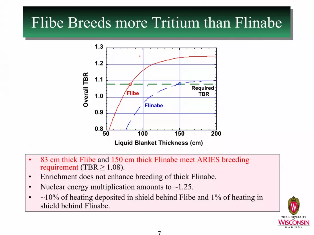
Flibe Breeds more Tritium than FlinabeFlibe Breeds more Tritium than Flinabe
0.8
0.9
1.0
1.1
1.2
1.3
50 100 150 200
Ove
rall
TBR
Liquid Blanket Thickness (cm)
Flibe Required
TBR
Flinabe
• 83 cm thick Flibe and 150 cm thick Flinabe meet ARIES breeding requirement (TBR ≥ 1.08).
• Enrichment does not enhance breeding of thick Flinabe.• Nuclear energy multiplication amounts to ~1.25.• ~10% of heating deposited in shield behind Flibe and 1% of heating in
shield behind Flinabe.

8
For Same Blanket Thickness, FlibeProvides Better Attenuation than Flinabe
For Same Blanket Thickness, FlibeProvides Better Attenuation than Flinabe
100
101
102
103
104
50 100 150 200
Peak
dpa
to F
S St
ruct
ure
(dpa
@ 4
0 FP
Y)
Liquid Blanket Thickness (cm)
Flibe
FS Limit
Flinabe304-SS Limit
• 85 cm Flibe blanket meets FS 200 dpa limit.• 1.5 m Flinabe blanket provides better shielding and meets 25 dpa
limit for 304-SS.

9
Helium Production is ExcessiveHelium Production is Excessive
10-1
100
101
102
103
104
50 100 150 200Peak
Hel
ium
Pro
duct
ion
at F
SSt
ruct
ure
(app
m @
40
FPY)
Liquid Blanket Thickness (cm)
Flibe
FS Reweldability Limit
Flinabe
Innermost shield layer/nozzles/feeding tubes cannot be re-welded at any time during operation.

10
Nuclear Source Term for Aerosol Calculations
Nuclear Source Term for Aerosol Calculations
100
101
102
103
50 100 150 200
Nuc
lear
Hea
ting
(W/c
m3 )
Radial Depth (cm)
58% Flibe, 42% Void
100
101
102
103
50 100 150 200
Nuc
lear
Hea
ting
(W/c
m3 )
Radial Depth (cm)
58% Flinabe, 42% Void
• Heating evaluated at midplane per unit volume of actual blanket composition.
• For isochoric heating analysis, detailed heating in fine meshes and time-dependent nuclear heating will be computed upon request.

11
Steel Composition (in wt%)Steel Composition (in wt%)
Fe 83.818 87.891 70.578C 0.052 0.04 0.046N 0.014 0.005 0.038O 0.16 0.13 –Si 0.1 0.24 0.47P – 0.005 0.026S 0.001 0.002 0.012Ti 0.35 0.09 0.03V 0.01 0.29 –Cr 12.58 8.7 17.7Mn 0.05 0.45 1.17Co – 0.0028 0.1Ni 0.27 0.0474 9.3Cu 0.02 0.01 0.2Nb 0.01 0.00033 –Mo 0.02 0.0021 0.33Ta – 0.08 –W 2.44 2 –Y 0.16 0.7 –
_____________________________________________________* R. Klueh et al., “Microstructure and Mechanical Properties of Oxide Dispersion-Strengthened Steels”
fusion materials semiannual progress report for the period ending June 30, 2000 (DOE/ER-0313/28), pp. 123-130. Fe-12Cr-3W-0.4Ti-0.25Y2O3 (12YWT) experimental alloy.
** IEA Modified F82H FS + 0.25wt% Y2O3, per M. Billone (ANL). Other elements include: B, Al, As, Pd, Ag, Cd, Sn, Sb, Os, Ir, Bi, Eu, Tb, Dy, Ho, Er, U.
# Starfire report: C. Baker et. al, "Starfire-A Commercial Tokamak Fusion Power Plant Study," ArgonneNational Laboratory Report, ANL/FPP-80-1 (1980).
ODS-12YWT-FS*
(Experimental Alloy)304-SS#ODS M-F82H-FS**

12
All Alloys Generate High Level WasteAll Alloys Generate High Level Waste
10-1
100
101
102
103
0 20 40 60 80 100
WD
R o
f Shi
eld
Stru
ctur
e
Shield Thickness (cm)
Flinabe 40 FPY
304-SS
Class C Limit
ODS-12YWT-FS
|Nozzles
ODS-MF82H-FS
10-1
100
101
102
103
0 20 40 60 80 100
WD
R o
f Shi
eld
Stru
ctur
e
Shield Thickness (cm)
Flibe40 FPY
304-SS
Class C Limit
ODS-12YWT-FS|
Nozzles
ODS-MF82H-FS
• ODS-MF82H-FS offers lowest WDR.• Thicker Flinabe blanket results in lower WDR.• Main contributors to WDR: 94Nb (from Nb), 99Tc (from Mo), and
192nIr (from W).• Potential solutions to meet waste requirement (WDR < 1):
– Control Mo and Nb, – Thicken blanket.

13
Effect of Mo and Nb on WDREffect of Mo and Nb on WDR
• In practice, Mo and Nb impurities cannot be zeroed out. Actual level depends on $/kg to keep Mo and Nb < 1 wppm.
• Flibe shield with Mo/Nb control should be > 50 cm thick to qualify as LLW.• Flinabe shield without Mo/Nb control meets waste requirement if ≥ 45 cm
thick.• Nozzles/feeding tubes generate high level waste unless protected by thicker
blanket or mixed with shield and disposed as single unit at EOL.
10-2
10-1
100
101
0 20 40 60 80 100WD
R o
f OD
S-F8
2H-F
S St
ruct
ure
Shield Thickness (cm)
w/ Mo and Nb
Class C Limit
Flibe, ODS-MF82H-FS, 40 FPY
w/o Mo and Nb
|Nozzles
10-2
10-1
100
101
0 20 40 60 80 100WD
R o
f OD
S-F8
2H-F
S St
ruct
ure
Shield Thickness (cm)
w/ Mo and NbClass C Limit
Flinabe, ODS-MF82H-FS, 40 FPY
w/o Mo and Nb
|Nozzles

14
Revisiting Logic Behind Thick Liquid Wall Concept
Revisiting Logic Behind Thick Liquid Wall Concept
HYLIFE-II
101
102
103
104
105
4 5 6 7 8
Cum
ulat
ive
Com
pact
ed W
aste
Volu
me
(m3 )
Chamber Wall Radius (m)
Shield
Blanket
Building
Total
Target (w/o recycling)
Thin Liquid Wall Concept
• Thick liquid wall concept developed to eliminate blanket replacement, reduce waste, and increase availability by 10% � 20% lower COE, per R. Moir (UCRL-JC-115748, April 1994).
• In IFE solid wall designs, blanket generates only 2-4% of total waste� Thick liquid wall concept offers small waste reduction.
(same conclusion made for MFE - APEX project)

15
ConclusionsConclusions• Class C LLW requirement is more restrictive than breeding
and dpa requirements.• No breeding problem identified for Flibe and Flinabe. • 85/150 cm thick Flibe/Flinabe blankets provide TBR of
1.08 and meet FS dpa limit. • Helium production in FS is excessive and precludes FS
reweldability during operation.• All steels produce high level waste (WDR >> 1).• ODS-MF82H-FS and Flinabe system offer lower WDR for
FS structure. • Low level waste can be achieved with combination of
Mo/Nb control and blanket/shield adjustment.• Nozzles/Feeding tubes need additional protection to qualify
as LLW unless combined with shield.

16
Importance of Results andWhat needs to be done
Importance of Results andWhat needs to be done
• Nuclear assessment is important to feasibility of thick liquid wall concept. Results show impact of thick liquid wall on: FS lifetime
Waste levelReduction in waste volume.
• Design-specific analysis needed to meet LLW requirement for nozzles and shield using:
– Nb and Mo impurity control– Thicker blanket (adjust TBR)– Thicker shield.
• Need feedback from materials community on acceptable Nb and Mo impurity level and impact on FS unit cost.

17
UW IFE DesignsUW IFE Designs
*in conjunction with other universities, national and international labsCalendar YearCalendar Year
9696SOLASE
SOLASE-HTDF*
HIBALL*LIBRA*
HIBALL-II*SIRIUS
SIRIUS-M
APEX*
LMF*SIRIUS-T
SIRIUS-P
LIBRA-LiTE*
SOMBRERO*OSIRIS*
19761976 7878 8080 8282 8484 8686 8888 9090 9292 9494
NIF*LIBRA-SP*
9898
X-1/Z-X*
0000
Fusion Technology Institute IFE/ICF Reactor Studies
Light Ion Beam (6)
Laser (9)
Heavy Ion Beam (3)
Z-Pinch (1)
0202
ARIES-IFE*
SENRI-ISENRI-IGIMMGIMM PrometheusPrometheus SOMBRERO-DPSSLSOMBRERO-DPSSL

18
UW IFE Design - HIBALL (1981)UW IFE Design - HIBALL (1981)
• Many INPORT* units � high surface area for condensation.
• LiPb seeps through woven, porous SiC flexible tubes.• Axial tension applied on tubes to limit motion.• Concerns: vaporized LiPb exerts high impulse load
on tubes, uncertainties in applied tension, possible change in SiC porosity, possible deviation from circular tube shape.
_____________* Inhibited flow Porous Tubes

19
UW IFE Design - LIBRA-SP (1995)UW IFE Design - LIBRA-SP (1995)
Cross-Section of the LIBRA-SP Target Chamber
ACCESS PORT
SUPPLY TANK
DIODE
DUCT TO EXPANSION CHAMBER
METERS
PERIT UNITs
SHIELD
REFLECTOR
TRANSMISSION LINE
TARGET INJECTOR
POOL
53°
HEAT EXCHANGER
1 2 3 4
1
2
3
4
5
6
7
8
9
10
11
12
13
14
16
15
5 6 7 8 9 10 11
9°
An Isometric View for the PERITs
Coolant Flow Direction
�
�
FAN SPRAY
PERIT Unit
• Two rows of PERIT* unit:– Perforated to maintain wetted surface
through jet fan spray– Rigid to withstand shock waves.
• LiPb coolant/breeder and FS tubes._____________* Perforated Rigid Tube