synopsis of low temperature chilled ceiling - WSBE17 Hong ...
49
SYNOPSIS OF LOW TEMPERATURE CHILLED CEILING APPLICATION IN TROPICAL AND SUB-TROPICAL COUNTRIES A CASE STUDY By Ir Paul Y C Chan
-
Upload
khangminh22 -
Category
Documents
-
view
1 -
download
0
Transcript of synopsis of low temperature chilled ceiling - WSBE17 Hong ...

SYNOPSIS OF
LOW TEMPERATURE CHILLED
CEILING
APPLICATION IN TROPICAL AND
SUB-TROPICAL COUNTRIES
A CASE STUDY
By Ir Paul Y C Chan

Content
1. Radiant Cooling Design Principles
2. Case Study
2.1 Project Details
2.2 Client’s Brief
2.3 Design
2.4 Performance Results

Traditional AC design adopts convective heat transfer principle using air handling
units or fan coil units recirculating room air to effect heat exchange (invented by
American Dr. Willis H Carrier in 1902)
Convective Heat Transfer
Q = h A (Ts – Tf)
For Fluid
Q = ṁ Cp (T1 – T2)
1. Radiant Cooling Design Principles
Heat Rejection
Cooling
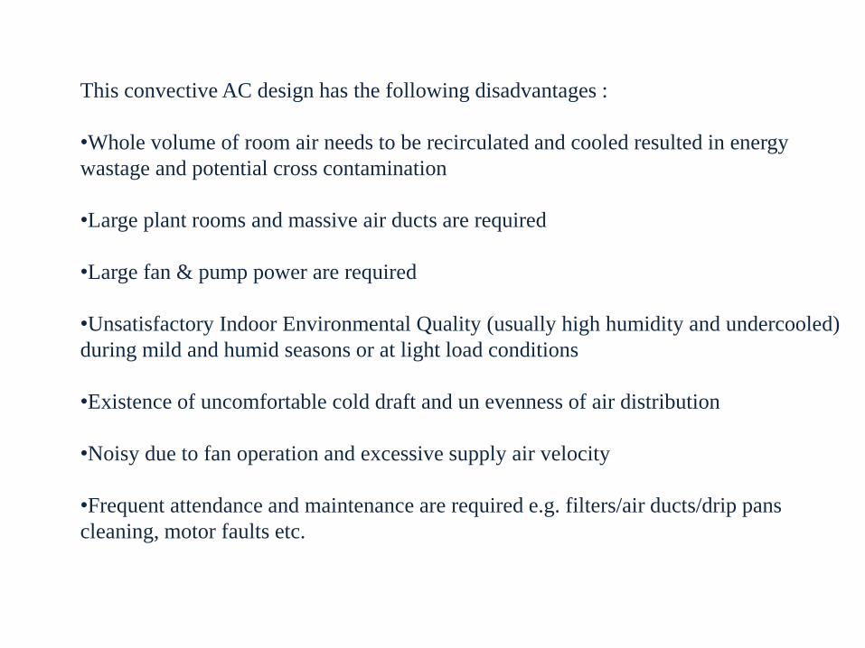
This convective AC design has the following disadvantages :
•Whole volume of room air needs to be recirculated and cooled resulted in energy
wastage and potential cross contamination
•Large plant rooms and massive air ducts are required
•Large fan & pump power are required
•Unsatisfactory Indoor Environmental Quality (usually high humidity and undercooled)
during mild and humid seasons or at light load conditions
•Existence of uncomfortable cold draft and un evenness of air distribution
•Noisy due to fan operation and excessive supply air velocity
•Frequent attendance and maintenance are required e.g. filters/air ducts/drip pans
cleaning, motor faults etc.

Radiant heat transfer occurs when objects temperature are above absolute 0 K.
According to Stefan Boltzmann Law :
Radiation Q = ɛ σ A (Tr4 – Tc
4)
Note that in this formula , heat transfer will take place in the speed of light, irrelevant
to the temperature of the medium and the distance between objects to a great extent is
insignificant. The heat transfer is proportional in the 4th power of the difference in
temperature of the objects, emissivity of the objects, area and the solid angle.
ConductionConvection
Radiation
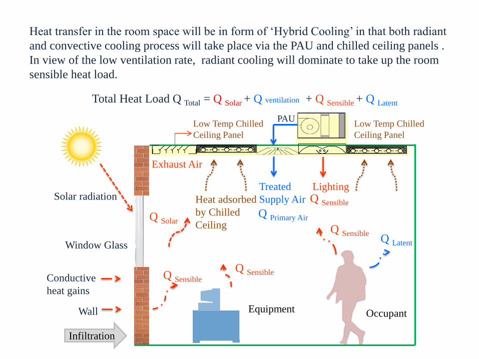
Heat transfer in the room space will be in form of ‘Hybrid Cooling’ in that both radiant
and convective cooling process will take place via the PAU and chilled ceiling panels .
In view of the low ventilation rate, radiant cooling will dominate to take up the room
sensible heat load.
Q Sensible
Lighting
Occupant
Solar radiation
Conductive
heat gains
Wall
Infiltration
Low Temp Chilled
Ceiling Panel
Exhaust Air
PAU
Treated
Supply Air
Q SolarQ Primary Air
Q Sensible
Low Temp Chilled
Ceiling Panel
Window Glass
Q SensibleQ Latent
Q Sensible
Equipment
Heat adsorbed
by Chilled
Ceiling
Total Heat Load Q Total = Q Solar + Q ventilation + Q Sensible + Q Latent
Hot & Humid
Outdoor Air
Special Primary Air Handling Unit
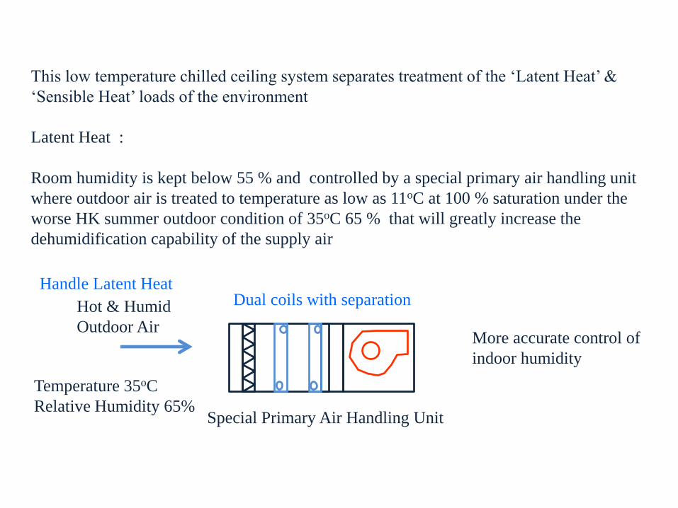
More accurate control of
indoor humidity
Temperature 35oC
Relative Humidity 65%
Handle Latent Heat
This low temperature chilled ceiling system separates treatment of the ‘Latent Heat’ &
‘Sensible Heat’ loads of the environment
Latent Heat :
Room humidity is kept below 55 % and controlled by a special primary air handling unit
where outdoor air is treated to temperature as low as 11oC at 100 % saturation under the
worse HK summer outdoor condition of 35oC 65 % that will greatly increase the
dehumidification capability of the supply air
Dual coils with separation

Low Temperature Chilled Ceiling
More energy efficient as
sensible heat transfer to
chilled ceiling:
More targeted
More effective
Room ambient air
temperature has less effect on
comfort level so it can be
elevated and save energy
Sensible Heat :
Part of the sensible heat is handled by the fresh air but the majority of this load is
handled by the chilled ceiling by means of radiation heat transfer amongst all hot
objects and cooled surfaces inside the room.
Surface temperature of the chilled ceiling will range from 16oC to 22oC depending on
the room loading conditions and comfort control. Chilled ceiling panels are
connected in series to form groups of panels to serve individual zones with separate
comfort controls.
Chilled Water Outlet
Temperature 10oC
Chilled Water Inlet
Temperature 7oC

• Room relative humidity will be kept at 55 % or below to avoid condensation on
chilled ceiling panels. Chilled water will be controlled by a dew point sensor to cut
off water supply when panel surface temperature reaches 16oC or below.
• Room CO2 level will be kept at 800 ppm or below using variable speed drive
primary air units
• Room CO2 level/humidity level, room temperature and chilled ceiling panel
temperature sensors will be installed to facilitate control of the chilled ceiling system.
• Many factors will affect ceiling coverage design of chilled ceiling panels such as
façade design, heat sources (human, lighting & equipment etc.) and building usage
type. In general chilled ceiling coverage of around 40 to 55% should be sufficient to
handle sensible load in most cases.

This is a renovation of an existing office building to a high performance modern Bank
Regional Headquarters
Details of the building 113-115, Argyle Street, MongKok, HK. completed in 1996, with
limited floor to floor headroom of 3000 mm, 23 floors of office and
other supporting floors
Total Floor Area Approximately 30,100 m2 and typical floor plate is around 900m2
Site Area 2,000 m2
Total Population Max. 110 persons/floor
(approx. 3,000 people in total after completion)
Building envelope Curtain Wall, Tinted Glass with Single Glazing
E&M Provision Air Conditioning ─ 1350TR (4750kW) Installed Capacity
Electrical Services ─ 4 nos. of 1500KVA Transformers
Fire Services ─ Full sprinkler protected
Lift Services ─ 7 nos. of Passenger Lift
2. A Case Study – HK Hang Seng Bank at MongKok Regional HQ
2.1 Project Details

Typical Floor Plan
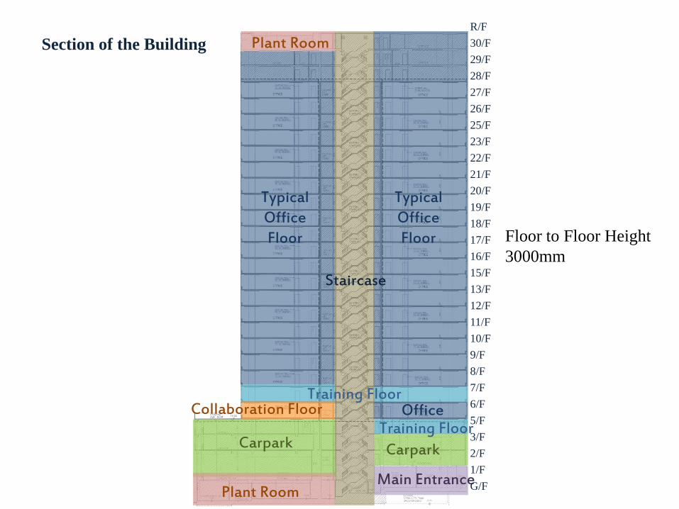
Typical Office Floor
Plant Room
OfficeCollaboration Floor
Plant Room
Carpark Carpark
Main Entrance
Staircase
Typical Office Floor
Training Floor
Training Floor
Section of the Building
R/F
30/F
29/F
28/F
27/F
26/F
25/F
23/F
22/F
21/F
20/F
19/F
18/F
17/F
16/F
15/F
13/F
12/F
11/F
10/F
9/F
8/F
7/F
6/F
5/F
3/F
2/F
1/F
G/F
Floor to Floor Height
3000mm
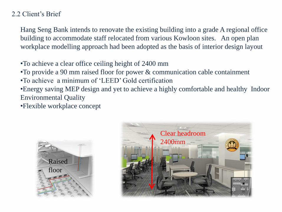
Hang Seng Bank intends to renovate the existing building into a grade A regional office
building to accommodate staff relocated from various Kowloon sites. An open plan
workplace modelling approach had been adopted as the basis of interior design layout
•To achieve a clear office ceiling height of 2400 mm
•To provide a 90 mm raised floor for power & communication cable containment
•To achieve a minimum of ‘LEED’ Gold certification
•Energy saving MEP design and yet to achieve a highly comfortable and healthy Indoor
Environmental Quality
•Flexible workplace concept
Raised
floor
Clear headroom
2400mm
2.2 Client’s Brief

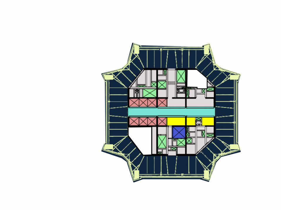
Chilled Ceiling Panel at
Open Plan Office
Chilled Ceiling Panel at
Meeting Room
LEGEND
Chilled Ceiling Panel (Coverage 45%)
Fan Coil Unit
Primary Air Handling Unit
Chilled Ceiling layout Plan
2.3 Design

Proposed Chilled Ceiling Grouping
Chilled Water Inlet
Chilled Water Outlet
D
Dew Point Temperature Sensor
Chilled Ceiling Panel connected in Series
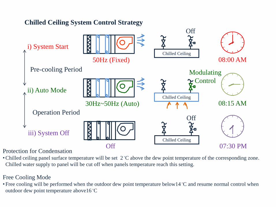
Protection for Condensation•Chilled ceiling panel surface temperature will be set 2 ◦C above the dew point temperature of the corresponding zone.
Chilled water supply to panel will be cut off when panels temperature reach this setting.
Free Cooling Mode•Free cooling will be performed when the outdoor dew point temperature below14 ◦C and resume normal control when
outdoor dew point temperature above16 ◦C
i) System Start
50Hz (Fixed)Chilled Ceiling
Off
08:00 AM
Pre-cooling Period
Operation Period
ii) Auto Mode
30Hz~50Hz (Auto)Chilled Ceiling
Modulating
Control
08:15 AM
iii) System Off
OffChilled Ceiling
Off
07:30 PM
Chilled Ceiling System Control Strategy

Flat Slab
250mmM&E Space
Raised Floor
90mm
New False
Ceiling Height
2400mm
Floor to Floor Height
3000mm
Limited M&E Space 220mm
Typical ceiling section

• Floor to Floor 3000mm (Under Slab 2750mm)
• Drop Slab thickness 375mm
• Flat Slab thickness 250mm
Under Slab
2750mm
Under Drop Slab
2625mm
Existing Site Constraints

This thermo graphic image shows the surface temperature of two different types Radiant
Ceiling panel under load condition. Hence it can be seen that the low temp chilled ceiling has
a much better cooling performance than other radiant cooling products in that it can maintain
even low temperature for a large portion of the radiant area.
Low Temperature Chilled Ceiling Other Chilled Ceiling Products
Thermography Image & Comparison between Low Temperature Chilled
Ceiling and Other Chilled Ceiling Products

Low Temperature Chilled Ceiling
Thermography Images for Typical Office Ceiling

Low Temperature Chilled Ceiling Construction Details

1. Rely on sensor setting and performance
• Regular sensor calibration is required
2. Less Air Movement
• Heat transfer by means of radiation
3. No Validated Standard for Cooling Load Calculation
• No simulation tools for radiant cooling system
• Only refer to project reference
Risks and Limitations
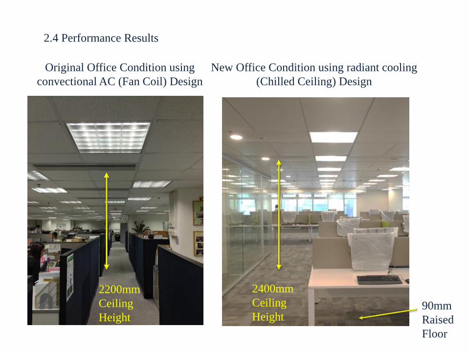
2200mm
Ceiling
Height
Original Office Condition using
convectional AC (Fan Coil) Design
90mm
Raised
Floor
New Office Condition using radiant cooling
(Chilled Ceiling) Design
2400mm
Ceiling
Height
2.4 Performance Results
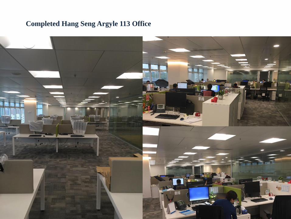
Completed Hang Seng Argyle 113 Office

Completed Hang Seng Argyle 113 Office

Cold spots
Local cold and hot spots are found with
a fan coil unit system.
Fan coil unit system
Chilled ceiling system
Temperature is more consistent and evenly
distributed with a chilled ceiling system.
Merits of radiant cooling compared with convective cooling
Less Temperature Stratification
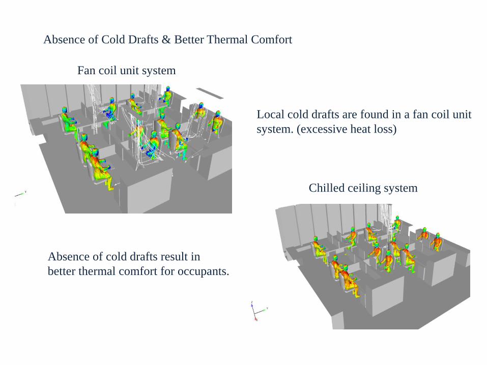
Local cold drafts are found in a fan coil unit
system. (excessive heat loss)
Fan coil unit system
Chilled ceiling system
Absence of cold drafts result in
better thermal comfort for occupants.
Absence of Cold Drafts & Better Thermal Comfort

S1
S2
S3
S6
S5
S4
S7
S8
S9
S10
S11
S12
Occupant Comfort Survey ( based on PMV method of Assessment )

TimeLocation
S1 S2 S3 S4 S5 S6 S7 S8 S9 S10 S11 S12
2:00
pm-1 -1 -1 1 0 0 0 0 -1 0 0 -1
3:00
pm0 0 0 0 0 1 -1 1 -1 1 -1 0
4:00
pm 0 0 0 1 0 0 0 1 0 0 0 0
Cold CoolSlightly
CoolNeutral
Slightly
WarmWarm Hot
-3 -2 -1 0 1 2 3
Comfort Zone
Survey Results
ASHRAE Thermal Sensation Scale
Analytical Comfort Zone Method

Outdoor conditions : 35 ◦C (DB) , 29 ◦C (WB)
Population : 110 person
Fresh air flow rate : 10 l/s/person
Single glazing façade with 0.85 shading coefficient
Design Fresh Air Load : 75 kW (~40 %)
Design Sensible Heat Load : 100 kW (~60 %)
Design Total Load : 175 kW
Cooling Load at Different Outdoor Conditions
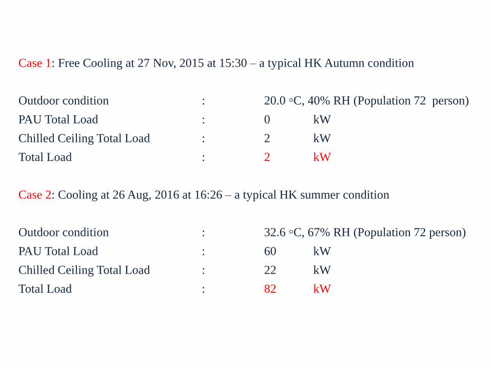
Case 1: Free Cooling at 27 Nov, 2015 at 15:30 – a typical HK Autumn condition
Outdoor condition : 20.0 ◦C, 40% RH (Population 72 person)
PAU Total Load : 0 kW
Chilled Ceiling Total Load : 2 kW
Total Load : 2 kW
Case 2: Cooling at 26 Aug, 2016 at 16:26 – a typical HK summer condition
Outdoor condition : 32.6 ◦C, 67% RH (Population 72 person)
PAU Total Load : 60 kW
Chilled Ceiling Total Load : 22 kW
Total Load : 82 kW

VAV/ AHU System
Space Temperature 23◦C ± 1 ◦C
Relative Humidity 55 % - 70 %
Heating/ Cooling Both but not common/ not well accepted
CO2 Concentration Average 900-1000 ppm
Recirculation Air 80 %
Acoustic Medium NC 38
Air Draft Problem Exist
Temperature Uniformity Average
Fan Coil System
Space Temperature 23◦C ± 1 ◦C
Relative Humidity 60 % - 75 %
Heating/ Cooling Both but not common/ not well accepted
CO2 Concentration Average 1000-1400 ppm
Recirculation Air 80 to 90 %
Acoustic Noisy NC 40 average
Air Draft Problem Exist
Temperature Uniformity Fluctuating
Chilled Ceiling System
Space Temperature 23◦C - 27 ◦C
Relative Humidity 50 % - 55 %
Heating/ Cooling Both and relatively comfortable
CO2 Concentration Average 600 ppm
Recirculation Air Flexible and can be full fresh air
Acoustic Extremely quiet typical under NC35
Air Draft Problem Very minimum
Temperature Uniformity Very Even
VAV/ AHU System
Fan Coil System
Chilled Ceiling System
Merits of Chilled Ceiling versus Conventional AC systems

VAV/ AHU System
Energy Performance
Cooling Load Calculation (Office) 200 W/m2
Water Pump Power ‘A’ kW
Air Fan Power ‘B’ kW
Operation and Maintenance
Ease of Operation Complicated
Maintenance Cost High
Plant Spatial Requirement High
Cost
Capital Cost High
Running Cost High
Fan Coil System
Energy Performance
Cooling Load Calculation (Office) 180 W/m2
Water Pump Power ‘A’ kW
Air Fan Power 40% of ‘B’ kW
Operation and Maintenance
Ease of Operation Less Complicated
Maintenance Cost High
Plant Spatial Requirement Medium
Cost
Capital Cost Low
Running Cost Medium
Chilled Ceiling System
Energy Performance
Cooling Load Calculation (Office) 100 W/m2
Water Pump Power 75% of ‘A’ kW
Air Fan Power 25% of ‘B’ kW
Operation and Maintenance
Ease of Operation Medium Complicated Complicated
Maintenance Cost Low
Plant Spatial Requirement Low
Cost
Capital Cost Medium(due to limited Suppliers)
Running Cost Low Chilled Ceiling System
VAV/ AHU / Fan Coil System
Merits of Chilled Ceiling versus Conventional AC systems

System
Item
Chilled Ceiling
SystemVAV System Fan Coil System Chilled ceiling vs VAV
AHU/ PAU Room
Space15m2 40 m2 - Around 63 % Saving
Ceiling Void Space 250mm 650 mm 400mm Around 60 % Saving
Comfort Control Adjust Panel Surface
Temperature
Adjust Supply Air
temp and volume
Adjust Supply Air
temp and volume-
Energy ConsumptionLow High Medium
Around 40% Saving
(+ 50 % if pump and fan
power are included)
Acoustic Performance Excellent Good Poor -
Room Temperature 23 ℃ – 27 ℃ 22 ℃ to 25 ℃ 22 ℃ to 25 ℃ -
0%
10%
20%
30%
40%
50%
60%
70%
80%
90%
100%
AHU/PAU Room Space Ceiling Void Space Energy Consumption
Chilled Ceiling System Variable Air Volume System Fan Coil System
Summary of Comparison ( for a Typical 1000 sq. m Office )

Hong Kong’s energy end-use distribution
Energy consumption in a typical office building Energy consumption in a office building
using chilled ceiling system & LED
空氣調節
Air Conditioning
55%
照明
Lighting14%
辦公室設備
Office Equipment
12%
其他
Others19%
空氣調節
Air Conditioning28%
Reduction by using CC System
27%
照明
Lighting10%
Reduction by using LED
4%
辦公室設備
Office Equipment12%
其他
Others19%
Energy Performance

0
10
20
30
40
50
60
70
80
90
100
0
20
40
60
80
100
120
140
160
180
200
220
8/2
2/1
6 0
:00
8/2
2/1
6 1
:00
8/2
2/1
6 2
:00
8/2
2/1
6 3
:00
8/2
2/1
6 4
:00
8/2
2/1
6 5
:00
8/2
2/1
6 6
:00
8/2
2/1
6 7
:00
8/2
2/1
6 8
:00
8/2
2/1
6 9
:00
8/2
2/1
6 1
0:0
0
8/2
2/1
6 1
1:0
0
8/2
2/1
6 1
2:0
0
8/2
2/1
6 1
3:0
0
8/2
2/1
6 1
4:0
0
8/2
2/1
6 1
5:0
0
8/2
2/1
6 1
6:0
0
8/2
2/1
6 1
7:0
0
8/2
2/1
6 1
8:0
0
8/2
2/1
6 1
9:0
0
8/2
2/1
6 2
0:0
0
8/2
2/1
6 2
1:0
0
8/2
2/1
6 2
2:0
0
8/2
2/1
6 2
3:0
0
RH
(%
)
Co
oli
ng
L
oa
d (
kW
)
CC
PAU
FCU system
RH
Actual OD
Temp
FCU OD
TempTem
per
atu
re
Cooling load profile in typical hot and humid summer day
Energy Performance

Cooling Energy
in 2016 (kWh)Total
Chilled Ceiling (Actual) FCU (Simulation)*
184,500 422,000
Cooling Energy
184,500 kWh
422,000 kWh
*simulated result by Hourly Analysis Program (E20)
Annual Energy Consumption for a Typical 1000 sq.m Office Floor

Annual Energy Consumption per Area
EUI (kWh/m2/annum)
Typical Office
(Multiple tenants)132
Typical Office
(Single tenants)279
Hang Seng Office
(Single tenants, Chilled Ceiling)156
*Total Internal Floor Area (IFA)
•The area of all enclosed space of the unit measured to the internal face of enclosing walls
•Commonly known as Construction Floor Area (CFA) in HK
Building Energy Utilization Index (EUI)
•A valuable index to manage energy usage
•Compare the whole-building energy use to other similar buildings
•Used for individual energy audits
Annual Energy
Utilization Index (EUI)
Total annual energy consumption of the central building services
installations in a building
Total internal floor area* of the building.(Unit of EUI = kWh/m2/annum)
=
Energy Performance – Energy Utilization Index
Energy Performance

Hang Seng 113
(Actual)
Hang Seng 113 LEED
(Baseline)
EMSD Typical Single
Tenants
AC System Chilled Ceiling LEED Baseline (FCU) -
EUI (kWh/m2/annum) 156 247* 279
HOT (MPP113) Internal Floor Area (m2) 33472
Annual Energy Consumption (kWh/annual) 5,221,000 8,254,000 9,339,000
Electricity Tariff Saving (HK$ 1/kWh) - HK$ 3,033,000 HK$ 4,118,000
*Use simulated data for comparison
HK$ 5,222,000
HK$ 8,254,000
HK$ 9,339,000
Energy Consumption for Whole Building

AC Plant
Skyscraper Ping An International Finance Centre
2nd Tallest building in China (Shenzhen)
4th in the World
Opportunities of Low Temperature Chilled Ceiling
Floor to Floor Height 4500 mm
False Ceiling 3150 mm
MEP Ceiling Space + Structure 1350 mm
AC Cooling Capacity 13000 TR
AC Plant Room 2000 m2
Typical floor AHU room 4 x 80 m2
600 m

AC Plant
AC Plant
Central chiller plant can be significantly
reduced and relocated to less valuable
basement floors that eases maintenance
and operation.
Same height of the building but office
false ceiling height can be increased by
350 mm
AC plant can be relocated to Basement
600 m
0 m
Scenario 1
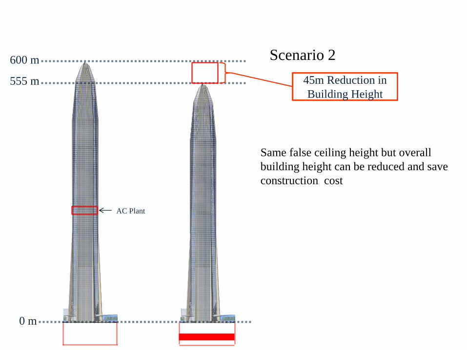
Same false ceiling height but overall
building height can be reduced and save
construction cost
AC Plant
600 m
0 m
555 m 45m Reduction in
Building Height
Scenario 2

AC Plant
600 m
0 m
10 more
floors
Same height but approximately 10 more
office floors can be built with same false
ceiling height
Scenario 3

With the adoption of
low temperature
chilled ceiling design,
the bulky AHU rooms
for conventional VAV
system will be
disappeared.
• GFA 3900m2
Advantages of more useful floor space
Hospital Projects
• Silent Operation
• Excellent Indoor Air Quality
• Energy Conservation
• Flexibility in Separation of Fresh Air Treatment
• 100% fresh Air Supply
• Even Temperature No Draft
• Easy Changeover to Heating / Cooling
Opportunities of Low Temperature Chilled Ceiling

Infrastructure Projects
• Suitable for High Space Large Volume Environment
• Excellent Indoor Air Quality
• Energy Conservation
• Much adopted to free cooling
• Easy Changeover to Heating / Cooling
• Office
• Hotel
• Academic Buildings & Student Hostel
• Exhibition/ Convention Area
• Luxurious Residential Development
• Industrial Undertaking and Factories

THANK YOU