REL 316*4 E V6.2 - Sertec Relay Services
986
REL316*4 Numerical Line Protection Operating Instructions 1MRB520050-Uen Edition July 2002
-
Upload
khangminh22 -
Category
Documents
-
view
2 -
download
0
Transcript of REL 316*4 E V6.2 - Sertec Relay Services
p
REL316*4
Numerical Line Protection
Operating Instructions
1MRB520050-UenEdition July 2002

1996 ABB Switzerland Ltd Baden
6th Edition
Applies for software version V6.3
All rights with respect to this document, including applications for patent andregistration of other industrial property rights, are reserved. Unauthorised use, inparticular reproduction or making available to third parties, is prohibited.
This document has been carefully prepared and reviewed. Should in spite of thisthe reader find an error, he is requested to inform us at his earliest convenience.
The data contained herein purport solely to describe the product and are not awarranty of performance or characteristic. It is with the best interest of ourcustomers in mind that we constantly strive to improve our products and keepthem abreast of advances in technology. This may, however, lead to discrep-ancies between a product and its “Technical Description” or “Operating Instructions”.

Version 6.3
1. Introduction B
2. Description of hardware C
3. Setting the functions F
4. Description of function and application C
5. Operation (HMI) E
6. Self-testing and diagnostics C
7. Installation and maintenance C
8. Technical data B
9. Interbay bus (IBB) interface E
10. Supplementary information G
12. Appendices C


How to use the Operating Instructions for the REL316*4 V6.3
What do you wish to What precisely? Look in the following Indices (I) / Sections (S):know about the device ...
* General theoretical Brief introduction I 1 (Introduction)familiarisation General overview I 1, S 2.1. to S 7.1. (all Section summaries)
Technical data I 8 (Data Sheet, c.t. requirements) Hardware I 2 (Description of hardware) Software I 3 (Setting the functions)
I 4 (Description of function and application) I 6 (Self-testing and diagnostics) I 10 (Software changes)
* How to install Checks upon receipt S 7.2.1.and connect it Location S 7.2.2.
Process connections I 12 (Wiring diagram), S 7.2., S 7.3.2. to S 7.3.5. Control system connections I 9 (IBB)
S 9.6. (IBB address list)
* How to set and Installing the HMI S 5.2.configure it Starting the HMI S 7.3.1., S 5.2.3.
Configuration S 3.2. to S 3.4., S 5.4., S 5.5., S 5.11. Setting functions S 3.5. to S 3.8., S 5.4., S 5.5., S 5.11. Quitting the HMI S 5.2.3.
* How to check, test Checking the connections S 7.2.3. to S 7.2.7.and commission it Functional test S 5.9.
Commissioning checks S 7.3.6.
* How to maintain it Fault-finding S 7.4.1., S 5.8. Updating software S 7.5. Adding hardware S 7.6.
* How to view and Sequential recorder S 5.6.transfer data Disturbance recorder S 5.6., S 3.7.4.
Measurements S 5.7., S 3.7.5. Local Display Unit S 5.13.


REL 316*4 1MRB520050-Uen / Rev. B ABB Switzerland Ltd
1-1
March 01
1. INTRODUCTION
1.1. General ....................................................................................1-2
1.2. Application ...............................................................................1-3
1.3. Main features ...........................................................................1-3
ABB Switzerland Ltd REL 316*4 1MRB520050-Uen / Rev. B
1-2
1. INTRODUCTION
1.1. General
The numerical line protection scheme REL 316*4 is one of thenew generation of fully digital protection systems, i.e. the ana-logue-to-digital conversion of the measured input variables takesplace immediately after the input transformers and the resultingdigital signals are processed exclusively by programmed micro-processors.
Within the PYRAMID® system for integrated control and protec-tion, REL 316*4 represents one of the compact line protectionunits.
Because of its compact design, the use of only a few differenthardware units, modular software and continuous self-monitoringand diagnostic functions, the REL 316*4 scheme optimally fulfilsall the demands and expectations of a modern protectionscheme with respect to efficient economic plant managementand technical performance.
The AVAILABILITY, which is the ratio between fault-free operat-ing time and total operational life, is certainly the most importantrequirement a protection device has to fulfil. As a result of con-tinuous monitoring, this ratio in the case of REL 316*4 is almostunity.
Operation, control and commissioning of the unit are the es-sence of SIMPLICITY thanks to the interactive, menu-controlledman/machine communication program, which runs on a personalcomputer. Absolute FLEXIBILITY of the REL 316*4 scheme, i.e.adaptability to a specific primary system or existing protection(retrofitting), is assured by the supplementary functions incorpo-rated in the software and by the ability to freely assign inputs andoutputs via the control program running on the PC (HMI).
Decades of experience in the protection of overhead lines andcables have gone into the development of the REL 316*4 to giveit the highest possible degree of RELIABILITY, DISCRIMINA-TION and STABILITY. Digital processing of all the signals en-dows the scheme with ACCURACY and constant SENSITIVITYthroughout its useful life.
The designation ‘RE. 316*4’ is used in the following sections ofthese instructions whenever the information applies to the entireseries of devices.

REL 316*4 1MRB520050-Uen / Rev. B ABB Switzerland Ltd
1-3
1.2. Application
The REL 316*4 numerical line protection scheme is designed forthe high-speed discriminative protection of lines and cables indistribution and transmission systems. The rated voltage of theline being protected is not a restriction and the protection is ap-plicable to solidly or low-resistance grounded systems, systemswith Petersen coils or to ungrounded systems.
REL 316*4 is suitable for the protection of long or short overheadlines or cables, double-circuit lines, heavily loaded lines, lineswith weak infeeds and what are referred to as “short-zone” lines.All kinds of faults are detected including close-in three-phasefaults, cross-country faults, evolving faults and high-resistanceearth faults.
REL 316*4 takes power swings and reversal of fault energy intoaccount. Switching onto an existing fault results in instantaneoustripping of the circuit-breaker.
REL 316*4 places relatively low requirements on the perform-ance of c.t’s and v.t’s and is not dependent on their characteris-tics (CVT’s are permissible).
REL 316*4 can operate with any kind of communications chan-nel (PLC, optical fibres etc.) between the terminal stations.
1.3. Main features
REL 316*4’s library of protection functions includes the following:
Distance protection with
overcurrent or underimpedance starters (polygon char-acteristic)
5 distance stages (independently set polygon character-istics for forwards and reverse measurement)
definite time overcurrent back-up protection (including"short-zone" protection)
V.t. supervision
power-swing blocking
system logic for
switch-onto-fault protection
overreaching

ABB Switzerland Ltd REL 316*4 1MRB520050-Uen / Rev. B
1-4
permissive underreaching transfer tripping (also forweak infeed and communications channel failure)
permissive overreaching transfer tripping (also forweak infeed, communications channel failure and re-versal of fault energy direction)
blocking scheme (also for reversal of fault energy di-rection)
sensitive E/F protection for ungrounded systems
E/F protection for grounded systems
inverse time earth fault overcurrent protection
overtemperature protection
definite time over and undercurrent protection
provision for inrush blocking
inverse-time over/undercurrent protection (Current-Inv)
directional definite time overcurrent protection
directional inverse time overcurrent protection
definite time over and undervoltage protection
power protection
synchrocheck.
breaker failure protection
REL 316*4 includes the following communication channelfunctions:
longitudinal differential protection
binary signal transmission.
REL 316*4 includes the following logic functions:
auto-reclosure
supplementary logic functions such as
logic
delay
contact bounce filter
supplementary user logic programmed using CAP316(function plan programming language FUPLA). This re-quires systems engineering.
REL 316*4 1MRB520050-Uen / Rev. B ABB Switzerland Ltd
1-5
The following measurement and monitoring functions are alsoprovided:
single-phase measuring function UIfPQ
three-phase measurement module
three-phase current plausibility
three-phase voltage plausibility.
The scheme includes an event memory (with information on faultdistance in relation to a reference length) and an event recorder.
The allocation of the opto-coupler inputs, the LED signals andthe auxiliary relay signal outputs, the setting of the various pa-rameters, the configuration of the scheme and the display of theevents and system variables are all performed interactively bymeans of the HMI.
REL 316*4 is equipped with serial interfaces for the connectionof a local control PC and for remote communication with the sta-tion control system.
REL 316*4 is also equipped with continuous self-monitoring andself-diagnostic functions. Suitable testing devices (e.g. theMODURES® test set XS92b) are available for quantitative test-ing.
REL 316*4 can be semi-flush or surface mounted or can be in-stalled in an equipment rack.


REL 316*4 1MRB520050-Uen / Rev. C ABB Switzerland Ltd
2-1
March 01
2. DESCRIPTION OF HARDWARE
2.1. Summary..................................................................................2-2
2.2. Mechanical design ...................................................................2-42.2.1. Hardware versions ...................................................................2-42.2.2. Construction.............................................................................2-42.2.3. Casing and methods of mounting ............................................2-42.2.4. Front of the protection unit .......................................................2-42.2.5. PC connection..........................................................................2-52.2.6. Test facilities ............................................................................2-5
2.3. Auxiliary supply unit .................................................................2-6
2.4. Input transformer unit ...............................................................2-6
2.5. Main processor unit..................................................................2-7
2.6. Binary I/O unit ..........................................................................2-8
2.7. Interconnection unit..................................................................2-8

ABB Switzerland Ltd REL 316*4 1MRB520050-Uen / Rev. C
2-2
2. DESCRIPTION OF HARDWARE
2.1. Summary
The hardware of the digital protection scheme RE. 316*4 com-prises 4 to 8 plug-in units, a connection unit and the casing:
Input transformer unit Type 316GW61 A/D converter unit Type 316EA62
or Type 316EA63 Main processor unit Type 316VC61a
or Type 316VC61b 1 up to 4 binary I/O units Type 316DB61
or Type 316DB62or Type 316DB63
Auxiliary supply unit Type 316NG65 Connection unit Type 316ML61a
or Type 316ML62a Casing and terminals for analogue signals and connectors for
binary signals.
The A/D converter Type 316EA62 or 316EA63 is only used inconjunction with the longitudinal differential protection and in-cludes the optical modems for transferring the measurements tothe remote station.
Binary process signals are detected by the binary I/O unit andtransferred to the main processor which processes them in rela-tion to the control and protection functions for the specific projectand then activates the output relays and LED’s accordingly.
The analogue input variables are electrically insulated from theelectronic circuits by the screened windings of the transformersin the input transformer unit. The transformers also reduce thesignals to a suitable level for processing by the electronic cir-cuits. The input transformer unit provides accommodation fornine transformers.
Essentially the main processor unit 316VC61a or 316VC61bcomprises the main processor (80486-based), the A/D converterunit, the communication interface control system and 2 PCMCIAslots.

REL 316*4 1MRB520050-Uen / Rev. C ABB Switzerland Ltd
2-3
Binary process signals, signals pre-processed by the controllogic, events, analogue variables, disturbance recorder files anddevice control settings can be transferred via the communicationinterface to the station control room. In the reverse direction,signals to the control logic and for switching sets of parametersettings are transferred by the station control system to the pro-tection.
RE. 316*4 can be equipped with one up to four binary I/O units.
There are two tripping relays on the units 316DB61 and316DB62, each with two contacts and according to version ei-ther:
8 opto-coupler inputs and 6 signalling relaysor 4 opto-coupler inputs and 10 signalling relays.
The I/O unit 316DB63 is equipped with 14 opto-coupler inputsand 8 signalling relays.
The 16 LED’s on the front are controlled by the 316DB6. unitslocated in slots 1 and 2.

ABB Switzerland Ltd REL 316*4 1MRB520050-Uen / Rev. C
2-4
2.2. Mechanical design
2.2.1. Hardware versions
RE. 316*4 is available in a number of different versions whichare listed in the data sheet under "Ordering information".
2.2.2. Construction
The RE. 316*4 is 6 U standard units high (U = 44.45 mm) andeither 225 mm (Order code N1) or 271 mm wide (Order codeN2). The various units are inserted into the casing from the rear(see Fig. 12.3) and then screwed to the cover plate.
2.2.3. Casing and methods of mounting
The casing is suitable for three methods of mounting.
Semi-flush mounting
The casing can be mounted semi-flush in a switch panel with theaid of four fixing brackets. The dimensions of the panel cut-outcan be seen from the data sheet. The terminals are located atthe rear.
Installation in a 19" rack
A mounting plate with all the appropriate cut-outs is available forfitting the protection into a 19" rack (see Data Sheet). The termi-nals are located at the rear.
Surface mounting
A hinged frame (see Data Sheet) is available for surface mount-ing. The terminals are located at the rear.
2.2.4. Front of the protection unit
A front view of the protection and the functions of the frontplateelements can be seen from Fig. 12.2.
A reset button is located behind the frontplate which serves threepurposes:
resetting the tripping relays and where the are configured tolatch, also the signalling relays and LED's and deleting thedistance protection display when running the control program
REL 316*4 1MRB520050-Uen / Rev. C ABB Switzerland Ltd
2-5
resetting of error messages resulting from defects detectedby the self-monitoring or diagnostic functions (short press)
resetting the entire protection (warm start, press for at leastten seconds) following the detection of a serious defect bythe self-monitoring or diagnostic functions.
These control operations can also be executed using the localcontrol unit on the front of the device. Should the latter fail, thereset button can be pressed using a suitable implement throughthe hole in the frontplate.
2.2.5. PC connection
In order to set the various parameters, read events and meas-urements of system voltages and currents and also for diagnos-tic and maintenance purposes, a personal computer (PC) mustbe connected to the optical serial interface (Fig. 12.2).
2.2.6. Test facilities
A RE. 316*4 protection can be tested using a test set TypeXS92b.
ABB Switzerland Ltd REL 316*4 1MRB520050-Uen / Rev. C
2-6
2.3. Auxiliary supply unit
The auxiliary supply unit 316NG65 derives all the supply volt-ages the protection requires from the station battery. Capacitorsare provided which are capable of bridging short interruptions(max. 50 ms) of the input voltage. The auxiliary supply unit isprotected against changes of polarity.
In the event of loss of auxiliary supply, the auxiliary supply unitalso generates all the control signals such as re-initialisation andblocking signals needed by all the other units.
The technical data of the auxiliary supply unit are to be found inthe data sheet.
2.4. Input transformer unit
The input transformer unit 316GW61 serves as input interfacebetween the analogue primary system variables such as cur-rents and voltages and the protection. The mounting plate of theunit can accommodate up to nine c.t's and v.t's. The shuntsacross the secondaries of the c.t's are also mounted in the inputtransformer unit.
The input transformers provide DC isolation between the primarysystem and the electronic circuits and also reduce (in the case ofthe c.t's, with the aid of a shunt) the voltage and current signalsto a suitable level for processing by the A/D converters. Thus theinput transformer unit produces voltage signals at its outputs forboth current and voltage channels.
The c.t's and v.t's actually fitted in the input transformer unit varyaccording to version. Further information can be obtained fromthe data sheet.

REL 316*4 1MRB520050-Uen / Rev. C ABB Switzerland Ltd
2-7
2.5. Main processor unit
The main processor runs the control and protection algorithmsas determined by the particular settings. It receives its data fromthe A/D converter unit and the I/O unit. The results computed bythe algorithms are transferred either directly or after further logi-cal processing to the binary I/O unit.
A 80486-based microprocessor is used in the main processorunit 316VC61a or 316VC61b. The samples taken by the A/Dconverter are pre-processed by a digital signal processor (DSP).The interfaces for connecting an MMI PC and for communicationwith the station control system (SPA, IEC60870-5-103) are in-cluded. A PCMCIA interface with two slots facilitates connectionto other bus systems such as LON and MVB. The flashEPROM’s used as program memory enable the software to bedownloaded from the PC via the port on the front.
A self-monitoring routine runs in the background on the mainprocessor. The main processor itself (respectively the correctoperation of the program) is monitored by a watchdog.

ABB Switzerland Ltd REL 316*4 1MRB520050-Uen / Rev. C
2-8
2.6. Binary I/O unit
The binary I/O unit 316DB6. enables binary signals received viaopto-couplers from station plant to be read and tripping andother signals to be issued externally.
All the input and output units provide electrical insulation be-tween the external signalling circuits and the internal electroniccircuits.
The I/O units in slots 1 and 2 also control the statuses of 8 LED'seach on the frontplate via a corresponding buffer memory.
The numbers of inputs and outputs required for the particularversion are achieved by fitting from one to four binary I/O units.The relationship between the versions and the number of I/Ounits is given in the data sheet.
The opto-coupler inputs are adapted to suit the available inputvoltage range by choice of resistor soldered to soldering posts.This work is normally carried at the works as specified in the or-der.
The technical data of the opto-coupler inputs and the trippingand signalling outputs can be seen from the data sheet.
2.7. Interconnection unit
The wiring between the various units is established by the inter-connecting unit 316ML62a (width 271 mm) or 316ML61a (width225 mm). It is located inside the housing behind the frontplateand carries the connectors and wiring needed by the individualunits.
In addition, the interconnection unit includes the connections tothe local control unit, the reset button and 16 LED’s for statussignals.
REL 316*4 1MRB520050-Uen / Rev. F ABB Switzerland Ltd
3-1
March 01
3. SETTING THE FUNCTIONS
3.1. General ....................................................................................3-53.1.1. Library and settings..................................................................3-53.1.2. Control and protection function sequence................................3-63.1.2.1. Repetition rate..........................................................................3-63.1.2.2. Computation requirement of protection functions.....................3-73.1.2.3. Computing requirement of the control functions.....................3-10
3.2. Control and protection function inputs and outputs................3-113.2.1. C.t./v.t. inputs.........................................................................3-113.2.2. Binary inputs ..........................................................................3-123.2.3. Signalling outputs ..................................................................3-123.2.4. Tripping outputs .....................................................................3-133.2.5. Measured variables................................................................3-13
3.3. Frequency range....................................................................3-13
3.4. System parameter settings ....................................................3-143.4.1. Hardware configuration..........................................................3-143.4.2. Entering the c.t./v.t. channels.................................................3-163.4.3. Entering comments for binary inputs and outputs..................3-183.4.4. Masking binary inputs, entering latching parameters
and definition of “double indications” .....................................3-183.4.5. Processing system functions .................................................3-183.4.5.1. Changing inputs and outputs .................................................3-193.4.5.2. Changing the system name ...................................................3-223.4.5.3. Changing the password .........................................................3-22
3.5. Protection functions ...............................................................3-233.5.1. HV distance protection function ............. (HV-Distance) ........3-233.5.2. Distance protection ...................................... (Distance) ........3-253.5.2.1. General ..................................................................................3-503.5.2.2. Starters ..................................................................................3-513.5.2.2.1. Overcurrent starters ...............................................................3-513.5.2.2.2. Underimpedance starters.......................................................3-523.5.2.2.3. Current enable .......................................................................3-543.5.2.2.4. E/F detector ...........................................................................3-543.5.2.2.5. Phase preference logic ..........................................................3-553.5.2.2.6. Undervoltage starters.............................................................3-553.5.2.3. Measuring units......................................................................3-563.5.2.3.1. Determining the distance zones.............................................3-563.5.2.3.2. Directional element ................................................................3-62

ABB Switzerland Ltd REL 316*4 1MRB520050-Uen / Rev. F
3-2
3.5.2.3.3. Overreaching zone.................................................................3-633.5.2.3.4. Reverse zone.........................................................................3-633.5.2.3.5. Time steps .............................................................................3-643.5.2.4. Definitive zone .......................................................................3-643.5.2.5. Back-up overcurrent unit ........................................................3-653.5.2.6. V.t. supervision ......................................................................3-663.5.2.7. Tripping logic..........................................................................3-673.5.2.8. Power-swing blocking ............................................................3-693.5.2.9. Allocation of c.t. and v.t. inputs ..............................................3-693.5.2.10. Allocation of binary inputs ......................................................3-703.5.2.11. Allocation of tripping commands ............................................3-723.5.2.12. Signals ...................................................................................3-723.5.3. Sensitive earth fault protection for
ungrounded systems and systems withPetersen coils ...................................... (EarthFaultIsol) ........3-73
3.5.4. Auto-reclosure ..................................... (Autoreclosure) ........3-813.5.4.1. General ..................................................................................3-983.5.4.2. Connections between auto-reclosure and
distance functions ..................................................................3-983.5.4.3. Connections between auto-reclosure and
overcurrent or differential functions......................................3-1003.5.4.4. Redundant schemes ............................................................3-1023.5.4.5. Master/follower logic ............................................................3-1043.5.4.6. Duplex logic .........................................................................3-1063.5.4.7. Timers..................................................................................3-1083.5.4.8. External binary inputs ..........................................................3-1123.5.4.9. Close CB and signalling outputs ..........................................3-1143.5.4.10. Timing diagrams ..................................................................3-1163.5.4.11. Checking the dead times .....................................................3-1263.5.5. Sensitive earth fault protection for
grounded systems ................................ (EarthFltGnd2) ......3-1293.5.5.1. Coordination with the distance protection ............................3-1353.5.5.2. Choice of operating mode....................................................3-1363.5.5.3. Choice of transfer tripping scheme ......................................3-1373.5.5.4. Setting the enabling pick-up levels.......................................3-1413.5.5.5. Setting the characteristic angle ‘Angle’ ................................3-1423.5.5.6. Setting the basic time ‘t basic’..............................................3-1433.5.5.7. Circuit-breaker delay............................................................3-1433.5.5.8. The comparison time ‘t comp’ ..............................................3-1433.5.5.9. Setting the waiting time ‘t wait’ .............................................3-1443.5.5.10. Setting the transient blocking time ‘t TransBlk’.....................3-1443.5.5.11. C.t./v.t. inputs of the function................................................3-1443.5.5.12. Binary inputs of the function.................................................3-1453.5.5.13. Outputs ................................................................................3-1463.5.6. Inverse definite minimum time earth fault
overcurrent function ..................................... (I0-Invers) ......3-147

REL 316*4 1MRB520050-Uen / Rev. F ABB Switzerland Ltd
3-3
3.5.7. Definite time over and undercurrent......... (Current-DT) ......3-1533.5.8. Inverse time overcurrent .......................... (Current-Inv) ......3-1593.5.9. Directional definite time ................................................
overcurrent protection........................... (DirCurrentDT) ......3-1653.5.10. Directional inverse time
overcurrent protection........................... (DirCurrentInv) ......3-1733.5.11. Definite time over and
undervoltage protection ........................... (Voltage-DT) ......3-1853.5.12. Power............................................................... (Power) ......3-1913.5.13. Overtemperature protection .......................(Overtemp.) ......3-2053.5.14. Synchrocheck function.......................... (SynchroChck) ......3-2133.5.14.1. General ................................................................................3-2223.5.14.2. Settings................................................................................3-2243.5.14.3. Binary inputs of the function.................................................3-2313.5.15. Breaker failure protection.................... (BreakerFailure) ......3-235
3.6. Control functions..................................................................3-2513.6.1. Control function...............................................(FUPLA) ......3-2513.6.1.1. Control function settings - FUPLA........................................3-2533.6.1.1.1. General ................................................................................3-2543.6.1.1.2. Timers..................................................................................3-2553.6.1.1.3. Binary inputs ........................................................................3-2553.6.1.1.4. Binary signals.......................................................................3-2553.6.1.1.5. Measurement inputs ............................................................3-2563.6.1.1.6. Measurement outputs ..........................................................3-2563.6.1.1.7. Flow chart for measurement inputs and outputs ..................3-2563.6.1.2. Loading FUPLA....................................................................3-2573.6.2. Logic ..................................................................(Logic) ......3-2593.6.3. Delay / integrator .............................................. (Delay) ......3-2633.6.4. Contact bounce filter .................................. (Debounce) ......3-2693.6.5. LDU events ...............................................(LDUevents) ......3-273
3.7. Measurement functions........................................................3-2773.7.1. Measurement function ......................................(UIfPQ) ......3-2773.7.2. Three-phase current plausibility............... (Check-I3ph) ......3-2833.7.3. Three-phase voltage plausibility ............ (Check-U3ph) ......3-2873.7.4. Disturbance recorder ....................... (Disturbance Rec) ......3-2913.7.5. Measurement module .......................(MeasureModule) ......3-3053.7.5.1. Impulse counter inputs.........................................................3-3113.7.5.2. Impulse counter operation....................................................3-3123.7.5.3. Impulse counter operating principle .....................................3-3123.7.5.4. Interval processing...............................................................3-313
ABB Switzerland Ltd REL 316*4 1MRB520050-Uen / Rev. F
3-4
3.8. Data transmission ................................................................3-3153.8.1. Principle of operation of the A/D converter 316EA62...........3-3153.8.1.1. Introduction ..........................................................................3-3153.8.1.2. Synchronisation principle .....................................................3-3153.8.1.3. Data transmission principle ..................................................3-3153.8.1.4. Consequences of transmission errors..................................3-3163.8.2. Longitudinal differential protection ................ (Diff-Line) ......3-3193.8.2.1. Setting instructions for lines with a
power transformer in the protected zone .............................3-3253.8.2.2. Setting instructions for lines without a
power transformer in the protected zone .............................3-3373.8.3. Binary data transmission...........................(RemoteBin) ......3-343

REL 316*4 1MRB520050-Uen / Rev. F ABB Switzerland Ltd
3-5
3. SETTING THE FUNCTIONS
3.1. General
3.1.1. Library and settings
REL 316*4 provides a comprehensive library of protection andcontrol functions for the complete protection of feeders.
The setting procedure is carried out with the aid of a personalcomputer and is extremely user-friendly.
The number of protection and control functions active in aREL 316*4 system is limited by the available computing capacityof the processing unit.
In each case, the control program checks whether sufficientcomputing capacity is available and displays an error message,if there is not.
The maximum possible number of protection functions is 48.
The settings and the software key determine which functions areactive. This procedure enables the most wishes with respect todifferent protection scheme configurations to be satisfied:
Only functions which are actually needed should beactivated. Every active function entails computing effort,which can influence the operating time.
Many of the functions can be used for multiple purposes,e.g.:
to achieve several stages of operation (with the same ordifferent settings and time delays)
for use with different input channels.
Other functions can only be configured for one specific pur-pose in each set of parameter settings:
binary signal transmission disturbance recorder contact bounce filter (Debounce) VDEW6.
Functions active in the same set of settings can be logicallyinterconnected, e.g. for interlocking purposes.

ABB Switzerland Ltd REL 316*4 1MRB520050-Uen / Rev. F
3-6
3.1.2. Control and protection function sequence
3.1.2.1. Repetition rateThe protection system software controls the operating sequenceof the individual functions. The latter are divided into routines,which are processed cyclically by the microprocessor. Thefrequency of the processing cycle (repetition rate) is determinedby the technical requirements of the application.For many functions, this depends on the permissible or desiredtripping delay. From this follows that the faster tripping shouldtake place, the higher will be the repetition rate. Typicalrelationships between tripping delay and repetition rate can beseen from Table 3.1.
Repetition rate Explanation Delay time
4 4 times every 20 ms 1) < 40 ms
2 2 times every 20 ms 40 ... 199 ms
1 1 time every 20 ms 200 ms
1) for 50 Hz or 60 Hz
Table 3.1 Typical protection function repetition ratesThe repetition rates of some of the functions do not depend ontheir settings, e.g. the distance protection always has a repetitionrate of 4 and the auto-reclosure 1.
The scanning of the binary inputs and the setting of the signal-ling and tripping outputs takes place at the sampling rate of theanalogue inputs.
While the operating speed of the various protection functions ismore than adequate for their purpose, they do operate in se-quence so that the effective operating times of output signalssuch as ‘start’ and ‘Trip’ are subject to some variation. Thisvariation is determined by the repetition rate controlling theoperation of the function. Typical values are given in Table 3.2.
Repetition rate Variation
4 -2...+5 ms
2 -2...+10 ms
1 -2...+20 ms
Table 3.2 Variation in the operating time of output signals ofprotection functions in relation to their repetition rates
REL 316*4 1MRB520050-Uen / Rev. F ABB Switzerland Ltd
3-7
3.1.2.2. Computation requirement of protection functions
The amount of computation a function entails is determined bythe following factors:
complexity of the algorithms used. This is characteristic foreach protection function.
Repetition rate:The faster the operating time of a protection function, thehigher its repetition rate according to Table 3.1. The compu-tation requirement increases approximately in proportion tothe repetition rate.
Already active protection functions:The protection system is able to use certain intermediate re-sults (measured variables) determined by a protection func-tion several times. In consequence, additional stages of thesame protection function with the same inputs generally onlyinvolve a little more computation for the comparison with thepick-up value, but not for conditioning the input signal.
The computation requirement of the REL 316*4 protection func-tions can be seen from Table 3.3. The values given are typicalpercentages in relation to the computing capacity of a fictitiousmain processing unit.
According to Table 3.1, the computation requirement of some ofthe functions increases for low settings of the time delay t andtherefore a factor of 2 or 4 has to be used in some instances.When entering the settings for a function with several stages, theone with the shortest time delay is assumed to be the first stage.
The computing performance of a REL 316*4 is 250 %, providinga 316VC61a or 316VC61b central processor is fitted. Thisapplies to all devices equipped with the local control unit on thefront. The computing performance of older devices with a316VC61 central processing unit is limited to 200 %.
The computing load can be viewed by selecting ‘List ProcedureList’ from the ‘List Edit Parameters’ menu and is given for thefour sets of parameters in per thousand.

ABB Switzerland Ltd REL 316*4 1MRB520050-Uen / Rev. F
3-8
Function 1st. stage 2nd. and higher stages Factor (**)
1ph 3ph 1ph 3ph t < 40 ms t < 200 ms
Distance (min.) 50
starters Z< 20Meas Bward 5VTSupNPS 3Power Swing 15
HV distance (min) 70
Meas Bward 5VTSupNPS 3Power Swing 15
EarthFltIsol 5 ditto 4 2
Autoreclosure 1 ditto
EarthFltGnd2 10 ditto 4 2
I0-Inverse 4 3
Current-DT 2 3 1 4 2
with Inrush Blocking 5 5 4 2Current-Inv 4 7 3
DirCurrentDT 19 ditto 4 2
DirCurrentInv 21 ditto
Voltage-DT 2 3 1 4 2
Power 5 14 3 8 2
Overtemp. 12 15 ditto
SynchroCheck 16 ditto 2
BreakerFailure 34 46 ditto
FUPLA 1/2/4 (***) ditto
VDEW6 1 (*)
Logic 4 ditto
Delay 8 ditto
Debounce 0.1 (*)
Analog RIO Trig 2 ditto 4 2
LDU events 4 ditto
UIfPQ 5 ditto
MeasureModuleVoltage/CurrentInp 10 dittoCnt 8 ditto
Check-I3ph 5 ditto
Check-U3ph 5 ditto
DisturbanceRec
without binary I/P 20 (*)with binary I/P 40 (*)
Diff-Line 50 ditto
RemoteBin 8 (*)
(*) can only be set once (**) always 1 for delays 200 ms
(***) depends on repetition rate (low / medium / high)
Table 3.3 Computation requirement of protection functions(in percent)
REL 316*4 1MRB520050-Uen / Rev. F ABB Switzerland Ltd
3-9
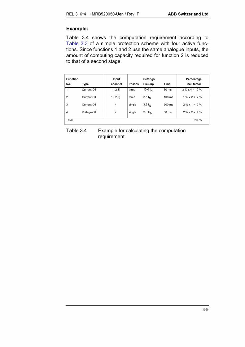
Example:
Table 3.4 shows the computation requirement according toTable 3.3 of a simple protection scheme with four active func-tions. Since functions 1 and 2 use the same analogue inputs, theamount of computing capacity required for function 2 is reducedto that of a second stage.
FunctionNo. Type
Inputchannel Phases
SettingsPick-up Time
Percentageincl. factor
1 Current-DT 1 (,2,3) three 10.0 IN 30 ms 3 % x 4 = 12 %
2 Current-DT 1 (,2,3) three 2.5 IN 100 ms 1 % x 2 = 2 %
3 Current-DT 4 single 3.5 IN 300 ms 2 % x 1 = 2 %
4 Voltage-DT 7 single 2.0 UN 50 ms 2 % x 2 = 4 %
Total 20 %
Table 3.4 Example for calculating the computationrequirement
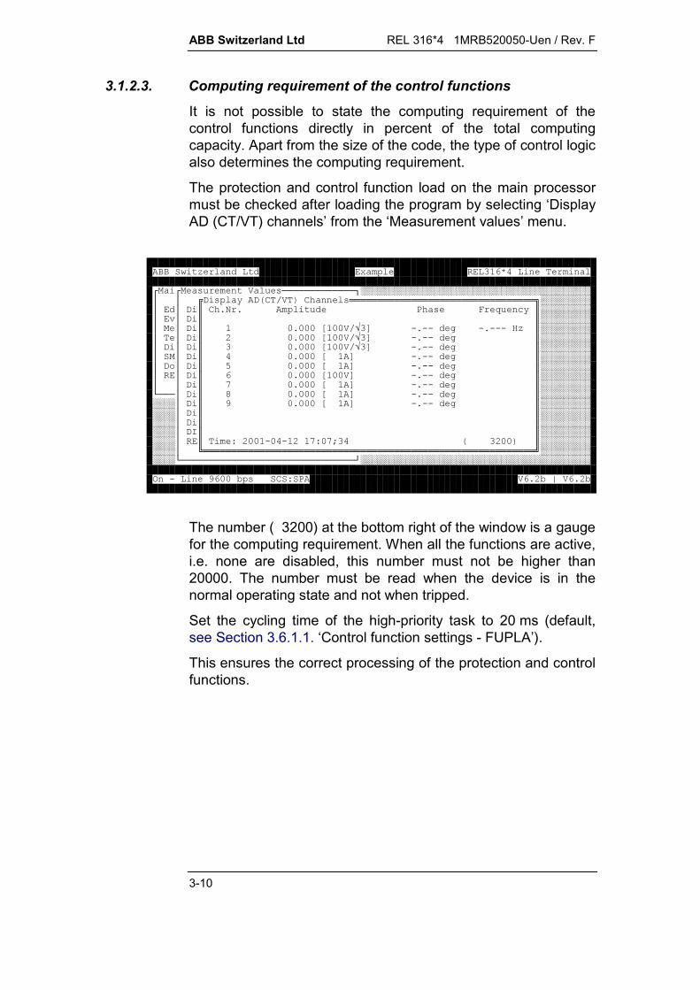
ABB Switzerland Ltd REL 316*4 1MRB520050-Uen / Rev. F
3-10
3.1.2.3. Computing requirement of the control functions
It is not possible to state the computing requirement of thecontrol functions directly in percent of the total computingcapacity. Apart from the size of the code, the type of control logicalso determines the computing requirement.
The protection and control function load on the main processormust be checked after loading the program by selecting ‘DisplayAD (CT/VT) channels’ from the ‘Measurement values’ menu.
!!!!!!!!!!!!!"#########################################$$%& '&()* +), ---------------------------------.#########$$&/),0102, 345'/#########$6$&//#########$$&/70777877 *9:;0;;<;0;;;=/#########$$&/>70777877 *9:;0;;</#########$&$&/70777877 *9:;0;;</#########$$&/707778:;0;;</#########$&?$&/@707778:;0;;</#########$$&/70777877 :;0;;</#########$$&/A707778:;0;;</#########B!!!$&/C707778:;0;;</#############$&/D707778:;0;;</#############$&//#############$&//#############$&E//#############$/F>77;7;>AF7AG(>77+/#############$H-----------------------------------------------------------I#############B!!!!!!!!!!!!!!!!!!!!!!!!!!!!!!!J#########################################K;D77L)F2 0>LM 0>L
The number ( 3200) at the bottom right of the window is a gaugefor the computing requirement. When all the functions are active,i.e. none are disabled, this number must not be higher than20000. The number must be read when the device is in thenormal operating state and not when tripped.
Set the cycling time of the high-priority task to 20 ms (default,see Section 3.6.1.1. ‘Control function settings - FUPLA’).
This ensures the correct processing of the protection and controlfunctions.
REL 316*4 1MRB520050-Uen / Rev. F ABB Switzerland Ltd
3-11
3.2. Control and protection function inputs and outputs
3.2.1. C.t./v.t. inputs(see Section 5.5.4.1.)
The protection scheme can include three types of input trans-formers, which can also have different ratings:
protection c.t’s metering c.t’s (core-balance) v.t’s.
The number and arrangement of the input transformers are de-fined either by sub-code K.. in the ordering code or by trans-former type entered for K=0.
Before being processed by the protection functions, the currentsand voltages coming from the input transformers are digitised inthe analogue section of the main processor unit.
Every analogue input channel is designated either single orthree-phase:
C.t’s: three-phase protection single-phase protection single-phase metering (core-balance)
V.t’s: three-phase Y connected single-phase.
A protection function can only be used in a three-phase mode, ifa corresponding three-phase group of c.t./v.t. input channels isavailable.
All protection function settings are based on the input values(secondary ratings) of the REL 316*4. The fine adjustment to suitthe effective primary system quantities is accomplished byvarying the reference settings of the analogue inputs.

ABB Switzerland Ltd REL 316*4 1MRB520050-Uen / Rev. F
3-12
3.2.2. Binary inputs(see Section 5.5.4.4.)
REL 316*4 recognises one of the following values:
logical “0” (fixed value) or FALSE logical “1” (fixed value) or TRUE binary input value (316DB6.) binary control and protection values as defined by the
function number and the corresponding signalling output binary values from the station control level binary values from the distributed input units (500RIO11) binary values with interlocking data.
All the above can also be set as binary inputs of control andprotection functions.
All the binary addresses set may be used either directly or in-verted.
3.2.3. Signalling outputs(see Section 5.5.4.2.)
All the control and protection signalling outputs provide thefollowing facilities:
external signalling via LED’s external signalling via relays event recording control of tripping relays external signalling via the communications interface external signalling via distributed output units (500RIO11) output of interlocking data.
The following applies to external signals via a signalling relay ora LED:
A signalling relay or LED can only be activated by a onesignal.
Every signalling relay and LED can be individually set tolatch.
A signal can activate up to two output channels, e.g.:
2 signalling relays 1 signalling relay and 1 LED 1 signalling relay and 1 tripping relay.
An output each can also be configured for the communicationinterface, the distributed output units, interlocking data and eventrecording.

REL 316*4 1MRB520050-Uen / Rev. F ABB Switzerland Ltd
3-13
Important signals are duplicated, e.g. ‘GenTrip’ and ‘General-TripAux’.
3.2.4. Tripping outputs(see Section 5.5.4.3.)
All protection functions can directly excite the tripping relays. Atripping logic matrix is provided for this purpose which enablesany function to be connected to any tripping channel. A trippingchannel can be activated by any number of protection functions.
Only the binary I/O units 316DB61 and 316DB62 are equippedwith tripping relays. Each unit has two relays each with twocontacts making four in all.
3.2.5. Measured variables(see Section 5.7.)
Apart from being processed internally, the analogue variablesmeasured by the REL 316*4 protection functions can also beviewed externally as:
a value:The input variables measured by the protection functions areavailable to the station control system via the communicationinterface.They can also be viewed locally on a PC (personal computer)running the operator program or on the local display unit(LDU) on the frontplate. Their values are referred to thesecondary voltages and currents at the input of theREL 316*4.
a recorded event:The instant a protection function trips, the value of the corre-sponding measured variable is recorded as an event.
3.3. Frequency range
The protection functions can be set to operate at a power systemfrequency fN of either 50 Hz or 60 Hz. The algorithms, whichexecute the protection functions, have been optimised to pro-duce the best results at the rated frequency fN. Discrepanciesfrom the rated frequency cause an additional error.

ABB Switzerland Ltd REL 316*4 1MRB520050-Uen / Rev. F
3-14
3.4. System parameter settings
3.4.1. Hardware configurationSummary of parameters:
Text Unit Default Min. Max. Step
NomFreq Hz 50 50 60 10A/D on VC61 (Select)
AD Config K 00 00 99 1
Slot 1 not used (Select)
Slot 2 not used (Select)
Slot 3 not used (Select)
Slot 4 not used (Select)
SWVers SX... X (Select)
SWVers S.XXX 100 1 999 1
Significance of the parameters:
NomFreqDetermination of the rated frequency: 50 Hz or 60 Hz.
A/Ddefines the type of A/D converter. Choose either “EA62…” or“EA63…” to correspond to the A/D converter unit inserted inthe longitudinal line differential protection: on VC61: A/D converter on 316VC61a or
316VC61b EA6. MasterS: short data transmission distance EA6. SlaveS: short data transmission distance EA6. MasterL: long data transmission distance EA6. SlaveL: long data transmission distance EA6. MstFoxS: short data trans. distance using FOX EA6. MstFoxL: long data trans. distance using FOX. EA6. SlvFoxS: short data trans. distance using FOX EA6. SlvFoxL: long data trans. distance using FOX.
The setting of the data transmission distance is normally de-termined by the attenuation of the optical fibre cable betweenthe two units.However, when using FOX optical fibre equipment, the set-ting is determined by the connection between the RE.316*4and the FOX equipment.

REL 316*4 1MRB520050-Uen / Rev. F ABB Switzerland Ltd
3-15
The data transmission distance setting influences the outputpower of the transmission diode. It must therefore be se-lected such that the receiver diode at the remote end is notoverloaded.To make sure that the setting is correct, measure the opticalsignal strength while commissioning the system. The outputpower must be in the respective range given in the followingtable (MM = Multi-mode optical cable 50/125m, SM =Single-mode optical cable 9/125m):
Setting
OFL Type EA6…..S EA6…..L
MM -26 … -20 dBm -16 … -13 dBm
SM -32 … -22 dBm -20 … -17 dBm
Select the setting such that taking the attenuation to beexpected due to the optical cable into account, the power atthe receiving end is between –34dBm to –22dBm. Measurethe signal strength at the receiving end to make sure that it iswithin this range.
Notes:
Take care when measuring the output power to setthe level for the correct type of optical cable in use.
One device must be configured as master (or‘MstFox’) and the other as slave (or ‘SlvFox’).
The same transmission distance, i.e. either ‘EA62…S’or ‘EA62…L’, has to be configured at both ends.
If an A/D converter Type 316EA62 is installed, the‘A/D’ parameter must be set to ‘EA62…’ even if theoptical fibre link is not in operation yet.
AD Config K:Version and type of input transformer unit: 0...17: K0: transformers to be specified
K1...K9: without longitudinal differentialprotection
K15...K17 with longitudinal differentialprotection.
ABB Switzerland Ltd REL 316*4 1MRB520050-Uen / Rev. F
3-16
This parameter must be set before configuring the pro-tection functions and cannot be changed subsequently.The setting must agree with the type of the I/P trans-former actually installed in the device. The hardware isnot checked.A list of input transformer unit codes is to be found in theData Sheet (Section 8).
Slot 1:Defines the type of I/O board in slot 1: not used, 316DB61, 316DB62 or 316DB63.
Slot 2:Defines the type of I/O board in slot 2: not used, 316DB61, 316DB62 or 316DB63.
Slot 3:Defines the type of I/O board in slot 3: not used, 316DB61, 316DB62 or 316DB63.
Slot 4:Defines the type of I/O board in slot 4: not used, 316DB61, 316DB62 or 316DB63.
SWVers SX...:First part (letter) of the software code.
SWVers S.XXX:Second part (figures) of the software code.
A summary of the protection functions according to softwarecodes is given in the Data Sheet (Section 8).
3.4.2. Entering the c.t./v.t. channels(see Section 5.5.5.)
Edit A/D channel type
If K=00 is set for the hardware configuration, c.t. and v.t.channels can be entered in any order, providing a correspondinginput transformer unit is fitted.
Edit A/D nominal value
Enter the rated values for the c.t’s and v.t’s in the inputtransformer unit (1 A, 2 A, 5 A, 100 V or 200 V). S and T phasesof three-phase channels assume the same value as R phase.
REL 316*4 1MRB520050-Uen / Rev. F ABB Switzerland Ltd
3-17
To ensure an adequate resolution of the distance function im-pedance settings at a rated current of 5 A, the impedance set-tings are automatically reduced by a factor of 10.
The ratings must be set at the beginning and not changedafterwards. This applies especially in the case of the dis-tance function.
Setting instructions for the longitudinal differential protection:
The rated current settings of the channels in the remote station(channels 7, 8 and 9) must agree with the effective ratedcurrents of the c.t’s in the remote station.
Edit A/D prim/sec ratio
These values are only of relevance in connection with theIEC60870-5-103 protocol. S and T phases of three-phase c.t.and v.t. channels assume the same value as R phase.
Edit A/D channel ref. val.
The reference values of the c.t. and v.t. channels enable the de-vice ratings to by matched to those of the protected unit. Theyare a factor which can be set in the range 0.5 to 2. S and Tphases of three-phase channels assume the same value as Rphase.
Example: Rated voltage = 110 V
Reference value of the voltage channel
110100
1100VV
.
Effects of changing the reference values:
With the exception of the impedance settings for the distancefunction, the protection function settings (parameters expressedin relation to ‘IN’ and ‘UN’) are automatically adjusted to the newreference values. In the case of the distance function, however,adjusting just the currents and not the voltages will change theimpedance pick-up values. For this reason the reference valuesfor the current inputs should not be changed.
Edit A/D channel comment
Facility is provided for the user to enter a comment for eachanalogue channel, which is displayed together with the channeltype when the corresponding c.t. or v.t. input parameter of aprotection function is selected.
ABB Switzerland Ltd REL 316*4 1MRB520050-Uen / Rev. F
3-18
3.4.3. Entering comments for binary inputs and outputs(see Section 5.5.5.)
Facility is provided for the user to enter individual comments foreach binary input and each signalling or tripping output. Thisoperation is carried out via the sub-menus EDIT BINARYINPUTS, EDIT TRIP OUTPUTS and EDIT SIGNAL OUTPUTS.
3.4.4. Masking binary inputs, entering latching parameters anddefinition of “double indications”(see Section 5.5.5.)
Binary channels can be ‘masked’ via the sub-menu CHANGESIGNALLING CHANNEL, i.e. they are excluded from beingrecorded as events.
Every LED and every signalling and tripping relay can be set to alatch or not to latch via the sub-menu EDIT SIGNAL OUTPUTS,respectively EDIT TRIP OUTPUTS.LED’s will only latch, however, providing the ‘LEDSigMode’parameter is also set for latching beforehand.Note that the green LED1 (stand-by signal) cannot be set to alatching mode.
The EDIT BINARY INPUTS menu provides facility for combiningany pair of consecutive binary channels to form a “doublesignal”. Up to 30 double signals can be defined and a runtimesupervision function can be selected for each pair.
3.4.5. Processing system functions(see Section 5.5.6.)
The system functions have settings which apply for all thedevice’s protection and control functions:
system inputs and outputs
system name
password.
REL 316*4 1MRB520050-Uen / Rev. F ABB Switzerland Ltd
3-19
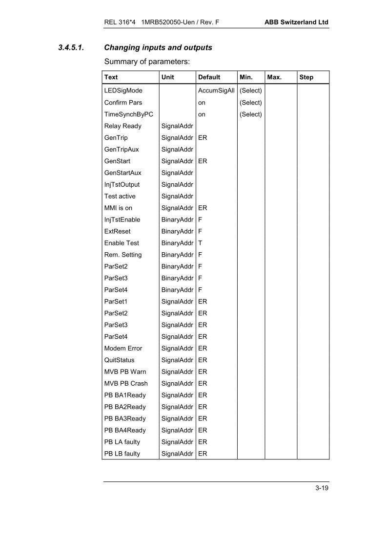
3.4.5.1. Changing inputs and outputs
Summary of parameters:
Text Unit Default Min. Max. Step
LEDSigMode AccumSigAll (Select)
Confirm Pars on (Select)
TimeSynchByPC on (Select)
Relay Ready SignalAddr
GenTrip SignalAddr ER
GenTripAux SignalAddr
GenStart SignalAddr ER
GenStartAux SignalAddr
InjTstOutput SignalAddr
Test active SignalAddr
MMI is on SignalAddr ER
InjTstEnable BinaryAddr F
ExtReset BinaryAddr F
Enable Test BinaryAddr T
Rem. Setting BinaryAddr F
ParSet2 BinaryAddr F
ParSet3 BinaryAddr F
ParSet4 BinaryAddr F
ParSet1 SignalAddr ER
ParSet2 SignalAddr ER
ParSet3 SignalAddr ER
ParSet4 SignalAddr ER
Modem Error SignalAddr ER
QuitStatus SignalAddr ER
MVB PB Warn SignalAddr ER
MVB PB Crash SignalAddr ER
PB BA1Ready SignalAddr ER
PB BA2Ready SignalAddr ER
PB BA3Ready SignalAddr ER
PB BA4Ready SignalAddr ER
PB LA faulty SignalAddr ER
PB LB faulty SignalAddr ER

ABB Switzerland Ltd REL 316*4 1MRB520050-Uen / Rev. F
3-20
Explanation of parameters:
LEDSigModeDisplay mode for LED signals:
AccumSigAllSignals are not reset, but accumulate. In this case, events,which excite the same signals, are superimposed on eachother.
Reset for START (ResetSigAll)'GenStart’ lights and all other LED’s are reset.All subsequent signals are displayed and those associatedwith the last event remain latched.
Reset for TRIP (ResetSigTrip)'GenStart’ lights and all other LED’s are reset.The signals generated by the last event are reset and newones are only displayed, if tripping takes place.
No latching (No Latch)LED signals reset as soon as the condition causing themdisappears.
In all three latching modes, the LED’s can be reset either byselecting the menu item ‘Latch Reset’ in the RESET menu onthe local control unit or by briefly activating the ‘Ext. reset’ binaryinput.Only those LED’s latch in the on state that are configured to doso according to Section 3.4.4.
Confirm Parsswitches the parameter confirm mode on and off.Use the <> to confirm and the <ESC> key to correct.
TimeSynchByPCswitches the synchronisation of the REL 316*4 clock to thePC clock on and off when starting up.
Relay ReadySignal showing that the relay is ready to operate.
GenTrip, GenTripAux (see Section 5.5.4.3.)General tripping signal generated via an OR function of alltripping signals assigned to the tripping logic when any one ofthe protection functions trips.
REL 316*4 1MRB520050-Uen / Rev. F ABB Switzerland Ltd
3-21
GenStart, GenStartAux (see Section 5.5.4.2.)General starting signal generated via an OR function of allstarting signals designated as events.
InjTstOutput (see Section 7.7.1.3.)Tripping signal for the test set.When the protection is set to the test mode, the distanceprotection signal ‘TripCB’ is assigned to the output signal‘InjTstOutput’.Although it is possible to assign two outputs to this signal,only one should be assigned. This signal is normally as-signed to the auxiliary relay S102.
Test active (see Section 5.9.)Signal indicating that the device is in the test mode.This signal remains set for as long as the MMI menu ‘Testfunctions’ is open.
MMI is onSignal indicating that the control PC is connected and serv-iceable.
InjTstEnable (see Section 7.7.1.3.)Input for switching to and from the test mode. It is normallyused in conjunction with the test adapter Type XX93 or316 TSS 01 and assigned to the binary input OC 101. Thisinput has to be inverted when using the test plug casing TypeXX93.F: - operating modeT: - test modexx: - all binary inputs.
Caution:
An active input does not influence the stand-by signal(green LED1).
When the input is active, the Baud rate of the MMIinterface is switched to 9600 bps.
ExtResetInput for remote resetting the signalling LED’s and relays:F: - no external resetxx: - all binary inputs.
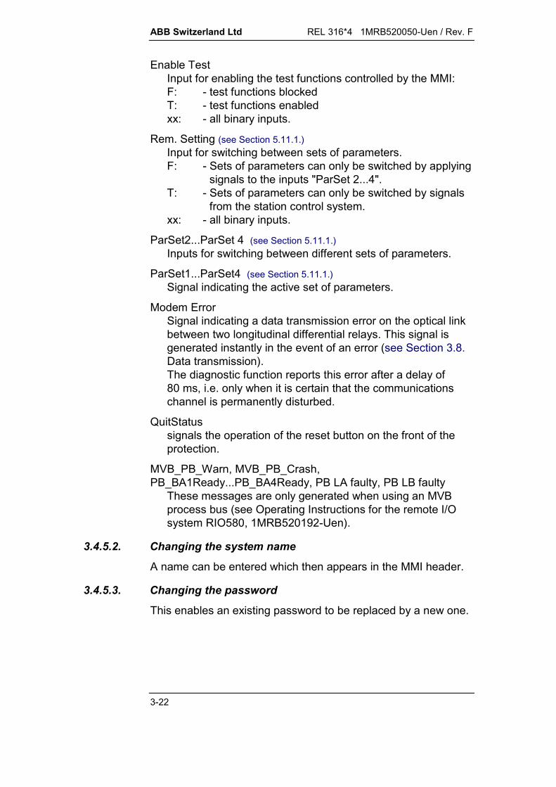
ABB Switzerland Ltd REL 316*4 1MRB520050-Uen / Rev. F
3-22
Enable TestInput for enabling the test functions controlled by the MMI:F: - test functions blockedT: - test functions enabledxx: - all binary inputs.
Rem. Setting (see Section 5.11.1.)Input for switching between sets of parameters.F: - Sets of parameters can only be switched by applying
signals to the inputs "ParSet 2...4".T: - Sets of parameters can only be switched by signals
from the station control system.xx: - all binary inputs.
ParSet2...ParSet 4 (see Section 5.11.1.)Inputs for switching between different sets of parameters.
ParSet1...ParSet4 (see Section 5.11.1.)Signal indicating the active set of parameters.
Modem ErrorSignal indicating a data transmission error on the optical linkbetween two longitudinal differential relays. This signal isgenerated instantly in the event of an error (see Section 3.8.Data transmission).The diagnostic function reports this error after a delay of80 ms, i.e. only when it is certain that the communicationschannel is permanently disturbed.
QuitStatussignals the operation of the reset button on the front of theprotection.
MVB_PB_Warn, MVB_PB_Crash,PB_BA1Ready...PB_BA4Ready, PB LA faulty, PB LB faulty
These messages are only generated when using an MVBprocess bus (see Operating Instructions for the remote I/Osystem RIO580, 1MRB520192-Uen).
3.4.5.2. Changing the system name
A name can be entered which then appears in the MMI header.
3.4.5.3. Changing the password
This enables an existing password to be replaced by a new one.
REL 316*4 1MRB520050-Uen / Rev. F ABB Switzerland Ltd
3-23
3.5. Protection functions
3.5.1. HV distance protection function (HV-Distance)
The HV distance protection is optimised for applications in EHVpower systems. The main difference compared with the standarddistance protection function is improved phase selection toachieve a better response to evolving faults on parallel circuits.
Refer to the standard distance relay function in Section 3.5.2. forthe setting procedure. However, note must be taken of thefollowing differences (the parameters in Section 3.5.2. that donot apply to the HV distance protection or have a differentsignificance are marked):
The HV distance function is only equipped with underimped-ance starters, i.e. the overcurrent starters have been omitted.As a consequence, the parameters “StartMode” and “Istart”,the binary input “ExtUZBlk” and the signals “Start OC” and“Start UZ” do not exist.
The function is only applicable to solidly grounded systems.Also the “PhaseSelMode” parameter has different settings.
In addition to the non-directional starter mode available up tothe present, the “PhaseSelMode” parameter also permits thedirection and reach of the overreach zone to be selected. Thisis only effective, however, for phase selection in the first timestep and has no influence on (non-directional) signals.The “PhaseSelMode” parameter can be set to one of the fol-lowing:non-directional (default)forwards overreach
An earth fault detector with negative phase sequence restraintI2 is now included in addition to the existing restraint using thelargest phase current Imax. The settings “Blocked” and “I0AND U0” are no longer available for the parameter“GndFaultMode”. The settings are therefore (the corre-sponding earth fault criteria are given on the right, IE = 3 I0being referred to as the neutral current):
I0: (IE > “3I0min”) AND (IE > 0.25 Imax)
I0 OR U0: (IE > “3I0min”) AND (IE > 0.25 Imax)OR (UE > “3U0min”)
ABB Switzerland Ltd REL 316*4 1MRB520050-Uen / Rev. F
3-24
I0(I2): (IE > “3I0min”) AND (IE > 0.23 I2)
I0(I2) OR U0: (IE > “3I0min”) AND (IE > 0.23 I2) OR(UE > “3U0min”)
The slope of the measurement characteristic for the first zoneis changed from 7° to 14° if the load current exceeds the set-ting of the new parameter “I Load” and power is flowing fromthe relay location towards the remote end of the line (over-reaching due to the semaphore effect).The setting range for “I Load” is 0...2 IN in steps of 0.01 IN(default setting = 0.5 IN), where:
“I Load” = 0.01...1.99 IN: Characteristic switches as de-scribed above.
“I Load” = 0 IN: Fixed slope of 14°
“I Load” = 2 IN: Fixed slope of 7°
The setting “BlockZ1” in the “Measurement” sub-menu hasbeen dropped and a binary input “ExtBlock Z1” provided in-stead.
In the case of short lines and a large line-to-source imped-ance ratio, a better response for phase-to-phase faults can beobtained by correcting the phase-angles of US and UT.Calibration is performed during commissioning as follows:
Inject the same voltage (0.5 UN) into all three phases inparallel.
Read the phase error of S and T phases (in relation to Rphase) in the “List AD channels”.
Enter the values of the readings for the parameters “SR Error”and “TR Error” in the sub-menu “Analogue inputs”.

REL 316*4 1MRB520050-Uen / Rev. F ABB Switzerland Ltd
3-25
3.5.2. Distance protection (Distance)
A. Application
Distance protection for the high-speed discriminative protectionof long or short overhead lines or cables, double-circuit lines,heavily loaded lines, lines with weak infeeds and what are re-ferred to as “short-zone” lines.The protection is applicable to solidly or low-resistance groundedsystems, systems with Petersen coils or to ungrounded systems.All kinds of faults are detected including close-in three-phasefaults, cross-country faults, evolving faults and high-resistanceearth faults.The protection remains stable in the presence of power swingsand reversal of energy direction. Switching onto an existing faultresults in instantaneous tripping of the circuit-breaker.The distance function can also act as back-up protection for thepower transformer and neighbouring lines. Most of the logicdescribed in this Section (e.g. the transmission of signals) is notused for these applications.
B. Features
overcurrent or underimpedance starters (polygon charac-teristic)
5 distance stages (independently set polygon characteristics) definite time overcurrent back-up protection also applicable
for protecting short zones (teed section in 1½ breakerschemes (see Section 4.2.1.5.4.))
V.t. supervision power-swing blocking tripping logics for:
switch-onto-fault protection overreaching zone permissive underreaching transfer tripping (also for weak
infeed and communications channel failure) permissive overreaching transfer tripping (also for weak
infeed, communications channel failure and reversal ofenergy direction)
blocking scheme (also for reversal of energy direction).

ABB Switzerland Ltd REL 316*4 1MRB520050-Uen / Rev. F
3-26
C. Inputs and outputs
I. C.t./v.t. inputs: three-phase currents three-phase voltages neutral current neutral current of the parallel circuit
II. Binary inputs: reversal of measuring direction distance function blocking underimpedance starter blocking power-swing blocking overcurrent back-up blocking (I O/C) dead line manual CB close zone extension isolator open communication receive communication channel failure single-phase auto-reclosure ready tripping condition blocking for the switch-onto-fault
protection incoming PLC blocking signal first zone blocking
III. Binary outputs: R+S+T starters RST starter R starter S starter T starter E starter I0 starter U0 starter starter Z< starter overcurrent back-up starter (I O/C) switch-onto-fault starter single-phase starter CB trip RST trip R trip S trip T trip

REL 316*4 1MRB520050-Uen / Rev. F ABB Switzerland Ltd
3-27
three-phase trip single-phase trip overcurrent back-up trip (I O/C) switch-onto-fault trip trip with transfer trip signal “short-zone” protection trip time 2nd. step Zone 1 time Zone 2 time Zone 3 time Zone 4 time final zone time measurement overreaching measurement forwards measurement reverse measurement ‘weak infeed’ trip distance protection blocked delayed distance protection blocked power-swing blocking v.t. supervision delayed v.t. supervision communication send PLC boost memory frequency deviation
IV. Measurements: Impedance loop RE Impedance loop SE Impedance loop TE Impedance loop RS Impedance loop ST Impedance loop TR

ABB Switzerland Ltd REL 316*4 1MRB520050-Uen / Rev. F
3-28
D. Distance protection function settings - Distance
Summary of parameters:
Text Units Default Min. Max. Step
GENERALParSet 4..1 P1 (Select)Ref. Length ohms/phase 01.000 0.01 30.000 0.001CT Neutral Busside (Select)EventRecFull all (Select)
C.T./V.T. INPUTSU input CT/VT-Addr 0I input CT/VT-Addr 0I0 input CT/VT-Addr 0I0P input CT/VT-Addr 0
STARTING (see ‘Measurement’ for final zone settings)1) StartMode OC (Select)2) PhaseSelMode solid ground (Select)2) GndFaultMode I0 (Select)1) Istart IN 004.00 0.5 10 0.01
Imin IN 000.20 0.1 2 0.013I0min IN 000.20 0.1 2 0.013U0min UN 000.00 0 2 0.01XA ohms/phase 000.0 0 999 0.1XB ohms/phase 000.0 -999 0 0.1RA ohms/phase 000.0 0 999 0.1RB ohms/phase 000.0 -999 0 0.1RLoad ohms/phase 000.0 0 999 0.1AngleLoad deg 45 0 90 0.1Uweak UN 000.00 0 2 0.01
MEASUREMENTX (1) ohms/phase 000.00 -300 300 0.01R (1) ohms/phase 000.00 -300 300 0.01RR (1) ohms/phase 000.00 -300 300 0.01RRE (1) ohms/phase 000.00 -300 300 0.01k0 (1) 1 001.00 0 8 0.01K0Ang
(1) deg 000.00 -180 90 0.01Delay (1) s 000.000 0 10 0.001
1) Not available on HV distance function.
2) Different settings for the HV distance function.
REL 316*4 1MRB520050-Uen / Rev. F ABB Switzerland Ltd
3-29
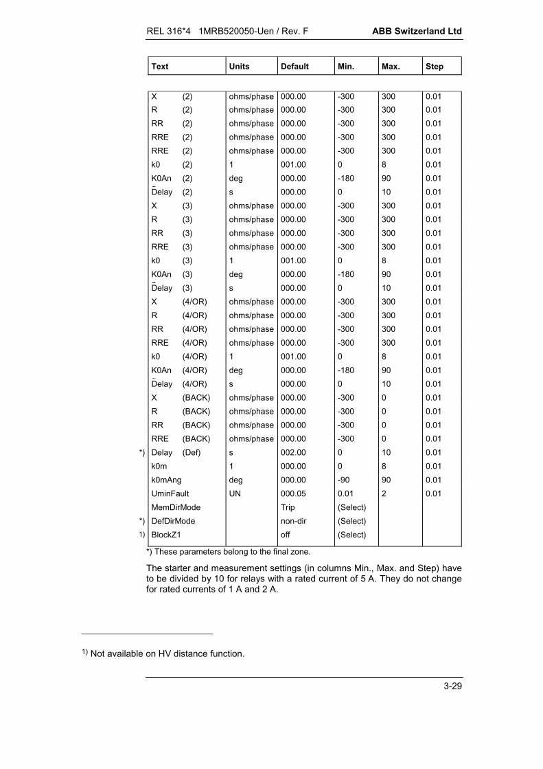
Text Units Default Min. Max. Step
X (2) ohms/phase 000.00 -300 300 0.01R (2) ohms/phase 000.00 -300 300 0.01RR (2) ohms/phase 000.00 -300 300 0.01RRE (2) ohms/phase 000.00 -300 300 0.01RRE (2) ohms/phase 000.00 -300 300 0.01k0 (2) 1 001.00 0 8 0.01K0Ang
(2) deg 000.00 -180 90 0.01Delay (2) s 000.00 0 10 0.01X (3) ohms/phase 000.00 -300 300 0.01R (3) ohms/phase 000.00 -300 300 0.01RR (3) ohms/phase 000.00 -300 300 0.01RRE (3) ohms/phase 000.00 -300 300 0.01k0 (3) 1 001.00 0 8 0.01K0Ang
(3) deg 000.00 -180 90 0.01Delay (3) s 000.00 0 10 0.01X (4/OR) ohms/phase 000.00 -300 300 0.01R (4/OR) ohms/phase 000.00 -300 300 0.01RR (4/OR) ohms/phase 000.00 -300 300 0.01RRE (4/OR) ohms/phase 000.00 -300 300 0.01k0 (4/OR) 1 001.00 0 8 0.01K0Ang
(4/OR) deg 000.00 -180 90 0.01Delay (4/OR) s 000.00 0 10 0.01X (BACK) ohms/phase 000.00 -300 0 0.01R (BACK) ohms/phase 000.00 -300 0 0.01RR (BACK) ohms/phase 000.00 -300 0 0.01RRE (BACK) ohms/phase 000.00 -300 0 0.01
*) Delay (Def) s 002.00 0 10 0.01k0m 1 000.00 0 8 0.01k0mAng deg 000.00 -90 90 0.01UminFault UN 000.05 0.01 2 0.01MemDirMode Trip (Select)
*) DefDirMode non-dir (Select)1) BlockZ1 off (Select)
*) These parameters belong to the final zone.
The starter and measurement settings (in columns Min., Max. and Step) haveto be divided by 10 for relays with a rated current of 5 A. They do not changefor rated currents of 1 A and 2 A.
1) Not available on HV distance function.

ABB Switzerland Ltd REL 316*4 1MRB520050-Uen / Rev. F
3-30
Text Units Default Min. Max. Step
O/C BACK-UP PROTECTIONI O/C IN 000.00 0 10 0.01Delay O/C s 005.00 0 10 0.1
V.T. SUPERVISIONVTSupMode off (Select)VTSupBlkDel off (Select)VTSupDebDel off (Select)U0min VTSup UN 000.20 0.01 0.5 0.01I0min VTSup IN 000.07 0.01 0.5 0.01U2min VTSup UN 000.20 0.01 0.5 0.01I2min VTSup IN 000.07 0.01 0.5 0.01
TRIP SCHEMESComMode off (Select)TripMode 1Ph trip (Select)SOTFMode off (Select)SOTF10sec off (Select)Weak off (Select)Unblock off (Select)Echo off (Select)TransBl off (Select)t1Block s 000.04 0 0.25 0.01t1TransBl s 000.05 0 0.25 0.01t2TransBl s 003.00 0 10 0.01t1EvolFaults s 003.00 0 10 0.01
POWER SWING BLOCKINGtPSblock s 000.00 0 10 0.01
BINARY INPUTSChgMeasDir BinaryAddr FExt Blk Dist BinaryAddr F
1) ExtUZBlk BinaryAddr FExt Blk PSB BinaryAddr TExt Blk O/C BinaryAddr FDeadLine BinaryAddr FManual Close BinaryAddr FZExtension BinaryAddr FIsol open BinaryAddr FCom Rec BinaryAddr F
1) Not available on HV distance function.
REL 316*4 1MRB520050-Uen / Rev. F ABB Switzerland Ltd
3-31
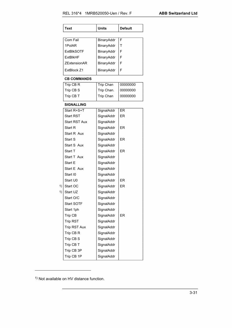
Text Units Default
Com Fail BinaryAddr F1PolAR BinaryAddr TExtBlkSOTF BinaryAddr FExtBlkHF BinaryAddr FZExtensionAR BinaryAddr F
ExtBlock Z1 BinaryAddr F
CB COMMANDSTrip CB R Trip Chan 00000000Trip CB S Trip Chan. 00000000Trip CB T Trip Chan 00000000
SIGNALLINGStart R+S+T SignalAddr ERStart RST SignalAddr ERStart RST Aux SignalAddrStart R SignalAddr ERStart R Aux SignalAddrStart S SignalAddr ERStart S Aux SignalAddrStart T SignalAddr ERStart T Aux SignalAddrStart E SignalAddrStart E Aux SignalAddrStart I0 SignalAddrStart U0 SignalAddr ER
1) Start OC SignalAddr ER1) Start UZ SignalAddr
Start O/C SignalAddrStart SOTF SignalAddrStart 1ph SignalAddrTrip CB SignalAddr ERTrip RST SignalAddrTrip RST Aux SignalAddrTrip CB R SignalAddrTrip CB S SignalAddrTrip CB T SignalAddrTrip CB 3P SignalAddrTrip CB 1P SignalAddr
1) Not available on HV distance function.
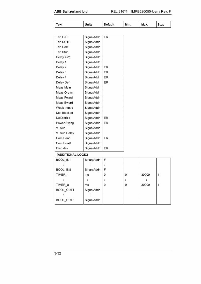
ABB Switzerland Ltd REL 316*4 1MRB520050-Uen / Rev. F
3-32
Text Units Default Min. Max. Step
Trip O/C SignalAddr ERTrip SOTF SignalAddrTrip Com SignalAddrTrip Stub SignalAddrDelay >=2 SignalAddrDelay 1 SignalAddrDelay 2 SignalAddr ERDelay 3 SignalAddr ERDelay 4 SignalAddr ERDelay Def SignalAddr ERMeas Main SignalAddrMeas Oreach SignalAddrMeas Fward SignalAddrMeas Bward SignalAddrWeak Infeed SignalAddrDist Blocked SignalAddrDelDistBlk SignalAddr ERPower Swing SignalAddr ERVTSup SignalAddrVTSup Delay SignalAddrCom Send SignalAddr ERCom Boost SignalAddrFreq dev SignalAddr ER
(ADDITIONAL LOGIC)BOOL_IN1 BinaryAddr F
: : :BOOL_IN8 BinaryAddr FTIMER_1 ms 0 0 30000 1
: : : : : :TIMER_8 ms 0 0 30000 1BOOL_OUT1 SignalAddr
: :BOOL_OUT8 SignalAddr

REL 316*4 1MRB520050-Uen / Rev. F ABB Switzerland Ltd
3-33
Explanation of parameters:
GENERAL
ParSet 4..1Parameter for determining in which set of parameters a par-ticular function is active (see Section 5.11.).
Ref. Length (see Section 3.5.2.1.)Reactance (secondary value) to be used as reference lengthof the line.
CT neutral (see Section 3.5.2.1.)Side of the c.t's on which the star-point is formed (current di-rection):
busbar side (old BBC diagram)line side (standard today)
This parameter only influences the distance function andonly the display of the system variables. It does not influencethe values of the A/D channels.
EventRecFull (see Page 3-48)Determination of whether all the distance function events inthe event list which have been reset should be displayed:
allsome
C.T./V.T. INPUTS (see wiring diagram in the Appendix)
U inputindicates the first of the v.t. inputs assigned to the threephase voltages.
I inputindicates the first of the c.t. inputs assigned to the threephase currents.
I0 inputindicates the c.t. input assigned to the neutral current (if fittedand activated). This is used for the external acquisition of theneutral current of the line. If the I0 input is not used, theneutral current is derived from the phase currents.
I0P inputindicates the c.t. input assigned to the neutral current of theparallel circuit (if fitted and activated). This is used for theneutral current of the parallel circuit of a double-circuit line.

ABB Switzerland Ltd REL 316*4 1MRB520050-Uen / Rev. F
3-34
Note:
The c.t. input (I0P) should be wired in the same sense as theneutral current input (I0) (e.g. terminals 9 and 10 correspondto terminals 7 and 8 respectively).
STARTING (see Section 3.5.2.2. and 4.2.1.1.)
StartMode 1)
Definition of the starters used:OC - overcurrentUZ - underimpedance.
PhaseSelMode 2)
Phase preference for cross-country faults in systems withPetersen coils and ungrounded systems:
solidly grounded (no phase preference)RTS(R) cyclicTRS(T) cyclicRTS acyclicRST acyclicTSR acyclicTRS acyclicSRT acyclicSTR acyclic.
GndFaultMode 2)
Method of detecting ground faults:I0I0 OR U0I0 AND U0.Blocked (only phase-to-phase loop measured, e.g. with
only two c.t's and V connected v.t's)
Istart 1)
Pick-up value of the overcurrent starters.
IminCurrent level for enabling the protection.
3I0minCurrent level of the neutral current (3I0) for enabling theprotection (ground fault detector).
1) Not available on HV distance function.
2) Different settings for the HV distance function.

REL 316*4 1MRB520050-Uen / Rev. F ABB Switzerland Ltd
3-35
3U0minVoltage level of the neutral voltage (3U0) at which the E/Fmeasurement is enabled (ground fault detector).
XAReactive reach of the impedance characteristic in the trippingdirection.
XBReactive reach of the impedance characteristic in the re-straint direction.
RAResistive reach of the impedance characteristic in the trippingdirection.
RBResistive reach of the impedance characteristic in the re-straint direction.
RLoadResistive reach for avoiding load encroachment.
AngleLoadLimit phase-angle for avoiding load encroachment.
Uweak(Phase) Voltage pick-up value for determining the “weak in-feed” or “dead line” conditions for enabling manuallyenergisation of the line. A setting of zero disables thefunction.
MEASUREMENT (see Section 3.5.2.3. and 4.2.1.2.)
X (n)Pick-up line reactance for Zone (n):
X < 0 for the restraint directionX = 0 disables the zone (Zone 1 cannot be disabled).
R (n)Pick-up line resistance for Zone (n); the sign must be thesame as for X (n).
RR (n)Resistive reach (incl. arc resistance) of Zone (n) for phasefaults; the sign must be the same as for X (n).
RRE (n)Resistive reach (incl. arc resistance) of Zone (n) for E/F's; thesign must be the same as for X (n).
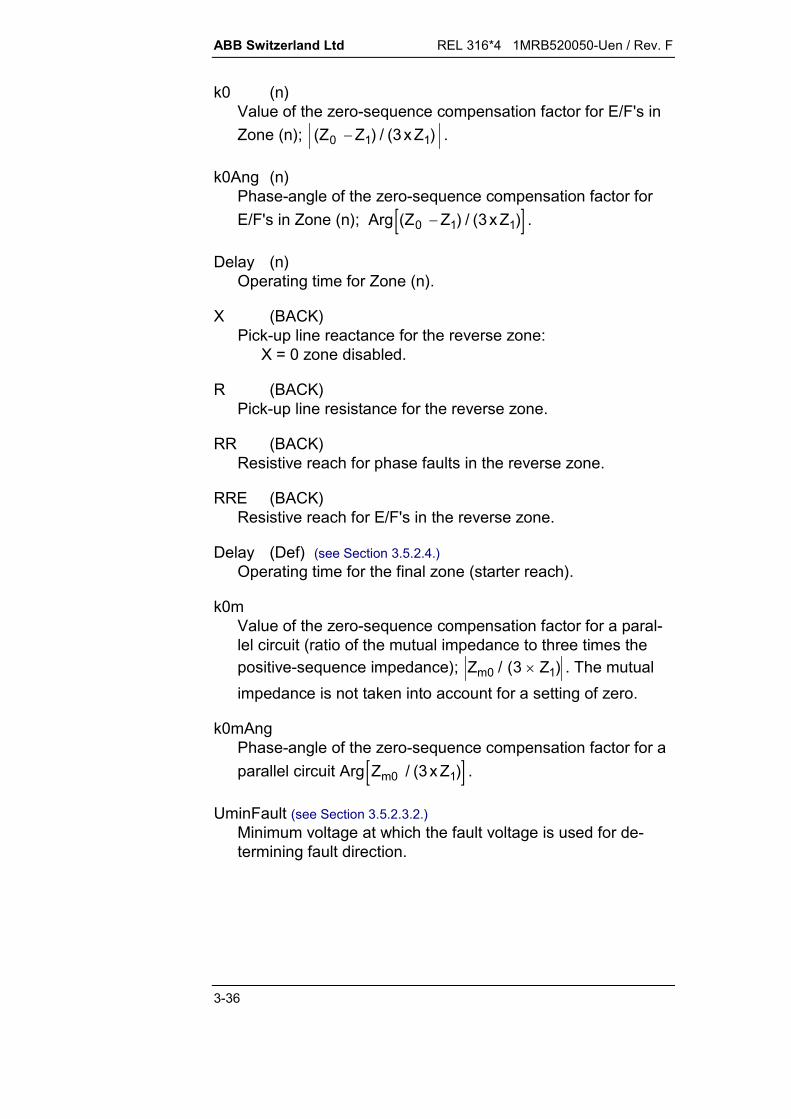
ABB Switzerland Ltd REL 316*4 1MRB520050-Uen / Rev. F
3-36
k0 (n)Value of the zero-sequence compensation factor for E/F's inZone (n); ( ) / ( )Z Z x Z0 1 13 .
k0Ang (n)Phase-angle of the zero-sequence compensation factor forE/F's in Zone (n); Arg ( ) / ( )Z Z x Z0 1 13 .
Delay (n)Operating time for Zone (n).
X (BACK)Pick-up line reactance for the reverse zone:
X = 0 zone disabled.
R (BACK)Pick-up line resistance for the reverse zone.
RR (BACK)Resistive reach for phase faults in the reverse zone.
RRE (BACK)Resistive reach for E/F's in the reverse zone.
Delay (Def) (see Section 3.5.2.4.)Operating time for the final zone (starter reach).
k0mValue of the zero-sequence compensation factor for a paral-lel circuit (ratio of the mutual impedance to three times thepositive-sequence impedance); )Z3(/Z 10m . The mutualimpedance is not taken into account for a setting of zero.
k0mAngPhase-angle of the zero-sequence compensation factor for aparallel circuit Arg Z x Zm0 13/ ( ) .
UminFault (see Section 3.5.2.3.2.)Minimum voltage at which the fault voltage is used for de-termining fault direction.
REL 316*4 1MRB520050-Uen / Rev. F ABB Switzerland Ltd
3-37
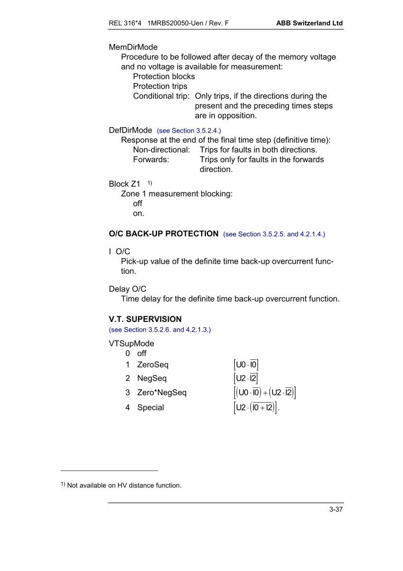
MemDirModeProcedure to be followed after decay of the memory voltageand no voltage is available for measurement:
Protection blocksProtection tripsConditional trip: Only trips, if the directions during the
present and the preceding times stepsare in opposition.
DefDirMode (see Section 3.5.2.4.)Response at the end of the final time step (definitive time):
Non-directional: Trips for faults in both directions.Forwards: Trips only for faults in the forwards
direction.
Block Z1 1)
Zone 1 measurement blocking:offon.
O/C BACK-UP PROTECTION (see Section 3.5.2.5. and 4.2.1.4.)
I O/CPick-up value of the definite time back-up overcurrent func-tion.
Delay O/CTime delay for the definite time back-up overcurrent function.
V.T. SUPERVISION(see Section 3.5.2.6. and 4.2.1.3.)
VTSupMode0 off1 ZeroSeq U I0 02 NegSeq U I2 2
3 Zero*NegSeq U I U I0 0 2 2
4 Special U I I2 0 2 .
1) Not available on HV distance function.
ABB Switzerland Ltd REL 316*4 1MRB520050-Uen / Rev. F
3-38
VTSupBlkDelDelayed blocking of the distance function (12 s) for operationof the v.t. supervision.
off - immediate blockingon - delayed blocking.
VTSupDebDelDelay (1 s) for resetting blocking by the v.t. supervision.
off - immediate reseton - delayed reset.
U0min VTSupPick-up setting of the neutral voltage (U0) for v.t. supervisionreferred to the rated v.t. voltage 100/ 3 or 200/ 3 .
I0min VTSupPick-up setting of the neutral current (I0) for v.t. supervision.
U2min VTSupPick-up setting of the negative sequence voltage (U2) for v.t.supervision referred to the rated v.t. voltage 100/ 3 or200/ 3 .
I2min VTSupPick-up setting of the NPS current (I2) for v.t. supervision.
TRIP SCHEMES (see Section 3.5.2.7. and 4.2.1.5.)
ComModeType of transfer tripping scheme:
offPUTT NONDIRPUTT FWDPUTT OR2POTTBLOCK OR.
TripModeType of tripping (single or three-phase):
1PhTrip - single-phase tripping (for single-phaseauto-reclosure)
3PhTrip - three-phase tripping in all cases
3PhTripDel3 - single-phase tripping (for single-phaseauto-reclosure) up to the end of ‘Delay(3)’ then three-phase tripping.
REL 316*4 1MRB520050-Uen / Rev. F ABB Switzerland Ltd
3-39
SOTFModeOperating mode of the switch-onto-fault function:
offnon-dir. non-directional underimpedance starting
(recommended setting)forward UR2 directional with overreaching (Zone 2, if
overreaching disabled) and non-directionalafter decay of any memory voltage.
SOTF10secEnables the 10 s delay for the switch-onto-fault function:
off (t = 200 ms)on (t = 10 s).
WeakEnables ‘Weak infeed’ logic for the PUTT or POTT transfertripping modes (Uweak must also be set):
offon.
UnblockDeblocking logic enable:
offon (only suitable for PLC).
Echo'Echo’ logic enable for the POTT transfer tripping mode:
offon.
TransBlEnables ‘Transient blocking’ logic (stabilisation for reversal ofpower direction on double-circuit lines) for the POTT andBLOCK OR (overreaching blocking scheme) transfer trippingmodes:
offon.
t1BlockTime allowed for receiving a blocking signal in the BLOCKOR (overreaching blocking scheme) mode.

ABB Switzerland Ltd REL 316*4 1MRB520050-Uen / Rev. F
3-40
t1TransBlTime 1 for the TRANSBL (transient blocking) mode. Delay forfaults after a fault was detected in the reverse direction.
t2TransBlTime 2 for the TRANSBL (transient blocking) mode. The logicremains enabled for the time t2 after a fault was detected inthe reverse direction.
t1EvolFaultsTime for discriminating evolving faults (three-phase trip forevolving faults during this time setting).
POWER-SWING BLOCKING (see Section 3.5.2.8. and 4.2.1.6.)
tPSblockMaximum time during which the power-swing blockingfunction is effective. The function is disabled when set tozero.
BINARY INPUTS (see Section 3.5.2.10.)
ChgMeasDirInput for changing the direction of measurement.
Ext Blk DistInput for blocking the distance protection function:
F: - not blockedxx: - all binary I/P’s (or O/P’s of protection functions).
Ext UZ Blk 1)
Input for blocking the underimpedance starters:F: - underimpedance starters enabledT: - underimpedance starters disabledxx: - all binary I/P’s (or O/P’s of protection functions).
Ext Blk PSBExternal disable for the power-swing blocking function:
F: - power-switch blocking enabledT: - power-switch blocking disabledxx: - all binary I/P’s (or O/P’s of protection functions).
1) Not available on HV distance function.

REL 316*4 1MRB520050-Uen / Rev. F ABB Switzerland Ltd
3-41
Ext Blk O/CExternal disable of the back-up overcurrent function
F: - enabledT: - disabledxx: - all binary I/P’s (or O/P’s of protection functions).
DeadLineLine de-energised signal (auxiliary contact on the circuit-breaker when the v.t's are on the busbar):
F: - input not usedxx: - all binary I/P’s (or O/P’s of protection functions).
Manual closeCircuit-breaker manual close signal:
F: - input not usedxx: - all binary I/P’s (or O/P’s of protection functions).
ZExtensionExternal zone extension control signal:
F: - external zone extension disabledxx: - all binary I/P’s (or O/P’s of protection functions).
Isol OpenIsolator open signal for activating the ‘short-zone’ logic andprotection (T section in 1½ breaker schemes):
F: - disabledxx: - all binary I/P’s (or O/P’s of protection functions).
Com RecInput for PLC signal from the remote station:
F: - input not usedxx: - all binary I/P’s (or O/P’s of protection functions).
Com FailInput for PLC failure signal:
F: - input not usedxx: - all binary I/P’s (or O/P’s of protection functions).
ABB Switzerland Ltd REL 316*4 1MRB520050-Uen / Rev. F
3-42
1PolARSingle-phase trip enable (used in conjunction with the auto-reclosure function):
F: - three-phase trip onlyT: - single and three-phase trip (depending on type of
fault)xx: - all binary I/P’s (or O/P’s of protection functions).
ExtBlkSOTFInput for blocking the tripping condition for the switch-onto-fault logic:
F: - enabledT: - disabledxx: - all binary I/P’s (or O/P’s of protection functions).
Note: The input does not disable the switch-onto-faultstarting signal.
ExtBlkHFInput for blocking a received PLC signal (controlled, forexample, by a sensitive E/F scheme using the same PLCchannel):
F: - input not usedxx: - all binary I/P’s (or O/P’s of protection functions).
ZExtensionARInput for enabling the overreaching zone by the auto-reclosure function:
F: - zone extension by the auto-reclosure functiondisabled
xx: - all binary I/P’s (or O/P’s of protection functions).
ExtBlock Z1Input for blocking measurement in the first zone:
F: - enabledT: - disabledxx: - all binary I/P’s (or O/P’s of protection functions).
REL 316*4 1MRB520050-Uen / Rev. F ABB Switzerland Ltd
3-43
CB COMMANDS
Trip CB RTripping logic for the R phase pole of the circuit-breaker. Thissignal is not generated while a blocking signal is beingapplied with the exception of a trip by the back-upovercurrent protection.
Trip CB STripping relay for the S phase pole of the circuit-breaker. Thissignal is not generated while a blocking signal is beingapplied with the exception of a trip by the back-upovercurrent protection.
Trip CB TTripping relay for the T phase pole of the circuit-breaker. Thissignal is not generated while a blocking signal is beingapplied with the exception of a trip by the back-upovercurrent protection.
SIGNALLING
Start R+S+TGeneral distance protection starting signal (OR logic for allstarting signals excluding ‘weak infeed').
Start RST (StartRSTAux)General distance protection starting signal (OR logic for allstarting signals including ‘weak infeed').
Start R (Start R Aux)Distance protection R phase starting signal (including ‘weakinfeed').
Start S (Start S Aux)Distance protection S phase starting signal (including ‘weakinfeed').
Start T (Start T Aux)Distance protection T phase starting signal (including ‘weakinfeed').
Start E (Start E Aux)Distance protection E/F starting signal (U0 or I0). Only gen-erated together with a phase starter.
Start I0Neutral current starting signal (I0).
Start U0Neutral voltage starting signal (U0).

ABB Switzerland Ltd REL 316*4 1MRB520050-Uen / Rev. F
3-44
Start OC 1)
Overcurrent starting signal.
Start UZ 1)
Underimpedance starting signal.
Start O/CBack-up overcurrent pick-up signal.
Start SOTFEnabling signal for the switch-onto-fault protection.
Start 1phIndicates that the distance protection was started by a singlephase.
Trip CBGeneral circuit-breaker tripping signal. This signal is disabledwhile a blocking signal is being applied with the exception ofa trip by the back-up overcurrent protection.
Trip RST (trip RST Aux)General tripping signal. This signal is not disabled while ablocking signal is being applied.
Trip CB RCircuit-breaker R phase trip signal.This signal is disabled while a blocking signal is being appliedwith the exception of a trip by the back-up overcurrentprotection.
Trip CB SCircuit-breaker S phase trip signal.This signal is disabled while a blocking signal is being appliedwith the exception of a trip by the back-up overcurrentprotection.
Trip CB TCircuit-breaker T phase trip signal.This signal is disabled while a blocking signal is being appliedwith the exception of a trip by the back-up overcurrentprotection.
1) Not available on HV distance function.
REL 316*4 1MRB520050-Uen / Rev. F ABB Switzerland Ltd
3-45
Trip CB 3PThree-phase trip signal. This signal is disabled while ablocking signal is being applied with the exception of a trip bythe back-up overcurrent protection.
Trip CB 1PSingle-phase trip signal. This signal is disabled while ablocking signal is being applied with the exception of a trip bythe back-up overcurrent protection.
Trip O/CBack-up overcurrent trip signal.
Trip SOTFSwitch-onto-fault trip signal.
Trip ComSignal for tripping either enabled by the receipt of a permis-sive signal or the non-receipt of a blocking signal. (This signalis disabled while a blocking signal is being applied.)
Trip Stub'Short-zone’ protection trip signal.
Delay >= 2Signal for starting in Zone 2 or higher.
Delay 1Signal for starting in Zone 1.
Delay 2Signal for starting in Zone 2.
Delay 3Signal for starting in Zone 3.
Delay 4Signal for starting in Zone 4 (excepting when Zone 4 is beingused as an overreaching zone).
Delay DefSignal for starting in the final zone.
Meas MainMeasurement by the distance function (Zones 1, 2, 3, 4 orthe final zone).
Meas OreachMeasurement in the distance protection overreach zone.

ABB Switzerland Ltd REL 316*4 1MRB520050-Uen / Rev. F
3-46
Meas FwardMeasurement by the distance protection in the forwards di-rection.
Meas BwardMeasurement by the distance protection in the reverse direc-tion (reverse zone).
Weak InfeedTripping by the ‘weak infeed’ function.
Dist BlockedSignal indicating that the distance protection is blocked.
DelDistBlkSignal delayed by 12 s indicating that the distance protectionis blocked.
Power SwingPower-swing blocking function picked up.
VTSupV.t. supervision picked up.
VTSup DelayDelayed operation of the v.t. supervision after 12 s.
Com SendSignal generated when a transfer trip signal is transmitted.
Com BoostSignal for boosting PLC transmitting power.
Freq devSignal indicating a deviation of the memory voltage fre-quency.
(ADDITIONAL LOGIC)The following settings are only of consequence when a speciallogic is loaded instead of the standard distance protection logic.Refer to the description of the corresponding logic for theirsignificance.BOOL_IN1, BOOL_IN2...BOOL_IN8
Additional binary inputs for the special distance protectionlogic.
TIMER_1, TIMER_2...TIMER_8Additional timer settings for the special distance protectionlogic.
BOOL_OUT1, BOOL_OUT2...BOOL_OUT8Additional signals for the special distance protection logic.

REL 316*4 1MRB520050-Uen / Rev. F ABB Switzerland Ltd
3-47
PROJECT SUBDIR
The user can determine in which subdirectory the distanceprotection logic is located. The default name “DISTSTD” applieswhen the standard distance protection logic located in the MMIdirectory is used.The input of a directory is only necessary when a special logic isused instead of the standard one. The procedure in this case isto be found in the description of the logic.
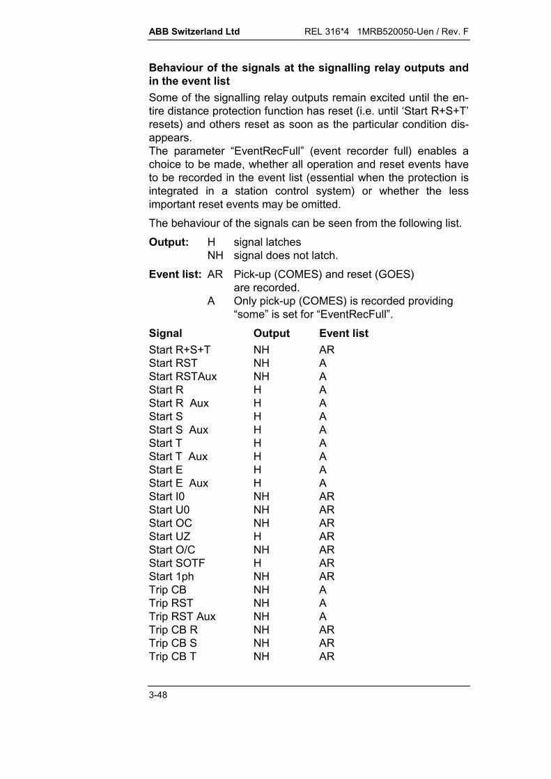
ABB Switzerland Ltd REL 316*4 1MRB520050-Uen / Rev. F
3-48
Behaviour of the signals at the signalling relay outputs andin the event listSome of the signalling relay outputs remain excited until the en-tire distance protection function has reset (i.e. until ‘Start R+S+T’resets) and others reset as soon as the particular condition dis-appears.The parameter “EventRecFull” (event recorder full) enables achoice to be made, whether all operation and reset events haveto be recorded in the event list (essential when the protection isintegrated in a station control system) or whether the lessimportant reset events may be omitted.The behaviour of the signals can be seen from the following list.Output: H signal latches
NH signal does not latch.Event list: AR Pick-up (COMES) and reset (GOES)
are recorded.A Only pick-up (COMES) is recorded providing
“some” is set for “EventRecFull”.
Signal Output Event listStart R+S+T NH ARStart RST NH AStart RSTAux NH AStart R H AStart R Aux H AStart S H AStart S Aux H AStart T H AStart T Aux H AStart E H AStart E Aux H AStart I0 NH ARStart U0 NH ARStart OC NH ARStart UZ H ARStart O/C NH ARStart SOTF H ARStart 1ph NH ARTrip CB NH ATrip RST NH ATrip RST Aux NH ATrip CB R NH ARTrip CB S NH ARTrip CB T NH AR

REL 316*4 1MRB520050-Uen / Rev. F ABB Switzerland Ltd
3-49
Trip CB 3P NH ATrip CB 1P NH ATrip O/C NH ARTrip SOTF NH ATrip Com NH ATrip Stub NH ADelay >= 2 NH ADelay 1 NH ADelay 2 NH ADelay 3 NH ADelay 4 NH ADelay Def NH AMeas Main H AMeas Oreach H ARMeas Fward H ARMeas Bward NH ARWeak Infeed NH ARDist Blocked NH ARDelDistBlk NH ARPower Swing NH ARVTSup NH ARVTSup delay NH ARCom Send NH ARCom Boost NH AFreq dev NH AR

ABB Switzerland Ltd REL 316*4 1MRB520050-Uen / Rev. F
3-50
E. Setting instructions
3.5.2.1. General
The first parameter in the sub-menu ‘General’ is ‘Ref length’which is needed to indicate the distance to a fault in the event ofa trip, but otherwise bears no influence in the protection function.The parameter gives the reactance of the reference length (insecondary /ph per unit length) and may be defined in km,miles, percent line length etc., i.e.
distanceX
ref. lengthmeas.
e.g.:
a) In km
Secondary reactance per km 0.2 /phRef. length = 0.2 /ph
b) In percent line length
Secondary reactance of the line length 25 /ph(1% 0.25 /ph)
Ref. length = 0.25 /ph
The setting of the parameter ‘CT neutral’ depends onwhether the star-point of the main c.t's is on the line side orthe busbar side. There are thus two possible settings ‘Busside’ or ‘Line side’. The ‘Line side’ option is the one tochoose, providing the protection is connected according tothe wiring diagram in the appendix. This setting only appliesto the distance protection function. It does not influence thepower direction in all the other functions or the displays ofthe A/D channels.
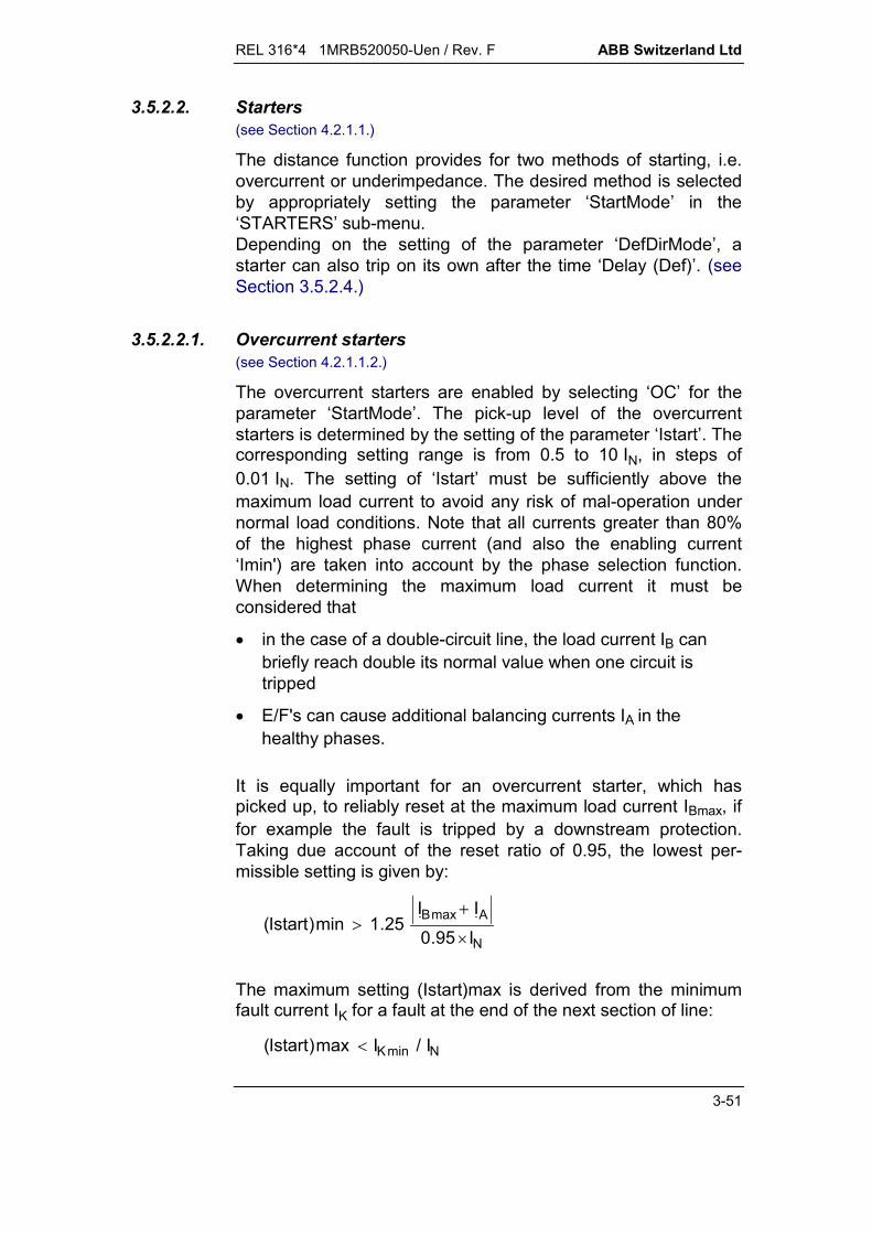
REL 316*4 1MRB520050-Uen / Rev. F ABB Switzerland Ltd
3-51
3.5.2.2. Starters(see Section 4.2.1.1.)
The distance function provides for two methods of starting, i.e.overcurrent or underimpedance. The desired method is selectedby appropriately setting the parameter ‘StartMode’ in the‘STARTERS’ sub-menu.Depending on the setting of the parameter ‘DefDirMode’, astarter can also trip on its own after the time ‘Delay (Def)’. (seeSection 3.5.2.4.)
3.5.2.2.1. Overcurrent starters(see Section 4.2.1.1.2.)
The overcurrent starters are enabled by selecting ‘OC’ for theparameter ‘StartMode’. The pick-up level of the overcurrentstarters is determined by the setting of the parameter ‘Istart’. Thecorresponding setting range is from 0.5 to 10 IN, in steps of0.01 IN. The setting of ‘Istart’ must be sufficiently above themaximum load current to avoid any risk of mal-operation undernormal load conditions. Note that all currents greater than 80%of the highest phase current (and also the enabling current‘Imin') are taken into account by the phase selection function.When determining the maximum load current it must beconsidered that
in the case of a double-circuit line, the load current IB canbriefly reach double its normal value when one circuit istripped
E/F's can cause additional balancing currents IA in thehealthy phases.
It is equally important for an overcurrent starter, which haspicked up, to reliably reset at the maximum load current IBmax, iffor example the fault is tripped by a downstream protection.Taking due account of the reset ratio of 0.95, the lowest per-missible setting is given by:
N
AmaxB
I95.0II
25.1min)Istart(
The maximum setting (Istart)max is derived from the minimumfault current IK for a fault at the end of the next section of line:
NminK I/Imax)Istart(

ABB Switzerland Ltd REL 316*4 1MRB520050-Uen / Rev. F
3-52
Should the above relationships result in (Istart)max being lowerthan (Istart)min, the underimpedance starters must be usedinstead.
3.5.2.2.2. Underimpedance starters(see Section 4.2.1.1.3.)
The underimpedance starters are enabled by selecting ‘UZ’ asthe ‘StartMode’ parameter. The following parameters then haveto be set:
XAXBRARBRLoadAngleLoad.
The characteristic of the underimpedance starters and the cor-responding setting parameters can be seen from Fig. 3.5.2.1.The parameters ‘RLoad’ and ‘AngleLoad’ define the permissibleload area.
X
R
CHARACTERISTICUNDERIMPEDANCE
XA
RB -RLoad RLoad RAAngleLoad
XB HEST 935 049 C
Fig. 3.5.2.1 Underimpedance starting characteristic
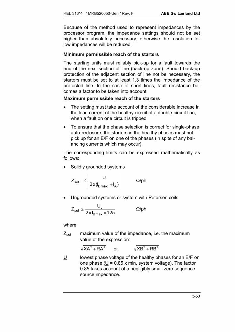
REL 316*4 1MRB520050-Uen / Rev. F ABB Switzerland Ltd
3-53
Because of the method used to represent impedances by theprocessor program, the impedance settings should not be sethigher than absolutely necessary, otherwise the resolution forlow impedances will be reduced.
Minimum permissible reach of the starters
The starting units must reliably pick-up for a fault towards theend of the next section of line (back-up zone). Should back-upprotection of the adjacent section of line not be necessary, thestarters must be set to at least 1.3 times the impedance of theprotected line. In the case of short lines, fault resistance be-comes a factor to be taken into account.Maximum permissible reach of the starters
The setting must take account of the considerable increase inthe load current of the healthy circuit of a double-circuit line,when a fault on one circuit is tripped.
To ensure that the phase selection is correct for single-phaseauto-reclosure, the starters in the healthy phases must notpick up for an E/F on one of the phases (in spite of any bal-ancing currents which may occur).
The corresponding limits can be expressed mathematically asfollows:
Solidly grounded systems
Z Ux I Iset
B A
2 ( )max/ph
Ungrounded systems or system with Petersen coils
25.1I2UZ
maxB
vset
/ph
where:
Zset maximum value of the impedance, i.e. the maximumvalue of the expression:
XA RA2 2 or XB RB2 2
U lowest phase voltage of the healthy phases for an E/F onone phase (U = 0.85 x min. system voltage). The factor0.85 takes account of a negligibly small zero sequencesource impedance.
ABB Switzerland Ltd REL 316*4 1MRB520050-Uen / Rev. F
3-54
Uv lowest phase-to-phase system voltage
1.25 safety factor
2 factor which takes account of the fact that phase cur-rents and not phase-to-phase currents are used.
These requirements are generally fulfilled without difficulty formost applications. Should, however, the first inequality not besatisfied, the right-hand side must be expressed vectorially andcompared with the underimpedance starting characteristic inrelation to the setting ‘RLoad’ etc.The healthy phases must be checked for the case of a single-phase-to-ground fault.
3.5.2.2.3. Current enableBefore a phase can take part in phase selection, it must be con-ducting a current higher than ‘Imin’. The recommended setting is0.2 IN.
3.5.2.2.4. E/F detectorThere are three alternative operating modes for the E/F detector,the desired one being chosen by the setting of the parameter‘GndFaultMode’. E/F detection can be based on measurement ofthe neutral current alone or in combination with the neutralvoltage. The fourth possibility is not to measure the ground loopat all, i.e. only the phase-to-phase loop is measured. Thefollowing alternatives are available for selection:
blocked (only measures the phase-to-phase loops)I0I0 AND U0I0 OR U0.
The criterion for the highest ‘3I0min’ setting is:
the E/F detector must pick-up for all E/F's in solidly groundedsystems and for all cross-country faults on ungrounded sys-tems or systems with Petersen coils, providing they lie withinthe reach of the underimpedance starters.

REL 316*4 1MRB520050-Uen / Rev. F ABB Switzerland Ltd
3-55
The criteria for the lowest ‘3I0min’ setting are:
the E/F detector must not pick up for an E/F on ungroundedsystems or systems with Petersen coils,
the E/F detector must not pick up for phase faults, althoughc.t. errors can cause false neutral currents.
The recommended setting is ‘3I0min’ = 0.5 IN.
Should it not be possible to find a setting, which satisfies boththese conditions, the neutral voltage (3U0min) must be used formeasurement in addition to the neutral current.
3.5.2.2.5. Phase preference logic(see Section 4.2.1.1.4.)
The desired phase preference logic for cross-country faults ischosen with the aid of the parameter ‘PhaseSelMode’.
In solidly grounded systems, the ‘PhaseSelMode’ parameter isdisabled by setting it to ‘solid ground’.
It is essential for all the relays in ungrounded systems and sys-tems with Petersen coils to be set to the same phase preferencelogic. The logic in use in a system must therefore be known be-fore one of the 8 alternative schemes can be selected:
RTS(R) cyclicTRS(T) cyclicRTS acyclicRST acyclicTSR acyclicTRS acyclicSRT acyclicSTR acyclic.
3.5.2.2.6. Undervoltage starters(Uweak)
The undervoltage starters are used in conjunction with theswitch-onto-fault function and the transfer tripping schemesPOTT and PUTT NONDIR (see Section 3.5.2.7.). The corre-sponding pick-up value is set in relation to the rated voltage withthe aid of the parameter ‘Uweak’, which has a setting range of 0to 2 UN in steps of 0.01.
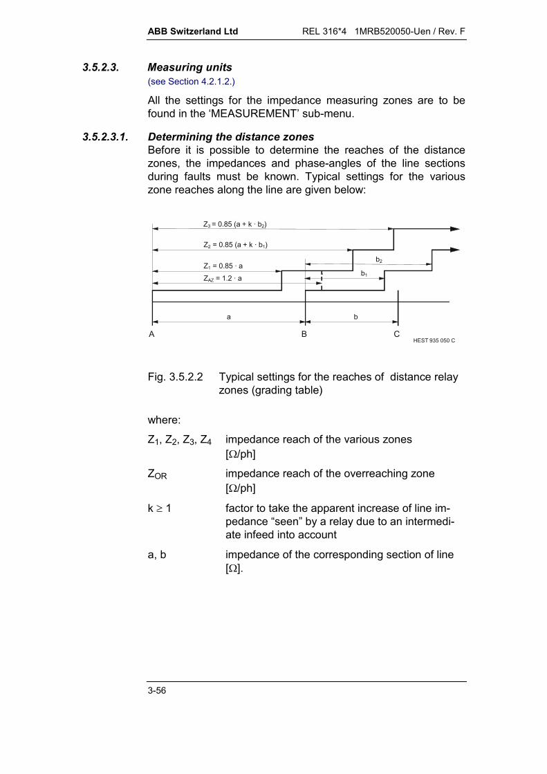
ABB Switzerland Ltd REL 316*4 1MRB520050-Uen / Rev. F
3-56
3.5.2.3. Measuring units(see Section 4.2.1.2.)
All the settings for the impedance measuring zones are to befound in the ‘MEASUREMENT’ sub-menu.
3.5.2.3.1. Determining the distance zonesBefore it is possible to determine the reaches of the distancezones, the impedances and phase-angles of the line sectionsduring faults must be known. Typical settings for the variouszone reaches along the line are given below:
A B C
a b
Z3 = 0.85 (a + k · b2)
b1
b2
Z2 = 0.85 (a + k · b1)
Z1 = 0.85 · aZAZ = 1.2 · a
HEST 935 050 C
Fig. 3.5.2.2 Typical settings for the reaches of distance relayzones (grading table)
where:
Z1, Z2, Z3, Z4 impedance reach of the various zones[/ph]
ZOR impedance reach of the overreaching zone[/ph]
k 1 factor to take the apparent increase of line im-pedance “seen” by a relay due to an intermedi-ate infeed into account
a, b impedance of the corresponding section of line[].

REL 316*4 1MRB520050-Uen / Rev. F ABB Switzerland Ltd
3-57
HEST 935 051 C
A B C
D
321 4
5
I + I B'A'
I A'~ ~
Fig. 3.5.2.3 Example for calculating k. The overreach must bechecked for k > 1 when the infeed B is not in op-eration.
1I
'I'IkA
BA
where:
IA' maximum fault current possible
IB' minimum fault current possible
1...5 distance relays.
Calculating the secondary line impedances
The primary values calculated from the grading table for the lineimpedances have to be converted to secondary values. Theseare obtained by applying the following relationship:
Z ZKK
ZKLs
LP
U
I
Lp
Z
where:
ZLp primary positive-sequence line impedance
ZLs secondary positive-sequence line impedance
KU main v.t. ratio
KI main c.t. ratio
KZ impedance ratio.
The same applies to the conversion of the resistances and reac-tances.
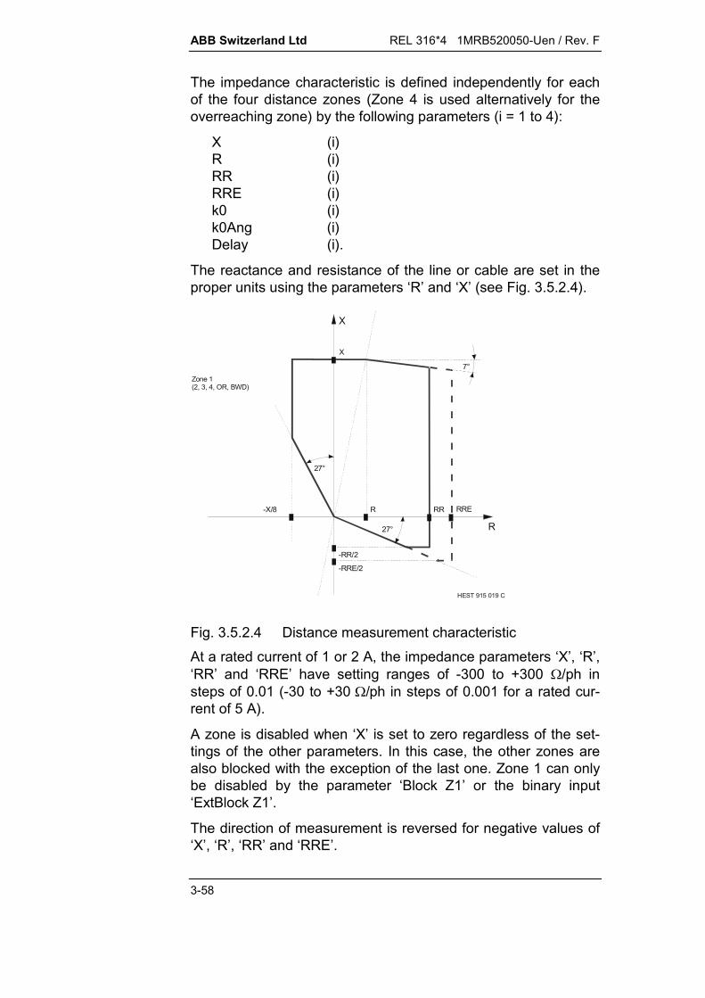
ABB Switzerland Ltd REL 316*4 1MRB520050-Uen / Rev. F
3-58
The impedance characteristic is defined independently for eachof the four distance zones (Zone 4 is used alternatively for theoverreaching zone) by the following parameters (i = 1 to 4):
X (i)R (i)RR (i)RRE (i)k0 (i)k0Ang (i)Delay (i).
The reactance and resistance of the line or cable are set in theproper units using the parameters ‘R’ and ‘X’ (see Fig. 3.5.2.4).
X
R
X
R RR-X/8
-RR/2
RRE
-RRE/2
HEST 915 019 C
7°
27°
27°
Zone 1 (2, 3, 4, OR, BWD)
Fig. 3.5.2.4 Distance measurement characteristicAt a rated current of 1 or 2 A, the impedance parameters ‘X’, ‘R’,‘RR’ and ‘RRE’ have setting ranges of -300 to +300 /ph insteps of 0.01 (-30 to +30 /ph in steps of 0.001 for a rated cur-rent of 5 A).
A zone is disabled when ‘X’ is set to zero regardless of the set-tings of the other parameters. In this case, the other zones arealso blocked with the exception of the last one. Zone 1 can onlybe disabled by the parameter ‘Block Z1’ or the binary input‘ExtBlock Z1’.
The direction of measurement is reversed for negative values of‘X’, ‘R’, ‘RR’ and ‘RRE’.

REL 316*4 1MRB520050-Uen / Rev. F ABB Switzerland Ltd
3-59
Allowing for fault resistance
Provision is made with parameters ‘RRE’ and ‘RR’ for allowingfor the fault resistance in an E/F loop and in a phase-to-phaseloop. The setting takes the E/F resistance comprising the resis-tance of the arc and the pylon footing resistance in relation to theline resistance into account.
Typical settings lie in the range RR(E)/X = 0.5...3.
The arc resistance RB can be calculated according to A.R. vanC. Warrington as follows:
4.1B Id28700R
where:
d length of arc in mI current in ARB arc resistance in .
Since the unit is /ph, the fault resistance appears differently inthe impedance plane according to the type of fault. Where thevalue of the fault resistance RF is known in (see Fig. 3.5.2.5),it has to be entered in the R/X diagram as follows:
E/F: R=RF/(1+k0)
phase-to-phase fault: R=RF/2
three-phase fault: R=RF/ 3 .
It is for this reason that fault resistance is compensated sepa-rately for E/F and phase-to-phase loops using the parameters‘RRE’ and ‘RR’. The parameter ‘RR’ will generally be set lowerthan ‘RRE’, because the phase-to-phase fault resistance is nor-mally very low.
RF RF RF RF
RFHEST 915 029 C
E/F Phase-to-phase fault Three-phase fault
Fig. 3.5.2.5 Fault resistance

ABB Switzerland Ltd REL 316*4 1MRB520050-Uen / Rev. F
3-60
Load current (area)
The load area defined by the underimpedance parameters‘RLoad’ and ‘AngleLoad’ is taken into account be starting andmeasuring characteristics. It follows from this that the relay canonly trip, if the fault impedance measured lies within theunderimpedance starting characteristic.
Zone 3
Zone 2
Zone 1
OVERREACH ZONE
REVERSE ZONE
X
R
Underimpedancecharacteristic
HEST 935 053 C
RLoadAngleLoad
Fig. 3.5.2.6 Relay characteristics
Note that the load impedance area is only formed when theunderimpedance starter (UZ) is in operation. It does not existwhen starting is provided by the overcurrent starter (OC).

REL 316*4 1MRB520050-Uen / Rev. F ABB Switzerland Ltd
3-61
Zero-sequence compensation of the protected line
The magnitude and phase-angle of the zero-sequence compen-sation factor are set individually for each zone using parameters‘k0’ and k0Ang’. The latter are calculated from the positive-se-quence impedance ZL and the zero-sequence impedance ZOL ofthe line:
k xZ Z
ZL L
L0
01 3
/( )
k x Z Z ZL L L0 01 3 / ( ) / )
Range: 0 to 8 in steps of 0.01
k Ang X X R R X RL L L L L L0 0 0 arctan ( ) / ( ) arctan( / )
Range: -180° to +90° in steps of 0.01.
Zero-sequence compensation for cables
Depending on the type of cable and the application, k0 is setbetween –10° and –130°. If a complex setting is made for k0, thepolygon characteristic is rotated in the R-jX diagram. At k0angles higher than 20°, a slight setting error causes severeunder or overreaching. The setting is often incorrect because
the cable data are not known exactly
measured data are only accurate for through faults, butscarcely ever accurate for internal faults
A setting of 0° or –180° (corresponds to negative values) istherefore recommended for k0:
k0 = 1/3 (X0L – XL) / XL
k0Ang = 0° for X0L > XL
k0Ang = -180° for X0L < XL
Note that the value of R must be set at least to(2RL + R0L) / 3 and the desired RRE is increased by (2RL +R0L) / 3.

ABB Switzerland Ltd REL 316*4 1MRB520050-Uen / Rev. F
3-62
R
jX
ZL
k0 ZL
k0
2 ZL + Z0) / 3
XL
XL - k0 XL
Ph-Ph
Ph-E
RRERR
(2 RL + R0L) / 3
Fig. 3.5.2.7 Relay characteristics
Zero-sequence compensation of double-circuit lines
The magnitude and phase-angle of the zero-sequence compen-sation factor for a double-circuit line are set using parameters‘k0m’ and ‘k0mAng’. This compensation only applies to Zones 1and 2, the overreaching zone and the reverse zone.
3.5.2.3.2. Directional element(see Section 4.2.1.2.4.)
Each distance zone has its own directional measuring element.The voltage used for measurement depends on the amplitude ofthe fault voltage in relation to the parameter ‘UminFault’. Thefault voltage is used, providing it is higher than the setting of‘UminFault’, and a voltage derived from the healthy voltage andthe memory voltage is used when it falls below. The recom-mended settings are 0.1 UN for conventional v.t's.
Should correct determination of direction not be possible(reference voltage too low or memory voltage decayed), the set-ting of the parameter ‘MemDirMode’ determines whether theprotection blocks or trips:
Block protection blocks all zones(definitive zone only if directional)
Trip protection trips
REL 316*4 1MRB520050-Uen / Rev. F ABB Switzerland Ltd
3-63
Cond. trip Protection blocks unless the instantaneous andpreceding zones are in opposite directions, in whichcase the protection trips.
3.5.2.3.3. Overreaching zone(OR)
The settings including the designation ‘4/OR’ (‘X (4/OR)’ ... delay(4/OR)’) can be used either for a fourth measuring zone or acompletely independent overreaching zone (but not for both atthe same time) by appropriately setting the parameter ‘Delay(4/OR)’ (see Section 3.5.2.3.5).
In applications requiring a fourth zone, the measuring unit of thesecond zone is used for overreaching.
An overreaching zone is necessary for the switch-onto-fault andzone extension logics and for overreaching transfer trippingschemes.
3.5.2.3.4. Reverse zone(BACK)
A reverse measuring zone is used in a blocking scheme andalso the logic for detecting a reversal of fault energy direction. Itis set using the parameters ‘X (BACK)’, ‘R (BACK)’, ‘RR (BACK)’and ‘RRE (BACK)’ which have setting ranges from 0 to -300/ph.
Note that:
for underimpedance starting (‘UZ’):With the exception of the load discrimination defined by theparameters ‘RLoad’ and ‘AngleLoad’, the reverse zoneoperates independently of the starters.
for overcurrent starting (‘OC’):The reverse zone is only in operation when an overcurrentstarter (‘Istart’) has picked up.
the binary input (‘Ext Blk UZ’) blocks operation regardless ofthe starter mode for the reverse zone.
Signal output: Meas Bward. Measurement of the reverse zone only takes place while the
first zone is active, i.e. the ‘Meas Bward’ signal resets at thelatest at the end the second time step.

ABB Switzerland Ltd REL 316*4 1MRB520050-Uen / Rev. F
3-64
3.5.2.3.5. Time steps(Delay)
The operating time of every activated distance zone (parameter‘X’ <> 0) is determined by the parameter ‘Delay’, which has asetting range of 0 to 10 s in steps of 0.01. The parameter‘Delay (4/OR)’ is also associated with a logic, which determineswhether it applies to Zone 4 or to the overreaching zone, i.e. if‘Delay (4/OR)’ < ‘Delay (2)’, it applies to the overreaching zone,otherwise to Zone 4.
The set times must satisfy the following relationships:
Delay (1) < Delay (2) < Delay (3) < Delay (4) < Delay(Def),
Delay (OR) < Delay (2).
When grading the operating times of several distance relays, theminimum grading time should not be less than the sum of thecircuit-breaker operating time plus 150 ms (reset time + operat-ing time of the measuring system + safety margin).
Recommended timer settings:
Zone 1: normally instantaneous.
Zone 2: 'Delay (2)’ is normally set to the sum of relay andcircuit-breaker operating times, arc extinction time, signaltransmission time and a tolerance margin, which amounts toabout 0.25 to 0.5 s. The tolerance includes an allowance forsequential tripping.
Zone 3: 'Delay (3)’ is set to about 2 x ‘Delay (2)’.
Zone 4: 'Delay (4)’ or ‘Delay(Def)’ is normally set to at least4 x ‘Delay (2)’.
Special cases may require settings, which deviate considerablyfrom the above recommendations.
The time steps of zones 1 to 4 must have settings less than‘Delay(Def)’.
3.5.2.4. Definitive zone(Def)
The definitive (or fifth) zone is subject to the same parameters asthe underimpedance starters (i.e. XA, XB, RA, RB, RLoad andAngleLoad).The corresponding time step is defined by the parameter ‘Delay(Def)’.

REL 316*4 1MRB520050-Uen / Rev. F ABB Switzerland Ltd
3-65
Definitive Zone
X
R
XA
RB -RLoad RLoad RAAngleLoad
XB HEST 935 054 C
27°
Directional(in tripping direction)
27°
Fig. 3.5.2.8 Definitive zone characteristic
The parameter ‘DefDirMode’ determines the response at the endof the definitive time. It can be set to be either directional (intripping direction) or non-directional (see Fig. 3.5.2.8).
Note:
There is still a definitive zone even using the overcurrentstarter (OC), but only with respect to the parameters ‘Delay(Def)’ and ‘DefDirMode’.
3.5.2.5. Back-up overcurrent unit(O/C Back-up Protection)(see Section 4.2.1.4.)
The settings for the back-up overcurrent unit are made via thesub-menu ‘O/C BACK-UP PROTECTION’. The setting of theparameter ‘I O/C’ determines the pick-up level, which can bechosen in steps of 0.1 IN between 0 and 10 IN. The associatedtime delay is set in steps of 0.1 s between 0 and 10 s by meansof the parameter ‘Delay O/C’.
ABB Switzerland Ltd REL 316*4 1MRB520050-Uen / Rev. F
3-66
The pick-up signal of the overcurrent unit is also used by theSTUB protection. If the function is being used for this purpose,i.e. the binary I/P ‘Isol open’ is at logical ‘1’, the tripping time isfixed at 25 ms.
3.5.2.6. V.t. supervision(see Section 4.2.1.3.)
The parameters for setting the v.t. supervision function are lo-cated in the sub-menu ‘V.T. SUPERVISON’. One of four differentoperating modes can be chosen using ‘VTSupMode’. Thefunction processes zero and negative-sequence components,which are either used on their own ('ZeroSeq’ and ‘NegSeq') orcombined ('Zero*NegSeq’ and ‘Spec').
ZeroSeq U I0 0
NegSeq U I2 2
Zero*NegSeq U I U I0 0 2 2
Spec U I I2 0 2
The four pick-up values are the settings of the parameters‘U0min VTSup’, ‘U2min VTSup’, ‘I0min VTSup’ and ‘I2min VTSup’.They can be set between 0 and 2 UN (or IN) in steps of 0.01. Thebasic settings are 0.2 UN for the voltage and 0.07 IN for thecurrent.
Only the ‘NegSeq’ or ‘Spec’ options are available in ungroundedsystems.
Upon operating, the v.t. supervision function is normally requiredto immediately block the distance protection function (seeSection 4.2.1.5.2.). Provision is made, however, for blocking thedistance function after a delay of 12 s by setting the parameter‘VTSupBlkDel’. This parameter is normally set in cases whereonly the overcurrent starters are in use.
REL 316*4 1MRB520050-Uen / Rev. F ABB Switzerland Ltd
3-67
If the v.t. supervision function remains picked up for longer than12 s, it resets only after a delay (1 s). Should a fault give rise tozero or negative-sequence current components, it resets im-mediately.The parameter ‘VTSupDebDel’ (deblocking) enables the resetdelay to be continuously enabled regardless of current.
Recommended setting:
Parameter Groundedsystem
Ungroundedsystem
VTSupDebDel enabled disabled
The signal ‘VTSup’ indicates that the distance function is beingblocked by the v.t. supervision and ‘VTSupDel’ that the 12 s de-lay is running.
3.5.2.7. Tripping logic(see Section 4.2.1.5.)
The parameters for determining the tripping logic are grouped inthe sub-menu ‘Trip Schemes’.
The various transfer tripping schemes are selected by setting theparameter ‘ComMode’ (3 x PUTT, POTT and OVERREACHINGBLOCKING schemes). The possible settings are given below.The settings for the different schemes only appear after hasscheme has been selected.
PUTT NONDIR
Permissive underreaching transfer tripping (non-directional)
‘Weak’ - enables the weak infeed logic.
PUTT FWD
Permissive underreaching transfer tripping (in line direction)
No other parameters.
PUTT OR2
Permissive underreaching transfer tripping (overreachingzone/Zone 2)
‘Unblock’ - selects the enabling logic for communicationschannel failure.

ABB Switzerland Ltd REL 316*4 1MRB520050-Uen / Rev. F
3-68
POTT
Permissive overreaching transfer tripping
‘Weak’ - enables the weak infeed logic.
‘Unblock’ - selects the enabling logic for communicationschannel failure.
‘Echo’ - enables the echo logic.
‘TransBl’ - enables the logic for reversal of fault energy
‘t1TransBl’ - min. holding time for the wrong energy directionsignal. This has to be set at least 50 ms longerthan the maximum reset time required by thecommunication channel.
‘t2TransBl’ - max. holding time for the wrong energy directionsignal. This has to be set at least 0.4 s longerthan the dead time setting to make sure thatblocking is still effective should an attempt bemade to reclose the faulted line.
BLOCK OR
Blocking scheme
‘TransBl’ - enables the logic for reversal of fault energy
‘t1Block’ - time allowed for the receipt of a PLC signal
‘t1TransBl’ - min. holding time for the wrong energy directionsignal. This has to be set at least 50 ms longerthan the maximum signal transmission time.
‘t2TransBl’ - max. holding time for the wrong energy directionsignal. This has to be set at least 0.4 s longerthan the dead time setting to make sure thatblocking is still effective should an attempt bemade to reclose the faulted line.
TripMode
Depending on the setting of the parameter ‘TripMode’, tripping iseither phase-selective, controlled by the binary input ‘1PolAR’(for ‘1phTrip’), always three-phase (for ‘3phTrip’) or three-phaseafter the time ‘Delay (3)’ (for ‘3phTripDel3’).

REL 316*4 1MRB520050-Uen / Rev. F ABB Switzerland Ltd
3-69
SOTF Mode
Access is gained to the switch-onto-fault logic settings by select-ing the parameter ‘SOTF Mode’. The alternatives presented arewhether the switch-onto-fault logic should trip on the basis of thenon-directional underimpedance starters or the overreachingzone.
This logic is enabled either by the undervoltage function delayedby 10 s or 200 ms (see Section 3.5.2.2.6) or the binary inputs‘Deadline’ and ‘Manual close’.
Two signalling outputs ‘Start SOTF’ and ‘Trip SOTF’ are associ-ated with the switch-onto-fault logic. ‘Start SOTF’ is intended forblocking the auto-reclosure function and ‘Trip SOTF’ signals thattripping took place as a result of the switch-onto-fault logic.
SOTF 10 sec
The parameter ‘SOTF10sec’ determines whether the undervol-tage function and the binary input ‘Deadline’ are enabled after10 s (‘on’) or after just 200 ms (‘off’). ‘off’ indicates switching ontoa fault after fast auto-reclosure (Fast OR). Tripping in this case isthus based on the decisions of the starters alone.
t1EvolFaults
The setting of the parameter ‘t1EvolFaults’ determines the timeduring which an evolving fault once detected results in a three-phase trip.
3.5.2.8. Power-swing blocking(see Section 4.2.1.6.)
Only the parameter ‘tPSblbock’ for the time during which thepower-swing blocking signal is maintained has to be set in the‘POWER-SWING BLOCKING’ sub-menu. The setting range is 0to 10 s in steps of 0.01. Tripping is enabled again at the latest atthe end of this time.
The power-swing blocking function is disabled when ‘tPSblock’ isset to zero or a logical ‘1’ is applied to the binary input ‘Ext BlkPSB’.
3.5.2.9. Allocation of c.t. and v.t. inputs(see Section 5.5.4.1.)
The parameters for allocating c.t. and v.t. input channels aregrouped in the ‘ANALOGUE (CT/VT) CHANNELS’ sub-menu.
ABB Switzerland Ltd REL 316*4 1MRB520050-Uen / Rev. F
3-70
3.5.2.10. Allocation of binary inputs(see Section 5.5.4.4.)
The parameters for allocating binary inputs are grouped in the‘BINARY INPUTS’ sub-menu.
All binary inputs can be allocated to external signals or the out-puts of other functions.
ChgMeasDirApplying a signal to this input reverses the direction of meas-urement for the entire distance protection function (all zones).
Ext Blk DistThis input blocks the entire distance protection function. Blockingis signalled by “Dist blocked” and after 12 s by “DelDistBlk”. Onlythe back-up overcurrent protection (I O/C) then remains active.
Ext UZ BlkThis input blocks the underimpedance starters, the neutralvoltage starter (U0), the measurement for ‘Weak’ and thereverse measurement. The overcurrent starters (OC) remain inoperation.
Ext Blk PSBThis input blocks the power-swing blocking function.
Ext Blk O/C back-upThis input blocks the back-up overcurrent protection (O/C Back-up Protection).
DeadlineThe signal applied to this input is needed by the switch-onto-faultlogic to indicate to the distance function that the line is withoutvoltage before the circuit-breaker is closed. It is used for theswitch-onto-fault logic providing the v.t's are on the busbars.
Manual ClosePrior to manually closing the circuit-breaker, this signal enablesthe switch-onto-fault logic and blocks the v.t. supervision func-tion.

REL 316*4 1MRB520050-Uen / Rev. F ABB Switzerland Ltd
3-71
ZExtensionThe overreaching logic permits instantaneous tripping within theoverreaching zone. It is enabled via the binary input ‘Zextension’or ‘ZExtensionAR’.For this purpose, the output ‘Zextension’ of the auto-reclosurefunction is connected to the input ‘ZExtensionAR’.
Isol openThis input is required by the STUB protection to ascertainwhether an isolator is open or not (see Section 4.2.1.5.4.).
ComRec
This input is needed for the external signal ‘ComRec’ (signalreceived by PLC, optical fibre link or point-to-point radio).
ComFail
This input signals to the protection that the PLC channel hasfailed.
1PolAR
This input permits single-phase tripping to take place and is usedin conjunction with single or three-phase auto-reclosureschemes. Refer to the Section ‘Auto-reclosure’ for the connec-tion to the auto-reclosure function.
ExtBlkSOTF
This input is needed in cases where the switch-onto-fault logic isnot enabled after an auto-reclosure.Refer to the Section ‘Auto-reclosure’ for the connection to theauto-reclosure function.
ExtBlkHF
This input blocks the reception of an intertripping signal. It isused for coordinating communication channel signals when in asolidly grounded system, the distance protection and the E/Fprotection use the same channel. It must be connected to the‘RecBlk’ signal of the E/F function.
ExtBlock Z1
This input blocks measurement in zone 1.

ABB Switzerland Ltd REL 316*4 1MRB520050-Uen / Rev. F
3-72
3.5.2.11. Allocation of tripping commands(see Section 5.5.4.3.)
The parameters for allocating tripping commands are grouped inthe ‘CB COMMANDS’ sub-menu.
The allocation of the output signals depends on whether singleor three-phase tripping has been set (parameter ‘TripMode'). Inthe case of three-phase tripping, the three tripping outputs areallocated to the same auxiliary tripping relay. Single-phase trip-ping ('TripMode’ set to ‘1PhTrip’ or ‘3PhTripDel3') requires threeseparate auxiliary tripping relays, i.e. the protection has to beequipped with at least two binary I/O units Type 316DB61/62.
3.5.2.12. Signals(see Section 5.5.4.2.)
The parameters for allocating binary outputs to auxiliary signal-ling relays are grouped in the ‘SIGNALLING’ sub-menu.
Some signalling outputs latch until the entire distance protectionfunction resets (i.e. until ‘Start R+S+T’ resets, see Section 3.5.2).

REL 316*4 1MRB520050-Uen / Rev. F ABB Switzerland Ltd
3-73
3.5.3. Sensitive earth fault protection for ungrounded systems andsystems with Petersen coils (EarthFaultIsol)
A. Application
The sensitive E/F protection detects E/F’s on overhead lines inradial systems. It is suitable for application in ungrounded sys-tems, systems with Petersen coils and in resistance groundedMV and HV systems. The scheme monitors the neutral voltageand current of the protected line. Depending on the characteristicangle chosen, it responds to either the real or apparent value ofthe neutral power.
B. Features
adjustable characteristic angle compensation of c.t. phase errors suppression of DC component in voltage and current signals suppression of harmonics in voltage and current signals.
C. Inputs and outputs
I. C.t./v.t. inputs
neutral current neutral voltage
II. Binary inputs
blocking signal
III. Binary outputs
tripping signal starting signal
IV. Measured variable
zero-sequence power.

ABB Switzerland Ltd REL 316*4 1MRB520050-Uen / Rev. F
3-74
D. Sensitive earth fault protection settings - EarthFaultIsol
Summary of parameters:
Text Units Default Min. Max. StepParSet 4..1 P1 (Select)Trip Tripping chan. 00000000P-Setting PN 0.050 0.005 0.100 0.001Angle degrees 000.00 -180.00 180.00 0.01Drop-Ratio % 60 30 95 1Delay s 00.50 00.05 60.00 0.01Phi-Comp degrees 0.00 -5.00 5.00 0.01CurrentInp CT/VT-Addr 0VoltageInp CT/VT-Addr 0PN UN*IN 1.000 0.500 2.500 0.001BlockInp BinaryAddr FTrip SignalAddr ERStart SignalAddr
Explanation of the parameters:
ParSet 4..1Parameter for determining in which set of parameters a par-ticular function is active (see Section 5.11.).
TripTripping logic (matrix).
P-SettingPick-up power setting.
AngleCharacteristic angle for the power measurement.
0° = real power forwards180° = real power backwards-90° = apparent power forwards90° = apparent power backwards
All angles between -180° and 180° can be set.
Drop-RatioReset ratio of the measuring trigger.

REL 316*4 1MRB520050-Uen / Rev. F ABB Switzerland Ltd
3-75
DelayDelay between the protection picking up and the protectiontripping. The delay setting also influences the reset time ofthe function. For t > 100 ms, the protection resets after50 ms. Resetting is not otherwise intentionally delayed.
Phi-CompCompensation of c.t. and v.t. phase errors. The setting con-cerns only the difference between the two errors.
CurrentInpDefines the c.t. input channel used for the neutral current.Only single-phase c.t. inputs can be set.
VoltageInpDefines the v.t. input channel used for the neutral voltage.Only single-phase v.t. inputs can be set.
PNRated power given by UN*IN.
BlockInpInput for blocking the sensitive E/F function.
F: - protection enabledT: - protection disabledxx: - all binary I/P’s (or O/P’s of protection functions).
TripTripping signal.
StartStarting signal.

ABB Switzerland Ltd REL 316*4 1MRB520050-Uen / Rev. F
3-76
E. Setting instructions
Settings:
Pick-up power P-SettingCharacteristic angle AngleReset ratio Drop-RatioDelay DelayPhase error compensation Phi-CompRated power PN
The value entered for ‘P-Setting’ is the power at which the func-tion picks up referred to rated power ‘PN’. The parameter ‘P-Setting’ has a setting range of 0.005 to 0.100 in steps of 0.001.
The setting of the parameter ‘Angle’ determines the characteris-tic angle of the measurement. Its implications are explainedbelow under "Real power" and "Apparent power".
The desired reset ratio is set as a percentage of the pick-upvalue using the parameter ‘Drop-Ratio’. To ensure that the resetratio is adequate for low values of ‘P-Setting’, the following con-dition is checked:
1'SettingP'10050100'Ratio-Drop'
An angle to compensate the relative phase errors of c.t’s andv.t’s can be entered using parameter ‘Phi-Comp’. The effectivecharacteristic angle is the sum of the parameters ‘Angle’ and‘Phi-Comp’.
The setting for the rated power is left at PN = 1.000. The corre-sponding reference value in the ‘ANALOGUE CT/VTCHANNELS-AD CHANNEL REF VAL’ menu must be adjustedfor rated voltages other than 100 V.
Real power
The real power component (real power component = proportionof real power current x displacement voltage) of the zero-se-quence power is monitored to detect E/F’s in systems withPetersen coils and high-resistance grounded systems. The neu-tral component of the current in the healthy phases resultingfrom their capacitances to ground and the inductive Petersen coilcurrent unite at the fault location and return to the source via thefaulted phase.
REL 316*4 1MRB520050-Uen / Rev. F ABB Switzerland Ltd
3-77
A power relay is installed at both ends of every line with the ex-ception of stub lines, which only require a relay at the sourceend. If the E/F current is too low and has to be artificially in-creased, an overvoltage relay is fitted to detect the displacementvoltage and connect a grounding resistor temporarily to the star-point. To avoid any incorrect response of the power relays whilethis is being done, they are enabled after a short delay. The sec-tion of the line with the fault is determined by comparison of therelay directions.
The real power component of the E/F current is determined bythe resistive losses of the lines, the Petersen coils and thegrounding resistors. A typical value for the charging current ofoverhead lines is around 2.5 A / 10 kV and 100 km. In the caseof cable systems, it can be determined from the cable data. Theminimum real power component of the current at the minimumvoltage at which the power relay has to operate can be deter-mined according to the above procedure. The power at which itmust pick up must be set somewhat lower to allow for phase andratio errors of the c.t’s.
The parameter ‘Angle’ must be set to 0° to measure real powerin the forwards direction, respectively 180° to measure realpower in the reverse direction.
Note:
The connections are made in strict accordance with the ABBwiring diagram.
Example of how to determine the setting
Assuming an overhead line system with an E/F current (sum ofthe three phase currents) of 30 A and a real power current com-ponent of 5 A. The core-balance c.t. has a ratio of 125:1. Thestar-point v.t. has a secondary voltage of 100 V for a solid E/F atthe generator/power transformer terminals. Therefore:
PN = 1 A x 100 V = 100 VA.
It is required to detect E/F’s down to 50 % of the displacementvoltage. The E/F current flows only from one side, so that no di-vision of the current takes place.
The real power component of the current of 5 A results in a sec-ondary current of:
IW = 5 A x 1/125 = 0.04 A at maximum displacement voltage
IW = 0.04 A x 0.5 = 0.02 A at 50 % displacement voltage.
ABB Switzerland Ltd REL 316*4 1MRB520050-Uen / Rev. F
3-78
The required pick-up power is thus:
P = 0.02 A x 50 V = 1 VA
This corresponds to 1 % referred to the rated power PN of100 VA.
A setting of 0.5 % PN is possible, but the accuracy of the c.t’smust be checked before deciding whether such a sensitive set-ting is permissible. The real power can be increased by adding agrounding resistor.
Apparent power
The apparent power component of the neutral power is moni-tored to detect E/F’s in ungrounded systems. Every feeder isequipped with a relay. During an E/F, the capacitive E/F currentof the entire system less that of the faulted line flows into thefaulted line. Only the E/F relay of the faulted line indicates powerflowing into its line.
The minimum capacitive E/F current available to operate the re-lays is the total capacitive E/F current of the whole system forthe smallest configuration to be expected less that of the faultedline. Of this capacitive current, only the percentage correspond-ing to the assumed minimum displacement voltage at which theprotection is still required to operate may be considered. If thereare any double-circuit lines, the division of current between thecircuits must also be taken into account.
To allow for the c.t. errors at such low current levels, the pick-upvalue set on the relay must be less than the product of the mini-mum current determined above and the minimum voltage.
The parameter ‘Angle’ must be set to -90° pick up for E/F’s in theforwards direction and 90° for the reverse direction.
Note:
The connections are made in strict accordance with the ABBwiring diagram.
REL 316*4 1MRB520050-Uen / Rev. F ABB Switzerland Ltd
3-79
Time delay
The delay required between the picking up of the relay (‘start')and tripping ('Trip') is set by means of parameter ‘Delay’. Thesetting range provided is 0.05 to 60 s in steps of 0.01.
C.t./v.t. inputs
The two c.t. and v.t. input channels ‘CurrentInp’ (current) and‘VoltageInp’ (voltage) have to be configured for the purpose. Thecurrent input channel may only be allocated to a single-phasemetering (core-balance) c.t. and the voltage channel to a single-phase v.t.
Binary inputs and outputs
The tripping output may be allocated to either a tripping relay ora signalling relay (different parameters) and the starting signal toa signalling relay.
Operation of the sensitive E/F protection can be inhibited by ap-plying a signal to the ‘BlockInp’ input.

ABB Switzerland Ltd REL 316*4 1MRB520050-Uen / Rev. F
3-80

REL 316*4 1MRB520050-Uen / Rev. F ABB Switzerland Ltd
3-81
3.5.4. Auto-reclosure (Autoreclosure)
A. ApplicationThe function can be configured for single or three-phase auto-reclosure.The unit can operate in conjunction with any of the threeprotection functions (distance, longitudinal differential andovercurrent protection) and either an internal or externalsynchrocheck function.However, an additional standard FUPLA logic T142 as detailedin the document 1KHF600220 is necessary for single-phasereclosing in 1½ breaker applications.
B. Features up to 4 fast or slow reclosure attempts first cycle with up to 4 individually configurable single and/or
three-phase reclosure attempts independent operating indicators for each reclosure cycle wide dead time setting range provision to control bypassing of the synchrocheck unit and
extending the dead time for the first zone by external signals clearly defined response to changing fault conditions during
the dead time (evolving faults) Logic for 1st. and 2nd. main protection (redundant), duplex
and master/follower schemes.
C. Inputs and outputs
I. C.t./v.t. inputs none
II. Binary inputs Start (Start) Redundant start (Start 2) *)
Redundant start (Start 3) *)
Three-phase trip (Trip CB 3P) Redundant three-phase trip (Trip CB2 3P) *)
Redundant three-phase trip (Trip CB3 3P) *)
General trip (Trip CB ) Redundant general trip (Trip CB2) *)
Redundant general trip (Trip CB3) *)
*) 2 and 3 denote the I/P’s of protection functions 2 and 3 or relays 2 and 3 in a redundant
protection scheme (see Fig. 3.5.4.4).

ABB Switzerland Ltd REL 316*4 1MRB520050-Uen / Rev. F
3-82
CB ready for open/close/open cycle (CB ready) CB2 ready for open/close/open cycle (CB2 ready) **)
CB ready for close/open cycle (CO Ready) CB2 ready for close/open cycle (CO Ready 2) **)
CB open (CB open) CB2 open (CB2 open) **)
CB2 preferred circuit-breaker (CB2 Priority) **)
Synchrocheck (SynchroChck) Synchrocheck 2 (SynchroChck2) **)
Dead line (Dead Line) Dead line 2 (Dead Line2) **)
External blocking input (ExtBlkAR) Conditional blocking input (CondBlkAR) Manual close blocking input (Manual Close) External synchrocheck bypass (Ext.SCBypas) External extension of dead time (Extend t1)
(1st. attempt) Delay from master CB (MasterDel) Block from master CB (MasterUnsucc) Block reclosure by follower (Inhibit Inp)
(redundant scheme) External 1P-1P selector for 1st. AR (MD1_EXT_1P_1P) External 1P-3P selector for 1st. AR (MD1_EXT_1P_3P) External 1P3P-3P selector for 1st. AR (MD1_EXT_1P3P_3P) External 1P3P-1P3P selector for 1st. AR (MD1_EX_1P3P_1P3P)
III. Binary outputs
CB close signal (Close CB) CB2 close signal (Close CB2) **)
Overreach switching signal (ZExtension) Definitive trip (Def. Trip) Prepare trip of all three phases (Trip 3-Pol) Block Follower CB (BlkFlwr) Delay Follower CB (DelFlwr) Block for Follower. recloser (Inhibit Outp) Reclosure function ready (AR Ready) Reclosure function blocked (AR Blocked) Reclosure cycle running (AR in prog.) 1st. single-phase reclosure in progress (First AR 1P) 1st. three-phase reclosure in progress (First AR 3P) 2nd. Reclosure in progress (Second AR) 3rd. reclosure in progress (Third AR)
**) 2 denotes the I/O’s for CB2 in a duplex scheme (see Fig. 3.5.4.7).

REL 316*4 1MRB520050-Uen / Rev. F ABB Switzerland Ltd
3-83
4th. reclosure in progress (Fourth AR)
IV. Measurements
None.

ABB Switzerland Ltd REL 316*4 1MRB520050-Uen / Rev. F
3-84
D. Autoreclosuresettings - Autoreclosure
Summary of parameters:
Text Units Default Min. Max. Step
GENERALParSet 4..1 P1 (Select)1. AR Mode 1P3P-1P3P (Select)2..4. AR Mode off (Select)
TIMERSt Dead1 1P s 001.20 0,05 300 0.01t Dead1 3P s 000.60 0,05 300 0.01t Dead1 Ext. s 001.00 0,05 300 0.01t Dead2 s 001.20 0,05 300 0.01t Dead3 s 005.00 0,05 300 0.01t Dead4 s 060.00 0,05 300 0.01t Oper s 000.50 0,05 300 0.01t Inhibit s 005.00 0,05 300 0.01t Close s 000.25 0,05 300 0.01t Discrim.1P s 000.60 0.10 300 0.01t Discrim.3P s 000.30 0.10 300 0.01t Timeout s 001.00 0,05 300 0.01t AR Block s 005.00 0,05 300 0.01
GENERAL BINARY INPUTSStart BinaryAddr off (F)Trip CB 3P BinaryAddr off (F)Trip CB BinaryAddr off (F)Start 2 BinaryAddr off (F)Trip CB2 3P BinaryAddr off (F)Trip CB2 BinaryAddr off (F)Start 3 BinaryAddr off (F)Trip CB3 3P BinaryAddr off (F)Trip CB3 BinaryAddr off (F)CB Ready BinaryAddr off (F)CO Ready BinaryAddr off (F)CB Open BinaryAddr off (F)Dead line BinaryAddr off (F)Ext. Blk AR BinaryAddr off (F)Cond.Blk AR BinaryAddr off (F)Manual Close BinaryAddr off (F)Inhibit Inp. BinaryAddr off (F)Extend t1 BinaryAddr off (F)
MD1 EXT 1P 1P BinaryAddr off (F)

REL 316*4 1MRB520050-Uen / Rev. F ABB Switzerland Ltd
3-85
Text Units Default Min. Max. StepMD1 EXT 1P 3P BinaryAddr off (F)MD1 EXT 1P3P 3P BinaryAddr off (F)MD1 EXT 1P3P 1P3P BinaryAddr off (F)
CLOSE COMMANDClose CB Trip Chan 00000000
GENERAL SIGNALSClose CB SignalAddrTrip 3-Pol SignalAddrDef. Trip SignalAddrAR Ready SignalAddrAR in Prog. SignalAddrAR Blocked SignalAddrFirst AR 3P SignalAddrFirst AR 1P SignalAddrSecond AR SignalAddrThird AR SignalAddrFourth AR SignalAddrInhibit Outp SignalAddr
SYNCHROCHECKSCBypas 1P off (Select)SCBypas 1P3P off (Select)Ext.SCBypas BinaryAddr off (F)SynchroChck BinaryAddr off (F)
ZONE EXTENSIONZE Prefault on (Select)ZE 1. AR off (Select)ZE 2. AR off (Select)ZE 3. AR off (Select)ZE 4. AR off (Select)ZExtension SignalAddr
MASTER/FOLLOWER LOGICMaster mode off (Select)MasterDelay BinaryAddr off (F)Mast.noSucc BinaryAddr off (F)DelayFlwr. SignalAddrBlk.toFlwr. SignalAddr

ABB Switzerland Ltd REL 316*4 1MRB520050-Uen / Rev. F
3-86
Text Units Default Min. Max. Step
DUPLEX LOGICCB2 Ready BinaryAddr off (F)CO Ready 2 BinaryAddr off (F)CB2 open BinaryAddr on (T)SynchroChck2 BinaryAddr off (F)Dead line 2 BinaryAddr off (F)Close CB2 Trip Chan 00000000Close CB2 SignalAddrCB2 Priority BinaryAddr off (F)
(ADDITIONAL LOGIC)P INPUT1 BinaryAddr off (F).:P INPUT16 BinaryAddr off (F)TMSEC Timer1 ms 0 0 30000 1.:TMSEC Timer8 ms 0 0 30000 1P OUTPUT1 SignalAddr.:P OUTPUT8 SignalAddr
Remarks on the signal designations:
The I/O signals specifically for redundant or duplex schemes in-clude the figure ‘2’, respectively ‘3’ in their designations.
The signals belonging to the basic configuration (1 protectionfunction and 1 auto-reclosure function) do not necessarily in-clude the figure ‘1’ in their designations.
Explanations of parameters:
GENERAL
ParSet 4..1Parameter for determining in which set of parameters a par-ticular function is active (see Section 5.11.).

REL 316*4 1MRB520050-Uen / Rev. F ABB Switzerland Ltd
3-87
1. AR ModeType of first reclosure
1. 1P-1P single-phase trip and reclosure for earthfaults (single-phase dead time), noreclosure for phase faults
1. 1P-3P single-phase trip followed by three phasetrip after approx. 20 ms, three-phasereclosure for earth faults (three-phasedead time initiated by single-phase trip),no reclosure for -phase faults
1. 1P3P-3P three-phase trip and reclosure for earthand phase faults (three-phase dead time)
1. 1P3P-1P3P single-phase trip and reclosure for earthfaults (single-phase dead time), three-phase trip and reclosure for phase faults(three-phase dead time)
Ext. Wahl External selection by the binary inputsMD1_EXT_1P_1P, MD1_EXT_1P_3P,MD1_EXT_1P3P_3P andMD1_EX_1P3P_1P3P.
2..4. AR ModeMaximum number of reclosure attempts (all three-phase)
off no 2nd., 3rd. or 4th. reclosure2 AR 2 reclosures3 AR 3 reclosures4 AR 4 reclosures.
TIMERS
t Dead1 1PDead time for first single-phase reclosure.
t Dead1 3PDead time for first three-phase reclosure.
t Dead1 Ext.Extension of 1st. dead time for single or three-phase reclo-sure (effective as long as a logical ‘1’ (pulse or continous) isapplied to the ‘Extend t1’ I/P before the dead time finishes(falling edge.)
t Dead22nd. dead time.
t Dead33rd. dead time.
t Dead44th. dead time.
ABB Switzerland Ltd REL 316*4 1MRB520050-Uen / Rev. F
3-88
t OperMaximum duration of a fault for which a reclosure attempt ismade.
t InhibitPeriod (CB recovery time) from the falling edge of the lastreclosure attempt during which the autoreclosure function isblocked and after which the function is reset.
In the event of an evolving fault between discrimination anddead times, the period commences at the instant of anothertrip occurring between the two times.
The reclaim timer is also started if the protection trips afterthe fault duration time ‘t Oper’ has elapsed.
t CloseDuration of CB close signal.
t Discrim.1PEvolving fault discrimination time for single-phase reclosure.
t Discrim.3PEvolving fault discrimination time for three-phase reclosure.
t TimeoutPeriod following the dead time during which the CB closesignal has to occur. If it does not, the ‘Def. Trip’ signal isgenerated.
t AR BlockTime during which reclosure is blocked. ‘t AR Block’ is startedby every blocking signal (‘Ext.Blk AR’, ‘Cond.Blk. AR’, ‘ManualClose’, ‘Inhibit Inp’ and ‘MasternoSucc’).
GENERAL BINARY INPUTS
Start *)I/P for signalling the start of a reclosure cycle.This I/P is connected to the ‘General start’ signal of aprotection function.
Trip CB 3P *)I/P for the three-phase trip signal.The three-phase trip from a protection function is connectedto this I/P.
*) For the auto-reclosure function to operate correctly, at least the ‘Start’ and ‘Trip CB 3P’
inputs must be connected to a protection function or via a binary system I/P to an externalprotection relay.

REL 316*4 1MRB520050-Uen / Rev. F ABB Switzerland Ltd
3-89
Trip CBI/P for the general trip signalThe general trip from a protection function is connected tothis I/P.
Set to ‘off’ (‘F’ or ‘False’), if not needed.
Start 2I/P for the AR start signal.In redundant protection schemes, the general start signalfrom the 2nd. protection is connected to this I/P.
Set to ‘off’ (‘F’ or ‘False’), if not needed.
Trip CB2 3PI/P for the three-phase trip signal.In redundant protection schemes, the three-phase trippingsignal from the 2nd. protection is connected to this I/P.
Set to ‘off’ (‘F’ or ‘False’), if not needed.
Trip CB2I/P for the general trip signal.In redundant protection schemes, the general start signalfrom the 2nd. protection is connected to this I/P.
Set to ‘off’ (‘F’ or ‘False’), if not needed.
Start 3I/P for the AR start signal.The general start signal from the 3rd. protection can beconnected to this I/P.
Set to ‘off’ (‘F’ or ‘False’), if not needed.
Trip CB3 3PI/P for the three-phase trip signal.The three-phase tripping signal from the 3rd. protection canbe connected to this I/P.
Set to ‘off’ (‘F’ or ‘False’), if not needed.
Trip CB3I/P for the general trip signal.The general start signal from the 3rd. protection can beconnected to this I/P.
Set to ‘off’ (‘F’ or ‘False’), if not needed.

ABB Switzerland Ltd REL 316*4 1MRB520050-Uen / Rev. F
3-90
CB ReadyI/P excited by a signal from the CB when it is ready(open/close/open).
Set to ‘on’ (‘T’ or ‘True’), if not needed or not fitted.
I/P logic: ‘CB ready’ OR ‘CB2 ready'In a duplex scheme, either an active ‘CB ready’ or ‘CB2ready’ I/P enables an auto-reclosure cycle.Resetting of this input is delayed internally by 100 ms.
CO ReadyI/P excited by a signal from the CB when it is ready for aclose/open cycle.
Set to ‘on’ (‘T’ or ‘True’) if not needed, not fitted and ‘Deadline’ or ‘ExtSCBypas’ not used.
I/P logic for enabling the closing command: [(‘synchrocheck’AND ‘CO Ready’) OR ‘Dead line’ OR ‘ExtSCBypas’].
CB OpenI/P excited by a signal from the CB when it is open.
Set to ‘off’ (‘F’ or ‘False’), if not needed.
To avoid the operation of fast circuit-breakers from beingblocked unintentionally, the effect of this input is delayedinternally by 100 ms.
Dead lineI/P indicating that the line is de-energised (‘CB open’ input ifthe v.t’s are on the busbar side).
Set to ‘off’ (‘F’ or ‘False’), if not needed.
An active I/P overrides the following logical relationship of theI/P’s: ‘synchrocheck’ AND ‘CO Ready'.
Ext. Blk ARI/P for blocking the internal auto-reclosure function.
Even an autoreclosure cycle that is in progress isimmediately blocked by a signal applied to this input.
The output signals ‘Trip 3 Pol’ and ‘Def Trip’ are generatedand a three-phase definitive trip takes place.
Set to ‘off’ (‘F’ or ‘False’), if not needed.
REL 316*4 1MRB520050-Uen / Rev. F ABB Switzerland Ltd
3-91
Cond. Blk. ARI/P for a conditional blocking signal.
Blocking only takes place providing an AR cycle is not inprogress.
Set to ‘off’ (‘F’ or ‘False’), if not needed.
When tripping is by the distance protection SOTF logic or adirectional E/F PLC signal, the corresponding signals can beconnected to this I/P to prevent auto-reclosure.
Manual CloseBlocking I/P excited by the manual CB close signal.
Even an autoreclosure cycle that is in progress isimmediately blocked by a signal applied to this input.
Set to ‘off’ (‘F’ or ‘False’), if not needed.
Inhibit Inp.I/P for blocking the follower reclosure function in a redundantscheme. The follower is blocked from the end of the masterclosing signal until the end of the reclaim time.
Set to ‘off’ (‘F’ or ‘False’), if not needed.
Extend t1Input for conditionally extending the dead time (single andthree-phase) for the first (fast) reclosure.
Set to ‘off’ (‘F’ or ‘False’), if not needed.
MD1_EXT_1P_1P, MD1_EXT_1P_3P, MD1_EXT_1P3P_3Pand MD1_EX_1P3P_1P3P
Inputs for externally selecting the mode for the first reclosure.They are only effective when the parameter ‘1. AR Mode’ isset to ‘Ext. select’.
Unused inputs must be set to ‘off’ (‘F’ or ‘False’). If a signal isapplied to more than one input, the next mode in the list isthe one that is active. The auto-reclosure function is blockedif none of the inputs is used.
CLOSE COMMAND
Close CBAuxiliary relay O/P for the CB close command.
ABB Switzerland Ltd REL 316*4 1MRB520050-Uen / Rev. F
3-92
GENERAL SIGNALSClose CB
CB close signal.Trip 3-Pol
Signal to the distance function so that it can only carry out athree-phase trip.This signal is inverted and connected to the distanceprotection I/P ‘1P AR’.This signal is active in many situations, but particularly whenthe AR function is blocked, the CB is not ready for AR, theCB is open, the single-phase discrimination time ‘t 1P Discrim’finishes or the output signal ‘First AR 3P’ is active.It resets at the end of reclaim time.
Def. TripSignal initiating lock-out tripping of the CB.This signal is normally active when the protection trips againafter the last programmed reclosing shot or trips while the ARfunction is blocked. The signal resets after a fixed time of 500 ms.
AR ReadySignal indicating that the AR function is ready for a reclosurecycle. This signal is active when the AR function is ON andstanding by and also during the closing command.
AR in Prog.Signal indicating that a reclosure cycle is in progress.This signal is active from the beginning of the dead time untilthe end of the last reclosure attempt.
AR BlockedSignal indicating that the auto-reclosure relay is blocked.
First AR 3PSignal indicating that the 1st. three-phase reclosure attemptis in progress.
First AR 1PSignal indicating that the 1st. single-phase reclosure attemptis in progress.
Second ARSignal indicating that the 2nd. reclosure attempt is inprogress (always three-phase).
Third ARSignal indicating that the 3rd. reclosure attempt is in progress(always three-phase).

REL 316*4 1MRB520050-Uen / Rev. F ABB Switzerland Ltd
3-93
Fourth ARSignal indicating that the 4th. reclosure attempt is in progress(always three-phase).
Inhibit OutpSignal for blocking the follower AR function in a redundantscheme.
This signal is active from the end of the close command fromthe master AR function to the end of the reclaim time.
SYNCHROCHECK BYPASS SETTINGSSCBypas 1P
Bypass of the synchrocheck and close/open ready signals forthe first single-phase reclosure:
'on' First single-phase reclosure not enabled bysynchrocheck and close/open ready signals(bypass always active).
'off' First single-phase reclosure enabled by thesynchrocheck and close/open ready signals(bypass inactive).
SCBypas 1P3PBypass of the synchrocheck and close/open ready signals forthe first single or three-phase reclosure:
'on' First reclosure not enabled by synchrocheck andclose/open ready signals(bypass always active).
'off' First reclosure enabled by synchrocheck andclose/open ready signals(bypass inactive).
Ext.SCBypasBypasses the ‘synchroChck’ and ‘CO Ready’ signals.
Set to ‘off’ (‘F’ or ‘False’), if not needed.
I/P logic for enabling the close command: [(‘synchrocheck’AND ‘CO Ready’) OR ‘Dead line’ OR ‘Ext.SCBypas’].
I/P logic for enabling the close command: [(‘synchroChk2’AND ‘CO Ready 2’) OR ‘Dead line’ OR ‘Ext.SCBypas’].
SynchroChckI/P for a signal from a synchrocheck relay.
Set to ‘on’ (‘T’ or ‘True’), if not needed, not fitted and ‘Deadline’ or ‘ExtSCBypas’ not used.
I/P logic: [(‘synchrocheck’ AND ‘CO Ready’) OR ‘Dead line’OR ‘Ext.SCBypas'].
ABB Switzerland Ltd REL 316*4 1MRB520050-Uen / Rev. F
3-94
ZONE EXTENSION
To achieve the functions described below, the ‘ZExtension’signal must be connected to the distance protection function(see Section 3.5.4.2.).This signal can be used to initiate fast tripping in schemesincluding overcurrent functions (see Section 3.5.4.3.).
ZE PrefaultDistance relay reach setting before the first fault:
'on' overreaching (‘ZExtension’ signal active)'off' underreaching (‘ZExtension’ signal inactive).
ZE 1. ARDistance relay reach after the 1st. reclosure attempt:
'on' overreaching (‘ZExtension’ signal active)'off' underreaching (‘ZExtension’ signal inactive).
ZE 2. ARDistance relay’s reach after the 2nd. reclosure attempt:
'on' overreaching (‘ZExtension’ signal active)'off' underreaching (‘ZExtension’ signal inactive).
ZE 3. ARDistance relay’s reach after the 3rd.. reclosure attempt:
'on' overreaching (‘ZExtension’ signal active)'off' underreaching (‘ZExtension’ signal inactive).
ZE 4. ARDistance relay’s reach after the 4th. reclosure attempt:
'on' overreaching (‘ZExtension’ signal active)'off' underreaching (‘ZExtension’ signal inactive).
ZExtensionSignal to the distance function to switch it to overreach orenable an overcurrent function with a short delay.
MASTER/FOLLOWER LOGIC
Master Mode(for 1½ breaker and redundant schemes)Selection of an auto-reclosure function to be “Master”:
‘on’ Master O/P signals transmitted.‘off’ Master O/P’s blocked.

REL 316*4 1MRB520050-Uen / Rev. F ABB Switzerland Ltd
3-95
MasterDelayI/P for a signal delaying the closing command from thefollower reclosure function.
This signal picks up when the dead time of the masterreclosure function starts and is reset either by a new trip afterthe last reclosure of the cycle or at the end of the wait timefollowing successful reclosure by the master.
Set to ‘off’ (‘F’ or ‘False’), if not needed.
Mast.noSuccI/P for a blocking signal from the master CB.
This signal is triggered by the rising edge of the ‘Def.Trip’output from the master reclosure function and resets after afixed time of 500 ms.
Set to ‘off’ (‘F’ or ‘False’), if not needed.
DelayFlwr.Signal to delay the follower CB for as long as the mastercircuit-breaker has not completed its auto-reclosure cycle.
The signal picks up at the start of master AR dead time andis reset either by the rising edge of the ‘Def.Trip’ output or thefalling edge of the ‘Close CB’ output after the time ‘tClose’.
Blk.toFlwrSignal to block the follower CB as long as reclosure of themaster CB is unsuccessful.
The excursion of this signal is the same as for the ‘Def.Trip’output.
DUPLEX LOGIC
CB2 ReadyI/P excited by a signal from CB2 when it is ready(open/close/open).
Set to ‘off’ (‘F’ or ‘False’), if not needed or not fitted.
I/P logic: ‘CB ready’ OR ‘CB2 ready'In a duplex scheme, the auto-reclosure cycle is enabledeither by an active ‘CB ready’ or ‘CB2 ready’ I/P.Resetting of this input is delayed internally by 100 ms.

ABB Switzerland Ltd REL 316*4 1MRB520050-Uen / Rev. F
3-96
CO Ready 2I/P excited by a signal from CB2 when it is ready for aclose/open operation.
Set to ‘on’ (‘T’ or ‘True’), if not needed, not fitted and ‘Deadline 2’ is not used.
I/P logic for enabling the close command:: [(‘synchrocheck2’AND ‘CO Ready 2’) OR ‘Dead line 2’ OR ‘ExtSCBypas'].
CB2 openI/P excited by a signal from CB2 when it is open.
Set to ‘on’ (‘T’ or ‘True’), if not needed. Observe the informa-tion given for the duplex logic in a duplex scheme (see Sec-tion 3.5.4.5.).
SynchroChck2I/P for a signal from a synchrocheck function belonging toCB2.
Set to ‘on’ (‘T’ or ‘True’), if not needed, not fitted and ‘Deadline 2’ or ‘ExtSCBypas’ not used.
I/P logic for enabling the close command: [(‘synchrocheck2’AND ‘CO Ready 2’) OR ‘Dead line 2’ OR ‘ExtSCBypas’].
Dead line 2I/P indicating that line 2 is de-energised (CB2 open and v.t’s2 on the busbar side).
Set to ‘off’ (‘F’ or ‘False’), if not needed.
An active I/P overrides the following logical relationship of theI/P’s: ‘synchrocheck 2’ AND ‘CO Ready 2’.
Close CB2Tripping relay O/P for the CB2 close command.
Close CB2Auxiliary relay O/P for the CB2 close signal.
CB2 PriorityInput for determining the preferred circuit-breaker:
‘off’ (‘F’ or ‘False’) CB1 is preferred circuit-breaker‘on’ (‘T’ or ‘True’) CB2 is preferred circuit-breaker.
If both circuit-breakers are closed before a fault, only the pre-ferred circuit-breaker performs the entire auto-reclosure cy-cle. The other circuit-breaker closes either after successful

REL 316*4 1MRB520050-Uen / Rev. F ABB Switzerland Ltd
3-97
auto-reclosure or when the close command to the preferredcircuit-breaker is not enabled (missing ‘CO Ready’ or‘Synchrocheck’).
(ADDITIONAL LOGIC)
The following settings are only of consequence if a special auto-reclosure logic is installed. In this case, consult the associateddescription for the significance of the various settings.
P_INPUT1, P_INPUT2…P_INPUT16Additional binary input for a special auto-reclosure logic.
TMSEC_Timer1, TMSEC_Timer2…TMSEC_Timer8Additional timer settings for a special auto-reclosure logic.
P_OUTPUT1, P_OUTPUT2…P_OUTPUT8Additional signals for a special auto-reclosure logic.
PROJECT DIRECTORY
The user can choose the subdirectory in which to store the auto-reclosure logic. The default name “AURESTD” applies whenusing the standard logic in the MMI directory.It is necessary to change the name and path when using aspecial logic. In this case, consult the associated description forthe procedure.
ABB Switzerland Ltd REL 316*4 1MRB520050-Uen / Rev. F
3-98
E. Setting instructions
3.5.4.1. General
The auto-reclosure function can perform from 1 to 4 auto-reclosure attempts. The first attempt can be either single orthree-phase while the subsequent attempts are always three-phase. The type and number are determined by the parameters‘1. AR Mode’ (4 different modes for the 1st. reclosure cycle) and‘2..4 AR Mode’.
The function can operate in conjunction with either an externaldistance protection relay or other internal protection functions.
It can also operate in a scheme comprising two or more protec-tion functions (see Sections 3.5.4.2. to 3.5.4.5.).
3.5.4.2. Connections between auto-reclosure and distance functions
The auto-reclosure function determines from the states of theinput signals ‘start’, ‘Trip CB’ and ‘Trip CB 3P’, whether the dis-tance protection has picked up and whether it has performed asingle or a three-phase trip. Only the ‘Trip CB’ signal isgenerated for a single-phase trip, whereas both the ‘Trip CB’ and‘Trip CB 3P’ signals are generated for a three-phase trip.
The external distance relay or internal distance function decideswhether single or three-phase tripping should take place.
The auto-reclosure function can send two signals to the distanceprotection. The ‘Trip 3-Pol’ signal informs the distance protectionwhether it should perform a single or a three-phase trip. The‘ZExtension’ signal switches the distance protection’s overreach-ing zone on and off.
When setting the parameters, attention should be paid to theorder of the functions. For runtime reasons, the distance functionshould be configured before the auto-reclosure function.
Where the SOTF logic is not required to operate during auto-reclosure, connect the ‘AR in prog.’ Signal to the ‘ExtBlkSOTF’binary I/P of the distance function. The ‘SOTF 10 s’ timer in thedistance function’s SOTF logic is normally activated for deadtimes <10 s and in this case the above connection is notnecessary.
If the SOTF logic initiates tripping, an auto-reclosure cycle canbe inhibited by connecting the ‘start SOTF’ from the distancefunction to the ‘CondBlkAR’ I/P of the auto-reclosure function.
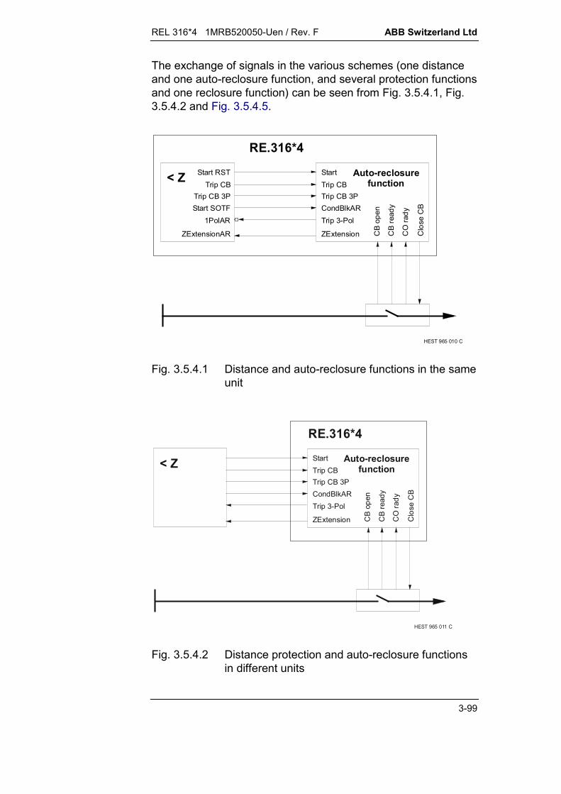
REL 316*4 1MRB520050-Uen / Rev. F ABB Switzerland Ltd
3-99
The exchange of signals in the various schemes (one distanceand one auto-reclosure function, and several protection functionsand one reclosure function) can be seen from Fig. 3.5.4.1, Fig.3.5.4.2 and Fig. 3.5.4.5.
RE.316*4
HEST 965 010 C
StartTrip CBTrip CB 3P
Trip 3-Pol
ZExtension
CondBlkAR
Start RSTTrip CB
Trip CB 3P
1PolAR
ZExtensionAR
Start SOTF
< Z Auto-reclosurefunction
CB
open
CB
read
y
CO
rady
Clo
se C
B
Fig. 3.5.4.1 Distance and auto-reclosure functions in the sameunit
StartTrip CBTrip CB 3P
Trip 3-Pol
RE.316*4
ZExtension
HEST 965 011 C
CondBlkAR
< Z Auto-reclosurefunction
CB
open
CB
read
y
CO
rady
Clo
se C
B
Fig. 3.5.4.2 Distance protection and auto-reclosure functionsin different units

ABB Switzerland Ltd REL 316*4 1MRB520050-Uen / Rev. F
3-100
3.5.4.3. Connections between auto-reclosure and overcurrent ordifferential functions
a) When setting the parameters, attention should be paid to theorder of the functions. For run-time reasons, the overcurrentfunction should be configured before the auto-reclosurefunction.
To prevent the discrimination timer from operating, connectthe overcurrent ‘Trip’ signal to the two inputs ‘Start’ and ‘TripCB 3P’ of the auto-reclosure function.
The time ‘t Close’ must be set longer than the maximumoperating time of the activated (graded) overcurrent functionsto prevent the reclaim time from blocking the AR function inthe event of a permanent fault:
tClose from AR function > tmax. overcurrent time delay
In cases where the zone extension signal is used inconjunction with overcurrent functions (see zone extensionsettings), the terms ‘overreach’ and ‘underreach’ have thefollowing meanings:
'overreach': enabling of an overcurrent function having ashort (non-graded) time delay.
'underreach’ : enabling of an overcurrent function having along (graded) time delay.
The exchange of signals in conjunction with O/C functions isshown in Fig. 3.5.4.3.
b) If only three-phase trip and reclosure operation is required inconjunction with a differential current function, connect thedifferential function trip output to the ‘Start’ and ‘Trip CB 3P’inputs of the reclosure function.
The additional FUPLA logic T129 is required for single-phasetrip and reclosure.
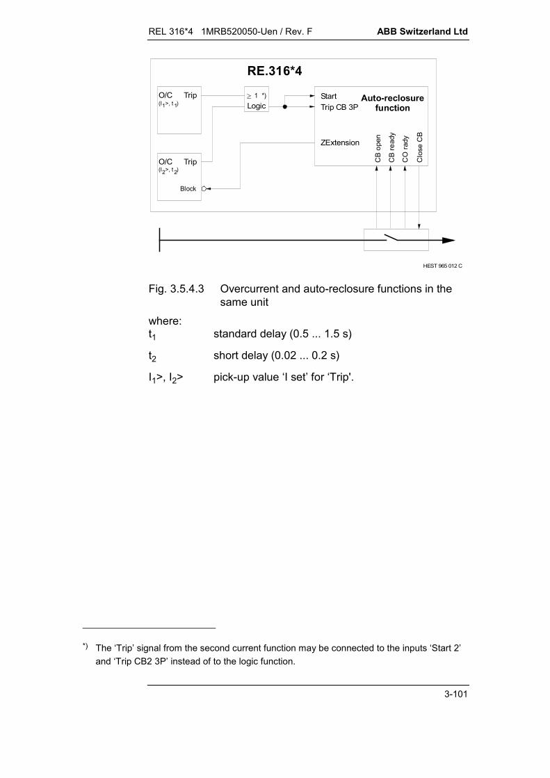
REL 316*4 1MRB520050-Uen / Rev. F ABB Switzerland Ltd
3-101
StartTrip CB 3P
RE.316*4
HEST 965 012 C
ZExtension
Logic
Block
O/C Trip(I >, t )2 2
O/C Trip(I >, t )1 1
1 *)
CB
ope
n
CB
read
y
CO
rady
Clo
se C
B
Auto-reclosurefunction
Fig. 3.5.4.3 Overcurrent and auto-reclosure functions in thesame unit
where:t1 standard delay (0.5 ... 1.5 s)
t2 short delay (0.02 ... 0.2 s)
I1>, I2> pick-up value ‘I set’ for ‘Trip'.
*) The ‘Trip’ signal from the second current function may be connected to the inputs ‘Start 2’
and ‘Trip CB2 3P’ instead of to the logic function.

ABB Switzerland Ltd REL 316*4 1MRB520050-Uen / Rev. F
3-102
3.5.4.4. Redundant schemes
Provision is made for coordinating the operation of twoprotection functions and one or two auto-reclosure functions perline terminal (see Fig. 3.5.4.4 and Fig. 3.5.4.5).
A master/follower logic has to be used to avoid any time-raceproblems due to differing timer tolerances.
A redundant scheme assumes first and second main protectionschemes each with its own reclosure function. The operation ofthe reclosure functions therefore has to be coordinated byconfiguring one as ‘master’ and the other as ‘follower’. If themaster AR starts first, it delays the operation of the follower ARuntil it has either achieved successful reclosure or otherwise.
If the follower AR is enabled first, its dead time starts to run, butshould the master start during the follow’s dead time, operationof the follower reclosure function is suspended and the mastertakes over and performs its reclosure cycle.
The follower is on “hot standby” and only takes over, if themaster AR or its protection function fails to operate.
The signal from a faulty contact like ‘CO Ready’ to the masterrecloser, however, would result in a ‘Def.Trip’ output after thetime ‘t Timeout’ and this would also block the Follower AR.
In the circuit of Fig. 3.5.4.4, the master and follower functionscan also be the other way round by appropriately configuring thesystem software.

REL 316*4 1MRB520050-Uen / Rev. F ABB Switzerland Ltd
3-103
Master mode = 'ON' Master mode = 'OFF‘
DelayFlwr
CB open
Close CB
CO ready
CB ready
Inhibit Outp
Inhibit Inp
Trip CB2 3P
HEST 965 013 C
< Z< Z
Star
t RST
Trip
CB
Trip
CB
3PSt
art S
OTF
1 P
olAR
ZExt
ensi
onA
R
RE.
316*
4St
art
Trip
CB
Trip
CB
3PC
ondB
lkAR
Trip
3-P
ol
ZExt
ensi
on
Star
tTr
ip C
BTr
ip C
B 3P
Con
dBlk
ARTr
ip 3
-Pol
ZExt
ensi
on
MasterDelay
CB open
Close CB
CO ready
CB ready
Inhibit Inp
Inhibit OutpAut
o-re
clos
ure
func
tion
Aut
o-re
clos
ure
func
tion
Fig. 3.5.4.4 Redundant scheme (first and second main < Z andauto-reclosure functions) with master/follower logic

ABB Switzerland Ltd REL 316*4 1MRB520050-Uen / Rev. F
3-104
RE.316*4
Backup
HEST 965 014 C
< Z (1)
< Z (2)
Trip CB 3PStart
Trip 3-Pol
ZExtension
Trip CB2
Trip CB2 3P
Start 2
Start RSTTrip CB
Trip CB 3P
1PolARStart SOTF
ZExtensionAR
Trip 3-Pol
StartTrip CBTrip CB 3P
ZExtension
CondBlkAR
Auto-reclosurefunction
CB
open
CB
read
y
CO
rady
Clo
se C
B
Fig. 3.5.4.5 Several protection functions and a common auto-reclosure unit
3.5.4.5. Master/follower logic
Provision is made for a master/follower logic in 1½ breakerschemes with two line protections per line and an auto-reclosurefunction per circuit-breaker.One of the reclosure functions is assigned the role of master byappropriately setting the parameter ‘Master mode’. After a suc-cessful reclosure, the master AR then enables the follower AR,respectively its CB (the connections are as given in Fig. 3.5.4.6for a three-phase trip and reclosure for all types of faults).

REL 316*4 1MRB520050-Uen / Rev. F ABB Switzerland Ltd
3-105
CB
ope
nC
B re
ady
CO
Rea
dy
Clo
se C
B
CB
ope
nC
B re
ady
CO
Rea
dy
Clo
se C
B
BlkFlwrDelFlwr
Star
t
Trip
CB
3P
Trip
CB
Trip
3-P
ol
Star
t 2Tr
ip C
B 2
Trip
CB
2 3P
Con
dBlk
AR
Trip CB R
Trip CB T
Trip CB S
Star
t SO
TF
1 P
olAR
=F
Trip
CB
3P
Trip
CB
Star
t RST
Star
t RST
Aux
MasterDel
MasterUnsucc
Trip CB R
Trip CB T
Trip CB S
Star
t SO
TF
Star
t RS
TAux
Trip
CB
3P
Trip
CB
Star
t RS
T
1 P
olAR
=F
RE.316*4 MAIN 1
< Z
RE.316*4 MAIN 2
< Z
RE.316*4Master AR
RE.316*4Follower AR
"Master CB” "Follower CB”
LINE
Star
t
Trip
CB
3P
Trip
CB
Con
dBlk
AR
Trip
3-P
ol
Star
t 2
Trip
CB
2
Trip
CB
2 3P
HEST 005 002 C
Fig. 3.5.4.6 Earth and phase fault master/follower scheme forAR mode 1P3P-3P
Note: A second line on the diameter (1½ breaker scheme)requires additional connections and logic.
ABB Switzerland Ltd REL 316*4 1MRB520050-Uen / Rev. F
3-106
Follower CB delay ‘DelayFlwr’
The master reclosure function sends an active ‘DelFlwr’ signal tothe ‘MasterDelay’ I/P of the follower to delay its ‘Close CB’command to the follower CB until the master reclosure functionissues the ‘Close CB’ command, which is followed by a wait timeof 300 ms as a precaution to allow time for a successfulreclosure. If the reclosure is unsuccessful, the output remainshigh until the signal ‘Def.Trip’ is activated (the ‘DelayFlwr’ signalresets and ‘Blk to Flwr’ signal is generated).Should this signal reset before the end of the follower dead time,the close command to the follower CB is issued at the end of thedead time.
Blocking reclosure by the follower ‘Blk.toFlwr’
The master reclosure function sends an active ‘Blk.toFlwr’ signalto the follower ‘Mast.noSucc’ I/P to block reclosure by thefollower, if the reclosure attempt by the master was unsuccessfulas indicated by the generation of its ‘Def.Trip’ output.
3.5.4.6. Duplex logic
A duplex logic for a line with two circuit-breakers is also included(see Fig. 3.5.4.7).
Observe the following in connection with a duplex scheme:
Note: One of the breakers has to be set to low priority.
For the scheme to operate correctly, the corresponding CBsignals must be connected to the ‘CB open’ and ‘CB2 open’inputs for the duplex logic (setting to ‘off’ disables the duplexlogic). Follow the procedure below, if separate ‘CB ready’ and‘CB open’ signals are not available from the circuit-breakers: Connect the two circuit-breaker signalling contacts
‘CB ready’ (air-pressure or spring charging) and‘CB closed’ in series. For this, ‘t Close’ must be set longerthan the maximum spring charging time to suppress thedefinitive trip signal in the case of a successful reclosure.
Assign the combined signals to the corresponding‘CB ready’ inputs.
Assign the same signals but inverted to the corresponding‘CB open’ inputs.

REL 316*4 1MRB520050-Uen / Rev. F ABB Switzerland Ltd
3-107
< Z (1)
RE.316*4
CB1
< Z (2)
CB2
HEST 965 016 C
Auto-reclosurefunction
Trip
CB
3P
Star
t SO
TF
1Pol
AR
ZExt
ensi
onA
R
Trip
CB
Star
t RS
T
ZExt
ensi
on
Trip
3-P
ol
Trip
CB
3P
Con
dBlk
AR
Trip
3-P
ol
ZExt
ensi
on
Trip
CB
Star
t
Trip
CB
2 3P
Trip
CB
2
Star
t 2
CB
ope
n
CB
read
y
CO
read
y
Clo
se C
B
CB
2 op
en
CB
2 re
ady
CO
read
y 2
Clo
se C
B2
Fig. 3.5.4.7 Duplex scheme (< Z can be redundant)

ABB Switzerland Ltd REL 316*4 1MRB520050-Uen / Rev. F
3-108
3.5.4.7. Timers
The timers have setting ranges extending up to 300 s in steps of10 ms.
The purpose of each of the timers is described below.
Dead times ‘t Dead1 1P’ to ‘t Dead 4’
Provided the trip signal is issued before ‘t Oper’ elapses, thedead time is the period between the tripping signal (‘Trip CB’)and the close signal (‘Close CB’).
The required dead time must be entered separately for each re-closure cycle. This necessitates setting the following parameters:'t Dead1 1P’, ‘t Dead1 3P’, ‘t Dead 2’, ‘t Dead 3’ and ‘t Dead 4’.
Provision is made for externally switching the dead times ‘tDead1 1P’ and ‘t Dead1 3P’ for the first (fast) reclosure attemptto a second setting. The corresponding additional time periodcan be set with the aid of the parameter ‘t Dead 1 Ext’ andactivated via the binary I/P ‘Extend t1’.
The 2nd., 3rd. and 4th. reclosure attempts are always three-phase.
Extended dead time ‘t Dead 1 Ext’
This time provides facility for extending the dead time (e.g. shouldthe communications channel be defective or for a redundantscheme with 2 auto-reclosure functions). The extended deadtime is enabled by the binary input ‘Extend t1’.
Maximum fault duration for a reclosure attempt ‘t Oper’
If a fault has persisted for some time, the probability of a suc-cessful reclosure reduces. The likelihood of the power systembecoming unstable is also greater for an unsuccessful auto-re-closure attempt following a fault which has persisted for a longperiod. It is for these reasons that the time after the inception ofa fault during which reclosure can be initiated is limited. The faultduration is set using parameter ‘t Oper’.
The timer for the fault duration is started by the pick-up signalfrom the protection function (Start). Faults resulting in trippingafter ‘t Oper’ are locked out (‘Def. Trip’) and reclosure does nottake place.
Should the fault duration time expire before the protection trips,auto-reclosure is blocked and the reclaim time is started.
REL 316*4 1MRB520050-Uen / Rev. F ABB Switzerland Ltd
3-109
Example:
Time ‘T Oper’ < ‘Delay(2)’ of the distance function means thatauto-reclosure only takes place for faults in the first distancezone (‘Delay(1)’).This function is not required for schemes that only use currentfunctions. The binary inputs ‘Start’ and ‘Trip CB 3P’ areconnected together (see Section 3.5.4.3.).
Reclaim time ‘t inhibit’The purpose of the inhibit time is among other things to permitthe circuit-breaker to recover its full voltage withstand. To thisend, it disables the auto-reclosure function for the time set forparameter ‘t inhibit’ after one of the following events:
the last reclosing attempt
a definitive trip resulting from a protection trip after the faultduration time ‘t Oper’
a recurring trip between discrimination time and dead time(evolving fault, see O/P signal ‘Def. Trip’).
Close signal duration ‘t Close’The maximum duration of the circuit-breaker close signal(command O/P ‘Close CB’) is determined by the parameter‘t Close’. Any tripping signal which occurs during this timeoverrides the close signal. A second, third or fourth reclosureattempt can only take place, if the next trip occurs within the time‘t Close’.
Discrimination times ‘t 1P discrim.’ and ‘t 3P discrim.’The discrimination time determines the procedure in the event ofa different kind of fault occurring during the dead time (evolvingfault), i.e. one of the other two phases also picks up or the trip-ping signal resets and picks up again. The discrimination time isstarted together with the dead time. Should a tripping signalrecur due to an evolving fault between the expiry of thediscrimination time and before the end of the dead time, thereclaim timer is started and a definitive trip (‘Def. Trip’) initiated.The dead time is also discontinued and the signal ‘AR in prog.’reset.If the first fault was initially an earth fault and evolves during thetime ‘t Dead1 1P’, but before the end of the discrimination time ‘tDiscrim 1P’, the dead time ‘t Dead1 3P’ is started and three-phase reclosure takes place.

ABB Switzerland Ltd REL 316*4 1MRB520050-Uen / Rev. F
3-110
The discrimination time ‘t Discrim 3P’ is also needed for 2 or 1½breaker schemes, where each circuit-breaker has its own auto-reclosure function.A typical setting for the parameters ‘t Discrim 1P’ or ‘t Discrim3P’ for single and three-phase reclosure is 50 % of the shortestdead time.The minimum permissible setting for the discrimination time is:
100 ms + CB time
Note:
The time ‘t1EvolFaults’ during which a subsequent fault has tobe detected (evolving or unsuccessful reclosure) is a distancefunction setting.
The distance protection parameter ‘t1EvolFaults’ enables thetime to be set during which a subsequent fault (evolving orunsuccessful reclosure) results in a three-phase trip, i.e. everysecond trip by the distance protection function trips all threephases. The auto-reclosure function also signals the switchoverto three-phase tripping by exciting the signal ‘Trip 3-Pol’ at theend of the fault discrimination time ‘t Discrim. 1P’.It is advisable to set the time ‘t1EvolFaults’ longer than the auto-reclosure dead time ‘t Dead1 1P’.
't Timeout'
The parameter ‘t Timeout’ determines the period after the deadtime within which the close signal must be issued, otherwise a‘Def.Trip’ is generated and no further reclosure attempt is made.Before a close command is issued at the end of every dead time,the logic [(‘synchroChck’ AND ‘CO ready’) OR ‘Dead Line’ OR‘ExtSCBypas’)] is checked and the command only enabledproviding all the criteria are correct within the setting of‘t Timeout’.
Blocking time ‘t AR Block'
The auto-reclosure function can be enabled or disabled by thefollowing binary I/P signals:
ExtBlkAR - also blocks during the reclosure cycle
Manual close - also blocks during the reclosure cycle
Inhibit Inp - also blocks during the reclosure cycle

REL 316*4 1MRB520050-Uen / Rev. F ABB Switzerland Ltd
3-111
CB Ready - blocks excepting during the reclosure cycle
CB2 Ready - blocks excepting during the reclosure cycle *)
CO Ready - blocks at the end of the reclosure cycleafter expiry of the time ‘t time-out’
CO Ready 2 - blocks at the end of the reclosure cycleafter expiry of the time ‘t time-out’ *)
Mast.noSucc - blocks the follower CB after anunsuccessful reclosure attempt by themaster
CondBlkAR - blocks excepting during the reclosure cycle.
Should a ‘CondBlkAR’ signal occur during a reclosure cycle (i.e.the ‘AR in prog.’ signal is active), it only becomes effective fromthe end of the current reclosure cycle and providing it is stillactive.
A reclosure cycle remains blocked for the duration of the setblocking time ‘t AR Block’ after the last binary I/P has been en-abled. Blocking also takes place during initialisation of theprotection relay when its auxiliary supply is switched on or theparameter settings are being loaded.
*) 2 denotes the I/O’s for CB2 in a duplex scheme (see Fig. 3.5.4.7.).

ABB Switzerland Ltd REL 316*4 1MRB520050-Uen / Rev. F
3-112
3.5.4.8. External binary inputs
Starting and tripping signals from the protection function:‘Start’ (‘Start 2’, ‘Start 3’), ‘Trip CB’ and ‘Trip CB 3P’(‘Trip CB2’, ‘Trip CB3’, ‘Trip CB2 3P’, ‘Trip CB3 3P’)
In order to control the auto-reclosure function, it is necessary toconfigure the three I/P signals ‘Trip CB’ (general trip), ‘Trip CB 3P’(three-phase trip) and ‘Start’. The normal procedure to achieve thisis to select the protection signals via the sub-menu ‘OUTPUTFROM FUNCTION’. Since the auto-reclosure function iscompletely independent, signals from other functions may alsobe selected.
In a 1st. and 2nd. main (redundant) protection scheme with oneauto-reclosure relay (see Section 3.5.4.4.), the I/P signals ‘TripCB2’, ‘Trip CB2 3P’ and ‘Start 2’ must also be connected to thesecond protection function.
Circuit-breaker ready signals: ‘CB ready’ and ‘CO Ready’(‘CB2 ready’ and ‘CO Ready 2’)
The I/P’s for the parameters ‘CO Ready’ and ‘CB ready’ (or ‘COReady 2’ and ‘CB2 ready’ in a duplex scheme) must be con-nected to the circuit-breakers in order to signal that they areready to perform a complete reclosure cycle. In cases where oneof the I/P’s is not used, it must be set to ‘TRUE’.
An active ‘CB ready’ signal informs the auto-reclosure functionthat reclosure is permissible (i.e. sufficient energy is available fora full open/close/open cycle).Once a reclosure cycle has started, this signal is ignored (be-cause the pressure varies during a reclosure cycle of an air-blastbreaker).
Resetting of this signal is internally delayed by 100 ms.
The ‘CO Ready’ signal (close-open cycle can be carried out) isonly effective during a reclosure cycle, i.e. during the dead time.Should there be insufficient energy to open the circuit-breakeragain following closure, the close signal is disabled and a ‘Def.Trip’ (definitive trip) is generated.This I/P is only used in conjunction with circuit-breakers, whichprovide the corresponding information (C-O query), e.g. spring-charged and air-blast circuit-breakers with two switching energylevels.

REL 316*4 1MRB520050-Uen / Rev. F ABB Switzerland Ltd
3-113
Circuit-breaker open ‘CB open’ (‘CB2 open’)It is also necessary to include the initial status of the circuit-breakers to prevent one from receiving a close signal, which wasalready open before the fault occurred.The binary I/P ‘CB open’ (and ‘CB2 open’ in a duplex scheme) isthus provided to determine the initial status of a circuit-breaker.The pick-up of these signals is delayed by 100 ms to prevent anyunwanted blocking of fast circuit-breakers.A circuit-breaker which was already open before the ‘Start’ signalwas received (‘CB open’ at logical ‘1’) is not closed by the auto-reclosure function.Where a circuit-breaker does not provide the necessary infor-mation (‘CB open’ signal), the I/P must be permanently set to‘off’ (‘F’ or ‘False’). Providing the scheme is also not a duplexscheme (i.e. only one CB), the binary I/P ‘CB2 open’ must alsobe permanently set to ‘on’ (‘T’ or ‘True’).Accordingly, these are the default settings for ‘CB open’ and‘CB2 open’.The auto-reclosure function can then operate with a single cir-cuit-breaker without a ‘CB open’ signal and no superfluous closesignal is generated for the non-existing CB2.
De-energised line ‘Dead Line’ (‘Dead Line 2’) with checkingof synchronism ‘synchroChck’ (‘synchroChck2’)Before the ‘Close CB’ (or ‘Close CB2’) instruction can be issued,either the ‘Dead line’ or the ‘synchroChck’ I/P (or ‘Dead line 2’ or‘synchroChck2’ in a duplex scheme) must be at logical ‘1’.Logic: [(‘synchroChck’ AND ‘CO ready’) OR ‘Dead Line’ OR‘ExtSCBypas']Logic: [(‘synchroChck2’ AND ‘CO ready 2’) OR ‘Dead Line 2’ OR‘ExtSCBypas']
External blocking ‘ExtBlkAR’ and ‘CondBlkAR'The reclosure function is always blocked by an active ‘ExtBlkAR’I/P.An active ‘CondBlkAR’ I/P will only block the function, providinga reclosure cycle is not running (i.e. the ‘AR in prog.’ signal is atlogical ‘0’).The ‘Cond.Blk AR’ signal is needed to prevent a reclosure cycle,when no reclosure is wanted for a first trip that occurs during ‘tOper’. This is the case, for example, for trips by the switch-onto-fault (SOTF) protection or by a directional E/F protection viaPLC.

ABB Switzerland Ltd REL 316*4 1MRB520050-Uen / Rev. F
3-114
To prevent the SOFT from initiating auto-reclosure, the distanceprotection ‘SOFT start’ signal must be connected to the‘CondBlkAR’ input.
'Manual close'
The reclosure function is immediately blocked (for the blockingtime ‘t AR Block’) by a ‘Manual close’ signal. This signal is alsoneeded for the overreaching logic to switch the ‘ZExtension’ sig-nal to ‘on’.
External synchrocheck bypass signal ‘ExtSCBypas'
This I/P provides facility for bypassing the ‘synchroChck’ and‘CO Ready’ (or SynchroChck2’ and ‘CO Ready 2’ for CB2) ena-bling I/P’s.It is only active for the first fast three-phase or single-phasereclosure attempt.
External extension of the dead time ‘Extend t1'
A logical ‘1’ at the ‘Extend t1’ I/P extends the dead times ‘t Dead11P’ and ‘t Dead1 3P’ by the setting ‘t Dead1 Ext’ for the first(fast) reclosure attempt. This could be necessary, for example, inthe event of a communication channel failure or in a redundantscheme.
3.5.4.9. Close CB and signalling outputs
The most important auto-reclosure output is the ‘Close CB’command which must be assigned to a heavy-duty auxiliary O/Prelay. This and 14 other heavy-duty and signalling O/P’s areprovided.
This signal picks up when the closing command is issued andresets at the end of the time ‘t Close’ or earlier if there is atripping occurs upon reclosing.
Status of the auto-reclosure function (‘AR Ready’ and ‘ARBlocked’)
The signal ‘AR Ready’ is generated when the auto-reclosurefunction is ready to perform a reclosure cycle and the signal ‘ARBlocked’ when it is blocked.
The ‘AR Ready’ signal is active providing a reclosure cycle is notblocked (no ‘AR Blocked’ signal) and a dead time is not running.
The ‘AR Ready’ signal is active during a reclose command forpurposes of enabling the synchrocheck function (see Fig. 3 inthe synchrocheck function section).
REL 316*4 1MRB520050-Uen / Rev. F ABB Switzerland Ltd
3-115
Auto-reclosure cycle in progress
There are six signals which show that a reclosure cycle is run-ning and what stage has been reached:
'AR in prog.' reclosure cycle in progress'First AR 1P' first single-phase reclosure attempt'First AR 3P' first three-phase reclosure attempt‘second AR' second reclosure attempt'Third AR' third reclosure attempt'Fourth AR' fourth reclosure attempt.
The signal ‘AR in prog’ picks up at the start of the dead time andis reset by the falling edge of the last reclose command.
Circuit-breaker closing signals ‘Close CB’ and ‘Close CB2'
The CB closing command is normally assigned to a heavy-dutyauxiliary O/P relay by correspondingly configuring the parameter‘Close CB’ (also ‘Close CB2’ in a duplex scheme). It is alsopossible to assign the same signal to a signalling O/P under thesame parameter name.
A trip subsequent to a close command during the time ‘t Close’ +300 ms switches the dead time step (second, third and fourthAR) or initiates a lock-out trip (depending on the setting). A closecommand is reset immediately after a trip.
Definitive trip ‘Def. Trip'
The ‘Def. Trip’ signal indicates that the circuit-breaker will remaintripped and no further reclosure attempts will be made. The fol-lowing conditions can cause a definitive trip:
All reclosure attempts were unsuccessful. A starting or tripping signal was generated after the dis-
crimination time and before dead time. Tripping takes place while a reclosure cycle is blocked (either
via the blocking I/P or by the reclaim time). The ‘synchroChck’ (or ‘Dead line’) and/or ‘CO Ready’ I/P’s
were not enabled during ‘t Timeout’ due to lack of syn-chronism.
The ‘CB open’ signal is still active 300 ms after the close signalhas reset (i.e. the CB has not responded to the close signal).
The trip signal that followed the start signal occurred after thefault duration time ‘t Oper’.
Tripping occurred for a phase fault and the mode selected forthe first reclosure cycle is 1P-1P or 1P-3P.

ABB Switzerland Ltd REL 316*4 1MRB520050-Uen / Rev. F
3-116
Perform three-phase trip ‘Trip 3-Pol'
The ‘Trip 3-Pol’ O/P instructs the line protection to trip all threephases.The signal can be externally or internally connected.This signal is generated automatically, if reclosure is blocked,‘CB Ready’ is inactive, the CB is open, the single-phasediscrimination time ‘t1P Discrim’ has elapsed or the signal ‘FirstAR 3P’ is active.
Zone extension ‘ZExtension’
The setting of the auto-reclosure parameter ‘ZE Prefault’ deter-mines the pre-fault reach of the distance protection when theauto-reclosure function is inactive (before the first fault), i.e. set-ting ‘ZE Prefault’ to ‘on’ activates the output signal ‘ZExtension’which then switches the distance function to overreach.
The parameters ‘ZE 1. AR reach’ to ‘ZE 4. AR reach’ provide fa-cility for individually switching the reach for each reclosure at-tempt. Setting one of these parameters to ‘on’ means that the‘ZExtension’ O/P is at logical ‘1’ and the distance relay isswitched to overreach either before fault occurrence or for thefollowing reclosure attempt, otherwise the distance relay is set tounderreach.
With the exception of its first change of state when providing‘ZEPrefault’ is set to ‘ON’ it resets together with the signal ‘TripCB’ or ‘Trip CB 3P’, this signal picks up and resets together withthe ‘Close CB’ signal.
The distance relay is switched to overreaching for a ‘Manualclose’.
It is switched to underreaching when the auto-reclosure functionis blocked.
Note also that the ‘ZExtension’ signal is connected to the binaryinput ‘ZEMode AR’ of the zone extension logic in the distanceprotection function.
3.5.4.10. Timing diagrams
The time relationship between the various signals during opera-tion of the auto-reclosure function can be seen from Fig. 3.5.4.8to Fig. 3.5.4.16.
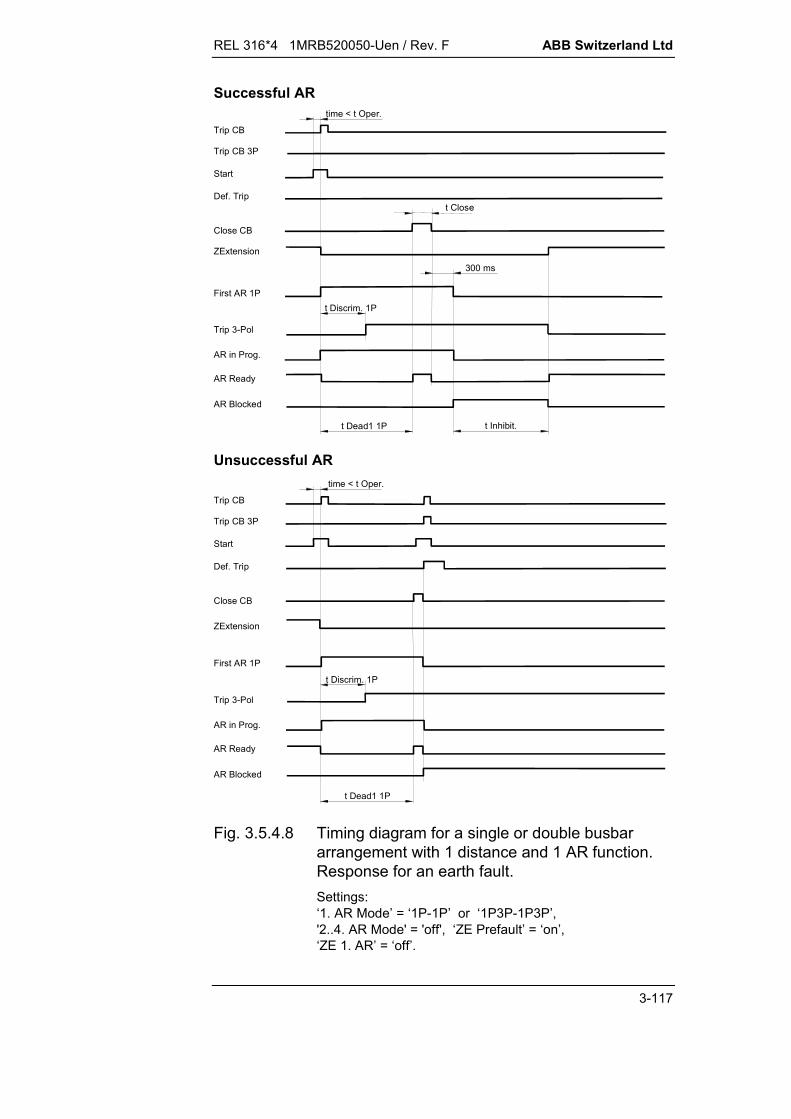
REL 316*4 1MRB520050-Uen / Rev. F ABB Switzerland Ltd
3-117
Trip CB
Start
Close CB
ZExtension
Def. Trip
First AR 1P
Trip CB 3P
AR in Prog.
AR Ready
AR Blocked
t Dead1 1P
time < t Oper.
Trip 3-Pol
t Discrim. 1P
Trip CB
Start
Close CB
ZExtension
Def. Trip
First AR 1P
Trip CB 3P
AR in Prog.
AR Ready
AR Blocked
t Inhibit.t Dead1 1P
time < t Oper.
Trip 3-Pol
t Discrim. 1P
Unsuccessful AR
Successful AR
t Close
300 ms
Fig. 3.5.4.8 Timing diagram for a single or double busbararrangement with 1 distance and 1 AR function.Response for an earth fault.Settings:‘1. AR Mode’ = ‘1P-1P’ or ‘1P3P-1P3P’,'2..4. AR Mode' = 'off', ‘ZE Prefault’ = ‘on’,‘ZE 1. AR’ = ‘off’.

ABB Switzerland Ltd REL 316*4 1MRB520050-Uen / Rev. F
3-118
t Inhibit.t Dead1 1P
time < t Oper.
t Discrim. 1P
t Close
300 ms
Trip CB
StartDef. Trip
Trip CB 3P
AR in Prog.
AR Ready
AR Blocked
Trip 3-Pol
Successful AR (evolving fault during ‘t Discrim1P’)
Close CB
ZExtension
First AR 1P
First AR 3P
time < t Oper.
t Dead1 1P
Trip CB
Start
Trip CB 3P
Unsuccessful AR (evolving fault within ‘t Dead1 1P’, but after ‘t Discrim1P’)
Close CB
ZExtension
Def. Trip
First AR 1P
AR in Prog.
AR Ready
AR Blocked
Trip 3-Pol
t Discrim. 1P
Fig. 3.5.4.9 Timing diagram for a single or double busbararrangement with 1 distance and 1 AR function.Response for an earth fault which evolves.Settings:‘1. AR Mode’ = ‘1P3P-1P3P’, '2..4. AR Mode' = 'off',‘ZE Prefault’ = ‘on’, ‘ZE 1. AR’ = ‘off’.

REL 316*4 1MRB520050-Uen / Rev. F ABB Switzerland Ltd
3-119
Trip CB 3P
Start
Close CB
ZExtension
Def. Trip
Trip CB
First AR 3P
Second AR
Third AR
time < t Oper.
Trip CB 3P
Start
Close CB
ZExtension
Def. Trip
Trip CB
First AR 3P
Second AR
Third AR
time < t Oper.Unsuccessful AR
Successful AR
t Close
AR in Prog.
AR Ready
AR Blocked
t Dead1 3P t Dead2 t Dead3
Trip 3-Pol
AR in Prog.
AR Ready
AR Blocked
t Dead1 3P t Dead2 t Dead3 t Inhibit.
Trip 3-Pol
300 ms
Fig. 3.5.4.10 Timing diagram for a single or double busbararrangement with 1 distance and 1 AR function.Response for multiple phase faults.Settings:‘1. AR Mode’ = ‘1P3P-1P3P’, ‘2..4. AR Mode’ = 3,‘ZE Prefault’ = ‘on’, ‘ZE 1. AR’ = ‘off’,‘ZE 2. AR’ = ‘on’ and ‘ZE 3. AR’ = ‘off’.

ABB Switzerland Ltd REL 316*4 1MRB520050-Uen / Rev. F
3-120
Start
Close CB
ZExtension
Def. Trip
Trip CB 3P
Trip 3-Pol
t Discrim. 1P
Master AR (Master Mode = "ON")
First AR 1P
DelayFlwr
AR in Prog.
AR Ready
AR Blocked
t Inhibit.t Dead1 1P
InhibitOut
Trip CBtime < t Oper.
Follower AR (Master Mode = "OFF", AR on "hot standby")
Start
Close CB
ZExtension
Def. Trip
Trip CB 3P
Trip 3-Pol
t Discrim. 1PFirst AR 1P
AR in Prog.
AR Ready
AR Blockedt Inhibit.t Dead1 1P
Trip CB
MasterDelay
InhibitInp
t Close
300 ms
time < t Oper.
Fig. 3.5.4.11 Timing diagram for redundant sheme with 2 AR´s.Response for 1 successful reclosure.Settings:‘1. AR Mode’ = ‘1P3P-1P3P’, ‘2..4. AR Mode’ = ‘off’,‘ZE Prefault’ = ‘on’ and ‘ZE 1. AR’ = ‘off’.
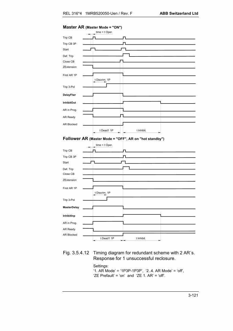
REL 316*4 1MRB520050-Uen / Rev. F ABB Switzerland Ltd
3-121
Start
Close CB
ZExtension
Def. Trip
Trip CB 3P
Trip 3-Pol
t Discrim. 1P
Master AR (Master Mode = "ON")
First AR 1P
DelayFlwr
AR in Prog.
AR Ready
AR Blocked
t Inhibit.t Dead1 1P
InhibitOut
Trip CB
time < t Oper.
Follower AR (Master Mode = "OFF", AR on "hot standby")
Start
Close CB
ZExtension
Def. Trip
Trip CB 3P
Trip 3-Pol
t Discrim. 1PFirst AR 1P
AR in Prog.
AR Ready
AR Blockedt Inhibit.t Dead1 1P
Trip CB
MasterDelay
InhibitInp
time < t Oper.
Fig. 3.5.4.12 Timing diagram for redundant scheme with 2 AR´s.Response for 1 unsuccessful reclosure.Settings:‘1. AR Mode’ = ‘1P3P-1P3P’, ‘2..4. AR Mode’ = ‘off’,‘ZE Prefault’ = ‘on’ and ‘ZE 1. AR’ = ‘off’.

ABB Switzerland Ltd REL 316*4 1MRB520050-Uen / Rev. F
3-122
Trip CB
Start
Close CB
ZExtension
Def. Trip
First AR 3P
Trip CB 3P
AR in Prog.
AR Ready
AR Blocked
t Dead1 3P
time < t Oper.
Trip 3-Pol
Close CB2
Trip CB
Start
Close CB
ZExtension
Def. Trip
First AR 3P
Trip CB 3P
AR in Prog.
AR Ready
AR Blockedt Inhibit.t Dead1 3P
Trip 3-Pol
Close CB2
t Close
300 ms
Unsuccessful AR
Successful AR
300 ms
time < t Oper.
Fig. 3.5.4.13 Timing diagram for duplex scheme.Response for a multiple phase fault.Settings:‘1. AR Mode’ = ‘1P3P-1P3P’, ‘2..4. AR Mode’ = ‘off’,‘ZE Prefault’ = ‘on’, ‘ZE 1. AR’ = ‘off’and ‘CB2 Priority’ = ‘off’.

REL 316*4 1MRB520050-Uen / Rev. F ABB Switzerland Ltd
3-123
Start
Close CB
ZExtension
Def. Trip
Trip CB 3P
Trip 3-Pol
t Discrim. 1P
First AR 1P
DelayFlwr
AR in Prog.
AR Ready
AR Blocked
t Dead1 1P
Blk.toFlwr
Trip CB
time < t Oper.
Follower AR (Master Mode = "OFF", Centre CB)
Master AR (Master Mode = "ON", CB on bus side)
Start
Close CB
ZExtension
Def. Trip
Trip CB 3P
Trip 3-Pol
t Discrim. 1PFirst AR 1P
MasterDelay
AR in Prog.
AR Ready
AR Blocked
t Dead1 1P
Mast.noSucc
Trip CB
time < t Oper.
Fig. 3.5.4.14 Timing diagram for a 1½ breaker scheme.Response for an unsuccessful reclosure.Settings:‘1. AR Mode’ = ‘1P3P-1P3P’ or ‘1P-1P’,‘2..4. AR Mode’ = ‘off’, ‘ZE Prefault’ = ‘on’and ‘ZE 1. AR’ = ‘off’.

ABB Switzerland Ltd REL 316*4 1MRB520050-Uen / Rev. F
3-124
Start
Close CB
ZExtension
Def. Trip
Trip CB 3P
Trip 3-Pol
t Discrim. 1P
First AR 1P
DelayFlwr
AR in Prog.
AR Ready
Blk.toFlwr
Trip CB
time < t Oper.
Follower AR (Master Mode = "OFF", Centre CB)
Master AR (Master Mode = "ON", CB on bus side)
Close CB
ZExtension
Def. Trip
Trip 3-Pol
t Discrim. 1PFirst AR 1P
MasterDelay
AR in Prog.
AR Ready
Mast.noSucc
t Close
StartTrip CB 3P
Trip CB
AR Blockedt Inhibit.t Dead1 1P
AR Blockedt Inhibit.t Dead1 1P
300 ms
t Close
300 ms
time < t Oper.
Fig. 3.5.4.15 Timing diagram for a 1½ breaker scheme.Response for a successful reclosure.Settings:‘1. AR Mode’ = ‘1P3P-1P3P’ or ‘1P-1P’,‘2..4. AR Mode’ = ‘off’, ‘ZE Prefault’ = ‘on’und ‘ZE 1. AR’ = ‘off’.
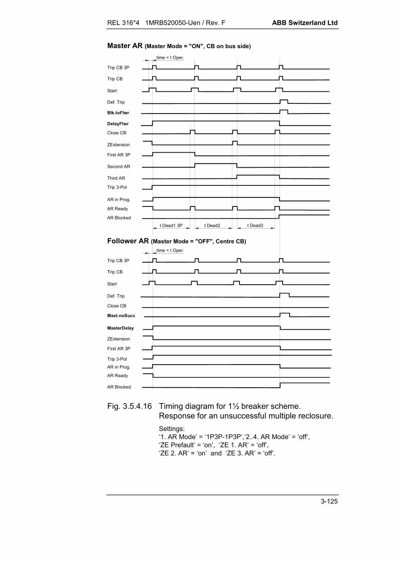
REL 316*4 1MRB520050-Uen / Rev. F ABB Switzerland Ltd
3-125
Trip CB 3P
Start
Close CB
ZExtension
Def. Trip
Trip CB
First AR 3P
Trip 3-Pol
Trip CB 3P
Start
Close CB
ZExtension
Def. Trip
Trip CB
First AR 3P
Second AR
Third AR
time < t Oper.
AR in Prog.
AR Ready
AR Blocked
t Dead1 3P t Dead2 t Dead3
Trip 3-Pol
Master AR (Master Mode = "ON", CB on bus side)
Follower AR (Master Mode = "OFF", Centre CB)
DelayFlwr
Blk.toFlwr
Mast.noSucc
MasterDelay
AR in Prog.
AR Ready
AR Blocked
time < t Oper.
Fig. 3.5.4.16 Timing diagram for 1½ breaker scheme.Response for an unsuccessful multiple reclosure.Settings:‘1. AR Mode’ = ‘1P3P-1P3P‘,‘2..4. AR Mode’ = ‘off’,‘ZE Prefault’ = ‘on’, ‘ZE 1. AR’ = ‘off’,‘ZE 2. AR’ = ‘on’ and ‘ZE 3. AR’ = ‘off’.

ABB Switzerland Ltd REL 316*4 1MRB520050-Uen / Rev. F
3-126
3.5.4.11. Checking the dead times
When commissioning the auto-reclosure function, it is not suffi-cient to check the combined operation of protection function,auto-reclosure function and circuit-breaker, the resulting deadtimes must also be determined.
Since the dead time settings do not correspond to the effectivetotal dead times, especially in a scheme with two circuit-breakers(see Fig. 3.5.4.17), the period during which the circuit-breaker isactually open must be measured. This entails adjusting the deadtime until the measured breaker time minus arcing and pre-ignition times and the inevitable CB tolerances result in anadequate composite dead time.
Providing the circuit-breakers at both ends of the line are of thesame type and thus permit the same tolerances to be assumedat both ends, the same dead time tp can be set in the twoterminal stations. Where this is not the case, the tripping andclosing times of the two circuit-breakers must also be measuredin addition to the dead times. The dead times set for the twoauto-reclosure functions must then ensure that a sufficiently long“overlapping” dead time exists to enable the circuit-breakers todeionise.

REL 316*4 1MRB520050-Uen / Rev. F ABB Switzerland Ltd
3-127
C
O
B
0 12
34
5
6
(t)
t7
t6
t4
t2
t5t3
t1
tp
twts
C
O
A
0 1
2
34
56
A B
HEST 925 035 C
A: circuit-breaker 1 B: circuit-breaker 2C: "closed" position O: "open" position
0: start 1: ‘trip’ signal2: contacts part 3: current interrupted4: ‘close’ signal 5: current flows again6: contacts make
t1: tripping time t2: reclosing time t3: arc extinction time
t4: dead time t5: pre-ignition time t6: duration of interruption
t7: resulting dead time
tp: dead time ts: inhibit time tw: fault duration
Fig. 3.5.4.17 Resulting composite dead time(Source: “Guidelines for auto-reclosure inelectrical power systems” published by theGerman Association of Power Utilities VDEW)

ABB Switzerland Ltd REL 316*4 1MRB520050-Uen / Rev. F
3-128

REL 316*4 1MRB520050-Uen / Rev. F ABB Switzerland Ltd
3-129
3.5.5. Sensitive earth fault protection for grounded systems(EarthFltGnd2)
A. Application
High-resistance earth faults, which cannot be detected by thedistance protection, can still cause appreciable problems in spiteof the relatively low fault currents involved.The sensitive E/F protection function has been included tocomplement the main line protection function and cover the lowE/F current range. The protection processes the zero-sequencecomponents 3I0 and 3U0.
B. Features
DC component filter harmonic filter directional measurement of zero-sequence components
(derived either internally or externally) current pick-up enabling level reference voltage enabling level adjustable characteristic angle permissive and blocking transfer tripping schemes echo logic for weak infeed and open circuit-breaker transient blocking logic for reversal of energy direction.
C. Inputs and outputs
I. C.t./v.t. inputs:
Voltage Current
II. Binary inputs:
External blocking Receive CB closed V.t. supervision Starting and tripping by the distance function
III. Binary outputs:
Pick-up Trip Fault forwards Fault backwards Transmit Block distance protection receive

ABB Switzerland Ltd REL 316*4 1MRB520050-Uen / Rev. F
3-130
IV. Measurements:
Neutral voltage (3U0) Neutral current (3I0) Real power component of neutral power (3U0 3I0) Apparent power component of neutral power Fault direction (1 = forwards, -1 = backwards;
this measured variable only applies when the binary input“CB closed” is active).
This function does not transfer any tripping measurementsvia the IBB.
The measurements in the event list are not generated at theinstant of tripping, but when the enabling levels “U-Setting”and “I-Dir are exceeded”.
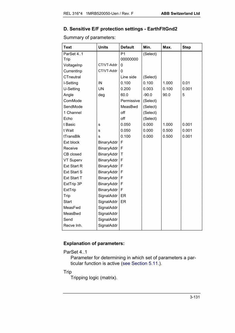
REL 316*4 1MRB520050-Uen / Rev. F ABB Switzerland Ltd
3-131
D. Sensitive E/F protection settings - EarthFltGnd2
Summary of parameters:
Text Units Default Min. Max. StepParSet 4..1 P1 (Select)Trip 00000000VoltageInp CT/VT-Addr 0CurrentInp CT/VT-Addr 0CTneutral Line side (Select)I-Setting IN 0.100 0.100 1.000 0.01U-Setting UN 0.200 0.003 0.100 0.001Angle deg 60.0 -90.0 90.0 5ComMode Permissive (Select)SendMode MeasBwd (Select)1 Channel off (Select)Echo off (Select)t Basic s 0.050 0.000 1.000 0.001t Wait s 0.050 0.000 0.500 0.001tTransBlk s 0.100 0.000 0.500 0.001Ext block BinaryAddr FReceive BinaryAddr FCB closed BinaryAddr TVT Superv BinaryAddr FExt Start R BinaryAddr FExt Start S BinaryAddr FExt Start T BinaryAddr FExtTrip 3P BinaryAddr FExtTrip BinaryAddr FTrip SignalAddr ERStart SignalAddr ERMeasFwd SignalAddrMeasBwd SignalAddrSend SignalAddrRecve Inh. SignalAddr
Explanation of parameters:
ParSet 4..1Parameter for determining in which set of parameters a par-ticular function is active (see Section 5.11.).
TripTripping logic (matrix).
ABB Switzerland Ltd REL 316*4 1MRB520050-Uen / Rev. F
3-132
VoltageInpdefines the v.t. input channel. All the v.t. input channels areavailable for selection. If the neutral voltage is derived fromthe three phase voltages, the first channel (R phase) of thegroup of three must be selected.
CurrentInpdefines the c.t. input channel. All the c.t. input channels areavailable for selection. If the neutral current is derived fromthe three phase currents, the first channel (R phase) of thegroup of three must be selected.
CT neutralSide of the c.t’s on which the star-point is formed (current di-rection): line (in accordance with the diagram in Section 12) busbar (reversed connection).
I-SettingCurrent pick-up setting.
U-SettingReference voltage pick-up setting.
AngleCharacteristic angle setting.
ComModeKind of transfer tripping scheme: permissive blocking.
SendModeFor what system condition a signal is transmitted in anintertripping scheme: forwards measurement (only permissive scheme) non-directional (only blocking scheme) backwards measurement (only blocking scheme).
1 ChannelSupplementary logic needed for coordinating E/F and dis-tance protections when using the same communicationschannel for a permissive scheme. off on.
REL 316*4 1MRB520050-Uen / Rev. F ABB Switzerland Ltd
3-133
Echo
Echo logic for weak infeed and open CB: off Echo logic disabled Weak Echo only for weak infeed Bkr Echo only when CB open Weak & Bkr Echo for weak infeed or CB open.
t BasicBasic time setting.
t WaitTime allowed for a blocking signal to be transferred and forthe directional comparison to be made.
tTransBlkBlocking time after a reversal of fault energy direction(transient blocking).
Ext blockI/P for an external blocking signal.F: - enabledT: - disabledxx: - all binary I/P’s (or O/P’s of protection functions).
ReceivePLC receive I/P.F: - no PLC receive signalxx: - all binary I/P’s (or O/P’s of protection functions).
CB closedCB position indicator I/P.F: - function disabledT: - function enabledxx: - all binary I/P’s (or O/P’s of protection functions).
VT SupervV.t. supervision I/P.F: - tripping enabledT: - tripping disabledxx: - all binary I/P’s (or O/P’s of protection functions).

ABB Switzerland Ltd REL 316*4 1MRB520050-Uen / Rev. F
3-134
Ext Start R / S / T, Ext Trip 3P, Ext TripI/P’s for the distance function signals ‘Start R’, ‘Start S’, ‘StartT’, ‘Trip CB 3P’ and ‘Trip CB’ for coordinating operation.F: - not connectedxx: - all binary I/P’s (or O/P’s of protection functions).
TripTripping signal O/P.
StartO/P for signalling that the protection has picked up, i.e. thecurrent has exceeded the enabling setting (“I-Setting”).
MeasFwdO/P for signalling a fault in the forwards direction.
MeasBwdO/P for signalling a fault in the backwards direction.
SendPLC transmit signal.
RecveInh.O/P for preventing the distance function from receiving a PLCsignal. (This is only effective when E/F and distance protec-tions use a common PLC channel, i.e. the parameter ‘1Channel’ is set to ‘on’ .)
REL 316*4 1MRB520050-Uen / Rev. F ABB Switzerland Ltd
3-135
E. Setting instructions
3.5.5.1. Coordination with the distance protection
Directional E/F function as ancillary to the distance function
Compared with integrated E/F and distance functions, the logicin an independent E/F function needs certain starting and trip-ping signals generated by the distance function and, providingthe connections are made as in Section 3.5.5.12., the E/F protec-tion is blocked in the following situations:
starting of more than one distance phase three-phase tripping any trip (single and three-phase), if ‘1 Channel’ is set to ‘on’.
Scheme with independent communication channels
Apart from the added security of redundancy, independent com-munication channels enable different transfer tripping schemesto be used for E/F and distance protections.
Providing the distance protection can detect a fault, it should tripbefore the E/F protection picks up. For this reason, the basic op-erating time ‘t basic’ for the E/F protection must be set longerthan the longest response time to be expected of the distanceprotection.
Scheme with a common communication channel
Where E/F and distance protections use the same communica-tion channel, the transfer tripping schemes must be either bothpermissive or both blocking. In the case of permissive schemes,in which the distance protection operates with non-directionalcriteria at one end for a weak infeed, a supplementary logic mustbe enabled by appropriately setting the parameter ‘1 Channel’.
This supplementary logic interlocks the distance relay’s receivesignal at the end of the E/F function’s basic time or when it picksup in the backwards direction. To this end, the signal ‘RecveInh’is connected to the distance protection input ‘ExtBlkHF’. Thusthe communication channel is initially available for use by thedistance protection and only made available to the E/F protectionat the end of the basic time. The basic time setting must allowadequate time for the distance protection to detect and clear afault if it can.

ABB Switzerland Ltd REL 316*4 1MRB520050-Uen / Rev. F
3-136
Independent directional E/F protection
The E/F function can also be applied as a completely independ-ent protection, but only in MV and HV systems.
The coordination of E/F and distance protections in this case isachieved by appropriately setting the parameter ‘t basic’ .If this time is too short, there is a likelihood that the E/F protec-tion will issue a three-phase trip before the circuit-breaker hasopened for faults that have been correctly detected by the dis-tance protection.The basic time of the E/F protection must therefore be longenough to ensure that the distance protection can trip phase-selectively.
No facility is provided for using the distance relay starters toachieve phase-selective tripping by the directional E/F function.
An independent directional E/F function requires its own com-munication channel which must be entirely independent of thedistance protection.
3.5.5.2. Choice of operating mode
It is assumed that the E/F protection settings at both ends of theprotected line are the same. This applies especially to the basictime, the blocking time, the transfer tripping scheme in use andoptions.

REL 316*4 1MRB520050-Uen / Rev. F ABB Switzerland Ltd
3-137
3.5.5.3. Choice of transfer tripping scheme
In the case of a permissive directional comparison scheme, theamount of fault resistance which can be detected reducestowards the remote end of the line, because the enabling currentmust be exceeded at both ends. Without additional precautions,the use of a permissive scheme would be limited on lines with aweak infeed at one end.
It was possible to eliminate this disadvantage by providing thedirectional E/F protection with its own echo logic for weakinfeeds which can be switched in and out as required.
Important:Note that the protection only operates in a comparisonmode during the comparison time (1 s) and is blocked at theend of this time. The comparison time starts at the end ofthe basic time.
On the other hand, a directional comparison scheme using ablocking signal is able to detect high-resistance E/F’s along thewhole length of the line, because the protection at the stronginfeed end is always able to trip although the current at the weakinfeed end does not reach the enabling level.
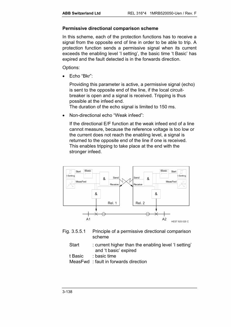
ABB Switzerland Ltd REL 316*4 1MRB520050-Uen / Rev. F
3-138
Permissive directional comparison scheme
In this scheme, each of the protection functions has to receive asignal from the opposite end of line in order to be able to trip. Aprotection function sends a permissive signal when its currentexceeds the enabling level ‘I setting’, the basic time ‘t Basic’ hasexpired and the fault detected is in the forwards direction.
Options:
Echo “Bkr”:
Providing this parameter is active, a permissive signal (echo)is sent to the opposite end of the line, if the local circuit-breaker is open and a signal is received. Tripping is thuspossible at the infeed end.The duration of the echo signal is limited to 150 ms.
Non-directional echo “Weak infeed”:
If the directional E/F function at the weak infeed end of a linecannot measure, because the reference voltage is too low orthe current does not reach the enabling level, a signal isreturned to the opposite end of the line if one is received.This enables tripping to take place at the end with thestronger infeed.
HEST 925 020 CA1 A2
Rel. 1
&
&
tBasic
I-Setting
MeasFwd
Start
Send
Receive
Rel. 2
&
&I-Setting
MeasFwd
StarttBasic
Send
Receive
Fig. 3.5.5.1 Principle of a permissive directional comparisonscheme
Start : current higher than the enabling level ‘I setting’and ‘t basic’ expired
t Basic : basic timeMeasFwd : fault in forwards direction

REL 316*4 1MRB520050-Uen / Rev. F ABB Switzerland Ltd
3-139
HEST 925 022 C
Basic ode operation m
Non-directional e "Transient Blocking"cho and
Non-directional echo
I set
I dir
U set
Iasymm
I
U
0
0
Tx: I-setting * MeasFwd * t BasicT: I-setting * MeasFwd * t Basic * RxTB: MeasBwd' + t TransBlk
TB: MeasBwd' + t TransBlk<Tx: MeasBwd * Rx>
<Tx: MeasBwd * Rx>
Fig. 3.5.5.2 Operation of a permissive directional comparisonscheme
<...> : optional functionRx : receiveMeasFwd : fault in forwards directionMeasBwd : fault in backwards direction including ‘Transient
blocking’MeasBwd’ : fault in backwards directionI dir : current enable for directional measurement
(= 0.7 I-Setting)I Setting : current enabling levelIasymm : asymmetrical currents under normal load conditionsTx : sendT : tripTB : transient blockingt TransBlk : blocking timet Basic : basic timet Wait : waiting timeU Setting : reference voltage.

ABB Switzerland Ltd REL 316*4 1MRB520050-Uen / Rev. F
3-140
Blocking directional comparison scheme
Providing the conditions for directional measurement are fulfilledi.e. the current higher than ‘I dir’ and the voltage higher than itsenabling level ‘U-Setting’, a protection function transmits ablocking signal to the remote station immediately it detects afault in the backwards direction.
Note: I dir = 0.7 I-Setting
A protection function measuring a fault in the direction of theprotected line trips at the end of the adjustable waiting time‘t wait’, providing a blocking signal is not received beforehand.
Options:
SendMode: ‘non-directional’
A blocking signal is transmitted in this mode, if the current ishigher than ‘I dir’, the basic time has expired and no fault isdetected in the forwards direction (including situations whena direction measurement is impossible, because 3U0 < U-Setting).
HEST 925 021 C
A1 A2
Rel. 1
&
&
tBasic
I-dir
I-Setting
tBasic
MeasBwd
MeasFwd
tWait
Send
Receive
Rel. 2
&
&Send
Receive
tBasic
tBasic
I-dir
I-Setting
MeasBwd
MeasFwd
tWait
Fig. 3.5.5.3 Principle of a blocking directional comparisonscheme
I-Setting : current enabling levelI-dir : current enable for directional measurement
(= 0,7 I-Setting)t Basic : basic timet Wait : waiting timeMeasFwd : fault in forwards directionMeasBwd : fault in backwards direction.

REL 316*4 1MRB520050-Uen / Rev. F ABB Switzerland Ltd
3-141
HEST 925 023 C
I set
I dir
U set
Iasymm
Basic operation mode
Non-directional transmission
I
U
0
0
Tx: I dir * MeasBwd * t Basic <+I dir * MeasFwd * t Basic>T: I set * MeasFwd * t Basic * Rx * t WaitTB: MeasBwd' + t TransBlk
Tx: I dir * MeasBwd * t Basic <+I dir * MeasFwd * t Basic>
TB: MeasBwd' + t TransBlk
<Tx: I dir *MeasFwd * t
Fig. 3.5.5.4 Operation of a directional comparison blockingscheme (for the legend, see after Fig. 3.5.5.2)
3.5.5.4. Setting the enabling pick-up levels
The setting of the current enabling ‘I dir’ must take account of thezero-sequence component in normal operation arising fromsystem asymmetries.
The pick-up setting for the voltage enabling signal ‘U-Setting’ isdetermined by the level of asymmetries on the secondary side(v.t. tolerances, asymmetrical burdens etc.).
The ability to read voltage and current values on the relay is auseful aid for determining these settings.
For example, if the enabling current setting ‘I-Setting’ is too low,the pick-up signal lights continuously (current circuit enabled).
Since an E/F causes asymmetrical voltages in the vicinity of thefault, the current flowing via the system capacitances also has azero-sequence component. A capacitive current of this kind on along line lies within the setting range of the sensitive E/F protec-tion function.
ABB Switzerland Ltd REL 316*4 1MRB520050-Uen / Rev. F
3-142
The pick-up level ‘I dir’ of the current circuit for the directionalmeasurement has a fixed setting of 0.7 x ‘I set’ to take accountof influences such as c.t. errors and the capacitive chargingcurrents of the line.
The following procedure is recommended for setting the pick-uplevels:
The enabling current for the directional measurement mustbe set to at least twice the maximum possible asymmetricalcurrent, which can occur in normal operation.
II
Iasymm
N- Setting2 0.
The voltage pick-up must be set to 1.6 times the level of thespurious voltages, which can occur due to asymmetries in thev.t. secondary circuit.
U Setting 1.6U
Usec.asymm
N-
where:
U-Setting : setting of the enabling voltage for the directionalmeasurement
Usec.asymm : voltage component 3 U0 caused by asymmetriesin the v.t. secondary circuit (e.g. v.t. errors)
UN : 100 V or 200 V according to v.t. unit in use
I-Setting : setting of the enabling current
Iasymm : current component 3I0 caused by asymmetricalload currents
IN : primary c.t. rated current.
3.5.5.5. Setting the characteristic angle ‘Angle’
The line marking the reversal of direction lies at +90° in relationto the reference voltage.
In order to achieve symmetrical operation of the directional ele-ment in spite of this, the characteristic angle should equal that ofthe zero-sequence impedance of the source.
REL 316*4 1MRB520050-Uen / Rev. F ABB Switzerland Ltd
3-143
3.5.5.6. Setting the basic time ‘t basic’
The basic time is the period between pick-up of the protectionand the earliest possible trip.
The operation of the protection function can be coordinated withothers on the same line by judiciously setting the basic time.
The basic time is also used to achieve coordination between theE/F function (three-phase tripping) and the distance function(phase-selective tripping).
The E/F protection is delayed to allow time for the distance pro-tection to respond to a fault if it can.
The basic time is normally set to:
t basic > max. tripping time of the phase-selective distanceprotection (taking account of signal transmissiontime and sequential tripping)
+ CB operating time+ aux. contact time
(I/P ‘CB closed’)+ safety margin.
The sum of these times is usually about 100 to 200 ms.
3.5.5.7. Circuit-breaker delay
To avoid operation of the enabling current detector during thetransient oscillations, which occur following the closing of thecircuit-breaker, it is blocked for 50 ms upon receiving the corre-sponding signal from the CB.
3.5.5.8. The comparison time ‘t comp’
The comparison time is the time allowed for the directional com-parison to be made and is therefore dependent on the type oftransfer tripping scheme.
The comparison time has a fixed setting of 1 s.
ABB Switzerland Ltd REL 316*4 1MRB520050-Uen / Rev. F
3-144
3.5.5.9. Setting the waiting time ‘t wait’
The waiting time is also started at the end of the basic time, butis only effective in a blocking scheme.
In a blocking scheme, tripping is delayed by the setting of ‘t wait’to allow time for the protection in the opposite station to decideon the direction of the fault and to transmit a correspondingblocking signal if necessary.
‘t wait’ should be set at least as long as the measuring time(about 30 ms) plus the longest possible signal transmission time.
3.5.5.10. Setting the transient blocking time ‘t TransBlk’
The protection function includes a "transient blocking logic" toprevent any mal-operation during the course of tripping a fault orauto-reclosure on double-circuit lines, when there is a likelihoodof the flow of energy reversing direction. The time setting can beselected in a wide range to suit the prevailing conditions.
For example, after a fault has been detected in the backwardsdirection, a second directional decision in the forwards directionis inhibited for the setting of ‘t TransBlk’ .
The time chosen is determined largely by the time required forthe measurement to reset and the transfer tripping scheme inuse.
The recommended setting is 60 ms plus the reset time of thecommunication channel.
3.5.5.11. C.t./v.t. inputs of the function
Where the zero-sequence components of the voltages and thecurrents are derived internally, the c.t. and v.t. inputs must beconnected precisely as shown in the wiring diagram. The neutralof the c.t’s in this case is formed on the line side and theparameter ‘CT neutral’ must be set to ‘line side’ .
REL 316*4 1MRB520050-Uen / Rev. F ABB Switzerland Ltd
3-145
3.5.5.12. Binary inputs of the function
Ext. block
Exciting the ‘Ext. block’ I/P disables the entire protection func-tion.
Receive
The signal transmitted by the protection in the opposite station isconnected to this I/P.
CB closed
The ‘CB closed’ I/P is intended for the position indicator signalfrom the circuit-breaker and has a fixed pick-up delay of 50 ms.The protection function is only enabled when this signal isreceived to confirm that the CB is closed. The correspondingauxiliary contacts for the three phases must be connected inseries to ensure that the protection does not operate duringsingle-phase reclosure.
The echo logic is enabled 100 ms after the circuit-breaker isopened.
VT Supervision
The ‘VT Superv’ I/P is needed to block the echo logic. It can beexcited either by the ‘VTSup’ signal from the internal distanceprotection function or an auxiliary contact on the m.c.b. via abinary I/P.
If this I/P is not needed, it must be set to “F”.
Ext Start R / S / T, Ext Trip 3P, Ext Trip
These I/P’s are for coordinating operation with the distanceprotection function. To them are connected the distance functionsignals ‘Start R’, ‘Start S’, ‘Start T’, ‘Trip CB 3P’ and ‘Trip CB’.
They must be set to “F” if an independent directional E/F schemeis in use.
ABB Switzerland Ltd REL 316*4 1MRB520050-Uen / Rev. F
3-146
3.5.5.13. Outputs
Trip
There are two ‘Trip’ signals, one for energising the tripping relayvia the tripping logic and the other for controlling LED’s andsignalling contacts.
Start
An active "Start" O/P signals that the zero-sequence current hasexceeded the pick-up setting ‘I-Setting’. This signal is only gen-erated providing the function is not blocked.
MeasFwd
‘MeasFwd’ is active when the measuring element detects a faultin the forwards direction, i.e. the settings of ‘I dir’ and ‘U setting’have been exceeded.
MeasBwd
‘MeasBwd’ is active when the measuring element detects a faultin the backwards direction, i.e. the settings of ‘I dir’ and ‘U set-ting’ have been exceeded.
Send
The ‘Send’ O/P is the signal sent to the other end of the line.
Receive Inhibit
The ‘Recve Inh’ signal prevents the distance function fromreceiving a PLC signal (see Section 3.5.5.1.). It is only generatedwhen the parameter ‘1 Channel’ is set, the basic time has expi-red or the E/F protection picks up for a reverse fault.
The signal ‘Recve Inh’ must be connected to the distance func-tion I/P ‘ExtBlkHF’.

REL 316*4 1MRB520050-Uen / Rev. F ABB Switzerland Ltd
3-147
3.5.6. Inverse definite minimum time earth fault overcurrentfunction (I0-Invers)
A. Application
Overcurrent function with IDMT characteristic. A typical applica-tion is as back-up for the E/F protection function, in which case itmeasures 3 I0 either supplied from an external source or inter-nally derived.
B. Features
Tripping characteristic according to British Standard 142(see Fig. 3.5.6.1):c = 0.02 : normal inversec = 1 : very inverse and long time earth faultc = 2 : extremely inverse.
DC component filter harmonic filter external 3 I0 signal or 3 I0 internally derived from the three
phase currents wider setting range than specified in BS 142.
C. Inputs and outputs
I. C.t./v.t. inputs
Current
II. Binary inputs
Blocking
III. Binary outputs
Starting Tripping
IV. Measurements
Neutral current.
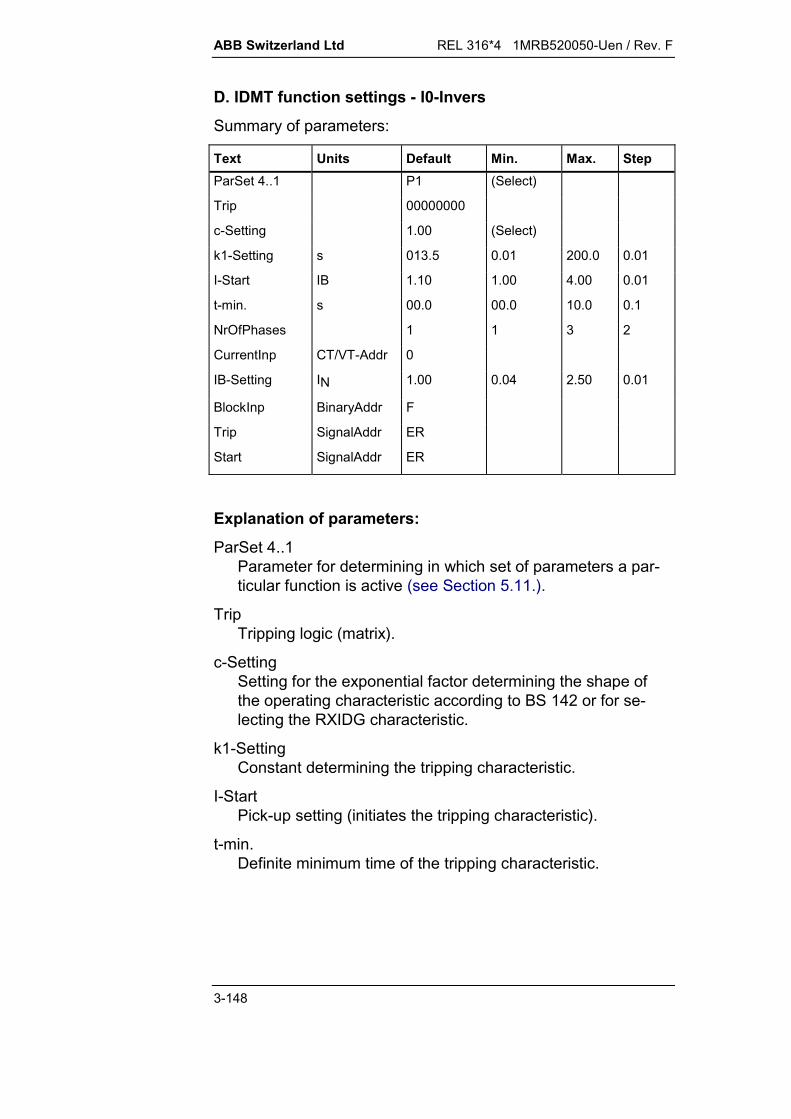
ABB Switzerland Ltd REL 316*4 1MRB520050-Uen / Rev. F
3-148
D. IDMT function settings - I0-Invers
Summary of parameters:
Text Units Default Min. Max. StepParSet 4..1 P1 (Select)
Trip 00000000
c-Setting 1.00 (Select)
k1-Setting s 013.5 0.01 200.0 0.01
I-Start IB 1.10 1.00 4.00 0.01
t-min. s 00.0 00.0 10.0 0.1
NrOfPhases 1 1 3 2
CurrentInp CT/VT-Addr 0
IB-Setting IN 1.00 0.04 2.50 0.01
BlockInp BinaryAddr F
Trip SignalAddr ER
Start SignalAddr ER
Explanation of parameters:
ParSet 4..1Parameter for determining in which set of parameters a par-ticular function is active (see Section 5.11.).
TripTripping logic (matrix).
c-SettingSetting for the exponential factor determining the shape ofthe operating characteristic according to BS 142 or for se-lecting the RXIDG characteristic.
k1-SettingConstant determining the tripping characteristic.
I-StartPick-up setting (initiates the tripping characteristic).
t-min.Definite minimum time of the tripping characteristic.

REL 316*4 1MRB520050-Uen / Rev. F ABB Switzerland Ltd
3-149
NrOfPhasesNumber of phases evaluated for measurement:
1 : neutral current direct from an c.t. input3 : neutral current derived internally from the three
phases.
CurrentInpdefines the c.t. input channel. All the current channels areavailable for selection. In the case of a three-phasemeasurement, the first channel (R phase) of the group ofthree must be selected.
IB-SettingReference current to take account of discrepancies with re-spect to IN.
BlockingInpI/P for the external blocking signal.
F: - unusedT: - function always blockedxx: - all binary I/P's (or O/P's of protection functions).
TripTripping signal.
StartPick-up signal.

ABB Switzerland Ltd REL 316*4 1MRB520050-Uen / Rev. F
3-150
E. Setting instructions
Protection function enable ‘I-Start’
The IDMT function starts to run when the current applied to thefunction exceeds the setting ‘I-Start’. ‘I-Start’ is normally set to1.1 IB.
Choice of tripping characteristic ‘c’
The shape of the IDMT characteristic is determined by the con-stant ‘c’.
The standard IDMT characteristics according to BS 142 are:
“normal inverse” : c = 0.02“very inverse” and “long time earth fault” : c = 1.00“extremely inverse” : c = 2.00
Fig. 3.5.6.1 IDMT tripping characteristic for ‘I0-Invers’ (I = 3 I0)
“c-Setting” can also be set to “RXIDG”, in which case the func-tion’s inverse characteristic corresponds to that of the relay TypeRXIDG:
t [s] = 5.8 – 1.35 In (I/IB)
The parameter “k1-Setting” has no influence in this case.

REL 316*4 1MRB520050-Uen / Rev. F ABB Switzerland Ltd
3-151
Time multiplier ‘k1-Setting’
Discriminative operation of the relays along a line is achieved bytime-grading. Assuming all the relays to be set to the same IB,this involves setting the time multiplier in equal steps (gradingtime), increasing from the load towards the source.
For example, in the case of the “very inverse” characteristic, theconstant c = 1 and the factor k1 13.5. The operating time t isthen given by
t kI
IB
13 10
Assuming the grading time of the protection functions to be 0.5 sat 6 x IB, the settings of k1 according to the formula
k1 = 5 t
for operating times between 0.5 and 2.5 s become:
t [s] k1 [s]
0.5 2.51 5
1.5 7.5
2 10
2.5 12.5
The characteristics according to BS 142 are set as follows:“normal inverse” : k1 = 0.14 s“very inverse” : k1 = 13.5 s“extremely inverse” : k1 = 80 s“long time earth fault” : k1 = 120 s.
Definite minimum time ‘t-min.’
Where the IDMT function is being applied as back-up protectionfor a directional E/F protection, the definite minimum time ‘t-min.’must be set as follows
t-min. = t basic + t comp
t basic = basic time of the E/F functiont comp = comparison time of the E/F function (1 s).
ABB Switzerland Ltd REL 316*4 1MRB520050-Uen / Rev. F
3-152
Interconnections between IDMT and directional E/F func-tions
The IDMT protection is non-directional.
Directional operation can, however, be achieved by linking thedirectional signal ( ‘MeasFwd’, i.e. fault in forwards direction)from the E/F protection to the blocking I/P of the IDMT function.The I/P must be inverted so that blocking of the IDMT function iscancelled by an active forwards signal.
When using this arrangement, it must be noted that, when‘MeasFwd’ does not pick up, the IDMT function cannot trip whenthe reference voltage of the E/F function is too low. If tripping isrequired for this case, the directional E/F signal ‘MeasBwd’ mustbe applied to the blocking input.
Applications with single-phase reclosure
In schemes involving single-phase reclosure, the ‘I0-Invers’function has to be blocked for the time that one pole of a circuit-breakers is open if the minimum tripping time ‘tmin’ is set lessthan the single-phase dead time. This avoids false three-phasetripping due to the load currents in the healthy phases.
Typical settings:
IB to be calculatedI-Start 1.1 IBc depends on the protected unitk1 to be calculatedt-min. 0.00

REL 316*4 1MRB520050-Uen / Rev. F ABB Switzerland Ltd
3-153
3.5.7. Definite time over and undercurrent (Current-DT)
A. Application
General purpose current function (over and under) for
phase fault protection back-up protection
or for monitoring a current minimum.
B. Features
insensitive to DC component insensitive to harmonics single or three-phase measurement maximum respectively minimum value detection in the three-
phase mode detection of inrush currents.
C. Inputs and outputs
I. C.t./v.t. inputs:
Current
II. Binary inputs:
Blocking
III. Binary outputs:
pick-up tripping
IV. Measurements:
current amplitude.

ABB Switzerland Ltd REL 316*4 1MRB520050-Uen / Rev. F
3-154
D. Definite time current function settings - Current-DT
Summary of parameters:
Text Unit Default Min. Max. Step
ParSet 4..1 P1 (Select)Trip 00000000Delay s 01.00 0.02 60.00 0.01I-Setting IN 02.00 0.02 20.00 0.01MaxMin MAX (1ph) (Select)NrOfPhases 001 1 3 2CurrentInp CT/VT-Addr 0BlockInp BinaryAddr FTrip SignalAddr ERStart SignalAddr ER
Explanation of parameters:
ParSet 4..1Parameter for determining in which set of parameters a par-ticular function is active (see Section 5.11.).
Tripdefines the tripping channel activated by the tripping O/P ofthe function (matrix tripping logic).
DelayTime between the function picking up and tripping.
I-SettingPick-up current setting.Forbidden settings: > 1.6 IN when supplied from metering cores < 0.2 IN when supplied from protection cores.
MaxMindefines operation as overcurrent or undercurrent or withinrush blocking. Settings: MIN (3ph): Undercurrent.
Three-phase functions detect the highestphase current.Not permitted for single-phase functions.
MIN (1ph): Undercurrent.Three-phase functions detect the lowestphase current.

REL 316*4 1MRB520050-Uen / Rev. F ABB Switzerland Ltd
3-155
MAX (3ph): Overcurrent.Three-phase functions detect the lowestphase current.Not permitted for single-phase functions.
MAX (1ph): Overcurrent.Three-phase functions detect the highestphase current.
MAX-Inrush: Blocks during inrush currents if one phaseexceeds setting.
NrOfPhasesdefines whether single or three-phase measurement.
CurrentInpdefines the c.t. input channel. All current I/P's may beselected. In the case of three-phase measurement, the firstchannel (R phase) of the group of three selected must bespecified.
BlockInpI/P for blocking the function.F: - not blockedT: - blockedxx: - all binary I/P's (or O/P's of protection functions).
TripTripping signal.
StartPick-up signal.
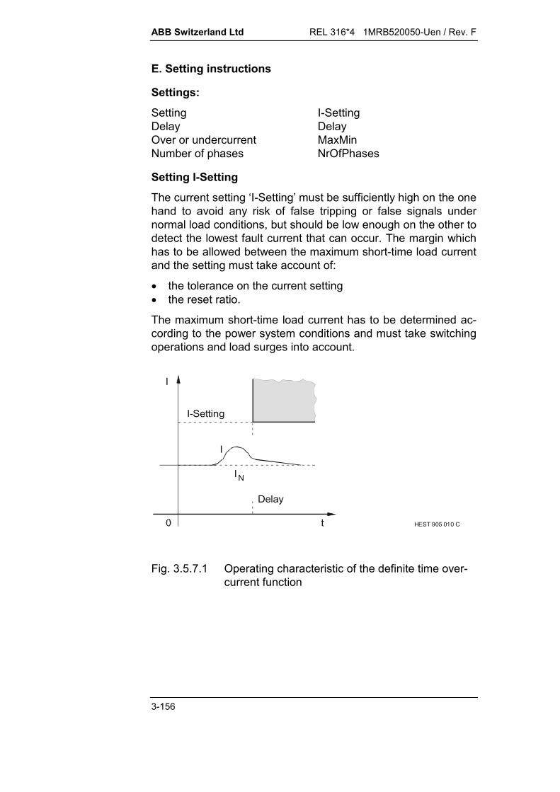
ABB Switzerland Ltd REL 316*4 1MRB520050-Uen / Rev. F
3-156
E. Setting instructions
Settings:
Setting I-SettingDelay DelayOver or undercurrent MaxMinNumber of phases NrOfPhases
Setting I-Setting
The current setting ‘I-Setting’ must be sufficiently high on the onehand to avoid any risk of false tripping or false signals undernormal load conditions, but should be low enough on the other todetect the lowest fault current that can occur. The margin whichhas to be allowed between the maximum short-time load currentand the setting must take account of:
the tolerance on the current setting the reset ratio.
The maximum short-time load current has to be determined ac-cording to the power system conditions and must take switchingoperations and load surges into account.
I
HEST 905 010 C
I
NI
I-Setting
Delay
Fig. 3.5.7.1 Operating characteristic of the definite time over-current function
REL 316*4 1MRB520050-Uen / Rev. F ABB Switzerland Ltd
3-157
Compensating any difference between the rated currents of c.t.IN1 and protected unit IGN is recommended. This is achieved withthe aid of the reference value of the A/D channel or by correctingthe overcurrent setting.
For example, for IGN = 800 A and IN1 = 1000 A, the setting for apick-up current of 1.5 IGN = 1200 A would have to be
2.1A1000A8005.1
II5.1
1N
GN
CurrentInp
An interposing c.t. in the input is essential for current settingslower than < 0.2 IN.
Delay
The delay is used to achieve discrimination of the overcurrentfunction. It is set according to the grading table for all the over-current units on the power system. The zone of protection of ourovercurrent function extends to the location of the next down-stream overcurrent relay.
Should the downstream relay fail to clear a fault, the overcurrentfunction trips slightly later as a back-up protection.
Setting MaxMin
This parameter enables the following operating modes to beselected:
MIN (3ph): Pick-up when the highest phase current alsofalls below the setting. This setting is not per-mitted for single-phase measurement.
MIN (1ph): Pick-up when the lowest phase current fallsbelow the setting.
MAX (3ph): Pick-up when the lowest phase current alsoexceeds the setting. This setting is not permit-ted for single-phase measurement.
MAX (1ph): Pick-up when the highest phase current ex-ceeds the setting.
MAX-Inrush: Blocking of inrush currents when a phasecurrent exceeds the setting.

ABB Switzerland Ltd REL 316*4 1MRB520050-Uen / Rev. F
3-158
Operation of the inrush blocking feature (parameter MaxMinset to ‘MAX-Inrush’)
The inrush detector picks up and blocks operation of the functionwhen the amplitude of the fundamental component of the currentexceeds the setting of the current function.
The inrush detector is based on the evaluation of the secondharmonic component of the current I2h in relation to the funda-mental frequency component I1h (evaluation of the amplitudes).
The output of the function is disabled when the ratio I2h/I1h ex-ceeds 10 % and enabled again when it falls below 8 %.
There is no setting for the peak value of I2h/I1h.
The function can operate with inrush blocking in both the singleand three-phase mode (parameter 'NrOfPhase').
In the three-phase mode, the phase used for evaluation is theone with the highest amplitude at rated frequency (pick-up andinrush detection).
REL 316*4 1MRB520050-Uen / Rev. F ABB Switzerland Ltd
3-159
3.5.8. Inverse time overcurrent (Current-Inv)
A. Application
Overcurrent function with time delay inversely proportional to thecurrent and definite minimum tripping time (IDMT).
B. Features
operating characteristics (see Fig. 3.5.8.1) according toBritish Standard 142:c = 0.02 : normal inversec = 1 : very inverse and long time earth faultc = 2 : extremely inverse.
insensitive to DC component insensitive to harmonics single or three-phase measurement detection of the highest phase value in the three-phase mode wider setting range than specified in B.S. 142.
C. Inputs and outputs
I. C.t./v.t. inputs:
current
II. Binary inputs:
Blocking
III. Binary outputs:
pick-up tripping
IV. Measurements:
current amplitude.
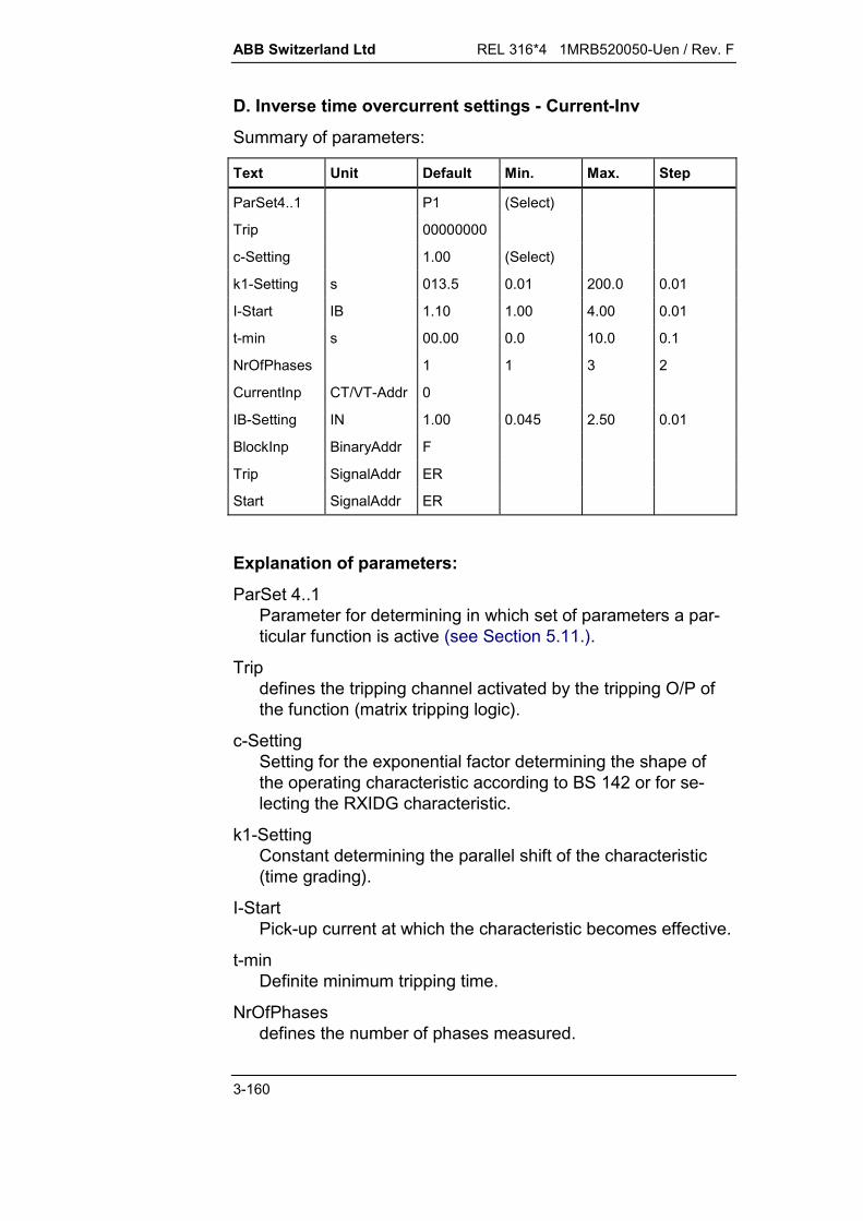
ABB Switzerland Ltd REL 316*4 1MRB520050-Uen / Rev. F
3-160
D. Inverse time overcurrent settings - Current-Inv
Summary of parameters:
Text Unit Default Min. Max. Step
ParSet4..1 P1 (Select)
Trip 00000000
c-Setting 1.00 (Select)
k1-Setting s 013.5 0.01 200.0 0.01
I-Start IB 1.10 1.00 4.00 0.01
t-min s 00.00 0.0 10.0 0.1
NrOfPhases 1 1 3 2
CurrentInp CT/VT-Addr 0
IB-Setting IN 1.00 0.045 2.50 0.01
BlockInp BinaryAddr F
Trip SignalAddr ER
Start SignalAddr ER
Explanation of parameters:
ParSet 4..1Parameter for determining in which set of parameters a par-ticular function is active (see Section 5.11.).
Tripdefines the tripping channel activated by the tripping O/P ofthe function (matrix tripping logic).
c-SettingSetting for the exponential factor determining the shape ofthe operating characteristic according to BS 142 or for se-lecting the RXIDG characteristic.
k1-SettingConstant determining the parallel shift of the characteristic(time grading).
I-StartPick-up current at which the characteristic becomes effective.
t-minDefinite minimum tripping time.
NrOfPhasesdefines the number of phases measured.

REL 316*4 1MRB520050-Uen / Rev. F ABB Switzerland Ltd
3-161
CurrentInpdefines the c.t. input channel. All current I/P's may beselected. In the case of three-phase measurement, the firstchannel (R phase) of the group of three selected must bespecified.
IB-SettingBase current for taking account of differences of rated currentIN.
BlockInpdefines the input for an external blocking signal.
F: - not usedT: - function always blockedxx: - all binary inputs (or outputs of protection
functions).
TripTripping signal.
StartPick-up signal.
ABB Switzerland Ltd REL 316*4 1MRB520050-Uen / Rev. F
3-162
E. Setting instructions
Settings:
Base current IB-SettingCharacteristic enabling current I-StartType of characteristic c-SettingMultiplier k1-Setting
The IDMT overcurrent function is used to protect transformers,feeders and loads of the auxiliaries supply system against phaseand earth faults. The function responds largely only to the fun-damental component of the fault current.
Base current “IB-Setting”
An IDMT relay does not have a fixed current setting above whichit operates and below which it does not, as does a definite time-overcurrent relay. Instead, its operating characteristic is chosensuch that it is always above the load current. To this end, therelay has a reference current IB that is set the same as the loadcurrent of the protected unit IB1. The reference current IBdetermines the relative position of the relay characteristic whichis enabled when the current exceeds the reference current by agiven amount (“I-Start”). By setting the reference current IB toequal the load current of the protected unit IB1 instead of its ratedcurrent, for
IB1 < IN of the protected unit: the protection is more sensitive
IB1 > IN of the protected unit: the protection permits maximumutilisation of the thermalcapability of the protected unit.
Example:Load current of protected unit IB1 = 800 AC.t. rated current IN1 = 1000 A
IN2 = 5 ARelay rated current IN = 5 A
Relay reference current “IB-Setting”:
IB I II
A AA
ABN2
N 1
1800 5
10004
Setting:
8.0A5A4
IIBN

REL 316*4 1MRB520050-Uen / Rev. F ABB Switzerland Ltd
3-163
An alternative is to adjust the position of the IDMT characteristicto match the rated load of the protected unit and set thereference current to its rated current instead of its load current.
Enabling the characteristic ‘I-Start’
The IDMT characteristic is enabled when the current exceedsthe setting ‘I-Start’. A typical setting for ‘I-Start’ is 1.1 IB.
Choice of characteristic ‘c-Setting’
The constant ‘c-Setting’ determines the shape of the IDMTcharacteristic.The settings for the standard characteristics according toB.S. 142 are:“normal inverse” : c = 0.02“very inverse” and “long time earth fault” : c = 1.00“extremely inverse” : c = 2.00.
Fig. 3.5.8.1 Operating characteristic of the IDMT overcurrentfunction
“c-Setting” can also be set to “RXIDG”, in which case thefunction’s inverse characteristic corresponds to that of the relayType RXIDG:
t [s] = 5.8 – 1.35 In (I/IB)
The parameter “k1-Setting” has no influence in this case.

ABB Switzerland Ltd REL 316*4 1MRB520050-Uen / Rev. F
3-164
Multiplier ‘k1-Setting’
The multiplier ‘k1-Setting’ enables the IDMT characteristicchosen by the setting of parameter c to be shifted withoutchanging its shape. This is used for grading the operating timesof a series of IDMT relays along a line to achieve discrimination.
For example, in the case of the “very inverse” characteristic, theconstant c = 1 and the factor k1 13.5. The operating time t isgiven by the equation
t kI
IB
1
1
Assuming a grading time of 0.5 s at 6 times the base current IB isrequired, the factor k1 for each of the relays is given by
k1 = 5 t
This produces for operating times between 0.5 and 2.5 s thefollowing settings for k1:
t [s] k1 [s]
0.5 2.51 5
1.5 7.5
2 10
2.5 12.5
The characteristics according to BS 142 are set as follows:“normal inverse” : k1 = 0.14 s“very inverse” : k1 = 13.5 s“extremely inverse” : k1 = 80 s“long time earth fault” : k1 = 120 s.
Typical settings:
IB-Setting corresponding to load current of the pro-tected unit
I-Start 1.1 IBc-Setting according to desired characteristic for the
protected unitk1-Setting according to the time grading calculationt-min 0.00

REL 316*4 1MRB520050-Uen / Rev. F ABB Switzerland Ltd
3-165
3.5.9. Directional definite time overcurrent protection(DirCurrentDT)
A. Application
Directional overcurrent function for detecting phase faults on ring lines detecting phase faults on double-circuit lines with an infeed at
one end backup protection for a distance protection scheme.
B. Features
directionally sensitive three-phase phase fault protection insensitive to DC component insensitive to harmonics voltage memory feature for close faults.
C. Inputs and outputs
I. C.t./v.t. inputs
current voltage
II. Binary inputs
Blocking PLC receive
III. Binary outputs
start start R start S start T forwards measurement backwards measurement tripping
IV. Measurements
current amplitudeof the three phase currents (IR, IS, IT)
active powerA positive measurement indicates the forwards direction(IR * UST, IS * UTR, IT * URS)
voltage amplitudeAmplitudes of the phase-to-phase voltages(UST, UTR, URS).

ABB Switzerland Ltd REL 316*4 1MRB520050-Uen / Rev. F
3-166
D. Directional overcurrent settings - DirCurrentDT
Summary of parameters:
Text Unit Default Min. Max. Step
ParSet4..1 P1 (Select)Trip B00000000CurrentInp CT/VT-Addr 0VoltageInp CT/VT-Addr 0I-Setting IN 2.0 0.1 20.0 0.01Angle Deg 45 -180 +180 15Delay s 1.00 0.02 60.00 0.01tWait s 0.20 0.02 20.00 0.01MemDirMode Trip (Select)MemDuration s 2.00 0.20 60.00 0.01Receive BinaryAddr TExt Block BinaryAddr FTrip SignalAddr ERStart SignalAddrStart R SignalAddr ERStart S SignalAddr ERStart T SignalAddr ERMeasFwd SignalAddrMeasBwd SignalAddr
Explanation of parameters:
ParSet 4..1Parameter for determining in which set of parameters a par-ticular function is active (see Section 5.11.).
Tripdefines the tripping channel activated by the function’stripping output (matrix tripping logic).
CurrentInpdefines the c.t. input channel. Only three-phase c.t’s can beset and the first channel (R phase) of the group of threeselected must be specified.
VoltageInpdefines the v.t. input channel. Only three-phase v.t’s can beset and the first channel (R phase) of the group of threeselected must be specified.

REL 316*4 1MRB520050-Uen / Rev. F ABB Switzerland Ltd
3-167
I-SettingPick-up setting for tripping.
AngleCharacteristic angle.
DelayDelay between pick-up and tripping.
tWaitTime allowed for the directional decision to be received fromthe opposite end in a blocking scheme.
MemDirModedetermines the response of the protection after the time setfor memorising power direction: trip block.
MemDurationTime during which the power direction last determinedremains valid.
ReceiveInput for the signal from the opposite end of the line:T: not usedxx: all binary inputs (or outputs of protection functions).
Ext BlockF: not blockedxx: all binary inputs (or outputs of protection functions).
TripTripping signal.
StartPick-up signal.
Start RR phase pick-up signal.
Start SS phase pick-up signal.
Start TT phase pick-up signal.
MeasFwdsignals measurement in the forwards direction.
MeasBwdsignals measurement in the backwards direction.

ABB Switzerland Ltd REL 316*4 1MRB520050-Uen / Rev. F
3-168
E. Setting instructions
Settings:
Pick-up current I-SettingCharacteristic angle AngleDelay DelayTime allowed for receipt of signal tWaitResponse at the end of thememorised power direction time MemDirModeTime during which the memoriseddirection is valid MemDuration
Pick-up value I-Setting
“I-Setting” must be chosen high enough to prevent false trippingor alarms from taking place and low enough to reliably detect theminimum fault current. The setting must be sufficiently above themaximum transient load current and allow for:
c.t. and relay inaccuracies the reset ratio.
The maximum transient load current has to be determinedaccording to the power system operating conditions and takeaccount of switching operations and load surges.
I
HEST 905 010 C
I
NI
I-Setting
Delay
Fig. 3.5.9.1 Operating characteristic of the definite timeovercurrent detector

REL 316*4 1MRB520050-Uen / Rev. F ABB Switzerland Ltd
3-169
Where the rated c.t. current IN1 differs from the rated current IGNof the protected unit, compensating the measurement to achievea match is recommended. This is done by correcting either thereference value of the A/D input or the setting.
For example, assuming IGN = 800 A and IN1 = 1000 A, the settingto pick up at 1.5 IGN = 1200 A would be
2,1A1000A8005,1
II5,1
1N
GN
Characteristic angle
Determining the phase-angle of the current provides anadditional criterion for preserving discrimination compared withnon-directional overcurrent protection. The directional sensitivityis 180° in relation to the reference voltage. This is illustrated inthe following diagrams. The angles given apply for connectionaccording to the connections in Section 12.
UST
IRUR
USUT
URS
UST
UTR
IR
= 45°
Operation:
L
L
Max. s
ensiti
vity
Restraint: ’cos ( - ) = neg. ’
’cos ( - ) = pos.
HEST 005 001 C
b)a)
’ = phase-angle between current and voltage(positive angle)
= Characteristic angleL = Border line between operating and restraint areas
a) Definition of currentand voltage
b) Operating characteristic
Fig. 3.5.9.2 Vector diagram for a fault in the forwards directionon R phase

ABB Switzerland Ltd REL 316*4 1MRB520050-Uen / Rev. F
3-170
The function determines the power direction by measuring thephase-angle of the current in relation to the opposite phase-to-phase voltage. Which current is compared with which voltagecan be seen from the following table.
Current input Phase-to-neutral voltage Calculated voltage
IR US, UT UST = US - UT
IS UT, UR UTR = UT - UR
IT UR, US URS = UR - US
The voltage measurement automatically compensates the groupof connection of the v.t’s. For example, the phase-to-phasevalues are calculated for Y-connected v.t’s (v.t. type UTS), whilethe input voltages are used directly for delta-connected v.t’s (v.t.type UTD).
Delay
The delay enables the protection to be graded with other time-overcurrent relays to achieve discrimination. Its setting is thuschosen in relation to the timer settings of upstream anddownstream protective devices. The zone of protection coveredby this overcurrent protection extends to the next overcurrentprotection device.Should in the event of a fault in the next downstream zone, theprotection for that zone fail, this protection function takes overafter the time set for “Delay” and clears the fault as backup.

REL 316*4 1MRB520050-Uen / Rev. F ABB Switzerland Ltd
3-171
I>
&
&
Forwards meas. R
Start R
I>
&
&
I S
U TR
Start S
I>
&
&
I T
U RS
Start T
1
Receive
1Start
td
1 & t AUS 1
I R
U ST
Forwards meas. S
Forwards meas. T
Reverse meas. R
Reverse meas. S
Reverse meas. T
Forwards meas.
Reverse meas.
Fig. 3.5.9.3 Block diagramtd = “Delay”t = “tWait”
Time allowed for a signal to be received
Where directional functions are configured in both line terminals,each can send a signal from its “MeasBwd” output to the“Receive” input of the function at the opposite end of the line(e.g. via a PLC channel) when it is measuring a fault in thereverse direction. This signal prevents the respective directionalovercurrent function from tripping, because the fault cannot be inthe zone between them. The functions therefore have to allowtime, i.e. the “wait time”, for the signal from the opposite lineterminal to be received. If none is received within “tWait”, thecircuit-breakers are tripped at both ends.The time set for “Delay” acts in this kind of scheme as a backupwhich does not rely on the communication channel. Thus whenthe “Receive” input is being used, the setting for “Delay” must belonger than the setting for “tWait”:
“Delay” > “tWait”.
ABB Switzerland Ltd REL 316*4 1MRB520050-Uen / Rev. F
3-172
Response after decay of the memorised voltage
The voltage measured by the protection can quickly decay toalmost zero for a close fault and make determining directionunreliable. For this reason, the function includes a voltagememory feature and for the first 200 milliseconds after theincidence of an overcurrent, the voltage measured immediatelybefore the fault is used as reference to determine fault direction.After this time, the last valid direction is used for an adjustableperiod (see next paragraph).“MemDirMode” provides facility for setting how the protectionmust respond after this time or in the event that the circuit-breaker is closed onto a fault and no voltage could bememorised beforehand. The two possible settings are theprotection can trip or it can block.
Time during which the memorised direction is valid
The “MemDuration” setting determines how long the last validdirection measurement shall be used. The setting should be asshort as possible (200 ms) when the function is being used asbackup for a distance function in an HV power system, becausean actually measured voltage is only available during this timeand therefore it is only possible to detect a reversal of directionduring this time. For longer settings, the last valid powerdirection is used instead of the actually memorised voltage.

REL 316*4 1MRB520050-Uen / Rev. F ABB Switzerland Ltd
3-173
3.5.10. Directional inverse time overcurrent protection(DirCurrentInv)
A. Application
Directional overcurrent function for detecting phase faults on ring lines detecting phase faults on double-circuit lines with an infeed at
one end backup protection for a distance protection scheme.
B. Features
directionally sensitive three-phase phase fault protection operating characteristics (see Fig. 3.5.10.1) according to
British Standard B.S.142:c = 0.02: normal inversec = 1: very inverse und long time earth faultc = 2: extremely inverse.
insensitive to DC component insensitive to harmonics voltage memory feature for close faults.
C. Inputs and outputs
I. C.t./v.t. inputs
current voltage
II. Binary inputs
Blocking PLC receive
III. Binary outputs
start start R start S start T forwards measurement backwards measurement tripping

ABB Switzerland Ltd REL 316*4 1MRB520050-Uen / Rev. F
3-174
IV. Measurements
current amplitudeof the three phase currents (IR, IS, IT)
active powerA positive measurement indicates the forwards direction(IR * UST, IS * UTR, IT * URS)
voltage amplitudeAmplitudes of the phase-to-phase voltages(UST, UTR, URS).

REL 316*4 1MRB520050-Uen / Rev. F ABB Switzerland Ltd
3-175
D. Directional overcurrent settings - DirCurrentInv
Summary of parameters:
Text Unit Default Min. Max. Step
ParSet4..1 P1 (Select)Trip B00000000CurrentInp CT/VT-Addr 0VoltageInp CT/VT-Addr 0I-Start IN 1.10 1.00 4.00 0.01Angle Deg 45 -180 +180 15c-Setting 1.00 (Select)k1-Setting s 13.5 0.01 200.00 0.01t-min s 0.00 0.00 10.00 0.01IB-Setting IN 1.00 0.04 2.50 0.01tWait s 0.20 0.02 20.00 0.01MemDirMode Trip (Select)MemDuration s 2.00 0.20 60.00 0.01Receive BinaryAddr TExt Block BinaryAddr FTrip SignalAddr ERStart SignalAddrStart R SignalAddr ERStart S SignalAddr ERStart T SignalAddr ERMeasFwd SignalAddr
MeasBwd SignalAddr
Explanation of parameters:
ParSet 4..1Parameter for determining in which set of parameters a par-ticular function is active (see Section 5.11.).
Tripdefines the tripping channel activated by the function’stripping output (matrix tripping logic).
CurrentInpdefines the c.t. input channel. Only three-phase c.t’s can beset and the first channel (R phase) of the group of threeselected must be specified.
ABB Switzerland Ltd REL 316*4 1MRB520050-Uen / Rev. F
3-176
VoltageInpdefines the v.t. voltage input channel. Only three-phase v.t’scan be set and the first channel (R phase) of the group ofthree selected must be specified.
I-StartPick-up current at which the characteristic becomes effective.
AngleCharacteristic angle.
c-SettingSetting for the exponential factor determining the operatingcharacteristic according to BS 142.
k1-SettingConstant determining the parallel shift of the characteristic.
t-minDefinite minimum operating time, operating characteristicconstant.
IB-SettingBase current for taking account of differences of rated currentIN.
tWaitTime allowed for the directional decision to be received.
MemDirModedetermines the response of the protection after the time setfor memorising power direction: trip block.
MemDurationTime during which the power direction last determinedremains valid.
ReceiveInput for the signal from the opposite end of the line:T: not usedxx: all binary inputs (or outputs of protection functions).
Ext BlockF: not blockedxx: all binary inputs (or outputs of protection functions).
TripTripping signal.

REL 316*4 1MRB520050-Uen / Rev. F ABB Switzerland Ltd
3-177
StartPick-up signal.
Start RR phase pick-up signal.
Start SS phase pick-up signal.
Start TT phase pick-up signal.
MeasFwdsignals measurement in the forwards direction.
MeasBwdsignals measurement in the backwards direction.
ABB Switzerland Ltd REL 316*4 1MRB520050-Uen / Rev. F
3-178
E. Setting instructions
Settings:Base current IB-SettingCharacteristic enabling current I-StartType of characteristic c-SettingMultiplier k1-SettingCharacteristic angle AngleDelay DelayTime allowed for receipt of signal tWaitResponse at the end of thememorised power direction time MemDirModeTime during which the memoriseddirection is valid MemDuration
Base current “IB-Setting”A tripping current is not set on an IDMT overcurrent function as itis on a definite time overcurrent function. Instead the position ofthe characteristic is chosen such that it is above the load current.The function, however, has a “base current” setting which is setto the full load current IB1 of the protected unit. The base currentsetting determines the position of the basic characteristic. Thecharacteristic is enabled when the base current is exceeded by apreset amount (I-Start). The adjustment of the base current IB tothe load current IB1 of the protected unit instead of its ratedcurrent enables for
IB1 < rated current of prot. unit : more sensitive protection
IB1 > rated current of prot. unit : maximum utilisation of thethermal capability of theprotected unit.
Example:Load current of the protected unit IB1 = 800 AC.t rated current IN1 = 1000 A
IN2 = 5 AProtection rated current IN = 5 A
Protection base current
A4A1000
A5A800IIIIB
1N
2N1B
Setting
A8.0A5A4
IIBN

REL 316*4 1MRB520050-Uen / Rev. F ABB Switzerland Ltd
3-179
An alternative is to adjust the position of the IDMT characteristicto match the rated load of the protected unit and set the basecurrent to its rated current instead of its load current.
Enabling the characteristic ‘I-Start’
The IDMT characteristic is enabled when the current exceedsthe setting ‘I-Start’. A typical setting for ‘I-Start’ is 1.1 IB.
Choice of characteristic ‘c-Setting’
The constant ‘c-Setting’ determines the shape of the IDMT char-acteristic. The settings for the standard characteristics accordingto B.S. 142 are:“normal inverse” : c = 0.02“very inverse” and “long time earth fault” : c = 1.00“extremely inverse” : c = 2.00.
Fig. 3.5.10.1 Operating characteristic of the directional IDMTovercurrent function
ABB Switzerland Ltd REL 316*4 1MRB520050-Uen / Rev. F
3-180
Multiplier ‘k1-Setting’
The multiplier ‘k1-Setting’ enables the IDMT characteristic cho-sen by the setting of parameter c to be shifted without changingits shape. This is used for grading the operating times of a seriesof IDMT relays along a line to achieve discrimination.
For example, in the case of the “very inverse” characteristic, theconstant c = 1 and the factor k1 13.5. The operating time t isgiven by the equation
t kI
IB
1
1
Assuming a grading time of 0.5 s at 6 times the base current IB isrequired, the factor k1 for each of the relays is given by
k1 = 5 t.
This produces for operating times between 0.5 and 2.5 s the fol-lowing settings for k1:
t [s] k1 [s]
0.5 2.51 5
1.5 7.5
2 10
2.5 12.5
The characteristics according to BS 142 are set as follows:
“normal inverse” : k1 = 0.14 s“very inverse” : k1 = 13.5 s“extremely inverse” : k1 = 80 s“long time earth fault” : k1 = 120 s.

REL 316*4 1MRB520050-Uen / Rev. F ABB Switzerland Ltd
3-181
Characteristic angle
Determining the phase-angle of the current provides an addi-tional criterion for preserving discrimination compared with non-directional overcurrent protection. The directional sensitivity is180° in relation to the reference voltage. This is illustrated in thefollowing diagrams. The angles given apply for connection ac-cording to the connections in Section 12.
UST
IRUR
USUT
URS
UST
UTR
IR
= 45°
Operation:
L
L
Max. s
ensiti
vity
Restraint: ’cos ( - ) = neg. ’
’cos ( - ) = pos.
HEST 005 001 C
b)a)
’ = phase-angle between current and voltage(positive angle)
= Characteristic angleL = Border line between operating and restraint areas
a) Definition of currentand voltage
b) Operating characteristic
Fig. 3.5.10.2 Vector diagram for a fault in the forwards directionon R phase
The function determines the power direction by measuring thephase-angle of the current in relation to the opposite phase-to-phase voltage. Which current is compared with which voltagecan be seen from the following table.
Current input Phase-to-neutral voltage Calculated voltage
IR US, UT UST = US - UT
IS UT, UR UTR = UT - UR
IT UR, US URS = UR - US
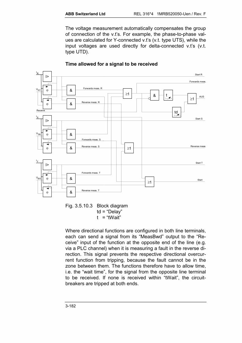
ABB Switzerland Ltd REL 316*4 1MRB520050-Uen / Rev. F
3-182
The voltage measurement automatically compensates the groupof connection of the v.t’s. For example, the phase-to-phase val-ues are calculated for Y-connected v.t’s (v.t. type UTS), while theinput voltages are used directly for delta-connected v.t’s (v.t.type UTD).
Time allowed for a signal to be received
I>
&
&
Forwards meas. R
Start R
I>
&
&
I S
U TR
Start S
I>
&
&
I T
U RS
Start T
1
Receive
1Start
td
1 & t AUS 1
I R
U ST
Forwards meas. S
Forwards meas. T
Reverse meas. R
Reverse meas. S
Reverse meas. T
Forwards meas.
Reverse meas.
Fig. 3.5.10.3 Block diagramtd = “Delay”t = “tWait”
Where directional functions are configured in both line terminals,each can send a signal from its “MeasBwd” output to the “Re-ceive” input of the function at the opposite end of the line (e.g.via a PLC channel) when it is measuring a fault in the reverse di-rection. This signal prevents the respective directional overcur-rent function from tripping, because the fault cannot be in thezone between them. The functions therefore have to allow time,i.e. the “wait time”, for the signal from the opposite line terminalto be received. If none is received within “tWait”, the circuit-breakers are tripped at both ends.
REL 316*4 1MRB520050-Uen / Rev. F ABB Switzerland Ltd
3-183
The time set for “Delay” acts in this kind of scheme as a backupwhich does not rely on the communication channel. Thus whenthe “Receive” input is being used, the setting for “Delay” must belonger than the setting for “tWait”:
“Delay” > “tWait”.
Response after decay of the memorised voltage
The voltage measured by the protection can quickly decay toalmost zero for a close fault and make determining direction un-reliable. For this reason, the function includes a voltage memoryfeature and for the first 200 milliseconds after the incidence of anovercurrent, the voltage measured immediately before the faultis used as reference to determine fault direction.After this time, the last valid direction is used for an adjustableperiod (see next paragraph).“MemDirMode” provides facility for setting how the protectionmust respond after this time or in the event that the circuit-breaker is closed onto a fault and no voltage could be memo-rised beforehand. The two possible settings are the protectioncan trip or it can block.
Time during which the memorised direction is valid
The “MemDuration” setting determines how long the last valid di-rection measurement shall be used. The setting should be asshort as possible (200 ms) when the function is being used asbackup for a distance function in an HV power system, becausean actually measured voltage is only available during this timeand therefore it is only possible to detect a reversal of directionduring this time. For longer settings, the last valid power direc-tion is used instead of the actually memorised voltage.

ABB Switzerland Ltd REL 316*4 1MRB520050-Uen / Rev. F
3-184

REL 316*4 1MRB520050-Uen / Rev. F ABB Switzerland Ltd
3-185
3.5.11. Definite time over and undervoltage protection (Voltage-DT)
A. Application
Standard voltage applications (overvoltage and undervoltagefunction).
B. Features
DC component filter harmonic filter single or three-phase voltage measurement maximum value, respectively minimum value, detection for
three-phase measurement.
C. Inputs and outputs
I. Analogue inputs:
Voltage
II. Binary inputs:
Blocking
III. Binary outputs:
Pick-up Tripping
IV. Measurements:
Voltage amplitude.

ABB Switzerland Ltd REL 316*4 1MRB520050-Uen / Rev. F
3-186
D. Over/undervoltage protection settings - Voltage-DT
Summary of parameters:
Text Units Default Min. Max. Step
ParSet 4..1 P1 (Select)
Trip 00000000
Delay s 02.00 0.02 60.00 0.01
V-Setting UN 1.200 0.010 2.000 0.002
MaxMin MAX (1ph) (Select)
NrOfPhases 001 1 3 2
VoltageInp AnalogAddr 0
BlockInp BinaryAddr F
Trip SignalAddr ER
Start SignalAddr ER
Explanation of parameters:
ParSet 4..1Parameter for determining in which set of parameters a par-ticular function is active (see Section 5.11.).
TripTripping circuit to which the O/P of the over/undervoltagefunction is connected (matrix tripping logic).
DelayTime delay between the function picking up and tripping.
V-SettingVoltage setting for tripping.
MaxMinOver or undervoltage mode selection:
MIN (3ph): Undervoltage.Three-phase functions detect the highest phase voltage.Not permitted for single-phase functions.
MIN (1ph): Undervoltage.Three-phase functions detect the lowest phase voltage.
REL 316*4 1MRB520050-Uen / Rev. F ABB Switzerland Ltd
3-187
MAX (3ph): Overvoltage.Three-phase functions detect the lowest phase voltage.Not permitted for single-phase functions.
MAX (1ph): Overvoltage.Three-phase functions detect the highest phase voltage.
NrOfPhasesNumber of phases included in the measurement.
VoltageInpAnalogue I/P channel. All the voltage channels are availablefor selection. In the case of a three-phase measurement, thefirst channel (R phase) of the group of three must be se-lected.
BlockInpI/P for blocking the function.F: - not blockedT: - blockedxx: - all binary I/P's (or O/P's of protection functions).
TripTripping signal.
StartPick-up signal.
ABB Switzerland Ltd REL 316*4 1MRB520050-Uen / Rev. F
3-188
E. Setting instructions
Settings:
Setting V-SettingDelay DelayOver or undervoltage MaxMinNumber of phases measured NrOfPhases
Two of these functions are frequently applied in a two-stagescheme. The first stage detects lower prolonged overvoltageswhile the second guards against higher overvoltages which haveto be cleared quickly.
Pick-up voltage (U-Setting)
Single-phase v.t.:A setting of 1.3 UN corresponds to a pick-up voltage of 130 V atthe input of the v.t.
Note that although a setting of 2.0 UN is possible, the range ofthe analogue inputs of the input transformer units K01...K17(REL 316*4) and K41...K47 (REC 316*4) is only 1.3 UN (i.e. max.130 V or 260 V).
Y connected three-phase v.t's:A setting of 1.3 UN corresponds to a pick-up voltage of 3/V130at the input of the v.t.(phase-to-neutral voltage).
Compensating any difference between the rated voltages of v.t’sUN1 and protected unit UGN is recommended. This is achievedwith the aid of the reference value of the A/D channel or bycorrecting the voltage setting.
For example, for UGN = 12 kV and UN1 = 15 kV, the setting for apick-up voltage of 1.4 UGN would have to be
14 14 1215
1121
. . .UU
kVkV
GN
N
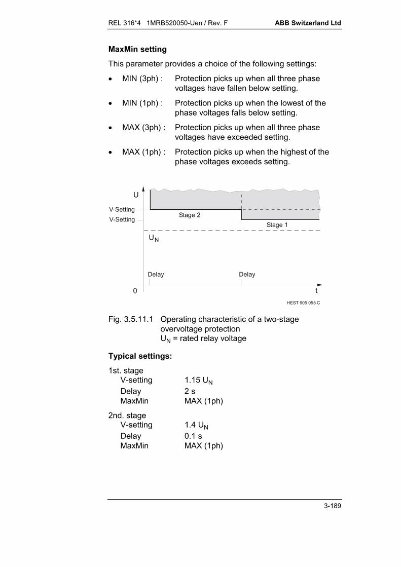
REL 316*4 1MRB520050-Uen / Rev. F ABB Switzerland Ltd
3-189
MaxMin setting
This parameter provides a choice of the following settings:
MIN (3ph) : Protection picks up when all three phasevoltages have fallen below setting.
MIN (1ph) : Protection picks up when the lowest of thephase voltages falls below setting.
MAX (3ph) : Protection picks up when all three phasevoltages have exceeded setting.
MAX (1ph) : Protection picks up when the highest of thephase voltages exceeds setting.
HEST 905 055 C
UN
0 t
U
Delay Delay
Stage 1Stage 2
V-SettingV-Setting
Fig. 3.5.11.1 Operating characteristic of a two-stageovervoltage protectionUN = rated relay voltage
Typical settings:
1st. stageV-setting 1.15 UNDelay 2 sMaxMin MAX (1ph)
2nd. stageV-setting 1.4 UNDelay 0.1 sMaxMin MAX (1ph)

ABB Switzerland Ltd REL 316*4 1MRB520050-Uen / Rev. F
3-190

REL 316*4 1MRB520050-Uen / Rev. F ABB Switzerland Ltd
3-191
3.5.12. Power (Power)
A. Application
Power function for monitoring reverse power active power reactive power power direction.
B. Features
definite time delay over or underpower adjustable characteristic angle provision for correction of phase errors caused by the input
circuit one, two or three-phase measurement (two-phase only with
delta connected v.t’s) wide range of applications (see Fig. 3.5.12.2 and Fig. 3.5.12.3) correction of c.t. and v.t. phase errors insensitive to DC components in voltage and current insensitive to harmonics in voltage and current.
C. Inputs and outputs
I. C.t./v.t. inputs:
current voltage
II. Binary inputs:
Blocking
III. Binary outputs:
pick-up tripping
IV. Measurements:
power.
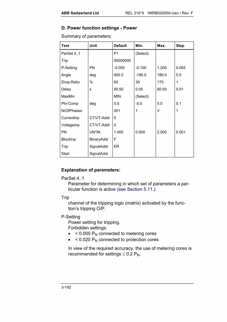
ABB Switzerland Ltd REL 316*4 1MRB520050-Uen / Rev. F
3-192
D. Power function settings - Power
Summary of parameters:
Text Unit Default Min. Max. Step
ParSet 4..1 P1 (Select)
Trip 00000000
P-Setting PN -0.050 -0.100 1.200 0.005
Angle deg 000.0 -180.0 180.0 5.0
Drop-Ratio % 60 30 170 1
Delay s 00.50 0.05 60.00 0.01
MaxMin MIN (Select)
Phi-Comp deg 0.0 -5.0 5.0 0.1
NrOfPhases 001 1 3 1
CurrentInp CT/VT-Addr 0
VoltageInp CT/VT-Addr 0
PN UN*IN 1.000 0.500 2.500 0.001
BlockInp BinaryAddr F
Trip SignalAddr ER
Start SignalAddr
Explanation of parameters:
ParSet 4..1Parameter for determining in which set of parameters a par-ticular function is active (see Section 5.11.).
Tripchannel of the tripping logic (matrix) activated by the func-tion’s tripping O/P.
P-SettingPower setting for tripping.Forbidden settings: < 0.005 PN connected to metering cores < 0.020 PN connected to protection cores
In view of the required accuracy, the use of metering cores isrecommended for settings 0.2 PN.

REL 316*4 1MRB520050-Uen / Rev. F ABB Switzerland Ltd
3-193
AngleCharacteristic angle between voltage and current formaximum sensitivity.0° = active power measurement90° = reactive power measurement (inductive),Settings between these limits are possible, e.g. for directionalmeasurements at locations on the power system.The correction of phase errors caused by the input circuit isalso possible.
Drop-RatioReset value in relation to the pick-up value. Thus dependingon the sign of the pick-up value, the setting of the reset ratiomust be greater or less than 100 %.Forbidden settings: Reset ratios >100 % for MAX and P-Setting >0 Reset ratios <100 % for MAX and P-Setting <0 Reset ratios <100 % for MIN and P-Setting >0 Reset ratios >100 % for MIN and P-Setting <0.A large hysteresis must be selected for low pick-up settingsand a small one for high pick-up settings (see Fig. 3.5.12.1).
Forbidden settings for hysteresis (= 100% reset ratio)settings: 0 5% 0 01. .P Setting- PN
10% P Setting- PN These conditions are fulfilled by setting, for example,
for 0 2 1, : P
PN
- Setting 95%
and
for 0 005 0 2. . : P
PN
- Setting 60%.
DelayTime between the function picking up and tripping. The timethe function takes to reset is also influenced by the delay setfor operation, i.e.:for t > 100 ms, the function resets after 50 ms, otherwise re-setting is instantaneous.
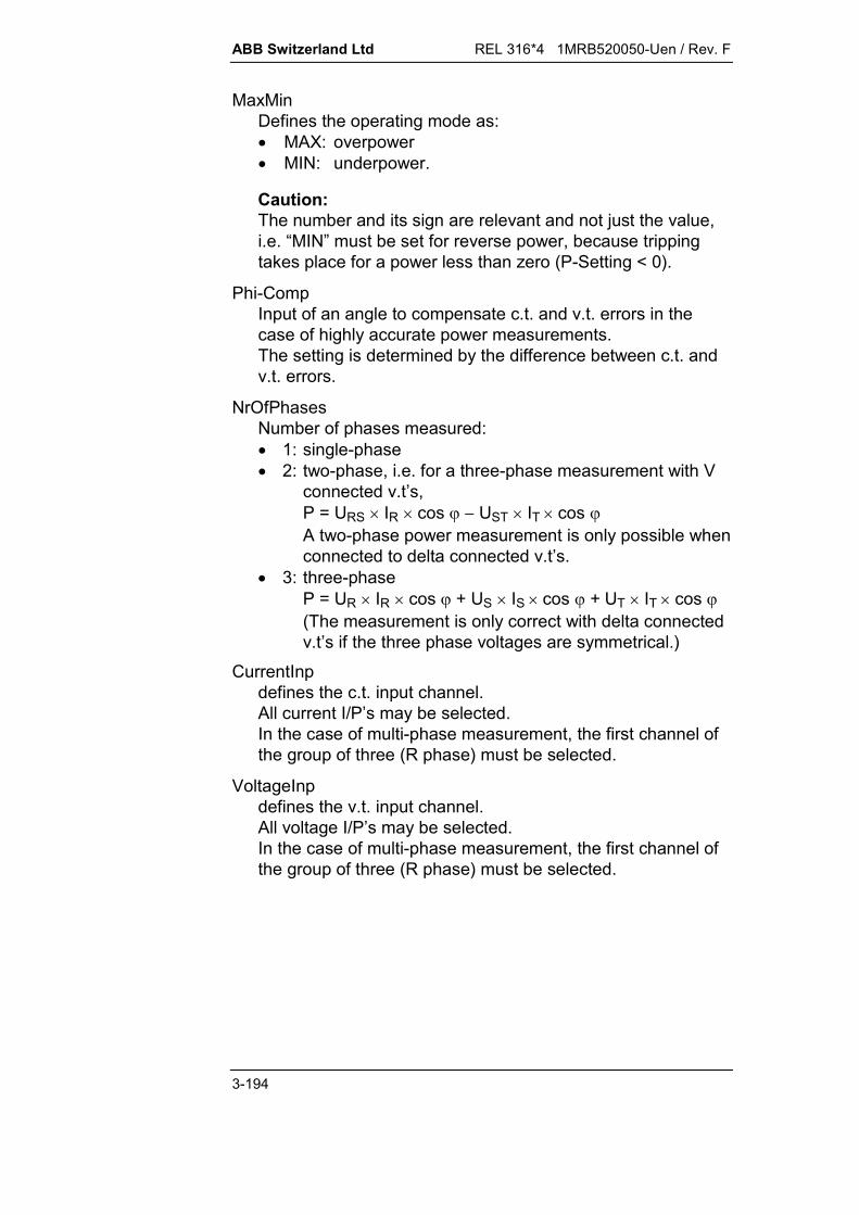
ABB Switzerland Ltd REL 316*4 1MRB520050-Uen / Rev. F
3-194
MaxMinDefines the operating mode as: MAX: overpower MIN: underpower.
Caution:The number and its sign are relevant and not just the value,i.e. “MIN” must be set for reverse power, because trippingtakes place for a power less than zero (P-Setting < 0).
Phi-CompInput of an angle to compensate c.t. and v.t. errors in thecase of highly accurate power measurements.The setting is determined by the difference between c.t. andv.t. errors.
NrOfPhasesNumber of phases measured: 1: single-phase 2: two-phase, i.e. for a three-phase measurement with V
connected v.t’s,P = URS IR cos UST IT cos A two-phase power measurement is only possible whenconnected to delta connected v.t’s.
3: three-phaseP = UR IR cos + US IS cos + UT IT cos (The measurement is only correct with delta connectedv.t’s if the three phase voltages are symmetrical.)
CurrentInpdefines the c.t. input channel.All current I/P’s may be selected.In the case of multi-phase measurement, the first channel ofthe group of three (R phase) must be selected.
VoltageInpdefines the v.t. input channel.All voltage I/P’s may be selected.In the case of multi-phase measurement, the first channel ofthe group of three (R phase) must be selected.

REL 316*4 1MRB520050-Uen / Rev. F ABB Switzerland Ltd
3-195
PNRated power as given by UN x IN. This enables the amplitudeof the power being measured to be compensated, e.g. to therated power factor of a generator.
BlockInpI/P for blocking the function.F: - not blockedT: - blockedxx: - all binary I/P’s (or O/P’s of protection functions).
TripTripping signal.
StartPick-up signal.
HEST 935 022 C
Reset ratio
Setting0.05 0.1 0.2 0.3 0.4 0.5 0.75 1
1
0
0.5
60%
95%
PPN
Res
et ra
tio
Fig. 3.5.12.1 Permissible reset ratio settings

ABB Switzerland Ltd REL 316*4 1MRB520050-Uen / Rev. F
3-196
E. Setting instructions
(function with two additional timers)
Settings:
Reference power PNSetting P-SettingReset ratio Drop-RatioOver/underpower MaxMinCharacteristic angle AnglePhase error compensation Phi-Comptripping delay Delay
The power function can be used for many applications. Someexamples are given in Fig. 3.5.12.2 and Fig. 3.5.12.3. Theangles given apply for connection according to the connectionsin Index 12.
*)
0
Q
P
OperatesRestrains
- Max/Min- Drop-Ratio- Angle
MAX
0° (30° )
Active overpower settings:
<100%
- P-Setting >0
Restrains
0
Q
P
Operates
MIN>100%0° (30° ) *)
Active underpower settings:
>0- P-Setting- Max/Min- Drop-Ratio- Angle
HEST 965 017 C
Fig. 3.5.12.2 Power function settings for different applications
*) The values in brackets apply for a single-phase measurement with the v.t. connected
phase-to-phase (e.g. IR current and URS voltage) or for a three-phase measurement withdelta connected v.t’s.
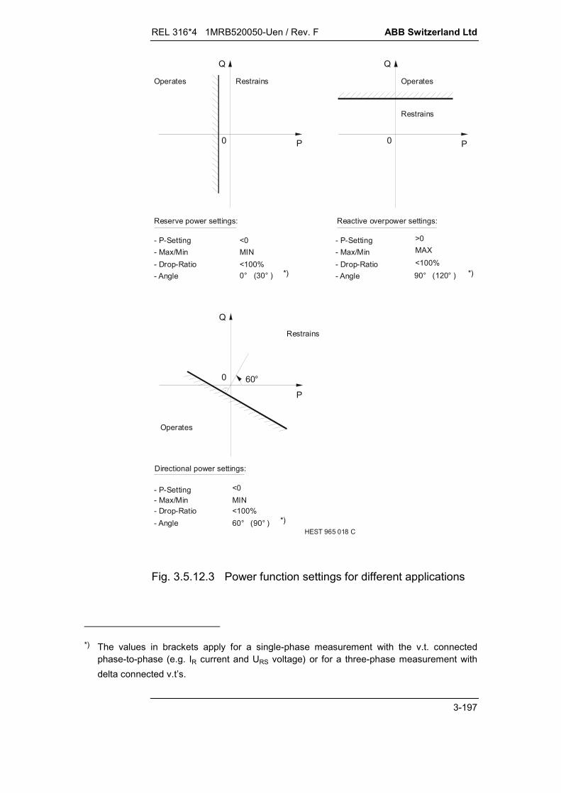
REL 316*4 1MRB520050-Uen / Rev. F ABB Switzerland Ltd
3-197
90° (120° )
Q
Operates
0 P
Restrains
Reserve power settings:
- P-Setting- Max/Min- Drop-Ratio- Angle
MIN
0° (30° ) *)<100%
<0
HEST 965 018 C
0
Q
P
Operates
Restrains
Reactive overpower settings:
- P-Setting- Max/Min- Drop-Ratio- Angle
>0MAX
*)<100%
Directional power settings:
- P-Setting- Max/Min- Drop-Ratio- Angle
MIN
60° (90° ) *)
Restrains
0
Q
P
Operates
60°
<100%
<0
Fig. 3.5.12.3 Power function settings for different applications
*) The values in brackets apply for a single-phase measurement with the v.t. connected
phase-to-phase (e.g. IR current and URS voltage) or for a three-phase measurement withdelta connected v.t’s.
ABB Switzerland Ltd REL 316*4 1MRB520050-Uen / Rev. F
3-198
Determining the settings
Where the rated currents and possibly also rated voltages ofc.t’s, v.t’s and the protected unit differ, it is of advantage to referthe setting to the rated power of the protected unit. Thisnecessitates modifying the sensitivity using the setting for PN.
Setting the reference power PN:
PU I
SU I
N
N N
GN
N N
3 1 1S U IP S
GN GN GN
GN GN GN
3cos
where:
SGN, PGN, UGN, IGN, cos GN: ratings of the protected unit
UN1, IN1: primary v.t. and c.t. ratings
PN, UN, IN: protection ratings.
Example 1
Generator: 96 MVA, 13,8 kV, 4 kA, cos = 0,8
V.t’s/c.t’s:14 4
3100
35 5
.;kV V kA A
Protection: 100 V; 5 A
Reverse power: 0.5 % PGN
Alternative 1: No modification of PN
Settings:
Reference power PU I
N
N N
10.
Reverse power:
PP
U IU IN
GN GN
N NGN
0 005 0 005 13 8 414 4 5
0 8 0 0031 1
. cos . ..
. .
REL 316*4 1MRB520050-Uen / Rev. F ABB Switzerland Ltd
3-199
Alternative 2: Modification for cosGN
Settings:
Reference power PU I
PS
N
N N
GN
GNGN
cos . 0 8
Reverse power: PP
U IU IN
GN GN
N N
0 005 0 005 13 8 414 4 5
0 0041 1
. . ..
.
Alternative 3: Modification for GN and c.t./v.t.. data
Settings:
Rated power PU I
U IU I
N
N N
GN GN
N NGN
1 1
13 8 414 4 5
0 8 0 614cos ..
. .
Reverse power PPN
0 005.
Characteristic angle
The power function is connected to the phase currents and aphase-to-neutral or phase-to-phase voltage. The purpose of thephase compensation is twofold:
to compensate the phase difference between the phase volt-age and the any measured phase-to-phase voltage
to determine whether the function responds to active or re-active power.
The following table summarises the most important operatingmodes to simplify setting the corresponding parameters correctly.The angles given apply for connection according to theconnections in Index 12.
The phase compensation also provides facility for changing thedirection of measurement or to compensate incorrect v.t. or c.t.polarity.
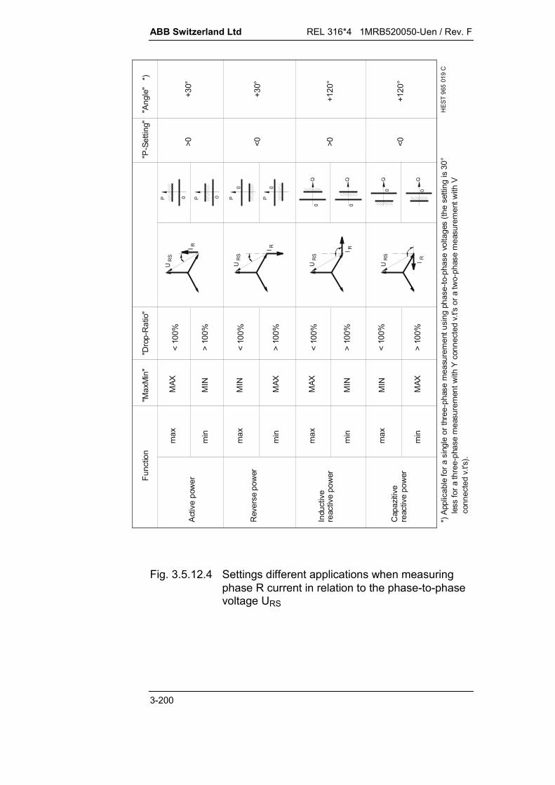
ABB Switzerland Ltd REL 316*4 1MRB520050-Uen / Rev. F
3-200
*) A
pplic
able
for a
sin
gle
or th
ree-
phas
e m
easu
rem
ent u
sing
pha
se-to
-pha
se v
olta
ges
(the
setti
ng is
30°
le
ss fo
r a th
ree-
phas
e m
easu
rem
ent w
ith Y
con
nect
ed v
.t's
or a
two-
phas
e m
easu
rem
ent w
ith V
c
onne
cted
v.t'
s).
"Max
Min
""P
-Set
ting"
max
min
> 10
0%
+120
°
P
Q
0
MAX
MIN
MAX
MIN
MAX
MIN
MAX
MIN
> 10
0%
> 10
0%
> 10
0%
max
min
max
min
max
min
HES
T 96
5 01
9 C
>0+3
0°
+30°
+120
°
P 0
0 0
0 0Q Q
0 0Q
I R
UR
S
I R
UR
S
I R
UR
S
I RUR
S
Func
tion
"Dro
p-R
atio
"
Activ
e po
wer
Indu
ctiv
ere
activ
e po
wer
Cap
azitiv
ere
activ
e po
wer
P P
"Ang
le"
*)
Rev
erse
pow
er
< 10
0%
< 10
0%
< 10
0%
< 10
0%
>0 <0<0
Fig. 3.5.12.4 Settings different applications when measuringphase R current in relation to the phase-to-phasevoltage URS
REL 316*4 1MRB520050-Uen / Rev. F ABB Switzerland Ltd
3-201
Phase compensation
This setting is for correcting the phase error between the v.t’sand c.t’s, which have a considerable adverse influence on themeasurement of active power at low power factors.
Example 2
The active power error at rated current and a power factor ofcos = 0 for a total phase error of 10' is
P = 0.03 = 0.03 10 = 0.3% [%; 1; min]
This is an error which is not negligible at a setting of 0.5%.
The total error corresponds to the difference between the v.t.and c.t. errors. The case considered in this example of full reac-tive current (100%) would scarcely occur in practice, but currentsfrom about 80% are possible.
Application as reverse power protection
The reverse power function is used primarily to protect the primemover. It is necessary for the following kinds of prime mover:
steam turbines
Francis and Kaplan hydro units
gas turbines
diesel motors.
Two reverse power functions are used for prime movers withratings higher than 30 MW, because of their importance andvalue.
The reverse power function has two stages. The setting is halfthe slip power of the generator/prime mover unit and is the samefor both stages.
The first stage has a short time delay and is intended to protectagainst overspeeding during the normal shutdown procedure. Bytripping the main circuit-breaker via the reverse power function,the possibility of overspeeding due to a regulator failure orleaking steam valves is avoided. To prevent false tripping in thecase of steam turbines, the reverse power function is enabled byauxiliary contacts on the main steam valves of the prime mover.

ABB Switzerland Ltd REL 316*4 1MRB520050-Uen / Rev. F
3-202
The purpose of the second stage is to guard against excessivelyhigh temperature and possible mechanical damage to the primemover. The time delay can be longer in this case, because thetemperature only increases slowly. Should power swings occurat low load due to the speed regulator or system instability, thesecond stage will not be able to trip, because the function re-peatedly picks up and resets before the time delay can expire. Itis for just such cases that the integrator (“Delay” function) isneeded to ensure reliable tripping.
U
IP>
Block
Trip
Integrator
t >1
t >2
t >3
Trip
Start
Trip
t1 fast stage interlocked with the main turbine steam valvet2 slow staget3 slow stage with an integrator where power swings are to be expected
Fig. 3.5.12.5 Reverse power protection for steam turbines
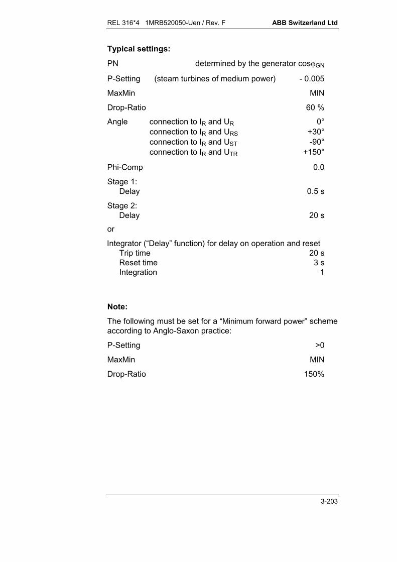
REL 316*4 1MRB520050-Uen / Rev. F ABB Switzerland Ltd
3-203
Typical settings:
PN determined by the generator cosGN
P-Setting (steam turbines of medium power) - 0.005
MaxMin MIN
Drop-Ratio 60 %
Angle connection to IR and UR 0°connection to IR and URS +30°connection to IR and UST -90°connection to IR and UTR +150°
Phi-Comp 0.0
Stage 1:Delay 0.5 s
Stage 2:Delay 20 s
or
Integrator (“Delay” function) for delay on operation and resetTrip time 20 sReset time 3 sIntegration 1
Note:
The following must be set for a “Minimum forward power” schemeaccording to Anglo-Saxon practice:
P-Setting >0
MaxMin MIN
Drop-Ratio 150%

ABB Switzerland Ltd REL 316*4 1MRB520050-Uen / Rev. F
3-204

REL 316*4 1MRB520050-Uen / Rev. F ABB Switzerland Ltd
3-205
3.5.13. Overtemperature protection (Overtemp.)
A. Application
Overtemperature protection with accurate thermal image of theprotected unit.
B. Features
1st. order thermal model alarm and tripping stages adjustable initial temperature DC component filter harmonic filter single or three-phase current measurement maximum value detection for three-phase measurement temperature rise calculated 40 times for each thermal time
constant setting.
C. Inputs and outputs
I. C.t./v.t. inputs
Current
II. Binary inputs
Blocking
III. Binary outputs
Alarm Tripping
IV. Measurements
Temperature rise Power dissipation Current.
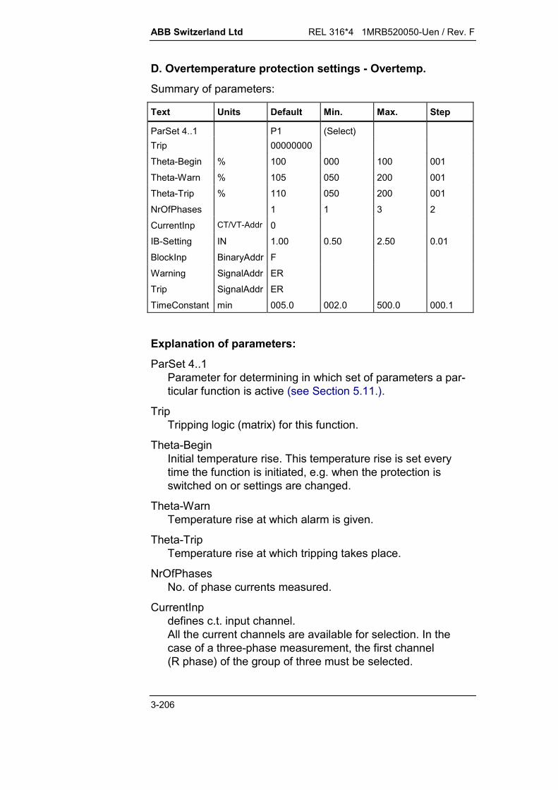
ABB Switzerland Ltd REL 316*4 1MRB520050-Uen / Rev. F
3-206
D. Overtemperature protection settings - Overtemp.
Summary of parameters:
Text Units Default Min. Max. Step
ParSet 4..1 P1 (Select)Trip 00000000
Theta-Begin % 100 000 100 001
Theta-Warn % 105 050 200 001Theta-Trip % 110 050 200 001
NrOfPhases 1 1 3 2
CurrentInp CT/VT-Addr 0IB-Setting IN 1.00 0.50 2.50 0.01
BlockInp BinaryAddr F
Warning SignalAddr ERTrip SignalAddr ER
TimeConstant min 005.0 002.0 500.0 000.1
Explanation of parameters:
ParSet 4..1Parameter for determining in which set of parameters a par-ticular function is active (see Section 5.11.).
TripTripping logic (matrix) for this function.
Theta-BeginInitial temperature rise. This temperature rise is set everytime the function is initiated, e.g. when the protection isswitched on or settings are changed.
Theta-WarnTemperature rise at which alarm is given.
Theta-TripTemperature rise at which tripping takes place.
NrOfPhasesNo. of phase currents measured.
CurrentInpdefines c.t. input channel.All the current channels are available for selection. In thecase of a three-phase measurement, the first channel(R phase) of the group of three must be selected.
REL 316*4 1MRB520050-Uen / Rev. F ABB Switzerland Ltd
3-207
IB-SettingReference current: Normal operating current of the protectedunit referred to the rated current of the protection.
BlockInpI/P for blocking the functionF: - not blockedT: - blockedxx: - all binary I/P’s (or O/P’s of protection functions).
WarningAlarm signal.
TripTripping signal.
TimeConstantThermal time constant for calculating the temperature rise.Settings < 2 minutes are not permitted.

ABB Switzerland Ltd REL 316*4 1MRB520050-Uen / Rev. F
3-208
E. Setting instructions
Settings:
Initial temperature rise Theta-BeginTemperature rise for alarm Theta-WarnTemperature rise for tripping Theta-TripNo. of phase currents measured NrOfPhasesReference current IB-SettingThermal time constant TimeConstant
The overtemperature function guards against inadmissibletemperature rise caused by overcurrents. The temperature riseis modelled on the basis of the influence of the current flowingthrough the protected unit on a thermal image of the protectedunit. In contrast to the overload protection, this function canprotect units of any power rating and thermal capacity. Itmonitors the temperature rise and not the absolute temperature.It takes account therefore neither of the ambient temperature northe effectiveness of a cooling system.
The protection operates with a thermal image of the temperaturerise. A current change causes the temperature of the protectedunit to rise from an initial value to a final value according to oneor several exponential functions. The various influences on thetemperature rise are the thermal response of, for example in thecase of a power transformer, the cooling water, the oil, thewindings etc. One exponential function such as that of thetransformer oil is always more dominant than the others. Thethermal image used in the protection for modelling the transienttemperature rise operates according to an exponential function.
The excursion of the temperature rise modelled by the protectionis determined by the following:
the final steady-state temperature corresponding to thecurrent
the increased temperature rise due to the transfer functions.
The protection assumes that at the rated current IGN of the pro-tected unit, the temperature rise represents 100 %. Neglectingany compensation of the A/D channel or the base current IB, theprotection measures a current IR determined by the rated currentof the c.t’s:
I I IIR GNN2
N
1
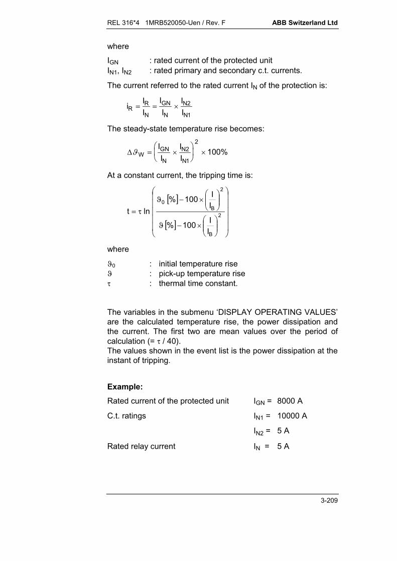
REL 316*4 1MRB520050-Uen / Rev. F ABB Switzerland Ltd
3-209
where
IGN : rated current of the protected unitIN1, IN2 : rated primary and secondary c.t. currents.
The current referred to the rated current IN of the protection is:
i II
II
IIR
R
N
GN
N
N2
N
1
The steady-state temperature rise becomes:
WGN
N
N2
N
II
II
1
2
100%
At a constant current, the tripping time is:
2
B
2
B0
II100%
II100%
lnt
where
0 : initial temperature rise : pick-up temperature rise : thermal time constant.
The variables in the submenu ‘DISPLAY OPERATING VALUES’are the calculated temperature rise, the power dissipation andthe current. The first two are mean values over the period ofcalculation (= / 40).The values shown in the event list is the power dissipation at theinstant of tripping.
Example:Rated current of the protected unit IGN = 8000 A
C.t. ratings IN1 = 10000 A
IN2 = 5 A
Rated relay current IN = 5 A
ABB Switzerland Ltd REL 316*4 1MRB520050-Uen / Rev. F
3-210
The temperature rise measured by the protection at a ratedcurrent of IGN is:
W
80005
510000
100% 64%2
The settings for overtemperatures of 5% and 10% respectivelyare:
Theta-Warn = 67%
Theta-Trip = 70%
Normally the protection is configured such that the initial tem-perature rise is 100 % (‘Theta-Begin’ = 100 %).
With IB adjusted, the settings become:
Base current: II
II
II
B
N
GN
N
N2
N
1
80005
510000
0 8.
The settings for alarm and tripping are then:
Theta-Warn = 105%
Theta-Trip = 110%
Transformers have two distinct exponential functions, one for theoil and one for the winding. The corresponding mean values are:
Oil : oil = 50 K oil = 120 min
Winding : W oil = 10 K W = 10 min
The total temperature rise of the winding is thus W = 60 K.
Since however the model operates with just a single exponentialfunction, its temperature rise has to follow the best possibleequivalent exponential function as shown in Fig. 3.5.13.1. Thesteady-state temperature rise of this equivalent function isidentical to the total temperature rise of the winding, i.e. W =60 K in the example above. Its time constant, however, istypically 60 to 80% of the temperature rise of the oil (see Fig.3.5.13.2).

REL 316*4 1MRB520050-Uen / Rev. F ABB Switzerland Ltd
3-211
HEST 905 035 C
0 t
1,0
1,5
i
i = i n
t [min]60 80
20
40
60
20 40 120 1400
100
120
80
100
140
160
nw
Oil
Oil
w
Oil
w Oil
w Oil
[°C]w t( )
Öl t( )
Oil = 50°C
t = 120 minOil
nw = 100°C
Oil = 90°C
nw = 60°C
w = 10 min
Fig. 3.5.13.1 Temperature rise of a transformer winding

ABB Switzerland Ltd REL 316*4 1MRB520050-Uen / Rev. F
3-212
0 100 200 300 400 500
120
110
130
140
i = 1.2
100
120
t [min]HEST 905 036 C
100
110
Winding temperature
Thermal image temperature
Overload
Temperature rise at ratedcurrent
Thermal time constant setting
126.4°C
[%][°C]
= 90 min = 50°Cn oil = 120 minoil
n oil = 10°Cnw = 10 min w
Fig. 3.5.13.2 Actual temperature rise of the winding comparedto the temperature rise of the thermal image
Typical settings:
IB-Setting to be calculated
Theta-Beginn 100%
Theta-Warn 105%
Theta-Trip 110%
REL 316*4 1MRB520050-Uen / Rev. F ABB Switzerland Ltd
3-213
3.5.14. Synchrocheck function (SynchroChck)
A. Application
Checking the synchronisation criteria (amplitudes, phase-shiftand frequency difference) of two electrical systems and, provid-ing the corresponding limits are satisfied, enabling them to beconnected in parallel.
B. Features
Monitoring synchronism:Single-phase voltage measurement.Comparison of the voltages (dU), phase-shift (dPh) and fre-quencies (df) of two voltage vectors. Calculation of the corre-sponding differences between the voltage vectors in thecomplex plane.Evaluation of the fundamental frequency components of thevoltage signals (after filtering of harmonic and DC compo-nents).
Monitoring voltage:Single or three-phase voltage measurement.Evaluation of instantaneous values (non-digitally filteredanalogue signals) resulting in a large permissible frequencyrange. Detection of the largest and smallest of the threephase voltages in the case of three-phase measurement.No filtering of harmonics or DC component.
Choice of phase for the voltage I/P’s on busbar and line sides(for amplitude and phase-angle adjustment).
Additional voltage I/P (for use in double busbar stations) withprovision for remote switchover.
Provision for remote selecting the operating mode.
C. Inputs and outputs
I. Analogue inputs:
Voltages (2 or 3 single or three-phase I/P’s for‘uBusInput1’, ‘uBusInput2’ and ‘uLineInput’)
II. Binary inputs:
2 I/P’s for enabling the synchrocheck function(‘ReleaseInp1’ and ‘ReleaseInp2’)
3 I/P’s for interlocking the synchrocheck O/P’s(‘BlckTrigBus1’, ‘BlckTrigBus2’ and ‘BlckTrigLine’)

ABB Switzerland Ltd REL 316*4 1MRB520050-Uen / Rev. F
3-214
1 I/P for bypassing the synchrocheck function(OverridSync)
2 I/P’s for remotely selecting operating mode(‘OpModeInp1’ and ‘OpModeInp2’)
2 I/Ps for remotely switching voltage channels in doublebusbar stations (‘uBus1Activ’ and ‘uBus2Activ’).
III. Binary outputs:
Function pick-up (Start) Circuit-breaker closing enable signal (PermitToClos) Function disabled signal (SyncBlockd) Enable O/P blocked signal (TrigBlockd) Synchrocheck bypassed signal (OverridSync) Amplitude difference in permissible range (AmplDifOK) Phase-shift in permissible range (PhaseDifOK) Frequency difference in permissible range (FreqDifOK) Busbars energised (LiveBus) Busbars de-energised (DeadBus) Line energised (LiveLine) Line de-energised (DeadLine).
IV. Measurements:
Synchronism check (single-phase) Voltage amplitude difference
(dU) = U bus - U line Phase-shift
(dPh) = PhBusbar - PhLine Frequency difference
(df) = f bus - f line
Voltage check (single or three-phase) max. busbar voltage (MaxuBus) min. busbar voltage (MinuBus) max. line voltage (MaxuLine) min. line voltage (MinuLine)
[Single-phase: max. voltage = min. voltageThree-phase: max. voltage = max. phase-to-phase
voltagemin. voltage = min. phase-to-phase
voltage].

REL 316*4 1MRB520050-Uen / Rev. F ABB Switzerland Ltd
3-215
D. Synchrocheck function settings - SynchroCheck
Summary of parameters:
Text Units Default Min. Max. StepParSet 4..1 P1 (Select)PermitToClos Trip Chan 00000000maxVoltDif UN 0.20 0.05 0.40 0.05maxPhaseDif deg 10.0 05.0 80.0 05.0maxFreqDif Hz 0.20 0.05 0.40 0.05minVoltage UN 0.70 0.60 1.00 0.05maxVoltage UN 0.30 0.10 1.00 0.05Operat.-Mode SynChck
l(Select)
supervisTime s 0.20 0.05 5.00 0.05t-Reset s 0.05 0.00 1.00 0.05uBusInp-Ph 1ph R-S (Select)uBusInput1 AnalogAddr 0uBusInput2 AnalogAddr 0uLineInp-Ph 3ph Y (Select)uLineInput AnalogAddr 0uBus1Activ BinaryAddr TuBus2Activ BinaryAddr FReleaseInp1 BinaryAddr TReleaseInp2 BinaryAddr FBlckTrigBus1 BinaryAddr FBlckTrigBus2 BinaryAddr FBlckTrigLine BinaryAddr FOverridSync BinaryAddr FOpModeInp1 BinaryAddr FOpModeInp2 BinaryAddr FPermitToClos SignalAddr ERStart SignalAddrSyncBlockd SignalAddrTrigBlockd SignalAddrSyncOverrid SignalAddrAmplDifOK SignalAddrPhaseDifOK SignalAddrFreqDifOK SignalAddrLiveBus SignalAddrDeadBus SignalAddrLiveLine SignalAddrDeadLine SignalAddr

ABB Switzerland Ltd REL 316*4 1MRB520050-Uen / Rev. F
3-216
Explanation of parameters:
ParSet 4..1Parameter for determining in which set of parameters a par-ticular function is active (see Section 5.11.).
PermitToClosLogic (matrix) O/P channel at which the CB close signal isavailable.
maxVoltDifMax. permissible voltage difference dU between thephases used for checking synchronism.
maxPhaseDifMax. permissible phase-shift dPh between the voltages ofthe phases used for checking synchronism.
maxFreqDifMax. permissible difference of frequency df between thephases used for checking synchronism.
minVoltageVoltage level for discriminating between busbar and linebeing live (lowest phase voltage in the case of three-phasemeasurement).
maxVoltageVoltage level for discriminating between busbar and linebeing dead (highest phase voltage in the case of three-phasemeasurement).
Operat.-ModePossible synchrocheck function operating modes: “SynChck only”: Synchrocheck
[Synchrocheck conditions fulfilled AND(bus live AND line live)]
“BusD & LineL”: Synchrocheck OR(bus dead AND line live)
“BusL & LineD”: Synchrocheck OR(bus live AND line dead)
“BusD LineD”: Synchrocheck OR(bus dead AND line live) OR(bus live AND line dead)
“BusD & LineD”: Synchrocheck OR(bus live AND line dead).
REL 316*4 1MRB520050-Uen / Rev. F ABB Switzerland Ltd
3-217
supervisTimePeriod between the function picking up and it issuing the CBclose enable (‘PermitToClos’).All the conditions for synchronism must remain fulfilled duringthis time, otherwise the function is reset.
t-ResetReset time following the non-fulfilment of one or more syn-chronism conditions.
uBusInp-PhChoice of phase I/P on the busbar side.Possible settings:1 ph RS, ST or TR; 1 ph RE, SE or TE; 3 ph Y; 3 ph The phase chosen must agree with the voltage I/P channelselected (i.e. ‘uBusInput1’ and, if selected, ‘uBusInput2’).
uBusInput11st. voltage I/P channel on the busbar side. This must agreewith the phase chosen (‘uBusInp-Ph’). In the case of a three-phase connection (‘uBusInp-Ph’ = ‘3 ph Y’ or ‘3 ph ’), thefirst channel (R phase) of a three-phase group must bechosen.
uBusInput22nd. voltage I/P channel (if applicable) on the busbar side.This must agree with the chosen phase (‘uBusInp-Ph’). In thecase of a three-phase connection (‘uBusInp-Ph’ = ‘3 ph Y’ or‘3 ph ’), the first channel (R phase) of a three-phase groupmust be chosen.If a second I/P is not configured, the function only takesaccount of the 1st. voltage I/P channel (‘uBusInput1’).
uLineInp-PhChoice of phase I/P on the line side.Possible settings:1 ph RS, ST or TR; 1 ph RE, SE or TE; 3 ph Y; 3 ph The phase chosen must agree with the voltage I/P channelselected (i.e. ‘uLineInput’).
ABB Switzerland Ltd REL 316*4 1MRB520050-Uen / Rev. F
3-218
uLineInputVoltage I/P channel on the line side. This must agree with thechosen phase (‘uLineInp-Ph’). In the case of a three-phaseconnection (‘uLineInp-Ph’ = ‘3 ph Y’ or ‘3 ph ‘), the firstchannel (R phase) of a three-phase group must be chosen.
uBus1Activ, uBus2ActivBinary I/P’s for switching between voltage I/P channels by anremote signal in the case of double busbars (mimic busbar).This I/P’s are only active providing the second busbar I/Pchannel has been configured (‘uBusInput2’).
F: - I/P disabledT: - I/P enabledxx: - all binary I/P’s (or O/P’s of protection functions).
‘uBus1Activ’ ‘uBus2Activ’ Selected voltage I/P
(T) TRUE (F) FALSE ‘uBusInput1’ active
(F) FALSE (T) TRUE ‘uBusInput2’ active
Other conditions The previous voltage I/Premains active
ReleaseInp1, ReleaseInp2Binary I/P’s for enabling the synchrocheck function. (The I/P’sare connected internally to an OR gate so that at least onemust be set to “TRUE” (T) or appropriately controlled by anremote signal.) If both I/P’s are set to “FALSE” (F), the func-tions routine (synchronism algorithm) does not run.These I/P’s are used where the synchrocheck function is onlyneeded at certain times (e.g. in auto-reclosure schemes).
F: - synchrocheck function disabledT: - synchrocheck function enabledxx: - all binary I/P’s (or O/P’s of protection functions)

REL 316*4 1MRB520050-Uen / Rev. F ABB Switzerland Ltd
3-219
BlkSynchBus1, BlkSynchBus2, BlkSynchLineBinary I/P’s for interlocking the enabling signals at the O/P ofthe synchrocheck function.These would be typically controlled by fuse failure equipment(m.c.b’s) monitoring the v.t. circuits.F: - blocking I/P disabledT: - blocking I/P continuously enabledxx: - all binary I/P’s (or O/P’s of protection functions)
Parts of the function effected by the blocking I/P’s: Assuming that both busbar I/P channels have been con-
figured, the active blocking I/P depends on the statuses ofthe binary I/P’s ‘uBus1Activ’ and ‘uBus2Activ':
‘uBus1Activ’ ‘uBus2Activ’ Selected voltage I/P
(T) TRUE (F) FALSE ‘BlckTrigBus1’ and ‘BlckTrigLine’
(F) FALSE (T) TRUE ‘BlckTrigBus2’ and ‘BlckTrigLine’
Other conditions The previous blocking I/P’sremain active
Assuming that only the first busbar I/P channel has beenconfigured, all the blocking I/P’s are active regardless of thestatuses of the binary I/P’s ‘uBus1Activ’ and ‘uBus2Activ’.
The active blocking I/P’s are connected internally to an ORgate and the CB close enabling O/P’s are blocked, if one ofthem is set to “TRUE” (T).
OverridSyncBinary I/P for bypassing the synchrocheck function. Thiscauses an enabling signal to be issued regardless of whetherthe synchronism conditions are fulfilled or not. It overrides thefunction’s blocking and other enabling I/P’s.
F: - I/P disabledT: - I/P enabled (The synchrocheck O/P ‘PermitToClos’ is
continuously active.)xx: - all binary I/P’s (or O/P’s of protection functions)
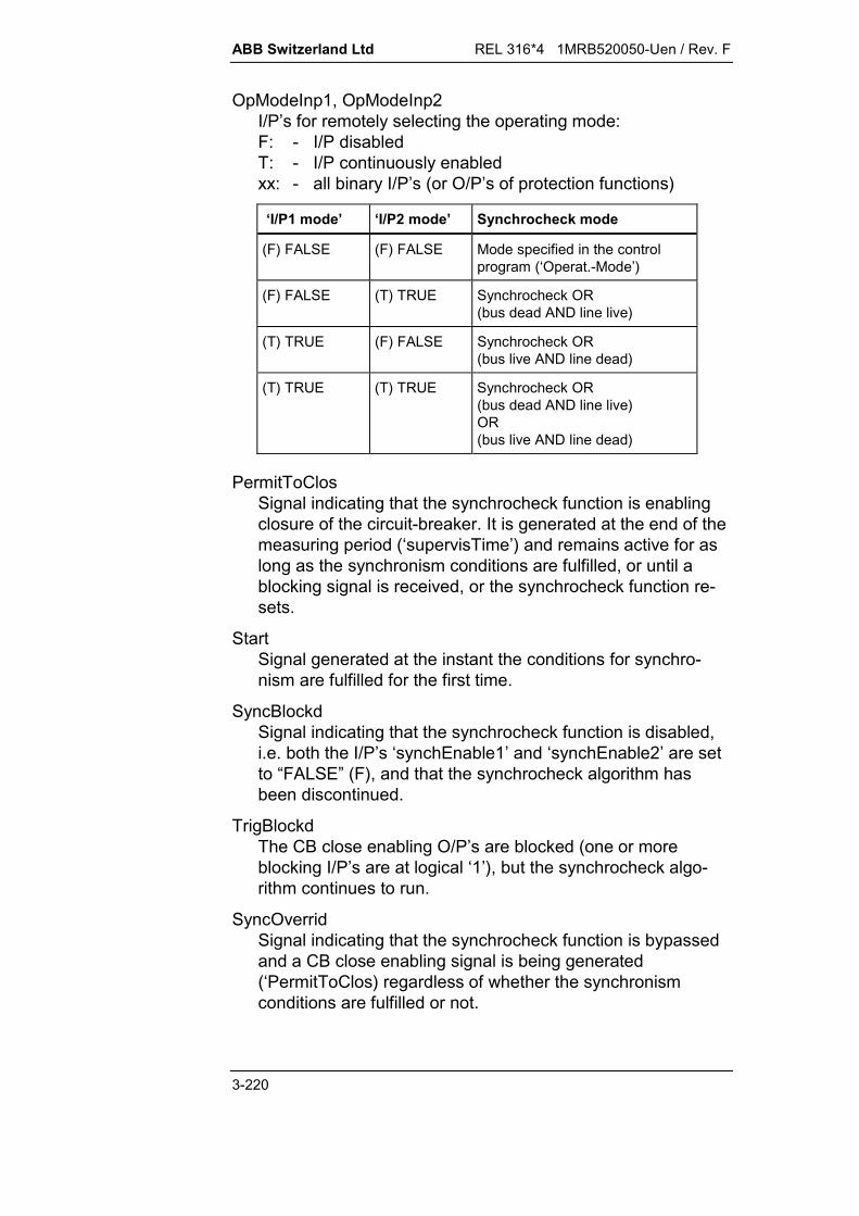
ABB Switzerland Ltd REL 316*4 1MRB520050-Uen / Rev. F
3-220
OpModeInp1, OpModeInp2I/P’s for remotely selecting the operating mode:F: - I/P disabledT: - I/P continuously enabledxx: - all binary I/P’s (or O/P’s of protection functions)
‘I/P1 mode’ ‘I/P2 mode’ Synchrocheck mode
(F) FALSE (F) FALSE Mode specified in the controlprogram (‘Operat.-Mode’)
(F) FALSE (T) TRUE Synchrocheck OR(bus dead AND line live)
(T) TRUE (F) FALSE Synchrocheck OR(bus live AND line dead)
(T) TRUE (T) TRUE Synchrocheck OR(bus dead AND line live)OR(bus live AND line dead)
PermitToClosSignal indicating that the synchrocheck function is enablingclosure of the circuit-breaker. It is generated at the end of themeasuring period (‘supervisTime’) and remains active for aslong as the synchronism conditions are fulfilled, or until ablocking signal is received, or the synchrocheck function re-sets.
StartSignal generated at the instant the conditions for synchro-nism are fulfilled for the first time.
SyncBlockdSignal indicating that the synchrocheck function is disabled,i.e. both the I/P’s ‘synchEnable1’ and ‘synchEnable2’ are setto “FALSE” (F), and that the synchrocheck algorithm hasbeen discontinued.
TrigBlockdThe CB close enabling O/P’s are blocked (one or moreblocking I/P’s are at logical ‘1’), but the synchrocheck algo-rithm continues to run.
SyncOverridSignal indicating that the synchrocheck function is bypassedand a CB close enabling signal is being generated(‘PermitToClos) regardless of whether the synchronismconditions are fulfilled or not.

REL 316*4 1MRB520050-Uen / Rev. F ABB Switzerland Ltd
3-221
AmplDifOKSignal indicating that the voltage difference dU betweenthe phases used for checking synchronism has fallen belowthe value of the parameter ‘maxVoltDif’.
PhaseDifOKSignal indicating that the phase-shift dPh between thephases used for checking synchronism has fallen below thevalue of the setting of ‘maxPhaseDif’.
FreqDifOKSignal indicating that the difference of frequency dfbetween the phases used for checking synchronism hasfallen below the value of the setting of ‘maxFreqDif’.
LiveBusSignal indicating that the busbar is energised.(U > ‘minVoltage’)
DeadBusSignal indicating that the busbar is de-energised.(U < ‘maxVoltage’)
LiveLineSignal indicating that the line is energised.(U > ‘minVoltage’)
DeadLineSignal indicating that the line is de-energised.(U < ‘maxVoltage’)

ABB Switzerland Ltd REL 316*4 1MRB520050-Uen / Rev. F
3-222
E. Setting instructions
3.5.14.1. General
It is only permissible to connect two energised parts of a powersystem, if the difference between the amplitudes of their voltagesand the phase-shift between them are within acceptable limits.
The purpose of the synchrocheck function is to determine theseparameters and decide whether it is permissible to connect thesystems in parallel.The function thus issues an enable signal (‘PermitToClos’),providing the voltages of the two systems are higher than the setminimum voltage (‘minVoltage’) and
the difference between the voltage amplitudes dU the phase-shift dPh the difference between the frequencies df
do not exceed the limits set for the parameters ‘maxVoltDif’,‘maxPhaseDif’ and ‘maxFreqDif’ for the adjustable time ‘supervis-Time’.
According to the operating mode (‘Operat.-Mode’) selected, thefunction also permits de-energised parts of a power system to becoupled.
Provision is also made for switching between voltage I/P’s be-longing to the busbars of a double busbar station by appropri-ately controlling two binary I/P’s (‘uBus1Activ’ and ‘uBus2Activ’).Note that the function can only check the synchronism of twovoltages at any one time, that of one of the busbars and that ofthe line.
The synchrocheck function is therefore used mainly to connect infeeds in parallel and to connect outgoing feeders
to the system to interconnect two synchronous or asynchronous parts of a
power system in auto-reclosure schemes as a safety check when carrying out manual switching op-
erations.Note:
The expressions in brackets are the names of the corre-sponding setting parameters. Refer also to Section D.

REL 316*4 1MRB520050-Uen / Rev. F ABB Switzerland Ltd
3-223
Application example: Feeder connected to double busbars
SS2
T1
T2
CBLine
Switching unit
Permit to Close
uLine Input
BlckTrigLineSynchrocheckVT SS2
VT SS1
uBus2Activ
uBus1Activ
uBusInput2
BlckTrigBus2
uBusInput1
BlckTrigBus1
SS1
VT Line
Closingcommand
HEST 925 025 C
Fig. 3.5.14.1 Principle of synchrocheck scheme for determiningthe instant when it is permissible to connect afeeder to the power system. (The voltages of bus-bar “SS2” and the line are monitored.)
where:
SS1, SS2 : busbar 1, busbar 2VT SS1, VT SS2, VT Line : v.t’s on busbar 1, busbar 2 and
lineT1, T2 : isolators on busbars 1 and 2CB : circuit-breakeruBusInput1, uBusInput2 : voltage I/P channels on the
busbar sideuLineInput : voltage I/P channel on the line
side

ABB Switzerland Ltd REL 316*4 1MRB520050-Uen / Rev. F
3-224
BlckTrigBus1, BlckTrigBus2, : I/P’s for blocking the synchro-BlSyncLine check function by the v.t. fuse
failure equipment.uBus1Activ, uBus2Activ : Binary I/P’s for switching be-
tween the analogue busbarvoltage I/P’s in accordance withthe configuration of the isola-tors (mimic busbar).
3.5.14.2. Settings
Max. voltage difference dU maxVoltDifMax. phase-shift dPh maxPhaseDifMax. frequency difference df maxFreqDifMinimum voltage level for monitoring minVoltage(determination of whether plant is energised)Maximum voltage level for monitoring maxVoltage(determination of whether plant is de-energised)Choice of operating mode Operat.-ModeMeasuring period (delay before issuing supervisTimeenable)Reset delay t-ResetChoice of phase for monitoring on the uBusInp-Phbusbar sideChoice of phase for monitoring on the uLineInp-Phline side
Monitoring the conditions for synchronism (‘maxVoltDif’,‘maxPhaseDif’ and ‘maxFreqDif’)
The determination of voltage difference, phase-shift and fre-quency difference is performed for just one of the phases of thethree-phase system. For this purpose, the analogue values arefirst filtered by a digital Fourier bandpass filter (to obtain the fun-damentals) and then the orthogonal components ‘U bus’ and ‘Uline’ are derived.The phase-shift dPh between the voltages and the differencebetween their amplitudes dU are calculated from the corre-sponding vector diagram in the complex plane.
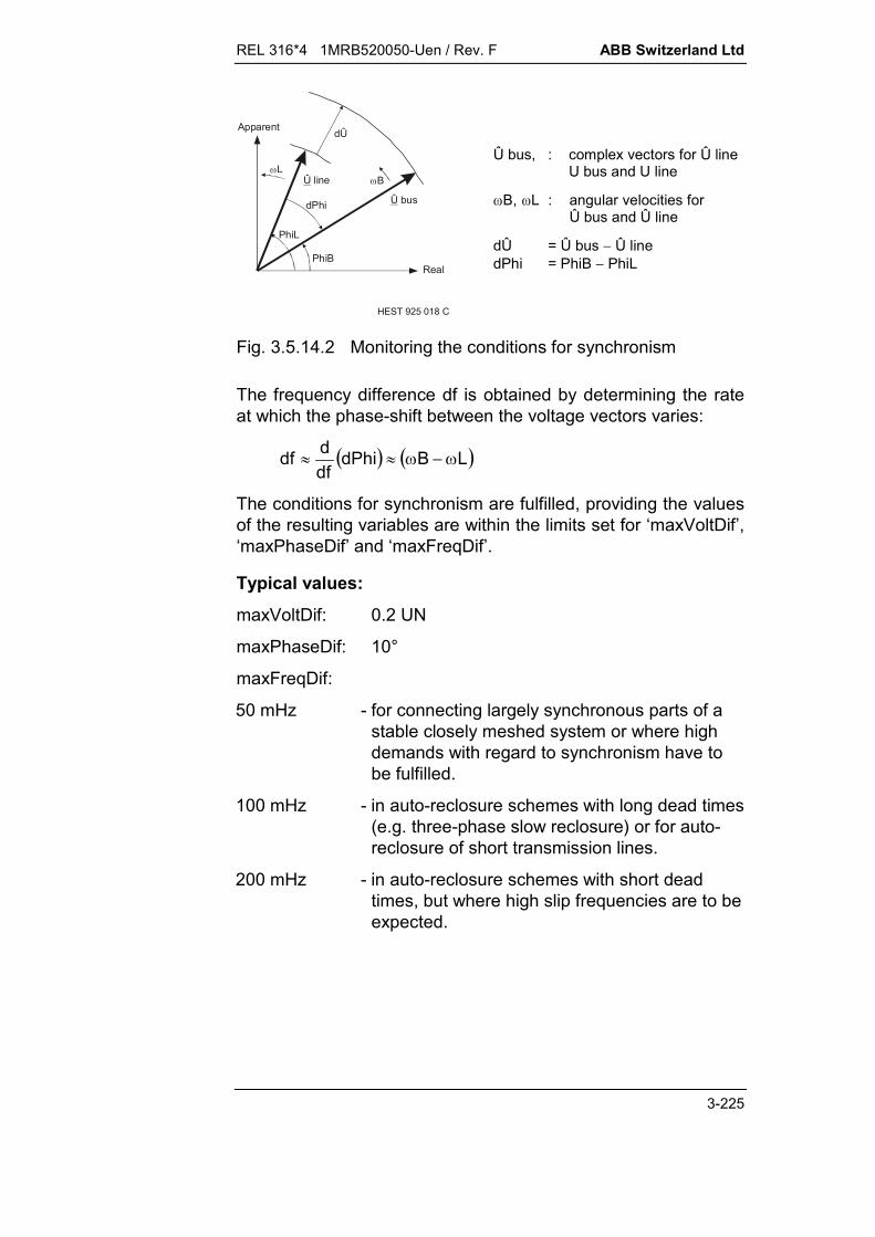
REL 316*4 1MRB520050-Uen / Rev. F ABB Switzerland Ltd
3-225
HEST 925 018 C
PhiB
PhiL
dPhi
Real
Û line
dÛApparent
Û bus
LB
Û bus, : complex vectors for Û line U bus and U line
B, L : angular velocities forÛ bus and Û line
dÛ = Û bus Û linedPhi = PhiB PhiL
Fig. 3.5.14.2 Monitoring the conditions for synchronism
The frequency difference df is obtained by determining the rateat which the phase-shift between the voltage vectors varies:
LBdPhidfddf
The conditions for synchronism are fulfilled, providing the valuesof the resulting variables are within the limits set for ‘maxVoltDif’,‘maxPhaseDif’ and ‘maxFreqDif’.
Typical values:
maxVoltDif: 0.2 UN
maxPhaseDif: 10°
maxFreqDif:
50 mHz - for connecting largely synchronous parts of astable closely meshed system or where highdemands with regard to synchronism have tobe fulfilled.
100 mHz - in auto-reclosure schemes with long dead times(e.g. three-phase slow reclosure) or for auto-reclosure of short transmission lines.
200 mHz - in auto-reclosure schemes with short deadtimes, but where high slip frequencies are to beexpected.
ABB Switzerland Ltd REL 316*4 1MRB520050-Uen / Rev. F
3-226
Note:
The setting of the synchronism measuring period (‘supervisTime’)must be chosen to correspond to the settings for the maximumphase-shift and maximum frequency difference.
Monitoring the voltage in two power systems(‘minVoltage’, ‘maxVoltage’)
The determination of voltage amplitude can be either based onmonitoring a single phase or all three phases depending on howthe particular AnalogAddr is configured. If the three phases areincluded, then the highest voltage of the three is detected for themaximum limit, respectively the lowest of the three for the mini-mum limit.
In order to be able to monitor the voltages in a wide frequencyrange, instantaneous values are measured (instead of digitallyfiltered analogue voltages).
The voltage detectors may be used to determine whether a sys-tem is de-energised or whether it is energised:
A system is considered to be “de-energised”, if its voltage(highest of the three phases in the case of three-phasemeasurement) falls below the setting of the parameter ‘max-Voltage’.
A system is considered to be “energised”, if its voltage (low-est of the three phases in the case of three-phasemeasurement) exceeds the setting of the parameter‘minVoltage’.
On no account will an enable signal permitting closure of the cir-cuit-breaker be issued, should the voltage lie between the limitsof ‘maxVoltage’ and ‘minVoltage’.
Typical values:
minVoltage 0.70 UNmaxVoltage 0.30 UN
Choosing the operating mode of the synchrocheck function(‘Operat.-Mode’)
Basically, an enable signal will always be issued, if the condi-tions for synchronism (‘dU’, ‘dPh’ and ‘df’) are fulfilled for theprescribed period and both systems, i.e. busbar and line, areenergised (voltage > ‘minVoltage’).

REL 316*4 1MRB520050-Uen / Rev. F ABB Switzerland Ltd
3-227
In cases where closure of the circuit-breaker should also be en-abled when one system is de-energised, e.g. connection of aradial feeder, this can be achieved by appropriately setting theparameter ‘Operat.-Mode':
‘Operat.-Mode’ Closure enabled when:
“Only SyncChk” Synchronism conditions fulfilled AND (busbar > ‘minVoltage’ AND line > ‘minVoltage’)
“BusD & LineL” “Only SyncChk” OR (busbar < ‘maxVoltage’ AND line > ‘minVoltage’)
“BusL & LineD” “Only SyncChck” OR (busbar > ‘minVoltage’ AND line < ‘maxVoltage’)
“BusD | LineD” “Only SyncChk” OR (busbar < ‘maxVoltage’ AND line > ‘minVoltage’) OR (busbar > ‘minVoltage’ AND line < ‘maxVoltage’)
“BusD & LineD” “Only SyncChk” OR (busbar < ‘maxVoltage’ AND line < ‘maxVoltage’)
Remote mode selection:
Four of the five operating modes can be selected by externalsignals applied to two of the function’s binary I/P’s (‘OpModeInp1’and ‘OpModeInp2’).
Binary I/P signals Mode (see above)
‘OpModeInp1’ ‘OpModeInp2’
(F) FALSE (F) FALSE “Mode set in the control program”(‘Operat.-Mode’)
(F) FALSE (T) TRUE “BusD & LineL”
(T) TRUE (F) FALSE “BusL & LineD”
(T) TRUE (T) TRUE “BusD | LineD”
Choice of phase for the voltage I/P on the busbar and linesides (‘uBusInp-Ph’, ‘uLineInp-Ph’)
The phase voltage (‘uBusInp-Ph’, ‘uLineInp-Ph’) to be used fordetermining synchronism can be entered separately for busbar

ABB Switzerland Ltd REL 316*4 1MRB520050-Uen / Rev. F
3-228
and line I/P’s (to facilitate individual adjustment of phase-angleand amplitude).All single and three-phase voltages are available for setting(1ph RS, ST or TR; 1ph RE, SE or TE; 3ph Y; 3ph ), but theones chosen must agree with the setting for the correspondingI/P channels (see Section D. “Synchrocheck function settings”).Where both busbar I/P’s are in use, the definition of the phase(‘uBusInp-Ph’) applies to both busbars.
Notes:
A phase-to-phase measurement is to be preferred for asingle-phase voltage measurement.If a single-phase I/P has to be chosen on both sides, thesame phase should be used wherever possible.
If a three-phase ‘Y’ connection is selected, phase-to-phasevoltages are formed internally. This reduces the harmoniccontent and enables the function to continue to be used inungrounded systems, which are required to remain in servicewith a single earth fault.
According to the setting for ‘uBusInp-Ph’ and ‘uLineInp-Ph’,either a just one phase or all three phases are monitored.Whether or not the conditions for synchronism (‘dU’, ‘dPh’and ‘df’) are fulfilled is determined on the basis of a singlephase, whereby the following apply:
Where three phases are monitored on busbar and linesides, the phase-to-phase potential URS is the one ex-tracted for further processing.
Should a three-phase measurement be defined on oneside and a single-phase on the other, Then the single-phase voltage set for the single-phase I/P is used on bothsides.
The measuring period (‘supervisTime’), reset time (‘t-Reset’)and the operating time of the function and also the deadtime of any auto-reclosure function
Measuring period (‘supervisTime’):
This adjustable delay time, which is initiated at the end of thepick-up time, is the period during which all the conditions forsynchronism must be continuously fulfilled to permit closure ofthe circuit-breaker. The timer is reset should one of the parame-ters move out of the permissible range.

REL 316*4 1MRB520050-Uen / Rev. F ABB Switzerland Ltd
3-229
Providing they all remain within their preset ranges, the enablesignal (‘PermitToClos’) is issued at the end of the measuringperiod.
Especially in auto-reclosure applications, it is of advantage to setthe measuring period (‘supervisTime’) in relation to the settingsfor ‘Phase diff.’ and ‘maxFreqDif’. It also provides facility forallowing for the operating time of the circuit-breaker:
' '
(' ' )('max ' )
( )supervisTimaxPhaseDi
me sf
FreqDif Hztv ts s
2360
where:
ts: circuit-breaker operating timeTypical range: 0 ... 100 ms.
tv: time required by the function to pick up(response by the function to transient phenomena in the in-put voltage and timer tolerances):
typically 60... 80 ms for values of ‘supervisTime’ < 200 ms
typically 80... 100 ms for values of ‘supervisTime’ 200 ms.
The above setting for the measuring period ensures that for aconstant frequency difference df within the setting of‘maxFreqDif’, the phase-shift dPh will still be inside the setpermissible angular range (- ‘maxPhaseDif’ to + ‘maxPhaseDif’)at the end of the time ‘supervisTime’.
Typical values:
For a phase-shift setting (‘maxPhaseDif’) of 10°:
‘maxFreqDif’ ‘supervisTime’
200 mHz100 mHz 50 mHz
100... 200 ms 250... 450 ms 600...1000 ms

ABB Switzerland Ltd REL 316*4 1MRB520050-Uen / Rev. F
3-230
Minimum operating time of the function:
The minimum operating time achieved by the function, i.e. theshortest possible time between the instant the synchronismconditions are fulfilled for the first time and the generation of thesignal enabling the circuit-breaker to be closed ‘PermitToClos’, isgiven by the sum of the measuring time setting ‘supervisTime’and the pick-up response time ‘tv’ of the function.
Min. operating time = (‘supervisTime’) + tv
Auto-reclosure dead time:
In an auto-reclosure scheme, the dead time set for the auto-reclosure function must be at least as long as the minimum op-erating time of the synchrocheck function given above in order topermit the synchrocheck function to issue an enable signal(‘PermitToClos’) within the dead time:
dead time min. operating time = (‘supervisTime’) + tv
Reset time (‘t-Reset’):
From the instant that one or more of the synchronism conditionsare no longer fulfilled, the enabling signal O/P (‘PermitToClos’)and the pick-up signal reset after the time set for ‘t-Reset’.
This ensures the a CB closing signal can be maintained for acertain minimum time.
Typical value:
t-Reset 50 ms.
Note:
Where high slip frequencies df are to be expected, ‘t-Reset’must be short enough to prevent the phase-shift from ex-ceeding the set permissible range of phase-angles(-'PhaseDif’ to + ‘PhaseDif’) during the reset time.

REL 316*4 1MRB520050-Uen / Rev. F ABB Switzerland Ltd
3-231
3.5.14.3. Binary inputs of the function
Inputs for switching between analogue busbar inputs (‘uBus1Activ’, ‘uBus2Activ’)
Where the two busbar I/P’s (‘Bus I/P1’ and ‘Bus I/P2’) have beenconfigured for a double busbar installation, the measurementcan be switched from one busbar to the other by signals corre-sponding to the isolator positions applied to the I/P’s‘uBus1Activ’ and ‘uBus2Activ':
‘uBus1Activ’ ‘uBus2Activ’ Analogue I/P’s for synchronisation
(T) TRUE (F) FALSE(F) FALSE (T) TRUE
‘uBusInput1’ and ‘uLineInput’‘uBusInput2’ and ‘uLineInput’
Other combinations of the states of these two I/P’s do not resultin any switching of the AnalogAddr channels and the prevailingsituation is maintained.
Notes:
The function (timer, all measuring elements and the associ-ated O/P’s) is automatically reinitialised when busbar I/P’sare switched. This procedure takes about 60 ms (internal re-sponse times). The function then begins to evaluate the newbusbar voltage and from this instant onwards the generationof an enable signal (‘PermitToClos’) relating to the newsystem configuration is possible.
‘The two binary I/P’s ‘uBus1Activ’ and ‘uBus2Activ’ areinactivated in configurations in which only one busbar I/P(‘uBusInput1’) is defined.
Blocking inputs for preventing the synchrocheck functionfrom issuing an enable signal (‘BlckTrigBus1’,‘BlckTrigBus2’, ‘BlckTrigLine’)
These are assigned to the corresponding voltage I/P’s and usedmainly when the v.t. circuit can be interrupted by fuse-failureequipment (miniature circuit-breakers). In such cases, theblocking I/P’s are connected to auxiliary contacts on the fuse-failure equipment. This precaution eliminates any risk of thesynchrocheck function permitting the closure of a circuit-breakeronto a line it considers to be de-energised, which in reality isunder voltage.
ABB Switzerland Ltd REL 316*4 1MRB520050-Uen / Rev. F
3-232
Functionality of the blocking I/P’s:
Both busbar voltage I/P’s have been configured:
Which of the blocking I/P’s is enabled depends on which ofthe busbar I/P’s ‘uBus1Activ’ and ‘uBus2Activ’ is active, i.e.on which voltage I/P is active:
‘uBus1Activ’ ‘uBus2Activ’ Active blocking I/P’s
(T) TRUE (F) FALSE(F) FALSE (T) TRUE
‘BlckTrigBus1’ and ‘BlckTrigLine’‘BlckTrigBus2’ and ‘BlckTrigLine’
Other combinations of the states of these two I/P’s do notinfluence the blocking I/P’s and the prevailing situation ismaintained.
If only one busbar voltage I/P is configured, all the blockingI/P’s (‘BlksyncBus1’, ‘BlksyncBus2’ and ‘BlckTrigLine’) areenabled regardless of the states of the binary I/P’s‘uBus1Activ’ and ‘uBus2Activ’.
The active blocking I/P’s are connected to an OR function so thata logical ‘1’ from any one of them causes all the measuring ele-ments and the associated O/P’s (‘start’, ‘AmplDifOK’, ‘Phase-DifOK’, ‘FreqDifOK’, ‘LiveBus’, ‘LiveLine’, ‘DeadBus’ and ‘Dead-Line’) and also the enabling O/P (‘PermitToClos’) to reset. Thealgorithm of the synchrocheck function, however, continues torun.
Inputs for enabling the synchrocheck function(‘ReleaseInp1’, ‘ReleaseInp2’)
Since the synchrocheck function is only required during the rele-vant switching operations and auto-reclosure cycles, it may beblocked at all other times to save processor time. The binaryI/P’s ‘ReleaseInp1’ and ‘ReleaseInp2’ are used for this purpose.Internally they are the I/P’s of an OR gate, so that at least onemust be active before the synchrocheck program will run.
If neither of the two enabling signals is at logical ‘1’, processingof the algorithm ceases. All the function’s measuring elementO/P’s also reset immediately and any circuit-breaker closeenabling signal (‘PermitToClos’) resets after the time set for ‘t-Reset’.
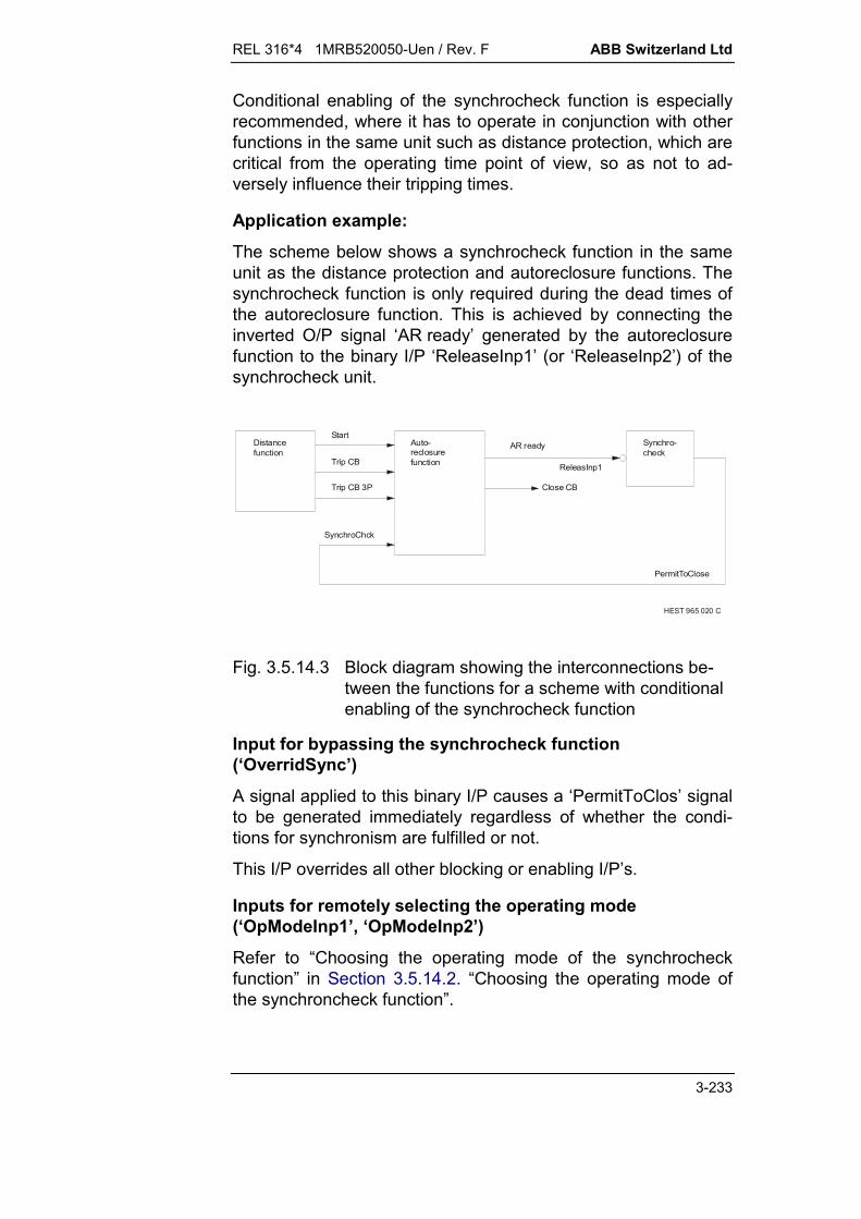
REL 316*4 1MRB520050-Uen / Rev. F ABB Switzerland Ltd
3-233
Conditional enabling of the synchrocheck function is especiallyrecommended, where it has to operate in conjunction with otherfunctions in the same unit such as distance protection, which arecritical from the operating time point of view, so as not to ad-versely influence their tripping times.
Application example:
The scheme below shows a synchrocheck function in the sameunit as the distance protection and autoreclosure functions. Thesynchrocheck function is only required during the dead times ofthe autoreclosure function. This is achieved by connecting theinverted O/P signal ‘AR ready’ generated by the autoreclosurefunction to the binary I/P ‘ReleaseInp1’ (or ‘ReleaseInp2’) of thesynchrocheck unit.
HEST 965 020 C
Start
Trip CB
Trip CB 3P
SynchroChck
PermitToClose
Close CB
AR readyDistancefunction
Auto-reclosurefunction
Synchro-check
ReleasInp1
Fig. 3.5.14.3 Block diagram showing the interconnections be-tween the functions for a scheme with conditionalenabling of the synchrocheck function
Input for bypassing the synchrocheck function(‘OverridSync’)
A signal applied to this binary I/P causes a ‘PermitToClos’ signalto be generated immediately regardless of whether the condi-tions for synchronism are fulfilled or not.
This I/P overrides all other blocking or enabling I/P’s.
Inputs for remotely selecting the operating mode(‘OpModeInp1’, ‘OpModeInp2’)
Refer to “Choosing the operating mode of the synchrocheckfunction” in Section 3.5.14.2. “Choosing the operating mode ofthe synchroncheck function”.

ABB Switzerland Ltd REL 316*4 1MRB520050-Uen / Rev. F
3-234
REL 316*4 1MRB520050-Uen / Rev. F ABB Switzerland Ltd
3-235
3.5.15. Breaker failure protection (BreakerFailure)
A. Application
Redundant tripping schemes (RED 1)) Repeated tripping attempts (BFP 2)) Backup tripping (BFP) End fault protection (EFP 3)) Unconditional tripping (UT 4)) External trip initiation.
B. Features
insensitive to DC component insensitive to harmonics single or three-phase operation blocking two independent timers (t1, t2) transfer tripping provision for disabling features (RED, BFP, EFP, UT) unique ID for each binary input and output.
C. Inputs and outputs
I. C.t./v.t. inputs
current.
II. Binary inputs
13205 Block BFP 13710 Start L1 13720 Start L2 13730 Start L3 13740 Start L1L2L3 13705 External start 13770 CB Off 13775 CB On 13780 Ext. trip t2 13785 Ext. trip EFP
1) Redundant2) Breaker failure protection3) End fault protection4) Unconditional trip

ABB Switzerland Ltd REL 316*4 1MRB520050-Uen / Rev. F
3-236
III. Binary outputs
23305 Trip t1 23315 Trip t1 L1 23320 Trip t1 L2 23325 Trip t1 L3 23310 Trip t2 23340 Remote trip 23345 Red. Trip L1 23350 Red. Trip L2 23355 Red. Trip L3 23375 EFP Rem trip 23370 EFP Bus trip 23330 Repeat trip after t1 23360 Unconditional trip after t1 23380 External trip after t1 23335 Backup trip after t2 23365 Unconditional trip after t2
IV. Measurements
Current amplitude L1 Current amplitude L2 Current amplitude L3.
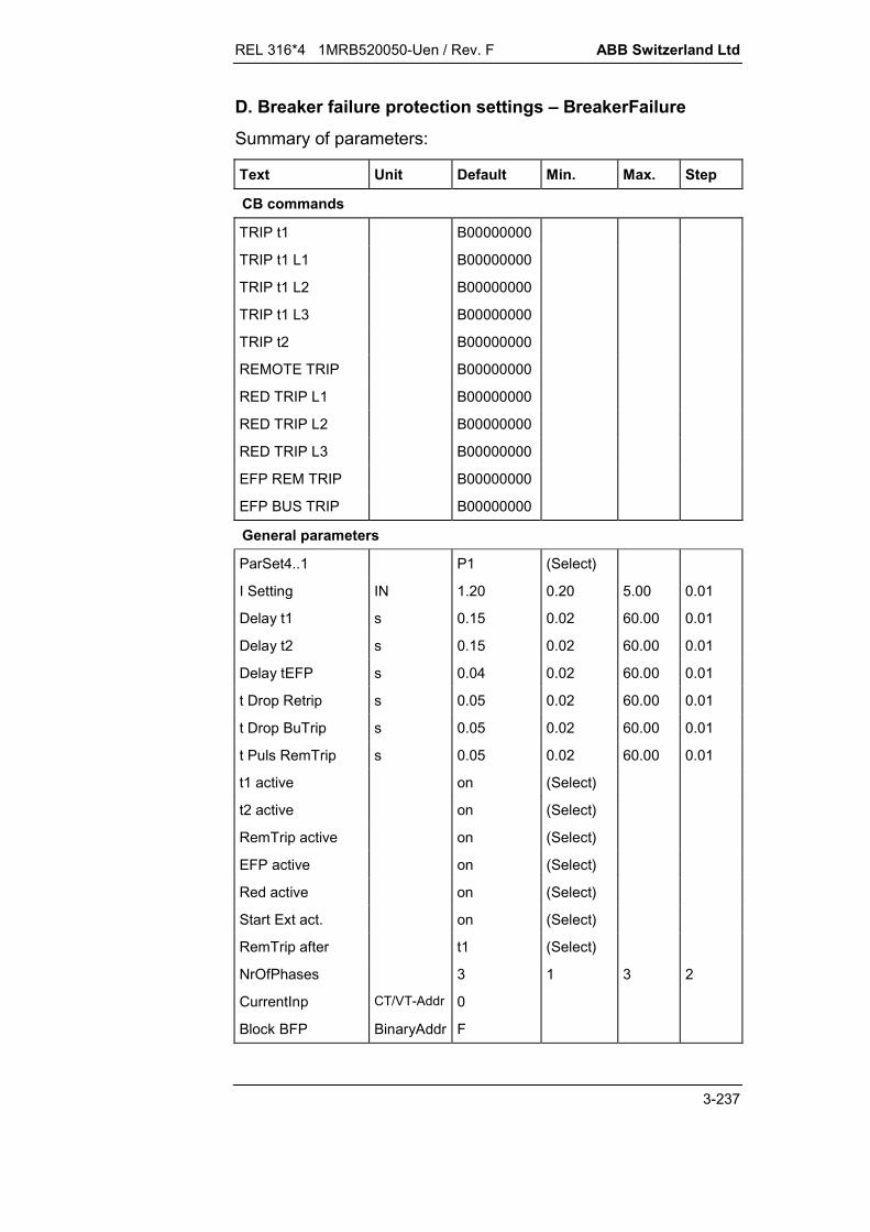
REL 316*4 1MRB520050-Uen / Rev. F ABB Switzerland Ltd
3-237
D. Breaker failure protection settings – BreakerFailure
Summary of parameters:
Text Unit Default Min. Max. Step
CB commands
TRIP t1 B00000000
TRIP t1 L1 B00000000
TRIP t1 L2 B00000000
TRIP t1 L3 B00000000
TRIP t2 B00000000
REMOTE TRIP B00000000
RED TRIP L1 B00000000
RED TRIP L2 B00000000
RED TRIP L3 B00000000
EFP REM TRIP B00000000
EFP BUS TRIP B00000000
General parameters
ParSet4..1 P1 (Select)
I Setting IN 1.20 0.20 5.00 0.01
Delay t1 s 0.15 0.02 60.00 0.01
Delay t2 s 0.15 0.02 60.00 0.01
Delay tEFP s 0.04 0.02 60.00 0.01
t Drop Retrip s 0.05 0.02 60.00 0.01
t Drop BuTrip s 0.05 0.02 60.00 0.01
t Puls RemTrip s 0.05 0.02 60.00 0.01
t1 active on (Select)
t2 active on (Select)
RemTrip active on (Select)
EFP active on (Select)
Red active on (Select)
Start Ext act. on (Select)
RemTrip after t1 (Select)
NrOfPhases 3 1 3 2
CurrentInp CT/VT-Addr 0
Block BFP BinaryAddr F

ABB Switzerland Ltd REL 316*4 1MRB520050-Uen / Rev. F
3-238
Text Unit Default Min. Max. Step
Start L1 BinaryAddr F
Start L2 BinaryAddr F
Start L3 BinaryAddr F
Start L1L2L3 BinaryAddr F
External Start BinaryAddr F
CB Off BinaryAddr F
CB On BinaryAddr F
Ext Trip t2 BinaryAddr F
Ext Trip EFP BinaryAddr F
Trip t1 SignalAddr ER
Trip t1 L1 SignalAddr ER
Trip t1 L2 SignalAddr ER
Trip t1 L3 SignalAddr ER
Trip t2 SignalAddr ER
Remote Trip SignalAddr ER
Red Trip L1 SignalAddr ER
Red Trip L2 SignalAddr ER
Red Trip L3 SignalAddr ER
EFP Rem Trip SignalAddr ER
EFP Bus Trip SignalAddr ER
Retrip t1 SignalAddr ER
Uncon Trip t1 SignalAddr ER
Ext Trip t1 SignalAddr ER
Backup Trip t2 SignalAddr ER
Uncon Trip t2 SignalAddr ER
Explanation of parameters:
TRIP t1defines the tripping channel activated by the function’stripping output TRIP t1 (matrix tripping logic). This output isactivated for a ‘Retrip’, ‘External Trip Initiate’ or‘Unconditional Trip’.
REL 316*4 1MRB520050-Uen / Rev. F ABB Switzerland Ltd
3-239
TRIP t1 L1, L2 or L3defines the tripping channel activated by the function’stripping outputs TRIP t1 L1, L2 or L3 (matrix tripping logic).This output is activated for a phase segregated ‘Retrip’.
TRIP t2defines the tripping channel activated by the function’stripping output TRIP t2 (matrix tripping logic). This output isactivated for a ‘Backup Trip’ or ‘Unconditional Trip’ the aftersecond time step t2.
REMOTE TRIPdefines the tripping channel activated by the function’stripping output REMOTE TRIP (matrix tripping logic).
RED TRIP L1, L2 or L3defines the tripping channel activated by the function’stripping outputs RED TRIP L1, L2 or L3 (matrix tripping logic).
EFP REM TRIPdefines the tripping channel activated by the function’stripping output EFP REM TRIP (matrix tripping logic).
EFP BUS TRIPdefines the tripping channel activated by the function’stripping output EFP BUS TRIP (matrix tripping logic).
ParSet 4..1Parameter for determining in which set of parameters a par-ticular function is active (see Section 5.11.).
I SettingPick-up of the current criterion for the breaker failureprotection (BFP), end fault protection (EFP) and theredundant tripping logic (RED).
Delay t1‘Retrip’ tripping delay
Delay t2Backup tripping delay.
Delay tEFPEnd fault protection delay.
t Drop RetripReset delay for ‘Retrip’, ‘Redundant Trip’ and ‘External TripInitiate’.
ABB Switzerland Ltd REL 316*4 1MRB520050-Uen / Rev. F
3-240
t Drop BuTripReset delay for backup tripping attempt.
t Puls RemTripTransfer tripping impulse width.
t1 activedefines whether timer t1 is enabled or disabled.‘on’ Timer t1 enabled‘off’ Timer t1 disabled.
t2 activedefines whether timer t2 is enabled or disabled.‘on’ Timer t2 enabled‘off’ Timer t2 disabled.
RemTrip activedefines whether transfer tripping is enabled or disabled.‘on’ Transfer tripping enabled‘off’ Transfer tripping disabled.
EFP activedefines whether the end fault protection is enabled or disabled.‘on’ End fault protection enabled‘off’ End fault protection disabled.
Red activedefines whether the redundant logic is enabled or disabled.‘on’ Redundant tripping logic enabled‘off’ Redundant tripping logic disabled.
Start Ext activedefines whether the unconditional tripping logic is enabled ordisabled.‘on’ Unconditional tripping logic enabled‘off’ Unconditional tripping logic disabled.
RemTrip afterdefines the delay for transfer tripping.‘t1’ after BFP time t1‘t2’ after BFP time t2.
NrOfPhasesdefines the number of phases supervised.‘1’ single-phase operation‘3’ three-phase operation.
CurrentInpdefines the c.t. input channel. Single and three-phase c.t’scan be set. The first channel (R phase) of the group of threeselected must be specified for three-phase c.t’s.

REL 316*4 1MRB520050-Uen / Rev. F ABB Switzerland Ltd
3-241
Block BFPInput for blocking the function.F: not blockedT: blockedxx: all binary inputs (or outputs of protection functions).
Start L1, L2 or L3BFP or RED Start in phase L1, L2 or L3F: disabledT: enabledxx: all binary inputs (or outputs of protection functions).
Start L1L2L3BFP or RED Start in all three phasesF: disabledT: enabledxx: all binary inputs (or outputs of protection functions).
External Startstarts the unconditional trip.F: disabledT: enabledxx: all binary inputs (or outputs of protection functions).
CB Offsignals that the circuit-breaker is fully open and also used tostart the end zone fault protection.F: CB not fully openT: CB fully openxx: all binary inputs (or outputs of protection functions).
CB Onsignals that the circuit-breaker is fully closed.F: CB not fully closedT: CB fully closedxx: all binary inputs (or outputs of protection functions).

ABB Switzerland Ltd REL 316*4 1MRB520050-Uen / Rev. F
3-242
Ext Trip t2Input for signals from the other BFP units in the station.F: No external trip after t2T: External trip after t2xx: all binary inputs (or outputs of protection functions).
Ext Trip EFPInput for signals from the end zone fault outputs of the otherBFP units in the station.F: No trip for end zone faultT: Trip for end zone faultxx: all binary inputs (or outputs of protection functions).
Trip t1signals a trip which is activated by one of the following logics: Repeat trip (see “Retrip t1”) External trip (see “Ext Trip t1”) Unconditional trip (see “UnconTrip t1”).
Trip t1 L1, L2 or L3signals a repeat trip of phase L1, L2 or L3.
Trip t2signals a backup trip. This signal is activated by the followinglogics: Backup trip after t2 (see “Backup Trip t2”) Unconditional trip after t2 (see “UnconTrip t2”).
Remote Tripsignals a transfer trip.
Red Trip L1, L2 or L3signals a redundant trip of phase L1, L2 or L3.
EFP Rem Tripsignals an end zone trip. This signal is an impulse of length ‘tPuls Rem Trip’ generated when the EFP timer has timed out.
EFP Bus Tripsignals an end zone trip. This signal is generated when theEFP timer has timed out and resets ‘tDrop Bu Trip’ after theinitiating signal has reset.

REL 316*4 1MRB520050-Uen / Rev. F ABB Switzerland Ltd
3-243
Retrip t1signals a repeat trip after t1. This signal is generated whenthe BFP timer t1 in one of the phases has timed out.
Uncon Trip t1signals an unconditional trip after t1. This signal is generatedwhen the UT timer t1 has timed out.
Ext Trip t1signals an external trip. This signal is generated when eitherthe input “Ext Trip t2” or “Ext Trip EFP” is enabled.
Backup Trip t2signals a backup trip after t2. This signal is generated whenthe BFP timer t2 has timed out.
Uncon Trip t2signals an unconditional trip after t2. This signal is generatedwhen the UT timer t2 has timed out.

ABB Switzerland Ltd REL 316*4 1MRB520050-Uen / Rev. F
3-244
E. Setting instructions
Settings:
Pick-up current setting: I SettingTripping delay: Delay t1
Delay t2Delay tEFP
Rest delay: t Drop Retript Drop BuTrip
Impulse: t Puls RemTrip
Enabled signals: t1 activet2 activeRemTrip activeEFP activeRed activeStart Ext active.
Pick-up current setting “I Setting”
If the BFP current detector pick-up setting is too low, there is apossibility that the detectors may reset too late after it has suc-cessfully tripped the circuit-breaker. This can be caused bydamped oscillations on the secondary side of the c.t.
On the other hand, if the setting is too high, the BFP may fail tooperate at all should, for example, the current fall below pick-upagain due to severe c.t. saturation. A typical setting for the pick-up current is just below the minimum fault current that can occuron the respective line.
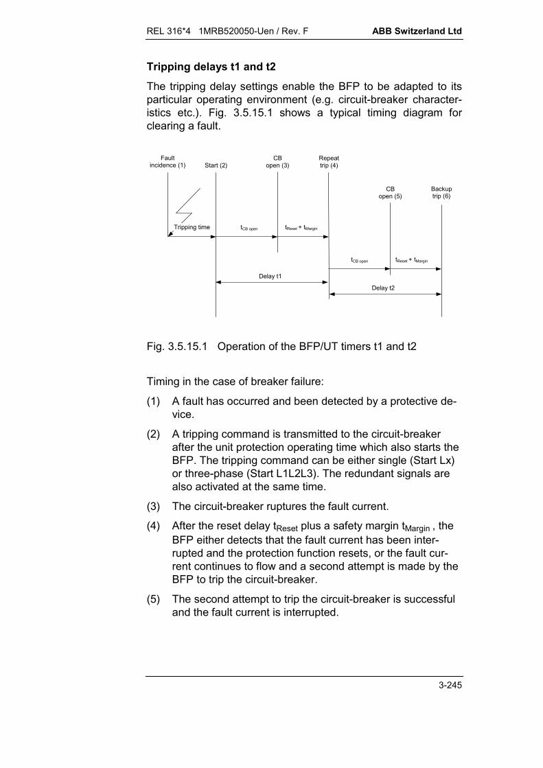
REL 316*4 1MRB520050-Uen / Rev. F ABB Switzerland Ltd
3-245
Tripping delays t1 and t2
The tripping delay settings enable the BFP to be adapted to itsparticular operating environment (e.g. circuit-breaker character-istics etc.). Fig. 3.5.15.1 shows a typical timing diagram forclearing a fault.
Tripping time tCB open
Delay t1
Delay t2
tReset + tMargin
tCB open tReset + tMargin
Start (2)CB
open (3)Repeattrip (4)
CBopen (5)
Backuptrip (6)
Faultincidence (1)
Fig. 3.5.15.1 Operation of the BFP/UT timers t1 and t2
Timing in the case of breaker failure:
(1) A fault has occurred and been detected by a protective de-vice.
(2) A tripping command is transmitted to the circuit-breakerafter the unit protection operating time which also starts theBFP. The tripping command can be either single (Start Lx)or three-phase (Start L1L2L3). The redundant signals arealso activated at the same time.
(3) The circuit-breaker ruptures the fault current.
(4) After the reset delay tReset plus a safety margin tMargin , theBFP either detects that the fault current has been inter-rupted and the protection function resets, or the fault cur-rent continues to flow and a second attempt is made by theBFP to trip the circuit-breaker.
(5) The second attempt to trip the circuit-breaker is successfuland the fault current is interrupted.
ABB Switzerland Ltd REL 316*4 1MRB520050-Uen / Rev. F
3-246
(6) After a further reset delay tReset plus a safety margin tMargin ,the BFP either detects that the fault current has been inter-rupted and the protection function resets, or the fault cur-rent continues to flow and the BFP initiates backup tripping.
If the BFP is only required to carry out a single breaker failurestep, timer t1 can be disabled (see ‘t1 active’). The response ofthe BFP corresponds once again to Fig. 3.5.15.1, but with timert1 set to zero.
Timing in the case of an unconditional trip:
(1) A fault has occurred and been detected by a protective de-vice.
(2) A signal at input ‘Ext Start’ starts the UT function.
(3) The circuit-breaker ruptures the fault current.
(4) If after the reset delay tReset plus a safety margin tMargin ,the CB auxiliary contact “CB On” still signals to the UT thatthe CB is closed, a second attempt is made by the UTfunction to trip the circuit-breaker.
(5) The second attempt to trip the circuit-breaker is successfuland the fault current is interrupted.
(6) If after a further reset delay tReset plus a safety margin tMar-gin the CB auxiliary contact “CB On” still signals to the UTthat the CB is closed, backup tripping is initiated by the UTfunction.
ResetopenCB tt1tDelay + tMargin
ResetopenCB tt2tDelay + tMargin
tCB open CB opening time including arc extinction time
tReset Reset time of the current criterion 1)
tMargin Allowance for variations in normal fault clearing times 2)
1) see reset time of the current detector tReset
2) see safety margin tMargin

REL 316*4 1MRB520050-Uen / Rev. F ABB Switzerland Ltd
3-247
Tripping delay tEFP
The setting for tEFP can be seen from Fig. 3.5.15.2 which showsa typical timing diagram for tripping a fault.
CBopen (3)
EFPtripping signal (4)
tEFP
CBtripping signal (1)
tCB open
CBtripped (2)
tReset + tMargin
tCB Off
Fig. 3.5.15.2 Timing diagram for an end zone fault
(1) Tripping command applied to the CB.
(2) CB auxiliary contact sends a signal that the CB is open tothe “CB Off” input of the function which is used to start theEFP.
(3) The circuit-breaker ruptures the fault current.
(4) After a reset delay plus a safety margin, the current unit ei-ther detects that the fault current has been interrupted andthe EFP function resets, or the fault current continues toflow and an EFP signal is issued.
ResetOffCBopenCB ttttEFP + tMargin
tCB open CB opening time including arc extinction time
tCB Off CB opening time of the CB auxiliary contact(Signal „CB open“)
tReset Reset time of the current detector 3)
tMargin Allowance for variations in normal fault clearing time 4)
3) see reset time of the current detector tReset
4) see Margin time tMargin
ABB Switzerland Ltd REL 316*4 1MRB520050-Uen / Rev. F
3-248
Reset time of the current detector tReset
The current detector reset time is determine by the power sys-tem configuration as follows:
Power system time constant up to 300 ms
Fault current up to 40 IN
Primary c.t’s TPX: tReset = 28 ms (ISetting 0.2 IN)
Primary c.t’s TPY: tReset = 28 ms (ISetting 1.2 IN)tReset = 38 ms (ISetting 0.4 IN)
Safety margin tMargin
A safety margin of 20 ms is recommended.
Reset times ‘t Drop Retrip’ and ‘t Drop BuTrip’
The function includes two independently adjustable signal resetdelays.
‘t Drop Retrip’ determines the reset delay for the following sig-nals: 23305 Trip t1
23315 Trip t1 L1
23320 Trip t1 L2
23325 Trip t1 L3
23345 Red Trip L1
23350 Red Trip L2
23355 Red Trip L3
23330 Retrip t1
23360 Uncon Trip t1
23380 Ext Trip t1.
‘t Drop BuTrip’ determines the reset delay for the following sig-nals: 23310 Trip t2
23370 EFP Bus Trip
23335 Backup Trip t2
23365 Uncon Trip t2.

REL 316*4 1MRB520050-Uen / Rev. F ABB Switzerland Ltd
3-249
Impulse ‘t Puls RemTrip’
‘t Puls RemTrip’ determines the width of the transfer tripping im-pulse for the following signals:
23340 Remote Trip
23375 EFP Rem Trip.
Enabling and disabling the various features
A number of the function’s features can be enabled and dis-abled.
t1 active
This setting provides facility for disabling the timer t1. When it isdisabled, none of the “repeat trip” group of signals is generated.
t2 active
This setting provides facility for disabling the timer t2. When it isdisabled, none of the “backup trip” group of signals is generated.
RemTrip active
This setting provides facility for disabling transfer tripping. Whenit is disabled, none of the “remote trip” group of signals isgenerated.
EFP active
This setting provides facility for disabling the end fault protection.When it is disabled, none of the “end fault” group of signals isgenerated.
Red active
This setting provides facility for disabling the redundantprotection. When it is disabled, none of the “redundant” group ofsignals is generated.
Start Ext act.
This setting provides facility for disabling the unconditional tripfeature. When it is disabled, none of the “unconditional trip”group of signals is generated.

ABB Switzerland Ltd REL 316*4 1MRB520050-Uen / Rev. F
3-250

REL 316*4 1MRB520050-Uen / Rev. F ABB Switzerland Ltd
3-251
3.6. Control functions
3.6.1. Control function (FUPLA)
A. Application
The control function is designed to perform data acquisition,monitoring, and control functions in MV and HV substations.The control logic of a switchgear bay can be configured for SF6gas-insulated switchgear (GIS), for indoor and outdoor switch-gear and for single, double or multiple busbar stations.
The control function registers and processes the switchgear po-sition signals, the measured variables and the alarms occurringin a switchgear bay. The corresponding data are then madeavailable at the communication interface (IBB).
The control function receives instructions from the station controlsystem (SCS) or from the local mimic, processes them in relationto the bay control logic configuration and then executes them.
The interlocks included in the control function device prevent in-admissible switching operations, which could cause damage toplant or endanger personnel.
B. Features
The control function depends on the particular application forwhich it is specifically created using CAP 316. It includes essen-tially:
detection and plausibility check of switchgear position signals switchgear control interlocks monitoring of switchgear commands run-time supervision integration of the local mimic detection of alarms and alarm logic processing of measured variables.
Eight FUPLA functions can be configured. The total maximum sizeof FUPLA code for all the functions is 128 kB. The FUPLA functioncannot be copied and not configured as 48th function. Thefunction plan programming language CAP 316 is described inthe publication 1MRB520059-Uen.

ABB Switzerland Ltd REL 316*4 1MRB520050-Uen / Rev. F
3-252
C. Inputs and outputs
I. C.t./v.t. inputs:
Constants, measured protection variables, IBB inputs andsampled values
II. Analogue outputs:
Measured variable outputs
III. Binary inputs:
Blocking input, binary input for blocking FUPLA Binary inputs from the IBB, the system and protection
functions
IV. Binary outputs:
Binary outputs to the IBB, the system, protection functionsand for event processing
V. Measurements:
Measured variable outputs.

REL 316*4 1MRB520050-Uen / Rev. F ABB Switzerland Ltd
3-253
3.6.1.1. Control function settings - FUPLA
When reconfiguring the FUPLA function, the directory where thefiles ‘project1.bin’ and ‘project.cfg’ are located must be enteredbefore all other parameters. The project name in the file‘project1.bin’ is used automatically as the name of the FUPLAfunction, but the name can be changed later.
!"#$%&&&&&&&&&&&&'((((((((((((((((((((((((((((((((((((((())**)*****)((((((((((((((((((((((((((((((((((((((())+)#, &&&&&&&&&&&&&&&&&&&&&&'((((((((((((((((((((((((((((((((((((()))))-.........................../((((((((((((((()) )0)) 1%$23453!6784((((((((((((((())))),9:...........................;((((((((((((((())))))((((((((((((((((((((((((((((((((((((()))<)=&&&&&&&&&&&&&&&&&&&&&&&&&&&>((((((((((((((((((((((((((((((((((((()) ))?3@)((((((((((((((((((((((((((((((((((((((()))A)3B$C)(((((((((((((((((((((((((((((((((((((((=&))D)3 E)((((((((((((((((((((((((((((((((((((((((())F)6$)(((((((((((((((((((((((((((((((((((((((((=&&&)0+)C%)((((((((((((((((((((((((((((((((((((((((((((()0),!B G)((((((((((((((((((((((((((((((((((((((((((((()00)3"$2 %%)((((((((((((((((((((((((((((((((((((((((((((()0)9#$%)((((((((((((((((((((((((((((((((((((((((((((()),9)((((((((((((((((((((((((((((((((((((((((((((()))(((((((((((((((((((((((((((((((((((((((((((((=&&&=&&&&&&&&&&&&&&&&&&&&&&&&&&&>(((((((((((((((((((((((((((((((((((((((7&F++2"6H ?*02I?*02
Fig. 3.6.1.1 Entering the FUPLA directory
The individual parameters can then be entered.
!"#$%&&&&&&&&&&&&'))**)*****)))D)- J7...................../)))F)44)) )+)4 4))))4"4)))0)4 E!4))))4 E7$4)) ))4@!$"4)))<)4@7$$"4=&)))4 1%$234))A)4,94=&&&)D)44)F):...........................;)0+)3"$2 %%))0)9#$%))),9))))=&&&=&&&&&&&&&&&&&&&&&&&&&&&&&&&>
Fig. 3.6.1.2 Entering the individual parameters
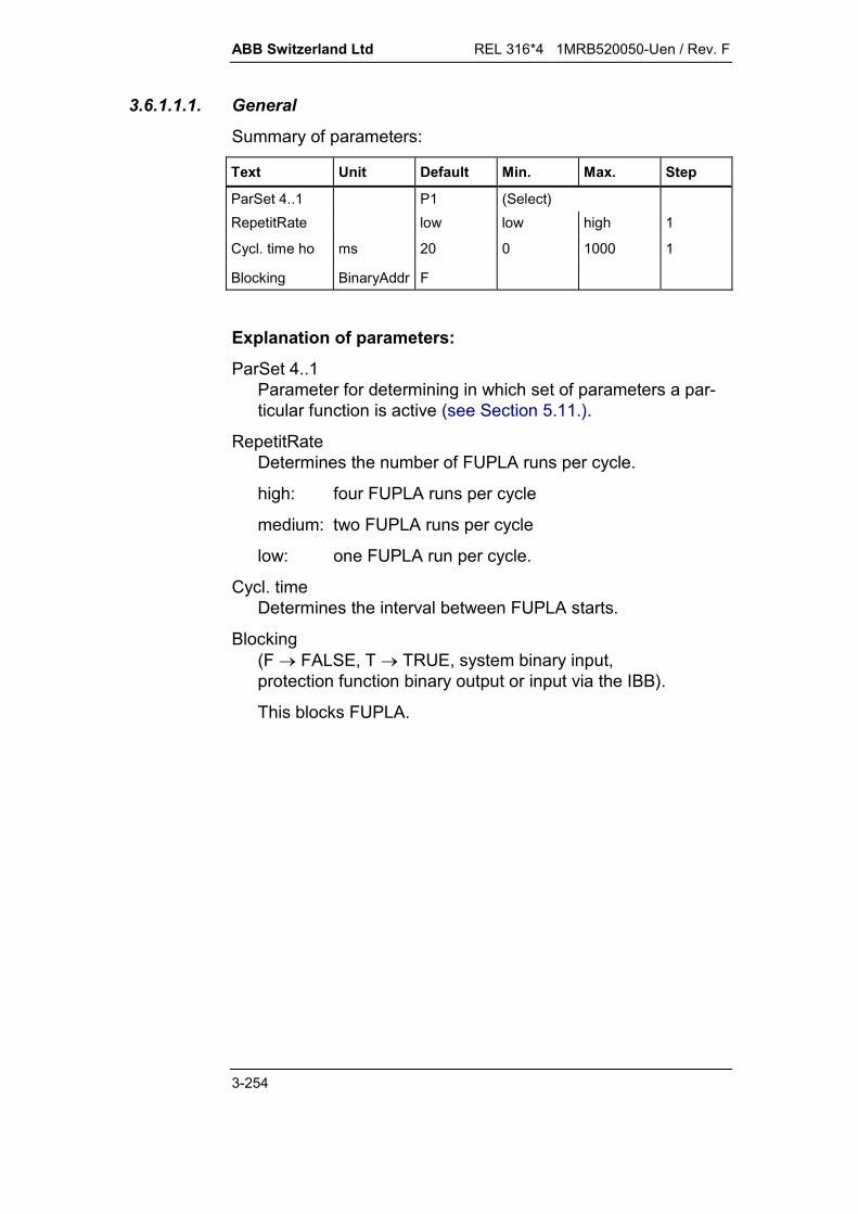
ABB Switzerland Ltd REL 316*4 1MRB520050-Uen / Rev. F
3-254
3.6.1.1.1. General
Summary of parameters:
Text Unit Default Min. Max. Step
ParSet 4..1 P1 (Select)RepetitRate low low high 1
Cycl. time ho ms 20 0 1000 1
Blocking BinaryAddr F
Explanation of parameters:
ParSet 4..1Parameter for determining in which set of parameters a par-ticular function is active (see Section 5.11.).
RepetitRateDetermines the number of FUPLA runs per cycle.
high: four FUPLA runs per cycle
medium: two FUPLA runs per cycle
low: one FUPLA run per cycle.
Cycl. timeDetermines the interval between FUPLA starts.
Blocking(F FALSE, T TRUE, system binary input,protection function binary output or input via the IBB).
This blocks FUPLA.
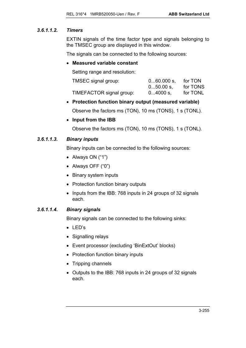
REL 316*4 1MRB520050-Uen / Rev. F ABB Switzerland Ltd
3-255
3.6.1.1.2. Timers
EXTIN signals of the time factor type and signals belonging tothe TMSEC group are displayed in this window.
The signals can be connected to the following sources:
Measured variable constant
Setting range and resolution:
TMSEC signal group: 0...60.000 s, for TON0...50.00 s, for TONS
TIMEFACTOR signal group: 0...4000 s, for TONL
Protection function binary output (measured variable)
Observe the factors ms (TON), 10 ms (TONS), 1 s (TONL).
Input from the IBB
Observe the factors ms (TON), 10 ms (TONS), 1 s (TONL).
3.6.1.1.3. Binary inputs
Binary inputs can be connected to the following sources:
Always ON (“1”)
Always OFF (“0”)
Binary system inputs
Protection function binary outputs
Inputs from the IBB: 768 inputs in 24 groups of 32 signalseach.
3.6.1.1.4. Binary signals
Binary signals can be connected to the following sinks:
LED’s
Signalling relays
Event processor (excluding ‘BinExtOut’ blocks)
Protection function binary inputs
Tripping channels
Outputs to the IBB: 768 inputs in 24 groups of 32 signalseach.
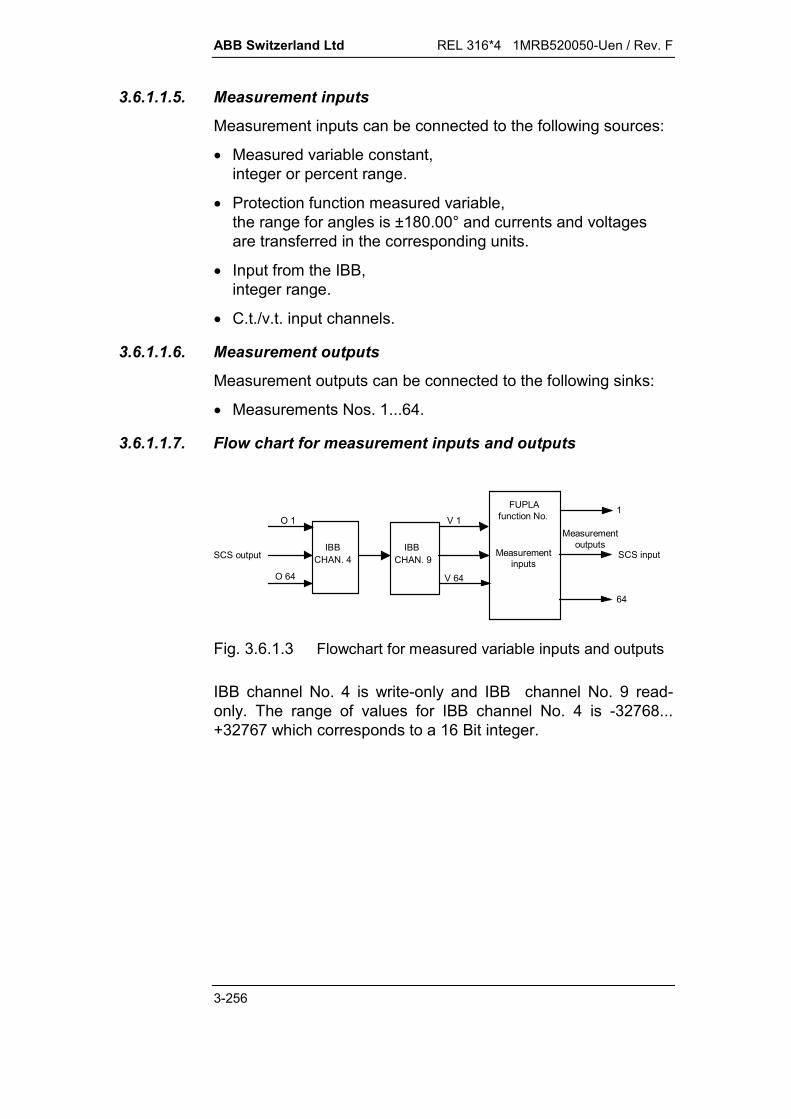
ABB Switzerland Ltd REL 316*4 1MRB520050-Uen / Rev. F
3-256
3.6.1.1.5. Measurement inputs
Measurement inputs can be connected to the following sources:
Measured variable constant,integer or percent range.
Protection function measured variable,the range for angles is ±180.00° and currents and voltagesare transferred in the corresponding units.
Input from the IBB,integer range.
C.t./v.t. input channels.
3.6.1.1.6. Measurement outputs
Measurement outputs can be connected to the following sinks:
Measurements Nos. 1...64.
3.6.1.1.7. Flow chart for measurement inputs and outputs
IBB
FUPLA 1
64
V 1
V 64
O 1
O 64
Measurement outputs
Measurement inputs
SCS output SCS inputCHAN. 4
function No.
IBB CHAN. 9
Fig. 3.6.1.3 Flowchart for measured variable inputs and outputs
IBB channel No. 4 is write-only and IBB channel No. 9 read-only. The range of values for IBB channel No. 4 is -32768...+32767 which corresponds to a 16 Bit integer.

REL 316*4 1MRB520050-Uen / Rev. F ABB Switzerland Ltd
3-257
3.6.1.2. Loading FUPLA
The FUPLA code has to be loaded again each time the FUPLAconfiguration is changed. After making internal FUPLA changesand copying the new versions of the files ‘project1.bin’ and‘project.cfg’ to the FUPLA directory, select “Editor” from the mainmenu and then ‘RETURN’ to load the new FUPLA code.
$&&&&&&&&&&&')))&&&&&&&&&&&&&&&&&&&&&'))))) " #$%"-........../))K #$%"4?L4))E" "4M85NM954))" "44)) O "#:..........;)) "B#)=&),9)))=&&&&&&&&&&&&&&&&&&&&&&&&&&&>
Fig. 3.6.1.4 Editor, Save ?

ABB Switzerland Ltd REL 316*4 1MRB520050-Uen / Rev. F
3-258

REL 316*4 1MRB520050-Uen / Rev. F ABB Switzerland Ltd
3-259
3.6.2. Logic (Logic)
A. Application
Logical combination of binary input signals or of output signalsfrom the protection functions, e.g. for specific signals required by the application supplementary protection functions.
B. Features
binary I/P channels assignable to binary I/P signals protection function O/P signals
All I/P channels can be inverted Following logic functions available for selection:
OR gate with 4 I/P’s AND gate with 4 I/P’s R/S flip-flop with 2 I/P’s for setting and 2 I/P’s for reset-
ting: The O/P is “0”, if at least one of the reset I/P’s is “1”. The O/P is “1”, if at least one of the set I/P’s is “1” AND
none of the reset I/P’s is “1”. The O/P status is sustained when all the I/P’s are at
“0”. Every logic has an additional blocking I/P, which when acti-
vated switches the O/P to “0”.
C. Inputs and outputs
I. C.t./v.t. inputs:
none
II. Binary inputs:
4 logic inputs blocking
III. Binary O/P’s:
tripping
IV. Measurements:
none.

ABB Switzerland Ltd REL 316*4 1MRB520050-Uen / Rev. F
3-260
D. Logic function settings - Logic
Summary of parameters:
Text Units Default Min. Max. Step
ParSet 4..1 P1 (Select)
Trip 00000000
Logic Mode OR (Select)
BinOutput SignalAddr ER
BlockInp BinaryAddr F
BinInp1 (R1) BinaryAddr F
BinInp2 (R2) BinaryAddr F
BinInp3 (S1) BinaryAddr F
BinInp4 (S2) BinaryAddr F
Explanation of parameters:
ParSet 4..1Parameter for determining in which set of parameters a par-ticular function is active (see Section 5.11.).
TripDefinition of the tripping circuit excited by the function’s O/P(tripping matrix).
Logic ModeDefinition of the logic function to be performed by the 4 binaryI/P’s. Possible settings: OR: OR gate with all 4 binary I/P’s AND: AND gate with all 4 binary I/P’s R/S flip-flop: Flip-flop with 2 set I/P’s (S1 and S2) and 2
reset I/P’s (R1 and R2). The O/P is set orreset when at least one of the correspondingI/P’s is at logical “1” (OR gate).Reset I/P’s take priority over the set I/P’s.
BinOutputOutput for signalling a trip.
REL 316*4 1MRB520050-Uen / Rev. F ABB Switzerland Ltd
3-261
BlockInpInput for blocking the function.
F: - not usedxx: - all binary inputs (or outputs of protection
functions).
The O/P is always at logical “0” when the blocking I/P is atlogical “1”.The blocking I/P acts as a reset I/P for the flip-flop function.
BinInp1 (R1), BinInp2 (R2), BinInp3 (S1), BinInp4 (S2)Binary inputs 1 to 4 (AND or OR function)Reset inputs 1 and 2 and set inputs 1 and 2 (RS flip-flop)
F: - not used (OR logic or RS flip-flop)T: - not used (AND logic)xx: - all binary inputs (or outputs of protection
functions).

ABB Switzerland Ltd REL 316*4 1MRB520050-Uen / Rev. F
3-262

REL 316*4 1MRB520050-Uen / Rev. F ABB Switzerland Ltd
3-263
3.6.3. Delay / integrator (Delay)
A. Application
General purpose timer for integration of pulsating binary signals to obtain a continuous
signal, e.g. output of the loss-of-excitation function (out-of-step protection) or reverse power protection
extension of short I/P signals (pulse prolongation) simple time delay.
B. Features
I/P channel and blocking input assignable to binary I/P signals protection function output signals
I/P channel and blocking input can be inverted. adjustable reset time 2 types of time delay
Integration: Only the time during which the I/P signal is atlogical "1" counts at the end of the time delay.
No integration: The total time from the instant the timerstarts until it is either reset or expires counts.
C. Inputs and outputs
I. C.t./v.t. inputs:
none
II. Binary inputs:
input signal blocking
III. Binary outputs:
pick-up tripping
IV. Measurements:
time from the instant the timer starts.
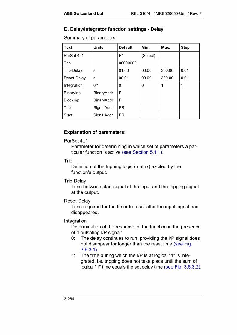
ABB Switzerland Ltd REL 316*4 1MRB520050-Uen / Rev. F
3-264
D. Delay/integrator function settings - Delay
Summary of parameters:
Text Units Default Min. Max. Step
ParSet 4..1 P1 (Select)
Trip 00000000
Trip-Delay s 01.00 00.00 300.00 0.01
Reset-Delay s 00.01 00.00 300.00 0.01
Integration 0/1 0 0 1 1
BinaryInp BinaryAddr F
BlockInp BinaryAddr F
Trip SignalAddr ER
Start SignalAddr ER
Explanation of parameters:
ParSet 4..1Parameter for determining in which set of parameters a par-ticular function is active (see Section 5.11.).
TripDefinition of the tripping logic (matrix) excited by thefunction's output.
Trip-DelayTime between start signal at the input and the tripping signalat the output.
Reset-DelayTime required for the timer to reset after the input signal hasdisappeared.
IntegrationDetermination of the response of the function in the presenceof a pulsating I/P signal:0: The delay continues to run, providing the I/P signal does
not disappear for longer than the reset time (see Fig.3.6.3.1).
1: The time during which the I/P is at logical "1" is inte-grated, i.e. tripping does not take place until the sum oflogical "1" time equals the set delay time (see Fig. 3.6.3.2).

REL 316*4 1MRB520050-Uen / Rev. F ABB Switzerland Ltd
3-265
BinaryInpTimer input.xx: - all binary inputs (or outputs of protection functions).
BlockInpInput for blocking the function.F: - enabledT: - disabledxx: - all binary inputs (or outputs of protection functions).
TripTripping signal.
StartPick-up signal.

ABB Switzerland Ltd REL 316*4 1MRB520050-Uen / Rev. F
3-266
HEST 935 019 C
Start
prolongation
Tripping
0
0
0
Impulse
t
t
t
(Notripping)
(Notripping)
t
t
t
tA
tR
tA
tR tR
0
0
0
t
t
t
t
t
t
tR
tA
tR tR
0
0
0
0
0
0
Start
prolongation
Tripping
Impulse
(Notripping)
tA
Note: Tripping only takes place, if a start also occurs within the time tR.tA tripping time ("Trip-Delay")tR reset time ("Reset-Delay")
Fig. 3.6.3.1 Operation of the “Delay” function without inte-gration
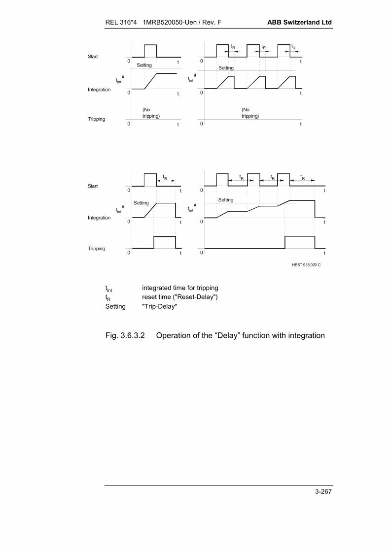
REL 316*4 1MRB520050-Uen / Rev. F ABB Switzerland Ltd
3-267
HEST 935 020 C
0
0
0
t
t
t
t
t
t
tR
0
0
0
t
t
t
t
t
t
tR tR tR
0
0
0
0
0
0
tint
tint
tR
tR
tint
tint
Setting
(Notripping)
(Notripping)
Start
Tripping
Integration
Start
Tripping
Integration
Setting
SettingSetting
tR
tint integrated time for trippingtR reset time ("Reset-Delay")Setting "Trip-Delay"
Fig. 3.6.3.2 Operation of the “Delay” function with integration

ABB Switzerland Ltd REL 316*4 1MRB520050-Uen / Rev. F
3-268

REL 316*4 1MRB520050-Uen / Rev. F ABB Switzerland Ltd
3-269
3.6.4. Contact bounce filter (Debounce)
A. Application
Suppresses the contact bounce phenomena of binary signals.This function is only used for the signals of binary input modules.
B. Features
Adjustable maximum bounce time The first edge of the respective input signal is prolonged by
the time ‘SupervisTime’.
C. Inputs and outputs
I. C.t./v.t. inputs:
none
II. Binary inputs:
Binary signals (input signals) blocking
III. Binary outputs:
none
IV. Measurements:
none.
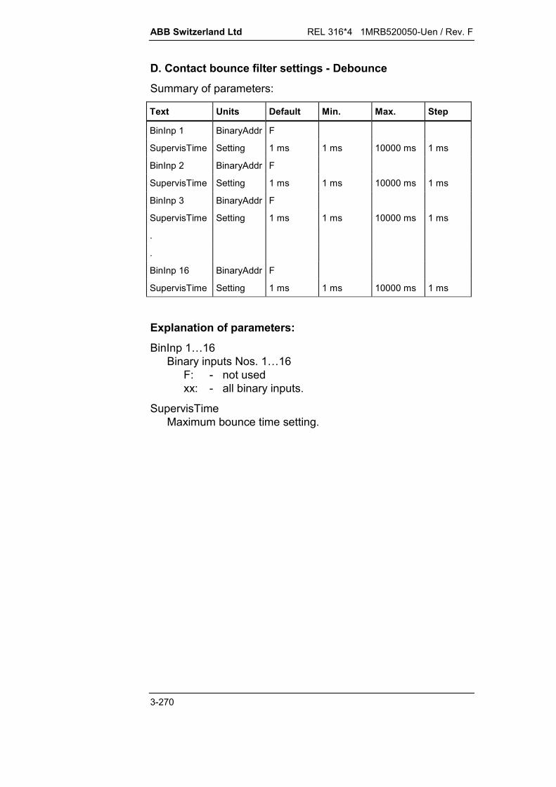
ABB Switzerland Ltd REL 316*4 1MRB520050-Uen / Rev. F
3-270
D. Contact bounce filter settings - Debounce
Summary of parameters:
Text Units Default Min. Max. Step
BinInp 1 BinaryAddr F
SupervisTime Setting 1 ms 1 ms 10000 ms 1 ms
BinInp 2 BinaryAddr F
SupervisTime Setting 1 ms 1 ms 10000 ms 1 ms
BinInp 3 BinaryAddr F
SupervisTime Setting 1 ms 1 ms 10000 ms 1 ms
.
.
BinInp 16 BinaryAddr F
SupervisTime Setting 1 ms 1 ms 10000 ms 1 ms
Explanation of parameters:
BinInp 1…16Binary inputs Nos. 1…16
F: - not usedxx: - all binary inputs.
SupervisTimeMaximum bounce time setting.

REL 316*4 1MRB520050-Uen / Rev. F ABB Switzerland Ltd
3-271
E. Setting instructions
The first edge of the input signal is prolonged by the time set for‘SupervisTime’.
Connect functions requiring filtered signals to the correctbinary inputs to start with.
The contact bounce filter ‘Debounce’ may only beconfigured once per set of parameters.

ABB Switzerland Ltd REL 316*4 1MRB520050-Uen / Rev. F
3-272

REL 316*4 1MRB520050-Uen / Rev. F ABB Switzerland Ltd
3-273
3.6.5. LDU events (LDUevents)
A. Application
Generates events that can be viewed on the local display unit(LDU) and provides facility for setting a user name.
B. Features
binary input that can be set by a binary input signal an output signal from a protection function
provision for inverting signals applied to the inputs direct connection of input to output: input 1 controls output 1,
input 2 control output 2 etc. additional blocking input for entire function: all outputs are
reset to logical “0” when blocking input at logical “1”.
An event lists the name of the signal connected to the input andnot the name of the output.
C. Inputs and outputs
I. C.t./v.t. inputs:
none
II. Binary inputs:
4 independent inputs blocking
III. Binary outputs:
4 independent outputs
IV. Measurements
none.

ABB Switzerland Ltd REL 316*4 1MRB520050-Uen / Rev. F
3-274
D. LDU event function settings – LDUevents
Summary of parameters:
Text Unit Default Min. Max. Step
ParSet 4..1 P1 (Select)
Trip 000000000
BlockInp BinaryAddr F
BinInput1 BinaryAddr F
BinInput2 BinaryAddr F
BinInput3 BinaryAddr F
BinInput 4 BinaryAddr F
BinOutput1 SignalAddr ER
BinOutput2 SignalAddr ER
BinOutput3 SignalAddr ER
BinOutput4 SignalAddr ER
Explanation of parameters:
ParSet 4..1Parameter for determining in which set of parameters a par-ticular function is active (see Section 5.11.).
TripDoes not perform any function, always “0”.
BlockInpBinary address used as blocking input.F: - not usedxx: - all binary inputs (or outputs of a protection
function).All outputs at logical “0” when the blocking input is active.
BinInput1, BinInput2, BinInput3, BinInput4Binary inputs 1 to 4: Every input acts directly on the corre-sponding output and can only be influenced by the inversionand blocking parameters.

REL 316*4 1MRB520050-Uen / Rev. F ABB Switzerland Ltd
3-275
BinOutput1, BinOutput2, BinOutput3, BinOutput4Signalling outputs 1 to 4: Every input acts directly on the cor-responding output. Whether an output is recorded as anevent can be enabled or disabled. When it is enabled, it ap-pears on the local display.
Note:
In contrast to all other functions, the name of the signal con-nected to the corresponding input appears in the event list in-stead of the name of the output. A function can therefore begiven a descriptive, easily understood name that appear in theevent list and on the local display.

ABB Switzerland Ltd REL 316*4 1MRB520050-Uen / Rev. F
3-276

REL 316*4 1MRB520050-Uen / Rev. F ABB Switzerland Ltd
3-277
3.7. Measurement functions
3.7.1. Measurement function (UIfPQ)
A. Application
Measurement of voltage, current, real and apparent power andfrequency, e.g. for display on the monitor of the control unit or fortransferring to a high level station control system for furtherprocessing.
B. Features
single-phase measurement (1 voltage and 1 current I/P) phase-to-ground or optionally phase-to-phase voltage meas-
urement (providing three-phase Y connected v.t’s are in-stalled)
evaluation of the fundamental frequency components high accuracy in the frequency range (0.9 ... 1.1) fN frequency of voltage measured unless voltage too low, in
which case current is measured; if both are too low, the resultis set to rated frequency
at least 1 measurement per second filters for voltage and current DC components filters for voltage and current harmonics provision for compensation of connection and measurement
phase errors.
C. Inputs and outputs
I. C.t./v.t. inputs
voltage currentII. Binary inputs
noneIII. Binary outputs
noneIV. Measurements:
voltage (unit UN) current (unit IN) real power (unit PN (P)) apparent power (unit PN (Q)) frequency (unit Hz).
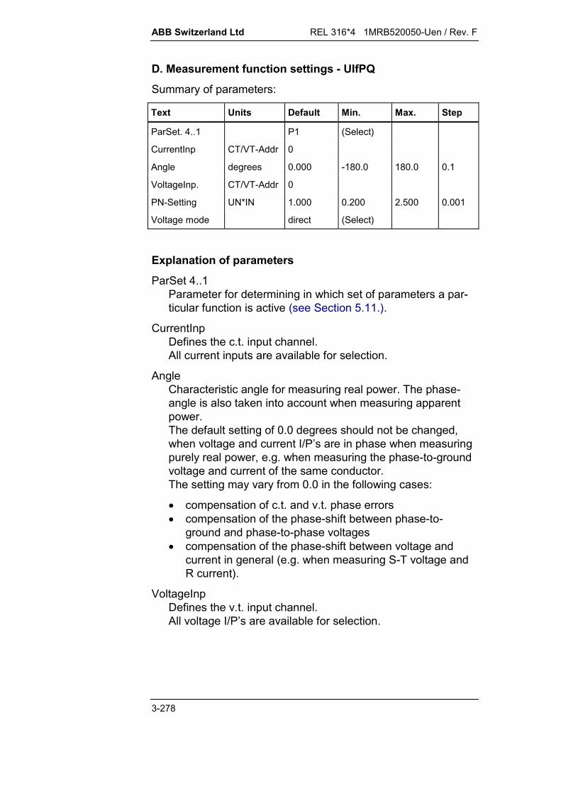
ABB Switzerland Ltd REL 316*4 1MRB520050-Uen / Rev. F
3-278
D. Measurement function settings - UIfPQ
Summary of parameters:
Text Units Default Min. Max. Step
ParSet. 4..1 P1 (Select)
CurrentInp CT/VT-Addr 0
Angle degrees 0.000 -180.0 180.0 0.1
VoltageInp. CT/VT-Addr 0
PN-Setting UN*IN 1.000 0.200 2.500 0.001
Voltage mode direct (Select)
Explanation of parameters
ParSet 4..1Parameter for determining in which set of parameters a par-ticular function is active (see Section 5.11.).
CurrentInpDefines the c.t. input channel.All current inputs are available for selection.
AngleCharacteristic angle for measuring real power. The phase-angle is also taken into account when measuring apparentpower.The default setting of 0.0 degrees should not be changed,when voltage and current I/P’s are in phase when measuringpurely real power, e.g. when measuring the phase-to-groundvoltage and current of the same conductor.The setting may vary from 0.0 in the following cases:
compensation of c.t. and v.t. phase errors compensation of the phase-shift between phase-to-
ground and phase-to-phase voltages compensation of the phase-shift between voltage and
current in general (e.g. when measuring S-T voltage andR current).
VoltageInpDefines the v.t. input channel.All voltage I/P’s are available for selection.

REL 316*4 1MRB520050-Uen / Rev. F ABB Switzerland Ltd
3-279
PNRated power corresponding to UN IN.This enables the amplitude of the measured power to beadjusted, for example, to equal the rated power factor of agenerator.
Voltage modeDefinition of the method of voltage measurement andtherefore also the calculation of power. Possible settings: direct The voltage of the selected voltage I/P is
measured directly. delta The phase-to-phase voltage formed by
the selected voltage I/P and the cycli-cally lagging voltage channel is meas-ured.This setting is not permitted when only asingle-phase is connected or whenphase-to-phase voltages are connected.
ABB Switzerland Ltd REL 316*4 1MRB520050-Uen / Rev. F
3-280
E. Setting instructions
The measurement function must be carefully set to obtain thebest accuracy. The following must be observed:
C.t./v.t. input channel reference valuesThe reference values for the voltage and current inputchannels must be set such that, when the rated values areapplied to the inputs, 1.000 UN and 1.000 IN are measuredby the function.
In most cases it will be possible to retain the default refer-ence setting (1.000) for the c.t. and v.t. input channels. Notethat any changes made to the reference value of a three-phase voltage or current I/P applies to all phases.
“Angle” setting for phase error compensationThe parameter “Phase-angle” must be correctly set in orderto measure real and apparent power correctly. In most casesit will be possible to retain the default reference setting of 0.0degrees when measuring the phase-to-ground voltage andcurrent of the same conductor.
Other settings may be necessary in the following cases:
a) A phase-to-phase voltage is being measured, e.g. meas-urement of the R phase current in relation to the R - Svoltage:=> phase compensation: +30.0°
b) Compensation of c.t. and v.t. phase errors.=> phase compensation: according to calibration,e.g. ( 5.0°...+5.0°)
c) Change of measuring direction or correction of c.t. or v.t.polarity.=> phase compensation: +180.0° or 180°
Where several of these factors have to be taken into consid-eration, the phase compensation in all the cases must beadded and the resultant set.
The angles given apply for connection according to theconnections in Section 12.
Power reference value “PN”In most cases it will be possible to retain the default refer-ence setting (1.000). Since the errors in the voltage andcurrent reference values add geometrically, a fine setting isrecommended to achieve the best possible accuracy.

REL 316*4 1MRB520050-Uen / Rev. F ABB Switzerland Ltd
3-281
Check the settings for “Angle” and “PN” using an accurate testset according to the following procedure:
a) Inject purely active power at rated voltage and current.b) The active power measurement must be as close as possible
to 1.000 or oscillate symmetrically to either side of it. Adjust the value of “PN” as necessary.
c) The reactive power measurement must be as close aspossible to 0.000 or oscillate symmetrically to either side of it. Adjust the value of “Angle” as necessary.

ABB Switzerland Ltd REL 316*4 1MRB520050-Uen / Rev. F
3-282

REL 316*4 1MRB520050-Uen / Rev. F ABB Switzerland Ltd
3-283
3.7.2. Three-phase current plausibility (Check-I3ph)
A. Application
Checking the plausibility of the three-phase current inputs for monitoring the symmetry of the three-phase system detection of a residual current supervision of the c.t. input channels.
B. Features
evaluation of the sum of the three phase currents the sequence of the three phase currents
provision for comparing the sum of the three phase currentswith a residual current I/P
adjustment of residual current amplitude blocking at high currents (higher than 2 x IN) blocking of phase-sequence monitoring at low currents
(below 0.05 x IN) insensitive to DC components insensitive to harmonics.
C. Inputs and outputs
I. C.t./v.t. inputs:
phase currents neutral current (optional)
II. Binary inputs:
blocking
III. Binary outputs:
tripping
IV. Measurements:
difference between the vector sum of the three phasecurrents and the neutral current.

ABB Switzerland Ltd REL 316*4 1MRB520050-Uen / Rev. F
3-284
D. Current plausibility function settings - Check-I3ph
Summary of parameters:
Text Units Default Min. Max. Step
ParSet 4..1 P1 (Select)
Trip 00000000
I-Setting IN 0.20 0.05 1.00 0.05
Delay s 10.0 0.1 60.0 0.1
CT-Compens 01.00 -2.00 +2.00 0.01
CurrentInp CT/VT-Addr 0
SumInp. CT/VT-Addr 0
BlockInp BinaryAddr F
Trip SignalAddr ER
Explanation of parameters:
ParSet 4..1Parameter for determining in which set of parameters a par-ticular function is active (see Section 5.11.).
TripDefinition of the tripping logic (matrix) excited by thefunction’s O/P.
I-SettingCurrent setting for tripping.
DelayTime between start signal at the I/P and the tripping signal atthe O/P.Forbidden settings: 1 s for current settings 0.2 IN.
CT-CompensAmplitude compensation factor for the residual current I/P,enabling different transformation ratios of the main c.t’s forphase and residual currents to be equalised.The polarity of the residual current can be reversed by enter-ing negative values.
REL 316*4 1MRB520050-Uen / Rev. F ABB Switzerland Ltd
3-285
CurrentInpDefines the current input channel.Any of the three-phase current I/P’s may be selected.The first channel (R phase) of a three-phase group is en-tered.
SumInpDefines the neutral current input channel.Any of the single-phase current I/P’s may be selected.
BlockInpInput for blocking the function.F: - enabledT: - disabledxx: - all binary inputs (or outputs of protection functions).
TripTripping signal.
Note:
If the phase sequence is incorrect, tripping takes place regard-less of setting (I-Setting).

ABB Switzerland Ltd REL 316*4 1MRB520050-Uen / Rev. F
3-286

REL 316*4 1MRB520050-Uen / Rev. F ABB Switzerland Ltd
3-287
3.7.3. Three-phase voltage plausibility (Check-U3ph)
A. Application
Checking the plausibility of the three-phase voltage inputs for detection of residual voltage monitoring the asymmetry of the three-phase voltage system
due to the zero-sequence component supervision of the v.t. input channels.
B. Features
Evaluation of the sum of the three phase voltages the sequence of the three phase voltages
provision for comparing the sum of the three phase voltageswith a residual voltage I/P
adjustment of residual voltage amplitude blocking at high voltages (higher than 1.2 UN) blocking of phase-sequence monitoring at low voltages
(below 0.4 UN phase-to-phase) insensitive to DC components insensitive to harmonics.
Evaluation of the phase voltages is only possible in the case of Yconnected input transformers, otherwise the residual componentcannot be detected.
C. Inputs and outputs
I. C.t./v.t. inputs:
phase voltages neutral voltage (optional)
II. Binary inputs:
Blocking
III. Binary outputs:
tripping
IV. Measurements:
Difference between the vector sum of the three phasevoltages and the neutral voltage.

ABB Switzerland Ltd REL 316*4 1MRB520050-Uen / Rev. F
3-288
D. Voltage plausibility function settings - Check-U3ph
Summary of parameters:
Text Units Default Min. Max. Step
ParSet 4..1 P1 (Select)
Trip 00000000
V-Setting UN 0.20 0.05 1.20 0.1
Delay s 10.0 0.1 60.0 0.1
VT-Compens 01.00 -2.00 +2.00 0.01
VoltageInp CT/VT-Addr 0
SumInp CT/VT-Addr 0
BlockInp BinaryAddr F
Trip Signaladdr ER
Explanation of parameters:
ParSet 4..1Parameter for determining in which set of parameters a par-ticular function is active (see Section 5.11.).
TripDefinition of the tripping logic (matrix) excited by thefunction's output.
V-SettingVoltage setting for tripping.
DelayTime between start signal at the I/P and the tripping signal atthe O/P.Forbidden setting: 1 s for voltage settings 0.2 UN.
VT-CompensAmplitude compensation factor for the residual voltage I/P,enabling different transformation ratios of the main v.t's forphase and residual voltages to be equalised.The polarity of the residual voltage can be reversed by enter-ing negative values.

REL 316*4 1MRB520050-Uen / Rev. F ABB Switzerland Ltd
3-289
VoltageInpDefines the voltage input channel.Any of the three-phase voltage inputs may be selected.The first channel (R phase) of a three-phase group is en-tered.Not applicable with delta connected v.t’s.
SumInpDefines the neutral voltage input channel.Any of the single-phase voltage inputs may be selected.
BlockInpInput for blocking the function.F: - enabledT: - disabledxx: - all binary inputs (or outputs of protection functions).
TripTripping signal.
Note:
If the phase sequence is incorrect, tripping takes place regard-less of setting (U-Setting).

ABB Switzerland Ltd REL 316*4 1MRB520050-Uen / Rev. F
3-290

REL 316*4 1MRB520050-Uen / Rev. F ABB Switzerland Ltd
3-291
3.7.4. Disturbance recorder (Disturbance Rec)
A. Application
Recording current and voltage wave forms and the values offunction variables before, during and after operation of a protec-tion function.
B. Features
records up to 9 c.t. and v.t. inputs records up to 12 measured function variables records up to 16 binary inputs sampling rate of 12 samples per period (i.e. 600, respectively
720 Hz) 9 analogue and 8 binary signals recorded in approx. 5 sec-
onds function initiated by the general pick-up or general trip sig-
nals, or by any binary signal (binary I/P or O/P of a protectionfunction).
data recorded in a ring shift register with provision for delet-ing the oldest record to make room for a new one.
choice of procedure if memory full: either ‘stop recording’ or‘Overwrite oldest records’.
C. Inputs and outputs
I. C.t./v.t. inputs:
all installed inputs available
II. Measured variable inputs:
all installed measured function variables available
III. Binary inputs:
all installed inputs available (also outputs of protectionfunctions)
IV. Binary outputs:
start of recording memory full
V. Measurements:
none.
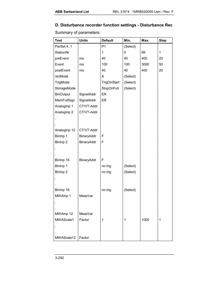
ABB Switzerland Ltd REL 316*4 1MRB520050-Uen / Rev. F
3-292
D. Disturbance recorder function settings - Disturbance Rec
Summary of parameters:
Text Units Default Min. Max. StepParSet 4..1 P1 (Select)
StationNr 1 0 99 1
preEvent ms 40 40 400 20
Event ms 100 100 3000 50
postEvent ms 40 40 400 20
recMode A (Select)
TrigMode TrigOnStart (Select)
StorageMode StopOnFull (Select)
BinOutput SignalAddr ER
MemFullSign SignalAddr ER
AnalogInp 1 CT/VT-Addr
AnalogInp 2 CT/VT-Addr
.
.
AnalogInp 12 CT/VT-Addr
BinInp 1 BinaryAddr F
BinInp 2 BinaryAddr F
.
.
BinInp 16 BinaryAddr F
BinInp 1 no trig (Select)
BinInp 2 no trig (Select)
.
.
BinInp 16 no trig (Select)
MWAInp 1 MeasVar
.
.
MWAInp 12 MeasVar
MWAScale1 Factor 1 1 1000 1
.
.
MWAScale12 Factor

REL 316*4 1MRB520050-Uen / Rev. F ABB Switzerland Ltd
3-293
Explanation of parameters:
ParSet 4..1Parameter for determining in which set of parameters a par-ticular function is active (see Section 5.11.).Only the original function in each set may be active. The fol-lowing must be observed, however, if a disturbance recorderis active in every set of parameters or the original functionwas copied:The old record is deleted when switching to a different set ofparameters to avoid misinterpretation. A record must there-fore be read out before switching sets of parameters.
StationNrNumber of the disturbance recorder for identifying records forsubsequent evaluation.
preEventDefinition of how long the recorder runs before a possibleevent.
EventDefinition of the maximum limit for the duration of an event(recording mode A). In recording mode B, the same parame-ter sets the duration of recording.
postEventDefinition of how long the recorder runs after an event (afterEventDur).
recMode (Recording mode)Definition of how events should be recorded. Possible set-tings:A: Recording only while the trigger signal is active. (mini-
mum time = 100 ms, maximum time = event durationsetting).
B: Recording from the instant of the trigger signal for theevent duration setting.
TrigModeDefinition of the instant of triggering and how binary signalsare recorded. The configured c.t. and v.t. channels arealways recorded. Possible settings:
TrigByStart: The disturbance recorder is triggered when aprotection function picks up (general pick-up). Binary sig-nals are not recorded.
ABB Switzerland Ltd REL 316*4 1MRB520050-Uen / Rev. F
3-294
TrigByTrip: The disturbance recorder is triggered when aprotection function trips (general trip). Binary signals arenot recorded.
TrigByBin1: The disturbance recorder is triggered by thebinary I/P 1. Binary signals are not recorded.
TrigAnyBin: Defined binary signals are recorded and re-cording is triggered by any of them via an OR gate.
TrStrt&Bin: Defined binary signals are recorded and re-cording is triggered by any of them via an OR gate andalso when a protection function picks up (general pick-up).
TrTrip&Bin: Defined binary signals are recorded and re-cording is triggered by any of them via an OR gate andalso when a protection function trips (general pick-up).
Note:If the trigger conditions are connected to an OR gate and one ofthem is fulfilled, the other trigger conditions bear no influenceand no further records are made. In this situation, a record isinitiated when the disturbance recorder is reset.
StorageModedetermines the procedure when the memory is full:
StopOnFull: No further data are recorded when the mem-ory is full.
Overwrite: The oldest records are overwritten and there-fore lost.
BinOutputO/P signalling that recording is taking place.
MemFullSignWarning that the memory is ¾ full. Normally, there remainssufficient room for at least one more record after this signal isgenerated.
REL 316*4 1MRB520050-Uen / Rev. F ABB Switzerland Ltd
3-295
AnalogInp 1...AnalogInp 12Defines the c.t. and v.t. inputs to be recorded. The setting isthe number of the I/P.
The numbers of the c.t. and v.t. inputs do not necessarilyhave to agree with the numbers of the c.t. and v.t. channels,however, no gaps are permitted (setting zero).
BinInp 1...BinInp 16Binary inputs to be recorded (for triggering modes“TrStrt&Bin, TrigAnyBin and TrTrip&Bin”). Binary address(binary input or output of a protection function). No recordingtakes place for FFALSE or TTRUE.
A particular order is not necessary. There may also be gaps.
BinInp 1...BinInp 16Definition of a corresponding binary signal as one of the trig-ger signals for initiating recording. All the trigger signals thusdefined, are connected to an OR gate so that any one ofthem can start recording. Possible settings are:
No trigger: The corresponding signal has no influence onthe start of recording.
Trigger: A positive-going edge of the corresponding signalfrom logical ‘0’ to logical ‘1’ initiates recording.
Inv. trigger: A negative-going edge of the correspondingsignal from logical ‘1’ to logical ‘0’ initiates recording.
MWAInp 1...MWAInp 12Measured variables to be recorded.Possible settings are:
Disconnect, no input
Constant measured variable, analogue value as aconstant
Binary output of a protection function, measured variableof the selected function
Input from IBB, input variable of IBB channel 4,inputs 1...64.
MWAScale1...MWAScale12Scaling factors for reading the disturbance records.

ABB Switzerland Ltd REL 316*4 1MRB520050-Uen / Rev. F
3-296
E. Setting instructions
General:
The disturbance recorder function may only be configuredonce for each set of parameters.
The special “disturbance recorder” function serves to record cur-rent and voltage waveforms and measured function variableswhen a protection function picks up. A battery buffered 64 kBytememory is provided for this purpose, which enables 9 analogueand 8 binary signals to be recorded within a maximum of approx.5 seconds.To ensure that the memory is not filled by useless data, record-ing only takes place after a starting signal (trigger signal). Eachtime a start signal is generated, the data are recorded for a pre-defined time and saved as an “event”. Thus depending on thedefinitions of the relevant times, the memory has capacity forbetween 1 and approx. 56 events.
To enable the circumstances leading up to an event and also theresponses after an event to be studied, an event comprisesthree parts, the pre-event data (recorded before the start signal),the data of the event itself and the post-event data. The dura-tions of these three periods can be independently defined.
How the data prior to an event is obtained requires a little moreexplanation. Data are continuously recorded from the instant theprogramming of the perturbograph function has been completed.They are fed into a ring shift register, the older data at thebeginning being overwritten as soon as the register is full. Thiscyclic overwriting of the ring register continues until a start signalinitiates the recording of an event (trigger signal). Thus the cir-cumstances immediately prior to the actual event are available inthe ring register.
The duration of the record of the actual event is determined bythe tripping signal (trigger signal), i.e. recording continues for aslong as it is active (recording mode A). If the tripping signal isvery short, recording lasts for at least 100 milliseconds and if it isvery long, recording is discontinued upon reaching the maximumduration (set event time). A second mode of operation is alsoprovided (recording mode B), for which the duration of recordingalways equals the set event time regardless of the duration ofthe trigger signal.
REL 316*4 1MRB520050-Uen / Rev. F ABB Switzerland Ltd
3-297
The post-event circumstances are of less importance, especiallyin recording mode B, in which case simply the duration of re-cording is extended. The essential thing is that during post-eventrecording, a new trigger signal can initiate the recording of newevents. This, however, means that two events overlap and it maynot always be possible to fully reconstruct the circumstances ofboth events (part of the pre-event data is in the preceding event).
The entire event memory operates as a ring register. This meansthat a single event can be deleted to make room for a new onewithout having to delete the others.
The procedure followed when the memory is full can be se-lected. Either recording is discontinued and no new events arerecorded, or the oldest records are overwritten so that the mem-ory always contains the latest events. It must be noted that inthis mode, a record can be deleted before it has been trans-ferred to an operator station. Even if transfer of a record is inprogress, it will be interrupted to make room for a new record.
Application programs
Disturbance recorder data (currents, voltages and measuredvariables) can be transferred back to the RE. 316*4 device usingthe conversion program INTERFAC (in conjunction with the testset XS92b) (see INTERFAC Operating Instructions CH-ES 86-11.53 E).
Refer to Section 9.3. for the procedure for transferring distur-bance data via the IBB.
Disturbance recorder data files are stored in a binary format andcan only be evaluated using the WinEVE program (see WinEVEOperating Instructions *BHT 450 045 D0000) or the REVALprogram (see REVAL Operating Instructions 1MDU10024-EN).
Measured function variables may have values which cannot beentirely reproduced by the evaluation software. Such variablescan be reduced using the scaling factors ‘MeasScale’. The high-est number the evaluation software can reproduce faithfully is16535. The evaluation software automatically takes account ofthe scaling factors.

ABB Switzerland Ltd REL 316*4 1MRB520050-Uen / Rev. F
3-298
The following table shows scaling examples for the most impor-tant measured function variables.
Function Meas. variable Nominal value ‘MeasScale’
UIfPQ f (50Hz) 20000 2
UIfPQ P 820698 52
UIfPQ Q 820698 52
SynchroCheck degrees (180) 31415 2
Power PN 1641397 105
‘MeasScale’ is given by: Margin16535
valueNominal
Processor capacity:
The disturbance recorder function runs on the same centralprocessing unit (CPU) as the protection functions. The processorcapacity required by the disturbance recorder function as a per-centage of the total capacity and in relation to the number of sig-nals is:
20% for 9 analogue and 0 binary signals 40% for 9 analogue and 16 binary signals.
The disturbance recorder function will thus be generally confinedto recording the analogue variables and be triggered by the gen-eral start or general trip signals. Changes in the states of binarysignals are nevertheless registered by the event recorder.
Recording duration:
The time during which data are recorded can be determinedfrom the following relationship:
t na b
prec
65535 1 2212
(( ) )(2 )
where trec: max. recording time
n: Number of events recorded
a: Number of c.t. and v.t. channels recorded
b: Number of Bytes required for binary channels (oneByte per eight binary signals)
p: duration of one cycle at power system frequency(e.g. 20 ms for 50 Hz).
REL 316*4 1MRB520050-Uen / Rev. F ABB Switzerland Ltd
3-299
Example:
n = 10
a = 9
b = 2 (i.e. 9 to 16 signals)
p = 20 ms
s 44.5ms 2012)292(
)22)110((65535trec
It follows that for the given number of channels and power sys-tem frequency, the capacity is sufficient for 10 events of 540 msduration each.
File PLOT.TXT
PLOT.TXT for WinEVE, REVAL (programs for evaluating distur-bance recorder data) and INTERFAC (data conversion programfor running disturbance data on the test set XS92b).
General remarks
The programs (WinEVE, REVAL and INTERFAC) need the filePLOT.TXT to be able to process the disturbance recorder data.For INTERFAC, all disturbance recorder data RExxxx.xxx muststart with the letters RE.

ABB Switzerland Ltd REL 316*4 1MRB520050-Uen / Rev. F
3-300
Example PLOT.TXT
Hardware configuration: A/D config: K9
Overcurrent: A1 (IN = 1A)
Overvoltage: U1 (UN = 100V)
******************************************************N: 001
S: ABB_Relays_Ltd
D 0 : D 0 /CO: 1
D 1 : D 1 /CO: 2
D 2 : D 2 /CO: 3
D 3 : D 3 /CO: 4
D 4 : D 4 /CO: 5
D 5 : D 5 /CO: 6
D 6 : D 6 /CO: 7
D 7 : D 7 /CO: 8
D 8 : D 8 /CO: 9
D 9 : D 9 /CO: 10
D10 : D10 /CO: 11
D11 : D11 /CO: 12
D12 : D12 /CO: 13
D13 : D13 /CO: 14
D14 : D14 /CO: 15
D15 : D15 /CO: 1
U 0 : UR /CO: 2 /TR: 0.1981 /UN: UN
U 1 : US /CO: 4 /TR: 0.1981 /UN: UN
U 2 : UT /CO: 11 /TR: 0.1981 /UN: UN
I 3 : I0 /CO: 10 /TR: 10.83 /UN: IN
U 4 : U /CO: 7 /TR: 0.1981 /UN: UN
U 5 : U /CO: 13 /TR: 0.1981 /UN: UN
I 6 : IR /CO: 8 /TR: 10.83 /UN: IN
I 7 : IS /CO: 12 /TR: 10.83 /UN: IN
I 8 : IT /CO: 9 /TR: 10.83 /UN: IN
******************************************************where:
N: station number: text
S: station name: text
Dnn binary channels: text (max. 8 char.)
Unn:, Inn: voltage channel, current channel: text (max. 8char.)
/CO 1 to 15: number of the plot colour for WinEVE(In the case of REVAL the plotting colour is de-termined by the particular layout.)

REL 316*4 1MRB520050-Uen / Rev. F ABB Switzerland Ltd
3-301
/TR: conversion ratio for WinEVE, REVAL
/UN: unit for WinEVE, REVAL: text.
Note:'Unn:’ and ‘Inn:’ are needed by INTERFAC to indicate whether achannel is being used for voltage or current.All c.t. and v.t. channels ‘Ann:’ may be chosen for WinEVE.
Ratio TR
Voltage channels for REL 316*4 and REC 316*4
100 V: TR = 19.81 in V200 V: TR = 39.62 in V
TR = 0.1981 times UN (PLOT.TXT)
Voltage channels for REG 316*4 and RET 316*4
15 V: TR = 5.144 in V100 V: TR = 34.312 in V200 V: TR = 68.624 in V
TR = 0.34312 times UN (PLOT.TXT)
Current channels RE. 316*4
Protection: 1 A: TR = 10.832 A: TR = 21.665 A: TR = 54.11
TR = 10.83 times IN (PLOT.TXT)
Metering: 1 A: TR = 0.25062 A: TR = 0.50115 A: TR = 1.253
TR = 0.2506 times IN (PLOT.TXT)
These ratios enable WinEVE to determine the secondaryvalues. These ratios must be multiplied by the ratio of themain c.t’s and v.t’s to obtain the primary system values.
INTERFAC does not evaluate CO, TR and UN.
Automatic creation of the file plotxxx.txt:
The file plotxxx.txt is automatically saved in the current directoryfrom which the operator program (MMI) was started when savingthe RE. 316*4 settings or in any directory given in the con-figuration file ‘rexx.cfg’, e.g.:
EVEDATA = .\RE2

ABB Switzerland Ltd REL 316*4 1MRB520050-Uen / Rev. F
3-302
Several files plotxxx.txt with different station numbers (xxx) canbe combined to a single plot.txt. The file plot.txt must be at thesame location as the disturbance recorder data for the REVALevaluation program.
Example:
PLOT.TXT (existing file), plot020.txt (data for station No. 20) andplot021.txt (data for station No. 21) can be combined using theDOS command:
C:\REL316C>copy PLOT.TXT+plot020.txt+plot021.txt PLOT.TXT
The file PLOT.TXT can be modified using an editor.
The evaluation is based on data expressed as multiples of UN orIN.
Instructions for installing the data evaluation program
The data evaluation program must be installed in strict accor-dance with the relative operating instructions.
WINEVE
Copy the file “PLOT.TXT” to the directory:
C:\I650\EVENTS
A disturbance should be recorded during the commissioning ofevery relay and the record stored in the directory given above.
The procedure for installing the station parameter files is as fol-lows:
Start the WINEVE program.
Open a fault recordThe following error message appears:
C:\I650\STATION\ST0xx.PARCould not find file.
Click on OK.
Select the menu item “Import station file” in the “Parameter”menu.
Select the file PLOT.TXT belonging to this disturbance re-cording.

REL 316*4 1MRB520050-Uen / Rev. F ABB Switzerland Ltd
3-303
Select the menu item “Save station” in the “Parameter” menu.
This procedure must be repeated for all the relays. The configu-ration file PLOT.TXT is no longer necessary and the error mes-sage concerning the missing station file does not appear.WINEVE provides facility for editing and resaving all the stationparameters (texts, colours etc.).Exception: The ratios TR have to be changed in the filePLOT.TXT and the file re-imported and saved again as de-scribed above.
REVAL
Copy the file “PLOT.TXT” to the following directory:
C:\SMS\REVAL\EVENTS
REVAL rereads the file PLOT.TXT every time a disturbance rec-ord is loaded, however, any colours specified in PLOT.TXT areignored. Instead, the colours are assigned by REVAL and can beedited after a disturbance record has been loaded.

ABB Switzerland Ltd REL 316*4 1MRB520050-Uen / Rev. F
3-304

REL 316*4 1MRB520050-Uen / Rev. F ABB Switzerland Ltd
3-305
3.7.5. Measurement module (MeasureModule)
A. Application
Measurement of 3 phase voltages, 3 phase currents, active andreactive power, power factor cos (cos phi) and frequency, e.g.for display on an operating device or transmission to a stationmonitoring system.
B. Features
Measurement of 3 phase voltages (Y and delta), currents,active and reactive power, power factor cos and frequency.
Provision for using the 3 phase current inputs in combinationwith either 3 phase-to-phase voltages or 3 phase-to-earthvoltages.
2 independent impulse counter inputs for calculation ofinterval and accumulated energy
The three-phase measurement and impulse counters can beused independently and may also be disabled.
Up to 4 measurement module functions can be configured onone RE..16 device.
All inputs and outputs can be configured by the user.
C. Inputs and Outputs
I. C.t./v.t. inputs
Voltage Current
II. Binary inputs
2 impulse inputs 2 reset inputs
III. Binary outputs
2 outputs for the new counter value
ABB Switzerland Ltd REL 316*4 1MRB520050-Uen / Rev. F
3-306
IV. Measurement values
Voltage URS (Unit UN) Voltage UST (Unit UN) Voltage UTR (Unit UN) Voltage UR (Unit UN) Voltage US (Unit UN) Voltage UT (Unit UN) Current R (Unit IN) Current S (Unit IN) Current T (Unit IN) Active power P (Unit PN) Reactive power Q (Unit QN) Power factor cos (Unit cos phi) Frequency f (Unit Hz) Interval energy value 1 (E1Int) Interval pulse number 1 (P1Int) Accumulated energy value 1 (E1Acc) Accumulated pulse number (P1Acc) Interval energy value 2 (E2Int) Interval pulse number 2 (P2Int) Accumulated energy value 2 (E2Acc) Accumulated pulse number 2 (P2Acc).
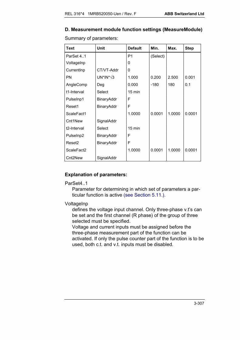
REL 316*4 1MRB520050-Uen / Rev. F ABB Switzerland Ltd
3-307
D. Measurement module function settings (MeasureModule)
Summary of parameters:
Text Unit Default Min. Max. Step
ParSet 4..1 P1 (Select)VoltageInp 0
CurrentInp CT/VT-Addr 0
PN UN*IN*3 1.000 0.200 2.500 0.001
AngleComp Deg 0.000 -180 180 0.1
t1-Interval Select 15 min
PulseInp1 BinaryAddr F
Reset1 BinaryAddr F
ScaleFact1 1.0000 0.0001 1.0000 0.0001
Cnt1New SignalAddr
t2-Interval Select 15 min
PulseInp2 BinaryAddr F
Reset2 BinaryAddr F
ScaleFact2 1.0000 0.0001 1.0000 0.0001
Cnt2New SignalAddr
Explanation of parameters:
ParSet4..1Parameter for determining in which set of parameters a par-ticular function is active (see Section 5.11.).
VoltageInpdefines the voltage input channel. Only three-phase v.t’s canbe set and the first channel (R phase) of the group of threeselected must be specified.Voltage and current inputs must be assigned before thethree-phase measurement part of the function can beactivated. If only the pulse counter part of the function is to beused, both c.t. and v.t. inputs must be disabled.
ABB Switzerland Ltd REL 316*4 1MRB520050-Uen / Rev. F
3-308
CurrentInpdefines the current input channel. Only three-phase c.t’s canbe set and the first channel (R phase) of the group of threeselected must be specified.Current and voltage input signals must come from the samec.t./v.t. input module.
PNReference value for measuring power. It enables theamplitude of the power values to be adjusted to take account,for example, of the rated power factor cos or tocompensate the amplitude errors of the input transformers.
AngleCompAngular setting for compensating the phase error. It is set toobtain the best possible power measuring accuracy. In manycases, the default setting of 0.0 degrees will be acceptable,but a different setting may be necessary to compensate thefollowing:a) c.t. and v.t phase errors
typical setting: -5° ... +5°b) correction of c.t. or v.t. polarity
typical setting: -180°or +180°.
t1-IntervalInterval set for accumulating pulses assigned to E1 acc_intervaland Pulse1acc_interval.The following settings are possible: 1 min, 2 min, 5 min,10 min, 15 min, 20 min, 30 min, 60 min and 120 min.
PulseInp1Input for energy counter impulse.F: not usedT: always active. This setting should not be used.xx: all binary inputs (or outputs of protection functions).
Note: Minimum pulse-width is 10 ms.
Reset1Input to reset E1accumulate and Pulse1accumulate outputs.F: no resetT: always resetxx: all binary inputs (or outputs of protection functions).

REL 316*4 1MRB520050-Uen / Rev. F ABB Switzerland Ltd
3-309
ScaleFact1Factor for scaling E1 outputs in relation to pulse counter output:E1acc_interval = Pulse1acc_interval ScaleFact1E1accumulate = Pulse1accumulate ScaleFact1.
Cnt1NewOutput to indicate that new values are available at impulsecounter 1 outputs and have been frozen. The binary output iscleared 30 s after the interval starts.
t2-IntervalSee t1-Interval.
PulseInp2See PulseInp1.
Reset2See Reset1.
ScaleFact2See ScaleFact1.
Cnt2NewSee Cnt1New.

ABB Switzerland Ltd REL 316*4 1MRB520050-Uen / Rev. F
3-310
E. Setting Instructions
To get the best performance from the measurement module, besure to set it properly. The following notes should help to decidethe correct settings:
Reference values for the analogue input channelsThe settings in this case should be chosen such that thefunctions measures 1.000 UN and 1.000 IN when ratedvoltage and current are being applied. In many cases thedefault setting (1.000) will be satisfactory.
Phase compensation “Angle comp”This setting is important for correct measurement of activeand reactive power and the power factor cos . For mostcases, it is possible to accept the default value 0.0°.
A different setting may be necessary to compensate the fol-lowing:a) c.t. and v.t. phase errors
typical setting: between -5.0° and +5.0°b) correction of direction of the measurement or c.t. or v.t.
polarity typical setting: -180.0° or +180.0°
Add multiple errors to obtain the correct compensation set-ting.
The angles given apply for connection according to the con-nections in Section 12.
Voltage measurementThe zero-sequence component in case of delta-connectedv.t’s is assumed to be zero, but with Y-connected v.t’s thezero-sequence voltage does have an influence on the phase-to-ground measurements. In an ungrounded power system,the phase-to-ground voltages will float in relation to ground.
Power and frequency measurementsA power measurement is obtained by summing the powers ofthe three-phase system: 3 S = UR IR* + US IS* + UT IT*.The measurement is largely insensitive to frequency in therange (0.8...1.2) fN. The frequency measured is that of thepositive sequence voltage. Should the voltage be too low, thefrequency is not measured and a value of 0.0 Hz results.
Where only the impulse counter is in use, both analogueinputs (current and voltage) must be disabled.

REL 316*4 1MRB520050-Uen / Rev. F ABB Switzerland Ltd
3-311
Where only the measurement part of the function is in use,the binary impulse and reset inputs of both impulse countersmust be disabled, i.e. “always FALSE”.
3.7.5.1. Impulse counter inputs
The impulses counted are normally generated by a measuring ormetering device (see Fig. 3.7.5.1).
tPulse
PulsePulse f
1T
tPause
Fig. 3.7.5.1 Impulse counter input signal
The maximum impulse repetition rate is 25 Hz (see Fig. 3.7.5.1).Thus the minimum time between the positive-going edges of two
input impulses is ms40Hz251T min,Puls .
The pulse-width is determined by the function generating theimpulses and the ratio between the pulse-width and the intervalbetween lagging and leading edges should be in the range 1:3 to1:1, i.e.:
ms10T41T
311t min,Pulsemin,Pulsemin,Pulse
.
Since the impulse counter is polled approximately every 5 ms,impulses are reliably detected with a safety factor of about 2.
The impulse counter evaluates the positive-going edges (01)of the input signal.
To filter any contact bounce (debouncing) phenomena, only thefirst positive-going edge is evaluated within a given period(typically 10 ms).
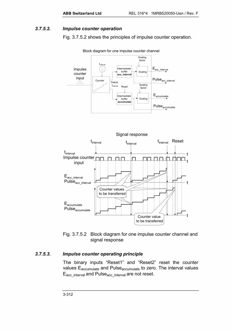
ABB Switzerland Ltd REL 316*4 1MRB520050-Uen / Rev. F
3-312
3.7.5.2. Impulse counter operation
Fig. 3.7.5.2 shows the principles of impulse counter operation.
Impulsecounter
input
tinterval
freeze tinterval
Intermediate buffer
acc_interval
Scalingfactor
ScalingEacc_interval
Block diagram for one impulse counter channel
Counter
ScalingEaccumulate
Pulseaccumulate
ScalingfactorReset
Intermediate buffer
accumulate
Pulseacc_interval
Impulse counterinput
Signal response
EaccumulatePulseaccumulate
Eacc_intervalPulseacc_interval
tinterval
t
t
t
t
tinterval tintervaltinterval
Counter values to be transferred
Reset
Counter value to be transferred
Fig. 3.7.5.2 Block diagram for one impulse counter channel andsignal response
3.7.5.3. Impulse counter operating principle
The binary inputs “Reset1” and “Reset2” reset the countervalues Eaccumulate and Pulseaccumulate to zero. The interval valuesEacc_interval and Pulseacc_interval are not reset.

REL 316*4 1MRB520050-Uen / Rev. F ABB Switzerland Ltd
3-313
When a reset command is applied to binary input “Reset1” or“Reset2”, measurement events with the values of Eaccumulate andPulseaccumulate are created for the respective channel before itscounters are reset.
Impulse counter values are stored in a RAM with a batterysupply and are not lost should the auxiliary supply fail. Impulsesarriving at the inputs while the software is being initialised, e.g.after settings have been made, are lost.
Capacity for Pulseaccumulate:At the maximum impulse repetition rate, the total number ofimpulses counted during a year is 25 pps 3,600 s/h 8,760h/year = 788,400,000 impulses per year. The output is resetto zero when a counter reaches 2,000,000,000, i.e. 2 109.Unless special measures taken or a counter is reset, it canoverflow at the worst after approx. 2,5 years.
Should an impulse counter overflow, the value of Pulseaccu-mulate is recorded in the event list. No further measures havebeen included, because1) an overflow is hardly likely to occur.2) should an overflow occur, it is obvious providing the
counters are checked regularly, for example, by an SCS.If necessary, the total number of impulses counted since thelast reset can be determined even after an overflow.
3.7.5.4. Interval processing
The interval starts at a full hour plus a even multiple of tIntervaland is synchronised to a full minute by the internal RE..16 clock.
Assuming tInterval is set to 120 min, the interval is started at evenhours throughout the day.
Impulse counter and energy outputs are set at the start of thefirst regular interval, even if the previous interval was incomplete.This ensures that no impulses are lost after starting the function.
When tinterval expires, the following takes place:
The counter values Eaccumulate, Pulseaccumulate, Eacc_interval andPulseacc_interval are stored in the intermediate buffers andremain unchanged until the end of the next interval.

ABB Switzerland Ltd REL 316*4 1MRB520050-Uen / Rev. F
3-314
When the new impulse counter results are frozen at the endof the interval, the binary output “Cnt1New”, respectively“Cnt2New” is set to TRUE. It is reset after 30 s regardless ofinterval duration and can be used to initiate reading of a newset of frozen interval values.
If selected for transmission, transmission of the counter val-ues via the LON interface is initiated by the positive-goingedge of this output.
The values Eacc_interval and Pulseacc_interval of the respectivechannel are only recorded as measurement events providingthe output “Cnt1New”, respectively “Cnt2New” is being used,for example, to control an event recorder, LED or signallingrelay.
The freezing of results, resetting and event recording of the in-terval counters is illustrated in Fig. 3.7.5.3.
tInterval tIntervaltInterval
Measurementevent
t
Reset
Internal onlyPulseaccumulate
t
tIntervaltInterval t
CounterFrozen 30 s30 s 30 s 30 s 30 s
Pulseacc_interval Internal only
t
t
Impulse counter input
Fig. 3.7.5.3 Interval processing

REL 316*4 1MRB520050-Uen / Rev. F ABB Switzerland Ltd
3-315
3.8. Data transmission
3.8.1. Principle of operation of the A/D converter 316EA62
3.8.1.1. Introduction
Local and remote stations are synchronised at the same sam-pling rate. Because the measurement of the data exchangedbetween the stations is synchronised, the method of memorymanagement and subsequent digital filtering, the measuredvariables of all the channels (local and transferred remote sig-nals) are made available to the main CPU at the same time. Thisis an essential for reliable differential longitudinal protection.
3.8.1.2. Synchronisation principle
The transfer of data via the optical modem between the316EA62 units in the two stations (master and slave) is syn-chronised, i.e. one of the two 316EA62 units functions as masterand controller for the transfer of data.
Should the communications channel become disturbed or inter-rupted, each of the A/D converters generates its own clock sig-nal.
Which of the stations is designated master and which slave isdetermined when setting the system parameters using the op-erator control program (MMI).
A counter is started when the master transmits a signal to theslave. Upon receiving the signal, the slave sends an echo backto the master. The counter is stopped by the master and thecount divided by 2 when it receives the echo. The result is thetransmission time. The echo signal includes specific data whichare tested by both stations and generate an error flag should theresult of the test be negative.
3.8.1.3. Data transmission principle
Sampling of the analogue variables commences as soon as thesynchronisation procedure has been completed.
The first three converted signals obtained from up to six localchannels are transferred via the serial interface to the opticalmodem, which then transmits them to the synchronously operat-ing remote station.
All the converted variables of the local station (maximum 6channels) and the variables received from the opposite station(maximum 3 channels) are digitally filtered before being trans-

ABB Switzerland Ltd REL 316*4 1MRB520050-Uen / Rev. F
3-316
ferred to the dual-port memory on the main CPU board316VC61a.
Provision is also made for the binary signal transmission functionto transfer 8 binary signals at the same time for processing in theremote station (see Section 3.8.3. Binary signal transmission).
3.8.1.4. Consequences of transmission errors
Should an error occur during the transmission of data, themaximum positive values (7FFF = +32767) are transmitted andan error flag is set until none of the samples are incorrect.
This is the reason why the readings of load values measured byprotection functions during a transmission error are so high,usually higher than setting. Fictitious measurements of this kindcannot cause tripping, because protection functions concernedare blocked internally during this period.
Attention is immediately drawn to data errors (error flag set onthe 316EA62 board) by the system alarm ‘Modem error’. If thebinary signal transmission function is also active, the alarm‘RemoteBiError’ is generated.
The diagnostic function, on the other hand, records these errorsafter a delay of 80 ms, i.e. only after the communications chan-nel is considered to be permanently disturbed. A single trans-mission error, e.g. a parity error, does not therefore lead to anerror being recorded by the diagnostic function.
Should signals be received again from the remote station aftersome time, the synchronisation procedure is initiated immedi-ately. The local channels 1 to 6 are not available during this briefperiod, i.e. the functions concerned are blocked for a short timeand this may possibly cause events to reset (starting, trippingetc.).
REL 316*4 1MRB520050-Uen / Rev. F ABB Switzerland Ltd
3-317
Consequences of transmission errors for protectionfunctions:
Functions which process the local analogue variables (A/Dchannels 1 to 6) are excluded from blocking by thecommunications channel and serve as back-up protection.
Functions which process the analogue variables transferredvia the communications channel (A/D channels 7 to 9) areblocked (Diff-Line, Check-I3ph, Current etc.).
The signals of the binary signal transmission function are setto ‘OFF’ (0 or false).
The inputs of the disturbance recorder A/D channels 7 to 9are set to zero.
Note on the ‘SynchroCheck’ and ‘EarthFltGnd2’ functions:
During an attempt to synchronise the two stations, the synchro-check function can generate the signals ‘uBusInp-Ph’, ‘uLineIn-put’, ‘PhaseDifOk’ and ‘FreqDifOk’. Nevertheless, incorrect op-eration cannot take place (closing of the circuit-breaker notenabled). The sensitive earth fault function ('EarthFltGnd2') canbriefly generate the signals ‘Start’, ‘MeasFwd’ and ‘MeasBwd’.This also cannot cause incorrect operation.

ABB Switzerland Ltd REL 316*4 1MRB520050-Uen / Rev. F
3-318
REL 316*4 1MRB520050-Uen / Rev. F ABB Switzerland Ltd
3-319
3.8.2. Longitudinal differential protection (Diff-Line)
A. Application
Differential protection of overhead lines, cables, transformerfeeders (two-winding transformers) and generator/transformerunits.
B. Features
non-linear inverse current operating characteristic(see Fig. 3.8.2.1)
high stability during through-faults and c.t. saturation fast operation individual comparison of phase currents insensitive to DC components insensitive to harmonics
Optional for power transformer protection:
inrush restraint evaluation of the ratio of second harmonic to fundamental detection of the highest phase current detection of an energised transformer on the basis of the
load current phase compensation for group of connection amplitude compensation (c.t. ratio).
C. Inputs and outputs
I. C.t./v.t. inputs
Current (2 x 3 inputs)
II. Binary inputs
Blocking Inrush g-High
III. Binary outputs
Tripping Tripping R phase Tripping S phase Tripping T phase Inrush signal Stability signal

ABB Switzerland Ltd REL 316*4 1MRB520050-Uen / Rev. F
3-320
IV. Measurements
R phase neutral current S phase neutral current T phase neutral current R phase restraint current S phase restraint current T phase restraint current.
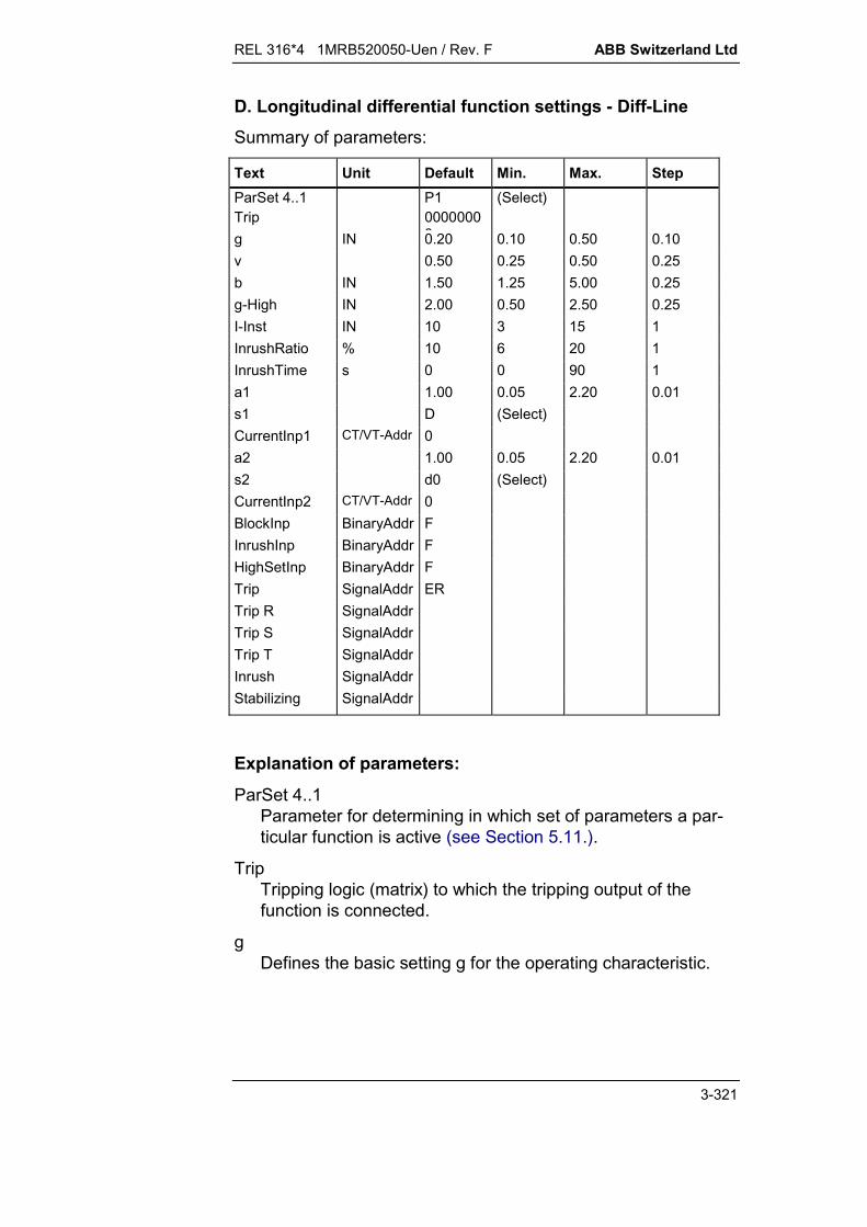
REL 316*4 1MRB520050-Uen / Rev. F ABB Switzerland Ltd
3-321
D. Longitudinal differential function settings - Diff-LineSummary of parameters:
Text Unit Default Min. Max. StepParSet 4..1 P1 (Select)Trip 0000000
0g IN 0.20 0.10 0.50 0.10v 0.50 0.25 0.50 0.25b IN 1.50 1.25 5.00 0.25g-High IN 2.00 0.50 2.50 0.25I-Inst IN 10 3 15 1InrushRatio % 10 6 20 1InrushTime s 0 0 90 1a1 1.00 0.05 2.20 0.01s1 D (Select)CurrentInp1 CT/VT-Addr 0a2 1.00 0.05 2.20 0.01s2 d0 (Select)CurrentInp2 CT/VT-Addr 0BlockInp BinaryAddr FInrushInp BinaryAddr FHighSetInp BinaryAddr FTrip SignalAddr ERTrip R SignalAddrTrip S SignalAddrTrip T SignalAddrInrush SignalAddrStabilizing SignalAddr
Explanation of parameters:
ParSet 4..1Parameter for determining in which set of parameters a par-ticular function is active (see Section 5.11.).
TripTripping logic (matrix) to which the tripping output of thefunction is connected.
gDefines the basic setting g for the operating characteristic.
ABB Switzerland Ltd REL 316*4 1MRB520050-Uen / Rev. F
3-322
vDefines the pick-up ratio v for the operating characteristic.
bDefines the setting of b on the operating characteristic.This is normally set to about 1.5 times the load current.
g-HighThis is a high-set basic setting which becomes effective whenthe input ‘HighSetInp’ is activated.The higher setting prevents mal-operation from taking placewhich may otherwise occur due, for example, to a temporarilyhigher excitation current (overfluxing).
I-InstThe differential current above which tripping takes place in-dependently of the inrush detector.This setting enables operating times for high internal faultcurrents to be reduced.
InrushRatioRatio of 2nd. harmonic to fundamental of the current abovewhich the inrush detector picks up.
InrushTimeTime during with the inrush detector is enabled after theprotected unit is energised or after a through-fault.
a1C.t. ratio compensation factor on side 1.
s1Group of connection on side 1 (primary).Possible settings: Y: star-connected winding (transformer in the zone of
protection) D: delta-connected winding.
CurrentInp1Defines the c.t. input channel for side 1. All the currentchannels are available for selection. In the case of a three-phase measurement, the first channel (R phase) of the groupof three must be selected.
a2C.t. ratio compensation factor on side 2.
REL 316*4 1MRB520050-Uen / Rev. F ABB Switzerland Ltd
3-323
s2Group of connection on side 2.Possible settings: All the usual phase groups, defining
how connected (y = star, d = delta, z = zigzag) phase-shift of the voltage on side 2 in relation to the volt-
age on side 1 in multiples of 30°.
CurrentInp2Defines the c.t. input channel for side 2. All the currentchannels are available for selection. In the case of a three-phase measurement, the first channel (R phase) of the groupof three must be selected.
BlockInpInput for blocking the functionF: - enabledT: - disabledxx: - all binary inputs (or outputs of protection functions).
InrushInp.Activates the inrush detector although the transformer isalready energised. It enables inrush currents to be detectedwhich occur, for example, when a transformer is energised inparallel.F: - not usedxx: - all binary inputs (or outputs of protection functions).
HighSetInpActivates the high-set basic setting g-High.F: - not usedT: - always activexx: - all binary inputs (or outputs of protection functions).
TripTripping signal.Note:The differential protection function does not have a startingsignal and every time it trips the signal ‘General start’ is settogether with the ‘Trip’ signal, providing the Trip command isconfigured to be recorded as an event (ER).
Trip-RTripping signal R phase.
Trip-STripping signal S phase.

ABB Switzerland Ltd REL 316*4 1MRB520050-Uen / Rev. F
3-324
Trip-TTripping signal T phase.
InrushInrush current detection signal.
StabilisingSignal IH > b during a through-fault.
Fig. 3.8.2.1 Operating characteristic of the longitudinal differ-ential protection function

REL 316*4 1MRB520050-Uen / Rev. F ABB Switzerland Ltd
3-325
E. Setting instructions
Basic setting gPick-up ratio vOperating characteristic changing point bHigh-set basic setting, g-HighInstantaneous operating current(uninfluenced by inrush detector) I-InstInrush detector pick-up ratio InrushRatioTime during which inrush detector active InrushTimeChoice of current input CurrentInp 1, 2C.t. ratio compensation factors a1 a2Group of connection on side 1 s1Group of connection on side 2 s2
The longitudinal differential function is primarily a phase faultprotection, but may also detect ground faults. It is a sensitive,fast and strictly discriminative unit protection.
3.8.2.1. Setting instructions for lines with a power transformer in theprotected zone
Basic setting g
The setting for “g” defines the minimum operating current atwhich the function picks up for an internal fault.
The value for “g” should be as low as possible to enable thefunction to detect high-resistance faults as well as solid phasefaults. Inter-turn faults are also detected where the protected unitincludes a power transformer.
The setting for “g” must be high enough, on the other hand, toexclude any risk of mal-operation due to:
line capacitance charging currents line leakage currents c.t. errors the off-load current of any power transformer included in the
protected unit at the highest short-time system voltage.
It should be noted when the protected unit includes a powertransformer that:
the off-load current of a modern transformer is very low,usually between 0.3 % and 0.5 % of IN at rated system volt-age. However, the excitation current can reach 10 % or moreof IN at the maximum short-time system voltage such as canoccur, for example, following load shedding.

ABB Switzerland Ltd REL 316*4 1MRB520050-Uen / Rev. F
3-326
A tap-changer can vary the voltage ratio in the range ±5 to±10 %, in some cases up to 20 % and more. This has to betaken into account both in the case of power transformerswith manually adjusted tap and with automatic tap-changers.
Note:This error is proportional to the through-current and istherefore best taken into account by the pick-up ratio setting“v”.
These factors produce an operating current which flows undernormal system operating conditions. The basic setting “g” musttherefore be chosen higher than the off-load operating current. Atypical value is g = 0.3 IN (30 % IN).
Pick-up ratio v
The pick-up setting “v” determines the stability of the longitudinaldifferential scheme during an external fault, i.e. at high levels ofthrough-fault current.
The value of “v” is defined by the ratio of the operating current torestraint current. It should be chosen such that faults can bedetected under load conditions which only produce a low operat-ing current. Through-fault stability must be maintained, however,at all costs. A typical setting is v = 0.5.
Restraint current b
The restraint current b defines the point at which the slope of thecharacteristic is switched.
The inclined part of the operating characteristic permits theprotection to remain stable even when c.t. saturation occursduring a through-fault.
The combination of the two slopes with a variable point ofswitching from one to the other enables the operating character-istic to be adapted to suit the requirements of the application.
A setting of 1.5 is recommended for “b”. This provides highstability during through-faults and adequate sensitivity for faultcurrents in the region of the load current.
Factor a2
The full setting range of factor a2 for c.t. ratio correction onlyapplies when the reference values of the analogue channels areset to 1.000. The highest permissible setting reduces for other

REL 316*4 1MRB520050-Uen / Rev. F ABB Switzerland Ltd
3-327
reference value settings according to the ratio between theanalogue channel reference values (line side 2 to line side 1).
Operating characteristicA restraint current is derived from the input variables I1 and I2measured at the two ends of the protected unit to ensure ade-quate through-fault stability. As the name implies, the restraintcurrent opposes the operating current.
The restraint current is either given by the equation:
I I IH 1 2 cos for -90° < < 90°
or it is zero
IH 0 for 90° < < 270°
The angle is defined as
( ; )I I1 2
The vector diagram relating the currents entering and leaving theprotected unit and the operating current measured on a loadedline is as follows:
I2 1
I
2I
I
HEST 905 003 C
The following diagram then applies during a through-fault:
2II
I2 1I = 0°
HEST 905 003 C
This then changes to the following for an internal fault:
2I1I= 180°
I2
HEST 905003 C
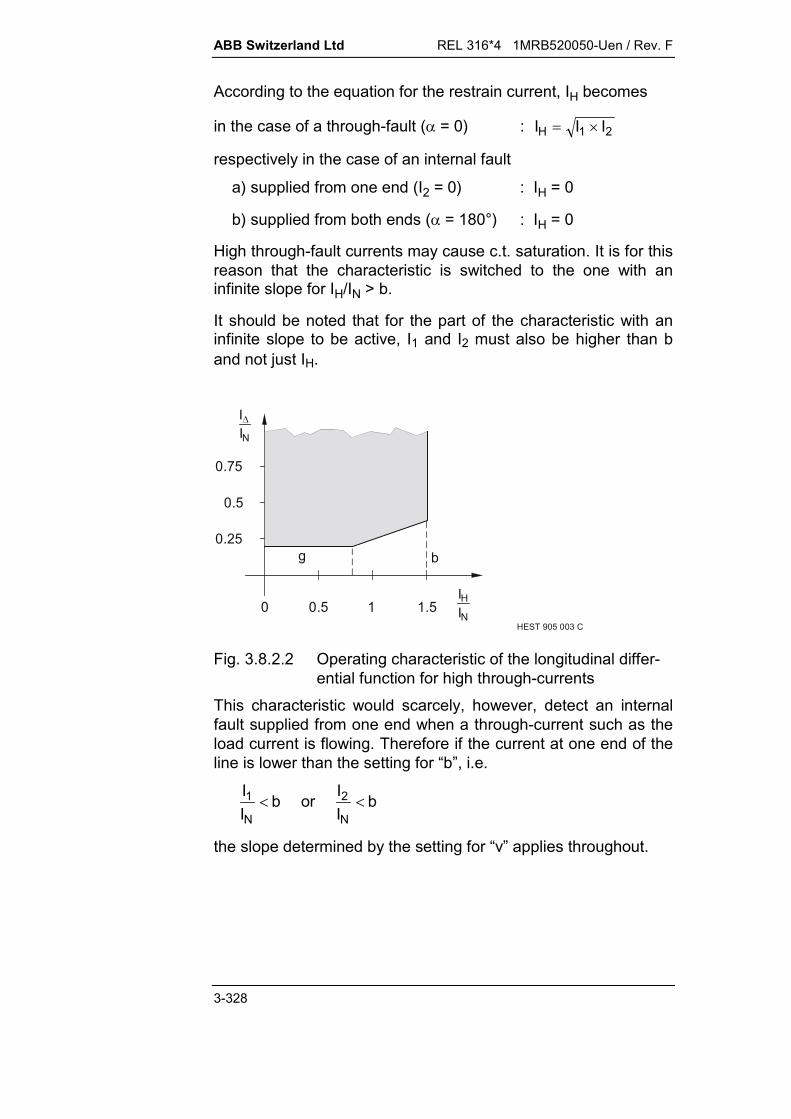
ABB Switzerland Ltd REL 316*4 1MRB520050-Uen / Rev. F
3-328
According to the equation for the restrain current, IH becomes
in the case of a through-fault ( = 0) : I I IH 1 2
respectively in the case of an internal fault
a) supplied from one end (I2 = 0) : IH = 0
b) supplied from both ends ( = 180°) : IH = 0
High through-fault currents may cause c.t. saturation. It is for thisreason that the characteristic is switched to the one with aninfinite slope for IH/IN > b.
It should be noted that for the part of the characteristic with aninfinite slope to be active, I1 and I2 must also be higher than band not just IH.
g b
0 0.5 1 1.5HEST 905 003 C
0.75
0.25
0.5
IIN
IHNI
Fig. 3.8.2.2 Operating characteristic of the longitudinal differ-ential function for high through-currents
This characteristic would scarcely, however, detect an internalfault supplied from one end when a through-current such as theload current is flowing. Therefore if the current at one end of theline is lower than the setting for “b”, i.e.
II
b or II
bN N
1 2
the slope determined by the setting for “v” applies throughout.
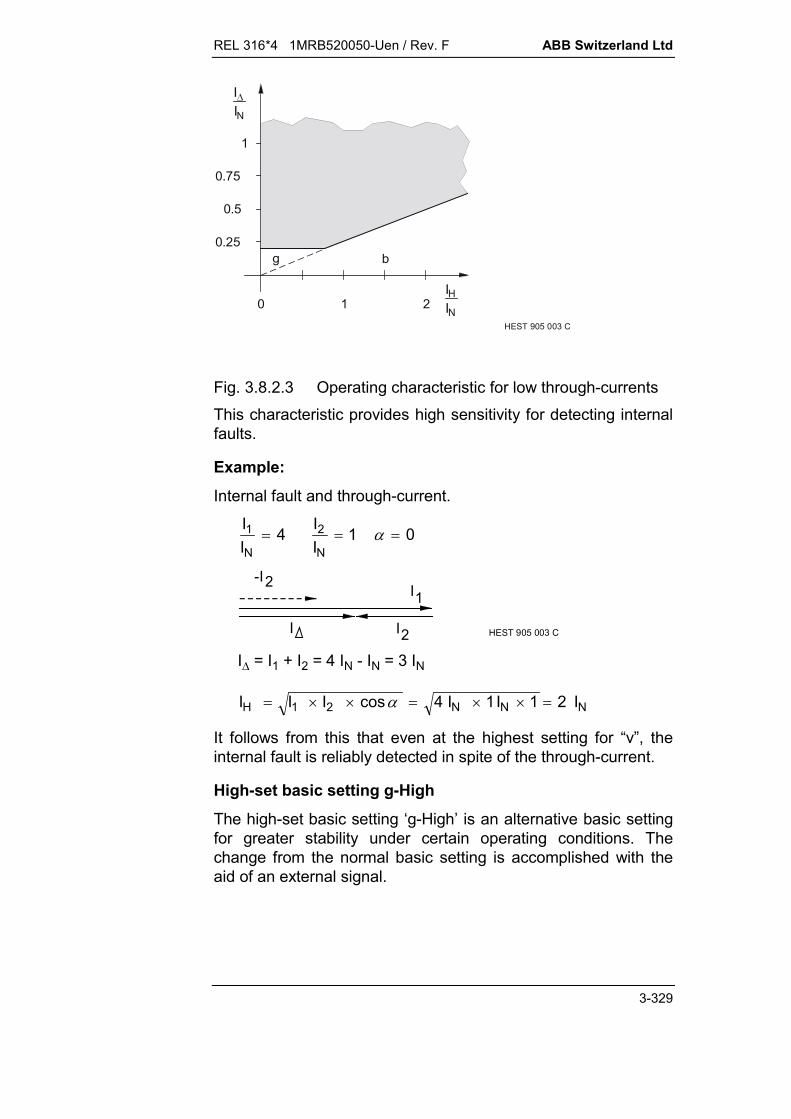
REL 316*4 1MRB520050-Uen / Rev. F ABB Switzerland Ltd
3-329
g
0
0.75
0.25
2
1
1
0.5
b
HEST 905 003 C
I
IN
IHNI
Fig. 3.8.2.3 Operating characteristic for low through-currentsThis characteristic provides high sensitivity for detecting internalfaults.
Example:
Internal fault and through-current.
II
IIN N
1 24 1 0
2II HEST 905 003 C
1I-I2
I = I1 + I2 = 4 IN - IN = 3 IN
I I I I I IH N N N 1 2 4 1 1 2cos
It follows from this that even at the highest setting for “v”, theinternal fault is reliably detected in spite of the through-current.
High-set basic setting g-High
The high-set basic setting ‘g-High’ is an alternative basic settingfor greater stability under certain operating conditions. Thechange from the normal basic setting is accomplished with theaid of an external signal.
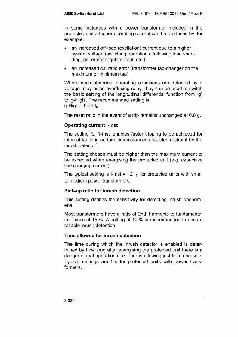
ABB Switzerland Ltd REL 316*4 1MRB520050-Uen / Rev. F
3-330
In some instances with a power transformer included in theprotected unit a higher operating current can be produced by, forexample:
an increased off-load (excitation) current due to a highersystem voltage (switching operations, following load shed-ding, generator regulator fault etc.)
an increased c.t. ratio error (transformer tap-changer on themaximum or minimum tap).
Where such abnormal operating conditions are detected by avoltage relay or an overfluxing relay, they can be used to switchthe basic setting of the longitudinal differential function from “g”to ‘g-High’. The recommended setting is g-High = 0.75 IN.
The reset ratio in the event of a trip remains unchanged at 0.8 g.
Operating current I-Inst
The setting for ‘I-Inst’ enables faster tripping to be achieved forinternal faults in certain circumstances (disables restraint by theinrush detector).
The setting chosen must be higher than the maximum current tobe expected when energising the protected unit (e.g. capacitiveline charging current).
The typical setting is I-Inst = 12 IN for protected units with smallto medium power transformers.
Pick-up ratio for inrush detection
This setting defines the sensitivity for detecting inrush phenom-ena.
Most transformers have a ratio of 2nd. harmonic to fundamentalin excess of 15 %. A setting of 10 % is recommended to ensurereliable inrush detection.
Time allowed for inrush detection
The time during which the inrush detector is enabled is deter-mined by how long after energising the protected unit there is adanger of mal-operation due to inrush flowing just from one side.Typical settings are 5 s for protected units with power trans-formers.

REL 316*4 1MRB520050-Uen / Rev. F ABB Switzerland Ltd
3-331
Both inrush detectors have to be active when there is apower transformer in the protection zone even if it is onlyfed from one end, because both functions process the samemeasured variables.
Choice of current input
To simplify the setting of a1, a2, s1 and s2, reversing the selec-tion of the channels on master and slave is recommended irre-spective of whether the protected unit includes a power trans-former or not.This procedure enables a1 and a2 as well as s1 and s2 to haveidentical settings in both master and slave.
Settings:
Master: CurrentInp1 to channel No.1CurrentInp2 to channel No.7
Slave: CurrentInp1 to channel No.7CurrentInp2 to channel No.1
C.t. ratio factors a1 and a2
The factors a1 and a2 provide facility for compensating differ-ences between the rated currents of the protected unit and thec.t’s.
The ‘a’ factors are defined by the ratio of the c.t. rated current tothe reference current.
In the case of a two-winding transformer in the zone of protec-tion, both windings have the same rated power and the trans-former rated current is taken as the reference current. Providingthe ‘a’ factors are correctly calculated and set, the settings for ‘g’,‘v’, ‘b’, ‘g-High’ and ‘I-Inst’ are all referred to the rated current ofthe transformer and not the primary rated current of the c.t’s.

ABB Switzerland Ltd REL 316*4 1MRB520050-Uen / Rev. F
3-332
250/5 A
1000/5 A
25 MVA110 kV
20 kV
131 A
722 A
1
2
HEST 905 004a C
IB1 = ITN1 = 131 A aIICT
TN1 250
1311911
1 .
IB2 = ITN2 = 722 A aII
CT
TN22 1000
7221382
.
The reference current setting only differs from the rated currentof the transformer if this is necessary because of the settingranges of the ‘a1’ and ‘a2’ factors.
It is also possible to take account of differences between c.t. andtwo-winding power transformer rated currents using the ref-erence value settings of the A/D channels. In this case, a1 = a2= 1 providing the primary and secondary powers are the same.For the above example, the reference value settings are:
II
II
TN
CT
TN2
CT
1
1 2
131250
0 524 7221000
0 722 . .
The ‘a’ factors only compensate the c.t. ratios for the longitudinaldifferential function.Changing the reference values of the A/D channels compen-sates the c.t. ratios for all the system’s functions and measure-ments.

REL 316*4 1MRB520050-Uen / Rev. F ABB Switzerland Ltd
3-333
Compensating the phase group of a power transformer inthe zone of protection
Phase-to-phase currents are used for measurement in order tobe able to compare the primary and secondary currents withoutregard to whether the windings are connected in star or delta.The phase-angle between the currents, however, has to becompensated by adding or subtracting current componentswithin the protection function. The phase relationships betweenthe current vectors for the various groups of connection can beseen from the following figures.
For example, for a power transformer Yd5
R
S
T
R
S
T
I 1R
I
I 1R
1S
1T
2R
2S
2T
150°
I
I
I
I
I
HEST 905 005 C
Star-connected primary Delta-connected secondary Phase-angle between the currents of the
same phase5 30° = 150°
2Red)(compensat2r
1S1Red)(compensat1r
II
)II(31/I
R
S
T
R
S
T
R
S
T
R
S
T
R
S
T
R
S
T
I1R
2RI
R
S
T
R
S
T
Yy0 Yy6
Yd1 Yd5
1 2 I1R 2RI 1 2 I1R
2RI
2 I1R 2RI 2
R
S
T
R
S
T
R
S
T
R
S
T
2 2
Yd7 Yd11I1R
2RI
I1R2RI
HEST 905 006 C
1
1
1
1

ABB Switzerland Ltd REL 316*4 1MRB520050-Uen / Rev. F
3-334
R
S
T
R
S
T
1 2I1R 2RI
Dy1
R
S
T
Dy5R
S
T
2
1R
2RI
1
R
S
T
R
S
T
1 2I 1R
2RI
I1R2RI
Yz7 Yz11
R
S
T
R
S
T
R
S
T
R
S
T
R
S
T
R
S
T
I1R
2RI
1 2 I1R 2RI 1 2
Yz1 Yz5
R
S
T
R
S
T
R
S
T
R
S
T
I1R
2RI
HEST 905 007 C
R
S
T
I1R2RI
Dy7
R
S
T
I1R
2RI
R
S
T
R
S
T
Dy11
Dd0 Dd6I 1R 2RI
1 2
1
1
2
2
1
1 2
2
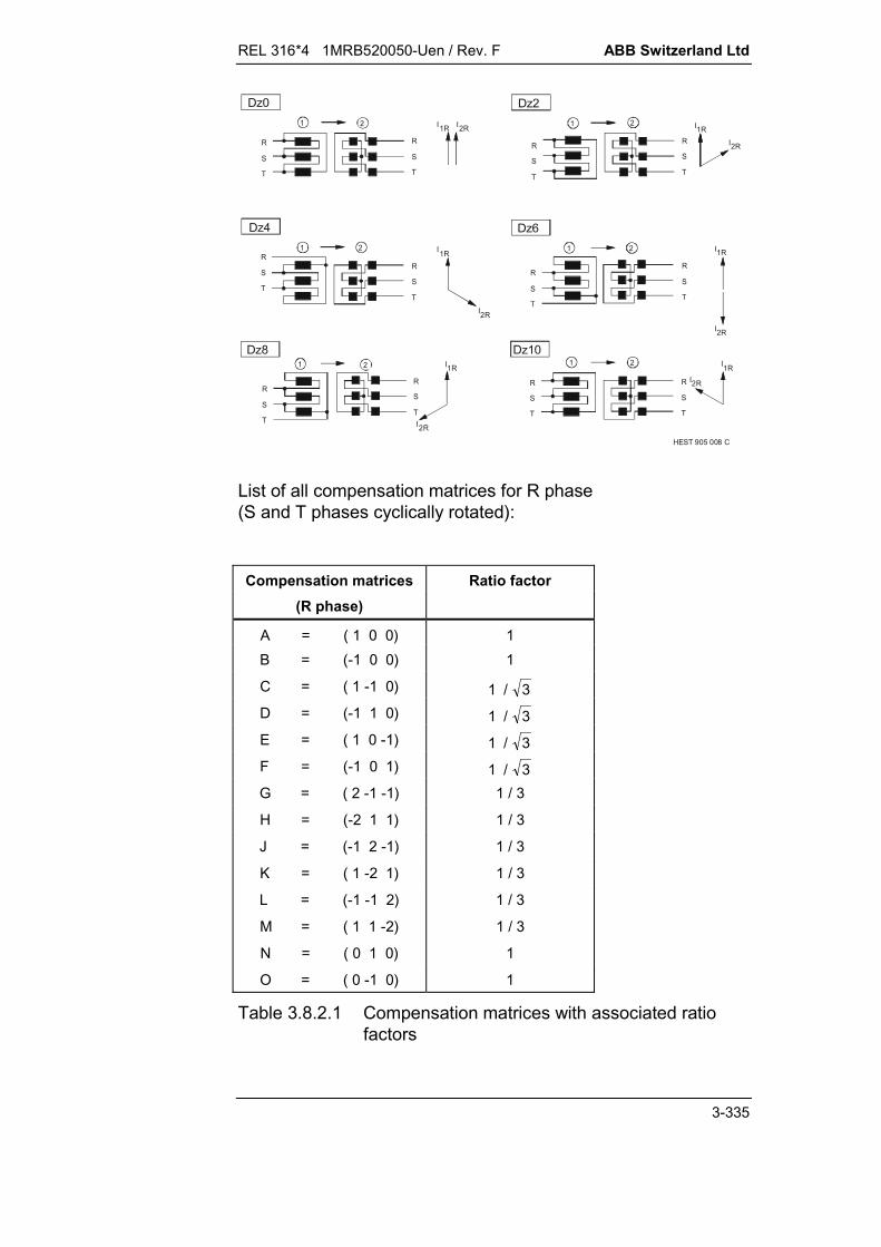
REL 316*4 1MRB520050-Uen / Rev. F ABB Switzerland Ltd
3-335
R
S
T
I1R2
R
S
T
I1R2
Dz8 Dz10
R
S
T
1
2RI
R
S
T
1
2RI
I1R
2RI
R
S
T
2R
S
T
1
R
S
T
2
R
S
T
1
Dz4 Dz6I1R
2RI
I1R 2RI
R
S
T
2
Dz0
R
S
T
1
R
S
T
2
R
S
T
1
Dz2
I1R
2RI
HEST 905 008 C
List of all compensation matrices for R phase(S and T phases cyclically rotated):
Compensation matrices Ratio factor(R phase)
A = ( 1 0 0) 1B = (-1 0 0) 1
C = ( 1 -1 0) 1 / 3D = (-1 1 0) 1 / 3E = ( 1 0 -1) 1 / 3F = (-1 0 1) 1 / 3G = ( 2 -1 -1) 1 / 3
H = (-2 1 1) 1 / 3
J = (-1 2 -1) 1 / 3
K = ( 1 -2 1) 1 / 3
L = (-1 -1 2) 1 / 3
M = ( 1 1 -2) 1 / 3
N = ( 0 1 0) 1
O = ( 0 -1 0) 1
Table 3.8.2.1 Compensation matrices with associated ratiofactors

ABB Switzerland Ltd REL 316*4 1MRB520050-Uen / Rev. F
3-336
a) Y-connected on side 1
Applies to two-winding transformers:
Phase group Compensation matrix Compensation matrixSide 1 Side 2
Yy0 E EYy6 E F
Yd1 E AYd5 C BYd7 E BYd11 C A
Yz1 E GYz5 C HYz7 E HYz11 C G
b) -connected on side 1
Applies to two-winding transformers:
Phase group Compensation matrix Compensation matrixSide 1 Side 2
Dy1 A CDy5 A FDy7 A DDy11 A E
Dd0 A ADd6 A B
Dz0 A GDz2 A KDz4 A LDz6 A HDz8 A JDz10 A M
REL 316*4 1MRB520050-Uen / Rev. F ABB Switzerland Ltd
3-337
3.8.2.2. Setting instructions for lines without a power transformer inthe protected zone
These recommendations are the result of extensive tests on anetwork model and take full account of the requirements withrespect to through-fault stability and operating time.
A current IBase is defined as the reverence value for deriving thesettings given below.IBase is chosen to be higher than the maximum load currentconducted by the line. Normally it will be the same as the c.t.rated current.The settings for g, b and I-Inst are referred to IBase.
Choice of c.t. input channel
To simplify the setting procedure for a1, a2, s1 and s2, reversingthe c.t. input channels is recommended regardless of whetherthere is a power transformer in the protection zone or not.This enables a1 and a2 and s1 and s2 to be set the same inMaster and Slave.
Setting:
Master: C.t input 1 to channel No.1C.t input 2 to channel No.7
Slave: C.t input 1 to channel No.7C.t input 2 to channel No.1
Settings for a1 and a2
(compensation for current amplitude (c.t. ratios))
Range 0.05…2.20 in steps of 0.01.
These two settings determine IBase and in doing so compensateany differences between the c.t’s ratios at the two ends of theline.
a) Feeder connected to single or multiple busbars (one circuit-breaker per feeder) with same-ratio c.t’s at the two ends:
In this case, the c.t. primary rated current is the same as themaximum load current.
a1 = 1; a2 = 1

ABB Switzerland Ltd REL 316*4 1MRB520050-Uen / Rev. F
3-338
b) Feeder connected to single or multiple busbars (one circuit-breaker per feeder) with c.t’s having different ratios at the twoends.
Compensated to the lower of the two ratios.
a = (In c.t. / IBase).
1000/1A 800/1A
a1= 1.25a1 = 1 (1000/800) = 1.25 a2 = 1 a2 = 1
Master Slave
1000/1A 800/1A a1 = 1
a2 = 1 (1000/800) = 1.25 a1 = 1
a2 = 1.25
Slave Master
IBase = 800 A IBase = 800 A
c) Feeder connected via a 1½ or two-breaker scheme with 2 c.t’swith a high ratio in parallel.
The c.t. installed in the transverse connection has to conductthe full current flowing between the two busbars and not justthe line current. A very high ratio is therefore usually chosen.
a = (In c.t. / IBasis).
Setting for s
(compensation for phase group)
Phase compensation is not necessary for a line. The setting istherefore:
s1 = D; s2 = d0
The phase group Dd0 does not suppress the zero-sequencecomponent, thus ensuring good sensitivity and correct phaseselection.
Where the two sets of c.t’s at the two line terminals are groundedon different sides, the difference can be compensated by settingDd6 at both ends.
Setting for v
(restraint at low currents)
0.25 or 0.50
v = 0.50 is the default value.
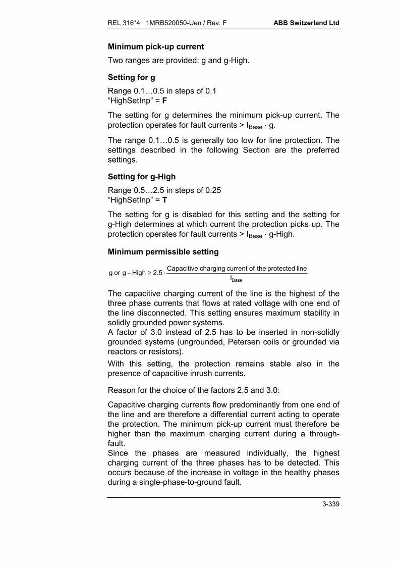
REL 316*4 1MRB520050-Uen / Rev. F ABB Switzerland Ltd
3-339
Minimum pick-up currentTwo ranges are provided: g and g-High.
Setting for gRange 0.1…0.5 in steps of 0.1“HighSetInp” = F
The setting for g determines the minimum pick-up current. Theprotection operates for fault currents > IBase g.
The range 0.1…0.5 is generally too low for line protection. Thesettings described in the following Section are the preferredsettings.
Setting for g-HighRange 0.5…2.5 in steps of 0.25“HighSetInp” = T
The setting for g is disabled for this setting and the setting forg-High determines at which current the protection picks up. Theprotection operates for fault currents > IBase g-High.
Minimum permissible setting
BaseIline protected the of current charging Capacitive5.2Highgorg
The capacitive charging current of the line is the highest of thethree phase currents that flows at rated voltage with one end ofthe line disconnected. This setting ensures maximum stability insolidly grounded power systems.A factor of 3.0 instead of 2.5 has to be inserted in non-solidlygrounded systems (ungrounded, Petersen coils or grounded viareactors or resistors).With this setting, the protection remains stable also in thepresence of capacitive inrush currents.
Reason for the choice of the factors 2.5 and 3.0:
Capacitive charging currents flow predominantly from one end ofthe line and are therefore a differential current acting to operatethe protection. The minimum pick-up current must therefore behigher than the maximum charging current during a through-fault.Since the phases are measured individually, the highestcharging current of the three phases has to be detected. Thisoccurs because of the increase in voltage in the healthy phasesduring a single-phase-to-ground fault.

ABB Switzerland Ltd REL 316*4 1MRB520050-Uen / Rev. F
3-340
2.5 = f1 f2' f3 solidly grounded systems3.0 = f1 f2" f3 non-solidly grounded systems
f1 = 1.2 maximum rated voltagef2’ = 0,8 3 maximum phase-to-ground voltage in
solidly grounded systems (Z0/Z1 < 4)f2’’ = 3 maximum phase-to-ground voltage in non-
solidly grounded systems (4 < Z0/Z1 < )f3 = 1.5 safety factor
The pick-up current can be set relatively high in most powersystems, because the basic current IBase is referred to the faultcurrent at the fault location and not in the individual infeeds.The fast-acting supervision of the communication channelintegrated in the function blocks the protection in the event of acommunication failure and excludes any possibility of falsetripping. A second enabling criterion is therefore unnecessary.When the differential current exceeds the tripping level, thelongitudinal differential protection function trips both ends of theline and does not require any special ancillary functions to detecta weak infeed and there are no restrictions on its application.To minimise the requirements on c.t. performance, a settingg-High b is often of advantage.The pick-up current must be set lower than the minimum faultcurrent and also low enough to still operate for relatively highfault resistances.
Determining the fault resistance that can be detected:
Neglecting the source impedance, the maximum fault resistancethat can be detected is approximately given by:
HighgI3U
RBase
systempowerF
Inrush restraint
“InrushInp” = T
This setting provides excellent stability even at the highest inrushcurrents and slowly decaying DC component.
Setting for b
This setting determines the switching point to v = . The inrushrestrain remains effective.

REL 316*4 1MRB520050-Uen / Rev. F ABB Switzerland Ltd
3-341
Range 1.25…5.00 in steps of 0.25
(b IBase) must be set higher than the maximum load current.
Recommended: b =1.5
Setting for I-Inst
The inrush restrain does not operated at differential currents highthan this setting.
Range 3…15 in steps of 1.0
The default setting is I-Inst = 3
I-Inst = 5 would be a typical setting for a radial line with a largepower transformer a the remote end.
With these settings, the protection exhibits high stability at highinrush currents and a saturation mismatch between the c.t’s.Peak inrush currents are permissible up to 15 IBase.

ABB Switzerland Ltd REL 316*4 1MRB520050-Uen / Rev. F
3-342
REL 316*4 1MRB520050-Uen / Rev. F ABB Switzerland Ltd
3-343
3.8.3. Binary data transmission (RemoteBin)
A. Application
Provision for transmitting and receiving up to 8 binary signalsbetween local and remote stations. The function is only activewhen the system is equipped with an A/D converter Type316EA62. The binary signals are transferred between the sta-tions via optical modems on the 316EA62 plug-in units and theoptical fibre cables linking them.
Binary signals which are received can be used for blocking,tripping and control functions.
B. Features
transmission of any 8 binary signals to the remote station provision of 8 signals received from the remote station (4 of
which can be assigned to the tripping logic).
C. Inputs and outputs
I. C.t./v.t. inputs
None
II. Binary inputs
8 inputs(binary signals for transmission to the remote station)
III. Binary outputs
8 outputs(signals received from the remote station which can beassigned to binary outputs)
Transmission error signal
IV. Measurements
None.

ABB Switzerland Ltd REL 316*4 1MRB520050-Uen / Rev. F
3-344
D. Binary data transmission settings - RemoteBin
Summary of parameters:
Text Unit Default Min. Max. Step
ParSet 4..1 P1 (Select)
RemTrip 1 Trip Chan 00000000
RemTrip 2 Trip Chan 00000000
RemTrip 3 Trip Chan 00000000
RemTrip 4 Trip Chan 00000000
RemChan 1 SignalAddr ER
RemChan 2 SignalAddr ER
RemChan 3 SignalAddr ER
RemChan 4 SignalAddr ER
RemChan 5 SignalAddr ER
RemChan 6 SignalAddr ER
RemChan 7 SignalAddr ER
RemChan 8 SignalAddr ER
SendChan 1 BinaryAddr F
SendChan 2 BinaryAddr F
SendChan 3 BinaryAddr F
SendChan 4 BinaryAddr F
SendChan 5 BinaryAddr F
SendChan 6 BinaryAddr F
SendChan 7 BinaryAddr F
SendChan 8 BinaryAddr F
RemBinError SignalAddr ER
Explanation of parameters:
ParSet 4..1Parameter for determining in which set of parameters a par-ticular function is active (see Section 5.11.).
RemTrip 1Tripping logic (matrix) excited by the signal ‘RemChan 1’from the remote station.
REL 316*4 1MRB520050-Uen / Rev. F ABB Switzerland Ltd
3-345
RemTrip 2Tripping logic (matrix) excited by the signal ‘RemChan 2’from the remote station.
RemTrip 3Tripping logic (matrix) excited by the signal ‘RemChan 3’from the remote station.
RemTrip 4Tripping logic (matrix) excited by the signal ‘RemChan 4’from the remote station.
RemChan 1 (2..8)Signal 1 (2..8) received from the remote station.
SendChan 1 (2..8)Input 1 (2..8) for transmitting a signal to the remote station.
F: - disabledT: - enabledxx: - all binary inputs (or outputs of a protection function).
RemBinErrorSignal indicating an error during binary data transmission.
ABB Switzerland Ltd REL 316*4 1MRB520050-Uen / Rev. F
3-346
E. Setting instructions
The binary data transmission function may only be confi-gured once for each set of parameters.
Should the binary data transmission fail, the alarm ‘RemBinError’is generated and the remote channels are set to ‘Off’ (‘0’). If thisresponse would disrupt an application, provision is made for in-verting the signals transferred by inverting the signal (SendChan)before transmission in the remote station and inverting the signal(RemChan) after reception in the local station.A failure of the communications channel (‘ModemError’) alsogenerates the alarm ‘RemBinError’ even if the ‘RemBin’ functionis only activated in one station.
REL 316*4 1MRB520050-Uen / Rev. C ABB Switzerland Ltd
4-1
August 00
4. DESCRIPTION OF FUNCTION AND APPLICATION
4.1. Summary..................................................................................4-3
4.2. Protection functions .................................................................4-54.2.1. Distance protection ..................................................................4-54.2.1.1. Starters ....................................................................................4-54.2.1.1.1. Operation of the starters ..........................................................4-54.2.1.1.2. Overcurrent starters .................................................................4-54.2.1.1.3. Underimpedance starters.........................................................4-74.2.1.1.4. Phase selection......................................................................4-114.2.1.2. Measuring units......................................................................4-134.2.1.2.1. Operation of the measuring units ...........................................4-134.2.1.2.2. Measurement during processing period I ...............................4-134.2.1.2.3. Measurement during processing period II ..............................4-164.2.1.2.4. Directional decision................................................................4-184.2.1.2.5. Construction of the measuring characteristic .........................4-204.2.1.3. V.t. supervision ......................................................................4-214.2.1.4. Back-up overcurrent function O/C..........................................4-244.2.1.5. System logic...........................................................................4-254.2.1.5.1. Structure of the system logic..................................................4-254.2.1.5.2. Enabling and blocking logic (SUPBL) ....................................4-264.2.1.5.3. Switch-onto-fault logic (SOTF) ...............................................4-264.2.1.5.4. Short-zone logic (STUB) ........................................................4-284.2.1.5.5. Zone extension logic (ZE) ......................................................4-284.2.1.5.6. Transient blocking logic (Transbl) ..........................................4-294.2.1.5.7. Communication channel failure (Deblock)..............................4-314.2.1.5.8. Permissive underreaching transfer tripping (PUTT) ...............4-324.2.1.5.9. Permissive overreaching transfer tripping (POTT) .................4-344.2.1.5.10. Overreaching blocking scheme (BLOCK OR)........................4-364.2.1.5.11. PLC transmit logic (HFSEND)................................................4-374.2.1.5.12. Tripping logic..........................................................................4-384.2.1.6. Power swing blocking (PSB) ..................................................4-414.2.1.7. Signal designations and abbreviations...................................4-434.2.2. Auto-reclosure........................................................................4-474.2.2.1. Logic segments......................................................................4-474.2.2.2. Signal designations................................................................4-554.2.3. Breaker failure protection.......................................................4-584.2.3.1. Introduction ............................................................................4-584.2.3.2. Three-phase/ single-phase mode ..........................................4-594.2.3.3. ‘Redundant Trip’ ....................................................................4-594.2.3.4. ‘Retrip’ ...................................................................................4-60

ABB Switzerland Ltd REL 316*4 1MRB520050-Uen / Rev. C
4-2
4.2.3.5. ‘Backup Trip’ .........................................................................4-604.2.3.6. ‘Remote Trip’ .........................................................................4-604.2.3.7. ‘Unconditional Trip’ ...............................................................4-604.2.3.8. ‘End Fault Trip’ ......................................................................4-614.2.3.9. ‘External Trip’ ........................................................................4-61

REL 316*4 1MRB520050-Uen / Rev. C ABB Switzerland Ltd
4-3
4. DESCRIPTION OF FUNCTION AND APPLICATION
4.1. Summary
Both analogue and binary I/P signals pass through a signalconditioning stage before being processed by the mainprocessor:Analogue signals go through the chain comprising the inputtransformer, shunt, low-pass filter (anti-alias filter), amplifier,sampling (sample and hold), multiplexer and A/D converter. Asdigital signals they are then separated by digital filters into realand apparent components before entering the main processor.The binary signals are isolated by opto-couplers in the inputcircuits and are evaluated by the main processor.Only now are the protection algorithms and the logic functionsprocessed in the main processor.
The distance protection function is equipped with overcurrent orunderimpedance starters. In ungrounded systems, all the usualcyclic and acyclic phase preference schemes are available.The residual (neutral) current and/or residual (zero-sequence)voltage are monitored to detect earth faults.The first distance zone, the overreaching zone and the reversezone measure simultaneously. All of the distance zones havewide setting ranges and can be set completely independently ofeach other, also with respect to whether they measure in theforwards or reverse direction. There are three directional dis-tance zones and a fourth, which can be either directional or non-directional as demanded by the application. The overreachingand reverse zones are for use in transfer tripping schemes withsignal transmission between the units at the two ends of a line.The operating characteristics are polygons with the reactanceborders slightly inclined to give an ideal tripping area. For closethree-phase faults with very low voltages, the use of a referencevoltage comprising a healthy voltage and the voltage of a mem-ory feature ensures a reliable directional decision.
Compensation of the mutual zero-sequence impedance of paral-lel circuits can be achieved by appropriate selection of the zero-sequence impedance factor (k0) or the residual current of theparallel circuit using k0m.
A v.t. supervision feature (fuse failure) is already incorporated.Its measurement can be based on either the zero-sequencecomponent (U0 . not I0) and/or the negative-sequence com-ponent (U2 . not I2). The latter is of special advantage in un-grounded systems or systems with poor grounding.

ABB Switzerland Ltd REL 316*4 1MRB520050-Uen / Rev. C
4-4
An independent back-up overcurrent function becomes a short-zone protection, as soon as the line isolator is opened. Trippingof the overcurrent back-up protection is uninfluenced by anysignal, which may be blocking the distance protection (e.g. v.t.supervision or power swing blocking).
The power swing blocking function monitors the variation of thequantity U . cos . This method of detecting power swings is en-tirely independent of the characteristic and location of the dis-tance protection. Power swings with frequencies between 0.2and 8 Hz are detected.
The sensitive E/F protection for ungrounded systems and sys-tems with Petersen coils measures both in the forwards and re-verse directions. A characteristic angle of 90 (U0 . I0 . sin ) ischosen for ungrounded systems and one of 0 (U0 . I0 . cos )for systems with Petersen coils.
An logic, which can be freely programmed with the aid of FUPLA(function block programming language), provides convenientfacility for achieving special circuits needed for specificapplications.
The auto-reclosure function enables up to four three-phase re-closure cycles to be carried out, each with independently setdead time for fast or slow auto-reclosure.
Where necessary, a large variety of supplementary protectionand logic functions is contained in the RE. 216 and RE. 316*4function software libraries.
The distance protection logic gives the user access for blockingor enabling purposes to a wide range of functions, including forexample the kind of transfer tripping scheme, switch-onto-faultlogic, zone extension logic, v.t. supervision logic and whether theprotection should trip just the phase concerned or all threephases for an E/F.
The memory of the event recorder function has sufficient capac-ity for up to 256 binary signals, which are recorded together withtheir relative times of occurrence and information regarding thedistance to the fault.
The memory of the perturbograph registers 9 analogue and 16binary signals. The number of events it can actually record in aparticular application depends on the total duration of an eventas determined by the amount of pre-event data (event history)and the duration of the event itself.

REL 316*4 1MRB520050-Uen / Rev. C ABB Switzerland Ltd
4-5
4.2. Protection functions
4.2.1. Distance protection
4.2.1.1. Starters
4.2.1.1.1. Operation of the starters
The distance function is equipped with either overcurrent or un-derimpedance starters. The setting of the parameter “StartMode”determines which of the two is in operation.
A starter must pick up at least twice before its signal is proc-essed (for phase selection, starting timers, signalling etc.).Should a starter pick up only sporadically, only the backwardsmeasuring system and ancillary functions such as displayingmeasurements etc. are enabled.
Starting signals do not reset unless all the starters have reset.
4.2.1.1.2. Overcurrent starters
The variables at the I/P’s of the overcurrent starters are thephase currents IR, IS and IT and the residual current IE (3I0),respectively the neutral voltage UE (3U0). Initially, a logicdetermines Imax, i.e. the highest of the three phase currents IR, ISand IT.If the value of Imax exceeds the setting of the parameter “Istart”(overcurrent starters), each of the phase currents Iph is checkedto determine whether it exceeds the setting of the parameter“Imin” (current enable) and also 80 % of Imax. In the case of theresidual current, the corresponding values are the setting of theparameter “3I0min” and 25 % of Imax.In the case of the ground current IE, it is checked whether itexceeds the setting of the parameter “3I0min” and also 25 % ofImax. Depending on the setting of the parameter “Earth faultdetector” (I0, I0 AND U0, I0 OR U0), it is checked at the sametime whether the residual voltage has exceeded the setting ofthe parameter “3U0min” (neutral voltage enable).The logical signals R, S, T and E are accordingly changed fromlogical “0” to logical “1” or remain at logical “0”. The kind of faultand the phases involved are thus determined, information whichis needed for
phase selection (determination of the loop to be measured) signalling the kind of fault (signalling relays, LED’s etc.) enabling signals for single or three-phase tripping starting the timers for the measuring zones.
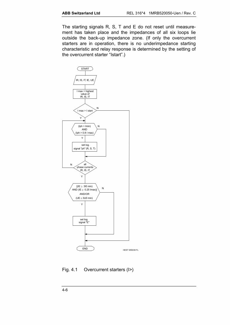
ABB Switzerland Ltd REL 316*4 1MRB520050-Uen / Rev. C
4-6
The starting signals R, S, T and E do not reset until measure-ment has taken place and the impedances of all six loops lieoutside the back-up impedance zone. (If only the overcurrentstarters are in operation, there is no underimpedance startingcharacteristic and relay response is determined by the setting ofthe overcurrent starter “Istart”.)
IR, IS, IT, IE, UE
START
(Iph > Imin)
N all
N
Y
I max > I start
set log.signal "ph" (R, S, T)
I max = highest
set log.signal "E"
END
AND
IR, IS, IT
HEST 955038 FL
(Iph > 0.8 I max)
[(IE 3I0 min)
AND/OR(UE 3U0 min)
Y
phase currentsIR, IS, IT
Y
N
Y
NAND (IE 0.25 Imax)]
value of
Fig. 4.1 Overcurrent starters (I>)

REL 316*4 1MRB520050-Uen / Rev. C ABB Switzerland Ltd
4-7
4.2.1.1.3. Underimpedance starters
The variables at the I/P’s of the underimpedance starters are thephase currents IR, IS and IT and the residual current IE (3I0) andthe phase-to-neutral voltages UR, US, UT and the neutral voltageUE (3U0).
IR, IS, IT, IEUR, US, UT, UE
START
N
Y
Iph Imin
N
END
NZ < Z Start
Y
Loop =phase selection
HEST 955037 C
set temp.signals "ph, "E"
allph-0 loops
Z < Z Start
N
log. signals =temp. signals
Y
Z = UphIph + 1 x IE
or Z = Uph1-Uph2Iph1 - Iph2
Z = U ph2 x Iph
N
Y
N
Y
Selectivityconditions
set temp.signals "ph1", "ph2"
allph-ph loops
Z < Z Start
Z = Uph1 - Uph2Iph1 - Iph2
N
Y
setlog. signals
(Iph1 Imin)
AND(Iph2 Imin)
N
Y
Y
[(IE 3I0min)AND (IE
0.25 Imax)]AND/OR
(UE 3U0 min)
Fig. 4.2 Underimpedance starters (Z<)
ABB Switzerland Ltd REL 316*4 1MRB520050-Uen / Rev. C
4-8
Depending on the setting of the parameter “Earth fault detector”(I0, I0 AND U0, I0 OR U0), the function determines initiallywhether one or both of the E/F criteria is fulfilled, i.e. whether theresidual current IE exceeds the setting of the parameter “3I0min”and/or the residual voltage UE the setting of the parameter“3U0min”. Should this be the case, the three phase-to-groundloops are measured first, otherwise just the three phase-to-phase loops.
The three phase-to-ground loops are dealt with as follows:
If IR (or IS, or IT) is greater than “Imin”, the corresponding loopsare enabled and the loop impedances calculated as follows:
R
RR I2
UZ (uncompensated)
S
SS I2
UZ (uncompensated)
T
TT I2
UZ (uncompensated)
All uncompensated impedances ZR, ZS and ZT are comparedwith the starting characteristic and temporarily set the logicalsignals ‘Ph’ and ‘E’ (no display). An impedance loop is selected(see Section 4.2.1.1.4.) on the basis of these signals (loop =selected phase).If the loop is a phase-to-neutral one, the impedance iscompensated by k0 = 1 for calculation:
Eph
0ph0ph I1I
UZ
e.g.
ER
R0R I1I
UZ
If the loop is a phase-to-phase one, the impedance is calculatedusing phase-to-phase quantities:
phph
phphphph I
UZ
e.g. Z U U
I IRSR S
R S
If the impedance (Z) calculated for the loop determined by thephase selection logic lies within the underimpedance startingcharacteristic (Zstart), the loop is used for measurement.

REL 316*4 1MRB520050-Uen / Rev. C ABB Switzerland Ltd
4-9
The logical signals are needed for
signalling the kind of fault (signalling relays, LED’s etc.) enabling signals for tripping starting the timers for the measuring zones.
The three phase-to-phase loops are dealt with as follows:
Providing Iph1 and Iph2 (IR and IS, IS and IT, or IT and IR) arehigher than “Imin”, the corresponding loops are enabled and theimpedances are calculated as follows:
Z U UI IRSR S
R S
Z U UI ISTS T
S T
Z U UI ITRT R
T R
Comparison of the three starting impedances eliminates thehealthy loops (discrimination condition).
If just one of the loop impedances lies within the underimped-ance starting characteristic (Zstart), only the signals (R and S), or(S and T), or (T and R) would be set to logical “1”.
If more than one of the loop impedances lie within the under-impedance starting characteristic, the signals R and S and T areset to logical “1”. The kind of fault is thus determined, informationwhich is needed for
phase selection (determination of the loop to be measured) signalling the kind of fault (remote signalling relays, frontplate
LED’s etc.) enabling signals for single or three-phase tripping starting the timers fsxdor the measuring zones.

ABB Switzerland Ltd REL 316*4 1MRB520050-Uen / Rev. C
4-10
Underimpedance starting and definitive zone characteristic
X
R
CHARACTERISTICUNDERIMPEDANCE
XA
RB -RLoad RLoad RAAngleLoad
XB HEST 935 049 C
Fig. 4.3 Underimpedance starting and definitive zonecharacteristic

REL 316*4 1MRB520050-Uen / Rev. C ABB Switzerland Ltd
4-11
4.2.1.1.4. Phase selection
The phase selection logic determines the loop
for the underimpedance starting measurement when anground fault has been detected
to be measured in the first period (max. 20 ms) after starting to be measured during the time the function is in the picked-
up state when a ground fault has been detected on anungrounded system or system with Petersen coils (phaseselection solidly grounded).
In a solidly grounded system (parameter “PhaseSelMode” set to“solid gr.”), the loop to be measured is determined according tothe following table:
Starters Loop measured
E/F R,E REE/F S,E SEE/F T,E TEPhase-to-phase fault R,S RSPhase-to-phase fault S,T STPhase-to-phase fault T,R TRPhase-to-phase-to-ground fault R,S,E RSPhase-to-phase-to-ground fault S,T,E STPhase-to-phase-to-ground fault T,R,E TRThree-phase fault R,S,T TR (RS) (ST)
In a solidly grounded system, both phases involved in a phase-to-phase-to-ground fault have to be tripped, which is not thecase in ungrounded systems or a systems with Petersen coils.
In ungrounded systems or a systems with Petersen coils (para-meter “PhaseSelMode” set to cyclic/acyclic phase selection), theloop to be measured is determined according to the followingtable:
Starters Loop measured
Phase-to-phase fault R,S RSPhase-to-phase fault S,T STPhase-to-phase fault T,R TRThree-phase fault R,S,T TR (RS) (ST)Cross-country fault *) R,S,ECross-country fault *) S,T,E according to phaseCross-country fault *) T,R,E selection logic*) two E/F’s at different locations
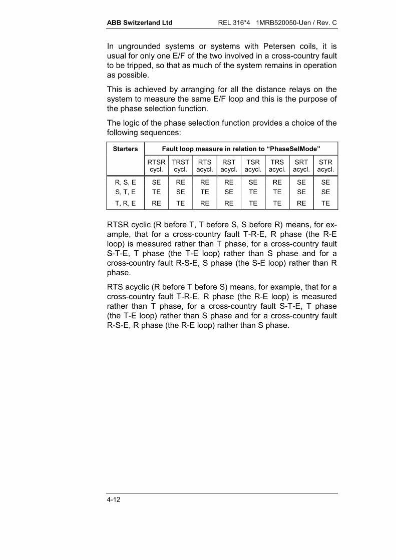
ABB Switzerland Ltd REL 316*4 1MRB520050-Uen / Rev. C
4-12
In ungrounded systems or systems with Petersen coils, it isusual for only one E/F of the two involved in a cross-country faultto be tripped, so that as much of the system remains in operationas possible.
This is achieved by arranging for all the distance relays on thesystem to measure the same E/F loop and this is the purpose ofthe phase selection function.
The logic of the phase selection function provides a choice of thefollowing sequences:
Starters Fault loop measure in relation to “PhaseSelMode”
RTSR TRST RTS RST TSR TRS SRT STRcycl. cycl. acycl. acycl. acycl. acycl. acycl. acycl.
R, S, E SE RE RE RE SE RE SE SES, T, E TE SE TE SE TE TE SE SE
T, R, E RE TE RE RE TE TE RE TE
RTSR cyclic (R before T, T before S, S before R) means, for ex-ample, that for a cross-country fault T-R-E, R phase (the R-Eloop) is measured rather than T phase, for a cross-country faultS-T-E, T phase (the T-E loop) rather than S phase and for across-country fault R-S-E, S phase (the S-E loop) rather than Rphase.
RTS acyclic (R before T before S) means, for example, that for across-country fault T-R-E, R phase (the R-E loop) is measuredrather than T phase, for a cross-country fault S-T-E, T phase(the T-E loop) rather than S phase and for a cross-country faultR-S-E, R phase (the R-E loop) rather than S phase.

REL 316*4 1MRB520050-Uen / Rev. C ABB Switzerland Ltd
4-13
4.2.1.2. Measuring units
4.2.1.2.1. Operation of the measuring unitsThe distance measurement of a fault is enabled after one of thetwo starting functions, overcurrent or underimpedance, haspicked up twice.Initially the fault loop determined by the phase selection functionis measured. This is called processing period I and lasts until atrip signal is generated in the first zone or a maximum of oneperiod of the power system frequency.At the latest after one period of the power system frequency, allsix impedance loops are measured. This is called processingperiod II, during which the three phase-to-ground loops and thethree phase-to-phase loops are measured alternately.Comparison of the results of the six measurements eliminatesthose impedance loops, which are not involved in the fault(discrimination conditions).The timer started by the starting units controls the comparison ofthe measured impedances with the polygon characteristic.
4.2.1.2.2. Measurement during processing period I
Processing period I lasts from the instant a starter picks up untilthe first tripping signal is generated, but is restricted to a maxi-mum of one period of the power system frequency. The inputsignals are the phase currents IR, IS, IT, the residual current IE(3I0), the residual current of any parallel circuit IEm (3I0m), theneutral current IEm of any parallel circuit of a double-circuit line(3I0m) and the three phase-to-ground voltages UR, US and UT,which have been sampled, analogue and digitally filtered andbroken down into their component vectors.If the overcurrent starters are in operation and have picked up,the phase selection function is performed and the loop to bemeasured determined. Should this not be the case, the loopdetermined by the underimpedance starters is measured.The impedance of a phase-to-ground loop, e.g. R-E is calcu-lated using the equation:
Z UI k I k IR
R
R E m Em
0 0(compensated)
wherek0: zero-sequence compensation factor for Z0
k Z Z Z0 0 1 13

ABB Switzerland Ltd REL 316*4 1MRB520050-Uen / Rev. C
4-14
k0m: zero-sequence compensation factor for the mutual im-pedance Z0m of double-circuit linek Z Zm m0 0 13
The mutual zero-sequence impedance of a double-circuit line(k0m . IEm) is only compensated for the 1st., 2nd. andoverreaching zones, and in the latter two cases, only if theirdirection of measurement is the same as that of the 1st. zone. Inthis respect, a reverse measuring zone is treated in the samemanner as an overreaching zone.
The mutual zero-sequence impedance (k0m . IEm) is not com-pensated, should IEm exceed 1.25 . IE or the direction of IEm notbe the same as that of IE. This prevents a “healthy” parallel cir-cuit from being adversely influenced by a fault relatively close tothe relay location of the faulted circuit.
Assuming a fault between R and S, the impedance of thephase-to-phase loop is calculated using the equation:
Z U UI IRSR S
R S
It is determined almost simultaneously, whether the impedancemeasured lies within the characteristic and whether it is in the di-rection of the 1st. zone and overreaching zone, or in the direc-tion of the reverse measuring zone. The corresponding trippingand other signals are processed by the system logic. Trippingof the circuit-breaker, however, only takes place after ameasuring unit has operated twice.
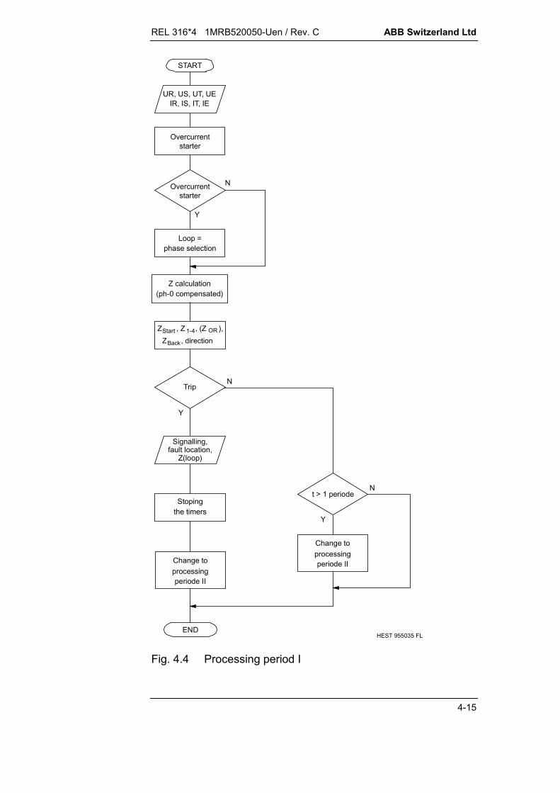
REL 316*4 1MRB520050-Uen / Rev. C ABB Switzerland Ltd
4-15
IR, IS, IT, IEUR, US, UT, UE
START
NTrip
N
Y
Z calculation(ph-0 compensated)
Overcurrent
Stoping
Y
END
Signalling,fault location,
Z(loop)
the timers
Nt > 1 periode
Loop =phase selection
starter
Y
HEST 955035 FL
Change toprocessingperiode II
Overcurrentstarter
Change toprocessingperiode II
Z , Z , (Z ),Start 1-4 OR
Z , directionBack
Fig. 4.4 Processing period I
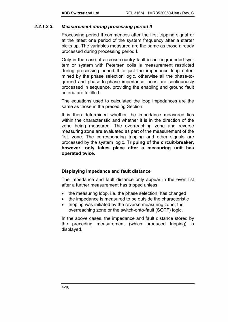
ABB Switzerland Ltd REL 316*4 1MRB520050-Uen / Rev. C
4-16
4.2.1.2.3. Measurement during processing period II
Processing period II commences after the first tripping signal orat the latest one period of the system frequency after a starterpicks up. The variables measured are the same as those alreadyprocessed during processing period I.
Only in the case of a cross-country fault in an ungrounded sys-tem or system with Petersen coils is measurement restrictedduring processing period II to just the impedance loop deter-mined by the phase selection logic, otherwise all the phase-to-ground and phase-to-phase impedance loops are continuouslyprocessed in sequence, providing the enabling and ground faultcriteria are fulfilled.
The equations used to calculated the loop impedances are thesame as those in the preceding Section.
It is then determined whether the impedance measured lieswithin the characteristic and whether it is in the direction of thezone being measured. The overreaching zone and reversemeasuring zone are evaluated as part of the measurement of the1st. zone. The corresponding tripping and other signals areprocessed by the system logic. Tripping of the circuit-breaker,however, only takes place after a measuring unit hasoperated twice.
Displaying impedance and fault distance
The impedance and fault distance only appear in the even listafter a further measurement has tripped unless
the measuring loop, i.e. the phase selection, has changed the impedance is measured to be outside the characteristic tripping was initiated by the reverse measuring zone, the
overreaching zone or the switch-onto-fault (SOTF) logic.
In the above cases, the impedance and fault distance stored bythe preceding measurement (which produced tripping) isdisplayed.

REL 316*4 1MRB520050-Uen / Rev. C ABB Switzerland Ltd
4-17
IR, IS, IT, IEUR, US, UT, UE
START
N
N
Y
Y
END
Signalling
Stoping thetimers
NTrip
Reset-
Selectivityconditions
Y
signalling
HEST 955036 C
6 Z calculations(ph-0 compensated)
Fallbackconditions
Signallingfault location
Z(loop)
I >, Z < Starting
Phase selection
ph-EN
Y
3 ph-ph Z-calculationph-0 Z-calculation
Z , directionBack
Z , Z , (Z ),Start 1-4 OR
solidly grounded network
AND (I> starting active)
Fig. 4.5 Processing period II

ABB Switzerland Ltd REL 316*4 1MRB520050-Uen / Rev. C
4-18
4.2.1.2.4. Directional decision
Before deciding the direction of a fault, the fault voltage (used asreference voltage) is checked to determine whether it is higherthan the setting of the parameter “UminFault” (minimum faultvoltage). Providing this is the case, the phase-angle of theimpedance, i.e. between fault current and voltage, is determined:
arg argZ UI
arg Z = arg U - arg I
where
arg: argument of the complex number (angle)
U : fault voltageU = UR (phase-to-ground loop, e.g. R-E)U = UR-US (phase-to-phase loop, e.g. R-S)
I : fault currentI = IR + IE . k0 + IEm . k0m (phase-to-ground loop,
e.g. R-E)I = IR - IS (phase-to-phase loop,
e.g. R-S)
arg Z must lie within the following limits for the fault to be desig-nated a “forwards fault":
- 27° < arg Z < + 117°
arg Z must lie within the following limits for the fault to be desig-nated a “reverse fault":
+ 153° < arg Z < - 63°
Z is the impedance measured by the protection, which corre-sponds to the line impedance ZL. By using the fault voltage asreference voltage for determining direction, the measurement isindependent of source impedance (see following Section 4.2.1.2.5.“Construction of the measuring characteristic”).

REL 316*4 1MRB520050-Uen / Rev. C ABB Switzerland Ltd
4-19
If the fault voltage is less than the setting of the parameter“UminFault” (minimum fault voltage), the impedance is deter-mined from the fault current and a separate reference voltage:
arg argZU
Irefref
= arg Uref - arg I
arg: argument of the complex number (angle)Uref: reference voltage
Uref = (US - UT) . 27° (phase-to-ground loop, e.g. R-E)Uref = (UR - UT) + 1/8 (URmem - UTmem)
(phase-to-phase loop, e.g. R-S)I : fault current
I = IR + IE . k0 + IEm . k0m (phase-to-ground loop,e.g. R-E)
I = IR - IS (phase-to-phase loop,e.g. R-S)
The reference voltage Uref is derived from the phase voltagesnot involved in the fault. In the case of a phase-to-phase loop,the reference voltage also includes a proportion of the memoryvoltage Umem. The duration of the memory voltage is limited tobetween 5 and 15 periods of the power system frequency, de-pending on the discrepancy between the measured frequencyand the rated power system frequency, i.e. the memory voltageis used for 15 periods at rated system frequency and for a pro-portionally reduced number of periods as the frequency deviatesfrom rated power system frequency.As long as the reference voltage Uref is greater than 0.5% ofrated voltage, it is used to determine fault direction:In this case, a “forwards fault” satisfies the condition:- 90° < arg Zref < + 90°A “reverse fault” satisfies the condition:+ 90° < arg Zref < - 90°Zref is the impedance measured by the protection, which con-tains a component of the source impedance ZS in addition to theline impedance ZL. The operating characteristic has to bemathematically transformed in order to make the influence of thesource impedance visible (see following Section 4.2.1.2.5.“Construction of the measuring characteristic”).If the reference voltage is less than 0.5% of rated voltage,direction is not taken into account for the phase-to-ground loopand tripping is blocked. In the case of the phase-to-phase loops,tripping is either enabled or blocked, depending on the setting ofthe parameter “MemDirMode”.

ABB Switzerland Ltd REL 316*4 1MRB520050-Uen / Rev. C
4-20
4.2.1.2.5. Construction of the measuring characteristic
X
R
X
R RR-X/8
-RR/2
RRE
-RRE/2
HEST 915 019 C
Zone 1(2,3,4,OR,BWD)
7°
27°
27°
Fig. 4.6 Measuring characteristic using the fault voltage asreference
X
R
X
R RR-X/8
7
-RR/2
RRE
-RRE/2ZS
27
Zone 1(2,3,4,OR,BWD)
HEST 915 020 C
Fig. 4.7 Measuring characteristic using a healthy voltage asreference
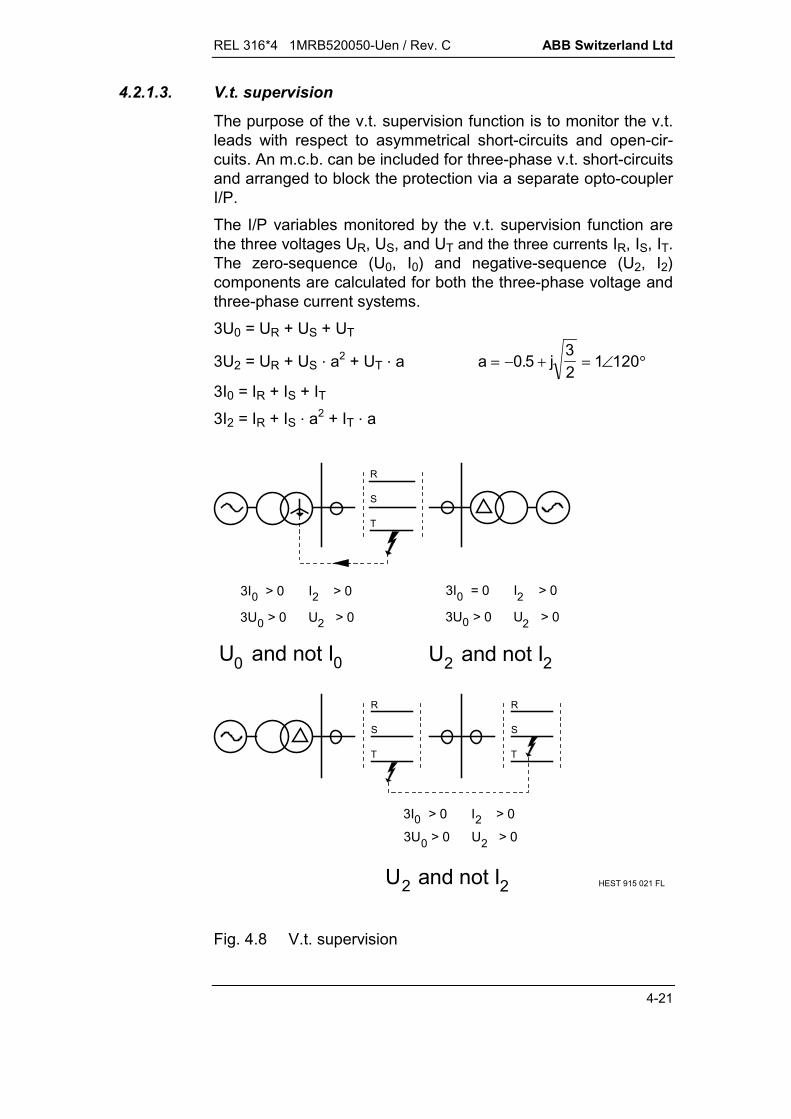
REL 316*4 1MRB520050-Uen / Rev. C ABB Switzerland Ltd
4-21
4.2.1.3. V.t. supervision
The purpose of the v.t. supervision function is to monitor the v.t.leads with respect to asymmetrical short-circuits and open-cir-cuits. An m.c.b. can be included for three-phase v.t. short-circuitsand arranged to block the protection via a separate opto-couplerI/P.The I/P variables monitored by the v.t. supervision function arethe three voltages UR, US, and UT and the three currents IR, IS, IT.The zero-sequence (U0, I0) and negative-sequence (U2, I2)components are calculated for both the three-phase voltage andthree-phase current systems.3U0 = UR + US + UT
3U2 = UR + US . a2 + UT . a a j 0 532
1 120.
3I0 = IR + IS + IT3I2 = IR + IS . a2 + IT . a
R
S
T
3I = 03I > 0
3U > 03U > 0
I > 0I > 0
U > 0U > 0
R
S
T
R
S
T
3I > 0
3U > 0
I > 0
U > 0
HEST 915 021 FL
0
20
2 0
20
2
0
20
2
U and not I22
U and not I00 U and not I22
Fig. 4.8 V.t. supervision
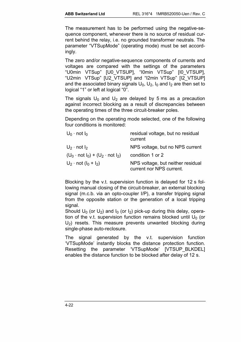
ABB Switzerland Ltd REL 316*4 1MRB520050-Uen / Rev. C
4-22
The measurement has to be performed using the negative-se-quence component, whenever there is no source of residual cur-rent behind the relay, i.e. no grounded transformer neutrals. Theparameter “VTSupMode” (operating mode) must be set accord-ingly.
The zero and/or negative-sequence components of currents andvoltages are compared with the settings of the parameters“U0min VTSup” [U0_VTSUP], “I0min VTSup” [I0_VTSUP],“U2min VTSup” [U2_VTSUP] and “I2min VTSup” [I2_VTSUP]and the associated binary signals U0, U2, I0 and I2 are then set tological “1” or left at logical “0”.
The signals U0 and U2 are delayed by 5 ms as a precautionagainst incorrect blocking as a result of discrepancies betweenthe operating times of the three circuit-breaker poles.
Depending on the operating mode selected, one of the followingfour conditions is monitored:
U0 . not I0 residual voltage, but no residualcurrent
U2 . not I2 NPS voltage, but no NPS current(U0 . not I0) + (U2 . not I2) condition 1 or 2U2 . not (I0 + I2) NPS voltage, but neither residual
current nor NPS current.
Blocking by the v.t. supervision function is delayed for 12 s fol-lowing manual closing of the circuit-breaker, an external blockingsignal (m.c.b. via an opto-coupler I/P), a transfer tripping signalfrom the opposite station or the generation of a local trippingsignal.Should U0 (or U2) and I0 (or I2) pick-up during this delay, opera-tion of the v.t. supervision function remains blocked until U0 (orU2) resets. This measure prevents unwanted blocking duringsingle-phase auto-reclosure.
The signal generated by the v.t. supervision function‘VTSupMode’ instantly blocks the distance protection function.Resetting the parameter ‘VTSupMode’ [VTSUP_BLKDEL]enables the distance function to be blocked after delay of 12 s.
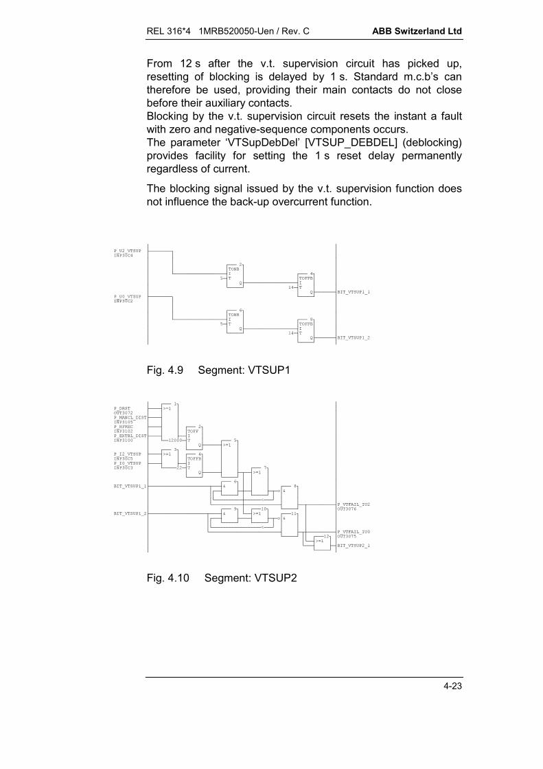
REL 316*4 1MRB520050-Uen / Rev. C ABB Switzerland Ltd
4-23
From 12 s after the v.t. supervision circuit has picked up,resetting of blocking is delayed by 1 s. Standard m.c.b’s cantherefore be used, providing their main contacts do not closebefore their auxiliary contacts.Blocking by the v.t. supervision circuit resets the instant a faultwith zero and negative-sequence components occurs.The parameter ‘VTSupDebDel’ [VTSUP_DEBDEL] (deblocking)provides facility for setting the 1 s reset delay permanentlyregardless of current.
The blocking signal issued by the v.t. supervision function doesnot influence the back-up overcurrent function.
Fig. 4.9 Segment: VTSUP1
!"#$%& ' ( ()& !" !" #*!" *+,*-+,.,*% & /# *+!"*-+.*,% & #!"
Fig. 4.10 Segment: VTSUP2

ABB Switzerland Ltd REL 316*4 1MRB520050-Uen / Rev. C
4-24
*+&0(&,- % *,% &&1 !"# +!" -!" ((&% & %/
Fig. 4.11 Segment: VTSUP3
4.2.1.4. Back-up overcurrent function O/C
The distance protection function includes a definite time overcur-rent unit as back-up protection. A starting signal “Start O/C” isset to logical “1”, when one or more of the currents IR, IS, and ITexceed the setting of the parameter “I O/C”. Following the ad-justable time delay “O/C delay”, the tripping signal “Trip O/C” isset to logical “1” and applied to the system logic.
Blocking signals generated by the distance, underimpedancestarting, power swing blocking or v.t. supervision functions donot influence the back-up overcurrent function.
The back-up overcurrent function is independent of the distanceprotection starters and, since it does not have to perform anyphase selection, can therefore have a more sensitive setting.

REL 316*4 1MRB520050-Uen / Rev. C ABB Switzerland Ltd
4-25
4.2.1.5. System logic
4.2.1.5.1. Structure of the system logic
The system logic processes the binary I/P signals from externalplant (opto-coupler I/P’s) and all the binary signals of the dis-tance protection function.
The system logic is programmed using FUPLA (function blockprogramming language) and is divided into what are referred toas segments, which are processed with a higher priority than, forexample, the auto-reclosure function.
Bina
ry in
put d
ata
of th
e di
stan
ce p
rote
ctio
n fu
nctio
n an
d th
e In
put/O
utpu
t uni
t
Bina
ry o
utpu
t dat
a to
per
turb
ogra
ph a
nd th
e In
put/O
utpu
t uni
t
VTSUP
SUPBL
SOTF
STUB
ZE
TRANSBL
UNBLOCK
PUTTREC
PUTSEND
POTTREC
POTSEND
BLOCREC
BLOSEND
HFSEND
TRIP
HEST 915 022 FL
Fig. 4.12 System logic in the distance protection functionThe O/P’s of the system logic are binary signals for controlling afault recorder, LED signals and auxiliary tripping and signallingrelays.

ABB Switzerland Ltd REL 316*4 1MRB520050-Uen / Rev. C
4-26
4.2.1.5.2. Enabling and blocking logic (SUPBL)
The logic of the v.t. supervision function (segment VTSUP) hasalready been described in the relevant Section. The segmentSUPBL coordinates all the external blocking signals distanceprotection [EXTBL_DIST] (opto-coupler I/P’s), the power swingblocking function [PS_BLOCK] and the v.t. supervision function[VT_BLOCK] and blocks all the distance protection functions[DISTBL] with the exception of the back-up overcurrent function.
()& !"&0 % &* &/ &(&
Fig. 4.13 Segment: SUPBL
4.2.1.5.3. Switch-onto-fault logic (SOTF)
When a circuit-breaker is closed onto and existing three-phasefault (e.g. forgotten earthing clamps), a three-phase trip is im-mediately initiated.
The fault detectors in this case are the non-directional starters(overcurrent or underimpedance units) or optionally theoverreaching zone, but this is only used in the following specialcases:
power transformer with high inrush currents at the remoteend of the line. In such cases fault detection involving thedistance measuring units is safer.
Close faults with complete voltage collapse may possibly nototherwise be detected, in which case the parameter“MemDirMode” has to be set to “Trip”.
The switch-onto-fault logic can be activated and the switch-onto-fault signal [SOTF] set to logical “1” in one of three ways:
1) by an auxiliary contact of the CB control switch when closingthe CB (opto-coupler I/P “Manual close” [MANCL_DIST])
2) by an auxiliary contact of the CB when opening the CB (opto-coupler I/P “Dead line” [DEADLINE])
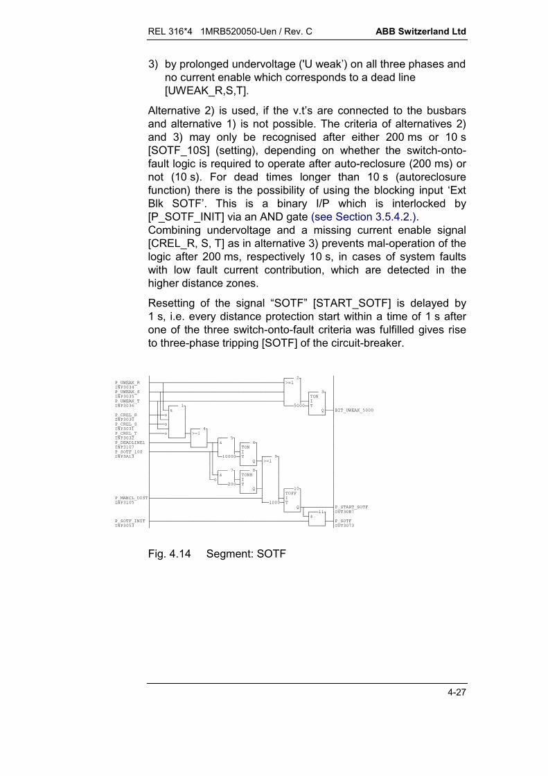
REL 316*4 1MRB520050-Uen / Rev. C ABB Switzerland Ltd
4-27
3) by prolonged undervoltage ('U weak’) on all three phases andno current enable which corresponds to a dead line[UWEAK_R,S,T].
Alternative 2) is used, if the v.t’s are connected to the busbarsand alternative 1) is not possible. The criteria of alternatives 2)and 3) may only be recognised after either 200 ms or 10 s[SOTF_10S] (setting), depending on whether the switch-onto-fault logic is required to operate after auto-reclosure (200 ms) ornot (10 s). For dead times longer than 10 s (autoreclosurefunction) there is the possibility of using the blocking input ‘ExtBlk SOTF’. This is a binary I/P which is interlocked by[P_SOTF_INIT] via an AND gate (see Section 3.5.4.2.).Combining undervoltage and a missing current enable signal[CREL_R, S, T] as in alternative 3) prevents mal-operation of thelogic after 200 ms, respectively 10 s, in cases of system faultswith low fault current contribution, which are detected in thehigher distance zones.
Resetting of the signal “SOTF” [START_SOTF] is delayed by1 s, i.e. every distance protection start within a time of 1 s afterone of the three switch-onto-fault criteria was fulfilled gives riseto three-phase tripping [SOTF] of the circuit-breaker.
2(%0 *!" 2(%0*, 2(%0*,, + 2(%0 (& ,,- (&,- (&-!" (%& (*+ #*, %/!"#+- $%& *% #+ #
Fig. 4.14 Segment: SOTF

ABB Switzerland Ltd REL 316*4 1MRB520050-Uen / Rev. C
4-28
4.2.1.5.4. Short-zone logic (STUB)
In 1½ breaker schemes, the short zone between the two circuit-breakers and the line isolator can be protected by the back-upovercurrent function by permitting its instantaneous pick-up sig-nal [OC_RST] to trip the circuit-breakers [TRIP_STUB] after25 ms whenever the line isolator is open (signal applied to theopto-coupler I/P “Isol open”).
This arrangement is only necessary, if the v.t’s are installed onthe line side of the isolator and the c.t’s are in the bars betweenthe circuit-breakers.
&(+
Fig. 4.15 Segment: STUB
4.2.1.5.5. Zone extension logic (ZE)
This logic enables the reach of the distance measurement to beswitched from the underreaching first zone to overreaching[BIT_TRIP_ZE] under the control of a signal from anotherfunction or an external signal.
Such a signal can originate, for example, from the internal auto-reclosure function (binary input “ZExtensionAR” [AR_ZE]) orfrom an opto-coupler input (binary input “ZExtension” [ZE_FOR_DIST]).
The internal auto-reclosure function issues an overreach signal[AR_ZE] when all the auto-reclosure conditions are fulfilled.
3( !" % 3(+/ $(% % %&&4 3(
Fig. 4.16 Segment: ZE

REL 316*4 1MRB520050-Uen / Rev. C ABB Switzerland Ltd
4-29
4.2.1.5.6. Transient blocking logic (Transbl)
This logic is only used in conjunction with a permissive over-reaching transfer tripping scheme (POTT) or an overreachingblocking scheme (BLOCK OR) on double-circuit lines with in-feeds from both ends and a high mutual zero-sequence imped-ance (both circuits on the same pylons). A blocking schemedoes not require this logic, providing the waiting time is set suf-ficiently long.
The logic solves the following problem:The problem (with POTT)
t = 0 s :
t = sign.rec.:
t = CB open :
Relays A1, B1 and B2detect the faultin the OR zoneand send a signalto the opposite station.Relay A2 detectsa backward fault.
A1
A2 B2
B1
A1
A2 B2
B1
Relays A1, B1 and A2receive a signal from the opposite station.
A1
A2 B2
B1
HEST 915 023 C
CB A1 opensbefore CB B1 opens.Relay A2 detects the fault in the OR zone,but still receivesa signal fromthe opposite station,e.g. it trips and opensthe “healthy” line.
Fig. 4.17 Transient blocking
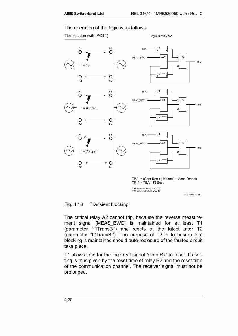
ABB Switzerland Ltd REL 316*4 1MRB520050-Uen / Rev. C
4-30
The operation of the logic is as follows:The solution (with POTT)
A1
A2 B2
B1
A1
A2 B2
B1
A1
A2 B2
B1
t = 0 s
t = sign.rec.
t = CB open
&
T1
T2 100ms
TBA
MEAS_BWD
TBE
&
T1
T2 100ms
TBA
MEAS_BWD
TBE
&
T1
T2 100ms
TBA
MEAS_BWD
TBE
Logic in relay A2
TBA = (Com Rec + Unblock) * Meas OreachTRIP = TBA * TBEnotTBE is active for at least T1.TBE resets at latest after T2.
HEST 915 024 FL
>=1
>=1
>=1
Fig. 4.18 Transient blocking
The critical relay A2 cannot trip, because the reverse measure-ment signal [MEAS_BWD] is maintained for at least T1(parameter “t1TransBl”) and resets at the latest after T2(parameter “t2TransBl”). The purpose of T2 is to ensure thatblocking is maintained should auto-reclosure of the faulted circuittake place.
T1 allows time for the incorrect signal “Com Rx” to reset. Its set-ting is thus given by the reset time of relay B2 and the reset timeof the communication channel. The receiver signal must not beprolonged.
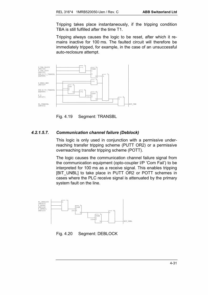
REL 316*4 1MRB520050-Uen / Rev. C ABB Switzerland Ltd
4-31
Tripping takes place instantaneously, if the tripping conditionTBA is still fulfilled after the time T1.
Tripping always causes the logic to be reset, after which it re-mains inactive for 100 ms. The faulted circuit will therefore beimmediately tripped, for example, in the case of an unsuccessfulauto-reclosure attempt.
%&0!"#% ##% %&#% -+!"$(%2, # % 2 %&,% !", #-*+.& %& (
Fig. 4.19 Segment: TRANSBL
4.2.1.5.7. Communication channel failure (Deblock)
This logic is only used in conjunction with a permissive under-reaching transfer tripping scheme (PUTT OR2) or a permissiveoverreaching transfer tripping scheme (POTT).
The logic causes the communication channel failure signal fromthe communication equipment (opto-coupler I/P ‘Com Fail’) to beinterpreted for 100 ms as a receive signal. This enables tripping[BIT_UNBL] to take place in PUTT OR2 or POTT schemes incases where the PLC receive signal is attenuated by the primarysystem fault on the line.
&&0+ ' (- '% & *+ - &
Fig. 4.20 Segment: DEBLOCK

ABB Switzerland Ltd REL 316*4 1MRB520050-Uen / Rev. C
4-32
4.2.1.5.8. Permissive underreaching transfer tripping (PUTT)
The PUTT logic is divided into a receive logic (segmentPUTTREC) and a transmit logic (segment PUTSEND).The O/P signals from the receive logic (PUTTREC) aretransferred to the transmit logic, while taking account of anyweak infeed (Weak) [UWEAK_R, S, T] and short-term enablesignals due to communication channel failure (Deblock)[BIT_UNBL].The tripping criterion is thus available for evaluation in conjunc-tion with the underimpedance starting characteristic (PUTTNONDIR) [PUTT_NONDIR], the starting characteristic in theforwards direction (PUTT FWD) [PUTT_FWD] or theoverreaching zone, respectively the 2nd. distance zone (PUTTOR2) [PUTT_OR2].The O/P signals from the transmit logic (PUTTSEND) arepassed on to the common transmit logic for PUTT, POTT andBLOCK OR schemes.The tripping (Trip) [TRIP_PUTT] and transmit (Tx) criteria[SEND_PUTT] can be seen from the following diagram.
A B C DE
t
t = Delay (1) TripSend
Trip (PUTT NONDIR)Trip (PUTT FWD)Trip (PUTT OR2)Send
TripSend
TripSend
TripSend
t = Com Rec :
t = Delay (Def) :
t = Delay (3) :
t = Delay (2) :
= 0 sec :
0 sec
= Meas Main= Meas Main
= Com Rec * (Start R+S+T + Weak)= Com Rec * Meas Fward= (Com Rec + Unblock) * Meas Oreach= Meas Main
= Meas Main= Meas Main
= Meas Main= "0"
= Start R+S+T (dir/nondir)= "0"
HEST 915 025 FL
Meas Main Meas Oreach
Com Rec
Delay (2)
Delay (3)
Delay (Def)
Meas Main
Meas Main
Meas BwardStart R+S+TWeak Infeed
Meas FwardStart R+S+TWeak Infeed
Fig. 4.21 PUTT NONDIR, PUTT FWD, PUTT OR2

REL 316*4 1MRB520050-Uen / Rev. C ABB Switzerland Ltd
4-33
& *+ % %&&,**!" &2,,,+ 3 2% ,,, ,& ,,+ #$(% ,,+ ',,!" $2,,*- &,,,!"' (,*,, ,,+&2(%0,,,*+ / ,*,- ,*,,2(%0 ,,,, ,,,- 2(%0*,,,,-*,2(%0 #+,-,,2(%0,,,,, ,,,-,,,,-*,,2(%0#+-2(%0,, --*,,,2(%0#!"*,2(%0#!" #
Fig. 4.22 Segment: PUTTREC
& !" &2 & * #+'- $(%$% % %&&( #
Fig. 4.23 Segment: PUTSEND

ABB Switzerland Ltd REL 316*4 1MRB520050-Uen / Rev. C
4-34
4.2.1.5.9. Permissive overreaching transfer tripping (POTT)
The POTT logic is divided into a receive logic (segmentPOTTREC) and a transmit logic (segment POTSEND).
The O/P signals from the receive logic (POTTREC) aretransferred to the transmit logic, while taking account of anyweak infeed (Weak) [UWEAK_R, S, T], short-term enablesignals due to communication channel failure (Deblock)[BIT_UNBL] and transient blocking (Transbl) [BIT_TBE].
The O/P signals from the transmit logic (POTTSEND) arepassed on to the common transmit logic for PUTT, POTT andBLOCK OR schemes, while taking account of the signal returnedfrom the remote end of the line in the case of a weak infeed(Echo).
The tripping (Trip) [TRIP_POTT] and transmit (Tx) criteria[SEND-POTT] can be seen from the following diagram.
A B C DE
t
t = Delay (1) TripSend
TripTrip WeakSendSend Echo
TripSend
TripSend
TripSend
t = Com Rec :
t = Delay (Def) :
t = Delay (3) :
t = Delay (2) :
= 0 sec := Meas Main= Meas Oreach * notTransbl
= (Com Rec + Unblock) * Meas Oreach * notTransbl= Com Rec * Weak * notMeas Bward * notMeas Oreach= Meas Oreach * notTransbl= Com Rec * notMeas Bward
= Meas Main= "0"
= Meas Main= "0"
= Start R+S+T (dir/nondir)= "0"
HEST 915 026 FL
0 sec Meas Main Meas Oreach
Com Rec
Delay (2)
Delay (3)
Delay (Def)
Meas Main
Meas Main
Meas BwardStart R+S+TWeak Infeed
Meas FwardStart R+S+TWeak Infeed
Fig. 4.24 POTT

REL 316*4 1MRB520050-Uen / Rev. C ABB Switzerland Ltd
4-35
$(% *+ &,!"' (,**% ##+ (,,-',,!" $2,,&('&+ (&0',,*- %$(%2,, #/,*-+2(%0 ,,,, ,*,# ,*,,-,,,-&2(%0*,,,, 2(%0*,,,,,-*,2(%0 #-+2(%0,,,,,, ,,,-,,,-,,,,,,,,,-*,,2(%0#-+2(%0,,,,, ---*,,,2(%0#!"*,2(%0#!" #
Fig. 4.25 Segment: POTTREC
&*4* #+$(% ,* (,,*-',,,*-!" -+,+-&('*,, !"$(%2,, #$2,, -' (*,, +(&0',,, %&('&,,,- #+* /-+(#
Fig. 4.26 Segment: POTSEND

ABB Switzerland Ltd REL 316*4 1MRB520050-Uen / Rev. C
4-36
4.2.1.5.10. Overreaching blocking scheme (BLOCK OR)
The BLOCK OR logic is divided into a receive logic (segmentBLOCREC) and a transmit logic (segment BLOSEND).
The O/P signals from the receive logic (BLOCREC) aretransferred to the transmit logic, while taking account of anytransient blocking due to reversal of energy direction (Transbl).
The O/P signals from the transmit logic are passed on to thecommon transmit logic for PUTT, POTT and BLOCK ORschemes.
The tripping (Trip) and transmit (Tx) criteria can be seen from thefollowing diagram.
A B C DE
t
t = Delay (1) TripSend
TripSend TripSend
TripSend
TripSend
t = t1Block :
t = Delay (Def) :
t = Delay (3) :
t = Delay (2) :
= 0 sec := Meas Main= Meas Bward
= Meas Oreach * notComRec * notTransbl= Meas Bward + Transbl = Meas Main= "0"
= Meas Main= "0"
= Start R+S+T (dir/nondir)= "0"
HEST 915 027 FL
0 sec Meas Main Meas Oreach
Com Rec
Delay (2)
Delay (3)
Delay (Def)
Meas Main
Meas Main
Meas BwardStart R+S+TWeak Infeed
Meas FwardStart R+S+TWeak Infeed
Fig. 4.27 BLOCK OR
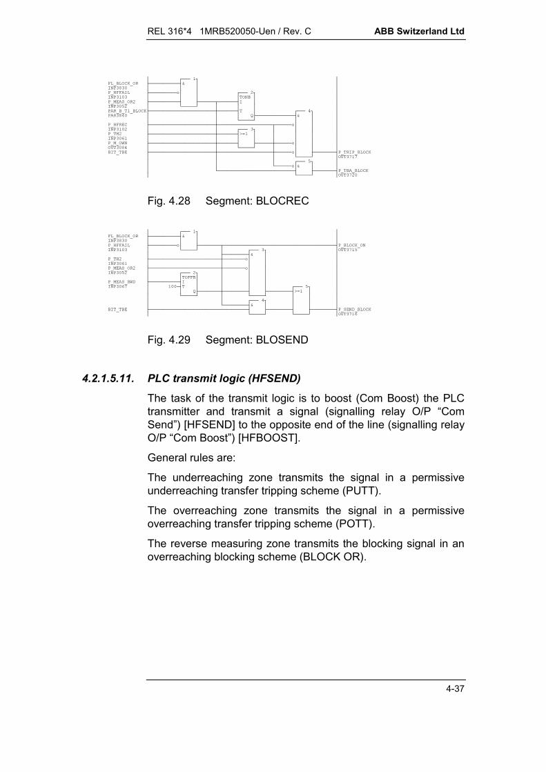
REL 316*4 1MRB520050-Uen / Rev. C ABB Switzerland Ltd
4-37
&&0 + '% &- $(% * % &0,% +' (,*- ',!" $2,,- (,,- &0##-+%&0#
Fig. 4.28 Segment: BLOCREC
&&0 + '% &-*&0 #+',- $(% ,- $(%2 #,!"+ ((&0#
Fig. 4.29 Segment: BLOSEND
4.2.1.5.11. PLC transmit logic (HFSEND)
The task of the transmit logic is to boost (Com Boost) the PLCtransmitter and transmit a signal (signalling relay O/P “ComSend”) [HFSEND] to the opposite end of the line (signalling relayO/P “Com Boost”) [HFBOOST].
General rules are:
The underreaching zone transmits the signal in a permissiveunderreaching transfer tripping scheme (PUTT).
The overreaching zone transmits the signal in a permissiveoverreaching transfer tripping scheme (POTT).
The reverse measuring zone transmits the blocking signal in anoverreaching blocking scheme (BLOCK OR).
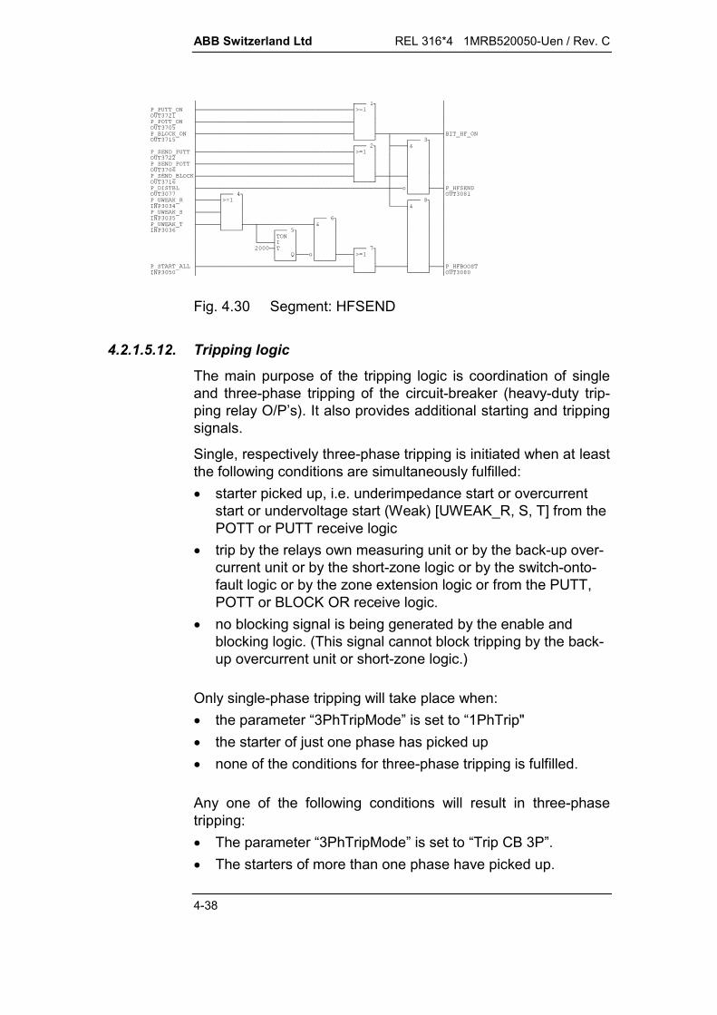
ABB Switzerland Ltd REL 316*4 1MRB520050-Uen / Rev. C
4-38
!"##&0* '#+(!"#(#(&0,# &,-'(##2(%0 !" +2(%0 2(%0*+ #-!"% %&&'
Fig. 4.30 Segment: HFSEND
4.2.1.5.12. Tripping logic
The main purpose of the tripping logic is coordination of singleand three-phase tripping of the circuit-breaker (heavy-duty trip-ping relay O/P’s). It also provides additional starting and trippingsignals.
Single, respectively three-phase tripping is initiated when at leastthe following conditions are simultaneously fulfilled: starter picked up, i.e. underimpedance start or overcurrent
start or undervoltage start (Weak) [UWEAK_R, S, T] from thePOTT or PUTT receive logic
trip by the relays own measuring unit or by the back-up over-current unit or by the short-zone logic or by the switch-onto-fault logic or by the zone extension logic or from the PUTT,POTT or BLOCK OR receive logic.
no blocking signal is being generated by the enable andblocking logic. (This signal cannot block tripping by the back-up overcurrent unit or short-zone logic.)
Only single-phase tripping will take place when: the parameter “3PhTripMode” is set to “1PhTrip" the starter of just one phase has picked up none of the conditions for three-phase tripping is fulfilled.
Any one of the following conditions will result in three-phasetripping: The parameter “3PhTripMode” is set to “Trip CB 3P”. The starters of more than one phase have picked up.

REL 316*4 1MRB520050-Uen / Rev. C ABB Switzerland Ltd
4-39
The auto-reclosure function has instructed the distance func-tion to trip all three-phases.
Either the back-up overcurrent function or the short-zonelogic has tripped.
operation of the switch-onto-fault logic A second trip occurs (e.g. evolving fault) during, for example,
the auto-reclosure dead time. The parameter “3PhTripMode” is set to “Trip CB 3P/Delay 3”
and the zone 3 time has expired (auto-reclosure in the 2nd.zone as well).
% !" 2(%0 #2(%0 * #% !" 2(%0#2(%0*, #+% !", 2(%0#2(%0*,,, ##,+!",,,,+ !" * /#+ **+# % 2 ,% *+,- !"+* .
Fig. 4.31 Segment: TRIP1
!"' ((' %% & - '+ '!" % # ' ((2(%0!"#2(%02 #
Fig. 4.32 Segment: TRIP2

ABB Switzerland Ltd REL 316*4 1MRB520050-Uen / Rev. C
4-40
!"#3( !" % 3(+/3((+ $(% % %&&4 *,*# $(%$% ,,* !"!"$2# #/ &0,,+##',,-**+ # ' ((,,,*!" ,,,,,*!"!"+ ,,,,,*,!"+ ,,,*,,##,-+/,- &,,,, ## # ' '((%&( '( ## % #
Fig. 4.33 Segment: TRIP3
*!"*,*,,* #+,,,,'+,-,,-!"-+,,,--+#-, '+ '#
Fig. 4.34 Segment: TRIP4

REL 316*4 1MRB520050-Uen / Rev. C ABB Switzerland Ltd
4-41
4.2.1.6. Power swing blocking (PSB)
The purpose of the power swing blocking function is to preventunwanted tripping of the distance protection function in responseto power system instability with oscillatory fluctuations of power(power swings) or loss of synchronism (out-of-step). The powerswing blocking function does not influence the operation of theback-up overcurrent function.
When power swings occur, the electrical parameters of the sys-tem vary at a slower or faster rate in relation to the angle be-tween the voltage vectors of the energy sources in different partsof the system. In the case of a fault on the other hand, stepchanges of these parameters take place. The parameters, whichregardless of location are subject to appreciable variation in thegeneral region around phase opposition ( = 180°), are the re-sistance R and the voltage component U . cos . The value of corresponds to the angle between phase voltage and current.
E1 U E2
U cos
U
IE1 E2
HEST 915 028 FL
E1 U E2
U
IE1 E2
Independent of: -Relay location -Relay characteristics -Relay settings
U cos
HEST 915 028 FL
U cos
U cos
Fig. 4.35 Power swing blocking
ABB Switzerland Ltd REL 316*4 1MRB520050-Uen / Rev. C
4-42
The voltage and current input variables are passed on to theevaluation system. The criterion for pick-up of the power swingblocking function is the continuous variation of (U . cos ), whichcorresponds to the variation of real power in relation to currentamplitude (P = I . U . cos ). The value of (U . cos ) isdetermined after every zero-crossing of the current. A blockingsignal is generated, as soon as a repetitive variation of the valueof (U . cos ) is detected, i.e. a variation must be detected atleast three times to count as a power swing.
Two periods are needed to detect the faster power swings up toa frequency of 8 Hz. The power swing blocking function does notpick up during a fault, because the variation of (U . cos ) inrelation to time only occurs once and at a much higher rate thanthe function’s operating range.
Slow swings are evaluated over five periods by a second sys-tem. At its lowest operating limit, this system detects a frequencyof 0.2 Hz.
Together the two systems cover a range from 0.2 to 8 Hz and nosetting is required during commissioning.
The blocking signal “PSB” is maintained for as long as the dis-tance protection function is in the picked-up state. The powerswing blocking function is only effective for the symmetricalthree-phase condition and cannot block the distance function forasymmetrical faults (E/F’s and phase-to-phase faults).
A blocking signal is not issued, if the zero-crossings of the cur-rent signal occur at relatively irregular intervals, because con-siderable differences between the zero-crossing intervals are aclear indication of a fault on the power system. Phase jumps inthe current wave form occur at the incidence of a fault, as aconsequence of incorrect switching and when c.t. saturationtakes place. Since the currents during power swings aresinusoidal and do not contain a DC component, it is permissibleto assume that the problem of c.t. saturation does not arise.Zero-crossings resulting from the slip are in any event excludedby the current enable setting of Imin.
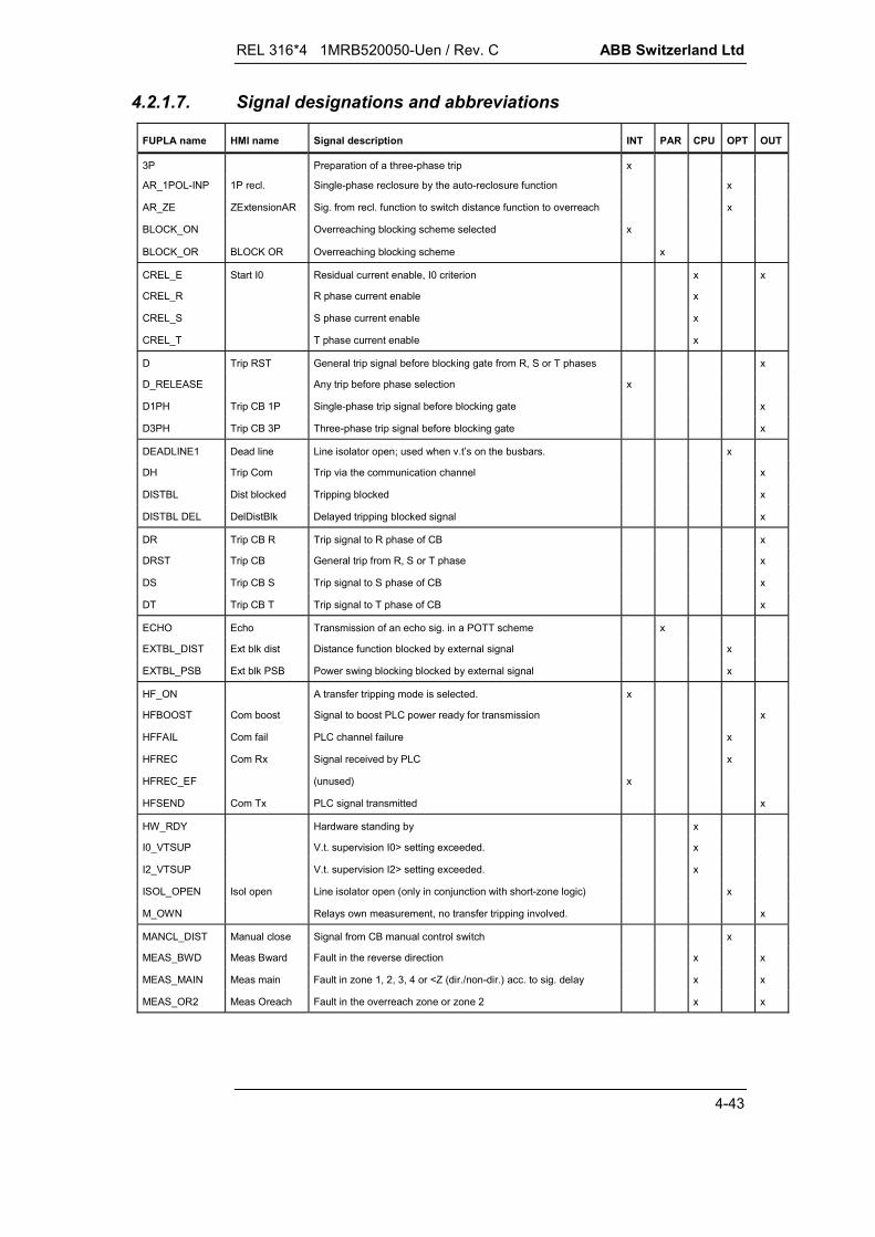
REL 316*4 1MRB520050-Uen / Rev. C ABB Switzerland Ltd
4-43
4.2.1.7. Signal designations and abbreviations
FUPLA name HMI name Signal description INT PAR CPU OPT OUT
3P Preparation of a three-phase trip x
AR_1POL-INP 1P recl. Single-phase reclosure by the auto-reclosure function x
AR_ZE ZExtensionAR Sig. from recl. function to switch distance function to overreach x
BLOCK_ON Overreaching blocking scheme selected x
BLOCK_OR BLOCK OR Overreaching blocking scheme x
CREL_E Start I0 Residual current enable, I0 criterion x x
CREL_R R phase current enable x
CREL_S S phase current enable x
CREL_T T phase current enable x
D Trip RST General trip signal before blocking gate from R, S or T phases x
D_RELEASE Any trip before phase selection x
D1PH Trip CB 1P Single-phase trip signal before blocking gate x
D3PH Trip CB 3P Three-phase trip signal before blocking gate x
DEADLINE1 Dead line Line isolator open; used when v.t’s on the busbars. x
DH Trip Com Trip via the communication channel x
DISTBL Dist blocked Tripping blocked x
DISTBL DEL DelDistBlk Delayed tripping blocked signal x
DR Trip CB R Trip signal to R phase of CB x
DRST Trip CB General trip from R, S or T phase x
DS Trip CB S Trip signal to S phase of CB x
DT Trip CB T Trip signal to T phase of CB x
ECHO Echo Transmission of an echo sig. in a POTT scheme x
EXTBL_DIST Ext blk dist Distance function blocked by external signal x
EXTBL_PSB Ext blk PSB Power swing blocking blocked by external signal x
HF_ON A transfer tripping mode is selected. x
HFBOOST Com boost Signal to boost PLC power ready for transmission x
HFFAIL Com fail PLC channel failure x
HFREC Com Rx Signal received by PLC x
HFREC_EF (unused) x
HFSEND Com Tx PLC signal transmitted x
HW_RDY Hardware standing by x
I0_VTSUP V.t. supervision I0> setting exceeded. x
I2_VTSUP V.t. supervision I2> setting exceeded. x
ISOL_OPEN Isol open Line isolator open (only in conjunction with short-zone logic) x
M_OWN Relays own measurement, no transfer tripping involved. x
MANCL_DIST Manual close Signal from CB manual control switch x
MEAS_BWD Meas Bward Fault in the reverse direction x x
MEAS_MAIN Meas main Fault in zone 1, 2, 3, 4 or <Z (dir./non-dir.) acc. to sig. delay x x
MEAS_OR2 Meas Oreach Fault in the overreach zone or zone 2 x x

ABB Switzerland Ltd REL 316*4 1MRB520050-Uen / Rev. C
4-44
FUPLA name HMI name Signal description INT PAR CPU OPT OUT
OC_D Trip O/C General O/C trip x x
OC_RST Start O/C General O/C start x x
ONE_CHL (not used) x
POTT POTT Permissive overreaching transfer tripping x
POTT_ON POTT scheme selected x
PSBLOCK Power swing Power swing function blocking signal x x
PUTT_FWD PUTT FWD PUTT for fowards only x
PUTT_NONDIR PUTT NONDIR PUTT for the entire underimpedance characteristic x
PUTT_ON A PUTT scheme is selected x
PUTT_OR2 PUTT OR2 PUTT only for overreach zone or zone 2 x
R Starting or Uweak phase selection sig. for R phase x
RELAY_RDY Relay ready Relay standing by. x
RST Start RST General start with Uweak active x
S Starting or Uweak phase selection sig. for S phase x
SEND_BLOCK Tx signal from BLOCK OR scheme x
SEND_POTT Tx signal from POTT scheme x
SEND_PUTT Tx signal from PUTT scheme x
SOTF Trip SOTF Switch-onto-fault condition fulfilled x
SOTF_10S SOTF10sec Switch-onto-fault condition fulfilled (after 10 s) x
SOTF_INIT Switch-onto-fault start x
ST1 Delay 1 Zone 1 time delay running x x
ST1FWD Zone 1 set for forwards measurement x
ST2 Delay 2 Zone 2 time delay running x x
ST2FWD Zone 2 set for forwards measurement x
ST3 Delay 3 Zone 3 time delay running x x
ST3FWD Zone 3 set for forwards measurement x
ST4 Delay 4 Zone 4 time delay running x x
ST4FWD Zone 4 set for forwards measurement x
START_ALL Start R+S+T General start with Uweak inactive x x
START_E Start E General E/F start with I0 and/or U0 x x
START_OC Start OC Overcurrent start x x
START_R Start R General start by R phase with Uweak inactive x x
START_S Start S General start by S phase with Uweak inactive x x
START_T Start T General start by T phase with Uweak inactive x x
START_U0 Start U0 Residual voltage start, U0 criterion x x
START_UZ Start UZ Underimpedance start x x
STDEF Delay def Lock-out timer running x x
STOR Overreach zone selected, i.e. T4<T2 x x

REL 316*4 1MRB520050-Uen / Rev. C ABB Switzerland Ltd
4-45
FUPLA name HMI name Signal description INT PAR CPU OPT OUT
T Starting or Uweak phase selection sig. for T phase x
T1_BLOCK t1Block Waiting time for HFREC, default 40 ms x
T1_TRANSBL t1TransBl Timer for monitoring the TBA signal, default 50 ms x
T1_TRIP t1EvolFaults Timer for detecting evolving faults, default 3000 ms x
T2_TRANSBL t2TransBl Max. duration of the TBE signal, default 3000 ms x
TBA_BLOCK BLOCK OR tripping condition fulfilled. x
TBA_POTT POTT tripping condition fulfilled. x
TBE Transient blocking logic selected. x
TH1 End of zone 1 time x
TH2 Delay >=2 End of zone 2 time x x
TH3 End of zone 3 time x
TH3P 3PhTripDel3 Three-phase trip after TH3 x
TH4 End of zone 4 time x
THDEF End of lock-out time x
THREE_PH_TRIP
3ph trip Always 3 phases tripped. x
TRANSBL TransBl Transient blocking logic x
TRIP_BLOCK Tripping signal from BLOCK OR scheme x
TRIP_POTT Tripping signal from PUTT scheme x
TRIP_PUTT Tripping signal from POTT scheme x
TRIP_STUB Trip Stub Tripping by short-zone logic x
TRIP_ZE Tripping by zone extension logic x
U0_VTSUP U0> setting exceeded. x
U2_VTSUP U2> setting exceeded. x
UNBL Deblocking selected. x
UNBLOCK Unblock PLC channel failure x
UWEAK_POTT "General Uweak condition fulfilled” from POTT x
UWEAK_PUTT "General Uweak condition fulfilled” from PUTT x
UWEAK_R Weak infeed in R phase x
UWEAK_S Weak infeed in S phase x
UWEAK_T Weak infeed in T phase x
UWEAKR_POTT
"Uweak condition fulfilled in R phase” from POTT x
UWEAKR_PUTT "Uweak condition fulfilled in R phase” from PUTT x
UWEAKS_POTT "Uweak condition fulfilled in S phase” from POTT x
UWEAKS_PUTT "Uweak condition fulfilled in S phase” from PUTT x
UWEAKT_POTT "Uweak condition fulfilled in T phase” from POTT x
UWEAKT_PUTT "Uweak condition fulfilled in T phase” from PUTT x
UZ_FORWARD Meas. Fward Fault in forwards direction x x
VT_FAIL VTSup V.t supervision operated. x
VTFAIL_DLY VTSup Delay Delayed VT_FAIL signal x
VTFAIL_IU0 V.t supervision using zero-sequence component x
VTFAIL_IU2 V.t supervision using negative-sequence component x

ABB Switzerland Ltd REL 316*4 1MRB520050-Uen / Rev. C
4-46
FUPLA name HMI name Signal description INT PAR CPU OPT OUT
WEAK Weak POTT/PUTT phase selection by weak infeed logic x
WI Weak Infeed Weak infeed condition fulfilled. x
ZE_FOR_DIST ZExtension Signal switching distance function to overreach x
INT: internal signal connecting two FUPLA segments
P_..........
BIT_........ (not contained in the above table)
PAR: Parameter or mode which can be set.
PAR_B_...... (short-time element, TONB: delayedpick-up,
TOFFB: delayedreset)
PAR_W_...... (long-time element, TON: delayedpick-up,
TOFF: delayedreset)
FL_......... (Flag, Mode)
CPU: Main processor signal
P_..........
OPT: Opto-coupler input
P_..........
OUT: Signal output which can be assigned to an output relay,LED, event recorder or disturbance recorder
P_..........
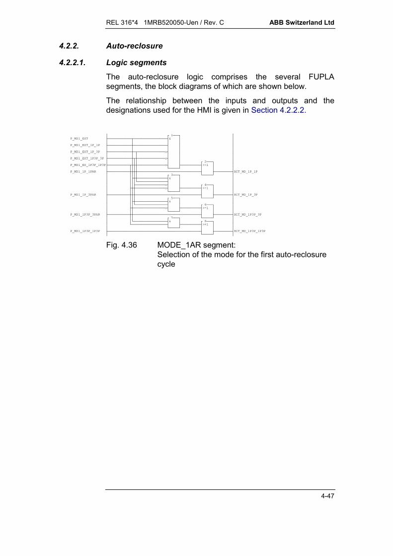
REL 316*4 1MRB520050-Uen / Rev. C ABB Switzerland Ltd
4-47
4.2.2. Auto-reclosure
4.2.2.1. Logic segments
The auto-reclosure logic comprises the several FUPLAsegments, the block diagrams of which are shown below.
The relationship between the inputs and outputs and thedesignations used for the HMI is given in Section 4.2.2.2.
$()*+$(),$(),*-$(),*,-$()*,,,-!"$% ,,,, $,,+-,,-!"$% ,,, $,+,-!"$% ,, $#+!"$ $
Fig. 4.36 MODE_1AR segment:Selection of the mode for the first auto-reclosurecycle

ABB Switzerland Ltd REL 316*4 1MRB520050-Uen / Rev. C
4-48
% % !"% % % % * % % + *-!" ,+ *,- ,,+/ *,,-*!"!",*% *,,-+ $,*,,!" $,,*,,,!"+,, ,,,,,*% ,*,,,,,,,* % ( ,,,,,-+!"#,!" $,,*,,,*,,,566678&8,9 :88;<=,>66666?,,,,,,,#,,,, % &0,,,,,,*,,,,!"+56667 $*,,,,8&8,,,,9 :8/8;<= !"!" >66666?% &-,,,!"&,,,,,&,,,,,* *,,, % (#,,,-+-+,!" ,, *,,, % (56667/8&8++9 :88;<=>66666?, % ,-$%(&,*-,* % +,56667,,,-8&8 (%,,,-9 :88;<= (%>66666?-+- $(( @A &0
Fig. 4.37 ARTRIP segment:Starting and tripping inputs, determination of theauto-reclosure mode, AR initiation and faultduration time
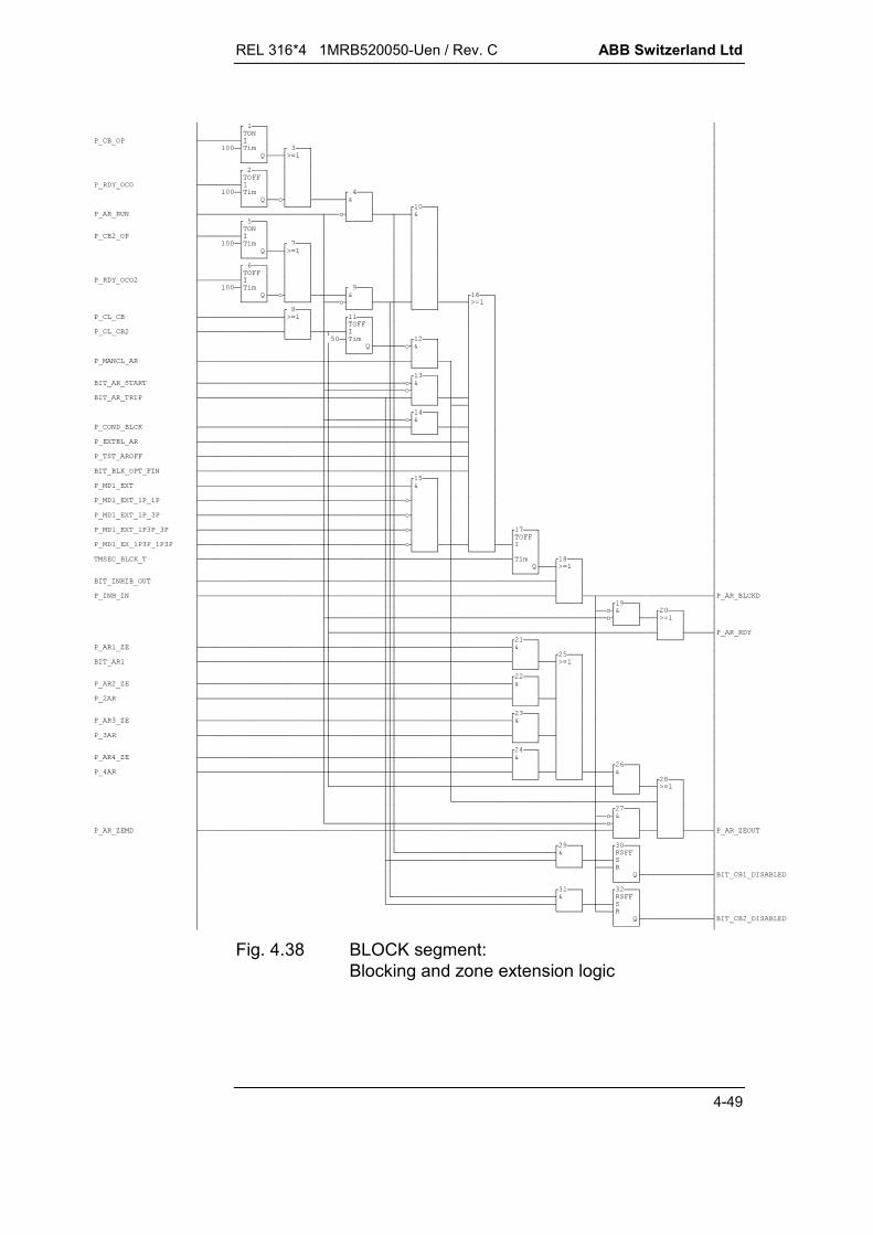
REL 316*4 1MRB520050-Uen / Rev. C ABB Switzerland Ltd
4-49
@A!" 1 @A-+% *-*+ @A#!" 1 @A/-,+-*,!"&!"&,* @A,,-+$%&% ,,,, % % ,,,,-+,,,- % ,,*,,,,,,,-+&0,,,,,,()&% ,,,,,,% ,,,,,, &0 ,,,,,,$(),,,,,+$(),,,,,-$(),,,,,-$(),,,,,-#$(),,,,,-, $(&0,,,,,,@A!" ' ,,,,,, ' ,,,,,,*% &0/-+,,,,,,-!",,,,,% 1% 3(,,,,,,+ % ,,,,,,!"% 3(,,,,,,+% ,,,,,,% 3(,,,,,,+% ,,,,,,% 3(,,,,,,+% ,,,,,,,+,,,,,!",#-+,,,,-% 3($,,,,% 3(/+ ,, %&(+ , %&(
Fig. 4.38 BLOCK segment:Blocking and zone extension logic

ABB Switzerland Ltd REL 316*4 1MRB520050-Uen / Rev. C
4-50
(%*+)- % * % ,*% ,*,% ,*,,% ,,,, % ,,,,% ,,,+% $,,,,,*!"% $,,,,,*,% $,,,,,*,,-!"+,,+,,#+,, &%% ,,,,,./% &0,,*%,,.+ % (*,*,,,,% $((%,,,@A,*-+#,,*!" -+, % (,,**,+, $((%,,,,,@A-*,,,!" $((%(),,,,,@A/,,,+#()(,,,,,,,,!" $((%,,,,,,,,@A-+ $((%,,,,,,,@A-+ $((%,,,,,,@A-+ (% $( ,,,,,@A*-+,!"/ ,, *-+566678&8,,9 :88;<=!">66666?,,,-+,,, $( ,,,@A# -+-%
Fig. 4.39 ARCOUNT segment:Auto-reclosure attempt counter

REL 316*4 1MRB520050-Uen / Rev. C ABB Switzerland Ltd
4-51
$%(&+% !" 2% (%*+ %&(,-* $( $(,,@A* 56667+8&8-*9 :8#8;<=+>66666? % ,,,* $1,++#-+ % (, % ,*,!"/+$1,,()1,,!"10,,+ 1,, (%&,,,,!"% &0,,* * $(&,,,,@A-&566678&89 :88;<=* &0>66666?-+--5/66678&89 :88;<=>66666?- (
Fig. 4.40 CLOSE1 segment:Close signal for the first circuit-breaker
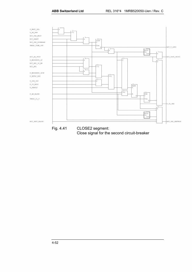
ABB Switzerland Ltd REL 316*4 1MRB520050-Uen / Rev. C
4-52
$%(&+% !" 2% (%*+ %&(,-* $( $(,,@A* 56667+8&8-*9 :8#8;<=+>66666? % ,,,* $1,++#-+ % (, % ,*,!"/+$1,,()1,,!"10,,+ 1,, (%&,,,,!"% &0,,* * $(&,,,,@A-&/-+-566678&89 :88;<=>66666?- &0- (
Fig. 4.41 CLOSE2 segment:Close signal for the second circuit-breaker

REL 316*4 1MRB520050-Uen / Rev. C ABB Switzerland Ltd
4-53
& @A*+ % , (%*,!"% &0*,,* * &% 56667#8&8-+9 :88;<=,+>66666?% ,,,*,,,,*,,,,,,- &-+/ - & @A+$%$((&&2
Fig. 4.42 SUCCES1 segment:Close supervision for the first circuit-breaker
& @A*+ % , (%*,!"% &0,,* * &% 56667#8&8-+9 :88;<=,+>66666?% ,,*,,,*,,,,,,- &-+/ - &
Fig. 4.43 SUCCES2 segment:Close supervision for the second circuit-breaker

ABB Switzerland Ltd REL 316*4 1MRB520050-Uen / Rev. C
4-54
$%$(*+ !" ( !" &% &0* #*+ ( !" &, *,!" %&(,,, &,*,,*,,,-!" %&(,,, &,,*,*,+,,,,-/ % ,,,,,*+ ,,,,,,- (%,,,,,*, % ( ,,,,,,, &% ,,,,,!" &% ,,,,,,,+ &%% ,,,,,,,,,,,,,+$,* @A,&0&2#!"$%,,,,,,,,*,,+$,,,,,,,, @A/-+( ,,+!"!",+,, $( ' ,,,@A,* ' + '-+ 1,,* ,,,,,- 2% #-+- ,- 2%
Fig. 4.44 DEFTRIP segment:Master/follower and duplex logic and definitiveTRIP signal

REL 316*4 1MRB520050-Uen / Rev. C ABB Switzerland Ltd
4-55
4.2.2.2. Signal designations
The relationship between the designations of the FUPLA inputand output signals and the parameter designations used in theHMI can be seen from the following tables. The tables do notshow the connections between the various segments.
Timer settings
FUPLA signal name HMI designation HMI setting
TMSEC_BLCK_T t AR Block 0.05 … 300
TMSEC_CL_T t Close 0.05 … 300
TMSEC_DEADT1_1P t Dead1 1P 0.05 … 300
TMSEC_DEADT1_3P t Dead1 3P 0.05 … 300
TMSEC_DEADT1_EXT t Dead1 Ext 0.05 … 300
TMSEC_DEADT2 t Dead2 0.05 … 300
TMSEC_DEADT3 t Dead3 0.05 … 300
TMSEC_DEADT4 t Dead4 0.05 … 300
TMSEC_DISCRT_1P t Discrim. 1P 0.10 … 300
TMSEC_DISCRT_3P t Discrim. 3P 0.10 … 300
TMSEC_INHIB_T t Inhibit 0.05 … 300
TMSEC_OPERT t Oper 0.05 … 300
TMSEC_TIME_OUT t Timeout 0.05 … 300
Binary inputs
FUPLA signal name HMI designation HMI setting
P_AR_MD2 2..4WE Modus 2 AR
P_AR_MD3 2..4WE Modus 3 AR
P_AR_MD4 2..4WE Modus 4 AR
P_AR_START Start -
P_AR_START_2 Start 2 -
P_AR_START_3 Start 3 -
P_AR_ZEMD ZE Prefault On
P_AR1_ZE ZE 1. AR On
P_AR2_ZE ZE 2. AR On
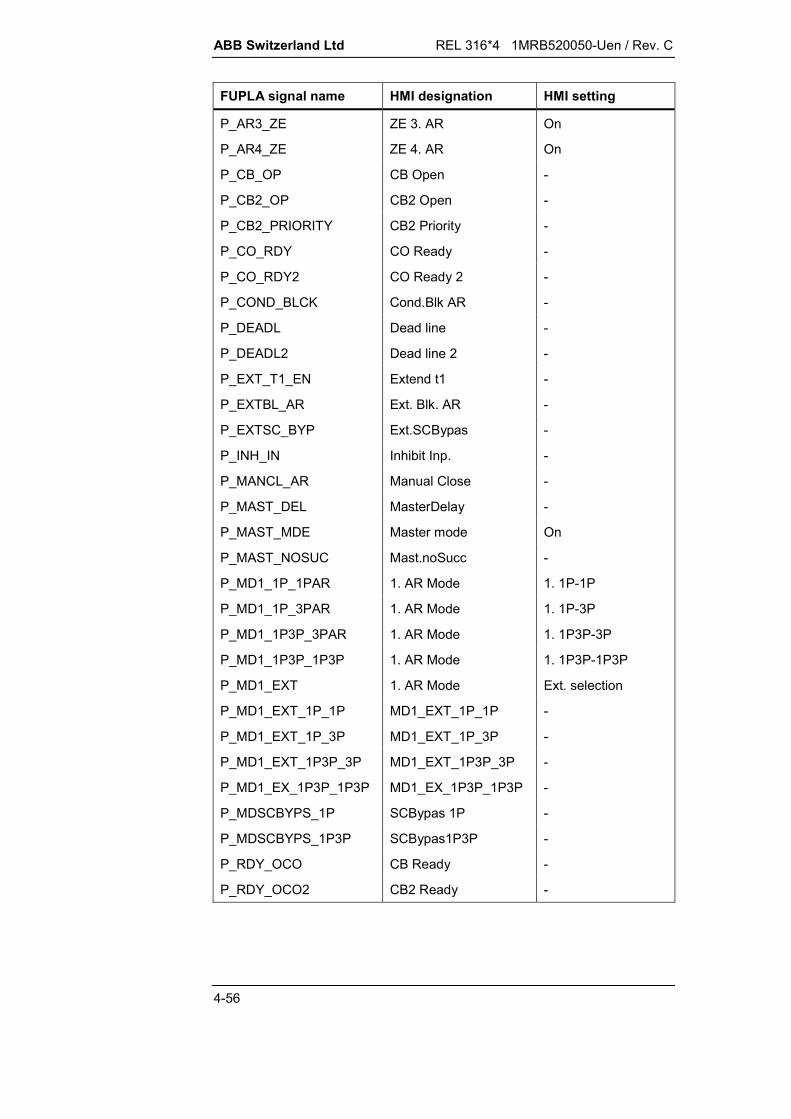
ABB Switzerland Ltd REL 316*4 1MRB520050-Uen / Rev. C
4-56
FUPLA signal name HMI designation HMI setting
P_AR3_ZE ZE 3. AR On
P_AR4_ZE ZE 4. AR On
P_CB_OP CB Open -
P_CB2_OP CB2 Open -
P_CB2_PRIORITY CB2 Priority -
P_CO_RDY CO Ready -
P_CO_RDY2 CO Ready 2 -
P_COND_BLCK Cond.Blk AR -
P_DEADL Dead line -
P_DEADL2 Dead line 2 -
P_EXT_T1_EN Extend t1 -
P_EXTBL_AR Ext. Blk. AR -
P_EXTSC_BYP Ext.SCBypas -
P_INH_IN Inhibit Inp. -
P_MANCL_AR Manual Close -
P_MAST_DEL MasterDelay -
P_MAST_MDE Master mode On
P_MAST_NOSUC Mast.noSucc -
P_MD1_1P_1PAR 1. AR Mode 1. 1P-1P
P_MD1_1P_3PAR 1. AR Mode 1. 1P-3P
P_MD1_1P3P_3PAR 1. AR Mode 1. 1P3P-3P
P_MD1_1P3P_1P3P 1. AR Mode 1. 1P3P-1P3P
P_MD1_EXT 1. AR Mode Ext. selection
P_MD1_EXT_1P_1P MD1_EXT_1P_1P -
P_MD1_EXT_1P_3P MD1_EXT_1P_3P -
P_MD1_EXT_1P3P_3P MD1_EXT_1P3P_3P -
P_MD1_EX_1P3P_1P3P MD1_EX_1P3P_1P3P -
P_MDSCBYPS_1P SCBypas 1P -
P_MDSCBYPS_1P3P SCBypas1P3P -
P_RDY_OCO CB Ready -
P_RDY_OCO2 CB2 Ready -

REL 316*4 1MRB520050-Uen / Rev. C ABB Switzerland Ltd
4-57
FUPLA signal name HMI designation HMI setting
P_SYN_CK SynchroChck -
P_SYN_CK2 SynchroChck2 -
P_TRIP Trip CB -
P_TRIP_2 Trip CB2 -
P_TRIP_3 Trip CB3 -
P_TRIP_3P Trip CB 3P -
P_TRIP_3P_2 Trip CB2 3P -
P_TRIP_3P_3 Trip CB3 3P -
Signal outputs
FUPLA signal name HMI designation
P_1AR_1P First AR 1P
P_1AR_3P First AR 3P
P_2AR Second AR
P_3AR Third AR
P_4AR Fourth AR
P_AR_3POL_OUT Trip 3-Pol.
P_AR_BLCKD AR Blocked
P_AR_RDY AR Ready
P_AR_RUN AR in Prog
P_AR_ZEOUT ZExtension.
P_BLCK_TO_FLW Blk.toFlwr.
P_CL_CB Close CB
P_CL_CB2 Close CB2
P_DEF_TRP Def. Trip
P_DEL_FLW DelayFlwr.
P_INH_OUT Inhibit Outp

ABB Switzerland Ltd REL 316*4 1MRB520050-Uen / Rev. C
4-58
4.2.3. Breaker failure protection
4.2.3.1. Introduction
This function provides backup protection to clear a fault afterbeing enabled by the unit protection for the case that the circuit-breaker (CB) should fail. It has to operate as quickly and reliablyas possible especially on EHV systems where stability is crucial.
To this end, current detectors continuously monitor the linecurrents and if they do not reset after a preset time, which allowsfor the operating times of the unit protection and the circuit-breaker, a tripping command is issued to either attempt to tripthe same circuit-breaker again or trip the surrounding circuit-breakers.
Resetting of current detectors is influenced by the followingfactors:
Even after the main CB contacts open, the current does notimmediately drop to zero, but to a level determined by thefault resistance and the resistance of the arc across the openCB contacts. The current only becomes zero after the de-ionisation time of the CB arc.
The pick-up setting of the detector.
The fault level prior to operation of the CB.
Whether the main c.t’s saturate. If a c.t. saturates, its secon-dary current may not pass through zero at the same time asits primary current and if the primary current is interrupted atzero, the c.t. flux may be at some positive or negative value.The secondary current therefore decays through the burdensof the relays thus increasing the reset time.
The resetting time varies typically between 20 and 30 ms.
Since for the above application, the current detectors shouldreset as quickly as possible, Fourier filter algorithms are includedto minimise the affect of c.t. saturation and eliminate completelyor substantially any DC offset.

REL 316*4 1MRB520050-Uen / Rev. C ABB Switzerland Ltd
4-59
The block diagram below shows the basic functions, which areexplained in the following Sections.
Ext Trip t2
Ext Trip EFP
Start Ext
CB On
CB Off
Unconditional logic
End Faultlogic
Retrip logic
Redundant logic
Back up logic
Remote logic
Currentdetectors
Start Lx
I
Red Trip Lx
Trip t1 Lx
Retrip t1
Remote Trip
Backup Trip t2
EFP Bus Trip
EFS Rem Trip
Uncon Trip t2
Uncon Trip t1
Ext Trip t1
Trip t2
Trip t1
HEST 005 045 C
1
1
1
Fig. 4.45 Block diagram
4.2.3.2. Three-phase/ single-phase mode
The function has three current detectors. When it is used in thethree-phase mode, each current detector measures the currentin each of the three phases.
In order to accommodate a fourth current detector measuring theneutral current, this function has to be duplicated and the secondfunction set to the single-phase mode and the appropriatecurrent pick-up. The two functions then operate in parallel .
This arrangement also covers the two special cases of phase-to-phase-to-ground and three-phase-to-ground faults.
4.2.3.3. ‘Redundant Trip’
The ‘Redundant Trip’ logic performs phase-segregated directtripping of the same circuit-breaker without any intentional timedelay, if the Start inputs are active and the corresponding currentdetectors have picked up. This ensures that the breaker receivesa tripping command in the event of a unit protection trip circuitfailure, which would otherwise cause a second attempt to trip thesame breaker or backup tripping of the surrounding breakers.
ABB Switzerland Ltd REL 316*4 1MRB520050-Uen / Rev. C
4-60
4.2.3.4. ‘Retrip’
The unit protection issues a trip command and simultaneouslystarts individual phases or all three phases of the breaker failfunction.
A second attempt is made to trip the corresponding phase orphases after the first time step (t1), providing the currentdetectors have not reset.
The ‘Retrip’ logic can be disabled if not required.
Separate timers for each phase ensure correct operation duringevolving faults.
4.2.3.5. ‘Backup Trip’
A second time step (t2) follows the first time step (t1) andinitiates backup tripping which is always of all three phases. Ifthe first time step is disabled, the second time step is startedimmediately, providing the current detectors have activated bythe starting signal from the protection.
The backup trip logic trips all surrounding breakers feeding thefault.
4.2.3.6. ‘Remote Trip’
The ‘Remote Trip’ logic trips the breaker at the remote end of theline.
Remote tripping can take place concurrently with the ‘Retrip’ or‘Backup’ functions or not at all as desired.
In contrast to the other tripping commands which remain activatefor a given period after the initiating signal has reset, the remotetripping signal is an impulse with a width which is adjustableirrespective of when the starting signal from the protectionresets.
4.2.3.7. ‘Unconditional Trip’
This feature was introduced to respond to low-level faults withcurrents too low for the current detectors to pick up or do notinitially cause any fault current at all such as mechanicalprotection devices like Buchholz, etc.
The start input bypasses the current detectors and activates thetime steps if the breaker is in the closed position. In all otherrespects, this logic is similar to the ‘Retrip’ and ‘Backup’ logics.
REL 316*4 1MRB520050-Uen / Rev. C ABB Switzerland Ltd
4-61
4.2.3.8. ‘End Fault Trip’
While in the case of a fault between a circuit-breaker and asingle set of c.t’s, the circuit-breaker may not fail, the affect onthe power system and the action that has to be taken are thesame as if the circuit-breaker had failed.
Where there is only a single set of c.t’s on the busbar side of acircuit-breaker, the zones of protection do not overlap and a faultbetween the circuit-breaker and the c.t’s is seen as a line fault,although it belongs to the busbar zone and persists after thecircuit-breaker has been tripped. The breaker failure protection’s‘End Fault Trip’ logic ultimately clears such faults at the end ofthe second time step.
This logic is enabled if the breaker is open and the currentdetectors are still picked up, indicating a fault between thebreaker and the c.t’s. The speed of tripping is determined by thetime delay setting.
Depending on whether the single set of c.t’s is on the line side orbus side of the circuit-breaker, either the section of busbar or thecircuit-breaker at the remote end of the line is tripped.
4.2.3.9. ‘External Trip’
This function has been included to make the breaker failprotection more user-friendly and reduce the amount of systemsengineering required. It generates an instantaneous trip wheneither of the following inputs is activated:
The input connected to the second time steps of otherbreaker fail protection devices in the station.
The input connected to the end fault outputs of other breakerfail protection devices in the station.

REL 316*4 1MRB520050-Uen / Rev. E ABB Switzerland Ltd
5-1
March 01
5. OPERATION (HMI)
5.1. Summary..................................................................................5-5
5.2. Installation and starting the operator program..........................5-65.2.1. PC requirements ......................................................................5-65.2.2. Installing the operator program ................................................5-65.2.3. Starting and shutting down the operator program....................5-9
5.3. Operation ...............................................................................5-115.3.1. General ..................................................................................5-115.3.2. Standard key functions applicable to all menus .....................5-115.3.3. Using the mouse ....................................................................5-125.3.4. Information displayed on the screen ......................................5-12
5.4. Main menu and sub-menus....................................................5-13
5.5. Editor .....................................................................................5-205.5.1. Present prot. funcs.................................................................5-215.5.1.1. Changing the settings of a function........................................5-235.5.1.2. Changing a function comment ...............................................5-235.5.1.3. Copying a function .................................................................5-255.5.1.4. Deleting a function .................................................................5-265.5.2. Adding a new function............................................................5-285.5.3. General information on editing parameters............................5-285.5.3.1. Entering numerical settings....................................................5-295.5.3.2. Selecting from a list of alternatives ........................................5-305.5.4. Explanation of the types of channels .....................................5-325.5.4.1. C.t./v.t. input channels ...........................................................5-325.5.4.2. Signalling channels ................................................................5-335.5.4.3. Tripping channels...................................................................5-395.5.4.4. Binary channels .....................................................................5-405.5.5. Editing hardware functions.....................................................5-475.5.5.1. Inserting a channel comment .................................................5-525.5.5.2. Analog (CT/VT) Channels ......................................................5-535.5.5.3. Excluding (masking) binary channels as events ....................5-545.5.5.4. Tripping and signalling channel latching ................................5-555.5.5.5. Definition of double signals ....................................................5-555.5.6. Editing system functions ........................................................5-585.5.7. Listing settings .......................................................................5-615.5.8. Saving the contents of the editor............................................5-625.5.8.1. Downloading to the device .....................................................5-63

ABB Switzerland Ltd REL 316*4 1MRB520050-Uen / Rev. E
5-2
5.5.8.2. Saving in and loading from a file ............................................5-63
5.6. Event handling and operation of thedisturbance recorder ..............................................................5-64
5.7. Displaying variables ...............................................................5-695.7.1. Displaying AD(CT/VT) channels ............................................5-695.7.2. Displaying load values ...........................................................5-705.7.3. Displaying binary inputs, signalling relays, LED’s or
tripping relays.........................................................................5-715.7.4. Displaying analogue inputs and outputs ................................5-715.7.5. Displaying ITL inputs and outputs ..........................................5-725.7.6. Displaying SCS outputs .........................................................5-735.7.7. Displaying FUPLA signals......................................................5-74
5.8. Diagnostics ............................................................................5-75
5.9. Test functions.........................................................................5-76
5.10. Documentation.......................................................................5-83
5.11. Operation with several sets of parameters.............................5-845.11.1. Switching sets of parameters .................................................5-845.11.2. Creating sets of parameters...................................................5-855.11.2.1. Assigning a protection function to a set of parameters ..........5-855.11.2.2. Copying a protection function with its settings .......................5-865.11.2.3. Displaying a function with its settings.....................................5-875.11.3. Logics.....................................................................................5-87
5.12. Remote HMI...........................................................................5-885.12.1. Summary................................................................................5-885.12.2. Modem requirements .............................................................5-885.12.3. Remote HMI shell ..................................................................5-895.12.3.1. Installation..............................................................................5-895.12.3.2. Configuring a new station.......................................................5-895.12.3.3. Establishing the connection to the station..............................5-945.12.4. Configuring a remote HMI for operation via the SPA-BUS
interface .................................................................................5-955.12.4.1. Remote HMI connected directly to the electro-optical
converter ................................................................................5-955.12.4.2. Remote HMI connected via a modem to the electro-optical
converter ................................................................................5-965.12.5. Configuring a remote HMI connected to an SRIO..................5-975.12.5.1. Remote HMI connected directly to the SRIO .........................5-975.12.5.2. Remote HMI connected via a modem to the SRIO ................5-985.12.6. Local control of a device via the interface at the front ............5-995.12.6.1. Remote HMI right of access to device functions ....................5-995.12.7. Control via an SPA-BUS or an SRIO .....................................5-995.12.7.1. HMI start-up .........................................................................5-100

REL 316*4 1MRB520050-Uen / Rev. E ABB Switzerland Ltd
5-3
5.12.7.2. SPAComm window ..............................................................5-1015.12.8. SRIO settings.......................................................................5-102
5.13. Local display unit .................................................................5-1035.13.1. Summary..............................................................................5-1035.13.2. Limitations............................................................................5-1035.13.3. General description..............................................................5-1035.13.3.1. Mechanical assembly and front view....................................5-1035.13.3.2. Electrical connections ..........................................................5-1045.13.3.3. Password .............................................................................5-1045.13.3.4. Passive operation ................................................................5-1045.13.3.5. LDU keypad .........................................................................5-1055.13.4. The three status LED’s ........................................................5-1065.13.4.1. General ................................................................................5-1065.13.4.2. Starting RE.316*4 ................................................................5-1065.13.4.3. No active protection functions ..............................................5-1075.13.4.4. Normal operation .................................................................5-1075.13.4.5. Pick-up of a protection function (General start)....................5-1075.13.4.6. Protection function trip (General Trip) ..................................5-1075.13.4.7. Fatal device error .................................................................5-1085.13.5. Text display (LCD) ...............................................................5-1085.13.5.1. General ................................................................................5-1085.13.5.2. Language.............................................................................5-1085.13.5.3. Interdependencies ...............................................................5-1085.13.5.4. Configuration........................................................................5-1095.13.6. Menu structure .....................................................................5-1095.13.7. Entry menu...........................................................................5-1115.13.8. Main menu ...........................................................................5-1115.13.8.1. Measurands .........................................................................5-1125.13.8.1.1. AD-Channels........................................................................5-1135.13.8.1.2. Load values..........................................................................5-1145.13.8.1.3. Binary signals.......................................................................5-1155.13.8.2. Event list ..............................................................................5-1185.13.8.3. User’s guide .........................................................................5-1185.13.8.4. Disturbance recorder list ......................................................5-1195.13.8.5. Diagnostics menu ................................................................5-1195.13.8.5.1. Diagnosis information ..........................................................5-1195.13.8.5.2. IBB status information..........................................................5-1205.13.8.5.3. Process bus information ......................................................5-1205.13.8.5.4. LED descriptions..................................................................5-1215.13.8.6. RESET menu .......................................................................5-1225.13.9. Automatic display.................................................................5-1235.13.9.1. General description..............................................................5-1235.13.9.2. Automatic display sequence ................................................5-1235.13.9.3. Stopping the automatic display routine ................................5-1235.13.9.4. Automatic display cycle........................................................5-123

ABB Switzerland Ltd REL 316*4 1MRB520050-Uen / Rev. E
5-4
5.14. SMS010 ...............................................................................5-1245.14.1. Installing SMS010 and ‘Reporting’ and ‘SM/RE.316*4’ for
SMS010 ...............................................................................5-1245.14.2. SMS010 Editor.....................................................................5-1255.14.2.1. Main menu ...........................................................................5-1255.14.3. Sub-menu ‘SMS010 editor’ ..................................................5-1265.14.4. Descriptions of the various menu items ...............................5-1275.14.4.1. Menu item ‘Edit Event. Dsc’ for processing Event.DSC .......5-1275.14.4.2. Menu item ‘Edit Logging. Dsc’ for processing Logging.DSC....5-1295.14.4.3. Menu item ‘Create New DSC Files’......................................5-1305.14.5. Creating a station after installing SMS010 ...........................5-1315.14.5.1. Creating the application structure ........................................5-1315.14.5.2. Updating the Spin.CNF file...................................................5-1355.14.5.3. Creating a report station ......................................................5-1375.14.5.4. Entering the SRIO address for ‘Reporting’ ...........................5-138

REL 316*4 1MRB520050-Uen / Rev. E ABB Switzerland Ltd
5-5
5. OPERATION (HMI)
5.1. Summary
The user shell for the RE. 316*4 has been designed to be largelyself-sufficient and requires a minimum of reference to the man-ual. This approach achieves a number of advantages:
functions selected from extremely user-friendly menus withfull screen displays and a combination of overlapping win-dows.
‘pop-up’ prompts wherever practical to guide the user andavoid errors.
provision for creating, editing and checking sets of parame-ters off-line, i.e. without being connected to the protectionequipment.
provision for transferring sets of parameters to and from files.
self-explanatory texts using a minimum of codes.
provision for the user to enter his own descriptions of func-tions, inputs and outputs.

ABB Switzerland Ltd REL 316*4 1MRB520050-Uen / Rev. E
5-6
5.2. Installation and starting the operator program
5.2.1. PC requirements
The HMI for the RE. 316*4 runs in the protected mode. Theminimum requirements for the PC are 16 MB of RAM, 12 MB freehard disc space and an operating system MS Windows 3.x,Windows 95 or Windows NT4.0 or higher. A 486 series proces-sor or higher is recommended.
The HMI communicates with the RE. 316*4 at a baud rate of9600 Baud. A problem can be encountered with some PC’s if thememory manager EMM386 is active.
Temporarily disable the EMM386 memory manager by entering‘REM’ at the beginning of the corresponding line in the ‘con-fig.sys’ file:
REM DEVICE=..........\EMM386........
Disabling the EMM386 memory manager is recommended. Theconsequence is less PC main memory below 640 kB, becausethe device drivers are loaded there instead of in the upper mem-ory range. This, however, has no influence on the operation ofthe HMI.
5.2.2. Installing the operator program
We recommend the strict observation of the following points be-fore installing the software on a your hard disc:
1. Ensure that your original floppy discs are write-protected.
2. Make backup copies of the original discs. Store the originalprogram discs in a safe place and use the copies to install theprogram.
The program is located on the floppy discs labelled “RE.316*4Software” in compressed form. There is also an installation pro-gram on the disc to simplify the installation program.
Installation on a hard disc under Windows 3.1 / 3.11:
1. Insert the first disc “Disk 1/4” into drive A.
2. Select ‘Run’ in the ‘File’ menu and enter ‘a:\setup’ in the win-dow that opens.
REL 316*4 1MRB520050-Uen / Rev. E ABB Switzerland Ltd
5-7
Installation on a hard disc under Windows 95 / NT 4.0:
1. Insert the first disc “Disk 1/4” into drive A.
2. Click on ‘Start’ on the task bar at the bottom of the screen.Select ‘Run’ in the menu that then opens and enter ‘a:\setup’.
Simply follow the instructions on the screen for the remainder ofthe procedure. The installation of the remote HMI shell is op-tional. Respond appropriately to the requests for language, drive,directory and program group.
HMI files and configuration
After installation, the following files amongst others are in theHMI directory:
pcgc91.exe: operator program.
re*.cfg: configuration file.
readme.e: text file with explanations of the in-stallation procedure and the latestinformation about new SW ver-sions.
diststd.bin: distance protection function logic.
aurestd.bin: auto-reclosure function logic.
Sub-directory VDEW6: VDEW6 function logic.
Before the operator program can be executed, the device driver“ansi.sys” has to be loaded. The installation program automati-cally modifies the configuration files for the operating system.
DOS, Windows 3.x:
In the file C:\CONFIG.SYS:device=c:\dos\ansi.sys.
Windows 95:
In the file C:\CONFIG.W40:device=c:\win95\command\ansi.sys
Windows NT 4.0:
In the file C:\WINNT\SYSTEM32\CONFIG.NT:device=%SystemRoot%\system32\ansi.sys
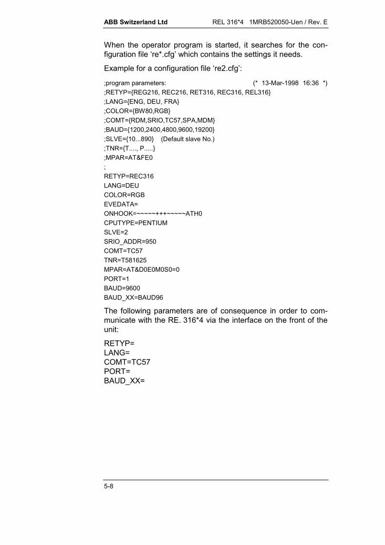
ABB Switzerland Ltd REL 316*4 1MRB520050-Uen / Rev. E
5-8
When the operator program is started, it searches for the con-figuration file ‘re*.cfg’ which contains the settings it needs.
Example for a configuration file ‘re2.cfg’:
;program parameters: (* 13-Mar-1998 16:36 *);RETYP=REG216, REC216, RET316, REC316, REL316;LANG=ENG, DEU, FRA;COLOR=BW80,RGB;COMT=RDM,SRIO,TC57,SPA,MDM;BAUD=1200,2400,4800,9600,19200;SLVE=10...890 (Default slave No.);TNR=T...., P.....;MPAR=AT&FE0;RETYP=REC316LANG=DEUCOLOR=RGBEVEDATA=ONHOOK=~~~~~+++~~~~~ATH0CPUTYPE=PENTIUMSLVE=2SRIO_ADDR=950COMT=TC57TNR=T581625MPAR=AT&D0E0M0S0=0PORT=1BAUD=9600BAUD_XX=BAUD96
The following parameters are of consequence in order to com-municate with the RE. 316*4 via the interface on the front of theunit:
RETYP=LANG=COMT=TC57PORT=BAUD_XX=
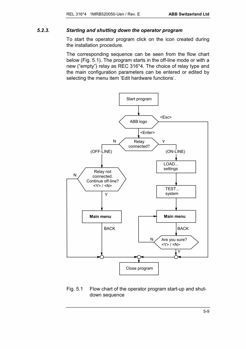
REL 316*4 1MRB520050-Uen / Rev. E ABB Switzerland Ltd
5-9
5.2.3. Starting and shutting down the operator program
To start the operator program click on the icon created duringthe installation procedure.
The corresponding sequence can be seen from the flow chartbelow (Fig. 5.1). The program starts in the off-line mode or with anew (“empty”) relay as REC 316*4. The choice of relay type andthe main configuration parameters can be entered or edited byselecting the menu item ‘Edit hardware functions’.
Start program
Relayconnected?
Relay notconnected.
Continue off-line?<Y> / <N>
LOAD...settings
TEST...system
Main menuMain menu
Are you sure?<Y> / <N>
(ON-LINE)(OFF-LINE)
Close program
ABB logo
Y
Y
Y
N
N
N
BACKBACK
<Enter>
<Esc>
Fig. 5.1 Flow chart of the operator program start-up and shut-down sequence

ABB Switzerland Ltd REL 316*4 1MRB520050-Uen / Rev. E
5-10
Note:
If the system is required to operate on-line to exchange databetween the PC and the RE. 316*4, the two must be connectedby a serial data cable. The cable connects the serial port COM 1or COM 2 on the PC to the optical connector on the front of theRE. 316*4. The protection must be in operation, i.e. the greenstand-by LED must be lit or flashing.
Units that are not synchronised by the station control system viathe interbay bus adopt the PC time when the HMI is started.

REL 316*4 1MRB520050-Uen / Rev. E ABB Switzerland Ltd
5-11
5.3. Operation
5.3.1. General
The HMI can be in one of four modes:
Menu: waiting for the user to select a menu item.
Operation: waiting for the user to enter data, e.g. parame-ter settings, confirmation of prompts, passwordetc.
Output: display of measured variables, event lists etc.These windows are closed by pressing <En-ter>.
Wait: while the program executes a command (key-board disabled). This can occur in any of theabove modes.
A menu presents the user with a list of functions to choose from.A menu item is selected by moving the selection bar up or downusing the up and down arrow keys and then pressing <Enter>.
As the user moves down the menu structure, the menus overlapeach other on the screen. The whole screen is used to displaydata. Auxiliary menus and messages are displayed in pop-upwindows and editing functions uses a combination of windowsand full screen.
5.3.2. Standard key functions applicable to all menus
Except while setting parameters, responding to prompts andexecuting special functions, the user is always confronted by amenu, from which a menu item or line normally has to be se-lected. The following keys perform the same functions for allmenus:
<> Previous line
<> Next line
<PgUp> Scroll up
<PgDn> Scroll down
<Home> Go to the beginning of the menu
<End> Go to the end of the menu
<Enter> Execute the operation described by the line
<Esc> Back to the previous window.
ABB Switzerland Ltd REL 316*4 1MRB520050-Uen / Rev. E
5-12
5.3.3. Using the mouse
Menus can be opened and closed and menu items selected us-ing the mouse instead of the keyboard. The mouse and themouse buttons are equivalent to the following keys:
Arrow keys Movement of the mouse.
<Enter> Left mouse button
<Insert> Right mouse button.
5.3.4. Information displayed on the screen
The following information is displayed at the bottom of thescreen:
Status of the connection to the RE. 316*4:“On-line” or “Off-line”.
Interface baud rate:“4800 bps”, “9600 bps” or “19200 bps”.
Active protocol for communication with the station controlsystem (SCS):“SCS:SPA” or “SCS:VDEW” or “SCS:LON” or “SCS:MVB”.
Software version:The version of the operator program is on the left and that ofthe device software on the right.
An activity indicator is located between the two version num-bers. A rotating dash indicates that the operator program iscommunicating with the device.

REL 316*4 1MRB520050-Uen / Rev. E ABB Switzerland Ltd
5-13
5.4. Main menu and sub-menus
The main menu gives the user the choice of performing one ofthe following operations:
1. Editor loads the editor and enables all theprotection and system functions tobe listed, changed and saved.
2. Event handling lists all the events in the eventmemory and enables the events tobe deleted.
3. Measurements displays protection variables in-cluding the A/D converter inputs.
4. Test functions checks the protection functions inthe various sets of parameters andthe operation of the LED signals,tripping relays and signalling re-lays.
5. Diagnostics provides fault-finding informationfor the protection system.
6. SMS010 editor enables events and measuredvariables to be configured for proc-essing by SMS010.
7. Documentation the device configuration can be canbe exported as a text file for usewhen engineering the SCS.
8. RETURN closes the operator program.
All the above options are available when the PC is connectedon-line, but only 1, 6, 7 and 8 when it is off-line.
Note:
With the exception of the editor, all the menu items are only rele-vant when the PC is connected on-line to the protection equip-ment, e.g. for transferring data. All printed and displayed dataare identical to those loaded in the protection and not related tothose being processed using the editor.

ABB Switzerland Ltd REL 316*4 1MRB520050-Uen / Rev. E
5-14
Editor
(b)
Event handling
(c)
(d)
(e)
(f)
(g)
Measurement values
Test functions
Diagnostics
ENTER PASSWORD
(i)
Documentation
Main menu
(a)
SMS010 Editor
(h)
Fig. 5.2 Main and sub-menu structure(see displays a to i on the following pages)
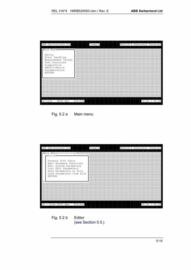
REL 316*4 1MRB520050-Uen / Rev. E ABB Switzerland Ltd
5-15
!!!!!!!!!!!"########################################################$$########################################################$$########################################################$%& '$########################################################$ ( ) ($########################################################$(* +($########################################################$, '(+($########################################################$--.$########################################################$,+ $########################################################$/0$########################################################$$########################################################1!!!!!!!!!!!!!!!!!!!!2##########################################################################################################################################################################################################################################################################################################################################################################################################################################################################################################################################################################################################################3.4--5(678)9:5;)9:5
Fig. 5.2 a Main menu
< ===========>########################################################?!!!!!!!!!!!!!!!!!!!!!"###############################################?$$###############################################?$8(8* +($###############################################?$& * +($###############################################?$@(8 ($###############################################?$(8 ($###############################################?$ %8 (*$###############################################?$ 8 (A*$###############################################?$/0$###############################################?$$###############################################B=1!!!!!!!!!!!!!!!!!!!!!!!!!!!2#################################################################################################################################################################################################################################################################################################################################################################################################################################################################################################################################################################################################################3.4--5(678)9:5;)9:5
Fig. 5.2 b Editor(see Section 5.5.)

ABB Switzerland Ltd REL 316*4 1MRB520050-Uen / Rev. E
5-16
< ===========>########################################################?%& '!!!!!!!!!!"##################################################?$$##################################################?$,( @+ %($##################################################?$(%($##################################################?$6 %($##################################################?$6 +C ($##################################################?$,( 5 ++$##################################################?$/0$##################################################?$$##################################################?1!!!!!!!!!!!!!!!!!!!!!!!!2##################################################B====================D##########################################################################################################################################################################################################################################################################################################################################################################################################################################################################################################################################################################################################################3.4--5(678)9:5;)9:5
Fig. 5.2 c Event handling(see Section 5.6.)
< ( ) (!!!!!!!!!!!!!"#########################################?$$#########################################?$,( @,E6F)G6C ($#########################################?%$,( @* + ( ($#########################################?$,( @ @H ($#########################################?$,( @' 3 ($#########################################?,$,( @3 ($#########################################?$,( @,3 ($#########################################?,$,( @ ' H ($#########################################?$,( @ ' 3 ($#########################################?$,( @H ($#########################################?$,( @3 ($#########################################B===$,( @HIH ($#############################################$,( @HI3 ($#############################################$,( @6I3 ($#############################################$,( @*/8' ($#############################################$/0$#############################################$$#############################################1!!!!!!!!!!!!!!!!!!!!!!!!!!!!!!!2#########################################3.4--5(678)9:5;)9:5
Fig. 5.2 d Measurement values(see Section 5.7.)

REL 316*4 1MRB520050-Uen / Rev. E ABB Switzerland Ltd
5-17
< ===========>########################################################??########################################################??########################################################?%& '?########################################################? ( ) (?#######!!!!!!!!!!!!!!!!"###############################?(* +(?#######$08J3,$###############################?, '(+(?#######$K$###############################?--.?#######$$###############################?,+ ?#######1!!!!!!!!!!!!!!!!2###############################?/0?########################################################??########################################################B====================D##########################################################################################################################################################################################################################################################################################################################################################################################################################################################################################################################################################################################################################3.4--5(678)9:5;)9:5
Fig. 5.2 e ENTER PASSWORD
< ===========>########################################################?(* +(!!!!!!!!!"###################################################?$$###################################################?$( $###################################################?$8A(+($###################################################?$%& '$###################################################?$ ( ) ($###################################################?$(, 'HA$###################################################?$8 (.+C'$###################################################?$+LJ$###################################################?$''J$###################################################B=$/+LJ$#####################################################$/0$#####################################################$$#####################################################1!!!!!!!!!!!!!!!!!!!!!!!2###########################################################################################################################################################################################################################################################################################################################################################################3.4--5(678)9:5;)9:5
Fig. 5.2 f Test functions(see Section 5.9.)
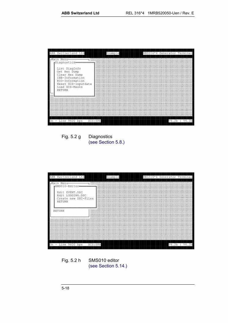
ABB Switzerland Ltd REL 316*4 1MRB520050-Uen / Rev. E
5-18
< ===========>########################################################?, '(+(!!!!!!!!!!"#####################################################?$$#####################################################?$(, 'HA$#####################################################?$&, $#####################################################?$6 &, $#####################################################?$H.HA $#####################################################?$H3.HA $#####################################################?$(6.H $#####################################################?$ 6. (L($#####################################################?$/0$#####################################################B=$$#######################################################1!!!!!!!!!!!!!!!!!!!!!2#########################################################################################################################################################################################################################################################################################################################################################################################################################################################################################################################################3.4--5(678)9:5;)9:5
Fig. 5.2 g Diagnostics(see Section 5.8.)
< ===========>########################################################?--.!!!!!!!!!"####################################################?$$####################################################?$)09,6$####################################################?$3H09,6$####################################################?$6 ,6.*($####################################################?$/0$####################################################?$$####################################################?1!!!!!!!!!!!!!!!!!!!!!!2####################################################?/0?########################################################??########################################################B====================D##########################################################################################################################################################################################################################################################################################################################################################################################################################################################################################################################################################################################################################3.4--5(678)9:5;)9:5
Fig. 5.2 h SMS010 editor(see Section 5.14.)

REL 316*4 1MRB520050-Uen / Rev. E ABB Switzerland Ltd
5-19
< ===========>########################################################??########################################################??########################################################?%& '?########################################################? ( ) (?#######!!!!!!!!!!!!!!!!"###############################?(* +(?#######$:9H$###############################?, '(+(?#######$ $###############################?--.?#######$$###############################?,+ ?#######1!!!!!!!!!!!!!!!!2###############################?/0?########################################################??########################################################B====================D##########################################################################################################################################################################################################################################################################################################################################################################################################################################################################################################################################################################################################################3.4--5(678)9:5;)9:5
Fig. 5.2 i Documentation(see Section 5.10.)

ABB Switzerland Ltd REL 316*4 1MRB520050-Uen / Rev. E
5-20
5.5. Editor
Edited data are stored in a separate buffer memory and nothingis changed in the protection until the save routine is executed.Thus a complete set of parameters can be created off-line with-out the PC being connected to the device. The only differencebetween off-line and on-line editing is that in the on-line mode,the user starts with copy of the current parameters and settingsdownloaded from the device. The “Editor” menu provides thefollowing options:
1. “Present prot. funcs”:Edit, copy or delete a currently active function in the system orinsert a new function.
2. “Edit hardware functions”:Edit parameters which effect the device hardware, e.g. con-figuration, analogue, binary, tripping and signalling channelsand the OBI configuration.
3. “Edit system parameters”:Edit parameters not connected with functions.
4. “List edit parameters”:A list of the settings can be displayed on the screen, saved ina file or printed on a printer connected to the parallel port ofthe PC.
5. “Save parameters to file”:Saves the complete set of parameters (entire contents of theeditor buffer) in a file.
6. “Load parameters from file”:Reverse operation of 5. A previously saved set of data isloaded from a file to the editor.
7. “RETURN”:Saves the edited set of parameters and returns the user to themain menu.

REL 316*4 1MRB520050-Uen / Rev. E ABB Switzerland Ltd
5-21
5.5.1. Present prot. funcs.
The settings and name of every active function can be changedor the function can be copied or deleted. The procedure is givenin Fig. 5.3.
Present prot. func.
(a)
Run function option
Edit function parameters
(c)
Edit function comment
(d)(b)
Present prot. func.
(e)
Edit function parameters
(f)
Are you sure?<N> / <Y>(g)
NO CHANGES SAVEDTO RELAY
(h)
Present prot. func.
(i)
N
Y
Fig. 5.3 Editing an active protection function(see displays a to i on the following pages)

ABB Switzerland Ltd REL 316*4 1MRB520050-Uen / Rev. E
5-22
< ===========>########################################################?<=====================>###############################################??8(8* +(!!!!!!!!!!!"###########################################??$$###########################################??$M---F--N6 .,$###########################################??$:M---F--N) '.,$###########################################??$M---F--N8$###########################################??$M---F--N) '.,$###########################################??$OM---F--N,( 5 ++$###########################################??$M---F--N*P +@$###########################################??$QH(* +$###########################################B=B=$/0$###############################################$$###############################################1!!!!!!!!!!!!!!!!!!!!!!!!!!!!!2#################################################################################################################################################################################################################################################################################################################################################################################################################################################3.4--5(678)9:5;)9:5
Fig. 5.3 a Present prot. funcs.
< ===========>########################################################?<=====================>###############################################??<8(8* +(===========>###########################################??? * +3!!!!!!!!!!"#########################################???$$#########################################???$ * +$#########################################???$* +0 $#########################################???$6@ * +$#########################################???$, * +$#########################################???$/0$#########################################???$$#########################################B=B=?1!!!!!!!!!!!!!!!!!!!!!!!!!!!!!2#############################################??###############################################B=============================D#################################################################################################################################################################################################################################################################################################################################################################################################################################################3.4--5(678)9:5;)9:5
Fig. 5.3 b Run function option
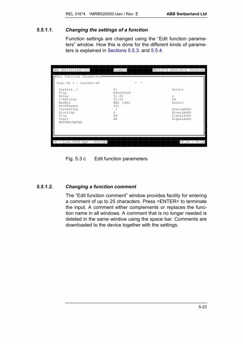
REL 316*4 1MRB520050-Uen / Rev. E ABB Switzerland Ltd
5-23
5.5.1.1. Changing the settings of a function
Function settings are changed using the “Edit function parame-ters” window. How this is done for the different kinds of parame-ters is explained in Sections 5.5.3. and 5.5.4.
* +8 (!!!!!!!!!!!!!!!!!!!!!!!!!!!!!!!!!!!!!!!!!!!!!!!!!!!!"$$$* +0.6 .,$$$$8 998+$$--------$$, @-9--($$H.'-:9--H0$$ RECG+$$03A8C ((--$$6 H '$$+LH* @$$' $$ ' $$/0F0$$$$$$$1!!!!!!!!!!!!!!!!!!!!!!!!!!!!!!!!!!!!!!!!!!!!!!!!!!!!!!!!!!!!!!!!!!!!!!!!!!!!23.4--5(678)9:5;)9:5
Fig. 5.3 c Edit function parameters
5.5.1.2. Changing a function comment
The “Edit function comment” window provides facility for enteringa comment of up to 25 characters. Press <ENTER> to terminatethe input. A comment either complements or replaces the func-tion name in all windows. A comment that is no longer needed isdeleted in the same window using the space bar. Comments aredownloaded to the device together with the settings.

ABB Switzerland Ltd REL 316*4 1MRB520050-Uen / Rev. E
5-24
< ===========>########################################################?<=====================>###############################################??<8(8* +(===========>###########################################???< * +3========* +6!!!!!!"###############????$K)K ) '$###############???? * +1!!!!!!!!!!!!!!!!!!!!!!!!!!!2###############????* +0 ?#########################################????6@ * +?#########################################????, * +?#########################################????/0?#########################################?????#########################################B=B=?B=============================D#############################################??###############################################B=============================D#################################################################################################################################################################################################################################################################################################################################################################################################################################################3.4--5(678)9:5;)9:5
Fig. 5.3 d Edit function comment
< ===========>########################################################?<=====================>###############################################??8(8* +(!!!!!!!!!!!"###########################################??$$###########################################??$M---F--N6 .,$###########################################??$:M---F--N)K ) '$###########################################??$M---F--N8$###########################################??$M---F--N) '.,$###########################################??$OM---F--N,( 5 ++$###########################################??$M---F--N*P +@$###########################################??$QH(* +$###########################################B=B=$/0$###############################################$$###############################################1!!!!!!!!!!!!!!!!!!!!!!!!!!!!!2#################################################################################################################################################################################################################################################################################################################################################################################################################################################3.4--5(678)9:5;)9:5
Fig. 5.3 e Present prot. funcs.

REL 316*4 1MRB520050-Uen / Rev. E ABB Switzerland Ltd
5-25
5.5.1.3. Copying a function
If a function’s settings in a second set of parameters are largelythe same as in a first, the function can be copied.The settings of the copied function are the same as the original,but the following parameters can not be changed subsequently:
all analogue inputs all signalling channels all tripping channels.
These parameters are not listed for this reason in the copiedfunction’s list of parameters (see Figures 5.3 c and e). However,if they are changed in the original, they are also automaticallychanged in the copy.The settings for the binary inputs and parameters “ParSet4..1”have to be re-entered for the copy. The binary input sourcesmust be active in the same set of parameters as the copy. Thecopied function must not be active in the same set of parametersas the original and the parameter set number of the original mustbe lower:
P1 pO P4 and pO < pK P4
wherepO = parameter set number of the original functionpK = parameter set number of the copied function.
* +8 (!!!!!!!!!!!!!!!!!!!!!!!!!!!!!!!!!!!!!!!!!!!!!!!!!!!!"$$$* +0Q.6 .,$$$$8 99+$$, @-9--($$H.'-:9--H0$$ RECG+$$03A8C ((--$$+LH* @$$/0F0$$$$$$$$$$$$$$$1!!!!!!!!!!!!!!!!!!!!!!!!!!!!!!!!!!!!!!!!!!!!!!!!!!!!!!!!!!!!!!!!!!!!!!!!!!!!23.4--5(678)9:5;)9:5
Fig. 5.3 f Edit function parameters

ABB Switzerland Ltd REL 316*4 1MRB520050-Uen / Rev. E
5-26
5.5.1.4. Deleting a function
A function can only be deleted, if there are no copies of it and itis not needed by another function (e.g. a binary output used toblock another function). As a safety precaution, the user is re-quested to confirm the deletion in response to the question “Areyou sure?”. If the particular function is at the bottom of the list, itdisappears altogether, otherwise its description is replaced by“Not used” to avoid having to renumber the functions.
< ===========>########################################################??########################################################?<=====================>###############################################???###############################################??<8(8* +(======!!!!!!!!!!!!!!!!!!!!!"##########################???$@ ( @ $##########################???< * +3===$(C%C($##########################????$A +S$##########################???? * +$T0KFTUK$##########################B=???* +0 $$############################???6@ * +1!!!!!!!!!!!!!!!!!!!!!2############################???, * +?#####################################B=??/0?#######################################???#######################################?B===================================D#######################################B===================================D###############################################################################################################################################################################################################################################################################3.4--5(678)9:5;)9:5
Fig. 5.3 g Are you sure?
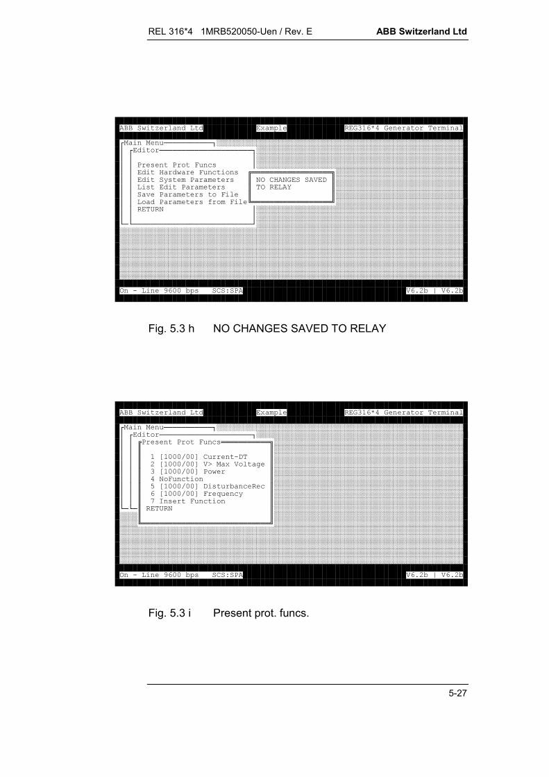
REL 316*4 1MRB520050-Uen / Rev. E ABB Switzerland Ltd
5-27
< ===========>########################################################?<=====================>###############################################???###############################################??8(8* +(?###############################################??& * +(!!!!!!!!!!!!!!!!!!"#############################??@(8 ($036&0),$#############################??(8 ($3U$#############################?? %8 (*$$#############################?? 8 (A*1!!!!!!!!!!!!!!!!!!2#############################??/0?###############################################???###############################################B=B===========================D#################################################################################################################################################################################################################################################################################################################################################################################################################################################################################################################################################################################################################3.4--5(678)9:5;)9:5
Fig. 5.3 h NO CHANGES SAVED TO RELAY
< ===========>########################################################?<=====================>###############################################??8(8* +(!!!!!!!!!!!"###########################################??$$###########################################??$M---F--N6 .,$###########################################??$:M---F--N)K ) '$###########################################??$M---F--N8$###########################################??$0* +$###########################################??$OM---F--N,( 5 ++$###########################################??$M---F--N*P +@$###########################################??$QH(* +$###########################################B=B=$/0$###############################################$$###############################################1!!!!!!!!!!!!!!!!!!!!!!!!!!!!!2#################################################################################################################################################################################################################################################################################################################################################################################################################################################3.4--5(678)9:5;)9:5
Fig. 5.3 i Present prot. funcs.

ABB Switzerland Ltd REL 316*4 1MRB520050-Uen / Rev. E
5-28
5.5.2. Adding a new function
An additional function is added either by selecting the secondlast menu item “Insert function” from the “Present prot. funcs.”menu (see Fig. 5.3 i) or a “No function” line if there is one. Uponpressing <Enter>, a list of the available functions appears. Selectthe desired function from the list and press <Enter> again. Thisopens the “Edit function parameters” window (see Fig. 5.3 c) andthe parameters can be set. The procedure for the different kindsof parameters is explained in Sections 5.5.3. and 5.5.4.
The last entry in the list of available functions is “No function”.Selecting this line and pressing <Enter> adds a “No function” lineto the list of active functions. This method can be used, for ex-ample, to adjust the list so that a given function has the samenumber in all the relays although.
5.5.3. General information on editing parameters
There are two types of parameters, which have to be entered:
1. those requiring the entry of a numerical value, e.g. current orvoltage settings
2. those requesting selection from a list of alternatives, e.g. op-tions or channels
Window used for both types of parameters: * +8 (!!!!!!!!!!!!!!!!!!!!!!!!!!!!!!!!!!!!!!!!!!!!!!!!!!!!"$$$* +0:.) '.,)K ) '$$$$8 998+$$------$$, @-:9--($$).'9:--/0$$ RECG+$$03A8C ((--$$) 'H '$$+LHA @$$--6-Q' $$ -' $$/0F0$$$$$$$1!!!!!!!!!!!!!!!!!!!!!!!!!!!!!!!!!!!!!!!!!!!!!!!!!!!!!!!!!!!!!!!!!!!!!!!!!!!!23.4--5(678)9:5;)9:5
Fig. 5.4 List of parameters

REL 316*4 1MRB520050-Uen / Rev. E ABB Switzerland Ltd
5-29
Keys used for both types of parameters:
List of parameters:
<> - Up a line
<> - Down a line
<PgUp> - One page up
<PgDn> - One page down
<Home> - Go to the beginning
<End> - Go to the end
<Enter> - Display the data entry/option select window
<Esc> - Return to previous window without saving changes
<Enter> - "Return/Input" - check and save parameters andreturn to previous menu.
Input/Selection window:
<Enter> - Return to the list of parameters and insert the set-ting from the “Input/Selection” window.
<Esc> - Return to the list of parameters without inserting thesetting from the “Input/Selection” window.
5.5.3.1. Entering numerical settings
The data input window appears on the right of the list of para-meters:
<* +8 (====================================================>???* +0:.) '.,)K ) '????8 998+??------??, @-:9--(??).'9:--!!!!!!!!!!!!!!!!!!!!!"?? RECG$).'$??03A8C ((--$$??) 'H$0J)/K$??+LHA$$??--6-Q$R:9---$?? -$H0-9--$??/0F01!!!!!!!!!!!!!!!!!!!!!2???????B============================================================================D3.4--5(678)9:5;)9:5
Fig. 5.5 Window for entering numerical settings
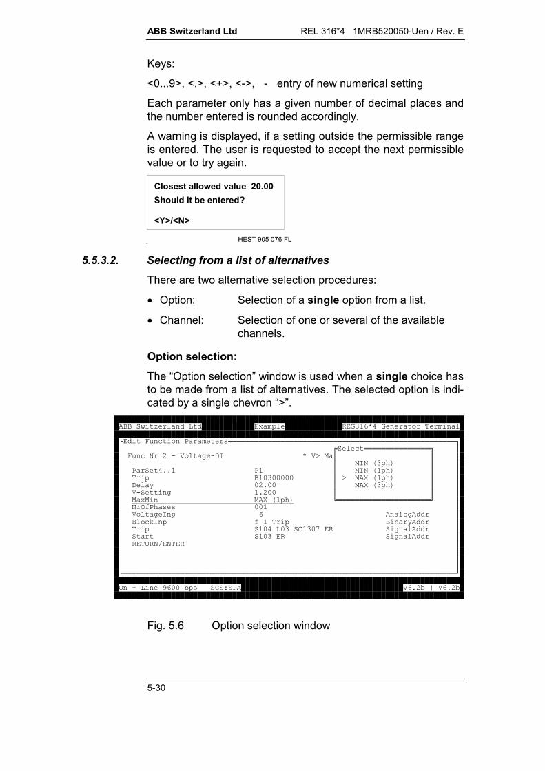
ABB Switzerland Ltd REL 316*4 1MRB520050-Uen / Rev. E
5-30
Keys:
<0...9>, <.>, <+>, <->, - entry of new numerical setting
Each parameter only has a given number of decimal places andthe number entered is rounded accordingly.
A warning is displayed, if a setting outside the permissible rangeis entered. The user is requested to accept the next permissiblevalue or to try again.
HEST 905 076 FL
Closest allowed value 20.00
<Y>/<N>
Should it be entered?
5.5.3.2. Selecting from a list of alternatives
There are two alternative selection procedures:
Option: Selection of a single option from a list.
Channel: Selection of one or several of the availablechannels.
Option selection:
The “Option selection” window is used when a single choice hasto be made from a list of alternatives. The selected option is indi-cated by a single chevron “>”.
<* +8 (====================================================>?+!!!!!!!!!!!!!!!"??* +0:.) '.,)K $$??$H0ECG$??8 998$H0ECG$??------$KRECG$??, @-:9--$RECG$??).'9:--$$?? RECG1!!!!!!!!!!!!!!!!!!!!!2??03A8C ((--??) 'H '??+LHA @??--6-Q' ?? -' ??/0F0???????B============================================================================D3.4--5(678)9:5;)9:5
Fig. 5.6 Option selection window
REL 316*4 1MRB520050-Uen / Rev. E ABB Switzerland Ltd
5-31
Keys:
<>, <>, <PgUp>, <PgDn> - Move the cursor in the selectionwindow
<Ins> - Selects a channel.
Channel selection:
The available alternatives in the “Channel selection” window areshown as rows of boxes, which apart from the channel number,also contain a field for up to 2 characters (see Fig. 5.7). Thechannel description consists of a explanatory text and/or a com-ment entered by the user when configuring the hardware func-tions (see Section 5.5.5). The corresponding information is dis-played as the selection bar is moved from one option to the next.
There are two methods of selection:
1. Multiple selection - All the channels, which have just beenselected with the aid of the cursor and the <Ins> key, are in-dicated by “X”. The cursor jumps to the first available channelupon opening the window.
2. Single selection - The channel selected is indicated by “X”and the “X” moves automatically, if a new selection is made.The cursor jumps to the first available channel upon openingthe window.
Keys:
<>, <> - Move the cursor in the selection window
<Ins> - Selects a channel
<Del> - De-selects an option (multiple selection only)
<-> - Inverts a channel(binary inputs only).
The system only permits channels to be selected it considers tobe plausible, otherwise a warning bleep sounds (but there is noerror message). Examples of implausible selections are setting achannel defined as a current input as a voltage input, or at-tempting to assign a signal to an output (relay or LED) which isalready occupied.

ABB Switzerland Ltd REL 316*4 1MRB520050-Uen / Rev. E
5-32
5.5.4. Explanation of the types of channels
There are four types of channels which conform generally to therules given in the preceding sections. Each one, however, has inaddition characteristics and abbreviations peculiar to itself.
5.5.4.1. C.t./v.t. input channels
The c.t. and v.t. input channels are assigned in the “A-D InputChannels” selection window:
<* +8 (====================================================>???* +0:.) '.,)K ) '????8 998+??------??, @-:9--(??).'9:--/0?? RECG+??03A8C ((--.,H 6C (!!!!!!!!!!"??) 'H$$??+LHA$<==<==<==<==<==<==<==<==<==>$??--6-Q$??:???O??Q?V?4?$?? -$?+W+W+?+?%?R%?%W%W%?$??/0F0$B==B==B==B==B==B==B==B==B==D$??$)C9--$??$)X ) '$??1!!!!!!!!!!!!!!!!!!!!!!!!!!!!2?B============================================================================D3.4--5(678)9:5;)9:5
Fig. 5.7 “A-D Input Channels” selection window
The nine boxes in the selection window representing the c.t. andv.t. input channels available are designated as follows:
Top: 1...9 : Channel No.
Bottom: c : c.t.
v : v.t.
o : no input transformer connected
+ : two “+” signs link a three-phase input trans-former group
X : selected channel.
The input transformer type and any user comment are displayedin the lower part of the window for the field currently selected.

REL 316*4 1MRB520050-Uen / Rev. E ABB Switzerland Ltd
5-33
The arrangement of the c.t. and v.t. input channels is establishedby the ordering code (K...). Prior to assigning the c.t. and v.t. in-put channels, the K code in the menu “Edit Relay Configuration”must be set (see Section 3.4.1.).
Only the first phase of a three-phase group may be selected; theother two phases are automatically included without any specialindication. Any channel may be selected, on the other hand, fora single-phase function.
The channel number is indicated in the parameter value columnof the “Edit function parameters” window.
5.5.4.2. Signalling channels
Signals can be assigned individually to the event recorder, up totwo physical outputs (LED’s, signalling and tripping relays anddistributed outputs) and an output to a station control system(SCS) and for interlocking purposes (ITL). The bleep sounds ifan attempt is made to use more than two physical outputs.
<* +8 (====================================================>???* +0:.) '.,)K ) '????8 99+ @3 !"+??$$??, @$' ,Y($(??).'$' @($/0?? $%+'$+??03A8C (($ @($??) 'H$' 6$ '??+LH$3 3Y($ @??$3 H$' ?? $/0$' ??/0F0$$??1!!!!!!!!!!!!!!!!!!!!!2?????B============================================================================D3.4--5(678)9:5;)9:5
Fig. 5.8 Setting signalling channels
LED signals
Before LED’s can be assigned, the respective I/O unit (1 forLED’s 1 to 8 or 2 for LED’S 9 to 16) must be selected in the“Select I/O slot” window. The “LED’s” selection window then ap-pears.

ABB Switzerland Ltd REL 316*4 1MRB520050-Uen / Rev. E
5-34
<+ @3 =>???<+H3.========================>????%?K???,(!!!!!!!!!!!!!!!!!!!!!"??/( 5H3.$$?3 ?$<==<==<==<==<==<==<==<==>$?3 ?X:$??:???O??Q?V?$??$? ??R??????$?B===============$B==B==B==B==B==B==B==B==D$B===================$$$$1!!!!!!!!!!!!!!!!!!!!!!!!!2
Fig. 5.9 “LED’s” selection window
The eight boxes representing the LED’s in the selection windoware designated as follows:
Top: 1...16 : Channel No.
Bottom: u (used) : channel in use
X : selected channel.
Note that channel 1 is not available for assignment, becauseLED 1 is always assigned to the standby alarm signal.
The number of the selected LED (e.g. L03) is indicated in the pa-rameter value column of the “Edit function parameters” window.
Signalling relays
Before signalling relays can be assigned, the respective I/O unit(1 to 4) must be selected in the “Select I/O slot” window. The“Signal relays” selection window then appears.
<+ @3 =>???<+H3.========================>????%?K???' @(!!!!!!!!!!!!"??/( 5H3.$$?3 ?$<==<==<==<==<==<==>$?3 ?X:$??:???O??$??$??? ?R???$?B===============$B==B==B==B==B==B==D$B===================$)K )XH8$$$1!!!!!!!!!!!!!!!!!!!!!!!!!2
Fig. 5.10 “Signal relays” selection window
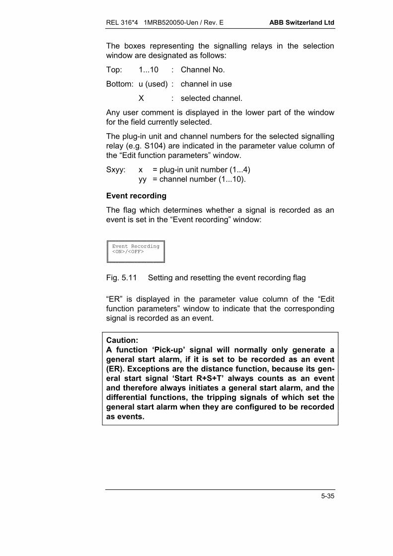
REL 316*4 1MRB520050-Uen / Rev. E ABB Switzerland Ltd
5-35
The boxes representing the signalling relays in the selectionwindow are designated as follows:
Top: 1...10 : Channel No.
Bottom: u (used) : channel in use
X : selected channel.
Any user comment is displayed in the lower part of the windowfor the field currently selected.
The plug-in unit and channel numbers for the selected signallingrelay (e.g. S104) are indicated in the parameter value column ofthe “Edit function parameters” window.
Sxyy: x = plug-in unit number (1...4)yy = channel number (1...10).
Event recording
The flag which determines whether a signal is recorded as anevent is set in the “Event recording” window:
!!!!!!!!!!!!!!!!!"$%+'$$T30KFT3**K$$$1!!!!!!!!!!!!!!!!!2
Fig. 5.11 Setting and resetting the event recording flag
“ER” is displayed in the parameter value column of the “Editfunction parameters” window to indicate that the correspondingsignal is recorded as an event.
Caution:A function ‘Pick-up’ signal will normally only generate ageneral start alarm, if it is set to be recorded as an event(ER). Exceptions are the distance function, because its gen-eral start signal ‘Start R+S+T’ always counts as an eventand therefore always initiates a general start alarm, and thedifferential functions, the tripping signals of which set thegeneral start alarm when they are configured to be recordedas events.
ABB Switzerland Ltd REL 316*4 1MRB520050-Uen / Rev. E
5-36
Caution:A function’s tripping command will normally only generate ageneral tripping alarm, if it is assigned to the tripping logic(matrix) and configured to be recorded as an event (ER).The distance function is an exception, because it alwayssets the general tripping alarm.
Tripping relays
Tripping relays can be used for signalling purposes. From Ver-sion V4.2 signals can be assigned to tripping relays to which asignal (‘u’ indication in the signalling channel selection window)or a tripping logic (signals and trips OR logic) has already beenassigned. The procedure for assigning tripping relays is thesame as for signalling relays above.
The plug-in unit and channel numbers for the selected trippingrelay (e.g. C201) are indicated in the parameter value column ofthe “Edit function parameters” window.
Cxyy: x = plug-in unit number (1...4)yy = channel number (1...2).
SCS signals
Before a signal can be assigned to the SCS, the respectivegroup (1 to 24) must be selected in the “Select SCS group” win-dow. The SCS signal groups 1c…24c are intended for transmit-ting short signals via the interbay bus(signal capturing). The“Signals to SCS” selection window then appears.

REL 316*4 1MRB520050-Uen / Rev. E ABB Switzerland Ltd
5-37
<+ @3 =>???+6. !!!!!!!!!!!!!!!!!!!!!!"?$$?%$K$?$$?$/( 56. $?3 $$?3 $99:X+99:+$?$$?1!!!!!!!!!!!!!!!!!!!!!!!!!!!!!!!!!!!!!!2B=====================D
<+ @3 =>' (6!!!!!!!!!!!!!!!!!!!!!!!!!!!!!!!!!!!!!!!!!!!!!!!"$$$<==<==<==<==<==<==<==<==<==<==<==<==<==<==<==<==<==<==<==<==>$$??:???O??Q?V?4?-??:???O??Q?V?4?:-?$$???????R???? ??????????$$B==B==B==B==B==B==B==B==B==B==B==B==B==B==B==B==B==B==B==B==D$$<==<==<==<==<==<==<==<==<==<==<==<==>$$?:?::?:?:?:O?:?:Q?:V?:4?-??:?$$?????????????$$B==B==B==B==B==B==B==B==B==B==B==B==D$$$$$1!!!!!!!!!!!!!!!!!!!!!!!!!!!!!!!!!!!!!!!!!!!!!!!!!!!!!!!!!!!!!2
Fig. 5.12 “Select SCS group” and “Signals to SCS” selectionwindows
The fields in the selection window are designated as follows:
Top: 1...32 : Channel No.
Bottom: u (used) : channel in use
X : selected channel.
The SCS assignment (e.g. SC1307) is indicated in the parame-ter value column of the “Edit function parameters” window.
SCxxyy: xx = SCS group number (1...24)yy = data node within a group (1...32).
Signal to RBO (remote binary output)
When assigning signals to the RBO (distributed output system),first select the group (1 to 80) in the “Select RBO No.” window.
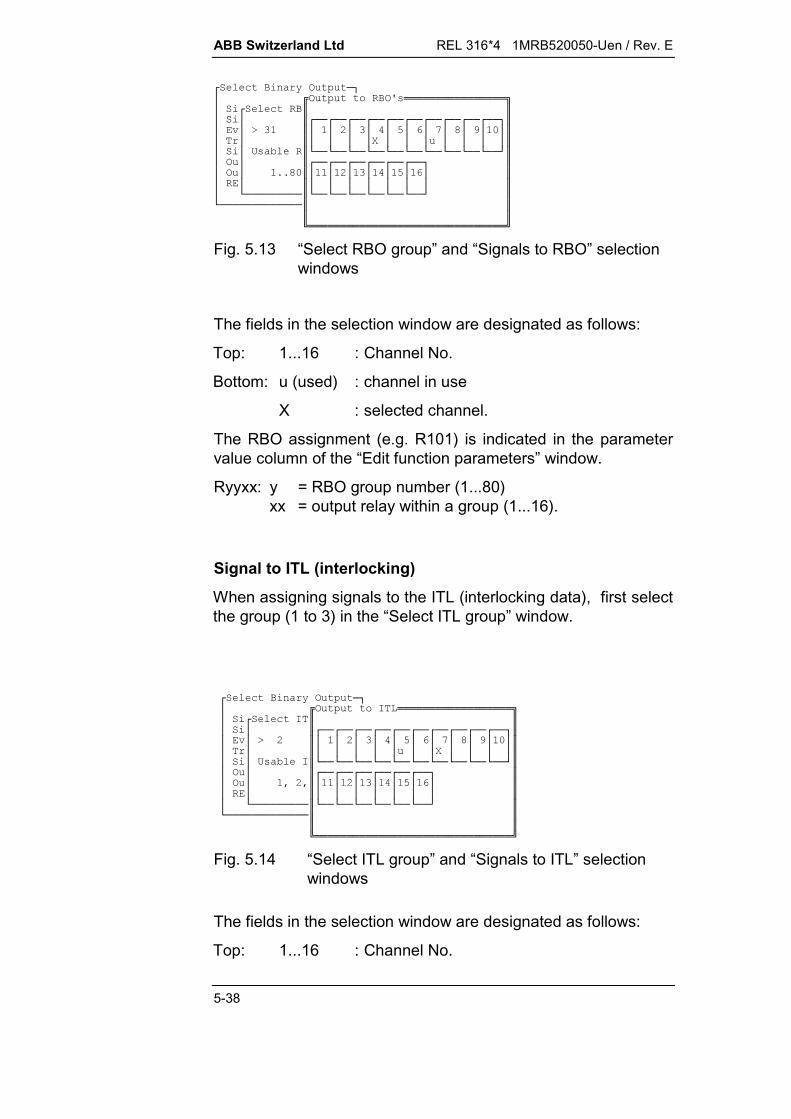
ABB Switzerland Ltd REL 316*4 1MRB520050-Uen / Rev. E
5-38
<+ @3 =>?3 3Y(!!!!!!!!!!!!!!!!"?<+$$??$<==<==<==<==<==<==<==<==<==<==>$?%?K$??:???O??Q?V?4?-?$??$????R??? ????$??/( 5$B==B==B==B==B==B==B==B==B==B==D$?3 ?$<==<==<==<==<==<==>$?3 ?99V-$??:???O??$??$???????$?B=========$B==B==B==B==B==B==D$B=============$$$$1!!!!!!!!!!!!!!!!!!!!!!!!!!!!!!!2
Fig. 5.13 “Select RBO group” and “Signals to RBO” selectionwindows
The fields in the selection window are designated as follows:
Top: 1...16 : Channel No.
Bottom: u (used) : channel in use
X : selected channel.
The RBO assignment (e.g. R101) is indicated in the parametervalue column of the “Edit function parameters” window.
Ryyxx: y = RBO group number (1...80)xx = output relay within a group (1...16).
Signal to ITL (interlocking)
When assigning signals to the ITL (interlocking data), first selectthe group (1 to 3) in the “Select ITL group” window.
<+ @3 =>?3 H!!!!!!!!!!!!!!!!!!"?<+H$$??$<==<==<==<==<==<==<==<==<==<==>$?%?K:$??:???O??Q?V?4?-?$??$????? ??R????$??/( 5H$B==B==B==B==B==B==B==B==B==B==D$?3 ?$<==<==<==<==<==<==>$?3 ?X:X$??:???O??$??$???????$?B=========$B==B==B==B==B==B==D$B=============$$$$1!!!!!!!!!!!!!!!!!!!!!!!!!!!!!!!2
Fig. 5.14 “Select ITL group” and “Signals to ITL” selectionwindows
The fields in the selection window are designated as follows:
Top: 1...16 : Channel No.
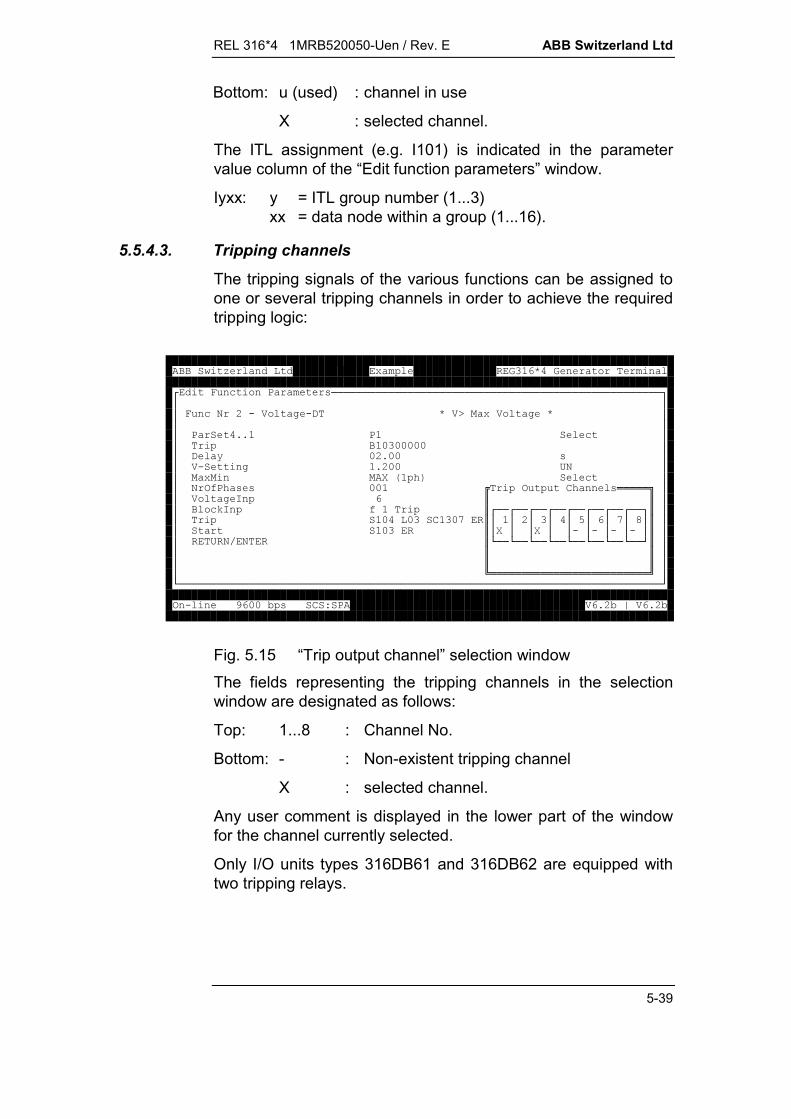
REL 316*4 1MRB520050-Uen / Rev. E ABB Switzerland Ltd
5-39
Bottom: u (used) : channel in use
X : selected channel.
The ITL assignment (e.g. I101) is indicated in the parametervalue column of the “Edit function parameters” window.
Iyxx: y = ITL group number (1...3)xx = data node within a group (1...16).
5.5.4.3. Tripping channels
The tripping signals of the various functions can be assigned toone or several tripping channels in order to achieve the requiredtripping logic:
<* +8 (====================================================>???* +0:.) '.,)K ) '????8 998+??------??, @-:9--(??).'9:--/0?? RECG+??03A8C ((--3 6C (!!!!!"??) 'H$$??+LHA$<==<==<==<==<==<==<==<==>$??--6-Q$??:???O??Q?V?$?? -$?R??R??.?.?.?.?$??/0F0$B==B==B==B==B==B==B==B==D$??$$??$$??1!!!!!!!!!!!!!!!!!!!!!!!!!2?B============================================================================D3.4--5(678)9:5;)9:5
Fig. 5.15 “Trip output channel” selection windowThe fields representing the tripping channels in the selectionwindow are designated as follows:
Top: 1...8 : Channel No.
Bottom: - : Non-existent tripping channel
X : selected channel.
Any user comment is displayed in the lower part of the windowfor the channel currently selected.
Only I/O units types 316DB61 and 316DB62 are equipped withtwo tripping relays.
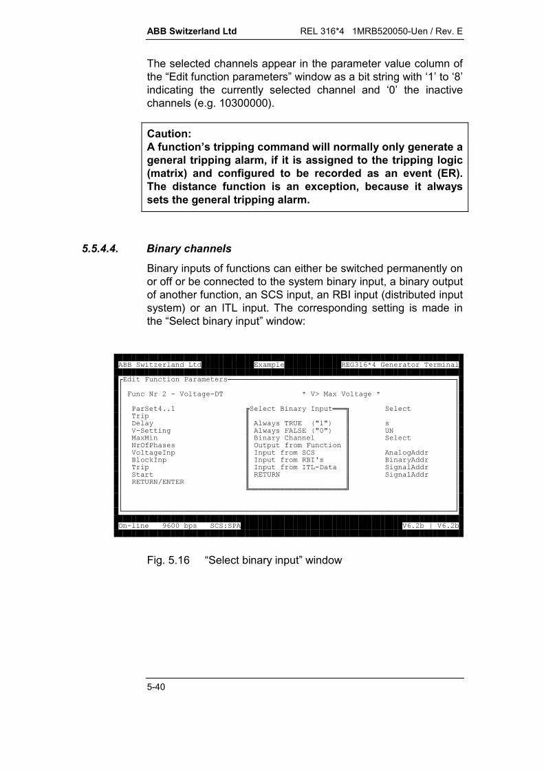
ABB Switzerland Ltd REL 316*4 1MRB520050-Uen / Rev. E
5-40
The selected channels appear in the parameter value column ofthe “Edit function parameters” window as a bit string with ‘1’ to ‘8’indicating the currently selected channel and ‘0’ the inactivechannels (e.g. 10300000).
Caution:A function’s tripping command will normally only generate ageneral tripping alarm, if it is assigned to the tripping logic(matrix) and configured to be recorded as an event (ER).The distance function is an exception, because it alwayssets the general tripping alarm.
5.5.4.4. Binary channels
Binary inputs of functions can either be switched permanently onor off or be connected to the system binary input, a binary outputof another function, an SCS input, an RBI input (distributed inputsystem) or an ITL input. The corresponding setting is made inthe “Select binary input” window:
<* +8 (====================================================>???* +0:.) '.,)K ) '????8 99+ @H !!!"+??$$??, @$ @(/EZZG$(??).'$ @(*EZ-ZG$/0?? $ @6C $+??03A8C (($3 A* +$??) 'H$H A6$ '??+LH$H AHY($ @??$H AH., $' ?? $/0$' ??/0F0$$??1!!!!!!!!!!!!!!!!!!!!!!2?????B============================================================================D3.4--5(678)9:5;)9:5
Fig. 5.16 “Select binary input” window

REL 316*4 1MRB520050-Uen / Rev. E ABB Switzerland Ltd
5-41
Always TRUE or Always FALSE
The binary inputs of functions can be set permanently on (logical1) or off (logical 0) by moving the selection bar to the corre-sponding line and pressing <Enter>.
“T” (true) in the parameter value column of the “Edit function pa-rameters” window indicates a permanently switched on input and“F” (flase) a permanently switched off input.
System binary input
Every function input can be assigned either inverted or non-inverted to a system binary input (opto-coupler input). The re-spective I/O unit (1 to 4) is selected first and then the “Binary in-put channels” selection window opens:<+ @H ===>???<+H3.========================>?????K??3 ? @H 6C (!!!!"?H?/( 5H3.$$?H?$<==<==<==<==<==<==<==<==>$?H?X:$??:???O??Q?V?$??$?H????????$?B===============$B==B==B==B==B==B==B==B==D$B===================$6$$$1!!!!!!!!!!!!!!!!!!!!!!!!!2
Fig. 5.17 “Binary input channels” selection window
The fields representing the binary input channels in the selectionwindow are designated as follows:
Top: 1...14 : Channel No.
Bottom: X : selected channel (<Ins> key)
I : selected channel inverted (<-> key).
Any user comment is displayed in the lower part of the windowfor the field currently selected.

ABB Switzerland Ltd REL 316*4 1MRB520050-Uen / Rev. E
5-42
The plug-in unit and channel number of the selected binary inputand a minus sign if it is inverted (e.g. -101) are indicated in theparameter value column of the “Edit function parameters” win-dow.
xyzz: x = non-inverted () or inverted (-) inputy = plug-in unit number (1...4)zz = channel number (1...14).
Note:
To cancel the selection of a channel, select “Always FALSE” or“Always TRUE ” in the “Select Binary Input” window.Since channels can have several inputs assigned to them, chan-nel with inputs already assigned to them are not especially indi-cated in the channel selection window.
Output of another function
Every function input can be assigned either inverted or non-inverted to output of another function. The respective function isfirst selected in the “Output from function” window and then theselection window with all the outputs of the corresponding func-tion opens:<+ @H ===>???<3 A* +=========>?????-M:F--N@(H3?+?3 ?-M:F--N36 .,!!!!!!!!!!!!"?H?M---F--N6$$?H?:M---F--N)$<==<==>$?H?M---F--N8$?-?-:?$??M---F--N)$?R??$??OM---F--N,$B==B==D$B===?M---F--N*$$?/0$$?1!!!!!!!!!!!!!!!!!!!!!!!!!2B=============================D
Fig. 5.18 “Output from function” selection window
The fields in the selection window are designated as follows:
Top: 1...47 : Channel No.
Bottom: X : selected channel (<Ins> key)
I : selected channel inverted (<-> key).
The signal name is displayed in the lower part of the window forthe field currently selected.
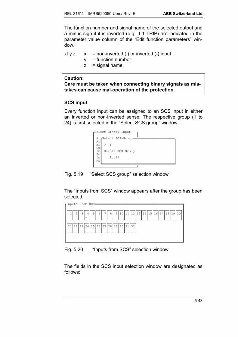
REL 316*4 1MRB520050-Uen / Rev. E ABB Switzerland Ltd
5-43
The function number and signal name of the selected output anda minus sign if it is inverted (e.g. -f 1 TRIP) are indicated in theparameter value column of the “Edit function parameters” win-dow.
xf y z: x = non-inverted ( ) or inverted (-) inputy = function numberz = signal name.
Caution:Care must be taken when connecting binary signals as mis-takes can cause mal-operation of the protection.
SCS input
Every function input can be assigned to an SCS input in eitheran inverted or non-inverted sense. The respective group (1 to24) is first selected in the “Select SCS group” window:
<+ @H ===>???+6. !!!!!!!!!!!!!!!!!!!!!!"?$$?$K$?3 $$?H$/( 56. $?H$$?H$99:$?$$?1!!!!!!!!!!!!!!!!!!!!!!!!!!!!!!!!!!!!!!2B======================D
Fig. 5.19 “Select SCS group” selection window
The “Inputs from SCS” window appears after the group has beenselected:H (*6!!!!!!!!!!!!!!!!!!!!!!!!!!!!!!!!!!!!!!!!!!!!!!"$$$<==<==<==<==<==<==<==<==<==<==<==<==<==<==<==<==<==<==<==<==>$$??:???O??Q?V?4?-??:???O??Q?V?4?:-?$$????H?????????????????$$B==B==B==B==B==B==B==B==B==B==B==B==B==B==B==B==B==B==B==B==D$$<==<==<==<==<==<==<==<==<==<==<==<==>$$?:?::?:?:?:O?:?:Q?:V?:4?-??:?$$?????????????$$B==B==B==B==B==B==B==B==B==B==B==B==D$$$$$1!!!!!!!!!!!!!!!!!!!!!!!!!!!!!!!!!!!!!!!!!!!!!!!!!!!!!!!!!!!!!2
Fig. 5.20 “Inputs from SCS” selection window
The fields in the SCS input selection window are designated asfollows:

ABB Switzerland Ltd REL 316*4 1MRB520050-Uen / Rev. E
5-44
Top: 1...32 : Channel No.
Bottom: X : selected channel (<Ins> key)
I : selected channel inverted (<-> key).
The SCS assignment (e.g. -SCSI2104) is indicated in the pa-rameter value column of the “Edit function parameters” window.
xSCSIyyzz: x = non-inverted ( ) or inverted (-) inputyy = SCS group number (1...24)zz = data node within the group (1...32).
RBI input (distributed input system)
Every function input can be assigned to an RBI input in either aninverted or non-inverted sense. The respective group (1 to 80) isfirst selected in the “Select RBI No.” window, after which the “In-puts from RBI” appears:<+ @H ===>?H AHY(!!!!!!!!!!!!!!!"?<+$H. $??$<==<==<==<==<==<==<==<==<==<==>$??K:$??:???O??Q?V?4?-?$?3 ?$???????????$?H?/( 5$B==B==B==B==B==B==B==B==B==B==D$?H?$<==<==<==<==<==<==<==<==<==>$?H?99V-$??:???O??Q?V?4?$??$?R?????????$?B=========$B==B==B==B==B==B==B==B==B==D$B=============$$$$1!!!!!!!!!!!!!!!!!!!!!!!!!!!!!!!2
Fig. 5.21 “Select RBI group” and “Inputs from RBI” selectionwindows
The fields in the RBI input selection window are designated asfollows:
Top: 1...19 : Channel No.
Bottom: X : selected channel (<Ins> key)
I : selected channel inverted (<-> key).
The RBI assignment (e.g. -R12111) is indicated in the parametervalue column of the “Edit function parameters” window.
xRIyyzz: x = non-inverted ( ) or inverted (-) inputyy = RBI device No. (1…80)zz = input in the device (1...19).
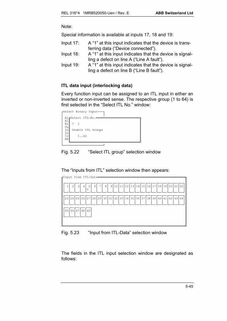
REL 316*4 1MRB520050-Uen / Rev. E ABB Switzerland Ltd
5-45
Note:
Special information is available at inputs 17, 18 and 19:
Input 17: A “1” at this input indicates that the device is trans-ferring data (“Device connected”).
Input 18: A “1” at this input indicates that the device is signal-ling a defect on line A (“Line A fault”).
Input 19: A “1” at this input indicates that the device is signal-ling a defect on line B (“Line B fault”).
ITL data input (interlocking data)
Every function input can be assigned to an ITL input in either aninverted or non-inverted sense. The respective group (1 to 64) isfirst selected in the “Select ITL No.” window:<+ @H ===>???+H.09!!!!!!!!!!!!!!!!!!!!!!!!"?$$?$K$?3 $$?H$/( 5H ($?H$$?H$99$?$$?1!!!!!!!!!!!!!!!!!!!!!!!!!!!!!!!!!!!!!!2B======================D
Fig. 5.22 “Select ITL group” selection window
The “Inputs from ITL” selection window then appears:H AH., !!!!!!!!!!!!!!!!!!!!!!!!!!!!!!!!!!!!!!!!!!!!!!!!"$$$<==<==<==<==<==<==<==<==<==<==<==<==<==<==<==<==<==<==<==<==<==<==>$$??:???O??Q?V?4?-??:???O??Q?V?4?:-?:?::?$$?????R??????????????????$$B==B==B==B==B==B==B==B==B==B==B==B==B==B==B==B==B==B==B==B==B==B==D$$<==<==<==<==<==<==<==<==<==<==<==<==<==<==<==<==<==<==<==<==<==<==>$$?:?:?:O?:?:Q?:V?:4?-??:???O??Q?V?4?-??:???$$???????????????????????$$B==B==B==B==B==B==B==B==B==B==B==B==B==B==B==B==B==B==B==B==B==B==D$$<==<==<==<==<==>$$?O??Q?V?4?$$??????$$B==B==B==B==B==D$$$$$1!!!!!!!!!!!!!!!!!!!!!!!!!!!!!!!!!!!!!!!!!!!!!!!!!!!!!!!!!!!!!!!!!!!2
Fig. 5.23 “Input from ITL-Data” selection window
The fields in the ITL input selection window are designated asfollows:
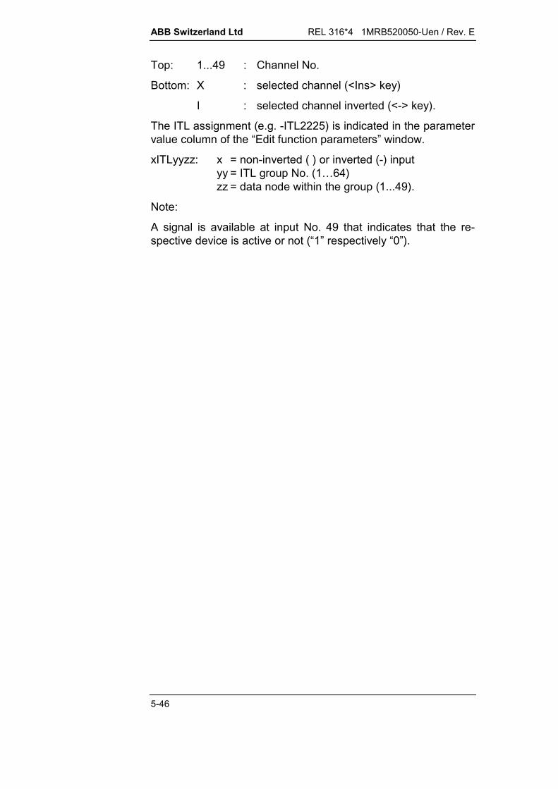
ABB Switzerland Ltd REL 316*4 1MRB520050-Uen / Rev. E
5-46
Top: 1...49 : Channel No.
Bottom: X : selected channel (<Ins> key)
I : selected channel inverted (<-> key).
The ITL assignment (e.g. -ITL2225) is indicated in the parametervalue column of the “Edit function parameters” window.
xITLyyzz: x = non-inverted ( ) or inverted (-) inputyy = ITL group No. (1…64)zz = data node within the group (1...49).
Note:
A signal is available at input No. 49 that indicates that the re-spective device is active or not (“1” respectively “0”).

REL 316*4 1MRB520050-Uen / Rev. E ABB Switzerland Ltd
5-47
5.5.5. Editing hardware functions
The hardware functions include all the hardware device settings.The menu structure can be seen from Fig. 5.24:
Edit hardware functions
(a)
(b)
Edit AD channels
(c)
Edit binary inputs
(d)
Edit trip outputs
(e)
Edit signal outputs
(f)
Edit relay configuration
(i)
IEdit IBB Configuration
Edit Analogue Inputs
(g)
Edit Analogue Outputs
(h)
Fig. 5.24 Editing hardware functions(see displays a to i on the following pages)

ABB Switzerland Ltd REL 316*4 1MRB520050-Uen / Rev. E
5-48
< ===========>########################################################?<=====================>###############################################??& * +(!!!!"#############################################??$$#############################################??$ @6A' $#############################################??$,E6F)G6C ($#############################################??$ @H ($#############################################??$3 ($#############################################??$' 3 ($#############################################??$ ' ($#############################################??$ ' ($#############################################B=B=$HFH3+A' $#################################################$/0$#################################################$$#################################################1!!!!!!!!!!!!!!!!!!!!!!!!!!!2#####################################################################################################################################################################################################################################################################################################################################################################3.4--5(678)9:5;)9:5
Fig. 5.24 a Edit hardware functions
* +8 (!!!!!!!!!!!!!!!!!!!!!!!!!!!!!!!!!!!!!!!!!!!!!!!!!!!!"$$$@()( $$$$0*PO-&$$F,)6+$$,6A'[:$$0,+$$0:,:+$$0,+$$00 (+$$J)(R999+$$J)(9RRR--$$/0F0$$$$$$$$$1!!!!!!!!!!!!!!!!!!!!!!!!!!!!!!!!!!!!!!!!!!!!!!!!!!!!!!!!!!!!!!!!!!!!!!!!!!!!23.4--5(678)9:5;)9:5
Fig. 5.24 b Edit relay configuration
The parameters are explained in Section 3.4.1.
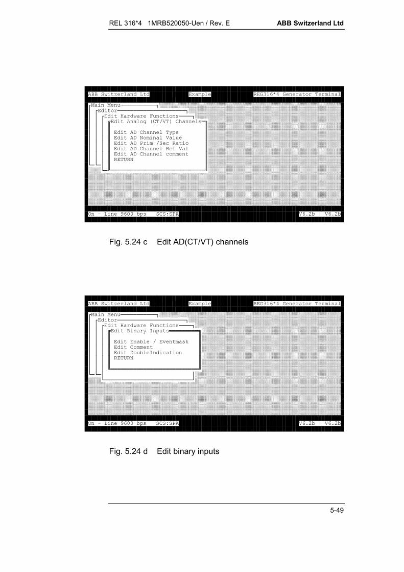
REL 316*4 1MRB520050-Uen / Rev. E ABB Switzerland Ltd
5-49
< ===========>########################################################?<=====================>###############################################??<& * +(====>#############################################??? 'E6F)G6C (!"#########################################???$$#########################################???$,6C @$#########################################???$,0 ) $#########################################???$,8F+ $#########################################???$,6C A) $#########################################???$,6C +$#########################################???$/0$#########################################B=B=?$$#############################################B=1!!!!!!!!!!!!!!!!!!!!!!!!!!!!!2#############################################################################################################################################################################################################################################################################################################################################################################################################################################################################################################################3.4--5(678)9:5;)9:5
Fig. 5.24 c Edit AD(CT/VT) channels
< ===========>########################################################?<=====================>###############################################??<& * +(====>#############################################??? @H (!!!!!!!!!"###########################################???$$###########################################???$ 5F% (L$###########################################???$6$###########################################???$, 5H+ $###########################################???$/0$###########################################???$$###########################################???1!!!!!!!!!!!!!!!!!!!!!!!!!!!2###########################################B=B=??#################################################B===========================D#################################################################################################################################################################################################################################################################################################################################################################################################################################################################################################################################3.4--5(678)9:5;)9:5
Fig. 5.24 d Edit binary inputs
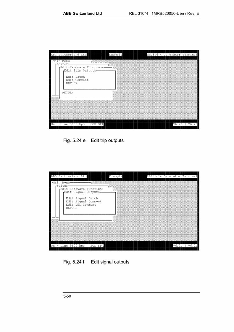
ABB Switzerland Ltd REL 316*4 1MRB520050-Uen / Rev. E
5-50
< ===========>########################################################?<=====================>###############################################??<& * +(====>#############################################???3 (!!!!!!!!!!"###########################################???$$###########################################???$ +C$###########################################???$6$###########################################???$/0$###########################################???$$###########################################???1!!!!!!!!!!!!!!!!!!!!!!!!!!!2###########################################???/0?#############################################B=B=??#################################################B===========================D#################################################################################################################################################################################################################################################################################################################################################################################################################################################################################################################################3.4--5(678)9:5;)9:5
Fig. 5.24 e Edit trip outputs
< ===========>########################################################?<=====================>###############################################??<& * +(====>#############################################???' 3 (!!!!!!!!"###########################################???$$###########################################???$' +C$###########################################???$' 6$###########################################???$,6$###########################################???$/0$###########################################???$$###########################################???1!!!!!!!!!!!!!!!!!!!!!!!!!!!2###########################################B=B=??#################################################B===========================D#################################################################################################################################################################################################################################################################################################################################################################################################################################################################################################################################3.4--5(678)9:5;)9:5
Fig. 5.24 f Edit signal outputs
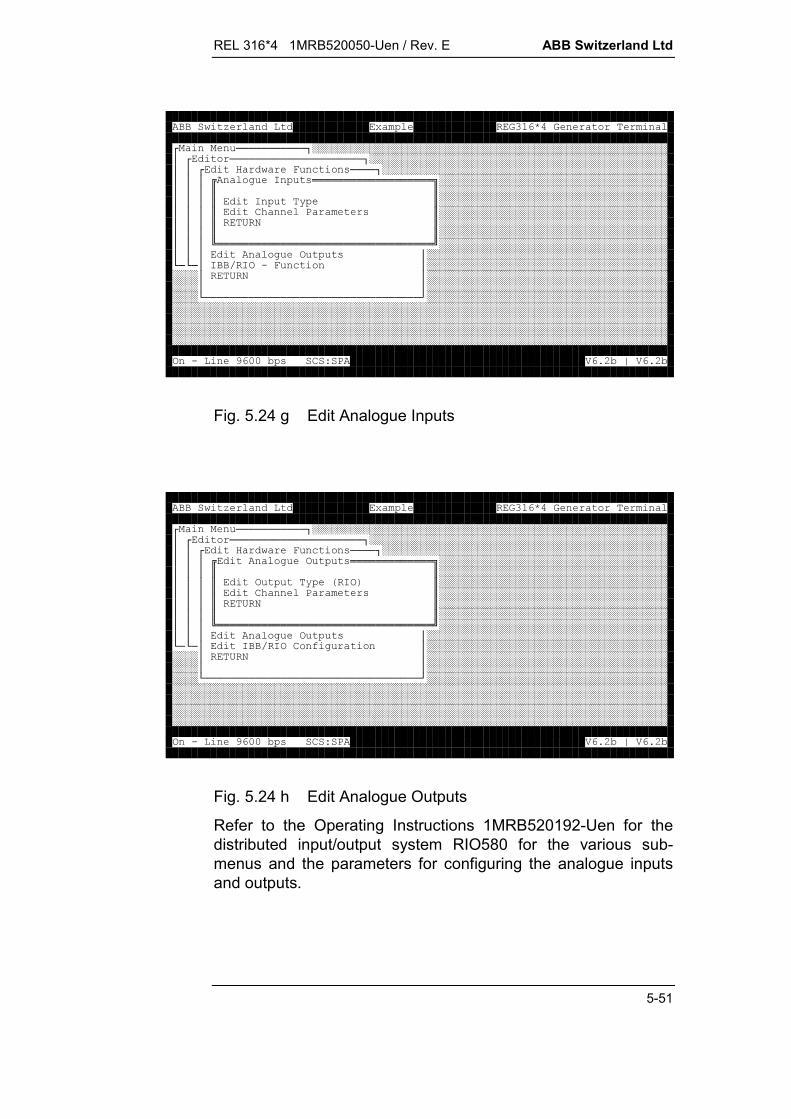
REL 316*4 1MRB520050-Uen / Rev. E ABB Switzerland Ltd
5-51
< ===========>########################################################?<=====================>###############################################??<& * +(====>#############################################??? ' H (!!!!!!!!!!!!!!!!!!!"####################################???$$####################################???$H @$####################################???$6C 8 ($####################################???$/0$####################################???$$####################################???1!!!!!!!!!!!!!!!!!!!!!!!!!!!!!!!!!!2####################################??? ' 3 (?######################################B=B=?HFH3.* +?##########################################?/0?##########################################??##########################################B==================================D##############################################################################################################################################################################################################################################################################################################################################################3.4--5(678)9:5;)9:5
Fig. 5.24 g Edit Analogue Inputs
< ===========>########################################################?<=====================>###############################################??<& * +(====>#############################################??? ' 3 (!!!!!!!!!!!!!"####################################???$$####################################???$3 @EH3G$####################################???$6C 8 ($####################################???$/0$####################################???$$####################################???1!!!!!!!!!!!!!!!!!!!!!!!!!!!!!!!!!!2####################################??? ' 3 (?######################################B=B=?HFH36A' ?##########################################?/0?##########################################??##########################################B==================================D##############################################################################################################################################################################################################################################################################################################################################################3.4--5(678)9:5;)9:5
Fig. 5.24 h Edit Analogue Outputs
Refer to the Operating Instructions 1MRB520192-Uen for thedistributed input/output system RIO580 for the various sub-menus and the parameters for configuring the analogue inputsand outputs.

ABB Switzerland Ltd REL 316*4 1MRB520050-Uen / Rev. E
5-52
< ===========>########################################################?<=====================>###############################################??<& * +(====>#############################################???H6A'9!!!!!!!!!!!!!!!!"###########################################???$$###########################################???$ H8 ($###########################################???$88 ($###########################################???$308 ($###########################################???$).H8 ($###########################################???$).H38 ($###########################################???$).H8 ($###########################################B=B=?$).8 ($###############################################B=$ 8 (A*$#################################################$ %H3.8 (*$#################################################$ H3.8 (A*$#################################################$/0$#################################################$$#################################################1!!!!!!!!!!!!!!!!!!!!!!!!!!!2#########################################################################################################################3.4--5(678)9:5;)9:5
Fig. 5.24 i Edit IBB Configuration
The various submenus and the parameters in them are ex-plained in Section 9.2. Refer to publication 1MRB520225-Uen forthe LON interbay bus settings, to publication 1MRB520270-Uenfor the MVB interbay bus settings and to publication1MRB520192-Uen for the MVB process bus settings.
5.5.5.1. Inserting a channel comment
A comment of up to 25 characters can be entered for everychannel by selecting the menu item “Edit comments”. The pro-cedure is different to that for the binary, tripping and signallingchannels.
<6(===============================================================>???.,H 6C (??6C (6!!!!!!!!!!!"??96C $K)X ) '$??:96C 1!!!!!!!!!!!!!!!!!!!!!!!!!!!2??96C H??96C H- ??O96C )- ??96C )X ) '??Q96C )X) '??V96C )X) '??496C )X) '??/0F0?????????B============================================================================D3.4--5(678)9:5;)9:5
Fig. 5.25 Editing the comments of analogue channels
Press <Enter> to open the data input window for editing channelcomments.

REL 316*4 1MRB520050-Uen / Rev. E ABB Switzerland Ltd
5-53
< ===========>########################################################?<=====================>###############################################??<& * +(====>#############################################???< @H (=========>###########################################?????###########################################???? 5F% (L?###########################################????6<+H3.========================>#####????, 5H+ ??#####????/0?K?#####?????+6C !!!!!!!!!!!"##???B==========================?/( 5H3.$$##B=B=???$<==<==<==<==<==<==<==<==>$######B===========================D?X:$??:???O??Q?V?$###################################?$?????????$###################################B===============$B==B==B==B==B==B==B==B==D$###################################################$6$###################################################$$###################################################1!!!!!!!!!!!!!!!!!!!!!!!!!2################################################################################3.4--5(678)9:5;)9:5
<+6C ===========>???<==<==<==<==<==<==<==<==>????:???O??Q?V??6C (6!!!!!!!!!!!!!!!!!!"?$K6$?1!!!!!!!!!!!!!!!!!!!!!!!!!!!!!!!!!!2???B=========================D
Fig. 5.26 Editing comments for binary, tripping and signallingchannels
After selecting the corresponding plug-in unit, the availablechannels are displayed in the “Select channel” window. Thecomment for the selected channel appears in the lower part ofthe window and the data input window for editing it can beopened by pressing <Return>.
5.5.5.2. Analog (CT/VT) Channels
The “Edit Analog (CT/VT) Channels” menu provides facility formaking the following settings which are described in detail inSection 3.4.2.:
Channel type:If the parameter “AD config” was set to K = 00 when configur-ing the relay, a type of input transformer can be selected forevery analogue channel. Three-phase groups of input trans-formers can only be assigned to channels 1...3, 4...6 or 7...9.
Rated value:The rating of the input c.t. or v.t. must be entered. The valuesof all three channels of a three-phase group change when oneis changed.

ABB Switzerland Ltd REL 316*4 1MRB520050-Uen / Rev. E
5-54
Primary/secondary ratio:These values are only of consequence in connection with theVDEW6 protocol. The ratio of all three channels of a three-phase group change when one is changed.
Change reference value:Reference values enable the protection ratings to be adjustedto those of the primary plant. The reference values of all threechannels of a three-phase group change when one is changed.
5.5.5.3. Excluding (masking) binary channels as events
Binary channels can be excluded from counting as events andappearing in the event list.
Upon selecting the menu item “Edit enable / event mask”, thewindow opens for changing the corresponding settings. Thechannels are displayed in groups of eight and each one can beselected and the mask set by pressing <Ins> or removed bypressing <Del>.
The channels appear in the parameter value column of the “Editfunction parameters” window as a bit string with ‘1’ to ‘8’ indicat-ing the masked channels and ‘0’ the non-masked channels (e.g.12300670). The parameters that start with “R” concern the dis-tributed input system.
<* +8 (====================================================>???H6 ????-F-.-V:--Q-??-F-4.--------??-:F-.-V--------??-:F-4.--------??-F-.-V--------??-F-4.--------!!!!!!!!!!!!!!!!!!!!!!!!!"??-F-.-V--------$$??-F-4.--------$<==<==<==<==<==<==<==<==>$??-F-.-V--------$??:???O??Q?V?$??-F-4.--------$?R?R?R???R?R??$??-:F-.-V--------$B==B==B==B==B==B==B==B==D$??-:F-4.--------$6$??-F-.-V--------$$??9991!!!!!!!!!!!!!!!!!!!!!!!!!2?B============================================================================D3.4--5(678)9:5;)9:5
Fig. 5.27 Changing the event masking settings

REL 316*4 1MRB520050-Uen / Rev. E ABB Switzerland Ltd
5-55
5.5.5.4. Tripping and signalling channel latching
Every LED and tripping and signalling relay can be individuallyset to latch by selecting the menu item “Change latching mode”.
The procedure is the same as the one described above for ex-cluding binary channels from counting as events.
5.5.5.5. Definition of double signals
Up to 30 double signals can be defined for binary channels.
Upon selecting the menu item “Edit double signals”, a menu ap-pears with a choice of either local inputs or distributed inputsystem inputs (process bus inputs).
< ===========>########################################################?<=====================>###############################################??<& * +(====>#############################################???< @H (=========>###########################################????, 5H+ !!!!!"#########################################????$$#########################################????$+ H ($#########################################????$H ($#########################################????$ %($#########################################????$/0$#########################################???B=$$#########################################B=B=?1!!!!!!!!!!!!!!!!!!!!!!!!!!!2#############################################B===========================D#################################################################################################################################################################################################################################################################################################################################################################################################################################################################################################################################3.4--5(678)9:5;)9:5
Fig. 5.28 Menu for selecting the kind of double signal
You then have to select the device you wish to edit to open thesettings window. Now mark the respective channel using the<Ins> key. This defines it and the channel immediately followingit as a double channel. Press the <Del> key to cancel the mark-ing. When on of the channels marked as a double channelchanges, a double record appears in the event list. It should benoted that double signals are automatically excluded from beingrecorded as normal events.

ABB Switzerland Ltd REL 316*4 1MRB520050-Uen / Rev. E
5-56
< ===========>########################################################?<=====================>###############################################??<& * +(====>#############################################???< @H (=========>###########################################????<, 5H+ =====>#########################################??????#########################################?????+ H (<+H3.========================>#####?????H (??#####????? %(?K?#####?????/0? @H 6C (!!!!"##???B=??/( 5H3.$$##B=B=?B========================?$<==<==<==<==<==<==<==<==>$######B===========================D?X:$??:???O??Q?V?$###################################?$?R?R???????$###################################B===============$B==B==B==B==B==B==B==B==D$###################################################$6$###################################################$$###################################################1!!!!!!!!!!!!!!!!!!!!!!!!!2################################################################################3.4--5(678)9:5;)9:5
Fig. 5.29 Defining double signals
Edit runtime supervision:
The “Edit runtime supervision” dialogue provides facility for ena-bling or disabling the runtime supervision for each double indica-tion.
What does the runtime supervision function do?:Double signals are needed to unequivocally determine the status(position) of switchgear. For this purpose, the two signals de-tecting the end positions of the switch are connected to two con-secutive inputs and form a “double indication”. Double indica-tions are presented in a somewhat different form in the event list.Instead of “on” or “off”, the signals are listed as “0-0”, “0-1”, “1-0”or “1-1”, whereby “0-1” means that the switch is closed and “1-0”that it is open. The switch is moving when the signals produce“0-0”, while the combination “1-1” should not occur at all in nor-mal operation.
The event “0-0” only signifies a transitory status while the switch(CB or isolator) is a actually moving. Providing everything isfunctioning normally this signal is less interesting and thereforecan be suppressed. Should on the other hand, the switch stick inan intermediate position, this signal suddenly becomes more im-portant. The runtime supervision enables these two conditions tobe distinguished. It can be set independently for each double in-dication and is active for a setting other than zero. The event “0-0” is thus initially suppressed and remains so as long as theswitch reaches either its open or closed limit position before theend of the runtime supervision setting. This prevents the event

REL 316*4 1MRB520050-Uen / Rev. E ABB Switzerland Ltd
5-57
list from becoming overburdened with unnecessary data. The“0-0” event is subsequently added to the event list, should aswitch not reach its end position within the specified time. Thetime stamp corresponds to the start of the switch movement.The status “1-1” is never suppressed even during the period ofthe runtime and appears in the event list immediately.
* +8 (!!!!!!!!!!!!!!!!!!!!!!!!!!!!!!!!!!!!!!!!!!!!!!!!!!!!"$$$H6 $$$$-F--9-($$-QF-V-9-($$-F-:-9-($$:-F-O:-9-($$/0F0$$$$$$$$$$$$$$$$$$$1!!!!!!!!!!!!!!!!!!!!!!!!!!!!!!!!!!!!!!!!!!!!!!!!!!!!!!!!!!!!!!!!!!!!!!!!!!!!23.4--5(678)9:5;)9:5
Fig. 5.30 Editing the runtime supervision
The runtime setting is entered in the dialogue “Edit runtime su-pervision” for each of the double indications that has been de-fined.
“S” signifies a double indication configured for a local input andan “R” one for a series RIO580 input unit.
The device number and the two inputs used for a double indica-tion are given in the following form:
xxy1/y2
where xx = device numbery1 = number of the first inputy2 = number of the second input.

ABB Switzerland Ltd REL 316*4 1MRB520050-Uen / Rev. E
5-58
Timer data:
Min. setting: 0.0 sMax. setting: 60.0 sIncrements: 0.1 sDefault setting: 0.0 s (i.e. runtime disabled).
5.5.6. Editing system functions
System functions include all the settings common to all func-tions. The menu structure can be seen from Fig. 5.31.
Edit system parameters
(a) (b)
Edit system name
(c)
Edit system passwordEnter new password
Edit system passwordEnter password
(d)
(e)
Edit system IO
Fig. 5.31 Editing system functions(see displays a to e on the following pages)

REL 316*4 1MRB520050-Uen / Rev. E ABB Switzerland Ltd
5-59
< ===========>########################################################?<=====================>###############################################??@(8 (!!!!!"#############################################??$$#############################################??$@(H3$#############################################??$@(0 $#############################################??$@(8 (($#############################################??$/0$#############################################??$$#############################################??1!!!!!!!!!!!!!!!!!!!!!!!!!!!2#############################################???###############################################B=B===========================D#################################################################################################################################################################################################################################################################################################################################################################################################################################################################################################################################################################################################################3.4--5(678)9:5;)9:5
Fig. 5.31 a Edit system parameters
* +8 (!!!!!!!!!!!!!!!!!!!!!!!!!!!!!!!!!!!!!!!!!!!!!!!!!!!!"$$$@(H3$$$$,'++ '+$$6A8 (AA+$$@+@86+$$ @ @' $$' $$ ' $$ ' $$ ' $$H\(3 ' $$( +%' $$H(' $$H\( 5* @$$(* @$$999$1!!!!!!!!!!!!!!!!!!!!!!!!!!!!!!!!!!!!!!!!!!!!!!!!!!!!!!!!!!!!!!!!!!!!!!!!!!!!23.4--5(678)9:5;)9:5
Fig. 5.31 b Edit function parameters
System settings concern those independent offunctions, binary inputs and signals. Refer to Sec-tion 3.4.5.1. for the significance of the various pa-rameters.
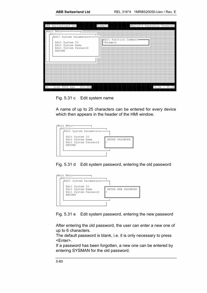
ABB Switzerland Ltd REL 316*4 1MRB520050-Uen / Rev. E
5-60
< ===========>########################################################?<=====================>###############################################??<@(8 (=====>#############################################????#* +6!!!!!!"###############???@(H3?#$K $###############???@(0 ?#1!!!!!!!!!!!!!!!!!!!!!!!!!!!2###############???@(8 ((?#############################################???/0?#############################################????#############################################??B===========================D#############################################???###############################################B=B===========================D#################################################################################################################################################################################################################################################################################################################################################################################################################################################################################################################################################################################################################3.4--5(678)9:5;)9:5
Fig. 5.31 c Edit system name
A name of up to 25 characters can be entered for every devicewhich then appears in the header of the HMI window.
< ===========>?<=====================>??<@(8 (=====>???????@(H3!!!!!!!!!!!!!!!!"???@(0 $08J3,$???@(8 (($K$???/0$$???1!!!!!!!!!!!!!!!!2??B===========================D???B=B===========================D
Fig. 5.31 d Edit system password, entering the old password
< ===========>?<=====================>??<@(8 (=====>???????@(H3!!!!!!!!!!!!!!!!!!!!"???@(0 $00J8J3,$???@(8 (($K$???/0$$???1!!!!!!!!!!!!!!!!!!!!2??B===========================D???B=B===========================D
Fig. 5.31 e Edit system password, entering the new password
After entering the old password, the user can enter a new one ofup to 6 characters.The default password is blank, i.e. it is only necessary to press<Enter>.If a password has been forgotten, a new one can be entered byentering SYSMAN for the old password.

REL 316*4 1MRB520050-Uen / Rev. E ABB Switzerland Ltd
5-61
5.5.7. Listing settings
All the settings or groups of settings can be viewed on thescreen, printed or saved in a file. The various possibilities can beseen from Fig. 5.32.
List edit parameters
Present edit functions
AD channels
Binary input channelsTrip output channelsMeldekanäle
Special system functions
similar to above
Active protection functionsand their parameters
AD channels andtheir utilisation
Address listProcedure list
RETURN
for development purposes only
System nameSoftware versionRelay configurationSystem settingsIBB/RIO configuration
All settings<Screen><Printer><File>
<Screen><Printer><File>
<Screen><Printer><File>
<Screen><Printer><File>
Library functions<Screen><Printer><File>
Signal output channels/LED’sDecentral outputsAnalogue inputsAnalogue outputs
Fig. 5.32 Listing relay settings
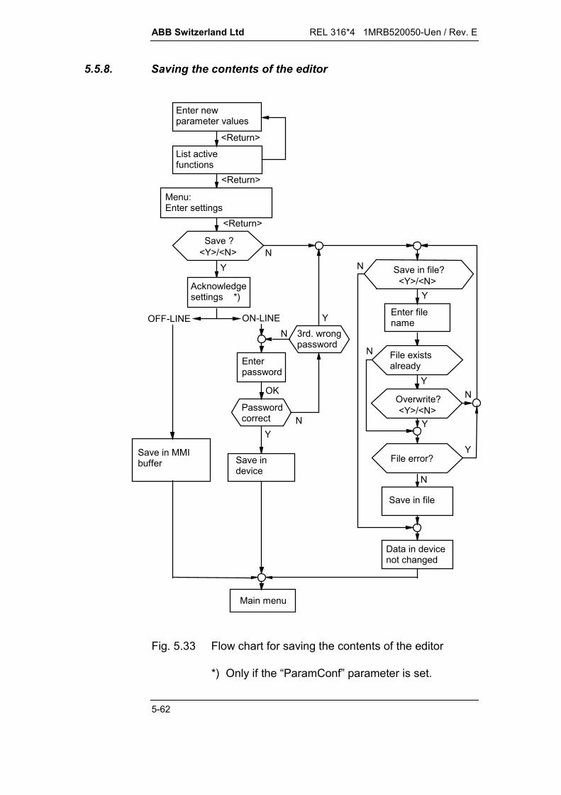
ABB Switzerland Ltd REL 316*4 1MRB520050-Uen / Rev. E
5-62
5.5.8. Saving the contents of the editor
Enter filename
Passwordcorrect N
Y
Main menu
Save indevice
YN
Save ?<Y>/<N>
List activefunctions
Enter newparameter values
<Return>
<Return>
<Return>
OK
OFF-LINE ON-LINE
Acknowledgesettings *)
3rd. wrongpassword
NY
Enterpassword
Y
N<Y>/<N>
Save in file?
Y
N
YFile error?
N
Y
File existsalready
N
Overwrite?<Y>/<N>
Save in MMIbuffer
Data in devicenot changed
Save in file
Menu:Enter settings
Fig. 5.33 Flow chart for saving the contents of the editor
*) Only if the “ParamConf” parameter is set.
REL 316*4 1MRB520050-Uen / Rev. E ABB Switzerland Ltd
5-63
5.5.8.1. Downloading to the device
The contents of the editor is downloaded to the device by re-peatedly selecting the “RETURN” line in the editor window. Theprocedure can be seen from Fig. 5.33.
As this operation is an extremely important one, a number of in-ternal checks are carried out (e.g. comparison of the softwarecode which is set with the existing software key). The down-loading procedure is aborted if errors are discovered (a corre-sponding message is displayed) and the existing device settingsare not changed.
Confirming parameters
If the “ParamConf” parameter is set, every new or changed pa-rameter has to be individually confirmed by pressing the <>key before it is saved. The corresponding menu for correcting aparameter can be opened by pressing <Esc>.
5.5.8.2. Saving in and loading from a file
The complete set of parameters including the hardware andsystem configuration data can be saved in a file either on afloppy or on the hard disc by one of the following:
selecting the menu item “Save Parameters to File”
repeatedly selecting “RETURN” as illustrated in Fig. 5.33.
The user is requested to enter a file name which must conformto the DOS format (max. 8 characters of file name and 3 char-acters extension). The file is created in the current directory, if apath is not entered (max. 35 characters). Corresponding errormessages are displayed should problems be encountered duringthe saving operation.
Loading a file from a drive is the reverse process of saving one.The user is requested to enter the name of the file. If a file of thatname is found, it is first checked for compatibility and thenloaded into the editor with the new set of parameters.
Note:
Loading a set of parameters from a file overwrites any data inthe editor beforehand. Therefore if you do not wish to loose theexisting data in the editor, they must be saved in a file beforeany other file is loaded.
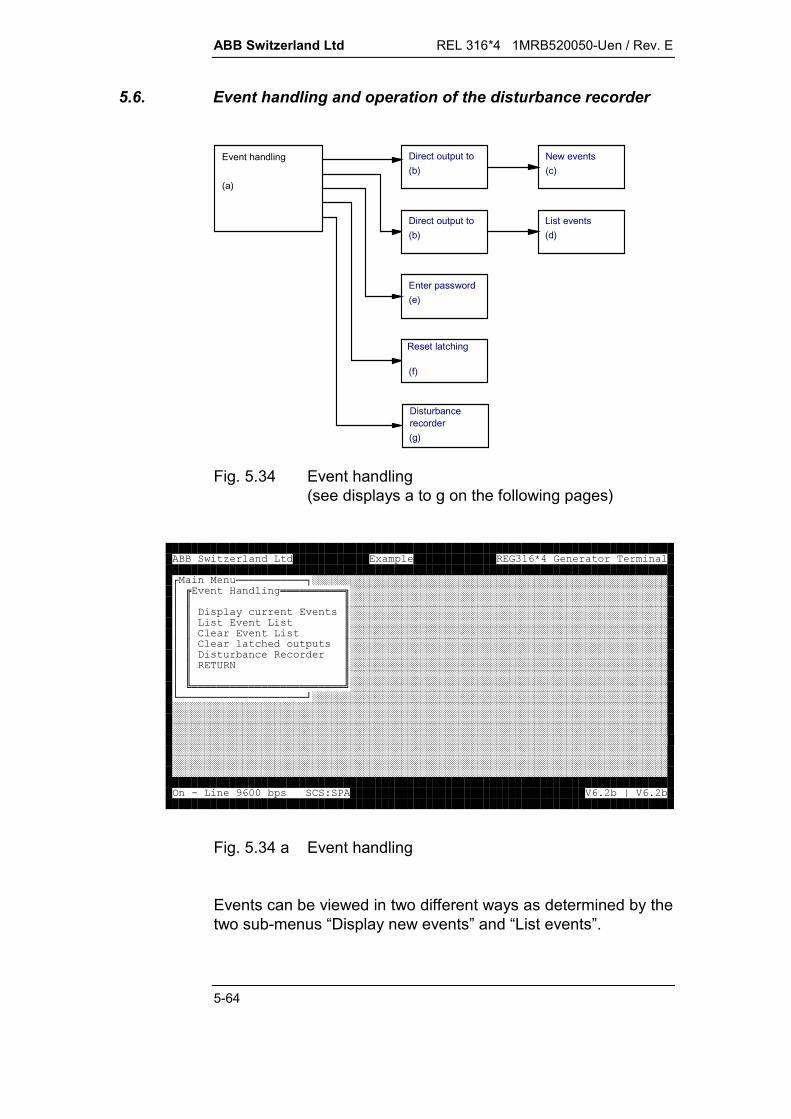
ABB Switzerland Ltd REL 316*4 1MRB520050-Uen / Rev. E
5-64
5.6. Event handling and operation of the disturbance recorder
(b)New events(c)
Direct output to
(b)Direct output to List events
(d)
Enter password(e)
Reset latching
(f)
Disturbancerecorder(g)
Event handling
(a)
Fig. 5.34 Event handling(see displays a to g on the following pages)
< ===========>########################################################?%& '!!!!!!!!!!"##################################################?$$##################################################?$,( @+ %($##################################################?$(%($##################################################?$6 %($##################################################?$6 +C ($##################################################?$,( 5 ++$##################################################?$/0$##################################################?$$##################################################?1!!!!!!!!!!!!!!!!!!!!!!!!2##################################################B====================D##########################################################################################################################################################################################################################################################################################################################################################################################################################################################################################################################################################################################################################3.4--5(678)9:5;)9:5
Fig. 5.34 a Event handling
Events can be viewed in two different ways as determined by thetwo sub-menus “Display new events” and “List events”.

REL 316*4 1MRB520050-Uen / Rev. E ABB Switzerland Ltd
5-65
In both cases, an invalid time stamp is indicated by a red ‘T’between the date and the time. An invalid time stamp resultsfrom the failure of the synchronisation signal on the interbay bus.The events of units that are not connected to the station auto-mation system are all marked as invalid following an interruptionof the auxiliary supply until the respective unit is resynchronisedto the PC time by running the HMI.
Display new events
In this mode, both the current relay events and the latest relayevents are displayed.
All the events are recorded in chronological order together withthe actual times they occurred (i.e. the time of the PC clock). Theevents are only displayed once, i.e. if the sub-menu is closedand then reopened, the display is empty until new events are re-corded.
If the transfer of the events to <Printer> or <File> was chosen, allthe events detected by the protection can be recorded over anyperiod of time. However, the HMI is busy and therefore blockedwhile this is going on. A “Load” or “Print” window indicates thatthe continuous display or printing mode is active. It remains sountil <Esc> is pressed. Do not switch the printer off, beforeleaving the continuous printing mode.
< ===========>?<%& '==========>?????,( @+ %(???(%(?!!!!!!!!!!!!!!!!!!!!!!!!!!!"??6 %(?$,+ $??6 +C (?$T+KFT8KFT*K$??,( 5 ++?$$??/0?1!!!!!!!!!!!!!!!!!!!!!!!!!!!2????B========================DB====================D
Fig. 5.34 b Direct output to

ABB Switzerland Ltd REL 316*4 1MRB520050-Uen / Rev. E
5-66
!!!!!!!!!!!!!!!!!!!!!!!!!!!!!!!!!!!!!!!!!!!!!!!!!!!!!!!!!!!!!!!!!!!!!!!!!!!!"$44V.-.:Q7:V]V9446 .,3**$$44V.-.:Q7:V]V9446 ., 3**$$O44V.-.:Q7:V]V944 3**$$44V.-.:Q7:V]49: 30$$Q44V.-.:Q7:V]49:6 ., 30$$V44V.-.:Q7:V]49:OO,( 5 +3 30$$444V.-.:Q7:V]49OO,( 5 +3 3**$$-44V.-.:Q7:V]O-9:6 .,30$$44V.-.:Q7:V]O-9:6 .,9-H0$$$$$$$$$$$$$$$$$1!!!!!!!!!!!!!!!!!!!!!!!!!!!!!!!!!!!!!!!!!!!!!!!!!!!!!!!!!!!!!!!!!!!!!!!!!!!!23.4--5(678)9:5;)9:5
Fig. 5.34 c New events
List events
The entire contents of the even memory (255 records) listed dis-played in the display mode.
Should the signal ‘General start’ pick up, the events are listedwith times in relation to the occurrence of the general start sig-nal, otherwise their actual times are given. The list can beviewed any number of times until it is deleted.
The display can be moved up or down line-by-line or scrolledpage-by-page using the keys <>, <> or <PgUp>, <PgDn>.The keys <Home> and <End> jump to the beginning, respec-tively end of the list.
!!!!!!!!!!!!!!!!!!!!!!!!!!!!!!!!!!!!!!!!!!!!!!!!!!!!!!!!!!!!!!!!!!!!!!!!!!!!"$:V,7-------7--]--9---6 ., 30$$:4,7-------7--]--9---O,( 5 +3 30$$-,7-------7--]--9--O,( 5 +3 3**$$,7-------7--]-9---6 .,30$$:,7-------7--]-9---6 .,9-H0$$,7-------7--]:9QQ-6 .,3**$$,7-------7--]:9QQ-6 ., 3**$$O44V.-.:Q7:V]V944 3**$$44V.-.:Q7:V]49: 30$$Q,7-------7--]--9---6 ., 30$$V,7-------7--]--9--O,( 5 +3 30$$4,7-------7--]--9-O,( 5 +3 3**$$-,7-------7--]-9---6 .,30$$,7-------7--]-9---6 .,9-H0$$:,7-------7--]-49V-6 .,3**$$,7-------7--]-49V-6 ., 3**$$44V.-.:Q7:V]OV94 3**$1!!!!!!!!!!!!!!!!!!!!!!!!!!!!!!!!!!!!!!!!!!!!!!!!!!!!!!!!!!!!!!!!!!!!!!!!!!!!23.4--5(678)9:5;)9:5
Fig. 5.34 d Event list

REL 316*4 1MRB520050-Uen / Rev. E ABB Switzerland Ltd
5-67
Deleting events
Providing a valid password is entered, the event list can be de-leted as follows.
< ===========>?<%& '==========>?????,( @+ %(???(%(?!!!!!!!!!!!!!!!!"??6 %(?$08J3,$??6 +C (?$K$??,( 5 ++?$$??/0?1!!!!!!!!!!!!!!!!2????B========================DB====================D
Fig. 5.34 e Enter password
Resetting latched outputs
After entering your password, you can reset the outputs thatlatch.
< ===========>?<%& '==========>?????,( @+ %(???(%(?!!!!!!!!!!!!!!!!"??6 %(?$08J3,$??6 +C (?$K$??,( 5 ++?$$??/0?1!!!!!!!!!!!!!!!!2????B========================DB====================D
Fig. 5.34 f Enter password

ABB Switzerland Ltd REL 316*4 1MRB520050-Uen / Rev. E
5-68
Disturbance recorder
List RecordsTransfer Records (12 Bit)
Reset RecorderRETURN
Disturbance Recorder
Number of Records = 0
Number of records Enter file name
Transfer disturbance data (e.g. 2 Bytes: 198)
Are you sure?<Y>/<N>
No. of deleted Records
Are you sure?<Y>/<N>
Reset disturbance recorder
(e.g. 2)
or:Events
Event 1 time 92.02.06 17:00:05Event 2 time 92.02.06 18:10:20
e.g.
Enter Password>
Delete Records
<No.> <Name.Ext>
Fig. 5.34 g Operation of the disturbance recorder
According to the above diagram, the disturbance recorder canoperate in one of the following modes:
List records:All the records in the memory are displayed.
Transfer records (12 Bit):One of the records is transferred. The number of the record andthe name of the file in which it should be stored must be given.
Delete records:The oldest record is deleted.
Reset disturbance recorder:The disturbance recorder is reinitialised and all the old recordsare deleted.

REL 316*4 1MRB520050-Uen / Rev. E ABB Switzerland Ltd
5-69
5.7. Displaying variables
< ( ) (!!!!!!!!!!!!!"#########################################?$$#########################################?$,( @,E6F)G6C ($#########################################?%$,( @* + ( ($#########################################?$,( @ @H ($#########################################?$,( @' 3 ($#########################################?,$,( @3 ($#########################################?$,( @,3 ($#########################################?,$,( @ ' H ($#########################################?$,( @ ' 3 ($#########################################?$,( @H ($#########################################B===$,( @3 ($#############################################$,( @HIH ($#############################################$,( @HI3 ($#############################################$,( @6I3 ($#############################################$,( @*/8' ($#############################################$/0$#############################################$$#############################################1!!!!!!!!!!!!!!!!!!!!!!!!!!!!!!!2#########################################3.4--5(678)9:5;)9:5
Fig. 5.35 Processing measurements
The load values measured by the protection functions and all thedevice inputs and outputs can be displayed.
The logic signals of all the FUPLA segments can be checked byselecting the menu item “Display FUPLA signals”. This is usedprimarily for testing at the works.
5.7.1. Displaying AD(CT/VT) channels
All 9 c.t. and p.t. inputs can be viewed at the same time: < ===========>########################################################?< ( <,( @,E6F)G6C (=================================>#########???6C909 8C (*P +@?#########??,(??#########??,(?-9VOMN-9--'O-9---&?#########??,(?:-9VOMN.:-9:'?#########??,(?-9VOMN:-9Q'?#########??,(?-9---MN.9..'?#########??,(?O-9---M--)N.9..'?#########??,(?-9---M--)N.9..'?#########??,(?Q9--M--)N-9-Q'?#########B=?,(?V-9444M--)N.4-9'?###########?,(?49---M--)NO-9:'?###########?,(?!!!!!!!!!!!!!!!!!!!!!!!"?###########?,(?744V.-.:Q$A6C ^$EQG?###########?/?1!!!!!!!!!!!!!!!!!!!!!!!2?###########???###########B=====B===========================================================D#######################################################################################3.4--5(678)9:5;)9:5
Fig. 5.36 Display AD(CT/VT) channels

ABB Switzerland Ltd REL 316*4 1MRB520050-Uen / Rev. E
5-70
Press an arrow key to open the reference channel window andselect the reference channel by entering its number. The refer-ence channel measures the frequency and provides the refer-ence for angular measurements.
5.7.2. Displaying load values
Load values are measured by every protection function with ameasurement algorithm. The desired function can be selectedvia the sub-menu “Display load values”.
Note that the list includes all the active functions for all the setsof parameters, i.e. also those which do not measure load valuessuch as:
auto-reclosure remote binary FUPLA VDEW6 defluttering logic disturbance recorder.
< ===========>########################################################?< ( ) (=============>###########################################??<,( @* + ( (==>#########################################????#########################################???M---F--N6 .,?#########################################???:M---F--N)K ) '?#########################################???M---F--N8?#########################################???M---F--N6 .,!!!!!!!!!!!!!!!!!!!!!!!!!!!!!!"#########???O$$#########???$-9VH0$#########???$$#########B=??1!!!!!!!!!!!!!!!!!!!!!!!!!!!!!!!!!!!!!!!!!!!!!!!!!!!!!!!!!!!2###########?B===============================D###########################################?,( @6I3 (?#############################################?,( @*/8' (?#############################################?/0?#############################################??#############################################B===============================D#########################################################################################################################3.4--5(678)9:5;)9:5
Fig. 5.37 Display function measurements (load values)

REL 316*4 1MRB520050-Uen / Rev. E ABB Switzerland Ltd
5-71
5.7.3. Displaying binary inputs, signalling relays, LED’s or trippingrelays
The inputs or outputs are displayed upon entering the number ofthe corresponding local or distributed input/output plug-in unit.Active inputs and outputs are indicated by an “X”.
< ===========>########################################################?< ( ) (=============>###########################################???###########################################??,( @,6C (?###########################################??,( @* + ( (?###########################################??,( @ @H (?###########################################??,( @' 3 (<+H3.========================>#####??,( @3 (??#####??,( @,3 (?K?#####??,( @H (? @H 6C (!!!!"##??,( @3 (?/( 5H3.$$##B=?,( @HIH (?$<==<==<==<==<==<==<==<==>$####?,( @HI3 (?X:$??:???O??Q?V?$####?,( @6I3 (?$??R????R???$####?,( @*/8' (B===============$B==B==B==B==B==B==B==B==D$####?/0?##############$$####??##############$$####B===============================D##############1!!!!!!!!!!!!!!!!!!!!!!!!!2################################################################################3.4--5(678)9:5;)9:5
Fig. 5.38 Display binary inputs
5.7.4. Displaying analogue inputs and outputs
Enter the device number to view the associated inputs or out-puts.
< < ( ) (=============>#########################################???#########################################??,( @,E6F)G6C (?#########################################?%?,( @* + ( (?#########################################??,( @ @H (?#########################################??,( @' 3 (?#########################################?,?,( @ ' H (!!!"#######################################??,( @,3$$#######################################?,?,( @ $4$#######################################??,( @ $:94$#######################################??,( @H$.O9$#######################################B===?,( @3$9:Q)$###########################################?,( @HH$QO9:4_6$###########################################?,( @H3$$###########################################?,( @63$$###########################################?,( @*/8$$###########################################?/0$$###########################################?$$###########################################B==============1!!!!!!!!!!!!!!!!!!2#######################################3.4--5(678)9:5;)9:5
Fig. 5.39 Display analogue inputs
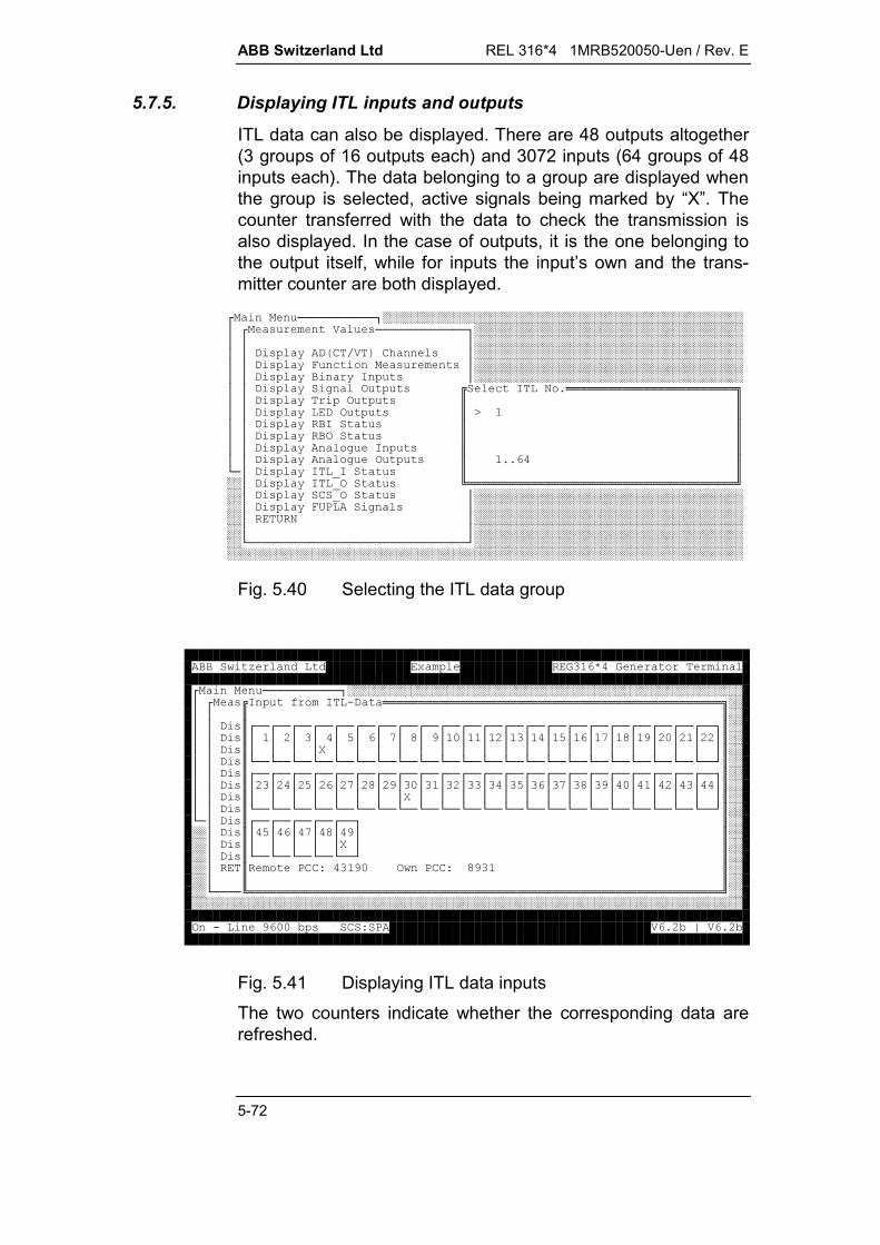
ABB Switzerland Ltd REL 316*4 1MRB520050-Uen / Rev. E
5-72
5.7.5. Displaying ITL inputs and outputs
ITL data can also be displayed. There are 48 outputs altogether(3 groups of 16 outputs each) and 3072 inputs (64 groups of 48inputs each). The data belonging to a group are displayed whenthe group is selected, active signals being marked by “X”. Thecounter transferred with the data to check the transmission isalso displayed. In the case of outputs, it is the one belonging tothe output itself, while for inputs the input’s own and the trans-mitter counter are both displayed.
< ===========>###################################################?< ( ) (=============>######################################???######################################??,( @,E6F)G6C (?######################################??,( @* + ( (?######################################??,( @ @H (?######################################??,( @' 3 (+H09!!!!!!!!!!!!!!!!!!!!!!!!"??,( @3 ($$??,( @,3 ($K$??,( @H ($$??,( @3 ($$??,( @ ' H ($$??,( @ ' 3 ($99$B=?,( @HIH ($$##?,( @HI3 (1!!!!!!!!!!!!!!!!!!!!!!!!!!!!!!!!!!!!!!2##?,( @6I3 (?########################################?,( @*/8' (?########################################?/0?########################################??########################################B===============================D###############################################################################################################
Fig. 5.40 Selecting the ITL data group
< ===========>########################################################?< (H AH., !!!!!!!!!!!!!!!!!!!!!!!!!!!!!!!!!!!!!!!!!!!!!!!!"##??$$##??,($<==<==<==<==<==<==<==<==<==<==<==<==<==<==<==<==<==<==<==<==<==<==>$##??,($??:???O??Q?V?4?-??:???O??Q?V?4?:-?:?::?$##??,($????R???????????????????$##??,($B==B==B==B==B==B==B==B==B==B==B==B==B==B==B==B==B==B==B==B==B==B==D$##??,($<==<==<==<==<==<==<==<==<==<==<==<==<==<==<==<==<==<==<==<==<==<==>$##??,($?:?:?:O?:?:Q?:V?:4?-??:???O??Q?V?4?-??:???$##??,($????????R???????????????$##??,($B==B==B==B==B==B==B==B==B==B==B==B==B==B==B==B==B==B==B==B==B==B==D$##B=?,($<==<==<==<==<==>$####?,($?O??Q?V?4?$####?,($?????R?$####?,($B==B==B==B==B==D$####?$86674-38667V4$####?$$####B====1!!!!!!!!!!!!!!!!!!!!!!!!!!!!!!!!!!!!!!!!!!!!!!!!!!!!!!!!!!!!!!!!!!!2################################################################################3.4--5(678)9:5;)9:5
Fig. 5.41 Displaying ITL data inputsThe two counters indicate whether the corresponding data arerefreshed.
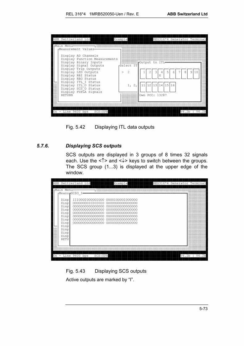
REL 316*4 1MRB520050-Uen / Rev. E ABB Switzerland Ltd
5-73
< ===========>########################################################?< ( ) (=============>###########################################???###########################################??,( @,6C (?###########################################??,( @* + ( (?###########################################??,( @ @H (?########3 H!!!!!!!!!!!!!!!!!!"##??,( @' 3 (<+H$$##??,( @3 (?$<==<==<==<==<==<==<==<==<==<==>$##??,( @,3 (?K:$??:???O??Q?V?4?-?$##??,( @H (?$????R???????$##??,( @3 (?$B==B==B==B==B==B==B==B==B==B==D$##B=?,( @HIH (?$<==<==<==<==<==<==>$####?,( @HI3 (?X:X$??:???O??$####?,( @6I3 (?$???????$####?,( @*/8' (B=========$B==B==B==B==B==B==D$####?/0?########$38667:VQ$####??########$$####B===============================D########1!!!!!!!!!!!!!!!!!!!!!!!!!!!!!!!2################################################################################3.4--5(678)9:5;)9:5
Fig. 5.42 Displaying ITL data outputs
5.7.6. Displaying SCS outputs
SCS outputs are displayed in 3 groups of 8 times 32 signalseach. Use the <> and <> keys to switch between the groups.The SCS group (1...3) is displayed at the upper edge of thewindow.
< ===========>########################################################?< ( 63I!!!!!!!!!!!!!!!!!!!!!!!!!!!!!!!!!!!!!!!!!!!!!!!!!!!!!"#########??$$#########??,($HHH333H33333H3333333H3333H333333$#########??,($33333333H3H3H3H33333333333333333$#########??,($33333333333333333333333333333333$#########??,($33333333333333333333333333333333$#########??,($33333333333333333333333333333333$#########??,($33333333333333333333333333333333$#########??,($33333333333333333333333333333333$#########??,($33333333333333333333333333333333$#########B=?,($$###########?,($$###########?,($$###########?,($$###########?/$$###########?$$###########B=====1!!!!!!!!!!!!!!!!!!!!!!!!!!!!!!!!!!!!!!!!!!!!!!!!!!!!!!!!!!!2#######################################################################################3.4--5(678)9:5;)9:5
Fig. 5.43 Displaying SCS outputs
Active outputs are marked by “I”.
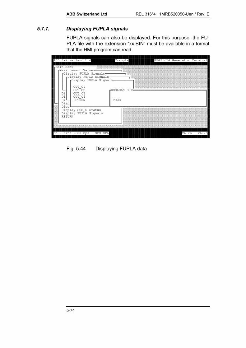
ABB Switzerland Ltd REL 316*4 1MRB520050-Uen / Rev. E
5-74
5.7.7. Displaying FUPLA signals
FUPLA signals can also be displayed. For this purpose, the FU-PLA file with the extension “xx.BIN” must be available in a formatthat the HMI program can read.
< ===========>########################################################?< ( ) (=============>###########################################??<,( @*/8' (==========>#########################################???<,( @*/8' (==========>#######################################????<,( @*/8' (==========>#####################################??????#####################################?????3/I3?#####################################??B=??3/I3:330I3/!!!!!!!!!!!!!!!!!!!!!!!!!!!!!!!!!!!!!"??,??3/I3$$??,??3/I3$$??,B=?/0$/$B=?,(?$$##?,(B===================1!!!!!!!!!!!!!!!!!!!!!!!!!!!!!!!!!!!!!!!!!!!!!!!!2##?,( @6I3 (?#############################################?,( @*/8' (?#############################################?/0?#############################################??#############################################B===============================D#########################################################################################################################3.4--5(678)9:5;)9:5
Fig. 5.44 Displaying FUPLA data
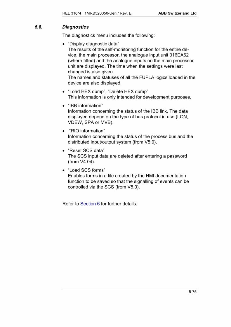
REL 316*4 1MRB520050-Uen / Rev. E ABB Switzerland Ltd
5-75
5.8. Diagnostics
The diagnostics menu includes the following:
“Display diagnostic data”The results of the self-monitoring function for the entire de-vice, the main processor, the analogue input unit 316EA62(where fitted) and the analogue inputs on the main processorunit are displayed. The time when the settings were lastchanged is also given.The names and statuses of all the FUPLA logics loaded in thedevice are also displayed.
“Load HEX dump”, “Delete HEX dump”This information is only intended for development purposes.
“IBB information”Information concerning the status of the IBB link. The datadisplayed depend on the type of bus protocol in use (LON,VDEW, SPA or MVB).
“RIO information”Information concerning the status of the process bus and thedistributed input/output system (from V5.0).
“Reset SCS data”The SCS input data are deleted after entering a password(from V4.04).
“Load SCS forms”Enables forms in a file created by the HMI documentationfunction to be saved so that the signalling of events can becontrolled via the SCS (from V5.0).
Refer to Section 6 for further details.

ABB Switzerland Ltd REL 316*4 1MRB520050-Uen / Rev. E
5-76
5.9. Test functions
Since some of them can disrupt the normal operation of the de-vice, test functions can only be accessed after entering the validpassword. They are used mainly during commissioning and mayonly be activated when the plant is out of service, or with thetripping and signalling circuits externally disconnected if in serv-ice.
The protection is re-initiated upon closing the “Test functions”menu and the set of parameters previously used in operation re-activated.
The procedure for using the test functions can be seen from thefollowing figures.
< ===========>########################################################?(* +(!!!!!!!!!"###################################################?$$###################################################?$( $###################################################?$8A(+($###################################################?$%& '$###################################################?$ ( ) ($###################################################?$(, 'HA$###################################################?$8 (.+C'$###################################################?$+LJ$###################################################?$''J$###################################################B=$/+LJ$#####################################################$/0$#####################################################$$#####################################################1!!!!!!!!!!!!!!!!!!!!!!!2###########################################################################################################################################################################################################################################################################################################################################################################3.4--5(678)9:5;)9:5
Fig. 5.45 Test functions
Set test data
< ===========>#########?<(* +(=========>####??( !!!!!!!!!!!!!"??$$??$8+( $??$ @($??$' @($??$3 @($??$ ' 3 ($??$,Y($??$/0$B=?$$##?1!!!!!!!!!!!!!!!!!!!!!!!!!2##??######B=======================D####
Fig. 5.46 Set test data

REL 316*4 1MRB520050-Uen / Rev. E ABB Switzerland Ltd
5-77
1. Testing the protection functions:
A protection function is selected for testing (using <Ins>) fromthe list of “active functions”. The list contains all the activefunctions occurring in all the sets of parameters, includingthose which cannot be tested such as
Check-I3ph VDEW6 Check-U3ph Flutter detection Distance Delay Auto-reclosure Counter Pole slipping Logic EarthFltGnd2 UIFPQ Remote binary Disturbance recorder FUPLA.
The next window requires the input of one or several test val-ues. The simulation of the input signals checks the operationof the function and its tripping and signalling channels.
< ===========>?<(* +(=========>??<( =============>???????8+( !!!!!!!!!!!!!!!!!!!!!!!!!!!!!!!!!!"??? @$<==<==<==<==<==<==>$???' $??:???O??$???3 @($???????$???,Y($B==B==B==B==B==B==D$???/0$*P +@$???1!!!!!!!!!!!!!!!!!!!!!!!!!!!!!!!!!!!!!!!!!!!!!!2B=?B=========================D?/0???B=======================D
Fig. 5.47 Set protection test data
< ===========>?<(* +(=========>??<( =============>???????8+<( =====================================>??? @?<==<==<==<==<==<==>????' ???:???O??????<*P +@==================================================>???????????-9---&!!!!!!!!!!!!!!!!!!!!!!!!!!!!!!!!!!!!"??????-9--/0$) 7M&N$?=DB=?B===?/0F0$K$??/?$$???1!!!!!!!!!!!!!!!!!!!!!!!!!!!!!!!!!!!!2?B=====??????B===========================================================D
Fig. 5.48 Enter measurement value

ABB Switzerland Ltd REL 316*4 1MRB520050-Uen / Rev. E
5-78
2. Testing the tripping relays, signalling relays or LED’s:
After entering the slot number, one or several tripping chan-nels may be selected for testing (by pressing <Ins>). Uponexecuting the command, the corresponding tripping relays,signalling relays and LED’s of the channels concerned areenergised.It is only possible to set tripping commands and signals ofone input/output unit at a time and the signals must be of thesame type, e.g. either signalling relays or LED’s.
< ===========>?<(* +(=========>??<( =============>???????8+( ???? @(????' @(?+H3.!!!!!!!!!!!!!!"???3 @(?$X:$???,Y(?$$???/0?$K$????1!!!!!!!!!!!!!!!!!!!!!!!!!!!!2B=?B=========================D?/0???B=======================D
Fig. 5.49 Select IO slot
< ===========>?<(* +(=========>??<( =============>???????8+( !!!!!!!!!!!!!!!!!!!!!!!!!!!!!!!!!!!!!"??? @$<==<==<==<==<==<==>$???' $??:???O??$???3 @($?R???R??R?$???,Y($B==B==B==B==B==B==D$???/0$$???1!!!!!!!!!!!!!!!!!!!!!!!!!!!!!!!!!!!!!!!!!!!!!!!!!2B=?B=========================D?/0???B=======================D
Fig. 5.50 Set test data
3. Energising RBO relays (distributed output):
After entering the device number, one or several output chan-nels can be selected (using <Ins>). The corresponding chan-nels energise the relays when the operation is executed. Onlyrelays belonging to the same device can be set at a time andit is not possible to set two different kinds of signals at thesame time, e.g. signalling relays in the RE.316*4 and in one ofthe distributed units.
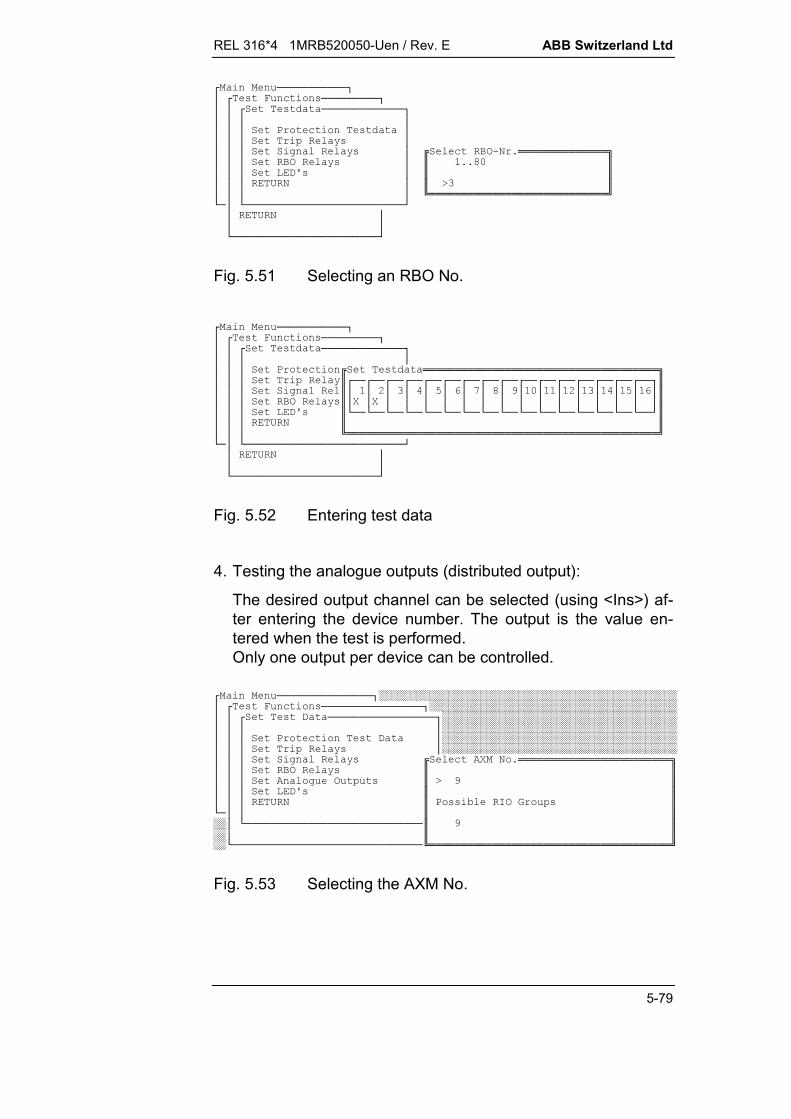
REL 316*4 1MRB520050-Uen / Rev. E ABB Switzerland Ltd
5-79
< ===========>?<(* +(=========>??<( =============>???????8+( ???? @(????' @(?+3.09!!!!!!!!!!!!!!"???3 @(?$99V-$???,Y(?$$???/0?$K$????1!!!!!!!!!!!!!!!!!!!!!!!!!!!!2B=?B=========================D?/0???B=======================D
Fig. 5.51 Selecting an RBO No.
< ===========>?<(* +(=========>??<( =============>???????8+( !!!!!!!!!!!!!!!!!!!!!!!!!!!!!!!!!!!!!"??? @$<==<==<==<==<==<==<==<==<==<==<==<==<==<==<==<==>$???' $??:???O??Q?V?4?-??:???O??$???3 @($?R?R???????????????$???,Y($B==B==B==B==B==B==B==B==B==B==B==B==B==B==B==B==D$???/0$$???1!!!!!!!!!!!!!!!!!!!!!!!!!!!!!!!!!!!!!!!!!!!!!!!!!2B=?B=========================D?/0???B=======================D
Fig. 5.52 Entering test data
4. Testing the analogue outputs (distributed output):
The desired output channel can be selected (using <Ins>) af-ter entering the device number. The output is the value en-tered when the test is performed.Only one output per device can be controlled.
< ===============>###############################################?<(* +(================>#######################################??<(, =================>#####################################????#####################################???8+(, ?#####################################??? @(?#####################################???' @(+R09!!!!!!!!!!!!!!!!!!!!!!!!"???3 @($$??? ' 3 ($K4$???,Y($$???/0$8((5H3 ($B=??$$##?B============================$4$##?$$##B==============================1!!!!!!!!!!!!!!!!!!!!!!!!!!!!!!!!!!!!!!2
Fig. 5.53 Selecting the AXM No.

ABB Switzerland Ltd REL 316*4 1MRB520050-Uen / Rev. E
5-80
< ===============>#############################################?<(* +(================>#####################################??<(, =================>###################################????###################################???8+(, !!!!!!!!!!!!!!!!!!!!!!!!!!!!!!!!!!!!"??? @$<==<==>$???' $??:?$???3 @($???$??? ' 3$B==B==D$???,Y($+6C $???/01!!!!!!!!!!!!!!!!!!!!!!!!!!!!!!!!!!!!!!!!!!!!!!!!!2B=???#####################################?B==============================D#####################################??#######################################B==============================D#####################################
Fig. 5.54 Selecting the channel
< ===============>##############################################?<(* +(================>######################################??<(, =================>####################################????####################################???8+<(, ====================================>#??? @?<==<==>?#???' ???:??#???3 @(?????#??? ' 3?B==B==D?#???,Y(?+6!!!!!!!!!!!!!!!!!!!!!!!!!!!!!!!!!!!!!!!!!"???/0B========$0) 7M9--999:-9--N$B=??$K$##?B========================$$##?1!!!!!!!!!!!!!!!!!!!!!!!!!!!!!!!!!!!!!!!!!2##B==============================D######################################
Fig. 5.55 Setting the output value
Perform selected test
After entering the test data, repeatedly press the <End> and<Enter> keys to return to the “Test functions” menu.
Select the menu item “Perform selected test” to start the test andapply the test data which has been set.
“Event handling”, “Measurement values” and “List diag. info.”
These menu items enable the corresponding functions to beused in the test mode and provide the facilities described in Sec-tions 5.6. to 5.8.
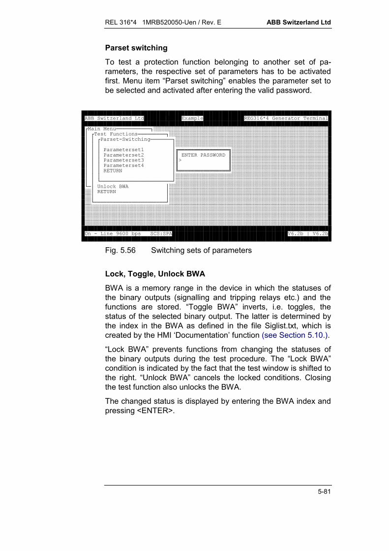
REL 316*4 1MRB520050-Uen / Rev. E ABB Switzerland Ltd
5-81
Parset switching
To test a protection function belonging to another set of pa-rameters, the respective set of parameters has to be activatedfirst. Menu item “Parset switching” enables the parameter set tobe selected and activated after entering the valid password.
< ===========>########################################################?<(* +(=========>###################################################??<8 (.+C'=======>#################################################????#################################################???8 (?!!!!!!!!!!!!!!!!"###############################???8 (:?$08J3,$###############################???8 (?$K$###############################???8 (?$$###############################???/0?1!!!!!!!!!!!!!!!!2###############################????#################################################??B=======================D#################################################B=?/+LJ?#####################################################?/0?#####################################################??#####################################################B=======================D###########################################################################################################################################################################################################################################################################################################################################################################3.4--5(678)9:5;)9:5
Fig. 5.56 Switching sets of parameters
Lock, Toggle, Unlock BWA
BWA is a memory range in the device in which the statuses ofthe binary outputs (signalling and tripping relays etc.) and thefunctions are stored. “Toggle BWA” inverts, i.e. toggles, thestatus of the selected binary output. The latter is determined bythe index in the BWA as defined in the file Siglist.txt, which iscreated by the HMI ‘Documentation’ function (see Section 5.10.).
“Lock BWA” prevents functions from changing the statuses ofthe binary outputs during the test procedure. The “Lock BWA”condition is indicated by the fact that the test window is shifted tothe right. “Unlock BWA” cancels the locked conditions. Closingthe test function also unlocks the BWA.
The changed status is displayed by entering the BWA index andpressing <ENTER>.

ABB Switzerland Ltd REL 316*4 1MRB520050-Uen / Rev. E
5-82
< ===========>########################################################??########################################################??#####################################<JI+L===>####?%& '?###############################<(* +(=========>? ( ) (?#######!!!!!!!!!"#############???(* +(?#######$KV$#############?( ??, '(+(?#######$$#############?8A(+(??--.?#######1!!!!!!!!!2#############?%& '??,+ ?###############################? ( ) (??/0?###############################?(, 'HA???###############################?8 (.+C'?B====================D###############################?+LJ?#####################################################?''J?#####################################################?/+LJ?#####################################################?/0?#####################################################??#####################################################B=======================D############################################################################################################################################################3.4--5(678)9:5;)9:5
Fig. 5.57 Toggle BWA: selecting the signal to toggle
< ===========>########################################################??########################################################??#####################################<JI+L===>####?%& '?###############################<(* +(=========>? ( ) (?#######!!!!!!!!!!!!!!!!"######???(* +(?#######$/..K*$######?( ??, '(+(?#######$$######?8A(+(??--.?#######1!!!!!!!!!!!!!!!!2######?%& '??,+ ?###############################? ( ) (??/0?###############################?(, 'HA???###############################?8 (.+C'?B====================D###############################?+LJ?#####################################################?''J?#####################################################?/+LJ?#####################################################?/0?#####################################################??#####################################################B=======================D############################################################################################################################################################3.4--5(678)9:5;)9:5
Fig. 5.58 Toggle BWA: displaying the signal status change
Extract from the file Siglist.txt :For BWA index 27, for example, “Toggle BWA” switches the cur-rent function “TRIP” signal on and off.
FunctionName FuncType SignalStdName BWAIndex SigType
System IO 34 GenTrip 3 SI
System IO 34 GenStart 5 SI
Logic 31 BinOutput 26 SI
Current 3 TRIP 27 SI
Current 3 Start 28 SI

REL 316*4 1MRB520050-Uen / Rev. E ABB Switzerland Ltd
5-83
5.10. Documentation
This menu item provides facility for generating various files re-quired when engineering an SCS system.
The files generated are as follows:
recxx.evt List of all the possible events with provision for de-fining whether an event should be recorded as such(masking).
recxx.inp List of all the binary inputs used.
recxx.out List of all the binary outputs used.
recxx.pbi List of distributed input/output modules with detailsof type and configuration.
recxx.sig List of all signals and their main data (name, ad-dress, event No., BWA index etc.)
xx = device address on the SCS bus.

ABB Switzerland Ltd REL 316*4 1MRB520050-Uen / Rev. E
5-84
5.11. Operation with several sets of parameters
The units of the RE. 316*4 series permit up to four independentsets of relay settings or protection configurations to be defined.Only one of these sets of parameters can be active at any onetime when the protection is in operation. Provision is made forswitching between sets of parameters.
5.11.1. Switching sets of parameters
One of the four sets of parameters is selected by
a) applying a signal to a binary input (opto-couplers)
b) a signal from the station automation system (SCS).
Setting binary inputs
A maximum of four binary inputs are used for switching sets ofparameters. They are configured by selecting the menu item“Edit inputs/outputs” in the “Edit system functions” menu.
If when configuring the inputs using the HMI they are left at theirdefault setting of “F” (FALSE = always OFF), the protection canonly operate with parameter set 1.
“Remote sel.” : If this I/P is activated, a signal from the sta-tion control system (SCS) is necessary toswitch between sets of parameters, other-wise the I/P's “ParSet2”, “ParSet3” and“ParSet4” determine which set of parame-ters is active.
“ParSet2”, “ParSet3” and “ParSet4”:
These three I/P's enable one of the four sets ofparameters to be selected.
ParSet2 ParSet3 ParSet4 Active set of para.
F F F 1
T F F 2
F T F 3
T T F no change
F F T 4
T F T no change
F T T no change
T T T no change
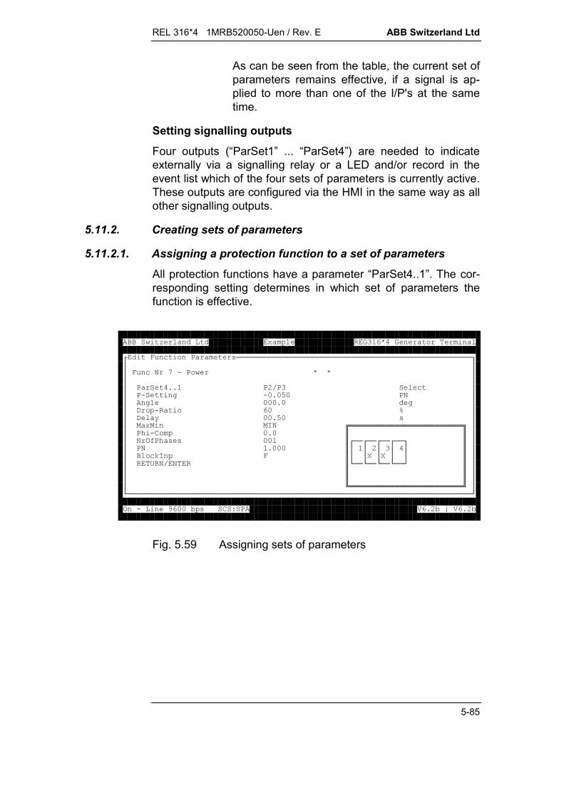
REL 316*4 1MRB520050-Uen / Rev. E ABB Switzerland Ltd
5-85
As can be seen from the table, the current set ofparameters remains effective, if a signal is ap-plied to more than one of the I/P's at the sametime.
Setting signalling outputs
Four outputs (“ParSet1” ... “ParSet4”) are needed to indicateexternally via a signalling relay or a LED and/or record in theevent list which of the four sets of parameters is currently active.These outputs are configured via the HMI in the same way as allother signalling outputs.
5.11.2. Creating sets of parameters
5.11.2.1. Assigning a protection function to a set of parameters
All protection functions have a parameter “ParSet4..1”. The cor-responding setting determines in which set of parameters thefunction is effective.
<* +8 (====================================================>???* +0Q.8????8 998:F8+??8.'.-9-O-80??'---9-'??,. -`??, @--9O-(?? H0!!!!!!!!!!!!!!!!!!!!!!!!!"??8C.6-9-$$??03A8C ((--$<==<==<==<==>$??809---$??:???$??+LH*$??R?R??$??/0F0$B==B==B==B==D$??$$??$$??1!!!!!!!!!!!!!!!!!!!!!!!!!2?B============================================================================D3.4--5(678)9:5;)9:5
Fig. 5.59 Assigning sets of parameters
ABB Switzerland Ltd REL 316*4 1MRB520050-Uen / Rev. E
5-86
5.11.2.2. Copying a protection function with its settings
A protection function can be copied together with its settingsfrom one set of parameters to another, if its settings in the sec-ond set of parameters remain mostly the same. The procedure isdescribed in Section 5.5.1.3.
The copied Version of the protection function assumes preciselythe same settings as the original function. The following parame-ters of a copied function cannot be changed subsequently
all analogue inputs all signalling outputs all tripping channels.
The copied function must not be active in the same set of pa-rameters as the original and the parameter set number of theoriginal function must be lower:
RULE: P1 pO P4 <---> pO < pK P4
pO = parameter set number of the original functionpK = parameter set number of the copied function.
The originals of existing copied functions cannot be deleted.

REL 316*4 1MRB520050-Uen / Rev. E ABB Switzerland Ltd
5-87
5.11.2.3. Displaying a function with its settings
< ===========>########################################################?<=====================>###############################################??8(8* +(!!!!!!!!!!!"###########################################??$$###########################################??$M---F--N6 .,$###########################################??$:M:--F--N)K ) '$###########################################??$M---F--N8$###########################################??$M-:--F--N6 .H%$###########################################??$OM:-F--N,( 5 ++$###########################################??$M---F-N6 .,$###########################################??$QM---F-:N) '.,$###########################################B=B=$VM-:-F-N8$###############################################$4H(* +$###############################################$/0$###############################################$$###############################################1!!!!!!!!!!!!!!!!!!!!!!!!!!!!!2###################################################################################################################################################################################################################################################################################################################################################################3.4--5(678)9:5;)9:5
Fig. 5.60 Presentation by the HMI of the protection functions
The list of functions and their settings are presented as follows:
A [B / C] D (e.g. 1 [1000/00] Current-DT)
A: Function No.
B: active in parameter set No., e.g.0030: parameter set 11230: parameter sets 1, 2 and 3
C: 0 = original functionn = copy of function n
D: function name.
5.11.3. Logics
Where several protection functions are related by a commonlogic, they must all be active in the same set of parameters.
Note:Outputs of copied distance protection functions can only beconnected to inputs of functions listed after the distancefunction in the function list.

ABB Switzerland Ltd REL 316*4 1MRB520050-Uen / Rev. E
5-88
5.12. Remote HMI
5.12.1. Summary
The firmware provides facility for controlling RE.316*4 devicesgrouped according to stations. All the HMI functions are avail-able. User access via the remote HMI to such functions as ‘Loadsetfile’, ‘Test function’, ‘Time synchronisation’ and ‘SPA commu-nication’ can be restricted.
We do not recommend loading and downloading ‘Setfiles’ via amodem link as all the device settings will be lost should the linebe interrupted during file transfer.
Remote HMI facilities:
local control of a device via the interface on the front
control of several devices in an SPA_BUS loop via a modemand the SPA-BUS interface
control of several devices in an SPA_BUS loop via the SPA-BUS interface
control of several devices in an SPA_BUS loop via an SRIO.In this operating mode, the HMI sets the SRIO clock and syn-chronises the device clocks.
control of several devices in an SPA_BUS loop via a modemlink and an SRIO. In this operating mode, the HMI sets theSRIO clock and synchronises the device clocks.
safe operation since the simultaneous access by local andremote HMI’s is excluded
system of access rights to restrict the operations possible onthe HMI
event recording transferred to a pre-defined individual di-rectory for each device
convenient HMI user shell for easy control.
5.12.2. Modem requirements
A modem used in conjunction with the remote HMI must be suit-able for asynchronous operation and the interface baud ratemust be independent of the line baud rate. It must be possible toset the interface baud rate to correspond to the SPA/SRIO baudrate.
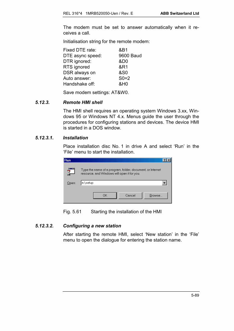
REL 316*4 1MRB520050-Uen / Rev. E ABB Switzerland Ltd
5-89
The modem must be set to answer automatically when it re-ceives a call.
Initialisation string for the remote modem:
Fixed DTE rate: &B1DTE async speed: 9600 BaudDTR ignored: &D0RTS ignored &R1DSR always on &S0Auto answer: S0=2Handshake off: &H0
Save modem settings: AT&W0.
5.12.3. Remote HMI shell
The HMI shell requires an operating system Windows 3.xx, Win-dows 95 or Windows NT 4.x. Menus guide the user through theprocedures for configuring stations and devices. The device HMIis started in a DOS window.
5.12.3.1. Installation
Place installation disc No. 1 in drive A and select ‘Run’ in the‘File’ menu to start the installation.
Fig. 5.61 Starting the installation of the HMI
5.12.3.2. Configuring a new station
After starting the remote HMI, select ‘New station’ in the ‘File’menu to open the dialogue for entering the station name.
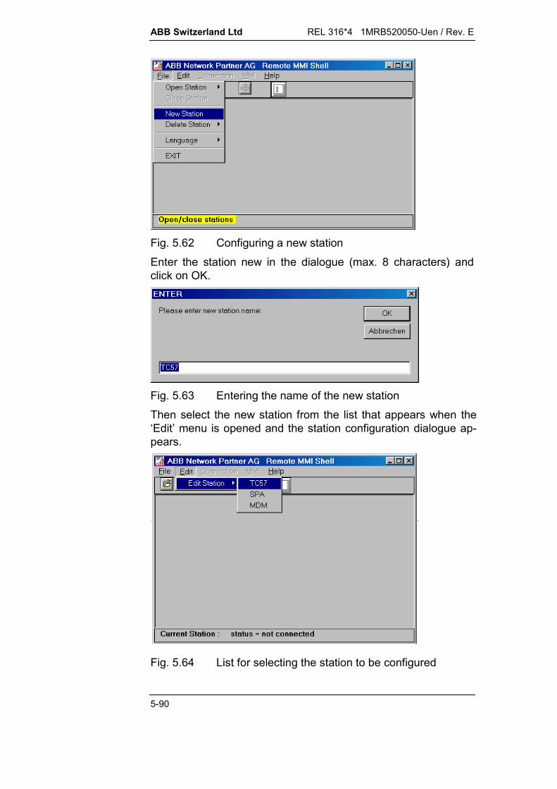
ABB Switzerland Ltd REL 316*4 1MRB520050-Uen / Rev. E
5-90
Fig. 5.62 Configuring a new stationEnter the station new in the dialogue (max. 8 characters) andclick on OK.
Fig. 5.63 Entering the name of the new stationThen select the new station from the list that appears when the‘Edit’ menu is opened and the station configuration dialogue ap-pears.
Fig. 5.64 List for selecting the station to be configured

REL 316*4 1MRB520050-Uen / Rev. E ABB Switzerland Ltd
5-91
The next task is to edit the files ‘Station.cfg’ and ‘MMKShell.mnu’in the configuration dialogue.The following parameters are set in ‘Station.cfg’:COMT : Communication parameters
TC57 = communication via interface at the frontSPA = communication via the SPA-BUS interfaceMDM = communication via modem and SPA-BUS
interfaceSRIO = direct communication via SRIORDM = communication via modem and SRIO.
BAUD : Baud rate.TNR : Station telephone number (T...tone dialling,
P...impulse dialling)MPAR : Modem initialisation parameters; in most cases the
default settings are satisfactory.
Select SAVE to confirm the parameter settings and update the file.
Fig. 5.65 Window for editing the station configuration
An entry for each device in the station has to be made in the file‘MMKShell.mnu’. The actual entry varies according to Windowsversion.
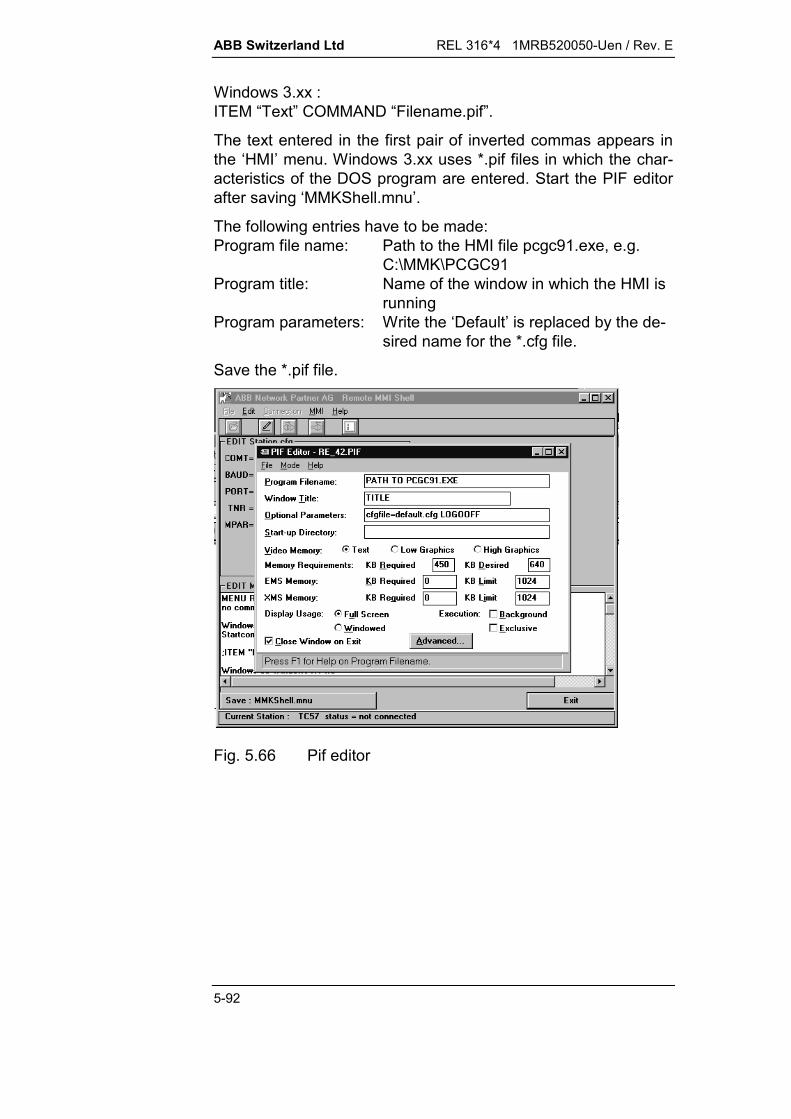
ABB Switzerland Ltd REL 316*4 1MRB520050-Uen / Rev. E
5-92
Windows 3.xx :ITEM “Text” COMMAND “Filename.pif”.
The text entered in the first pair of inverted commas appears inthe ‘HMI’ menu. Windows 3.xx uses *.pif files in which the char-acteristics of the DOS program are entered. Start the PIF editorafter saving ‘MMKShell.mnu’.
The following entries have to be made:Program file name: Path to the HMI file pcgc91.exe, e.g.
C:\MMK\PCGC91Program title: Name of the window in which the HMI is
runningProgram parameters: Write the ‘Default’ is replaced by the de-
sired name for the *.cfg file.
Save the *.pif file.
Fig. 5.66 Pif editor

REL 316*4 1MRB520050-Uen / Rev. E ABB Switzerland Ltd
5-93
Entry in ‘MMKShell.mnu’ for Windows 95 and Windows NT:
ITEM “Text” COMMAND “Path to MMK\PCGC91CFGFILE=NAME.CFG LOGOOFF”
The ‘NAME.CFG’ file is created after saving the ‘MMKShell.mnu’file and can be edited in the dialogue ‘Edit NAME.CFG’ by se-lecting it from the ‘HMI’ menu:
RETYP Device type, e.g. REG316LANG HMI languageCOLOR RGB = colour screenEVEDATA Directory where the HMI saves disturbance re-
corder data. The directory will be created if it doesnot already exist.
SLVE SPA slave address.BAUD Only in conjunction with communication parameter
TC57, 9600 Baud or 19200 Baud.
Fig. 5.67 Editing *.cfg
Click on ‘Exit’ to terminate the edit mode.
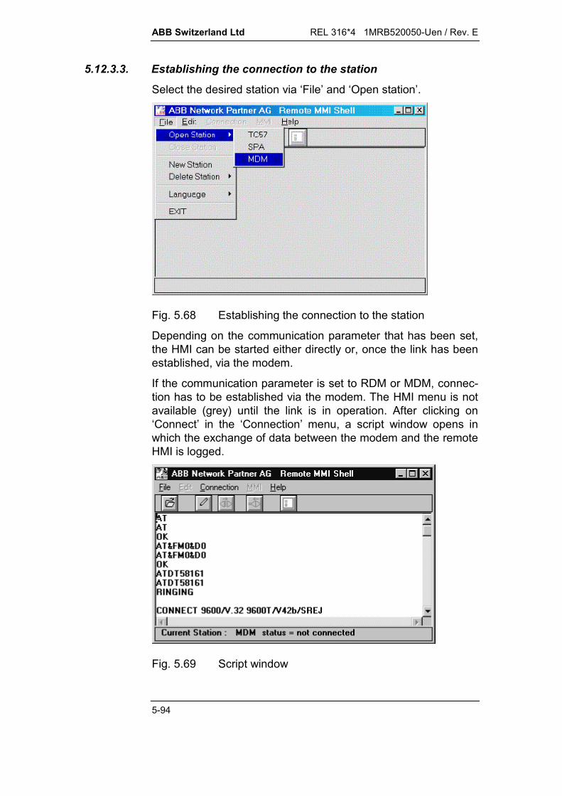
ABB Switzerland Ltd REL 316*4 1MRB520050-Uen / Rev. E
5-94
5.12.3.3. Establishing the connection to the station
Select the desired station via ‘File’ and ‘Open station’.
Fig. 5.68 Establishing the connection to the station
Depending on the communication parameter that has been set,the HMI can be started either directly or, once the link has beenestablished, via the modem.
If the communication parameter is set to RDM or MDM, connec-tion has to be established via the modem. The HMI menu is notavailable (grey) until the link is in operation. After clicking on‘Connect’ in the ‘Connection’ menu, a script window opens inwhich the exchange of data between the modem and the remoteHMI is logged.
Fig. 5.69 Script window
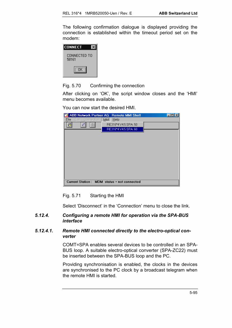
REL 316*4 1MRB520050-Uen / Rev. E ABB Switzerland Ltd
5-95
The following confirmation dialogue is displayed providing theconnection is established within the timeout period set on themodem:
Fig. 5.70 Confirming the connectionAfter clicking on ‘OK’, the script window closes and the ‘HMI’menu becomes available.
You can now start the desired HMI.
Fig. 5.71 Starting the HMI
Select ‘Disconnect’ in the ‘Connection’ menu to close the link.
5.12.4. Configuring a remote HMI for operation via the SPA-BUSinterface
5.12.4.1. Remote HMI connected directly to the electro-optical con-verter
COMT=SPA enables several devices to be controlled in an SPA-BUS loop. A suitable electro-optical converter (SPA-ZC22) mustbe inserted between the SPA-BUS loop and the PC.
Providing synchronisation is enabled, the clocks in the devicesare synchronised to the PC clock by a broadcast telegram whenthe remote HMI is started.
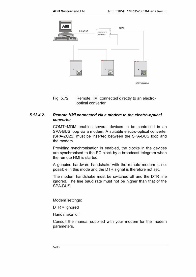
ABB Switzerland Ltd REL 316*4 1MRB520050-Uen / Rev. E
5-96
ELECTRO/OPTO
CONVERTER
Tx
Rx
RS232SPA
HEST953001 C
R
BayUnits
E
C
R
BayUnits
E
C
R
BayUnitsE
C
Fig. 5.72 Remote HMI connected directly to an electro-optical converter
5.12.4.2. Remote HMI connected via a modem to the electro-opticalconverter
COMT=MDM enables several devices to be controlled in anSPA-BUS loop via a modem. A suitable electro-optical converter(SPA-ZC22) must be inserted between the SPA-BUS loop andthe modem.
Providing synchronisation is enabled, the clocks in the devicesare synchronised to the PC clock by a broadcast telegram whenthe remote HMI is started.
A genuine hardware handshake with the remote modem is notpossible in this mode and the DTR signal is therefore not set.
The modem handshake must be switched off and the DTR lineignored. The line baud rate must not be higher than that of theSPA-BUS.
Modem settings:
DTR = ignored
Handshake=off
Consult the manual supplied with your modem for the modemparameters.
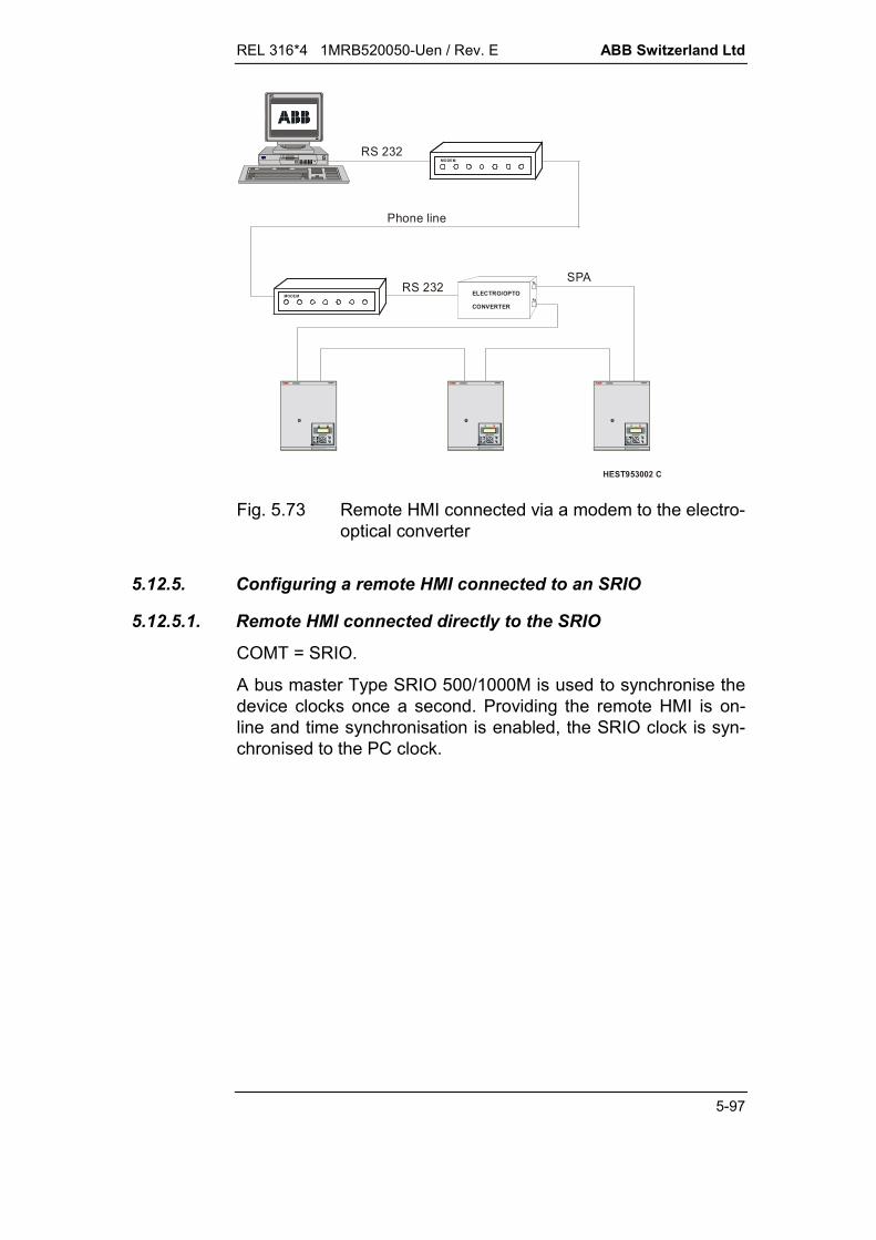
REL 316*4 1MRB520050-Uen / Rev. E ABB Switzerland Ltd
5-97
ELECTRO/OPTO
CONVERTER
Tx
Rx
RS 232
RS 232SPA
Phone line
HEST953002 C
R
BayUnits
E
C
R
BayUnits
E
C
R
BayUnits
E
C
MODEM
MODEM
Fig. 5.73 Remote HMI connected via a modem to the electro-optical converter
5.12.5. Configuring a remote HMI connected to an SRIO
5.12.5.1. Remote HMI connected directly to the SRIO
COMT = SRIO.
A bus master Type SRIO 500/1000M is used to synchronise thedevice clocks once a second. Providing the remote HMI is on-line and time synchronisation is enabled, the SRIO clock is syn-chronised to the PC clock.

ABB Switzerland Ltd REL 316*4 1MRB520050-Uen / Rev. E
5-98
Terminal
SPA
RS232
HEST 953003 C
SPA-ZCx
R
BayUnitsE
C
R
BayUnits
E
C
R
BayUnitsE
C
SRIO 1000MABB Strömberg
41
2
Fig. 5.74 Remote HMI connected directly to the SRIO
5.12.5.2. Remote HMI connected via a modem to the SRIO
COMT = RDM.
The control of several devices via an SRIO can be expandedusing a modem connection.
SRIO only provides a full hardware handshake for BUS 1.
S RIO 1000MAB B Ström berg
Terminal
41
2
RS232
SPA
RS232
Telephone line
HEST 953004 C
MODEM
SPA-ZCx
R
BayUnitsE
C
R
BayUnitsE
C
R
BayUnitsE
C
MODEM
Fig. 5.75 Remote HMI connected via a modem to the SRIO

REL 316*4 1MRB520050-Uen / Rev. E ABB Switzerland Ltd
5-99
5.12.6. Local control of a device via the interface at the front
All the HMI menu items are available in this operating mode. It isalso possible to read and change passwords and assign accessrights.
5.12.6.1. Remote HMI right of access to device functions
Provision is made for restricting access by the remote HMI. Aftersuccessively selecting the menu items ‘Edit hardware functions’,‘Edit special functions’ and ‘OBI function’, the following menuitems are accessible for COMT=TC57:
RemoteMMI enabled / disabledDetermines access in general by the re-mote HMI via the SPA-BUS.
TimeSync enabled / disabledDetermines time synchronisation by theremote HMI.
SPAComm enabled / disabledDetermines access to the SPA communi-cation window in the remote HMI.
Testfunction enabled / disabledDetermines access to the test functions inthe remote HMI.
Downloading enabled / disabledDetermines access by the remote HMI tothe download function for parameter set-tings. When downloading is disabled,changes to parameter settings can still bemade, but only saved in a file.
5.12.7. Control via an SPA-BUS or an SRIO
The slave control window appears after the program starts and acheck is made to determine whether the corresponding device isready.).6!!!!!!!!!!!!!!!!!!!!!!!!!!!!!!!!!!!!!!!!!!!!!!!"$$$ (P (7K)R7V7RR$$$$$1!!!!!!!!!!!!!!!!!!!!!!!!!!!!!!!!!!!!!!!!!!!!!!!!!!!!!!!!!!!!2
Fig. 5.76 Master request
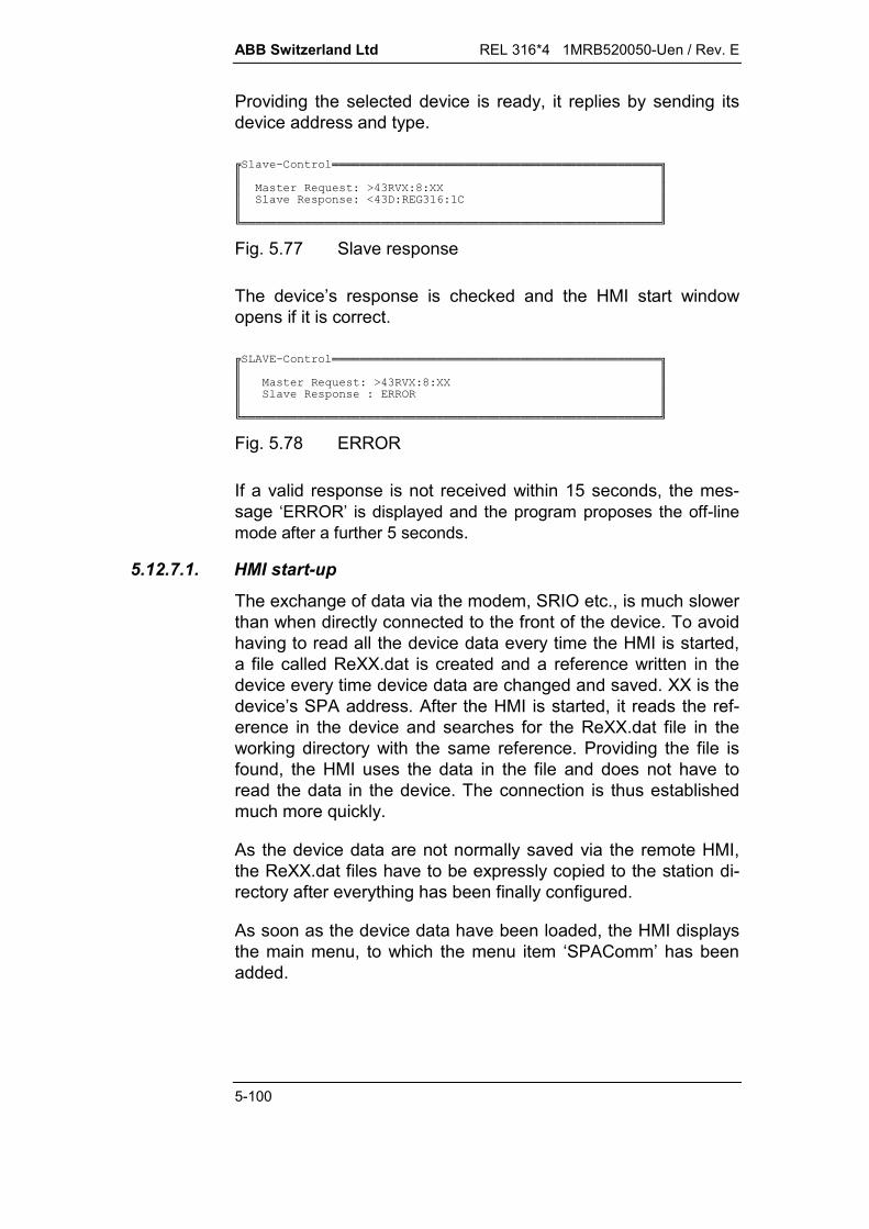
ABB Switzerland Ltd REL 316*4 1MRB520050-Uen / Rev. E
5-100
Providing the selected device is ready, it replies by sending itsdevice address and type.
%.6!!!!!!!!!!!!!!!!!!!!!!!!!!!!!!!!!!!!!!!!!!!!!!!"$$$ (P (7K)R7V7RR$$ %((7T,776$$$1!!!!!!!!!!!!!!!!!!!!!!!!!!!!!!!!!!!!!!!!!!!!!!!!!!!!!!!!!!!!2
Fig. 5.77 Slave response
The device’s response is checked and the HMI start windowopens if it is correct.
).6!!!!!!!!!!!!!!!!!!!!!!!!!!!!!!!!!!!!!!!!!!!!!!!"$$$ (P (7K)R7V7RR$$ %((73$$$1!!!!!!!!!!!!!!!!!!!!!!!!!!!!!!!!!!!!!!!!!!!!!!!!!!!!!!!!!!!!2
Fig. 5.78 ERROR
If a valid response is not received within 15 seconds, the mes-sage ‘ERROR’ is displayed and the program proposes the off-linemode after a further 5 seconds.
5.12.7.1. HMI start-up
The exchange of data via the modem, SRIO etc., is much slowerthan when directly connected to the front of the device. To avoidhaving to read all the device data every time the HMI is started,a file called ReXX.dat is created and a reference written in thedevice every time device data are changed and saved. XX is thedevice’s SPA address. After the HMI is started, it reads the ref-erence in the device and searches for the ReXX.dat file in theworking directory with the same reference. Providing the file isfound, the HMI uses the data in the file and does not have toread the data in the device. The connection is thus establishedmuch more quickly.
As the device data are not normally saved via the remote HMI,the ReXX.dat files have to be expressly copied to the station di-rectory after everything has been finally configured.
As soon as the device data have been loaded, the HMI displaysthe main menu, to which the menu item ‘SPAComm’ has beenadded.
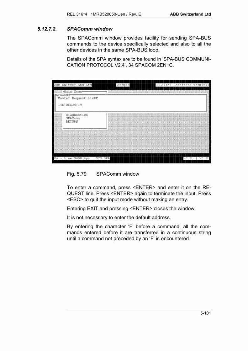
REL 316*4 1MRB520050-Uen / Rev. E ABB Switzerland Ltd
5-101
5.12.7.2. SPAComm window
The SPAComm window provides facility for sending SPA-BUScommands to the device specifically selected and also to all theother devices in the same SPA-BUS loop.
Details of the SPA syntax are to be found in ‘SPA-BUS COMMUNI-CATION PROTOCOL V2.4’, 34 SPACOM 2EN1C.
####< ============>###################################################863!!!!!!!!!!!!!!!!!!!!!!!!!!!!!!!!!!!!!!!!!!!!!!!!!!!!!!!!!!!!!!!!!!!!"#$ (P (7K*$#$$#$,7:74$#$$#1!!!!!!!!!!!!!!!!!!!!!!!!!!!!!!!!!!!!!!!!!!!!!!!!!!!!!!!!!!!!!!!!!!!!!!!!!!!2#####?, '(+(?#######################################################?86?#######################################################?/0?#######################################################??#######################################################B=====================D#####################################################################################################################################################################################################################################################################################################################################################################################################################################################################################################################################################################################################################3.4--5(678)9:5;)9:5
Fig. 5.79 SPAComm window
To enter a command, press <ENTER> and enter it on the RE-QUEST line. Press <ENTER> again to terminate the input. Press<ESC> to quit the input mode without making an entry.
Entering EXIT and pressing <ENTER> closes the window.
It is not necessary to enter the default address.
By entering the character ‘F’ before a command, all the com-mands entered before it are transferred in a continuous stringuntil a command not preceded by an ‘F’ is encountered.

ABB Switzerland Ltd REL 316*4 1MRB520050-Uen / Rev. E
5-102
5.12.8. SRIO settings
Refer to ‘Programming manual SRIO 1000M and 500M’ havingthe No. ‘34 SRIO 1000M 2 EN1 B’ for how to program the SRIO500/1000M.
SRIO 500/1000M must be configured as follows:
BUS_MODE:
BUS Code MODE
1 9 Saco 100M Slave mode
2 6 Fast SPA Master mode
3 0 Null mode
4 10 Terminal mode
BUS-Setup:
setup BUS 1 BUS 2 BUS 4
baud 9600 9600 9600
parity 2 2 0
stopbit 1 1 1
cts 1 0 0
dcd 1 0 0
aut.lf 1 0 1
timeout 60000 3000 0
resend 0 3 0
ANSI_SETUP must be set to ‘half-duplex’; the other parametersin ANSI_SETUP are of no consequence.
After the new BUS modes have been saved (STORE F), thesystem has to be restarted.
The SRIO slave address must agree with the address in the filere-01.cfg (950). The SRIO address is set in SYSPAR P4.
A (dummy) data point must be entered in the SRIO data base forevery device in the SPA-BUS loop.
REL 316*4 1MRB520050-Uen / Rev. E ABB Switzerland Ltd
5-103
5.13. Local display unit
5.13.1. Summary
The local display unit (LDU), i.e. local human/machine interface(HMI), is a simpler alternative to the HMI running on a PC andforms an integral part of an RE.316*4. It provides service per-sonnel with facility for viewing statuses and events and readingmeasurements. The hierarchically structured menus give limitedaccess to process and system data. The unit is operated with theaid of just a few pushbuttons. Three light-emitting diodes (LED’s)indicate the status of the system independently of the menu be-ing displayed.
5.13.2. Limitations
The local display unit forms an integral part of an RE.316*4 de-vice and provides a number of facilities for service personnel.
Information about the process and the state of the device can beviewed on the LDU, but it is not possible to either change orcopy device settings. The device can be restarted, however, byselecting the corresponding menu item.
5.13.3. General description
The LDU is primarily intended for service personnel so that theycan obtain brief information on the status of the RE.316*4 deviceand the protected unit.
A general indication is provided by the three LED’s and detailscan be read via the various menus on the LCD. It is neither pos-sible to configure the functions of the LED’s or the menu struc-ture nor edit the texts of the different displays, however, the lattercorrespond to the texts on the HMI on the PC and vary to suitthe configuration of the particular RE.316*4.
5.13.3.1. Mechanical assembly and front view
The LDU is fitted at the bottom right of the frontplate. The LED’sthat are familiar from older units are at the top left and the resetbutton is accessible through a small hole in the frontplate.
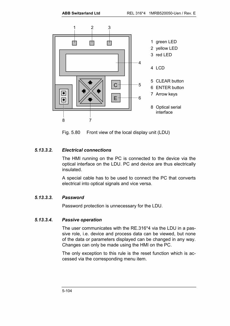
ABB Switzerland Ltd REL 316*4 1MRB520050-Uen / Rev. E
5-104
C
E
1 2 3
4
5
6
78
1 green LED2 yellow LED3 red LED
4 LCD
5 CLEAR button6 ENTER button7 Arrow keys
8 Optical serialinterface
Fig. 5.80 Front view of the local display unit (LDU)
5.13.3.2. Electrical connections
The HMI running on the PC is connected to the device via theoptical interface on the LDU. PC and device are thus electricallyinsulated.
A special cable has to be used to connect the PC that convertselectrical into optical signals and vice versa.
5.13.3.3. Password
Password protection is unnecessary for the LDU.
5.13.3.4. Passive operation
The user communicates with the RE.316*4 via the LDU in a pas-sive role, i.e. device and process data can be viewed, but noneof the data or parameters displayed can be changed in any way.Changes can only be made using the HMI on the PC.
The only exception to this rule is the reset function which is ac-cessed via the corresponding menu item.

REL 316*4 1MRB520050-Uen / Rev. E ABB Switzerland Ltd
5-105
5.13.3.5. LDU keypad
The LDU keypad comprises six pushbuttons which are only everpressed one at a time to perform the various control functions.Pressing a second button has no effect as long as the first buttonremains pressed. The function of the second button is only exe-cuted after the first one has been released.
There are two ways of navigating within the menu structure:
Step-by-step: A button is pressed to perform a first operationand then a second button to perform the next operation andso on.
Holding a button depressed: An operation can be repeated byholding the corresponding button depressed longer than thenormal response time (fixed setting of 0.5 seconds).
The pushbuttons perform the following functions:
“E”executes an operation (ENTER function), i.e. a menu item isexecuted which in the case of the LDU means moving downa level in the menu structure. The button has no function onthe lowest level in the menu structure.
“C”corresponds to the ESCAPE button on a PC. It is used toclose an active menu. It returns the user from every menuitem to the entry menu.
“”, ””The upwards and downwards arrow keys are used either forselecting a desired menu item at the same level in the menustructure or for selecting a value to be viewed in the activemenu (e.g. different events in the event list). These keys arerepresented in the text by the symbols “^” and “v”.
“”The right arrow key performs the same function as the “E”button. It is represented in the text by the symbol “>”.
“”The left arrow key closes the active menu and returns theuser to the next level up in the menu structure. It is repre-sented in the text by the symbol “<”.

ABB Switzerland Ltd REL 316*4 1MRB520050-Uen / Rev. E
5-106
5.13.4. The three status LED’s
5.13.4.1. General
A RE.316*4 unit can be in different statuses, the most importantof which are indicated by the three LED’s on the LDU. They havethe colours green, yellow and red and each can be either off,flashing or continuously lit.
In the diagrams below, the LED’s are represented by squares.An empty square indicates that the respective LED is off, a blacksquare that it is lit and a diagonally half black, half empty squarethat it is flashing.
= lit = flashing = off
The three LED’s are described on the first line of the entry menu.
green yellow red
Activ Start Trip ABB REC316*4
Fig. 5.81 LED markings
5.13.4.2. Starting RE.316*4
The yellow and green LED’s flash throughout the initialisationprocedure to indicate that the device is not operational. Thegreen LED in the row of LED’s at the top left of the deviceflashes as well.
green yellow red
Fig. 5.82 LED statuses when starting the RE.316*4

REL 316*4 1MRB520050-Uen / Rev. E ABB Switzerland Ltd
5-107
5.13.4.3. No active protection functions
If none of the protection functions is active (none programmed orall blocked), the initialisation procedure is completed and no er-rors were found, the device is not standing by. In this status, thegreen LED on the LDU flashes and the green LED in the row ofLED’s at the top left of the device lights continuously.
green yellow red
Fig. 5.83 LED statuses when none of the protection functionsis active
5.13.4.4. Normal operation
When the device is active and there are no errors or faults, thegreen, yellow and red LED’s are all off.
green yellow red
Fig. 5.84 LED statuses in normal operation
5.13.4.5. Pick-up of a protection function (General start)
The pick-up of at least one protection function (General start sig-nal active) is indicated by the fact that the green and yellowLED’s light. The yellow LED remains lit after the general starthas reset and only extinguishes after it has been actively reset(see Section 5.13.8.6.).
green yellow red
Fig. 5.85 LED statuses for a general start
5.13.4.6. Protection function trip (General Trip)
The trip of at least one protection function (General Trip signalactive) is indicated by the fact that the green, yellow and redLED’s light. The yellow and red LED’s remain lit after the general

ABB Switzerland Ltd REL 316*4 1MRB520050-Uen / Rev. E
5-108
trip has reset and only extinguish after they have been activelyreset (see Section 5.13.8.6).
green yellow red
Fig. 5.86 LED statuses for a general trip
5.13.4.7. Fatal device error
All three LED’s flash when a serious error is detected that dis-ables the device.
green yellow red
Fig. 5.87 LED statuses for a fatal error
5.13.5. Text display (LCD)
5.13.5.1. General
Upper and lower case characters are displayed and all the char-acters needed for German, English and French are installed.
The display of variables (measurements, binary signals etc.) isrefreshed at intervals of approximately a second.
5.13.5.2. Language
The LDU supports a number of languages, however, the lan-guage used by the HMI on the PC during commissioning is thelanguage set on the LDU and cannot be changed during normaloperation. The LDU language is programmed automatically tothat of the HMI on the PC. Care must therefore be taken whenchanging parameter settings that the HMI on the PC is operatingin the desired language.
5.13.5.3. Interdependencies
The menus are not dependent on changes in the process or thestatus of the device, i.e. a menu text remains on the display untilthe user selects a different menu item. The only exceptions arethe start-up procedure and downloading parameter settings from

REL 316*4 1MRB520050-Uen / Rev. E ABB Switzerland Ltd
5-109
the PC to the device during which time the entry menu is dis-played. No menus can be selected while text is being down-loaded from the PC to the RE.316*4.
For measuring values the display is refreshed approximatelyevery second.
5.13.5.4. Configuration
The menu structure described below is largely fixed and nothingneeds to be configured. It is neither possible to add a menu itemnor change a menu text. Certain menu items and texts vary withsystem configuration and are therefore indirectly variable. Forexample, if an additional protection function is configured, themenu items needed to view its measurements are automaticallyinserted. The signal texts are copied from the HMI on the PC.
5.13.6. Menu structure
The information displayed on the LDU is accessed via a menustructure with five levels. An overview of the menu structure isgiven in the diagram below. The user can only move from onemenu item to another in a vertical direction, i.e. it is impossible togo directly from one menu item to another on the same level, butin a different branch.
Every menu item consists of two parts:
Header (first line on the LCD): The header shows the name ofthe active menu. A menu name starts and finishes with a hy-phen to distinguish it from the menu items available for selec-tion. The header with the menu name is always displayedeven if there are more than three items in the menu and it isnecessary to scroll through them.
Menu lines: The menu items available for selection are dis-played on lines two, three and four. Note: An arrow pointingdownwards at the end of line 4 means that the menu containsmore menu items below the one displayed. These can beviewed by pressing the arrow key “v”. An arrow pointing up-wards at the end of line 2 means that the menu contains moremenu items above the one displayed. These can be viewedby pressing the arrow key “^”.
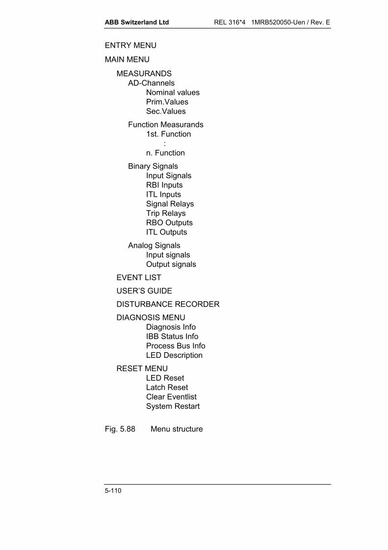
ABB Switzerland Ltd REL 316*4 1MRB520050-Uen / Rev. E
5-110
ENTRY MENU
MAIN MENU
MEASURANDSAD-Channels
Nominal valuesPrim.ValuesSec.Values
Function Measurands1st. Function :n. Function
Binary SignalsInput SignalsRBI InputsITL InputsSignal RelaysTrip RelaysRBO OutputsITL Outputs
Analog SignalsInput signalsOutput signals
EVENT LISTUSER’S GUIDEDISTURBANCE RECORDERDIAGNOSIS MENU
Diagnosis InfoIBB Status InfoProcess Bus InfoLED Description
RESET MENULED ResetLatch ResetClear EventlistSystem Restart
Fig. 5.88 Menu structure

REL 316*4 1MRB520050-Uen / Rev. E ABB Switzerland Ltd
5-111
5.13.7. Entry menu
The entry menu is at the top of the menu structure. It is dis-played every time the system is started or after pressing the “C”button to exit a menu item and does not have a header, but sim-ply four lines of text. The user accesses the main menu from theentry menu by pressing either button “E” or “>”.
The entry menu comprises two parts:
The first line states the significance of the three LED’s:green LED: “Active”yellow LED: “Start”red LED: “Trip”.
Lines two to four show the name of the device, the systemname assigned to it and the software version. The mainmenu is accessed by pressing either the “E” or “>” button.
The entry menu always comprises four lines and the buttons “C”,“^” and “v” have no effect. There is nothing to select in this dis-play. If the RE.316*4 has not been configured, “Local Display”appears on line 3, otherwise the name assigned to the deviceusing the HMI on the PC. Fig. 5.89 shows a typical entry menu:
Activ Start Trip ABB REC316*4 Example V5.1
Fig. 5.89 Entry menu
5.13.8. Main menu
The main menu lists the groups of submenus that can be se-lected to obtain more information on the device and the primaryprocess. The name “Main Menu” is in the header and three ofthe submenus on the three lines below. Unless the submenusshown are at the top or the bottom of the list there is an arrow atthe end of line four pointing downwards and/or at the end of linetwo pointing upwards to show in which direction the user canscroll to see the other menu items. The first of the menu items(line 2 of the display) is always underlined which means that it isselected. The list can be scrolled using the arrow keys “^” and

ABB Switzerland Ltd REL 316*4 1MRB520050-Uen / Rev. E
5-112
“v” so that a different menu item is moved to line 2 and is under-scored. One of the menu items is always underscored, i.e. is al-ways selected. The function of a selected menu item is executedby pressing either button “E” or “>”.
The main menu includes the following menu items: Measurands Event list User’s guide Disturbance recorder Diagnostic menu Reset menu.
-Mainmenu-MeasurandsEventlistUser’s –Guide
Fig. 5.90 Main menu
5.13.8.1. Measurands
The measurands menu lists all the menu items associated withmeasurements. The name “Measurands” is in the header andthe available submenus on the three lines below.
The measurements menu includes the following menu items: AD-Channels Funct. measurands Binary signals Analogue signals.
-Measurands-CT/VT-ChannelsFunct. MeasurementsBinary Signals
Fig. 5.91 Measurements menu
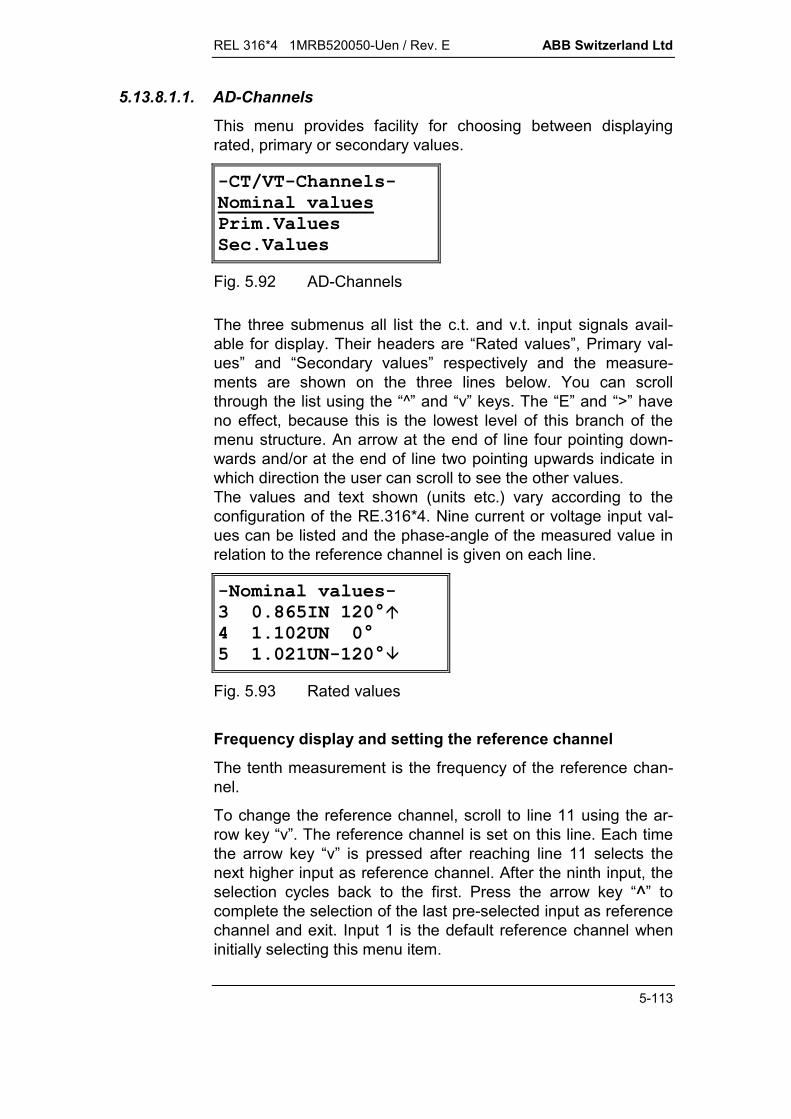
REL 316*4 1MRB520050-Uen / Rev. E ABB Switzerland Ltd
5-113
5.13.8.1.1. AD-Channels
This menu provides facility for choosing between displayingrated, primary or secondary values.
-CT/VT-Channels-Nominal valuesPrim.ValuesSec.Values
Fig. 5.92 AD-Channels
The three submenus all list the c.t. and v.t. input signals avail-able for display. Their headers are “Rated values”, Primary val-ues” and “Secondary values” respectively and the measure-ments are shown on the three lines below. You can scrollthrough the list using the “^” and “v” keys. The “E” and “>” haveno effect, because this is the lowest level of this branch of themenu structure. An arrow at the end of line four pointing down-wards and/or at the end of line two pointing upwards indicate inwhich direction the user can scroll to see the other values.The values and text shown (units etc.) vary according to theconfiguration of the RE.316*4. Nine current or voltage input val-ues can be listed and the phase-angle of the measured value inrelation to the reference channel is given on each line.
-Nominal values-3 0.865IN 120°4 1.102UN 0°5 1.021UN-120°
Fig. 5.93 Rated values
Frequency display and setting the reference channel
The tenth measurement is the frequency of the reference chan-nel.
To change the reference channel, scroll to line 11 using the ar-row key “v”. The reference channel is set on this line. Each timethe arrow key “v” is pressed after reaching line 11 selects thenext higher input as reference channel. After the ninth input, theselection cycles back to the first. Press the arrow key “^” tocomplete the selection of the last pre-selected input as referencechannel and exit. Input 1 is the default reference channel wheninitially selecting this menu item.

ABB Switzerland Ltd REL 316*4 1MRB520050-Uen / Rev. E
5-114
-AD-Channels-9 0.77IN-120°10 51.11Hz11 Ref.Channel 1
Fig. 5.94 C.t. and p.t. inputs and selection of reference chan-nel
5.13.8.1.2. Load values
This menu lists all the configured functions. The name “Funct.measurands” is in the header and the configured functions onthe three lines below.
There are fewer or more lines of load values depending on theprotection functions that are configured. ‘No function’ is on thesecond line where no function has been configured.
-Funct.Measurand1.Current-DT2.U>High Voltage3.Power
Fig. 5.95 Menu for selecting load values
Load values displayThe menu lists all the measurements by the selected functionthat can be viewed. The name of the function is in the headerand its measurements on the three lines below. If there are morethan three measurements, the entire list can be viewed using thearrow keys “^” and “v”. The buttons “E” and “>” have no effect,because this is the lowest level of this branch of the menustructure. Lines 2 to 4 are empty for functions that do not havemeasurements.
The values and text shown (units etc.) vary according to thefunction selected.
-10.UifPQ-1 0.997 UN2 4.014 IN3 10.999 P(PN)
Fig. 5.96 Measurements by the UifPQ function
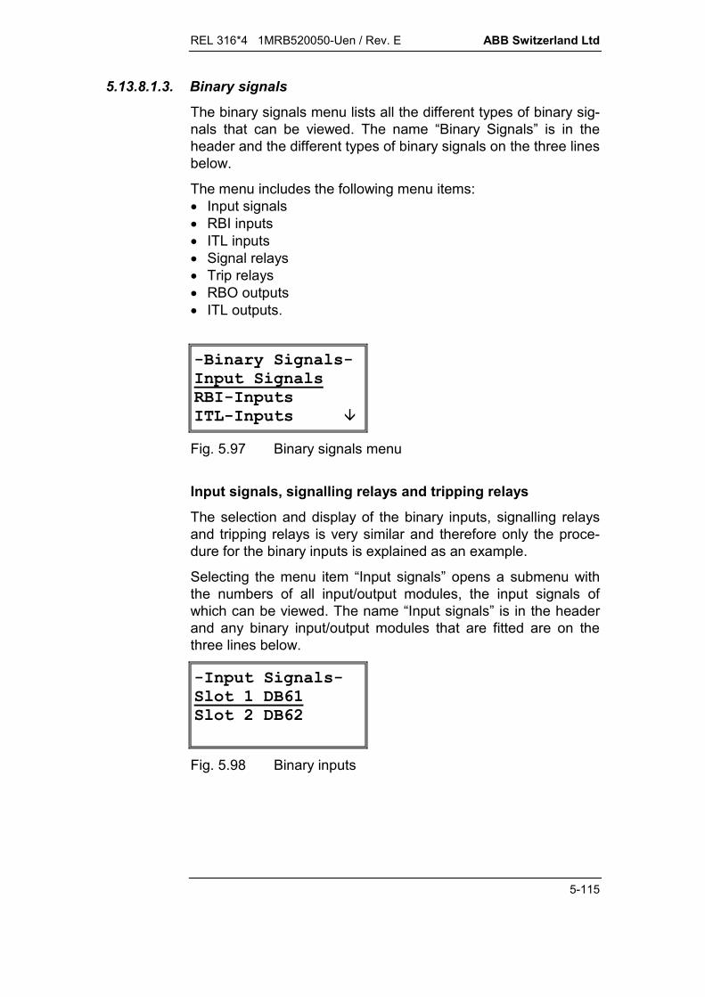
REL 316*4 1MRB520050-Uen / Rev. E ABB Switzerland Ltd
5-115
5.13.8.1.3. Binary signals
The binary signals menu lists all the different types of binary sig-nals that can be viewed. The name “Binary Signals” is in theheader and the different types of binary signals on the three linesbelow.
The menu includes the following menu items: Input signals RBI inputs ITL inputs Signal relays Trip relays RBO outputs ITL outputs.
-Binary Signals-Input SignalsRBI-InputsITL-Inputs
Fig. 5.97 Binary signals menu
Input signals, signalling relays and tripping relays
The selection and display of the binary inputs, signalling relaysand tripping relays is very similar and therefore only the proce-dure for the binary inputs is explained as an example.
Selecting the menu item “Input signals” opens a submenu withthe numbers of all input/output modules, the input signals ofwhich can be viewed. The name “Input signals” is in the headerand any binary input/output modules that are fitted are on thethree lines below.
-Input Signals-Slot 1 DB61Slot 2 DB62
Fig. 5.98 Binary inputs

ABB Switzerland Ltd REL 316*4 1MRB520050-Uen / Rev. E
5-116
The module’s binary valuesThe effective values, i.e. the statuses, of the inputs are dis-played. The designation “Slot 1 DB6.” is in the header and thevalues of the inputs are displayed on line 3. The buttons “E” and“>” have no effect, because this is the lowest level of this branchof the menu structure. As only a single line is needed, the arrowkeys “v” and “^” are also ineffective. To make the statuses of theinputs easier to assimilate, a logical ‘0’ is represented by a hy-phen ‘-’ and a logical ‘1’ by an ‘X’. The LSB is on the extreme leftand the order is the same as on the HMI on the PC.
-Slot 1 DB61
-X-X---XLSB
Fig. 5.99 Binary input statuses
RBI and ITL inputs and outputs
Since the selection and display of the RBI and ITL inputs andoutputs is very similar, the procedure for the RBI inputs will beexplained and applies for all the others.
When opened, the “RBI inputs” display shows the currentstatuses of the RBI inputs of the first module. If no input moduleis assigned to this number, all the inputs indicate a zero. Thedisplay can be switched from one module to the next using thearrow keys “v” and “^”.
To make the statuses of the inputs easier to assimilate, a logical‘0’ is represented by a hyphen ‘-’ and a logical ‘1’ by an ‘X’. TheLSB is on the extreme left and the order is the same as on theHMI on the PC.
-RBI-Inputs- 1-X-X---X--------LSB
Fig. 5.100 RBI inputs
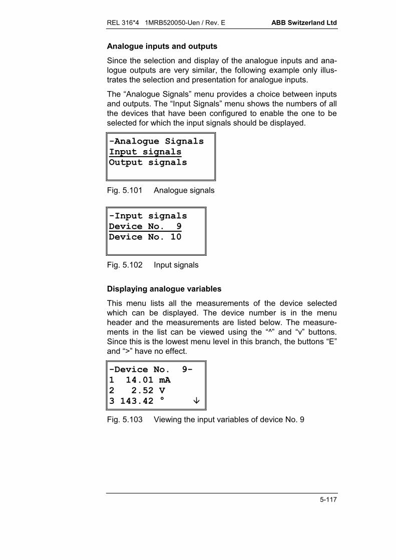
REL 316*4 1MRB520050-Uen / Rev. E ABB Switzerland Ltd
5-117
Analogue inputs and outputs
Since the selection and display of the analogue inputs and ana-logue outputs are very similar, the following example only illus-trates the selection and presentation for analogue inputs.
The “Analogue Signals” menu provides a choice between inputsand outputs. The “Input Signals” menu shows the numbers of allthe devices that have been configured to enable the one to beselected for which the input signals should be displayed.
-Analogue SignalsInput signalsOutput signals
Fig. 5.101 Analogue signals
-Input signalsDevice No. 9Device No. 10
Fig. 5.102 Input signals
Displaying analogue variables
This menu lists all the measurements of the device selectedwhich can be displayed. The device number is in the menuheader and the measurements are listed below. The measure-ments in the list can be viewed using the “^” and “v” buttons.Since this is the lowest menu level in this branch, the buttons “E”and “>” have no effect.
-Device No. 9-1 14.01 mA2 2.52 V3 143.42 °
Fig. 5.103 Viewing the input variables of device No. 9

ABB Switzerland Ltd REL 316*4 1MRB520050-Uen / Rev. E
5-118
5.13.8.2. Event list
This menu item opens a list with the last 20 events together withthe tripping values of the corresponding protection functions andalso the special “LDU events” function. The name “Event List” isin the header and the latest event is displayed below it. Theolder events can be viewed using the arrow keys. The numbersof the events are the same on the LDU and the HMI on the PC.Note that an event cannot be wholly displayed because it needs4 lines and only 3 are available. It is thus always necessary touse the arrow keys “v” and “^” to view all the information relatedto one event.
The text (function name and unit) is the same as that in theevent list on the HMI on the PC.
-Event list-32 1.Current-DT 4.036 IN 13:55;57.571
Fig. 5.104 Event list
5.13.8.3. User’s guide
This menu item gives access to brief instructions on how to usethe LDU, e.g. the functions of the buttons.
-User’s Guide-E=Enter the preselected menu
Fig. 5.105 User’s guide
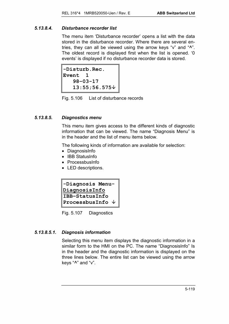
REL 316*4 1MRB520050-Uen / Rev. E ABB Switzerland Ltd
5-119
5.13.8.4. Disturbance recorder list
The menu item ‘Disturbance recorder’ opens a list with the datastored in the disturbance recorder. Where there are several en-tries, they can all be viewed using the arrow keys “v” and “^”.The oldest record is displayed first when the list is opened. ‘0events’ is displayed if no disturbance recorder data is stored.
-Disturb.Rec.Event 1 98–03-17 13:55;56.575
Fig. 5.106 List of disturbance records
5.13.8.5. Diagnostics menu
This menu item gives access to the different kinds of diagnosticinformation that can be viewed. The name “Diagnosis Menu” isin the header and the list of menu items below.
The following kinds of information are available for selection: DiagnosisInfo IBB StatusInfo ProcessbusInfo LED descriptions.
-Diagnosis Menu-DiagnosisInfoIBB–StatusInfoProcessbusInfo
Fig. 5.107 Diagnostics
5.13.8.5.1. Diagnosis information
Selecting this menu item displays the diagnostic information in asimilar form to the HMI on the PC. The name “DiagnosisInfo” Isin the header and the diagnostic information is displayed on thethree lines below. The entire list can be viewed using the arrowkeys “^” and “v”.

ABB Switzerland Ltd REL 316*4 1MRB520050-Uen / Rev. E
5-120
The status of the device is at the top of the list followed by thetime when the software was downloaded, the time when settingswere last changed and finally the statuses of an FUP programsthat are loaded.
-Diagnosis Info-Relay–Status:No Error
Fig. 5.108 General status information
5.13.8.5.2. IBB status information
Select this menu item to view information on the interbay bus(LON, MVB etc.). The name “IBB StatusInfo” is in the headerfollowed by three lines with the IBB diagnostic information. Youcan scroll through the list using the “^” and “v” keys:
The interbay bus connected (SPA, VDEW, LON or MVB) isshown on the second line together with the information‘Ready’ (operational), ‘No response’ (if no telegrams aretransferred, but the device is ready) or ‘Inactive’ (this ap-pears, for example, when the corresponding interface is notfitted). The HMI on the PC must be used to obtain more de-tailed information.
Station number and the time
Neuron chip ID (LON only)
-IBB Status Inf-SPA-BUSReady
Fig. 5.109 Interbay bus information
5.13.8.5.3. Process bus information
Here information about the process bus can be viewed in asimilar manner to information about the station bus. The name“ProcessbusInfo” is in the header and the operating mode, thestatus of the PC card, the PC card type, the software versionand the PC card counter appear below.

REL 316*4 1MRB520050-Uen / Rev. E ABB Switzerland Ltd
5-121
-Process bus inf-PC-Card Error: No Error
Fig. 5.110 Information about the process bus (PC card error)
5.13.8.5.4. LED descriptions
The significance of the LED’s at the top left of the frontplate canbe viewed on the LDU by selecting this menu item.
-LED Description1:Relay ready2:Trip 13:Trip 2
Fig. 5.111 Significance of the LED’s
Entering the LED function texts
The texts describing the significance of the LED’s displayed onthe LDU is entered via the HMI. The corresponding dialogue isaccessed in the HMI on the PC by selecting ‘Editor’ / ‘Edit hard-ware functions’ / ‘Edit signal outputs’ and then the menu item‘Edit LED description. The procedure is the same as for the ex-isting menu item ‘Edit signal comment’.
< ===========>########################################################?<=====================>###############################################??<& * +(====>#############################################???<' 3 (========>###########################################?????###########################################????' +C?###########################################????' 6<+H3.========================>#####????,6??#####????/0?K?#####?????<+6C ===========>##???B==========================?/( 5H3.??##B=B=????<==<==<==<==<==<==<==<==>?######B===========================D?X:???:???O??Q?V??###################################?6C (6!!!!!!!!!!!!!!!!!!"?###################################B=====$K,%+ @$?#########################################1!!!!!!!!!!!!!!!!!!!!!!!!!!!!!!!!!!2?###################################################??###################################################B=========================D################################################################################3.4--5(678)9:5;)9:5
Fig. 5.112 Entering a comment to describe a LED

ABB Switzerland Ltd REL 316*4 1MRB520050-Uen / Rev. E
5-122
The text entered is then downloaded to the RE.316*4 togetherwith all the other data and can be viewed on the LDU.
5.13.8.6. RESET menu
This menu item opens a submenu that enables the user to de-lete different kinds of obsolete information or execute a warmstart.The menu includes the following four items: LED reset Latch reset Clear event list System restart.
The first menu item (LED reset) resets the two LED’s ‘Start’ and‘Trip’ on the front of the LDU.The second menu item (Latch reset) resets all the latched LED’son the frontplate and all latched outputs.The third menu item deletes the event list (only the one in theLDU and not the one in the PC).The fourth menu item restarts the RE.316*4.
-Reset Menu-LED resetLatch resetClear event list
Fig. 5.113 Reset menu
Upon selecting any of the above menu items, a dialogue ap-pears requesting confirmation that you wish to execute the ac-tion ‘Are you sure? Yes/No?’. The default response is ‘No’. Se-lect the appropriate response using the arrow keys “v” and “^” (inthe same way as selecting a menu item) and execute by press-ing “E” or “>”.
-LED reset-Are you sure? No / Yes
Fig. 5.114 Are you sure?
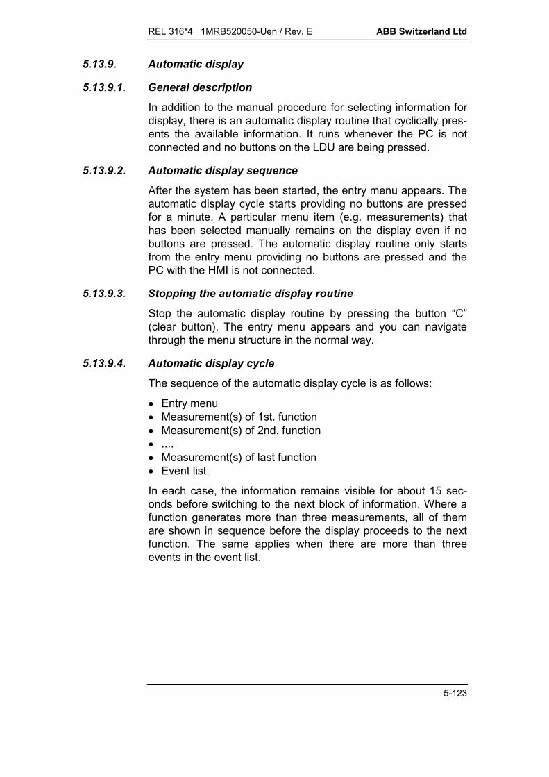
REL 316*4 1MRB520050-Uen / Rev. E ABB Switzerland Ltd
5-123
5.13.9. Automatic display
5.13.9.1. General description
In addition to the manual procedure for selecting information fordisplay, there is an automatic display routine that cyclically pres-ents the available information. It runs whenever the PC is notconnected and no buttons on the LDU are being pressed.
5.13.9.2. Automatic display sequence
After the system has been started, the entry menu appears. Theautomatic display cycle starts providing no buttons are pressedfor a minute. A particular menu item (e.g. measurements) thathas been selected manually remains on the display even if nobuttons are pressed. The automatic display routine only startsfrom the entry menu providing no buttons are pressed and thePC with the HMI is not connected.
5.13.9.3. Stopping the automatic display routine
Stop the automatic display routine by pressing the button “C”(clear button). The entry menu appears and you can navigatethrough the menu structure in the normal way.
5.13.9.4. Automatic display cycle
The sequence of the automatic display cycle is as follows:
Entry menu Measurement(s) of 1st. function Measurement(s) of 2nd. function .... Measurement(s) of last function Event list.
In each case, the information remains visible for about 15 sec-onds before switching to the next block of information. Where afunction generates more than three measurements, all of themare shown in sequence before the display proceeds to the nextfunction. The same applies when there are more than threeevents in the event list.
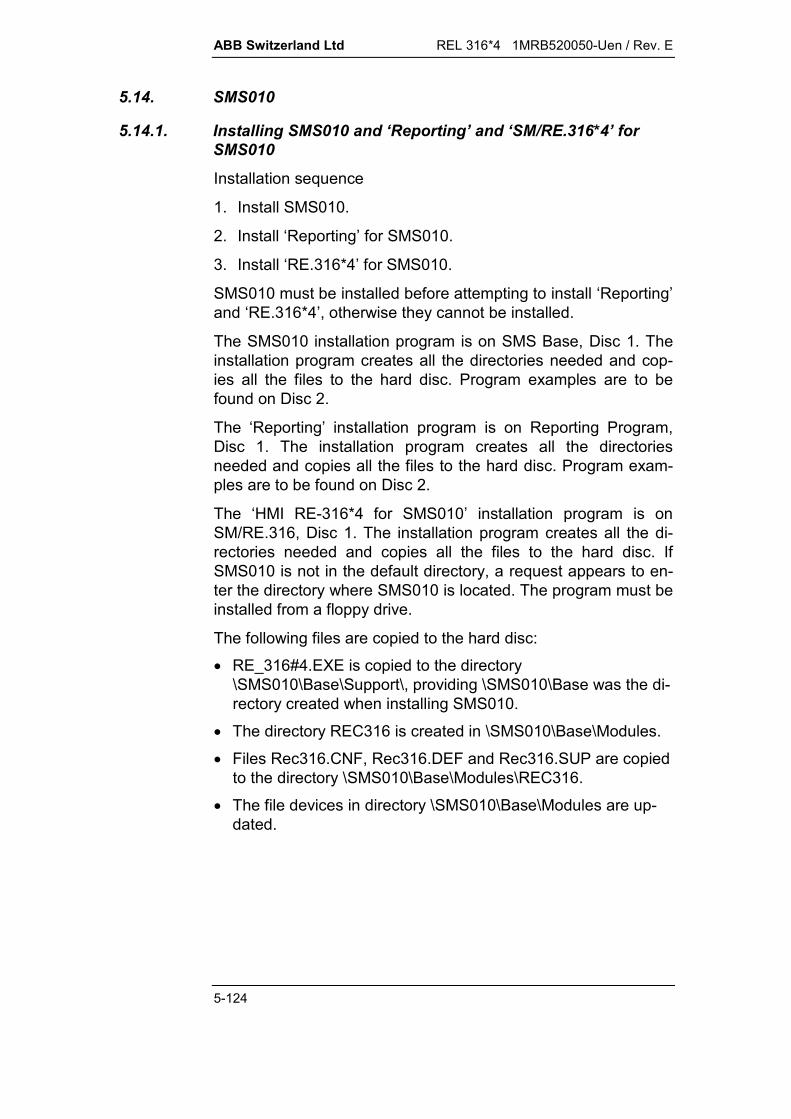
ABB Switzerland Ltd REL 316*4 1MRB520050-Uen / Rev. E
5-124
5.14. SMS010
5.14.1. Installing SMS010 and ‘Reporting’ and ‘SM/RE.316*4’ forSMS010
Installation sequence
1. Install SMS010.
2. Install ‘Reporting’ for SMS010.
3. Install ‘RE.316*4’ for SMS010.
SMS010 must be installed before attempting to install ‘Reporting’and ‘RE.316*4’, otherwise they cannot be installed.
The SMS010 installation program is on SMS Base, Disc 1. Theinstallation program creates all the directories needed and cop-ies all the files to the hard disc. Program examples are to befound on Disc 2.
The ‘Reporting’ installation program is on Reporting Program,Disc 1. The installation program creates all the directoriesneeded and copies all the files to the hard disc. Program exam-ples are to be found on Disc 2.
The ‘HMI RE-316*4 for SMS010’ installation program is onSM/RE.316, Disc 1. The installation program creates all the di-rectories needed and copies all the files to the hard disc. IfSMS010 is not in the default directory, a request appears to en-ter the directory where SMS010 is located. The program must beinstalled from a floppy drive.
The following files are copied to the hard disc:
RE_316#4.EXE is copied to the directory\SMS010\Base\Support\, providing \SMS010\Base was the di-rectory created when installing SMS010.
The directory REC316 is created in \SMS010\Base\Modules.
Files Rec316.CNF, Rec316.DEF and Rec316.SUP are copiedto the directory \SMS010\Base\Modules\REC316.
The file devices in directory \SMS010\Base\Modules are up-dated.

REL 316*4 1MRB520050-Uen / Rev. E ABB Switzerland Ltd
5-125
5.14.2. SMS010 Editor
5.14.2.1. Main menu
!!!!!!!!!!!"########################################################$$########################################################$$########################################################$%& '$########################################################$ ( ) ($########################################################$(* +($########################################################$, '(+($########################################################$--.$########################################################$,+ $########################################################$/0$########################################################$$########################################################1!!!!!!!!!!!!!!!!!!!!2##########################################################################################################################################################################################################################################################################################################################################################################################################################################################################################################################################################################################################################3.4--5(678)9:5;)9:5
Fig. 5.115 Main menu
The menu item ‘SMS010 editor’ is added to the main menu wheninstalling SMS010.

ABB Switzerland Ltd REL 316*4 1MRB520050-Uen / Rev. E
5-126
5.14.3. Sub-menu ‘SMS010 editor’
< ===========>########################################################?--.!!!!!!!!!"####################################################?$$####################################################?$)09,6$####################################################?$3H09,6$####################################################?$6 ,6.*($####################################################?$/0$####################################################?$$####################################################?1!!!!!!!!!!!!!!!!!!!!!!2####################################################?/0?########################################################??########################################################B====================D##########################################################################################################################################################################################################################################################################################################################################################################################################################################################################################################################################################################################################################3.4--5(678)9:5;)9:5
Fig. 5.116 SMS010 editor
The menu items in the ‘SMS010 editor’ sub-menu are used for cre-ating and processing the files needed for integrating SMS010.Concerned are the ‘Reporting’ files EVENT.DSC, LOGGING.DSCand CHANNEL.DSC.
The menu items perform the following:
Edit Event.dsc for processing the fileEvent.DSC.
Edit Logging.dsc for processing the file Log-ging.DSC.
Create New Dsc Files for creating and configuring thefiles needed for ‘Reporting’ inthe set of device parametersettings.
(In the off-line mode, a parameter file must be downloaded firstusing the editor’s ‘Load from file’ function, since the ‘Create newDSC files’ function requires the currently active set of parametersettings.)

REL 316*4 1MRB520050-Uen / Rev. E ABB Switzerland Ltd
5-127
5.14.4. Descriptions of the various menu items
5.14.4.1. Menu item ‘Edit Event. Dsc’ for processing Event.DSC !!!!!!!!!!!!!!!!!!!!!!!!!!!!!!!!!!!!!!!!!!!!!!!!!!!!!!!!!!!!!!!!!!!!"$ @ ((^O6&00^:8 '4A:V$$O9-:*P +@$$6,(+ 5($$+LE/TG3000U(U($$:+LE/TG3**U(00$$30U(00$$3**U(00$$O 30U(00$$ 3**U(00$$$$$$$$$$$$$$$$$1!!!!!!!!!!!!!!!!!!!!!!!!!!!!!!!!!!!!!!!!!!!!!!!!!!!!!!!!!!!!!!!!!!!!!!!!!!!!23.4--5(678)9:5;)9:5
Fig. 5.117 A typical page of the Event.DSC file.
Default settings:
Report = Report
Alarm = Yes
Audible = No
Reset = NO.
The number displayed for ‘Relay address’ is the slave addressset for the relay and the one for ‘Channel’ the function number inthe parameter list. The function type is also shown in the header.
Code = Event number
Description = Event designation
Report = An occurrence of an event is only listed inthe SMS010 report, if ‘Report’ is specifiedin this column.
Alarm = Determines whether an alarm appears inthe list or not.
Audible = ‘Yes’ in this column causes the acousticalarm to be given as well.
Reset = Reset function (Yes/No).

ABB Switzerland Ltd REL 316*4 1MRB520050-Uen / Rev. E
5-128
The above settings can be changed using the space bar oncethey have been selected (Report/No. or Yes/No). None of theother settings can be changed.
Refer to the Section ‘Reporting’ in the SMS010 manual for adetailed explanation of the settings.
Keys:
Page Up previous page
Page Down next page
Arrow key one line up
Arrow key one line down
Arrow key moves the cursor to the right
Arrow key moves the cursor to the left
Space bar for editing settings
F1 help
ESC for terminating the program. If changeswere made, your are requested to con-firm that they should be saved.
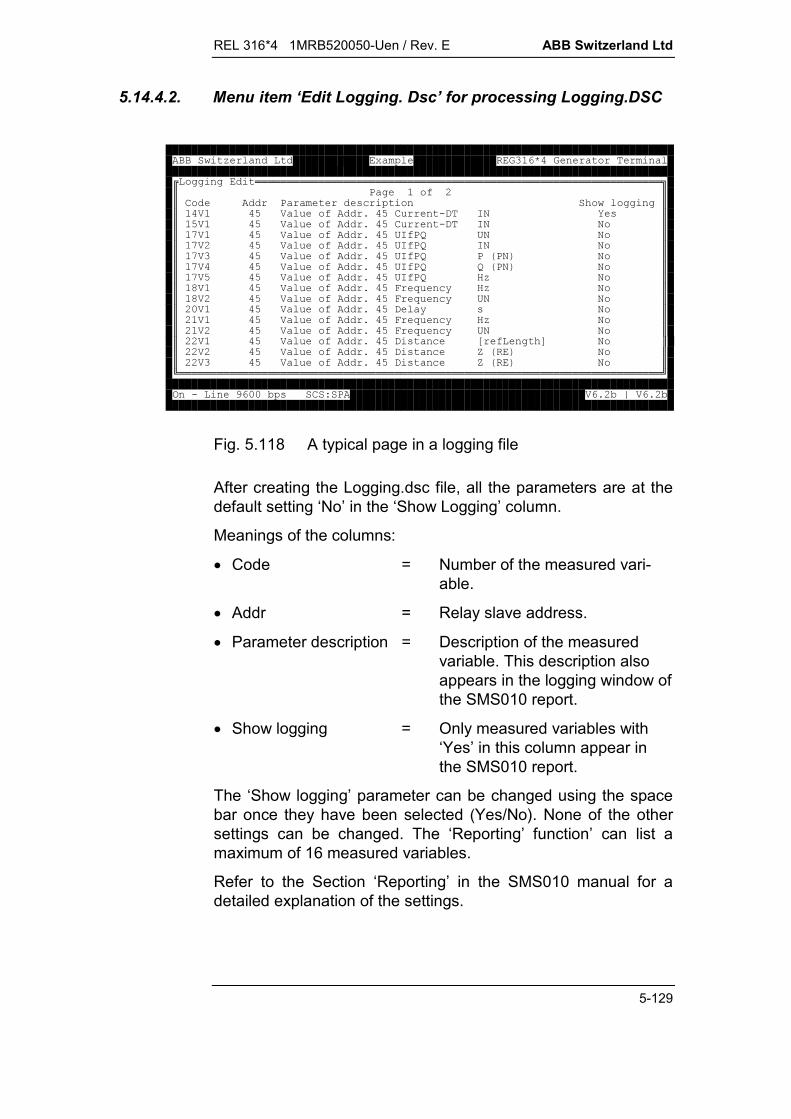
REL 316*4 1MRB520050-Uen / Rev. E ABB Switzerland Ltd
5-129
5.14.4.2. Menu item ‘Edit Logging. Dsc’ for processing Logging.DSC
'''!!!!!!!!!!!!!!!!!!!!!!!!!!!!!!!!!!!!!!!!!!!!!!!!!!!!!!!!!!!!!!!!"$8 'A:$$68 (+C'''$$)O) A9O6 .,H0U($$O)O) A9O6 .,H00$$Q)O) A9O/HA8a/00$$Q):O) A9O/HA8aH00$$Q)O) A9O/HA8a8E80G0$$Q)O) A9O/HA8aaE80G0$$Q)OO) A9O/HA8a&0$$V)O) A9O*P +@&0$$V):O) A9O*P +@/00$$:-)O) A9O, @(0$$:)O) A9O*P +@&0$$:):O) A9O*P +@/00$$::)O) A9O,( +MA'CN0$$::):O) A9O,( +bEG0$$::)O) A9O,( +bEG0$1!!!!!!!!!!!!!!!!!!!!!!!!!!!!!!!!!!!!!!!!!!!!!!!!!!!!!!!!!!!!!!!!!!!!!!!!!!!!23.4--5(678)9:5;)9:5
Fig. 5.118 A typical page in a logging file
After creating the Logging.dsc file, all the parameters are at thedefault setting ‘No’ in the ‘Show Logging’ column.
Meanings of the columns:
Code = Number of the measured vari-able.
Addr = Relay slave address.
Parameter description = Description of the measuredvariable. This description alsoappears in the logging window ofthe SMS010 report.
Show logging = Only measured variables with‘Yes’ in this column appear inthe SMS010 report.
The ‘Show logging’ parameter can be changed using the spacebar once they have been selected (Yes/No). None of the othersettings can be changed. The ‘Reporting’ function’ can list amaximum of 16 measured variables.
Refer to the Section ‘Reporting’ in the SMS010 manual for adetailed explanation of the settings.
ABB Switzerland Ltd REL 316*4 1MRB520050-Uen / Rev. E
5-130
Keys:
Page Up previous page.
Page Down next page.
Arrow key one line up.
Arrow key one line down.
Space bar for editing settings.
F1 help.
ESC for terminating the program. If changeswere made, your are requested to con-firm that they should be saved.
5.14.4.3. Menu item ‘Create New DSC Files’
This menu item is for creating the files needed from the pa-rameter list of the particular device the first time the HMI isstarted. It is also needed every time the device parameter set-tings are changed.
In the off-line mode, a parameter file must be downloaded firstusing the editor’s ‘Load from file’ function, since the ‘Create newDSC files’ function requires the currently active set of parametersettings.
The following files are created:
Event.DSC event handling file for ‘Reporting’
Logging.DSC logging window file for ‘Reporting’
Channel.DSC file with the function designations
Functyp.DSC required for updating files.

REL 316*4 1MRB520050-Uen / Rev. E ABB Switzerland Ltd
5-131
5.14.5. Creating a station after installing SMS010
When SMS is started for the first time, a message is displayed tothe effect that the file ‘Spacom.CNF’ does not exist and the ap-plication structure is invalid.
5.14.5.1. Creating the application structure
Select Alter application structure from the Utilities menu tocreate a new application structure. There are five levels.
6/HHH6398/8!!!!!!!!!!!!!+!!!!!!!!!!!!!!"$ +A' ($$+ ( ($$ + ( + $$6C+L + ( + $$ $$8. $$6('$$) $1!!!!!!!!!!!!!!!!!!!!!!!!!!!!!!!!!2(+6RH
Level 1:A name for an organisation can be entered after entering ‘a’(= add) in Select organisation.
!+3' !"+@71!!!!!!!!!!!!!!!!!!!!!!!267ccc9 +@767cc,.Rc!6 !!!!!!!!!!!!!!!!!!!!!!!!!!!"$$$8 $1!!!!!!!!!!!!!!!!!!!!!!!!!!!!!!!!!!!!!!!!!!!!!!!!!!!!26^6A' ( ^^,^,6^% (%0^(+

ABB Switzerland Ltd REL 316*4 1MRB520050-Uen / Rev. E
5-132
Level 2:The next level and the Select station window are reached bypressing <Enter>. Press ‘a’ to enter a station name.
!+3' !"+@7$8!+ !"67ccc1!!!!!!1!!!!!!!!!!!!!!!!!!29 +@767cc,.Rc!6 !!!!!!!!!!!!!!!!!!!!!!!!!!!"$$$ $1!!!!!!!!!!!!!!!!!!!!!!!!!!!!!!!!!!!!!!!!!!!!!!!!!!!!23' 78 ^^,^,6^% (%0^(+
Level 3:The next level and the Select object/bay window are reachedby pressing <Enter>. Press ‘a’ to enter a bay name. TheSpin.CNF file is also created at this level by entering ‘c’ (Cre-ate communications parameters). Provision is also made atthis level for changing the SPA protocol to SRIO.
!+3' !"+@7$8!+ !"67ccc1!!!!!!$ !+35\+F @!"1!!!!!!1!!!!!!!!!!!!!!!!!!!!!29 +@767cc,.Rc!6 !!!!!!!!!!!!!!!!!!!!!!!!!!!"$$$08.:6O$1!!!!!!!!!!!!!!!!!!!!!!!!!!!!!!!!!!!!!!!!!!!!!!!!!!!!23' 78 7 6^6 + + (^^,^,6^% (%0^(+

REL 316*4 1MRB520050-Uen / Rev. E ABB Switzerland Ltd
5-133
Creating the Spin.CNF file after entering ‘c’.!+3' !"+@7$8!+ !"67ccc1!!!!!!$ !+35\+F @!"1!!!!!!$08.:6O$9 +@71!!!!!!!!!!!!!!!!!!!!!267cc,.Rc!+ + (!!!!!!!!!!!!!!!!!!!!!!!!!!!!!!!!!!!!!!!!!!!!!!"$$$8C7Q-QQ-Q$$6+7,+,+$$ 76363$$8+78H3$$ 74--4--$$8 @7)0)0$$, 5(7QQ$1!!!!!!!!!!!!!!!!!!!!!!!!!!!!!!!!!!!!!!!!!!!!!!!!!!!!!!!!!!!!!!!!!!!!!!!!!!!!!!26^6 + + (86^% 6^P 0^( %
Level 4:The next level and the Select unit window are reached bypressing <Enter>. Press ‘a’ to open the selection window.Select for example REC 316 from this menu. Then select Re-port station to if you wish to create one.
!+3' !"+@7$8!+ !"67ccc1!!!!!!$ !+35\+!!!!!!!!!!!!!!!!!!!!"1!!!!!!$08.:!+$ @$9 +@71!!!!!!1!!!!!!!$3,$67cc,.Rc$3&$$6$$83H30$1!!!!!!!!!!!!!!!!!!!!23' 78 7 35\F @708.:6O6^6 + + (6^P 0^(+

ABB Switzerland Ltd REL 316*4 1MRB520050-Uen / Rev. E
5-134
Level 5:The next level, the Select module/part of unit window and thedata input window Setting Spacom slave address are reachedby pressing <Enter>. Now enter the SPA address for the de-vice.
!+3' !"+@7$8!+ !"67ccc1!!!!!!$ !+35\+F @!"1!!!!!!$08.:!!!!!!!!!!!!!+/!!!!!!!!!!!!!!" +@71!!!!!!$6!!!!!!!!+ F8 A/!!!!!!!!!"1!!!!!$666d8+ $1!!!!!!!!!!!!!!!!!!!!!!!!!!!!!!!!!!!!!!!!!!!!!23' 78 7 35\F @708.:6O/7666d8+ 6^6 + + (^C ( +A^^,^,6^% (%0^(+
Entering the address.!+3' !"+@7$8!+ !"67ccc1!!!!!!$ !+35\+F @!"1!!!!!!$08.:!!!!!!!!!!!!!+/!!!!!!!!!!!!!!" +@71!!!!!!$6!!!!!!!!+ F8 A/!!!!!!!!!"1!!!!!$666d8+ $1!!!!!!!!!!!!!!!!!!!!!!!!!!!!!!!!!!!!!!!!!!!!!2!'863( % ((!!!!!!!"$$$C (((7--$$0 ((7-O$$$3' 78 1!!!!!!!!!!!!!!!!!!!!!!!!!!!!!!!!!!!!!!2 7 35\F @708.:6O/7666d8+ F8 7666d8+ 6^6 + + (^C ( +A^^,^,6^% (%0^(+
If your wish to add further stations, return to the correspondinglevel. For example, to insert another device, repeat all steps fromlevel 3.

REL 316*4 1MRB520050-Uen / Rev. E ABB Switzerland Ltd
5-135
5.14.5.2. Updating the Spin.CNF file
Select Edit comunication parameter file from the Comm pa-rameters menu.
6/HHH6398/8!!!!!!!!!!!!!!+!!!!!!!!!!!!!!"$+ + A$$8+ + A$1!!!!!!!!!!!!!!!!!!!!!!!!!!!!!!!!!!2(+6RH
Select the desired station and respond with ‘Yes’ to the ques-tion ‘Continue with this file?’.
6/HHH6398/8!!!!!!!!!!!!!!+!!!!!!!!!!!!!!"$+ + A$$8+ + A$!3' !!!!!!!!!!!! !!!!!!!!!!!!35\F @!!!!!!!!!!!!/!!!!!!!!!!!!!!!!"$8 $1!!!!!!!!!!!!!!!!!!!!!!!!!!!!!!!!!!!!!!!!!!!!!!!!!!!!!!!!!!!!!!!!!!!!!!!!!!!!!!2(+6RH

ABB Switzerland Ltd REL 316*4 1MRB520050-Uen / Rev. E
5-136
Select ‘SRIO’ from the Protocol sub-menu.6/HHH6398/8!!!!!!!!!!!!!!+!!!!!!!!!!!!!!"$+ + A$$8+ + A$!!!!!!!!!!!!!!!!!!!!!!!"!!!!!!!!!!!!2$6$$HA +@$$6 + $$8+$$+ @+$!!!!!!!!!!!!!!!!"$$J$$$8$$$H3$!!!!!!21!!!!!!!!!!!!!!!!2(+6RH
Select NOT USED from the Secondary protocol sub-menu6/HHH6398/8!!!!!!!!!!!!!!+!!!!!!!!!!!!!!"$+ + A$$8+ + A$!!!!!!!!!!!!!!!!!!!!!!!"!!!!!!!!!!!!2$6$$HA +@$$6 + $$8+$$+ @+$$ $!!!!!!!!!!!!!!!!"$$J$$$8$!!!!!!2$H3$$0 ($1!!!!!!!!!!!!!!!!2(+6RH
All other settings can be left at their default values.
Note that all the above settings must agree with the SRIO set-tings (Syspar 4).

REL 316*4 1MRB520050-Uen / Rev. E ABB Switzerland Ltd
5-137
5.14.5.3. Creating a report station
Select Alter application structure from the Utilities menu.
Omit levels 1 and 2 by pressing <Enter>.
Level 3: To enter a bay name for the report station, selectSelect object/bay and enter ‘a’.
!+3' !"+@7$8!+ !"67ccc1!!!!!!$ !+35\+F @!"1!!!!!!$08.:6O$9 +@7$08.:64$67cc,.Rc1!!!!!!!!!!!!!!!!!!!!!2!6 !!!!!!!!!!!!!!!!!!!!!!!!!!!"$$$08$1!!!!!!!!!!!!!!!!!!!!!!!!!!!!!!!!!!!!!!!!!!!!!!!!!!!!23' 78 7 6FW,^6C 'F,+9 ^^,^,6^% (%0^(+
Level 4: Press <Enter> to proceed to the Select unit windowand enter ‘a’. Now select Report station from the list whichappears.
!+3' !"+@7$8!+ !"67ccc1!!!!!!$ !+35\+!!!!!!!!!!!!!!!!!!!!"1!!!!!!$08.:!+$ @$9 +@7$08.:1!!!!!!!$3,$67cc,.Rc$08$3&$1!!!!!!!!!!!!!!$6$$83H30$1!!!!!!!!!!!!!!!!!!!!23' 78 7 35\F @7086^6 + + (6^P 0^(+
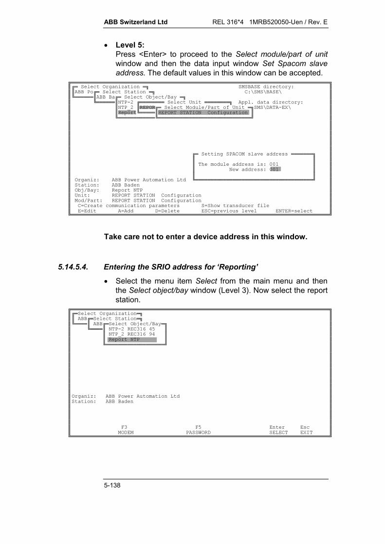
ABB Switzerland Ltd REL 316*4 1MRB520050-Uen / Rev. E
5-138
Level 5:Press <Enter> to proceed to the Select module/part of unitwindow and then the data input window Set Spacom slaveaddress. The default values in this window can be accepted.
!+3' !"+@7$8!+ !"67ccc1!!!!!!$ !+35\+F @!"1!!!!!!$08.:!!!!!!!!+/!!!!!!!!"9 +@7$08I:$83!+ F8 A/!"c,.Rc$1!!!!!$83H306A' $1!!!!!!!!!!!!1!!!!!!!!!!!!!!!!!!!!!!!!!!!!!!2!'863( % ((!!!!!!!"$$$C (((7--$$0 ((7--$$$3' 78 1!!!!!!!!!!!!!!!!!!!!!!!!!!!!!!!!!!!!!!2 7 35\F @708/783H306A' F8 783H306A' 6^6 + + (^C ( +A^^,^,6^% (%0^(+
Take care not to enter a device address in this window.
5.14.5.4. Entering the SRIO address for ‘Reporting’
Select the menu item Select from the main menu and thenthe Select object/bay window (Level 3). Now select the reportstation.
!+3' !"$!+ !"1!!!!$!+35\+F @!"1!!!!$08.:6O$$08I:64$$08$1!!!!!!!!!!!!!!!!!!!23' 78 7 **O(+3,8J3,6RH
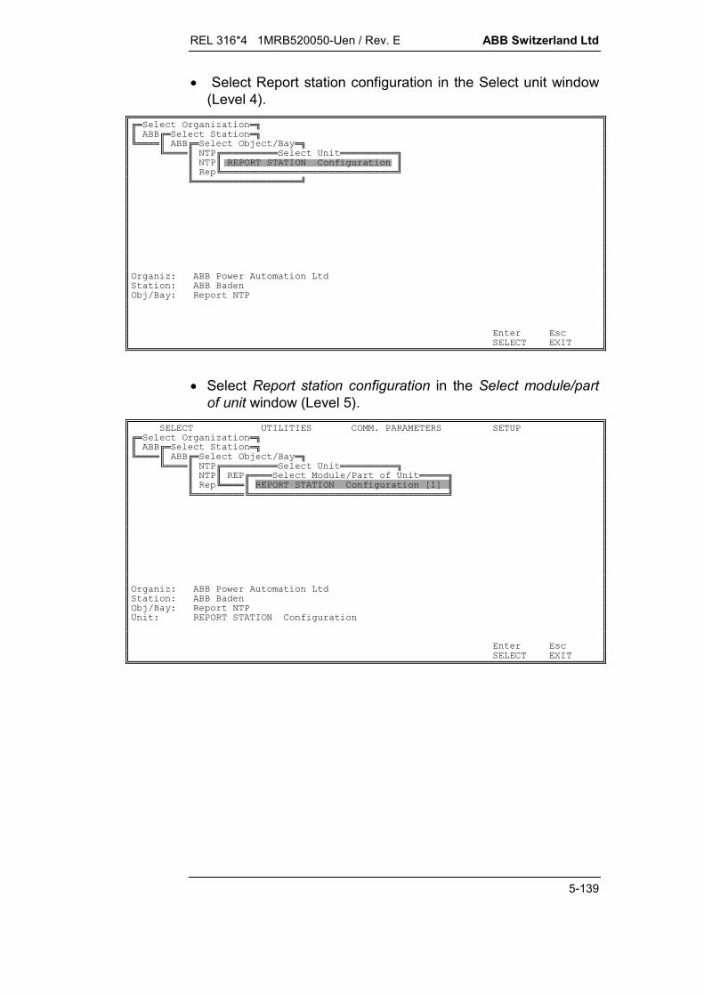
REL 316*4 1MRB520050-Uen / Rev. E ABB Switzerland Ltd
5-139
Select Report station configuration in the Select unit window(Level 4).
!+3' !"$!+ !"1!!!!$!+35\+F @!"1!!!!$08!!!!!!!!!!+/!!!!!!!!!!"$08$83H306A' $$1!!!!!!!!!!!!!!!!!!!!!!!!!!!!!!!21!!!!!!!!!!!!!!!!!!!23' 78 7 35\F @708(+6RH
Select Report station configuration in the Select module/partof unit window (Level 5).
6/HHH6398/8!+3' !"$!+ !"1!!!!$!+35\+F @!"1!!!!$08!!!!!!!!!!+/!!!!!!!!!!"$08$8!!!!+ F8 A/!!!!!"$1!!!!$83H306A' MN$1!!!!!!!!!1!!!!!!!!!!!!!!!!!!!!!!!!!!!!!!!!!!!23' 78 7 35\F @708/783H306A' (+6RH

ABB Switzerland Ltd REL 316*4 1MRB520050-Uen / Rev. E
5-140
Select the menu item Select function and then Report stationsettings (Level 6).
6/HHH6398/8!+3' !"$!+ !"1!!!!$!+35\+F @!"1!!!!$08!!!!!!!!!!+/!!!!!!!!!!"$08$8!!!!+ F8 A/!!!!!"$1!!!!$8!!!!!+A +!!!!!"MN$1!!!!!!!!!1!!!!$83( ('($!!!!21!!!!!!!!!!!!!!!!!!!!!!!!!23' 78 7 35\F @708/783H306A' F8 783H306A' MN*Q*V(+83,36RH
The SRIO address can now be entered and all the ‘Reporting’settings made in the window which opens.
!83H30!!!!!!!!!!!!!!!!!!!%9-!!!!!!!!!!!!!!!!!!!!!+A!"$83( ('(::9-4944$$$$<.....................................><.86.A-O9-944-7Q.....>$$?8(% (??0% (?$$?.....................................??.....................................?$$?<. ((..............>??<. ((..............>?$$?63FH3 ((^4O-??63FH3 ((^4O-?$$?<.( (..........>??<.( (..........>?$$? F( %^0?? F( %^0?$$?%F( %^0??%F( %^0?$$?'''F( %^0??'''F( %^0?$$?8 @^Q??8 @^Q?$$?8L^ @??8L^ @?$$?8C^??8C^?$$?'''( %A^0??'''( %A^0?$$?<. '('(..........>??<. '('(..........>?$$?8@^(??8@^(?$$?8( ^:9--CC9??8( ^:9--CC9?$$?8% ^-9-CC9??8% ^-9-CC9?$$.............................................................................D$$C ((AC63FH3 C( 9 '74--99444$1!!!!!!!!!!!!!!!!!!!!!!!!!!!!!!!!!!!!!!!!!!!!!!!!!!!!!!!!!!!!!!!!!!!!!!!!!!!!!!28',8'/*Q(+0R8)836&0RH
Refer to the Section ‘Reporting’ in the SMS010 manual for afurther information.

REL 316*4 1MRB520050-Uen / Rev. C ABB Switzerland Ltd
6-1
March 01
6. SELF-TESTING AND MONITORING
6.1. Summary .................................................................................6-2
6.2. Monitoring the auxiliary supply.................................................6-2
6.3. Monitoring the firmware ...........................................................6-2
6.4. Monitoring the hardware ..........................................................6-3
6.5. Diagnostic events ....................................................................6-3
6.6. Device diagnosis......................................................................6-6
6.7. HEX dump ...............................................................................6-8
6.8. IBB information ........................................................................6-86.8.1. SPA bus...................................................................................6-86.8.2. LON bus...................................................................................6-96.8.3. MVB.......................................................................................6-116.8.4. VDEW bus .............................................................................6-13
6.9. RIO information......................................................................6-13
6.10. Resetting SCS data ...............................................................6-13
6.11. Load SCS mask.....................................................................6-14

ABB Switzerland Ltd REL 316*4 1MRB520050-Uen
6-2
6. SELF-TESTING AND MONITORING
6.1. Summary
The continuous self-monitoring and diagnostic features incorpo-rated in RE. 316*4 assure high availability both of the protectionfunctions and the power system it is protecting. Hardware fail-ures are signalled instantly via an alarm contact.
Special importance has been given to monitoring the externaland internal auxiliary supply circuits. The correct operation andmaintenance of tolerances of the A/D converter (both on externalc.t./v.t. input boards Type 316EA62 or 316EA63 or in the CPUitself) are checked by making it continuously convert twoprecisely known reference voltages.
The execution of the program itself is monitored by a watchdog.
Security when transferring data by serial communication be-tween the protection and a local control and setting unit (PC) orwith a remote system (station control system) is provided by acommunication protocol with a "Hamming" distance of 4.
Special functions are provided for monitoring the integrity of thev.t. connections and for checking the symmetry of the threephase voltages and currents.
6.2. Monitoring the auxiliary supply
Both the external auxiliary supply applied to the protection andthe internal electronic supplies are continuously monitored. Thesupply unit is capable of bridging supply interruptions up to50 ms. After this time, the O/P's are blocked and the unit is resetand reinitialised.
6.3. Monitoring the firmware
A hardware timer (watchdog) monitors the execution of the pro-gram. Providing the program runs correctly, the timer is reset atregular intervals. Should for some reason the execution of theprogram be interrupted and the timer not be reset, the O/P's areblocked and the unit reinitialised.
REL 316*4 1MRB520050-Uen / Rev. C ABB Switzerland Ltd
6-3
6.4. Monitoring the hardware
For the most part, the hardware is either monitored or self-test-ing both while the system is being initialised after switching onand afterwards during normal operation. Upon switching on theauxiliary supply, a test routine completely checks the hardwareincluding the RAM and the flash EPROM checksums. The func-tion and accuracy of the A/D converter is tested by converting a10 V reference voltage to a digital value and checking that theresult lies within ± 1%.
The switch-on test takes about 10 seconds while the green(stand-by) LED does not light and the protection functions areblocked. Upon successful completion of the test, the stand-byLED flashes and the start-up routine commences. As soon asthe standby LED lights continuously, the device is operational.
The above routine continues to run as a background functionduring normal operation, checking the memories (excepting theRAM) at frequent intervals. The reference voltage is alsorepeatedly converted together with the current and voltagechannels to monitor the A/D converters.
6.5. Diagnostic events
A corresponding entry is made in the event list whenever thediagnostic function detects a failure.
The following entries in the list are possible:
System startThe device was switched on.
Protection restartThe protection and control functions were activated.
System warm startThe device was restarted after the reset button was pressedor a watchdog time-out.
Protection stopThe protection and control functions were stopped by theparameters being re-entered.
Supply failureThe device was switched off or there was a supply failure.

ABB Switzerland Ltd REL 316*4 1MRB520050-Uen
6-4
Diagnosis: main processor 316VC61a/316VC61b ready(0001H).
Diagnosis: A/D processor EA6. not ready.The external A/D processor 316EA62 or 316EA63 is notready. This occurs during normal operation, because the A/Dprocessor on the 316VC61a/316VC61b is active.
Diagnosis: internal A/D ready (0001H)The A/D processor on the 316VC61a/316VC61b is ready.
Diagnosis: system status: OK.
The above list of diagnostic messages reflects the operatingstate when the device is standing by. The following messagesand hexadecimal weightings can be generated by a fault.
Designation Function Weighting
RDY Device standing by 0001H
WDTO Watchdog time-out 0002H
WDDIS Watchdog disabled 0004H
HLT Stop procedure initiated 0008H
SWINT Software interrupt 0010H
RAM RAM error 0100H
ROM ROM error 0200H
VREF Reference voltage out-of-tolerance 0400H
ASE A/D converter error 0800H
EEPROM Parameter memory error 2000H
The hexadecimal weighting of an error message may also be theaddition of simpler errors. For example, VREF and ASE are re-corded as 0400H + 0800H = 0C00H.
Failures with a weighting less than 080H are listed as ‘minor er-rors’, e.g. a warm start after pressing the reset button.
Failures with a weighting higher than 0100H are ‘fatal errors’ andresult in blocking of the protection and control functions.
Note: Normally, a fatal error always concerns the entire device.An exception to this rule occurs when an EEPROM error is de-tected on a 316EA62 or 316EA63.
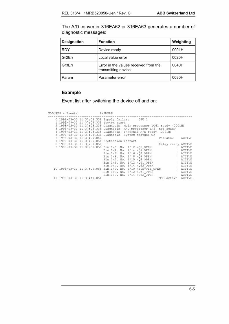
REL 316*4 1MRB520050-Uen / Rev. C ABB Switzerland Ltd
6-5
The A/D converter 316EA62 or 316EA63 generates a number ofdiagnostic messages:
Designation Function Weighting
RDY Device ready 0001H
Gr2Err Local value error 0020H
Gr3Err Error in the values received from thetransmitting device
0040H
Param Parameter error 0080H
Example
Event list after switching the device off and on:
MODURES - Events EXAMPLE------------------------------------------------------------------------------ 0 1998-03-30 11:37;08.338 Supply failure CPU 1 1 1998-03-30 11:37;08.338 System start 2 1998-03-30 11:37;08.338 Diagnosis: Main processor VC61 ready (0001H) 3 1998-03-30 11:37;08.338 Diagnosis: A/D processor EA6. not ready 4 1998-03-30 11:37;08.338 Diagnosis: Internal A/D ready (0001H) 5 1998-03-30 11:37;08.338 Diagnosis: System status: OK 6 1998-03-30 11:37;09.050 ParSatz2 ACTIVE 7 1998-03-30 11:37;09.056 Protection restart 8 1998-03-30 11:37;09.058 Relay ready ACTIVE 9 1998-03-30 11:37;09.058 Bin.I/P. No. 1/ 2 (Q0_OPEN ) ACTIVE Bin.I/P. No. 1/ 4 (Q1_OPEN ) ACTIVE Bin.I/P. No. 1/ 6 (Q2_OPEN ) ACTIVE Bin.I/P. No. 1/ 8 (Q9_OPEN ) ACTIVE Bin.I/P. No. 1/10 (Q8_OPEN ) ACTIVE Bin.I/P. No. 1/12 (Q51_OPEN ) ACTIVE Bin.I/P. No. 1/14 (Q52_OPEN ) ACTIVE 10 1998-03-30 11:37;09.058 Bin.I/P. No. 2/10 (BUS-TIE_OPEN ) ACTIVE Bin.I/P. No. 2/12 (Q51_OPEN ) ACTIVE Bin.I/P. No. 2/14 (Q52_OPEN ) ACTIVE 11 1998-03-30 11:37;40.051 MMC active ACTIVE.
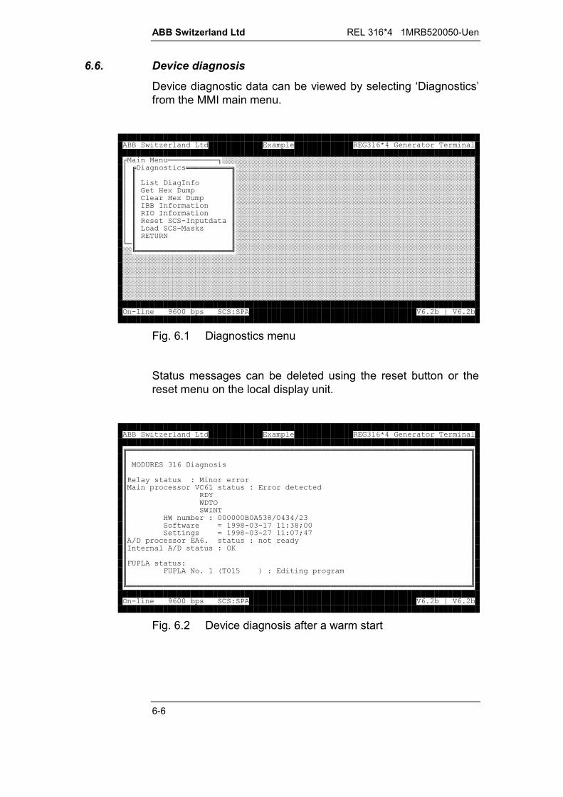
ABB Switzerland Ltd REL 316*4 1MRB520050-Uen
6-6
6.6. Device diagnosis
Device diagnostic data can be viewed by selecting ‘Diagnostics’from the MMI main menu.
!!!!!!!!!!!"########################################################$%& '()(**********+#####################################################$,,#####################################################$,(& '-.,#####################################################$,/& ,#####################################################$,0 /& ,#####################################################$,--. ,#####################################################$,-1-. ,#####################################################$,(02- ,#####################################################$, 02 (3(,#####################################################$,45,#####################################################6!,,#######################################################7*********************8#########################################################################################################################################################################################################################################################################################################################################################################################################################################################################################################################################129::;(0<=>?@;A>?@;
Fig. 6.1 Diagnostics menu
Status messages can be deleted using the reset button or thereset menu on the local display unit.
%****************************************************************************+,,,1&4& '((,,,, B( (<,, )((>0( (<),,&C,,D&1,,D-5,,/D ;<:::::::EFG:G@,,. H99F2:2I<FJ::,,'(H99F2:2@I<:IJI,,G&)((?( (< B,,- G&( (<1K,,,,L4=( (<,,L4=5?M:EN<'' ,,,7****************************************************************************8129::;(0<=>?@;A>?@;
Fig. 6.2 Device diagnosis after a warm start

REL 316*4 1MRB520050-Uen / Rev. C ABB Switzerland Ltd
6-7
Fig. 6.2 shows the diagnostic data of a device after a warm start.The significance of the various parameters is as follows:
HW number: 000000B0A538/0434/23Every 316VC61a or 316VC61b processor board has a uniquenumber. To this are added the codes for the microprocessorand the PCMCIA controller (PC card).
Software = 1998-03-17 11:38;00Date and time when the device firmware was created.
Settings = 1998-03-27 11:07;47Date and time when the parameter settings were lastdownloaded.
A/D processor EA6. Status: not readyThe external 316EA62 or 316EA63 A/D processor is not fitted.
Internal A/D Status: OKThe A/D processor on the 316VC61a or 316VC61b isstanding by.
FUPLA status: FUPLA No. 1 (T015 ): Editing programName of the FUPLA in the device. This uniquely identifies theFUPLA code loaded in the device. The FUPLA code can beprocessed either in the program (‘Prog’) or the parameter(‘Para’) memory. After the FUPLA code has been loaded,processing commences in the parameter memory. It is thencopied to the program memory and runs in the background.The processing speed of the program memory is higher.Up to eight different FUPLA logics can be loaded at the sametime and the status of each one is displayed. The followingstatuses are possible:
Blocked The blocking input is preventing the execution of theFUPLA logic.
Halted The execution of the FUPLA logic has been haltedbecause, for example, the FUPLA code cannot beaccessed temporarily.
Processing The FUPLA logic is being processed.
Initialised The FUPLA logic is already initialised, but inactive.
Inactive The FUPLA logic is loaded, but is not running.

ABB Switzerland Ltd REL 316*4 1MRB520050-Uen
6-8
6.7. HEX dump
Additional information to the diagnostic information is availableby selecting ‘Diagnostics’ from the main menu and then ‘LoadHEX dump’. Most of this data cannot be evaluated by the user,but they are frequently useful to ABB personnel for fault-finding.Once the data has been read, it should be deleted again byselecting ‘Delete HEX dump’ to make room for saving new data.
%****************************************************************************+,,,:::<:::::::)H(,,:::<:::@::::0('H:EFF/,,:::<:::: H=&LOP,,:::<::::EFF=' ) H:/,,:::<:::F:::,,:::<::::::@,,:::<:::0:L:,,:::<::::F=1<:::::::::::::::,,:::<::::,,:::<::@:::,,:::<::,,:::<:::I0F,,:::<::FI0,,:::<::I9,,:::<::0:&,,:::<:::::E,7****************************************************************************8129::;(0<=>?@;A>?@;
Fig. 6.3 HEX dump
6.8. IBB information
Depending on the firmware installed and therefore the choice ofthe interbay bus, various data on the status of the bus in relationto the station control system and the PC card can be obtainedvia this menu item.
6.8.1. SPA bus
No special information is available about the SPA bus.
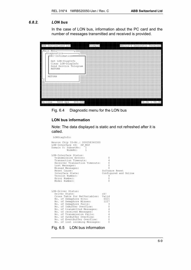
REL 316*4 1MRB520050-Uen / Rev. C ABB Switzerland Ltd
6-9
6.8.2. LON bus
In the case of LON bus, information about the PC card and thenumber of messages transmitted and received is provided.
!!!!!!!!!!!"########################################################$& '()(!!!!!!!!!!"#####################################################$$%1-2-. ********+#################################################$$,,#################################################$$,152& '-.,#################################################$$,0 152& '-.,#################################################$$,Q)' ,#################################################$$,45,#################################################$$,,#################################################$$7***********************8#################################################$$45$#####################################################6!$$#######################################################6!!!!!!!!!!!!!!!!!!!!!R#########################################################################################################################################################################################################################################################################################################################################################################################################################################################################################################################################129::;(0<=>?@;A>?@;
Fig. 6.4 Diagnostic menu for the LON bus
LON bus information
Note: The data displayed is static and not refreshed after it iscalled.15& '-.<5 0S-&25?<::::EF:::152-. )-&<&=O-=& :< ;5<55<152-. ) (< ((((<: ( ) (<)Q ( ) (<:((( '(<:(((( '(<:(0 (<. (-. ) <0.' 1>(5 ;<5 ;<:5 ;<:152&Q (<&Q <3T0(( ;.5> ;(<> 5?. S/(<@5?. S(((<@@I5?. SL (<5?.- ..1Q.<:5?. ((( '(<5?.)Q(( '(<:5?. (((L (<5?.1 ..1Q.<:5?.Q ..1Q.<:5?.()'(( '(<:
Fig. 6.5 LON bus information

ABB Switzerland Ltd REL 316*4 1MRB520050-Uen
6-10
The table below explains the significance of the various items ofinformation.
Neuron Chip ID-No. Hardware number of the neuron chip on the PC card
LON interface ID Must always be set to “DP_MIP”.
Domain Number of the domain to which the device belongs(can be set via the LON bus).
Subnet No. Number of the sub-network to which the devicebelongs (can be set via the LON bus).
Node No. Device node number (can be set via the LON bus).
Transmission errors Number of errors detected during reception.
Transaction timeouts Number of transaction confirmations not received.
Receiver transactiontimeouts
Number of messages received that were lost,because of incorrect settings at the receiving end.
Lost messages Number of messages lost, because the receivememory in the RE.316*4 was full.
Missed messages Number of messages lost, because the receivememory on the PC card was full.
Reset cause Reason for the last restart executed by the PC card.
Interface Status Normal: “Configured and on-line”.
Version number PC card firmware version
Error number 0 = no error or error on the PC card.
Model number Always 0
Driver state OK or error message
Cross table fornetwork variables
Valid or invalid (table loaded via the LON bus).
No. of semaphore hits Information for ABB purposes
No. of semaphoremisses
Information for ABB purposes
No. of semaphorefails
Information for ABB purposes
No. of IN bufferoverflows
Number of messages lost, because the driver bufferwas full.
No. of transmittedmessages
Total number of messages transmitted since theinformation was deleted.
No. of receivedmessages
Total number of messages received since theinformation was deleted.

REL 316*4 1MRB520050-Uen / Rev. C ABB Switzerland Ltd
6-11
No. of OUT bufferoverflows
Number of messages that could not be transmitted,because the buffer on the PC card was full.
No. of event bufferoverflows
Number of events that could not be transmitted,because the buffer on the PC card was full.
No. of lost incomingmessages
Number of messages lost, because the driverreceive buffer was full.
Delete LON diag. info
Selecting this menu item resets the various diagnostic informa-tion counters to zero.
Send service telegram
The menu item causes the PC card to send a service telegramwhich corresponds to pressing the service button on the PCcard. It is needed when configuring the network.
6.8.3. MVB
This menu item provides information about the PC card and thenumber of messages transmitted and received.
!!!!!!!!!!!"########################################################$& '()(!!!!!!!!!!"#####################################################$$%--. **********+###############################################$$,,###############################################$$,>2& '((-.,###############################################$$,0 >2& '((-.,###############################################$$,>(( '(,###############################################$$,45,###############################################$$,,###############################################$$7*************************8###############################################$$45$#####################################################6!$$#######################################################6!!!!!!!!!!!!!!!!!!!!!R#########################################################################################################################################################################################################################################################################################################################################################################################################################################################################################################################################129::;(0<=>?@;A>?@;
Fig. 6.6 MVB diagnostics menu
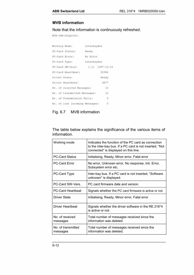
ABB Switzerland Ltd REL 316*4 1MRB520050-Uen
6-12
MVB information
Note that the information is continuously refreshed.>2-2& '-.<
D3'<-; B (
=020 (< B
=020 <5
=020 B<-; B (
=020 D2>(<?99I2@2E
=020 / <EEF
&Q < B
&Q/ ; <FII
5?.)Q(( '(<@
5?. ((( '(<@
5?. (((L (<:
5?.()'(( '(<:
Fig. 6.7 MVB information
The table below explains the significance of the various items ofinformation.
Working mode Indicates the function of the PC card as connectionto the inter-bay bus. If a PC card is not inserted, “Notconnected” is displayed on this line.
PC-Card Status Initialising, Ready, Minor error, Fatal error
PC-Card Error No error, Unknown error, No response, Init. Error,Subsystem error etc.
PC-Card Type Inter-bay bus. If a PC card is not inserted, “Softwareunknown” is displayed.
PC-Card SW-Vers. PC card firmware date and version
PC-Card Heartbeat Signals whether the PC card firmware is active or not.
Driver State Initialising, Ready, Minor error, Fatal error
Driver Heartbeat Signals whether the driver software in the RE.316*4is active or not.
No. of receivedmessages
Total number of messages received since theinformation was deleted.
No. of transmittedmessages
Total number of messages received since theinformation was deleted.
REL 316*4 1MRB520050-Uen / Rev. C ABB Switzerland Ltd
6-13
No. of transmissionfails
Number of errors while transmitting a message, forexample, because the buffer on the PC card was notavailable.
No. of lost incomingmessages
Number of messages lost, because the driverreceive buffer was full.
Delete MVB diag. info
Selecting this menu item resets the various diagnostic informa-tion counters to zero.
Load MVB messages
Selecting this menu item displays the last message sent orreceived and also the last event transmitted. These data are onlyneeded for development purposes and are not described in moredetail for that reason.
6.8.4. VDEW bus
No special information is available for the VDEW bus.
6.9. RIO information
Information is displayed on the status of the process bus and thedistributed input/output system. A detailed description of the datais given in publication 1MRB520192-Uen.
6.10. Resetting SCS data
After entering his password, an authorised user can delete theSCS input data.
ABB Switzerland Ltd REL 316*4 1MRB520050-Uen
6-14
6.11. Load SCS mask
This menu item provides facility to import a form (mask) from afile that was created using the MMI documentation function toconfigure the transfer of events via the SCS.
Part of a file of this kind is given below. In this case, the file onlycontains text and it can therefore be edited if necessary using anormal editor. Every possible event is listed with channel andevent number (see Index 9). “OFF” means that an event is“masked”, i.e. it cannot be transferred to be recorded as anevent. Conversely “ON” that it is transferred and recorded. Thefile is created automatically be the MMI and enables all theevents that have been configured.
Extract from the file “recxx.evt”:
0E1 OFF0E2 OFF0E3 OFF0E4 OFF0E5 OFF0E6 OFF0E7 OFF0E8 OFF
......
REL 316*4 1MRB520050-Uen / Rev. C ABB Switzerland Ltd
7-1
February 00
7. INSTALLATION AND MAINTENANCE
7.1. Summary..................................................................................7-3
7.2. Installation................................................................................7-47.2.1. Checking the shipment ............................................................7-47.2.2. Place of installation and ambient conditions ............................7-47.2.2.1. Guidelines for RF grounding ....................................................7-57.2.2.2. Guidelines for wiring rack assemblies......................................7-77.2.3. Checking the c.t. connections ................................................7-107.2.4. Checking the v.t. connections ................................................7-117.2.5. Checking the auxiliary supply connections.............................7-117.2.6. Checking the duty of the tripping and signalling contacts ......7-127.2.7. Checking the opto-coupler inputs...........................................7-12
7.3. Commissioning ......................................................................7-137.3.1. Connecting the setting and control PC...................................7-137.3.1.1. Minimum PC requirements.....................................................7-137.3.1.2. Serial interface parameters ....................................................7-137.3.1.3. PC connecting cable ..............................................................7-137.3.2. Connecting the equipment to the auxiliary d.c. supply ...........7-147.3.3. Connecting the binary inputs and outputs..............................7-147.3.4. Connecting v.t. and c.t. circuits ..............................................7-157.3.5. Connecting optical fibre cables for the
longitudinal differential protection...........................................7-167.3.6. Commissioning tests..............................................................7-16
7.4. Maintenance ..........................................................................7-187.4.1. Fault-finding ...........................................................................7-187.4.1.1. Stand-by LED on the frontplate..............................................7-187.4.1.2. Man/machine interface...........................................................7-197.4.1.3. Restarting...............................................................................7-20
7.5. Software updates ...................................................................7-227.5.1. Settings..................................................................................7-227.5.2. Deleting the settings and the program and
downloading a new program..................................................7-227.5.3. Problems transferring the new software.................................7-24
7.6. Replacing hardware units.......................................................7-26
ABB Switzerland Ltd REL 316*4 1MRB520050-Uen / Rev. C
7-2
7.7. Testing the protection functions .............................................7-297.7.1. MODURES test set XS92b ....................................................7-297.7.1.1. Test socket case XX93 and test connector YX91-4 ...............7-297.7.1.2. Test socket casing 316 TSS 01, test plug RTXH 24
and test cable YX 91-7...........................................................7-307.7.1.3. Switching to the test mode.....................................................7-317.7.2. Testing the distance protection function.................................7-327.7.3. Checking the direction of measurement.................................7-327.7.4. Testing the directional E/F function........................................7-347.7.4.1. Injecting power system voltages and currents .......................7-347.7.4.2. Real power measurement ......................................................7-347.7.4.3. Apparent power measurement...............................................7-367.7.4.4. Testing using a test set ..........................................................7-38
REL 316*4 1MRB520050-Uen / Rev. C ABB Switzerland Ltd
7-3
7. INSTALLATION AND MAINTENANCE
7.1. Summary
The place of installation and the ambient conditions must con-form to the data given in the data sheet. Sufficient room must beleft in front and behind the equipment to allow access for main-tenance or adding to the system. Air must be allowed to circulatefreely around the unit.
During the course of commissioning, all the wiring to the unitmust be checked and the auxiliary supply voltage and the volt-age for the opto-coupler inputs must be measured.
Functional testing can be carried out with the aid of the test setType XS92b.
All the essential functions of the protection are subject to con-tinuous self-testing and monitoring and therefore periodic main-tenance and testing are not normally necessary.
It is recommended, however, to check the values of the voltagesand currents of the external circuits from time to time using theon the input channel display on the HMI. The tripping circuitsshould be tested at the same time.

ABB Switzerland Ltd REL 316*4 1MRB520050-Uen / Rev. C
7-4
7.2. Installation
7.2.1. Checking the shipment
Check that the consignment is complete upon receipt. The near-est ABB agent must be notified immediately should there be anydiscrepancies in relation to the delivery note, shipping papers orthe order.
Visually check the state of all items when unpacking them. Shouldany damage be found, the last carrier must be informed imme-diately followed by a claim in writing pointing out his responsibilityfor the damage. Also inform your nearest ABB office or agent andABB Switzerland Ltd, Department UTAAA-P, CH-5401 Baden, Swit-zerland.
If the equipment is not going to be installed immediately, it mustbe stored in a suitable room in its original packing.
7.2.2. Place of installation and ambient conditions
When choosing the place of installation, ensure that there is suf-ficient space in front of the equipment, i.e. that the serial inter-face connector and the local control and display unit are easilyaccessible.
In the case of semi-flush mounting or installation in 19" equip-ment racks, space behind the equipment must be provided foradding ancillary units (e.g. 316DB61 and 316DB62), replacingunits and changing electronic components (firmware).
Since every piece of technical equipment can be damaged ordestroyed by inadmissible ambient conditions,
the relay location should not be exposed to excessive airpollution (dust, aggressive substances)
severe vibration, extreme changes of temperature, high lev-els of humidity, surge voltages of high amplitude and shortrise time and strong induced magnetic fields should beavoided as far as possible
air should be allowed to circulate freely around the equip-ment.
The equipment may be mounted in any attitude, but is normallymounted vertically (for reading the display and frontplate mark-ings).

REL 316*4 1MRB520050-Uen / Rev. C ABB Switzerland Ltd
7-5
7.2.2.1. Guidelines for RF grounding
Grounding the casing in a cubicle
Connect the rear of the casing (individual unit or rack) to thehinged frame in the cubicle by a braided copper strip (at least2 cm wide) which should be as short as possible. To prevent cor-rosion, a Cupal disc (copper-plated aluminium) must be insertedbetween aluminium and copper parts.
Connect the ground rail in the cubicle to the plant ground.
The interconnecting cable must have at least the same gauge asthe ground rail in the cubicle.
HEST 965 021 FL
*
**
non-insulated connection
* ground rail
** plant ground
Fig. 7.1 RF grounding in a cubicle

ABB Switzerland Ltd REL 316*4 1MRB520050-Uen / Rev. C
7-6
Grounding a casing in a rack
The equipment is fitted with a grounding screw ( ) to which aflexible copper braiding (at least 2 cm wide) must be connected.
A suitable tinned copper braided connection of the correct lengthand fitted with lugs is available from ABB Power Automation Ltd(Order No. 1MRB 400047).
Choose the shortest possible route to the nearest groundingpoint on the cubicle frame or mounting plate, which must have adirect connection to the station ground.
All metal surfaces used for the ground connections must beprotected against corrosion and be good electrical conductors,i.e. no paint or non-conducting agents.
HEST 965 022 FL
***
*
Electricallyconducting
Electricallyconducting
Electricallyconducting
***
*
non-insulated connection
* braided copper (at least 3 cm wide)
** plant ground
Fig. 7.2 RF grounding forsemi-flush mounting
Fig. 7.3 RF grounding forsurface mounting

REL 316*4 1MRB520050-Uen / Rev. C ABB Switzerland Ltd
7-7
7.2.2.2. Guidelines for wiring rack assemblies
Where digital protection devices (individual units) or protec-tion systems are supplied in a rack, it is essential that the bi-nary inputs and outputs (BIO’s) and the auxiliary supply whichhave to be wired from the rack to the cubicle terminals be runseparately from the c.t. and v.t. cables (not in the same duct orloom).
This precaution reduces the parallel coupling of conductedinterference.
Should this not be possible along the whole route, parallel cou-pling can be reduced by crossing at right angles. Completeseparation, however, is to be preferred.
RE. 316*4
Aux. supply
Aux. supply
Crossing
c.t's/v.t's
c.t's/v.t's
Terminals
Fig. 7.4 Separation of rack wiring in a cubicle
ABB Switzerland Ltd REL 316*4 1MRB520050-Uen / Rev. C
7-8
Screened leads must be used for the c.t. and v.t. wiring fromthe terminals to the equipment.
Recommendation
It is also recommended to use screened leads for the binary in-puts and outputs (BIO’s) and the auxiliary supply.
The following applies if the equipment is not installed in acubicle:
The terminals should be as close as possible to the equipmentterminals so that the unscreened lengths of cables are veryshort!
Screened c.t., v.t., binary input and output and auxiliary supplycables can be secured in one of the following ways:
Assemblies fitted into panels:
C.t. and v.t. leads to the terminals can be secured, for example,to a surface (steel rail) using cable clamps. The surface must bein direct contact with the plant ground and the cable screensmust make good contact with the cable clamps all the wayround.
This, however, is not always the case and the screen is fre-quently not in contact at the sides which impairs the screeningeffect. To overcome this drawback, a special ** copper braidtape can be wound on top of the cable screen in the region ofthe clamps. This then ensures maximum screening efficiency.
** Suitable tinned copper braid tape is available from 3M underthe designation:
"Scotch No. 24"(Fitting instructions should also be requested.)
Assemblies fitted into cubicles:(2 alternatives)
a) The c.t. and v.t. cables going to the terminals can passthrough cable glands. Again the cable screens must be ingood contact with the gland all the way round and the glandwith the plant ground (e.g. via the panel or strip material inwhich the gland is fitted).

REL 316*4 1MRB520050-Uen / Rev. C ABB Switzerland Ltd
7-9
C.t. and v.t. leads to the terminals can be secured, for exam-ple, to a surface (steel or copper) using conduit clamps. Thesurface (e.g. floor plate) must be in direct contact with theplant ground and the cable screens must make good contactwith the conduit clamps all the way round.
b) This, however, is not always the case and the screen is fre-quently not in contact at the sides which impairs the screen-ing effect. To overcome this drawback, a special ** copperbraid tape can be wound on top of the cable screen in theregion of the clamps. This then ensures maximum screeningefficiency.
To prevent corrosion, a Cupal disc (copper-plated aluminium)must be inserted between aluminium and copper parts.

ABB Switzerland Ltd REL 316*4 1MRB520050-Uen / Rev. C
7-10
7.2.3. Checking the c.t. connections
The c.t’s must be connected in strict accordance with diagramsupplied with the equipment.
The following checks must be carried out to check the c.t’s andc.t. circuits:
polarity check primary injection test plot the excitation curve c.t. circuit grounding.
The polarity check (as close as possible to the protection equip-ment) not only checks the current input circuit as a whole, it alsochecks the phase-angle of the c.t.
Primary injection checks for a ratio error and the wiring to theprotection equipment. Each phase-to-neutral and phase-to-phase circuit should be injected. In each case, the phase cur-rents and the neutral current should be measured.
The relative polarities of the c.t’s and their ratios can also bechecked using load current.
Plotting the excitation curve verifies that the protection is con-nected to a protection core and not a metering core.
Each electrically independent current circuit may only be earthedin one place, in order to avoid balancing currents created by po-tential differences.
Core-balance c.t’s
If the residual current is obtained from a core-balance c.t., theground for the cable screen must first be taken back through thecore-balance c.t. before connecting it to ground. The purpose ofthis is to ensure that any spurious E/F current flowing along thescreen of the cable cancels itself and is not measured falsely asan E/F on the relay’s own feeder.

REL 316*4 1MRB520050-Uen / Rev. C ABB Switzerland Ltd
7-11
7.2.4. Checking the v.t. connections
The v.t’s must be connected in strict accordance with diagramsupplied with the equipment.
The following checks must be carried out to check the v.t. cir-cuits:
polarity check wiring check v.t. circuit grounding.
The rated voltage of an E/F protection scheme is defined as thevoltage which occurs between the terminals “e” and “n” for asolid phase-to-ground fault. An E/F of this kind, e.g. on T phase(see Fig. 7.5), causes the voltages of R and S phases to in-crease from phase-to-neutral to phase-to-phase potential andthese add vectorially to produce a voltage between terminals “e”and “n", which is three times the phase-to-neutral voltage.
HEST 945 002 C
R
ST
UT
UR
R
ST US
UR U0
US u
3 u·
a) normal load condition b) E/F on T phase
Fig. 7.5 Voltages in an ungrounded three-phase power system
7.2.5. Checking the auxiliary supply connections
Check that the supply is connected with the correct polarity. Thed.c. supply voltage must lie within the permissible operatingrange of the power supply unit installed under all operating con-ditions (see Technical Data for the respective power supply unit).
The power supply unit, type 316NG65 is protected by a fuse,type T 3.15 A.

ABB Switzerland Ltd REL 316*4 1MRB520050-Uen / Rev. C
7-12
7.2.6. Checking the duty of the tripping and signalling contacts
Check that the loads connected to all the contacts are within thespecified ratings given in the “Contact ratings” section of thedata sheet.
7.2.7. Checking the opto-coupler inputs
Check the polarity and supply voltage of all opto-coupler inputsin relation to the ordering code (also given on the rating plate atthe rear of the equipment).
REL 316*4 1MRB520050-Uen / Rev. C ABB Switzerland Ltd
7-13
7.3. Commissioning
Before commencing commissioning, i.e. before the station is en-ergised, carry out the checks given in Section 7.2.
7.3.1. Connecting the setting and control PC
Connect the serial interface of the PC to the interface connectoron the front of the equipment. Details of the communication pa-rameters and the connector pins are given in the following Sec-tions.
7.3.1.1. Minimum PC requirements
The minimum requirements to be fulfilled by the HMI PC are:
MS Windows 3.1x, Windows 95 or Windows NT4.0 operatingsystem or higher
16 MByte RAM
1 floppy drive (3½"; 1.44 MByte) and a hard disc with at least12 MByte of free space
1 serial interface (RS-232C)
1 parallel interface (Centronics).
7.3.1.2. Serial interface parameters
The HMI initialises the serial interface and automatically sets thecorresponding parameters.
7.3.1.3. PC connecting cable
The connecting cable between the serial interface connectors onthe frontplate of the protection equipment (optical connector onthe front of the local control and display unit) and on the PC(9-pin SUB-D plug) is an optical fibre cable with the order No.1MRB380084-R1 (see Data Sheet).
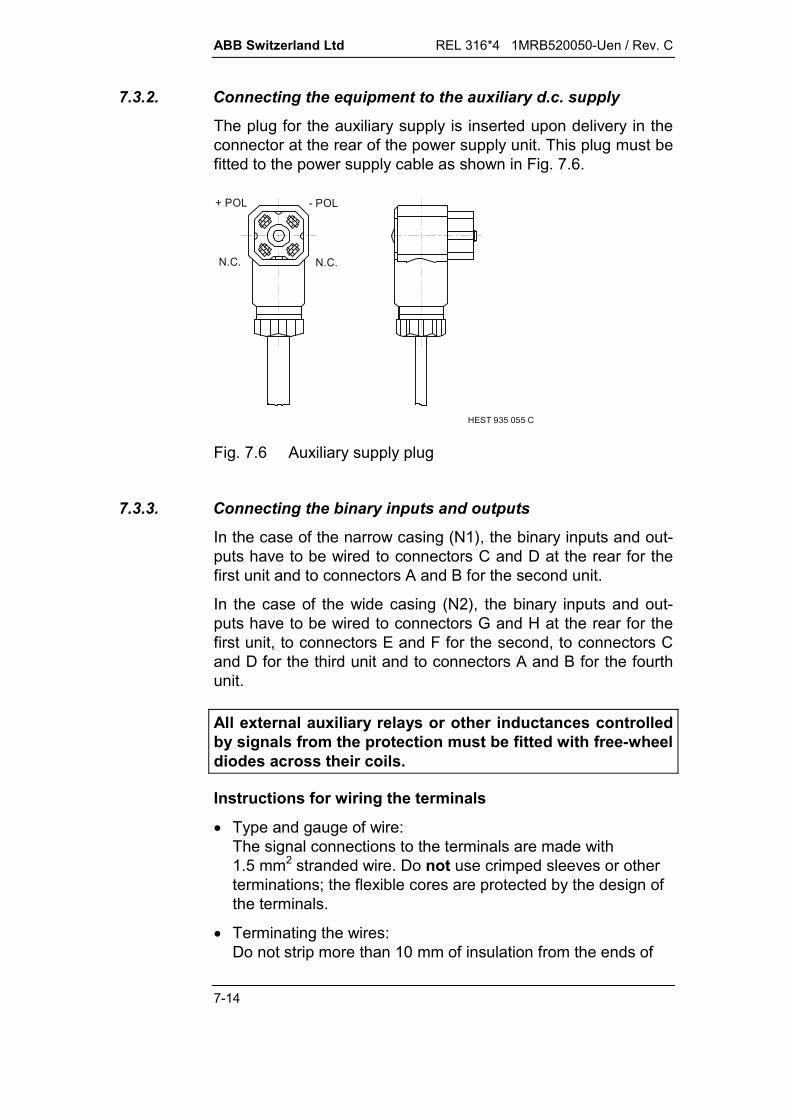
ABB Switzerland Ltd REL 316*4 1MRB520050-Uen / Rev. C
7-14
7.3.2. Connecting the equipment to the auxiliary d.c. supply
The plug for the auxiliary supply is inserted upon delivery in theconnector at the rear of the power supply unit. This plug must befitted to the power supply cable as shown in Fig. 7.6.
HEST 935 055 C
+ POL - POL
N.C. N.C.
Fig. 7.6 Auxiliary supply plug
7.3.3. Connecting the binary inputs and outputs
In the case of the narrow casing (N1), the binary inputs and out-puts have to be wired to connectors C and D at the rear for thefirst unit and to connectors A and B for the second unit.
In the case of the wide casing (N2), the binary inputs and out-puts have to be wired to connectors G and H at the rear for thefirst unit, to connectors E and F for the second, to connectors Cand D for the third unit and to connectors A and B for the fourthunit.
All external auxiliary relays or other inductances controlledby signals from the protection must be fitted with free-wheeldiodes across their coils.
Instructions for wiring the terminals
Type and gauge of wire:The signal connections to the terminals are made with1.5 mm2 stranded wire. Do not use crimped sleeves or otherterminations; the flexible cores are protected by the design ofthe terminals.
Terminating the wires:Do not strip more than 10 mm of insulation from the ends of
REL 316*4 1MRB520050-Uen / Rev. C ABB Switzerland Ltd
7-15
the wires. Insert the stripped ends of the cores perpendicularlyto the rear of the device into the terminals and secure them bytightening the screw next to each one. As the channel for thewire in the terminals is slightly curved, twisting the wiresslightly when inserting them is a help. Only insert onestranded wire into each terminal.Take care that no strands protrude that may cause arcing orshort-circuits.
Bridging terminals:Where it is necessary to bridge terminals, do so at externalterminals on the cubicle.
7.3.4. Connecting v.t. and c.t. circuits
Instructions for wiring the terminals
Type and gauge of wire:The v.t. and c.t. connections to the terminals are made with2.5 mm2 stranded wire (e.g. H07V-K). The ends of the wires inthis case must be fitted with crimped sleeves. V.t. and c.t. connections may be made alternatively by 4 mm2
solid wire.
Terminating the wires:Insert the ends of the wires perpendicularly to the rear of thedevice into the terminals and secure them by tightening thescrew next to each one.Take care that no strands protrude that may cause arcing orshort-circuits.
Bridging terminals:Where it is necessary to bridge neighbouring terminals, do sodirectly at the protective device using standard links (e.g. asmanufactured by PHOENIX). The terminals are designed toaccommodate these in addition to a 2.5 mm2 gauge lead. Al-ternatively, circuits have to be bridged at external terminals onthe cubicle.

ABB Switzerland Ltd REL 316*4 1MRB520050-Uen / Rev. C
7-16
7.3.5. Connecting optical fibre cables for the longitudinal differen-tial protection
Optical fibre cables are connected using Type FC connectors.
Take care when inserting the connectors that only to tighten thescrew fitting after checking that the nose on the plug is properlyseated in the groove of the base.
To exclude any risk of false tripping when connecting or discon-necting a cable in operation, only do so after the auxiliary supplyto at least one of the terminal units has been switched off.
In cases where the terminal units are connected via communica-tions devices such as FOX-U, ensure that the communication inboth directions is via the same route (equal lengths).
7.3.6. Commissioning tests
For the protection scheme as a whole to operate correctly, it isnot enough for just the protection equipment itself to be in order,the reliable operation of the other items of plant in the protectionchain such as circuit-breakers, c.t’s and v.t’s (e.g. protection andmetering core leads exchanged), station battery (earth fault),alarm and signalling circuits etc. and all the cabling is equallyimportant.The correct operation of the equipment itself is determined bythe following tests:
secondary injection of every current and voltage input activating and deactivating every binary input (opto-coupler) energising and de-energising every auxiliary tripping and sig-
nalling relay checking the settings (printed by the HMI).
These tests confirm that none of the protection hardware is de-fective. The actual protection functions are contained in the soft-ware and are continuously monitored. They do not thereforeneed to be especially tested during commissioning.
The following is a list of some of the tests and the faults they areintended to disclose.
REL 316*4 1MRB520050-Uen / Rev. C ABB Switzerland Ltd
7-17
Test Faults disclosed
Injection of rated value at all c.t. and v.t.inputs (e.g. using test set Type XS 92b)
Hardware defectiveWrong rated currentWrong rated voltageWrong reference value
Activation/deactivation of all binary in-puts (opto-couplers)
Hardware defectiveIncorrect setting(not inverted)Incorrect assignment
Energisation of all auxiliary tripping re-lays (using the test function)
Hardware defectIncorrect assignment
Energisation/de-energisation of all aux-iliary signalling relays (using the testfunction)
Hardware defectIncorrect assignment
A further useful facility is provided by the “Display analogue val-ues” menu which enables the currents and voltages applied tothe protection to be viewed. It can thus be seen whether the am-plitude and phase of the currents and voltages are correct. TheAppendix in Section 12. includes a test report.
ABB Switzerland Ltd REL 316*4 1MRB520050-Uen / Rev. C
7-18
7.4. Maintenance
Because of the self-testing and monitoring features included, theequipment requires neither special maintenance nor periodictesting.
Where testing is considered necessary, the following procedureis recommended:
Measure the currents and voltages in the secondaries of themain c.t’s and v.t’s and compare the results with the valuesdisplayed by the HMI.
Test the external circuits using the test functions provided bythe HMI (see Section 5.9.).
The life of the wet electrolytic condensers is about 20 years. Thisassumes a mean ambient temperature outside the casing of40 °C. An increase of 10 °C shortens the life by half and a de-crease of 10 °C extends it by half.
7.4.1. Fault-finding
7.4.1.1. Stand-by LED on the frontplate
The following may be possible causes, should the green stand-by LED not light continuously, but be extinguished or flash al-though the auxiliary supply is switched on:
Stand-by LED extinguished
The auxiliary supply unit Type 316N65 is not properly in-serted or is defective. Insert properly or replace the unit.
The input/output unit Type 316DB6. is not properly insertedor defective. Insert properly or replace the unit.
The logic processor Type 316VC61a or 316VC61b is defec-tive. Replace either the main processor unit or the completeequipment.
Green stand-by LED flashes
The equipment does not have a valid set of parameter set-tings.
The active set of parameters and the ‘software key’ do notagree.
REL 316*4 1MRB520050-Uen / Rev. C ABB Switzerland Ltd
7-19
A hardware fault has been discovered by the diagnostic func-tion on either the Type 316VC61a/316VC61b or 316EA62unit.
To determine whether a set of settings has been downloaded tothe equipment, connect it to a PC and start the HMI. Check viathe menus ‘Editor’ and ‘Edit function parameters’ and ‘Edit hard-ware functions’ whether functions have settings and whether thehardware has been configured.
If the settings appear in order, check whether parameters orfunctions have been entered which are not permitted by the‘software key’.
Should it appear that there is a disagreement with the ‘softwarekey’, proceed as follows:
Connect the equipment to a PC and start the HMI.
Download a slightly changed set of settings to the equipment.The HMI then compares the ‘software key’ with the pro-grammed functions before it actually downloads the settingsand reports and error if they do not agree (EPLD error).
7.4.1.2. Man/machine interface
If communication between the protection equipment and the PCthis is not possible in spite of the fact that the stand-by LED is lit,first check the serial interface connectors and connecting cable.Where the connection appears to be in order, reboot the PC byswitching it off and on and then restart the HMI.
Should this also prove unsuccessful, restart the device either byselecting the menu item ‘Warm start’ in the RESET menu on thelocal control and display unit (see Section 5.13.8.6.) or by hold-ing the reset button depressed until the stand-by LED (green)starts to flash (about 10 seconds). This is a software restart,which is equivalent to switching the auxiliary supply off and on.
In the event of a defect, send the diagnostic information ob-tained via ‘List DiagInfo’ and ‘Get Hex Dump’ together withthe device settings to your local support centre.

ABB Switzerland Ltd REL 316*4 1MRB520050-Uen / Rev. C
7-20
The following example is of a ROM defect in the main processorunit:
List DiagInfo:
!"#$$$$$$%$&'() *++',$(,(-$$*++.,$,$$+//-$'0&1&2 &1
03& 03&
0 #-452
Get Hex Dump:1000:0000 0004 Error code = stopped1000:0002 0000 Code segment = 00D8H1000:0004 06D9 Module name = RUNPROT TEXT1000:0006 00D8 Program counter = 06D9H1000:0008 00041000:000A 00521000:000C 01F11000:000E 0178 EEPROM: 000000000000001011000:0010 01991000:0012 00A01000:0014 00E11000:0016 07301000:0018 00001000:001A 00001000:001C 00001000:001E 0005.
7.4.1.3. Restarting
The detection of an error or defect by the self-testing and moni-toring functions during normal operation initiates the following:
Processing by the protection functions is stopped and theiroperation blocked.
The binary outputs are reset and further operation blocked.This includes resetting the ‘Relay ready’ signal, if it was acti-vated.
The stand-by signal (green LED on the frontplate) flashes.
Communication between the PC and the protection equipmentremains intact, however, and provides facility for localising thecause of the problem.
Blocking of the protection is maintained until an attempt is madeto restart it by pressing the reset button on the frontplate. Shouldrestarting be successful, but the original defect still exists, thesame sequence is repeated and the protection is blocked onceagain.

REL 316*4 1MRB520050-Uen / Rev. C ABB Switzerland Ltd
7-21
Either the 316VC61a or 316VC61b unit or the complete equip-ment has to be replaced in the case of error messages con-cerning the main or logic processors.
Should the diagnostic function report an error in the A/D proces-sor (type 316EA62) although none is fitted, the message can beignored. If one is fitted, however, it must be replaced.
An entry is made in the event list every time the protection is re-started.
ABB Switzerland Ltd REL 316*4 1MRB520050-Uen / Rev. C
7-22
7.5. Software updates
Updating the software with the latest version and where neces-sary also the hardware can add new functions or new features tothe device.
The software version can be is given in the bottom right-handcorner of the HMI screen when it is operating on-line (the firstnumber is the version of the HMI and the second number theversion of the software in the equipment).
The HMI is compatible with the equipment software when thefirst digit after the point is the same in both numbers.
The equipment software can be updated without opening theequipment, because it is stored in a read/write memory (flashEPROM’s).
Generally the software must be updated by ABB personnel.Nevertheless, the procedure is described below so that it can beperformed by correspondingly qualified personnel (PC experi-ence essential) if necessary.
7.5.1. Settings
Make a backup copy of the settings using the HMI (menu items‘Enter function parameters’ and ‘Save in file’). Then close theHMI.
7.5.2. Deleting the settings and the program and downloading anew program
The following additional files which are necessary to update thefirmware are in the HMI directory after installation:
spa316a.h26, lon316a.h26,vdew316a.h26:
Software for the processor unit316VC61a, depends on com-munications protocol.
spa316b.h26, lon316b.h26,vdew316b.h26:
Software for the processor unit316VC61b, depends on com-munications protocol.
REL 316*4 1MRB520050-Uen / Rev. C ABB Switzerland Ltd
7-23
spa316a.bat, lon316a.bat,vdew316a.bat:
Batch file for loading the soft-ware into the processor unit316VC61a, depends on com-munications protocol.
spa316b.bat, lon316b.bat,vdew316b.bat:
Batch file for loading the soft-ware into the processor unit316VC61b, depends on com-munications protocol.
The type of processor board can be determined using the HMIdiagnostic function. Upon selecting ‘Show diagnostic data’, oneof the lines displayed is ‘HW No.’, which in the case of316VC61a includes the code ‘0434’:
HW-No.: xxxx/0434/xx
or for 316VC61b the code ‘04Ax’:HW-No.: xxxx/04Ax/xx
The new software is loaded into devices with the existing soft-ware version V5.0 is accomplished by running the correspondingbatch file. For this purpose, make the active directory the HMI di-rectory via the File Manager (Windows 3.1 or 3.11) or Explorer(Windows 95, 98 or NT 4.0) and execute the appropriate batchfile. The version, type of processor board (316VC61a or316VC61b) and the desired communication protocols are thendisplayed again. Click on N (no) to abort or on Y (yes) to con-tinue.
The HMI proper does not then start, but simply a window ap-pears with the question ‘Are you sure? <Y>/<N>’ as a safetyprecaution. If you enter ‘N’ the normal HMI starts; if you enter ‘Y’the settings and the program are instantly deleted. The deletingprocedure takes about twenty seconds. During this time ‘Savingrestart relay’ flashes on the screen.
At the end of this operation, the file ‘*.h26’ is transferred to theequipment. This takes about 5 minutes. During this time the pro-gress is indicated by numbered lines and dots:
33...............................................................................................

ABB Switzerland Ltd REL 316*4 1MRB520050-Uen / Rev. C
7-24
After transfer has been completed, the new program startsautomatically and the time stamp of the *.h26 file is saved in theequipment.
During the whole of this operation do not make any entries at thekeyboard of the PC, as this interrupts the automatic procedure.
7.5.3. Problems transferring the new software
Problems and errors can never be excluded when transferringand saving new software (e.g. supply failure during transfer).Should something of this kind occur, an attempt can be made torepeat the transfer by executing the batch file again. If theequipment responds neither to the call by the batch file nor theHMI, try to reinitialise the equipment by switching the auxiliarysupply off and back again and then repeat the transfer of theprogram file.
Should this also prove unsuccessful, the following proceduremust be executed to delete the contents of the program memoryin the main processor unit:
Devices with the main processor unit 316VC61a have to beopened and the main processor unit removed from them. Fit thetwo jumpers X601 and X602 and reinsert the main processorunit. Switch on the auxiliary supply and wait for thirty seconds.Switch off the auxiliary supply and withdraw the main processoragain. The program is now deleted. Remove the two jumpers,plug the main processor in again, reassemble the equipment andrepeat the program transfer procedure.
Switch of the auxiliary supply to devices equipped with mainprocessor 316VC61b and then insert the pin supplied into thesocket below the SPA or VDEW6 communication interface.Switch on the auxiliary supply for about thirty seconds, switch itoff again and withdraw the pin. This procedure deletes the pro-gram and the new program can be loaded after switching on theauxiliary supply again.
Should the pin not be available, the same procedure can beused as described in the previous paragraph for the 316VC61awith the exception that the jumper marked ‘TEST’ has to be in-serted instead of X601 and X602.

REL 316*4 1MRB520050-Uen / Rev. C ABB Switzerland Ltd
7-25
Fig. 7.7 Main processor unit 316VC61ashowing the jumpers X601 and X602(derived from HESG 324 502)

ABB Switzerland Ltd REL 316*4 1MRB520050-Uen / Rev. C
7-26
7.6. Replacing hardware units
Qualifications
Hardware units may only be replaced by suitably qualifiedpersonnel. Above all it is essential for the basic precautionsconcerning protection against electrostatic discharge be ob-served.
It may be necessary to transfer existing settings from the relay ordownload new ones to the relay, procedures which assume fa-miliarity with the HMI.
Note that incorrect handling of the devices and their componentparts can cause damage (to the devices or the plant) such as:
false tripping of items of plant in operation destruction of main c.t’s and v.t’s etc.
The following are basic precautions which have to be taken toguard against electrostatic discharge:
Before handling units, discharge the body by touching thestation ground (cubicle).
Hold units only at the edges, do not touch contacts or com-ponents.
Only store and transport units in or on the original packing.
Tools required
Relays can be opened at the rear. The backplates are securedeither Philips screws or Torx screws. Accordingly one of the fol-lowing is required:
Philips screwdrivers No. 1 and No. 2
or
Torx screwdrivers No. 10 and No. 20.
Terminal screws are always of the normal slotted type. No othertools are required.
Procedure
Follow the check list in the Appendix of Section 12. when re-placing hardware units.
The check list is primarily intended for replacing defective unitsby ones of the same type (same code). If a different relay con-figuration is desired or necessary, units may be have to be re-
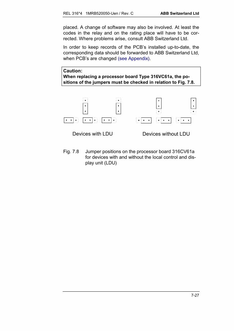
REL 316*4 1MRB520050-Uen / Rev. C ABB Switzerland Ltd
7-27
placed. A change of software may also be involved. At least thecodes in the relay and on the rating place will have to be cor-rected. Where problems arise, consult ABB Switzerland Ltd.
In order to keep records of the PCB’s installed up-to-date, thecorresponding data should be forwarded to ABB Switzerland Ltd,when PCB’s are changed (see Appendix).
Caution:When replacing a processor board Type 316VC61a, the po-sitions of the jumpers must be checked in relation to Fig. 7.8.
Devices with LDU Devices without LDU
Fig. 7.8 Jumper positions on the processor board 316CV61afor devices with and without the local control and dis-play unit (LDU)

ABB Switzerland Ltd REL 316*4 1MRB520050-Uen / Rev. C
7-28
Caution:If a processor board, type 316VC61b is replaced in a unit,check the jumpers according to Fig. 7.9. These jumpers arelocated between the two connectors.
Including LDU: X2200 – X2201X2203 – X2204X2206 – X2207
Excluding LDU: X2201 – X2202X2204 – X2205X2207 – X2208
Fig. 7.9 Jumper positions on the 316VC61b processor boardfor devices including and excluding a local controland display unit (LDU) on the front(derived from HESG 324 526)

REL 316*4 1MRB520050-Uen / Rev. C ABB Switzerland Ltd
7-29
7.7. Testing the protection functions
The current data, settings and protection configuration can beselected, viewed and also printed, providing a printer is con-nected to the PC, via the HMI menu “LIST RELAY SETTINGS”(see Section 5.5.7.).
7.7.1. MODURES test set XS92b
The REL 316*4 protection functions can be tested using a nor-mal protection relay test set, e.g. MODURES XS92b. This ismost conveniently achieve in the plant by inserting theREL 316*4 into the test socket case XX93 or 316 TSS 01 whichis wired to the test set.
A detailed description of the test set XS92b is to be found in datasheet 1MDB520006-Ben and in the Instructions for Installationand Operation 1MRB520014-Uen.
7.7.1.1. Test socket case XX93 and test connector YX91-4
Upon inserting the test plug YX91-4 (see Appendices in Section 12.):
the secondaries of the main c.t’s are short-circuited
the protection equipment is isolated from the primary systemc.t’s and v.t’s
the tripping circuits are interrupted
the protection’s current and voltage inputs are connected tothe test set
the opto-coupler input OC101 is interrupted which auto-matically switches the protection to the test mode
the signalling relay S 102 is connected to the test set.
Caution:Every tripping relay has two contacts in parallel. Test plugYX91-4 can interrupt up to four DC tripping circuits. Thismust be taken into account when connecting the trippingcircuits.
If necessary, the DC circuits, which have been interrupted, canbe closed on the test set XS92b. For this purpose, twelve 2 mmdiameter sockets marked 1 to 12 are provided on the front of the

ABB Switzerland Ltd REL 316*4 1MRB520050-Uen / Rev. C
7-30
AC93 unit in the test set (AX91/92 in the case of XS92a). Theyare connected in parallel with test plug contacts B1 to B12 whichcorrespond to sockets A1 to A12 on the test socket case XX93.
The connections can thus be made again by inserting jumpers insockets 1 to 12.
Caution:Take care when inserting jumpers into the 2 mm sockets,because they are directly connected to the DC battery sup-ply for the tripping circuits!
The surface mounting, semi-flush mounting and 19" rack ver-sions can all be tested using the test socket case XX93. The cor-responding dimensioned drawings and the wiring diagram for theconnections between the REL 316*4 and the XX93 are includedin the Appendices (Section 12.).
The connections to the test set Type XS92b are established us-ing the cable and test connector YX91-4. This enables testingwith four currents and three voltages. An ancillary test plug TypeYX93 is optionally available for testing REL 316*4 units equippedwith a fifth c.t. and a fourth or fifth v.t. The ancillary plug is in-serted into the XX93 casing and connected by banana plugs andcables to the test set.
The connections between the XS92b test set and the XX93casing via the YX91-4 test plug are shown in the Appendices(Section 12.).
7.7.1.2. Test socket casing 316 TSS 01, test plug RTXH 24and test cable YX 91-7
The test socket casing 316 TSS 01 consists of a casing intowhich a block of RTXP 24 test sockets has been installed.It is suitable for testing the surface mounting, semi-flush mount-ing and 19” rack versions of the REL 316. The correspondingdimensioned drawings and the wiring diagram for the connec-tions between the REL 316*4 and the 316 TSS 01 are includedin the Appendices (Section 12.).
The connections to the test set Type XS92b are established us-ing the test connector RTXH 24 and test cable YX91-7. This en-ables testing with four currents and three voltages. Banana plugsand cables are used for connecting REL 316*4 units equippedwith a fifth c.t. and a fourth v.t. to the test set.

REL 316*4 1MRB520050-Uen / Rev. C ABB Switzerland Ltd
7-31
The connections between the XS92b test set and the RTXH 24test plug and the 316 TSS 01 casing via the YX91-7 cable areshown in the Appendices (Section 12.).
Inserting the test plug RTXH 24 and test cable YX91-7:
short-circuits the secondaries of the main c.t’s
isolates the protection device from the primary system c.t’sand v.t’s
interrupts two auxiliary DC supplies to the tripping relays
connects the current and voltage inputs of the protection de-vice to the test set
activates the opto-coupler input OC101 to switch the protec-tion device automatically to the test mode
connects the signalling relay S102 to the test set.
The unused contacts A8-B8 and A9-B9 are available for eitherinterrupting the two other DC circuits or for connecting a fifth v.t.(for the synchrocheck function).
7.7.1.3. Switching to the test mode
The protection switches automatically to the injection test modewhen a logical “1” is applied to the binary I/P ‘InjTstEnable’(normally opto-coupler OC 101). In the test mode:
the distance protection signal ‘Trip CB’ is assigned to theoutput signal ‘InjTstOutput’
all tripping and signalling relays (including ‘Relay ready’) areblocked excluding the signalling relay assigned to ‘InjTstOut-put’
the distance protection function is waiting to receive controldata from the test set XS92b for assigning signals to the out-put ‘InjTstOutput’
the baud rate of the interface at the front is reduced to 9600 ifnot already at it, because the test set XS92b cannot commu-nicate at a higher baud rate.
The binary input ‘InjTstEnable’ has to be inverted when using thetest socket casing XX93.

ABB Switzerland Ltd REL 316*4 1MRB520050-Uen / Rev. C
7-32
7.7.2. Testing the distance protection functionGeneral instructions for testing the distance protection functionare given in Section 8 of publication 1MRB520014-Uen and forthe use of test programs in publications CH-ES 86-11.52 E andCH-ES 86-11.54 E.
7.7.3. Checking the direction of measurementThere are two HMI menus for checking the direction of meas-urement.Normally the menu “DISPLAY LOAD VALUES” and sub-menu“Distance” should be used. The following is an example of thedisplay in this case in /phase:---------- [RefLength]---------- + j ------ Z (RE)---------- + j ------ Z (SE)---------- + j ------ Z (TE) 50.00 + j 1.50 Z (RS) 50.00 + j 1.50 Z (ST) 50.00 + j 1.50 Z (TR)This display indicates that the relay is measuring in the forwardsdirection, because the real component of the phase-to-phaseimpedance is positive, i.e. providing the scheme is wired ac-cording to the standard ABB diagram in the Appendices (Section12.), the c.t’s are grounded on the line side and power flows fromthe busbars into the line. If the real component is negative,power is flowing from the line towards the busbars.The settings ‘CT Neutral’ on line and busbar sides and the binaryinput ‘ChgMeasDir’ on the distance protection function influencethis display.The first four lines (fault distance and phase-to-ground loop im-pedances) do not influence the direction of measurement.The last three lines (phase-to-phase loop impedances) are dis-played providing the load current exceeds
VX
U5.0
A
0ph and 0.5 Imin.
where:XA reactance in the tripping direction (see Section 3.5.2.2.2.)Imin pick-up setting of the low-current enabling function.

REL 316*4 1MRB520050-Uen / Rev. C ABB Switzerland Ltd
7-33
If no impedances are displayed at the normal settings, increasethe setting of the impedance parameter Xi (e.g. XBACK) until thefirst condition is fulfilled.
A second possibility for checking the direction of measurementor for obtaining a ‘second opinion’ is to use the menu “DISPLAYANALOGUE CHANNELS” (see Section 5.7.1.). This methodworks for load currents down to about 5% of rating.
Since this menu is not restricted to a single protection function, itis not dependent on the settings of the various functions (ex-cepting the reference for analogue channels) and especially noton the ‘Bus side/Line side’ setting of the ‘CT neutral’ parameterand the binary input ‘ChgMeasDir’ on the distance protectionfunction.
Example:
For a purely resistive load with power flowing from the busbarinto the line and the c.t. neutral on the line side, the angle be-tween R phase voltage and current (or US-IS, UT-IT) is zero de-grees.
This method of checking the direction of measurement, however,does not disclose whether the setting of the parameter‘CT neutral’ (‘Bus side/Line side’) is correct.

ABB Switzerland Ltd REL 316*4 1MRB520050-Uen / Rev. C
7-34
7.7.4. Testing the directional E/F function(for ungrounded systems)
7.7.4.1. Injecting power system voltages and currents
Where it is not possible to test the protection by installing an E/Fon the primary system, it can be tested using load current.
The test circuits of Fig. 7.12 to Fig. 7.15 differ only in the wiringof the v.t’s. Version a) is used in all cases in which the terminalsof all the secondaries are accessible, e.g. three single-phasev.t’s. Version b) is used in all other cases, but it must be notedthat the residual voltage can only be measured, if the powersystem neutral has a defined potential.
Caution:The following changes to the c.t. and v.t. circuits may onlybe carried out when no current is flowing, respectively whenthe voltage is switched off.
7.7.4.2. Real power measurement
a) Testing with the residual current of a Holmgren circuit(three c.t’s in parallel)
If a staged E/F cannot be installed on the system, the protectionfunction can be tested using load current. To this end, the con-nections to the c.t’s and v.t’s must be temporarily changed (seeFig. 7.12a and b). No changes have to be made to the wiring ofthe protection.:
Short-circuit the R and S phase c.t’s and disconnect themfrom the Holmgren circuit with the T phase such that only theT phase c.t. supplies current to the relay.
Interrupt the v.t. secondary of the same phase (T phase inthe above example) or isolate (by opening the correspondingsingle-phase isolator or removing the fuse) and short-circuitits primary.
Providing load energy is flowing into the line, the red LED on thefront of the protection must now light up.
Note:Be sure to re-establish the original circuit at the conclusionof the test!

REL 316*4 1MRB520050-Uen / Rev. C ABB Switzerland Ltd
7-35
b) Injecting residual current from a core-balance c.t.
In the case of a core-balance c.t., the load currents flowing in thethree phases cancel each other. Therefore for purposes of thetest, an additional conductor supplied from an auxiliary a.c.source is passed through the core. No changes have to be madeto the wiring of the protection.:
Carry out the changes to the v.t. circuit as described under a)above (see Fig. 7.13a and b).
The voltage between v.t. terminals e and n is used as theauxiliary a.c. source for the test current through the core-balance c.t. The test current circuit includes a switch and aseries resistor. The series resistor limits the current to a per-missible level for the v.t’s and the switch limits the duration ofthe load on the v.t’s to a minimum. It may be necessary toreduce the setting of the parameter (P-Setting) at low in-jection currents.
The value of the resistor is determined as follows:
R xU xUP xK
H rel
10
where:
UH voltage across the v.t. secondary terminals n and e
Urel voltage across the I/P terminals of the protection
P pick-up power setting
K ratio of the core-balance c.t.
The ‘Pick-up’ and ‘Trip’ signals must operate, if the conductorpassing through the c.t. is connected to terminal n on the busbarside and terminal e on the line side.
Note:Be sure to re-establish the original circuit at the conclusionof the test!

ABB Switzerland Ltd REL 316*4 1MRB520050-Uen / Rev. C
7-36
7.7.4.3. Apparent power measurement
The phase sequence of the power system must be R-S-T for thistest.
a) Testing with the residual current of a Holmgren circuit(three c.t’s in parallel)
If a staged E/F cannot be installed on the system, the protectionfunction can be tested using load current. To this end, the con-nections to the c.t’s and v.t’s must be temporarily changed (seeFig. 7.14a and b). No changes have to be made to the wiring ofthe protection.:
Short-circuit the R and S phase c.t’s and disconnect themfrom the Holmgren circuit with the T phase such that only theT phase c.t. supplies current to the relay.
Interrupt the secondary circuit of the R phase v.t. or isolateand short-circuit its primary.
Providing load energy is flowing into the line, the signals ‘Pick-up’ and ‘Trip’ must operate.
Note:Be sure to re-establish the original circuit at the conclusionof the test!
b) Injecting residual current from a core-balance c.t.
For purposes of the test, an additional conductor supplied froman auxiliary a.c. source is passed through the core. No changeshave to be made to the wiring of the protection (see Fig. 7.15aand b):
Interrupt the secondary circuit of the T phase v.t. or isolateand short-circuit its primary. The phase-to-phase voltage ofthe two other phases (R and S) is used as the auxiliary a.c.source for the test current through the core-balance c.t. Thetest current circuit includes a switch and a series resistor.The series resistor limits the current to a permissible level forthe v.t’s and the switch limits the duration of the load on thev.t’s to a minimum. It may be necessary to reduce the settingof the parameter (P set) at low injection currents.
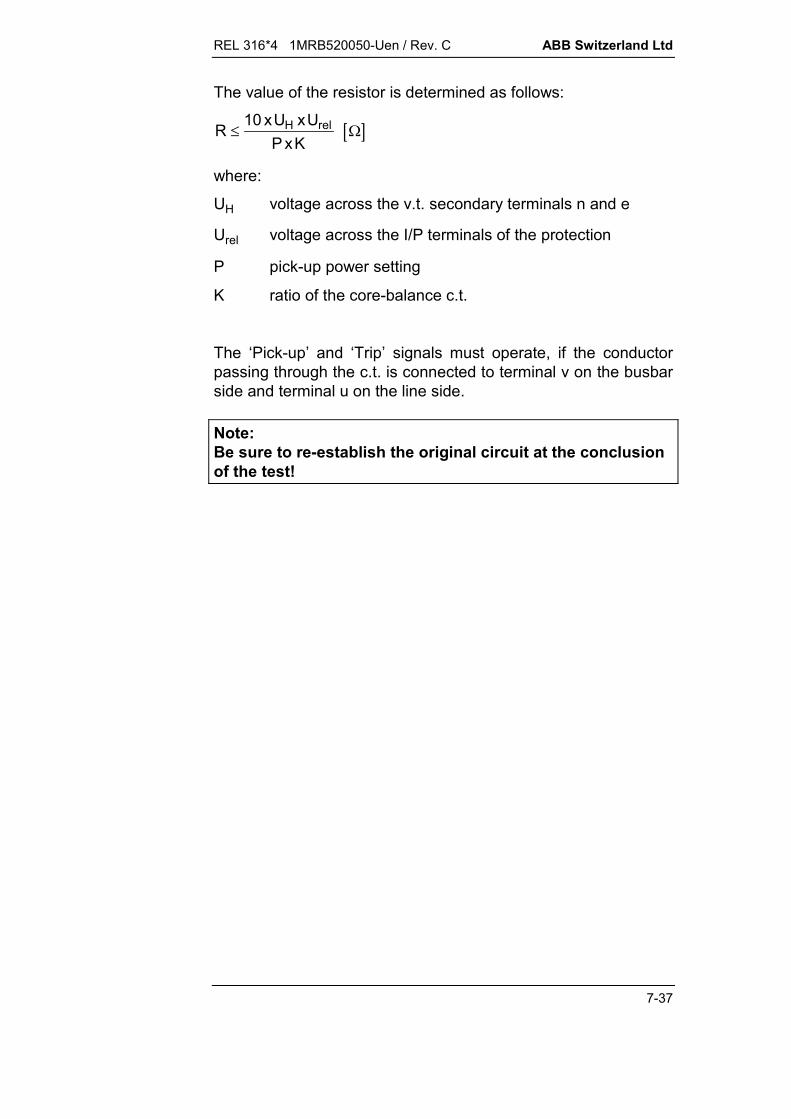
REL 316*4 1MRB520050-Uen / Rev. C ABB Switzerland Ltd
7-37
The value of the resistor is determined as follows:
R xU xUP xK
H rel
10
where:
UH voltage across the v.t. secondary terminals n and e
Urel voltage across the I/P terminals of the protection
P pick-up power setting
K ratio of the core-balance c.t.
The ‘Pick-up’ and ‘Trip’ signals must operate, if the conductorpassing through the c.t. is connected to terminal v on the busbarside and terminal u on the line side.
Note:Be sure to re-establish the original circuit at the conclusionof the test!

ABB Switzerland Ltd REL 316*4 1MRB520050-Uen / Rev. C
7-38
7.7.4.4. Testing using a test set
The MODURES test set XS92b injects the corresponding vari-able a.c. signals and enables the accuracy of the pick-up andtime delay settings to be determined.
a) Three single-phase v.t’s or a five-limbthree-phase v.t.:Residual voltage across the brokendelta secondary circuit (also appliesto a normal three-phase v.t. with aninterposing Y/delta connected v.t’s)
HEST 945017 C
RST
U V W
U UR S
e n
U U
U
R S
0
wvu
broken deltaconnectionU0 = UR + US
metering wind-ings wherefitted
Legend:R, S, T = three-phase primary systemU, V, W = v.t. primary terminalsu, v, w = v.t. metering terminalsn, e = broken delta terminals for E/F protection
HEST 945018 FL
RST
U V W
e nU0
u v w
HEST 945019 FL
RST
e n
U0
U V W
u v w
b) Five-limb v.t. c) Three-phase v.t. plus star-point v.t.(must have delta-connected balancingwindings)
Fig. 7.10 Methods of measuring residual voltage

REL 316*4 1MRB520050-Uen / Rev. C ABB Switzerland Ltd
7-39
Note:All these test schemes only apply when the protection iswired according to the ABB wiring diagram.
HEST 945020 FL
k k k
l l l
R S T
K K K
L L L
k
l
R S T
HEST 945021 FL
a) Holmgren c.t. connection b) Core-balance c.t.
HEST 945022 FL
R S T
k
l
K K K
L L L
c) Special c.t. arrangement for sensitive E/F protection
Fig. 7.11 Methods of measuring residual current

ABB Switzerland Ltd REL 316*4 1MRB520050-Uen / Rev. C
7-40
HEST 945023 FL
4
en
3
5
K K K
2
LLL
k k k
l l l
1
6
RST
HEST 945024 FL
4
en
3
52
K K K
LLL
k k k
l l l
6
RST
1
a) Changes to v.t. secondary circuit for testing b) Changes to v.t. primary circuit fortesting
C.t’s (2):T phase separated from R and S phases andsupplying protectionR and S phases short-circuited
C.t’s (2):T phase separated from R and S phasesand supplying protectionR and S phases short-circuited
V.t’s (3):T phase removed from broken delta
V.t’s (3):T phase primary fuse removed or isolatoropened (4) and winding short-circuited
The phases used must by as shown or cyclically rotated!
Legend:
1 circuit-breaker2 c.t’s3 v.t’s
4 fuse5 REL 316*46 load direction
Fig. 7.12 Test circuit (for = 0) with Holmgren connected c.t’s
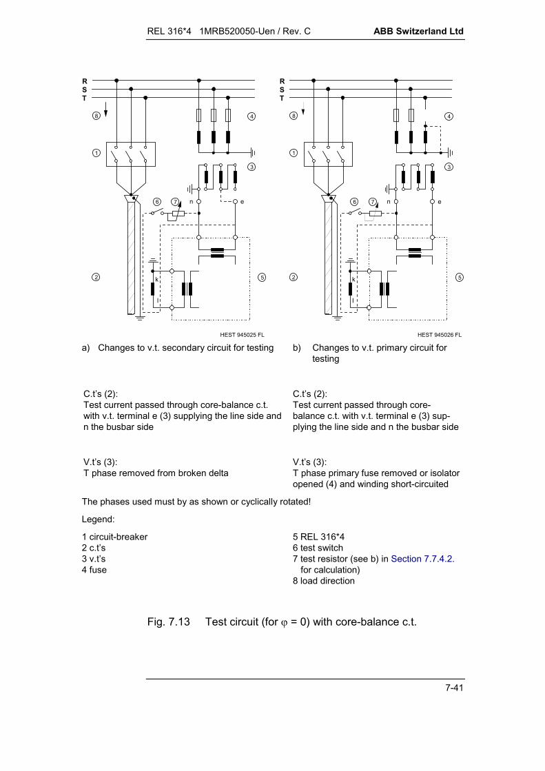
REL 316*4 1MRB520050-Uen / Rev. C ABB Switzerland Ltd
7-41
HEST 945025 FL
8
5
4
en
3
k
l
1
2
76
RST
HEST 945026 FL
1
8
5
4
en
3
k2
76
RST
I
a) Changes to v.t. secondary circuit for testing b) Changes to v.t. primary circuit fortesting
C.t’s (2):Test current passed through core-balance c.t.with v.t. terminal e (3) supplying the line side andn the busbar side
C.t’s (2):Test current passed through core-balance c.t. with v.t. terminal e (3) sup-plying the line side and n the busbar side
V.t’s (3):T phase removed from broken delta
V.t’s (3):T phase primary fuse removed or isolatoropened (4) and winding short-circuited
The phases used must by as shown or cyclically rotated!
Legend:
1 circuit-breaker2 c.t’s3 v.t’s4 fuse
5 REL 316*46 test switch7 test resistor (see b) in Section 7.7.4.2.
for calculation)8 load direction
Fig. 7.13 Test circuit (for = 0) with core-balance c.t.

ABB Switzerland Ltd REL 316*4 1MRB520050-Uen / Rev. C
7-42
RST
HEST 945027 FL
1
6
5
4
en
3
2
K K K
LLL
k k k
l l l
HEST 945028 FL
6
5
4
RST
en
3
2
K K K
LLL
k k k
l l l
1
a) Changes to v.t. secondary circuit for testing b) Changes to v.t. primary circuit fortesting
C.t’s (2):T phase separated from R and S phases andsupplying protectionR and S phases short-circuited
C.t’s (2):T phase separated from R and S phasesand supplying protectionR and S phases short-circuited
V.t’s (3):R phase removed from broken delta
V.t’s (3):R phase primary fuse removed or isolatoropened (4) and winding short-circuited
The phases used must by as shown or cyclically rotated!
Legend:
1 circuit-breaker2 c.t’s3 v.t’s
4 fuse5 REL 316*46 load direction
Fig. 7.14 Test circuit (for = -90° capacitive) with Holmgrenconnected c.t’s
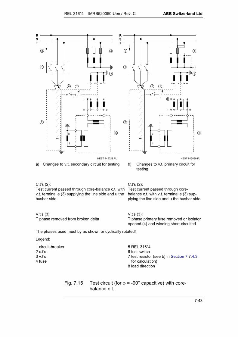
REL 316*4 1MRB520050-Uen / Rev. C ABB Switzerland Ltd
7-43
HEST 945029 FL
8
5
4
3
u v w76
en
k
l
1
RST
2
HEST 945030 FL
8
5
2
1
k
l
4
3
u v w
en
76
RST
a) Changes to v.t. secondary circuit for testing b) Changes to v.t. primary circuit fortesting
C.t’s (2):Test current passed through core-balance c.t. withv.t. terminal e (3) supplying the line side and u thebusbar side
C.t’s (2):Test current passed through core-balance c.t. with v.t. terminal e (3) sup-plying the line side and u the busbar side
V.t’s (3):T phase removed from broken delta
V.t’s (3):T phase primary fuse removed or isolatoropened (4) and winding short-circuited
The phases used must by as shown or cyclically rotated!
Legend:
1 circuit-breaker2 c.t’s3 v.t’s4 fuse
5 REL 316*46 test switch7 test resistor (see b) in Section 7.7.4.3.
for calculation)8 load direction
Fig. 7.15 Test circuit (for = -90° capacitive) with core-balance c.t.


REL 316*4 1MRB520050-Uen / Rev. B ABB Switzerland Ltd
8-1
March 01
8. TECHNICAL DATA
Data Sheet REL 316*4.....................................1MRK506013-Ben
C.t. requirements for the REL 316*4distance protection function ............................ CH-ES 45-12.30 E
C.t. requirements for the longitudinaldifferential protection of lines not having atransformer in the protection zone ...........................ESP 9.201 E
Protection c.t. core requirements for transformerprotection (also applies to transformer protectionby a longitudinal differential function) ............. CH-ES 30-32.10 E

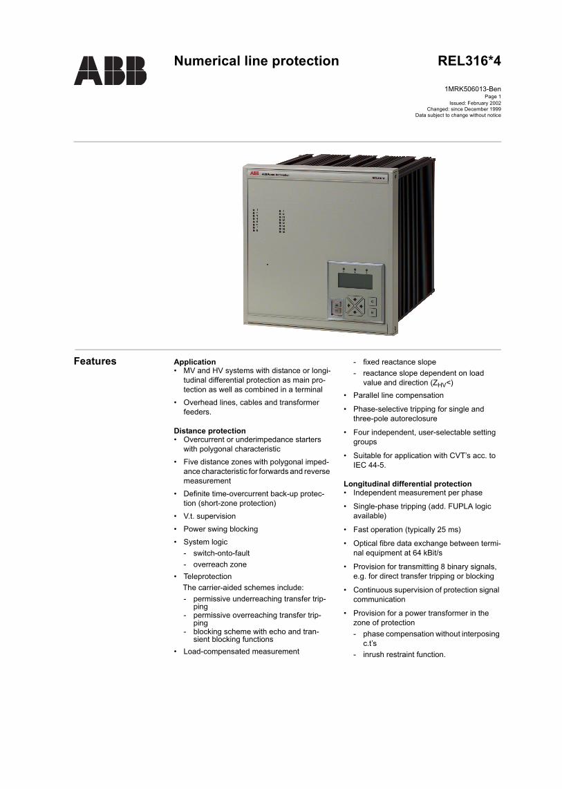
Page 1
Features Application• MV and HV systems with distance or longi-
tudinal differential protection as main pro-tection as well as combined in a terminal
• Overhead lines, cables and transformer feeders.
Distance protection• Overcurrent or underimpedance starters
with polygonal characteristic• Five distance zones with polygonal imped-
ance characteristic for forwards and reverse measurement
• Definite time-overcurrent back-up protec-tion (short-zone protection)
• V.t. supervision• Power swing blocking• System logic
- switch-onto-fault- overreach zone
• TeleprotectionThe carrier-aided schemes include:- permissive underreaching transfer trip-
ping- permissive overreaching transfer trip-
ping- blocking scheme with echo and tran-
sient blocking functions• Load-compensated measurement
- fixed reactance slope- reactance slope dependent on load
value and direction (ZHV<)• Parallel line compensation
• Phase-selective tripping for single and three-pole autoreclosure
• Four independent, user-selectable setting groups
• Suitable for application with CVT’s acc. to IEC 44-5.
Longitudinal differential protection• Independent measurement per phase
• Single-phase tripping (add. FUPLA logic available)
• Fast operation (typically 25 ms)
• Optical fibre data exchange between termi-nal equipment at 64 kBit/s
• Provision for transmitting 8 binary signals, e.g. for direct transfer tripping or blocking
• Continuous supervision of protection signal communication
• Provision for a power transformer in the zone of protection- phase compensation without interposing
c.t’s- inrush restraint function.
Numerical line protection REL316*4
1MRK506013-Ben
Issued: February 2002Changed: since December 1999
Data subject to change without notice
Numerical line protection REL316*41MRK506013-Ben
Page 2
Features (cont’d)Features (cont’d)
ABB Switzerland LtdUtility Automation
Earth fault protection• Sensitive earth fault protection for
ungrounded systems and systems with Petersen coils
• Directional comparison function for detect-ing high-resistance faults in neutral earth-ing systems
• Inverse time-overcurrent function with four characteristics according to B.S. 142.
Current and voltage functions• Definite time-overcurrent function with
inrush detection
• Inverse time-overcurrent function with four characteristics according to B.S. 142 and one characteristic identical to the zero-sequence relay type RXIDG
• Directional inverse and definite time over-current protection
• Definite time-overvoltage and undervoltage function
• Thermal overload function.
Control and monitoring functions• Single and three-phase multi-shot auto-
reclosure
• Synchrocheck
• Breaker-failure protection
• Metering
• Real and apparent power measurement
• 2 different measuring functions of voltage, current and frequency
• Fault location
• Sequence of events records
• Disturbance recorder
• Run-time supervision.
Distance protection for high-voltage lines (<ZHV)(Identification code SN100 and SN300)
Application
• 220 kV and 380 kV high-voltage lines in grids with grounded star-points
• Overhead lines and cables
Distance protection
• All six fault loops are measured simulta-neously (6 systems) allowing the fast detec-tion of evolving faults also in the case of double-circuit lines
• Fast operation, minimum 21 ms and typi-cally 25 ms, see isochrones below
• Suitable for application with CVT’s accord-ing to IEC 44-5
• Polygonal underimpedance starter with stability against load encroachment
• Distance measurement with polygonal operating characteristic
• Two selectable criteria for the differentia-tion of short-circuits with or without earth. Improved detection of the earth fault with application of I2 compared with I0
• The three distance zones responsible for the protection of the line are measured simultaneously and operate without delay- 1 underreaching zone- 1 overreaching zone for comparison
schemes- 1 reverse measuring zone for compari-
son schemes (echo and tripping logic at weak infeed, stabilization for double lines, resp. transmission of the blocking order for blocking systems)
• Load compensation of the reach of the first underreaching distance zone in order to avoid a possible overreach on the load exporting line-side even for high-resistance faults and double-end infeed
• Two time-delayed overreaching back-up zones
• Delayed back-up operation by the under-impedance starter, directional or nondirec-tional
• V.t. supervision
• Back-up overcurrent function
• The phase selection can be set directional and limited to the effective range of the overreach zone providing improved phase selection for single-pole autoreclosing

Numerical line protection REL316*41MRK506013-Ben
Page 3
ABB Switzerland LtdUtility Automation
• Elimination of possible overreach in case of resistive phase-to-phase-to-earth faults
• Improved performance under high SIR
• Power swing blocking independent from the operating characteristic and from the place of installation of the distance relay
• System logic and carrier logic:
- automatic switch-onto-fault protection
- overreach zone, effective for all types of fault or for single-phase faults only, con-trolled by the autoreclosure function and current starter via external input or auto-matically in case of failure of the PLC channel
- underreaching permissive transfer trip-ping with or without voltage criterion at weak infeed
- overerreaching permissive transfer trip-ping with echo and tripping logic at weak infeed
- overreaching system with blocking sig-nal
- stabilization of the overreaching sys-tems at change of energy direction on parallel lines
• The distance protection function may be applied for capacitive voltage transformers
Back-up protection*
• Non-directional overcurrent protection with definite time delay and/or inverse time
• Directional earth fault protection with signal comparison for selective detection of very high-resistance earth faults
• Multi-activation facility of the available function.
* also available in the distance protection function.
Process supervision• Sequence of events recorder (with fault
indication)
• Disturbance recorder with analogue and binary channels.
Functions for programming by the user• Logic (AND, OR and S/R flip-flop)
• Timer/integrator.
Application-specific ancillary functions(optional)• Graphical engineering of a logic to user
specifications (CAP316). An editor and code compiler are used to generate data, which is loaded into the equipment via the HMI. This software allows signals from all functions to be interconnected and the realization of new functionalities if necessary.
Self-supervision• Continuous self-supervision and diagnosis
• Test equipment for quantitative testing available
• Continuous supervision of the optical fibre link for the longitudinal differential function
• Plausibility check of the three-phase cur-rent and voltage inputs.
Operational control• Multi-lingual menu-based operator pro-
gram CAP2/316 based on Windows
• Four independent, user-selectable param-eter sets able to be activated via binary input can be stored in REL316*4
• Multi-activation and allocation of functions.
Serial interfaces• Frontplate interface for local connection of
a personal computer
• Back plane interface for remote communi-cation with a station control system: 7LON, IEC 60870-5-103, MVB (part of IEC 61375), SPA
• Back plane interface for process bus: MVB (part of IEC 61375).
Installation• REL316*4 is suitable for semi-flush or sur-
face mounting or installation in a rack.
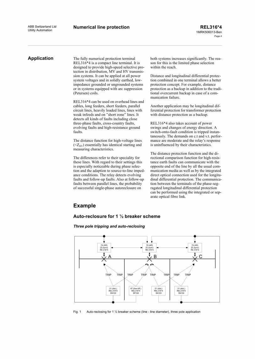
Numerical line protectionABB Switzerland LtdUtility Automation
REL316*41MRK506013-Ben
Page 4
Application The fully numerical protection terminal REL316*4 is a compact line terminal. It is designed to provide high-speed selective pro-tection in distribution, MV and HV transmis-sion systems. It can be applied at all power system voltages and in solidly earthed, low-impedance grounded or ungrounded systems or in systems equipped with arc suppression (Petersen) coils.
REL316*4 can be used on overhead lines and cables, long feeders, short feeders, parallel circuit lines, heavily loaded lines, lines with weak infeeds and on ”short zone” lines. It detects all kinds of faults including close three-phase faults, cross-country faults, evolving faults and high-resistance ground faults.
The distance function for high-voltage lines (<ZHV) essentially has identical starting and measuring characteristics.
The differences refer to their speciality for these lines. With regard to their settings this is especially noticeable during phase selec-tion and the adaption to source-to-line imped-ance conditions. The relay detects evolving faults and follow-up faults. Also at follow-up faults between parallel lines, the probability of successful single-phase autoreclosure on
both systems increases significantly. The rea-son for this is the limited phase selection within the reach.
Distance and longitudinal differential protec-tion combined in one terminal allows a better protection concept. For example, distance protection as a backup in addition to the tradi-tional overcurrent backup in case of a com-munication failure.
Another application may be longitudinal dif-ferential protection for transformer protection with distance protection as a backup.
REL316*4 also takes account of power swings and changes of energy direction. A switch-onto-fault condition is tripped instan-taneously. The demands on c.t and v.t. perfor-mance are moderate and the relay’s response is uninfluenced by their characteristics.
The distance protection function and the di-rectional comparison function for high-resis-tance earth faults can communicate with the opposite end of the line by all the usual com-munication media as well as by the integrated direct optical connection used for the longitu-dinal differential protection. The communica-tion between the terminals of the phase-seg-ragated longitudinal differential protection can be performed using the integrated or sep-arate optical fibre link.
Example
Auto-reclosure for 1 ½ breaker scheme
Three pole tripping and auto-reclosing
Fig. 1 Auto-reclosing for 1 ½ breaker scheme (line - line diameter), three pole application
79 (AR)25 (sync)RE.316*4
79 (AR)25 (sync)RE.316*4
79 (AR)25 (sync)RE.316*4
21 (dist.)REL316*4
SN100
87 (line diff.)REL316*4
SP100
21 (dist.)REL316*4
SN100
21 (dist.)REL316*4
SN100
TRIP TRIPTRIP TRIP TRIP TRIPTRIP TRIP
A B C
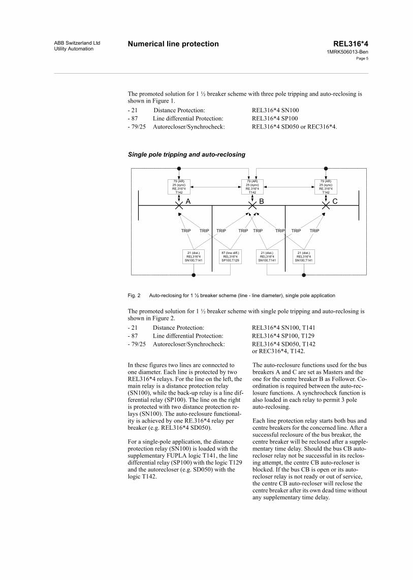
Numerical line protection REL316*41MRK506013-Ben
Page 5
ABB Switzerland LtdUtility Automation
The promoted solution for 1 ½ breaker scheme with three pole tripping and auto-reclosing is shown in Figure 1.- 21 Distance Protection: REL316*4 SN100- 87 Line differential Protection: REL316*4 SP100- 79/25 Autorecloser/Synchrocheck: REL316*4 SD050 or REC316*4.
Single pole tripping and auto-reclosing
Fig. 2 Auto-reclosing for 1 ½ breaker scheme (line - line diameter), single pole application
The promoted solution for 1 ½ breaker scheme with single pole tripping and auto-reclosing is shown in Figure 2.- 21 Distance Protection: REL316*4 SN100, T141- 87 Line differential Protection: REL316*4 SP100, T129- 79/25 Autorecloser/Synchrocheck: REL316*4 SD050, T142
or REC316*4, T142.
In these figures two lines are connected to one diameter. Each line is protected by two REL316*4 relays. For the line on the left, the main relay is a distance protection relay (SN100), while the back-up relay is a line dif-ferential relay (SP100). The line on the right is protected with two distance protection re-lays (SN100). The auto-reclosure functional-ity is achieved by one RE.316*4 relay per breaker (e.g. REL316*4 SD050).
For a single-pole application, the distance protection relay (SN100) is loaded with the supplementary FUPLA logic T141, the line differential relay (SP100) with the logic T129 and the autorecloser (e.g. SD050) with the logic T142.
The auto-reclosure functions used for the bus breakers A and C are set as Masters and the one for the centre breaker B as Follower. Co-ordination is required between the auto-rec-losure functions. A synchrocheck function is also loaded in each relay to permit 3 pole auto-reclosing.
Each line protection relay starts both bus and centre breakers for the concerned line. After a successful reclosure of the bus breaker, the centre breaker will be reclosed after a supple-mentary time delay. Should the bus CB auto-recloser relay not be successful in its reclos-ing attempt, the centre CB auto-recloser is blocked. If the bus CB is open or its auto-recloser relay is not ready or out of service, the centre CB auto-recloser will reclose the centre breaker after its own dead time without any supplementary time delay.
79 (AR)25 (sync)RE.316*4
T142
79 (AR)25 (sync)RE.316*4
T142
79 (AR)25 (sync)RE.316*4
T142
21 (dist.)REL316*4
SN100,T141
87 (line diff.)REL316*4
SP100,T129
21 (dist.)REL316*4
SN100,T141
21 (dist.)REL316*4
SN100,T141
TRIP TRIPTRIP TRIP TRIP TRIPTRIP TRIP
A B C

Numerical line protectionABB Switzerland LtdUtility Automation
REL316*41MRK506013-Ben
Page 6
Design The REL316*4 belongs to the generation of fully numerical line protection terminals, i.e. analogue to digital conversion of the input variables takes place immediately after the input transformers and all further processing of the resulting numerical signals is perfor-med by microprocessors and controlled by programs.
Standard interfaces enable REL316*4 to communicate with other control systems. Provision is thus made for the exchange of data such as reactionless reporting of binary states, events, measurements and protection parameters or the activation of a different set of settings by higher level control systems.
Because of its compact design, the very few hardware units it needs, its modular software and the integrated continuous self-diagnosis and supervision functions, REL316*4 ideally fulfils the user’s expectations of a modern protection terminal at a cost-effective price. The AVAILABILITY of a terminal, i.e. the ratio between its mean operating time in ser-
vice without failure and its total life, is most certainly the most important characteristic re-quired of protection equipment. As a conse-quence of the continuous supervision of its functions, this quotient in the case of REL316*4 is typically always close to 1.
The menu-based HMI (human machine inter-face) and the REL316*4 small size makes the tasks of connection, configuration and setting simple. A maximum of FLEXIBILITY, i.e. the ability to adapt the protection for applica-tion in a particular power system or to coordi-nate with, or replace units in an existing pro-tection scheme, is provided in REL316*4 by ancillary software functions and the assign-ment of input and output signals via the HMI.
REL316*4’s RELIABILITY, SELECTIV-ITY and STABILITY are backed by decades of experience in the protection of lines and feeders in transmission and distribution sys-tems. Numerical processing ensures consis-tent ACCURACY and SENSITIVITY throughout its operational life.
Hardware The hardware concept for the REL316*4 line protection equipment comprises four differ-ent plug-in units, a connecting mother PCB and housing (Fig. 3):
• analog input unit• central processing unit• 1 to 4 binary input/output units• power supply unit• connecting mother PCB• housing with connection terminals.
In the analog input unit an input transformer provides the electrical and static isolation between the analogue input variables and the internal electronic circuits and adjusts the sig-nals to a suitable level for processing. The
input transformer unit can accommodate a maximum of nine input transformers (volt-age-, protection current- or measuring trans-former).
Every analog variable is passed through a first order R/C low-pass filter on the main CPU unit to eliminate what is referred to as the aliasing effect and to suppress HF inter-ferences (Fig. 4). They are then sampled 12 times per period and converted to digital sig-nals. The analog/digital conversion is per-formed by a 16 Bit converter.
A powerful digital signal processor (DSP) carries out part of the digital filtering and makes sure that the data for the protection algorithms are available in the memory to the main processor.

Numerical line protection REL316*41MRK506013-Ben
Page 7
ABB Switzerland LtdUtility Automation
Fig. 3 Hardware platform overview (RE.316*4)
The processor core essentially comprises the main microprocessor (Intel 80486) for the protection algorithms and dual-ported memo-ries (DPMs) for communication between the A/D converters and the main processor. The main processor performs the protection algo-rithms and controls the local HMI and the in-terfaces to the station control system. Binary signals from the main processor are relayed to the corresponding inputs of the I/O unit and thus control the auxiliary output relays and the light emitting diode (LED) signals. The main processor unit is equipped with an RS232C serial interface via which among other things the protection settings are made, events are read and the data from the distur-bance recorder memory are transferred to a local or remote PC.
On this main processor unit there are two PCC slots and one RS232C interface. These serial interfaces provide remote communica-tion to the station monitoring system (SMS) and station control system (SCS) as well as to the remote I/O’s.
REL316*4 can have one to four binary I/O units each. These units are available in three versions:
a) two tripping relays with two heavy-duty contacts, 8 opto-coupler inputs and 6 signalling relays Type 316DB61.
b) two tripping relays with two heavy-duty contacts, 4 opto-coupler inputs and 10 sig-nalling relays Type 316DB62.
c) 14 opto-coupler inputs and 8 signalling relays Type 316DB63.
When ordering REL316*4 with more than 2 I/O units casing size N2 must be selected.
According to whether one or two I/O units are fitted, there are either 8 LED's or 16 LED’s visible on the front of the REL316*4.
Fibre optical connections for line differentialprotection and binary signal transmission
HMI
TripOutputs
Sign.Outputs
Bin.Inputs
Remote I/O
PCMCIA
a
b
c
d
DC
DC+5V
+15V
-15V+24V
PowerSupply
A/D DSP
CPU486
SerialController
RS232
FLASHEPROM
Tranceiver
RAM
SW-Key
PCC
LONIEC1375
SPA / IEC870-5-103
LED'sSCSSMS
SerialController
RS232
DPM
TripOutputs
Sign.Outputs
Bin.Inputs
I / OPorts
PCC
Process bus
TripOutputs
Sign.Outputs
Bin.Inputs
Remote I/O
TripOutputs
Sign.Outputs
Bin.Inputs
Remote I/O
TripOutputs
Sign.Outputs
Bin.Inputs
I / OPorts
TripOutputs
Sign.Outputs
Bin.Inputs
I / OPorts
TripOutputs
Sign.Outputs
Bin.Inputs
I / OPorts (MVB)
RX Tx
A/D DSP
IEC1375
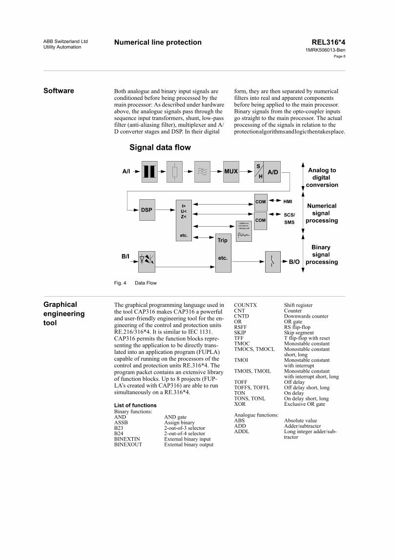
Numerical line protectionABB Switzerland LtdUtility Automation
REL316*41MRK506013-Ben
Page 8
Software Both analogue and binary input signals are conditioned before being processed by the main processor: As described under hardware above, the analogue signals pass through the sequence input transformers, shunt, low-pass filter (anti-aliasing filter), multiplexer and A/D converter stages and DSP. In their digital
form, they are then separated by numerical filters into real and apparent components before being applied to the main processor. Binary signals from the opto-coupler inputs go straight to the main processor. The actual processing of the signals in relation to the protection algorithms and logic then takes place.
Fig. 4 Data Flow
Graphical engineering tool
The graphical programming language used in the tool CAP316 makes CAP316 a powerful and user-friendly engineering tool for the en-gineering of the control and protection units RE.216/316*4. It is similar to IEC 1131. CAP316 permits the function blocks repre-senting the application to be directly trans-lated into an application program (FUPLA) capable of running on the processors of the control and protection units RE.316*4. The program packet contains an extensive library of function blocks. Up to 8 projects (FUP-LA’s created with CAP316) are able to run simultaneously on a RE.316*4.
List of functionsBinary functions:AND AND gateASSB Assign binaryB23 2-out-of-3 selectorB24 2-out-of-4 selectorBINEXTIN External binary inputBINEXOUT External binary output
COUNTX Shift registerCNT CounterCNTD Downwards counterOR OR gateRSFF RS flip-flopSKIP Skip segmentTFF T flip-flop with resetTMOC Monostable constantTMOCS, TMOCL Monostable constant
short, long TMOI Monostable constant
with interruptTMOIS, TMOIL Monostable constant
with interrupt short, longTOFF Off delayTOFFS, TOFFL Off delay short, longTON On delayTONS, TONL On delay short, longXOR Exclusive OR gate
Analogue functions:ABS Absolute valueADD Adder/subtracterADDL Long integer adder/sub-
tractor

Numerical line protection REL316*41MRK506013-Ben
Page 9
ABB Switzerland LtdUtility Automation
ADMUL Adder/multiplierCNVIL Integer to long integer
converterCNVLBCD Long integer to BC con-
verterCNVLI Long integer to integer
converterCNVLP Long integer to percent
converterCNVPL Percentage to long inte-
ger converterDIV DividerDIVL Long integer dividerFCTL Linear functionFCTP Polynomial functionFILT FilterINTS, INTL IntegratorKMUL Factor multiplierLIM Limiter
LOADS Load shedding functionMAX Maximum value detectorMIN Minimum value detectorMUL MultiplierMULL Long integer multiplierNEGP Percent negatorPACW Pack binary signals
into integerPDTS, PDTL DifferentiatorPT1S, PT1L Delayed approximationSQRT Square rootSWIP Percent switchTHRLL Lower limit thresholdTHRUL Upper limit thresholdTMUL Time multiplierUPACW Unpack binary sig-
nals from an integer.
Part of FUPLA application (Q0) : control and interlocking logic for three objects Q0,Q1, Q2. B_DRIVE is a macro based on binary function blocks.
DPMIN_Q0_CLOSEDDPMIN_Q0_OPEN
Q0_SEL_DRIVE_Q0GEN_REQUEST_ON
GEN_REQUES_ON
GEN_SYNCQ1_Q1_OPENQ2_Q2_OPEN
GEN_REQUEST_EXE
B_DRIVECLOP
SELRQONRQOF
SYNCRQEX
T:SYT:RT
CLOP
POK
GONGOFGEXEXE
GOONGOOFSYSTSREL
ALSYBKS
KDOF
Q0_CLQ0_OPQ0_Q0_POK
Q0_Q0_CLOSED
Q0_Q0_OPEN
Q0_GUIDE_ONQ0_GUIDE_OFFQ0_GUIDE_EXEQ0_EXE
Q0_GOON_Q0Q0_GOOFF_Q0Q0_Q0_SYSTDPMOUT_Q0_SEL_REL
Q0_SUP_SEL_REL_Q0
Q0_ALSYQ0_BLOCK_SELECTQ0_KDO_FAIL
1&
2>=1
6=1
5&
4&
3
301
Example:
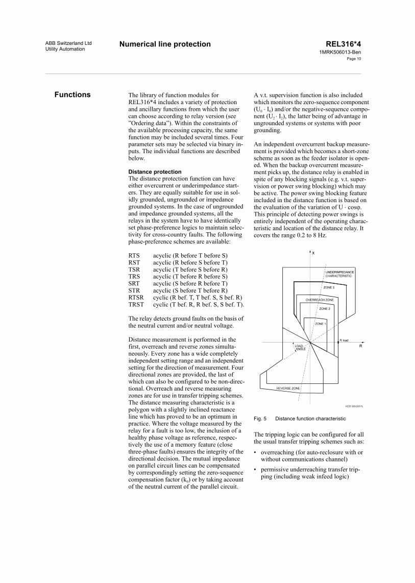
Numerical line protectionABB Switzerland LtdUtility Automation
REL316*41MRK506013-Ben
Page 10
Functions The library of function modules for REL316*4 includes a variety of protection and ancillary functions from which the user can choose according to relay version (see ”Ordering data”). Within the constraints of the available processing capacity, the same function may be included several times. Four parameter sets may be selected via binary in-puts. The individual functions are described below.
Distance protectionThe distance protection function can have either overcurrent or underimpedance start-ers. They are equally suitable for use in sol-idly grounded, ungrounded or impedance grounded systems. In the case of ungrounded and impedance grounded systems, all the relays in the system have to have identically set phase-preference logics to maintain selec-tivity for cross-country faults. The following phase-preference schemes are available:
RTS acyclic (R before T before S)RST acyclic (R before S before T)TSR acyclic (T before S before R)TRS acyclic (T before R before S)SRT acyclic (S before R before T)STR acyclic (S before T before R)RTSR cyclic (R bef. T, T bef. S, S bef. R)TRST cyclic (T bef. R, R bef. S, S bef. T).
The relay detects ground faults on the basis of the neutral current and/or neutral voltage.
Distance measurement is performed in the first, overreach and reverse zones simulta-neously. Every zone has a wide completely independent setting range and an independent setting for the direction of measurement. Four directional zones are provided, the last of which can also be configured to be non-direc-tional. Overreach and reverse measuring zones are for use in transfer tripping schemes. The distance measuring characteristic is a polygon with a slightly inclined reactance line which has proved to be an optimum in practice. Where the voltage measured by the relay for a fault is too low, the inclusion of a healthy phase voltage as reference, respec-tively the use of a memory feature (close three-phase faults) ensures the integrity of the directional decision. The mutual impedance on parallel circuit lines can be compensated by correspondingly setting the zero-sequence compensation factor (k0) or by taking account of the neutral current of the parallel circuit.
A v.t. supervision function is also included which monitors the zero-sequence component (U0 I0) and/or the negative-sequence compo-nent (U2 I2), the latter being of advantage in ungrounded systems or systems with poorgrounding.
An independent overcurrent backup measure-ment is provided which becomes a short-zone scheme as soon as the feeder isolator is open-ed. When the backup overcurrent measure-ment picks up, the distance relay is enabled in spite of any blocking signals (e.g. v.t. super-vision or power swing blocking) which may be active. The power swing blocking feature included in the distance function is based on the evaluation of the variation of U cos. This principle of detecting power swings is entirely independent of the operating charac-teristic and location of the distance relay. It covers the range 0.2 to 8 Hz.
Fig. 5 Distance function characteristic
The tripping logic can be configured for all the usual transfer tripping schemes such as:
• overreaching (for auto-reclosure with or without communications channel)
• permissive underreaching transfer trip-ping (including weak infeed logic)

Numerical line protection REL316*41MRK506013-Ben
Page 11
Functions (cont’d)Functions (cont’d)
ABB Switzerland LtdUtility Automation
• permissive overreaching transfer tripping (with echo tripping in the case of a weak infeed and blocking logic for change of energy direction)
• blocking scheme (with blocking logic for change of energy direction).
The tripping logic provides access for the user to disable or enable a variety of func-tions such as the type communications chan-nel, the switch-onto-fault logic, the over-reaching zone, the v.t. supervision logic and whether tripping by the function should be single or three-phase.
Distance protection for high-voltage linesThe distance protection function (<ZHV) is especially suited for 220 kV and 380 kV lines.
The "HV distance" function essentially has identical starting and measuring characteris-tics and the same setting parameters as the standard "distance" function.
The setting parameters for not effectively earthed networks have been omitted and a few new ones added, especially in connection with an improved phase selection.
The operating times for the "HV distance" function are shown in the form of isochrones. (see Section 'High-voltage distance protec-tion function operating times'). All other functions remain unchanged.
Longitudinal differential protectionThe longitudinal differential protection func-tion included with REL316*4 is suitable for the protection of
• overhead lines• cables• transformer feeders.It operates according to the proven trans-former protection algorithm used in RET316*4 and exhibits the same outstanding characteristics with respect to through-fault stability and minimum c.t. performance.
The scheme is phase-selective and takes full advantage of the high data transfer rate of 64 kBit/s possible with an optical fibre link to sample the analogue input variables at both ends of the line and transfer the correspond-ing values to the opposite station without al-most any delay.
Fig. 6 Operating characteristic of the longitudinal differential function
I2

Numerical line protection REL316*41MRK506013-Ben
Page 12
Functions (cont’d)Functions (cont’d)
ABB Switzerland LtdUtility Automation
Fig. 7 Longitudinal differential protection with a power transformer in the protected zone
Tripping takes place should the comparison of the values in the terminal stations result in a differential current I above a given level (see operating characteristic in Fig. 6). The self-supervision function of the optical fibre link operates at such a speed that an additional enabling signal is not necessary.
Interposing c.t’s are not needed where the protected unit includes a power transformer (Fig. 7). The settings for the protection are made using a convenient control program running on a personal computer.
Provision is made for transmitting other sig-nals via the optical fibre link in addition to those of the longitudinal differential function. These might be intertripping signals to the remote station generated by other internal protection functions or applied to the termi-nals binary inputs by some other external ter-minal. A ground fault comparison scheme can thus operate via the same optical fibre link. When the terminal equipment in one sta-tion is being tested, the equipment in the other station can be remotely blocked.
When the longitudinal protection function is in use, a maximum of six analogue inputs is available, e.g. three current and three voltage measurements for main and backup protec-tions and for the disturbance recorder. Fol-lowing analogue to digital conversion, the signals branch in two directions. All six go to the main processor for evaluation for the local protection functions and the three correspon-ding to the local phase currents are addition-ally converted to light signals by an optical modem for transmission to the opposite sta-
tion where they are evaluated in relation to the local current signals. Similarly the cur-rents measured and digitized in the remote station are transferred to the local station and evaluated. A digital signal processor (DSP) ensures that the sampling and coordination of the signals in the two stations and also the transmission between the stations is properly synchronized. Thus there are two current sig-nals available for the longitudinal differential comparison of each phase in both stations. Comparison is performed in the main proces-sor according to the proven algorithm men-tioned above.
As previously explained, the longitudinal dif-ferential function operates in conjunction with an optical fibre link between the stations at the ends of the transmission line. The sig-nals are transmitted by a LED diode with a wavelength of 1300 nm and are coupled by a Type FC optical connector. Depending on the attenuation of the of the optical cable used, distances of up to 28 km can be covered. Repeaters have to be used for longer dis-tances which in the case of FOX 6 Plus or Fox 20 enable transmission over distances up to 120 km (Fig. 8).
In REL316*4 units for longitudinal differen-tial applications, the standard distance protec-tion function can also be activated. The ope-ration for single-pole autoreclosure is fore-seen with the T129 logic. The other standard software of the line protection terminal is un-influenced. Other optional functions from the software library are also provided (see table of codes).

Numerical line protectionABB Switzerland LtdUtility Automation
REL316*41MRK506013-Ben
Page 13
Fig. 8 Optical fibre link (OFL) using communications system Type FOX with a data transfer rate of 2 MBit/s
Auto-reclosureThe autoreclosure function included in REL316*4 permits up to four three-phase reclosure cycles to be carried out, each with an independently adjustable dead time for fast and slow autoreclosure. Where single-phase reclosure is being applied, the first reclosure is the single-phase one and the others are three-phase.
The autoreclosure function can also be loaded several times in the same parameter set. This function also contains an integrated additio-nal logic (FUPLA). This allows a customer-specific AR functionality. Both these possi-bilities have been used for the CH standard AR. Two AR functions are loaded for this: the first function with additional logic serves as fast autoreclosure and the second function as slow autoreclosure.
The integrated autoreclosure function for high-voltage lines (REL316*4/SN300) is employed on lines without local protection redundancy.
A separate autoreclosure unit is especially suitable for lines with redundant protection.
This unit enables practically all conventional and all modern line protection relays suitable for single-phase tripping to be connected to one system.
SynchrocheckThe synchrocheck function determines the difference between the amplitudes, phase-angles and frequencies of two voltage vec-tors. Checks are also included to detect a dead line or busbar.
Thermal overloadThe thermal overload function can be used for either cables or overhead lines. It is equip-ped with alarm and tripping stages and has a wide setting range for adjusting the time con-stant to match that of the protected unit.
Definite time voltage functionThe voltage function can be set to operate on overvoltage or undervoltage with a definite time delay. Either single or three-phase mea-surements can be performed.
Definite time current functionThe current function can be set to operate on overcurrent or undercurrent with a definite time delay. Either single or three-phase mea-surements can be performed.
Inverse time overcurrent functionThe operating time of the inverse time over-current function reduces as the fault current increases and it can therefore achieve shorter operating times for fault locations closer to the source. Four different characteristics ac-cording to British Standard 142 designated normal inverse, very inverse, extremely in-verse and long time inverse but with an ex-tended setting range are provided. The func-tion can be configured for single-phase mea-

Numerical line protection REL316*41MRK506013-Ben
Page 14
Functions (cont’d)Functions (cont’d)
ABB Switzerland LtdUtility Automation
surement or a combined three-phase mea-surement with detection of the highest phase current.
Directional overcurrent protectionThe directional overcurrent protection func-tion is available either with inverse time or definite time overcurrent characteristic. This function comprises a voltage memory for faults close to the relay location. The function response after the memory time has elapsed can be selected (trip or block).
Inverse time ground fault overcurrent functionThe inverse time ground fault overcurrent function monitors the neutral current of the system which is either measured via a neutral current input transformer or derived inter-nally in the terminal from the three phase cur-rents. Four different characteristics according to British Standard 142 designated normal inverse, very inverse, extremely inverse and long time inverse but with an extended set-ting range are provided.
Directional ground fault function for ungrounded systems or systems with Petersen coilsThe sensitive ground fault protection function for ungrounded systems and systems with Petersen coils can be set for either forwards or reverse measurement. The characteristic angle is set to ±90° (U0 I0 sin) in ungroun-ded systems and to 0° or 180° (U0 I0 cos) for systems with Petersen coils. The neutral current is always used for measurement in the case of systems with Petersen coils, but in ungrounded systems its use is determined by the value of the capacitive current and mea-surement is performed by a core-balance c.t. to achieve the required sensitivity.
Directional ground fault function for grounded systemsA sensitive directional ground fault function based on the measurement of neutral current and voltage is provided for the detection of high-resistance ground faults in solidly or low-resistance grounded systems. The scheme operates either in a permissive or blocking mode and can be used in conjunc-tion with an inverse time ground fault over-current function. In both cases the neutral current and voltage can be derived either externally or internally.
Frequency functionThe frequency function is based on the mea-surement of one voltage. This function is able to be configured as maximum or minimum function and is applied as protection function and for load shedding. By multiple configura-tion of this function almost any number of stages can be realized.
Rate-of-change of frequency This function offers alternatively an enabling by absolute frequency. It contains an under-voltage blocking facility. Repeated configu-ration of this function ensures a multi-step setup.
MeasuringBoth measuring functions measure the single-phase rms values of voltage, current, frequen-cy, real power and apparent power for display on the local HMI or transfer to the station control system. A choice can be made bet-ween phase-to-neutral and phase-to-phase voltages.
Ancillary functionsAncillary functions such as a logic and a delay/integrator enable the user to create logi-cal combinations of signals and pick-up and reset delays.
A run-time supervision feature enables checking the opening and closing of all kinds of breakers (circuit-breakers, isolators, ground switches...). Failure of a breaker to open or close within an adjustable time results in the creation of a corresponding sig-nal for further processing.
Plausibility checkThe current and voltage plausibility functions facilitate the detection of system asymme-tries, e.g. in the secondary circuits of c.t’s and v.t’s.
Sequence of events recorderThe event recorder function provides capacity for up to 256 binary signals including time marker with a resolution in the order of milli-seconds and gives the distance to a fault ex-pressed as a percentage of a specified refer-ence reactance, e.g. the reactance of the pro-tected line.
Disturbance recorderThe disturbance recorder monitors up to 9 analogue inputs, up to 16 binary inputs and internal results of protection functions. The capacity for recording disturbances depends on the duration of a disturbance as deter-
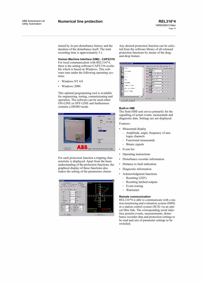
Numerical line protectionABB Switzerland LtdUtility Automation
REL316*41MRK506013-Ben
Page 15
mined by its pre-disturbance history and the duration of the disturbance itself. The total recording time is approximately 5 s.
Human Machine Interface (HMI) - CAP2/316For local communication with REL316*4, there is the setting software CAP2/316 availa-ble which is based on Windows. This soft-ware runs under the following operating sys-tems:
• Windows NT 4.0• Windows 2000.
This optimal programming tool is available for engineering, testing, commissioning and operation. The software can be used either ON-LINE or OFF-LINE and furthermore contains a DEMO mode.
For each protection function a tripping char-acteristic is displayed. Apart from the basic understanding of the protection functions, the graphical display of these functions also makes the setting of the parameters clearer.
Any desired protection function can be selec-ted from the software library of all released protection functions by means of the drag-and-drop feature.
Built-in HMIThe front HMI unit serves primarily for the signalling of actual events, measurands and diagnostic data. Settings are not displayed.
Features:
• Measurand display- Amplitude, angle, frequency of ana-
logue channels- Functional measurands- Binary signals
• Event list• Operating instructions• Disturbance recorder information• Distance to fault indication• Diagnostic information• Acknowledgment functions
- Resetting LED’s- Resetting latched outputs- Event erasing- Warmstart.
Remote communicationREL316*4 is able to communicate with a sta-tion monitoring and evaluation system (SMS) or a station control system (SCS) via an opti-cal fibre link. The corresponding serial inter-face permits events, measurements, distur-bance recorder data and protection settings to be read and sets of parameter settings to be switched.

Numerical line protection REL316*41MRK506013-Ben
Page 16
Functions (cont’d)Functions (cont’d)
ABB Switzerland LtdUtility Automation
Using the LON bus permits in addition the exchange of binary information between the individual bay controllers, e.g. signals for sta-tion interlocking.
Remote in- and outputs (RIO580)Using the process bus type MVB remote in- and output units (500RIO11) can be connec-ted to the RE.316*4 terminals. The input and output channels can be extended to a large number by using RIO580 remote input/output system. Installing 500RIO11 I/O close to the process reduces the wiring dramatically, since they are accessible via fibre optic link from the RE.316*4 terminals.
Analog signals can also be connected to the system via the 500AXM11 from the RIO580 family:
• DC current 4...20 mA0...20 mA-20...20 mA
• DC voltage 0...10 V-10...10 V
• Temp. sensor Pt100, Pt250, Pt1000, Ni100, Ni250, Ni1000.
Self-diagnosis and supervisionRE.316*4’s self-diagnosis and supervision functions ensure maximum availability not only of the protection terminal itself, but also of the power system it is protecting. Hard-ware failures are immediately signalled by an alarm contact. In particular, the external and internal auxiliary supplies are continuously supervised. The correct function and toler-ance of the A/D converter are tested by cycli-cally converting two reference voltages. Spe-cial algorithms regularly check the proces-sor’s memories (background functions). A watchdog supervises the execution of the pro-grams.
The program execution itself is monitored by a watchdog function for each processor.
An important advantage of the extensive self-diagnosis and supervision functions is that periodic routine maintenance and testing are reduced.
The optical fibre link is also supervised on terminal equipped with the longitudinal dif-ferential function. For this purpose test data are transmitted in addition to the protection signals to test the integrity of the communica-tions channel. The supervision function also detects the failure of the auxiliary supply in one terminal station. In the event that the optical fibre link should fail, the back-up pro-tection functions remain operational.
Supporting softwareThe operator program facilitates configura-tion and setting of the protection, listing para-meters, reading events and listing the various internal diagnostic data.
The evaluation programs REVAL and WIN-EVE (MS Windows/Windows NT) are avail-able for viewing and evaluating the disturban-ces stored by the disturbance recorder. Where the disturbance data are transferred via the communications system to the disturbance recorder evaluation station, the file transfer program EVECOM (MS Windows/Windows NT) is also used.
The program XSCON is available for conver-sion of the RE.316*4 disturbance recorder data to ABB’s test set XS92b format. This offers reproduction of electrical quantities recorded during a fault.

Numerical line protectionABB Switzerland LtdUtility Automation
REL316*41MRK506013-Ben
Page 17
Technical dataHardware
Table 1: Analogue input variables
Table 2: Contact data
Number of inputs according to version, max. 9 analogue inputs (voltages and currents, 4 mm2 terminals)
Rated frequency fN 50 Hz or 60 Hz
Rated current IN 1 A, 2 A or 5 A
Thermal rating of current circuitcontinuousfor 10 sfor 1 sdynamic (half period)
4 x IN30 x IN100 x IN250 x IN (peak)
Rated voltage UN 100 V or 200 V
Thermal rating of voltage circuitcontinuousduring 10 s
1.3 x UN2 x UN
Burden per phasecurrent inputs
at IN = 1 Aat IN = 5 A
voltage inputsat UN
<0.1 VA<0.3 VA
<0.25 VA
V.t. fuse characteristic Z acc. to DIN/VDE 0660 or equivalent
Tripping relays
No. of contacts 2 relays per I/O unit 316DB61 or 316DB62 with 2 N/O contacts each, 1.5 mm2 terminals
Max. operating voltage 300 V AC or V DC
Continuous rating 5 A
Make and carry for 0.5 s 30 A
Surge for 30 ms 250 A
Making power at 110 V DC 3300 W
Breaking capacity for L/R = 40 msBreaking current with 1 contact
at U <50 V DCat U <120 V DCat U <250 V DC
1.5 A0.3 A0.1 A
Breaking current with 2 contacts in seriesat U <50 V DCat U <120 V DCat U <250 V DC
5 A1 A0.3 A
Signalling contacts
No. of contacts 6, 10 or 8 acc. to I/O unit (316DB61, 316DB62 or 316DB63),1 contact per sig. relay with 1.5 mm2 terminalsEach interface unit equipped with 1 C/O contact and the all others N/O contacts
Max. operating voltage 250 V AC or V DC
Continuous rating 5 A
Make and carry for 0.5 s 15 A
Surge for 30 ms 100 A
Making power at 110 V DC 550 W
Breaking current for L/R = 40 ms at U <50 V DCat U <120 V DCat U <250 V DC
0.5 A0.1 A0.04 A
The user can assign tripping and signalling contacts to protection functions
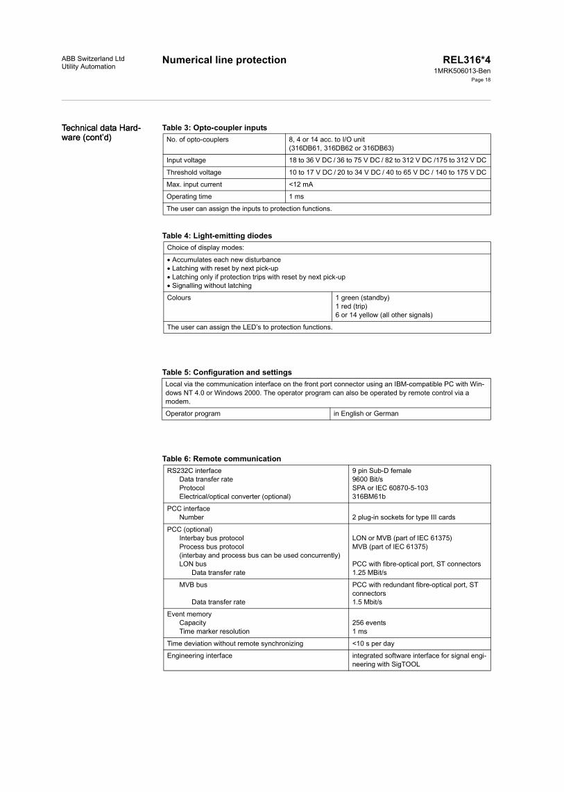
Numerical line protection REL316*41MRK506013-Ben
Page 18
Technical data Hard-ware (cont’d)Technical data Hard-ware (cont’d)
ABB Switzerland LtdUtility Automation
Table 3: Opto-coupler inputs
Table 4: Light-emitting diodes
Table 5: Configuration and settings
Table 6: Remote communication
No. of opto-couplers 8, 4 or 14 acc. to I/O unit(316DB61, 316DB62 or 316DB63)
Input voltage 18 to 36 V DC / 36 to 75 V DC / 82 to 312 V DC /175 to 312 V DC
Threshold voltage 10 to 17 V DC / 20 to 34 V DC / 40 to 65 V DC / 140 to 175 V DC
Max. input current <12 mA
Operating time 1 ms
The user can assign the inputs to protection functions.
Choice of display modes:
Accumulates each new disturbance Latching with reset by next pick-up Latching only if protection trips with reset by next pick-up Signalling without latching
Colours 1 green (standby)1 red (trip)6 or 14 yellow (all other signals)
The user can assign the LED’s to protection functions.
Local via the communication interface on the front port connector using an IBM-compatible PC with Win-dows NT 4.0 or Windows 2000. The operator program can also be operated by remote control via a modem.
Operator program in English or German
RS232C interfaceData transfer rateProtocolElectrical/optical converter (optional)
9 pin Sub-D female9600 Bit/sSPA or IEC 60870-5-103316BM61b
PCC interfaceNumber 2 plug-in sockets for type III cards
PCC (optional)Interbay bus protocolProcess bus protocol(interbay and process bus can be used concurrently)LON bus
Data transfer rate
LON or MVB (part of IEC 61375)MVB (part of IEC 61375)
PCC with fibre-optical port, ST connectors1.25 MBit/s
MVB bus
Data transfer rate
PCC with redundant fibre-optical port, ST connectors1.5 Mbit/s
Event memoryCapacityTime marker resolution
256 events1 ms
Time deviation without remote synchronizing <10 s per day
Engineering interface integrated software interface for signal engi-neering with SigTOOL

Numerical line protectionABB Switzerland LtdUtility Automation
REL316*41MRK506013-Ben
Page 19
Table 7: Auxiliary supply
Table 8: General data
Supply voltage
Voltage range 36 to 312 V DC
Voltage interruption bridging time 50 ms
Fuse rating 4 A
Load on station battery at normal operation(1 relay energized) <20 W
during a fault (all relays energized)
with 1 I/O unitwith 2 I/O unitswith 3 I/O unitswith 4 I/O units
<22 W<27 W<32 W<37 W
Additional load of the optionsline differentialprotection (code SPxxx)SPA, IEC 60870-5-103 or LON interfaceMVB interface
7.5 W1.5 W2.5 W
Buffer time of the event list and fault recorder data at loss of auxiliary supply >2 days (typ. 1 month)
Temperature rangeoperationstorage
-10° C to +55° C-40° C to +85° C
EN 60255-6 (1994),IEC 60255-6 (1988)
Humidity 93%, 40° C, 4 days IEC 60068-2-3 (1969)
Seismic test 5 g, 30 s, 1 to 33 Hz (1 octave/min)
IEC 60255-21-3 (1995),IEEE 344 (1987)
Leakage resistance >100 M, 500 V DC EN 60255-5 (2001),IEC 60255-5 (2000)
Insulation test 2 kV, 50 Hz, 1 min1 kV across open contacts
EN 60255-5 (2001),IEC 60255-5 (2000),EN 60950 (1995)
Surge voltage test 5 kV, 1.2/50 s EN 60255-5 (2001),IEC 60255-5 (2000) *
1 MHz burst disturbance test 1.0/2.5 kV, Cl. 3; 1MHz,400 Hz rep.freq.
IEC 60255-22-1 (1988),ANSI/IEEE C37.90.1 (1989)
Fast transient test 2/4 kV, Cl. 4 EN 61000-4-4 (1995), IEC 61000-4-4 (1995)
Electrostatic discharge test (ESD)
6/8 kV (10 shots), Cl. 3 EN 61000-4-2 (1996),IEC 61000-4-2 (2001)
Immunity to magnetic interfer-ence at power system frequen-cies
300 A/m; 1000 A/m; 50/60 HzEN 61000-4-8 (1993),IEC 61000-4-8 (1993)
Radio frequency interference test (RFI)
• 0.15-80 MHz, 80% amplitude modulated10 V, Cl. 3
• 80-1000 MHz, 80% amplitude modulated10 V/m, Cl. 3
• 900 MHz, puls modulated10 V/m, Cl. 3
EN 61000-4-6 (1996)EN 61000-4-6 (1996),EN 61000-4-3 (1996),IEC 61000-4-3 (1996),ENV 50204 (1995)
Emission Cl. A EN 61000-6-2 (2001),EN 55011 (1998),CISPR 11 (1990)
* Reduced values apply for repeat tests according to IEC publication 255-5, Clauses 6.6 and 8.6.

Numerical line protection REL316*41MRK506013-Ben
Page 20
Technical data Hard-ware (cont’d)Technical data Hard-ware (cont’d)
ABB Switzerland LtdUtility Automation
Table 9: Mechanical designWeight
Size N1 casingSize N2 casing
approx. 10 kgapprox. 12 kg
Methods of mounting semi-flush with terminals at rearsurface with terminals at rear19" rack mounting, height 6U, width N1: 225.2 mm (1/2 19" rack). Width N2: 271 mm.
Enclosure Protection Class
IP 50 (IP 20 if MVB PC cards are used)IPXXB for terminals.
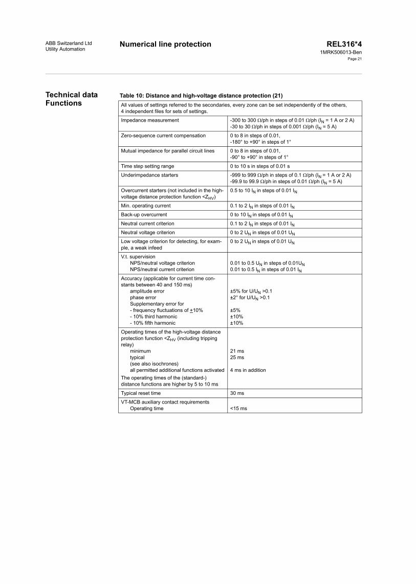
Numerical line protectionABB Switzerland LtdUtility Automation
REL316*41MRK506013-Ben
Page 21
Technical dataFunctions
Table 10: Distance and high-voltage distance protection (21)All values of settings referred to the secondaries, every zone can be set independently of the others,4 independent files for sets of settings.
Impedance measurement -300 to 300 /ph in steps of 0.01 /ph (IN = 1 A or 2 A)-30 to 30 /ph in steps of 0.001 /ph (IN = 5 A)
Zero-sequence current compensation 0 to 8 in steps of 0.01,-180° to +90° in steps of 1°
Mutual impedance for parallel circuit lines 0 to 8 in steps of 0.01,-90° to +90° in steps of 1°
Time step setting range 0 to 10 s in steps of 0.01 s
Underimpedance starters -999 to 999 /ph in steps of 0.1 /ph (IN = 1 A or 2 A)-99.9 to 99.9 /ph in steps of 0.01 /ph (IN = 5 A)
Overcurrent starters (not included in the high-voltage distance protection function <ZHV)
0.5 to 10 IN in steps of 0.01 IN
Min. operating current 0.1 to 2 IN in steps of 0.01 INBack-up overcurrent 0 to 10 IN in steps of 0.01 INNeutral current criterion 0.1 to 2 IN in steps of 0.01 INNeutral voltage criterion 0 to 2 UN in steps of 0.01 UN
Low voltage criterion for detecting, for exam-ple, a weak infeed
0 to 2 UN in steps of 0.01 UN
V.t. supervisionNPS/neutral voltage criterionNPS/neutral current criterion
0.01 to 0.5 UN in steps of 0.01UN0.01 to 0.5 IN in steps of 0.01 IN
Accuracy (applicable for current time con-stants between 40 and 150 ms)
amplitude errorphase errorSupplementary error for- frequency fluctuations of +10%- 10% third harmonic- 10% fifth harmonic
±5% for U/UN >0.1±2° for U/UN >0.1
±5%±10%±10%
Operating times of the high-voltage distance protection function <ZHV (including tripping relay)
minimumtypical(see also isochrones)all permitted additional functions activated
The operating times of the (standard-)distance functions are higher by 5 to 10 ms
21 ms25 ms
4 ms in addition
Typical reset time 30 ms
VT-MCB auxiliary contact requirementsOperating time <15 ms
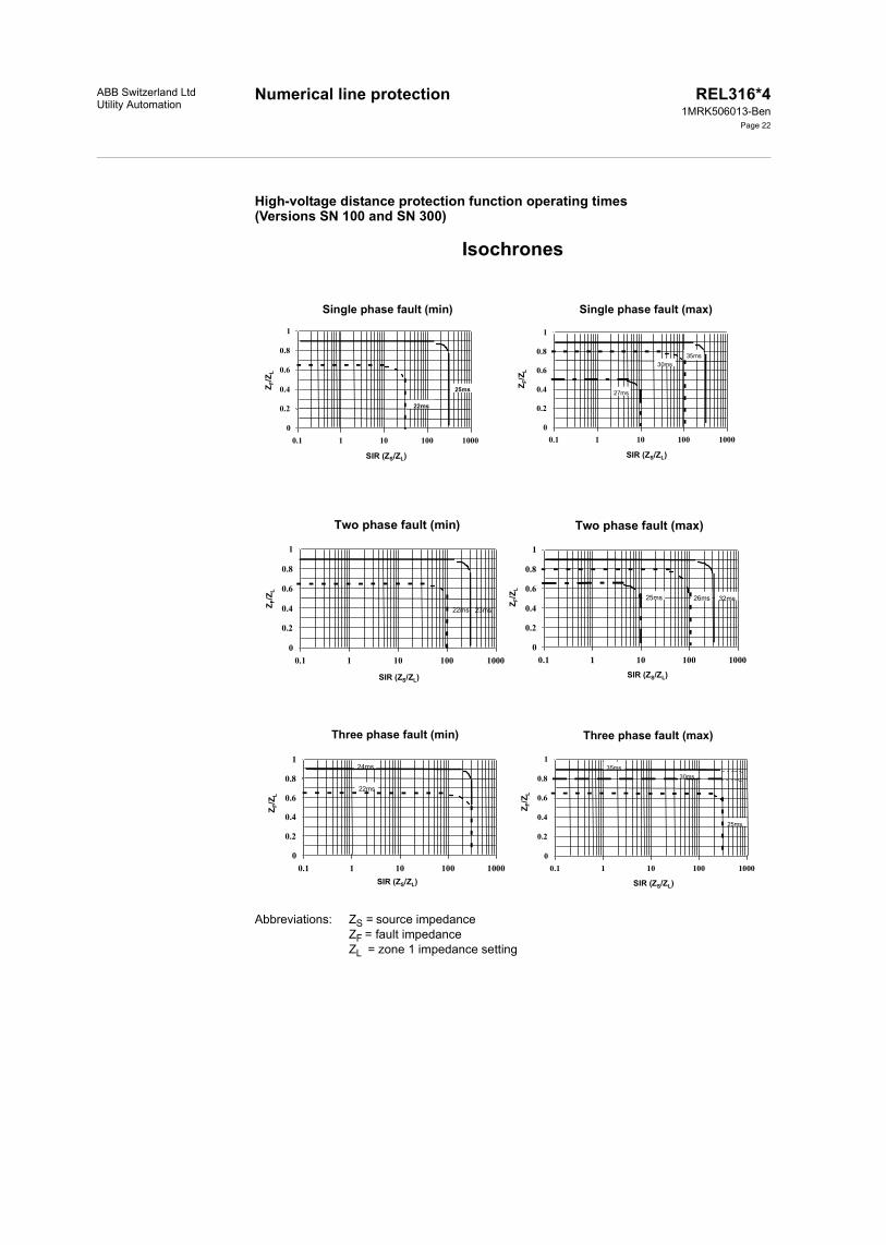
Numerical line protectionABB Switzerland LtdUtility Automation
REL316*41MRK506013-Ben
Page 22
High-voltage distance protection function operating times (Versions SN 100 and SN 300)
Isochrones
Abbreviations: ZS = source impedanceZF = fault impedanceZL = zone 1 impedance setting
Single phase fault (min)
0
0.2
0.4
0.6
0.8
1
0.1 1 10 100 1000
25ms
22ms
Single phase fault (max)
0
0.2
0.4
0.6
0.8
1
0.1 1 10 100 1000
30ms35ms
27ms
SIR (ZS/ZL)
Z F/Z
L
Z F/Z
L
SIR (ZS/ZL)
Two phase fault (min)
0
0.2
0.4
0.6
0.8
1
0.1 1 10 100 1000
22ms 23ms
Two phase fault (max)
0
0.2
0.4
0.6
0.8
1
0.1 1 10 100 1000
25ms 32ms26ms
Z F/Z
L
Z F/Z
L
SIR (ZS/ZL) SIR (ZS/ZL)
Three phase fault (min)
0
0.2
0.4
0.6
0.8
1
0.1 1 10 100 1000
22ms
24ms
Three phase fault (max)
0
0.2
0.4
0.6
0.8
1
0.1 1 10 100 1000
25ms
30ms35ms
Z F/Z
L
Z F/Z
L
SIR (ZS/ZL) SIR (ZS/ZL)
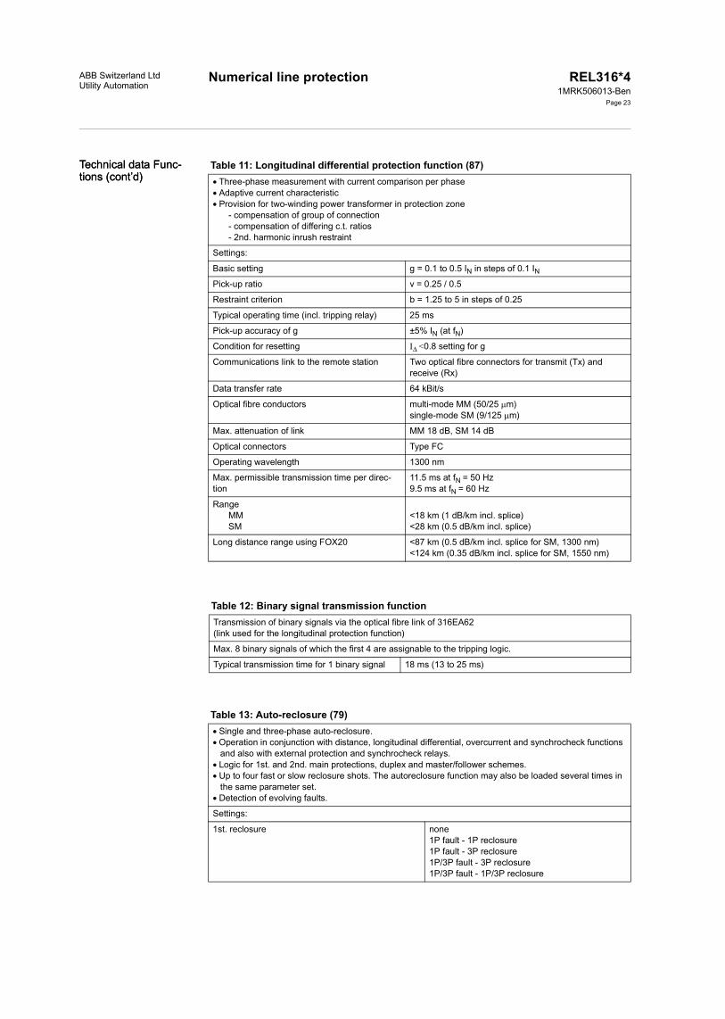
Numerical line protection REL316*41MRK506013-Ben
Page 23
Technical data Func-tions (cont’d)Technical data Func-tions (cont’d)
ABB Switzerland LtdUtility Automation
Table 11: Longitudinal differential protection function (87)Three-phase measurement with current comparison per phaseAdaptive current characteristic Provision for two-winding power transformer in protection zone
- compensation of group of connection- compensation of differing c.t. ratios- 2nd. harmonic inrush restraint
Settings:
Basic setting g = 0.1 to 0.5 IN in steps of 0.1 INPick-up ratio v = 0.25 / 0.5
Restraint criterion b = 1.25 to 5 in steps of 0.25
Typical operating time (incl. tripping relay) 25 ms
Pick-up accuracy of g ±5% IN (at fN)
Condition for resetting I <0.8 setting for g
Communications link to the remote station Two optical fibre connectors for transmit (Tx) and receive (Rx)
Data transfer rate 64 kBit/s
Optical fibre conductors multi-mode MM (50/25 m)single-mode SM (9/125 m)
Max. attenuation of link MM 18 dB, SM 14 dB
Optical connectors Type FC
Operating wavelength 1300 nm
Max. permissible transmission time per direc-tion
11.5 ms at fN = 50 Hz9.5 ms at fN = 60 Hz
RangeMMSM
<18 km (1 dB/km incl. splice)<28 km (0.5 dB/km incl. splice)
Long distance range using FOX20 <87 km (0.5 dB/km incl. splice for SM, 1300 nm)<124 km (0.35 dB/km incl. splice for SM, 1550 nm)
Table 12: Binary signal transmission functionTransmission of binary signals via the optical fibre link of 316EA62(link used for the longitudinal protection function)
Max. 8 binary signals of which the first 4 are assignable to the tripping logic.
Typical transmission time for 1 binary signal 18 ms (13 to 25 ms)
Table 13: Auto-reclosure (79)Single and three-phase auto-reclosure.Operation in conjunction with distance, longitudinal differential, overcurrent and synchrocheck functions
and also with external protection and synchrocheck relays.Logic for 1st. and 2nd. main protections, duplex and master/follower schemes.Up to four fast or slow reclosure shots. The autoreclosure function may also be loaded several times in
the same parameter set. Detection of evolving faults.
Settings:
1st. reclosure none1P fault - 1P reclosure1P fault - 3P reclosure1P/3P fault - 3P reclosure1P/3P fault - 1P/3P reclosure

Numerical line protection REL316*41MRK506013-Ben
Page 24
Technical data Func-tions (cont’d)Technical data Func-tions (cont’d)
ABB Switzerland LtdUtility Automation
Table 14: Synchrocheck function (25)
2nd. to 4th. reclosure nonetwo reclosure cycles three reclosure cycles four reclosure cycles
Single-phase dead time 0.05 to 300 s
Three-phase dead time 0.05 to 300 s
Dead time extension by ext. signal 0.05 to 300 s
Dead times for 2nd., 3rd. and 4th. reclosures 0.05 to 300 s
Fault duration time 0.05 to 300 s
Reclaim time 0.05 to 300 s
Blocking time 0.05 to 300 s
Single and three-phase discrimination times 0.1 to 300 s
All settings in steps of 0.01 s
Determination of synchronism- Single-phase measurement. The differences between the amplitudes, phase-angles and frequen-
cies of two voltage vectors are determined. Voltage supervision
- Single or three-phase measurement- Evaluation of instantaneous values and therefore wider frequency range- Determination of maximum and minimum values in the case of three-phase inputs
Phase selection for voltage inputs Provision for switching to a different voltage input (double busbar systems) Remote selection of operating mode
Settings:
Max. voltage difference 0.05 to 0.4 UN in steps of 0.05 UN
Max. phase difference 5 to 80° in steps of 5°
Max. frequency difference 0.05 to 0.4 Hz in steps of 0.05 Hz
Min. voltage 0.6 to 1 UN in steps of 0.05 UN
Max. voltage 0.1 to 1 UN in steps of 0.05 UN
Supervision time 0.05 to 5 s in steps of 0.05 s
Resetting time 0 to 1 s in steps of 0.05 s
AccuracyVoltage differencePhase differenceFrequency difference
for 0.9 to 1.1 fN±5% UN±5°±0.05 Hz
Table 15: Thermal overload function (49)Thermal image for the 1st. order model. Single or three-phase measurement with detection of maximum phase value.
Settings:
Base current IB 0.5 to 2.5 IN in steps of 0.01 INAlarm stage 50 to 200% N in steps of 1% N
Tripping stage 50 to 200% N in steps of 1% N
Thermal time constant 2 to 500 min in steps of 0.1 min
Accuracy of the thermal image ±5% N (at fN) with protection c.t.'s±2% N (at fN) with metering c.t.'s

Numerical line protectionABB Switzerland LtdUtility Automation
REL316*41MRK506013-Ben
Page 25
Table 16: Definite time current function (51DT)Over and undercurrent detection. Single or three-phase measurement with detection of the highest, respectively lowest phase current. 2nd. harmonic restraint for high inrush currents.
Settings:
Pick-up current 0.02 to 20 IN in steps of 0.01 INDelay 0.02 to 60 s in steps of 0.01 s
Accuracy of the pick-up setting (at fN) ±5%
Reset ratioovercurrentundercurrent
>94% (for max. function)<106% (for min. function)
Max. operating time without intentional delay 60 ms
Inrush restraintpick-up settingreset ratio
optional0.1 I2h/I1h0.8
Table 17: Definite time voltage function (27/59)Over and undervoltage detection Single or three-phase measurement with detection of the highest, respectively lowest phase voltage
Settings:
Pick-up voltage 0.01 to 2.0 UN in steps of 0.002 UN
Delay 0.02 to 60 s in steps of 0.01 s
Accuracy of the pick-up setting (at fN) ±2% or ±0.005 UN
Reset ratio (U 0.1 UN)overvoltageundervoltage
>96% (for max. function)<104% (for min. function)
Max. operating time without intentional delay 60 ms
Table 18: Inverse time overcurrent function (51)Single or three-phase measurement with detection of the highest phase currentStable response to transients
Inverse time characteristic(acc. to B.S. 142 with extended setting range)
normal inversevery inverseextremely inverselong time inverse
t = k1 / ((I/IB)C- 1)
c = 0.02c = 1c = 2c = 1
or RXIDG characteristic t = 5.8 - 1.35 · In (I/IB)
Settings:
Number of phases 1 or 3
Base current IB 0.04 to 2.5 IN in steps of 0.01 INPick-up current Istart 1 to 4 IB in steps of 0.01 IBMin. time setting tmin 0 to 10 s in steps of 0.1 s
k1 setting 0.01 to 200 s in steps of 0.01 s
Accuracy classes for the operating time according to British Standard 142RXIDG characteristic
E 5.0±4% (1 - I/80 IB)
Reset ratio >94%

Numerical line protection REL316*41MRK506013-Ben
Page 26
Technical data Func-tions (cont’d)Technical data Func-tions (cont’d)
ABB Switzerland LtdUtility Automation
Table 19: Inverse time ground fault overcurrent function (51N)Neutral current measurement (derived externally or internally) Stable response to transients
Inverse time characteristic(acc. to B.S. 142 with extended setting range)
normal inversevery inverseextremely inverselong time inverse
t = k1 / ((I/IB)C - 1)
c = 0.02c = 1c = 2c = 1
or RXIDG characteristic t = 5.8 - 1.35 · In (I/IB)
Settings:
Number of phases 1 or 3
Base current IB 0.04 to 2.5 IN in steps of 0.01 INPick-up current Istart 1 to 4 IB in steps of 0.01 IBMin. time setting tmin 0 to 10 s in steps of 0.1 s
k1 setting 0.01 to 200 s in steps of 0.01 s
Accuracy classes for the operating time according to British Standard 142RXIDG characteristic
E 5.0±4% (1 - I/80 IB)
Reset ratio >94%
Table 20: Directional definite time overcurrent protection (67) Directional overcurrent protection with detection of the power direction Backup protection for distance protection scheme
Three-phase measurement Suppression of DC- and high-frequency components Definite time characteristic Voltage memory feature for close faults
Settings:
Current 0.02 to 20 IN in steps of 0.01 INAngle -180° to +180° in steps of 15°
Delay 0.02 s to 60 s in steps of 0.01 s
tWait 0.02 s to 20 s in steps of 0.01 s
Memory duration 0.2 s to 60 s in steps of 0.01 s
Accuracy of pick-up setting (at fN)Reset ratioAccuracy of angle measurement(at 0.94 to 1.06 fN)
±5% or ±0.02 IN>94%
±5°Voltage input rangeVoltage memory rangeAccuracy of angle measurement at voltage memoryFrequency dependence of angle measurement at voltage memoryMax. Response time without delay
0.005 to 2 UN<0.005 UN±20°
±0.5°/Hz60 ms
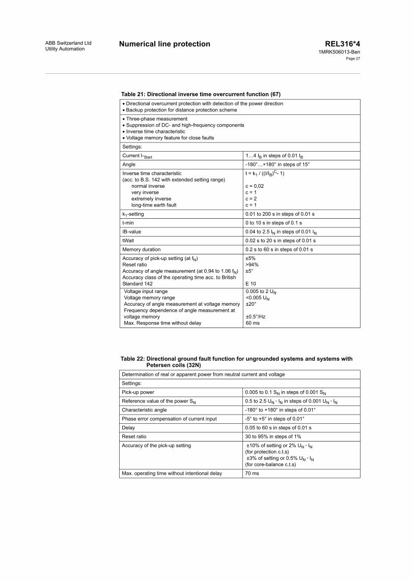
Numerical line protectionABB Switzerland LtdUtility Automation
REL316*41MRK506013-Ben
Page 27
Table 21: Directional inverse time overcurrent function (67)Directional overcurrent protection with detection of the power directionBackup protection for distance protection scheme
Three-phase measurement Suppression of DC- and high-frequency components Inverse time characteristic Voltage memory feature for close faults
Settings:
Current I-Start 1…4 IB in steps of 0.01 IBAngle -180°…+180° in steps of 15°
Inverse time characteristic(acc. to B.S. 142 with extended setting range)
normal inverse very inverse extremely inverse long-time earth fault
t = k1 / ((I/IB)C- 1)
c = 0,02c = 1c = 2c = 1
k1-setting 0.01 to 200 s in steps of 0.01 s
t-min 0 to 10 s in steps of 0.1 s
IB-value 0.04 to 2.5 IN in steps of 0.01 INtWait 0.02 s to 20 s in steps of 0.01 s
Memory duration 0.2 s to 60 s in steps of 0.01 s
Accuracy of pick-up setting (at fN)Reset ratioAccuracy of angle measurement (at 0.94 to 1.06 fN)Accuracy class of the operating time acc. to British Standard 142
±5%>94%±5°
E 10Voltage input rangeVoltage memory rangeAccuracy of angle measurement at voltage memoryFrequency dependence of angle measurement at voltage memoryMax. Response time without delay
0.005 to 2 UN<0.005 UN±20°
±0.5°/Hz60 ms
Table 22: Directional ground fault function for ungrounded systems and systems with Petersen coils (32N)
Determination of real or apparent power from neutral current and voltage
Settings:
Pick-up power 0.005 to 0.1 SN in steps of 0.001 SN
Reference value of the power SN 0.5 to 2.5 UN · IN in steps of 0.001 UN · INCharacteristic angle -180° to +180° in steps of 0.01°
Phase error compensation of current input -5° to +5° in steps of 0.01°
Delay 0.05 to 60 s in steps of 0.01 s
Reset ratio 30 to 95% in steps of 1%
Accuracy of the pick-up setting ±10% of setting or 2% UN · IN(for protection c.t.s) ±3% of setting or 0.5% UN · IN(for core-balance c.t.s)
Max. operating time without intentional delay 70 ms
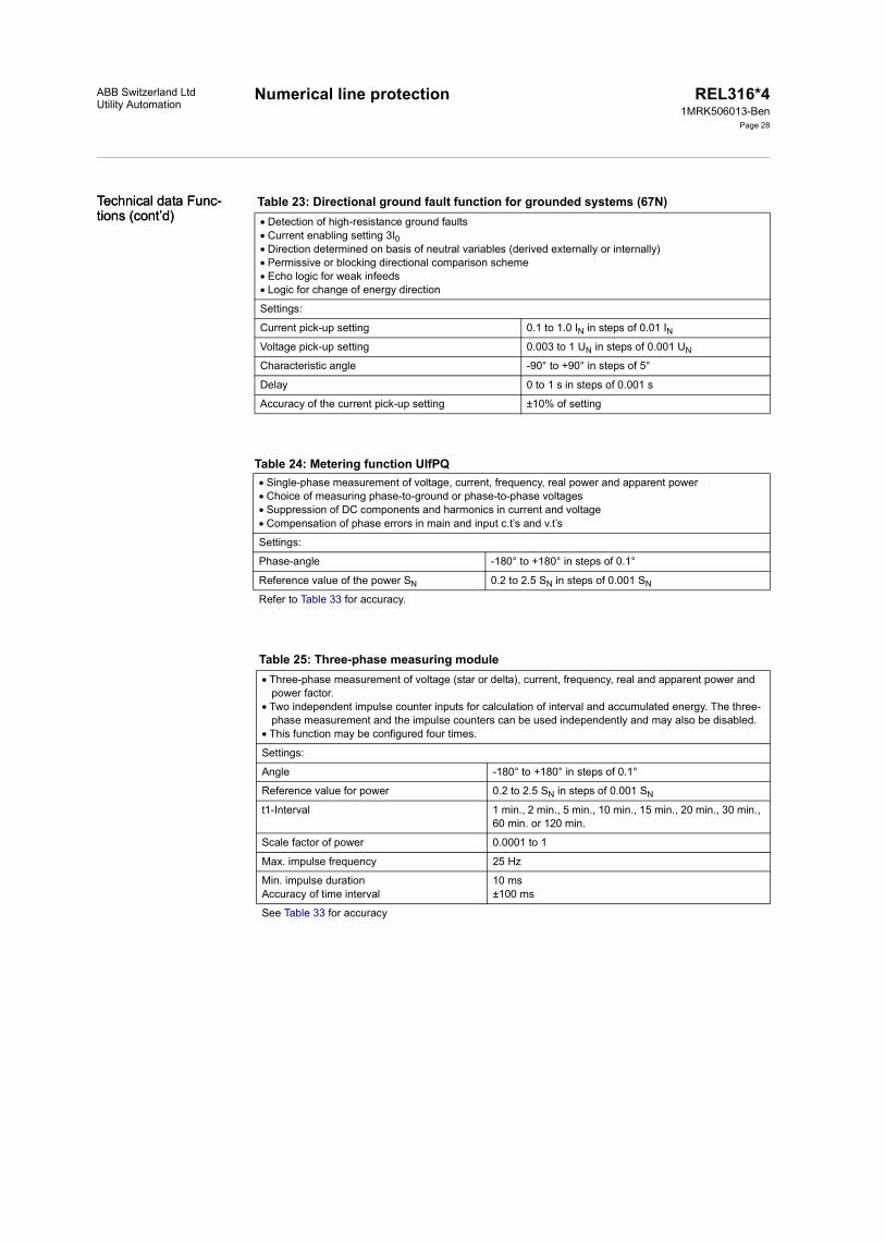
Numerical line protection REL316*41MRK506013-Ben
Page 28
Technical data Func-tions (cont’d)Technical data Func-tions (cont’d)
ABB Switzerland LtdUtility Automation
Table 24: Metering function UIfPQ
Table 23: Directional ground fault function for grounded systems (67N) Detection of high-resistance ground faultsCurrent enabling setting 3I0Direction determined on basis of neutral variables (derived externally or internally)Permissive or blocking directional comparison schemeEcho logic for weak infeedsLogic for change of energy direction
Settings:
Current pick-up setting 0.1 to 1.0 IN in steps of 0.01 INVoltage pick-up setting 0.003 to 1 UN in steps of 0.001 UN
Characteristic angle -90° to +90° in steps of 5°
Delay 0 to 1 s in steps of 0.001 s
Accuracy of the current pick-up setting ±10% of setting
Single-phase measurement of voltage, current, frequency, real power and apparent powerChoice of measuring phase-to-ground or phase-to-phase voltagesSuppression of DC components and harmonics in current and voltageCompensation of phase errors in main and input c.t’s and v.t’s
Settings:
Phase-angle -180° to +180° in steps of 0.1°
Reference value of the power SN 0.2 to 2.5 SN in steps of 0.001 SN
Refer to Table 33 for accuracy.
Table 25: Three-phase measuring moduleThree-phase measurement of voltage (star or delta), current, frequency, real and apparent power and
power factor. Two independent impulse counter inputs for calculation of interval and accumulated energy. The three-
phase measurement and the impulse counters can be used independently and may also be disabled. This function may be configured four times.
Settings:
Angle -180° to +180° in steps of 0.1°
Reference value for power 0.2 to 2.5 SN in steps of 0.001 SN
t1-Interval 1 min., 2 min., 5 min., 10 min., 15 min., 20 min., 30 min., 60 min. or 120 min.
Scale factor of power 0.0001 to 1
Max. impulse frequency 25 Hz
Min. impulse durationAccuracy of time interval
10 ms±100 ms
See Table 33 for accuracy

Numerical line protectionABB Switzerland LtdUtility Automation
REL316*41MRK506013-Ben
Page 29
Table 26: Power function (32)Measurement of real or apparent powerProtection function based on either real or apparent power measurementReverse power protectionOver and underpowerSingle, two or three-phase measurementSuppression of DC components and harmonics in current and voltageCompensation of phase errors in main and input c.t’s and v.t’s
Settings:
Power pick-up -0.1 to 1.2 SN in steps of 0.005 SN
Characteristic angle -180° to +180° in steps of 5°
Delay 0.05 to 60 s in steps of 0.01 s
Phase error compensation -5° to +5° in steps of 0.1°
Rated power SN 0.5 to 2.5 UN IN in steps of 0.001 UN INReset ratio 30% to 170% in steps of 1%
Accuracy of the pick-up setting ±10% of setting or 2% UN IN(for protection c.t.s) ±3% of setting or 0.5% UN IN(for core-balance c.t.s)
Max. operating time without intentional delay 70 ms
Table 27: Breaker-failure protection (50BF)Features Individual phase current recognition Single or three-phase operation External blocking input Two independent time steps Remote tripping adjustable simultaneously with retripping or backup tripping Possibility of segregated activating/deactivating each trip (Redundant trip, retrip, backup trip and remote
trip).
Settings
Current 0.2 to 5 IN in steps of 0.01 INDelay t1 (repeated trip) 0.02 to 60 s in steps of 0.01 s
Delay t2 (backup trip) 0.02 to 60 s in steps of 0.01 s
Delay tEFS (End fault protection) 0.02 to 60 s in steps of 0.01 s
Reset time for retrip 0.02 to 60 s in steps of 0.01 s
Reset time for backup trip 0.02 to 60 s in steps of 0.01 s
Pulse time for remote trip 0.02 to 60 s in steps of 0.01 s
Number of phases 1 or 3
Accuracy of current operating time (at fN)Reset ratio of current measurement
±15%>85%
Reset time (for power system time constants up to 300 ms and short-circuit currents up to 40 · IN)
28 ms (with main c.t.s TPX)28 ms (with main c.t.s TPY and
current setting 1,2 IN38 ms (with main c.t.s TPY and
current setting 0,4 IN
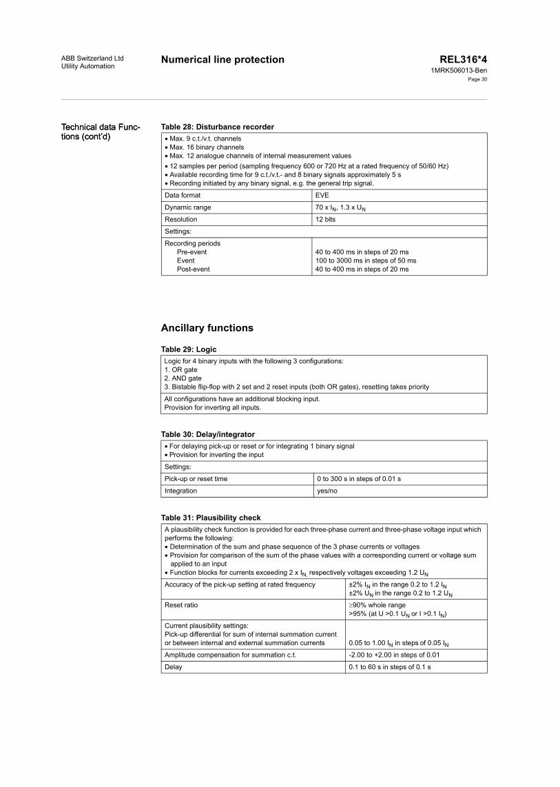
Numerical line protection REL316*41MRK506013-Ben
Page 30
Technical data Func-tions (cont’d)Technical data Func-tions (cont’d)
ABB Switzerland LtdUtility Automation
Table 28: Disturbance recorder
Ancillary functions
Table 29: Logic
Table 30: Delay/integrator
Table 31: Plausibility check
Max. 9 c.t./v.t. channelsMax. 16 binary channelsMax. 12 analogue channels of internal measurement values12 samples per period (sampling frequency 600 or 720 Hz at a rated frequency of 50/60 Hz)Available recording time for 9 c.t./v.t.- and 8 binary signals approximately 5 sRecording initiated by any binary signal, e.g. the general trip signal.
Data format EVE
Dynamic range 70 x IN, 1.3 x UN
Resolution 12 bits
Settings:
Recording periods Pre-event EventPost-event
40 to 400 ms in steps of 20 ms100 to 3000 ms in steps of 50 ms40 to 400 ms in steps of 20 ms
Logic for 4 binary inputs with the following 3 configurations:1. OR gate2. AND gate3. Bistable flip-flop with 2 set and 2 reset inputs (both OR gates), resetting takes priority
All configurations have an additional blocking input.Provision for inverting all inputs.
For delaying pick-up or reset or for integrating 1 binary signalProvision for inverting the input
Settings:
Pick-up or reset time 0 to 300 s in steps of 0.01 s
Integration yes/no
A plausibility check function is provided for each three-phase current and three-phase voltage input which performs the following: Determination of the sum and phase sequence of the 3 phase currents or voltages Provision for comparison of the sum of the phase values with a corresponding current or voltage sum
applied to an input Function blocks for currents exceeding 2 x IN, respectively voltages exceeding 1.2 UN
Accuracy of the pick-up setting at rated frequency ±2% IN in the range 0.2 to 1.2 IN±2% UN in the range 0.2 to 1.2 UN
Reset ratio 90% whole range>95% (at U >0.1 UN or I >0.1 IN)
Current plausibility settings:Pick-up differential for sum of internal summation current or between internal and external summation currents 0.05 to 1.00 IN in steps of 0.05 INAmplitude compensation for summation c.t. -2.00 to +2.00 in steps of 0.01
Delay 0.1 to 60 s in steps of 0.1 s

Numerical line protectionABB Switzerland LtdUtility Automation
REL316*41MRK506013-Ben
Page 31
SN = 3 UN IN (three-phase)SN = 1/3 3 UN IN (single-phase)
Voltage plausibility settings:Pick-up differential for sum of internal summation voltage or between internal and external summation voltages 0.05 to 1.2 UN in steps of 0.05 UN
Amplitude compensation for summation v.t. - 2.00 to +2.00 in steps of 0.01
Delay 0.1 to 60 s in steps of 0.1 s
Table 32: Run-time supervisionThe run-time supervision feature enables checking the opening and closing of all kinds of breakers (cir-cuit-breakers, isolators, ground switches...). Failure of a breaker to open or close within an adjustable time results in the creation of a corresponding signal for further processing.
Settings
Setting time 0 to 60 s in steps of 0.01 s
Accuracy of run time supervision ±2 ms
Table 33: Accuracy of the metering function UIfPQ and three-phase measuring module (including input voltage and input current c.t.)
Input variable Accuracy ConditionsCore balance c.t.s with error compensation
Protection c.t.s without error com-pensation
Voltage ±0.5% UN ±1% UN 0.2 to 1.2 UNf = fN
Current ±0.5% IN ±2% IN 0.2 to 1.2 INf = fN
Real power ±0.5% SN ±3% SN 0.2 to 1.2 SN0.2 to 1.2 UN0.2 to 1.2 INf = fN
Apparent power ±0.5% SN ±3% SN
Power factor ±0.01 ±0.03 S = SN, f = fNFrequency ±0.1% fN ±0.1% fN 0.9 to 1,1 fN
0.8 to 1,2 UN

Numerical line protectionABB Switzerland LtdUtility Automation
REL316*41MRK506013-Ben
Page 32
Connection diagram
Fig. 9 Typical wiring diagram of REL316*4 in size N1 casing with two input/output units 316DB62
CURRENTAND VOLTAGEINPUTS
TRIP
COMMUNICATIONPORT(LOCAL HMI) (PC))
SERIAL COMMUNI-CATION WITH SUB-STATION CONTROL
EARTHING SCREWON CASING
OPTOCOUPLERINPUTS
DC SUPPLY
SIGNALLING
(VALID FOR CODE K03)

Numerical line protection REL316*41MRK506013-Ben
Page 33
ABB Switzerland LtdUtility Automation
Ordering Please specify:• Quantity• Ordering number• ADE code + key
The following basic versions can be ordered:
Stand alone units REL316*4 with built-in HMI (see table below) HESG448750M0001
Table 34: REL316*4 basic versions
Ord
er N
o.H
ESG
4487
50M
0001
Relay ID code
<Z <ZH
V
E/Fu
ngnd
E/Fg
ndAR SC Lo
ng. d
iffBS
TBa
sic-
SW
A*B0U*K01E*I*F0J0 Q0V0R0W0Y*N*M* SA010 T*** X
A*B0U*K01E*I*F0J0 Q0V0R0W0Y*N*M* SA100 T*** X X
A*B0U*K03E*I*F*J* Q*V*R*W*Y* N*M* SE010 T*** X
A*B0U*K03E*I*F*J* Q*V*R*W*Y* N*M* SE100 T*** X X
A*B*U*K04E*I*F*J* Q*V*R*W*Y* N*M* SG100 T*** X X X
A*B*U*K04E*I*F*J* Q*V*R*W*Y* N*M* SH100 T*** X X X X
A*B*U*K09E*I*F*J* Q*V*R*W*Y* N*M* SH300 T*** X X X X X
A*B0U*K03E*I*F*J* Q*V*R*W*Y* N*M* SK100 T*** X X X
A*B0U*K05E*I*F*J* Q*V*R*W*Y* N*M* SK300 T*** X X X X
A*B0U*K05E*I*F*J* Q*V*R*W*Y* N*M* SL100 T*** X X X
A*B0U*K05E*I*F*J* Q*V*R*W*Y* N*M* SM100 T*** X X X X
A*B0U*K08E*I*F*J* Q*V*R*W*Y* N*M* SM300 T*** X X X X X
A*B0U*K01E*I*F0J0 Q0V0R0W0Y*N*M* SA020 T*** X
A*B0U*K03E*I*F*J* Q*V*R*W*Y* N*M* SC020 T*** X
A*B0U*K05E*I*F*J* Q*V*R*W*Y* N*M* SC050 T*** X X
A*B0U*K03E*I*F*J* Q*V*R*W*Y* N*M* SD020 T*** X X
A*B0U*K05E*I*F*J* Q*V*R*W*Y* N*M* SD050 T*** X X X
A*B*U*K04E*I*F0J0 Q0V0R0W0Y*N*M* SG020 T*** X X
A*B*U*K04E*I*F*J* Q*V*R*W*Y* N*M* SH020 T*** X X X
A*B*U*K09E*I*F*J* Q*V*R*W*Y* N*M* SH050 T*** X X X X
A*B0U*K16E*I*F*J*Q*V*R*W*Y*N*M* SP100 T*** X X X X X
A*B0U*K16E*I*F*J*Q*V*R*W*Y*N*M* SP200 T*** X X X X X X
A*B*U*K17E*I*F*J*Q*V*R*W*Y*N*M* SP300 T*** X X X X X X
A*B0U0K15E*I*F*J* Q*V*R*W*Y*N*M* SP400 T*** X X X X
A*B0U*K16E*I*F*J*Q*V*R*W*Y*N*M* SP400 T*** X X X X
A*B*U*K17E*I*F*J*Q*V*R*W*Y*N*M* SP400 T*** X X X X
A*B0U*K16E*I*F*J*Q*V*R*W*Y*N*M* SP500 T*** X X X X X
A*B0U*K05E*I*F*J*Q*V*R*W*Y*N2M* SN100 T*** X X X
A*B0U*K05E*I*F*J*Q*V*R*W*Y*N2M* SN300 T*** X X X X X
A*B0U*K08E*I*F*J*Q*V*R*W*Y*N2M* SN300 T*** X X X X X
T0129 is to be ordered additionally in case that single-pole autoreclosure for line differential protection is required.
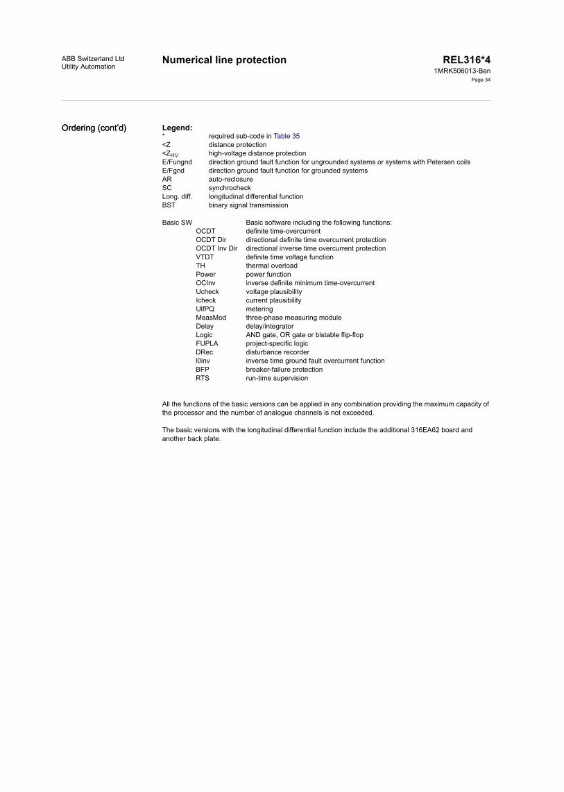
Numerical line protection REL316*41MRK506013-Ben
Page 34
Ordering (cont’d)Ordering (cont’d)
ABB Switzerland LtdUtility Automation
Legend:* required sub-code in Table 35<Z distance protection<ZHV high-voltage distance protection E/Fungnd direction ground fault function for ungrounded systems or systems with Petersen coilsE/Fgnd direction ground fault function for grounded systemsAR auto-reclosureSC synchrocheckLong. diff. longitudinal differential functionBST binary signal transmission
Basic SW Basic software including the following functions:OCDT definite time-overcurrentOCDT Dir directional definite time overcurrent protectionOCDT Inv Dir directional inverse time overcurrent protectionVTDT definite time voltage functionTH thermal overloadPower power functionOCInv inverse definite minimum time-overcurrentUcheck voltage plausibilityIcheck current plausibilityUlfPQ meteringMeasMod three-phase measuring moduleDelay delay/integratorLogic AND gate, OR gate or bistable flip-flopFUPLA project-specific logicDRec disturbance recorderl0inv inverse time ground fault overcurrent functionBFP breaker-failure protectionRTS run-time supervision
All the functions of the basic versions can be applied in any combination providing the maximum capacity of the processor and the number of analogue channels is not exceeded.
The basic versions with the longitudinal differential function include the additional 316EA62 board and another back plate.

Numerical line protectionABB Switzerland LtdUtility Automation
REL316*41MRK506013-Ben
Page 35
Table 35: Definitions of the relay ID codes in Table 34Sub code Significance Description RemarksA- A0
A1A2A5
none1A2A5A
rated current state
B- B0B1B2B5
none1A2A5A
rated current state
C- C0C1C2C5
none1A2A5A
rated current state
D- D0D1D2D5
none1A2A5A
rated current state
U- U0U1U2
none100 V AC200 V AC
rated voltage state
K- K01 3 VTs (3ph star Code U-)3 CTs (3ph Code A-)
VT, CT and MT combination in input transformer unit type 316GW61
see previous table
K03 3 VTs (3ph star Code U-)3 CTs (3ph Code A-)1 CT (1ph Code A-)1 CT (1ph Code A-)
CT = current transformerVT = voltage transformerMT = metering transformer
K04 3 VTs (3ph star Code U-)1 VT (1ph Code U-)3 CTs (3ph Code A-)1 CT (1ph Code A-)1 MT (1ph Code B-)
K01 to K14:without differential functionK15 to K20:with differential function
K05 3 VTs (3ph star Code U-)1 VT (1ph Code U-)3 CTs (3ph Code A-)1 CT (1ph Code A-)1 CT (1ph Code A-)
K08 3 VTs (3ph star Code U-)1 VT (1ph Code U-)1 VT (1ph Code U-)3 CTs (3ph Code A-)1 CT (1ph Code A-)
K09 3 VTs (3ph star Code U-)1 VT (1ph Code U-)1 VT (1ph Code U-)3 CTs (3ph Code A-)1 MT (1ph Code B-)
K15 3 CTs (3ph Code A-)3 not defined3 remote CTs optical link to the remote sta-
tion
K16 3 CTs (3ph Code A-)3 VTs (3ph star Code U-)3 remote CTs optical link to the remote sta-
tion

Numerical line protection REL316*41MRK506013-Ben
Page 36
Ordering (cont’d)Ordering (cont’d)
ABB Switzerland LtdUtility Automation
K17 3 CTs (3ph Code A-)1 VT (1ph Code U-)1 VT (1ph Code U-)1 MT (1ph Code B-)3 remote CTs optical link to the remote sta-
tion
E- E1 8 optocoupler6 signal. relays2 command relays8 LED's
1. binary input/output unitType 316DB61
see previous table
E2 4 optocoupler10 signal. relays2 command relays8 LED's
1.binary input/output unitType 316DB62
E3 14 optocoupler8 signal. relays8 LED's
1.binary input/output unitType 316DB63
I- I3I4I5I9
82 to 312 V DC36 to 75 V DC18 to 36 V DC175 to 312 V DC
1. binary input/output unitoptocoupler input voltage
state
F- F0 none
F1 8 optocoupler6 signal. relays2 command relays8 LED's
2. binary input/output unitType 316DB61
see previous table
F2 4 optocoupler10 signal. relays2 command relays8 LED's
2. binary input/output unitType 316DB62
F3 14 optocoupler8 signal. relays8 LED's
2. binary input/output unitType 316DB63
J- J0J3J4J5J9
none82 to 312 V DC36 to 75 V DC18 to 36 V DC175 to 312 V DC
2. binary input/output unitoptocoupler input voltage
state
Q- Q0 none
Q1 8 optocoupler6 signal. relays2 command relays
3. binary input/output unit Type 316DB61
see previous table
Q2 4 optocoupler10 signal. relays2 command relays
3. binary input/output unit Type 316DB62
Q3 14 optocoupler8 signal. relays
3. binary input/output unit Type 316DB63
V- V0V3V4V5V9
none82 to 312 V DC36 to 75 V DC18 to 36 V DC175 to 312 V DC
3. binary input/output unitoptocoupler input voltage
state

Numerical line protectionABB Switzerland LtdUtility Automation
REL316*41MRK506013-Ben
Page 37
1) MVB interface (for interbay or process bus) not applicable for surface-mounted version.
The order number has been defined for the basic version as above and the required accessories can be ordered according to the following Table.
R- R0 none
R1 8 optocoupler6 signal. relays2 command relays
4. binary input/output unit Type 316DB61
see previous table
R2 4 optocoupler10 signal. relays2 command relays
4. binary input/output unit Type 316DB62
R3 14 optocoupler8 signal. relays
4. binary input/output unit Type 316DB63
W- W0W3W4W5W9
none82 to 312 V DC36 to 75 V DC18 to 36 V DC175 to 312 V DC
4. binary input/output unitoptocoupler input voltage
state
Y- Y0Y1Y2Y3Y41)
no comm. protocolSPA IEC 60870-5-103LONMVB (part of IEC 61375)
Interbay bus protocol
N- N1N2
casing width 225.2 mmcasing width 271 mm
see previous table
M- M1M51)
Semi-flush mountingSurface mounting, standard ter-minals
Order M1 and sepa-rate assembly kit for 19" rack mounting
S- SA000toSO990
basic versions REL316*4without differential function
Different versions of func-tions
see previous table
SP000toSQ990
basic versions REL316*4with differential function
SZ990 order not acc. to Data Sheet
T- T0000T0001xtoT9999x
without FUPLA logicFUPLA logic
Customer-specific logicx = version of the FUPLA logic
Defined by ABB Switzerland Ltd
T0129x
T0141x
T0142x
Logic for single-phaseautoreclosure for line differ-ential protectionLogic for single-phase autoreclosure for the distance protection with a 1½-breaker schemeLogic for single-phase autoreclosure for a reclosure unit with a 1½-breaker scheme
T0990x FUPLA logic written by others
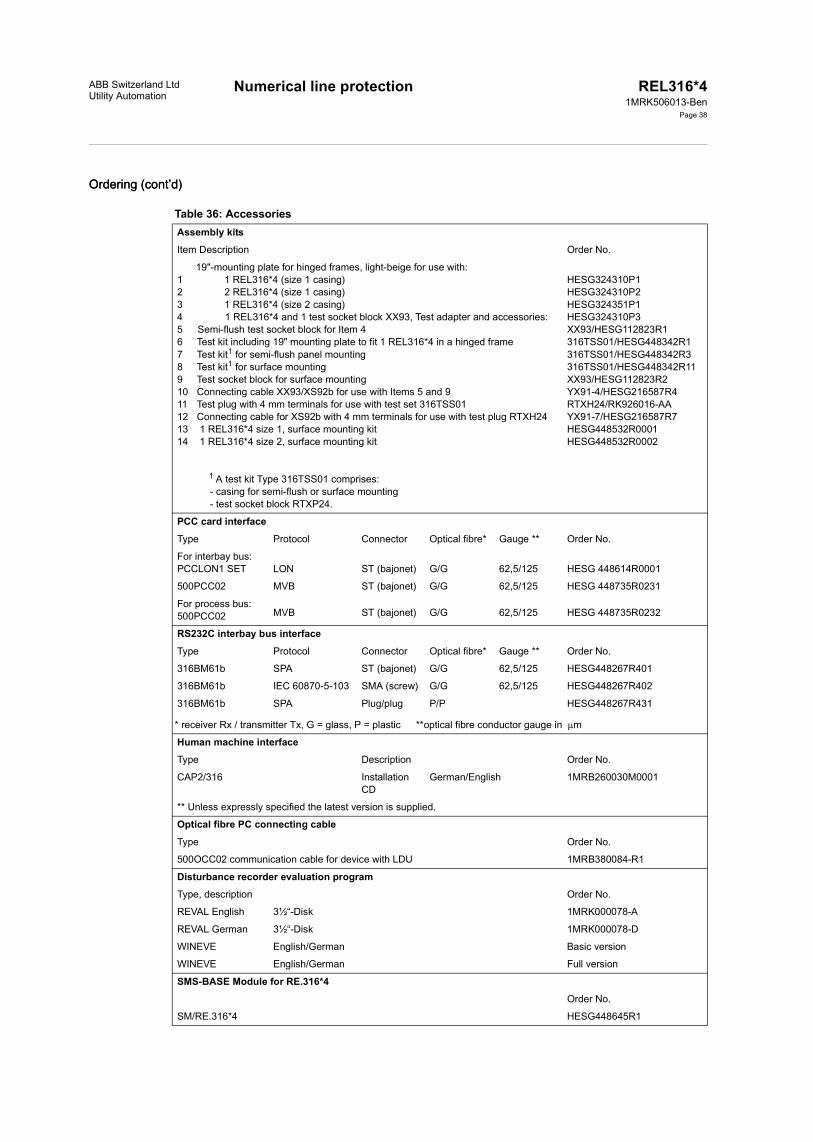
Numerical line protection REL316*41MRK506013-Ben
Page 38
Ordering (cont’d)Ordering (cont’d)
ABB Switzerland LtdUtility Automation
Table 36: AccessoriesAssembly kitsItem Description Order No.
19"-mounting plate for hinged frames, light-beige for use with:1 1 REL316*4 (size 1 casing)2 2 REL316*4 (size 1 casing)3 1 REL316*4 (size 2 casing)4 1 REL316*4 and 1 test socket block XX93, Test adapter and accessories:5 Semi-flush test socket block for Item 46 Test kit including 19" mounting plate to fit 1 REL316*4 in a hinged frame7 Test kit1 for semi-flush panel mounting8 Test kit1 for surface mounting9 Test socket block for surface mounting10 Connecting cable XX93/XS92b for use with Items 5 and 911 Test plug with 4 mm terminals for use with test set 316TSS0112 Connecting cable for XS92b with 4 mm terminals for use with test plug RTXH2413 1 REL316*4 size 1, surface mounting kit14 1 REL316*4 size 2, surface mounting kit
1 A test kit Type 316TSS01 comprises:- casing for semi-flush or surface mounting- test socket block RTXP24.
HESG324310P1HESG324310P2HESG324351P1HESG324310P3XX93/HESG112823R1316TSS01/HESG448342R1316TSS01/HESG448342R3316TSS01/HESG448342R11XX93/HESG112823R2YX91-4/HESG216587R4RTXH24/RK926016-AAYX91-7/HESG216587R7HESG448532R0001HESG448532R0002
PCC card interfaceType Protocol Connector Optical fibre* Gauge ** Order No.
For interbay bus:PCCLON1 SET LON ST (bajonet) G/G 62,5/125 HESG 448614R0001
500PCC02 MVB ST (bajonet) G/G 62,5/125 HESG 448735R0231
For process bus:500PCC02 MVB ST (bajonet) G/G 62,5/125 HESG 448735R0232
RS232C interbay bus interfaceType Protocol Connector Optical fibre* Gauge ** Order No.
316BM61b SPA ST (bajonet) G/G 62,5/125 HESG448267R401
316BM61b IEC 60870-5-103 SMA (screw) G/G 62,5/125 HESG448267R402
316BM61b SPA Plug/plug P/P HESG448267R431 * receiver Rx / transmitter Tx, G = glass, P = plastic **optical fibre conductor gauge in m
Human machine interface Type Description Order No.
CAP2/316 Installation CD
German/English 1MRB260030M0001
** Unless expressly specified the latest version is supplied.
Optical fibre PC connecting cableType Order No.
500OCC02 communication cable for device with LDU 1MRB380084-R1
Disturbance recorder evaluation programType, description Order No.
REVAL English 3½“-Disk 1MRK000078-A
REVAL German 3½“-Disk 1MRK000078-D
WINEVE English/German Basic version
WINEVE English/German Full version
SMS-BASE Module for RE.316*4Order No.
SM/RE.316*4 HESG448645R1

Numerical line protection REL316*41MRK506013-Ben
Page 39
ABB Switzerland LtdUtility Automation
Dimensioned drawings
Fig. 10 Semi-flush mounting, rear connections. Size N1 casing.

Numerical line protection REL316*41MRK506013-Ben
Page 40
Dimensioned draw-ings (cont’d)Dimensioned draw-ings (cont’d)
ABB Switzerland LtdUtility Automation
Fig. 11 Semi-flush mounting, rear connections. Size N2 casing

Numerical line protectionABB Switzerland LtdUtility Automation
REL316*41MRK506013-Ben
Page 41
Fig. 12 Surface mounting, casing able to swing to the left, rear connections. Size N1 casing

Numerical line protection REL316*41MRK506013-Ben
Page 42
Dimensioned draw-ings (cont’d)Dimensioned draw-ings (cont’d)
ABB Switzerland LtdUtility Automation
Fig. 13 Surface mounting, casing able to swing to the left, rear connections. Size N2 casing.
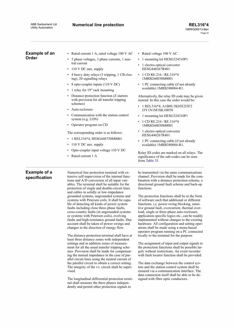
Numerical line protection REL316*41MRK506013-Ben
Page 43
ABB Switzerland LtdUtility Automation
Example of an Order
• Rated current 1 A, rated voltage 100 V AC• 3 phase voltages, 3 phase currents, 1 neu-
tral current• 110 V DC aux. supply• 4 heavy duty relays (3 tripping, 1 CB clos-
ing), 20 signalling relays• 8 opto-coupler inputs (110 V DC)• 1 relay for 19" rack mounting• Distance protection function (Z starters
with provision for all transfer tripping schemes)
• Auto-reclosure• Communication with the station control
system (e.g. LON)• Operator program on CD.
The corresponding order is as follows:
• 1 REL316*4, HESG448750M0001• 110 V DC aux. supply• Opto-coupler input voltage 110 V DC• Rated current 1 A
• Rated voltage 100 V AC• 1 mounting kit HESG324310P1• 1 electro-optical converter
HESG448267R401• 1 CD RE.216 / RE.316*4
1MRB260030M0001• 1 PC connecting cable (if not already
available) 1MRB380084-R1.
Alternatively, the relay ID code may be given instead. In this case the order would be:
• 1 REL316*4, A1B0U1K03E2I3F2J3Y1N1M1SK100T0
• 1 mounting kit HESG324310P1• 1 CD RE.216 / RE.316*4
1MRB260030M0001• 1 electro-optical converter
HESG448267R401• 1 PC connecting cable (if not already
available) 1MRB380084-R1.
Relay ID codes are marked on all relays. The significance of the sub-codes can be seen from Table 35.
Example of a specification
Numerical line protection terminal with ex-tensive self-supervision of the internal func-tions and A/D conversion of all input vari-ables. The terminal shall be suitable for the protection of single and double-circuit lines and cables in solidly or low-impedance grounded systems, ungrounded systems and systems with Petersen coils. It shall be capa-ble of detecting all kinds of power system faults including close three-phase faults, cross-country faults (in ungrounded systems or systems with Petersen coils), evolving faults and high-resistance ground faults. Due account shall be taken of power swings and changes in the direction of energy flow.
The distance protection terminal shall have at least three distance zones with independent settings and in addition zones of measure-ment for all the usual transfer tripping sche-mes. Provision shall be made for compensat-ing the mutual impedance in the case of par-allel circuit lines using the neutral current of the parallel circuit to obtain a correct setting. The integrity of the v.t. circuit shall be super-vised.
The longitudinal differential protection termi-nal shall measure the three phases indepen-dently and permit other protection signals to
be transmitted via the same communications channel. Provision shall be made for the com-bination with a distance protection scheme, a directional ground fault scheme and back-up functions.
The protection functions shall be in the form of software such that additional or different functions, i.e. power swing blocking, sensi-tive ground fault, overcurrent, thermal over-load, single or three-phase auto-reclosure, application-specific logics etc., can be readily implemented without changes to the existing hardware. All configuration and setting oper-ations shall be made using a menu-based operator program running on a PC connected locally to the terminal for the purpose.
The assignment of input and output signals to the protection functions shall be possible lar-gely without restrictions. An event recorder with fault locator function shall be provided.
The data exchange between the control sys-tem and the station control system shall be ensured via a communication interface. The data connection itself shall be able to be de-signed with fibre optic conductors.
Numerical line protectionABB Switzerland LtdUtility Automation
REL316*41MRK506013-Ben
Page 44
Other relevant documents
Operating instructions REL316*4 (printed) 1MRB520050-UenOperating instructions REL316*4 (CD) 1MRB260030M0001Operating instructions Testing program using XS92b CH-ES 86-11.52 ECAP316 Technical Data sheet 1MRB520167-BenTest Set XS92b Data sheet 1MRB520006-BenREL316*4 Reference list 1MRB520212-RenCurrent transformer requirements - Description CH-ES 45-12.30 ESigTOOL Data sheet 1MRB520158-BenRIO580 Data sheet 1MRB520176-Ben
The operating instructions are available in English or German (please state when ordering).
ABB Switzerland LtdUtility AutomationBrown-Boveri-Strasse 6CH-5400 Baden/SwitzerlandTel. +41 58 585 77 44Fax +41 58 585 55 77E-mail: [email protected]
www.abb.com/substationautomation
Printed in Switzerland (0205-1000-0)

CH-ES 45-12.30 E
ABB Switzerland Ltd02-06-27
1/4
DEMANDS ON MEASURING TRANSFORMERS FOR Version 3.10REL 316 and REL 316*4 and higher
IntroductionThe operation of any distance protection is influenced by distortion in themeasuring quantities. The current to the protection will be heavily distorted whenthe current transformer is saturated. In most cases it is not possible to avoidcurrent transformer saturation for all fault conditions, therefore measures aretaken in the distance protections to allow for current transformer saturation withmaintained proper operation. REL 316 / REL 316*4 can allow for relatively heavycurrent transformer saturation but not an unlimited one.
Requirements on current transformers
Choice of current transformersThe current transformer should be of the type TPS, TPX or TPY with accuracyaccording IEC 44-6 or better. The use of the linearized current transformer typeTPZ results only in a turn (anti clock wise) of the relay characteristic of somedegrees.
The current transformer ratio should be selected so that the current to theprotection is larger than the minimum operating value for all faults that shall bedetected. Minimum operating current for the distance protection in REL 316 /REL 316*4 is 10% of nominal current.
Conditions for the CT requirementsThe requirements for REL 316 / REL 316*4 are a result of investigations performedin our network simulation program. The tests have been performed with a digitalcurrent transformer model.
The setting of the current transformer model was representative for current trans-formers type TPX and TPY.
The performance of the distance protection was checked for both symmetrical andfully asymmetrical fault currents. A source with a time constant from 40 up to 120milliseconds was used at the tests. The current requirements below are thusapplicable both for symmetrical and asymmetrical fault currents.Both phase to ground, phase to phase and three phase faults were tested.
Released: Department:
UTAST
Rev.: C
CH-ES 45-12.30 E
ABB Switzerland Ltd
2/3
The protection was checked with regard to directionality, security to trip andoverreach. All testing was made with and without remanence flux in the currenttransformer core. It is difficult to give general recommendations for additionalmargins for remanence flux. It depends on the demands of reliability and economy.When current transformers of type TPY are used, practically no additional margin isneeded due to the anti remanence air gap. For current transformer of Type TPX,the small probability of a fully asymmetrical fault together with maximumremanence flux in the same direction as the flux generated by the fault has to bekept in mind at the decision of an additional margin. Fully asymmetrical faultcurrent will be achieved when the fault occurs at zero voltage (0°). Investigationshave proved that 95% of the faults in the network will occur when the voltage isbetween 40° and 90°.
Fault currentThe current transformer requirements are based on the maximum fault current forfaults in different positions. Maximum fault current will occur for three phase faultsor single phase to ground faults. The current for a single phase to ground fault willexceed the current for a three phase fault when the zero sequence impedance inthe total fault loop is less than the positive sequence impedance.
When calculating the current transformer requirements, the maximum fault currentshould be used and therefore both fault types have to be considered.
Cable resistance and additional loadThe current transformer saturation is directly affected by the voltage at the currenttransformer secondary terminals. This voltage, for a ground fault, is developed in aloop containing the phase and neutral conductor and additional load in this loop.For three phase faults, the neutral current is zero, and only the phase conductor andadditional phase load have to be considered.
In the calculation, the loop resistance should be used for phase to ground faults andthe phase resistance for three phase faults.
REL 316 / REL 316*4 current transformer requirementsThe current transformer secondary limiting emf (E2max) should meet the tworequirements below. The requirements assume 20 to 120 msec maximum dc timeconstant for the network and 100% DC offset.

CH-ES 45-12.30 E
ABB Switzerland Ltd
3/4
1. Faults close to the relay location
2r
LCTpn
snmaxkmax2
I
2.0RRaI
IIE
Ikmax : maximum primary fundamental frequency componentfor forward and reverse fault
Ipn : primary nominal ct currentIsn : secondary nominal ct currentIr : REL 316 / REL 316*4 rated currentRCT : ct secondary winding resistanceRL : ct secondary cable resistance and additional loada : the factor is a function of the frequency and the time constant for the
dc component in the fault currentfor forward or reverse faults according to thediagram in Figure 1 below.
bw : backward resp. reversefw : forward
0
1
2
3
4
5
6
0 20 40 60 80 100 120DC Time Constant ms
a
50 Hz bw60 Hz bw50 Hz fw60 Hz fw
Figure 1: Factor a as a function of the frequency and the time constant Values valid for memory direction mode = block
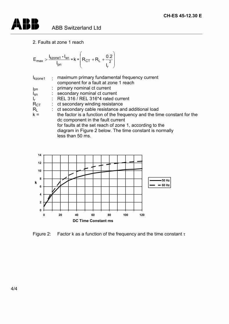
CH-ES 45-12.30 E
ABB Switzerland Ltd
4/4
2. Faults at zone 1 reach
2r
LCTpn
sn1kzonemax
I
2.0RRkI
IIE
Ikzone1 : maximum primary fundamental frequency currentcomponent for a fault at zone 1 reach
Ipn : primary nominal ct currentIsn : secondary nominal ct currentIr : REL 316 / REL 316*4 rated currentRCT : ct secondary winding resistanceRL : ct secondary cable resistance and additional loadk = the factor is a function of the frequency and the time constant for the
dc component in the fault currentfor faults at the set reach of zone 1, according to thediagram in Figure 2 below. The time constant is normallyless than 50 ms.
DC Time Constant ms
k
0
2
4
6
8
10
12
14
0 20 40 60 80 100 120
50 Hz60 Hz
Figure 2: Factor k as a function of the frequency and the time constant
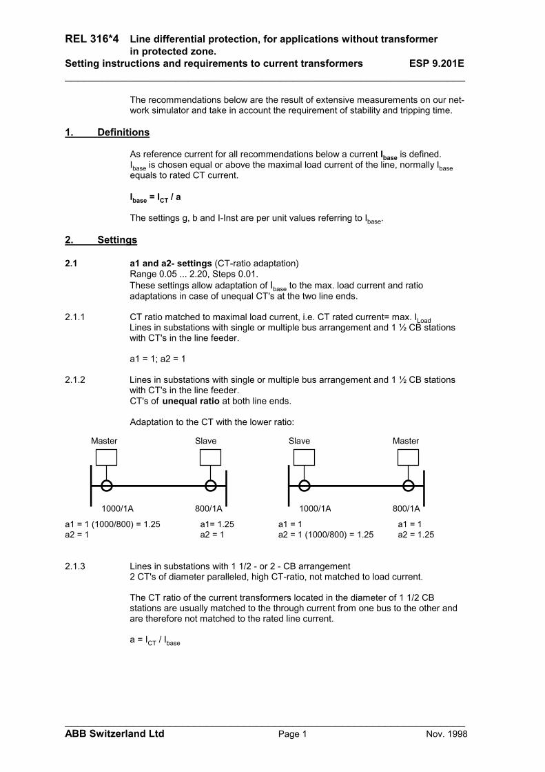
REL 316*4 Line differential protection, for applications without transformerin protected zone.
Setting instructions and requirements to current transformers ESP 9.201E_________________________________________________________________
_________________________________________________________________ABB Switzerland Ltd Page 1 Nov. 1998
The recommendations below are the result of extensive measurements on our net-work simulator and take in account the requirement of stability and tripping time.
1. Definitions
As reference current for all recommendations below a current Ibase is defined.Ibase is chosen equal or above the maximal load current of the line, normally Ibaseequals to rated CT current.
Ibase = ICT / a
The settings g, b and I-Inst are per unit values referring to Ibase.
2. Settings
2.1 a1 and a2- settings (CT-ratio adaptation)Range 0.05 ... 2.20, Steps 0.01.These settings allow adaptation of Ibase to the max. load current and ratioadaptations in case of unequal CT's at the two line ends.
2.1.1 CT ratio matched to maximal load current, i.e. CT rated current= max. ILoadLines in substations with single or multiple bus arrangement and 1 ½ CB stationswith CT's in the line feeder.
a1 = 1; a2 = 1
2.1.2 Lines in substations with single or multiple bus arrangement and 1 ½ CB stationswith CT's in the line feeder.CT's of unequal ratio at both line ends.
Adaptation to the CT with the lower ratio:
1000/1A 800/1A
a1= 1.25a1 = 1 (1000/800) = 1.25a2 = 1 a2 = 1
Master Slave
1000/1A 800/1A
a1 = 1a2 = 1 (1000/800) = 1.25a1 = 1
a2 = 1.25
Slave Master
2.1.3 Lines in substations with 1 1/2 - or 2 - CB arrangement2 CT's of diameter paralleled, high CT-ratio, not matched to load current.
The CT ratio of the current transformers located in the diameter of 1 1/2 CBstations are usually matched to the through current from one bus to the other andare therefore not matched to the rated line current.
a = ICT / Ibase

REL 316*4 Line differential protection, for applications without transformerin protected zone.
Setting instructions and requirements to current transformers ESP 9.201E_________________________________________________________________
_________________________________________________________________ABB Switzerland Ltd Page 2 Nov. 1998
2.2 s- setting (Connection group correction)For the line there is no phase group compensation necessary, the following is selected:
s1=D, s2=d0
With this setting the zero sequence component of the currents is included in themeasurement, best sensitivity and correct phase selection is achieved.No other s- setting shall be selected, unless there is a transformer in the protectedzone.
2.3 v- setting (bias at small currents, below Ibase b)
Range: 0.25 or 0.50
v= 0.50 is chosen as a standard setting
2.4 Minimum operating currentTwo ranges can be set: g and g-High
2.4.1 g- setting (lower range)Range 0.1 ... 0.5, Step 0.1Parameter “HighSetInp” = F
The g setting defines the minimum operating current.The protection will pick up for a fault current of > Ibase g.
In most line protection applications the range 0.1 ... 0.5 is to low.Settings as per 2.4.2 are prefered
2.4.2 g-High setting (upper range)Range 0.50 ... 2.5, Step 0.25Parameter “HighSetInp” = T
With this setting the g-setting is not active any more, the g-High setting determines the pick up current.The protection will pick up at a fault current of > Ibase g-High.
2.4.3 Minimum allowed setting
IbaseLineprotectedtheofcurrentchargingcapacitive2.5highgorg
The "capacitive charging current of the protected line" is the phase-currentmeasured at single sided infeed, i.e current measured with the circuit open at theremote end.
This setting allows full stability in a effectively grounded network.In not effectively grounded networks apply a factor 3.0 instead of 2.5
With this setting also the transient capacitive inrush currents will not endanger thestability.
It may be of advantage to chose g-High >= b, this to minimise the requirementimposed to the CT's. See examples under 3.
The pick-up current shall be lower then the minimum fault current and shall allowfor sufficient ground-fault resistance.
Justification of above factors 2.5 and 3.0

REL 316*4 Line differential protection, for applications without transformerin protected zone.
Setting instructions and requirements to current transformers ESP 9.201E_________________________________________________________________
_________________________________________________________________ABB Switzerland Ltd Page 3 Nov. 1998
The capacitive charging currents are measured by the protection as differentialcurrents. The minimum operating current therefore has to be set higher then themaximum capacitive charging current occurring for a fault outside the line.Since the measurement is made on a per phase basis, the capacitive current to betaken in account is the highest possible charging current per phase.
2.5 = f1 * f2’ * f3 In solidly grounded systems3.0 = f1 * f2’’ * f3 In systems with isolated neutral or Petersen coil
compensation (not effectively ground networks)f1 = 1.2 Max. system voltagef2’ = 0.8 * 3 Max. phase to ground voltage in solidly grounded
systems ( Z0 / Z1 < 4)f2’’ = 3 Max. phase to ground voltage in not effectively
grounded systems (Z0 /Z1 = infinite)f3 = 1.5 Safety factor
g-High may be used in most applications and may be set relatively high, since theoperating current Ibase refers to the actual short circuit current flowing through thefault (= differential current).
A fast supervision logic blocks the differential function in case if a communicationfailure in the fibre optical link, no second release criterion is required. For thisreason this differential protection is not dependent on the individual infeed currentsand faces no problem in case of weak infeed from one end.
Max. fault resistance
The max. ground fault resistance, which can be detected is approximately(source impedance's neglected):
highgI3URF
base
rated
2.5 Inrush restraintParameter “InrushInp” =TThis setting allows optmal stability also in case of heavy through flowingtransformer Inrush currents with long DC time constants.
2.6 Pick-up value for the directional comparison feature (v =
2.6.1 b- settingswitching over to v = the 2nd harmonic restraint remains activeRange 1.25 ... 2.50, Steps 0.25
(b Ibase) has to be set above ILoad_max.
Recommended setting: b = 1.5.

REL 316*4 Line differential protection, for applications without transformerin protected zone.
Setting instructions and requirements to current transformers ESP 9.201E_________________________________________________________________
_________________________________________________________________ABB Switzerland Ltd Page 4 Nov. 1998
2.6.2 I-Inst settingv = , the 2nd harmonic restraint is not active above this current level
Range 5 ...... 15, Steps 1.0 for SW-Versions < V4.0Range 3 ...... 15, Steps 1.0 for SW-Versions >=V4.0
I-Inst = 3 is chosen as a standard setting
I-Inst = 5 is recommended for a line with single end infeed, feeding a transformerwith high MVA rating.
With this setting the protection tolerates high Inrush currents flowing over the line.Such currents might produce unequal saturation phenomena in the CT's at the twoline ends. The peak value of the Inrush current may reach up to 15 Ibase.
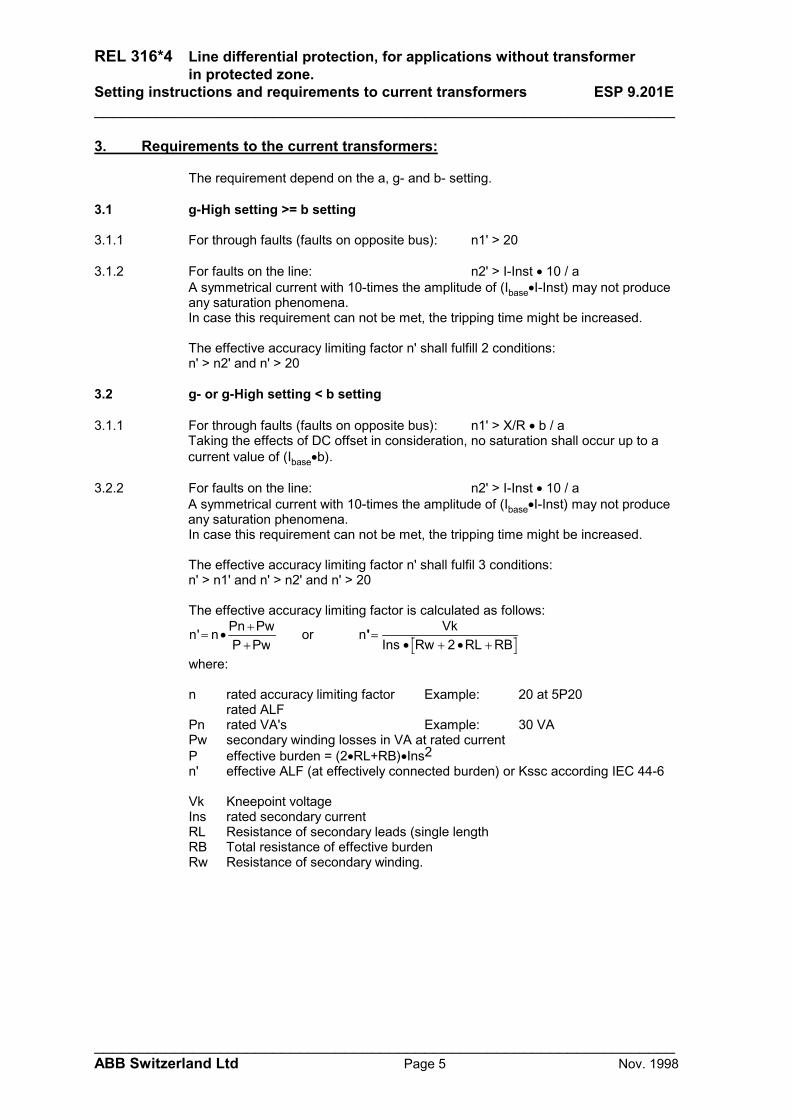
REL 316*4 Line differential protection, for applications without transformerin protected zone.
Setting instructions and requirements to current transformers ESP 9.201E_________________________________________________________________
_________________________________________________________________ABB Switzerland Ltd Page 5 Nov. 1998
3. Requirements to the current transformers:
The requirement depend on the a, g- and b- setting.
3.1 g-High setting >= b setting
3.1.1 For through faults (faults on opposite bus): n1' > 20
3.1.2 For faults on the line: n2' > I-Inst 10 / aA symmetrical current with 10-times the amplitude of (IbaseI-Inst) may not produceany saturation phenomena.In case this requirement can not be met, the tripping time might be increased.
The effective accuracy limiting factor n' shall fulfill 2 conditions:n' > n2' and n' > 20
3.2 g- or g-High setting < b setting
3.1.1 For through faults (faults on opposite bus): n1' > X/R b / aTaking the effects of DC offset in consideration, no saturation shall occur up to acurrent value of (Ibaseb).
3.2.2 For faults on the line: n2' > I-Inst 10 / aA symmetrical current with 10-times the amplitude of (IbaseI-Inst) may not produceany saturation phenomena.In case this requirement can not be met, the tripping time might be increased.
The effective accuracy limiting factor n' shall fulfil 3 conditions:n' > n1' and n' > n2' and n' > 20
The effective accuracy limiting factor is calculated as follows:
n' n Pn PwP Pw
or n VkIns Rw RL RB
' 2
where:
n rated accuracy limiting factor Example: 20 at 5P20rated ALF
Pn rated VA's Example: 30 VAPw secondary winding losses in VA at rated currentP effective burden = (2RL+RB)Ins2n' effective ALF (at effectively connected burden) or Kssc according IEC 44-6
Vk Kneepoint voltageIns rated secondary currentRL Resistance of secondary leads (single lengthRB Total resistance of effective burdenRw Resistance of secondary winding.

REL 316*4 Line differential protection, for applications without transformerin protected zone.
Setting instructions and requirements to current transformers ESP 9.201E_________________________________________________________________
_________________________________________________________________ABB Switzerland Ltd Page 6 Nov. 1998
Example 1 (g = b)
Ipssc = 25 kA for close-in faults on the lineCT 500/1A 20VA, 5P20, Rw = 4Burden = 2 RL+RB = 1 = 1 VA
a1=a2 = 1g-High = 1.5 Parameter “HighSetInp” = Tb = 1.5I-Inst = 4
n' = 20 • (20+4)/(1+4) = 96n1' required = 20n2' required = 4 / 1 • 10 = 40This CT is suitable.
Example 2 (g < b)
Ipssc = 40 kA for close-in faults on the lineTp = 100 ms X / R = 31
primary system DC time constant at minimum generationCT 500/1A 20VA, 5P20, Rw = 4Burden = 2 RL+RB = 1
a1=a2 = 1g-High = 0.75 Parameter “HighSetInp” = Tb = 1.5I-Inst = 4
n' = 20 • (20+4) / (1+4) = 96n1' required = 31 • 1.5/1 = 46n2' required = 4 / 1 • 10 = 40This CT is suitable.
Example 3 (Generator line in 1 1/2 CB substation)
Ipssc = 40 kA for close-in faults on the lineTp = 180 ms X/R = 57
primary system DC time constant at minimum generationcontribution of power plant
Load current = 600 ACT 1200/1A 20VA, 5P20, R2 = 8Burden = 2 1
a1=a2 = 2g-High = 1.0 Parameter “HighSetInp” = Tb = 1.5I-Inst = 10
n' = 20 • (20+8)/(1+8) = 62n1' required = 57 • 1.5/2 = 42n2' required = 10 / 2 • 10 = 50This CT is suitable.
If a check shows, that the following effective ALF factors are met, a more detailedcheck is not required for normal applications.n' = 75 for applications in high and very high voltage networksn' = 50 for applications in sub transmission and distribution networks.
CH-ES 30-32.10 E
ABB Switzerland Ltd02-07-02
1/3
DEMANDS ON MEASURING TRANSFORMERS FOR RET 316 / RET 316*4 Version 3.10and higher
IntroductionThe operation of any transformer protection is influenced by distortion in themeasuring quantities. The current to the protection will be heavily distorted whenthe current transformer is saturated.In most cases it is not possible to avoidcurrent transformer saturation for all fault conditions, therefore measures aretaken in the transformer protections to allow for current transformer saturation withmaintained proper operation. RET 316 / RET 316*4 can allow for heavy currenttransformer saturation but not an unlimited one.
Requirements on current transformers
Choice of current transformersThe current transformer should be to type TPS,TPX or TPY with accuracy class5P20 or better. The use of the linearized current transformer type TPZ leads onlyto a small phase angle shift and they can be used without problems, if the sametype is on both sides of the transformer. Possibly ABB Switzerland Ltd, Utility Auto-mation can be contacted for confirmation that the actual type can be used.
The current transformer ratio should be selected so that the current to the protec-tion is larger than the minimum operating value for all faults that shall be detected.Minimum operating current for the transformer protection in RET 316 / RET 316*4is 10% of nominal current.
Conditions for the CT requirementsThe requirements for RET 316 / RET 316*4 are a result of investigations performedin our network simulation program. The tests have been performed with a digitalcurrent transformer model.The setting of the current transformer model was representative for current trans-formers type TPX and TPY.
The performance of the transformer protection was checked for internal and ex-ternal both symmetrical and fully asymmetrical fault currents. A source with a timeconstant from 40 up to 300 milliseconds was used at the tests. The current require-ments below are thus applicable both for symmetrical and asymmetrical faultcurrents.Both phase to ground, and three phase faults were tested.
Released: Department:
UTAST
Rev.: E

CH-ES 30-32.10 E
ABB Switzerland Ltd
2/3
The protection was checked with regard to security to block. All testing was madewith and without remanence flux in the current transformer core. It is difficult togive general recommendations for additional margins for remanence flux. Itdepends on the demands of reliability and economy.When current transformers of type TPY are used, practically no additional marginis needed due to the anti remanence air gap. For current transformer of TypeTPX, the small probability of a fully asymmetrical fault together with maximumremanence flux in the same direction as the flux generated by the fault has to bekept in mind at the decision of an additional margin. Fully asymmetrical faultcurrent will be achieved when the fault occurs at zero voltage (0°). Investigationshave proved that 95% of the faults in the network will occur when the voltage isbetween 40° and 90°.
Fault currentThe current transformer requirements are based on the maximum fault current forfaults in different positions. Maximum fault current will occur for three phase faultsor single phase to ground faults. The current for a single phase to ground fault willexceed the current for a three phase fault when the zero sequence impedance inthe total fault loop is less than the positive sequence impedance.
When calculating the current transformer requirements, the maximum fault currentshould be used and therefore both fault types have to be considered.
Cable resistance and additional loadThe current transformer saturation is directly affected by the voltage at the currenttransformer secondary terminals. This voltage, for a ground fault, is developed in aloop containing the phase and neutral conductor and additional load in this loop.For three phase faults, the neutral current is zero, and only the phase conductor andadditional phase load have to be considered.
In the calculation, the loop resistance should be used for phase to ground faultsand the phase resistance for three phase faults.
RET 316 / RET 316*4 current transformer requirementsThe current transformer effective overcurrent factor should meet the tworequirement below. The requirement assume 40 to 300 msec maximum dc timeconstant for the network.
1. I
IPE PBPE Prn n'
N
ct. of N

CH-ES 30-32.10-E
ABB Switzerland Ltd
3/3
n : rated overcurrent factor (ALF = accuracy limit factor)n' : necessary effective overcurrent factor, as a function of fault current IK,
(at nominal frequency and time constant of the network)PB : connected burden at rated currentPE : ct losses of secondary windingsPr : rated ct burdenIN : nominal current related to the protected object
and 2.the dependence of the curves of fig 1 and 2, where:for fault currents 3 * IN the CT's should not saturate
02468
10121416
0 3 4 6 8 10 12 14 16 18 20
with 50% remanence without remanence IK/IN
n'
Figure 1: Transformer with 2 windings
05
101520253035
0 3 4 6 8 10 12 14 16 18 20
with 50% remanence without remanence
n'
IK/IN
Figure 2: Transformer with 3 windings


REL 316*4 1MRB520050-Uen / Rev. E ABB Switzerland Ltd
9-1
March 01
9. INTERBAY BUS (IBB) INTERFACE
9.1. Connection to a station control system ....................................9-3
9.2. Setting the IBB/RIO function ....................................................9-4
9.3. Transferring disturbance recorder data via the IBB .................9-9
9.4. Synchronisation .....................................................................9-11
9.5. SPA bus address format ........................................................9-119.5.1. Masking events......................................................................9-12
9.6. SPA address list ....................................................................9-139.6.1. Channel 0 ..............................................................................9-139.6.2. Channel 0 event list ...............................................................9-149.6.3. Channel 1 event list ...............................................................9-149.6.4. Channel 3 event list ...............................................................9-149.6.5. Channel 4 event list ...............................................................9-159.6.6. Channel 4 analogue input ......................................................9-159.6.7. Binary input signals................................................................9-159.6.8. IBB input signals ....................................................................9-169.6.9. Binary output signals..............................................................9-179.6.10. Tripping signals......................................................................9-179.6.11. LED signals............................................................................9-179.6.12. IBB output signals..................................................................9-189.6.13. IBB output signal event masks...............................................9-199.6.14. Binary input event masks.......................................................9-219.6.15. Hardware ...................................... 35....................................9-229.6.16. Channel 8 system I/O’s................. 34....................................9-239.6.17. IBB I/O .......................................... 43....................................9-259.6.18. Current-DT...................................... 2....................................9-269.6.19. Current............................................ 3....................................9-279.6.20. Diff-Transf ....................................... 4....................................9-289.6.21. Underimped .................................... 5....................................9-319.6.22. MinReactance................................. 6....................................9-329.6.23. NPS-DT .......................................... 7....................................9-339.6.24. NPS-Inv ........................................ 11....................................9-349.6.25. Voltage.......................................... 12....................................9-359.6.26. Current-Inv.................................... 13....................................9-369.6.27. OLoad-Stator ................................ 14....................................9-379.6.28. OLoad-Rotor ................................ 15....................................9-38
ABB Switzerland Ltd REL 316*4 1MRB520050-Uen / Rev. E
9-2
9.6.29. Power............................................ 18....................................9-399.6.30. Imax-Umin .................................... 20....................................9-409.6.31. Delay............................................. 22....................................9-419.6.32. Diff-Gen ........................................ 23....................................9-429.6.33. Distance........................................ 24....................................9-439.6.34. Frequency..................................... 25....................................9-539.6.35. Overexcitat.................................... 26....................................9-549.6.36. Count ............................................ 27....................................9-559.6.37. Overtemp. (RE. 316*4) ................. 28....................................9-569.6.38. Check-I3ph ................................... 29....................................9-579.6.39. Check-U3ph.................................. 30....................................9-589.6.40. Logic ............................................. 31....................................9-599.6.41. Disturbance Rec ........................... 32....................................9-609.6.42. Voltage-Inst................................... 36....................................9-639.6.43. Autoreclosure................................ 38....................................9-649.6.44. EarthFaultIsol................................ 40....................................9-689.6.45. Voltage-Bal ................................... 41....................................9-699.6.46. U/f-Inv ........................................... 47....................................9-709.6.47. UIfPQ............................................ 48....................................9-729.6.48. SynchroCheck .............................. 49....................................9-739.6.49. Rotor-EFP..................................... 51....................................9-769.6.50. Stator-EFP.................................... 52....................................9-789.6.51. I0-Invers........................................ 53....................................9-809.6.52. Pole-Slip ....................................... 55....................................9-819.6.53. Diff-Line ........................................ 56....................................9-839.6.54. RemoteBin .................................... 57....................................9-869.6.55. EarthFltGnd2 ................................ 58....................................9-879.6.56. FUPLA .......................................... 59....................................9-899.6.57. FlatterRecog ................................. 60....................................9-909.6.58. HV distance .................................. 63....................................9-919.6.59. LDU events ................................... 67..................................9-1019.6.60. Debounce ..................................... 68..................................9-1029.6.61. df/dt............................................... 69..................................9-1039.6.62. DirCurrentDT ................................ 70..................................9-1049.6.63. DirCurrentInv ................................ 71..................................9-1069.6.64. BreakerFailure .............................. 72..................................9-1089.6.65. MeasureModule ............................ 74..................................9-111
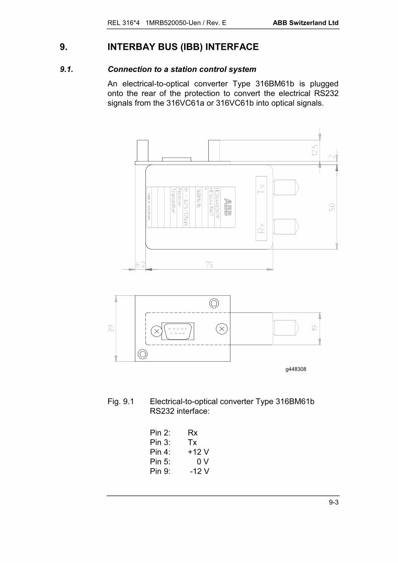
REL 316*4 1MRB520050-Uen / Rev. E ABB Switzerland Ltd
9-3
9. INTERBAY BUS (IBB) INTERFACE
9.1. Connection to a station control system
An electrical-to-optical converter Type 316BM61b is pluggedonto the rear of the protection to convert the electrical RS232signals from the 316VC61a or 316VC61b into optical signals.
g448308
Fig. 9.1 Electrical-to-optical converter Type 316BM61bRS232 interface:
Pin 2: RxPin 3: TxPin 4: +12 VPin 5: 0 VPin 9: -12 V
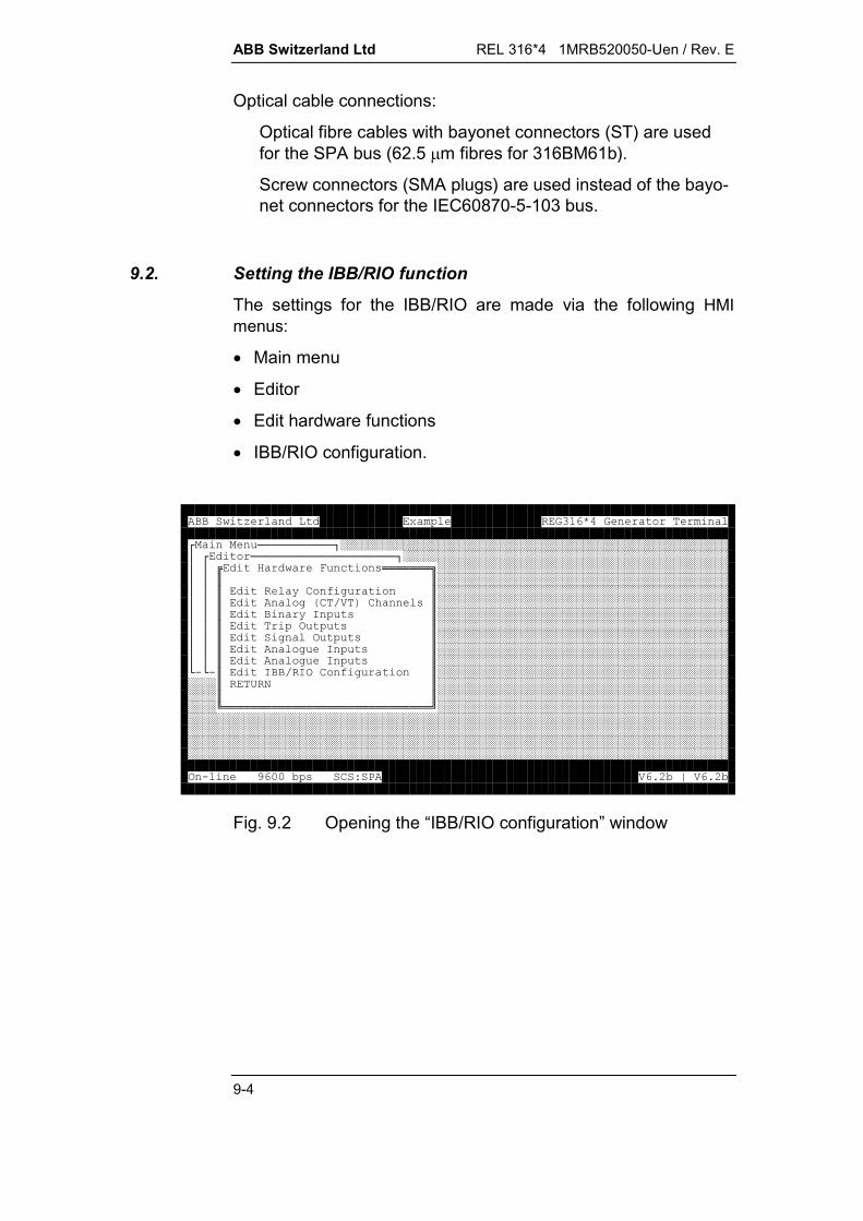
ABB Switzerland Ltd REL 316*4 1MRB520050-Uen / Rev. E
9-4
Optical cable connections:
Optical fibre cables with bayonet connectors (ST) are usedfor the SPA bus (62.5 m fibres for 316BM61b).
Screw connectors (SMA plugs) are used instead of the bayo-net connectors for the IEC60870-5-103 bus.
9.2. Setting the IBB/RIO function
The settings for the IBB/RIO are made via the following HMImenus:
Main menu
Editor
Edit hardware functions
IBB/RIO configuration.
!!!!!!!!!!!"########################################################$!!!!!!!!!!!!!!!!!!!!!"###############################################$$%& ' ()*******+##########################################$$,,##########################################$$, -./0 ,##########################################$$, 01.234.5 ),##########################################$$, -6 ),##########################################$$,7 ),##########################################$$,0 7 ),##########################################$$, 0 6 ),##########################################$$, 0 6 ),##########################################8989,6267./0 ,##############################################,:;,##############################################,,##############################################<******************************=##################################################################################################################################################################################################################################################################################################################################################################79>??@).AB3CD@E3CD@
Fig. 9.2 Opening the “IBB/RIO configuration” window

REL 316*4 1MRB520050-Uen / Rev. E ABB Switzerland Ltd
9-5
The IBB/RIO function menu lists the following items (see Fig. 9.3):
!!!!!!!!!!!"########################################################$!!!!!!!!!!!!!!!!!!!!!"###############################################$$& ' ()!!!!"#############################################$$$%6./0C****************+###########################################$$$,,###########################################$$$, 6B ),###########################################8!$$,BB ),#############################################$$,7;B ),#############################################$$,396B ),#############################################8!$,3967B ),###############################################$,396B ),###############################################$,39B ),###############################################$, B )/',###############################################$, F679B )',###############################################$, 679B )/',###############################################8!,:;,#################################################,,#################################################<***************************=#########################################################################################################################79>??@).AB3CD@E3CD@
Fig. 9.3 IBB configuration
Caution:The settings for the LON interbay bus are to be found inpublication 1MRB520225-Uen, for the MVB interbay bus in1MRB520270-Uen and for the MVB process bus in1MRB520192-Uen.
%' (B )****************************************************+,,,6./0C,,,, F2;D,, (5(2 (F(,,-(5 (,,769G?,,769G,,769GD,,769G,,769G,,769GH,,769G,,769GI,,769GJ,,769G>,,CCC,<****************************************************************************=79>??@).AB3CD@E3CD@
Fig. 9.4 General IBB parameters
Slave/NodeAddr
Range 2- 255. Must be set to the correct SPA bus address.

ABB Switzerland Ltd REL 316*4 1MRB520050-Uen / Rev. E
9-6
TouchScreen/SMS
Setting determines whether the touch screen or an SMS has tobe controlled:
inactive Connection not in operation (default)
active Connection in operation.
Note that this parameter has no influence in the versions for theSPA and IEC60870-5-103 buses.
The versions for the LON and MVB buses have a fully functionalSPA interface in parallel with the interbay bus for connecting ei-ther a touch screen or an SMS. The parameter ‘Touch-Screen/SMS’ should only be set to ‘active’, when the second in-terface is in use, because the response time of the LON or MVBbus is somewhat longer.
Read Distr. Data
This parameter defines what has access to the disturbance re-corder data:
by IBB The disturbance recorder data can be read viathe interbay bus (SCS).
by SMS The disturbance recorder data can be read bythe SMS.
Disturbance recorder data can always be read by the HMI re-gardless of the setting.
Note that this parameter has no influence in the versions for theSPA and IEC60870-5-103 buses.
TimeSynchr.
Defines the time for synchronisation via the IBB when the sum-mer time bit is set:
Standard time Only the summer time bit is set and standardtime is used for synchronisation (preferredsetting).
Summer time Summer time is used for synchronisation inspite of the fact that the summer time bit isalso set.
‘Standard time’ has to be selected when the summer time bit isnot set (e.g. as in the case of the SPA bus).

REL 316*4 1MRB520050-Uen / Rev. E ABB Switzerland Ltd
9-7
' (B )!!!!!!!!!!!!!!!!!!!!!!!!!!!!!!!!!!!!!!!!!!!!!!!!!!!!"$$$6./0C$$$$ F2;(G6 !!!!!!!"$$ (5(2$$($$ K)CK $K7 /' (!!!!!!!!!"($$769G$.$$$$769GD$7 $%:6/BL*+9K$$$769G$6$D,, @ (($$$769G$6$,:;,L$$$769GH$$,6;,$$$769G$$,B1B;4,$$$769GI8!!!8!!!,L1B;4,$$$769GJ,&,!!!!!!!!!!!M$$769G>,:;,$$769G?,,$$CCC<*************=$8!!!!!!!!!!!!!!!!!!!!!!!!!!!!!!!!!!!!!!!!!!!!!!!!!!!!!!!!!!!!!!!!!!!!!!!!!!!!M79>??@).AB3CD@E3CD@
Fig. 9.5 Connecting an IBB measurement
%' (B )****************************************************+,,,6./0C,,,, >??(,, ) )NLF)//(,,(F0??0 ,,6 )0??>0 ,,.(,,-((,,B.(,,)' ()(,,K 0(,,:;2;,,,,,,,,,<****************************************************************************=79>??@).AB3CD@E3CD@
Fig. 9.6 SPA parameters
The parameters must be set as follows:
Baud rate
Default 9600 for SPA bus. Do not change.

ABB Switzerland Ltd REL 316*4 1MRB520050-Uen / Rev. E
9-8
Master mask
Bit masks.The bit masks set for every function via the SPA bus apply forall binary events. No masks are used for analogue events.
Q events offAs above, but all analogue events are blocked. This is thedefault setting and must always be used when the device isconnected to an SCS100.
Event offAll events are masked (not recorded).This setting is intended for testing and during commissioningwhen it is not wanted that events be transmitted to the controlroom.
Receiving
Indicates that valid SPA telegrams have been received.
Initialising
Indicates that the device is being initialised.
The following parameters determine the access rights of the re-mote HMI and can only be configured on the local HMI (seeSection 5.12.):
RemoteMMC on / offEnables or disables the remote HMI.
TimeSync on / offEnables or disables synchronisation by the remote HMI.
SPAComm on / offEnables or disables the SPA communication window on theremote HMI.
TestFunct. on / offEnables or disables the test function on the remote HMI.
Load code on / offEnables or disables the downloading of a ‘setfile’ from the re-mote HMI.

REL 316*4 1MRB520050-Uen / Rev. E ABB Switzerland Ltd
9-9
9.3. Transferring disturbance recorder data via the IBB
Disturbance recorder data (records) can be read and transferredvia the SPA bus with the aid of the EVECOM program. Furtherdetails are contained in the Operating Instructions for EVECOM.
The data are made available in the EVE format when transfer isrequested. Data transfer is controlled using the SPA BUS vari-ables V20, M28, M30, M31, V16 and V17.
V20:
Write: WV20:1 starts the transmission of a telegram.
Read: RV20 returns the number of disturbance recorderrecords available.
V17:
Write: WV17:1...5 determines the compression factor, i.e.1%...5%.
Read: RV17 returns the compression factor.
Compression reduces the number of periods that have to betransferred per channel. Assuming the 12 points of a period de-viate by less than the specified compression factor from the cor-responding points of the preceding period, the points themselvesare not transferred, but simply the number of repeats in relationto the preceding period. For example, if a record consists of 100periods all the same, then only the 12 points of one period andthe number of repeats are transferred. Compression is appliedindependently for each individual channel.
M28:
Write: WM28:n selects a disturbance recorder record fortransfer. n has a value between 1 and the numberof records that that can be read using RV20. Theconversion of the record to the EVE format startsand the first response is NAK. WM28:n has to berepeated until the response is ACK. (From firmwareV4.0.)
Read: RM28 returns the directory information, time stampand record number.1995-05-10 12.34;23.423 RE001.001
ABB Switzerland Ltd REL 316*4 1MRB520050-Uen / Rev. E
9-10
M29:
Write: NAK.
Read: returns the number of lines in a record (0...1023). Aline contains 26 Byte of data. 0 is returned if a rec-ord has not been selected (M28).
M30:
Write: WM30:n moves the pointer to the line to be trans-ferred. The pointer is automatically incremented byone every time a line is transferred until there areno lines left. The pointer is set to 1 at the com-mencement of data transfer (WM28:n).
Read: RM30 returns the number of the line that wastransferred last.
M31:
Write: NAK.
Read: RM31 transfers the line indicated by the pointer.
V16:
Write: WV16:1, WV16:0, deletes the oldest record.
Read: RV16 returns the status of the disturbance re-corder.0: Disturbance recorder not full.1: Disturbance recorder full.
V20:
Write: WV20:0 terminates data transfer.

REL 316*4 1MRB520050-Uen / Rev. E ABB Switzerland Ltd
9-11
9.4. Synchronisation
The internal clock is synchronised either by the station controlsystem (SCS 100) or a radio clock (DCF77). Synchronisation viathe IBB takes priority over synchronisation by the HMI.
After the device is switched off and on again, the clock continuesat the time before it was switched off until the next time telegramis received.
9.5. SPA bus address format
The structure of the SPA bus telegram is as follows:
<slave address><operation><channel No.><data type><data/event No.>
The slave address identifies the device.
The default address is 2. The slave address can be changedusing the operator program (HMI). The HMI has to be used toassign an address to the device as defined in the station controlsystem. The device also responds to data with the address 900which is used to synchronise all the devices in an SPA bus loopsimultaneously.
Possible operations are:
Read data from the device (R) and write data in the device (W).
The channel number identifies the active functions.
All channel numbers from 0 to 13 are reserved for system func-tions. Channel numbers from 14 to 60 are used for numberingthe protection and control functions configured for the device.
Data type enables the different kinds of data in a device to beaddressed specifically. The following types of data are used:
S settingsI binary or analogue inputsO binary or analogue outputsE single eventsV measurements, system variables and event maskingQ measurements stored at the instant of trippingT timeD dateL event memoryB back-up event memory.
ABB Switzerland Ltd REL 316*4 1MRB520050-Uen / Rev. E
9-12
Data and event numbers are needed to designate individualitems of data and events in data channels.
The table below shows the channel number mapping for a typi-cal configuration:
Function Funct. No. Chan. No. Comment
Current 14 14 First protection function
Voltage 15 15 Second protection function
Delay 16 16 Third protection function
The function numbers in the above table correspond to the HMInumbers.
The measured variable of the first function (current) in a devicewith the slave address 2 is read as follows:
2R14V1.
The SPA bus syntax is defined in SPA BUS COMMUNICATIONPROTOCOL V2.x, 34 SPACOM EN1C.
9.5.1. Masking events
Once all those binary inputs, IBB output signals and system andprotection function events which are not to be recorded asevents (masked) have been loaded into the device (e.g. usingW14V155), they have to be copied to the non-volatile memoryusing the save command W255V255:1 so that they are not lostshould the auxiliary supply fail.
REL 316*4 1MRB520050-Uen / Rev. E ABB Switzerland Ltd
9-13
9.6. SPA address list
9.6.1. Channel 0
Summary of parameters:
Address Access Text Default Step
V102 R VC type identification 316VC61
V104 R VC software version
V110 R, W Master event mask 1 Q eventsmasked
0 Bit mask active
2 All events masked
V115 R Time telegram counter
V116 R Date telegram counter
V120 R Restart counter 0
V200 R, W SPA address 2 2...255
V201 R, W Baud rate 9600 4800, 9600, 19200
F R Module Type REC316 REG316, REL316,RET316
S0 R Number of functions 0 1...60
S1 R Function type number S1...S60
S100 R, W Parameter set switch 1 1...4
T R, W Time
D R, W Date and time
L R Read event
B R Read event again
Date format: YY-MM-DD hh.mm;ss.sss
ABB Switzerland Ltd REL 316*4 1MRB520050-Uen / Rev. E
9-14
9.6.2. Channel 0 event list
Event No. Cause Event mask Enable code
0E1 No error V155 1
0E2 Minor error V155 2
0E4 Major error V155 4
0E8 Fatal error V155 8
0E47 Protection stopped V155 16
0E48 Protection restarted V155 32
0E49 Warm protection start V155 64
0E50 Cold protection start V155 128
0E51 Event buffer overflow V155 256
9.6.3. Channel 1 event list
Event No. Cause Event mask Enable code
1E11 AD error V155 1
1E31 Bus failure V155 256
1E41 Supply failure V155 4096
9.6.4. Channel 3 event list
Event No. Cause Event mask Enable code
3E1 CPU OK V155 1
3E2 CPU failure V155 2
3E3 CPU RAM failure V155 4
3E4 CPU ROM failure V155 8
3E11 EA62 OK V155 16
3E12 EA62 failure V155 32
3E13 EA62 RAM failure V155 64
3E14 EA62 ROM failure V155 128
3E21 Internal AD OK V155 256
3E22 Internal AD failure V155 512
3E23 Internal AD RAM failure V155 1024
3E24 Internal AD ROM failure V155 2048

REL 316*4 1MRB520050-Uen / Rev. E ABB Switzerland Ltd
9-15
9.6.5. Channel 4 event list
Event No Cause Event mask Enable code
4E21 PC-Card No failure V156 16
4E22 PC-Card Fatal error V156 32
4E23 PC-Card Non-urgent error V156 64
4E24 PC-Card Not ready V156 128
9.6.6. Channel 4 analogue input
Channel 4 provides 64 data points which are available either foranalogue FUPLA inputs or analogue outputs via the distributedinput/output unit 500AXM11. The numerical range is-32768...+32767 (16 Bit integers).The data can be entered in decimal or 4-digit hexadecimal for-mat.The data remains intact in the event of a supply failure.Real values are converted to integers,integer=real 100.Input format: nnn.mm.
FFFFHData point number: O1...O64
9.6.7. Binary input signals
The significance of the events, for standard as well as for doublesignals, is explained in Section 9.6.14.
Channel Inputs Events Slot
101 I1 - I16 E1 - E32 1
102 I1 - I16 E1 - E32 2
103 I1 - I16 E1 - E32 3
104 I1 - I16 E1 - E32 4
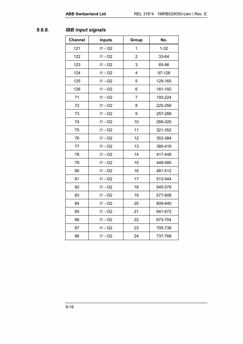
ABB Switzerland Ltd REL 316*4 1MRB520050-Uen / Rev. E
9-16
9.6.8. IBB input signals
Channel Inputs Group No.
121 I1 - I32 1 1-32
122 I1 - I32 2 33-64
123 I1 - I32 3 65-96
124 I1 - I32 4 97-128
125 I1 - I32 5 129-160
126 I1 - I32 6 161-192
71 I1 - I32 7 193-224
72 I1 - I32 8 225-256
73 I1 - I32 9 257-288
74 I1 - I32 10 289-320
75 I1 - I32 11 321-352
76 I1 - I32 12 353-384
77 I1 - I32 13 385-416
78 I1 - I32 14 417-448
79 I1 - I32 15 449-480
80 I1 - I32 16 481-512
81 I1 - I32 17 513-544
82 I1 - I32 18 545-576
83 I1 - I32 19 577-608
84 I1 - I32 20 609-640
85 I1 - I32 21 641-672
86 I1 - I32 22 673-704
87 I1 - I32 23 705-736
88 I1 - I32 24 737-768
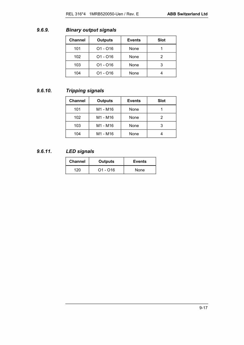
REL 316*4 1MRB520050-Uen / Rev. E ABB Switzerland Ltd
9-17
9.6.9. Binary output signals
Channel Outputs Events Slot
101 O1 - O16 None 1
102 O1 - O16 None 2
103 O1 - O16 None 3
104 O1 - O16 None 4
9.6.10. Tripping signals
Channel Outputs Events Slot
101 M1 - M16 None 1
102 M1 - M16 None 2
103 M1 - M16 None 3
104 M1 - M16 None 4
9.6.11. LED signals
Channel Outputs Events
120 O1 - O16 None

ABB Switzerland Ltd REL 316*4 1MRB520050-Uen / Rev. E
9-18
9.6.12. IBB output signals
Channel Outputs Group Event No.
121 O1 - O32 1 121E1...E64
122 O1 - O32 2 122E1...E64
123 O1 - O32 3 123E1...E64
124 O1 - O32 4 124E1...E64
125 O1 - O32 5 125E1...E64
126 O1 - O32 6 126E1...E64
71 O1 - O32 7 71E1...E64
72 O1 - O32 8 72E1...E64
73 O1 - O32 9 73E1...E64
74 O1 - O32 10 74E1...E64
75 O1 - O32 11 75E1...E64
76 O1 - O32 12 76E1...E64
77 O1 - O32 13 77E1...E64
78 O1 - O32 14 78E1...E64
79 O1 - O32 15 79E1...E64
80 O1 - O32 16 80E1...E64
81 O1 - O32 17 81E1...E64
82 O1 - O32 18 82E1...E64
83 O1 - O32 19 83E1...E64
84 O1 - O32 20 84E1...E64
85 O1 - O32 21 85E1...E64
86 O1 - O32 22 86E1...E64
87 O1 - O32 23 87E1...E64
88 O1 - O32 24 88E1...E64
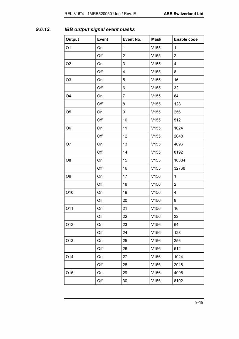
REL 316*4 1MRB520050-Uen / Rev. E ABB Switzerland Ltd
9-19
9.6.13. IBB output signal event masks
Output Event Event No. Mask Enable code
O1 On 1 V155 1
Off 2 V155 2
O2 On 3 V155 4
Off 4 V155 8
O3 On 5 V155 16
Off 6 V155 32
O4 On 7 V155 64
Off 8 V155 128
O5 On 9 V155 256
Off 10 V155 512
O6 On 11 V155 1024
Off 12 V155 2048
O7 On 13 V155 4096
Off 14 V155 8192
O8 On 15 V155 16384
Off 16 V155 32768
O9 On 17 V156 1
Off 18 V156 2
O10 On 19 V156 4
Off 20 V156 8
O11 On 21 V156 16
Off 22 V156 32
O12 On 23 V156 64
Off 24 V156 128
O13 On 25 V156 256
Off 26 V156 512
O14 On 27 V156 1024
Off 28 V156 2048
O15 On 29 V156 4096
Off 30 V156 8192

ABB Switzerland Ltd REL 316*4 1MRB520050-Uen / Rev. E
9-20
Output Event Event No. Mask Enable code
O16 On 31 V156 16384
Off 32 V156 32768
O17 On 33 V157 1
Off 34 V157 2
O18 On 35 V157 4
Off 36 V157 8
O19 On 37 V157 16
Off 38 V157 32
O20 On 39 V157 64
Off 40 V157 128
O21 On 41 V157 256
Off 42 V157 512
O22 On 43 V157 1024
Off 44 V157 2048
O23 On 45 V157 4096
Off 46 V157 8192
O24 On 47 V157 16348
Off 48 V157 32768
O25 On 49 V158 1
Off 50 V158 2
O26 On 51 V158 4
Off 52 V158 8
O27 On 53 V158 16
Off 54 V158 32
O28 On 55 V158 64
Off 56 V158 128
O29 On 57 V158 256
Off 58 V158 512
O30 On 59 V158 1024
Off 60 V158 2048
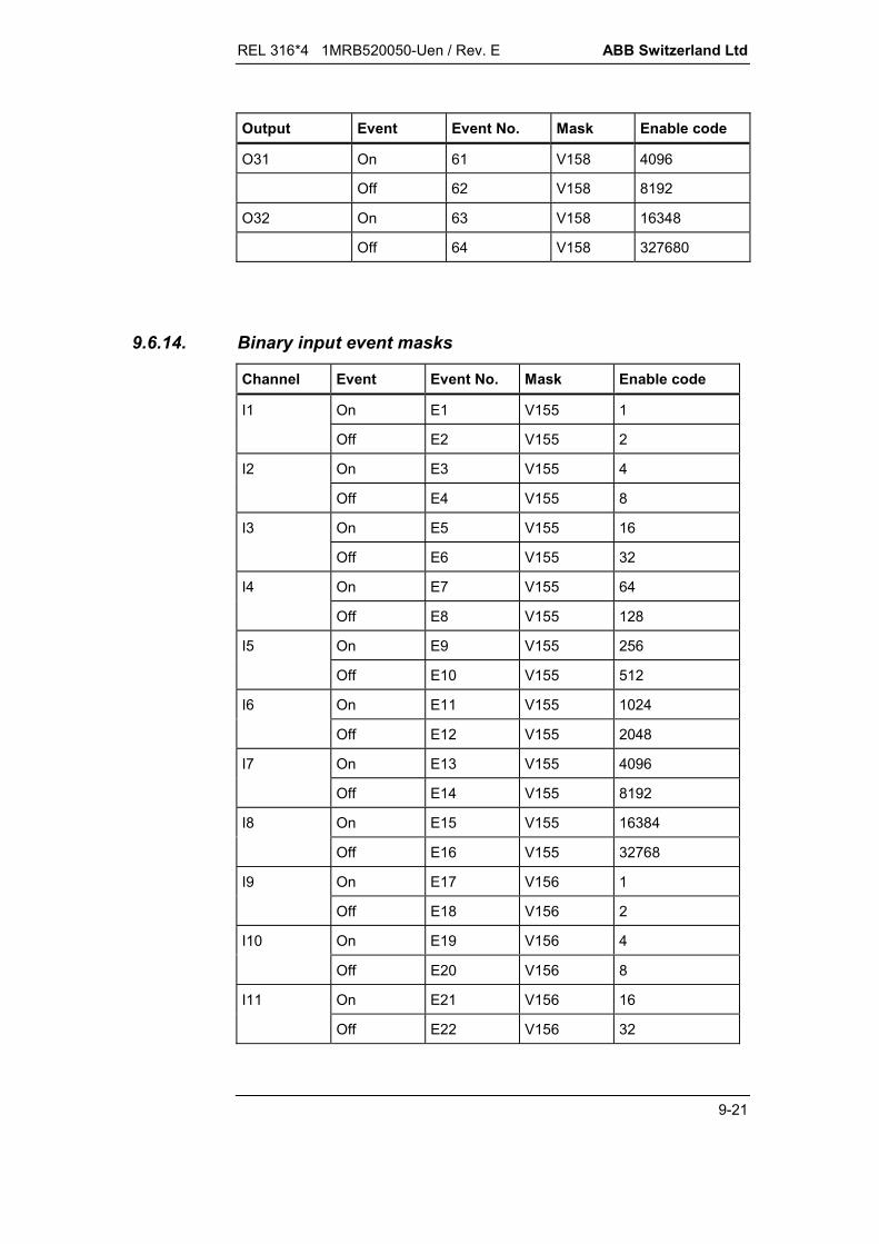
REL 316*4 1MRB520050-Uen / Rev. E ABB Switzerland Ltd
9-21
Output Event Event No. Mask Enable code
O31 On 61 V158 4096
Off 62 V158 8192
O32 On 63 V158 16348
Off 64 V158 327680
9.6.14. Binary input event masks
Channel Event Event No. Mask Enable code
I1 On E1 V155 1
Off E2 V155 2
I2 On E3 V155 4
Off E4 V155 8
I3 On E5 V155 16
Off E6 V155 32
I4 On E7 V155 64
Off E8 V155 128
I5 On E9 V155 256
Off E10 V155 512
I6 On E11 V155 1024
Off E12 V155 2048
I7 On E13 V155 4096
Off E14 V155 8192
I8 On E15 V155 16384
Off E16 V155 32768
I9 On E17 V156 1
Off E18 V156 2
I10 On E19 V156 4
Off E20 V156 8
I11 On E21 V156 16
Off E22 V156 32

ABB Switzerland Ltd REL 316*4 1MRB520050-Uen / Rev. E
9-22
Channel Event Event No. Mask Enable code
I12 On E23 V156 64
Off E24 V156 128
I13 On E25 V156 256
Off E26 V156 512
I14 On E27 V156 1024
Off E28 V156 2048
I15 On E29 V156 4096
Off E30 V156 8192
I16 On E31 V156 16384
Off E32 V156 32768
In the case of a double signal the significance of the eventschanges as shown in the following example where the inputs 2and 3 are configured as double signal.
Input Event No. Significance Significance atdouble signal
E3 on 1-0I2
E4 off 0-1
E5 on 0-0I3
E6 off 1-1
9.6.15. Hardware 35
Summary of parameters:
Address Access Text Unit Default Min. Max. Step
1S1 R SWVers SX... <Select> X 1 25 1
A 1
B 2
C 3
… …
Y 25
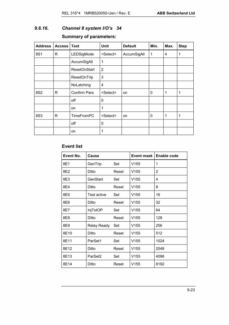
REL 316*4 1MRB520050-Uen / Rev. E ABB Switzerland Ltd
9-23
9.6.16. Channel 8 system I/O’s 34
Summary of parameters:
Address Access Text Unit Default Min. Max. Step
8S1 R LEDSigMode <Select> AccumSigAll 1 4 1
AccumSigAll 1
ResetOnStart 2
ResetOnTrip 3
NoLatching 4
8S2 R Confirm Pars <Select> on 0 1 1
off 0
on 1
8S3 R TimeFromPC <Select> on 0 1 1
off 0
on 1
Event list
Event No. Cause Event mask Enable code
8E1 GenTrip Set V155 1
8E2 Ditto Reset V155 2
8E3 GenStart Set V155 4
8E4 Ditto Reset V155 8
8E5 Test active Set V155 16
8E6 Ditto Reset V155 32
8E7 InjTstOP Set V155 64
8E8 Ditto Reset V155 128
8E9 Relay Ready Set V155 256
8E10 Ditto Reset V155 512
8E11 ParSet1 Set V155 1024
8E12 Ditto Reset V155 2048
8E13 ParSet2 Set V155 4096
8E14 Ditto Reset V155 8192
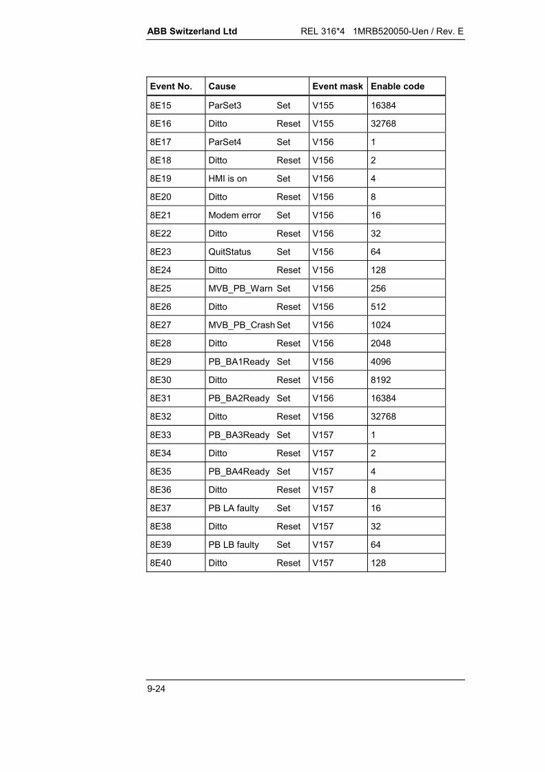
ABB Switzerland Ltd REL 316*4 1MRB520050-Uen / Rev. E
9-24
Event No. Cause Event mask Enable code
8E15 ParSet3 Set V155 16384
8E16 Ditto Reset V155 32768
8E17 ParSet4 Set V156 1
8E18 Ditto Reset V156 2
8E19 HMI is on Set V156 4
8E20 Ditto Reset V156 8
8E21 Modem error Set V156 16
8E22 Ditto Reset V156 32
8E23 QuitStatus Set V156 64
8E24 Ditto Reset V156 128
8E25 MVB_PB_Warn Set V156 256
8E26 Ditto Reset V156 512
8E27 MVB_PB_Crash Set V156 1024
8E28 Ditto Reset V156 2048
8E29 PB_BA1Ready Set V156 4096
8E30 Ditto Reset V156 8192
8E31 PB_BA2Ready Set V156 16384
8E32 Ditto Reset V156 32768
8E33 PB_BA3Ready Set V157 1
8E34 Ditto Reset V157 2
8E35 PB_BA4Ready Set V157 4
8E36 Ditto Reset V157 8
8E37 PB LA faulty Set V157 16
8E38 Ditto Reset V157 32
8E39 PB LB faulty Set V157 64
8E40 Ditto Reset V157 128
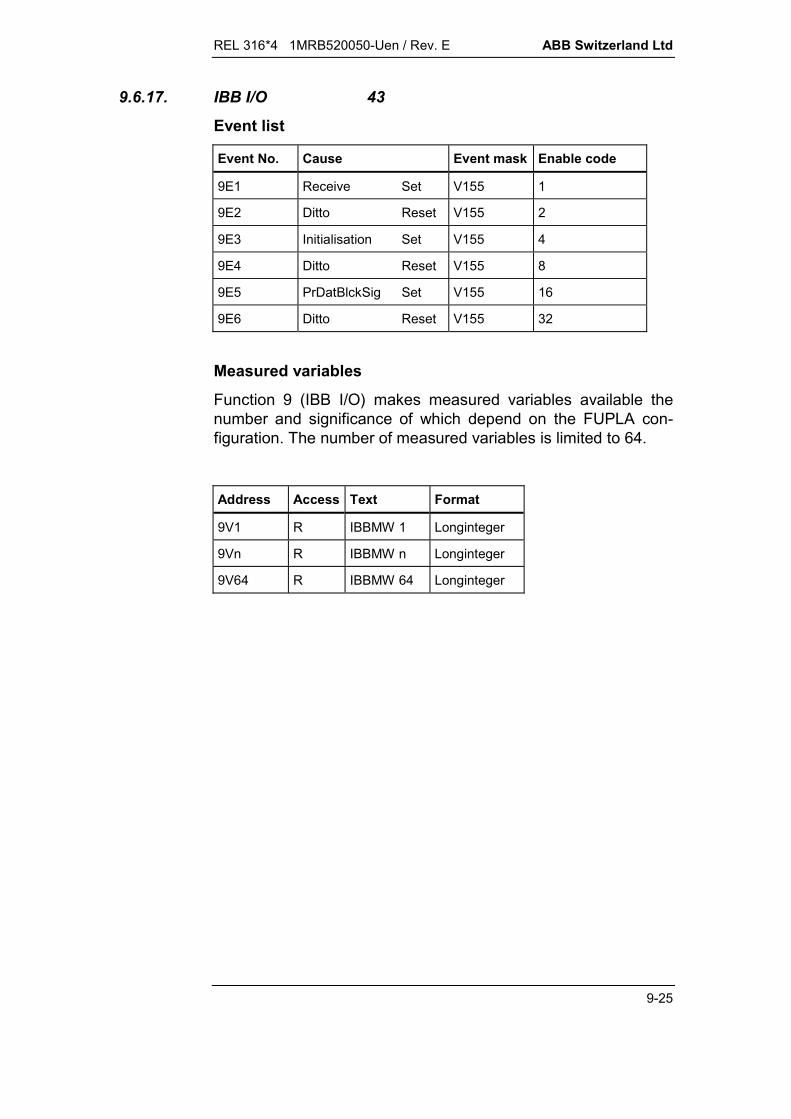
REL 316*4 1MRB520050-Uen / Rev. E ABB Switzerland Ltd
9-25
9.6.17. IBB I/O 43
Event list
Event No. Cause Event mask Enable code
9E1 Receive Set V155 1
9E2 Ditto Reset V155 2
9E3 Initialisation Set V155 4
9E4 Ditto Reset V155 8
9E5 PrDatBlckSig Set V155 16
9E6 Ditto Reset V155 32
Measured variables
Function 9 (IBB I/O) makes measured variables available thenumber and significance of which depend on the FUPLA con-figuration. The number of measured variables is limited to 64.
Address Access Text Format
9V1 R IBBMW 1 Longinteger
9Vn R IBBMW n Longinteger
9V64 R IBBMW 64 Longinteger

ABB Switzerland Ltd REL 316*4 1MRB520050-Uen / Rev. E
9-26
9.6.18. Current-DT 2
Basic channel No.: 14
Summary of parameters:
Address Access Text Unit Default Min. Max. Step
14S4 R ParSet4..1 <Select> P1 00000010B 00011110B
14S5 R TRIP 00000000B
14S9 R Delay s 00.01 0.00 60.00 0.01
14S10 R I-Setting IN 04.00 0.1 20 0.1
14S11 R f-min Hz 040.0 2 50 1
14S12 R MaxMin <Select> MAX -1 1 2
MIN -1
MAX 1
14S13 R NrOfPhases 001 1 3 2
Measured variables
Address Access Text Dec.
14V1 R IN 2
Tripping levels
Address Access Text Dec.
14Q1 R IN 2
Event list
Event No. Cause Event mask Enable code Status
14E1 Trip Set V155 1 14I1
14E2 Ditto Reset V155 2
14E3 Start Set V155 4 14I2
14E4 Ditto Reset V155 8
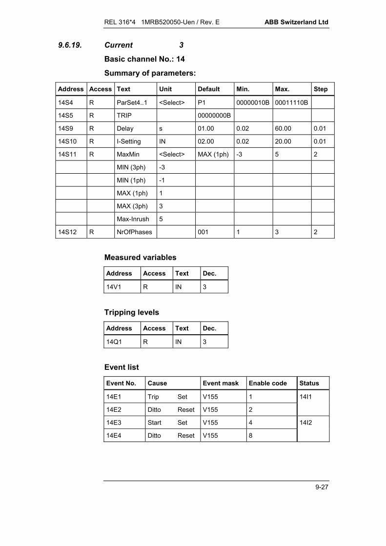
REL 316*4 1MRB520050-Uen / Rev. E ABB Switzerland Ltd
9-27
9.6.19. Current 3
Basic channel No.: 14
Summary of parameters:
Address Access Text Unit Default Min. Max. Step
14S4 R ParSet4..1 <Select> P1 00000010B 00011110B
14S5 R TRIP 00000000B
14S9 R Delay s 01.00 0.02 60.00 0.01
14S10 R I-Setting IN 02.00 0.02 20.00 0.01
14S11 R MaxMin <Select> MAX (1ph) -3 5 2
MIN (3ph) -3
MIN (1ph) -1
MAX (1ph) 1
MAX (3ph) 3
Max-Inrush 5
14S12 R NrOfPhases 001 1 3 2
Measured variables
Address Access Text Dec.
14V1 R IN 3
Tripping levels
Address Access Text Dec.
14Q1 R IN 3
Event list
Event No. Cause Event mask Enable code Status
14E1 Trip Set V155 1 14I1
14E2 Ditto Reset V155 2
14E3 Start Set V155 4 14I2
14E4 Ditto Reset V155 8

ABB Switzerland Ltd REL 316*4 1MRB520050-Uen / Rev. E
9-28
9.6.20. Diff-Transf 4
Basic channel No.: 14
Summary of parameters:
Address Access Text Unit Default Min. Max. Step
14S4 R ParSet4..1 <Select> P1 00000010B 00011110B
14S5 R TRIP 00000000B
14S9 R g IN 0.20 0.10 0.50 0.10
14S10 R v 0.50 0.25 0.50 0.25
14S11 R b 1 1.50 1.25 5.00 0.25
14S12 R g-High IN 2.00 0.50 2.50 0.25
14S13 R I-Inst IN 10 3 15 1
14S14 R a1 1.00 0.05 2.20 0.01
14S15 R s1 <Select> Y 0 1 1
Y 0
D 1
14S16 R a2 1.00 0.05 2.20 0.01
14S17 R s2 <Select> y0 00 21 1
y0 0
y1 1
y5 2
y6 3
y7 4
y11 5
d0 6
d1 7
d5 8
d6 9
d7 10
d11 11
z0 12
z1 13
z2 14

REL 316*4 1MRB520050-Uen / Rev. E ABB Switzerland Ltd
9-29
Address Access Text Unit Default Min. Max. Step
z4 15
z5 16
z6 17
z7 18
z8 19
z10 20
z11 21
14S18 R a3 1.00 0.05 2.20 0.01
14S19 R s3 <Select> y0 00 21 1
y0 0
y1 1
y5 2
y6 3
y7 4
y11 5
d0 6
d1 7
d5 8
d6 9
d7 10
d11 11
z0 12
z1 13
z2 14
z4 15
z5 16
z6 17
z7 18
z8 19
z10 20
z11 21

ABB Switzerland Ltd REL 316*4 1MRB520050-Uen / Rev. E
9-30
Address Access Text Unit Default Min. Max. Step
14S20 R InrushRatio % 10 6 20 1
14S21 R InrushTime s 5 0 90 1
Measured variables
Address Access Text Dec. Address Access Text Dec.
14V1 R IN (Id-R) 2 14V4 R IN (IhR) 2
14V2 R IN (Id-S) 2 14V5 R IN (IhR) 2
14V3 R IN (Id-T) 2 14V6 R IN (IhR) 2
Tripping levels
Address Access Text Dec.
14Q1 R IN (Id-R) 2
14Q2 R IN (Id-S) 2
14Q3 R IN (Id-T) 2
Event list
Event No. Cause Event mask Enable code Status
14E1 Trip Set V155 1 14I1
14E2 Ditto Reset V155 2
14E3 Trip-R Set V155 4 14I2
14E4 Ditto Reset V155 8
14E5 Trip-S Set V155 16 14I3
14E6 Ditto Reset V155 32
14E7 Trip-T Set V155 64 14I4
14E8 Ditto Reset V155 128
14E9 Inrush Set V155 256 14I5
14E10 Ditto Reset V155 512
14E11 Stabil Set V155 1024 14I6
14E12 Ditto Reset V155 2048
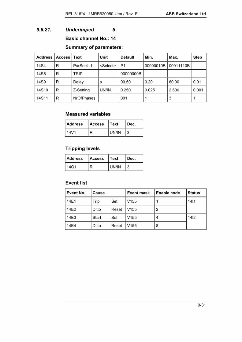
REL 316*4 1MRB520050-Uen / Rev. E ABB Switzerland Ltd
9-31
9.6.21. Underimped 5
Basic channel No.: 14
Summary of parameters:
Address Access Text Unit Default Min. Max. Step
14S4 R ParSet4..1 <Select> P1 00000010B 00011110B
14S5 R TRIP 00000000B
14S9 R Delay s 00.50 0.20 60.00 0.01
14S10 R Z-Setting UN/IN 0.250 0.025 2.500 0.001
14S11 R NrOfPhases 001 1 3 1
Measured variables
Address Access Text Dec.
14V1 R UN/IN 3
Tripping levels
Address Access Text Dec.
14Q1 R UN/IN 3
Event list
Event No. Cause Event mask Enable code Status
14E1 Trip Set V155 1 14I1
14E2 Ditto Reset V155 2
14E3 Start Set V155 4 14I2
14E4 Ditto Reset V155 8

ABB Switzerland Ltd REL 316*4 1MRB520050-Uen / Rev. E
9-32
9.6.22. MinReactance 6
Basic channel No.: 14
Summary of parameters:
Address Access Text Unit Default Min. Max. Step
14S4 R ParSet4..1 <Select> P1 00000010B 00011110B
14S5 R TRIP 00000000B
14S9 R Delay s 00.50 0.20 60.00 0.01
14S10 R XA-Setting UN/IN -2.00 -5.00 00.00 0.01
14S11 R XB-Setting UN/IN -0.50 -2.50 +2.50 0.01
14S12 R NrOfPhases 001 1 3 1
14S13 R Angle deg 000 -180 180 005
14S14 R MaxMin <Select> MIN -1 1 2
MIN -1
MAX 1
Measured variables
Address Access Text Dec.
14V1 R UN/IN 3
Tripping levels
Address Access Text Dec.
14Q1 R UN/IN 3
Event list
Event No. Cause Event mask Enable code Status
14E1 Trip Set V155 1 14I1
14E2 Ditto Reset V155 2
14E3 Start Set V155 4 14I2
14E4 Ditto Reset V155 8
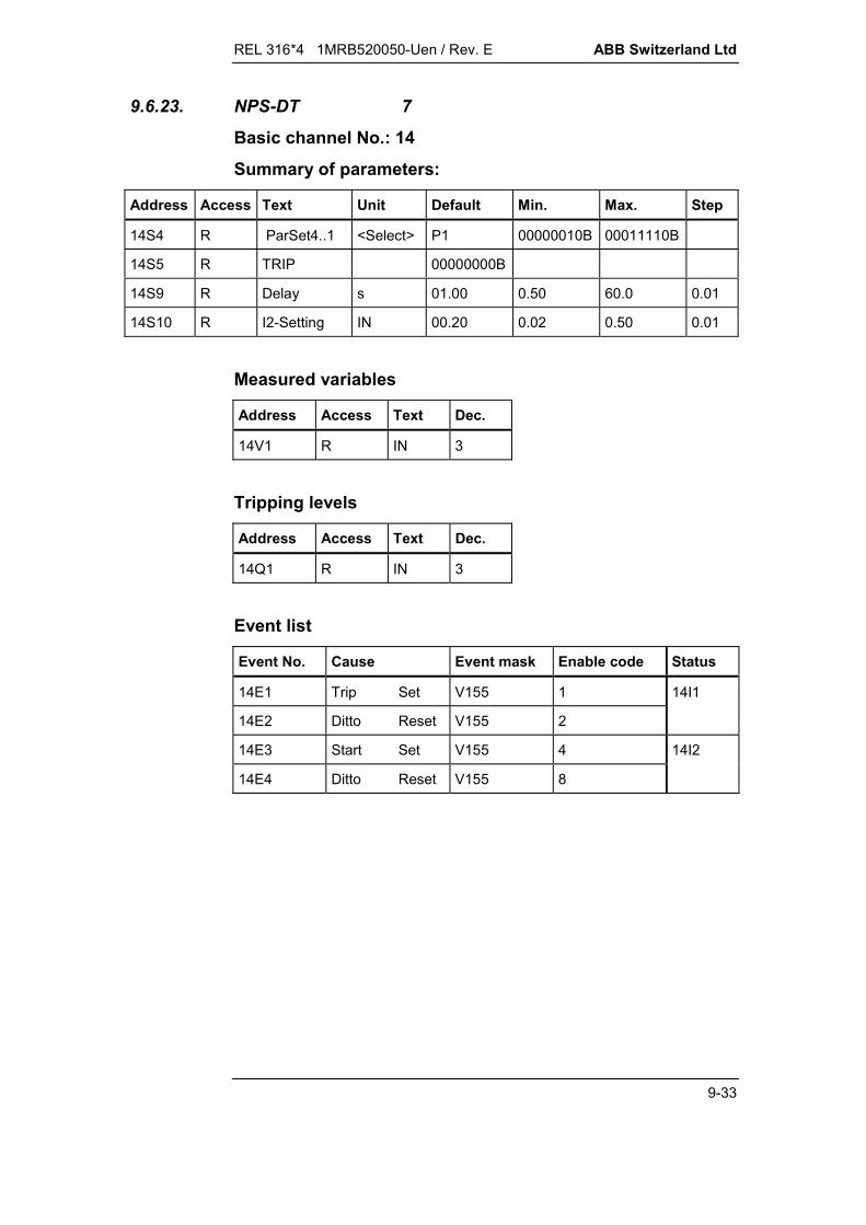
REL 316*4 1MRB520050-Uen / Rev. E ABB Switzerland Ltd
9-33
9.6.23. NPS-DT 7
Basic channel No.: 14
Summary of parameters:
Address Access Text Unit Default Min. Max. Step
14S4 R ParSet4..1 <Select> P1 00000010B 00011110B
14S5 R TRIP 00000000B
14S9 R Delay s 01.00 0.50 60.0 0.01
14S10 R I2-Setting IN 00.20 0.02 0.50 0.01
Measured variables
Address Access Text Dec.
14V1 R IN 3
Tripping levels
Address Access Text Dec.
14Q1 R IN 3
Event list
Event No. Cause Event mask Enable code Status
14E1 Trip Set V155 1 14I1
14E2 Ditto Reset V155 2
14E3 Start Set V155 4 14I2
14E4 Ditto Reset V155 8
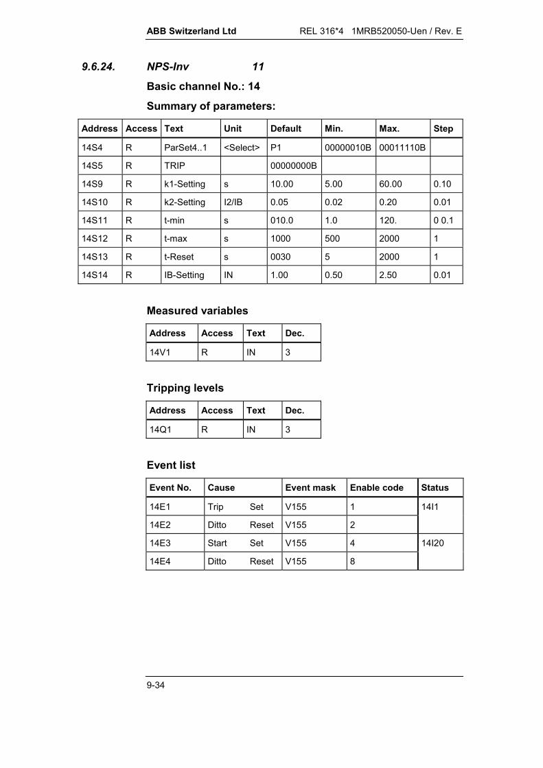
ABB Switzerland Ltd REL 316*4 1MRB520050-Uen / Rev. E
9-34
9.6.24. NPS-Inv 11
Basic channel No.: 14
Summary of parameters:
Address Access Text Unit Default Min. Max. Step
14S4 R ParSet4..1 <Select> P1 00000010B 00011110B
14S5 R TRIP 00000000B
14S9 R k1-Setting s 10.00 5.00 60.00 0.10
14S10 R k2-Setting I2/IB 0.05 0.02 0.20 0.01
14S11 R t-min s 010.0 1.0 120. 0 0.1
14S12 R t-max s 1000 500 2000 1
14S13 R t-Reset s 0030 5 2000 1
14S14 R IB-Setting IN 1.00 0.50 2.50 0.01
Measured variables
Address Access Text Dec.
14V1 R IN 3
Tripping levels
Address Access Text Dec.
14Q1 R IN 3
Event list
Event No. Cause Event mask Enable code Status
14E1 Trip Set V155 1 14I1
14E2 Ditto Reset V155 2
14E3 Start Set V155 4 14I20
14E4 Ditto Reset V155 8

REL 316*4 1MRB520050-Uen / Rev. E ABB Switzerland Ltd
9-35
9.6.25. Voltage 12
Basic channel No.: 14
Summary of parameters:
Address Access Text Unit Default Min. Max. Step
14S4 R ParSet4..1 <Select> P1 00000010B 00011110B
14S5 R TRIP 00000000B
14S9 R Delay s 02.00 0.02 60.00 0.01
14S10 R U-Setting UN 1.200 0.010 2.000 0.002
14S11 R MaxMin <Select> MAX (1ph) -3 3 2
MIN (3ph) -3
MIN (1ph) -1
MAX (1ph) 1
MAX (3ph) 3
14S12 R NrOfPhases 001 1 3 1
Measured variables
Address Access Text Dec.
14V1 R UN 3
Tripping levels
Address Access Text Dec.
14Q1 R UN 3
Event list
Event No. Cause Event mask Enable code Status
14E1 Trip Set V155 1 14I1
14E2 Ditto Reset V155 2
14E3 Start Set V155 4 14I2
14E4 Ditto Reset V155 8

ABB Switzerland Ltd REL 316*4 1MRB520050-Uen / Rev. E
9-36
9.6.26. Current-Inv 13
Basic channel No.: 14
Summary of parameters:
Address Access Text Unit Default Min. Max. Step
14S4 R ParSet4..1 <Select> P1 00000010B 00011110B
14S5 R TRIP 00000000B
14S9 R c-Setting <Select> 1.00 0 2 1
0.02 0
1.00 1
2.00 2
RXIDG 3
14S10 R k1-Setting s 013.50 0.01 200.00 0.01
14S11 R I-Start IB 1.10 1.00 2.00 0.01
14S12 R NrOfPhases 1 1 3 2
14S13 R IB-Setting IN 1.00 0.20 2.50 0.01
14S14 R t-min s 00.00 00.00 10.00 00.10
Measured variables
Address Access Text Dec.
14V1 R IN 3
Tripping levels
Address Access Text Dec.
14Q1 R IN 3
Event list
Event No. Cause Event mask Enable code Status
14E1 Trip Set V155 1 14I1
14E2 Ditto Reset V155 2
14E3 Start Set V155 4 14I2
14E4 Ditto Reset V155 8

REL 316*4 1MRB520050-Uen / Rev. E ABB Switzerland Ltd
9-37
9.6.27. OLoad-Stator 14
Basic channel No.: 14
Summary of parameters:
Address Access Text Unit Default Min. Max. Step
14S4 R ParSet4..1 <Select> P1 00000010B 00011110B
14S5 R TRIP 00000000B
14S9 R k1-Setting s 041.4 1.0 120.0 0.1
14S10 R I-Start IB 1.10 1.00 1.60 0.01
14S11 R t-min s 0010.0 1.0 120.0 0.1
14S12 R tg s 0120.0 10.0 2000.0 10.0
14S13 R t-max s 0300.0 100.0 2000.0 10.0
14S14 R t-Reset s 0120.0 10.0 2000.0 10.0
14S15 R IB-Setting IN 1.00 0.50 2.50 0.01
14S16 R NrOfPhases 3 1 3 2
Measured variables
Address Access Text Dec.
14V1 R IN 3
Tripping levels
Address Access Text Dec.
14Q1 R IN 3
Event list
Event No. Cause Event mask Enable code Status
14E1 Trip Set V155 1 14I1
14E2 Ditto Reset V155 2
14E3 Start Set V155 4 14I2
14E4 Ditto Reset V155 8

ABB Switzerland Ltd REL 316*4 1MRB520050-Uen / Rev. E
9-38
9.6.28. OLoad-Rotor 15
Basic channel No.: 14
Summary of parameters:
Address Access Text Unit Default Min. Max. Step
14S4 R ParSet4..1 <Select> P1 00000010B 00011110B
14S5 R TRIP 00000000B
14S9 R k1-Setting s 033.8 1.0 50.0 0.1
14S10 R I-Start IB 1.10 1.00 1.60 0.01
14S11 R t-min s 0010.0 1.0 120.0 0.1
14S12 R tg s 0120.0 10.0 2000.0 10.0
14S13 R t-max s 0300.0 100.0 2000.0 10.0
14S14 R t-Reset s 0120.0 10.0 2000.0 10.0
14S15 R IB-Setting IN 1.00 0.50 2.50 0.01
Measured variables
Address Access Text Dec.
14V1 R IN 3
Tripping levels
Address Access Text Dec.
14Q1 R IN 3
Event list
Event No. Cause Event mask Enable code Status
14E1 Trip Set V155 1 14I1
14E2 Ditto Reset V155 2
14E3 Start Set V155 4 14I2
14E4 Ditto Reset V155 8

REL 316*4 1MRB520050-Uen / Rev. E ABB Switzerland Ltd
9-39
9.6.29. Power 18
Basic channel No.: 14
Summary of parameters:
Address Access Text Unit Default Min. Max. Step
14S4 R ParSet4..1 <Select> P1 00000010B 00011110B
14S5 R TRIP 00000000B
14S9 R P-Setting PN -0.050 -0.100 1.200 0.005
14S10 R Angle deg 000.0 -180.0 180.0 5.0
14S11 R Drop-Ratio % 60 30 170 1
14S12 R Delay s 00.50 0.05 60.00 0.01
14S13 R MaxMin <Select> MIN -1 +1 2
MIN -1
MAX 1
14S14 R Phi-Comp. deg 0.0 -5.0 5.0 0.1
14S15 R NrOfPhases 001 1 3 1
14S16 R PN UN*IN 1.000 0.500 2.500 0.001
Measured variables
Address Access Text Dec.
14V1 R PN 3
Tripping levels
Address Access Text Dec.
14Q1 R PN 3
Event list
Event No. Cause Event mask Enable code Status
14E1 Trip Set V155 1 14I1
14E2 Ditto Reset V155 2
14E3 Start Set V155 4 14I2
14E4 Ditto Reset V155 8

ABB Switzerland Ltd REL 316*4 1MRB520050-Uen / Rev. E
9-40
9.6.30. Imax-Umin 20
Basic channel No.: 14
Summary of parameters:
Address Access Text Unit Default Min. Max. Step
14S4 R ParSet4..1 <Select> P1 00000010B 00011110B
14S5 R TRIP 00000000B
14S9 R Delay s 01.00 0.5 60.00 0.01
14S10 R Strom IN 02.00 0.5 20 0.1
14S11 R Hold-Voltage UN 00.70 0.4 1.1 0.01
14S12 R Hold-Time s 01.00 0.1 10 0.02
14S13 R NrOfPhases 001 1 3 2
Measured variables
Address Access Text Dec.
14V1 R IN 3
14V2 R UN 3
Tripping levels
Address Access Text Dec.
14Q1 R IN 3
Event list
Event No. Cause Event mask Enable code Status
14E1 Trip Set V155 1 14I1
14E2 Ditto Reset V155 2
14E3 Start Set V155 4 14I2
14E4 Ditto Reset V155 8
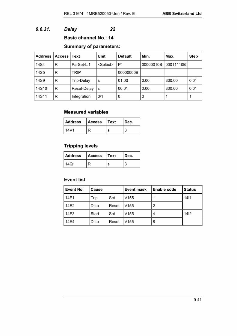
REL 316*4 1MRB520050-Uen / Rev. E ABB Switzerland Ltd
9-41
9.6.31. Delay 22
Basic channel No.: 14
Summary of parameters:
Address Access Text Unit Default Min. Max. Step
14S4 R ParSet4..1 <Select> P1 00000010B 00011110B
14S5 R TRIP 00000000B
14S9 R Trip-Delay s 01.00 0.00 300.00 0.01
14S10 R Reset-Delay s 00.01 0.00 300.00 0.01
14S11 R Integration 0/1 0 0 1 1
Measured variables
Address Access Text Dec.
14V1 R s 3
Tripping levels
Address Access Text Dec.
14Q1 R s 3
Event list
Event No. Cause Event mask Enable code Status
14E1 Trip Set V155 1 14I1
14E2 Ditto Reset V155 2
14E3 Start Set V155 4 14I2
14E4 Ditto Reset V155 8
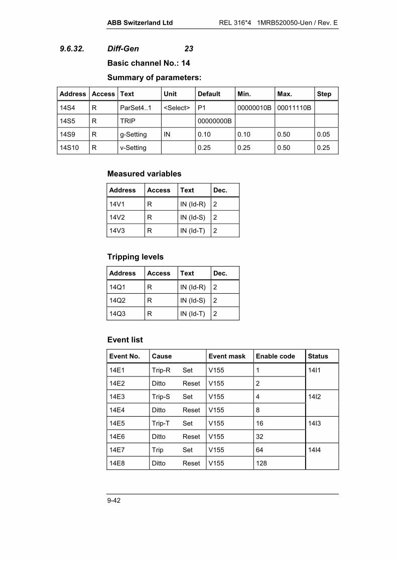
ABB Switzerland Ltd REL 316*4 1MRB520050-Uen / Rev. E
9-42
9.6.32. Diff-Gen 23
Basic channel No.: 14
Summary of parameters:
Address Access Text Unit Default Min. Max. Step
14S4 R ParSet4..1 <Select> P1 00000010B 00011110B
14S5 R TRIP 00000000B
14S9 R g-Setting IN 0.10 0.10 0.50 0.05
14S10 R v-Setting 0.25 0.25 0.50 0.25
Measured variables
Address Access Text Dec.
14V1 R IN (Id-R) 2
14V2 R IN (Id-S) 2
14V3 R IN (Id-T) 2
Tripping levels
Address Access Text Dec.
14Q1 R IN (Id-R) 2
14Q2 R IN (Id-S) 2
14Q3 R IN (Id-T) 2
Event list
Event No. Cause Event mask Enable code Status
14E1 Trip-R Set V155 1 14I1
14E2 Ditto Reset V155 2
14E3 Trip-S Set V155 4 14I2
14E4 Ditto Reset V155 8
14E5 Trip-T Set V155 16 14I3
14E6 Ditto Reset V155 32
14E7 Trip Set V155 64 14I4
14E8 Ditto Reset V155 128

REL 316*4 1MRB520050-Uen / Rev. E ABB Switzerland Ltd
9-43
9.6.33. Distance 24Basic channel No.: 14Summary of parameters:The starter and measurement settings (in columns Min., Max.and Step) with the unit 'ohms/phase' have to be divided by 10 forrelays with a rated current of 5 A.
Address Access Text Unit Default Min. Max. Step
14S4 R ParSet4..1 <Select> P1 00000010B 00011110B
14S5 R TRIP CB R 00000000B
14S6 R TRIP CB S 00000000B
14S7 R TRIP CB T 00000000B
14S9 R X (1) /ph 000.00 -300 300 0.01
14S10 R R (1) /ph 000.00 -300 300 0.01
14S11 R RR (1) /ph 000.00 -300 300 0.01
14S12 R RRE (1) /ph 000.00 -300 300 0.01
14S13 R k0 (1) 1 001.00 0 8 0.01
14S14 R k0Ang(1) deg 000.00 -180 90 0.01
14S15 R Delay(1) s 000.000 0 10 0.001
14S16 R X (2) /ph 000.00 -300 300 0.01
14S17 R R (2) /ph 000.00 -300 300 0.01
14S18 R RR (2) /ph 000.00 -300 300 0.01
14S19 R RRE (2) /ph 000.00 -300 300 0.01
14S20 R k0 (2) 1 001.00 0 8 0.01
14S21 R k0Ang(2) deg 000.00 -180 90 0.01
14S22 R Delay(2) s 000.00 0 10 0.01
14S23 R X (3) /ph 000.00 -300 300 0.01
14S24 R R (3) /ph 000.00 -300 300 0.01
14S25 R RR (3) /ph 000.00 -300 300 0.01
14S26 R RRE (3) /ph 000.00 -300 300 0.01
14S27 R k0 (3) 1 001.00 0 8 0.01
14S28 R k0Ang(3) deg 000.00 -180 90 0.01
14S29 R Delay(3) s 000.00 0 10 0.01

ABB Switzerland Ltd REL 316*4 1MRB520050-Uen / Rev. E
9-44
Address Access Text Unit Default Min. Max. Step
14S30 R X (4/OR) /ph 000.00 -300 300 0.01
14S31 R R (4/OR) /ph 000.00 -300 300 0.01
14S32 R RR (4/OR) /ph 000.00 -300 300 0.01
14S33 R RRE (4/OR) /ph 000.00 -300 300 0.01
14S34 R k0 (4/OR) 1 001.00 0 8 0.01
14S35 R k0Ang(4/OR) deg 000.00 -180 90 0.01
14S36 R Delay(4/OR) s 000.00 0 10 0.01
14S37 R X (BACK) /ph 000.00 -300 0 0.01
14S38 R R (BACK) /ph 000.00 -300 0 0.01
14S39 R RR (BACK) /ph 000.00 -300 0 0.01
14S40 R RRE (BACK) /ph 000.00 -300 0 0.01
14S41 R StartMode <Select> I> 2 6 2
UZ 4
OC 6
14S42 R PhasSelMode <Select> solid ground 0 8 1
Solid ground 0
RTS(R) cycl 1
TRS(T) cycl 2
RTS acycl 3
RST acycl 4
TSR acycl 5
TRS acycl 6
SRT acycl 7
STR acycl 8
14S43 R ComMode <Select> off 0 5 1
off 0
PUTT Nondir 1
PUTT Fward 2
PUTT OR2 3
POTT 4
BLOCK OR 5

REL 316*4 1MRB520050-Uen / Rev. E ABB Switzerland Ltd
9-45
Address Access Text Unit Default Min. Max. Step
14S44 R VTSupMode <Select> off 0 4 1
off 0
I0 1
I2 2
I0*I2 3
Special 4
14S45 R Ref Length /ph 01.000 0.01 30.000 0.001
14S46 R CT Neutral <Select> Busside -1 1 2
Busside -1
Lineside 1
14S47 R k0m 1 000.00 0 8 0.01
14S48 R k0mAng deg 000.00 -90 90 0.01
14S49 R Imin IN 000.20 0.1 2 0.01
14S50 R 3I0min IN 000.20 0.1 2 0.01
14S51 R U0 VTSup UN 000.20 0.01 0.5 0.01
14S52 R I0 VTSup IN 000.07 0.01 0.5 0.01
14S53 R U2 VTSup UN 000.20 0.01 0.5 0.01
14S54 R I2 VTSup IN 000.07 0.01 0.5 0.01
14S55 R Istart IN 004.00 0.5 10 0.01
14S56 R XA /ph 000.0 0 999 0.1
14S57 R XB /ph 000.0 -999 0 0.1
14S58 R RA /ph 000.0 0 999 0.1
14S59 R RB /ph 000.0 -999 0 0.1
14S60 R RLoad /ph 000.0 0 999 0.1
14S61 R AngleLoad deg 045.0 0 90 0.1
14S62 R Delay(Def) s 002.00 0 10 0.01
14S63 R UminFault UN 000.05 0.01 2 0.01
14S64 R MemDirMode <Select> Trip 0 2 1
Block 0
Trip 1
Cond Trip 2
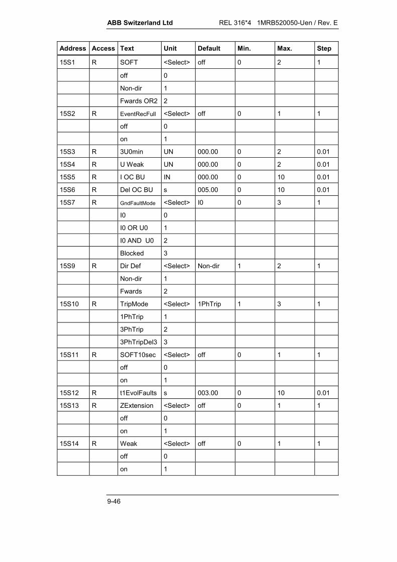
ABB Switzerland Ltd REL 316*4 1MRB520050-Uen / Rev. E
9-46
Address Access Text Unit Default Min. Max. Step
15S1 R SOFT <Select> off 0 2 1
off 0
Non-dir 1
Fwards OR2 2
15S2 R EventRecFull <Select> off 0 1 1
off 0
on 1
15S3 R 3U0min UN 000.00 0 2 0.01
15S4 R U Weak UN 000.00 0 2 0.01
15S5 R I OC BU IN 000.00 0 10 0.01
15S6 R Del OC BU s 005.00 0 10 0.01
15S7 R GndFaultMode <Select> I0 0 3 1
I0 0
I0 OR U0 1
I0 AND U0 2
Blocked 3
15S9 R Dir Def <Select> Non-dir 1 2 1
Non-dir 1
Fwards 2
15S10 R TripMode <Select> 1PhTrip 1 3 1
1PhTrip 1
3PhTrip 2
3PhTripDel3 3
15S11 R SOFT10sec <Select> off 0 1 1
off 0
on 1
15S12 R t1EvolFaults s 003.00 0 10 0.01
15S13 R ZExtension <Select> off 0 1 1
off 0
on 1
15S14 R Weak <Select> off 0 1 1
off 0
on 1
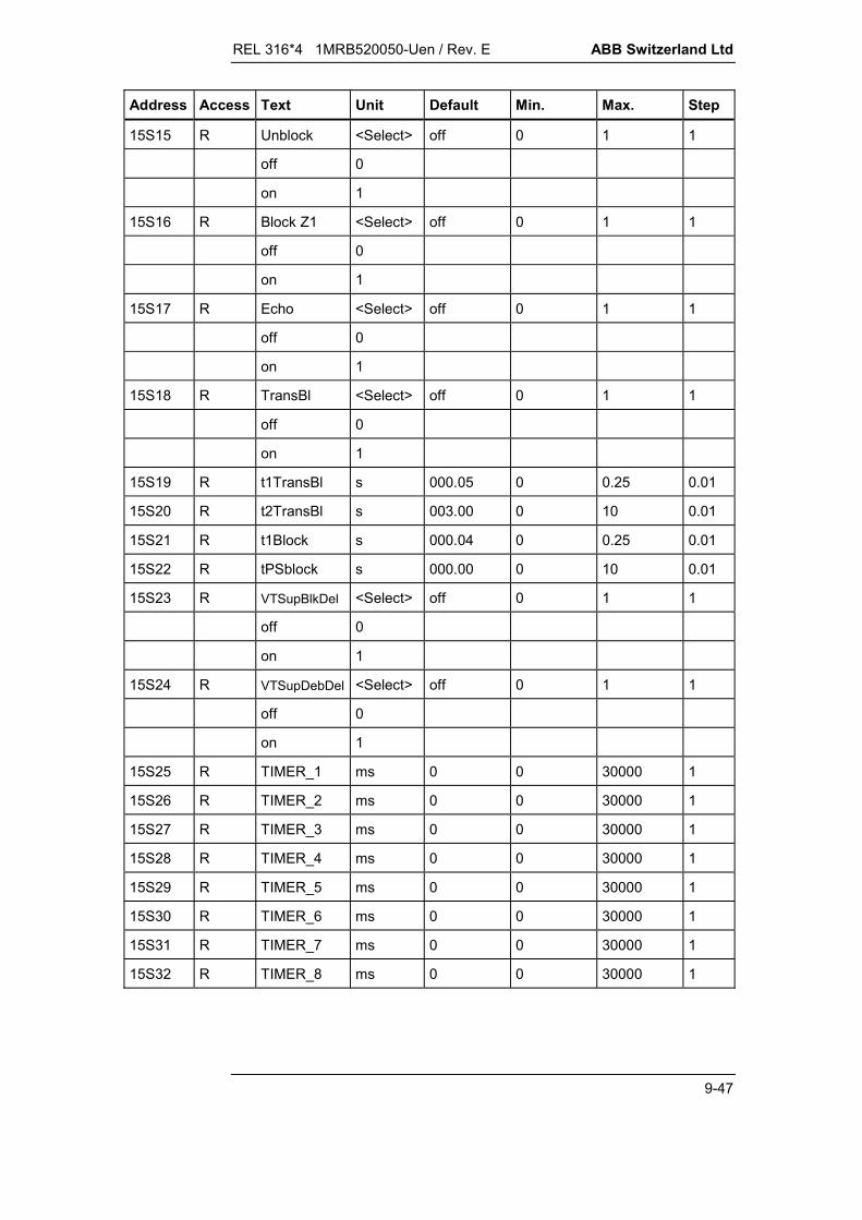
REL 316*4 1MRB520050-Uen / Rev. E ABB Switzerland Ltd
9-47
Address Access Text Unit Default Min. Max. Step
15S15 R Unblock <Select> off 0 1 1
off 0
on 1
15S16 R Block Z1 <Select> off 0 1 1
off 0
on 1
15S17 R Echo <Select> off 0 1 1
off 0
on 1
15S18 R TransBl <Select> off 0 1 1
off 0
on 1
15S19 R t1TransBl s 000.05 0 0.25 0.01
15S20 R t2TransBl s 003.00 0 10 0.01
15S21 R t1Block s 000.04 0 0.25 0.01
15S22 R tPSblock s 000.00 0 10 0.01
15S23 R VTSupBlkDel <Select> off 0 1 1
off 0
on 1
15S24 R VTSupDebDel <Select> off 0 1 1
off 0
on 1
15S25 R TIMER_1 ms 0 0 30000 1
15S26 R TIMER_2 ms 0 0 30000 1
15S27 R TIMER_3 ms 0 0 30000 1
15S28 R TIMER_4 ms 0 0 30000 1
15S29 R TIMER_5 ms 0 0 30000 1
15S30 R TIMER_6 ms 0 0 30000 1
15S31 R TIMER_7 ms 0 0 30000 1
15S32 R TIMER_8 ms 0 0 30000 1

ABB Switzerland Ltd REL 316*4 1MRB520050-Uen / Rev. E
9-48
Measured variables
Address Access Text Dec.
14V1 R [Ref Length] 2
14V2-14V3 R Z (RE) 2
14V4-14V5 R Z (SE) 2
14V6-14V7 R Z (TE) 2
14V8-14V9 R Z (RS) 2
14V10-14V11 R Z (ST) 2
14V12-14V13 R Z (TR) 2
Tripping levels
Address Access Text Dec.
14Q1 R [Ref Length] 2
14Q2-14Q3 R Z (RE) 2
14Q4-14Q5 R Z (SE) 2
14Q6-14Q7 R Z (TE) 2
14Q8-14Q9 R Z (RS) 2
14Q10-14Q11 R Z (ST) 2
14Q12-14Q13 R Z (TR) 2
Note:A tripping value will only be overwritten (e.g.: Z(RS)) if the sameloop (RS) trips again.

REL 316*4 1MRB520050-Uen / Rev. E ABB Switzerland Ltd
9-49
Event list
Event No. Cause Event mask Enable code Status
14E1 Start I0 Set V155 1 14I1
14E2 Ditto Reset V155 2
14E3 Start U0 Set V155 4 14I2
14E4 Ditto Reset V155 8
14E5 Meas Oreach Set V155 16 14I3
14E6 Ditto Reset V155 32
14E7 Trip O/C Set V155 64 14I4
14E8 Ditto Reset V155 128
14E9 Power Swing Set V155 256 14I5
14E10 Ditto Reset V155 512
14E11 Trip CB R Set V155 1024 14I6
14E12 Ditto Reset V155 2048
14E13 Trip CB S Set V155 4096 14I7
14E14 Ditto Reset V155 8192
14E15 Trip CB T Set V155 16384 14I8
14E16 Ditto Reset V155 32768
14E17 Trip SOFT Set V156 1 14I9
14E18 Ditto Reset V156 2
14E19 Start O/C Set V156 4 14I10
14E20 Ditto Reset V156 8
14E21 Meas Main Set V156 16 14I11
14E22 Ditto Reset V156 32
14E23 Trip CB Set V156 64 14I12
14E24 Ditto Reset V156 128
14E25 Start R+S+T Set V156 256 14I13
14E26 Ditto Reset V156 512
14E27 Com Send Set V156 1024 14I14
14E28 Ditto Reset V156 2048
14E29 Dist Blocked Set V156 4096 14I15
14E30 Ditto Reset V156 8192
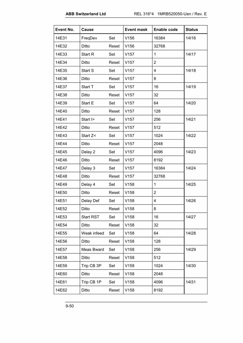
ABB Switzerland Ltd REL 316*4 1MRB520050-Uen / Rev. E
9-50
Event No. Cause Event mask Enable code Status
14E31 FreqDev Set V156 16384 14I16
14E32 Ditto Reset V156 32768
14E33 Start R Set V157 1 14I17
14E34 Ditto Reset V157 2
14E35 Start S Set V157 4 14I18
14E36 Ditto Reset V157 8
14E37 Start T Set V157 16 14I19
14E38 Ditto Reset V157 32
14E39 Start E Set V157 64 14I20
14E40 Ditto Reset V157 128
14E41 Start I> Set V157 256 14I21
14E42 Ditto Reset V157 512
14E43 Start Z< Set V157 1024 14I22
14E44 Ditto Reset V157 2048
14E45 Delay 2 Set V157 4096 14I23
14E46 Ditto Reset V157 8192
14E47 Delay 3 Set V157 16384 14I24
14E48 Ditto Reset V157 32768
14E49 Delay 4 Set V158 1 14I25
14E50 Ditto Reset V158 2
14E51 Delay Def Set V158 4 14I26
14E52 Ditto Reset V158 8
14E53 Start RST Set V158 16 14I27
14E54 Ditto Reset V158 32
14E55 Weak infeed Set V158 64 14I28
14E56 Ditto Reset V158 128
14E57 Meas Bward Set V158 256 14I29
14E58 Ditto Reset V158 512
14E59 Trip CB 3P Set V158 1024 14I30
14E60 Ditto Reset V158 2048
14E61 Trip CB 1P Set V158 4096 14I31
14E62 Ditto Reset V158 8192

REL 316*4 1MRB520050-Uen / Rev. E ABB Switzerland Ltd
9-51
Event No. Cause Event mask Enable code Status
15E1 Trip RST Set V155 1 15I1
15E2 Ditto Reset V155 2
15E3 Trip Com Set V155 4 15I2
15E4 Ditto Reset V155 8
15E5 Delay 1 Set V155 16 15I3
15E6 Ditto Reset V155 32
15E7 Com Boost Set V155 64 15I4
15E8 Ditto Reset V155 128
15E9 Trip Stub Set V155 256 15I5
15E10 Ditto Reset V155 512
15E11 VTSup Set V155 1024 15I6
15E12 Ditto Reset V155 2048
15E13 VTSup Delay Set V155 4096 15I7
15E14 Ditto Reset V155 8192
15E15 Start R Aux Set V155 16384 15I8
15E16 Ditto Reset V155 32768
15E17 Start S Aux Set V156 1 15I9
15E18 Ditto Reset V156 2
15E19 Start T Aux Set V156 4 15I10
15E20 Ditto Reset V156 8
15E21 Start E Aux Set V156 16 15I11
15E22 Ditto Reset V156 32
15E23 Start RST Aux Set V156 64 15I12
15E24 Ditto Reset V156 128
15E25 Trip RST Aux Set V156 256 15I13
15E26 Ditto Reset V156 512
15E27 Start SOFT Set V156 1024 15I14
15E28 Ditto Reset V156 2048
15E29 Delay >= 2 Set V156 4096 15I15
15E30 Ditto Reset V156 8192

ABB Switzerland Ltd REL 316*4 1MRB520050-Uen / Rev. E
9-52
Event No. Cause Event mask Enable code Status
15E31 Meas Fward Set V156 16384 15I16
15E32 Ditto Reset V156 32768
15E33 BOOL_OUT1 Set V157 1 15I17
15E34 Ditto Reset V157 2
15E35 BOOL_OUT2 Set V157 4 15I18
15E36 Ditto Reset V157 8
15E37 BOOL_OUT3 Set V157 16 15I19
15E38 Ditto Reset V157 32
15E39 BOOL_OUT4 Set V157 64 15I20
15E40 Ditto Reset V157 128
15E41 BOOL_OUT5 Set V157 256 15I21
15E42 Ditto Reset V157 512
15E43 BOOL_OUT6 Set V157 1024 15I22
15E44 Ditto Reset V157 2048
15E45 BOOL_OUT7 Set V157 4095 15I23
15E46 Ditto Reset V157 8192
15E47 BOOL_OUT8 Set V157 16384 15I24
15E48 Ditto Reset V157 32768
15E49 Start 1ph Set V158 1 15I25
15E50 Ditto Reset V158 2
15E51 DelDistBlock Set V158 4 15I26
15E52 Ditto Reset V158 8

REL 316*4 1MRB520050-Uen / Rev. E ABB Switzerland Ltd
9-53
9.6.34. Frequency 25
Basic channel No.: 14
Summary of parameters:
Address Access Text Unit Default Min. Max. Step
14S4 R ParSet4..1 <Select> P1 00000010B 00011110B
14S5 R TRIP 00000000B
14S9 R Frequency Hz 48.00 40.00 65.00 0.01
14S10 R U-Block UN 0.20 0.20 0.80 0.10
14S11 R Delay s 01.00 0.10 60.00 0.01
14S12 R MaxMin <Select> MIN -1 1 2
MIN -1
MAX 1
Measured variables
Address Access Text Dec.
14V1 R Hz 3
14V2 R UN 2
Tripping levels
Address Access Text Dec.
14Q1 R Hz 3
Event list
Event No. Cause Event mask Enable code Status
14E1 Block.(U<) Set V155 1 14I1
14E2 Ditto Reset V155 2
14E3 Trip Set V155 4 14I2
14E4 Ditto Reset V155 8
14E5 Start Set V155 16 1I3
14E6 Ditto Reset V155 32
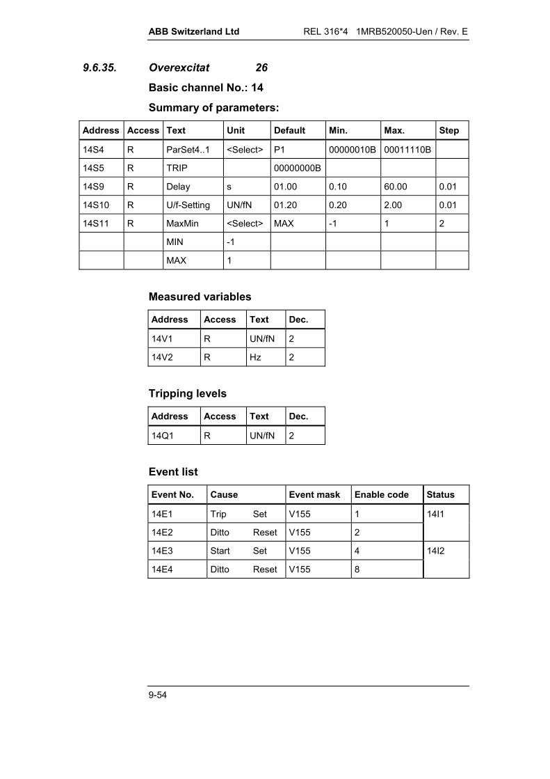
ABB Switzerland Ltd REL 316*4 1MRB520050-Uen / Rev. E
9-54
9.6.35. Overexcitat 26
Basic channel No.: 14
Summary of parameters:
Address Access Text Unit Default Min. Max. Step
14S4 R ParSet4..1 <Select> P1 00000010B 00011110B
14S5 R TRIP 00000000B
14S9 R Delay s 01.00 0.10 60.00 0.01
14S10 R U/f-Setting UN/fN 01.20 0.20 2.00 0.01
14S11 R MaxMin <Select> MAX -1 1 2
MIN -1
MAX 1
Measured variables
Address Access Text Dec.
14V1 R UN/fN 2
14V2 R Hz 2
Tripping levels
Address Access Text Dec.
14Q1 R UN/fN 2
Event list
Event No. Cause Event mask Enable code Status
14E1 Trip Set V155 1 14I1
14E2 Ditto Reset V155 2
14E3 Start Set V155 4 14I2
14E4 Ditto Reset V155 8
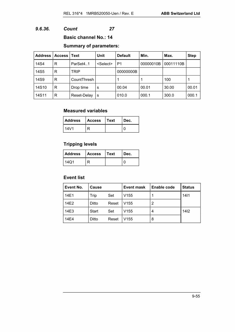
REL 316*4 1MRB520050-Uen / Rev. E ABB Switzerland Ltd
9-55
9.6.36. Count 27
Basic channel No.: 14
Summary of parameters:
Address Access Text Unit Default Min. Max. Step
14S4 R ParSet4..1 <Select> P1 00000010B 00011110B
14S5 R TRIP 00000000B
14S9 R CountThresh 1 1 100 1
14S10 R Drop time s 00.04 00.01 30.00 00.01
14S11 R Reset-Delay s 010.0 000.1 300.0 000.1
Measured variables
Address Access Text Dec.
14V1 R 0
Tripping levels
Address Access Text Dec.
14Q1 R 0
Event list
Event No. Cause Event mask Enable code Status
14E1 Trip Set V155 1 14I1
14E2 Ditto Reset V155 2
14E3 Start Set V155 4 14I2
14E4 Ditto Reset V155 8
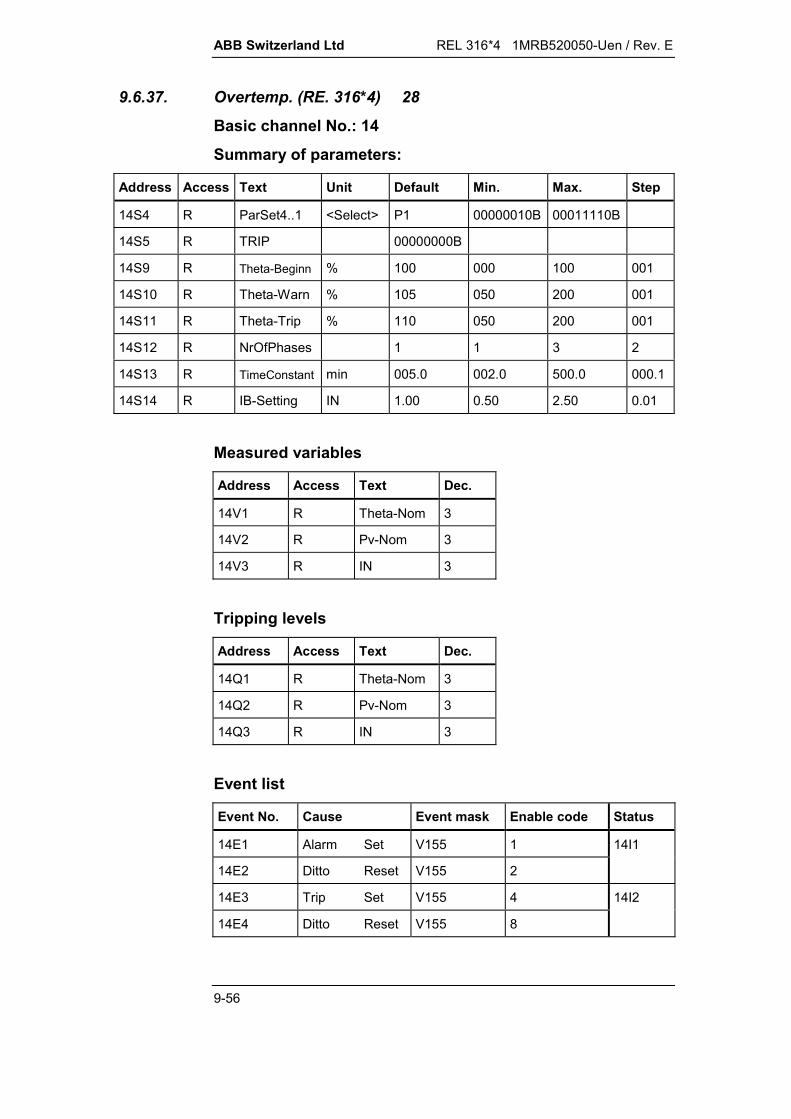
ABB Switzerland Ltd REL 316*4 1MRB520050-Uen / Rev. E
9-56
9.6.37. Overtemp. (RE. 316*4) 28
Basic channel No.: 14
Summary of parameters:
Address Access Text Unit Default Min. Max. Step
14S4 R ParSet4..1 <Select> P1 00000010B 00011110B
14S5 R TRIP 00000000B
14S9 R Theta-Beginn % 100 000 100 001
14S10 R Theta-Warn % 105 050 200 001
14S11 R Theta-Trip % 110 050 200 001
14S12 R NrOfPhases 1 1 3 2
14S13 R TimeConstant min 005.0 002.0 500.0 000.1
14S14 R IB-Setting IN 1.00 0.50 2.50 0.01
Measured variables
Address Access Text Dec.
14V1 R Theta-Nom 3
14V2 R Pv-Nom 3
14V3 R IN 3
Tripping levels
Address Access Text Dec.
14Q1 R Theta-Nom 3
14Q2 R Pv-Nom 3
14Q3 R IN 3
Event list
Event No. Cause Event mask Enable code Status
14E1 Alarm Set V155 1 14I1
14E2 Ditto Reset V155 2
14E3 Trip Set V155 4 14I2
14E4 Ditto Reset V155 8

REL 316*4 1MRB520050-Uen / Rev. E ABB Switzerland Ltd
9-57
9.6.38. Check-I3ph 29
Basic channel No.: 14
Summary of parameters:
Address Access Text Unit Default Min. Max. Step
14S4 R ParSet4..1 <Select> P1 00000010B 00011110B
14S5 R TRIP 00000000B
14S9 R I-Setting IN 0.20 0.05 1.00 0.05
14S10 R Delay s 10.0 0.1 60.0 0.1
14S11 R CT-Compens +1.00 -2.00 +2.00 0.01
Measured variables
Address Access Text Dec.
14V1 R IN 3
Tripping levels
Address Access Text Dec.
14Q1 R IN 3
Event list
Event No. Cause Event mask Enable code Status
14E1 Trip Set V155 1 14I1
14E2 Ditto Reset V155 2

ABB Switzerland Ltd REL 316*4 1MRB520050-Uen / Rev. E
9-58
9.6.39. Check-U3ph 30
Basic channel No.: 14
Summary of parameters:
Address Access Text Unit Default Min. Max. Step
14S4 R ParSet4..1 <Select> P1 00000010B 00011110B
14S5 R TRIP 00000000B
14S9 R U-Setting UN 0.20 0.05 1.20 0.05
14S10 R Delay s 10.0 0.1 60.0 0.1
14S11 R VT-Compens +1.00 -2.00 +2.00 0.01
Measured variables
Address Access Text Dec.
14V1 R UN 3
Tripping levels
Address Access Text Dec.
14Q1 R UN 3
Event list
Event No. Cause Event mask Enable code Status
14E1 Trip Set V155 1 14I1
14E2 Ditto Reset V155 2

REL 316*4 1MRB520050-Uen / Rev. E ABB Switzerland Ltd
9-59
9.6.40. Logic 31
Basic channel No.: 14
Summary of parameters:
Address Access Text Unit Default Min. Max. Step
14S4 R ParSet4..1 <Select> P1 00000010B 00011110B
14S5 R TRIP 00000000B
14S9 R Logic Mode <Select> OR 0 2 1
OR 0
AND 1
RS-Flipflop 2
Event list
Event No. Cause Event mask Enable code Status
14E1 BinOutput Set V155 1 14I1
14E2 Ditto Reset V155 2

ABB Switzerland Ltd REL 316*4 1MRB520050-Uen / Rev. E
9-60
9.6.41. Disturbance Rec 32
Basic channel No.: 14
Summary of parameters:
Address Access Text Unit Default Min. Max. Step
14S4 R ParSet4..1 <Select> P1 00000010B 00011110B
14S9 R StationNr No. 01 00 99 01
14S10 R preEvent ms 40 40 400 20
14S11 R Event ms 100 100 3000 50
14S12 R postEvent ms 40 40 400 20
14S13 R recMode <Select> A 0 1 1
A 0
B 1
14S14 R TrigMode <Select> TrigOnStart 0 5 1
TrigOnStart 0
TrigOnTrip 1
TrigOnBin 2
TrigAnyBi 3
TrigStart&Bi 4
TrigTrip&Bin 5
14S15 R BinInp 1 <Select> No trig 0 2 1
No trig 0
Trigger 1
Inv. Trigger 2
14S16 R BinInp 2 <Select> No trig 0 2 1
No trig 0
Trigger 1
Inv. Trigger 2
14S17 R BinInp 3 <Select> No trig 0 2 1
No trig 0
Trigger 1
Inv. Trigger 2
14S18 R BinInp 4 <Select> No trig 0 2 1

REL 316*4 1MRB520050-Uen / Rev. E ABB Switzerland Ltd
9-61
Address Access Text Unit Default Min. Max. Step
No trig 0
Trigger 1
Inv. Trigger 2
14S19 R BinInp 5 <Select> No trig 0 2 1
No trig 0
Trigger 1
Inv. Trigger 2
14S20 R BinInp 6 <Select> No trig 0 2 1
No trig 0
Trigger 1
Inv. Trigger 2
14S21 R BinInp 7 <Select> No trig 0 2 1
No trig 0
Trigger 1
Inv. Trigger 2
14S22 R BinInp 8 <Select> No trig 0 2 1
No trig 0
Trigger 1
Inv. Trigger 2
14S23 R BinInp 9 <Select> No trig 0 2 1
No trig 0
Trigger 1
Inv. Trigger 2
14S24 R BinInp 10 <Select> No trig 0 2 1
No trig 0
Trigger 1
Inv. Trigger 2
14S25 R BinInp 11 <Select> No trig 0 2 1
No trig 0
Trigger 1
Inv. Trigger 2

ABB Switzerland Ltd REL 316*4 1MRB520050-Uen / Rev. E
9-62
Address Access Text Unit Default Min. Max. Step
14S26 R BinInp 12 <Select> No trig 0 2 1
No trig 0
Trigger 1
Inv. Trigger 2
14S27 R BinInp 13 <Select> No trig 0 2 1
No trig 0
Trigger 1
Inv. Trigger 2
14S28 R BinInp 14 <Select> No trig 0 2 1
No trig 0
Trigger 1
Inv. Trigger 2
14S29 R BinInp 15 <Select> No trig 0 2 1
No trig 0
Trigger 1
Inv. Trigger 2
14S30 R BinInp 16 <Select> No trig 0 2 1
No trig 0
Trigger 1
Inv. Trigger 2
14S31 R StorageMode <Select> StopOnFull 0 1 1
StopOnFull 0
Overwrite 1
Event list
Event No. Cause Event mask Enable code Status
14E1 Bin output Set V155 1 14I1
14E2 Ditto Reset V155 2
14E3 Mem full Set V155 4 14I2
14E4 Ditto Reset V155 8

REL 316*4 1MRB520050-Uen / Rev. E ABB Switzerland Ltd
9-63
9.6.42. Voltage-Inst 36
Basic channel No.: 14
Summary of parameters:
Address Access Text Unit Default Min. Max. Step
14S4 R ParSet4..1 <Select> P1 00000010B 00011110B
14S5 R TRIP 00000000B
14S9 R Delay s 00.01 0.00 60.00 0.01
14S10 R U-Setting UN 1.40 0.01 2.00 0.01
14S11 R f-min Hz 040.0 25 50 1
14S12 R MaxMin <Select> MAX -1 1 2
MIN -1
MAX 1
14S13 R NrOfPhases 001 1 3 2
Measured variables
Address Access Text Dec.
14V1 R UN 2
Tripping levels
Address Access Text Dec.
14Q1 R UN 2
Event list
Event No. Cause Event mask Enable code Status
14E1 Trip Set V155 1 14I1
14E2 Ditto Reset V155 2
14E3 Start Set V155 4 14I2
14E4 Ditto Reset V155 8

ABB Switzerland Ltd REL 316*4 1MRB520050-Uen / Rev. E
9-64
9.6.43. Autoreclosure 38Basic channel No.: 14Summary of parameters:
Address Access Text Unit Default Min. Max. Step
1S4 R ParSet4..1 <Select> P1 00000010B 00011110B
14S5 R TRIP 00000000B
14S6 R CB2 close 00000000B
14S9 R 1. AR Mode <Select> 1. 1P3P-1P3P 1 5 1
1. 1P-1P 1
1. 1P-3P 2
1. 1P3P-3P 3
1. 1P3P-1P3P 4
ExtSelection 5
14S10 R 2..4AR Mode <Select> off 0 3 1
off 0
2 AR 1
3 AR 2
4 AR 3
14S11 R Master Mode <Select> off 0 1 1
off 0
on 1
14S12 R ZE Prefault <Select> on 0 1 1
off 0
on 1
14S13 R ZE 1. AR <Select> off 0 1 1
off 0
on 1
14S14 R ZE 2. AR <Select> off 0 1 1
off 0
on 1
14S15 R ZE 3. AR <Select> off 0 1 1
off 0
on 1

REL 316*4 1MRB520050-Uen / Rev. E ABB Switzerland Ltd
9-65
Address Access Text Unit Default Min. Max. Step
14S16 R ZE 4. AR <Select> off 0 1 1
off 0
on 1
14S17 R SCBypass 1P <Select> off 0 1 1
off 0
on 1
14S18 R SCBypass1P3P <Select> off 0 1 1
off 0
on 1
14S19 R t Dead1 1P s 001.20 0.05 300 0.01
14S20 R t Dead1 3P s 000.60 0.05 300 0.01
14S21 R t Dead1 Ext s 001.00 0.05 300 0.01
14S22 R t Dead2 s 001.20 0.05 300 0.01
14S23 R t Dead3 s 005.00 0.05 300 0.01
14S24 R t Dead4 s 060.00 0.05 300 0.01
14S25 R t Oper. s 000.50 0.05 300 0.01
14S26 R t Inhibit s 005.00 0.05 300 0.01
14S27 R t Close s 000.25 0.05 300 0.01
14S28 R t Discrim.1P s 000.60 0.10 300 0.01
14S29 R t Discrim.3P s 000.30 0.10 300 0.01
14S30 R t Timeout s 001.00 0.05 300 0.01
14S31 R t AR Block. s 005.00 0.05 300 0.01
14S32 R TMSEC_Timer1 ms 0 0 30000 1
14S33 R TMSEC_Timer2 ms 0 0 30000 1
14S34 R TMSEC_Timer3 ms 0 0 30000 1
14S35 R TMSEC_Timer4 ms 0 0 30000 1
14S36 R TMSEC_Timer5 ms 0 0 30000 1
14S37 R TMSEC_Timer6 ms 0 0 30000 1
14S38 R TMSEC_Timer7 ms 0 0 30000 1
14S39 R TMSEC_Timer8 ms 0 0 30000 1
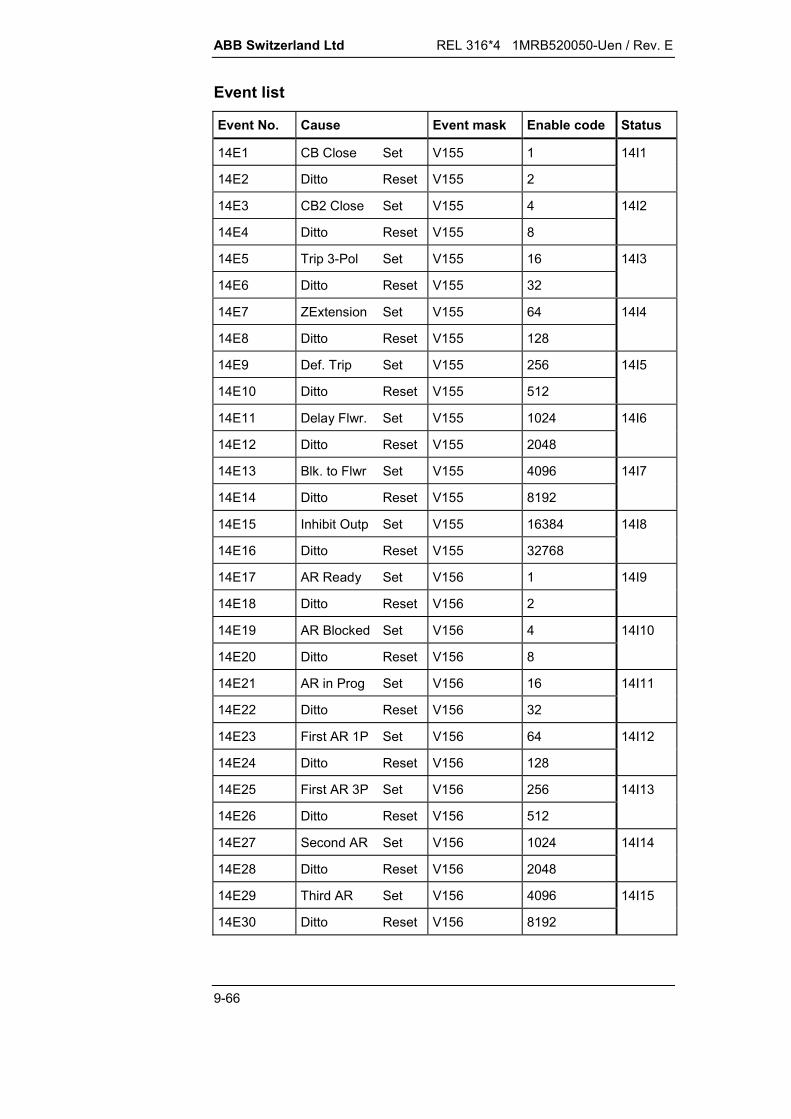
ABB Switzerland Ltd REL 316*4 1MRB520050-Uen / Rev. E
9-66
Event list
Event No. Cause Event mask Enable code Status
14E1 CB Close Set V155 1 14I1
14E2 Ditto Reset V155 2
14E3 CB2 Close Set V155 4 14I2
14E4 Ditto Reset V155 8
14E5 Trip 3-Pol Set V155 16 14I3
14E6 Ditto Reset V155 32
14E7 ZExtension Set V155 64 14I4
14E8 Ditto Reset V155 128
14E9 Def. Trip Set V155 256 14I5
14E10 Ditto Reset V155 512
14E11 Delay Flwr. Set V155 1024 14I6
14E12 Ditto Reset V155 2048
14E13 Blk. to Flwr Set V155 4096 14I7
14E14 Ditto Reset V155 8192
14E15 Inhibit Outp Set V155 16384 14I8
14E16 Ditto Reset V155 32768
14E17 AR Ready Set V156 1 14I9
14E18 Ditto Reset V156 2
14E19 AR Blocked Set V156 4 14I10
14E20 Ditto Reset V156 8
14E21 AR in Prog Set V156 16 14I11
14E22 Ditto Reset V156 32
14E23 First AR 1P Set V156 64 14I12
14E24 Ditto Reset V156 128
14E25 First AR 3P Set V156 256 14I13
14E26 Ditto Reset V156 512
14E27 Second AR Set V156 1024 14I14
14E28 Ditto Reset V156 2048
14E29 Third AR Set V156 4096 14I15
14E30 Ditto Reset V156 8192

REL 316*4 1MRB520050-Uen / Rev. E ABB Switzerland Ltd
9-67
Event No. Cause Event mask Enable code Status
14E31 Fourth AR Set V156 16384 14I16
14E32 Ditto Reset V156 32768
14E33 P_OUTPUT1 Set V157 1 14I17
14E34 Ditto Reset V157 2
14E35 P_OUTPUT2 Set V157 4 14I18
14E36 Ditto Reset V157 8
14E37 P_OUTPUT3 Set V157 16 14I19
14E38 Ditto Reset V157 32
14E39 P_OUTPUT4 Set V157 64 14I20
14E40 Ditto Reset V157 128
14E41 P_OUTPUT5 Set V157 256 1421
14E42 Ditto Reset V157 512
14E43 P_OUTPUT6 Set V157 1024 1422
14E44 Ditto Reset V157 2048
14E45 P_OUTPUT7 Set V157 4096 1423
14E46 Ditto Reset V157 8192
14E47 P_OUTPUT8 Set V157 16384 14I24
14E48 Ditto Reset V157 32768

ABB Switzerland Ltd REL 316*4 1MRB520050-Uen / Rev. E
9-68
9.6.44. EarthFaultIsol 40
Basic channel No.: 14
Summary of parameters:
Address Access Text Unit Default Min. Max. Step
14S4 R ParSet4..1 <Select> P1 00000010B 00011110B
14S5 R TRIP 00000000B
149 R P-Setting PN 0.050 0.005 0.100 0.001
14S10 R Angle deg 000.00 -180.00 180.00 0.01
14S11 R Drop-Ratio % 60 30 95 1
14S12 R Delay s 00.50 0.05 60.00 0.01
14S13 R Phi-Comp. deg 0.00 -5.00 5.00 0.01
14S14 R PN UN*IN 1.000 0.500 2.500 0.001
Measured variables
Address Access Text Dec.
14V1 R PN 3
Tripping levels
Address Access Text Dec.
14Q1 R PN 3
Event list
Event No. Cause Event mask Enable code Status
14E1 Trip Set V155 1 14I1
14E2 Ditto Reset V155 2
14E3 Start Set V155 4 14I2
14E4 Ditto Reset V155 8

REL 316*4 1MRB520050-Uen / Rev. E ABB Switzerland Ltd
9-69
9.6.45. Voltage-Bal 41
Basic channel No.: 14
Summary of parameters:
Address Access Text Unit Default Min. Max. Step
14S4 R ParSet4..1 <Select> P1 00000010B 00011110B
14S5 R TRIP 00000000B
14S9 R V-Unbalance UN 0.20 0.10 0.50 0.05
14S10 R Delay s 0.04 0.00 1.00 0.01
14S11 R t-Reset s 1.50 0.10 2.00 0.01
14S12 R NrOfPhases 003 1 3 2
Measured variables
Address Access Text Dec.
14V1 R UN (Ud-1) 2
14V2 R UN (Ud-2) 2
14V3 R UN (Ud-3) 2
Tripping levels
Address Access Text Dec.
14Q1 R UN (Ud-1) 2
14Q2 R UN (Ud-2) 2
14Q3 R UN (Ud-3) 2
Event list
Event No. Cause Event mask Enable code Status
14E1 Trip Set V155 1 14I1
14E2 Ditto Reset V155 2
14E3 Start Set V155 4 14I2
14E4 Ditto Reset V155 8
14E5 Trip-Line1 Set V155 16 14I3
14E6 Ditto Reset V155 32
14E7 Trip-Line2 Set V155 64 14I4
14E8 Ditto Reset V155 28

ABB Switzerland Ltd REL 316*4 1MRB520050-Uen / Rev. E
9-70
9.6.46. U/f-Inv 47
Basic channel No.: 14
Summary of parameters:
Address Access Text Unit Default Min. Max. Step
14S4 R ParSet4..1 <Select> P1 00000010B 00011110B
14S5 R TRIP 00000000B
14S9 R V/f-Setting UN/fN 01.10 1.05 1.20 0.01
14S10 R t-min min 0.20 0.01 2.00 0.01
14S11 R t-max min 60.0 5.0 100.0 0.1
14S12 R t-Reset min 60.0 0.2 100.0 0.1
14S13 R t[V/f=1.05] min 70.00 00.01 100.00 0.01
14S14 R t[V/f=1.10] min 70.00 00.01 100.00 0.01
14S15 R t[V/f=1.15] min 06.00 00.01 100.00 0.01
14S16 R t[V/f=1.20] min 01.000 00.001 30.000 0.001
14S17 R t[V/f=1.25] min 00.480 00.001 30.000 0.001
14S18 R t[V/f=1.30] min 00.300 00.001 30.000 0.001
14S19 R t[V/f=1.35] min 00.220 00.001 30.000 0.001
14S20 R t[V/f=1.40] min 00.170 00.001 30.000 0.001
14S21 R t[V/f=1.45] min 00.140 00.001 30.000 0.001
14S22 R t[V/f=1.50] min 00.140 00.001 30.000 0.001
14S23 R UB-Setting UN 01.00 0.80 1.20 0.01
Measured variables
Address Access Text Dec.
14V1 R UN/fN 2
14V2 R Hz 2

REL 316*4 1MRB520050-Uen / Rev. E ABB Switzerland Ltd
9-71
Tripping levels
Address Access Text Dec.
14Q1 R UN/fN 2
Event list
Event No. Cause Event mask Enable code Status
4E1 Trip Set V155 1 14I1
14E2 Ditto Reset V155 2
14E3 Start Set V155 4 14I2
14E4 Ditto Reset V155 8

ABB Switzerland Ltd REL 316*4 1MRB520050-Uen / Rev. E
9-72
9.6.47. UIfPQ 48
Basic channel No.: 14
Summary of parameters:
Address Access Text Unit Default Min. Max. Step
14S4 R ParSet4..1 <Select> P1 00000010B 00011110B
14S9 R Angle deg 000.0 -180.0 180.0 0.1
14S10 R PN UN*IN 1.000 0.200 2.500 0.001
14S11 R Voltage mode <Select> direct 1 2 1
direct 1
ph-to-ph 2
Measured variables
Address Access Text Dec.
14V1 R UN 3
14V2 R IN 3
14V3 R P (PN) 3
14V4 R Q (PN) 3
14V5 R Hz 3

REL 316*4 1MRB520050-Uen / Rev. E ABB Switzerland Ltd
9-73
9.6.48. SynchroCheck 49
Basic channel No.: 14
Summary of parameters:
Address Access Text Unit Default Min. Max. Step
14S4 R ParSet4..1 <Select> P1 00000010B 00011110B
14S5 R TRIP 00000000B
14S9 R maxVoltDif UN 0.20 0.05 0.40 0.05
14S10 R maxPhaseDif deg 10.0 05.0 80.0 05.0
14S11 R maxFreqDif Hz 0.20 0.05 0.40 0.05
14S12 R minVoltage UN 0.70 0.60 1.00 0.05
14S13 R maxVoltage UN 0.30 0.10 1.00 0.05
14S14 R Operat.-Mode <Select> SynChck only 0 4 1
SynChck only 0
DBus + LLine 1
LBus + DLine 2
DBus DLine 3
DBus + DLine 4
14S15 R SupervisTime s 0.20 0.05 5.00 0.05
14S16 R t-Reset s 0.05 0.00 1.00 0.05
14S17 R LiveBus <Select> 1ph R-S 0 7 1
1ph R-S 0
1ph S-T 1
1ph T-R 2
1ph R-E 3
1ph S-E 4
1ph T-E 5
3ph-delta 6
3ph-Y 7

ABB Switzerland Ltd REL 316*4 1MRB520050-Uen / Rev. E
9-74
Address Access Text Unit Default Min. Max. Step
14S18 R LiveLine <Select> 3ph-Y 0 7 1
1ph R-S 0
1ph S-T 1
1ph T-R 2
1ph R-E 3
1ph S-E 4
1ph T-E 5
3ph-delta 6
3ph-Y 7
Measured variables
Address Access Text Dec.
14V1 R UN (dU) 2
14V2 R deg (dPhi) 2
14V3 R Hz (|df|) 2
14V4 R UN (max. bus V) 2
14V5 R UN (min. bus V) 2
14V6 R UN (max. line V) 2
14V7 R UN (min. line V) 2
Tripping levels
Address Access Text Dec.
14Q1 R UN (dU) 2
14Q2 R deg (dPhi) 2
14Q3 R Hz (|df|) 2
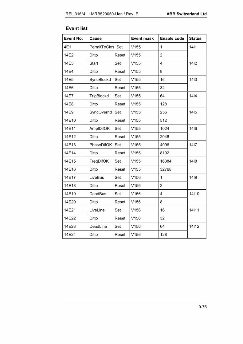
REL 316*4 1MRB520050-Uen / Rev. E ABB Switzerland Ltd
9-75
Event list
Event No. Cause Event mask Enable code Status
4E1 PermitToClos Set V155 1 14I1
14E2 Ditto Reset V155 2
14E3 Start Set V155 4 14I2
14E4 Ditto Reset V155 8
14E5 SyncBlockd Set V155 16 14I3
14E6 Ditto Reset V155 32
14E7 TrigBlockd Set V155 64 14I4
14E8 Ditto Reset V155 128
14E9 SyncOverrid Set V155 256 14I5
14E10 Ditto Reset V155 512
14E11 AmplDifOK Set V155 1024 14I6
14E12 Ditto Reset V155 2048
14E13 PhaseDifOK Set V155 4096 14I7
14E14 Ditto Reset V155 8192
14E15 FreqDifOK Set V155 16384 14I8
14E16 Ditto Reset V155 32768
14E17 LiveBus Set V156 1 14I9
14E18 Ditto Reset V156 2
14E19 DeadBus Set V156 4 14I10
14E20 Ditto Reset V156 8
14E21 LiveLine Set V156 16 14I11
14E22 Ditto Reset V156 32
14E23 DeadLine Set V156 64 14I12
14E24 Ditto Reset V156 128
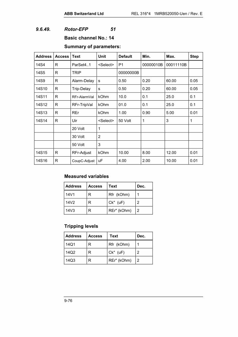
ABB Switzerland Ltd REL 316*4 1MRB520050-Uen / Rev. E
9-76
9.6.49. Rotor-EFP 51
Basic channel No.: 14
Summary of parameters:
Address Access Text Unit Default Min. Max. Step
14S4 R ParSet4..1 <Select> P1 00000010B 00011110B
14S5 R TRIP 00000000B
14S9 R Alarm-Delay s 0.50 0.20 60.00 0.05
14S10 R Trip-Delay s 0.50 0.20 60.00 0.05
14S11 R RFr-AlarmVal kOhm 10.0 0.1 25.0 0.1
14S12 R RFr-TripVal kOhm 01.0 0.1 25.0 0.1
14S13 R REr kOhm 1.00 0.90 5.00 0.01
14S14 R Uir <Select> 50 Volt 1 3 1
20 Volt 1
30 Volt 2
50 Volt 3
14S15 R RFr-Adjust kOhm 10.00 8.00 12.00 0.01
14S16 R CoupC-Adjust uF 4.00 2.00 10.00 0.01
Measured variables
Address Access Text Dec.
14V1 R Rfr (kOhm) 1
14V2 R Ck" (uF) 2
14V3 R REr" (kOhm) 2
Tripping levels
Address Access Text Dec.
14Q1 R Rfr (kOhm) 1
14Q2 R Ck" (uF) 2
14Q3 R REr" (kOhm) 2

REL 316*4 1MRB520050-Uen / Rev. E ABB Switzerland Ltd
9-77
Event list for Rotor-EFP
Event No. Cause Event mask Enable code Status
14E1 Trip Set V155 1 14I1
14E2 Ditto Reset V155 2
14E3 Start Trip Set V155 4 14I2
14E4 Ditto Reset V155 8
14E5 Alarm Set V155 16 14I3
14E6 Ditto Reset V155 32
14E7 Start Alarm Set V155 64 14I4
14E8 Ditto Reset V155 128
14E9 InterruptInt Set V155 256 14I5
14E10 Ditto Reset V155 512
14E11 InterruptExt Set V155 1024 14I6
14E12 Ditto Reset V155 2048
14E13 Rer-Adjust Set V155 4096 14I7
14E14 Ditto Reset V155 8192
14E15 CoupC-Adjust Set V155 16384 14I8
14E16 Ditto Reset V155 32768
14E17 Extern-Block Set V156 1 14I9
14E18 Ditto Reset V156 2

ABB Switzerland Ltd REL 316*4 1MRB520050-Uen / Rev. E
9-78
9.6.50. Stator-EFP 52
Basic channel No.: 14
Summary of parameters:
Address Access Text Unit Default Min. Max. Step
14S4 R ParSet4..1 <Select> P1 00000010B 00011110B
14S5 R TRIP 00000000B
14S9 R Alarm-Delay s 0.50 0.20 60.00 0.05
14S10 R Trip-Delay s 0.50 0.20 60.00 0.05
14S11 R RFs-AlarmVal kOhm 10.0 0.1 20.0 0.1
14S12 R RFs-TripVal kOhm 01.0 0.1 20.0 0.1
14S13 R REs kOhm 1.00 0.70 5.00 0.01
14S14 R REs-2.Starpt kOhm 1.00 0.90 30.00 0.01
14S15 R RFs-Adjust kOhm 10.00 8.00 12.00 0.01
14S16 R MTransRatio 100.0 10.0 200.0 0.1
14S17 R NrOfStarpt 1 1 2 1
Measured variables
Address Access Text Dec.
14V1 R Rfs (kOhm) 1
14V2 R Inst. trans. ratio 1
14V3 R REs" (kOhm) 2
Tripping levels
Address Access Text Dec.
14Q1 R Rfs (kOhm) 1
14Q2 R Inst. trans. ratio 1
14Q3 R REs" (kOhm) 2
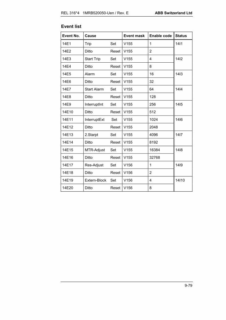
REL 316*4 1MRB520050-Uen / Rev. E ABB Switzerland Ltd
9-79
Event list
Event No. Cause Event mask Enable code Status
14E1 Trip Set V155 1 14I1
14E2 Ditto Reset V155 2
14E3 Start Trip Set V155 4 14I2
14E4 Ditto Reset V155 8
14E5 Alarm Set V155 16 14I3
14E6 Ditto Reset V155 32
14E7 Start Alarm Set V155 64 14I4
14E8 Ditto Reset V155 128
14E9 InterruptInt Set V155 256 14I5
14E10 Ditto Reset V155 512
14E11 InterruptExt Set V155 1024 14I6
14E12 Ditto Reset V155 2048
14E13 2.Starpt Set V155 4096 14I7
14E14 Ditto Reset V155 8192
14E15 MTR-Adjust Set V155 16384 14I8
14E16 Ditto Reset V155 32768
14E17 Res-Adjust Set V156 1 14I9
14E18 Ditto Reset V156 2
14E19 Extern-Block Set V156 4 14I10
14E20 Ditto Reset V156 8

ABB Switzerland Ltd REL 316*4 1MRB520050-Uen / Rev. E
9-80
9.6.51. I0-Invers 53
Basic channel No.: 14
Summary of parameters:
Address Access Text Unit Default Min. Max. Step
14S4 R ParSet4..1 <Select> P1 00000010B 00011110B
14S5 R TRIP 00000000B
14S9 R c-Setting <Select> 1 0 2 1
0.02 0
1.00 1
2.00 2
RXIDG 3
14S10 R k1-Setting s 013.50 0.01 200.00 0.01
14S11 R I-Start IB 1.10 1.00 2.00 0.01
14S12 R NrOfPhases 1 1 3 2
14S13 R IB-Setting IN 1.00 0.20 2.50 0.01
14S14 R t-min s 00.00 00.00 10.00 00.10
Measured variables
Address Access Text Dec.
14V1 R IN 3
Tripping levels
Address Access Text Dec.
14Q1 R IN 3
Event list
Event No. Cause Event mask Enable code Status
14E1 Trip Set V155 1 14I1
14E2 Ditto Reset V155 2
14E3 Start Set V155 4 14I2
14E4 Ditto Reset V155 8
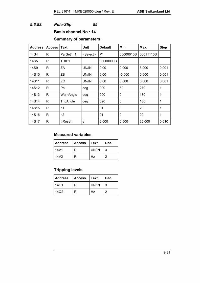
REL 316*4 1MRB520050-Uen / Rev. E ABB Switzerland Ltd
9-81
9.6.52. Pole-Slip 55
Basic channel No.: 14
Summary of parameters:
Address Access Text Unit Default Min. Max. Step
14S4 R ParSet4..1 <Select> P1 00000010B 00011110B
14S5 R TRIP1 00000000B
14S9 R ZA UN/IN 0.00 0.000 5.000 0.001
14S10 R ZB UN/IN 0.00 -5.000 0.000 0.001
14S11 R ZC UN/IN 0.00 0.000 5.000 0.001
14S12 R Phi deg 090 60 270 1
14S13 R WarnAngle deg 000 0 180 1
14S14 R TripAngle deg 090 0 180 1
14S15 R n1 01 0 20 1
14S16 R n2 01 0 20 1
14S17 R t-Reset s 5.000 0.500 25.000 0.010
Measured variables
Address Access Text Dec.
14V1 R UN/IN 3
14V2 R Hz 2
Tripping levels
Address Access Text Dec.
14Q1 R UN/IN 3
14Q2 R Hz 2
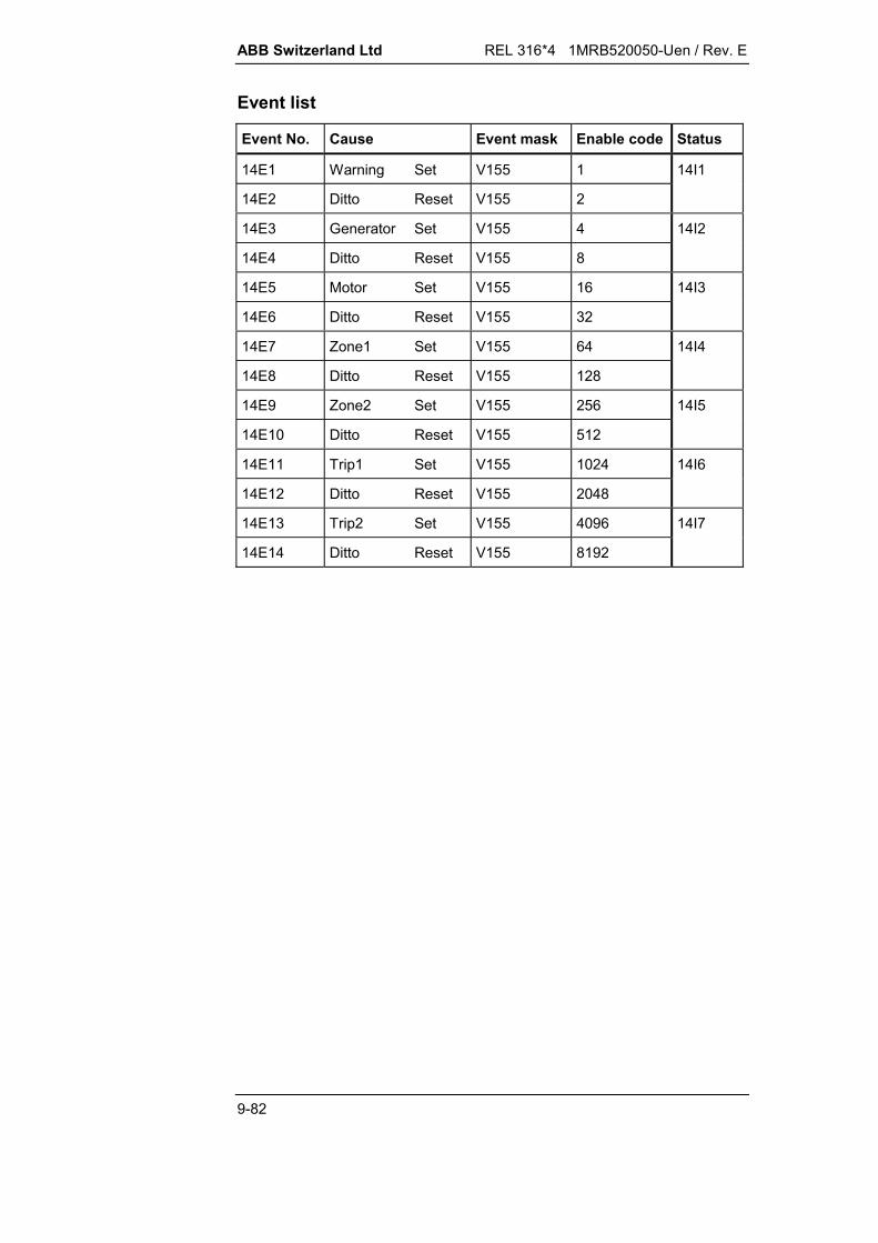
ABB Switzerland Ltd REL 316*4 1MRB520050-Uen / Rev. E
9-82
Event list
Event No. Cause Event mask Enable code Status
14E1 Warning Set V155 1 14I1
14E2 Ditto Reset V155 2
14E3 Generator Set V155 4 14I2
14E4 Ditto Reset V155 8
14E5 Motor Set V155 16 14I3
14E6 Ditto Reset V155 32
14E7 Zone1 Set V155 64 14I4
14E8 Ditto Reset V155 128
14E9 Zone2 Set V155 256 14I5
14E10 Ditto Reset V155 512
14E11 Trip1 Set V155 1024 14I6
14E12 Ditto Reset V155 2048
14E13 Trip2 Set V155 4096 14I7
14E14 Ditto Reset V155 8192
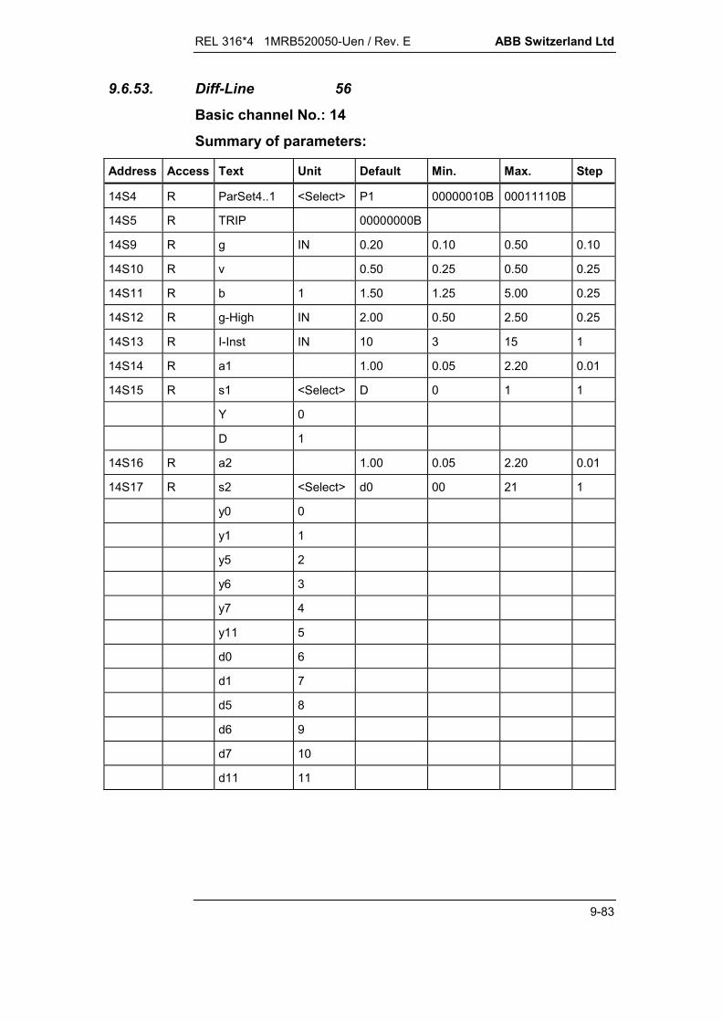
REL 316*4 1MRB520050-Uen / Rev. E ABB Switzerland Ltd
9-83
9.6.53. Diff-Line 56
Basic channel No.: 14
Summary of parameters:
Address Access Text Unit Default Min. Max. Step
14S4 R ParSet4..1 <Select> P1 00000010B 00011110B
14S5 R TRIP 00000000B
14S9 R g IN 0.20 0.10 0.50 0.10
14S10 R v 0.50 0.25 0.50 0.25
14S11 R b 1 1.50 1.25 5.00 0.25
14S12 R g-High IN 2.00 0.50 2.50 0.25
14S13 R I-Inst IN 10 3 15 1
14S14 R a1 1.00 0.05 2.20 0.01
14S15 R s1 <Select> D 0 1 1
Y 0
D 1
14S16 R a2 1.00 0.05 2.20 0.01
14S17 R s2 <Select> d0 00 21 1
y0 0
y1 1
y5 2
y6 3
y7 4
y11 5
d0 6
d1 7
d5 8
d6 9
d7 10
d11 11

ABB Switzerland Ltd REL 316*4 1MRB520050-Uen / Rev. E
9-84
Address Access Text Unit Default Min. Max. Step
z0 12
z1 13
z2 14
z4 15
z5 16
z6 17
z7 18
z8 19
z10 20
z11 21
14S18 R InrushRatio % 10 6 20 1
14S19 R InrushTime s 0 0 90 1
Measured variables
Address Access Text Dec. Address Access Text Dec.
14V1 R IN (Id-R) 2 14V4 R IN (IhR) 2
14V2 R IN (Id-S) 2 14V5 R IN (IhS) 2
14V3 R IN (Id-T) 2 14V6 R IN (IhT) 2
Tripping levels
Address Access Text Dec.
14Q1 R IN (Id-R) 2
14Q2 R IN (Id-S) 2
14Q3 R IN (Id-T) 2
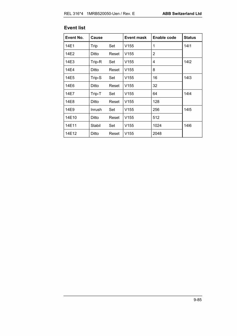
REL 316*4 1MRB520050-Uen / Rev. E ABB Switzerland Ltd
9-85
Event list
Event No. Cause Event mask Enable code Status
14E1 Trip Set V155 1 14I1
14E2 Ditto Reset V155 2
14E3 Trip-R Set V155 4 14I2
14E4 Ditto Reset V155 8
14E5 Trip-S Set V155 16 14I3
14E6 Ditto Reset V155 32
14E7 Trip-T Set V155 64 14I4
14E8 Ditto Reset V155 128
14E9 Inrush Set V155 256 14I5
14E10 Ditto Reset V155 512
14E11 Stabil Set V155 1024 14I6
14E12 Ditto Reset V155 2048

ABB Switzerland Ltd REL 316*4 1MRB520050-Uen / Rev. E
9-86
9.6.54. RemoteBin 57
Basic channel No.: 14
Summary of parameters:
Address Access Text Unit Default Min. Max. Step
14S4 R ParSet4..1 <Select> P1 00000010B 00011110B
14S5 R RemTRIP 1 00000000B
14S6 R RemTRIP 2 00000000B
14S7 R RemTRIP 3 00000000B
14S8 R RemTRIP 4 00000000B
Event list
Event No. Cause Event mask Enable code Status
14E1 RemChan 1 Set V155 1 14I1
14E2 Ditto Reset V155 2
14E3 RemChan 2 Set V155 4 14I2
14E4 Ditto Reset V155 8
14E5 RemChan 3 Set V155 16 14I3
14E6 Ditto Reset V155 32
14E7 RemChan 4 Set V155 64 14I4
14E8 Ditto Reset V155 128
14E9 RemChan 5 Set V155 256 14I5
14E10 Ditto Reset V155 512
14E11 RemChan 6 Set V155 1024 14I6
14E12 Ditto Reset V155 2048
14E13 RemChan 7 Set V155 4096 14I7
14E14 Ditto Reset V155 8192
14E15 RemChan 8 Set V155 16384 14I8
14E16 Ditto Reset V155 32768
14E17 RemBinError Set V156 1 14I9
14E18 Ditto Reset V156 2
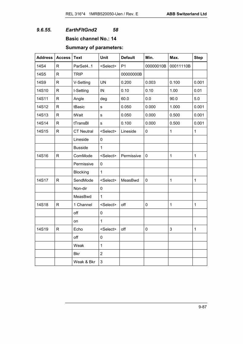
REL 316*4 1MRB520050-Uen / Rev. E ABB Switzerland Ltd
9-87
9.6.55. EarthFltGnd2 58
Basic channel No.: 14
Summary of parameters:
Address Access Text Unit Default Min. Max. Step
14S4 R ParSet4..1 <Select> P1 00000010B 00011110B
14S5 R TRIP 00000000B
14S9 R V-Setting UN 0.200 0.003 0.100 0.001
14S10 R I-Setting IN 0.10 0.10 1.00 0.01
14S11 R Angle deg 60.0 0.0 90.0 5.0
14S12 R tBasic s 0.050 0.000 1.000 0.001
14S13 R tWait s 0.050 0.000 0.500 0.001
14S14 R tTransBl s 0.100 0.000 0.500 0.001
14S15 R CT Neutral <Select> Lineside 0 1 1
Lineside 0
Busside 1
14S16 R ComMode <Select> Permissive 0 1 1
Permissive 0
Blocking 1
14S17 R SendMode <Select> MeasBwd 0 1 1
Non-dir 0
MeasBwd 1
14S18 R 1 Channel <Select> off 0 1 1
off 0
on 1
14S19 R Echo <Select> off 0 3 1
off 0
Weak 1
Bkr 2
Weak & Bkr 3

ABB Switzerland Ltd REL 316*4 1MRB520050-Uen / Rev. E
9-88
Measured variables
Address Access Text Dec.
14V1 R UN 2
14V2 R IN 2
14V3 R Forwards 0
Note: This function does not provide tripping levels (Q).
Event list
Event No. Cause Event mask Enable code Status
14E1 Trip Set V155 1 14I1
14E2 Ditto Reset V155 2
14E3 Start Set V155 4 14I2
14E4 Ditto Reset V155 8
14E5 MeasFwd Set V155 16 14I3
14E6 Ditto Reset V155 32
14E7 MeasBwd Set V155 64 14I4
14E8 Ditto Reset V155 128
14E9 Senden Set V155 256 14I5
14E10 Ditto Reset V155 512
14E11 Recve Inh Set V155 1024 14I6
14E12 Ditto Reset V155 2048
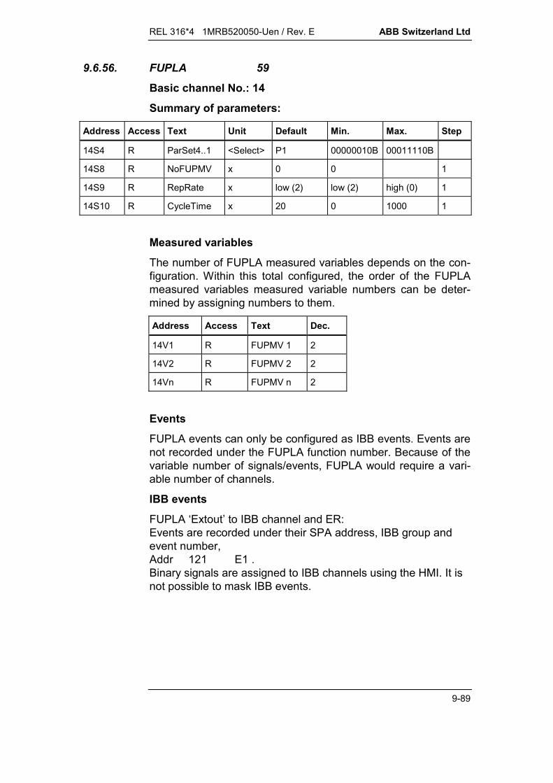
REL 316*4 1MRB520050-Uen / Rev. E ABB Switzerland Ltd
9-89
9.6.56. FUPLA 59
Basic channel No.: 14
Summary of parameters:
Address Access Text Unit Default Min. Max. Step
14S4 R ParSet4..1 <Select> P1 00000010B 00011110B
14S8 R NoFUPMV x 0 0 1
14S9 R RepRate x low (2) low (2) high (0) 1
14S10 R CycleTime x 20 0 1000 1
Measured variables
The number of FUPLA measured variables depends on the con-figuration. Within this total configured, the order of the FUPLAmeasured variables measured variable numbers can be deter-mined by assigning numbers to them.
Address Access Text Dec.
14V1 R FUPMV 1 2
14V2 R FUPMV 2 2
14Vn R FUPMV n 2
Events
FUPLA events can only be configured as IBB events. Events arenot recorded under the FUPLA function number. Because of thevariable number of signals/events, FUPLA would require a vari-able number of channels.
IBB events
FUPLA ‘Extout’ to IBB channel and ER:Events are recorded under their SPA address, IBB group andevent number,Addr 121 E1 .Binary signals are assigned to IBB channels using the HMI. It isnot possible to mask IBB events.

ABB Switzerland Ltd REL 316*4 1MRB520050-Uen / Rev. E
9-90
9.6.57. FlatterRecog 60
Basic channel No.: 14
Summary of parameters:
Address Access Text Unit Default Min. Max. Step
14S4 R ParSet4..1 <Select> P1 00000010B 00011110B
14S9 R SupervisTime s 1.0 0.1 60.0 0.1
14S10 R NoOfChanges 2 2 100 1
Event list
Event No. Cause Event mask Enable code Status
14E1 InputStatus1 Set V155 1 14I1
14E2 Ditto Reset V155 2
14E3 InputStatus2 Set V155 4 14I3
14E4 Ditto Reset V155 8
14E5 InputStatus3 Set V155 16 14I5
14E6 Ditto Reset V155 32
14E7 InputStatus4 Set V155 64 14I7
14E8 Ditto Reset V155 128
14E9 FlatterSig1 Set V155 256 14I2
14E10 Ditto Reset V155 1024
14E11 FlatterSig2 Set V155 512 14I4
14E12 Ditto Reset V155 2048
14E13 FlatterSig3 Set V155 4096 14I6
14E14 Ditto Reset V155 8192
14E15 FlatterSig4 Set V155 16384 14I8
14E16 Ditto Reset V155 32768

REL 316*4 1MRB520050-Uen / Rev. E ABB Switzerland Ltd
9-91
9.6.58. HV distance 63Basic channel No.: 14Summary of parameters:The starter and measurement settings (in columns Min., Max.and Step) with the unit 'ohms/phase' have to be divided by 10 forrelays with a rated current of 5 A.
Address Access Text Unit Default Min. Max. Step
14S4 R ParSet4..1 <Select> P1 00000010B 00011110B
14S5 R TRIP CB R 00000000B
14S6 R TRIP CB S 00000000B
14S7 R TRIP CB T 00000000B
14S9 R X (1) /ph 000.00 -300 300 0.01
14S10 R R (1) /ph 000.00 -300 300 0.01
14S11 R RR (1) /ph 000.00 -300 300
14S12 R RRE (1) /ph 000.00 -300 300
14S13 R k0 (1) 1 001.00 0 8 0.01
14S14 R k0Ang(1) deg 000.00 -180 90 0.01
14S15 R Delay(1) s 000.000 0 10 0.001
14S16 R X (2) /ph 000.00 -300 300 0.01
14S17 R R (2) /ph 000.00 -300 300 0.01
14S18 R RR (2) /ph 000.00 -300 300 0.01
14S19 R RRE (2) /ph 000.00 -300 300 0.01
14S20 R k0 (2) 1 001.00 0 8 0.01
14S21 R k0Ang(2) deg 000.00 -180 90 0.01
14S22 R Delay(2) s 000.00 0 10 0.01
14S23 R X (3) /ph 000.00 -300 300 0.01
14S24 R R (3) /ph 000.00 -300 300 0.01
14S25 R RR (3) /ph 000.00 -300 300 0.01
14S26 R RRE (3) /ph 000.00 -300 300 0.01
14S27 R k0 (3) 1 001.00 0 8 0.01
14S28 R k0Ang(3) deg 000.00 -180 90 0.01
14S29 R Delay(3) s 000.00 0 10 0.01
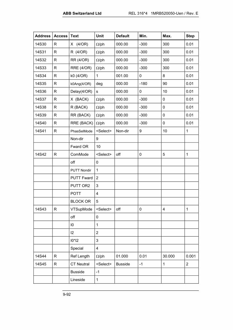
ABB Switzerland Ltd REL 316*4 1MRB520050-Uen / Rev. E
9-92
Address Access Text Unit Default Min. Max. Step
14S30 R X (4/OR) /ph 000.00 -300 300 0.01
14S31 R R (4/OR) /ph 000.00 -300 300 0.01
14S32 R RR (4/OR) /ph 000.00 -300 300 0.01
14S33 R RRE (4/OR) /ph 000.00 -300 300 0.01
14S34 R k0 (4/OR) 1 001.00 0 8 0.01
14S35 R k0Ang(4/OR) deg 000.00 -180 90 0.01
14S36 R Delay(4/OR) s 000.00 0 10 0.01
14S37 R X (BACK) /ph 000.00 -300 0 0.01
14S38 R R (BACK) /ph 000.00 -300 0 0.01
14S39 R RR (BACK) /ph 000.00 -300 0 0.01
14S40 R RRE (BACK) /ph 000.00 -300 0 0.01
14S41 R PhasSelMode <Select> Non-dir 9 10 1
Non-dir 9
Fward OR 10
14S42 R ComMode <Select> off 0 5 1
off 0
PUTT Nondir 1
PUTT Fward 2
PUTT OR2 3
POTT 4
BLOCK OR 5
14S43 R VTSupMode <Select> off 0 4 1
off 0
I0 1
I2 2
I0*I2 3
Special 4
14S44 R Ref Length /ph 01.000 0.01 30.000 0.001
14S45 R CT Neutral <Select> Busside -1 1 2
Busside -1
Lineside 1

REL 316*4 1MRB520050-Uen / Rev. E ABB Switzerland Ltd
9-93
Address Access Text Unit Default Min. Max. Step
14S46 R k0m 1 000.00 0 8 0.01
14S47 R k0mAng deg 000.00 -90 90 0.01
14S48 R Imin IN 000.20 0.1 2 0.01
14S49 R 3I0min IN 000.20 0.1 2 0.01
14S50 R U0 VTSup UN 000.20 0.01 0.5 0.01
14S51 R I0 VTSup IN 000.07 0.01 0.5 0.01
14S52 R U2 VTSup UN 000.20 0.01 0.5 0.01
14S53 R I2 VTSup IN 000.07 0.01 0.5 0.01
14S54 R XA /ph 000.0 0 999 0.1
14S55 R XB /ph 000.0 -999 0 0.1
14S56 R RA /ph 000.0 0 999 0.1
14S57 R RB /ph 000.0 -999 0 0.1
14S58 R RLoad /ph 000.0 0 999 0.1
14S59 R AngleLoad deg 045.0 0 90 0.1
14S60 R SR error deg 0.00 -2.00 2.00 0.01
14S61 R TR error deg 0.00 -2.00 2.00 0.01
14S62 R Delay(Def) s 002.00 0 10 0.01
14S63 R UminFault UN 000.05 0.01 2 0.01
14S64 R MemDirMode <Select> Trip 0 2 1
Block 0
Trip 1
Cond Trip 2
15S1 R SOFT <Select> off 0 2 1
off 0
Non-dir 1
Fwards OR2 2
15S2 R EventRecFull <Select> off 0 1 1
off 0
on 1
15S3 R 3U0min UN 000.00 0 2 0.01
15S4 R U Weak UN 000.00 0 2 0.01

ABB Switzerland Ltd REL 316*4 1MRB520050-Uen / Rev. E
9-94
Address Access Text Unit Default Min. Max. Step
15S5 R I OC BU IN 000.00 0 10 0.01
15S6 R Del OC BU s 005.00 0 10 0.01
15S7 R GndFaultMode <Select> I0 4 7 1
I0 4
I0 OR U0 5
I0(I2) 6
I0(I2) OR U0 7
15S9 R Dir Def <Select> Non-dir 1 2 1
Non-dir 1
Fwards 2
15S10 R TripMode <Select> 1PhTrip 1 3 1
1PhTrip 1
3PhTrip 2
3PhTripDel3 3
15S11 R SOFT 10sec <Select> off 0 1 1
off 0
on 1
15S12 R t1EvolFaults s 003.00 0 10 0.01
15S14 R Weak <Select> off 0 1 1
off 0
on 1
15S15 R Unblock <Select> off 0 1 1
off 0
on 1
15S16 R Echo <Select> off 0 1 1
off 0
on 1
15S17 R TransBl <Select> off 0 1 1
off 0
on 1
15S18 R t1TransBl s 000.05 0 0.25 0.01
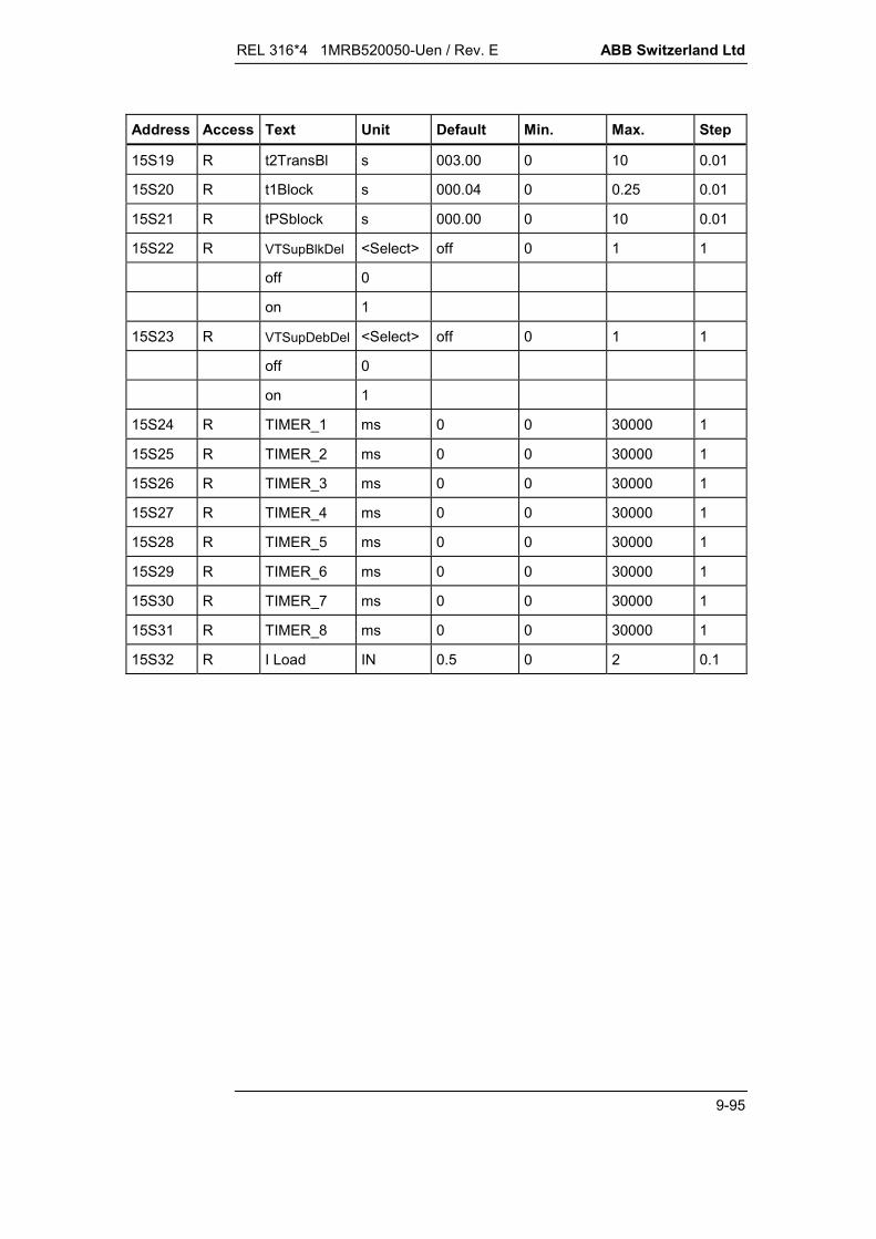
REL 316*4 1MRB520050-Uen / Rev. E ABB Switzerland Ltd
9-95
Address Access Text Unit Default Min. Max. Step
15S19 R t2TransBl s 003.00 0 10 0.01
15S20 R t1Block s 000.04 0 0.25 0.01
15S21 R tPSblock s 000.00 0 10 0.01
15S22 R VTSupBlkDel <Select> off 0 1 1
off 0
on 1
15S23 R VTSupDebDel <Select> off 0 1 1
off 0
on 1
15S24 R TIMER_1 ms 0 0 30000 1
15S25 R TIMER_2 ms 0 0 30000 1
15S26 R TIMER_3 ms 0 0 30000 1
15S27 R TIMER_4 ms 0 0 30000 1
15S28 R TIMER_5 ms 0 0 30000 1
15S29 R TIMER_6 ms 0 0 30000 1
15S30 R TIMER_7 ms 0 0 30000 1
15S31 R TIMER_8 ms 0 0 30000 1
15S32 R I Load IN 0.5 0 2 0.1
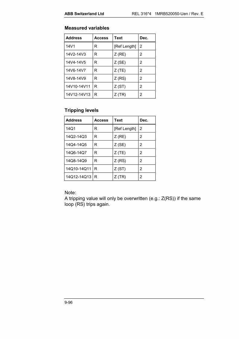
ABB Switzerland Ltd REL 316*4 1MRB520050-Uen / Rev. E
9-96
Measured variables
Address Access Text Dec.
14V1 R [Ref Length] 2
14V2-14V3 R Z (RE) 2
14V4-14V5 R Z (SE) 2
14V6-14V7 R Z (TE) 2
14V8-14V9 R Z (RS) 2
14V10-14V11 R Z (ST) 2
14V12-14V13 R Z (TR) 2
Tripping levels
Address Access Text Dec.
14Q1 R [Ref Length] 2
14Q2-14Q3 R Z (RE) 2
14Q4-14Q5 R Z (SE) 2
14Q6-14Q7 R Z (TE) 2
14Q8-14Q9 R Z (RS) 2
14Q10-14Q11 R Z (ST) 2
14Q12-14Q13 R Z (TR) 2
Note:A tripping value will only be overwritten (e.g.: Z(RS)) if the sameloop (RS) trips again.

REL 316*4 1MRB520050-Uen / Rev. E ABB Switzerland Ltd
9-97
Event list
Event No. Cause Event mask Enable code Status
14E1 Start I0 Set V155 1 14I1
14E2 Ditto Reset V155 2
14E3 Start U0 Set V155 4 14I2
14E4 Ditto Reset V155 8
14E5 Meas Oreach Set V155 16 14I3
14E6 Ditto Reset V155 32
14E7 Trip O/C Set V155 64 14I4
14E8 Ditto Reset V155 128
14E9 Power Swing Set V155 256 14I5
14E10 Ditto Reset V155 512
14E11 Trip CB R Set V155 1024 14I6
14E12 Ditto Reset V155 2048
14E13 Trip CB S Set V155 4096 14I7
14E14 Ditto Reset V155 8192
14E15 Trip CB T Set V155 16384 14I8
14E16 Ditto Reset V155 32768
14E17 Trip SOFT Set V156 1 14I9
14E18 Ditto Reset V156 2
14E19 Start O/C Set V156 4 14I10
14E20 Ditto Reset V156 8
14E21 Meas Main Set V156 16 14I11
14E22 Ditto Reset V156 32
14E23 Trip CB Set V156 64 14I12
14E24 Ditto Reset V156 128
14E25 Start R+S+T Set V156 256 14I13
14E26 Ditto Reset V156 512
14E27 Com Send Set V156 1024 14I14
14E28 Ditto Reset V156 2048
14E29 Dist Blocked Set V156 4096 14I15
14E30 Ditto Reset V156 8192

ABB Switzerland Ltd REL 316*4 1MRB520050-Uen / Rev. E
9-98
Event No. Cause Event mask Enable code Status
14E31 FreqDev Set V156 16384 14I16
14E32 Ditto Reset V156 32768
14E33 Start R Set V157 1 14I17
14E34 Ditto Reset V157 2
14E35 Start S Set V157 4 14I18
14E36 Ditto Reset V157 8
14E37 Start T Set V157 16 14I19
14E38 Ditto Reset V157 32
14E39 Start E Set V157 64 14I20
14E40 Ditto Reset V157 128
14E41 Delay 2 Set V157 256 14I21
14E42 Ditto Reset V157 512
14E43 Delay 3 Set V157 1024 14I22
14E44 Ditto Reset V157 2048
14E45 Delay 4 Set V157 4096 14I23
14E46 Ditto Reset V157 8192
14E47 Delay Def Set V157 16384 14I24
14E48 Ditto Reset V157 32768
14E49 Start RST Set V158 1 14I25
14E50 Ditto Reset V158 2
14E51 Weak Set V158 4 14I26
14E52 Ditto Reset V158 8
14E53 Meas Bward Set V158 16 14I27
14E54 Ditto Reset V158 32
14E55 Trip CB 3P Set V158 64 14I28
14E56 Ditto Reset V158 128
14E57 Trip CB 1P Set V158 256 14I29
14E58 Ditto Reset V158 512
14E59 Trip RST Set V158 1024 14I30
14E60 Ditto Reset V158 2048
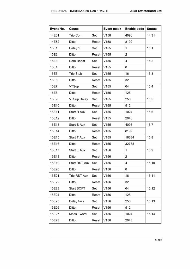
REL 316*4 1MRB520050-Uen / Rev. E ABB Switzerland Ltd
9-99
Event No. Cause Event mask Enable code Status
14E61 Trip Com Set V158 4096 14I31
14E62 Ditto Reset V158 8192
15E1 Delay 1 Set V155 1 15I1
15E2 Ditto Reset V155 2
15E3 Com Boost Set V155 4 15I2
15E4 Ditto Reset V155 8
15E5 Trip Stub Set V155 16 15I3
15E6 Ditto Reset V155 32
15E7 VTSup Set V155 64 15I4
15E8 Ditto Reset V155 128
15E9 VTSup Delay Set V155 256 15I5
15E10 Ditto Reset V155 512
15E11 Start R Aux Set V155 1024 15I6
15E12 Ditto Reset V155 2048
15E13 Start S Aux Set V155 4096 15I7
15E14 Ditto Reset V155 8192
15E15 Start T Aux Set V155 16384 15I8
15E16 Ditto Reset V155 32768
15E17 Start E Aux Set V156 1 15I9
15E18 Ditto Reset V156 2
15E19 Start RST Aux Set V156 4 15I10
15E20 Ditto Reset V156 8
15E21 Trip RST Aux Set V156 16 15I11
15E22 Ditto Reset V156 32
15E23 Start SOFT Set V156 64 15I12
15E24 Ditto Reset V156 128
15E25 Delay >= 2 Set V156 256 15I13
15E26 Ditto Reset V156 512
15E27 Meas Fward Set V156 1024 15I14
15E28 Ditto Reset V156 2048
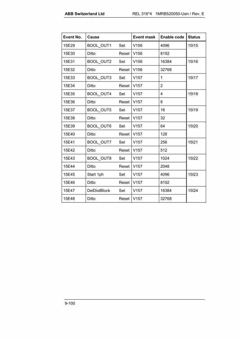
ABB Switzerland Ltd REL 316*4 1MRB520050-Uen / Rev. E
9-100
Event No. Cause Event mask Enable code Status
15E29 BOOL_OUT1 Set V156 4096 15I15
15E30 Ditto Reset V156 8192
15E31 BOOL_OUT2 Set V156 16384 15I16
15E32 Ditto Reset V156 32768
15E33 BOOL_OUT3 Set V157 1 15I17
15E34 Ditto Reset V157 2
15E35 BOOL_OUT4 Set V157 4 15I18
15E36 Ditto Reset V157 8
15E37 BOOL_OUT5 Set V157 16 15I19
15E38 Ditto Reset V157 32
15E39 BOOL_OUT6 Set V157 64 15I20
15E40 Ditto Reset V157 128
15E41 BOOL_OUT7 Set V157 256 15I21
15E42 Ditto Reset V157 512
15E43 BOOL_OUT8 Set V157 1024 15I22
15E44 Ditto Reset V157 2048
15E45 Start 1ph Set V157 4096 15I23
15E46 Ditto Reset V157 8192
15E47 DelDistBlock Set V157 16384
15E48 Ditto Reset V157 32768
15I24

REL 316*4 1MRB520050-Uen / Rev. E ABB Switzerland Ltd
9-101
9.6.59. LDU events 67
Basic channel No.: 14
Summary of parameters:
Address Access Text Unit Default Min. Max. Step
14S4 R ParSet4..1 <Select> P1 00000010B 00011110B
14S5 R TRIP 00000000B
Event list
Event No. Cause Event mask Enable code Status
14E1 BinOutput1 Set V155 1 14I1
14E2 Ditto Reset V155 2
14E3 BinOutput2 Set V155 4 14I2
14E4 Ditto Reset V155 8
14E5 BinOutput3 Set V155 16 14I3
14E6 Ditto Reset V155 32
14E7 BinOutput4 Set V155 64 14I4
14E8 Ditto Reset V155 128
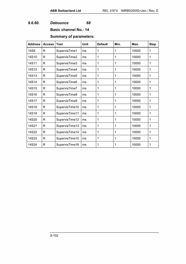
ABB Switzerland Ltd REL 316*4 1MRB520050-Uen / Rev. E
9-102
9.6.60. Debounce 68
Basic channel No.: 14
Summary of parameters:
Address Access Text Unit Default Min. Max. Step
14S9 R SupervisTime1 ms 1 1 10000 1
14S10 R SupervisTime2 ms 1 1 10000 1
14S11 R SupervisTime3 ms 1 1 10000 1
14S12 R SupervisTime4 ms 1 1 10000 1
14S13 R SupervisTime5 ms 1 1 10000 1
14S14 R SupervisTime6 ms 1 1 10000 1
14S15 R SupervisTime7 ms 1 1 10000 1
14S16 R SupervisTime8 ms 1 1 10000 1
14S17 R SupervisTime9 ms 1 1 10000 1
14S18 R SupervisTime10 ms 1 1 10000 1
14S19 R SupervisTime11 ms 1 1 10000 1
14S20 R SupervisTime12 ms 1 1 10000 1
14S21 R SupervisTime13 ms 1 1 10000 1
14S22 R SupervisTime14 ms 1 1 10000 1
14S23 R SupervisTime15 ms 1 1 10000 1
14S24 R SupervisTime16 ms 1 1 10000 1

REL 316*4 1MRB520050-Uen / Rev. E ABB Switzerland Ltd
9-103
9.6.61. df/dt 69
Basic channel No.: 14
Summary of parameters:
Address Access Text Unit Default Min. Max. Step
14S4 R ParSet4..1 <Select> P1 00000010B 00011110B
14S5 R TRIP 00000000B
14S9 R df/dt Hz/s -1.0 -10.0 10.0 0.1
14S10 R Frequency Hz 48.00 00.00 65.00 0.01
14S11 R BlockVoltage UN 0.2 0.2 0.8 0.1
14S12 R Delay s 00.10 0.10 60.00 0.01
Measured variables
Address Access Text Dec.
14V1 R Hz/s 2
14V2 R Hz 3
14V3 R UN 2
Tripping levels
Address Access Text Dec.
14Q1 R Hz/s 2
4Q2 R Hz 3
Event list
Event No. Cause Event mask Enable code Status
14E1 Blocked(U<) Set V155 1 14I1
14E2 Ditto Reset V155 2
14E3 TRIP Set V155 4 14I2
14E4 Ditto Reset V155 8

ABB Switzerland Ltd REL 316*4 1MRB520050-Uen / Rev. E
9-104
9.6.62. DirCurrentDT 70
Basisc channel No.: 14
Summery of parameters:
Address Access Text Unit Default Min. Max. Step
14S4 R ParSet4..1 <Select> P1 00000010B 00011110B
14S5 R Trip 00000000B
14S9 R I-Setting IN 2.00 0.20 20.00 0.01
14S10 R Angle deg 45 -180 +180 15
14S11 R Delay s 01.00 0.02 60.00 0.01
14S12 R tWait s 0.20 0.02 20.00 0.01
14S13 R MemDirMode <Select> Trip 0 1 1
Trip 0
Block 1
14S14 R MemDuration s 2.00 0.20 60.00 0.01
Measured variables
Address Access Text Dec.
14V1 R IN (R) 3
14V2 R IN (S) 3
14V3 R IN (T) 3
14V4 R PN (IR, UST) 3
14V5 R PN (IS, UTR) 3
14V6 R PN (IT, URS) 3
14V7 R UN (ST) 3
14V8 R UN (TR) 3
14V9 R UN (RS) 3

REL 316*4 1MRB520050-Uen / Rev. E ABB Switzerland Ltd
9-105
Tripping levels
Address Access Text Dec.
14Q1 R IN (R) 3
14Q2 R IN (S) 3
14Q3 R IN (T) 3
14Q4 R PN (IR, UST) 3
14Q5 R PN (IS, UTR) 3
14Q6 R PN (IT, URS) 3
14Q7 R UN (ST) 3
14Q8 R UN (TR) 3
14Q9 R UN (RS) 3
Event list
Event No. Cause Event mask Enable code Status
14E1 Trip Set V155 1 14I1
14E2 Ditto Reset V155 2
14E3 Start Set V155 4 14I2
14E4 Ditto Reset V155 8
14E5 Start R Set V155 16 14I3
14E6 Ditto Reset V155 32
14E7 Start S Set V155 64 14I4
14E8 Ditto Reset V155 128
14E9 Start T Set V155 256 14I5
14E10 Ditto Reset V155 512
14E11 MeasFwd Set V155 1024 14I6
14E12 Ditto Reset V155 2048
14E13 MeasBwd Set V155 4096 14I7
14E14 Ditto Reset V155 8192
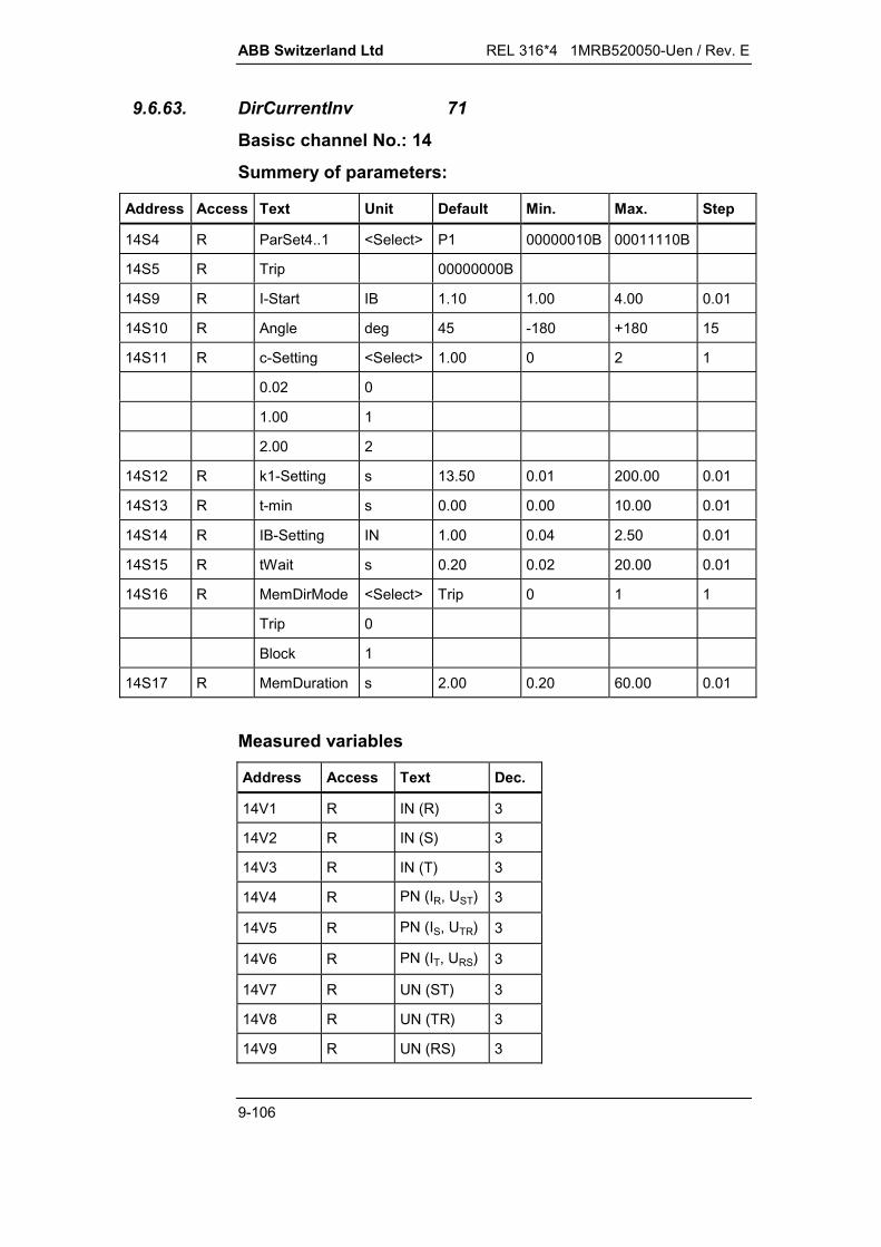
ABB Switzerland Ltd REL 316*4 1MRB520050-Uen / Rev. E
9-106
9.6.63. DirCurrentInv 71
Basisc channel No.: 14
Summery of parameters:
Address Access Text Unit Default Min. Max. Step
14S4 R ParSet4..1 <Select> P1 00000010B 00011110B
14S5 R Trip 00000000B
14S9 R I-Start IB 1.10 1.00 4.00 0.01
14S10 R Angle deg 45 -180 +180 15
14S11 R c-Setting <Select> 1.00 0 2 1
0.02 0
1.00 1
2.00 2
14S12 R k1-Setting s 13.50 0.01 200.00 0.01
14S13 R t-min s 0.00 0.00 10.00 0.01
14S14 R IB-Setting IN 1.00 0.04 2.50 0.01
14S15 R tWait s 0.20 0.02 20.00 0.01
14S16 R MemDirMode <Select> Trip 0 1 1
Trip 0
Block 1
14S17 R MemDuration s 2.00 0.20 60.00 0.01
Measured variables
Address Access Text Dec.
14V1 R IN (R) 3
14V2 R IN (S) 3
14V3 R IN (T) 3
14V4 R PN (IR, UST) 3
14V5 R PN (IS, UTR) 3
14V6 R PN (IT, URS) 3
14V7 R UN (ST) 3
14V8 R UN (TR) 3
14V9 R UN (RS) 3
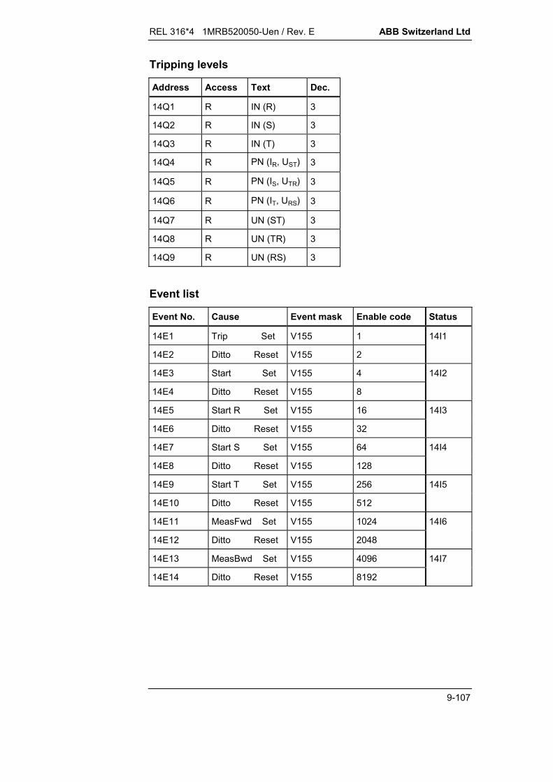
REL 316*4 1MRB520050-Uen / Rev. E ABB Switzerland Ltd
9-107
Tripping levels
Address Access Text Dec.
14Q1 R IN (R) 3
14Q2 R IN (S) 3
14Q3 R IN (T) 3
14Q4 R PN (IR, UST) 3
14Q5 R PN (IS, UTR) 3
14Q6 R PN (IT, URS) 3
14Q7 R UN (ST) 3
14Q8 R UN (TR) 3
14Q9 R UN (RS) 3
Event list
Event No. Cause Event mask Enable code Status
14E1 Trip Set V155 1 14I1
14E2 Ditto Reset V155 2
14E3 Start Set V155 4 14I2
14E4 Ditto Reset V155 8
14E5 Start R Set V155 16 14I3
14E6 Ditto Reset V155 32
14E7 Start S Set V155 64 14I4
14E8 Ditto Reset V155 128
14E9 Start T Set V155 256 14I5
14E10 Ditto Reset V155 512
14E11 MeasFwd Set V155 1024 14I6
14E12 Ditto Reset V155 2048
14E13 MeasBwd Set V155 4096 14I7
14E14 Ditto Reset V155 8192

ABB Switzerland Ltd REL 316*4 1MRB520050-Uen / Rev. E
9-108
9.6.64. BreakerFailure 72
Basisc channel No.: 14
Summery of parameters:
Address Access Text Unit Default Min. Max. Step
14S4 R ParSet4..1 <Select> P1 00000010B 00011110B
14S5 R 23105 TRIP t1 00000000B
14S9 R 23110 TRIP t1 L1 00000000B
14S13 R 23115 TRIP t1 L2 00000000B
14S17 R 23120 TRIP t1 L3 00000000B
14S21 R 23125 TRIP t2 00000000B
14S25 R 23130 REMOTE TRIP 00000000B
14S29 R 23135 RED TRIP L1 00000000B
14S33 R 23140 RED TRIP L2 00000000B
14S37 R 23145 RED TRIP L3 00000000B
14S41 R 23150 EFS REM TRIP 00000000B
14S45 R 23155 EFS BUS TRIP 00000000B
14S49 R I Setting IN 1.20 0.2 5 0.01
14S50 R Delay t1 s 0.15 0.02 60 0.01
14S51 R Delay t2 s 0.15 0.02 60 0.01
14S52 R Delay tEFP s 0.04 0.02 60 0.01
14S53 R t Drop Retrip s 0.05 0.02 60 0.01
14S54 R t Drop BuTrip s 0.05 0.02 60 0.01
14S55 R t Pulse RemTrip s 0.05 0.02 60 0.01
14S56 R t1 active <Select> on 0 1 1
off 0
on 1
14S57 R t2 active <Select> on 0 1 1
off 0
on 1
14S58 R RemTrip active <Select> on 0 1 1
off 0
on 1
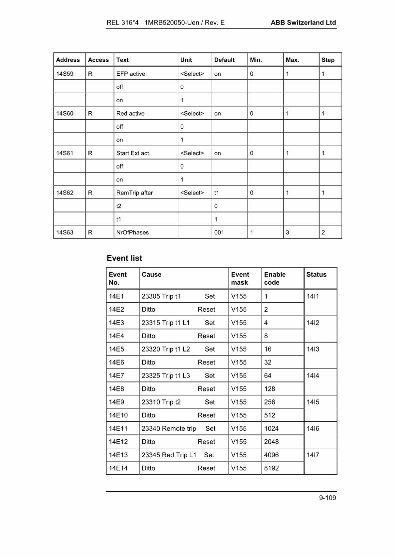
REL 316*4 1MRB520050-Uen / Rev. E ABB Switzerland Ltd
9-109
Address Access Text Unit Default Min. Max. Step
14S59 R EFP active <Select> on 0 1 1
off 0
on 1
14S60 R Red active <Select> on 0 1 1
off 0
on 1
14S61 R Start Ext act. <Select> on 0 1 1
off 0
on 1
14S62 R RemTrip after <Select> t1 0 1 1
t2 0
t1 1
14S63 R NrOfPhases 001 1 3 2
Event list
EventNo.
Cause Eventmask
Enablecode
Status
14E1 23305 Trip t1 Set V155 1 14I1
14E2 Ditto Reset V155 2
14E3 23315 Trip t1 L1 Set V155 4 14I2
14E4 Ditto Reset V155 8
14E5 23320 Trip t1 L2 Set V155 16 14I3
14E6 Ditto Reset V155 32
14E7 23325 Trip t1 L3 Set V155 64 14I4
14E8 Ditto Reset V155 128
14E9 23310 Trip t2 Set V155 256 14I5
14E10 Ditto Reset V155 512
14E11 23340 Remote trip Set V155 1024 14I6
14E12 Ditto Reset V155 2048
14E13 23345 Red Trip L1 Set V155 4096 14I7
14E14 Ditto Reset V155 8192
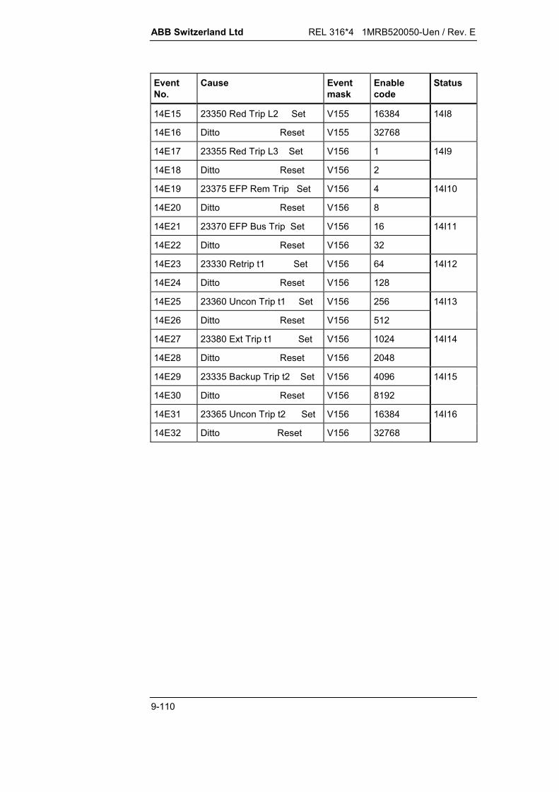
ABB Switzerland Ltd REL 316*4 1MRB520050-Uen / Rev. E
9-110
EventNo.
Cause Eventmask
Enablecode
Status
14E15 23350 Red Trip L2 Set V155 16384 14I8
14E16 Ditto Reset V155 32768
14E17 23355 Red Trip L3 Set V156 1 14I9
14E18 Ditto Reset V156 2
14E19 23375 EFP Rem Trip Set V156 4 14I10
14E20 Ditto Reset V156 8
14E21 23370 EFP Bus Trip Set V156 16 14I11
14E22 Ditto Reset V156 32
14E23 23330 Retrip t1 Set V156 64 14I12
14E24 Ditto Reset V156 128
14E25 23360 Uncon Trip t1 Set V156 256 14I13
14E26 Ditto Reset V156 512
14E27 23380 Ext Trip t1 Set V156 1024 14I14
14E28 Ditto Reset V156 2048
14E29 23335 Backup Trip t2 Set V156 4096 14I15
14E30 Ditto Reset V156 8192
14E31 23365 Uncon Trip t2 Set V156 16384 14I16
14E32 Ditto Reset V156 32768
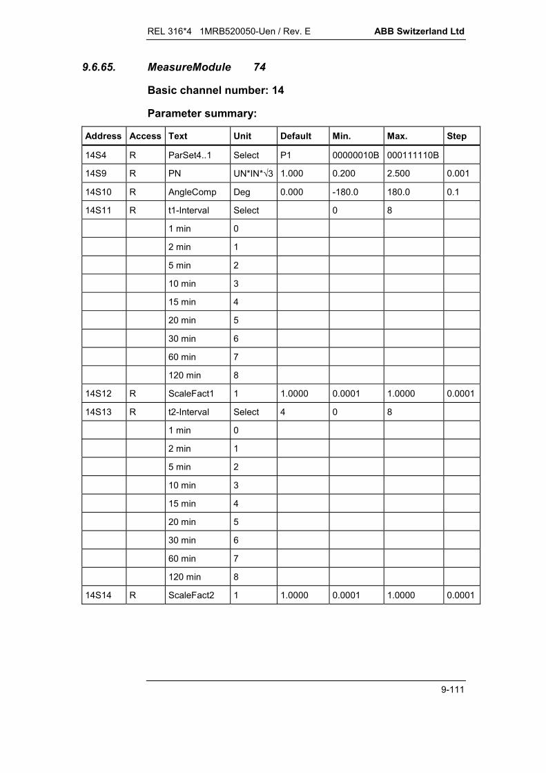
REL 316*4 1MRB520050-Uen / Rev. E ABB Switzerland Ltd
9-111
9.6.65. MeasureModule 74
Basic channel number: 14
Parameter summary:
Address Access Text Unit Default Min. Max. Step
14S4 R ParSet4..1 Select P1 00000010B 000111110B
14S9 R PN UN*IN*3 1.000 0.200 2.500 0.001
14S10 R AngleComp Deg 0.000 -180.0 180.0 0.1
14S11 R t1-Interval Select 0 8
1 min 0
2 min 1
5 min 2
10 min 3
15 min 4
20 min 5
30 min 6
60 min 7
120 min 8
14S12 R ScaleFact1 1 1.0000 0.0001 1.0000 0.0001
14S13 R t2-Interval Select 4 0 8
1 min 0
2 min 1
5 min 2
10 min 3
15 min 4
20 min 5
30 min 6
60 min 7
120 min 8
14S14 R ScaleFact2 1 1.0000 0.0001 1.0000 0.0001

ABB Switzerland Ltd REL 316*4 1MRB520050-Uen / Rev. E
9-112
Measured variables
Address Access Text Dec.
14V1 R URS(UN) 3
14V2 R UST(UN) 3
14V3 R UTR(UN) 3
14V4 R UR(UN) 3
14V5 R US(UN) 3
14V6 R UT(UN) 3
14V7 R IR(IN) 3
14V8 R IS(IN) 3
14V9 R IT(IN) 3
14V10 R P (PN) 3
14V11 R Q (PN) 3
14V12 R cos phi 3
14V13 R Hz 3
14V14 R E1Int 3
14V15 R P1Int 0
14V16 R E1Acc 3
14V17 R P1Acc 0
14V18 R E2Int 3
14V19 R P2Int 0
14V20 R E2Acc 3
14V21 R P2Acc 0
Tripping levels
Address Access Text Dec.
14Q16 R E1Acc 3
14Q17 R P1Acc 0
14Q20 R E2Acc 3
14Q21 R P2Acc 0

REL 316*4 1MRB520050-Uen / Rev. E ABB Switzerland Ltd
9-113
Event list
Event No. Cause Event mask Enable code Status
14E1 Cnt1New Set V155 1 14I1
14E2 Ditto Reset V155 2
14E3 Cnt2New Set V155 4 14I2
14E4 Ditto Reset V155 8

REL 316*4 1MRB520050-Uen / Rev. G ABB Switzerland Ltd
10-1
July 02
10. SUPPLEMENTARY INFORMATION
10.1. Changes in Version 5.0 in relation to Version 4.5 ..................10-310.1.1. Local display unit (LDU).........................................................10-310.1.2. New ‘LDU events’ function.....................................................10-310.1.3. New processor unit 316VC61a ..............................................10-3
10.2. Known software weaknesses in V5.0 ....................................10-310.2.1. Year 2000 conformity.............................................................10-310.2.2. ‘LDU events’ function.............................................................10-3
10.3. Changes in Version 5.1 in relation to Version 5.0 ..................10-410.3.1. Distributed input/output system RIO580 ................................10-410.3.2. Year 2000 conformity.............................................................10-410.3.3. ‘LDU events’ function.............................................................10-4
10.4. Changes in Version 5.1a in relation to Version 5.1 ................10-410.4.1. ‘I0-Invers’ function..................................................................10-4
10.5. Changes in Version 5.1b in relation to Version 5.1a ..............10-410.5.1. ‘Min-Reactance’ function........................................................10-4
10.6. Changes in Version 5.1c in relation to Version 5.1b ..............10-410.6.1. Year 2000 conformity.............................................................10-4
10.7. Changes in Version 5.2 in relation to Version 5.1c ................10-510.7.1. Frequency rate of change protection .....................................10-510.7.2. Touch screen or SMS in parallel with the SCS connection ....10-5
10.8. Changes in Version 5.2a in relation to Version 5.2 ................10-510.8.1. Frequency rate of change protection ‘df/dt’............................10-5
10.9. Changes in Version 6.0 in relation to Version 5.2(a)..............10-510.9.1. Directional overcurrent functions ‘DirCurrentDT’ and
‘DirCurrentInv’ ........................................................................10-510.9.2. Breaker failure protection ‘BreakerFailure’.............................10-510.9.3. Runtime supervision ..............................................................10-510.9.4. New processor unit 316VC61b ..............................................10-6
10.10. Changes in Version Version 6.2 in relation to Version 6.0 .....10-610.10.1. Analogue input/output unit 500AXM11...................................10-610.10.2. ‘Analogue RIO Trigger’ function.............................................10-6

ABB Switzerland Ltd REL 316*4 1MRB520050-Uen / Rev. G
10-2
10.10.3. Measurement module ............................................................10-610.10.4. Commands via a Stage 2 LON bus .......................................10-6
10.11. Changes in Version 6.3 in relation to Version 6.2 ..................10-610.11.1. A/D converter unit 316EA63 ..................................................10-610.11.2. Updating the 316EA63 firmware ............................................10-7
REL 316*4 1MRB520050-Uen / Rev. G ABB Switzerland Ltd
10-3
10. SUPPLEMENTARY INFORMATION
10.1. Changes in Version 5.0 in relation to Version 4.5
10.1.1. Local display unit (LDU)
From Version V5.0, the software supports the local display unit(see Section 5.13.).
10.1.2. New ‘LDU events’ function
The LDU events list only includes tripping levels. The newfunction ‘LDU events’ enables additional events to be selectedfor listing (see Section 3.6.5.).
10.1.3. New processor unit 316VC61a
All devices equipped with the local display unit (LDU) also havethe new processor unit 316VC61a; devices not equipped withthe LDU can have either the 316VC61 or 316VC61a.
Whether there is a 316VC61a in a device not equipped with alocal control and display unit can be determined using the HMIdiagnostic function. Upon selecting ‘Show diagnostic data’, oneof the lines displayed is ‘HW No.’, which in the case of316VC61a includes the code ‘0434’: HW-Nr.: xxxx/0434/xx
The computing capacity of the 316VC61a is 250% (comparedwith 200% in the case of 316VC61).
10.2. Known software weaknesses in V5.0
10.2.1. Year 2000 conformity
Version V5.0 is influenced to a minor extent by the year 2000problem, but the correct operation of the devices during and afterthe change of the century is assured. The only shortcomingconcerns the time stamp, which retains ‘19’ in the year instead ofchanging to ‘20’. All other data is correct and the events arelisted in the correct chronological order.
10.2.2. ‘LDU events’ function
The ‘LDU events’ function is not available when the HMI isoperating off-line.

ABB Switzerland Ltd REL 316*4 1MRB520050-Uen / Rev. G
10-4
10.3. Changes in Version 5.1 in relation to Version 5.0
10.3.1. Distributed input/output system RIO580
From Version V5.1, the software supports the distributedinput/output system RIO580. The latter comprises a number ofdistributed input/output units that are connected to an RE.316*4device via an MVB (multipurpose vehicle bus) and an MVB PCboard. Refer to Data Sheet 1MRB520176-Ben and OperatingInstructions 1MRB520192-Ben for further details.
10.3.2. Year 2000 conformity
With the exception of the VDEW version, for which the synchroni-sation of the time will not function via the VDEW bus in the year2000, all Version V5.1 devices are fully immune to the year 2000problem.
10.3.3. ‘LDU events’ function
The ‘LDU events’ function is also now available when the HMI isoperating off-line.
10.4. Changes in Version 5.1a in relation to Version 5.1
10.4.1. ‘I0-Invers’ function
The ‘I0-Invers’ is always enabled regardless of the software keyin use.
10.5. Changes in Version 5.1b in relation to Version 5.1a
10.5.1. ‘Min-Reactance’ function
The underreactance function can now also be connected toY-connected v.t’s.
10.6. Changes in Version 5.1c in relation to Version 5.1b
10.6.1. Year 2000 conformity
All devices are immune to the year 2000 problem from VersionV5.1c onwards.
REL 316*4 1MRB520050-Uen / Rev. G ABB Switzerland Ltd
10-5
10.7. Changes in Version 5.2 in relation to Version 5.1c
10.7.1. Frequency rate of change protection
A df/dt function has been added to the function block library.Because of an error, however, it is not displayed for all thesoftware keys there are (see Section 10.8.1.).
10.7.2. Touch screen or SMS in parallel with the SCS connection
Where a station control system (SCS) is connected via a LON orMVB bus, there is a second fully functional SPA interfaceavailable in parallel which can be used for connecting a touchscreen an SMS.
10.8. Changes in Version 5.2a in relation to Version 5.2
10.8.1. Frequency rate of change protection ‘df/dt’
V5.2a of the HMI shows the ‘df/dt’ function for all software keys,for which the ‘Frequency’ function has been enabled.
10.9. Changes in Version 6.0 in relation to Version 5.2(a)
10.9.1. Directional overcurrent functions ‘DirCurrentDT’ and‘DirCurrentInv’
Two directional overcurrent functions ‘DirCurrentDT’ with definitetime and ‘DirCurrentInv’ with inverse time characteristic havebeen added to the function block library. They are accessible forall software keys for which the current and voltage functions areenabled.
10.9.2. Breaker failure protection ‘BreakerFailure’
A ‘BreakerFailure’ function has been added to the function blocklibrary which is accessible to all software keys.
10.9.3. Runtime supervision
A runtime supervision function can be specified for pairs ofinputs that have been configured as “double indications”(see Section 5.5.5.5.).
ABB Switzerland Ltd REL 316*4 1MRB520050-Uen / Rev. G
10-6
10.9.4. New processor unit 316VC61b
Version 6.0 supports the new 316VC61b processor unit. Todetermine whether a device contains a 316VC61b processorunit or not, open ‘List diagnostic information’ in the HMIdiagnostic function and check the code ‘04Ax’ on line ‘HW No.’:
HW No.: xxxx/04Ax/xx
10.10. Changes in Version Version 6.2 in relation to Version 6.0
10.10.1. Analogue input/output unit 500AXM11
Versions from V6.2 onwards support the analogue input/outputunit 500AXM11 of the distributed input/output system RIO580.
10.10.2. ‘Analogue RIO Trigger’ function
An ‘Analogue RIO Trigger’ function has been added to thefunction block library which is available for all software keys andfacilitates the supervision of the input signals of the analogueinput/output unit 500AXM11. Refer to the Operating Instructionsfor the distributed input/output system RIO580, Publication1MRB520192-Uen, for further details.
10.10.3. Measurement module
The ‘MeasureModule’ function has been added to the functionblock library. It is available for all software keys and facilitates thethree-phase measurement of voltage, current, active and reactivepower, power factor and frequency. Two counter impulse inputsare also provided for metering energy.
10.10.4. Commands via a Stage 2 LON bus
In automation systems equipped with a Stage 2 LON interbaybus, commands can be transferred from the automation systemto the bay units.
10.11. Changes in Version 6.3 in relation to Version 6.2
10.11.1. A/D converter unit 316EA63
From Version V6.3, the software supports the new A/D converterunit 316EA63 which supersedes the previous plug-in unit 316EA62.

REL 316*4 1MRB520050-Uen / Rev. G ABB Switzerland Ltd
10-7
10.11.2. Updating the 316EA63 firmware
The new A/D converter unit 316EA63 allows the firmware to bedownloaded without opening the unit. If updating is necessary,this is done in a similar fashion as updating the main processorfirmware (see Section 7.5.). After each update of the mainprocessor firmware, the 316EA63 firmware must also be up-dated.
When applying the DOS HMI, updating is made by calling up thebatch file ‘loadEA63.bat’, which is listed in the HMI directory.
When applying the Windows HMC CAP2/316, the item ‘EA63download’ in the menu ‘Options’ must be selected.


REL 316*4 1MRB520050-Uen / Rev. C ABB Switzerland Ltd
12-1
March 01
12. APPENDICES
12.1 List of abbreviations and symbols..........................................12-2
Fig. 12.2 Numerical line protection REL 316*4 (front view)...................12-3
Fig. 12.3 Numerical line protection REL 316*4View from the rear showing the location of units....................12-4
Fig. 12.4 Dimensioned drawings for semi-flush andsurface mounting of the test socket cases .............................12-5
Fig. 12.5 Test socket case Type XX93 .................................................12-6
Fig. 12.6 Set-up for testing with the test set Type XS92band the test socket case Type XX93......................................12-7
Fig. 12.7 Set-up for testing with the test set Type XS92band the test socket case Type 316TSS01 .............................12-7
Fig. 12.8 Wiring diagram for the test socket case Type XX93(corresponds to HESG 324 171)............................................12-8
Fig. 12.9 Wiring diagram for the test socket case Type 316TSS01(corresponds to HESG 324 348)............................................12-9
Check list for replacing hardware unitsReport for replacing hardware units
TEST REPORT
Typical wiring diagram for the numerical line protection REL 316*4
Notification

ABB Switzerland Ltd REL 316*4 1MRB520050-Uen / Rev. C
12-2
12.1 List of abbreviations and symbolsIA : balancing current
IB : load current
IN : rated current
IK : fault current
k0 : zero-sequence compensation orresidual current coefficient
KI : main c.t. ratio
KU : main v.t. ratio
KZ : impedance ratio
UN : rated voltage
Zi : impedance reach of zone i
ZL = RL + jXL : positive-sequence line impedance
Z0L : zero-sequence line impedance
ZLp : primary positive-sequence line impedance
ZLs : secondary positive-sequence line impedance
ZOR : impedance setting of the overreach zone
Index i : zone No.

REL 316*4 1MRB520050-Uen / Rev. C ABB Switzerland Ltd
12-3
Fig. 12.2 Numerical line protection REL 316*4(front view)
1. Green LED (stand-by)2. LED’s for 1st. I/O unit3. LED’s for 2nd. I/O unit4. Reset button behind frontplate5. Local display unit (LDU) with optical serial interface6. Text space
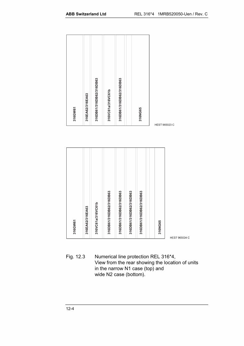
ABB Switzerland Ltd REL 316*4 1MRB520050-Uen / Rev. C
12-4
HEST 965023 C
316G
W61
316E
A62
/316
EA63
316D
B61
/316
DB
62/3
16D
B63
316V
C61
a/31
6VC
61b
316D
B61
/316
DB
62/3
16D
B63
316N
G65
316G
W61
316E
A62
/316
EA63
316D
B61
/316
DB
62/3
16D
B63
316V
C61
a/31
6VC
61b
316D
B61
/316
DB
62/3
16D
B63
316N
G65
316D
B61
/316
DB
62/3
16D
B63
316D
B61
/316
DB
62/3
16D
B63
Fig. 12.3 Numerical line protection REL 316*4,View from the rear showing the location of unitsin the narrow N1 case (top) andwide N2 case (bottom).

REL 316*4 1MRB520050-Uen / Rev. C ABB Switzerland Ltd
12-5
Panel cutout
Panel cutout
Fig. 12.4 Dimensioned drawings for semi-flush andsurface mounting of the test socket casesTypes 316TSS01 (top) and XX93 (bottom)

ABB Switzerland Ltd REL 316*4 1MRB520050-Uen / Rev. C
12-6
Fig. 12.5 Test socket case Type XX93A...C Connectors for test plug YX91-4D Ancillary test connector YX93, where fitted
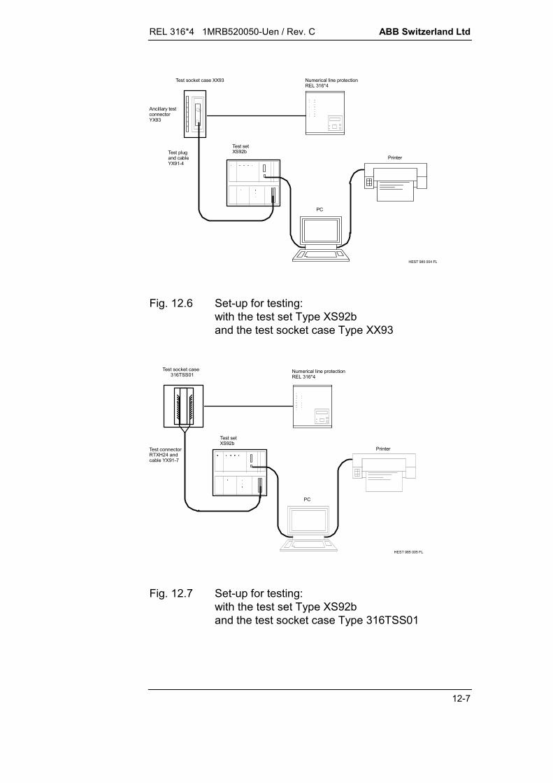
REL 316*4 1MRB520050-Uen / Rev. C ABB Switzerland Ltd
12-7
PC
Printer
Numerical line protectionREL 316*4
Test socket case XX93
Ancillary testconnector YX93
Test plugand cableYX91-4
Test setXS92b
HEST 985 004 FL
Fig. 12.6 Set-up for testing:with the test set Type XS92band the test socket case Type XX93
PC
Printer
Numerical line protectionREL 316*4
Test socket case 316TSS01
Test setXS92b
Test connectorRTXH24 andcable YX91-7
HEST 985 005 FL
Fig. 12.7 Set-up for testing:with the test set Type XS92band the test socket case Type 316TSS01

ABB Switzerland Ltd REL 316*4 1MRB520050-Uen / Rev. C
12-8
Fig. 12.8 Wiring diagram for the test socket case Type XX93(corresponds to HESG 324 171)
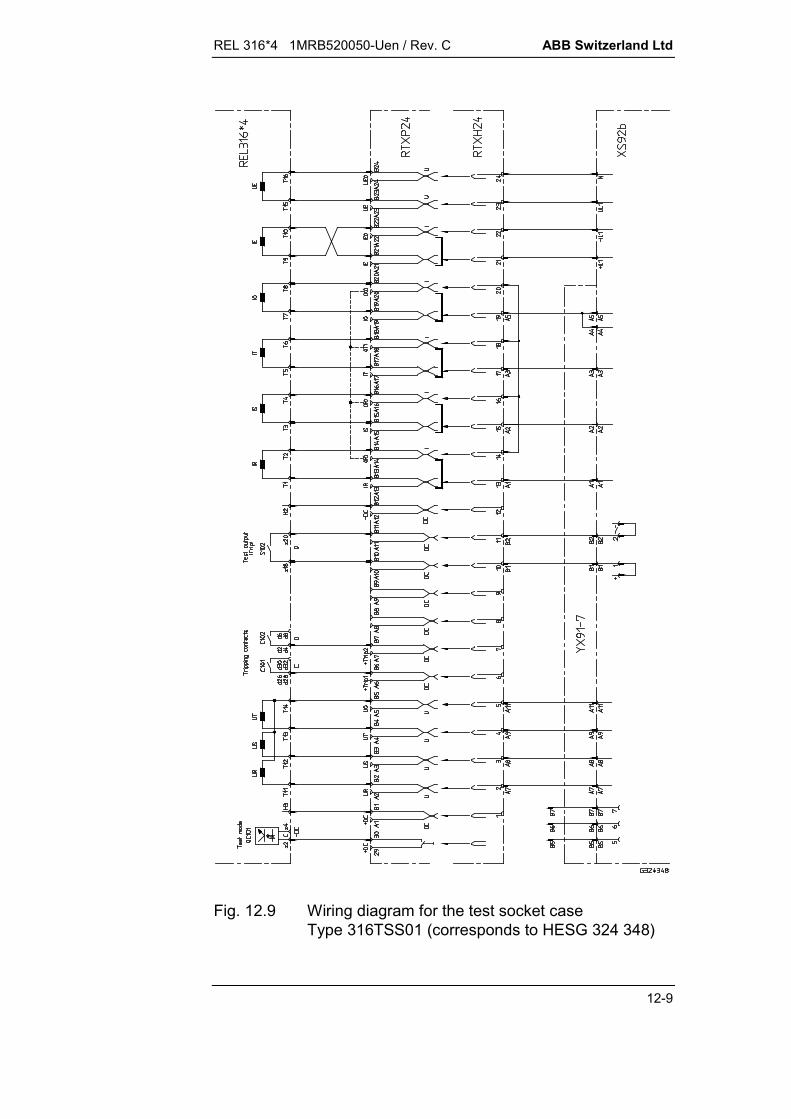
REL 316*4 1MRB520050-Uen / Rev. C ABB Switzerland Ltd
12-9
Fig. 12.9 Wiring diagram for the test socket caseType 316TSS01 (corresponds to HESG 324 348)


Checklist for replacing hardware modules in RE . 316*4 units
99-06
Not applicable CompletedNot fitted
Read out and save the existing unit settings
(always necessary when replacing the 316VC61).Read out or print the diagnostic and event lists (for defects)
Switch off the auxiliary supply.
Short-circuit the external c.t. leads and then disconnect them. 1)
Disconnect the external v.t. leads. 1)
Disconnect the current and voltage circuits from the unit. 1)
Unscrew the electrical-to-optical converter Type 316BM61 (OBI)
or withdraw the PC card.If necessary, fit a coupling device to loop the optical fibre cable sothat the rest of the system can continue to operate.
Remove the covers from the unit. 2)
Mark the slot of the module to be replaced and withdraw it. 3)
Make a note of the module’s technical data.
Compare the ordering code and software of old and new modules.
Make a note of the technical data of the new module.
Insert the new module in the slot previously marked.
Refit the covers on the unit.
Refit the electrical-to-optical converter Type 316BM61 (OBI) or
reinsert the PC card.Reconnect the ground to the unit if it was removed.
Reconnect c.t. and v.t. circuits.
Switch on the auxiliary supply.
Download to the unit the settings previously saved (always
necessary when replacing the 316VC61) and also any FUPLA logic on the disc.Check the operation of the unit
(e.g. check the voltages and currents in the “Display analoguechannels” menu. Depending on the type of module that has beenreplaced, other checks may be necessary such as for a316DB61/62/63 the alarms, tripping signals and binary inputs).
1) Only necessary when replacing the input transformer module 316GW61.2) Flush-mounted version: Remove the auxiliary supply plug, unscrew the backplate (4 large and
4 small screws around the edge, 2 screws holding the power supply unit and 2 screws holding theRS232 interface; the connectors do not have to be removed).Surface-mounted version: Swing the relay out on its hinges and remove the backplate as for theflush-mounted version.
3) Refer to the respective Operating Instructions for the locations of the modules (slots).

Report to be filled in after replacing hardware modulesin RE . 316*4 units
02-05
To enable a record of the modules to be kept (traceability), please forward the following information toABB Power Automation Ltd (by fax or mail) whenever modules are replaced:
Address ABB Switzerland LtdUtility AutomationDepartment UTAAA-PBruggerstrasse 71aCH-5401 BadenSwitzerland Fax ++ 41 58 585 31 30
General data
Client .............................................. Station ......................................... Feeder ....................................
RE. 316*4 data (sticker on unit)
Type of unit ..................................................................Unit ID ..................................................................Serial No. .................................................................. Item ..........Drawing No. / Revision index ..................................................................Ordering code ..................................................................Software version FW: .................... MMC: ....................(sticker below reset button)
Module data
Old module New module
Type of module / Revision ........................................ ........................................Module ID ........................................ ........................................Serial No. ........................................ ........................................Drawing No. / Revision index ........................................ ........................................Barcode No. ........................................ ........................................Software version of IC's (if any) A .......... Vers. ..........
A .......... Vers. ..........A .......... Vers. ..........A .......... Vers. ..........
Date when hardware replaced ....................
Remarks: ................................................................................................................................................................................................................................................................................................................................................................................................
Name: Signature: Date:

TEST SHEETSTATION: FEEDER:
99-02
Line Protection Type REL316*4
Date: Signature:
Client
Date: Signature:
Checklist
Kind of check Remarks
Relay number
Visual check for transport damage
Visual check of external wiring
Check of relay grounding
Check of supply voltage (DC/AC)
Check of settings
Check of C.T. circuits
Check of P.T. circuits
Secondary injection with test set type ......
Check of input signals
Check of signalisation/alarms
Check of starting breaker failure protection
Check of HF circuits
HF - “End to End“ test
Check of tripping
Check of reclosing
Directional check
Stability check (longitudinal diff. function)
Final check

TEST SHEETSTATION: FEEDER:
99-02
Line Protection Type REL316*4
Date: Signature:
Client
Date: Signature:
Primary line datas SettingsLength ..................... km According to separate print outPos. seq. impedance ..................... Ω/ph angle .................... ° Software version of the relay ........Zero seq. impedance ..................... Ω/ph angle .................... °
Main C.T./P.T. ratioAnalogue inputs 1 - 3 ..................... / ................... Analogue input 4 .................... / ............Analogue inputs 7 - 9 ..................... A / ................... A Analogue input 5 .................... / ............
Analogue input 6 .................... / ............
Secondary injection
Impedance function "Distance" Directional earth fault function "EarthFaultIsol"Nom. val. Measured value [Ω/ph] Nom. val. Measured value
[Ω/ph] R S T [VA] [V * A = VA]X (1) Forward
X (2) --- --- Backward
X (3) --- --- Directional earth fault function "EarthFltGnd2"
X (4/OR) --- --- I-Setting [A] V-Setting [V]
XA --- --- Nom. val. Meas. val. Nom. val. Meas. val.
XB --- ---
Longitudinal differential function "Diff-Line“Measuring of the basic setting g
Phase Nominal val. [A] Measured value [A] If the fibre optic link or the relay at the opposite
R station is not ready, the “Diff-Line“ function is
S blocked and the analogue inputs can only be
T checked using the menue “Display AD Channels“.
Synchrocheck function "SynchroCheck"Parallel injection (1phase) of "uLineInput" and "uBusInput1" or "uBusInput2" respectively
Injected "uLineInput" parallel "uBusInput1" "uLineInput" parallel "uBusInput2"
Differential voltage Differential angle Differential voltage Differential angle
voltage[V]
∆Unom.[UN]
∆Umeas. *[UN]
∆αnom.[deg]
∆αmeas. *[deg]
∆Unom.[UN]
∆Umeas. *[UN]
∆αnom.[deg]
∆αmeas. *[deg]
* To be read in the menu "Display Function Measurements" ---> "SynchroCheck"Synchrocheck function must be released
Additional functions Result............................................................................................................................................ .......................................................................................................................................................... .......................................................................................................................................................... ..............

TEST SHEETSTATION: FEEDER:
99-02
Line Protection Type REL316*4
Date: Signature:
Client
Date: Signature:
Activation/Deactivation of Binary Inputs
DB61 DB62 DB63 DB61 DB62 DB63
Function/Remarks Result Function/Remarks Result
OC 101 ............................................ .............. OC 201 ............................................ ..............OC 102 ............................................ .............. OC 202 ............................................ ..............OC 103 ............................................ .............. OC 203 ............................................ ..............OC 104 ............................................ .............. OC 204 ............................................ ..............OC 105 ............................................ .............. OC 205 ............................................ ..............OC 106 ............................................ .............. OC 206 ............................................ ..............OC 107 ............................................ .............. OC 207 ............................................ ..............OC 108 ............................................ .............. OC 208 ............................................ ..............OC 109 ............................................ .............. OC 209 ............................................ ..............OC 110 ............................................ .............. OC 210 ............................................ ..............OC 111 ............................................ .............. OC 211 ............................................ ..............OC 112 ............................................ .............. OC 212 ............................................ ..............OC 113 ............................................ .............. OC 213 ............................................ ..............OC 114 ............................................ .............. OC 214 ............................................ ..............
DB61 DB62 DB63 DB61 DB62 DB63
Function/Remarks Result Function/Remarks Result
OC 301 ............................................ .............. OC 401 ............................................ ..............OC 302 ............................................ .............. OC 402 ............................................ ..............OC 303 ............................................ .............. OC 403 ............................................ ..............OC 304 ............................................ .............. OC 404 ............................................ ..............OC 305 ............................................ .............. OC 405 ............................................ ..............OC 306 ............................................ .............. OC 406 ............................................ ..............OC 307 ............................................ .............. OC 407 ............................................ ..............OC 308 ............................................ .............. OC 408 ............................................ ..............OC 309 ............................................ .............. OC 409 ............................................ ..............OC 310 ............................................ .............. OC 410 ............................................ ..............OC 311 ............................................ .............. OC 411 ............................................ ..............OC 312 ............................................ .............. OC 412 ............................................ ..............OC 313 ............................................ .............. OC 413 ............................................ ..............OC 314 ............................................ .............. OC 414 ............................................ ..............

TEST SHEETSTATION: FEEDER:
99-02
Line Protection Type REL316*4
Date: Signature:
Client
Date: Signature:
Activation/Deactivation of Alarm RelaysFunction/Remarks Result
DB61 S 101 ............................................................................................................ .............. DB62 S 102 ............................................................................................................ .............. DB63 S 103 ............................................................................................................ ..............
S 104 ............................................................................................................ ..............S 105 ............................................................................................................ ..............S 106 ............................................................................................................ ..............S 107 ............................................................................................................ ..............S 108 ............................................................................................................ ..............S 109 ............................................................................................................ ..............S 110 ............................................................................................................ ..............
DB61 S 201 ............................................................................................................ .............. DB62 S 202 ............................................................................................................ .............. DB63 S 203 ............................................................................................................ ..............
S 204 ............................................................................................................ ..............S 205 ............................................................................................................ ..............S 206 ............................................................................................................ ..............S 207 ............................................................................................................ ..............S 208 ............................................................................................................ ..............S 209 ............................................................................................................ ..............S 210 ............................................................................................................ ..............
DB61 S 301 ............................................................................................................ .............. DB62 S 302 ............................................................................................................ .............. DB63 S 303 ............................................................................................................ ..............
S 304 ............................................................................................................ ..............S 305 ............................................................................................................ ..............S 306 ............................................................................................................ ..............S 307 ............................................................................................................ ..............S 308 ............................................................................................................ ..............S 309 ............................................................................................................ ..............S 310 ............................................................................................................ ..............
DB61 S 401 ............................................................................................................ .............. DB62 S 402 ............................................................................................................ .............. DB63 S 403 ............................................................................................................ ..............
S 404 ............................................................................................................ ..............S 405 ............................................................................................................ ..............S 406 ............................................................................................................ ..............S 407 ............................................................................................................ ..............S 408 ............................................................................................................ ..............S 409 ............................................................................................................ ..............S 410 ............................................................................................................ ..............

TEST SHEETSTATION: FEEDER:
99-02
Line Protection Type REL316*4
Date: Signature:
Client
Date: Signature:
Activation of Tripping Relays
Function/Remarks Result
DB61 C 101 Contact 1 ............................................................................................. .............. DB62 C 101 Contact 2 ............................................................................................. ..............
C 102 Contact 1 ............................................................................................. ..............C 102 Contact 2 ............................................................................................. ..............
DB61 C 201 Contact 1 ............................................................................................. .............. DB62 C 201 Contact 2 ............................................................................................. ..............
C 202 Contact 1 ............................................................................................. ..............C 202 Contact 2 ............................................................................................. ..............
DB61 C 301 Contact 1 ............................................................................................. .............. DB62 C 301 Contact 2 ............................................................................................. ..............
C 302 Contact 1 ............................................................................................. ..............C 302 Contact 2 ............................................................................................. ..............
DB61 C 401 Contact 1 ............................................................................................. .............. DB62 C 401 Contact 2 ............................................................................................. ..............
C 402 Contact 1 ............................................................................................. ..............C 402 Contact 2 ............................................................................................. ..............


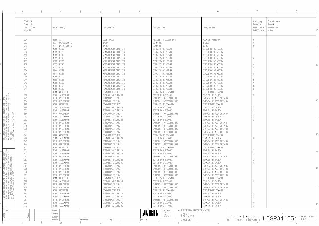


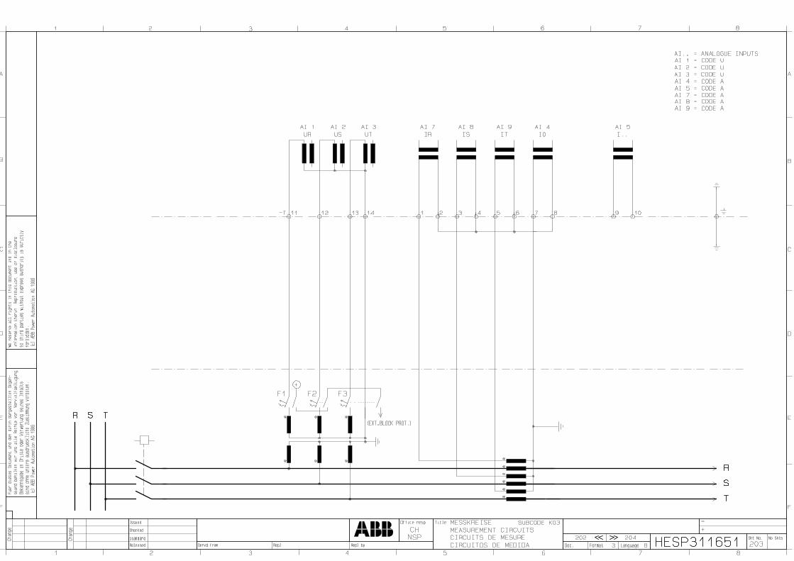

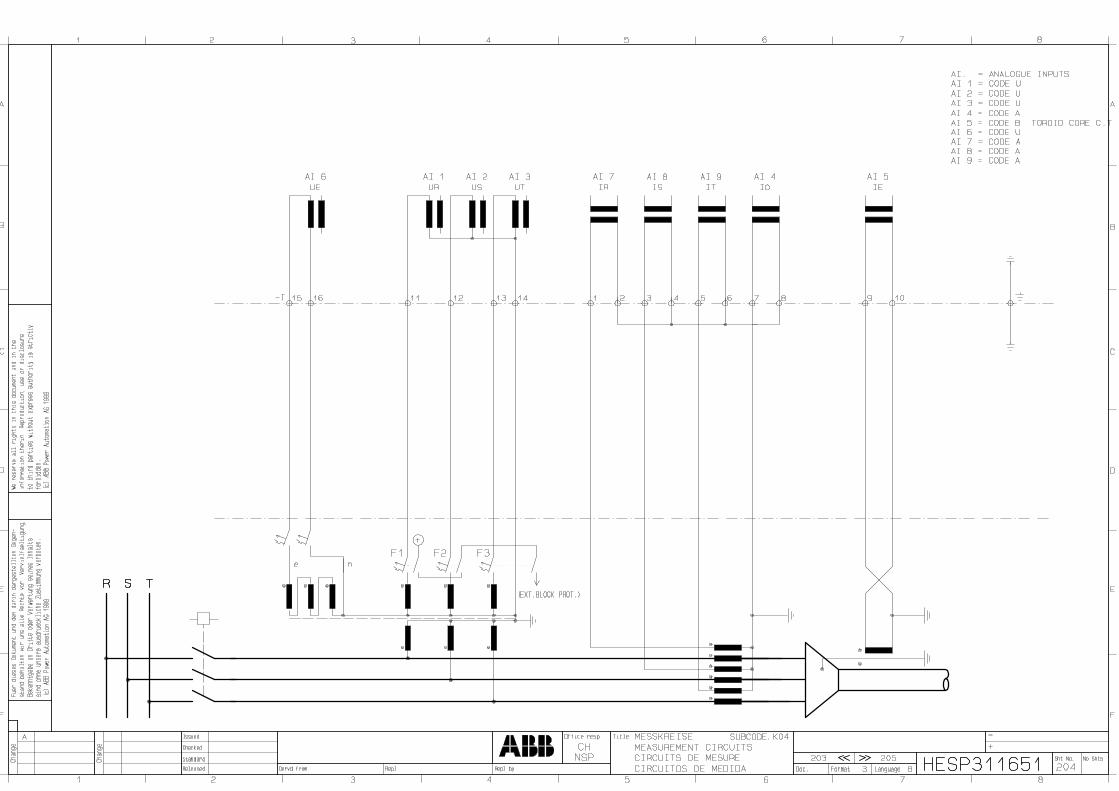


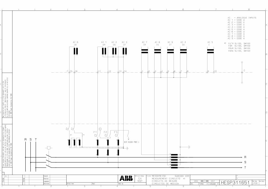

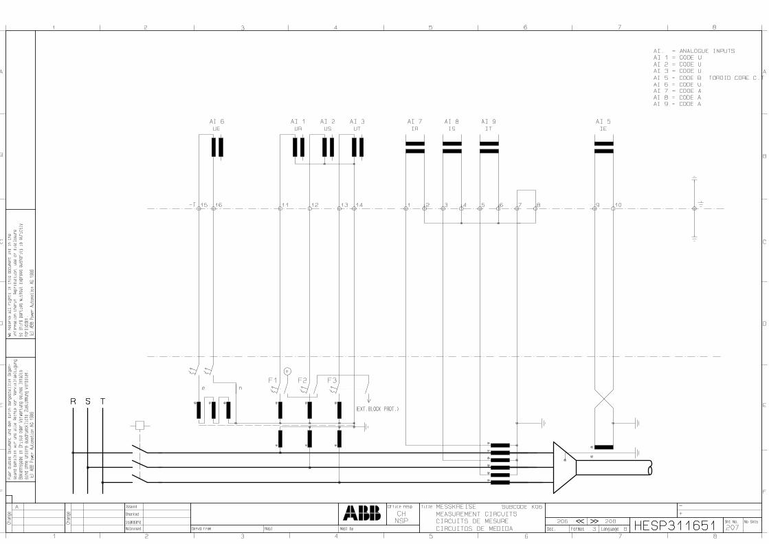


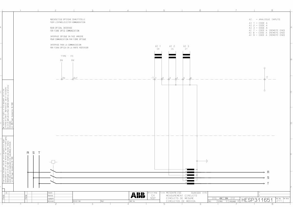


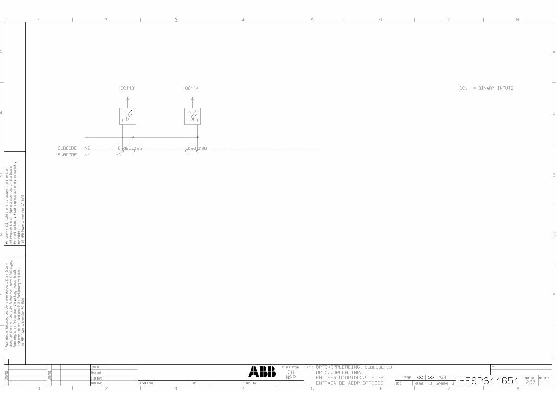

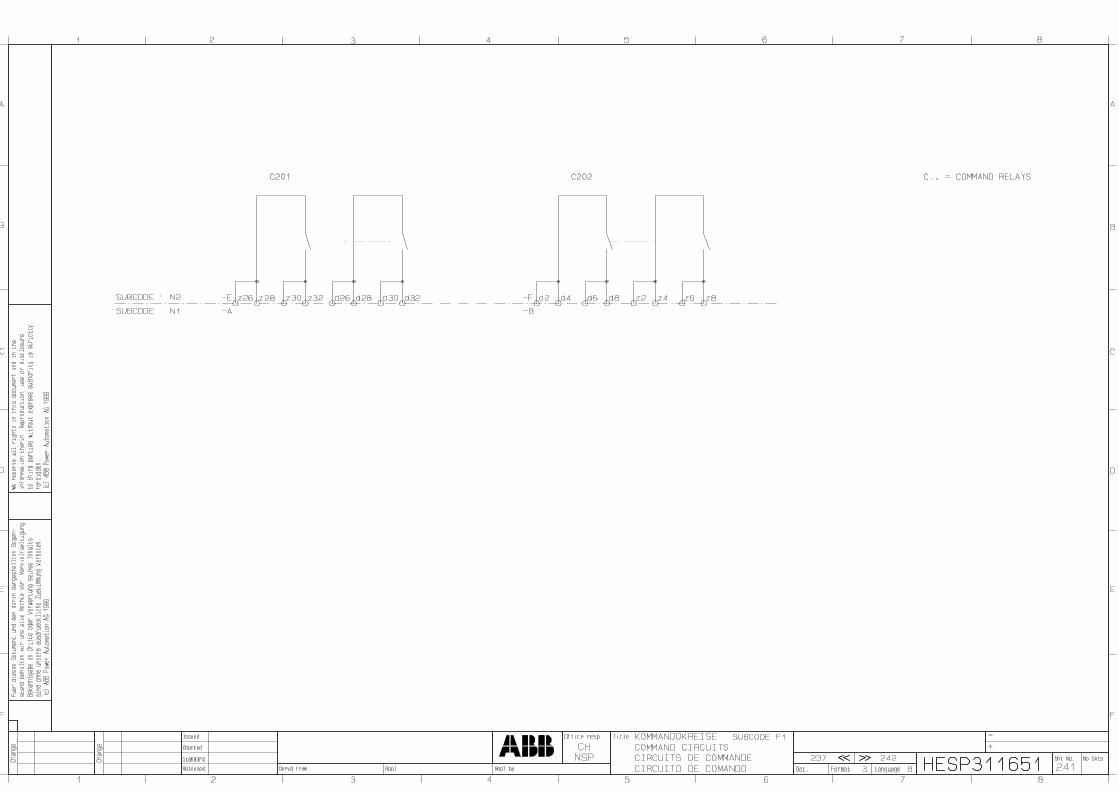


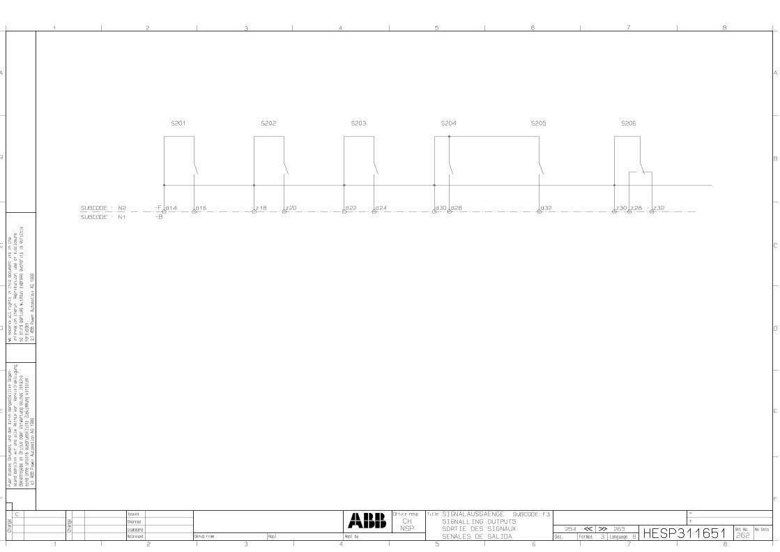

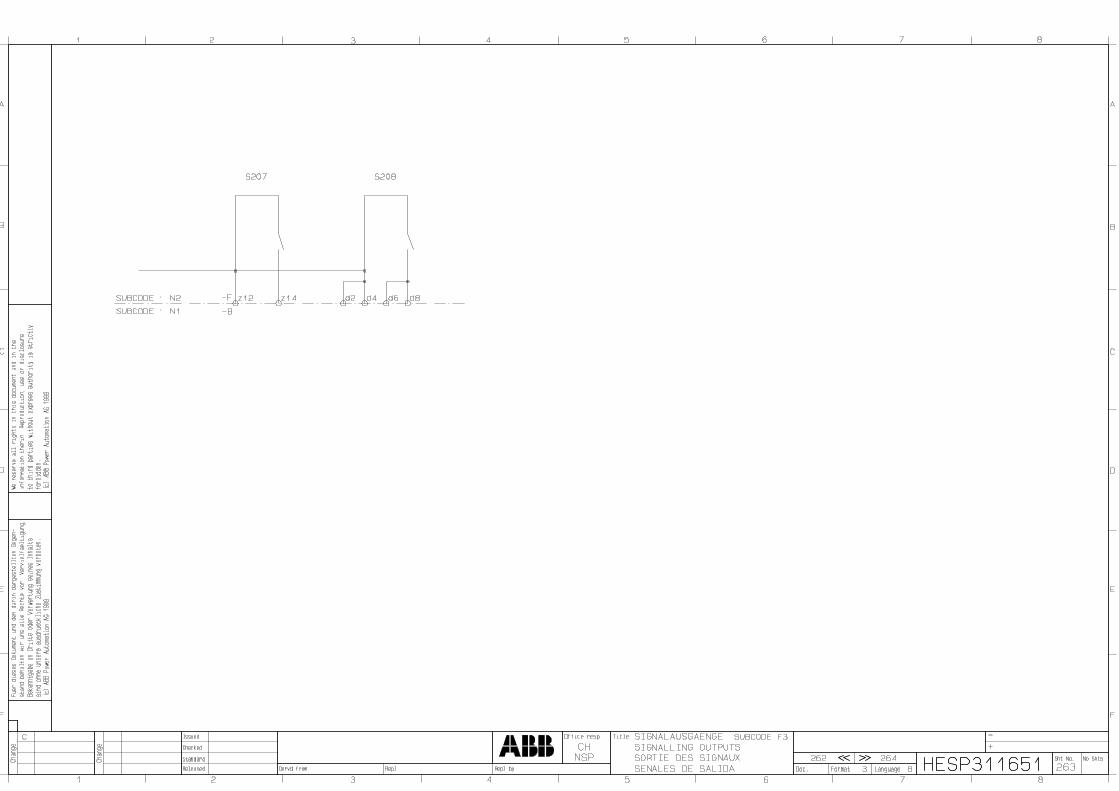


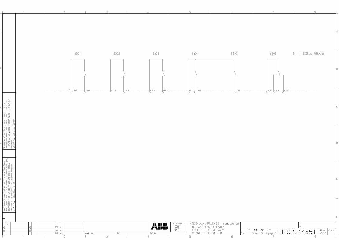

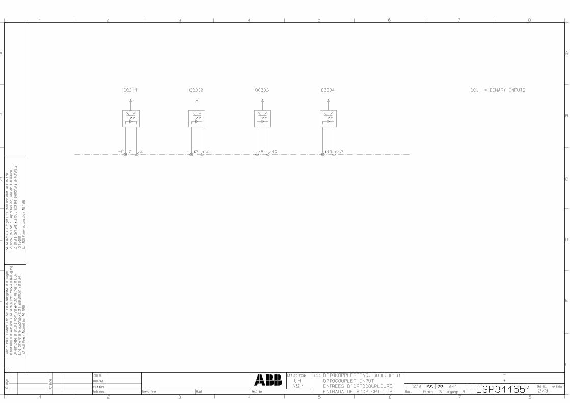


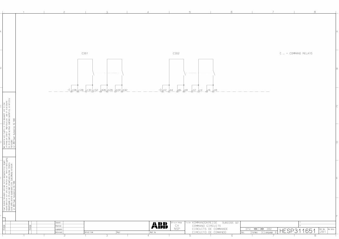


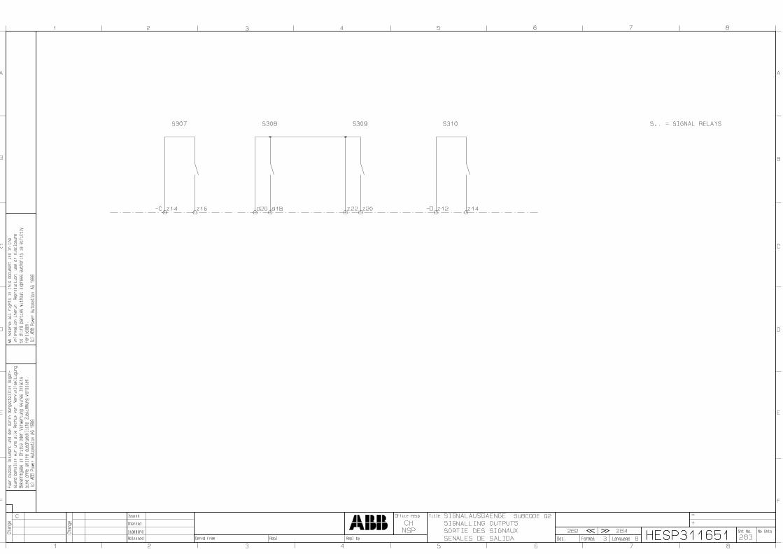


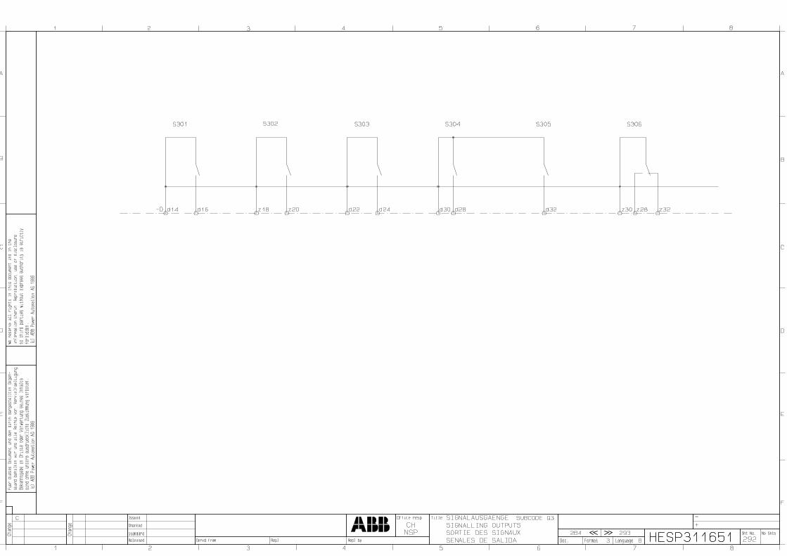


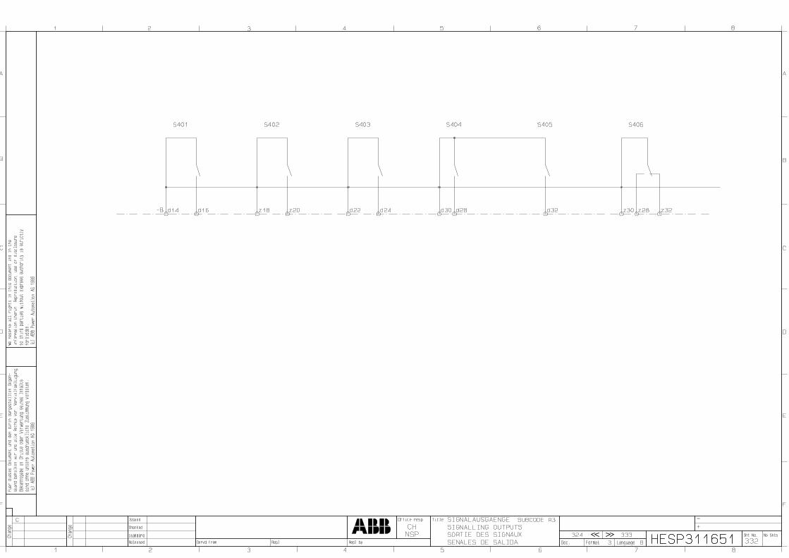


Notification Form for Errors in this DocumentDear User,We constantly endeavour to improve the quality of our technical publications andwould like to hear your suggestions and comments. Would you therefore please fill inthis questionnaire and return it to the address given below.
ABB Switzerland LtdUtility AutomationBetreuung Dokumentation, UTA-BD1Römerstrasse 29 / Gebäude 733/3CH-5401 BadenTelefax +41 58 585 28 00---------------------------------------------------------------------------------------------------------------Concerns publication: 1MRB520050-Uen (REL 316*4 V6.3)Have you discovered any mistakes in this publication? If so, please note here thepages, sections etc.
Do you find the publication readily understandable and logically structured? Can youmake any suggestions to improve it?
Is the information sufficient for the purpose of the publication? If not, what is missingand where should it be included?
Name Date
Company
Postal code Town Country


Notification Form for Equipment Faults and ProblemsDear User,Should you be obliged to call on our repair service, please attach a note to the unitdescribing the fault as precisely as possible. This will help us to carry out the repairswiftly and reliably, which after all is to your own advantage.Please attach a completed form to every unit and forward them to the address below.
Place of delivery Baden/Switzerland:
ABB Switzerland LtdUtility AutomationRepair Center, UTAAA-PWarenannahme Terminal CACH-5401 Baden---------------------------------------------------------------------------------------------------------------Equipment data:Unit type:Serial No.: ……….....................................In operation since:
Reason for return: (tick where applicable)
Overfunction
No function
Outside tolerance
Abnormal operating temperature
Sporadic error
Unit for checking
Remarks/Description of fault:
Customer: Date:
Address:
Please contact: Phone: Fax:


Notification Form for Software Errors and ProblemsDear User,As we all know from practice, software does not always function as expected for allapplications. A precise description of the problem and your observations will help usto improve and maintain the software. Please complete this form and send it togetherwith any supporting information or documents to the address below.
ABB Switzerland LtdUtility AutomationBetreuung Software, Abt. UTASSBruggerstrasse 71aCH-5401 BadenTelefax +41 58 585 86 57e-mail: SA-LEC-Support@ch.abb.com---------------------------------------------------------------------------------------------------------------
Unit/ REC 316*4 SW Version: REC 216 SW Version:System: REG 316*4 SW Version: REG 216 SW Version:
REL 316*4 SW Version: HMI SW Version: RET 316*4 SW Version: other: SW Version: XS92a / XS92b SW Version:
Problem: Program error (unit/system) Program error (HMI /PC) Error in manual Suggestion for improvement other:
Can the error be reproduced at will? yes no
Particulars of hardware and software (unit/system configuration including jumperpositions, type of PC etc.):
Problem located? yes noSuggested changes enclosed? yes noThe following are enclosed (floppy with settings etc.):
Floppy Unit/system settings, file name: other:Description of problem:
Customer: Date:
Address:
Please contact: Phone: Fax:
DESCRIPTION OF PROBLEM: (continuation)
___________________________________________________________________ACTION (internal use of ABB Switzerland Ltd, Dept. UTASS only)Received by: Date:Answered by: Date:
Problem solved? yes no
Week: Name: Position: Consequence:---------------------------------------------------------------------------------------------------------------

IMPORTANT NOTICE!
Experience has shown that reliable operation of our products isassured, providing the information and recommendations con-tained in these Operating Instructions are adhered to.
It is scarcely possible for the instructions to cover every eventu-ality that can occur when using technical devices and systems.We would therefore request the user to notify us directly or ouragent of any unusual observations or instances, in which theseinstructions provide no or insufficient information.
In addition to these instructions, any applicable local regulationsand safety procedures must always be strictly observed bothwhen connecting up and commissioning this equipment.
Any work such as insertion or removal of soldered jumpers orsetting resistors, which may be necessary, may only be per-formed by appropriately qualified personnel.
We expressly accept no responsibility for any direct damage,which may result from incorrect operation of this equipment,even if no reference is made to the particular situation in theOperating Instructions.

ABB Switzerland LtdUtility AutomationBrown Boveri Strasse 6CH-5400 Baden / SwitzerlandTelefon +41 58 585 77 44Telefax +41 58 585 55 77e-mail [email protected]
www.abb.com/substationautomation
Printed in Switzerland (0108-0050-0)