Bharat Heavy Electricals Limited Doc No. TB-413-316-103 ...
51
-
Upload
khangminh22 -
Category
Documents
-
view
0 -
download
0
Transcript of Bharat Heavy Electricals Limited Doc No. TB-413-316-103 ...
Bharat Heavy Electricals Limited Doc No. TB‐413‐316‐103 Technical Specification
Clamps and Connectors SECTION 1 REV 00
Page 1 of 5
SCOPE, SPECIFIC TECHNICAL REQUIREMENTS AND QUANTITIES.
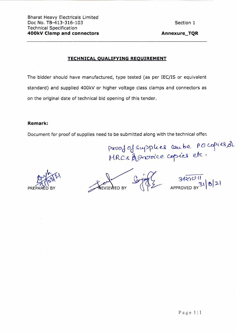
[1] SCOPE
This technical specification covers the requirements of design, manufacture,
testing at works, packing and dispatch of Clamps & Connectors to site.
This section covers the scope, quantities, Specific Technical Requirements for
Clamps & Connectors as specified by the customer. The offered equipment
shall also comply with the General Technical Requirements for the project as
detailed under section-3 of this specification.
The specification comprises of following sections
Section-1 Scope, project specific technical requirements & bill of
quantities.
Section-2 Standard Technical Specification for Clamps & Connectors.
Section-3 Project details & general technical Specifications for all the
equipments under the project.
Section-4 Annexures
Annexure-A (Compliance Certificate)
Annexure-B (Schedule of Technical Deviations)
In case of any discrepancies between the requirements mentioned under
different Sections of technical specifications, order of precedence shall be as
follows:
Section-1 shall precede Section-2, Section-2 shall precede Section-3.
In general, no deviation from the requirements specified in various clauses of
this specification shall be allowed and hence, a certificate to this effect shall
have to be furnished along with the offer (Annexure-A), however bidder
shall furnish list of conflicts/ ambiguities/ deviations (if any) in Schedule of
Technical Deviations (Annexure-B). Any conflicts/ ambiguities/ deviations
mentioned elsewhere in technical offer shall not be reviewed. In case the
Bharat Heavy Electricals Limited Doc No. TB‐413‐316‐103 Technical Specification
Clamps and Connectors SECTION 1 REV 00
Page 2 of 5
deviations mentioned in the Schedule of Technical Deviations are not
technically acceptable, the offer of the bidder will be liable to rejection.
The scope of supplies shall be as per commercial terms and conditions
enclosed separately with the enquiry.
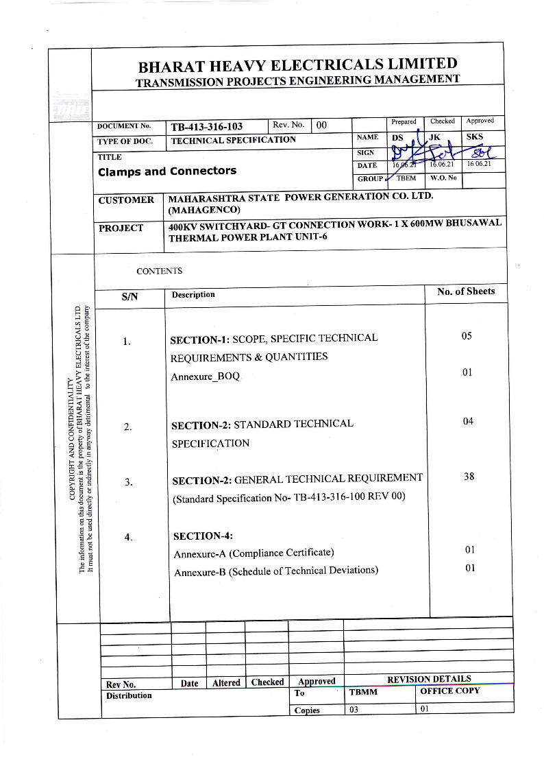
[2] The Clamps & Connectors are required for the following Project
Customer: MAHARASHTRA STATE POWER GENERATION CO. LTD.
(MAHAGENCO)
Project: 400KV SWITCHYARD- GT CONNECTION WORK- 1 X 600MW
BHUSAWAL THERMAL POWER PLANT UNIT-6
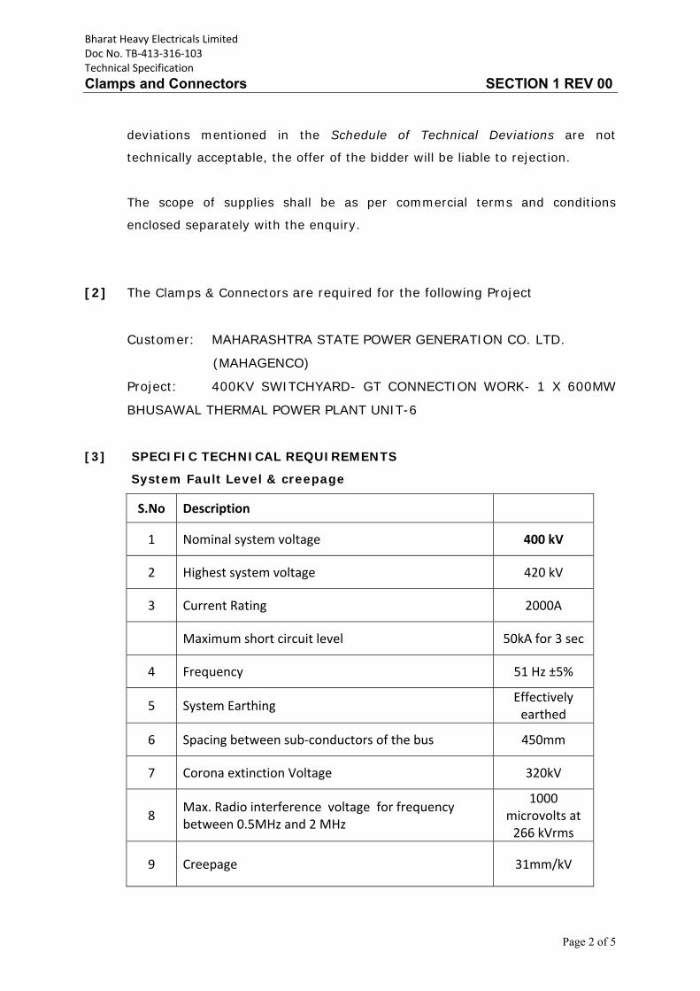
[3] SPECIFIC TECHNICAL REQUIREMENTS
System Fault Level & creepage
S.No Description
1 Nominal system voltage 400 kV
2 Highest system voltage 420 kV
3 Current Rating 2000A
Maximum short circuit level 50kA for 3 sec
4 Frequency 51 Hz ±5%
5 System Earthing Effectively earthed
6 Spacing between sub‐conductors of the bus 450mm
7 Corona extinction Voltage 320kV
8 Max. Radio interference voltage for frequency between 0.5MHz and 2 MHz
1000 microvolts at 266 kVrms
9 Creepage 31mm/kV
Bharat Heavy Electricals Limited Doc No. TB‐413‐316‐103 Technical Specification
Clamps and Connectors SECTION 1 REV 00
Page 3 of 5
[4] OTHER TECHNICAL REQUIREMENTS:
4.1 All equipment shall perform satisfactorily under various other
electrical, electromechanical and meteorological conditions of the
site of installation.
4.2 All equipment shall be able to withstand all external and internal
mechanical, thermal and electromechanical forces due to various
factors like wind load, temperature variation, ice & snow, (wherever
applicable) short circuit etc. for the equipment.
4.3 The equipment shall also comply to facilitate erection of equipment,
all items to be assembled at site shall be “match marked”.
[5] BILL OF QUANTITIES: Please refer Annexure_BOQ
5.1 Individual quantity may vary up to any extend however total contract
value may vary up to ±20%.
5.2 The scope of supply shall also include:
i) All connector hardware along with bimetallic washers / strip/liners as
required.
ii) All hardware required for connecting to the respective equipment
terminals.
iii) Minimum 5 % extra hardware and bimetallic washers/strips/liners of
each type.
[6] GTP/DRAWINGS
Bidder to submit detailed GTP in line with technical specification during
contract stage for review and approval, it will be the bidder’s responsibility to
get the same approved from the ultimate customer M/s MAHAGENCO/ DCPL.
[7] QUALITY PLAN
Bharat Heavy Electricals Limited Doc No. TB‐413‐316‐103 Technical Specification
Clamps and Connectors SECTION 1 REV 00
Page 4 of 5
The contractor shall carry out contract works in accordance with sound quality
management principles which shall include controls which are necessary to
ensure full compliance to all requirements of the specification & applicable
international standards. These quality management requirements shall apply
to all activities during design, procurement, manufacturing, inspection,
testing, packaging, shipping, inland transportation, storage, site erection &
commissioning. Contractor shall submit detailed Quality Plan for BHEL /
customer’s approval.
[8] TYPE TESTING, INSPECTION, TESTING & INSPECTION CERTIFICATE
Please refer Section-2 of technical specification for the details of type
test requirement.
All equipment being supplied shall conform to type tests as per technical
specification and shall be subject to routine tests in accordance with
requirements stipulated under respective sections.
The reports for all type tests as per technical specification shall be furnished
by the bidder along with equipment / material drawings. The type tests
conducted earlier should have either been conducted in accredited laboratory
(accredited based on ISO / IEC Guide 25 / 17025 or EN 45001 by the national
accreditation body of the country where laboratory is located or as
applicable).
Unless otherwise specified elsewhere, the type test reports submitted shall be
of the tests conducted within last 10 (Ten) years from the original date of
technical bid opening of this tender.
In case the test reports are of the test conducted earlier than 10 (Ten) years
from the original date of technical bid opening of this tender, the contractor
shall repeat these test(s) at no extra cost to BHEL / MAHAGENCO.
Bharat Heavy Electricals Limited Doc No. TB‐413‐316‐103 Technical Specification
Clamps and Connectors SECTION 1 REV 00
Page 5 of 5
Further, in the event of any discrepancy in the test reports i.e. any test report
not acceptable due to any design/manufacturing changes or due to non-
compliance with the requirement stipulated in the Technical Specification or
any/all type tests not carried out, same shall be carried out without any
additional cost and time implication to BHEL / MAHAGENCO.
The Bidder shall intimate BHEL with the detailed program about the type tests
at least two (2) weeks in advance in case of domestic supplies & six (6)
weeks in advance in case of foreign supplies.
Note – (1.) Type test report shall be reviewed for approval in detailed
engineering stage only. However, for evaluation purpose, the confirmation of
valid type test reports is to be submitted along with the technical bid.
----- x-----
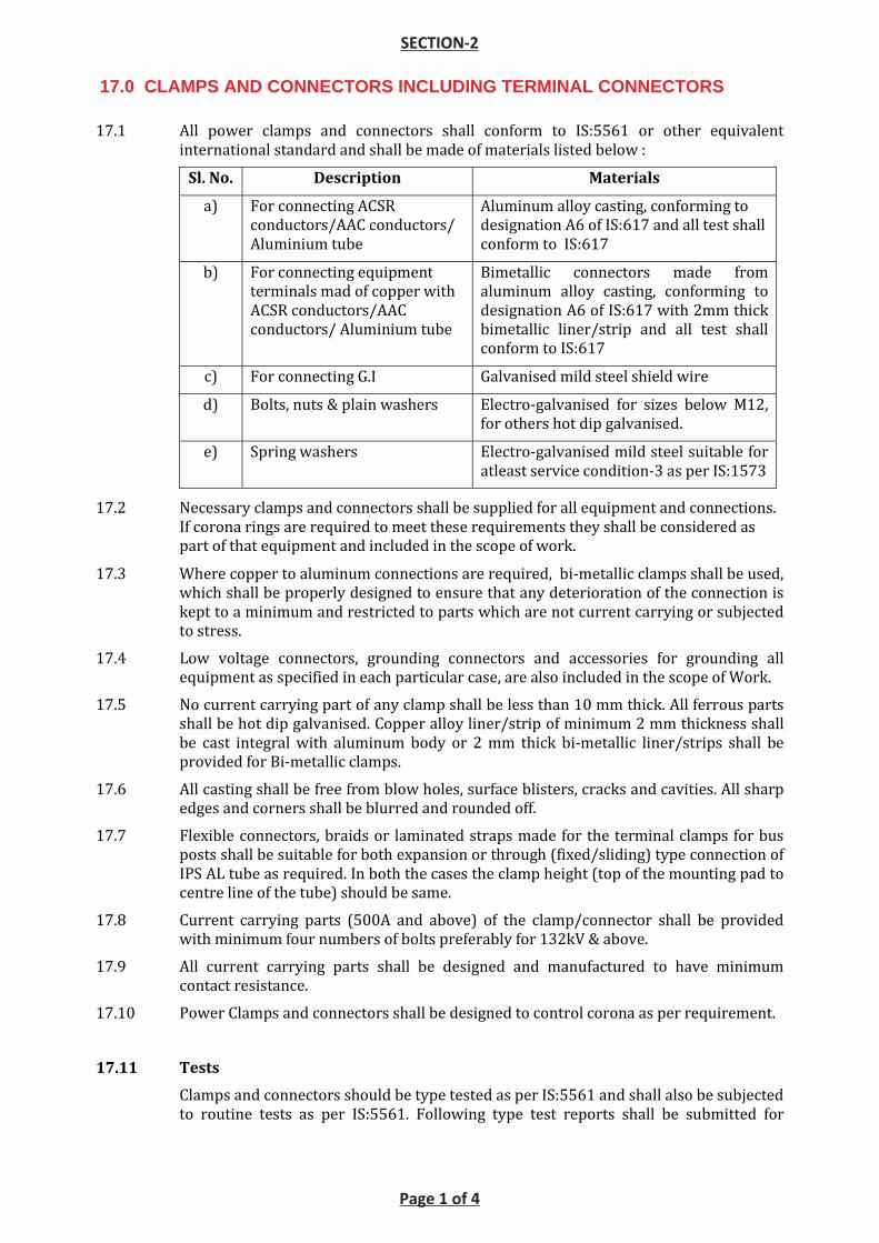
17.1 All power clamps and connectors shall conform to IS:5561 or other equivalent
international standard and shall be made of materials listed below :
Sl. No. Description Materials
a) For connecting ACSR
conductors/AAC conductors/
Aluminium tube
Aluminum alloy casting, conforming to
designation A6 of IS:617 and all test shall
conform to IS:617
b) For connecting equipment
terminals mad of copper with
ACSR conductors/AAC
conductors/ Aluminium tube
Bimetallic connectors made from
aluminum alloy casting, conforming to
designation A6 of IS:617 with 2mm thick
bimetallic liner/strip and all test shall
conform to IS:617
c) For connecting G.I Galvanised mild steel shield wire
d) Bolts, nuts & plain washers Electro-galvanised for sizes below M12,
for others hot dip galvanised.
e) Spring washers Electro-galvanised mild steel suitable for
atleast service condition-3 as per IS:1573
17.2 Necessary clamps and connectors shall be supplied for all equipment and connections.
If corona rings are required to meet these requirements they shall be considered as
part of that equipment and included in the scope of work.
17.3 Where copper to aluminum connections are required, bi-metallic clamps shall be used,
which shall be properly designed to ensure that any deterioration of the connection is
kept to a minimum and restricted to parts which are not current carrying or subjected
to stress.
17.4 Low voltage connectors, grounding connectors and accessories for grounding all
equipment as specified in each particular case, are also included in the scope of Work.
17.5 No current carrying part of any clamp shall be less than 10 mm thick. All ferrous parts
shall be hot dip galvanised. Copper alloy liner/strip of minimum 2 mm thickness shall
be cast integral with aluminum body or 2 mm thick bi-metallic liner/strips shall be
provided for Bi-metallic clamps.
17.6 All casting shall be free from blow holes, surface blisters, cracks and cavities. All sharp
edges and corners shall be blurred and rounded off.
17.7 Flexible connectors, braids or laminated straps made for the terminal clamps for bus
posts shall be suitable for both expansion or through (fixed/sliding) type connection of
IPS AL tube as required. In both the cases the clamp height (top of the mounting pad to
centre line of the tube) should be same.
17.8 Current carrying parts (500A and above) of the clamp/connector shall be provided
with minimum four numbers of bolts preferably for 132kV & above.
17.9 All current carrying parts shall be designed and manufactured to have minimum
contact resistance.
17.10 Power Clamps and connectors shall be designed to control corona as per requirement.
17.11 Tests
Clamps and connectors should be type tested as per IS:5561 and shall also be subjected
to routine tests as per IS:5561. Following type test reports shall be submitted for
SECTION-2
Page 1 of 4
17.0 CLAMPS AND CONNECTORS INCLUDING TERMINAL CONNECTORS
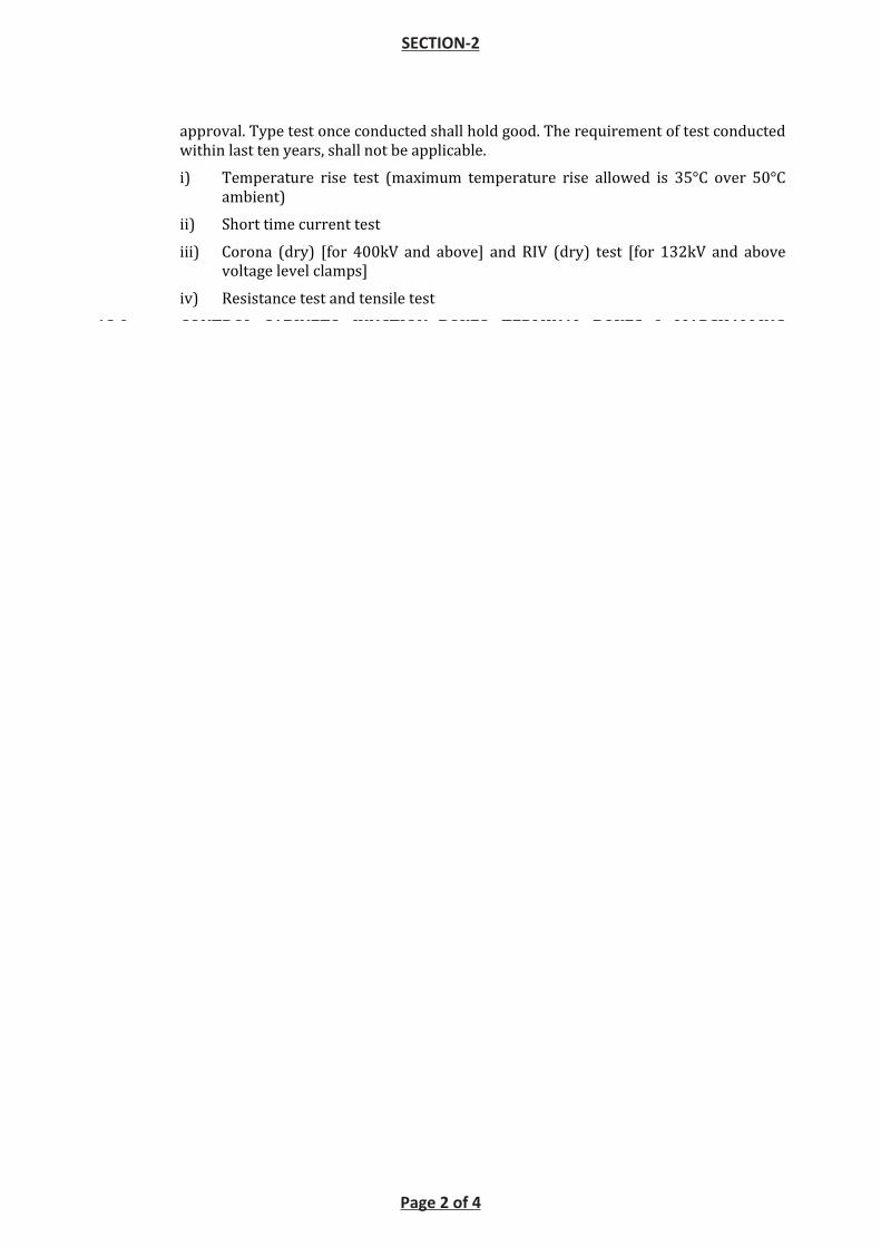
approval. Type test once conducted shall hold good. The requirement of test conducted
within last ten years, shall not be applicable.
i) Temperature rise test (maximum temperature rise allowed is 35°C over 50°C
ambient)
ii) Short time current test
iii) Corona (dry) [for 400kV and above] and RIV (dry) test [for 132kV and above
voltage level clamps]
iv) Resistance test and tensile test
18.0 CONTROL CABINETS, JUNCTION BOXES, TERMINAL BOXES & MARSHALLING BOXES FOR OUTDOOR EQUIPMENT
18.1 All types of boxes, cabinets etc. shall generally conform to & be tested in accordance
with IS-5039/IS-8623, IEC-60439, as applicable, and the clauses given below:
18.2 Control cabinets, junction boxes, Marshalling boxes & terminal boxes shall be made of
stainless steel of atleast 1.5 mm thick or aluminum enclosure of atleast 1.6 mm thick
and shall be dust, water and vermin proof. Stainless steel used shall be of grade SS304
(SS316 for coastal area) or better. The box shall be properly braced to prevent
wobbling. There shall be sufficient reinforcement to provide level surfaces, resistance
to vibrations and rigidity during transportation and installation. In case of aluminum
enclosed box the thickness of aluminum shall be such that it provides adequate rigidity
and long life as comparable with sheet steel of specified thickness.
18.3 A canopy and sealing arrangements for operating rods shall be provided in marshalling
boxes / Control cabinets to prevent ingress of rain water.
18.4 Cabinet/boxes shall be provided with double hinged doors with padlocking
arrangements. The distance between two hinges shall be adequate to ensure uniform
sealing pressure against atmosphere.
18.5 All doors, removable covers and plates shall be gasketed all around with suitably
profiled EPDM/Neoprene/PU gaskets. The gasket shall be tested in accordance with
approved quality plan, IS:11149 and IS:3400. Ventilating Louvers, if provided, shall
have screen and filters. The screen shall be fine wire mesh made of brass.
Further, the gasketing arrangement shall be such that gaskets are pasted in slots (in
door fabrication/gasket itself) in order to prevent ingression of dust and moisture
inside the panels so that no internal rusting occurs in panels during the operation of
the equipment.
18.6 All boxes/cabinets shall be designed for the entry of cables by means of weather proof
and dust-proof connections. Boxes and cabinets shall be designed with generous
clearances to avoid interference between the wiring entering from below and any
terminal blocks or accessories mounted within the box or cabinet. Suitable cable gland
plate above the base of the marshalling kiosk/box shall be provided for this purpose
along with the proper blanking plates. Necessary number of cable glands shall be
supplied and fitted on this gland plate. Gland plate shall have provision for some future
glands to be provided later, if required. The Nickel plated glands shall be dust proof,
screw on & double compression type and made of brass. The gland shall have provision
for securing armour of the cable separately and shall be provided with earthing tag.
The glands shall conform to BS:6121.
18.7 A 240V, single phase, 50 Hz, 15 amp AC plug and socket shall be provided in the
cabinet with ON-OFF switch for connection of hand lamps. Plug and socket shall be of
industrial grade.
SECTION-2
Page 2 of 4
SECTION - (SE) SWITCHYARD ERECTION
Technical Specification, Section : SE Page - 19 of 58 C / ENGG / SPEC / SE REV. NO: 10 (Apr’16)
7.0 SPACERS
7.1 General
Spacers shall conform to IS: 10162. The spacers are to be located at a suitable spacing to limit the short circuit forces as per IEC -60865. Wherever Employer’s 765kV, 400 kV, 220kV & 132kV standard gantry structures are being used, the spacer span(s) for different conductor / span configurations and corresponding short circuit forces shall be as per Annexure-D. For strung buses, flexible type spacers shall be used whereas for jumpers and other connections rigid type spacers shall be used. All quad/twin conductors between equipments/ bus shall be provided with at least one spacer.
Wherever Employer’s 765kV, 400 kV, 220kV & 132kV standard gantry structures are not being used, necessary spacer span calculation shall be provided by the contractor during detailed engineering for the approval of Employer.
7.2 Constructional Features
7.2.1 No magnetic material shall be used in the fabrication of spacers except for GI bolts and nuts.
7.2.2 Spacer design shall be made to take care of fixing and removing during installation and maintenance.
7.2.3 The design of the spacers shall be such that the conductor does not come in contact with any sharp edge.
7.3 Tests
Each type of spacers shall be subjected to the following type tests, acceptance tests and routine tests:
7.3.1 Type Tests: Following type test reports shall be submitted for approval as per clause 9.2 of Section - GTR.
a) Clamp slip tests
The sample shall be installed on test span of twin conductor bundle string or quadruple conductor bundle string (as applicable) at a tension of 44.2 kN. One of the clamps of the sample when subjected to a longitudinal pull of 2.5 kN parallel to the axis of the conductor shall not slip on the conductor. The permanent displacement between the conductor and the clamp of sample measured after removal of the load shall not exceed 1.0 mm. Similar tests shall be performed on the other clamps of the samesample.
b) Fault current test as per Cl 5.14.2 of IS: 10162. Alternately, the same can be carried by simulated short circuit method for which compressive forces shall be based on IEC-60865.
c) Corona Extinction Voltage Test (Dry).
This test shall be performed on 765 kV, 400 kV and 220 kV spacers as per procedure mentioned at Annexure - C, Minimum Corona Extinction voltage shall be as per clause 2.3.2.
SECTION-2
Page 3 of 4
SECTION - (SE) SWITCHYARD ERECTION
Technical Specification, Section : SE Page - 20 of 58 C / ENGG / SPEC / SE REV. NO: 10 (Apr’16)
d) RIV Test (Dry)
This test shall be performed as per procedure mentioned at Annexure - C,Maximum RIV levels shall be as per clause 2.3.2.
e) Resilience test (if applicable)
f) Tension Test
g) Log decremant test (if applicable)
h) Compression test
i) Galvanising test
7.3.2 Acceptance Test (As per IS:10162)
a) Visual examination
b) Dimensional verification
c) Movement test
d) Clamp slip test
e) Clamp bolt torque test (if applicable)
f) Assembly torque test
g) Compression test
h) Tension test
i) Galvanising test
j) Hardness test for neoprene (if applicable)
The shore hardness of different points on the elastometer surface of cushion grip clamp shall be measured by shore hardness meter. It shall be between 65 to 80.
k) Ultimate Tensile Strength Test
The UTS of the retaining rods shall be measured. It shall not be less than 35 kg/Sq. mm.
7.3.3 Routine test
a) Visual examination
b) Dimensional verification
8.0 BUS POST INSULATORS
The post insulators shall conform in general to latest IS: 2544, IEC-60168, IEC 60273 and IEC-60815.
SECTION-2
Page 4 of 4
Bharat Heavy Electricals Limited Doc No. TB‐413‐316‐100 Technical Specification
General Technical Requirement SECTION 3
Page 1 of 38
SCOPE, SPECIFIC TECHNICAL REQUIREMENTS AND QUANTITIES.
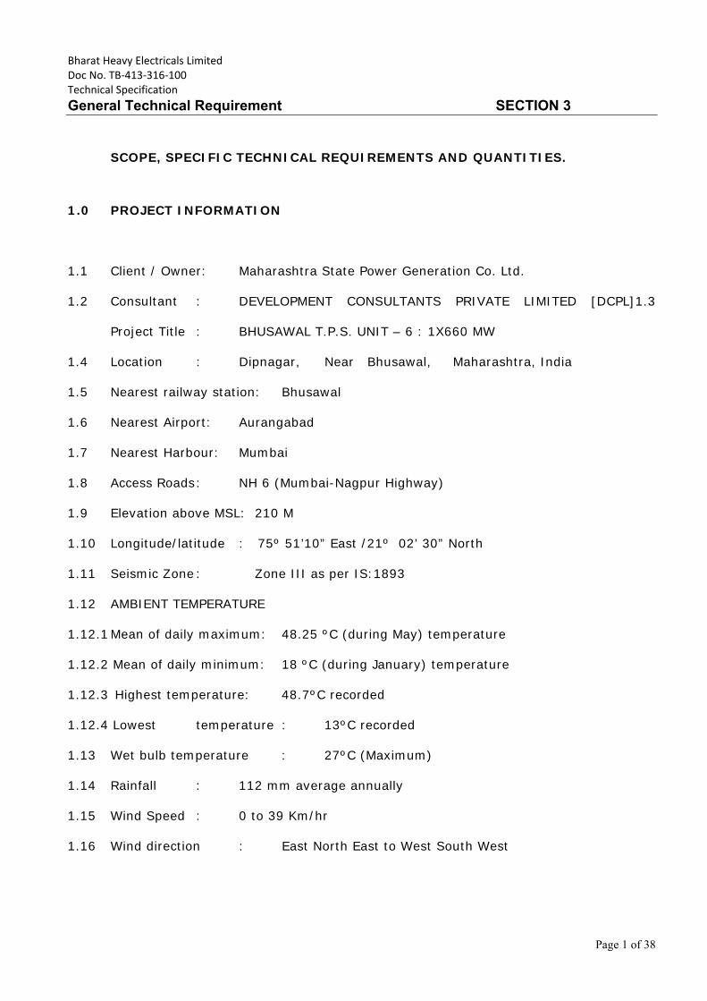
1.0 PROJECT INFORMATION
1.1 Client / Owner: Maharashtra State Power Generation Co. Ltd.
1.2 Consultant : DEVELOPMENT CONSULTANTS PRIVATE LIMITED [DCPL]1.3
Project Title : BHUSAWAL T.P.S. UNIT – 6 : 1X660 MW
1.4 Location : Dipnagar, Near Bhusawal, Maharashtra, India
1.5 Nearest railway station: Bhusawal
1.6 Nearest Airport: Aurangabad
1.7 Nearest Harbour: Mumbai
1.8 Access Roads : NH 6 (Mumbai-Nagpur Highway)
1.9 Elevation above MSL: 210 M
1.10 Longitude/latitude : 75º 51’10” East /21º 02’ 30” North
1.11 Seismic Zone : Zone III as per IS:1893
1.12 AMBIENT TEMPERATURE
1.12.1 Mean of daily maximum: 48.25 ºC (during May) temperature
1.12.2 Mean of daily minimum: 18 ºC (during January) temperature
1.12.3 Highest temperature: 48.7ºC recorded
1.12.4 Lowest temperature : 13ºC recorded
1.13 Wet bulb temperature : 27ºC (Maximum)
1.14 Rainfall : 112 mm average annually
1.15 Wind Speed : 0 to 39 Km/hr
1.16 Wind direction : East North East to West South West
Bharat Heavy Electricals Limited Doc No. TB‐413‐316‐100 Technical Specification
General Technical Requirement SECTION 3
Page 2 of 38
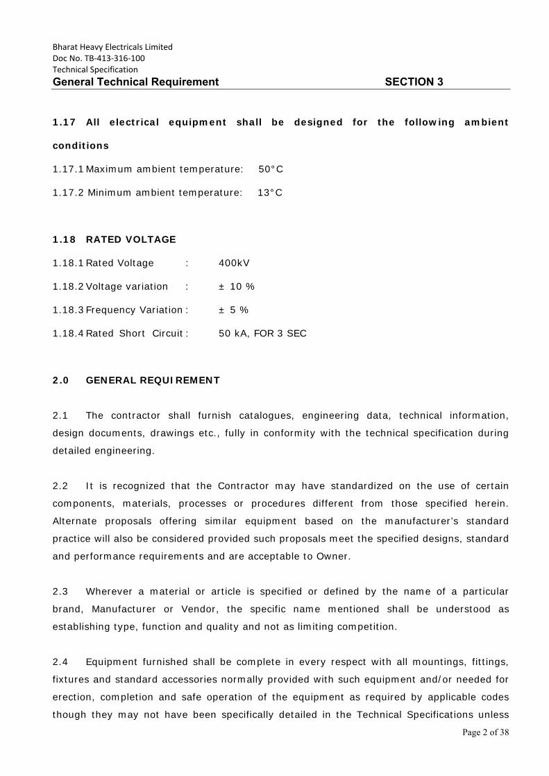
1.17 All electrical equipment shall be designed for the following ambient
conditions
1.17.1 Maximum ambient temperature: 50°C
1.17.2 Minimum ambient temperature: 13°C
1.18 RATED VOLTAGE
1.18.1 Rated Voltage : 400kV
1.18.2 Voltage variation : ± 10 %
1.18.3 Frequency Variation : ± 5 %
1.18.4 Rated Short Circuit : 50 kA, FOR 3 SEC
2.0 GENERAL REQUIREMENT
2.1 The contractor shall furnish catalogues, engineering data, technical information,
design documents, drawings etc., fully in conformity with the technical specification during
detailed engineering.
2.2 It is recognized that the Contractor may have standardized on the use of certain
components, materials, processes or procedures different from those specified herein.
Alternate proposals offering similar equipment based on the manufacturer’s standard
practice will also be considered provided such proposals meet the specified designs, standard
and performance requirements and are acceptable to Owner.
2.3 Wherever a material or article is specified or defined by the name of a particular
brand, Manufacturer or Vendor, the specific name mentioned shall be understood as
establishing type, function and quality and not as limiting competition.
2.4 Equipment furnished shall be complete in every respect with all mountings, fittings,
fixtures and standard accessories normally provided with such equipment and/or needed for
erection, completion and safe operation of the equipment as required by applicable codes
though they may not have been specifically detailed in the Technical Specifications unless
Bharat Heavy Electricals Limited Doc No. TB‐413‐316‐100 Technical Specification
General Technical Requirement SECTION 3
Page 3 of 38
included in the list of exclusions. Materials and components which are minor in nature and
incidental to the requirement but not specifically stated in the specification and bid price
schedule, which are necessary for commissioning and satisfactory operation of the
switchyard/ substation unless specifically excluded shall be deemed to be included in the
scope of the specification and shall be supplied without any extra cost. All similar standard
components/parts of similar standard equipment provided, shall be inter-changeable with
one another.
2.5 The Contractor shall also be responsible for the overall co-ordination with internal
/external agencies; Supplier of Owner’s supplied equipments, project management, training
of Owner’s manpower, loading, unloading, handling, insurance, moving to final destination
for successful erection, testing and commissioning of the substation
/switchyard.
2.6 The bidder shall be responsible for safety of human and equipment during the
working. It will be the responsibility of the Contractor to co-ordinate and obtain Electrical
Inspector's clearance before commissioning. Any additional items, modification due to
observation of such statutory authorities shall be provided by the Contractor at no extra cost
to the Owner.
3.0 STANDARDS
3.1 The works covered by the specification shall be designed, engineered, manufactured,
built, tested and commissioned in accordance with the Acts, Rules, Laws and Regulations of
India.
3.2 The equipment to be furnished under this specification shall conform to latest issue
with all amendments (as on the originally scheduled date of bid opening) of standard
specified under Annexure-C of this section, unless specifically mentioned in the specification.
3.3 The Bidder shall note that standards mentioned in the specification are not mutually
exclusive or complete in themselves, but intended to complement each other.
Bharat Heavy Electricals Limited Doc No. TB‐413‐316‐100 Technical Specification
General Technical Requirement SECTION 3
Page 4 of 38
3.4 The Contractor shall also note that list of standards presented in this specification is
not complete. Whenever necessary the list of standards shall be considered in conjunction
with specific IS/IEC.
3.5 When the specific requirements stipulated in the specifications exceed or differ than
those required by the applicable standards, the stipulation of the specification shall take
precedence.
3.6 Other internationally accepted standards which ensure equivalent or better
performance than that specified in the standards specified under Annexure-C/ individual
sections for various equipments shall also, be accepted, however the salient points of
difference shall be clearly brought out during detailed engineering along with English
language version of such standard. The equipment conforming to standards other than
specified for various equipments shall be subject to Owner’s approval.
4.0 SERVICES TO BE PERFORMED BY THE EQUIPMENT BEING FURNISHED
4.1 The 420kV system is being designed to limit the switching surge over voltage of 2.5
p.u., respectively and the power frequency over voltage of 1.5 p.u., respectively. In case of
the 420kV system, the initial value of the temporary over voltages could be 2.0 p.u. for 1-2
cycles. The equipment furnished under this specification shall perform all its functions and
operate satisfactorily without showing undue strain, restrike etc under such over voltage
conditions.
4.2 All equipments shall also perform satisfactorily under various other electrical,
electromechanical and meteorological conditions of the site of installation.
4.3 All equipment shall be able to withstand all external and internal mechanical, thermal
and electromechanical forces due to various factors like wind load, temperature variation, ice
& snow, (wherever applicable) short circuit etc for the equipment.
4.4 The bidder shall design terminal connectors of the equipment taking into account
various forces that are required to withstand.
4.5 The equipment shall also comply to the following:
a) To facilitate erection of equipment, all items to be assembled at site shall be “match
marked”.
Bharat Heavy Electricals Limited Doc No. TB‐413‐316‐100 Technical Specification
General Technical Requirement SECTION 3
Page 5 of 38
b) All piping, if any between equipment control cabinet/operating mechanism to
marshalling box of the equipment, shall bear proper identification to facilitate the connection
at site.
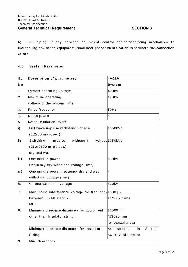
4.6 System Parameter
SL
No
Description of parameters 400kV
System
1. System operating voltage 400kV
2. Maximum operating
voltage of the system (rms)
420kV
3. Rated frequency 50Hz
4. No. of phase 3
5. Rated Insulation levels
i) Full wave impulse withstand voltage
(1.2/50 microsec.)
1550kVp
ii) Switching impulse withstand voltage
(250/2500 micro sec.)
dry and wet
1050kVp
iii) One minute power
frequency dry withstand voltage (rms)
630kV
iv) One minute power frequency dry and wet
withstand voltage (rms)
-
6. Corona extinction voltage 320kV
7. Max. radio interference voltage for frequency
between 0.5 MHz and 2
MHz
1000 µV
at 266kV rms
8. Minimum creepage distance - for Equipment
other than Insulator string
10500 mm
(13020 mm
for coastal area)
Minimum creepage distance - for Insulator
String
As specified in Section-
Switchyard Erection
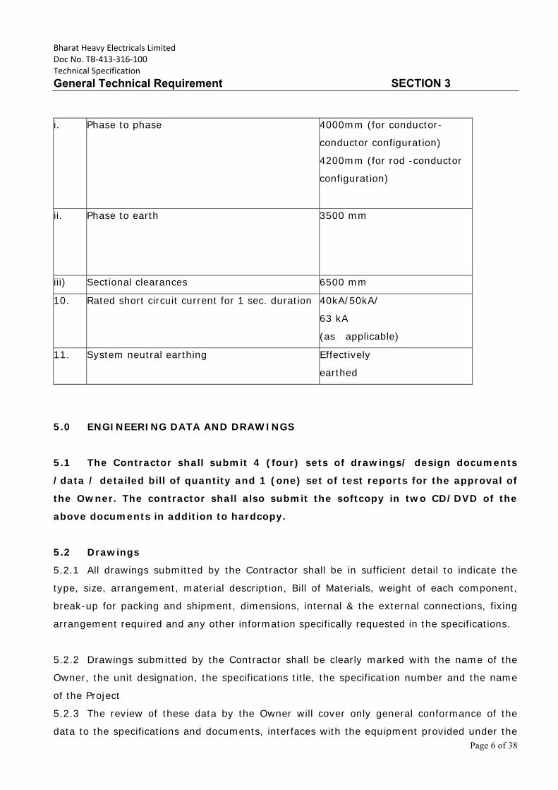
9. Min. clearances
Bharat Heavy Electricals Limited Doc No. TB‐413‐316‐100 Technical Specification
General Technical Requirement SECTION 3
Page 6 of 38
i. Phase to phase 4000mm (for conductor-
conductor configuration)
4200mm (for rod -conductor
configuration)
ii. Phase to earth 3500 mm
iii) Sectional clearances 6500 mm
10. Rated short circuit current for 1 sec. duration 40kA/50kA/
63 kA
(as applicable)
11. System neutral earthing Effectively
earthed
5.0 ENGINEERING DATA AND DRAWINGS
5.1 The Contractor shall submit 4 (four) sets of drawings/ design documents
/data / detailed bill of quantity and 1 (one) set of test reports for the approval of
the Owner. The contractor shall also submit the softcopy in two CD/DVD of the
above documents in addition to hardcopy.
5.2 Drawings
5.2.1 All drawings submitted by the Contractor shall be in sufficient detail to indicate the
type, size, arrangement, material description, Bill of Materials, weight of each component,
break-up for packing and shipment, dimensions, internal & the external connections, fixing
arrangement required and any other information specifically requested in the specifications.
5.2.2 Drawings submitted by the Contractor shall be clearly marked with the name of the
Owner, the unit designation, the specifications title, the specification number and the name
of the Project
5.2.3 The review of these data by the Owner will cover only general conformance of the
data to the specifications and documents, interfaces with the equipment provided under the
Bharat Heavy Electricals Limited Doc No. TB‐413‐316‐100 Technical Specification
General Technical Requirement SECTION 3
Page 7 of 38
specifications, external connections and of the dimensions which might affect substation
layout. This review by the Owner may not indicate a thorough review of all dimensions,
quantities and details of the equipment, materials, any devices or items indicated or the
accuracy of the information submitted. This review and/or approval by the Owner shall not
be considered by the Contractor, as limiting any of his responsibilities and liabilities for
mistakes and deviations from the requirements, specified under these specifications and
documents.
5.4 All manufacturing and fabrication work in connection with the equipment prior to the
approval of the drawings shall be at the Contractor’s risk. The Contractor may make any
changes in the design which are necessary to make the equipment conform to the provisions
and intent of the Contract and such changes will again be subject to approval by the Owner.
Approval of Contractor’s drawing or work by the Owner shall not relieve the contractor of
any of his responsibilities and liabilities under the Contract.
5.5 All engineering data submitted by the Contractor after final process including review
and approval by the Owner shall form part of the Contract Document and the entire works
performed under these specifications shall be performed in strict conformity, unless
otherwise expressly requested by the Owner in Writing.
5.6 Approval Procedure
The following schedule shall be followed generally for approval and for providing final
documentation.
i) Approval/comments/ As per L2 schedule by Owner on initial
submission
ii) Resubmission Within 1 (one) weeks (whenever from date of
comments required)
iii) Approval or comments Within 1 (three) weeks of receipt of resubmission.
iv) Furnishing of distribution 2 weeks from the date copies (2 hard copies to
each of approval substation and one scanned
copy (pdf format)
v) Furnishing of distribution copies of test reports

Bharat Heavy Electricals Limited Doc No. TB‐413‐316‐100 Technical Specification
General Technical Requirement SECTION 3
Page 8 of 38
(a) Type test reports 2 weeks from the date (one scanned softcopy in
of final approval pdf format to each substation plus
one for corporate centre & one hardcopy per
substation)
(b) Routine Test Reports -do- (one copy for each substation)
vi) Furnishing of instruction/ On completion of Engineering operation manuals (2
copies per substation and two softcopies (pdf format)
(vii) As built drawings (two sets of On completion of entire works
hardcopy per substation & two softcopies (pdf format)
NOTE :
(1) The contractor may please note that all resubmissions must incorporate all comments
given in the earlier submission by the Owner or adequate justification for not incorporating
the same must be submitted failing which the submission of documents is likely to be
returned.
(2) All drawings should be submitted in softcopy form, however substation design
drawings like SLD, GA, all layouts etc. shall also be submitted in AutoCAD Version. SLD, GA
& layout drawings shall be submitted for the entire substation in case of substation
extension also.
(3) The instruction Manuals shall contain full details of drawings of all equipment being
supplied under this contract, their exploded diagrams with complete instructions for storage,
handling, erection, commissioning, testing, operation, trouble shooting, servicing and
overhauling procedures.
(4) If after the commissioning and initial operation of the substation, the instruction
manuals require any modifications/additions/changes, the same shall be incorporated and
the updated final instruction manuals shall be submitted by the Contractor to the Owner.
Bharat Heavy Electricals Limited Doc No. TB‐413‐316‐100 Technical Specification
General Technical Requirement SECTION 3
Page 9 of 38
(5) The Contractor shall furnish to the Owner catalogues of spare parts if any .
(6) All As-built drawings/documents shall be certified by site indicating the changes
before final submission.
6.0 MATERIAL/ WORKMANSHIP
6.1 General Requirement
6.1.1 Where the specification does not contain references to workmanship, equipment,
materials and components of the covered equipment, it is essential that the same must be
new, of highest grade of the best quality of their kind, conforming to best engineering
practice and suitable for the purpose for which they are intended.
6.1.2 In case where the equipment, materials or components are indicated in the
specification as “similar” to any special standard, the Owner shall decide upon the question
of similarity. When required by the specification or when required by the Owner the
Contractor shall submit, for approval, all the information concerning the materials or
components to be used in manufacture. Machinery, equipment, materials and components
supplied, installed or used without such approval shall run the risk of subsequent rejection, it
is to be understood that the cost as well as the time delay associated with the rejection shall
be borne by the Contractor.
6.1.3 The design of the Works shall be such that installation, future expansions,
replacements and general maintenance may be undertaken with a minimum of time and
expenses. Each component shall be designed to be consistent with its duty and suitable
factors of safety, subject to mutual agreements. All joints and fastenings shall be devised,
constructed and documented so that the component parts shall be accurately positioned and
restrained to fulfill their required function. In general, screw threads shall be standard metric
threads. The use of other thread forms will only be permitted when prior approval has been
obtained from the Owner.
Bharat Heavy Electricals Limited Doc No. TB‐413‐316‐100 Technical Specification
General Technical Requirement SECTION 3
Page 10 of 38
6.1.4 Whenever possible, all similar part of the Works shall be made to gauge and shall also
be made interchangeable with similar parts. All spare parts shall also be interchangeable and
shall be made of the same materials and workmanship as the corresponding parts of the
Equipment supplied under the Specification. Where feasible, common component units shall
be employed in different pieces of equipment in order to minimize spare parts stocking
requirements. All equipment of the same type and rating shall be physically and electrically
interchangeable.
6.1.5 All materials and equipment shall be installed in strict accordance with the
manufacturer’s recommendation(s). Only first-class work in accordance with the best
modern practices will be accepted. Installation shall be considered as being the erection of
equipment at its permanent location. This, unless otherwise specified, shall include
unpacking, cleaning and lifting into position, grouting, levelling, aligning, coupling of or
bolting down to previously installed equipment bases/foundations, performing the alignment
check and final adjustment prior to initial operation, testing and commissioning in
accordance with the manufacturer’s tolerances, instructions and the Specification. All factory
assembled rotating machinery shall be checked for alignment and adjustments made as
necessary to re-establish the manufacturer’s limits suitable guards shall be provided for the
protection of personnel on all exposed rotating and / or moving machine parts and shall be
designed for easy installation and removal for maintenance purposes. The spare
equipment(s) shall be installed at designated locations and tested for healthiness.
6.1.6 The Contractor shall apply oil and grease of the proper specification to suit the
machinery, as is necessary for the installation of the equipment. Lubricants used for
installation purposes shall be drained out and the system flushed through where necessary
for applying the lubricant required for operation. The Contractor shall apply all operational
lubricants to the equipment installed by him.
6.1.7 All oil, grease and other consumables used in the Works/Equipment shall be
purchased in India unless the Contractor has any special requirement for the specific
application of a type of oil or grease not available in India. If such is the case, he shall
declare in the proposal, where such oil or grease is available. He shall help Owner in
establishing equivalent Indian make and Indian Contractor. The same shall be applicable to
other consumables too.
Bharat Heavy Electricals Limited Doc No. TB‐413‐316‐100 Technical Specification
General Technical Requirement SECTION 3
Page 11 of 38
6.2 Provisions for Exposure to Hot and Humid climate
Outdoor equipment supplied under the specification shall be suitable for service and storage
under tropical conditions of high temperature, high humidity, heavy rainfall and environment
favorable to the growth of fungi and mildew. The indoor equipments located in non-air
conditioned areas shall also be of same type.
6.2.1 Space Heaters
6.2.1.1 The heaters shall be suitable for continuous operation at 240V as supply
voltage. On- off switch and fuse shall be provided.
6.2.1.2 One or more adequately rated thermostatically connected heaters shall be
supplied to prevent condensation in any compartment. The heaters shall be installed in the
compartment and electrical connections shall be made sufficiently away from below the
heaters to minimize deterioration of supply wire insulation. The heaters shall be suitable to
maintain the compartment temperature to prevent condensation.
6.2.2 FUNGI STATIC VARNISH
Besides the space heaters, special moisture and fungus resistant varnish shall be applied on
parts which may be subjected or predisposed to the formation of fungi due to the presence
or deposit of nutrient substances. The varnish shall not be applied to any surface of part
where the treatment will interfere with the operation or performance of the equipment. Such
surfaces or parts shall be protected against the application of the varnish.
6.2.3 Ventilation opening
Wherever ventilation is provided, the compartments shall have ventilation openings with fine
wire mesh of brass to prevent the entry of insects and to reduce to a minimum the entry of
dirt and dust.
6.2.4 Degree of Protection
The enclosures of the Control Cabinets, Junction boxes and Marshalling Boxes, panels etc. to
be installed shall comply with following degree of protection as detailed here under:
Bharat Heavy Electricals Limited Doc No. TB‐413‐316‐100 Technical Specification
General Technical Requirement SECTION 3
Page 12 of 38
a) Installed out door: IP- 55
b) Installed indoor in air conditioned area: IP-31
c) Installed in covered area: IP-52
d) Installed indoor in non-air conditioned area where possibility of entry of water
is limited: IP-41.
e) For LT Switchgear (AC & DC distribution Boards): IP-52
f) For Surge monitors: IP 67
The degree of protection shall be in accordance with IS:2147, IS:13947 (Part-I)/IEC-60947
(Part-I)/IS 12063/IEC-60529. Type test report for IP-55 or higher degree of protection test,
shall be submitted for approval.
6.3 RATING PLATES, NAME PLATES AND LABELS
6.3.1 Each main and auxiliary item of substation is to have permanently attached to it in a
conspicuous position a rating plate of non-corrosive material upon which is to be engraved
manufacturer’s name, year of manufacture, equipment name, type or serial number
together with details of the loading conditions under which the item of substation in question
has been designed to operate, and such diagram plates as may be required by the Owner.
The rating plate of each equipment shall be according to IEC requirement.
6.3.2 All such nameplates, instruction plates, rating plates of transformers, reactors, CB,
CT, CVT, SA, Isolators, C & R panels and PLCC equipments shall be bilingual with Hindi
inscription first followed by English. Alternatively, two separate plates one with Hindi and the
other with English inscriptions may be provided.
6.4 FIRST FILL OF CONSUMABLES, OIL AND LUBRICANTS
All the first fill of consumables such as oils, lubricants, filling compounds, touch up paints,
soldering/brazing material for all copper piping of circuit breakers and essential chemicals
etc. which will be required to put the equipment covered under the scope of the
specifications, into operation, shall be furnished by the Contractor unless specifically
excluded under the exclusions in these specifications and documents.
7.0 DESIGN IMPROVEMENTS / COORDINATION
Bharat Heavy Electricals Limited Doc No. TB‐413‐316‐100 Technical Specification
General Technical Requirement SECTION 3
Page 13 of 38
7.1 The bidder shall offer the equipment meeting the requirement of the technical
specification. However, the Owner or the Contractor may propose changes in the
specification of the equipment or quality thereof and if the contractor & Owner agree upon
any such changes, the specification shall be modified accordingly.
7.2 If any such agreed upon change is such that it affects the price and schedule of
completion, the parties shall agree in writing as to the extent of any change in the price
and/or schedule of completion before the Contractor proceeds with the change. Following
such agreement, the provision thereof, shall be deemed to have been amended accordingly.
7.3 The Contractor shall be responsible for the selection and design of appropriate
equipments to provide the best coordinated performance of the entire system. The basic
design requirements are detailed out in this Specification. The design of various components,
sub-assemblies and assemblies shall be so done that it facilitates easy field assembly and
maintenance.
7.4 The Contractor has to coordinate designs and terminations with the agencies (if any)
who are Consultants/Contractor for the Owner. The names of agencies shall be intimated to
the successful bidders.
7.5 The Contractor will be called upon to attend design co-ordination meetings with the
Engineer, other Contractor’s and the Consultants of the Owner (if any) during the period of
Contract.
8.0 QUALITY ASSURANCE PROGRAMME
8.1 To ensure that the equipment and services under the scope of this Contract, whether
manufactured or performed within the Contractor’s Works or at his Sub-Contractor’s
premises or at the Owner’s site or at any other place of Work as applicable, are in
accordance with the specifications, the Contractor shall ensure suitable quality assurance
programme to control such activities at all points necessary. A quality assurance programme
of the Contractor shall be in line with ISO requirements & shall generally cover the following:
b) System for Document and Data Control.
c) Qualification and Experience data of Bidder’s key personnel.
Bharat Heavy Electricals Limited Doc No. TB‐413‐316‐100 Technical Specification
General Technical Requirement SECTION 3
Page 14 of 38
d) The procedure for purchases of materials, parts, components and selection of sub-
Contractor’s services including vendor analysis, source inspection, incoming raw material
inspection, verification of material purchases etc.
e) System for shop manufacturing and site erection controls including process controls,
fabrication and assembly control.
f) System for Control of non-conforming products including deviation dispositioning, if
any and system for corrective and preventive actions based on the feedback received from
the Customers and also internally documented system for Customer complaints.
g) Inspection and test procedure both for manufacture and field activities.
h) System for Control of calibration of testing and measuring equipment and the
indication of calibration status on the instruments.
i) System for indication and appraisal of inspection status.
j) System of Internal Quality Audits, Management review and initiation of corrective and
Preventive actions based on the above.
k) System for authorizing release of manufactured product to the Owner.
l) System for maintenance of records.
m) System for handling, storage and delivery.
n) A quality plan detailing out the specific quality control measures and procedure
adopted for controlling the quality characteristics relevant to each item of equipment
furnished and /or service rendered.
o) System for various field activities i.e. unloading, receipt at site, proper storage,
erection, testing and commissioning of various equipment and maintenance of records. In
this regard, the Owner has already prepared Standard Field Quality Plan for transmission
line/substation equipments as applicable, Civil/erection Works which is required to be
followed for associated works.
The Owner or his duly authorized representative reserves the right to carry out quality audit
and quality surveillance of the system and procedure of the Contractor/his vendor’s quality
management and control activities.
8.2 Quality Assurance Documents
The Contractor shall ensure availability of the following Quality Assurance Documents:
Bharat Heavy Electricals Limited Doc No. TB‐413‐316‐100 Technical Specification
General Technical Requirement SECTION 3
Page 15 of 38
i) All Non-Destructive Examination procedures, stress relief and weld repair procedure
actually used during fabrication, and reports including radiography interpretation reports.
ii) Welder and welding operator qualification certificates.
iii) Welder’s identification list, welding operator’s qualification procedure and welding
identification symbols.
iv) Raw Material test reports on components as specified by the specification and in the
quality plan.
v) The Manufacturing Quality Plan(MQP) indicating Customer Inspection Points (CIPs) at
various stages of manufacturing and methods used to verify that the inspection and testing
points in the quality plan were performed satisfactorily.
vi) Factory test results for testing required as per applicable quality plan/technical
specifications/GTP/Drawings etc.
vii) Stress relief time temperature charts/oil impregnation time temperature charts,
wherever applicable.
8.3 INSPECTION, TESTING & INSPECTION CERTIFICATE
8.3.1 No surge arrester shall be dispatched without inspection and testing. The inspection
may be carried out by the Owner’s representative at any stage of manufacture. The bidder
shall grant free access to the Owner’s representative at a reasonable time when the work is
in progress.
8.3.2 Inspection and acceptance of any equipment under this specification by the MSETCL
shall not relieve the supplier of his obligation of furnishing equipment in accordance with the
specification and shall not prevent subsequent rejection if the equipment is found to be
defective.
8.3.11 All Test Reports and documents to be submitted in English during final inspection of
equipment by Owner or as and when required for submission.
9.0 TYPE TESTING & CLEARANCE CERTIFICATE
9.1 All equipment being supplied shall conform to type tests as per technical specification
and shall be subject to routine tests in accordance with requirements stipulated under
respective sections.
Bharat Heavy Electricals Limited Doc No. TB‐413‐316‐100 Technical Specification
General Technical Requirement SECTION 3
Page 16 of 38
9.2 The reports for all type tests as per technical specification shall be furnished by the
Contractor along with equipment / material drawings. The type tests conducted earlier
should have either been conducted in accredited laboratory (accredited based on ISO / IEC
Guide 25 / 17025 or EN 45001 by the national accreditation body of the country where
laboratory is located).
Unless otherwise specified elsewhere, the type test reports submitted shall be of
the tests conducted within last 05 (five) years from the NOA (Notification of
award) date i.e. 17.01.2018 of this project. In case the test reports are of the test
conducted earlier than 05 (five) years from the date of NOA, the contractor shall repeat
these test(s) at no extra cost to the Employer.
Further, in the event of any discrepancy in the test reports i.e. any test report not
acceptable due to any design/manufacturing changes or due to non-compliance with the
requirement stipulated in the Technical Specification or any/all type tests not carried out,
same shall be carried out without any additional cost implication to the Employer.
The Contractor shall intimate the Employer the detailed program about the type tests at
least two (2) weeks in advance in case of domestic supplies & six (6) weeks in advance in
case of foreign supplies.
9.4 The Employer reserves the right to witness any or all the type tests. The Employer
shall bear all expenses for deputation of Employer’s representative(s) for witnessing the type
tests.
10.0 TESTS
10.1 Pre-commissioning Tests
On completion of erection of the equipment and before charging, each item of the equipment
shall be thoroughly cleaned and then inspected jointly by the Employer and the Contractor
for correctness and completeness of installation and acceptability for charging, leading to
initial pre-commissioning tests at Site. The list of pre- commissioning tests to be performed
are given in respective chapters and shall be included in the Contractor’s quality assurance
programme.
Bharat Heavy Electricals Limited Doc No. TB‐413‐316‐100 Technical Specification
General Technical Requirement SECTION 3
Page 17 of 38
10.2 Commissioning Tests
10.2.1 The available instrumentation and control equipment will to be used during such tests
and the Employer will calibrate, all such measuring equipment and devices as far as
practicable.
10.2.2 Any special equipment, tools and tackles required for the successful completion of the
Commissioning Tests shall be arranged by the Contractor at his own cost.
10.2.3 The specific tests requirement on equipment have been brought out in the respective
chapters of the technical specification.
10.3 PRECOMMISSIONING, COMMISSIONING, TRIAL-RUN & COMPLETION
As soon as the Facilities covered by these specifications are physically completed in all
respects, the Pre commissioning, Commissioning, Trial-run and Completion of the Facilities,
as mentioned below, shall be attained in accordance with the procedure given in the
Conditions of Contract, Vol.-I of the Bidding Documents.
(i) Pre commissioning : As per relevant Sections
(ii) Commissioning : Charging of the Facilities at rated voltage.
Further, wherever appearing in these specifications, the words–‘commissioning checks’,
‘installation checks’, ‘site tests’, ‘performance guarantee tests for fire protection system’, are
to be considered as ‘pre commissioning checks’.
(iii) Trial-run : Operation of the Facilities or any part thereof by the
Contractor immediately after the Commissioning for a continuous period of 72 (Seventy two)
hours continuously. In case of interruption due to problem/ failure in the respective
equipment, the contractor shall rectify the problem and after rectification, continuous
72 (Seventy two) hours period start after such rectification.
(iv) Completion : Upon successful completion of Trial-run.
‘Guarantee Test(s)’ and/or ‘Functional Guarantees’ are applicable only for Substation
Automation System as specified in Section-‘Substation Automation System.’
Bharat Heavy Electricals Limited Doc No. TB‐413‐316‐100 Technical Specification
General Technical Requirement SECTION 3
Page 18 of 38
11.0 PACKAGING & PROTECTION
11.1 All the equipments shall be suitably protected, coated, covered or boxed and crated to
prevent damage or deterioration during transit, handling and storage at Site till the time of
erection. On request of the Employer, the Contractor shall also submit packing
details/associated drawing for any equipment/material under his scope of supply, to
facilitate the Employer to repack any equipment/material at a later date, in case the need
arises. While packing all the materials, the limitation from the point of view of availability of
Railway wagon sizes in India should be taken into account. The Contractor shall be
responsible for any loss or damage during transportation, handling and storage due to
improper packing. Any demurrage, wharfage and other such charges claimed by the
transporters, railways etc. shall be to the account of the Contractor. Employer takes no
responsibility of the availability of the wagons.
11.2 All coated surfaces shall be protected against abrasion, impact, discolouration and any
other damages. All exposed threaded portions shall be suitably protected with either a
metallic or a non-metallic protecting device. All ends of all valves and pipings and conduit
equipment connections shall be properly sealed with suitable devices to protect them from
damage.
12.0 FINISHING OF METAL SURFACES
12.1 All metal surfaces shall be subjected to treatment for anti-corrosion protection. All
ferrous surfaces for external use unless otherwise stated elsewhere in the specification or
specifically agreed, shall be hot-dip galvanized after fabrication. All steel conductors
including those used for earthing/grounding (above ground level) shall also be galvanized
according to IS: 2629.
12.2 HOT DIP GALVANISING
12.2.1 The minimum weight of the zinc coating shall be 610 gm/sq.m and minimum average
thickness of coating shall be 86 microns for all items having thickness 6mm and above and
900 gm/sq.m for coastal area (30km from sea shore approximately) or as specified in
Section-Project. For items lower than 6mm thickness requirement of coating thickness shall
Bharat Heavy Electricals Limited Doc No. TB‐413‐316‐100 Technical Specification
General Technical Requirement SECTION 3
Page 19 of 38
be as per relevant ASTM. For surface which shall be embedded in concrete, the zinc coating
shall be 610 gm/sq.m minimum and 900 gm/sq.m for coastal area as specified in Section-
Project.
12.2.2 The galvanized surfaces shall consist of a continuous and uniform thick coating of
zinc, firmly adhering to the surface of steel. The finished surface shall be clean and smooth
and shall be free from defects like discoloured patches, bare spots, unevenness of coating,
spelter which is loosely attached to the steel globules, spiky deposits, blistered surface,
flaking or peeling off, etc. The presence of any of these defects noticed on visual or
microscopic inspection shall render the material liable to rejection.
12.2.3 After galvanizing, no drilling or welding shall be performed on the galvanized parts of
the equipment excepting that nuts may be threaded after galvanizing. Sodium dichromate or
alternate approved treatment shall be provided to avoid formation of white rust after hot dip
galvanization.
12.2.4 The galvanized steel shall be subjected to four numbers of one minute dips in copper
sulphate solution as per IS-2633.
12.2.5 Sharp edges with radii less than 2.5 mm shall be able to withstand four immersions of
the Standard Preece test. All other coatings shall withstand six immersions. The following
galvanizing tests should essentially be performed as per relevant Indian Standards.
- Coating thickness
- Uniformity of zinc
- Adhesion test
- Mass of zinc coating
12.2.6 Galvanised material must be transported properly to ensure that galvanised surfaces
are not damaged during transit. Application of touch-up zinc rich paint at site shall be
allowed with approval of Engineer Incharge.
12.3 PAINTING
12.3.1 All sheet steel work shall be degreased, pickled, phosphated in accordance with the
IS- 6005 “Code of practice for phosphating iron and sheet”. All surfaces, which will not be
easily accessible after shop assembly, shall beforehand be treated and protected for the life
of the equipment. The surfaces, which are to be finished painted after installation or require
Bharat Heavy Electricals Limited Doc No. TB‐413‐316‐100 Technical Specification
General Technical Requirement SECTION 3
Page 20 of 38
corrosion protection until installation, shall be shop painted with at least two coats of primer.
Oil, grease, dirt and swaf shall be thoroughly removed by emulsion cleaning. Rust and scale
shall be removed by pickling with dilute acid followed by washing with running water, rinsing
with slightly alkaline hot water and drying.
12.3.2 After phosphating, thorough rinsing shall be carried out with clean water followed by
final rinsing with dilute dichromate solution and oven drying. The phosphate coating shall be
sealed with application of two coats of ready mixed, stoving type zinc chromate primer. The
first coat may be “flash dried” while the second coat shall be stoved.
12.3.3 After application of the primer, two coats of finishing synthetic enamel paint shall be
applied, each coat followed by stoving. The second finishing coat shall be applied after
inspection of first coat of painting.
12.3.4 The exterior and interior colour of the paint in case of new substations shall preferably
be RAL 7032 for all equipment, marshalling boxes, junction boxes, control cabinets, panels
etc. unless specifically mentioned under respective sections of the equipments. Glossy white
colour inside the equipments /boards /panels/junction boxes is also acceptable. The exterior
colour for panels shall be matching with the existing panels in case of extension of a
substation. Each coat of primer and finishing paint shall be of slightly different shade to
enable inspection of the painting. A small quantity of finishing paint shall be supplied for
minor touching up required at site after installation of the equipments.
12.3.5 In case the contractor proposes to follow his own standard surface finish and
protection procedures or any other established painting procedures, like electrostatic
painting etc., the procedure shall be submitted during detailed engineering for Employer’s
review & approval.
18.0 CONTROL CABINETS, JUNCTION BOXES, TERMINAL BOXES & MARSHALLING
BOXES FOR OUTDOOR EQUIPMENT
18.1 All types of boxes, cabinets etc. shall generally conform to & be tested in accordance
with IS-5039/IS-8623, IEC-60439, as applicable, and the clauses given below:
Bharat Heavy Electricals Limited Doc No. TB‐413‐316‐100 Technical Specification
General Technical Requirement SECTION 3
Page 21 of 38
18.2 Control cabinets, junction boxes, Marshalling boxes & terminal boxes shall be made of
stainless steel of atleast 1.5 mm thick or aluminum enclosure of atleast 1.6 mm thick and
shall be dust, water and vermin proof. Stainless steel used shall be of grade SS304 (SS316
for coastal area) or better. The box shall be properly braced to prevent wobbling. There shall
be sufficient reinforcement to provide level surfaces, resistance to vibrations and rigidity
during transportation and installation. In case of aluminum enclosed box the thickness of
aluminum shall be such that it provides adequate rigidity and long life as comparable with
sheet steel of specified thickness.
18.3 A canopy and sealing arrangements for operating rods shall be provided in
marshalling boxes / Control cabinets to prevent ingress of rain water.
18.4 Cabinet/boxes shall be provided with double hinged doors with padlocking
arrangements. The distance between two hinges shall be adequate to ensure uniform sealing
pressure against atmosphere.
18.5 All doors, removable covers and plates shall be gasketed all around with suitably
profiled EPDM/Neoprene/PU gaskets. The gasket shall be tested in accordance with approved
quality plan, IS:11149 and IS:3400. Ventilating Louvers, if provided, shall have screen and
filters. The screen shall be fine wire mesh made of brass.
Further, the gasketing arrangement shall be such that gaskets are pasted in slots (in door
fabrication/gasket itself) in order to prevent ingression of dust and moisture inside the
panels so that no internal rusting occurs in panels during the operation of the equipment.
18.6 All boxes/cabinets shall be designed for the entry of cables by means of weather proof
and dust-proof connections. Boxes and cabinets shall be designed with generous clearances
to avoid interference between the wiring entering from below and any terminal blocks or
accessories mounted within the box or cabinet. Suitable cable gland plate above the base of
the marshalling kiosk/box shall be provided for this purpose along with the proper blanking
plates. Necessary number of cable glands shall be supplied and fitted on this gland plate.
Gland plate shall have provision for some future glands to be provided later, if required. The
Nickel plated glands shall be dust proof, screw on & double compression type and made of
brass. The gland shall have provision for securing armour of the cable separately and shall
be provided with earthing tag. The glands shall conform to BS:6121.
Bharat Heavy Electricals Limited Doc No. TB‐413‐316‐100 Technical Specification
General Technical Requirement SECTION 3
Page 22 of 38
18.7 A 240V, single phase, 50 Hz, 15 amp AC plug and socket shall be provided in the
cabinet with ON-OFF switch for connection of hand lamps. Plug and socket shall be of
industrial grade.
18.8 LED based illumination of minimum 9 watts shall be provided. The switching of the
fittings shall be controlled by the door switch.
For junction boxes of smaller sizes such as lighting junction box, manual operated earth
switch mechanism box etc., plug socket, heater and illumination is not required to be
provided.
18.9 All control switches shall be of MCB/rotary switch type and Toggle/piano switches
shall not be accepted.
18.10 Earthing of the cabinet shall be ensured by providing two separate earthing pads. The
earth wire shall be terminated on to the earthing pad and secured by the use of self etching
washer. Earthing of hinged door shall be done by using a separate earth wire.
18.11 The bay marshalling kiosks shall be provided with danger plate and a diagram
showing the numbering/connection/feruling by pasting the same on the inside of the door.
18.12 The following routine tests alongwith the routine tests as per IS:5039 shall also be
conducted:
i) Check for wiring
ii) Visual and dimension check
18.13 The enclosure of bay marshalling kiosk, junction box, terminal box and control
cabinets shall conform to IP-55 as per IS:13947 including application of 2KV rms for 1 (one)
minute, insulation resistance and functional test after IP-55 test.
19.0 DISPOSAL OF PACKING MATERIAL & WASTE FROM CONSTRUCTION SITE
After completion of the work, Contractor shall dispose-off all the packing & waste materials
including empty conductor drums, cable drums, wooden containers, oil drums, gas cylinders
and other waste/scrapped materials from construction site at his own cost and shall make
the substation area properly cleaned.
Bharat Heavy Electricals Limited Doc No. TB‐413‐316‐100 Technical Specification
General Technical Requirement SECTION 3
Page 23 of 38
20.0 TERMINAL BLOCKS AND WIRING
20.1 Control and instrument leads from the switchboards or from other equipment will be
brought to terminal boxes or control cabinets in conduits. All interphase and external
connections to equipment or to control cubicles will be made through terminal blocks.
20.2 Terminal blocks shall be 650V grade and have continuous rating to carry the
maximum expected current on the terminals and non-breakable type. These shall be of
moulded piece, complete with insulated barriers, stud type terminals, washers, nuts and lock
nuts. Screw clamp, overall insulated, insertion type, rail mounted terminals can be used in
place of stud type terminals. But the terminal blocks shall be non-disconnecting stud type
except for the secondary junction boxes of Current Transformer and Voltage Transformer.
20.3 Terminal blocks for current transformer and voltage transformer secondary leads shall
be provided with test links and isolating facilities. The current transformer secondary leads
shall also be provided with short circuiting and earthing facilities.
20.4 The terminal shall be such that maximum contact area is achieved when a cable is
terminated. The terminal shall have a locking characteristic to prevent cable from escaping
from the terminal clamp unless it is done intentionally.
20.5 The conducting part in contact with cable shall preferably be tinned or silver plated
however Nickel plated copper or zinc plated steel shall also be acceptable.
20.6 The terminal blocks shall be of extensible design, multilayer terminal arrangement is
not allowed in any junction box (Common MB, Individual MB, JB etc.). There should be su
fficient space at both sides of terminals so that ferrule number of wires / TB numbers are
clearly visible during wire removal or insertion.
20.7 The terminal blocks shall have locking arrangement to prevent its escape from the
mounting rails.
20.8 The terminal blocks shall be fully enclosed with removable covers of transparent, non-
deteriorating type plastic material. Insulating barriers shall be provided between the
terminal blocks. These barriers shall not hinder the operator from carrying out the wiring
without removing the barriers.
Bharat Heavy Electricals Limited Doc No. TB‐413‐316‐100 Technical Specification
General Technical Requirement SECTION 3
Page 24 of 38
20.9 The arrangements shall be in such a manner so that it is possible to safely connect or
disconnect terminals on live circuits and replace fuse links when the cabinet is live.
20.10 Atleast 20 % spare terminals shall be provided on each panel/cubicle/box and these
spare terminals shall be uniformly distributed on all terminals rows.
20.11 There shall be a minimum clearance of 250 mm between the First/bottom row of
terminal block and the associated cable gland plate for outdoor ground mounted marshalling
box and the clearance between two rows of terminal blocks shall be a minimum of 150 mm.
20.12 The Contractor shall furnish all wire, conduits and terminals for the necessary
interphase electrical connections (where applicable) as well as between phases and common
terminal boxes or control cabinets. For equipments rated for 400 kV and above the wiring
required in these items shall be run in metallic ducts or shielded cables in order to avoid
surge overvoltages either transferred through the equipment or due to transients induced
from the EHV circuits.
20.14 All input and output terminals of each control cubicle shall be tested for surge
withstand capability in accordance with the relevant IEC Publications, in both longitudinal
and transverse modes. The Contractor shall also provide all necessary filtering, surge
protection, interface relays and any other measures necessary to achieve an impulse
withstand level at the cable interfaces of the equipment.
21.0 LAMPS & SOCKETS
21.1 Lamps & Sockets
All lamps shall use a socket base as per IS-1258, except in the case of signal lamps.
All sockets (convenience outlets) shall be suitable to accept both 5 Amp & 15 Amp pin round
Standard Indian plugs. They shall be switched sockets with shutters.
21.2 Hand Lamp:
A 240 Volts, single Phase, 50 Hz AC plug point shall be provided in the interior of each
cubicle with ON-OFF Switch for connection of hand lamps.
21.3 Switches and Fuses:
21.3.1 Each panel shall be provided with necessary arrangements for receiving, distributing,
isolating and fusing of DC and AC supplies for various control, signaling, lighting and space
Bharat Heavy Electricals Limited Doc No. TB‐413‐316‐100 Technical Specification
General Technical Requirement SECTION 3
Page 25 of 38
heater circuits. The incoming and sub-circuits shall be separately provided with miniature
circuit breaker / switch fuse units. Selection of the main and Sub-circuit fuse ratings shall be
such as to ensure selective clearance of sub-circuit faults. Potential circuits for relaying and
metering shall be protected by HRC fuses.
21.3.2 All fuses shall be of HRC cartridge type conforming to IS:9228 mounted on plug-in
type fuse bases. Miniature circuit breakers with thermal protection and alarm contacts will
also be accepted. All accessible live connection to fuse bases shall be adequately shrouded.
Fuses shall have operation indicators for indicating blown fuse condition. Fuse carrier base
shall have imprints of the fuse rating and voltage.
ANNEXURE- CORONA AND RADIO INTERFERENCE VOLTAGE (RIV) TEST
1. General
Unless otherwise stipulated, all equipment together with its associated connectors, where
applicable, shall be tested for external corona (for 400kV & above) both by observing the
voltage level for the extinction of visible corona under falling power frequency voltage and
by measurement of radio interference voltage (RIV) for 132kV and above.
Bharat Heavy Electricals Limited Doc No. TB‐413‐316‐100 Technical Specification
General Technical Requirement SECTION 3
Page 26 of 38
2. Test Levels:
The test voltage levels for measurement of external RIV and for corona extinction voltage
are listed under the relevant clauses of the specification.
3. Test Methods for RIV:
3.1 RIV tests shall be made according to measuring circuit as per International Special-
Committee on Radio Interference (CISPR) Publication 16-1(1993) Part -1. The measuring
circuit shall preferably be tuned to frequency with 10% of 0.5 Mhz but other frequencies in
the range of 0.5 MHz to 2 MHz may be used, the measuring frequency being recorded. The
results shall be in microvolts.
3.2 Alternatively, RIV tests shall be carried out in accordance with relevant IEC of
respective equipment or NEMA standard Publication No. 107-1964.
3.3 In measurement of, RIV, temporary additional external corona shielding may be
provided. In measurements of RIV only standard fittings of identical type supplied with the
equipment and a simulation of the connections as used in the actual installation will be
permitted in the vicinity within 3.5 meters of terminals.
3.4 Ambient noise shall be measured before and after each series of tests to ensure that
there is no variation in ambient noise level. If variation is present, the lowest ambient noise
level will form basis for the measurements. RIV levels shall be measured at increasing and
decreasing voltages of 85%, 100%, and 110% of the specified RIV test voltage for all
equipment unless otherwise specified. The specified RIV test voltage for 765kV, 400 kV, 220
KV is listed in the detailed specification together with maximum permissible RIV level in
microvolts.
3.5 The metering instruments shall be as per CISPR recommendation or equivalent device
so long as it has been used by other testing authorities.
3.6 The RIV measurement may be made with a noise meter. A calibration procedure of
the frequency to which noise meter shall be tuned shall establish the ratio of voltage at the
high voltage terminal to voltage read by noise meter.
4. Test Methods for Visible Corona

Bharat Heavy Electricals Limited Doc No. TB‐413‐316‐100 Technical Specification
General Technical Requirement SECTION 3
Page 27 of 38
The purpose of this test is to determine the corona extinction voltage of apparatus,
connectors etc. The test shall be carried out in the same manner as RIV test described above
with the exception that RIV measurements are not required during test and a search
technique shall be used near the onset and extinction voltage, when the test voltage is
raised and lowered to determine their precise values. The test voltage shall be raised to
110% of specified corona extinction voltage and maintained there for five minutes. In case
corona inception does not take place at 110%, test shall be stopped, otherwise test shall be
continued and the voltage will then be decreased slowly until all visible corona disappears.
The procedure shall be repeated at least 4 times with corona inception and extinction
voltage recorded each time. The corona extinction voltage for purposes of determining
compliance with the specification shall be the lowest of the four values at which visible
corona (negative or positive polarity) disappears. Photographs with laboratory in complete
darkness shall be taken under test conditions, at all voltage steps i.e. 85%, 100%, and
110%. Additional photographs shall be taken at corona inception and extinction voltages. At
least two views shall be photographed in each case using Panchromatic film with an ASA
daylight rating of 400 with an exposure of two minutes at a lens aperture of f/5.6 or
equivalent. The photographic process shall be such that prints are available for inspection
and comparison with conditions as determined from direct observation. Photographs shall be
taken from above and below the level of connector so as to show corona on bushing,
insulators and all parts of energised connectors. The photographs shall be framed such that
test object essentially, fills the frame with no cut-off.
For recording purpose, modern devices utilizing UV recording methods such as image
intensifier may also be used.
4.1 The test shall be recorded on each photograph. Additional photograph shall be taken
from each camera position with lights on to show the relative position of test object to
facilitate precise corona location from the photographic evidence.
4.2 In addition to photographs of the test object preferably four photographs shall be
taken of the complete test assembly showing relative positions of all the test equipment and
test objects. These four photographs shall be taken from four points equally spaced around
the test arrangement to show its features from all sides. Drawings of the laboratory and test
set up locations shall be provided to indicate camera positions and angles. The precise
location of camera shall be approved by Employer’s inspector, after determining the best
camera locations by trial energization of test object at a voltage which results in corona.
Bharat Heavy Electricals Limited Doc No. TB‐413‐316‐100 Technical Specification
General Technical Requirement SECTION 3
Page 28 of 38
4.3 The test to determine the visible corona extinction voltage need not be carried out
simultaneously with test to determine RIV levels.
4.4 However, both test shall be carried out with the same test set up and as little time
duration between tests as possible. No modification on treatment of the sample between
tests will be allowed. Simultaneous RIV and visible corona extinction voltage testing may be
permitted at the discretion of Employer’s inspector if, in his opinion, it will not prejudice
other test.
5. Test Records:
In addition to the information previously mentioned and the requirements specified as per
CISPR or NEMA 107-1964 the following data shall be included in test report:
a) Background noise before and after test.
b) Detailed procedure of application of test voltage.
c) Measurements of RIV levels expressed in micro volts at each level.
d) Results and observations with regard to location and type of interference sources
detected at each step.
e) Test voltage shall be recorded when measured RIV passes through 100 microvolts in
each direction.
f) Onset and extinction of visual corona for each of the four tests required shall be
recorded.
The frequency range for the earthquake spectra shall be as per IEC–6227-300.
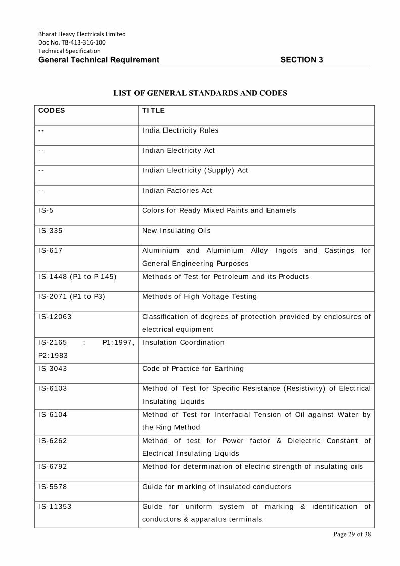
Bharat Heavy Electricals Limited Doc No. TB‐413‐316‐100 Technical Specification
General Technical Requirement SECTION 3
Page 29 of 38
LIST OF GENERAL STANDARDS AND CODES CODES TITLE
-- India Electricity Rules
-- Indian Electricity Act
-- Indian Electricity (Supply) Act
-- Indian Factories Act
IS-5 Colors for Ready Mixed Paints and Enamels
IS-335 New Insulating Oils
IS-617 Aluminium and Aluminium Alloy Ingots and Castings for
General Engineering Purposes
IS-1448 (P1 to P 145) Methods of Test for Petroleum and its Products
IS-2071 (P1 to P3) Methods of High Voltage Testing
IS-12063 Classification of degrees of protection provided by enclosures of
electrical equipment
IS-2165 ; P1:1997,
P2:1983
Insulation Coordination
IS-3043 Code of Practice for Earthing
IS-6103 Method of Test for Specific Resistance (Resistivity) of Electrical
Insulating Liquids
IS-6104 Method of Test for Interfacial Tension of Oil against Water by
the Ring Method
IS-6262 Method of test for Power factor & Dielectric Constant of
Electrical Insulating Liquids
IS-6792 Method for determination of electric strength of insulating oils
IS-5578 Guide for marking of insulated conductors
IS-11353 Guide for uniform system of marking & identification of
conductors & apparatus terminals.
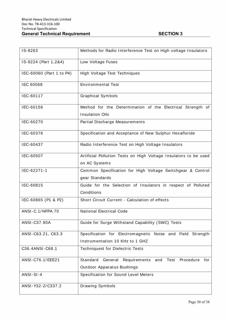
Bharat Heavy Electricals Limited Doc No. TB‐413‐316‐100 Technical Specification
General Technical Requirement SECTION 3
Page 30 of 38
IS-8263 Methods for Radio Interference Test on High voltage Insulators
IS-9224 (Part 1,2&4) Low Voltage Fuses
IEC-60060 (Part 1 to P4) High Voltage Test Techniques
IEC 60068 Environmental Test
IEC-60117 Graphical Symbols
IEC-60156 Method for the Determination of the Electrical Strength of
Insulation Oils
IEC-60270 Partial Discharge Measurements
IEC-60376 Specification and Acceptance of New Sulphur Hexafloride
IEC-60437 Radio Interference Test on High Voltage Insulators
IEC-60507 Artificial Pollution Tests on High Voltage Insulators to be used
on AC Systems
IEC-62271-1 Common Specification for High Voltage Switchgear & Control
gear Standards
IEC-60815 Guide for the Selection of Insulators in respect of Polluted
Conditions
IEC-60865 (P1 & P2) Short Circuit Current - Calculation of effects
ANSI-C.1/NFPA.70 National Electrical Code
ANSI-C37.90A Guide for Surge Withstand Capability (SWC) Tests
ANSI-C63.21, C63.3 Specification for Electromagnetic Noise and Field Strength
Instrumentation 10 KHz to 1 GHZ
C36.4ANSI-C68.1 Techniquest for Dielectric Tests
ANSI-C76.1/EEE21 Standard General Requirements and Test Procedure for
Outdoor Apparatus Bushings
ANSI-SI-4 Specification for Sound Level Meters
ANSI-Y32-2/C337.2 Drawing Symbols
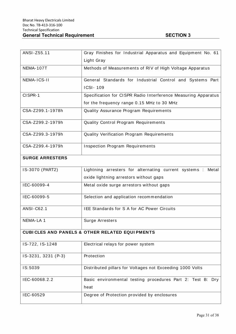
Bharat Heavy Electricals Limited Doc No. TB‐413‐316‐100 Technical Specification
General Technical Requirement SECTION 3
Page 31 of 38
ANSI-Z55.11 Gray Finishes for Industrial Apparatus and Equipment No. 61
Light Gray
NEMA-107T Methods of Measurements of RIV of High Voltage Apparatus
NEMA-ICS-II General Standards for Industrial Control and Systems Part
ICSI- 109
CISPR-1 Specification for CISPR Radio Interference Measuring Apparatus
for the frequency range 0.15 MHz to 30 MHz
CSA-Z299.1-1978h Quality Assurance Program Requirements
CSA-Z299.2-1979h Quality Control Program Requirements
CSA-Z299.3-1979h Quality Verification Program Requirements
CSA-Z299.4-1979h Inspection Program Requirements
SURGE ARRESTERS
IS-3070 (PART2) Lightning arresters for alternating current systems : Metal
oxide lightning arrestors without gaps
IEC-60099-4 Metal oxide surge arrestors without gaps
IEC-60099-5 Selection and application recommendation
ANSI-C62.1 IEE Standards for S A for AC Power Circuits
NEMA-LA 1 Surge Arresters
CUBICLES AND PANELS & OTHER RELATED EQUIPMENTS
IS-722, IS-1248 Electrical relays for power system
IS-3231, 3231 (P-3) Protection
IS:5039 Distributed pillars for Voltages not Exceeding 1000 Volts
IEC-60068.2.2 Basic environmental testing procedures Part 2: Test B: Dry
heat
IEC-60529 Degree of Protection provided by enclosures
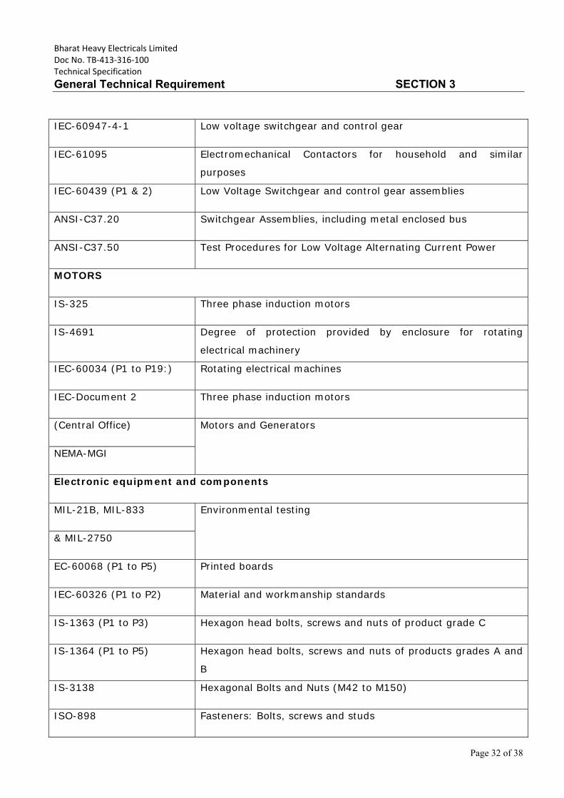
Bharat Heavy Electricals Limited Doc No. TB‐413‐316‐100 Technical Specification
General Technical Requirement SECTION 3
Page 32 of 38
IEC-60947-4-1 Low voltage switchgear and control gear
IEC-61095 Electromechanical Contactors for household and similar
purposes
IEC-60439 (P1 & 2) Low Voltage Switchgear and control gear assemblies
ANSI-C37.20 Switchgear Assemblies, including metal enclosed bus
ANSI-C37.50 Test Procedures for Low Voltage Alternating Current Power
MOTORS
IS-325 Three phase induction motors
IS-4691 Degree of protection provided by enclosure for rotating
electrical machinery
IEC-60034 (P1 to P19:) Rotating electrical machines
IEC-Document 2 Three phase induction motors
(Central Office) Motors and Generators
NEMA-MGI
Electronic equipment and components
MIL-21B, MIL-833 Environmental testing
& MIL-2750
EC-60068 (P1 to P5) Printed boards
IEC-60326 (P1 to P2) Material and workmanship standards
IS-1363 (P1 to P3) Hexagon head bolts, screws and nuts of product grade C
IS-1364 (P1 to P5) Hexagon head bolts, screws and nuts of products grades A and
B
IS-3138 Hexagonal Bolts and Nuts (M42 to M150)
ISO-898 Fasteners: Bolts, screws and studs
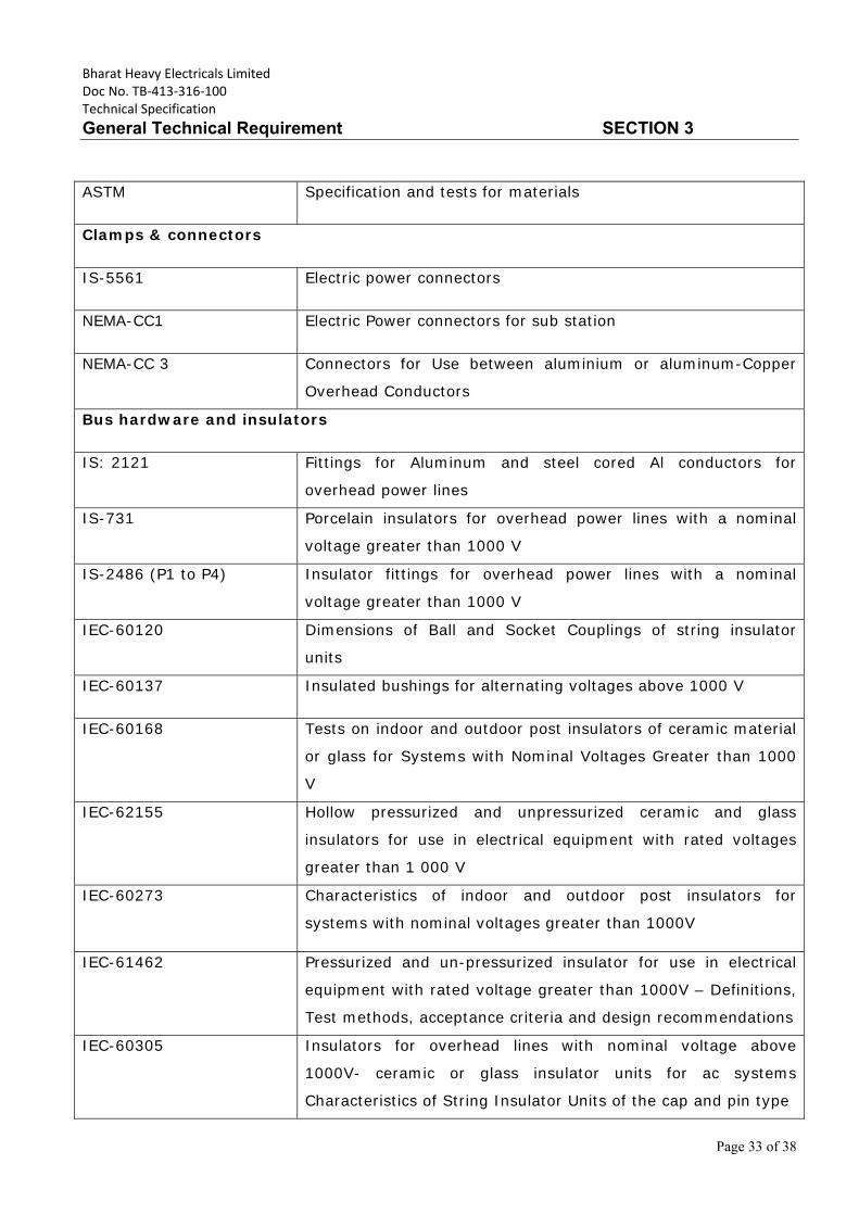
Bharat Heavy Electricals Limited Doc No. TB‐413‐316‐100 Technical Specification
General Technical Requirement SECTION 3
Page 33 of 38
ASTM Specification and tests for materials
Clamps & connectors
IS-5561 Electric power connectors
NEMA-CC1 Electric Power connectors for sub station
NEMA-CC 3 Connectors for Use between aluminium or aluminum-Copper
Overhead Conductors
Bus hardware and insulators
IS: 2121 Fittings for Aluminum and steel cored Al conductors for
overhead power lines
IS-731 Porcelain insulators for overhead power lines with a nominal
voltage greater than 1000 V
IS-2486 (P1 to P4) Insulator fittings for overhead power lines with a nominal
voltage greater than 1000 V
IEC-60120 Dimensions of Ball and Socket Couplings of string insulator
units
IEC-60137 Insulated bushings for alternating voltages above 1000 V
IEC-60168 Tests on indoor and outdoor post insulators of ceramic material
or glass for Systems with Nominal Voltages Greater than 1000
V
IEC-62155 Hollow pressurized and unpressurized ceramic and glass
insulators for use in electrical equipment with rated voltages
greater than 1 000 V
IEC-60273 Characteristics of indoor and outdoor post insulators for
systems with nominal voltages greater than 1000V
IEC-61462 Pressurized and un-pressurized insulator for use in electrical
equipment with rated voltage greater than 1000V – Definitions,
Test methods, acceptance criteria and design recommendations
IEC-60305 Insulators for overhead lines with nominal voltage above
1000V- ceramic or glass insulator units for ac systems
Characteristics of String Insulator Units of the cap and pin type
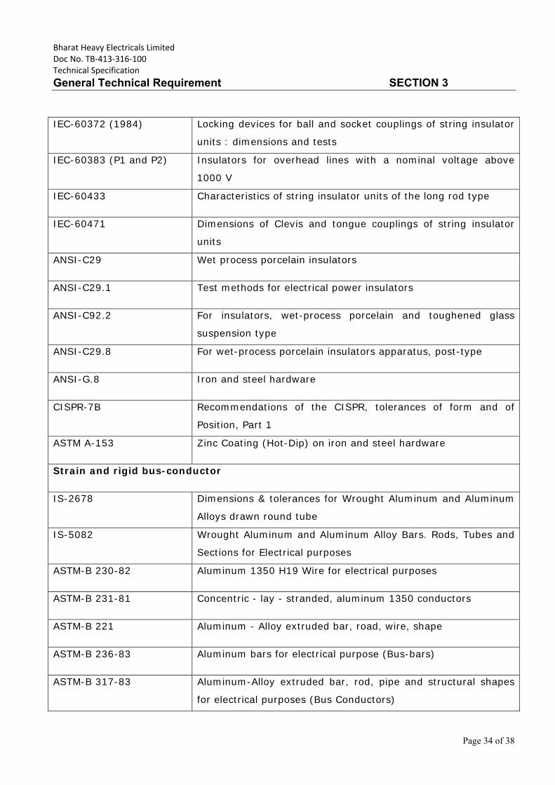
Bharat Heavy Electricals Limited Doc No. TB‐413‐316‐100 Technical Specification
General Technical Requirement SECTION 3
Page 34 of 38
IEC-60372 (1984) Locking devices for ball and socket couplings of string insulator
units : dimensions and tests
IEC-60383 (P1 and P2) Insulators for overhead lines with a nominal voltage above
1000 V
IEC-60433 Characteristics of string insulator units of the long rod type
IEC-60471 Dimensions of Clevis and tongue couplings of string insulator
units
ANSI-C29 Wet process porcelain insulators
ANSI-C29.1 Test methods for electrical power insulators
ANSI-C92.2 For insulators, wet-process porcelain and toughened glass
suspension type
ANSI-C29.8 For wet-process porcelain insulators apparatus, post-type
ANSI-G.8 Iron and steel hardware
CISPR-7B Recommendations of the CISPR, tolerances of form and of
Position, Part 1
ASTM A-153 Zinc Coating (Hot-Dip) on iron and steel hardware
Strain and rigid bus-conductor
IS-2678 Dimensions & tolerances for Wrought Aluminum and Aluminum
Alloys drawn round tube
IS-5082 Wrought Aluminum and Aluminum Alloy Bars. Rods, Tubes and
Sections for Electrical purposes
ASTM-B 230-82 Aluminum 1350 H19 Wire for electrical purposes
ASTM-B 231-81 Concentric - lay - stranded, aluminum 1350 conductors
ASTM-B 221 Aluminum - Alloy extruded bar, road, wire, shape
ASTM-B 236-83 Aluminum bars for electrical purpose (Bus-bars)
ASTM-B 317-83 Aluminum-Alloy extruded bar, rod, pipe and structural shapes
for electrical purposes (Bus Conductors)
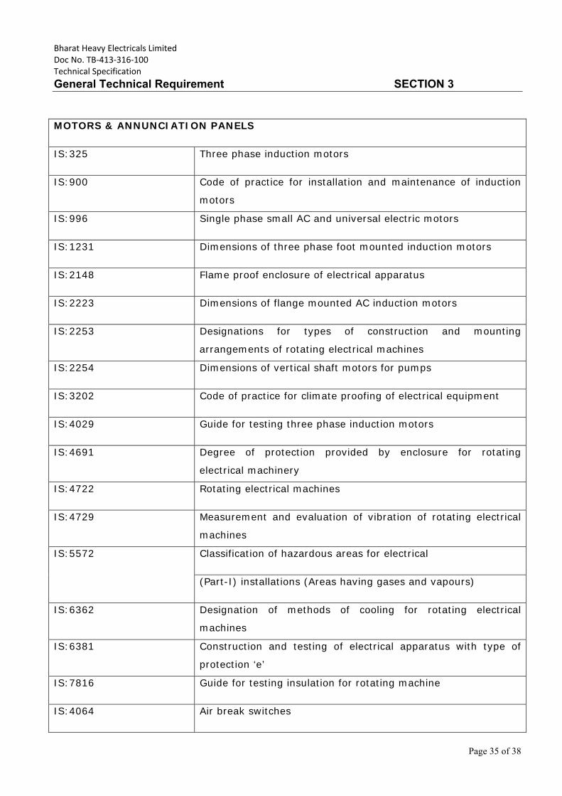
Bharat Heavy Electricals Limited Doc No. TB‐413‐316‐100 Technical Specification
General Technical Requirement SECTION 3
Page 35 of 38
MOTORS & ANNUNCIATION PANELS
IS:325 Three phase induction motors
IS:900 Code of practice for installation and maintenance of induction
motors
IS:996 Single phase small AC and universal electric motors
IS:1231 Dimensions of three phase foot mounted induction motors
IS:2148 Flame proof enclosure of electrical apparatus
IS:2223 Dimensions of flange mounted AC induction motors
IS:2253 Designations for types of construction and mounting
arrangements of rotating electrical machines
IS:2254 Dimensions of vertical shaft motors for pumps
IS:3202 Code of practice for climate proofing of electrical equipment
IS:4029 Guide for testing three phase induction motors
IS:4691 Degree of protection provided by enclosure for rotating
electrical machinery
IS:4722 Rotating electrical machines
IS:4729 Measurement and evaluation of vibration of rotating electrical
machines
IS:5572 Classification of hazardous areas for electrical
(Part-I) installations (Areas having gases and vapours)
IS:6362 Designation of methods of cooling for rotating electrical
machines
IS:6381 Construction and testing of electrical apparatus with type of
protection ‘e’
IS:7816 Guide for testing insulation for rotating machine
IS:4064 Air break switches
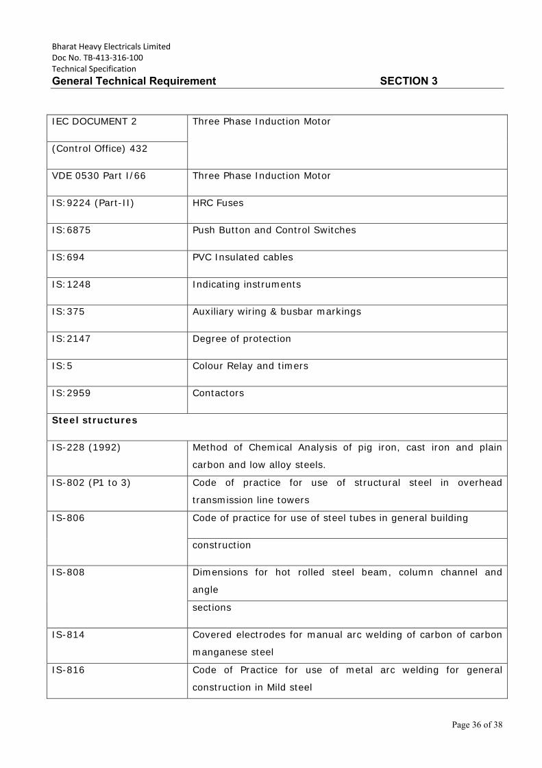
Bharat Heavy Electricals Limited Doc No. TB‐413‐316‐100 Technical Specification
General Technical Requirement SECTION 3
Page 36 of 38
IEC DOCUMENT 2 Three Phase Induction Motor
(Control Office) 432
VDE 0530 Part I/66 Three Phase Induction Motor
IS:9224 (Part-II) HRC Fuses
IS:6875 Push Button and Control Switches
IS:694 PVC Insulated cables
IS:1248 Indicating instruments
IS:375 Auxiliary wiring & busbar markings
IS:2147 Degree of protection
IS:5 Colour Relay and timers
IS:2959 Contactors
Steel structures
IS-228 (1992) Method of Chemical Analysis of pig iron, cast iron and plain
carbon and low alloy steels.
IS-802 (P1 to 3) Code of practice for use of structural steel in overhead
transmission line towers
IS-806 Code of practice for use of steel tubes in general building
construction
IS-808 Dimensions for hot rolled steel beam, column channel and
angle
sections
IS-814 Covered electrodes for manual arc welding of carbon of carbon
manganese steel
IS-816 Code of Practice for use of metal arc welding for general
construction in Mild steel
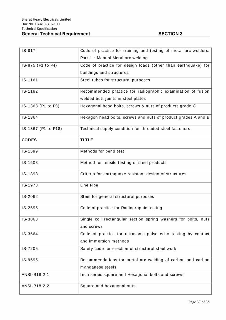
Bharat Heavy Electricals Limited Doc No. TB‐413‐316‐100 Technical Specification
General Technical Requirement SECTION 3
Page 37 of 38
IS-817 Code of practice for training and testing of metal arc welders.
Part 1 : Manual Metal arc welding
IS-875 (P1 to P4) Code of practice for design loads (other than earthquake) for
buildings and structures
IS-1161 Steel tubes for structural purposes
IS-1182 Recommended practice for radiographic examination of fusion
welded butt joints in steel plates
IS-1363 (P1 to P3) Hexagonal head bolts, screws & nuts of products grade C
IS-1364 Hexagon head bolts, screws and nuts of product grades A and B
IS-1367 (P1 to P18) Technical supply condition for threaded steel fasteners
CODES TITLE
IS-1599 Methods for bend test
IS-1608 Method for tensile testing of steel products
IS-1893 Criteria for earthquake resistant design of structures
IS-1978 Line Pipe
IS-2062 Steel for general structural purposes
IS-2595 Code of practice for Radiographic testing
IS-3063 Single coil rectangular section spring washers for bolts, nuts
and screws
IS-3664 Code of practice for ultrasonic pulse echo testing by contact
and immersion methods
IS-7205 Safety code for erection of structural steel work
IS-9595 Recommendations for metal arc welding of carbon and carbon
manganese steels
ANSI-B18.2.1 Inch series square and Hexagonal bolts and screws
ANSI-B18.2.2 Square and hexagonal nuts
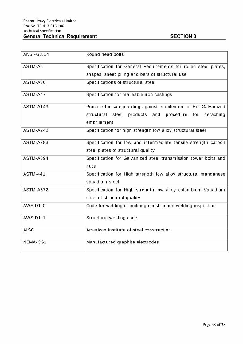
Bharat Heavy Electricals Limited Doc No. TB‐413‐316‐100 Technical Specification
General Technical Requirement SECTION 3
Page 38 of 38
ANSI-G8.14 Round head bolts
ASTM-A6 Specification for General Requirements for rolled steel plates,
shapes, sheet piling and bars of structural use
ASTM-A36 Specifications of structural steel
ASTM-A47 Specification for malleable iron castings
ASTM-A143 Practice for safeguarding against embilement of Hot Galvanized
structural steel products and procedure for detaching
embrilement
ASTM-A242 Specification for high strength low alloy structural steel
ASTM-A283 Specification for low and intermediate tensile strength carbon
steel plates of structural quality
ASTM-A394 Specification for Galvanized steel transmission tower bolts and
nuts
ASTM-441 Specification for High strength low alloy structural manganese
vanadium steel
ASTM-A572 Specification for High strength low alloy colombium-Vanadium
steel of structural quality
AWS D1-0 Code for welding in building construction welding inspection
AWS D1-1 Structural welding code
AISC American institute of steel construction
NEMA-CG1 Manufactured graphite electrodes
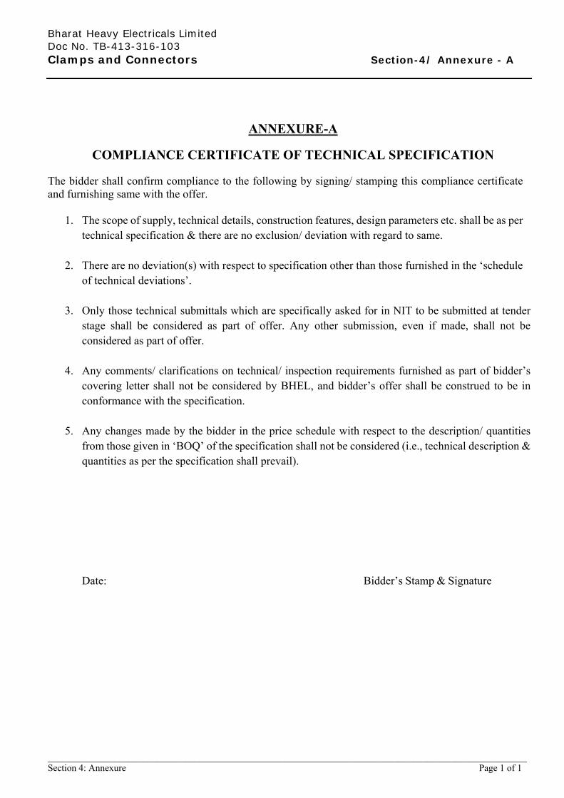
Bharat Heavy Electricals Limited Doc No. TB-413-316-103 Clamps and Connectors Section-4/ Annexure - A
_____________________________________________________________________________________________________ Section 4: Annexure Page 1 of 1
ANNEXURE-A
COMPLIANCE CERTIFICATE OF TECHNICAL SPECIFICATION The bidder shall confirm compliance to the following by signing/ stamping this compliance certificate and furnishing same with the offer.
1. The scope of supply, technical details, construction features, design parameters etc. shall be as per technical specification & there are no exclusion/ deviation with regard to same.
2. There are no deviation(s) with respect to specification other than those furnished in the ‘schedule of technical deviations’.
3. Only those technical submittals which are specifically asked for in NIT to be submitted at tender
stage shall be considered as part of offer. Any other submission, even if made, shall not be considered as part of offer.
4. Any comments/ clarifications on technical/ inspection requirements furnished as part of bidder’s
covering letter shall not be considered by BHEL, and bidder’s offer shall be construed to be in conformance with the specification.
5. Any changes made by the bidder in the price schedule with respect to the description/ quantities
from those given in ‘BOQ’ of the specification shall not be considered (i.e., technical description & quantities as per the specification shall prevail).
Date: Bidder’s Stamp & Signature
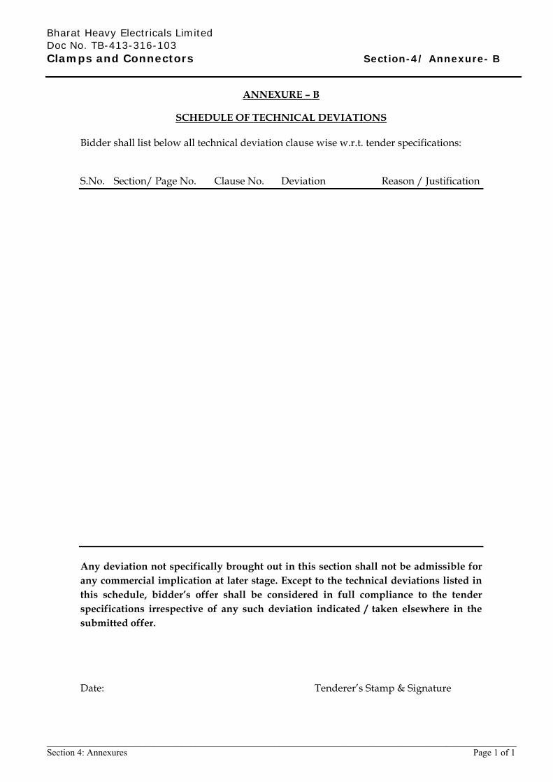
Bharat Heavy Electricals Limited Doc No. TB-413-316-103 Clamps and Connectors Section-4/ Annexure- B
_____________________________________________________________________________________________________ Section 4: Annexures Page 1 of 1
ANNEXURE – B
SCHEDULE OF TECHNICAL DEVIATIONS Bidder shall list below all technical deviation clause wise w.r.t. tender specifications: S.No. Section/ Page No. Clause No. Deviation Reason / Justification Any deviation not specifically brought out in this section shall not be admissible for any commercial implication at later stage. Except to the technical deviations listed in this schedule, bidder’s offer shall be considered in full compliance to the tender specifications irrespective of any such deviation indicated / taken elsewhere in the submitted offer.
Date: Tenderer’s Stamp & Signature