brook - Makharia Electricals Private Limited
25
Keeping Industry Turning CD Frame sizes 56 to 450 BROOK CROMPTON a WOLONG company
-
Upload
khangminh22 -
Category
Documents
-
view
4 -
download
0
Transcript of brook - Makharia Electricals Private Limited
Keeping Industry Turning
CDFrame sizes 56 to 450
BROOKCROMPTONa WOLONG company
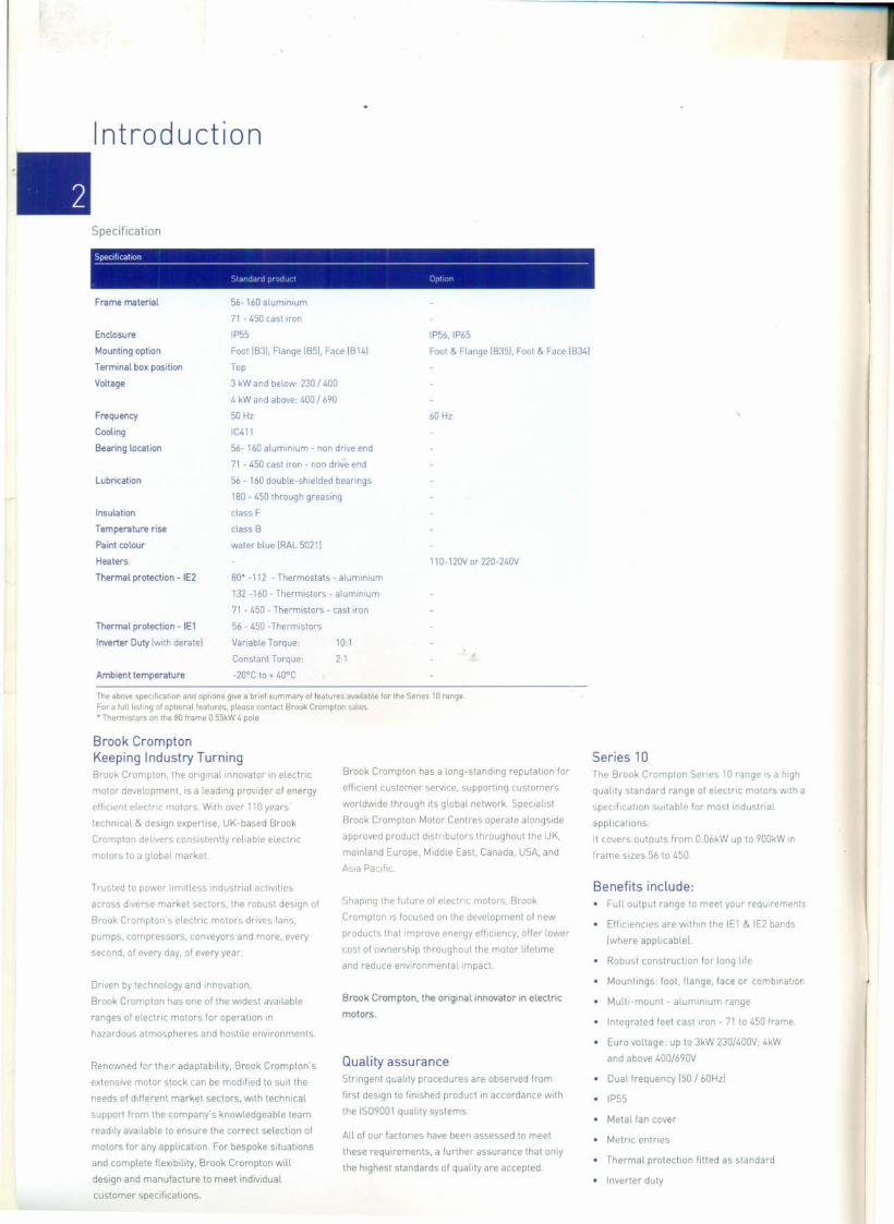
Introduction
Specification
_Sp_e_c_lfI_ca_t_'o_n _
Standard product Option
IP55
Foot IB31.Flange IB51. Face IB 141
Top
3 kW and below: 230 / 400
4 kW and above: 400 /690
50 Hz
IC411
56- 160 aluminium - non drive end
71 - 450 cast Iron - non dnve end
56 - 160 double-shielded bearings
180 - 450 through greasing
class F
class B
water blue IRAL 50211
80' -112 - Thermostats - aluminium
132 -160 - Thermistors - aluminium
71 - 450 - Thermistors - cast Iron
56 - 450 -Thermistors
Variable Torque: 10:1
Constant Torque: 2:1
-20°C to + 40°C
Frame material 56- 160 aluminium
71 - 450 cast Iron
Enclosure
Mounting option
Terminal box position
Voltage
Frequency
Cooling
Bearing location
Lubrication
Insulation
Temperature rise
Paint colour
Heaters
Thermal protection - IE2
Thermal protection - IEl
Inverter Duty [wrth deratel
Ambient temperature
IP56,IP65
Foot & Flange IB351. Foot & Face IB341
60 Hz
110- 120Vor 220-240V
Series 10The Brook Crompton Series 10 range is a high
quality standard range of electric motors with a
speciticanon SUitable for most industrial
applications.
It covers outputs from 0.06kW up to 900kW In
frame sizes 56 to 450.
The above specification and options give a brief summary of features available for the Series 10 rangeFor a full listing of optional features. please contact Brook Crompton saLes .• Thermistors on the 80 frame 0.55kW 4 pole
Brook CromptonKeeping Industry TurningBrook Crompton, the original Innovator In electnc
motor development, IS a leading provider of energy
efficrent electric motors. With over 110 years'
technical & design expertise, UK-based Brook
Crompton delivers consistently reliable electric
motors to a global market.
Trusted to power limitless industrial activities
across diverse market sectors, the robust design of
Brook Crompton's electric motors drives fans,
pumps, compressors, conveyors and more, every
second, of every day, of every year.
Driven by technology and mnovauon,
Brook Crompton has one of the Widest available
ranges of electric motors for operation In
hazardous atmospheres and hostile environments.
Renowned for their adaptability, Brook Crompton's
extensive motor stock can be modified to suit the
needs of different market sectors, with technical
support from the company's knowledgeable team
readily available to ensure the correct selection of
motors for any application. For bespoke situatrons
and complete flexibility, Brook Crompton will
design and manufacture to meet individual
customer specifications.
Brook Crompton has a long-standing reputation for
effrcient customer service, supporting customers
worldwide through its global network. Specialist
Brook Crompton Motor Centres operate alongside
approved product distributors throughout the UK,
mainland Europe, Middle East. Canada, USA, and
ASia Pacific.
Shaping the future of electnc motors, Brook
Crompton IS focused on the development of new
products that Improve energy efficiency, offer lower
cost of ownership throughout the motor lifetime
and reduce environmental Impact.
Brook Crompton, the original innovator in electric
motors.
QuaLity assuranceStringent quality procedures are observed from
first design to finished product In accordance with
the 1509001 quality systems.
All of our factones have been assessed to meet
these requirements, a further assurance that only
the highest standards of quality are accepted.
Benefits include:• Full output range to meet your requirements
• EffiCienCies are within the IEl & IE2 bands
Iwhere apphcablel.
• Robust construction for long life
• Mountings: foot, flange, face or combination
• Multi-mount - aluminium range
• Integrated feet cast Iron - 71 to 450 frame.
• Euro voltage: up to 3kW 230/400V: 4kW
and above 400/690V
• Dual frequency 150 / 60HzI
• IP55
• Metal fan cover
• Metric entries
• Thermal protection fitted as standard
• Inverter duty

Standards and environment
•Standards
Standards----------------------------------Series 10 motors are manufactured to theInternational standards listed below
Environment EnclosureAll motors have degrees of IP protection as defined in IEC
EN 60034-5. The normal arrangement is IP55.
See Specification [page 21for alternatives.Performance IEC 60034-1
IEC 60072-1
IEC 60034-7
IEC 60034-5
IEC 60034-14 [grade AI
IEC60034-9
Motor coolingMotors are cooled in accordance with IEC 60034-6.
The normal arrangement is IC411 [Totally Enclosed Fan
Ventilatedl via a fan mounted at the non-drive end.
Dimensions
Mounting
Enclosure protection
Vibration
Noise
European directivesThe following European directives apply
Directives
Compliance with European directives applymg to AC induction motors---------------------------------------------------------------------------------------------------------------------Directives Low voltaqe Macbmerv Electromagnetic compatibility Eoe-q, related oroducts
ILVI IMOI IEMel IE-PI
Reference numbers 2014/35/EU 2006/42/EC 2014/30/EU 2009/125/EC[previously 73/23/EEC, [previously 89/392/EEC, [previously 89/336/EEC, [previously 92/42/EEC,
93/68/EEC & 2006/95/ECI 93/44/EEC, 98/37/EC & 92/31/EEC, 93/68/EEC & 96/57/EC, 2000/55/EC &
98/79/ECI 2004/108/ECI 2005/32/ECI
Yes No No YesEN 60034 Not applicable EN 60034-1 EN 60034-30
Declaration of conformity Declaration of incorporation Staternent'" Declaration of conformity
Yes Yes YesRelevant electrical equip- Statement?' Component Minimum efficiency levelsment operating between for motor outputs
50 to 1000volts AC 0.75 - 375kW
2-6 pole
Motor CE marked
StandardsDocumentation for customers' technical file
Safety instructions with every motorComment
l1JMotors operating from a correctly applied. sinusoidal lAC] suppLy meet the requirements of the EMC directive and are within the limits specified in standard EN 60034-1
(21When installed in accordance with our customer safety and installation and maintenance instructions, they can be put into service only when the machinery into which they
are being incorporated, has been declared to be in conformity with the machinery directive in accordance with Article 4[21 and Annex lIB of that Directive [98/37/EECI
Minimum Energy Performance Standard
The new standard
The EU MEPS scheme sets new mandatory
minimum efficiency levels for most single speed
3ph induction motors up to 375kW rated up to
1000V, unlike the narrow definition of the CEMEP
voluntary scheme which only covered a small
number of standard motors.
New Efficiency levels in Europe [Time Linel
Mandatory from:
Since 1" January 2015:
Minimum efficiency requirement at IE3 level for
7.5 - 375kW motors or IE2levei for motors
equipped with an appropriate variable speed drive.
From 1" January 2017:
Minimum efficiency requirement at IE3 level for
0.75 - 375kW motors or IE2 level for motors
equipped with an appropriate variable speed drive.The Voluntary Agreement, since 1998, of CEMEP
for motor manufactures has expired
[classes EFF3 /EFF2/EFFI LThe new standard for motors is now mandatory
regulation in Europe.
The scope of EU MEPS covers 2, 4 & 6 pole single
speed 3ph induction motors from 0.75 to 375kW,
rated up to 1000V based on continuous duty
operation.
Aiming to reduce energy consumption throughout
Europe and the rest of the world, it comes into ef-
fect in 3 stages. The effect of this is to maxi mise
potential savings in electric motor driven systems.
Base of the regulation is a new internationallEC
60034-30 standard. It defines the following
efficiency classes:
lEI - Standard Efficiency [comparable to EFF21
IE2 - High Efficiency [comparable to EFFI and USA
EPACT 60 HzI
IE3 - Premium Efficiency [comparable to USA
"NEMA Premium" 60 HzI

Performance data
.& .,.ol!~;- <'!' ss~ '" ~ .'i I:- d-~ ~<>: ~ r» F i:f~ ..s~.§'cP c
-S'rJ .:..it .•..'" ~II t-~ $' ~ .:.:::::..$i .§'<f .:.:::::~'<t....'b~fJ) ;:, b
"'.-~".::J .::,.0 1..t....::J ~ q; Q,0 ".:::; t....(:;i.
,'" '" ,'" -'?
3000 rnrn 1 [2 pole), aluminium construction
PN 'N---------- ---------------kW hp n 130 V 400 V 690 V h C", 0 MN MA M" MK 'A J II'A k'l
mm Type A A A 10 PN 10 I'N Nm MN MN MN IN kqrn rllMI
0.09 0.15 2750 B-DA56MA 0.52 0.30 62.0 0.70 0.31 2.1 2.2 5.2 0.00018 3.6
0.12 0.20 2750 B-DA56MB 0.62 0.36 67.0 0.72 0.41 2.1 2.2 5.2 0.00023 3.9
0.18 0.25 2720 B-DA63MA 0.87 0.50 65.0 0.80 0.63 2.2 2.3 5.5 0.00031 4.8
0.25 0.33 2720 B-DA63MB 1.14 0.66 68.0 0.81 0.88 2.2 2.3 5.5 0.0006 5.1
0.37 0.5 2740 B-DA71MA 1.62 0.94 70.0 0.81 1.28 2.2 2.3 6.1 0.00075 6.0
0.55 0.75 2740 B-DA71MB 2.30 1.33 730 0.82 1.91 2.2 2.3 6.1 0.0009 6.5
0.75 1.0 2870 A-DA80MA 2.93 1.69 77.4 0.83 2.49 2.5 3.0 5.3 0.0012 56 10.5
1.1 1.5 2870 A-DA80MB 4.18 2.40 79.6 0.83 3.66 3.2 3.8 7.0 0.0014 57 11.5
1.5 2.0 2890 A-DA90SA 5.45 3.13 81.3 0.85 4.96 2.7 3.5 7.1 0.0029 61 17.0
2.2 3.0 2890 A-DA90LA 7.81 4.49 83.2 0.85 7.27 2.4 3.0 6.9 0.0055 61 210
3.0 4.0 2890 A-DA100LA 10.2 5.88 84.6 0.87 9.91 3.2 4.0 8.0 0.0109 63 26.5
4.0 5.5 2900 A-DA112MA 7.65 4.43 85.8 0.88 13.2 2.5 3.0 7.5 0.0126 65 29.5
5.5 7.5 2930 A-DA132SA 10.4 6.01 87.0 0.88 17.9 2.7 3.5 7.5 0.0377 68 42.5
7.5 10 2930 A-DA132SB 14.0 8.09 88.1 0.~8 24.4 2.4 3.3 7.5 0.0499 68 48.0~11.0 15 2940 A-DA160MA 20.0 11.6 89.4 0.89 35.7 2.2 2.9 7.6 0.055 72 88.0
15.0 20 2940 A-DA160MB 26.9 15.6 90.3 0.89 48.7 2.3 3.1 7.6 0.075 73 97.0
18.5 25 2940 A-DA160LA 33.0 19.1 90.9 0.89 60.1 2.3 3.1 7.4 0.124 73 107
A-OA frame nomenclature indicates an IE2 efficiency motor
See performance data notes on page 28
Performance data
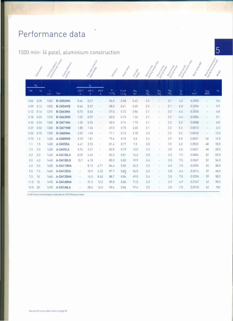
1500 rmn (4 pole], aluminium construction
I'N IN---------- ---------------kW hp n ) W V /IUO V 69ll V h (I) (11 MN M!,\ M ) MK 1/\ j I fJA kq
nun lYIH A A /I.. 1 (I PN 1 lJ fJN Nm MN MN MN IN kqm <JUIA]
0.06 0.08 1325 B-DA56MA 0.46 0.27 56.0 0.58 0.43 2.0 2.1 4.0 0.0003 3.6
0.09 0.12 1325 B-DA56MB 0.64 0.37 58.0 0.61 0.65 2.0 2.1 4.0 0.0004 3.9
0.12 0.16 1310 B-DA63MA 0.73 0.42 57.0 0.72 0.84 2.1 2.2 4.4 0.0005 4.8
0.18 0.25 1310 B-DA63MB 1.02 0.59 60.0 0.73 1.26 2.1 2.2 4.4 0.0006 5.1
0.25 0.33 1330 B-DA71MA 1.30 0.75 65.0 0.74 1.73 2.1 2.2 5.2 0.0008 6.0
0.37 0.50 1330 B-DA71MB 1.85 1.06 67.0 0.75 2.65 2.1 2.2 5.2 0.0013 6.3
0.55 0.75 1390 B-DA80MA 2.59 1.49 71.1 0.75 3.78 2.3 2.3 5.2 0.0018 12.5
0.75 1.0 1430 A-DA80MB 3.15 1.81 79.6 0.75 5.0 2.4 2.9 5.0 0.0021 46 14.0
1.1 1.5 1430 A-DA90SA 4.41 2.53 81.4 0.77 7.3 3.0 3.5 6.0 0.0023 48 18.0
1.5 2.0 1430 A-DA90LA 5.76 3.31 82.8 0.79 10.0 3.2 3.8 6.8 0.0027 48 20.5
2.2 3.0 1440 A-DA100LA 8.09 4.65 84.3 0.81 14.6 3.0 3.5 7.0 0.0054 52 29.0
3.0 4.0 1440 A-DA100LB 10.7 6.18 85.5 0.82 19.9 2.6 3.3 7.0 0.0067 52 34.0
4.0 5.5 1450 A-DA112MA 8.13 4.71 86.6 0.82 26.3 3.5 4.0 7.5 0.0095 53 38.0
5.5 7.5 1460 A-DA132SA 10.9 6.32 87.7 0.83 36.0 2.2 2.8 6.4 0.0214 59 48.0J.
7.5 10 1460 A-DA132MA 14.5 8.42 88.7 0.84 49.0 2.4 3.0 7.0 0.0296 59 58.5
11.0 15 1470 A-DA160MA 21.0 12.2 89.8 0.84 71.5 2.5 2.9 6.9 0.0747 62 90.0
15.0 20 1470 A-DA160LA 28.4 16.5 90.6 0.84 97.4 2.5 3.0 7.5 0.0918 62 104
A-OA frame nomenclature indicates an IE2 efficiency motor
See performance data notes on page 28
Performance data
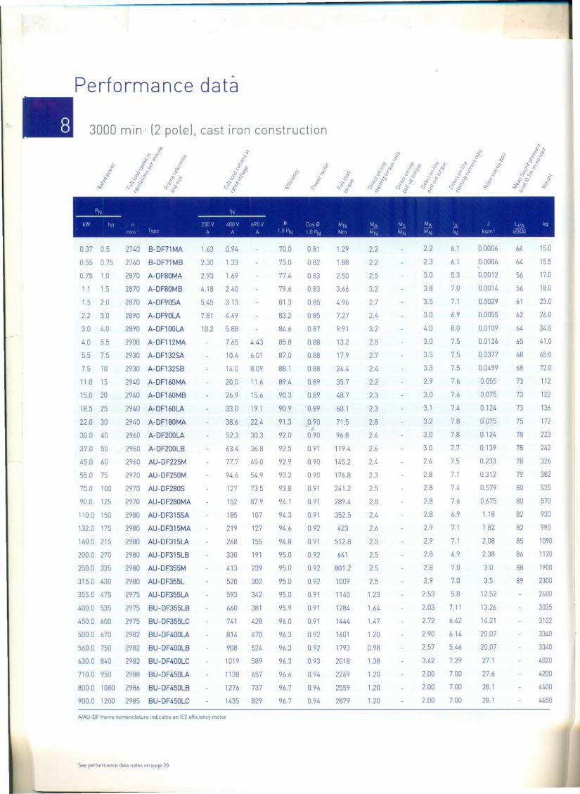
3000 rmn [2 polel, cast iron construction
PN 'N--------- -------------kW he n nov 400V 6QOV h Co-, 0 MN MA MS ~K 'I; J LpA kg
rrun Type A A AID PN 10 PN Nrn MN M-N MN 'N kgm dBlAI
0.0006
0.0006
0.0012
0.0014
0.0029
0.0055
0.0109
0.0126
0.0377
0.0499
0.055
0.075
0.124
0.075
0.124
0.139
0.233
0.312
0.579
0.675
1.18
1.82
2.08
2.38
3.0
3.5
12.52
13.26
14.21
20.07
20.07
27.1
27.6
28.1
28.1
15.0
15.5
17.0
18.0
230
26.0
34.0
41.0
65.0
no112
122
136
172
223
242
326
382
525
570
930
990
1090
1120
1900
2300
2600
3035
3122
3340
3340
4020
4200
4400
4650
2.2
2.3
3.0
3.8
3.5
3.0
4.0
3.0
3.5
3.3
2.9
3.0
3.1
3.2
3.0
3.0
2.6
2.8
2.8
2.8
2.8
2.9
2.9
2.8
2.8
2.9
2.53
2.03
2.72
2.90
2.57
3.42
2.00
2.00
2.00
6.1
6.1
5.3
7.0
7.1
6.9
8.0
7.5
7.5
7.5
7.6
7.6
7.4
7.8
7.8
7.7
7.5
7.1
7.4
7.6
6.9
7.1
7.1
6.9
7.0
7.0
5.8
7.11
6.42
6.14
5.46
7.29
7.00
7.00
7.00
64
64
56
56
61
62
64
65
68
68
73
73
73
75
78
78
78
79
80
80
82
82
85
86
88
89
0.37 0.5
0.55 0.75
0.75 1.0
1.1 1.5
1.5 2.0
2.2 3.0
3.0 4.0
4.0 5.5
5.5 7.5
7.5 10
11.0 15
15.0 20
18.5 25
no 30
30.0 40
37.0 50
45.0 60
55.0 75
75.0 100
90.0 125
110.0 150
132.0 175
160.0 215
200.0 270
250.0 335
315.0 430
355.0 475
400.0 535
450.0 600
500.0 670
560.0 750
630.0 840
710.0 950
800.0 1080
900.0 1200
2740 B-DF71MA 1.63
2740 B-DF71MB 2.30
2870 A-DF80MA 2.93
2870 A-DF80MB 4.18
2870 A-DF90SA 5.45
2890 A-DF90LA 7.81
2890 A-DF100LA 10.2
2900 A-DFl12MA
2930 A-DF132SA
2930 A-DF132SB
2940 A-DF160MA
2940 A-DF160MB
2940 A-DF160LA
2940 A-DF180MA
2960 A-DF200LA
2960 A-DF200LB
2960 AU-DF225M
2970 AU-DF250M
2970 AU-DF280S
2970 AU-DF280MA
2980 AU-DF315SA
2980 AU-DF315MA
2980 AU-DF315LA
2980 AU-DF315LB
2980 AU-DF355M
2980 AU-DF355L
2975 AU-DF355LA
2975 BU-DF355LB
2975 BU-DF355LC
2982 BU-DF400LA
2982 BU-DF400LB
2982 BU-DF400LC
2988 BU-DF450LA
2986 BU-DF450LB
2985 BU-DF450LC
0.94
1.33
1.69
2.40
3.13
4.49
5.88
7.65
10.4
14.0
20.0
26.9
33.0
38.6
52.3
63.4
77.7
94.6
127
152
185
219
268
330
413
520
593
660
741
814
908
1019
1138
1276
1435
70.0
730
77.4
79.6
81.3
83.2
84.6
85.8
87.0
88.1
89.4
90.3
90.9
91.3
92.0
92.5
92.9
93.2
93.8
94.1
94.3
94.6
94.8
95.0
95.0
95.0
95.0
95.9
96.0
96.3
96.3
96.3
96.6
96.7
96.7
0.81
0.82
0.83
0.83
0.85
0.85
0.87
0.88
0.88
0.88
0.89
0.89
0.89
0.90
0.90
0.91
0.90
0.90
0.91
0.91
0.91
0.92
0.91
0.92
092
092
0.91
0.91
0.91
092
092
0.93
0.94
0.94
0.94
1.29
1.88
2.50
3.66
4.96
7.27
9.91
13.2
17.9
24.4
35.7
48.7
60.1
71.5
96.8
119.4
145.2
176.8
241.2
289.4
352.5
423
512.8
641
801.2
1009
1140
1284
1444
1601
1793
2018
2269
2559
2879
2.2
2.2
2.5
3.2
2.7
2.4
3.2
2.5
2.7
2.4
2.2
2.3
2.3
2.8
2.6
2.6
2.4
2.3
2.5
2.8
2.4
2.6
2.5
2.5
2.5
2.5
1.23
1.64
1.47
1.20
0.98
1.38
1.20
1.20
1.20
4.43
6.01
809
11.6
15.6
19.1
22.4
30.3
36.8
45.0
54.9
73.5
87.9
107
127
155
191
239
302
342
381
428
470
524
589
657
737
829
A/AU-DF frame nomenclature indicates an IE2 efficiency motor
See perlormance data notes on page 28

Performance data
1500 rrun 1 [4 pole], cast iron construction
PN 'N--------- -------------kW hp n 23IJV 400V 690V h Cus0 MN MA MS Mt 'A J lPA kg
rrun l ypc A A A I II PN I II PN Nm MN MN MN 'N kgm uBlAI
0.25 0.33
0.37 0.50
0.55 0.75
0.75 1.0
1.1 1.5
1.5 2.0
2.2 3.0
3.0 4.0
4.0 5.5
5.5 7.5
7.5 10
11.0 15
15.0 20
18.5 25
220 30
30.0 40
37.0 50
45.0 60
55.0 75
75.0 100
90.0 125
110.0 150
132.0 175
160.0 215
200.0 270
250.0 335
315.0 430
355.0 475
400.0 535
450.0 600
500.0 670
560.0 750
630.0 840
710.0 950
800.0 1070
900.0 1200
1330 B-DF71 MA 1.30
1330 B-DF71 MB 1.83
1390 B-DF80MA 2.58
1430 A-DF80MB 3.15
1430 A-DF90SA 4.41
1430 A-DF90LA 5.76
1440 A-DF1ooLA 8.09
1440 A-DF1ooLB 10.7
1410 A-DF112MA 13.3
1460 A-DF132SA
1460 A-DF132MA
1470 A-DF16oMA
1470 A-DF16oLA
1470 A-DF18oMA
1470 A-DF18oLA
1470 A-DF2ooL
1480 A-DF255S
1475 AU-DF225M
1475 AU-DF250MA
1480 AU-DF28oS
1480 AU-DF28oMA
1485 AU-DF315S
1485 AU-DF315M
1485 AU-DF315LA
1485 AU-DF315LB
1485 AU-DF355M
1490 AU-DF355L
1485 AU-DF355LA
1485 BU-DF355LB
1485 BU-DF355LC
1492 BU-DF4ooLA
1492 BU-DF4ooLB
1492 BU-DF4ooLC
1492 BU-DF450LA
1492 BU-DF450LB
1492 BU-DF450LC
0.75
106
1.49
1.81
2.53
3.31
4.65
6.18
8.13
10.9
14.5
21028.4
34.0
39.8
53.9
66.2
80.2
97.6
132
159
189
226
273
341
422
531
612
680
757
831
924
1043
1164
1308
1496
4.71
6.32
8.42
12.2
16.5
19.7
23.1
31.3
38.4
46.5
56.6
76.7
91.9
109
131
159
198
244
308
353
393
437
480
533
602
672
755
864
65.0
67.0
71.1
79.6
81482.8
84.3
85.5
86.6
87.7
88.7
89.8
90.6
91.2
91.6
92.3
92.7
93.1
93.5
94.0
94.2
94.5
94.7
94.9
95.1
95.1
95.1
95.1
96.4
96.4
96.4
96.4
96.4
96.4
96.6
96.6
0.74 1.80
0.75 2.66
0.75 3.78
0.75 5.01
0.77 7.35
0.79 10.0
0.81 14.6
0.82 19.9
0.82 26.3
0.83 40.0
0.84 49.0
0.84 71.4
0.84 97.4
0.86· J. 120.2
0.87 143
0.87 195
0.87 239
0.87 290.4
0.87 356
0.87 484
0.87 581
0.89 707
0.89 849
0.89 1029
0.89 1286
0.90 1608
0.90 2026
0.88 2283
0.88 2572
0.89 2894
0.90 3200
0.90 3585
0.91 4033
0.91 4545
0.93 5120
0.92 5760
2.1
2.1
2.2
2.4
3.0
3.2
3.0
2.6
3.5
2.2
2.4
2.5
2.5
2.6
2.6
2.4
2.5
2.5
2.6
2.7
2.7
2.7
2.7
3.0
3.0
2.8
2.6
1.93
1.80
1801.83
2.02
1.75
1.30
1.53
1.75
2.2
2.2
2.3
2.9
3.5
3.8
3.5
3.3
4.0
2.8
3.0
2.9
3.0
3.1
3.1
2.9
2.7
2.8
2.7
2.7
2.7
2.9
2.9
3.0
3.0
2.9
2.8
2.6
2.6
2.6
2.52
2.67
2.34
2.57
2.28
2.34
5.2
5.2
5.2
5.0
6.0
6.8
7.0
7.0
7.5
6.4
7.0
6.9
7.5
7.8
7.5
7.1
7.5
7.6
7.3
7.6
7.5
7.1
7.3
7.4
7.6
7.5
7.4
6.5
6.5
6.5
6.19
6.64
5.81
6.17
6.91
5.81
0.0006
0.0008
0.0018
0.0021
0.0023
0.0027
0.0054
0.0067
0.0095
0.0214
0.0296
0.0747
0.0918
0.139
0.158
0.262
0.406
0.469
0.66
1.12
1.46
3.11
3.62
4.13
4.73
6.5
8.2
9.5
10.6
115
18.41
19.62
21.33
41.00
49.50
49.50
55
55
58
46
48
4852
52
53
59
59
62
62
64
64
64
64
65
66
69
69
77
77
82
82
8484
14.0
14.5
15.0
16.0
23.0
25.0
33.0
34.0
38.0
65.0
76.0
118
132
164
182
245
258
290
388
510
606
910
1000
1055
1128
1700
1900
2150
2300
2460
3132
3548
3589
4055
4724
4732
AlAU-OF frame nomenclature indicates an IE2 efficiency motor
See performance data notes on page 28

~-~,
Performance data
1000 rnrn- [6 pole], cast iron construction.:!' ~o.S' ,S- 6- sJi' ~ s~ '" ~ s t cl-
t ~ " ~ bcJ ror& F (j
.,," -s~~~ c...s'ri::..~
....'" ~t·&' .J' ~ .:;::;:.-S ~.:!' .;::;;.~ ,<t..."D~CI) '" ." $ ~o? 4..'::;' ~o ".:::i ~ '1.° ",.:;j e<.'" '" <.'" -s
I~ IN--------- -------------kW t I) II / {[J V IdHJ V (/j(J .; h () '" Mf\J MA M,) Mv 1/\ J I IJ/\ kq
I11HI I JP! /\ II A 1 IJ I'N 1 [J I'f'-J Nfll MN MN Mr~ IN kqm dH[Aj
0.18 0.25 850 B-DF71MA 1.21 0.70 56.0 0.66 2.02 1.9 2.0 4.4 0.0011 52 14.0
0.25 0.33 850 B-DF71MB 1.56 0.90 59.0 0.68 2.81 1.9 2.0 4.0 0.0014 52 14.5
0.37 0.5 885 B-DF80MA 2.13 1.23 62.0 0.70 3.99 1.9 2.0 4.7 0.0016 54 15.0
0.55 0.75 885 B-DF80MB 2.94 1.70 65.0 0.72 5.94 1.9 2.1 4.7 0.0019 54 16.0
0.75 1.0 920 A-DF90SA 3.45 1.98 75.9 0.72 7.79 2.2 2.4 4.5 0.0029 45 19.0
1.1 1.5 920 A-DF90LA 4.84 2.78 78.1 0.73 11.4 2.4 2.6 4.5 0.0035 45 22.0
1.5 2.0 940 A-DF100LA 6.29 3.62 79.8 0.75 15.2 1.8 2.2 4.2 0.0069 49 32.0
2.2 3.0 960 A-DFl12MA 8.88 5.11 81.8 0.76 21.9 2.3 2.8 4.5 0.014 53 41.0
3.0 4.0 960 A-DF132SA 11.9 6.84 83.3 0.76 29.8 1.8 2.4 4.5 0.0286 53 44.0
4.0 5.5 960 A-DF132MA 8.98 5.21 84.6 0.76 39.8 2.3 2.7 5.0 0.0357 55 53.0
5.5 7.5 960 A-DF132MB 12.0 6.95 86.0 0.77 54.7 1.9 2.8 5.5 0.0449 55 63.5
7.5 10 970 A-DF160MA 15.9 9.23 87.2 0.78 73.8 2.0 3,0 6.5 0.081 57 118
11.0 15 970 A-DF160LA 22.7 13.1 88.7 0.79 108.3 2.4 3.3 7.5 0.116 57 145
15.0 20 970 A-DF180LA 29.4 17.1 89.7 0.82 • J47.7 2.0 2.7 6.4 0.207 58 198
18.5 25 970 A-DF200LA 36.5 21.1 90.4 0.81 182.1 2.3 3.0 7.0 0.315 58 200
220 30 970 A-DF200LB 43.1 25.0 90.9 0.81 216.6 2.3 2.8 7.0 0.36 61 228
30.0 40 980 AU-DF225M 56.2 32.6 91.7 0.84 292.3 2.2 2.7 6.5 0.547 62 265
37.0 50 985 AU-DF250M 68.1 39.5 92.2 0.85 358.7 2.5 2.7 6.9 0.843 62 370
45.0 60 980 AU-DF280S 81.5 47.2 92.7 0.86 438.5 2.2 2.4 7.0 1.39 63 490
55.0 75 980 AU-DF280MA 99.2 57.5 93.1 0.86 536 2.4 2.5 7.1 1.65 64 540
75.0 100 990 AU-DF315SA 134 77.9 93.7 0.86 723 2.8 3.0 7.3 4.11 68 900
90.0 125 990 AU-DF315MA 161 93.2 94.0 0.86 868 2.7 2.9 7.1 4.78 68 980
110.0 150 990 AU-DF315LA 196 113 94.3 0.86 1061 2.9 2.9 7.4 5.45 73 1045
132.0 175 990 AU-DF315LB 231 133 94.6 0.87 1273 3.0 3.1 7.6 6.12 73 1100
160.0 215 990 AU-DF355MA 277 160 94.8 0.88 1543 3.1 3.1 7.6 9.5 80 1550
200.0 270 990 AU-DF355MB 345 200 95.0 0.88 1929 3.0 3.0 7.8 10.4 80 1600
250.0 335 990 AU-DF355L 432 249 95.0 0.88 2412 3.1 3.0 7.7 12.4 80 1700
315.0 420 990 AU-DA355LA 563 325 95.0 0.85 3039 2.1 2.4 6.5 13.5 2310
355.0 480 990 AU-DF355LB 634 366 95.0 0.85 3424 2.1 2.4 6.5 14.3 2490
400.0 544 990 BU-DF400LA 701 405 95.9 0.86 3856 2.08 2.48 6.38 21.86 3560
450.0 612 994 BU-DF400LB 783 452 95.9 0.86 4323 2.07 2.43 6.31 22.31 3840
500.0 680 994 BU-DF400LC 871 503 96.1 0.86 4804 1.86 2.19 5.72 23.52 3870
560.0 760 994 BU-DF450MB 874 505 96.0 0.86 5380 1.64 2.32 5.99 54.10 4200
630.0 850 994 BU-DF450LA 1097 633 96.1 0.86 6052 1.65 2.30 5.99 60.60 4620
710.0 960 994 BU-DF450LB 1235 713 95.9 0.86 6821 1.71 2.33 6.13 67.90 5080
800.0 1080 994 BU-DF450LC 1381 797 96.5 0.87 7686 1.52 2.06 5.47 67.90 5080
.AJAU-DF frame nomenclature indicates an IE2 efficiency motor
See performance data notes on page 28

Performance data notes
750 rrun [8 polel, cast iron construction.& ...".S'S' <'!' s
r!;,p ~s s l:' ~Jjs 4'<> ;;7 b~ 'b~ C. (j
~ b ,p c ,'" ~-Sib ;,.~ '" ~ slJ £?-&' -Sf' r!; ~§'-s:-~'" b
0 Scl ".:;)~o '<~J>~ 4..;;;) ..!!' s ,,-0 4.;) s-,'" .. ~ ~
I~IJ "J--------- -------------kW h!J r LJ[JV I.(JfJ-I 69[JV h C(»0 ~J~J MA r-'1c) tJr< j, ) rl ~-j
rrur llfH I\. /I k lfJPN llJP\J t~rr MN ~i'J MJ I'J "3 Jf~1
0.09 0.15 600 B-DF71MA 0.99 0.57 40.0 0.57 1.3 1.8 1.9 2.8 0.0008 48 6.0
0.12 0.20 600 B-DF71MB 1.21 0.70 45.0 0.57 2.16 1.8 1.9 2.8 0.0010 48 6.3
0.18 0.25 645 B-DF80MA 1.45 0.84 51.0 0.61 2.66 1.8 1.9 3.3 0.0025 48 8.9
0.25 0.33 645 B-DF80MB 1.90 1.10 54.0 0.61 3.70 1.8 1.9 3.3 0.0030 48 10.4
0.37 0.5 670 B-DF90S 2.44 1.41 62.0 0.61 5.27 1.8 1.9 4.9 0.0051 53 12.1
0.55 0.75 670 B-DF90LA 3.58 2.07 63.0 0.61 7.84 1.8 2.0 4.0 0.0065 53 13.7
0.75 1.0 680 B-DF100LA 3.95 2.28 71.0 0.67 10.5 1.8 2.0 4.0 0.0095 56 230
1.1 1.5 680 B-DF100LB 5.45 3.15 73.0 0.69 15.4 1.8 2.0 5.0 0.0110 56 25.1
1.5 2.0 690 B-DF112MA 7.24 4.18 75.0 0.69 20.8 1.8 2.0 5.0 0.0245 59 28.2
2.2 3.0 705 B-DF132S 9.92 5.73 78.0 0.71 29.8 1.8 2.0 6.0 0.0314 61 40.3
3.0 4.0 705 B-DF132M 13.0 7.51 79.0 0.73 40.6 1.8 2.0 6.0 0.0395 61 45.0
4.0 5.5 720 B-DF160MA 9.76 5.64 81.0 0.73 53.1 1.9 2.0 6.0 0.0753 65 68.5
5.5 7.5 720 B-DF160MB 12.9 7.44 83.0 0.74 72.9 2.0 2.0 6.0 0.0931 65 76.0
7.5 10 720 B-DF160L 16.9 9.76 85.5 0.75 • #- 99.5 2.0 2.0 6.0 0.1260 65 86.2
11.0 15 730 B-DF180L 23.9 13.8 87.5 0.76 144 2.0 2.0 6.0 0.203 70 160
15.0 20 730 B-DF200L 32.4 18.7 88.0 0.76 196 2.0 2.0 6.6 0.399 73 228
18.5 25 730 BU-DF225S 39.0 22.5 90.0 0.76 242 1.9 2.0 6.6 0.491 73 242
220 30 730 BU-DF225M 45.0 26.0 90.5 0.78 288 1.9 2.0 6.6 0.547 73 265
30.0 40 735 BU-DF250M 60.2 34.8 91.0 0.79 390 1.9 2.0 6.6 0.834 75 368
37.0 50 735 BU-DF280S 73.9 42.7 91.5 0.79 481 1.9 2.0 6.6 1.93 76 472
45.0 60 735 BU-DF280M 89.4 51.6 92.0 0.79 585 1.8 2.0 6.6 3.65 76 538
55.0 75 735 BU-DF315SA 106 61.2 92.8 0.81 715 1.8 2.0 6.6 4.79 82 900
75.0 100 735 BU-DF315MA 144 83.1 93.0 0.81 975 1.8 2.0 6.6 5.58 82 1000
90.0 125 735 BU-DF315LA 169 97.6 93.8 0.82 1169 1.8 2.0 6.6 6.37 82 1055
110.0 150 735 BU-DF315LB 206 119 94.0 0.82 1429 1.8 2.0 6.4 7.23 82 1118
132.0 175 740 BU-DF355MA 248 143 93.7 0.82 1704 1.8 2.0 6.4 7.9 90 2000
160.0 215 740 BU-DF355MB 299 172 94.2 0.82 2065 1.8 2.0 6.4 10.3 90 2150
200.0 270 740 BU-DF355L 368 212 94.5 0.83 2581 1.8 2.0 6.4 12.3 90 2250
250.0 340 740 BU-DF355LB 485 280 95.3 0.78 3226 1.80 2.0 6.5 14.53 2460
315.0 420 740 BU-DF355LC 610 352 95.5 0.78 4065 1.80 2.0 6.5 15.39 2750
355.0 480 745 BU-DF400LB 641 370 95.6 0.85 4551 1.72 2.25 5.84 29.76 3592
400.0 540 745 BU-DF400LC 723 417 95.6 0.85 5128 1.96 2.44 6.39 31.34 3949
450.0 600 745 BU-DF450LB 817 472 95.7 0.83 5768 1.62 2.18 5.43 75.20 4660
500.0 675 745 BU-DF450LC 913 527 95.7 0.83 6409 1.74 2.23 5.65 79.30 4870
See performance data notes on page 28

Dimensions
r'RI ~..1 (I
----M I' I r, f t r
'! I~ '! l~'/ 'I----'/ J r
'j I ./Irl I
I ~ ,.., , I / I !I /
----r,.., II ! II
L
0KK
TBW
Foot, flange and face mounting - frame sizes 80 to 160 aluminium [A-OAJ
, ,
$-¥- ' ,
- ------- T ]----------------------------------------
I. ,.I~;o:==. ==---B::5==F~:l--I ----./
I \
Bz .--~IS!
1I
"-IS!
"-IS!
[
F
0AC
TBH
0K
o:I:
AB
4 HOLE505ON M PCD

Dimensions
Foot, flange and face mounting - frame sizes 80 to 160 aluminium [A-OAJ •Ge-e-a.
Terminal boxType ,............,
Alurrumurn A 13 C H K I AA AB AC IlB HA HO HE TBW TBH KK
A-DASOM
A-DA90S
A-DA90L
125
140
140
160
190
216
216
254
254
100
100
125
140
140
140
50
56
56
80 lOx 14 290
90 lOx 14 325
90 10x14 350
100 12 x 16 398
112 12 x 16 440
132 12 x 16 475
132 12 x 16 513
160 15 x 18 609
160 15 x 18 653
35
37
37
157
173
173
196
227
262
262
309
309
158
175
175
198
219
258
258
315
315
A-DA160L 300 250 350 18.5 5.0 15
125
125
150
172
180
186
224
260
304
Flange & Face
Type M B" 'TC L.r' 9 1M B I. rY'DJr"I"j
A,urr r L,T M N PST LA M N PST LA
c&
8
10
10
11
12
15
15
18
18
213 104
233 112
233 112
260 124
281 135
320 153.5
320 153.5
402 194.5
402 194.5
101 101
109
109
109
119
119
1 x M25
A-DA100L
A-DA112M
A-DA132S
63
70
89
40
41
51
51
55
55
100 80 120 M6 3.0
115 95 140 M8 3.0 14
115 95 140 M6 3.0 14
130 110 160 M8 3.5 15
130 110 160 M8 3.5 15
165 130 200 Ml0 3.5 17
165 130 200 Ml0 3.5 17
215 180 250 M12 4
215 180 250 M12
Shaft
Type:...,'I r ,..,.. :::: E:: ~ ~ ER ::.J _ •.....
109
109
109
119
119
119
155
155
1 x M25
1 x M25
1 x M32
2 x M32
2x M32
2 x M32
2 x M40
119
164
164 2 x M40
A-DA132M
A-DA160M
A-DA160L
178 89
108
108
30
40
50
50
65
90
M6
M8
Ml0
7.5
10
MlO
M12
M16
210
254
A-DASO
A-DA90
A-DA100
A-DAl12M
A-DA132
A-DA160
19
24
40
50
60
15.5 6
TAPPEDHOLE DH
A-DA80M
A-DA90S
A-DA90L
A-DA100L
A-DAl12M
A-DA132S
165 130 200 12 3.5 12
165 130 200 12 3.5 11
165 130 200 12 3.5 11
215 180 250 14.5 4.0 13
215 180 250 14.5 4.0 14
265 230 300 14.5 4.0 14
20
24
24
33
37
8
8
G
A-DA132M
A-DA160M
265 230 300 14.5 4.0 14
300 250 350 18.5 5.0 15
8
28
28
8 7
60
80
8
10
12
38
42 110
For tolerance details and notes - see page 26

Dimensions
Foot. flange and face mounting - frame sizes 56 to 160 aluminium [B-OA]
It! 3~t! ~~
-----~.' "r 1 ~c' r '"
1M H')II~' 13 v)1M \ l[ 111M )rn------M( r-unn opt or ,
1Mill/diM Rli.1M IWI/IMJ1I11-----Moununq opuon
L
TBW
0KK. .
$-'~-'"' '
- .._.-.- m·- - ------------------
I. ' .~r===. '::' J~~IL
11I fool\.
8-z ..-~CSl
l!
11.
CSl
0AC
TBH
0K
C:I:
AB
4 HOLE505ON M PCD
HOLE505ON M PCD

Dimensions
Foot, flange and face mounting - frame sizes 56 to 160 aluminium [B-OAJ •General
Tcrrrunal hut
Type ~
Alurr-nuum A!:3 C 11 K L NI AI) AC BB HA HO HE:. TBW T8~j KK
B-OA56M
B-OA63M
B-OA71M
B-OASOM
B-OA90S
B-OA90L
B-OA100L
B-OAl12M
B-OA132S
B-OA132M
B-OA160M
B-OA160L
90
100
112
125
140
140
160
190
216
216
254
254
71
80
90
100
100
125
140
140
140
178
210
254
36
40
45
5.8 x 8.3 199 23 111
123
138
157
173
173
196
227
113
120
136
155
175
175
195
219
258
258
315
315
88
100
110
125
125
150
172
180
186
224
260
304
8
10
10
11
12
15
15
18
18
153
166
183
205
228
228
252
294
320
320
397
397
72
78
87
102.5
107.5
107.5
121.5
147.5
153.5
153.5
194.5
194.5
86
101
101
101
109
109
109
119
119
119
155
155
86
101
101
101
109
109
109
119
119
119
164
164
1 x M20
1 x M20
1 x M20
1 x M25
1 x M25
1 x M25
1 x M32
2 x M32
2x M32
2x M32
2 x M40
2 x M40
56
63
71
7 x 9.5 217 24
7 x 11 245 26
262
262
304
304
50
56
80
90
90
100
112
132
132
160
160
10 x 14 287 35
lOx 14 310 37
Flange & Face
Type M 81 mour- 'Ig I~ 8 I. ~ --,,,' rj
/I. ufT In urn M N PST I A M N PSI LA
B-OA56M
B-OA63M
B-OA71M
B-OASOM
B-OA90S
B-OA90L
B-OA100L
B-OAl12M
B-OA132S
B-OA132M
B-OA160M
B-OA160L
100 80 120
115 95 140 10
lOx 14 335 3756
63
70
89
89
108
108
12 x 16 383 40
12x16 401 41
12x 16 475 51
12x16 51351
15 x 18 609 55
15 x 18 653 55
8
10
65
75
50
60
80 M5 2.5
90 M5 2.5
165 130 200 12 3.5 11 115 95 140 M8 3.0 14
9
11
14
19
24
28
20
23
30
40
50
60
60
130 110 160 10 3.5 10
165 130 200 12 3.5 12
85 70 105 M6 2.5
100 80 120 M6 3.0
115 95 140 M8 3.0 14
130 110 160 M8 3.5 15
130 110 160 M8 3.5 15
165 130 200 M10 3.5 17
165 130 200 Ml0 3.5 17
215 180 250 M12 4
215 180 250 M12 4
165 130 200 12 3.5 11
215 180 250 14.5 4.0 13
215 180 250 14.5 4.0 14
265 230 300 14.5 4.0 14
265 230 300 14.5 4.0 14
300 250 350 18.5 5.0 15
300 250 350 18.5 5.0 15
Shaft
TypeAlum.ni.r- F :: G ::;:: fB t~ :...,
B-OA56
B-0A63
B-OA71
B-OASO
B-OA90
B-OA100
B-OAl12M
B-OA132
B-OA160
28
38
42
80
110
3
4
7.2 3 16
16
25
3.5
2.5
M4
M4
M5
M6
M8
Ml0
Ml0
M12
M16
8.5 4
7.5
10
For tolerance details and notes - see page 26
8
11
15.5
20
30
40
50
50
8
8
10
12
24
24
33
37
8
8
65
90
oo
GTAPPEDHOLE DH
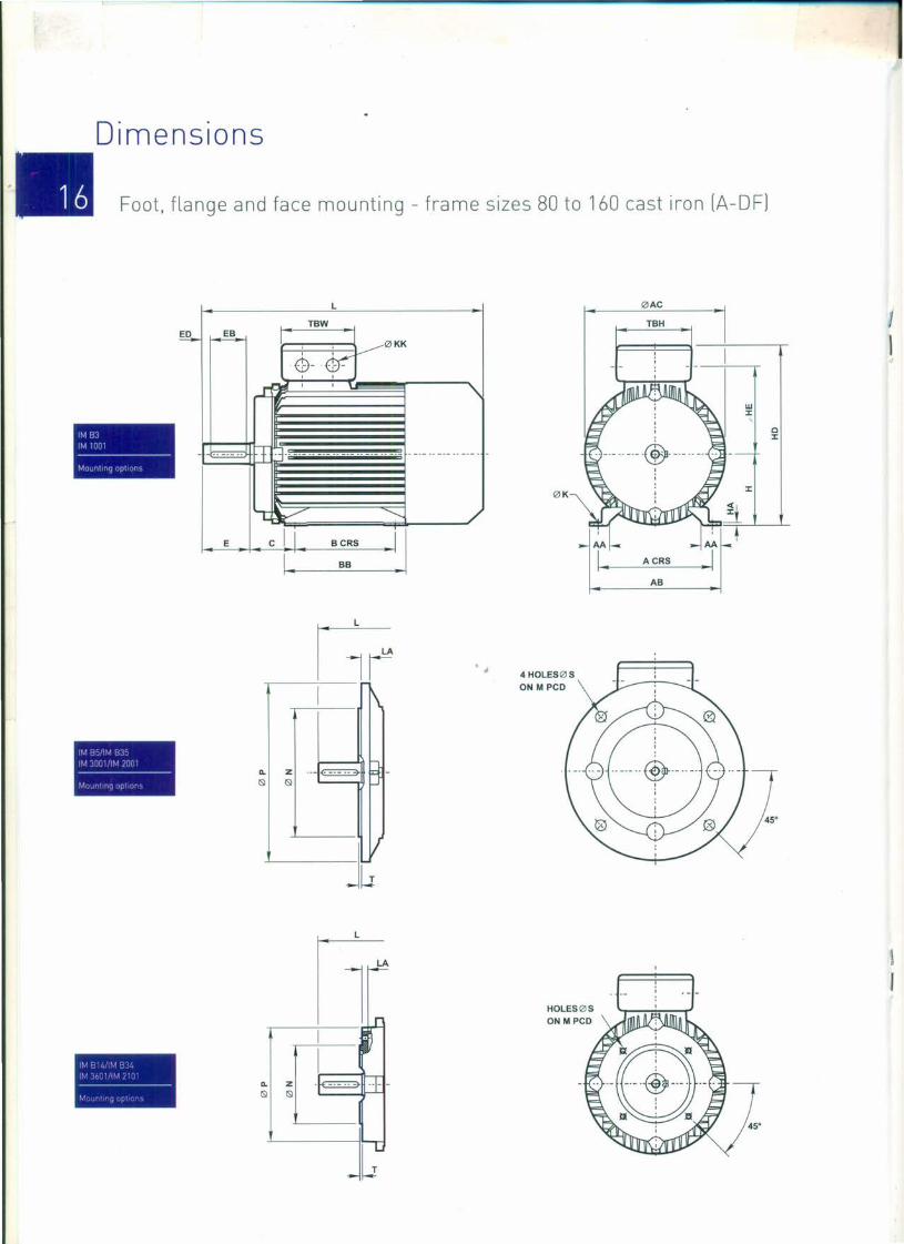
Dimensions
Foot, flange and face mounting - frame sizes 80 to 160 cast iron (A-OF]
1M 831M ':-Ie----------------Mo.muno ont ( n
I~! B )I '/ i,.,I'! r : ill) I
----------------1/ •• 1 ,
I '. I, • J f~". '.".
L
TBW
0KK~~
0-lfrr' ,J, " I \tll--~~._.--._.--._."-._.-_..--._.-.-I. ' .~ '::' ~I
I' ~II ~
j-Z .--~l ISl
I I
"-ISl
Jw
"-ISl
0AC
d
ITBH
~
W:I:,C:I:
0K :I:

Dimensions
Foot, flange and face mounting - frame sizes 80 to 160 cast iron [A-OF] •General
Tr-rrnmal boxType ,......-.......
ClStroo ABC H K L AA AB AC 8B IIA 110 Hf TBW TBH KK
A-DF80M
A-DF90S
A-DF90L
A-DF100L
A-DFl12M
125
140
140
160
190
216
216
254
254
100
100
125
140
50
56
56
63
70
89
89
80
90
90
100
112
132
132
160
160
140
140
178
210
254
A-DF132S
A-DF132M
A-DF160M
A-DF160L
108
108
10
10
10
12
12
12
12
14.5
14.5
304
336
361
406
452
470
508
34
36
160
176
176
200
240
262
262
314
314
167
183
183
206
220
259
259
315
315
150
161
186
213
225
200
238
260
304
10
12
12
14
15
15
15
18
18
227 102
102
102
102
110
110
110
152
152
102
102
102
102
118
1 X M25
1 X M25
1 X M25
1 X M32
2 X M32
36
40
50
55
55
245
245
266
294
335
335
411
411
118 2x M32
608
652
65
65
118
162
162
2 X M32
2 X M40
2x M40
CClnae&C2e
Type f.1S~"'"'~~· J \~B,_~,,""l
:: 1 ' \1 N !-J <, l.~ 1'.' \ r ~ T L:"
A-DF80M
A-DF90S
A-DF90L
A-DF100L
165 130 200 12 3.5 12
165 130 200 12 3.5 11
165 130 200 12 3.5 11
215 180 250 14.5 4.0 13
A-DFl12M
A-DF132S
A-DF132M
A-DF160M
215 180 250 14.5 4.0 14
265 230 300 14.5 4.0 14
265 230 300 14.5 4.0 14
300 250 350 18.5 5.0 15
300 250 350 18.5 5.0 15A-DF160L
100 80 120 M6 3.0
115 95 140 M8 3.0 14..-115 95 140 M8 3.0 14
130 110 160 M8 3.5 15
130 110 160 M8 3.5 15
165 130 200 MlO 3.5 17
165 130 200 Ml0 3.5 17
215 180 250 M12
215 180 250 M12
S'-e
Type::: =: :: : - ~ r c ::- =-A-DFBO
A-DF90
19 40 6
8
8
8
24 50
A-DF100
A-DFl12M
A-DF132
A-DF160
28 60
60
80
110
28
38
42
10
12
8
8
40
50
50
65
90
MlO
M12
M16
For tolerance details and notes - see page 26
15.5
20
24
24
33
37
6 30 M6
M8
Ml0
5
7.5
10
GTAPPEDHOLE DH

Dimensions
Foot, flange and face mounting - frame sizes 71 to 160 cast iron [8-0FJ
1M BJ1M 10111-----Mounting nptmn >
1M H,/IM 8351M 3D01/IM 7001-----Mounting options
1M 814/IM 8341M 3601/IM 2101-----Mounting opuons
L IZlAC
TBW TBH
IZlKK
IZlK
. .~-.~
- '
C:I:.3-. _._.. _.- .. _._.. -- -- -- . _.- .. _.- .. _._. -
I. ,.~ '::' ~I
1 1\
Bz ..-~&
V-- Lr
0..
&
AB
HOLES IZl5
ON M PCD
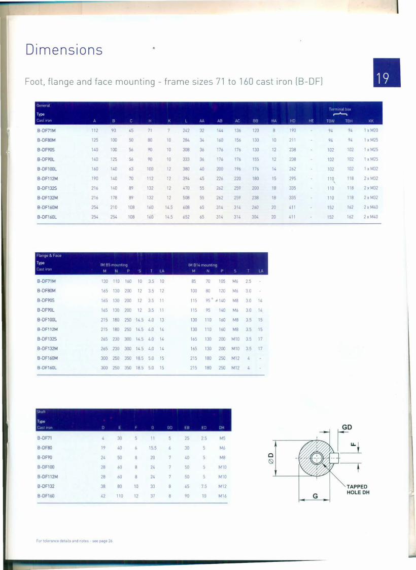
Dimensions
Foot. flange and face mounting - frame sizes 71 to 160 cast iron [8-0F] •8-DF71M
8-DF80M
8-DF90S
8-DF90L
8-DF100L
8-DFl12M
8-DF132S
8-DF132M
8-DF160M
8-DF160L
112
125
140
140
160
190
216
216
254
254
90
100
100
125
140
140
140
178
210
254
45
50
56
71
80
90
56
63
70
89
89
108
108
90
100
112
132
132
160
160
10
10
10
12
12
12
12
14.5
14.5
242
284
308
333
380
394
470
508
608
652
32
34
36
36
40
45
55
55
65
65
144
160
176
176
200
226
262
136
156
176
176
196
220
259
259
314
314
120
130
130
155
176
180
200
238
260
304
8
10
12
12
14
15
18
18
20
20
190
211
238
238
262
295
335
335
411
411
94
94
102
102
102
110
110
110
152
152
94 1 x M20
262
314
314
94 1 x M25
1 x M25102
102
102
118
118
118
162
162
1 x M25
1 x M32
2 x M32
2 x M32
2 x M32
2 x M40
2 x M40
8-DF71M
8-DF80M
8-DF90S
8-DF90L
8-DF100L
130 110 160 10 3.5 10
165 130 200 12 3.5 12
165 130 200 12 3.5 11
165 130 200 12 3.5 11
215 180 250 14.5 4.0 13
215 180 250 14.5 4.0 14
265 230 300 14.5 4.0 14
265 230 300 14.5 4.0 14
300 250 350 18.5 5.0 15
300 250 350 18.5 5.0 15
8-DFl12M
8-DF132S
8-DF132M
8-DF160M
8-DF160L
85 70 105 M6 2.5
100 80 120 M6 3.0
115 95 140 M8 3.0 14
115 95 140 M6 3.0 14
130 110 160 M8 3.5 15
130 110 160 M8 3.5 15
165 130 200 Ml0 3.5 17
165 130 200 MlO 3.5 17
215 180 250 M12
215 180 250 M12 4
8-DF71
8-DF80
8-DF90
8-DF100
8-DFl12M
8-DF132
8-DF160
19
30
40
50
60
60
80
8
8
10
12
24
28
28
38
42 110
For tolerance details and notes - see page 26
11
15.5
20
24
24
33
37
5
8
8
25
30
40
50
50
65
90
2.5 M5
M6
M8
Ml0
Ml0
M12
M16
c(Sl
G
7.5
10
GO
b~
TAPPEDHOLE DH
=

Dimensions
Foot and flange mounting - frame sizes 180 to 355 cast iron [A/AU-OF]
Gefl( r II ,
, " I (r nuuol boxType Q " ,............,
rll t , H ( II ~ L I M, A') /,l ,)1) Ill, Ill) 'H lHW If)H K~
A-DF180M
A-DF180L
A-DF200L
AU-DF225S
AU-DF225M
AU-DF250M
AU-DF280S
AU-DF280M
AU-DF315S
AU-DF315M
AU-DF315L
AU-DF355M
AU-DF355L
279
279
318
356
356
406
457
457
508
508
508
610
610
241
279
121
121
133
149
149
168
190
190
216
216
216
254
254
180
180
200
225
225
250
280
280
315
315
315
355
355
14.5 688 688 70
14.5 726 70
16.5 779 779 70
18.5 824 75
18.5 849 819 75
24 910 910 80
24 982 982 85
24 1033 1033 85
28 1224 1194 120
28 1334 1304 120
28 1334 1304 120
28 1556 1487 116
28 1556 1487 116
349
349
388
431
431
484
542
542
628
628
628
726
726
355
355
397
446
446
485
547
547
620
620
620
698
698
311
349
369
162 2 X M40
162 2 X M40
210 2xM50
210 2xM50
305
286
311
349
368
419
406
457
508
560
630
22
22
450 226.5 152
450 226.5 152
504 249 190
561 278 190
561 278 190
610 303 218
669 333 218
669 333 218
842 445 280
842 445 280
842 445 280
997 540 330
997 540 330
320 2 X M63
320 2 X M63
320 2 X M63
380 2 X M63
380 2 X M63
25
368
393
445
485
28
28
30
35
35
45
45
45
52
52
210 2 X M50
248 2 X M63
248 2 X M63
248 2 X M63536
570
680
680
750
750
11, Jt
Type 1M I) 1M j{ i IT J rln (Jr I r..1 ~J I T I /1
A-DF180M/L 300 250
A-DF200L 350 300
AU-DF225S/M 400 350
AU-DF250 500 450
AU-DF280 500 450
AU-DF315S/M/L 600 550
AU-DF355M/L 740 680
350 18.5 15
400 18.5 17
450 18.5 20
550 18.5 22
550 18.5 22
660 24 6 22
800 24 6 25
TAPPEDHOLE DH
G
, ,
, i' ! [, I.
Type ------------------------------------- -------------------------------------
I ) c, II II 1)1 J I I r) IJ II I IJI
A-DF180M/L 48 110
AU-DF200L 55 110
AU-DF225S 60 140
AU-DF225M 60 140
AU-DF250M 65 140
AU-D F280S/M 75 140
AU-DF315S/M/L 80 170
AU-DF355M/L 100 210
14 42.5
16 49
18 53
18 53
18 58
20 67.5
22 71
28 90
9
10
90
100
125
125
125
125
160
180 15
M16
M20
M20
M20
M20
M20
M20
M24
48
55
110 14 42.5
110 16 49 10
90 10
100
M16
M20
55
60
65
65
75
110 16 49
140 18 53
140 18 58
140 18 58
140 20 67.5
100
125 7.5
125 7.5
125 7.5
125 7.5
10
11
11
11
M20
M20
M20
M20
M20
10
12
For tolerance details and notes - see page 26
7.5
7.5
7.5
11
11
11
12
14
16
7.5

Dimensions
Foot and flange mounting - frame sizes 180 to 355 cast iron [B/BU-OF]
1M Iii1M 111111-----MIJlJlillllq opt 1)1
1MI)II/IM Illl(1M lIUJI/IM /I){JI-----MillJldlllq' [1111111
L
TBW
0KK. .o~'\1- -'P-o..
- .. _._.. + .=j- ....
I. ' . ~;:o:===. B B=C:' J~fl ----/
I 1\
8-z .. - c::::=::::3-ISI
V
0AC
TBH
0K
C:I:
AB
4 HOLES0SON M PCD
Up to 200 frame
8 HOLES0sON M PCD (1)
8 holes at 22.5° for flanges to suit 225 frames and above to European specification

Dimensions
•Foot and flange mounting - frame sizes 180 to 355 cast iron fB/BU-OFJ
(Jfrr!rl ,
, , Terminal boxType / ': ,..............
( J I" JI I I' ( +1 II I I !J\ All t•.{ BH 11/, Ill, III IHW [Hli KK
B-OF180M
B-OF180L
B-OF200L
BU-OF225S
BU-OF225M
BU-OF250M
BU-OF280S
BU-OF280M
BU-OF315S
BU-OF315M
BU-OF315L
BU-OF355M
BU-OF355L
279
279
318
241
279
305
286
311
349
368
419
121
121
133
149
149
168
190
190
180
180
200
225
225
250
14.5 688 688 70
14.5 726 726 70
16.5 771 771 70
18.5 824 75
18.5 849 819 75
24 910 910 80
24 982 982 85
24 1033 1033 85
28 1208 1178 120
28 1318 1288 120
28 1318 1288 120
28 1556 1487 116
28 1556 1487 116
349
349
388
431
431
484
542
542
628
628
628
726
726
355
355
397
446
311
349
369
368
393
445
485
536
570
680
680
750
750
450 229 152
450 229 152
504 249 190
552 270 190
552 270 190
613 299 218
667 333 218
667 333 218
842 445 280
842 445 280
842 445 280
997 544.5 330
997 544.5 330
162 2 x M4022
22
25
28
162 2 x M40
210 2 x M50
210 2x M50
210 2 x M50
356
356
406
457
457
446 28
30
35
35
45
45
45
52
52
485
547
547
620
620
620
698
698
248 2 x M63
248 2 x M63
248 2 x M63
320 2 x M63
320 2 x M63
320 2 x M63
380 2 x M63
380 2 x M63
280
280
315
315
315
355
355
508
508
508
610
610
406
457
508
560
630
216
216
216
254
254
11Jlrl'
Type 1M ["J Ir..-1l~}'J II !JIHltllllr
r I I I I r.t1 r J I) 'J I 1/,
B-OF180M/L 300 250
B-OF200L 350 300
BU-OF225S/M 400 350
BU-OF250 500 450
BU-OF280 500 450
BU-OF315S/M/L 600 550
BU-OF355M/L 740 680
350 18.5
400 18.5
450 18.5
550 18.5
550 18.5
660 24
800 24
15
17
20
22
22
22
25
• J.
c<Sl
TAPPEDHOLE DH
G
I III
1'11111, , /p()11Type ------------------- -------------------
r ) I I I I, I I I, f II II I I) [JlI II ) I I! [,I) I H II) III1
B-OF180M/L 48 110
BU-OF200L 55 110
BU-OF225S 60 140
BU-OF225M 60 140
BU-OF250M 65 140
BU-OF280S/M 75 140
BU-OF315S/M/L 80 170
BU-0F355M/L 100 210
14 42.5
16 49
18 53
18 53
18 58
20 67.5
22 71
28 90
90
100
125
125
125
125
160
180
10 M16
M20
M20
M20
M20
M20
M20
M24
48
55
110
110
14 42.5
16 49
90 10
100
M16
M2010
11
10
7.5
7.5
7.5
7.5
11
11
12
55
60
65
65
75
110
140
140
140
140
16 49
18 53
18 58
18 58
20 67.5
10 100
125 7.5
125 7.5
125 7.5
125 7.5
M20
M20
M20
M20
M20
11
11
14
16
11
1215
For tolerance details and notes - see page 26
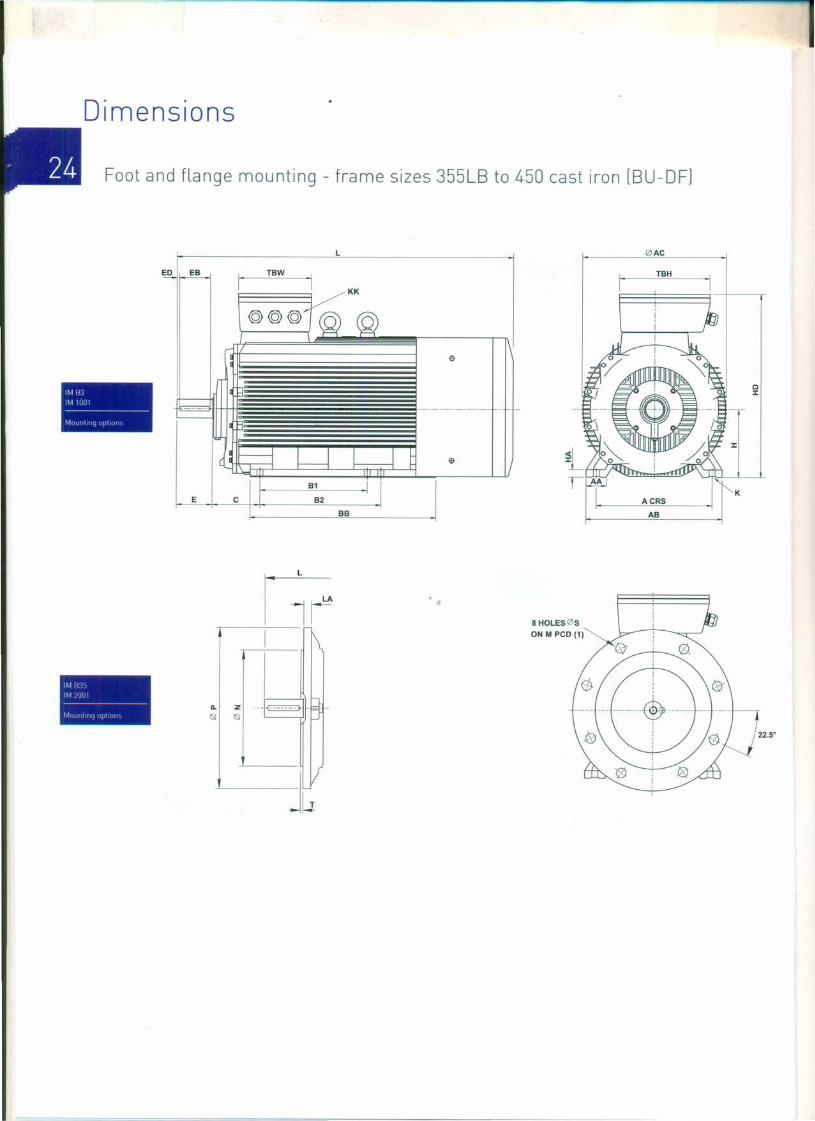
Dimensions
Foot and flange mounting - frame sizes 355LB to 450 cast iron (BU-DF)
1M H l1M lllll!-----MI)IJ!III II I!III
ED EB1
TBW
~KK
I ©©©"@ @l
$
II
- - ----------. -
a 1f-------1~ I I ~ $
B1 iE C B2
BB
L IZIAC
TBH
1M I{il)
1M /IJlJI-----MUIIIIIII] Iii (Jr,
II.
IS!
1!1 1\
8-z ... -~IS!
II-~
L
8 HOLESlZIs
ON M PCD (1)
LA

Dimension
Foot and flange mounting - frame sizes 355LB to 450 cast iron [BU-OFJ
General ~{.:::.~ ~'-- -c- Icrrmoa box
Type , \,': ,~ ~
c.yt rr or- A B 1 B7 C H K L L I M AH Al BB HA HD TBW TBH KK
BU-OF355B +
BU-OF400M
BU-OF400L
BU-OF450M
BU-OF450L
630
686
686
800
800
800 224 355 35
36
36
36
36
1918 1898 1863 116 760 745 1140
1881 1881 1820 120 806 860 1090
1881 1881 1820 120 806 860 1090
2200 2200 2050 150 950 950 1200
2200 2200 2050 150 950 950 1200 1400 460 530 3 X M63
630 710 280 400
630 710 280 400
900 1000 250 450
900 1000 250 450
1120 392 572 3 X M6352
52
55
62
62
1080 430 485 3 X M63
1080 430 485 3 X M63
1400 460 530 3 X M63
Flange
Type 1M B5 1M B35 mounting
C,1' t Iron M N PST LA
BU-0F355
BU-OF400
BU-OF450
840 780 800 24
940 880 1000 28
1040 980 1100 32 8 TAPPEDHOLE DH
G
Scal'z poo . 2pole
Type --------------------------------------- ---------------------------------------Cas' -c- J E F G GO EB ED OH 0 E F G GO EB ED OH
BU-OF355
BU-OF400
BU-OF450
110 210 28 86
100
16 160
180
180
130
140
140
M24
M24
110 210 28
130 250 32
16
M20M24
M24
M24
80
85
90
170 22 67.5 14
14
14119 16
15
15
15
15
170 22
170 25
76
86
For tolerance detaiLs and notes - see page 26
•
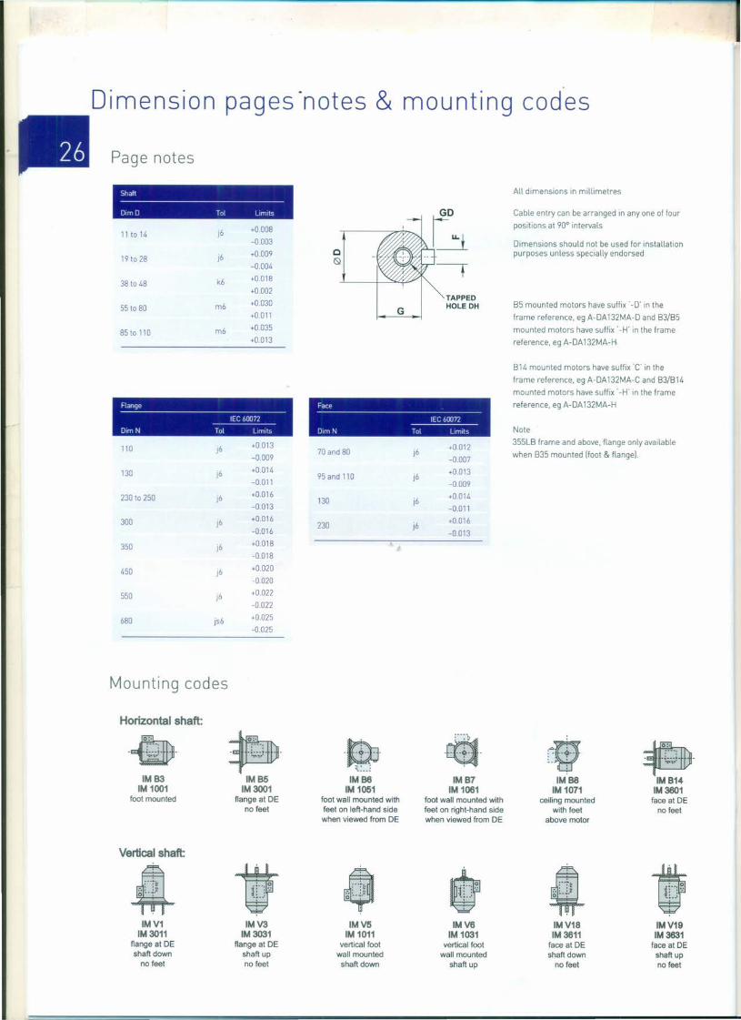
Dimension pages 'notes & mounting codes
Page notes
Shaft-------------------------------Dim 0 Tol Limits
All dimensions in millimetres
Cable entry can be arranged in anyone of four
positions at 90° intervals11 to 14 J6 +0.008
-0003
J6 +0.009 Q19 to 28 ~-0.004
38 to 48 k6 +0.018+0.002
TAPPED55 to 80 m6 +0030 HOLE DHG+0011
85 to 110 m6 +0.035+0.013
Dimensions should not be used for installationpurposes unless specially endorsed
85 mounted motors have suffix' -D' in the
frame reference. eg A-DA132MA-D and 83/85
mounted motors have suffix '-H' in the frame
reference. eg A-DA132MA-H
Flange--------------------------------lEG 60072------------
Dim N Tal Limits
814 mounted motors have suffix 'C' in the
frame reference. eg A-DA132MA-C and 83/814
mounted motors have suffix '-H' in the frame
reference. eg A-DA 132MA-HFace-------------------------------lEG 60072------
Dim N ToL Limits Note
355L8 frame and above. flange only availablewhen 835 mounted [foot & flangel.
110 J6 +0.013 +001270 and 80 j6-0.009 -0007
130 J6 +0.014 +0.01395and 110 j6-0.011 -0.009
230 to 250 J6 +0.016 +0.014130 j6-0013 -0.011
300 J6 +0.016 +0.016230 j6-0.016 -0.013
350 j6 +0018-0.018
450 j6 +0020
-0.020
550 j6 +0.022-0.022
680 js6 +0.025-0025
Mounting codes
Horizontal shaft:
~~
.~.~
;..-: ;-": ....t· .~
~W- - -~-.;.t- -- - - -~-':-.~--- : .• Q .. ;---:- -!.;.~-.~---
~:--~IMB3 IMB5 IMB8 IMB7 IMB8 IMB14
1M1001 1M 3001 1M1051 1M1061 1M1071 1M 3601foot mounted flange at DE foot wall mounted with foot wall mounted with ceiling mounted face at DE
no feet feet on left-hand side feet on right-hand side with feet no feetwhen viewed from DE when viewed from DE above motor
Vertical shaft:
4 • $ W 4 tg ~-+!: ~-~..: . ,-,: :~ ~-~..: . g ~-~-~ ~.~..:0---:-
IMV1 IMV3 IMV5 IMV6 IMV18 IMV191M 3011 1M3031 1M1011 1M1031 1M 3611 1M 3631
flange at DE flange at DE vertical foot vertical foot face at DE face at DEshaft down shaft up wall mounted wall mounted shaft down shaft up
no feet no feet shaft down shaft up no feet no feet

Tech nica l informatio.n
Bearing arrangements •Mechanical
_______ T_yp_e______ __ 8_0_.1_"_"9 __ "_______ __ 0_'1_,(_'_1_''' _
A urt uuurn C J~llr(JfI Poles Drive end Non unvc cuu Olive cfld Nun drive end
8/ A-DA56 All 6201ZZ 6201ZZ 12 X 25 X 7 12 X 25 X 7
8/ A-DA63M All 6201ZZ 6201ZZ 12x25x7 12 X 25 X 7
8/ A-DA71M 8/ A-DF71M All 6202ZZ 6202ZZ 15x30x7 15 X 30 X 7
8/ A-DA80M 8/ A-DF80M All 6204ZZ 6204ZZ 20 X 35 X 7 20 X 35 X 7
8 / A- DA90S/L 8/ A-DF90S/L All 6205ZZ 6205ZZ 25 X 40 X 7 25 X 40 X 7
8/A-DA100L 8/ A-DF100L All 6206ZZ 6206ZZ 30x47x7 30x47x7
8/ A-DAl12M 8/A-DFl12M All 6306ZZ 6306ZZ 30x47x7 30x47x7
8/ A-DA 132S/M 8/ A-DF132S/M All 6308ZZ 6308ZZ 40 X 62 X 7 40 X 62 X 7
8/ A-DA 160M/L 8/ A-DF160M/L All 6309ZZ 6309ZZ 45 X 62 X 12 45 X 62 X 12
8/ A-DF180M/L All 6311 6311 55 X 75 X 12 55 X 75 X 12
8/ A-DF200L All 6312 6312 60x80x12 60x80x12
8/ AU-DF225S/M All 6313 6313 65 X 90 X 12 65 X 90 X 12
8/ AU-DF250S/M All 6314 6314 70x90x 12 70x90x12
8/ AU-DF280S/M 6314 6314 70 X 90 X 12 70x90x 12
8 / AU - 0 F280S/M 4 up 6317 6317 85 X 110 X 12 85x 110x 12
8/ AU-DF315S/M/L 6317 6317 85xll0x12 85 X 110 X 12
8/ AU-DF315S/M/L 4 up 6319 6319 95x 120x 12 95 X 120 X 12
8/ AU-DF355M/L 6319 6319 J. 95 X 120 X 12 95x 120x 12
8/ AU-DF355M/L 4 up NU322 6322 110x 140x 14 110x 140x 14
8U-DF400 NU2194E &6219 72198 84.5 X 97 X 10 84.5x97xl0
8U-DF400 4 up NU326E 6326 119x140x14 119x140x14
8U-DF450 2 NU222E & 6222 72228 110x 124x 12 110 X 124 X 12
8U-DF450 4 up 6328 6328 140x 154x 15 140 X 154 X 15
111Frame sizes 56-160 have sealed for life beanngs With C3 clearances. Frame sizes 180-355 bearings have regreasmg facilities with C3 clearance.121Sizes given are In mm and represent bore x outside diameter x Width.
The seal material used on all frame sizes and all polarity IS nitrile rubber rNBRJ.
Type I JI t r I Jill 'I I 1111111r t I h(J I'. r--------- ------------- --------------- ------------- ---------------fjlJII/Jrilri 'vrrl, II II'HI/(Jrlr /lllr II 111I11/lltll Vlrll! II Ihlll/rHIIJl V,rlll II
8/ A-DF180M/L 3 1.75 8 4.25 12 6 12 6
8/ A-DF200L 3 1.75 8 4.25 12 6 12 6
8/ AU-DF225S 3 1.5 8 4 11 5.5 11 5.5
8/ AU-DF225M 3 1.5 8 4 11 5.5 11 5.5
8/ AU-DF250M 2 1 7.5 3.75 10.5 5.25 10.5 5.25
8/ AU-DF280S 1.5 0.75 7 3.5 10 5 10 5
8/ AU-DF280M 1.5 0.75 7 3.5 10 5 10 5
8/ AU-DF315S 1 0.5 3.8 1.9 7.5 3.75 7.5 3.75
8/ AU-DF315M 1 0.5 3.8 1.9 7.5 3.75 7.5 3.75
8/ AU-DF315L 1 0.5 3.8 1.9 7.5 3.75 7.5 3.75
8/ AU-DF355M 1 0.5 2.5 1.25 2 1 2 1
8/ AU-DF355L 1 0.5 2.5 1.25 2 1 2 1
8U-DF400
8U-DF450
Sealed for life bearings are fitted With a premium quality grease to ensure exceptional reliability under a wide range of operatingconditions. Under normal operating conditions, a grease life of more than 25,000 hours can be achieved.The reqreasinq time should be reduced If the beanng operating temperature is in excess of 70·C.
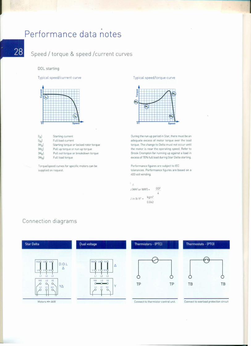
·Performance data notes
Speed / torque & speed /current curves
DOL starting
Typical speed/current curve
1:~so I.
INn-
0 Speed
Starting currentFull load currentStarting torque or locked rotor torquePull up torque or run up torquePull out torque or breakdown torqueFull load torque
Torque/speed curves for specific motors can besupplied on request.
Connection diagrams
Star Delta Dual voltage
W2 U2 V2
U1 V1 W1
D,Q,L£:::,
11 L2 L3
W2 U2 V2
Y£:::'
W2 U2 'W
L1 V W1
L2 L3
W2 U2 V2
~L1 V1 Wi
y
Motors => 4kW
Typical speed/torque curve
~~~0...
M.
0 Speed
During the run up period in Star, there must be anadequate excess of motor torque over the loadtorque, The change to Delta must not occur untilthe motor is near the operating speed, Refer toBrook Crompton for running up against a load inexcess of 70% full load during Star Delta starting.
Performance figures are subject to IECtolerances. Performance figures are based on a400 volt winding,
J IWK' or WR'I = GO'4
J in lb ft' = kgm'0.042
Thermistors - (PTel
TP TP
Connect to thermistor control unit.
Thermostats - (PTOI
TB TB
Connect to overload protection circuit