REL 551 2.5 Line differential protection terminal | ABB
62
Page 1 5(/ /LQHGLIIHUHQWLDO SURWHFWLRQWHUPLQDO 1MRK 506 179-BEN Revision: B Issued: November 2003 Data subject to change without notice )HDWXUHV • Open terminal with extensive configuration possibilities and expandable hardware design to meet specific user requirements • Phase-segregated line differential protec- tion • Phase and residual overcurrent protection • Thermal overload protection • Versatile local human-machine interface (LED-HMI) • Extensive self-supervision with internal event recorder • Time synchronization with 1 ms resolution • Four independent groups of complete set- ting parameters • Powerful software PC ‘tool-box’ for moni- toring, evalution and user configuration )XQFWLRQV • Line differential - Line differential protection, phase segre- gated (DIFL) • Current - Instantaneous non-directional phase overcurrent protection (IOCph) - Instantaneous non-directional residual overcurrent protection (IOCr) - Definite time non-directional phase overcurrent protection (TOCph) - Definite time non-directional residual overcurrent protection (TOCr) - Two step time delayed non-directional phase overcurrent protection (TOC2) - Time delayed non-directional residual overcurrent protection (TEF) - Thermal overload protection (THOL) - Breaker failure protection (BFP) • Power system supervision - Broken conductor check (BRC) - Overload supervision (OVLD) • System protection and control - Sudden change in phase current protec- tion (SCC1) - Sudden change in residual current pro- tection (SCRC) - Undercurrent protection (UCP) - Phase overcurrent protection (OCP) - Residual overcurrent protection (ROCP) • Secondary system supervision - Current circuit supervision, current based (CTSU) • Control - Single command, 16 signals (CD) - Autorecloser - 1- and/or 3-phase, single circuit breaker (AR1-1/3) - Autorecloser - 1- and/or 3-phase, double circuit breakers (AR12-1/3) - Autorecloser - 3-phase, single circuit breaker (AR1-3) - Autorecloser- 3-phase, double circuit breaker (AR12-3) • Logic - Three pole tripping logic (TR01-3) - Additional three pole tripping logic (TR02-3) - Single, two or three pole tripping logic (TR01-1/2/3) - Additional single, two or three pole trip- ping logic (TR02-1/2/3) - Pole discordance logic (PDc) 3URWHFW ,7
-
Upload
khangminh22 -
Category
Documents
-
view
3 -
download
0
Transcript of REL 551 2.5 Line differential protection terminal | ABB

1MRK 506 179-BEN
Page 1
Revision: BIssued: November 2003Data subject to change without notice
• Open terminal with extensive configuration possibilities and expandable hardware design to meet specific user requirements
• Phase-segregated line differential protec-tion
• Phase and residual overcurrent protection
• Thermal overload protection
• Versatile local human-machine interface (LED-HMI)
• Extensive self-supervision with internal event recorder
• Time synchronization with 1 ms resolution
• Four independent groups of complete set-ting parameters
• Powerful software PC ‘tool-box’ for moni-toring, evalution and user configuration
• Line differential
- Line differential protection, phase segre-gated (DIFL)
• Current
- Instantaneous non-directional phase overcurrent protection (IOCph)
- Instantaneous non-directional residual overcurrent protection (IOCr)
- Definite time non-directional phase overcurrent protection (TOCph)
- Definite time non-directional residual overcurrent protection (TOCr)
- Two step time delayed non-directional phase overcurrent protection (TOC2)
- Time delayed non-directional residual overcurrent protection (TEF)
- Thermal overload protection (THOL)
- Breaker failure protection (BFP)
• Power system supervision
- Broken conductor check (BRC)
- Overload supervision (OVLD)
• System protection and control
- Sudden change in phase current protec-tion (SCC1)
- Sudden change in residual current pro-tection (SCRC)
- Undercurrent protection (UCP)
- Phase overcurrent protection (OCP)
- Residual overcurrent protection (ROCP)
• Secondary system supervision
- Current circuit supervision, current based (CTSU)
• Control
- Single command, 16 signals (CD)
- Autorecloser - 1- and/or 3-phase, single circuit breaker (AR1-1/3)
- Autorecloser - 1- and/or 3-phase, double circuit breakers (AR12-1/3)
- Autorecloser - 3-phase, single circuit breaker (AR1-3)
- Autorecloser- 3-phase, double circuit breaker (AR12-3)
• Logic
- Three pole tripping logic (TR01-3)
- Additional three pole tripping logic (TR02-3)
- Single, two or three pole tripping logic (TR01-1/2/3)
- Additional single, two or three pole trip-ping logic (TR02-1/2/3)
- Pole discordance logic (PDc)

1MRK 506 179-BEN
Page 2
- Additional configurable logic blocks (CL2)
- Communication channel test logic (CCHT)
- Multiple command, one fast block with 16 signals (CM1)
- Multiple command, 79 medium speed blocks each with 16 signals (CM79)
• Monitoring
- Disturbance recorder (DR)
- Event recorder (ER)
- Trip value recorder (TVR)
- Supervision of AC input quantities (DA)
- Supervision of mA input quantities (MI)
• Metering capabilities
- Pulse counter logic for metering (PC)
- Six event counters (CN)
• Hardware
- 18 LEDs for extended indication capabil-ities
• Several input/output module options includ-ing measuring mA input module (for trans-ducers)
The main purpose of the REL 551 terminal is the protection, control and monitoring of overhead lines and cables. It provides for one-, two-, and/or three-pole tripping. The
true current differential protection provides excellent sensitivity and phase selection in complex network configurations.
Type tested software and hardware that com-ply with international standards and ABB´s internal design rules together with extensive self monitoring functionality, ensure high reliability of the complete terminal
The terminal’s closed and partly welded steel case makes it possible to fulfill the stringent EMC requirements.
Serial data communication is via optical con-nections or galvanic RS485.
An extensive library of protection, control and monitoring functions is available. This library of functions, together with the flexible hardware design, allows this terminal to be configured to each user´s own specific requirements. This wide application flexibil-ity makes this product an excellent choice for both new installations and the refurbishment of existing installations.
The platform hardware and common software functions are included in all REx 5xx termi-nals. It is the foundation on which all termi-nals are built. Application specific modules and functions are added to create a specific terminal type or family.
The REx 5xx platform consists of a case, hardware modules and a set of common func-tions.
The closed and partly welded steel case makes it possible to fulfill stringent EMC requirements. Three different sizes of the case are available to fulfill the space require-ments of different terminals. The degree of protection is IP 40 according to IEC 529 for
cases with the widths 1/2x19” and 3/4x19”. IP 54 can be obtained for the front area in flush and semiflush applications. Mounting kits are available for rack, flush, semiflush or wall mounting.
All connections are made on the rear of the case. Screw compression type terminal blocks are used for electrical connections. Serial communication connections are made by optical fibre connectors type Hewlett Packard (HFBR) for plastic fibres or bayonet type ST for glass fibres.
A set of hardware modules are always included in a terminal. Application specific modules are added to create a specific termi-nal type or family.

1MRK 506 179-BEN
Page 3
The common functions provide a terminal with basic functionality such as self supervi-sion, I/O-system configurator, real time clock
and other functions to support the protection and control system of a terminal.
Common functions are the software functions always included in the terminals.
!"#$" %&'
Use the local HMI, SMS or SCS to view the status of the self-supervision function. The self-supervision operates continuously and includes:
• Normal micro-processor watchdog func-tion
• Checking of digitized measuring signals
• Checksum verification of PROM contents and all types of signal communication
()#$*+$,%-'
Use the time synchronization source selector to select a common source of absolute time for the terminal when it is a part of a protec-tion system. This makes comparison of events and disturbance data between all ter-minals in a SA system possible.
+Two main alternatives of external time syn-chronization are available. Either the syn-chronization message is applied via any of the communication ports of the terminal as a telegram message including date and time, or as a minute pulse, connected to a binary input. The minute pulse is used to fine tune already existing time in the terminals.
The REx 5xx terminal has its own internal clock with date, hour, minute, second and millisecond. It has a resolution of 1 ms.
The clock has a built-in calendar that handles leap years through 2098. Any change between summer and winter time must be handled manually or through external time synchronization. The clock is powered by a capacitor, to bridge interruptions in power supply without malfunction.
The internal clock is used for time-tagging disturbances, events in Substation monitoring system (SMS) and Substation control system (SCS), and internal events.
%.'
Use the four sets of settings to optimize the terminals operation for different system con-ditions. By creating and switching between fine tuned setting sets, either from the human-machine interface or configurable binary inputs, results in a highly adaptable terminal that can cope with a variety of system scenar-ios.
+The GRP function block has four functional inputs, each corresponding to one of the set-ting groups stored within the terminal. Acti-vation of any of these inputs changes the active setting group. Four functional output signals are available for configuration pur-poses, so that continuous information on active setting group is available.
//)% '
The user can with the available logic function blocks build logic functions and configure the terminal to meet application specific require-ments.
Different protection, control, and monitoring functions within the REx 5xx terminals are quite independent as far as their configuration in the terminal is concerned. The user can not change the basic algorithms for different functions. But these functions combined with the logic function blocks can be used to cre-ate application specific functionality.
"/)%&0'The inverter function block INV has one input and one output, where the output is in inverse ratio to the input.

1MRK 506 179-BEN
Page 4
1/)%1'The OR function is used to form general combinatory expressions with boolean vari-ables. The OR function block has six inputs and two outputs. One of the outputs is inverted.
&/)%&'The AND function is used to form general combinatory expressions with boolean vari-ables.The AND function block has four inputs and two outputs. One of the inputs and one of the outputs are inverted.
/)%-'The function block TM timer has drop-out and pick-up delayed outputs related to the input signal. The timer has a settable time delay (parameter T).
/)%'The function block TL timer with extended maximum time delay at pick-up and at drop-out, is identical with the TM timer. The dif-ference is the longer time delay.
/)%'The pulse function can be used, for example, for pulse extensions or limiting of operation of outputs. The pulse timer TP has a settable length.
* $/)%2'The function block TQ pulse timer with extended maximum pulse length, is identical with the TP pulse timer. The difference is the longer pulse length.
*"1/)%31'The exclusive OR function XOR is used to generate combinatory expressions with bool-ean variables. The function block XOR has two inputs and two outputs. One of the out-puts is inverted. The output signal is 1 if the input signals are different and 0 if they are equal.
!(/)%!'The Set-Reset (SR) function is a flip-flop that can set or reset an output from two inputs respectively. Each SR function block has two outputs, where one is inverted.
!(#$+/)%!-'The Set-Reset function SM is a flip-flop with memory that can set or reset an output from two inputs respectively. Each SM function block has two outputs, where one is inverted. The memory setting controls if the flip-flop
after a power interruption will return the state it had before or if it will be reset.
//)%.'The GT function block is used for controlling if a signal should be able to pass from the input to the output or not depending on a set-ting.
!//)%!'The function block TS timer has outputs for delayed input signal at drop-out and at pick-up. The timer has a settable time delay. It also has an Operation setting On, Off that controls the operation of the timer.
-"%-1'The Move function block MOF is put first in the slow logic and is used for signals coming from fast logic into the slow logic. The MOF function block is only a temporary storage for the signals and does not change any value between input and output.
-"/)%-1'The Move function block MOL is put last in the slow logic and is used for signals going out from the slow logic to the fast logic. The MOL function block is only a temporary stor-age for the signals and does not change any value between input and output.
"%0'
When using a Substation Automation system, events can be spontaneously sent or polled from the terminal to the station level. These events are created from any available signal in the terminal that is connected to the event function block. The event function block can also handle double indication, that is nor-mally used to indicate positions of high-volt-age apparatuses. With this event function block, data also can be sent to other terminals over the interbay bus.
+As basic, 12 event function blocks EV01-EV12 running with a fast cyclicity, are avail-able in REx 5xx. When the function Appara-tus control is used in the terminal, additional 32 event function blocks EV13-EV44, run-ning with a slower cyclicity, are available.
Each event function block has 16 connecta-bles corresponding to 16 inputs INPUT1 to INPUT16. Every input can be given a name

1MRK 506 179-BEN
Page 5
with up to 19 characters from the CAP 540 configuration tool.
The inputs can be used as individual events or can be defined as double indication events.
The inputs can be set individually, from the Parameter Setting Tool (PST) under the Mask-Event function, to create an event at pick-up, drop-out or at both pick-up and drop-out of the signal.
The event function blocks EV01-EV06 have inputs for information numbers and function type, which are used to define the events according to the communication standard IEC 60870-5-103.
!" 4%'
Use the AC monitoring function to provide three phase or single phase values of voltage and current. At three phase measurement, the values of apparent power, active power, reac-tive power, frequency and the RMS voltage and current for each phase are calculated. Also the average values of currents and volt-ages are calculated.
+Alarm limits can be set and used as triggers, e.g. to generate trip signals.
The software functions to support presenta-tion of measured values are always present in the terminal. In order to retrieve actual val-ues, however, the terminal must be equipped with the appropriate hardware measuring module(s), i.e. Transformer Input Module (TRM).
!"4%-'
Use the DC monitoring function to measure and process signals from different measuring transducers. Many devices used in process control uses low currents, usually in the range 4-20 mA or 0-20 mA to represent various parameters such as frequency, temperature and DC battery voltage.
+Alarm limits can be set and used as triggers, e.g. to generate trip signals.
The software functions to support presenta-tion of measured values are always present in the terminal. In order to retrieve actual val-ues, however, the terminal must be equipped with the mA Input Module (MIM).
51+%1'
The I/O system configurator must be used in order for the terminal’s software to recognize added modules and to create internal address mappings between modules and protections and other functions.
!6-%!6'
Use the setting restriction function to prevent unauthorized setting changes and to control when setting changes are allowed. Unpermit-ted or uncoordinated changes by unautho-rized personnel may influence the security of people and cause severe damage to primary and secondary power circuits.
By adding a key switch connected to a binary input a simple setting change control circuit can be built simply allowing only authorized keyholders to make setting changes from the built-in HMI.
+Activating the setting restriction prevents unauthorized personell to purposely or by mistake change terminal settings or configu-ration from the local HMI.
The function permits remote changes of set-tings and reconfiguration through the serial communication ports.
All other functions of the local human-machine communication remain intact. This means that an operator can read disturbance reports, setting values, the configuration of different logic circuits and other available information.

1MRK 506 179-BEN
Page 6
7) %7!'
The protection and control terminals have a complex configuration with many included functions. To make the testing procedure eas-ier, the terminals include the feature to indi-vidually block a single, several or all functions.
This means that it is possible to see when a function is activated or trips. It also enables the user to follow the operation of several related functions to check correct functional-ity and to check parts of the configuration etc.
The Release Local for line differential func-tion is only possible to operate if the terminal has been set in test mode from the HMI.
8$ %'
Current line-differential protection compares the currents entering and leaving the pro-tected overhead line or cable. The differential function offers phase-segregated true current differential protection for all networks. Cur-rent comparison on a per phase basis obviates the problem of the current summation approach and provides phase selection infor-mation for single-pole tripping.
A dependable communication link is needed to allow exchange of information between the terminals at the line ends. Direct optical fiber or galvanic communication link are sup-ported, as well as digital communication sys-tems like ed and route switched networks.The transmission time is measured in short inter-vals to provide correct synchronization of local clocks. The transmission time compen-sation is based on the assumption that the transmission time is the same in both direc-tions.
The line differential function in the protection of version 2.3 is compatible with earlier ver-sions 1.1, 1.2 and 2.0.
Two independent binary signals can be trans-mitted from one line side to the other through the differential communication link for trip-ping, control or information purposes.
+The current differential function is of master/master design. Each terminal evaluates the three phase currents related to its line end, in terms of amplitude and phase angle, and sends them to the other terminal through the communication channel. At the same time it receives the three current information from the other terminal and performs locally the phase segregated current comparison.
All currents are Fourier filtered in order to extract the sine and cosine components. The six components, two per phase, are included in a message that is transmitted every 5 ms to the remote terminal over a synchronous 56/64 kbit/s data channel. Also included in the message is information for differential func-tion supervision, CT saturation detection, synchronisation of terminals, transfer trip sig-nals etc.
The differential measurement is stabilised phase by phase with the current scalar sum, see figure 1. The degree of stabilisation is set-table.
All currents are individually supervised by the patented CT saturation detection algo-rithm, to minimise the requirements on the CTs. In case of CT saturation, the degree of stabilisation is increased in the affected phase in the differential protections at both ends, see figure 1.

1MRK 506 179-BEN
Page 7
Figure 1: Operating characteristic
The communication delay is continuously measured and automatically compensated for, in the differential measurement. This function enables the terminal to use a communication network with automatic route switching (route switching is frequently used in public digital networks).
The communication telegram is checked for errors, and on detection of erroneous infor-mation the telegram is excluded from the evaluation. In order to trip, two or three out of four accepted telegrams are required. This provides the needed security against wrong operation due to transmission disturbances.
( $"%1 $'
Different system conditions, such as source impedance and the position of the faults on long transmission lines influence the fault
currents to a great extent. An instantaneous phase overcurrent protection with short oper-ate time and low transient overreach of the measuring elements can be used to clear close-in faults on long power lines, where short fault clearing time is extremely impor-tant to maintain system stability.
IDiff ILocal IRemote+=
IBias
ILocal IRemote+
2-------------------------------------------=
IBias( ) Evaluate Max IBias( )Own phase[ ] OR 0.5 IBias( )Other phases⋅[ ] =

1MRK 506 179-BEN
Page 8
+The current measuring element continuously measures the current in all three phases and compares it to the set operate value IP>>. A filter ensures immunity to disturbances and dc components and minimizes the transient overreach. If any phase current is above the set value IP>>, the phase overcurrent trip sig-nal TRP is activated. Separate trip signal for the actual phase(s) is also activated. The input signal BLOCK blocks all functions in the current function block.
( "%1 '
The instantaneous residual overcurrent pro-tection can be used in a number of applica-tions. Below some examples of applications are given.
• Fast back-up earth fault protection for faults close to the line end.
• Enables fast fault clearance for close in earth faults even if the distance protection or the directional residual current protec-tion is blocked from the fuse supervision function
+The current measuring element continuously measures the residual current and compares it to the set operate value IN>>. A filter ensures immunity to disturbances and dc components and minimizes the transient overreach. If the residual current is above the set value IN>>, the residual overcurrent trip signal TRN is activated. The general trip signal TRIP is activated as well. The input signal BLOCK blocks the complete function.
( $"%1 $'
The time delayed overcurrent protection, TOC, operates at different system conditions for currents exceeding the preset value and which remains high for longer than the delay time set on the corresponding timer. The function can also be used for supervision and fault detector for some other protection func-
tions, to increase the security of a complete protection system. It can serve as a reserve function for the line distance protection, if activated under fuse failure conditions which has disabled the operation of the line distance protection.
+The current measuring element continuously measures the current in all three phases and compares it to the set operate value IP>. A fil-ter ensures immunity to disturbances and dc components and minimizes the transient overreach. If the current in any of the three phases is above the set value IP>, a common start signal STP and a start signal for the actual phase(s) are activated. The timer tP is activated and the phase overcurrent trip signal TRP is activated after set time. The general trip signal TRIP is activated as well.
The input signal BLOCK blocks the function. The input signal BLKTR blocks both trip sig-nals TRP and TRIP.
( "%1 '
The time delayed residual overcurrent protec-tion is intended to be used in solidly and low resistance earthed systems. The time delayed residual overcurrent protection is suitable as back-up protection for phase to earth faults, normally tripped by operation of the distance protection. The protection function can also serve as protection for high resistive phase to earth faults.
+The residual current measuring element con-tinuously measures the residual current and compares it with the set operate value IN>. A filter ensures immunity to disturbances and dc components and minimizes the transient overreach. If the measured current is above the set value IN>, a start signal STN is acti-vated. The timer tN is activated and the residual overcurrent trip signal TRN is acti-vated after set time. The general trip signal TRIP is activated as well. The input signal BLOCK blocks the function. The input signal BLKTR blocks both trip signals TRN and TRIP.

1MRK 506 179-BEN
Page 9
# + ( $"%1 '
The two current/time stages of overcurrent protection TOC2 improve the possibility to get fast operation for nearby faults by using a high set current stage with short time delay. The low current stage is set with appropriate time delay to get selectivity with the adjacent relays in the system. In networks with inverse time delayed relays, selectivity is generally best obtained by using the same type of inverse time characteristic for all overcurrent relays.
+The current measuring element continuously measures the current in all phases and com-pares it to the set operate value for the two current stages. A filter ensures immunity to disturbances and dc components and mini-mizes the transient overreach. If the current in any of the three phases is above the set value I>Low, the start signal for the low current stage is activated. With setting Characteristic = Def, the timer tLow is activated and the trip signal TRLS is activated after set time. If inverse time delay is selected, the timer tMin-Inv starts when the current is above the set value I>Low. If the current also is above the set value I>Inv, the inverse time evaluation starts. When both time circuits operate, the definite time circuit tLow is activated and the trip signal TRLS is activated after the addi-tional time tLow. If the current is above the set value I>High, the timer tHigh is activated and the trip signal TRHS is activated after set time.
The input signal BLOCK blocks all func-tions. Each current stage can also be individu-ally blocked.
+ "(%'
Use the inverse and definite time delayed residual overcurrent functions in solidly earthed systems to get a sensitive and fast fault clearance of phase to earth faults.
The nondirectional protection can be used when high sensitivity for earth fault protec-tion is required. It offers also a very fast back-up earth fault protection for the part of a
transmission line, closest to the substation with the protection.
The nondirectional residual overcurrent pro-tection can be given a relatively low current pick-up setting. Thus the protection will be sensitive, in order to detect high resistive phase to earth faults.
+The residual overcurrent protection (TEFdir) measures the residual current of the protected line. This current is compared to the current settings of the function. If the residual current is larger than the setting value a trip signal will be sent to the output after a set delay time. The time delay can be selected between the definite or inverse possibility.
In order to avoid unwanted trip for trans-former inrush currents, the function is blocked if the second harmonic content of the residual current is larger than 20% of the measured residual current.
$$" (%61'
Load currents that exceed the permissible continuous value may cause damage to the conductors and isolation due to overheating. The permissible load current will vary with the ambient temperature.
The THOL thermal overcurrent function supervises the phase currents and provides a reliable protection against damage caused by excessive currents. The temperature compen-sation gives a reliable thermal protection even when the ambient temperature has large vari-ations.
+The final temperature rise of an object rela-tive the ambient temperature is proportional to the square of the current. The rate of tem-perature rise is determined by the magnitude of the current and the thermal time constant of the object. The same time constant deter-mines the rate of temperature decrease when the current is decreased.
The thermal overload function uses the high-est phase current. The temperature change is continuously calculated and added to the fig-ure for the temperature stored in the thermal memory. When temperature compensation is used, the ambient temperature is added to the

1MRK 506 179-BEN
Page 10
calculated temperature rise. If no compensa-tion is used, 20o C is added as a fixed value. The calculated temperature of the object is then compared to the set values for alarm and trip.
The information on the ambient temperature is received via a transducer input with for example 0 - 10 mA or 4 - 20 mA.
The output signal THOL--TRIP has a dura-tion of 50 ms. The output signal THOL--START remains activated as long as the cal-culated temperature is higher than the set trip value minus a settable temperature difference TdReset (hysteresis). The output signal THOL--ALARM has a fixed hysteresis of 5o C.
7)%7'
In many protection applications local redun-dancy is used. One part of the fault clearance system is however never duplicated, namely the circuit breaker. Therefore a breaker fail-ure protection can be used.
The breaker failure protection is initiated by trip signals from different protection func-
tions within or outside the protection termi-nal. When a trip signal is sent to the breaker failure protection first, with no or a very short delay, a re-trip signal can be sent to the pro-tected breaker. If fault current is flowing through the breaker still after a setting time a back-up trip signal is sent to the adjacent breakers. This will ensure fault clearance also if the circuit breaker is out of order.
+Breaker failure protection, BFP, provides backup protection for the primary circuit breaker if it fails to clear a system fault. It is obtained by checking that fault current per-sists after a brief time from the operation of the object protection and issuing then a three phase trip command to the adjacent circuit breakers (back-up trip).
Correct operation at evolving faults is ensured by phase segregated starting com-mand, phase segregated current check and phase segregated settable timers.
Additionally, the retrip of the faulty circuit breaker after a settable time is possible. The retrip can be controlled by current check or carried out as direct retrip.
#+"
7) $)%7 '
The main purpose of the BRC broken con-ductor check function is the detection of bro-ken conductors on protected power lines and cables (series faults). It is also able to detect interruptions in the secondary current cir-cuits.
+The BRC function detects a broken conductor condition by detecting the non symmetry between currents in the three phases. It does this by measuring the difference between the maximum and minimum phase currents, i.e. it compares the magnitude of the minimum cur-rent with that of the maximum current, and gives an output if the minimum current is less than 80% of the maximum current for a set time interval. At the same time, the highest
current must be higher than a set percentage of the terminal rated current.
1" "%10'
The overload protection, OVLD, prevents excessive loading of power transformers, lines and cables.
Alternative application is the detection of pri-mary current transformer overload, as they usually can withstand a very small current beyond the rated value.
+The function continuously measures the three phase currents flowing through the terminal. If any of the three currents is beyond the pre-set overcurrent threshold for a time longer than the preset value, a trip signal is acti-vated.

1MRK 506 179-BEN
Page 11
!+
! $$%! '
The sudden change in current protection function (SCC1) can be used wherever a sud-den change in current can be used to improve the overall functionality of the protection sys-tem. The main application is as a local crite-rion to increase security when transfer trips are used.
In many power systems transfer trips are used, i.e. a trip criterion in one substation will be transferred to an adjacent substation via some sort of communication system. For such solutions there is always a risk that a false transfer trip signal is generated in the com-munication system and causes an unwanted trip. In order to prevent such a scenario a local criterion can be added in the substation where the trip is intended to take place. Such a local criterion could be a sudden change in current on a line, which, in a correct sequence, is disconnected in the remote end.
+The amplitude of the difference between the magnitudes of two consecutive cycles is derived by means of the fourier coefficients of the fundamental signal.
The integration time is one power system cycle.
The change in current is compared to a set-ting value to create the start and, after a time delay, the trip signal.
! $ %! '
The sudden change in residual current protec-tion function (SCRC) can be used wherever a sudden change in residual current can be used to improve the overall functionality of the protection system. The main application is as a local criterion to increase security when transfer trips are used.
Whenever an earth-fault occurs, or a circuit-breaker get stuck in one phase, a residual cur-rent appears, that can be used to increase the security of transfer trip arrangements.
+The amplitude of the difference between the magnitudes of two consecutive cycles is
derived by means of the fourier coefficients of the fundamental signal.
The integration time is one power system cycle.
The change in residual current is compared to a setting value to create the start and, after a time delay, the trip signal.
9 %9 '
The undercurrent protection function (UCP) can be used whenever a "low current" signal is needed. The main application is as a local criterion to increase security when transfer trips are used.
In many power systems transfer trips are used, i.e. a trip criterion in one substation will be transferred to an adjacent substation via some sort of communication system. For such solutions there is always a risk that a false transfer trip signal is generated in the com-munication system and causes an unwanted trip. In order to prevent such a scenario a local criterion can be added in the substation where the trip is intended to take place. Such a local criterion could be low current on a line, which, in a correct sequence, is discon-nected in the remote end.
+When any phase current decreases under the setpoint value, a start signal is issued.
When a start signal is activated and the car-rier received signal is true, a trip signal is issued after a settable time delay.
$"%1 '
The overcurrent protection function (OCP) can be used wherever a "high current" signal is needed. There is a number of applications for the high current protection, wherever cur-rent has to be limited, or certain actions have to be taken when the current exceeds specific values.
+The amplitude of the phase currents are cal-culated by means Fourier filtering. When any of the phase currents are larger than the set-

1MRK 506 179-BEN
Page 12
ting values for the high-set step or the low-set step, the corresponding start signal will be activated. At the same time the corresponding timer will be started. After the timer for the step has elapsed and there is a CR signal, a trip signal will be activated.
"%1 '
The residual overcurrent protection function (ROCP) can be used wherever a high residual current signal is needed. There is a number of applications for the high residual current pro-tection, most of them related to earth faults in
low impedance earthed systems. One exam-ple is to use the residual overcurrent protec-tion as a simple earth fault protection, as a back-up for the primary earth fault protection included in the line distance protection.
+The amplitude of the residual current is calcu-lated by means Fourier filtering. When the residual current is larger than the setting value for the high-set step or the low set step, the corresponding start signal will be acti-vated. At the same time the corresponding timer will be started. After the timer for the step has elapsed and there is a CR signal, a trip signal will be activated.
! ++"
"8(/ % !9'
Faulty information about current flows in a protected element might influence the secu-rity (line differential protection) or depend-ability (line distance protection) of a complete protection system.
The main purpose of the current circuit super-vision function is to detect different faults in the current secondary circuits and influence
the operation of corresponding main protec-tion functions.
The signal can be configured to block differ-ent protection functions or initiate an alarm.
+The function compares the sum of the three phase currents from one current transformer core with a reference zero sequence current from another current transformer core.
The function issues an output signal when the difference is greater than the set value.
! 8:% '
The terminals may be provided with a func-tion to receive signals either from a substa-tion automation system (SMS and/or SCS) or from the local human-machine interface, HMI. That receiving function block has 16 outputs that can be used, for example, to con-trol high voltage apparatuses in switchyards. For local control functions, the local HMI can also be used. Together with the configuration logic circuits, the user can govern pulses or steady output signals for control purposes within the terminal or via binary outputs.
+The single command function consists of a function block CD for 16 binary output sig-nals.
The output signals can be of the types Off, Steady, or Pulse. The setting is done on the
MODE input, common for the whole block, from the CAP 531 configuration tool.
The outputs can be individually controlled from the operator station, remote-control gateway, or from the local HMI. Each output signal can be given a name with a maximum of 13 characters from the CAP 531 configura-tion tool.
The output signals, here OUT1 to OUT16, are then available for configuration to built-in functions or via the configuration logic cir-cuits to the binary outputs of the terminal.
%'
The majority of power line faults are transient in nature, i.e. they do not recur when the line is re-energized following disconnection. The main purpose of the AR automatic reclosing function is to automatically return power

1MRK 506 179-BEN
Page 13
lines to service following their disconnection for fault conditions.
Especially at higher voltages, the majority of line faults are single-phase-to-earth. Faults involving all three phases are rare. The main purpose of the single- and two-pole automatic reclosing function, operating in conjunction with a single- and two-pole tripping capabil-ity, is to limit the effect to the system of faults involving less than all three phases. This is particularly valuable for maintaining system stability in systems with limited meshing or parallel routing.
+The AR function is a logical function built up from logical elements. It operates in conjunc-
tion with the trip output signals from the line protection functions, the OK to close output signals from the synchrocheck and energizing check function, and binary input signals. The binary input signals can be for circuit breaker position/status or from other external protec-tion functions.
Of the six reclosing programs, one provides for three-pole reclosing only, while the others provide for single- and two-pole reclosing as well. For the latter, only the first shot may be single- or two-pole. All subsequent shots up to the maximum number will be three-pole. For some of the programs, depending on the initial trip, no shot, or only one shot, will be permitted irrespective of the number of shots selected.
%'
The main purpose of the TR trip logic func-tion is to serve as a single node through which all tripping for the entire terminal is routed.
The main purpose of the single- and two-pole extension to the basic three-pole tripping function is to cater for applications where, for reasons of system stability, single-pole trip-ping is required for single-phase faults, and/or two-pole tripping is required for two-phase faults, e.g. on double circuit parallel lines.
To meet the different single, double, 1 and 1/2 or other multiple circuit breaker arrange-ments, one or more identical TR function blocks may be provided within a single termi-nal. The actual number of these TR function blocks that may be included within any given terminal depends on the type of terminal. Therefore, the specific circuit breaker arrangements that can be catered for, or the number of bays of a specific arrangement that can be catered for, depends on the type of ter-minal.
+The minimum duration of a trip output signal from the TR function is settable.
The TR function has a single input through which all trip output signals from the protec-tion functions within the terminal, or from external protection functions via one or more of the terminal’s binary inputs, are routed. It
has a single trip output for connection to one or more of the terminal’s binary outputs, as well as to other functions within the terminal requiring this signal.
The expanded TR function for single- and two-pole tripping has additional phase segre-gated inputs for this, as well as inputs for faulted phase selection. The latter inputs enable single- and two-pole tripping for those functions which do not have their own phase selection capability, and therefore which have just a single trip output and not phase segre-gated trip outputs for routing through the phase segregated trip inputs of the expanded TR function. The expanded TR function has two inputs for these functions, one for imped-ance tripping (e.g. carrier-aided tripping com-mands from the scheme communication logic), and one for earth fault tripping (e.g. tripping output from a residual overcurrent protection). Additional logic secures a three-pole final trip command for these protection functions in the absence of the required phase selection signals.
The expanded TR function has three trip out-puts, one per phase, for connection to one or more of the terminal’s binary outputs, as well as to other functions within the terminal requiring these signals.
The expanded TR function is equipped with logic which secures correct operation for evolving faults as well as for reclosing on to persistent faults. A special input is also pro-vided which disables single- and two-pole tripping, forcing all tripping to be three-pole.

1MRK 506 179-BEN
Page 14
%'
Breaker pole position discordance can occur on the operation of a breaker with indepen-dent operating gears for the three poles. The reason may be an interruption in the closing or trip coil circuit, or a mechanical failure resulting in a stuck breaker pole. A pole dis-cordance can be tolerated for a limited time, for instance during a single-phase trip-reclose cycle. The pole discordance function detects a breaker pole discordancy not generated by auto-reclose cycle and issues a trip signal for the circuit breaker.
+The operation of the pole discordance logic, PD, is based on checking the position of the breaker auxiliary contacts. Three parallel nor-mally open contacts in series with three nor-mally closed contacts in parallel of the respective breaker poles form a condition of pole discordance, connected to a binary input dedicated for the purpose.
//)% '
Additional configurable logic means that an extended number of logic circuits are avail-able. Also Move function blocks (MOF, MOL), used for synchronization of boolean signals sent between logics with slow and fast execution, are among the additional config-urable logic circuits.
+The functionality of the additional logic func-tion blocks are the same as for the basic logic functions, but with an extended number of blocks.
$% 6'
Many secondary system applications require testing of different functions with confirmed information about the result of the test. The main purpose of the CCHT communication channel test logic is to perform testing of communication channels (power line carrier) in applications where continuous monitoring by some other means is not possible due to technical or economic reasons, and to indi-cate the result of the test.
+Starting of a communications channel test may be performed manually (by means of an external pushbutton) or automatically (by means of an included timer). When started, the CCHT logic initiates the sending of an impulse (carrier send signal) to the remote end. This action starts the operation of the applicable external functions. On receipt of the sent signal at the remote end terminal, a return signal is immediately sent back to the initiating end by the identical CCHT logic function within that terminal. The initiating end waits for this returned signal. It reports a successful or an unsuccessful response to the initiated test based on the receipt or not of this signal. An input is provided through which it is possible to abort the test by means of an external signal.
"% &'
The function consists of six counters which are used for storing the number of times each counter has been activated. It is also provided with a common blocking function for all six counters, to be used for example at testing. Every counter can separately be set on or off by a parameter setting.
+The function block has six inputs for increas-ing the counter values for each of the six counters respectively. The content of the counters are stepped one step for each posi-tive edge of the input respectively.
The function block also has an input BLOCK. At activation of this input all six counters are blocked.
- % -'
The terminals may be provided with a func-tion to receive signals either from a substa-tion automation system or from other terminals via the interbay bus. That receiving function block has 16 outputs that can be used, together with the configuration logic circuits, for control purposes within the ter-minal or via binary outputs. When it is used to communicate with other terminals, these terminals must have a corresponding event function block to send the information.

1MRK 506 179-BEN
Page 15
+One multiple command function block CM01 with fast execution time also named and/or 79 multiple command function blocks CM02-CM80 with slower execution time are available in the REx 5xx terminals as options.
The output signals can be of the types Off, Steady, or Pulse. The setting is done on the MODE input, common for the whole block, from the CAP 531 configuration tool.
The multiple command function block has 16 outputs combined in one block, which can be
controlled from the operator station or from other terminals. One common name for the block, with a maximum of 19 characters, is set from the configuration tool CAP 531.
The output signals, here OUT1 to OUT16, are then available for configuration to built-in functions or via the configuration logic cir-cuits to the binary outputs of the terminal.
The command function also has a supervision function, which sets the output VALID to 0 if the block did not receive data within a config-ured INTERVAL time.
- /%'
Use the disturbance report to provide the net-work operator with proper information about disturbances in the primary network. The function comprises several subfunctions enabling different types of users to access rel-evant information in a structured way.
Select appropriate binary signals to trigger the red HMI LED to indicate trips or other important alerts.
+The disturbance report collects data from each subsystem for up to ten disturbances. The data is stored in nonvolatile memory, used as a cyclic buffer, always storing the lat-est occurring disturbances. Data is collected during an adjustable time frame, the collec-tion window. This window allows for data collection before, during and after the fault.
The collection is started by a trigger. Any binary input signal or function block output signal can be used as a trigger. The analog signals can also be set to trigger the data col-lection. Both over levels and under levels are available. The trigger is common for all sub-systems, hence it activates them all simulta-neously.
A triggered report cycle is indicated by the yellow HMI LED, which will be lit. Binary signals may also be used to activate the red HMI LED for additional alerting of fault con-ditions. A disturbance report summary can be viewed on the local HMI.
Use the indications list to view the state of binary signals during the fault. All binary input signals to the disturbance report func-tion are listed.
+The indications list tracks zero-to-one changes of binary signals during the fault period of the collection window. This means that constant logic zero, constant logic one or state changes from logic one to logic zero will not be visible in the indications list. Sig-nals are not time tagged. In order to be listed in the indications list the:
1. signal must be connected to the DRP function blocks, (DRP1, DRP2, DRP3).
2. setting parameter, IndicationMask, for the input must be set to Show.
Output signals of other function blocks of the configuration will be listed by the signal name listed in the corresponding signal list. Binary input signals are listed by the name defined in the configuration.
The indications can be viewed on the local HMI and via SMS.
/ %'
Use the disturbance recorder to record analog and binary signals during fault conditions in order to analyze disturbances. The analysis may include fault severity, fault duration and protection performance. Replay the recorded data in a test set to verify protection perfor-mance.
1MRK 506 179-BEN
Page 16
+The disturbance recorder records both analog and binary signal information and up to ten disturbances can be recorded.
Analog and digital signals can be used as trig-gers. A trigger signal does not need to be recorded.
A trigger is generated when the analog signal moves under and/or over set limit values. The trig level is compared to the signal’s average peak-to-peak value, making the function insensible to DC offset. The trig condition must occur during at least one full period, that is, 20 ms for a 50 Hz network.
The recorder continuously records data in a cyclic buffer capable of storing the amount of data generated during the set pre-fault time of the collection window. When triggered, the pre-fault data is saved and the data for the fault and post-fault parts of the collection window is recorded.
The RAM area for temporary storage of recorded data is divided into subareas, one for each recording. The size of a subarea depends on the set recording times. There is sufficient memory for four consecutive recordings with a maximum number of analog channels recorded and with maximum time settings. Should no subarea be free at a new distur-bance, the oldest recording is overwritten.
When a recording is completed, the post recording process:
• merges the data for analog channels with corresponding data for binary signals stored in an event buffer
• compresses the data without loosing any data accuracy
• stores the compressed data in a non-vola-tile memory
The disturbance recordings can be viewed via SMS or SCS.
" %'
Use the event recorder to obtain a list of binary signal events that occurred during the disturbance.
+When a trigger condition for the disturbance report is activated, the event recorder collects time tagged events from the 48 binary signals that are connected to disturbance report and lists the changes in status in chronological order. Each list can contain up to 150 time tagged events that can come from both inter-nal logic signals and binary input channels and up to ten disturbances can be recorded. Events are recorded during the total recording time which depends on the set recording times and the actual fault time.
Events can be viewed via SMS and SCS.
" %0'
Use the trip value recorder to record fault and prefault phasor values of voltages and cur-rents to be used in detailed analysis of the severity of the fault and the phases that are involved. The recorded values can also be used to simulate the fault with a test set.
+Pre-fault and fault phasors of currents and voltages are filtered from disturbance data stored in digital sample buffers.
When the disturbance report function is trig-gered, the function looks for non-periodic change in the analog channels. Once the fault interception is found, the function calculates the pre-fault RMS values during one period starting 1,5 period before the fault intercep-tion. The fault values are calculated starting a few samples after the fault interception and uses samples during 1/2 - 2 periods depend-ing on the waveform.
If no error sample is found the trigger sample is used as the start sample for the calcula-tions. The estimation is based on samples one period before the trigger sample. In this case the calculated values are used both as pre-fault and fault values.
The recording can be viewed on the local HMI or via SMS.

1MRK 506 179-BEN
Page 17
- % '
The pulse counter logic function counts exter-nally generated binary pulses, for instance pulses coming from an external energy meter, for calculation of energy consumption values. The pulses are captured by the binary input module and then read by the pulse counter function. The number of pulses in the counter is then reported via LON to the station con-trol system or read via SPA from the station monitoring system as a service value.
+Up to 12 inputs located on binary input mod-ules can be used for counting of pulses with a
frequency of up to 40 Hz. The registration of pulses is done for positive transitions (0 to 1) on any of the 16 binary input channels on the input module.
Pulse counter values are read from the opera-tor workplace with predefined cyclicity with-out reset. The integration time period can be set in the range from 30 seconds to 60 min-utes and is synchronized with absolute system time.
The counter value is a 32-bit, signed integer with a range 0...+2147483647. The reported value over the communication bus contains Identity, Value, Time and Pulse Counter Quality.
(
The remote terminal communication modules are used both for differential line protection applications and for binary signal transfer of up to 32 signals to remote end (RTC), for example for distance protections. The follow-ing hardware modules are available:
• V35/36 contra-directional and co-direc-tional
• X.21
• RS530/422 contra-directional and co-directional
• G.703
• Short-range galvanic module
• Fibre optical communication module
• Short-range fibre optical module
/ The fibre optical communication module DCM-FOM can be used both with multi-mode and single-mode fibres.The communi-cation distance can typically be up to 30 km for single mode fibre and be up to 15 km for multi-mode fibre, with high quality fibres even longer. This interface can also be used for direct connection to communication equipment of type FOX from ABB.
."The galvanic data communication modules according to V35/36 DCM-V36 contra, DCM-V36 co, X.21 DCM-X21, RS530/422 DCM-RS 530 contra, DCM-RS 530 co can be
used for galvanic short range communication covering distances up to 100 m in low noise environment. Only contra-directional opera-tion is recommended in order to get best sys-tem performance. These modules are designed for 64 kbit/s operation but can also be used at 56 kbit/s.
!$" The short-range galvanic module DCM-SGM can be used for communication over galvanic pilot wires and can operate up to distances between 0,5 and 4 km depending on pilot wire cable. Twisted-pair, double-screened cable is recommended.
!$/ The short-range fibre optical module DCM-SFOM can only be used with multi-mode fibre .The communication distance can nor-mally be up to 5 km. This module can also be used for direct connection to optical/electrical communication converters of type 21-15xx and 21-16xx from FIBERDATA
Physically the DCM module is inserted in slot position S19 for 1/2 19” rack.
Physically the DCM module is inserted in slot position S29 for 3/4 19” rack.
( .;<="The galvanic data communication module DCM-G.703 according to G.703 is not recom-mended for distances above 10 m. Special attention must be paid to avoid problems due to noise interference. This module is designed only for 64 kbit/s operation.

1MRK 506 179-BEN
Page 18
"
Figure 2: Dedicated link, optical fibre connection
Fig. 1 Dedicated link, short range optical fibre connection
Figure 3: Multiplexed link, optical fibre connection
Fig. 2 Multiplexed link, fibre optical-galvanic connection with FOX 515
en03000159.vsd
REx 5xxDCM-FOMsinglemode ormultimode
optical fibres
REx 5xxDCM-FOMsinglemode ormultimode
en03000150.vsd
REx 5xx DCM-SFOMmultimode
optical fibres
REx 5xxDCM-SFOMmultimode
REx 5xx DCM-FOMFOX
515/512
MUX
otherusers
to theother end
en03000151.vsd
optical fibres
otherusers
Galvanic G.703twisted pair cable withdouble screen< 10 m
to theother end
en03000152.vsd
REx 5xx DCM-FOM FOX 512/515 MUX
optical fibres

1MRK 506 179-BEN
Page 19
Fig. 3 Multiplexed link, galvanic connection, V35/V36 contra directional
Figure 4: Multiplexed link, galvanic connection, V35/V36 co-directional
REx 5xxDCM-V36contra MUX
otherusers
to theother end
en03000153.vsd
Galvanic V35/V36twisted pair cablewith double screen< 100 m
REx 5xx DCM-V36 co MUX
otherusers
to theother end
en03000154.vsd
Galvanic V35/V36twisted pair cablewith double screen< 100 m

1MRK 506 179-BEN
Page 20
Figure 5: Multiplexed link, galvanic connection, X.21
Figure 6: Multiplexed link, galvanic connection, RS 530/422
REx 5xx DCM-X.21 MUX
otherusers
to theother end
en03000155.vsd
Galvanic X.21twisted pair cablewith double screen< 100 m
REx 5xxDCM-RS 530contra
MUX
otherusers
to theother end
en03000156.vsd
Galvanic RS 530/422twisted pair cablewith double screen< 100 m
1MRK 506 179-BEN
Page 21
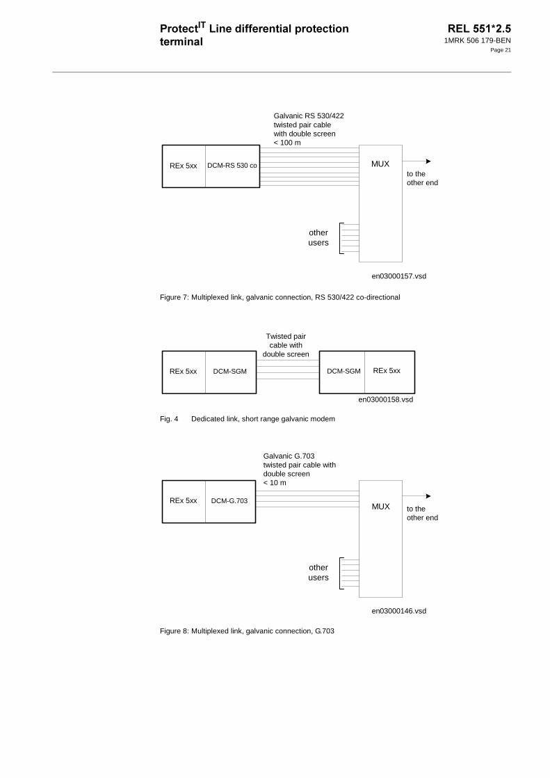
Figure 7: Multiplexed link, galvanic connection, RS 530/422 co-directional
Fig. 4 Dedicated link, short range galvanic modem
Figure 8: Multiplexed link, galvanic connection, G.703
REx 5xx DCM-RS 530 co MUX
otherusers
to theother end
en03000157.vsd
Galvanic RS 530/422twisted pair cablewith double screen< 100 m
en03000158.vsd
REx 5xx
Twisted paircable with
double screen
REx 5xxDCM-SGMDCM-SGM
Galvanic G.703twisted pair cable withdouble screen< 10 m
REx 5xx DCM-G.703MUX
otherusers
to theother end
en03000146.vsd

1MRK 506 179-BEN
Page 22
Figure 9: Multiplexed link, optical fiber - galvanic connection V35/V36 with 21 - 15X
Figure 10:Multiplexed link, optical fibre - galvanic connection X.21 with 21-16X
otherusers
Galvanic V35/V36twisted pair cable withdouble screen< 100 m
to theother end
en03000147.vsd
REx 5xx DCM-SFOM21-15XFIBERDATA
V35/V36
MUX
optical fibres
otherusers
Galvanic X.21twisted pair cable withdouble screen< 100 m
to theother end
en03000148.vsd
REx 5xx DCM-SFOM21-16XFIBERDATA
X.21
MUX
optical fibres

1MRK 506 179-BEN
Page 23
Figure 11:Multiplexed link, optical fibre - galvanic connection G.703 with 21-16X
!
One or two optional optical serial interfaces with LON protocol, SPA protocol or IEC 60870-5-103 protocol, for remote com-munication, enables the terminal to be part of a Substation Automation (SA) system. These interfaces with terminal designations X13 and X15 are located at the rear of the terminal. The two interfaces can be configured inde-pendent of each other, each with different
functionalities regarding monitoring and set-ting of the functions in the terminal.
One RS485 interface can be inserted replac-ing one of the optical interfaces. The RS485 interface is ordered as terminated for last ter-minal in a multidrop connection. The RS485 interface is alternatively ordered as untermi-nated for point to point connection, or for intermediate location in a multidrop connec-tion. A selection between SPA and IEC 60870-5-103 is made in software at setting of the terminal.
!8!
This communication bus is mainly used for SMS. It can include different numerical relays/terminals with remote communication possibilities. Connection to a personal com-puter (PC) can be made directly (if the PC is located in the substation) or by telephone modem through a telephone network with CCITT characteristics.
+When communicating with a PC, using the rear SPA port, the only hardware needed for a station monitoring system is:
• Optical fibres
• Opto/electrical converter for the PC
• PC
or
• A RS485 network installation according to EIA Standard RS485
• PC
Remote communication over the telephone network also requires a telephone modem.
The software needed in the PC, either local or remote, is CAP 540.
otherusers
Galvanic G.703twisted pair cable withdouble screen< 10 m
to theother end
en03000149.vsd
REx 5xx DCM-SFOM21-16XFIBERDATA
G.703
MUX
optical fibres
!(//
Alt 1 Alt 2 Alt 3
X13 SPA/IEC fibre optic SPA/IEC RS485 SPA fibre optic
X15 LON fibre optic LON fibre optic IEC fibre optic

1MRK 506 179-BEN
Page 24
SPA communication is applied when using the front communication port, but for this purpose, no special serial communication function is required in the terminal. Only the software in the PC and a special cable for front connection is needed.
!8 % :<>;<((<='
This communication protocol is mainly used when a protection terminal communicates with a third party control system. This system must have a program that can interpret the IEC 60870-5-103 communication messages.
+As an alternative to the SPA communication the same port can be used for the IEC com-munication.
The IEC protocol may be used alternatively on a fibre optic or on an RS485 network. The fibre optic network is point to point only, while the RS485 network may be used by multiple terminals in a multidrop configura-tion.
The IEC 60870-5-103 protocol implementa-tion in REx 5xx consists of these functions:
• Event handling
• Report of analog service values (measure-ments)
• Fault location
• Command handling
-Autorecloser ON/OFF
-Teleprotection ON/OFF
-Protection ON/OFF
-LED reset
-Characteristics 1 - 4 (Setting groups)
• File transfer (disturbance files)
• Time synchronization
The events created in the terminal available for the IEC protocol are based on the event function blocks EV01 - EV06 and distur-bance function blocks DRP1 - DRP3. The commands are represented in a dedicated function block ICOM. This block has output signals according to the IEC protocol for all commands.
!81&
An optical network can be used within the Substation Automation system. This enables communication with the terminal through the LON bus from the operator’s workplace, from the control center and also from other terminals.
+An optical serial interface with LON protocol enables the terminal to be part of a Substation Control System (SCS) and/or Substation Monitoring System (SMS). This interface is located at the rear of the terminal. The hard-ware needed for applying LON communica-tion depends on the application, but one very central unit needed is the LON Star Coupler and optic fibres connecting the star coupler to the terminals. To communicate with the ter-minals from a Personal Computer (PC), the SMS 510, software or/and the application library LIB 520 together with MicroSCADA is needed.
! %! -'
+8!5 The serial communication module for SPA/IEC is placed in a slot at the rear part of the main processing module. The serial commu-nication module can have connectors for:
• two plastic fibre cables; (Rx, Tx)
• two glass fibre cables; (Rx, Tx)
• galvanic RS485
The type of connection is chosen when order-ing the terminal.
+81&The serial communication module for LON is placed in a slot at the rear part of the Main processing module. The serial communica-tion module can have connectors for:
• two plastic fibre cables; (Rx, Tx)
• two glass fibre cables; (Rx, Tx)
The type of connection is chosen when order-ing the terminal.
1MRK 506 179-BEN
Page 25
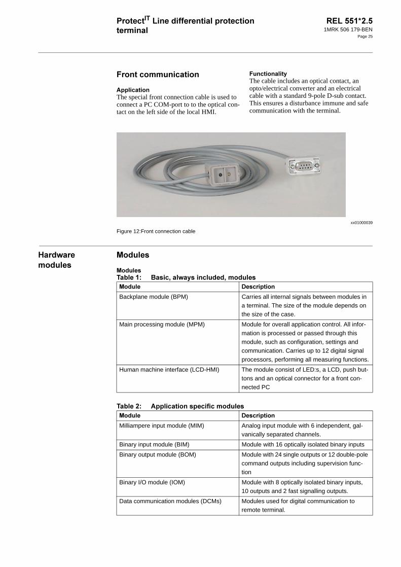
The special front connection cable is used to connect a PC COM-port to to the optical con-tact on the left side of the local HMI.
+The cable includes an optical contact, an opto/electrical converter and an electrical cable with a standard 9-pole D-sub contact. This ensures a disturbance immune and safe communication with the terminal.
xx01000039
Figure 12:Front connection cable
6 #
-
- /? 78#+ 8
/?
-
Backplane module (BPM) Carries all internal signals between modules in a terminal. The size of the module depends on the size of the case.
Main processing module (MPM) Module for overall application control. All infor-
mation is processed or passed through this module, such as configuration, settings and communication. Carries up to 12 digital signal
processors, performing all measuring functions.
Human machine interface (LCD-HMI) The module consist of LED:s, a LCD, push but-tons and an optical connector for a front con-
nected PC
-
Milliampere input module (MIM) Analog input module with 6 independent, gal-vanically separated channels.
Binary input module (BIM) Module with 16 optically isolated binary inputs
Binary output module (BOM) Module with 24 single outputs or 12 double-pole command outputs including supervision func-
tion
Binary I/O module (IOM) Module with 8 optically isolated binary inputs, 10 outputs and 2 fast signalling outputs.
Data communication modules (DCMs) Modules used for digital communication to remote terminal.

1MRK 506 179-BEN
Page 26
#+ %!-'
The power supply module, PSM, with built in binary I/O is used in 1/2 and 3/4 of full width 19” units. It has four optically isolated binary inputs and five binary outputs, out of which one binary output is dedicated for internal fail.
+The power supply modules contain a built-in, self-regulated DC/DC converter that provides full isolation between the terminal and the battery system.
5 %-'
+The inputs of the A/D-conversion module (ADM) are fed with voltage and current sig-nals from the transformer module. The cur-rent signals are adapted to the electronic voltage level with shunts. To gain dynamic range for the current inputs, two shunts with separate A/D channels are used for each input current. By that a 16-bit dynamic range is obtained with a 12 bits A/D converter.
The input signals passes an anti aliasing filter with a cut-off frequency of 500 Hz.
Each input signal (5 voltages and 5 currents) is sampled with a sampling frequency of 2 kHz.
The A/D-converted signals are low-pass fil-tered with a cut-off frequency of 250 Hz and down-sampled to 1 kHz in a digital signal processor (DSP) before transmitted to the main processing module.
%-'
+A transformer input module can have up to 10 input transformers. The actual number depends on the type of terminal. Terminals including only current measuring functions only have current inputs. Fully equipped the transformer module consists of:
• Five voltage transformers
• Five current transformers
The inputs are mainly used for:
• Phase currents
• Residual current of the protected line
• Residual current of the parallel circuit (if any) for compensation of the effect of the zero sequence mutual impedance on the fault locator measurement or residual cur-rent of the protected line but from a paral-lel core used for CT circuit supervision function or independent earth fault func-tion.
• Phase voltages
• Open delta voltage for the protected line (for an optional directional earth-fault protection)
• Phase voltage for an optional synchro-nism and energizing check.
7+51/
Input channels with high EMI immunity can be used as binary input signals to any func-tion. Signals can also be used in disturbance or event recording. This enables extensive monitoring and evaluation of the operation of the terminal and associated electrical circuits.
Transformer input module (TRM) Used for galvanic separation of voltage and/or
current process signals and the internal cir-cuitry.
A/D conversion module (ADM) Used for analog to digital conversion of analog
process signals galvanically separated by the TRM.
Serial communication module (SCM) Used for SPA/LON/IEC communication
LED module (LED-HMI) Module with 18 user configurable LEDs for indi-cation purposes
-

1MRK 506 179-BEN
Page 27
+Inputs are designed to allow oxide burn-off from connected contacts, and increase the disturbance immunity during normal protec-tion operate times. This is achieved with a high peak inrush current while having a low steady-state current. Inputs are debounced by software.
Well defined input high and input low volt-ages ensures normal operation at battery sup-ply earth faults.
The voltage level of the inputs is selected when ordering.
I/O events are time stamped locally on each module for minimum time deviance and stored by the event recorder if present.
7+ %7-'
Use the binary input module, BIM, when a large amount of inputs are needed. The BIM is available in two versions, one standard and one with enhanced pulse counting inputs to be used with the pulse counter function.
+The binary input module, BIM, has 16 opti-cally isolated binary inputs.
A signal discriminator detects and blocks oscillating signals. When blocked, a hystere-sis function may be set to release the input at a chosen frequency, making it possible to use the input for pulse counting. The blocking frequency may also be set.
7+ %71-'
Use the binary output module, BOM, for trip output or any signalling purpose when a large amount of outputs is needed.
+The binary output module, BOM, has 24 soft-ware supervised output relays, pairwise con-nected to be used as single-output channels with a common connection or as command output channels.
Figure 13:Relay pair example
7+5 %1-'
Use the binary I/O module, IOM, when few input and output channels are needed. The ten output channels are used for trip output or any signalling purpose. The two high speed signal output channels are used for applica-tions where short operating time is essential.
+The binary I/O module, IOM, has eight opti-cally isolated inputs and ten output relays. One of the outputs has a change-over contact. The nine remaining output contacts are con-nected in two groups. One group has five contacts with a common and the other group has four contacts with a common, to be used as single-output channels.
The binary I/O module also has two high speed output channels where a reed relay is connected in parallel to the standard output relay.
1 Output connection from relay 1
2 Common input connection
3 Output connection from relay 2
xx00000299.vsd
5
5
2
1
3

1MRK 506 179-BEN
Page 28
%--'
Use the milliampere input module, MIM, to interface transducer signals in the +/-20 mA range from for example temperature and pres-sure transducers.
+The milliampere input module has six input channels, each with a separate protection and filter circuit, A/D converter and optically iso-lated connection to the backplane.
The digital filter circuits have individually programmable cut-off frequencies, and all parameters for filtering and calibration are stored in a nonvolatile memory on the mod-ule. The calibration circuitry monitors the module temperature and commences an auto-matical calibration procedure if the tempera-ture drift increase outside the allowed range. The module uses the serial CAN bus for backplane communication.
Signal events are time stamped locally for minimum time deviance and stored by the event recorder if present.
6$ % (6-'
The human machine interface is used to mon-itor and in certain aspects affect the way the product operates. The configuration designer can add functions for alerting in case of important events that needs special attention from you as an operator.
Use the terminals built-in communication functionality to establish SMS communica-tion with a PC with suitable software tool. Connect the PC to the optical connector on the local HMI with the special front commu-nication cable including an opto-electrical converter for disturbance free and safe com-munication.
Figure 14:The LCD-HMI module
1. Status indication LEDs
2. LCD display
3. and buttons
4. Navigation buttons
5. Optical connector
E
C
2
3
1
5
4

1MRK 506 179-BEN
Page 29
The number of buttons used on the HMI module is reduced to a minimum to allow a communication as simple as possible for the
user. The buttons normally have more than one function, depending on actual dialogue.
> %(6-'
The LED indication module is an additional feature for the REx 5xx terminals for protec-tion and control and consists totally of 18 LEDs (Light Emitting Diodes). The main purpose is to present on site an immediate visual information such as protection indica-tions or alarm signals. It is located on the front of the protection and control terminals.
+The 18 LED indication module is equipped with 18 LEDs, which can light or flash in either red, yellow or green color. A descrip-tion text can be added for each of the LEDs.
Figure 15:The 18 LED indication module (LED-HMI)
The information on the LEDs is stored at loss of the auxiliary power for the terminal, so that the latest LED picture appears immediately after the terminal has restarted succesfully.
%686'Each LED indication on the HMI LED mod-ule can be set individually to operate in six different sequences; two as follow type and four as latch type. Two of the latching types are intended to be used as a protection indica-tion system, either in collecting or re-starting mode, with reset functionality. The other two are intended to be used as a signaling system in collecting mode with an acknowledgment functionality.
1 Three-color LEDs
2 Descriptive label, user exchangeable
xx00000406.vsd
1
2

1MRK 506 179-BEN
Page 30
6 # +
8#$"
Figure 16:Case without rear cover
Figure 17:Case without rear cover with 19” rack mounting kit
A
B C
D
E
xx02000646.vsd
F
GH
J
K
xx02000647.vsd
, 7 . 6 @ A
6U, 1/2 x 19”
265.9
223.7 205.7
190.5
203.7 - -
6U, 3/4 x 19” 336 204.1 252.9 318 316 - 186.6 -
6U, 1/1 x 19” 448.3 430.3 428.3 465.1 482.6
The H and K dimensions are defined by the 19” rack mounting kit
(mm)

1MRK 506 179-BEN
Page 31
8#$"
Figure 18:Case with rear cover Figure 19:Case with rear cover and 19” rack mounting kit
Figure 20:Case with rear cover
A
B CD
E
F
xx02000648.vsd
J
IH
G
K
xx02000649.vsd
xx02000650.vsd
, 7 . 6 @ A
6U, 1/2 x 19” 223.7 205.7 203.7 - -
6U, 3/4 x 19” 265.9 336 204.1 245.1 255.8 318 190.5 316 - 227.6 -
6U, 1/1 x 19” 448.3 430.3 428.3 465.1 482.6
The I and K dimensions are defined by the 19” rack mounting kit.
(mm)

1MRK 506 179-BEN
Page 32
(*<<8
Flush mounting Semi-flush mounting
,
( %'
B5( 7B5(
6U, 1/2 x 19” 210.1 254.3
6U, 3/4 x 19” 322.4 254.3
6U, 1/1 x 19” 434.7 254.3
C = 4-10 mm
D = 16.5 mm
E = 187.6 mm without rear protection cover, 228.6 mm with rear protection cover
F = 106.5 mm
G = 97.6 mm without rear protection cover, 138.6 mm with rear protection cover
A
B
C
D
E
xx02000665.vsd
F
G
xx02000666.vsd

1MRK 506 179-BEN
Page 33
(*<<8 /+
Figure 21:Flush mounting of side by side cases
, (
7 .
6U, 3/4 x 19” 326.4 259.3 352.8 190.5 34.4 13.2 ø 6.4
6U, 1/1 x 19” 438.7 259.3 465.1 190.5 34.4 13.2 ø 6.4
(mm)
B
A
C
G
D
E
F
xx02000651.vsd
xx02000652.vsd
19"

1MRK 506 179-BEN
Page 34
8#
Figure 22:Wall mounting
,%' 7
6U, 1/2 x 19” 292 267.1
6U, 3/4 x 19” 404.3 379.4 272.8 390 247
6U, 1/1 x 19” 516 491.1
80
xx02000653.vsd
E
A
B
CD
Screws M6 orcorresponding
en02000654.vsd

1MRK 506 179-BEN
Page 35
#
Figure 23:Hardware structure of the 3/4 of full width 19” case
en03000144.eps
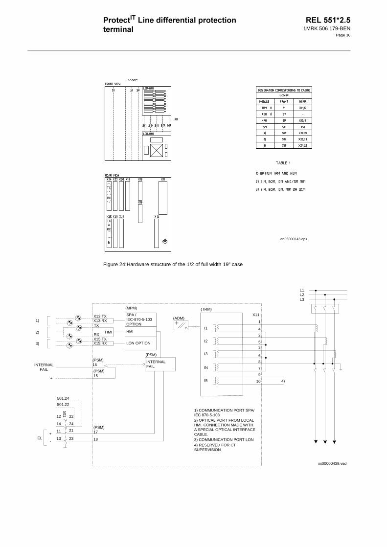
1MRK 506 179-BEN
Page 36
Figure 24:Hardware structure of the 1/2 of full width 19” case
en03000143.eps
xx00000439.vsd
X13:RXX13:TX
TX
HMIRXX15:TXX15:RX
HMI
LON OPTION
SPA /IEC-870-5-103OPTION
(MPM)
+
-
(PSM)17
18
1)
2)
3)
EL
L2
1
L1
L3
X11:
4
2
53
6
8
7
9
10 4)
∩
(ADM)
INTERNALFAIL
(PSM)
INTERNALFAIL
(PSM)16
(PSM)15
+
12 22
14 24
11 21
13 23
501
501.24
501.22
I1
I2
I3
IN
I5
(TRM)
1) COMMUNICATION PORT SPA/IEC 870-5-1032) OPTICAL PORT FROM LOCALHMI. CONNECTION MADE WITHA SPECIAL OPTICAL INTERFACECABLE.3) COMMUNICATION PORT LON4) RESERVED FOR CTSUPERVISION

1MRK 506 179-BEN
Page 37
$ .
/=?
/C? D$
/? !-(#!+-
/:? -(,48 "
"?
The specified value of an influencing factor to which are referred the characteristics of the
equipment.
&?
The range of values of an influencing quantity (factor) whithin which, under specified condi-tions, the equipment meets the specified requirements.
1"?
The range of values of a given energizing quantity for which the equipment, under specified conditions, is able to perform its intended functions according to the specified requirements.
Material Steel sheet
Front plate Steel sheet profile with cut-out for HMI and for 18 LED when included
Surface treatment Aluzink preplated steel
Finish Light beige (NCS 1704-Y15R)
Degree of protection Front side: IP40, optional IP54 with sealing strip. Rear side: IP20
, D$
6U, 1/2 x 19” ≤ 8.5 kg
6U, 3/4 x 19” ≤ 11 kg
2+ " &
Auxiliary dc voltage EL = (48 - 250) V +/- 20%
2+ " &
Current Ir = 1 or 5 A (0.2-30) × Ir
(0.2-15) x Ir for line differen-
tial function
Operative range (0.004-100) x IrPermissive overload 4 × Ir cont.
100 × Ir for 1 s *)
Burden < 0.25 VA at Ir = 1 or 5 A
Frequency fr = 50/60 Hz +/-10%*) max. 350 A for 1 s when COMBITEST test switch is included.

1MRK 506 179-BEN
Page 38
/;? $ +
/>? *+ +"+
/E? 4+
/<? /+
" &
Ambient temperature
Operative range
+20 °C
-25 °C to +55°C
-10 °C to +55 °C 0.01% / °C
Relative humidity
Operative range
10%-90%
0%-95%
10%-90% -
Storage temperature -40 °C to +70 °C - -
D$
Ripple, in DC auxiliary voltage Max 12% 0.01% / %
Interrupted auxiliary DC voltage 48-250 V dc ±20%
Without reset <50 ms
Correct function 0-∞ s
Restart time <180 s
D$
Frequency dependence fr ±10% for 50 Hz
fr ±10% for 60 Hz
±2.0% / Hz
Harmonic frequency dependence (10% content)
2nd, 3rd and 5th harmonic of fr ±6.0%
+"
1 MHz burst disturbance 2.5 kV IEC 60255-22-1, Class III
For short range galvanic modem 2.5kV IEC 60255-22-1, Class III
For galvanic interface
• common mode 1 kV IEC 60255-22-1, Class II
• differential mode 0.5 kV IEC 60255-22-1, Class II
Electrostatic discharge
Direct application Air 8 kV
Contact 6 kV
IEC 60255-22-2, Class III
For short range galvanic modem Air 8 kV IEC 60255-22-2, Class III
Contact 6 kV
Fast transient disturbance 4 kV IEC 60255-22-4, Class A
For short range galvanic modem 4 kV IEC 60255-22-4, Class A
For galvanic interface 1 kV IEC 60255-22-4, Class B
Surge immunity test 1-2 kV, 1.2/50µs
high energy
IEC 60255-22-5
Power frequency immunity test 150-300 V,
50 Hz
IEC 60255-22-7, Class A

1MRK 506 179-BEN
Page 39
/?
/?
/=? -$
/C? )
/? "
Power frequency magnetic field test 1000 A/m, 3s IEC 61000-4-8, Class V
Radiated electromagnetic field distur-bance
10 V/m, 80-1000 MHz
IEC 60255-22-3
Radiated electromagnetic field distur-bance
10 V/m, 80-1000 MHz,
1.4-2.0 GHz
IEC 61000-4-3, Class III
Radiated electromagnetic field distur-bance
35 V/m
26-1000 MHz
IEEE/ANSI C37.90.2
Conducted electromagnetic field dis-turbance
10 V, 0.15-80 MHz IEC 60255-22-6
Radiated emission 30-1000 MHz IEC 60255-25
Conducted emission 0.15-30 MHz IEC 60255-25
+"
Dielectric test 2.0 kVAC, 1 min. IEC 60255-5
Impulse voltage test 5 kV, 1.2/50 µs, 0.5 J
Insulation resistance >100 MΩ at 500 VDC
Immunity EN 61000-6-2
Emissivity EN 61000-6-4
Low voltage directive EN 50178
+"
Vibration Class I IEC 60255-21-1
Shock and bump Class I IEC 60255-21-2
Seismic Class I IEC 60255-21-3
Built-in calender With leap years through 2098
0
Recording manner Continuous, event con-
trolled
List size 40 events, first in-first out
+"

1MRK 506 179-BEN
Page 40
/:? -(+$
/;? !-!"
/>? /
/E? ( //)/
/<? "//)/
+
Time tagging resolution 1 ms
Time tagging error with synchronisation once/60 s ± 1.5 ms
Time tagging error without synchronisation ± 3 ms/min
0
Protocol SPA
Communication speed for the terminals 300, 1200, 2400, 4800, 9600 Bd
Slave number 1 to 899
Change of active group allowed Yes
Change of settings allowed Yes
0
Communication speed for the cable 0.3-115 Kbaud
9 7) "/+
10 ms AND 30 gates
OR 60 gates
INV 20 inverters
SM 20 flip-flops
GT 5 gates
TS 5 timers
200 ms SR 5 flip-flops
XOR 39 gates
7) "/+ ! +
TM 10 timers 0.000-60.000 s in steps of 1 ms
± 0.5% ± 10 ms
TP 10 pulse timers 0.000-60.000 s in
steps of 1 ms
± 0.5% ± 10 ms
TL 10 timers 0.0-90000.0 s in steps of 0.1 s
± 0.5% ± 10 ms
TQ 10 puls timers 0.0-90000.0 s in steps of 0.1 s
± 0.5% ± 10 ms

1MRK 506 179-BEN
Page 41
/? ( //)
/? /)
/=? ( 8$
/C? 1 ("
9 7) "/+
200 ms AND 239 gates
OR 159 gates
INV 59 inverters
MOF 3 registers
MOL 3 registers
7) "/+ ! +
TP 40 pulse timers 0.000-60.000 s in steps of 1 ms
± 0.5% ± 10 ms
! +
Current scaling, CTFactor (0.40-1.00) in steps of 0.01 -
Minimum operate current, IMinOp (20-150) % of (CTFactor x Ir) in
steps of 1%
±10% of Ir at I ≤Ir
±10% of I at I >IrSlope 1 (20-150) % of Ibias in steps of 1% ±5%
Slope 2 (30-150) % of Ibias in steps of 1% ±5%
Slope 1/Slope 2 intersection (100-1000) % of (CTFactor x Ir) in
steps of 1%
±10% of Ir at I ≤Ir
±10% of I at I>IrSlope at saturation 1.60 x Ibias ±5%
Saturation min current (100-1000) % of (CTFactor x Ir) in
steps of 1%
±10% of Ir at I ≤Ir
±10% of I at I >Ir 0
Operate
time
Idiff > 2 x Ibias and Idiff
>4 x IMinOp
Typical 28 ms
Reset time at Idiff = 0 Max 55 ms
Transfer trip operate time Max 35 ms
! 1
+
Operate cur-rent I>>
Phase measur-ing elements
(50-2000)% of I1b In steps of
1%
- ± 2.5 % of Ir at I ≤Ir
± 2.5 % of I at I > Ir-
Residual measur-ing elements
(50-2000)% of I1b In steps of 1%
± 2.5 % of Ir at I ≤ Ir
± 2.5 % of I at I > Ir
Maximum operate time at I > 10 × Iset Max. 15ms -
Dynamic overreach at τ< 100 ms - < 5%

1MRK 506 179-BEN
Page 42
/? 1 ( "
/:? 1 (# + ( $"
! +
Operate current Phase measuring ele-ments, IP>
(10-400) % of I1b in steps of 1 %
± 2.5 % of Ir at I ≤ Ir± 2.5 % of I at I >Ir
Residual measuring elements, IN>
(10-150) % of I4b in steps of 1 %
± 2.5 % of Ir at I ≤ Ir± 2.5 % of I at I >Ir
Time delay Phase measuring ele-ments
(0.000-60.000) s in steps of 1 ms
± 0.5 % of t ± 10 ms
Residual measuring
elements
(0.000-60.000) s in
steps of 1 ms
± 0.5 % of t ± 10 ms
Dynamic overreach at τ< 100 ms - < 5 %
! +
Operate value for low set function
I > Low
(5-500)% of I1b in steps of 1%
+/- 2.5% of I1r at
I ≤ I1r
+/- 2.5 % of I at I>I1r
Base current for inverse time calculation
I > Inv
(5-500) % of I1b in steps of 1%
+/- 2.5 % of I1r at
I ≤ I1r
+/- 2.5 % of I at I> I1r
Minimum operate time
tMinInv
(0.000-60.000)s in steps of 1 ms
+/- 0.5 % +/- 10 ms
Definite time delay for low set function
tLow
(0.000-60.000)s in steps of 1 ms
+/- 0.5 % +/- 10 ms
Operate value of high set function
I > High
(50-2000)% of I1b in steps of 1%
+/- 2.5% of I1r at
I ≤ I1r
+/- 2.5 % of I at I>I1r
Definite time delay for high set function
tHigh
(0.000-60.000) s in steps of 1 ms
+/- 0.5 % +/- 10 ms
Normal inverse characteristic
I = Imeas/Iset
IEC 60255-3 class 5+/- 60 ms
Very inverse characteristic IEC 60255-3 class 7.5+/- 60 ms
Extremely inverse character-istic
IEC 60255-3 class 7.5+/- 60 ms
Dynamic overreach at τ< 100 ms <5%
t 13.5I 1–----------- k⋅=

1MRK 506 179-BEN
Page 43
/;? ( + ( "
/>? 61($$"
! +
Start current, definite time or inverse time delay, IN>
5-300% of Ib in steps of 1%
± 5% of set value
Operate value
for directional current mea-surement
Forward IN
at ϕ=65 degrees
5-35% of Ib in steps
of 1%
± 1.5% of Ir
Reverse 60% of the setting for forward operation
± 1.5% of Ir
Characteristic angles 65 degrees lagging ± 5 degrees at 20 V and Iset=35% of Ir
Definite time delay 0.000 - 60.000 s in steps of 1ms
± 0.5 % +/-10 ms
Time multiplier for inverse time
delay
k
0.05-1.10 in steps of
0.01
According to IEC 60255-3
Normal inverse characteristic
I = Imeas/Iset
IEC 60255-3 class 5 ± 60 ms
Very inverse characteristic IEC 60255-3 class 7.5 ± 60 ms
Extremely inverse characteristic IEC 60255-3 class 7.5 ± 60 ms
Logarithmic characteristic ± 5 % of t at I = (1.3-29) × IN
Min. operate current for depen-dent characteristic, IMin
100-400% of IN in steps of 1%
± 5% of Iset
Minimum operate time for depen-dent characteristic, tMin
0.000-60.000 s in steps of 1 ms
± 0.5 % ± 10 ms
Minimum polarising voltage 1 % of Ur At 50 Hz: 1% of Ur ± 5%
At 60 Hz: 1% of Ur -15% to -5%
Reset time <70 ms -
! +
Mode of operation Off / NonComp / Comp
( Function blocked/No temp.
compensation/Temp. comp.)
Base current
IBase
(10 - 200 ) % of I1b in steps of 1 %
± 2.5% of Ir
Temperature rise at IBase
TBase (0 - 100) °C in steps of 1° C ± 1°C
t 13.5I 1–----------- k⋅=
t 5.8 1.35– ln IIN-----⋅=

1MRK 506 179-BEN
Page 44
/E? $"
/=<? 7(7)
Time constant
tau (1 - 62) min in steps of 1 min ± 1 min
Alarm temperature
TAlarm (50 - 150) °C in steps of 1°C
Trip temperature
TTrip (50 - 150) °C in steps of 1 °C
Temp. difference for reset of trip
TdReset(5 - 30) °C in steps of 1°C
! +
Upper value for mA input
MI11-I_Max -25.00 - 25.00 mA in steps of 0.01 mA
± 0.5% of set value
Lower value for mA input
MI11-I_Min
-25.00 - 25.00 mA in steps of
0.01 mA
+/- 0.5% of set value
Temp. corresponding to the MI11-I_Max setting
MI11-MaxValue-1000 - 1000 °C in steps of 1 °C
+/- 1% of set value +/- 1°C
Temp. corresponding to the MI11-I_Min setting
MI11-MinValue-1000 - 1000° C in steps of 1 °C
+/- 1% of set value +/- 1°C
! +
Operate current, IP> (one
measuring element per phase)
5-200% of I1b in steps of 1% ± 2.5% of Ir at I ≤ Ir± 2.5% of I at I > Ir
Retrip time delay t1 0.000-60.000 s in steps of 1 ms
± 0.5% ± 10 ms
Back-up trip time delay t2 0.000-60.000 s in steps of 1
ms
± 0.5% ± 10 ms
0
Trip operate time Max 18 ms
Operate time for current detection Max 10 ms
! +

1MRK 506 179-BEN
Page 45
#+"
/=? 7 (7) $)
/=? 10(1" "
!+
/==? ! (! $$
/=C? ! (! $
/=? 9 (9
! +
Minimum level of highest phase current for operation,
IP>
10-100% of I1b in steps of 1% ± 2.5% of Ir
Output time delay, t 0.000-60.000 s in steps of 0.001s
± 0.5% ± 10ms
! +
Operate current, IP> 20-300% of I1b in steps of 1% ± 2.5% of Ir at I≤Ir± 2.5% of I at I>Ir
Time delay, t 0.0-90000.0 s in steps of
0.1 s
± 0.5% ± 10 ms
! +
Change in current per power system cycle, DIL>
20.0-100.0% of Ib in steps of 0.1%
± 5.0 % of Ir
Time delay for start signal, tHStart 0.000-60.000 s in steps of 1 ms
± 0.5 % ± 10 ms
Time delay for trip signal, tHTrip 0.000-60.000 s in steps of
1 ms
± 0.5 % ± 10 ms
! +
Change in residual current per power system cycle, DIN>
20.0-100.0% of Ib in steps of 0.1%
± 5.0% of Ir
Time delay for start signal, tHStart 0.000-60.000 s in steps of 1 ms ± 0.5 % ± 10 ms
Time delay for trip signal, tHTrip 0.000-60.000 s in steps of 1 ms +± 0.5 % ± 10 ms
! +
Low-set step of undercurrent limit, ILLow< 5.0-100.0% of Ib in steps of 0.1%
± 2.5 % of Ir
High-set step of undercurrent limit, ILHigh< 5.0-100.0% of Ib in
steps of 0.1%
± 2.5 % of Ir
Time delayed operation of low-set step, tLow 0.000-60.000 s in steps of 1 ms
± 0.5 % ± 10 ms
Time delayed operation of high-set step, tHigh
0.000-60.000 s in steps of 1 ms
± 0.5 % ± 10 ms
Reset ratio > 106% typically

1MRK 506 179-BEN
Page 46
/=:? 1 (1"
/=;? 1 ( "
! ++"
/=>? !9( "8/
/=E? (
0 +
Low-set operating value, ILLow> 5.0-200.0% of Ib in steps of 0.1% ± 5.0 % of IrHigh-set operating value, ILHigh> 5.0-200.0% of Ib in steps of 0.1% ± 5.0 % of IrTime delay of low-set step, tLow 0.000-60.000 s in steps of 1 ms ± 0.5 % ± 10 ms
Time delay of high-set step, tHigh 0.000-60.000 s in steps of 1 ms ± 0.5 % ± 10 ms
Reset ratio > 94% typically
! +
Residual overcurrent low-set limit, INLow>
5.0-100.0% of Ib in steps of 0.1%
± 2.5 % of Ir
Residual overcurrent high-set limit,
INHigh>
5.0-100.0% of Ib in steps
of 0.1%
± 2.5 % of Ir
Time delayed operation of low-set step, tLow
0.000-60.000 s in steps of 1 ms
± 0.5 % ± 10 ms
Time delayed operation of high-set step, tHigh
0.000-60.000 s in steps of 1 ms
± 0.5 % ± 10 ms
Reset ratio > 95% typically
! +
Operate current, IMinOp 5-100% of I1b in steps of 1% ± 5.0% of Ir
! +
Automatic reclosing open time:
shot 1 - t1 1ph 0.000-60.000 s in steps of 1 ms
± 0.5% ± 10 ms
shot 1 - t1 2ph 0.000-60.000 s in steps of 1 ms
± 0.5% ± 10 ms
shot 1 - t1 3ph 0.000-60.000 s in steps of
1 ms
± 0.5% ± 10 ms
shot 2 - t2 3ph 0.0-9000.0 s in steps of 0.1 s
± 0.5% ± 10 ms
shot 3 - t3 3ph 0.0-9000.0 s in steps of 0.1 s
± 0.5% ± 10 ms
shot 4 - t4 3ph 0.0-9000.0 s in steps of
0.1 s
± 0.5% ± 10 ms
Autorecloser maximum wait time for sync, tSync
0.0-90000.0 s in steps of 0.1 s
± 0.5% ± 10 ms

1MRK 506 179-BEN
Page 47
/C<? (
/C? (
/C? ( 8/
Duration of close pulse to circuit
breaker tPulse
0.000-60.000 s in steps of
1 ms
± 0.5% ± 10 ms
Reclaim time, tReclaim 0.0-90000.0 s in steps of 0.1 s
± 0.5% ± 10 ms
Inhibit reset time, tInhibit 0.000-60.000 s in steps of
1 ms
± 0.5% ± 10 ms
Maximum trip pulse duration, tTrip (longer trip pulse durations will either extend the dead time or interrupt the
reclosing sequence)
0.000-60.000 s in steps of 1 ms
± 0.5% ± 10 ms
Maximum wait time for release from Master, tWaitForMaster
0.0-90000.0 s in steps of 0.1 s
± 0.5% ± 10 ms
Maximum wait time between shots, tAu-toWait
0.000-60.000 s in steps of 1 ms
± 0.5% ± 10 ms
Time delay before indicating reclosing
unsuccessful, tUnsuc
0.0-90000.0 s in steps of
0.1 s
± 0.5% ± 10 ms
Time CB must be closed before AR becomes ready for a reclosing cycle, tCBClosed
0.000-60.000 s in steps of 1 ms
± 0.5% ± 10 ms
0
Reclosing shots 1-4
Programs Three pole trip: 1
Single, two and three pole trip: 6
Number of instances Up to six depending on terminal type (different terminal types support dif-ferent CB arrangements and numbers
of bays)
Breaker closed before start 5 s
! +
0 +
Setting for the minimum trip
pulse length, tTripMin
0.000 - 60.000 s in steps of
1 ms
± 0.5% ± 10 ms
! +
Auxiliary-contact-based function - time delay
(0.000-60.000) s in steps of 1 ms
± 0.5 % ±10 ms

1MRK 506 179-BEN
Page 48
/C=? 6( $
/CC? &("
-
/C? (/
/C:? (/
! +
Time interval between auto-matic starts of testing cycle,
tStart
0.0-90000.0 s in steps of 0.1 s ± 0.5% ± 10 ms
Time interval available for test of the external function to be registered as suc-
cessful, tWait
0.0-90000.0 s in steps of 0.1 s ± 0.5% ± 10 ms
Minimum time interval required before repeated test of the external function,
tCh
0.0-90000.0 s in steps of 0.1 s ± 0.5% ± 10 ms
Duration of CS output sig-nal, tCS
0.0-90000.0 s in steps of 0.1 s ± 0.5% ± 10 ms
Duration of CHOK output signal, tChOK
0.0-90000.0 s in steps of 0.1 s ± 0.5% ± 10 ms
Duration of inhibit condition
extension after the BLOCK input signal resets, tInh
0.0-90000.0 s in steps of 0.1 s ± 0.5% ± 10 ms
0
Counter value 0-10000
Max. count up speed 10 pulses/s
!
Pre-fault time, tPre 50-300 ms in steps of 10 ms
Post-fault time, tPost 100-5000 ms in steps of 100 ms
Limit time, tLim 500-6000 ms in steps of 100 ms
Number of recorded disturbances Max. 10
!
Overcurrent triggering 0-5000% of Inb in steps of 1%
Undercurrent triggering 0-200% of Inb in steps of 1%
Overvoltage triggering 0-200% of Unb in
steps of 1% at 100 V sec.
Undervoltage triggering 0-110% of Unb in steps of 1%

1MRK 506 179-BEN
Page 49
/C;? (/
/C>? ("
/CE? -"% ('
0
Number of binary signals 48
Number of analog signals 10
Sampling rate 2 kHz
Recording bandwidth 5-250 Hz
Total recording time with ten analog and 48 binary signals recorded. (The amount of harmonics can affect the maximum storage time)
40 s typically
Current channels Dynamic range Without DC off-
set
(0.01-110.00) × Ir
With full DC off-set
(0.01-60.00) × Ir
Resolution 0.5 % of IrAccuracy at rated frequency
I ≤ Ir ± 2.5 % of IrI > Ir ± 2.5 % of I
0
Event buffering capacity Max. number of events/disturbance report 150
Max. number of disturbance reports 10
& +
Frequency (0.95 - 1.05) x fr ± 0.2 Hz
Current (RMS) (0.2 - 4) x Ir ± 2.5% of Ir, at I≤ Ir
± 2.5% of I, at I> Ir

1MRK 506 179-BEN
Page 50
/<? --(
-
/? (
/? !(!
! +
mA measuring function ± 5, ± 10, +± 20 mA 0-5, 0-10, 0-20, 4-20 mA
± 0.1 % of set value ± 0.005 mA
Max current of transducer
to input, I_Max
(-25.00 to +25.00) mA in steps
of 0.01
Min current of transducer to input, I_Min
(-25.00 to +25.00) mA in steps of 0.01
High alarm level for input, HiAlarm
(-25.00 to +25.00) mA in steps of 0.01
High warning level for
input, HiWarn
(-25.00 to +25.00) mA in steps
of 0.01
Low warning level for input, LowWarn
(-25.00 to +25.00) mA in steps of 0.01
Low alarm level for input, LowAlarm
(-25.00 to +25.00) mA in steps of 0.01
Alarm hysteresis for input,
Hysteresis
(0-20) mA in steps of 1
Amplitude dead band for input, DeadBand
(0-20) mA in steps of 1
Integrating dead band for input, IDeadB
(0.00-1000.00) mA in steps of 0.01
! +
Input frequency See Binary Input Module (BIM) -
Cycle time for pulse counter
30 s, 1 min, 1 min 30 s, 2 min, 2 min 30 s, 3 min, 4 min, 5 min, 6 min, 7 min 30s,
10 min, 12 min, 15 min, 20 min, 30 min, 60 min
± 0,1% of set value
0
Protocol SPA
Communication speed 300, 1200, 2400, 4800, 9600, 19200 or 38400 Bd
Slave number 1 to 899
Remote change of active group allowed yes/no
Remote change of settings allowed yes/no
Connectors and optical fibres glass or plastic

1MRK 506 179-BEN
Page 51
/=? 1&(!
/C? :<>;<((<=(!
/? 1/4!5
/:? !C>4!5
/;? 1&(1/41&/
/>? -(."
0
Protocol LON
Communication speed 1.25 Mbit/s
Connectors and optical fibres glass or plastic
0
Protocol IEC 60870-5-103
Communication speed 9600, 19200 Bd
Connectors and optical fibres glass or plastic
./ /
Cable connector ST connector HFBR, Snap-in connector
Fibre diameter 62.5/125 µm
50/125 µm
1 mm
Max. cable length 500 m 30 m
Cable connector Phoenix, MSTB 2.5/6-ST-5.08 1757051
Cable dimension SSTP according to EIA Standard RS485
Max. cable length 100 m
./ /
Cable connector ST-connector HFBR, Snap-in connector
Fibre diameter 62.5/125 µm
50/125 µm
1 mm
Max. cable length 1000 m 30 m
+ +
V.36/V11 Co-directional (on request) ITU (CCITT) D-sub 25 pins
V.36/V11 Contra-directional ITU (CCITT) D-sub 25 pins
X.21/X27 ITU (CCITT) D-sub 15 pins
RS 530/RS422 Co-directional (on request) EIA D-sub 25 pins
RS 530/RS422 Contra-directional EIA D-sub 25 pins
G.703 Co-directional ITU (CCITT) Screw
0
Data transmission synchronous, full duplex
56 or 64 kbit/s
For G703 only 64 kbit/s
Transmission type
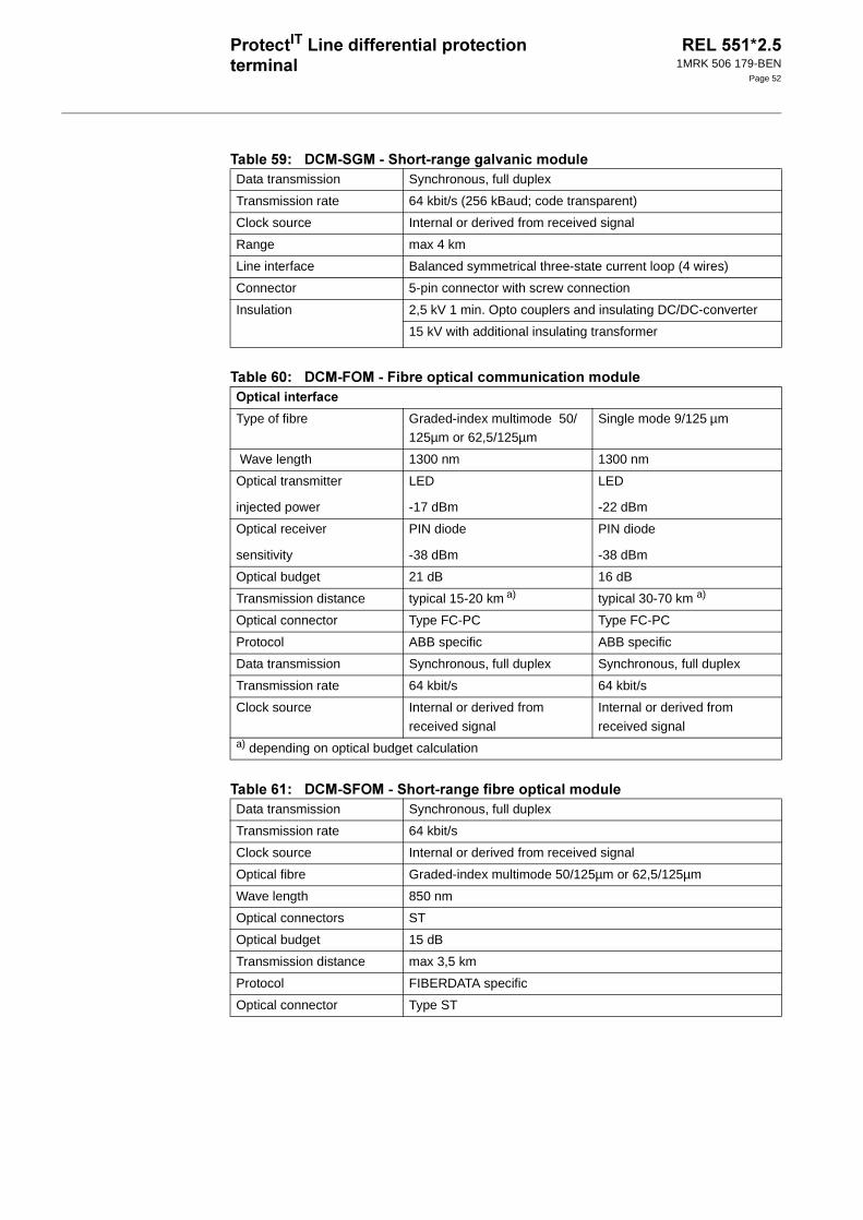
1MRK 506 179-BEN
Page 52
/E? -(!.-(!$("
/:<? -(1-(/
/:? -(!1-(!$(/
Data transmission Synchronous, full duplex
Transmission rate 64 kbit/s (256 kBaud; code transparent)
Clock source Internal or derived from received signal
Range max 4 km
Line interface Balanced symmetrical three-state current loop (4 wires)
Connector 5-pin connector with screw connection
Insulation 2,5 kV 1 min. Opto couplers and insulating DC/DC-converter
15 kV with additional insulating transformer
1
Type of fibre Graded-index multimode 50/125µm or 62,5/125µm
Single mode 9/125 µm
Wave length 1300 nm 1300 nm
Optical transmitter
injected power
LED
-17 dBm
LED
-22 dBm
Optical receiver
sensitivity
PIN diode
-38 dBm
PIN diode
-38 dBm
Optical budget 21 dB 16 dB
Transmission distance typical 15-20 km a) typical 30-70 km a)
Optical connector Type FC-PC Type FC-PC
Protocol ABB specific ABB specific
Data transmission Synchronous, full duplex Synchronous, full duplex
Transmission rate 64 kbit/s 64 kbit/s
Clock source Internal or derived from
received signal
Internal or derived from
received signala) depending on optical budget calculation
Data transmission Synchronous, full duplex
Transmission rate 64 kbit/s
Clock source Internal or derived from received signal
Optical fibre Graded-index multimode 50/125µm or 62,5/125µm
Wave length 850 nm
Optical connectors ST
Optical budget 15 dB
Transmission distance max 3,5 km
Protocol FIBERDATA specific
Optical connector Type ST

1MRK 506 179-BEN
Page 53
6 #
/:? 7-81-8!-(7+
/:=? 71-81-8!-(7+
/:C? --(,48 "
C C> < <
Binary inputs BIM: 16, IOM: 8, PSM: 4
Debounce frequency 5 Hz (BIM), 1 Hz (IOM)
Oscillating signal discrimi-nator.*
Blocking and release settable between 1-40 Hz
Binary input voltage RL 24/30 VDC
+/-20%
48/60 VDC
+/-20%
110/125 VDC
+/-20%
220/250 VDC
+/-20%
Power dissipation (max.) 0.05 W/input 0.1 W/input 0.2 W/input 0.4 W/input
*) Only available for BIM
4+ !+
+
Binary outputs BOM: 24, IOM: 10, PSM: 4
IOM: 2
Max system voltage 250 V AC, DC 250 V AC, DC
Test voltage across open contact, 1 min 1000 V rms 800 V DC
Current carrying
capacity
Continuous 8 A 8 A
1 s 10 A 10 A
Making capacity at inductive load with L/R>10 ms
0.2 s 30 A 0.4 A
1.0 s 10 A 0.4 A
Breaking capacity for AC, cos ϕ>0.4 250 V/8.0 A 250 V/8.0 A
Breaking capacity for DC with L/R<40ms 48 V/1 A 48 V/1 A
110 V/0.4 A 110 V/0.4 A
220 V/0.2 A 220 V/0.2 A
250 V/0.15 A 250 V/0.15 A
Maximum capacitive load - 10 nF
2+ " &
mA input module
input range +/- 20 mA -
input resistance Rin = 194 ohm
-
power consumption each mA-module ≤ 4 W -
each mA-input ≤ 0.1 W -

1MRK 506 179-BEN
Page 54
/:? --( D$
Ambient temperature, mA-input 2-20 mA -10°C to +55°C 0.02% / °C
1MRK 506 179-BEN
Page 55
1 .
Carefully read and follow the set of rules to ensure problem-free order management. Be aware that certain functions can only be ordered in combination with other functions and that some functions require specific hardware selections.
7$ #
/+
-
7+51/
-/
! ++"
-
Basic REx 5xx platform and common functions housed in selected casing
Operator’s manual (English)
Installation and commissioning manual (English)
Technical reference manual (English)
Application manual (English)
Binary I/O resided on power supply module
A/D module
Transformer module
Line differential protection, phase segregated
Instantaneous non-directional phase overcurrent protection
Definite time non-directional phase overcurrent protection
Current circuit supervision, current based
Supervision of AC input quantities
Supervision of mA input quantities (Requires optional mA-transducer module, )

1MRK 506 179-BEN
Page 56
-/Add measuring capabilities by selecting input energizing options from the following tables.
1
REL 551 Quantity: 1MRK 002 480-AE
Default:
The terminal is delivered without loaded configuration.
!""#$%& ! "
"'(" ")
Option:
Customer specific configuration On request
*+,)
Engergizing quantities for binary inputs on power supply module
24-30 V 1MRK 002 238-AA
48-60 V 1MRK 002 238-BA
110-125 V 1MRK 002 238-CA
220-250 V 1MRK 002 238-DA
-* (+!,.!/ +"! .$012#%3)
*+,)
Rated measuring input energizing quantities 1A 1MRK 000 157-CD
5 A 1MRK 000 157-DD
*415%4146265" &!!
Three pole tripping logic %415 1MRK 001 458-VA
Single, two or three pole tripping logic %4146265 1MRK 001 458-XA
Instantaneous non-directional residual overcurrent protec-tion
1MRK 001 456-VA
Definite time non-directional residual overcurrent protection (
1MRK 001 456-XA
Two step time delayed non-directional phase overcurrent
protection 2
1MRK 001 459-LA
Time delayed non-directional residual overcurrent protec-tion
1MRK 001 456-YA
Thermal phase overload protection 7 1MRK 001 457-DA
Breaker failure protection 8 1MRK 001 458-AA

1MRK 506 179-BEN
Page 57
#+"
!+
-
-
Broken conductor check 8 1MRK 001 457-UA
Overload supervision 3 1MRK 001 457-FA
Sudden change in phase current protection (SCC1) 1MRK 001 460-EB
Sudden change in residual voltage protection (SCRC) 1MRK 001 460-FA
Undercurrent protection (UCP) 1MRK 001 460-KB
Phase overcurrent protection (OCP) 1MRK 001 460-LB
Residual overcurrent protection (ROCP) 1MRK 001 460-MA
Single command, 16 signals 1MRK 001 458-EA
Autorecloser - 1- and/or 3-phase, single circuit breaker 41465
1MRK 001 458-LA
Autorecloser - 1- and/or 3-phase, double circuit breakers 421465
1MRK 001 457-KA
Autorecloser - 3-phase, single circuit breaker 415 1MRK 001 458-MA
Autorecloser- 3-phase, double circuit breaker 4215 1MRK 001 457-LA
Additional three pole tripping logic %215 1MRK 001 459-VA
Additional single, two or three pole tripping logic %2146265
1MRK 001 459-XA
Pole discordance logic (contact based) 1MRK 001 458-UA
Additional configurable logic blocks 2 1MRK 001 457-MA
Communication channel test logic 7 1MRK 001 459-NA
-*-&!"" &++
Multiple command, one fast block with 16 signals (CM1) 1MRK 001 455-RA
Multiple command, 79 medium speed blocks each with 16 signals 9:
1MRK 001 458-YA
Disturbance recorder 1MRK 001 458-NA
Event recorder 1MRK 001 459-KA
Trip value recorder 3 1MRK 001 458-SA
-*&+ "! 8 /! 1
&!!
Pulse counter logic for metering 1MRK 001 458-TA
Six event counters - 1MRK 001 445-CA

1MRK 506 179-BEN
Page 58
! 6-% '
6 #
,When ordering I/O modules, observe the maximum quantities according to table below.
/::? -*$ #51
-*+,&
2nd HMI language, german 7 1! German 1MRK 001 459-AA
2nd HMI language, russian 7 1 Russian 1MRK 001 459-BA
2nd HMI language, french 7 1 French 1MRK 001 459-CA
2nd HMI language, spanish 7 1 Spanish 1MRK 001 459-DA
2nd HMI language, italian 7 1 Italian 1MRK 001 459-EA
Customer specific language Contact your local ABB representative for availability
18 LED indication module 17 1MRK 000 008-DA
Maximum number of modules
Note: Standard order
of location for I/O modules is BIM-BOM-IOM-MIM-DCM from
right to left as seen from the rear side of the terminal
Case size
3/4 x 19”
1MRK 000 151-GC
1/2 x 19”
1MRK 000 151-FC
Binary input module
8
8 3
Binary output mod-ules 8
Binary input/output modules
4 3
Milliampere input
module
3 1
Data communication module for remote ter-minal communication
1 1
0 5

1MRK 506 179-BEN
Page 59
7+5
Binary input module 8 16 inputs
RL24-30 VDC Quantity: 1MRK 000 508-DB
RL48-60 VDC Quantity: 1MRK 000 508-AB
RL110-125 VDC Quantity: 1MRK 000 508-BB
RL220-250 VDC Quantity: 1MRK 000 508-CB
Binary input module with enhanced pulse counting capabilities for the pulse counter logic for
metering 8 16 inputs
*+&!!/ "
RL24-30 VDC Quantity: 1MRK 000 508-HA
RL48-60 VDC Quantity: 1MRK 000 508-EA
RL110-125 VDC Quantity: 1MRK 000 508-FA
RL220-250 VDC Quantity: 1MRK 000 508-GA
* "&&+ "! 8 !&+6"!
""+(!$)
Binary output module 24 output relays 8 Quantity: 1MRK 000 614-AB
* "&&+6"! !&+ "! 8
""+(!$)
Binary input/output module 8 inputs, 10 outputs, 2 high-speed outputs
RL24-30 VDC Quantity: 1MRK 000 173-GB
RL48-60 VDC Quantity: 1MRK 000 173-AC
RL110-125 VDC Quantity: 1MRK 000 173-BC
RL220-250 VDC Quantity: 1MRK 000 173-CC
mA input module 6 channels Quantity: 1MRK 000 284-AB
*," &!!.+,&!.
Co-directional V.36 galvanic module 135;
Contra-directional V.36 galvanic module 135;
On request
1MRK 000 185-BA
X.21 galvanic module 1<24 1MRK 000 185-CA
Co-directional RS530 galvanic module 1#5% On request
Contra-directional RS530 galvanic module 1#5%
1MRK 000 185-EA
Fibre optical module 1 1MRK 000 195-AA
Short range galvanic module 1= 1MRK 001 370-AA
Short range fibre optical module 1 1MRK 001 370-DA
Co-directional G.703 galvanic module 1=)9%5 1MRK 001 370-CA

1MRK 506 179-BEN
Page 60
!
#$
- #$C<$
"
!(//
Alt 1 Alt 2 Alt 3
X13 SPA/IEC fibre optic SPA/IEC RS485 SPA fibre optic
X15 LON fibre optic LON fibre optic IEC fibre optic
1 3=8+"/
SPA/IEC 60870-5-103 interface 6 Plastic fibres 1MRK 000 168-FA
SPA/IEC 60870-5-103 interface 66
-
Glass fibres 1MRK 000 168-DA
SPA/IEC 60870-5-103 interface RS485 gal-vanic, for termination of last termi-nal in multi-drop 66$0#
RS485 galvanic 1MRK 002 084-BA
SPA/IEC 60870-5-103 interface, RS485 gal-
vanic, for point-to-point or inter-mediate location in multi-drop 66$0#
RS485 galvanic 1MRK 002 084-CA
1 38+"/
LON interface - Plastic fibres 1MRK 000 168-EA
LON interface 66- Glass fibres 1MRK 000 168-DA
IEC 60870-5-103 interface 66- Glass fibres 1MRK 000 168-DA
IEC 60870-5-103 interface 6 Plastic fibres 1MRK 000 168-FA
Test switch module RTXP 24 in RHGS6 case 1MRK 000 371-CA
With internal earthing RK 926 215-BB
With external earthing RK 926 215-BC
On/off switch for the DC-supply 6/ RK 795 017-AA
19” rack mounting kit 4:>' 1MRK 000 020-BR
Wall mounting kit ? 1MRK 000 020-DA
Flush mounting kit 1MRK 000 020-Y
Semiflush mounting kit "1 1MRK 000 020-BS
Additional seal for IP54 protection of flush and semiflush
mounted terminals #$
1MKC 980 001-2
Cover for rear area including fixing
screws and assembly instruction 6U, 3/4 x 19” 1MRK 000 020-AB
6U, 1/2 x 19” 1MRK 000 020-AC

1MRK 506 179-BEN
Page 61
-)
"
A+#$
/
-
/)
Side-by-side mounting kit !1&+1! 1MRK 000 020-Z
21-15X: Optical/electrical converter for short range fibre optical module V.36 (supply 48-110 VDC) 2414#<
1MRK 001 295-CA
21-16X: Optical/electrical converter for short range fibre
optical module X.21/G 703 (supply 48-110 VDC) 2414;<
1MRK 001 295-DA
Key switch for restriction of settings via LCD-
HMI @+/
Quantity: 1MRK 000 611-A
Front connection cable between LCD-HMI and PC for terminal handling (Opto/9-pole D-
sub) &
Quantity: 1MKC 950 001-2
/#%%" /+!,!/"
*+ "&(AB !
User documentation CD-ROM REx 5xx, RET 521, RED 521 (DOC-CD)
Quantity:
1MRK 002 270-AA
*+ "&!" B !
Operator’s manual Quantity: 1MRK 506 150-UEN
Technical reference manual Quantity: 1MRK 506 152-UEN
Installation and commissioning manual Quantity: 1MRK 506 151-UEN
Application manual Quantity: 1MRK 506 153-UEN
For our reference and statistics we would be pleased to be provided with the following applica-tion data:
Country: End user:
Station name: Voltage level: kV

1MRK 506 179-BEN
Page 62
-
$""#/$
Accessories for REx 5xx*2.3 1MRK 514 009-BEN
CAP 540*1.2 1MRK 511 112-BEN
77$+ 7
Substation Automation
SE-721 59 Västerås
Sweden
Telephone: +46 (0) 21 34 20 00
Facsimile: +46 (0) 21 14 69 18
Internet: www.abb.com/substationautomation