4096078-PE AGI 107035-SU 53640-Inspire XT-2.5 ... - Greenbook.net
Upload
khangminh22Category
view
3download
0
Section 6 SOP for FRM Jan 2017 Page 1 of 53 Revision 1
FORSYTH COUNTY OFFICE OF ENVIRONMENTAL ASSISTANCE AND PROTECTION
STANDARD OPERATING PROCEDURE (SOP)
FRM PM 2.5

Section 6 SOP for FRM Jan 2017 Page 2 of 53 Revision 1
Signature Page
By the signatures below, the Forsyth County Office of Environmental Assistance and Protection (FCEAP) certifies that the information contained in the following Standard Operating Procedure (SOP) is complete and fully implemented as the official guidance for our Office. However, due to circumstances that may arise during the sampling year, some practices may change. If a change occurs, a notification of change and a request for approval will be submitted to EPA Region 4 at that time.
Name: Cary Gentry Signature: Date: 1/6/17
Title: FCEAP QA Specialist
Name: Jason Bodenhamer Signature: Date: 1/6/17
Title: FCEAP Program Manager
Name: Minor Barnette Signature: Date: 1/6/17
Title: FCEAP Director
Name: Signature: Date:
Title:
Name: Signature: Date:
Title:
Section 6 SOP for FRM Jan 2017 Page 3 of 53 Revision 1
Table of Contents
6.0 SCOPE AND PURPOSE ........................................................................................................................ 5
6.1 SAMPLER DESCRIPTION AND ASSEMBLY .................................................................................... 5
6.1.1 Features of the PM2.5 Sampler ....................................................................................................... 5
6.1.2 Assembly of 2025i Sampler .............................................................................................................. 8
6.2 2025i Sampler Setup ............................................................................................................................... 9
6.3 Site Visits ............................................................................................................................................... 12
6.3.1 External Leak Check ..................................................................................................................... 12
6.3.2 Return sample filters ...................................................................................................................... 14
6.3.3 Verification Checks ........................................................................................................................ 15
6.3.4 Calibration ...................................................................................................................................... 20
6.4 Pre/Post Sampling Filter Procedures ................................................................................................... 24
6.4.1 Receive Filter from State ............................................................................................................... 24
6.4.2 Loading Pre Sampled Filters ......................................................................................................... 28
6.4.3 Picking Up Sampled Filters and Retrieving Data ........................................................................ 29
6.4.4 Process Sampled Filter Data ......................................................................................................... 35
6.4.5 Shipping Sampled Filters to State ................................................................................................. 40
6.5 Analyzing the PM2.5 Data ..................................................................................................................... 40
6.5.1 Filter Weights Review .................................................................................................................... 40
6.6 Data Processing/AQS Data Generator ................................................................................................. 43
6.6.1 PM2.5 Database Quarterly Filter Analysis .................................................................................... 43
6.6.2 QA Data Validation/Blanks ........................................................................................................... 46
6.6.3 Prepare PM2.5 AQS Report ............................................................................................................ 48
References ................................................................................................................................................... 51
Appendix A .................................................................................................................................................. 52

Section 6 SOP for FRM Jan 2017 Page 4 of 53 Revision 1
REVISION DATE CHANGES TO SOP
1 Wholesale changes for switch to 2025i unit
Section 6 SOP for FRM Jan 2017 Page 5 of 53 Revision 1
STANDARD OPERATING PROCEDURES FOR FRM2.5
Forsyth County Office of Environmental Assistance and Protection
6.0 SCOPE AND PURPOSE
The U.S. Environmental Protection Agency (EPA) began regulating fine particles in July 1997. The regulation set forth the reference monitoring method in the Code of Federal Regulations (CFR) at 40 CFR Part 50, Appendix L. This document is intended to assist the Forsyth County Office of Environmental Assistance and Protection (FCEAP) to use the EPA reference method to monitor the ambient atmosphere for particles with an aerodynamic diameter of 2.5 µm or less, known as fine particles (PM2.5). Fine particles are formed in the atmosphere from gases such as sulfur dioxide, reactive oxides of nitrogen, and volatile organic compounds. Sources include power plants, diesel trucks, wood stoves, and industrial processes.
The goal of the FCEAP PM2.5 program is the measurement of fine particles in units of micrograms per cubic meter (µg/m3). Using a Thermo Scientific Partisol®-Plus Model 2025i PM2.5 Sequential Sampler, referred to as “PM2.5 Sampler” for the remainder of this document, particles are collected on 47mm diameter, 2µm pore-size Teflon® filters over a 24-hour time period. The concentrations are then compared to the National Ambient Air Quality Standard (NAAQS) of 35 µg/m3 for 24 hours and 12 µg/m3 annual arithmetic mean concentration.
This document focuses on the assembly, operation, and repair of the PM2.5 samplers and should be used in conjunction with the supplied Service Manual. The Service Manual is the reference method for all adjustments to the sampler by FCEAP technicians and will not be reproduced in this SOP.
6.1 SAMPLER DESCRIPTION AND ASSEMBLY
The PM2.5 Sampler is designed to meet the regulatory monitoring requirements for PM2.5 (40 CFR Part 50, Appendix L). The sampler draws a known volume of air at a constant flow rate through a PM10 inlet followed by a Very Sharp Cut Cyclone(VSCC). After a 24-hour sampling period, the pre-weighed Teflon® filter is collected and gravimetrically analyzed. The mass concentration is reported as µg/m3.
6.1.1 Features of the PM2.5 Sampler
An active volumetric flow control system that maintains a constant volumetric flow rate of 16.67 L/min by incorporating a mass flow controller, and ambient temperature and pressure sensors.
The temperature of the collection filter is maintained within 5 °C of the outdoor ambient temperature by a continuous filter compartment ventilation system.
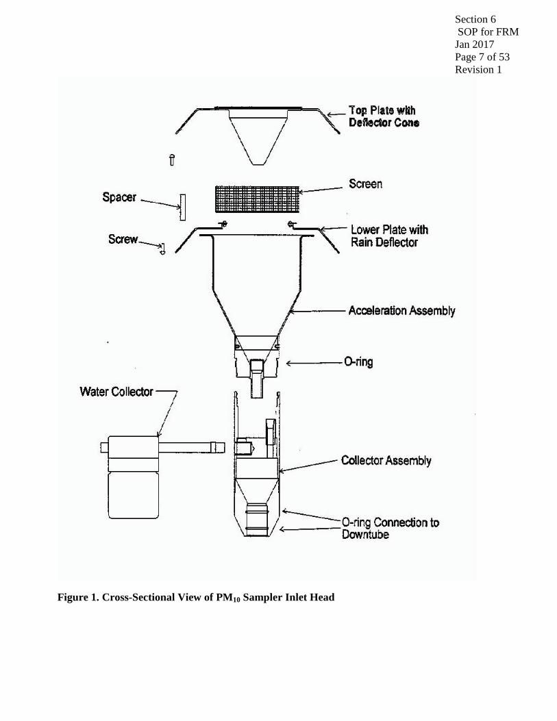
The inlet is designed to remove particles with an aerodynamic diameter of greater than 10 µm and sends particles less than 10 µm to the next filtration stage. Figure 1 is a schematic of the PM10 inlet head.
Figure 2 depicts the VSSC that removes particles greater than 2.5 µm and allows 2.5 um in diameter and smaller particles to be collected on a Teflon® filter.
The sampler uses standard 47 mm Teflon® filters housed in reusable cassettes.
The sampler has a filter exchange and storage system that simplifies transportation, minimizes contamination, and allows for up to 177 hours between site visits.

Section 6 SOP for FRM Jan 2017 Page 6 of 53 Revision 1
A record of filter data is stored for each filter used in the sampler, and includes all U.S. EPA specified values such as error condition flagging and average temperatures and pressures. Filter data records also include sampled volume and analog input data averaged over the collection period.
The sampler has a capacity to store 50 filter data records.
Interval data are stored every five minutes, and include the five-minute averages of the filter temperature, ambient temperature, ambient pressure, and flow rate.
The sampler has capacity to store 16 days of five-minute interval data.
The sampler has capacity to store 32 days of 30 minute input data.
A bi-directional RS-232 interface for data transfer to or from a PC or Palmtop device is used.
Section 6 SOP for FRM Jan 2017 Page 7 of 53 Revision 1
Figure 1. Cross-Sectional View of PM10 Sampler Inlet Head

Section 6 SOP for FRM Jan 2017 Page 8 of 53 Revision 1
Figure 2. Cross Sectional view of PM2.5 Very Sharp Cut Cyclone
6.1.2 Assembly of 2025i Sampler
6.1.2.1 Unpacking and Inspection
Inspect the packing container upon receipt of a new sampler for damage. Notify the carrier of any damage and hold for their inspection. The carrier, not Thermo Scientific, is responsible for damage incurred during transit.
6.1.2.2 Parts Inventory
Inventory the shipping container contents using the enclosed packing list as a guide. Note any missing parts and notify Thermo Scientific of the discrepancies.
6.1.2.3 Sampler Assembly
Section 6 SOP for FRM Jan 2017 Page 9 of 53 Revision 1
Use the Quick Start Guide that accompanies the sampler for assembly instructions. Each new PM2.5 Sampler will undergo a series of tests taken from the EPA questionnaire (Appendix A) of this SOP. If the answer to any question is NO, then the acceptance criteria have failed and the sampler is rejected for service with the FCEAP.
6.2 2025i Sampler Setup
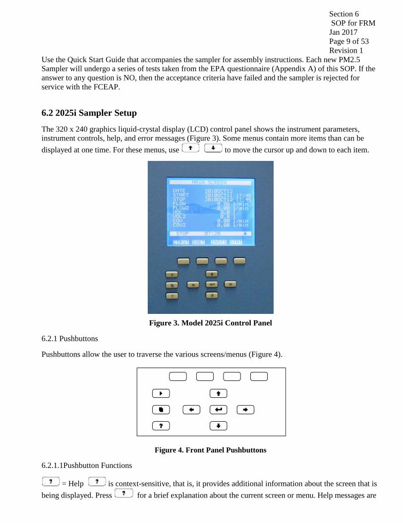
The 320 x 240 graphics liquid-crystal display (LCD) control panel shows the instrument parameters, instrument controls, help, and error messages (Figure 3). Some menus contain more items than can be displayed at one time. For these menus, use to move the cursor up and down to each item.
Figure 3. Model 2025i Control Panel
6.2.1 Pushbuttons
Pushbuttons allow the user to traverse the various screens/menus (Figure 4).
Figure 4. Front Panel Pushbuttons
6.2.1.1Pushbutton Functions
= Help is context-sensitive, that is, it provides additional information about the screen that is being displayed. Press for a brief explanation about the current screen or menu. Help messages are

Section 6 SOP for FRM Jan 2017 Page 10 of 53 Revision 1
displayed using lower case letters to easily distinguish them from the operating screens. Press to return to the Run screen, or any other key to exit a help screen.
6.2.1.2 = Up, Right, Down, Left. The four arrow pushbuttons move the cursor Up, Right, Down, Left change values and states in specific screens.
= Enter is used to select a menu item, accept/set/save a change, and/or toggle On/Off functions.
6.2.1.3 The soft keys are multi-functional keys that use part of the display to identify their function. The soft keys provide a shortcut to the most often used menus and screens. They are located directly underneath the display, and user-defined labels in the lower part of the display indicate the function of each key at that time.
6.2.1.4 To change a soft key, place the menu cursor “>” on the item of the selected menu or screen you wish to set. Press followed by the selected soft key within 1 second of pressing . The “edit soft key prompt” will be displayed for configuration of the new label.
Note: Not all menu items may be assigned to soft keys. If a particular menu or screen item cannot be assigned, the “edit soft key prompt” screen will not come up upon entering right-arrow-soft key combinations. All items under the Service menu (including the menu itself) cannot be assigned soft keys.
6.2.2 Programming a Sample Run
This section describes the procedures for programming the Sampler for a sampling run using the Basic Sampling method. This procedure describes the process for the Partisol 2025i.
6.2.2.1 Prepare a filter cassette magazine with the desired number of conditioned 47 mm filters in cassettes (including blank filter cassettes or separator disk cassettes if required). For the Partisol 2025i, a single filled filter cassette magazine will be used for sampling.
6.2.2.2 Install the prepared filter cassette magazines in the filter shuttle mechanisms on the left side of the Partisol 2025i Samplers. A clean, empty storage magazine should be installed on the right side of each filter exchange mechanism.
6.2.2.3 Use the following procedure to program the Sampler for a sampling run. Refer to the “Firmware Screen Descriptions” chapter that follows for detailed information about the screens in this procedure. Note The front panel pushbuttons shown in the following procedure are used to traverse the screens and menus.
Accessing the Main Menu – To access the Main Menu, press repeatedly until the Main Menu appears. Sample ID information can be entered in the Sample mode, but the Sampler must be in the Stop mode to enter a new sampling program. If the Sampler is in the Wait mode or Sample mode, press to enter the Stop mode. If the Sampler is in the Audit mode, press repeatedly to display the Main Menu, scroll to Audit and Calibration and press to display the Audit and Calibration menu, with the cursor at Audit mode, press to display the Audit Mode screen. In the Audit Mode screen, press
to exit Audit mode and press to confirm the change.
6.2.2.4 On the Main screen, confirm that the date and time (EST) are correct.

Section 6 SOP for FRM Jan 2017 Page 11 of 53 Revision 1
6.2.2.5 If the date or time is not correct, in the Main Menu, scroll to Instrument Setup and press scroll to Date/Time and press to display the Date and Time screen. In the Date and Time screen, press to access the Edit mode and follow the screen directions to edit the date and/or time. When the changes are complete, press to save the changes. Press to return to the Instrument Setup menu
6.2.2.6 Confirm that the Site ID is correct.
6.2.2.7 In the Main Menu, scroll to Instrument Setup and press to display the Instrument Setup menu. In the Instrument Setup menu, scroll to Site ID, press , and confirm that the Site ID is correct. If the Site ID is not correct, scroll to the incorrect Site ID, press to display the alphanumeric entry screen, enter the correct Site ID description, and save it.
Press repeatedly to return to the Main Menu. In the Main Menu with the cursor at Sample Setup, press to display the Sample Setup menu.
6.2.2.8 The Sample Setup menu allows you to choose modes such as:
“Auto Populate”, which calculates the default start time and date once sample 01 is programmed;
“Apply EPA Times”, which is a shortcut key for midnight-to midnight, 24-hour continuous sampling;
“Apply Default Times”, which automatically applies the default time settings.
6.2.2.9 To apply EPA default conditions (midnight-to-midnight, continuous, 24-hour sampling) scroll to “Apply EPA Times” in the Sample Setup menu, press to display the Apply EPA Times screen, and press to set the EPA times. To “Apply Default Times,” scroll to Apply Default Times in the Sample Setup menu, press to display the “Apply Default Times” screen, and press to set the default times. In our case we sample 1 in 3 days (every 72 hrs) and 1 in 6 days (every 144hrs).
6.2.2.10 Use the following procedure to set sample parameters manually. At Sample Setup, scroll to Sample 01, press and use the pushbuttons as indicated on the screen to set the sample start time and date for the first sample. Alternately, press again and use the pushbuttons to select a field and change the value. Note that holding the pushbutton down causes the value to increment faster. When the start time setting is complete, scroll to Save and press to save the start time and date. Press repeatedly to return to the Sample 1 menu.
6.2.2.11 At the Sample 1 menu, scroll to Stop, press , and use the pushbuttons as indicated on the screen to set the sample stop time and date. When the stop time setting is complete, scroll to Save and press to save the start time and date. Press to return to the Sample 1 menu.
At the Sample 1 menu, scroll to Filter Blank, press to display the “Filter is a Blank” screen, and press to toggle to Yes or No as appropriate. Press to return to the Sample 1 menu.

Section 6 SOP for FRM Jan 2017 Page 12 of 53 Revision 1
At the Sample 1 menu, scroll to Filter ID, and press to display the “Filter ID” screen. Use the pushbuttons as indicated on the screen to set the Filter ID number, and press to save the setting. Press to return to the Sample 1 menu.
At the Sample 1 menu, scroll to Cassette ID, and press to display the “Cassette ID” screen. Use the pushbuttons as indicated on the screen to set the Cassette ID number, and press to save the setting. Press to return to the Sample 1 menu.
At the Sample 1 menu, scroll to Filter Type, and press to display the “Filter Type” screen. Use the pushbuttons as indicated on the screen to change the Filter Type to “T”, and press to save the setting. Press to return to the Sample 1 menu.
6.2.2.12 Continue to program Sample 02-Sample 16 as appropriate. If the Sampler is in Stop mode, press to return to the Wait mode.
6.3 Site Visits
6.3.1 External Leak Check
An external leak check must be performed once a month or whenever the upper lid is opened.
For these audit procedures, prepare a set of audit magazines consisting of a supply magazine and a clean empty storage magazine. The audit supply magazines (Figure 5) should contain an open test cassette part # 36-012077, an external leak check cassette (with a 47mm filter) and a blocked test filter cassette part # 36-012078. The empty cassette should be in the topmost position as shown in Figure 5. Load the disks starting with the blocked test disk cassette, then the filter cassette, and the empty test cassette (no backing screen) last.

Section 6 SOP for FRM Jan 2017 Page 13 of 53 Revision 1
Figure 5. Loaded Audit Magazine – 2025i
6.3.1.1 Use the following procedure to perform an external leak check.
Note: To ensure leak tightness, a filter cassette containing a new 47 mm filter must be installed in the sampling position of the Sampler.
6.3.1.2 Press to go to the Audit and Calibration menu, scroll to Advance Filter, and press 2x to advance the audit filter cassette into sampling position.
6.3.1.3 Attach the flow audit adapter to the sample tube (Figure 6) and close the valve on the flow audit adapter.
Figure 6. Flow Audit Adapter with Valve in Closed Position
6.3.1.4 Scroll to “Leak Checks,” press , scroll to External, and press . The following message displays:
MAKE SURE THAT FILTER IS IN PLACE AND LEAK CHECK ADAPTER IS CLOSED!!!
Empty cassette is without backing screen Several additional external leak cassette filters can be added to the magazine for use in the event of an external leak check failure.

Section 6 SOP for FRM Jan 2017 Page 14 of 53 Revision 1
6.3.1.5 Press to begin testing.
6.3.1.6 A Pass or Fail message will display at the end of the leak check cycle. The leak check pass criterion is a pressure drop of 25 mmHg or less. If a Fail message is displayed, slowly release the adapter and advance a new audit test cassette and repeat the leak check test. Several attempts can be made with different audit test cassettes. If a Fail message is STILL displayed, slowly release the adapter and advance a blocked test cassette and repeat the leak check test.
If a leak check fail message is displayed on the screen after multiple external leak checks, while using several different external leak check filters, an internal leak check can be performed using the solid disk cassette. An internal leak checks can help to isolate the cause of the leak. Additionally, a cleaning of the sample V-seals may be necessary. If leak checks continue to fail inspect all “O” rings for faults or breaks and test pump performance. After a successful leak check, slowly open the valve on the flow audit adapter.
6.3.2 Return sample filters
6.3.2.1 Press to go to the Audit and Calibration menu, scroll to Advance Filter, and press to advance the sample filter cassette back into the sampling position. The sample filter cassette needs to be returned to its position before the leak checks were done.
6.3.2.2 Press repeatedly to display the Main Menu, scroll to Audit and Calibration and press to display the Audit and Calibration menu, with the cursor at Audit mode, press to display the
“Audit Mode” screen. In the “Audit Mode” screen, press to exit Audit mode and press to confirm the change.
6.3.2.3 Once back in the office open the PM2.5 Database (S:\PM2.5\DATABASE\PM2.5V2006) and select the Leak Check button (Figure 7). Enter in the data for the appropriate site and dates. Another leak check MUST be performed EVERY 10 sample periods, at a MINIMUM.

Section 6 SOP for FRM Jan 2017 Page 15 of 53 Revision 1
Figure 7. Leak Check Button
6.3.3 Verification Checks
NOTE: If temperature and/or pressure have to be recalibrated for any reason, the flow must also be recalibrated (see section 6.3.4)
6.3.3.1 The Sampler may be in the Stop Mode or in Audit mode to perform the verification audits. If the Sampler is in the Stop Mode proceed with the verification audit. If the Sampler is running a sample and an audit must be performed, interrupt the sample by entering the Audit mode. When the audit is completed, replace the current sample filter and resume the sample. Enter the Audit mode by pressing , scrolling to Audit and Calibration, and pressing to display the Audit and Calibration menu. With the cursor at Audit Mode, press to display the Audit Mode screen, press to enter the Audit mode, and press
to confirm the setting.

Section 6 SOP for FRM Jan 2017 Page 16 of 53 Revision 1
6.3.3.1.1 Press to return to the Audit and Calibration menu.
6.3.3.1.2 Remove the currently installed storage magazine(s) from the right side of the Sampler and cover with an orange storage cap. Label the magazine(s) orange storage cap with instrument designation(s).
6.3.3.1.3 Remove supply magazine from the left side of the filter shuttle mechanism and install on storage side.
6.3.3.1.4 Install the audit magazine on the supply side. Ensure that the pressure supply line is connected at the bottom of the magazine.
6.3.3.1.5 At the Audit and Calibration menu, scroll to Advance Filter, and press to advance the filter. This will transfer the current sampling filter to the respective supply magazine temporarily placed in the right side of the filter shuttle mechanism.
6.3.3.1.6 Remove the supply magazine(s) from the right side of the Sampler, cover with an orange storage cap to prevent contamination of the partially exposed filters, and set aside.
6.3.3.1.7 Use Verification form found: S:\A&M\PM2.5\Verif&CalSheet.xls to print out sheet and take to field. Refer to Figure 9 for the Verification and Calibration Spreadsheet page.
6.3.3.2 Ambient Air Temperature
Figure 8: Ambient Temperature Sensor
6.3.3.2.1 Determine the current temperature (°C) at the ambient temperature sensor using an external thermometer [°C = 5/9 x (°F - 32)]. Insert probe into the external radiation shield (see Figure 8).
Write the Ambient Temperature on Verification sheet (see Figure 9).
Place sampling proble

Section 6 SOP for FRM Jan 2017 Page 17 of 53 Revision 1
Figure 9: Verification Worksheet
6.3.3.2.2 Verify that the value of Ambient Temp displayed in the Audit screen is within ±2 °C of the measured temperature. If the value is not within the limits, a calibration needs to be performed on the ambient temperature sensor (see Section 6.3.4.2) as soon as possible and inform the program manager. . All verification checks are noted in the site logbook and PM 2.5 database.
6.3.3.3 Filter Temperature
6.3.3.3.1 Perform leak check PRIOR to Filter Temperature check (see Section 6.3.1). Remove the PM-10 inlet from the sample tube by pulling straight up on the sample tube. Unlatch and open the Sampler’s hood. Pull straight up to remove the VSCC (Figure 10).

Section 6 SOP for FRM Jan 2017 Page 18 of 53 Revision 1
Figure 10: Removing the Very Sharp Cut Cyclone
6.3.3.3.2 Verify the Sampler filter temperature by inserting an external thermometer into the sampling chamber (see Figure 11). Do not let the external probe contact anything within the sampling chamber.
Note: The empty cassette (without a filter installed) should be in sampling position.
Figure 11: 2025i – Inserting an External Temperature Probe into the Sampling Chamber
6.3.3.3.3 Write the Filter Temperature on Verification sheet (see Figure 9). All verification checks are noted in the site logbook and PM 2.5 database.
6.3.3.3.4 Compare the measured temperature (°C) with the Filter Temp displayed in the Audit screen. If the measured and Filter Temp readings are not within ± 2 °C [°C = 5/9 x (°F - 32)] perform the filter temperature calibration procedure (see Section 6.3.4.3) and inform the program manager.
6.3.3.3.5 Re-install the VSCC and perform an external leak check (Section 6.3.1). Close the hood and latch.
6.3.3.4 Ambient Pressure
6.3.3.4.1 Determine the current ambient station pressure, using the Streamline Pro in mm Hg (absolute pressure, not corrected to sea level). Verify the Sampler’s ambient pressure by measuring the current ambient station pressure in mm Hg with an external measurement device.
Section 6 SOP for FRM Jan 2017 Page 19 of 53 Revision 1
6.3.3.4.2 Use the following conversion factors if needed:
To convert from Atmospheres @ 0 °C to mmHg, multiply by 760.
To convert from millibars to mmHg, multiply by 0.75012.
To convert from inches Hg @ 32 °F to mmHg, multiply by 25.4.
6.3.3.4.3 Write Ambient Pressure on Verification sheet (see Figure 9).
6.3.3.4.4 Verify that the value for Ambient Pres in the Audit screen is within ±10 mm Hg of the measured ambient pressure. If the value is not within the limits, a calibration must be performed as soon as possible (see Section 6.3.4.3) and inform the program manager. All verification checks are noted in the site logbook and PM 2.5 database.
6.3.3.5 Flow Verification
6.3.3.5.1 Perform the leak check, all temperature verifications, and pressure verification, before performing the flow verification procedure.
Note: Ensure that the filter cassette carrier previously installed in the Sampler (which was used to perform the external leak check) remains in the unit for the flow verification.
6.3.3.5.2 The proper values for the Streamline Pro constants can be entered into the Sampler for proper calculation of the measured flow values. Use the following procedure to perform a flow audit on the Partisol 2025i:
6.3.3.5.3 Remove the flow audit adapter used during the leak check and install the Streamline Pro on the sample tube.
6.3.3.5.4 Press repeatedly to display the Main Menu. Scroll to Audit and Calibration, press , scroll to Audit, press , scroll to Flow, press to turn on the flow, and wait for the flow to stabilize (minimum of 5 minutes). The default sample flow should be 16.7 L/min, unless it was changed in the default settings of the Sampler. Record the flow rate from the Pro and the Sampler.
6.3.3.5.5 Write Flow Check Values on Verification sheet (see Figure 9).
6.3.3.5.6 Press to turn Off the flow. The measured flow should be within ±4% of the displayed Cur Flow. If this is not the case, perform the flow calibration procedure and inform the program manager.
6.3.3.6 Maintenance/Return to Sample/Wait mode Procedures
6.3.3.6.1 The FCEAP PM 2.5 Maintenance Schedule Form (see Figure 12), found in the S:\A&M\PM2.5\Verif&Calsheet.xls spreadsheet is both a guide and a log of the maintenance 30, 60, 90 days work to be performed on a sampler. A copy of this form will be signed by the technician performing the preventive maintenance. Any other maintenance performed should also be noted on the form.

Section 6 SOP for FRM Jan 2017 Page 20 of 53 Revision 1
Figure 12: Maintenance Schedule Form
6.3.3.6.2 Return to Sample/Wait Mode
6.3.3.6.3 Install the previous supply magazine on the left side.
6.3.3.6.4 Press repeatedly to return to the Audit and Calibration menu, scroll to Advance Filter, and press to put the original sample filter back into the sampling position and to collect the audit filters.
6.3.3.6.5 Put a fresh storage magazine on or put the original storage magazine with exposed filters back on the right side.
6.3.3.6.6 Reinstall the PM10 inlet on the sample tube.
6.3.3.6.7 Press to restart the Sampler and continue the current sampling program.
6.3.4 Calibration
6.3.4.1 This section contains the procedures needed to perform calibrations on the Sampler. Calibrations should be performed when the instrument is in Service mode. Thermo strongly advises that the calibrations described in this section be performed in the order presented. Refer to the “Firmware Screen Descriptions” chapter for detailed information about the screens and parameters in these calibration procedures.
For these Calibration procedures, prepare a set of audit magazines consisting of a supply magazine and a clean empty storage magazine. Audit magazine requirements are described in detail in Section 6.3.1.
Section 6 SOP for FRM Jan 2017 Page 21 of 53 Revision 1
6.3.4.1.1 Press repeatedly to display the Main Menu, scroll to Service mode and press . In the Service Mode screen, press to toggle the Service mode to On. Press to return to the Main Menu.
6.3.4.1.2 Display the Audit and Calibration Menu by pressing , scrolling to Audit and Calibration, and pressing to display the Audit and Calibration menu.
6.3.4.1.3 Remove the currently installed storage magazine(s) from the right side of the Sampler and cover with an orange storage cap. Remove supply magazine(s) from the left side of the filter shuttle mechanism and install on storage side.
6.3.4.1.4 Install the audit magazine(s) on the supply side. Ensure that the pressure supply line is connected at the bottom of the magazine.
6.3.4.1.5 At the Audit and Calibration menu, scroll to Advance Filter, and press to advance the filter. This will transfer the current sampling filters to the respective supply magazine temporarily placed in the right side of the filter shuttle mechanism.
6.3.4.1.6 Remove the supply magazine(s) from the right side of the Sampler, cover with an orange storage cap to prevent contamination of the partially exposed filters, and set aside. Install the clean storage filter magazines on the right side of the Sampler.
6.3.4.1.7 Enter the Calibration menu by pressing , scrolling to Audit and Calibration, and pressing , to display the Audit and Calibration menu. With the cursor at Calibration, press , to display
the Calibration menu.
6.3.4.2 Ambient Air Temperature Calibration
6.3.4.2.1 Use the following procedure to calibrate the ambient air temperature.
Note: The Service mode must be set to ON to perform the following procedure. To turn the Service mode ON refer to Section 6.3.4.1.1 above.
6.3.4.2.2 The calibration will be done at ambient conditions, so, the reference temperature measurement taken by a Streamline Pro (not the same Streamline Pro kit used for verification checks) can be taken with the probe installed in the radiation sensor. FCEAP does a 1-pt check.
6.3.4.2.3 In the Calibration menu, scroll to Ambient Temp and press . At the Ambient Temperature Calibration screen, use the pushbuttons to enter the reference value in °C [°C = 5/9 x (°F - 32)], and press
to save the value. The Sampler automatically adjusts the corresponding offset based on this input.
6.3.4.2.4 Write the Ambient Temperature on the Calibration Sheet (see Figure 13).

Section 6 SOP for FRM Jan 2017 Page 22 of 53 Revision 1
Figure 13: Calibration Worksheet
6.3.4.3 Filter Temperature Calibration.
6.3.4.3.1 Perform leak check PRIOR to Filter Temperature check (see Section 6.3.1). Remove the PM-10 inlet from the sample tube by pulling straight up on the sample tube. Unlatch and open the Sampler’s hood. Pull straight up to remove the VSCC (Figure 10). Verify the Sampler filter temperature by inserting an the external thermometer of the Streamline Pro (not the same Streamline Pro kit used for verification checks) into the sampling chamber as shown in Figure 11. Do not let the external probe contact anything within the sampling chamber.
Note: The empty cassette (without a filter installed) should be in sampling position.
6.3.4.3.2 Press to return to the Calibration menu, scroll to Filter Temp and press
6.3.4.3.3 At the Filter Temp Calibration screen, use the pushbuttons to enter the reference value in °C [°C = 5/9 x (°F - 32)], and press to save the value. The Sampler automatically adjusts the corresponding offset based on this input.
6.3.4.3.4 Write the Filter Temperature on the Verification and Calibration Sheet (See Figure 13)
6.3.4.3 Ambient Pressure Calibration
6.3.4.3.1 Use the following procedure to perform an ambient pressure calibration. Press to return to the Calibration menu, scroll to Ambient Pres and press .
6.3.4.3.2 Determine the current ambient station pressure in mmHg (absolute pressure, not corrected to sea level) using a NIST calibrated Streamline Pro (not the same Streamline Pro kit used for verification checks).
Section 6 SOP for FRM Jan 2017 Page 23 of 53 Revision 1
6.3.4.3.3 Use the following conversion factors if needed:
To convert from Atmospheres @ 0 °C to mmHg, multiply by 760.
To convert from millibars to mmHg, multiply by 0.75012.
To convert from inches Hg @ 32 °F to mmHg, multiply by 25.4.
6.3.4.3.4 Enter the measured ambient pressure and press . Write the Ambient Pressure on the Calibration Worksheet (see Figure 13). The Sampler automatically adjusts the corresponding offset based on this input.
6.3.4.4 Flow Calibration
6.3.4.4.1 An external leak check must be performed BEFORE FLOW CALIBRATION. The Partisol 2025i contains a single flow sensor, operating at a default flow rate of 16.7 L/min. The calibration of the flow controllers in the Partisol 2025i can be performed using a three-point calibration using the Streamline Pro Transfer Standard.
6.3.4.4.2 Prior to performing a Flow Calibration, perform the temperature and pressure calibrations, and external leak test procedures described in this chapter. The filter cassette used to perform the leak test should remain in the sample position for the flow calibration.
6.3.4.4.3 Remove the inlet from the external sample tube of the Partisol 2025i. Attach the Streamline Pro (not the same Streamline Pro kit used for verification checks) to the sample tube.
6.3.4.4.4 Press repeatedly to return to the Main Menu. Scroll to Audit and Calibration and press to display the Audit and Calibration menu. Scroll to Calibration and press to display the
Calibration menu. Scroll to Flow and press to display the Calibration Flow menu.
6.3.4.4.5 Default calibration setpoints are already entered into the sampler. Thermo recommends that these setpoints be used as they are configured for 10% above and below the usual setpoint. For the Partisol 2025i Sampler, the following values are recommended for a three-point calibration of the 16.7 L/min flow rate setpoint:
Setpoint 1 (Min Flow): 15.0 L/min (10% below the usual 16.7 L/min set point)
Setpoint 2: The usual 16.7 L/min setpoint. Setpoint 3 (Max Flow): 18.4 L/min (10% above the usual 16.7 L/min set point)
6.3.4.4.6 Scroll to Setpoint 1 and press to display the Setpoint 1 screen. The Sampler will automatically open the proper valves and start the pump. After 5 minutes, the flow will stabilize to the desired setpoint.
6.3.4.4.7 Enter the actual flow rate measured by the Streamline Pro.
6.3.4.4.8 Repeat 6.3.4.4.6 and 6.3.4.4.7 for the remaining flow setpoints. The sampler will automatically calculate the Slope and Intercept when the calibration is complete.
6.3.4.4.9 Write the Flow Calibration values on the Calibration Sheet (see Figure 13).
Section 6 SOP for FRM Jan 2017 Page 24 of 53 Revision 1
6.3.4.4.10 Restore the sampling hardware to its original state by removing the Streamline Pro from the sample tube and reinstalling the inlet.
Note: It is not necessary to remove the filter cassette used for the leak check and flow calibration from the sampling position, since the Sampler automatically replaces this cassette with a new one upon entering the Sample Operating mode.
6.3.4.5 Maintenance/Return to Sample/Wait mode Procedures (Refer to 6.3.3.6)
6.4 Pre/Post Sampling Filter Procedures
PM2.5 Database: The PM2.5 Database (S:\PM2.5\DATABASE\PM2.5V2006), referred in this document, was created in Microsoft Access and is used as a tool to streamline the numerous aspects of the PM2.5 program. Similar to a digital logbook, the database is used to store information from when a filter arrives from the Lab, is taken to the site for sampling, and shipped back to the Lab post sampling. ALL filter information (pre and post) from the beginning of the PM2.5 network (January 1, 1999) to the current date is stored in the database. Additionally, ALL comments and leak checks performed on the FRMs are input into the database. The database is also used to aid the process of creating AQS files for each filter post sampling. The operator needs to understand how to use and work with the PM2.5 database so that a proper, complete, record is stored for each filter.
Hattie Avenue 3 day (HA3): Every three days based on US EPA’s 3 day sampling schedule, Duration: 24hrs, midnight to midnight (standard time)
Hattie Avenue 6 day (HA6): Every six days based on US EPA’s 6 day sampling schedule, Duration: 24hrs, midnight to midnight (standard time)
6.4.1 Receive Filter from Lab
6.4.1.1 Retrieve cooler from mail area. 6.4.1.2 Open cooler and retrieve the filters stored in the cassette magazine(s) and filter list provide by the Lab.
6.4.1.3 Open Excel spreadsheet S:\PM2.5\FilterCheckIn.xls (see Figure 14). Go to “SetUp” tab and enter the first filter number at the top of the highlighted column. Simply fill in the column with the remaining filter numbers.

Section 6 SOP for FRM Jan 2017 Page 25 of 53 Revision 1
Figure 14: FilterCheckIn Worksheet (Setup tab)
6.4.1.4 Go to the “FilterIDSheet” tab (see Figure 15). This sheet is in the format to import into the PM2.5 Access database. Determine and fill in the “strSiteName,” “datePlannedRunDate,” “dateDateCheckedIn,” “dateInitialWeighDate,”dateDateofSetup,” “dateTimeofSetup,” “strOperator,” and “strComments” FOR EACH FILTER
FilterIDSheet = Filter ID
strSiteName = Site name
datePlannedRunDate = Planned sample date
dateDateCheckedIn = Date filters added to database
dateInitialWeightDate = Date filters initially weighed by Lab
dateDateofSetup = Date filters taken to site
dateTimeofSetup = Time of day filters taken to site
strOperator = Operator
strComments = Comments (if any)

Section 6 SOP for FRM Jan 2017 Page 26 of 53 Revision 1
Figure 15: FilterCheckIn Worksheet (FilterIDSheet tab)
Note: For each batch of filters, use one as a BLANK for each site.
6.4.1.5 Save file.
6.4.1.6 Open Access (S:\PM2.5\DATABASE\PM2.5V2006) Press the “Import New Filters” button (see Figure 16). Press the “Filter Report” button (see Figure 17).

Section 6 SOP for FRM Jan 2017 Page 27 of 53 Revision 1
Figure 16: Import New Filters Button
Figure 17: Filter Report Button

Section 6 SOP for FRM Jan 2017 Page 28 of 53 Revision 1
6.4.1.7 Review for errors and fix as needed and print for field use.
6.4.1.8 Separate filters for each monitor based on the sampling schedule. For example, the 1 in 3 sampler (HA3) will receive double the amount of filters than the 1 in 6 sampler (HA6).
6.4.2 Loading Pre Sampled Filters
6.4.2.1 Bring printed Setup/Pickup Report from Access (S:\PM2.5\DATABASE\PM2.5V2006) for HA3, HA6 (see Figure 18) and unsampled filters. Open sampler.
Figure 18: Setup/Pickup Form
6.4.2.1.1 Load filters into the LEFT magazine holder. Any filters already in the magazine will have to remain on top of the newer filters. The following sites run on the schedule listed below:
Hattie Avenue 3 day sampler: HA3
Hattie Avenue 6 day sampler: HA6
6.4.2.1.2 Program sampler with Filter IDs and any BLANK(S) using the following procedures taken from the Partisol 2025i Sequential Air Sampler/Partisol 2025i-D Dichotomous Sequential Air Sampler Instruction Manual (15Jul2014), Thermo Fisher Scientific Co., Inc. Part Number 110100-00.
6.4.2.2 Program Sampler for New Filters
Refer to Section 6.2.2

Section 6 SOP for FRM Jan 2017 Page 29 of 53 Revision 1
6.4.2.2.1 In the Main Menu, choose Sample Setup > Apply EPA Times. The Apply EPA Times screen is used to automatically apply midnight-to-midnight, 24-hour continuous sampling EPA times.
For BOTH Hattie Avenue instruments (3 day AND 6 day sampling) In the Main Menu, choose Sample Setup > Apply Default Times
Hattie Avenue 3 day sampler: 72hrs for 3 day
Hattie Avenue 6 day sampler: 144 for 6 day
Filter ID is used to enter the filter’s serial number. This field displays the Filter ID numbers for the filters that are in sampling positions 1-16. Enter the Filter ID number(s) from the Setup/Pickup Form (see Figure 18)
6.4.2.2.2 Cassette ID is used to enter the filter cassette screen serial number. Cassette ID numbers are entered, incremented and edited in the manner described above for Filter ID numbers. Currently, the Cassette IDs are RP000000 for ALL samples
6.4.2.2.3 FCEAP sets aside one field blank per sampler per filter batch. Ideally, filter blanks should occur on the same sampling day at all samplers in the network. In the Main Menu, choose Sample Setup > Sample > Filter Blank.
This parameter is either Yes or No and it defines whether the filter numbers are intended to be used as sampling filters or blank filters. If you set this parameter to Yes, the first filter in each supply magazine will be a blank filter and the next filters advanced by the Sampler will be the sampling filters.
Please refer to Partisol 2025i Sequential Air Sampler/Partisol 2025i-D Dichotomous Sequential Air Sampler Instruction Manual (15Jul2014), Thermo Fisher Scientific Co., Inc. Part Number 110100-00.
6.4.3 Picking Up Sampled Filters and Retrieving Data
6.4.3.1 Preparation for Field Work
Sampled filters MUST be picked up <=7days 9 hours from sample end date, per CFR (QA Handbook Volume II Appendix D, Revision No. 0, Date: 05/13, pg 24). Equipment to bring: Flash drive, cassette magazine, and cooler with several ice packs.
6.4.3.1.1 Prepare the flash drive for downloading in the field. Place the flash drive in the USB port.
6.4.3.1.2 Open Access (S:\PM2.5\DATABASE\PM2.5V2006)
6.4.3.1.3 On the database screen hit "1. Prepare Disk" (see Figure 19). The disk has two directories: HA3 and HA6. Within each directory are filter, input and interval file names. Press “OK” when “PM2.5 Disk Ready” window pops up.
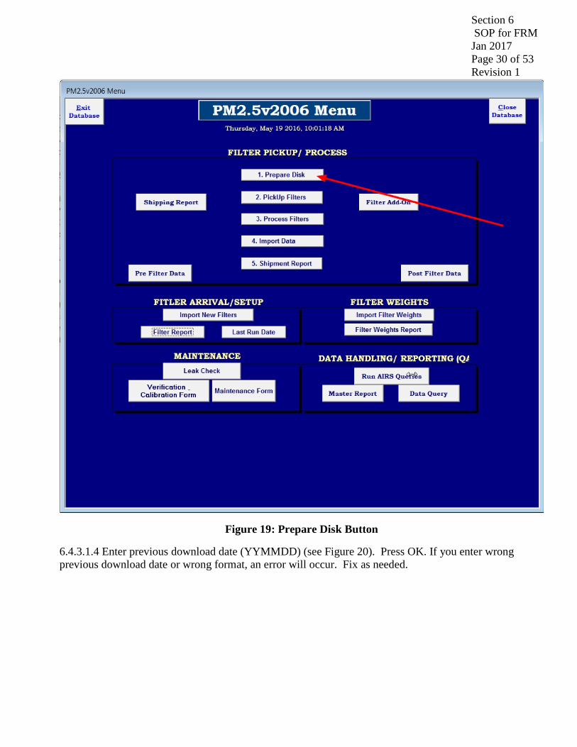
Section 6 SOP for FRM Jan 2017 Page 30 of 53 Revision 1
Figure 19: Prepare Disk Button
6.4.3.1.4 Enter previous download date (YYMMDD) (see Figure 20). Press OK. If you enter wrong previous download date or wrong format, an error will occur. Fix as needed.

Section 6 SOP for FRM Jan 2017 Page 31 of 53 Revision 1
Figure 20: Previous Download Date Input
6.4.3.1.5 On the database screen hit "2. PickUp Filters" (see Figure 21). “Filter Shipment and Pickup” form will open (see Figure 22).
6.4.3.1.6 Fill in HIGHLIGHTED CELLS ONLY for each filter being picked up.
“Filter Collection Date” mm/dd/yyyy
“Filter Collection Time” hh:mm The time entered is an estimate of the actual time the filters are picked up from the site. This estimate used is 20 m later than departure time from the office, which accounts for travel time to the site. Edits WILL be made if actual collection times vary from the estimate by more than 2 minutes by using the Pre Filter Data button.
“Date Shipped Back” mm/dd/yyyy
6.4.3.1.7 Hit “Enter Data” button OR hit . Remove flash drive and take to field.
6.4.3.2 Picking Up Sampled Filters

Section 6 SOP for FRM Jan 2017 Page 32 of 53 Revision 1
6.4.3.2.1 Open the PM2.5 sampler. Remove the cassette magazine from the RIGHT (sampled) side, place on cap and store in cooler with frozen ice packs. Replace with an empty supply magazine.
Figure 21: Pickup Filters Button

Section 6 SOP for FRM Jan 2017 Page 33 of 53 Revision 1
Figure 22: Filter Shipment & Pickup Form
6.4.3.2.2 Downloading Sampled Filter Data by opening the RPComm software on the site computer which can be found on the Desktop.
6.4.3.2.3 Press the Telephone Icon within the program to connect to PM2.5 Sampler. The icon is the sixth one counting from left to right. Note: placing the cursor over the icon will give a description of the action associated with the icon. (See Figures 23 & 24)
6.4.3.2.4 Filter, Interval and Input data will all be downloaded. Once connected press “Download selected data from storage pointer” (see Figures 23 & 24).

Section 6 SOP for FRM Jan 2017 Page 34 of 53 Revision 1
Figure 23: RPComm Downloading Data Interface
Figure 24: RPComm Icons
6.4.3.2.5 Insert PM2.5 flash drive in an open USB port on the site computer. After downloading press the Disk Icon (Figure 23 & 24) to save the data. Save the data to the PM2.5 flash drive for the appropriate instrument and location (HA3 & HA6).
6.4.3.2.6 Three files need to be saved, Filter, Interval, and Input. The first file saved is Filter data. Save in the appropriate directory(HA3 & HA6).
Format eg for HA3 on September 1, 2016: 160901FILTER-HA3
Interval data Format eg for HA3 on September 1, 2016: 160901INTERVAL-HA3
Input data Format eg for HA3 on September 1, 2016: 160901INPUT-HA3

Section 6 SOP for FRM Jan 2017 Page 35 of 53 Revision 1
6.4.4 Process Sampled Filter Data
6.4.4.1 Insert the PM2.5 flash drive in an open USB port on your computer and open Access (S:\PM2.5\DATABASE\PM2.5V2006) Click “3. Process Filters” (see Figure 25). This opens up an Excel Macro Macro05v4.xls (make sure to “enable macros” if prompted) (see Figure 26).
Figure 25: Process Filters Button

Section 6 SOP for FRM Jan 2017 Page 36 of 53 Revision 1
Figure 26: Macro05v4.xls
6.4.4.2 Select the appropriate button corresponding to the site(s) visited. Input the download date (yymmdd) and wait for the program to process the data.
6.4.4.3Exit Excel and return to the PM2.5V2006 database and Press “4. Import Data” button (see Figure 27). Select the site(s) visited and date (mm/dd/yyyy) then press “Begin Import”.
Figure 27: Process Filters Button

Section 6 SOP for FRM Jan 2017 Page 37 of 53 Revision 1
6.4.4.4 The uploaded data can be found under the “Post Filter Data” button. Note: The database WILL NOT IMPORT data with the same filter IDs.
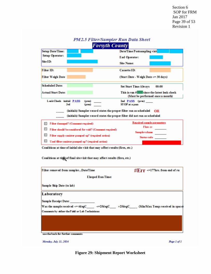
6.4.4.5 Press “5. Shipment Report” (see Figure 28). A Shipment Report MUST be printed out for EACH filter being shipped.
Figure 28: Shipment Report Button
6.4.4.6 Match each filter ID to the appropriate Shipment Report sheet. Review the sheet for any run errors, etc (see Figure 29). Notes from the operator concerning filter condition or sampling issues should appear on the sheet as well. Initial “Sampler record states the proper filter ran as scheduled” OR “Sampler record states the proper filter did not run as scheduled”.
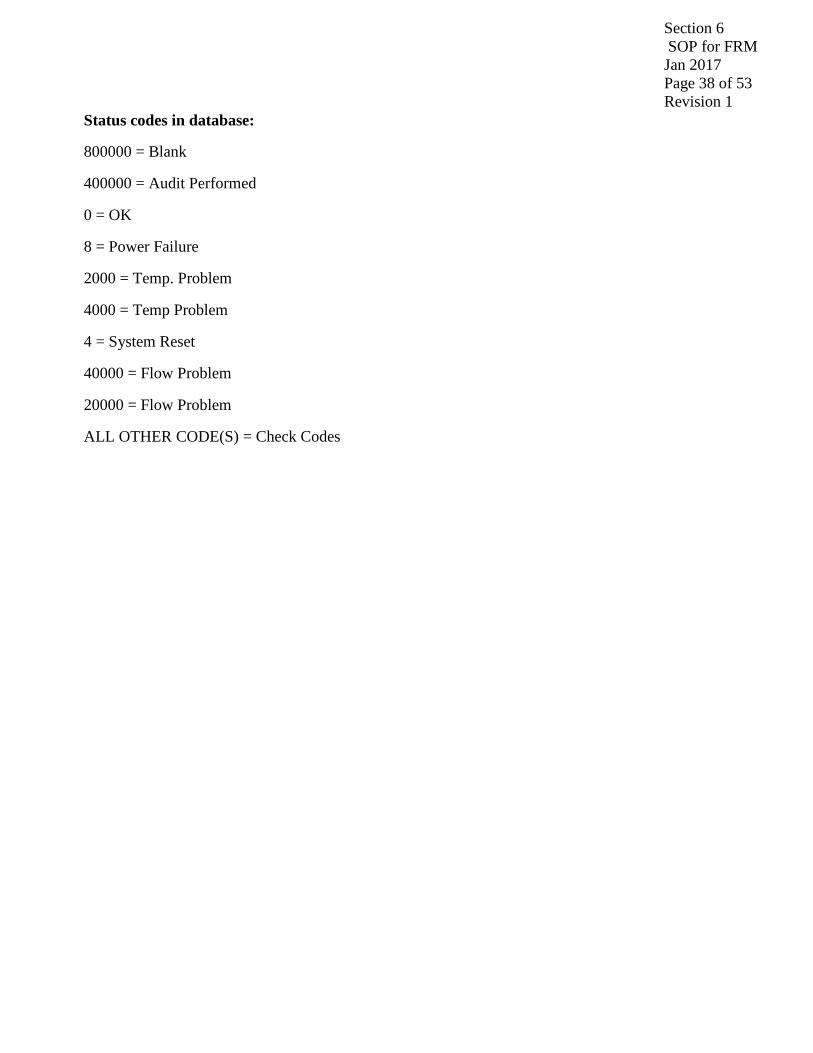
6.4.4.7 Status codes are often generated by the sampler during a sample run indicating various validity “flags” and/or codes which invalidate a sample. Several of these codes, which are listed below, are programmed in the database and will be listed under the “Status Codes” section of the “PM2.5 Filter/Sampler Run Data Sheet.” Status codes NOT programmed into the database will produce “Check Codes” listing. ALL status codes and “Check Codes” listings are a GUIDE ONLY for the operator. The operator is ultimately responsible for determining if a sample is Valid or Invalid with the aid of the status codes and “Check Codes” listing.
Section 6 SOP for FRM Jan 2017 Page 38 of 53 Revision 1
Status codes in database:
800000 = Blank
400000 = Audit Performed
0 = OK
8 = Power Failure
2000 = Temp. Problem
4000 = Temp Problem
4 = System Reset
40000 = Flow Problem
20000 = Flow Problem
ALL OTHER CODE(S) = Check Codes
Section 6 SOP for FRM Jan 2017 Page 39 of 53 Revision 1
Figure 29: Shipment Report Worksheet
Section 6 SOP for FRM Jan 2017 Page 40 of 53 Revision 1
6.4.4.8 Put the filters back into the cassette magazine and metal container for shipping. If the filters are NOT going to be shipped back, then store the filters in the lab refrigerator along with the paperwork. The sampled filters MUST be shipped back to the Lab within 48 hours of collection to avoid any hold time problems.
6.4.5 Shipping Sampled Filters to State
6.4.5.1 Note: Sampled filters MUST be ready to go by 12:30pm on the shipping day.
6.4.5.2 Obtain a cooler from laboratory refrigerator and place the metal shipping container with filter cassette inside. Place digital thermometer (stored in refrigerator), reset, and quickly place into the cooler. Place ice packs around the metal shipping container then two more on top (~5 ice packs in all). Fold the SIGNED Shipment Report(s) (see Figure 29) and lay on TOP. Close the lid and seal with duct tape.
6.4.5.3 MAKE SURE to check the address card on top of the cooler so that it is showing the address for the lab, NOT Forsyth County.
6.4.5.4 Place the cooler in the shipment area and turn over sign found in the front office area to “Package to be Picked Up”. IF the mail has been picked up for the day, take cooler to mailroom located in the basement of the Forsyth County Government Center.
6.5 Analyzing the PM2.5 Data
6.5.1 Filter Weights Review
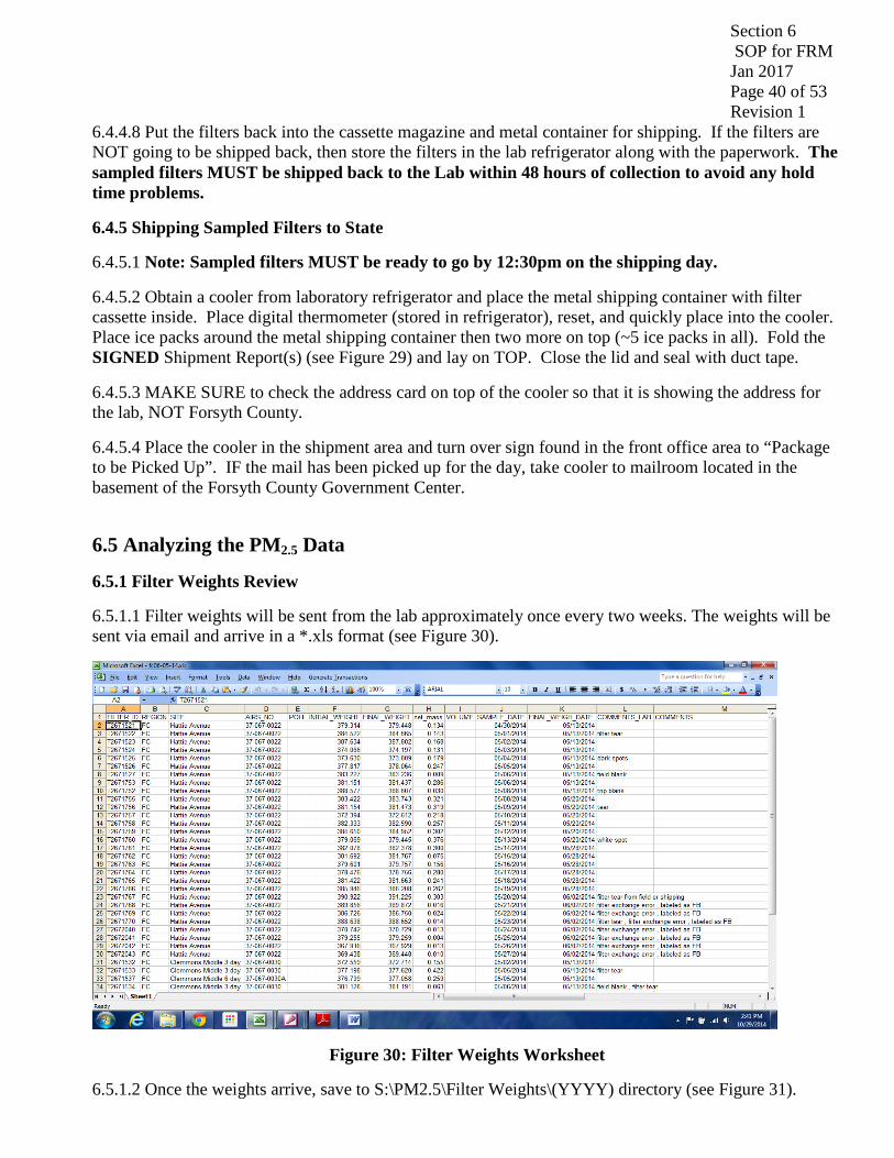
6.5.1.1 Filter weights will be sent from the lab approximately once every two weeks. The weights will be sent via email and arrive in a *.xls format (see Figure 30).
Figure 30: Filter Weights Worksheet
6.5.1.2 Once the weights arrive, save to S:\PM2.5\Filter Weights\(YYYY) directory (see Figure 31).

Section 6 SOP for FRM Jan 2017 Page 41 of 53 Revision 1
Figure 31: Filter Weights Directory
6.5.1.3 Open the attachment in MS Excel. S:\PM2.5\Filter Weights\(YYYY)\filterdata_00.xls. Sort the records by Sample Date. To prepare the new filter weight data for inclusion in the database, first delete the header line. Then, save the file as a *.txt file (Tab delimited). Remember the file name!
6.5.1.4 Open Access (S:\PM2.5\DATABASE\PM2.5V2006) and press “Import Filter Weights” (see Figure 32).
Figure 32: Import Filters Weights Button
Section 6 SOP for FRM Jan 2017 Page 42 of 53 Revision 1
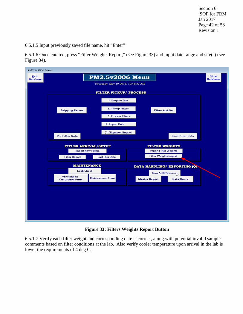
6.5.1.5 Input previously saved file name, hit “Enter”
6.5.1.6 Once entered, press “Filter Weights Report,” (see Figure 33) and input date range and site(s) (see Figure 34).
Figure 33: Filters Weights Report Button
6.5.1.7 Verify each filter weight and corresponding date is correct, along with potential invalid sample comments based on filter conditions at the lab. Also verify cooler temperature upon arrival in the lab is lower the requirements of 4 deg C.

Section 6 SOP for FRM Jan 2017 Page 43 of 53 Revision 1
Figure 34: Filters Weight Input
6.6 Data Processing/AQS Data Generator
6.6.1 PM2.5 Database Quarterly Filter Analysis
6.6.1.1 Open Access (S:\PM2.5\DATABASE\PM2.5V2006). Go to the “Data Handling/Reporting(QA) box Press the “Master Report” button. (see Figure 35)

Section 6 SOP for FRM Jan 2017 Page 44 of 53 Revision 1
Figure 35: Master Report Button
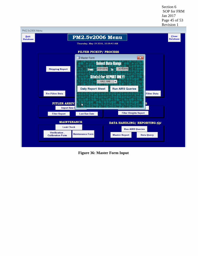
6.6.1.2 Choose the date range (usually 3 month quarter).
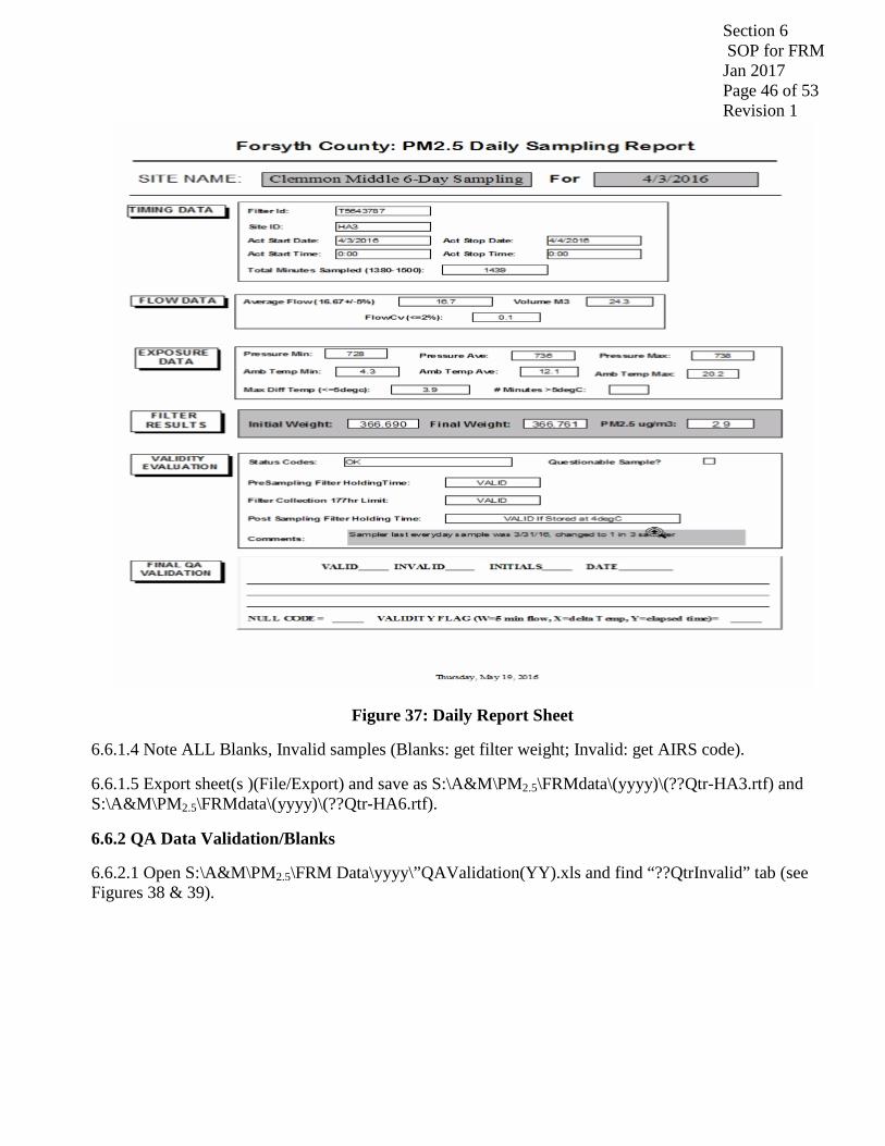
6.6.1.3 Select the preferred site(s) (HA3 & HA6) (see Figure 36). Press the “Daily Report Sheet” button and review each sheet (see Figure 37). Confirm all parameters, especially “total sample time,” “total volume,” “CV%,” “total flow rate,” and “comments” are listed and within the parameters listed on the “Daily Report Sheet.” Verify filter weight cell is populated. If ALL the parameters are within the specified range and the filter weight is there, then the sample is considered VALID, otherwise, the sample is INVALID. The filter weight for ALL INVALID samples can not be used. In addition, ALL INVALID samples MUST have comment specifying the problem(s) leading to the INVALID sample.
Section 6 SOP for FRM Jan 2017 Page 45 of 53 Revision 1
Figure 36: Master Form Input
Section 6 SOP for FRM Jan 2017 Page 46 of 53 Revision 1
Figure 37: Daily Report Sheet
6.6.1.4 Note ALL Blanks, Invalid samples (Blanks: get filter weight; Invalid: get AIRS code).
6.6.1.5 Export sheet(s )(File/Export) and save as S:\A&M\PM2.5\FRMdata\(yyyy)\(??Qtr-HA3.rtf) and S:\A&M\PM2.5\FRMdata\(yyyy)\(??Qtr-HA6.rtf).
6.6.2 QA Data Validation/Blanks
6.6.2.1 Open S:\A&M\PM2.5\FRM Data\yyyy\”QAValidation(YY).xls and find “??QtrInvalid” tab (see Figures 38 & 39).

Section 6 SOP for FRM Jan 2017 Page 47 of 53 Revision 1
Figure 38: Data Validation Worksheet
Figure 39: Blank Worksheet
6.6.2.2 Input date and AIRS code for ALL bad filters for HA3 and HA6. Save spreadsheet
6.6.2.3 Find “??QtrBlank” tab and input date and weight(ug) for ALL blanks for HA3 and HA6. Save spreadsheet. Review blank data and verify it satisfies the acceptance criteria for field blanks, which is +/- 30 micrograms. If not, please review previous field blank results and inspect instrument for problems.

Section 6 SOP for FRM Jan 2017 Page 48 of 53 Revision 1
Check for issues related to the transporting, holding, transferring, and collecting of the filters. Report all information to the Program Manager.
6.6.3 Prepare PM2.5 AQS Report
6.6.3.1 Open Access (S:\PM2.5\DATABASE\PM2.5V2006) Press “Run AQS Query” (see Figure 40).
Figure 40: Run AQS Queries Button
6.6.3.2 Ten AQS data files are created.
88101.txt ,68101.txt,68102.txt,68103.txt,68104.txt,68105.txt,68106.txt,68107.txt,68108.txt,68109.txt
6.6.3.3 Go to S:\A&M\PM2.5\AIRSData\ToBeProcessed and open AQSDataMacro.xls. Press “ctrl-r” so the editing macro can run. (see Figure 41).

Section 6 SOP for FRM Jan 2017 Page 49 of 53 Revision 1
Figure 41: AQSDataMacro
6.6.3.4 Files written to S:\A&M\PM2.5\AIRSData\Processed. Edit EACH AIRS data file using Notepad (see Figure 42). Start with 88101.txt, which is the filter weight data. Follow formatting example below:
Figure 42: 88101.txt

Section 6 SOP for FRM Jan 2017 Page 50 of 53 Revision 1
HA3 “Good” filter on March 24, 2016 with a weight of 11.7 ug/m3
RD|I|37|067|0022|88101|1|7|105|118|20160324|00:00|11.7|||||||||||||
HA1 “Bad filter with “AN” AQS code (change AQS code as needed) on March 25, 2016
RD|I|37|067|0022|88101|1|7|105|118|20160325|00:00||AN||||||||||||
HA1 Blank filter (put in appropriate weight…eg. 0.016 ug) on March 26, 2016
RB|I|37|067|0022|88101|1|7|077|118|FIELD|20160326|00:00|16||||||||||||||||||||||||||||||||||||||||||||I
HA6 “Good” filter on March 17, 2016 with a weight of 12.5 ug/m3
RD|I|37|067|0022|88101|2|7|105|118|20160317|00:00|12.5|||||||||||||
HA6 “Bad filter with “AN” AQS code (change AIRS code as needed) on March 18, 2016
RD|I|37|067|0022|88101|2|7|105|118|20160318|00:00||AN||||||||||||
CM3 Blank filter (put in appropriate weigh eg 0.005ug) on March 18, 2016
RB|I|37|067|0022|88101|2|7|077|118|FIELD|20160318|00:00|5||||||||||||||||||||||||||||||||||||||||||||I
6.6.3.5 Delete any extra filter(s) line(s) and save.
6.6.3.6 Open/Edit all other data files (68101.txt, 68102.txt, 68103.txt, 68104.txt, 68105.txt, 68106.txt, 68107.txt, 68108.txt, 68109.txt).
6.6.3.7 Go through and Delete lines for ALL Invalid filter dates AND ALL Extra filter dates and save.
6.6.3.8 Open S:\A&M\PM2.5\AIRSData\Processed\ “CombineAQSMacro.xls” (see Figure 43) Press ctrl-c so the editing macro can run. This creates file “CombinedAQSS.txt”.
Figure 43: CombineAQSMacro.txt
Section 6 SOP for FRM Jan 2017 Page 51 of 53 Revision 1
6.6.3.9 Save As S:\A&M\PM2.5\AIRSData\Processed\yyyy\”??Qtr(yyyy)AQS.txt.
6.6.3.10 Notify Lawrence Akoje and Jason Bodenhamer files are ready.
References
EPA. 1998. Quality Assurance Guidance Document 2.12. Monitoring PM 2.5 in Ambient Air Using Designated Reference or Class I Equivalent Methods. U.S. Environmental Protection Agency. National Exposure Research Lab. Research Triangle Park, NC 2016 EPA-454/B-16-001.
EPA. 1997. Reference Method for the Determination of Fine Particulate Matter as PM2.5 in the Atmosphere. U.S. EPA. 40 CFR Part 50, Appendix L.(as amended at FR 19719, April 22, 1999, 71 FR 61226, Oct. 17, 2006.)
EPA. 1995. Guidance for the Preparation of Standard Operating Procedures (SOPs). U.S.Environmental Protection Agency. Publication QA/G-6, U.S. EPA Quality Assurance Division, Washington, DC. November, 1995.
EPA. 2013. QA Handbook Volume II, Appendix D, Measurement Quality Objectives and Validation Templates. Revision No. 0, Date: 05/13.
Partisol 2025i Sequential Air Sampler/Partisol 2025i-D Dichotomous Sequential Air Sampler Instruction Manual (15Jul2014), Thermo Fisher Scientific Co., Inc. Part Number 110100-00. 27 Forge Parkway, Franklin, MA 02038, 1-508-520-0430, www.thermo.com/aqi
Section 6 SOP for FRM Jan 2017 Page 52 of 53 Revision 1
Appendix A
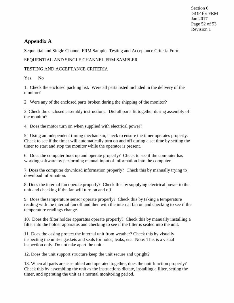
Sequential and Single Channel FRM Sampler Testing and Acceptance Criteria Form
SEQUENTIAL AND SINGLE CHANNEL FRM SAMPLER
TESTING AND ACCEPTANCE CRITERIA
Yes No
1. Check the enclosed packing list. Were all parts listed included in the delivery of the monitor?
2. Were any of the enclosed parts broken during the shipping of the monitor?
3. Check the enclosed assembly instructions. Did all parts fit together during assembly of the monitor?
4. Does the motor turn on when supplied with electrical power?
5. Using an independent timing mechanism, check to ensure the timer operates properly. Check to see if the timer will automatically turn on and off during a set time by setting the timer to start and stop the monitor while the operator is present.
6. Does the computer boot up and operate properly? Check to see if the computer has working software by performing manual input of information into the computer.
7. Does the computer download information properly? Check this by manually trying to download information.
8. Does the internal fan operate properly? Check this by supplying electrical power to the unit and checking if the fan will turn on and off.
9. Does the temperature sensor operate properly? Check this by taking a temperature reading with the internal fan off and then with the internal fan on and checking to see if the temperature readings change.
10. Does the filter holder apparatus operate properly? Check this by manually installing a filter into the holder apparatus and checking to see if the filter is sealed into the unit.
11. Does the casing protect the internal unit from weather? Check this by visually inspecting the unit=s gaskets and seals for holes, leaks, etc. Note: This is a visual inspection only. Do not take apart the unit.
12. Does the unit support structure keep the unit secure and upright?
13. When all parts are assembled and operated together, does the unit function properly? Check this by assembling the unit as the instructions dictate, installing a filter, setting the timer, and operating the unit as a normal monitoring period.

Section 6 SOP for FRM Jan 2017 Page 53 of 53 Revision 1
14. a. Does unit calibrate?
Does unit pass calibration?
_____________________________ ( Accept / Reject )
Certifying Official
City/State: ____________________ Telephone Number: ______________
Serial Numbers for Samplers Accepted: Serial Numbers for Samplers Being Rejected:
Copyright © 2022 FDOKUMEN