section 2.5 diablo canyon nuclear power plant
111
EXHIBIT 1 SAFETY REPORT CHANGE REQUEST – SECTION 2.5 DIABLO CANYON NUCLEAR POWER PLANT USCA Case #14-1213 Document #1544340 Filed: 03/25/2015 Page 1 of 111
-
Upload
khangminh22 -
Category
Documents
-
view
1 -
download
0
Transcript of section 2.5 diablo canyon nuclear power plant

EXHIBIT 1
SAFETY REPORT CHANGE REQUEST – SECTION 2.5
DIABLO CANYON NUCLEAR POWER PLANT
USCA Case #14-1213 Document #1544340 Filed: 03/25/2015 Page 1 of 111

DGPP Form 69-20108 (r0/09/12)
UFSAR Change Request
Xl3.lD2 Attachment 4Page 1 of4
I ll-ÐAli( AFFEtT I ELLiving UËSAR to be Changed (check only one): I Living DCPP UFSAR or ! Living DC ISFSI UFSAR
Section(s): 2.5 (SeÍsmology and GeoJ.ogy)
Table(s): u/n Figure(s): 2.5-33, 2.5-3a, 2.5-35, 2.5-36
2. DESCRIPTION OF
3. UFSAR REVISED CONTENT MARKUPS:Mark up a copy of all the affec,ted pages in the Living UFSAR to clearly show the proposed changes, additions,and deletions to text, tables, figures, and appendices. The track changes feature in MS Word is preferred for allchanges to text, Enter the number of pages included in the attached markup:
No, ofmarked up pages attached: 94
5.4
FOR LICEN USE
GONTENT:
4
%
Summary description of the proposed change (use additional pages lf required):UFSAR Section 2.5 (Selsmology and Geology) is revised to reflect the resuLts ofthe Licenslng Basis Veriflcation Project review of the Seisnology and Geoloqysection and proposed enhancenents. The proposed change is belng processed againstUFSAR Revlslon 20.
Check all that apply and enter document number where applicable:
fl Minor Editorial Correction - See lnstructions
El Otner (descrlbe):annotated Markup
El Attached Applicability Determinalion (AD) D Llcense Amendment No,:
E Atlached LBIE Screen n Requlred by Regulation:
! LBIE No.
! ocp l¡0.
n SnP Notificalion:
Does the UFSAR change requlre a change any of lhe following? lf so, process per the applicable procedure,
Deslgn Criteria Memorandum E Yes 8l.lo DCM No SAPN No:
Procedures flYes El No Proc No.: SAPN No:
Technical Specification Bases nYes Xl No TS Bases No. SAPN NO:
v-2.s (4)CR No:
Tracking SAPN 50567477
Xl3.lD2 Form 69-20108 - UFSAR Change Request.docx 0604.1830
Signatures are on the next päge.
USCA Case #14-1213 Document #1544340 Filed: 03/25/2015 Page 2 of 111
DCPP Form 69-20108 (101091121UFSAR Change Request
Xl3.lD2 Attachment4Page 2 of 4
6. TOR
7. REVIEWER
8. TECHNIGAL APPROVAL
,l0. LEAD ORGANIZATION SECTION OWNER
o
Prlnt Last NameAngeLuccl
LAN IDPJA9
Date¿/+/ts
Prlnt Last NameTlman
LAN ID.'PTH
Date
ID
Slgnature ls only required lf the change afbcts Chapter 17 of the DCPP UFSAR, or Chapter 1 1 of the DC ISFSIUFSAR. Attach the Evaluatlon of QA Program Changes form.
Print Last Name Slgnature lAN ID Date
lf the change afÞcls more than one sectlon owner, attach a separate copy of thls sheet br each,
Print NamgA þ*
I-AN5
Print Last Name ID Datea
PrintL
Print Last Name Slgnature LAN ID Date
FOR LICENSING USE ONLY11
12. CHANGEI
13.
CR No: v-2.5 (4)Tracking SAPN: 50567477
/3
(3
Xl3.lDz Form 69-20108 - UFSAR Change Request,docx 0604,1710
USCA Case #14-1213 Document #1544340 Filed: 03/25/2015 Page 3 of 111

DCPP Form 69-20108 (10/09/12)UFSAR Change Request
Xl3.lDz Attachment 4Page 3 of 4
INSTRUCTIONS for COMPLETING THE UFSAR CHANGE REQUEST(Do Not Use for S/l Display Change Requests)
lnltiatorBlock I - Check which UFSAR is to be changed and identify the section(s), table(s), and figure(s), lf
both the DCPP UFSAR and DC ISFSI UFSAR are to be changed, use a separate changerequest form for each.
Block 2 - Provide a description of the proposed change.Block 3 - Markup the affected pages from the Living UFSAR to clearly lndicate the changes being
made, Enter the total number of pages in the markup,. Tñe resulting level of detail should be consistent with or exceed the level of detail in
the current UFSAR.. Verify the format and content of the change comply with the guidance provided in
Reg, Guide 1.70 Rev. 1 and NEI 98-03, Rev. 1 for the DCPP UFSAR and Reg.Guide 3.62 for the DC ISFSI UFSAR. Refer to Attachmenl2for additional guidance,
. Use the CLB Search Tool to confirm that all affected pages of the UFSAR areincluded in the markup.
. Changes to the LBVP enhanced sections must maintain the enhanced format,Electronic markups usinþ MS Word track changes are preferred.
Block 4 - Check the applicable box(es) and enter information for the documents used to justify theproposed change.. The documents clted in Block 4 must be approved before licensing will make the
changes to the Living UFSAR.. Any proposed changes to the UFSAR must include the accompanying LBIE Screen
documents from the TS3.lD2 evaluation.. As a minimum, the UFSAR Change Request must have an accompanying LBIE
Applicability Determination (AD). The only time an AD is not required is if the changesare strictly minor editorial changes (e,9., corrections to spelling, grammar, page andtable number, table of contents pages).
Block 5 - Determine if the UFSAR change will require a change to DCMs, procedures, or TS Bases,lf so, check yes and enter the document number and tracking SAPN tracking the changerequest to DCMS, procedures, orTS Bases. Otherwise check no.
Block 6 - Print name, sign, enter your LAN lD, and date. Following this step:. Obtain reviews from other disciplines if deemed necessary and have reviewe(s) sign
Block 7.. Obtain a technical approval from a knowledgeable supervisor or manager for Block B,. Obtain QV director's approval in Block g if ohange affects Chapter 17 of the DCPP
UFSAR or Chapter 11 of the DC ISFSI UFSAR.. Obtain the affected section owner's approval in Block'10. Attach additionalcopies if
more than one section owner is affected. Section owners are identified in FileNet(NPG Library:/Licensing Bases - DCPP/"FSAR Update/AdministrativeDocuments/Lead Organization Assignments),
. Submit the approved request and supporting documentation to licensing,
X13.lD2 Form 69-20108 - UFSAR Change Requesl.docx 0604.1710
USCA Case #14-1213 Document #1544340 Filed: 03/25/2015 Page 4 of 111

DCPP Form 69-20108 |.10109112l.UFSAR Change Request
Xl3.lD2 Attachment 4Page 4 of 4
Reviewer(slBlock 7 - Review the proposed UFSAR change using the source for the change (e,9., design
change package, corrective action SAPN, license amendment, etc,) and the instructionsprovided in Section 5.5. Upon completion of the review, print name,.sign, enter LAN lD,and date.
Technical ApprovalBlock I - A knowledgeable supervisor or manager reviews and approves the proposed change.
Prínt name, sign, enter l-AN lD, and date to approve the change,. The individual signing as the technical approver and shall not be the change request
initiator.
QV Director ApprovalBlock 9 - The QV director must approve any UFSAR changes that affect Chapter 17 of the DCPP
UFSAR or Chapter 1 1 of the DC ISFSI UFSAR. Print name, sign, enter LAN lD, and dateto approve the change.
. . The QV director can also sign as the individual signing as the technical approver(Block 8), but cannot be the change request initiator.
. The "Evaluation of QA Program Changes" form AD1.NQ2 must be attached.
Lead Oroanization Section Owner ApprovalBlock l0 - The section owner reviews and approves the change request, Refer to Section 4,3 for
responsibilities, The lead organizations and section owners for the DCPP UFSAR arêfound in FileNet at: NPG Library:/Licensing Bases - DCPP/"FSAR Update/AdministrativeDocuments/Lead Organization Assignments.
FOR LICENSING USE ONLYLicensinqBlockl l - Review the change request. Assign a CR number from the CR log and initiate a tracking
SAPN. Enter the CR number and SAPN number in the spaces provided, Print name,sign, enter LAN lD, and date to approve the change.
Blockl2 - Print name, sign, enter LAN lD, and date to indicate the change has been incorporatedinto the Living UFSAR the affected files have checked back into FileNet.
Blockl3 - The FileNet copy should be opened and checked to confìrm the change has beenproperly incorporated, This verification of incorporation may be performed by anyone inlicensing, the LBVP, or the ISFSI project as requested by the UFSAR licensing engineer.
Blockl4 - Record any closing information that may be warranted from a historical perspective or forfuture reference. Entry in this block is optional.
Xl3.lD2 Form 69.20108 - UFSAR Change Request,docx 0604,1710
USCA Case #14-1213 Document #1544340 Filed: 03/25/2015 Page 5 of 111

DCPP UNITS 1 & 2 FSAR UPDATE
2.5 GEOLOGY AND SEISMOLOGY
This section presents the findings of the reglonal arld site-speciflc geologio andseismologic investigations of the Diablo Canyon Power Plant (DCPP) site, lnformationpresented is in compliance with the criteria in Appendix A of 10 CFR F'art 100, asclc,.scril¡ed belou,. and meets the format and content recommendations of RegulatoryGuide 1.70, Revision 1 (Refetc;rtce 39XgS), Since ther developmerrt ltl tlìs ce¡$m'cirrJrrrls loi DCPI" prrcjates lhs issu¿¡n<;e of 10 CFR F'art 100, Appendu A, ''Seisnlic an<Í(ìaologir: Siling Cliteli;-r for Nrrciear ['ower' Plants," tlre lolìorting DCFF erarlfrt¡(¡ahes arr.planì spocifrc
lrr crrder lo capturc: the historícal progress of lhe ç¡eoleclinic¡l anci seisrnologicælinvestrgations ¡rssociatecl vvifh tlre DCPF site, information pertaininE t<l the followìngtllrer: tirne periocli ls do:s.cribecl hereln
(1) Origìnal Oesigrr Flrase: investigalions performed in support of the flrelinrinaryfiafety Analysir Report, llrior to the issuance of the Unit 1 construclion permit(1967), tlrrough (he eerty sfages of the construclion ol Unit 1 (1971). TheDesigrr Earihquake ¿rnd Double Design Eartirquake gruuncl nrotjons areas-qociatecl wí(lr lhis phase. These earthqr-rakas are sirnilar to tlre regulatorygrour'rd rnotit¡n level fhal the l.,lRC subsequently develclped in'i 0 CFIì Part 1otilippenrJÌ'.i A ¡rs lhe "Operaling Þasis Earlhqtlal'.e (OBE)" gror;r'rcl motton anci the''Saf e Shr-rlclc,'wr E arllrciuake ( SSE)'' grouncl nrolion. re spectively
(il1 1-losgrri Evalrtaiion Phasc investigations perfornred in response tcr theidentillcalirrn of the olfslrore Hosgri fãult zane (1 971) through [he issuance ofthe Unít 1 operating Ùicense (1984). The 1977 Hosgri Earthqual<e groundmotions are associa(ecl i¡riltr this plrase. The Hosgri Evalrtation Phase does notatfecl or clianqe the inves(igations ancl cortclusions of lhe Oiì!.¡inai DesignPh¡lse
(3) l.on'¡ lerrri Sers;nric lrogrem (l-lSP) EvälLlaliün Phase. investiçlalionspr-;lorrrrccl irr responsc tc' tlì{'Litense C<lnclili.Jn lterrr l.Jo 2 tì (7)of ilte Unit I
o¡crating licens¿; (19t 4) tlrrotrgli the rerncvaÌ ol tlre Ltcelr¡e Cìondiliorr (199 l).includino cunent orr-going investigations The 1$91 L1 SP grourrd nrotion is¡¡ssociaierl witl¡ llu!. ¡rhase- The [.TSl-J Evalualion Pllase cloe-s nol affe¡ct orcbarìgt, llre irrvestigatìonç alrl cr-rnçf¡¡s¡onr. of eithel lhe Original Design Phaser.rr the llosgri Evalualion Flrase
()rreruiev¡
I Locations of earlhquake epicenters within 200 miles of the plant site, and faults andeafthquake epicenters within 75 miles of the plant site for either magniludes orintensilies, respeclively, are shown in Figures 2.5-2,2,5-3, and 2,5-4 {{hrouglr 1972). Ageologic and tectonic map of the region surrounding the site is çti+e,rj+{w+shes{s<Êshown in Figure 2,5-5, and detafled information about site geology is presented in
2,5-1LBVP UFSAR Change RequeslSeismology and Geology
Edited for consislencyAdded for ClarltyEcl¡led for Consistenry
Added for Clarity - Reler toApplicablllly Delermlnallon Malrix ltem#1
Added for Clarity - Refer toAppl¡cabill(y Determination Matrìx llenr#2Added lor ClarityEdlled lor Clarity
Added for Clarlty - Refer loApplicsb¡lity Determ¡nâl¡on Malr¡x ltem#3Edlled for Clarlty
USCA Case #14-1213 Document #1544340 Filed: 03/25/2015 Page 6 of 111

4$S^a'¡4J$9lJhe-NRG pe'rfe+neC an extecsír' rE\.¡e',l"' eÊ{hd gt+atR€FeCJnC F6&EFr+pçreC+nd-es¡,m{@U'lEf++tee+ien€---ln-F€t¡ruary-æe+
Í4ì{Æ+-d-saì¡stjed !the-S.S€-t?-the $lRG+equastÊd-.ÈåH€ln+€f,f,¡rnelsty+aaf+s,€-frË+ñ PË€,€ì-á{qg-ag&E-
lìe-
DCPP UNIT'S 1 & 2 FSAR UPDATE
Figures 2.5-E through 2.5-,f6, Geologyãnd seísmology are discussed in detailinI Seclions 2.5.2-i through 2.5.5'4. Additional lnformation on site geology is contained in
References 1 and 2.
6[¡ f{evefi+Þs+-3ï4$igdi{he4¡eGìs¡+,ed{lr rng-L-+c€nsê DFA 80, ln DPR ee+se€enC*iecJten*+-q+|Jhê+tgf-é{ã.1€+¡+?Jtt'
--_-- "FGjiË-+ìrgj!d€+åt'.tand implamen t+{l*-çeis'm++4e+tg+l++ses+16€C+Ê'+heÐ+eble Êal-.yerrPewer Plarìl-
P€-qË+Æ€ve{uet io+e#+l+1++eep#ies-weo${taC{h+:ten+
Tlìe,t+sP€¿¡Ðk+ir{s+}íts+€i,v€-dê{s-Þs€eÈ-*f,d-aÊalyËe€{hãttlFc¡at€-+Þelaeete-geeloç}N;;¡nelc¿icnai+1¡,Íe¡mali an in lh i s s eel ien-ef tlt€ FS'4 R U Fd€ì+e, |1 ewe\¡€ ft{b€++SP-¡n+¿erra deeg nel edd @þlåe-tT9 P rsi¡sdç ¡nC-ee
Detailecl supporling data pertaining to this section are presented in Appendices 2,54,2.58,2.5C, arrd 2.5D of Reference 27 in Section 2.3, Geologic and seismic informationfrom investigations that responded to Nuclear Regulatory Commission (NRC) licensingreview questions are presented Appendices 2.5E and 2.5F of the same reference, Abrief synopsis of the information presenled in Reference 27 (Section 2.3) is glven below.The DCPP site is located in San Luis Obispo County approximately 190 miles south ofSan Francisco and 150 miles northwest of Los Angeles, California. lt is edjacenl to thePacific Ocean, 12 miles west-southwest of the city of San Luis Obispo, the county seat.The plant site location and topography are shown in Figure 2,5-1 ,
The site is located near the mouth of Diablo Creek whioh flows out of the San LuisRange, lhe dominant feature to the northeast. The Pacific Ocean is southwest of thesite. Facllities for the power plant are located on a nrarine terrace that is situatedbetween lhe mountain range and the ocean,
The terrace is bedrock overlain by surlicial deposits of marine and nonmarine origin.PG&Ë Design Crtass l5r€+sm€4€{e€€qd slructures at the site arc situated on bedrock
2.5-2LBVP UFSAR Change RequeslSeismology and Geology
Edited for clarlty' Revlsed SeclionNumberEdited for Clarity- Revlsed SeclionNumber
Moved Text lo Enhanced Secl¡on2.57 l
Edited for Clarily - Refer toApplicabllily Del€flnlnalion Malrix lterilfl5
USCA Case #14-1213 Document #1544340 Filed: 03/25/2015 Page 7 of 111
DCPP UNITS 1 & 2 FSAR UPDATE
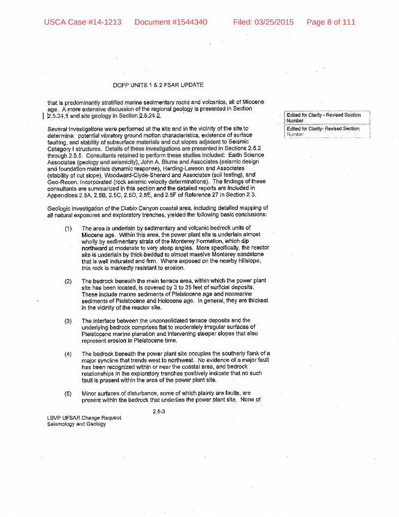
that ls predomi ine sedimentary rocks and volcanics, all of Mioceneage. A more e of the regional geology is presented in Section
| þ.s.2+.l'and si nP,5.2*,2. Edlted for Clarlty - Revised
Edlted for Revlsed SectionSeveral investigations were performed at the slte and in the vlcinity of the site todetermine: potential vibratory ground motion characteristics, existence of surfacefaulting, and st SeismicCategory I stru ections 2'5,2through 2,5,5. Earth ScienceAssociates (ge smic designand foundation materials dynamic response), Harding-Lawson and Associates(stability of cut slope), Woodward-Clyde-Sherard and Associates (soil testing), andGeo-Recon, lncorporated (rock seismic veloclty determinations). The findings of theseconsultants are summarized in this section and the detailed repotts are included inAppåndices 2.5A,2.5B,2.5C,2.5D,2,5E, and 2,5F ot Reference 27 in Section 2'3,
Geologic investigation of the Diablo Can¡¡on coastal area, inoluding detailed mapping ofall natural exposures and exploratory trenches, yielded the following basic conclusions:
(1) The area is underlain by sedimentary and volcanic bedrock unlts ofMiocene age, Within this area, the power plant site is underlain almostwholly by sedimentary strata of the Monterey Formation, which dipnorlhward at moderate to very steep angles, More specifically, the reactorsite is underlain by thick-bedded to almost massive Monterey sandstonethat is well indurated and firm, \Mtere exposed on the nearby hillslope,this rock is markedly resistant to erosion.
(z',) The bedrock beneath the main terrace area, within which the power plantsite has been located, is covered by 3 to 35 feet of surficial deposits.These include marine sediments of Pleistocene age and nonmarinesediments of Pleistocene and Holocene age, ln general, they are thickestin the vicinlty of the reactor slte.
The interface between the unconsolidated terrace deposits and theunderlying bedrock comprlses flat to moderately irregular surfaces ofPleistocene marine planation and intervening steeper slopes that alsorepresènt erosion in Pleistocene time,
The bedrock beneath the power plant slte occupies the southerly flank of amajor syncline that trends west to northwest. No evidence of a major faulthas been recognized within or near the coastal area, and bedrockrelationships in the exploratory trenches positively indicate that no suchfault is present wlthin the area of the power plant site,
Minor surfaces of disturbancer some of which plainly are faults, arepresent within the bedrock that underlies the power plant site. None of
2,5-3
(4)
(5)
LBVP UFSAR Change RequestSeismology and Geology
Number
(3)
USCA Case #14-1213 Document #1544340 Filed: 03/25/2015 Page 8 of 111

DCPP UNITS 1 & 2 FSAR UPDATE
these bresks offsets the interface between bedrock and the cover ofterrace deposits, and none of them extends upward into the surfìcialcover. Thus, the latest movements along these small faults must haveantedated erosion of the bedrock section in Pleistocerie lime,
(6) No landslide masses or other gross expressions of ground instability arepresent within the power plant sile or on the main hillslope easl of the siteSome landslides have been identified in adjacent ground, but these areminor features confined to the naturally oversteepened walls of DiabloCanyon.
(7) No waler of subsudace origin was ençountered in the exploratorytrenches, ancl the level of permanent groundwater beneath the mainterrace area probably is little different from that of the adjacent lowerreaches of the deeply incised Diablo Creek
i'.1'i,'i. [-¡esigtr Basis
?- 5,'1 ,1 Gçlls¡al DesiS¡rr Criteriorr 2, 1ÐË7 Pcrf(rrnta¡rcc Starrdarrls
Itiìf:'n'siystarrrs s,tructures, anrl corrr¡:onerlts hírve U.an ¡6çrtr:r-l desicltìêd anci enalyzedl¡r '..v¡tlìsta!1d llro¡;e forces th¿rl nriqht result lronl the t'rìosl sevefe nãtllr¿ìl e¡¡rlltqrrakefrlìenomen;'
2,5.1 .2 Licerrge Condilion 2.C(7) ol DCPP Facility Operatirrg License DPR40 Rev44 ({.TsP), Elernent.s {1), (2}and (3)
DCPP developecl and implemented a progtam to re-evalirate the seismic designbases ttsed for the Diablc-¡ Canyon Power Plant
Tlre ¡rrogi'anr includecl lhe follorrring three Ë.ìernsnts lhât were conrpleted and¡ìcceÞted by tlre f'JRC (References 40, â1 . and 43):
(li ThÉ identtfìcatio¡t, exarnitration, and evaluetiori of all relevarrt geologic andsr¡is¡¡-ric dâla, ¡r'ìforrrìâlion, and intefpretatic'ns that have Lreconle avÊlläblesince tl¡e 1979 ASt U hearirrg in order to rrpdale llre geoir:gy, seisnrology¿rrtd tectc-¡ttics ir fl rÉ: rrjgiorì r:'f tiit'Dialllo C,an,vrr:r Ntrclear l'otver Plant lfrteeclecl to clefirre the earll'rqrur!<e poterrrtial of !he region al Íl affecllr theDierblt Canyorr PlanÌ, PGSE hgs ¿rlso re-evafulate<l the enrlier infonnaticrnarrrJ acqr.rired adclitionai <lata,
(:?) DCFP has te-e,¡alulrtecl the nragrri(uclc' ol lhe eadlrquahes, use:cl tcrcleterrnirre lne seiurnic basi:¡ r¡l ll re D;atrlo Carryort l.,luclear Piani rrsing lheinfçr¡nalion fronr [!lenren[ 1
2.5-4LBVP UFSAR Change RequestSeismology and Geology
Adcled for Clarity - New Sub-seclionlo Justify Design Btses Criter¡aRefer to Applicabllìty Delerminationlvlatrix ltem # 6
Added for Clarily - New Sub-6ecfionto ldonl¡ty License RequirementUFSAR Seclion 3 1.2.2Refer to Applicabll¡ty DelerminalionMatrix ltem # 6
USCA Case #14-1213 Document #1544340 Filed: 03/25/2015 Page 9 of 111

DCPP UNITS 1 & 2 FSAR UPDATE
(3) ll0Plt lr¿s rr-ovalualed lhe groirnd rnotron al llre sile baseci on tlìe resullgobtainerl frorn Elenlenï 2 willr frrll consicleratron oI sile and other relevanleffects
A\s a cÐnditíon of the l{RC's cjoseout ol License Conclition'2.C.(7). PGt'E corïmilted toseverâl orrgoing activities in strpporl of the LTSP, ¿¡s discussed in ir prrblic nreetingbetween F'Lì&E ancl the NRC orr March 15, 1991 (lleference 53), described es lhe"Fran-rewc'rk lor lhe F'trture," ¡n ã lette/ to lhe l.lRC, dätâd Aprll '17. 1991 (Referenc€' 50),and af¡irrned by tlre llRC ín SSER 34 (Flr:ference 43) These ongoing aclivitjes ¿redlsc¡.rssed ¡n Secl¡on 2.5.7-
2.ft.1,3 10 CFR P;rri 1Oft, March l9tìtj - Roaclor 9itc Criteria
During tire delsnninrtion of the location c¡f the. Diablo Canyori Por¡¡er Plan, considerationvlae giverr to lhe physical characteristice ol the sìle, inclitding seismology and geology.
I z.s.z+ BAStc cEoLoctc AND sElsMtc tNFoRMATtoN
This section presents the basic geologic and seismic information for DCPP site andsurrounding region. lnformation contained herein has been obtained from literaturestuclies, lield investigations, and laboratory tesling and is to be used as a basis forevaluations required to provide a safe design for the hcility, The basic dâta containedin lhis section and in Refarence 27 of Section 2.3 are referenced in several otherseclions of this FSAR Update. Additional inlormation, developed during lhe l'losgri ancJI ISF evaluetiotrs, is desc¡ibei in Sìections ?.5,3 9.3 and 2.5 3 9,d, respedively
I Z.s.zl.l Regional Geology
I Z.s.z+.1.t Regional Physiography
Díablo Canyon is in the southern Coast Range which is a part of the California CoastI Ranges section of the Pacific Border physiographic province (refer toeee Figure 2.5-1 )
The region surrounding the power plant site consists of mountains, foothllls, marirìeterraces, and valleys. The dominant features are the San Luis Range adjacent to thesite to the northeasl, the Senta Lucia Range farther inland, lhe lowlands of the LosOsos and San Luis Obispo Valleys separating the San Lt¡is and Santa Lucia Ranges,and the marine terrace along the coastal margin of lhe San Luis Range,
Landforms of the San Luis Range and lhe adjacent marine terrace produce thephysiography at the site and in the region surrounding the site, The westerly end of theSan Luis Range is a mass of rugged high ground that extends from San Luis ObispoCreek and San Luis Obispo Bay on lhe east and is bounded by the Pacific Ocean onthe south and wesl. Except for its narrow fringe of coaslal terraces, the range isfealured by west-northwesterlyirending ridge and canyon topography. Ridge crest
2.5-5LBVP UFEAR Change RequestSeismology and Geology
Added for Clarity - New Sub"secllonto ldenttry Ltûense RequlremerìlSSER 34Refer lo Appt¡câbil¡ly Dëternì¡nationMalr¡x llem#6
, Added for Clarlty - NBw Sub.seclionto ldentlfy License RequirementRefer to Appllcabllity ÞetenninationMalrlx ltem f 6
Ed¡ted for Clar¡ly - Rovised SectionNumber
Edited for Clarily - Added SectionPo¡nler
Edlted for Clâflty - Revised SeclionNumberEdlted for Clarity - Revised SeclionNumber
Edlted for Clarlty - Refer [oApplicabllity Determinalion Matrlx lt€nì#7
USCA Case #14-1213 Document #1544340 Filed: 03/25/2015 Page 10 of 111

DCPP UNITS 1 & 2 FSAR UPDATE
altitudes range fronr about 800 to 1800 feet. Nearly all of the slopes are steep, and theyare modified locally by extensive slump and earthfiow landslides.
Most of the canyons have narrow.bottomed, V-shaped cross sections. Alluvial fans andtalus aprons are prominent features along the þases of many slopes and at localitieswhere ravines debouch onto relatively gentfe tenace surfaces. The coastal terrace beltextencls between a steep mountain-lront backscarp and a near-vertical sea cliff 40 to?00 feel ln helght. Boththe bedrock benches ofthe lerraces and the present offshorewave.cut bench are ìrregular in deta¡|, wlth numerous basins and rook projections,
The main terrace along the coastal margin of the San Luis Range is a gently tomoderatety sloping strip of land as much âs 2000 feel in maximum width, The morelandward pafts of its surface are defined by broad aprons of alluvial deposits. Thiscover thlns progressively ln a seaward dlrection and ls absent altogether ln a few placesalong the presenl sea cllff, The main terrace represents a series of at least lhreewave-cut rock benches thal have approximate shoreline-angle elevations of 70 100,and 120 feet..
Owing to both the prevalling seaward slopes of the rock surfaces ancl the variablethickness of overlying marine and nonmarine cover, the presenl surface of the maintenace ranges from 70 to more than 200 feet in elevation. Remnants of higher terrasesexisl al scettered locations along upper slopes and ridge crests. The most extensiveamong these is a series of terrace súrfaces at altltuctes of 300+, 400+, and 700+ feet althe wesl end of the ridge between Coon and lslay Creeks, north of Point Buchon. A
I surface descrlbed by Headlee (Reference ìf!,¡'s as a marine tenace at an altltude ofaboul 700 feet forms the top of San Luis H¡ll, Remnants of a lower terraca at an altitudeof 30 to 45 feet are preserved at the mouth of Diablo Canyon and at severel placesfarther north
Owing lo conlrasting resìstance to erosíon among the various beclrock units of the SanLuis Range, the detailed topography of the wave-iut benches commonly is veryirregular, As extreme examples, both moclern and fossll sea stacks rise as much as100 feet al¡ove the general levels of adjaoent marine-eroded surfaces al severallocafitles.
2-5-BLBVP UFSAR Change RequestSeismology and Geology
Edited lor Consistency
USCA Case #14-1213 Document #1544340 Filed: 03/25/2015 Page 11 of 111

DCPP UNITS 1 & 2 FSAR UPDATE
I Z.S.x+.1.2 Regional Geologlc and Tectonlc Setting
I z,s,za,'t,z,t Geologic sott¡ng
The San Luis Range is underlain by a synclinal section of Tertiary sedimentary andvoloanlc rocks, which have been downfolded into a basement of Mesozoic rocks nowexposed along its southwest and northeast sides. Two zones of faulting have beenrecognized within the range. The Edna fault zone trends along its northeast side, andthe Miguelito fault zone extends into the range from the vicinity of Avila Bay. Minorfaults anct bedding-plane shears can be seen in the parts of the section that are wellexposed atong the sea cllff fringing the coastal lerrace benches, None of these feultsshows evidence of geotogically recent activity, and the most recent movements alongthose in the rocks underlying the youngest coaslal terraces can be positively dated asolder than S0,000 to 120,000 years, Geologic and tectonic maps of the regionsurroundirrg the site are shown in Figures 2.5-5 (2 sheets), 2,5-6, 2.5-8, and 2.5-9.
I Z,s,z+.l,z,Z Tsctonic Features of the CentralCoastal Reglon
DCPP site lies withln the southern Coast Ranges structural province, and approximatelyupon the centerline axis of the northwest-trending block of crust thal is bounded by lheSan Andreas fault on the norlheast and the continental margin on the southwest. Thiscrustal block is characterized by northwest-trending struotural and geomorphic features,in contrast to the west-lrending features of the Transverse Ranges to the south, Amajor geologic boundary within the block is associated with the Sur-Nacimlento andRinconada faults, which separate terrains of contrasting basament rock types. Theground southwest of the Sur-Nacimiento zone and the southerly half of the Rinconada'fault, referred to as lhe Coastal Block, is underlaln by Franciscan basement rocks ofdominantly oceanic types, whereas that to the norlheast, referred to as the SalinlaBlock, is underlain by granitic and metamorphic basement rocks of continental types.
I eage (lìelerÊrrcr., 10J'É'outlined lhe geology of tlre Coast Ranges, describing itgenerally in terms of "core complexes" of basement rocks and sunounding sections ofyounger sedimentary rocks. The prlncipal Franciscan core complex of tlre southernCoast Range crops out on the coastal side of lhe Santa Lucia Range from the vìcinìty ofSan Luis Oblspo to Point Sur, a distance of 120 miles, lts complex features reflectnumerous episodes of dsformation that evidently included foldlng, faulting, and thelectonic emplacement of extensive lrodies of ultrabasic rocks. Other core complexesconsisting of granitic and metanrorphic basement rocks are exposed in the southernCoast Ranges in the ground between the Sur-Nacimienlo and Rinconada and in theSan Andreas feult zones. The locations of these areas of basement rock exposure areshown in Figure 2,5-6 and in Figure 1 of Appendix 2.5D of Reference 27 in Section 2.3.
Younger structural features include thick folded basins of Tertíary strata and the largefaults that form structural boundaries between and within lhe core oomplexes andbasins.
2.b.7LBVP. UFSAR Çhange RequestSeisnrology and Geology
Edlted for Clarity - Rev¡sed Sect¡onNumberEdited for Clarily - Revised $ectlonNumber
Ediled for Clarity - Revlsed SectlonNumber
Ed¡ted for conslstency
USCA Case #14-1213 Document #1544340 Filed: 03/25/2015 Page 12 of 111

DCPP UNITS 1 & 2 FSAR UPDATE
The slructure of the southern Coasl Ranges has evolved during a lengthy hlstory ofdeformation extending fiom the time when the ancestral Sur-Nacimiento zone was asite for subduction (a Benioff zone) along the lhen-existing continental margln, throughsubsequenl parts of Cenozoio time when the San Andreas fault system was theprincipal expression of the regional strees-strain system. The latest episodes of majordeformation involved folding and fâulting of Pliocene and older sediments during mld-Pliocene time, and renewed movements along preexisting faults during early or mid-Pliocene time, Present tectonic activity within the region is dominated by interactionbetween the Pacifc and American crustâl plales on opposite sides of the San Andteasfault and by continuing vertical uplift of the Coast Ranges. ln the regional setting of
I OCpp sile, the majgr struclural features atlcircssed rlLrring the original clesipn phase arethe San Andreas, Rinconada-San Marcos-Jolon, Sur-Nacimiento, and Santa Lucia Bankfaults. ,AclCltinnal laults we¡e icie¡rtif ed during llre l'losçri evalualicrn and t..TSPev¡iltl*li¡¡fr f-rhä:,.es, r|scusssd irr Secticrns 2.3.3.S.3 and 2.5.3.0.4, respectively. The SanSimeon fault may also be included wlth this group. These oriqinal d*eigrr phasu faultsare described as follows:
7. San Anclreas Faull
The San Andreas fault is recognized as a major transfornr fault of regìonal dimensionsthat forms an active boundary between the Pacific and North American crustal plates.Cumulative slip along the San And¡eas fâull may have amounted to several hundredmiles, and a substantial fraclion of the total slip has occurred during lale Cenozoic tímeThe faqlt has spectacular topographlc expression, generally lying within a ríft valley oralong an escaÍpment mountain frpnt, ancl having assocìated sag ponds, low scerps,right'laterally deflected stresms, and related manifeslations of recent activity.
The most recent episode of large-scale movement along the reach of the San Andreasfault that is closest to the San Luis Range occuned during the great Fort Tejoneárthquake of 1857. Geologic evidence portinent to the behavior cif tlre faull during thisand earlier seismic events was studied in great detail by Wallace (Refetencee 15 andji? t"¡-"' who reported in terms of infrequent great earthquakes accontpanied by groundrupture of 10 to 30 feet, with intervening periods of near total quiescence. Allen(itsí+rerr,:r 1f:)'*' suggested thal such þehavior has been typical for this reach of theSan Andreas fault and has been fundamentally different írom the behavior of the faultalong the reach farther northwest, where creep and numerous srnall earthquakes haveoccurred. He further suggested lhat release of accrrmulating strain energy might havebeen fåcilitated by the presence of large Emorrnts of serpentine in the faull zone to thenorthwest, and relarded by thelocking effect of lhe broad bend of the faultzone where itc¡osses the Transverse Ranges to lhe southeast.
Movement is currently taking place along large segmenls of the San Andreas fault. Theacllve reach ol the fault between Parkfield and San Franclsco is currenlly undergoingrelative movement of at least 3 to 4 cm/yr, as determined geodetically and analyzed by
I Savage ancl Burford (tlefererrce 33)t+r.-*n"n the movemènt that occurs durlng theepisodes of fault displacement in the weslern part of lhe Basin and Ranges Province is
?.5-8LBVP UFSAR Change RequestSoismology and Geology
Add6d for Clarity - Reler toApplicãblllty Oelernrlnatio¡r Matr¡x ltem#4Added for Clarity- Seclion pohìler
Added for Clarlty--RÊler toApplicâbllity oeterminâlion Matr¡x ltem#4
Edited for Consislency
Edited for Oonsislency
Edited for Consistency
USCA Case #14-1213 Document #1544340 Filed: 03/25/2015 Page 13 of 111

DCPP UNITS 1 & 2 FSAR UPDATE
âdcled to the minimum of 3 to 4 cm/yr of continuously and lntermittently released strain,the total probably amounts to at least 5 to 6 om/yr. This may account for essentially allof the relative motion between lhe Pacifìc and Norlh American plates at present. ln theTransverse Ranges to the south, this strain is distributed between lateral slip along theSan Andreas system and east-west striking lateral slip faulting. thrust faulting, andfolding Nonh of the latilude of Monterey Bay and soulh of the Transverse Ranges,transcurrentmovemenl is again concentrated along the San Andreas system, but inlhose regions, it is disttibuted among several major slrands ol lhe system.
2. SunNacintìonto Faull Zane
The Sur-Nacimiento fault zone has been regarcled as the system of faults that extendsfrom the vicinity of Po¡nt Sur, near the northwest ènd of the Santa Lucia Range, to theBig Pine fault in the western Traneverse Ranges, and that separates the granilic-metamorplric basement of the Salinian Blook from lhe Franciscan basement of theÇoastal Block, The most prominent faults that êre included within this zone are, fromnorthwest to southeast, the Sur, Nacimiento, Rinconada, ancl (south) Nacimiento faultsTlre Sur fault, which extends as far nolhward as Point Sur on land, continues to lhenorthwest in the offshore conlinental margin. At its southerly end, the zone termÍnateswhere the (south) Nacimiento fault is cut off by the Big Pine fault. The overall lenglh ofthe Sur-Nacimiento fault zone between Point Sur and the Transverse Ranges is about180 miles. The 60 mlle long Nacimíento fault, between points of juncture with the Surand Rinconada faults, forms lhe longest segment wilhin this zone. Pago (Referencer 1)sislated that:
"lt is unlikely lhat the Nacimiento fault proper has displaced lhe ground surface inLate Quaternãry time, as there are no indicative offsets of streams, ridges, terracedeposits, or other topographic features. The Great Valley-type rocks on thenortheast side must have been down-dropped against the older Franciscan rockson the southwest, yet they commonly stand higher in the topography, This impliesrelative quiescence of the Latê Qualemary time, allowing differentìal erosjon totake place. ln a few localíties, the norlheast slde is the low Eide, and thisinconsistency favors the same conclusion, ln addition lo the foregoingcircumstances, the fault is offset by minor cross-faults in a manner suggesting lhatlittle, if any, Late Quaternary near-surface movement had occurred along the mainfracture."
lHertlr;eíererrcc I41'¡r',ontheotherhand,statecJthat: "...youthful topographicfeatures (offset streams, sag poncls, possible fault scarplets, and apparentlyoversteepened slopes) suggest movemenl along both (Sur-Nacimiento and Rinconada)
I fault zones," The map compilecl by Jennings (Referelrce 23)e, however, shows onlylhe Rinconada with a symbol indicating "Quaternary faull displacement "
The resutts of photogeologic study oTthe region traversed by the Sur-Nacimiento faultzorìe tend to support Page's view, A pronounced zone of faulþcontrolled topographiclineaments can be lraced from the northwest end of the Nacimiento fault southeastward
2.5-9LBVP UFSAR Change RequestSeismology and Geology
Edlled for Consistoncy
Edlted for Consistency
Edlled for Conslslency
USCA Case #14-1213 Document #1544340 Filed: 03/25/2015 Page 14 of 111

DCPP UNITS 1 & 2 FSAR UPDATË
to the Rinconada (south Nacimiento), Ëast Huasna, and West Huasna faults. Onlyalong the Rinconada, however, are there topographicfeatures that seem to haveoriginated through fault disturbênces of the ground surface rather than throughdifferential erosion along. zones of shearing and juxtaposilion of differlng rocks,
I Ricfrter (fi+fcrt'rr¡:*.: 'i li¡'t" noted that some historic seisrnìcity, particularly the 1952Bryson earlhquake, appears to have originated along lhe Nacimiento fault. This view is
I supporled Þy recenl work of S. W Smith (iìtfr':rcra:q 3,0)t* thât indicates that theBryson shock and lhe epicenlers of several smaller, more recent earthquakes werélocated along or near the lrace of the Nacímiento,
3. Rinconada (Naclm¡enlo)-San Marcos-Jolon-San Antonio Fauil Systlm
A system of major faults extends northwestward, parallel lo lhe San Andreas fault, froma point of junction wlth tlre Big Pine fault in the western Transverse Ranges. Ïhissystem ínclucles several faults that have been meppqd as seperate features and
I assigned individual names. Dlbblee (Refererrce 2?){J'' however, has suggested thatthese faults are part of a single system, provisionally termed the Rinconada fault zoneatter one of its more prominent members, He also proposed abandoning the nemeNacimiento for the large fault that constltutes the mosl southerly parl of this system, asit is not continuous with the Nacimiento fault to the north, near lhe Nacimiento River.The newly defined Rinconada fault system comprises the old (south) NacimÌento,Rinconada, and San Marcos faults. Dibblee proposed that the system also include the
I Espinosa and Reliz faults, to the north, but dåta¡iecl work by Durham (f-<eference 2ti]6does not seem to support this interpretation. lnstead, the system may extend intoLockwood Valley and die out there along the Jolon and San Antonio faults, All the faultsof the Rinconada system have undergone signlficant movement during middle and lateCenozoic time, though the entire system did not behave as a urrit. Dibblee pointed outthat: "Relative vertical displacemenls are corìtroversial, inconsistent, reversed from onesegmeñt to another; the major movement mäy be slrike slip, as on the San Andreasfault."
Regarding the strurctural relationship of the Rinoonada fault lo rrearby faults, Dibbleewrote as follows:
"Thrust or reverse faults of Quaternary age are associated with the Rinconada faullalong much of its course on one or both sides, within g miles, especially in areas ofintense folding. ln the northem patt several, including the San Antonio fault, arepresent along both margins of the range of hills between the Salinas andLockwood Valleys . . . , along which this range was elevated in part. Near lhesouthern part are lhe major southwest-dipping South Cuyama and Ozena faultsalong which the Sierra Madre Range was elevated against Cuyama Valley, withvertical displacements possibly up to 8000 feet. All lhese thrust or reverse faultsdip inward toward lhe Rinconacla fault and presumalrly either splay from it at depth,or are branches of it, These faults, combined with the intense folding betweenthem, lndicated that severe compression accompanied possible transcurrentnlovemenl along the Rinconada fault."
2.5"10LBVP UFSAR Change RequestSeisnrology and Geology
Ed¡ted for Conslstency
Edlled for ConslstenDy
Edllod for Conststency
Edlted for Consiitency
USCA Case #14-1213 Document #1544340 Filed: 03/25/2015 Page 15 of 111

DCPP UNITS 1 & 2 FSAR UPDATE
"The La Panza fault along which the La Panza Range was elevated ,.., inQuaternary time, Ìs a rÊverse fuult that dips northeasl under the range, and is notdirectly related to the Rinconada fault.
"The Big Pine fault against which the Rinconada fault abuts . . . is a high angleleft-lateial transcurrent fault active in Quaternary time lR€,f er€,rrce 3:i)'*'. The PineMountain fault south of lt . . , . is a northeasl-dipping reverse fault along which thePine Mountain Range was elevatecl in Quaternary line. This faull may have beenreactivatecl along an earlier fault that may have been continuous with theRinconada fault, but displaced about I miles from il by left slip on the Big Pine fault(Referenr.e 1ZJrÉ¡ in Ouaternary time,"
"The Rinconada and Reliz faults were aotive after deposltlon of the MontereyShale and Pancho Rico Formation, which are severely deformed adjacent andnear lhe faults. The faults were again active after deposition of the Paso RoblesFormation but to a lesser degree. These faults do not affectthe alluvium or terracedeposits, There are no offset stream channels along these faults. However, ln twoareas several canyons and streãms are deviated, possibly by right-lateralrnovemenl on the (Espinosa €nd San Marcos segments of the) Rinconada fault.There are no indicalions that these faulls are presently active."
4. San Sitneon Fault
The fault here referred to as the San Simeon fault trends along lhe base of thepeninsula that li€s north of the settlement of San Simeon, This fault is on land for adistance of 12 miles belween its only outcrop, north of Ragged Point, and Point SanSimeon. lt may extend as rnuch as 16 miles farther to the southeast, to the vicinity ofPoint Estero.. This possibility is suggested by the straight reach of coastline betweenCambria and Point Estero, which is directly aligned with the onshore trend of the fault;its linear form may well have been controlled by a zone of sttuctural weaknessassociated with the infened southerly parl of the fault. South of Port Estero, however,there is no evidence of faulting observable in the seismic rellection profiles acrossEstero Bay, and the trend definecl by the Los Osos Valley-Estero Bay series of lowerMiocene or Oligocene intrusivee extends across the San Simeon hend withoutdeviation.
I tttonn of Point Pieclras Blancas, Silver (ßefererrcr 2ü)r¡q reports a fault with about5 kilometers of vertical separation between the 4-kilometer-thick Tertiary section in theoffshore basin and the nearby 1-lçilometer-high exposure of Franciscan basement rocksin the coastline mountain front, The existence of a fault in lhis region is also indioatedby the 30- mllligal gravity anomaiy between tlre offshore basin and the onshore ranges(Plate ll of Appendix 2.5D of Reference ?7 in Sectlon 2,3), This postulated fault maywell be a norlhward extension of the San Simeon fault lf this is the case, the SanSimoon fault may have a total length of as mutch as 00 miles.
2,5-11LBVP UFSAR Change RequeslSeismology and Geology
Ediled for Consrslency
Edltecl for Conslstenry
Edlted for Conaistency
USCA Case #14-1213 Document #1544340 Filed: 03/25/2015 Page 16 of 111

DCPP UNITS 1 & 2 FSAR UPDATE
Between Point San Simeon end Ragged Point, the San Simeon fault lies along the baseof a broad peninsula, the surface of which is characterized by elevated marine terracesand younger, steep-walled ravines and canyons. The low, terraced topography of thg
.peninsula contrasts sharply wlth that of the steep mountain front that rises immediately'behind lt, Clearly, the ground west of the maln fault represents a part of the sea floorthat has been locally arched up.
This has resulted in exposure of the fault, which elsewhere is concealed undenryater offthe shoreline,
The ground between the San Simeon fault and the southwest coastline of the PiedrasBlancas peninsula is underlain by faulted blocks and slivers of Franciscan rocks,serpentinites, Tertiary sedimentary breccia and volcanic rocks, and Miocene shale. Thefaulted contacts between these rock masses trend somewhat more westerly than thetrend of the San Simeon fault. One north-dipping reverse fault, which separatesserpentinlte from graywacke, has broken marlne terrace deposlts ln at least two places,one of them in the basal part of lhe lowest and youngest tenace, Movement along thisbranch ïault has therefore occurred less than 1 30,000 years before the present,although the uppermost, youngest Pleistocene deposits are apparently not broken.Prominent topographic lineations defined by northwest-aligned ravines that íncise theupper terrace surface, on the other hand, apparently have originated through headwardgully erosion along faults and faulte{ contacts, rather than through the effects of surfacefaulting,
The characteristics of the San Simeon fault can be summarized as follows: The faultmay be related to a fault along the coast to the north that displays some 5 kilometers ofvertical displacement. Near San Simeon, lt exhibits probable Plelstocene right-lateralstrike-slip movement of as much as 1500 feet near San Simeon, although it apparentlydoes not break dune sand deposits of late Pleistocene or early Holocene age. A.branchreverse fault, however, breaks upper Pleistocene marine terace deposits' The SanSimeon fault may extend as far south as Point Estero, but lt dies out before crosslng thenorthern part of Estero Bay.
5. Sanfa Lucia Bank Fault
South of the latitude of Point Piedras Blancas, the western boundary of the mainoffshore Santa Maria Basin is defined by the east-facing scarp along the east side of theSanta Lucia Bank. This scarp is associated with the Santa Lucia Bank fault, thestructure that separates the subsided block under the basin from the structural hlgh ofthe bank, The escarpment that rises above the west side of the fault trace has amaximum height of about 450 feet, as shown on U,S, Coast and Geodetic Survey(USC&GS) Bathymetric Map 1306N-20.
The Sania Lucia Bank fault can be traced on the sea floor for a distance of about65 miles. Extensíons that are overlapped by upper Tertiary strata continue to the southfor at least another 10 miles, as well as to the north, The northern extension may be
2.5-12LBVP UFSAR Change RequestSeismology and Geology
USCA Case #14-1213 Document #1544340 Filed: 03/25/2015 Page 17 of 111

DCPP UNITS 1 & 2 FSAR UPDATE
related to another, largely buried fault that crosses and may intersect the trencl of theSanta Lucia Bank fault. This second fault extends to the surfacE only at points north ofthe lalitude of Polrrt Piedras Blanoas.
West of the Santa Luoia Bank fault, betwe,en N lalitudes 34"30'and 30", severaleubparallel faulls are characterizecl by apparenl surface ssarps. The longest sf thesefaults trends along the upper continental slope for a distance of as much as 45 miles,and generally exhiblts a west-facing scarp. Other faults are preÊent in a zone about30 mltes long lying belween the 45 mile fault and the Santa Lucia Bank fault. Thesefaults range from 5 to 15 or more mifes in length, and have both easl-and west-facingscãrps.
This ¿one of faulting corresponds closely ln space with the cluster of earthquakeepicenters around N latitude 34'45' and 121'30'W longitude, ancl it probably representsthe source structure for lhose shocks (Figure 2.5-3).
I Z.S,zt.t.Z,t Tectonic Features in the Vicfnlty of the DCPP Site
Geologic relatíonships between the major fold and fault slructures ln the vicinity ofÞiablo Canyon are ehown in Figures 2.5-5, 2.5-6, and 2.5-7. and are described andillustrated in Appendix 2,5D of Reference 27 of Section 2.3. The San LuisRanges-Estero Bay area is characterized structurally by west-northwesf-trencling foldsand laults. These include the San Luis-Pismo syncline and the bordering Los OsosValley and Poinl San Luis antiformal highs and the West Huasna, Eclna, and SanMiguelito faults. A few miles offshore, the slructural fealures associated with this trendmerge into a north-northwest-trending zone of folds and faults lhat is referred to hereinas the offshore Santa Maria Basin East Boundary zone of foldlng and faulting, Thegeneral paltern of structural highs and lows of the onshore area is werped and steppeddownward to the west across this boundary zone, to be replaced by morenortherly-trending folds in the lower part of lhe offshore þasin section. The overallrelalionship between {he onshore Coast Ranges and lhe offshore oontinental margin isone of differential uplift and sulrsidence. The East Boundary zone represents thestructutal expression of lhe zone of inflection between these regions of contrastingvertical movement.
ln terms of regional relalionships, strurclural style, and history of movement, the faults inI tne San Luis Ranges-Estero Bay vicinity, ì¡Jerriii*ri (lrrr¡ng lhÈ originat rltrsic¡rr Jrlr.r:.,::.
may be characterized as follows:
1. Wesl Huasna Faull
This fault zone separates lhe large downwarp of the Huasna syncline on the northeastfrom Franciscan assemblage roclrs of the Los Osos Valley antiform and the Tertìaryseclion of the southerly parl of the San Luis-Pismo syncline on lhe southwest. TheWest Huasna fault is thought to join wlth the Suey fault to the south, Differences inthicknesses and facies relationships between units of apparently equivalent age on
2.â.1i)LBVP UFSAR Change RequeslSeismoìogy and Geology
Edlled for Clarity - Revised SectionNumlrer
ArJdecl for Clarily - Refer toApplicabillty Ðeterrninal¡on ñlakix Itenr#4
USCA Case #14-1213 Document #1544340 Filed: 03/25/2015 Page 18 of 111
DCPP UNITS 1 &2 FSAR UPDATE
opposlte sides of the fault are interpreted as indicating laleral movement along the fault;however, the available evidence regarding the amount and even the relative sense ofdisplacement is nol consistenl, The Wesl Huasna shows no evidence of lateQuaternary activlty.
2, Edna Faull Zone
The Edna faull zone lies along a wesþnorthwesterly trend that extends obliquely fromthe West Huasna iault at its soulheast end to the hills of the San Luis Range south ofMorro Bay. Several isolated breaks that lie on a line with the trend are presenl in theTertiary strata beneath the south part of Estero Bay, east of the Santa Maria Basin EastBoundary fault zone across the mouth of the bay.
The Edna fault is typically a zone of two or more anastomosing branches that range inwiclth from 1/2 mile to as much as 1-1/2 miles, Although indiVidualstrands are variouslyoriented and exhibit various senses of amounts of movement, the zone as a wholeclearly expresses high-angle dip-slip displacement (down to the southwest). The
. lrregular traces of maj that llttle,I occuned. Preliminary shown by {+rr
I and Hall {liefererrcæ 2 lotal amo from1500 to a few thousand feet along the central part of the fault zone. The amount ofdisplacement aoross the main fault trend evidently decreases to the northwest, wherelhe zone is mostly overlapped by upper Tertlary strata,
It may be, however, thal most of the movement in the Baywood Park vicinity has beentransferred to the north-trending branch of the Edna, which juxtaposes Pliocene andFranoiscan rocks where last exposed. ln tlre northwesterly part of the San Luis Range,lhe Ëdna fault forms much of the boundary between the Ïertiary and basement rocksections. Most of the measurable displacemenls along this zone of rupture occurreddurlng or after folding of the Pliocene Pismo Formation but prior to depositlon of thelower Pleistocene Paso Robles Formation. Some addltional movement has occurredduring or since early Pleistocene time, however, tlecause Monterey strata have beenfaulted agalnst Paso Robles deposits along at leatt one strand of the Edna near thelread of Arroyo Grande valley, Thls involved steep reverse fault movement, with lhesoulhwest side raised, in oontrast lo the earlier normal displacement down to thesotllhwest
Searclr has failed to reveal dislocation of deposits younger than the Paso RoblesFormation, disturbance of late Qualernary landforms, or olher evidence of Holocene orlale Pleistocene activity.
3. San Miguetito Fault Zone
Northwesterly-trending faults have been mapped in the area between Pismo Beach andArroyo Grande, and from Avila Beach to the vìcinity of the west fork of VineyardCanyon, north of San Luis Hill. Because these faults lie on the sane trend, appear to
?.5.14LBVP UFSAR Change R€questSeismology and Goology
Ed¡led fÞr ConsistencyËditer! for Consislency
USCA Case #14-1213 Document #1544340 Filed: 03/25/2015 Page 19 of 111
DCPP UNI'I'S 1 & 2 FSAR UPDATE
reflect simllar sgnses of movement. and are "separated" only by an area of no exposurealong llre shoreline belween Pismo Beach and Avila Beach, they may well be part of amore or less oontinuous zone about 10 miles long. As on lhe Edna faull. movements,along lhe San Miguellto fault appear to have been predominantly dip-slip, but wlthdisplacement down on the northeast. Hall's preliminary cross section indicates totalvertical seperalìon of about 1400 teet. The fault is mapped as being overlain byunbroken deposits of the Paso Robles Formation near Arroyo Grande,
Field checking of the grouncl along the projected trend of the San Miguetito fault zonenoÉhwest of Vineyard Canyon in the San Luis Range has substantiated Hall's note lhatthe fault cannot be traced west of that area,
Detailed mapping of the nearly continuous sea cliff exposures extending across thistrend northeast of Point Buchon has shown there is no faultìng along the San Miguelitolrend at the northwesterly end of the range, Like the Edna fault zone, the San Migttelitofault zone evidently represents a zone of high-angle dip-slip rupluring along the flank oftlre San Luis-Pismo syncline,
4. East Boundaty Zone of the Offshore Santa Maria Basin
The boundary between lhe otfshore Santa Maria Basin and the onshore features of thesouthem Coast Ranges is a 4lo 5 wide zone ol generally north-northwest-trending
I totOs, faults, and onlap unconforrnities refened to as the "Hosgri fault zone" by Wagner| {Refnrett,,r 31 ¡r3q. Jþs geology of this boundary zonê has been investigatecl in delail
by means of extensive seìsmic reflection profiling, high resolution surface profiling, andsíde scan sonar surveying.
More general information aboul structuraf relatlonships atong the boundary zone hasbeen obtained from the pattern of Bouguer Gravity anomaly values that exist in ilsvicínity. These data show lhe East Boundary zone to consist of a series of generallyparallel north-northwest-trend¡ng faults and folds, developed chiefly in upper Pl¡ocenestrata tlrat flank upwarped lower Pliocene and older rocks. The zone extends fromsouth of the latitude of Poinl Sal to north of Point Piedras Blancas, Wthin the zone,individual fault breaks range in length from less than 1000 feet up to a maximum ofabout 30 miles. The overall length of lhe zone is approximately 90 mlles, with about60 nriles of relatively continuous faulting.
The apparent vefiical component of movement is down to the west across some faultsand down to the easl across others. Along lhe central reach of the zone, opposite theSan Luis Range, a block of ground has been dropped between the two main strands ofthe fault to form a graben struclure. Within lhe graben, and at other points along theEast Bounclary zone, beclding in the rock has been folded down toward the upthrownside of the wesl sìde down fault. This feature evidently is an expressìon of "reversedrag" phenomena
r.5-15tBVP UFSAR Change RequeslSeismology and Geology
Edlted for ConElstency
USCA Case #14-1213 Document #1544340 Filed: 03/25/2015 Page 20 of 111

The axes of folds in the ground on elther side of the principal fault breaks can be tracedfor distances of as much as 22 miles, The fold axes typically are nearly horizontal;maximum axial plunges seem to be 5l or less. The structure and onlqp relationships ofthe upper Pliocene, as reflected in the configuration of the unconformlty at its base, aresuch that it consistently rises from the offshore basin and across the boundary zone viaa series of upwarps, asymmetric folds, and faults. This configuration seems tocorrespond generally to a zone of warping and partial disruption along the boundarybetween relatively uplifting and subsiding regions,
I iz.s.z+.'t.s, Geologic History
The geologlc history reflected by the rocks, structural features, and landforms of theSan Luis Range is typical of that of the southern Coast Ranges of California in its lengthand complexity. Six general episodes for which there is direct evidence can betaþulated as follows:
Aoe Eoisode Evidenee
DCPP UNITS 1 & 2 FSAR UPDATE
Late Mesozoic Development of Franciscan andUpper Cretaceous rock assemblages
Late Mesozoic - Early Coast RangesEarlyTertiary deformation
Mid-Tertiary Uplift and erosion
Franciscan and otherMesozoic rocksStructural features pre-servedin the Mesozoic rocks
Erosion surface at the baseof the Tertiary sectlon
Vaqueros, Rincon, Obispo,Point Sal, Monterey, and PismoFormation and associated volcanicintrusive, and brecciated rocks
Mid- and late-Tertiary
Accumulation of Mioceneand Pliocene sedimentaryand volcanic rocks
Pliocene Folding and faulting associated with Folding and faultlng of thethe Pllocene Coast Ranges deformation Tertiary and basement rocks
Pleistocene Uplift and erosion, development of Pleistocene and Holocenesuccesslve tiers of wave-cut-benches deposlts, present land-forms'alluvial fan, talus, and landslide deposition.
The earliest recognizable geologic history of the southern Coast Ranges began lnMesozoic time, during the Jurassic period when eugeosynolinal deposits (graywackesandstone, shale, chert, and basalt) accumulated in an offshore trenoh developed inoceanic crust.
Some time after the initiation of Franciscan sedimentation, deposition of a sequence ofmlogeosynclinal or shelf sandstones and shales, known as the Great Valley Sequence,began on the contlnental crust, at somê distance to the east of the Franciscan trench.
2.5-16LBVP UFSAR Change RequestSeismology and Geology
USCA Case #14-1213 Document #1544340 Filed: 03/25/2015 Page 21 of 111

DCPP UÍ{ITS,1 & 2 FSAR UPDATE
Deposition of bolh sequences continued lnlo Cretaceous t¡me, even whlle the crustalbasement section on whlch lhe Grêât Valley strata were being deposlted wasundergoing plrltonlsm lnvolvlng emplacement of granltic rocks, Subsequôntly, thoFranciscan assemblage, the Great Valley Sequence, and the graníte.intruded basementrocks were tectonically juxtaposed. The resulting terrane consisted generally of graniiicbasement thrust over intensely deformed Franciscan, with Great Valley Sequence slrataoverlying the besement, bul thrust over and faulted into the Franciscatr.
The processes that were involved in the tectonic juxtaposition evidently were activeI Ouring the Mesozoic, and continued into the early tertiary. Page (f iaferen'* "5)é has
shown that lhey were completod by no later than Oligocene time, so that the dual corecomplex basement of lhe soutlrern Coast Ranges was formed by then.
The Miocene and later geologic history of the southern Coast Ranges region began withdeposilion of the Vaqueros gnd Rincon Formalions on a surfäce eroded on theFranciscan and Great Valfey core complex rocks.
Following depcisition and some cleformation and erosion of these formations, lhestratigraphic un¡l that includes the Point Sal and Obispo Formations as approximatelyoontemporaneous faoies was laid down, The Obispo oonsists of a seclion of tr.ffaceoussandstorre and mudstorre, witlr lesser amounts of shale, and lensing layers of vilric andlithic.crystal tuff. Locally, the unit is featured by masses of clastlc-textured tuffaceousrock that exhiþit cross-cutting intrusive relations with the bedded parts of the formalion.The Obispo and Point Sal were folded and locally eroded prior to ìnitiation of lhe mainepisode of upper Miocene and Pliocene marine sedlmentation,
During late middle Miocene to late Miocene time, deposition of the thick sections ofsilica-rich shale of lhe Monterey Forrnation began. Deposition of this formation andequlvalenl strata took place throughout much of the coastal region of Californla, butapparently was centered in a series of offshore basins that all developecl at about thesame time, some 10 to 12 million years ago, Local volcanism toward lhe latler part ofthis time is shown by the presence of diabase dikes and sills in the Monterey. Near théend of lhe Mlocene, the Monterey strata were subjected to oompresslonal deformationresulling in folcllng, in part with great complexity, and in faulting. Near the oidcontinental margin, represented by the Sur-Nacimienlo fault zone, the deformatlon wasmost intense, and was accompanied by uplift. This apparently resulted in the firstdevelopment of many of the large folds of the southern Coast Ranges ¡ncluding lheHuasna and San Luis-Pismo synclines, and in the partial erosion of the folded Montereysection in areas of uplift The pattern of reglonal uplift of the Coast Ranges andsubsidence of the offshore basins, with local upwarping and faulting in a zone ofinflection along the boundÉry between the two regions, apparently became welleslatrlislred during the episocle of late Miocene and Mio-Pliocene cliastrophism
Sedinrentation resumed rn Pliocene fime throughot¡t mt,¡ch of lhe region of the MioceneÌ:asins, and several thousand feet of siltstone and sandstone was deposited. This waslhe last significant episode of marine sedimentation in the region of the present Coast
2.5.17LBVP UFSAR Change Reque$lSeismology and Geology
Edited for Conslslency
USCA Case #14-1213 Document #1544340 Filed: 03/25/2015 Page 22 of 111

DCPP UNITS 1 & 2 FSAR UPDATE
Ranges. Pliocene deposits in the region of uplift were then folded, and there wasrenewed movemenl along mosl of the preexisting larger faults.
Differential movements belween the Coast Ranges uplift and the offshore basins wereagain concentrated along the boundary zone of inllection, resulting in upwarping andfaulting of the basemenl, Miocene, and Pliocene sections. Relative ciisplacementacross parts of this zone evidently was dominantly vertical, because the faulting in thePliocene has defìnitely extensional character, and Miocene structures can be traceclacross the zone without apparent lateral offset, The þasement and Tertiary sectionsstep down seaward. away from the uplift, along a system of normal faults havinghundreds to nearly a thousancl feet of dip-slip offset. A second, more seaward systemof normal faults is antilhetic to the master set ancl exhibits only tens to a few hundredsof feet of displacement. Strata belween these faults locally exhibit reverse dragdownfolding toward the edge of the Pliocene basin, whereas the section is essenliallyundeformed farther offshore, This style of deformalion indicates a passive response,through gravity tectonics, to the onshore uplift,
The Plio-Pleistocene uplift was accompanied by rapid erosion, with consequent neãrbydeposition of clastic sediments such as the Paso Robles Formalion in valleyslhrouglrout the southern Coast Ranges. The high-angle reverse and normal faultíng
I observed by Compton (Referencn 38)#i in lhe northern Santa Lucia Range alsooccurred farther south, probably more or less contemporaneously wlth accumulation ofthe continental deposits. Much of the Quaternary faulting other than that related to theSan Andreas right lateral stress-straln system måy well have occurred at this time.
Tectonlc activity during the Quaternary has involved continued general uplifl of thesouthern Coast Ranges, with superimposed local downwarping and continuedmovement along faults of the San Andreas syslem, The uplift is shown by thegenerál high elevation and steep youthful topography that charactërizes the GoastRanges and by'the wirlespread uplifted marine and stream terraces. Localdownwarping can be seen in valleys, such as the Santa Maria Valley, where thicksections of Plio-Pleistocene and younger deposits have accumr.tlated. Evidence ofsignifioanl late Quaternary fault movement is seen in the topography along theRinconada-San Marcos, Espinosa, San Simeon, and Santa Lucia Bank faults, as wellas along the San Andreas itself. Only along the San Andreas, however, is thereevidence of Holocene or contempolary movemeni.
The latest stage in the evolution of the San Luis Range has extenclèd frommid-Pleistocene time to the present, and has involved more or less continuousinteraction between apparent uplitt of the range and alternaling periods of erosion ordeposition, especially along the coest, dur¡ng times of relatively rising, falling, orunchanging sea level, The developmenl of wave-cut benches and the accumulalion ofmarine deposlls on these bençhes have provided a reliable guide to the minlmum ageoI latest displacements along breaks in the underlying bedrock. Detailed exploralion oflhe interfaces between wave-cut benches and overlying marlne deposits al the site ofDCPP has shown that no breaks extend across these interfaces, This demonstrates
2.5-1ALBVP UFSAR Change RequestSeisnrology and Geology
Ecllled for Cons¡stency
USCA Case #14-1213 Document #1544340 Filed: 03/25/2015 Page 23 of 111

DCPP UNITS 1 & 2 FSAR UPDATE
that the youngest faulting or other bedrock breakage in that area antedated the time ofterrace cutting, whioh is on the order of 80,000 to 120,000 years before the present.
The bedrock seotion and the surfìcial deposits that formerly capped this bedrock onwhich the power plant facilities are located have been studied in detall to determine'whether they express any evidence of deformation or dislocation ascribable toearthquake effects,
The surficial geologic materials at the site consisted of a thin, discontinuous basalsection of rubbly marine sand and sllty sand, and an overlylng section of nonmarinerocky sand and sandy clay alluvial and colluvial deposits, These deposits wereextensively exposed by exploratory trenches, and were examined and mapped ln detaí|,No evidence of earthquake-induced effects suoh as lurching, slumping, fissuring, andliquefaction was detected during thls investlgation.
The initial movement of some of the landslide masses now present in Diablo Canyonupstream from the switchyard area may have been triggered by earthquake shaking. ltis also possible that some local talus deposlts may represent earthquake-triggered rockfalls from the sea cliff or other steep slopes in the vicinity.
Deformation of the rock substrata ln the slte area may well have been accompanled byearthquake activity at the time of its occurrence in the geologio past, There is noevidence, however, of post-terrace earthquake effects in the bedrock where the powerplant is being constructed.
I iz.s.z+.t.¿ Qt¡qtisrep-hy stlhe 9g¡ LFie -Rênss cnC V!ç¡¡!tv
The geologic section exposed in the San Luis Range comprises sedimentary, igneous,and tectonically emplaced ultrabasic astic,and hypabyssal intrusive rocks ofTe ofQuaternary age, The llthology, age, bYHeadlee and more recently have been mapped in detail by Hall, The geology of the
in Figure 2, s secllon constructedshown in F ic events that resulted in
I críbed in thi in Section 2.5.2+'1'3,Geologic History.
I a.s.z+.t.1.'l Basement Rocks
An assemblage of rocks typical of the Coast Ranges basement terrane west of theNacimiento fault zone is exposed along the south and northeast sides of the San LuisRange, As described by Headlee, this assemblage includes quartzose and greywackesandstone, shale, radiolarian chert, intrusive serpentine and diabase, and pillow basalt.Some of these rocks have been dated as Upper Cretaceous from containedmicrofossils, including pollen and spores, and Headlee suggested that they mayrepresent dislocated parts of the Great Valley Sequence, There is contrasting
2.5-19LBVP UFSAR Change RequestSeismology and Geology
I Ed¡ted for Clarlty - Revlsed sectionI Number
Clarlty - Revised Section
Edlted for Clarlty - Revlsed SeclionNumberi
USCA Case #14-1213 Document #1544340 Filed: 03/25/2015 Page 24 of 111

DCPP UNITS 1 & 2 FSAR UPDATE
evidence, however, that at least the pillow basalt and associated cherty rocks may bemore typically Franciscan. Certalnly, such rocks are characteristic of the Franclscanterrane. Further, a potassium-argon age of 156 million years, equivalent to UpperJurassic, has been determined for a core of similar rocks obtained from the bottom of
I the Montodoro Well No. 1 near Point Buchon,
|'z.s.z+.1.+,2 reÉiary Rocks
Five formational unlts are represented in the Tertiary section of the San Luls Range.The lower part of this section comprises rocks of the Vaqueros, Rincon, and ObispoFormations, which range in age from lower Mioc.ene through middle Miocene, Thesestrata crop out in lhe vicinity of Hazard Canyon, at the northwest end of the range, andin a broad band along the south coastal margin of the range, ln both areas theVaqueros rests directly on Mesozoic basement rocks. The core of the western San LuisRange is underlain by the Upper Miocene Monterey Formation, which constitutes thebulk of the Tertiary section. The Upper Miocene to Lower Pliocene Pismo Formationcrops out in a discontinuous band along the southwest flank and across the west end ofthe range, resting with some discordance on the Monterey section and elsewheredirectly on older Tertiary or basement rocks.
The coastal area in the vicinity of Diablo Canyon is underlain by strata that have beenvariously correlated with the Obispo, Poinl Sal, and Monterey Formations, Headlee, forexample, has shown the Point Sal as overlying the Obispo, whereas Hall hasconsidered these two units as different facies of a single time-stratigraphio unit,Whatever the exact stratigraphic relationships of these rocks might prove to be, it isclear that they lie above the main body of tuffaceous sedimenlary rooks of the ObispoFormation and below the main part of the Monterey Formatlon. The existence ofintrusive bodies of both tuff breccia and diabase in this part of the section indicateseither that local volcanic activity continued beyond the time of deposition of the ObispoFormation, or that the section represents a predominantly sedimentary facies of theupper part of the Obispo Formation. ln either oase, the strata underlying the powerplant site range downward through the Obispo Formation and presumably include a fewhundred feet of the Rincon and Vaqueros Formations resting upon a basement ofMesozoic rooks.
A generalized description of the major units in the Tertiary section follows, and a moredetailed description of the rocks exposed at the power plant site is included in a latersection.
The Vaqueros Formation has been described by Headlee as consisting of 100 to 400feet of resistant, massive, coarse-grained, calcareously cemented bioclastic sandstoneThe overlying Rincon Formation consists of 200 to 300 feet of dark gray to chooolatebrown calcareous shale and mudstone.
The Obispo Formation (or Obispo Tuff) is 800 to 2000 feet thick and comprisesalternating massive to thick-bedded, medium to fino grained vitric-lithic tuffs, finely
2.5-20LBVP UFSAR Change RequestSeismology and Geology
I e,iltóo ior cl"rtllI Number
- Revlsed Secllon
USCA Case #14-1213 Document #1544340 Filed: 03/25/2015 Page 25 of 111

DCPP UNITS 1 & 2 FSAR UPDATE
laminated black and brown marine siltstone and shale, and medium grained light tanmarine sandstone. Headlee assigned to the Point Sal Formation a section desoribed asconsisting chlefly of medium to fine grained silty sandstone, with several thin silty andfossiliferous limestone lenses; it is gradational upward into siliceous shale characteristicof the Monterey Formation, The Monterey Formation ltself is composed predominantlyof porcelaneous and fìnely laminated slliceous and cherty shales,Tho Pismo Formation consists of massive, medium to fine grained arkosic sandstone,wilh subordinate amounts of siltstone, sandy shale, mudstone, hard siliceous shale, andchert.
I z.s.z+,'t.:+,i Quaternary Deposlts
Deposits of Pleistocene and Holocene age are widespread on the coastal tenacebenches along the southwest margin of the San Luis Range, and they exist fartheronshore as local alluvial and stream-terrace deposits, landslide debris, and variouscolluvial accumulations. The coastal terrace deposits include discontinuous thin basalsections of marlne sllt, sand, gravel, and rubble, some of which are highly fosslllferous,and generally much thicker overlying sections of talus, alluvial-fan debris, and otherdeposits of landward origin. All of the marine deposits and most of the overlyingnonmarine accumulations are of Pleistocene age, but some of the uppermost talus andalluvial deposlts are Holocene. Most of the alluvial and colluvial materials conslst ofsilty clayey sand with irregularly distributed fragments and blocks of locally exposedrock types. The landslide deposits include chaotic mixtures of rock fragments andfine-grained matrix debris, as well as some large masses of nearly lntact to thoroughlydisrupted bedrock.
A more detailed description of surficial deposits that are present in the vicinity of thepower plant slte is included in a later section.
I lZ.S.z+;t.s Structure of the San Luis Range and Vicinily
I iz,a,z+.l.s,l Gene¡al Features
The geologic structure of the San Luis Range-Estero Bay and adjacent offshore area ischaracterized by a complex set of folds and faults (Figures 2.5-5,2.5-6, and 2.5-7).Tectonic events that produced these folds and faults are discussed in Section
| 2.s.2+.t.5, Geologic History. The San Luis Range-Estero Bay and adjacent offshorearea lies within the zone of transition from the west-trending Transverse Rangestructural province to the northwest-trendlng Coast Ranges province, Major structuralfeatures are the long narrow downfold of the San Luis-Pismo syncline and the borderingantiformal structural highs of Los Osos Valley on the northeast, and of Point San Luisand the adjacent offshore area on the southwest. This set of folds trends obliquely intoa north-northwest aligned zone of basement upwarping, folding, and hlgh-angle normalfaulting that lies a few miles off lhe coast. The maín onshore folds can be recognized,by seismic reflection and gravity techniques, in the structure of the buried, downfaultedMiocene section that lies across (west of) this zone.
2.5-21LBVP UFSAR Change RequestSeismology and Geology
i. eo¡teã ¡.iõrålv lnìviseð seõti.-n-- ìI Number i
lor . Revised SectionNumberEdlted fo¡ Clarity - Revised SoctionNumber
Edited for Clarity. Revlsed Section
USCA Case #14-1213 Document #1544340 Filed: 03/25/2015 Page 26 of 111
DCPP UNITS 1 & 2 FSAR UPDATE
Lesser, but yet lmportant structural features in this area include smaller zones of faultingand trends of volcanic intrusives. The Edna and San Miguelito fault zones disrupt partsof the northeast and southwest flanks of the San Luis-Pismo syncline, A southwardextension of the San Simeon fault, the existence of which js inferred on the basis of thelinearity of the coastlíne between Cambria and Point Estero, and of the gravlty gradientin that area, may extend into, and die out within, the northern part of Estero Bay. Analigned series of plugs and lensoid masses of Teñiary volcanic rocks that inhude theFranciscan Formation along the axls of the Los Osos Valley antiform extends from theouter part of Estero Bay southeastward tor 22 miles (Figure 2.5-6),
These features define the major elements of geologic structure in the San LuisRange-Estero Bay area. Other struotural elements include the complex fold and faultstructures within the Franciscan core complex rocks and the numerous smaller foldswithin the Tertiary section.
2.5.2+.1.5.2 $q¡ Lujq-Pig¡ng Sy¡cl!4g .
The main synclinal fold of the San Luis Range, referred to here as the San Luis-Pismosyncline, trends about N60'W and forms a structural trend more than 15 miles in length.The fold system comprises several parallel anticlines and synclines across its maximumonshore width of about 5 miles, lndividual folds of the system typically range in lengthfrom hundreds of feet to as much as 10,000 feet. The folds range from zero to morethan 30' in plunge, and have flank dips as steep as 90", Various kinds of smaller foldsexist locally, especially flexures and drag folds associated with tuff intrusions and withzones of shear deformation.
Near Estero Bay, the major fold extends to a depth of more lhan 6000 feet. Farlhersouth, in the central part of the San Luis Range, it is more than 11,000 feet deep, Partsof the northeast flank of the fold are disrupted by faults associated with the Edna faultzone. Local breaks along lhe central part ofthe southwest flank have been referred toas the San Miguelito fault zone,
I ,z,s.z+.t.s.l' Los osos Valley Antiform
The body of Franciscan and Great Valley Sequence rocks that crops out between theSan Luis-Pismo and Huasna synclines is here referred to as the Los Osos Valleyantiform, This composite struoture extends southward from the Santa Lucia Range,across the central and northern part of Estero Bay, and thence southeastward to thepoint where it is faulted out at the juncture of the Edna and the West Huasna faultzones.
Notable structural features within this core complex include northwest- andwest-northwest- trending-faults that separate Franciscan melange, graywacke,metavolcanic, and serpentinite unlts, The serpentinites have been intruded or draggedwithin faults, apparently over a wide range of scales. One of the more persistent zones
2.5-22LBVP UFSAR Change RequestSeismology and Geology
f Edlted for Clarlty: Revlsed Secllon ì
I Numþ9¡
Ed¡ted for Clarity - Revlsed SeclionNumber
USCA Case #14-1213 Document #1544340 Filed: 03/25/2015 Page 27 of 111

DCPP UNITS 1 & 2 FSAR UPDATE
of serpentinite bodies occurs along a trend which extends west-northwestward from theWest Huasna fault, lt has been suggested that movement from this fault may havetaken place within this serpentine þelt. The range of hills that lies between the coastand Highway 1 between Estero Bay and Cambria is underlain by sandstone,and minorshale of the Great Valley Sequence, referred to as the Cambria slab, which has beenunderthrust by Franciscan rocks. The thrust contact extends southeastward underEstero Bay near Cayucos. This contact is probably related to the fault contact betweenGreat Valley and Franciscan rocks looated just north of San Luis Obispo, which Pagehas shown to be overlain by unbroken lower Miocene strata,
A prominent feature of the Los Osos Valley antiform is the line of plugs and lensoidmasses of intrusive Tertiary volcanic rocks. These distinctive bodies are present atisolated points along the approximate axis of the antiform over a distance of 22 miles,extending from the center of outer Estero Bay to the upper part of Los Osos Valley(Figure 2.5-6), The consistent trend of the intrusives provides a useful reference forassessing the possibility of northwest-trending lateral slip faulting within Estero Bay. ltshows that such faulting has not extended across the trend from either the inferred SanSimeon fault offshore south extenslon, or from faults in the ground east of the SanSimeon trend,
I Z.S.Z+|1.5.4 Edna and San Miguelito Fault Zgnqq
I ttrese fault zones are described in Section 2.5.2+:11.2.3,
| :2.5.21.1.5.5, Adjac_eqt ofFbqre f;¡qa q¡{ E_qs_t-BqqtdqryMaria Basin
The stratigraphy and west-northwest-trending structure that characterize the onshoreregion from Point Sal to north of Polnt Estero have been shown by extensive marinegeophysical surveylng to extend into the adjacent offshore area as far as thenorth-northwest trending structural zone that forms a boundary with the main offshoreSanta Maria Basin. Owíng to the inegular outline of the coast, the width of the offshoreshelf east of this boundary zone renges lrom2-112 to as much as 12 mlles. The shelfarea ls narrowest opposite the reach of coast between Point San Luis and PointBuchon, and widest in Estero Bay and south of San Luis Bay,
The major geologic features that underlie the near-shore shelf include, from south tonorth, the Casmalia Hills anticline, the broad Santa Maria Valley downwarp, theantlclinal structural high off Point San Luis, the San Luis-Pismo syncline, and theLos Osos Valley antiform.
The form ofthese features is defined by the outcrop pattern and structure oflhe olderPliocene, Miocene, and basement core complex rocks, The younger Pliocene stratathat constitute the upper 1000 to 2000 feet of section in the adjacent offshore SantaMaria Basin are partly buttressed and partly faulted against the rocks that underlie the
2.5-23LBVP UFSAR Change RequestSeismology and Geology
Edlted forNumber
Clarlty . Revised Section
lor Clarlty - Revlsed Section
the for Clarlty - Sectlonumbet
USCA Case #14-1213 Document #1544340 Filed: 03/25/2015 Page 28 of 111
DCPP UNITS 1 & 2 FSAR UPDATE
near-shore shelf, and they unconformably overlap the boundary zone and parts of theshelf in several areas.
The boundaries between the San Luis-Pismo syncline and the adjacent Los OsosValley and Point San Luis antiforms can be seen in the offshore area to bo expressedchiefly as zones of inflection between synclinal and anticllnal folds, rather than as zonesof fault rupture such as occurs farther south along the Edna and San Miguelito faults,lsolated west-northwest- trending faults of no more than a few hundred feetdisplacement are located along the northeast flank of the syncline in Estero Bay. Thesefaults evidently are the northwesternmost expressions of breakage along the Edna faulttrend.
The main San Luis-Pismo synclinal structure opens to the northwest, attainlng amaximum width of E or 9 miles in the southerly part of Estero Bay. The Point San Luishigh, on the other hand, is a domal structure, the exposed basement rock core of whichis about 10 miles long and 5 miles wide,
ofthe ary zone have been| .l.Z.S. is essentiallY anbetwe f the offshore basin
and the regional upllft of the southern Coast Ranges, ln the vicinity of the San LuisRange, the zone is characterized by pronounced upwarping and normal faulting of thebasement and overlying Tertiary rock sections. Both modes of deformation havecontrlbuted to the structural relief of about 500 feet in the Pliocene section, and of1500 feet or more in the basement rocks, across this boundary, Successively youngerstrata are banked unconformably against the slopes that have formed from time to timein response to the relative uplifting of the ground east of the boundary zone.
A series of near-suÉace structural troughs forms prominen!features within the segmentof the boundary zone structure that extends between the approximate latitudes ofArroyo Grande and Estero Bay. This trough structure apparently has formed throughthe extension and subsidence of a block of ground in the zone where the downwarp ofthe offshore basin has pulled away from the Santa Lucia uplift, Continued subsidenceof this block has resulted in deformation and partial disruption of the buttressunconformity between the otfshore Pliocene section and the near-shore Miocene andolder rocks, This deformation is expressed by normal faulting and reverse drag typedownfolding of the Pliocene strata adjacent to the contact, along the east side of thetrough.
On the opposite, seaward side of the trough, a series of antithetic down-to-the-eastnormal faults of small displacement has forrned in the Pliocene strata west of thecontact zone. These faults exhiblt only a few tens of feet displacemenl, and they seemto exhibit constant or even decreasing displacement downward,
The structural evolution of the offshore area near Estero Bay and the San Luis RangeinvòNed episodes of compressional deformation that affected the upper Tertiary section
2,5-24LBVP UFSAR Change RequeslSeismology and Geology
Edlted for Clarity - Revised SectionNumber
1
USCA Case #14-1213 Document #1544340 Filed: 03/25/2015 Page 29 of 111

DCPP UNITS 1 & 2 FSAR UPDATE
sinrilarly on opposite sides of lhe boundary zone. The section on either side exhlbitsabout lhe same intensity and style of folding. Majorfolds, such ss the San Luis-Plsmosyncline and the Piedras Blancas antlcline, can be traced inlo the ground across theboundary zone.
The internal structure of the zone, including the presence of severÊl on-lapunconformities in the adjacent Pliocene section, shows lhat, at least during Plioceneand early Pleistocene time, the boundary zone has been the inflection llne between theCoast Ranges uplift and the otfshore Santa Maria Basin downwarp,
Eviclence lhat uplfft has continued through fate Pleistocene time, at least in lhe vicinityof the San Luis Range, is given by the presence of successive liers of marine terracesalong lhe seaward flank of the range. The wave-cut benches and back scarps of theseterruces now exist at elevations ranging from about -300 feet (below sea level) to morethan 300 feet above sea level.
The ground within which lhe East Boundary zone lies has bsen beveled by thepost-Wisconsin marine transgression, and so lhe zone generally is not expressed
. topographically. Small topographic features, such as a seaward topographic-step-up ofI the sea floor surface across the east-ciown fault at the BBN (llefer*rrce 371'-' (offshore¡
survey line 27 crossìng, in Estero Bay, and several possible faulþline notch backscarps, however, may represent minor topographic expressions of deformatlon wlthinthe zone.
I z.S.ts.l.ø Structural Stabllisr
. The potential for surface or subsurface subsidence, uplift, or collapse at the site or inI lhe regiorr surrounding the slte, is discussed in Section 2.5,f-4, Staþilityof Subsurface
Materials,
I Z.S.x.t.l Regional Groundwater
Grounclwater in the region sunoundÍng lhe site ls used as a backup source due to ltspoor quatity and the lack of a signilìcant groundwater reseryoir. Sectíon 2.4.13 statesthat most of the groundwater at the site or in the area around the site is elther in thealluvial deposits of Diablo Creek or seeps from springs encountered in excavallons atthe site.
I z.s.za.z Slte Geology
I z.ø,t-l,z.t Site Physiography
The site consisls ol approximately 750 acres near the mouth of Ðiaþlo Creek and islocated on a sloping coastal terrace, ranghrg from 60 to 150 feet above sea level, Theterrace lerminates at the Pacifìc Ocean on the southwest and extends toward the San
2,8-25LBVP UFSAR Change RequestSeismology and Geology
Edited lo¡ Consislency
Ed¡ted for Clarlty - Rev¡sed SeotionNumber
F-dtted for Clarlty . Revised Secl¡onNumber
Ecliled lor Clarity - Rev¡sed SectìotìNumber
Ediled lor Clarity - Revised SectlonNumtrerEdlted lor Cl€rity . Revised SectionNumber
USCA Case #14-1213 Document #1544340 Filed: 03/25/2015 Page 30 of 111

.DCPP UNITS 1 & 2 FSAR UPDATE
Luis Mountains on the northeast. The terrace consists of bedrock overlain by surficialdeposlts of marine and nonmarine orlgin,
The remainder of this section presents a detailed description of site geology.
I'z.s.z+.2.2 gencr¡! Fgslqreg
The area of the DCPP site is a coastaltract in San Luis Obispo County approximately6.5 miles northwest of Point San Luis. lt lies immediately southeast of the mouth ofDiablo Canyon, a major westward-draining feature of the San Luis Range, and about amile southeast of Lion Rock, a prominent offshore element of the highly irregularcoastline,
The ground being developed as a power plant site occupies an extensive topographicterrace about 1000 feet in average width. ln its pregrading, natural state, the gentlyundulating surface of this tenace sloped gradually southwestward to an abrupttermination along a cliff fronting the ocean; in a landward, or northeasterly, direction, itrose with progressively increasing slope to merge with the much steeper front of afoothill ridge of the San Luis Range, The surface ranged in altitude from 65 to 80 feetalong the coastline to a maximum of nearly 300 feet along the base of the hlllslope tothe northeast, but nowhere was its local relief greater than 10 feet, lts only majorinterruption was the steep-walled canyon of lower Diablo Creek, a gash about 75 feet inaverage depth,
The entire subject area is underlain by a complex sequence of stratified marinesedimentary rocks and tuffaceous volcanic rocks, all of Terliary (Miocene) age,Diabasic intrusive rocks are locally exposed high on the walls of Diablo Canyon at theedge of the area. Both the sedimentary and volcanic rocks have been folded andothen¡trise disturbed over a considerable range of scales,
Surficial deposits of Quaternary age are widespread, ln a few places, they are as thiokas 50 feet, but their average thickness probably is on the order of 20 feet over theterrace areas and 10 feet or less over the entire mapped ground, The most extensivedeposits underlie the main topographic tenace.
Like many other parts of the California coast, the Diablo Canyon area is characterizedby several wave-cut benches of Pleistocene age. These sulaces of irregular butgenerally low relief were developed across bedrock by marlne eroslon, and they areancient analogues of the benches now being cut approximately at sea level along thepresent coast. They were formed during periods when the sea level was higher, relativeto the adjacent land, than it is now, Each is thinly and discontinuously mantled withmarine sand, gravel, and rubble similar to the beach and offshore deposits that areaccumulating along the present coastline, Along its landward margin each bears thickerand more localized coarse deposits similar to the modern talus along the base of thepresent sea cliff.
2.5-26LBVP UFSAR Change RequestSeismology and Geology
USCA Case #14-1213 Document #1544340 Filed: 03/25/2015 Page 31 of 111

OCPP UN S 1 & 2 FSAR UPDATË
Both the ancient wave-cut benches and their overlying manne and shoreline depositshave been buried beneath silty to gravelly detritus derived from landward sources afterthe benches were, in effect, abandoned by the ocean. This nonmerine cover isessentially an apron of coalesclng fan deposits and other alluvial debris thal is thickestadjacent lo the ntouths of major canyons.
Wtrere they have been deeply trenched by subsequent erosion, as along Diablo Canyonin the. map areas, these deposits can be seen to have buried some of the benches sodeeply that thoir individual identÍlies are not reflecled by the present (pregrading) rathersmooth terrace topography. Thus, the surface of the matn terrace ls deflned malnly bynonmarlne deposlts thât conoeai both the older benches of marine erosion and some of
I the abruptly rising ground that separates them (refe', toe+na Figures 2.5-8 and 2.5-10).
The observecl and inferred relationships among the terrace surfaoes and the wave-outbenches buried beneath lhem can be summarized as follows:
Edlted for Clarily - Reler loApplicabllity Matrix ltem d 7
Wsve-cvt BenchAltitude, feet Location
Terraoe SurfaceAltitude. feet Location
170-175 Small remnanls on side Mainly Sides of Diablo Canyonof Diablo Canyon 170-190 upper parts of main
tenace; in placesseparated from lower
1 45-1 55
1 20-1 30
90-100
30-45 Small remnants above modernsea cliff
No depositional terrace
Approx. Small to moderately largearea along preÈent coastline
Wthin the subject area the wave-cut benches increase progressively in age withincreasing elevelion above presenl s.ea level: henoe, their order in tha above list is oneof decreasing age. By far, tlre mosl extensive ol tlrese benches slopes gently seawardfrom a shoreiine angle that lies at an elevation of 100 feet aÉove present sea level,
The geology of lhe power plant site is shown in the site geologic maps, Figures 2.5'8and2.5-9, and geologic section, Figure 2.5-10.
2,5-27LBVP UFSAR Change Request$eisnrology and Geology
Very small remnants on sicles Mainlyof Diablo Canyon 150-170
Subparallel bænches elongate Mainlyin a northwest-southeast 70-160direction but with consider-able aggregate width whollybeneath main terrace surface
parts of terrace byscarps
Most of ma¡n terrace.a widespread surfaceon a composite sectionof nonmarine deposits;no well-defined scarps
0
USCA Case #14-1213 Document #1544340 Filed: 03/25/2015 Page 32 of 111

I iz,a,z+,2.s strati graphy
| z.s.2+.z.s.t obispo Tuff
are tough, coheslve, and relatively resistant to erosion,
were recognized anywhere in the exposed volcanic section,
volcanic matrices.
DCPP UNITS 1 & 2 FSAR UPDATE
2.5-28
Edlted for Clarity - Revlsed SectionNumberEdlted for Clarlty - Revlsad SectlonNumber
LBVP UFSAR Change RequestSeismology and Geology
USCA Case #14-1213 Document #1544340 Filed: 03/25/2015 Page 33 of 111

DCPP UNITS 1 & 2 FSAR UPDATE
The Obispo Tuff is underlain by mudstones of early Miocene (pre'Monterei) age, onwhich lt rests with a highly irregular contactthat eppears to be in part intrusive. Thisco¡tacl lies offshore in the vicinity of the power plant site, but lt is exposed along theseacoast to the southeast.
ln a gross way, the Obispo underlies the basal part of the Monterey formalion, but manyof its conlacts with these sedimentary strala are plainly intrusive. Moreover, individualsflls and dikes of slightly to thoroughly altered tuffaceous rocks appear here and there lnthe Monterey section, not uncommonly at stratigraphic levels well above lts base (refer1o+++ Flgures 2.5-8 and 2.5-13), The observed physical relationships, together with thelocal occurrence of diatoms and foraminifera w¡thin the prlncipal messes of volcanicrocks, indicale that much of the Obispo Tuff ln this area probably was emplaced atshallow depths benealh the Miocene sea floor during accumulation of the Montereyslrata The tuff unit does not appear to represent a single, well'defined eruptive event,nor is it llkely to lrave been derived from a single souroe conduil.
I z.s.zl.z.s.z Monterey Formatlon
Stratified marine rocks variously correlated with the Monterey Formation, Point SalFormation, and Obispo Tuff underlie most of the subject area, including all of thatportion intended for power plant locatlon, They are almost conllnuously exposed alonglhe cresoentic sea cliff that borders Diabto Cove, and elsewhere lhey appear in muchlnore localized outcrops, For convenlence, lhey are here assigned lo the MontereyFormation ("Tm" on map, Figure 2,5-8) in order to delineate them from lhe adjacentmore tuffaceous rocks so lypioal of the Obispo Tuff.
The observed rook types, listed in general orderof decreaslng abundanoe, are silty andtuffaceous sandstone, siliceous shale, ohaly siltstone and mudstone, diatomaceousshale, sandyto highly tuffaoeous shale, calcareous shale and impure limestoné,bituminous shale, fine- to coarse-gÍeined sandstone, impure vitric tuff, sllicifiedlimestone and shale, ancl tutf-pellet sandstone. Dark colorecl and relatively fìne'grainedslrata are most abundant in the lowest part of the seclion, as exposed along lhe eastsíde of Diablo Cove, whereas lighter colored sandstones and siliceous shales aredominant ât Êtratigraphically lrigher levels farther north. ln detail, howevet, the differentrock types are interbeddecl in various combinations, and intervals of unlform lithologyrarely are thlcker than 30 feel, lndeed, the closely-spaced alternations of contrastingstrata yield a prominent rib-like pattern of oulcrop along much of lhe sea cliff andshoreline bench forr.ning tlre margin of Diablo Cove-
The sandstones are mainly fine- to medium-grained, and most are distinctly tutfaceous,Shards of volcanic Alass generally are recognizable under lhe microscope, ancl the veryfine-grained siliceous matrix may well have been derived largely through alteration oforiginal glassy material. Some of the sandstone contains small but megascopicallyvisible fragments of pumice, perlitic glass, and tuff, and a few beds grade along strikeinto submarine tuff breccia. The sanclstones are thinly to very thickly layered: individrtalbeds 6 inches to 4 feet thick are fairly common, and a few appear to be as thick as
2.5.?9LBVP UFSAR Change RequestSeismology and Geology
Ëdltèd for Clarify - Reler toApplicablllty Mslrix ltem ti 7
Edlled for Clarity - Rovised Seclion' Number
USCA Case #14-1213 Document #1544340 Filed: 03/25/2015 Page 34 of 111

DCPP UNITS 1 & 2 FSAR UPDATE
15 feet, Some of them are hard and very resistant to erosion, and they typically formsubdued but nearly continuous elongated projeclions on major hillslopes (Figure 2.5-8),
The siliceous shales are buff to light gray platy rocks that are moderately hard toextremely hard accordíng to their silica content, but they tend to break readily alongbedding and fracture surfaces, The bituminous rocks and the slltstones and mudstonesare darker colored, softer, and grossly more compact. Some of them are very thinlybedded or lamlnated, others appear almost massive or form matrices for irregularlyellipsoidal masses of somewhat sandier materià|. The diatomaceous, tuffaceous, andsandy rocks are lighter colored. The more tuffaceous types are softer, and thediatomaceous ones are soft to the degree of punkiness; both kinds of rocks are easilyeroded, but are markedly cohesive and tend to retain their gross posltions on even thesteepest of slopes,
The siliceous shale and most of the hardest, highly siliclfied rooks weather to very lightgray, and the dark colored, fine-grained rocks tend to bleach when weathered. Theother lypes, including the sandstones, weather to various shades of buff and lightbrown. Stains of iron oxides are widespread on exposures of nearly all the Montereyrocks, and are especially well developed on some of the finest-grained shales thatcontain disseminated pyrite, All but the hardest and most thick-bedded rocks areconsiderably broken to depths of as much as 6 feet ín the zone of weathering on slopesother than lhe present sea cliff, and the broken fragments have been separated anddisplaced by surface creep to somewhat lesser depths.
I Z,S.z+.z.s.l Diabasic lntrusive Rocks
Small, irregular bodies of diabasic rocks are poorly exposed high on the walls of DiabloCanyon at and beyond the northeasterly edge of the map area. Contact relationshipsare readily determined at only a few places where these rocks evidently are intruslveínto the Monterey Formation. They are considerably weathered, but an ophitic texture isrecognizable. They consist chiefly of calcic plagioclase and augite, with some olivine,opeque minerals, and zeolitic alteration products.
I i2.s.z+:2,s.;,4 Masses of Brecclated Rocks
Hlghly irregular masses of coarsely breociated rocks, a few feet to many tens of feet inmaximum dimension, are present in some of the relatively siliceous parts of theMonterey section that adjoin the principal bodies of Obispo Tuff. The fracturing anddislocation is not genetically related to any recognizable faults, but instead seems tohave been associated with emplacement of the volcanic rocks; lt evidently wasaccompanied by, or soon followed by, extensive silicification, Many adjacent fragmentsin the breccias are closely juxtaposed and have matching opposed aurfaces, so thatthey plainly represent no more than coarse crackling of the brittle rocks. Otherfragments, though angular or subangular, are not readily matched with adjacentfragments and hence may represent significant translation wlthin the entire rockmasses.
LBVP UFSAR Change RequeslSeismology and Geology
Edited for Clarity - Revlsed SectlonNumber
2.5-30
USCA Case #14-1213 Document #1544340 Filed: 03/25/2015 Page 35 of 111

DCPP UNITS 1 & 2 FSAR UPDATE
The ratio of matrix materials to coarse fragments is very low in most of the breccias andnowhere was it observed to exceed about 1:3, The matrices generally comprlse smallerangular fiagments of the same Monterey rocks that are elsewhere dominant in thebreccias, and they characteristically are set in a slliceous cement. Tuffaceous matrices,with or without Monterey fragments, also are widespread and commonly show theeffects of pervaslve silicification, All the exposed breccias are firmly cemented, andthey rank among the hardest and most resistant units in the entire bedrock section.
A few 3 to 1E inch beds of sandstone have been pulled apart to form separate tabularmasses along specific stratigraphic horizons in higher parts of the Monterey sequence.Such lndividual tablets, which are boudins rather than ordinary breccia fragments, areespecially well exposed in the sea cliff at the northern corner of Diablo Cove, They areflanked by much finer-grained strata that converge around their ends and continueessentially unbroken beyond them. This boudinage or separation and stringing out ofsandstone beds that lie within intervals of much softer and more shaly rocks hasresulted from compression during folding of the Monterey section. lts distribution isstratigraphically controlled and ls not systematically related to recognizable faults in thearea,
I z.s.z+,z,l.d Surficial Depgsits
1. Coastal Temce Deposits
The coastal wave-cut benches of Pleistocene age, as described in a foregoing section,are almost continuously blanketed by terrace deposits (Qter in Figure 2,5-8) of severalcontrasting types and modes of origin. The oldest of these deposits are relatively thinand patchy in their occurrence, and were laid down along and adjacent to ancientbeaches duríng Pleistocene time, They are covered by considerably thicker and moreextensive nonmarine accumulations of detrital materials derived from various landwardsources,
The marine deposits consist of silt, sand, gravel, and cobbly to bouldery rubble. Theyare approximately 2 feet in average thickness over the entire terrace area and reach amaximum observed thickness of about 8 feet. They rest directly upon bedrock, some ofwhich is marked by numerous holes attributable to the action of boring marine mollusks,and they commonly contain large rounded cobbles and boulders of Monterey andObispo rocks that have been símilarly bored. Lenses and pockets of highly fossilíferoussand and gravel are present locally,
The marine sediments are poorly to very well sorted and loose to modorately wellconsolidated. All of them have been naturally compacted; the degree of compactionvaries according to the material, but it is consistently greater than that observed ln anyof the associated surficial deposits of other types. Near the inner margins of individualwave-cut benches the marine deposits merge landward into coarser and lesswell-sorted debris that evidently accumulated along the bases of ancient sea cliffs or
2.5-31LBVP UFSAR Change RequeslSeismology and Geology
:Edited forClarity - Revlsed SectlonNumber
USCA Case #14-1213 Document #1544340 Filed: 03/25/2015 Page 36 of 111

DCPP UNITS 1 & 2 FSAR UPDATE
other shoreline slopes, This debris is locally as much as 12 feet thick; it forms broad butvery short aprons, now buried beneath younger deposits, that are ancient analogues ofthe talus accumulations along the inner margin of the present beach in Diablo Cove,One of these occurences, identified as "fossil Qtb" in the geologic map of Figure 2.5-8,is well exposed high on the northerly wall of Diablo Canyon,
A younger, thicker, and much more continuous nonmarine cover is present over most ofthe coastal terrace area, lt conslstently overlies the marine deposits noted above, and,where thêse are absent, it rests directly upon bedrock, lt is composed in part of alluvialdetritus contributed during Pleistocene time from Diablo Canyon and several smallerdrainage courses, and it thickens markedly as traced sourceward toward thesecanyons, The detritus represents a series of alluvial fans, some of which appear tohave partly coalesced with adjacent ones. lt is chiefly fine- to moderately-coarse-grained gravel and rubble characterized by tabular fragments of Monterey rocks in arather abundant silty.to clayey matrix. Most of it is thlnly and regularly stratlfied, but thedistinctness of this layering varies greatly from place to place.
Slump, creep, and slope-wash deposits, derived from adjacent hlllsides by relativelyslow downhill movement over long periods of tlme, also form major parts of thenonmarine tenace cover, All are loose and uncompacted. They comprise fragments ofMonterey rocks in dark colored clayey matrices, and their internal structure is essentiallychaotic. ln some places they are crudely interlayered with the alluvial fan deposits, andelsewhere they overlie these bedded sediments. On parts of the maln terrace area notreached by any of the alluvial fans, a cover of slump, creep, and slope-wash deposits, afew inches to nearly 10 feet thick, rests directly upon either marine terrace deposits orbedrock.
Thus, the entire section of terrace deposits that caps the coastal benches of Pleistocenemarine erosion is heterogeneous and internally complex; it includes contributions ofdetritus from contrasting sources, from dlfferent directions at different times, and viaseveral basically different modes of transport and deposition,
2. Stream-tenace Deposits
Several narrow, irregular benches along the walls of Diablo Canyon are veneered by afew inches to 6 feet of silty gravels that are somewhat coarser but otherwise similar tothe alluvial fan deposits described above. These stream-terrace deposits (Qst)originally occupied the bottom of the canyon at a time when the lower course of DiabloCreek had been cut downward through the alluvial fan sediments of the main terraceand well into the underlying bedrock. Subsequent deepening of the canyon leftremnants of the deposits as cappings on scattered small terraces,
3. LandslideDoposlts
The walls of Diablo Canyon also are marked by tongue- and benchJike accumulationsof loose, rubbly landslide debris (Qls), consisting mainly of highly broken and jumbled
2,5-32LBVP UFSAR Change RequestSeismology and Geology
USCA Case #14-1213 Document #1544340 Filed: 03/25/2015 Page 37 of 111

DÇPP UNITS 1 & Z FSAR UPDATE
messes ol Monterey rocks with ebundant silty and Boify matrix materials. Theselandslide bodies represent localized failure on nalurally oversteepened slopes, generallyconfìned to fractured bedrock In and immediately beneath the zone of weathering.lndivldual bodies within the mapped erea are small, wlth probable maximumlhicknesses no greater lhan 20 feet, All of them lie outside the area intended for powerplant consiruclion.
Landslide deposlts along the sea cliff have been recogrtized at only one localig, on thenorth sicle of Diablo Cove about 400 feel northwesl of the mouth of Diablo Canyon,Here slippage has ocourred along bedding and fraclure surfaces in silioeous Monlereyrocks, and it hae been confined essentially to the axial region of a well-defined syncline
| (ref+,r lor'€b F¡gure 2.5-8). Several episodes of sliding are attested by thin, elongatemasses of highly broken ground separated from one anotlrer by well-defined zones ofdislocation. Some of lhese masses are slill capped by terrace deposits. The entirecomposite accumulation of debris is not more than 35 feel in maximum thickness, andground failure at thís localÍly does not appear to have resulted in major recession of thecliff, Elsewhere within the mapped area, landsliding along the sea cliff evidently has notbeen a significant procees.
Large landslides, some of them involving substantial thickness of bedrock, are presenton both sides of Diablo Canyon not far northeast of thÊ power plant area. Theseoccurrences need not þe considereci in connection wilh the planl slte, but they havebeen regarded as significant factors in establishing a satisfactory grading design for theswitchyard and other up-canyon installations. They are not dealt with in this section.
4. Slump, Areap, and S/ope-wash DeposÍs
As noted earlier, slump, creep, and slope-wash deposits (Qsw) form parts of thenonmarine sedimentary blahket on the main terrace, These materials are shownseparately on the geologic map only in those limited areas where they have beenconsiderably concerrtraled along well-defined swales and are readily distinguished fromother surficial deposits. Their actual distrlbr.rtion is much w¡der, änd they undoubtedlyare present over a large fraction of the areas designatecl as Qter; their averagelhickness in such areas, however, is probably less than 5 feet,
Angular fragments of Monterey rocks are sparsely to very abundantly scattered throughlhe slump, creep. and slope-wash deposits, whose most oharaclerislic feature is afine-grained matrix that is dark colored, moderately rich in clay minerals, and extremelysoft when wet. lnternal layering is rarely observable and nowhere is sharply expressed,The debris seenrs to have been rather thoroughly intermixed cluring its slow migrationdown hlllslopes in response to gravity. That it was derived nrainly from broken materialsin the zone of weathering is shown by several exposures in which it grades downwardthrough soily debris into highly disturbed and partly weathered beclrock, and thence intoprogressively fresher ancl less þroken bedrock,
5. Talus and Beach Oeposits
2,5-33LBVP UFSAR Change RsqueslSeismology and Geology
Édiled for Clarity - Refer toApplicabllily Determinalion Matrlx llenl#7
USCA Case #14-1213 Document #1544340 Filed: 03/25/2015 Page 38 of 111

DCPP UNITS 1 & 2 FSAR UPDATE
Much of the present coastline in the subject area is marked by bare rock, but DiabloCove and a few other large indentations are fringed by narrow, discontinuous beachesand irregular concentrations of sea cliff talus. These deposits (Qtb) arÊ very coarsegrained. Their total volume ls small, and they are of interest mainly as modernanalogues of much older deposits at higher levels beneath the maln tenace surface.'
The beach deposlts consist chiefly of well-rounded cobbles. They form thin veneersover bedrock, and in Diablo Cove they grade seaward into patches of coarse pebblysand. The floors of both Diablo Cove and South Cove probably are irregular in detailand are featured by rather hard, fresh bedrock that is discontinuously overlain byirregular thin bodies of sand and gravel, The distribution and abundance of kelpsuggest that bedrock crops out over large parts ofthese cove areas where the seabottom cannot be observed from onshore points.
6. St¡eam-laid Alluvium
SheamJaid alluvium (Qal) occurs as a strip along the present narrow floor of DiabloCanyon, where it is only a few lt is composed of irregularlyintertongued sllt, sand, gravel, sharply stratified' poorly towell sorted, and, in general, so of it is at least moderatelyporous.
7. Other Deposits
Earlier inhabitation indicated by several midden deposits thatare rich in charcoal and bones. The most extensive of theseoccurrences marks oned village along the edge of the mainterrace immediately northwesl of Diablo Canyon. Others have been noted on the mainterrace Just east of the mouth of Diablo Canyon, on the shoreward end of South Point,and at several places in and near the plant site,
I iz.s.z+.2.q structure
I iZ.S.z+.2.+.1. Tectonlc Structures Underlylng the Region Surrounding the Site
The dominant tectonic structure in the region of the powei plant site is the SanLuis-Pismo downw his structure lsbounded on the no re ofthe Los ososand San Luis Valle lt zone lies along thenortheast flank of the range, and the parallel Miguelito fault extends into lhesoutheasterly end of the range. A norlh-northwest- tr continuily thatmay be a fault has been inferred or interpolated from rses in theoffshore, extending within about 5 miles of the site at pproach. Tothe west of this discontinuity, the structure is dominated by north to north-
LBVP UFSAR Change RequestSeismology and Geology
Edited for Clarlty - Revised SectionNumberEdlted for Clarlty - Revlsed SeclionNumber
!
,i
ìl
2,5-34
USCA Case #14-1213 Document #1544340 Filed: 03/25/2015 Page 39 of 111

DCPP UNITS 1 & 2 FSAR UPDATE
northwest-trending folds in Tertiary,rocks. These features are lllustrated ln Figure 2,5-3and described in this section.
Tectonic structures underlying the site and region surrounding the site are identified inthe above and following sections, and they are shown ln Figures 2,5-3, 2,5-5, 2.5-8,2,5-10,2.5-15, and 2.5-16, They are listed as follows:
| 2,s,2+,2;q.Z Tectonlc Structures Underlying the Slte
(Figure 2,5-16).
A minor fault zone extends into the site from the west, but dies out in the vicinity of theUnlt 1 turbine building. Two mapped for distances of 35 to morethan 200 feet in the bedrock excavation for the Unit 1
containment structure. ln ad , cross-cutting bodies of tuff and tuffbrecia, and cemented "crackle breccia" could be considered as tectonic structures.
nch.e
been dated as 80,000 to 120,000 years old. The tectonic structures probably arereiated to the Pliocenelower Pleistocene episode of Coast Ranges deformation, whichoccurred more than 1 ùitt¡on years ago.
The bedrock units within the entire subject area form paft of the southerly flank of a verylarge syncline that is a major feature of the San Luls Range, The northerly-dippingsequence of strata is marked by several smaller folds with subparallel trends andflank-to-flank dimensions measured in hundreds of feet. One of these, a syncline withgentle lo moderate westerly plunge, is the largest flexure recognized in the vlcinity ofihe power plant slte. lts axis lies a short distance north of the site and about 450 feet '
northeastof themouthof DiabloCanyon (Figures2.5-8and2.5-10), Eastof thecanyonthis fold appears to west it probably iscomplicated by sev y as a single feature,Some of this compl rgin of Diablo Cove'where the beds exposed in the sea cliff have been closelynortheast trends. Here a tight syncline (shown in Figure 2 llerfolds can be recognized, and steep to near-vertical dips ar parts ofthe section.
LBVP UFSAR Ghange RequestSeismology and GeologY
Edited for ClarltyNumber
: Revlsed Sectlon
2.5-35
USCA Case #14-1213 Document #1544340 Filed: 03/25/2015 Page 40 of 111

DCPP UNITS 1 & 2 FSAR UPDATE
The southerly flank of the main syncline within the map area steepens markedly astraced southward away from the fold axis. Most of this steepening is concenlratedwithin an across-strilte distance of about 300 feel as revealed by the strata exposed inthe sea cliff soulheastward from the moutlr of Diablo Canyon: farther southwerd thebeds of sandstone and finer-grained rocks dip rather uniformly at angles of 70" or more,A slight overturning through the vertical characterizes the several hundred feet ofsection exposed immediately north of the Obispo Tuff that underlies Soulh Point ancl the
I north shore of South Cove (ref*r tose* Figure 2.5-8). Thus the main syncllne, thoughsimple in gross form, is dist¡nctly asymmetric. Ihe steepnqss of its southerly fìanl< maywell have resulted from buttressing, during the folding, by the relatively massive andcompetent unit of tuffaceous rocks that adjoins the Monterey strata at this general levelof exposure.Smaller folds, corrugations, ancl highly irregular convolutlons are wldespread among theMonterey rocks, especlally the finest-grainecl and most shaley lypes. Some of lheseflexures trend east to southeast and appear to be drag features systematically related tothe larger-scale folding in the area. Most, however, reflect no consistent form or trend,range in scale from inches to only a few feet, and evidently are conlined to relatively softrocks that are flanked by intervals of harder end more massive strala, They constitutecrudely tabular zones of contorlion within which individual rock layers can be lraced forshort distances but rarely are contínuous throughoutthe deformed ground.
Some of this contoÉion appears to have derived from slumping and sliding ofunconsoliclated sediments on lhe Miocene sea floor during accumulation of theMonterey section. Most of lt, in contrast, plainly oocurred at much laler times,presumably after oonversion of the sediments to sedimentary rocks, and lt can be mostreadily attributed to highly localized deformation during the ancient folding of a sectionthat compr¡ses rocks with oontrasting degrees of struotural oompetenoe
| 2.s.21,2,4.3 FauÍs
Numerous feults with total displacemenls ranging from a few inches to several feet ctttthe exposed Monterey rocks. Most of these occur wilhin, or along the margins of, thezones of contortion noted above. They are sharp, tight breaks with highly diverseattitudes, and they typically are marked by 1/16-inch or less of gouge or microbreccia.Nearly all of them are curving or othen¡lise somawhat irregular surfaces, and many canbe seen to terminate abruptly or to die out gradually wlthin masses of tightly foldedrocks, These small faults appear to have been developed as end products of localizeclintense deformation caused by folcling of the bedrock section. Their unsystemalicatlitudes, small displacements, and linrited effects upon the hosl rocks identlfy them assecond-order fealures, i.e., as results rather than causes of the localized folding andconvolution with which they are associated. .
Three distinctly larger and more continuous faults also were reoognized within themapped area, They are well exposed on the sea cliff that fringes Diablo Cove (rc.Íetlosria Figure 2.5-8), and each lies within a zone ôf moderately to severely contortedfine-grained Monterey strata. Each is actually a zone,6 inches to sevoral feetwide,
2.5_36LBVP UFSAR Change Request$eismology and Geology
Edited lor Clarlty - Reler toApBlicsbllity Delormlnâllon MalÍìx lten'ì$7
Ed¡led for Clarlty - Revlsed S€cllonNumber
Ed¡led lor Clarlty - Refer toApplicabllity Delermlnation Malrix llem#7
USCA Case #14-1213 Document #1544340 Filed: 03/25/2015 Page 41 of 111
DCPP UNITS 1 & 2 FSAR UPDATE
within which two or more subparallel tlght breaks are marked by slickensides, 1/4'inchor less ofgouge, and looal stringers ofgypsum. None ofthese breaks appears to besystematically related to individpal folds within the adjoining rocks, None of themextends upward into the overlying blanket of Quaternary terrace deposits'
One of these faults, exposed on the north side of the cove, trends north-northwestessentially parallelto the flanking Monterey bedbeds. Another, exposed on .the east side of theessentially irertical; thus, lt ls essentially parallelsection. Neither of these faults projects towardconstruction. The third fault, which appears on the sea cliff at the mouth of DiabloCanyon, trends northeast and projects toward the ground ln the northernmost part of thepower plant site. lt dips northward somewhat more steeply than the adjacent strata,
Total displacement is not known for any of these three faults on the basis of naturalet, That these breaks are notsharpness, by the thinness ofessenllal lack of correlationthe enclosing strata and anY
dírections of movement along the slip surfaces,
confirmed by examination of 34 samples under the microscope,
Sedimentary layering, recognized ln 27 of these samples, was observed to bo grosslycontinuous even though dislocated here and there by tiny fractures. Moreover, nearlyall the samples were found to contain shards of volcanic glass and/or the tests offoraminifera; some of these delicate components showed effects of microfracturing anda few had been offset a millimeter or less along tiny shear surfaces, but none appearedto have been smeared out or partially obliterated by intense shearing or grinding. Thus,the three larger faults in the area evidently were superimposed upon ground thatalready had been deformed primarily by small-scale and locally very intense foldingrather than by pervasive grinding and milling,
It is not known whether these faults were late-stage results of major folding ln lhe regionor were products of independent tectonic activlty. ln either case, they are relatlvelyancient features, as they are capped without break by the Quaternary terrace depositsexposed along the uelements of regional rockalong their respectiv etsamong recognizable stratigraphic units,
2.5-37LBVP UFSAR Change RequestSeismology and Geology
USCA Case #14-1213 Document #1544340 Filed: 03/25/2015 Page 42 of 111

DCPP UNITS 1 & 2 FSAR UPDATE
Seaward projection of one or more of these faults might be taken to explain a posslblelarge offset of the Obìspo Tuff units exposed on North Point and South Point, Thenotion of such an offset, however, would rest upon lhe assumption that these two unitsare displaced parts of an originafly continuous body, for which tlrera is no real evidence,lndeed, the lwo tuff units are bounded on their northerly sides by lithologlcally differentparts of the Monterey Formation; hence, they were clearty originally emplaced atdifferent stratigraphic levels and are not dkec,tly correlative.
I z.d.t+,2.5 Geologlcal Relationshìps at tho Unlùs I and 2 Powor Plant Slte
I Z.s.Z+.z,s,t Geologlc lnvestlgations at the Site
The geologìc relatlonships al DCPP slte have been studied ln lerms of both local andregional stratigraphy and structure, with an emphasis on relalionships that could ald indeting the youngesttectonlc activity in the area. Geologic conditions that could affectthe design, construction, and performance of various components of the plantinstallation also were identified and evaluated, The investigalions were carried out inthree main phases, which spanned the time between lnitial site selection andcompletion of foundation construclion
I Z.S.t+.Z.s,z Fea sibl I ity I nvesti gation Phase
Work directed toward determining tlre pertinenl general geologic conditions at the planlsile oomprised detailed mapping of avallable exposures, limited hand trenching ínareas wlth criticsl relationships, and petrographic study of the principal rock types. Theresults of this feasibillty program were presentecl in a report that also includedrecommendations for determining suitability of the site in terms of geologic conditions.lnformation from this early phase of studies is included in the preceding four sectionsand illustrated in Figures 2.5-8, 2.5-9, and 2.5-f 0.
I Z.s.z+.z.s.f Suitablllty lnvestlgation Phase
The record phase of invesligalions was directed toward testing and confirming thefavorable judgments concerning site feasibility. l¡rasmt¡clr as the principal remaininguncertainlies involved structural features in the local bedrpck, additional effort wasnlade to expose and map'these features ancl thelr relalionships, This wasaccomplished lhrough excavation of large lrenches on a grid pattern that extendedthroughout the plant area, followed by photographing the trench walls and logging theexposed geologicfeatures. Large-scale photographs were used as a mapping base,and llre recorded data were then transferred to controlled verlical seclìons at a scale of1 inch = 20 feet. The results of lhis work were repoñed in three supplements to the
I original geologic report {tìcference, 1)'r'. Supplementary Reports I and lll presenteddata and interpretation based on lrench exposures in the areas of the Unit 'l and Unit 2installations, respeotively. Supplenentary Report ll clescribed the relationships of smallbedrock faults exposecl in the exploratory trenches and in the nearby sea cliff.
2 5-38LBVP UFSAR Change ReqlrestSeismology and Geology
Ecliterl lor Cfarlly - Revlsed SectiorrNumlærEdltcd for Clarlty - Revlsed SeclionNumber
Edile{, for Clsrlty . Revissd SectlonNumber
Edlled for Clarity - Revlsed SeclionNumber
Edited for Consistency
USCA Case #14-1213 Document #1544340 Filed: 03/25/2015 Page 43 of 111

DCPP UNITS 1 & 2 FSAR UPDATE
I a.s.z+.2,s,4 Construction Geology Investigatlon Phase
Figures 2,5-15 and 2,5-16.
I Z.s.Z+.2.5.6 Exploratory Trenching Program, Unlt I Site
encountered 3 to I feet above their floors,
unconsolidated materials,
2.5-39LBVP UFSAR Change Request
. Seismology and GeologY
- Revlsed
Edlted lor Clarlty - Revlsed SectionNumber
USCA Case #14-1213 Document #1544340 Filed: 03/25/2015 Page 44 of 111

DCPP UNITS 1 & 2 FSAR UPDATE
1. Bedrock
The bedrock that was continuously exposed in the lowest parts of all the exploratorytrenches lies within a portion of the Montery Formation charaoterized by apreponderance of sandstone. lt corresponds to the part of the section that crops out in, lower Diablo Canyon and along the sea cliff souteastward from the canyon mouth. Thesandstone ranges from light gray through buff to light reddish brown, from silty tomarkedly tutfaceous, and from thin-bedded and platy to massive. The distribution andthickness of beds can be readily appralsed from sections along Trenches A and B(Figure 2,5-12) that show nearly all individual bedding surfaces that could be recognizedon the ground.
The sandstone ranges from very hard to moderately soft, and some of lt feels slightlypunky when struck with a pick. All of it is, however, firm and very compac,t. ln general,the most platy parts of the sequence are also the hardest, but the soundest rock in thearea is almost masslve sandstone of the kind that underlies the site of the intendedreactor structure. This rock is well exposed on the nearby hillslope adjoining the mainterrace area, where it has been markedly resistant to erosion and stands out as distinctlow ridges.
Tuff, consisting chiefly of altered volcanic glass, forms irregular sills and dikes ln severalparts of the bedrock section. This material, generally light gray to buff, is compact butdistinctly softer than the enclosing sandstone, lndividual bodies are 112 inch to 4 feetthick, They are locally abundant ln Trench C west of Trench A, and in Trench Asouthward beyond the end of the section in Figure 2.5'12. They are very rare or absentin Trenches B and D, and in the easterly parts of Trench C and the northerly parts ofTrench A. These volcanic rocks probably are related to the Obispo Tuff as describedearlier, but all known masses of typical Obispo rocks in this area lie at considerabledistances west and south ofthe ground occupied by lhe trenches.
2. Bedrock Structure
The stratification of the Monterey rocks dips northward wherever it was observable inthe trenches, in general, at angles of 35 to 55". Thus, the bedrock beneath the powerplant site evidently lies on the southerly flank of the major syncline noted and describedearlier. Zones of convolution and other expressions of locally intense folding were notrecognized, and probably are much less common in this general part of the section thanin other, previously described parts that include intervals of softer and more shaleyrocks,
Much of the sandstone is traversed by fractures, Planar, curving, and irregular surfacesare well represented, and, in places, they are aþundant and closely spaced. Allprominent fractures and many of the minor and discontinuous ones aro shown in thesections of Figure 2.5-12. Also shown in these sections are all recogñized slip joints,shear surfaces, and faults, i.e., all surfaces along which the bedrock has been
2.5-40LBVP UFSAR Change RequestSeismology and Geology
USCA Case #14-1213 Document #1544340 Filed: 03/25/2015 Page 45 of 111

DCPP UNITS 1 & 2 FSAR UPDATE
displaced. Such features are most abundant in Trenches A and C near theirintersection, ln Trench D west of the intersection with Trench A, and near the northerlyend ofTrench B,
Most of the surfaces of movemenl are hairllne features with or wlthout thin films of clayand/or gypsum, Displacements range from a small fraction of an inch to several inches,The other surfaces are more prominent, with well-defined zones of gouge and fine-grained breccia ordinarily 1/8 inch or less in thickness. Such zones were obserued toreach a maximum thlckness of nearly l12inch along two small faults, but onty as locallenses or pockets. Exposures were not sufficiently extensive in three dimensions fordefinitely determining the magnltude of slip along lhe more prominent faults, but all ofthese breaks appeared to be mlnor features. lndeed, no expressions of major faultingwere recognized in any of the trenches despite oareful search, and the continuousbedrock exposures precluded the possibility that such features could have been readilyoverlooked.
A northeast-trending fault that appears on the sea cliff at the mouth of Diablo Canyonprojects toward the ground in the northernmost part of the power plant site, as noted ina foregoing section. No zone of breaks as prominent as this one was identified ln thetrench exposures, and any dístinct northeastward continuation of the fault wouldnecessarily lie north of the trenched ground. Alternatively, this fault might well separatenortheaslward into several smaller faults; some or all of these could correspond to someor all of the breaks mapped in the northerly parts of Trenches A and B.
3. Terrace Deposds
Marine terrace deposits of Pleistocene age form a cover, generally 2 to 5 feet thick, overthe bedrock that líes beneath the power plant síte, This cover was observed to becontinuous in Trench C and the northerly part of Trench A, and to be nearly continuousin the other two trenches, lts lithology is highly variable, and includes bouldery rubble,loose beach sand, pebbly silt, silty to clayey sand with abundant shell fragments, andsoft clay derived from underlying tuffaceous rocks, Nearly all of these deposlts are atleast sparsely fossiliferous, and, in a few places, they consist mainly of shells and shellfragments, Vertebrate fossils, chiefly vertebral and rib materials representing largemarine mammals, are present locally; recognized occurÍences are designated by thesymbol X ln the sections of Figure 2.5-12.
At the easterly ends of Trenches C and D, the marine deposits lntergrade andintertongue in a landward direction with thicker and coarser accumulations of poorlysorted debris, This material evidently ls talus that was formed along the base of anancient sea cliff or other shoreline slope. ln some places, the maririe deposits areoverlain by nonmarine terrace sediments with a sharp break, but elsewhere the contactbetween these two kinds of deposits is a dark colored zone, a few inches to as much as2 feet thick, that appears to represent a soll developed on the marine section,Fragments of these soily materials appear here and there in the basal parts of thenonmarine section,
2,5-41LBVP UFSAR Change RequestSeismology and Geology
USCA Case #14-1213 Document #1544340 Filed: 03/25/2015 Page 46 of 111
DCPP UNITS 1 & 2 FSAR UPDATE
The nonmarine sediments that were exposed in Trenches B, C, and D and ln the
source, the ancient mouth of Diablo Canyon,
Slump, creep, and slope-wash deposits, which constitute the youngest major element ofthe tenace section, overlie the alluvial fan gravels and locally are interlayered with them.\Mere the gravels are absent, as in the southerly part of Trench A, this younger ooverrests directly upon bedrock. lt is loose and uncompacted, internally chaotic, and iscomposed of fragments of Monterey rocks in an abundant dark colored clayey matrix.
All the terrace deposits are soft and unconsolidated, and hence are much less resistantto erosion than is the underlying bedrock. Those appearing along the walls ofexplorato o storms, and showedsome ten no gross failure werenoted in t t these materials wouldcause special problems during construction of a power plant,
4. lnteiace Between Bedrock and Sutficia\ Deposls
As once exposed continuously in the exploratory trenches, the contact between bedrockand oveflying terrace deposits represents a broad wave-cut platform of Flelstocene age,This buried surface of ancient marine erosion ranges in altltude between extremes of82 and 100 feet, and more than three-fourths of it lies within the more limited range of90 to 100 feet. lt terminates eastward agalnst a moderately steep shoreline slope, thelowest parts of which were encountered at the extreme easterly ends of Trenches Cand D, and beyond this slope is an older buried bench at an altitude of 120 to 130 feet.
Avallable exposures indicate that the configuration of the eroslonal platform is markedlysimilar, over a wide range of scales, to that of the platform now being cut approximatelyat sea level along the present coast. n a seaward(westerly) direction and is marked by rdprojections that must have appeared ch wasbeing formed (Figures 2,5-12 and2.5 rly exposedin Trenches B and D at and near their intersection, is a wide, westerly-trendingprojection that rlses 5 to 15 feet above neighboring parts of the bench surface. lt iscomposed of massive sandstone that was relatively resistant to the ancient waveerosion.
As shown in the sections and sketches of Figure 2.5-12, the surface of the platform isnearly planar in some places but elsewhere is highly irregular in detail. The smâll-scaleirregularities, generally 3 feet or less in vertical extent, including knob, spine, and rib like
2,5_42LBVP UFSAR Change RequestSeismology and Geology
USCA Case #14-1213 Document #1544340 Filed: 03/25/2015 Page 47 of 111

DCPP UNITS 1 & 2 FSAR UPDATE
projections and various wave-scoured pits, crevices, notches, and channels, Theupward projections clearly correspond to relatively hard, resistant beds or parts of bedsln the sandstone section. The depressions conslstently mark the posltions of relativelysoft silty or shaley sandstone, of very soft tuffaceous rocks, or of extensively jointedrocks. The surface traces of most faults and some of the most prominent joints are insharp depressions, some of them wlth overhanging walls, All these irregularities ofdetail have modern analogues that can be recognized on the bedrock bench now beingcut along the margins of Diablo Cove,
The interface between bedrock and overlying surficial deposits is of particular interest inthe trenched area because it provides information concernlng the age of youngest faultmovements wlthin the bedrock section. This interface ls nowhere offset by faultsrevealed in the trenches, but instead has been developed inegularly across these faultsafter their latest movements. The consistency of thls general relationship wasestablished by highly detailed tracing and inspection of the contact as freshly exhumedby scaling of the trench walls, Gaps in exposure of lhe interface necessarily weredeveloped at the bur intersections of trenches; at these localities, the bedrock wascarefully laid bare so that alljolnts and faults could be recognized and traced along thetrench floors to points where their relationships with the exposed interface could bedetermined.
Corroborative evidence conoerning the age of the most recent fault displacementsstems from the marine deposits that overlie the bedrock benoh and form the basal partof the terrace section. That these deposits rest without break across the traces of faultsin the underlying bedrock was shown by the continuity of individual sedimentary bedsand lenses that could be clearly recognized and traced.
Further, some of the faults are directly capped by individual boulders, cobbles, pebbles,shells, and fossil bones, none of which have been affected by fault movements, Thus,the most recent fault displacements in the plant site area occurred prior to marineplanation of the bedrock and deposition of the overlying terrace sediments. As pointedout earlier, the age of the most recent faulting in this area is therefore at least 80,000years and more probably at least 120,000 years, lt mlght be mlllions of years.
I A.S.z+.z.s.e Exploratory Trenchlng Program, Unlt 2 Site
Eight additional trenches were out beneath the main terrace surface south of DiabloCanyon (Figure 2.5-13) in order to extend the scope of subsurface exploration toinclude all ground in the Unit 2 plant site. As in the area of the Unit 1 plant site, thetrenches formed two groups; those ln each group were parallel with one another andwere oriented nearly normal to those of the other group. The excavations'pertinent tothe Unit 2 plant site can be briefly identifed as follows:
1. NotÍh-nofthwest Alignment
LBVP UFSAR Change RequestSeismology and Geology
Edlted for Clarlty - Rovised SeclionNúmber
2,5-43
USCA Case #14-1213 Document #1544340 Filed: 03/25/2015 Page 48 of 111
DCPP UNITS 1 & 2 FSAR UPDATE
a. Trench F.J,240 feet long, was a southerly extenslon of older Trench BE(originally designated as Trench B),
b, Trench WU, 1300 feet long, extended southward from Trênch DG(originally designated as Trench D), and lts northerly part lay about 65 feeteast of Trench EJ. The northernmost 485 feet of this trench was mappedin connection with the Unit 2 trenching program.c. . Trench MV, 700 feet long, lay about 190 feet east of Trench WU. Thenorthernmost 250 feet of this trench was mapped in connection with theUnit 2 trenching program.
d. Trench AF (originally designated as Trench A) was mapped earlier inconnection with the detailed study of the Unit 1 plant site. A section forthis trench, which lay about 140 feet west of Trench EJ, was included withothers in the report on the Unit 1 trenching program.
2. East-no¡thoast Alignment
Trench KL, about 750 feet long, lay 180 feet south of Trench DG(originally designated as Trench D) and crossed Trenches AF, EJ, andWU.
Trench NO, about 730 feet long, lay 250 feet south of Trenoh KL andcrossed Trenches AF, WU, and MV.
These trenches, or parts thereof, covered the area intended for the Unlt 2 power plantconstruction, and the intersection of Trenches \A/U and KL coinoìded in position with thecenter of the Unit 2 nuclear reactor structure.
All five additional trenches, throughout their: aggregate length of nearly half a mile,revealed a section of surfìcial deposlts and underlying Monterey bedrock tha!corresponded to the two-ply sequence of surficial deposits and Monterey strata exposedin the older trenches and along the sea cliff in nearby Diablo Cove, The trenchesranged in depth from 10 feet (or less along their approach ramps) to nearly 35 feet, andall had sloping sides that gave way downward to essentially vertical walls in the bedrockencountered 3lo 22 feet above their floors, To facilitate detailed geologic mapping, theeasterly walls of Trenches EJ, WU, and MV and the southerly walls of Trenches KL andNO were trimmed to near-vertical slopes extending upward from the trench floors tolevels well above the top of bedrock. These walls subsequently were scaled back bymeans of hand tools in order to provide fresh, clean exposures prior to mapping of thecontact between bedrock and overlying unconsolidated materlals.
The geologic sections shown in Figures 2,5-12 and 2.5-13 correspond in position to thevertical portions of the mapped trench walls. Relationships exposed at higher levels onsloping portions of the trench walls have been projected to the vertical planes of thesections. Centerlines of intersec'ting trenches are shown for convenience, but the
2,5-44LBVP UFSAR Change RequestSelsmology and Geology
a,
b
USCA Case #14-1213 Document #1544340 Filed: 03/25/2015 Page 49 of 111

DCPP UNITS 1 & 2 FSAR UPDATË
planes of the gËologic seations do not contain lhe centerlines of the respect¡vetrenches,
3. Bedrock
The bedrock that was continuously exposed in the lowest parts of all the BxploÍatorylrenches lies wlthin a part of the Monterey Formation characþrized by a preponderanceof sandstone, lt conesponds to the portion of the section that crops out along the seaclifi southward from the mouth of Diablo Canyon. The sandstone is light to mediumgray where fresh, and light gray to buff and reddish brown where weathered. lt ranges
, from silty to markedly tuffaceous, with tuffaceous units tending to dominate southwardI and southwestward from the central parts of the trenched area (refer lo** geologic
sect¡on in Figure 2.5-13), Much of the sandstone is thin-bedded and platy, but the mostsiliceous parts of the sectlon are characterlzed by a strata a foot or more in thickness.lndivldual beds commonly are well deflned by adjacent thin layers of more sllly nraterial.
Bedding is less distinct in the more luffaceoug parts of the section, some of which seemto þe almost massive. These rocks typically are broken by numerous tight fracturesdisposed at high angles to one another so llrat, where weathered, their appearance isooarsely blocky rather than layered.
As broadly indicated in the geologic seclions, the sandstone ranges from very hard tomoderately sofl, and some of lt feels slightly punky when struck with a piok. All of lt,however, is firrn and very compacl ln general, the most platy parts of the sequence arerelatively hard, but the hardest and soundest rock in the area is lhicK-bedded to almostmassive sandstone of the kind at and lmmediately north of the site for the intendedreactor structure. This resistant rocK is well exposed as distinct low ridges on thenearby hillslope adjoining the main tenace area,
Tuff, consisting chiefly of altered volcanic glass, is abundant within the bedrock section.Also widely scattered, þut much less abundant, is tuff breccia, consisting typieally ofsmalt fragmante of older tuff, pumlce, or Monterey rocks in a matrix of fresh to alteredvolcanic glass. These materials, which form sllls, dikes, and highly iregular intrusivernasses, are generally light gray to buff, gritty, and compact but distinctly softer llranmuch of the enclosing sandstone- lndividual lrodies range from stringers less than aquarter of an lnch thick to bulbous or mushroom-shaped masses with maximumexposed dimensions measured ln tens of feet. As shown on the geologic sectlons, theyare abundant in all tlre trenches.
These volcanic rocks probably are related to the Obispo Tuff, large masses of which arewefl exposed west and south of the trenched ground. The bodies exposed in lhetrenches doubtless represent a rather lengthy period of Miocene volcanism, duringwhich the Monlerey strata were repeatedly invadecl by bolh tutf and tuff breccia.lndeed, several of the mapped tuff units were llrerirselves intruded lry dlkes of youngertuff, as shown, for example, in Sections l(L and NO.
LBVP UFSAR Change RequeslSeismology and Geology
Edlt€d for Clarlly - Refer toAppllcabllily Delerminåt¡on Malrlx ltet¡ï7
2 5.45
USCA Case #14-1213 Document #1544340 Filed: 03/25/2015 Page 50 of 111

DCPP UNITS 1 & 2 FSAR UPDATE
4. Bedrock Structure
The stratification of the Monterey rocks dips northward wherever it was observable inthe trenches, in general, at angles of45 to 85", The steepness of dip increasesprogressively from north to south in the trenched ground, a relationship also noted alongthe sea cliff southward from the mouth of Diablo Canyon. Thus, the bedrock beneaththe power plant site evidently lies on the southerly flank of the major syncline that wasdescribed previously. Zones of convolution and other expressions of locally intensefolding were not recognized, and they probably are much less common in this generalpart of the section than in other (previously described) parts that lnclude intervals ofsofter and more shaley rocks.
Much of the sandstone is traversed by fractures. Planar, curving, and lrregular surfacesare well represented, and in places they are abundant and closely spaced, Allprominent'fractures and nearly all of the minor and discontinuous ones are shown onthe geologic sec{ions (Figure 2,5-13). Also shown ln these sections are all recognlzedshear surfaces, faults, and other discontinuities along which the bedrock has been .displaced, Such features are nowhere abundant in the trench exposures,
Most of the surfaces of movement are hairlíne breaks with or without thin films of clay,calclte, and/or gypsum, Displacements range from a small fraction of an inch to severalinches, A few other surfaces are more prominent, with well-defined zones of fine,grained breccia and/or infilling mineral material ordinarily 1/8 inch or less in thickness,Such zones were observed to reach maximum thicknesses of 3/8 to 1/2 inch alongthree small faults, but only as local lenses or pockets,
Exposures are not sufficiently extensive in three dimensions for definitely determiningthe magnitude of slip along allthe faults, but for most of them it is plainly a few lnches orless. None of them appears to be more than a minor break in a bedrock section thathas been folded on a large scale. lndeed, no expres'sions of major faulting wererecognized in any ofthe trenches despite careful search, and the continuous bedrockexposures preclude the posslbility that such features could be readily overlooked.
Most surfaces of past movement probably were active during times when the Montereyrooks were being deformed by folding, when rupture and some differential movementswould be expected ln a section comprising such markedly differing rook gpes, Some ofthe fault displacements may well have been older, as attested in two places byrelationships involving small faults, the Monterey rocks, and tuff.
ln Trench \tVU south of Trench KL, for example, sandstone beds were seen to havebeen offset about a foot along a small fault, A thin sill of tuff occupies the samestratigraphic horizon on opposite sides of this fault, but the slll has not been displacedby the fault. lnstead, the tuff occupies a short segment of the fault to effect the slight jogbetween its positions in the strata on either side, lntrusion of the tuff plainly postdatedall movements along this fault,
LBVP UFSAR Change RequestSeismology and Geology
2.546
USCA Case #14-1213 Document #1544340 Filed: 03/25/2015 Page 51 of 111

DCPP UNITS 1 & 2 FSAR UPDATE
5, Terrace Depos/ls
Marine terrace deposlts of Pleistocene age fornr cover6, generally 2 to 5 feet thick, butlocally as much as 12feet lhiok, over lhe bedrock that lies beneath the Unlt 2 plant site.These covers were observed to be continuous in some parts of all the trenches, andthin and cliscontinuous in a few other parts. Elsewhere, the marine sediments wereabsent altogether, as in the lower.and more southerly pårts of Trenches EJ and WU andin the lower and more westedy paÊs of Trenches KL and NO.
The range in lilhology of these deposits is considerable, and includes bouldery rubble,gravel composed of well-rounded fragments ol shells ancl/or Monterey rocks, beachsand, loose accumulations of shells, pebbly silt. silty to clayey sand wilh abundant shellfragments, and soft clay derived from underlying tuffaceous rocks. Nearly all of thedeposits are at least sparsely fossiliferous, ancl many of them contain little other thanshell material. Vertebrate fossils. chiefly vertebral and rlb materials representing largemarinè mâmmäls, are present locally.
The trenches'in and near the site of lhe reactor structure exposed a Þuried narrow ridgeof hard bedrock that once projected westward as a bold promontory along an ancientsea coast, probably at a time when sea level corresponded approximately to the present
I t OO toot contour (rnfer tose+ Figure 2.6-i 1) Along the flanks of this prornontory andthe face of an adjoining buried sea cliff that extends southeastward through lhe area inwhich Trenches MV and NO intersected, the marine deposits intergrade and intertonguewith lhicker and coarser accumulations of poorly sorted debris. This rubbly materialevidenlly is talus that was formed and deposlted along the margins of the ancientshoreline cliff,
Símilar gradations of older marine deposlts into older talus deposits were oþsewable athigher levels in lhe easternmost parts of Trenches l(L and NO, where the rubblynraterials doubtless lie against a more ancient sea cliff that wes formed when sea levelcorresponclecl to th€ present 140 foot contour. The clltf itself was not exposed,however, as it lies slightly beyond the limits of lrenching.
ln many places, the marine covers are overlain by younger nonmarine terracèsediments wlth a sharp break, but elsewhere lhe contact between these two kinds oldeposits is a zone of dark colored material, a few inches to as much as 6 feet thick, thatrspresents weathering and development of soils on the marine sections. Fragments ofthese soily materials are presenl here and there in the basal parts of the nonmarinesection. Over large areas, the porous marine deposits have been cliscolored throughinfiltration by fine-grained materials deríved from the overlying ancienl soils.
The nonmarine accumulations, which form the predominant fraction of lhe entire terracecover, consist mainly of slump, creep, and slope-wash debris that is characteristicallyloose. uncompacted, and internally chaotic. These relatively dark colored deposits arefine grained and clayey, but they contain sparse to very abundant fragments ofMonterey rocks generally ranging from less than an inch lo about 2 feet in maximunl
2.5-47LBVP UFSAR Change RequeslSeisnrology and Geology
Edlted for Clarlty - Røfer toAppl¡cBb¡llty Delerrninalion#7
Matrí¿ ltem
USCA Case #14-1213 Document #1544340 Filed: 03/25/2015 Page 52 of 111

DCPP UNITS I & 2 FSAR UPDATE
dimqnsion. Toward Diablo Canyon they overlie and, in places, intertongue with silty todayéy gravels that are ancient óontr¡buiions from Diabló Creek when it flowed at levelsmuch higher than its present one, These "dirty" alluvial deposits appeared only in themost northerly parts of the more recently trenched tenace area, and they are notdistinguished from other parts of the nonmarine cover on the geologlc sections(Figure 2.5-13),All the terrace deposits are soft and unconsolidated, and hence are much less resistantto erosion than is the underlying bedrock. Those appearing along the walls of theexploratory trenches showed some tendency to wash and locally to rill when exposed toheavy rainfall, but little slumping and no gross failure were noted in the trenches.
6. lnterface Between Bedrock and Sut'fic¡al Daposifs
As exposed continuously in the exploratory trenches, the contact between bedrock andoverlying terrace deposits represents two wave-cut platforms and intervening slopes, allof Pleistocene age. The broadest surface of ancient marine erosion ranges in altitudefrom 60 to 105 feet, and its shoreward margin, at the base of an ancient sea cliff, liesuniformly within 5 feet of the 100 foot contour, A higher, older, and less extensivemar¡ne platform ranges in altitude.from 130 to 145 feet, and most of it lies within theranges of 135 to 140 feet, As noted previously, these are two of several wave-cutbenches in this coastal area, each of which terminates eastward against a cliff or steepshoreline slope and westward at the upper rim of a similar but younger slope.
Available exposures indicate that the configurations of the erosional platforms aremarkedly similar, over a wide range of soales, to that of the platform now being cutapproximately at sea level along the present coast. Grossly viewed, they slope verygently in a seaward (westerly) direction and are marked by broad, shallow channels andby upward projections that must have appeared as low spines and reefs when thebenches were being formed. The most prominent reefs, which rise from a few inches toabout 5 feet above neighboring parts of the bench surfaces, are composed of hard,thick-bedded sandstone that was relatively resistant to ancient wave erosion,As shown in the geologic sections (Figure 2.5-13), the surfaces of the platforms arenearly planar in some places but elsewhere are highly inegular in detail. The smallscale irregularities, generally 3 feet or less in vertical extent, include knob-, spine-, andrib-like projections and various wave-scoured plts, notches, orevices, and channels,Most of the upward projections closely correspond to relatively hard, resistant beds orparts of beds in the sandstone section, The depressions consistently mark the positionsof relatively soft silty or shaley sandstone, of very soft tuffaceous rocks, or of extensivelyjointed rocks. The surface traces of most faults and some of the most prominent jointsare in sharp depressions, some of them with overhanging walls, All these irregularitiesof detail have modern analogues that can be recognized on the bedrock bench nowbeing cut along the margins of Diablo Cove.
The inierface between bedrock and overlying surficial deposits provides informationconcerning the age of youngest fault movements within the bedrock seotion. Thisinterface is nowhere offset by faults that were exposed in the trenches, but instead has
2,548LBVP UFSAR Change RequestSeismology and Geology
USCA Case #14-1213 Document #1544340 Filed: 03/25/2015 Page 53 of 111

DCPP UNITS 1 & 2 FSAR UPDATE
been developed irregularly across the faults after their latest movements. Theconsistency of this general relatlonship was establlshed by hlghly detailed tracing andinspection of the contact as freshly exhumed by scallng of the trench walls, Gaps inexposure of the interface necessarily were developed at the intersections of trenches asin the exploralion at the Unit 1 site. At such localities, the bedrock was carefully laidbare so that alljoints and faults could be recognized and traced along the trench floorsto points where their relationships with the exposed interface could be determined,
Corroborative evidence concerning the age of the most recent fault displacementsstems from the marine deposits that overlie the bedrock bench and form a basal part ofthe terrace section. That these deposits rest without break across the traces of faults inthe underlying bedrock was shown by the continuity of individualsedimentary beds andlenses that could be clearly reoognized and traced. As in other parts of the site area,some of the faults are directly capped by individual boulders, cobbles, pebbles, shells,and fossil bones, none of which have béen affected by fault movements, Thus, themost recent fault displacements in the plant slte area occurred before marine planationof the bedrock and deposition of the overlying tenace sediments.
The age of the most recent faulting in this area is therefore at least 80,000 years. Moreprobably, it is at least 120,000 years, the age most generally asslgned to these terracedeposits along other parts of the California coastline. Evidence from the higher benchin the plant site area indicates a much older age, as the unfaulted marine deposits thereare considerably older than those that occupy the lower bench corresponding to the100 foot terrace. Moreover, it can be noted that ages thus determined for most recentfault displacements are minlmal rather than absolute, as the latest faulting actually couldhave occuned millions of years ago.
During the Unlt 2 exploratory trenching program, specialattention was directed to thoseexposed parts of the wave-cut benches where no marine deposlts are present, andhence where there are no overlying reference mater¡als nearly as old as the benchesthemselves, At such places, lhe bedrock beneath each bench has been weathered todepths ranging from less than 1 inch to at least l0 feet, a feature that evidentlycorresponds to a lengthy period of surface exposure from the time when the bench wasabandoned by the sea to the time when lt was covered beneath encroaching nonmarlnedeposits derived from hillslopes to the east,
Stratification and other structural features are clearly recognizable in the weatheredbedrock, and lhey obviously have exercised some degree of control over localization ofthe weathering, Moreover, in places where upward pîojections of bedrock have beengradually bent or rotationally draped in response to weathering and creep, theircontalned fractures and surfaces of movement have been correspondingly bent,Nowhere in such a section that has been disturbed by weathering have the materialsbeen cut by younger fractures that would represent straight upward projections ofbreaks in the underlying fresh rocks. Nor have such fractures been observed in any ofthe overlying nonmarine terrace cover.
LBVP UFSAR Change RequestSeismology and Geology
2.5-49
USCA Case #14-1213 Document #1544340 Filed: 03/25/2015 Page 54 of 111
DCPP UNITS 1 & 2 FSAR UPDATE
Thus, the minimum age of any fault movement in the plant site area is based oncompatlble evidence from undlsplaced reference features of four kinds: (a) Pleistocenewave-cut benches developed on bedrock, (b) immediately overlying marine deposits
. that are very slightly younger, (c) zones of weathering that represent a considerableI span of subsequent time, and (d) younger terrace deposits of nonmarine origin.
I iz.s.z+.2.s.1. Bedrock Geology of the Plant Foundatlon Excavatlons
Bedrock was continuously exposed ln the foundation excavations for major structuralcomponents of Units 1 and 2, Outlines and inved elevations of these large openings,which ranged in depth from about 5 to nearly 90 feet below the original ground surface,are shown in Figures 2.5-15 and 2.5-16. The complex pattern of straight and curvedwalls with various positions and orientations provided an excellent three-dimensionalrepresentation of bedrock structure. These walls were photographed at large scales asconstruction progressed, and the photographs were used directly as a geologicmapping base. The largest excavations also were mapped in debil on a surveyedplanimetric base.
Geologic mapping of the plant excavations confirmed the conclusions based on earlierinvestigations at the site. The exposed section of Monterey strata was found tocorrespond in lithology and structure trc what had been predicted from exposures at themouth of Diablo Canyon, along the sea cliffs in nearby Diablo Cove, and in the testtrenches, Thus, the plant foundation ls underlain by a moderately to steeply north-dipping sequence of thin to thick bedded sandy mudstone and fine-grained sandstone.The rocks at these levels are generally fresh and competent, as they lie below the zoneof intense near-surfaoe weathering,
Several thin interbeds of claystone were exposed in the southwestern part of the plantsite in the excavations for the Unit 2 turbine-generator building, intake conduits, andoutlet struclure. These beds, which generally are less than 6 inches thick, are distinctlysofter than the flanking sandstone, Some of them show evldence of intemal shearing,
Layers of tuffaceous sandstone and sills, dikes, and inegular masses of tuff and tuffbreccia are present in most parts of the foundation area. They tend to increase inabundance and thickness toward the south, where they are relatively near the largemasses of Obispo Tuff exposed along the coast south of the plant site,
Some of the tuff bodies are conformable with the enclosing sandstone, but others aremarkedly discordant. Most are clearly intrusive. lndividual masses, as exposed ln theexcavations, range in thickness from less than 1 lnch to about 40 feet, The tuff breccia,which ls less abundant than the tuff, consists typically of small fragments of older tuff,pumice, or Monterey rocks ln a matrlx of fresh to highly altered volcanic glass, At thelevels of exposure ín the excavations, both the tuff and tuff breccia are somewhat sotterthan the enclosing sandstone.
2.5-50LBVP UFSAR Change RequestSeismology and Geology
Edlted for Clarlty - Revlsed SectlonNumbor
USCA Case #14-1213 Document #1544340 Filed: 03/25/2015 Page 55 of 111

DCPP UNITS 1 & 2 FSAR UPDATE
The stratification of the Moñterey rocks dips generally northward throughout the plantfounc,lation area. Steepness of dips inoreases progressively and, in places, sharply fromnorlh to south, ranging from 10 to 15" on lhe north side of Unil 1 to 75 to 80'in lhe areaof Unit 2. A local reversal in direction of dip reflects a small ope¡ fold or warp ln theUnit 1 area. The axis ol this fold ls parallel to the overall strike of the bedding, andstrata on the north limb dip eouthward at angles of 10 to 15'. The more generalsteepening of dips from north to south may reflect btrttressing by the large masses ofObispo Tuff south of the plant slle.
The bedrock of the plant area is traversed throughout by fractures, including variousplanar, broadly curving, and irregular breaks, A domìnant sel of steeply dipping tovertical joints trends northerly, nearly normal to the strike of bedding. Other joints arediverseiy oriented with strikes ln various directions and dips ranging from 10" to vertical.Many fractures curve abruptly, terminate against other breaks. or die out within singlebeds or groups of beds.
Most of the joints are widely spaced, ranging from about 1 to 10 leet aparl, but wlthinsevaral northerly trending zones, ranging in wldth from 10 to 20 faet, closely spacednear vertical fractures give the rocks a blocky or platy appearance, The fracture andioint surfaces are predominantly clean and tighl, although some irregular ones are thinlycoated with clay or gypsum, Others could be traced into lhin zones of breccia withcalcite cement.
Several small faults were mapped in the foundation excavations for Unit 1 and the outletstructure, A detaÍled discusslon of these breaks and their relationship to faults that weremapped earlier along the sea cllff and in the exploratory trenches is included in thefollowing section.
I z,s,z+,z.s.a Relationships of Faults and Shea¡ Surfaces
Several subparallel breaks are recognizable on the sea cliff immediately south of DiabloCanyon, where they transect moderately thick-bedded sandstone of the kind exposed inthe exploratory trenches to the east. These breaks are nearly cuncordant wilh the
I Uedrock stratification but, in general, they dip more steeply (refer trx'e* detaileclstruc-ture section, Figure 2.5-14) ancl trond more northerly than the stralification, Theirlrend differs signíficantly from much of their mapped trace, as the trace of each inclineclsurface is markedly affec'ted by the local steep topography. The indicated trend, whichprojects eastward toward ground north of the Unit 1 reactor slte, has been summedfrom numerous indiviclual measurements of strike on the sea clifi exposures, and ll alsocorresponds to the traoe of the main break as observed in nearly horizontal outcropwithin the tidal zone west of the cliff.
The structure section shows all recognizable surfaces of faulting and shearing in thesea clif that are conlinuous for distances oi 10 feet or more. Taken together, theyrepresent a zone of dìslocation along which rocks on lhe norlh have moved upward withrespect to those on the south as lndic¿ted by the attitude and roughness sense of
2.5-51LBVP UFSAR Change RequeslSeismology and Geology
Edlled lor Clarlly - Revisecl Soctionl{uml¡er
Edlted for Cladty - Re ter loAppllmbility Doternrlnallon Matrix llern#7
%
USCA Case #14-1213 Document #1544340 Filed: 03/25/2015 Page 56 of 111

OCPP UNITS 1 & 2 FSAR UPDATE
slickensides. The total amounl of movement cannot be determined by any directmeans, but it probably is not more than a few tens of feet and could well be less than10 feet. This ls suggesled by the following observed features;
(1) All individual breaks are sharp and narrow, and the strata between themare essentially undeformed except for thoir gross inclination,
(2) Some breaks plainly die out as traced upward along the cliff suÉace, andothers merge wìth adjoinîng þreaks. At lesst one well"dEfined broak buttsdownward againl a crôss-break, whìch in turn butfs upward against abreak that branches snd dies out approximately 20 feet away (ru.{er proeelructure ôection, Figure 2.5-14, for details).
(3) Nearly all the breaks ourve moderatêly to abruptly in the general directionof movement along them,
(4) Most of the breaks are little more than knife-edge fealures afong whichrock is in direct contact with rock, and others are marked by thin flms ofgouge. Maxlmum thlckness of gouge anywhero observed ls aboul112inch, and such exceptional oÇcurrences are confìned to shorl curvingsegments of the main break at the southerly margin of the zone.
(5) No fault breccia is present: instoed, the zone represents transection ofotherwise undefonned rocks by sharply-defìned breaks. No bedrock unitis cut off and juxtaposed against a unit of different lithology along any ofthe breaks.
(6) Local prorninence of the exposed breaks, and especially the main one. isclue to slickensides, surface coatings of gypsum, and iron-oxide stainsrather than to any features reflecting large-scale movements.
This zone of faulting cannot be regarded as a major tectonic elemenl, nor is it the kindof feature normally essociated with the generation of earthquakes. lt appears lnstead toreflect second-order rupturing related to a rnarked change in díp of strata to lhe soüth,and its general sense of movement is what one would expect if the breaks weredeveloped durÌng folding of the Monterey section against what amounts to a broad
I buttress of Obispo Tuff farther south (r eler l')êo¡4 geofogic map, Figure 2.5-8). That thefault and shear movements were ancient is positively indisated by upward truncation ollhe zone at the bench of marine eroslon along the base of lhe overlylng terracedeposits,
As lndicated earlier, bedrock was conlinuously exposed along several exploratorytrenches. This bedrock is traversed by numerous fractures, most of which represent nomore than rupture and very smell amounts of simple separalion, Tho others addltionallyrepresenl dlsplacement of the bedrock, and the map in Figure 2,5-14 shows everyexposed break in lhe ¡nit¡al set of trenches along which any amount of displacementcould be recognized or infened,
?.5-52LBVP UFSAR Change RequestSeismology and Geology
Edlled tor Cladty - Refer toAppllcablllly 0€terminalion Matrix llemil7
Edlted lor Clarily - Reler loApplicability Deleminallon Mafrix llemil7
USCA Case #14-1213 Document #1544340 Filed: 03/25/2015 Page 57 of 111

DCPP UNITS 1 A2 FSAR UPDATE
That lhe surfaces of movement constitute no4îore than minor elements of the bedrockstruclure was verifìed by detailed mapping of the large excavations for the plantstructures, Detailed examination of lhe excavation walts indicated that the faultsexposed in the sea cliff soulh of Diablo Canyon continue lhrough the rock under the Unlt1 turbine-generator building, where lhey are expressed as three subparallel bteaks witheasterly trend and moderalely steep northerty dips (Figure 2.5-16).Stratigraphic separation along these breakç renges from a few inches to nearly 5 feet,and, in general, decreases eastward on each ol thenl. They evidently die out in theground irnmediately west of the containment excavation, and lheir eastward projec'tionsare represented by several joints along which no offsets have ocourred, Such jolnts,wilh eastward trend and northwarcl dip, also are abundant in some of the groundadjacent to the faultç on the south (Figure 2.5-15).
The easterly reach of the Diablo Canyon sea clitf faults apparently corresponds to thetwo most northerly of the north-dipping faults mapped in Trench A (Figure 2.5-14).Dying out of these breaks, as established from subsequent large excavations in theground east of where Trench A was located, explains and verifies the absence of faultsin the exposed rocks of Trenches B and C, Other minor faults and shear surfacesmapped in the trench exposures could not be ldentified ln the more extensive exposuresof fresher rocks ín the Unit 1 containment and turbine"generâtor building excavalìons.The few other minor faults that were mapped in these large excavations evidently arenot sufficiently conlinuous to have been present ln the exploratory lrenches.
I z.S.Zt.z,O Slte Engineering Properties
I z,s.Zl.z,U Field and Laboratory tnvostlgations
ln order to determine anticipated ground accelerations at lhe site, il was necessary toconduct field surveys and laboratory testlng to evaluete the engineering properlles ofthe materials underlying the site,
I Aore holes were clrillecl into the rock upon whìch PCì8.Ë. tie=igr, Glass f€,e+eEi*ryJstructures are founded. The borings were locatecl at or near lhe intersection of the then
I exisling Unit 1 exploratìon trenchei. (liafer lo9+* Figures 2,5-11 ,2.5-12, ancl 2.5-13 forexploratory trenchrng programs and boring locations,) These holes were coredcontinuously ancl representative samples were taken from the cores and submitted forlaboratory testing.
The fielcl work also included a reconnaissance to evaluale physical conditicln ol therocks that were exposed in trenches, and samples were collected from the groundsurface in the trenches for laboratory tesling These investigations included seismicrefraction measurements ãcross,the ground srrrface and uphote seismic measurementsin the various drlll holes to determine shear ancl compressional velocilies of verticallypropagated waves.
2.5-53LBVP UFSAR Change RequestSeismology and Geology
Edlted for Clarity - Rovlsed SecllonNuñberEdlted fôr Clarity. Revised Secl¡onNu¡nber
Ed¡ted for Clarity - Reler toApplicablllty Delermirralíon Malrix ltem#5Edited for Clarity - Refer toAfipl¡cabllily Delermination Matrlx llenr#7
USCA Case #14-1213 Document #1544340 Filed: 03/25/2015 Page 58 of 111

DCPP UNITS 1 E2 FSAR UPDATE
þeneath lhe planl slte showwave velocity both laterally i
determined from laboratoryof elastic modull necessary for use in dynamic analyses of struotures.
Detalls of field investigations and resr;lts of laboratory testing and correlation of data arecontained in Appendíces 2,54 end 2.58 of Reference 27 in Section 2,3,
I z.s.ll.Z.ø,2 Summary and Correlation of Data
The foundation material a1 the site can be categorized as a stratifìed seguence of fine tovery fine grained sanclstone deeply weathered to an average elevation of 75 to B0 feet,mean sea levet (MSL). The rock is closely fractured, with tighlly closed or healedfraetures generally present below elevation 75 feet. Compressional and shear Wavevelocity interfaces generally are at an average elevation of 75 feet, correlaling withfracture conditions.
Time-distance plots and seismic veloclty protiles presenting results of each seismicrefraction line and time depth plots with results for each uphole seismic survey are
results of the refraction survey for Unlt 1 is also included in Appendix 2,54 of Reference27 in Section 2.3,
Table 1 of Appendix 2.54 of Reference 27 of Sectíon 2.3 shows calculations ofPolsson'g ratio and Young's Modulus based on representatlve compressional and shearwave velocities from the fleld geophysical invesligations and laboratory measurement5of compressional wave velocities. Table 2 of Appendix 2.54 of the same referencepresents laboratory test results including density, unconfined compressive strength,Poisson's ratio and calcUlated values for compressional and shear wave velocities,shear modulus, and constrained modulus. Secant modulus values in Table 2 Weredetermined from cyclic stress-controlled laboralory tests.
Conrpressional wave veloclly measurements were made in lhe laboratory of fourselected core samples and three hand specimens from exposures in the trenchexcavations Measured values ranged from 5700 to 9500 feet per second. A complete
'2.8-64LBVP UFSAR Change RequeslSeismology and Geology
Edlled for Clarily - Revised SectionNumbe¡
Added lor Clarily - Refer toApplicability Dôterminallon Matrlx ltenììfB
USCA Case #14-1213 Document #1544340 Filed: 03/25/2015 Page 59 of 111

DCPP UNITS 1 & 2 FSAR UPDATE
tabulatlon of these results can be found in Appendix 2,54 of Referenæ 27 ofSection 2.3,
2.5,2+.2,e.5, Dynamic Elqqtjc Moduli and Po,lsson'9 B?t¡o
Laboratory test results are considered to be indicative of intac.t specimens of foundationmaterials,-Field test results are considered to be Indicative of the gross assemblage offoundation materials, including fractures and other defec{s, Load stress conditions areobtained by evaluating cyclic load tests, ln'place load stress conditions andconfinement of the material at depth are also lnfluential in determining elastic behavior'Because of these conslderations, originally recommended representative values forYoung's Modulus of Elasticity and Poisson's ratio for the site were:
Clarity Sectlon
Depth Below Bottom of Trench
0 to approximately 15 feetBelow 15 feet
E
44 x 1oB lbtft2148 x 1oo lbÆÉ
ô
0.200.18
A single value was selec'ted for Young's cause the initialanalyses of the seismic response of the value that wasconsidered representative of the founda hole.
testing and analysis in rock mechanics that had been made and which resulted inconsiderably more being known about the behavior of rock under seismic strains in1970 than in 196E or 1969,
For the purposes of developing the mathematical models that represented the rockmass, the foundation was divided into horizontal layers based on: (a) the estimated
considerations, the founding material properties as shown in Figure 2.5-19 wereselected as being representalive of the physical conditions ln the founding rock'
| 2.s.2+.2.a.+ Engineered Backfill
2,5-55LBVP UFSAR Change RequestSeismology and Geology
Edlted for Claflty - Revlsed SeclionNumber
I
I
I
USCA Case #14-1213 Document #1544340 Filed: 03/25/2015 Page 60 of 111

DCPP UNITS 1 E 2 FSAR UPDATE
aaèmtl operations were carefully controlled to ensure stabllity and safeiy. Allengineered backfill was placed in lifts not exceeding I inches in loose depth, Yardareas and roads were compacted to 95 percent relative compaclion as determined bythe method specifìed in ASTM 01557, Rock larger than I inches in lts largestdimension that would not break down under the compactors was nol permitted,Figures 2,5-1 7 and 2,5-18 showthe plan and profile viewof excavation and backflll formajor plant stn tctures.
I z.o.fr.z.O.S Foundation Bear¡ng Pressures
| .f'e,tle Oesign Class lSe|s*i¡eçêþ$Ð -FÉ.1 struclures were analyzed to determine thefoundation pressures resulting from the combinatisn of dead load, live load, and thedouble design earthguakê (DDE). The maximum pressure was found to be 158 ksf andoccurs under lhe containment structure foundation slab. This analysis assumed that thelateral seismic shear force wlll be transfened to the rock at the base of the staÞ which lsembedded 11 feet into roclc This computed bearing pressure is consideredconservative in that no passive lateral pressure was assumed to act on the sides of theslab, Based on the results of the laboratory tests of unconfned compressive slrength ofrepresentatíve samples of rock al the site, which ranged from 800 to 1300 ksf, thecalculated foundation pressure is well below the ultimate in sítu rock bearing capacity.
Adverse hydrologic effects on the foundations of PGaE Design Class l5ùe+se+e4a{qe+yI structures (there are no PG&E f]tesrgn Class lSercçniçêat€€€ryf embankments) canbe safely neglected at this site, since PG&F Deslgn Clas-q lSeísn4i€-C€{sÊsrf-{structures are founded on a substanlial layer of bedrock, and the groundwater level lieswell below grade, at a level corresponding to that of Diablo Creek, Additionally, thecomputed factors of safety (minimum of 5 under DDE) of foundation pressures versttsunconfined compressive strenglh of rock are sufficiently high to ensure foundationintegrity in the unlikely event groundwaler levels temporarlly rose to foundalion grade.
Soil properties such as grain size, Atterberg limits, and water contenl need not beconsidered since PGûE ûesign Class lg€¡+ñt+€alege+l struclures and l--'Lì¿tl: L)esrg¡rrLìl¿rsù ll{i¡¡¡+-{ie+*+is€etege++t structures housing PGÉ'E Design Class I equipment arefoundecl on rock,
I z.o,r;tvtenaroRY GRoUND MoloN
I z.o.æ,f Geologic Conditions of the Site and Viclnity
DCPP is situated at the coastline on the southwest flank of the San Luis Range, in thesouther¡r Çoasl Ranges of Calitornia. The San Luis Range branches from the maincoastal mountain chain, the Santa Lucia Range, in the area north of the Santa MariaValley and southeast of the plant site, and lhence follows an alignment that curvestoward the west. Owing to this divergence in structural grain, the range juts out fromthe regional coastline as a broed peninsula and is separated from the Santa Lucia
2,5'56LBVP UFSAR Change RequeslSeismology and Geology
Editetl for Clarlty .'R€vised SeclionNumberEdlted for Clarlty - Refer loAppllcability Delermination Malrix ltenrds
Edlted for Clsrlty - Ref€r loAppllcâbillty Oelerminalion Mslrix ll€mIt5Edited for Clarlly - RÊler toAppllcabllity Determlnallon Malrix llem#5Edlted lor Clarll.y - Reler toAppllcablllty Oeterminalion Malrix ltem,¿5
Ed¡ted for Clarlty- Refer toApplicability Delernrinalion Malrix llem#5Ëdlted for Clar¡ty - R€ifer toApplicaÞillly Delerminalion Matr¡x ltenl#5Edlled for Clarity - Reler toAppllcablllty Determirìation MBlrix ltem#5Edllecl for ÕlarityEdlted for Clarlly .Revised SeclionNumber
USCA Case #14-1213 Document #1544340 Filed: 03/25/2015 Page 61 of 111

DCPP UNITS 1 & 2 FSAR UPDATE
Range by an elongated lowland that extends southeasterly from Morro Bay andincludes Los Osos and $an Luis Obispo Valleys, lt ls characterized by ruggedwesþnorthwesterly trending ridges and canyons, and by a narrow fringe of coastalterraces along lts southwesterly flank.
Dia6lo Canyon follows a generally west-southwesterly course from lhe central part ofthe range to lhe north-central part of the terraced coastal strip. Detailed discussions ofthe lithology, stratigraphy, stlucture, and geologic history of the plant site and
I surrounding region are presented in Section 2.5.2+.
I Z.s.U.z Underlying Tectonic Structures
I Evldence pertaining to tectonic and seismic conditions in the region of the DCPP site.I clevelo¡rect durlng the oríginal design phase. is summarized later in the section, and is
illustrated in Figures 2.5-2,2.5-3,2.54, and 2.5-5. Table 2,5-1 includes a 8ummarylisting of the nature and effects of .all signÍficant historic earthquakes within 75 miles of
I the site that have been reported through the end ol 1Ð-12. Table 2,5-2 shows locationsof 19 selected earthquakes that have been investigated by S. W. Smlth. Table 2.5-3
I lists ttre princ¡pal faults ln the region thal were identified cluring the; origirral elesigrr phaseand indicates major elements of their histories of displacement, in geological time units,
Pr¡or to rhË slaf rf construction of DCPP, Benioff and Smith (Reference 5)6 heveassessed the maximum earthquekes to be expected at the site, and John A. Blume andAssociates (References 6 and 7)eåa*e derived the slte v¡bratory motlons that couldresult from these maximum earthquakes, whicJr fon'¡r tlre besis of the DesignF:artnquak€. An extensive discussion of the geology of the southern Coast Ranges, thewestern Transverse Ranges, and the adjoining offshore region is presented in Appendix2.5Ð of Reference 27 of Section 2.3. Tectonic features of the central coasial region arediscussed in Section 2.5.2+.1 .2, Regional Geologic and Tectonic Setting.
Ådcjilrrrnai irrforn r¿itiorr abotil tlre lectonic ancl seìsmic condtlions was gathered tlurirrçtlhc ilosgn evãtu¡tror¡ and Ll SP evahlation plras,es as discrtssed irr llections 2.5.3.S 3n¡rcf lii 5 l1 Sì 4, rs5psq¡¡v.¡t
I Z.S.ef.s Behavior During Prior EaÉhquakes
Physical evidence that indicates the behavlor of subsurface malerials, strata, andI structure durirrg prior earthquakes is presented in Section 2.5.2r,2.5. The section
presents the fìndings of the exploratory trenohing programs conducted at the site,
I z.sæ.+ Englneering Properties of Materials Underlying the Site
A description of the static and dynamic engineeríng properties of the materialsI underlyirrg the site is presented in Section 2,5.21 ,2.6. Site Engineering Properties.
I z.s,fa.S Earthqr.rake Hístory
2.5-s7LBVP UFSAR Change RequestSêismology and Geology
Ed¡ted for Clarlty - Revised Seclion'Number
Ecllled for Clarlty - Revised SeclionNumbor
Added for Clarlty - Refer loAppllcsbillty Determlnallon Matrlx ltemil4
' Added for Clarity - Roler lo' ApÞllcablllly Delermlna(lon Matrlx llem#3Added for Clarlly - Refer toAppllcabllily D€lermlnalion Malrix lterì#4Added for Clarity - Relef lo
' Appllcablllty Determlnalion Matrix ltem#9
, Ediled for Consi$lencyEdiled for ClarityEdlled for ConsistencyEdlt€d for ClârityAdded for Clarlty - Refer loApplicobllily Delermlnslion Malrlx llenr#10Ediled for ClatityAdd€d lor Clarlly - Secl¡on polnter.
Ëdiled for Clarity - Revised SeclionNumtrerEdited lor Clarlty - Revised Soclion
' Numbor
Edltêd for Clarlty . Revlsed SeolionNumber
Edilod for Clarity - Revised SeclionNumberEdited lor Cladty . Revised SectionNumber
USCA Case #14-1213 Document #1544340 Filed: 03/25/2015 Page 62 of 111
DCPP UNITS 1 & 2 FSAR UPDATE
The seismicity of lhe southern Coasl Ranges region is known from scattered recordsextending baok lo the beginning ol the 'l9lh century, and from instrurmental recordsdating from about 1900. Dêteiled records of earthquake locations and magnitudesbecame available following installation of the California lnstitute of Technology andUniversity of California (Berkeley) selsmograph arrays in 1832.
A plot of the epicenters for all large historical earthquakes and for all instrumentally, recorded earthquakes of Magnitude 4 or farger that have occuned within 200 miles ofI DCPP site, thrr.rugh the encl of 197?, is given in Figure 2.5-2, Plots of all historically and. instrumentelly recorded epicenters and all mapped faults within about 75 miles of theI site knnwn thr(i(rgh llre errcl c¡f 1 tl7Z are shown in Figures 2.5-3 and 2.5.4.
I A tanutated list of selsmic events tlirurrglr tlre ¿fid d 197?- represenling the computerprintout from lhe Berkeley Seismograþh Siation records, supplemented with records ofindividual shocks of greater thân Mâgnitude 4 that appeer only ln the Caltech records, lsincluded as Table 2,5-1. Table 2,S-2'gives a summary of revised epioenters of arepresentalive sample of earthquakes otf the coaÊt of Callfornia near San Luis Obispo,as determined by S. W. Smilh
I Z.O,'rr.O Correlation of Epicenters With Geologic Structuras
Sludies of particular aspects of the seismicity of the southern Coasl Ranges regionhave been made by Benioff and Smith, Richter, and Allen. From results of thesestudies, together with data pertaining to lhe lrroader aapects of the geology andseismicity of central and eastern Callfornía, il can be concluded that, allhough thesouthern Coast Ranges region may be subjected to vibratory ground motion fromearthquakes originating along faults as distant as 200 miles or more, the region itself islraversed by faults capable of producing large earthquakes, and thal the strongestshaking possible for sltes within lhe region probably woutd be caused by earthquakesno more than a few tens of miles away. Therefore, only the seismicity of the southernCoast Ranges, the adjacent offshore area, and the western Transverse Ranges isreviewed in detail.
Figure 2.5-3 shows three principal concentratlons of earthquake epicenters, threesmaller or more dlffuse areas of actlvlty, and a scattering of other epicenters, forr:arlhguú1,.r:" recorded lhftìugh 1972. The most active areas, ln terms of numbers ofslrocks, are the reach of lhe San Andreas fault norlh of about 35'7'latitude, lhe offshorearea near Santa Barbara, and the offshore Santa Lucia Bank area, Notableconcentrations of epicenters also arc located as occurring in Salinas Valley, at PoinlSan Simeon, and near Point Conceplion. The scatlered e¡:icenters are most numerousin the general vicinities of the most active areas, but they also occur at isolated pointsthroughout the region
The reliability of the position of instrumentally located epicenters of small shocks in thecentral California region has been relatively poor in the past, owing to lts position
2.5-58LBVF UFSAR Change ReqireslSeismology and Geology
Added for Clarity- Refer toApplicability Determination Matrix llem#8Added lor Clodty - Refer lcrAppllc,€bll¡ty DBterminâl¡on MálrÍx I lÊm#3Added fot Clarity - Refer toApplicability Delermlnation Matrix ltomtt3
Edlted lor Clarity - Revised SectionNurnber
Added for Clarity - Refer toAppllcaÞif¡ty Þelerminalion Matrix llem#3
USCA Case #14-1213 Document #1544340 Filed: 03/25/2015 Page 63 of 111

DCPP UNITS 1 & 2 FSAR UPDATE
between the areas covered by the Berkeley and Caltech seismograph networks, Arecent sludy by Smilh, however, resulted in relocation of nineteen epicenters in thecoastal and offshore region between the latitudes of Point Arguello and Point Sur.
I StuOies by Gawthrcp (fiefer¿.nce 29)4 and reported ln Wagñer have led to results thatseem to accord generally with those achioved by Smith.
The epicenters relooated by Smith and those recorded by Gawthrop are plotted inFigure 2,5-3. This plot shows that most of the epicenters reçorded in the offshore regionseem to be spatially associated with faults in the Santa Lucia Bank region, the EastBoundary zone, and the San Sinreon fault. Olher epicenters, lncluding ones for the'1 952 Bryson shock, and several smaller shocks originalty located in the offshore area,were clelermined to be centered on or near the Sur-Nacimiento fault north of the latitudeof San Simeon.
I z.d,tZ,Z ldentlflcation of Active FaulE
Faults that have evldence qf recent activfty and have portions passing within 200 milesI of the site, as lrnown througtr lhe encl oÍ 107t. are identifÌed in Section 2.5.?Ai,2,
I Z.S.sf.e Description of Activo Faults
Active faults lhal have any pad passing within 200 miles of the sìte, as known throughfhs grìd ol 1972, are described in Sestion 2.5.21.1.2. Adclilional active faults wereiclentified tiunng tlre llosgri and I TSP evaluation plrases as clescribed in Sections2.{ì 3 S 3 and 2,5.3.9 4. respectively.
2. 5. 3¡, 9 D€*i g n a n rt Li ce ns i rrg Bas ts Ea rth q u a k r:s!¡'axisru+r-Ea+þSrri*o
ì'he seismic design anrf evaluation ol DCFP is based on the earlhquakes dsricr¡bed rnlhe following four ¡;ubseclions, Refer to Seclion 3.7 lor the desigrr criteria associatedrvith lho applicatìon of tl¡ese earthc¡uakes to ttre sttrrciures, systerns, and conrporlenlsTlre UE, DDE, and 11Ë are rlesigrr bases earthquakes ând lhe t.l SP is a licensing basesearthquake
I Z,S,:.0.t Design Earthquake
I Drrring lhr original clesìgn phase. Benioff and Smith, in reviewing the seismicity of theregion around DCPP site, determined the maximum earthquakes that could reasonablybe expected to affect the site Their conclusions regarcling the maximum sizeearthquakes that can be expected to occur during the life of the reactor are listed below:
(1) Ean@afe n: A great earthquake may occur on the San Andreas fault ala distance fronl the slte of more than 48 mlles. lt would be likely toproduce surface rupture along the San Anclreas fault over a distance of200 miles with a horizontal slip of about 20 feet and a vertical slip of 3 feet.
LBVP UFSAR Change RequestSeismology and Geology
Edilêd for Cons¡sl8nçy
Êdiled for Clarity - Revieed Secl¡onNunìbêr
Added fot Clarity - Reler loApp,ic6billty Delerm¡natlon Matrix I tenr#3Êdited for Clarity . Revised SeclionNumberEdlted for Clarlty- Revlsod SecttonNuml¡erAdded for Clar¡ty - Refer toApplicabllity Determinallon Malrix ltem#3EditBd for Clarily - Rev¡sed SecllonNumber
Added fof Clârlty - Sectlon PoinlefEdited lo¡ Clarlly - Revised SecllonNumberËdilêd for Clarlty - Revls€d Sub.secllon headerRefer to Applioablllty Delerrninal¡onMalrlx ltem # 11
Added lor Clarlty - New Päragraph loclarlfy lhe purpose ol content in lhefollowing sub-sectlons.
Aclded for Clarily - l{ew Sub-seclionfor Dêslgn Earthquâke
I UFSAR Sect¡on 3,7.1.1Refer to Applicabllity DetermlnationMahlx ltem # '12
Ad<ted for Clarlty - Reler toApplicábtlily Det€rminâlion Matrix ltenl*4
2.5-59
USCA Case #14-1213 Document #1544340 Filed: 03/25/2015 Page 64 of 111

DCPP UNITS 1 & 2 FSAR UPDATE
The duralion of strong shaking from such an event would be about 40seconds, and the equivalent magnitude would be 8,5.
(2) Earthquake Br A large earlhquake on the Nacimiento (Rlnconada) fault ata distance from the site of more than 20 miles would be likely to produce a60 mile surface rupture along the Nacimiento fault, a stip of 6 feet in thehorizontal direction, and have a duralion of 10 seconds. The equivalentmagnitude would be 7.25.
(3) EarthqLrake C: Possible large earthguakes occurring on ofishore faultsystems that may need to be considered for the generation of seismic seawaves are listed below;
Localion
Santa Ynez Extension 80 miles
Cape Mendocino, NWExtension of SanAndreas fault
100 miles
Gorda Escarpment 40 miles
Length ofFault Break Slip. feet
10 horizontal
10 horizontal
Distanceto Site
50 miles
420 miles
420 mlles7
Edlted for Clarlty - Refer toApplicablllty Deleminalion MaU¡x ltemd 13
Moved Texl to Enhanced Seclion2 5.3.S.3
5 vertical orhorizontal
(4) Earthouake D: Should a great earthquake occur on the San Andreasfault, as described in "A" above, large aftershocks may occur out todistances of about 50 miles from the San Andreas fault, but thoseafrershocks which are not located on existing faults would not be expectedto produce new surface faulting, and would be restricted to depths ofabout 6 miles or more ând magnitudes of about 6.75 or less. The distancefrom the site to such aftershocks would thus be more than 6 miles,
se++re*-e+$e-seie¡n++p<¡l€sl¡ðl€tJ€r¡1{-**+appe+in+¡e+€giê+ì4,*+€F$Lsile-l¡a+-bcen nr,acle-fe+fÉ#Ð{j1.1æ-ex{€â€+v€-+tddJ{eca{-stsdies-or-s{+-€fid etf'hêreg€€Seelien 3,3. 'IJ+iç re e€tivity, tÞ echievaê5€€€€ÐÈÊ{4+uA¿{-+e+açi++d¡v¡li'+s+ees$a{iSygeþaO+e-i+-te-m+etcþsê$¿eC-1€t€-{rle.islee€€.}B€livi+f, +¿+rr+¡+nen*ens-ÐRal+.{$€,-€f {ê.f€+i$åfi €Ê-
p4igg*,s+{€Sr*r€'€it+¡l*++++C-+e-e+a*tat€{he#+eËF{€Ê€b$+ty-{e+åth€fÊF+äpa#u.hfee-€i+;Þ+e+++4t¡ltgdÊ 7,É earth{isêkê€en'+€r€€r+.lo*g"aa-eÍ{oheçe+sri€-o!gÊstÊgr€Je+J+tn+,-ge€er€{y-r€br+e4-l¡¡¡¡lhe-::Hr¡sgr+fu+Áfr++ìê<J¿teJed-msth€dåîre*++s;+nAçþçr!.{qediJrcateeeçe+ter*reéèesed-e+th¡+€+slrJí+tì€,ì-â{€-de€ll+rii{h-i-Ë-$s€¡¡€,F-lì'jl-
2 5.60LBVP UFSAR Change RequestSeismology and Geology
USCA Case #14-1213 Document #1544340 Filed: 03/25/2015 Page 65 of 111

DCPP UNITS 1 & 2 FSAR UPDATE
The avallable information suggesls that the faults in this region can be associated withcontrasting general levels of seismic potential. These are as follows:
(1) Level l: Potential for great earthquakes involving surface faulting overdietances on the order of 100 miles: seismic activity at this level shouldoccur onÍy on the reach of the San Andreas fautt that extends between thelocales of Cajon Pass and Parkfield. This was the souroe of the 1857 FortTejon earthquake, estimated to have been of Magnltude 8.
(21 Level il: Polential for large earlhquakes involving faulting over distanceson the order of tens of miles: seismic activity at this level can occur alongoffshore faults in the Santa Lucia Bank region (the likely source of theMagnitude 7.3 earthquake o1 1927), and possibly along the Big Pine andSanta Ynez faults in the Transverse Ranges,
Allhough the Rinconada-San Marcos-Jolon, Espinosa, Sur-Nacimlento,and San Simeon faults do not exhibit historical or even Holocene activltyindìcating this level of seismic potential, the fault dimensions, togather withevidence of late Pleistocene movements along these faults, suggest thatthey may be regarded as capable of generaling similarly largeearlhquakes,
(3) Level lll: Potentialfor earthquakes r€sulting chiefly from movement atdepth with no surface faulting, but at least with some possibility of surfacefaulting of as much as a few miles strike lengh and a few feet of slip:Seismic activity Bt this level probably could occur on almost any majorfault in the southsrn Coast Ranges and adjacent regions,
From the observed geologic record of limited fault activity extencling intoQuaternary time, and from the lristorlcal record of apparently associatedseismiclty, it can þe inferred lhat both the greaterfreguency of earthquakeactlvity and larger shocks from earlhquake source structures having thislevel of seismic potential probably will be associated with one of therelatively extensive faults, Faults ln the vlcinlty of the San Luis Range thatmay be considered to hâve such seismic potential include the WestHuasna, Edna, and otfshore Santa Maria Basin East Boundary zone.
(4) Level lV: Potential for earthquakes and aftershocks resulting frorn crustalmovements thal cannot be associatecl with any near-surface faultstructr¡res: such earthquakes apparently can occur almost anywhere ínthe region,
Tlris irtlotnration forms lhe basis ol llrp DesÍott Earlhquel<t. rlesr:riherJ in Section2 5 3 l0'l
2.9.3,S.? llottl¡le Derigrr Earltrquaka
LBVP UFSAR Change RequestSeismology Êncl Geology
Arldecl for Glarlty - Seclion pointer
2.5-61
USCA Case #14-1213 Document #1544340 Filed: 03/25/2015 Page 66 of 111
DCPP UNITS 1 & 2 FSAR UPDATE
During lhe orioirrirl clesigr, ¡rhasc. in order t(r asgure adeqrtale [eserve se¡srniü res¡sl¡ngc¿rpabilrty of safely relal€d slrr¡ctUres. çystenrs, añd conrponents. arr earthquake¡rrodttcing lwr.rlirn¿s lhe ac:cc;leraliûn valrres of the Desiç¡t; Ëartlrquake wãs slsoconsidered (RefÈrence 51 )
2.5.3.9.3 Hosgri Earthqoakc
l¡r 1976, Eubseqrrent to tlre issuarrce ol the constrr¡ction permil ol IJnìt 1, PG&E wasrequested by the NRC to evaluate the plant's capability to withstand a postulatedRichler Magnitude 7.5 earthquake centered along an offshore zone of geologic faulting,approximately 3 miles offefrore, generally referred to as lhe "Hosgri fault." TheCe[aile+l+ne{beA*;+e€$*$-€s+ple*+neCl{ieatien+Berfe'med beseC en{hig €valuaiien ere deell$itl+i+€eet¡€++7. Details cl lhe inveslig¿tions associated w¡t't this faLtfl are provided inAppendices 2.5D, 2.5E, anrJ 2.5F of Reference 27 in Section 2.3 An overv¡ew isprovi<leci in Section 2.5 3.10.3 Note lhat the Shorellne Fault Zone (referto Section2.5,7 1l is considerecl to Dc I lesser included case under the Hosgri evaluatiorr(Reference 55)
A further assessment of the seismic potential of faults mapped in the region of DCPPsite washes&en made following the extensive additional studies of on- and [email protected] Section 2,3. This wes done in terms of observed Holocene activity, to achieveassessment of what seismic activity is reasonably probable, in terms of observed latePleistocene activity, fault dimensions, and style of deformation.
2,5.3.9.4 1991 l-ong'l'orm Seismic Program Éafthquako
PG&[ performecl ¿ reev¿rlualion oï the seismic clesign bases cf DCPP in response 1o
License Concliiion No 2,C (7) of the lJnit 1 Operaling Licen:,e Details of tlristeevalUelrorì reterrerl lc' ar: llte Lorrg'l'ernt Seisnric Prograrn are prcrviiiecl irì ['ectt(ìil2.5.7
PG&Ë's civaluatì,Jrrs irrch-rciecl the clevelopment of signifrr:ant additional cJatir a¡rp|cable toItre geolog¡y, seisrnoiogy ¿rncl tet;lonics of th¿ DCPP regiorr. irrclrtcling characleriz-ahortof the l-losgri. Los Osos, San Luris Bay, Olson, San Sinreorl, ancJ WjtnlarÁvenue faults.'Ihese laults were evaluated as potential seisnriu sources (Referenræ 40, Chapter 3).H(rwever, PG&E cletermirred that lhe potential seisrnic soLrrces of significance io thegrouncl moliolls at thE site are. the Hosgri and Los Osos fault zones, and the San LuisBay faull. based on the probabilistic seismic hazarcl analysis, and the Hosgri fault zone,basecl on ilre cletenrinislic anatysis. Delails are provided in Reference 40. Chapters 2ancl 3, ancl summarized in SSER 34, Section 2 5,1 , "Geology" and 2.5 2, "Selsmology".
Tlre f'JRC's re\,¡Èw of PG&E's erv:rluations is docurnentecl ln Relerences 42 äncl 43.
LBVP UFSAR Change RequestSeismology anc! Geology
Added for Clarity - New Sub-seolionfor Double Deslgn EadhquakeUFSAR Seclion 3.7.1.1Refer to Appllcablllty DeterminallonMatrix ltem # 14
Added for Clärlty - New Sub-sectionfor Hosgri EarthquakeUFSAR Secllon 3.7.1.'lSSER 4Refer lo Applicatlllity Delerm¡nalionMatrlx llem # 15
Acfded for Clarity - Refer loAppllcabllity Determlnallon Mâtrix ltem#16Added for Clarity - Refer loApplicabillty Determ¡nElion Malrix ller¡fl17Deleled - Conlenl relerence poinlerlo sectlon 3.7 lncluded as pâr1 olEnhanced Section 2.S.3.9,
Added for Clarity - Prov¡des reforencelo exisling UFSAR mater¡âl andsections wllh lufher details.Added for Clarity - Refor loApplicabillty Determlnalion Matrlx ltem#18Edited for ClarityAdded for Clarity - Refor toApplicablllly Deterrìrlnâl¡on Matrlx lterll#19Moved Texl from Section 2.5 2-9
Added for Clar¡ty - New Sub.sectionfor 1991 Long Term Seismic PrograrnEarlhquake,
Added for Clarity - Refer toApplicabllity Determinallon Matrix ltsm#20
2,5-6?
USCA Case #14-1213 Document #1544340 Filed: 03/25/2015 Page 67 of 111

DCPP UNITS 1 & 2 FSAR UPDATË
2.5,:lå.10 Ground Acceleratlons and Response Spectra
J'lte seisnic rlesron and cvah¡alion of DCPP is bssed on lhe earlhqr.lakes described inlhe follovring lúur' e.ut)sccl¡ons. Refer fo Section 3.7 for the design criteda asgociaLeclv.4Ur th+ apphc:alicrrr of thy f)E, DÐE, and HE to lhe struë(ures, syslemrì. andcotlponent: ¡r¡cl lh; Í:ei$r.ìlic margin assessnre¡rt of the I TSP
2.6.3,'l lJ.'i t-tesiErn Ênrthquake
Ijuring the c,ngin.rl d!'Eign phesÉ. the+F'* maximum ground acceleratlon thát wouldoccur ât DCPP site v¡asþ¿s-bee¡i estimâted for each of the postulated earthquakeslisted in Section 2.5.:47,9, using the methods set forlh ln References 12 and 24. Theplanl site acceleralion wrsis primarily dependent on lhe following parameters:Gutenberg-Richter magnitttcle and released energy, dislance from the earthquake focus
, to the plant site, shear and compressional velocities of the rock media, and density ofI the rock. Rock properties are discussed under Section 2,5.2-1 .2.6, Sile Engineering
Properties.
I The maximum rock accelerations that would occur at the DCPP site we.rea+ri estimatedas:
Earthquake A . , . . 0,10 9 Earlhquake C . . , , 0.05 9Eadhquake B , . . . 0 12 g Earthquake D . . . . 0.20 9
ln addition to the maximum ac¡eleration. the frequency distributlon of earthquakemotions is important for comparison of the effects on plant structures and equipment. lngeneral, the parameters affecting the frequency distrlbution are distance, properties ofthe tr.snsmitting mêdia, length of faulting, focus depth, and total energy release.Earthquakes that ntight reach the site after traveling over greal distances would lend tohave their high frequency waves filtered out. Earlhquakes that might be centered closeto the site would tend to produce wave forms al the site having minor low frequencycharacteristics.
ln order to evaluate the frequency distribution of earlhquakes, the concept of thoresponse spectrum is used,
For nearby earthquakes, the resulting response spectra accelerations would peaksharply at shorl periods and would decay rapidly at longer periods. Earthquake D woulclproduce such response spectra. The March 1957 San Francisco earthquake asrecorded in Golden Gate Park (S80"E component) was the same type. lt procluced amaximum recorded ground acceleration of 0.13 g (on rock) at a distance of aboutI miles from the epicenter. Since Earthquake D has an assignecl hypocentral distanceof 12 mlles, it would be expected to produce response speclra similar in shape to thoseof the 1957 event.
LBVP UFSAR Change RequestSeismology and Geology
Edlled for Clarlly - Revised SeclionNumber
Added for Clarily - New lntroductorypar4qrsph to defin€ sub.s€clionconlenl.Addéd lor Clarity - New St¡b"sectionfor Design EarlhquakaUFSAR Secllon 3.7.1,1Refer to Appllcablllty DelermifiationMalr¡x ltem # 21
Added for Clarfty - Refer toApplicabllity oelerminstion Matrix ltenìfl4Ediled lor ClarllyEdlled lor Clar¡ly. Revised Secl¡onNumberEdlted for CtarilyEdited for Clarlly - Revised SectionNumberEdlted for Clarlly
2.5.63
USCA Case #14-1213 Document #1544340 Filed: 03/25/2015 Page 68 of 111

DCPP UNITS 1 & 2 FSAR UPDATE
Large earthquakes centered at some distance from the plant site would tend to produceresponse specira accelerations that peak at longer periods than those for nearbysmaller shocks, Such spectra malntain a higher spectral acceleration throughout theperiod range beyond the peak period. Earthquakes A and C are events that would tendto produce this type of spectra. The intensity of shaking as indicated by the maximumpredicted ground acceleratíon shows that Earthquake C would always have lowerspectral accelerations than Earthquake A,
Since the two shocks would have approximately the same shape spectra, Earthquake Cwould always have lower spectral accelerations than Earthquake A, and lt is thereforeeliminated from further consideralion. The north-south component of the 1940 ElCentro earthquake produced response spec'tra that emphasized the long periodcharacteristics descrlbed above. Earthquake A, because of lts distance from the plantsite, would be expected to produce response spectra similar in shape to those producedby the El Centro event, Smoothed response spectra for Earthquake A were constructedby normalizing the El Centro spectra to 0.10 g. These spectra, however, show smalleraccelerations than the corresponding spectra for Earthquake B (discussed in the nextparagraph) for all building periods, and thus Earthquake A is also eliminated fromfurther consideration,
Earthquake B would tend to produce response spectra that emphasize the intermediateperiod range inasmuch as the epicenter ls not close enough to the plant site to producelarge high frequency (short-per¡od) effecls, and it is too close to the slte and too small inmagnitude to produce large low frequency (long-perlod) effects, The N69"Wcomponent to the 1952 Taft earthquake produced response spectra having suchcharacteristics. That shock was therefore used as a guide in establishing the shape ofthe response spectra that would be expected for Earthquake B.
Following several meetings with the AEC staff and their consultants, the following twomodifications were made in order to make the criteria more conservative:
(1) The Earthquake D time-hlstory was modified ín order to obtain bettercontinuity of frequency distribution between Earthquakes D and B.
(2) The accelerations of Earthquake B were increased by 25 percent in orderto provide the required margin of safety to compensate for possibleuncertainties in the basic earthquake data.
Accordingly, Earthquake D-modified was derived by modlfying the S80"E component ofthe 1957 Golden Gale Park, San Francisco earthquake, and then normalizing to amaximum ground acceleration of 0.20 g. Smoothed response spectra for thisearthquake are shown in Figure 2.5-21 . Likewise, Earthquake B was derived bynormalizing the N69'W component of the 1952 Taft earthquake to a maximum groundacceleration of 0,15 g. Smoothed response spectra for Earthquake B are shown inFigure 2.5-20. The maximum vibratory motion at the plant site would be produced by
LBVP UFSAR Change RequestSeismology and Geology
2.5-64
USCA Case #14-1213 Document #1544340 Filed: 03/25/2015 Page 69 of 111

DCPP UNITS 1 & 2 FSAR UPDATE
elther Earthquake D-modilìed or Earthquake B, depending on the natural period of thevlbrating body,
f.6.3.'f 0,2 Þout¡ls Ilo*ign Earthquako
The nraxirtunr grr:trrrrl aoceleration atrd response opeclra for llre Double Desgnf:árthquåke are lwice those associateei wiltt the design eartltquake, as <iescribed lnSeclion 2.5.3 10 I (Reference 5 í)
2.5.3.10,3 Hosg¡rl Earthqurke
As nrentioned earlier, based on a review of the studies presented in Appendices 2.5Dand 2,5E (of Reference 27 in Section 2,3) by the NRC and the Unile<J $tates Geologicgurvey (USGS) (acting as the NRC's geological consultant), tlte l'.lRC r$suecl SSER 4€u¡r,ple*reei-{-l+¡.-l<.r.tl¡+*lRG-Ssfetf€.velustkl+f-{€e++i$Efi}vua+þe+ted-in May 1976.This supplemenl included the USGS conclusion that a magnitucle 7,5 earthquake coufdoccur on the Hosgri fâult åt a point nearesl to the Diablo Canyon sile. The USGSfurther conoluded that such an earlhquake should be described in terms of near faulthorizontal ground motion using techniques and conditlons presented in GeologicalSurvey Circular 672. The USGS also recomnrended that an effectlve, rather thaninstrumental, acoeleration be derived for seismic analysis.
The NRC adopted the USGS rEcommendation of the seismic potential of the Hosgrifault. ln addition, based on the recommendation of Dr. N, M. Newmark, the NRCprescribed that an effective horizontal ground acceleration of 0.759 be used for thedevelopment of response spectra to be employed in a seismic evaluation of the plant.The NRC oullined prooedures considered appropriate for the evaluation including anadjustmenl of the response spectra to account for the filtering effect of the laçe buildingfoundations. An appropriate allowance for torsion and tllting was to be inoluded in theanalysis. A guideline for the consideratlon of inelastic behavior, with an associatedduotility ratio, was also established,
I fne NRC issued ÊSER SSuppffiin September 1976, Thissupplement ìncluded independently-derived response spectra and the rationale for theirdevelopment. Parameters to be used in the foundation filtering calculation weredelineatecl for each major slructure. The supploment prescribed that either the speclradeveloped by Blume or Newmark would be acceptable for use ln the evaluation with thefollowing condilions:
(1) ln the case of lhe Newmark spectra no reduction for nonlinear effectswot¡ld be taken except in certain specilio areâs on an individual casebasis.
(2) In the case of the Blume spectra a reduction for nonlinear behavior usinga ductillty ratio of up to 1.3 may be employed,
2.5-65LBVP UFSAR Change RequestSeismology and Geology
Added for Clarily - New Sub-secllonfor Double Dêslgn EârlhquakeUFSAR Section 3.7.1.1Refer lo Appllc¿blllly DelerminationMatrlx llem d 22
Added fof Clar¡ty - New Sub-seclianfor 1977 Hosgri EadhquakeUFSAR $ect¡on 3.7.'1.1Rêfer to Applicability ÞelerminatlonMatrlx llsm # 23
Edllêd for Clãrlty - DÊl¡nodAbbrevlsted ïilleEdlted for Clarlty
, Edited fo¡ Clarity
USCA Case #14-1213 Document #1544340 Filed: 03/25/2015 Page 70 of 111

DCPP UI{ITS .1 .9 2 FSAR UPDATE
(3) The Blume spectra would be adjusted so as not to fall below the Newmarkspectra at any frequency.
The development of the Blume ground response spectra, including the etfect offoundatlon f lterlng, is briefly discussed below, The rationale and derivation of theNewmark ground response spectra is discussed in Appendìx C lo Supplement No, 5 ofthe SER.
The time-histories of strong motion for selected earlhquakes recorded on rock close tothe epicenters were normalized to a 0.759 peak accelerslion- Such records provide thebest available models for the Diablo Canyon conditions relative to the Hosgri feult zone.The eight earlhquake records rrsed are listed in the table below.
Epicentral PeakDepth, Distance, AccelerationM km Recorded at Component qEerlhouake
Helena 1935Helena 1935Daly City 1957Daly City 1957Parkfield 1966Parklield 1966San Femando 1
San Fernando 1
HelenaHelenaGolden Gate ParkGolden Gate ParkTemblor 2Temblor 2Pacoima DamPacoima
665.35,35.65,6
971 6.6971 6.6
55II771313
0.160.130.1 30,110.330.281.171.08
3toB3toBII
77
3
EWNSNS()WNlOES25WN65WS14WN76W
The magnitudes are the greatest recorded thus far (September 1985) olose in on rockstations and range from 5.3 to 6.6. Adjustments were made subsequently in the periodrange of the response spectrum above 0.40 sec for the greater long period energyexpected in a 7.5M shock as compared to the model magnitudes.
The procedure followed was to develop 7 percent damped response spectra for each ofthe eighl records normafized to 0.759 and lhen to treat the results statistically accordirrgto period bands to obtain the mean, the median, and the standard deviations pf spectralresponse. At lhis stage, no adjustments tor the size of the foundation or for ductilìlywere made The 7 percent damped response speclra were used as the basis forcalculati¡g spectra at olher damping values.
Figwes 2.5-29 and 2.5-30 show free-lield horizontal ground response spectra asdetermined by Blume and Newmark, respectively, at damping levels from two to sevenpercenl.
Figures 2.5-31 and 2,5-32 show vertical ground response spectra as determined ÞyBlume and Newmarl<, respectively, for two to seven percont clamping. The ordinates of
, ve¡1ical spectra are taken as two-thirds of thecorresponding orclinates of the horizontalI spectra. These responne .*pe¿lra irnulized rn ,|977, are descrii:cd eo the "'15177 lJosgrr
2.5,66LBVP UFSAR Change RequeslSeismology and Geotogy
USCA Case #14-1213 Document #1544340 Filed: 03/25/2015 Page 71 of 111

DCPP UNITS 1 & 2 FSAR UPDATE
re$ponse spectra ". I'Jote llr¡rt tfre Shoreline FatlltZone (rofer to Sectiorl 2 5 7.1) isconsidsred to l¡e a lesser includecl case under fhe llosgri¿'valunlion (Reference 5fr)
2.5.3,10.4 1991 Long J'crm Scisrnic Program Earlfiquake
As discussed in Section 2 Fr.3.9,4, the Long Term Seisrnlc Prog¡rant. in response toLlcense Conclilion No. 2 C.(7) deternrinerf thet the goveming earthquake source for lhecleterministic seismlc margins evâlualìon of DCPP (841h percentile grouncl mot¡onresponse spectrum) is the l-{osgri fault Ground motions, and the coflespoßdlng free-'field response spectrã for a Richter fi4aç¡rrttude 7.2 eartlrguake centered along lheHo.sgri fault, approximately 4.5 km from DCPP, were developed lry PG&E, âsclooumented in Reference 40. Thls evenl is refened to as tlre 'LTSP Earthquake.' As¡lart of their review of Relerence 40, f he NRC conoluded lhat s¡rectre developed byPG&E coLrlcl undereslirnate the ground motion (Reference 42). As e result, the finalspÊctra, applicable to the LTSP evaluation oí DCPP, is an envelope of lhat developedtry FG&E and lhat develo¡;ed by the l.lRC Figures 2,5-33 and 2.5.34 show the 84thpercentile groLtnd rnotion resporìse speclrum at 501' damping for the horizontal andvedical direclions, respectively. desc¡ibed as the "1991 l-TSP response specträ".l'hese spectra deline (lre current licensing basis for the LTSP
FigLrrc 2 lì-35 shows a conrparison of lhe horizcntal 1.991 LTSP response spectntm withthe 1977 l.lewmarl.. l-losgii spectrum (ba$ecj on,Reference 40, Figure 7-2) Thiscomparison inclicates lf¡¿f (tre 1977 Hosgri spedrurn is greáer than the 1991 LTSPspectrunì at âll frequencies less than about 15 Hz. but the 1 991 LTSP spectrulnexceeds the 1977 llosgri spectrr-rm by approxlmately 10 pêrcent for frequencies abovel5 Flz This exceedarrce wae ¡rccepted by the NtìC in SSER 34 (Reference 42),Section 3.8. 1 . 1 (Grcrtind-Motion lnpul f<tr Determittistic Evalualiorts):
"Orr the basis of PG&E's margirrs evaluation cliscussed in Section 3.8 I 7of tlris SSER, the staff concludes that lhese higlt-fiequency spectraìexceedances are not siç¡nìlìcant'
ln addilion. tlre NRC states in SSER 34 (Reference 42), Section 1..'1 (.St¡mnl:rry of StaffConclusions),
'-l he statí rìoles lhal tlre seismic qualilìcation basis for Dialrlo Canyon willcc¡n[inue to l.ie the original clesign basis plus lhe Hosgri evaluation basis,alorrg with the associated analylical melhods, lnltial conditions. etc. Tlte!TSP lras served as a useful chech of the acleqrtacy of the seismicmargins ancl hÊs generally cottfirmed that tlìe margins are acceptalrle."
lhereÍore, (he 1991 l-'l-SF'gr'ourrd nroticn response spectra cloes nol re¡>lace or nlodtfy,the DE. DDE. or 1977 llosqri ies¡:orise spcÇtra cJescribeci al¡ove
I z.s.a+ suRFAcE FAULTtNc
LBVP UFSAR Change RequestSeismology and Geology
Added for ClariÇ - Refer toApplioobllity Dolerminalion Matrix llenl#24Added for Clarily - Refer toApplicablllty Dolermlnal¡on Malrix ltem#18Added for Clarity - New Sub-sect¡on.
Added for Clarity - Refer toAppllcability Delerminalion Matr¡x llenl#25Ediled for Clalty - Revised Secl¡onNurnber
2.5-67
USCA Case #14-1213 Document #1544340 Filed: 03/25/2015 Page 72 of 111

DCPP UNITS 1 & 2 FSAR UPDATE
I Z,S.U.1 Geologic Conditions of the Site
. The geologio history and lithologic, stratigraphic, and structurâl condltions of the slteI and the surrounding area are described in Section 2,5,2.1 and are lllustraled in the
various ligures inclucled in Section 2,5.
I Z,S.*.2 Evidence for Fault Offset
Substantive geologic evidence, described under Section 2.5.2+.2, Sita Geology-+fg€P{r Sile, indicates that the ground at and near the site has not been displaced byfaulting for at leasl 80,000 to 120,000 years, lt can be infened, on the basis of regionalgeologic history, that minor faults in the site bedrock date from the mid-Pliocene or, atthe latest, from mid-Pleistocene episodes of tectonic activity.
I Z.S..re,l ldentífication of Active Faults
I tnree zones that include faults greater than 1000 feet in length werehåve+*çn mappedwithin about 5 miles of the site. Two of these, the Edna and San Miguelito fault zones,were mapped on land in the San Luis Range, The third, consisting of several breaksassooiated wlth the offshore Santa Maria Basin East Boundary zone of folding and
I faulting, is described in Seclions 2,5,21 .1.2.3 and 2.5.21.1,5.5 under Regionai Geologicand Tectonic Setting, The mapped trace 0f tures ls shown fn
I f igures 2.5-3 and 2.5-4, Arjclirio¡ral ac.lrve- fa fied throrrglr (he strrdÍesI as*ocialerl willt the HosEri Ëvaluatron ancl L ilr $eclicrns 2 5,3.[|.3I anrJ 2 5 3.S,4 respectively
2.5.,¡3.4 Eafthquakes Associated With Actíve Faults
'ilte eartltquakes tliscussions are hnriled to tlìose identifred cluring the orìginal designlrlrase ancl cio noI inclr¡cle alty eadhquaKes recorded sillce 19î1
The Eclna fault or fault zone has been âctive at some time since the deposition ol thePlio-Pleislocene Paso Robles Formatlon, which it displaces, lt has no morphologicexpression suggestive of late Pleistooene aclivity, nor is it known to displace latePleistocene or younger deposlts. Four eplcenters of small (3.9 to 3M) shooks and42 other eplcenters lor shocks of "small" or "unknown" intensity have been reported asoccurring in lhe approxìmate vic¡nlty of the Edna fault (Figures 2,5-3 and 2,5-4). Owingto the small size of the earthquakes that they repreeent, however, all of these epicentersare only approximately located. Furlher, they fall in the energy range of shocks that canbe generated by fuirly large oonstruotion blasls. At present, no conclusive evidence isavailable to determlne whether the Edna fault could be classifìed as seismically active,or as geologically active in the sense of having undergone multiple nlovements withinthe last 500,000 years.
2.5-68LBVP UFSAR Change RequeslSeismology and Geology
Edlted for Clarlty - Revised SectionNumber
Edlled for Clar¡ty. Revlsed Sec{ionNumber
Edlted for Clarily - Revised SeclionNumbefEdiled lor Clarlty - Revised SeclionNumberEdllod for Clarlty - Sectìon llllereference revlsed to match seclionlltle,
Edited for Clarlty - Revised SeclionNumberEdlted for Clarlty
Edlled for Clârily. Revlsed SeclionNumberEdlled for Clsr¡ly - Revised SectlonNumberAdded fer Clarily - Seclion Pointer
Ediled for Clarity - Revisßd SeclionNunìber
Adrled for Clarily - Refer [oApplicflb¡l¡ly Deternrinal¡on MaUlr llenì#26
USCA Case #14-1213 Document #1544340 Filed: 03/25/2015 Page 73 of 111

DCPP UNITS 1 & 2 FSAR UPDATE
The San Miguelito fault has been nrapped as not disptacing the Plio-Pleislocene PasoRobles Formation. No instrumental ep¡center has been reliably recorded from ltsvicinity, but the Berkeley Seismologlcal Laboratory indicates Avila Bay as the presumedepicentral location for a moderately damaging (lntensity Vll at Avila) eafihquake thaloccurred on December 1, 1916, lt seems likely, however, that this shock occurred alongthe offshore East Boundary zone rather then on the San MiguelÎto fault zone.
The East Boundary zone has an overall length of about 70 miles lndividual breakswithin the zone are as much as 30 miles long, though the varying amount ofdfsplacement that occurs along specilic lrreaks índicates that movement a[ong them isnot uniform, and lt suggests that breakage may have occurred on separate, limitedsegments of the faults. The reach of the zone that is opposite DCPP site contains fourfault breaks. These breaks range from 1 to 15 miies ln tength, and they have minimumdistances of 2.1 to 4.5 mlles fronr the site. The Easl Boundary zone is considered to beseismically active. since at least five instrurnentally well locateql epicenters and as manyas ten less reliably localed other epicenlers are centered along or near the zone. Oneof the breaks (located 3-1/2 miles offshore from the site) exhiblts topographicexpreesion that nray represent a tectonio offset of the sea floor sr¡rfaoe et a polnt alongIts trace 6 míles norlh of the site. Other faults in the East Boundary zone haveassociated erosion features, a few of whÍch could posslbly be partly of faultline origin,
The earthquake of December 1 , 191 6, though listed as having an epicentral location atAvila Bay, ís considered more probably to have originated along eilher the EastBoundery zone or, possibly, the Santa Lucia Bank fault. Effects of this shock at Avilaincluded tandsliding in Dairy Canyon, 2 miles norlh of town, and "..,disturbance ofwaters in the Bay of San Luis Obispo." "...plaster in several cottages...was jarredloose...while some of the smokestacks on the (Union Oit Company) rel¡nery weretoppled over." ll is apparently on this basis thai the Berkeley listing of earthquakesassÌgns this shock a "lerge" intensity and places its approximate epicentral location atPort San Luis
A small (Magnltude 2.9) shock that a¡rparenlly orlghãted near the East Boundary zonea short distance south of DCPP eite was lightly felt at the site on Septembar 24, 1974,This shock, like most of those recordecl along the East Boundary zone, was notdamagÍng.
The mlnor fault zone that was mapped in the sea oliff at the mouth of Diablo Creek andin the excavalion for lhe Unit 1 turbine building has an onshore length of about 550 feet,and it probably continues for some distanoe offslrore lt has been definitely determinedto be not aclive,
I Z.s.af.S Correlatìon of Epiconters With Active Faults
Earthquake epicenters located within 50 nliles of DCPP site. fot earlhrìuakts reccrr,Je,cltlrrougli i972 havebeenapproximatelytocateclinthevicinityof eachof thefaults. The
LBVP UFSAR Change RequestSeismology and Geòlogy
Ediled for Clarily. Revised SeclionNurnber
Added for Clarlty - Refer toApplicability Oeteminalion Maldx llemIt3
2.5-69
USCA Case #14-1213 Document #1544340 Filed: 03/25/2015 Page 74 of 111

DCPP UNITS 1 & 2 FSAR UPDATE
reported earthquakes are listed in Table 2.5-1 and as follows, and their indicatedepicentral locations are shown in Figures 2.5-3 and 2,5-4:
2.5-70LBVP UFSAR Change RequestSeismology and Geology
USCA Case #14-1213 Document #1544340 Filed: 03/25/2015 Page 75 of 111
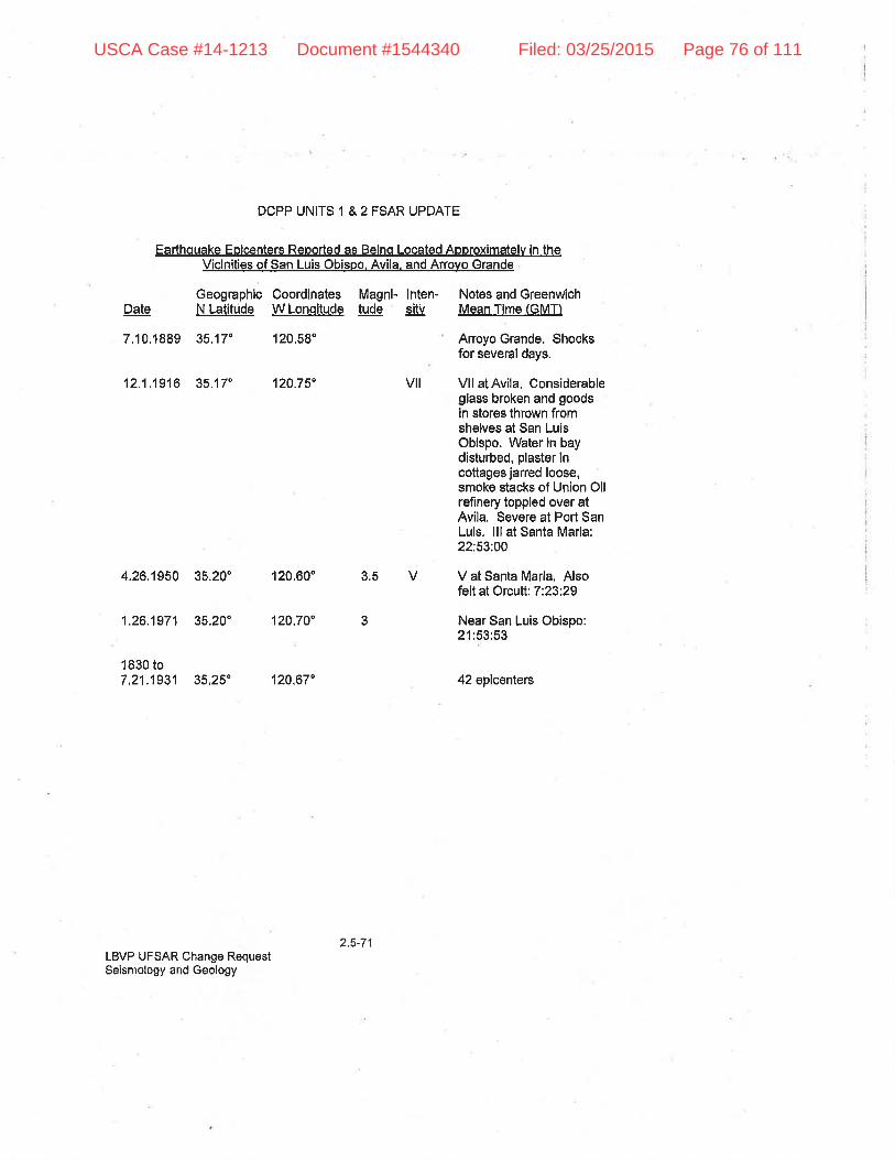
DCPP UNITS 1 & 2 FSAR UPDATE
Earthouake Eoicenters Reoorted as Beino Located Aooroximatelv ln theViclnities of San Luis Obispo. Avila, and Arrovo Grande
Geographlc Coordlnates Magnl- lnten- Notes and GreenwichN Latitùde W Lonoítude tude Cily Mean Time (GMT)Date
7,10.1889 35.17' 120.58'
12.1.1916 35.17" 120.75" vil
4.26.1950 35,20" 120,60" 3r5 V
1.26.1971 35.20' 120.70' 3
1830 to7.21,1931 35,25" 120,67"
LBVP UFSAR Change RequestSeismology and Geology
Arroyo Grande. Shocksfor several days.
Vll atAvila, Considerableglass broken and goodsin stores thrown fromshelves at San LuisObispo. Water in baydisturbed, plaster lncottages jarred loose,smoke stacks of Union Ollrefinery toppled over atAvila. Severe at Port SanLuis. lll at Santa Maria:22:53:00
V at Santa Marla, Alsofelt at Orcutt: 7:23:29
Near San Luis Obispo:21:53:53
42 epicenters
2,5-71
USCA Case #14-1213 Document #1544340 Filed: 03/25/2015 Page 76 of 111

DCPP UNITS 1 & 2 FSAR UPDATE
Viclnitv of the Offshore Santa M,aria Basin East Boundarv Zone
GeographicCoordinates Magni- lnten- Notes and GreenwichDãte
s.27,1 sBS(30-1)
N Latttude W LonqitudP tude sitv Mean Time l'GMïl
35,62: 121.94" 3 ilt Felt at Templeton:16:08:00
9.2.r esg(30'6) ss.¡6" 121.s0" 3 Ofi San Luis ObispoCounly; felt âtCambria: 2:50:30
1 .27J945 34.75" 120.67"
12.31.1g4s(30'10) 3s,60" 121.23'
11,17.1949 34,80" 120.70"
z.s 1 9bs(30-23) 3s.86" 121 .1s"
17:50:31
Felt along ooasl fiomLompoc to MossLanding. Vl at SanSimeon. V at Cayucns,Creston, MossLandìng. PiedrasBlancas Light Station:14:35:46
lV at Santa Maria.Near Priest: 5:06:60
46
3.9
2.8
aq West of San Simeon:7:10:19
6.2f .1ss7(30-254) 3s,2s" 120.95" 3.7 Off Coast. Felt in SanLuis Qbispo, MorroBay.20:46:42
B 10.1958 35,60" 121 .30 3.4 Near San Simeon5:30'.42
1 0.25 1967 35.73" 121 .45^ 2.6 Near San $imeon23:05:39.5
I lnigures in parentheses refer to events relocated by S. W. Smilh, r€fÊr l,-ìs{r€ Täble 2,5-2).
LBVP UFSAR Change RequestSeisrnology ond Geology
Erllted lor Clarlty - Refèr toApplicabillty OetÊrmlnal¡on Mâtrix lterrril7
2,ã-72
USCA Case #14-1213 Document #1544340 Filed: 03/25/2015 Page 77 of 111

DCPP UNITS 1 & 2 FSAR UPDATE
I Z.S,æ,e Description of Acfive Faults
Data pertaining to faults with lengths greater than 1000 feet and reaches within 50 milesof the site, as idenlit¡ed during the oriçjinal design phase, are included in Section2.5.?J.1,5, Structure of the San Luis Range and Vicinity, and in Figures 2.5-3 and 2,5-4.These data indicate the fault lengths, relationship of the fuults to regional tectonlcstructures, known history of displacements, outer limits, and whelher the faulls can beconsidered as active.
I Z.s,<U Results of Faulting lnvestlgatlon
The site for Units 1 and 2 of DCPP was investigated in delail for faulting and otherpossíbly detrimental geologic conditions. From studies made prior to design of theplant, it was determined that there was need to take into account the possibillty olsurface faulting in such design. The data on which this determination was based arepresented in Section 2.5.?1.?, Sìte Geology.
I z.s.sl Stabillty of Subsurface Matçrials
The possibility of past olpotentìal surface or subsurface ground subsidence, uplifi, orcollapse in the vicinity of DCPP was considered during the course of the geologicinvestigafions for Unlts 1 and 2,
I Z,O.e+.t Geologic Fealures
The slte is underlain by folded bedrock strata consisting predominantly of sandynludstone and fine-graìned sandstone. The existence ofan unbroken and otherwiseundeformed section of upper Pleistocene terrace deposits overlying a wave-cut bedrockbench at the site provides posilive evidence that alf folding and faulting in the bodrookantedated formation of the lerrace. Local depressions and other irregularities on thebedrock surface plainly reflect eroslon in an ancienl surf zone,
The rocks that constítute the þedrock section are not subJect to signíficant solutloneffects (i.e., development of cavitles or channels that could affect the engineering orfluid conducting character of the rock) because the bedrock section does not containthick or continuous bodies of soluble rock types such as lirnestone orgypsurn. Voidsencountered during excavation at the site were limlted to thin zones of vuggy brecciaand isolated vugs in some beds of caloareous mudstone, Areas where such minorvuggy conditions were presenI were noted at a few locations in the excavation lor theUnit 2 containment and fuel handling structures (at plant grid coordinates N59, N597,E10, E005 and N59, N700, E10, E120).
The maximum size of any individual opening was 3 inches or less, and mo€t were lessthan 'l inch in maximum dimension. Because of lhe limited extent and isotated nature ofthese small voids, they were not considered slgnifìcant in foundation engineering orslope stability analyses.
2.5'73LBVP UFSAR Change RequeslSeismology and Geology
Edllecl for Clarlty . Revised Secl¡onNuml¡er
Added for Clarity - Refer loApplicablllty Det€rrnlnatlon Malrlx llen'l*4Edlted l0r Clarlty - Revlsed SectlonNumbsr
Edlted for Clarily - Revisod Secttonf{umber
Edl(ed for Clarity - Rev¡sod SecllonNumberEdited for Clarily' Revised Secl¡onNumber
Edlled lor Clarlty - Rev¡secl Secllonlrlurnber
USCA Case #14-1213 Document #1544340 Filed: 03/25/2015 Page 78 of 111
DCPP UNITS 1 & 2 FSAR UPDATE
It has been determined by lield examination that no sea caves exist in the lmmediatevicinlty of the slte, The only cave like natural features in the area are shallow pits andhollows in some of the sea cliff outcrops of resistant tuff, These features generally havedimensions of a few inches to about 10 feet. They are superficial, and have originatedthrough differentíal weathering of variably cemented rock,
Several exploratory wells have been drilled for petroleum within the San Luis Range,but no production was achieved and the wells were abandoned, The area is not nowactlve in terms of either production or exploration; The location of the abandoned wellsis shown in Figure 2,5-6, and the geologic relationships in the Range are fllustrated inSection A-A' of Figure 2,5-6 and in Figure 2.5-7, Section D-D'. The nearestoíÞproducing area is the Arroyo Grande field, about 15 míles to the southeast,
The potential for future problems of ground instability at the site, because of nearbypetroleum produclion, can be assessed in terms of the geologic potential for theoccurrence of oil within, or offshore from, the San Luis Range. ln addition, assessmentcan be made in terms of the geologic relationshlps in the slte as contrasted wlthgeologic oonditions in places where oil field exploitation has resulted in deformation ofthe ground surface.
As shown in Figures 2.5.6 and 2.5-7, the San Luis Range has the structural form of abroad synclinal fold, which in turn is made up of several tightly compressed anticlinesand synclines of lesser order. The configuration is not conducive to entrapment ofhydrocarbon fluids, as such fluids tend to migrate upward through beddíng andfracture-controlled zones of higher primary and secondary pormeabllity until they reacha local trap or escape into the near surface or surface environment.
\Â/ithin the San Luis Range, the only recognizable structural traps are in local zoneswhere plunge reversals exist along the crests of the second-order anticlines. Suchstructures evidently were the actual or hoped-for targets for most of the exploratorywells that have been drilled in the San Luis Range, but none of these wells hasproduced enough oil or gas to record; lhus, the traps have not been effective, orperhaps the strata are essentially lacking in hydrocarbon fluids. Other conditions thatindicate poor petroleum prospects forthe Range include the general absence ofgood reservoir rocks wlthin the section and the relatively shallow basement of nonpetroliferous Franciscan rocks.
ln the offshore, adjacent to the southerly flank of the San Luis Range, subsuffaceconditions are not well known, but are probably generally similar, Scattered datasuggest that a structural high, perhaps defined by a west-northwest plunging anticline,may exist a few miles offshore from DCPP site. Such a feature could conceivably serveas a structural trap, if local closure were present along its axis; however, it seemsunlikely that it would contain slgniflcant amounts of petroleum,
2.5-74LBVP UFSAR Change RequestSeismology and Geology
USCA Case #14-1213 Document #1544340 Filed: 03/25/2015 Page 79 of 111
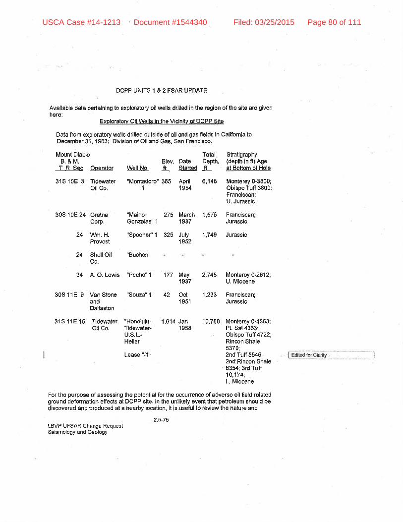
DCPP UNITS 1 & 2 FSAR UPDATE
Available data pertainlng to exploratory oil wells drilled in the region of the site are givenhere:
Exploratorv Oil Wells in the Vicinitv of DCPP Site
Data from exploratory wells drilled outside of oil and gas fields in California toDecember 31, 1963: Division of Oil and Gas, San Francisco,
Mount DiabloB.&M,T R Sec Operator
31S1OE 3 TidewaterOilCo,
30S 10E 24 GretnaCorP.
31S 11E 15 TidewaterOllCo.
TotalElev, Date Depth,ft Started fr
Stratigraphy(depth in ft) Ageat Bottom of Hola
Monterey 0-3800;Obispo Tuff 3800Franciscan;U. Jurassic
FranciscanJurassic
WellNo.
"Montadoro" 3651
"Maino-Gonzales" 1
"Honolulu-Tidewater-U,S.L.-Heller
6,146
275 March 1,5751937
July1952
1,749 Jurassic
April1 954
24 Wm. H.Provost
"Spoone/'1 325
24 ShellOilCo.
"Buchon"
34 A. O. Lewis "Pecho" 1
30S 11E 9 Van Stone "Souza" 1
andDallaston
Monterey 0-2612;U, Miocene
1,233 Franciscan;Jurassic
10,788 Monterey0-4363;Pt. Sal 4363;Obispo Tulf 4722;Rincon Shale5370;2nd Tuff 5546;2nd Rincon Shale6354; 3rd Tuff10,174;L, Miocene
177 May 2,7451937
42 Oot1 951
1,614 Jan1 958
Lease "ilq
For the purpose of assessing the potential for the occurrence of adverse oll field relatedground deformation effects at DCPP slte, in the unlikely event that petroleum should bediscovered and produced at a nearby location, it is useful to review the nature and
2.5_75LBVP UFSAR Change RequestSeismology and Geology
for
USCA Case #14-1213 Document #1544340 Filed: 03/25/2015 Page 80 of 111
DCPP UIIITS 1 & 2 FSAR UPDATE
causes of such ground detormation, and the lypes of geologic condltions at placeswhere it has been observed.The general subject of surface deformation associated wlth oil and gas field operallons
I has been reviewed by Yerkes and Castle (Referel¡c* 22f=, among others. Suchdeformation includes tJifferential subsídence, development ol horizontally compresslvestrain effeots within the central parts of subsidence bowls and horizontally extengivestrain effects around their margins, and development or activation of oracks and faults.Pullapart cracks and normal faults may develop in the merginal zone of extensivestrain, whlle reverse and thrust fuults sometimes occur in the central, compresslve partof subsidence bowls, These effects all can develop when extraction of petroleum,water, and sand, plus lowering of fluid pressures, result in compression within andadjacent to producing zones, and ettendant subsidence of the overlying ground. Othereffects, including rebound of the ground surface, fault activation, and oarthquakegeneratíon, have resulted from injection of fluid inlo the ground for purposes ofsecondary r€covery, subsidence control, and disposal of fluid waste.
ln virtually all instances of ground-surfaoe deformatlon associated wlth petroleumproc{uclion, the producing field has been centered on an anticfinal structure, in generalrelatively broad and intemally faulted. The strata in the producing and ovellying parts ofthe section typically are poorly consolidatecl sandetone, slltstone, claystone, and shaleof low structural competence. Tlre field generally is one wlth relatlvely large production,wlth significant decline of fluid pressure ln the producing zones.
The conditions just ciled can be contrastecl with those obtained in the vicinity of DCPPsite, where the rocts lie along the flank of a major ayncline. They consist of tightsandstone, tuffaceous sandstone, mudstone, and shale, together wlth large resistanlmâsses of tuft and cliaÞase. Bedding clips range from near horizontal to verlical andsteeply overturned, as shown in Section D-D' of Figure 2.5-7 and Section A-B otFigure 2.5-10. This structural selling is unlíke eny reported from areas whereoil"fieÌd-associated surface deformation has occuned,
The foregoing discussion leads to the following conclusions: (a) future development ofa producing oil fielcl in the vicinity of DCPP site is hlghly unlikely because of unfavorablegeologic conditions, ând (b) geologic conditions in the síte vicinity are not conducive tothe occurrence of srtrface deformation, even if nearby petroleum production could beachievecl.
As was noted in Section 2.4, the rocks underlying the site do not constitute a signilìcantgroundwater reservoiÍ, so that future development of deep rock water wells ln thevicinity is not a reasonable possibility. The considerations pertaining to surfacedeformation resulting from water extraction are about the same as for petroleumexlraction, so there is no likelihood that DCPP site could experience artificially inclucedand polentially damaging subsidence, uplift, collapse, or changes in subsllrfaceeffective stress related to pore pressLrre phÊnonìena,
LBVP UFSAR Change RequeslSeisnrology and Geology
Ediled for Conslslen(y
2.5-76
USCA Case #14-1213 Document #1544340 Filed: 03/25/2015 Page 81 of 111
DCPP UNITS 1 & 2 FSAR UPDATE
Tlrere are no mineral deposits of oconomic significance ln the ground underlying thesite.
Allhough sonre regional warping and upllfr may well be taklng place ín the southernCoast Ranges, such deformalion cannot be sutficiently rapid and local to imposesignlficant effects on coastel installalions. Appar.enf elevation of the San Luis Rangehas lncreased €bout 100 feel relatîve to sea level s¡nce thê cutt¡ng of the main terracebench at least E0,000 years ago.
Expresslons of deforrnation preserved ln the bedrock ât the site include minor faults,folds. end zones of blocky fracturing ln sandstone and intra-bed sheafing in claystone.Zones of cemented breccia also are present, aa is widespread evidenoe of dlsturbanceadjacent to intrusive bodies of tuff, Local weakening of the rocks ln some of thesezones led to some problems during construction, but these were handled byconventional techniques such as overexcavation and rock bolting. No observedfeatures of detormation are large or continuous enough to impose signlficant effects onthe overall performance of the site foundation.
The foundation excavations for Units 1 and 2 were extended below the zone of intensenear sudace weathering so that the exposed bedrock was found to be relatively freshand firm The princípal zones of structural weal(ness are associated with small bodiesof altered tuff and with internally shearecl beds of claystone, The claystone intra-beclshearwas expressed by the development of numerous slickenslded shear surfaceswithin parts of the beds, especially in places where the claystone had locally beensqueezed lnto pod like masses. The shearing and local squeezing clearly areexpressions of the preferential occurrence of differential adjustments in the relativelyweaker claystone beds durlng foldlng of the secllon.
The claystone beds are locatized [n a part of lhe rock section that underlies thedischarge structure and extsncls across the southerly part of the Unit 2turbine-generator building, thence contínuing easlerly, along a strike through theground south of the Unit 2 containment. The bedding dips 48 to 75" north wlthin thiszone. lndividttal clayslone beds range from 112 inch to about 6 inches in thickness, andlhey occur as interbeds in the sandstone-mudslone rock section
. The relationship of the claystone layers to the foundation excayation is such that theyI crop out in several nerrow bands across the floor ancl walls (refer tqs++ Figures 2,5-i5
and 2,5-16). Thus, the claystone bed remalns confined within the rock section, exceptilr a narrow strip at the face of the exoevation. Because of the small amounl ofclaystone mass and the geometr¡c relationshlp of the steeply dipping claystoneinterbeds to the foundation structures, it was delermined that the finished structurewould nol be affected by any tendency of the clayslone to undergo further changes involume.
LBVP UFSAR Change RequestSeisrnology and Geology
Ediled lor Clarily - Refer toApplicab¡l¡ty Dotermlnalion Mátrix trern#7
2,5-77
USCA Case #14-1213 Document #1544340 Filed: 03/25/2015 Page 82 of 111

DCPP UiJITS 1 & 2 FSAR UPDATE
The only areá ln which ôlaystone swelling was monitored was along the nofth wall of lhelower part ot the large slot cut for the cooling water dlscharge structure. There areseveral thin (6 inches or less) claystone interbeds in the sandstone-mudstone section,Because the orientation of the bedding and the plane of the cul face dfffer by only aboul30", and the bedding dips steeply into the face, opening of the cut served both toremove lateral support from the rock behind the face, and also to expose the clay bedsto rainfall and runoff. This apparently resulted in both load refief and hydration swellingof the newly exposed claystone, which in turn caused some outward movêment of thecut face. The movement then continued as gravity creep of the looally destablllzedmass of rock between the clayslone beds and the free face. The movement was finallycontrolled by installation of drilled-in laleraftie-backs, prior to placement of thereinforced concrete wall of the discharge structure.
No evldence of unrelieved residual stresses in the bedrock was noted during tlreexcavation or subsequent conslruction of lhe plant foundation, lsolated'occurrences oftemporary slope lnstablllty cleâfy were related to locälly weathered and fractured rock,hydration swelling of claystone interbeds, end local saturatlon by surface runoff, TheUnits 1 and 2 power planl facilities are founcled on physioally and chemically stablebedrock,
I Z,S,s+.2 Properties of Underlylng Maüerials
, Static and dynamic engineering properties of nraterials in the subsurface al lhe site areI presented in Section 2.5.2+.2,6, Site Engineering Properlies.
I z.s.ra,r plot plan
Plan views of the site indìcating exploratory boring and trenching locations are, presented in Figures 2.5-8 and 2,5-11 through 2.5"15. Profiles illuslrating theI subsurÍace condilions relative to the PGóiË Destlln ClagE lserer¡ç€st+greÊl structures, are ftrrnished in Flgures 2.S-12 through 2,5-16. Discussions of engineering propeñiesI of materials and groundwater condltions are included in Section 2.5,21,,2,6, Site
Engineering Properties.
I z.s,s+.+ Soiland Rock Gharacterlstics
lnformatlon on compressional and shear wave velooity surveys performed al the site areincft¡ded in Appendices 2.5A and 2,58 of Reference 27 of Section 2.3. Values of soilmodulus of elasticity and Poisson's ratio calculated from seismic measurements arepresented in Table 1 of Appendix 2,5A of Reference 27 of Section 2,3, and inFigure 2.5-1 9. Boring and trench logs are presented in Fígures 2.5-23 through 2.5-28.
I Z.O.S+.S Excavatlonsand Backllll
2.5J8LBVP UFSAR Change RequestSeismology and Geology
Edlted for Clarlty - Revised SeclionNumber
Edited for C¡ärtty - Revised SectionNumberEdlted br Clatlty - Royised Secl¡onNumber
Ediled for Çlaríty - Refer toAppllcatrllity Detenninalion Malr¡r ltemf5Edited for Clarity. Revised SecllonNumber
Edited for Clarily - Revised SeclionNumber
Edited for Clarlty. Revlsed SeciionNumbsr
USCA Case #14-1213 Document #1544340 Filed: 03/25/2015 Page 83 of 111

DCPP UNITS 1 & 2 FSAR UPDAÏE
Plan and profile clrawings of excavations and backlTll at the site are presented in. Figures 2,5-17 and 2.5-18, The engineered backfill placement operatìons are discussedI in Section 2.5.21.2,6.4, Engineered Backfll
I z.s.a+.G Groundwator Condltione
Groundwater cond[tions at the site are discussed in Section 2.4,13, The effect onfoundalions of frG&Ë Design Class lÊeissie4ategoryJ slructures ls discussed ÌnSectlon 2.5,2+,2,6, Slte En glneerlhg Propertles.
I Z.S.Sl.l Rosponse of Sof I ancl Rock to Dynamlc Loadlng
Detalls of dynamlc testing on slte materials are contained ln Appendlces 2,5A and 2,58of Reference 27 in Section 2.3.
I Z.S.s+.t Liquefaction Potontial
I As stated in Section 2.5,24.2,6.5, adverse hydrologic effects on foundations of PG8.EI Design Ctass l$'ei+n¡ir+€e+egetÊ{ structures can be neglected dr.¡e to the structures
being founded on bedrock and the groundwater level lying well below fìnal grade.
There is a small local zone of medìum dense sand located norlheast of the lntakestruqture and beneath a portion of buried ASW piping lhat is not attached to thecirculating water tunnelÊ, This zone is susceptible to liquefaction during design basisseismlc events (References 45 and 46). The associated liquefactlon-¡nducedsettlements from seismic events are considered in lhe design of the buried ASW piping,(References 48 and 49)
I z.S.s+.9 Earthquake Design Basis
I sign bases ctionI e design reI the earthqr alysisI rponents is
acceleration curves for the site resulling from Earthquake B and Earthquake D-modif¡ed, are shown in Figures 2.5-20 and 2,5-21 , respectively. Response spectrum curves forI the+-5[4 Hosgri earthquake are shown in Figures 2,5-29 through 2.5-32.
I z,s,æ.'to staflc Anatysts
A discussion of the analyses performed on materials at the site is presented inI Seotion 2.5.'¿+.2.6, Site Éngineering Properties.
LBVP UFSAR Change RequestSeismology and Geology
Ediled tor Cfarily- Revised SoclionNumberEdited for Clarity - Revlsod Section
, Number
, Ed¡ted far Clarlty - Refer lo. Applicablllty Det€rmlûallon Matrlx ltem:#5
Edited for Clarlly - Revised SeotionNumberEdlled for Clarily. Revieed SeclionNumber
Edlted lor Clarity. Revised SeclionNumberEdlted for Clarlly - Revlsed SeclionNumborEdited fof Clarity - Refer toApplicêbillly Oelermlnallon Malrix ltemfl5
Edited for Clarity - Revised SectlonNumber
, Ëd¡led lor ClarltyAdcled for ClarltyEdlled for Clarity - Revised Secl¡onNumberEd¡ted lot ClerltyAdded forCtarlly - Secllon Fointersrevl6ed lo be more Bccurâle.
Edited lor Ctarity . Revised SectionNunìber
Edlled for Clarity . Revlsed SeclionNurnber
2 5.79
USCA Case #14-1213 Document #1544340 Filed: 03/25/2015 Page 84 of 111
DCPP UNITS 1 & 2 FSAR UPDAÏE
| ¿.A.g.tt Criteria and Design Methods
The criteria and methods used in evaluafing subsurface material stâbility are presentedI in Section 2,5.2+.2,6, Sile Engineering Properties.
I Z,SjÉ.1Z Techniques to lmprove $ubsr¡rface Condltions
Due to the bearing of in sitri rock being well in excess of lhe foundalion pressure, notrealment of the in situ rock is necessary. Compaclion specifications for backfill are
I presented in Section 2,5.i41.2.6.4, Engiáeered Backfìll.
I z.s.ar sLoPE STAB|LTTY
I z.S.W,t Sfope Characteristics
. The only slope whose failure during a DDE could adversely affect the nuclear powerI plânl is the slope east of the buitding complex (rafer tos+e Figures 2"5-17 ,2.F18, and
2.5-22). To evaluâte the stablllly of this slope, lhe soil and rock conditions wereinvestigated by exploratory borings, test pits, and a thorough geological reconnaissanceby the soil consultant, Harding-Lawson Associâtes, and was in addition to lhe overallgeologic investigation performed by other consultants.
The slope confìguration and representative locations of the subsurface condltionsdetermined from the exploration are shown on Plates 2, 3, and 4 of Appenclix 2.5C ôfReference 27 of Sec{ion 2.3. Reference 44 provides further lnformation complled in1997 in response to NRC queslions on landslide polential.
Bedrock is exposed along the lower porlions of the cut slope up to aboul the lowerbench at elevation 115 feet. lt consists of tuffaceous siltslone and fine-grainedsandstone of the Monterey Formalion. Terrâce gravel overlies bedrock and extends toan approximate elevation of 145 feet. Stiff clays and silty solls with gravel and rockfragments c¿nstitute the upper material on lhe slte. The upper few feet of fine-grainedsoÍls are d'ark brown and expansive,
No free groundwater was obserued in any of the borings wbich were drilled in April1971, nor was any evidence of groundwater observed in this slope during the previousyoars of investigalion and construction of lhe project.
lln response to an NRC request in early 1997, PG&E conducted furlher investigations ofslope stability at tlre site iReference 44)"þ. The results of the investigations showedlhat eaflhquake loading, as a ru=sr.¡Íi of arr earllrquah;e on the Hosgri laull zone. followingperiods of prolonged precipitation will not produce any significant slope lailure that canimpact Design Class I structures and equipment. ln addition, polential slope failuresunder such conditions will not aclversely impact other important facilities, including theraw water reservoirs, the 230 kV ancl 500 kV sw¡tchyards, and the intake and dischargestructures, Potential lanclslides may temporaríly block the access road at several
2.s"80LBVP UFSAR Change RequestSeismology and Geology
Edited for Clarlly - Revised SectionNumber
Edlted lor Clarlty - Revised SeclionNumberEdlted for Clarlly ' Rovised SecllonNumber
Edited lor Cladty - Revlsed SectlonNumberEdited for Clarily - Revised SoclionNumberEdiled for Clarlty - Revlsed SectlonNumbÉr
Edlted for Clafity - Reler toApplioabillly Delermlnalion Matrix ltemil7
Edited lor Consislency
Add€d for Clarity - Refel toApplicabllily Delernìkìation Malr¡x llenìil27
USCA Case #14-1213 Document #1544340 Filed: 03/25/2015 Page 85 of 111
DCPP UNITS 1 & 2 FSAR UPDATE
locations. However, there is considerable room adjacent to and norlh of the road toreroute emergency traffic.
The Investigation of the cut slope included geologic mapping of the soil arrd rockcondil¡ons exposed on the surface of slope and existing benches. Subsurfaceconditions were investigated by drilling test borings and by axcavating tesl pits in the
I natural slope above the plant sile (relÈr to+e* Figì.rre 2.5-22ir, The teËt borings weredrilled with a truck mounted, 24 lnch flight auger drill rig, and the test pits wereexcavatod with a track"mounted backhoe. Boring and Log of Test Pits 1, 2, and 3 werelogged by the soll consultanti borings 2 and 3 were logged by PG&E engineeringpersonnel. The logs of all borings were verified by the soil consultant, who examined allsamples obtained from each boring. Undisturbed samples were obtained from boring 2and each of the test pits. Because of lhe stiffness of the soil, hardness of the rock, andtype of drilling equlpment used, lhe undisturbed sanrples were obtained by pushing an18.inch steel lube that measured 2,5 inches in outside diameter, A Sprague &Henwood split-barrel sampler containing brass liners was used to obtain undisturbeclsoil samples from the test pits. The brass liners measured 2.5 inches in outsidedlanreter and 6 inches in height. Logs of the borings ancl pits are shown in Figures 2.5-23 through 2,5-27. The soils were classäied in accordance with the Unified SoilClassification System presented in Figure 2.5-28.
I Z.S,s+.2 Design Orlterla and Analyses
Undisturbed samples of the materials encountered in pits and borings were examinedby the soil consultant ín lhe laboratory and were subsequenlly tested to determine theshear strenglh, moisture oontent¡ and dry density. Slrain controlled, unconsolidated,undrained triaxial tests al field moisture were performed on the clay to evaluate theshear strength of the materials penelrated. (The samples were maÍntained at fielclmoisture since adverse moislure or seepage conditions were nol encountered duringtlris investigation nor previous investigations.) The conflning stÍess wes variecf inrelation to depth el which the undisturbed sample was taken, The test results arepresonted on the boring logs and are explained by the Key to Test Dala, Figure 2.5-29.
The results of strength tests were correlated with the results devetopecl during earlierinvestigations of DCPP site Mohr circles of stresses at fallure (6 to 7 percent srain)were drawn for each strength test result, and lailure lines were developed tlrrouglrpoints representing one-half lhe devialor stresses, An average C-0 strength equal to acohesíon (C) value of 1000 psf and an angle of internal friction (0) of 29" was selectedfor the slope slability analysis. The analysis was checked by maintaining the angle ofinternal friction (0) constant at 190 and varying the cohesion (C) from 950 psf (weakestlayer) to 3400 psf(deepest and strongest layer).
Because of the presence of large gravel sizes, il was not possible to eccuratelydetermine the st¡ength of the sand and gravel lense. However, basec.l on tests on sandsamples from other parls of lhe site, an angle of internal friction of 35' was eeleoted esbeing the minimum available. An assumed rock strength of 5000 psf was usecl. This
LBVP uFsAR change Requesl 2'5'81
Seismology ancl Geology
Moved toxl lrorn Section 2.5 5.2
Edlted lor Clarlty - Rel€r teApplicabillty Delernì¡nalion Malnx llom#7
Edlled for Clârlly - Rev¡sed Se6tiohNumt¡er
USCA Case #14-1213 Document #1544340 Filed: 03/25/2015 Page 86 of 111

DCPP UNITS 1 & 2 FSAR UPDATE
value is consistent with strength tests performed on remold rock samples from otherareas of f he site.
The stability of the slope was analyzed for the forces of gravity using a slatic methodthat is, the conventional nrethod of slices. This analysis was checked using Bishop'smodified method. The static method of analysis was chosen because, for the soilsonditions al the site, lt was judged to be more conservative than a dynamic analysls,
Because the overall strength of the rock would preclude a stability failure except along aplane of weakness which was not encountered in the borings or during the manygeologic mappings of the slope, only the stability of the soil over the rock was analyzed.The strength parameters were varied as previously discussed to detennine theminimum factor of safety under the mosl critical strength condition. For the staticanalysis exctuding horizontal forces, lhe factor of safety was compuled to be 3 Whenthe additional unbalanced horizontal force of 0,4 t¡mes the welght of the soll within thecritical surface combined wlth a vertical force of 0.26 times the weighl was included, lheminimum computed factor of safety was 1,1.
On the basis of the investigation and analysis, lt was concluded that the slope adJacentto DCPP site would not experience instability of sufficient magnitude to damageadjacent safety-related structures.
The above conclusion is substantiated by additional fielcl exploration, laboratory tests,I and dynamic analyses using finite element techniques. Refer toSee Appendix Þ.5C of
Reference 27 in Section 2.3, Harding-Lawson Associates'report on this work.
¡. tt-€lte-vJin@Êreeipiieli.en-+¿ill-eelrre4see any signif¡Êent clepe{ailttp¿{€l€f#-iåli++re.++*árt.inettClrg+he-r@
!e grv eial le e¡ t i ens, H -ttever, thff e i s eør sktre.nUt+ee*aelaeen++e-aed+ot{h-alUre-rês+.te {€F€*+iê€trt€rgene,f4¡eff*+
I ex.€.3-+-*a+xpte+a+t++
{lreinryeslt ie++appregFeilåe+€it€nd+€€l+ee nditræe-+xBesed-en-he*t+#a+etelepe-and+xrs{mg$e+rehes--€+rb5ufu s@Lb+aril!€e-te€{+€¡¡n¡+++++i-Cepe-etreve-the-plenl-dte-1se+ @ngs+vereAçilk'+f+aAÞe-{+i.çk-s¡r¡snleeJ-++¡nct +l+Så-É€+++1ri.ll¡i+ +-I racl.- nre r+C€dåe€khee=-€wing*v1-tog€'g€G++i!+@nesss*efllì-b€¡¡Êg++-sf,d+ +e¡êr€+-lsg€.edèf+C€.8€€g+êe€+iÐg-p€+€,êÊf,81,-+h€Jsg+4Ê¿lt lae-t+Ss-u+r-+eiiì€d+./-{h+-çell-eer+:r+1t+nf-\¡læ-eia+Ê.râ€4€lt€ef,âÞl€€-âblatnêC+n€¡r+
2.5-82LBVP UFSAR Change RequestSeismology and Geology
Ediled lor Clarity - Reler loApplicability Determinalion Matrix ltem#7
Moved lext lo Enhanced Section2.5.6.1.
Deleted - Sub-seclioû texl relocatedlo Enhanced Section 2.5 6.1.
USCA Case #14-1213 Document #1544340 Filed: 03/25/2015 Page 87 of 111
DCPP UNITS 1 & 2 FSAR UPDATE
gã€l'$€rJflgi-Hixfi+lt¡+Þed+e++çle+we+e-eÞieiaed{+e+Sçf¡rqsì2-erìd-€€C+€'f.{ì.+-{€€fpi l+--Eeearr+e+f l9re+{òff.r+e¿-eHhe-es+L-egt+iprnec*+te+C-lfr++¿ndiet¡rþ+- h+1êôt-lr+5e{halçeo-sursel-3Fi+,rchesrleuiçi¿k;3brne+er--A-Sg+aS{}Ê-Heeweed€pl¡l-barrt-{;eråBl+$-€Ðrì+Ériâ,€++êsá+n+ër¿e+.$Ê+d+ê€,þlê¡ @l+sfpt{+-Th+liraas f¡ss¡¡-a¡¡e-+s,r++el-2-5-i*€he{-¡+ì-sdsidõdlãm€{e+-€fl4€-¡fi€h€ç-¡Ê-l+iríg*+J=âgt€.€++lìt+r+r¡g+erxtË¡t€-å+Ë+.qs'#F-in+iãsf+så€-23+h+esgW-Tlì+-s+i1++++re-cla*sifie4in r¡eee¡aþ¡¡¿6-r,r{lþ1h€11ã¡{¡€d^Se¡l4k¡çêid+êtie'+SysJe+Bres€Ê{€{!¡å++€rr€+€-:8ì
I Z.S.e .rø Slope Stabllity for Burled Auxlliary Saltwater $ystem Piping
A port¡on of the buried ASW piping for Unit 1 ascends an approxlmate 2:1(horizontal/vertical) slope to the parking area near the meteorology tower (Plates 1 and2 of Reference 47). To ensure the stability of this slope in which the ASW piping isburied, a geotechnical evaluetion, considering various design basis seismic events, wasperformed by Harding Lewson Associales. This evaluation is described in Reference47. Based on this evaluation, lt was ooncluded that lhis slope will be stable duringseismic events and that additional loads resulting from permanent deformation of theslope will not impact the burìed ASW piping.
2.6.7 Long Term Seismic Program
On Novenrber 2, 1s84, the NRC issued the Diablo Canyon Unit 1 Facility OperatingLicense DPR-80. tn DPR-80, License Condition ltem 2.C,(7), the NRC stated, in part:
"PG&E shall develop and implement a program to reevaluate the seismic designbases used for the Diablo Canyon Power Plant,"
PG&E's reevaluation effort in response to the license condition was titled the "LongTerm S PG&E prepared and submitted to the NRC lhe "Final
I Rep.ort g Term Selsmic Program" in July 1988 (ReterenceI 4c,)*. the NRC performed an oxtensive review of the Final
, Moved text to Enhanced Seclion2.5.6.1 ,
Ediled for Clarlty - Revlsed SeclionNumber
Added for Clarily - New Sub-seclionfor lhe Terfi Selsmic Program.
Edited for Consislency
Ediled for Consistency
Ecliled for Consistency
Edited for Conslstency
Report, and PG&E prepared and submitted wrilten responses to formal NRC questions.ln February 1991 , PG&E issued the "Addendum to the 1988 Final Report of lhe DiabtoCanyon Long Term Seismic Program" (tìeference 41 )4. ln June 1 9gt , the NRCissued Supplem.ent Number 34 lo lhe Diablo Canyon Safety Evaluation Report (SSER)(Reference 42)tr. in which the NRC concluded that PG&E had satisfied LicenseCondition 2.C.(7) of Facilily Operaling License DFR-80. ln the SSER the NRCrequested certain confirmalory analyses from PG&E, and PG&E subsequentlysubmitted the requested anâlyses. The NRC's final acceptance of lhe LTSP is
I documented ¡n a letter to PG&E datecl April 17, 1992 (Reference 43)i€.
The LTSP conlains extensive dala bases and analyses that update the basic geologicand seismic information in this section of the FSAR Update. However, the LTSP
I material cloes not address or alter the current design iicensing basis for the plant.+n+
LBVP UFSAR Change Requesl 2'5'83
Seismology and Geology
USCA Case #14-1213 Document #1544340 Filed: 03/25/2015 Page 88 of 111
DCPP UNITS 1 & 2 FSAR UPDATE
fi-usìs++eiiì+d$€b+i{*}ì€+SAR!Ê4å{€, lrr SSEB 34 (RefËrence 42), the NR(l slatercl."The- Staf¡ notes that lhe seisrnic qualificalion basis for Diablo Canyon will conttnue lobe the original ctesign basis plus the Hosgri Evaluation basis, along with associateclanalytii=l melhods, initial c¡nditions, etc."
As a conclitìori of lhe I'lRC's 6lose oul ol l-icense Condltion 2.C.(7), PG&E comrñitted toEeveral ongoirrg activilies in supporl of lhe LTSP. as discussed in a public meetingbetween PG&E and the NRC on March 15, 1991 (Reference 53), describecl as the"Franlework for fhe Future," in a letler to the NRC, dated April 17, 1991 (Referenc-e 50),and affirmed lry the NRC in SSER 34 (Reference a3). These ongoing aclìvitiês itrclttdelhe following lhet are related to geology and seisnrology (Reference 42, Section2 5.2.4)
(1) To cÆntinue to maintain a slrong geosciences and engineering stafi tokeep abreast of ner¡v gecrlogícal, seismic, and se¡srn¡c engitreerirrginformatíon anrl ovah¡ate it with respect to its sigrtifiornce to ÞiahloCanyon.
(2j To continue to operalÊ the strorrg.rnolion acceleronreter array and tl¡ecoastal seisnric I relworh
A complete listing of bibliographic references to the LTSP reports and other documentsmay be found in References 40,41 and 42
2.5.7.1 Slroreline Fault 7-one
ln NovÈlrber 2C108, as ¡r result of the ongoin¡; activiiies clesc¡it¡ecl in Section 2.5 7 , f,hetJSGg working in collahoratron y¡ith the PG&E Geosciences Department, idenlifred analignnrerrl of nricrose¡snicity errbparallel lt lhÉ c¡¡astline adjace nt to DCPP indicatinEthe possibte presence of a previously ttnidentifìed feult fooated approximalely 1 l'.rrotlshore ol tlCPP. Tlre oflshore regíon associâtÊci with this fault was subseqttenllynanred lhe Shcreline faull zone
PG&E cJevelopecl estimatea of lhe 84r' percentile deterrninislic grortnd molion responsespectnrnt for earthquakes associalecl wtth the Stroreline faull zone. The results of thestrrcfy of lhe Shoreline fattll zone are documented in Reference 52 A map shr:wing tlreloc¿lion of the Shorelirre Faull Zone is provided in Figure 2.5-36. This report inclucles ecomparison of lhe updated 84'h percentile deternlinistic response spec'tra with the 1991LTSF arrcl 1977 l-losgri earthquake response spectra This cornparison inclÍcates thalthe uprlate<l cletermrnistic response spectra ate enveloped by both the 1977 Hosgriearllrc¡rrake speclnrnì and the 1991 LT$P earthquake sPectrum.
The l.,lRC developecl arr independent assessment of lhe seisrnic soulÕe characleristtcsof tlle Sttoréhrre farrll arrd pelormed ar, rndepenclent delerminisl¡c sËismic hazardassessnlent (fìeferences 54 and 55). The NRC concludecl that their çorrservativeestnnatÈs fcr ll'it- poterrlial ground molions fronl the Sltoreline hult are al ctr below the
2.5-84LBVP UFSAR Change RequestSeismology and Geology
Deleled for Clarlly * Refer toApptlcabllity Delerm¡nal¡on Matrix llenì#29Moved Text lrom Sectlon 2.5
Added for Clarity - Refer toApplicabillty Determination Matrix llenì#28Movecl texl frarn Enhanced Seclion2.5.
USCA Case #14-1213 Document #1544340 Filed: 03/25/2015 Page 89 of 111

DCPP UNIÏS 1 & 2 FSAR UPDATE
nround nrotions for which lhe DCPP has been evaluated previously ancJ dernonstratedto have a reasonable assrrrance o[ safrty (i.e , tlre 1977 Hosgri eârlhquake ancl 1991LTSP eartltquäke ground motion response Epeolrâ). The I'lRÇ slatecl lhat the:"Shoreline scenario should Lre co¡rsidered as a lesser irrcludecl case rlrlrjer the llc¡sgrievaluation,"
:2.5.7.2 Evahration of Updated Estirnates of Grouncl Motlon
As an outcome of lhe Shoreline fault zone evalualion descrlbed in Sedion 2Í>,7 1 ,lheFrrocess to be used for the evalualion of new/updated geological/seismologicallnformalicrn has heen developed (Relerences 55 and 56), The new/updatedç¡eologÌcal/seismological lnformation, resulting from he activities descdl:ed in Section2.5.7, will lre evalualed tlsing a process tlraf is corrsisl.enl wÍtlr tlre evalualion proÇ€ssclefrned tly the NRC in Reference 57.
2,5.8 Safety Evsluation
2,6,8,1 Gnnsral Design Criterion 2, '1967 Peffrrrrnance Stanrlarcls
Ther deiernlination ol the appropriale earthquake pãrameters for design of plant SSCs isadcliessed througlrou( Section ?,5. and lhe rnaxirl-rrrnr earlhqual<es for lhe ¡:tanl site arepresentecl in Seclions 2.5.3.9.1, 25.39.2., ancl 2.5 3.9.3. Theassociated design basis sitetree feld accelerations ancl res¡:onse spectra are presented in Seclions 2.5.3,10 1,2 5.3,10 2 and 2.5,3.10.3. The seisrnic design of lhese SSC is addressed in Section 3.7.
2.â.8,2 License Golrdition 2,C(7) of ttcPP Faclf lty Operatfng License DPR{0 Rev44 (LTSPI, Elernents (1), (2) and (3)
PG&E's rÊevaluation effort in respcns€ to the license conclition v¡as trtled the "l,-ong'lerm Seismic Program" (LTSP), PG&E prepared and suþmitted to the NRC the "FinalReport of the Dlablo Canyon Long. Ternr Seismic Program" ln July 1988 Betr,veen 1986ancl 1991 the l.lRC perfonned an exlensive review of the Final Reporl and PG&EÞrepated arrcl sr,l[¡rlifted wrilten respor¡ses [o fornral t{RC queslions" ln February f 991.Ë'úì&E iesued the "Adden<ium lo the 19BB Final Report of tlre Diablo Canyon Long TernrSeisnric f)rogram". ln Jrrne 1991, the NRC issued Supplenrent Nun¡ber 34 tc¡ the DlablcrCanyo¡-r Safety Evaluation Reporl (SSER) in which lhe l.lRC conch¡cled that PG&E hadsatislred License Ccndition ?.C.(7) of Fercility Operating License DPR-80 tn the SSERthe I'JttC reqtteslecl cedain confirmatory arralyses lrorn PG&E, and PG&E sr.rbsec¡uentlysr,rl-rmittecl lhe requestecl analyses Tl"re lrlRC's frnal acceptance of the LTSF isclocumented jn a letter to PG&E dated April 17, 1992
'Ihe colrmitments Íìade as a part of the Diablo Canyon Long Term Säisnûc Progranrare rJelaíled in Section 2 5 3 ç].4 and Sec(ion 2 5 7.
2.5.8.3 10 CFR Pad 100, March 1966. Reaclor Site Criteria
2.5.85LBVP UFSAR Change RequestSeismology and ceology
Added for Clarlly * New Sub-sectionlo describo the Shoreline Fault ZonoRefer to Appllcabllily DetermlnationMatrlx lfem # 30
A<tded for Clarlty - New Sub-sectlonlo describe lhê Evalualion of UpdatedEstimatos of Groun<J MotionRefer lo Applicabllity DetormlnE tionMatrix ltem # 31
Added lor Clarity * New Sub-seclionto Jusllfy Dos¡gn Bases Crlt€ria
Discusslon Added lo Juslity DesignBasis RequirementUFSAR Seclion 3.2.1UFSAR Seclion 3,7UFSAR Section 2,5.3.9UFSAR Seclion 2,5.3,10Ref€r to Applicabllity DelerminalionMatrix ltem # 32
Discuss¡on Added lo Jusliry DesìgnBasls RequiremenlssER 34Refer lo Appllcabil¡ty Detemina l¡onM8trlx ll€m # 33
USCA Case #14-1213 Document #1544340 Filed: 03/25/2015 Page 90 of 111

DCPP UNITS 1 & 2 FSAR UPDATE
I Ar. dar*ribr+ in $ectiÕrrs. L5.2 fhrOcgli ?.5.C1 Fbðve, lhe physìcal chrirgcrÊristicE ot rheI situ incltrr.lirrrr agie¡¡161¡¡gy and q¡eology lrave L¡aen cr¡nuldered.
I z.s.sr REFERENcES
1 R. H. Jahns, "Geology of the Diablo Canyon Power Plant Site, San Luis ObispoCounty, Callfornia," 1967-5uoplementerv Reports land ll, 1968€upplementarvReÞort lll, Diablo Canyon PSAR, Docket No, 50-275, (Main Report andSupplementary Report l). Diablo Canyon PSAR, Docket No. b0-S23, (All reports,1966 and 1967),
? R. H, Jahns, 'Guide to the Geology of the Diablo Canyon Nuclear Power PlantSite, San Luis Obispo County, Califomla," Geol. Soc. Amer,, Guìdebook for 66thAnnuai Meeting, Cordifleran Section, 1970
Deleted in Revision 1
Deleted in Revision 1
Discussion Added lo Jusllfy DeslgnBasls RequlromenlRefer to Applicab¡lily Delerminat¡onMatrlx ltem# 34
Ediled lor Clar{ly - Revised SeclionNumber
.J.
4
5. H, Benioff and S, W. Smith, "seismic Evaluation of the Diablo Canyon Site,"Diablo Canvon Unit '1 PSAR, Docket No 50-275. Also, Diablcj Canyon Unit 2PSAR Docket No. 50-323, 1967
6
7
I
John A. Blume & Associates, Engineers, "Earthquake Design Críteria for lheNuclear Power Planl - Diablo Canyon Site," Disblo Canvon Unit 1 PSAR, DocketNo. 50-275., January 12,1967. Also, Diablo Canyon Unit 2 PSAR DocketNo. 50-323.
John A. Blume & Associates, Engineers, "Recommended Earthquake DesignCritería for the Nuclear Power Plant - Unit No. 2, Diablo Canyon Site," DiabloCanvon Unlt2 PSAR, Docket No.50-323, June 24, 1968.
Deleted in Revision 1
9. Deleted in Revision 1
10. editor), Bull. '190,
1966. pp 255-276.
11. B. M. Page, "Sur-Nacinriento Fault Zone of California: Continental MarginTectonics," Geol. Soc, Amer.. Bull,, Vol, 91, 1970, pp 667-690,
12, J, G, Vedder and R, D. Brown, "Structural and Stratigraphic Relations Along theNacimiento Fault in the Santa Lucia Range and San Rafael Mountains,California," W, R, Dlckinson ancf Arthur Grantz (editors), Proceedinqs of
2.5-86LBVP UFSAR Change RequestSeismology and Geology
USCA Case #14-1213 Document #1544340 Filed: 03/25/2015 Page 91 of 111

13.
15.
DCPP UNITS 1 & 2 FSAR UPDATE
Conference on Geoloqic Problems of the San Andreas Fault Svstem, StanfordUniversig Publs. in the Geol. Sciences, Vol. Xl, 1968, pp 242-25E.
C. F. Richter, "Possible Seismicity of the Nacimiento Fault, Califomia," @[SqWI., Bull,, Vol, E0, 1969, pp 1363-1366,
E, W. Hart, "Possible Active Fault Movement Along the Nacimiento Fault Zone,Southern Coast Ranges, Califomia," (abs,), Geol. Soc. Amer., Abstracls withPrograms for 1969, pt, 3, 1969, pp22-23,
R. E. Wallaceì "Notes on Stream Channels Offset by the San Andreas Fault,Southerh Coast Ranges, California," W, R. D¡ckinson and Arthur Grantz (editors),
Svstem, Stanford Universíty Publs. in the Geol, Sciences, Vol, Xl, 196E,pp242-258.
Deleted ln Revlsion 1
Deleted in Revision 1
L, A. Headlee, Geoloqv of the Coastal Portion of the San Luis Ranoe. San LuisObisgo Countv, California, Unpublished MS thesls, Universlty of SouthernCalifornia, 1965,
C. A. Hall, "Geologic Map of the Morro Bay South and Port San LuisQuadrangles, San Luis County, Callfornla," U.S, Geoloqlcal SurvevMiscellaneous Field Studies Mao MF-S11 ,1973.
C. A. Hall and R, C, Surdam, "Geology of the San Luis Obispo-Nipomo Area,San Luis Obispo County, Californla," Geol. Soc. Amer., Guidebook for 63rd Ann.Meetíng, Cordilleran Section, 1967.
R, F. Yerkes and R. O. Castle, "Surface Deformation Associated with Oil andGas Field Operations in the Unlted States in Land Subsidence,".@!!l0gs.91thg Tokvo Svmposium, Vol, 1,.1ASH/A1HS Unesco,1969, pp 55-65.
C, W, Jennings, et al,, Geoloqic Map of Californla,gouth Hall scale 1:750,000,Galifornia Div. Mines and Geology, 1972.
2.5-87
16. C. R, Allen, "The Tectonic Environmenls of Seismlcally Active and lnactive AreasAlong the San Andreas Fault System," W, R. Dickinson and Arthur Grantz(editors),Fault SysteÐ, Stanford University Publs, ín the Geol. Sciences, Volume Xl, 1968,pp 70-82,
17.
18.
19.
20.
21.
22,
23.
LBVP UFSAR Change RequestSeismology and Geology
USCA Case #14-1213 Document #1544340 Filed: 03/25/2015 Page 92 of 111

24.
25.
26.
DCPP UNITS 1 & 2 FSAR UPDATE
John H, Wgglns, Jr,, "Effect of Site Conditions on Earthquake lntensity," ASCE.P!qçSSd!gg, Vol, 90, ST2, Part 1, 1964,
B, M, Page, "Time of Completion of Underthrusting of Franciscan Beneath GreatValleyRocksWestofSalinianBlock,Californiâ'',@,Bull,,Vol.81,1970, pp 2825-2834.
Eli A, Silver, "Basin Development Along Translational Continentdl Margins,"W. R. Dickinson (editor), Geolooic lnterpretations from Global Tectonics withAoplications for Californla Geolooy and Petroleum Exploration, San JoaquinGeological Society, Short Course, 1974,
T, W Dibblee,and lts Sionificance, Unpublished abstract of talk given to the AAPG, PacificSec{ion, 1972,
D, L, Durham, "Geology of the Southern Salinas Valley Area, CalifornÍa,"U,S, Geol, Survev Prof. Paper E19, 1974, p 111,
\t1/illiam Gawthrop, Preliminarv Report on a Short-term Seismic Studv of the SanLuis obisoo Reqion, in Mav 1973 (Unpublished researoh paper), 1973.
S. W. Smith, Analvsis of Offshore Seismicitv in the Vicinitv of the Diablo CanyonNuclear Power Plant, report to Pacific Gas and Electrlc Company, 1974.
H. C. Wagner, "Marine Geology between Cape Sân Martin and Pt. Sal, South-Central California Offshore; a Preliminary Report, August 1974,".USGS OoenFile Report 74-252, 1974.
32. R. E. Wallace, "Earthquake Recurrence lntervals on the San Adreas Fault",Geol. Soc. Amer., Bull,, Vol, 81, 1970, pp 1875-2890,
J. C. Savage and R. O. Burford, "Geodetic Determination of Relative PlateMotion ln Central California", Jour. Geoohvs. Reg, Vol. 78, No. 5, 1973,pp 832-845,
Deleted in Revision 1
35, Hill, et al., "San Andreas, Garlock, and Big Pine faults, California" - A Study ofthe character, history, and significance of their displacements, S9I-Sq.¿@,Bull,, Vol,64, No.4, 1953, pp 443-458,
36. C,A. Hall and C,E, Corbato, "Stratigraphy and Structure of Mesozoic andCenozoic Rocks, Nipomo Quadrangle, Southern Coast Ranges, California,"Gçol. Soc. Amer,, Bull,, Vol, 78, No. 5, 1969, pp 559-582. (Table 2,5-3, Sheet 1
of2),
2.5-88LBVP UFSAR Change RequestSeismology and Geology
27.
28.
29.
30,
31.
33
34
USCA Case #14-1213 Document #1544340 Filed: 03/25/2015 Page 93 of 111

39
40
41
DCPP UNITS 1 & 2 FSAR UPDATE
37 Bolt, Beranek, and Newrhan, lnc., ,
197311974. (Appendix 2.5D, to Diablo Canyon Power Plant Flnal Safety AnalyslsReport as amended through August 1 9E0), (See also Reference 27 ofSection 2.3.)
38, R. R, Compton, "Quatenary of the California Coast Ranges;" E. H. Bailey (editor),Geoloqv of Northern Calífornia, California Division Mines and Geology, Bull, 190,1966, pp 277-287.
Regulatory Guide 1,70, Revision 1, Standard Format and Contentpf SafçlvAnalvsls Reports for Nuclear Power Plantq, USNRC, October 1972.
Paoific Gas and Electric Company, Final Report of the Diablo Canvon Lono TermSeismic Prooram, July 1988.
Pacific Gas and Electric Company, Addendum to the 1988 Flnal Report of theDiablo Canvon Lonq Term Seismic Proqram, February 1991.
42, NUREG-0675, Supplement No. 34, Safetv Evaluation Report Related to theOperatlon of Diablo Canvon Nuclear_Power Plant. Units I and 2, USNRC,June 1991.
43. NRC letter tb PG&E, Transmittal of Safetv Evaluetion Closlno Out Diablo CanvonLono-Term Selsmic Prooram, (TAC Nos. M80670 and M80671), April 17, 1992.
44. Pacific Gas and Electric Company, Assessment g:l Slope Stabilltv Near theDiablo Canvon Power Plant, April 1997.
45. Harding Lawson Associates, Liquefaction Evaluation - Proposed ASW Bvpass -Diablo Canygn Power Plant, August 23, 1996.
46. Harding Lawson Associates Letter, *Geotechnical Consultation - LiquefactionEvaluation - Proposed ASW Bypass - Diablo Canyon Power Plant,'October 1, 1996.
47, Harding Lawson Associates Report, Geotechnical Slope Stabilitv Evaluation -ASW Svstom Bvpass, Unit 1 - Diablo Canvon Power Plant, July 3, 1996.
48. License Amendment Request 97-11, Submitted to the NRC by PG&E LettersDCL-97-150, dated August 26,1997; DCL-97-177, dated October 14, 1997;DCL-97-191, dated November 13, 1997; and DCL-98-013, datedJanuary 29, 1998.
49. NRC Letter to PG&E dated March 26, 1999, granting License AmendmentNo. 131 to Unit 1 and No. 129 to Unit 2.
2,5_89LBVP UFSAR Change RequestSeismology and Geology
USCA Case #14-1213 Document #1544340 Filed: 03/25/2015 Page 94 of 111
5g
51.
52.
53
54
55.
56.
DCPP UNITS 1 & 2 FSAR UPDATÉ
PG&E lettet to tlre NRC, "Benefils and lnsights of the Long Teml SeismicProgram,' DCL-91-091, April'17, 1901
John A. Blume and Associales lelter to FrG&E. "Ealhquake Design Criteria forlhe Nuclear Power Plant - Diablo Canyon Site," January 12. 1967.
Paciltc Gas and Electric Cornpany, Report on the Analvsis of the Shoreline FaùltZolt€ . çejtrat Coãstal Cafifornia, January 201 1.
I'IRC L.etter to FG&E, "Sqqrnrarv of March 15. 1991 Pu.ÞJic Meotinq to DiscussDieblo Canvon Lono-Term.Sçjsmic Proqrem (TAC Nos. 55305 ând 6e049)',Mârch 2?, 1991
NRC Offrce of Nuclear Regulatory Research. "Confrrmatory Analysis of Seismicllazarcl at the Diablo Canyon Power Plant form the Shoreline Faull Zone,"Research lnfot'nlation Letler No, 12-01 . September 2012
NRC letler to PG&E, "Diablo Canyon Power Planl, Unit Nos. 1 and 2 - NRClìevlew ol Shoreline Fault (TAC Nos. M85306 and M85307)," October 12,2012.
Pacific Gas and Electric Company leüer to the NRC, "Wthdrawal of UcenseArnendment Requesl '11-05, Evaluation Process lor New Seisrnic lnformalionand Ctarifying the Díablo Cartyon Power Plent Sate Shutdown Earthquaké.:Letler No DCL-''|2.103, October 25.2012.
NRC leller to All Power Reactor Lícensees and llofclers of Construsüon Permitsin Aclive or [f eferred Slalus, "Request of lnlprmation Pursuant to Title 10 of lheCode of Federal Regulalions 50.54(0 Regarding Recommendations 2.1. 2,3. ancl9.3 of the ltlear"'lerm Task Force Revíew of lnsiglrle from {lre Fukushima Dai-lchiAccident " M¿rc 12.2012
2.5-90
57
Added for Clarlty - Refer toAppllcnblllly Dêternìhallon Matrix llem#35
LBVP UFSAR Change BequestSeismology and Geology
USCA Case #14-1213 Document #1544340 Filed: 03/25/2015 Page 95 of 111

ÞCPP UNITS 1 & 2 FSAR UPDATE
?0
70
'e¡$t. r0
00
0¡0ü 020 ú10 0úa ort 16 rto?!rÉlñl
rao raô tæ ?00
NolesI This llgura. iç b¡sed on Releænce 42 Figùte 2 4
Added for Cfarìty - Refer toApÞlicsblllty Dctermlnation Matrix llem#36
LBVP UFSAR Change RequætSeismology ând Geology
FSAR UPDATEUN¡ÎS 1 Al'lD 2
CAltYOt'¡ 8lTE,FTGURE 2.e33
FRË.I; FIÉLD SPECTRUMHoRtZONTAt 1991 LÌSFiB4TH PERCENTILE NON.
ËXCEEDANCE)AS MODIF IËÛ PER SSER.
34
USCA Case #14-1213 Document #1544340 Filed: 03/25/2015 Page 96 of 111

20
DCPP.UNITS 1 & 2 FSAR UPDATE
A
;I
l0
OZ
0€ 0t0 0€ cð oä tqj tæoillad lE..l
to tü ræ
Noler1 thrs figtrre is t>esed or¡ Reference 42. Figure 2.5
Adcled for Clarlty - Reler toAppllcablllty oetermlnållon Malrix ltem#37
LBVP UFSAR Change RequestSeismology and Geology
FSAR UÞOAIEU¡¡ITS t AIID 2
ofA8Lo cAt{YOr{ srTEFIGURE 2.É-3,{
FREE'FIÊLD SPÊTÍRUMVERTICAL tggI LTSP
181T11 PERCE lìlTlLE No'!-EXCÊEOANCE)
AS MOT}IFIF-D PER SSER-34
USCA Case #14-1213 Document #1544340 Filed: 03/25/2015 Page 97 of 111
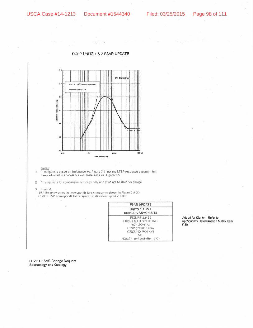
2i
15
DCPP UNITS 1 & 2 FSAR UPDATE
- - tt?? hrot lwÞ'rl
-rgtr
Lf aP
6% 0¿ 0
ll
I ï N
\
III
00
rô
0É
ûr0 r@ t0 oû r0q00FFqu.rcy llkf
I'loles'flris frgurê is based on Refe¡€nce 40, Frgure 7-2. bul lhe LTSP tesponse spechurn lrast'een arljrrsted in accordan(:€ v/ilil Ref€ronce 42.ligura2.5
2 I lirs lru,,re is for conìpånsoil prirposes onty and sh¡ill not be used for des¡qn
:t Lr:gër rdf f 77 I lrrslll (Nevrtrrark¡ ccr¡respor¡{is lc, llrË s'f)ectrrtflr shovrn in Figtle 2 5-3o. 19!Jt t TSP corrÊsporìds lo llre sf€clnun shr-ì\r.ñ xt Êicure 7 5-33
Added for Clarlty - Refer toApplicablllty Determlnatlon Matrlx ltem#38
LBVP UFSAR Change RequestSeismology and Geology
FS/ìR UPT¡ATE.UNITS .I AND 2
DIABLO CANYON SITEÍ:IGURE 2 S35
FREE FIELD SPECTRA.HOR12ONfAt
[.TSP (tlGEE lgflBrGROUtlD MOl IOl.l
VSIIOSGliI (Ntsvl/h¡lÀlll¿ I 97 7¡
USCA Case #14-1213 Document #1544340 Filed: 03/25/2015 Page 98 of 111

DCPP UNITS 1 & 2 FSAR UPDATE
ll0oroot(tanl
E
ì
I \i:.'lr'Ì1,
Bt!ro8ry
\þ'
q-'I
d¿.' .
i¡,rLü.\r, OråÞo0¡y
LEGEND
f-lswayroa
- Slsoà'ç, Ho¡01. Son tdÊ ftsy, ond Wl¡wáf dr¡o l4I¡, rh stHl $ìso opfiodmd!,
lr*,d'-n
s
0r2l-t$la.r=-l(lqrE{6!021
Notes1 Thls liflurt is bi¿seC on fìelerence 52. t.i(.lurû 1't
LBVP UFSAR Change RequestSeismology ând Geology
FSAR UPfJATË
I ¡GURL: 2 fi.3tjklAt ' or srtofrEltNE t:AULT
STUNY ARgA
Added for Clsr¡ly - Refer toApÞlicab¡llty Delermìnâlion Mätrix llem#39
U¡{ITS 1 ANO 2DIABLO CANYON SITE
USCA Case #14-1213 Document #1544340 Filed: 03/25/2015 Page 99 of 111

DCPP Form 69-10430 (121051121
Appllcablllty Determlnation
TS3.|D2 Attachment IPage I of 2
Proposed Activlty Title/lmplementing Document No:UFSAR Sectlon 2.5 (ceology and Seismology)
Unit:D1 trz 81&2lmp Doc Rev No:0
Briefly describe what is being changed and why:
UFSAR Section 2,5 (Geology and Seismology) is revised to reflect the results of the Licensing Basis VerificationProject for the Geology and Seismology section. The proposed change is belng processed against UFSARRevision 20. Changes include added text (e.9. to explicitly identify the licensing basis design requirements), revisedtext (e,9, to provide clarification), deleted teK (e.9, to remove excessive delail), and moved text (e,9. to re-organizeexisting information to improve reader understanding). The changes and the justification for each are shown in theattached annotated markup or Applicability Determination Matrix, Refer to the attached AD approach descriptionfor a discussion of the ApplicaÞility Determination Matrlx.
3. Applicabillty Determination Conclusions (refer to Section 8.18 for instructions):
X A 10 CFR 50.59 or 72.48 screen is NOT required because ALL aspects of the activity arecontrolled by one or more of the processes listed above, or have been approved by the NRC,or are covered in full in another LBIE review.
tl A 10 CFR 50.59 or 72.48 screen will be completed because some or all the aspects of theactivity are not controlled by any of the processes listed above or cannot be exempted fromthe 10 CFR 50.59172,48 screen.
2. Applicabllity Determinations (refer to Section I for lnstructions). Does the proposed activitylnvolve:
a. A change to the Facllity License, Environmental Protection Plan, or Technical Speclfications? trY 8rlb. A change to the Quality Assurance Program? trY Xruc. A change to the Security Plan (PSP, SCP, STQP, or CSP)? trY Xtld, A change to the Emergency Plan? trY Xtle, A change to the lnservice Testing (lST) Program Plan? trY 8Nf. A change to the lnservice lnspection (lSl) Program Plan? trY trNS. A change to the Fire Protection Program? trY Xtlh A noncompliance with the Environmental Protoction Plan or the potential creation of a
sltuation adverse to the environment?trY X¡l
t. A change tp the UFSAR (lncluding document$ lncorporated by reference) excluded from therequirement to peform a 50.59t72.48 review?
trv !ruj, Maintenance thal restores SSCs to their original or newly approved designed condition?
(Check "N" lf act¡vity ls related to lSFSl.)trY 8N
k. A temporary alteration in support of maintenance (TASM) that will be in effect duringnon-power operatlons and/or for 90 days or less during at power operations? (Check "N" ifactivity is related to lSFSl,)
¡Y X¡I
t. Managerial or administrative procedure/process controlled under 10 CFR 50, Appendix B or10 CFR 72, subpart G?
!Y X l.l
m. Regulatory commitment not covered by another regulatory based change process? trY Etln An impact to other plant specific programs (e.9., the ODCM) that are controlled by
regulations, the Operating License, or Technical Speclfications?trY X t'l
4. Does the proposed activity involve a change to the plant that requires a safety assessment? (referto Section 15 for instructions)
!Y Xtl
TS3.lD2 Form 69-10430 - Applicabllily Determinatlon.docx 0604.1710
USCA Case #14-1213 Document #1544340 Filed: 03/25/2015 Page 100 of 111

DOPP Form 69-1 0430 1121051121Appllcabl I lty Determ i nation
TSS.|D2 Attachntent 1
Page 2 of 2
5. Remarks: (Use this section to provlde suffìcient justifiealion(s) per step 5.1.2 lor delerminalions inttep 2 and conclusion ln slep 3.)
The changes do not lnvolve clrangeo lo lhe Faclllly/lsFsl OL, EPP or TS, or lhe ldenlified Plans/Programs (items2.a through 2.9), non-compliance wllh the Env¡ronmenlal Plan (ltem 2,h), malntenance (ltem 2,j), temporaryalterations ((llem 2.K), managerial or admlnlstrative prooedure/process (ltem 2.1), regulalory commltmenl notcovered by anolher regulatory proceEs (llem 2.m), or an impact to olher plant-specific programs (llem 2.n). Iheproposed change does lnvolve changes to lhe UFSAR, some of whlch are excluded from lhe requirements toperlonn a 10 CFR 50.59 review,
Item 2.1
ïhe prcpoeed activily involves chenges to lhe UFSAR lhat explicitly idenlifo the licenslng basls designrequlremenls and fheir basos eubmltted to, and approved by, the NRC ln dooketed correspondence. Olherchanges are made for clarification and lo remove excessive detail or repelílive i¡formation, The attachedannotaled merkup and Applicebllity ttetermination Matrlx ident'rfy the changes and associated Juslificalions. Notelhe Applicabillty Determlnation Matrlx provides furtherJustifcatlon of speclfic proposed UFSAR changes and areldontlfled ln thê altached annolated markups as "Refer lo Applicabllily Determlnatlon Mãtrix" (refer lo atlachedapproach <llscusslon), The changes are excluded from the requirement to perform e 10 CFR 50.591/2.48 reviewper the guldanoe of NEI 98-03, Appendix A, Section 42. The ohanges are'edlto¡ial changes, clarlficallons tolmprovo reader underslandlng, and lncorporalion of lnformalion approved by the NRC as a result of a licenseamendmenl or other docketed correspondence' (IS3.lD2 Seclion 8.12, Blook 2,i, Note 2). Refer to ailachedLicense Basis lmpact Evaluafion (LBIE) and Licensing Basis Verìfication Projecl UFSAR Enhancemenl initiative,LBIE Appllcabillty Determinâlion Approach.
Item 3
A 10 CFR 50,59 screen ¡s not required because all aspects of the proposed aclivity are controlled by the processeslisted in Section 2, An Appticabllity Determlnalion Matrlx has been atlached to provide Juslificallon as to why theidentffìed changes/aclivities do nol require a 10 CFR 60.59,'
Itsm 4
A revlew of Secflon 15 of TS3.ID2 has been performed and lt has been determined that a safety assessment ls notrequired. As staled in Section 15.3 lhe proposed acllvlly has no safety slgnificance. The proposed aclivily alsodoes not include any of lhe activities deflned ln Seclion 15,4,
'**F#*þ:',#:orrLB'|E) Dale: Prlnl Last Name:Angelucci
**'"Tryl1"" TLBIEAD or TLBIE) Date;
//i/i3Prlnt Last Name:Tyman
Signature: (Qual: TLBIEAD or TLBIE)revje|ecl by'PctE),t ;
iJtl¡;-- - -
n ru¿nDate:
r"l q i¡:Prlnt Lasl Name;llorstnrarr
Refer to Secllon 6, for lnslructions on handllng compleled forms
TS3.lD2 Form 69-10430 . AppllcÊbillty Determinallon.docx 0004.1806
USCA Case #14-1213 Document #1544340 Filed: 03/25/2015 Page 101 of 111

Licensi ng Basis. Verification P roject UFSAR Enhancement I nltiatlveLBIE-Applicability Determination Approach
Approach Discusslon
The primary objective of the Licensing Basis Verification ProJect (LBVP) Updated FinalSafetyAnalysis Report (UFSAR) Enhancement initiative is to modiff the DCPP UFSAR such that itclearly and succinctly states the licensing basis design requirements to which PG&E hascommitted for DCPP and which the U,S. Nuclear Regulatory Commísçion (NRC) has approved.
UFSAR changes are made iñ accordance with applicable regulations, DCPP procedures, andindustry/NRC guidance, including the Nuclear Energy lnstitute's (NEl's) Guidelines for UpdatingFinal Safety Analysis Repods (NEl 98-03, Revision 1), NEI's Guidelines for 10 CFR 50,59lmplementafibn (NEl 96-07, Revision 1), and NRC's Standard Format and Content of SafetyAnalysis Reporfs for Nuclear Power Plants (Regulatory Guide [RG] 1 .70, Revision 1). By LBVPdefinition and scope, the project's UFSAR enhancement Change Requests (CRs) involvedocumentation-only changes; any physical changes that are identified as a result of LBVPreview will be done separate from and outside of the LBVP.
LBVP-initiated UFSAR CRs will include up to four types of UFSAR changes, as follows:
1. Added text (e.9., to explicitly identify the licensing basis design requirements)2. Revised text (e.9., to provide clarification)3, Deleted text (e,9., to remove excessive detail)4. Moved text (e.9., to reorganize existing information to improve reader understanding)
Because the LBVP is not changing the physical plant, its design, Íts design basis, or its licensingbasis, it is anticípated that most, íf not all, of the UFSAR changes will not be subject to 10 CFR50.59 (i.e., Title 10 of the U.S. Code of Federal Regulations, Section 50.59) and the LicensingBasis lmpact Evaluation (LBIE) review process will appropriately terminate at the ApplicabilityDetermination (AD) stage, Any individual change(s) for which the AD concludes that 10 CFR50,59 screening is required will be documented in a separate CR to facílitate processing,
The LBVP will generally submit UFSAR enhancements on a section-by-section basis (or bygroups of sections, as appropriate for the subject). The first LBVP enhancement changerequest, which has been incorporated, addressed Section 3.1 (including subsections, tables,and Appendix 3,14), That section describes DCPP's conformance with AEC/NRC GeneralDesign Criteria (GDCs) and the basic design requirements for plant structures, systems, andcomponents important to safeÇ. The Section 3.1 revision was based on a thorough but generallicensing basis review for the plant. As the LBVP continues the enhancement process, anyconflicts identified between revised Section 3,1 and other sections of the UFSAR will beresolved in accordance with procedure OM7.lD1. The licensing basis review for the UFSARsection(s) that are the subject of thís enhancement CR identified the applicable GDCs andfound no conflicts with UFSAR Section 3.1 (an inconsistent / ambiguous text reference to GDC44,1971was deleted).
The specific guidance that is expected to be applicable to dispositíon LBVP-initiated UFSARCRs at the LBIE AD stage includes:
USCA Case #14-1213 Document #1544340 Filed: 03/25/2015 Page 102 of 111

DCPP Procêdure TS,3.lD2, Licensrnq Basls /mpacf Evaluafions:
Block 2i lnstructions (Sec. 8.12, Note 2) - "UFSAR changes that can be excluded fromthe requirement to perform a 10 CFR 50,59 ... review include editorial changes,clariflcations to improve reader understanding, ,,. and incorporation of informationapproved by the NRC as a result of a license amendment request or other docketedcorrespondence."
r Block 3 on Attachment 1 (AD) Form - "A 10 CFR 50.59 ,.. screen is NOT requiredbecause ALL aspects of the activity .., are covered in full in another LBIE review."
:
Attachment 2, Section 9,a, sixth bullet - "Examples of editorial non-technical correctíonsallowed (without a 10 CFR 50.59 evaluation) include ... [c]orrections or clarification oftext or table information that do not affect technical content (as agreed to by the UFSARlicensing engineer and the section owner,)"
NEI 98-03, Revision 1. Aopendix A ("Modifuinq the Updated FSAR"):
Section A3 - "[A] licensee may elect to reformat the UFSAR to more clearly identify thedesign bases as defined in 10 CFR 50.2."
Section A4 - "Licensees may elect to simplífy information contained in the UFSAR toimprove its focus, clarity and maintainability. ... Detailed text and drawings may beremoved from the UFSAR to the extent that the information provided exceeds thatnecessary to present the plant design bases, safety analyses and appropriate UFSARdescription. ... The following types of excessively detailed textual information may beremoved from UFSARs, except as indicated by applicable regulatory guidance or NRCSafety Evaluation Reports: [1] Descriptive information that is not important to providingan understanding of the plant's design and operation from either a general or gystemfunctional perspective, [2] Design information that is not important to the description ofthe facility or presentation of its safety analysis and design bases, [3] Design informationthat, if changed during the life of the plant, would have no impact on the ability of plantsystems, structures and components described in the UFSAR to perform their designbasis function(s), [and] [4] Analytical information, e.9., detailed calculations, that is notimportant to providing an understanding of the safety analysis methodology, inputassumptions and results, and/or compliance with relevant regulatory and industrystandards."
Section A5 - "Licensees may remove obsolete and redundant information andcommitments from UFSARs."
NEI 96-07, Revision 1
Section 4.1 .3 - "[M]odifications to the UFSAR that are not the result of activitiesperformed under 10 CFR 50.59 are not subjectto controlunder 10 CFR 50,59, Suchmodifications include reformatting and simplification of UFSAR information and removal
a
a
a
a
o
USCA Case #14-1213 Document #1544340 Filed: 03/25/2015 Page 103 of 111

of obsolete or redundant information and excessive detail. ... Similarly, 10 CFR 50.59need not be applied to the following types of activities: [e]ditorial changes to theUFSARI;] [c]larifications to improve reader understanding[;l lc]orrection ofinconsistencies within the UFSAR (e,9,, between sections)l;][m]inor corrections todrawings, e.9., correcting mislabeled valves[; and] [s]imllar changes to UFSARinformation that do not change the meaning or substance of information presented,"
NEI 98-03, Revision 1, is endorsed by NRC RG 1.181 , Content of the Updated Final SafetyAnalysis Repoñ in Accordance with 10 CFR 50.71(e), dated September 1999. NEI 96-07,Revision 1, is endorsed by NRC RG 1,187, Guidance for lmplementation of 10 CFR 50.59,Changes,Iesfs, and Experiments, dated November 2000.
Applicabllity Determination Matrix
ln addition to providing annotations in the UFSAR Change Request Markup, some items mayrequire additional discussion and justificatíon for the change. These changes are identífied inthe annotated markup as "Refer to Applicability Determination Matrix." The applicability matrixprovides further discussion of the proposed changes and identifies associated LBlEs, LARs,LAs, and analyses that provide the justification for the activities not requiring a 10 CFR 50.59screen. The applicabilíty determination matrÍx also identifies actívities that do require a 10 CFR50.59 screen.
USCA Case #14-1213 Document #1544340 Filed: 03/25/2015 Page 104 of 111
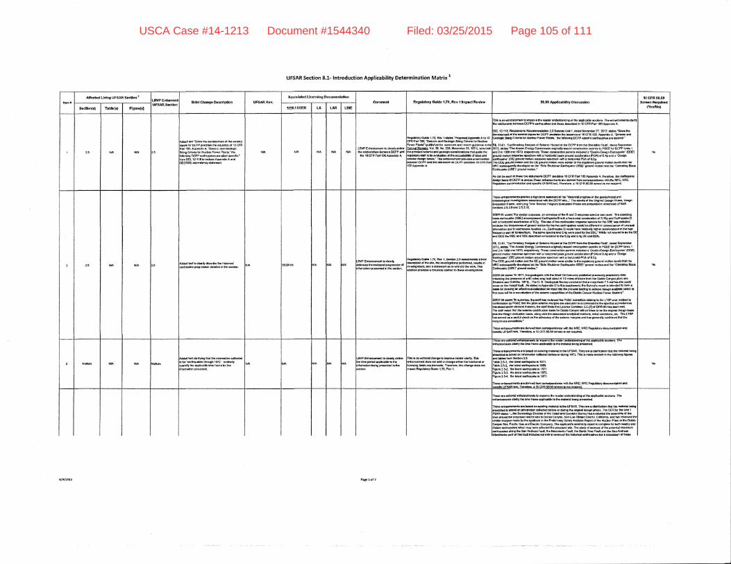
UFSAR Section 8-1- lntroduction Applicability Determination Marix 1
ItaGArtec{Gd LMng UFSAR Scllon'
UF5ARS.cltofl Brlct Chetgc Oorrlptlon UFSAR Rcv.Assoclatcd Uccndng DocurrEnhtloo
Canrrrnl Rcgddory GuHc 1.70, Rcv 1 lrryrct Rovlrr 605t Applcrb[[y Dlccussbnr0 cFR f05l
Scrcln Roqrdmd{YcalNolSocdon(:l Tebh(4 Flgurc(rl SER,SSER LA LAR LAE
?.5 HA NTA 15
Addcd d'Slrr tha (,ardoo6.l.4 o( t F Et rnElrE{r.lo( DCPP ,{o(htG! &G lorirorEo ol 10 cFRPdt 10o, ADeGadr A 'Sol.rnE ad GGobeicglhg Crisris lo, Nrbaa Porrcr plofilr.' lhqldoxlnO DCPP codhqudca so dom rpoclb,"
iilA N'A WA t{r tlllLA\rP Enhorqaal la dclrty do&!tp tt*il1oftltitr bdFon EPP.rd
t rOCFRPrnlmADporldhA
toguhloty G.Jatb 1.r0. R!t, 1 drbr 'Prof6.d AFort A !o 10lfR Pan {D.'Sdofibdrdc6oloeac S0ng q{ah lor i.ludo..,arwr PEl|l' (pr0lrhod ,q cqllridl' .nd lrtdirn gddona. ln thldqgL&cff, vct t6. t'b. 211, ildrt tlbd ?3. lyr1l" u.il rddh. Drhchd.cbnlc!1d eoolodooonrBsldotr:ndguEothorlllatdy 6tt h [r GrdrEoon d tho sccarte1y d rn!. rnd
ril3 r.nduunconr!.l lo iprov.l,tt rcrdf ufibtaMlng.r h rpcldlo.o6oil- Iha crrhcrcr'iloltt dlrlha rolgtUrrnF botuom OCPPI .or0rcsr|Gr sru tho.. lt3rcrtbrd fr 10 CFR Pdt 'loo. orondrr A
m. 12-llf Rclpdl:rlo Roc['rrnoodlalotl ZtS.bnEU1! 1. rhtod Novoobor?7.2012. !illioa €incotto,od*moil o( tho !.rrrE lrDsts tor DCPP F!dd!! fio L..rErEc d 10 CFR t00. ADpsrAr A. -SolomE rrd3.do* Sfrrgqtrllrtot lt *rrPru6rPh3,-llr.ldbilIno DCPP<pocalposrhqJlforlrD do,,rx{-
tL 12{1. Eadffiory ArE }lll oa Sc.LrnE }br!6d d rtc DCPP lrorn tho .st rdh. Farlf. dor6d SlplctrDar1012. .toloi'IlE Atoa*c Enugy trmrrfftaoi o.!lm!y trnEd con rrudbn Dornltl r! ,g!E rrDOPp Ullr 1
rnd 2 h t9dt ulrd ,97q, irtgocl,voly.llt. 6 so.ldruc$on porm{t hdud.d ! Oodlo D.dgn E!flhquolc'{oDElXa*d mdm iorplri ErcEutr {li 8 hqucrfrl p!!k OrDl,id locdsr!{m (PGA} ol O.aO lnd a 'tulgl
Xo
oBE,sSE cQuralrry ltllrft.rL EroEPP rilllt .dqno.t.o DCPp D(g(Eto! IOCFRAp9c.* A.
fno DDE lrqlnd mooon {r(t tno O€ florrx, moqon Hro c!{br $ ttro rooirduy Orol.(d mo0on bvds ,l't lhoqC q&coqoorfty doml+oo !a ho 5!to S'urd*l! €rfh+nto {SSg' eroorrd mo0on m( o|o aopordhc Brih:rdt{r,tda (OB€f erdrd
'noilort.'\icsr bo..cn fll'td..ttrtaotasn. f,EPP plldrLr IOCrR Fut'too,lppodn 4. $E dor!, OG GlthquskG,orbn las|l d DCPP |l strtirq.Ir.$ odwan''o'ltr ttt d.6r.d tun co.rltpondlrEo *{h tho ,\nC, NRCfrgdoUy aeamntrrbt .rld ifori E t,Fgr\Ri.rc r}rr.lm. a 1O CFR 5O.39 tffin b ml nqfi.'li
25 NA N/Alarl io dr!rl!/ &tcdbo llo lrtsio.tdl 0!
Errtronzomntb dol& tcordatqycd.b l-?0. R6r t,g.ctbnzS rDcomfirrEt !b''ol,d.r{plE ol 0ro db. $o hrollooot,.to ?orfoo!.4 r6ult! ol
ID!|. .,rlilrrsal! if prilrld! r ligr t6t d t fi!ry d th. 'hBtorrol pfoorl!.. ot !l! ol3aXcdnrlcd atldro{crDholcrl ltrrslilEtlonr loso.ldtd ultll $o OCPP ,ro..." Th. ,e!rn! d rx Orblo.t Cbr|ln Ptt6.. H6t'1Erst [!oo PFoo. ord Ltrl! Te'm soEfilo Psoorosr Eaalloton Pnss! e! pmao,ltod fi mhaDcod UFSARucnqro 25.3.9 ad 23.3-rO
SSER 01 sldr. Ts .,rdOo BJrpo.6. an !'ral+o ol !to. I utd D ruporu rpcco u.o (rcd lt c orrtthro!..5 lrfilqrll.o (Ots€, rnooporad Eurh$taka B v,lh s trgtorld Eoc.ld!flon d 0.150 oltd Eofilqllfc D
^llh aio.Eorrlt lorrloErct do20: Thr t,3. dlrE.Efiqu*o rG$illtgcrrD loa ltlo8c 6 o&!d
.{o
ilsrdtlqr duq lo.o0qudro locrtlon, (... E.lihqudE O yodd ttrvr rllahflty tt[r6 Eccol.f.t ono il ,r hlehtr.qrrnct pdr C lta opGcfuTrt fba oom{ E dra &!d 0.{, r,u md lo( t E SSE- llt,ilb n6{ dord b s lho turd ODE tn OBE -td SSE <to,roDod coooopoid lo tp Q2g rxt Cag D€ ct|d f,ff-RL 12.gt. :corf lmElory Am{yrk <f Schne }la:!rd d th. OCPP lruo ttrc Shootro Fott(", dard Sodsnbo1ry12, dsE {ho Alomlc E r!to}, to.llrilllblt o{ttuty E&Gr, canlln cudr Domlc lo PGEE lor DCPF lJdt[ 1
ild f h 19e! lrd i8?O. llrooc$r.ry. ffro.r Gsrlruct,n pdfiifi lndudd e'Dortlo Do.ton €sthqEt '{mE)gfol.r{ molbl tupoar.scoUn r*h!tl.rLq|ldpsokgrurod o@lorrlm{PCAI ol0.{0 f1., !'N!nErrrqdo' {OE) oltrsrdrrdon r.cDdrr..rcrfixlr lth ! hoflrE {d PGA oa O2O.Ilr. CO€ lrqnd molo.r arn hc DE gru,l<f mctlo'r slt dr{E lo [to ro6rbory grurrd modoo Lv€h A[l lio
Fqrordqr d6t!.o4 h lha r.&L For.rf.d h [to r.cUq- nvdlgoIofi!. (rd ! ttElqftorl .. lo IlD dld ol. xartL ThLd('*l.rt p.o!r5ar r hrdoffd rolll!fi lo tr!.!o ff.a0oolbia ElrfiqlDlio (OBEI' lro{rld tloiolt.'
SS€R Oa strtc. "fr f iff . ilo gEdooadr t.tlh fr Shrl Ol Camosn, p|$IGM pllnqdy pr+;cety drtrFr(cdrp fro Farr.rc. o( a r0 n&. lono tdrf riout { 1t2 tr{o dt lra. tnrtt tho DbUo Corryoo glutt rrtOlorfk|lsrd Grfitfhr lEltL.Ih! U- 6. OtdooEtf $.nrycanddod fhoa. DEOrfirdc 7.5.dflrqrll! carldocErr oil fio l.l(n!!l tara A dslcd ln ADF.rd& C lo lt{c qrgCc.rFrn. lh. slrn,cyr rcpoil 5 lltllrd.d lo lo.tn ,
ryrg Bt.ry -.qrgHrl.wsMrrq iEBIv uE}tr@@u g Exle Itugtr fgr.oFrur rr[rocaaoi.l tcr mduabr olfhrortsnbcepoltlth.Cth.Drblo Crrwr tt d.ar Pow gdlool.'
SS€f, 3a d.t 'h ariuiuy. lh! dalt lr[ rwlrwd lha PGaE luur*flda r.ldrE b ttn ['tSP ri( arH locorr,iqratn ty PGst lffi trc corr r.5mlo nolltnr or aocqEto lo armqtodco lrrc tplct{
'rcd!rcEdh.rr&d rndr d6llor{ { .Dorro. ho {dr rLl(,r thc tx.rB conilhl zc.(a d tPR{lo tlr lccn nrtIho 6tl ltd.a lhol UE a.irrfc q.rdmcsEr borh td OhHa CmFr yll cantrpt ro b. fno drhol daJgn b.abCu. t o |brgrl stolldon D..L" !loi0 r.l,l fho d.ocldod .ltat icrt rnffi. hillcl condl!6( s!c. Tho LTSPhot ranrcd 8 l rmtd d[d( olt th. adrcttc, o( tlrc orblilc malin lnd h6 gmrdly Elrnnn.at lhot lhcmrllrE oro ooc.PhH("
Ito{o orito.tccrictlr !il dotrld tD{t Gon[lponarsrco t.or lho ]rRC, NFC Regntdry documoAHioo ot€[rottaE I,F3AR ilrt Ttarcfolo. ! 'lO CFR 50.53 rtroofl E nG ,o$rod"
rruthlo IIA ,YA frrflFb\ddcd lql d!ily&r! lhol tho ar{onrE.aon cdodrds lor'Etlhqrra,{s! lltorlltl 13f2' lo clclrlypEnilty tho rppIcoblo ltnr tron. lor ltnloflrro{dr rrofonlod
.BuP hhcnccnrn |o CcUl, dfrmhomoD.rbdellcflblc blt|.rrdrnslontoang porrr*ed h ttrc)dbr
fll. t ar rdltortd durrg: fo hrPrwG lI&r d!dv. fhbdir!,rcqrrqrl aloor rFi rdd oachonolc'tftq ltltl,'E1mlll otItc1rlt !{rrh rcqa.rErEr*r. TiraGtd.. di3.ftrr!. abrardlnp.d R.g.rlfqyaJir! 1-rO. FGY l.
I n6. atc Col{qEt ffi E rlptwc sF G4f rng6rslmmg g tm aFpiGaDF tlcuont. r rumtmccoroar daryfi. !or. lnm. @ptcrurro rnd rtrtdrC !oll! prG&rllc(L
lho.. rnhicoaurir aE Drtod onorllrEmdrd 1ll$cUFSAR.lhoyarcocbfdtmorrrhd thofltdoriltctr!0x!.cr{Gd lr h.(, dr lrIilnstbn cdloclld ffi! o. d{ln, 1 971 TLr h rrllrh rvitrd h ltr6 ldbr9m tlsrc.Id Ulllrtrotn ao{ilolr ?,t:rob5all. tn u.t ldlxqrll.51071-flob2lle il. blod.drrr$,ok lo 1000.:tgur 3.td fr hert.{trqurlr rc 1971.fuir't ZL]. lho h63t 6!.fiqu*. E 19rz:lom Z5{. ilE bt6d ortauor! |. 1971.
hlo
f, lra Gdlo.tsl .nIo,rcGlfloail lD rnp.o'ro thc ,ladtr und{nlmdlm o( frto l0Clcauo .ocild|3. Thortalornr cladt' lho ffao tBrne lpClcoDlo lo lh. ri{r'rd bcfig prl'onfrd.
o rdrs:rcormnta qr bocod m qttfi0 rfidqlol ft tho l.rFSAR Thoy lro ! dn loot on tllot fm ltdaorlol lolrgnrt6d ts t rod ofl frfomdon *dod bdol! or.torE fhe oootrd d6lgr ,aroo!. TtE SER fd Da t,rlt 1
R ruol '-to &haology Divblon ol tto Cac g{ Gco<rolhl s.xvey hro ootr&{ fho Dal!.trbif of lhorq^i{ h. p(opfl.(, 16.10r{0 tr Dlluo Clnylo Soo LlrL Obtao Coor*y, Cdfoant!. lnd h.[ trwl!*cd lh.r rDslri3 rmd. !y ltl. .prlk!il h tr, Prafnnry Scroty lrutyth Rrto.l d thc tfudcrr Phl el Itlo tloblo|oe S[q Plc[lc G6 qd Ebctrlc Compary. Th! Eptcuilt ..rqrtslry llFon lr oornplct! ,or Do$ arcly sllirf aa{$qu.t(il {fGtt ,rry rEv! dHad th! Dlopq.d alq Tfr dr{ cf tancor oa lh. pobf,ttd rEfill{|ql!l.ro danf fi. Asr And.cor F.uil. th. Hoclrnlsnto FuIi. tr s!trt! Ynd Fodt lrE $o gon Andtlaarhoda ud ol tll5 l&.{ tElr6 not odt , rartawd lfiD htllodod rilrElEkdr b{t ! rticubn ol ttEa
USCA Case #14-1213 Document #1544340 Filed: 03/25/2015 Page 105 of 111

UFSAR Section 8.1- lntroduction Applicability Determination Matrix I
tr$rtAtfcct.d LMng UFSAR Soctlon r
LEYP ErthenctdUFSAR Scctlon BrhtChange Dcsctlpfiott UFSARRcv-
Airoclrtod Llccnchlg Doctficnte[orCormod Roluldoryculd6 tJ0, Rcvl Lnptl Rorlcw E059 Applc&trty Dl*ussho
t0 cFR 505tScrcooRcqulmd
tYctlNolSGcrbn(sl TrNo(sf FQuro{rf SER'SSER l-A LAR LgE
Htrfhh |{,4 N,Ard&d U. -(lJrng !D orlgttldoabnpho.'!oCouiy qtanily rho aoifcaHt qmo trlm tor tt*or{anorg66 p16*r6.
o,l
/P Brltncdmd to dldlyddtl3rfit p.rtid dlclblolorh.rard|on botE prlrdcrl h lfic
ar odrbdd cndroE ro llltrDv. rad!. chitrr. Tltarilnrn do.arEt odd or dtr!t0. alh.rlrr.lutaro,ral olr0 DtaL tqutf'ld:n ltctrlo6. trti dott!€ do.a ridRrodrr.ry Glndo t.m. R6.'t.
rdo,n Grr rdlod ls tro ccrftqit*. lrlqucflsy .p.ctnm or lsdtld{ih. dcolh ol tocuo. rf6 lrd drabn o,rt ain daLllrol"
Iho sER !l tro t tntt 2 PSAR !t0t!o'Tho enoilnab d tt'o oalooy d tho Bsrllo c.tryon l{rdorr Plad slittrrold*d hAE c. Dsctdt{o. J{}z75 lan &tC.t orrts u.o talrEtod lndcompoaod ufi fro !t oa!4o llorgtutD.*r<l hcuflootorytaE u attaL raf. dllthod sretE!.d t4-13. t966- Ttrormlyulo lpcotolo booaclr{yactnrodardEprsd{orrdoq'nt !prr.hd.(tto.oaaPodlo(ttEclGologyriichvotldlcpertomtloin molnaa.tra Girrlud€o ol lra rl6.i
ssER ot |td!| -Ihra ooaaoorErd r!.tm&, ov&lstb.i nfllcrrolrrlrrtorYd xil/atltsplb.ra caiduclcd.rrc!toce. fto. tf,..dr{l'uo.r ct dilqtcd h r$. Flnc lldrfy ric},!rr Rogor (F31t61 167 xt D^blo Cnnrurl{rd!o( Pbnt .lh md rl ! ltpoll bytfllgru (f fl41 Ih g.obly crd t tsmdooY d l,|o Dsds Carydr r[t r.torracrdty [ro AECrtsf nd rngooaogEd rts rtadoglcd.drboro. lh. U.3. OoobOcal sw., (uscsl.adhG U.S. Cood lri Ccodila &rrv.I. dd.rg tno conolrdJor poon[ tltttThottndLo!ctEtrc|rrwwr.DUlilrodontldEtbarlS, lr08.!ortt.lficsERlorUnaiz tiflfirottodlo
..r{r{c drr0o hfl( lh. s€R co.rctldld:(11-Tlror. !r! rD rdqdftllh ndor rcrtr cr dho, !.do!lc til'dun ,n tlo da 0E[ Bid Do c.Dclsd to bcdlordt,Tidly h Oro lnrrr<ll& r'lckt&f d hd .rf!. rlr. rE,!d rrtrflrksl, ldkt mair lrlt tr Oro Na'dmlorto lail. andrhFdftndbrgtrufrroo.lfittlpproodrrto x5ft *o(4 r'20rrlh.o( itorllo totL llglholrt''sldt2l'--!r4 Cort and Goo6cdcSt twy loroor ll$ lhnoDPrclttrt ooloourld O2oo sl th. trlo lIE fi md(lrihoprodt{cCn dilmgtofidftDdfltol!ott!ddala.oftrqu.loudtv.cafuvtlF.Oaogo,1r,\Er.cl(lorlhooolo dr*dot(l cotaono.-
Ilrro ol*pncqnqtu ltt ddrrt sdottronE b d.alr tbto md rto rn dgdott !t. {otnl do*tlloll wtoprrldfid il a Dlrt oa Or. dlOhd d6lon ,filor d Ot! Dbtt Ih. i{. uE rro.olt.l nwodool,oil Htr Pt(qrnadb ddilnho tho Ddoq$s, ol [ro lfl! .. a 'llctor.tl!
!fld thtrl to d.f.fiho Arc E1r lor lh. ddtlrl drod. d thDtrli-rt{r.oh.ncafirnatrJtdldlddrlldmtornp.6rct odtr{flddiEtt'0DorIEl!6{r.R6/r.Sldl(|,1.1.! and do.n r|ol tdd d cficltlt olhaf tfio ftnalrrrC or lcarrng i.t. ,lqtrG'n nB" TtEi. onnorEcns(ta t oddlrod tqn cqr.ap6t dr r(fr [r hlRC. ilFC Fcluhlory (6rnontrtb.r rtt EFoclllc IS-SAF tdt Th.lclorr.! 10 CFF 50.59 gc(..n h nc rqulrod-
No
Uufoh NA t{A \rfiiro , !!aan onco. o('SGllnlcCoiooo.VDotgnClal
E *r!.lcdnadfo.suGrdlatu ocorgarorasyl.fi@'rr,oahrrUFS
RSodlm. noodeI orE! t.ro. n.Y 1 doot fit -{ro.r rl. ndt rthlr.ib b. gaa{ 1o( €lsl, ,lhrcd lqraflnari{ s.rd rtrtctuce. fharcloro.,tr actrqyh nd krr9oct DCPIFr cotmlunsr l.g ilth EC.Jhrlf,rd..
I D,opotod lctfultt twh- { o0Cra,t6 rl 'scbmlc Cdaueary f ie'PSIE Dur{n Ch f E ffi h t!PP Ol-ESot on ?-23.{ lltd T!& t.
r ,oro.rd ldfrw rwro. af, Gr,orloo. d 'Nolr-9ohn{o Gtttlory f lo'PG6E hlo?t Cl!!o f m dallnod llOCPP o|Ud 30.{06 2JJ.r e.l(l Trdr l.r proOocod ocilvfy d!'flor El h rt! UF:llR boocd ofl t r brnrholooy filc lt Eorulttod h fio OCPP O&.fi bco.ffi brtE loCFRr0-Sgproc!!!. Tlroroforo.l 10CFR5O5' Scrocn !r ffil FqrJri{.
tlo
N.t til/A .5_5
lwEhdon hc lo({om to Eor1tiyrbodr t!{LJkdtrctilt
34 ls.lP E,lhrrctlaontto doddY dlnrElrdlcruo f{,qts tEas tuquallmcdr
aD ililrq ror E filrEld sodaila 15.t-l -2144
]t{d.mut u! btrod on .pprorrod lctndnf lrlla aou.lo doct,lrod! 6 *hdolrd h lro anldtGd UFS Rnar{!9. lffilctlon ol rpdlclt . tJilofrro Boil! lalIrrDoils prtt ldlt €*w oa aG EEPF &omnq!$lrillonh r.d n*{rffiDily d Ut UF9AR Thh lad b tbrr,ld irm ril{Do 6oarnor*, rarddr<! n llrurrnor* hloql ttrd hs"G bom qlvloltt, +ptotld Ey tp NRC. Dy [E]l.E {.llorilrtleal. or orEtrll Srtaty3rduonoRoacrfp{.fiEc.o!75);ftGn a..rIOCFRs0.50sclunhnotEqdrod.R.tertDb.lrr^OU!m(luhhsrcadsodoilZLll.'l -2,I.i3 !c rdctyG{dt![on dl.crr.b(L
No
r&rhh ttlll N/A d curoncrn d iSao Fhuc' to fuot sVP Edaoconror{ lo aoalto
1mflc, 1l!not $h
n !o dth{ llrrofln ?5ldoa0$ricrts0rlho tctt trtr rofr!$rlrtt!(rr
l@*|o
antlocltnl!il F !n .Cbld d8{Gdhn b httprot G t!6dor u{dorthndno Pot NEl C65r, BlY 1. g.Gdon ^(.dodtrdoddqctanoo.ttortlbfttr{oaoldlldtohg0610l.qril .inrIr- Tncr.fd..olocFR5O.5o
NcSldtotr .
1.2.8: N'AI lqtTd!r. HocAEvst Udl .'rar.rroo\{vo rrloctyol3Cm lcotperscond tcr rrE louda0on o8llfc,'
Etrmc&ndnro dcodyddYtat .!oGrl'E Hqd EvdqoUoi.
D.opocod lc$dry dlElt r!. tho rff, gtr@yll ilqulr!{ by,U6y &rld. 1-?o, Rd 1. Ifirr.ld!. lhb lctrrtt dod,load OcPFr@nri*ild tof*. !dfr*y.
I h|. onl|Glloofirottl E tr{orndFn 6otlt 0d aaoan uro t&tgn Hopo[ | nx n6om q.Ir|Go G Yolr w lfr mtrsllo ltraa nw y.locfy dt fio 0lo ilolor, 6rdo!0o.1 r! ltLy EG dltGrtr{ thm tior. u!€{ ior lh. {rloflcdod$tPh6..
Ilr t{oooll E F( h rdqr {11 l,otcrtal Fmpodor. :nAcr -Iho ttstmol C loundluon gEdr lE En strrg!oh.r t5v! illoEil, a{ 3dE tt por !.G. i pobtoft r,.ilo d 0:!. rd ! tptdllc lfldy or 22{.-
Ihao r,trsncqrrcfb om dodvcd frqn seccrpmdotm r.rth tho hRC. ilFC Foo(dory Ooertnolrlrtilt! ott ,
r['
252 tl,A MAP E0horrral(I to dllrly.lofirrI Bololt ar! gnltr oo.r6,dod[i,'rdEdlqrar
Grl{o1.m.Fw tr(l chatnoo-
tunl olE Sr{r[Rodrlosos{ltloltotF<dh!fdo$$ctsttdA'rdbtillvdDoc.stBloook q{rttrxl, Fod<loo a ltnolrt cf rcy lcotrLrll ,r{.tloll4 flrcfr(lirglho ddc d lhn ild ca .o.tsltuctbi d l,ti,dy22.190c.
Br&fl rnd &Dtrrt 'Sclnh EY![lrioo d th. Oldo Oar,rdt S{r.' pullticd Julrry t. 1067. prouda t pnlail&.! tful r.a urd a rlr tr.,i d tr. d6tlEl .dttqu.k a dd.tlb.d b.b, $ AL ilsnfl l.t! t10- Thh,cn rd dufil! nr! fttludor ol trt. oru m I vlda aI. arld cmdudod bo|o6 ol' $!'l ol ur4 I soni.fircto{t
Itu. .d!ilcortrdr tr dofird figm co.ltaporl{.tc. xfi thr ttlc. f'nc Frytfuqy dootmoldgt sttdrpdts LIFS R lst Ttt ?rtor8. ! l0 CFR r(LrD rct .lt 16 tlot lt{..rfiL
No
10 5.? Nil N./Atddod6(t '.$t*n lo|mrt|!!0.l30ltrro Do.brtEorltCu.f('
P g*ri.rrn r* b do;ly do0mhosE farmoorlhqtr}dstud by E *rill ra{l St{lh srotr lclto DE
Jr$ ! s drlEdon rD mrror. Io!fu cBty. rno.lrtil|ult!lb.irang tar. !t EPP t! unaquo tnt, dor trol codqttr to tr:BEf}gE oootlsrdofi tpcrrlkd rl RocdslqycllIdo 1.r0. Rl, Iar DCPP rncolvod i! hEd llccm.t {oG ilro pttLbtlE df,grgaeA Thorolro. fi.! rrr.nEBdoa. rd lnp.d Rcsihlorygnrh 1.70. Rrr, '.!.
rh.lordllcfircfitt arilomlrbnllc(tYrdrrorncdrrrts uFsAFtdr ll dlriltc.d r.qbr625J-0.1 rrn:5J.10,1l. rsl 6 dr0o0 UFSAR Srcrbn 3.7.11 t h Dottp oddod to rrh ..et lt ro #ry th! puoo.. d tr m.dtn trr&qt*idorh.dD, Bfil!il lrn sn[r.
il|'rad TJFSAR Socib 25-i.8,1 n.|!. 'lB!'tlcn drrd qnIil tl rw|oslnO ft rotstttory cf rtu tolqr !.E rEpP !f!. doloflnh.d ho a.lfnn rortftulot thol cqjc naomaHf !. .tDodod to dttct tl. dL.'
ilto r.d LrsAR so.{bo ?J311r,1 stdfi'AcCoar'holy, ElrtEd(o t}fiod{bd s @rl!,0( ry '- tnalntm/|irltoryttrodofl!fth.ffidt tEidboPtgdlE.dDl.ltrr ErtrquarcD{lot$r(qElrltqsok E t.9onfie,llfi.
'trEnl gsird d tho vlhallrg DEdy.
JFSIR s.do|t !.7.'1.1 ura'fo( .brbn p( po$a, thc llapomo .rosft ,o, .[dl dlrnplq valro ltomItr{l.tcf! B md Eld]qud(o D(trodrhlao (omunod to trodlco m orn .lopo tP.cElrtt. th. .coc{ctloon,crr lo. rr, ,.dod dl nrl .nvdA. .pookudt b .qd b t, &t0d d rho trc y:lllcr ts'l tho Ednqu]o BrDocrur .flo fi! EDttxu.lo Dmorfrod lPostl,rlL Vrrltsd ttoo lt E 0tol'ld E€lo's$rrn. !n0ltb eorlE{ ItDc[sld
UFSAR Section 8-1- lntrodustion Applicability Determination Matrix 1
hmArtadld LMng UFSAR Stcll,on I.BVPE fitrrrcrd
UFSAR Sosllon Erlot Clrlnglc Dorcrlpilon UFSAR Rcv.A$ocht6d LlcdEfng DoarrrrGoffi ott
Cornmcnt Rcgn&tory GuHc 1.70, Rov 1 ltrplcl Rot llw So.!t Appterbdty lllrcucdon10 GFR to.!t
Scrccn Requlrcd(Yo3/No)
Sodloft(.1 Trblc{sl r.lEurt(r) SER'SSER u I-AR LBIE
NA N'Aloc0arl hal.ba lEm'llodmn t ErfisfE:rdd Llrroolo
l@nldotyCrirh 1.70. Rw l roqdrs!.,lEcr!6loo€r, ltotro*,tl m (dflquok8. iholrt.rhdrlor*l d(l,lqlElc.od thorgddri brlt cstthduoks h rlct ru 2.5-ZA 2.5.2-10. rd
dtlilcrnbo b lrrE oyc nd.r l'd.fibnd|r0 t ltr DCPP corlrqpla llCr.rE bEr. Trx (rtLd(,lr.ddrb rl. DCPP Erttqucrr lb,lEro booaofi ocbra'6d conaxo. nailror.
NoEAf,EqATO It' t-Eugndlo LrqDmcsrfiq('t(! tconotno D!!a d ocPP 15211. ...D.clh,tly.lrOS€ei SSEdon (lpCy'to OCPP ltt
iaarr htl DGar 6ol6d rrduGtcoflrE trlDa.clBltcrorl6(, ro,6rtyp6or{lhr OCPp tc.lrline bod.tt pdtlh. totElafi.nG$s ol ltlo lodon ol Florrhlory Gdd. L7O. F!? t.
rrftarcorrrotl'!fl.{o.d drrftcriqr!&rrcv. rlloot uiltot?Er*te p.t NEl90{7. Frdy t. Soctlon {-'l06 DOt ldat d ctE tgo olfrrof Do tsrEtqEl or loo|l.nc DorJt rqurorDcnGs ThuEloli. ! 10 cFR $.!Or6n t3 not ra$d?r4
25:3 N'A l,r/AI qlb-!.c!orr lodlcu.o !}o Do3llnn.ko oq f porf!e!. fo EorlO and ttconduEonhqnlor
-SlrP Enhmcomoil b dodry dolhohofuEnH\rd(oooqE dtll.EPP r|!al0n dld Scdlarno tlalatcftCd.cr-
b Raorfiay Gard. 1.70. R6, I tnr..r Rft,owtot!6Lllv Ettlroihdba lllotrn lom 6
lhhh!chrltcdbrblnprEvsrEdE rrld.ilrsrfngolthcDcPPc&thq5n!lcailLlgb.r[Thr]nfcclbilndultad d!tuic fna DCPP .dth$rsfa hralng boilllt a d!a( lnd ooclr mrryrot f ho OE tlrltlqrilt n dEdt,.thod n LrSAR aactm 3.r-1.1. fd ddlo! 9u.Fdoa. tho ,srpo.!a! ap.ct'! td d.rl d{rnpattg vrte lon!txlq!h! B am EotrfiCoo,il D,modflld !r! 6o|'lDlr|od lo D.odlrcr oi s.do9o !!.dtt ttt TrD eolorritor4dLE fot !ry porra( qr trrc r6.doFo rpodurr lo oqld b lho lqgor .l ih! lyo td{m ltom tlt Elrtr$efo B
Noiold gdird odtdr ncDonar aDo€ta tla atrrm.d i6 b. li.o{frdr ot fha corl6Doidog no&ut croclta
fha DE f $G htpolitGJcd odrqudra t\d mrld prodtrG ot r. tutrultrl md vcrlta{ vlblltory acdadhnc.'
fIIr rrri&tcorn d n !n odEo.til rbrlk ilo.r ro rrp,ufi rrodor urddiEtldho EiNEI SE {}?. R.v l. Sodhn 4.r 3md dooo |tot tdd q t,lmgr.[i.r tl. ll,l(dord or lanltlo DaGl6 tqutiifioab- llro{stdo. o 10 CFR An59Scrxt ! nd loqiloc.
25f.9 N'A ilA .5.1 '7,f-BVP ffloncloront la cococlypogflDlracd !flo( kto+rccrl\madncrr 2O
hh ra sn c'dltoabl c,lErt!|. lo lmFo.r! r.!du dsflr. TranlEncdncil doil nol add o(dEngE Gfh6f tnc tunctlqd c,clrrrloo hri! r!$Jelrmdr. Tllllrorc. tltt dtonllo doai nornp6 R.Srldcry Gr.idc 1.t0. F.1, 1.
ll O ClqtEden D lorr.c a lypolraDhDDl alrol l\uuru@c h ,tmnotro,ll -ru lo Do LrEnCl ru/5 ttj^x noilo torrr ilRCiD$roalord(,lrdlcldo.rEllxt 0rA[. d!a!d J6r{^Eyzl. 197.. I]rb RAldo.! nolarlrocl,t lh! rrctltn ln cpcttoo. Tt a clEloo r r(,FdLd by llto orl0{ttd do3lgt EF,L 'S.rmac EYsldhn o( lh.{o CErrst s[r.'tyBmlo r [l{l srnn, srd by SSEF Ol.
8!.*oltorraAmnnrtPo{d!(a'Ttp oqwrlql mcarrhlouotldbo ?-14.'ln S9EROI. J!ilrty rr5,touEhr B E dEclraod a t$oor{udo 7-v1 !brl9 ollohor!--
t\b
s2.9 N'A N'A 5.f,.0.2,{6d clr{oclloo b atto(*rtltlcrlobroDoo{nEgfiquafa o0 t porfdns to Oo3le(t md UcatotntBfl.EuthqLlfo!.
31/P Elfuncaosd lD dolrfr drlktoho Ddrblo Iholo[l Ectlquol(a as orln,tl rcPP doelon ttrdlco0olE116 srdtoid(ca-
Llar to R.!uF&y Grtd. 1.70. R6v t SnFd Rryk$rrorlFb0ty D.amiltdon LJEro( ldn 16
h.l lt a cloaroc.iln b mDam |ubauno.f3r[trE d lr l:gr oanttqrp m{E 9.E rr @ffincfrrdod doffiE llpD@P oortlqualsbdr8ltoDsrt}ll ofurgldtono.! ttrrlor. Tno DEontqrnlo Etmrt dotk|ld tr UFSARxioS.?.l.r.-tlp DO€lutE lt'"dh.'tc!roatlhqlala td€uld rrothk{d.rdioratn c{ lhrao E tro EE'
lTlsdsrncaffilrlrrn lddld r,hnlicdgr torr!ffi! tlldcrfidorcE {llif Ft.lElF6-(fr.Fd 1- ScclJon{1r*t doil nc rdd q dlllrC. Glh.r ,r tul(rltnC o,lcddllo Dr{r rdirlrrlrnn. ThorElm. { 10 cFR $5o
iaa
t5 25.2.C r{/A N,A 19J\d& rub*ac{oi bdlad.ra !E Hoa0A:sfrr$Etr Dr f Don*ra lo Do{Cn lid tlsotrlh!to.hErttlqrrdor
o{.8lrP Bfuoconont io doorl, dolbrcho ffoiprt ffir{.al(' oa o?tc ot [roPP (bd![t.ndli&lh{ tarloirr,rqdalrL
I ilt lt a €lcrtclllhil b fipro!/c tlcoof unoofl4llExlo q rtta Lr.l.r clnnqtrE rc11I9 DEE I m &rctcEndr&d {tottE trro EPP t€ oo.olqud(! Loanstrro Drob h o chlt md coidor rmrn t Tlto tG b doulvdolnrtn tF3ARr.<!oo3-7.'!.1. ?GtE t|or r!$&dod bytfto tfiClo ci.dtdooto ConfraDdblnylovatalcrda,ootr&o REils. rrogil!ft 75 olnt4,ote codu*l elorp cn dlsnoo rilo r( godoolc turm0, goootlrylrofirdlolrffrHqilFout- Thl!trtttaldr'rrrhcuoodhfhovEfq,.ctl'parltrfionnlrtPocltalttDtmEdo I tha t{6$l G/*rEilto.i ff Hotod Girs{ udlFoo[kcofd!0oo r!!pdr. .podr qr.vla lor ho{Eoard md v.rtral tt!. tlc5 Otarrnd moilon !t 6a pbil rno t oar lh.€ ar lh. Ncm!{* lnd gfnrr rp.ct fucttod ,r Scclh.l 2.5'
fhrr crhinom.nl rr m dtro{td durlc!0o.t to fr?lorfl tEd.rutdJtiBndh! F }Et 9€{}7, Rcv l. sldEn itt:nd {roE ool ldd oI ctsrl!. .lttro. tf]o lrdrqd d llcooolrT b!!E ,!$Juota!na!- Irrotototo. 8 10 cfR 3159
lilo
16 2-3J.t tgrA N/^ lod lld 'h 19?0. utcorLErl to ttE L.trrlEoiomit'Eiqr Dosq al t tnll l.'fo r.rb4cffrt.
&*noooncnttoddlno $lEdiE lcltttlto.dorarbod
Itdo ts rtl a'olorEl .lsIo to lmFot t raador dlrtf. ThEcntrlrcorFaa doi not odal q t,lorrllo o$rt ltcfihctb'tEl Bloonrfig OBt tlcdsnrtr Thorslorpr i*a drarro d6 ,rotfntoa RocnadDrycrrfrlo I.7I). Rw 1.
Ilt ra ! drlllcen E fiptoro rEda ultdlrrtrrdh0 o( tllt DCPP G!ilfit5fc [onertu bottr. At 3urn,il{|rDd trDC|"-7C618.l{o!th! Sulm..yd &,XLTGRE So!fi{c Oo.ErFUrot!Ird!o(1. trG t{IrG r.qrcdod. otld FGEE!!r.od ro ! a.lrnb rlct drfilfi c tfE du{r nrllly 5 r^fidryd ! no0rr!r& I5 .son{or! ofl $a }ioa0dFsrdtThh r3lnr aprrorhdclyt yldt !r!.r &. -.lx!E d cottgrlrc0oil Poflril CPRJC on ,rc.I 2!. lgBt. .adrflnod f,r DCL I@7O0, Co{trtu*im Prfil ErtoDrlo.r
ffi- Tctitt dlroC \rJo ltioo!.d Ulo !E@ rd io h.d not td t@lvod s flnsl U. S. GrdtDE t Slt o,rUSGSI ,!porl, !o tl! mogdtulo ol rno o!.dl$l*o lo bo Dodulrt d on lto t{oo$ btfi uss nd !o'l lEo4NurofiCo!.. DBd ofi tr. IJSGSI *tll r6port!. H h.d bron't|lffdng E rotsn|illo u,ic ProcodlrG lnd eilthEodd b! li s.d ,or Girsldltg ,h drrf. c.DoDdry rd rrtheEn rhs ! mtIln*h t.5 oufiqJolo s! ttto t{onorl drtfha ctlrrll a.rd pEadtnatu Ebdbvdt 6utd baJ{rdlod hn{ baql d.t .loDcd tD ot dLr.bmcra) tsrr lirr hrd rEqrcgld tho rrGdng ra prt,rldoffat! OIH! ofld grcccdtlEt b rrolEand torc{lrdfidfrytOfi ar,l fi.vrlrdo.r
pbAf .p**on oo rohd m( Etnorrlh $o?dd lrol !EFo. $C ttrt aor0tqulao mo(trlSJ.h lllot b !o 75. oEyr^odd proco{ raut thc onaly*o 8r qdcldy ro pocatk,'
nrlsoc'rhdr.sncrtttrtE6crlv.d htln cdrl(Dooalottco t{ltl lho ttJRq lnc rtoddo.ydoclri6a{lrbn. Irdlpc$c t FS^R tdl: trcdqr. t l0 cfR 5O.5e ScDon r trol Eqft(
l{o
11 5.7 i{ra llff 3_! 3 td'BorElnsldy mdr.oll{rm.,P Entnmla fo dslrly rrcIrDDulnrydtu l{0!,orl For.N tolhaPP 3llo.
h m oAdH dlurgr forrnprorr. rr.&r drdty. ThrrrBul aoa tEl t(|d q chalgf, dtrr rnr luElD(E, 6,n0blstsrrqllrdn r1t!. aI nol,utd hdt rtt h lr{sch{EErto.dy lcrnohg !o.ls- Thatdo., tca .fio.Er doc. rrldFLouEoryGr(lo L70, Ro{ 1.
i roorE DCPP tlL
r Hflofl 6io?ort 5.(,r1 32' Itea Thos rnxrcr. aa Ellil oDwe. s(?P(,l ft. Coilpotvr n"? nol: (1) lh.rgrn tor.l rom puo tfiin a6od 3 rn0.r d 0r. tll!, P) fill it ovrd lcn{th ro lpcrqlttaLq f0 ,nlh. snd r,b
32. N/ N'A 3.8., ttll 'iblo lhdlho Shstlm Fcd Zom!o ScdEl 23,7-l I 6 sruldarod lo bc I
,P fuuc.mont E d.ori, dmrr.Slsolrn FsriZcn E! ! l@rr
Ih.| |!. doilIdudrlo tng.*s toodd dofiy. ThG olrrllqEf!konafiw boob drcPPlasrlquclod doorrrcl c.rt'o.m lolhtcBEI}Se oo.mgt rilqt.poctlod h Roc'Itroty Grrado 1,7o. R$, I!r DCPF racrtrrd ab lr$C tcoaoo lctorE SE ol$thltrg d
RI- 12{1 Hlnrdory ardfr6 ol Scftflrc ttaru{ rt llr DIeUo Clnrart Poi.{ Pt!t, ltoft tlo Slro(olno Felna'tho ritRc st!t6-TtE.oadtr turcoto fdlno Eant+orcodh dotorrilnldt ssmbJordkfg l*ob podtdcdI sl lhc SIF(dna t&it !-tna.El(r scffidlo doydogad !d ltnof bytE NEc ao ( o( t lovtmoo lfrohr rho HE lrurrd nolkl rl.l $o LTSP C,our( morql Tho tE oru,td ficiloa rid tto LTSP gloud loodo.l !t0 ND
lP9frdu r Itfir{o.a. llrL drr{6 6o!a nol inDEl l{ror.tdoryG.rd. t-?0. Rrir 1.
Dhtr P.Urbrroly WGIY.
ularmca{tlr[3 or. d-t .d t?o.n cD|rltpondmc! uaot th. I*lC, NRC n.e U.lory 6oafi.nhnon mac UqSARlcit Thaabr. o 10 CFR fo.5e sron I nol t qrrlEd.
USCA Case #14-1213 Document #1544340 Filed: 03/25/2015 Page 107 of 111

UFSAR Section 8.1- lntroduction Applicability Determination Matrix r
.lffiAfhetart Ut'lng UFSTR Soctlon'
LEVP EnhryrcodT FSAR Soctlon
Eilof ChmgcD*ctlp(hn UFSIR Rcv.Acsocbtod LkGotltlg Docurrtrtrllo n
Gormarf Rcgdltory And! 1J0. Rcvl lnFdRGrrlcit, 3053 Applctblfry Dltcucalon10 cFR i0,5'
Scrccn Raquhed(Ycrllol
secilor{s} Trbh$ flgrc{il SER'SSER l-A LER I.HE
r9 ?.52 NA N'A 2.53.9.3
n.d tGfr'.- dt.r,.f. lddtErd.ludhr d oF|d orBlo(! ooolooy o( $! hlllrwylDl! fiit.r.pon.d ,n AtlPndn ?.5D ot Rrtocrn zf olEIql ZJ.'10 rood-sxlot[Ar! ldducrol dudlttan- sd anshorD oroboy ard t6 ,aDo.hd hporG Z$ C FllLrorE.2T ril 3octofl.u.'
B$atcqn.ilb{E Ebthool aalslnpr{ E rwoEdil tha to!d!r-
bat dldlltchorpoto rooroya rc!&rlortv. rhh,rlcom.ilt dofi nci rdd rdrmgo o&hot ih! tlrrctodd o.Eft brab nquEnotlta' A! tr!il.ttl nclrltod tl tll cirq|gslkEody lcdts{r0 b!!E T,tolrttc. s!16 dErgt doao ndEi Flddolsy Addo 1.?0. Rr t.
It& orllgllcllnlI{ b nloridod b d.rfy tn l,tirE lcd n tur. s{ fh. oadfbml dldo Ucl g! P.dqrEd. At cE
"FSAR ! n rc{Ny rfron '|o
.rodorh t.d lo bo{olrotlilth! 3tu('o! iavc baot! F.r{onod lnlhorld rtryFaro.
rD9.&rdL 15D r . Rcaon 'lt,m
ocloo!. d 1sfa ay Eonh sctrrE/ar Ai.oc!L. u[o( 'G@y d ltr! sollnroflib6dRldoc..rdtpAdlolfrr!Onrfiarecdadn nadlr.f.nolca$omlo,WfhSo.drlRclffilorcOrdCUn h. tylchr, ot Th! Sro Luh R.,!96 rnd gulo Eol.'
\ppsldr 25E gtrotar addoDod G@c rr|6 ffiloto!ts Slrrhr ' 1975 ond anguon ilRc tprdlotr'
fppcoilt 2-iF grcreifo 'efrilond GdoCc eid Somloldob St (loo - tg,f arl rmcnors lnolc ilAC ouooatana
Jtts 6rion6nrtt Ehrtba fio hlirodcal r|.qt! d f5'arlJt3r- lodlllmd 'tr{ba.- THa Grr.lamihitlt dlrxrdkorn oo.r..DondD{ca *n UE }nC, NRC Rle{fd!.Y Doomoilstlo(l !t{ |ocilc UFSIAR rort Thcroloo, o 10cFR 50-iO .ftrrl1. rd EqUr.d.
!e
20 2-52 fl^ ltl 5-3.3.arwrlJorodbn f si &actlbtE LTBPo Condton ZC.[I) .[ f po(latr b fdrnsdd Bsd! Ealtlqrarc.
tag$orlcGrr.ol to Foufil3don6o(,tth. LnlPlc.rroloft rYaludo.\ !d nbnc.!yf[ NRc TTSSER }l.
p*fory Oddo 1.7t, Rov 1 lmclcl FhtlcrrlotooLnnhlaDn lrtm(tlnlc
LlgP ffir naould !o r fittxil aa ltc.tlr Ooilr5on zc.O lodornor{od u r parf c{ !t! t{tlll oprtr0n0pr.PGEE,.ooh<tOravdu&.r.lldboalEfvsttt@{t co.6ltoih$c1t80LISPF'ldR.rottAnnroum fo$6 rtPofl to r,tEs,cr on f,Al ,roitl $o llRC rse ta{od n 19gt- Tha t{RCa lE^rlctttt u,oflu'E, do .mlyDro cr fu'lt dc., n ssER'3{ lnd tEL 940417. TfdrlmtH ol scr, Evdtrton cblno o|rlo cln fiLorgtTorm soHrcPre!ililR 34 rnrb.-A. ! Er*oal. r64cur. cqrdud.d ratrfi.arhlrrca Cl r nrrnbot o( qo<t8nri|ltat. tF;ddt tu.stddcdthd. rltladaord.toddr.Blrtcdradal$.lolt ollh! .3'ltkm.Lryaomdlramodw FGlfE hor not d.rprdt c, Llcettr Condldo,t 2c.C4 d Hty Qolttho tlclttl DPF{tt.'
.E8|17Id6-EyhltodrtodDcc(ttDof 26.t8l.r|dAril3, lgE PGEE'lDnlt dErroq{ododkre.f .rdt sr- BaodootlrooomlylolPcEEendurodt|tdtrorltud{ra!Eo(o$IFrGt{i,dmfid Dy lho ItE sood 0[ound fiofcl't ltlt o rdo{r!f! solltllc m!t$14 ltrd ffi tlo orotd 9Er ,n llh L n a
*arg atnarC Ihr ao{r tne trvrrtd dEa, slbltild. md Go.tcrtr xllh PglEt t.rEl,jffl.. O,! rn'3. tlg dal, ttrda M ttr. dfimqory t .lr l|gn GSER 3.1 hcr brm E0aa!d!tt, 6oli..d. Th. rt,l a!ld,rdoor$v-rhErdoatn1.conrplcl..rtrHf .{fctdril|!DlouoCsrt Glrtlg-Tms!|stlcffiilltit.lolr,ACNa. lf.{tr,'OrfiDrl1.-
Er mhtncdnoota a.o oamd t'oro conotpondcrrco 1#l ltl iHC. NRC tagrrery aloolmfir'I,m. end.rrlc UFSAR ldt; thsds!. .10 CFF 5(L50 :lctsll h not ir$*.d
r,}o
,7 s.zlo tiIA NA 10-1rd lut-o.don lo doatcalic Dtllglh{rrokG n 9liotrlo io&u.IrdAcshtsilar!no'pqr' spoara
-SlrP E thlttcorlr.ni bdcqly ddlm,Eh0.rElrlh{qoh. r. dr.a, trr.)CPP d!.lonondfcodd D@r.,drcrrrr.3.
l! RrOttdory Otfdo 1-m. RoY 1 lmprd Ro{ktro.lH[Y&acnrfirftri ta&!( rml rt
E . dulorllor t(t lm9ct . ,!.(g tfir6(6rrh, d ltE DCPP ottnaE&o EoillE Docla Th' 3tlo.rcoorEEcdddholnoDcPP ldtxrr*sfc!iltqtcrlr h adaa ud cprrlranuncr'rhc DEodriq'to
' cl"til
rcd h UFAAR rodorr r,7.1-t. 'Fof dttlglq|fPo.a $. tG.Domorpocf'!,or rodt darCngtdtr lrom|l!t.fo I and EaltrCxftO D<Aodillod rro cqnOhod to F.lduco dr cnvo5FtpGdum. Ih. lccob'llbflolof atd porlodonlhocrteloporf<rfnm n Gqd btE bryord $ofis'1.llsoatrDr?l ltto Eottltq|rll(, Bfirrr .{rd !r! Eotonlrho D{trEdr.d lg.Arl,ll vorlcd tE t*t oomd lccdoratFm- lnd tk Y.(lEl rregroutto itdoil rrotott ! tpocie r! oaNltlod ts tc tuoritrlro d rlD Elrot9oardtto hollrooEl !po6rr'
OEl!nro }r}poolldalcrthqrrbrndsdd Fduoo0rr.! ttorEfibl E EvodclldldcrylceaStlloaa'
mltmocna.{ rt rn G(ilofll d.rilcltlm to lm!.or,! ttadoa urdGltE|dl,tg 9ct NEI 9O{7. Rov 1. Scctbo .1.1-3
do.i nol qdd 6 cftdllp dlhor tho hrt(ilo.tal oa llocltlng laaL ll$rbc.nott , fharlo.!. r 10 CFR 3O-5etcnt3nollcqflcd.
tlo
z2 5.2-rO il/A tyA 1O.'\(dod librccrron to($earrr tra Dut*Oo$nilrquorE ar x Ptrlsfi to Orsnrl accdddbnntdRoloot.roSmcln
i/? Errtatcfironf t ddt/ d.llt!r Dottbb Dcrlon €aflhqu.r! so ort.tTGEPP d6hn.rldlcddltgrnadft$ri.lr b R!!dob.y G*ro 1.70. tuv 1 tmPraRardntfor
rHlyDotlrrnh.tbn lffi. lmr aa
ort Corc!rdudDd d.fhcur. DCPP o|{'r$El(.trcorcm lado h tdo|'rad oottc,oonumr.ThoDDE c!t!qu& tcttrly rldlnod n UFSAR $doo 3.7-1.1. 'Th. DOE E lh. nyPdhollcd !.ntqEl| fiat sld pmOoco,cdolltlorliilcr trto.! o{ $a OE'
nt lrlst$r|E { 3 an !iloalol dlrrtlcr{El ro hProrrt taot ., unffitr[!.xrE p6( NEt t&t 7. Rd 1 . S!filt '
nd tb.! rd ddd,chrtoc r{i6rtt! lrmcfiotral d lbdr{ro boB|. r!(prunuttr. fh.{tfoc. ! 1OCFR 50-59
No
a 52.10 N/A N'A .53iO.!\drbd ljb*etlan to dlrahr fie 1937 HorylEsah$Jrlc or n F6!rr b Grqrxl lco.doflllo?rrr,EfulEatSodrr.
lirP E*stcrna b darlr ddfttotrs Hgton E.rurqld.!8t cmollhc)CP!P rlutn adllooohO toiatdslrFr.k!..
lr! lol ull qol.iduocd .blhotho DCPP HE ruoq1Fl(3 lcefldng !6h h ! dG rnd stclu nanrrrr- Tho tlE lld!{{trdf,ld h UFSAR mcrEr 3.7.1.1. ?GaE io ]Gql,3rLd Dy rr[ ilRc lo ry*d. tro illri(. ErpollltYto nfiatndr?o.niohd REnararcOntio 7-5on{hqjal(.c.rf!ildrb|E oi dt trd! A|r.{ $€loolcfdrrlrto. gdidslfdd.Ed ro a fto t{oo[l Fo(il. Ihi !t tll|0m la ([.qr|!d h lh! Yrbl[ cfleFFE rarcn ( a apccficsly tdqrldo attE t{oaon ca*rltbn o.HdorldrurlGvllullolt
tcEdoiddrtlloatoo !po(t! cnllr brtDits[|tdc|lrvlr<ftolbldcroqdrnorlool0!thntdac toil lE{€ rc uro tlovrnsl< rid Bfm! rp.cf. doorrtrcl h Sadbo 2.ffil3 dr.l.lrc.rEil tr tn odtrbl dorltcoCon to lnF{or. tEdor urdorriu&t0 D.r ilEl e0{r7. Rd 1. Stctbo {.Umd dcr nol d.t s Efiillp orh., lh3 lrn<ilond ol loonrrrg b.]a f.ortrmodE ThaclotG- o 10 cFR 3O-5e
hb
2. 51.10 f{rA ilrA 10.3I {rn -TrEoo toeoo.. .Pdfr, fistltid ha6 Ooocdffi a lio'fgrl ffi tEponso
Enhancormlt ra drrdy dotlno l Ilt !'l odlottolc.langoro ffi/o r6dq dqlty. Tneortrlmoor.rt t'oon nd odl oa drltrgo oillrlt lh. fuatb.El ofEu]ring hats tt{rurornoilc Thofll€.o. lhir ctrtlo! dG nolmp.d Rootr*iloryc(5s 1.70, Rw 1-
, c l drrk:a|on b mFE[ Eadar urdrttlsldtT oa ttlo II/P .oniquaE lE(lalll0 D!fl4 I m smrEolllq,ldil a cilr i!ilng Grrrlro tor tBr r!9(rro. !Psr! fi qtlototl Tht! i b evoao Gonlucs ttnidilrElolyr lrt LISP nfildr ldt phcr al r htor tHe,
.r$Elclrilrt trtnc&dlllaktflrdottio hr,luro t6ds utdctd!.r(tlgpor ]€l0o{I?. Rcv 1. s.tttn{1-3docr not rdd s Cr..rg. .[hcr Or. tunailond or ltcryrrng lodr ].gutam.rr,a. Ihdc{6rq. a 10 CFR SO.50
,tlo
lilr oYtt rttoar
USCA Case #14-1213 Document #1544340 Filed: 03/25/2015 Page 108 of 111
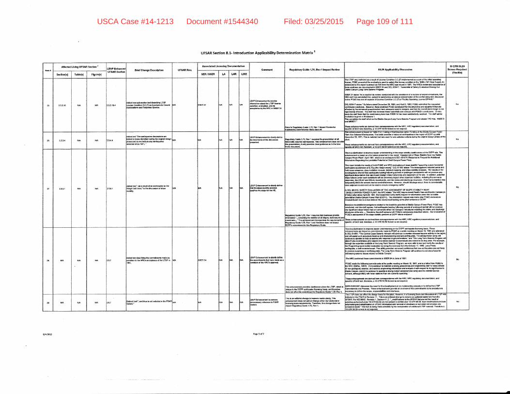
UFSAR Section 8-L lntroduction Applicability Determination Matrix I
ft6Attoctcd Llvhg UFSAR Scctlon I
LB\IP EntunccdUFSAR SG<tlon Brlol Chfirgc Dcrcrlptba UFS,ARRGv.
A.r:oclrtod Llccnrlng Docurtmtat onGamcd Rrguhtory Guldo 1.70. Rav t trpra Rovlcw 60.59 Applcrbllty Dlrcusrlon
l0 cFR 505,Scrcon Rcquhcd
(Yo.lNo)S.cfon{d Tatsa{r} Flgurc(s] SER/SSER l-A LER LBIE
:5 5:.10 t{,A N'A r&anm r,b{ocnolt H tll6lDlrE LTSPI Ccodlthn LGO) u lpsi.Irr b Grqrdrlootls r! Rolpofr3o Spodfr.
f,,i
Erh!|lcdttotltta Bovtdo!0on !!otl Iho LfSP kara.m..adqlEl. illdltllno D., ltro irRC rn SSER I
10 REgutdsy Gddo 1.r0. Ro, 1 lnpacr ncrdorvtq!El[t Dolonnfrrolon t/hru l.fi rt
tho tlSp 5o fl.,Uc< s. r r..Ul ol LEdr.. Condarbn 2-C(r) lnrCtrtmlrd !! ! ptl d th! haool OorliL{i:Bra. PBIE prclcnlrd ttri GvDl$dloarr lr..d to ldlfy &b lac.nr. colldflbn h'1fi. 19A! LTSP Hnd Rlpdt Antddcrntrn fo 0*r ro,on b dlar.r er RAI lrom rrlc tSC uor alsurd |n 19fn. Thr NRC! ,lrrLrv8d occ!'drfio af,rr.$fiohr{d erE docunfiLd hSSER 3{ o.d DcL!@117. filrilldd Sdllry ErdsuonclBrrg Od}!tlo Culroa Loao.Icrm SoE ilc Pro0rart
BSEF ].a dcel'Aar rEqrlol lErGrlor. qr,ldfitt$ht!lsrtdlE o( ! rrrmDerd sPfrt oorlJ*!,ttr. $rfiC affi ,l!3 cdEtJdod 1'lsl irrqad !o rrlrra.rcy 6ndrlEd rtbdtr0dbn d &s calirmob.y latr d66tr!ad,olo*. POaE iu rmt dl uroc. d LlEoa.o Coftdftlto ?.C.fll ol F!ij]0]'opDElr!, Llc6nra DPF{O.'
lCLgZOllT edn'Eytcloo rrarcd Dcorrtot26, 1ffi. sa6 ^prtl3.
19Oe PcAE.ulmisad ,ts Eq$rrod;qftltl6{', srdtl6. Sssd o.r ll.!! eldyo.r PG6E coccharoal t tat lrla ttlrctt Ga tno oqrynoil i|al durdcctcd by flr frmmod lEmd tlo0ln troe ldlqsro ldttlac tlt tdnE. lttd ttd tE d.tD! plorf m!O{n 6 not,orrurolru, dtod.d, TtD adt trus FrLtcd t}o.o aamfido ur{ mlr! sttt PGg,E ! @trdualn!. On tn!rrb tlo otdt littds trd t n q{tnrlory lqn ,tottl SSER 34 hr, Dodl o{u6dlv ,atdv(d. Th! d!fi .dci,lvalrodln ra Orrn ln Encloorr t.tEa comrloL.01a *rrr ardt on $a EIoUo C!.rf!n Lfi!tsT!f,n Soalrlc Ptoorttr Erd rl6GG TAC fld" ll6fifrolrd l/8O371.-
nrrs rntarumrda lrt (b,na!d trorn cof,r6Dotatlc.uih th€ IrRC. ilFE Egl,ldla.ynoarffitl6!ffi. rrd,r.do,s LF3laR lcrt lflr.lar, c 1O CFR !0!O 9cr!n l! nel Epred
,\,o
?0 :J.3.. t{rA N/A
l!{'Iho o..t{Et€.fEtnrtolt| iroro uld! ldcndllod dl'h{ lh! oiCnd d..!rlutd (b nol hdt 60 atyogthqukooDd drm 1071. -
,P ffitod.atrdctlrEtln5ldrro dho dl(,Irohn ftcuhtory GrId. l-?0. f,d I rlqura! Uo pr!{orfiixr ol al
radilcdy raco{rcd ilntqualo1 ftrs !,irrE rrr{do6 ,tol I
t* p.ca&*otbn.lt mty provldac cltnr Oqiorp u to lho t{nrrlrm dlco!.ad,
,r*$nc.mna I Eaod on Iaolr z5-'1. urang 6t tollrqJtrlil w ,9 ffia s m wm wle ruStr! Solocl.d Errrriqlllor. TnE tlt t !.oYrdd a udory ct laritqralrrr lE oi. r?lFm ol OCPP up or{amb!r30, 197'r. Thlr b ftil.daltr6tsr urrd lorgc colocoondrd5dulttg th. cardnd dealgn !fto.
, oilialaoil.niorr! dofirod troGcol.ro9olr.ro?r*Olfno iRC. NRC toOpbtoryoarnslotla[ afid
t{o
2l ?.15. ll,A N'Allfrl.d laat -, ti !{o.9dhfl !dr!.naxhy.
roul. d 'r o!ilfituoh o0 lho'tolhGOGr.raon o{ d{Do
.BVP E rrrrmod lo dor'l, ddlrctr.{ $o rlolo d!!{tystd,rL{rrol{h. ti!doF forilto tC.
Rootddory Gnk o 1.m. Rw 1 rceutot tlid( llqroor! Fot l&:rq,tl&n'*co(utrng tp r$alty of d dopti. tofi mhrnl arloidrrda-." ltt[ grtroccror( hcotpoolc !tt! rlquhE rdlnRrigr*d!., G.tts 1.70. Rov 1 6.rd llErtfor. {roi nd hrD.cttlCPPr {ofirtamdrtlod$r Rcqldry&.dr.
nr6 b r chattc.Oon lo InFGr! rrodlr ${tqgllng d frra.bP.3lbalty tpll,kcrcrr d 6o DCFP ti4 Th.rrlrancryaoot tr ocd g1 ldoot|oLoo pcr.nrrd h hc ttPo( 'Aas.gflt!flt ol sep. C|Dittry i'rsortf, Doulo!ryDn Pot,5 P|!nf. $rI 199. rfitsh 6 !n ondocna to El.rl{rg. Frporra to Rrqtod to.lddilbaeldooruuoo R.Ocrdrrg ift! l-fnlfdo PoLnttol.r Dld 6rye'r PoxorPhnt
lhrFe..f doE& nr. t-uk orDcth POIE ua f'Ftc mtJruffid Gle.d!b&t?'EmeE.PEk lnier*!,E{,lqllln ocoo&fillon d o75 g trlc lt0orl lt,tr(L'EL 9I{r' dao. 'Th! hrEtd!4brrr ifldrdoo lctEl stdEld loodrdraeso. daflsdr0oat 6rllurl- &toll{ ,erpDatlot dld rlopo rlrMty analyroQ' nr tG.rna oa dFftlahlllorl.rl'toir.dtMrdthqLatE loofiO lolo*.gnorldo d Ddalgcd prochlto0orl xllnotpodt 6an,rydkltf doE tdn! t1!( crt h6pod lhrtn Chr. I ttrucrur{ rnd oqrbmorr ot dro $!. ln !dd!o.t. DoaoilhlilSc hllroe tln{crllJcilcor{5o{rr vI nol odr! !.lylmDod o{r!t [npodld tacll0ol, tttcfud&tg lhol'v$oh,uxrn tro. rfio 2lr{il .d.rd 5$lil fl'dclt}flfo, ,td Ep lntake dtd <locloroo arEur... Potltdtd brrdl'lth6 mtyomOootlytrbctttrorco.aarde!ffirdtocr$olr!. +lffiiror,gnouuUDGloloocqr.fiotrl!condd.llDlsoaflr ldFconl lo lri ndtid flo rdd E tltqrlu crErEE tll rranf
n DCL TT.tgTs. SAFETY EI,ALIJATION OF THE TASESSTGTTT OF g,PE STABIITY I€ARUAAII)C NYOIJPOTYERPI-AIIIT.ihoNRClLbrTb6MICll. r"YrilcdPrcncG$undElslcC.nrgmyrPGtqhf.rrts.d^p{2!. 1897,llrr,clrofldodro&cndt.ttqr! l1dntdmabnoDot tt ,!fltil(btot
'ltbl tl Dt8blo GrtEo PorH Plrnt pcPP!. TIlr rnd{r8to3l roqrld ud rtrldr sff PGaE #oird al
Jruand Ercnt dtI ro c mrd dldo rrr lho csJdyroad btdloo to t lo deor ctlkrt. tl DGPp.
bood m !sdcirltodtriodgqiooilddcd b:nohrddto! pdcttldA EtdoCrn or PomrPbt( POAE l,t!illc&rdr<l and ltrr .t8tt .gt.t . ttlqt cltthqu.l. loadr1! dov't { potode d gtolorpcd ,affi u., nol producIly rryrfkrnl rlc?6 ,olh?o lH lrn €.nr.raly dr..l tho crFgory I alrcrut
'tdJ.ltE tttn lttd.o md dh6!90
Itndtl|or Lt tho rtl!. - TlHt ora, ttt. rtolf oo,rara {rfh POeEa c.rtdudm dc.lrtod dnt- Ou ovalud6n oarccEa arlailrEnt d lho .lqo {lbatty prot*oo u DCPP rlo r rndsed.'
lhcoe oohrromroatolrcder{t cd,to.n€adrc.rdo(r t{httEl.lFE fvRcroguhoryaffioildrorl f,ldDoGrfrc ITFSAR lort. ltrrotEo. s lo CFR IIt Sctofit b trot lqdrod.
No
2E t{r^'tA
tl/A 5.7 34F6hffi6.{ Ir dlltlY ddlm
.nfiffiEil prlddC dulllcanqr rboul ltc LTSP. iffil
.: lo lhc IEPP ooilrqdo lco,tdn! hrr" ar|d lErdo.e, not dtoc{ rb coiwt*mor{ lo F.nddqy Gul(lo 1.rO. Ro{ t
Thh lc ! dorft*Fa fo ftFoYo ,or(c lndor{ndlttg d rho DCPP olrtlt|Jll.a lhoilalne D.tlo" Thogoonberronlr la tstod !n ffiitncrri mtdo ty pOSE d a Drruo tb.r&rC on llttrrr ti 1e9, ond trktErcdhDCL8ir$f.'ThoCariialC{itSdaanlctlotnstr,flco.rrrrrololnoatDrnrlErooorlh{urt rcrMly5rfEro0b.t.[rd r{! r*n ur h .cqrlll.ry hcdtno atd c,rudn2|tE rl{avr.tt csih{udklr. Tho aiElrf ttElton !rt!Y nitrconabiroto.P.d.toholE or!.alaarlo tcDoaaoraerorJnd !lord!a-!nd'rno Lcllc Lrm6.hnac fttgatn *lldFwPGeE bltidchorn and lo.Pond n autrotrmrrna(tono$rt.ua !EGdtofi!!otrystre. Fotcstpb,Urouti Srr orpoooc lvaililh h lho toiro Torm Scf,tdc p?DCtem. rp eo(o .bls b l,od lad 1! r, thq ,larit olhc fto0r8tl!0ro.mCmotloa lvEluooofl br lt.tqOo tpwdalr lrorlllhoociolcl 17, 1ff19. Lofi. PId.ailfiqd(.. ! ralrscsdGdotr.l* Ttil !6llly9{qrldod ncrt!..dqr5storh na*ldflnuslD 8t ndllldybptEdqacluspillllC6oornblt1gdaE Tnol,ltgTorrtrSobtiloProgrrmrd€orttpctopEvrdo!locrrtloi0ddr!.3li0 tltmlctcilr!6 ,!l!lcd toDl!tsb c.rtror\'
?GtE 'nod.
th. tdbd{E tr rralhrrtts c urc Fr*c rnclong oo Uorcn $. lif l- .nd [r 5 lcid fitir FGSE totr|. t{FC (Eilb(. 1g91rr: (1) ft cdtailo to trlhtsn.tfott o.oracnc.. ard .r$n€cdaE atofilD h!G?.!,BrCd m {noloCitc{ rdrric. -d lol!'lts !n!*tcrt,E Horfilfbn an l or"iuolo { r6h f! p.ct b lo tt{lrlflclfb toqarrb ctryoq ar! E lo coDllruD to oPorlb I tlpogffoton ecololD'llslor rrsy .n t tho colrid aolttfiEhot\6(t droson frdy rilh lrnr e$ooa rt n ol! arr!.{ty od-JlrE. '
Ilromc**loacotrrrrlrorHydrrfitcottltpdtddrcoYatlfhoNRC.t*Crcodrtorydmrrmrrtdon stdspcE$c UFSAF rctt lhcrctao. o f 0 CFR 50.59 ScrE t h td tu+tlro(
9APN 50552r!7 dloq,rots ttp ncod ls $o dn doDrncd ot en rmd.mentl:g D(Ecdurc tc ttolim tho LTIPCq|ralrDoftt! lnd Ptffi. fhooo orharrftontr Fsv(b !n a/,Ivlr\rol liE colilfifitlltrJ E, t p.ocodxo nnoclro!ryto ddnr thr acor.. rudrorroliln t arn hllrrsr
rbtottt. t\Rg..6gtarEc tr LTSPr991.
commlmonaf 6qt5'! rud!.a!fion d rE t{RC! lppro'rrot
2' N,A lrrA N'A ldt'- ordrhr nd Erdrdod OE -BvP EntrrEmdi lo rffi6r.nocc*tty rotmloFSAFlJp(fra
ilr i m adtorlol rf6!E ro krEtrrr r6dor #V. lttlflhmrEr( docr nol dd or dunOo otthor t ! ,(.rr6ood ortrgralrlc Dalb rqdrtmarrE Th.'!loE. &E cha.lo. d@r tlalnport Rrguhlwol*b 1.7o. Ro/ 1.
Iho LISF d!.i 'ld
lAod |tb dcG4n td.rr lortu !ht( llm,d, d E llcot!3srg DtolG ill{ ol€usdon ol L IsP *oth*J#h{!.F6 RhR.vsiilr11. It*aErn.rrttotdlttraooptotwrot!an.rrrtEtoClrdom!illrmtrcITFSARPrrNEl80{7.Rcvtslon1.Srctb?la.l3.'-mod.ltstlltmblt!ttsARtffisrE?uth.r!trt lcdoailirllafdaEadmdoa10CFR5450 aa nol uqrd loco{t olffi 1OCFR JO.58.srrcn tDodaet6tr rtcltJd!l.lomaqrg !.rd atr$Ut !0on d UFSAR htilndElr rtd t9ootd d obsdilto o. rfifinldDrf Hr(lllllroo !tr.lrrcrqar t rla.|.' ltla tm I Ddrt nrd. olaol'lr DVfi. llE mUon d Dd6limd LTIIP mrtdi4 fhmfor. 6
flo
USCA Case #14-1213 Document #1544340 Filed: 03/25/2015 Page 109 of 111
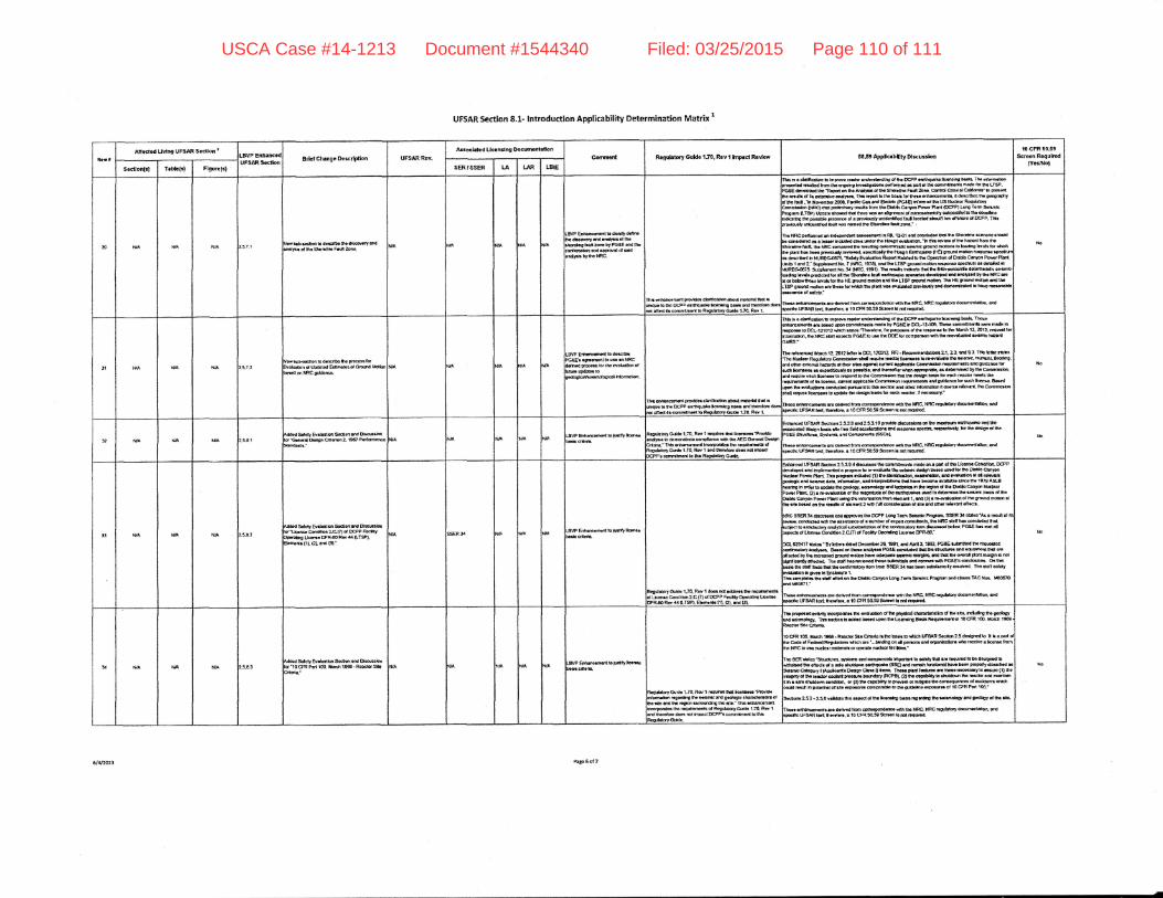
UFSAR Section 8.1- lntroduction Applicability Determination Matrix r
ianrAficcrod Uvtnf UFSAR Soctlon
LBVP Erh.nctdUFSAR So<,IoN Brlct Chm gc OcrcdPllon UFSAR Rcnr.
Atrochtcd Llcctn{ng DocurrnldonConntct{ Rcgufltory GuHc 'tj70. Rcv I lrprct Rctdcw 5059 Applcebllty Orcurdon
10 cFR [0.53ScrccoRoquH
(Yc.n&{Soctlon({ Trblo(9 F$urc(s) sER'SSER IT l-rR L8E
30 t{A ,\I'A N'Allcv qrbrocion to ocGarlbG lha.X@ortty urdrrdFl. o{ tho Stortllrr Frri Zonc.
.gvP &*roncsrd. b dc8dy dltkl!ho ffcororyild rmlrl.d rhrlffi0g t4ji:onc D, PoEE md db:natr|rrdin rE(.Dg,a.sl d !.ldtiCf,rn bI$G lRC.
t r,lnorrmrfi PHito. dd{bdbr dd.t rrEtollsl ti{tluo 10 tl6 trcPs drtrllrch tcrnrhc bBi lrd t r|6|0dtoct l| coormttrrut b Roopldoq' Gdd. 1.70. Rdr t
Itdo .' a chdtcdo|t b nnpoo ,.-o, un rfirlrrdlr{ C {a OCPP aqrhq|!*o tlc.rtr,lrlt !!E!. TIE irldtrxtstlcrrE rlad rilulld trEi tls qEoafi! lrwults{irt poarqlrld * pon d ilro snrr*norrr modo lot tho L19.rGfE darobood up SoDdt dl ttro Ar:olflr ol $o Shddlm Feil 206, c.ntd C66cl!l Cll|arrE. !! F.odrtho rotrir o{ !r aElon lrE edF6|. nra rrpon lr ttro bo.t3 fs itrcso or*ldtoorfloalr, lt dc!.rlDc! rE oao(flPtry, fro rq, .ar ilorromb0, 2t[f,. Plcltc car lad Eccttc 1p66'9 ldqnrod ho tlS !&door nooUaorrtoorE{dforl (tGc) otcpr}*l.ryEd.rron lfu DFbloGrtqlrr PosPlrlt(EPF, LonO Tlm ao|3roEPtoonm ILTSPI thddar,roFdrttdtho'! xoo.lt a$rmoil6(ms16ohm{dly slDpordlql&rhoao!il.nondcrtho 8to Dodleto grroorn d r pnrdornly mklor|tlh lilJt locof od looltt kn oaftfiato d OCPP. Ttr!xarrbuoly urdotntbd bul rE tEri.d lho Sfiolr'IeD lqa aulo.- .
Iho ti!trC porlorEl!( !n *!d.p.ndmt !..Ga.lnss h RL tl{rl .rd cddrr.a d6r lh! Sho.diio ac.rutu chdrldb.ce|.,d.r.d !a E l!.|lrhcird.d c...u.rstho tlo.aflc.*rdb.'trr lrt rGt irwo{ thE hst!fi, ndnffioshorcIm tad. thc lfrC comrma tho llGring 6cl6ltnr{arrc rolsilc lroud Eroxma io lodne hvolr ls u,!'dr[r ptrr her ueo prrourlyrltrbtm4 .pocIc.lrlh. t{otofl EfffqslLD tr{El ltqmd mol|ollrqtrtis oPoEnu0r do..rrb.d h NURECST5 'Srt.l, Er/lfr!tun Fcpo.t Fr&lid to $. Op.nt oil G, Orblo cfivon po|,ar Pl8tl.t nlts 1 snd z' &plomrnt No. ? (NFc, 1978), Drrr lnc LrsP grerd mollofl ,ouF(Eo GFodNm o. odalod ntltllfiEc$?s. Suodrnont llo.3a ttf,C. 19et). Itrc l\ocfir lr*bt! tlotlhc G.a$forcocil! alo(milrBtG 3o,!cllorang bv.lc p.o([cld lo( r! lho Slordru hdl mn rCr.fo c.orfoo At# .fl, rnsh'ro{ R rio iaFC a!il d lolax ttto.d bYo: lq l,r! i€ $ound ngbn rtu olr LTSP golr*t ndqr. th! ]tE ,ro{!ld rttoaEn lrd llE-TsP gtol,n(l rElbn.rotho.tlotr*{dllt Cmtuo.ct'drdGn prcvlordgt{ t iltornEorl lo hovo ruro.Elfffirrrc. stadcly.'
ftcro onarqrcomcaasaoffi ftffi crrorPort{talr$thtr ftfltc. ilRC rogrSqyderr't)mtroo{1 ,rdspdtlc LrFSAR tGrij lh.rrld!' . t0 CFR 5&50 gso.n E nd lqtrod
No
31 N'A ila lilAtM.'oddt ro (t.ocrlDo llo Focotolq'lbn
oa t Dd!'od EslBdGd o.ountant'SCpldam-
ffE4coranl todc*rea'r{rrtnonttouaa anNRCd p(r.rsro, rh. {r6tdd| .,lPdltilo
I}l| n*ilconrlrd pflrrHr. dsdrtsslbn aloul 'lua{ttl
fi.t Iu!'tqua to h. DCPP.!ttrqu*6 tc.nalrrg btl3 rdirr,[tcttu grr.d t cstrlrlBm.rl fo R{uldEry Goldo 1.?0. Rt, t
rlr 6 dc{tcrtbo to lmF[ovs llodor unfudrt 0Qc ot rrl. DCPP Gdt{t5fofcalrE bGdc' ThceD.Eqmodr ]! bor.d t,o.l commatnrlnb rllst o Dy PGaE h DCL-12-16. ftcro tunr{tnfil! r4E ! mldo ffrDil. b DCt-1Zf Of2 htradr rrd,o. -Thc.ds6. lol pt;Prors o{ rh. t tpqr.t to lho Usrtfi 't?. 2ot?. ruqDcd tqI'rlqioai,rrrotrlcttlttdD6cl! PGIElo l..!lh. DEtorEmPolldlshtlt. raardlffiao|lstE h€anltas:
ilet'ltco(l Mrcfi lZ Zol2hnrrbEL 13@12 RF|-Rocommrddonszl.23, urdg,tr Tllo btE trb!, Htdolr fio0l{*sry Cqtrnttobo lhd llqulrc n crol ficam.tr E ra{l,dt,.la Ur 6ldr{c. tq'nu,ol. tto(dttg,drccdcrndheftbd oldlLalopilclrfa.! orccablo coarmtsblrtlqrltEmd{Elrld ouidaru tort lc!r|!aa .. dpcdElourly or porluq md th.r0drir $flon 4pmPrfb. !. d.tcrmhd hC fia Colrl.aLrh.\
No
'oqtfrcmfilr d il|' 8caflto, Crr.nt lop{catlo Col'ittttsilcr roqor6fi6rrl3 arrd !|,6otr tt ilrdl llcaft.. 8a.ad
^qoo ,|r araluotonrcsduclorl Brrtlqrtlo ttt. rstlcn ard ollrc iloJtodrco iloo.mr r.lwaf( tho Cutr,rF.bnrtral roqro llcq:soortg updds lho doo{nD''lolq oocli rcaor. I nocoooory.'
ttors.nhE|.utiltt! u, ddrvod hqnlo{tloPoodonce I,tn $o ilRc. l.lRcr!0rbet, do(Ir'ttofltroql t,ldrpcdtc tFS R ldl; thil.{c., . t0 cFR SOS0 ScI..,r lc ml r!e,rod,
3? ,gA NA }ll,AH Sdcfy EYdwJo.lSodmsnd U6axtbn1Gar6d OarFr Crlu6n2 19O7 Pd{snorl.c
.gVP Er*ranccno{ lt ru*fy Im. RoguIrtory Oddc 1.70. Rw'l raQ&oi thdttcsrcr?tt, ldc
cld UFBAR Sodsr! 2.f:.f l,td :.5,a10 FDirld! ohcslrbfl. ot tto rtarrrrn oglttqtJclo o{d rnoctod ttoo6n lodr do f rac f,d<l mlordbil and tlrooil. rpoctr4 t6oGcri'oly. lq rfi. dodon d ltESiu.fiJ6. SFlcnil\ lnd Co,rroofit!(ssl
d*EraatroiltrpdodtrodtrDln cdrdpo.tddlc! vadt fh! NRC, NtlC rtO[5orY doctmltoo.!, q(c tf,SAR tal; lhadsr. r l0 CFR !O59 A6(!on b rfr rlqJrod.
tLtrtrlt - f r*r (l't..rc.npr{ hcdDotilla ltE r!(lftm.dr dRoguldory Andt
'.7O. Ril/ 1 md Urorc(oco do{o nol rtpst
)cPPs conraltrqrt to ltllr Roorldoo G{rdo.
33 $A NN tl,Aurdod Sdofy Bdl[ttd| Socdofltnd D6r!8loitor.ljcdo@ndlba 2-C,(A d fEPP FldyDrqrt! Uc.nr! DPR4oRw 4{ (LTSP},ibrnonr 0i. (a, on<, O)."
v At Ercamcril toEiitf ltstotrql!tb.
Elouhlry Oud! 1.7Q Rw 1 da.|l n f idd.oi. dr 'lquritlcot3d Lrcon o Co.dtldracffl of mP FlCfy Op.ml'l! ttr(E.DPR.!OR6, {4 lLTSPl. EldFr{. (t}. Ol. i.l(l BL
ilftlr'cod t#S R Sffin 2-53.!..{ dua|oo tho cttttnlrnort nado dsl pa.l d oE Lholtr! Conditb[ EPP,olrdopod .nrr fndomo.rh{ a p(q[ffi b ,F.rrokd. tltc.olnaa daclon b{roa 1I2!d lor lro Dslo Qntglrurdrs Po{of fi!r'! thl! g.oc.dn nddod o) 0to ltbil[k $o.\ rrrmn|&,\ ar! cldldm ol d rolrlail,arro(lc rtra, r.rmE dsts, ilolIrdtofl. l.dHttro!frqra lh.t hTrt looaa lratd. olncsrt|G 19lg ASL8iGtdng h 0(d3r ta qpdd! lho lEdoed. roirmo|o!|' rod fdd(. rr ,E lGdon d C. DoOb Cqt on t*daorPoil(Pbnt Ol! ll{vilrrdho oltrc ttlaFtfirco(Orcotrdrqst(.r rradto dGtcan nGlll..tl3mlc bdh diroDatrbCuryorPaorPbntudrurhol.rlsalck rltstrdomdrll.grdOr!r!-vlascroool$.lruftdmoldtolh.rltc !or.( m ..h. l.3rb ol deo.rt2 r ath tli colrlld.f!0on oa rfl! orld oftl' rlkrtoatl .fi.clr.
NRC SSER 34 4tc|rlr.s lr5 eFwo! tro DCPP Lolt0 Toru goE|rtlc Profira SSm 3{ ntllo 'Ar ! tlodl C trrrl.r. Enad.d u{h lh. llslrtEncr oa : riltnblt d .rfi coatoiliilf!, lht NnC dal, han dldrd.d tllLEhlocrra ordE6rsdyatsd E b.bd!fifird t: Btlktrcory fm.I3alsod tot*, POaE hx nE( dllrD.dr ol Ucrnr. oond0oa 2.Gf0 o( Eocoty OpordrE tlar6 tlPR{o,'
ELg2O{l?rdn'[email protected]. :99:L PGaE tulrnnod ln. rgar0dod
'onttrrtry orrdfra. E!.!d o|1 t E|! !nol}r.a POfE conct*fo<t tM, tno tllrct E otrd lQlp.trotl.lhal oE
dlostod b, 1,l tEtooc.d c{oond molbrr ,rovo dcoroo ruac aaullq md ltat tlo ryorsl Cglt tnugft E ttdrbrslEo?tlttrd.( thr ddl luorwstr<lttom qDmnsh lod conaru *ttr PGffEl {fidtilolls. o,l tI'D@lo ho 6tl hdsltri Uocorf&ilalorylloEtrfii SSER 3{ b!! togl celht .rorll [c olved. Ihod, sdolylvrf.abr t0 $roi h Erlosrm 1.fh.a cc,tlrlctr lh. tltl Gtlorl on th. UrUo csnloo Lg|o.fdtt| Solrttlr p,lotrrn Ild clc.a TAC Not' llioSTorn }GoEI1.-
IhcH alrarcurrcrtr lro dorirad ttufi Gdtla0oortclr gifi tE t{Rq NRC rqtt&ry demmLlolt m.lrpdE t FttAE tlrl lMir. . 10 CFR 5O!0 Scrrn h rd nq,fr<t
u,
lt N'A ilIA t{IA 1.5.t 3,ad Sorgty EtdrJo0on S{dldr otts Dlqroolon'10cFR Prd too. tlorEfi'18€9- Roocto.sr. N/A
E *r!6c.mant to rtdfy fc.ttlocfnclr!.
RqddE ycrJ'do 1.ro, Rgl/1 rqukarndi lcllr .!'Ft€vld!kdrme,l riril*E trrr.bmlcE d !r&!{c ctutldltlt{catfio ots md tha ro$on rlll?qrldrr lho rl!!.' IhbaorllmlmoilEcarpodoc lho roqutunooh ol FogUeisryc.iCo t.71, R.Y 1lard ltsdft dorr rc( fm Dodt D@Pt EDnlrlrtnorf ro rhb
nr Fo|oi.dir{W lrcorpotltil tE Glrdsouoo ol 0lo y'irylk l cttdoctgEfn d hf ot!. ,EtdrE th. godooyUrd oolradogy. ttt, !!(tor r! ddod uuco upcr lro t*otntr6 Bog! noquF.fiarf ol l0 CFR 100. rrolc[ 1969 .
?!orl0rgtoOitdla
locFR rm. lrErt,r lSc9-Retssr.O{odohtrcbtrLbrf&h UFaARliodon2sdo.Ehadio. R L r Pttt oltlo Coda ., Fodortl Frlrlottqtr rfil€i aro '-.btr*q or d gcronr urd oluttalcr dto slcDlYG ! llcofiro ttomh{ r{RC to ur. flrda$rrddobor opor{. ilrclorltcllhr'rho aER 3!h.'Strraur!o. rldam! rnd corlFfleils ,flporErr l,o astoty lhd or roqslod to Do doslgnod 1o,{rhalrrr., $o otlodr d n gdo .lrrdoEi oa.t}qr*. €S€) utd totnaln luEtlod tuhrt b.Gn gropoily do.dftod E!9crilt cdoeo.y I Fppf6nf. Dldg[I Ct!. 0 fnnn TlEl. pEri $GJ,!! m $so nooooorylo tEtrrrrB (11 &orrognty d Uto rodor toobnl D.fiara bofidtry GCPBI E') ta aCUty ta silrldolio tr! tu.lo. llld moml*:f ir r iatt atrtdst .r condtloi\ o, {3, lrt GrFo!frty fo Prcvd o. m[td. $o cdlaquorGEo r{ eeCOontr rtlcicdrd r.ufi h pdxrbl otl.[6 @o{rr!r cttrpailtlo to th! !i.M.I|'.:Ftur!r ot l0 CfR Pdl 1m.'
srtaoo232-z5avdld.tottl!lof.drrltr!lc.rEnufid!tTrrdr9rhor.iltdoorlrdlmhrydttt tlo.
thar oolroocormnb o.t rr.rnrcd tsn Go(l!'pond..ra v{n rn ffiC. NBC trEutdory deJoitlrtolt ordipoclt IJFS R t.rt trrr(o... I 10 Cfq !O5t 9ct .n b ,!ot nqdaod.
No
USCA Case #14-1213 Document #1544340 Filed: 03/25/2015 Page 110 of 111

UFSAR Section 8.1- lntroduction Applicability Determination Matrix 1
nogddory Guldo 1Jo. Rov 1 tnprct Rovtar
5O rt6 oddort h rupro.r ol Enh.mld UttiAH ffiErl 2.5.r. (dcl b AD uobr trom,.2651 rsr.drrod h ouppo(l ltEnh.nctd T FSAF Sccuoll 253re fiftrto AO urlrn lllrn 11{32 tsi 0dlcd h olpod d Blhtnc.d UFgAfi Scfioa 2.5.7.1. Elor to AD Udrk ltor,l !3{,53 ro! oddod h alppoil 6f Blh.nctd UFBAF Socton 2a7, ,!rc, to AD lrstff llcttt ,2t,l E Eddcd h clJDpct of Enh$t€d UFSAR Sodbn L5.7.1. roto, b AD filttt llor' l3o55En rdffi h rlpgotl of E|h.rud t FE R Stdon 15.7.1- rlorto AD Udtn [olt1 t3058 Er lddGd h Brpeoil td Enhnc.d t FS F So.rh 25.7.2 ElG.to AE) rrd't i.r, l3l57 lot ortd.d tl auPpoi rl E,ltunc*t T FSAF srdor 2-5.7-2 tt tcr rt aO rrlrir llcnt tsl
rrfiohorml!{'r lrp otivcd tt!.n qonilpondonct *tt t|. NRC. NRC tGguhory doannotrrD0fi. drd
.ilsochicdlltu1thboFsARctrrruercqu..Lchongotaeodotcdv'ilhd!rttbaUonlndloromovocrcc$}y.6ttE8orlGp,c morkup. Cho ngol lhd roqldrr
USCA Case #14-1213 Document #1544340 Filed: 03/25/2015 Page 111 of 111