Reflection and transmission coefficients of a single layer in poroelastic media
12
Reflection and transmission coefficients of a single layer in poroelastic media Robiel Martinez Corredor a) Facultad de Ingenier ıa, Universidad Nacional de La Plata, Calle 1 y 47, La Plata (B1900TAG), Pcia. de Buenos Aires, Argentina Juan E. Santos b) CONICET, Instituto del Gas y del Petr oleo, Facultad de Ingenier ıa, Universidad de Buenos Aires, Avenue Las Heras 2214 Piso 3, C1127AAR, Buenos Aires, Argentina Patricia M. Gauzellino Departamento de Geof ısica Aplicada, Facultad de Ciencias Astron omicas y Geof ısicas, Universidad Nacional de La Plata, Paseo del Bosque s/n, La Plata, B1900FWA, Argentina Jos e M. Carcione Istituto Nazionale di Oceanografia e di Geofisica Sperimentale (OGS), Borgo Grotta Gigante 42c, 34010 Sgonico, Trieste, Italy (Received 12 January 2014; revised 22 April 2014; accepted 28 April 2014) Wave propagation in poroelastic media is a subject that finds applications in many fields of research, from geophysics of the solid Earth to material science. In geophysics, seismic methods are based on the reflection and transmission of waves at interfaces or layers. It is a relevant canonical problem, which has not been solved in explicit form, i.e., the wave response of a single layer, involving three dissimilar media, where the properties of the media are described by Biot’s theory. The displacement fields are recast in terms of potentials and the boundary conditions at the two interfaces impose continuity of the solid and fluid displacements, normal and shear stresses, and fluid pressure. The existence of critical angles is discussed. The results are verified by taking proper limits—zero and 100% porosity—by comparison to the canonical solutions corresponding to single-phase solid (elastic) media and fluid media, respectively, and the case where the layer thickness is zero, representing an interface separating two poroelastic half-spaces. As examples, it was calculated the reflection and transmission coefficients for plane wave incident at a highly permeable and compliant fluid-saturated porous layer, and the case where the media are saturated with the same fluid. V C 2014 Acoustical Society of America.[http://dx.doi.org/10.1121/1.4875713] PACS number(s): 43.20.Gp [OU] Pages: 3151–3162 I. INTRODUCTION The problem of reflection and refraction (transmission) of waves at a layer has practical applications in many fields. In geophysics, the topic is relevant in seismic methods, engi- neering and soil mechanics, hydrogeology, and underwater acoustics. In particular, in hydrocarbon exploration the layer is a porous medium, sandstone for instance, whose properties can be determined on the basis of multi-component seismic data, by using processing techniques, amplitude variations with offset (AVO) methods and inversion algorithms. The literature is vast in the case of a single interface. The authors attacked the problem for welded and non-welded interfaces (cracks and fractures), in some cases considering wave ani- sotropy and attenuation (Carcione, 1996, 1997, 1998; Carcione and Picotti, 2012), and in the poroelastic case using Biot’s theory (Santos et al., 1992), and a three-phase exten- sion of this theory (Carcione et al., 2003; Rubino et al., 2006; Santos et al., 2004). There are relatively many works for a layer described by a single-phase (solid) case, e.g., Widess (1973) and Bakke and Ursin (1998) consider the nor- mal incidence case for a thin layer, Juhlin and Young (1993) studied AVO effects of a thin layer, while the effect of the thickness of a sedimentary layer has been investigated by Chung and Lawton (1995a,b). Carcione (2001) computes the scattering response of a lossy layer having orthorhombic symmetry and embedded between two isotropic half-spaces, and Liu and Schmitt (2003) obtain the P-wave reflection coefficient in isotropic lossless media as a function of the incidence angle. Ultrasonic properties of porous and permeable media have been treated by Wu et al. (1990), Johnson et al. (1994), Jocker and Smeulders (2009), and Fellah et al. (2013). In all these articles the authors have compared theoretical predic- tions with experimental data. In particular, Wu et al. (1990) studied the reflection and transmission of elastic waves at an interface between a fluid and a fluid-saturated porous a) Author to whom correspondence should be addressed. Electronic mail: [email protected] b) Also at: Universidad Nacional de La Plata, Calle 1 y 47, La Plata (B1900TAG), Pcia. de Buenos Aires, Argentina and Department of Mathematics, Purdue University, 150 N. University Street, West Lafayette, IN 47907-2067. J. Acoust. Soc. Am. 135 (6), June 2014 V C 2014 Acoustical Society of America 3151 0001-4966/2014/135(6)/3151/12/$30.00
Transcript of Reflection and transmission coefficients of a single layer in poroelastic media

Reflection and transmission coefficients of a single layerin poroelastic media
Robiel Martinez Corredora)
Facultad de Ingenier�ıa, Universidad Nacional de La Plata, Calle 1 y 47, La Plata (B1900TAG),Pcia. de Buenos Aires, Argentina
Juan E. Santosb)
CONICET, Instituto del Gas y del Petr�oleo, Facultad de Ingenier�ıa, Universidad de Buenos Aires,Avenue Las Heras 2214 Piso 3, C1127AAR, Buenos Aires, Argentina
Patricia M. GauzellinoDepartamento de Geof�ısica Aplicada, Facultad de Ciencias Astron�omicas y Geof�ısicas, Universidad Nacionalde La Plata, Paseo del Bosque s/n, La Plata, B1900FWA, Argentina
Jos�e M. CarcioneIstituto Nazionale di Oceanografia e di Geofisica Sperimentale (OGS), Borgo Grotta Gigante 42c,34010 Sgonico, Trieste, Italy
(Received 12 January 2014; revised 22 April 2014; accepted 28 April 2014)
Wave propagation in poroelastic media is a subject that finds applications in many fields of
research, from geophysics of the solid Earth to material science. In geophysics, seismic methods
are based on the reflection and transmission of waves at interfaces or layers. It is a relevant
canonical problem, which has not been solved in explicit form, i.e., the wave response of a single
layer, involving three dissimilar media, where the properties of the media are described by Biot’s
theory. The displacement fields are recast in terms of potentials and the boundary conditions at the
two interfaces impose continuity of the solid and fluid displacements, normal and shear stresses,
and fluid pressure. The existence of critical angles is discussed. The results are verified by taking
proper limits—zero and 100% porosity—by comparison to the canonical solutions corresponding
to single-phase solid (elastic) media and fluid media, respectively, and the case where the layer
thickness is zero, representing an interface separating two poroelastic half-spaces. As examples, it
was calculated the reflection and transmission coefficients for plane wave incident at a highly
permeable and compliant fluid-saturated porous layer, and the case where the media are saturated
with the same fluid. VC 2014 Acoustical Society of America. [http://dx.doi.org/10.1121/1.4875713]
PACS number(s): 43.20.Gp [OU] Pages: 3151–3162
I. INTRODUCTION
The problem of reflection and refraction (transmission)
of waves at a layer has practical applications in many fields.
In geophysics, the topic is relevant in seismic methods, engi-
neering and soil mechanics, hydrogeology, and underwater
acoustics. In particular, in hydrocarbon exploration the layer
is a porous medium, sandstone for instance, whose properties
can be determined on the basis of multi-component seismic
data, by using processing techniques, amplitude variations
with offset (AVO) methods and inversion algorithms. The
literature is vast in the case of a single interface. The authors
attacked the problem for welded and non-welded interfaces
(cracks and fractures), in some cases considering wave ani-
sotropy and attenuation (Carcione, 1996, 1997, 1998;
Carcione and Picotti, 2012), and in the poroelastic case using
Biot’s theory (Santos et al., 1992), and a three-phase exten-
sion of this theory (Carcione et al., 2003; Rubino et al.,2006; Santos et al., 2004). There are relatively many works
for a layer described by a single-phase (solid) case, e.g.,
Widess (1973) and Bakke and Ursin (1998) consider the nor-
mal incidence case for a thin layer, Juhlin and Young (1993)
studied AVO effects of a thin layer, while the effect of the
thickness of a sedimentary layer has been investigated by
Chung and Lawton (1995a,b). Carcione (2001) computes the
scattering response of a lossy layer having orthorhombic
symmetry and embedded between two isotropic half-spaces,
and Liu and Schmitt (2003) obtain the P-wave reflection
coefficient in isotropic lossless media as a function of the
incidence angle.
Ultrasonic properties of porous and permeable media
have been treated by Wu et al. (1990), Johnson et al. (1994),
Jocker and Smeulders (2009), and Fellah et al. (2013). In all
these articles the authors have compared theoretical predic-
tions with experimental data. In particular, Wu et al. (1990)
studied the reflection and transmission of elastic waves at an
interface between a fluid and a fluid-saturated porous
a)Author to whom correspondence should be addressed. Electronic mail:
[email protected])Also at: Universidad Nacional de La Plata, Calle 1 y 47, La Plata
(B1900TAG), Pcia. de Buenos Aires, Argentina and Department of
Mathematics, Purdue University, 150 N. University Street, West
Lafayette, IN 47907-2067.
J. Acoust. Soc. Am. 135 (6), June 2014 VC 2014 Acoustical Society of America 31510001-4966/2014/135(6)/3151/12/$30.00

medium and Fellah et al. (2013) analyzed fast and slow
waves transmitted through human cancellous bone sample.
To our knowledge, the explicit calculation of the coeffi-
cients for poroelastic media has not been addressed. Existing
methods are restricted to normal incidence and/or are based
on numerical algorithms (Allard et al., 1986; Pride et al.,2002; Quintal et al., 2009; Schmidt and Tango, 1986). In
general, these works are based on a constitutive equation
described by Biot’s theory of poroelasticity (Biot, 1956,
1962; Carcione, 2007; Carcione et al., 2010), which is suffi-
ciently general to model the desired characteristics of wave
propagation, in particular, the presence of the P waves (type-
I and type-II compressional waves) and its effects on interfa-
ces (Dutta and Od�e, 1979a,b, 1983; Plona, 1980).
We solve the scattering problem at all angles of inci-
dence for a single layer embedded between two half-spaces
with dissimilar media, where the properties of the media are
described by Biot’s theory of poroelasticity. The displace-
ment fields are recast in terms of potentials and the boundary
conditions at the two interfaces impose continuity of the
solid and fluid displacements, normal and shear stresses,
and fluid pressure. The methodology is analogous to that
presented in Santos et al. (1992); Rubino et al. (2006); and
Carcione (2001, 2007, Sec. 6.4). The results are verified for
specific limiting cases with already published theoretical
equations (Brekhovskikh, 1980; Carcione, 2007; Liu and
Schmitt, 2003; Pilant, 1979; Santos et al., 1992).
The paper is organized as follows. Biot’s theory is
reviewed first. Then, we illustrate the methodology and finally
we present the examples. The final equations are verified with
limiting cases consisting of a single interface in poroelastic
media and a layer, where the media can be solids or fluids.
The examples are relevant for applications in reflection
seismology.
II. BIOT’S THEORY
We consider a porous solid saturated by a viscous com-
pressible fluid and assume that the whole aggregate is iso-
tropic. Let U and Uf be the averaged displacement vectors of
the solid and fluid parts of the medium, respectively. Then,
W is defined as the averaged relative fluid displacement per
unit volume of bulk material,
W ¼ /ðUf � UÞ; (1)
where / is the effective porosity.
Let eij and rij denote the strain tensors of the solid and
the bulk material, respectively, and let Pf denote the fluid
pressure. Following Biot (1956, 1962), the stress-strain rela-
tions can be written as
rij ¼ 2leijðUÞ þ dijðkcr � U þ Dr �WÞ; i; j ¼ 1; 2; 3;
Pf ¼ �Dr � U �Mr �W (2)
(Carcione, 2007). Here, l is the wet-rock shear modulus of
the bulk material, considered to be equal to the shear modu-
lus of the dry-rock. The grains are characterized by density
qs, bulk modulus Ks and shear modulus ls, while the fluid by
qf, Kf, and viscosity g. The grains are assumed to form an
elastic porous matrix characterized by a porosity /, perme-
ability j, bulk modulus Km, and shear modulus lm. The
Lam�e constants of the saturated rock are kc and l. The con-
stants kc, D, and M in Eq. (2) can be written as (Carcione,
2007; Dutta and Od�e, 1979a,b, 1983)
a¼ 1�Km
Ks; M ¼ a�/
Ksþ /
Kf
� ��1
; D¼ aM;
Kc ¼ Kmþ a2M; kc ¼ Kc�2
3l: (3)
Next, let
qb ¼ ð1� /Þqs þ /qf (4)
be the mass density of the bulk material. Also, let g and bdenote the mass and viscous coupling coefficients between
the solid and fluid phases (Berryman, 1980, 1982; Dutta and
Od�e, 1979a,b, 1983):
g ¼Sqf
/; b ¼ g
j; S ¼ 1
21þ 1
/
� �; (5)
where S is known as the structure factor. Then, assuming
constant coefficients l, kc, D, and M in Eq. (2), Biot’s equa-
tions of motion can be stated as (Biot, 1956, 1962; Carcione,
2007)
r � r ¼ Hcrðr � UÞ � lr� ðr � UÞ þ Drðr �WÞ
¼ qb
@2U
@t2þ qf
@2W
@t2;
�rPf ¼ Drðr � UÞ þMrðr �WÞ
¼ qf
@2U
@t2þ g
@2W
@t2þ b
@W
@t; (6)
where Hc ¼ kc þ 2l.
A plane wave analysis shows that in this type of media
two compressional waves (type-I and type-II waves) and one
shear of S-wave can propagate (Biot, 1956).
III. REFLECTION AND TRANSMISSIONCOEFFICIENTS
The fluid-saturated system consists of three media, Xn,
n ¼ 1; 2; 3 with different properties as shown in Fig. 1. Let
z ¼ 0 be the boundary between X1 and X2, and z ¼ h the
boundary between X2 and X3, and consider a type-I com-
pressional plane wave in X1 incident at z ¼ 0 with an angle
hi1 with respect to the vertical z axis. Following Santos et al.(2004) and Dutta and Od�e (1983), we represent the incident,
reflected, and transmitted waves using potentials.
For X1 the potentials of the solid and relative fluid dis-
placement are given by
ui1 ¼ Ai1eiðxt�qi1�xÞ;
wi1 ¼ Bi1eiðxt�qi1�xÞ; (7)
where
3152 J. Acoust. Soc. Am., Vol. 135, No. 6, June 2014 Corredor et al.: Reflection and transmission of a single layer

qi1 ¼ qi1½sinðhi1Þ; cosðhi1Þ�
is the complex wave vector determining the polarization
direction.
Let uð1Þrc , uð1Þrs , wð1Þrc ; and wð1Þrs be the compressional and
shear potentials of the solid and relative fluid displacement,
for the reflected waves in X1. They are given by
uð1Þrc ¼ Að1Þr1 eiðxt�q
ð1Þr1�xÞ þ A
ð1Þr2 eiðxt�q
ð1Þr2�xÞ;
uð1Þrs ¼ Að1Þrs eiðxt�qð1Þrs �xÞ;
wð1Þrc ¼ Bð1Þr1 eiðxt�q
ð1Þr1�xÞ þ B
ð1Þr2 eiðxt�q
ð1Þr2�xÞ;
wð1Þrs ¼ Bð1Þrs eiðxt�qð1Þrs �xÞ; (8)
where the subscript r indicates the reflected wave, c indicates
compressional wave and s shear wave, the super-index (1)
refers to medium 1. Subscripts 1 and 2 indicate type-I and
type-II waves, respectively.
In X2, the potentials are
uð2Þtc ¼ Að2Þt1 eiðxt�q
ð2Þt1 �xÞ þ A
ð2Þt2 eiðxt�q
ð2Þt2 �xÞ;
uð2Þts ¼ Að2Þts eiðxt�q
ð2Þts �xÞ;
wð2Þtc ¼ Bð2Þt1 eiðxt�q
ð2Þt1�xÞ þ B
ð2Þt2 eiðxt�q
ð2Þt2�xÞ;
wð2Þts ¼ Bð2Þts eiðxt�q
ð2Þts �xÞ;
uð2Þrc ¼ Að2Þr1 eiðxt�q
ð2Þr1�xÞ þ A
ð2Þr2 eiðxt�q
ð2Þr2�xÞ;
uð2Þrs ¼ Að2Þrs eiðxt�qð2Þrs �xÞ;
wð2Þrc ¼ Bð2Þr1 eiðxt�q
ð2Þr1�xÞ þ B
ð2Þr2 eiðxt�q
ð2Þr2�xÞ;
wð2Þrs ¼ Bð2Þrs eiðxt�qð2Þrs �xÞ; (9)
the subscript t indicating the transmitted wave.
Finally, potentials in X3 are expressed by
uð3Þtc ¼ Að3Þt1 eiðxt�q
ð3Þt1 �xÞ þ A
ð3Þt2 eiðxt�q
ð3Þt2 �xÞ;
uð3Þts ¼ Að3Þts eiðxt�q
ð3Þts �xÞ;
wð3Þtc ¼ Bð3Þt1 eiðxt�q
ð3Þt1�xÞ þ B
ð3Þt2 eiðxt�q
ð3Þt2�xÞ;
wð3Þts ¼ Bð3Þts eiðxt�q
ð3Þts �xÞ: (10)
In general, we determine qlj ¼ ðvlj; bljÞ ¼ qlj½sinðhljÞ,cosðhljÞ�, l ¼ i; r; t; and j ¼ 1; 2; s for each kind of wave.
The solid and relative fluid vectors UðnÞ ¼ UðnÞx ;UðnÞz
� �and WðnÞ ¼ WðnÞx ;WðnÞz
� �in Xn, n ¼ 1; 2; 3 are given by
(Santos et al., 1992)
Uð1Þ ¼ rui1 þruð1Þrc þ � @uð1Þrs
@z;@uð1Þrs
@x
!
¼ Uð1Þi1 þ U
ð1Þr1 þ U
ð1Þr2 þ Uð1Þrs ; (11)
Wð1Þ ¼ rwi1 þrwð1Þrc þ � @wð1Þrs
@z;@wð1Þrs
@x
� �
¼ Wð1Þi1 þW
ð1Þr1 þW
ð1Þr2 þWð1Þrs ; (12)
Uð2Þ ¼ ruð2Þtc þ � @uð2Þts
@z;@uð2Þts
@x
!þruð2Þrc
þ � @uð2Þrs
@z;@uð2Þrs
@x
!
¼ Uð2Þt1 þ U
ð2Þt2 þ U
ð2Þts þ U
ð2Þr1 þ U
ð2Þr2 þ Uð2Þrs ; (13)
Wð2Þ ¼ rwð1Þtc þ � @wð2Þts
@z;@wð2Þts
@x
!þrwð2Þrc
þ � @wð2Þrs
@z;@wð2Þrs
@x
� �
¼ Wð2Þt1 þW
ð2Þt2 þW
ð2Þts þW
ð2Þr1 þW
ð2Þr2 þWð2Þrs ; (14)
Uð3Þ ¼ ruð3Þtc þ � @uð3Þts
@z;@uð3Þts
@x
!
¼ Uð3Þt1 þ U
ð3Þt2 þ U
ð3Þts ; (15)
Wð3Þ ¼ rwð3Þrc þ � @wð3Þrs
@z;@wð3Þrs
@x
� �
¼ Wð3Þt1 þW
ð3Þt2 þW
ð3Þts : (16)
Here UðnÞlj and W
ðnÞlj , l ¼ i; r; t, j ¼ 1; 2; s, denote the
type-I P wave, type-II P wave, and shear wave components
of UðnÞ and WðnÞ, respectively. The super-index (n) denotes
any variable associated with the medium Xn.
The boundary conditions at the interfaces located at
z ¼ 0 and z ¼ h impose continuity of the solid and fluid dis-
placements, continuity of the normal and shear stress, and
continuity of the fluid pressure (Dutta and Od�e, 1983; Santos
et al., 2004). Therefore, at z ¼ 0 and z ¼ h we impose the
conditions
UðnÞx ¼ Uðnþ1Þx ; (17)
UðnÞz ¼ Uðnþ1Þz ; (18)
rðnÞzz ¼ rðnþ1Þzz ; (19)
rðnÞxz ¼ rðnþ1Þxz ; (20)
PðnÞf ¼ P
ðnþ1Þf ; (21)
FIG. 1. (Color online) Geometry of the two half-spaces and the embedded
layer.
J. Acoust. Soc. Am., Vol. 135, No. 6, June 2014 Corredor et al.: Reflection and transmission of a single layer 3153
WðnÞz ¼ Wðnþ1Þz ; n ¼ 1; 2: (22)
The amplitude of the reflection and transmission coeffi-
cients Rð1Þj and T
ð3Þj , j ¼ 1; 2; s, for the different waves are
defined as the ratio of the solid-displacement amplitude of
the corresponding wave and that of the incident wave (Dutta
and Od�e, 1983; Santos et al., 2004), i.e,
Rð1Þj ¼
Að1Þrj q
ð1Þrj
Að1Þi1 q
ð1Þi1
(23)
and
Tð3Þj ¼
Að3Þtj q
ð3Þtj
Að1Þi1 q
ð1Þi1
: (24)
Using Eqs. (7)–(10) to obtain expressions for each of
the pairs mentioned above and substituting them in Eq. (6)
leads us to the following relationships between the ampli-
tudes of the solid and the relative amplitudes to the fluid
(Santos et al., 2004):
BðnÞlj ¼ cðnÞlj A
ðnÞlj ; j ¼ 1; 2; s; l ¼ r; t; n ¼ 1; 2; 3;
Bi1 ¼ ci1Ai1; (25)
with
cðnÞrj ¼qðnÞb x2 � q
ðnÞrj
� �2
HðnÞc
�
qðnÞrj
� �2
DðnÞ � qðnÞf x2
� ; j ¼ 1; 2; n ¼ 1; 2;
cðnÞi1 ¼qð1Þb x2 � q
ð1Þi1
� �2
Hð1Þc
�
qð1Þi1
� �2
Dð1Þ � qð1Þf x2
� ;
cðnÞtj ¼qðnÞb x2 � q
ðnÞtj
� �2
HðnÞc
�
qðnÞtj
� �2
DðnÞ � qðnÞf x2
� ; j ¼ 1; 2; n ¼ 2; 3;
cðnÞrs ¼lðnÞ�qðnÞrs
�2 � qðnÞb x2
qðnÞf x2; n ¼ 1; 2;
cðnÞts ¼lðnÞ�qðnÞts
�2 � qðnÞb x2
qðnÞf x2; n ¼ 2; 3:
The boundary conditions (17)–(22) require that the
phase factors at the interfaces z ¼ 0 and z ¼ h are the same:
vi1 ¼ vð1Þr1 ¼ vð1Þr2 ¼ vð1Þrs ¼ vð2Þt1 ¼ vð2Þt2 ¼ vð2Þts ¼ vð2Þr1
¼ vð2Þr2 ¼ vð2Þrs ¼ vð3Þt1 ¼ vð3Þt2 ¼ vð3Þts ¼ v; (26)
which represents Snell’s law and allows us to obtain the
reflected and transmitted angles hlj for each type of wave as
a function of the incidence angle hi1.
Application of the boundary conditions (17)–(22) and
Snell’s law Eq. (26) at z ¼ 0 and z ¼ h give two systems of
linear equations in the unknowns Ar1, Ar2, Ars, At1, At2; and
Ats (see Appendix A). These two systems have coefficients
depending on the wave numbers qðnÞlj , n ¼ 1; 2; 3,
l ¼ i; r; t, j ¼ 1; 2; s.
Set
CðnÞlj ¼ A
ðnÞlj =Ai1; l¼ r; t; j¼ 1;2; s; n¼ 1;2;3: (27)
Using the matrix notation of Carcione (2007, Sec. 6.4)
to relate the fields at z ¼ 0 and z ¼ h we obtain
ðA1 � B � A3Þr ¼ �ip; (28)
where r ¼ ðCð1Þr1 ;Cð1Þr2 ;C
ð1Þrs ;C
ð3Þt1 ;C
ð3Þt2 ;C
ð3Þts ÞT, ip ¼ ½�v;�bð1Þi1 ;
fð1Þi1 ;�2lð1Þvbð1Þi1 ;nð1Þi1 ;�bð1Þi1 cð1Þi1 �
T; and B ¼ T 0ð Þ � T hð Þ½ ��1
that acts as a boundary condition. The matrices of the system
Eq. (28) are given in Appendix B.
The amplitude of the reflection and transmission coeffi-
cients for the different types of waves are defined as
Rð1Þj ¼ C
ð1Þrj
qð1Þrj
qð1Þi1
;
Tð3Þj ¼ C
ð3Þtj
qð3Þtj
qð1Þi1
; j ¼ 1; 2; s: (29)
An incident S wave has the same scattering matrix as the
P incident wave, but the array ip in Eq. (28) is replaced by
is ¼ bð1Þis ;�v;�fð1Þis ;�lð1Þ v2� bð1Þis
� �2 �
;0;�cð1Þis v
� T
:
IV. EXAMPLES
In this section, we test the reflection and transmission
coefficients and consider several cases of interest in reservoir
geophysics. The following cases are taken into account.
Case 1: A validation test when X1, X2; and X3 are inviscid
fluids, corresponding to the limit case / ¼ 1, l ¼ 0, g ¼ 0.
Case 2: A validation test when we have a single inter-
face between two elastic isotropic solids X1 and X3, corre-
sponding to the limit case / ¼ 0, g ¼ 0.
Case 3: A single porous medium saturated with three
different fluids, so that we have three different media identi-
fied with X1, X2; and X3 as in Fig. 1. The objective is to take
the limit when the layer thickness h of X2 tends to zero to
recover the results obtained by Santos et al. (2004).
Case 4: A porous background with an embedded porous
layer X2. The media are only saturated with water. The
reflection and transmission coefficients are shown for three
different values of the thickness of layer h.
A. Case 1. P waves in fluid media
We check the reflection and transmission coefficients
for compressional plane waves propagating within a fluid
3154 J. Acoust. Soc. Am., Vol. 135, No. 6, June 2014 Corredor et al.: Reflection and transmission of a single layer
medium. Considering the notation in Fig. 1, we choose X1 as
water, X2 as oil and X3 as gas, all with zero viscosity and
with densities and bulk moduli given in Table I. To model
X1, X2; and X3 as fluids, the shear modulus is set to zero,
while the porosity is set to one. Thus, in this case only the
boundary conditions (21) and (22) are considered. The thick-
ness of the layer X2 is h¼ 0.1 cm, which is equal to 0.0055%
of the wavelength of the compressional wave in X2.
Figure 2 shows the magnitude and phase of the reflec-
tion and transmission coefficients versus the incidence
propagation angle. It can be observed a perfect agreement
with the analytical results [Eqs. (A11) and (A12)] of Liu and
Schmitt (2003).
B. Case 2. P and S waves in solid media
We choose X1 and X3 to be solids with Ks ¼ 37 GPa,
ls ¼ 44 GPa; and qs ¼ 2:65 g=cm3, while the layer X2 is
defined by qs ¼ 2:55 g=cm3, Ks ¼ 25 GPa; and ls ¼ 9 GPa.
The porosity is set to zero, and therefore there are no pore
fluids. The thickness of the layer is h¼ 0.1 cm, correspond-
ing to 0.0013% of the wavelength of the compressional
wave in X2.
Figure 3 shows the reflection and transmission coeffi-
cients of compressional and shear waves due to the tetra-
partition of the incident P-wave at the interfaces z ¼ 0 and
TABLE I. Properties of the saturant fluids.
Property Gas Water Oil
qf (g/cm3) 0.1398 1.0 0.7
Kf (GPa) 0.05543 2.25 0.57
g (Poise) 0.00022 0.01 0.04
FIG. 2. (Color online) Reflection and transmission coefficients of the com-
pressional wave as a function of the incidence angle for a thickness
h¼ 0.1 cm. The solid lines and dots correspond to Liu and Schmitt’s solu-
tion and the present solution, respectively. The incident P wave has a fre-
quency of 50 Hz, /¼ 1 and g¼l¼ 0. (a) Absolute value of the reflection
and transmission coefficients; (b) phase angle of the reflection and transmis-
sion coefficients.
FIG. 3. (Color online) Reflection and transmission coefficients of the com-
pressional and shear waves as a function of the incidence angle for a thick-
ness h¼ 0.1 cm. The solid and dotted lines correspond to Carcione’s
solution and the present solution, respectively. The incident P wave has a
frequency of 50 Hz, and g¼/¼ 0. The absolute values are shown with
semi-log scales. (a) Absolute value of the reflection and transmission coeffi-
cients (P and S waves); (b) phase angle of the reflection and transmission
coefficients (P and S waves).
J. Acoust. Soc. Am., Vol. 135, No. 6, June 2014 Corredor et al.: Reflection and transmission of a single layer 3155

z ¼ h. Our results are consistent with those of [Carcione,
2007, Eq. (6.215)].
C. Case 3. Media with the same frame and threedifferent fluids
Here we validate our expressions against the reflection
and transmission coefficients for a single planar interface sep-
arating two half spaces of saturated porous media. To per-
form the comparison with the results published in Santos
et al. (2004), we set h¼ 0 cm in Eq. (28) to recover Eq. (19)
of that paper, i.e., the thin layer model in Fig. 1 reduces to
the case of two Biot media in contact. The frames in the three
poroelastic media X1, X2; and X3 in Fig. 1 are defined
by Km ¼ 8:66 GPa, Ks ¼ 37 GPa, l ¼ 6:5 GPa, / ¼ 0:297,
j ¼ 1:9 D; and qs ¼ 2:65 g=cm3. The saturant fluids are water
in X1, gas in X2 and oil in X3, with properties given in Table I.
The incident plane wave is type-II of frequency 50 kHz.
Figure 4 shows the magnitude of the reflection coefficients
as a function of the incidence angle for the different types of
waves and three different values of the layer thickness,
h¼ 0.1 cm (2% of the wavelength of the type-I wave in the
layer), h¼ 0.4 cm and h¼ 0 cm. For the type-I and II waves,
the magnitude of the reflection coefficients decreases as hincreases, while the opposite behavior is observed for shear
waves. Besides, for type-I and II waves, there is a critical
angle between 10 and 20 deg; for shear waves two critical
angles exists for the case h¼ 0. The transmission coefficients
of the three types of waves behave similarly to the reflection
coefficients. The plots are not included for brevity. Note that
in Fig. 4, for the case h¼ 0, we get a perfect agreement with
the results reported in Figs. 6, 7, and 8 of Santos et al.(2004).
FIG. 4. (Color online) Absolute value of the reflection coefficients of the type I, type II and shear waves as a function of the incidence angle corresponding to
three different layer thicknesses h. The incident wave is a type II P-wave of frequency 50 kHz. (a) Absolute value (type I wave); (b) absolute value (type II
wave); (c) absolute value (shear wave).
3156 J. Acoust. Soc. Am., Vol. 135, No. 6, June 2014 Corredor et al.: Reflection and transmission of a single layer
D. Case 4. Three media saturated with the same fluid
The regions X1 and X3 (the background) are described
by the properties Km ¼ 1:17 GPa, Ks ¼ 37 GPa,
l ¼ 1:4 GPa, / ¼ 0:25; and j ¼ 0:18 D. On the other hand,
the medium X2 is a highly permeable and compliant po-
rous layer of porosity / ¼ 0:5 with Km ¼ 0:58 GPa and
l ¼ 0:6 GPa determined from the Krief model (Krief
et al., 1990):
Km
Ks¼ l
ls
¼ ð1� /Þ3=ð1�/Þ; (30)
with Ks ¼ 37 GPa and ls ¼ 44 GPa. The permeability in X2
is computed from the relation (Carcione et al., 2000):
j ¼r2
g/3
45ð1� /Þ2; (31)
where rg ¼ 20 lm is the average radius of the grains, giving
a value of 2.22 D. The layer thickness h varies from 0.05%
to 0.0005% of the type-I P-wave wavelength of the back-
ground. The three media are saturated with water.
Figure 5 shows the magnitude and phase of the reflec-
tion and transmission coefficients as a function of the inci-
dence angle. The incident plane wave is a type-I P wave of
frequency 50 Hz. The reflection coefficients decrease as htends to zero, i.e., when the three-layer system approaches a
single medium with identical properties, and tends to one as
the angle tends to 90 deg; both coefficients exhibit a critical
angle at about 26 deg, and polarity changes can be observed
in the phases. The transmission coefficient remains approxi-
mately constant, except at 90 deg, where it approaches zero.
Figure 6 shows the magnitude and phase of the reflec-
tion and transmission coefficients of the type-II P waves as a
function of the incidence angle. The magnitudes decrease as
FIG. 5. (Color online) Reflection and transmission coefficients of type I waves as a function of the incidence angle for three different thicknesses h. The inci-
dent wave is a type I P-wave of frequency 50 Hz. (a) Absolute value of the reflection coefficient; (b) absolute value of the transmission coefficient; (c) phase
of the reflection coefficient; (d) phase of the transmission coefficient.
J. Acoust. Soc. Am., Vol. 135, No. 6, June 2014 Corredor et al.: Reflection and transmission of a single layer 3157
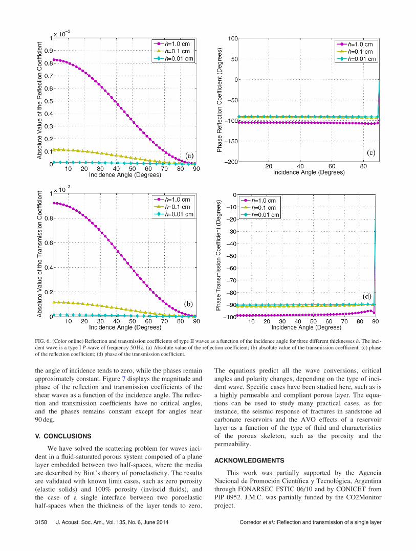
the angle of incidence tends to zero, while the phases remain
approximately constant. Figure 7 displays the magnitude and
phase of the reflection and transmission coefficients of the
shear waves as a function of the incidence angle. The reflec-
tion and transmission coefficients have no critical angles,
and the phases remains constant except for angles near
90 deg.
V. CONCLUSIONS
We have solved the scattering problem for waves inci-
dent in a fluid-saturated porous system composed of a plane
layer embedded between two half-spaces, where the media
are described by Biot’s theory of poroelasticity. The results
are validated with known limit cases, such as zero porosity
(elastic solids) and 100% porosity (inviscid fluids), and
the case of a single interface between two poroelastic
half-spaces when the thickness of the layer tends to zero.
The equations predict all the wave conversions, critical
angles and polarity changes, depending on the type of inci-
dent wave. Specific cases have been studied here, such as is
a highly permeable and compliant porous layer. The equa-
tions can be used to study many practical cases, as for
instance, the seismic response of fractures in sandstone ad
carbonate reservoirs and the AVO effects of a reservoir
layer as a function of the type of fluid and characteristics
of the porous skeleton, such as the porosity and the
permeability.
ACKNOWLEDGMENTS
This work was partially supported by the Agencia
Nacional de Promoci�on Cient�ıfica y Tecnol�ogica, Argentina
through FONARSEC FSTIC 06/10 and by CONICET from
PIP 0952. J.M.C. was partially funded by the CO2Monitor
project.
FIG. 6. (Color online) Reflection and transmission coefficients of type II waves as a function of the incidence angle for three different thicknesses h. The inci-
dent wave is a type I P-wave of frequency 50 Hz. (a) Absolute value of the reflection coefficient; (b) absolute value of the transmission coefficient; (c) phase
of the reflection coefficient; (d) phase of the transmission coefficient.
3158 J. Acoust. Soc. Am., Vol. 135, No. 6, June 2014 Corredor et al.: Reflection and transmission of a single layer

APPENDIX A: LINEAR SYSTEMS
Here, we report the linear equations for the unknown
amplitude of the reflected and transmitted waves. First,
application of the boundary conditions (17)–(22) at z ¼ 0
yields the linear system
�vAð1Þi1 � vA
ð1Þr1 � vA
ð1Þr2 þbð1Þrs Að1Þrs
¼�vAð2Þt1 � vA
ð2Þt2 þbð2Þts A
ð2Þts � vA
ð2Þr1 �vA
ð2Þr2 þbð2Þrs Að2Þrs ;
(A1)
�bð1Þi1 Að1Þi1 � bð1Þr1 A
ð1Þr1 � bð1Þr2 A
ð1Þr2 � vAð1Þrs
¼ �bð2Þt1 Að2Þt1 � bð2Þt2 A
ð2Þt2 � vA
ð2Þts
�bð2Þr1 Að2Þr1 � bð2Þr2 A
ð2Þr2 � vAð2Þrs ; (A2)
Að1Þi1 fð1Þi1 þ A
ð1Þr1 fð1Þr1 þ A
ð1Þr2 fð1Þr2 � Að1Þrs fð1Þrs
¼ Að2Þt1 fð2Þt1 þ A
ð2Þt2 fð2Þt2 � A
ð2Þts fð2Þts
þAð2Þr1 fð2Þr1 þ A
ð2Þr2 fð2Þr2 � Að2Þrs fð2Þrs ; (A3)
�2lð1ÞAi1vbð1Þi1 � 2lð1ÞAr1vbð1Þr1 � 2lð1ÞAr2vbð1Þr2
� lð1ÞArs v2 � ðbð1Þrs Þ2
h i¼ �2lð2ÞAt1vbð2Þt1 � 2lð2ÞAt2vbð2Þt2
� lð2ÞAts v2 � ðbð2Þts Þ2h i
� 2lð2ÞAr1vbð2Þr1
�2lð2ÞAr2vbð2Þr2 � lð2ÞArs v2 � ðbð2Þrs Þ2
h i; (A4)
FIG. 7. (Color online) Reflection and transmission coefficients of shear waves as a function of the incidence angle for three different thickness h. The incident
wave is a type I P-wave of frequency 50 Hz. (a) Absolute value of the reflection coefficient; (b) absolute value of the transmission coefficient; (c) phase of the
reflection coefficient; (d) phase of the transmission coefficient.
J. Acoust. Soc. Am., Vol. 135, No. 6, June 2014 Corredor et al.: Reflection and transmission of a single layer 3159
Að1Þi1 nð1Þi1 þ A
ð1Þr1 nð1Þr1 þ A
ð1Þr2 nð1Þr2 ¼ A
ð2Þt1 nð2Þt1 þ A
ð2Þt2 nð2Þt2 þ A
ð2Þr1 nð2Þr1 þ A
ð2Þr2 nð2Þr2 ; (A5)
�bð1Þi1 cð1Þ2 Að1Þi1 � bð1Þr1 cð1Þ1 A
ð1Þr1 � bð1Þr2 cð1Þ2 A
ð1Þr2 � vcð1Þrs Að1Þrs
¼ �bð2Þt1 cð2Þ1 Að2Þt1 � bð2Þt2 cð2Þ2 A
ð2Þt2 � vcð2Þts A
ð2Þts � bð2Þr1 cð2Þ1 A
ð2Þr1 � bð2Þr2 cð2Þ2 A
ð2Þr2 � vcð2Þrs Að2Þrs : (A6)
Similarly, at z ¼ h we obtain
�vAð3Þt1 e�ibð3Þt1 h � vA
ð3Þt2 e�ibð3Þt2 h þ bð3Þts A
ð3Þts e�ibð3Þts h ¼� vA
ð2Þt1 e�ibð2Þt1 h � vA
ð2Þt2 e�ibð2Þt2 h þ bð2Þts A
ð2Þts e�ibð2Þts h � vA
ð2Þr1 e�ibð2Þr1
h
� vAð2Þr2 e�ibð2Þr2
h þ bð2Þrs Að2Þrs e�ibð2Þrs ; (A7)
�bð3Þt1 Að3Þt1 e�ibð3Þ
t1h � bð3Þt2 A
ð3Þt2 e�ibð3Þ
t2h � vA
ð3Þts e�ibð3Þts h ¼� bð2Þt1 A
ð2Þt1 e�ibð2Þ
t1h � bð2Þt2 A
ð2Þt2 e�ibð2Þ
t2h � vA
ð2Þts e�ibð2Þts h
� bð2Þr1 Að2Þr1 e�ibð2Þr1
h � bð2Þr2 Að2Þr2 e�ibð2Þr2
h � vAð2Þrs e�ibð2Þrs h; (A8)
Að3Þt1 fð3Þt1 e�ibð3Þt1 h þ A
ð3Þt2 fð3Þt2 e�ibð3Þt2 h � A
ð3Þts fð3Þts e�ibð3Þts h ¼A
ð2Þt1 fð2Þt1 e�ibt1h þ A
ð2Þt2 fð2Þt2 e�ibð2Þt2 h � A
ð2Þts fð2Þts e�ibtsy þ A
ð2Þr1 fð2Þr1 e�ibr1h
þ Að2Þr2 fð2Þr2 e�ibr2h � Að2Þrs fð2Þrs e�ibrsh; (A9)
�2lð3ÞAt1vbð3Þt1 e�ibð3Þt1 h � 2lð3ÞAt2vbð3Þt2 e�ibð3Þt2 h � lð3ÞAts v2 � ðbð3Þts Þ2h i
e�ibð3Þts h
¼ �2lð2ÞAð2Þt1 vbð2Þt1 e�ibð2Þt1
h � 2lð2ÞAð2Þt2 vbð2Þt2 e�ibð2Þt2
h � lð2ÞAð2Þts v2 � ðbð2Þts Þ2h i
e�ibð2Þts h
�2lð2ÞAð2Þr1 vbð2Þr1 e�ibð2Þr1h � 2lð2ÞAð2Þr2 vbð2Þr2 e�ibð2Þr2
h � lð2ÞAð2Þrs v2 � ðbð2Þrs Þ2
h ie�ibð2Þrs h; (A10)
Að3Þt1 nð3Þt1 e�ibð3Þ
t1h þ A
ð3Þt2 nð3Þt2 e�ibð3Þ
t2h ¼ A
ð2Þt1 nð2Þt1 e�ibð2Þ
t1h þ A
ð2Þt2 nð2Þt2 e�ibð2Þ
t2h þ A
ð2Þr1 nð2Þr1 e�ibð2Þr1
h þ Að2Þr2 nð2Þr2 e�ibð2Þr2
h; (A11)
�bð3Þt1 cð3Þ1 Að3Þt1 e�ibð3Þt1 h � bð3Þt2 cð3Þ2 A
ð3Þt2 e�ibð3Þt2 h � vcð3Þts A
ð3Þts e�ibð3Þts h
¼ �bð2Þt1 cð2Þ1 Að2Þt1 e�ibð2Þ
t1h � bð2Þt2 cð2Þ2 A
ð2Þt2 e�ibð2Þ
t2h � vcð2Þts A
ð2Þts e�ibð2Þts h
�bð2Þr1 cð2Þ1 Að2Þr1 e�ibð2Þr1
h � bð2Þr2 cð2Þ2 Að2Þr2 e�ibð2Þr2
h � vcð2Þrs Að2Þrs e�ibð2Þrs h: (A12)
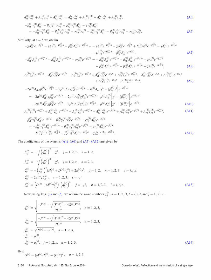
The coefficients of the systems (A1)–(A6) and (A7)–(A12) are given by
bðnÞrj ¼ �ffiffiffiffiffiffiffiffiffiffiffiffiffiffiffiffiffiffiffiffiffiffiffiffiffi
qðnÞrj
� �2
� v2
r; j ¼ 1; 2; s; n ¼ 1; 2;
bðnÞtj ¼ �ffiffiffiffiffiffiffiffiffiffiffiffiffiffiffiffiffiffiffiffiffiffiffiffiffi
qðnÞtj
� �2
� v2
r; j ¼ 1; 2; s; n ¼ 2; 3;
fðnÞlj ¼ � qðnÞlj
� �2
ðHðnÞc þ DðnÞcðnÞlj Þ þ 2lðnÞv2; j ¼ 1; 2; n ¼ 1; 2; 3; l ¼ i; r; t;
fðnÞls ¼ 2lðnÞvbðnÞls ; n ¼ 1; 2; 3; l ¼ r; t;
nðnÞlj ¼ DðnÞ þMðnÞcðnÞlj
� �qðnÞlj
� �2
; j ¼ 1; 2; n ¼ 1; 2; 3; l ¼ i; r; t: (A13)
Now, using Eqs. (3) and (5), we obtain the wave numbers qðnÞlj , n ¼ 1; 2; 3, l ¼ i; r; t, and j ¼ 1; 2; s:
qðnÞr1 ¼
ffiffiffiffiffiffiffiffiffiffiffiffiffiffiffiffiffiffiffiffiffiffiffiffiffiffiffiffiffiffiffiffiffiffiffiffiffiffiffiffiffiffiffiffiffiffiffiffiffiffiffiffiffiffiffiffiffiffiffi�FðnÞ �
ffiffiffiffiffiffiffiffiffiffiffiffiffiffiffiffiffiffiffiffiffiffiffiffiffiffiffiffiffiffiffiffiffiffiffiffiffiffiðFðnÞÞ2 � 4GðnÞKðnÞ
q2GðnÞ
vuut; n ¼ 1; 2; 3;
qðnÞr2 ¼
ffiffiffiffiffiffiffiffiffiffiffiffiffiffiffiffiffiffiffiffiffiffiffiffiffiffiffiffiffiffiffiffiffiffiffiffiffiffiffiffiffiffiffiffiffiffiffiffiffiffiffiffiffiffiffiffiffiffiffi�FðnÞ þ
ffiffiffiffiffiffiffiffiffiffiffiffiffiffiffiffiffiffiffiffiffiffiffiffiffiffiffiffiffiffiffiffiffiffiffiffiffiffiðFðnÞÞ2 � 4GðnÞKðnÞ
q2GðnÞ
vuut; n ¼ 1; 2; 3;
qð1Þrs ¼ffiffiffiffiffiffiffiffiffiffiffiffiffiffiffiffiffiffiffiffiffiffiffiNðnÞ � iVðnÞ
p; n ¼ 1; 2; 3;
qð1Þr1 ¼ q
ð1Þi1 ;
qðnÞrj ¼ q
ðnÞtj ; j ¼ 1; 2; s; n ¼ 1; 2; 3: (A14)
HereGðnÞ ¼ ðMðnÞHðnÞc Þ � ðDðnÞÞ2 ; n ¼ 1; 2; 3;
3160 J. Acoust. Soc. Am., Vol. 135, No. 6, June 2014 Corredor et al.: Reflection and transmission of a single layer

FðnÞ ¼ x2 2qðnÞf DðnÞ � HðnÞc gðnÞ � qðnÞb MðnÞh i
þ iHðnÞc bðnÞx; n ¼ 1; 2; 3;
KðnÞ ¼ x4 qðnÞb gðnÞ � ðqðnÞf Þ2
h i� iqðnÞb bðnÞx3; n ¼ 1; 2; 3;
NðnÞ ¼ x2
lðnÞqðnÞb �
ðqðnÞf Þ2x2gðnÞ
ðgðnÞÞ2x2 þ ðbðnÞÞ2
" #; n ¼ 1; 2; 3;
VðnÞ ¼ ðqðnÞf Þ2 x3bðnÞ
lðnÞððgðnÞÞ2x2 þ ðbðnÞÞ2Þ; n ¼ 1; 2; 3:
APPENDIX B: FINAL SYSTEM OF EQUATIONS
Each of the matrices in system (28) are defined by
A1 ¼
�v �v bð1Þrs 0 0 0
�bð1Þr1 �bð1Þr2 �v 0 0 0
fð1Þr1 fð1Þr2 �fð1Þrs 0 0 0
�2lð1Þvbð1Þr1 �2lð1Þvbð1Þr2 �lð1Þ v2 � ðbð1Þrs Þ2
h i0 0 0
nð1Þr1 nð1Þr2 0 0 0 0
�cð1Þr1 bð1Þr1 �cð1Þr2 bð1Þr2 �cð1Þrs v 0 0 0
0BBBBBBBBBBBB@
1CCCCCCCCCCCCA; (B1)
and
A3 ¼
0 0 0 �ve�ibð3Þt1 h �ve�ibð3Þt2 h bð3Þts e�ibð3Þts h
0 0 0 �bð3Þt1 e�ibð3Þt1
h �bð3Þt2 e�ibð3Þt2
h �ve�ibð3Þts h
0 0 0 fð3Þt1 e�ibð3Þt1 h fð3Þt2 e�ibð3Þt2 h �fð3Þts e�ibð3Þts h
0 0 0 �2lð3Þvbð3Þt1 e�ibð3Þt1 h �2lð3Þvbð3Þt2 e�ibð3Þt2 h �lð3Þ v2 � bð3Þts
� �2�
e�ibð3Þts h
0 0 0 nð3Þt1 e�ibð3Þt1 h nð3Þt2 e�ibð3Þt2 h 0
0 0 0 �cð3Þt1 bð3Þt1 e�ibð3Þt1
h �cð3Þt2 bð3Þt2 e�ibð3Þt2
h �cð3Þts ve�ibð3Þts h
0BBBBBBBBBBBBBB@
1CCCCCCCCCCCCCCA
: (B2)
Finally, B ¼ Tð0Þ � ½TðhÞ��1and TðzÞ ¼ S1 � S2ðzÞ being
S1 ¼
�v �v bð2Þts
�bð2Þt1 �bð2Þt2 �v
fð2Þt1 fð2Þt2 �fð2Þts
�2lð2Þvbð2Þt1 �2lð2Þvbð2Þt2 �lð2Þ vð2Þ � ðbð2Þts Þ2h i
nð2Þt1 nð2Þt2 0
�cð2Þt1 lð2Þt1 �cð2Þt2 l
ð2Þt2 �cð2Þts v
�v �v bð2Þrs
�bð2Þr1 �bð2Þr2 �v
fð2Þr1 fð2Þr2 �fð2Þrs
�2lð2Þvbð2Þr1 �2lð2Þvbð2Þr2 �lð2Þ vð2Þ � ðbð2Þrs Þ2
h inð2Þr1 nð2Þr2 0
�cð2Þr1 lð2Þr1 �cð2Þr2 l
ð2Þr2 �cð2Þrs v
0BBBBBBBBBBBB@
1CCCCCCCCCCCCA
(B3)
and
S2ðzÞ ¼
e�ibð2Þt1 z 0 0 0 0 0
0 e�ibð2Þt2
z 0 0 0 0
0 0 e�ibð2Þts z 0 0 0
0 0 0 e�ibð2Þr1z 0 0
0 0 0 0 e�ibð2Þr2
z 0
0 0 0 0 0 e�ibð2Þrs z
0BBBBBBBBB@
1CCCCCCCCCA: (B4)
J. Acoust. Soc. Am., Vol. 135, No. 6, June 2014 Corredor et al.: Reflection and transmission of a single layer 3161

Allard, J. F., Bourdier, R., and Depollier, C. (1986). “Biot waves in layered
media,” J. Appl. Phys. 60, 1926–1929.
Bakke, N. E., and Ursin, B. (1998). “Thin-bed AVO effects,” Geophys.
Prospect. 46, 571–587.
Berryman, J. G. (1980). “Confirmation of Biot’s theory,” Appl. Phys. Lett.
37, 382–384.
Berryman, J. G. (1982). “Elastic waves in fluid-saturated porous media,” in
Macroscopic Properties of Disordered Media (Springer Berlin,
Heidelberg), pp. 38–50.
Biot, M. A. (1956). “Theory of propagation of elastic waves in a fluid-saturated
porous solid. I. Low-frequency range,” J. Acoust. Soc. Am. 28, 168–178.
Biot, M. A. (1962). “Mechanics of deformation and acoustic propagation in
porous media,” J. Appl. Phys. 33, 1482–1498.
Brekhovskikh, L. M. (1980). Waves in Layered Media, 2nd ed. (Academic,
New York), 503 pp.
Carcione, J. M. (1996). “Elastodynamics of a non-ideal interface:
Application to crack and fracture scattering,” J. Geophys. Res.: Solid
Earth 101, 28177–28188.
Carcione, J. M. (1997). “Reflection and transmission of qP-qS plane waves
at a plane boundary between viscoelastic transversely isotropic media,”
Geophys. J. Int. 129, 669–680.
Carcione, J. M. (1998). “Scattering of elastic waves by a plane crack of fi-
nite width in a transversely isotropic medium,” Int. J. Numer. Anal.
Methods Geomech. 22, 263–275.
Carcione, J. M. (2001). “Amplitude variations with offset of pressure-seal
reflections,” Geophysics 66, 283–293.
Carcione, J. M. (2007). “Wave fields in real media: Wave propagation in
anisotropic, anelastic, porous and electromagnetic media,” in Handbook ofGeophysical Exploration, 2nd ed., revised and extended (Elsevier,
Oxford), Vol. 38, 538 pp.
Carcione, J. M., Gurevich, B., and Cavallini, F. (2000). “A generalized
Biot-Gassmann model for the acoustic properties of shaley sandstones,”
Geophys. Prospect. 48, 539–557.
Carcione, J. M., Morency, C., and Santos, J. E. (2010). “Computational
poroelasticity—A review,” Geophysics 75, A229–A243.
Carcione, J. M., and Picotti, S. (2012). “Reflection and transmission coeffi-
cients of a fracture in transversely isotropic media,” Stud. Geophys. Geod.
56, 307–322.
Carcione, J. M., Santos, J. E., Ravazzoli, C. L., and Helle, H. B. (2003).
“Wave simulation in partially frozen porous media with fractal freezing
conditions,” J. Appl. Phys. 94, 7839–7847.
Chung, H. M., and Lawton, D. C. (1995a). “Amplitude responses of thin
beds: Sinusoidal approximation versus Ricker approximation,” Geophysics
60, 223–230.
Chung, H. M., and Lawton, D. C. (1995b). “Frequency characteristics of
seismic reflections from thin beds,” Can. J. Explor. Geophys. 31, 32–37.
Dutta, N. C., and Od�e, H. (1979a). “Attenuation and dispersion of compres-
sional waves in fluid-filled porous rocks with partial gas saturation (White
model)�Part I: Biot theory,” Geophysics 44, 1777–1788.
Dutta, N. C., and Od�e, H. (1979b). “Attenuation and dispersion of compres-
sional waves in fluid-filled porous rocks with partial gas saturation (White
model)�Part II: Results,” Geophysics 44, 1789–1805.
Dutta, N. C., and Od�e, H. (1983). “Seismic reflections from a gas-water
contact,” Geophysics 48, 14–32.
Fellah, M., Fellah, Z. E. A., Mitri, F. G., Ogam, E., and Depollier, C.
(2013). “Transient ultrasound propagation in porous media using Biot
theory and fractional calculus: Application to human cancellous bone,”
J. Acoust. Soc. Am. 133, 1867–1881.
Jocker, J., and Smeulders, D. (2009). “Ultrasonic measurement on poroelas-
tic slabs: Determination of reflection and transmission coefficients and
processing for Biot input parameters,” Ultrasonics 49, 319–330.
Johnson, D. L., Plona, T. J., and Kojima, H. (1994). “Probing porous media
with first and second sound II. Acoustic properties of water saturated
porous media,” J. Appl. Phys. 76, 115–125.
Juhlin, C., and Young, R. (1993). “Implication of thin layers for amplitude
variation with offset (AVO) studies,” Geophysics 58, 1200–1204.
Krief, M., Garat, J., Stellingwerff, J., and Ventre, J. (1990). “A petrophysical
interpretation using the velocities of P and S waves (full waveform son-
ic),” Log Anal. 31, 355–369.
Liu, L., and Schmitt, D. R. (2003). “Amplitude and AVO responses of a sin-
gle thin bed,” Geophysics 68, 1161–1168.
Pilant, W. L. (1979). Elastic Waves in the Earth (Elsevier Science,
Amsterdam), 493 pp.
Plona, T. (1980) “Observation of a second bulk compressional wave in a
porous medium at ultrasonic frequencies,” Appl. Phys. Lett. 36, 259–261.
Pride, S. R., Tromeur, E., and Berryman, J. G. (2002). “Biot slow-wave
effects in stratified rock,” Geophysics 67, 271–281.
Quintal, B., Schmalholz, S. M., and Podladchikov, Y. Y. (2009). “Low-fre-
quency reflections from a thin layer with high attenuation caused by inter-
layer flow,” Geophysics 74, N14–N22.
Rubino, J. G., Ravazzoli, C. L., and Santos, J. E. (2006). “Reflection and
transmission of waves in composite porous media: A quantification of
energy conversions involving slow waves,” J. Acoust. Soc. Am. 120,
2425–2436.
Santos, J. E., Corbero, J. M., Ravazzoli, C. L., and Hensley, J. L. (1992).
“Reflection and transmission coefficients in fluid-saturated porous media,”
J. Acoust. Soc. Am. 91, 1911–1923.
Santos, J. E., Ravazzoli, C. L., and Carcione, J. M. (2004). “A model for
wave propagation in a composite solid matrix saturated by a single-phase
fluid,” J. Acoust. Soc. Am. 115, 2749–2760.
Schmidt, H., and Tango, G. (1986). “Efficient global matrix approach to the
computation of synthetic seismograms,” Geophys. J. R. Astron. Soc. 84,
331–359.
Widess, M. B. (1973) “How thin is a thin bed?,” Geophysics 38,
1176–1180.
Wu, K., Xue, Q., and Adler, L. (1990). “Reflection and transmission of elas-
tic waves from a fluid-saturated porous solid boundary,” J. Acoust. Soc.
Am. 87, 2346–2358.
3162 J. Acoust. Soc. Am., Vol. 135, No. 6, June 2014 Corredor et al.: Reflection and transmission of a single layer