Numerical simulation of the Vasilev reflection
8
Shock Waves (2008) 18:235–242 DOI 10.1007/s00193-008-0159-5 ORIGINAL ARTICLE Numerical simulation of the Vasilev reflection A. Defina · D. P. Viero · F. M. Susin Received: 7 May 2008 / Accepted: 4 July 2008 / Published online: 17 July 2008 © Springer-Verlag 2008 Abstract We present a high resolution numerical solution of the Vasilev reflection configuration within the framework of depth averaged two-dimensional inviscid shallow water flow. The study provides the details of the steady flow field and shock wave pattern close to the triple point which confirm the four-wave theory. The shape of the reflected shock in the region upstream of the supercritical patch is also investigated. Keywords Vasilev reflection · Weak shock reflection · Four-wavetheory · Supercritical channel flow PACS 47.85.Dh 1 Introduction In steady supercritical channel flow the reflection of a shock wave over a straight wall leads to three main, distinctly different wave configurations namely, regular and irregular reflection, whose solution is provided by the two- and the three-shock theory developed by von Neumann [11], and Guderley and Vasilev reflections, whose solution is provided by the four-wave theory suggested by Guderley [2]. In gas dynamics, the Guderley reflection (GR) has been simulated numerically at moderately low Mach numbers. The numerical simulations performed by Vasil’ev [8], Vasil’ev and Kraiko [9], and Zakharian et al. [12] using the full Communicated by E. Timofeev. A. Defina (B ) · D. P. Viero · F. M. Susin University of Padova, Padova, Italy e-mail: defi[email protected] D. P. Viero e-mail: [email protected] F. M. Susin e-mail: [email protected] Euler equations and the numerical solution of the unsteady transonic disturbance equations for an ideal gas provided by Hunter and Brio [3] and Tesdall and Hunter [5], all confirmed the validity of the four-wave theory. Recently, the shock wave pattern predicted by the four- wave theory has been further confirmed by Skews and Ashworth [4] who experimentally detected the expansion fan and the supersonic patch behind the triple point using a special shock tube. In the Vasilev reflection (VR) the solution is again pro- vided by the four-wave theory but, unlike the GR, the flow between the slip stream and the Mach stem is subsonic (or subcritical, within the framework of shallow water flow) [1]. The main difficulty in reproducing a VR, either numeri- cally or experimentally, stems from the relatively high Mach number (or Froude number) which characterizes this reflec- tion configuration. In fact, at moderately high Mach number the supercritical patch behind the triple point is awfully small, so that it requires an extremely refined computational grid to be resolved. In this work, we resolve a VR numerically to provide new information about this reflection configuration. We give the details of the numerical approach and we discuss in depth the results. The solution is obtained within the framework of depth averaged two-dimensional inviscid shallow water flow. How- ever, because of the strong analogy between shallow water flow and either two-dimensional gas flow or shallow granular flow, we are confident that the present work can be of more general interest. 2 The Vasilev reflection The shock wave pattern of the VR is very similar to that of the irregular (or Mach) reflection (see Fig. 1). The incident 123
-
Upload
independent -
Category
Documents
-
view
3 -
download
0
Transcript of Numerical simulation of the Vasilev reflection

Shock Waves (2008) 18:235–242DOI 10.1007/s00193-008-0159-5
ORIGINAL ARTICLE
Numerical simulation of the Vasilev reflection
A. Defina · D. P. Viero · F. M. Susin
Received: 7 May 2008 / Accepted: 4 July 2008 / Published online: 17 July 2008© Springer-Verlag 2008
Abstract We present a high resolution numerical solutionof the Vasilev reflection configuration within the frameworkof depth averaged two-dimensional inviscid shallow waterflow. The study provides the details of the steady flow fieldand shock wave pattern close to the triple point which confirmthe four-wave theory. The shape of the reflected shock in theregion upstream of the supercritical patch is also investigated.
Keywords Vasilev reflection · Weak shock reflection ·Four-wavetheory · Supercritical channel flow
PACS 47.85.Dh
1 Introduction
In steady supercritical channel flow the reflection of a shockwave over a straight wall leads to three main, distinctlydifferent wave configurations namely, regular and irregularreflection, whose solution is provided by the two- and thethree-shock theory developed by von Neumann [11], andGuderley and Vasilev reflections, whose solution is providedby the four-wave theory suggested by Guderley [2].
In gas dynamics, the Guderley reflection (GR) has beensimulated numerically at moderately low Mach numbers. Thenumerical simulations performed by Vasil’ev [8], Vasil’evand Kraiko [9], and Zakharian et al. [12] using the full
Communicated by E. Timofeev.
A. Defina (B) · D. P. Viero · F. M. SusinUniversity of Padova, Padova, Italye-mail: [email protected]
D. P. Vieroe-mail: [email protected]
F. M. Susine-mail: [email protected]
Euler equations and the numerical solution of the unsteadytransonic disturbance equations for an ideal gas provided byHunter and Brio [3] and Tesdall and Hunter [5], all confirmedthe validity of the four-wave theory.
Recently, the shock wave pattern predicted by the four-wave theory has been further confirmed by Skews andAshworth [4] who experimentally detected the expansionfan and the supersonic patch behind the triple point usinga special shock tube.
In the Vasilev reflection (VR) the solution is again pro-vided by the four-wave theory but, unlike the GR, the flowbetween the slip stream and the Mach stem is subsonic (orsubcritical, within the framework of shallow water flow) [1].
The main difficulty in reproducing a VR, either numeri-cally or experimentally, stems from the relatively high Machnumber (or Froude number) which characterizes this reflec-tion configuration. In fact, at moderately high Mach numberthe supercritical patch behind the triple point is awfully small,so that it requires an extremely refined computational grid tobe resolved.
In this work, we resolve a VR numerically to provide newinformation about this reflection configuration. We give thedetails of the numerical approach and we discuss in depththe results.
The solution is obtained within the framework of depthaveraged two-dimensional inviscid shallow water flow. How-ever, because of the strong analogy between shallow waterflow and either two-dimensional gas flow or shallow granularflow, we are confident that the present work can be of moregeneral interest.
2 The Vasilev reflection
The shock wave pattern of the VR is very similar to that ofthe irregular (or Mach) reflection (see Fig. 1). The incident
123

236 A. Defina et al.
Fig. 1 Steady flow in a linearchannel contraction producing aVasilev reflection. The shadedarea has F < 1, the flow is fromleft to right
Fig. 2 Shock polar diagram of the overall and local triple pointstructure for the Vasilev reflection shown in Fig. 1. cR and cI denote thecritical condition for the reflected and incident shock polar, respectively
shock I , the reflected shock R, and the Mach stem M , meetat the triple point T. A contact discontinuity, the slip streamS, and an expansion fan (E) also originate at T. Flow velocityis discontinuous across S, while water depth and flow direc-tion are both continuous. The expansion fan accelerates theflow from critical condition (sonic condition in gas dynam-ics) behind the reflected shock and produces a sail-shapedpatch of supercritical flow (supersonic flow in gas dynamics)attached to the slip stream and embedded inside the subcriti-cal flow (subsonic flow in gas dynamics) downstream of thereflected shock and the Mach stem (Fig. 1).
The Vasilev reflection can be regarded as a special GR inthat the solution is provided by the four-wave theory [1,10].It differs from the GR because the flow between the slipstream and the Mach stem is subcritical. In the shock polarrepresentation, the VR occurs when the characteristic fromthe critical point cR of the reflected shock polar intersects thesubcritical branch of the incident shock polar (Fig. 2).
2.1 The Vasilev reflection domain
Figure 3 shows the VR domain in the (F0, θ)-plane, F0 beingthe Froude number of the incoming flow. The limit condition
Fig. 3 Reflection domain in the (F0, θ)-plane. Vasilev reflection ispossible for flow conditions between the curves θV and θV 1. In thedomain region between curves θV 1 and θV 2 two distinct Vasilev reflec-tion configurations are possible. For the sake of clarity, the detachmentcondition θD and the normal condition θN are also plotted. No reflectionis possible for θ > θc. For θG < θ < θc and θ > θD the four-wave the-ory only provides physical solutions. The circle denotes the reflectioncondition which is simulated with the numerical model: F0 = 1.93,θ = 10◦
which separates the VR from the GR is the deviation θV suchthat the characteristic E from point cR (Fig. 2) intersects theincident shock polar exactly at the critical condition cI .
A single Vasilev solution exists when flow conditions layin the region of the reflection domain bounded by the curvesθV and θV 1, θV 1 being the flow deviation such that the inci-dent and the reflected shock polars intersects at the criticalcondition cR (upper panel of Fig. 4). Two distinct VRs arepossible when flow conditions lay between curves θV 1 andθV 2. The latter is defined as the flow deviation such that thecharacteristic E from point cR is externally tangent to theincident shock polar (lower panel of Fig. 4).
Vasilev reflection is the only solution when flow condi-tions lay in the region of the reflection domain bounded bythe curves θV , θD , and θG . The limit condition θG occurswhen the reflected shock polar is internally tangent to theincident shock polar.
123

Numerical simulation of the Vasilev reflection 237
Fig. 4 Shock polar representation of limit conditions for the Vasilevreflection: θV 1 condition (upper panel) and θV 2 condition (lower panel)
We recall here that the above boundaries of the VR domainhave been determined within the framework of shallow waterflow, and they only qualitatively compare with those dis-cussed in [1,10] for the case of gas flow.
2.2 The numerical model
The unsteady depth-averaged shallow water equations (SWE)are used to solve for the VR pattern in a supercritical chan-nel flow with a linear contraction at moderately low Froudenumber.
The conservative form of depth-averaged SWE is writtenin vector form as
∂U∂t
+ ∇F = S (1)
where
U =⎛⎝
huhvh
⎞⎠ , F =
⎛⎜⎜⎝
hu hv
hu2 + 12 gh2 huv
huv hv2 + 12 gh2
⎞⎟⎟⎠ (2)
and u, v are the flow velocity components in x, y directions,g is gravity, and h is the flow depth. On neglecting viscos-ity and assuming an horizontal bottom, the source term S inEq. 1 is identically zero.
The SWE are solved with a second-order accurate,Godunov-type, finite volume method on an unstructured tri-angular grid. We apply weighted averaged flux (WAF) scheme
[6] and remove spurious oscillations in the vicinity of highwater depth and velocity gradients by enforcing a total varia-tion diminishing (TVD) constraint to the scheme. The chosenlimiter function is equivalent to van Leer’s conventional fluxlimiter [7].
In order to resolve the solution near the triple point we usea nested-block grid refinement technique which consists oftwo steps.
In the first step the steady-state solution is computed overthe whole domain with appropriate boundary conditions. Inthis step we use a very refined grid along the shocks andover the subcritical flow region behind the Mach stem andthe reflected shock.
In the second step only a portion of the domain aroundthe triple point is considered. This sub-domain is meshedwith a finer resolution grid and the steady-state solution isthen computed with initial and boundary conditions extractedfrom the converged results of the preceding simulation.
The second step is iterated as many times as necessaryuntil the required resolution is achieved. In each iterationthe number of computational elements is maintained and thedomain is reduced approximately by a factor of four. As aresult, the grid size is halved at each step.
It is worth noting that standard local grid refinement tech-niques implicitly assume that inaccuracy of the solution overthe coarsely discretized part of the domain weakly affectsthe solution over the refined region. The present numeri-cal technique further assumes that the symmetric statementholds, i.e., that the increased accuracy of the solution over therefined grid has a negligible impact on the solution over theneighboring coarser grid. A grid refinement study confirmedthat this assumption is fairly reasonable.
We simulate the shock reflection pattern in a steady super-critical channel flow with a linear contraction (Fig. 1). Theincoming flow has F0 = 1.93 and it is deviated by an angleθ = 10◦. This flow condition lays within the VR domain andis marked by a circle in Fig. 3.
The starting grid size � around the triple point, along theshocks and in the subcritical flow region behind the Machstem and the reflected shock is approximately 0.03 hM , hM
being the Mach stem height.The downstream boundary is situated far enough from the
channel contraction so that the flow is supercritical on it anda radiation boundary condition is prescribed. At the upstreamboundary, where the flow is uniformly supercritical, all vari-ables (h, u, v = 0) are specified. The upper and lower bound-aries (i.e., the channel walls) are assumed impermeable anda free slip condition is imposed.
Figure 5 shows the leading order solution computedover the whole domain. The flow behind the reflected shockand the Mach stem close to the triple point is fully sub-critical and the existence of a supercritical patch cannot beenvisaged.
123

238 A. Defina et al.
Fig. 5 The leading order computational domain and the numericalsolution for F0 = 1.93 and θ = 10◦: solid lines are h/h0-contours(contour spacing is 0.04), dashed line is the critical line. The shadedarea has F ≤ 1. The flow is from left to right
2.3 Results and discussion
The computation requires a large number of refining steps toresolve the four-wave pattern close to the triple point becauseof the relatively high Froude number. The most refined gridhas a mesh size � = 1.55 · 10−39hM .
We track the solution convergence, at each computationaliteration, by plotting on the polar diagram the computed flowdepth and flow direction extracted along a circle of radiusr0 ≈ 10� with center point on the triple point. The solu-tion in the subcritical region behind the reflected shock andthe Mach stem is given by the dotted curves connecting theincident shock polar to the reflected shock polar shown inFig. 6. The curves actually plotted in Fig. 6 have been inter-polated from the original solution to improve legibility. It canbe observed that the convergence velocity reduces where theincident and reflected shock polars are close to each otherand in the vicinity of the converged solution (i.e., four wavesolution).
Figure 7 shows the shock pattern close to the triple pointat different resolutions. As the grid size and thus the dis-tance from the triple point reduce the flow field experiencesstriking changes: the iso-Froude contours in frames a to dhave completely different patterns. The reflected shock andthe Mach stem both rotate counterclockwise while the slipstream experiences an opposite rotation. The Froude numberbehind the reflected shock and in the flow region betweenthe slip stream and the Mach stem slowly increases towardcritical condition (frames a to e).
A small, poorly resolved supercritical patch is detectedbehind the triple point when the grid size is approximately� = 1.1 · 10−35hM (Fig. 7d). At this zoom level, the iso-Froude contours behind the triple point take a pattern whichresemble the shape of the supercritical patch.
After the appearance of the supercritical patch iso-Froudecontours maintain similar patterns as the refinement proce-dure progresses.
Fig. 6 Shock polar representation of the Vasilev reflection for F0 =1.93 and θ = 10◦. Dotted lines show the computed flow depth andflow direction extracted, at each grid resolution, along a circle of radiusr0 ≈ 10� with center point on the triple point. Labels denote the nondimensional radius r0/hM
The patch of supercritical flow behind the triple point takesa well defined shape at a grid size � = 6.8 · 10−37hM
and the height of the patch is approximately 5 · 10−35hM
(Fig. 7e).Details of the flow and shock pattern close to the triple
point are given in Fig. 7f. The reflected shock, the Mach stem,the slip stream and the expansion fan have the directions pre-dicted by the four-wave theory. The flow is subcritical belowthe slip stream with a Froude number ranging from barelysmaller than one close to the triple point to F ≈ 0.97 atthe downstream end of the flow region below the supercriti-cal patch. The computed Froude number in the supercriticalpatch is F ≈ 1.02, slightly smaller than the theoretical valueF = 1.03.
Figure 8 shows the flow depth and flow direction at thesame resolution of frames e and f of Fig. 7.
In Fig. 8a, the relative flow depth across the supercriticalpatch has a behavior very similar to that of Froude number atthe same resolution. Flow depth smoothly increases down-stream away from the expansion fan and it reaches the valueh/h0 ≈ 1.896 along the critical line bounding downstreamthe supercritical patch. However, as opposite to iso-Froudecontours, iso-levels do not kink at the lower boundary of thesupercritical patch because flow depth is continuous acrossthe slip stream.
Close to the triple point (Fig. 8c), the iso-h/h0 contoursshow a complex pattern. However, because of the very smallwater depth differences (iso-h/h0 contours have a line spac-ing of 0.004), this result might be a numerical artifact due tospurious oscillations.
123

Numerical simulation of the Vasilev reflection 239
Fig. 7 The Vasilev reflectionpattern close to triple point T forF0 = 1.93 and θ = 10◦ atdifferent grid resolutions (i.e., atdifferent zoom levels). The solidlines are iso-Froude contours(line spacing is 0.005); the thindashed line is the critical line. Inthe last frame ( f ) the analyticalsolution of the four-wave modelis superimposed to thenumerical solution: the whitelines are the Mach stem, theincident and the reflected shock,the thin solid lines enfold theexpansion fan E , and the thickdashed line is the slipstream
a b
dc
e f
123

240 A. Defina et al.
Fig. 8 The Vasilev reflectionpattern close to the triple pointfor F0 = 1.93 and θ = 10◦ atdifferent grid resolutions (i.e., atdifferent zoom levels). The solidlines are iso-h/h0 contours in(a) and (c) (line spacing is0.004), and iso-directioncontours in (b) and (d) (linespacing is 0.02◦, angles aregiven with respect to thehorizontal and are positive whenthe flow is toward the reflectingwall). The shaded area hasF ≤ 1
The flow direction has a quite different behavior (Fig. 8b).The iso-θ contours are approximately straight lines across thesupercritical patch and have approximately the same direc-tion as the expansion fan. Again, because of the very smalldirection differences (iso-θ contours have a line spacing of0.02◦), the complex pattern of the flow direction inside theregion downstream of the reflected shock and the Mach stem,and very close to the triple point (Fig. 8d) is possibly due tonumerical oscillations.
Numerical results suggest that a weak and diffusedcompression wave affects the flow in the supercritical patch.In fact, water depth in the supercritical patch increasesgradually from the end of the expansion fan towards thedownstream critical line (Fig. 8a). In addition, the flow inthe supercritical patch gently turns toward the reflecting wall(Fig. 8b) suggesting that the compression wave originatesfrom along the upper boundary of the patch, i.e. from the crit-ical line bounding downstream the patch. Here, a vanishingly
123
Numerical simulation of the Vasilev reflection 241
small deviation toward the reflecting wall is imposed by thesubcritical flow immediately downstream, which possiblytriggers the compression wave.
Quantitative comparison between four-wave theory andnumerical results close to the triple point is given in Table 1.Apart from the moderate difference between the theoreticaland numerical relative water depth and flow direction insidethe supercritical patch (the error is smaller than 0.5%), theoverall agreement between theory and computational resultsis good and confirms the validity of the four-wave theory.
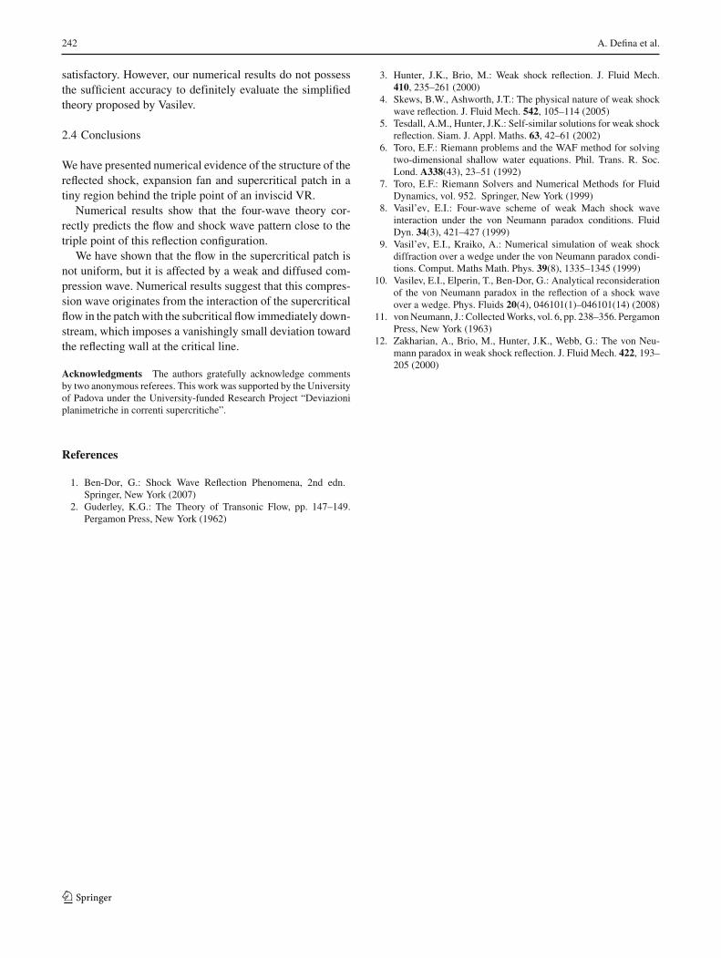
The present numerical technique allows for a detailedreconstruction of the shape of the reflected shock. At eachrefinement step, the simulated branch of the reflected shock isextracted at discrete points (approximately 15 ∼ 20 points).
The computed angle β between the reflected shock andthe x-axis is plotted in Fig. 9, where the chosen coordinatesystem has the origin at the triple point and is oriented suchthat the y-axis is tangent to the reflected shock at the origin(inset of Fig. 9).
The scatter of the plotted points is due to the finite width ofthe numerical reflected shock front (approximately 2�/3�).This introduces some inaccuracy in the tracking of the frontposition and in the evaluation of the triple point position.
Table 1 Comparison between four-wave theory and numerical resultsclose to the triple point
Upstream of the Inside the Below thereflected shock supercritical patch slipstream
h/h0 1.893 (1.896) 1.855 (1.864) 1.855 (1.864)
F 1.00 (∼1.00) 1.03 (1.02) 0.998 (�1.00)
θ 17.07◦ (17.14◦) 17.26◦ (17.28◦) 17.26◦ (17.28◦)
Italic is used to denote numerical solution
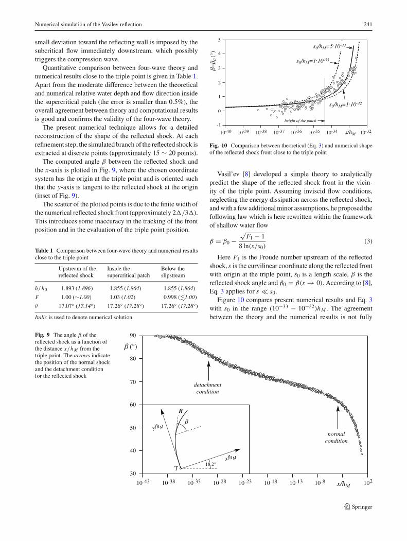
Fig. 10 Comparison between theoretical (Eq. 3) and numerical shapeof the reflected shock front close to the triple point
Vasil’ev [8] developed a simple theory to analyticallypredict the shape of the reflected shock front in the vicin-ity of the triple point. Assuming inviscid flow conditions,neglecting the energy dissipation across the reflected shock,and with a few additional minor assumptions, he proposed thefollowing law which is here rewritten within the frameworkof shallow water flow
β = β0 −√
F1 − 1
8 ln(s/s0)(3)
Here F1 is the Froude number upstream of the reflectedshock, s is the curvilinear coordinate along the reflected frontwith origin at the triple point, s0 is a length scale, β is thereflected shock angle and β0 = β(s → 0). According to [8],Eq. 3 applies for s � s0.
Figure 10 compares present numerical results and Eq. 3with s0 in the range (10−33 − 10−32)hM . The agreementbetween the theory and the numerical results is not fully
Fig. 9 The angle β of thereflected shock as a function ofthe distance x/hM from thetriple point. The arrows indicatethe position of the normal shockand the detachment conditionfor the reflected shock
123
242 A. Defina et al.
satisfactory. However, our numerical results do not possessthe sufficient accuracy to definitely evaluate the simplifiedtheory proposed by Vasilev.
2.4 Conclusions
We have presented numerical evidence of the structure of thereflected shock, expansion fan and supercritical patch in atiny region behind the triple point of an inviscid VR.
Numerical results show that the four-wave theory cor-rectly predicts the flow and shock wave pattern close to thetriple point of this reflection configuration.
We have shown that the flow in the supercritical patch isnot uniform, but it is affected by a weak and diffused com-pression wave. Numerical results suggest that this compres-sion wave originates from the interaction of the supercriticalflow in the patch with the subcritical flow immediately down-stream, which imposes a vanishingly small deviation towardthe reflecting wall at the critical line.
Acknowledgments The authors gratefully acknowledge commentsby two anonymous referees. This work was supported by the Universityof Padova under the University-funded Research Project “Deviazioniplanimetriche in correnti supercritiche”.
References
1. Ben-Dor, G.: Shock Wave Reflection Phenomena, 2nd edn.Springer, New York (2007)
2. Guderley, K.G.: The Theory of Transonic Flow, pp. 147–149.Pergamon Press, New York (1962)
3. Hunter, J.K., Brio, M.: Weak shock reflection. J. Fluid Mech.410, 235–261 (2000)
4. Skews, B.W., Ashworth, J.T.: The physical nature of weak shockwave reflection. J. Fluid Mech. 542, 105–114 (2005)
5. Tesdall, A.M., Hunter, J.K.: Self-similar solutions for weak shockreflection. Siam. J. Appl. Maths. 63, 42–61 (2002)
6. Toro, E.F.: Riemann problems and the WAF method for solvingtwo-dimensional shallow water equations. Phil. Trans. R. Soc.Lond. A338(43), 23–51 (1992)
7. Toro, E.F.: Riemann Solvers and Numerical Methods for FluidDynamics, vol. 952. Springer, New York (1999)
8. Vasil’ev, E.I.: Four-wave scheme of weak Mach shock waveinteraction under the von Neumann paradox conditions. FluidDyn. 34(3), 421–427 (1999)
9. Vasil’ev, E.I., Kraiko, A.: Numerical simulation of weak shockdiffraction over a wedge under the von Neumann paradox condi-tions. Comput. Maths Math. Phys. 39(8), 1335–1345 (1999)
10. Vasilev, E.I., Elperin, T., Ben-Dor, G.: Analytical reconsiderationof the von Neumann paradox in the reflection of a shock waveover a wedge. Phys. Fluids 20(4), 046101(1)–046101(14) (2008)
11. von Neumann, J.: Collected Works, vol. 6, pp. 238–356. PergamonPress, New York (1963)
12. Zakharian, A., Brio, M., Hunter, J.K., Webb, G.: The von Neu-mann paradox in weak shock reflection. J. Fluid Mech. 422, 193–205 (2000)
123