Integration of numerical analysis, virtual simulation and finite ...
Upload
khangminh22Category
view
1download
0
Acta Technica 62 No. 3A/2017, 335–346 c© 2017 Institute of Thermomechanics CAS, v.v.i.
Analysis on modeling and numericalsimulation for badminton racket of
braiding composite material based onANSYS
Liyan Zhang1
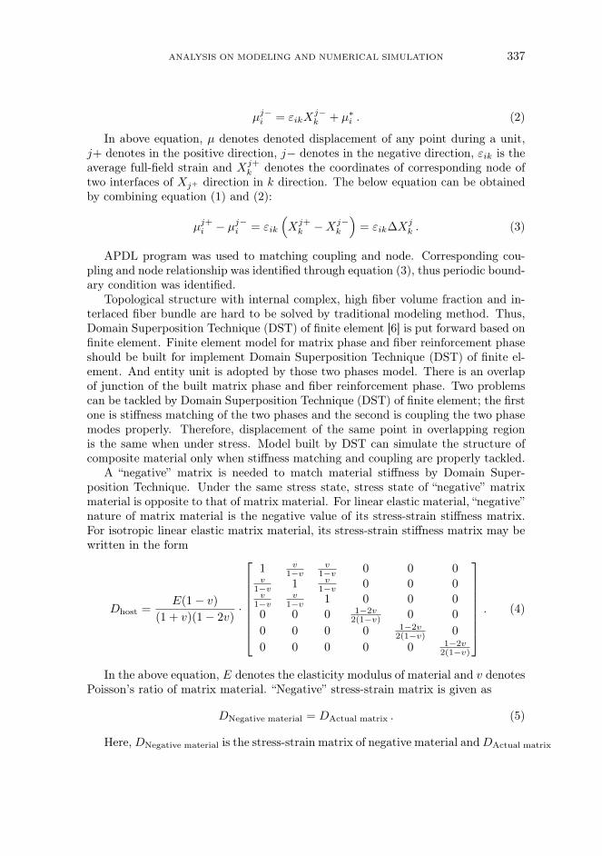
Abstract. Braiding composite material featured good mechanical property such as highstrength and high modulus is widely used in badminton racket manufacturing. Parameterized finiteelement models for badminton racket of braiding composite material is built by ANSYS softwarebased on Domain Superposition Technique of finite element, such as filament reinforcement phasemodel and matrix phrase model. Then, statics analysis, elastic properties prediction, invalidationdiscrimination and modal kinetic analysis are made for badminton racket model, which providestheory for design racket. Finally, elastic property of racket shaft is predicted and its result provesthat Domain Superposition Technique of finite element is feasible.
Key words. Braiding composite material, badminton racket, ANSYS, Domain SuperpositionTechnique of finite element, parameterized modeling.
1. Introduction
Composite material, a new material with excellence performance, is made up ofno less than two materials of different properties by chemical or physical treatment,such as organic polymer, inorganic nonmetal and metal. Braiding composite materialwith well mechanical property is made up of pre-form and matrix phase material[1]. And pre-form with overall structure is woven by different methods. Nowadays,studies on braiding composited material are generally focused on unit cell model.Then, proper periodic boundary condition and load was used for mechanical analysis.However, few studies were focused on building overall model with braiding compositematerial. Badminton racket made up of braiding composite material was taken asobject of study and its material model was built to study the overall mechanicalproperty was studied.
1Shenyang Normal University, Liaoning, 110034, China; E-mail: [email protected]
http://journal.it.cas.cz

336 LIYAN ZHANG
2. Literature review
In the early 1980, Ko [2] identified “fibrage” in his thesis and elaborated cubicunit cell model with rectangle surface for the first time. A finite element modelwith multi-scale was built by Wang et al. [3] using fiber, unit cell and laminate inthree dimensions. Multi-scale progressive damage analysis was made on compositematerial of 2×2 braiding structure. However, finite element analysis can only focuson a certain parameters of the structure because of diverse model parameter. Theoryand experiment was combined by Masters [4] to analyze mechanical properties ofbraiding composite material. Among those four methods, laminate model was theeasiest one to be achieved. For even laminated board, direction of fiber bundlewas the same and a bending correction factor was introduced to represent bendingproperty of the fiber.
Thee badminton racket designed here is manufactured by resin transfer moulding(RTM), a technology developed from wet molding process and shooting techniqueand the most widely used and mature liquid modeling technology. Products ofRTM molding is featuring smooth surface, stable quality, high fiber volume content,minor pollution, low cost and high efficiency. Finite element method can be used tosimulate lay-up of fiber material and resin impregnation-reinforced fiber material andto study technological parameter, temperature and pressure those influence molding.Based on previous study, modeling and numerical simulation for badminton racketof braiding composite material was analyzed using ANSYS.
3. Research method
3.1. Domain Superposition Technique of finite element
At present, study on braiding composite material modeling was almost all fo-cused on unit cell model, a representative elementary volume. Unit cell model builtby traditional braiding composite material was aimed to reflect fiber reinforced phasemodel and matrix phase model as well as the overall construction of component astrue as possible. True braiding composited material model was obtained after fiberreinforcement phase model was subtracted from matrix phase model with Booleanoperation based on ANSYS. Thus, two phases finite element model with no crossoverand overlap in space were obtained. Besides, special unit should be added at thejunction of the two phases, thus related mechanical relation between them was pro-duced. Within the final model, periodic boundary condition was used to finishpretreatment.
Braiding composite material was generally identified as an interconnection ofa large number of representative periodic unit cells. Thus, variation of boundarysurface of neighboring unit cell should be the same when under load. Variation ofany point on surface and its corresponding node should be the same. Displacementfield of any pair of parallel surface can be described as follows [5]
µj+i = εikX
j+k + µ∗
i , (i, j, k = x, y, z) , (1)
ANALYSIS ON MODELING AND NUMERICAL SIMULATION 337
µj−i = εikX
j−k + µ∗
i . (2)
In above equation, µ denotes denoted displacement of any point during a unit,j+ denotes in the positive direction, j− denotes in the negative direction, εik is theaverage full-field strain and Xj+
k denotes the coordinates of corresponding node oftwo interfaces of Xj+ direction in k direction. The below equation can be obtainedby combining equation (1) and (2):
µj+i − µj−
i = εik
(Xj+
k −Xj−k
)= εik∆Xj
k . (3)
APDL program was used to matching coupling and node. Corresponding cou-pling and node relationship was identified through equation (3), thus periodic bound-ary condition was identified.
Topological structure with internal complex, high fiber volume fraction and in-terlaced fiber bundle are hard to be solved by traditional modeling method. Thus,Domain Superposition Technique (DST) of finite element [6] is put forward based onfinite element. Finite element model for matrix phase and fiber reinforcement phaseshould be built for implement Domain Superposition Technique (DST) of finite el-ement. And entity unit is adopted by those two phases model. There is an overlapof junction of the built matrix phase and fiber reinforcement phase. Two problemscan be tackled by Domain Superposition Technique (DST) of finite element; the firstone is stiffness matching of the two phases and the second is coupling the two phasemodes properly. Therefore, displacement of the same point in overlapping regionis the same when under stress. Model built by DST can simulate the structure ofcomposite material only when stiffness matching and coupling are properly tackled.
A “negative” matrix is needed to match material stiffness by Domain Super-position Technique. Under the same stress state, stress state of “negative” matrixmaterial is opposite to that of matrix material. For linear elastic material, “negative”nature of matrix material is the negative value of its stress-strain stiffness matrix.For isotropic linear elastic matrix material, its stress-strain stiffness matrix may bewritten in the form
Dhost =E(1 − v)
(1 + v)(1 − 2v)·
1 v1−v
v1−v 0 0 0
v1−v 1 v
1−v 0 0 0v
1−vv
1−v 1 0 0 0
0 0 0 1−2v2(1−v) 0 0
0 0 0 0 1−2v2(1−v) 0
0 0 0 0 0 1−2v2(1−v)
. (4)
In the above equation, E denotes the elasticity modulus of material and v denotesPoisson’s ratio of matrix material. “Negative” stress-strain matrix is given as
DNegative material = DActual matrix . (5)
Here,DNegative material is the stress-strain matrix of negative material andDActual matrix

338 LIYAN ZHANG
is the stress-strain matrix of actual matrix.When implementing the Domain Superposition Technique (DST), it should match
material nature to fiber reinforcement phase. The final filamentary phase materialafter matching equals the subtract matrix material nature from filament phase ma-terial nature, which can be obtained by subtracting the actual matrix phase stress-strain stiffness matrix from actual fiber reinforcement phase tress-strain stiffnessmatrix:
Dcor = Den +Dho . (6)
In the above equation, Dcor denotes the matrix of modified reinforced stress-strainmatrix, Den denotes the matrix of actual reinforced stress-strain matrix and Dho
denotes the matrix of actual stress-strain matrix (substrate). In a word, the natureof matrix material was identified by grid cell of overall model and modified materialconstitutive model was identified by unit of fiber bundle region. Thus, materialcharacteristics of overall superposition domain and true fiber bundle material wasthe same. For any designated node in any unit, its coordinate of the coupling ofmodel fiber phase and matrix phase node is identified as
x =
m∑i=1
Nixi, y =
m∑i=1
Niyi, z =
m∑i=1
Nizi . (7)
In the above equation, x, y and z denote the coordinates of the overall coordinatesystem for a node in the unit. This is an interpolation function of the unit which isidentified under natural system of coordinates. SymbolN denotes the shape functionthat is given as N = µ/δe, µ being the distance of any point during the unit andδe the displacement of the element node. Also, the displacement of the designatednode is identified as
u =
m∑i=1
Niui, v =
m∑i=1
Nivi, w =
m∑i=1
Niwi . (8)
Here, u, v and w denote the displacement components of a node in the unit.The principle of Domain Superposition Technique is coupling of the designated
node and freedom degree of the node on the same unit with the designated node.Thus, node coupling method is used to couple node of the fiber reinforcement phasemodel to the matrix model.
3.2. Parametric modeling and mechanical analysis
For the designed racket handle, its diameter was 7.3mm, thickness was 1.5mmand length was 450mm. Given racket frame was an oval, whose major semi-axis was140mm, minor semi-axis was 110mm, thickness was 14mm and its diameter was setas 0.7mm. Composite material of carbon fiber-epoxy resin was used, whose fiberreinforcement phase material was M40 carbon fiber and matrix phase and bracingwire was bisphenol A (BPA) epoxy resin. Parameters of material used for fiber andresin are shown in Table 1.

ANALYSIS ON MODELING AND NUMERICAL SIMULATION 339
Table 1. Thermophysical properties of regular fluid and nanoparticles
Material property E1 (GPa) E2 (GPa) G12 (GPa) G23 (GPa) v12 v23
Carbon fiber 393 25.53 25.53 11.94 0.20 0.25Resin 3.62 3.62 - - 0.35 0.35
(1) Analysis on finite element model
Solid64 entity unit was used to build fiber reinforcement phase and matrix phaseof racket of two-dimension and three-direction braiding. There were three axialyarn and four braiding yarn included in the unit cell model of braiding compositematerial [7]. Fiber bundle material with filament dip-dyed part of resin and elas-tic constant of fiber bundle material was calculated by weighted average method.Through calculation below we obtained: E1 = 141.90GPa, E2 = E3 = 7.13GPa,G12 = G13 = 4.65GPa, G23 = 3.93GPa, v12 = v13 = 0.23, v23 = 0.36. For simulat-ing pre-stress of positions that bracing line connected with racket frame, PSMESHcommand was used to build pre-load stretching section of each positions. Then,SLOAD command was used to exert preload and poundage of bracing wire can beparameterized. Two-dimension and two-direction braiding and two-dimension andthree-direction braiding were adopted by fiber reinforcement phase and both of theirknitting angles are 45 degree. Fiber volume fraction of racket of two-dimension andthree-direction braiding was 21.56%. Finite element model of fiber phase and matrixphase for badminton racket handle of two-dimension and three-direction braiding areshown in Figs. 1 and 2. Other specified model are not listed one by one here.
Fig. 1. Finite element model for fiber phase of racket handle of two-dimension andthree-direction braiding
According to the practical situation of badminton racket under stress, two dif-ferent forces were put on the two end faces of ANSYS model of racket handle using

340 LIYAN ZHANG
Fig. 2. Finite element model for matrix of racket handle of two-dimension andthree-direction braiding
DST- a full constraint and a vertical force. Diameter of badminton cork was 20mm–25mm, thus a round area was defined to be hit by vertical force (300N). For theround area, midpoint of bracing wire was identified as a center of a circle and 25mmwas set as the diameter. Domain Superposition Technique was used to processthe built finite element parameterized model, thus the final model was identified asshown in Fig. 3.
Fig. 3. Finite element model of badminton racket modified by DomainSuperposition Technique
Under above constraint and stress, it can be calculated by ANSYS that themaximum equivalent stress of the whole racket was 154.28MPa and the maximumequivalent displacement was 1.25mm, which was positioned around the top of racketframe. The maximum equivalent stress of racket frame was 72.86MPa at crosspoint of fiber and matrix phase. The maximum equivalent stress of racket handlewas 154.82MPa around the contact position of racket handle and racket frame.Position around the connection point of racket frame and racket handle can beeasily broken off because figure of the contact position was changed. Thus, it can beinferred that distribution of whole equivalent stress of braiding composite materialwas uneven and whole equivalent stress of fiber bundle was obviously higher thanwhole equivalent stress of the matrix. Therefore, it can be known that fiber bundleof braided composite material was bearing the main force. Besides, apart from thestress concentration at top, whole fiber bundle was under even distributed forceand whole equivalent displacement of racket was linear distributed. Thus, whole

ANALYSIS ON MODELING AND NUMERICAL SIMULATION 341
performance of braiding composite material under stress was proved basically thesame.
For finite element model for racket of two-dimension and two-direction braiding,its fiber volume fraction was 13.75%. Above parametric modeling and mechanicalanalysis was made for racket of two-dimension and two-direction braiding, thus it canbe found that under the same constraint and loading, the maximum equivalent stressof model of two-dimension and two-direction braiding and model of two-dimensionand three-direction braiding was 154.28MPa and 198.18MPa, respectively. Thewhole equivalent stress of two-dimension and three-direction was much less than thatof two-dimension and two-direction. Besides, their whole equivalent displacementwas different. The reason that the whole bearing capacity of braided racket of two-dimension and three-direction braiding was much better than that of braided racketof two-dimension and two-direction braiding was that part of the loading was bornby the added axial fiber of racket of two-dimension and three-direction braiding. Thewhole equivalent stress of fiber bundle of racket of two-dimension and two-directionbraiding was obviously higher than that of the matrix. The whole force of fiberbundle was even distributed except that there was stress concentration at the endof constraint.
(2) Failure identification
With the wider application scope of braiding composite, it was of more and morepractical importance to have a failure criterion. Nowadays, strength criterion ofmodified traditional material was applied by many researchers to braiding compos-ite material, including the maximum stress criterion, Tsai-Hill criterion and Tsai-Wumultinomial criterion. Among all these mature criterion to explain fracture of com-posite material, Tsai-Wu multinomial criterion was the most comprehensive one andit would not be described in detailed as the limited to layout. According to failureidentification criterion of Tsai-Wu, when failure factor was no less that 1, compo-nent was identified as failure. When intensity factor was less than 1, componentwas identified as safe. For racket handle of two-dimension and two-direction braid-ing, the maximum overall intensity factor of Tsai-Wu failure criterion was 0.51. Forracket handle of two-dimension and three-direction braiding, the maximum overallintensity factor of Tsai-Wu failure criterion was 0.36. Because intensity factor ofthose two braiding method was less than 1, the overall component was identified assafe and would not fail. Security coefficient of racket handle of two-dimension andthree-direction braiding was higher than that of the racket handle of two-dimensionand two-direction braiding. The racket design was identified as reasonable and safebecause it was measured within security coefficient under above extreme case.
(3) Elastic performance prediction for racket handle
Nowadays, mechanical performance analysis on composite material was mainlyfocused on elastic performance, specifically numerical modeling on elastic modulus,Poison’s ration and shear modulus based on unit cell. Thus, elastic performanceof the overall racket handle of composite material was analyzed as bellow based onDomain Superposition Technique (DST) of finite element.

342 LIYAN ZHANG
Two different forces were put on the end faces of finite element model of rackethandle using DST—a full constraint and a displacement loading. Let δ = 0.05 × L,which means that the overall strain is 0.5%. The mean strain ε and mean stress δxon the plane X = L was calculated by ANSYS software. Then, elasticity modulusEy, Poisson’s ratio µxy and shear modulus Gxy of the composite can be obtainedaccording to this formation and definition formula. Besides, Ey = Ez, µxz = µyz
and Gxy, Gyz can be obtained using the common approach.ANSYS finite element analysis model for predicting elastic performance is shown
in Fig. 4.
Fig. 4. Model for predicting elastic performance of racket handle with fullconstraint and displacement loading
It can be concluded that with Domain Superposition Technique (DST) of finiteelement, it is effective to analyze overall component of racket handle, which effec-tiveness is also proved by accurate result of sparse finite element mesh. Elasticperformance of racket handle predicted by DST is shown in Table 2.
Table 2. Predicting result of elastic performance
Ex
(GPa)Ey
(GPa)Ez
(GPa)µxy µxz µyz Gxy
(GPa)Gxz
(GPa)Gyz
(GPa)
Two-dimensionand two-directions
40.33 6.35 6.33 0.31 0.31 0.93 13.6 13.6 3.2
Two-dimensionand three-directions
61.75 9.31 9.31 0.31 0.35 0.97 15.4 15.1 4.7
In conclusion, because part of the loading was born by the added axial fiber,racket of two-dimension and three-direction braiding was better that racket of two-dimension and two-direction braiding. Weight of those two rackets was almost thesame. Besides, hand feeling and overall anti-bending and anti-torsion of racket oftwo-dimension and three-direction braiding was better than that of racket of two-dimension and two-direction braiding. Thus, racket of two-dimension and three-direction braiding was more and more popular among designers and amateur ofbadminton.

ANALYSIS ON MODELING AND NUMERICAL SIMULATION 343
3.3. Analysis of modality dynamics
Modality is the inherent vibration of object. There are corresponding inherentfrequency, damping ratio and modal shape for each order of mode. Those parameterscan be used to design and optimize badminton racket to avoid unnecessary losscaused by resonance during hitting through modal analysis on finite element andfinite element analysis result. Finite element model for modal analysis is the samemodel for static analysis and material property used in statics. Fixed constraintwas put on one of the end of racket handle. Modal calculation of finite elementfor racket was calculated by ANSYS software with partitioning Lanczos methodwhen there was not loading on finite element model, which calculation was basedon parameterized calculation procedure developed according to static calculationmethod. For modality of high order, its contribution value to response was lowand its rate of decay was relative fast. Generally, only modality of low order wasincluded in modality analysis, thus, inherent frequency of the first-four-order wasselected. For racket of two-dimension and three-direction braiding, conclusion ofinherent frequency and mode of vibration of the first-four-order are shown in Table3.
Table 3. Inherent frequency and mode of vibration of the first-four-order of racket oftwo-dimensional and three-directional braiding
Order Inherent frequency(Hz)
Mode of vibration
1 34.25 Vibration in X −−Z plane
2 56.83 Vibration in X −−Y plane
3 75.92 Vibration in X −−Z plane
4 120.60 Compound vibration in planeX −−Y and X −−Z
4. Design result and analysis
Overall size of badminton racket and the automatic analysis software were de-signed based on visual programming software Microsoft Visual Basic6.0 and finiteelement analysis software ANSYS. The analysis result can be extracted by the pre-programmed procedure and automatic generated a report saved as WORD format.
The software designed has to be logged in with user name and code for security.At the top of operation interface, there were menu item, tool bar and diagram fig-ure of ANSYS finite element for badminton racket. In function menu, there weresystem, parametric modeling of finite element, analytical calculation and analysisreport. There were options for specific function in pull-down menu, such as initialinstallation path of software, material property setting for matrix phase and fiberphase, boundary conditions and loading, ANSYS solving and exit. Statics analysis,failure identification and modal analysis were included in this software. Click statics

344 LIYAN ZHANG
analysis, load and boundary constrain interface would popup. User can load bad-minton racket according to specific requirement. Thus, the earlier stage of designingsize of badminton frame and handle, constraint and load were accomplished. Af-ter loading, a box of “save data” would popup. Click “confirm”, the software wouldstart analysis and solving with background program. When background programfinished reading, dialog box would return to operational status and popup “ANSYScalculation finished”. Then, information bar would remind user the succeed solving.The final solving result can be checked by clicking “result query”. At the left sideof interface, result of overall badminton racket, racket frame, racket handle can bechecked according to the need. Corresponding equivalent stress and displacementfringe can also be checked. Partial enlarged details of fiber phase equivalent stress atracket handle of two-dimensional and three-directional braiding are shown in Fig. 5.
Fig. 5. Partial enlarged detail of fiber phase equivalent stress at racket handle oftwo-dimension and three-direction braiding
With this software, overall parameterization design of badminton racket andcomputation requirement of automatic finite element analysis can be satisfied, whichis of practical significance because a more convenient guideline for badminton racketdesign is provided.
5. Conclusion
Main research result:(1) Finite element model for badminton racket of two-dimension and two-direction
braiding and two-dimension and three-direction braiding was built based on DomainSuperposition Technique (DST) of finite element. Equivalent stress and equivalent
ANALYSIS ON MODELING AND NUMERICAL SIMULATION 345
displacement fringe of racket when hitting can be calculated with ANSYS analyticalsoftware. Besides, statics analysis, elastic performance prediction, failure identifica-tion and modal mechanical analysis for racket were complete.
(2) Calculation and optimization software for badminton racket structure wasdeveloped based on visual programming software VB 6.0 and software of finite ele-ment analysis ANSYS, which can be used to design structure of badminton racketand analyze and calculate it with finite element.
References
[1] Z.X.Tang, R. Postle: Mechanics of three-dimensional braided structures for com-posite materials – part I: fabric structure and fibre volume fraction. Composite Struc-tures 49 (2000), No. 4, 451–459.
[2] F.K.Ko: Three-dimensional fabrics for composites. An introduction to the weavestructure. Proc. International Conference on Composite Materials, ICCM IV, 25–28October 1982, Tokyo, Japan, Progress in Science and Engineering of Composites,Japan Society for Composite Materials 2 (1982), 1609–1619.
[3] Y.Q.Wang, A. S.D.Wang: On the topological yarn structure in 3-D rectangularand tubular braided preforms. Journal Composites Science & Technology 51 (1994),575–586.
[4] J. E.Masters, R. L. Foye, C.M.Pastore, Y.Gowayed: Mechanical properties oftriaxially braided composites: Experimental and analytical results. Journal of Compos-ites, Technology and Research 15 (1993), No. 2, 112–122.
[5] Z.Xia, Y. Zhang, F. Ellyin: A unified periodical boundary conditions for represen-tative volume elements of composites and applications. International Journal of Solidsand Structures 40 (2003), No. 8, 1907–1921.
[6] W.G. Jiang: Implementation of domain superposition technique for the nonlinearanalysis of composite materials. Journal of Composite Materials 47 (2013), No. 2,243–249.
[7] C. Zhang, X.Xu, X.Yan: Three unit-cell structure models of 3-D five-directional andfull five-directional braided composites. Journal of Nanjing University of Aeronautics& Astronautics 45 (2013), No. 02, 170–178.
Received May 7, 2017

346 LIYAN ZHANG
Copyright © 2022 FDOKUMEN