Reactive multi-agent approach to local platoon control: stability analysis and experimentations
22
Int. J. Intelligent Systems Technologies and Applications, Vol. x, No. x, xxxx 1 Reactive Multi-agent approach to local platoon control: stability analysis and experimentations Jean-Michel Contet*, Franck Gechter Pablo Gruer, Abderrafiaa Koukam University of Technology of Belfort-Montbeliard (UTBM) Systems and Transportation Laboratory (SET) Belfort, France Tel.: +33 (0)3 84 58 33 41 Fax: +33 84 58 33 42 {firstname.name}@utbm.fr *Corresponding author Abstract: This article presents a local control approach to linear platoons, systems of vehicles that displace together adopting a train configuration without any material coupling. Linear platoon technology is considered as a potential base for the definition of new urban transportation services. The main problems related to platoon systems is the geometry control: control of inter-vehicle distance and common trajectory matching. The geometry control problem is generally treated according to one of two approaches: global or local. This paper focuses on a local approach which does not require sophisticated sensors and/or costly road equipment. The objective of this local control approach allows satisfactory distance regulation and matching to any common trajectory, by using local perception capabilities of platoon’s vehicles. The basic perception capability consists in measuring the vectorial distance between a given vehicle and its predecessor. The behavior of each platoon vehicle is determined by a physics inspired interaction model based on a virtual spring-damper. Stability and other platoon safety properties are analyzed on the base of the physics inspired interaction model. Both simulation and experimentation have been used to measure trajectory error and to evaluate inter-vehicle distance during platoon evolution. Keywords: Platoon, local control, stability proof, simulation, experimentation Biographical notes: Jean-Michel Contet graduated from the University of Technology of Belfort-Montbeliard (UTBM) with an engineer degree and a Msc degree in Computer Science. His PhD (also at UTBM) focused on multi-vehicle navigation. He is currently research attache in the SET laboratory and its main research activity is on reactive multi-agent systems their formal specification and verification. He earned a silver medal in the European YEAR 2008 contest in the category ”Future vision of road transportation” and the first regional prize rewarding young researchers. Franck Gechter obtained a Master in engineering and a Master in photonics and image processing from the L. Pasteur Strasbourg I Copyright c 2009 Inderscience Enterprises Ltd.
-
Upload
multiagent -
Category
Documents
-
view
0 -
download
0
Transcript of Reactive multi-agent approach to local platoon control: stability analysis and experimentations
Int. J. Intelligent Systems Technologies and Applications, Vol. x, No. x, xxxx 1
Reactive Multi-agent approach to local platooncontrol: stability analysis and experimentations
Jean-Michel Contet*, Franck GechterPablo Gruer, Abderrafiaa Koukam
University of Technology of Belfort-Montbeliard (UTBM)Systems and Transportation Laboratory (SET)Belfort, FranceTel.: +33 (0)3 84 58 33 41Fax: +33 84 58 33 42{firstname.name}@utbm.fr*Corresponding author
Abstract: This article presents a local control approach to linearplatoons, systems of vehicles that displace together adopting a trainconfiguration without any material coupling. Linear platoon technologyis considered as a potential base for the definition of new urbantransportation services. The main problems related to platoon systemsis the geometry control: control of inter-vehicle distance and commontrajectory matching. The geometry control problem is generally treatedaccording to one of two approaches: global or local. This paper focuseson a local approach which does not require sophisticated sensorsand/or costly road equipment. The objective of this local controlapproach allows satisfactory distance regulation and matching to anycommon trajectory, by using local perception capabilities of platoon’svehicles. The basic perception capability consists in measuring thevectorial distance between a given vehicle and its predecessor. Thebehavior of each platoon vehicle is determined by a physics inspiredinteraction model based on a virtual spring-damper. Stability and otherplatoon safety properties are analyzed on the base of the physicsinspired interaction model. Both simulation and experimentation havebeen used to measure trajectory error and to evaluate inter-vehicledistance during platoon evolution.
Keywords: Platoon, local control, stability proof, simulation,experimentation
Biographical notes: Jean-Michel Contet graduated from theUniversity of Technology of Belfort-Montbeliard (UTBM) with anengineer degree and a Msc degree in Computer Science. His PhD (alsoat UTBM) focused on multi-vehicle navigation. He is currently researchattache in the SET laboratory and its main research activity is onreactive multi-agent systems their formal specification and verification.He earned a silver medal in the European YEAR 2008 contest in thecategory ”Future vision of road transportation” and the first regionalprize rewarding young researchers.
Franck Gechter obtained a Master in engineering and a Master inphotonics and image processing from the L. Pasteur Strasbourg I
Copyright c© 2009 Inderscience Enterprises Ltd.
2 J-M. Contet and F. Gechter and P. Gruer and A. Koukam
University (France), F. Gechter received the Ph.D. in ComputerScience from H. Poincare Nancy I University (France) in 2003, wherehe served as an assistant Professor from 1999 to 2004. He served as aresearcher in INRIA (French Research National Institute for ComputerScience and Automatic Control) (Nancy France) from 1999 to 2004.In 2004, he became associate professor of the Belfort MontbeliardTechnological University (UTBM) and researcher of the ICAP Teamof the Systems and Transportations Laboratory (Belfort France).
Juan Pablo Gruer holds an engineering degree in electronics fromthe Universidad Nacional de Tucuman (Argentina) and an egineeringdegree in Computer Science from the Institut Nationale Polytechniquede Grenoble. After a few years in industry as a real-time engineer, DrGruer returned to academia to prepare a PhD Thesis in ComputerScience in University de Haute Alsace at Mulhouse, France, awardedin 1989. From 1990 to 2008. Dr Gruer holds a Full Professor positionat UTBM and is a member of the ICAP team of the Systems andTransportation Laboratory (SET). Dr Gruer’s research interests are informal specification and verification of multi-agent systems and formaldesign approaches for reactive multi-agent applications with criticalsafety of operation constraints.
A. Koukam is full Professor at University of Technology of BelfortMontbeliard (UTBM). He received his PhD at Univeristy of Nancy 1and his Habilitation A Diriger des Recherches (HDR) at Universityof Bourgogne in 2000. He is currently responsible of the Systems andTransportations laboratory. His works concern Multi-Agents Systems,modelisation, simulation and optimisation with heuristics. He ledtwo european projects (TRASCOM 2002-2004, SURE 2003-2005) andseveral contracts with industry in the following fields: transportplanification, mobile networks and flow simulations in industrial sites.

Reactive Multi-agent approach to local platoon control 3
1 Introduction
Embedded vehicle intelligence benefits from the development of computers,sensors and interfaces. Many applications based on new vehicle capabilitiessuch as environment perception, communication, decision making and controlare widely studied. Among them, we can mention linear platoons: systems ofvehicles that displace together adopting a train configuration without any materialcoupling. Linear platoons are currently attracting research interest in the frameof energy, environment and security concerns. Linear platoons appear as thebase technology upon which innovative urban transportation systems could beproposed. Approaches to linear platoons can be classified as either global orlocal. Global approaches use a decision making component with global perceptioncapabilities, such as precise vehicle’s positioning. They also require inter-vehiclecommunication capabilities with a high level of reliability. Both requirementsfrequently lead to expensive road infrastructure. In this work, a local approachto linear platoon systems is proposed. It is based on vehicles with autonomousdecision-making and control features. It requires local, well defined perceptioncapabilities and does not need any inter-vehicle communication. Linear platoonstructure emerges as consequence of self-organizing behavior of each vehicle. Fromthis point of view, the local approach presented here can be considered as areactive multi agent system, where each vehicle corresponds to an autonomousagent.Linear platoon systems need to address the geometry control problem, includingtwo aspects: controlling inter-vehicle distance and achieving single trajectorymatching. The approach presented here addresses the geometry control problemby defining the behavior of vehicle as a result of their local perceptions, accordingto a physics-inspired interaction model.
This paper is structured as follow. The next section presents a review of theplatoon control approach. Then, section 3 proposes the reactive and localapproach, based on physics interaction model. Section 4 presents the stabilityanalysis. Finally, simulation and experimentation results are presented andcommented.
2 Platoon Control
2.1 Problem terms
The linear platoon geometry control problem has been defined as the set offunctional capabilities for a vehicle to be able, on one hand, to control inter-vehicledistance and, on the other hand, to achieve single trajectory matching. Generally,the geometry control problem is addressed through two sub problems: longitudinalcontrol and lateral control. Longitudinal control consists in controlling brakingand acceleration in order to stabilize the distance between following vehicles.Lateral control consists in determining a vehicle’s direction according to platoon’strajectory.

4 J-M. Contet and F. Gechter and P. Gruer and A. Koukam
Figure 1 Example of linear platoon simulation in a virtual environment
Most of the approaches presented in platoon literature can be classified aseither global or local, as already stated. Next paragraphs present a rapid state ofthe art about both of them.
2.2 Global approaches
Global approaches require the presence of a decision-making entity, generallyembedded in the head vehicle, which determines some reference information(trajectory points, steering and speed instruction, ...) and communicates them toeach follower vehicles. Two examples of a global approach can be presented. Thefirst one (11; 12) uses positioning systems such as GPS RTK to compute trajectorypoints to be visited by follower vehicles. In the second one (13), the leading vehiclebroadcasts driving information (steering and speed) to each follower vehicle, as inthe European Chauffeur project.
Global approaches yield good trajectory matching but global positioning withGPS or other technology requires road adaptation to avoid tunneling or canyoneffects. Moreover, a safe, reliable communication network between vehicle isrequired.
Consequently, global control approaches produce adequate results, subject tostrong constraints on sensors (high cost), road adaptation and communicationreliability between vehicles.
2.3 Local approaches
Local approaches perform longitudinal and lateral control based only oneach vehicle’s perception capabilities. Generally, vehicles are equipped withsensors which produce measures like inter-vehicle distance vectors. Each vehiclecomputes its own command references (acceleration and direction) only fromit’s own perceptions (measures). Most of the lateral or longitudinal controlstrategies proposed within local approaches use the PID (Proportional, Integral,Derivative) controllers (14; 15; 16) or other regulation-loop based algorithm(17; 18; 19; 13; 25). Other approaches, propose are based on the model of a

Reactive Multi-agent approach to local platoon control 5
particular physical phenomenon to determine vehicle’s control references. Forinstance, Gehrig and Stein (20) adopt a particle physics force model. Soo-yeongYi and Kil-to Chong (21) model immaterial vehicle coupling by means of animpedance control mechanism. Those two proposals suffer from the anticipationerror problem, defined later in this section, which handicaps the quality oftrajectory matching.
The advantage of local approaches stems from the absence of a componentwith a critical role. Local approaches do not require expensive road infrastructure,neither they need inter vehicle communication. They can use less expensive andmore reliable sensors. On the other hand, local approaches, as already mentioned,can suffer from poor trajectory matching but also from the so called accordioneffect produced during platoon evolution.
Anticipationaccelerationinstruction
Perceptiondistance
Figure 2 Local anticipation problem
This paper proposes a local platoon control approach which yields performancelevels close to those obtained by global control. Performance is evaluated in termsof inter-vehicle distance error and of lateral error, both of which will be definedin section 5.3. Our approach bases on the capability of each vehicle to measurethe vectorial distance to the vehicle immediately preceding it. The main cause oflateral error is the anticipation phenomenon, illustrated by figure 2: a vehicle triesto follow the direction of the distance vector to its predecessor. The local approachpresented here minimizes the anticipation error taking into account local curveproperties.
3 The interaction model
The local approach to linear platoons presented in this paper considers eachvehicle as a reactive agent which determines its behavior from local perceptioncapabilities. The focus is concentrated here on capabilities related to the main

6 J-M. Contet and F. Gechter and P. Gruer and A. Koukam
platoon functions: longitudinal and lateral control. Other local perceptioncapabilities, related to functions as obstacle avoidance, are presented in (7).
The proposed local approach is based on an interaction model using the localperception of the vehicle. In this model, interaction are enabled by forces whichare computed from a virtual physical link. The virtual link is made by a classicalspring-damper model as shown in figure 3 (a). Let consider the point of view ofplatoons vehicle Vn. In this approach, operation of Vn bases on its perception ofthe preceding vehicle, Vn−1 in the train.
3.1 Principle
The interaction model proposed in this paper bases on forces, which are notmaterially exerted, but which are computed from a virtual physical interactiondevice relating vehicles Vn and Vn−1. This virtual link connection is made by aclassical spring damper model (C.f figure 3 (a)). Each vehicle i is represented by
its position ~Xi = [xi,yi]. The distance between vehicles is d = ‖ ~Xn−1 − ~Xn‖. Thisdistance is deduced from the inter-vehicle distance and the angle θ. This virtuallink parameters are stiffness k, damping h and spring’s resting length l0. Thus,forces involved are :
• Spring force ~Fs:
~Fs = −k(‖ ~Xn−1 − ~Xn‖ − l0) ~un−1 n (1)
With ~un−1 n the unnitaire vector between the vehicle n− 1 and n (since thenumerotation start from 1 for the head vehicle and the preceding vehiclefrom the head one is n− 1).
• Damping force ~Fd:
~Fd = −h( ~Xn−1 − ~Xn) (2)
As a first approximation, longitudinal and lateral control references can thusbe determined taking these three forces (~Fs, ~Fd), and computed a new accelerationvalue. However, this model is not sufficient to avoid lateral error (6). This resultis due to limitations of the linear impedance control model (Fig. 3 (a)). Figure 3shows the acceleration anticipation and its consequence on the trajectory of Vn.To avoid this problem, the model has been improved by a new force introducinga flexibility of the spring-damper model in curves. The new force is aimed atcompensate the acceleration anticipation. It is based on a virtual moment, result ofa flexing spring and damping ~M = (km ∗ θ − hmθ) ∗ ~z with km the torsion spring,hm the torsion damping, θ the spring angle of flexion and θ the spring torsionspeed. This force is computed using the vectorial product of the distance betweenthe moment application point and the preceding vehicle position (C.f Fig. 3 (b)).This moment has the same behavior as a spring damper but in rotation.

Reactive Multi-agent approach to local platoon control 7
Accelerationanticipation
Perceptiondistance
(a)
Vn1
Vn
AccelerationPerceptiondistance
Ø
A
B
(b)
Vn1
Vn
Figure 3 Spring-damper based interaction model
Let consider ~MA the vectorial distance between the front vehicle and the pointof application moment M (C.f Fig. 3 right). The mass of the vehicle is denoted asm (vehicles are supposed to have the same mass).
The torsion force is :
• Torsion force ~Ftorsion:
~Ftorsion = ~BA ∧ ~M (3)
From now on, the vehicle acceleration can be computed using Newton’s law ofmotion in the preceding vehicle reference frame :
m ∗ ~Xn =∑force
~Fn
m ∗ ~Xn = −k(‖ ~Xn−1 − ~Xn‖ − l0) ~un−1 n
−h( ~Xn−1 − ~Xn) + ~BA ∧ ~M
(4)
Acceleration value can be computed using the equation 4. By discreteintegration, speed and vehicle state (position and orientation) and then thecommand law can be determined. In this case, command law consists in vehicledirection and speed. The choice of a command law takes into account thecharacteristics of the test vehicle used in our laboratory.
3.2 Computation of interaction Model Parameters
The goal of this section is to present how the interaction model parameters canbe computed taking into account the stability criterion. The interaction modelintroduces six variables, mass m, stiffness k, damping h, spring’s unstretchedlength l0 (regular distance), km torsion spring parameter and hm torsion stiffness
parameter. Vehicle n is taken as reference frame for coordinate values. So ~Y =[x, y] represents the difference between vehicles n-1 and n taking into account the
spring’s unstretched length. Similarly, ~Y expresses the speed difference betweenvehicles Vn−1 and Vn.

8 J-M. Contet and F. Gechter and P. Gruer and A. Koukam
• The mass m of an agent vehicle is set by the mass of the real vehicle.
• In order to find the values of the other parameters, the platoon is supposedto be well formed (θ = 0 the regular spring torsion angular). With thisassumption, the Newton’s equation became
m ∗ ~Y = −k(~Y )− h(~Y ) (5)
The solution is deduced using the critical damping case : ε = 1⇒ ∆ = 0.
ε =h
2 ∗√k ∗m
= 1 (6)
Then damping parameter becomes:
h = 2 ∗√k ∗m (7)
• Spring tends to its rest length l0. Thus, this parameters can be chosen tocorrespond to the expected inter-vehicle distance. According to the scheduleequation, a condition can be defined on l0:
l0 >V 20
2 ∗ acc(8)
• k represents the stiffness and therefore the vehicle capacity to follow the frontvehicle. In order to have an adaptable virtual the link between vehicle, kvalue can be linked to vehicle speed. Thanks to an energy study based onthe spring and damping force, the following equation can be obtained:
E = Epotential + Ekinetics =1
2∗ k ∗ (~Y .~Y ) +
1
2∗m ∗ (~Y.~Y ) (9)
The system energy represents the system stability, so the condition ∆E = 0corresponds to the vehicle stability control, i.e there are neither loss or gainof energy on both kinematics and potential points of view. Thanks to thiscondition, k can be expressed using inter-vehicle speed difference:
k =m ∗ V 2
Y 2(10)
With V the inter-vehicle speed difference and Y corresponding to the regulardistance.
• The two last parameters, i.e. torsion spring parameter km and torsiondamper parameter hm can be deduced from newton equation.

Reactive Multi-agent approach to local platoon control 9
First, km parameter can be deduced as follow:
m ∗ ~Y = −k(~Y )− h(~Y ) + ~Ftorsionwith
‖~Y ‖ = accmax~Y = regulardistance
~Y = regularspeed
(11)
Thus, torsion spring parameter km is equal to
km =
√m2acc2max + k2regulardistance2 + h2regularspeed2
‖MA‖ ∗ θ(12)
From now on, according to the Newton dynamics equation, km and hm canbe linked using the following expressions, the interaction model being basedon two moments:
~Torsionspring =
00kmθ
(13)
~Torsiondamping =
00
−hmθ
(14)
In this case, from the dynamics low of motion, M = Torsion spring +Torsion damping. Then, the following equation can be deduced:
kmθ − hmθ = 0 (15)
According to these formulas, all model parameters are computed, followingtwo steps : firstly, parameters’ values (stiffness k, damping h, km torsion springparameter and hm torsion stiffness) are recalculated from current value of speedand inter-vehicle distance. Secondly, new value of acceleration is computed.
4 Inter-Vehicle Distance Stability Analysis
Analysis of the interaction model by applying classical laws allows to prove thatthe interaction model satisfies a set of platoon stability properties. The nextsection presents two kinds of proofs: one applying a direct approach and the otherusing an energetic point of view.
10 J-M. Contet and F. Gechter and P. Gruer and A. Koukam
4.1 Platoon Stability Based on Transfer Function
Platoon stability is treated following the “string stability” problem which has beenstudied in (10). A platoon is said to be stable if, under no other excitations,the error magnitude decreases as it propagates along the vehicle stream. Thissection proposes to prove the string stability relatively to longitudinal control(Consequently, elements link to lateral control (i.e θ = 0 and θ = 0) are notconidered in the demonstration). Formally speaking, if the transfer function of thesystem composed of two successive vehicles exhibits a magnitude less or equal to1, string stability is obtained (23; 24). In order to verify this property, the controllaw of vehicles n− 1 and n must be expressed with θ = 0 (Longitudinal control):
let assume A(jω) to be equal to~X(jω)n−1
~X(jω)n. From laws of motion applied to vehicles
n− 1 and n, the following equation is obtained{m ∗ ~Xn−1 = −k ~Xn−1 − h ~Xn−1
m ∗ ~Xn = −k ~Xn − h ~Xn
(16)
From A(jω), A(s) can be computed, knowing that jω=s, A(s) = h∗s+ks2+h∗s+k .
String stability is guaranteed only if: |A(jω)| ≤ 1. This condition is verified with
k ≤ m∗ω2
2 . Thanks to the k value variation, this condition is ω ≥√
2/m ∗ VY (withV the inter-vehicle speed difference and Y the inter-vehicle distance). This studyproof that our system is stable to any frequency. The error propagation will beattenuated through the platoon.
4.2 Inter-Vehicle Distance Stability Proof Based on Energy
The goal of this section is to check if the stability (platoon stability is representedby the stabilization of the distance between each follower vehicle) of the system iskept in run time. To this end, Lyapunov stability of motion conditions are applied(9; 22). The system energy results from the addition of kinetic and potentialenergies. Vehicle i taken as reference frame, energy can be expressed as follow:
E = Ekinetics + Epotential = Ekinetics + Epot(Fs) + Epot(Ftorsion)
E = 12 ∗m ∗ ( ~X. ~X) + 1
2 ∗ k ∗ ( ~X. ~X) +∫X
∫θ~F .dY dθ
(17)
By applying Lyapunov stability of motion conditions (9; 22), we assume thatwith V(x,y,θ)= E.{
V (x, y, θ) ≥ 0
V (x, y, θ) < 0(18)
The first condition is filled since: ‖~Y ‖2 ≥ 0 and Epot(Ftorsion) ≥ 0 with θ ∈[−π/2, π/2].
E = Epot + Ekin ≥ 0 (19)

Reactive Multi-agent approach to local platoon control 11
The second condition :
E(x, y, θ) = E(x, y, θ)pot + E(x, y, θ)kin = Ekinetics + Epot(Fs) + Epot(Ftorsion)(20)
Energy Proof, Starting from equation 4, we obtain:
m ∗[xy
]= −h ∗
[xy
]− k ∗
[xy
]+ (km ∗ θ − hmθ) ∗
[xy
].
[sin(θ)cos(θ)
](21)
Let’s assume that:[x2y2
]=
[xy
]and
[x1y1
]=
[xy
](22)
[x2y2
]=
[xy
]and
[x1y1
]=
[xy
][x1y1
]=
[x2y2
][x2y2
]= − k
m ∗[x1y1
]+ km∗θ−hmθ
m ∗[x1y1
].
[sin(θ)cos(θ)
]− h
m ∗[x2y2
](23)
[∂E(x,y,θ)
∂x∂E(x,y,θ)
∂y
]=
[ ∂E∂x1
+ ∂E∂x2
∂E∂x1
+ ∂E∂x2
](24)
[∂E(x,y,θ)
∂x∂E(x,y,θ)
∂y
]=
[x22(kmsin(θ)− h)y22(kmcos(θ)− h)
](25)
The derivative of Energy is negative if the angular h ∗ km is greater than 1since θ ∈ [−π/2, π/2] . Applying Lyapunov stability of motion conditions as in(6; 4), shows that the system is stable when time tends to infinity. Thus, thedistance between vehicles tends to the un-stretched spring length when the platoonmoves without environmental influence, if the condition on rotation angle (θ ∈[−π/2, π/2]) is verified.
5 Simulation and experiments
The physics inspired interaction model previously defined is the base to thespecification of the local platooning control algorithm. Based on this algorithm,simulation and experimentation scenarios are designed and performed to check theplatoon evolution particularly during lateral displacement situations and a set ofsafety platoon conditions.
12 J-M. Contet and F. Gechter and P. Gruer and A. Koukam
5.1 Platforms presentation
This section shows the platforms used to test the platoon control algorithm.The first platform is a 3D simulator which incorporates a physics engine andsensors simulations, which allow to test realistic scenarios. The second platform iscomposed of modified GEM electrical vehicles automated by the laboratory SeT.
Simulation platform
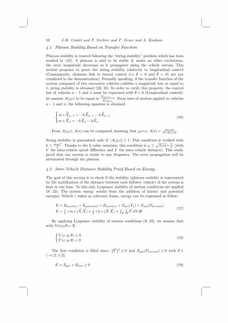
The 3D simulation tool has been developed during CRISTAL project (http://www.projet-cristal.net/). This tool has been fully realized in the Systems andTransportations laboratory. The goal of this application is to simulate and studyas fine as possible platooning solutions in regular conditions and also in the caseof forbidden scenarios such as car crashes.
Figure 4 3D simulator (Top) physics engine (Low)
This tool can simulate the behavior of the following elements for each vehicle:perception, control law computation and vehicle physical reaction. The physicsengine (cf. figure 4) simulates the interactions between vehicle components (wheels,shocks, ...) and stage (soil, ...) taking into account their physical properties(friction coefficient, spring rate, ...) and the nature of their mechanical connections(pivot, ...).
Experimental platform
Systems and Transportations Laboratory owns two electric vehicles (cf. figure 5left). These vehicles have been automated and can be controlled by a onboardsystem.

Reactive Multi-agent approach to local platoon control 13
Multiagent Systems
Vehicle
Sensors
OnBoard System
Steering
Braking Acceleration
Perception information
Direction and speed instruction
Instructions
Figure 5 SeT laboratory electrical vehicle (left), vehicle architecture (right)
Figure 5 shows the vehicle onboard system. The onboard computer receivesperception information and sends direction and speed commands to the vehiclecontrol device. The reactive local platoon system presented in this article has beenimplemented on this onboard computer.
5.2 Simulation and experimental protocol
Experiments were conducted on the Technopark site from the city of Belfort. Thesimulations were performed on a 3D geolocalized model of the same site built fromGeographical Information Sources and topological data.
Figure 6 Simulation et experimentation path
Figure 6 shows the path (white curve) used for the simulation andexperimentation. It was selected because it allows to move the train on a longdistance in an urban environment using a trajectory with different curve radius.
14 J-M. Contet and F. Gechter and P. Gruer and A. Koukam
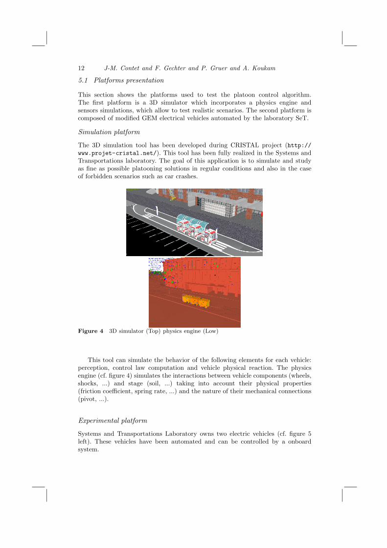
In order to compare the simulation and the experimentation results, parameterswere the same on simulation and real experiments. Thus, the perception of eachvehicle is made by a simulated laser range finder having the same characteristics(range, angle, error rate,...) as the vehicle real sensor. The distance and the anglebetween vehicles are computed thanks to this sensor. To improve this measure,reflective beacons have been installed at the rear of the head vehicle (cf. figure 7).
Figure 7 Reflective beacon
This beacon is composed of three reflective rubbers. The middle position oneallows to measure the distance between vehicles. The left and right are used tocompute the angle θ (cf. 7).
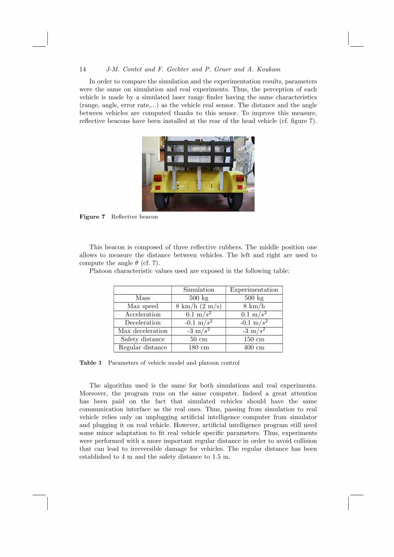
Platoon characteristic values used are exposed in the following table:
Simulation Experimentation
Mass 500 kg 500 kg
Max speed 8 km/h (2 m/s) 8 km/h
Acceleration 0.1 m/s2 0.1 m/s2
Deceleration -0.1 m/s2 -0.1 m/s2
Max deceleration -3 m/s2 -3 m/s2
Safety distance 50 cm 150 cm
Regular distance 180 cm 400 cm
Table 1 Parameters of vehicle model and platoon control
The algorithm used is the same for both simulations and real experiments.Moreover, the program runs on the same computer. Indeed a great attentionhas been paid on the fact that simulated vehicles should have the samecommunication interface as the real ones. Thus, passing from simulation to realvehicle relies only on unplugging artificial intelligence computer from simulatorand plugging it on real vehicle. However, artificial intelligence program still needsome minor adaptation to fit real vehicle specific parameters. Thus, experimentswere performed with a more important regular distance in order to avoid collisionthat can lead to irreversible damage for vehicles. The regular distance has beenestablished to 4 m and the safety distance to 1.5 m.

Reactive Multi-agent approach to local platoon control 15
5.3 Simulation and experimentation scenarios
This subsection presents tests performed both in simulation and with real vehiclesto assess the quality of platooning. The following cases were discussed:
• Evaluation of inter-vehicle distance: measuring the distance between twofollowing vehicles, compared to the desired regular inter-vehicle distanceduring platoon evolution (cf. figure 8).
• Evaluation of lateral deviation: measuring the distance between thetrajectories of the geometric center of a vehicle relative to the same path ofhis predecessor (cf. figure 8). For the measurement, points on the first vehicletrajectory were selected. Then, the normal trace of these points is drawnand a measure of the distance between the selected point and the point ofintersection with the trajectory of its predecessor is made.
Longitudinal error
Regular distance Lateral error
Preceding vehicle path
Following vehicle path
Figure 8 Longitudinal error (left) Lateral error (right)
5.4 Evaluation of inter-vehicle distance
This subsection presents the results of the evaluation of the inter-vehicle distancewith a train of four vehicles in simulation and with a train of two vehicles inexperimentation (Only two laboratory vehicles are available for the moment).As for simulations, the number of vehicles is determined by industrial partnerrequirements, however simulations with up to 10 vehicles have been successfullyperformed.
To evaluate the inter-vehicle distance, the train is submitted to criticaloperations such as starting, emergency braking and quick change of speed of thefirst vehicle.
16 J-M. Contet and F. Gechter and P. Gruer and A. Koukam
5.4.1 Simulation
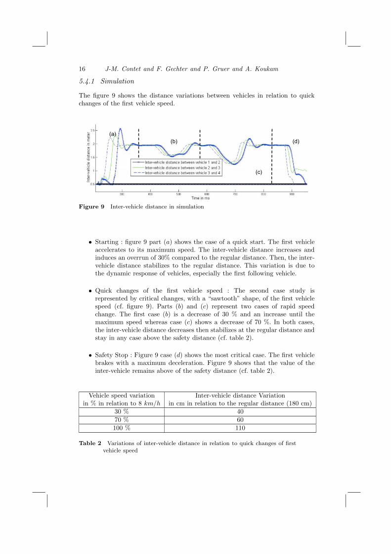
The figure 9 shows the distance variations between vehicles in relation to quickchanges of the first vehicle speed.
(a) (b)
(c)
(d)
Figure 9 Inter-vehicle distance in simulation
• Starting : figure 9 part (a) shows the case of a quick start. The first vehicleaccelerates to its maximum speed. The inter-vehicle distance increases andinduces an overrun of 30% compared to the regular distance. Then, the inter-vehicle distance stabilizes to the regular distance. This variation is due tothe dynamic response of vehicles, especially the first following vehicle.
• Quick changes of the first vehicle speed : The second case study isrepresented by critical changes, with a “sawtooth” shape, of the first vehiclespeed (cf. figure 9). Parts (b) and (c) represent two cases of rapid speedchange. The first case (b) is a decrease of 30 % and an increase until themaximum speed whereas case (c) shows a decrease of 70 %. In both cases,the inter-vehicle distance decreases then stabilizes at the regular distance andstay in any case above the safety distance (cf. table 2).
• Safety Stop : Figure 9 case (d) shows the most critical case. The first vehiclebrakes with a maximum deceleration. Figure 9 shows that the value of theinter-vehicle remains above of the safety distance (cf. table 2).
Vehicle speed variation Inter-vehicle distance Variationin % in relation to 8 km/h in cm in relation to the regular distance (180 cm)
30 % 4070 % 60
100 % 110
Table 2 Variations of inter-vehicle distance in relation to quick changes of firstvehicle speed

Reactive Multi-agent approach to local platoon control 17
5.4.2 Experiments
Figure 10 shows the distance evolution between the two electric vehicles duringthe experiment.
(a)
(b)
(c)
(d)
Figure 10 Inter-vehicle distance in real experiments
• Starting : Figure 10 illustrates the same as what has been shown insimulation (Figure 9). Part denoted (a) presents the quick start. The firstvehicle accelerates to its maximum speed (8km/h). The inter-vehicle distanceincreases until an overrun of 55% compared to the regular distance. Then,the inter-vehicle distance stabilizes to the regular distance, set at 4 m forthe experiments. This variation is due to the vehicle dynamic response, dueto the time of 500 ms between sending speed commands and the receptioncontrol to the electric motor.
• Rapid changes of the first vehicle speed : Area (b) and (c) (cf. figure 10)represent two cases of quick speed change. As in simulation, the first case(b) is a decrease of 30 % followed by an increase until the maximum speed.Case (c) shows a decrease of 70 %. In both cases, the inter-vehicle distancedecreases then stabilizes at the regular distance. Inter-vehicle distance neverreaches a value above safety distance.
• Safety Stop : figure 10 case (d) shows a lead vehicle deceleration (Untilnow, an emergency braking with maximum deceleration cannot be performedbecause the latency between sending orders and executing them is too high(500 ms)). The value of the inter-vehicle distance remains above of the safetydistance, set at 1.5 m.
5.4.3 Conclusion: Evaluation of inter-vehicle distance
Table 3 gives an overview of the inter-vehicle distance variation. We can observethat despite the very sudden changes in first vehicle speed, this value is above thevalue of the safety distance and stabilize rapidly to the regular distance.

18 J-M. Contet and F. Gechter and P. Gruer and A. Koukam
Critical case Inter-vehicle distance
Simulation
Starting from 0 to maximal speed Overrun of 30% compared to the regular distance
Speed variation of 30 et 70 % Inter-vehicle distance variation 20 et 50 %
Safety stop from maximal speed to 0 Above the value of the safety distance
Experimentation
Starting from 0 to maximal speed Overrun of 55% compared to the regular distance
Speed variation of 30 et 70 % Inter-vehicle distance variation 30 et 50 %
Safety stop from maximal speed to 0 Above the value of the safety distance
Table 3 Evaluation of inter-vehicle distance
5.5 Evaluation of lateral deviation
This subsection proposed to evaluate the distance between the trajectories of thegeometric center of a vehicle relative to the same path of his predecessor. Thislateral deviation may cause problems in curves as the friction of pavement andcollisions with vehicles in the opposite direction.
5.6 Simulation: evaluation of lateral deviation
The simulation was performed with a train of four vehicles.
X
Y
Figure 11 Simulation: lateral error during exit station
Figure 11 presents the tracks of vehicles to measure the lateral error betweeneach vehicle. The simulation was realized during exit station. In this case, the erroris not greater than the width of a tire (i.e. 20 cm).

Reactive Multi-agent approach to local platoon control 19
Wheel rotation Curve Medium Maximum(degree) radius error error
5.73 18 m 12 cm 14 cm
11.46 9 m 30 cm 40 cm
17.2 6 m 50 cm 65 cm
22.9 4.5 m 55 cm 67 cm
28.65 3.6 m 67 cm 75 cm
Table 4 Simulation: trajectory error in curve
To see the maximum error then the train evolve, we plotted the lateral error inrelation to the wheel rotation (cf. figure 12).
Figure 12 Simulation: lateral error in relation to the wheel rotation
Table 4 shows the maximum lateral error and average in relation to the radiusof curvature of the lead vehicle. We note that in normal operation case (wheelrotation < 10 degrees), we have a lateral error less than 20 cm.
5.7 Experimentation : evaluation of lateral deviation
The experiment was realized with two electric vehicles from SeT laboratory. Themeasure has been realized thanks to the GPS RTK installed on vehicles to knowtheir positions in centimeter.

20 J-M. Contet and F. Gechter and P. Gruer and A. Koukam
Wheel rotation angle
Dis
tanc
e er
ror i
n ce
ntim
eter
Figure 13 Lateral error in relation to the wheel rotation
To see the maximum error then the train evolve, we plotted the lateral error inrelation to the wheel rotation (cf. figure 5).
Wheel rotation Curve Medium Maximum(degree) radius error error
5.73? 18 m 30 cm 45 cm
11.46? 9 m 40 cm 52 cm
17.2? 6 m 46 cm 56 cm
22.9? 4.5 m 55 cm 70 cm
28.65? 3.6 m 70 cm 90 cm
Table 5 Experimentation: trajectory error in curve
5.8 Conclusion : evaluation of lateral deviation
Table 5 shows the maximum and average lateral error in relation to the radiusof curvature from the lead vehicle. The results presented in the table show thatthe tracking error of the vehicle simulation is close to the experiment. Indeed, theresults presented in the table 4 represent the average error between each car of thetrain, similar levels of values are found.
Reactive Multi-agent approach to local platoon control 21
6 Conclusion
The aim of this article was to present a better local platoon control based onthe bending of a virtual spring damper. In this paper, platoon control bases onlyon local perception capabilities. Each vehicle behavior is deduced from a physicsinspired interaction model an embodied in a reactive agent architecture. Theuse of physics inspired forces enables an easier tuning of the interaction modelparameters and the adaptation to any kind of vehicle. Besides, the physic modelhas been used to prove platoon stability, by using classic physical proof method:energy analysis. Analogously, another stability proof have been realized followinga transfer-function approach. To assert the transition from abstract to concrete,simulations have been implemented to show the applicability of the theoreticalmodel. Some simulations have been made on a 3D simulator which integratesvehicle dynamic properties (maximal speed and acceleration, ....). Simulationand experimentation scenarios are designed and performed to check the platoonevolution particularly during lateral displacement situations and a set of safetyplatoon conditions. These experimentations exhibit a little curved trajectory errorduring the platoon evolution and indicate that the presented approach improvesplatoon quality. Moreover, we are exploring the possibility of building formalspecification models and exploiting them in order to verify by model-checking somesafety properties (8).
References
[1] Hedrick, J.K. and Tomizuka, M. and Varaiya, P.: Control issues in automatedhighway systems. IEEE Control Systems Magazine. pp 21 - 32. (1994)
[2] Debojyoti, M. and Asis M.: Pollution control by reduction of drag on cars and busesthrough platooning. Int. J. of Environment and Pollution - Vol. 30, No.1 pp. 90-96,(2007)
[3] Ferber J.: Multi-Agent System: An Introduction to Distributed ArtificialIntelligence. Harlow: Addison Wesley Longman ISBN 0-201-36048-9, J. Ferber,(1999)
[4] Gaud, N. and Gechter, F. and Galland, S. and Koukam, A.: Holonicmultiagent multilevel simulation : Application to real-time pedestrians simulationin urban environment, Twentieth International Joint Conference on ArtificialIntelligence,IJCAI’07, 1275-1280, (2007)
[5] Contet, J.M. and Gechter, F. and Gruer, P. and Koukam, A.: Physics inspiredmultiagent model for vehicle platooning, International Conference on AutonomousAgents and Multiagent Systems AAMAS, (2007)
[6] Contet, J.M. and Gechter, F. and Gruer, P. and Koukam, A.: Multiagent SystemModel for Vehicle Platooning with Merge and Split Capabilities, Third InternationalConference on Autonomous Robots and Agents, 41-46, (2006)
[7] Gechter, F. and Contet, J.M. and Gruer, P. and Koukam, A.: Car-driving assistanceusing organization measurement of reactive multi-agent system, InternationalConference on Computational Science 2010, (2010)
[8] Contet, J.M. and Gechter, F. and Gruer, P. and Koukam, A.: An Approach toCompositional Verification of Reactive Multiagent Systems, Working Notes of theTwenty-Fourth AAAI Conference on Artificial Intelligence (AAAI), Workshop on
22 J-M. Contet and F. Gechter and P. Gruer and A. Koukam
Model Checking and Artificial Intelligence, Atlanta, Georgia, USA, July 11-12, 2010,(2010)
[9] Taylor F. and Lyapunov A.M.: The general problem of the stability of the motion,(1992)
[10] William L. Garrard and Reggie J. Caudill.: Dynamic Behavior of Strings ofAutomated Transit Vehicles, SAE Transactions, pp. 1365-1378, (1977)
[11] Martinet P., Thuilot B., Bom J.: Autonomous Navigation and Platooning using aSensory Memory, International IEEE Conference on Intelligent Robots and Systems,IROS’06, Beijing, China, (2006)
[12] Myung J.W and Jae Weon C.: A relative navigation system for vehicle platooning,SICE 2001. Proceedings of the 40th SICE Annual Conference. International SessionPapers, 28 - 31, (2001)
[13] Fritz, H.: Longitudinal and lateral control of heavy duty trucks for automatedvehicle following in mixed traffic: Experimental results from the CHAUFFEURproject, IEEE Conference on Control Applications - Proceedings, 2, 1348 - 1352,(1999)
[14] Ioannou, P. and Xu, Z.: Throttle and brake control systems for automatic vehiclefollowing, IVHS Journal, 345 - , (1994)
[15] Moskwa, John J. and Hedrick,Karl J.: Nonlinear algorithms for automotive enginecontrol, IEEE Control Systems Magazine, 10, 88 - 93, (1990)
[16] Daviet, P. and Parent, M.: Longitudinal and lateral servoing of vehicles in a platoon,IEEE Intelligent Vehicles Symposium, Proceedings, 41 - 46, (1996)
[17] Sheikholeslam, S. and Desoer, C.A.: Longitudinal control of a platoon of vehicleswith no communication of lead vehicle information: A system level study, IEEETransactions on Vehicular Technology, 42, 546 - 554, (1993)
[18] Lee, H. and Tomizuka, M.: Adaptive vehicle traction force control for intelligentvehicle highway systems (IVHSs), IEEE Transactions on Industrial Electronics, 50,37 - 47, (2003)
[19] Kehtarnavaz, N. and Griswold, N.C. and Lee, J.S.: Visual control of an autonomousvehicle (BART)–The vehicle-following problem, IEEE Transactions on VehicularTechnology, 40, 654 - 662, (1991)
[20] Gehrig, S.K. and Stein, F.J., Elastic bands to enhance vehicle following, IEEEConference on Intelligent Transportation Systems, Proceedings, ITSC, 597 - 602,(2001)
[21] Soo-Yeong Yi and Kil-To Chong, Impedance control for a vehicle platoon system,Mechatronics (UK), Vol 15, pages 627, (2005)
[22] Leipholz H.: An introduction to the stability of Dynamic systems and rigid bodies,(1987)
[23] Swaroop, D. and Hedrick, J.K., String stability of interconnected systems,Automatic Control, IEEE Transactions on, 41, 349-357, (1996)
[24] Liang C. and Peng H., Optimal Adaptive Cruise Control with GuaranteedString Stability, Liang, C. and Peng, H.: Optimal Adaptive Cruise Control withGuaranteed String Stability, (1998)
[25] Klancar G. and Matko D. and Blazic S., Wheeled Mobile Robots Control in a LinearPlatoon, Journal of Intelligent and Robotic System, (2008)