Reactive Power Compensation and Imbalance Suppression ...
16
energies Article Reactive Power Compensation and Imbalance Suppression by Star-Connected Buck-Type D-CAP Xiaosheng Wang 1,2 , Ke Dai 2, *, Xinwen Chen 3 , Xin Zhang 2 , Qi Wu 2 and Ziwei Dai 4 1 China-EU Institute for Clean and Renewable Energy, Huazhong University of Science and Technology, Wuhan 430074, China; [email protected] 2 State Key Laboratory of Advanced Electromagnetic Engineering and Technology, School of Electrical and Electronic Engineering, Huazhong University of Science and Technology, Wuhan 430074, China; [email protected] (X.Z.); [email protected] (Q.W.) 3 Wuhan National Laboratory for Optoelectronics, Huazhong Institute of Electro-optics, Wuhan 430223, China; [email protected] 4 Department of Electrical, Computer and System Engineering, Rensselaer Polytechnic Institute, Troy, NY 12180, USA; [email protected] * Correspondence: [email protected] Received: 5 March 2019; Accepted: 16 May 2019; Published: 18 May 2019 Abstract: Reactive power and negative-sequence current generated by inductive unbalanced load will not only increase line loss, but also cause the malfunction of relay protection devices triggered by a negative-sequence component in the power grid, which threatens the safe operation of the power system, so it is particularly important to compensate reactive power and suppress load imbalance. In this paper, reactive power compensation and imbalance suppression by a three-phase star-connected Buck-type dynamic capacitor (D-CAP) under an inductive unbalanced load are studied. Firstly, the relationship between power factor correction and imbalance suppression in a three-phase three-wire system is discussed, and the principle of D-CAP suppressing load imbalance is analyzed. Next, its compensation ability for negative-sequence currents is determined, which contains theoretical and actual compensation ability. Then an improved control strategy to compensate reactive power and suppress imbalance is proposed. If the load is slightly unbalanced, the D-CAP can completely compensate the reactive power and negative-sequence currents. If the load is heavily unbalanced, the D-CAP can only compensate the positive-sequence reactive power and a part of the negative-sequence currents due to the limit of compensation ability. Finally, a 33 kVar/220 V D-CAP prototype is built and experimental results verify the theoretical analysis and control strategy. Keywords: dynamic capacitor; inductive unbalanced load; reactive power compensation; imbalance suppression; compensation ability 1. Introduction There are a large number of inductive unbalanced loads in three-phase three-wire power systems generating reactive power and negative-sequence current, which not only increase line loss, but also cause malfunctions in overload protection devices triggered by negative-sequence current, thus threatening the safe operation of the power system. It is particularly important to compensate reactive power and negative-sequence current [1,2]. Reactive power compensation is an important means to improve power quality. Shunt power capacitors and shunt reactors have been widely used in power grid [3], but they can only provide constant reactive power. Different from fixed capacitors, static Var compensator (SVC) has advantages of adjustable reactive power and rapid response speed. Elements which may be used to make SVC typically include thyristor-controlled reactor (TCR) and thyristor-switched capacitor (TSC). In [4,5], Energies 2019, 12, 1914; doi:10.3390/en12101914 www.mdpi.com/journal/energies
-
Upload
khangminh22 -
Category
Documents
-
view
2 -
download
0
Transcript of Reactive Power Compensation and Imbalance Suppression ...

energies
Article
Reactive Power Compensation and ImbalanceSuppression by Star-Connected Buck-Type D-CAP
Xiaosheng Wang 1,2, Ke Dai 2,*, Xinwen Chen 3, Xin Zhang 2, Qi Wu 2 and Ziwei Dai 4
1 China-EU Institute for Clean and Renewable Energy, Huazhong University of Science and Technology,Wuhan 430074, China; [email protected]
2 State Key Laboratory of Advanced Electromagnetic Engineering and Technology, School of Electrical andElectronic Engineering, Huazhong University of Science and Technology, Wuhan 430074, China;[email protected] (X.Z.); [email protected] (Q.W.)
3 Wuhan National Laboratory for Optoelectronics, Huazhong Institute of Electro-optics, Wuhan 430223, China;[email protected]
4 Department of Electrical, Computer and System Engineering, Rensselaer Polytechnic Institute,Troy, NY 12180, USA; [email protected]
* Correspondence: [email protected]
Received: 5 March 2019; Accepted: 16 May 2019; Published: 18 May 2019
Abstract: Reactive power and negative-sequence current generated by inductive unbalanced loadwill not only increase line loss, but also cause the malfunction of relay protection devices triggered bya negative-sequence component in the power grid, which threatens the safe operation of the powersystem, so it is particularly important to compensate reactive power and suppress load imbalance.In this paper, reactive power compensation and imbalance suppression by a three-phase star-connectedBuck-type dynamic capacitor (D-CAP) under an inductive unbalanced load are studied. Firstly, therelationship between power factor correction and imbalance suppression in a three-phase three-wiresystem is discussed, and the principle of D-CAP suppressing load imbalance is analyzed. Next,its compensation ability for negative-sequence currents is determined, which contains theoreticaland actual compensation ability. Then an improved control strategy to compensate reactive powerand suppress imbalance is proposed. If the load is slightly unbalanced, the D-CAP can completelycompensate the reactive power and negative-sequence currents. If the load is heavily unbalanced, theD-CAP can only compensate the positive-sequence reactive power and a part of the negative-sequencecurrents due to the limit of compensation ability. Finally, a 33 kVar/220 V D-CAP prototype is builtand experimental results verify the theoretical analysis and control strategy.
Keywords: dynamic capacitor; inductive unbalanced load; reactive power compensation; imbalancesuppression; compensation ability
1. Introduction
There are a large number of inductive unbalanced loads in three-phase three-wire power systemsgenerating reactive power and negative-sequence current, which not only increase line loss, butalso cause malfunctions in overload protection devices triggered by negative-sequence current, thusthreatening the safe operation of the power system. It is particularly important to compensate reactivepower and negative-sequence current [1,2].
Reactive power compensation is an important means to improve power quality. Shunt powercapacitors and shunt reactors have been widely used in power grid [3], but they can only provideconstant reactive power. Different from fixed capacitors, static Var compensator (SVC) has advantagesof adjustable reactive power and rapid response speed. Elements which may be used to make SVCtypically include thyristor-controlled reactor (TCR) and thyristor-switched capacitor (TSC). In [4,5],
Energies 2019, 12, 1914; doi:10.3390/en12101914 www.mdpi.com/journal/energies

Energies 2019, 12, 1914 2 of 16
two kinds of reactive power compensation schemes along with harmonic reduction techniques forunbalanced loads are addressed. Although with novel solutions, harmonic problems produced by TCRobtain some improvement, while high energy loss and large volume further limit its development.
Compared with SVC, the static synchronous compensator (STATCOM) has higher compensationaccuracy, faster regulation speed, stronger compensation ability, and lower harmonic content basedon a fully-controllable power semiconductor device and high switching frequency [6]. Two controlstrategies for star-connected and delta-connected STATCOMs under an unbalanced load are proposedin [7,8]. However, the ability of a STATCOM compensating negative-sequence current is affectedby its structure. In [9], the compensation ability of STATCOM with star and delta configurations isindicated and analyzed. The third-harmonic injection method proposed in [10] achieves a significantimprovement in STATCOM ability of simultaneous compensation for reactive and negative-sequencecurrent. Considering unbalanced grid voltages, an improved regulation scheme with positive andnegative sequence control for modular multilevel converter (MMC) in medium-voltage distributionstatic synchronous compensator (DSTATCOM) application is proposed in [11].
Although the compensation characteristic of a STATCOM for reactive and negative-sequencecurrents is good, it is complicated to stabilize and balance DC-link electrolytic capacitors’ voltages,which will influence the reliability of STATCOMs [12,13]. Additionally, the high cost of STATCOMsaffect their application in low-power applications. Although a matrix converter can be designed asa dynamic compensator without the bulky electrolytic capacitors, large numbers of bi-directionalswitches have to be used [14,15].
In [16–18], a magnetic energy recovery switch (MERS) is applied in reactive power compensationdue to its characteristic equivalent to a variable capacitor. However, it will produce some harmonicsbecause it adopts a phase-shifting control method. Additionally, electrolytic capacitor voltagefluctuation will further increase the harmonic contents of the output current. Similar to MERS, anotherVAr generator is analyzed in [19,20], which can be equivalent to a variable capacitor with a H-bridgeinverter and DC capacitance. The same as with STATCOMs, the voltage fluctuation of the electrolyticcapacitor on the DC side will affect their reliability.
Considering a large number of fixed capacitors in a distribution system, it is economical if powerelectronic technology can be used to reconstruct them to achieve better performance. Compared withthe above compensators, the dynamic capacitor (D-CAP) is a simple, reliable, and economical solutionwithout bulky electrolytic capacitors, which is composed of a power capacitor and a thin AC converter(TACC) [21–23]. Furthermore, the TACC could be configured with a simple topology, such as a Buck,Boost, or a Buck-Boost circuit, so the D-CAP has great potential to be used in low-power applications.Extending cells with a series connection, it is also feasible for the D-CAP to be applied in high-voltageapplications [24]. Considering harmonic contents in the grid voltage, the output currents of the D-CAPwill contain some distortions due to the impacts of self-resonance and on-state voltage drop of theswitches. In order to reduce the harmonic content of the output currents, a waveform shaping strategyand a resonance damping method are proposed in [25,26], respectively.
Although reactive power compensation has got some focus for D-CAP, load imbalance suppressionhas not been discussed. Since the D-CAP is equivalent to a capacitor controlled by the duty ratio,it is meaningful to study how to suppress the load imbalance by capacitors. Reference [27] showsthat only adopting capacitors cannot compensate for all unbalanced load, but it does not specify itscompensation range. Using a delta-connected D-CAP to compensate the unbalanced load has beenstudied in the author’s previous article [28]. Although the voltage in each phase is the same for adelta-connected D-CAP without the potential deviation at the neutral point, the line voltage of thedelta structure is larger than the phase voltage of the star structure. For a star-connected D-CAP, theoperating voltage of the switching device is lower than a delta-connected D-CAP, and the number ofcascaded units is less, especially in high-voltage applications [24]. Due to the cost advantages, it is alsoof great significance to study star-connected D-CAPs. In this paper, reactive power compensation andimbalance suppression for a three-phase star-connected Buck-type D-CAP are explored.

Energies 2019, 12, 1914 3 of 16
The innovations of this paper can be described as follows: In Section 2, the relationship betweenpower factor correction and load imbalance suppression in three-phase three-wire system is analyzed.In Section 3, the theoretical compensation ability of the D-CAP for negative-sequence current is derived.Considering that the rated voltage of the D-CAP is limited, the actual compensation ability of theD-CAP is also analyzed. In Section 4, an improved control strategy is proposed, which can makethe D-CAP compensate negative-sequence current the best. Finally, experimental results verify thecorrectness of the theoretical analysis and the effectiveness of the control strategy.
2. Principle of the D-CAP Compensating for Reactive Power and Suppressing theLoad Imbalance
2.1. Relationship between Power Factor Correction and Imbalance Suppression
For the system of a three-phase star-connected Buck-type D-CAP and inductive unbalanced load,shown in Figure 1, in order to simplify the analysis, only fundamental components are considered.The load is linear and the three-phase voltages on the grid side [uTa uTb uTc] are balanced andsymmetrical, where:
uTa = Um sin(ωt)uTb = Um sin(ωt− 120)uTc = Um sin(ωt + 120)
(1)
Energies 2019, 12, x FOR PEER REVIEW 3 of 15
also of great significance to study star-connected D-CAPs. In this paper, reactive power compensation and imbalance suppression for a three-phase star-connected Buck-type D-CAP are explored.
The innovations of this paper can be described as follows: In Section 2, the relationship between power factor correction and load imbalance suppression in three-phase three-wire system is analyzed. In Section 3, the theoretical compensation ability of the D-CAP for negative-sequence current is derived. Considering that the rated voltage of the D-CAP is limited, the actual compensation ability of the D-CAP is also analyzed. In Section 4, an improved control strategy is proposed, which can make the D-CAP compensate negative-sequence current the best. Finally, experimental results verify the correctness of the theoretical analysis and the effectiveness of the control strategy.
2. Principle of the D-CAP Compensating for Reactive Power and Suppressing the load imbalance
2.1. Relationship between Power Factor Correction and Imbalance Suppression
For the system of a three-phase star-connected Buck-type D-CAP and inductive unbalanced load, shown in Figure 1, in order to simplify the analysis, only fundamental components are considered. The load is linear and the three-phase voltages on the grid side [uTa uTb uTc] are balanced and symmetrical, where:
sin( )sin( 120 )sin( 120 )
Ta m
Tb m
Tc m
u U tu U tu U t
ωωω
= = − = +
(1)
Inductive unbalanced
load
PSa+jQSauTa iSa
iSb
iSc
iLa
iLb
iLc
PLa+jQLa
PLb+jQLb
PLc+jQLc
Da2Ca Dc
2CcDb2Cb
Equivalent circuit of three phase D-CAP
uTb
uTc
PSb+jQSb
PSc+jQSc
iCa
iCb
iCc
PCb+jQCb
PCa+jQCa
PCc+jQCc
N1
CaCFa
LFa
LBa
S11a S12a S21a S22a
CbCFb
LFb
LBb
S11b S12b S21b S22b
CcCFc
LFc
LBc
S11c S12c S21c S22c
N1
iCa
iCb
iCc
(a) (b)
Figure 1. (a) Three phase star-connected Buck-type D-CAP compensating for inductive unbalanced load; and (b) the structure diagram of the three-phase star-connected Buck-type D-CAP.
As shown in Figure 2, according to the symmetric component method, the three-phase grid side currents [iSa iSb iSc] can be decomposed into positive-sequence components [i+
Sa i+ Sb i+
Sc] and negative-sequence components [i-
Sa i- Sb i-
Sc ], where:
sin( )sin( )
Sa Sa Sa
Sa Sm
Sa Sm
i i ii I ti I t
ω ϕω ϕ
+ −
+ + +
− − −
= +
= − = −
(2)
Figure 1. (a) Three phase star-connected Buck-type D-CAP compensating for inductive unbalancedload; and (b) the structure diagram of the three-phase star-connected Buck-type D-CAP.
As shown in Figure 2, according to the symmetric component method, the three-phase gridside currents [iSa iSb iSc] can be decomposed into positive-sequence components [i+Sa i+Sb i+Sc] andnegative-sequence components [i−Sa i−Sb i−Sc], where:
iSa = i+Sa + i−Sai+Sa = I+Sm sin(ωt−ϕ+)
i−Sa = I−Sm sin(ωt−ϕ−)(2)
Energies 2019, 12, 1914 4 of 16Energies 2019, 12, x FOR PEER REVIEW 4 of 15
iSc+
iSc-
iSb+
iSa+
iSb-
iSa-
φ+
φ-
uTa
uTb
uTc
iSa
iSb
iSc
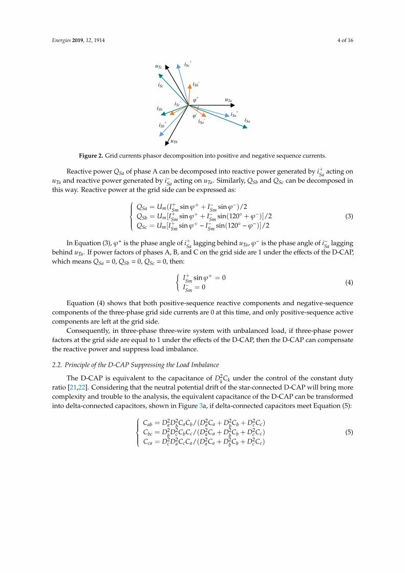
Figure 2. Grid currents phasor decomposition into positive and negative sequence currents.
Reactive power QSa of phase A can be decomposed into reactive power generated by i+ Sa acting
on uTa and reactive power generated by i- Sa acting on uTa. Similarly, QSb and QSc can be decomposed in
this way. Reactive power at the grid side can be expressed as:
( sin sin ) / 2[ sin sin(120 )] / 2[ sin sin(120 )] / 2
Sa m Sm Sm
Sb m Sm Sm
Sc m Sm Sm
Q U I IQ U I IQ U I I
ϕ ϕϕ ϕϕ ϕ
+ + − −
+ + − −
+ + − −
= +
= + + = − −
(3)
In Equation (3), φ+ is the phase angle of i+ Sa lagging behind uTa, φ– is the phase angle of i–
Sa lagging behind uTa. If power factors of phases A, B, and C on the grid side are 1 under the effects of the D-CAP, which means QSa = 0, QSb = 0, QSc = 0, then:
sin 00
Sm
Sm
II
ϕ+ +
−
=
= (4)
Equation (4) shows that both positive-sequence reactive components and negative-sequence components of the three-phase grid side currents are 0 at this time, and only positive-sequence active components are left at the grid side.
Consequently, in three-phase three-wire system with unbalanced load, if three-phase power factors at the grid side are equal to 1 under the effects of the D-CAP, then the D-CAP can compensate the reactive power and suppress load imbalance.
2.2. Principle of the D-CAP Suppressing the load imbalance
The D-CAP is equivalent to the capacitance of D2 k Ck under the control of the constant duty ratio
[21,22]. Considering that the neutral potential drift of the star-connected D-CAP will bring more complexity and trouble to the analysis, the equivalent capacitance of the D-CAP can be transformed into delta-connected capacitors, shown in Figure 3a, if delta-connected capacitors meet Equation (5):
2 2 2 2 2
2 2 2 2 2
2 2 2 2 2
/ ( )/ ( )/ ( )
ab a b a b a a b b c c
bc b c b c a a b b c c
ca c a c a a a b b c c
C D D C C D C D C D CC D D C C D C D C D CC D D C C D C D C D C
= + +
= + + = + +
(5)
Shown in Figure 3b, iCab can be decomposed into active component ip Cab parallel with uTa, and
reactive component iq Cab, perpendicular to uTa. Similarly, iCac can be decomposed into ip
Cac and iq Cac. Then
the reactive and active components of iCa can be expressed with iq Cab + iq
Cac and ip Cab + ip
Cac. Similarly, iCb and iCc also contain active and reactive components. The total active power absorbed by the three-phase D-CAP is 0, which provides feasibility for the D-CAP to suppress load imbalance by transferring active power and compensating reactive power if the duty ratio can be controlled reasonably.
Figure 2. Grid currents phasor decomposition into positive and negative sequence currents.
Reactive power QSa of phase A can be decomposed into reactive power generated by i+Sa acting onuTa and reactive power generated by i−Sa acting on uTa. Similarly, QSb and QSc can be decomposed inthis way. Reactive power at the grid side can be expressed as:
QSa = Um(I+Sm sinϕ+ + I−Sm sinϕ−)/2QSb = Um[I+Sm sinϕ+ + I−Sm sin(120 + ϕ−)]/2QSc = Um[I+Sm sinϕ+
− I−Sm sin(120 −ϕ−)]/2(3)
In Equation (3), ϕ+ is the phase angle of i+Sa lagging behind uTa, ϕ− is the phase angle of i−Sa laggingbehind uTa. If power factors of phases A, B, and C on the grid side are 1 under the effects of the D-CAP,which means QSa = 0, QSb = 0, QSc = 0, then:
I+Sm sinϕ+ = 0I−Sm = 0
(4)
Equation (4) shows that both positive-sequence reactive components and negative-sequencecomponents of the three-phase grid side currents are 0 at this time, and only positive-sequence activecomponents are left at the grid side.
Consequently, in three-phase three-wire system with unbalanced load, if three-phase powerfactors at the grid side are equal to 1 under the effects of the D-CAP, then the D-CAP can compensatethe reactive power and suppress load imbalance.
2.2. Principle of the D-CAP Suppressing the Load Imbalance
The D-CAP is equivalent to the capacitance of D2kCk under the control of the constant duty
ratio [21,22]. Considering that the neutral potential drift of the star-connected D-CAP will bring morecomplexity and trouble to the analysis, the equivalent capacitance of the D-CAP can be transformedinto delta-connected capacitors, shown in Figure 3a, if delta-connected capacitors meet Equation (5):
Cab = D2aD2
bCaCb/(D2aCa + D2
bCb + D2c Cc)
Cbc = D2bD2
c CbCc/(D2aCa + D2
bCb + D2c Cc)
Cca = D2c D2
aCcCa/(D2aCa + D2
bCb + D2c Cc)
(5)
Energies 2019, 12, 1914 5 of 16Energies 2019, 12, x FOR PEER REVIEW 5 of 15
Y-Δ
a
b
c
Cab Cbc
Ccaa
b
c
iCab
iCbc
iCca
iCa
iCb
iCc
iCb
iCaiCc iCc
Da2Ca
Db2Cb
Dc2Cc
uTc
uTb
uTa
uTab
uTca
iCab
iCac
iCa
pCabi
qCabi
pCaci
qCaci
(a) (b)
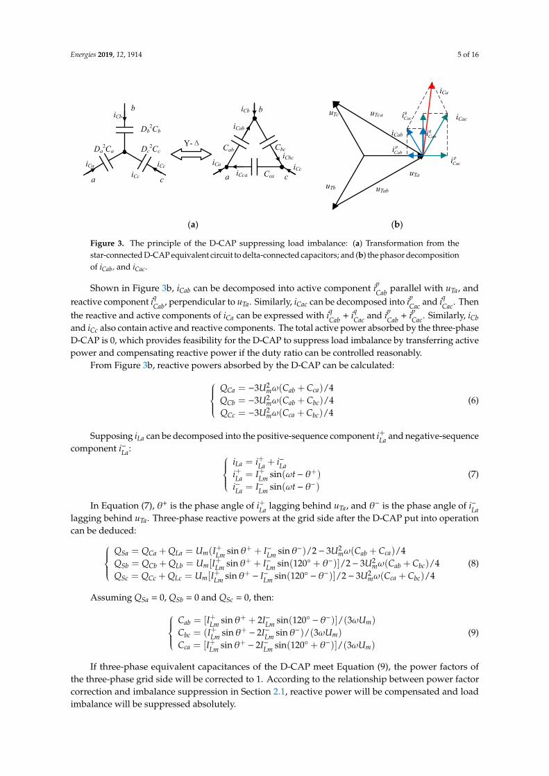
Figure 3. The principle of the D-CAP suppressing load imbalance: (a) Transformation from the star-connected D-CAP equivalent circuit to delta-connected capacitors; and (b) the phasor decomposition of iCab, and iCac.
From Figure 3b, reactive powers absorbed by the D-CAP can be calculated:
2
2
2
3 ( ) / 43 ( ) / 43 ( ) / 4
Ca m ab ca
Cb m ab bc
Cc m ca bc
Q U C CQ U C CQ U C C
ωωω
= − +
= − + = − +
(6)
Supposing iLa can be decomposed into the positive-sequence component i + La and negative-
sequence component i- La :
sin( )sin( )
La La La
La Lm
La Lm
i i ii I ti I t
ω θω θ
+ −
+ + +
− − −
= +
= − = −
(7)
In Equation (7), θ+ is the phase angle of i+ La lagging behind uTa, and θ-is the phase angle of i–
La lagging behind uTa. Three-phase reactive powers at the grid side after the D-CAP put into operation can be deduced:
2
2
2
= = ( sin + sin ) / 2 3 ( ) / 4= = [ sin sin(120 + )] / 2 3 ( ) / 4= = [ sin sin(120 )] / 2 3 ( ) / 4
Sa Ca La m Lm Lm m ab ca
Sb Cb Lb m Lm Lm m ab bc
Sc Cc Lc m Lm Lm m ca bc
Q Q Q U I I U C CQ Q Q U I I U C CQ Q Q U I I U C C
θ θ ωθ θ ωθ θ ω
+ + − −
+ + − −
+ + − −
+ − +
+ + − + + − − − +
(8)
Assuming QSa = 0, QSb = 0 and QSc = 0, then:
[ sin 2 sin(120 )] / (3 )( sin 2 sin ) / (3 )[ sin 2 sin(120 )] / (3 )
ab Lm Lm m
bc Lm Lm m
ca Lm Lm m
C I I UC I I UC I I U
θ θ ωθ θ ωθ θ ω
+ + − −
+ + − −
+ + − −
= + −
= − = − +
(9)
If three-phase equivalent capacitances of the D-CAP meet Equation (9), the power factors of the three-phase grid side will be corrected to 1. According to the relationship between power factor correction and imbalance suppression in Section 2.1, reactive power will be compensated and load imbalance will be suppressed absolutely.
3. Compensation Ability of a Star-Connected D-CAP for Negative-Sequence Currents
3.1. Theoretical Compensation Ability of a Star-Connected D-CAP
Figure 3. The principle of the D-CAP suppressing load imbalance: (a) Transformation from thestar-connected D-CAP equivalent circuit to delta-connected capacitors; and (b) the phasor decompositionof iCab, and iCac.
Shown in Figure 3b, iCab can be decomposed into active component ipCab parallel with uTa, andreactive component iqCab, perpendicular to uTa. Similarly, iCac can be decomposed into ipCac and iqCac. Thenthe reactive and active components of iCa can be expressed with iqCab + iqCac and ipCab + ipCac. Similarly, iCband iCc also contain active and reactive components. The total active power absorbed by the three-phaseD-CAP is 0, which provides feasibility for the D-CAP to suppress load imbalance by transferring activepower and compensating reactive power if the duty ratio can be controlled reasonably.
From Figure 3b, reactive powers absorbed by the D-CAP can be calculated:QCa = −3U2
mω(Cab + Cca)/4QCb = −3U2
mω(Cab + Cbc)/4QCc = −3U2
mω(Cca + Cbc)/4(6)
Supposing iLa can be decomposed into the positive-sequence component i+La and negative-sequencecomponent i−La:
iLa = i+La + i−Lai+La = I+Lm sin(ωt− θ+)i−La = I−Lm sin(ωt− θ−)
(7)
In Equation (7), θ+ is the phase angle of i+La lagging behind uTa, and θ− is the phase angle of i−Lalagging behind uTa. Three-phase reactive powers at the grid side after the D-CAP put into operationcan be deduced:
QSa = QCa + QLa = Um(I+Lm sinθ+ + I−Lm sinθ−)/2− 3U2mω(Cab + Cca)/4
QSb = QCb + QLb = Um[I+Lm sinθ+ + I−Lm sin(120 + θ−)]/2− 3U2mω(Cab + Cbc)/4
QSc = QCc + QLc = Um[I+Lm sinθ+ − I−Lm sin(120 − θ−)]/2− 3U2mω(Cca + Cbc)/4
(8)
Assuming QSa = 0, QSb = 0 and QSc = 0, then:Cab = [I+Lm sinθ+ + 2I−Lm sin(120 − θ−)]/(3ωUm)
Cbc = (I+Lm sinθ+ − 2I−Lm sinθ−)/(3ωUm)
Cca = [I+Lm sinθ+ − 2I−Lm sin(120 + θ−)]/(3ωUm)
(9)
If three-phase equivalent capacitances of the D-CAP meet Equation (9), the power factors ofthe three-phase grid side will be corrected to 1. According to the relationship between power factorcorrection and imbalance suppression in Section 2.1, reactive power will be compensated and loadimbalance will be suppressed absolutely.

Energies 2019, 12, 1914 6 of 16
3. Compensation Ability of a Star-Connected D-CAP for Negative-Sequence Currents
3.1. Theoretical Compensation Ability of a Star-Connected D-CAP
In Equation (9), we can find I+Lmsinθ+ is the positive-sequence reactive component amplitudeof the load currents, and I−Lmsinθ−, I−Lmsin(120 + θ−), −I−Lmsin(120 − θ−) are the negative-sequencereactive components amplitude of the load currents. For example, under some load conditions, thepositive-sequence reactive components’ amplitude is smaller than two times of negative-sequencereactive components amplitude. Then the value of Cbc is negative according to Equation (9), which isunachievable for the D-CAP. Therefore, the compensation ability of the D-CAP is limited.
Take phase A as another example shown in Figure 4. Draw vertical line relative to uTa from theend point of i+La and dividing line 1 parallel to uTa at the midpoint of vertical line. The value of Cabis positive if i−La is in the zone 1 which is above dividing line 1. Similarly, the values of Cca and Cbcare positive if i−Lb and i−Lc are in zone 2 and zone 3, respectively. Considering that i−La, i−Lb, and i−Lc aresymmetrical, the value of Cab, Cbc, and Cca are all greater than 0 if and only if i−La, i−Lb, and i−Lc are all inthe ∆RST.
Energies 2019, 12, x FOR PEER REVIEW 6 of 15
In Equation (9), we can find I+ Lmsinθ+ is the positive-sequence reactive component amplitude of
the load currents, and I- Lmsinθ-, I-
Lmsin(120° + θ-), –I- Lmsin(120° – θ-) are the negative-sequence reactive
components amplitude of the load currents. For example, under some load conditions, the positive-sequence reactive components’ amplitude is smaller than two times of negative-sequence reactive components amplitude. Then the value of Cbc is negative according to Equation (9), which is unachievable for the D-CAP. Therefore, the compensation ability of the D-CAP is limited.
Take phase A as another example shown in Figure 4. Draw vertical line relative to uTa from the end point of i+
La and dividing line 1 parallel to uTa at the midpoint of vertical line. The value of Cab is positive if i-
La is in the zone 1 which is above dividing line 1. Similarly, the values of Cca and Cbc are positive if i-
Lb and i- Lc are in zone 2 and zone 3, respectively. Considering that i-
La , i- Lb , and i-
Lc are symmetrical, the value of Cab, Cbc, and Cca are all greater than 0 if and only if i-
La , i- Lb , and i-
Lc are all in the ΔRST.
Consequently, in the three-phase three-wire system, if the negative-sequence components of the load currents are located in the ΔRST, shown in Figure 4, meaning the value of equivalent capacitances calculated by Equation (9) are positive, the D-CAP can completely compensate the reactive power and suppress the load imbalance. Otherwise, the D-CAP can only compensate the positive-sequence reactive components and a part of the negative-sequence components of the load currents lying in the scope of ΔRST.
Zone 1
Dividing line 1
R S
T
uTa
uTb
uTc
iLc+
iLa+
iLb+
iLa-
iLb-
iLc-
Actual compensation ability
Theoretical compensation ability
/ 4Lqr i
Figure 4. Theoretical and actual compensation ability of the D-CAP for negative-sequence currents.
Additionally, the circle with radius i+ Lq/4 in Figure 4 refers to the actual compensation ability of
the D-CAP, which will be illustrated in Section 3.2.
3.2. Actual Compensation Ability of a Star-Connected D-CAP
Deviation of potential at the neutral point will occur when the star-connected D-CAP suppresses the load imbalance, which will make one of the voltages between the grid side and the D-CAP neutral point higher. In practice, the rated voltage of each phase D-CAP is generally 1.1–1.3 times higher than the grid voltage in order to maintain a safety margin, so the actual compensation ability of the D-CAP under an unbalanced load will be limited by the rated voltage.
Shown in Figure 5, the coordinate expressions of three phase grid voltages are:
( ,0)
( / 2, 3 / 2)
( / 2, 3 / 2)
Ta m
Tb m m
Tc m m
U U
U U U
U U U
(10)
In order to compensate reactive power and negative-sequence currents, the coordinate expressions of [iCa iCb iCc] can be described as:
Figure 4. Theoretical and actual compensation ability of the D-CAP for negative-sequence currents.
Consequently, in the three-phase three-wire system, if the negative-sequence components of theload currents are located in the ∆RST, shown in Figure 4, meaning the value of equivalent capacitancescalculated by Equation (9) are positive, the D-CAP can completely compensate the reactive powerand suppress the load imbalance. Otherwise, the D-CAP can only compensate the positive-sequencereactive components and a part of the negative-sequence components of the load currents lying in thescope of ∆RST.
Additionally, the circle with radius i+Lq/4 in Figure 4 refers to the actual compensation ability of theD-CAP, which will be illustrated in Section 3.2.
3.2. Actual Compensation Ability of a Star-Connected D-CAP
Deviation of potential at the neutral point will occur when the star-connected D-CAP suppressesthe load imbalance, which will make one of the voltages between the grid side and the D-CAP neutralpoint higher. In practice, the rated voltage of each phase D-CAP is generally 1.1–1.3 times higher thanthe grid voltage in order to maintain a safety margin, so the actual compensation ability of the D-CAPunder an unbalanced load will be limited by the rated voltage.
Energies 2019, 12, 1914 7 of 16
Shown in Figure 5, the coordinate expressions of three phase grid voltages are:.
UTa = (Um, 0).
UTb = (−Um/2,−√
3Um/2).
UTc = (−Um/2,√
3Um/2)
(10)
In order to compensate reactive power and negative-sequence currents, the coordinate expressionsof [iCa iCb iCc] can be described as:
.ICa = (−I−Lm cosθ−, I−Lm sinθ−) + (0, I+Lm sinθ+).ICb = [−I−Lm cos(120 − θ−),−I−Lm sin(120 − θ−)] + [
√3(I+Lm sinθ+)/2,−I+Lm sinθ+/2]
.ICc = [−I−Lm cos(120 + θ−), I−Lm sin(120 + θ−)] + [−
√3(I+Lm sinθ+)/2,−I+Lm sinθ+/2]
(11)
Energies 2019, 12, 1914 7 of 15
( cos , sin ) (0, sin )
[ cos(120 ), sin(120 )] [ 3( sin ) / 2, sin / 2]
[ cos(120 ), sin(120 )] [ 3( sin ) / 2, sin / 2]
Ca Lm Lm Lm
Cb Lm Lm Lm Lm
Cc Lm Lm Lm Lm
I I I I
I I I I I
I I I I I
θ θ θ
θ θ θ θ
θ θ θ θ
− − − − + +
− − − − + + + +
− − − − + + + +
= − + = − − − − + − = − + + + − −
(11)
uTa
uTb
uTc
iCa
iCb
iCc uaN1
ubN1
ucN1
x
y
N1
N
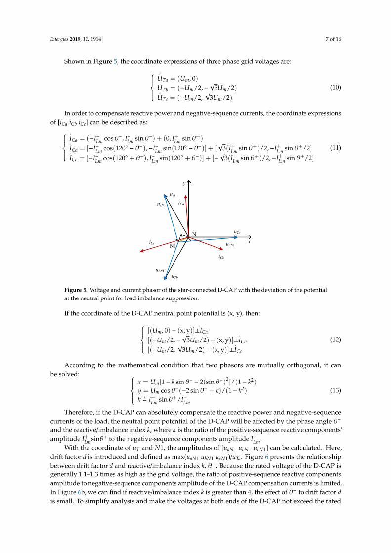
Figure 5. Voltage and current phasor of the star-connected D-CAP with the deviation of the potential at the neutral point for load imbalance suppression.
If the coordinate of the D-CAP neutral point potential is (x, y), then:
[( ,0) (x, y)]
[( / 2, 3 / 2) (x, y)]
[( / 2, 3 / 2) (x, y)]
m Ca
m m Cb
m m Cc
U I
U U I
U U I
− ⊥ − − − ⊥ − − ⊥
(12)
According to the mathematical condition that two phasors are mutually orthogonal, it can be solved:
2 2
2
[1 sin 2(sin ) ] / (1 )cos ( 2sin ) / (1 )sin /
m
m
Lm Lm
x U k ky U k kk I I
θ θθ θθ
− −
− −
+ + −
= − − −
= − + −
(13)
Therefore, if the D-CAP can absolutely compensate the reactive power and negative-sequence currents of the load, the neutral point potential of the D-CAP will be affected by the phase angle θ-
and the reactive/imbalance index k, where k is the ratio of the positive-sequence reactive components’ amplitude I+
Lmsinθ+ to the negative-sequence components amplitude I– Lm.
With the coordinate of uT and N1, the amplitudes of [uaN1 ubN1 ucN1] can be calculated. Here, drift factor d is introduced and defined as max(uaN1 ubN1 ucN1)/uTa. Figure 6 presents the relationship between drift factor d and reactive/imbalance index k, θ–. Because the rated voltage of the D-CAP is generally 1.1–1.3 times as high as the grid voltage, the ratio of positive-sequence reactive components amplitude to negative-sequence components amplitude of the D-CAP compensation currents is limited. In Figure 6b, we can find if reactive/imbalance index k is greater than 4, the effect of θ– to drift factor d is small. To simplify analysis and make the voltages at both ends of the D-CAP not exceed the rated voltage, θ– is assumed to be kept at a value producing the maximal potential deviation at the neutral point. Therefore, for D-CAP currents, the positive-sequence reactive components’ amplitude should be greater than four times the negative-sequence components amplitude to ensure the voltages at both ends of the D-CAP do not exceed its rated voltage.
Figure 5. Voltage and current phasor of the star-connected D-CAP with the deviation of the potentialat the neutral point for load imbalance suppression.
If the coordinate of the D-CAP neutral point potential is (x, y), then:[(Um, 0) − (x, y)]⊥
.ICa
[(−Um/2,−√
3Um/2) − (x, y)]⊥.ICb
[(−Um/2,√
3Um/2) − (x, y)]⊥.ICc
(12)
According to the mathematical condition that two phasors are mutually orthogonal, it canbe solved:
x = Um[1− k sinθ− − 2(sinθ−)2]/(1− k2)
y = Um cosθ−(−2 sinθ− + k)/(1− k2)
k , I+Lm sinθ+/I−Lm
(13)
Therefore, if the D-CAP can absolutely compensate the reactive power and negative-sequencecurrents of the load, the neutral point potential of the D-CAP will be affected by the phase angle θ−
and the reactive/imbalance index k, where k is the ratio of the positive-sequence reactive components’amplitude I+Lmsinθ+ to the negative-sequence components amplitude I−Lm.
With the coordinate of uT and N1, the amplitudes of [uaN1 ubN1 ucN1] can be calculated. Here,drift factor d is introduced and defined as max(uaN1 ubN1 ucN1)/uTa. Figure 6 presents the relationshipbetween drift factor d and reactive/imbalance index k, θ−. Because the rated voltage of the D-CAP isgenerally 1.1–1.3 times as high as the grid voltage, the ratio of positive-sequence reactive componentsamplitude to negative-sequence components amplitude of the D-CAP compensation currents is limited.In Figure 6b, we can find if reactive/imbalance index k is greater than 4, the effect of θ− to drift factor dis small. To simplify analysis and make the voltages at both ends of the D-CAP not exceed the rated

Energies 2019, 12, 1914 8 of 16
voltage, θ− is assumed to be kept at a value producing the maximal potential deviation at the neutralpoint. Therefore, for D-CAP currents, the positive-sequence reactive components’ amplitude should begreater than four times the negative-sequence components amplitude to ensure the voltages at bothends of the D-CAP do not exceed its rated voltage.Energies 2019, 12, 1914 8 of 15
d =
Max
(uaN
1,u
bN
1,u
cN1)/
uT
a
− k
d =
Max(u
aN
1,u
bN
1,u
cN1)
/uTa
k
d = 1.3
k =
4
Area 1
Rated voltage limit line
Com
pen
sati
on
ab
ilit
y l
imit
lin
e
X:+ Y: Z:1
A
3
2 1
(a) (b)
Figure 6. Relationship between drift factor d and reactive/imbalance index k, θ–: (a) Three-
dimensional graphics of d(k, θ–) = max (uaN1 ubN1 ucN1)/uTa; and (b) projection of the curved surface on
the k-d plane.
As shown in Figure 6b, Point A is the intersection of the rated voltage limit line (d = 1.3) and the
compensation ability limit line (k = 4). Area 1 is below the rated voltage limit line (d = 1.3) and on the
right of the compensation ability limit line (k = 4). Here, area 1 is equivalent to the circle whose radius
is i+
Lq/4 in Figure 4. If the negative-sequence components of the load currents are in the scope of the
circle, that means θ– and the reactive/imbalance index k are in area 1, and D-CAP can compensate the
reactive power and suppress the load imbalance without exceeding the rated voltage limit.
4. Proposed Control Strategy of the D-CAP to Compensate the Reactive Power and Suppress
Load Imbalance
For the three-phase star-connected Buck-type D-CAP, the proposed control strategy to
compensate the reactive power and suppress load imbalance is shown in Figure 7.
iCkRDFT1
|iCk|A1=Re ( )
B1=Im( )2 2
1 1( )A B+
Inductive unbalanced
load
A
B
C
PLL
ωt
D-CAP D-CAP D-CAPiLbiLa iLc
abcdq
ωt abcdq
-ωt
LPF
+
+
+
-
-
-
PI
PI
PI
Dc
Db
Da
+ -
+ -
+ -
carrier
Ldi−Lqi−
Lqi+Determine
amplitude of D-CAP
command current with Equation (18)
Cci*
Cci
Cbi*
Cbi
Cai*
Cai
uTb
uTa
uTc iCaiCb iCc
*
Lqi −
*
Ldi −
CkI
CkI
Figure 7. Proposed control strategy of a star-connected D-CAP compensating the reactive power and
suppressing the load imbalance.
Figure 6. Relationship between drift factor d and reactive/imbalance index k, θ−: (a) Three-dimensionalgraphics of d(k, θ−) = max (uaN1 ubN1 ucN1)/uTa; and (b) projection of the curved surface on the k-d plane.
As shown in Figure 6b, Point A is the intersection of the rated voltage limit line (d = 1.3) and thecompensation ability limit line (k = 4). Area 1 is below the rated voltage limit line (d = 1.3) and on theright of the compensation ability limit line (k = 4). Here, area 1 is equivalent to the circle whose radiusis i+Lq/4 in Figure 4. If the negative-sequence components of the load currents are in the scope of thecircle, that means θ− and the reactive/imbalance index k are in area 1, and D-CAP can compensate thereactive power and suppress the load imbalance without exceeding the rated voltage limit.
4. Proposed Control Strategy of the D-CAP to Compensate the Reactive Power and SuppressLoad Imbalance
For the three-phase star-connected Buck-type D-CAP, the proposed control strategy to compensatethe reactive power and suppress load imbalance is shown in Figure 7.
Firstly, we transform the load currents [iLa iLb iLc] with Equations (14) and (15), respectively. Thenpassing through a low-pass filter, the positive-sequence active and reactive components [i+Ld i+Lq], andnegative-sequence active and reactive components [i−Ld i−Lq] are obtained:
i+Ldi+Lq
= 2/3(
sinωt sin(ωt− 120) sin(ωt + 120)cosωt cos(ωt− 120) cos(ωt + 120)
)I+Lm sin(ωt−ϕ+)
I+Lm sin(ωt−ϕ+− 120)
I+Lm sin(ωt−ϕ+ + 120)
=(
I+Lm cosϕ+
−I+Lm sinϕ+
)(14)
i−Ldi−Lq
= 2/3(− sin(ωt) − sin(ωt + 120) − sin(ωt− 120)cos(ωt) cos(ωt + 120) cos(ωt− 120)
)I−Lm sin(ωt−ϕ−)
I−Lm sin(ωt−ϕ− + 120)I−Lm sin(ωt−ϕ− − 120)
=(−I−Lm cosϕ−
−I−Lm sinϕ−
)(15)

Energies 2019, 12, 1914 9 of 16
Since the actual compensation ability of the D-CAP for negative-sequence currents is limited byits rated voltage, it is necessary to add an amplitude limit on the negative-sequence currents. Theprocessing method of the negative sequence currents is derived as follows:
i∗−Lq =
i−Lq, i f k√(i−Ld)
2 + (i−Lq)2 < i+Lq
i−Lqi+Lq/[k√(i−Ld)
2 + (i−Lq)2], i f k
√(i−Ld)
2 + (i−Lq)2 > i+Lq
(16)
i∗−Ld =
i−Ld, i f k√(i−Ld)
2 + (i−Lq)2 < i+Lq
i−Ldi+Lq/[k√(i−Ld)
2 + (i−Lq)2], i f k
√(i−Ld)
2 + (i−Lq)2 > i+Lq
(17)
If the D-CAP can compensate the reactive power and negative-sequence currents to the utmost,the amplitudes of [iCa iCb iCc] are uniquely determined. Command current amplitudes of the D-CAPcan be obtained with i∗+Lq , i∗−Ld, and i∗−Lq as follows:
∣∣∣i∗Ca
∣∣∣ = √(i∗−Ld)
2 + (i+Lq + i∗−Lq)2
∣∣∣i∗Cb
∣∣∣ = √(i∗−Ld/2−
√3i∗−Lq/2)
2+ (−
√3i∗−Ld/2− i∗−Lq/2 + i+Lq)
2
∣∣∣i∗Cc
∣∣∣ = √(i∗−Ld/2 +
√3i∗−Lq/2)
2+ (√
3i∗−Ld/2− i∗−Lq/2 + i+Lq)2
(18)
We compare the command currents amplitudes calculated by Equation (18) with the actual currentamplitudes of [iCa iCb iCc], which can be extracted and calculated with the RDFT method [29]. Then weregulate the error through a PI controller to control the duty ratio of the D-CAP. Finally, the switches ofthe Buck-type AC-AC converter are driven through the modulated output signal. By adjusting theduty ratio, the positive-sequence reactive power and negative-sequence currents of the load can beeffectively compensated.
Energies 2019, 12, x FOR PEER REVIEW 8 of 15
d =
Max
(uaN
1,ubN
1,ucN
1)/u T
a
θ − k
d =
Max
(uaN
1,ubN
1,ucN
1)/u T
a
k
d = 1.3
k =
4
Area 1
Rated voltage limit line
Com
pens
atio
n ab
ility
lim
it lin
e
X:+∞Y:∀Z:1
A
3
2 1
(a) (b) Figure 6. Relationship between drift factor d and reactive/imbalance index k, θ–: (a) Three-dimensional graphics of d(k, θ–) = max (uaN1 ubN1 ucN1)/uTa; and (b) projection of the curved surface on the k-d plane.
As shown in Figure 6b, Point A is the intersection of the rated voltage limit line (d = 1.3) and the compensation ability limit line (k = 4). Area 1 is below the rated voltage limit line (d = 1.3) and on the right of the compensation ability limit line (k = 4). Here, area 1 is equivalent to the circle whose radius is i+
Lq/4 in Figure 4. If the negative-sequence components of the load currents are in the scope of the circle, that means θ– and the reactive/imbalance index k are in area 1, and D-CAP can compensate the reactive power and suppress the load imbalance without exceeding the rated voltage limit.
4. Proposed Control Strategy of the D-CAP to Compensate the Reactive Power and Suppress Load Imbalance
For the three-phase star-connected Buck-type D-CAP, the proposed control strategy to compensate the reactive power and suppress load imbalance is shown in Figure 7.
iCkRDFT1
|iCk|A1=Re ( )B1=Im( ) 2 2
1 1( )A B+
Inductive unbalanced
load
A
B
C
PLL
ωt
D-CAP D-CAP D-CAPiLbiLa iLc
abcdq
ωt abcdq
-ωt
LPF+
+
+
-
-
-
PI
PI
PI
Dc
Db
Da
+ -
+ -
+ -
carrier
Ldi−Lqi−
Lqi+Determine
amplitude of D-CAP
command current with Equation (18)
Cci*Cci
Cbi*Cbi
Cai *Cai
uTb
uTa
uTc iCa iCb iCc
*Lqi −
*Ldi −
CkI
CkI
Figure 7. Proposed control strategy of a star-connected D-CAP compensating the reactive power and suppressing the load imbalance.
Figure 7. Proposed control strategy of a star-connected D-CAP compensating the reactive power andsuppressing the load imbalance.
5. Experiment Verification
In order to verify the effectiveness of the control strategy, experimental tests with a 33 kVar/220 Vthree-phase Buck-type D-CAP are carried out. Figure 1b shows the system configuration. The D-CAP
Energies 2019, 12, 1914 10 of 16
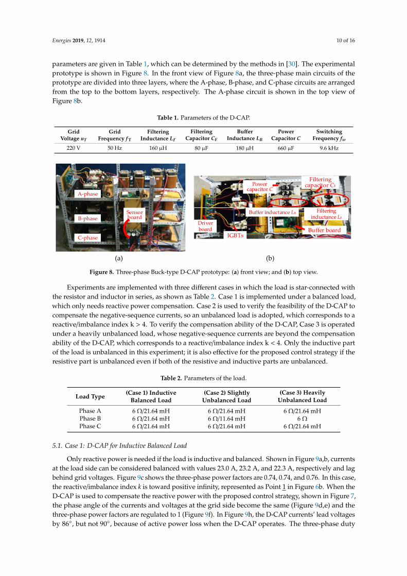
parameters are given in Table 1, which can be determined by the methods in [30]. The experimentalprototype is shown in Figure 8. In the front view of Figure 8a, the three-phase main circuits of theprototype are divided into three layers, where the A-phase, B-phase, and C-phase circuits are arrangedfrom the top to the bottom layers, respectively. The A-phase circuit is shown in the top view ofFigure 8b.
Table 1. Parameters of the D-CAP.
GridVoltage uT
GridFrequency f T
FilteringInductance LF
FilteringCapacitor CF
BufferInductance LB
PowerCapacitor C
SwitchingFrequency fw
220 V 50 Hz 160 µH 80 µF 180 µH 660 µF 9.6 kHz
Energies 2019, 12, x FOR PEER REVIEW 10 of 15
Table 1. Parameters of the D-CAP.
Grid voltage uT
Grid Frequency
fT
Filtering Inductance
LF
Filtering Capacitor
CF
Buffer Inductance
LB
Power Capacitor
C
Switching Frequency
fw 220 V 50 Hz 160 μH 80 μF 180 μH 660 μF 9.6 kHz
Experiments are implemented with three different cases in which the load is star-connected with the resistor and inductor in series, as shown as Table 2. Case 1 is implemented under a balanced load, which only needs reactive power compensation. Case 2 is used to verify the feasibility of the D-CAP to compensate the negative-sequence currents, so an unbalanced load is adopted, which corresponds to a reactive/imbalance index k > 4. To verify the compensation ability of the D-CAP, Case 3 is operated under a heavily unbalanced load, whose negative-sequence currents are beyond the compensation ability of the D-CAP, which corresponds to a reactive/imbalance index k < 4. Only the inductive part of the load is unbalanced in this experiment; it is also effective for the proposed control strategy if the resistive part is unbalanced even if both of the resistive and inductive parts are unbalanced.
C-phase
B-phase
A-phase
Sensor board
Buffer inductance LB
Buffer boardDriver board
IGBTs
Power capacitor C
Filtering capacitor CF
Filtering inductance LF
(a) (b) Figure 8. Three-phase Buck-type D-CAP prototype: (a) front view; and (b) top view.
Table 2. Parameters of the load.
Load Type
(Case 1) Inductive Balanced Load
(Case 2) Slightly Unbalanced Load
(Case 3) Heavily Unbalanced Load
Phase A 6 Ω/21.64 mH 6 Ω/21.64 mH 6 Ω/21.64 mH Phase B 6 Ω/21.64 mH 6 Ω/11.64 mH 6 Ω Phase C 6 Ω/21.64 mH 6 Ω/21.64 mH 6 Ω/21.64 mH
5.1. Case 1: D-CAP for Inductive Balanced Load
Only reactive power is needed if the load is inductive and balanced. Shown in Figure 9a,b, currents at the load side can be considered balanced with values 23.0 A, 23.2 A, and 22.3 A, respectively and lag behind grid voltages. Figure 9c shows the three-phase power factors are 0.74, 0.74, and 0.76. In this case, the reactive/imbalance index k is toward positive infinity, represented as Point 1 in Figure 6b. When the D-CAP is used to compensate the reactive power with the proposed control strategy, shown in Figure 7, the phase angle of the currents and voltages at the grid side become the same (Figure 9d,e) and the three-phase power factors are regulated to 1 (Figure 9f). In Figure 9h, the D-CAP currents’ lead voltages by 86°, but not 90°, because of active power loss when the D-CAP operates. The three-phase duty ratios of the D-CAP are 0.51, 0.47, and 0.47, respectively. Therefore, the reactive power compensation can be achieved under the effects of the D-CAP if the load is balanced and inductive.
Figure 8. Three-phase Buck-type D-CAP prototype: (a) front view; and (b) top view.
Experiments are implemented with three different cases in which the load is star-connected withthe resistor and inductor in series, as shown as Table 2. Case 1 is implemented under a balanced load,which only needs reactive power compensation. Case 2 is used to verify the feasibility of the D-CAP tocompensate the negative-sequence currents, so an unbalanced load is adopted, which corresponds to areactive/imbalance index k > 4. To verify the compensation ability of the D-CAP, Case 3 is operatedunder a heavily unbalanced load, whose negative-sequence currents are beyond the compensationability of the D-CAP, which corresponds to a reactive/imbalance index k < 4. Only the inductive partof the load is unbalanced in this experiment; it is also effective for the proposed control strategy if theresistive part is unbalanced even if both of the resistive and inductive parts are unbalanced.
Table 2. Parameters of the load.
Load Type (Case 1) InductiveBalanced Load
(Case 2) SlightlyUnbalanced Load
(Case 3) HeavilyUnbalanced Load
Phase A 6 Ω/21.64 mH 6 Ω/21.64 mH 6 Ω/21.64 mHPhase B 6 Ω/21.64 mH 6 Ω/11.64 mH 6 ΩPhase C 6 Ω/21.64 mH 6 Ω/21.64 mH 6 Ω/21.64 mH
5.1. Case 1: D-CAP for Inductive Balanced Load
Only reactive power is needed if the load is inductive and balanced. Shown in Figure 9a,b, currentsat the load side can be considered balanced with values 23.0 A, 23.2 A, and 22.3 A, respectively and lagbehind grid voltages. Figure 9c shows the three-phase power factors are 0.74, 0.74, and 0.76. In this case,the reactive/imbalance index k is toward positive infinity, represented as Point 1 in Figure 6b. When theD-CAP is used to compensate the reactive power with the proposed control strategy, shown in Figure 7,the phase angle of the currents and voltages at the grid side become the same (Figure 9d,e) and thethree-phase power factors are regulated to 1 (Figure 9f). In Figure 9h, the D-CAP currents’ lead voltagesby 86, but not 90, because of active power loss when the D-CAP operates. The three-phase duty

Energies 2019, 12, 1914 11 of 16
ratios of the D-CAP are 0.51, 0.47, and 0.47, respectively. Therefore, the reactive power compensationcan be achieved under the effects of the D-CAP if the load is balanced and inductive.Energies 2019, 12, x FOR PEER REVIEW 11 of 15
duty ratio=0.51
(a) (d) (g) (j)
duty ratio=0.47
(b) (e) (h) (k)
duty ratio=0.47
(c) (f) (i) (l)
Figure 9. D-CAP for inductive balanced load: (a) A-phase voltage and current at the load side; (b) voltage and current phasor at the load side; (c) power and energy at the load side; (d) A-phase voltage and current at the grid side after compensation; (e) voltage and current phasor at the grid side after compensation; (f) power and energy at the grid side after compensation; (g) D-CAP currents; (h) voltage and current phasor at the D-CAP side; (i) grid voltages; (j) A-phase duty ratio; (k) B-phase duty ratio; and (l) C-phase duty ratio.
5.2. Case 2: D-CAP for Slightly Unbalanced Inductive Load
Comprehensive control of reactive power compensation and imbalance suppression are implemented under a slightly unbalanced load in this case. Calculated by Equation (13), the reactive/imbalance index k is equal to 5.4, which corresponds to Point 2 in Figure 6b. Shown in Figure 10, currents at the grid side are unbalanced (Figure 10a) and lag behind grid voltages (Figure 10b) when the D-CAP is not put into operation with power factors 0.81, 0.85, and 0.72, respectively (Figure 10c). Currents at the grid side become balanced (Figure 10d,e) and the three-phase power factors are regulated to 1 (Figure 10f) after the D-CAP is put into operation. The three-phase equivalent capacitances can be regulated properly under different duty ratios, whose values are, respectively, 0.38, 0.47, and 0.62. In the Figure 10g,h, the output currents of the D-CAP are unbalanced due to different equivalent capacitances. Since the negative-sequence components’ amplitude is smaller than one quarter of the positive-sequence reactive components’ amplitude in this case, which is not constrained by the negative-sequence components’ amplitude limit shown in Equations (16) and (17), the greatest voltage at both ends of the three-phase D-CAP is 262.7 V in Figure 10i.
duty ratio=0.38
(a) (d) (g) (j)
Figure 9. D-CAP for inductive balanced load: (a) A-phase voltage and current at the load side;(b) voltage and current phasor at the load side; (c) power and energy at the load side; (d) A-phasevoltage and current at the grid side after compensation; (e) voltage and current phasor at the grid sideafter compensation; (f) power and energy at the grid side after compensation; (g) D-CAP currents;(h) voltage and current phasor at the D-CAP side; (i) grid voltages; (j) A-phase duty ratio; (k) B-phaseduty ratio; and (l) C-phase duty ratio.
5.2. Case 2: D-CAP for Slightly Unbalanced Inductive Load
Comprehensive control of reactive power compensation and imbalance suppression areimplemented under a slightly unbalanced load in this case. Calculated by Equation (13), thereactive/imbalance index k is equal to 5.4, which corresponds to Point 2 in Figure 6b. Shown inFigure 10, currents at the grid side are unbalanced (Figure 10a) and lag behind grid voltages (Figure 10b)when the D-CAP is not put into operation with power factors 0.81, 0.85, and 0.72, respectively(Figure 10c). Currents at the grid side become balanced (Figure 10d,e) and the three-phase powerfactors are regulated to 1 (Figure 10f) after the D-CAP is put into operation. The three-phase equivalentcapacitances can be regulated properly under different duty ratios, whose values are, respectively, 0.38,0.47, and 0.62. In the Figure 10g,h, the output currents of the D-CAP are unbalanced due to differentequivalent capacitances. Since the negative-sequence components’ amplitude is smaller than onequarter of the positive-sequence reactive components’ amplitude in this case, which is not constrainedby the negative-sequence components’ amplitude limit shown in Equations (16) and (17), the greatestvoltage at both ends of the three-phase D-CAP is 262.7 V in Figure 10i.
Energies 2019, 12, 1914 12 of 16
Energies 2019, 12, x FOR PEER REVIEW 11 of 15
duty ratio=0.51
(a) (d) (g) (j)
duty ratio=0.47
(b) (e) (h) (k)
duty ratio=0.47
(c) (f) (i) (l)
Figure 9. D-CAP for inductive balanced load: (a) A-phase voltage and current at the load side; (b) voltage and current phasor at the load side; (c) power and energy at the load side; (d) A-phase voltage and current at the grid side after compensation; (e) voltage and current phasor at the grid side after compensation; (f) power and energy at the grid side after compensation; (g) D-CAP currents; (h) voltage and current phasor at the D-CAP side; (i) grid voltages; (j) A-phase duty ratio; (k) B-phase duty ratio; and (l) C-phase duty ratio.
5.2. Case 2: D-CAP for Slightly Unbalanced Inductive Load
Comprehensive control of reactive power compensation and imbalance suppression are implemented under a slightly unbalanced load in this case. Calculated by Equation (13), the reactive/imbalance index k is equal to 5.4, which corresponds to Point 2 in Figure 6b. Shown in Figure 10, currents at the grid side are unbalanced (Figure 10a) and lag behind grid voltages (Figure 10b) when the D-CAP is not put into operation with power factors 0.81, 0.85, and 0.72, respectively (Figure 10c). Currents at the grid side become balanced (Figure 10d,e) and the three-phase power factors are regulated to 1 (Figure 10f) after the D-CAP is put into operation. The three-phase equivalent capacitances can be regulated properly under different duty ratios, whose values are, respectively, 0.38, 0.47, and 0.62. In the Figure 10g,h, the output currents of the D-CAP are unbalanced due to different equivalent capacitances. Since the negative-sequence components’ amplitude is smaller than one quarter of the positive-sequence reactive components’ amplitude in this case, which is not constrained by the negative-sequence components’ amplitude limit shown in Equations (16) and (17), the greatest voltage at both ends of the three-phase D-CAP is 262.7 V in Figure 10i.
duty ratio=0.38
(a) (d) (g) (j)
Energies 2019, 12, x FOR PEER REVIEW 12 of 15
duty ratio=0.47
(b) (e) (h) (k)
duty ratio=0.62
(c) (f) (i) (l)
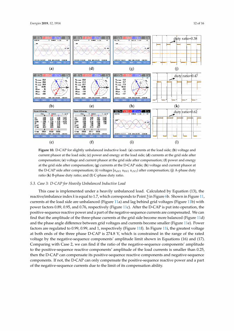
Figure 10. D-CAP for slightly unbalanced inductive load: (a) currents at the load side; (b) voltage and current phasor at the load side; (c) power and energy at the load side; (d) currents at the grid side after compensation; (e) voltage and current phasor at the grid side after compensation; (f) power and energy at the grid side after compensation; (g) currents at the D-CAP side; (h) voltage and current phasor at the D-CAP side after compensation; (i) voltages [uaN1 ubN1 ucN1) after compensation; (j) A-phase duty ratio (k) B-phase duty ratio; and (l) C-phase duty ratio.
5.3. Case 3: D-CAP for Heavily Unbalanced Inductive Load
This case is implemented under a heavily unbalanced load. Calculated by Equation (13), the reactive/imbalance index k is equal to 1.7, which corresponds to Point 3 in Figure 6b. Shown in Figure 11, currents at the load side are unbalanced (Figure 11a) and lag behind grid voltages (Figure 11b) with power factors 0.89, 0.95, and 0.76, respectively (Figure 11c). After the D-CAP is put into operation, the positive-sequence reactive power and a part of the negative-sequence currents are compensated. We can find that the amplitude of the three-phase currents at the grid side become more balanced (Figure 11d) and the phase angle difference between grid voltages and currents become smaller (Figure 11e). Power factors are regulated to 0.99, 0.99, and 1, respectively (Figure 11f). In Figure 11i, the greatest voltage at both ends of the three phase D-CAP is 274.8 V, which is constrained in the range of the rated voltage by the negative-sequence components’ amplitude limit shown in Equations (16) and (17). Comparing with Case 2, we can find if the ratio of the negative-sequence components’ amplitude to the positive-sequence reactive components’ amplitude of the load currents is smaller than 0.25, then the D-CAP can compensate its positive-sequence reactive components and negative-sequence components. If not, the D-CAP can only compensate the positive-sequence reactive power and a part of the negative-sequence currents due to the limit of its compensation ability.
duty ratio=0.33
(a) (d) (g) (j)
duty ratio=0.44
(b) (e) (h) (k)
Figure 10. D-CAP for slightly unbalanced inductive load: (a) currents at the load side; (b) voltage andcurrent phasor at the load side; (c) power and energy at the load side; (d) currents at the grid side aftercompensation; (e) voltage and current phasor at the grid side after compensation; (f) power and energyat the grid side after compensation; (g) currents at the D-CAP side; (h) voltage and current phasor atthe D-CAP side after compensation; (i) voltages [uaN1 ubN1 ucN1) after compensation; (j) A-phase dutyratio (k) B-phase duty ratio; and (l) C-phase duty ratio.
5.3. Case 3: D-CAP for Heavily Unbalanced Inductive Load
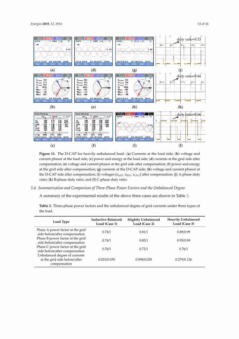
This case is implemented under a heavily unbalanced load. Calculated by Equation (13), thereactive/imbalance index k is equal to 1.7, which corresponds to Point 3 in Figure 6b. Shown in Figure 11,currents at the load side are unbalanced (Figure 11a) and lag behind grid voltages (Figure 11b) withpower factors 0.89, 0.95, and 0.76, respectively (Figure 11c). After the D-CAP is put into operation, thepositive-sequence reactive power and a part of the negative-sequence currents are compensated. We canfind that the amplitude of the three-phase currents at the grid side become more balanced (Figure 11d)and the phase angle difference between grid voltages and currents become smaller (Figure 11e). Powerfactors are regulated to 0.99, 0.99, and 1, respectively (Figure 11f). In Figure 11i, the greatest voltageat both ends of the three phase D-CAP is 274.8 V, which is constrained in the range of the ratedvoltage by the negative-sequence components’ amplitude limit shown in Equations (16) and (17).Comparing with Case 2, we can find if the ratio of the negative-sequence components’ amplitudeto the positive-sequence reactive components’ amplitude of the load currents is smaller than 0.25,then the D-CAP can compensate its positive-sequence reactive components and negative-sequencecomponents. If not, the D-CAP can only compensate the positive-sequence reactive power and a partof the negative-sequence currents due to the limit of its compensation ability.
Energies 2019, 12, 1914 13 of 16
Energies 2019, 12, x FOR PEER REVIEW 12 of 15
duty ratio=0.47
(b) (e) (h) (k)
duty ratio=0.62
(c) (f) (i) (l)
Figure 10. D-CAP for slightly unbalanced inductive load: (a) currents at the load side; (b) voltage and current phasor at the load side; (c) power and energy at the load side; (d) currents at the grid side after compensation; (e) voltage and current phasor at the grid side after compensation; (f) power and energy at the grid side after compensation; (g) currents at the D-CAP side; (h) voltage and current phasor at the D-CAP side after compensation; (i) voltages [uaN1 ubN1 ucN1) after compensation; (j) A-phase duty ratio (k) B-phase duty ratio; and (l) C-phase duty ratio.
5.3. Case 3: D-CAP for Heavily Unbalanced Inductive Load
This case is implemented under a heavily unbalanced load. Calculated by Equation (13), the reactive/imbalance index k is equal to 1.7, which corresponds to Point 3 in Figure 6b. Shown in Figure 11, currents at the load side are unbalanced (Figure 11a) and lag behind grid voltages (Figure 11b) with power factors 0.89, 0.95, and 0.76, respectively (Figure 11c). After the D-CAP is put into operation, the positive-sequence reactive power and a part of the negative-sequence currents are compensated. We can find that the amplitude of the three-phase currents at the grid side become more balanced (Figure 11d) and the phase angle difference between grid voltages and currents become smaller (Figure 11e). Power factors are regulated to 0.99, 0.99, and 1, respectively (Figure 11f). In Figure 11i, the greatest voltage at both ends of the three phase D-CAP is 274.8 V, which is constrained in the range of the rated voltage by the negative-sequence components’ amplitude limit shown in Equations (16) and (17). Comparing with Case 2, we can find if the ratio of the negative-sequence components’ amplitude to the positive-sequence reactive components’ amplitude of the load currents is smaller than 0.25, then the D-CAP can compensate its positive-sequence reactive components and negative-sequence components. If not, the D-CAP can only compensate the positive-sequence reactive power and a part of the negative-sequence currents due to the limit of its compensation ability.
duty ratio=0.33
(a) (d) (g) (j)
duty ratio=0.44
(b) (e) (h) (k)
Energies 2019, 12, x FOR PEER REVIEW 13 of 15
duty ratio=0.66
(c) (f) (i) (l)
Figure 11. The D-CAP for heavily unbalanced load: (a) Currents at the load side; (b) voltage and current phasor at the load side; (c) power and energy at the load side; (d) currents at the grid side after compensation; (e) voltage and current phasor at the grid side after compensation; (f) power and energy at the grid side after compensation; (g) currents at the D-CAP side; (h) voltage and current phasor at the D-CAP side after compensation; (i) voltages [uaN1 ubN1 ucN1] after compensation; (j) A-phase duty ratio; (k) B-phase duty ratio; and (l) C-phase duty ratio.
5.4. Summarization and Comparison of Three-Phase Power Factors and the Unbalanced Degree
A summary of the experimental results of the above three cases are shown in Table 3.
Table 3. Three-phase power factors and the unbalanced degree of grid currents under three types of the load.
Load Type Inductive Balanced Load (Case 1)
Slightly Unbalanced Load (Case 2)
Heavily Unbalanced Load (Case 3)
Phase A power factor at the grid side before/after compensation 0.74/1 0.81/1 0.89/0.99
Phase B power factor at the grid side before/after compensation 0.74/1 0.85/1 0.95/0.99
Phase C power factor at the grid side before/after compensation 0.76/1 0.72/1 0.76/1
Unbalanced degree of currents at the grid side before/after compensation 0.023/0.039 0.098/0.029 0.279/0.126
In Case 1, it can be found that three-phase power factors are corrected to 1 with the inductive balanced load. The parameters of the load are not exactly the same, so the unbalanced degree of the load current is 2.3%. Additionally, there are some active power loss and sampling errors when the D-CAP operates, so there is still a slight imbalance on the grid currents after compensation. Although the unbalanced degree increases from 2.3% to 3.9%, we can think the grid currents are balanced and reactive power compensation is achieved under the inductive balanced load. In Case 2, the load is slightly unbalanced with reactive/imbalance index k = 5.4, the three-phase power factors are corrected from 0.81, 0.85, and 0.72 to 1, and the unbalanced degree drops from 9.8% to 2.9%. Reactive power compensation and imbalance suppression are realized. In Case 3, the load is heavily unbalanced with reactive/imbalance index k = 1.7, and negative-sequence currents cannot be compensated completely due to the amplitude limit of i*–
Ld and i*– Lq. Only positive-sequence reactive components and a part of
the negative-sequence components of the load currents are compensated, so the unbalanced degree decreases from 27.9% to 12.6%, power factors increase from 0.89, 0.95, and 0.76 to 0.99, 0.99, and 1.
6. Conclusions
In this paper, reactive power compensation and imbalance suppression by a 33 kVar/220 V star-connected Buck-type D-CAP in a three-phase three-wire system are studied. An improved control strategy is proposed, which can make full use of the rated voltage margin of the D-CAP to compensate the negative-sequence currents of the load. The following conclusions are obtained through theoretical analysis and experimental verification:
(1) In the three-phase three-wire system, if three-phase power factors at the grid side are equal to 1 under the effects of the D-CAP, then the D-CAP can suppress load imbalance.
Figure 11. The D-CAP for heavily unbalanced load: (a) Currents at the load side; (b) voltage andcurrent phasor at the load side; (c) power and energy at the load side; (d) currents at the grid side aftercompensation; (e) voltage and current phasor at the grid side after compensation; (f) power and energyat the grid side after compensation; (g) currents at the D-CAP side; (h) voltage and current phasor atthe D-CAP side after compensation; (i) voltages [uaN1 ubN1 ucN1] after compensation; (j) A-phase dutyratio; (k) B-phase duty ratio; and (l) C-phase duty ratio.
5.4. Summarization and Comparison of Three-Phase Power Factors and the Unbalanced Degree
A summary of the experimental results of the above three cases are shown in Table 3.
Table 3. Three-phase power factors and the unbalanced degree of grid currents under three types ofthe load.
Load Type Inductive BalancedLoad (Case 1)
Slightly UnbalancedLoad (Case 2)
Heavily UnbalancedLoad (Case 3)
Phase A power factor at the gridside before/after compensation 0.74/1 0.81/1 0.89/0.99
Phase B power factor at the gridside before/after compensation 0.74/1 0.85/1 0.95/0.99
Phase C power factor at the gridside before/after compensation 0.76/1 0.72/1 0.76/1
Unbalanced degree of currentsat the grid side before/after
compensation0.023/0.039 0.098/0.029 0.279/0.126
Energies 2019, 12, 1914 14 of 16
In Case 1, it can be found that three-phase power factors are corrected to 1 with the inductivebalanced load. The parameters of the load are not exactly the same, so the unbalanced degree of theload current is 2.3%. Additionally, there are some active power loss and sampling errors when theD-CAP operates, so there is still a slight imbalance on the grid currents after compensation. Althoughthe unbalanced degree increases from 2.3% to 3.9%, we can think the grid currents are balanced andreactive power compensation is achieved under the inductive balanced load. In Case 2, the load isslightly unbalanced with reactive/imbalance index k = 5.4, the three-phase power factors are correctedfrom 0.81, 0.85, and 0.72 to 1, and the unbalanced degree drops from 9.8% to 2.9%. Reactive powercompensation and imbalance suppression are realized. In Case 3, the load is heavily unbalanced withreactive/imbalance index k = 1.7, and negative-sequence currents cannot be compensated completelydue to the amplitude limit of i∗−Ld and i∗−Ld. Only positive-sequence reactive components and a part ofthe negative-sequence components of the load currents are compensated, so the unbalanced degreedecreases from 27.9% to 12.6%, power factors increase from 0.89, 0.95, and 0.76 to 0.99, 0.99, and 1.
6. Conclusions
In this paper, reactive power compensation and imbalance suppression by a 33 kVar/220 Vstar-connected Buck-type D-CAP in a three-phase three-wire system are studied. An improved controlstrategy is proposed, which can make full use of the rated voltage margin of the D-CAP to compensatethe negative-sequence currents of the load. The following conclusions are obtained through theoreticalanalysis and experimental verification:
(1) In the three-phase three-wire system, if three-phase power factors at the grid side are equal to1 under the effects of the D-CAP, then the D-CAP can suppress load imbalance.
(2) If the negative-sequence currents of the load are located in the ∆RST shown in Figure 4, theD-CAP can theoretically completely compensate the reactive power and suppress load imbalance.However, the actual compensation ability is limited by its rated voltage.
(3) If the load is inductive balanced, only reactive power compensation is needed. Under theeffect of the D-CAP, three-phase power factors can be corrected to 1.
(4) If the load is slightly unbalanced, whose negative-sequence currents’ amplitude is less than 1/4of the positive-sequence reactive currents’ amplitude, the D-CAP can compensate the reactive powerand suppress load imbalance.
(5) If the load is heavily unbalanced, whose negative-sequence currents’ amplitude is greaterthan 1/4 of the positive-sequence reactive currents’ amplitude, the D-CAP can only compensatethe positive-sequence reactive power and a part of the negative-sequence currents due to the ratedvoltage limit.
Author Contributions: X.W. and K.D. conceived this article and designed the experiments; X.W., X.C., and X.Z.developed control routine and performed the hardware experiment; and all authors wrote the paper.
Funding: This research was funded by National Natural Science Foundation of China [Multimode ResonanceMechanism and Corresponding Multifunction Active Damping Control Technique for Power Electronic HybridSystems] grant number [51277086].
Conflicts of Interest: The authors declare no conflict of interest.
References
1. He, Z.X.; Xu, Q.M.; Luo, A.; Xiao, H.G.; Chen, Y.D.; Jin, G.B.; Ma, F.J. Circulating current derivation andcomprehensive compensation of cascaded STATCOM under asymmetrical voltage conditions. IET Gener.Transm. Distrib. 2016, 10, 2924–2932.
2. Tan, K.H.; Lin, F.J.; Chen, J.H. A three-phase four-leg inverter-based active power filter for unbalancedcurrent compensation using a petri probabilistic fuzzy neural network. Energies 2017, 10, 2005. [CrossRef]
3. IEEE. IEEE Guide for Application of Shunt Power Capacitors, IEEE Std. 1036, 2010; IEEE: Piscataway, NJ, USA,2010. [CrossRef]
Energies 2019, 12, 1914 15 of 16
4. Das, S.; Chatterjee, D.; Goswami, S.K. Tuned-TSC based SVC for reactive power compensation and harmonicreduction in unbalanced distribution system. IET Gener. Transm. Distrib. 2018, 12, 571–585. [CrossRef]
5. Chatterjee, D.; Das, S.; Goswami, S. A GSA based modified SVC switching scheme for load balancing andsource power factor improvement. IEEE Trans. Power Deliv. 2016, 31, 2072–2082.
6. Xu, C.; Dai, K.; Chen, X.W.; Kang, Y. Voltage droop control at point of common coupling with arm currentand capacitor voltage analysis for distribution static synchronous compensator based on modular multilevelconverter. IET Power Electron. 2016, 9, 1643–1653. [CrossRef]
7. Song, Q.; Liu, W. Control of a cascade STATCOM with star configuration under unbalanced conditions.IEEE Trans. Power Electron. 2009, 24, 45–58. [CrossRef]
8. Chang, W.N.; Liao, C.H. Design and implementation of a STATCOM based on a multilevel FHB converterwith delta-connected configuration for unbalanced load compensation. Energies 2017, 10, 921. [CrossRef]
9. Behrouzian, E.; Bongiorno, M. Investigation of negative-sequence injection capability of cascaded H-bridgeconverters in star and delta configuration. IEEE Trans. Power Electron. 2016, 32, 1675–1683. [CrossRef]
10. Oghorada, O.J.K.; Zhang, L. Unbalanced and reactive load compensation using MMCC-based SATCOMswith third harmonic injection. IEEE Trans. Ind. Electron. 2019, 66, 2891–2902. [CrossRef]
11. Xu, C.; Dai, K.; Chen, X.W.; Kang, Y. Unbalanced PCC voltage regulation with positive- and negative-sequencecompensation tactics for MMC-DSTATCOM. IET Power Electron. 2016, 9, 2846–2858. [CrossRef]
12. She, X.; Huang, A.Q.; Wang, G. 3-D space modulation with voltage balancing capability for a cascadedseven-level converter in a solid-state transformer. IEEE Trans. Power Electron. 2011, 26, 3778–3789. [CrossRef]
13. Zhang, Y.; Adam, G.P.; Lim, T.C. Hybrid multilevel converter: Capacitor voltage balancing limits and itsextension. IEEE Trans. Ind. Inform. 2013, 9, 2063–2073. [CrossRef]
14. Wheeler, P.W.; Rodriguez, J.; Clare, J.C. Matrix converters: A technology review. IEEE Trans. Ind. Electron.2002, 49, 276–288. [CrossRef]
15. Raghuram, M.; Avneet, K.C.; Santosh, K.S. Switched capacitor impedance matrix converter. In Proceedings ofthe IEEE Energy Conversion Congress and Exposition, Cincinnati, OH, USA, 1–5 October 2001; pp. 1071–1075.
16. Cheng, M.M.; Feng, K.; Isobe, T.; Shimada, R. Characteristics of the magnetic energy recovery switch as astatic Var compensator technology. IET Power Electron. 2015, 8, 1329–1338. [CrossRef]
17. Wei, Y.W.; Kang, L.Y.; Huang, Z.Z.; Li, Z.; Cheng, M.M. A magnetic energy recovery switch based terminalvoltage regulator for the three-phase self-excited induction generators in renewable energy systems. J. PowerElectron. 2015, 15, 1305–1317. [CrossRef]
18. Wei, Y.W.; Fang, B.; Kang, L.Y.; Huang, Z.Z.; Liu, T.G. Parallel-connected magnetic energy recovery switchused as a continuous reactive power controller. J. Power Electron. 2016, 16, 1494–1503. [CrossRef]
19. Chen, R.R.; Liu, Y.T.; Peng, F.Z. A solid state variable capacitor with minimum capacitor. IEEE Trans.Power Electron. 2017, 32, 5035–5044. [CrossRef]
20. Liu, Y.T.; Wang, X.R.; Peng, F.Z. An H-bridge-based single-phase VAr generator with minimum dc capacitance.IEEE J. Emerg. Sel. Top. Power Electron. 2018, 6, 2001–2014. [CrossRef]
21. Prasai, A.; Sastry, J.; Divan, D.M. Dynamic capacitor (D-CAP): An integrated approach to reactive andharmonic compensation. IEEE Trans. Ind. Appl. 2010, 46, 2518–2525. [CrossRef]
22. Prasai, A.; Divan, D.M. Control of dynamic capacitor. IEEE Trans. Ind. Appl. 2011, 47, 161–168. [CrossRef]23. Liu, Q.; Deng, Y.; He, X. Boost-Type inverter-less shunt active power filter for VAR and harmonic compensation.
IET Power Electron. 2013, 6, 535–542. [CrossRef]24. Dijkhuizen, F.; Gödde, M. Dynamic capacitor for HV applications. In Proceedings of the IEEE Energy
Conversion Congress and Exposition, Atlanta, GA, USA, 12–16 September 2010; pp. 1511–1518.25. Chen, X.; Dai, K.; Xu, C. Reactive power compensation with improvement of current waveform quality for
single-phase buck-type dynamic capacitor. In Proceedings of the IEEE Applied Power Electronics Conferenceand Exposition (APEC), Long Beach, CA, USA, 20–24 March 2016; pp. 1358–1363.
26. Xiong, L.L.; Dai, K.; Chen, X.; Wang, X.S.; Dai, Z.W. Reactive power compensation and resonance damping forthree-phase buck-type dynamic capacitor. In Proceedings of the IEEE Applied Power Electronics Conferenceand Exposition (APEC), San Antonio, TX, USA, 4–8 March 2018; pp. 1473–1478.
27. Pana, A.; Baloi, A.; Molnar-Matei, F. Load balancing by unbalanced capacitive shunt compensation—Anumerical approach. In Proceedings of the 14th International Conference on Harmonics and Quality ofPower—ICHQP, Bergamo, Italy, 26–29 September 2010; pp. 1–6.
Energies 2019, 12, 1914 16 of 16
28. Wang, X.S.; Dai, K.; Chen, X.; Tan, T.; Dai, Z.W. Optimal compensation of delta-connected dynamic capacitorfor unbalanced load. In Proceedings of the 2018 IEEE International Power Electronics and ApplicationConference and Exposition (PEAC), Shenzhen, China, 4–7 November 2018; pp. 1–6.
29. Xu, C.; Dai, K.; Chen, X.W.; Peng, L.; Zhang, Y.X. Parallel resonance detection and selective compensationcontrol for SAPF with square-wave current active injection. IEEE Trans. Ind. Electron. 2017, 64, 8066–8078.[CrossRef]
30. Anish, P. Direct Dynamic Control of Impedance for VAR and Harmonic Compensation. Ph.D. Thesis, GeorgiaInstitute of Technology, Atlanta, Georgia, 2011.
© 2019 by the authors. Licensee MDPI, Basel, Switzerland. This article is an open accessarticle distributed under the terms and conditions of the Creative Commons Attribution(CC BY) license (http://creativecommons.org/licenses/by/4.0/).