PSK 160 COMFORT | Siegware
28
ASSEMBLY INSTRUCTIONS T / PVC PORTAL Parallel slide & tilt hardware for PVC and timber elements with 12 mm chamber dimension/airgap. PSK 160 COMFORT Window systems Door systems Comfort systems
-
Upload
khangminh22 -
Category
Documents
-
view
1 -
download
0
Transcript of PSK 160 COMFORT | Siegware

ASSEMBLY INSTRUCTIONST / PVC
PORTAL
Parallel slide & tilt hardwarefor PVC and timber elementswith 12 mm chamber dimension/airgap.
PSK 160 COMFORT
Window systems
Door systems
Comfort systems


3/28H48.PSK-HKS001_EN 06.2017
ContentsPSK 160 COMFORTContents
PORTALPSK
Contents
1 GENERAL INFORMATION ..........................4
1.1 Target group of this documentation ............. 41.2 Intended use ................................................. 41.3 Incorrect use ................................................. 41.4 Safety notes .................................................. 41.5 Directives of the Trade Organisation
for Locks and Fittings (Gütegemeinschaft Schlösser und Beschläge e. V.) ...................... 5
1.6 Dimensions ................................................... 51.7 Scheme overview .......................................... 61.8 Operating sequence ...................................... 61.9 Operating sticker ........................................... 61.10 Application diagram ...................................... 6
2 PROCESSING SPECIFICATIONS ..................7
2.1 Size ranges..................................................... 72.2 Abbreviations ................................................ 7
3 OVERVIEW OF HARDWARE COMPONENTS ...........................................8
3.1 Hardware components presentation scheme A ....................................................... 8
3.2 Hardware list hardware components ............ 9
4 MOUNTING THE HARDWARE COMPONENTS .........................................11
4.1 Mounting the running rail and guiding rail................................................... 11
4.2 Installing the tilt stay ................................... 124.3 Installing the bogie wheels ......................... 134.4 Installing the connecting rod ....................... 134.5 Installing supporting piece L ....................... 144.6 Mounting the bogie wheels cover .............. 144.7 Inserting the sliding sash ............................. 154.8 Removing the sliding sash ........................... 154.9 Installing the bogie wheels safeguard ......... 164.10 Removing the bogie wheels safeguard ...... 174.11 Positioning the trigger ................................. 174.12 Positioning the stop .................................... 184.13 Tipping brake ............................................... 194.14 Stop buffer .................................................. 204.15 Additional brake .......................................... 21
5 ADJUSTMENT ..........................................21
5.1 Adjusting the tilt stay .................................. 215.2 Height adjustment of the bogie wheels ...... 225.3 Adjustment of the tilt angle of the bogie
wheels ......................................................... 22
6 PROFILE SECTIONS ..................................23
6.1 Vertical cross-section, top ........................... 236.2 Vertical cross-section bottom...................... 24
7 JIGS ..........................................................25
8 LIABILITY .................................................26
8.1 Intended use ............................................... 268.2 Product liability ........................................... 268.3 Disclaimer of liability ................................... 268.4 Environmental protection ........................... 268.5 Feedback on documentation ...................... 26

06.20174/28 H48.PSK-HKS001_EN
PORTAL PSK 160 COMFORTGeneral information
PSK
1 General information
1.1 Target group of this documentation
This documentation is intended for use by specialists only. All work described in this document is to be performed by experienced professionals with training and practice in the assembly, installation and maintenance of PORTAL hardware as the safe and professional assembly of the PORTAL hardware is not possible without the relevant expertise. Keep these installation instructions in a safe place.
1.2 Intended use
• The PSK 160 COMFORT parallel slide & tilt hardware for use in windows or patio doors with PVC profiles.
• Sash weight max. 160 kg.
• The PSK 160 COMFORT is intended for use in permanent buildings.
• The PSK 160 COMFORT allows the horizontal opening and closing of windows and patio doors from profiles for parallel slide & tilt elements.
• The parallel slide & tilt elements must be installed vertically, in no circumstances in a sloping position.
1.3 Incorrect use
• The steel fittings specified in these assembly instructions are electro-galvanised and then finished using a special technique.
• They must not be used: – in wet rooms – in environments where the air contains aggressive or corrosive components – in environments where the air contains salt
• Please contact your SIEGENIA sales consultant in such cases
1.4 Safety notes
• Maintenance must be carried out on the PSK 160 COMFORT at least once a year. See PORTAL maintenance instructions
• Furthermore, for the PSK 160 COMFORT, the specifications provided by the profile manufacturers or system owners must also be adhered to with regard to possible restrictions on sash dimensions, sash weights and locking distances.
• Where special manufacturing instructions or fabrication guidelines exist, these must be explicitly adhered to.
• The specifications given for torques must be adhered to.
• Your complete set of hardware should solely be composed of SIEGENIA hardware components. Otherwise damage could occur, for which we accept no liability.
• If special safety aspects must be observed (e.g. for installation in schools, nurseries, hotels, etc.) we recommend the installation of a lockable handle or the use of the PS 200 COMFORT.
• All hardware components must be properly assembled as per the description on pages "Assembly" PSK hardware components and "Adjustment".
• PSK 160 COMFORT elements may only be surface treated before the hardware components are assembled. Treating these surfaces at a later stage can reduce the functional capacity of the hardware components. In such cases we are not obliged to honour any warranty.
• When block setting, please observe technical guideline no. 3 from the German Glazing Trade [Glaserhandwerk], “Blocking glazing units” [Klotzung von Verglasungseinheiten].
• Never use acid curing sealants as they may cause the hardware components to corrode.
• Never use acidic lubricants and cleaning agents in the vicinity of the guiding rail/the slider.

5/28H48.PSK-HKS001_EN 06.2017
PSK 160 COMFORTGeneral information
PORTALPSK
• Keep the running rail and all rebates free from dirt and debris, especially from deposits of cement and plaster. Avoid exposing the hardware directly to water and do not let cleaning agents come into contact with the hardware.
1.5 Directives of the Trade Organisation for Locks and Fittings (Gütegemeinschaft Schlösser und Beschläge e. V.)
The directives of the Trade Organisation for Locks and Fittings provide comprehensive information on the correct operation and maintenance of hardware for windows and French doors. It is mandatory to adhere to these directives.
You can find the latest versions of the directives, in a range of languages here: http://www.beschlagindustrie.de/ggsb/richtlinien.asp
VHBH – Hardware for windows and patio doors Guidelines/notes on the product and on liability
VHBE – Hardware for windows and patio doors Guidelines and notes for end users
1.6 Dimensions
All dimensions are nominal values and include the general tolerances (formerly "dimensional variations"). All nominal values are given in mm.

06.20176/28 H48.PSK-HKS001_EN
PORTAL PSK 160 COMFORTGeneral information
PSK
1.7 Scheme overview
Scheme A
or DIN left DIN right Scheme A with 1 sliding sash/1 fixed sash*
Scheme G
Scheme G with 1 sliding sash/2 fixed sashes*
Scheme C
Scheme C with 2 sliding sashes/2 fixed sashes*
Scheme K
Scheme K with 2 sliding sashes/1 fixed sash*
* Turning sashes instead of the fixed sash are also possible. Turning sashes with rose inside only and removable handle (see handle catalogue).
1.8 Operating sequence
Fig. 1:
Tilt position
Sliding position
Locking position
Operating sequence for PSK 160 COMFORT
1.9 Operating sticker
Attach the operating sticker (slide direction DIN left or DIN right) in a visible position on the installed parallel slide & tilt sash.
The operating sticker is enclosed in the tilt stay carton
Fig. 2: Operating sticker PS/PSK COMFORT
Bitte den passenden Aufkleber ablösen und gut sichtbar am Flügel anbringen.Please remove suitable sticker and affix it in a clearly visible way to the sash.Retirer l´auto-collant pertinent et le placer bien visiblement sur le vanail coulissant.
PORTAL PS COMFORT/PORTAL PSK COMFORT
PS COMFORT PS COMFORT PSK COMFORT PSK COMFORT DIN RECHTS/DIN RIGHT/DIN DROIT DIN LINKS/DIN LEFT/DIN GAUCHE DIN RECHTS/DIN RIGHT/DIN DROIT DIN LINKS/DIN LEFT/DIN GAUCHE
H47.BA-PSK008XX-00
ATTENTION: Primary and secondary sashes must be labelled accordingly to prevent faulty operation.
The sliding sashes may be operated only in the order specified below.
Opening: primary sash first 1. then secondary sash 2.
Closing: secondary sash first 2. then primary sash 1.
1.10 Application diagram
It is essential to observe the application diagram for PSK 160 COMFORT H58.AWD_P_S007DE.

7/28H48.PSK-HKS001_EN 06.2017
PSK 160 COMFORTProcessing specifications
PORTALPSK
2 Processing specifications
2.1 Size ranges
Scheme version A C
Sash rebate width (FFB) Sliding sash 670-2000 670–2000
Sash rebate height (FFH) Sliding sash 840-2800 840–2800
Frame width (RAB) Depends on profile system; determined by the sash rebate width for scheme A max. 4260
Frame to sash clearance 125
Sash weight max. 160 kg
Ratio sash height (FH) / sash width (FB) > 2.5 : 1
• SIEGENIA-Construction drawings PVC profiles:
– PSK 160 COMFORT Scheme A Scheme C Scheme G Scheme K
• The size ranges specified above must not be exceeded.
• In addition, with regard to the SIEGENIA hardware PSK 160 COMFORT, the specifications of the profile manufacturers or system owners also apply, especially with regard to possible restrictions on sash dimensions, sash weight and locking distance.
• Where special manufacturing instructions or fabrication guidelines exist, these must be explicitly adhered to.
• See the construction drawing for the respective profile system for further details.
• Screw heads must not project into the functional area of components. This can lead to material damage and loss of function.
2.2 Abbreviations
The following abbreviations are used in these assembly instructions:
F Guiding rail M Centre S-RS Steel roller reinforced security FB Sash width MV Centre lock SW Wrench size FFB Sash rebate width OKFF Top edge floor V Front FH Sash height PZ Profile cylinder VS Locking side FFH Sash rebate height RAB Frame width
VSO Locking side top G Hand position RAH Frame height VSU Locking side bottom H Rear RFB Frame rebate width ZV Centre lock L Bogie wheels S-ES Steel-reinforced security

06.20178/28 H48.PSK-HKS001_EN
PORTAL PSK 160 COMFORTOverview of hardware components
PSK
3 Overview of hardware components
3.1 Hardware components presentation scheme A
1
2
8
21
28 29
34
3538
3538
30
36 3730
32
33
32
22
4
5
10
13
1217 1725 26
31
31
27
11
14
1820 19
1523
16 24
67 6
4
3
9
For central locking gear seeDocument: H4006.2701en
Product catalogue for PORTAL PSK 160

9/28H48.PSK-HKS001_EN 06.2017
PSK 160 COMFORTOverview of hardware components
PORTALPSK
3.2 Hardware list hardware components
Item
PiecesScheme
Material description
Material number
Basic Add-ons for colour
A C SilverRAL 9003
signal white
RAL 8022 brown F9 old gold
1 1 2 Handle Si-line PSK 31 PHIJ0010 872086 858264 895634 -5H401_ -5H001_35 PHIJ0030 875902 875926 895689 -5H401_ -5H001_
1 2 PSK 160 COMFORT consisting of:right PMKJ1031-10001_left PMKJ1032-10001_
2 1 2 Bogie wheels PSK COMFORT V Front3 1 2 Bogie wheels PSK COMFORT H Rear4 2 4 Vertical supporting part PSK COMFORT5 1 2 Sticker PSK bogie wheels safeguard6 2 4 Slider PSK COMFORT7 1 2 PORTAL key8 1 2 Bogie wheels safeguard Front9 1 2 Bogie wheels safeguard Rear
depending on sash rebate width (FFB) and frame width (RAB)
1 1Profile set PSK-COMFORT
consisting of:
Size1)
Size 87/200 Size 107/240 Size 130/286 Size 160/346 Size 200/426
FFB 670- 870 871-1070 1071-1300 1301-1600 1601-2000
RAB to 2000 2001-2400 2401-2860 2861-3460 3461-4260
PMPJ1100 PMPJ1110 PMPJ1120 PMPJ1130 PMPJ1140
-52501_ -52501_ -52501_ -52501_ -52501_
-50201_ -50201_ -50201_ -50201_ -50201_
-51201_ -51201_ -51201_ -51201_ -51201_
-5H401_ -5H401_ -5H401_ -5H401_ -5H401_
-5H001_ -5H001_ -5H001_ -5H001_ -5H001_
10 1 1 Cover rail L
11 1 1 Connecting rod L12 1 1 Guiding rail13 1 1 Cover rail F14 1 1 Running rail
for COMFORT Style version
1 2 Bag cover cap set PSK COMFORT Style consisting of: PMAJ2050 -02501_ -00201_ -01201_ -0H401_ -0H001_
15 1 2 Cover cap L Style right16 1 2 Cover cap L Style left17 2 4 Cover cap F
1 2 Bag of accessories running rail PSK-COMFORT consisting of:
right
PMZJ1051
Silver -10001_
Silver -10001_
Silver -10001_
Black -09901_
Black -09901_
left PMZJ1052 -10001_ -10001_ -10001_ -09901_ -09901_18 1 2 Stop19 1 2 Stop body20 1 2 Stop sleeve21 1 2 Trigger22 1-2 2-4 Supporting piece L Carton with 100 piece PZLJ1010-09906_
for COMFORT Soft version
1 2 Bag cover cap set PSK COMFORT Soft consisting of: PMAJ1050 -02501_ -00201_ -01201_ -0H401_ -0H001_
23 1 2 Cover cap L Soft right an alternative to item 1524 1 2 Cover cap L Soft left an alternative to item 1617 2 4 Cover cap F
1 2 Bag of accessories running rail PSK-COMFORT consisting of:
right
PMZJ1051
Silver -10001_
Silver -10001_
Silver -10001_
Black -09901_
Black -09901_
left PMZJ1052 -10001_ -10001_ -10001_ -09901_ -09901_18 1 2 Stop19 1 2 Stop body20 1 2 Stop sleeve21 1 2 Trigger

06.201710/28 H48.PSK-HKS001_EN
PORTAL PSK 160 COMFORTOverview of hardware components
PSK
Item
PiecesScheme
Material description
Material number
Basic Add-ons for colour
A C SilverRAL 9003
signal white
RAL 8022 brown F9 old gold
22 1-2 2-4 Supporting piece L Carton with 100 piece PZLJ1010-09906_
depending on sash rebate width (FFB)
25 1 2
Tilt stay PSK 160
A connecting rod slider is prescribed for size 200.
SizeSize 87 Size 107 Size 130 Size 160 Size 200
FFB 670- 870 871-1070 1071-1300 1301-1600 1601-2000
RightPSKJ1011-10001_ PSKJ1021-10001_ PSKJ1031-10001_ PSKJ1041-10001_ PSKJ1051-10001_
LeftPSKJ1012-10001_ PSKJ1022-10001_ PSKJ1032-10001_ PSKJ1042-10001_ PSKJ1052-10001_
26 1 2
Connecting rod slider
Push connecting rod with clipped sliders into the guiding rail.
SizeSize 87 Size 107 Size 130 Size 160 Size 200
FFB 670- 870 871-1070 1071-1300 1301-1600 1601-2000
PVSJ0010-10001_ PVSJ0020-10001_ PVSJ0030-10001_ PVSJ0040-10001_ PVSJ0050-10001_
1 2
Bag cover rail K PSK 160 consisting of:
SizeSize 87 Size 107 Size 130 Size 160 Size 200
FFB 670- 870 871-1070 1071-1300 1301-1600 1601-2000
PMAJ1100 PMAJ1110 PMAJ1120 PMAJ1130 PMAJ1140
-52501_ -52501_ -52501_ -52501_ -52501_
-50201_ -50201_ -50201_ -50201_ -50201_
-51201_ -51201_ -51201_ -51201_ -51201_
-5H401_ -5H401_ -5H401_ -5H401_ -5H401_
-5H001_ -5H001_ -5H001_ -5H001_ -5H001_
27 1 2 Cover rail K28 1 2 Cover cap K right29 1 2 Cover cap K left30 0-2 0-4 Supporting piece K only for sizes 160 and 200
31 1-20for PVC systems Tap SK H2 3.9x32 DIN7504 PZUJ0010-00008_for timber systems Screw SHR AW20 4.1x30 PZUJ0020-00008_
Accessories
32 2 2 Distance piece see profile data sheet
33 1 2 Handle Si-line PSK ABS lockable31 PHIJ0020 872093 858318 895641 – -5H001_35 PHIJ0090 – 875957 895696 – -5H001_
COMFORT hardware components
34 1 2 Stop buffer F Only in combination with connecting rod slider PRZJ0030-10001_
35 2 4 PSK COMFORT accessoriesAdditional brake
PVC stay measurements 9 PRZJ0010-10001_PVC stay measurement 13 PRZJ0020-10001_
Timber rebate width 18 PRZJ0060-10001_Timber rebate width 20 PRZJ0050-10001_Timber rebate width 24 PRZJ0040-10001_
1 2 PSK COMFORT Tipping brake accessories consisting of: PZDJ0010-10001_36 1 2 Tipping brake casing Can be used on left and right side37 1 2 Tipping brake brake Can be used on left and right side38 2 4 Packer FRUP02

11/28H48.PSK-HKS001_EN 06.2017
PSK 160 COMFORTMounting the hardware components
PORTALPSK
4 Mounting the hardware components
4.1 Mounting the running rail and guiding railA
B
DANGER
Danger to life due to sliding sash falling out
Wrong position of the guiding and running rail.
• Adhere to the positioning dimensions.
The construction drawing related to the profile must be observed for correct assembly of the guiding and running rail.
A Guiding railB Running rail
Position the guiding rail.Observe the construction drawing related to the profile.
Position the running rail. Observe the construction drawing related to the profile. Attach load-bearing, end-to-end running rail support when assembling the hardware.
1. Slider
2. Slider
Push both sliders into the guiding rail. Pay attention to the orientation.
If the connecting rod is used, clip this into the slider first.

06.201712/28 H48.PSK-HKS001_EN
PORTAL PSK 160 COMFORTMounting the hardware components
PSK
Push slider together with the connecting rod into the guiding rail.
Shorten the cover rail to the required length and clip onto the guiding rail.
Attach a cover cap F to each end of the guiding rail.
4.2 Installing the tilt stay
X
1.2. 2.
3.
4. 4.
Screw tilt stay to the centre of the sash (1.). Depending on sash width screw on 2 additional supporting pieces K (2.) for sizes 160 and 200.
Trim cover rail K to the required length X and clip on (3.). Observe the construction drawing related to the profile.
Attach right and left cover caps K to the sides of the cover rail (4.).

13/28H48.PSK-HKS001_EN 06.2017
PSK 160 COMFORTMounting the hardware components
PORTALPSK
4.3 Installing the bogie wheels
S1 Screw 4.8 x 16*S2 Screw 4.8 x 32*
S1
S2
S2
Push supporting part into bogie wheels V and H Screw both bogie wheels tightly onto sliding sash according to their position. *Screw length dependent on profile
4.4 Installing the connecting rod
7 7Y1.
2.
3.
Position connecting rod on the bogie wheels H (1.) and mark the cut on the connecting rod (2.) on the cutting mark of second bogie wheels V.
Crop connecting rod to required length and fix in the bogie wheels (3.). Y = Length of connecting rod
4. 5.
4
6. 7.4
Insert connecting rod into bogie wheels V (4.) and fix with head cap screw (5.). Torque 10-11 Nm.
Insert connecting rod into bogie wheels H (6.) and fix with head cap screw (7.). Torque 10-11 Nm.
06.201714/28 H48.PSK-HKS001_EN
PORTAL PSK 160 COMFORTMounting the hardware components
PSK
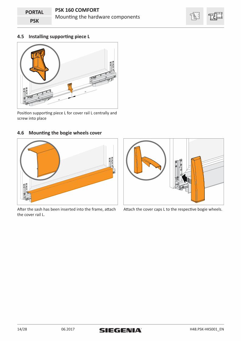
4.5 Installing supporting piece L
=
=
Position supporting piece L for cover rail L centrally and screw into place
4.6 Mounting the bogie wheels cover
After the sash has been inserted into the frame, attach the cover rail L.
Attach the cover caps L to the respective bogie wheels.

15/28H48.PSK-HKS001_EN 06.2017
PSK 160 COMFORTMounting the hardware components
PORTALPSK
4.7 Inserting the sliding sash
DANGER
Danger to life due to sliding sash falling out
Stay arm has not engaged.
• Confirm that the coupling bolt is engaged in the slider by pulling on the stay arm.
Place stay arms of tilt stay into tilt position. Position the sash on the running rail at an incline and insert the coupling bolt of the stay arms into the slider.
Snap in stay arms of tilt stay into slider.
4.8 Removing the sliding sash
Only the PORTAL key may be used to release the stay arms in the slider
Place stay arms of tilt stay into tilt position. Release stay arms from the slider using the PORTAL key.
Lift off the stay arms of the tilt stay.

06.201716/28 H48.PSK-HKS001_EN
PORTAL PSK 160 COMFORTMounting the hardware components
PSK
4.9 Installing the bogie wheels safeguard
DANGER
Danger to life due to sliding sash falling out
Not mounted bogie wheels safeguard.
• The bogie wheels safeguard must be correctly installed in both bogie wheels of a sliding sash.
1 2
The bogie wheels safeguard can only be installed in a parallel positioned sash.
Position the relevant version (right or left) of the bogie wheels safeguard in the running rail.
3
4
4
Push safeguard into bogie wheels V and H. Fix the safeguard in the bogie wheels with a locking screw.

17/28H48.PSK-HKS001_EN 06.2017
PSK 160 COMFORTMounting the hardware components
PORTALPSK
5 6
4 4 1.2.1.2.3. 3.
41. 2. 3. 41. 2. 3.
The locking screw must be completely countersunk. Do not overtighten the locking screw, torque max. 3 Nm.
Adhere the notes sticker to the protective foil of the cover rail L. Pay attention to correct orientation of the sticker.
4.10 Removing the bogie wheels safeguard
The removal of the bogie wheels safeguard is carried out in reverse sequence to the installation.
4.11 Positioning the trigger
1 2R
Slide the trigger sideways into the running rail. Position the trigger according to the profile.
R
Rebate width R1)
18 16
19 15
20 14
21 13
22 12
34
Dimension R is designed to the position of bogie wheels V.If the position of bogie wheels V is changed, the position of the trigger must be adapted accordingly.
Fix trigger position with head cap screw. Torque max. 3 Nm.

06.201718/28 H48.PSK-HKS001_EN
PORTAL PSK 160 COMFORTMounting the hardware components
PSK
4.12 Positioning the stop
Assemble the stop according to the required DIN direction.
Slide the stop sideways into the running rail.
4
Fix stop into the running rail with Allen key. Final positioning only after the sliding sash has been installed. Torque max. 3 Nm.

19/28H48.PSK-HKS001_EN 06.2017
PSK 160 COMFORTMounting the hardware components
PORTALPSK
4.13 Tipping brakeInstall the tipping brake with the tilt stay closed before you install the sliding sash in the frame.Range of application: +10°C to +40°CStorage: -20°C to +80°C
If the brake is disassembled, the function can no longer guaranteed.
Assemble the tipping brake according to the required version of the DIN direction right/left.
Only dismantle the tilt brake using a slotted screwdriver.
Position the tipping brake on the tilt stay. Screw the tipping brake firmly into place.

06.201720/28 H48.PSK-HKS001_EN
PORTAL PSK 160 COMFORTMounting the hardware components
PSK
4.14 Stop buffer
DANGER
Danger to life due to sliding sash falling out
Not mounted connecting rod slider.
• The stop buffer may only be used if the connecting rod slider has been mounted.
1 2
Insert stop buffer into the guiding rail. Push the stop buffer as far as the PSK COMFORT slider.
3
4
4
Completely open sliding element and stop before the bogie wheels hit the stop.
Close the sliding element again. Now fix the stop buffer with a hexagon screw. Max. torque 3 Nm.

21/28H48.PSK-HKS001_EN 06.2017
PSK 160 COMFORTAdjustment
PORTALPSK
4.15 Additional brake
Version for timber elements
Version for PVC elements
Scheme A left
Scheme C
Scheme A right
180
180
or
Positioning point for the additional brake on the frame. Position 180 mm from the sash rebate corner.Slide the additional brake accordingly in case of collision with other frame parts.
1.
2.
Only for PVC version.Place the additional brake on the profile-specific FRUP.
Press back the brake lever (1.), in order to guarantee space for the lever path.Position additional brake and screw firmly into place (2.).
5 Adjustment
5.1 Adjusting the tilt stay
4
Adjust the engaging function of the tilt stay with Allen key SW 4: stronger (+), weaker (–).
06.201722/28 H48.PSK-HKS001_EN
PORTAL PSK 160 COMFORTAdjustment
PSK
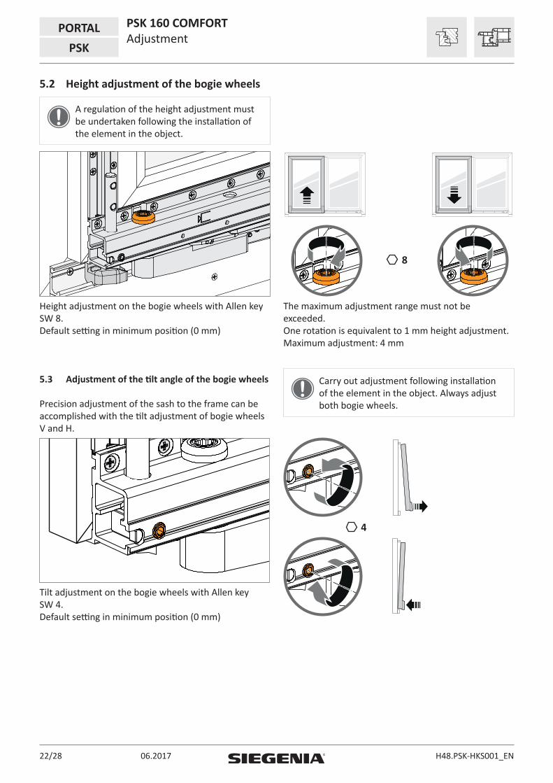
5.2 Height adjustment of the bogie wheels
A regulation of the height adjustment must be undertaken following the installation of the element in the object.
8
Height adjustment on the bogie wheels with Allen key SW 8. Default setting in minimum position (0 mm)
The maximum adjustment range must not be exceeded. One rotation is equivalent to 1 mm height adjustment. Maximum adjustment: 4 mm
5.3 Adjustment of the tilt angle of the bogie wheels
Precision adjustment of the sash to the frame can be accomplished with the tilt adjustment of bogie wheels V and H.
Carry out adjustment following installation of the element in the object. Always adjust both bogie wheels.
4
Tilt adjustment on the bogie wheels with Allen key SW 4. Default setting in minimum position (0 mm)

23/28H48.PSK-HKS001_EN 06.2017
PSK 160 COMFORTProfile sections
PORTALPSK
6 Profile sections
6.1 Vertical cross-section, top
15,5
FH FFH
RAH
FH FFH
RAH
1212
16
~ 5
19
OKFF
11,5
30,5
4,5
3543
1614
min. 16
125

06.201724/28 H48.PSK-HKS001_EN
6.2 Vertical cross-section bottom15
,5FH FF
H
RAH
FH FFH
RAH
1212
16
~ 5
19
OKFF
11,5
30,5
4,5
3543
1614
min. 16
Further dimensions in the corresponding construction drawing.
With bevelled or round rebates, insert an additional 5th screw.Screw length dependent on profile.Consequently potential restriction of the tilt adjustment.
PORTAL PSK 160 COMFORTProfile sections
PSK

25/28H48.PSK-HKS001_EN 06.2017
7 JigsMaterial description Material number
PSK COMFORT jig for bogie wheels PAFL1010-09601_
PSK COMFORT jig locking part for locking parts PALJ0110-02101_
Clamping jig PSK COMFORT for running and guiding rail PAEL1010-00001_L+F rail
PSK 160 COMFORTJigs
PORTALPSK

06.201726/28 H48.PSK-HKS001_EN
PORTAL PSK 160 COMFORTLiability
PSK
8 Liability
8.1 Intended use
Any use of this product that is not in accordance with its intended use, or any adaptation of or modification to the product and its associated components for which our express consent has not been obtained, is strictly prohibited. We accept no liability whatsoever for any material losses or injury to people caused by failure to comply with this stipulation.
8.2 Product liability
Our products are guaranteed – subject to correct installation and proper use – for a period of one year from the date of receipt by a company (according to our general terms and conditions) or as otherwise agreed, and for a period of two years for end consumers, in accordance with statutory provisions. As part of our ongoing improvements, we reserve the right to replace individual components or entire products. Consequential losses resulting from defects are excluded from the warranty within the limits of the law. The warranty shall become void if modifications that are not authorised by us or have not been described in this documentation are performed on the product and/or individual components, or if the product and/or individual components is/are dismantled or (partly) dismantled, and the defect is due to the changes made.
8.3 Disclaimer of liability
The product and its components are subject to stringent quality controls. The product functions reliably and safely when used correctly. Our liability for consequential losses and/or claims for damages is excluded, except in the case of wilful misconduct or gross negligence, or where we are responsible for injury to life, physical injury or damage to health. Strict liability under the German Product Liability Act (Produkthaftungsgesetz) remains unaffected. Liability for the culpable violation of significant contractual obligations also remains unaffected; liability in this case is limited to losses that are specific to the contract and that could have been foreseen. The above regulations do not imply a change in the burden of proof to the detriment of the consumer.
8.4 Environmental protection
Although our products do not fall within the scope of the German Electrical and Electronic Equipment Act (ElektroG), SIEGENIA will continue to meet the requirements of this Act and will endeavour to completely eliminate the use of substances that are hazardous to the environment as soon as this becomes technically feasible. Electrical products should not be disposed of as household waste.
8.5 Feedback on documentation
We welcome your comments and suggestions on how to improve our documentation. Please email your comments to [email protected].


Contact your dealer:
Head Office:Industriestraße 1–357234 WilnsdorfGERMANY
Phone: +49 271 3931-0Telefax: +49 271 [email protected]
SIEGENIA worldwide:
Austria Phone: +43 6225 8301
Belarus Phone: +375 17 3143988
Benelux Phone: +31 85 4861080
China Phone: +86 316 5998198
France Phone: +33 3 89618131
Germany Phone: +49 271 39310
Great Britain Phone: +44 2476 622000
Hungary Phone: +36 76 500810
Italy Phone: +39 02 9353601
Poland Phone: +48 77 4477700
Russia Phone: +7 495 7211762
South Korea Phone: +82 31 7985590
Switzerland Phone: +41 33 3461010
Turkey Phone: +90 216 5934151
Ukraine Phone: +38 044 4054969
You can find address details for our
international sites at: www.siegenia.com
H48.
PSK-
HKS0
01_E
N/0
1