PROJECT THESIS final
94
1 CHAPTER 1 INTRODUCTION 1.1 General Developing countries are more vulnerable to hazards because of their increasing rate of development and urban growth. The lack of proper disaster management leads to increase in risk in more densely populated cities. Most of the growth in terms of civil structures and infrastructure will concentrate in the developing countries for the next few decades. These countries are already loaded with various urban problems like population growth, urban sprawl, building density and lack of financial strength. The risk is continuously increasing in these countries at an alarming rate. The sole purpose of all mitigation processes in the world is to save human lives and property from the impact of natural disasters. It is impossible to live in a disaster free environment but it is possible to reduce the impact of disasters by proper risk management strategies. The pre-planned mitigation activities not only save the human lives but also reduce the potential effect of disasters. The proper disaster management strategy at initial planning level improves the overall functioning structure and helps us to face the ill effects of disaster. Earthquakes can create disasters of high magnitudes when they hit metropolitan areas of large population and infrastructure. India having vast territory, large population and unique geo climatic conditions, and the Indian sub continent is exposed to natural hazardous events. Even today natural hazards like floods cyclones, droughts and earthquakes are not rare in the country. While the vulnerability varies from region to region, a large part of the country is exposed to such natural hazards, which often turn into disasters causing significant injury, deaths and destruction of property. Indian subcontinent is among the world’s most earthquake prone areas. Geology predisposes sixty percent of the country’s area vulnerable to earthquake disaster. Twelve percent of its land is liable to severe earthquake intensity. The highest seismic risk is concentrated in the north, near the border with Pakistan, Bangladesh, Bhutan, China and Nepal. This region of high seismic risk is home to 610 million people, 60% of the nation’s population containing cities with populations a over 14 million inhabitant. Seven major earthquakes have struck different parts of India over a span of last 25 years. The approximate deaths, affected people and injured people in
-
Upload
independent -
Category
Documents
-
view
1 -
download
0
Transcript of PROJECT THESIS final

1
CHAPTER 1
INTRODUCTION
1.1 General Developing countries are more vulnerable to hazards because of their increasing rate of
development and urban growth. The lack of proper disaster management leads to increase in risk
in more densely populated cities. Most of the growth in terms of civil structures and infrastructure
will concentrate in the developing countries for the next few decades. These countries are already
loaded with various urban problems like population growth, urban sprawl, building density and
lack of financial strength. The risk is continuously increasing in these countries at an alarming
rate. The sole purpose of all mitigation processes in the world is to save human lives and property
from the impact of natural disasters. It is impossible to live in a disaster free environment but it is
possible to reduce the impact of disasters by proper risk management strategies.
The pre-planned mitigation activities not only save the human lives but also reduce the
potential effect of disasters. The proper disaster management strategy at initial planning level
improves the overall functioning structure and helps us to face the ill effects of disaster.
Earthquakes can create disasters of high magnitudes when they hit metropolitan areas of large
population and infrastructure.
India having vast territory, large population and unique geo climatic conditions, and the
Indian sub continent is exposed to natural hazardous events. Even today natural hazards like
floods cyclones, droughts and earthquakes are not rare in the country. While the vulnerability
varies from region to region, a large part of the country is exposed to such natural hazards, which
often turn into disasters causing significant injury, deaths and destruction of property.
Indian subcontinent is among the world’s most earthquake prone areas. Geology
predisposes sixty percent of the country’s area vulnerable to earthquake disaster. Twelve percent
of its land is liable to severe earthquake intensity. The highest seismic risk is concentrated in the
north, near the border with Pakistan, Bangladesh, Bhutan, China and Nepal. This region of high
seismic risk is home to 610 million people, 60% of the nation’s population containing cities with
populations a over 14 million inhabitant. Seven major earthquakes have struck different parts of
India over a span of last 25 years. The approximate deaths, affected people and injured people in

2
last 20 years are 32 thousand, 25 million and 200 million respectively. On 26 January 2001, a
very severe earthquake struck Bhuj and shook most parts of Gujarat, causing widespread damage
and devastation. Over 13,805 persons lost their lives, 167,000 persons were injured, over a
million homes were damaged or destroyed and there was large-scale damage to social and
physical infrastructure.
The India-Pakistan earthquake on October 8, 2005 is the most recent example of
seismicity of Himalayan region. The IMD recorded a earthquake magnitude of 7.4 on Richter
scale. The earthquake occurred in the western Himalayas in the morning at about 09.20 hrs IST
(IMD, 2005). The epicenter was 125km WNW of Srinagar near Muzaffarabad, Kashmir. The
earthquake was widely felt in Islamabad, Lahore, Punjub, Chandigarh, Delhi, Himachal Pradesh,
Uttaranchal, Rajasthan, Haryana and adjoining areas. Nearly 20,000 people are feared dead in
Pakistan and death toll in Jammu & Kashmir is reported to have crossed 600 with huge property
loss. Table 1.1 provides the details of some past earthquakes in India.
Table1.1. Past earthquakes in India
Buildings in urban areas are highly vulnerable structures in seismic events especially in
developing countries. There is a direct relationship between the damage of civil structures to the
number of casualties. Most causalities, damage and economic losses caused by earthquake result

3
from ground motion acting upon buildings incapable of withstanding such motion. Damage to
buildings also causes a variety of secondary effects that can be greatly destructive. Lack of
capacity buildings leads to increase in risk of property loss in developing countries. Damage to
essential buildings substantially increases the rate of casualties. In the absence of risk analysis
tools and databases required for earthquake risk assessment, it will be very difficult to assess the
loss in post earthquake event.
1.2 Seismic Load Conditions:
Seismic design force, in each element of the damping system due to horizontal
earthquake load shall be taken as the maximum force of the following three loading conditions:
1. Stage of Maximum Displacement: Seismic design force at the stage of maximum displacement
shall be calculated Seismic forces in elements of the damping system, shall be calculated by
imposing design forces of displacement-dependent damping devices on the damping system as
pseudostatic forces. Design seismic forces of displacement-dependent damping devices shall be
applied in both positive and negative directions at peak displacement of the structure
1.3 Parametric Effects on Joint Shear Capacity:
The proposed simple and unified RC joint shear strength and deformation models
indicate that concrete Compressive strength, beam reinforcement, joint transverse reinforcement,
in-plane geometry, out-of-plane Geometry and joint eccentricity are more informative than other
parameters in determining RC joint shear Capacity. At peak response, the influence of these
parameters on RC joint shear stress vs. joint shear strain and a standard configuration is first
determined to examine the effects of These parameters on joint shear behavior. For the geometric
conditions of this standard reference point, in-plane
Geometry is an interior connection (1.0 for JP and JPRU); out-of-plane geometry has no
transverse beams (1.0 for TB); and joint eccentricity does not exist (1.0 for 1-e/bc). For the non-
geometric conditions, the median database values are simply used (34.0 MPa for concrete
compressive strength, 0.054 for joint transverse Reinforcement index (JI), and 0.32 for beam
reinforcement index (BI)). The influence of geometric parameters on peak RC joint shear stress
vs. joint shear strain behavior based on the standard configuration. An increase of values for in-
plane geometry or out-of-plane geometry results in an increase in both shear stress and shear

4
strain at the peak; an increase of degree of joint Eccentricity causes a decrease in shear stress and
an increase in shear strain at the same time (i.e., decrease in joint shear stiffness). An increase of
value for in-plane geometry or out-of-plane geometry means that RC Beam-column connections
have better geometry for resisting joint shear input demand. For example, when joint Shear
demand exceeds the capacity of RC joint shear resistance mechanisms, the joint panel rapidly
expands in both the in-plane and out-of-plane directions. Thus, the existence of two transverse
beams effectively provides passive confinement to the joint panel. When the centerline of beam
member(s) does not coincide with the centerline of the column cross-section, the joint panel is
subjected to torsion due to joint eccentricity, in addition to the shear force transferred from
longitudinal beams. The weakened diagonal concrete strut and truss (joint shear resistance
mechanisms) due to the generated torsion might trigger a reduction in joint shear stiffness. The
influence of non-geometric parameters on RC joint shear stress vs. joint shear strain behavior
based on the standard configuration. An increase of concrete compressive strength or beam
reinforcement results in an increase of both shear stress and shear strain simultaneously; an
increase of joint transverse reinforcement causes an increase of joint shear stiffness. Because the
capacity of both diagonal concrete strut and truss mechanisms is dependent on concrete
compressive strength, joint shear stress vs. joint shear strain at the peak has a proportional
relation to concrete compressive strength. Beam reinforcement index represents the relative
confinement provided to the joint panel by in-plane beam reinforcement. More Confinement at
the top and bottom of the joint panel by longitudinal beam reinforcement strengthens joint shear
resistance mechanisms. Joint transverse reinforcement index represents the relative confinement
provided by joint transverse reinforcement within the joint panel. Because joint shear failure
initiates an expansion of a joint panel in the in-plane and out-of-plane directions, the improved
confinement against the joint panel’s expansion results in an increase in joint shear stiffness
1.4 Structural damage associated with system faults:
Similar failure patterns of buildings have been repeatedly observed. Investigations of past
earthquakes damage. Design requirements have been modified or added for the protection of new
constructions. However older structures designed and constructed using outdated technology, are
susceptible to the some patterns of damage during future earthquakes.

5
1.4.1 Heavy Structures:
Inertial forces in horizontal and vertical directions are developed with vibration of
structure. Vertical inertial forces are developed by the vertical vibration of structure caused by
the vertical ground motion and also by the vibration of floor slabs. The dominant part of the
structural damage is caused by the horizontal inertial forces associated with lateral vibration of
the structure. The amplitude of inertial forces is proportional to the mass of the structure part in
vibration and the response acceleration developed at the point. Heavy structures such as adobe
houses and reinforced concrete construction attract larger inertial forces during earthquakes.
1.4.2 Period of Vibration:
Acceleration is an important index in engineering. Although the acceleration of an
earthquake ground motion appears to be random, the signal contains special dominant periods of
vibration, representing characteristics of surface geology at the construction site. The
acceleration amplitude of ground motion is generally is large in a period range less than 0.5 to
1.0 s, and decays with the length of periods. Therefore, the acceleration response, corresponding
to the inertia forces, is generally large for short period structures for a given duration of an
earthquake motion the short period structure is subjected to more cycles of oscillation that is the
short period structure is generally more susceptible to damage unless larger resistance is
provided.
1.4.3 Strength and deformation capacity:
A structure does not always fail immediately when the action reaches the strength
(maximum resisting capacity) of a structure. A structure collapses when deformation capacity is
reached in vertical load carrying members, such as columns and walls. The location of damage
can be controlled by selecting weak regions of a structure in design planning. A large
deformation capacity after reaching the strength, commonly known as ductility, can be built into
weak structural members so that the collapse can be delayed even after significant structural
damage is developed.
The brittle modes of failure should be prevented in vertical load carrying members. If the
brittle modes of failure cannot be corrected in construction, then higher strength must be
provided and also the mass of the construction should be reduced.
6
The structural damage of a building with high lateral resistance (stiffness and strength).
Is likely to be smaller under frequent minor earthquakes than that of a building with low
resistance, regardless of the deformation capacity. Therefore, a certain minimum resistance is
necessary for the continued operation of buildings after frequent earthquakes
1.4.4 Progressive Collapse:
When a vertical member, such as structural wall, fails in a brittle mode, the shear carried
by member must be resisted by the other vertical member s in the same storey. The additional
shear often triggers brittle failure of the other members because the structural are normally
designed under the same specification, i.e., if a member fails in brittle manner, the other
members may fail in same mode. Collapse of a building in a story occurs by progressive brittle
failure of vertical members.
Failure of vertical members does not simply results in the reduction of lateral resistance,
but also results in loss of vertical load carrying capacity. The gravity load supported by the
failure member must be transferred to adjacent vertical members. The failure of gravity load
transfer causes partial collapse around the failing vertical member.
1.4.5 Concentration of Damage: The concentration of structural deformation and associated damage limited localities
should be avoided if the deformation capacity at expected damage locations is limited, especially
in reinforced concrete buildings. Collapse of a building is normally caused by the failure vertical
load carrying members of the story. In order to protect vertical members in a multi-story
construction, they should be provided with the higher strength than horizontal members so the
damage should be directed to horizontal members.
1.4.6 Vertical Irregularities:
When the stiffness and associated strength are abruptly reduced in a story along the
height, earthquake-induced deformations tend to concentrate at the flexible and/or weak story.
The concentration of damage in a story leads to large deformations in vertical members. The
excessive deformation in vertical members often leads to collapse of the story.
Soft/weak first stories are especially common in multi-story residential buildings in urban
areas, where the first story often is used for open spaces, commercial facilities or garages. For
example, structural walls that separate residential units in levels above may be discontinued in

7
the first story to meet flexible usage requirements. The first story columns during strong
earthquake shaking must resist a large base shear, inevitably leading to large story drift
concentrated in the story.
1.4.7 Horizontal Irregularities: If, for example, structural walls are placed on one side of a building while the other side
has open frames, the eccentricity between the centers of mass and resistance causes torsional
vibration during an earthquake. Larger damage develops in members away from the center of
resistance. The structural wall is reducing lateral deformation and resisting large horizontal
forces, especially when they are distributed in plan.
1.5 Contribution of Nonstructural Elements: Nonstructural elements, such as masonry concrete or infill walls and stairways, are
degraded in structural analysis although they can contribute significantly to the stiffness of the
framing system. The existence of these high stiffness nonstructural elements can cause irregular
stiffness distributions in plan or along height.
Nonstructural elements are commonly neglected in modeling and analysis in design
calculations, but are placed for the purpose of building function, for example, partition wall.
When stiff and strong nonstructural elements, the interaction can lead to damage in nonstructural
and structural elements. A typical example is captive column, where deformable length is
shortened by spandrels directly attached to the column.
1.6 Pounding of Adjacent Buildings: Pounding of adjacent buildings causes structural damage. Proper distance should be
maintained between adjacent buildings. In the case of serial buildings constructed side by side in
some localities the edge buildings, the edge buildings are often pushed outward and suffer severe
damage while inner buildings are protected from excessive lateral deformation.

8
. Figure 1.1. Pounding can occur in adjacent buildings located very close to each other due to
earthquake-induced shaking (source: Murty 2005).
1.6.1 Separate adjacent buildings by joints:
Pounding and hammering of adjacent buildings can cause substantial damage, if not
collapse. The threat of collapse is greatest when the floor slabs of adjacent buildings are at
different levels and hit against the columns of the neighbouring building. In such cases the joints
must conform with the relevant design rules.
This implies the following:
1) the joints must have a certain minimum width (specified in the building codes)
2) the joints must be empty (no contact points) In order to enable free oscillations and avoid
impact between adjacent buildings, it is often necessary to have a substantial joint width. As long
as the structural elements do not lose their load bearing capacity at pounding.

9
Figure 1.2. The pounding of two similar buildings with floors at the same levels caused
damage to the façades as well as spalling etc. to the structure (Mexico 1985).
Figure 1.3. Substantial damage resulted from the pounding of these two, very different,
buildings (Mexico 1985).
1.7 Deterioration with Age: Deterioration of structural materials with aging and aggressive environmental condition
reduces the seismic performance potential of a building, prior earthquake damage, unless
properly repaired and strengthened, has the same effect. It is important either to maintain the

10
structure at regular intervals or follow rigid construction specification for durability of the
structure.
1.7.1 Foundation: The failure of foundation is caused by:
Liquefaction and loss of bearing or tension capacity
Landslides
Fault rupture
Compaction of soils
Differential settlements
It is normally difficult to design and construct a safe foundation to resist ground
movement immediately above the rupture. Although foundation failures do not pose a life threat,
the cost of damage investigation and repair work is extremely high. Therefore, it is advisable to
reduce the possibility of foundation failure.
1.7.2 Nonstructural Elements: Damage of nonstructural or architectural elements, such as partitions, windows, doors
and mechanical facilities, interrupts the use of building. The cost of repair work on a building is
often governed by the replacement of the damaged nonstructural elements, rather than the repair
work on structural elements. Damage of nonstructural elements may create a falling hazard for
people in or escaping from, the building; furthermore, fallen elements may block evacuation
routes in severely damaged buildings.
1.7.3 Damage in Structural Members: Failure type of members may be different for columns, beams, walls and beam-column
joints. It is important to consider the consequence of member failure on structural performance;
example the failure of vertical members often leads to the collapse of the building.
1.7.4 Flexural Compression Failure of Members: A reinforced concrete member subjected to axial force and bending moment normally
fails in compression of concrete after yielding of longitudinal reinforcement; the failure mode is
normally called flexural compression failure. The deformation capacity of building is influenced
by the level of axial force in the column and the amount of lateral reinforcement provided in the
region of plastic deformation. The level of axial force is limited in design to a relatively low

11
level under the gravity condition. During an earthquake, however, exterior columns, especially
corner ones, are subjected to varying axial force due to overturning moment of a structure, the
axial force level in these columns may become extremely high in compression, leading to
flexural compression failure. It is often difficult to distinguish shear compression failure and
flexural compression failure, as both take place near the column ends and involves concrete
crushing. The lateral confining reinforcement can delay the crushing failure of concrete under
high compressive stresses.
1.7.5 Shear Failure in Columns: The most brittle mode failure is shear. Shear force cause tensile stress in diagonal
direction to the member axis. After the concrete cracks under tensile stress, the stress must be
transferred to the lateral reinforcement. Brittle shear occurs in the diagonal tension mode when
the maximum amount of lateral reinforcement (size, spacing and strength of shear reinforcement)
is not provided in the member.
When the minimum amount of lateral reinforcement is provided in a member, the shear
failure is developed in the form of diagonal compression failure of concrete after yielding of
lateral reinforcement. This mode failure is not brittle as the diagonal tension failure, but the
deformation capacity is limited. If an excessive amount of lateral reinforcement is provided,
diagonal compression failure takes place prior to the yielding of lateral reinforcement. Therefore,
there is an upper limit in the amount of lateral reinforcement effective for shear resistance. After
the compressive failure of concrete, the vertical load carrying capacity of the column is lost,
leading to the collapse in story.
Because the lateral reinforcement resists tensile force under shear, the ends rectilinear
lateral reinforcement should be anchored in the core concrete with 135-degree bend, or they
should be welded together. When a reinforcing bar is bent, permanent plastic deformation takes
place at the bend and the region becomes less ductile. The reinforcing steel capable of
developing high toughness and ductility before fracture must be used for lateral reinforcement.
1.7.6 Shear Failure of Flat Plate Construction: A flat plate floor without column capitals is popular in some regions because it does not
have girders below a slab level. The critical part of the flat slab system is the vertical shear
transfer between the slab and column. The shear failure at “the connection leads to the pan-cake

12
collapse” of the building, leaving of space between the adjacent floors after the collapse. Serious
failure was observed in 1985 Mexico City earthquake.
1.7.7 Bond Splitting Failure:
The bond stresses acting on deformed bars cause ring tension to the surrounding concrete
high flexural bond stresses may exist in members with steep movement gradients along their
lengths. If longitudinal reinforcement of beam or column is not supported by closely spaced
stirrups or ties, splitting cracks may develop along the longitudinal reinforcement, especially
when the strength of concrete low, when large diameter longitudinal bars with high strength are
used, or when the concrete cover on the deform bars is thin. These splitting cracks result in loss
of bond stress, limiting the flexural and/or shear resistance at a small deformation.
1.7.8 Splice Failure of Longitudinal Reinforcement:
Longitudinal reinforcement is spliced in various ways, including lap splices, mechanical
splices and welded splices. Splices should be located in a region where tensile stress is low.
Splices in older buildings were located in regions of high tensile stresses because the
implications for earthquake performance were inadequately understood. Splice failure reduces
flexural resistance of the member often before yielding.
1.7.9 Anchorage Failure:
The force in longitudinal reinforcements in beams and columns must be anchored with in
beam-column connection or foundation. Connections of older building construction may be joint
transverse reinforcement; in which case the column and beam is reinforced is anchored is
essentially plain concrete. If the beam longitudinal reinforcement is not fully anchored in a
beam-column joint, the bar may pull out from the joint; example beam bottom reinforcement, in
non-seismic design, is embedded a short distance into the beam-column joint.
1.7.10 Beam-Column joint Failure:
When moment resisting frame is designed for weak-beam strong-column behavior, the
beam-column joint may be heavily stressed after beam yielding and diagonal cracking may be
formed in the connection. Wide flexural cracks may be developed at the beam end, partially
attributable the slip of beam reinforcement with in the connection. Such shear cracking may

13
reduce the stiffness of a building. Failure is observed in beam-column joints with narrow
columns and also in beam-column joints without lateral reinforcement.
1.7.11 Failure of Piles:
The inertia force acting in a building must be resisted by the foundation of structure. High
bending moments combined with axial forces acting at the top of pile can cause crushing of
concrete. Such damage in the foundation structure is difficult to identify after the earthquake,
unless apparent inclination of a building is detected as a result of permanent foundation
deformation.
1.8 Quality of Workmanship and Materials:
The performance construction is affected by the quality of work during construction. For
example the material strength is specified in design documents may not be developed during
construction. The amount of reinforcement is not placed as specified design. The end lateral
reinforcement is not bent in 135 degrees as the building code specifies. Concrete cover to
reinforcement is not sufficient and the reinforcing bar is rusted with cracks in surface of the
concrete. Education of construction workers and inspection of construction work are necessary to
maintain the quality of workmanship.
The quality of materials also deteriorates with age. Proper maintenance of structure is essential.
Changes in use and occupancy often involves structural modifications without proper
investigation into the consequence in the event of an earthquake
1.9 Better understanding of effects of masonry infill walls in developing countries:
Reconnaissance after three or four of the recent earthquakes in India has shown
researchers and practitioners around the world the potentially beneficial effects of masonry infill
walls in multistory buildings. The conventional wisdom in developed countries has been to
discourage the use of masonry infill in seismic regions, but the Indian earthquake damage has
shown that masonry infill walls provide additional support in structures with rather poorly
designed and constructed reinforced concrete frames. The added support is enough to keep the
buildings from collapse. This observation has potentially huge life-saving implications in many
developing countries.

14
1.10 Structure regularity:
The guiding principles governing the initial conceptual design are as follows:
a) The aspect of seismic hazard should be taken into account in the early stages of the conceptual
design of a building,
b) Structure should be simple,
c) Transmission of the seismic (inertia) forces to the ground should be direct and clear
d) Uniformity, symmetry and redundancy should be ensured,
e) Structure should be statically undetermined,
f) Bi-directional resistance and stiffness should be ensured
g) Torsion resistance and stiffness should be ensured (main structural elements should be placed
symmetrically nearby periphery of the building)
h) Structural elements should be appropriately connected with floor systems or diaphragms
(which have to have sufficient in-plane stiffness),
i) Building should have adequate foundation.
Figure1.3 (a): Examples of regular and irregular initial building designs:
a):Uniformity along the height; b): Bi-directional resistance and stiffness; c): Symmetry in plan
1.10.1 The regularity criteria in plan and in elevation:
The regularity of the structure in the plan of different floors, as well as in elevation of the
building should be ensured.
The regularity criteria in plan are: a) With respect to the lateral stiffness and mass distribution, the position of force resisting
elements should be approximately symmetrical in plan with respect to two orthogonal
axes (Figure1.4 (b)).

15
Figure 1.4 (b): Regularity of a building in plan and appropriate position of force resisting
elements.
b) The plan configuration should be compact. The dimensions of recesses in one direction should
not exceed 25% of the whole dimension of floor area in this direction (compact plan
configuration which is not H, L, I, C or X – shaped). Figure 3: Regularity of initial building
design in plan according to distribution of masses and subdivision of the entire building by
seismic joints.
c) The in-plane stiffness of the floors should be sufficiently large in comparison with the lateral
stiffness of the vertical structural elements, so that the deformation of the floor has a small effect
on the distribution of the forces among the vertical structural elements.
The regularity criteria in elevation are as follows:
a) All lateral load-resisting systems, like cores, structural walls or frames should run without
interruption from the foundations to the top of the building.
b) The deflected shapes of the individual systems under horizontal loads should not be very
different. This condition may be considered satisfied in case of frame systems and wall systems.
c) Both the lateral stiffness and the mass of the individual storeys should remain constant or
reduce gradually, without abrupt changes, from the base to the top (Figure 1.5(c)).
Figure 1.5 (C): Large eccentricities and uniformity along the height and influence of
different heights of columns.
d) When set backs are present, the following additional conditions apply:
Structure is regular if set-back at any floor is not greater than 20% of the dimension of the plan
below. If the set-back does not preserve symmetry, in each face, the sum of the set-backs at all
storeys should not exceed than 30 % of the plan dimension of the first storey, and the individual
set-backs should not exceed 10% of the dimension of the plan below( Figure 1.6)

16
Figure 1. .6 Regularity of set-backs.
1.10.2 Other irregularities:
Longer overhanging elements should be avoided. Columns should run directly to the
ground where this is possible. Supporting columns with beams is not recommendable. Initial
structure design should follow the above recommendations. If necessary, uniformity may be
realized by subdividing the entire building by seismic joints into dynamically independent units,
provided that these joints are designed against pounding of the individual units (Figure 3). The
construction of completely irregular structures is not explicitly forbidden, however, it is much
harder to ensure a desirable level of safety against strong earthquake for an irregular structure.
For this reason the irregular structures are in general less safe, even if the structure is capable to
withstand design forces. Non-structural elements (appendages) of buildings shall be adequately
connected to the main structure Non-structural elements (appendages) of buildings (e.g. parapets,
gables antennae, mechanical appendages and equipment, curtain walls, partitions, railings)
should be verified to resist the designed seismic action. They should be adequately connected to
the main structure. Non-structural elements (in-fills) can help to dissipate the energy, if they are
correctly arranged and connected to the structure. It is necessary to prevent negative influences
of individual non-structural elements or partial in-fills, that can damage the main R/C structure
(the effect of short column).

17
Figure 1.7(a). Influence of building shape: a) Buildings with simple shapes permit the
shaking induced inertia forces to flow directly to the foundation and hence perform well in
earthquakes; b) buildings with irregular shapes force the inertia forces to bend at each re-entrant
corner, which results in damage at these corners and hence poor earthquake beahvior of the
building as a whole (source: Murty 2005).
Figure 1.7(b) . Sudden changes in load path lead to poor performance of buildings in
earthquakes: a) setbacks; b) weak or flexible stories; c) sloping ground; d) hanging or floating
columns; e) discontinuous structural members (source: Murty 2005).
18
1.11 Reinforced concrete:
Reinforced concrete is one of the most widely used modern building materials. Concrete
is an “artificial stone” obtained by mixing cement, sand, and aggregates with water. Fresh
concrete can be molded into almost any shape, giving it an inherent advantage over other
materials. It became very popular after the invention of Portland cement in the 19th century;
however, its limited tension resistance initially prevented its wide use in building construction.
To overcome poor tensile strength, steel bars are embedded in concrete to form a composite
material called reinforced concrete (RC).
The use of reinforced concrete construction in the modern world stems from the wide
availability of its ingredients - reinforcing steel as well as concrete. Except for the production of
steel and cement, the production of concrete does not require expensive manufacturing mills.
But, construction with concrete does require a certain level of technology, expertise and
workmanship, particularly in the field during construction. Despite this need for sophistication
and professional inputs, a large number of single-family houses or low-rise residential buildings
across the world have been and are being constructed using reinforced concrete without any
engineering assistance. Such buildings, in seismic areas, are potential death traps.
A typical reinforced concrete building (shown in Figure 1.9(a)) is generally made of a
number of plate-like horizontal elements (slabs), rib-like horizontal elements (beams) connected
to the underside of slabs, slender vertical elements (columns), and flat vertical elements (walls).
In most cases, all these elements are cast monolithically that is, beams and columns are cast at
the construction site in a single operation in order to act in unison. Fresh concrete is poured into
wood or steel forms placed around the steel reinforcement for different elements in buildings.
Such buildings are called monolithic (or cast-in-place) reinforced concrete buildings, in contrast
to precast reinforced concrete buildings, wherein each of the elements are cast separately (often
in a factory environment) and then assembled together at the building site. In monolithic
reinforced concrete buildings, the connection between the elements is achieved by providing
continuous reinforcement bars that pass from one element to another. The intersection between a
beam and a column, known as beam-column joint, plays a vital role in the capacity of these
buildings to resist lateral loads.

19
Figure 1.8 (a): A typical reinforced concrete building
In reinforced concrete frames the integral action of beams, columns and slabs, provides
resistance to both gravity and lateral loads through bending in beams and columns. Reinforced
concrete frames built in earthquake-prone regions should possess ductility, or the ability to
sustain significant deformations under extreme loading conditions. Frames that are designed to
resist mainly the effects of gravity loads most often are called non-ductile (or gravity) frames.
The non-ductile reinforced concrete frame with or without infill walls is a very common building
construction technology practiced around the globe these three-dimensional reinforced concrete
frames (beam-column-slab) are made functional for habitation by building walls called infill
walls. These walls are built at desired locations throughout the building, usually in the vertical
plane defined by adjoining pairs of beams and columns. One popular material used for making
walls across the world is burnt clay brick masonry in cement mortar. Lately, the use of cement
blocks, hollow cement blocks and hollow clay tiles is on the rise across the world. In some cases,
the masonry infill walls are also reinforced with steel bars passing through them in the vertical
and horizontal directions and anchoring into the adjoining beams and columns.

20
Reinforced concrete construction is extensively practiced in many parts of the world,
especially in developing countries. With the rapid growth of urban population, reinforced
concrete frame construction has been widely used for residential construction in both the
developing and industrialized countries. Design applications range from single-family dwellings
in countries like Algeria and Colombia, to high-rise apartment buildings in Chile, Canada,
Mexico, Turkey, India, and China. Examples of RC frame construction are shown figures 1.9
Figure1.9: Low-to-midrise RC frame construction: Turkey (top left; from Gulkan et
al.2002; Colombia (top right; from Mejia 2002); Taiwan (bottom left; from Yao and Sheu
2002); India (bottom right; from Jaiswal et al. 2002)
Because of the high occupancy associated with these buildings, as well as their ubiquitous
presence throughout the world, significant fatalities and property losses can be associated with
their potential poor earthquake performance. Thus, special care is required to understand the
challenges that earthquakes pose and ensure that appropriate features are incorporated in the
architectural and structural design and construction of reinforced concrete frame buildings.
depicts the construction of a modern reinforced concrete frame building.

21
The estimated number of vulnerable reinforced concrete frame buildings in seismic zones
across world is staggering, including both developing and highly industrialized countries. In
industrialized countries, thousands of older RC frame buildings are considered to be at risk since
the building codes did not include requirements for special seismic detailing of reinforced
concrete structures until the 1970’s when several earthquakes demonstrated the need for more
ductile design.
FIigure1.10. Examples of RC highrises in Canada (left; from Pao and Brzev 2002) and Chile
(right; from Moroni and Gomez 2002). RC shear walls provide resistance to earthquake effects
in these buildings while columns are designed to resist gravity loads.
The role of architect and structural engineer is very vital in the planning and design of the
structure, which is seismically efficient to withstand the design earthquakes. They also should
strictly implement the code provisions, hence there is scope for the structure to with stand the
earthquakes and save lives, minimize the damage to the property. Hence the constructed
buildings lacking seismic resistance should be retrofitted and the buildings being planned for
construction should be properly planned with good collaboration of architect, structural engineer.
1.12 Future Role of Earthquake Engineering:
Safety in the event of major earthquakes is one performance objective. The importance of
ductility has been emphasized for the survival of the building; i.e., a structure should be capable
of resistance after developing plastic deformation (damage). At the same time, ductility was used
as a means to reduce the seismic forces. It is concerned that damage may develop in a structure

22
even during frequent minor earthquake motions because the structure is designed for too low
lateral load resisting relying on large ductility. It is costly to repair structural as well as non-
structural damage after minor but frequent earthquakes, and the building cannot be used during
the repair period. A structural engineer should advice a building owner about the possible cost of
repairs and losses associated with having cease to building operation during repair work if a
building is designed with low lateral resistance.
The damage level of structural and non-structural elements is known to be closely related to
story drift (inter-story deformation). Structural damage to a brittle but high resisting building is
much smaller under more frequent earthquake motions than damage to a ductile structure. A
number of damage investigations reported the effectiveness of structural walls in reducing the
damage to structural members as well as non-structural elements. The importance of limiting the
story drift during an earthquake by providing large stiffness and high lateral resistance should be
emphasized in earthquake engineering.
The non-structural elements such as windows, partitions, doors and architectural facilities, are
essential parts of a building’s function. Even if structural members suffer no or slight damage if
partitions are broken in residential building, the unit may not be occupiable until such it gets
repaired or replaced.
If the computer facilities are damaged in computer or information center of accompany, the
function of a building is lost. The cost of repair and recovery work is often governed by the
replacement of non-structural elements than the repair work on structural elements.
Falling of broken non-structural elements is dangerous for people for escaping from the building,
and falling or overturned objects may block evacuation of routes in a building. The non-
structural elements must be protected from minor frequent earthquakes to reduce the financial
burden of the building. Controlling the inter-story drift through the use of structural walls or
structural control devices and improving the method to fasten the non-structural elements to the
structure may reduce damage partitions. Stiff, weak and brittle brick walls; filled in a flexible
moment-resisting frame, fail at an early stage even during medium-intensity earthquakes; such
damage may reduced by providing some gap between the brick wall and columns.

23
The response (acceleration or velocity) of a structure must be controlled to prevent heavy
furniture and equipment from falling of shelves; otherwise the contents of the building should be
properly fastened to the structure.
Earthquake resistant design technology has progressed significantly in the last few
decades. Damage investigations have demonstrated the poor performance of older buildings
designed using out-dated technology. The retrofitting is of deficient buildings is an urgent task
for owners, who are responsible for the maintaining performance of their building to the existing
code level. An efficient and reliable seismic assessment procedure should be employed for to
identify probably deficient buildings. New structural wall may be added to enhance the lateral
resistance of weak buildings as long as the foundation has sufficient capacity to support the
additional weight caused by the walls. Steel bracings can be installed if the foundation is
defective. The ductility of columns can be improved by steel plate jacketing or carbon fiber
plastic sheet wrapping.
The behavior of a structure under lateral loading with irregularities in its plan and torsion
can be avoided by provision of seismic joint or separation joint. The joint provided divides the
structure into parts by which the each part behaves individually and the column shears and
moments are reduced. Hence the pounding effect under earthquake loading can be avoided.
1.12.2 Lessons Learned From Earthquakes:
Earth quake engineering is not a pure science but has been done through the observation
of failure of structures during earthquakes. The sole aim of the engineering has been not repeat
the same mistakes in the event of future earthq This section reveals the observation of damage of
man made construction, with emphasis on damage to reinforced concrete buildings. Those
defects found in existing constructions should be identified for vulnerability assessment and
retrofitted for safety in the event of future earthquakes.
1.13 The regularity criteria in plan and in elevation:
The regularity of the structure in the plan of different floors, as well as in elevation of the
building should be ensured. The regularity criteria in plan are: With respect to the lateral stiffness
and mass distribution, the position of force resisting elements should be approximately
symmetrical in plan with respect to two orthogonal axes.

24
Figure 1.11: Regularity of a building in plan and appropriate position of force resisting elements.
The plan configuration should be compact. The dimensions of recesses in one direction should
not exceed 25% of the whole dimension of floor area in this direction (compact plan
configuration which is not H, L, I, C or X – shaped).
Figure 1.12: Regularity of initial building design in plan according to distribution of masses and
subdivision of the entire building by seismic joints.
1.14 Global plastic mechanisms shall be ensured:
Columns and beams of the frame system have to be constructed in a such way that the
damage occurs mainly at the ends of the beams and at the bottoms of the columns in the ground
floor. Such mechanism is called global plastic mechanism. Local plastic mechanisms have to be
avoided by adequate planning and reinforcing of beams and columns of the frame. In general,
this can be achieved if the columns are designed to be
stronger than beams (the principle of “weak beams and strong columns”).
1.15 Eccentricity in irregular multistory buildings:
The position of the center of rigidity at a floor level as defined as the "load center" or
"centroid of loads" on that floor. The suggestion to compare torques and torsional shears when
these quantities are computed by static (using the real eccentricities) versus dynamic modal
analysis in the three examples is well taken. This comparison is useful to demonstrate the
difference between the static and dynamic estimates of the torsional effect on the example
buildings is the torsional moment comparison for the three example buildings. In the dynamic
analysis, for simplicity only the fundamental mode contribution is taken into account. The higher
modal contributions are in fact insignificant for these three buildings. To make the comparison

25
meaningful, the dynamic results are normalized such that the base shears are the same for both
the static and the dynamic calculation. It can be seen that while the shapes of the torsional
moment envelopes are similar, the dynamic torsional moment envelopes are considerably larger
than the envelopes calculated by statics using the actual structural eccentricity values. The total
(lateral and torsional) shear envelope comparison between static and dynamic calculation for a
critical lateral load-resisting element. For buildings A and B, the shears on element 4 are taken
for comparison. For building C, element 1 is more susceptible to torsional effects and the
comparison is based on the shears in this element. Again, the dynamic shear exceeds the static
shear envelope in all three buildings, although this difference between the shear envelopes is less
than the difference between the torsional moment envelopes. Since most lateral loadings on
buildings are dynamic in nature, a comparison of the given three examples based on static and
dynamic methods of analysis shows that some modification on the static eccentricity is necessary
if the static approach is to be used to obtain a realistic estimate of the torsional effect due to wind
and or earthquake loading. For example, in NBCC 85’s torsional provision for earthquake
effects, an amplification factor of 1.5 is applied to the structural eccentricity value in calculations
of torsional moment.
Figure 1.13. Seismic Performance Assessment of Reinforced Concrete Structures with Masonry Infilled Panels:The Case of Block # 22 of the Santa Maria Hospital in Lisbon

26
1.16 Initial Linear Model:
The building block # 22 is located in the north wing of the Hospital, as shown in Figure
2. The structure consists of nine storeys, with six N-S, reinforced concrete plane frames with a
spacing of approximately 5.75 m. The building plan is rectangular, 28.91×12.65 m for the first 5
floors, with a setback of 4.31 m in the direction of the frames for the top storey. The storey
height varies between 3.0 and 4.0 m. The cross-sectional dimensions of members vary along the
height, particularly the columns whose cross-sectional area at the top floor is less than 25% of
that of the lowest storey. All the slabs are one-way, spanning between the frames. The building
was modelled using a 3D finite element model, with frame elements representing beams and
columns. Considering that the analysis was performed in the N-S direction (direction of the
expansion joints), no interaction with building blocks # 21 and # 23 was accounted for. The
external and internal masonry infill panels were also modelled using a pair of diagonal frame
elements for each panel, the details of which are discussed later in this section. The storey slabs
were represented by equivalent beams and modelled as rigid diaphragms. The nonlinear static
analysis requires the consideration of the actual force-deformation relationships for all sections
which, in this case, were based on the longitudinal reinforcements of the beams and columns,
taken from the original project drawings. The numerical analyses (dynamic elastic and static
inelastic) were carried out with the SAP2000 Nonlinear, Version 7.42 Program (CSI, 2001). As
expected, the preliminary bare RC frame numerical model led to fundamental period values
much higher than the experimental ones, thus leading to the inclusion of the masonry stiffening
effect in the final numerical model.
1.17 Reinforced Concrete Frame Buildings with Masonry Infill Walls:
To improve the understanding of the poor seismic performance of reinforced concrete
frame buildings with masonry infill walls, and 2) to offer viable alternative construction
technologies that can provide a higher level of seismic safety. Causes for the unsatisfactory
seismic performance of these RC frame buildings lie in (a) the poor choice of a building site, (b)
the inappropriate choice of building architectural forms that offer poor seismic performance, (c)
the absence of structural design for expected earthquake behavior, (d) the lack of special seismic
detailing of key structural elements, (e) inadequately skilled construction labor, (f) poor quality
building materials, and (g) the absence of construction supervision. The problem is aggravated

27
further by the use of unreinforced masonry infill walls, usually made of clay bricks or hollow
clay tiles. The effect of infills is usually not accounted for in the design, however these walls
may significantly affect the way in which the building responds to earthquake ground shaking
and may even cause the building to collapse (as reported often after several major earthquakes
worldwide). In general, achieving satisfactory seismic performance of RC frame buildings
subjected to several cycles of earthquake ground shaking is considered to be a challenge even in
highly industrialized countries with advanced construction technology. Keeping these challenges
in mind, this document proposes two alternative building technologies characterized by a higher
level of seismic safety at a comparable cost and construction complexity to RC frame
construction; these technologies are confined masonry construction and RC frame construction
with RC shear walls .Considering the enormous number of existing RC frame buildings with
infills in regions of moderate to high seismic risk across the world, this document also discusses
some generic seismic retrofit strategies for these structures that may reduce associated risks. It is
important that all those involved in the construction process understand how these buildings
perform during earthquakes, what the key challenges are related to their earthquake safety, and
what construction technology alternatives might be more appropriate. Authors of this document
believe that better understanding of these critical issues will result in improved construction and
retrofit practices for buildings of this type, reducing life and property losses in future
earthquakes.
1.17.1 Out-of-plane seismic resistance of masonry infills:
The difficulty in isolating masonry infill walls from RC frames is that such walls become
susceptible to collapse in the out-of-plane direction, that is, in the direction perpendicular to the
wall surface. This is particularly pronounced when the story height is large or when the column
spacing is large. Once masonry walls crack, continued shaking can easily cause collapse in the
heavy infill blocks and pose a serious life safety threat to building inhabitants. frame buildings
that have columns of different heights within one story suffered more damage in the shorter
columns than in the taller columns located in the same story. Short columns are stiffer, and
require a larger force to deform by the same amount than taller columns that are more flexible.
This increased force generally incurs extensive damage on the short columns, as illustrated by
earthquake damage photos.

28
a) b) c) Figure 1.14. Out-of-plane seismic resistance of masonry infills
Infill walls influence the behavior of a RC frame: Figure (a) a bare frame; Figure (b) infill walls
must be uniformly distributed in the building; and Figure (c) if the inflls are absent at the ground
floor level this modifies the load paths, which is detrimental to earthquake performance
1.18 Statement
‘T’ shaped unsymmetrical structures 10,20,30 and 40 was considered. In this analysis the
input parameters were change in number of stories, joint width and earthquake loading in X and
Z directions.compared continuous building with gap building and
For the analysis, the structure considered varied in number of stories, the dimensions of
the structure are explained below
Earthquake analysis has been carried out for ‘T’ shape irregularity varying different
parameters, which are listed and explained below.
Floor height is considered to be 3.2m.
Column to column spacing is maintained as 5m.
Foundation depth is taken as 3.2m
Column dimensions are 600×600mm&300×600mm
Beam dimensions are 300×450mm
Walls are modeled as Infill brick walls with diagonal strut compression members and
thickness of wall is assumed as 230mm.
Slabs are modeled as master slave

29
1.19 Objective:
“T” shape irregularity is considered with 10, 20, 30 and 40 stories, for the seismic
analysis. earthquake loading in X and Z directions. To make the configuration simpler, the ‘T’
can be divided into two simple rectangles. Three cases are considered in the present analysis
namely 1) Without any joint 2) Disjointed structure with gap between the rectangular shapes and
3) With seismic joint providing Elastomer material.For above three cases study Maximum joint
displacement, Axial force in columns, Bending moment(My and Mz) in columns and
eccentricity.

30
CHAPTER 2
LITERATURE REVIEW Building configuration play very important role in seismic response of structures normal
irregular structure like L-shape and T-shape buildings are converted in to simple regular
configuration by providing seismic joints. Brief Literature on the topic is presented in this
chapter.
Proença, Carlos S. Oliveira and J.P. Almeida[1] Performance-Based Design, Seismic
Assessment, Masonry Infilled Structures Early, pre-code, reinforced concrete structures present
undetermined resistance to earthquakes. This situation is particularly unacceptable in the case of
essential facilities, such as healthcare structures. Amongst these, the Santa Maria Hospital –
finished in 1953 with a total area of 120,000 m2 – in Lisbon, was designed without explicit
consideration for earthquake loading. Given the crucial importance of this healthcare facility in
the case of a strong earthquake in the greater Lisbon metropolitan area, the Portuguese Health
Ministry requested a seismic vulnerability assessment of the Hospital structure, as well as of the
major non-structural components, medical equipment and basic infrastructure lifelines. The
structural seismic vulnerability assessment stages comprised the development of linear dynamic
and nonlinear static numerical models for some of the more representative building blocks.
Nonlinear static analyses were conducted on one of the Hospital’s most representative buildings
according to displacement-based seismic design methodologies, A first nonlinear model was
significantly modified through the introduction of diagonal struts, representing the stiffening
effect of infill masonry walls, to match the experimentally determined fundamental frequencies.
The analysis was carried out by means of two distinct nonlinear models, in terms of the load
patterns. The first model (as described above) was used until all struts at a given intermediate
storey collapsed, leading to a substantial change in the deformation and load pattern. The
subsequent second model differed from the first model by the removal of the struts that had
collapsed. A sensitivity analysis was carried out by changing the strength parameters of the
diagonal struts. The final capacity curve was computed combining the former two capacity
curves, and the

31
performance point was subsequently estimated through the Capacity Spectrum Method (CSM).
The results show that the structure does not collapse but the high damage concentration in the
intermediate storey renders the building partially inoperative.
Murthy [2] You must know this earthquakes take place at locations where there are mountains.
If you want to know the exact locations, take the relief globe from your drawing room and run
your finger along the mountain line. You now have the complete data on where most earthquakes
have been occurring in the world. Now, that is not the end of it. Earthquakes can and have been
occurring at other locations too, particularly where there are not necessarily any major mountain
ranges; the 1993 earthquake in Deccan plateau of Marathwada in central India is a recent
example of this from our country. This means that in India, virtually over 60% of the area is
under the threat of moderate to strong earthquake shaking. Earthquake prediction is possible or
not, one has to learn to live with them if one insists on living in areas with earthquake hazard. So,
most effort of scientists and engineers is focused on earthquake preparedness, from both
engineering and sociological points of view. An earthquake imposes displacement on the
structure, while winds and waves apply force on it. The displacement imposed at the base of the
structure during earthquake causes inertia forces to be generated in it, which are responsible for
damage in the structure. As a consequence of this, the mass of the structure being designed
assumes importance; the more the mass, the higher is the inertia force.
Slak and Kilar[3] The article briefly summarizes code requirements that are important, and
should be considered already during initial conceptual building design. It is important to stress
that the buildings with extremely unfavourable/unregular floor plan cannot be transformed into a
safe design simply with the help of good static calculation. Any safety verified in such a way is
only imaginary and can be easily disproved by a first stronger earthquake impact. The author
hope’s that engineers-architects will find the synopsis helpful when designing/planning
earthquake resistant reinforced concrete structures with irregularities.
32
Emilla Juhasova [4] The general use of new European Standard from packages of structural
Euro codes will appear in near future .The construction of new structure strengthening and repair
of existing ones are based on the decision regarding the target life or remaining the indicative
design service live in EN 1990:2002 are lower in comparison with national standards STN
730031:1989 (Table 1). The structure shall be designed such that even if its performances
deteriorate over it design service life the performance of the structure does not fall below the
intended level. However, the environmental effects can influence the structural safety both in
view of action changes and the deterioration of material properties as well possible source of
frequent or permanent vibrations that should be considered include walking, synchronized
movements of people machinery ground born vibration form traffic and wind action. Accidental
vibrations are those from blast earthquakes, impact subsidence and explosions. The largest
vibrations occur on the surface. The waves amplitude decreases with depth surface ray light
waves cause vertical and horizontal motions of practical in vertical plan oriented in the direction
of waves propagation their velocity VR is usually less than 92% of shear. Shear wave velocity
Vs but it may have higher value depending on poison ratio. Surface low waves or similar to shear
axes, but locking vertical displacement their velocity Vt.
Hemanth B. Kaushik Et Al. [5] Reinforced concrete (RC) frame buildings are the most
common type of constructions in urban India, which are subjected to several types of forces
during their lifetime, such as static forces due to dead and live loads and dynamic forces due to
wind and earthquakes. Unlike static forces, amplitude, direction and location of dynamic forces,
especially due to earthquakes, vary significantly with time, causing considerable inertia effects
on buildings. Behaviour of buildings under dynamic forces depends upon the dynamic
characteristics of buildings, which are controlled by both their mass and stiffness properties,
whereas the static behaviour is solely dependent upon the stiffness characteristics. Performance
of buildings largely depends on the strength and deformability of constituent members, which is
further linked to the internal design forces for the members. The internal design forces in turn
depend upon the accuracy of the method employed in their analytical determination. Analysing
and designing buildings for static forces is a routine affair these days because of availability of
affordable computers and specialized programs which can be used for the analysis. On the other

33
hand, dynamic analysis is a time-consuming process and requires additional input related to mass
of structure, and an understanding of structural dynamics for interpretation of analytical results.
Somayya Ammanagi S.Venkatesha and C.S.Manahor[6] Methods for experimentally
establishing dynamic characteristic linear vibrating structures, such as, matrix of impulse
response functions. Complex frequency response function or modal characteristic, namely,
national frequencies, modal damping and mode shapes are currently well established these
characteristic depend upon the physical properties of the structures such as elastic constants,
mass density, boundary conditions and geometric characteristic. Any such modification is treated
in the present study as a “structural damage “. The methods of vibration based structural
inspection are based on the premises that (a) these changes are observable and (b) via the
application of inverse procedures, these changes can be related to the causative modifications to
the physical parameters of the scope of their inspection includes the detecting locating and
quantifying the structural damages. A combine experimentally and analytical program of
research aimed at developing methods for structural damage detection using vibration dotes
under ambient loads and Bayesian methods for FE model. Updating is currently under way at the
Indian Institution of Science .Damage in linear system which are based on frequency and modal
domain descriptions. These procedures are applied on synthetically and experimentally dotes
.Experimental studies are conducted on cantilever beams and on three – storied building frame
model and this has involved measurement of a set of frequency response function using impulse
hammer tests on the structures in its original state and in a modified and subsequent extraction of
model parameters using curve fitting methods. The analytical methods of damage identification,
when applied to experimental, are shown to be successful in characterizing structural
modification with reasonable accuracy.
V. Jaya, G.R. Dodagoudar and Boominathan[7] Seismic response of a structure founded on
soil deposit is quite different from the structure founded on rock. Seismic excitation experienced
by the structure in general is a function of the earthquake source, travel path effects, local site
effects and soil-structure interaction effects. The result of the first three of these factors is a free-
field ground motion. Structural response to free-field motion is influenced by soil-structure
interaction. In particular, acceleration within structure are effected by flexibility of the

34
foundation and free-field motions. Consequently, an accurate assessment of inertial forces and
displacement in the structures requires a rational treatment of soil-structure interaction effects.
The foundation flexibility has a significant effect on the seismic response of tall slender
structures and the soil nonlinearity could increase or decrease the displacement response
depending on the characteristics of the ground motion and the structure. Have The foundation
embedment and stain dependent dynamic properties of soil media surrounding the foundation
have a significant effect on the seismic response of deeply embedded structures due to the effects
of soils structure interaction. Soil foundation structures should consider the variation of soil
characteristics with depth and nonlinear behavior of the soil existing at the site of interest. The
characteristics of the seismic motions will be modified by the presence of a rigid foundation,
particularly for embedded foundations. The stack structure is modeled using conventional finite
elements such as brick and shell elements. The characteristics of the soils such as shear wave
velocity. Response spectra of acceleration and displacement at different levels of ventilation
stack or obtained from the SFSI analysis. Two cases involving stack with and without
embedment are considered for the interaction analysis a parametric sensitivity analysis is also
carried out to understand the various factors affecting the SFSI and the overall seismic response
of the ventilation stack.
Sanjaya Kumar Patro and Ravi Sinha [8] Energy dissipation systems with sliding friction
based devices are being increasingly used for a seismic design of structures. In recent years a
number of these devices have been installed in structures throughout the world. Houser et al.
surveyed various technologies of structural control, including supplemental energy dissipation
devices. The friction device usually consists of a semi rigid friction joing formed by two sliding
surfaces and an intermediate layer of inexpensive friction material that are joined and fastened by
controllable high strength bolts. These devices have proved to be very efficient in dissipating
larger amount of energy that any other method that involves yielding of steel plates, viscoelastic
materials and viscous materials. The use of friction devices typically requires fewer damping
devices in a building to provide the required amount of energy dissipation. Typically these
devices have very good performance characteristics and load amplitude, excitation frequency, or
the number of applied load cycles does not significantly affect their behavior. They can be
designed not to slip during low or moderate earthquake and wind excitations.

35
The sliding friction between metals droops from a higher static to a lower kinetic value,
usually abruptly and is termed as stiction or stic slip effect. Stick slip motion is observed in cases
where the coefficient of friction has its maximum velocity. In such cases, the slope of the curve
between friction coefficient and sliding velocity in negative. This decrease friction coefficient
with increase in sliding velocity is defined as stribec effect. The stribeck velocity (us) governs
the rate of change of friction coefficient and its value depends on response memory (history of
response) material properties and surface finish. The stribeck velocity (us) can be regarded as the
decay rate of the sliding friction coefficient.
S. R. Balsubramanin K .Balaji Rao [9] Loss estimation due to an earthquake is one of the areas
wherein, a lot of effort has been devoted during the recent past, because, it is of importance to
those: who directly own/ maintain facilities like building/infrastructures; who indirectly maintain
such facilities (say, insurance companies); who manage relief operations/emergency situation;
who are responsible for setting up the regulations for such facilities. ‘Risk analysis’ is a well
accepted methodology for making such informed decisions in social economic, socio technical
sectors. Earlier the authors developed a methodology for estimating the expected number of
unreinforced brick masonry buildings that would be damaged, when exposed to earthquakes, in
faridkot district of Punjab. In this paper a methodology has been presented for carrying out the
regional risk analysis of brick masonary buildings and the same has been carried out for different
districts of four states of india (viz uttar Pradesh, uttarakhand, Punjab and Tamilnadu) Fixing the
focal depth of earthquakes; since this information is not available in the earthquake catalogue,
the same is generated using STAI. The STAI divides the country into 43 blocks (each having its
own range of latitude and longitude). Details of earthquakes that have occurred, focal mechanism
solutions for most of these events, tectonic information have been provided in the STAI. The
average focal depth of different earthquakes in each block, covering the entire country, has been
evaluated. In addition approximately 25 blocks around the border (into the other countries such
as Pakistan, Nepal, Banglades, Bhutan, Myanmar and China) of the country have been
considered for the analysis. Since the information of focal depth of earthquakes in these blocks is
not readily available, it has been taken as the shallowest among those adjacent blocks for which
the average focal depth is available in STAI. Thus the updated version of the earthquake
catalogue containing the information of focal depth has been prepared.
36
Sudhir Kumar Jain [10] It is important in seismically active areas to provide safe and
economical protection for life and limb by making adequate provisions for earthquake resistance
in buildings. For most ordinary buildings, it is sufficient to provide earthquake resistance in the
building by means of a suitable building code. This usually involves static analysis of the
building for the prescribed lateral forces, which take into account in an approximate manner the
effects of building characteristics, soil characteristics, seismic risk in the area, importance of the
building, etc. however, there are buildings that have some special characteristics, which make it
difficult to model their dynamic behavior satisfactorily by a code type static analysis. Such
buildings warrant detailed dynamic analysis for satisfactory answers to questions concerning the
behavior during earthquakes. Included in the category are high-rise buildings, buildings with
extreme plan dimensions (e.g.; long and narrow buildings), building with eccentric center of
mass or stiffness, (this leads to coupled torsional and transitional moments), buildings with
vertical setbacks, soft first-story buildings or buildings with other unusual characteristics.
Ugur Ersoy [11] Every year more than 300 000 earthquakes occur on the earth. Many of these
are of small intensity and do not cause any damage to our structures. However, earthquakes of
larger intensity in the vicinity of populated areas cause considerable damage and loss of life. It is
estimated that on average 15000 people have been killed each year throughout the world because
of earthquakes.
The main objective of this paper is to lay down some basic principles for producing
earthquake resistant reinforced concrete structures. These are simple principles and easy to
apply. They have been developed in the light of analytical and experimental research done and
on observations made from past earthquakes.
Seismic resistance should be initiated at the architectural design stage. If the general
configuration chosen by the architect is wrong, it is very difficult and expensive for the structural
engineer to make the building seismic resistant. As a general principle the floor plan should be as
symmetrical as possible. The length of wings (T, L, cross shaped buildings) causing re-entrant
corners should not be large. If the length of the wings is not short, then a seismic Joint should
separate these from the main building.

37
CHAPTER 3
IRREGULARITIES IN STRUCTURES
3.1 General
The experiences from the past strong earthquakes prove that the initial conceptual design
of a building is extremely important for the behavior of the building during an earthquake. It was
shown repeatedly that no static analysis could assure a good dissipation of energy and favourable
distribution of damage in irregular buildings, such as, for example, structures with large
asymmetry or distinctively soft storeys.
Figure 3.1. A building with very irregular shape suffered extensive damage in Bhuj (2001)
The responsibility for a “good” initial conceptual design lies with the architect, as well as
with the structural engineer providing numerical proof of the structure’s safety. The guidelines
for a “good” conceptual design are included in building codes, however, the codes are much
more suited to the needs of structural engineers as to the needs of architects. where many
requirements related to initial design include formulae with parameters that could be obtained
only by preliminary static analysis. On the other hand, same requirements are formulated only as
recommendations and their fulfillment depends on experience and judgment of the designer.
From this point of view the cooperation between architect and structural engineer would be
therefore necessary also during the initial phase of the design of the building. In practice it is

38
difficult to perform static analysis if, for example, the floor plan is still under discussion, so this
cooperation is not working properly in many cases (especially for less complex buildings). It is
evident that architects should be familiar with the basic rules of earthquake resistant design, so
that they can be incorporated in their building solution already from the first sketch.
3.2 Architect, constructor and initial building design:
The initial building design is usually proposed by an architect who should harmonize the
needs of investor with his own ideas and concepts, as well as with all static and other technologic
requirements. It is also necessary to adapt the functionality of the building, to define the major
dimensions of the building and to propose the arrangement of the rooms in the way that
correspond best to the given location, as well as to the needs of the investor and/or user. Of
course the architect also tends to design a recognizable structure and strives to fulfill the
architectural, urban and artistic criteria. On this basis the outline scheme of the building is
usually selected. Many times at that point the structure is already well defined and often also
confirmed by the investor. The structural analysis, that follows, might reveal some mistakes and
in this case it is necessary to correct the project. This phase causes many contradictions between
architectural and structural field. Conflicts start in most cases between the architect, who does
not have enough knowledge about construction, and civil engineer who do not have the
understanding of complexity of the architect’s work and his artistic mission when designing a
building and site. In the usual practice nowadays it seems that the choice of the structure layout
is left to the architect and the proof of its safety is left exclusively to the structural engineer. This
approach is ineffective and should be treated as old-fashioned. More and more complex and
pretentious architectural creations that we are witnessing today demand a dynamic cooperation
among architects and engineers from all fields. We hope the presented synopsis will – at least to
some extend – help to overcome the extensive problem of so needed mutual cooperation.

39
3.3 The philosophy of the structural design on seismic areas:
The destroying power of the energy brought in a structure by an earthquake is enormous.
Due to economic reasons most of the structures cannot be made strong enough accommodate all
of that energy without any plastic deformations (i.e. damage). Depending on the structure and its
life cycle, a certain damage of the structure therefore must be tolerated. For this reason the actual
(elastic) seismic forces are reduced to design forces by behavior factor q. The adopted reduction
factors are valid for the structures with reasonable regularity in plan and elevation. We should be
aware that during a real earthquake, the forces could be much larger than the design forces (up to
6 times) so all numerical proofs based on reduced forces and elastic analysis cannot warranty the
favourable behaviour during a strong earthquake. A structural designer can choose between three
ductility classes. Ductility class defines balance between allowed reduction of seismic load and
the complexity of structural design and realization of details. These ductility classes are low
(DC/Low), medium (DC/Medium) and high (DC/High). Low ductility class prescribes larger
calculated seismic forces in combination with less complicated realization of details, whereas the
high ductility class prescribes reduced earthquake forces in combination with high-quality
realization of details and the use of more accurate calculating methods.
3.4 Factors affecting buildings vulnerability:
The earthquake engineering community believes that there are four virtues on which the
vulnerability of building depends.
1. Good Structural Configurations
2. Lateral Strength
3. Adequate Stiffness
4. Good Ductility
3.4.1 Structural Configuration:
A building is a typical composition of structural and non-structural elements. The
structural elements include vertical components (such as columns and walls) and horizontal
components (such as floors, roofs, beams and girders). The performance of any building in an
earthquake mainly depends upon these structural elements. Structural elements are those
elements of the building that help to support the horizontal and vertical forces acting on it. There
are basically two types structural framing possible to withstand gravity and seismic load, viz.

40
load bearing wall construction and framed construction. The framed constructions can be used
for a greater number of storeys compared to a bearing wall construction. The strength and
ductility can be better controlled in framed constructions through design. The strength of the
framed construction is not affected by the size and number of openings. Non-structural elements
are those elements of buildings that are connected to a structural system but without a load
carrying system. The non-structural elements include varieties of different architectural,
mechanical, electrical components and other house contents. According to the response to the
earthquake motion and in order to assess their damage, these elements are classified into two
classes; acceleration sensitive nonstructural elements and drift sensitive non-structural elements.
The components comes under acceleration sensitive are cantilever, parapets, racks, cabinets,
piping system, HVAC system, lighting fixtures etc. They are called acceleration sensitive
because their cause of damage floor acceleration. The components comes under drift sensitive
are nonbearing walls, partitions, exterior wall panels, veneer, finishes and penthouses. They are
called drift sensitive because their cause of damage is an inter story drift.
3.4.2 Shape of the building:
An important feature is the general planning and design consideration of proposed
buildings. The general planning includes symmetry and regularity in the overall shape of a
building. The building should be kept symmetrically about both the axes. Asymmetry leads to
torsion during earthquakes and is not very stable. Simple rectangular shapes behave better in an
earthquake than shapes with many projections. Torsion effects of ground motion are pronounced
in long narrow rectangular blocks.
3.4.3 Height and Number of storeys: Height is perhaps one of the most important elements in a building’s configuration.
When the height of the building is bigger, then the displacement of the buildings is greater. In
tall buildings with large height-to-base size ratios, the horizontal movement of the floors in an
earthquake during ground shaking is large. In short but very long buildings, the damaging effects
during shaking are many. And, in buildings with large plans area like warehouses, the horizontal
seismic forces can be excessive to be carried by columns and walls. Buildings that have fewer
columns or walls in a particular storey or with unusually tall storeys tend to damage or collapse,
which is initiated in that storey. Many buildings with an open ground storey intended for parking
are more prone to collapse or were severely damaged. Among those multi-storey buildings that
41
collapsed in Gujarat during the 2001 Bhuj earthquake, a majority of them had the ground storey
left open for parking convenience without any walls built between the columns.
3.4.4 Building Proximity:
The separation distance between buildings is an important factor for preventing it from
hammering or pounding damage in case of a seismic event. A physical separation of 3 to 4 cm
between two blocks throughout the height above the plinth level will be adequate for up to 3
storied buildings. The separation section can be treated just like expansion joints or it may be
filled or covered with a weak material, which would easily crush and crumble during earthquake
shaking. Such separation may be considered in larger buildings since it may not be convenient in
small buildings. Every multistoried building can swing according to its own natural frequency
during an earthquake. The probable displacement of a building can be found out from a structural
analysis. The minimum separation distance between two buildings must be 4 % of the height of
the buildings - this is basically with the assumption that most structures will not drift more than 2
% during the occurrence of an earthquake.
3.4.5 Lateral Strength:
The lateral strength of any building is the maximum lateral force that it can resist, such
that the damage induced in it does not result in collapse. The lateral force largely depends upon
the total weight of the superstructure and stiffness of the building. Larger the stiffness for given
mass, shorter the fundamental period of vibration of the structure. The inertia forces are
proportional to the mass of the building and only that part of the loading action that possesses
mass will give rise to seismic force on the building. The lighter the material, the smaller will be
the seismic force.
3.4.6 Building Stiffness:
The height of a building is related to another important structural characteristic: the
building flexibility. Taller buildings tend to be more flexible than short buildings. Consider a thin
metal rod. It is very difficult to bend a short metal rod by hand of same diameter than a rod of
somewhat longer in length. A building behaves similarly. We say that a short building is stiff,
while a taller building is flexible. Obviously, flexibility and stiffness are really just the two sides
of the same coin. If something is stiff, it isn't flexible and vice-versa.

42
3.4.7 Ductility:
Ductility is the ability to undergo distortion or deformation bending under severe
earthquake shaking even after yielding. Different individual buildings shaken by the same
earthquake respond differently. It is far more desirable for a building to sustain a limited amount
of deformation than for it to suffer a complete breakage failure. The ductility of a structure is in
fact one of the most important factors affecting its earthquake performance. The building should
possess enough ductility to withstand the size and types of earthquakes it is likely to experience
during its lifetime.
3.5 Foundation: Buildings, which are structurally strong to withstand earthquakes sometimes, fail due to
an inadequate foundation design. Tilting, cracking and failure of superstructures may result from
soil liquefaction and differential settlement of footing. Certain types of foundations are more
susceptible to damage than others. For example, isolated footings of columns are likely to be
subjected to differential settlement particularly where the supporting ground consists of different
or soft types of soil. Mixed type of foundations within the same building may also lead to
damage due to differential settlement. Very shallow foundations deteriorate because of
weathering, particularly when exposed to freezing and thawing in the regions of cold climate.
Buildings can be constructed on firm and soft soils but it will be dangerous to build them on
weak soils. Hence appropriate soil investigations should be carried out to establish the allowable
bearing capacity and nature of soil. Weak soils must be avoided or compacted to improve them
so as to qualify as firm or soft.
3.6 Building Material and Construction Technique:
Construction material and technique affect the seismic performance of a building. The
construction technique is largely depending upon the building material used for building
construction. Two types of construction techniques generally used in Indian context. These are
load-bearing construction and RC framed construction. The building materials used in
construction of load bearing structure and RC framed structures are given in the table below. A
building constructed of bricks in cement mortar will behave much better than constructed of
bricks in mud mortar, provided all other parameters remain the same. To resists the internal
forces caused by earthquakes it is helpful if the materials perform well both in compression and

43
in tension. Materials, which perform well only in compression, are often reinforced by other
materials with good tensile strength qualities.
3.7 Damage limitation requirement:
This criteria demands that the structure withstand an earthquake without the occurrence of
damage and the associated limitations of use, the costs of which would be disproportionately
high in comparison with the costs of the structure itself.
3.8 Global stability requirement:
The stability of the entire structure against collapse and slide also has to be examined. It also
has to be examined whether the foundations and ground have the capacity of withstanding the
shocks of an earthquake without suffering major permanent deformations.
3.9 Evolution of Building Separation Requirements: This provision requires buildings to be separated to reduce pounding damage during
earthquakes in the 1994 UBC. As early as 1952, the UBC included a nonspecific requirement to
provide building separation. From the 1961 to 1985 editions, structures were required to provide
separation “to avoid contact under deflection from seismic action.” A professional guideline
recommended that a separation of 3/K times the calculated deflection be provided, where K was
a horizontal force factor used in calculating design base shear. The 1988 UBC integrated this
guideline by requiring the separation to be to 3(Rw / 8), here Rw was a structural response
modification factor approximately equal to 8/K. In effect, the requirement specified the
separation to be three times the design deformation.
Pounding and hammering of adjacent buildings can cause substantial damage, if not collapse.
The threat of collapse is greatest when the floor slabs of adjacent buildings are at different levels
and hit against the columns of the neighboring building. In such cases the joints must conform
with the relevant design rules. This implies the following: 1) the joints must have a certain
minimum width (specified in the building codes) 2) the joints must be empty (no contact points)
In order to enable free oscillations and avoid impact between adjacent buildings, it is often
necessary to have a substantial joint width. As long as the structural elements do not lose their
load bearing capacity at pounding, other solutions are also possible. When designing a building,
it is important to visualize the dynamic behavior of the structure as realistically as possible. In

44
this T-shaped building, the stiffnesses of the two wings, respective to each principal direction,
are very different. The two wings will tend to oscillate very differently but will also hinder each
other. This leads to large additional stresses, particularly at the corners of the floor slabs and at
the end of each wing, and may necessitate heavy structural measures. The problem can be
avoided by separating the two wings by a joint respecting relevant seismic design rules. The
result is two compact rectangular buildings that are «dynamically independent»
3.10 Rapid Screening and Evaluation of Damaged Buildings:
Moderate or large earthquakes in urban areas may place heavy demands on the design and
construction professions. Damaged buildings must be identified and screened to guide decisions
on the safety of continued occupancy and the need to post some structures as unsafe. The
demand for rapid screening and the urgent need for shelter may require help from a broad
segment of the design and construction professions. Previous earthquake experience, good
advance training, or both, are essential for proficiency in post-earthquake screening and
evaluation. Currently the engineering community participates in such a training program with the
Office of Emergency Services (OES), through the Structural Engineers Association of California
(SEAOC) and the American Society of Civil Engineers (ASCE). In 1991 CCAIA became a
participant in OES volunteer damage assessment programs, training courses for architects have
been held, and architects are now included in the OES plan for post-earthquake evaluations. This
participation is highly commendable, and should continue as rapidly as possible. Thus architects
can also acquire the skills needed for effective post-earthquake screening and evaluation. With
adequate training, they can make significant contributions to earthquake disaster response.
Participation in training and post-earthquake site visits are excellent ways to increase architects’
seismic knowledge, which will also assist them in their regular practice
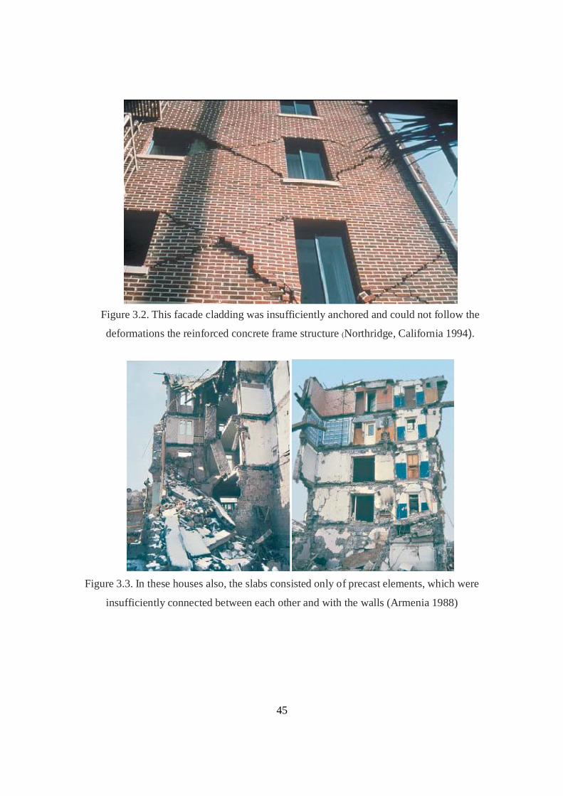
45
Figure 3.2. This facade cladding was insufficiently anchored and could not follow the
deformations the reinforced concrete frame structure (Northridge, California 1994).
Figure 3.3. In these houses also, the slabs consisted only of precast elements, which were
insufficiently connected between each other and with the walls (Armenia 1988)

46
CHAPTER 4
EARTHQUAKE ANALYSIS OF REINFORCED CONCRETE BUILDINGS
4.1 General:
Most recent earthquakes have shown that the irregularities in plan, elevation, distribution
of mass, stiffness and strengths may cause serious damage in structural systems. However an
accurate evaluation of the seismic behavior of irregular buildings is quite difficult and a
complicated problem. Due to the variety of parameters and the choice of possible models for
torsionally unbalanced systems, there is as yet neither common agreement nor any accurate
procedure advised by researchers on common practice in order to evaluate the torsional effects.
Performance of reinforced concrete structures largely depends on the strength and
deformability of constituent members, which is further, linked to the internal design forces for
the members. The internal design forces in turn depend upon the accuracy of the method
employed in their analytical determination. Analysing and designing buildings for static forces is
a routine affair these days because of availability of affordable computers and specialized
programs which can be used for the analysis. On the other hand, dynamic analysis is has a vital
role in lateral loading and requires additional input related to mass of structure, and an
understanding of structural dynamics for interpretation of analytical results.
To perform well in earthquake, a building should possess four main attributes, namely simple
and regular configuration, and adequate lateral strength, stiffness, and ductility. Buildings having
simple and regular geometry and uniformly distributed mass and stiffness suffer much less
damage.
On the other hand buildings with irregular configurations suffer seviour damage, which is
incomparable. When such irregularrities are unavoidable, these structures should be treated
specially and designed with the provision seismic joint or separation joint. These seismic joints
should be placed at appropriate place, the place of a joint should be in such away that the effects
of irregularities are avoided or at least minimized.
In the present thesis work ‘T’ irregularity is chosen by varying different parameters such
as number of stories, direction of lateral loading and width of the joint. Dynamic analysis is
adopted, for the chosen structure to study the behaviour with joint, continuous and with gap in
the structure.

47
4.2 Dynamic analysis:
Dynamic analysis represents the response of the structure to dynamic effects. Dynamic
analysis is defined as time varying response. The loads and response vary with time, so it is
evident that the dynamic problem does not have single solution as static problem dose. Thus the
internal moment and shear must equilibrate not only the externally applied force but also inertia
forces resulting from the acceleration of the structure. Inertia forces, which resist acceleration of
the structure, represent the most important distinguishing characteristic of the structural
dynamic problem s, in general if the inertial forces represent significant portion of the total
loads equilibrated by the internal elastic forces of the structure then the dynamic characteristic
of the problem must be account for this solution. In other words if the motion are very slow that
the inertia forces are negligibly small, the analysis for any desired instance of time may be made
by static structural analysis procedure even though the load response may be time varying.
There are two methods of analysis as prescribed by the code [IS: 1893-(1984 and 2002).
Bureau of Indian Standard] the two methods are listed below.
Seismic coefficient method.
Response spectrum method.
4.3 Seismic coefficient method:
In the seismic co-efficient method, the design lateral force shall first be computed for the
whole building as a whole. This design lateral force shall then be distributed to the various floor
levels. The overall design seismic force is then obtained at each floor level, shall then be
distributed to individual lateral load resisting elements depending upon the floor diaphragm
action. Seismic co-efficient that could generally be adopted in different zones of the country
though, of course a rigorous analysis considering all the factors involved has to be made in the
case of all important projects in order to arrive at a suitable seismic co-efficient for design.

48
4.4 Response spectrum method:
Response spectrum analysis is procedure to compute the peak response of a structure
during an earthquake directly from earthquake response or design spectrum without the need of
the response history analysis of the structure, by this analysis we can obtain peak response,
which is sufficiently accurate for the structural analysis of the structure.
In this method natural frequencies and mode shapes are obtained by a free vibration
analysis. For each significant natural mode, the response acceleration co-efficient (sa/g) is
obtained the code (IS: 1893-2002).
For the present thesis work response spectrum method is adopted for the dynamic analysis of the structure. 4.5 Problem description:
Building taken for seismic analysis: ‘T’ shaped unsymmetrical structure was considered. In this analysis the input parameters
were change in number of stories, joint width and earthquake loading in X and Z directions.
For the analysis, the structure considered varied in number of stories, the dimensions of
the structure are explained below with plan and isometric view figures.
Earthquake analysis has been carried out for ‘T’ shape irregularity varying different
parameters, which are listed and explained below.

49
Figure 4.1. Plan of continuous building

50
Figure 4.2. Plan of gap building
Figure 4.3. Plan of joint (Elastomer) building

51
Figure 4.4.One side selected critical columns are highlighted
Figure 4.5 .One side selected critical columns are highlighted

52
Figure 4.6. Plane view of the ten storeyed building
Figure 4.7 .Plane view of the twenty storeyed building

53
Figure 4.8. Plane view of the thirty storeyed building
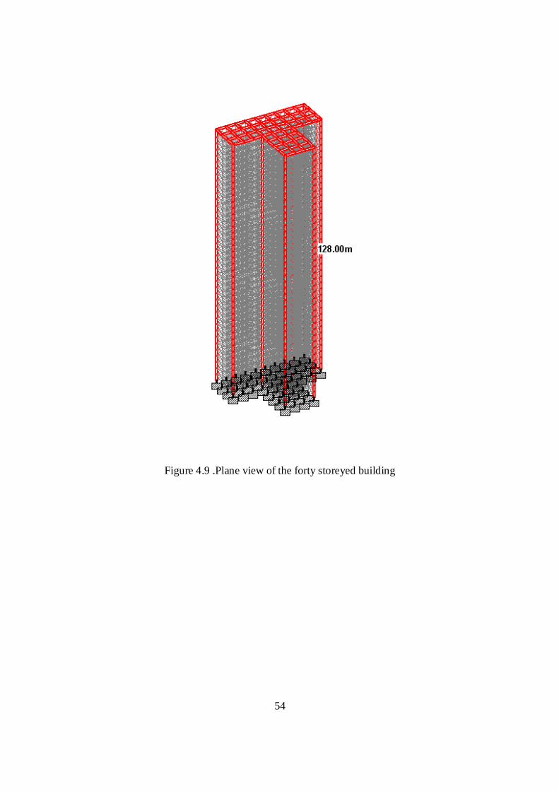
54
Figure 4.9 .Plane view of the forty storeyed building

55
4.6 Dimensions of structural members :
Floor height is considered to be 3.2m.
Column to column spacing is maintained as 5m.
Foundation depth is taken as 3.2m
Column dimensions are 600×600mm&300×600mm
Beam dimensions are 300×450mm
Walls are modeled as Infill brick walls (compression members) and thickness of wall
is assumed as 230mm.
Slabs are modeled as master slave
The master/slave option provided in STAAD allows the user to model specialized
linkages (displacement tying, rigid links) in the system. For example, SLAVE FY … connects
the two joints such that the Y displacement at the slave will be the sum of Y displacement at the
master plus the rigid rotation. The master-slave option enables us to specify rigid links or
specialized linkages in the structure. This facility can be used to model special structural
elements such as ties or a floor diaphragm which makes the floor rigid for in plane movements
4.7 Load calculations:
Self-weight is assigned which covers the dead load of beams, columns, slabs and walls.
Floor finish is assigned as 1.5kN/m2.
Live load is considered as 4 kN/m2.
Using IS 1893-2002 seismic load definition for response spectrum following
parameters are assigned
Zone III
Zone factor (Z) 0.16
Importance factor (I) as1
Response reduction factor (R) as 3
SS1
All the dead loads assigned with factor one where as live loads are assigned with factor of
0.25 in the response spectrum definition.

56
Lateral load coefficient is calculated as 0.026 (Z/2×I/R)
Combination method SRSS
Spectrum type acceleration
Interpolation type linear
Damping ratio 5 %( 0.05)
Scale 1
Sub soil class Medium soil
Torsion is assigned.
4.8 The Input Parameters:
Number of stories 10, 20,30 and 40
Direction of lateral loading X and Z
1. Joint width is varied depending upon the structure
Ten storeyed
1. Continuous
2. 13mm joint width in dir.-X
3. 18mm joint width in dir.-Z
4. Gap of 18mm & 13mm
Twenty storeyed
1. Continuous
2. 30mm joint width in dir.-X
3. 42mm joint width in dir.-Z
4. Gap of 42mm & 30mm
Thirty storeyed
1. Continuous
2. 50mm joint width in dir.-X
3. 72mm joint width in dir.-Z
4. Gap of 50mm & 72mm
Forty storeyed
1. Continuous
2. 76mm joint width in dir.-X

57
3. 110mm joint width in dir.-Z
4. Gap of 76mm & 110mm
For the above given input parameters the above shown models are analysed. The
resultant moments, axial force, and eccentricities are compared for different variant input
parameters.
Ten storeyed building:
Maximum story drift = 11.807mm
Joint width = R/2 × maximum story drift
= 3/2 ×11.807mm
= 17.71mm (approx 18mm)
Twenty storeyed building:
Maximum story drift = 27.801mm
Joint width = R/2 × maximum story drift
= 3/2 ×27.801
= 41.70mm (approx 42mm)
Thirty storeyed building:
Maximum story drift = 47.795mm
Joint width = R/2 × maximum story drift
= 3/2 ×47.795
= 71.69mm (approx 72mm)
Forty storied building:
Maximum story drift = 73.272mm
Joint width = R/2 × maximum story drift
= 3/2 ×73.272
= 109.908mm (approx 110mm)

58
CHAPTER 5
RESULTS AND DISCUSSIONS 5.1 Results Column Moments and Axial Force Results (One Side Critical Columns): Table 5.1 Comparison of axial load in columns varying in joint width for a ten storeyed building
with earthquake loading in ‘Z’ direction
Axial force in kN 10 storeyed dir-Z
Column nos.
Continuous Gap (18mm)
Joint (18mm)
103 15265 15899 15930
104 14657 15317 15348
124 10909 10625 10646
130 3827 10857 10911
131 3169 10356 10394
134 12389 13490 13515
149 13231 14012 14038
150 10925 13563 13589

59
Table 5.2 Comparison of axial load in columns varying in joint width for a ten storeyed building
with earthquake loading in ‘Z’ direction
Moment (My) in (kN-m) 10 storeyed dir-Z
Column Continuous Gap(18mm)
Joint(18mm)
nos.
103
2770 2669 2638
104
2764 2662 2668
124
2898 2791 2798
130
522 419 447
131
522 443 444
134
2762 2661 2667
149
2769 2668 2674
150
2763 2661 2667
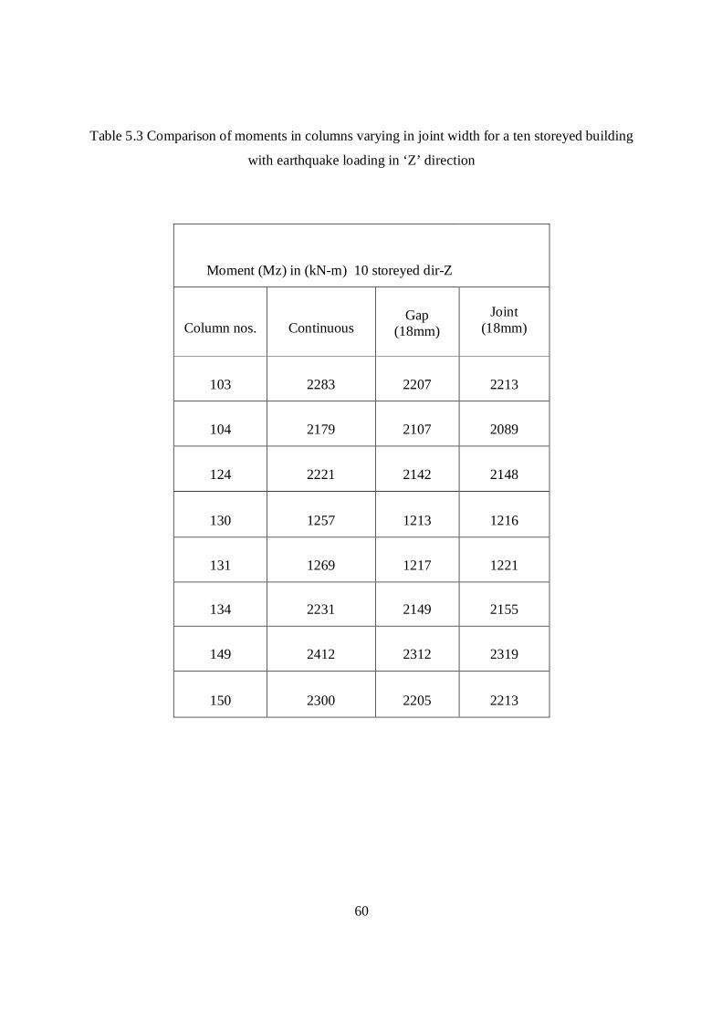
60
Table 5.3 Comparison of moments in columns varying in joint width for a ten storeyed building
with earthquake loading in ‘Z’ direction
Moment (Mz) in (kN-m) 10 storeyed dir-Z
Column nos.
Continuous Gap
(18mm)
Joint
(18mm)
103 2283 2207 2213
104 2179 2107 2089
124 2221 2142 2148
130 1257 1213 1216
131 1269 1217 1221
134 2231 2149 2155
149 2412 2312 2319
150 2300 2205 2213

61
Table 5.4 Comparison of axial load in columns varying in joint width for a twenty
storeyed building with earthquake loading in ‘Z’ direction
Axial force in (kN) 20 storeyed dir-Z
Column nos. Continuous
Gap (42mm)
Joint (42mm)
103 48673 58180 58283
104 47720 57659 57761
124 36772 35573 35650
130 5654 38089 38161
131 7038 36582 36638
134 39728 42799 55628
149 48386 56938 57040
150 48083 56646 56749

62
Table 5.5 Comparison of moments in columns varying in joint width for a ten storeyed building
with earthquake loading in ‘Z’ direction
Moment (My) in (kN-m) 20 storeyed dir-Z
Column nos. Continuous
Gap (42mm)
Joint (42mm)
103 5637 5841 5855
104 5630 5834 5848
124 5920 6134 6149
130 1074 961 963
131 1070 956 958
134 5627 5831 5844
149 5635 5839 5852
150 5628 5832 5845

63
Table 5.6 Comparison of moments in columns varying in joint width for a twenty storeyed
building with earthquake loading in ‘Z’ direction
Moment (Mz) in (kN-m) dir-Z
Column nos.
Continuous
Gap (42mm)
Joint (42mm)
103 4608 4459 4470
104 4384 4243 4254
124 4472 4319 4331
130 2552 2468 2476
131 2571 2478 2486
134 4507 4348 4360
149 4908 4715 4732
150 4667 4484 4500

64
Table 5.7 Comparison of axial load in columns varying in joint width for a thirty storeyed
building with earthquake loading in ‘Z’ direction
Axial force in (kN) 30 storeyed dir-Z
Column nos. Continuous Gap Joint
72(mm) 72(mm)
103 95644 123000 123000
104 94098 123000 123000
124 76910 74304 74507
130 8446 79018 78974
131 76410 76364 1623
134 73242 68117 68282
149 106000 129000 130000
150 106000 129000 129000

65
Table 5.8 Comparison of moments in columns varying in joint width for a thirty storeyed
building with earthquake loading in ‘Z’ direction
Moment (My) in (kN-m) 30 storeyed dir-Z
Column Continuous Gap Joint
72(mm) 72(mm)
103 8535 8958 8981
104 8528 8952 8975
124 8971 9410 9434
130 1631 1461 1465
131 1623 1453 1457
134 8522 8942 8965
149 8530 8951 8974
150 8524 8944 8967

66
Table 5.9 Comparison of moments in columns varying in joint width for a thirty storeyed
building with earthquake loading in ‘Z’ direction
Moment (Mz) in (kN-m) 30 storeyed dir-Z
Column Continuous Gap Joint
72(mm) 72(mm)
103 6948 6726 6746
104 6604 6395 6413
124 6744 6518 6539
130 3859.4 3739 3752
131 3886 3754 3767
134 6805 6570 6592
149 7435 7154 7183
150 7064 6798 6825

67
Table 5.10 Comparison of axial load in columns varying in joint width for a forty storeyed
building with earthquake loading in ‘Z’ direction
Axial force in (kN) 40 storeyed dir-Z
Column Continuous Gap Joint
(110mm) (110mm)
103 125000 176000 181000
104 139000 143000 144000
124 131000 127000 128000
130 10852 114000 117000
131 17663 127000 130000
134 81111 188000 192000
149 186000 230000 232000
150 186000 230000 232000

68
Table 5.11 Comparison of moments in columns varying in joint width for a forty storeyed
building with earthquake loading in ‘Z’ direction
Moment (My) in (kN-m) 40 storeyed dir-Z
Column Continuous Gap Joint
(110mm) (110mm)
103 11463 11333 12221
104 11456 11327 12215
124 12050 11893 12830
130 2192 1832 1979
131 2180 1823 1969
134 11446 11307 12195
149 11454 11318 12205
150 11447 11311 12198

69
Table 5.12 Comparison of moments in columns varying in joint width for a forty storeyed
building with earthquake loading in ‘Z’ direction
Moment (Mz) in (kN-m) 40 storeyed dir-Z
Column Continuous Gap Joint
(110mm) (110mm)
103 9309 9014 9043
104 8845 8567 8595
124 9037 8737 8772
130 5177 5021 5043
131 5213 5040 5063
134 9123 8812 8851
149 9983 9609 9665
150 9482 9129 9182

70
Table 5.13 Comparison of axial load in columns varying in joint width for a ten storeyed
building with earthquake loading in ‘X’ direction
Axial force in (kN) 10 storeyed dir-X
Column nos.
Continuous Gap (13mm)
Joint (13mm)
103 13453 13971 14001
104 12848 13389 13418
124 3761 11945 11965
130 3169 9577 9630
131 11274 9134 9172
134 11227 11869 11894
149 11738 12387 12413
150 12373 12210 12234

71
Table 5.14 Comparison of moments in columns varying in joint width for a ten storeyed building
with earthquake loading in ‘X’ direction
Moment (My) in (kN-m) 10 storeyed dir-X
Column nos. Continuous Gap (13mm)
Joint (13mm)
103 2328 2237 2243
104 2298 2207 2213
124 438 2337 2343
130 439 375 376
131 2327 373 374
134 2320 2229 2235
149 2327 2236 2242
150 2320 2230 2236

72
Table 5.15 Comparison of moments in columns varying in joint width for a ten storeyed
Building with earthquake loading in ‘X’ direction
Moment (Mz) in (kN-m) 10 storeyed dir-X
Column nos. Continuous Gap
(13mm)
Joint
(13mm)
103 2719 2635 2640
104 2593 2513 2518
124 1498 2555 2561
130 1510 1449 1452
131 2788 1454 1458
134 2657 2566 2572
149 2877 2766 2773
150 2741 2636 2643
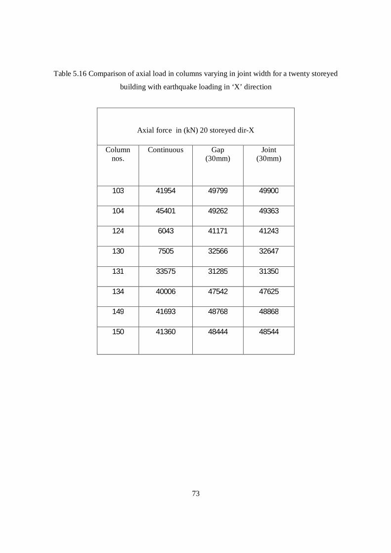
73
Table 5.16 Comparison of axial load in columns varying in joint width for a twenty storeyed
building with earthquake loading in ‘X’ direction
Axial force in (kN) 20 storeyed dir-X
Column nos.
Continuous
Gap (30mm)
Joint (30mm)
103 41954 49799 49900
104 45401 49262 49363
124 6043 41171 41243
130 7505 32566 32647
131 33575 31285 31350
134 40006 47542 47625
149 41693 48768 48868
150 41360 48444 48544

74
Table 5.17 Comparison of moments in columns varying in joint width for a twenty storeyed
building with earthquake loading in ‘X’ direction
Moment (My) in (kN-m) 20 storeyed dir-X
Column nos.
Continuous
Gap (30mm)
Joint (30mm)
103 4700 4857 4870
104 4693 4851 4863
124 895 5098 5111
130 892 801 803
131 4697 796 798
134 4690 4847 4860
149 4698 4855 4868
150 4691 4848 4861
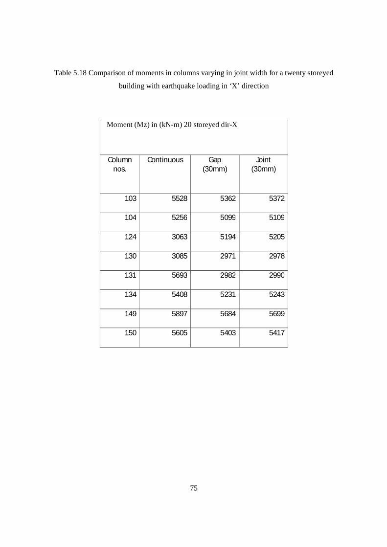
75
Table 5.18 Comparison of moments in columns varying in joint width for a twenty storeyed
building with earthquake loading in ‘X’ direction
Moment (Mz) in (kN-m) 20 storeyed dir-X
Column nos.
Continuous
Gap (30mm)
Joint (30mm)
103 5528 5362 5372
104 5256 5099 5109
124 3063 5194 5205
130 3085 2971 2978
131 5693 2982 2990
134 5408 5231 5243
149 5897 5684 5699
150 5605 5403 5417

76
Table 5.19 Comparison of axial load in columns varying in joint width for a thrity storeyed
building with earthquake loading in ‘X’ direction
Axial force in (kN) 30 storeyed dir-X
Column nos.
Continuous
Gap (50mm)
Joint (50mm)
103
81609
104000
104000
104 96185 104000 104000
124
89973
87068
87247
130
8446
7836
7893
131
10921
64631
64658
134
65150
59307
59438
149
20722
21613
21660
150 89938 109000 109000

77
Table 5.20 Comparison of moments in columns varying in joint width for a thrity storeyed
building with earthquake loading in ‘X’ direction
Moment (My) IN (kN-m) 30 storeyed dir-X
Column nos.
Continuous
Gap (50mm)
Joint (50mm)
103
7059
7393 7414
104
7090
7423
7444
124
7456
7801
7823
130
1356
1213
1217
131
1342
1181
1184
134
7085
7415
7436
149
7093
7423
7444
150
7086
4179
7437
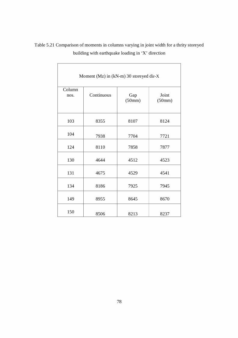
78
Table 5.21 Comparison of moments in columns varying in joint width for a thrity storeyed
building with earthquake loading in ‘X’ direction
Moment (Mz) in (kN-m) 30 storeyed dir-X
Column nos.
Continuous
Gap
(50mm)
Joint
(50mm)
103
8355
8107
8124
104 7938 7704
7721
124
8110
7858
7877
130
4644
4512
4523
131
4675
4529
4541
134
8186
7925
7945
149
8955
8645
8670
150 8506 8213
8237

79
Table 5.22 Comparison of axial load in columns varying in joint width for a forty storeyed
building with earthquake loading in ‘X’ direction
Axial force in (kN) 40 storeyed dir-X
Column nos.
Continuous
Gap (76mm)
Joint (76mm)
103
132000
173000
178000
104 164000 173000 177000
124
155000
139000
140000
130
10852
110000
112000
131
25092
107000
109000
134
148000
156000
157000
149
157000
193000
195000
150 157000 193000 195000

80
Table 5.23 Comparison of moments in columns varying in joint width for a forty storeyed
building with earthquake loading in ‘X’ direction
Moment (My) in (kN-m) 40 storeyed dir.-X
Column nos.
Continuous
Gap (76mm)
Joint (76mm)
103
9519
9387
10125
104
9512
9381
10118
124
10003
9847
10626
130
1819 1519
1641
131
1810
1511
1633
134
9504
9364
10102
149
9511
9374
10111
150
9504
9367
10104

81
Table 5.24 Comparison of moments in columns varying in joint width for a forty storeyed building with
earthquake loading in ‘X’ direction
Moment (Mz) in (kN-m) 40 Storeyed dir-X
Column nos.
Continuous
Gap (76mm)
Joint (76mm)
103
11206
8862
8856
104 10645 8420 8415
124
10881
8771
8792
130
6237
5093
5112
131
6279
5115
5135
134
10989
8938
8971
149
12039
10128
10219
150 11433 9623 9710

82
Table 5.25 Joint displacements when earth quake loading in ‘X’ and ‘Z’ directions for 10,20,30
and 40 storeyed structures
Joint displacements when earth quake loading in ‘X’ and ‘Z’ directions
Directions Of
Loading
Storeyed
Continuous
Gap
Joint
X
10 10 10 10
20 23 22 23
30 39 39 40
40 60 57 60
Z
10 14 14 15
20 36 38 38
30 67 79 78
40 108 140 139

83
Figure 5.1 Comparison of column joint displacement continuous structure with gap and joint
structures 10,20,30&40 storeyed buildings with earthquake loading in ‘X’ direction
Figure 5.2 Comparison of column joint displacement continuous structure with gap and joint
structures for 10,20,30&40 storeyed buildings with earthquake loading in ‘Z’ direction.
0.5%
2.5%
0.5%
5%
3.5%
3.5%
2%
1%
0
10
20
30
40
50
60
70
Join
t disp
lace
men
t in
(mm
)
10storeyed 20storeyed 30storeyed 40storeyed In 'X' Direction
CONTINUOUS
GAP
JOINT
2%
6.5%
18%
29%
10%
5.5%
17.5%
29%
0
20
40
60
80
100
120
140
160
Join
t disp
lace
men
t in
(mm
)
10storeyed 20storeyed 30storeyed 40storeyed In 'Z' Direction
CONTINUOUS
GAP
JOINT

84
Figure 5.3 Comparison of column axial force continuous with gap and joint structures for
10,20,30&40 storeyed buildings with earthquake loading in ‘X’ direction.
Figure 5.4 Comparison of column axial force continuous structure with gap and joint for
10,20,30&40 storeyed buildings with earthquake loading in ‘Z’ direction.
4%
8.5%
8%
5.5%
4.5%
9%
8%
8%
020000400006000080000
100000120000140000160000180000200000
Axi
al fo
rce
in (k
N)
10storeyed 20storeyed 30storeyed 40storeyedColumn 104 in 'X' direction
CONTINUOUS
GAP
JOINT
4.5%
21%
29.5%1.5%
5%
21%
33%3%
0
20000
40000
60000
80000
100000
120000
Axi
al fo
rce
in (k
N)
10storeyed 20storeyed 30storeyed 40storeyedColumn 104 in 'Z' direction
CONTINUOUS
GAP
JOINT

85
Figure 5.5 Comparison of column moment continuous structure with gap and joint structures for
10,20,30&40 storeyed buildings with earthquake loading in ‘X’ direction.
Figure 5.6 Comparison of column moment continuous structure with gap and joint structures
10,20,30&40 storeyed buildings with earthquake loading in ‘Z’ direction.
3%
3%
3% 21%
3%
3%
3% 21%
0
2000
4000
6000
8000
10000
12000M
omen
t in
(kN
-m)
10storeyed 20storeyed 30storeyed 40storeyedColumn 104 in 'X' direction
CONTINUOUS
GAP
JOINT
3%
3%
3%
3%
4%
3%
3%
3%
0100020003000400050006000700080009000
10000
Mom
ent i
n (k
N-m
)
10storeyed 20storeyed 30storeyed 40storeyedColumn 104 in 'Z' direction
CONTINUOUS
GAP
JOINT

86
Figure 5.7 Comparison of column axial force continuous structure with gap and joint structures
for 10,20,30&40 storeyed buildings with earthquake loading in ‘X’ direction.
Figure 5.8 Comparison of column axial force continuous structure with gap and joint structures
10,20,30&40 storeyed buildings with earthquake loading in ‘Z’ direction
1.3%
17%
21%
23%
1.3%
17%
21%
25%
0
50000
100000
150000
200000
250000
Axi
al fo
rce
in (k
N-m
)
10storeyed 20storeyed 30storeyed 40storeyedColumn 150 in'x' direction
CONTINUOUS
GAP
JOINT
24%
18%
22%
24%
24.5%
18%
22%
25%
0
50000
100000
150000
200000
250000
Axi
al fo
rce
IN (k
N-m
)
10storeyed 20storeyed 30storeyed 40storeyedColumn 150 in 'Z' direction
CONTINUOUS
GAP
JOINT

87
Figure 5.9 Comparison of column moment continuous structure with gap and joint structures for
10,20,30&40 storeyed buildings with earthquake loading in ‘X’ direction
Figure 5.10 Comparison of column moment continuous structure with gap and joint structures
for 10,20,30&40 storeyed buildings with earthquake loading in ‘Z’ direction
4%
3.5%
3.5%16%
3.5%
3.5%
3%15%
0
2000
4000
6000
8000
10000
12000
14000
Mom
ent i
n (k
N-m
)
10storeyed 20storeyed 30storeyed 40storeyedColumn 150 in 'X' direction
CONTINUOUS
GAP
JOINT
4%
4%
4%
4%
4%
3.5%
3.5%
3%
0100020003000400050006000700080009000
10000
Mom
ent i
n (k
N-m
)
10storeyed 20storeyed 30storeyed 40storeyedColumn 150 'Z' direction
CONTINUOUS
GAP
JOINT

88
Table 5.26 Eccentricity results: T-shape 10, 20, 30&40 storeyed earthquake loading in both X &Z directions:
Serial number
Type of structure Eccentricity in X - direction
Eccentricity in Z -direction
1
Continuous 25 10
2
Joint 25 10
3 Gap (no plastic material)
25 10
5.2 Discussions 5.2.1 Column Moments for Gap and Joint Structure:
For corner column 104 When loading in ‘X’-direction the decrement in Moments Gap
and Joint structures when compare to continuous structure 10, 20, 30 and 40 storeyed are 3%-
3%, 3%-3%, 3%-3% and 21%-21% respectively.
For corner column 104 When loading in ‘Z’-direction the decrement Moment in Gap and
Joint structures when compare to continuous structure 10,20,30 and 40 storeyed are 3%-4%, 3%-
3%, 3%-3% and 3%-3% respectively
5.2.2 Axial Force for Gap and Joint Structure:
For corner column 104 When loading in ‘X’-direction the increment in Axial force Gap
and Joint structures when compare to continuous structure 10, 20, 30 and 40 storeyed are 4%-
4.5%, 8.5%-9%, 8%-8% and 5.5%-8% respectively.
For corner column 104 When loading in ‘Z’-direction the increment in Axial force Gap
and Joint structures when compare to continuous structure 10, 20, 30 and 40 storeyed are 4.5%-
5%, 21%-21%, 29.5%-33% and 1.5%-3% respectively.

89
5.2.3 Column moments for gap and joint structure:
For corner column 150 When loading in ‘X’-direction the decrement in Moments Gap
and Joint structures when compare to continuous structure 10, 20, 30 and 40 storeyed are 4%-
3.5%, 3.5%-3.5%, 3.5%-3% and 16%-15% respectively.
For corner column150 When loading in ‘Z’-direction the decrement in Moments Gap and
Joint structures when compare to continuous structure 10, 20, 30 and 40 storeyed are 4%-4%,
4%-3.5%, 4%-3.5% and 4%-3% respectively.
5.2.4 Axial force for gap and joint structure:
For corner column 150 When loading in ‘X’-direction the increment in Axial force Gap
and Joint structures when compare to continuous structure 10, 20, 30 and 40 storeyed are 1.3%-
1.3%, 17%-17%, 21%-21% and 23%-25% respectively.
For corner column 150 When loading in ‘Z’-direction the increment in Axial force Gap
and Joint structures when compare to continuous structure 10, 20, 30 and 40 storeyed are 24%-
24.5%, 18%-18%, 22%-22% and 24%-25% respectively
5.2.5 Joint displacement for ‘X’ and ‘Z’-directions:
When loading in ‘X’-direction the increment in Joint displacement Gap and Joint
structures when compare to continuous structure 10, 20, 30 and 40 storeyed are 0.5%-3.5%,
2.5%-3.5%, 0.5%-2% and 5%-1% respectively.
When loading in ‘Z’-direction the increment in Joint displacement Gap and Joint
structures when compare to continuous structure 10, 20, 30 and 40 storeyed are 2%-10%, 6.5%-
5.5%, 18%-17.5% and 29%-29% respectively

90
5.2.6 Eccentricity:
The eccentricity in ‘X’ direction is 25, and `Z’ direction is 10, in T-shaped three types of
structures (continuous, gap, & joint) the eccentricity is same.

91
5.3 Conclusions In the present work ’T’ shape plan irregular building is considered for the analysis
(a) Continuous buildings
(b) Gap buildings
(c) Joint with Elastomer buildings
Based on the work carried out, the following conclusions are drawn.
For taller buildings (40storeyed):
a) Provision of seismic joints with elastomers would reduce the column moments (Mz) by
about 25% and (My) increasing 7% when compared to a continuous structure. But the
axial forces are increasing by about 25%
b) Provision of seismic joints with elastomers would increase maximum joint displacement by 29%
when compared to a continuous building
For shorter buildings (10storeyed):
a) Provision of seismic joints with elastomers would reduce the column moments (Mz)
and(My) by about 4% when compared to a continuous structure. But the axial forces are
increasing by about 5%
b) Provision of seismic joints with elastomers would increase maximum joint displacement
by 10% when compared to a continuous building

92
SCOPE OF FUTURE STUDY
1 Other irregularities such as ‘H’, ’X’, ’C’ vertical and mass irregularities may be
studied
2. Effect of seismic joints on irregular buildings with soft storey.
3. Irregular buildings may be analysed and compared the results of seismic coefficient
method and response spectrum method.

93
REFERENCES
1. J. Proença, Carlos S. Oliveira and J.P. Almeida: Performance-Based Design, Seismic
Assessment, Masonry Infilled Structures, the case of block # 22 of the santa maria
hospital in Lisbon, ICIST/IST, Av. Rovisco Pais, Nº 1, 1049-001, Lisbon, Portugal in
September 2002
2. Murthy C.V.R., “Preparing for earthquakes where India stands”,The Newsletter of IIT
Kanpur. Vol 3(2), May 2000.
3. T.Slak and V.Kilar: Initial conceptual design of Earthquake resistantant reinforced
concrete and masonry buildings according. University of Ljubljana, Faculty of
Architecture, Slovenia
4. Emilla Juhasova: Effect of structural integrity in improving the resistance to dynamic
loads. Dubravska cesta 9,845 03 Brastislava, Slovakia May 2003
5. Hemanth B.Kaushik Durgeshc Rai, and Sudhir K Jain: Scientific correspondence: A
case for use of dynamic analysis in designing for Earthquake forces, current science,
vol.91, No.7, 10 October 2006.
6. Somayya Ammanagi S. Venkatesher and C.S. Manahor: Analytical and experimental
investigations into structural damage identification using vibrating data.DCE, IIT
Bangalore Vol.31(1) June 2004
7. V.Jaya, Gr. Dodagoudar and Boominathan: Soil-foundation-structure interaction;
ventilation stack: finite method: SASSI 2000; response spectrum: peak accerlation.
8. Sanajaya Kumar Patro and Ravi Sinha: Earthquake-resistant structures; energy
dissipation; optimization; passive control; performance evaluation vibration control.DCE,
IIT Bombay, Powai 400076, 26 March 2008
9. S.R.Balisubramanink K.Balaji Rao: Seismic vulnerability regional risk analysis;
expected seismic loss; brick masonry buildings.CSIR campus,Taramani,Chennai 26 June
2009.
10. Sudhir Kumar Jain: Analytical models for the dynamics of the building ERL 83-02.

94
11. Ugur Ersoy : Seismic Resistant Reinforced Concrete Structures-Desig Principles,
Journal of Islamic Academy of Sciences 1:1, 20-26,1988