FINAL THESIS SMITHURST.pdf
386
University of Huddersfield Repository Smithurst, Peter G. The Development, Technology and Application of Mechanised Manufacture to the Enfield Pattern 1853 Rifle and the Achievement of Interchangeability Original Citation Smithurst, Peter G. (2020) The Development, Technology and Application of Mechanised Manufacture to the Enfield Pattern 1853 Rifle and the Achievement of Interchangeability. Doctoral thesis, University of Huddersfield. This version is available at http://eprints.hud.ac.uk/id/eprint/35383/ The University Repository is a digital collection of the research output of the University, available on Open Access. Copyright and Moral Rights for the items on this site are retained by the individual author and/or other copyright owners. Users may access full items free of charge; copies of full text items generally can be reproduced, displayed or performed and given to third parties in any format or medium for personal research or study, educational or not-for-profit purposes without prior permission or charge, provided: • The authors, title and full bibliographic details is credited in any copy; • A hyperlink and/or URL is included for the original metadata page; and • The content is not changed in any way. For more information, including our policy and submission procedure, please contact the Repository Team at: [email protected]. http://eprints.hud.ac.uk/
-
Upload
khangminh22 -
Category
Documents
-
view
3 -
download
0
Transcript of FINAL THESIS SMITHURST.pdf

University of Huddersfield Repository
Smithurst, Peter G.
The Development, Technology and Application of Mechanised Manufacture to the Enfield Pattern 1853 Rifle and the Achievement of Interchangeability
Original Citation
Smithurst, Peter G. (2020) The Development, Technology and Application of Mechanised Manufacture to the Enfield Pattern 1853 Rifle and the Achievement of Interchangeability. Doctoral thesis, University of Huddersfield.
This version is available at http://eprints.hud.ac.uk/id/eprint/35383/
The University Repository is a digital collection of the research output of theUniversity, available on Open Access. Copyright and Moral Rights for the itemson this site are retained by the individual author and/or other copyright owners.Users may access full items free of charge; copies of full text items generallycan be reproduced, displayed or performed and given to third parties in anyformat or medium for personal research or study, educational or not-for-profitpurposes without prior permission or charge, provided:
• The authors, title and full bibliographic details is credited in any copy;• A hyperlink and/or URL is included for the original metadata page; and• The content is not changed in any way.
For more information, including our policy and submission procedure, pleasecontact the Repository Team at: [email protected].
http://eprints.hud.ac.uk/

THE DEVELOPMENT, TECHNOLOGY AND APPLICATION OF MECHANISED MANUFACTURE TO THE ENFIELD PATTERN 1853 RIFLE AND THE ACHIEVEMENT OF INTERCHANGEABILITY
1
THE DEVELOPMENT, TECHNOLOGY AND APPLICATION OF MECHANISED MANUFACTURE TO THE ENFIELD PATTERN
1853 RIFLE AND THE ACHIEVEMENT OF INTERCHANGEABILITY
PETER G. SMITHURST
A thesis submitted to the University of Huddersfield In partial fulfilment of the requirements for the degree of
Doctor of Philosophy
School of Computing and Engineering The University of Huddersfield
April 2020

THE DEVELOPMENT, TECHNOLOGY AND APPLICATION OF MECHANISED MANUFACTURE TO THE ENFIELD PATTERN 1853 RIFLE AND THE ACHIEVEMENT OF INTERCHANGEABILITY
2

THE DEVELOPMENT, TECHNOLOGY AND APPLICATION OF MECHANISED MANUFACTURE TO THE ENFIELD PATTERN 1853 RIFLE AND THE ACHIEVEMENT OF INTERCHANGEABILITY
3
COPYRIGHT
1. The author of this thesis, (including any appendices, newly created drawings and/or diagrams and/or any schedules to this thesis), owns any copyright in it (the “Copyright”) and he has given The University of Huddersfield the right to use such copyright for administrative, promotional, educational and/or teaching purposes.
2. Copies of this thesis, either in full or in extracts, may be made only in accordance with the regulations of the University Library. Details of these regulations may be obtained from the Librarian. This page must form part of any such copies made.
3. The ownership of any patents, designs, trademarks and any and all other intellectual property rights except for the Copyright (the “Intellectual Property Rights) and any reproduction of copyright works, for example graphs and tables (“Reproductions”) which may be described in this thesis, may not be owned by the author and may be owned by third parties. Such Intellectual Property Rights and Reproductions cannot and must not be made available for use without the prior written permission of the owner(s) of the relevant Intellectual Property Rights and/or Reproductions.

THE DEVELOPMENT, TECHNOLOGY AND APPLICATION OF MECHANISED MANUFACTURE TO THE ENFIELD PATTERN 1853 RIFLE AND THE ACHIEVEMENT OF INTERCHANGEABILITY
4

THE DEVELOPMENT, TECHNOLOGY AND APPLICATION OF MECHANISED MANUFACTURE TO THE ENFIELD PATTERN 1853 RIFLE AND THE ACHIEVEMENT OF INTERCHANGEABILITY
5
ABSTRACT
This thesis provides for the first time a detailed study of the mechanised
manufacture of the Enfield rifle and the achievement of interchangeability. It includes many new insights into the technology and processes employed.
These insights are derived from evidence presented by previously unstudied material and documentary sources combined with an understanding of the requirements of the rifle and of the machining operations to achieve them.
From 1857 onwards, the interchangeable manufacture of the Enfield Pattern 1853 rifle was accomplished through the extensive use of technology developed in the United States by the middle of the 19th century. The technology embodied many novel features:
1. Traditionally many components were produced by the fluid transfer of the actions of the craftsman from one feature to the next: with mechanisation, many of those features had to be created separately by highly specialised machines.
2. Machines needed to be designed to perform each of these stages sequentially, either on a single machine or using a series of machines. It was necessary that each stage be carefully planned so it did not impede the succeeding stage.
3. While the machines were sophisticated, they were not generally ‘self-acting’ and required a manual operator.
4. The careful planning of operations can be considered the beginnings of ‘production engineering’.
5. Uniformity was achieved by the use of guides, jigs, fixtures and gauges. 6. Those machines which performed operations in sequence might be likened to
the CNC machines of today in which the manual operator and the guides, jigs and fixtures have been replaced by the computer program and stepper motors. Following a brief introduction to the functional elements of the Enfield rifle,
this thesis then proceeds to show how those technologies brought about radical changes in the procurement system and, more importantly, how they were applied to the manufacture of the three principal components of the rifle – lock, stock and barrel.

THE DEVELOPMENT, TECHNOLOGY AND APPLICATION OF MECHANISED MANUFACTURE TO THE ENFIELD PATTERN 1853 RIFLE AND THE ACHIEVEMENT OF INTERCHANGEABILITY
6

THE DEVELOPMENT, TECHNOLOGY AND APPLICATION OF MECHANISED MANUFACTURE TO THE ENFIELD PATTERN 1853 RIFLE AND THE ACHIEVEMENT OF INTERCHANGEABILITY
7
LIST OF CONTENTS
COPYRIGHT 3 ABSTRACT 5 LIST OF CONTENTS 7 LIST OF FIGURES 13 DECLARATION 31 ACKNOWLEDGEMENTS 33 LIST OF PUBLICATIONS 35 Chapter 1: INTRODUCTION AND LITERATURE REVIEW 37 1.1 Background - outline of events contributing
to the introduction of mechanised interchangeable manufacture at Enfield 38 1.2 Contemporary accounts of manufacture 39 1.3 The wider historical background and extended review
of the literature 40 1.4 The American system of manufacture 54 1.5 Gauging 57 1.6 Motivation for this study 59 1.7 Aims and objectives 59 1.8 Structure of the thesis 60 Chapter 2: THE BASIC TECHNOLOGY OF THE ENFIELD RIFLE 63
2.1 Overview 64 2.2 Fundamentals of the percussion system of ignition 64 2.3 The lock 65 2.4 Operation of the lock 67 2.5 The barrel 68 2.6 Rifling 70 2.7 The conundrum of a muzzle-loading rifle 71 2.8 Solutions to the problem of muzzle-loading rifles 72 2.9 Minié’s Solution 75 2.10 Minié’s system adapted and adopted 76 2.11 The stock 77 Chapter 3: ORIGINS AND PROCUREMENT 79
3.1 Origin of the Pattern 1853 rifle 80 3.2 Procurement by contract 82 3.3 Discontent amongst contractors 85 3.4 Discontent of the government 86

THE DEVELOPMENT, TECHNOLOGY AND APPLICATION OF MECHANISED MANUFACTURE TO THE ENFIELD PATTERN 1853 RIFLE AND THE ACHIEVEMENT OF INTERCHANGEABILITY
8
3.5 Select Committee on Small Arms 90 3.6 Pursuit of mechanisation
3.6.1 The lock 93 3.6.2 The stock 93 3.6.3 The barrel 94
3.7 The Committee on Machinery 94 3.8 Equipping the Enfield factory 95 3.9 Specifications of the Pattern 1853 Enfield rifle 97 3.10 ‘Viewing’ and inspection procedures 100 3.11 Operations at Enfield 104 3.12 Summary 108 Chapter 4: MANUFACTURE OF THE LOCK 111 4.1 Overview 112 4.2 Forging the lockplate 115 4.3 Machining the lockplate
4.3.1 Machining the outer face 116 4.3.2 Machining the inner face 117 4.3.3 Drilling the lockplate holes 120 4.3.4 Machining the lockplate edges 124 4.3.5 Gauging the lockplate 133
4.4 The hammer 136 4.4.1. Gauging the hammer 143
4.5 The tumbler 144 4.5.1. Gauging the tumbler 148
4.6 The sear 150 4.6.1. Gauging the sear 152
4.7 The bridle 152 4.7.1 Gauging the bridle 155
4.8 The swivel 156 4.8.1. Gauging the swivel 158
4.9 The mainspring 158 4.9.1. Gauging the mainspring 160
4.10 The sear spring and its gauging 160 4.11 The screws and their gauging 161 4.12 Gauging the assembled lock 165 4.13 Some metrology of the Enfield lockplates 166
4.13.1. Tower 1855 lockplates 168 4.13.2. Belgian 1856 lockplates 171 4.13.3. Damage revealed in the metrology process 172 4.13.4. Questions surrounding the inspection of contract locks 173 4.13.5 Further metrology and interchangeability 174
4.14 Summary 178
Chapter 5: MANUFACTURE OF THE STOCK 181 5.1 Overview 182 5.2 The advent of mechanisation 183 5.3 Blanchard’s developments in the United States in 1819 184 5.4 Equipping the Enfield factory 189 5.5 The Enfield stock 190

THE DEVELOPMENT, TECHNOLOGY AND APPLICATION OF MECHANISED MANUFACTURE TO THE ENFIELD PATTERN 1853 RIFLE AND THE ACHIEVEMENT OF INTERCHANGEABILITY
9
5.5.1 Slabbing 194 5.5.2 Centering 196 5.5.3 Rough-turning the fore end 196 5.5.4 Rough-turning the butt 200 5.5.5 Spotting 202 5.5.6 Bedding the barrel 205 5.5.7 Hand-finishing the recess for the breech tang 209 5.5.8 Stock sawn to length at butt and muzzle; butt shaped
to receive the butt plate 209 5.5.9 Planing the stock 211 5.5.10 Tang of the butt plate let in; holes for screws
are bored and tapped 214 5.5.11 Bedding the lock 220
5.5.11.1 Recessing for the lockplate 224 5.5.11.2 Recessing for the screw heads 226 5.5.11.3 Drilling the hole for the sear tang 229 5.5.11.4 Recessing for the mainspring 229
5.5.12 Bedding the trigger guard, drilling screw holes, cutting recess for trigger plate and ramrod stop 232
5.5.13 Stock cut for the bands from a copy and the nose cap let on 236
5.5.14 Stock turned between the bands 236 5.5.15 Arris at the extreme muzzle-end of the stock
under the flange of the nosecap taken off by hand 240 5.5.16 Butt end of the stock and fore-end of stock between
lock and first [bottom] band finish turned in a copying lathe 240 5.5.17 Stock grooved for ramrod 242 5.5.18 Recessed for the ramrod spring and transverse
hole for fixing pin bored 243 5.5.19 Hole bored for ramrod 245 5.5.20 Holes for lockplate fxing screws, breech tang screw,
nosecap screw and pin hole for tenon of trigger guard are bored 246
5.6 Gauging 248 5.7 Summary 251 Chapter 6: The barrel - Part 1 – creating the tube 253
6.1 Overview 254 6.2 Specifications for the Enfield barrel 254 6.3 Manufacture of the barrel tube
6.3.1 Creating the ‘mould’ 255 6.3.2 Creating the seamed tube 257 6.3.3 Welding the seam 258 6.3.4 Tapering 261 6.3.5 Straightening 264 6.3.6 ‘Lumping’ 265
6.4 Summary 266 Chapter 7: The barrel - Part 2 – finishing the barrel 267
7.1 Overview 268

THE DEVELOPMENT, TECHNOLOGY AND APPLICATION OF MECHANISED MANUFACTURE TO THE ENFIELD PATTERN 1853 RIFLE AND THE ACHIEVEMENT OF INTERCHANGEABILITY
10
7.2 Equipping the Enfield Factory 268 7.3 Manufacture
7.3.1 First Rough-boring 269 7.3.2 Second rough-boring 273 7.3.3 Barrel cut to length 273 7.3.4 ‘Rough’ turned outside 274 7.3.5 Grinding 276 7.3.6 ‘Fine’ boring 278 7.3.7 Breeching 281 7.3.8 Machining the breech pin 284 7.3.9 Threading the breech pin 286 7.3.10 Machining and threading the counter-bore in the barrel 287 7.3.11 Gauging the ‘breeching’ 294 7.3.12 The front sight and muzzle 294 7.3.13 Machining the bolster (nipple seat) 298 7.3.14 Percussioning 301 7.3.15 Polishing 303 7.3.16 Rifling 303 7.3.17 Rear Sight 311
7.4 ‘Viewing’ and gauging 7.4.1 Viewing 311 7.4.2 External gauging 312 7.4.3 Gauging the bore and rifling 317
7.5 Proving 321 7.6 Browning 323 7.7 Summary 324 Chapter 8: Conclusions and further work 325 8.1 Review of research aims, objectives and achievements 326 8.2 Conclusions 328 8.3 Contributions to knowledge 329 8.4 Further work 330 Appendix 1 The percussion cap 334 Copies of documents relative to the development of the percussion cap by Joshua Shaw. Appendix 2 Joseph Smith, contractor 325 Copies of official and other documents issued to Joseph Smith, a contractor in Birmingham, relating to many aspects of the old procurement system, inspection procedures and specifications referred to in this thesis. Appendix 3 James Burton 358 Transcripts and abstracts of relevant documents relating to the activities of James Burton at Enfield.

THE DEVELOPMENT, TECHNOLOGY AND APPLICATION OF MECHANISED MANUFACTURE TO THE ENFIELD PATTERN 1853 RIFLE AND THE ACHIEVEMENT OF INTERCHANGEABILITY
11
Appendix 4 Greenwood & Batley 365 Abstracts / transcripts from the order books of Greenwood and Batley, Leeds, of orders placed by the Royal Small Arms Factory, Enfield, for machines and tooling. Appendix 5 Expenditure at Enfield 368 Memoranda on Royal Small Arms Factory, Enfield, expenditure for the year 1855. Appendix 6 Expenditure & production figures 371 Official Royal Small Arms Factory, Enfield Returns for the years 1858, 1859 and 1860 showing expenditure and production. Appendix 7 Enfield lockplate hole metrology 374 References 377

THE DEVELOPMENT, TECHNOLOGY AND APPLICATION OF MECHANISED MANUFACTURE TO THE ENFIELD PATTERN 1853 RIFLE AND THE ACHIEVEMENT OF INTERCHANGEABILITY
12

THE DEVELOPMENT, TECHNOLOGY AND APPLICATION OF MECHANISED MANUFACTURE TO THE ENFIELD PATTERN 1853 RIFLE AND THE ACHIEVEMENT OF INTERCHANGEABILITY
13
LIST OF FIGURES
CHAPTER 1 CHAPTER 2. BASIC TECHNOLOGY OF THE ENFIELD RIFLE Fig. 2.1 A sectioned barrel with the gunpowder and projectile in place
and the cap sat on the nipple 65
Fig. 2.2 A typical percussion lock as fitted to the Enfield Pattern 1853 rifle 66 Fig. 2.3. The internal elements of a typical percussion lock as fitted to the
Enfield Pattern 1853 rifle 66
Fig. 2.4 ‘Exploded’ perspective sketch showing the train of interacting
Components 67
Fig. 2.5 Interactions of tumbler and sear 67
Fig. 2.6 A breech pin fitted to an Enfield barrel 69 Fig. 2.7 The Enfield rifle front sight 69 Fig. 2.8 The Enfield rifle rear sight 70
Fig. 2.9 Exaggerated schematic cross- section through a rifled barrel showing
the different diameters involved 71
Fig. 2.10 The Ferguson rifle 72
Fig. 2.11 Left: A sectioned Brunswick rifle barrel showing the muzzle with
its two notches coinciding with the rifling to guide the loading of the
‘belted ball’. Right: a Brunswick ‘belted ball’ 73
Fig. 2.12 Left. Section through the breech of a Delvigne rifle showing the
reduced-bore powder chamber and the shoulder against which
the ball was rammed and expanded. Right sketch to show how Delvigne’s
system worked 74

THE DEVELOPMENT, TECHNOLOGY AND APPLICATION OF MECHANISED MANUFACTURE TO THE ENFIELD PATTERN 1853 RIFLE AND THE ACHIEVEMENT OF INTERCHANGEABILITY
14
Fig. 2.13 Left. Section of the breech of a Thouvenin rifle showing the pillar
against which the ball was rammed and expanded. Right sketch
to show the principle of Thouvenin’s system 74
Fig. 2.14 Greener’s expanding ball 75
Fig. 2.15 Left: The Minié conical bullet’s shape made correct alignment in
loading almost impossible. Right: this defect overcome by Pritchett’s
cylindro-conoidal bullet 77
Fig. 2.16 Top; The Italian walnut stock blank. Bottom; the finished rifle 78
CHAPTER 3. ORIGINS AND PROCUREMENT
Fig. 3.1 Top; New Land Pattern musket – the last of the flintlock muskets,
c. 1802. Bottom; The Pattern 1851 Minié rifle 81
Fig. 3.2 Top; The French Model 1777 musket. Bottom; Pattern 1853
Enfield rifle 82
Fig. 3.3 Contract details issued to Joseph Smith in 1851 84
Fig. 3.4 Robbins & Lawrence contract Pattern 1853 rifle 88
Fig. 3.5 Components of an early production Colt 1851 Navy revolver
exhibiting the serial number on every component 89
Fig. 3.6 Lock from a Robbins & Lawrence ‘Mississippi’ rifle dated 1851 and
possibly exhibited at the Great Exhibition 89
Fig. 3.7 Original Royal Small Arms Factory, Enfield, drawing, No. 458
(part, unfinished), showing the Pattern 1853 Rifle from the left 98
Fig. 3.8 Original Royal Small Arms Factory, Enfield, drawing, No. 746, of
the Pattern 1853 Rifle 98
Fig. 3.9 Original Royal Small Arms Factory, Enfield, drawing, No. 749
of lock components 99
Fig. 3.10 Original Royal Small Arms Factory, Enfield, drawing of the
nipple for the “Interchangeable Arm” 100

THE DEVELOPMENT, TECHNOLOGY AND APPLICATION OF MECHANISED MANUFACTURE TO THE ENFIELD PATTERN 1853 RIFLE AND THE ACHIEVEMENT OF INTERCHANGEABILITY
15
Fig. 3.11 Part of the set of gauges for the Enfield Pattern 1853 rifle 103
Fig. 3.12 Excerpt from a contract document issued to Joseph Smith in
connection with the manufacture of the Pattern 1853 Artillery Carbine 104
Fig. 3.13 A ‘sealed pattern’ rifle with the date 1857 and the name
Enfield on the lockplate 110
Fig. 3.14 Details of the rifle shown in Fig. 3.13 110
CHAPTER 4 MANUFACTURE OF THE LOCK Fig. 4.1 Original Royal Small Arms Factory, Enfield, drawing, No. 749
of lock components. Dated September 1860 112
Fig. 4.2 The lock components and terminology 113
Fig. 4.3 The Lock of a Sealed Pattern Enfield Pattern 1853 rifle showing
the internal components and their arrangement 113
Fig. 4.4 ‘train’ of interactions – spring, swivel, tumbler and sear 113
Fig. 4.5 Lockplate forging die 115
Fig. 4.6 Pair of dies in use to forge a lockplate with a thin ‘flash’ projecting
around the edges 116
Fig. 4.7 Shaped jaws in a vice to hold the lockplate 117
Fig. 4.8 Finished lockplate made by Robbins & Lawrence 118
Fig. 4.9 Drawing of the lockplate forging showing, in dotted lines, the
alignment of the finished lower edge of bolster, B, with the finished
bolster, A 118
Fig. 4.10 Path of the milling cutters with the lockplate set at 6° 119 Fig. 4.11 Un-milled portion shown in red 119
Fig. 4.12 Milling across at 90° 119
Fig. 4.13 Portions untouched in the milling operations 120
Fig. 4.14 Circular striations visible on the Windsor lockplate 120
Fig. 4.15 Outer face of ‘dummy’ Enfield pattern 1853 lockplate 121

THE DEVELOPMENT, TECHNOLOGY AND APPLICATION OF MECHANISED MANUFACTURE TO THE ENFIELD PATTERN 1853 RIFLE AND THE ACHIEVEMENT OF INTERCHANGEABILITY
16
Fig. 4.16 Inner face of ‘dummy’ Enfield pattern 1853 lockplate 121
Fig. 4.17 Diameters of the projecting features and the ejector 122
Fig. 4.18 Diameters of the holes 122
Fig. 4.19 Sear spring drawing with annotation to highlight the ‘nib’ 123
Fig. 4.20 The slot for the sear spring-nib 123
Fig. 4.21 Detail showing bolster, B, and head of mainspring 124
Fig. 4.22 A ‘form-milling’ operation on the front upper edge of a lockplate 125
Fig. 4.23 The only known surviving Robbins and Lawrence ‘edge’ or
‘profile’ miller, recently restored and in working condition 126
Fig. 4.24 The edge miller, with parts named 126
Fig. 4.25 Machine described by Fitch as identical to those supplied to Enfield 127
Fig. 4.26 Detail from Greenwood & Batley drawing of ‘Edge Milling Machine,
‘Medium Pattern’, showing sectional elevation of rack and pinion
table feed 128
Fig. 4.27 Detail of ‘Edge Milling Machine’ drawing showing plan view of
rack and pinion table feed 128
Fig. 4.28 Detail of ‘Edge Milling Machine, Medium Pattern’ showing the
disposition of spindle and guide pin fixture 129
Fig. 4.29 Contours of the Enfield 1853 lockplate 130
Fig. 4.30 Using the bottom edge extremities to align the lockplate parallel
with direction of travel creates a re-entrant section, allowing the guide
pin and cutter to by-pass it 130
Fig. 4.31 ‘Positive’ lower contour created by angling the bottom edge of the
lockplate with respect to direction of travel enables the guide pin and
the milling cutter to follow both contours 131
Fig. 4.32 Template and lockplate configuration to achieve the milling of
two edges 132

THE DEVELOPMENT, TECHNOLOGY AND APPLICATION OF MECHANISED MANUFACTURE TO THE ENFIELD PATTERN 1853 RIFLE AND THE ACHIEVEMENT OF INTERCHANGEABILITY
17
Fig. 4.33 Milling the front profiles 133
Fig. 4.34 Profile gauge with 1858 dated lockplate fitted 134
Fig. 4.35 Profile gauge with 1856 dated ‘Windsor’ lockplate not fitting 134
Fig. 4.36 Acceptance mark of the British inspector in America 134
Fig. 4.37 Enfield lockplate plug gauges for the ‘plain’ holes 136
Fig. 4.38 The hammer. (From R.S.A.F. drawing No. 749) 136
Fig. 4.39 Milling the hammer nose recess at Liege in a special fixture
using the manually powered end mill 138
Fig. 4.40 Greenwood and Batley drawing No. 719 of an edge milling
machine with lever operated feeds 139
Fig. 4.41 Side (top) and front (bottom) view details showing cross-head
control lever and the spring-assisted up-stroke. Greenwood and Batley
drawing No. 719 140
Fig. 4.42 Sectional side elevation of cross-head from Greenwood and Batley
drawing No. 738 of a ‘Medium Pattern’ edge milling machine with
annotations to show the operating system 141
Fig. 4.43 Detail from Greenwood and Batley drawing No. 738 showing
a part-sectional front view of the crosshead and spindle housing,
annotated to show the lever, rollers and depth stop 142
Fig. 4.44 Gauges for hammer 143
Fig. 4.45 Unknown gauge, front and rear view 144
Fig. 4.46 The tumbler, Royal Small Arms Factory drawing No. 749, 1860 144
Fig. 4.47 The tumbler 144
Fig. 4.48 Enfield rifle Tumbler forging 145
Fig. 4.49 Machine used at Liége for facing the tumbler 146
Fig. 4.50 The ‘anti-friction boss’, swivel-pin hole and hole for hammer screw
of the Enfield rifle tumbler 146
THE DEVELOPMENT, TECHNOLOGY AND APPLICATION OF MECHANISED MANUFACTURE TO THE ENFIELD PATTERN 1853 RIFLE AND THE ACHIEVEMENT OF INTERCHANGEABILITY
18
Fig. 4.51 Filing jig used in Liége to form the square on the tumbler shank 147
Fig. 4.52 Compound gauge for tumbler 148
Fig. 4.53 The gauge in use checking alignment of the square with the tumbler
body and body profile 148
Fig. 4.54 The gauge in use checking dimensions of the square and the
body/arbour geometry and sizes 149
Fig. 4.55 The gauge in use checking diameters of small arbour and large
arbour with its anti-friction collar 149
Fig. 4.56 The gauge used to check the accuracy of the slot for the swivel
and the placement of the swivel-pin hole 149
Fig. 4.57 Annotated R.S.A.F drawing No. 749 150
Fig. 4.58 The Enfield sear 150
Fig. 4.59 A sear forging with fins trimmed off 151
Fig. 4.60 Possible method of milling the sear tang by rotating it about its
axis in contact with a vertical rotating milling cutter shown in red 151
Fig. 4.61 The gauge for the sear 152
Fig. 4.62 The gauge in use to check the profiles against hole position 152
Fig. 4.63 The Bridle, (R.S.A.F drawing No. 749) 153
Fig. 4.64 Three views of the Enfield bridle 153
Fig. 4.65 Compound gauge for the bridle 155
Fig. 4.66 Gauge being used to check the geometry of holes, pin and profile 155
Fig. 4.67 Gauge for checking the inner profile of the bolster in relation to
the holes and main profile 155
Fig. 4.68 Gauge for checking mutual position of holes and pin, complete with
‘ejector’ to help remove it 156
Fig. 4.69 Plug gauge for the tumbler pivot hole 156
Fig. 4.70 Swivel (R.S.A.F drawing No. 749) 156

THE DEVELOPMENT, TECHNOLOGY AND APPLICATION OF MECHANISED MANUFACTURE TO THE ENFIELD PATTERN 1853 RIFLE AND THE ACHIEVEMENT OF INTERCHANGEABILITY
19
Fig. 4.71 The Enfield swivel 156
Fig. 4.72 The traditional hook-lock of the Pattern 1851 Minié rifle 157
Fig. 4.73 The swivel gauge and details showing the swivel in place on it 158
Fig. 4.74 Mainspring 158
Fig. 4.75 An Enfield Pattern 1853 mainspring 158
Fig. 4.76 Detail of circular striations left by hollow milling the locating pin 159
Fig. 4.77 Gauge for mainspring 160
Fig. 4.78 Sear spring 160
Fig. 4.79 Gauge for the sear spring 161
Fig. 4.80 A ‘side-nail grinder’ for use by hand to form the shanks of screws 164
Fig. 4.81 Gauge marked “Pattern 53 lock screws” 164
Fig. 4.82 Lock assembly gauge marked ‘W.D. Standard’ 165
Fig. 4.83 Lock assembly gauge fitted with ‘working model’ of the lock 165
Fig. 4.84 The Enfield Pattern 1853 Lockplate Holes 166
Fig. 4.85 Showing the bridle, tumbler and sear in place 167
Fig. 4.86 Lockplate held in a jig having an ‘L’-shaped lever acted upon by a
screw which pressed the lockplate against square shoulders at its
left-hand tip and along its bottom edge 168
Fig. 4.87 Three Brazier lockplates superimposed showing close correspondence
of the holes 169
Fig. 4.88 Quantified discrepancies of bridle locating holes showing greatest
variation in the three Brazier lockplates in Fig. 4.87 169
Fig. 4.89 Brazier lockplate and lockplate by Corbett 170
Fig. 4.90 Brazier lockplate and lockplate by Partridge 170
Fig. 4.91 Brazier lockplate and lockplate by Steatham 170
Fig. 4.92 Corbett and Partridge lockplates compared 170
Fig. 4.93 Partridge and Steatham lockplates compared 171

THE DEVELOPMENT, TECHNOLOGY AND APPLICATION OF MECHANISED MANUFACTURE TO THE ENFIELD PATTERN 1853 RIFLE AND THE ACHIEVEMENT OF INTERCHANGEABILITY
20
Fig. 4.94 Brazier and Belgian lockplate compared 171
Fig. 4.95 Brazier and Belgian lockplate compared 171
Fig. 4.96 Two Belgian lockplates compared 171
Fig. 4.97 Detail from a contract of 1851 173
Fig. 4.98 Abstract from contract document detailing the lock inspection
process 174
Fig. 4.99 Robbins & Lawrence lockplate with Liege lockplate XII.8428 175
Fig. 4.100 Robbins & Lawrence lockplate with Liege lockplate XII.9102 175
Fig. 4.101. Robbins & Lawrence lockplate with Enfield lockplate of 1861 175
Fig. 4.102 Bridle from an Enfield lock dated 1861 is a perfect fit to the gauge 176
Fig. 4.103 Tumbler from an Enfield lock dated 1861 is a perfect but tight
fit in the gauge 177
CHAPTER 5 MANUFACTURE OF THE STOCK
Fig. 5.1 Blanchard’s machine as shown in his patents of 1819 and 1820 185
Fig. 5.2 Plan of Blanchard’s machine from the patents of 1819 and 1820 185
Fig. 5.3 Front elevation from Buckle’s patent drawing showing the model,
P, the workpiece, R, the friction wheel, N, and the cutting wheel with
its ‘crooked knives or cutters’, M 186
Fig. 5.4 Blanchard’s original rebuilt machine now preserved in the
U.S. National Armory at Springfield, Massachusetts 187
Fig. 5.5 The Italian walnut stock blank 190
Fig. 5.6 Stock template 191
Fig. 5.6A Butt marking 1. Inspector’s stamp on the ‘wrist’ 191
Fig. 5.6B Butt marking 2 191
Fig. 5.6C Butt marking 3 191
Fig. 5.6D Fore end markings for lengths of 1st class musket and 2nd and
3rd class carbines complete with spelling error 192

THE DEVELOPMENT, TECHNOLOGY AND APPLICATION OF MECHANISED MANUFACTURE TO THE ENFIELD PATTERN 1853 RIFLE AND THE ACHIEVEMENT OF INTERCHANGEABILITY
21
Fig. 5.7 Gauges, metal, for stocking, set of 5 193
Fig. 5.8 Slabbing. 1, the blank; 2, the first sawcut 194
Fig. 5.9 Extent of the saw-cut, avoiding undercutting the breech face 195
Fig. 5.10 Slabbing; the final stage, making the oblique cut to remove the
excess timber strip 195
Fig. 5.11 Top view of portion of a stock which has undergone slabbing 195
Fig. 5.12 A centre-hole in the muzzle-end of a stock blank after slabbing 196
Fig. 5.13 Arrangement of stock and pattern in the turning machine
showing the mountings and support bar in blue 197
Fig. 5.14 Interpretation of the system as described in The Engineer 198
Fig. 5.15 An arrangement using Watt’s parallel motion which would have
met the needs of the stock-turning machine 199
Fig. 5.16 Butt-turning machine used in America is of similar arrangement
in having pattern below the workpeice 200
Fig. 5.17 Top and underside views of a stock with a ‘rough-turned’ fore-end 200
Fig. 5.18 A ‘rough-turned’ butt. The curved form of the cutter is evident in the
turning marks 201
Fig. 5.19 ‘Rough-turning’ the butt extended to the position of the lower band
where ‘rough-turning’ of the fore-end terminated 201
Fig. 5.20 ‘Rough-turning’ the butt from lower band to heel 202
Fig. 5.21 The ‘spot’ at the muzzle 203
Fig. 5.22 The ‘spot’ on one face of the butt 203
Fig. 5.23 The ‘spot’ at the lock 204
Fig. 5.24 The ‘spot’ at the lower band 204
Fig. 5.25 Schematic Interpretation of ‘spotting’ as described in The Engineer 204
Fig. 5.26 Barrel-bedding machine used at Enfield 205
THE DEVELOPMENT, TECHNOLOGY AND APPLICATION OF MECHANISED MANUFACTURE TO THE ENFIELD PATTERN 1853 RIFLE AND THE ACHIEVEMENT OF INTERCHANGEABILITY
22
Fig. 5.26A. Detail of the Enfield machine showing the cutter spindles, B and
the table, A 207
Fig. 5.27 Barrel-bedding machine used at Springfield in 1878 206
Fig. 5.27A. Detail of the Springfield machine; stock highlighted in brown, the
cutters highlighted in blue, and the ‘pattern’ F behind the stock 207
Fig. 5.28 Suggested nature of the rotary cutter and its mounting for squaring
the breech-face of the barrel channel 208
Fig. 5.29 A stock with barrel channel finished - the complex nature of the
breech-end is clearly visible 209
Fig. 5.30 Profile gauge for end face of the butt 210
Fig. 5.31 The cutter block for machining the butt face 210
Fig. 5.32 Arrangement envisaged for machining the curved faces of the butt 211
Fig. 5.33 Two parts of the same stock, showing planing on the top of the
butt and at the breech tang to be an interrupted cut 213
Fig. 5.34 Planed underside from toe of butt to lower band 213
Fig. 5.35 The side-cup 214
Fig. 5.36 The Ames butt-plate bedding machine used at Enfield 214
Fig. 5.37 A detail from Fig. 5.36 showing the features referred to in the
Description 215
Fig. 5.38 The buttplate 216
Fig. 5.39 Diagram of the butt showing the alignments of three screw holes and
the buttplate tang with the butt horizontal 216
Fig. 5.40. Detail showing the cutter, M, and, in blue, the guide pin and template.
B is the fixture against which the stock, shown in brown, is pressed 217
Fig. 5.41 Detail of Fig. 5.37 showing the drill and guide pin with the
end of the butt highlighted in brown 218

THE DEVELOPMENT, TECHNOLOGY AND APPLICATION OF MECHANISED MANUFACTURE TO THE ENFIELD PATTERN 1853 RIFLE AND THE ACHIEVEMENT OF INTERCHANGEABILITY
23
Fig. 5.42 Hypothetical centre of rotation to put the oblique hole into
horizontal alignment 219
Fig. 5.43 The lock-bedding machine used at Enfield 220
Fig. 5.44 Detail showing stock fixed on the table, A 221
Fig. 5.45 Details from Greenwood and Batley drawing 448 highlighting the
model of the barrel against which the stock is located 222
Fig. 5.46 Detail of the lockplate recess pattern compared with a drawing
of the lock internal components 222
Fig. 5.47 Edgewise view of a lock to show the varying profiles of the
components on the inner lockplate face and the three principal depths of
the lock housing 223
Fig. 5.48 Position of the stock in relation to the pattern on the machine table 224
Fig. 5.49 The cutter and guide pin for the first operation 225
Fig. 5.50 The Cutter and guide pin for the second operation 226
Fig. 5.51 Approximate scaling of the depth of cut shown in Fig. 5.50 and
the lock components in profile 226
Fig. 5.52 The recess in the stock showing cavities for the screw heads 227
Fig. 5.53 Detail of Fig. 5.50 guide pin passing through an unnamed feature 228
Fig. 5.54 The guide plate or ‘jig’ postulated for use in conjunction with the
pattern for drilling the holes in the 2nd and 3rd operations 228
Fig. 5.55 Approximate scaling of the depth of cut and the sear tang 229
Fig. 5.56 Scaling of the depths of cut to receive the bridle, mainspring
and sear spring 229
Fig. 5.57 Portions of the ‘oblique cut’ left after barrel-bedding 230
Fig. 5.58 Outward extension of the lockplate recess in the pattern lock
housing, top, shown in conjunction with the cut-out for the ‘cone seat’
or ‘nipple bolster’ 230

THE DEVELOPMENT, TECHNOLOGY AND APPLICATION OF MECHANISED MANUFACTURE TO THE ENFIELD PATTERN 1853 RIFLE AND THE ACHIEVEMENT OF INTERCHANGEABILITY
24
Fig. 5.59 Timber left behind after machining the opening for the ‘cone seat’ 231
Fig. 5.60 Fillet left in cutting out the opening for the cone seat 231
Fig. 5.61 Fillet on the left-hand wall of the barrel channel 232
Fig. 5.62 The Enfield Pattern 1853 trigger guard 232
Fig. 5.63 Features of the Enfield Pattern 1853 trigger guard and its bed
on the stock 232
Fig. 5.64 The Enfield Pattern 1853 stock showing the extremities of the
trigger guard 233
Fig.5.65 The trigger guard bedding machine illustrated by Benton 233
Fig. 5.66 Holes for the trigger plate bosses 234
Fig. 5.67 The Enfield Pattern 1853 trigger plate 234
Fig. 5.68 Further details of the trigger guard bedding operations 235
Fig. 5.69 Detail from a Greenwood and Batley drawing No. 731 showing a
pattern for cutting the trigger recess in a stock 235
Fig. 5.70 Rough-turned stock cut for the bands 236
Fig. 5.71 Turning between bands showing removal of the timber left after
cutting for the bands 237
Fig. 5.72 Greenwood and Batley machine for turning between the bands 237
Fig. 5.73 Transverse cross-section through the working elements 238
Fig. 5.74 Plan view showing the hollow bearings, F, carrying the model
Barrel on which the stock, shown in brown, is fitted, and the four cutter
blocks, C 238
Fig. 5.75 Copying lathe at Enfield for finish turning the butt 240
Fig. 5.76 Benton’s machine for ‘rough turning’ the stock from butt to
bottom band 241
Fig. 5.77 The Enfield butt finish-turning machine 241

THE DEVELOPMENT, TECHNOLOGY AND APPLICATION OF MECHANISED MANUFACTURE TO THE ENFIELD PATTERN 1853 RIFLE AND THE ACHIEVEMENT OF INTERCHANGEABILITY
25
Fig. 5.78 A ‘finish-turned’ butt of similar period showing the fine furrows
left by the cutter 242
Fig. 5.79 Sequence in cutting the ramrod groove with the inverted stock
mounted on a model of the barrel 243
Fig. 5.80 Top: First pattern ramrod with a swell on the shaft and a ‘mushroom’
head. Bottom; second pattern with a plain shaft and a jag-head 244
Fig. 5.81 ‘Burton’s spoon’ ramrod retaining spring 244
Fig. 5.82 Ramrod retaining spring from French M. 1822 musket 244
Fig. 5.83 Recess for rod spring 245
Fig. 5.84 Part of a Greenwood and Batley drawing, No. 708, of a ramrod
channel boring machine 246
Fig. 5.85. Detail, R.S.A.F Drawing No 458 247
Fig. 5.86 Detail, R.S.A.F Drawing No 746 247
Fig. 5.87 Left: Plan view of the tip of the fore end showing the counterboring
for the head of the nose cap screw in the barrel channel; Right: the
nose-cap and screw 248
Fig. 5.88 ‘Working Model’ of lock issued to the Stocking Department
at Enfield 249
Fig. 5.89 Marking on the ‘Working Model’ 249
Fig. 5.90 Interior of the ‘Working Model’ 250
Fig. 5.91 Model of breech-end of a barrel marked ‘For Barrel Gauges’ 250
Fig. 5.92 Breech end of stock ready to receive the barrel with breech tang
finished and seating for underside of nipple bolster correctly shaped 250
Fig. 5.93 Breech end of stock fitted with breeching gauge 251
CHAPTER 6 MANUFACTURE OF THE BARREL Part 1 – creating the tube
Fig. 6.1 Excerpt from a contract specification for the manufacture of
Pattern 1853 Artillery Carbine barrels 255

THE DEVELOPMENT, TECHNOLOGY AND APPLICATION OF MECHANISED MANUFACTURE TO THE ENFIELD PATTERN 1853 RIFLE AND THE ACHIEVEMENT OF INTERCHANGEABILITY
26
Fig. 6.2 The roughly pre-formed ‘skelp’ ready for rolling to form the ‘mould’ 256
Fig. 6.3 Rolls for producing the ‘mould’ and converting it into a seamed tube 257
Fig. 6.4 Creating the ‘mould’ 257
Fig. 6.5 The first step in converting the ‘mould’ into a tube 258
Fig. 6.6 The second set of rolls incorporated two welding ‘passes’ on the left
and nine tapering ‘passes’ to the right 258
Fig. 6.7 The seamed tube after passing through the first ‘pass’ of the
welding rolls (top) and the second pass (bottom) 259
Fig. 6.8 Barrel rolling at Birmingham, showing a stage in the production of
an Enfield Rifle barrel – note there is no device for regulating the
position of the mandrel 260
Fig. 6.9 Barrel rolling mill shown by Fitch with crossbars in place to ensure
correct positioning of the mandrel 260
Fig. 6.10 Illustration from Burton’s patent of 1860 261
Fig. 6.11 Detail from Fig. 6.7 shows the steps in the tapering rolls where
the muzzle and breech diameters meet 262
Fig. 6.12 Photographic reconstruction showing how the top and bottom
rolls need to be mirror images if tapered tubes are to be produced 262
Fig. 6.13 Perspective sketch of segmental tapering rolls 263
Fig. 6.14 Sketch showing transformation of a cylindrical to a tapered
tube on its passage through the rolls from A to B 264
Fig. 6.15 The tube after the first pass through the tapering rolls 264
Fig. 6.16 The final stage of taper rolling, creating a longer than needed
barrel tube 264
Fig. 6.17 The iron plate used for straightening the barrels at various stages 265
Fig. 6.18 The tube after straightening 265

THE DEVELOPMENT, TECHNOLOGY AND APPLICATION OF MECHANISED MANUFACTURE TO THE ENFIELD PATTERN 1853 RIFLE AND THE ACHIEVEMENT OF INTERCHANGEABILITY
27
Fig. 6.19 A ‘lumped’ barrel, the marks from the die visible as a slight ridge
projecting beyond the ‘lump’ 266
CHAPTER 7 MANUFACTURE OF THE BARREL Part 2 – finishing the barrel
Fig. 7.1 The boring bit used at Enfield prior to 1857 270
Fig. 7.2 The boring tool illustrated in Pettibone’s patent 271
Fig. 7.3 A 4-spindle barrel ‘rough’ or ‘nut-boring’ machine used at Springfield
Armory in 1878 272
Fig. 7.4 Muzzle and breech of a barrel after the ‘hot processing’ 274
Fig. 7.5 Elevation and plan views of the carriage of the barrel turning
lathe at Tula 275
Fig. 7.6 Barrel turned up to the lump 276
Fig. 7.7 Grinding barrels for the 1851 ‘Minié’ rifle at Birmingham 277
Fig. 7.8 Barrel grinding at Springfield Armory 277
Fig. 7.9 Barrel after grinding 278
Fig. 7.10 A boring bar ‘spilled-up’ with the spill retaining ring 279
Fig. 7.11 The action of a ‘spilled’ boring tool 279
Fig. 7.12 Fine-boring machine used in the private trade 280
Fig. 7.13 End elevation of barrel with breech pin fitted 281
Fig. 7.14 Joint between breech pin heel and tang and rear face of the barrel 281
Fig. 7.15 The Enfield Pattern 1853 breech pin [plug] in its finished
machined state 281
Fig. 7.16 The ‘fit’ requirements of the Enfield Pattern ’53 breech pin [plug] 282
Fig. 7.17 Effect of thread starting points on positional accuracy of two
Components 283
Fig. 7.18 Centre holes in the Tula Breech-pin 285
Fig. 7.19 The fixture for the breech pin in the Tula lathe 286
Fig. 7.20 Details of machine for threading the breech pin at Tula 286

THE DEVELOPMENT, TECHNOLOGY AND APPLICATION OF MECHANISED MANUFACTURE TO THE ENFIELD PATTERN 1853 RIFLE AND THE ACHIEVEMENT OF INTERCHANGEABILITY
28
Fig. 7.21 Annotated detail of the machine at Liége for counter-boring and
threading the breech 288
Fig. 7.22 Counterbore used at Liege with a square head and shank 289
Fig. 7.23 The first tap used at Liege with its pilot 289
Fig. 7.24 Threading the breech at Tula with the barrel centred and secured in
a special fixture on the mandrel nose 290
Fig. 7.25 First and second ‘rough’ boring of the Enfield barrel with the ‘lump’
still in its forged state 291
Fig. 7.26 Enfield barrels after counterboring, left, and threading, right 291
Fig. 7.27 Proposed fixture on a lathe mandrel to accept the breech of the
Enfield barrel 292
Fig. 7.28 Any misalignment from machining errors would be allowed for in
an over-sized breech pin forging 293
Fig. 7.29 Excerpt from contract to Joseph Smith, 1851, for Jegging breech
pins and other hand-work on various features of the Pattern 1851
rifle barrel 293
Fig. 7.30 Datum line on breech pin and barrel 294
Fig. 7.31 The Enfield front sight 294
Fig. 7.32 Possible fixture for marking or milling the front sight bed 296
Fig. 7.33 The Enfield front sight bed milled 296
Fig. 7.34 The front sight block brazed on 297
Fig. 7.35 The blade of the foresight milled and muzzle turned 298
Fig. 7.36 The ‘belt’ under the foresight left after turning in the process
of being removed by filing 298
Fig. 7.37 The finished foresight and muzzle 298
Fig. 7.38 Finishing of the bolster 298
Fig. 7.39 Underside of the breech rounded 299

THE DEVELOPMENT, TECHNOLOGY AND APPLICATION OF MECHANISED MANUFACTURE TO THE ENFIELD PATTERN 1853 RIFLE AND THE ACHIEVEMENT OF INTERCHANGEABILITY
29
Fig. 7.40 Detail of a machine used at Liége for shaping the bolster / nipple
seat of a Spanish musket 300
Fig. 7.41 The cutters used in the machine above 300
Fig. 7.42 Comparison of the bolsters / nipple seats of the Spanish
musket, left, and the Enfield rifle, right 301
Fig. 7.43 Left: The holes for the nipple and vent drilled. Right: hole
for nipple tapped 301
Fig. 7.44 Face of breech pin showing mark from vent drill 302
Fig. 7.45 The finished nipple seat / bolster 302
Fig. 7.46 The junction of the lockplate with the underside of the
bolster highlighted 303
Fig. 7.47 A ‘hand’ rifling machine in use in Birmingham 304
Fig. 7.48 Rifling cutter head for ‘float-rifling’ with ‘spale’ fitted 305
Fig. 7.49 Manceaux’s rifling machine as shown in the patent 306
Fig. 7.50 The rifling machine used at Enfield 306
Fig. 7.51 Plan view of the Enfield rifling machine 307
Fig. 7.52 Detail of Fig. 7.50 showing the barrel fitted into the housing, A,
and clamped at B 307
Fig. 7.53 Detail showing the rifling rod, E, fitted to the spindle mounted
on the carriage, D 308
Fig. 7.54 Detail plan view of the machine showing the rifling rod, h, the
leadscrew, c and the ‘sine bar’, d 308
Fig. 7.55 Detail plan view showing the rifling rod, h, with its cutter, I 309
Fig. 7.56 Schematic representation of the construction of the rifling cutter head 309
Fig. 7.57 Barrel external dimensions gauge 313
Fig. 7.58 Barrel gauge applied to ‘butt’ and muzzle 313
Fig. 7.59 The sight, A, and bayonet stud, B 314

THE DEVELOPMENT, TECHNOLOGY AND APPLICATION OF MECHANISED MANUFACTURE TO THE ENFIELD PATTERN 1853 RIFLE AND THE ACHIEVEMENT OF INTERCHANGEABILITY
30
Fig. 7.60 Front sight / muzzle gauge 314
Fig. 7.61 ‘Gauge, receiving, breech’, in use, checking form and alignment
of breech pin tang and heel and the underside of the nipple bolster 315
Fig. 7.62 Barrel length gauge 315
Fig. 7.63 Marking on barrel length gauge 316
Fig. 7.64 Marking on bridle gauge 316
Fig. 7.65 Model of breech-end of a barrel marked ‘For Barrel Gauges’ 316
Fig. 7.66 Detail of inscription - ‘For Barrel Gauges / Standard’ 316
Fig. 7.67 A postscript on the cavalry carbine contract specification document
by R. W. Gunner on behalf of the Superintendent 318
Fig. 7.68 A .577 ‘accepting’ and a .580 ‘rejecting’ plug gauge, dated
1868, corresponding with those described by Gunner in 1857 319
Fig. 7.69 Rifling rejecting plug gauges for Breech (top) and muzzle (Bottom) 320
Fig. 7.70 Rifling receiving plug gauge for Breech 320
Fig. 7.71 A sectioned ‘proof ball’, left, compared with a sectioned standard
‘service ball’, right 321
Fig. 7.72 Abstract re proof from contract to Joseph Smith for 1856 cavalry
carbine, E.I.Co. Pattern 322
Fig. 7.73 Abstract re proof from contract to Joseph Smith for the 1853
artillery carbine 322
Fig. 7.74 Further abstract re proof from contract to Joseph Smith for the
1853 artillery carbine 322
Fig. 7.75 The perfectly finished bore 323
Fig. 7.76 The perfectly finished barrel 324

THE DEVELOPMENT, TECHNOLOGY AND APPLICATION OF MECHANISED MANUFACTURE TO THE ENFIELD PATTERN 1853 RIFLE AND THE ACHIEVEMENT OF INTERCHANGEABILITY
31
DECLARATION
This thesis is submitted for the degree of Doctor of Philosophy at the University of
Huddersfield. I declare that the work in this thesis was carried out in accordance with
the Regulations of the University of Huddersfield.
This work is original except where acknowledgements and references are made to
previous works. Neither this nor any substantially similar thesis has been or is being
submitted for a degree, diploma or other qualification at any other university.

THE DEVELOPMENT, TECHNOLOGY AND APPLICATION OF MECHANISED MANUFACTURE TO THE ENFIELD PATTERN 1853 RIFLE AND THE ACHIEVEMENT OF INTERCHANGEABILITY
32
THE DEVELOPMENT, TECHNOLOGY AND APPLICATION OF MECHANISED MANUFACTURE TO THE ENFIELD PATTERN 1853 RIFLE AND THE ACHIEVEMENT OF INTERCHANGEABILITY
33
ACKNOWLEDGEMENTS
This work has been carried out within the School of Computing and
Engineering of the University of Huddersfield through a fee-waiver studentship and I
offer my deep gratitude to the University for its support of this study.
I wish to thank my main supervisor, Dr. Paul Bills, and Dr. Paul Wilcock who
acted as mentor, for their support and guidance throughout.
Thanks are also due to the Master and colleagues at Royal Armouries,
especially Graeme Rimer, during my time as a curator of firearms and my role as
Curator Emeritus, for their help, support and my continued unrestricted access to the
collections, without which this study would not have been possible.
A small programme of metrology was carried out c. 2000 through the
kindness and cooperation of Malcolm Jackson, metrologist, of the School of
Engineering at Sheffield Hallam University.
My thanks are offered to the Registrar at Birmingham Museum and Art
Gallery for access to the unique collections of specimen barrels and stocks which
represent the stages in their manufacture and were invaluable resources for this
study.
Similarly I extend thanks to the Directors of the West Yorkshire Archives for
the loan, through Royal Armouries, for photography of numerous Greenwood and
Batley drawings of various machines used in the processes studied.
Acknowledgement is also due to Paula Smithurst and Lynne Hinchliff for the
thankless task of proofreading.
Last but by no means least I must thank Bob Gordon who had similar
interests and, when Professor of Geophysics and Engineering at Yale University, set
me off on this path many years ago.

THE DEVELOPMENT, TECHNOLOGY AND APPLICATION OF MECHANISED MANUFACTURE TO THE ENFIELD PATTERN 1853 RIFLE AND THE ACHIEVEMENT OF INTERCHANGEABILITY
34

THE DEVELOPMENT, TECHNOLOGY AND APPLICATION OF MECHANISED MANUFACTURE TO THE ENFIELD PATTERN 1853 RIFLE AND THE ACHIEVEMENT OF INTERCHANGEABILITY
35
LIST OF PUBLICATIONS
Relevant to this topic From handcraft to mechanised industry – developments in gunmaking in the 19th century. Royal Armouries Yearbook 1, 1996 Glimpses into Greenwood and Batley; Royal Armouries Yearbook 3, 1998 Colt in London, a chapter for The History of Colt Firearms, Dean Boorman, Salamander Books Ltd, London, 2000 The second Industrial Revolution: New England and the British connection. (Paper presented at Dartmouth College, New Hampshire, April 2001) Tools & Technology. 19(1). pg. 1 - 4. (Spring 2001) The guns and gunmaking machinery of Robbins & Lawrence; Royal Armouries Yearbook 7, 2002 (also served as the guidebook to the American Precision Museum, Windsor, Vermont) Christopher Spencer: the manufacturing technology of his repeating rifle; (with Prof. David Williams, Loughborough University); Arms and Armour: Journal of the Royal Armouries 1.2 (2004) The Pattern 1853 Rifled Musket – Genesis; Arms and Armour: Journal of the Royal Armouries, 4.2 (2007) The Enfield in America; Arms and Armour: Journal of the Royal Armouries, 2008. The Enfield Rifle Musket Pattern 1853; Osprey 2011 Samuel Colt 1814-1862; commemorating a legend. Part 1. The Rampant Colt, journal of the Colt Collectors Association Inc., Winter 2014. Samuel Colt 1814-1862; commemorating a legend. Part 2. The Rampant Colt, journal of the Colt Collectors Association Inc., Spring 2015. France, Russia and early interchangeability. Arms and Armour: Journal of the Royal Armouries, Vol. 16, No. 2, 2019 Other topics Benjamin Huntsman – father of the steel industry; Bridon World, 1979 Sheffield Industrial Museum, Kelham Island – an introduction to Sheffield’s Industrial History; 1982

THE DEVELOPMENT, TECHNOLOGY AND APPLICATION OF MECHANISED MANUFACTURE TO THE ENFIELD PATTERN 1853 RIFLE AND THE ACHIEVEMENT OF INTERCHANGEABILITY
36
Further studies of the kinetic template effect in the metal ion-catalysed reactions of ortho-donor-substituted aryl halides with tertiary phosphines. Structural requirements of the template. David W. Allen, Paul E. Cropper, Peter G. Smithurst, Peter R. Ashton, Brian F. Taylor; Journal of the Chemical Society, Perkin Transactions 1, January 1986, Royal Society of Chemistry The Cutlery Industry, Shire Publications, 1987 Lock, Stock and Barrel –an exhibition of Sheffield made shooting accessories (jointly with Nicola Moyle); Sheffield Industrial Museum 1991 Henry Bessemer – Gun Maker, Part I, Classic Arms and Militaria, July 1994 Henry Bessemer – Gun Maker, Part II, Classic Arms and Militaria, November 1997 Hotchkiss 37mm revolving cannon; Royal Armouries Yearbook 2, 1997 Mallet’s Mortars – a great experiment in artillery; Royal Armouries Yearbook 2, 1997 Artillery after the Crimea – large gunmaking becomes a science; Royal Armouries Yearbook 5, 2000 Swords, Daggers and Bayonets; Bridgewater Books; 2009. (The bayonets section and other contributions) Firearms: an illustrated history – the definitive visual guide Dorling Kindersley 2014 (consultant and numerous contributions) The Gatling Gun. Osprey 2015 The Gatling Gun. Special Weapons, Harris Publications Inc., 2015 Thomas Firth and Sons – steelmakers to the arms industries: Part 1 – Smallarms - Enfield, government contractors and others. Arms and Armour: Journal of the Royal Armouries, Vol. 13, No. 2, 2016 Edged Weapons 1 – metallurgy and manufacture Edged Weapons 2 – form and function Two papers presented to the British Association of Forensic Medicine, July, 2017, and later published on their website. Thomas Firth and Sons – steelmakers to the arms industries: Part 2 – Heavy Armaments. Arms and Armour: Journal of the Royal Armouries, Vol. 15, No. 2, 2018 Feeding the Gatling part 1 – ammunition H.B.S.A. journal Vol. 4, No.10, 2018 Feeding the Gatling part 2 – ammunition feed systems H.B.S.A. journal Vol. 5, 2019

THE DEVELOPMENT, TECHNOLOGY AND APPLICATION OF MECHANISED MANUFACTURE TO THE ENFIELD PATTERN 1853 RIFLE AND THE ACHIEVEMENT OF INTERCHANGEABILITY
37
CHAPTER 1
INTRODUCTION
This chapter provides an introduction to the research background of this study and
the work presented in this thesis.
It commences with a review of existing literature which has both a direct and a
tangential bearing on the topic.
It outlines the motivation for this study which lies in the numerous errors, deficiencies
and fallacies contained within much of this literature.
It then details the aims and objectives of this study and the means by which they
have been accomplished.
Finally, it outlines the structure of the thesis.

THE DEVELOPMENT, TECHNOLOGY AND APPLICATION OF MECHANISED MANUFACTURE TO THE ENFIELD PATTERN 1853 RIFLE AND THE ACHIEVEMENT OF INTERCHANGEABILITY
38
1.1 The Background
In the 1850’s, the nature of the firearm issued to British troops and its design,
procurement and manufacture underwent revolutionary changes. Following the
introduction of a rifle for general issue in 1851, problems encountered with it led, in
1852, to a series of experiments being carried out which are described in detail
(Report, 1852). The result was the creation of the Pattern 1853 Enfield rifle in which
were combined various features of various weapons submitted. Although it began as
a hybrid, it was to become a thoroughbred.
Shortly after the creation of Pattern 1853 rifle, the Select Committee on Small
Arms was established in 1854 to examine its manufacture and procurement. The
Minutes of Evidence of this committee (Report, 1854) contains testimonies from
numerous persons from within the gun trades and some eminent engineers. There
are conflicting testimonies; those who claimed that mechanisation and
interchangeabilty was feasible and those who claimed the opposite; those who
claimed that machinery was already in use and those who dismissed that idea; those
who felt that a government factory was a good idea and those who were against it.
Their final report, submitted on 12th May 1854, reflects these disparate views,
especially in regard to the expansion of the factory at Enfield to take over the
manufacture of government arms from the private contract procurement system. It
was both woolly and indecisive.
However, its outcome was possibly pre-empted, for in that same year the
Committee on the Machinery of the United States, comprising three officers 0F
1, was
sent to America by the Select Committee to examine the machinery used in gun
manufacture and with authority to purchase appropriate machines for use at Enfield.
Their report was published in 1855 and contains details of the various contracts
1 Lt. Col. Burn, Royal Artillery; Lt. Warlow, Royal Artillery; John Anderson, Ordnance Inspector of Machinery

THE DEVELOPMENT, TECHNOLOGY AND APPLICATION OF MECHANISED MANUFACTURE TO THE ENFIELD PATTERN 1853 RIFLE AND THE ACHIEVEMENT OF INTERCHANGEABILITY
39
entered into and, while it forms the basis of a later and otherwise excellent and
valuable study (Rosenberg, 1968), it lists only machines and does not touch upon
their purpose or functional aspects.
1.2 Contemporary accounts of manufacture
The introduction of the Pattern 1851 and, almost immediately afterwards, the
Pattern 1853 rifles, coupled with the debates surrounding their manufacture and
procurement, sparked a small flurry of ‘popular’ accounts. One of the earliest was an
article in the Illustrated London News on the manufacture of rifle barrels (I.L.N.,1851
Supplement, Feb. 1, p. 85) and illustrates, amongst other things, the grinding of
barrels. A second, on the manufacture of the Enfield Pattern 1853 Rifle, appeared in
1855 (I.LN.,1855, Supplement, April 28, pps. 410,411) and has some details of the
barrel rolling and rifling processes, but makes the mistake of titling the article the
‘Minié rifle’ although from its date it is clearly referring to the rifle of 1853. 1F
2
A further article, written at the time mechanisation had been introduced at
Enfield, describes somewhat cursorily the manufacture of the rifle and, in this
author’s view, is accompanied by crude and meaningless illustrations (I.LN., 1861,
pps. 304, 305).
In his book, The Rifle Musket, (Jervis, 1854), the author pays attention to the
barrel and its manufacture at the expense of other vital components. The present
author, however, notes for the first time that Jervis’ illustration of the barrel welding
and taper-rolling mill contains a serious error and could not possibly have produced a
tapered barrel. This same error is reproduced in another publication a few years
later, The Book of Field Sports, (Miles, 1860, pps.29 – 35).
The most expansive articles are a series which appeared in The Engineer
(Engineer, 1859) and another series in the Mechanic’s Magazine (Mechanic, 1861),
2 There was a tendency in some quarters to continue referring to the 1853 rifle as the ‘Minié’ which, however confusing, is not entirely incorrect since it also employed Minie’s principle (see Chapter 2).

THE DEVELOPMENT, TECHNOLOGY AND APPLICATION OF MECHANISED MANUFACTURE TO THE ENFIELD PATTERN 1853 RIFLE AND THE ACHIEVEMENT OF INTERCHANGEABILITY
40
dealing with the Enfield Pattern 1853 rifle specifically. Each covers, in varying detail,
the manufacture of the various components of the rifle. The series in The Engineer is
extensively illustrated with line drawings of a number of machines, but mainly those
used in stock manufacture. However, the present author has noted a feature not
commented on previously, that these articles exhibit an inexplicable lack of attention
to detail, possibly arising from a lack of familiarity with firearms, in that illustrations of
the rifle and its components, central to its theme, are mirror images!
The Mechanic’s Magazine articles lack illustrations which is an unfortunate
oversight in dealing with a subject which would have been unfamiliar to many outside
of, and no doubt to many acquainted with, the ‘gun trades’.
A later article written by an engineer for engineers (Greenwood, 1862) gives
detail on some of the stock-making machinery and how various machines functioned,
accompanied by excellent line drawings, but, in restricting its content to ‘lock
bedding’ and ‘finish turning the fore end’, offers important, but limited, assistance.
1.3 The wider historical background and extended review of the literature
As Cooper notes in her study of Thomas Blanchard and his invention of gun-
stocking machines, Blanchard had to ‘build skill into his machines (Cooper, 1991, p.
91). This is equally true of all the other skilled operations in gunmaking, an
attenuated list of which is provided (Chapter 3, p. 83). To replace all of these by
machines was a formidable task by any standards. The only way of appreciating that
cumulative achievement is through an understanding of the gradual evolution of the
technology from traditional gun manufacturing methods.
Starting with the first recorded attempts at interchangeable firearms
manufacture, by the time of the manufacture of the Enfield Pattern 1853 rifle it had a
history extending over almost 150 years and here it is only possible to touch upon
some of the landmarks in that evolutionary process.

THE DEVELOPMENT, TECHNOLOGY AND APPLICATION OF MECHANISED MANUFACTURE TO THE ENFIELD PATTERN 1853 RIFLE AND THE ACHIEVEMENT OF INTERCHANGEABILITY
41
There are very few primary sources which provide a comprehensive account
of gunmaking and those which do exist were written as first-hand accounts of
practices at a particular time and place. The oldest so far encountered is Espingarda
Perfeyta [The Perfect Gun] which was published in Portugal in the early 18th century
(Fiosconi and Guserio, 1718). Although it deals with sporting guns produced on a
small scale, it nevertheless provides extensive details on the various methods of
making of barrels2F
3 and illustrates the tools, techniques and simple machines used in
the process.
Thus, it describes the boring of barrels using square iron bars edged with
steel and packed with slivers of wood – what became known in England as ‘spill
boring’ - to achieve the correct bore size. This technology was still being used at
Enfield in the late 1850’s. Externally, the circular portions of the barrel were turned in
a simple lathe, followed by draw-filing with a series of files with ever finer teeth to
finish them. It makes the very important point that the bore has to be absolutely
straight, truly circular and has to have uniform wall thickness – criteria still applicable
today. Most importantly, perhaps, it shows the use of simple gauges to ascertain
critical dimensions and which later became a vital adjunct of interchangeable
manufacturing.
Since there were a limited number of ways in making iron tubes at this time,
they undoubtedly reflect some, if not all, of the methods employed elsewhere
throughout the period in question. This becomes apparent when studying various
editions of Diderot’s and D’Alembert’s L’Encyclopédie (Diderot, 1751, 1779, 1784),
where emphasis is placed again on the barrel. In the illustrations of the various
3 It is perhaps worth noting that no evidence has been found to show any need for iron tubes of any nature other than for gun barrels prior to 1815 when William Murdoch, the pioneer of gas lighting, used old musket barrels screwed together to pipe gas throughout the Soho Works near Birmingham (Marks, 1903, p.3). The earliest gunmakers had, therefore, to create a wholly new technology.

THE DEVELOPMENT, TECHNOLOGY AND APPLICATION OF MECHANISED MANUFACTURE TO THE ENFIELD PATTERN 1853 RIFLE AND THE ACHIEVEMENT OF INTERCHANGEABILITY
42
stages in the manufacturing processes, elements of the methods described in
Espingarda Perfeyta are apparent. Diderot’s illustration of machines does reveal both
refinement over those used earlier, plus a variety of new machines, tools and
techniques which had been developed.
The techniques described by Diderot and later by Cotty (1806) indicate that
barrels were finished externally by grinding, a practice which continued into the
second half of the 19th century and was used at Enfield. An attempt was made by
Villons (1716) to replace grinding by a powered rotary ‘file’ set in a bench and, by
moving the barrel longitudinally over the rotating ‘cutter’, it acted as a draw-filing
machine (Taylor, 1920, p.24). A similar but more refined machine is illustrated in
Diderot, (1762, pl. II). A very recent paper (Williams and Harding, 2018) examines in
detail abortive attempts to replace musket barrel grinding by lathe turning at Enfield
during the period c1780-c1840.
By studying Fiosconi and Diderot it is possible to reach a fuller understanding
of how the hand-forging of the crude wrought iron tubes and their conversion into
finished barrels developed in the 18th century and was continued into the later 19th
century.
Fitch (1882, p. 4) suggests that interchangeability had been achieved in
France in 1717, although this date might be attributed to Samuel Colt who claimed
that interchangeability had been attempted at the royal arsenal at Versailles at that
time (Edwards, 1953, p. 49). This date also appears in another publication (Deyrup,
1970, p.11). Whilst it has not been possible to find corroborating evidence in support
of this date being a starting point, it has been noted (Gordon, 2010) that Réaumur, in
his 1722 treatise on iron and steel, explained the benefits of having interchangeable
parts in firearms.
Alder, (1997) also touches upon this earlier attempt to achieve
interchangeability and notes that it was in 1723, not 1717, as stated by Colt and

THE DEVELOPMENT, TECHNOLOGY AND APPLICATION OF MECHANISED MANUFACTURE TO THE ENFIELD PATTERN 1853 RIFLE AND THE ACHIEVEMENT OF INTERCHANGEABILITY
43
repeated later by Fitch and Deyrup, that this was attempted by an armourer-inventor,
Guillaume Deschamps and by 1727 he had produced 660 locks all judged
interchangeable by the inspectors appointed by Jean-Florent de Vallière, Inspector
General of Artillery (Alder, 1997, p. 221.). Peaucelle, in his paper (2005, p. 60) states
that Deschamps’ contract required the parts to be interchangeable, making it the
earliest known contract with such a requirement. However, while Vallière recognised
the value of a standardised lock, he rejected Deschamps’ interchangeability,
achieved through extensive hand filing, as superfluous, impractical and expensive
(Alder, 1997, p. 222.). Peaucelle, (2005, p.62, footnote 15) states that Deschamps’
work passed to Spain where, in 1773, the French ambassador sent to Versailles a
memorandum from the French artisans working in Segovia stating their locks were
interchangeable.
Two documents which are seminal to any study of interchangeable firearms
manufacture appeared in France in the later 18th century. One was Honoré Blanc’s
Mèmoire Important, (Blanc, 1790) submitted to the National Assembly of France,
proclaiming his achievement of manufacturing gun locks with interchangeable
components for his Modèle 1777 musket. In response, members of L’Academie
Royale des Sciences, (de Borda, et. al., 1791) attested to Blanc’s claims. 3F
4
Working under Gribeauval, Blanc designed the iconic 1777 Fusil D’infanterie
and its bayonet, both of which were to have a profound influence on weapon design
and manufacture, and elements of these will be found in the Enfield rifle and bayonet
of 1853. Important as it is, Blanc’s Memoire (1790), and the report by the Academy of
Sciences (de Borda, et. al., 1791), give limited detail on how his locks were made but
do refer to die-forging techniques and milling cutters in the making of components.
4 Copies of the originals of these two documents were kindly supplied by the Service Historique De La Defense at Vincennes...

THE DEVELOPMENT, TECHNOLOGY AND APPLICATION OF MECHANISED MANUFACTURE TO THE ENFIELD PATTERN 1853 RIFLE AND THE ACHIEVEMENT OF INTERCHANGEABILITY
44
Cotty’s Mémoire sur la Fabrication des armes portatives de Guerre [Memoir on the
Manufacture of Portable Weapons of War], although appearing in 1806, covers the
manufacture of a very slightly modified version of Blanc’s Model 1777 musket. It is
the first publication which provides extensive details of the manufacture of both lock
and barrel. Cotty also gives some details on the inspection procedures applied to the
various components, but has little to say about the stock.
At the time Cotty was writing, interchangeabilty had been abandoned but
many of the methods employed were very similar, although he is somewhat
disparaging of ‘machine methods’ in general, preferring the ‘hand-craft’ approach to
gunmaking (1806, p.156) and dismissed Blanc’s claims of interchangeability as
chimerical (1806, p.72). General Gassendi, in his Aide Memoire of 1809, was also
critical of Blanc’s claims (Durfee, 1894, p.473). The author has found evidence to
suggest that Blanc’s claims may not have been as chimerical as Cotty suggested but
more extensive work is needed to affirm or counter this view (Smithurst, 2019)
In his excellent study, Engineering the revolution – arms and enlightenment in
France, 1763 – 1815, (1997), Alder provides a detailed account of the vacillations in
the approach to musket manufacture – ‘man’ versus ‘machine’ - within the French
revolutionary period and gives valuable insights into both approaches. Of particular
interest are Alder’s references to some of the tools and techniques employed,
including illustrations of Blanc’s set of gauges which are unique in their date and
nature, and many are reflected in the set of Enfield gauges produced around 1857.
Also included by Alder are copies of contemporary line drawings of craftsmen
and their tools. Importantly, Alder illustrates a now ‘missing’ dimensioned workshop
drawing of the model 1777 musket lock components. This drawing is especially
important as it is the earliest known ‘orthographic projections’ of any firearm
components, elevating them from the ‘art’ of gunmaking into ‘engineered’ products.

THE DEVELOPMENT, TECHNOLOGY AND APPLICATION OF MECHANISED MANUFACTURE TO THE ENFIELD PATTERN 1853 RIFLE AND THE ACHIEVEMENT OF INTERCHANGEABILITY
45
Together with Cotty’s book, these provide a wider understanding of manufacturing
methods employed in France in the late 18th and early 19th centuries.
It is also worth noting that in the early 19th century, John Bodmer, a Swiss civil
engineer, also became involved in lock making. Little is known of his work beyond an
intriguing sentence in his obituary (Bodmer, 1869) which stated he used special
machines for shaping the lock components with perfect uniformity, and a note by
Alder (1997, p.236) that he had made interchangeable locks for the French Empire
government within the 1800-1815 period.
The earliest work encountered which provides detail on the tools and
techniques used in the production of the gunstock, which at that time was entirely
produced by hand, is Mémoire sur le montage du fusil [Memoir on the assembling of
the musket], (Dale, 1810). Although describing the practices at the Manufacture
Impériale d’Armes de Liège, the arm in question is the French 1777 musket.
Strangely, it also includes the heat treatment of the lock components and the various
inspection procedures applied.
The only complete account covering all aspects of gun and bayonet
manufacture in the first quarter of the 19th century is Description of the Tula Weapon
Factory in regard to historical and technical aspects (Gamel 1826). In this respect it is
similar to a combination of the French texts of Cotty (1806) and Dale (1810). Gamel’s
work is of additional interest in that it, too, is effectively describing the manufacture of
the French 1777 musket. Gamel was aware of Cotty’s book (1806) on arms
manufacture in France, and no doubt so were others in the Russian military hierarchy
(Gamel, 1826, p.133 footnote 3). Although never directly stated it has to be
concluded that Russia copied the 1777 musket in its entirety because the similarities
between the two are too numerous to be coincidental, and it became the Russian
Model 1808.

THE DEVELOPMENT, TECHNOLOGY AND APPLICATION OF MECHANISED MANUFACTURE TO THE ENFIELD PATTERN 1853 RIFLE AND THE ACHIEVEMENT OF INTERCHANGEABILITY
46
While all these authors describe their contemporary technology, the French
technology was slightly earlier and Gamel’s work makes it clear that Russia, rarely
seen as a source of innovation, was making extensive use of machines by 1826.
Indeed, Gamel remarks that it was the Emperor’s wish that manufacturing at Tula be
brought to the highest level and suggested that it was better equipped than any
factory in England. Gamel’s illustrations, often perspective drawings, give a clarity of
detail of the tools and machines not found in previous works.
The Jones’s, father and son, from the gun trade in Birmingham, were invited
to Tula in 1817 (Gamel, 1826, Introduction, p.xviii) and were instrumental in
improving manufacturing methods, particularly through the introduction of die-forging
techniques. Gamel claims that through the Jones’ contribution, interchangeability of
locks was achieved and the author has found evidence to suggest that Gamel’s
claims may be correct but more extensive work is needed to evaluate this view
(Smithurst, 2019). A study of Gamel’s work thus allows some direct comparisons to
be made with French methods and gives an insight into possible practices in England
at that time.
Despite extensive mechanisation, the creation of crude barrel tubes at Tula
continued to use the traditional ‘hand-craft’ techniques, but their finishing was
mechanised. In 1813 lathes were introduced for taper-turning the outside of barrels
automatically (Gamel, 1826, p.107). The bores were finished by what he refers to as
‘honing’ but which is a refined ‘draw-filing’ machine.
Two of the earliest books which cover gunmaking in Britain are The Science
of Gunnery (Greener, 1841) and Engines of War (Wilkinson, 1841). Greener provides
an extensive account of making barrels of various descriptions but contents himself
with the comments on the general attributes of locks and the superiority of locks
made by Brazier (Greener, 1841, pps.159-161). Wilkinson is more generalised and

THE DEVELOPMENT, TECHNOLOGY AND APPLICATION OF MECHANISED MANUFACTURE TO THE ENFIELD PATTERN 1853 RIFLE AND THE ACHIEVEMENT OF INTERCHANGEABILITY
47
offers little help, giving a brief account of making gun barrels, and is even less
informative with regard to locks, simply stating that their manufacture is
accomplished by good filing, good fitting and excellent tools (Wilkinson, 1841, p.86).
All the English accounts so far studied are generally selective and incomplete when it
comes to describing gunmaking methods in detail.
However, the early years of the nineteenth century were a period in which
British gunmakers made significant contributions to mechanising some of the
processes used in the manufacture of the barrel. Numerous experiments were made
at this time to introduce mechanisation into the process of making the basic tube but
few, if any, are documented in the various publications which existed until the 1850’s
when interest in the new British rifles was aroused. A more complete picture is to be
found in the patent record (for example, Cook, 1808; Bradley, 1811; Jones, 1806,
1809; James, 1812; Osborn, 1812; Roose, 1843.)
These patents reveal that the major innovations were Osborn’s rolling mill for
tapering gun barrels (Osborn, 1813) and the use of rolls for welding the tube
(Osborn, 1817). These, coupled with Heywood’s patent in 1814 for a rolling mill
which converted a flat plate into a seamed tube ready for welding, became the basis
of military barrel making technology in Britain until late in the 19th century but were
not adopted in America until 1860 when they were installed at the Springfield Armory
(Fitch, 1882, p.10).
Rough and fine boring, as noted by the Greeners (1841, pps. 145-6; 1884,
pps. 269-273), were carried out in the traditional way, as elsewhere, using square
bars of iron edged with steel and packed with slivers of wood and paper.
A broader perspective of English gunmaking practices can be found in The
Birmingham gun trade (Williams, 2004) which gives an excellent overview but by its
very nature is restricted in the detail it can provide.
THE DEVELOPMENT, TECHNOLOGY AND APPLICATION OF MECHANISED MANUFACTURE TO THE ENFIELD PATTERN 1853 RIFLE AND THE ACHIEVEMENT OF INTERCHANGEABILITY
48
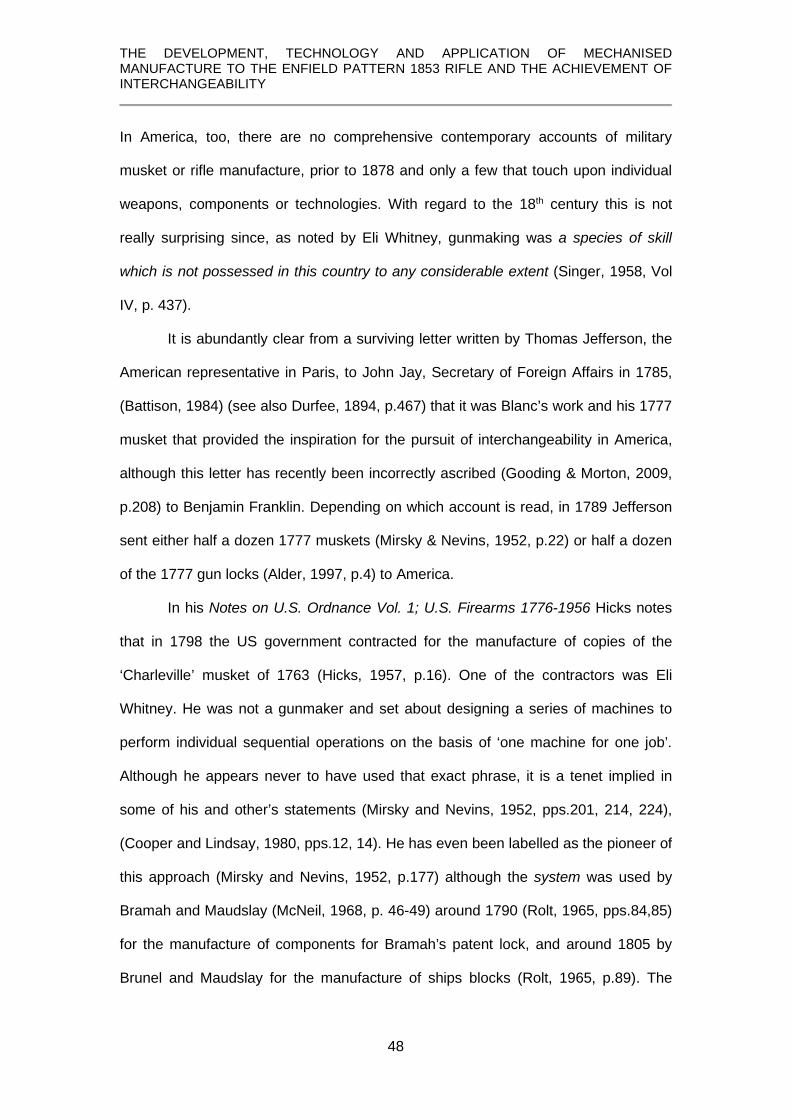
In America, too, there are no comprehensive contemporary accounts of military
musket or rifle manufacture, prior to 1878 and only a few that touch upon individual
weapons, components or technologies. With regard to the 18th century this is not
really surprising since, as noted by Eli Whitney, gunmaking was a species of skill
which is not possessed in this country to any considerable extent (Singer, 1958, Vol
IV, p. 437).
It is abundantly clear from a surviving letter written by Thomas Jefferson, the
American representative in Paris, to John Jay, Secretary of Foreign Affairs in 1785,
(Battison, 1984) (see also Durfee, 1894, p.467) that it was Blanc’s work and his 1777
musket that provided the inspiration for the pursuit of interchangeability in America,
although this letter has recently been incorrectly ascribed (Gooding & Morton, 2009,
p.208) to Benjamin Franklin. Depending on which account is read, in 1789 Jefferson
sent either half a dozen 1777 muskets (Mirsky & Nevins, 1952, p.22) or half a dozen
of the 1777 gun locks (Alder, 1997, p.4) to America.
In his Notes on U.S. Ordnance Vol. 1; U.S. Firearms 1776-1956 Hicks notes
that in 1798 the US government contracted for the manufacture of copies of the
‘Charleville’ musket of 1763 (Hicks, 1957, p.16). One of the contractors was Eli
Whitney. He was not a gunmaker and set about designing a series of machines to
perform individual sequential operations on the basis of ‘one machine for one job’.
Although he appears never to have used that exact phrase, it is a tenet implied in
some of his and other’s statements (Mirsky and Nevins, 1952, pps.201, 214, 224),
(Cooper and Lindsay, 1980, pps.12, 14). He has even been labelled as the pioneer of
this approach (Mirsky and Nevins, 1952, p.177) although the system was used by
Bramah and Maudslay (McNeil, 1968, p. 46-49) around 1790 (Rolt, 1965, pps.84,85)
for the manufacture of components for Bramah’s patent lock, and around 1805 by
Brunel and Maudslay for the manufacture of ships blocks (Rolt, 1965, p.89). The

THE DEVELOPMENT, TECHNOLOGY AND APPLICATION OF MECHANISED MANUFACTURE TO THE ENFIELD PATTERN 1853 RIFLE AND THE ACHIEVEMENT OF INTERCHANGEABILITY
49
same approach is even found in a screw-making machine (Wyatt, 1760) which
became the basis of an operational factory in 1762 (Rolt, 1965, p.58).
In 1798 the United States’ Secretary of War, James McHenry, established
uniformity as a procurement goal for American arms makers (Gordon, 2010). It has
been suggested (Roe,1916, p.134-136) that in his venture Whitney achieved
interchangeability, a fact apparently attested to by a letter from Jefferson (Mirsky &
Nevins, 1952, p.214). Cooper & Lindsay (1980, p.16), however, suggest that at the
time Whitney was working, sufficiently precise tools did not exist in the United States
to enable interchangeability to be achieved, a view reflected by Gordon (1988) in an
analysis of excavated material from Whitney’s factory site. This view is borne out by
the examination of a lock of the French 1777 style made by Whitney at this time in
the Springfield Armory collections which bears the ‘assembly marks’ common to non-
interchangeable locks (Smithurst, 2019).
One thing Whitney did accomplish was that in 1801, after becoming aware of
Blanc’s 1777 lock, he sought and was given approval to incorporate it in his
‘improved’ 1798 US contract musket. In 1816 Blanc’s locks were adopted as
standard (Hicks, 1957, p. 19), so, again, the impact of Blanc’s work is apparent.
Roe also claims that during this venture, Whitney invented the milling
machine (Roe, 1912, p.1037-8), a claim repeated by Woodbury (1960, pps.16-19),
but a recent study makes an undeniable case for it being the brainchild of Simeon
North around 1816 (Battison, 1984). It has been stated by Smith, (Mayr, 1984, p 72)
that uniformity, as noted above, was an early official goal of the American
government, and in 1813 a contract which specified ‘interchangeability’ was issued to
Simeon North for the manufacture of twenty thousand pistols and claimed as being
the earliest known government contract with that requirement (Roe, 1916, p.134).
This is contradicted by Peaucelle (2005, p. 60) who notes that a contract with this
requirement was issued by the French government 90 years earlier.

THE DEVELOPMENT, TECHNOLOGY AND APPLICATION OF MECHANISED MANUFACTURE TO THE ENFIELD PATTERN 1853 RIFLE AND THE ACHIEVEMENT OF INTERCHANGEABILITY
50
One major achievement in interchangeability was made in America in this
period. Smith comments on the contributions made by John Hall who invented a
breech-loading rifle in 1811 (Hall, 1811) which was produced at the government’s
Harper’s Ferry Armory. Hall had proposed as early as 1816 making his rifles
interchangeable and Smith (1977, p.235) states that Hall employed a variety of
machines designed to cut, shape and smooth the exteriors of metal components but
no details of these machines are known, except another source which states these
contrivances performed with cutters and saws work usually done elsewhere with
grindstones, chisels and files (Fitch, 1882, p.26).
In 1828 Simeon North was granted a contract with the U.S. Ordnance
Department to supply five thousand Hall rifles. By 1834, working to a set of gauges
supplied by Hall, North was also producing interchangeable rifles and the
components of Hall’s and North’s rifles, produced in different establishments, were
interchangeable. This was a major achievement in the evolution of precision
manufacturing and Smith suggests (1977, p.212), that no two individuals played a
more important role in this development, or as machine-tool innovators, during the
early 19th century. In the absence of any knowledge of Hall’s machines it is difficult to
assess his contribution, but North’s milling machine certainly ranks as a major
landmark in manufacturing technology.
Whitney’s work marks the beginning of the quest for interchangeability in the
United States and this is examined in Harper’s Ferry and the new technology (Smith,
1977). As the title suggests, this particularly focuses on activities at the U.S.
government’s armory established at Harpers Ferry in Virginia, but also explores the
vital cooperation with the primary Armory at Springfield, Massachusetts, which
played a major part. However, there seems little to suggest that there was any new
approach to making the lock components.

THE DEVELOPMENT, TECHNOLOGY AND APPLICATION OF MECHANISED MANUFACTURE TO THE ENFIELD PATTERN 1853 RIFLE AND THE ACHIEVEMENT OF INTERCHANGEABILITY
51
Smith (1977, pps. 96, 97) notes that at some time between the 1790’s and 1814, the
‘screw auger’ was invented for ‘rough-boring’ barrels. The earliest surviving factual
evidence is to be found in a U.S. patent granted in 1814 to Daniel Pettibone (see
Chapter 7). Smith further suggests that it was asserted at the time that such ‘drills’
had been in use as early as 1796 in America, and in England even earlier, but no
evidence for this latter claim has been found. Pettibone’s ‘auger’ could only work in
pre-existing holes so is basically a reamer and in the author’s view it is the oldest
known spiral-fluted reamer for which tangible evidence exists. In a footnote, Smith
(1977, p.96) notes that by 1821 a machine similar to Pettibone’s was in use at
Springfield but does not state whether Pettibone’s ‘auger’ was being used. Another
source (Abbott, 1852, p.5) tells us that at this later date it was not, but ‘screw-augers’
were in use at the Norwich Armories in 1864 (Anonymous, 1864, p.6).
At Harper’s Ferry in 1818, Sylvester Nash patented a self-acting lathe for
taper turning musket barrels (Nash, 1818; Smith, 1977, p.121) but this machine
appears less refined than the one being used at Tula in 1813 (Gamel, 1826, p.107).
However, grinding continued to be used for external finishing in various
establishments until the 1850’s at least (Abbott, 1852, p.8; I.L.N., 1851, p.185).
In this same period a set of machines was developed by Thomas Blanchard
and feature in a later study (Cooper, 1991). The first in this series was the Machine
for turning gunstocks patented in 1819 (Blanchard, 1819). A gunstock is far from
symmetrical and at no point do they have a circular cross-section, the usual outcome
of being ‘turned’ in lathe. Accounts of their manufacture by hand (Dale 1810;
Memoria, 1850) reveal the nature of the skills required even in their overall shaping
to correct dimensions.
Additional machines were developed by Blanchard for carrying out other
operations on the stock, including accurately creating the three-dimensionally
complex recess for the lock, and which, perhaps more than any others, illustrates the

THE DEVELOPMENT, TECHNOLOGY AND APPLICATION OF MECHANISED MANUFACTURE TO THE ENFIELD PATTERN 1853 RIFLE AND THE ACHIEVEMENT OF INTERCHANGEABILITY
52
problems faced by the designers of machine tools which had to replicate and replace
the hand-craft skills.
Hounshell (1984, p.38) suggests that Thomas Blanchard did not draw
inspiration from Brunel’s machinery because the blocks were not irregularly shaped.
He then further suggests (1984, p.38) that Brunel drew inspiration from as yet
unknown American inventions on the basis that he was living in the United States at
the end of the 18th century. The present author has to challenge these statements. If
there was such an important innovation as to inspire Brunel’s block-making
machines, how could it remain ‘as yet unknown’ after the extensive research into this
subject?
Brunel’s ideas were first raised by him when dining in Washington with
Alexander Hamilton4F
5, Secretary of the Treasury and often referred to as “the father of
American manufacturing” (Bagust, 2006, p.20). It is suggested that there seems a
greater possibility, therefore, that Brunel’s ideas may have passed via Hamilton to
inspire as yet unknown American inventions.
Blanchard himself, in his revised 1819 patent, refers to rotary cutters as used
in the English machines (see also Cooper, 1991, p.139) and it was even noted in
Russia that Brunel’s machinery might be adapted to gunstocks (Gamel 1826, p.155,
footnote 1). Blanchard’s patent claimed no general principles but only a systematic
arrangement and method of operation (Smith, 1977, p.125) – exactly what was to be
found in Brunel’s machines. Brunel’s ‘dead-eye’ machine, which was not included in
his patent, embodied a feature crucial to Blanchard’s gunstock lathe – a cam and
follower which caused the rotary cutter to rock backwards and forwards as it followed
a rotating eccentric cam to cut a discontinuous groove in the circumference of the
5 In his Report on Manufactures, Hamilton made an extremely prescient comment - If there be anything in a remark often to be met with, namely, that there is, in the genius of the people of this country, a peculiar aptitude for mechanic improvements, it would operate as a forcible reason for giving opportunities to the exercise of that species of talent, by the propagation of manufactures. (Hamilton, 1791, p. 22)

THE DEVELOPMENT, TECHNOLOGY AND APPLICATION OF MECHANISED MANUFACTURE TO THE ENFIELD PATTERN 1853 RIFLE AND THE ACHIEVEMENT OF INTERCHANGEABILITY
53
circular ‘dead-eye’. By giving this cam and ‘rocking’ cutter a longitudinal motion, it
would create the basic principle of the Blanchard gunstock lathe. However, this in no
way denies the importance of Blanchard’s gun stocking machinery which ranks as
another major landmark of ‘Yankee ingenuity’.
An official publication of the United States Ordnance Department (Benton,
1878) describes the manufacture of the then current rifle and bayonet. Although of
later date, many of the processes referred to, along with illustrations of the machines
used, are either identical or very closely similar to those being used twenty years
earlier at Enfield and elsewhere. It is on a par with Gamel’s work on the operations at
the Tula weapon factory in 1826, though it has less descriptive detail.
In 1850, another publication gave a detailed description of the manufacture of
a musket, Memoria De la fabricacion del fusil de nuevo modelo en la Real
Manufactura de Armas de Lieja en los anos de 1847 y 1848 [Memoire on the
manufacture of the new model musket in the Royal Manufacture of Weapons in Liege
in the years of 1847 and 1848] (Memoria, 1850). It was published in Madrid but, as
seen from the title, it describes gunmaking practices at the Royal Manufactory in
Liege in the years 1847 and 1848, and the text is accompanied by numerous
drawings. While the musket has several unusual features and although numerous
machines were employed at various stages in the processes, it is clear that hand-
methods were still relied upon to a large extent. Thus, the barrel was still welded by
hand, despite the development in England of rolling mills for this purpose, and the
machines used for finishing the barrel are reminiscent of those used at Tula. Hand-
forging was extensively applied to making various lock components and die-forging
appears to be reserved for their final shaping, and the stock was a hand-crafted
product. In this respect, they reflect more the late 18th/early 19th century French
practices. Nor is there any mention of interchangeability, but that is hardly surprising.
That concept was not going to re-emerge in Europe for another few years.

THE DEVELOPMENT, TECHNOLOGY AND APPLICATION OF MECHANISED MANUFACTURE TO THE ENFIELD PATTERN 1853 RIFLE AND THE ACHIEVEMENT OF INTERCHANGEABILITY
54
Over the decades from 1960 onwards there have been countless books
published on the ‘history of firearms’ but very few concern themselves with their
production. From the British viewpoint, two books can be mentioned: British Military
Firearms 1650 – 1850 (Blackmore, 1961) and The British Soldier’s Firearm, 1850 –
1864 (Roads, 1964). These were, and still are, first-class ground-breaking studies,
being the first of a very few serious studies of the development and evolution of
British military firearms up to the mid-19th century, but both only touch on
manufacture since it was peripheral to their primary purpose and neither studies that
topic in depth. Roads’ book, unlike his thesis (Roads 1961) which was the main
foundation for the book, does illustrate some gauges and tooling but since he does
not explain their specific functions they appear more as an afterthought.
1.4 The American system of manufacture Numerous studies concerning the early development of the interchangeable
manufacture of firearms are American and written from the point of view of the
economic, social, political and administrative imperatives surrounding it. Such studies
might add to a wider understanding of the subject by stressing various factors which
were important in driving the quest for interchangeability in America, but they offer
little or nothing of that fundamental element – the technology itself. This is also true
of one otherwise excellent Ph.D. thesis, The development of the Royal Small Arms
Factory (Enfield Lock) and its influence upon mass production technology and
product design C1820 - C1880 (Lewis, 1996).
They may tell us how the ‘system’ operated and what the technology
achieved but they do not tell us how it was achieved. They may mention techniques
and machines but do not explain their operations.

THE DEVELOPMENT, TECHNOLOGY AND APPLICATION OF MECHANISED MANUFACTURE TO THE ENFIELD PATTERN 1853 RIFLE AND THE ACHIEVEMENT OF INTERCHANGEABILITY
55
It is also a period in which recent studies often blend various concepts such
as interchangeability, mechanisation and mass production 5F
6 under a single heading –
‘the American system of manufactures’. Such a label has given rise to extensive
misconceptions and it is noted in the introduction by the American editor, Ed
Battison, a recognised technology historian, to the translated version of Description
of the Tula Weapon factory:-
Here, in the United States, popular and hurried historians have built an elaborate story, much of it mythical, around a few names while ignoring the work of others. (Gamel, 1826, p.xii) To this might be added an observation by Somerset Maugham: The faculty for myth is innate in the human nature. It seizes with avidity upon any incidents, surprising or mysterious, in the career of those who have at all distinguished themselves from their fellows, and invents a legend to which it then attaches a fanatical belief. (Maugham, The moon and sixpence)
Some of this myth is present in what is otherwise an excellent overview of the early
development of the ‘American System’ published in the American Machinist.
(Anonymous, 1977). The published papers of a symposium held in 1981, Yankee
enterprise; the rise of the American system of manufactures, (Mayr, 1981),
perpetuate the idea that the ‘American system’ was an American initiative.
The same system was at the root of Bramah’s and Maudslay’s set of
machinery for the manufacture of Bramah’s patent lock. Alfred Hobbs, the first
person to ‘pick’ Bramah’s ‘unpickable’ lock in 1851, makes no mention of these
machines in the section of his book dealing with lock manufacture (Hobbs, 1868). In
English and American tool builders (Roe, 1916), which has a bust of Henry Maudslay
as the frontispiece and is generally assumed to be an in-depth study of machine tool
development, the author also fails to acknowledge the Bramah lock making
machinery. If further evidence were needed, the very fact that Brunel’s and
6 The term ‘mass production’ first appears to have been used in 1918 in an article by W. Freeland, Mass production in the Winchester shops, Iron Age, 101, pps. 616-21. (see Hounshell, 1984, note 4, p.345)

THE DEVELOPMENT, TECHNOLOGY AND APPLICATION OF MECHANISED MANUFACTURE TO THE ENFIELD PATTERN 1853 RIFLE AND THE ACHIEVEMENT OF INTERCHANGEABILITY
56
Maudslay’s machines, put into operation in 1805 (Rolt, 1965, p.89), were able to
produce between 130,000 and 140,000 blocks in a year (Tomlinson, c1852, p.139)
is, in this author’s view, sufficient evidence of a manufacturing ‘system’ based on
‘machinery’ to dismiss such a claim that the American system was actually American.
Whether viewed from the perspective of ‘organisation’ of processes, ‘mechanisation’
or ‘interchangeability’, it had precedents elsewhere.
Rosenberg asserts that die-forging techniques, drilling and filing jigs, taps and
gauges formed part of America’s most significant contribution to this emerging
technological process and his final comment uses this and other factors to explain
why this particular system first emerged in America (Mayr, 1981, pp.58,59,60). The
present author suggests that it denies the historical evidence, available at the time of
Rosenberg’s comment, of dies being used in France in the last quarter of the 18th
century and in Britain at least by the early 19th century and possibly even earlier, and
other tools that he mentions also existed previously.
Whilst important improvements had undoubtedly been made in America in the
execution and achievement of interchangeable manufacturing, they were
improvements and adaptations of technologies borrowed, perhaps in some cases
unwittingly, or in a process that anthropologists might refer to as “parallel evolution”,
from a variety of developments with widely dispersed dates and geographies.
Gordon (1987) noted that the ability of craftsmen to achieve the manufacture
of standardized, precision metal products in quantity, with work spread amongst
several craftsmen, began at least as early as 1537 when Georg Hartman, a prolific
instrument maker in Nuremberg, Germany, made large numbers of ‘identical’
astrolabes. It has been noted earlier that the earliest interchangeability in firearms
was accomplished by hand methods.

THE DEVELOPMENT, TECHNOLOGY AND APPLICATION OF MECHANISED MANUFACTURE TO THE ENFIELD PATTERN 1853 RIFLE AND THE ACHIEVEMENT OF INTERCHANGEABILITY
57
Adam Smith, in his Wealth of Nations speaks of the facility of machines to
enable one man to do the work of many (Smith, 1776, p.4) although the nature of the
machines he was referring to were probably those in the textile trades. Writing later,
when even simple machine tools had been refined, in his work On the economy of
machinery and manufactures, Babbage made pertinent observations:
A considerable difference exists between Making and Manufacturing. The Former refers to the production of a Small, the latter to a very large number of individuals [items] (Babbage, 1835, p.120) and
Whenever it is required to produce a great multitude of things, all of exactly the same kind, the proper time has arrived for the construction of tools or machines by which they may be manufactured. (Babbage, 1835, p.268) He refers to what we commonly understand to be machines, with the observation of
their ability to make things with perfect identity, thereby also alluding to mass
production and interchangeable manufacture (Babbage, 1835, p.66).
1.5 Gauging
One aspect of verifying the accuracy of components, and especially those of
the lock, in order to achieve interchangeability was the use of gauges. Blanc
produced a set of gauges for this purpose around 1777 but no mention of them in
other gun manufacturing centres at that time has been found. It is ironic that it was
clockmaker, Eli Terry, who made the first practical application of a gauging system in
America with the production of a standardized product with interchangeable parts
made by different contractors working to gauges designed and supplied by Terry
(Gordon, 2010).
Accounts of the work of Hall and North stress the importance of gauges to
check the dimensional accuracy of a variety of components. They were, and still are,
an essential part of the ‘tooling’ used in precision manufacturing. Uselding (Mayr &

THE DEVELOPMENT, TECHNOLOGY AND APPLICATION OF MECHANISED MANUFACTURE TO THE ENFIELD PATTERN 1853 RIFLE AND THE ACHIEVEMENT OF INTERCHANGEABILITY
58
Post, 1984, p.104) suggests that in the 19th century, interchangeable manufacturing
relied on ‘size’ accuracy determined by gauges, but that they were not used to check
‘position or form’. The present author avers that in this he is mistaken since both of
those attributes are clearly embodied in various gauges used by Blanc in the late
eighteenth century and, as will be shown later, were used on the Enfield rifle.
Whilst the Vernier gauge had been invented in 1631 (Daumas, 1989), no
evidence has been found of its use in gun manufacturing workshops. Likewise,
Maudslay’s bench screw micrometer of 1805 (Rolt, 1957, p.89), built for his own use
primarily, was far from portable, and it wasn’t until 1848 that the first hand-held
micrometer was introduced by Jean Laurent Palmer of Paris (Roe, 1916, p.212). The
first of this type was put on the market by Brown and Sharpe in America in 1868, and
one of these was the first to be imported into Britain at some time post-1868 by
Churchill & Co. (Rolt, 1957, p.177). These facts make it all the more interesting that
in his thesis, Lewis (1996, pp.16, 17) reports that George Lovell was using a
micrometer to measure bore gauges at Enfield in 1833. Although to prepare such
gauges, accurate to 0.001-inch, an equally accurate measuring device would have
been required, the nature of Lovell’s micrometer remains unknown.
Nevertheless, it was an extensive set of gauges and improved Blanchard
stock-making machines supplied by the Ames Co. of Chicopee, Massachusetts, and
the highly specialised metalworking machines supplied by Robbins and Lawrence of
Windsor, Vermont, in combination with British barrel making technology, which
became the foundations of the Royal Small Arms Factory at Enfield for the creation
of the Pattern 1853 Enfield Rifle.
Using this machinery and the extensive set of gauges supplied at the same
time enabled the first interchangeable firearm outside America to be produced and is
noted in the following comment::

THE DEVELOPMENT, TECHNOLOGY AND APPLICATION OF MECHANISED MANUFACTURE TO THE ENFIELD PATTERN 1853 RIFLE AND THE ACHIEVEMENT OF INTERCHANGEABILITY
59
Rifle Muskets made at the Royal Small Arms Factory are distinguished by the word ‘Enfield’ engraved on the lock-plate and have their corresponding parts exactly identical in size and interchangeable. (Petrie, 1865, p. 32) 1.6 Motivation for this study
It is the paucity of technical details in all of these accounts, and especially in
those that purport to describe the manufacture of the Enfield rifle, that are at the
foundation of this study. After these accounts appeared in the mid-19th century, no
other study of this topic, in depth or otherwise, has been undertaken.
1.7 Aims and Objectives
The aim of this study, therefore, is to provide for the first time a complete and
detailed analysis of the machines and processes used in the manufacture of the
principal components – lock, stock and barrel – of this rifle and the achievement of
interchangeability. It will accomplish this through applying, also for the first time, an
understanding of both the prerequisites of those components and the machining
operations required to achieve them, to a number of objectives:
1. Highlighting and correcting errors in those original accounts.
2. Highlighting and supplementing omissions of detail in those accounts.
3. A detailed study for the first time of surviving specimens of barrels in each
stage of their manufacturing processes to provide new insights into those
processes.
4. A detailed study for the first time of surviving specimens of stocks in each
stage of their manufacturing processes to provide new insights into those
processes.
5. A detailed study of the manufacture of locks to provide new insights into the
machines and processes involved.

THE DEVELOPMENT, TECHNOLOGY AND APPLICATION OF MECHANISED MANUFACTURE TO THE ENFIELD PATTERN 1853 RIFLE AND THE ACHIEVEMENT OF INTERCHANGEABILITY
60
6. A detailed study for the first time of surviving factory drawings of various
machines to provide new insights into their functioning and the operations
they performed.
7. A detailed study of various and unique official documents to provide new
details of a variety of factors relating to procurement and manufacture pre-
and post- interchangeability and are included in an appendix.
8. A limited metrology study of a feature of a lockplate to reveal the
inadequacies of the gauging system employed pre-interchangeability
9. A detailed study of surviving gauges and their application in interchangeable
manufacturing and a limited metrological study to show the success of the
technologies employed.
10. The study of relevant letters and documents of James Burton, recruited from
America as Chief Engineer at Enfield to oversee the setting up and
commissioning of the American machinery. These documents are contained
within the archive collections at Yale University and transcripts of them are
included in an Appendix, to shed light on some of these machines and
processes.
1.7 Structure of the thesis
This section provides an outline of the contents of the following chapters in this
thesis:
Chapter 2 - describes the basic technology and construction of the Enfield rifle.
Chapter 3 – provides an outline of the origination of the rifle, its procurement through
private contract and the events leading to the decision by the government to
establish its own manufactory and implement mechanisation and the pursuit of
interchangeability.
Chapter 4 – describes the manufacture of the lock, examining each component in
detail and providing many new insights into their various features and the machining

THE DEVELOPMENT, TECHNOLOGY AND APPLICATION OF MECHANISED MANUFACTURE TO THE ENFIELD PATTERN 1853 RIFLE AND THE ACHIEVEMENT OF INTERCHANGEABILITY
61
operations required to achieve them. Metrology data suggests the nature of pre-
interchangeable gauging and the achievement of interchangeability is also shown by
the application of the appropriate gauges.
Chapter 5 – describes the manufacture of the stock and provides many new details
of the machines and processes omitted from contemporary accounts.
Chapter 6 – describes the first stage in the manufacture of the barrel in which a flat
wrought iron plate is converted into a seam-welded tapered tube.
Chapter 7 – describes the conversion of this welded tube into the finished barrel
which involves a number of complex machining operations, many of which have not
been studied in detail before.
Chapter 8 – offers the conclusions that can be drawn from this study and suggests
avenues for further research.

THE DEVELOPMENT, TECHNOLOGY AND APPLICATION OF MECHANISED MANUFACTURE TO THE ENFIELD PATTERN 1853 RIFLE AND THE ACHIEVEMENT OF INTERCHANGEABILITY
62

THE DEVELOPMENT, TECHNOLOGY AND APPLICATION OF MECHANISED MANUFACTURE TO THE ENFIELD PATTERN 1853 RIFLE AND THE ACHIEVEMENT OF INTERCHANGEABILITY
63
CHAPTER 2 BASIC TECHNOLOGY OF THE ENFIELD RIFLE
It seems appropriate at the outset, for the benefit of those who may have no
familiarity with firearms, to outline the technology and construction of the rifle under
discussion since its functional characteristics define what was needed for its
manufacture by both manual and mechanical means.

THE DEVELOPMENT, TECHNOLOGY AND APPLICATION OF MECHANISED MANUFACTURE TO THE ENFIELD PATTERN 1853 RIFLE AND THE ACHIEVEMENT OF INTERCHANGEABILITY
64
2.1 Overview
Most firearms until the mid-19th century were characterised by three principle
components – lock, stock and barrel. The lock constituted the means of ignition -
firing the gun - and was the only true ‘mechanism’; the stock was used as the
mounting for lock and the barrel, which contained the explosive charge and directed
the projectile to its target, in their correct juxtaposition.
These items were widely different; the lock comprised a number of moving
components which had to interact with precision, otherwise the gun might fire
accidentally – ‘go off at half cock’. The stock was an elaborate piece of wood with
accurately formed mounting points to which the other components were fitted. The
barrel was basically an iron tube accurately finished inside and out and strong
enough to withstand the internal forces of the explosion of the powder;.
2.2 Fundamentals of the percussion system of ignition
By the 1830’s, the ‘percussion system’ was becoming the prevalent means of
providing ignition – ‘firing the gun’. This was based on the invention of Reverend
Alexander Forsyth (Forsyth, 1807) who, by combining his interests in chemistry and
shooting, created a system in which ignition was achieved by using the flash from
highly unstable and sensitive chemicals, such as potassium chlorate and sulphur,
gold or mercury fulminate, which detonate 6F
7 when struck, hence the term ‘percussion
ignition’.
Forsyth’s basic principle underwent various mechanical refinements in the
ensuing years until the ‘percussion cap’ was invented by Joshua Shaw in America in
1822 (Deyrup, 1970, pps.22, 23 and footnotes). It has been suggested that this may
have been invented by John Day in England in 1823 (Bedford, 1969, p.9) but the
7 Detonation is a virtually instantaneous decomposition and may be over in 1/10,000 second; an explosion is a fast-burning decomposition and may last 1/100 second. (Robinson, 1944, p.2)

THE DEVELOPMENT, TECHNOLOGY AND APPLICATION OF MECHANISED MANUFACTURE TO THE ENFIELD PATTERN 1853 RIFLE AND THE ACHIEVEMENT OF INTERCHANGEABILITY
65
date of documentary evidence favours Shaw (see Appendix 1). The ‘cap’ became the
most successful way of exploiting Forsyth’s invention.
The cap, generally made of copper and often in the shape of a ‘top-hat’, the
crown of which contained a small amount of ‘fulminate’ secured by a drop of shellac
varnish. The cap was fitted to the top of a ‘nipple’, a hollow column screwed into the
breech of the barrel. This provided a channel down which the flame from the
fulminate was blasted at the instant of detonation and ignited the main charge of
propellant in the barrel.
Fig. 2.1 A sectioned barrel with the gunpowder and projectile in place and the cap sat on the nipple, and showing the channel to the powder charge highlighted in red. (© P Smithurst 2020)
In the author’s view, this combination of Forsyth’s detonating principle embodied in a
copper cap could be argued to be the greatest revolution in firearms development
since the invention of gunpowder itself since it led to, and sustains, all firearms to this
day which use self-contained metal-cased cartridges with a percussion ‘primer’ or
‘cap’ fitted in their base.
2.3 The lock
The means by which ignition was achieved was by means of of a ‘lock’, which
might be loosely compared with a common lock in having a number of interacting

THE DEVELOPMENT, TECHNOLOGY AND APPLICATION OF MECHANISED MANUFACTURE TO THE ENFIELD PATTERN 1853 RIFLE AND THE ACHIEVEMENT OF INTERCHANGEABILITY
66
components whose movements were driven or controlled by springs. It was the only
true ‘mechanism’ in the rifle.
Externally the percussion lock is very simple, having a hammer that can be drawn
back against the mainspring and locked in position until it is released by pulling the
trigger.
Fig. 2.2 External view of a typical percussion lock fitted to the Enfield Pattern 1853 rifle. (© P Smithurst, 2020)
Internally it has a number of components which have to interact accurately in a ‘train’
for the lock to work and to do so safely.
Fig. 2.3 The internal elements of a typical percussion lock as fitted to the Enfield Pattern 1853 rifle. (© P Smithurst, 2020)

THE DEVELOPMENT, TECHNOLOGY AND APPLICATION OF MECHANISED MANUFACTURE TO THE ENFIELD PATTERN 1853 RIFLE AND THE ACHIEVEMENT OF INTERCHANGEABILITY
67
Fig. 2.4 ‘Exploded’ perspective sketch showing the train of interacting components.
(© P. Smithurst, 2020) 2.4 Operation of the lock – ‘cocking’ and ‘firing’ the gun
A square hole in the hammer allowed it to be fitted, in the correct orientation,
to a squared shank on the tumbler. As the hammer is drawn back, it causes the
tumbler to rotate clockwise as shown in Fig. 5 below. The sear is acted upon by the
sear spring so that its thin nose is always pressed against the body of the tumbler
which has two notches, or ‘bents’. Eventually, as the hammer is drawn further back
the sear nose encounters the first ‘bent’ and drops into place with an audible ‘click’.
This is the ‘half-cock bent’ and is undercut so that if the hammer is eased forward
again at this point, the nose of the sear is trapped in a slot. Even though the
mainspring has been partly compressed by this action, the trapped nose of the sear
prevents it being released when the trigger is pressed. This is known as the ‘half-
cocked’ or ‘safe’ position.
Fig. 2.5 Interactions of tumbler and sear. (© P Smithurst 2020)

THE DEVELOPMENT, TECHNOLOGY AND APPLICATION OF MECHANISED MANUFACTURE TO THE ENFIELD PATTERN 1853 RIFLE AND THE ACHIEVEMENT OF INTERCHANGEABILITY
68
By continuing to draw the hammer back, the second ‘bent’ is brought into
contact with the sear nose. This ‘bent’ is a simple step cut in the body of the tumbler
and the pressure of the sear spring forces the sear nose to fall behind this step. By
releasing the hammer at this point, it is held in the ‘full-cocked’ or firing position by
the sear preventing rotation of the tumbler, in the same manner as a ratchet and
pawl, and the mainspring is fully compressed. Pressure on the trigger, which
engages with the tang of the sear, (see Fig. 2.4) causes the sear to rotate on its axis
pin. Because this ‘bent’ is simply stepped, the sear nose disengages, allowing the
tumbler to rotate under the pressure of the mainspring, carrying the hammer with it to
strike the percussion cap with great force and detonate it.
The importance of the correct interaction of these lock components, which is
dependent upon their accurate formation, cannot be overemphasised and Cotty
(1806, pps.75-87) goes to great lengths to explain the consequences of any errors in
their relative proportions at their points of interaction. The tumbler is possibly the
most important element since it controls the action of the lock and for this reason was
often referred to by artillery officers in charge of musket manufacture in late 18th
century France as ‘le cerveau de la platine’ - ‘the brain of the lock’ (Alder, 1997,
pp.197,199). Whilst Cotty’s comments refer to the flintlock, they are equally
applicable to comparable components in the percussion lock.
All of the lock components are subject to wear and some, especially the forks
at the tip of the mainspring and the swivel they engage with, are subject to shock.
Therefore they need to be made from the highest quality materials, heat treated in
ways appropriate to the service they perform.
2.5 The barrel
What is generally referred to as the barrel of the Enfield rifle actually
comprised two elements – the barrel proper which is an iron tube having a cylindrical
bore and tapered on the outside, and which is provided with a female thread at the

THE DEVELOPMENT, TECHNOLOGY AND APPLICATION OF MECHANISED MANUFACTURE TO THE ENFIELD PATTERN 1853 RIFLE AND THE ACHIEVEMENT OF INTERCHANGEABILITY
69
wide (breech) end to receive a threaded plug, or breech pin in correct terminology at
that time, which is screwed into it. This breech pin was also forged with an integral
tang in the form of a narrow and relatively thin rearward extension which serves to
act as an anchorage point for the breech-end of the barrel.
Fig. 2.6 A breech pin fitted to an Enfield barrel. (© Birmingham City Museums)
The barrel was fitted with two sights. The front sight was brazed to the barrel as a
permanent fixture and in cross-section took the form of an inverted ‘V’.
Fig. 2.7 Enfield rifle front sight. (XII.979 © Royal Armouries)

THE DEVELOPMENT, TECHNOLOGY AND APPLICATION OF MECHANISED MANUFACTURE TO THE ENFIELD PATTERN 1853 RIFLE AND THE ACHIEVEMENT OF INTERCHANGEABILITY
70
The rear sight was more elaborate in having the facility for adjustment, allowing the
barrel to be inclined to the horizontal by pre-determined amounts to accommodate a
variety of ranges up to 900 or 1000 yards. It was soft-soldered to the barrel on an
accurate centreline and at a predetermined distance from the front sight.
Fig. 2.8 The Enfield rifle rear sight. (I.L.N. 1855, p 410) 2.6 Rifling
Prior to the development of the rifle most firearms, whether for sporting or
military use, were ‘smoothbores’; that is to say, the bores of the barrel were plain
cylinders. However, it had long been known that ‘rifling’ – spiral grooves cut into the
walls of the bore – substantially increased both accuracy and range of a projectile,
both of which were highly desirable features. Accuracy was improved by causing the
projectile to rotate rapidly, giving it gyroscopic stability in flight. Even a modest
estimate with the Enfield Pattern 1853 rifle, given a rifling pitch of one turn in 6.6 feet
(2 metres), a bullet travelling at 1000 feet (303 metres) per second would acquire a
rotation about its axis in its direction of flight approaching 10,000 rpm.
Range was increased by virtue of the bullet filling the bore, as it needed to do
to fully engage the shallow rifling grooves, and thereby minimising or eliminating any

THE DEVELOPMENT, TECHNOLOGY AND APPLICATION OF MECHANISED MANUFACTURE TO THE ENFIELD PATTERN 1853 RIFLE AND THE ACHIEVEMENT OF INTERCHANGEABILITY
71
escape of propellant gases in the gap between the bullet and the walls of the bore,
usually referred to as ‘windage’. Since range is a function of muzzle energy (kinetic
energy of the projectile), which is itself a function of velocity, clearly the greater the
work done by the explosive forces on the projectile, the greater its range.
Perhaps the best testimony to the superiority of the rifle over the traditional
smooth-bore musket is summed up by the comment of Captain McKerlie of the Royal
Engineers following trials of the smooth-bored 1842 Pattern Musket at Chatham in
1846:
. . . as a general rule musketry fire should never be opened beyond 150 yards, and certainly not exceeding 200 yards; at this distance half the number of shots missed the target, 11ft. 6 inches, and at 150 yards a very large number also missed . . . (Bond, 1884, p.197) 2.7 The conundrum of a muzzle-loading rifle
For the virtues of a rifle to be realised in practice, the projectile had obviously
to engage with the helical rifling grooves in the bore. For that to happen, the projectile
needed to be the same diameter as the bottom of the grooves, which is larger than
the diameter across the top of the ridges between the grooves – the lands.
Fig. 2.9 Exaggerated schematic cross- section through a rifled barrel showing the different diameters involved. © P. Smithurst, 2019 How, then, could a projectile be loaded into a muzzle loading rifle if it needed to
engage the grooves but still remain a sliding fit in the bore?

THE DEVELOPMENT, TECHNOLOGY AND APPLICATION OF MECHANISED MANUFACTURE TO THE ENFIELD PATTERN 1853 RIFLE AND THE ACHIEVEMENT OF INTERCHANGEABILITY
72
Patrick Ferguson provided one solution to that problem in 1776 by designing
a rifle which loaded at the breech. This allowed a projectile to be used which filled the
rifling grooves and which performed excellently:
My rifle is in a fair way – by the unanimous suffrages of every officer who has seen it, it has been recommended as superior to any musket rifle or other firearm now in use, & Lord Townsend now talks of having some hundreds made. (Gilchrist. 2003, p. 20)
Fig. 2.10 The Ferguson rifle. By unscrewing a plug attached to the trigger guard, access to the breech end of the barrel was provided, whereby a ball and powder could be loaded. Screwing the plug back into place once again sealed the breech, ready for firing. This is Ferguson’s own rifle. (XII.11209, © Royal Armouries) Enough were made to equip a regiment, but wider adoption was mitigated against by
costs. The breech-plug, to enable it to open and close the breech in a single
revolution, had a seven-start thread and would pose an interesting problem to
manufacture even today; the threaded hole into which it fitted closely even more so.
2.8 Solutions to the problem of muzzle-loading rifles.
With muzzle loading rifles, various methods were tried to overcome the
inherent problem. For instance, with the rifle developed by Ezekiel Baker in 1800
(Blackmore, 1961, p.113), the projectile – a spherical ball – was wrapped in a thin
linen ‘patch’ lubricated with tallow so that, when loaded, the flexible linen was
pressed into the rifling grooves and at the same time gripped the ball with the result

THE DEVELOPMENT, TECHNOLOGY AND APPLICATION OF MECHANISED MANUFACTURE TO THE ENFIELD PATTERN 1853 RIFLE AND THE ACHIEVEMENT OF INTERCHANGEABILITY
73
that when fired, the ball spun as it travelled along the barrel and jettisoned the patch
when it left the muzzle.
The Brunswick rifle, copied from its German namesake and adopted by the
British army for limited issue in 1837, had two grooves and used a ball with an
equatorial ‘belt’ to match the geometry of the bore and which engaged the rifling in
loading, and to ease loading the muzzle had two notches cut to act as a guide.
Fig. 2.11 Left: A sectioned Brunswick rifle barrel showing the muzzle with its two notches coinciding with the rifling to guide the loading of the ‘belted ball’. (XII.2444, © Royal Armouries). Right: a Brunswick ‘belted ball’. (© P. Smithurst, 2020) However, so difficult was it to load a muzzle loading rifle after a number of rounds
had been fired due to fouling from accumulated powder residues, that in the case of
the Baker rifle, the soldiers were issued with mallets to help drive the ball down the
bore (Blackmore, 1961, p.118).
The Brunswick rifle fared no better –
The loading of this rifle is so difficult that it is wonderful how the rifle regiments can have continued to use it so long. The force required to ram down the ball being so great as to render a man’s hand much too unsteady for accurate shooting. (Report, 1852, p.31)
In 1826, Captain Henri-Gustave Delvigne of the French army became one of
the first to explore ways of overcoming this problem and in 1838 had specimens of
his design of rifle made in England. These had a powder chamber at the breech end
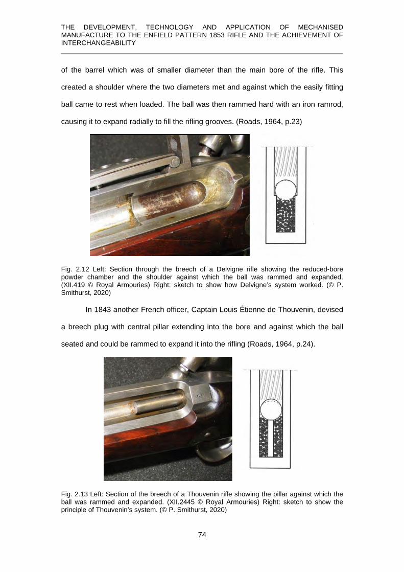
THE DEVELOPMENT, TECHNOLOGY AND APPLICATION OF MECHANISED MANUFACTURE TO THE ENFIELD PATTERN 1853 RIFLE AND THE ACHIEVEMENT OF INTERCHANGEABILITY
74
of the barrel which was of smaller diameter than the main bore of the rifle. This
created a shoulder where the two diameters met and against which the easily fitting
ball came to rest when loaded. The ball was then rammed hard with an iron ramrod,
causing it to expand radially to fill the rifling grooves. (Roads, 1964, p.23)
Fig. 2.12 Left: Section through the breech of a Delvigne rifle showing the reduced-bore powder chamber and the shoulder against which the ball was rammed and expanded. (XII.419 © Royal Armouries) Right: sketch to show how Delvigne’s system worked. (© P. Smithurst, 2020)
In 1843 another French officer, Captain Louis Étienne de Thouvenin, devised
a breech plug with central pillar extending into the bore and against which the ball
seated and could be rammed to expand it into the rifling (Roads, 1964, p.24).
Fig. 2.13 Left: Section of the breech of a Thouvenin rifle showing the pillar against which the ball was rammed and expanded. (XII.2445 © Royal Armouries) Right: sketch to show the principle of Thouvenin’s system. (© P. Smithurst, 2020)

THE DEVELOPMENT, TECHNOLOGY AND APPLICATION OF MECHANISED MANUFACTURE TO THE ENFIELD PATTERN 1853 RIFLE AND THE ACHIEVEMENT OF INTERCHANGEABILITY
75
There were various drawbacks with both of these systems, probably the most
important one in the author’s view being that an initially symmetrical projectile was
distorted into an unpredictable asymmetrical shape which would have had a serious
effect on its directional stability in flight and, therefore, on accuracy.
2.9 Minié’s solution
William Greener, a well-known gunmaker in Birmingham, was also exploring
this problem and in 1835 (Roads, 1964, p.25) he submitted a projectile to the Board
of Ordnance in which the force of the explosion itself was used to expand the bullet
into the rifling. It consisted of a ball with a cavity into which was fitted a conical plug.
At the instant of firing, this plug was driven into the cavity, causing the ball to expand.
Fig. 2.14 Greener’s expanding ball. (Greener, 1884, p.124)
The problem here was ensuring that the plug and cavity remained coaxial with the
bore in loading and although Greener’s idea was dismissed as being ‘useless and
chimerical’ (Greener, 1884, p.123) ultimately, in modified form, it was to provide the
basis of the system adopted.
In 1842, Delvigne patented another method of expanding the bullet which
bears close resemblance to Greener’s, except an elongated bullet was used which
had a cavity in its base and instead of a conical wedge being used to expand the
base, reliance was placed upon the gases from the explosion to cause expansion. It
has been noted (Roads, 1964, p. 25) that the British government was monitoring
foreign developments in small arms, especially in France, and the Inspector of Small
Arms, George Lovell, had been in regular correspondence with Delvigne from 1838.

THE DEVELOPMENT, TECHNOLOGY AND APPLICATION OF MECHANISED MANUFACTURE TO THE ENFIELD PATTERN 1853 RIFLE AND THE ACHIEVEMENT OF INTERCHANGEABILITY
76
There is the possibility, therefore, that Lovell had mentioned Greener’s ‘useless and
chimerical’ proposal to Delvigne.
Be that as it may, the next person to become engaged in the problem was
Captain Claude Etienne Minié and in 1844 simply took Delvigne’s bullet and inserted
an iron cup in the base cavity, in effect acting in the same way as Greener’s conical
plug. However, despite Minié acknowledging Delvigne’s work and making a joint
statement that they wished the system be called the ‘Delvigne – Minié’, the shorter
name was adopted and it became the ‘Minié’, or more often just simply the ‘Minnie’
(Roads, 1964, p.24).
Greener’s name in this connection has been forgotten, despite his contribution being
officially recognised in 1856 when:
The Lords of the Treasury have, at the recommendation of Lord Panmure, awarded the sum of £1,000 to Mr. Greener, as a public recognition of his priority in bringing before the late Board of Ordnance, in the year 1836, his suggestion for the application of the expansive principle in rifle bullets. (Ordnance, 1857, Minute 1169) A claim by a Captain Norton to have invented it in 1828 was summarily dismissed:
The committee do not feel they have official grounds or documentary evidence on which to recognise Captain Norton’s claim. (Ordnance, 1860, Minute 2058) 2.10 Minié’s system adopted and adapted
In 1851, the British military establishment adopted Minié’s projectile and
created the Pattern 1851 ‘Minié’ rifle. The original Minié bullet was conoidal and was
difficult to load so that it remained coaxial with the bore during loading and when
fired. It was very likely to leave the muzzle with an axis of rotation inclined to its axis
of symmetry, resulting in inaccuracy.

THE DEVELOPMENT, TECHNOLOGY AND APPLICATION OF MECHANISED MANUFACTURE TO THE ENFIELD PATTERN 1853 RIFLE AND THE ACHIEVEMENT OF INTERCHANGEABILITY
77
Fig. 2.15 Left: The Minié conical bullet’s shape made correct alignment in loading almost impossible. Right: this defect overcome by Pritchett’s cylindro-conoidal bullet. (Report, 1852)
These and other factors led to the series of experiments in 1852 which
resulted in the creation of the Pattern 1853 Enfield Rifle. Along with the rifle was a
new bullet. A cylindro-conoidal bullet designed by Pritchett, having a cylindrical base
portion, was adopted. Both bullets had hollow conical cavities in the base which, in
the Pritchett bullet, was fitted a truncated conical boxwood plug. On firing, this plug
was driven into the cavity, causing the ‘skirt’ to expand and fill the rifling grooves. The
Enfield rifle using Pritchett’s bullet was to prove a formidable combination and were
used in conflicts across the world.
2.11 The stock
The stock acted as the foundation of the weapon and upon which all the
components were mounted. Therefore, it had to be made with a similar precision to
the components so that they fitted exactly. The barrel and lock had to be very
accurately positioned in relationship to each other so that the hammer would fall
centrally on the nipple.

THE DEVELOPMENT, TECHNOLOGY AND APPLICATION OF MECHANISED MANUFACTURE TO THE ENFIELD PATTERN 1853 RIFLE AND THE ACHIEVEMENT OF INTERCHANGEABILITY
78
Fig. 2.16 Top; The Italian walnut stock blank. Bottom; the finished rifle. (© Royal Armouries) Likewise, the fore-end had to be machined so that the iron ‘bands’ which secured the
barrel had to be an exact fit.
In selecting timber, it had to be free from knots and any sign of incipient
cracks and the grain had to be carefully judged so that any curvature might be
utilised rather than create a weakness. The wood had then to be properly seasoned
for up to three years so that it would not warp in the extremes of climate encountered
in Britain’s widespread Empire. It was then sawn into the rough ‘blank’ shown above
and when finished was liberally treated with linseed oil.

THE DEVELOPMENT, TECHNOLOGY AND APPLICATION OF MECHANISED MANUFACTURE TO THE ENFIELD PATTERN 1853 RIFLE AND THE ACHIEVEMENT OF INTERCHANGEABILITY
79
CHAPTER 3
ORIGINS AND PROCUREMENT
This chapter commences with the universal adoption of a rifle to be issued to all
troops and the creation of the Pattern 1853 rifle.
It then proceeds to examine the traditional system of procurement of arms through
private contract and outlines the problems inherent in that system which led to the
establishment of the Select Committee on Small Arms.
The committee obtained evidence by examination of various contractors and
engineers to find a more efficient way of manufacture.
Under the authority of the Select Committee, the Committee on Machinery was
established and sent to America to examine and report on gunmaking methods there.
The outcome was the establishment of the Royal Small Arms Factory (R.S.A.F.) at
Enfield where the manufacturing process was mechanised and interchangeability
pursued.

THE DEVELOPMENT, TECHNOLOGY AND APPLICATION OF MECHANISED MANUFACTURE TO THE ENFIELD PATTERN 1853 RIFLE AND THE ACHIEVEMENT OF INTERCHANGEABILITY
80
3.1 Origin of the Pattern 1853 rifle
In the early 1850’s, the decision to arm the British serviceman with an
accurate and long-range rifle in place of the inaccurate and short-range smooth-bore
musket had been brought about by ground-breaking developments in the design of
projectile as outlined in Chapter 2.
The first step in this process was taken on 13th October, 1851, when, after a
series of trials, the Committee on Small Arms recorded the specifications for a new
Rifled Musket based on Minié’s principle:
Barrel of .702 in. calibre rifled with four grooves of equal depth throughout their length. Minié projectile to weigh, including its iron cup, 680gr. 7F
8 Charge to be 2 ½ dr., and 50 rounds of ammunition to weigh 5lb. 10oz. The entire musket to work out at 8oz. less than that in service. (Roads, 1964, p.33) The Marquis of Anglesea, Master General of Ordnance, with the agreement of the
Commander in Chief, the Duke of Wellington, determined that the ‘Minié’ rifle,
designated as the Rifle, Pattern 1851, should become the standard issue weapon to
all infantry (Report, 1852, p.3). However, a variety of problems were soon
experienced with the new rifle, the principal one being its weight but also its large
calibre which limited the quantity of ammunition a soldier could carry.
As a result, early in 1852, the new Master General of Ordnance, Viscount Hardinge:
invited some of the principal gunmakers of England to submit patterns of muskets [rifles] for the use of the army, in the hopes of obtaining a lighter and more efficient arm for the service, the following makers prepared and sent in muskets for trial: Mr. Purdey, Mr. Westley Richards, Mr. Lancaster, Mr. Wilkinson, and Mr. Greener. Mr. Lovell, the Inspector of Small Arms, also prepared a new musket at the Government manufactory. (Report, 1852, p.3)(see also Smithurst, 2007, pps. 123-140) A series of experiments ensued in which each of the rifles submitted underwent
rigorous comparative trials to determine the merits of each with regard to a variety of
8 Note that avoirdupois weights are used in 19th century ballistic terminology: 680 grains = 44.2g.; 2 ½ drachms = 0.156 oz.(ounces) = 4.43g.; 8oz. = 226g.; 5lb (pounds) 10oz. = 2.55kg.

THE DEVELOPMENT, TECHNOLOGY AND APPLICATION OF MECHANISED MANUFACTURE TO THE ENFIELD PATTERN 1853 RIFLE AND THE ACHIEVEMENT OF INTERCHANGEABILITY
81
factors including the requirements of rugged military service. The outcome was that
two rifles were made at the Royal Manufactory at Enfield:
in which were embodied the improvements and alterations suggested by the experience obtained during the course of the trials with the experimental arms, and which, it was hoped, would possess the necessary requirements for a military weapon. The musket including bayonet to weigh about 9lbs 3oz. The bore decided upon was .577 inch. The barrel to be, in length, 3 feet 3 inches. “ “ weight, 4lbs 6oz. “ to have 3 grooves. “ to have a constant spiral of 1 turn in 6 feet 6 inches. 8F
9
“ to be fastened to the stock by 3 bands. The ramrod to have a swell near the head. The bayonet to be fixed by means of a locking ring. The lock to be made with a swivel. (Report, 1852, p.35)
These were significant departures from what had become the traditional
design of the musket and its components for British military service. Fig. 1 shows the
Pattern 1851 rifle along with the flintlock musket of 50 years earlier. In its overall
form, the Pattern 1851 Minié rifle owed much to its English forebears, especially in
regard to the attachment of the barrel to the stock using cross-pins passing through
lugs attached beneath the barrel, and ‘ramrod pipes’ to hold the ramrod in place.
Fig. 3.1 Top; New Land Pattern musket, the last of the flintlock muskets, c.1802 (XII.132). Bottom; The 1851 Pattern Minié rifle (XII.1907). (© Royal Armouries)
9 The Imperial weights and measures correspond to, approximately: weight 4.16kg.; bore size 14.7mm; barrel length 1metre; barrel weight 2 kg; rifled 1 turn in 2 metres.

THE DEVELOPMENT, TECHNOLOGY AND APPLICATION OF MECHANISED MANUFACTURE TO THE ENFIELD PATTERN 1853 RIFLE AND THE ACHIEVEMENT OF INTERCHANGEABILITY
82
In contrast, the Pattern 1853 rifle owed more to the French Model 1777 musket in the
use of iron ‘bands’, encircling both barrel and stock and securing the ramrod,
features that were to become widely adopted for military firearms.
Fig. 3.2 Top; The French Model 1777 musket. (XII.201). Bottom; Pattern 1853 Enfield rifle. (sealed pattern, XII.1918). (© Royal Armouries)
At the core of this British military rifle, then, were French innovations in design
and, more especially, in ballistics by using Pritchett’s modification of the Minié bullet.
For any new weapon which was accepted into service, one or more specimens were
prepared to which were attached one or more wax seals bearing the arms of the
Board of Ordnance or other official bodies and were referred to as ‘sealed patterns’.
These sealed patterns then became the reference standards upon which
manufacture was based and products assessed, a system initiated by Charles I
(Charles I, 1631).
3.2 Procurement by contract
From the earliest days of the musket becoming the primary infantry weapon,
procurement had been through contracts with the private gun trade which, by the
1850’s, was concentrated in Birmingham.
Most firearms until the mid-19th century were characterised by three principal
components – lock, stock and barrel – and their purpose and characteristics were
discussed in Chapter 2. In addition there were numerous other items such as trigger,

THE DEVELOPMENT, TECHNOLOGY AND APPLICATION OF MECHANISED MANUFACTURE TO THE ENFIELD PATTERN 1853 RIFLE AND THE ACHIEVEMENT OF INTERCHANGEABILITY
83
trigger guard, buttplate, the means for holding the barrel in place and various screws
which are all grouped together under the term ‘gun furniture’.
A wide variety of specialised skills were used in the production of firearms in
the pre-mechanised age as shown below: This is a non-exhaustive list provided by
Goodman (1866, pps. 392-3).
Barrel Welders Barrel Borers Barrel Grinders Barrel filers and Breechers Barrel Rib Makers Barrel Breech Forgers and Stampers Barrel Smoothers – prepare the barrel for browning Barrel Browners Barrel Riflers Barrel Machiners – prepare the front sight and the lump end of the barrel for the nipple Barrel Jiggers – lump filers and break-off fitters – prepare the breech end of the barrel Percussioners – finish the nipple seat, fit the nipple and adjust the hammer to the nipple
Stock makers Maker-off – file the stocks to give them their proper finish, glass paper and oil them Stockers – let in the barrel and lock and roughly shape the stock Furniture Forgers and Casters Furniture Filers Rod Forgers Rod Grinders and Polishers Rod Finishers Band Forgers and Stampers Band Machiners Band Filers Band Pin Makers Sight Stampers Sight Machiners Sight Jointers Sight Filers Sighters and Sight Adjusters
Oddwork Makers Engravers (lock etc.) Polishers – lock and furniture Screwers – let in the furniture and remaining pins and screws Strippers – prepare the gun for rifling and proof Finishers – distribute the parts to the browner, polisher, maker-off, barrel smoother and when they are returned put the guns together and adjust the parts Lock Forgers Lock Machiners Lock Filers Lock Freers – adjust the working parts of the lock Trigger Boxers
It is a perfect illustration of Adam Smith’s observation on the division of labour:
This great increase in the quantity of work, which, in consequence of the division of labour, the same number of people are capable of performing, is owing to three different circumstances; first to the increase in dexterity of every particular workman; secondly to the saving of the time which is commonly lost in passing from one species of work to another and, lastly, to the invention of a great number of machines which facilitate and abridge labour, and enable one man to do the work of many. (Smith, 1776, p. 4 et seq) The way the contract system worked was that:
the component parts of a musket are in the first instance procured by open contract, and after inspection and approval, placed in the Ordnance Stores. There is a separate contract for each of the separate parts; each is subjected to a strict view or examination by viewers specially appointed for the purpose; accuracy of shape and size is secured by a system of gauges, while other tests are employed to ascertain the strength of the work and the soundness of the material. . and . . A portion of the materials so received into store is issued to the Government establishment at Enfield, to be there set up; that is, fitted together and finished into complete muskets. The chief part of the materials is, however, delivered to contractors who contract for the

THE DEVELOPMENT, TECHNOLOGY AND APPLICATION OF MECHANISED MANUFACTURE TO THE ENFIELD PATTERN 1853 RIFLE AND THE ACHIEVEMENT OF INTERCHANGEABILITY
84
setting-up9F
10, and return the arms to the Board of Ordnance finished. In this state it is again subjected to a view. (Report, 1854, p. iii)
Despite the fact that gauges were used in the inspection process, none, it
would appear, were issued to the contractors, nor were they issued a ‘pattern’ of the
item they had contracted to make, Fig. 3.
Fig. 3.3 Contract details issued to Joseph Smith in 1851. (Appendix 2; © P. Smithurst 2019) They had to work from a single ‘pattern’ weapon deposited at the Ordnance
Department office in Birmingham or the Tower and obtain their specifications by
examining that, or the relevant parts of it. James Gunner, Superintendent at Enfield,
in his evidence to the Select Committee stated that three sealed patterns were
created at Enfield upon the introduction of a new weapon (Report, 1854, p.286) and
one was issued to the Tower and one to the Ordnance Office in Birmingham.
This raises an immediate question - were these made using the same filing
jigs, gauges etc.? If they were, then were they interchangeable? It seems very
10 ‘setting-up’ was for the fitting and assembling of all the components to produce a finished rifle and entailed creating special features on the stock to accept the various components.

THE DEVELOPMENT, TECHNOLOGY AND APPLICATION OF MECHANISED MANUFACTURE TO THE ENFIELD PATTERN 1853 RIFLE AND THE ACHIEVEMENT OF INTERCHANGEABILITY
85
unlikely since interchangeability was not actively being sought at that time. In that
case, workers in Birmingham and London would be working to two close but different
standards.
Gunner also suggested that these pattern weapons should be loaned to
individual contractors for a few days to enable them to make their own gauges and
that if they worked together, it would take them only two or three days (Report, 1854,
p. 292). This was a very unrealistic time estimate to make a set for each contractor,
each set allowing each component to fit them as accurately as required by the
inspection process, considering the number and nature of the gauges later supplied
by Ames for the lock, for instance. Gauge making is demanding of both skill and time.
For the Board of Ordnance not to have issued patterns or matching gauges to the
contractors was a very inefficient way of proceeding.
3.3 Discontent amongst the contractors
The system was almost guaranteed to cause delay and arouse discontent
and complaints by the contractors over the strictness of the inspection process, or
‘viewing’, and became a serious bone of contention by those engaged in
‘government work’:
When a man finds his work rejected, and incurs a serious loss for some deviation so slight, that, for all practical purposes, it is immaterial, he will naturally hesitate to continue in a business where his week’s earnings depend upon such doubtful, and, it may be, capricious decisions. (Report, 1854, p. ix) When it is realised that the gauging system in use only specified an upper limit on
size and the lower acceptable limit was at the discretion of the inspector, such
discontent and distrust of the system is understandable. Added to those problems
faced by contractors was the fact that while the 1851 Pattern ‘Minié’ rifle largely
copied its forbears, the rifled barrel was a new departure and created at least one
other step in the manufacturing process. But that was a minor problem in comparison
with the Pattern 1853 rifle which was different in almost every respect. Such

THE DEVELOPMENT, TECHNOLOGY AND APPLICATION OF MECHANISED MANUFACTURE TO THE ENFIELD PATTERN 1853 RIFLE AND THE ACHIEVEMENT OF INTERCHANGEABILITY
86
changes, following rapidly upon one another, meant that contractors were still
producing one while having to re-tool to produce the other and for which only a
limited amount of their existing tooling could be applied.
3.4 Discontent of the government
Following the issue of a contract for 28,000 of the new 1851 Pattern rifles in
February 1852, they were not delivered until November 1853 (Report, 1854, pp.451,
452). Also, after the adoption into service of the 1853 pattern rifle and arms derived
from it, in April of that year contracts were entered into for the supply of 2,000 artillery
carbines. Only 500 had been completed by January 1854 (Report, 1854, p.452). An
order for materials for 20,000 rifles placed in July 1853 was seriously delayed. By this
time the situation was critical because the Crimean war created a pressing need for
arms. Part of this problem was historical in nature. J. Wood, Secretary to the Board
of Ordnance, in a memorandum dated February 1854, suggested that after the peace
in 1815 when:
the manufacture of arms for the government ceased and the workmen were dispersed. Little afterwards was done with regard to the provision of arms, until the adoption of the percussion principle, when a re-equipment of the army became necessary. The trade had then fallen into a very disjointed state and there was difficulty in collecting together men capable of making a new arm in a satisfactory manner; . . (Report 1854, p.451) He went on to comment on
the injury to the service and the high prices which resulted from the organised combinations both of the masters and men in the gun trade. (Report, 1854, p.451) Various other deficiencies of the system were cited in a similar vein, but perhaps the
most significant was:
The rifle musket of 1851 having been superseded in 1853 by another of smaller bore, and somewhat different construction, the Board, in July last, called for tenders for materials for 20,000 muskets of the latter description. The offers received were so unsatisfactory as to price, and evinced so perfect a combination amongst the parties, that they were, after some correspondence, declined . . . (Report, 1854, p.452)

THE DEVELOPMENT, TECHNOLOGY AND APPLICATION OF MECHANISED MANUFACTURE TO THE ENFIELD PATTERN 1853 RIFLE AND THE ACHIEVEMENT OF INTERCHANGEABILITY
87
That such ‘combinations’ were very real is evidenced by a resolution of a
meeting of the Setting-Up Contractors at the Stork Hotel in Birmingham on Thursday,
March 27th, 1856, and chaired by J. Goodman Esq., sent to Joseph Smith (see
Appendix 1, item 9):
In response to this dire need for rifles, on the 31st October 1854, the Board of
Ordnance issued a contract for 20,000 rifles to manufacturers in Liège (Roads, 1864,
p.86). These rifles are recognizable by the date in italics on the lockplate and Liège
proof marks. On 12th February, 1855, Messrs. Fox, Henderson, and Co.’s offer to
supply, through ‘a manufacturing firm’ in the United States of America, 25,000 Enfield
rifles at £3.50 each, was accepted (Précis, 1861). This manufacturer was Robbins &
Lawrence. Fox, Henderson & Co. had prepared Joseph Paxton’s submission of his
design for the Great Exhibition building (Exhibition, 1851, p.4) and became the main
contractor for the construction of the ‘Crystal Palace’ and, as such, would have had
intimate knowledge of the exhibitors. There was no formal contract between the
Board of Ordnance and Fox, Henderson & Co., they had merely accepted an offer;
the contract was between Fox, Henderson & Co. and Robbins & Lawrence. Whilst it
is a deeply complex legal and financial concatenation of events which have been
discussed in varying detail from varying perspectives (Hubbard, 1922, pp. 70-73;
Satterlee, 1940), it was the foreclosing of this contract with Robbins & Lawrence by
Fox, Henderson & Co. that led to the final demise of Robbins & Lawrence in 1856
and ultimately of Fox, Henderson & Co. shortly afterwards. The contract is an event
preserved in the rare Pattern 1853 rifles Robbins & Lawrence did succeed in
producing, distinguished by being the only ‘Enfield’ rifles to have the place of
manufacture outside of England, WINDSOR, inscribed on the lockplate alongside the
crown but with no monogram.

THE DEVELOPMENT, TECHNOLOGY AND APPLICATION OF MECHANISED MANUFACTURE TO THE ENFIELD PATTERN 1853 RIFLE AND THE ACHIEVEMENT OF INTERCHANGEABILITY
88
Fig. 3.4 Robbins & Lawrence contract Pattern 1853 rifle. (XII.1628 © Royal Armouries)
The Board of Ordnance were also possibly stimulated in their dissatisfaction
with products obtained through contract by the products exhibited at the Great
Exhibition by Samuel Colt of Hartford, Connecticut, and Robbins & Lawrence of
Windsor, Vermont, alluded to (Chapter 1, p1). But it was not the firearms themselves
which were the cause of this stimulation; it was the way in which they had been
manufactured. Both exhibited firearms made almost completely by machinery. Some
have claimed that Colt’s revolvers were interchangeable but this author has argued
(Smithurst, 2014, 2015)10F
11, using documentary (Anonymous, 1857) and material
evidence, that at that time such claims are unsustainable. Serial numbers stamped
on each component acted as ‘assembly marks’, traditionally used in non-
interchangeable firearms to allow parts to be correctly reunited after further
processing.
11 This paper, published in two parts by the Colt Collectors Association Inc., despite its condemnation of claims of interchangeability, was voted ‘best article of the year’.

THE DEVELOPMENT, TECHNOLOGY AND APPLICATION OF MECHANISED MANUFACTURE TO THE ENFIELD PATTERN 1853 RIFLE AND THE ACHIEVEMENT OF INTERCHANGEABILITY
89
Fig. 3.5 Components of an early production Colt 1851 Navy revolver exhibiting the serial number on every component. (© P. Smithurst 2015) In contrast, the Robbins & Lawrence rifle locks have all the hallmarks of
interchangeability: the lack of ‘assembly marks’.
Fig. 3.6 Lock from a Robbins & Lawrence ‘Mississippi’ rifle dated 1851 and possibly exhibited at the Great Exhibition. (XII.430, © Royal Armouries) This latter fact itself was unheard of in English or European gunmaking, other than
the work of Honoré Blanc in the late 18th century and at Tula in the 1820’s.
The factors surrounding private contracts led the Honourable Board of
Ordnance to declare that:
Owing to the delays constantly recurring in the fulfilment of contracts for arms, the high price demanded by the contractors, and the inconvenience occasioned to the

THE DEVELOPMENT, TECHNOLOGY AND APPLICATION OF MECHANISED MANUFACTURE TO THE ENFIELD PATTERN 1853 RIFLE AND THE ACHIEVEMENT OF INTERCHANGEABILITY
90
service by these causes, the Honourable Board of Ordnance, towards the end of the year 1853, considered it advisable, in order to secure a regular supply of them, to take this branch of manufacture into their own hands, and erect a government establishment capable of producing muskets in large numbers, and at a moderate price, by the introduction of machinery into every part of the manufacture where it was applicable. (Rosenberg, 1968, pps.91-97) There were various outcomes from this. When the Ordnance estimates of £150,000
for the building of a new factory were laid before Parliament, it was opposed on the
grounds that:
the manufacturers of Birmingham and London were quite capable of supplying the Board with any quantity of arms necessary at a lower rate (Rosenberg, 1968, p.94) than the Board could make them, despite the evidence to the contrary and which had
brought about this determination by the Board in the first place.
3.5 Select Committee on Small-Arms
This disagreement resulted in the appointment of a Parliamentary Select
Committee on the 1st March 1854 to:
consider the Cheapest, most expeditious, and most efficient mode of providing Small Arms for Her Majesty’s Service. (Report, 1854, p.ii) Whilst the Minutes of Evidence of the Select Committee, which supplied the basis for
the final report, make interesting and informative reading, it is only possible to include
here a fraction of the various testimonies obtained and fragments of the Committee’s
findings. There was much, entirely understandable, subjectivity on the part of the
gunmakers themselves in defending their own positions. Objectivity in the support of
mechanisation came from those who had extensive experience in that arena,
whether in gunmaking or other areas of manufacture.
John Anderson11F
12 had been responsible for designing and developing
machinery for use at Woolwich Arsenal in the manufacture of artillery equipment
there. The abstracts below, from his testimony as recorded in the Minutes of
Evidence of the Select Committee (Report, 1854, pp.26-38), are instructive in a
12 Inspector of Machinery at Woolwich Arsenal and later published on the subject (Anderson, 1857)
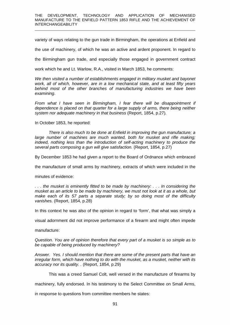
THE DEVELOPMENT, TECHNOLOGY AND APPLICATION OF MECHANISED MANUFACTURE TO THE ENFIELD PATTERN 1853 RIFLE AND THE ACHIEVEMENT OF INTERCHANGEABILITY
91
variety of ways relating to the gun trade in Birmingham, the operations at Enfield and
the use of machinery, of which he was an active and ardent proponent. In regard to
the Birmingham gun trade, and especially those engaged in government contract
work which he and Lt. Warlow, R.A., visited in March 1853, he comments:
We then visited a number of establishments engaged in military musket and bayonet work, all of which, however, are in a low mechanical state, and at least fifty years behind most of the other branches of manufacturing industries we have been examining. From what I have seen in Birmingham, I fear there will be disappointment if dependence is placed on that quarter for a large supply of arms, there being neither system nor adequate machinery in that business (Report, 1854, p.27). In October 1853, he reported:
There is also much to be done at Enfield in improving the gun manufacture; a large number of machines are much wanted, both for musket and rifle making; indeed, nothing less than the introduction of self-acting machinery to produce the several parts composing a gun will give satisfaction. (Report, 1854, p.27) By December 1853 he had given a report to the Board of Ordnance which embraced
the manufacture of small arms by machinery, extracts of which were included in the
minutes of evidence:
. . . the musket is eminently fitted to be made by machinery: . . . In considering the musket as an article to be made by machinery, we must not look at it as a whole, but make each of its 57 parts a separate study; by so doing most of the difficulty vanishes. (Report, 1854, p.28) In this context he was also of the opinion in regard to ‘form’, that what was simply a
visual adornment did not improve performance of a firearm and might often impede
manufacture:
Question. You are of opinion therefore that every part of a musket is so simple as to be capable of being produced by machinery? Answer. Yes. I should mention that there are some of the present parts that have an irregular form, which have nothing to do with the musket, as a musket, neither with its accuracy nor its quality. . (Report, 1854, p.29)
This was a creed Samuel Colt, well versed in the manufacture of firearms by
machinery, fully endorsed. In his testimony to the Select Committee on Small Arms,
in response to questions from committee members he states:

THE DEVELOPMENT, TECHNOLOGY AND APPLICATION OF MECHANISED MANUFACTURE TO THE ENFIELD PATTERN 1853 RIFLE AND THE ACHIEVEMENT OF INTERCHANGEABILITY
92
I would simplify the gun very much. . These detailed forms are not necessary, and it might be made suitable to the application of machinery by the one simple operation, and yet be made handsome. (Report, 1854, p.91) These views are certainly evinced in the lines of his revolvers where any three-
dimensional embellishments are eschewed in favour of a simplicity of form that
created a streamlined aesthetic which set his revolvers apart from any others.
In his paper to the Institution of Civil Engineers, Colt makes his views on this
even clearer:
Machinery is now employed by the author, to the extent of about eight-tenths of the whole cost of the construction of these firearms; he was induced gradually to use machinery to so great an extent, by finding that with hand labour it was not possible to obtain that amount of uniformity, or accuracy in the several parts, which is so desirable, and also because he could not otherwise get the number of arms made, at anything like the same cost, as by machinery. . (Colt, 1851, pp.44, 45)
While his claims, and subsequent claims of interchangeability on his behalf
have been argued to be unsustainable based on physical and documentary evidence
as noted earlier (Smithurst, 2014, 2015), it remains an excellent and succinct
endorsement of the virtues of a proper systematic application of machinery to the
manufacture of firearms. Taken with Anderson’s earlier observations and the
interchangeability achievement of Robbins & Lawrence, it is indicative of a new
approach in which products are beginning to be designed for ease of manufacture by
machine rather than an elaborate aesthetic merit.
3.6 pursuit of mechanisation
The deciding factors in the government’s decision to pursue mechanisation,
however, are contained in the summaries of the Select Committee with regard to the
state of the trades involved the making of the principal components, lock, stock and
barrel, despite the occasional contradictory testimonies (Report, 1854, pp. xxiv-xxv):

THE DEVELOPMENT, TECHNOLOGY AND APPLICATION OF MECHANISED MANUFACTURE TO THE ENFIELD PATTERN 1853 RIFLE AND THE ACHIEVEMENT OF INTERCHANGEABILITY
93
3.6.1 The lock
Mr, Prosser12F
13 said that no lock machinery is employed in this country. . but that proper machines would reduce the cost of locks 50 per cent., and that the locks of the Russian musket are made by machinery in a very perfect manner. Mr. Lancaster13F
14 considered that much is to be done with machinery, which would ensure uniformity in the lock, and then but little skilled labour would be required to finish it. Mr. Goodman14F
15 considered that, although no part of the lock is at present made by machinery, yet it might be applied to locks with advantage, and that such locks would be better and more uniform than those made by hand labour. Mr. Swinburne15F
16 stated that lock machinery which now exists might be improved with some small degree of advantage, but that there are some lockmakers who now use machinery to a great extent. Mr. Nasmyth16F
17 was of opinion that the more intricate parts of the lock. . could be done by special machines; 3.6.2 The stock Up to the present time little has been done in this country towards making the stocks of guns by machinery Mr. Scott17F
18, a gunmaker, stated that he had attempted to apply machinery to this purpose, but found existing machines and tools to be inadequate. Messrs. Wallis18F
19 and Whitworth19F
20 gave evidence of the existence of machinery in America that accomplished this object in a very superior manner, and which they had seen in actual operation.
13 Richard Prosser, civil engineer in Birmingham, who was engaged in writing a book on the construction and manufacture of firearms. 14 Charles William Lancaster was a prominent gunmaker who had supplied arms to the Board of Ordnance. 15 John Dent Goodman, merchant and partner in a gunmaking business; later became Chairman of the Birmingham Small Arms Company. 16 John Field Swinburne, contractor for ‘setting up’ guns for the government. 17 James Nasmyth, inventor of the steam hammer, had supplied the Russian arsenal at Tula with steam stamping equipment for use in die-forging. 18 William Scott, Birmingham gunmaker, at one time viewer for the Board of Ordnance, and a ‘setter-up’ 19 George Wallis, Headmaster, Government School of Art, Birmingham and one of the Commissioners sent to visit the New York Exhibition, and visited the Springfield Armory and the Massachusetts Arms Company. 20 Joseph Whitworth, Engineer, machine tool builder and pioneer of standardised screw threads.

THE DEVELOPMENT, TECHNOLOGY AND APPLICATION OF MECHANISED MANUFACTURE TO THE ENFIELD PATTERN 1853 RIFLE AND THE ACHIEVEMENT OF INTERCHANGEABILITY
94
3.6.3 The barrel According to Mr. Millward20F
21, more machinery has been applied to the barrel than to any other part, and the machinery which he employed saved him 30 per cent. in labour. Mr. Prosser thought the present system of boring a ‘bungle’, and capable of being improved. Mr. Whitworth21F
22 expressed his opinion that great improvements might be made, and that the barrels might be finished on the outside by self-acting machines, without grinding. Colonel Gordon22F
23 said that the system of rifling which is practised in Belgium is more correct, cheaper, and does not injure the health of the workmen so much as ours. Mr. Whitworth contemplated a . . self-acting. . machine that would rifle a number of gun barrels at the same time. 3.7 Committee on Machinery
On the authority of the Select Committee, a Committee on the Machinery of
the United States23F
24 was sent to America early in 1854 to gather information
regarding the machines used in the manufacture of firearms there (Rosenberg, 1968,
p.90).
The Committee on Machinery pre-empted the findings of the Select Committee since
they had been authorised to purchase machines for Enfield up to a value of £30,000.
However, pending the findings of the Select Committee, this sum was reduced to
£10,000 but later increased to £12,500 (Rosenberg, 1968, p.91-97).
They were also empowered to employ James Burton, the engineer at
Harper’s Ferry Armory in Virginia, whose expertise and experience in the operation of
a firearms factory equipped for gunmaking by machinery would be ideal to act as
21 Charles Millward, gun barrel maker in Birmingham and contractor to the Board of Ordnance. 22 Joseph Whitworth, the eminent engineer and machine tool designer who later experimented with forms of rifling and produced accurate long-range rifles which are highly prized even today 23 Lt. Col. Alexander Gordon, member of Committee on Small-Arms. 24 Comprised of Lieutenant-Colonel Robert Burn, R.A., Lieutenant Thomas Picton Warlow, R.A., and John Anderson, Ordnance Inspector of Machinery,

THE DEVELOPMENT, TECHNOLOGY AND APPLICATION OF MECHANISED MANUFACTURE TO THE ENFIELD PATTERN 1853 RIFLE AND THE ACHIEVEMENT OF INTERCHANGEABILITY
95
Superintendent / Assistant Engineer to oversee the setting up and commencement of
operations at the Enfield factory (see Appendix 2).
This in itself was a strong indication of the government’s intentions and was
reinforced by the delegation’s contracting for machinery to be shipped to England.
3.8 Equipping the Enfield factory
Tenders from Robbins & Lawrence on 26th May 1854 and 24th July, were
accepted to supply tooling in the list below. (Rosenberg, 1968, pp.181 - 184)
For lockplate 7 milling machines 2 drilling machines, 5 spindles Tapping apparatus Apparatus for reaming tumbler hole to size 1 edging machine
For hammer 2 drilling machines, 4 spindles 6 milling machines
1 checking machine for hammer hole and for trimming lockplate
For tumbler 2 double milling machines
3 milling machines 2 drilling machine, 4 spindles 1 grooving machine 1 squaring machine 1 screw (hand) machine
For swivel 1 drilling machine, 4 spindles 1 milling machine
For sear 1 drilling machine, 4 spindles 2 milling machines 1 double milling machine
For mainspring 4 milling machines 1 drilling machine, 4 spindles
For bridle 1 drilling machine 4 milling machines
For lock screws 2 screw milling machines 2 thread cutting (hand) machines 1 slitting machine 1 pointing machine 1 clipping machine
For nipple 1 clamp milling machine 1 chasing machine

THE DEVELOPMENT, TECHNOLOGY AND APPLICATION OF MECHANISED MANUFACTURE TO THE ENFIELD PATTERN 1853 RIFLE AND THE ACHIEVEMENT OF INTERCHANGEABILITY
96
1 squaring machine 3 drilling machine, 6 spindles 2 hand machines for finishing thread On the 18th August, the Committee on Machinery accepted a further tender for
Mainspring testing apparatus 6 milling bridges Apparatus for holding and stamping barrels
The total number of machines ordered was therefore 82, but it has been claimed
(Pam, 1998, p.52) the number was 139 and that an additional 9 woodworking
machines were supplied. Unfortunately, Pam does not give his source and no
evidence has been found to support this larger number. Woodworking machines
were indeed supplied, but numbered 12, and were ordered by the Committee on
Machinery (Rosenberg, 1968, p.184) for use by the Royal Carriage Department at
Woolwich, not Enfield.
It is often assumed that the machines alone created an accurate,
interchangeable, component. That this is not so is indicated by the filing jigs detailed
below supplied by the Ames Manufacturing Company of Chicopee, Massachusetts,
as part of their contract of 18th August, 1854, and used to hand-finish components to
size and form so that they fit the gauges, (Rosenberg, 1968, pps. 187-190):
2 filing jigs for the edges of the tumbler 2 filing jigs for edges and 1 filing jig for end of tang of sear 1 filing jig for edges of bridle 2 filing jigs for hook and tang of mainspring 2 filing jigs for edges and 1 filing jig for length of mill end of sear spring 2 filing jigs for breech [pin?] Filing jig for edges of trigger guard Filing jig for mortise of trigger plate Filing jig for edges of finger piece and 2 filing jigs for edges of blade
In addition to machines ordered from Robbins & Lawrence, on 17th May 1854, the
Ames Company were also contracted to supply a set of 15 gun-stocking machines
(Rosenberg, 1968, p.181):
Machine for roughing Machine for rough turning (with patent rights) Machine for spotting [machining small flat datum surfaces on the stock]

THE DEVELOPMENT, TECHNOLOGY AND APPLICATION OF MECHANISED MANUFACTURE TO THE ENFIELD PATTERN 1853 RIFLE AND THE ACHIEVEMENT OF INTERCHANGEABILITY
97
Machine for sawing breech and muzzle Machine for bedding the barrel Machine for planing side and edges with an extra spindle Machine for bedding breech plate [i.e., butt plate] Machine for fitting bands (with patent rights) Machine for turning between the bands Machine for smooth turning breech (with patent rights) Machine for smooth turning above the lock (with patent rights) Machine for bedding the lock [i.e., inletting the lock] Machine for bedding the guard [trigger guard] Machine for boring side tang screws and pin holes Machine for grooving for ramrod
A supplementary order on 18th August 1854 was placed for 8 additional machines
(Rosenberg, 1968, p.191):
1 Rough stocking machine 3 Smooth turning machines for the butt behind the lock 1 Smooth turning machine for the stock in front of the lock 2 Machines for edging the lockplate [presumably the same or similar to the
edging machine supplied by Robbins and Lawrence] 1 apparatus for testing power24F
25 bringing the total number of machines from Ames to 23.
From an earlier comment by the Committee on Machinery (Rosenberg, 1968,
p.180), patent rights had been purchased to allow them to make copies of machines
should the need arise. A few years later, Greenwood and Batley of Leeds certainly
produced stocking machines bearing a close similarity to those supplied by Ames
(Greenwood, 1862).
Details of many of those machines and special tools will be examined and
discussed in the appropriate chapters describing the manufacture of the lock, stock
and barrel of the Enfield rifle when the factory became fully operational in 1857.
3.9 Specifications of the Pattern 1853 rifle
There are no known full written specifications for the manufacture of the
Enfield Rifle and it has already been noted that contractors had to work to pattern
arms supplied via the Ordnance Offices at the Tower of London or at Birmingham.
25 The purpose of this remains unknown but may refer to testing the mainspring (see Chapter 4, p.42) or the force required to operate the trigger.

THE DEVELOPMENT, TECHNOLOGY AND APPLICATION OF MECHANISED MANUFACTURE TO THE ENFIELD PATTERN 1853 RIFLE AND THE ACHIEVEMENT OF INTERCHANGEABILITY
98
Of the few contemporary factory drawings which exist, once forming part of the
M.O.D. Pattern Room25F
26 collections now lodged with Royal Armouries, are probably
unique but only one, that of the nipple, or cone, is dimensioned.
An unfinished and un-dated drawing shows the rifle from the left side, a detail
from which is shown in Fig. 3.7
Fig. 3.7 Original Royal Small Arms Factory, Enfield, drawing, No. 458 (part, unfinished), showing the Pattern 1853 Rifle from the left. (© Royal Armouries) The interesting feature of this drawing is that it shows the relationship between the
main functional elements.
Another drawing, Fig. 3.8, is also undated and the size it is possible to
reproduce it here reveals little detail, but shows the rifle as it appeared in 1853 with
the first pattern of barrel bands but with the post-Crimean War ramrod, suggesting a
date of ca. 1857 or later.
Fig. 3.8 Original Royal Small Arms Factory, Enfield, drawing, No. 746 of the Pattern 1853 Rifle. (© Royal Armouries)
26 The Pattern Room was the facility at Enfield for the storage of the Sealed Pattern weapons and accessories. It was later expanded to house specimens of the then current firearms in use by various nations and that function continues through to the present time.

THE DEVELOPMENT, TECHNOLOGY AND APPLICATION OF MECHANISED MANUFACTURE TO THE ENFIELD PATTERN 1853 RIFLE AND THE ACHIEVEMENT OF INTERCHANGEABILITY
99
The captions on the drawing, transcribed below, give some understanding of the
designated materials:
A. the stock of walnut wood R. trigger, iron, case hardened B. barrel of the very best wrought iron S. breech pin, iron C. ramrod of steel well tempered. The head of same CX being of wrought iron
T. rod stop, iron
D. buttplate of brass U. cone or nipple, steel, tempered E. lockplate wrought iron case hardened V. cone seating of barrel F. hammer wrought iron case hardened W. trigger plate, brass G. sight body w[rought] iron X. tumbler screw, iron, case hardened H. sight leaf steel Y. square of tumbler for hammer to fit I. slide, steel Z. mainspring, steel, tempered J. cap, iron [top of sight leaf] A1. sear spring, steel, tempered L. spring, steel screws and pin, steel B1. Sear, steel, tempered M, M, M. three bands, lower middle and upper, iron
C1. Bridle, iron, case hardened
N, N. band and guard swivels D1. Tumbler, steel, tempered O. nose cap brass E1. Swivel, steel, tempered P. front sight iron 3, 4, 5, lock screws, turned, sear screw,
bridle screw and sear spring screw all of steel, tempered
Q. guard, brass F1. side cups, brass These two drawings are later discussed in more detail (Chapter. 5, pp.62, 63).
A third drawing, Fig. 3.9, dated 1860 and signed by the draughtsman, Charles
Hayes, shows the individual lock components. Details from this will be used in
Chapter 4 which deals with the manufacture of the lock
Fig. 3.9 Original Royal Small Arms Factory, Enfield, drawing, No. 749, of lock components. (© Royal Armouries)

THE DEVELOPMENT, TECHNOLOGY AND APPLICATION OF MECHANISED MANUFACTURE TO THE ENFIELD PATTERN 1853 RIFLE AND THE ACHIEVEMENT OF INTERCHANGEABILITY
100
A further un-numbered drawing, Fig. 3.10, has the title “Standard dimensions
of nipples with working allowances”.
Fig. 3.10 Original Royal Small Arms Factory, Enfield, drawing of the nipple for the “Interchangeable Arm”. (© Royal Armouries) It is annotated “Pitch of thread 181/3 to an inch” and the note “Interchangeable Arm”
which dates it to c.1857 or slightly later. It is of particular interest in being the only
dimensioned drawing found from this period which provides some quantified
tolerances. It also highlights Enfield’s or the Board of Ordnance’s - later the War
Department’s - propensity to use very obscure thread sizes and for which no official
reason has been discovered. It may simply have been to discourage ‘unofficial’ or
‘sub-standard’ copies being produced and fraudulently offered and which might be
injurious to the weapon or the weapon’s user.
3.10 ‘Viewing’ and inspection procedures
As already indicated, a key feature of the manufacturing process was
inspection, or ‘viewing’, of a finished item in which gauges played an important role.
Few if any gauges in use prior to the Enfield factory being established have survived,
or at least, none has been knowingly encountered, but in the pursuit of
interchangeability, gauges were vital. The Committee on Machinery ordered a large

THE DEVELOPMENT, TECHNOLOGY AND APPLICATION OF MECHANISED MANUFACTURE TO THE ENFIELD PATTERN 1853 RIFLE AND THE ACHIEVEMENT OF INTERCHANGEABILITY
101
number and variety of gauges from the Ames Manufacturing Co. (Rosenberg, 1968,
pps. 187-190) and comprised:
For lockplate 1 gauge and plugs for testing the drilling 1 gauge receiving for testing the edges 1 gauge pattern for testing the position of bolster for mainspring 1 gauge, grooved, for thickness of plate, bolster, etc. 1 gauge, plug, for testing the sizes of holes 2 gauge, plug, for testing the tapping 1 pattern for filing bolster to height For hammer 1 gauge, pattern, for testing the punching 1 gauge, pattern, for testing milling of bolster 1 gauge, pattern, for testing for straightening 1 gauge, pattern, for testing edges 1 gauge, grooved, for testing the finished dimensions 1 gauge for testing drilling of nose For tumbler 1 gauge, receiving, for testing the milling, filing, etc. 1 filing gauge for squares For sear 1 gauge, receiving, for testing the milling, filing, etc. 1 gauge, plug, for testing drilling and milling For bridle 1 gauge, receiving, for testing filing 1 gauge, pattern and plugs, for testing drilling etc. For mainspring 1 gauge, receiving, for testing filing, etc. 1 gauge plate, for levelling bottom edges For sear spring 1 gauge, receiving, for testing filing, etc. 1 gauge plate for levelling bottom edges For lock screws Gauge plate for testing dimensions, length, cutting threads etc. For barrel Gauge for testing counter-boring of breech Gauge for testing the tapping of breech Gauge, plug, for testing the drilling of cone seat Gauge for screw-tapping Gauge, receiving, for testing cone seat drilling Gauge, receiving, for breech Gauge, profile, for testing the underside of tang Gauge, profile, for top [of tang?] Gauge, plate, for testing the diameter of breech tenon Gauge, plate, for testing the barrel at six points Gauge, plate, for length and height of stud Gauge, plate, for testing the position of stud from breech Gauge, nut, for testing threads of breech screw and tap For butt plate Gauge, receiving, for testing the filing, etc. Gauge, plate, for testing the exterior curves etc.

THE DEVELOPMENT, TECHNOLOGY AND APPLICATION OF MECHANISED MANUFACTURE TO THE ENFIELD PATTERN 1853 RIFLE AND THE ACHIEVEMENT OF INTERCHANGEABILITY
102
For trigger guard Gauge, receiving, for testing the filing Gauge, profile, for testing the underside Gauge, plate, for thickness, curves etc. For trigger plate Gauges, receiving Gauges, grooved, for testing thickness etc. 2 gauges, plugs, for tapping etc. For trigger Gauges, receiving, for testing the thickness etc. For ramrod Gauges, plates, for testing the diameter and screw Gauges, profile, for testing the form of head and swell For nipple (cone) Gauges, plates, for testing the exterior and interior diameter Gauges and nut for testing screw and tap Screws 2 gauge plates for testing lengths, diameters, screws etc. of side, tang, breech-plate, guard plate and trigger screws For bands 3 gauge mandrels for testing interior dimensions For stock Pattern for vertical profile of finished stock (brass) Gauge, pattern, for testing spotting and angle of butt end Gauge, barrel, (solid steel) for testing groove Gauge for testing length from breech of barrel of band shoulders Gauge, bands etc. Gauge for testing position of lock bed Gauge for testing the cut for tenon of breech screw [barrel tang] Gauge for testing the depth of guard bed Gauge pattern for testing the fitting of guard bed Pattern for testing the profile from breech of band to breech [butt] plate
4 gauges grooved (16 grooves) for testing the various diameters of stocks Gauge pattern for testing margins around lock and sideplate
The Ames company would have needed to have been supplied with a rifle to
work from in creating the gauges, and that rifle became, in effect, the prototype of the
interchangeable series of rifles. If it still exists, its whereabouts is not known. They
would also have needed to work in close collaboration with Robbins & Lawrence to
ensure that the products from their machines matched Ames’ gauges.
A cased set of gauges, Fig. 3.11, still survives in Royal Armouries collections,
transferred from the M.O.D. Pattern Room when that facility closed.

THE DEVELOPMENT, TECHNOLOGY AND APPLICATION OF MECHANISED MANUFACTURE TO THE ENFIELD PATTERN 1853 RIFLE AND THE ACHIEVEMENT OF INTERCHANGEABILITY
103
Fig. 3.11 Part of the set of gauges for the Enfield Pattern 1853 rifle. (PR.10142, ex Pattern Room collection, © Royal Armouries) Despite the large number of gauges, spread over two layers, it does not contain the
full set as specified in the Ames contract of 1854 and consists of a mixture of 1857-
dated and un-dated gauges, and some marked ‘standard’, indicating a mixture of
sources. The gauges that are dated 1857 may be part of the set supplied by Ames
but since they are not named, they continue to remain anonymous. Nevertheless, the
‘set’ is a unique and highly important aspect of the manufacture of the
Interchangeable Pattern 1853 Rifle.
These gauges provide only an upper limit on size so that over-sized
components were automatically rejected. An item that did ‘fit’ the gauge relied on the
judgement of the inspector as to whether that item was of acceptable size or was too
loose, and therefore too small, and thus should be rejected. One aspect of ‘gauging’,
therefore, still remained somewhat arbitrary. It might have been expected that in a
component such as the lock, where each component had to engage and interact
accurately with another, as in, for example, the sear and the tumbler, a lower-limit
gauge would have been a more certain way of ensuring correct ‘fit’ than reliance
upon the judgement of the inspector. It could be argued that the concept of
‘tolerance’ – the variation between maximum and minimum critical dimensions - did
not exist at this date, but there is evidence to show that, to some extent, it did. It has
been noted in the nipple drawing, Fig. 3.10. It is clearly expressed in contract
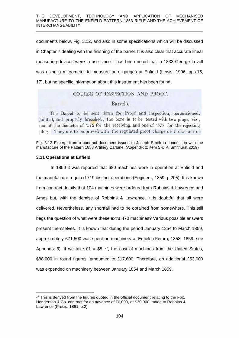
THE DEVELOPMENT, TECHNOLOGY AND APPLICATION OF MECHANISED MANUFACTURE TO THE ENFIELD PATTERN 1853 RIFLE AND THE ACHIEVEMENT OF INTERCHANGEABILITY
104
documents below, Fig. 3.12, and also in some specifications which will be discussed
in Chapter 7 dealing with the finishing of the barrel. It is also clear that accurate linear
measuring devices were in use since it has been noted that in 1833 George Lovell
was using a micrometer to measure bore gauges at Enfield (Lewis, 1996, pps.16,
17), but no specific information about this instrument has been found.
Fig. 3.12 Excerpt from a contract document issued to Joseph Smith in connection with the manufacture of the Pattern 1853 Artillery Carbine. (Appendix 2; item 5 © P. Smithurst 2019) 3.11 Operations at Enfield
In 1859 it was reported that 680 machines were in operation at Enfield and
the manufacture required 719 distinct operations (Engineer, 1859, p.205). It is known
from contract details that 104 machines were ordered from Robbins & Lawrence and
Ames but, with the demise of Robbins & Lawrence, it is doubtful that all were
delivered. Nevertheless, any shortfall had to be obtained from somewhere. This still
begs the question of what were these extra 470 machines? Various possible answers
present themselves. It is known that during the period January 1854 to March 1859,
approximately £71,500 was spent on machinery at Enfield (Return, 1858, 1859, see
Appendix 6). If we take £1 = $5 26F
27, the cost of machines from the United States,
$88,000 in round figures, amounted to £17,600. Therefore, an additional £53,900
was expended on machinery between January 1854 and March 1859.
27 This is derived from the figures quoted in the official document relating to the Fox, Henderson & Co. contract for an advance of £6,000, or $30,000, made to Robbins & Lawrence (Précis, 1861, p.2)

THE DEVELOPMENT, TECHNOLOGY AND APPLICATION OF MECHANISED MANUFACTURE TO THE ENFIELD PATTERN 1853 RIFLE AND THE ACHIEVEMENT OF INTERCHANGEABILITY
105
It is also known, for instance, from the details of the American machines listed
above, that none were for barrel manufacture. It is therefore significant that a list of
64 machines needed for finishing 250 barrels per day was drawn up by James
Burton in a memorandum sent to Captain Dixon, R.A. 27F
28 on Sept 10th 1855. This list
was augmented in an order placed with Robbins & Lawrence on Nov. 14th 1855,
bringing the total to 70 machines (Appendix 3) but again, it is not known how many
were actually supplied before Robbins & Lawrence ceased trading.
James Gunner testified to the Select Committee on the 26th March, 1854, that
barrel rolling had just been introduced at Enfield “a few days previously” (Report,
1854, p.286). As will be discussed in chapter 6, two sets of rolls would be needed,
one for forming the skelp into a tube and one for welding and tapering the tube. In
addition, a die-stamp would be needed for consolidating and forming the welded-on
‘lump’ that would become the nipple seat and some form of press for straightening
the tube after rolling.
According to Fitch (1882, p.10) the daily output of a set of rolls was 200 per
day, but that referred to the simpler process starting with a pre-drilled blank tube and
using rolls only to lengthen and taper it. If we allow time for bending up a tube from a
flat plate using another set of rolls and welding the tube prior to tapering, that figure
might be conservatively divided by 3, indicating another 3 sets of rolls would be
required to meet Burton’s output of 250 barrels per day.
In December of 1855, a further list indicates £7,250 being expended on
machinery but does not indicate numbers, or in most cases, the nature of the
machines (Thomas, 1855. See Appendix 4). One exception is ‘screw-machines’,
supplied by Hobbs & Co. (Thomas, 1855, p.2, line 2). It is almost certain that this was
the lock-making company established by Alfred Hobbs with the prize money he
received during the Great Exhibition for ‘picking’ Bramah’s ‘unpickable’ lock after it
28 Inspector of Small Arms at Enfield

THE DEVELOPMENT, TECHNOLOGY AND APPLICATION OF MECHANISED MANUFACTURE TO THE ENFIELD PATTERN 1853 RIFLE AND THE ACHIEVEMENT OF INTERCHANGEABILITY
106
had remained inviolate for 60 years (McNeil, 1968, pps.199-200). Hobbs branded his
locks ‘machine made’ and used the latest technology in their manufacture. An
account of his operations makes the very pertinent observation:
The various studs and screws are made . . . by girls with automaton machines which require little or no skill beyond that of putting in the raw material and taking out the finished products. (Engineer, 1859, p.190)
Since the truly ‘automatic’ screw machine was only invented by Christopher
Spencer in 1873 (Spencer, 1873), it has to be inferred that Hobbs was using some
form of ‘turret’ or ‘capstan’ lathe which might be regarded as ‘semi-automatic’ in
requiring a degree of manual operation. Such machines may have been supplied by
Robbins & Lawrence since there is no evidence that any similar machines existed in
England at that time. Frederick Howe, who was to become one of Robbins &
Lawrence’s key tool designers, during his apprenticeship encountered a ‘turret’ or
‘capstan’ lathe with a multiple tool holder rotating on a vertical, as opposed to a
horizontal axis and this was to become the type favoured by Robbins & Lawrence
(Rolt, 1965, p. 165). Others suggest it to have been invented by Henry Stone,
another employee of Robbins & Lawrence and who first produced it commercially in
1854 (Roe, 1916, p.143).
On 22nd Oct 1856, an order was placed with Greenwood & Batley for:
2 lathes for making sight spring screws with cross slide carrying the top two longitudinal slides with levers for milling the wire and threading the screw and 1 cross slide for cutting off the screw (Appendix 4) This falls short of a description of the ‘vertical-axis-turret’ lathe of Robbins and
Lawrence but such a machine, similar in action to a lathe, which turned the shanks,
threaded them, and then cut them off from the bar stock would be a fast operation.
The screws still needed slotting but even so, output probably outpaced the
production of the components for which they were needed. It would be logical, in the
light of these orders, to infer that screw-making at Enfield used efficient and fast
machine methods.

THE DEVELOPMENT, TECHNOLOGY AND APPLICATION OF MECHANISED MANUFACTURE TO THE ENFIELD PATTERN 1853 RIFLE AND THE ACHIEVEMENT OF INTERCHANGEABILITY
107
This casts serious doubt on the accuracy of the only account of screw-making
which describes the process as: forging, clamp-milling the head, slotting the head,
rounding the shank with a hollow end mill, threading, all in separate machines
(Engineer, 1859, pps. 384, 422). Considering that there were 15 different screws
used on the rifle, to make them in such a way would have been very inefficient.
Any doubts as to whether Robbins & Lawrence were able to supply some
machines before their demise is dispelled by the comment in the report of the
American ‘Military Commission to Europe’ in 1855-56:
. . the names of “Ames”, of Chicopee, Massachusetts, and “Robbins & Lawrence”, of Windsor, Vermont, &c, are accordingly to be read on most of the machines at Enfield. (Mordecai, 1860, p.107)
The question remains as to which machines were supplied? Although a few
can be identified, by type more than by name, in various accounts since such
machines were previously unknown in England, ‘screw machines’ do not appear
unless they are taken to be items in the list of tooling noted on page 13 as being
supplied by Robbins & Lawrence.
1 screw (hand) machine 2 screw milling machines 2 thread cutting (hand) machines 1 slitting machine 1 pointing machine 1 clipping machine
The highlighted machines were used in making lock screws but their number argues
against them being ‘turret’ lathes since a single turret lathe could have performed all
of those operations except the ‘slitting’.
Even if it is assumed that 4 rolling mills and all their ancillary equipment,
taken together with the machinery noted above, totalled 100, added to which are the
American machines initially ordered, the total still falls short of the 680 noted in ‘The
Engineer’. The costs of various machinery – rolling mills etc., Burton’s machines for
finishing barrels and those contained in Thomas’s list, might amount to the sum

THE DEVELOPMENT, TECHNOLOGY AND APPLICATION OF MECHANISED MANUFACTURE TO THE ENFIELD PATTERN 1853 RIFLE AND THE ACHIEVEMENT OF INTERCHANGEABILITY
108
recorded as being spent on machinery, £25,500, in the financial year 1855-1856
(Return, 1858). The surviving order books of Greenwood and Batley of Leeds, for
instance, do indeed show some orders from Enfield for a variety of gunmaking
machinery within this period, but only amounting to £2,380 (Appendix 4).
There remains, in round figures, £30,100 unaccounted for. If we take the
figure of 680 machines being accurate, it can only be assumed that additional
machinery was purchased from unspecified sources to possibly eliminate
‘bottlenecks’ in the production process or to enhance output or both.
Evidence exists to support such a view. On 6th October, 1858, Dixon wrote to
Burton to announce that General Peel had approved Dixon’s proposal to increase
output. On 3rd December Dixon sent another letter to say that in the preceding two
weeks, 1200 arms had been produced (Appendix 3). In the four-year period January
1854 – March 1858, 26,739 Musket Rifles (pattern 1853) made by machinery,
complete, were delivered into store from Enfield (Appendix 6, Return, 1858), an
average of approximately 6,680 per year.
However, in the 12-month period, April 1858 to March 1859, 57,256 rifles
were produced at Enfield (Appendix 6, Return, 1859). That almost nine-fold increase
in output strongly suggests that much of that additional expense was on machinery
for manufacturing the rifle.
In 1860, just over 87,000 rifles were made interchangeably by this machinery
at Enfield. (Appendix 6, Return, 1860); in the same year it was directed that the army
shall be equipped exclusively with rifles of the interchangeable pattern (Bond, 1884,
p. 207).
3.12 Summary
Within the period from 1854, when the select Committee on Small Arms was
established to examine the question of procurement, to 1857 when the Royal Small

THE DEVELOPMENT, TECHNOLOGY AND APPLICATION OF MECHANISED MANUFACTURE TO THE ENFIELD PATTERN 1853 RIFLE AND THE ACHIEVEMENT OF INTERCHANGEABILITY
109
Arms Factory at Enfield commenced production, the processes of both procurement
and manufacture of military firearms underwent a revolutionary transformation.
By having all the operations carried out on a single site allowed the process to
be systematised and streamlined instead of each component or group of components
being manufactured in separate establishments. No longer was there the need for
the parts to be gathered into storage at the Tower of London, only to be re-issued to
‘setters-up’ to assemble the finished weapon.
Greater control could be applied to production and greater uniformity
achieved through a system of gauging which allowed individual components to be
exact replicas of one another, thus leading to interchangeability.
Such a system could only be implemented with great capital outlay beyond
the means of individual contractors. In 1856, however, the London Armoury
Company was formed as a joint stock company to initially manufacture Adams’
revolvers but that was scaled down at some unknown date when a contract for
Pattern 1853 Enfield rifles was issued by the War Department (Sword, 1986, p.49;
Pritchard, 2014, p.58). It was acknowledged (Petrie, 1866, p.32; Roads, 1964, p.83)
that these were the only ‘contract’ rifles accepted as being interchangeable with the
Enfield-produced arms and therefore it can be concluded they used similar machines
and identical gauges to those at Enfield, requiring significant capital outlay. 28F
29
In the words of John Anderson in a letter to James Burton on 26th January
1857:
It has been uphill work but let us thank God that it is now an accomplished fact and that success has crowned the efforts that have been made. I will not say how proud I shall be to have a complete Enfield Musket. I look upon it as the most mechanical triumph of the age. (Appendix 2)
29 This is supported by a manuscript notebook, dated 1864, belonging to Harry Greenwood of Greenwood and Batley detailing machines presumably to be ordered to fulfil new contracts with the Confederate States’ government during the American Civil War. This notebook was transcribed by the author c.1999 but the current location of this notebook is not known.

THE DEVELOPMENT, TECHNOLOGY AND APPLICATION OF MECHANISED MANUFACTURE TO THE ENFIELD PATTERN 1853 RIFLE AND THE ACHIEVEMENT OF INTERCHANGEABILITY
110
A sealed Pattern 1853 rifle, shown in the following illustrations, was prepared and
exists in Royal Armouries collection.
Fig. 3.13 A ‘sealed pattern’ rifle with the date 1857 and the name Enfield on the lockplate. (XII.976, © Royal Armouries)
Fig. 3.14 Details of the rifle shown in Fig. 13. (XII.976, © Royal Armouries)
With the date ‘1857’ and ‘Enfield’ on the lockplate the author suggests, even though
no documentary evidence has been found, that it marks the beginning of the new era
of interchangeable manufacture at Enfield.

THE DEVELOPMENT, TECHNOLOGY AND APPLICATION OF MECHANISED MANUFACTURE TO THE ENFIELD PATTERN 1853 RIFLE AND THE ACHIEVEMENT OF INTERCHANGEABILITY
111
CHAPTER 4
MANUFACTURE OF THE LOCK
This chapter provides a more in-depth understanding of the manufacture of the lock
than has appeared before.
To achieve this, a variety of evidence not previously studied or published has been
drawn upon and will be presented here for the first time.
Similarly, details lacking in contemporary accounts have been supplemented by
deductions and inferences based on an understanding of requirements of the product
and the process.
In addition, some metrology data offers insights into the nature of the gauging system
before interchangeable manufacture was undertaken.
The application of gauges used in interchangeable manufacture is studied and
presented for the first time and an example reveals that interchangeable manufacture
had been achieved after 1857.

THE DEVELOPMENT, TECHNOLOGY AND APPLICATION OF MECHANISED MANUFACTURE TO THE ENFIELD PATTERN 1853 RIFLE AND THE ACHIEVEMENT OF INTERCHANGEABILITY
112
4.1 Overview
The lock is the most complex part of the Pattern 1853 Enfield rifle, not just
because it was its only mechanism but also because most components, with the
exception of the screws, are asymmetrical and incorporate few straight lines as will
be seen in the following illustrations. It therefore needed great care in planning and
executing manufacture.
Mechanisation created serious challenges in requiring machines to replicate
hand skills but in describing the processes employed after 1857 the various
contemporary accounts provide wholly inadequate detail.
It has therefore been necessary to examine and analyse in detail for the first
time a range of unique artefacts and documents to allow an in-depth understanding
of this topic to be presented. One of these is a unique factory drawing of the lock
components, Fig. 4.1.
Fig. 4.1 Original Royal Small Arms Factory, Enfield, drawing, No. 749 of lock components. dated September 1860. (© Royal Armouries) Details from this drawing will be used as the manufacture of each component is
considered. The correct terminologies of the fully assembled lock components are
shown in Fig. 4.2.

THE DEVELOPMENT, TECHNOLOGY AND APPLICATION OF MECHANISED MANUFACTURE TO THE ENFIELD PATTERN 1853 RIFLE AND THE ACHIEVEMENT OF INTERCHANGEABILITY
113
Fig. 4.2 The lock components and terminology. (© P. Smithurst, 2019)
Fig. 4.3 The Lock of a Sealed Pattern Enfield Pattern 1853 rifle showing the internal components and their arrangement. (XII.1918 © Royal Armouries;) Four of the components acted in a ‘train’ – the mainspring, swivel, tumbler and sear.
Fig. 4.4 ‘train’ of interactions – spring, swivel, tumbler and sear. (© P. Smithurst, 2019)

THE DEVELOPMENT, TECHNOLOGY AND APPLICATION OF MECHANISED MANUFACTURE TO THE ENFIELD PATTERN 1853 RIFLE AND THE ACHIEVEMENT OF INTERCHANGEABILITY
114
It has not been expressed in engineering terms before but for such a mechanism
to work effectively and smoothly, a number of criteria had to be met:
1. all of the components were pivoted, therefore the centres of those pivots had to be accurately formed and placed in relation to the interacting elements of the components
2. the centres of the holes into which they fitted had to be accurately located and formed in their mutual positioning of the components on the lockplate
3. the portions of the components that interacted had to be accurate regarding the form and dimensions of mating parts.
To achieve all of this was difficult enough and the degree of skill needed for
what was largely hand-file work prior to mechanisation resulted in extensive
specialisation and the use of some ‘mechanical aids’, such as filing and hand-drilling
jigs, as opposed to machine tools. When interchangeability and mechanisation were
pursued, the process was elevated to new levels. Not only did the components have
to interact correctly in one lock mechanism but had to do so if transferred to another
lock mechanism. Details of how lock making was accomplished in England prior to
1857 is not known with any certainty; it can be argued that locks were manufactured
using similar technology to that described as being used at the Tula weapon factory
since aspects of that technology were imported from Birmingham 29F
30 (Gamel, 1826,
p.131). However, even that assumption has to be guarded since details given in the
Minutes of Evidence of the Select Committee on Small Arms reveal that little
machinery was used in lock making (Report, 1854, pp. xxiv-xxv).
Even with the extensive mechanisation introduced, many of the components
were still finished by filing, judging by the number of filing jigs supplied along with the
machines (Rosenberg, 1968, p.188), and it has to be inferred that in many instances,
machines were simply used for roughly forming some components which were
finished ‘to gauge’ with files.
30 John Jones and his son, who were diesinkers working in the gun trades in Birmingham, were invited to Tula in 1817.

THE DEVELOPMENT, TECHNOLOGY AND APPLICATION OF MECHANISED MANUFACTURE TO THE ENFIELD PATTERN 1853 RIFLE AND THE ACHIEVEMENT OF INTERCHANGEABILITY
115
4.2 Forging the Lockplate
The lockplate was the foundation upon which all components were mounted
and is therefore an appropriate starting point. The best quality wrought iron was used
to provide a close grain structure and good case-hardening properties. It is clear from
the only, very sparse, account which touches upon this is that the lockplate was
roughly shaped in a “forging machine’ and then ‘pressed while still almost white-hot
into a die” (Mechanic, 1861, p.144). The ‘forging machine’ was undoubtedly a small
power hammer while the latter implies a ‘closed-die’ drop-forging process.
In Royal Armouries collections is a drop-forging die which has not previously
been studied but its two distinctive ‘bolsters’ and size, which includes a ‘machining
allowance’ on its edges, conform to the Pattern 1853 lockplate and indicates that this
die was used to produce that component.
Fig. 4.5 Lockplate forging die. (XVIII.560. © Royal Armouries)
A number of questions raise themselves in this context. The cavity in the die
is only slightly deeper than the thickness of the lockplate. It is deduced that a second
die, having a matching cavity without the two bolsters, was used in conjunction with
the die in Fig. 4.5 to produce a lockplate of sufficient thickness to provide machining

THE DEVELOPMENT, TECHNOLOGY AND APPLICATION OF MECHANISED MANUFACTURE TO THE ENFIELD PATTERN 1853 RIFLE AND THE ACHIEVEMENT OF INTERCHANGEABILITY
116
allowances on its outer and inner faces. The advantage of a formed top die, as
opposed to simply a flat-faced die, is that the thickness of the forging is controlled,
provided there is sufficient metal to fill each die, with any excess being squeezed out
between the dies to form a ‘flash’ or ‘fin’.
Fig. 4.6 Pair of dies in use to forge a lockplate with a thin ‘flash’ projecting around the edges.
(© P. Smithurst 2019)
The flash or fin would also serve the purpose of acting as a ‘cushion’, preventing the
two dies from making direct contact and possible damage, and would then be
removed using a trimming die and punch. This was likely to produce some distortion
so the lockplate would be returned to the forging die to be straightened again.
4.3 Machining the Lockplate
The lockplate had to receive all the components of the lock accurately
positioned and to be given an exact thickness and profile to fit the lock recess in the
stock. The forging therefore had to undergo extensive machining. Some machines in
the Robbins & Lawrence contract for machinery and tooling consisted of:
7 Milling machines 2 Drilling machines, 5 spindles Tapping apparatus
Apparatus for reaming tumbler hole to size 1 Edging machine. 1 milling tool for milling the mainspring bolster 1 Pattern for filing bolster to height
(Rosenberg, 1968, pp.181, 183, 190) It becomes clear, however, that these were to supplement existing tooling.
4.3.1 Machining the outer face
The first operation was to machine the outer face. The various descriptions
provide virtually no detail so again it is necessary to apply some deductions. A small

THE DEVELOPMENT, TECHNOLOGY AND APPLICATION OF MECHANISED MANUFACTURE TO THE ENFIELD PATTERN 1853 RIFLE AND THE ACHIEVEMENT OF INTERCHANGEABILITY
117
clue can be derived from The Engineer (1859, p.384 where it states “the neck is
planed to a true face in a small shaping machine” and is “fixed by means of an
eccentric handle”. The only meaningful part of this description is the small shaping
machine; as for what is meant by the “neck” can only be guessed to be the narrow
front portion but it is a term never before encountered in this context. It also leaves
unanswered the question of what the fixture for the lockplate was like. It is
unreasonable to consider the lockplate, in whatever fixture was used, to have been
clamped on its face since this would have not allowed the planing of the whole face
and, had the lockplate been slightly deformed, it could have ‘sprung’ when released
and thereby defeated the object of the excise. It is far more likely to have been held
by its edges in a vice with suitably shaped jaws, Fig. 4.7, and a fast-acting cam – the
“eccentric handle” noted in The Engineer - to close the jaws.
Fig. 4.7 Shaped jaws in a vice to hold the lockplate. (© P. Smithurst 2019)
A ledge following the profile of the edge of the jaws and equidistant beneath the top
face of the jaws would hold the lockplate level and prevent any downward movement
from the pressure exerted by the cutter and the edge of the jaws would give the
necessary support during planing.
4.3.2 Machining the inner face
Examination of the inner face of a finished lockplate, Fig. 4.8, shows the two
bolsters, A and B.

THE DEVELOPMENT, TECHNOLOGY AND APPLICATION OF MECHANISED MANUFACTURE TO THE ENFIELD PATTERN 1853 RIFLE AND THE ACHIEVEMENT OF INTERCHANGEABILITY
118
Fig. 4.8 Finished lockplate made by Robbins & Lawrence. (© P. Smithurst, 2019)
Not previously noted elsewhere is that the lower edge of B, referred to as the
‘mainspring bolster’, which is undercut to provide an abutment for securing the
mainspring, has been trimmed at an angle and its edge is tangential to the bolster, A.
Measurement shows this tangent to be very close to 6° to the extremities of the lower
edge of the lockplate. This angle would have determined the settings for subsequent
machining operations on this face of the forging.
Fig.4.9 Drawing of the lockplate forging showing, in dotted lines, the alignment of the finished lower edge of bolster, B, with the finished bolster A. (© P. Smithurst, 2019)
After planing the outside face to produce a flat surface, the brief description simply
states
plate is . . . fixed in another machine upon a plate [fixture] which is fed under a spindle having keyed upon it a pair of circular cutters placed so far apart as to clear one boss [bolster] and take a slice off B, and at the same time thinning the plate down from end to end. (Engineer, 1859, p.384) The second reference to a ‘plate’ must refer to a ‘fixture’. It would have been
necessary for the lockplate in the fixture, or the fixture itself, to be angled at 6°. The
above description does not mention how the lockplate was clamped but it would have
been necessary to clamp it by its opposite edges, as opposed to its face, to allow

THE DEVELOPMENT, TECHNOLOGY AND APPLICATION OF MECHANISED MANUFACTURE TO THE ENFIELD PATTERN 1853 RIFLE AND THE ACHIEVEMENT OF INTERCHANGEABILITY
119
clear passage for the milling cutters. This would easily have been achieved using a
vice with shaped jaws as shown earlier.
The process in question was clearly a horizontal ‘gang’ milling operation
because the description continues to state the cutter arbour is “horizontal and parallel
to the table on which work is mounted”.
Fig. 4.10 Path of the milling cutters with the lockplate set at 6°. (© P. Smithurst, 2019)
This would have left an un-milled portion as shown below in Fig. 11:
Fig. 4.11 Un-milled portion shown in red. (© P. Smithurst, 2019)
Using the same fixture in the third operation, the un-machined portion was
“principally taken away by another similar machine with three cutters” (Engineer,
1859, p.384) cutting at a right angle to the first operation.
Fig. 4.12 Milling across at 90°. (© P. Smithurst 2019)
The result of these two milling operations would have been two ‘islands’ untouched
by the milling cutters.

THE DEVELOPMENT, TECHNOLOGY AND APPLICATION OF MECHANISED MANUFACTURE TO THE ENFIELD PATTERN 1853 RIFLE AND THE ACHIEVEMENT OF INTERCHANGEABILITY
120
Fig. 4.13 Portions untouched in the milling operations. (© P. Smithurst 2019)
These were removed in the fourth operation:
the plate is placed under a vertical drill spindle which is fitted with a [hollow] cylindrical milled cutter which at once shapes the bosses [bolsters] and takes away what the cross-milling has left: a screw-stop secures the proper depth of cut. (Engineer, 1859, p.384)
This is a too simplistic description. Considering the accuracy required in
having the hollow end mill concentric with the bolsters, another ‘fixture’ with the
lockplate angled at 6o and able to be moved the precise distance between the
centreline of the bolsters while maintaining concentricity would have been necessary.
Evidence of this operation is visible as circular striations on the lockplate, Fig. 4.14.
Fig. 4.14 Circular striations visible on the Windsor lockplate. (© P. Smithurst, 2019)
4.3.3 Drilling the lockplate holes
The fifth operation was to drill the eight holes in the lockplate and new
information on this topic is presented here. According to a letter from Anderson 30F
31 to
31 John Anderson was Inspector of Machinery at the Royal Gun Factory, Woolwich, and a
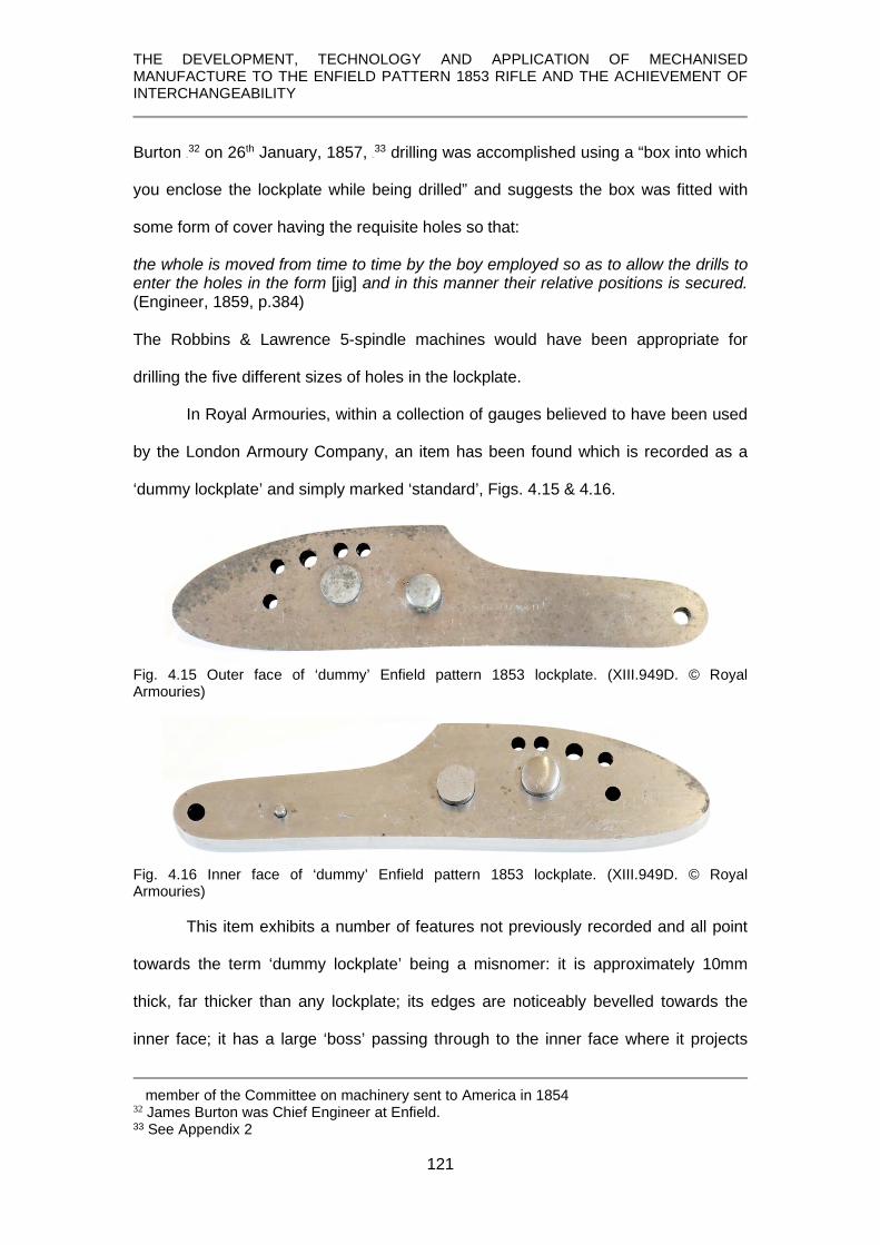
THE DEVELOPMENT, TECHNOLOGY AND APPLICATION OF MECHANISED MANUFACTURE TO THE ENFIELD PATTERN 1853 RIFLE AND THE ACHIEVEMENT OF INTERCHANGEABILITY
121
Burton 31F
32 on 26th January, 1857, 32F
33 drilling was accomplished using a “box into which
you enclose the lockplate while being drilled” and suggests the box was fitted with
some form of cover having the requisite holes so that:
the whole is moved from time to time by the boy employed so as to allow the drills to enter the holes in the form [jig] and in this manner their relative positions is secured. (Engineer, 1859, p.384) The Robbins & Lawrence 5-spindle machines would have been appropriate for
drilling the five different sizes of holes in the lockplate.
In Royal Armouries, within a collection of gauges believed to have been used
by the London Armoury Company, an item has been found which is recorded as a
‘dummy lockplate’ and simply marked ‘standard’, Figs. 4.15 & 4.16.
Fig. 4.15 Outer face of ‘dummy’ Enfield pattern 1853 lockplate. (XIII.949D. © Royal Armouries)
Fig. 4.16 Inner face of ‘dummy’ Enfield pattern 1853 lockplate. (XIII.949D. © Royal Armouries)
This item exhibits a number of features not previously recorded and all point
towards the term ‘dummy lockplate’ being a misnomer: it is approximately 10mm
thick, far thicker than any lockplate; its edges are noticeably bevelled towards the
inner face; it has a large ‘boss’ passing through to the inner face where it projects
member of the Committee on machinery sent to America in 1854 32 James Burton was Chief Engineer at Enfield. 33 See Appendix 2

THE DEVELOPMENT, TECHNOLOGY AND APPLICATION OF MECHANISED MANUFACTURE TO THE ENFIELD PATTERN 1853 RIFLE AND THE ACHIEVEMENT OF INTERCHANGEABILITY
122
approximately 3mm; on the inner face a small pin projects. Measurement of these
show them to have diameters corresponding to holes on a lockplate for the large
tumbler arbour and for the locating pin on the mainspring.
Fig. 4.17 Diameters of the projecting features and the ejector. (XIII.949D. © Royal Armouries)
A lockplate having these two holes could be fitted to the ‘dummy’s’ inner face and be
removed by a sliding ‘ejector’ passing through to the inner face.
Any thought that it was used to check the positions of the holes in the finished
lockplate by attaching this and inserting the appropriate screws through the holes in
this device is countered by two important features:
• Firstly, its thickness prevents the passage of the screws to engage with a
finished lockplate fitted to its inner face.
• Secondly, the hole diameters are the same as those in a finished lockplate
and therefore represent the root diameter of the thread, not the screw shank
diameter, thus preventing the insertion of the screws.
Fig. 4.18 Diameters of the holes. (XIII.949D. © Royal Armouries)
Similarly, any thought that it might be a filing jig to finely finish the lockplate
profile is countered by the facts that neither profile is of the correct size dismiss such
an idea.
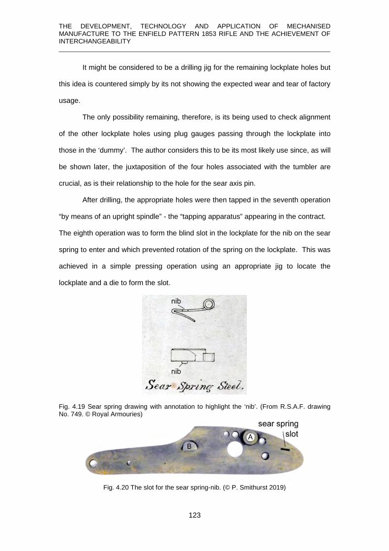
THE DEVELOPMENT, TECHNOLOGY AND APPLICATION OF MECHANISED MANUFACTURE TO THE ENFIELD PATTERN 1853 RIFLE AND THE ACHIEVEMENT OF INTERCHANGEABILITY
123
It might be considered to be a drilling jig for the remaining lockplate holes but
this idea is countered simply by its not showing the expected wear and tear of factory
usage.
The only possibility remaining, therefore, is its being used to check alignment
of the other lockplate holes using plug gauges passing through the lockplate into
those in the ‘dummy’. The author considers this to be its most likely use since, as will
be shown later, the juxtaposition of the four holes associated with the tumbler are
crucial, as is their relationship to the hole for the sear axis pin.
After drilling, the appropriate holes were then tapped in the seventh operation
“by means of an upright spindle” - the “tapping apparatus” appearing in the contract.
The eighth operation was to form the blind slot in the lockplate for the nib on the sear
spring to enter and which prevented rotation of the spring on the lockplate. This was
achieved in a simple pressing operation using an appropriate jig to locate the
lockplate and a die to form the slot.
Fig. 4.19 Sear spring drawing with annotation to highlight the ‘nib’. (From R.S.A.F. drawing No. 749. © Royal Armouries)
Fig. 4.20 The slot for the sear spring-nib. (© P. Smithurst 2019)

THE DEVELOPMENT, TECHNOLOGY AND APPLICATION OF MECHANISED MANUFACTURE TO THE ENFIELD PATTERN 1853 RIFLE AND THE ACHIEVEMENT OF INTERCHANGEABILITY
124
The bolster, B, was then ‘undercut’ to form the housing for the head of the
mainspring, followed by filing to its correct height on the lockplate using the “pattern
for filing bolster to height” in the Ames contract.
Fig. 4.21 Detail showing bolster, B, and head of mainspring. (© P. Smithurst 2019)
The large hole for the tumbler arbour was burnished by the insertion of a revolving
burnisher which was slightly tapered at the lower end and had a ‘flat’ on one side with
the corners rounded so as not to cut.
4.3.4 Machining the lockplate edges
Although these final operations are described in the Engineer, (1859, p.384),
there is much that was left unsaid and that shortfall is rectified here by providing an
in-depth analysis of how they could be accomplished.
Firstly, it has to be deduced that die-forging produced a lockplate with sufficient
uniformity for its edges to act as datum edges for operations up to this point.
Then, as noted in The Engineer:
The two surfaces, front and back, having been thus formed, it becomes necessary to rough out and finish off the outside edge to an accurate gauge, and this is effected by clipping the plate in an upright position and passing it under a milling-block filed up to the right shape: by this means the top edge is roughed out. (Engineer, 1859, p.384) This can only be a reference to ‘form-milling’ and such a cutter for milling the front top
edge of a lockplate is shown in Fig. 4.22.

THE DEVELOPMENT, TECHNOLOGY AND APPLICATION OF MECHANISED MANUFACTURE TO THE ENFIELD PATTERN 1853 RIFLE AND THE ACHIEVEMENT OF INTERCHANGEABILITY
125
Fig. 4.22 A ‘form-milling’ operation on the front upper edge of a lockplate. (© American Precision Museum, Windsor, VT.) This ‘roughing-out’ process was followed by more accurate machining:
The plate is then bolted down on a horizontal bed and acted upon by a pair of horizontal revolving milling tools, which are so placed that one finishes the top and the other the bottom edge of the plate. Forms are placed behind these milling tools, and guide pins are fixed to the frames to which the spindles are fixed; these are kept up to their work by means of weights, so that the true shape is imparted to the plate by a simple movement of the bed to which it is fixed. (Engineer, 1859, p.384) This passage undoubtedly refers to the edging machine referred to in the contract,
but falls short of being an accurate description, especially in stating the cutters were
horizontal – they revolved in a horizontal plane about a vertical axis. This confusion
may have arisen simply from the fact that such a machine had not been previously
seen in England.
Fig. 4.23 shows the only Robbins & Lawrence ‘edge’ or ‘profile’ milling
machine known to survive and was restored with assistance from the author.

THE DEVELOPMENT, TECHNOLOGY AND APPLICATION OF MECHANISED MANUFACTURE TO THE ENFIELD PATTERN 1853 RIFLE AND THE ACHIEVEMENT OF INTERCHANGEABILITY
126
Fig. 4.23 The only known surviving Robbins and Lawrence ‘edge’ or ‘profile’ miller, recently restored and in working condition. (© American Precision Museum, Windsor, VT.)
Fig. 4.24 supplies the terminology applied to features of the machine.
Fig. 4.24 The edge miller, with parts named. (Benton, 1878, Pl. XXII)

THE DEVELOPMENT, TECHNOLOGY AND APPLICATION OF MECHANISED MANUFACTURE TO THE ENFIELD PATTERN 1853 RIFLE AND THE ACHIEVEMENT OF INTERCHANGEABILITY
127
Finally, there is the machine illustrated by Fitch, Fig. 4.25, which he suggests as
being identical to those supplied to Enfield.
Fig. 4.25 Machine described by Fitch as identical to those supplied to Enfield. (Note the weight suspended between the frames). (Fitch, 1882, p. 29, Fig. 26) A notable feature of the machine in Fig. 4.25 is having what appears to be a weight
suspended beneath the machine. A table, weight-driven in one direction, certainly
aids understanding of its ‘modus operandi’.
Drawings made by Greenwood and Batley of a single-spindle machine are
believed to have been derived from the Robbins & Lawrence machines. This
drawing, Figs. 4.26 and 4.27, not previously studied or published, shows the table to
have been moved by rack and pinion.

THE DEVELOPMENT, TECHNOLOGY AND APPLICATION OF MECHANISED MANUFACTURE TO THE ENFIELD PATTERN 1853 RIFLE AND THE ACHIEVEMENT OF INTERCHANGEABILITY
128
Fig. 4.26 Detail from Greenwood & Batley drawing of ‘Edge Milling Machine, Medium Pattern’, showing sectional elevation of rack and pinion table feed. (© West Yorkshire Archives, G&B Archive Drawing No. 738; photo by G. Ombler)
Fig. 4.27 Detail of ‘Edge Milling Machine’ drawing showing plan view of rack and pinion table feed. (© West Yorkshire Archives, G&B Archive Drawing No. 738; photo by G. Ombler)
A rack and pinion, as opposed to screw feed, would have been necessary to
allow the table to be moved by a falling weight and to more easily follow a contour.
Another advantage is that with a gearing ratio giving an approximately 10:1 reduction
the table with its attached weight would be relatively easily returned to the starting
position by means of a crank handle.

THE DEVELOPMENT, TECHNOLOGY AND APPLICATION OF MECHANISED MANUFACTURE TO THE ENFIELD PATTERN 1853 RIFLE AND THE ACHIEVEMENT OF INTERCHANGEABILITY
129
The description of the profiling operation in The Engineer mentions the use of
a guide pin which obviously ‘follows’ a master pattern or template. This guide pin can
just be seen in Figs. 4.23 and 4.24 fixed at the side of the milling cutter. Again, calling
upon the Greenwood & Batley drawing No. 738, this shows the arrangement of
spindle and guide pin.
Fig. 4.28 Detail of ‘Edge Milling Machine, Medium Pattern’ showing the disposition of spindle and guide pin fixture. (© West Yorkshire Archives, G&B Archive Drawing No. 738; photo by G. Ombler)
It can be seen in Fig. 4.28 that they are at 4-inch centres and while this is only
a single spindle machine, the double-spindle machine was undoubtedly the same
since they are of similar proportions. The position and spacing of spindle and guide
pin would not have allowed the lockplate, which is approximately 5.4 inches long, and
its ‘pattern’ to be placed cross-wise side by side on the table, nor would it have so
easily achieved the desired result. They would have to be placed adjacent
longitudinally. As will be shown, this has a bearing on the way the milling operation
could be carried out.
There are features of this operation not previously discussed in any of the
published accounts and are presented here.

THE DEVELOPMENT, TECHNOLOGY AND APPLICATION OF MECHANISED MANUFACTURE TO THE ENFIELD PATTERN 1853 RIFLE AND THE ACHIEVEMENT OF INTERCHANGEABILITY
130
When in use, the table was being continually drawn in one direction by the
force applied to it by the weight. This would require that the lateral, manual,
movement of the cross head carrying the cutter and the guide pin followed a ‘positive’
rather than a ‘negative’, or re-entrant contour. Thus, both the ‘guide-pin’ and cutter
would be compelled to follow the profile. Any, even slight, movement away from the
contour would immediately allow the table, acted upon by the weight, to move
forward to restore that contact. Studying the lockplate closely reveals various
features concerning its contour and Fig. 4.29 shows that it has two ‘re-entrant’
sections.
Fig. 4.29 Contours of the Enfield 1853 lockplate. (© P. Smithurst, 2019)
Thus, if the lockplate and its template were fitted longitudinally on
the table, using the line between the two extremities of the lower
edge as a datum parallel to the direction of travel, the guide-pin,
following the template while the table was being impelled
longitudinally by the weight, would not follow these curves. As
soon as the guide pin cleared the rounded end of the lockplate at
the top, for instance, the table would immediately be propelled
forward by the free-falling weight until contact between guide pin
and template, and thus the cutter, was restored at the bottom end
of the lockplate, as in Fig. 4.30.
Fig. 4.30 Left. Using the bottom edge extremities to align the lockplate parallel with direction of travel creates a re-entrant section, allowing the guide pin and cutter to by-pass it. (© P. Smithurst, 2019)

THE DEVELOPMENT, TECHNOLOGY AND APPLICATION OF MECHANISED MANUFACTURE TO THE ENFIELD PATTERN 1853 RIFLE AND THE ACHIEVEMENT OF INTERCHANGEABILITY
131
Manual adjustment to maintain contact of the guide-pin with the template during such
motion would be impossible.
The author suggests that by slightly angling the template and the lockplate by
as little as 3°, as in Fig. 4.31, the difficulty of this lower re-entrant section would be
overcome and cause the guide-pin to follow a ‘positive’ contour and transmit this to
the cutter and thus, to the lockplate. Using an exact copy of the lockplate, the guide
pin and cutter would have to be of the same diameter. At the same setting, the table
could be drawn back to its starting position and the second, upper contour, milled by
moving the cross-head to the left to allow the table to begin its travel with the guide
pin and milling cutter following the profile on the right.
Fig. 4.31 ‘Positive’ lower contour created by angling the bottom edge of the lockplate with respect to direction of travel enables the guide pin and the milling cutter to follow both contours. (© P. Smithurst 2019)

THE DEVELOPMENT, TECHNOLOGY AND APPLICATION OF MECHANISED MANUFACTURE TO THE ENFIELD PATTERN 1853 RIFLE AND THE ACHIEVEMENT OF INTERCHANGEABILITY
132
Both these operations would be accomplished with the configuration of template and
lockplate suggested in Fig. 4.32, which also shows the paths of guide-pin and milling
cutter. Stops would undoubtedly be incorporated into the template to arrest the table
when the milling cutter had cleared the lockplate.
Fig. 4.32 Template and lockplate configuration to achieve the milling of two edges. (© P. Smithurst 2019) The remaining edge and opposite tip of the lockplate could be milled in a similar
fashion using a different template and fixture as shown in Fig. 4.33.

THE DEVELOPMENT, TECHNOLOGY AND APPLICATION OF MECHANISED MANUFACTURE TO THE ENFIELD PATTERN 1853 RIFLE AND THE ACHIEVEMENT OF INTERCHANGEABILITY
133
Fig. 4.33 Milling the front profiles. (© P. Smithurst 2019)
Of course, all this presumes the accurate positioning of the template and
lockplate, mounted in suitable fixtures on the table. This accurate positioning would
have been simplified by the fixtures for lockplate and template being an integrated
unit, thereby avoiding any displacement of one or the other.
Work on the lockplate was finished, apart from being polished and case-
hardened later
4.3.5 Gauging the lockplate
Gauges for the lockplate supplied as part of the Ames contract included:
1 gauge and plugs for testing the drilling 1 gauge receiving for testing the edges
1 gauge pattern for testing the position of the bolster for the Mainspring 1 gauge grooved for thickness of plate, bolster, etc. 1 gauge plug for testing the sizes of holes 2 gauges plug for testing tapping
The profile gauge is self-explanatory. In Fig. 4.34 the lockplate fits as it should.
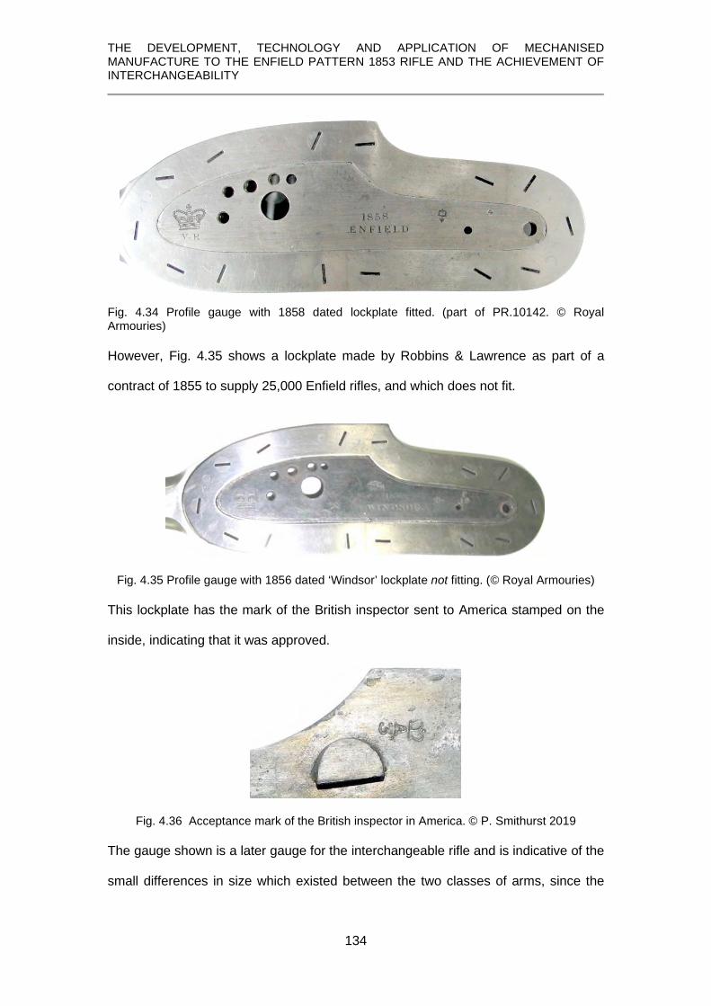
THE DEVELOPMENT, TECHNOLOGY AND APPLICATION OF MECHANISED MANUFACTURE TO THE ENFIELD PATTERN 1853 RIFLE AND THE ACHIEVEMENT OF INTERCHANGEABILITY
134
Fig. 4.34 Profile gauge with 1858 dated lockplate fitted. (part of PR.10142. © Royal Armouries) However, Fig. 4.35 shows a lockplate made by Robbins & Lawrence as part of a
contract of 1855 to supply 25,000 Enfield rifles, and which does not fit.
Fig. 4.35 Profile gauge with 1856 dated ‘Windsor’ lockplate not fitting. (© Royal Armouries) This lockplate has the mark of the British inspector sent to America stamped on the
inside, indicating that it was approved.
Fig. 4.36 Acceptance mark of the British inspector in America. © P. Smithurst 2019
The gauge shown is a later gauge for the interchangeable rifle and is indicative of the
small differences in size which existed between the two classes of arms, since the

THE DEVELOPMENT, TECHNOLOGY AND APPLICATION OF MECHANISED MANUFACTURE TO THE ENFIELD PATTERN 1853 RIFLE AND THE ACHIEVEMENT OF INTERCHANGEABILITY
135
acceptance by the inspector of something considered oversize is untenable and the
Robbins & Lawrence arms were ostensibly interchangeable.
An answer may lie in a very rare publication containing a note relating to the
Robbins & Lawrence contract, where It has been suggested, based on the account of
Lawrence himself, (Hubbard, 1922, p.71) that at the commencement of the Robbins
& Lawrence arms contract:
the Robbins & Lawrence Company called upon the War Office for sample models [of the] 1853 Enfield rifles but upon disassembling them it was discovered that no two of them were alike. A set of accurate gauges was then requested and these were also promptly sent. They were made of hard wood – originally accurate possibly to 1/64 inch – but during their sea voyage they had suffered from dampness and were warped and swollen. With this more or less useless material at hand, Robbins & Lawrence proceeded to make a drawing of the Enfield Rifle as they believed it was intended to be, and from this drawing built an extremely accurate ‘master gun’. They then made sets of hardened steel gauges carefully oilstoned after hardening to fit the parts of this master gun; they built sets of accurate jigs and fixtures around the parts which were to be drilled or milled, and sets of templates for the profiling and stocking machines were cut from these sample parts. . . . . they worked very closely to their gauges, making every part like every corresponding part, thus attaining absolute interchangeability in this stand of arms.
If true, this would account for the disparity between the Enfield gauge and the
Windsor lockplate, but it raises other questions. If Robbins & Lawrence had already
made gauges, why was another set ordered from Ames, and what were the Ames
gauges made to fit? It can only be concluded that they were made to match a
‘sample’ non-interchangeable weapon different from that supplied to Robbins &
Lawrence and which then became the prototype of the interchangeable series.
The plain holes in the lockplate were gauged with simple plug gauges,
probably used in conjunction with the item shown in Figs. 4.15 – 4.18 (p. ).
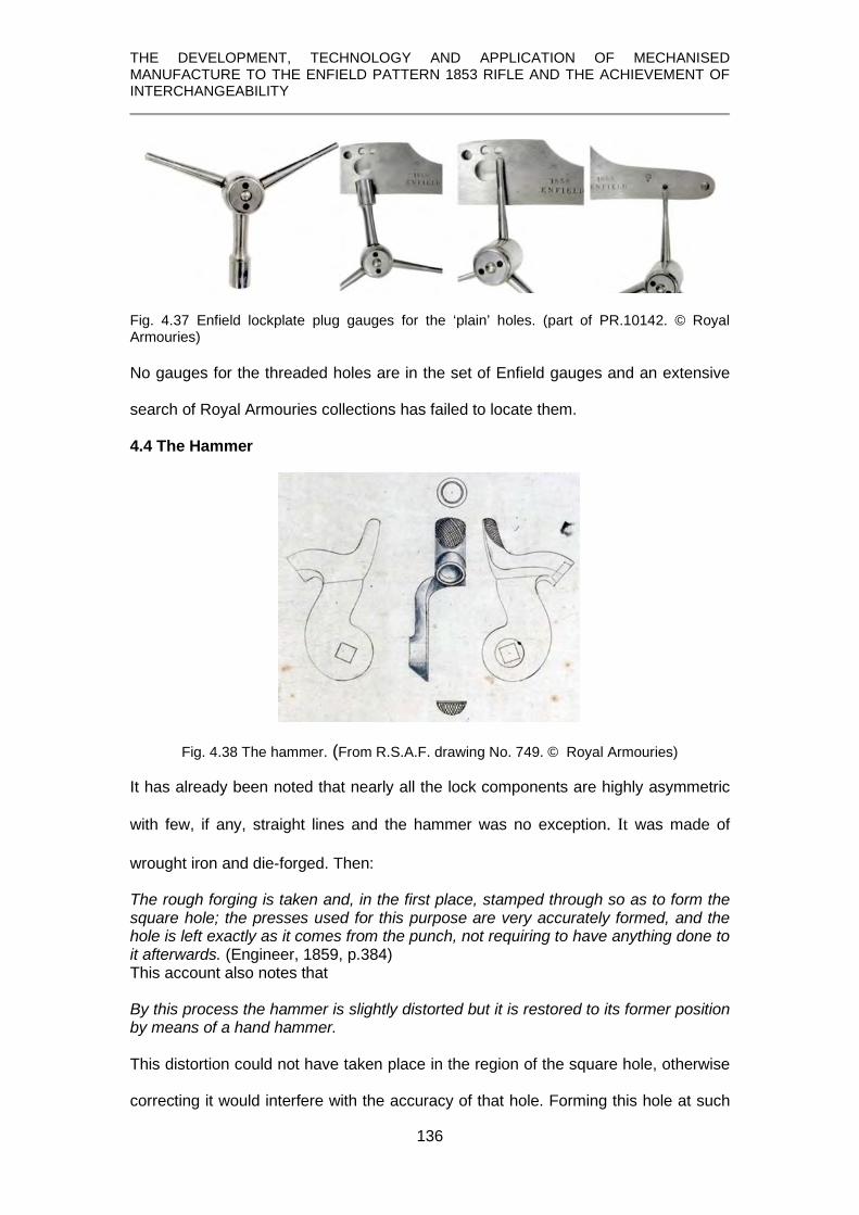
THE DEVELOPMENT, TECHNOLOGY AND APPLICATION OF MECHANISED MANUFACTURE TO THE ENFIELD PATTERN 1853 RIFLE AND THE ACHIEVEMENT OF INTERCHANGEABILITY
136
Fig. 4.37 Enfield lockplate plug gauges for the ‘plain’ holes. (part of PR.10142. © Royal Armouries) No gauges for the threaded holes are in the set of Enfield gauges and an extensive
search of Royal Armouries collections has failed to locate them.
4.4 The Hammer
Fig. 4.38 The hammer. (From R.S.A.F. drawing No. 749. © Royal Armouries)
It has already been noted that nearly all the lock components are highly asymmetric
with few, if any, straight lines and the hammer was no exception. It was made of
wrought iron and die-forged. Then:
The rough forging is taken and, in the first place, stamped through so as to form the square hole; the presses used for this purpose are very accurately formed, and the hole is left exactly as it comes from the punch, not requiring to have anything done to it afterwards. (Engineer, 1859, p.384) This account also notes that
By this process the hammer is slightly distorted but it is restored to its former position by means of a hand hammer. This distortion could not have taken place in the region of the square hole, otherwise
correcting it would interfere with the accuracy of that hole. Forming this hole at such

THE DEVELOPMENT, TECHNOLOGY AND APPLICATION OF MECHANISED MANUFACTURE TO THE ENFIELD PATTERN 1853 RIFLE AND THE ACHIEVEMENT OF INTERCHANGEABILITY
137
an early stage also suggests it may have acted as the datum for future operations so
its orientation in relation to the hammer nose especially was of particular importance.
The hammer was arrested in its fall by the nose striking the cap on the nipple;
excessive travel could cause the mainspring to strike the bottom of the lock housing
in the stock, resulting in splitting at that point.
For finishing the hammer, the tooling contract specified: Robbins & Lawrence:
1 drilling machine, 4 spindles 5 milling machines 1 checking machine for hammer hole and for trimming lockplate.
(Rosenberg, 1968, p.182) Ames: 1 drilling tool for nose (Rosenberg, 1968, p.188) The description of the first of these finishing operations is vague:
All the curves required are obtained by a series of machines fitted with circular cutters, and to effect this perfectly it has to be fixed seven different times. As these are all on the principle of those before described, it is unnecessary to say anything more about them. (Engineer, 1859, p.384) Producing these curves accurately undoubtedly required edge-milling operations.
The account in The Engineer then goes on to state;
The eye of the bolster is then rounded by means of a circular cutter on a vertical spindle. The ‘bolster’ was the part of the hammer in which the square hole, the ‘eye’, was
located and this operation was the formation of the circular flat surface around the
square hole for the hammer screw to seat on, as shown in Fig. 4.38.
The hammer nose was then recessed so that it covered the cap and the
nipple when it struck them to prevent any cap fragments striking the face of the
shooter. To do this the hammer was secured in a moveable fixture so that the face of
the nose was horizontal and the hole ‘roughed-out’ by means of what needed to be a
flat-nosed drill of some form, similar to a ‘slot drill’ – and then finished with a slightly
tapered drill [end mill/slot drill] to make the recess conical.

THE DEVELOPMENT, TECHNOLOGY AND APPLICATION OF MECHANISED MANUFACTURE TO THE ENFIELD PATTERN 1853 RIFLE AND THE ACHIEVEMENT OF INTERCHANGEABILITY
138
It is possible to draw a comparison with the hand-method, used in Liège in the
manufacture of a Spanish musket, where a hand-powered ‘end mill’ was used to form
the hammer-nose recess using a special fixture.
Fig. 4.39 Milling the hammer nose recess at Liège in a special fixture using the manually powered end mill. (Memoria, 1850, plate 35)
The outside edge of the hammer nose was then rounded concentric with the
recess by means of what can only have been a hollow end mill. This was fitted with a
spring-loaded guide pin which was entered into the recess and allowed the hollow
mill to be fed downwards to perform its work on the outside of the hammer nose.
Finally, it is noted (Engineer, 1859, p.385):
The last process, that of getting the body of the hammer to figure, is more uncommon in its action, and so merits our particular attention. The hammer is fixed in a trough filled with soap and water 33F
34, and above it revolves a milling cutter, coned to a point; this revolves at a speed equal to 1,300 revolutions [per minute]; the spindle of this cutter is moved up and down by means of a lever. Fixed to the same frame is a pointed guide-pin, which travels over a form [template] of the required shape and placed in a similar position; by this means a counterpart is formed to the mould and the hammer is completely shaped. This description suggests it only moves on two axes but to copy a 3-dimensional
surface the guide and cutter obviously have to move on 3 axes. However, resort can
be had again to the unpublished Greenwood & Batley archive drawings. One edge
34 This would act as a coolant and lubricant and probably accounts for the term ‘suds’ being used for ‘cutting oil’ at the present time.
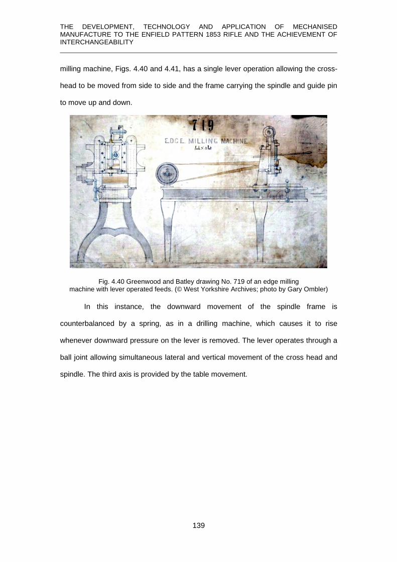
THE DEVELOPMENT, TECHNOLOGY AND APPLICATION OF MECHANISED MANUFACTURE TO THE ENFIELD PATTERN 1853 RIFLE AND THE ACHIEVEMENT OF INTERCHANGEABILITY
139
milling machine, Figs. 4.40 and 4.41, has a single lever operation allowing the cross-
head to be moved from side to side and the frame carrying the spindle and guide pin
to move up and down.
Fig. 4.40 Greenwood and Batley drawing No. 719 of an edge milling machine with lever operated feeds. (© West Yorkshire Archives; photo by Gary Ombler)
In this instance, the downward movement of the spindle frame is
counterbalanced by a spring, as in a drilling machine, which causes it to rise
whenever downward pressure on the lever is removed. The lever operates through a
ball joint allowing simultaneous lateral and vertical movement of the cross head and
spindle. The third axis is provided by the table movement.

THE DEVELOPMENT, TECHNOLOGY AND APPLICATION OF MECHANISED MANUFACTURE TO THE ENFIELD PATTERN 1853 RIFLE AND THE ACHIEVEMENT OF INTERCHANGEABILITY
140
Fig. 4.41 Side (top) and front (bottom) view details showing cross-head control lever and the spring-assisted up-stroke. Greenwood and Batley drawing No. 719. (© West Yorkshire Archives; photo by G. Ombler)

THE DEVELOPMENT, TECHNOLOGY AND APPLICATION OF MECHANISED MANUFACTURE TO THE ENFIELD PATTERN 1853 RIFLE AND THE ACHIEVEMENT OF INTERCHANGEABILITY
141
The second Greenwood & Batley machine of this nature, Fig. 42, is more
conventional in not having the spring-assisted upstroke, but its basic operation is
otherwise the same.
Fig. 4.42 Sectional side elevation of cross-head from Greenwood and Batley drawing No. 738 of a ‘Medium Pattern’ edge milling machine with annotations to show the operating system. (© West Yorkshire Archives; photo by G. Ombler)
On this machine the operating lever is again fitted with a ball joint carried in a fixture
on the cross-head support. It also passes through a swivelling housing fitted to the
vertical frame of the cross-head carrying the spindle and guide-pin.
By virtue of these mountings it can move horizontally and vertically
simultaneously, thereby moving the cross head laterally on its mounting and the
spindle and guide pin vertically. Where necessary, a depth stop controlled the
downward movement.

THE DEVELOPMENT, TECHNOLOGY AND APPLICATION OF MECHANISED MANUFACTURE TO THE ENFIELD PATTERN 1853 RIFLE AND THE ACHIEVEMENT OF INTERCHANGEABILITY
142
Fig. 4.43 Detail from Greenwood and Batley drawing No. 738 showing a part-sectional front view of the crosshead and spindle housing, annotated to show the lever, rollers and depth stop. (© West Yorkshire Archives; photo by G. Ombler)
The traversing of the heavy crosshead of both these machines was facilitated
by being mounted on rollers. Either of these machines 34F
35 would accomplish the
shaping of the hammer but a pointed cutter as stated in the account in The Engineer
would require an almost infinite number of passes. This may have been an instance
of poor observation of the cutter if viewed at a distance. The author considers the
task would have been better accomplished with a tapered cutter ending in a small
diameter rounded nose. It is stated that thirteen operations were required to finish the
hammer. (Engineer, 1859, p.385)
35 A high level of manual dexterity was required in their operation.

THE DEVELOPMENT, TECHNOLOGY AND APPLICATION OF MECHANISED MANUFACTURE TO THE ENFIELD PATTERN 1853 RIFLE AND THE ACHIEVEMENT OF INTERCHANGEABILITY
143
4.4.1 Gauging the hammer
The contract for gauges specified:
1 gauge pattern for testing the punching 1 gauge pattern for testing milling of bolster 1 gauge pattern for testing for straightening 1 gauge pattern for testing the edges 1 gauge grooved for testing the finished dimensions 1 gauge for testing the drilling of nose (Rosenberg, 1968, p.188) The only three gauges in the set in Royal Armouries collections that can be identified
with the hammer are those shown in Fig.4.44.
Fig. 4.44 Gauges for hammer. (part of PR.10142. © Royal Armouries)
The gauge on the left in Fig. 4.44 would fulfil several functions of various
Ames gauges. It effectively checks the ‘offset’ of the head from the main body and its
profile. It also allows the relationship between the square hole in the body and the
hammer nose to be confirmed. In addition it confirms the correct ‘milling of the
bolster’, that is to say the thickness where the square hole, the ‘eye’, is. The round
projection is a retractable ‘ejector’ to push the hammer off the square.
The gauge on the right in Fig. 4.44 checks the square, the flat portion surrounding
the square hole and the recess in the nose.

THE DEVELOPMENT, TECHNOLOGY AND APPLICATION OF MECHANISED MANUFACTURE TO THE ENFIELD PATTERN 1853 RIFLE AND THE ACHIEVEMENT OF INTERCHANGEABILITY
144
A third gauge in the set, Fig. 4.45, might appear at first sight to be for checking the
offset of the recess in the nose from the square hole.
Fig. 4.45 Unknown gauge, front and rear view. (part of PR.10142). © Royal Armouries) However its orientation is incorrect, the truncated conical projection on the ‘ball’ does
not fit the hammer nose and to date it has been impossible to determine its function
in relation to the Pattern 1853 rifle and it may relate to a different weapon.
4.5 The Tumbler
Fig. 4.46 The tumbler, Royal Small Arms Factory drawing No. 749, 1860. (© Royal Armouries)
Fig. 4.47 The tumbler. (© P. Smithurst 2019)

THE DEVELOPMENT, TECHNOLOGY AND APPLICATION OF MECHANISED MANUFACTURE TO THE ENFIELD PATTERN 1853 RIFLE AND THE ACHIEVEMENT OF INTERCHANGEABILITY
145
The tumbler is another component with a highly irregular and complex shape and
which needs to be very accurately formed.
The tooling contracts in this instance specified:
Robbins & Lawrence:
2 double milling machines 3 milling machines 1 drilling machine, 4 spindles 1 grooving machine 1 squaring machine 1 screw (hand) machine (Rosenberg, 1968, p.182) Ames Co.: 2 filing jigs for edges 1 drilling tool for screw-hole 1 tapping tool for screw-hole
1 drilling tool for swivel axle-hole (Rosenberg, 1968, p.188) The tumbler was first forged in dies to give the body its approximate shape. It also
had a short stub projecting from what would become its inner face and a long, thick,
shank projecting from the opposite side and from which the square would be formed.
Fig. 4.48 Enfield rifle Tumbler forging. (© P. Smithurst 2019)
The accurate formation of the tumbler was the key to the correct functioning
of the lock. The first process was to insert the arbours of the tumbler forging into the
cavities of two coaxial hollow end mills and revolve it whilst the mills are fed down the
arbours onto the faces of the body of the tumbler. This was undoubtedly the ‘double

THE DEVELOPMENT, TECHNOLOGY AND APPLICATION OF MECHANISED MANUFACTURE TO THE ENFIELD PATTERN 1853 RIFLE AND THE ACHIEVEMENT OF INTERCHANGEABILITY
146
milling machine’ referred to in the contract, and by this means the arbours were
rounded and the body thinned down to the correct thickness with its faces square
with the arbours. This description is similar to a machine used in Liège in the
manufacture of a musket for the Spanish government. The tumbler was rotated, by
means of a driving ‘dog’, h, between two milling cutters, e, e’, which ‘face’ the body to
correct thickness and round the arbours square to the body, Fig. 4.49.
Fig. 4.49 Machine used at Liège for facing the tumbler; the tumbler is rotated by the drive dog, h, between two milling cutters, e, e’. (Memoria, 1850, plate 33, detail)
The arbours were then more accurately finished by taking a thin cut off the face from
which the large arbour projected to leave a small shoulder – the anti-friction boss –
around the base of the arbour (Engineer, 1859, p.385).
Fig. 4.50 The ‘anti-friction boss’, swivel pin hole and hole for hammer screw of the Enfield rifle tumbler. (Annotated R.S.A.F. drawing No. 749, 1860. © Royal Armouries)
This ‘anti-friction’ boss was to ensure the tumbler body did not rub against the inner
face of the lockplate.

THE DEVELOPMENT, TECHNOLOGY AND APPLICATION OF MECHANISED MANUFACTURE TO THE ENFIELD PATTERN 1853 RIFLE AND THE ACHIEVEMENT OF INTERCHANGEABILITY
147
The two arbours were then finished to correct length and the hole for the ‘swivel axle’
drilled with the special tool supplied. The hole for the swivel-axle and the large arbour
then provided datum points for it to be secured in a fixture for profile milling, requiring
four separate operations.
The hole for the screw was drilled in the end of the large arbour and tapped
using the ‘screw (hand) machine’. The end of the small arbour was rounded with a
concave hollow milling cutter and then the slot for the swivel milled with a slitting saw.
It will be noticed that this slot follows a double curve (dotted line in Fig. 50) so a
profile milling machine would be used and, subsequently, part of one flank of the slit,
bisecting the hole for the swivel pin, was removed to allow the swivel to be inserted.
The square on the tumbler arbour, onto which the hammer was fitted, was formed by
mounting the tumbler in a fixture, the hole for the swivel pin acting as a datum, and
using a ‘gang-milling’ operation employing two face-milling cutters mounted
horizontally and correctly spaced, creating two ‘flats’. Rotating the fixture through 90°
enabled the square to be finished. Obviously, the centre of rotation of the fixture
would have to coincide with the centres of the arbours and the position of the flats
would have to be in correct juxtaposition to the position of the hammer.
A similar system was being used in Liège a few years previously but this
relied upon hand-filing the flats in a specially prepared jig, Fig. 51.
Fig. 5.51 Filing jig used in Liège to form the square on the tumbler shank.
(Memoria, 1850, Fig. 36 – annotated detail)

THE DEVELOPMENT, TECHNOLOGY AND APPLICATION OF MECHANISED MANUFACTURE TO THE ENFIELD PATTERN 1853 RIFLE AND THE ACHIEVEMENT OF INTERCHANGEABILITY
148
In this jig, two holes of the same diameter as the swivel pin and placed at 90o, enable
the tumbler to be accurately rotated to allow two opposing flats of the square to be
filed in succession.
Finally, the square on the Enfield tumbler arbour was pressed into a die to
‘size’ it so that it was an exact fit in the square hole on the hammer. This raises the
question of the purpose of the 1 filing gauge for squares ordered from the Ames
Company (Rosenberg, 1968, p.188). Since no filing was involved, according to the
only account available, it is difficult to envisage its function.
In the fourteenth operation the edge of the tumbler was completed in a
copying (edge) milling machine. The last operation would have been the use of the
filing jig for finishing to gauge and for accurately forming the ‘bents’, or notches, for
the sear to engage with.
4.5.1 Gauging the tumbler
The Ames contract specified – 1 Gauge receiving for testing the milling, filing etc. (Rosenberg, 1968, p.188) There are two in the set of surviving Enfield gauges which incorporate profiles and
dimensions of various features. Their functions are shown in Figs.4.52 – 4.56.
Fig. 4.52 Compound gauge for tumbler. (part of PR.10142 © Royal Armouries)
Fig. 4.53 The gauge in use checking alignment of the square with the tumbler body and body profile. (© Royal Armouries)

THE DEVELOPMENT, TECHNOLOGY AND APPLICATION OF MECHANISED MANUFACTURE TO THE ENFIELD PATTERN 1853 RIFLE AND THE ACHIEVEMENT OF INTERCHANGEABILITY
149
Fig. 4.54 The gauge in use checking dimensions of the square and the body/arbour geometry and sizes. (© Royal Armouries)
Fig. 4.55 The gauge in use checking diameters of small arbour and large arbour with its anti-friction collar. © Royal Armouries) The second gauge is for checking the relationship of the arbour with the swivel axis-
pin hole and the geometry of the swivel recess in the body of the tumbler.
Fig. 4.56 The gauge used to check the accuracy of the slot for the swivel and the placement of the swivel-pin hole. (part of PR.10142. © Royal Armouries)

THE DEVELOPMENT, TECHNOLOGY AND APPLICATION OF MECHANISED MANUFACTURE TO THE ENFIELD PATTERN 1853 RIFLE AND THE ACHIEVEMENT OF INTERCHANGEABILITY
150
4.6 The sear
The sear was probably the least geometrically complex component of the lock
but still had to be finished with special care as both the safety and functioning of the
weapon depended upon its correct engagement with the tumbler.
Fig. 4.57 Annotated R.S.A.F. Fig. 4.58 The Enfield sear. © P. Smithurst 2019 drawing No. 749 (© Royal Armouries)
It would need to be of high-quality steel, properly heat treated, to withstand the
stresses upon it, and any failure in the dimensional accuracy of the sear nose, where
it engaged with the notches on the tumbler, could result in either an unserviceable
weapon or the risk of the weapon being fired accidentally.
The tooling contracts specified
Robbins & Lawrence 1 Drilling machine, 4 spindles
2 Milling machines 1 Double milling machine (Rosenberg, 1968, p. 182) Ames. 1 Drilling tool for axle tube 2 Filing jigs for edges 1 Filing jig for end of tang (Rosenberg, 1968, p.188) The die-forged sear was pressed through a trimming die to remove any ‘fins’ and the
forging, Fig. 4.59, was then ready for subsequent machining.

THE DEVELOPMENT, TECHNOLOGY AND APPLICATION OF MECHANISED MANUFACTURE TO THE ENFIELD PATTERN 1853 RIFLE AND THE ACHIEVEMENT OF INTERCHANGEABILITY
151
Fig. 4.59 A sear forging with fins trimmed off. (© P. Smithurst 2019)
Machining commenced with drilling and reaming the hole by which it was
suspended in the lock. The faces of the body were then faced parallel and to correct
thickness in a machine similar to that used for the facing of the tumbler, and the body
was profile-milled to give it the required form. The author suggests that the flat upper
face of the tang would also have been created in this operation since it is co-planar
with the top face of the body; its rounded face, which in cross-section forms
approximately two-thirds of a circle, was effected by means of a revolving cutter
block, (Engineer, 1859, p.385). This is a somewhat inadequate description and the
author considers that for such a simple operation, it would be machined by being set
with the tang upright on a rotating fixture and rotated about the tang axis with its face
in contact with a vertical milling cutter, as in Fig. 60.
Fig. 4.60 Possible method of milling the sear tang by rotating it about its axis in contact with a vertical rotating milling cutter shown in red. (© P. Smithurst 2018)
For either of these latter two milling operations, it would have needed to be
firmly seated on a suitable fixture using its flat face, which would explain why the
machining of the anti-friction boss was left until last. In a similar manner to the
tumbler, this was carried out using a single hollow end-mill with a suitable recess and

THE DEVELOPMENT, TECHNOLOGY AND APPLICATION OF MECHANISED MANUFACTURE TO THE ENFIELD PATTERN 1853 RIFLE AND THE ACHIEVEMENT OF INTERCHANGEABILITY
152
a pilot to centre it in the hole. After this, fine finishing work on the sear was carried
out by hand and the use of the filing jigs.
4.6.1 Gauging the sear
The contract for gauges from Ames specified:
1 Gauge receiving for testing filing, milling etc. 1 Gauge plug for testing drilling and milling. (Rosenberg, 1968, p.188) There is only one gauge is in the surviving set, Fig. 4.61. It has a number of slots to
gauge various dimensions and in particular, the sear nose, and the overall profile in
relation to the pivot hole.
Fig. 4.61 The gauge for the sear. (part of PR.10142. © Royal Armouries)
Fig. 4.62 The gauge in use to check the profiles against hole position. (© Royal Armouries)
4.7 The Bridle
The bridle was another complex three-dimensional item with compound
curves and few straight lines which is apparent in the three views shown in Fig. 4.64.

THE DEVELOPMENT, TECHNOLOGY AND APPLICATION OF MECHANISED MANUFACTURE TO THE ENFIELD PATTERN 1853 RIFLE AND THE ACHIEVEMENT OF INTERCHANGEABILITY
153
Fig. 4.63 The Bridle, (R.S.A.F drawing No. 749 (annotated) © Royal Armouries.)
Fig. 4.64 Three views of the Enfield bridle. (© P. Smithurst 2019)
The tooling contract specified:
Robbins & Lawrence 1 Drilling Machine 4 Milling Machines (Rosenberg, 1968, pps. 182, 183) Ames
2 drilling tools for holes and milling pivot 1 filing jig for edges
1 tool for reaming tumbler axis and holes (Rosenberg, 1968, p.188) Machining commenced with,
first, the inside of the bolster . . . is milled after the manner before described, and the same tool faces the upper side and makes it square with the bolster itself. (Engineer, 1859, p.385) The author considers this meaningless since it would be impossible to mill the upper
surface in this operation, so it has to mean the inner surface from which the bolster
projects which would appear to an observer as ‘uppermost’ when the bridle was
inverted and mounted for milling the bolster. The same account goes on to state that
the outside face was then roughly milled. After placing in a drilling jig, the holes for

THE DEVELOPMENT, TECHNOLOGY AND APPLICATION OF MECHANISED MANUFACTURE TO THE ENFIELD PATTERN 1853 RIFLE AND THE ACHIEVEMENT OF INTERCHANGEABILITY
154
the sear pin [screw] and bridle pin [screw] were drilled and in the same machine the
locating pin was formed by means of a hollow end mill, described as a ‘rose bit’. This
indicates that the pin was integral and not inserted. It was then placed in a ‘die-clip’,
[taken to mean a shaped jig] and the pivot-hole reamered out by hand – so it had
obviously been drilled beforehand. It would have been logical to do it in the same
drilling jig as the other two holes, thereby ensuring mutual accuracy in their positions.
The edges were then rough-milled to shape and, by means of a ‘copying machine’,
the inside of the bolster was finished. This was certainly one of Robbins &
Lawrence’s ‘edging machines’ described earlier. The same account states The top
[actually the bottom where it seats on the lockplate] of the bolster was then faced.
Again, this is considered illogical inasmuch as the bolster could not be faced because
of the projecting pin and it would be thought to have already been faced in forming
the pin. The pin was then reduced to correct length and its tip rounded. The two
screw holes were counterbored to accept the heads of the ‘pins’ [screws]. The top
face was milled to correct thickness, followed by milling the inner curve between the
screw holes.
The final operation,
which until lately has always been done by hand, the finishing of the outside edge of the bolster and cutting its irregular curve, is effected in a beautiful little copying machine, which is so arranged to take the outline and pitch, at the same time following the irregularities with much greater accuracy than the most experienced workman could do, although the desired effect is so difficult of attainment. Considering the curve in question was partly conical with a varying non-circular
cross-section, this could only be executed by one of the Robbins and Lawrence 3-
dimensional profiling machines similar to that used for forming the curved surface of
the hammer and employing a ‘pattern’ of the bridle. The bridle, being now complete,
as far as it is possible to make it by machine, it is finished by hand which is an
oblique reference to the Ames filing jig supplied, a further indication that machines
often required the support of hand-skills and tools.

THE DEVELOPMENT, TECHNOLOGY AND APPLICATION OF MECHANISED MANUFACTURE TO THE ENFIELD PATTERN 1853 RIFLE AND THE ACHIEVEMENT OF INTERCHANGEABILITY
155
4.7.1 Gauging the bridle
The contract called for
1 gauge receiving for testing the filing 1 gauge pattern and plugs for testing, drilling etc. (Rosenberg, 1968, p.188) Although only two gauges were specified, the second may actually comprise
separate plug gauges; there are four gauges in the surviving cased set.
Fig. 4.65 Compound gauge for the bridle. (part of PR.10142. © Royal Armouries)
Fig. 4.66 Part of the gauge in Fig. 4.65 being used to check the geometry of holes, pin and profile. (© Royal Armouries)
Fig. 4.67 Gauge for checking the inner profile of the bolster in relation to the holes and main profile. (part of PR.10142). © Royal Armouries)
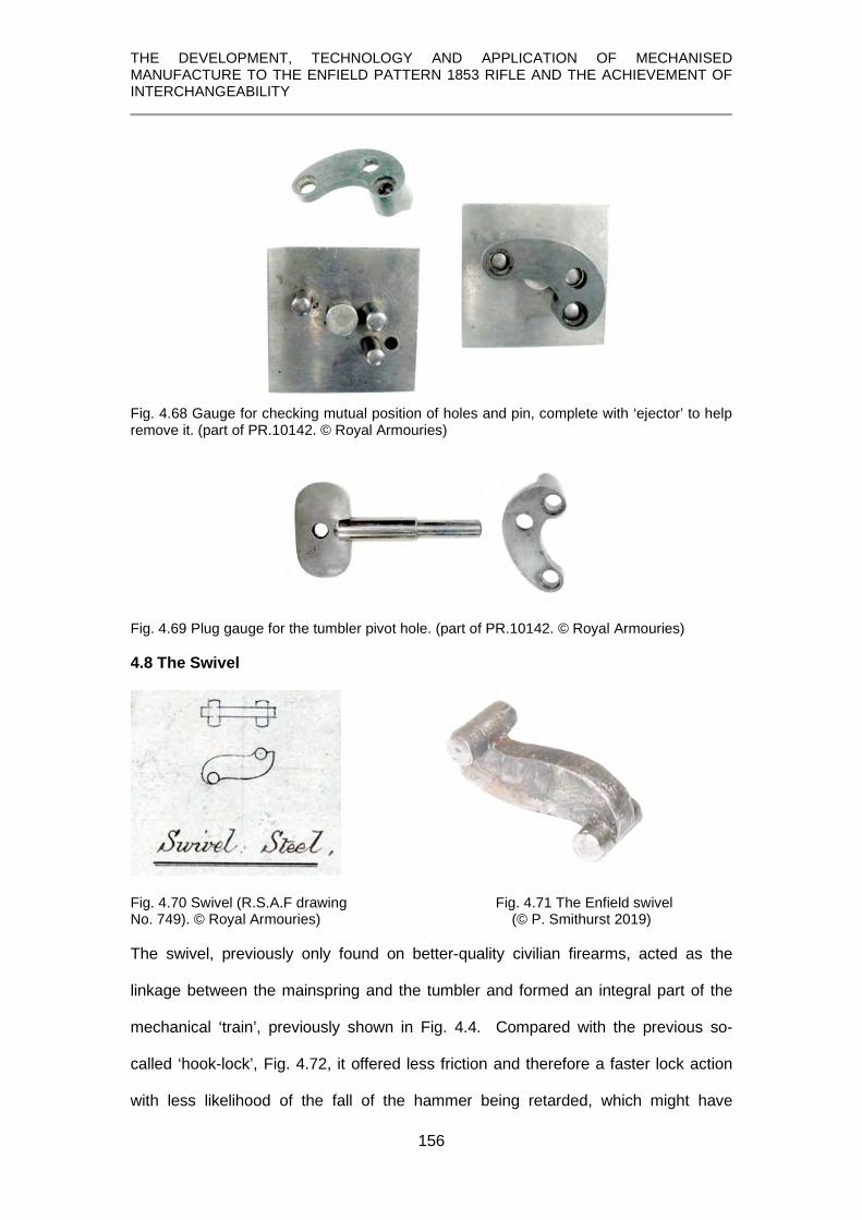
THE DEVELOPMENT, TECHNOLOGY AND APPLICATION OF MECHANISED MANUFACTURE TO THE ENFIELD PATTERN 1853 RIFLE AND THE ACHIEVEMENT OF INTERCHANGEABILITY
156
Fig. 4.68 Gauge for checking mutual position of holes and pin, complete with ‘ejector’ to help remove it. (part of PR.10142. © Royal Armouries)
Fig. 4.69 Plug gauge for the tumbler pivot hole. (part of PR.10142. © Royal Armouries)
4.8 The Swivel
Fig. 4.70 Swivel (R.S.A.F drawing Fig. 4.71 The Enfield swivel No. 749). © Royal Armouries) (© P. Smithurst 2019) The swivel, previously only found on better-quality civilian firearms, acted as the
linkage between the mainspring and the tumbler and formed an integral part of the
mechanical ‘train’, previously shown in Fig. 4.4. Compared with the previous so-
called ‘hook-lock’, Fig. 4.72, it offered less friction and therefore a faster lock action
with less likelihood of the fall of the hammer being retarded, which might have

THE DEVELOPMENT, TECHNOLOGY AND APPLICATION OF MECHANISED MANUFACTURE TO THE ENFIELD PATTERN 1853 RIFLE AND THE ACHIEVEMENT OF INTERCHANGEABILITY
157
resulted in non-detonation of the percussion cap. In the ‘hook-lock’, the ‘hook’ on the
end of the mainspring rode up and down the claw of the tumbler in action and was a
cause of friction and wear on both components. The hook-lock was used until the
introduction of the Pattern 1853 rifle and can be found in the lock of its processor, the
Pattern 1851 ‘Minié’ rifle (see Chapter 3). Its replacement with the ‘swivel-lock’ was
just one of the many refinements introduced with the new rifle.
Fig. 4.72 The traditional hook-lock of the Pattern 1851 Minié rifle. (XII.1907. © Royal Armouries) The tooling contract for this consisted simply of a 4-spindle drilling machine
(Rosenberg, 1968, p.182) but this was obviously to supplement existing machines.
The swivel began its existence as bar of steel 5/16 (0.312 inches, 7.9mm)
square which was sawn into lengths slightly longer than required. This was secured
in a fixture and the portions between where the pivots would be formed were milled
away on both sides to leave square bosses at the ends on either side. These bosses
were then converted with a hollow end mill into the circular pins or ‘axles’, removing
metal to the same level as the web between them. The edges were then milled to
shape in two consecutive operations and the heads of the pins slightly domed.

THE DEVELOPMENT, TECHNOLOGY AND APPLICATION OF MECHANISED MANUFACTURE TO THE ENFIELD PATTERN 1853 RIFLE AND THE ACHIEVEMENT OF INTERCHANGEABILITY
158
4.8.1 Gauging the swivel No gauges for the swivel were in the Ames contract but one is present in the
preserved set of gauges and was used to check form and dimensions.
Fig. 4.73 The swivel gauge and details showing the swivel in place on it. (part of PR.10142. © Royal Armouries)
4.9 The Mainspring
Fig. 4.74 Mainspring.( R.S.A.F. Fig. 4.75 An Enfield Pattern 1853 mainspring. drawing 749 © Royal Armouries) © P. Smithurst 2019 The only machines detailed in the contract with Robbins & Lawrence were three
milling machines (Rosenberg, 1968, p.182) and some tooling from the Ames Co.:

THE DEVELOPMENT, TECHNOLOGY AND APPLICATION OF MECHANISED MANUFACTURE TO THE ENFIELD PATTERN 1853 RIFLE AND THE ACHIEVEMENT OF INTERCHANGEABILITY
159
1 drilling tool for tang and milling pivot. 1 gauge plate for levelling the bottom edges.
2 filing jigs for hook and tang. (Rosenberg, 1968, p.188) Once again The Engineer (1859, p.385) provides a confusing description in which
terms like ‘lower’ and ‘top’ refer to its position in the various machines, as opposed to
its position on the lockplate.
The mainspring was first hand-forged to approximate shape and then re-
heated to red heat before placing in a bending device in which it was bent to form the
‘V’ and each arm was formed to correct curvature against fixed templates. The
bottom edge of the arm carrying the locating pin was then milled flat, leaving a small
block for the locating pin, and the longer arm was milled, removing a little more metal
than on the shorter branch so that it did not rub against the lockplate during flexing.
This difference can be discerned in the drawing above, Fig. 4.74, and provides the
equivalent of the anti-friction bosses on the tumbler and sear. The locating pin was
formed using a hollow end-mill, evidence of which can be seen in the detail in Fig.
4.76.
Fig. 4.76 Detail of circular striations left by hollow milling the locating pin. The other marks on the edges where it meets the lockplate and on the face may be file marks. (© P. Smithurst 2019) Some filing was involved and what may be traces of milling or filing on the edge of
the spring where it faces the lockplate can be seen in the illustration above.

THE DEVELOPMENT, TECHNOLOGY AND APPLICATION OF MECHANISED MANUFACTURE TO THE ENFIELD PATTERN 1853 RIFLE AND THE ACHIEVEMENT OF INTERCHANGEABILITY
160
4.9.1 Gauging the mainspring Only two gauges were contracted for from Ames:
1 gauge receiving for testing filing etc. 1 gauge plate for levelling bottom edges (Rosenberg, 1968, p.188) The mainspring gauge in the surviving set is a complex gauge with cut-outs for
checking the thicknesses and widths at various points and an arrangement for
checking the curvatures on both arms of the spring, the positions of the ‘fork’,
locating pin and the ‘tang’ by means of which it engages with the undercut bolster on
the lockplate. It may well match the Ames ‘gauge, receiving’ noted above.
Fig. 4.77 Gauge for mainspring. (part of PR.10142. © Royal Armouries)
It would have been sensible to test the ‘strength’ of the mainspring and within the list
of gauges ordered from Ames is 1 apparatus for testing power (chapter 3, p.16)
which may have been used for this purpose but is nowhere described.
4.10 Sear spring and its gauging
Fig. 4.78 Sear spring. (R.S.A.F. drawing No. 749. © Royal Armouries)

THE DEVELOPMENT, TECHNOLOGY AND APPLICATION OF MECHANISED MANUFACTURE TO THE ENFIELD PATTERN 1853 RIFLE AND THE ACHIEVEMENT OF INTERCHANGEABILITY
161
No machines were contracted for, but the contract for gauges also includes some
tooling:
1 Gauge receiving for testing filing etc. 1 Gauge plate for levelling bottom edges 2 Filing jigs for edges 1 Filing jigs for length of mill end 1 Clamp for drilling hole (Rosenberg, 1968, p. 188)
The manufacture of the sear spring, considering its overall similarity to the
mainspring, used similar methods; bending the piece of steel hot, followed by milling,
drilling of the ‘eye’, then filing to fit the gauge before finally being hardened and
tempered.
The filing jigs in the contract, as noted above, are strong indications that much of the
work was done by hand, both in forging and filing to finished size and shape. As with
the mainspring, the gauge tests for thickness and widths at various points, profile,
and the correct relationship between ‘eye’ [screw hole] and ‘nib’.
Fig. 4.79 Gauge for the sear spring. (part of PR.10142. © Royal Armouries)
4.11 Screws and their gauging
There are four screws which form part of the lock components: two identical bridle
screws, one of which acts as a pivot for the sear; one sear spring screw; one
hammer screw. The bridle and sear spring screws have identical threads and only
differ in length; the hammer screw has a coarser thread and larger diameter head.

THE DEVELOPMENT, TECHNOLOGY AND APPLICATION OF MECHANISED MANUFACTURE TO THE ENFIELD PATTERN 1853 RIFLE AND THE ACHIEVEMENT OF INTERCHANGEABILITY
162
The machines ordered from Robbins & Lawrence for their manufacture comprised:
2 screw milling machines 2 thread cutting (hand) machines 1 slitting machine 1 pointing machine (Rosenberg, 1968, p. 182) This was later supplemented by: 1 clipping machine (Rosenberg, 1968, p. 183) The Ames Co. supplied
Gauge plate for testing dimensions, length, cutting threads etc. The only mention found in regard to the manufacture of these screws is that:
the tumbler screw is formed in a manner very similar to that before described, only that it is screwed by hand, then hardened and tempered . . the sear-spring screw likewise. (Engineer, 1859, p.422) The only screw described in ‘The Engineer’ was that for the barrel-tang which was
forged, the head ‘clamp-milled’35F
36, the shank rounded by a hollow end mill – a similar
operation to that used on the ‘pins’ of the mainspring, tumbler and swivel. However,
there is no mention of a clamp milling machine in the contract, nor of the cutters for
clamp-milling. But, the mention of ‘screw milling machines’ raises questions. The
context in which they are mentioned suggests to the author that they were used for
milling screw threads. However, it is known that the ‘thread-milling’ machine was first
invented, or at least patented, in 1897 by H. Liebert of Rochdale (Steeds, 1969,
p.141).
It has already been noted in Chapter 3 that ‘screw-machines’ were supplied by
Hobbs & Co. (Thomas, 1855, p.2, line 2) which was almost certainly the lock making
company established by Alfred Hobbs, an American who would have had access and
knowledge of machine tools used in America. An account of his operations makes
the very pertinent observation:
36 Clamp-milling used two dies with cavities to match the profile of the screw and ‘teeth’ formed in them. They were clamped around the rotating workpiece to produce the desired shape.

THE DEVELOPMENT, TECHNOLOGY AND APPLICATION OF MECHANISED MANUFACTURE TO THE ENFIELD PATTERN 1853 RIFLE AND THE ACHIEVEMENT OF INTERCHANGEABILITY
163
The various studs and screws are made . . . by girls with automaton machines which require little or no skill beyond that of putting in the raw material and taking out the finished products. (Engineer, 1859, p.190)
Since the truly ‘automatic’ screw machine was only invented by Christopher
Spencer in 1873 (Spencer, 1873), the author infers that Hobbs was using some form
of ‘turret’ or ‘capstan’ lathe which might be regarded ‘semi-automatic’ in requiring a
degree of manual operation. Hobbs’ machines may have been supplied by Robbins
& Lawrence since the author has found no evidence for any similar machines existing
in England at that time. Frederick Howe, who was to become one of Robbins &
Lawrence’s key tool designers, during his apprenticeship encountered a ‘turret’ or
‘capstan’ lathe with a multiple tool holder rotating on a vertical, as opposed to a
horizontal, axis (Rolt, 1965, p. 165). Others suggest it to have been invented by
Henry Stone, another employee of Robbins & Lawrence and who first produced it
commercially in 1854 (Roe, 1916, p.143). It is therefore all the more strange that it
does not feature amongst the Robbins & Lawrence tooling.
In the face of that, and considering the ‘hand-threading’ machines mentioned,
it can only be concluded that ‘thread milling’ was simply the use of a hollow end mill
to reduce the diameter of a bar of iron to form the shank and underside of the head of
the screws, the part-formed screw separated from the bar by the use of a suitable
formed parting-off tool to create a slightly ‘domed’ head, and then a slot cut in the
head. The thread could then be cut with the ‘hand machine’, The absence of a lathe
being mentioned is taken to mean that the tooling supplied were special tools to
supplement either existing machines at Enfield, or which would have been readily
available from numerous English makers. This, of course, is all circumstantial but
based on an understanding of engineering workshop practice. However, the nature of
the ‘clipping machine’ mentioned remains a mystery – no such machine is mentioned
in any of the contemporary accounts. Also, there is no mention of a ‘hollow end mill’
in the contract, although this could easily have been produced in the Enfield factory

THE DEVELOPMENT, TECHNOLOGY AND APPLICATION OF MECHANISED MANUFACTURE TO THE ENFIELD PATTERN 1853 RIFLE AND THE ACHIEVEMENT OF INTERCHANGEABILITY
164
toolroom. Indeed, such tools referred to as ‘grinders’ for use by hand were supplied
to regimental armourers for the same purpose.
Fig. 4.80 A ‘side-nail grinder’ for use by hand to form the shanks of screws. (© P. Smithurst
2020)
No workshop drawings of the screws are known to exist but their general form
is shown by the gauge in Fig. 81. Their profiles in the gauge can be clearly seen, the
holes being used to check shank/thread sizes plus a larger recess for the head of the
hammer screw. This gauge differs from all the others in being the only one not being
marked with the War Department mark, or designated as ‘standard’ and was
probably made in the factory as a duplicate of, or replacement for, the original gauge
supplied by Ames.
Fig. 4.81 Gauge marked “Pattern 53 lock screws”. (part of PR.10142. © Royal Armouries)

THE DEVELOPMENT, TECHNOLOGY AND APPLICATION OF MECHANISED MANUFACTURE TO THE ENFIELD PATTERN 1853 RIFLE AND THE ACHIEVEMENT OF INTERCHANGEABILITY
165
4.12 Gauging the assembled lock
A further gauge, not featured in the Ames contract list, exists and would have
been used for ensuring that the assembled lock would fit the lock recess in the stock.
Fig. 4.82 Lock assembly gauge marked ‘W.D. Standard’. (part of PR.10142. © Royal Armouries)
Fig. 4.83 Lock assembly gauge fitted with ‘working model’ of the lock. (© Royal Armouries)
Fig. 4.83 shows a ‘reverse’ view of it fitted with the ‘working model’ lock which will be
discussed in Chapter 5, and was used in the Stocking Department to check the lock
recess in the stock.
Being fitted with a trigger, it also allowed the lock to be operated to ensure
none of the moving parts would at any time foul the lock recess in the stock and,
furthermore, it also allowed the position of the hammer nose in relation to the nipple
to be checked and may have functioned as the “Mainspring testing apparatus”

THE DEVELOPMENT, TECHNOLOGY AND APPLICATION OF MECHANISED MANUFACTURE TO THE ENFIELD PATTERN 1853 RIFLE AND THE ACHIEVEMENT OF INTERCHANGEABILITY
166
ordered from Robbins & Lawrence (Chapter 3, p.15) or, more likely the “Apparatus
for testing power” ordered from Ames since it was listed in the gauges contract
(Chapter 4, p.17).
4.13 Some metrology of the Enfield Lockplates
No metrology of the lockplate has ever been published and some 18 years
ago, through the kindness and cooperation of colleagues at Royal Armouries and of
Malcolm Jackson, metrologist at the School of Engineering at Sheffield Hallam
University, the author was able to have carried out some simple metrology on a
group of Enfield lockplates.
The focus of this study was to determine any variations in the mutual
locations of a specific group of holes, 1, 2, 5 and 6, highlighted in red in the drawing
below, Fig. 4.84.
Fig. 4.84 The Enfield Pattern 1853 Lockplate Holes. (© P. Smithurst 2020)
The holes relate to the bridle (blue) which acts as a ‘cage’ housing the tumbler
(black) and the sear (red) and may be more apparent when they are seen in
conjunction with these key components, Fig. 4.85.

THE DEVELOPMENT, TECHNOLOGY AND APPLICATION OF MECHANISED MANUFACTURE TO THE ENFIELD PATTERN 1853 RIFLE AND THE ACHIEVEMENT OF INTERCHANGEABILITY
167
Fig. 4.85 Showing the bridle, tumbler and sear in place. (© P. Smithurst 2020)
It is clear that since the bridle is a single entity, the matching holes in the lockplate
had to correspond exactly, otherwise the bridle could not be fitted. Whilst there had to
be some clearance in the shank diameter of the screws and the holes in the bridle
through which they passed, this would have been minimal otherwise the bridle could
have moved and caused the tumbler to ‘cant over’ and ‘bind’. It has to be accepted
that since all these locks passed inspection and were accepted into service, all were
correctly made and assembled to the satisfaction of the inspectors.
The study focussed on the lockplates from two groups of rifles in Royal
Armouries’ collections; those assembled using contracted locks supplied to the
Tower and dated 1855 and those supplied through a contract with manufacturers in
Liege with locks dated 1856. They were selected because they represented the
largest groups with identical dates which it was felt would provide a valid basis for
comparison and allow some inferences to be drawn respecting the inspection
process.
A special ‘jig’, Fig. 4.86, was made to hold the lockplates in identical positions
during the measuring process and had cavities into which the bolsters of the
lockplates fitted to enable them to lay flat.

THE DEVELOPMENT, TECHNOLOGY AND APPLICATION OF MECHANISED MANUFACTURE TO THE ENFIELD PATTERN 1853 RIFLE AND THE ACHIEVEMENT OF INTERCHANGEABILITY
168
Fig. 4.86 Lockplate held in a jig having an ‘L’-shaped lever acted upon by a screw which pressed the lockplate against square shoulders at its left-hand tip and along its bottom edge. (© P. Smithurst 2020)
The shoulders against which the lockplate abutted were square with each other and
parallel to the corresponding outside edges. All the holes were measured regarding
their positions relative to the large hole for the tumbler arbour as the origin and
centres were obtained by averaging diameters using a cylindrical probe to minimise
errors in threaded holes.
The data, obtained using a Siemens coordinate measuring machine, was
never published and the results are presented here for the first time and the
tabulated metrology results are shown in Appendix 6.
A visual interpretation of the numerical data was created by ‘reconstructing’
the sets of holes using a 2-dimensional version of ‘AutoCAD’, ‘Autosketch’, which
allowed dimensions to be reproduced accurately to within two decimal places.
Bearing in mind all these locks were produced at a time before interchangeable
manufacturing was introduced, using this method a number of discrepancies in the
lockplates are revealed which allow some inferences to be drawn regarding the
manufacturing and inspection processes and the acceptable limits of variations.
4.13.1. Tower 1855 Lockplates
Within this group are three lockplates, XII.7235, XII.8999 and XII.9000,
manufactured by Joseph Brazier & Son, the most celebrated lock maker at that time.

THE DEVELOPMENT, TECHNOLOGY AND APPLICATION OF MECHANISED MANUFACTURE TO THE ENFIELD PATTERN 1853 RIFLE AND THE ACHIEVEMENT OF INTERCHANGEABILITY
169
Using the visual ‘replicas’ and superimposing them, shows the close correspondence
between the holes, Fig. 4.87.
Fig. 4.87 Three Brazier lockplates superimposed showing close correspondence of the holes. (© P. Smithurst 2020)
The degree of correspondence in relation to holes 1, 2, 5 & 6 can be quantified, as
shown in Fig. 4.88 in which the distance between the centres of the most widely
spaced holes is noted.
Fig. 4.88 Quantified discrepancies of bridle locating holes showing greatest variation in the three Brazier lockplates in Fig. 4.87. (© P. Smithurst 2020)
The results of applying the same process to other lockplates in this series,
using one of Brazier’s lockplates for reference, are shown below in Figs. 4.89 – 4.91.
These all show what was obviously an acceptable degree of variation in hole
positions.

THE DEVELOPMENT, TECHNOLOGY AND APPLICATION OF MECHANISED MANUFACTURE TO THE ENFIELD PATTERN 1853 RIFLE AND THE ACHIEVEMENT OF INTERCHANGEABILITY
170
Fig. 4.89 Brazier lockplate and lockplate by Corbett. (© P. Smithurst 2020)
Fig. 4.90 Brazier lockplate and lockplate by Partridge. (© P. Smithurst 2020)
Fig. 4.91 Brazier lockplate and lockplate by Steatham. (© P. Smithurst 2020)
Two other pairs, drawn from those used earlier, can also be compared, Figs. 4.92,
4.93.
Fig. 4.92 Corbett and Partridge lockplates compared. (© P. Smithurst 2020)

THE DEVELOPMENT, TECHNOLOGY AND APPLICATION OF MECHANISED MANUFACTURE TO THE ENFIELD PATTERN 1853 RIFLE AND THE ACHIEVEMENT OF INTERCHANGEABILITY
171
Fig. 4.93 Partridge and Steatham lockplates compared. (© P. Smithurst 2020)
4.13.2. Belgian 1856 Lockplates
The same technique applied to the Belgian lockplates, using the same Brazier
lockplate as reference gives similar results, but only a few are illustrated, for
instance.
Fig. 4.94 Brazier and Belgian lockplate compared. (© P. Smithurst 2020)
Fig. 4.95 Brazier and Belgian lockplate compared. (© P. Smithurst 2020)
Fig. 4.96 Two Belgian lockplate compared. (© P. Smithurst 2020)

THE DEVELOPMENT, TECHNOLOGY AND APPLICATION OF MECHANISED MANUFACTURE TO THE ENFIELD PATTERN 1853 RIFLE AND THE ACHIEVEMENT OF INTERCHANGEABILITY
172
It is clear from this evidence that it would have been impossible to fit the bridle of one
lock maker the lockplate of another.
4.13.3. Damage revealed in the metrology process
During the metrology it was discovered that some holes were noted as ‘block’
(see Appendix 7). In these instances, this simply meant that the hole 6, which
corresponds with the locating pin on the bridle, was blocked by the remnant of the
fractured pin. This could indicate a number of factors. Since the lock was
disassembled during the viewing or inspection process, such a breakage must have
occurred subsequently.
Also, since these rifles never left military service and have been in storage
ever since – they have never been in private hands – such a breakage might have
resulted from various causes: careless disassembly and/or reassembly by the
regimental armourer, which is unlikely.
A more likely cause is that, as noted in the contract document, Fig. 98, the
locks were initially examined in ‘the filed state’, implying that the components had not
been case-hardened. Case hardening of very asymmetric items, such as the bridle,
is known to cause some ‘warping’ when they are quenched. 36F
37 Moreover, to achieve
a reasonable depth of case hardening in the body of the bridle may have resulted in
over-hardening of the slender locating pin, making it extra-brittle. Fitting and
tightening the screws of a possibly slightly warped hardened bridle to the lockplate
might easily have caused this fracture which would have passed un-noticed since the
lock had already been inspected.
37 Such warping was known to exist in the manufacture of files, especially half-round files where the larger area of the curved surface allows it to cool faster when quenched, causing the file to bend. File makers counteracted this tendency by judiciously bending the unhardened files so that they straightened when quenched!

THE DEVELOPMENT, TECHNOLOGY AND APPLICATION OF MECHANISED MANUFACTURE TO THE ENFIELD PATTERN 1853 RIFLE AND THE ACHIEVEMENT OF INTERCHANGEABILITY
173
4.13.4. Questions surrounding inspection of contract locks.
The deviation between the holes relating to the bridle alone, and their
acceptability, calls into question the nature of both the process of manufacture by
private contractors, and inspection.
It is known from contractual details that each manufacturer, of whatever
component of the rifle, could only ‘inspect’ the patterns at the Ordnance Offices at the
Tower of London or at Birmingham and would have to prepare his own jigs and
gauges.
Fig. 4.97 Detail from a contract of 1851. (Appendix 2, item 1. © P. Smithurst 2020)
Under such circumstances is not really surprising that such variation existed;
what is more surprising is that, in many cases, such close correspondence resulted.
Another contract document, Fig. 98, implies it was the correct functioning of the lock,
its correct overall size and shape and the finishing of the components that were of
primary concern, rather than precise component sizes and hole positions.

THE DEVELOPMENT, TECHNOLOGY AND APPLICATION OF MECHANISED MANUFACTURE TO THE ENFIELD PATTERN 1853 RIFLE AND THE ACHIEVEMENT OF INTERCHANGEABILITY
174
Fig. 4.98 Abstract from contract document detailing the lock inspection process. (Appendix 2, item 5 © P. Smithurst 2020)
No reference to the nature of the ‘standard jegs and gauges’ is known to
exist. However, in view of the fact that these variations in positions of the array of
holes associated with the bridle were officially acceptable, the author infers that no
gauge could have been used to assess them; it would have been impossible to
construct a gauge that would encompass these variations without risk of sacrificing
the functional integrity of the lock. While the lockplate-bridle-tumbler combination had
to be an exact fit, the other interacting components would have been made to interact
correctly.
4.13.5 Further metrology and interchangeability
A further, smaller programme of metrology was performed recently with the
intention of establishing some ‘bench marks’ for comparison with interchangeable
manufacture provided by a Robbins & Lawrence ‘Windsor’ lockplate and an 1861
Enfield lockplate.
The Windsor contract rifles fell within the period when the second pattern
barrel bands, held in place by a spring instead of a clamping screw, were in use.
Most of these rifles were made under contract in Liège in 1856 and it is therefore
likely that it was samples of these which were supplied to Robbins & Lawrence as
‘patterns’. It was felt to be instructive, therefore, to compare a Windsor lockplate with
these Liège-made rifles and some results are shown below.

THE DEVELOPMENT, TECHNOLOGY AND APPLICATION OF MECHANISED MANUFACTURE TO THE ENFIELD PATTERN 1853 RIFLE AND THE ACHIEVEMENT OF INTERCHANGEABILITY
175
Fig. 4.99 Robbins & Lawrence lockplate with Liege lockplate XII.8428. (© P. Smithurst 2020)
Fig. 4.100 Robbins & Lawrence lockplate with Liege lockplate XII.9102. (© P. Smithurst 2020)
In addition to the expected hole centre discrepancies encountered previously, it
should be noted that in both cases, the large hole in the Windsor lockplate is offset to
the left in relation to the Liège-made rifles.
This same discrepancy is found in comparing the Windsor lockplate with that
of the 1861 Enfield lockplate.
Fig. 4.101. Robbins & Lawrence lockplate with Enfield lockplate of 1861. (© P. Smithurst 2020)

THE DEVELOPMENT, TECHNOLOGY AND APPLICATION OF MECHANISED MANUFACTURE TO THE ENFIELD PATTERN 1853 RIFLE AND THE ACHIEVEMENT OF INTERCHANGEABILITY
176
It should be noted that the lockplate in Fig. 4.101 was from a lock made at Enfield in
1861. This date, in combination with the name ‘Enfield’, indicates this lock to be one
of the ‘interchangeable’ series which came into production after 1857. 37F
38 Taking the
bridle from this lock and applying to it the gauge, Fig. 4.102, shows its overall form
and the critical three holes and the locating pin to be a perfect fit.
Fig. 4.102 Bridle from an Enfield lock dated 1861 is a perfect fit to the gauge. (The small hole in the gauge is for an ‘ejector-pin’ in the event of the bridle being a ‘tight fit’.) (gauge part of PR.10142. © Royal Armouries)
A similar exercise performed with the tumbler, the other item of complex form,
from this lock of 1861 was also a perfect fit to the gauge, Fig. 4.103. [The tumbler
was a tight fit so it was not pushed fully into the gauge]
38 It should be noted that even after 1857, contractors were still used to manufacture short rifles and carbines and these will have the name ‘Tower’ and a post-1857 date on the lock and are not interchangeable.

THE DEVELOPMENT, TECHNOLOGY AND APPLICATION OF MECHANISED MANUFACTURE TO THE ENFIELD PATTERN 1853 RIFLE AND THE ACHIEVEMENT OF INTERCHANGEABILITY
177
Fig. 4.103 Tumbler from an Enfield lock dated 1861 is a perfect but tight fit in the gauge. (gauge part of PR.10142. © Royal Armouries) This is taken to be clear indication that interchangeability of these complex
components was indeed being achieved. It might be argued that two samples are
statistically insignificant. On the other hand, in the absence of interchangeable
manufacture, the author would argue that the chance of finding two components at
random that were perfect fits to the gauges is vanishingly small. The metrology data

THE DEVELOPMENT, TECHNOLOGY AND APPLICATION OF MECHANISED MANUFACTURE TO THE ENFIELD PATTERN 1853 RIFLE AND THE ACHIEVEMENT OF INTERCHANGEABILITY
178
of this particular lockplate with regard to the holes for the bridle can therefore be
taken to represent the ‘standard’.
Unfortunately, it has not been possible at this time to further extend this
metrology to interchangeable arms because all available avenues for the loan of
locks or lock components have been exhausted.
4.14 Summary
In addressing this topic, much new material, ranging from unpublished factory
drawings, artefacts, unique official documents, metrology data and specially prepared
drawings, has been utilised and included in providing a more detailed analysis and
description of the manufacture of the lock and its attendant procedures than hitherto.
It has been shown
1. that the lock is a complex mechanism composed of parts having complex
geometries.
2. that sophisticated machines were required for the accurate repetitive
production of lock components of complex shape, and insights into the
operation of these machines and the accurate repetitive production of
components, not present in other published accounts, have been provided
3. that the bridle had four locating features, each of which had to coincide
exactly with its mounting points on the lockplate and both demanded high
degrees of accuracy
4. that the tumbler had to be accurately formed to perform its proper function
5. that other vital components had to accurately interact with the tumbler in a
‘train’ and their accurate manufacture, fitting and interaction had to be
sustained if any components were transferred to another lock to exhibit
interchangeability.

THE DEVELOPMENT, TECHNOLOGY AND APPLICATION OF MECHANISED MANUFACTURE TO THE ENFIELD PATTERN 1853 RIFLE AND THE ACHIEVEMENT OF INTERCHANGEABILITY
179
6. that interchangeability had been achieved after 1857, demonstrated by the
simple fitting of the more complex components of an 1861 dated lock to
gauges dating from 1857
7. that gauging was the essence of the system
8. that the incomprehensible issue of wooden gauges to Robbins & Lawrence at
the time of the contract for rifles is indicative of the ‘establishment’s’
rudimentary concept of gauging.
9. that the contract for gauges from Ames suggests that the ‘establishment’ was
not able to construct the gauges required
10. that had gauges such as those supplied by Ames been in use and duplicates
issued to contractors then interchangeability could have been achieved prior
to 1857.

THE DEVELOPMENT, TECHNOLOGY AND APPLICATION OF MECHANISED MANUFACTURE TO THE ENFIELD PATTERN 1853 RIFLE AND THE ACHIEVEMENT OF INTERCHANGEABILITY
180

THE DEVELOPMENT, TECHNOLOGY AND APPLICATION OF MECHANISED MANUFACTURE TO THE ENFIELD PATTERN 1853 RIFLE AND THE ACHIEVEMENT OF INTERCHANGEABILITY
181
CHAPTER 5
MANUFACTURE OF THE STOCK
In this chapter the manufacture of the stock is examined in detail.
After tracing the historical development of the machines involved it provides details of
the machines and processes beyond those previously published.
This is based on the evidence provided specimen stocks in their stages of
manufacture and some surviving factory drawings of the machines used, none of
which have been studied or published previously.
Newly created drawings have been used to supplement the elucidation of processes
involved.
One set of stock-making machines could produce 1200 finished stocks per week
(Greenwood, 1862, p.335), a vast improvement over the traditional methods
employed, and being interchangeable made assembly, or ‘setting-up’, and re-
stocking ‘in the field’ a much simpler task. That these gunstocks were durable is
evidenced by the large numbers which survive to this day.

THE DEVELOPMENT, TECHNOLOGY AND APPLICATION OF MECHANISED MANUFACTURE TO THE ENFIELD PATTERN 1853 RIFLE AND THE ACHIEVEMENT OF INTERCHANGEABILITY
182
5.1 Overview
While the barrel is the key item of any firearm, followed by the ‘lock’ or other
device which comprises the ignition system, it is the gunstock upon which they are
mounted in correct juxtaposition along with other parts of the gun that enables it to be
used. It is a vital part of that triumvirate, ‘lock, stock and barrel’.
The details contained in the few published accounts of manufacture provide
incomplete details of the various processes the stock passes through. However, the
author has been able to draw upon a collection of stocks in different stages of
manufacture plus some original factory drawings of some machines, neither of which
have been previously studied or published. It has thus been possible to arrive at and
present insights and a fuller understanding of the functions of the various machines
and the processes they performed. This has been augmented by newly created
drawings to elucidate various machine characteristics and processes.
Traditionally, walnut has been the chosen wood and, as Cotty noted in 1806:
Walnut wood offers more advantages than others for the assembly of firearms, and is used only for military firearms. For this wood is no longer likely to be available ready for use, since it must have at least three years after cutting, including two under cover. If a wood is not sufficiently dry, by giving it a stroke of a plane, the chip is still wet and it has the smell of green wood; exposed to the sun, the wood splits when it dries. These woods must be grey or half grey; the white ones almost always coming from the sapwood, which is an imperfect part, must be discarded, as well as those with yellow stains and worm holes, or other defects which show their decomposition or bad quality; finally, those who are not sufficiently straight in their whole length, or which have knots which can cause them to break, must also be discarded. In general, their quality depends on the terrain in which they grew, their age, and how they were treated after cutting. They can be kept forever by rubbing them at intervals with a piece of serge or cloth impregnated with oil. (Cotty, 1806, p.14,15)
These criteria still apply but it is worth noting that Royal Armouries have in
their collections seven French Model 1777 An. XIII (1804) muskets (Acc. No.:
XII.2228, XII.2229, XII.2230, XII.2231, XII.2232, XII.2233, XII.2234), dated 1806,
fitted with stocks of Beech, Poplar, Maple, Chestnut, Ash, Oak and Elm, reportedly

THE DEVELOPMENT, TECHNOLOGY AND APPLICATION OF MECHANISED MANUFACTURE TO THE ENFIELD PATTERN 1853 RIFLE AND THE ACHIEVEMENT OF INTERCHANGEABILITY
183
part of a series of experiments to find a suitable alternative to walnut as the forests
were depleted of this timber in the Napoleonic wars.
In Mémoire sur le montage du fusil, (Dale, 1810) the making of the gunstock
for the French 1777 musket at Liège is described and makes it abundantly clear that
all the work was carried out by hand. At the Russian weapon factory at Tula, Elm or
Birch were employed, and the work was usually carried out in the stockmakers’ own
homes (Gamel, 1826, pp.91,92). The stockmakers were supplied with all the
components to build a finished musket and therefore they also acted as ‘setters-up’
[assemblers] of the musket.
Likewise, the gunstock for a Spanish musket manufactured in Liège in the
late 1840’s relied upon hand-skills (Memoria, 1850) and it is logical to assume that
similar practices were also used in England until c. 1855 since there were no
mechanical alternatives.
5.2 The advent of mechanisation
In his section on gun-stock manufacture, Gamel notes:
By viewing in Portsmouth the excellent machines invented by Mr. Brunell [sic] for the manufacture of ship blocks, it is easy to agree that mechanical methods could also be convenient for the manufacture of the gun-stocks. (Gamel 1826, p.155, footnote) These machines, (Brunel, 1801), were certainly ground-breaking in many respects
but one that offerered scope for adaptation to the making of a gun stock was that
used for the production of the dead-eyes, the circular blocks by means of which the
standing rigging was secured to the sides of the ship. This machine does not appear
in the patent but is usually included with illustrations of Brunel’s machinery at
Portsmouth. While dead eyes were circular, they had two peripheral grooves which
did not extend to the full circumference and tapered to nothing at each end. The
machine for scoring these grooves used a two-lobed cam attached to the spindle on
which the dead-eye was mounted and which acted on a ‘cam-follower’. This ‘follower’
was attached to a weighted or spring-loaded frame carrying a rotating circular cutter,

THE DEVELOPMENT, TECHNOLOGY AND APPLICATION OF MECHANISED MANUFACTURE TO THE ENFIELD PATTERN 1853 RIFLE AND THE ACHIEVEMENT OF INTERCHANGEABILITY
184
causing it to rock backwards and forwards and bring the cutter into or out of
engagement with the workpiece and thus produce the discontinuous groove. This
feature appears on later gunstock machines but, apart from Gamel, no-one is known
to have considered the adaptation of Brunel’s machine to making gunstocks.
In 1802 a patent was granted to Joseph Bramah for Machinery for forming
gunstocks &c. (1802) but although the title is encouraging, it fails to live up to
expectation and in many respects it differs little and offers less than Bentham’s
patents (1791), (1793) and is primarily concerned with producing flat, linear, or
spherical surfaces. No record of it ever having been put into practice in any context
has been found.
5.3 Blanchard’s developments in the United States
In the United States, the mechanisation of gunstock manufacture was already
underway when Gamel wrote his footnote. In 1819 a patent was granted to Thomas
Blanchard for a machine for turning gunstocks (Blanchard, 1819). His original patent
had four principal claims but was objected to (Cooper 1991, p.81) and was re-issued
on Jan. 20, 1820 with the claims:
The first principle of which I claim to be the inventor consists in the centres of the guide [model or pattern] and work [workpiece] being placed in a line, and parallel to the centres of a friction wheel and the cutting wheel, which are also placed on a line, by means of which, and a spring bearing against the opposite side of the frame containing the guide [this is probably meant to be ‘friction wheel’] and cutting wheel, the irregularities of the guide in its revolutions keep the centre of the work at the same distance from the cutters as the centre of the guide is from the exterior of its irregularities, which bear against the friction wheel. The combination and application of the above principles, together with the other parts and movements of the machine (which are not of themselves claimed to be new) to produce the desired effect, constitute the second and last principle on which a patent for this machine is claimed.
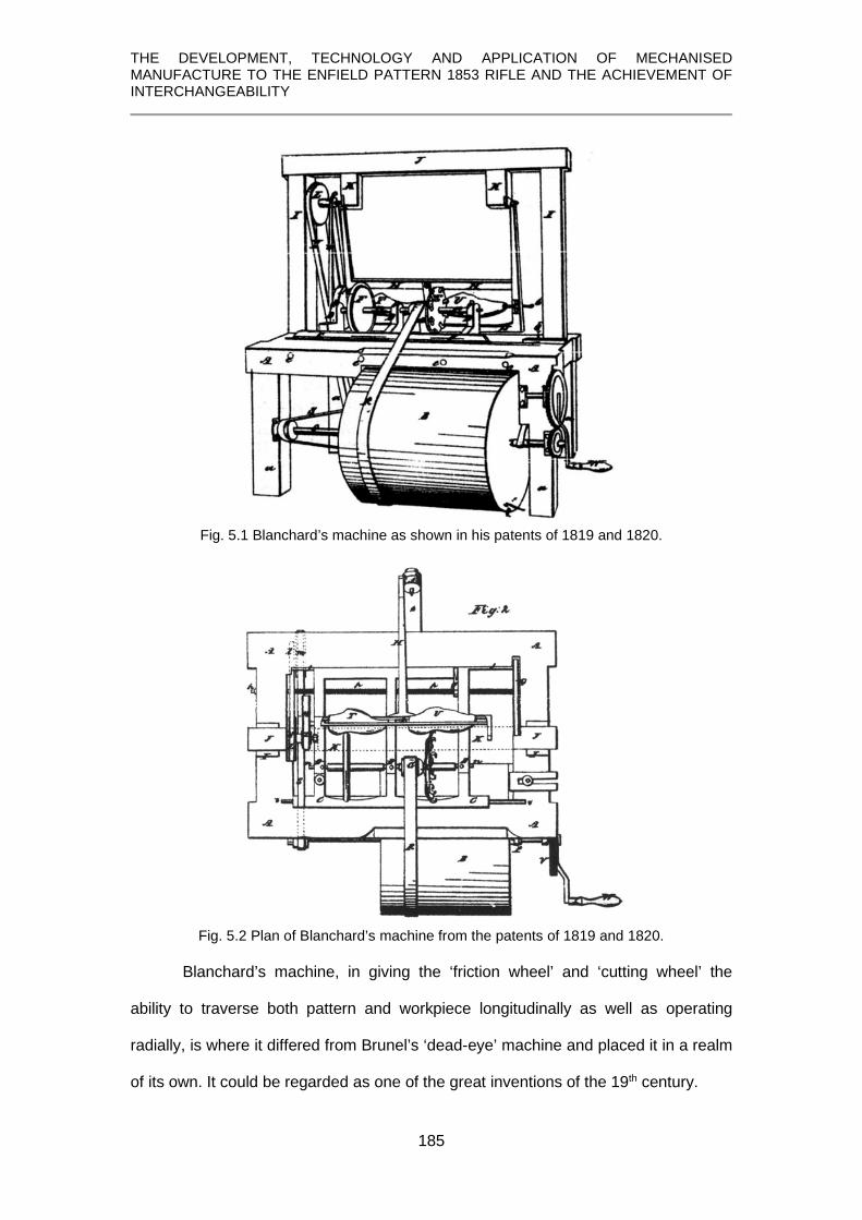
THE DEVELOPMENT, TECHNOLOGY AND APPLICATION OF MECHANISED MANUFACTURE TO THE ENFIELD PATTERN 1853 RIFLE AND THE ACHIEVEMENT OF INTERCHANGEABILITY
185
Fig. 5.1 Blanchard’s machine as shown in his patents of 1819 and 1820.
Fig. 5.2 Plan of Blanchard’s machine from the patents of 1819 and 1820.
Blanchard’s machine, in giving the ‘friction wheel’ and ‘cutting wheel’ the
ability to traverse both pattern and workpiece longitudinally as well as operating
radially, is where it differed from Brunel’s ‘dead-eye’ machine and placed it in a realm
of its own. It could be regarded as one of the great inventions of the 19th century.

THE DEVELOPMENT, TECHNOLOGY AND APPLICATION OF MECHANISED MANUFACTURE TO THE ENFIELD PATTERN 1853 RIFLE AND THE ACHIEVEMENT OF INTERCHANGEABILITY
186
In 1822 a U.K. patent (Buckle, 1822) was granted and it is apparent that
Buckle must have been a patent agent38F
39 because reading beyond the preliminary
statement it is clear that the patent application was lodged by John Parker Boyd of
Boston in the United States under the more comprehensive description:
Certain Improvements in machinery for shaping or cutting out irregular forms in wood or any other materials or substances which admit of being cut by cutters or tools revolving with a circular motion, whether such motion be continuous or reciprocated.
Unfortunately, Cooper, in her excellent study of Blanchard, makes no
reference to Boyd or any attempt to obtain a U.K. patent so a question mark must
remain over Boyd’s role and intentions. An additional point of interest is made by
Greenwood who states that the principle of Blanchard’s copying lathe was invented
by a man named Rigg, near Birmingham, where he used it for making shoe lasts, but
offers no date or corroborating evidence (Greenwood, 1862, p.340).
Regardless of the true provenance of the Buckle / Boyd patent, the drawings
which accompany it are clearer and more numerous than those of Blanchard’s.
Fig. 5.3 Front elevation from Buckle’s patent drawing showing the model, P, the workpiece, R, the friction wheel, N, and the cutting wheel with its ‘crooked knives or cutters’, M. (Buckle 1822)
What will be noticed is that in both Blanchard’s and Boyd’s drawings, the
machine is shown set up for making shoe lasts and has the ‘model’ and the
39 Whilst many Patents cite the name of the inventor, it is often the patent agent whose name appears first.

THE DEVELOPMENT, TECHNOLOGY AND APPLICATION OF MECHANISED MANUFACTURE TO THE ENFIELD PATTERN 1853 RIFLE AND THE ACHIEVEMENT OF INTERCHANGEABILITY
187
‘workpiece’ adjacent on the same spindle centres and carried in a swinging frame, D,
in Fig. 5.3. Thus, as the model rotated, the workpiece rotated at the same speed and
as they were mounted in a swinging frame, the ‘friction wheel’, which followed the
contour of the model, caused the frame, and therefore the cutter wheel, which was
coaxial with friction wheel, to move likewise. In this way the same contour was
transferred to the workpiece. Whilst the same arrangement could be used for
gunstocks, it would make the machine very long. Instead, it was rearranged so that
the model was behind the workpiece, and that the work was carried out separately on
the butt and fore-end of the stock, no doubt to avoid any flexing of a long, slender
item.
Fig. 5.4 Blanchard’s original rebuilt machine now preserved in the U.S. National Armory at Springfield, Massachusetts. (© U.S. National Parks Service)
A surviving example of Blanchard’s gun-stocking lathe at Springfield Armory,
Fig. 5.4, carries a plaque with the date ‘1822’. This is curious since his machines

THE DEVELOPMENT, TECHNOLOGY AND APPLICATION OF MECHANISED MANUFACTURE TO THE ENFIELD PATTERN 1853 RIFLE AND THE ACHIEVEMENT OF INTERCHANGEABILITY
188
were destroyed in a fire on July 1st 1825 (Cooper, 1991, p.92). It is additionally
curious because it is officially recorded that it was in 1821 that Blanchard was paid
$288.49 for a ‘machine to turn gunstocks’ supplied to Springfield Armory (Report,
1823, p.97).
As shown in Fig. 5.4, the gunstock was fixed at the front of a swinging frame
and behind it was fitted the model, usually of bronze or cast iron. The mountings for
the stock and model had to have parallel axes and the model and stock being worked
upon had to be mounted in exactly the same orientation to one another and their
rotation was synchronised by a train of gears. The friction wheel and the cutting
wheel were eighteen inches in diameter and were mounted with their diameters
coplanar in an iron frame which was fed along the bed of the machine by a powered
leadscrew. Both the model and stock had to be correctly positioned in relation to
each other so that as the model revolved, it caused the friction wheel bearing against
it to move radially by following its profile, thus moving the swinging frame and
transferred the profile at that point to the gunstock which was acted upon by the
cutter wheel.
Blanchard also created machines for performing other operations on the stock
and following a contract with George Bomford, Chief of Ordnance, on 27th July 1828,
Blanchard set up his ‘production line’ which involved 14 stages (Cooper, 1991, p.92);
1 ‘cutting stock blank to thickness and length’ 2 ‘rough shaping’ the stock 3 ‘rough turning’ followed by ‘fine turning’ 4 ‘boring for the barrel’ 5 ‘milling the bed for the breech of the barrel and breech pin [breech plug] 6 ‘cutting the bed for the tang of the breech plate’ [butt plate PGS] 7 ‘boring the holes for the breech plate [butt plate] screws 8 ‘for gauging for the barrel’ 9 ‘cutting for the tang of the breech pin’ 10 ‘for forming the concave for the upper band’ 11 ‘for dressing the stock for and between the bands’ 12 ‘forming the bed for the lockplate’ 13 ‘forming the bed for the interior of the lock’ 14 ‘for boring the holes for the side and tang pins’

THE DEVELOPMENT, TECHNOLOGY AND APPLICATION OF MECHANISED MANUFACTURE TO THE ENFIELD PATTERN 1853 RIFLE AND THE ACHIEVEMENT OF INTERCHANGEABILITY
189
While they performed a wide range of operations in preparing the gunstock, they did
not carry out all of them and for that reason Blanchard’s process was referred to as
‘half-stocking’ and the remainder of the work – fitting of the side plate, trigger guard,
trigger, ramrod and band springs – was carried out by hand (Cooper, 1991, p.91).
None of these additional machines have survived, nor were they patented, so
no record exists of what they looked like and how they worked. In 1880, it was
commented: Of most of these machines little more than the name remains (Fitch,
1882, p.16).
5.4 Equipping the Enfield factory
By the middle of the 19th century, updated Blanchard machines were being
manufactured by the Ames Company of Chicopee Falls, Massachusetts and on 17th
May, 1854, they submitted a tender to the Committee on Machinery for the supply of
stock making machinery for Enfield which consisted of:
Machine for roughing Machine for rough turning (with patent rights)
Machine for spotting [machining small flat datum/clamping surfaces on the stock] Machine for sawing breech and muzzle Machine for bedding the barrel Machine for planing side and edges with an extra spindle Machine for bedding breech plate [i.e., butt plate] Machine for fitting bands (with patent rights) Machine for turning between the bands Machine for smooth turning breech (with patent rights) Machine for smooth turning above the lock (with patent rights) Machine for bedding the lock [i.e., inletting the lock] Machine for bedding the guard [trigger guard] Machine for boring side tang screws and pin holes [it is unclear what is meant by ‘side tang’, unless it refers to the cups for the ‘side nail’ heads]
(Rosenberg, 1968, p.181)
It will become clear that in the description of the various stages of
manufacture, additional machines were used and from an earlier comment by the
Committee on Machinery (Rosenberg, 1968, p.180), patent rights had been
purchased to allow the War Department to make copies of machines should the need
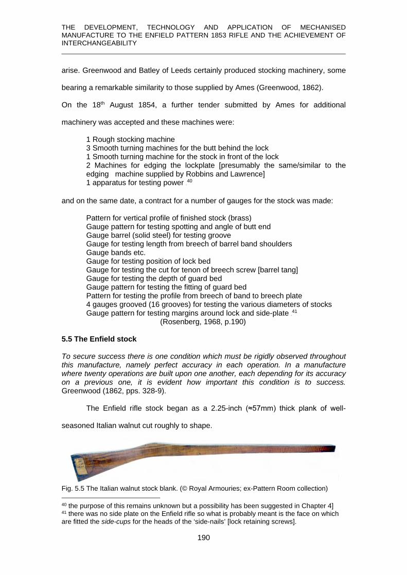
THE DEVELOPMENT, TECHNOLOGY AND APPLICATION OF MECHANISED MANUFACTURE TO THE ENFIELD PATTERN 1853 RIFLE AND THE ACHIEVEMENT OF INTERCHANGEABILITY
190
arise. Greenwood and Batley of Leeds certainly produced stocking machinery, some
bearing a remarkable similarity to those supplied by Ames (Greenwood, 1862).
On the 18th August 1854, a further tender submitted by Ames for additional
machinery was accepted and these machines were:
1 Rough stocking machine 3 Smooth turning machines for the butt behind the lock 1 Smooth turning machine for the stock in front of the lock 2 Machines for edging the lockplate [presumably the same/similar to the edging machine supplied by Robbins and Lawrence] 1 apparatus for testing power 39F
40 and on the same date, a contract for a number of gauges for the stock was made:
Pattern for vertical profile of finished stock (brass) Gauge pattern for testing spotting and angle of butt end Gauge barrel (solid steel) for testing groove Gauge for testing length from breech of barrel band shoulders Gauge bands etc. Gauge for testing position of lock bed Gauge for testing the cut for tenon of breech screw [barrel tang] Gauge for testing the depth of guard bed Gauge pattern for testing the fitting of guard bed Pattern for testing the profile from breech of band to breech plate 4 gauges grooved (16 grooves) for testing the various diameters of stocks
Gauge pattern for testing margins around lock and side-plate 40F
41 (Rosenberg, 1968, p.190) 5.5 The Enfield stock To secure success there is one condition which must be rigidly observed throughout this manufacture, namely perfect accuracy in each operation. In a manufacture where twenty operations are built upon one another, each depending for its accuracy on a previous one, it is evident how important this condition is to success. Greenwood (1862, pps. 328-9).
The Enfield rifle stock began as a 2.25-inch (≈57mm) thick plank of well-
seasoned Italian walnut cut roughly to shape.
Fig. 5.5 The Italian walnut stock blank. (© Royal Armouries; ex-Pattern Room collection)
40 the purpose of this remains unknown but a possibility has been suggested in Chapter 4] 41 there was no side plate on the Enfield rifle so what is probably meant is the face on which are fitted the side-cups for the heads of the ‘side-nails’ [lock retaining screws].

THE DEVELOPMENT, TECHNOLOGY AND APPLICATION OF MECHANISED MANUFACTURE TO THE ENFIELD PATTERN 1853 RIFLE AND THE ACHIEVEMENT OF INTERCHANGEABILITY
191
Within the box of gauges for the Pattern 1853 rifle in Royal Armouries
collections is a wooden template, Fig. 5.6, the exact purpose which is not known.
Fig. 5.6 Stock template. (part of PR.10142 © Royal Armouries)
From the inspector’s stamp on the ‘wrist’ – the narrow portion between the butt and
where the lock is mounted - it was clearly an ‘official’ item prepared at Enfield.
Fig. 5.6A Butt marking 1. Inspector’s stamp on the ‘wrist’.
It also carries additional markings stamped into the wood relating to a variety of arms
within the Pattern 1853 series:
Fig. 5.6B Butt marking 2. Pattern for musket stock (minimum size) Prepared April 30 1859
Fig. 5.6C Butt marking 3. Width of stock in the rough 2 ¼ inches.

THE DEVELOPMENT, TECHNOLOGY AND APPLICATION OF MECHANISED MANUFACTURE TO THE ENFIELD PATTERN 1853 RIFLE AND THE ACHIEVEMENT OF INTERCHANGEABILITY
192
Fig. 5.6D Fore end markings for lengths of 1st class musket and 2nd and 3rd class carbines complete with spelling error. (part of PR.10142 © Royal Armouries)
As indicated by the butt stamping, it was intended as a ‘pattern’ for rifle-
muskets and the fore-end clearly matches the rifle-musket length as indicated by the
stamping at the tip, but it also carries two additional markings relating to the lengths
of 2nd and 3rd class 41F
42 carbine stocks.
The ‘pattern’ is of flimsy construction, made up of three pieces of thin wood
hinged together, one of which has come adrift, and is not really fit for the purpose of
factory production use. After all, brass stock gauges had already been supplied by
Ames and its wooden construction is certainly curious when it is considered that
regimental armourers, as part of their ‘Armourer’s Forge’ equipment, were being
supplied with ‘Gauges, metal, for stocking’ in sets of 5, Fig. 5.7.
42 First-class arms were either new or as good as new, and were issued to regular troops. If a first-class arm had been repaired to any great extent it was relegated to ‘second-class’ and the stock stamped with the number ‘2’ in place of ‘1’ and issued to volunteers or militia groups. Further repairs were recorded by additional number ‘2’’s stamped on the stock. If yet further damage resulted in a weapon being considered ‘unfit for service’, they were relegated to third-class and used for recruit drilling (Roads, 1964, p.75).

THE DEVELOPMENT, TECHNOLOGY AND APPLICATION OF MECHANISED MANUFACTURE TO THE ENFIELD PATTERN 1853 RIFLE AND THE ACHIEVEMENT OF INTERCHANGEABILITY
193
Fig. 5.7 Gauges, metal, for stocking, set of 5. (Petrie, 1865, p. 84 and plate XVI)
If it was simply used for checking the length of repaired arms, that is 2nd or 3rd
class arms, being marked also for for a 1st class arm is inconsistent.
Consideration of Its nature suggests to the author that it would have lent itself
to being carried when visiting timber suppliers. Its form and markings would enable
different sizes of timber to be selected for the three different lengths of arms, but that
does not explain why 2nd and 3rd class arms were included.
Greenwood (1862, pps. 328-9), itemises the various operations as:
1. Slabbing. 2. Marking centres. 3. Fore-end rough turned. 4. Butt rough turned. 5. Spotting – 5 flat places cut on the right-hand side of the stock and 2
on the left. 6. Bedding the barrel – hollow channel cut in the fore-end and the recess
for the tang of the breech pin [screw]. 7. Hand-finishing the recess for the breech tang. 8. Stock sawn to exact length at butt and muzzle and the butt shaped to
the form of the butt plate by a revolving cutter. 9. The two opposing flat faces are planed where the lock is to fit;
recesses for the side cups are formed; the upper edges of barrel channel are profile; upper and lower edges of the butt.
10. Tang of the butt plate is let in; the three holes for screws are bored and the two large holes are tapped.
11. The corner under the tang of the butt plate is rounded by hand.
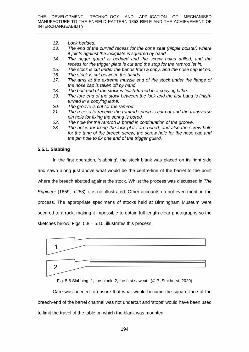
THE DEVELOPMENT, TECHNOLOGY AND APPLICATION OF MECHANISED MANUFACTURE TO THE ENFIELD PATTERN 1853 RIFLE AND THE ACHIEVEMENT OF INTERCHANGEABILITY
194
12. Lock bedded. 13. The end of the curved recess for the cone seat (nipple bolster) where
it joints against the lockplate is squared by hand. 14. The rigger guard is bedded and the screw holes drilled, and the
recess for the trigger plate is cut and the stop for the ramrod let in. 15. The stock is cut under the bands from a copy, and the nose cap let on. 16. The stock is cut between the bands. 17. The arris at the extreme muzzle end of the stock under the flange of
the nose cap is taken off by hand. 18. The butt end of the stock is finish-turned in a copying lathe. 19. The fore end of the stock between the lock and the first band is finish-
turned in a copying lathe. 20. The groove is cut for the ramrod. 21. The recess to receive the ramrod spring is cut out and the transverse
pin hole for fixing the spring is bored. 22. The hole for the ramrod is bored in continuation of the groove. 23. The holes for fixing the lock plate are bored, and also the screw hole
for the tang of the breech screw, the screw hole for the nose cap and the pin hole to fix one end of the trigger guard.
5.5.1. Slabbing
In the first operation, ‘slabbing’, the stock blank was placed on its right side
and sawn along just above what would be the centre-line of the barrel to the point
where the breech abutted against the stock. Whilst the process was discussed in The
Engineer (1859, p.258), it is not illustrated. Other accounts do not even mention the
process. The appropriate specimens of stocks held at Birmingham Museum were
secured to a rack, making it impossible to obtain full-length clear photographs so the
sketches below, Figs. 5.8 – 5.10, illustrates this process.
Fig. 5.8 Slabbing. 1, the blank; 2, the first sawcut. (© P. Smithurst, 2020)
Care was needed to ensure that what would become the square face of the
breech-end of the barrel channel was not undercut and ‘stops’ would have been used
to limit the travel of the table on which the blank was mounted.

THE DEVELOPMENT, TECHNOLOGY AND APPLICATION OF MECHANISED MANUFACTURE TO THE ENFIELD PATTERN 1853 RIFLE AND THE ACHIEVEMENT OF INTERCHANGEABILITY
195
Fig. 5.9 Extent of the saw-cut, avoiding undercutting the breech face. (© P. Smithurst, 2020)
This saw-cut was then cut into obliquely across at the breech, separating the surplus
piece of timber from the stock.
Fig. 5.10 Slabbing; the final stage, making the oblique cut to remove the excess timber strip.
(© P. Smithurst, 2020)
A portion of one of the stocks in the Birmingham Museum collections which
has undergone the ‘slabbing’ operation is shown in Fig. 5.11. What is apparent on
the specimen, though not so easily seen in the photograph, are the angular lines left
by the saw teeth which appear parallel with the oblique cut, suggesting the use of a
bandsaw. In the description of the process (Engineer, 1859, p.258), however, it
states a circular saw was used, although bandsaws were available as shown by a
patent granted to Robert Eadon of Sheffield in 1856 for the manufacture of ‘cast-
steel’ bandsaw blades (Eadon, 1856).
Fig. 5.11 Top view of portion of a stock which has undergone slabbing.
(© Birmingham City Museums)

THE DEVELOPMENT, TECHNOLOGY AND APPLICATION OF MECHANISED MANUFACTURE TO THE ENFIELD PATTERN 1853 RIFLE AND THE ACHIEVEMENT OF INTERCHANGEABILITY
196
The flat faces thus formed on the top of the fore-end of the stock and the
breech were then used as reference faces to mount it on another fixture on the
machine and, according to one article (Engineer, 1859, p. 259) the excess material at
the butt and muzzle was removed. Greenwood (1868, p. 329), however, notes that
only the muzzle end was trimmed at this stage and goes on to state the butt and
muzzle were trimmed at the eighth operation.
5.5.2 Centering
For this operation the stock was mounted on its side on a flat iron plate, the
recently sawn surfaces being pressed up against a shoulder on the plate. At the butt
end, a slide fitted with four projecting points was placed against the butt and given a
blow with a hammer, driving the points into the face of the butt.
At the muzzle end, an accurately placed conical drill bored a centre hole and
this was visible on a stock which had been ‘centred’.
Fig. 5.12 A centre-hole in the muzzle-end of a stock blank after ‘slabbing’. (1885S 00607.00002 © Birmingham City Museums)
Unfortunately, because the stock was fixed in a rack, it was not possible to
record the ‘centering’ on the butt. These centre holes matched centre points for
mounting the stock on the machines which performed the rough-turning operations.
5.5.3 Rough-turning the fore end
This operation is discussed (Engineer, 1859, p.258) but, again, it is not
illustrated, and the description of the machine is somewhat convoluted and
incomplete. As described in The Engineer, the stock was passed through a hollow
bearing and the centre-hole at the muzzle was located on a centre point on the

THE DEVELOPMENT, TECHNOLOGY AND APPLICATION OF MECHANISED MANUFACTURE TO THE ENFIELD PATTERN 1853 RIFLE AND THE ACHIEVEMENT OF INTERCHANGEABILITY
197
machine. The prepared flat surface of the stock fore end rested against a straight and
flat iron bar between the two bearings. What is not stated, but of great importance, is
that this iron bar could be no wider than the section of stock being turned. It might
therefore have been stepped to match the steps in the stock. The portion of the stock
where the lock would be fitted was contained within the hollow bearing and fixed by a
clamping screw.
From the description it is clear that the stock blank was mounted above the
pattern. Those also needed be in exact mutual alignment and to rotate synchronously
for the form of the iron pattern to be transferred to the stock. A schematic conception
of this arrangement is shown in Fig. 5.13.
Fig. 5.13 Arrangement of stock and pattern in the turning machine showing the mountings and support bar in blue. (© P. Smithurst 2020)
The next part of the description in The Engineer offers nothing to give a real
understanding of how this machine worked. It simply states that the follower wheel
and cutter vibrate on levers hung on centres near the ground line. It implies a system
as shown in Fig. 5.14, which clearly would not have worked since the cutter wheel
would never have been in contact with the stock.

THE DEVELOPMENT, TECHNOLOGY AND APPLICATION OF MECHANISED MANUFACTURE TO THE ENFIELD PATTERN 1853 RIFLE AND THE ACHIEVEMENT OF INTERCHANGEABILITY
198
Fig. 5.14 Interpretation of the system as described in The Engineer. (© P. Smithurst 2019)
A simple expedient to creating a working system would have been to use
James Watt’s parallel motion which, by means of a system of linkages, he was able
to maintain the vertical motion of a piston rod of a steam engine whilst its point of
connection on the end of a beam moved in an arc.
Thus, in the turning machine, this could have been achieved by having the
follower wheel and cutting wheel on separate on separate levers, the lower ends of
which were connected, and vertically separated, at two points on the machine. These
two levers would then have had a linkage, of equal length to the distance between
the lower mounting points, connecting them at, say, the centres of the follower and
cutter wheels, or at other points, so that levers and linkages formed a parallelogram,
Fig, 5.15. Thus, as shown, the revolving of the lower pattern in contact with the
follower wheel would cause the cutter wheel to move in unison and transfer the same
profile of the pattern to the stock.

THE DEVELOPMENT, TECHNOLOGY AND APPLICATION OF MECHANISED MANUFACTURE TO THE ENFIELD PATTERN 1853 RIFLE AND THE ACHIEVEMENT OF INTERCHANGEABILITY
199
Fig. 5.15 An arrangement using Watt’s parallel motion which would have met the needs of the stock-turning machine. (© P. Smithurst 2020)
Some means of keeping the follower in contact with the pattern would have
been needed and on the Enfield machine this was accomplished by a treadle system
operated by the machinist. The machine at Enfield also incorporated an improvement
by James Burton and utilised two follwers and two cutting wheels, allowing two
portions of the fore-end to be machined at the same time and halving the time
required. The machine was ‘self-acting’, the carriage which carried the stock and
pattern being traversed past the cutting and follower wheels by a leadscrew.
An American publication of later date covering the manufacture of a similar
component provides an even less informative description but does illustrate a
machine closely similar to that used at Enfield for the butt, not the fore-end, Fig. 5.16.
There is insufficient detail to suggest a ‘Watt’s parallel motion’ system was used, but
it would be difficult to find a simpler alternative.

THE DEVELOPMENT, TECHNOLOGY AND APPLICATION OF MECHANISED MANUFACTURE TO THE ENFIELD PATTERN 1853 RIFLE AND THE ACHIEVEMENT OF INTERCHANGEABILITY
200
Fig. 5.16 Butt turning machine used in America is of similar arrangement in having pattern below the workpeice. (Benton, 1878, p.110 and plate XV)
The curved rim of the follower wheel meant that the steps where the bands
would ultimately fit exhibited themselves as smooth transitions at this stage but it is
not known whether the transitions on the pattern were also smooth or had the square
steps. In the latter, the steps would be gradually ‘turned over’ at the corners, making
them useless in when it came to ‘squaring’ these steps later, so patterns with smooth
transitions would have been a better option. The specimen below in the Birmingham
Museum collections shows a portion of a ‘rough-turned’ fore-end terminating at the
position where the lower band would ultimately be fitted.
Fig. 5.17 Top and underside views of a stock with a ‘rough-turned’ fore-end. (1885S00607.00003 © Birmingham City Museums)
5.5.4 Rough-turning the butt
The only description of this process as carried out at Enfield (Engineer, 1859,
p.258) is minimal and, again, lacks any illustrations. It is stated that the machine was
similar to that for turning the fore-end and that the cutter-wheel had:

THE DEVELOPMENT, TECHNOLOGY AND APPLICATION OF MECHANISED MANUFACTURE TO THE ENFIELD PATTERN 1853 RIFLE AND THE ACHIEVEMENT OF INTERCHANGEABILITY
201
twelve hooked cutters of three different forms - - ; the first two are for getting rid of the extra timber, and the last for taking a chisel cut. These tool discs make on an average 3,000 revolutions per minute.
The specimens in Birmingham Museum’s collections provides examples of
this process, although, for reasons already noted, it was not possible to obtain a full-
length photograph.
Fig. 5.18 A ‘rough-turned’ butt. The curved form of the cutter is evident in the turning marks. (© Birmingham City Museums)
The ‘rough-turning’ of the butt also included the remainder of the stock up to
the position of the lower band, the termination point from ‘rough-turning’ of the fore-
end. Apart from anything else, this is evident on the specimen shown by the change
in the marks left by the cutter at this junction.
Fig. 5.19 ‘Rough-turning’ the butt extended to the position of the lower band where ‘rough-turning’ of the fore-end terminated. (1885S607.0004 © Birmingham City Museums)
This evidence presented by the Birmingham Museum specimens parallels
Benton’s description, removing the surplus stock [timber] from the lower band to the
heel of the butt (1878, p.111) and he illustrates the machine, referred to earlier, for
this purpose, Fig. 5.20.

THE DEVELOPMENT, TECHNOLOGY AND APPLICATION OF MECHANISED MANUFACTURE TO THE ENFIELD PATTERN 1853 RIFLE AND THE ACHIEVEMENT OF INTERCHANGEABILITY
202
Fig. 5.20 ‘Rough-turning’ the butt from lower band to heel. (Benton, 1878, plate XV)
5.5.5 Spotting
Examination of one of the Birmingham Museum specimens shows purpose of
this process was to create seven flat surfaces at 900 to the flat surface on the top of
the fore-end created in the slabbing operation. Two were on each side of the ends of
the butt and the muzzle end of the fore-end; one was where the lock was to be fitted;
two more along the right-hand side of the fore-end, as noted by Greenwood (1862, p.
328). Though not always mentioned, these ‘spots’ became datum planes for future
operations.
Both machine and process are described with minimal detail: the stock is held down by two spring clips upon a plate the width of the flat surface prepared by the slabbing machine; this plate is weighted and fitted with guides so that it can be worked up and down vertically by means of a treddle [sic]. - - - when the stock is fitted and clipped in position and taken as high as it can come, that by application of the foot it can be brought down; the machine then being supplied with seven stout saws on five spindles, two placed the right distance apart on those situated at the extreme ends of the stock, it will be seen that, by lowering the table, these saws will form the seven required spots . . (Engineer, 1859, p.258)
There are a number of issues with these statements. The first is, that if the
stock was mounted on a plate the width of the flat surface prepared by the slabbing
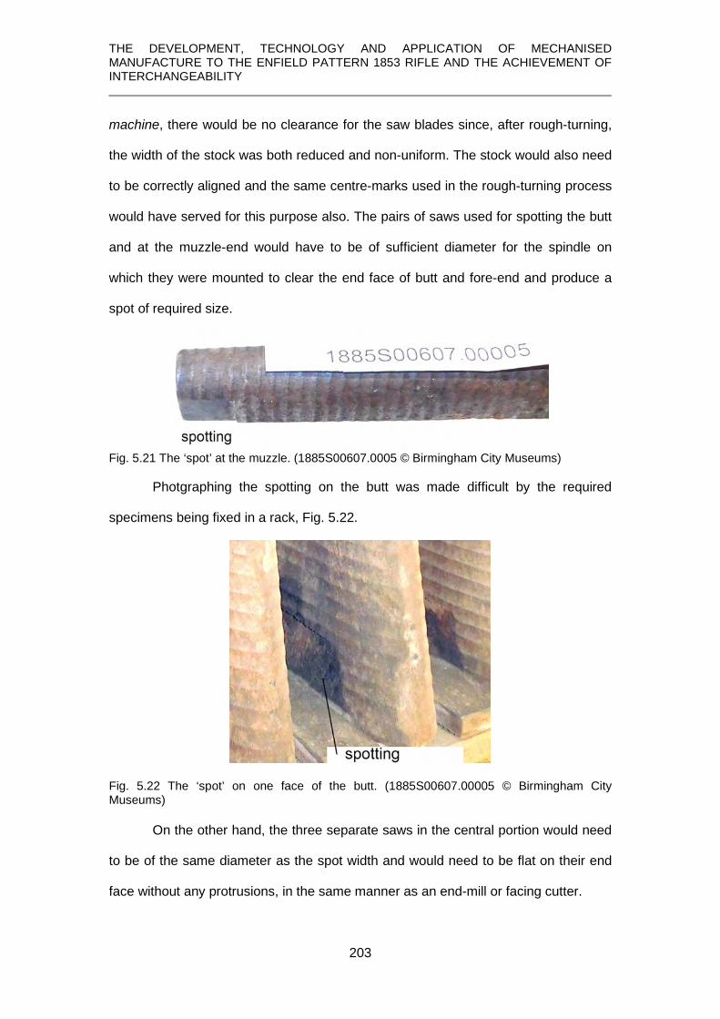
THE DEVELOPMENT, TECHNOLOGY AND APPLICATION OF MECHANISED MANUFACTURE TO THE ENFIELD PATTERN 1853 RIFLE AND THE ACHIEVEMENT OF INTERCHANGEABILITY
203
machine, there would be no clearance for the saw blades since, after rough-turning,
the width of the stock was both reduced and non-uniform. The stock would also need
to be correctly aligned and the same centre-marks used in the rough-turning process
would have served for this purpose also. The pairs of saws used for spotting the butt
and at the muzzle-end would have to be of sufficient diameter for the spindle on
which they were mounted to clear the end face of butt and fore-end and produce a
spot of required size.
Fig. 5.21 The ‘spot’ at the muzzle. (1885S00607.0005 © Birmingham City Museums)
Photgraphing the spotting on the butt was made difficult by the required
specimens being fixed in a rack, Fig. 5.22.
Fig. 5.22 The ‘spot’ on one face of the butt. (1885S00607.00005 © Birmingham City Museums)
On the other hand, the three separate saws in the central portion would need
to be of the same diameter as the spot width and would need to be flat on their end
face without any protrusions, in the same manner as an end-mill or facing cutter.

THE DEVELOPMENT, TECHNOLOGY AND APPLICATION OF MECHANISED MANUFACTURE TO THE ENFIELD PATTERN 1853 RIFLE AND THE ACHIEVEMENT OF INTERCHANGEABILITY
204
Fig. 5.23 The ‘spot’ at the lock. (1885S00607.00005, © Birmingham City Museums)
Fig. 5.24 The ‘spot’ at the lower band. (1885S00607.00005, © Birmingham City Museums)
The features of a machine that could accomplish these operations, based on
the description available and the evidence presented by the stocks themselves is
shown in Fig. 5.25.
Fig. 5.25 Schematic Interpretation of ‘spotting’ as described in The Engineer.
(© P. Smithurst 2019)
The stock was mounted upside-down in the spotting machine and has been shown
as viewed from the rear for simplicty in illustrating the result. The stock was lowered

THE DEVELOPMENT, TECHNOLOGY AND APPLICATION OF MECHANISED MANUFACTURE TO THE ENFIELD PATTERN 1853 RIFLE AND THE ACHIEVEMENT OF INTERCHANGEABILITY
205
from its raised position on its mounting plate past the rotating cutters which removed
the timber in the required places. Not mentioned in any account is that there were
two primary criteria in spotting; that all the spot faces were at predetermined
distances and parallel to the centre line of the stock, and the need for the ability of
precise adjustment of the settings of the saws in the machine. These spots were of
importance in the operations which follow.
5.5.6 Bedding the barrel
Barrel-bedding consisted of forming a tapered groove in the fore-end of the
stock and recesses at the breech-end into which the tang and heel of the breech pin
fitted.
Fig. 5.26 Barrel-bedding machine used at Enfield. (Engineer, 1859, p.258)
Whilst this ilustration actually represents the machine used at Enfield,
important features of it are not clearly shown. A second illustration, Fig. 5.27, whilst

THE DEVELOPMENT, TECHNOLOGY AND APPLICATION OF MECHANISED MANUFACTURE TO THE ENFIELD PATTERN 1853 RIFLE AND THE ACHIEVEMENT OF INTERCHANGEABILITY
206
being for a different rifle, is fundamentally the same and, when enlarged, offers
clearer details.
Fig. 5.27 Barrel-bedding machine used at Springfield in 1878. (Benton, 1878, plate V)
The process is described in The Engineer (1859, p.258):
To effect this, it is inserted into a recess on a long moveable table, A, . . . To fix the stock in position it is clipped at the five spots made on the long side and pressed up against two horizontal lips projecting a little over on each side of the top of the recess made to receive it by studs from below: this ensures it being in line and level with the trued surface. (Engineer, 1859, p.258) and raises various questions. Obviously, the ‘lips projecting a little over on each side
of the top of the recess’ would also need to project at each end of the recess since,
without that constraint, the stock could assume any angle to the horizontal since the
one pair of lips would act as a pivot point.
The second question concerns the spots. The description implies that the
spots were simply used as bearing points for ‘clips’ but, as datum faces, they would
have been used to bear against five accurately prepared vertical bearing surfaces
and clamped against those, because by this stage the stock had no other flat sides.
Details from the above illustrations are shown below, Figs. 5.26A and 5.27A and Fig.
5.27A, being clearer, has allowed minor editing to highlight the stock and cutters in

THE DEVELOPMENT, TECHNOLOGY AND APPLICATION OF MECHANISED MANUFACTURE TO THE ENFIELD PATTERN 1853 RIFLE AND THE ACHIEVEMENT OF INTERCHANGEABILITY
207
place but it should be noted that the Enfield machine had only three vertical cutters,
not four as shown in the Springfield machine.
Fig. 5.26A. Detail of the Enfield machine showing the cutter spindles, B and the table, A.
Fig. 5.27A. Detail of the Springfield machine; stock highlighted in brown, the cutters highlighted in blue, and the ‘pattern’ F behind the stock.
The process commenced using one of the cutters, B in Fig. 5.26A, nearest
the front. The frame carrying the cutter spindles was moved to the rear so that the
guide pin, adjacent to the cutter, could be lowered by a lever to engage with a pattern
having a tapered groove, exactly matching the form the barrel channel in the stock
was to have, and placed immediately behind and parallel with the stock.
By moving the table longitudinally, by means of a rack and pinion, and moving
the frame carrying the cutter both laterally and vertically, constrained by its guide pin
in the pattern channel, a tapered groove was cut in the stock.
In a similar manner, the second cutter from the front was then used to cut a
recess for the heel of the breech pin and then the third cutter, inclined at the
appropriate angle, was used to cut the recess for the tang of the breech pin.

THE DEVELOPMENT, TECHNOLOGY AND APPLICATION OF MECHANISED MANUFACTURE TO THE ENFIELD PATTERN 1853 RIFLE AND THE ACHIEVEMENT OF INTERCHANGEABILITY
208
The next machining operation was to remove any unevenness left in the
barrel channel by the previous tool. The table was moved to the front and:
There the stock [should read barrel channel] receives its finished taper by means of the cutting-spindle D, [see Fig. 5.27A] which is suspended from the cross-bracket, F, and can be indued [sic] with a vibratory motion by means of the long handle, which is seen to be in position. The tool which is fixed to this cutting-spindle is merely a curved lip of steel, very similar to the side of a common auger. It is by means of this vibrating motion that the mould or form can be followed as the feed is given, and the side and up and down movements enable the required taper to be given. (Engineer, 1859, p.258) This long cutter, D, is highlighted in blue in Fig. 5.27A.
Again it is a confusing statement and a number of points arise. There is no
mention of a guide pin to follow the mould or form which suggests that the cutting
spindle with its curved lip of steel was of the same contour as the finished barrel. The
use of the term vibratory motion is misleading; it is taken to mean the up and down
motion given to the spindle by means of the handle since any true vibratory motion of
the spindle implies it turned eccentrically or moved longitudinally, either of which
would have defeated the object of the exercise.
The fifth and final operation was to square the end of the barrel channel
against which the breech sat and to do this the stock was moved to the far end of the
machine and the cut was taken
by a similar tool spindle to that just described. This is merely brought down into position by means of handles (Engineer, 1859, p.258). This part of the machine is hidden in both illustrations and, more importantly, the
cutter is not shown. Bearing in mind the nature of the job it has to do, it would have to
be able to cut on the sides and exposed end face, as shown in Fig. 5.28.

THE DEVELOPMENT, TECHNOLOGY AND APPLICATION OF MECHANISED MANUFACTURE TO THE ENFIELD PATTERN 1853 RIFLE AND THE ACHIEVEMENT OF INTERCHANGEABILITY
209
Fig. 5.28 Suggested nature of the rotary cutter and its mounting for squaring the breech face of the barrel channel. (© P.Smithurst 2019) To enter the barrel channel it would have needed to have been mounted on a
pendant-type support able to move only vertically and both it and the cutter had to be
of correct form to match the breech-end of the barrel. The cutter would also have
been driven by a flat-belt via a pulley mounted on the opposite end of the shaft to the
cutter so that, with a belt in place, it did not exceed the width of the channel.
5.5.7 Hand-finishing the recess for the breech tang.
Not mentioned in the account in The Engineer was the need to round the
shoulder of the recess for the barrel-tang where it meets the recess for the heel of
the breech pin, and squaring this recess, which were done by hand (Greenwood,
1862, p.329; Benton, 1878, p.111). The result of this operation is shown in Fig. 5.29.
Fig. 5.29 A stock with barrel channel finished - the complex nature of the breech-end is clearly visible. (1885S607.00006 © Birmingham City Museum.) 5.5.8 Stock sawn to length at butt and muzzle; butt shaped to receive the butt plate.
After completing the work on the bedding of the barrel, the stock was sawn to
exact length at butt and muzzle on another machine. No details are offered in any

THE DEVELOPMENT, TECHNOLOGY AND APPLICATION OF MECHANISED MANUFACTURE TO THE ENFIELD PATTERN 1853 RIFLE AND THE ACHIEVEMENT OF INTERCHANGEABILITY
210
account but, since the square face of the breech-end of the barrel channel was the
only longitudinal datum, the author concludes that the stock would have laid flat,
using the spots as horizontal alignment datums, against a model of the barrel
accurately positioned so that butt and muzzle would be cut off at their correct
distances from the breech face.
This was followed by shaping the butt to receive the butt-plate using a:
revolving cutter block which runs horizontally. This block is fitted with steel tools in the form of plane irons with their edges nicked in, so as to give in effect a series of chisels, which leave, of course the spaces between them in the cut unacted upon by simply setting the tools, so that each following one takes away what the former has left, a good surface is obtained, and the cut being across the grain, only half of the weight is put upon each cutter. The curve is given to the butt by a guide pin and mould. (Engineer, 1859, p.259)
This is an inadequate description. It is clear from a surviving butt profile
gauge, Fig. 5.30, that the end face of the butt was curved on two perpedicular
planes, one convex and the other concave.
Fig. 5.30 Profile gauge for end face of the butt. (part of PR.10142 © Royal Armouries)
The revolving ‘cutter block’, referred to as running horizontally, is taken to
mean its periphery revolves horizontally, i.e., it has a vertical axis, and would need to
be of the nature shown in Fig. 5.31, with its cutting edges extending just over the
width of the butt and offset on each side to give a ‘continuous’ cut in two stages.

THE DEVELOPMENT, TECHNOLOGY AND APPLICATION OF MECHANISED MANUFACTURE TO THE ENFIELD PATTERN 1853 RIFLE AND THE ACHIEVEMENT OF INTERCHANGEABILITY
211
Fig. 5.31 The cutter block for machining the butt face. © P. Smithurst 2019
The author suggests that the production of the curved surfaces to the end of
the butt, based on the description provided, is as shown in Fig. 5.32. To prevent
presenting the butt acidentally to the cutter before the guide pin and template were
engaged, a safeguard, such as an extended mounting for the pin so it could bear
against an extension of the template before it engaged with the template proper,
would have been needed.
Fig. 5.32 Arrangement envisaged for machining the curved faces of the butt. (© P. Smithurst 2019)
The convex form to the end of the butt would be automatically given by the concave
form of the cutter blades and the concave form by the profile of the template.
5.5.9 Planing the stock
This comprised a number of operations:

THE DEVELOPMENT, TECHNOLOGY AND APPLICATION OF MECHANISED MANUFACTURE TO THE ENFIELD PATTERN 1853 RIFLE AND THE ACHIEVEMENT OF INTERCHANGEABILITY
212
1. the two opposing flat faces where the lock was to fit were planed
2. recesses for the cups for the side-nails (lock screws) were formed
3. the upper edges of barrel channel were profiled
4. upper and lower edges of the butt were planed.
The description of these operations in The Engineer (1859, p. 258) is, once
again, both inadequate and convoluted and, judging by the evidence of the stocks
themselves, differs from the itemised list provided by Greenwood (1862, pps. 328-9).
Planing was carried out on a multi-functional machine. First to be planed were each
side of the lock housing and this was carried out by mounting the inverted stock so
that the barrel channel fit on a pattern of the barrel attached to a sliding flat platform.
Attached to this platform was a vertical housing into which the two opposing
spots on the butt could be fitted and the stock clamped in position. This platform
carrying the stock was then traversed in turn past cutter blocks fitted with plane
blades rotating on vertical axes placed at front and rear so that each side of the stock
at the position of the lock was planed flat, parallel to and equidistant from the centre
line.
The stock was then re-mounted on another table sliding independently on two
horizontal axes. It was mounted so that it was lying flat, the spots along the right-
hand side of the stock seated on raised blocks so that its centre-line was horzontal,
and clamped in position.
By means of a guide pin acting against a horizontal template, the stock was
traversed past a cutter which planed a flat surface along the top of the butt. From the
evidence of the stocks, Fig. 5.33, this was performed in two stages; one to form a flat
surface at the heel where the tang of the butt-plate would fit, the second to form a flat
surface where the breech tang fitted.

THE DEVELOPMENT, TECHNOLOGY AND APPLICATION OF MECHANISED MANUFACTURE TO THE ENFIELD PATTERN 1853 RIFLE AND THE ACHIEVEMENT OF INTERCHANGEABILITY
213
Fig. 5.33 Two parts of the same stock, showing planing on the top of the butt and at the breech tang to be an interrupted cut. (1885S607.00009. © Birmingham City Museum)
Evidence of the stocks also shows, Fig. 5.34, that the underside of the butt
was planed in a continuous cut from the toe of the butt to the position of the lower
band, covering the position where the trigger guard would be later fitted.
Fig. 5.34 Planed underside from toe of butt to lower band. (1885S607.00009. © Birmingham City Museum.)
The account in The Engineer (1859, p.258) does refer to taking a cut down the back
of the butt which would be correct if the top of the butt was facing the observer.
Following planing of the butt, the two recessses on the face opposite the lock
were formed to receive the ‘side-cups’, Fig. 5.35, into which the heads of the lock
screws, or ‘side nails’, fitted. These were simple forms, consisting of a circular disc

THE DEVELOPMENT, TECHNOLOGY AND APPLICATION OF MECHANISED MANUFACTURE TO THE ENFIELD PATTERN 1853 RIFLE AND THE ACHIEVEMENT OF INTERCHANGEABILITY
214
approximately 0.625 inches (16mm) in diameter and 0.187 inches (4mm) thick having
two diametrically opposed lobes.
Fig. 5.35 The side-cup. (Petrie, 1866, plate V).
With the stock laid flat with the lock face downwards, the recesses were simply cut
with two appropriately sized cutters, one for the central body and one for the side
lobes. A template and guide pin would have undoubtedly been used since the
centres of the side-cup recesses had to coincide exactly with the position of the side-
nail [lock screw] holes in the lockplate so, again, accurate positioning was essential.
5.5.10 Tang of the butt plate let in; the three holes for screws are bored and the two large holes are tapped.
These operations were accomplished by a single machine provided by the
Ames Co. and is shown in Fig. 5.36.
Fig. 5.36 The Ames butt-plate bedding machine used at Enfield. (Engineer, 1849, p.258)

THE DEVELOPMENT, TECHNOLOGY AND APPLICATION OF MECHANISED MANUFACTURE TO THE ENFIELD PATTERN 1853 RIFLE AND THE ACHIEVEMENT OF INTERCHANGEABILITY
215
As it stands, this image, reproduced closely to the size as it appeared in The
Engineer, is difficult to read, the key letters being too small and obscured by the
shading of the engraving. Relevant details have therefore been reproduced to larger
scale, Fig. 5.37, and new key letters added to assist in understanding the description
of its operation. Even then, the description does not make certain features and
procedures clear and some extrapolation and deductions have been resorted to,
based upon the knowledge of what needed to be accomplished, and these will be
highlighted in what follows.
The operation commenced with the fixing of the butt of the stock in position:
. . the butt-end of the stock being fitted against a plate of iron hung upon a spindle, so as to enable its position to be changed without being released; it is fixed tight in the following manner:- The eccentric handle A presses the small plate which rests upon it against the stock and lifts it against the cross-piece, B, and the small portion of a mould the size of the barrel, C, fixed at the end of the side-plate, D; the handle, E, clips the stock sideways in a similar manner. . . . One of the bearings of the spindle on which the stock turns is shown by the letter G. (Engineer, 1859, p.259)
Fig. 5.37 A detail from Fig. 5.36 showing the features referred to in the description.
There are various points which the above description omits to mention. At this
stage in its manufacture the stock was still in its rough-turned and planed condition. It
would thus retain the spots on each side of the butt which would have served as
clamping points and positional datums. Also, ‘the small plate’ which rested upon the

THE DEVELOPMENT, TECHNOLOGY AND APPLICATION OF MECHANISED MANUFACTURE TO THE ENFIELD PATTERN 1853 RIFLE AND THE ACHIEVEMENT OF INTERCHANGEABILITY
216
lever, A, would have needed to be quite long and narrow, and suitably curved, so that
it could bear upon the planed portion on the underside of the stock where the trigger
guard would be utlimately fitted.
To clarify what was to be achieved can de done through simple illustration.
Below, Fig. 5.38, is a buttplate from the rifle, showing the tang which had to be let-in
and the three screw holes, alongside a drawing, Fig. 5.39, showing these features on
the butt.
Fig. 5.38 The buttplate. Fig. 5.39 Diagram of the butt showing the alignments of three screw holes and the buttplate tang with the butt horizontal. (© P. Smithurst 2019) It will be seen in the diagram, Fig. 5.39, that the tang recess was parallel with the top
edge of the butt, its screw hole perpendicular, the upper screw at the heel of the butt
angled and the lower buttplate screw horizontal.
To reduce the number of settings, the stock needed to be first mounted with
the upper edge of the butt in the horizontal position for cutting the recess for the
buttplate tang, drilling its screw hole, followed by drilling and tapping the lower
buttplate screw hole.
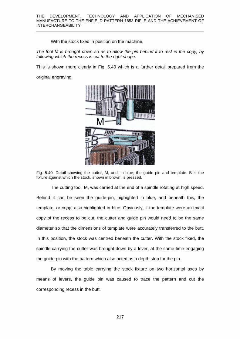
THE DEVELOPMENT, TECHNOLOGY AND APPLICATION OF MECHANISED MANUFACTURE TO THE ENFIELD PATTERN 1853 RIFLE AND THE ACHIEVEMENT OF INTERCHANGEABILITY
217
With the stock fixed in position on the machine,
The tool M is brought down so as to allow the pin behind it to rest in the copy, by following which the recess is cut to the right shape. This is shown more clearly in Fig. 5.40 which is a further detail prepared from the
original engraving.
Fig. 5.40. Detail showing the cutter, M, and, in blue, the guide pin and template. B is the fixture against which the stock, shown in brown, is pressed.
The cutting tool, M, was carried at the end of a spindle rotating at high speed.
Behind it can be seen the guide-pin, highighted in blue, and beneath this, the
template, or copy, also highlighted in blue. Obviously, if the template were an exact
copy of the recess to be cut, the cutter and guide pin would need to be the same
diameter so that the dimensions of template were accurately transferred to the butt.
In this position, the stock was centred beneath the cutter. With the stock fixed, the
spindle carrying the cutter was brought down by a lever, at the same time engaging
the guide pin with the pattern which also acted as a depth stop for the pin.
By moving the table carrying the stock fixture on two horizontal axes by
means of levers, the guide pin was caused to trace the pattern and cut the
corresponding recess in the butt.

THE DEVELOPMENT, TECHNOLOGY AND APPLICATION OF MECHANISED MANUFACTURE TO THE ENFIELD PATTERN 1853 RIFLE AND THE ACHIEVEMENT OF INTERCHANGEABILITY
218
The cutter and guide pin were then disengaged and the frame carrying the
tool spindles rotated to bring the drill, N in Fig. 5.37 (p. 36), and its guide pin into the
same position, the exact rotation of this frame being determined by a stop. In this
instance, the guide pin would have been the same diameter as the semi-circular tip
of the pattern to ensure that the drill was on the same centre line. By lowering the drill
spindle with a lever, the tang-screw hole was drilled.
The next step was to drill the hole for the lower of the two large buttplate
screws. This utilised a horizontal drilling spindle, again with an associated guide pin
which simply entered a correctly positioned hole, despite the apparent misalignment
in Fig.5.41.
Fig. 5.41 Detail of Fig. 5.37 showing the drill and guide pin with the end of the butt highlighted in brown.
The table upon which the stock was mounted was moved forward to bring the
guide-pin hole nearest the front into line with the guide-pin. This ensured the correct
position of the drill bit which was then advanced by means of a lever. After
withdrawing the drill, the table with the butt was then moved rearward, the guide pin
entered into the farthest hole, and the hole in the butt tapped. This used a self-

THE DEVELOPMENT, TECHNOLOGY AND APPLICATION OF MECHANISED MANUFACTURE TO THE ENFIELD PATTERN 1853 RIFLE AND THE ACHIEVEMENT OF INTERCHANGEABILITY
219
reversing tapping head which automatically cut the thread to the required depth and
then withdrew itself.
The final operation performed by this machine was the drilling and tapping of
the oblique hole at the top corner, or heel, of the butt. According to The Engineer
(1859, p. 259) this was precisely similar to the one just described. This is patently
incorrect. The only way it could be achieved using the same tooling was to first rotate
the butt to bring the position of the oblique hole into horizontal alignment with the
tooling. This is where the importance of the note:
the stock being fitted against a plate of iron hung upon a spindle, so as to enable its position to be changed without being released becomes apparent.
Such a feature would need to take into account the accurate geometrical
positioning of the centre of rotation. This has been experimented with graphically,
Fig. 5.42, and the centre point indicated provides the correct geometry for bringing
the centre of the oblique hole into horizontal alignment with the same drill and tap
used for the lower, horizontal hole, for this operation.
Fig. 5.42 Hypothetical centre of rotation to put the oblique hole into horizontal alignment.
(© P. Smithurst 2019)
It will be seen in Fig.5.37 (p. 36) that there is an opening in the sliding table
which would make a rotation of this nature possible and, aligned thus, the operations

THE DEVELOPMENT, TECHNOLOGY AND APPLICATION OF MECHANISED MANUFACTURE TO THE ENFIELD PATTERN 1853 RIFLE AND THE ACHIEVEMENT OF INTERCHANGEABILITY
220
do become “precisely similar”. The corner under the tang of the butt plate was then
finished by rounding by hand (Greenwood 1862, p. 328).
5.5.11 Bedding the lock
This process was the cutting of the recess in the stock into which the lock
fitted using the machine in Fig. 5.43. One of the these machines used at Enfield
survives in the Science Museum in London. Another, although, from Colt’s factory in
Hartford, Connecticut, is at the American Precision Museum in Windsor, Vermont.
The author, at one time Executive Director at this museum, was able to operate the
machine and can attest to its effectiveness.
Fig. 5.43 The lock bedding machine used at Enfield. The stock can be seen laid and fixed on its left hand side on a moveable carriage beneath the rotating carousel fitted with a number of cutter spindles. (Engineer, 1859, p.294)

THE DEVELOPMENT, TECHNOLOGY AND APPLICATION OF MECHANISED MANUFACTURE TO THE ENFIELD PATTERN 1853 RIFLE AND THE ACHIEVEMENT OF INTERCHANGEABILITY
221
The illustration above does little justice to the machine’s complexity. The
‘carousel’, mounted above the table on which the stock is fixed, carries five powered
spindles, each fitted with a cutter specific to the operation it has to perform. This
carousel is rotated, bringing each spindle to bear in succession, and at each rotation
of the carousel the drive belt is automatically disengaged and re-engaged
successively with each spindle. The stock was clamped on its side on the moveable
table, A, Fig. 5.44, using the spots on the stock to ensure its correct horizontal
position, and by pressing the barrel channel up against a short model of the barrel, it
was correctly positioned longitudinally and laterally.
Fig. 5.44 Detail showing stock fixed on the table, A.
Not clearly visible in the illustration in Fig. 5.44 is how the model barrel was
arranged but this detail is provided by a contemporary Greenwood and Batley
drawing of aspects of this machine, Fig. 5.45, and which has not been previously
studied or published.

THE DEVELOPMENT, TECHNOLOGY AND APPLICATION OF MECHANISED MANUFACTURE TO THE ENFIELD PATTERN 1853 RIFLE AND THE ACHIEVEMENT OF INTERCHANGEABILITY
222
Fig. 5.45 Details from Greenwood and Batley drawing 448 highlighting the model of the barrel against which the stock is located. (© West Yorkshire Archives)
The key to this machine was the pattern, Fig. 5.46, which was an exact
replica of the recess to be cut in the stock.
Fig. 5.46 Detail of the lockplate recess pattern (Greenwood and Batley Dwg 448, © West Yorkshire Archives) compared with a drawing of the lock internal components. (from RSAF drawing 746, © Royal Armouries)
Examination of an edge-on view of a lock, Fig. 5.47, which, although not a
Pattern 1853 Enfield lock, is closely comparable in terms of its internal components

THE DEVELOPMENT, TECHNOLOGY AND APPLICATION OF MECHANISED MANUFACTURE TO THE ENFIELD PATTERN 1853 RIFLE AND THE ACHIEVEMENT OF INTERCHANGEABILITY
223
and their arrangement, shows that components project to varying distances from the
inner face of the lockplate.
Fig. 5.47 Edgewise view of a lock to show the varying profiles of the components on the inner lockplate face and the three principal depths of the lock housing. (© P. Smithurst 2019) These variations in the projection of components are closely followed in the lock
recess of the stock, removing as little material as necessary so as not to further
weaken the stock at what is one of its weakest points.
The author suggests therefore that the three different colours within the
recess pattern drawing coincide with the three different depths at various points to
accommodate the components, including in certain instances, such as with
mainspring, tumbler, sear spring and sear, their movement in arcs of various sweeps
and radii. The sear tang is anomolous in having to project deep into the stock to
engage with the trigger.
It has been noted in Chapter 4 that the lock fit closely against the shoulder of
the nipple bolster on the barrel, so it was therefore essential that the stock and
pattern be in correct mutual alignment on this machine, Fig. 5.48. This was ensured
by the positioning of the model barrel against which the stock was clamped

THE DEVELOPMENT, TECHNOLOGY AND APPLICATION OF MECHANISED MANUFACTURE TO THE ENFIELD PATTERN 1853 RIFLE AND THE ACHIEVEMENT OF INTERCHANGEABILITY
224
Fig. 5.48 Position of the stock in relation to the pattern on the machine table. (Greenwood and Batley Dwg 448 42F
43, © West Yorkshire Archives) The description in ‘The Engineer’ identifies 5 stages in the lock-bedding process:
1. recess for the lockplate cut 2. recesses for screw heads cut 3. recess for the tang of the sear is cut 4. recess for the mainspring is cut 5. small tool used to finish the corners left by No. 4
5.5.11.1 Recessing for the lockplate
The first operation, cutting the recess for the lockplate, used the cutter shown
in Fig. 5.49.
43 A curious feature of Fig. 5.48 is that, notwithstanding the first lock-bedding operation has already been carried out, i.e., creating the recess for the lockplate, it also shows a stock in which various features appear completed when, in reality, those operations, such as finish-turning and machining the square shoulders against which the barrel-bands abutted, were performed after bedding the lock.

THE DEVELOPMENT, TECHNOLOGY AND APPLICATION OF MECHANISED MANUFACTURE TO THE ENFIELD PATTERN 1853 RIFLE AND THE ACHIEVEMENT OF INTERCHANGEABILITY
225
Fig. 5.49 The cutter and guide pin for the first operation. (Greenwood and Batley, Dwg 448, © West Yorkshire Archives)
There are a number of general points worth noting about this and other
cutters; it had spiral flutes, like a slot-drill or router bit, and it revolved at 7,000 rpm. A
feature of cutters for the 1st, 4th and 5th operations was having their shanks turned
eccentrically to the extent of 1/64th-inch (0.4mm) and this eccentricty was also applied
to the tapered sockets in the spindle and which were graduated on half of the
circumference of their end faces. These features allowed perfect accuracy to be
maintained after cutters were sharpened by minutely adjusting their positions in the
sockets.
For the first operation, the cutter and guide-pin were 0.375 inch diameter and
the guide-pin was fitted with a cross bar, held in place by a taper key, to act as a
depth stop against the top face of the pattern throughout the full extent of its
movement. The first spindle was set in motion and the operator lowered it, entering
the guide pin into the pattern and, by means of levers, traversed both table and
spindle so that the shallow recess was completely cut out.

THE DEVELOPMENT, TECHNOLOGY AND APPLICATION OF MECHANISED MANUFACTURE TO THE ENFIELD PATTERN 1853 RIFLE AND THE ACHIEVEMENT OF INTERCHANGEABILITY
226
5.5.11.2 Recessing for the screw heads
With regard to the next stage, conflicting information is presented by the
accounts of ‘The Engineer’ (1859, p.294), and Greenwood (1862, p.332) but the
evidence of the Greenwood & Batley drawings suggest it was to recess the screw
heads. The carousel was rotated to bring the second spindle into position and the
drawing in Fig 5.50 is noted as being for the second operation, using 0.3-inch
diameter cutter and a 0.25-inch diameter guide pin.
Fig. 5.50 Cutter and guide pin for the second operation. (Greenwood and Batley, Dwg 448, © West Yorkshire Archives)
If this drawing is examined in detail and compared with the lock in Fig. 5.51,
Fig. 5.51 Approximate scaling of the depth of cut shown in Fig. 5.50 and the lock components in profile.

THE DEVELOPMENT, TECHNOLOGY AND APPLICATION OF MECHANISED MANUFACTURE TO THE ENFIELD PATTERN 1853 RIFLE AND THE ACHIEVEMENT OF INTERCHANGEABILITY
227
it becomes apparent that this second operation cannot have been for the drilling of
the hole for the sear tang as stated by Greenwood (1862, p.332) since the hole
would not be deep enough, but was for cutting holes for the heads of the screws as
noted in ‘The Engineer’ (1859, p.294).
Bearing in mind the heads of the screws, which from measurement of several
examples were 0.264 inches diameter, the 0.3 inches diameter cutter shown
provided clearance. These recesses are not apparent in the drawing of the lock-
bedding pattern but are evident in the actual lock recess of the stock in Fig. 5.52.
Fig. 5.52. The recess in the stock showing cavities for the screw heads. (© P. Smithurst 2019)
A question which arises is, that in the absence of holes for the guide pin in the
pattern, how was it aligned with the centres of the screws? The absence of these
holes in the pattern may simply be an error in the drawing but, considering the
meticulous care taken with the remainder of it, this seems very unlikely.
Examination of Fig. 5.50 shows that in addition to the two mounting points for
the guide pin, the pin itself passes through a third item at its lower end, Fig. 5.53.
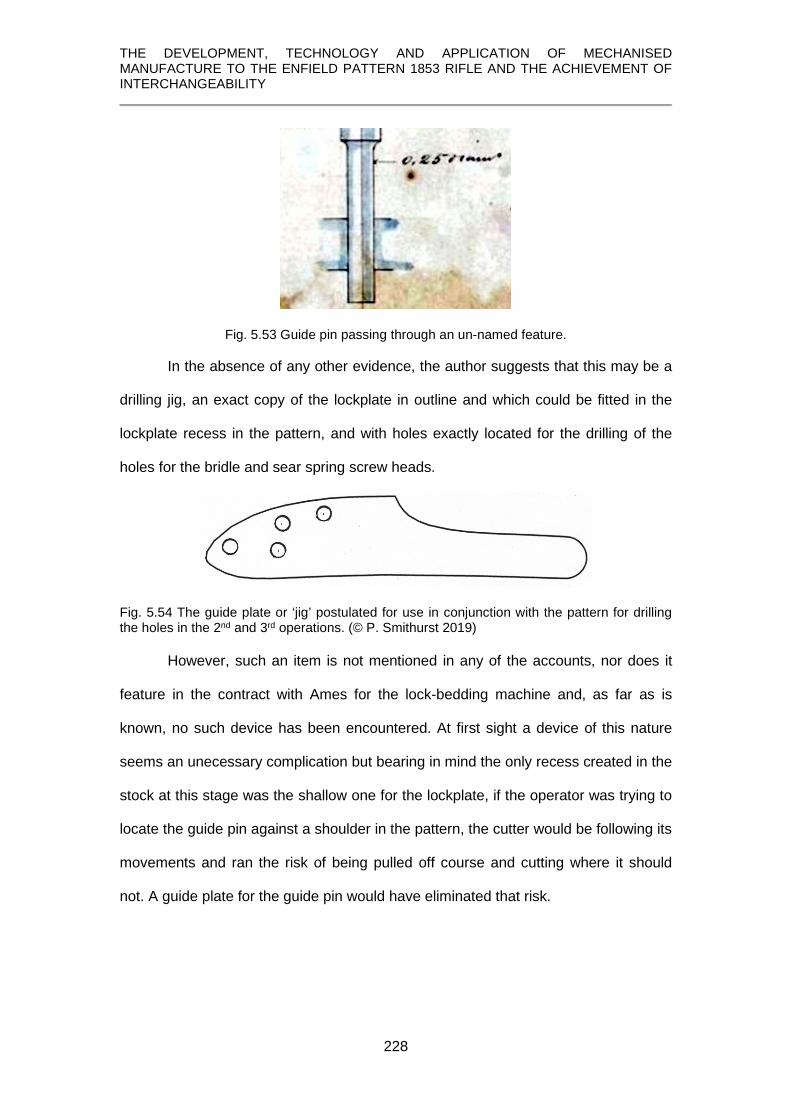
THE DEVELOPMENT, TECHNOLOGY AND APPLICATION OF MECHANISED MANUFACTURE TO THE ENFIELD PATTERN 1853 RIFLE AND THE ACHIEVEMENT OF INTERCHANGEABILITY
228
Fig. 5.53 Guide pin passing through an un-named feature.
In the absence of any other evidence, the author suggests that this may be a
drilling jig, an exact copy of the lockplate in outline and which could be fitted in the
lockplate recess in the pattern, and with holes exactly located for the drilling of the
holes for the bridle and sear spring screw heads.
Fig. 5.54 The guide plate or ‘jig’ postulated for use in conjunction with the pattern for drilling the holes in the 2nd and 3rd operations. (© P. Smithurst 2019)
However, such an item is not mentioned in any of the accounts, nor does it
feature in the contract with Ames for the lock-bedding machine and, as far as is
known, no such device has been encountered. At first sight a device of this nature
seems an unecessary complication but bearing in mind the only recess created in the
stock at this stage was the shallow one for the lockplate, if the operator was trying to
locate the guide pin against a shoulder in the pattern, the cutter would be following its
movements and ran the risk of being pulled off course and cutting where it should
not. A guide plate for the guide pin would have eliminated that risk.

THE DEVELOPMENT, TECHNOLOGY AND APPLICATION OF MECHANISED MANUFACTURE TO THE ENFIELD PATTERN 1853 RIFLE AND THE ACHIEVEMENT OF INTERCHANGEABILITY
229
5.5.11.3 Drilling the hole for the sear tang
The third operation was the drilling of the deep hole for the sear tang. It was a
similar arrangement to that for the second operation but using a longer drill. Again,
using approximate scaling of the drawing against the lock profile, Fig. 5.55, confirms
it was used for this purpose.
Fig. 5.55 Approximate scaling of the depth of cut and the sear tang.
This used a drill of 0.415 inches diameter, but a guide pin of 0.25-inches diameter as
in the second operation. It could, therefore, have used the same guide plate
postulated for the second operation in which a fourth hole, coinciding with the centre
of the sear tang hole, had been provided, as shown in Fig. 5.54.
5.5.11.4 Recessing for the mainspring
A 0.3 inch diameter cutter and guide pin were used and their function
becomes apparent by applying a similar scaling of the lock components alongside
the cutter and guide pin, Fig. 5.56.
Fig. 5.56 Scaling of the depths of cut to receive the bridle, mainspring and sear spring.
Greenwood (1862, p.332) notes that this fourth operation cut out the principal
recesses below the lockplate and partially cuts out the curved recess for the cone
seat [author’s underlining].
It can be seen that in bedding the barrel and the breech pin, there remained
two portions of the timber left by the ‘oblique cut’ of the slabbing process.

THE DEVELOPMENT, TECHNOLOGY AND APPLICATION OF MECHANISED MANUFACTURE TO THE ENFIELD PATTERN 1853 RIFLE AND THE ACHIEVEMENT OF INTERCHANGEABILITY
230
Fig. 5.57 Portions of the ‘oblique cut’ left after barrel-bedding. (607.00006 © Birmingham City
Museum)
That on the lockplate side would be removed during the lock-bedding
operation. The only way this operation partially cuts out the curved recess for the
cone seat would have been to transfer the guide pin from the deeper portions of the
pattern to the ‘bulbous’ extension from the lockplate recess. This is shown in detail
below alongside the cut-out in the stock for the ‘cone seat’ or ‘nipple bolster’, Fig.
5.58.
Fig. 5.58 Outward extension of the lockplate recess in the pattern lock housing, top, shown in conjunction with the cut-out for the ‘cone seat’ or ‘nipple bolster’.

THE DEVELOPMENT, TECHNOLOGY AND APPLICATION OF MECHANISED MANUFACTURE TO THE ENFIELD PATTERN 1853 RIFLE AND THE ACHIEVEMENT OF INTERCHANGEABILITY
231
Therefore, if the previous interpretation of the colouring of the drawing is
correct, the removal of timber for the opening for the ‘cone seat’ would only be to the
same depth as the lockplate recess, and therefore only partial, leaving a small
portion of the wall of the barrel channel, Fig. 5.59.
Fig. 5.59 Timber left behind after machining the opening for the ‘cone seat’.
(© P. Smithurst 2019)
This is felt to be an oversight in what was a carefully planned operation and it is
argued, therefore, that this could have been achieved if the portion of the lock-
bedding pattern was deeper than has been indicated or deduced, thereby allowing
the bulk of this timber to be removed and leaving only a small fillet, Fig. 5.60.
Fig. 5.60 Fillet left in cutting out the opening for the cone seat. (© P. Smithurst 2019)
This would better satisfy the comment by Greenwood (1862, p.328-9) that The end of the curved recess for the cone seat (nipple bolster) where it joints against the lockplate is squared by hand.
At some unspecified stage, the remains of the timber left by the oblique cut
was be removed to leave a quadrant fillet between the left-hand wall of the barrel
channel and the vertical breech face, Fig. 5.61.

THE DEVELOPMENT, TECHNOLOGY AND APPLICATION OF MECHANISED MANUFACTURE TO THE ENFIELD PATTERN 1853 RIFLE AND THE ACHIEVEMENT OF INTERCHANGEABILITY
232
Fig. 5.61 Fillet on the left-hand wall of the barrel channel. (© P. Smithurst 2019)
The fifth operation was very much a repeat of the fourth but using a 0.2-inch diameter
cutter and guide pin to remove the last vestiges of timber left in corners of the lock
recess by the larger cutter used in the previous operation.
5.5.12 Bedding the trigger guard, drilling screw holes, cutting recess for trigger plate and the stop for the ramrod
All operations were carried out on one machine. In Fig. 5.63 the other
features created at this stage can also be seen and will be dealt with in order.
Fig. 5.62 The Enfield Pattern 1853 trigger guard. (© P. Smithurst 2019)
Fig. 5.63 Features of the Enfield Pattern 1853 trigger guard and its bed on the stock.

THE DEVELOPMENT, TECHNOLOGY AND APPLICATION OF MECHANISED MANUFACTURE TO THE ENFIELD PATTERN 1853 RIFLE AND THE ACHIEVEMENT OF INTERCHANGEABILITY
233
As can be seen from the illustrations, the mating surface between trigger
guard and stock followed a curve which approximates to the arc of a circle.
Fig. 5.64 The Enfield Pattern 1853 stock showing the extremities of the trigger guard. (© P. Smithurst 2019)
This gives some indication of the primary requirements of a machine to perform this
operation and the machine is illustrated in The Engineer, but gives an overall
impression rather than any real detail. A clearer illustration of this machine is
provided by Benton, a detail of the main functional elements of which are shown in
Fig. 5.65.
Fig. 5.65 The trigger guard bedding machine illustrated by Benton. (1878, Pl. XI)
In the caption to Benton’s illustration, the item H is described as an oscillating
fixture. It is difficult to understand how it can ‘oscillate’ since it appears fixed at ech
end, but it would act as a guide if its centre of curvature was concentric with the arc
of the stock, G, on which the trigger guard is bedded. Thus, as the mounting on
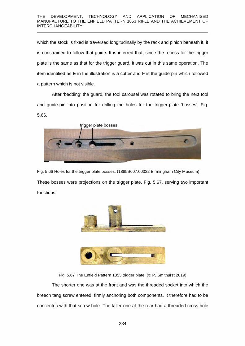
THE DEVELOPMENT, TECHNOLOGY AND APPLICATION OF MECHANISED MANUFACTURE TO THE ENFIELD PATTERN 1853 RIFLE AND THE ACHIEVEMENT OF INTERCHANGEABILITY
234
which the stock is fixed is traversed longitudinally by the rack and pinion beneath it, it
is constrained to follow that guide. It is inferred that, since the recess for the trigger
plate is the same as that for the trigger guard, it was cut in this same operation. The
item identified as E in the illustration is a cutter and F is the guide pin which followed
a pattern which is not visible.
After ‘bedding’ the guard, the tool carousel was rotated to bring the next tool
and guide-pin into position for drilling the holes for the trigger-plate ‘bosses’, Fig.
5.66.
Fig. 5.66 Holes for the trigger plate bosses. (1885S607.00022 Birmingham City Museum)
These bosses were projections on the trigger plate, Fig. 5.67, serving two important
functions.
Fig. 5.67 The Enfield Pattern 1853 trigger plate. (© P. Smithurst 2019)
The shorter one was at the front and was the threaded socket into which the
breech tang screw entered, firmly anchoring both components. It therefore had to be
concentric with that screw hole. The taller one at the rear had a threaded cross hole

THE DEVELOPMENT, TECHNOLOGY AND APPLICATION OF MECHANISED MANUFACTURE TO THE ENFIELD PATTERN 1853 RIFLE AND THE ACHIEVEMENT OF INTERCHANGEABILITY
235
into which the trigger screw fit, acting as a pivot for the trigger, and was cut into by
the slot for the trigger.
The third operation was to drill the three holes for the trigger guard screws,
using a third cutter and guide pin.
Lastly, the fourth operation was to form the slot for the trigger, trigger guard
tenon and the ramrod stop, a transverse slot just behind the front screw hole.
Although the machine in Fig. 66 (p. 50) only shows three sets of cutters and guide
pins, the machine at Enfield had four (Engineer, 1859, p.294).
Fig. 5.68 Further details of the trigger guard bedding operations.
(1885S607.00022 Birmingham City Museum)
A surviving Greenwood and Batley drawing, Fig. 5.69, shows the pattern for
performing the slotting of the stock for the trigger but is for a different weapon since it
has a swelling at the end of the tang, does not incorporate a guide for forming the
slot for the ramrod stop, nor the longitudinal slot for the tenon on the front of the
Enfield trigger guard.
Fig. 5.69 Detail from a Greenwood and Batley drawing No. 731 showing a pattern for cutting the trigger recess in a stock. (© West Yorkshire Archives)

THE DEVELOPMENT, TECHNOLOGY AND APPLICATION OF MECHANISED MANUFACTURE TO THE ENFIELD PATTERN 1853 RIFLE AND THE ACHIEVEMENT OF INTERCHANGEABILITY
236
5.5.13 Stock cut for the bands from a copy and the nose cap let on.
The purpose of the first process was to machine the rough-turned stock to
create the squared seatings against which the barrel bands were fixed and is shown
in Fig. 5.70.
Fig. 5.70 Rough-turned stock cut for the bands: Top: bottom band, closest to the lock; Middle: middle band; Bottom: top band, including machining of the whole of that portion of the fore-end and cutting the recess for nose-cap (not shown). (1885S607.0015 © Birmingham City Museum)
The only source of information regarding the machine for this purpose and
process (Engineer, 1859, p.294) is not aided in its description by the lack of
illustrations. However, it is stated that the next operation, turning between the bands,
the machine is similar, in many respects, to the one just described (Engineer, 1859,
p.294) and for this the details provided by Greenwood (1862, pps.332-334) can be
drawn upon.
5.5.14 Stock turned between the bands
The only difference between the machines would seem to be that, apart from
different widths and numbers of cutters, the stock needed to be clamped in different
places so as not to interfere with the cuts to be made. Within those constraints, the
machines and processes were the same and ‘turning between the bands’, which

THE DEVELOPMENT, TECHNOLOGY AND APPLICATION OF MECHANISED MANUFACTURE TO THE ENFIELD PATTERN 1853 RIFLE AND THE ACHIEVEMENT OF INTERCHANGEABILITY
237
removed the remaining surplus timber to create the result shown in part in Fig. 5.71,
will be described.
Fig. 5.71 Turning between bands showing removal of the timber left after cutting for the bands. (this only partially shows the turning between the lower and middle bands). (top:1885S607.0015 and bottom; 1885S607.0016. © Birmingham City Museum)
The machine used is shown in Fig. 5.72 and after its functions have been
described, it will be understood that it also provided the basic requirements of the
previous operation for cutting under the bands.
It is another copying machine but, because the two portions of the fore-end of
the stock are uniform in cross-section along their length, the pattern takes the form of
a cam, rather than a complete model of the fore-end. Also, instead of a cutter which
traversed the workpiece, two pairs of cutters were used, each pair combined
extending the full length of the parts to be machined.

THE DEVELOPMENT, TECHNOLOGY AND APPLICATION OF MECHANISED MANUFACTURE TO THE ENFIELD PATTERN 1853 RIFLE AND THE ACHIEVEMENT OF INTERCHANGEABILITY
238
Fig. 5.72 Greenwood and Batley machine for turning between the bands. (Greenwood, 1862, Plate 82)
Unlike the previous copy-turning machine described in The Engineer, in this
machine the stock was inserted through hollow bearings which only carried the
model barrel to which the stock was fixed; the cams were mounted on a separate
shaft.
An examination of a cross-section through the top portion of the machine, Fig.
5.73, shows the arrangement of the principal components.
Fig. 5.73 Transverse cross-section through the working elements. The stock, B, mounted on a model of the barrel, E, carried in hollow bearings, F. Above it is a shaft carrying the cams, A and the tracers or followers, I, fixed to a rocking frame, G, carrying the rotating blocks into which the cutters, C, are fixed. (adapted from Greenwood, 1862, Plate 91)

THE DEVELOPMENT, TECHNOLOGY AND APPLICATION OF MECHANISED MANUFACTURE TO THE ENFIELD PATTERN 1853 RIFLE AND THE ACHIEVEMENT OF INTERCHANGEABILITY
239
A plan view, Fig. 5.74, shows the nature of the cutter blocks and their relationship
with the stock.
Fig. 5.74 Plan view showing the hollow bearings, F, carrying the model barrel on which the stock, shown in brown, is fitted, and the four cutter blocks, C. (adapted from Greenwood, 1862, Plate 92) The rotations of the shafts carrying the cams and the stock were synchronised by two
identical gears in mesh with an ‘idler’ gear so that when rotated by hand, both rotated
in the same direction and at the same speed.
Two pairs of cutter blocks, C, were carried on ‘rocking’ frames on each side of
the stock. In addition, each ‘rocking’ frame was fitted with a tracer or cam follower, I,
in Fig. 5.73. Its position on the rotating cam determined the depth of cut taken on the
stock and was finely adjustable to allow for wear and readjustment after re-
sharpening the blades. The cutter blocks were of sufficient length so that the
matching pairs on opposite sides cut the full length of the part of the stock they
worked on, with a small overlap in the middle which is evident in Fig. 5.74. It should
be noted that that where the stocks had been cut for seating the bands in the
previous operation, these areas then acted as bearing and clamping points, F, for
turning between the bands.

THE DEVELOPMENT, TECHNOLOGY AND APPLICATION OF MECHANISED MANUFACTURE TO THE ENFIELD PATTERN 1853 RIFLE AND THE ACHIEVEMENT OF INTERCHANGEABILITY
240
One pair of rotating cutters were brought into contact with the stock by the
operator pressing a foot pedal and the stock, mounted on its model barrel, was
rotated by hand. This was followed by engaging the pair of cutters on the opposite
rocking frame’ and in this way the whole of the stock between the lower and top
bands was machined.
The cutter blocks were fitted with a number of plane blades whose cutting
edges were parallel to a vertical plane through the centre line of the stock but were
inclined in the horizontal plane. Thus, when rotating and presented up to the stock,
the point of contact with the cutting edge moved along the stock providing a ‘paring’
action along the grain, rather than a ‘tearing’ action across the grain, leading to a
smooth finish. All that was required after this process was a quick rubbing down with
glasspaper and this part of the stock was finished.
5.5.15 Arris at the extreme muzzle-end of the stock under the flange of the nosecap taken off by hand.
This was simply the removal of the sharp corner at the end of the stock to
accomodate the inside radius at the junction of the end flange and the underside of
the casting of the nosecap to allow it sit firmly on the wood.
5.5.16 Butt end of the stock and fore-end of stock between lock and first [bottom] band finish turned in copying lathe.
Greenwood (1862, p.230) and Benton (1878, p. 112) note these as being two
separate operations whereas The Engineer (1859, p.348) makes no distinction and
only illustrates one machine.
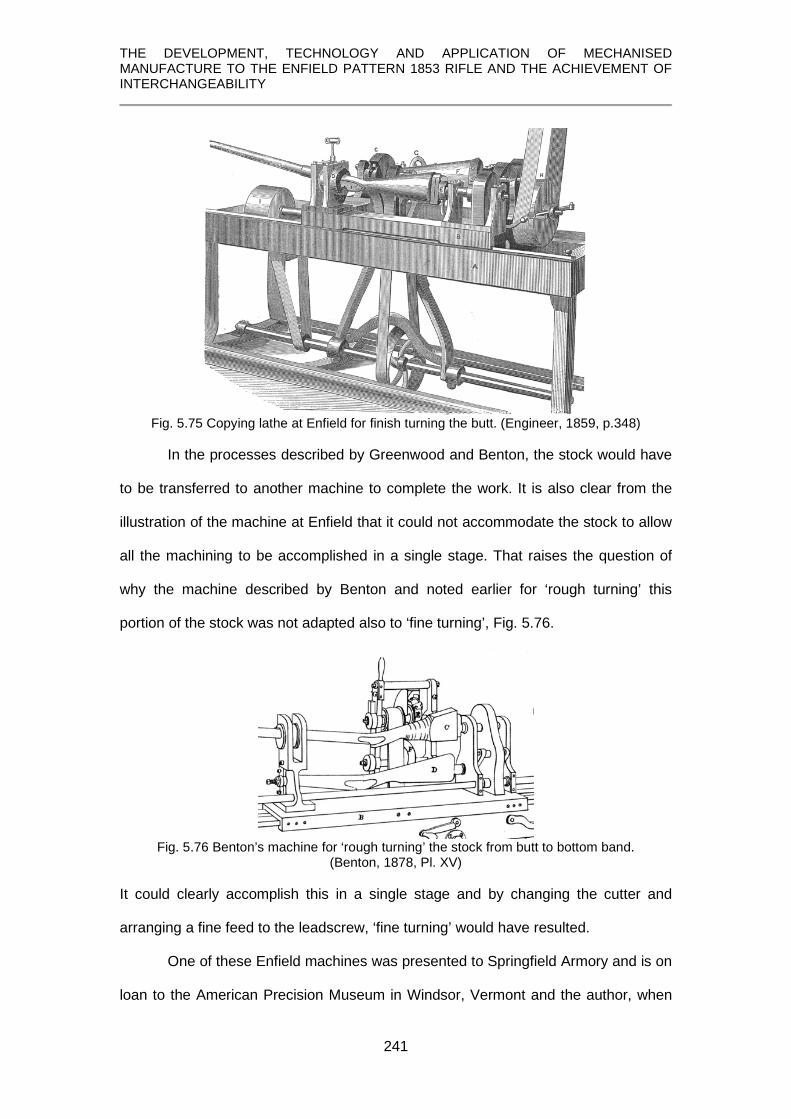
THE DEVELOPMENT, TECHNOLOGY AND APPLICATION OF MECHANISED MANUFACTURE TO THE ENFIELD PATTERN 1853 RIFLE AND THE ACHIEVEMENT OF INTERCHANGEABILITY
241
Fig. 5.75 Copying lathe at Enfield for finish turning the butt. (Engineer, 1859, p.348)
In the processes described by Greenwood and Benton, the stock would have
to be transferred to another machine to complete the work. It is also clear from the
illustration of the machine at Enfield that it could not accommodate the stock to allow
all the machining to be accomplished in a single stage. That raises the question of
why the machine described by Benton and noted earlier for ‘rough turning’ this
portion of the stock was not adapted also to ‘fine turning’, Fig. 5.76.
Fig. 5.76 Benton’s machine for ‘rough turning’ the stock from butt to bottom band.
(Benton, 1878, Pl. XV)
It could clearly accomplish this in a single stage and by changing the cutter and
arranging a fine feed to the leadscrew, ‘fine turning’ would have resulted.
One of these Enfield machines was presented to Springfield Armory and is on
loan to the American Precision Museum in Windsor, Vermont and the author, when

THE DEVELOPMENT, TECHNOLOGY AND APPLICATION OF MECHANISED MANUFACTURE TO THE ENFIELD PATTERN 1853 RIFLE AND THE ACHIEVEMENT OF INTERCHANGEABILITY
242
Executive Director at that museum, was able to operate it and can attest to its
functionality. The photograph below shows the arrangement of the principal operative
features.
Fig. 5.77 The Enfield butt finish-turning machine. (©. Springfield Armory / American Precision Museum, Windsor, VT.)
The the cutter wheel is visible and is fitted with conical cups sharpened on
their rims and held in place by set-screws, allowing them to be rotated as occasion
demanded to allow for wear or slight damage. Also visible is the hollow bearing
through which the stock is passed and clamped in place. The frame carrying the
follower and cutter wheels is moved along the bed by a leadscrew as the pattern and
stock are rotating. Having finish-turned the butt, the portion of the fore-end between
the finish-turned butt up to the position of the first band was turned in a similar
machine. By extending the bed of this machine, it could have accomodated the whole
of the stock to be worked upon, from butt to bottom band, in a single operation.
One point noted (Engineer, 1859, p.348) was that to maintain the sharp
corners between the planed surfaces of the lock seat, and the flat face on the oposite
side, where they meet the curves of the stock, the pattern was enlarged at this point
so the follower wheel could move over a rounded corner while the cutter wheel was
not in contact with the stock. Continued rotation of the stock and pattern brought the
cutter wheel back into contact with the stock at the appropriate point.

THE DEVELOPMENT, TECHNOLOGY AND APPLICATION OF MECHANISED MANUFACTURE TO THE ENFIELD PATTERN 1853 RIFLE AND THE ACHIEVEMENT OF INTERCHANGEABILITY
243
It is clear from surviving specimens, although not Enfield, Fig. 5.78, that this
process, by the very nature of the cutters, left a very slightly ribbed surface which
would need further hand-finishing with sandpaper to create a perfectly smooth stock.
Fig. 5.78 A ‘finish-turned’ butt of similar period showing the fine furrows left by the cutter.
(© P. Smithurst 2019) 5.5.17 Stock grooved for ramrod
This was a straightforward operation in comparison with others and involved
cutting a groove from the end of the fore-end down to the first, or bottom, band. It
was carried out on a machine similar to a vertical milling machine or router with a
high-speed spindle to which the cutters were fixed. The stock was mounted inverted
vertically on a model of the barrel to allow accurate positioning. This model barrel
was fixed to a table which could slide and move the stock longitudinally. The first
groove to be cut used a square-ended cutter. This groove was then enlarged slightly
at the bottom using a ball-eneded cutter of sufficient size so that the ramrod was a
loose fit and would remain so if the wood swelled or shrank due to changes in
humidity. The effects of these operations are shown below, Fig. 5.79.
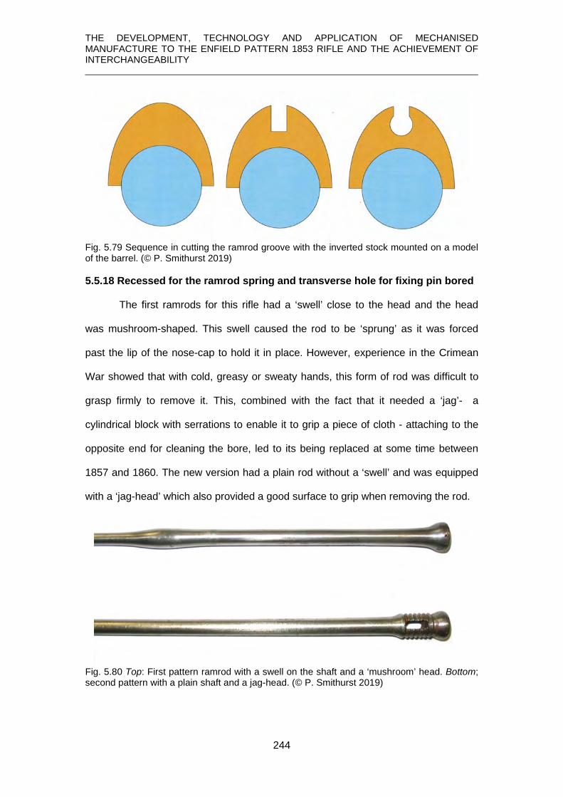
THE DEVELOPMENT, TECHNOLOGY AND APPLICATION OF MECHANISED MANUFACTURE TO THE ENFIELD PATTERN 1853 RIFLE AND THE ACHIEVEMENT OF INTERCHANGEABILITY
244
Fig. 5.79 Sequence in cutting the ramrod groove with the inverted stock mounted on a model of the barrel. (© P. Smithurst 2019)
5.5.18 Recessed for the ramrod spring and transverse hole for fixing pin bored
The first ramrods for this rifle had a ‘swell’ close to the head and the head
was mushroom-shaped. This swell caused the rod to be ‘sprung’ as it was forced
past the lip of the nose-cap to hold it in place. However, experience in the Crimean
War showed that with cold, greasy or sweaty hands, this form of rod was difficult to
grasp firmly to remove it. This, combined with the fact that it needed a ‘jag’- a
cylindrical block with serrations to enable it to grip a piece of cloth - attaching to the
opposite end for cleaning the bore, led to its being replaced at some time between
1857 and 1860. The new version had a plain rod without a ‘swell’ and was equipped
with a ‘jag-head’ which also provided a good surface to grip when removing the rod.
Fig. 5.80 Top: First pattern ramrod with a swell on the shaft and a ‘mushroom’ head. Bottom; second pattern with a plain shaft and a jag-head. (© P. Smithurst 2019)

THE DEVELOPMENT, TECHNOLOGY AND APPLICATION OF MECHANISED MANUFACTURE TO THE ENFIELD PATTERN 1853 RIFLE AND THE ACHIEVEMENT OF INTERCHANGEABILITY
245
The plain shaft of the new ramrod meant it could not be simply held in place
by friction and a spring was devised to bear upon the lower portion of the rod when in
place in the stock. It is commonly refered to as ‘Burton’s spoon’, suggesting it was
devised by James Burton, Chief Engineer at Enfield, although a similar device was
used on French, and possibly other European muskets, earlier.
Fig. 5.81 ‘Burton’s spoon’ ramrod retaining spring. (Petrie, 1866, plate V)
Fig. 5.82 Ramrod retaining spring from French M. 1822 musket. (© P. Smithurst 2019)
Having to accommodate a spring meant two additional operations in the
manufacture of the stock. The first was to use a profile milling machine with a spindle
and a guide pin to follow a pattern, similar, for instance, as that used to cut the
recess for the buttplate tang, and circular cutter marks can be seen at the bottom of
the recess in Fig. 5.83.
Fig. 5.83 Recess for rod spring. (1885S00607.00020 © Birmingham City Museum)
The second operation was to drill the cross hole for the spring retaining pin.
Because of the small diameter of the hole and the long slender nature of the drill to

THE DEVELOPMENT, TECHNOLOGY AND APPLICATION OF MECHANISED MANUFACTURE TO THE ENFIELD PATTERN 1853 RIFLE AND THE ACHIEVEMENT OF INTERCHANGEABILITY
246
encompass the full length of the hole, it was found advisable to drill from both sides
(Engineer, 1859, p.348). This used a very ingenious machine with two exactly
opposed drilling spindles on vertical slides. The stock was mounted exactly
horizontally on its side and in correct alignment.
The lower spindle on its slide was raised by a lever. Attached to this slide was
a spring having a boss, serving as a latch, at its extremity. As this slide was raised
and the lower hole drilled, this boss engaged with a corresponding boss on the upper
slide and latched on to it. Thus, as the bottom slide and spindle was lowered, the
upper slide with its spindle was brought downwards to drill the second half of the
hole. At the appropriate point, this latching was automatically disengaged and the
upper slide was returned to its starting position by a spring. Unfortunately, no
illustration of this machine has been found.
5.5.19 Hole bored for ramrod
This hole was a continuation of the channel already prepared. The only detail
of this operation which has been discovered is a Greenwood and Batley drawing of
the machine but which is in very poor water-stained and grimy condition. Even with
digital enhancement it has proved impossible to obtain a good image of the details of
the machine and the best that can be offered is shown in Fig. 5.84.
Fig. 5.84 Part of a Greenwood and Batley drawing, No. 708, of a ramrod channel boring machine. (© West Yorkshire Archives)
The only clear feature in the above drawing is that the stock was inverted and
mounted vertically, logically using a model of the barrel again for accurate

THE DEVELOPMENT, TECHNOLOGY AND APPLICATION OF MECHANISED MANUFACTURE TO THE ENFIELD PATTERN 1853 RIFLE AND THE ACHIEVEMENT OF INTERCHANGEABILITY
247
positioning, and the hole was drilled as far as the slot for the ramrod stop (see Fig.
5.68, p. 55).
5.5.20 Holes for lockplate fxing screws, for breech tang screw, for nosecap screw and pin hole for tenon of trigger guard are bored
All of these holes had to be drilled in their exact positions to coincide with
holes in the components they engaged with. It is strange that holes for the lock
screws (side nails) were not drilled at the time the recesses for the side cups were
made since both would have required the same centres.
Regarding the other holes, the two unpublished official drawings of the
Pattern 1853 rifle referred to at different points in this thesis, R.S.A.F. No. 458 and
746, are interesting. Careful scrutiny of R.S.A.F. drawing No. 458, Fig.5.85, clearly
shows the hole for the trigger guard tenon pin, but reveals a fact so far overlooked:
the boss on the trigger plate for the breech tang srew is misaligned and may account
for the drawing never being completed.
Fig. 5.85. Detail, R.S.A.F. Drawing No 458. (© Royal Armouries)
Another fact that has been overlooked by anyone previously studying the
second drawing, R.S.A.F. No. 746, Fig. 5.86, is that the trigger plate is incorrect and
the boss to receive the tang screw is shown in completely the wrong position.

THE DEVELOPMENT, TECHNOLOGY AND APPLICATION OF MECHANISED MANUFACTURE TO THE ENFIELD PATTERN 1853 RIFLE AND THE ACHIEVEMENT OF INTERCHANGEABILITY
248
Fig. 5.86 Detail, R.S.A.F. Drawing No 746. (© Royal Armouries)
The drilling and counterboring at the tip of the barrel channel for the nose cap
screw, which might be regarded as the last of the machining operations on the stock,
also required care in setting-up. Not only did the hole have to align with the hole in
the nose cap, the wood at this point was thin so the counterboring to receive the
head of the screw had to be accurately controlled.
Fig. 5.87 Left: Plan view of the tip of the fore end showing the counterboring for the head of the nose cap screw in the barrel channel, (1885S00607.00022 © Birmingham City Museum) and Right, the nosecap and screw. (Petrie, 1866, Plate V)
All that remained to be done was to lightly sandpaper the stock and oil it
before putting into store ready for assembly with the other components as a finished
weapon. In contrast, Benton (1878, p.113) records that before boring for the tip screw
[nosecap screw] the entire surface of the stock was finished and smoothed by the
use of spokeshaves, scrapers and sandpaper which either indicates a lesser quality
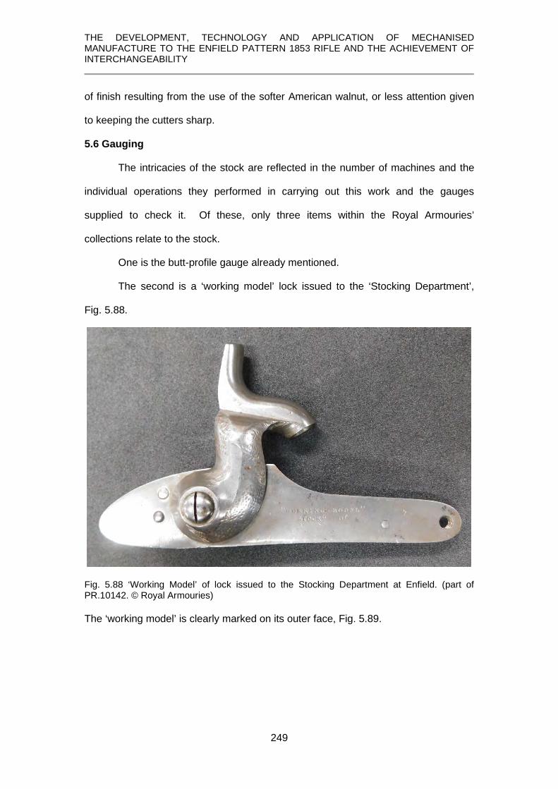
THE DEVELOPMENT, TECHNOLOGY AND APPLICATION OF MECHANISED MANUFACTURE TO THE ENFIELD PATTERN 1853 RIFLE AND THE ACHIEVEMENT OF INTERCHANGEABILITY
249
of finish resulting from the use of the softer American walnut, or less attention given
to keeping the cutters sharp.
5.6 Gauging
The intricacies of the stock are reflected in the number of machines and the
individual operations they performed in carrying out this work and the gauges
supplied to check it. Of these, only three items within the Royal Armouries’
collections relate to the stock.
One is the butt-profile gauge already mentioned.
The second is a ‘working model’ lock issued to the ‘Stocking Department’,
Fig. 5.88.
Fig. 5.88 ‘Working Model’ of lock issued to the Stocking Department at Enfield. (part of PR.10142. © Royal Armouries) The ‘working model’ is clearly marked on its outer face, Fig. 5.89.

THE DEVELOPMENT, TECHNOLOGY AND APPLICATION OF MECHANISED MANUFACTURE TO THE ENFIELD PATTERN 1853 RIFLE AND THE ACHIEVEMENT OF INTERCHANGEABILITY
250
Fig. 5.89 Marking on the ‘Working Model’. (part of PR.10142. © Royal Armouries)
It is correctly assembled and able to be ‘cocked’, as befits a working model, to
enable it to fully test all aspects of the lock-bedding operation.
Fig. 5.90 Interior of the ‘Working Model’. (part of PR.10142. © Royal Armouries)
What is additionally clear, and is to be expected considering the nature of its
purpose, is that this lock has no ‘assembly marks’, showing it to be one of the
interchangeable series produced at Enfield from 1857 onwards.
The third item was used by the London Armoury Company and is inscribed
“L.A.C. / For Barrel Gauges / Standard”. Taken literally, this would appear to be used
for testing gauges for the barrel but it has been argued later, Chapter 7, p.47, that
such a use is incompatible with the known barrel gauges (see Chapter 7, p. 46).

THE DEVELOPMENT, TECHNOLOGY AND APPLICATION OF MECHANISED MANUFACTURE TO THE ENFIELD PATTERN 1853 RIFLE AND THE ACHIEVEMENT OF INTERCHANGEABILITY
251
It would, however, serve for testing the ability of the stock to accept the finished
barrel by checking the correct inletting of the breech tang, the cut-out for the nipple
bolster where it meets the lockplate, and the bedding of this complex portion of the
barrel, Figs. 5.91 – 5.93.
Fig. 5.91 Model of breech-end of a barrel marked ‘For Barrel Gauges’. (XIII.949F © Royal
Armouries)
Fig. 5.92 Breech end of stock ready to receive the barrel with breech tang finished and seating for underside of nipple bolster correctly shaped. (607.00022 © Birmingham City
Museums)
Fig. 5.93 Breech end of stock fitted with breeching gauge. (XIII.949F © Royal Armouries;
stock © P. Smithurst 2019) 5.7 Summary
This account of stock manufacture has utilised the study of, and drawn upon,
a variety of artefacts and documents not previously studied or published which, in
combination with the few existing published accounts, has enabled new insights into
this topic to be presented.
It has been shown that the manufacture of the stock required an unusual degree of
accuracy in a finished wooden product:
THE DEVELOPMENT, TECHNOLOGY AND APPLICATION OF MECHANISED MANUFACTURE TO THE ENFIELD PATTERN 1853 RIFLE AND THE ACHIEVEMENT OF INTERCHANGEABILITY
252
1. the varied physical form of the stock created numerous intricate features.
2. they required careful and accurate design of the machines to create them.
3. very little hand-work was required to supplement these processes.
4. new perspectives of many obscure details of these machines and the
processes they performed have been provided,
5. examination of hitherto unstudied specimens of each stage of the
manufacturing process have aided these new perspectives
6. examination of unique archive drawings of some machines have enabled a
fuller understanding of their characteristics to be provided
7. newly created drawings have been included to elucidate machines and their
functions.

THE DEVELOPMENT, TECHNOLOGY AND APPLICATION OF MECHANISED MANUFACTURE TO THE ENFIELD PATTERN 1853 RIFLE AND THE ACHIEVEMENT OF INTERCHANGEABILITY
253
CHAPTER 6
MANUFACTURE OF THE BARREL
Part 1 – creating the tube
This chapter deals with the first stage in making the barrel, consisting of the
conversion of a flat plate of wrought iron into a long, tapered, seam-welded tube.
The development of barrel rolling technology is briefly discussed and its application
covered in detail.
Specifications for the Enfield rifle barrel at this stage in its manufacture are provided.
New information has been presented, derived from a study of unique specimens in
Birmingham City Museum representing stages in this phase of barrel manufacture.
Errors in previous publications on this topic have also been corrected

THE DEVELOPMENT, TECHNOLOGY AND APPLICATION OF MECHANISED MANUFACTURE TO THE ENFIELD PATTERN 1853 RIFLE AND THE ACHIEVEMENT OF INTERCHANGEABILITY
254
6.1 Overview
At this stage of its manufacture, the barrel of any rifle or musket needs to
satisfy one criterion: it has to be able to withstand the pressure generated by the
explosion of propellant within it. This fell within the province of those involved in
making the iron tube from which the finished barrel would be created.
Traditionally, the ‘raw’ tube had been made by hand and details of the
methods employed can be found in a variety of sources (Fiosconi. and Guserio,
1718; Diderot, 1751, 1779, 1784; Cotty, 1806; Gamel, 1826) and those hand
methods, slow and highly labour intensive, remained in use in many places until the
second half of the 19th century.
In Britain, however, the process of making the raw tubes by rolling had been
pioneered and the technology used was principally based on the patents of Osborn
(1813, 1817) and Heywood (1814). Osborn’s patent of 1813 related to a rolling mill
for producing tapered round bars and his 1817 patent to a rolling mill for welding a
seamed tube. Heywood’s patent was for a rolling mill to create those seamed tubes.
6.2 Specifications for the Enfield barrel
The Report of the Select Committee on Small Arms (Report, 1854, p. 491)
included a brief specification and an excerpt is given below:
Specification for barrels in the filed state for Rifle Musket Pattern of 1853, .577 bore. The barrels to be rolled of the best charcoal iron, and the lumps forged of the same, without steely or hard parts to obstruct the rifling; to be free from greys or flaws from end to end; no wires to be admitted, and if any be afterwards found, the whole expense incurred in setting up to be charged against the barrel-masters; 7th January 1854. J. A. Pellatt, for the Inspector of Small Arms.
Recently discovered documents show that at the onset of manufacturing, the
wording changed in the specifications issued to contractors for the production of the
1853 Pattern Artillery Carbine and the 1856 Short Rifle, which would not have
differed fundamentally from those applied to the long ‘three-band’ rifle barrel.

THE DEVELOPMENT, TECHNOLOGY AND APPLICATION OF MECHANISED MANUFACTURE TO THE ENFIELD PATTERN 1853 RIFLE AND THE ACHIEVEMENT OF INTERCHANGEABILITY
255
Fig. 6.1 Excerpt from a contract specification for the manufacture of Pattern 1853 Artillery Carbine barrels. (see Appendix 2, item 5. © P. Smithurst 2018)
The 1856 Pattern Short Rifle contract simply added that the breech pin and
front-sight were also to be made of the best wrought iron, suggesting that prior to
1856, contractors for the rifle and the carbine may have been tempted to use an
inferior, and therefore cheaper, quality of iron for breech-pin and front-sight. It is
inconceivable that manufacture at the Enfield factory, once it began production,
would have been any less stringent.
In studying the manufacturing operations applied to the barrel, various
accounts have been drawn upon. All the accounts misinterpret or omit details and
even some stages in the process. Drawing on information contained in these various
accounts, the stages in making the ‘raw’ tube are deduced to comprise:
‘Skelp’ passed through rolls to produce a ‘mould’. ‘Mould’ passed through rolls to produce a tube with open seam. ‘Welding’ - seamed tube rolled to weld the seam. ‘Tapering’ - Welded tube passed through rolls to produce full length tapered
tube ‘Lumping’ – iron lump welded on and shaped for the nipple bolster
6.3 Manufacture of the barrel tube 6.3.1 Creating the ‘mould’ The ‘skelp’ – a flat plate of iron - was the starting point of this process and the size of
this varies with the source of information:
sixteen inches long and four inches wide and approximately ten pounds (Jervis, 1854, p.3; Miles, 1860, p.31) twelve inches long and five and a half inches wide and a half inch thick (Goodman, 1866, p.388) twelve inches long by four inches wide and three-quarters of an inch thick (I.L.N. 1855, p.410)

THE DEVELOPMENT, TECHNOLOGY AND APPLICATION OF MECHANISED MANUFACTURE TO THE ENFIELD PATTERN 1853 RIFLE AND THE ACHIEVEMENT OF INTERCHANGEABILITY
256
thirteen inches long, five and a quarter inches wide at one end and five inches at the other with the long edges bevelled to provide a better joint when welded, and a half inch thick (I.L.N. 1861, p.304); thirteen inches long, five and a quarter inches wide at one end and five inches at the other with the long edges bevelled to provide a better joint when welded, and nine-sixteenths inches thick (Mechanic, 1861, p.127). A tangential reference simply suggests that it was twelve inches long, (Engineer, 1859, p.348).
Such variations are not unexpected since the skelp was simply cut from a
larger iron plate. What mattered more was that there was enough metal so that the
finished tube was of sufficient dimensions for conversion into a finished barrel. There
was agreement that the iron be of the very best quality and was supplied by Marshall
& Co. of Wednesbury (I.L.N. 1855, p.410). The first step was to convert this skelp
into a channel-shape, and this was partly formed by hand prior to rolling.
Fig. 6.2 The roughly pre-formed skelp ready for rolling to form the ‘mould’. (2002 D 0048 © Birmingham City Museum)
One account (I.L.N. 1855, p.410) states that the skelp was moderately heated
and subjected to the action of a pair of rollers which bend it into a shape called a
‘mould’.
This ‘mould’ was produced by a set of rolls shown in Fig. 6.3, using the three
grooves, or ‘passes’, 43F
44 on the left.
44 ‘passes’ was a common term used by those in the trade for the mating grooves in the rolls through which the metal was passed; it could also refer to the number of times the metal went through the rolls.

THE DEVELOPMENT, TECHNOLOGY AND APPLICATION OF MECHANISED MANUFACTURE TO THE ENFIELD PATTERN 1853 RIFLE AND THE ACHIEVEMENT OF INTERCHANGEABILITY
257
Fig. 6.3 Rolls for producing the ‘mould’ and converting it into a seamed tube. The shapes obtained can be seen from the ‘daylight’ – the space between the rolls. (Jervis, 1854, p.3)
This creation of the mould by the rolling mill in Fig. 6.3 is more clearly shown
in Fig. 6.4, in which the original published image, shown upside down, has been
inverted to show the correct orientation.
Fig. 6.4 Creating the mould. (I.L.N. 1855, p.410)
In any rolling mill the rolls contra-rotate so that their mating surfaces are both
travelling in the same direction. In a hand-rolling 44F
45 mill, the metal, after passage
through the rolls, was manually returned to the receiving side of the rolls, often via a
reheating furnace, for passage through successive grooves. The mould, having been
initially formed by passage through the first opening, or ‘pass’, in the rolls (far left,
Figs. 6.3 and 6.4), was re-heated in a furnace before being fed through the next two
‘passes’ which lengthened it and reduced its width.
6.3.2 Creating the seamed tube
Further re-heating prepared it for being converted into a tube by the last two
passes and which, because they decrease in diameter, lengthened it even more. The
45 ‘Hand-rolling’ means the metal is manipulated by hand;, the rolls are not hand-powered.

THE DEVELOPMENT, TECHNOLOGY AND APPLICATION OF MECHANISED MANUFACTURE TO THE ENFIELD PATTERN 1853 RIFLE AND THE ACHIEVEMENT OF INTERCHANGEABILITY
258
collection in Birmingham City Museum does not have all the semi-cylindrical
examples, but does have an example showing a seamed tube which is the result of
the first stage of ‘turning the edges over’ to bring them together, Fig. 6.5.
Fig. 6.5 The first step in converting the ‘mould’ into a tube. (2002 D 484 © Birmingham City Museum)
6.3.3 Welding the seam
Having obtained the seamed tube, it required welding, drawing out to full
length and tapering, with a small allowance for trimming at the muzzle and breech
ends to bring to finished length. These actions were performed using a second set of
rolls, Fig. 6.6.
Fig. 6.6 The second set of rolls incorporated two welding ‘passes’ on the left and nine tapering ‘passes’ to the right. (Jervis, 1854, p.4)
The seamed tube was heated to welding temperature, at which the surface
became a fluid film. It was withdrawn from the furnace on a mandrel with a circular
guard to prevent the white-hot metal slipping down the mandrel onto the worker’s
hand, and inserted into the far left-hand ‘pass’ of the rolls.
Any rolling mill has to have the periphery of the rolls flanking the grooves in
contact to maintain the correct geometry and sizes of the passes, but often during

THE DEVELOPMENT, TECHNOLOGY AND APPLICATION OF MECHANISED MANUFACTURE TO THE ENFIELD PATTERN 1853 RIFLE AND THE ACHIEVEMENT OF INTERCHANGEABILITY
259
operation, the reaction to the pressure exerted on the metal causes the top roll to lift
slightly, especially if the bearings are worn, leaving a small gap. Metal is forced into
this gap, creating a rib or ‘fin’ on the rolled metal, and these are visible in Fig. 6.7.
Fig. 6.7 The seamed tube after passing through the first ‘pass’ of the welding rolls (top) and the second ‘pass’ (bottom). The ‘fin’ created by the small gap between the contact faces of the rolls is clearly visible. (top 2002 D 322; bottom 2002.D. 293 © Birmingham City Museum)
In the next passage through the rolls the barrel tube would be rotated through 90
degrees so that this fin was forced back into the body of the metal, a system
repeated until, in the last pass of the barrel through the rolls, this fin was eliminated.
Barrel rolling is shown in Fig. 6.8 but in the view of the author it implies that
the mandrel was simply held by hand as the barrel was drawn off it and passed
through the rolls. This would not only create the risk of having both the tube and the
mandrel drawn into the rolls but negated an important function of the mandrel,
making it an almost impossible undertaking if held by hand. The tip of the mandrel
had to be placed on the vertical centre line of the rolls and the barrel drawn off the
mandrel to pass through the rolls.

THE DEVELOPMENT, TECHNOLOGY AND APPLICATION OF MECHANISED MANUFACTURE TO THE ENFIELD PATTERN 1853 RIFLE AND THE ACHIEVEMENT OF INTERCHANGEABILITY
260
Fig. 6.8 Barrel rolling at Birmingham, showing a stage in the production of an Enfield Rifle barrel – note there is no device for regulating the position of the mandrel. (I.L.N. 1855, p.410)
An illustration in an American report, Fig. 6.9, which, although of later date,
exhibits close similarity to the barrel rolling mill shown in Osborn’s patent (Osborn,
1817, 4105) since, as Fitch notes, English barrel-rolling technology had been
introduced into America in 1860.
Fig. 6.9 Barrel rolling mill shown by Fitch with cross bars in place to ensure correct positioning of the mandrel. (Fitch, 1882, p.10)

THE DEVELOPMENT, TECHNOLOGY AND APPLICATION OF MECHANISED MANUFACTURE TO THE ENFIELD PATTERN 1853 RIFLE AND THE ACHIEVEMENT OF INTERCHANGEABILITY
261
In this illustration, guard rails can be seen in front of the rolls, against which
the disc on the mandrel rested, and are carefully adjusted so that it placed the end of
the mandrel on the vertical centre line of the rolls. Fitch comments on the accurate
positioning of the mandrel:
It is important to have the rods extend just to the center of the rolls, for if they go too far the hardened bearing of the mandrel will be torn off, and if not far enough, the barrel will be crushed together . . . The proper length of the mandrel is determined by a stop, with washers upon the rod, bringing up against a bar in the frame. (Fitch, 1882, p.9)
This requirement for the correct positioning of the mandrel is also made clear
in Burton’s patent (1860), Fig. 6.10, which shows a section of the barrel with the
mandrel in place.
Fig. 6.10 Illustration from Burton’s patent of 1860.
The hardened bearing referred to by Fitch is taken to mean the enlarged
‘head’ of the mandrel as illustrated by Burton. Based on the U.K. patent record, a
mandrel with a head was first used in the making of iron gas pipes (Russell, 1824)
and became standard practice. Being only short, the head eliminated the risk of
having the barrel tube cool sufficient to become a ‘shrink-fit’ on a full length mandrel
that filled the bore.
6.3.4 Tapering
After passage through the first two cylindrical-section welding passes of the
rolls, the barrels then had to be tapered. Closer examination of Fig. 6.6 reveals that

THE DEVELOPMENT, TECHNOLOGY AND APPLICATION OF MECHANISED MANUFACTURE TO THE ENFIELD PATTERN 1853 RIFLE AND THE ACHIEVEMENT OF INTERCHANGEABILITY
262
the nine passes on the right in the top roll have steps in them because the grooves
are tapered and the starting and finishing diameters are different.
Fig. 6.11 Detail from Fig. 6.6 shows the steps in the tapering rolls where the muzzle and breech diameters meet. (Jervis, 1854, p.4)
However, the author notes an important error in Fig. 6.6; the bottom roll
should be a mirror image of the top roll so that as the rolls rotate, the steps pass
each other at the same point. The rolls should therefore appear as:
Fig. 6.12 Photographic reconstruction showing how the top and bottom rolls need to be mirror images if tapered tubes are to be produced. (© P. Smithurst 2019) This same error was repeated in another account (Miles, 1860, p.31) which
‘borrowed’ extensively from Jervis.
The rotation of the rolls had to be synchronised through gearing so that at
each revolution, the steps coincided exactly, otherwise the taper would be deformed.
The pre-heated barrel tube had to be inserted when the wide portion of the groove
appeared and the use of tapering rolls required very good judgement on the part of
the workmen:

THE DEVELOPMENT, TECHNOLOGY AND APPLICATION OF MECHANISED MANUFACTURE TO THE ENFIELD PATTERN 1853 RIFLE AND THE ACHIEVEMENT OF INTERCHANGEABILITY
263
This operation . . . is a very difficult one: the grooves of the rollers not being concentric, the workman has to watch his opportunity very nicely and thrust in the barrel at the exact moment the proper part of the roller comes round. (I.L.N., 1861, p.304) and is reflected and amplified in another comment :
The breech end of the barrel was first formed, the roller watching his opportunity, and inserting the bar of iron when the broad section of the groove presented itself. (Greener, 1884, p.253)
An important point to note is that the tube being tapered had to be such that
when it was rolled to full length, its length did not exceed the length of the grooves.
In the author’s view, taper rolling would have been greatly aided by the use of
what are often referred to as ‘segmental rolls’ in which a part of the circumference is
removed to leave a gap between the start and finish of the grooves. The functioning
of ‘segmental’ tapering rolls is more clearly explained in the diagrams below. Fig.
6.13, shows the segmental nature of the rolls, the tube entering the deeper groove at
A and exiting the shallow portion at B. They would also have accommodated an over-
length tube.
Fig. 6.13 Perspective sketch of segmental tapering rolls. (© P. Smithurst 2019)
A side view, showing the passage of the tube through the rolls is given in Fig. 6.14.

THE DEVELOPMENT, TECHNOLOGY AND APPLICATION OF MECHANISED MANUFACTURE TO THE ENFIELD PATTERN 1853 RIFLE AND THE ACHIEVEMENT OF INTERCHANGEABILITY
264
Fig. 6.14 Sketch showing transformation of a cylindrical to a tapered tube on its passage through the rolls from A to B. (© P. Smithurst 2019)
Nowhere in the descriptions of taper-rolling is there mention of a mandrel being used
but it would have been essential to maintain bore size while the outside was being
progressively reduced in diameter.
The result of the first pass through the rolls is shown in Fig. 6.15 and the final
product, a full-length tapered tube, in Fig. 6.16.
Fig. 6.15 The tube after the first pass through the tapering rolls. (2002.D.294 © Birmingham City Museum;. Photo by G. Ombler)
Fig. 6.16 The final stage of taper rolling, creating a longer than needed barrel tube. (© Birmingham City Museum; number not visible. Photo by G. Ombler)
6.3.5 Straightening
After rolling, the practice at both Birmingham (I.L.N. 1855, p.410) and Enfield
(Mechanic, 1861, p.127), was to insert an iron bar into the hot barrel and roughly
straighten it by striking it on a large iron plate, at the same time dislodging any ‘fire-
scale’ - flakes of iron oxides - coating the surface, Fig. 6.17.

THE DEVELOPMENT, TECHNOLOGY AND APPLICATION OF MECHANISED MANUFACTURE TO THE ENFIELD PATTERN 1853 RIFLE AND THE ACHIEVEMENT OF INTERCHANGEABILITY
265
Fig. 6.17 The iron plate used for straightening the barrels at various stages. (I.L.N. 1855, p.410)
A further operation at Enfield used a machine referred to as a ‘squeezer’
(Engineer, 1859, p.348) in which the lower anvil was in the form of a die the full
length of the barrel and having a semi-circular channel matching the larger diameter
of the barrel and a similar upper die was attached to an eccentric which caused the
two dies to open and close. The workman moved the cold barrel backwards and
forwards in the lower swage, turning it as necessary so that the dies would remove
any bends, producing a tube as straight as could possibly be achieved by this
means. Fig. 6.18.
Fig. 6.18 The tube after straightening. (© Birmingham City Museum; number not visible. Photo by G. Ombler)
6.3.6 ‘Lumping’
Having prepared the barrel tube, the next stage was the welding-on at the
breech-end of a small lump of iron, sometimes referred to as a ‘bolster’, of the same
quality iron from which the barrel was made, in the process known as ‘lumping’. The
lump of iron and the breech end of the barrel were heated to welding heat and the
lump of iron, held in tongs, attached, or ‘dabbed-on’, by hand.

THE DEVELOPMENT, TECHNOLOGY AND APPLICATION OF MECHANISED MANUFACTURE TO THE ENFIELD PATTERN 1853 RIFLE AND THE ACHIEVEMENT OF INTERCHANGEABILITY
266
A good weld was vital to the service and safety of the rifle, so, whilst still at
welding temperature, the breech-end was placed between two dies and given blows
from a trip-hammer to consolidate the weld and, at the same time, roughly shape the
lump, Fig. 6.19.
Fig. 6.19 A ‘lumped’ barrel, the marks from the die visible as a slight ridge projecting beyond the ‘lump’. (2002.D.307.4, © Birmingham City Museum;. Photo by G. Ombler) 6.4 Summary
The development of barrel rolling technology was a great improvement over
the previous ‘manual’ methods. While it still required hand labour, this was drastically
reduced. The nature of the skills required also changed and high levels of different
skills were required, especially in the use of tapering rolls. Nowhere has any record
of the number of barrel tubes produced daily or weekly been found, but it has to be
presumed that it was considerably faster than the traditional hand methods. In
consideration of the welding of the seam for instance, a single pass through the rolls
could be accomplished in a minute or less, and would be more certain of producing a
sound and uniform weld. Performing this work by hand would have required several
stages in the welding stage alone with several re-heats in between. Likewise in
drawing out to length and tapering.
A number of errors in previous accounts have been corrected and actual
specimens, not previously studied or published, have been used to illustrated and
clarify the various operations involved.

THE DEVELOPMENT, TECHNOLOGY AND APPLICATION OF MECHANISED MANUFACTURE TO THE ENFIELD PATTERN 1853 RIFLE AND THE ACHIEVEMENT OF INTERCHANGEABILITY
267
CHAPTER 7
MANUFACTURE OF THE BARREL
Part 2 – finishing the barrel
This chapter is devoted to converting the tube, discussed in Chapter 6, into a finely engineered item. “The degree of straightness required in a gun barrel is nothing short of absolute perfection”. (Goodman, 1866, p.394) To this might be added two other criteria – the bore must be perfectly cylindrical and the outer surface coaxial with the bore. The barrel tubes discussed in Chapter 6, by their very nature, already had a ‘bore’ but a lot of further work was required to bring it to the degree of perfection required in a rifle barrel intended for long range and accuracy. The processes involved in this are described in various sources with varying degrees of accuracy, consistency and completeness. This chapter, through a detailed study of previously unstudied material and unique and unpublished documentary evidence, provides for the first time a complete description and new insights into these processes and the machines which achieved those criteria.

THE DEVELOPMENT, TECHNOLOGY AND APPLICATION OF MECHANISED MANUFACTURE TO THE ENFIELD PATTERN 1853 RIFLE AND THE ACHIEVEMENT OF INTERCHANGEABILITY
268
7.1 Overview
By the early 19th century, various mechanical methods had been developed
for finishing the tube inside and outside.
It is important in this context, therefore, to quote from a memorandum sent by
James Burton to Colonel Dixon, Inspector of Small Arms, on 10th September, 1855,
covering this very topic:
I beg leave respectfully to submit for your information the accompanying brief statement, exhibiting the numbers, description and probable cost of the machines yet required for this establishment, in order to complete the system of machinery for the manufacture of small arms. No facilities having as yet been provided for the finishing of the barrels. (see Appendix 2) It is clear that until this time, any mechanical methods used in barrel finishing at
Enfield were minimal and probably based on tradition since there were no known
alternatives in Britain.
7.2 Equipping the Enfield Factory
Dixon authorised Burton to purchase the necessary machines and on
November 14th, 1855, an order was placed with Robbins & Lawrence (see Appendix
2). This was at a crucial time in the fortunes of Robbins & Lawrence and in
December, 1855, Captain Jervis, who had been sent to America to oversee a
contract between Fox, Henderson & Co. and Robbins & Lawrence for Enfield Pattern
1853 rifles, reported that Robbins & Lawrence had become insolvent and almost a
year later, in November 1856, Robbins & Lawrence had stopped work (Précis, 1861).
It has already been recorded in Chapter 3 that any doubts as to whether
Robbins & Lawrence were able to supply any machines contained in their extensive
contracts before their demise is dispelled by the comment in the report of the
American ‘Military Commission to Europe’ in 1855-56:
. . the names of “Ames”, of Chicopee, Massachusetts, and “Robbins & Lawrence”, of Windsor, Vermont, &c, are accordingly to be read on most of the machines at Enfield. .(Mordecai, 1860, p.107)

THE DEVELOPMENT, TECHNOLOGY AND APPLICATION OF MECHANISED MANUFACTURE TO THE ENFIELD PATTERN 1853 RIFLE AND THE ACHIEVEMENT OF INTERCHANGEABILITY
269
No records of receipts have been located and the nature of the machines actually
supplied can only be gained through inference from oblique references.
Nevertheless, a study of Burton’s order (Appendix 2) sheds some light on the
machining operations he envisaged for finishing the barrel:
8 Rough boring machines for the first cut after the barrel is welded, of 3 spindles each, and each to be furnished with one set of tools called nut augurs.45F
46 4 Second boring or reaming machines of 1 spindle each, and each to be furnished with one set of reamers. 6 Finish boring machines of 2 spindles each, each to be furnished with one set of reamers. 1 Lathe for turning the barrel whole length, with one set of tools. 2 Double hand lathes, each to contain two head and tailstocks, with all the tools &c for squaring & cutting the barrel to exact length. 12 Milling machines for milling the barrel (breech &c) 17 sets of fixtures for the above 12 milling machines, and 21 sets of mills or saws for the various cuts upon the barrel &c. 4 Drill presses for drilling & counterboring the tang & cone seat; each to be furnished with drills and fixtures for holding the barrels. 2 Machines for milling the end of the breech screw to diameter & length, with tools, cutters & fixtures for holding the tang. 2 Machines for counterboring the breech of the barrel for breech screw; each with tools and fixtures for holding the barrel. 2 Machines for cutting the thread upon the breech screw, each to be furnished with one set of Dies and taps. 2 machines for tapping and countersinking the cone seat, with bits and taps complete. 1 Machine for polishing the interior of the barrel; to be furnished with one lot of rods, connecting rod, balance wheel and all the overhead works complete. 4 Machines for polishing the exterior of the barrel of 5 spindles each, with all the overhead works complete. 2 Machines for clamp milling the muzzle of the barrel for bayonet socket, with dies and reamers complete. 1 Machine for grinding the exterior of the barrel, complete
A notable absence from this list are rifling machines which will be discussed later.
7.3 Manufacture
7.3.1 First Rough-boring
In consideration of the whole process of manufacturing any barrel, creating an
accurate bore at this stage would facilitate later operations. Indeed, the observation
in relation to activities at Springfield Armory is very applicable:--
46 ‘Nut augurs’ were, in effect, spiral-fluted reamers, as opposed to the augers used in woodworking.

THE DEVELOPMENT, TECHNOLOGY AND APPLICATION OF MECHANISED MANUFACTURE TO THE ENFIELD PATTERN 1853 RIFLE AND THE ACHIEVEMENT OF INTERCHANGEABILITY
270
It is a general principle however that the inside work is kept always in advance of the outside, as it is the custom with all machinists and turners to adopt the rule that is so indispensable and excellent in morals, namely, to make all right first within, and then to attend to the exterior. (Abbott, 1852, p.149)
The barrel first had to be annealed to eliminate any work-hardening that had
developed during rolling, lumping and straightening before work could commence.
In describing manufacture in Birmingham, one account (I.L.N.,1855, p.410) records
that rough boring was carried out:-
by steel ‘bitts’, properly hardened and tempered, tapering in the first instance from about half to three-eighths of an inch, the cutting part being about eighteen inches long. These revolve at the rate of 500 times per minute, and three or four of them are used . . This ‘bitt’ approximates to the boring bit in use at Enfield in 1854, Fig. 7.1.
Fig. 7.1 The boring bit used at Enfield. Prior to 1857. (Jervis, 1854, p.5)
This type of tool had become universal but later, at Enfield, it is clear that new
machines had been introduced and rough boring had become a two-stage process,
the second stage removing less metal (Mechanic, 1861, p.127). Whether these
machines were from Robbins & Lawrence is not known but there is an intriguing
order from Colonel Dixon at Enfield in the Greenwood and Batley order book of 1859
for:
2 m/cs for first boring barrels with self-acting feed motion and same as special machine at Enfield 1 m/c for second boring barrels with self-acting feed motion and same as special machine at Enfield [author’s underlining] (see Appendix 3)
This suggests that some different machines, possibly from Robbins &
Lawrence, were already in use at Enfield. That the machine at Enfield accorded with
the items on Burton’s list is supported by the observation that:
The tools themselves are shaped like a screw, tapering slightly away from the cutting edge, so as to ensure the borings being left behind in the barrel as they creep along their course. (Engineer, 1859, p.348)

THE DEVELOPMENT, TECHNOLOGY AND APPLICATION OF MECHANISED MANUFACTURE TO THE ENFIELD PATTERN 1853 RIFLE AND THE ACHIEVEMENT OF INTERCHANGEABILITY
271
and is at least suggestive of a Robbins & Lawrence origin.
These ‘bits’, the ‘nut augers’ of Burton, had spiral cutting heads six inches
long welded to a shaft sufficiently long to pass through the barrel. In America this
process was referred to as ‘nut-boring’ and Benton, (1878, p.25) also comments that
at Springfield Armory the barrels were bored with two ‘twist augers’.
Burton specifies the ‘rough boring’ machines to be furnished with one set of
tools called nut augurs. Unfortunately, none of these accounts illustrates one of these
bits or augers and the only illustration located is that in the US Patent granted to
Pettibone in 1814, Fig. 7.2.
Fig. 7.2 The boring tool illustrated in Pettibone’s patent. (1814)
In ‘rough boring’, the nature of the crude bores in which rough boring commenced
meant that barrels could only be set approximately to the centre-line of the machine
but, as will be seen in some images to follow, there was sufficient metal to provide a
‘machining allowance’ to accommodate slight misalignment.
The Engineer (1859, p.348) and Mechanic’s Magazine, (1861, p.127) report
that at Enfield the barrels: –
. . are fixed in sets of four in an iron trough half-filled with water. The four spindles or rods, to which the boring tools are fixed, are inserted into the rough barrels, and as they revolve the trough is drawn, by a self-acting motion, slowly back, taking the barrels with it; by this means the boring tools make a very slow cut This differs from the machine specified by Burton, which had three spindles, but it
was noted that this four-spindle machine was of American extraction
(Mechanic,1861, p.127), and is, again, suggestive that part of the order with Robbins
& Lawrence may have been fulfilled, though in modified form.
Two of these augers, or bits, of different diameters were used in the first
rough boring stage. No illustration of the machine is provided but they were

THE DEVELOPMENT, TECHNOLOGY AND APPLICATION OF MECHANISED MANUFACTURE TO THE ENFIELD PATTERN 1853 RIFLE AND THE ACHIEVEMENT OF INTERCHANGEABILITY
272
undoubtedly closely similar to those in use at Springfield Armory which are described
and illustrated by Benton in 1878, Fig. 7.3, and which Fitch (1880, p. 11) notes as
being similar to that designed by F. Howe at Robbins & Lawrence in 1850. The major
difference was that the Springfield machines were fed by hand, not by ‘self-acting
motion’. Another difference in American practice was that the trough contained ‘soda-
water’ (Fitch, 1882, p.11) – not the popular drink, but a solution of sodium carbonate,
as opposed to water, which had the advantage that like many alkaline solutions, it
would not corrode ferrous metals. 46F
47
Fig. 7.3 A 4-spindle barrel ‘rough’ or ‘nut boring’ machine used at Springfield Armory in 1878.
(Benton, 1878, plate. XVII)
47 In the Sheffield tool and cutlery trades, after grinding, blades were usually dipped in lime-water and left to dry, leaving a thin white film of lime on the blade which, being alkaline, helped to protect its surface from rusting.

THE DEVELOPMENT, TECHNOLOGY AND APPLICATION OF MECHANISED MANUFACTURE TO THE ENFIELD PATTERN 1853 RIFLE AND THE ACHIEVEMENT OF INTERCHANGEABILITY
273
At Springfield (Fitch, 1882, p.11), and at Enfield also, judging from the description
above, in the first rough-boring the bits were pulled through the barrel and which,
being under tension, would help to keep them straight. The use of a four-spindle
machine is recorded elsewhere (I.L.N. 1861, p.304), and also notes that after rough
boring, the barrel was again ‘set and straightened’ with hammers by hand.
7.3.2 Second rough-boring
Burton’s memorandum and subsequent order to Robbins & Lawrence
(Appendix 2) makes it clear that there was to be a second stage in the rough-boring
process:
Second boring or reaming machines of 1 spindle each, and each to be furnished with one set of reamers and this view is supported by the later order from Dixon to Greenwood & Batley:
1 machine for second boring barrels with self-acting feed motion and same as special machine at Enfield This second stage is not noted in contemporary commentaries and the use of the
term ‘reamers’ shows this to be an altogether different process and similar to those
used in ‘fine boring’ which followed later.
7.3.3 Barrel cut to length
At Springfield, at this point the rough ends left by the circular saws on the
barrel were squared up in a milling machine (Benton, 1878, p.25). However, Burton’s
order called for:-
Double hand lathes, each to contain two head and tailstocks, with all the tools &c for squaring & cutting the barrel to exact length. which would have fulfilled the same requirements as a milling machine.
Performing this operation at this point would have certainly been logical in
view of the comment, turning the exterior is the point now to be attended to when
describing the process at Enfield (Mechanic, 1861, p.127) and which was also the
next stage at Springfield (Benton, 1878, p.25). The need for cutting to length and

THE DEVELOPMENT, TECHNOLOGY AND APPLICATION OF MECHANISED MANUFACTURE TO THE ENFIELD PATTERN 1853 RIFLE AND THE ACHIEVEMENT OF INTERCHANGEABILITY
274
‘squaring’ muzzle and breech is clearly shown by muzzle and breech after the hot
processing and in which state they were rough-bored.
Fig. 7.4 Muzzle and breech of a barrel after the ‘hot processing’.
(2002.D.703.1 © Birmingham City Museum) 7.3.4 ‘Rough’ turned outside In fixing the barrels in a lathe for the purpose of turning the outside, they are centred by means of a cone inserted in the end (Engineer, 1859, p.348).
The ‘cones’, more commonly referred to as lathe ‘centres’, were of hardened
steel. Having the muzzle and breech square with the bore were prime requisites for
setting up the barrel between ‘centres’ so that the bore was as coaxial as possible
with the centre line of the lathe. This, in turn, ensured the external surface was
coaxial with the bore and the criterion of a uniform wall thickness would also be met.
Unfortunately, Burton’s order only states the purpose of the machine: 1 Lathe for turning the barrel whole length, with one set of tools . and offers no enlightenment of its operational characteristics. However, from two
descriptions of this operation (Engineer, 1859, p.348; Mechanic, 1861, p.127) it is
clear that this was a taper-turning operation. With the barrel set up in the lathe, the
slide rest carrying the turning tool followed a flat guide set at an angle to the lathe
axis to create the correct external taper and a similar method was also used to allow
the ‘steady’, which supported the barrel opposite the turning tool to avoid any flexure,
to match the changing barrel diameter as turning progressed.

THE DEVELOPMENT, TECHNOLOGY AND APPLICATION OF MECHANISED MANUFACTURE TO THE ENFIELD PATTERN 1853 RIFLE AND THE ACHIEVEMENT OF INTERCHANGEABILITY
275
No illustrations of this lathe have been found but two machine used elsewhere can
be mentioned. In 1818 in America, Sylvester Nash (Nash, 1818) patented a self-
acting lathe for taper turning musket barrels. However, it differed in a number of ways
from the lathe described in use at Enfield:
It was the mandrel on which the barrel was mounted, not the barrel itself, which was supported on centres at each end. The steadies were stationary and only brought into use when the saddle carrying the turning tool had passed them The steadies were only applied to the slender part of the barrel, not over its full length. The turning tool was lifted by the guide bar to create a taper and would therefore not have had a consistent centre-height, leading to difficulty in cutting metal at some points in its travel along the barrel
The author suggests that some of these features were serious flaws in Nash’s
lathe. By contrast, the lathe used at the Tula weapon factory in 1826, although a
close contemporary of Nash’s lathe, was more sophisticated and corresponds more
closely with that described as being used at Enfield.
Fig. 7.5 Elevation and plan views of the carriage of the barrel turning lathe at Tula.
(Gamel, 1826, plate VII)

THE DEVELOPMENT, TECHNOLOGY AND APPLICATION OF MECHANISED MANUFACTURE TO THE ENFIELD PATTERN 1853 RIFLE AND THE ACHIEVEMENT OF INTERCHANGEABILITY
276
In the lathe at Tula the carriage was constructed with sliding front and rear cross-
slides, each guided by equally-angled guide-bars which acted so as to enable the
turning tool to impart a taper and the steady to follow that taper as the carriage
traversed the barrel, Fig. 7.5. However, as with Nash’s lathe, the barrel was mounted
on a mandrel which was carried on the centres.
Unlike the Tula flintlock barrel, which had no projections, the Enfield barrel
could only be turned up to the ‘lump’.
Fig. 7.6 Barrel turned up to the lump. (2002.D.295.1, © Birmingham City Museum)
This illustration also shows the excess metal in the raw barrel, referred to earlier.
7.3.5 Grinding
After turning, barrels were again cold-hammered to straighten them if
necessary, and were then ground against large and wide sandstone grinding wheels
to remove tool marks. In Birmingham, barrels were traditionally held loosely at each
end and allowed to rotate in contact with the grindstone. A lumped-barrel, as
opposed to a plain flintlock barrel, would have required extra care but the barrels of
the 1851, and 1853 rifles (I.L.N., 1855, p.410) were ‘hand-ground’.

THE DEVELOPMENT, TECHNOLOGY AND APPLICATION OF MECHANISED MANUFACTURE TO THE ENFIELD PATTERN 1853 RIFLE AND THE ACHIEVEMENT OF INTERCHANGEABILITY
277
Fig. 7.7 Grinding barrels for the 1851 ‘Minié’ rifle at Birmingham. (I.L.N., 1851, p.85)
At Enfield the barrels were also ground but were fitted to a mandrel and
rotated by means of a small crank handle. This method was used at Springfield
Armory in the United States in 1852, Fig. 7.8, and is also shown by Diderot (1779,
Pl.3).
Fig. 7.8 Barrel grinding at Springfield Armory. (Abbott, 1852, p.8)
A very recent paper (Williams and Harding, 2018) examines in detail abortive
attempts to replace musket barrel grinding by lathe turning at Enfield during the
period c1780-c1840.

THE DEVELOPMENT, TECHNOLOGY AND APPLICATION OF MECHANISED MANUFACTURE TO THE ENFIELD PATTERN 1853 RIFLE AND THE ACHIEVEMENT OF INTERCHANGEABILITY
278
Grinding might seem detrimental to the accuracy achieved by turning but it
was claimed that grinders could approach lathe-turned accuracy (Greener, 1884,
p.273).
Fig. 7.9 Barrel after grinding. On the actual item it is possible to clearly see the ‘swirled’ marks left by moving the barrel longitudinally whilst in contact with the rotating grindstone. (2002.D.299.2 © Birmingham City Museum; Photo by Gary Ombler)
After grinding, the bore was viewed again and, if necessary, the barrel
straightened by a judicious blow or two from a hammer (Jervis 1854, p.6).
7.3.6 ‘Fine’ boring
As this term implies, it was a more delicate process than ‘rough boring’ and
gradually brought the bore close to its finished size and condition. It was carried out
in two stages, before and after finishing the outside of the barrel.
The earliest description of this process applied to the pattern 1853 barrel in
Birmingham contents itself with a simple commentary –
. . . the barrel comes into the hands of the fine borer, who works with a different kind of ‘bitt’, not taper, and having only one cutting edge, about fourteen inches long. (I.L.N., 1855, p.410). However, a description of the operations at Enfield at a later date provides more
details: -
A square tool or rimer, some 15in. long, is passed through them, the barrels, still being fixed and the tool revolving. The spaces left by the square fitting into the round hole are filled up with strips of wood, and the cut is regulated by the interposition of a thickness of paper. (Engineer, 1859, p.348)
This was, superficially, similar to the second rough-boring operation but
incorporated a simple technique for enlarging the bore by very small increments.

THE DEVELOPMENT, TECHNOLOGY AND APPLICATION OF MECHANISED MANUFACTURE TO THE ENFIELD PATTERN 1853 RIFLE AND THE ACHIEVEMENT OF INTERCHANGEABILITY
279
After the first passage of the square tool through the bore it was ‘spilled-up’, meaning
that it was packed with a ‘spill’, or sliver, of oak so as to cause the boring bar to have
its cutting edge pressed against the walls of the bore. This process acquired the
traditional term ‘spill-boring’. The spill was held in place on the boring head by a ring
and, after being well greased, were entered into the bore, the ring being gradually
pushed off and the barrel bored once more (Jervis, 1854, p.5).
Fig. 7.10 A boring bar ‘spilled-up’ with the spill retaining ring. (Greener, 1884, p.273)
The action of a ‘spilled’ boring tool is shown in Fig. 7.11. It only cuts on one
corner, the other two being covered by the spill, while the fourth has been rounded
and polished to burnish the bore.
Fig. 7.11 The action of a ‘spilled’ boring tool. (© P. Smithurst 2019)
Very fine adjustment of bore size was accomplished by the insertion of slips of paper
between the spill and the tool and it was reported that this process allowed the bore
diameter to be regulated to one-thousandth of an inch (Jervis, 1854, p.5; Miles, 1860,
p.32).
As to the nature of the machine used, Burton again specifies its purpose in
the order to Robbins & Lawrence, but not its functional characteristics:

THE DEVELOPMENT, TECHNOLOGY AND APPLICATION OF MECHANISED MANUFACTURE TO THE ENFIELD PATTERN 1853 RIFLE AND THE ACHIEVEMENT OF INTERCHANGEABILITY
280
6 Finish boring machines of 2 spindles each, each to be furnished with one set of reamers.
In 1861 it was recorded that one barrel only is operated upon at a time
(Mechanic, 1861, p.127) and is indicative that the two-spindle machines for fine
boring ordered from Robbins & Lawrence may not have been delivered. The reamers
referred to can be taken to mean the square spill-boring tools since that is how they
basically functioned – as reamers – and revolved at 70 rpm. It has been stated that
the carriage to which the barrel was fitted was drawn along by a 56lb (25.4kg) weight
(Miles, 1860, p.32). This may seem crude but had the advantage over a ‘self-acting’,
i.e. mechanical, feed in that the rate of feed was self-regulating and allowed the
speed of passage of the boring tool to adjust itself if it encountered ‘hard-spots’ in the
bore and not be forced through with possibly detrimental effects.
No illustration of one of these machines used at Enfield has been found but a cruder
version used in the private gun trade is illustrated by Greener, Fig. 7.12 :
Fig. 7.12 Fine-boring machine used in the private trade. (Greener, 1884, p.272)
Whilst lacking the sophisticated cast iron construction of the Enfield
machines, it operated on the same principles and the chains to which the weights are
attached are clearly visible.

THE DEVELOPMENT, TECHNOLOGY AND APPLICATION OF MECHANISED MANUFACTURE TO THE ENFIELD PATTERN 1853 RIFLE AND THE ACHIEVEMENT OF INTERCHANGEABILITY
281
7.3.7 Breeching
This includes a number of processes on both barrel and breech-pin:
1. Counterboring the breech and tapping to receive the breech-pin. 2. Machining the cylindrical body of the breech-pin to size and threading.
Various points become obvious from an examination of a finished barrel;
• The vertical centre line of the tang and heel of the breech pin is parallel with the side face of the bolster.
• The abutment faces of tang and heel seat firmly on the end face of the barrel.
Fig. 7.13 End elevation of barrel with Fig. 7.14 Joint between breech pin heel and tang breech pin fitted. (© P. Smithurst 2019) and rear face of the barrel. (© P. Smithurst 2019) These features are apparent in Figs. 7.13 and 7.14 and become important reference
points for the fitting of front and rear sights.
Two more features which are not visible but of equal importance were:
• the threaded portion of the breech pin had to seat on the shoulder formed in the counter-bore
• the threads in barrel and on the breech pin had to be a very close fit.
Fig. 7.15 The Enfield Pattern 1853 breech pin [plug] in its finished machined state. (© P. Smithurst 2019)

THE DEVELOPMENT, TECHNOLOGY AND APPLICATION OF MECHANISED MANUFACTURE TO THE ENFIELD PATTERN 1853 RIFLE AND THE ACHIEVEMENT OF INTERCHANGEABILITY
282
Fig. 7.16 The ‘fit’ requirements of the Enfield Pattern ’53 breech pin [plug].
(© P. Smithurst 2019)
Neglect of either of factors 3 and 4 would create crevices for the accumulation
of powder residues which would be, in one case difficult and in the other, impossible
to remove by standard cleaning procedures, leading to corrosion at these most highly
stressed parts of the barrel. Item 4 is embodied in the specification by Pellat quoted
at the beginning of this chapter - the breech pin to be cylindrical, clean screwed, and
not to shake on the second thread.
To these criteria can be added two more:
• The face of the breech had to be at 90o to the axis of the bore and counter-bore.
• The faces of the tang and heel of the breech pin had to be coplanar and at 90o to the axis of the threaded body.
Individually, these six criteria might appear simple but collectively they presented
serious manufacturing challenges which have not been addressed in any account to
date.
The problem lay in the very nature of screw threads. It is a simple fact that in
fitting a bolt into a nut, one or other has to be rotated until the threads engage. The
same is true of fitting the breech-pin into the breech. The difference lies in the fact
that when the breech pin is screwed in tightly, the end face of the breech pin had to
meet the shoulder at the end of the counterbore and the tang and heel of the breech
pin must not only be tightly up against the breech face of the barrel, they must also
be in correct alignment with any chosen datum face of the barrel. This is like saying

THE DEVELOPMENT, TECHNOLOGY AND APPLICATION OF MECHANISED MANUFACTURE TO THE ENFIELD PATTERN 1853 RIFLE AND THE ACHIEVEMENT OF INTERCHANGEABILITY
283
that when the nut is screwed as far as it will go on the bolt, a chosen face of the
hexagonal nut must coincide exactly with a chosen face of the hexagonal bolt-head.
Fig. 7.17 Effect of thread starting points on positional accuracy of two components.
(© P. Smithurst 2019)
An ordinary screw thread has a starting point. A screw of 20 threads per inch
which is exactly 0.5 inches long will, obviously, have 10 threads. Entering it into a
hole with a matching 20 threads per inch, it will rotate exactly 10 times and enter
exactly 0.5-inches. However, reverting to the nut and bolt analogy, unless the threads
on both items start in exactly the correct place, it is impossible to obtain alignment of
any chosen datum faces. In the example shown, Fig. 7.17, the possible starting
points of threads in nuts and bolts are shown as a red line and their angular
variations are infinite. Some may appear to give alignment of the faces but, the
selected faces shown in red reveals this as a misconception. In only one case, the
last in the illustration, in which the thread starting points coincide, does true
alignment result.
THE DEVELOPMENT, TECHNOLOGY AND APPLICATION OF MECHANISED MANUFACTURE TO THE ENFIELD PATTERN 1853 RIFLE AND THE ACHIEVEMENT OF INTERCHANGEABILITY
284
The chance of correct alignment, unless very special care was taken whether
the bolt and nut are threaded by hand or machine, would be infinitesimal. It is that
special care which is the crux to solving this problem.
This alignment was the requirement of breeching and could only result from
very accurate machining. It was not something that could be achieved by hand-
threading, despite the statement in at least one account (Mechanic, 1861, p.127),
and was certainly recognised by Burton in his memorandum and subsequent order to
Robbins & Lawrence:
2 Machines for milling the end of the breech screw to diameter & length, with tools, cutters & fixtures for holding the tang. 2 Machines for counterboring the breech of the barrel for breech screw, each with tools and fixtures for holding the barrel. 2 Machines for cutting the thread upon the breech screw, each to be furnished with one set of Dies and taps.
For the reasons referred to earlier, it is unlikely that these machines were delivered
from Robbins & Lawrence, leaving the question of how this was carried out.
7.3.8 Machining the breech pin
That question is partly answered by an entry in the Greenwood and Batley
order book on 5th September 1857 for:
1 m/c for threading breech screw (Appendix 3) ‘Breech screw’ is taken to mean the ‘breech-pin’, otherwise it would simply have
stated ‘threading the breech’. Considering the nature of the work and the workpiece,
this order would undoubtedly have included a feature referred to by Burton in his
order to Robbins & Lawrence, namely ‘fixtures for holding the tang’.
Without any further details of the Enfield machines used for making the
breech pin, but considering the nature of the required criteria, the only comparisons
that can be made are with those used at Tula (Gamel, 1826). These, with additional
refinements, provide a logical basis for postulating methods employed at Enfield.

THE DEVELOPMENT, TECHNOLOGY AND APPLICATION OF MECHANISED MANUFACTURE TO THE ENFIELD PATTERN 1853 RIFLE AND THE ACHIEVEMENT OF INTERCHANGEABILITY
285
At Tula, the breech-pin was forged by hand. Given its unusual shape, whilst
some preliminary shaping might have been done by hand at Enfield, it would almost
certainly have been finished using dies in a drop-stamp. This would have the
advantage of creating an item of reasonably uniform size for subsequent work. Also,
any forging needs to be sufficiently over-size to allow for subsequent machining to
bring it to correct size and form and this ‘over-size’ became important in later stages.
Dedicated machines were used at Tula for turning and threading the breech
pin and this would certainly have been the practice at Enfield where systematised
accuracy was being sought. Burton had envisaged milling machines for bringing the
‘body’ of the breech pin to correct length and diameter for subsequent threading. This
implies the use of a hollow end-mill to form the body and face the heel and tang
faces, followed by a second operation to face the end of the breech pin body to
correct length. In both cases, the workpiece would have to be accurately positioned.
At Tula, the breech pin had small conical centre holes made, coinciding with
the axis of the cylindrical portion, Fig. 7.18.
Fig. 7.18 Centre holes in the Tula Breech-pin. (© P. Smithurst 2019)
These centre holes were for mounting the breech-pin forging on centres in the
lathe, one forming part of a fixture to hold the tang but would have served equally
well for accurate location in a milling machine.
Burton’s reference to ‘fixtures for holding the tang’ is reflected in the Tula
machine, Fig. 7.19, taking the form of a special fixture on the nose of the lathe
mandrel, 2, accommodating the tang of the breech pin, 13, and was used to rotate it

THE DEVELOPMENT, TECHNOLOGY AND APPLICATION OF MECHANISED MANUFACTURE TO THE ENFIELD PATTERN 1853 RIFLE AND THE ACHIEVEMENT OF INTERCHANGEABILITY
286
while the centre holes created on the pin were used to locate it and support the outer
end.
Fig. 7.19 The fixture for the breech pin in the Tula lathe. (Gamel, 1826, Fig. XII)
Such an arrangement allowed the machining of the cylindrical ‘body’ to
correct diameter and length and also the faces of the heel and tang, ensuring a
coplanar and 90o interface between the two. As noted earlier, the same outcome
would have been possible using a dedicated milling machine at Enfield.
7.3.9 Threading the breech pin
The threading of the breech pin at Tula was carried out using a similar
machine but in which the tailstock took the form of a set of adjustable dies.
Fig. 7.20 Details of machine for threading the breech pin at Tula. (Gamel, 1826, Fig. XIII)
The breech pin was securely held in a similar fixture on the end of the lathe mandrel
which was capable of sliding in its bearings, Fig. 7.20. The mandrel was set to
revolve slowly and the breech pin fed into the dies, 4, held in a special fixture, 20, for
the thread to be cut. Once the threading had begun, the sliding mandrel allowed the
rotating breech pin to be drawn into the die. This machine was fitted with an

THE DEVELOPMENT, TECHNOLOGY AND APPLICATION OF MECHANISED MANUFACTURE TO THE ENFIELD PATTERN 1853 RIFLE AND THE ACHIEVEMENT OF INTERCHANGEABILITY
287
automatic disengage and reverse mechanism actuated when the threading had
proceeded to the required extent.
A similar machine would have fulfilled Burton’s requirement for
Machines for cutting the thread upon the breech screw, each to be furnished with one set of Dies and taps.
However, there is no indication that the Tula machine allowed every breech pin to
enter the dies at exactly the same point, so the thread could have started anywhere
on the periphery. This was of little consequence in a round flintlock barrel without a
‘lump’, but unacceptable in the case of the Enfield breech pin.
It would have been possible to overcome this deficiency by the application of
‘indexing’, that is, a repeatable and accurate radial alignment of dies and breech pin
at the commencement of threading. The fixture holding the breech pin would have
required a means of ensuring that every breech pin was always presented to the die
at the same position. Then, setting the lathe in motion whilst pressing the pin against
the dies, the threads would be cut, starting at the same point on the breech pin body,
‘square’ with the axis and of the same length to match the recess they had to fit.
7.3.10 Machining and threading the counter-bore in the barrel
Burton’s concept of performing this operation is embodied in his order for: 2 Machines for counterboring the breech of the barrel for breech screw; each with tools and fixtures for holding the barrel. The recess into which the breech pin fitted was the counterbore in the barrel and any
machines would need to ensure it was machined to the same depth and be threaded
to match the starting point of the thread on the breech pin. Apart from what the
machines were required to accomplish, further details are not recorded. However, it
is again possible to draw comparisons.
Machines for performing these operations were used at Tula (Gamel, 1826,
Figs. XI) and Liége (Memoria, 1850, plates 12 and 13). Both utilised similar
principles, each of which would have been applicable to the Enfield barrel. However,

THE DEVELOPMENT, TECHNOLOGY AND APPLICATION OF MECHANISED MANUFACTURE TO THE ENFIELD PATTERN 1853 RIFLE AND THE ACHIEVEMENT OF INTERCHANGEABILITY
288
while the barrels made at Liége, being ‘percussion’ and having a nipple bolster, had
closer similarities with the Enfield barrel, the nature of the breech pin did not require
any particular orientation since it did not have a tang. On the other hand, the barrel in
the Tula illustrations is clearly octagonal at the breech and would be expected to
require special care in threading the breech and the breech pin to achieve correct
orientation with one of the octagonal faces, but there is no reference to that
requirement in the text.
The principal features of the machine used at Liege are shown in Fig. 7.21.
Fig. 7.21 Annotated detail of the machine at Liége for counter-boring and threading the breech. (from Memoria, 1850, plate 12) In this drawing, F is a flange integral with the lathe mandrel which has a bore of
sufficient size to receive the barrel. M is a plate attached to this flange by bolts, L and
has a hole shaped to match the cross-section of the breech-end of the barrel. The
barrel was inserted and passed down the hollow mandrel until the breech face was
approximately flush with the face of M and was then clamped in place by the bolt, K,
bearing on the ‘lump’ or bolster. The bolts, L, screwed into the flange, F, passed
through oversized holes in M, allowing M to ‘float’ on the flange, F, and enabling the
barrel to be aligned on the pilot, P, which was exactly coaxial with the mandrel
centre-line. The bolts, L, were then tightened and the centred barrel was ready for
subsequent operations.

THE DEVELOPMENT, TECHNOLOGY AND APPLICATION OF MECHANISED MANUFACTURE TO THE ENFIELD PATTERN 1853 RIFLE AND THE ACHIEVEMENT OF INTERCHANGEABILITY
289
The bar with the pilot was replaced by the counterbore having an equal
square shank and a pilot extension to guide it, Fig. 7.22.
Fig. 7.22 Counterbore used at Liége with a square head and shank. (Memoria, 1850, plate 13, Fig. 3a)
Had all the tools been carefully made with square shanks of the same size, they
would have been interchangeable on the machine.
Counterboring was followed by threading using a tap with a pilot extension, to
maintain alignment with the bore and, a square body, Fig.7.23.
Fig. 7.23 The first tap used at Liége with its pilot. (Memoria, 1850, plate 13, Fig. 4a)
It was then returned to the machine and the breech faced with a face-milling
cutter with a pilot. To face the breech after counterboring and threading would have
created counterbores of different depths. The Spanish musket had a totally different
breech pin from the Enfield rifle and such variations were of little consequence but
would not have been acceptable for the Enfield rifle.
At Tula, a more sophisticated machine was used. The barrel, previously
having had the breech faced and counterbored to correct depth in another machine,
was mounted in a special fixture, centred by a pilot and fixed by clamping screws.

THE DEVELOPMENT, TECHNOLOGY AND APPLICATION OF MECHANISED MANUFACTURE TO THE ENFIELD PATTERN 1853 RIFLE AND THE ACHIEVEMENT OF INTERCHANGEABILITY
290
Fig. 7.24 Threading the breech at Tula. The barrel centred and secured in a special fixture on the mandrel nose. (from Gamel, 1826, Fig.X)
This machine also had a sliding spindle and threading was done under power but
intermittently, each partial rotation of the spindle screwing the barrel onto the tap, the
spindle sliding forward at each stage.
The threading machines for the breech at Tula and at Liége both used taps
with a square shank which could be manufactured in such a way that the threads
started at a specific point in relation to a datum. Both also worked on a barrel with an
identifiable datum feature. Both could therefore be provided with an indexing facility
to ensure that the threads formed in the breech started at the same point in each
barrel. Combining this with a modified Tula machine for cutting exactly positioned
threads on the breech pin would have performed the required tasks at Enfield.
To have enabled this to have worked at Enfield, some preliminary machining
of the ‘lump’ or ‘nipple bolster’ would have been necessary to create the required
datum face/s for successful operation. The contention that this actually took place
between the second ‘rough’ boring and turning operations and before breeching
commenced is supported by the images below. The first, Fig. 7.25, shows barrels
after the first and second ‘rough’ borings to have an un-machined ‘lump’

THE DEVELOPMENT, TECHNOLOGY AND APPLICATION OF MECHANISED MANUFACTURE TO THE ENFIELD PATTERN 1853 RIFLE AND THE ACHIEVEMENT OF INTERCHANGEABILITY
291
Fig. 7.25 First and second ‘rough’ boring of the Enfield barrel with the ‘lump’ still in its forged
state.(© Birmingham City Museums)
The next image shows two barrels after counterboring and threading. Note in
the left-hand image the burr left by milling the top face of the lump, indicating this
took place after machining the barrels to length and fine boring; likewise the burr
raised on the end face after threading shows threading took place after the end face
was machined.
Fig. 7.26 Enfield barrels after counterboring, left, and threading, right. (© Birmingham City Museums)
To hold the Enfield barrel, a device similar to that used at Liége is envisaged
and in which there is a shaped recess to accommodate the ‘lump’, using the top and
side machined faces of the lump to act as a datum faces which would be of
importance when it came to ‘starting’ the threads.

THE DEVELOPMENT, TECHNOLOGY AND APPLICATION OF MECHANISED MANUFACTURE TO THE ENFIELD PATTERN 1853 RIFLE AND THE ACHIEVEMENT OF INTERCHANGEABILITY
292
Fig. 7.27 Proposed fixture for a lathe mandrel to accept the breech of the Enfield barrel
(shown in red). (© P. Smithurst 2019)
The top and side faces of the ‘lump’ would be machined square with each
other and at a set distance from the centreline of the bore. That would allow the
barrel to be clamped in place using the bolt, A, in the front part of the fixture, B. This
part of the fixture would ‘float’ on the mounting plate, C, by virtue of its securing bolts
D, passing through over-sized holes, to allow the bore to be aligned with a guide pin
in the tailstock, the guide pin entered into the bore and the bolts, D, tightened.
The barrel would then be counterbored followed by tapping. By establishing a
suitable datum on the barrel mounting that coincided with a suitable datum on the
tap, threads would always have identical starting points and match those of the
breech pin. Following these procedures, the breech pin would, when tightened,
approach correct alignment.
In any machining operation there are always sources of small errors due to
tool or machine wear. This would have been allowed for in the breech-pin forging
being oversize so that any small machining error, which placed the breech-pin heel
and tang slightly askew, as shown in Fig. 7.28, could be corrected.

THE DEVELOPMENT, TECHNOLOGY AND APPLICATION OF MECHANISED MANUFACTURE TO THE ENFIELD PATTERN 1853 RIFLE AND THE ACHIEVEMENT OF INTERCHANGEABILITY
293
Fig. 7.28 Any misalignment from machining errors would be allowed for in an over-sized breech pin forging. (© P. Smithurst 2019)
The anticipation of error is reflected by some tools ordered from the Ames
Company: two filing jigs for breech (Rosenberg, 1969, p.189).
It is another instance showing that ‘mechanisation’ did not totally eliminate
hand skills and reflects an earlier private contract:-
Fig. 7.29 Excerpt from contract to Joseph Smith, 1851, for Jegging breech pins and other hand-work on various features of the Pattern 1851 rifle barrel. (Appendix 2, item 1, © P. Smithurst 2019)
Indicative of the challenges faced in ‘breeching’ is that, even after the rifle
became ‘interchangeable’, that description never applied to the breech pin. Once
fitted to a barrel, they became an entity in their own right and, in view of the need to
separate them on occasions during manufacture, it was standard practice to inscribe
a datum line across the heel and the barrel so they could be re-fitted accurately.

THE DEVELOPMENT, TECHNOLOGY AND APPLICATION OF MECHANISED MANUFACTURE TO THE ENFIELD PATTERN 1853 RIFLE AND THE ACHIEVEMENT OF INTERCHANGEABILITY
294
Fig. 7.30 Datum line on breech pin and barrel. (© P. Smithurst 2019)
7.3.11 Gauging the ‘breeching’
Various gauges were supplied by the Ames Company for the breeching
process:
gauge for testing the counterboring of the breech gauge for testing the tapping of the breech gauge, profile, for testing underside of tang gauge, profile, for top of tang gauge plate for testing diameter of breech tenon gauge nut for testing the thread of breech screw and tap gauge, receiving, for breech (Rosenberg, 1969, p.189).
The only gauge of this group which appears to survive may be the Gauge,
receiving, for breech, for checking the result of the work on the finished breech pin
and is dated 1857. However, the surviving gauge could only be used after the nipple
bolster had been finished, suggesting it may be different, and will be discussed later.
7.3.12 The front sight and muzzle
Fig. 7.31 The Enfield front sight. (XII.979 © Royal Armouries)
The front sight may seem a small and insignificant block of iron but it
performed two vital functions. Its primary purpose was to enable the rifle to be
accurately aimed at its target and to achieve that it needed to accurately positioned
so that its vertical centre line lay on the vertical plane through the centre line of the

THE DEVELOPMENT, TECHNOLOGY AND APPLICATION OF MECHANISED MANUFACTURE TO THE ENFIELD PATTERN 1853 RIFLE AND THE ACHIEVEMENT OF INTERCHANGEABILITY
295
bore and was at the correct distance from where the rear sight would be later fitted.
Any discrepancy in either of those criteria would have resulted in serious inaccuracy
and negated the whole point of long-range accuracy endowed by the rifling. Its
second important function was to secure the bayonet, for which purpose it had to be
at the correct distance from the muzzle and its base had to be a close fit in the slots
of the bayonet socket.
Despite the obvious care needed in fitting and forming the front sight, of all
the accounts covering the manufacture of this rifle it is only mentioned en passant in
one and which notes its being fitted after grinding:
The barrel is now “sighted”. Being laid horizontally on a metal plate, a line is drawn along it, coinciding with the axis of the barrel. The muzzle bead, or sight, is now brazed on by means of a composition of borax, brass clippings and water. (Miles, 1860, p.32)
In the author’s view, this description of the process, lacking in so much detail,
is nonsense. Laying the barrel horizontally on a metal plate and scribing a line along
it would have produced a line at an angle to the centre line of the bore because the
barrel was tapered. Also, the front sight could only be fitted after the top and side
faces of the lump had been machined and the breech pin fitted since these provided
the necessary reference features for the sight to be accurately placed.
Whereas it is possible to conceive methods by which a line parallel to the
centre line of the bore could be accurately scribed on the top of the barrel, working to
a longitudinally scribed line would not achieve all the requirements and would
introduce sources of error. A fixture which would enable this to be done could equally
act as a fixture in a milling machine for the sight bed to be milled parallel to the
horizontal plane through the centre line of the bore and the correct distance from
breech and/or muzzle.

THE DEVELOPMENT, TECHNOLOGY AND APPLICATION OF MECHANISED MANUFACTURE TO THE ENFIELD PATTERN 1853 RIFLE AND THE ACHIEVEMENT OF INTERCHANGEABILITY
296
Fig. 7.32 Possible fixture for marking or milling the front sight bed. (© P. Smithurst 2019)
This would seem to be the approach adopted in the manufacture of the
Springfield rifle (Benton, 1878, pps. 26-28) and is reflected in the specimen barrels in
Birmingham museum on which no scribed lines are visible.
In his description of the process, Benton (1878, p.26) simply states that the
barrel is placed in a milling machine and a seat for the front sight milled out.
Fig. 7.33 The Enfield front sight bed milled. (2002.D.299.3. © Birmingham City Museum)
Benton also notes that the ends of the sight bed were undercut, indicating the use of
a ‘dovetail’ end mill. It would have been a useful aid, insofar as these undercut edges
were ‘turned-up’ with a chisel, the foresight block placed in position, and then the
edges driven down again, clamping the block in place ready for brazing. Bearing in
mind there were no gas torches at this time, brazing had to be done in the forge
hearth or a furnace and the sight block needed to be secured in place otherwise any
movement would easily dislodge it.
The absence of any undercut on the Birmingham barrel suggests the sight
block was held in place by other means, probably the use of a thin iron ‘binding wire’
which is still a common practice. Such a method slowed down the process and would
not have been in keeping with Enfield’s ethos of ‘system’ and ‘efficiency’ so it is
suggested that a system similar to Benton’s was probably used.

THE DEVELOPMENT, TECHNOLOGY AND APPLICATION OF MECHANISED MANUFACTURE TO THE ENFIELD PATTERN 1853 RIFLE AND THE ACHIEVEMENT OF INTERCHANGEABILITY
297
Once the sight block had been secured, a mixture of borax47F
48 and brass
clippings, made into a thick paste with water, was applied to the joints and the
muzzle either thrust into the hot coals of the forge hearth or into a furnace. It was
common practice also to plug the muzzle of ‘fine-bored’ barrels with clay to prevent
heat damage to the inner surface.
Fig. 7.34 The front sight block brazed on. (2002.D.299.4. © Birmingham City Museum)
In his list of machines, Burton included
2 Machines for clamp milling the muzzle of the barrel for bayonet socket, with dies and reamers complete.
It was necessary for the muzzle to be cylindrical and of correct diameter to fit
the bayonet socket but clamp milling could only be easily applied before the front
sight block was attached. There is no evidence to indicate that these machines were
ever supplied, or that clamp milling was applied to the muzzle. While the Birmingham
specimens do not necessarily reflect practice at Enfield, they do show that bringing
the muzzle to correct size and form, in the absence of ‘clamp-milling’, was achieved
by turning which left a raised ‘belt contiguous with the sight block.
Milling of the ‘blade’ on foresight block also commenced at this point with a
transverse cut to shape the front of the blade, followed by a second operation to
shape the flanks and reduce its width.
48 Borax has the advantage of reacting with and dissolving iron oxides, thereby cleaning the surface and helping the molten brass ‘flow’ into the joint, in addition to preventing further oxidation. The ‘borax bead test’, in which a metallic compound was fused with a small quantity of borax to produce a ‘glass’ whose colour is indicative of the metal present is, or was, a common procedure in qualitative inorganic chemical analysis.

THE DEVELOPMENT, TECHNOLOGY AND APPLICATION OF MECHANISED MANUFACTURE TO THE ENFIELD PATTERN 1853 RIFLE AND THE ACHIEVEMENT OF INTERCHANGEABILITY
298
Fig. 7.35 The blade of the foresight milled and muzzle turned. Note the step at the termination of the cylindrical portion of the muzzle and the raised ‘belt’ left under the foresight. (2002.D.296.5 © Birmingham City Museum) The raised belt produced by the turning operation was removed by filing.
Fig. 7.36 The ‘belt’ under the foresight left after turning in the process of being removed by filing. (2002.D.296.4 © Birmingham City Museum)
Further filing then finished the foresight block to its correct dimensions, an important
factor since it had to be able to enter the slot in the bayonet socket.
Fig. 7.37 The finished foresight and muzzle. (2002.D.296.2 © Birmingham City Museum) 7.3.13 Machining the bolster (nipple seat)
The object of this was to transform the bolster into its approximate final shape.
Fig. 7.38 Finish machining of the bolster. (2002.D.295. and 295.5 © Birmingham City
Museum)

THE DEVELOPMENT, TECHNOLOGY AND APPLICATION OF MECHANISED MANUFACTURE TO THE ENFIELD PATTERN 1853 RIFLE AND THE ACHIEVEMENT OF INTERCHANGEABILITY
299
Exactly how this was accomplished is described with minimal detail:
A number of minor operations, by aid of revolving steel cutters with sharp and innumerable teeth, are performed. . . they speedily shape the cone seatings and the breech-pins, mill and tap the hole for the cone itself, and effect numerous little other things which it is not necessary here to detail . . . (Mechanic, 1861, p.127) and – The nipple seats are after this worked up by a series of revolving cutters, the barrels being fixed on a centre and moved round a segment; after this they are finished off with a smooth file. (Engineer, 1859, p.348)
These are inadequate descriptions of what was a complex procedure.
Unfortunately, the Birmingham Museum specimens do not appear to include all the
stages and the result of several milling operations in which the seating is
approaching its final shape is shown in Fig. 7.38.
At some point in this process, possibly before work on shaping the nipple seat
began, the underside was shaped, either by milling or planing, to form a circular
profile which was later further reduced to blend it with the remainder of the barrel.
Fig. 7.39 Underside of the breech rounded. (2002.D.299.3 © Birmingham City Museum)
The means by which the shaping of the nipple seat was accomplished, the
barrels being fixed on a centre and moved round a segment as noted above,
suggests a similarity with the processes used in the production of a musket for the
Spanish government at Liège in 1847 (Memoria, 1850).
A rotating platform, k, Fig. 7.40, carried a fixture, o, into which the barrel, l,
was fitted with its bolster uppermost and its top face coplanar with the platform. The

THE DEVELOPMENT, TECHNOLOGY AND APPLICATION OF MECHANISED MANUFACTURE TO THE ENFIELD PATTERN 1853 RIFLE AND THE ACHIEVEMENT OF INTERCHANGEABILITY
300
holder, o, was attached to the table in such a way that the barrel, when fitted, had its
centre of rotation such that when rotated against the rotating cutter, c, the required
arc would be machined on the edge of the bolster when the platform was rotated and
the barrel traversed the arc, q, q.
Fig. 7.40 Detail of a machine used at Liège for shaping the bolster / nipple seat of a Spanish musket. (Memoria, 1850, Plate 21, fig. 1)
The fixture, o, was attached to the table in such a way that the barrel, when
fitted, had its centre of rotation such that when rotated against the rotating cutter, c,
the required arc would be machined on the edge of the bolster when the platform
was rotated and the barrel traversed the arc, q, q, limited by a stop, m. A variety of
cutters, Fig. 7.41, were used to generate the required profiles on the bolster.
Fig. 7.41 The cutters used in the machine above.
(Memoria, 1850, Plate 21, figs. 4, 5 & 6)

THE DEVELOPMENT, TECHNOLOGY AND APPLICATION OF MECHANISED MANUFACTURE TO THE ENFIELD PATTERN 1853 RIFLE AND THE ACHIEVEMENT OF INTERCHANGEABILITY
301
No reason can be conceived why a similar machine with appropriate cutters
could not have been used to machine the bolster / nipple seat on the Enfield rifle. If
the two nipple seats are compared, Fig. 7.42, it will be seen that they have similar
features which support such a view.
Fig. 7.42 Comparison of the bolsters / nipple seats of the Spanish musket, left, and the Enfield rifle, right. (adapted from Memoria, 1850, Plate 1, fig. 1 and; 2002.D.295.5, © Birmingham City Museum.
7.3.14 Percussioning
‘Percussioning’ was the drilling and threading of the hole into which the nipple
was screwed, and drilling an angled vent at the bottom of this hole (Jervis, 1854,
p.7).
Various tools for these operations were supplied by Ames:
drilling tool for vent drilling tool for cone-seat tapping tool for cone-seat and taps, reamers. (Rosenberg, 1969, p.189).
and could have utilised the same machine which milled the base of the nipple seat.
Tapping the hole for the nipple followed drilling the vent to avoid thread damage.

THE DEVELOPMENT, TECHNOLOGY AND APPLICATION OF MECHANISED MANUFACTURE TO THE ENFIELD PATTERN 1853 RIFLE AND THE ACHIEVEMENT OF INTERCHANGEABILITY
302
Fig. 7.43 Left: The holes for the nipple and vent drilled. Right: hole for nipple tapped. 2002.D.295.6 and 2002.D.299.5 © Birmingham City Museum
That the breech pin was fitted by the time percussioning was carried out is
supported by the face of one shown in Fig. 7.44 upon which a ‘scallop’ had been left
by the tip of the drill used to drill the vent.
Fig. 7.44 Face of breech pin showing mark from vent drill. © P. Smithurst 2019
When all the machining of the bolster had been carried out, the nipple seat
bolster was carefully finished by filing.

THE DEVELOPMENT, TECHNOLOGY AND APPLICATION OF MECHANISED MANUFACTURE TO THE ENFIELD PATTERN 1853 RIFLE AND THE ACHIEVEMENT OF INTERCHANGEABILITY
303
Fig. 7.45 The finished nipple seat / bolster. (2002.D.299.6, © Birmingham City Museum)
It should also be noted that the nipple had to be placed so that it was centred on the
nose of the hammer and this would partly be determined by the underside of the
bolster being an accurate and close fit with the front concave edge on the lockplate,
Fig. 7.46. Great care was therefore needed in the finishing of this part of the bolster.
Fig. 7.46 The junction of the lockplate with the underside of the bolster highlighted. (© Trustees of Royal Armouries, XII.1918, Sealed Pattern, dated 1859)
7.3.15 Polishing
The outside of the barrel was polished by machine. Although there are
discrepancies in the various accounts as to which stage in the operations this took
place it would have been sensible to delay it as long as possible to avoid any
blemishes arising from other work carried out. Five barrels, using the threaded
breeches, were screwed onto an upright frame in the machine. In use, the barrels
were caused to rotate and reciprocate vertically and spring loaded clamps, probably

THE DEVELOPMENT, TECHNOLOGY AND APPLICATION OF MECHANISED MANUFACTURE TO THE ENFIELD PATTERN 1853 RIFLE AND THE ACHIEVEMENT OF INTERCHANGEABILITY
304
faced with oak, which could follow the taper were ‘loaded with emery and oil’ and
applied to the barrels. These bear some resemblance to the draw-polishing machines
described by Fitch (1882, p.12) except in those machines the barrels were clamped
on the exterior of the breech.
7.3.16 Rifling
Before rifling commenced, the barrel was fine-bored again to bring it as close
as possible to .577 inch diameter and for which gauges were used and will be
discussed later. The bore was then polished. The rifling consisted of three equal
grooves, making one half turn in the length of the barrel, thirty-nine inches. In the
Illustrated London News account (I.L.N., 1855, p.410) it is stated that the rifling
grooves were of uniform depth and Jervis (1854, p.47) states they were .262 inches
wide and .014 inches deep. These comments apply to non-interchangeable rifles
and, as will be discussed shortly, criteria changed after 1857.
Barrels made by private contractors were often rifled by hand using a simple
machine, as shown in Fig. 7.47, being used on what are stated to be ‘Minié’ 48F
49
barrels but further details in the article are clearly for the Enfield Pattern 1853 rifle.
Fig. 7.47 A ‘hand’ rifling machine in use in Birmingham. (I.L.N., 1855, p.410)
49 The Enfield Pattern 1853 rifle was often, and confusingly, referred to as the ‘Minié’

THE DEVELOPMENT, TECHNOLOGY AND APPLICATION OF MECHANISED MANUFACTURE TO THE ENFIELD PATTERN 1853 RIFLE AND THE ACHIEVEMENT OF INTERCHANGEABILITY
305
The barrel was clamped in two upright supports positioned along the centre-
line of the machine. The rifling tool was carried on a long rod attached to a spindle
set in a sliding frame at the opposite end of the machine. This spindle carried a
pinion which engaged with a transverse rack, one end of which was kept in contact
with a horizontally inclined bar set so that as the sliding frame moved forward, this
rack caused the rifling rod to rotate one-half turn in the length of the barrel. The
cutter, which took the form a short narrow section of a ‘float’ or file, was set in the
‘rifling head’, Fig. 7.48. In America, the process was referred to as ‘float-rifling’ or
‘floating-out’ or ‘file-tool rifling’ (Fitch, 1882, p.12).
After one groove had been cut, the rifling rod was withdrawn from the barrel
and the spindle into which it was fitted rotated by one-third of a revolution and the
rifling process repeated until all three grooves had been cut. To assist cutting to the
correct depth, a sliver of wood, referred to as a ‘spale’, but variously known as a ‘spill’
when used in the boring process, could be fitted at the back of the cutter head to
press it against the barrel wall as shown in Fig. 7.48.
Fig. 7.48 Rifling cutter head for ‘float-rifling’ with ‘spale’ (brown) fitted. (I.L.N., 1855, p.410)
However, when production at Enfield began, the process was more
sophisticated and cut ‘progressive rifling’, that is, grooves of decreasing depth from
breech to muzzle, and, depending upon the source, these were -
about a quarter inch in width, and a depth of .02in. at the breech and .005in. at the muzzle (Engineer, 1859, p.349) .235in. in width, .015in. in depth at the breech, and .005in. at the muzzle (Miles, 1860, p.33)

THE DEVELOPMENT, TECHNOLOGY AND APPLICATION OF MECHANISED MANUFACTURE TO THE ENFIELD PATTERN 1853 RIFLE AND THE ACHIEVEMENT OF INTERCHANGEABILITY
306
Clarification on the rifling specifications will be provided later in this chapter.
It was reported (I.L.N., 1861, p.304) that rifling at Enfield was carried out
using a Belgian machine but is more likely to be the machine patented by Manceaux
of Paris, (Manceaux, 1852), Fig. 7.49, a view confirmed by the comment -
It appears that machinery for rifling muskets has been little used in England; but a French machine has been lately applied to this purpose. (Report, 1854, p.xxiv) Manceaux’s machine was the only one at this time capable of progressive rifling.
Fig. 7.49 Manceaux’s rifling machine as shown in the patent. (Manceaux, 1852)
In Manceaux’s patent, rotary motion is given to the rod carrying the rifling cutter as it
moves through the barrel by means of a pinion on the rod meshing with a rack
engaging with the inclined ‘sine bar’ below the machine. The Enfield machines, Fig.
7.50, differed in their construction but embodied the same principles.
Fig. 7.50 The rifling machine used at Enfield. (Engineer, 1859, p.348)

THE DEVELOPMENT, TECHNOLOGY AND APPLICATION OF MECHANISED MANUFACTURE TO THE ENFIELD PATTERN 1853 RIFLE AND THE ACHIEVEMENT OF INTERCHANGEABILITY
307
A plan view of the machine shows that its major difference from Manceaux’s machine
is in having the inclined ‘sine bar’ positioned horizontally at the side of the machine.
Fig. 7.51 Plan view of the Enfield rifling machine. (Miles, 1860, p.33)
The rifling cutter was held at the end of a rod which rotated as it was drawn
through the barrel, and at the same time the position of the cutter was adjusted to
make a progressively deeper cut as it moved from muzzle to breech. These motions
were achieved in the following way.
Fig. 7.52 Detail of Fig. 7.50 showing the barrel fitted into the housing, A, and clamped at B.
The muzzle of the barrel was fixed in the clamp, B, and its breech fitted into a
housing, A, on the spindle of a headstock which also carried a division plate, C. This
plate had three equally spaced holes into which could be fitted a detent attached to
the bed. Un-clamping the barrel, rotating the spindle carrying it one third of a
revolution so the detent registered with a hole in the division plate and then re-
clamping the barrel, positioned the barrel for the three grooves to be cut.
The rifling cutter head was carried on a rod, E, (Fig. 7.53) fitted at its right-
hand end into a spindle mounted on the carriage, D. This was moved along the bed
of the machine by a leadscrew positioned centrally beneath it and reversibly driven

THE DEVELOPMENT, TECHNOLOGY AND APPLICATION OF MECHANISED MANUFACTURE TO THE ENFIELD PATTERN 1853 RIFLE AND THE ACHIEVEMENT OF INTERCHANGEABILITY
308
by the belting via two bevel pinions which could selectively engaged with a crown
wheel to drive the leadscrew in either direction.
Fig. 7.53 Detail showing the rifling rod, E, fitted to the spindle mounted on the carriage, D.
The spindle, to which the rifling rod was attached, carried a pinion engaging
with a rack. At its outer end, this rack had a fitting which allowed it to engage with
and slide on a horizontally inclined bar, often referred to as a sine bar, fitted at the
rear of the bed. This is more clearly shown in Fig. 7.54 below.
Fig. 7.54 Detail plan view of the Enfield machine, Fig. 7.51, showing the rifling rod, h, the leadscrew, c and the ‘sine bar’, d. (From Miles, 1860, p.33)
The ‘sine bar’ was set at the appropriate angle and, as the carriage was
moved along by the leadscrew beneath it, the rack was caused to move transversely,
rotating the pinion and the rifling bar so that it made a half revolution in the length of
the barrel. At the opposite end of the rifling bar, the cutter-head was fitted with the
hook-shaped cutter, i, Fig. 7.55.

THE DEVELOPMENT, TECHNOLOGY AND APPLICATION OF MECHANISED MANUFACTURE TO THE ENFIELD PATTERN 1853 RIFLE AND THE ACHIEVEMENT OF INTERCHANGEABILITY
309
Fig. 7.55 Detail plan view showing the rifling rod, h, with its cutter, i. (From Miles, 1860, p.33)
The depth of cut was regulated by the screw, l, at the end of a long rod which
is free to slide through the housing on the left but is prevented from rotating. Aspects
of this are more clearly shown in the schematic diagrams, Fig. 7.56, below.
Fig. 7.56 Schematic representation of the construction of the rifling cutter head.
(© P. Smithurst 2018)
The adjusting screw bore upon a wedge whose tip was under the cutter. Rotation of
the screw raised or lowered the cutter, the width of which was the same as that of the
groove to be cut and whose cutting edge was at the tip of a hook, hence the term
‘hook-rifling’ being used to describe this method of cutting rifling grooves.
Rifling commenced at the muzzle. As the rifling bar began its longitudinal
travel, it was rotated by the sine bar acting on the rack, thereby rotating the pinion
connected to the rifling bar. The rifling bar also rotated relative to the adjusting screw,
causing the screw to be continuously advanced by a very small amount. This, acting
on the wedge, caused its cutting edge to rise as it travelled along the bore, cutting a
groove of progressively increasing depth towards the breech. The pitch of the screw
combined with the angle of the wedge had to be such as to raise the cutter only
0.010 inch over a length of 39 inches.

THE DEVELOPMENT, TECHNOLOGY AND APPLICATION OF MECHANISED MANUFACTURE TO THE ENFIELD PATTERN 1853 RIFLE AND THE ACHIEVEMENT OF INTERCHANGEABILITY
310
The rifling process often left a burr along the lip of the groove and according
to a contract document:
any burr raised in rifling to be removed by lapping according to Barrels approved from Enfield. Draw leading will be allowed to remove any little roughness or rivelling 49F
50 on the cuts which may be considered necessary (Appendix 1, item 7) ‘Lapping’ was usually performed using a short cylinder of lead cast on the end of a
brass or steel rod. It was machined to the correct diameter and moved up and down
the bore whilst being rotated and fed with a small amount of fine emery/oil paste.
This could only act on the lands, removing any burrs raised at their edges and
polishing their faces. Draw-leading was a similar process but acted only
longitudinally. The lead cylinder would need ribs on its surface to fit the rifling
grooves and could only be used with uniform, as opposed to progressive rifling which
varied in depth.
With regard to the rifling machine, contradictory information surrounds it. On
24th July 1854, Robbins & Lawrence submitted a tender to the War Department,
which was accepted on the same day, and included:
2 machines for rifling barrels 3ft. 3in. long. (Rosenberg, 1968, p.184)
Unfortunately, no illustration of this machine has been located, but there is a
description of it:
In 1854 a rifling machine was designed by H. D. Stone at Windsor, Vermont, for the English government, which cut three grooves at a time, the twist being given by a vertical rack, actuated by a roller moving in guides. (Fitch, 1882, p.13)
The use of a vertical rack to impart rotation to the rifling rod makes it similar in
this respect to Manceaux’s machine, but in its ability to cut three grooves at once it
differs from any machine described in the various accounts of operations at Enfield.
Even Major Mordecai of the U.S. Army, following a visit to Enfield in 1855/56, makes
the comment:
50 ‘Rivelling’ might be defined as ‘wrinkles’ or pronounced striations or ripples left by a worn rifling cutter with an uneven cutting edge.

THE DEVELOPMENT, TECHNOLOGY AND APPLICATION OF MECHANISED MANUFACTURE TO THE ENFIELD PATTERN 1853 RIFLE AND THE ACHIEVEMENT OF INTERCHANGEABILITY
311
The machine used at Enfield for rifling barrels with grooves of progressive depths, was obtained from Liège, being of the same kind as those ordered from there for our armories. (Mordecai, 1860, p.107) and again confirms that some machines ordered from Robbins & Lawrence were
never supplied.
7.3.17 Rear Sight
The manufacture of the rear sight required twelve or thirteen operations, by
hand and machine, before it was ready for fitting but space precludes these being
examined. According to contract details, it was fitted between the fine boring and
rifling stages since it was to be viewed for boring-up with the back sight soldered on
(Appendix 1, item 5). On the other hand, ‘The Mechanics’ Magazine’ states that at
Enfield it was fitted after rifling (Mechanic, 1861, p. 127). It had to be positioned so
that its centre line lay on a line between the centres of the front sight and the breech
tang and coincident in the vertical plane with the axis of the bore. It also had to be at
the correct distance from the front sight, otherwise the ranges shown upon it would
be incorrect. It was soft-soldered in place and its position checked by the use of
gauges.
7.4 ‘Viewing’ and gauging 7.4.1 Viewing
Throughout its manufacture, the barrel, like all other components, was
subjected to various examination procedures. ‘Viewing’ was the term applied to a
combination of a visual and, for the barrel, an examination of the bore with gauges.
The visual inspection was to ensure there were no defects which would be
missed by gauging. At its simplest it would check surface finish and for flaws such as
cracks in the metal, which might indicate that forging / welding had been carried out
at too low a temperature. A visual examination would also detect an imperfect weld in
a barrel seam, and all of these might have been hidden until revealed by machining.

THE DEVELOPMENT, TECHNOLOGY AND APPLICATION OF MECHANISED MANUFACTURE TO THE ENFIELD PATTERN 1853 RIFLE AND THE ACHIEVEMENT OF INTERCHANGEABILITY
312
The most rigorous visual examination was to check for straightness of the
bore. This was carried out intermittently during manufacture but, on the finished
barrel this viewing acquired a high degree of rigour and required great expertise. The
barrel was held up and pointed towards a source of light and rotated slowly while the
inspector looked down the bore. The shadow cast by the muzzle was examined to
make sure its edge was a continuous line. Any diversion from that would indicate a
slight bend which was corrected by laying the barrel across a channel on an anvil
and striking at the correct point with a mallet.
7.4.2 External gauging
To ensure that the barrel satisfied the external requirements for dimensions
and, in some instances, shape, it was checked by the use of gauges.
The barrel gauges, supplied by the Ames Company, comprised:
gauge for testing the counterboring of the breech gauge for testing the tapping of the breech gauge plug for testing drilling of cone [nipple] seat gauge for screw-tapping gauge receiving for testing cone-seat drilling gauge receiving for breech gauge profile for testing underside of tang gauge profile for top of tang gauge plate for testing diameter of breech tenon 50F
51 gauge plate for testing the barrel at six points gauge plate for length and height of stud gauge for testing the position of stud from breech gauge-nut for testing the thread of breech screw and tap
(Rosenberg, 1968, p.189)
In the set of gauges once used at Enfield and now part of Royal Armouries’
collections, only a few barrel gauges have survived. Their names and natures,
however, make their purpose largely self evident.
51 This is taken to mean the cylindrical body of the breech pin

THE DEVELOPMENT, TECHNOLOGY AND APPLICATION OF MECHANISED MANUFACTURE TO THE ENFIELD PATTERN 1853 RIFLE AND THE ACHIEVEMENT OF INTERCHANGEABILITY
313
One gauge in this collection tests the finished barrel at six points: butt,51F
52 4, 6,
16, 26 and 35 inches from the butt, and one open and one ring gauge for muzzle.
Fig. 7.57 Barrel external dimensions gauge. (Part of PR.10142 © Royal Armouries)
What is noticeable on this gauge is the use of what are taken to be hardened steel
inserts on the flanks of the openings to minimise wear and maintain dimensional
accuracy. Such inserts have not been observed on any of the other gauges, raising
the question of how they were produced. One clue exists in the comments of Richard
Lawrence in relation to the contract for rifles where he states that gauges were made
and were ‘carefully oilstoned’ to bring them to accurate dimensions (Hubbard, 1922,
p.71). Precision grinding was made possible only by the development of the first
successful artificial grinding wheel by Norton in 1877 (Rolt, 1965, p. 179) and the first
universal grinding machine produced by Brown & Sharpe in 1876 (Rolt, 1965, p.183).
Fig. 7.58 Barrel gauge applied to ‘butt’ and muzzle. (© Royal Armouries)
52 From comparison of the gauge with a barrel, the ‘butt’ of the barrel is the wide breech end.

THE DEVELOPMENT, TECHNOLOGY AND APPLICATION OF MECHANISED MANUFACTURE TO THE ENFIELD PATTERN 1853 RIFLE AND THE ACHIEVEMENT OF INTERCHANGEABILITY
314
Two of the barrel gauges ordered from the Ames Company are described as gauge plate for length and height of stud gauge for testing the position of stud from breech
(Rosenberg, 1968, pps. 187-190)
The use of term ‘stud’ is unusual in this context since it is usually taken to
refer to a small rectangular block beneath the muzzle of a musket which engages
with the slot in the socket of a bayonet. Benton, Fig. 7.59, refers to the front sight
being composed of two elements, the sight proper, A, and the bayonet-stud, B.
Fig. 7.59 The sight, A, and bayonet stud, B. (Benton, 1878, p.6)
Since both Ames and Benton were American, they very likely used the same
terminology, and it is taken to have the same meaning with the Enfield rifle since this
also used the front sight base as a ‘stud’ for attachment of the bayonet and there is
nothing else which needed to have a specific size and distance from the breech.
None of the surviving Enfield gauges matches those described in the Ames
contract, but there is one, Fig. 7.60, that mimics the bayonet socket and performs the
functions of testing the size of ‘stud’ of the front sight and the diameter of the muzzle.
Fig. 7.60 Front sight / muzzle gauge. (Part of PR.10142 © Royal Armouries)
The only other gauge on the original list which may survive is the Gauge,
receiving, for breech. That shown in Fig. 7.61, is for checking the result of the work
on the finished bolster and breech pin, and is dated 1857.

THE DEVELOPMENT, TECHNOLOGY AND APPLICATION OF MECHANISED MANUFACTURE TO THE ENFIELD PATTERN 1853 RIFLE AND THE ACHIEVEMENT OF INTERCHANGEABILITY
315
Fig. 7.61 Gauge receiving breech, in use, checking form and alignment of breech pin tang and heel and the underside of the nipple bolster. (Part of PR.10142, © Royal Armouries)
A barrel length gauge, Fig. 7.62, exists but forms part of a second set of
gauges in Royal Armouries’ collections which was possibly used by The London
Armoury Company. It is inscribed ‘Length of Barrel 3 Feet 3 Inches’, Fig. 7.63, so is
clearly for the Pattern 1853 Enfield rifle.
The inscription is also flanked by two ‘stars’ in identical fashion to gauges,
such as the bridle gauge, Fig. 7.64, contained in the Enfield set which suggests it
may once either have been part of this set or from the same source.
Fig. 7.62 Barrel length gauge. (part of XIII.949 © Royal Armouries)

THE DEVELOPMENT, TECHNOLOGY AND APPLICATION OF MECHANISED MANUFACTURE TO THE ENFIELD PATTERN 1853 RIFLE AND THE ACHIEVEMENT OF INTERCHANGEABILITY
316
Fig. 7.63 Marking on barrel length gauge. (part of XIII.949 © Royal Armouries)
Fig. 7.64 Marking on the Enfield bridle gauge. (part of PR.10142 © Royal Armouries)
Another gauge in this collection is simply inscribed “L.A.C./ For Barrel Gauges
/ Standard”, Fig.7. 66.
Fig. 7.65 Model of the breech-end of a barrel marked ‘For Barrel Gauges’. (XIII.949F © Royal Armouries)
Fig. 7.66 Detail of inscription - ‘For Barrel Gauges / Standard’. (XIII.949F © Royal Armouries) It can be seen to be fitted with a finished breech pin having a correctly formed tang,
but an unfinished nipple bolster/seating and, whilst not obvious from the photograph,
it is only about 14 inches long. Considering that the barrel gauge previously

THE DEVELOPMENT, TECHNOLOGY AND APPLICATION OF MECHANISED MANUFACTURE TO THE ENFIELD PATTERN 1853 RIFLE AND THE ACHIEVEMENT OF INTERCHANGEABILITY
317
examined gauged the diameter at several points along its length from ‘butt’ to
muzzle, and had a ring gauge for the muzzle, it is difficult to comprehend the purpose
of this item since it would have had limited use in checking the barrel gauge. Had it
read ‘For Breeching Gauge’ its purpose would have been more understandable,
particularly as it has the mating surface between nipple bolster and lockplate is
finished, it would have been ideal for checking the accuracy of that gauge shown in
Fig. 7.61 and also for checking the work on the stock, as has been discussed in
Chapter 5 (pps. 250, 251).
7.4.3 Gauging the bore and rifling
Once rifled, the rifling and bore were subjected to close inspection and
gauging. All of the gauges mentioned so far provided either an upper or a lower limit
on size, but not both. In the case of the bore and rifling, the concept of ‘tolerance’ is
encountered for the first time.
There is little to offer guidance in the application of these inspection
processes beyond the specifications outlined at the beginning of this chapter and the
little that does exist serves to highlight the fact that those early specifications were
changed over time.
The author has recently discovered documents which have a bearing on this.
Some are private contracts relating to the 1853 Pattern Artillery Carbine, the 1856
Pattern Short Rifle and the 1856 Cavalry Carbine, East India Co. Pattern, all of which
are rifled arms of ·577-inch calibre, so it can be presumed that identical gauging
procedures would have been applied to them. In addition are two memoranda on
bore and rifling gauging. Copies of these are contained in Appendix 2.
The Artillery Carbine and Short Rifle both had limits of the acceptance of a
plug gauge of 0.572-inch and rejection if the 0.577-inch plug entered the bore
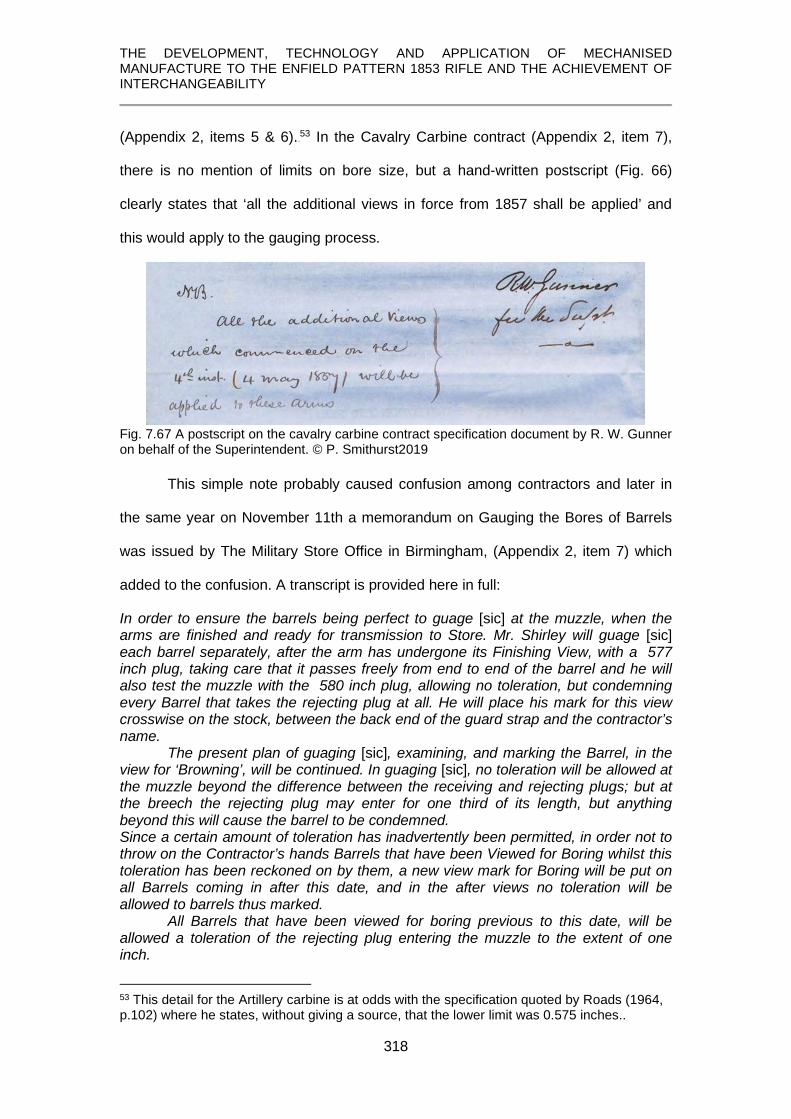
THE DEVELOPMENT, TECHNOLOGY AND APPLICATION OF MECHANISED MANUFACTURE TO THE ENFIELD PATTERN 1853 RIFLE AND THE ACHIEVEMENT OF INTERCHANGEABILITY
318
(Appendix 2, items 5 & 6).52F
53 In the Cavalry Carbine contract (Appendix 2, item 7),
there is no mention of limits on bore size, but a hand-written postscript (Fig. 66)
clearly states that ‘all the additional views in force from 1857 shall be applied’ and
this would apply to the gauging process.
Fig. 7.67 A postscript on the cavalry carbine contract specification document by R. W. Gunner on behalf of the Superintendent. © P. Smithurst2019
This simple note probably caused confusion among contractors and later in
the same year on November 11th a memorandum on Gauging the Bores of Barrels
was issued by The Military Store Office in Birmingham, (Appendix 2, item 7) which
added to the confusion. A transcript is provided here in full:
In order to ensure the barrels being perfect to guage [sic] at the muzzle, when the arms are finished and ready for transmission to Store. Mr. Shirley will guage [sic] each barrel separately, after the arm has undergone its Finishing View, with a ·577 inch plug, taking care that it passes freely from end to end of the barrel and he will also test the muzzle with the ·580 inch plug, allowing no toleration, but condemning every Barrel that takes the rejecting plug at all. He will place his mark for this view crosswise on the stock, between the back end of the guard strap and the contractor’s name. The present plan of guaging [sic], examining, and marking the Barrel, in the view for ‘Browning’, will be continued. In guaging [sic], no toleration will be allowed at the muzzle beyond the difference between the receiving and rejecting plugs; but at the breech the rejecting plug may enter for one third of its length, but anything beyond this will cause the barrel to be condemned. Since a certain amount of toleration has inadvertently been permitted, in order not to throw on the Contractor’s hands Barrels that have been Viewed for Boring whilst this toleration has been reckoned on by them, a new view mark for Boring will be put on all Barrels coming in after this date, and in the after views no toleration will be allowed to barrels thus marked. All Barrels that have been viewed for boring previous to this date, will be allowed a toleration of the rejecting plug entering the muzzle to the extent of one inch.
53 This detail for the Artillery carbine is at odds with the specification quoted by Roads (1964, p.102) where he states, without giving a source, that the lower limit was 0.575 inches..

THE DEVELOPMENT, TECHNOLOGY AND APPLICATION OF MECHANISED MANUFACTURE TO THE ENFIELD PATTERN 1853 RIFLE AND THE ACHIEVEMENT OF INTERCHANGEABILITY
319
Whereas a .577-inch plug was previously a rejecting gauge, it now had to
pass freely along the full length of the bore and a .580-inch plug was not allowed to
enter the barrel except under certain circumstances. Of particular interest in this
memorandum, despite its confusion, is the use of the term toleration which, since it is
applied to dimensions, can be read as ‘tolerance’ and is the earliest reference to this
concept to have been noted although it is implicit in the bore gauges.
Fig. 7.68 A .577 ‘accepting’ and a .580 ‘rejecting’ plug gauge, dated 1868, corresponding with those described by Gunner in 1857. © P. Smithurst 2018
Whilst the contractors at that time would have been totally familiar with
regulations prior to this date, what had been the ‘rejecting’ plug had become the
‘accepting’ plug, just over five-thousandths of an inch had been added to the
acceptable bore size and new rules for the ‘acceptance’ and ‘rejection’ of barrels
introduced. It can be imagined that the barrel contractors began searching through
their previously over-sized rejected barrels to find ones that might comply with the
new specification. It may have been this confusion which prompted James Burton,
Chief Engineer at Enfield, to issue the following memorandum in1858 (Appendix 2,
item 8).
In order not to exceed the depth of .015, which is the figure representing the depth of groove at breech, calculated upon one turn over 6ft 6in: and commencing at the muzzle with .005, it is absolutely necessary to have a plug to test the rifling, slightly under .015 at the breech. A plug for this purpose measuring .013 of an inch is to be employed for the reception plug, and one measuring .016 for the rejecting.

THE DEVELOPMENT, TECHNOLOGY AND APPLICATION OF MECHANISED MANUFACTURE TO THE ENFIELD PATTERN 1853 RIFLE AND THE ACHIEVEMENT OF INTERCHANGEABILITY
320
At the muzzle, where the depth is intended never to exceed .005 of an inch, two plugs will be used in the Rifling View in order not to allow of any groove being accepted which may be deeper than .005. These two plugs will be respectively .005 for acceptance and .008 for rejection. The width of the groove in the rifle barrel is to be .235 of an inch.
Therefore Burton, in stating the need for, and specifying, the sizes of gauges
for the rifling, taken in conjunction with the absence of any previous references to
gauges for this purpose, suggests that none had previously been used. His
memorandum concludes with a detailed listing of relevant dimensions and limits. The
first four items relate to gauges for the bore and are distinctly larger than any sizes
specified hitherto – a full ten-thousandths of an inch greater in upper and lower limits.
It has to be wondered why such a change was made and no other reference to, or
explanation for it, has been found. The last four items in the list relate to the gauges
for rifling depth limits at breech and muzzle. The set of bore gauges in Royal
Armouries collections, once forming part of the Pattern Room collections and dating
to 1862, contains rifling gauges in addition to the standard bore gauges, but is
incomplete.
Fig. 7.69 Rifling rejecting plug gauges for Breech (top) and muzzle (Bottom). (Part of
PR.10144 © Royal Armouries)
Fig. 7.70 Rifling receiving plug gauge for Breech. (Part of PR.10144 © Royal Armouries)

THE DEVELOPMENT, TECHNOLOGY AND APPLICATION OF MECHANISED MANUFACTURE TO THE ENFIELD PATTERN 1853 RIFLE AND THE ACHIEVEMENT OF INTERCHANGEABILITY
321
7.5 Proving
The most vital and demanding test of a barrel was ‘proving’ in which it was
fired to confirm its ability to withstand the explosion within it.
According to a specification by Pellat on behalf of the Inspector of Small
Arms:
the barrel before percussioning to be proved with seven drachms 53F
54 of small arm powder, and an elongated service ball, with a cork wad over the ball. (Report, 1854, p.491) This was an extreme test, using nearly three times the normal service charge of
powder.
What is believed to be an elongated service ball’ [bullet] is compared with a
standard service ‘ball’ in Fig. 7.71. This ball, from the weight of a ‘half’ section,
weighs approximately 710 grains, almost 30% more than a service ball.
Fig. 7.71 A sectioned ‘proof ball’, left, compared with a sectioned standard ‘service ball’, right.
(© P. Smithurst 2019)
It is also longer and cylindrical and its increased inertia would serve to increase the
pressure generated by the explosion momentarily until it began moving.
There was an obvious logic to ‘proving’ at this early stage since, if the barrel
failed after percussioning, all the extra time and effort would have been wasted, but
the only way of accomplishing it before a vent had been drilled was by the use of a
special plug with a vent.
54 The standard ‘service’ charge was 2½ drachms (≈1.5g.) of powder with the service bullet of 530 grains (≈ 34.5g.)

THE DEVELOPMENT, TECHNOLOGY AND APPLICATION OF MECHANISED MANUFACTURE TO THE ENFIELD PATTERN 1853 RIFLE AND THE ACHIEVEMENT OF INTERCHANGEABILITY
322
This early proving is also supported in contract specifications issued to
Joseph Smith for the manufacture of the East India Company cavalry carbine
adopted for British service use in 1856 (Roads, 1964, p.109):
Fig. 7.72 Abstract re proof from contract to Joseph Smith for 1856 cavalry carbine, E.I.Co. Pattern. (Appendix 1, item 7, © P. Smithurst 2019)
The fact that it states that the barrel underwent a second proof after percussioning,
implies that it underwent its first proof before percussioning. However, an earlier
contract document issued in 1853 for the Pattern 1853 Artillery Carbine clearly states
that percussioning took place before the barrel was proved.
Fig. 7.73 Abstract re proof from contract to Joseph Smith for the 1853 artillery carbine.
(see Appendix 1, item 5. © P. Smithurst 2019)
This same contract also shows that for proof – no second proof is mentioned - the
‘elongated service ball’ was replaced by a standard service ball:
Fig. 7.74 Further abstract re proof from contract to Joseph Smith for the 1853 artillery carbine.
(© P. Smithurst 2019)
Prior to 1860/61 carbines and short rifles were produced only by contractors and
such variations in specifications reflect the confusion pervading the contract system.

THE DEVELOPMENT, TECHNOLOGY AND APPLICATION OF MECHANISED MANUFACTURE TO THE ENFIELD PATTERN 1853 RIFLE AND THE ACHIEVEMENT OF INTERCHANGEABILITY
323
It should be remembered that these proof specifications applied to barrels
supplied by private contract. To date, no specifications for the process of proof of rifle
barrels at Enfield have been located but it is extremely unlikely that they were any
less rigorous.
7.6 Browning
After all the inspection processes, the barrel was ‘browned’ which actually
gave it a deep blue-black colour. It inhibited rusting and prevented reflection. The
polished and de-greased barrel was rubbed over two or three times a day for four or
five days in a room at 70°F with a solution of
6oz. spirits of wine (ethyl alcohol) 6oz. tincture of steel (Iron III Chloride in alcohol) 2oz. corrosive sublimate (Mercury II Chloride) 6oz. sweet spirits of nitre (Ethyl Nitrite in alcohol) 3oz. Nitric Acid Made up to 1 gallon with water
until the desired colour was produced. (Miles, 1860, p.33)
The result of the application of all this technology was a masterpiece of engineering
with an occasional input of craftsmanship:
After this process the bore is a most perfect cylinder, beautifully polished, and the light is reflected to such an extent as to cause an appearance, on looking through it, as if the farther extremity were a thin film of light concentrical with the circle which is nearest the eye. (Engineer, 1859, p.348)
Fig. 7.75 The perfectly finished bore. (1855.5.731 © Birmingham City Museum0

THE DEVELOPMENT, TECHNOLOGY AND APPLICATION OF MECHANISED MANUFACTURE TO THE ENFIELD PATTERN 1853 RIFLE AND THE ACHIEVEMENT OF INTERCHANGEABILITY
324
Fig. 7.76 The perfectly finished barrel. (1855.5.731 © Birmingham City Museum)
7.7 Summary
The technology employed has been examined in greater depth than in any
previously published account.
1. It has been shown that the finishing of the barrel to high standards of
accuracy required a series of complex operations.
2. It has been shown that important details of these operations were omitted
from these accounts.
3. These have been examined and supplemented with the aid of previously
unstudied documents and unique items in the collections of various
museums.
4. new insights into many aspects of manufacture have been provided;
particular reference might be made to the manufacture and fitting of the
breech pin and the machining of the complex geometry of the nipple seat
bolster.
5. It has been noted that in specifications for finishing the barrel the first
encountered use of the concept of ‘tolerance’ was applied to an examination
procedure.

THE DEVELOPMENT, TECHNOLOGY AND APPLICATION OF MECHANISED MANUFACTURE TO THE ENFIELD PATTERN 1853 RIFLE AND THE ACHIEVEMENT OF INTERCHANGEABILITY
325
CHAPTER 8
CONCLUSIONS and FURTHER WORK
This chapter summarises the achievements of this research and how the
objectives detailed in Chapter 1 have been met. From this the conclusions reached
by this study are drawn and a summary of the author’s contribution to a greater
knowledge and understanding of this topic are presented.
In 1859 it was reported that 680 machines were in operation at Enfield and
the manufacture of the rifle required 719 distinct operations. Throughout this thesis,
the truth of the words of the Committee on Machinery sent to America to investigate
the use of machines in gun making, that interchangeability was achieved through the
“adaptation of special tools to minute purposes”54F
55 has been extensively
demonstrated.
Finally, avenues for further research are suggested.
55 Rosenberg, (1968, p.193)

THE DEVELOPMENT, TECHNOLOGY AND APPLICATION OF MECHANISED MANUFACTURE TO THE ENFIELD PATTERN 1853 RIFLE AND THE ACHIEVEMENT OF INTERCHANGEABILITY
326
8.1 Review of research aims, objectives and achievements
Aim. The aim of this study was to provide for the first time a complete and detailed
analysis of the machines and processes used in the manufacture of the principal
components – lock, stock and barrel – of the Enfield Pattern 1853 rifle and the
achievement of interchangeability.
All of the proposed objectives, many of which overlapped in their relevance to
different parts of this study, have been fulfilled.
Objective 1: Highlight and correct errors in original contemporary accounts.
Achievement 1: A careful study of those accounts has enabled these errors to
be identified and corrected in appropriate chapters of this thesis.
Objective 2: Highlighting and supplementing omissions of detail in those accounts.
Achievement 2: Extensive additional details have been provided through
fulfilment of the following objectives.
Objective 3: To undertake a detailed study of specimen barrels in each stage of
their manufacture.
Achievement 3: A comprehensive study of these specimens has been
undertaken and, in conjunction with other fulfilled objectives, has enabled new
insights into the processes involved in their manufacture to be provided and are
contained in Chapters 6 and 7.
Objective 4: To undertake a detailed study of specimens of stocks in their stages of
manufacture.
Achievement 4: A comprehensive study of these specimens has been
undertaken and, in conjunction with other fulfilled objectives, has enabled new
insights into the processes involved in their manufacture and which are contained in
Chapter 5.

THE DEVELOPMENT, TECHNOLOGY AND APPLICATION OF MECHANISED MANUFACTURE TO THE ENFIELD PATTERN 1853 RIFLE AND THE ACHIEVEMENT OF INTERCHANGEABILITY
327
Objective 5: To undertake a detailed study of the manufacture of the lock
Achievement 5: A comprehensive study of this component has been
undertaken and, in conjunction with other fulfilled objectives, has enabled new
insights into the processes involved in its manufacture to be provided in Chapter 4.
Objective 6: To undertake a study of surviving contemporary factory drawings of
various machines.
Achievement 6: A detailed study of these drawings has been undertaken and
the details they contained have allowed new insights into the functioning of these
machines and the processes they performed. The results of this study are contained
in Chapters 4, 5, 6 and 7.
Objective 7: To undertake a detailed study of various newly discovered and unique
documents relating to procurement and manufacture.
Achievement 7: These documents have provided new insights into the system
of procurement and manufacture prior to and after the introduction of mechanisation
and interchangeability. Many of the results of this study can be found in Chapters 3,
4, 5, 6 and 7.
Objective 8: A limited metrology study of features of the lockplate to assess the
gauging system employed prior to interchangeable manufacture.
Achievement 8: This study, in highlighting dimensional discrepancies in
combination with other factors derived from objective 7, reveals the inadequacies of
the gauging system employed.
Objective 9: To undertake a detailed study of surviving gauges, relating to the
three principal components studied, in interchangeable manufacturing.
Achievement 9: The applications of gauges to various elements of the principal
components studied are included in relevant chapters. In the absence of more
metrology data the gauges are also used to illustrate that interchangeability was
achieved.

THE DEVELOPMENT, TECHNOLOGY AND APPLICATION OF MECHANISED MANUFACTURE TO THE ENFIELD PATTERN 1853 RIFLE AND THE ACHIEVEMENT OF INTERCHANGEABILITY
328
Objective 10: To undertake a study of the documents of James Burton pertaining
to manufacture of the rifle at Enfield
Achievement 10: These documents provide new insights into, especially, the
manufacture of the barrel and changes in the specifications of the bore and rifling.
8.2 Conclusions Based on the evaluations and evidence presented in the previous chapters, the
major findings of this study are given below:
Conclusion 1: That the manufacture of the rifle, especially in the post-
interchangeability era, was a far more complex undertaking than is apparent in the
early, contemporary, accounts of its manufacture.
Conclusion 2: That these accounts contain significant errors and omissions of
detail in regard to the functional characteristics of the machines, the operations they
accomplished and how they were accomplished.
Conclusion 3: That the original system of procurement through private
contract was highly inefficient. Inspection processes in use were arbitrary and any
gauging system employed was rudimentary and inadequate.
Conclusion 4: That it was dissatisfaction with this procurement system that
led the Board of Ordnance / War Department to establish the Royal Small Arms
Factory at Enfield and to introduce machinery for the manufacture of the Enfield rifle
with interchangeable parts.
Conclusion 5: That this technology consisted of highly sophisticated
machines in which most of the skills of the craftsman were replicated and led to
standards of accuracy not exhibited in any firearms outside of America at that time.
Conclusion 6: That despite mechanical sophistication, hand-finishing of some
components was still required to remove small amounts of material left by the
machining operations and bring them to a state of readiness for gauging, or to
remove cutting tool marks.

THE DEVELOPMENT, TECHNOLOGY AND APPLICATION OF MECHANISED MANUFACTURE TO THE ENFIELD PATTERN 1853 RIFLE AND THE ACHIEVEMENT OF INTERCHANGEABILITY
329
Conclusion 7: That high a degree of accuracy was achieved, as shown by the
gauging processes discussed and illustrated.
Conclusion 8: That interchangeability was in fact first achieved in Britain with the
post-1857 rifles manufactured at Enfield.
Conclusion 9: That the achievement of interchangeability relied on a comprehensive
system of gauging.
Conclusion 10: That had a rational system of gauging been employed pre-1857,
interchangeability might have been achieved sooner.
8.3 Contributions to knowledge
The contents of this thesis have given a greater understanding of the various
components considered and of the technologies employed in their manufacture.
Contribution 1: It is the first time that a detailed study of the manufacture of the
principal components of this rifle has been undertaken since the publishing of a few
accounts in the middle of the 19th century. Numerous errors and omissions in those
accounts have been highlighted and corrected.
Contribution 2: A fuller analysis of the manufacture of the lock has been performed
and presented. It has revealed numerous factors not previously considered in both
the construction and design of the lock components and of their manufacture. This
has enabled many new insights into, and some proposals for, the functional elements
of the machines and processes required to accomplish their manufacture.
Contribution 3: A detailed analysis of the manufacture of the stock has revealed a
number of hitherto unconsidered features in its design. An examination of these in
conjunction with details of those machines used has allowed new insights into the
nature and functions of these machines to be provided.
Contribution 4: An analysis of the finishing of the barrel tube has brought to light a
number of critical factors which have previously been overlooked. In addressing

THE DEVELOPMENT, TECHNOLOGY AND APPLICATION OF MECHANISED MANUFACTURE TO THE ENFIELD PATTERN 1853 RIFLE AND THE ACHIEVEMENT OF INTERCHANGEABILITY
330
those and other aspects, a greater understanding of the manufacturing processes
has been presented.
Contribution 5: It has been shown through a simple programme of metrology that,
prior to the introduction of interchangeable manufacture at Enfield, any gauging
system in use was both rudimentary and ineffectual. Had it been otherwise,
interchangeability would have been achieved sooner. For the first time, the existence
of an effective and systematic gauging regime after manufacture had been
established at Enfield has been practically demonstrated by its application to many
components, and has revealed the accomplishment of interchangeability.
8.4 Future work
The study has highlighted the need for further researches into this topic.
Recommendation 1: To establish interchangeability as an incontestable fact. This
would require a substantial collection of the post-1857 Pattern 1853 rifles, made by
both Enfield and the London Armoury Company. These would need to be dismantled,
especially the locks, followed by gauging them or undertaking some metrology
components or attempting substitution of components. Locating these rifles and
obtaining permission from museums or private owners to dismantle the locks and to
carry out metrology or unite components with gauges is probably, considering their
relative rarity and corresponding high value, to prove a far from easy task.
Recommendation 2: With gauges mostly providing an upper size limit, attempt to
assess the criteria used to establish an acceptable lower limit. This could possibly be
accomplished through an extensive programme of metrology but would face the
same constraints outlined in Recommendation 1.
Recommendation 3: In 1853 and in 1857, bore sizes and gauges were specified to
one-thousandth of an inch; what measuring instruments and tools were being used to
make them? What led to the re-specification of bore sizes at Enfield up to 1858?

THE DEVELOPMENT, TECHNOLOGY AND APPLICATION OF MECHANISED MANUFACTURE TO THE ENFIELD PATTERN 1853 RIFLE AND THE ACHIEVEMENT OF INTERCHANGEABILITY
331
Recommendation 4: Many of the machines no longer exist; their ‘reconstruction’
using suitable 3-D animation software and small scale 3D printing would offer
valuable insights into their mechanical elements and functional characteristics.
Recommendation 5: It has been suggested that in the late 18th century,
interchangeability of locks was being achieved in France by Honoré Blanc. Some
evidence has been found that may support this. A more detailed study of the
techniques and technology used to manufacture the French 1777 musket should be
undertaken alongside attempts to verify or discard the idea that interchangeability
was achieved. This will, however, require an extensive range of these muskets and
locks made by Blanc to be examined and these are unlikely to be found in Britain.
Likewise, Blanc’s surviving gauges in the Musée de l'Armée in Paris are unlikely to
be accessible.

THE DEVELOPMENT, TECHNOLOGY AND APPLICATION OF MECHANISED MANUFACTURE TO THE ENFIELD PATTERN 1853 RIFLE AND THE ACHIEVEMENT OF INTERCHANGEABILITY
332

THE DEVELOPMENT, TECHNOLOGY AND APPLICATION OF MECHANISED MANUFACTURE TO THE ENFIELD PATTERN 1853 RIFLE AND THE ACHIEVEMENT OF INTERCHANGEABILITY
333
APPENDICES
Appendix 1 The percussion cap Appendix 2 Joseph Smith documents Appendix 3 James Burton documents Appendix 4 Greenwood & Batley orders Appendix 5 Expenditure at Enfield, 1855 Appendix 6 Enfield expenditure & production, 1858, 1859, 1860 Appendix 7 Enfield lockplate hole metrology

THE DEVELOPMENT, TECHNOLOGY AND APPLICATION OF MECHANISED MANUFACTURE TO THE ENFIELD PATTERN 1853 RIFLE AND THE ACHIEVEMENT OF INTERCHANGEABILITY
334
APPENDIX 1
THE PERCUSSION CAP
Copy of a document once in the collection of Springfield Armory and now in the State Archives of Massachusetts. (only the relevant portion included, with transcript) Remarks Relative to Mr. Shaw’s Detonating Gun. July 11th, 1822, directed to the Editor of the Hampton Patriot
Mr. Joshua Shaw of Philadelphia has made an improvement in firearms which promises to be of considerable public utility. It is termed “the Detonating Gun”. It differs from the common gun by having attached to the barrel a kind of pan called the Antechamber which is screwed into and communicates with the chamber in the barrel, to this is attached what is called the priming tube which is a piece of case-hardened iron or steel about half an inch in length and about ¼ of an inch in diameter next to the pan and a little smaller at the other end where it receives the cock with a small hole through it lengthwise into the antechamber, on this tube is placed the priming cap which is a small piece of copper made in a form so as to exactly fit the tube, and has on the upper part of the inside a small quantity of oximuriate of potash55F
56 and some other ingredients, which on the percussion of the cock explodes and communicates to the charge in the barrel with the rapidity of lightning.
56 Oximuriate of potash is potassium chlorate and mixed with sulphur is easily detonated.

THE DEVELOPMENT, TECHNOLOGY AND APPLICATION OF MECHANISED MANUFACTURE TO THE ENFIELD PATTERN 1853 RIFLE AND THE ACHIEVEMENT OF INTERCHANGEABILITY
335
APPENDIX 2
JOSEPH SMITH
Joseph Smith of 28, Loveday Street, Birmingham, was a government
contractor, c. 1851 - 1860. His work seems to have been varied, acting mainly as a
‘setter-up’ but later referring to himself as a ‘gunmaker’. This small archive consists of
a variety of documents issued to him in his various capacities.
Some are official Board of Ordnance, or after 1854, War Department printed
contracts, whilst others are manuscript documents notifying changes to contracts,
specifications or inspection procedures, etc.
With the exception of a letter from the secretary of the ‘combination’ of
‘setters-up’, and two contracts relating to the 1851 ‘Minié’ rifle, all encompass arms
within the Pattern 1853 series and whilst the ‘3-band’ rifle musket is only mentioned
twice, the details regarding various components and inspection criteria applied to the
other arms in the Pattern 1853 series are equally applicable to the rifle, except proof
charges where specified.

THE DEVELOPMENT, TECHNOLOGY AND APPLICATION OF MECHANISED MANUFACTURE TO THE ENFIELD PATTERN 1853 RIFLE AND THE ACHIEVEMENT OF INTERCHANGEABILITY
336
1. 1851 – contract for ‘jegging breech pins’ and ‘filing the lumps’ on Minié barrels.

THE DEVELOPMENT, TECHNOLOGY AND APPLICATION OF MECHANISED MANUFACTURE TO THE ENFIELD PATTERN 1853 RIFLE AND THE ACHIEVEMENT OF INTERCHANGEABILITY
337

THE DEVELOPMENT, TECHNOLOGY AND APPLICATION OF MECHANISED MANUFACTURE TO THE ENFIELD PATTERN 1853 RIFLE AND THE ACHIEVEMENT OF INTERCHANGEABILITY
338

THE DEVELOPMENT, TECHNOLOGY AND APPLICATION OF MECHANISED MANUFACTURE TO THE ENFIELD PATTERN 1853 RIFLE AND THE ACHIEVEMENT OF INTERCHANGEABILITY
339
2 1852. Documents relating to cock [hammer] stamping.

THE DEVELOPMENT, TECHNOLOGY AND APPLICATION OF MECHANISED MANUFACTURE TO THE ENFIELD PATTERN 1853 RIFLE AND THE ACHIEVEMENT OF INTERCHANGEABILITY
340
3. Though undated, from the designation of ‘new Pattern’ rifle muskets, this document is believed to relate to the Pattern 1853 rifle, rather than the Pattern 1851.

THE DEVELOPMENT, TECHNOLOGY AND APPLICATION OF MECHANISED MANUFACTURE TO THE ENFIELD PATTERN 1853 RIFLE AND THE ACHIEVEMENT OF INTERCHANGEABILITY
341
4. Contract for setting-up Pattern 1853 rifles

THE DEVELOPMENT, TECHNOLOGY AND APPLICATION OF MECHANISED MANUFACTURE TO THE ENFIELD PATTERN 1853 RIFLE AND THE ACHIEVEMENT OF INTERCHANGEABILITY
342
5. Contract specifications for the Artillery Carbine Pattern 1853.

THE DEVELOPMENT, TECHNOLOGY AND APPLICATION OF MECHANISED MANUFACTURE TO THE ENFIELD PATTERN 1853 RIFLE AND THE ACHIEVEMENT OF INTERCHANGEABILITY
343

THE DEVELOPMENT, TECHNOLOGY AND APPLICATION OF MECHANISED MANUFACTURE TO THE ENFIELD PATTERN 1853 RIFLE AND THE ACHIEVEMENT OF INTERCHANGEABILITY
344

THE DEVELOPMENT, TECHNOLOGY AND APPLICATION OF MECHANISED MANUFACTURE TO THE ENFIELD PATTERN 1853 RIFLE AND THE ACHIEVEMENT OF INTERCHANGEABILITY
345

THE DEVELOPMENT, TECHNOLOGY AND APPLICATION OF MECHANISED MANUFACTURE TO THE ENFIELD PATTERN 1853 RIFLE AND THE ACHIEVEMENT OF INTERCHANGEABILITY
346
6. Specifications for the Short Rifle, Pattern 1856.

THE DEVELOPMENT, TECHNOLOGY AND APPLICATION OF MECHANISED MANUFACTURE TO THE ENFIELD PATTERN 1853 RIFLE AND THE ACHIEVEMENT OF INTERCHANGEABILITY
347

THE DEVELOPMENT, TECHNOLOGY AND APPLICATION OF MECHANISED MANUFACTURE TO THE ENFIELD PATTERN 1853 RIFLE AND THE ACHIEVEMENT OF INTERCHANGEABILITY
348

THE DEVELOPMENT, TECHNOLOGY AND APPLICATION OF MECHANISED MANUFACTURE TO THE ENFIELD PATTERN 1853 RIFLE AND THE ACHIEVEMENT OF INTERCHANGEABILITY
349
7. Contract for the Pattern 1856 Cavalry Carbine (East India Co. carbine)

THE DEVELOPMENT, TECHNOLOGY AND APPLICATION OF MECHANISED MANUFACTURE TO THE ENFIELD PATTERN 1853 RIFLE AND THE ACHIEVEMENT OF INTERCHANGEABILITY
350

THE DEVELOPMENT, TECHNOLOGY AND APPLICATION OF MECHANISED MANUFACTURE TO THE ENFIELD PATTERN 1853 RIFLE AND THE ACHIEVEMENT OF INTERCHANGEABILITY
351
7. 1857 Memorandum issued relating to bore gauging, inspection, and tolerances. enlarged and spread over three pages for clarity)
In order to ensure the barrels being perfect to guage [sic] at the muzzle, when the arms are finished and ready for transmission to Store. Mr. Shirley will guage each barrel separately, after the arm has undergone its Finishing View, with a ·577 inch plug, taking care that it passes freely from end to end of the barrel and he will also test the muzzle with the ·580 inch plug, allowing no toleration, but condemning every Barrel that takes the rejecting plug at all.

THE DEVELOPMENT, TECHNOLOGY AND APPLICATION OF MECHANISED MANUFACTURE TO THE ENFIELD PATTERN 1853 RIFLE AND THE ACHIEVEMENT OF INTERCHANGEABILITY
352
He will place his mark for this view crosswise on the stock, between the back end of the guard strap and the contractor’s name. The present plan of guaging, examining, and marking the Barrel, in the view for ‘Browning’, will be continued. In guaging, no toleration will be allowed at the muzzle beyond the difference between the receiving and rejecting plugs; but at the breech the rejecting plug may entre for one third of its length, but anything beyond this will cause the barrel to be condemned.
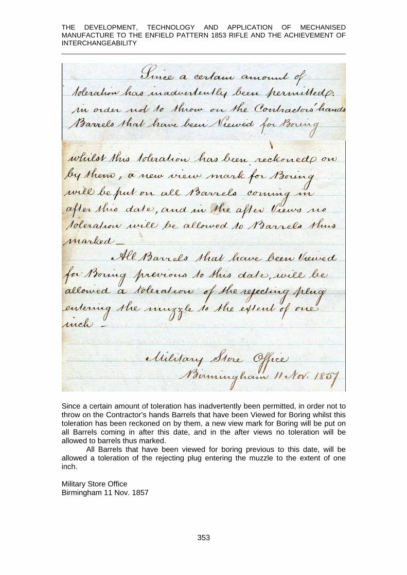
THE DEVELOPMENT, TECHNOLOGY AND APPLICATION OF MECHANISED MANUFACTURE TO THE ENFIELD PATTERN 1853 RIFLE AND THE ACHIEVEMENT OF INTERCHANGEABILITY
353
Since a certain amount of toleration has inadvertently been permitted, in order not to throw on the Contractor’s hands Barrels that have been Viewed for Boring whilst this toleration has been reckoned on by them, a new view mark for Boring will be put on all Barrels coming in after this date, and in the after views no toleration will be allowed to barrels thus marked. All Barrels that have been viewed for boring previous to this date, will be allowed a toleration of the rejecting plug entering the muzzle to the extent of one inch. Military Store Office Birmingham 11 Nov. 1857

THE DEVELOPMENT, TECHNOLOGY AND APPLICATION OF MECHANISED MANUFACTURE TO THE ENFIELD PATTERN 1853 RIFLE AND THE ACHIEVEMENT OF INTERCHANGEABILITY
354
8. 1858 Further memorandum issued by James Burton changing the specifications of bore sizes.
In order not to exceed the depth of .015, which is the figure representing the depth of groove at breech, calculated upon one turn over 6ft 6in: and commencing at the muzzle with .005, it is absolutely necessary to have a plug to test the rifling, slightly under .015 at the breech. A plug for this purpose measuring .013 of an inch is to be employed for the reception plug, and one measuring .016 for the rejecting. At the muzzle, where the depth is intended never to exceed .005 of an inch, two plugs will be used in the Rifling View in order not to allow of any groove being accepted which may be deeper than .005. These two plugs will be respectively .005 for acceptance and .008 for rejection. The width of the groove in the rifle barrel is to be .235 of an inch.
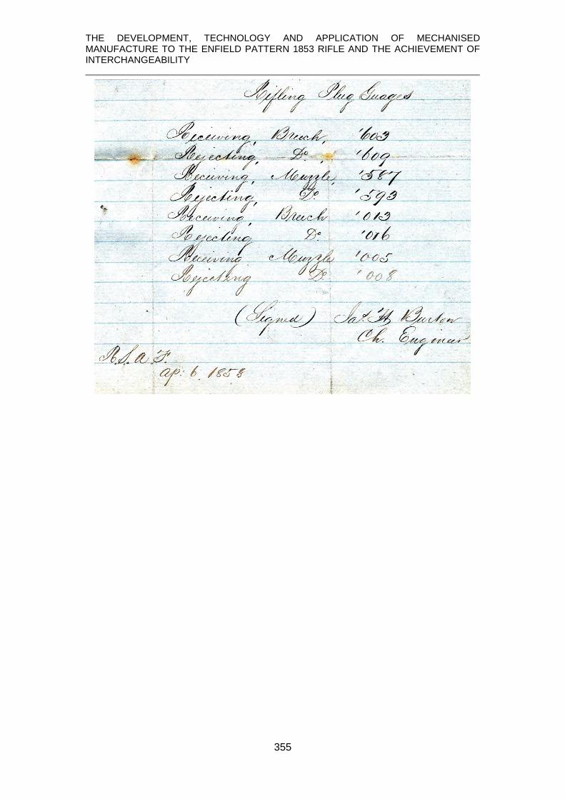
THE DEVELOPMENT, TECHNOLOGY AND APPLICATION OF MECHANISED MANUFACTURE TO THE ENFIELD PATTERN 1853 RIFLE AND THE ACHIEVEMENT OF INTERCHANGEABILITY
355

THE DEVELOPMENT, TECHNOLOGY AND APPLICATION OF MECHANISED MANUFACTURE TO THE ENFIELD PATTERN 1853 RIFLE AND THE ACHIEVEMENT OF INTERCHANGEABILITY
356
9. Minute from a meeting of the contractors for ‘setting-up’, chaired by J. D. Goodman Esq. and signed by the secretary, Joseph Bourne, shows that ‘combinations’ did exist.
At a meeting of Contractors for Setting Up held at the Stork Hotel, Thursday, March 27th, 1856, J. D. Goodman Esq. in the Chair.
(see transcript below)

THE DEVELOPMENT, TECHNOLOGY AND APPLICATION OF MECHANISED MANUFACTURE TO THE ENFIELD PATTERN 1853 RIFLE AND THE ACHIEVEMENT OF INTERCHANGEABILITY
357
That this meeting is of opinion that the Setting Up price of 28/- is indivisible, and it will not recognise the right of any member of this body of Contractors for Setting Up, either by himself, or his partners, or indirectly through any connexion of his with whom he may have pecuniary interest or advantage to tender for, or to accept any offers, or make any terms for any the least significant position or branch of the work for which in the aggregate 28/- is paid by the War Department, and this meeting further pledges itself not to countenance, but to oppose most strongly, under any form or pretext, a departure from such principle, and hereby bind each member of this body individually and collectively to seek personal interests by consulting the general interests of the entire body of Contractors for Setting Up. [signed] Joseph Bourne Secretary To Mr Joseph Smith

THE DEVELOPMENT, TECHNOLOGY AND APPLICATION OF MECHANISED MANUFACTURE TO THE ENFIELD PATTERN 1853 RIFLE AND THE ACHIEVEMENT OF INTERCHANGEABILITY
358
APPENDIX 3
JAMES BURTON
Transcripts and abstracts of relevant documents contained in the archives of Yale University. (copies of actual documents too poor to be included) ___________________________________________________________________ Springfield, Mass. May 16th [?] 1854 To Col. Burns, H[er] B[ritannic] M[ajesty’s] Ordnance Board. Sir, Understanding that the English Government contemplates establishing a manufactory of small arms and also the introduction therein of machinery and tools similar in character to those in use at the U. S. armories for facilitating the manufacture of military small arms, I have thought that it might be deemed expedient to secure the services of some mechanical engineer familiar with the construction and use of such machinery etc. Should this be the case, I beg leave to tender my services in that capacity, having been in the service of the U. S. Ordnance Department for the last ten years at the Harper’s Ferry Armory in various positions immediately connected with the manufacture, and for the last four and a half years in the responsible position of Master Armorer having charge of the entire mechanical department of the Armory. I have testimonials from Colonel Benjamin Huger and Major Thos[?] Symington, both members of the U.S. Ordnance Board and have been in command of the Armory, and should it be necessary, can obtain more from other officers of the Department. For reasons which it is not necessary here to explain, I am desirous of obtaining an appointment elsewhere and would therefore be pleased to enter the service of your Government in the above mentioned capacity, provided a sufficient inducement were offered, say, not less than 400£ per annum, and expenses out for myself and my family. The consideration of this application is respectfully solicited at as early a day as may suit your convenience. I am Very Respectfully Your Obedt. Servt.

THE DEVELOPMENT, TECHNOLOGY AND APPLICATION OF MECHANISED MANUFACTURE TO THE ENFIELD PATTERN 1853 RIFLE AND THE ACHIEVEMENT OF INTERCHANGEABILITY
359
London, May 31st 1855 J Burton Esqu. U.S. Armory Sir, I have the authority of the Hon Board of Ordnance for informing you that should you now be willing to engage yourself to the British Government as Engineer of the new Armory for 5 years or permanently, you will receive as pay four hundred pounds a year clear of taxes & a house will be found you. I have to request that you will answer this immediately, as should you not be willing to accept this offer, it is necessary some one else should be appointed without delay. I have the honour to be Sir Yr obedient servant J Picton Warlow Capt. R. A. __________________________________________________________________ Office of Ordnance 20th September 1855 S 10086 Sir, Mr Monsel [?] with the assent of the Lords Commissioners of her Majesty’s Treasury having approved of your engagement as Chief Engineer of the Royal Small Arms Factory at Enfield, on the salary of £400 per annum, exclusive of Income Tax, commencing from the 15th June last and with the understanding that you shall be provided with a suitable house and that the expenses incurred by yourself and family in travelling to England shall be defrayed by the Government. I am directed by Mr Monsell[?] to notify the same to you, adding that authority has been given for the payment of your salary etc. accordingly. I am Sir Your most obedient servant, J H Burton Esq Care of Captain Dixon

THE DEVELOPMENT, TECHNOLOGY AND APPLICATION OF MECHANISED MANUFACTURE TO THE ENFIELD PATTERN 1853 RIFLE AND THE ACHIEVEMENT OF INTERCHANGEABILITY
360
Royal Manufactory, Enfield Sept 10th 1855 Capt. Dixon, R.A. Inspector of Small Arms Sir, I beg leave respectfully to submit for your information the accompanying brief statement, exhibiting the numbers, description and probable cost of the machines yet required for this establishment, in order to complete the system of machinery for the manufacture of small arms. No facilities having as yet been provided for the finishing of the barrels. List of Machines for finishing the Barrel of the Enfield Musket – 250 per day 56F
57
8 rough boring machines @ $475 = $3,800 4 Second “ “ @ $285 = $1,140 6 Finish “ “ @ $475 = $2,830 12 Turning lathes @ $450 = $5,400 2 Double Hand lathes @ $400 = $800 12 Milling machines @ $300 = $3,600 fixtures for do. @ $525 = $525 4 Drill presses @ $250 = $1,000 2 Milling machines for breech screw @ $200 = $400 2 Counterboring machines @ $200 = $400 2 Screwcutting machines @ $175 = $350 2 Tapping cone seat @ $115 = $230 2 Milling machines for muzzle @ $400 = $800 1 Machine for grinding @ $100 = $100 1 Machine for inside polishing @ $400 = $400 4 do outside do @ $500 = $2000
$23,795.00 add 7½ per cent for packing etc. $1,784.62 $25,579.62 for gauges, small tools and fixtures $4,420.38 $30,000.00
57 This differs in a few small but important details from the document in Public Record Office – see page 361

THE DEVELOPMENT, TECHNOLOGY AND APPLICATION OF MECHANISED MANUFACTURE TO THE ENFIELD PATTERN 1853 RIFLE AND THE ACHIEVEMENT OF INTERCHANGEABILITY
361
Copy of memorandum in Public Record Office, Cat No. T 1/5975

THE DEVELOPMENT, TECHNOLOGY AND APPLICATION OF MECHANISED MANUFACTURE TO THE ENFIELD PATTERN 1853 RIFLE AND THE ACHIEVEMENT OF INTERCHANGEABILITY
362
Royal Small Arms Factory, Enfield Lock, Nov. 14th 1855 Messrs Robbins & Lawrence, Windsor, Vt., USA Gentlemen, I am authorized by Capt. Dixon, the superintendent of this Armory, to inform you that your proposals for furnishing the machinery, tools, &c &c, necessary for finishing 250 Rifle barrels per day, of the pattern at present adopted by this Govt., are accepted with some modifications and additions. Annexed you will find a schedule as modified of the machines &c, the prices being in accordance with your tender. Upon examining it you will observe that several machines not embraced in your proposals have been added to it, which you will, it is expected, furnish - at fair remunerative prices, and which you will be paid enough to make known to me as early as convenient. There are 2 machines for clamp milling the muzzle of the barrel for the bayonet socket, and 1 machine for grinding the exterior of the barrel; that is the lever, press[?] and block used for forcing this barrel up to the grindstone. The clamp milling machines, as also the lever press for grinding barrels – are desired to be made similar to those in use at the Springfield Armory for the same purposes, and which you will have reference previous to their construction. The 7th item in your proposal, viz; 15 machines and fixtures for milling the barrel & sight is superseded by your last tender, July 17th 1855, for 12 milling machines, fixtures, cutters &c for the same purpose. The time specified in your proposal for the delivery of this machinery is within fifteen (15) months of the date of order. Inasmuch as you now have all these machines developed and the patterns made, it is expected that you will be able to deliver them in much less time, which you will please specify in writing by return mail, fixing it at as early a date as possible as the machinery is much wanted. The 16 machines for rifling the barrel are entirely omitted, inasmuch as we have machines here for the same purpose that are preferred to the American machines. You have, however, two to furnish upon the order you are now engaged in filling. We have also lathes for turning the barrel, which are considered superior machines, but as we wish to test your improvements in barrel lathes, one is included in the accompanying lot. A model barrel will be sent to you as soon as it can be prepared, but you need not wait for this to put the machines in hand. Any further information you may require upon this subject, I will cheerfully give you upon addressing me as above. I am Sirs Your most Obedt. Servt. J H B Chief Engineer.

THE DEVELOPMENT, TECHNOLOGY AND APPLICATION OF MECHANISED MANUFACTURE TO THE ENFIELD PATTERN 1853 RIFLE AND THE ACHIEVEMENT OF INTERCHANGEABILITY
363
Schedule of Machines, fixtures &c &c to be furnished at the prices annexed by the Robbins & Lawrence Co. of Windsor, Vermont, U.S.A. for the British Government, the same to be delivered on shipboard at New York, well packed and boxed, within [blank] months of the date of order; an allowance of 7½ per cent upon the prices annexed to be added for boxing and delivery at New York. Said machinery to be adapted to the fabrication of the British Rifle Musket barrels. No 1 8 Rough boring machines for the first cut after the barrel is welded, of 3 spindles each, and each to be furnished with one set of tools called nut augurs. Each $475 No 2 4 Second boring or reaming machines of 1 spindle each, and each to be furnished with one set of reamers. Each $285 No 3 6 Finish boring machines of 2 spindles each, each to be furnished with one set of reamers. Each $475 4th 1 Lathe for turning the barrel whole length, with one set of tools. $245 5th 2 Double hand lathes, each to contain two head and tailstocks, with all the tools &c for squaring & cutting the barrel to exact length. Each $400 6th 12 Milling machines for milling the barrel (breech &c) Each $300 7th 17 sets of fixtures for the above 12 milling machines, and 21 sets of mills or saws for the various cuts upon the barrel &c. $525 8th 4 Drill presses for drilling & counterboring the tang & cone seat; each to be furnished with drills and fixtures for holding the barrels. Each $250 9th 2 Machines for milling the end of the breech screw to diameter & length, with tools, cutters & fixtures for holding the tang. Each $200 10th 2 Machines for counterboring the breech of the barrel for breech screw; each with tools and fixtures for holding the barrel. Each $200 11th 2 Machines for cutting the thread upon the breech screw, each to be furnished with one set of Dies and taps. Each $175 12th 2 machines for tapping and countersinking the cone seat, with b??? and taps complete. Each $115 13th 1 Machine for polishing the interior of the barrel; to be furnished with one lot of rods, connecting rod, balance wheel and all the overhead works complete. Each $400 14th 4 Machines for polishing the exterior of the barrel of 5 spindles each, with all the overhead works complete. Each $500 15th 2 Machines for clamp milling the muzzle of the barrel for bayonet socket, with dies and reamers complete. Each $ # 16th 1 Machine for grinding the exterior of the barrel, complete Each $ # [70 machines]

THE DEVELOPMENT, TECHNOLOGY AND APPLICATION OF MECHANISED MANUFACTURE TO THE ENFIELD PATTERN 1853 RIFLE AND THE ACHIEVEMENT OF INTERCHANGEABILITY
364
Woolwich 26th January 1857 Dear Mr Burton, I am truly delighted to hear that the musket is now complete. It has been uphill work but let us thank God that it is now an accomplished fact and that success has crowned the efforts that have been made. I will not say how proud I shall be to have a complete Enfield Musket. I look upon it as the most mechanical triumph of the age. On Wednesday I shall of course say a few words on the application of machinery to small arms, and should feel obliged for the loan of as many parts as can be got ready for me, mainly to lie on the table for examination. I shall feel glad if I could have the box into which you enclose the lockplate while being drilled. Could you bring that with you if you come, if not can you send it. Do not disturb yourself regarding the ?? arrangements, you will accomplish all in due time. With very best regards I am my dear Mr Burton, Yours sincerely, John Anderson ___________________________________________________________________ 6th October 1858 My dear Burton, Mr. ??? has informed me that Genl. Peel has highly approved of my proposal for increasing the production of the factory and he has sent out the papers to the Treasury. There will be no demur and I think you may also consider that you will be ordered to America to see to them [remainder to be transcribed] Dixon _______________________________________________________________ 3rd December 1858 My dear Burton, You will be glad to hear that we are going on very well here. For the last two weeks we have done over 1200 arms. Dixon _________________________________________________________________

THE DEVELOPMENT, TECHNOLOGY AND APPLICATION OF MECHANISED MANUFACTURE TO THE ENFIELD PATTERN 1853 RIFLE AND THE ACHIEVEMENT OF INTERCHANGEABILITY
365
APPENDIX 4
R.S.AF. ENFIELD ORDERS TO GREENWOOD AND BATLEY, LEEDS. (transcribed from order books contained in the Greenwood and Batley Archives, West Yorkshire Archives Service.)
Order No Details Col Dixon, Enfield Lock 26th May 1856 7 12 small drilling machines [delivery commenced with 3 on 26 July and final 3 sent 23 Aug] 56 Col Dixon, Enfield Lock 8th Aug 1856 7 vertical drilling m/c, in all respects like the twelve in Or No 7 £126 Col Dixon, Enfield 22nd Oct 1856 80 2 lathes for making sight spring screws with cross slide carrying the top two longitudinal slides with levers for milling the wire and threading the screw and 1 cross slide for cutting off the screw. £64
5 milling m/c for finish milling the head of the screw. Placed upon baseplate upon [???] same as the American m/c. £190
Col Dixon, Enfield 14th July 1857 226 2 clamp milling m/cs £90 Royal Small Arms Factory, Enfield 3rd Sept 1857 259 1 milling m/c for screws as before except bedplate 2” longer £35 260 2 clamp milling m/cs same as Or No 226 £90 261 1 m/c to slit screws same as Or No 82 £30 262 1 tapping m/c as before with 2 pullies [sic] and double clutch £15 Royal Small Arms Factory, Enfield 5 Sept 1857 265 2 large grindstone troughs and spindles £80 266 4 m/cs for rifling £400 267 1 m/c for leading out after rifling £40

THE DEVELOPMENT, TECHNOLOGY AND APPLICATION OF MECHANISED MANUFACTURE TO THE ENFIELD PATTERN 1853 RIFLE AND THE ACHIEVEMENT OF INTERCHANGEABILITY
366
268 1 m/c for tapping cone seat £30 269 1 m/c for threading breech screw £30 270 1 m/c for edge milling £60 271 2 m/cs for cupping head of ramrod £20 272 1 polishing bench, double shaft and pullies £120 284 Col Dixon, Enfield 16th Oct 1857 2 wood screw threading m/cs £30 Col Dixon, Enfield 31st July 1858 424 2 edge milling m/cs, single spindle as before £120
1 pair edge rollers 20” die with gearing for driving them, complete £55
2 grindstone troughs for stones 3 feet die 5 in thick, with screw plates, fast and loose pulleys 14“ dia. £30
427 1 m/c for screwing the ends of ramrods £20
Col Dixon, Enfield 10th Nov 1858 502 1 m/c for leading interior of barrels same as Or No 267 £40
1 cast iron frame, spindle etc. for large grindstone for barrels, same as Or No 265 with reduced length of pillow blocks to allow of more wear of stone £40
2 m/cs for clamp milling and cupping head of ramrod, same as before, Or No 271, for standing on ordnance bed. £60
2 m/cs for mortice drilling head of ramrod, same as before {order number not given], on ordnance bed £60
1 cast iron frame, spindle etc. for large grindstone for ramrods, same as for barrels £40
1 cast iron bench 20ft long for polishing heads, with shafting, pullies etc. same as before Or No 272 £80
7 sets of headstocks and spindles for polishing wheels, fitted to the above bed and same as now in use £70
1 m/c, double head, for milling small screws for bands, same as Or No 259, fitted on bed to rest on ordnance bed £35
1 m/c for slitting heads of guard screws, same as Or No 261 £26

THE DEVELOPMENT, TECHNOLOGY AND APPLICATION OF MECHANISED MANUFACTURE TO THE ENFIELD PATTERN 1853 RIFLE AND THE ACHIEVEMENT OF INTERCHANGEABILITY
367
Col Dixon, Enfield 10th Nov 1858 (coned) 510 Or No 7 £18
1 m/c, vertical, 1 spindle, similar to mortice drilling m/c minus the feed gears, for milling sight notches. £25
Col Dixon, Enfield 4th Feb 1859
570 – 576 lineshafting, pulleys etc.
Col Dixon, Enfield 21 Mar 1859
590 4 m/cs for copy milling the backs of butt plates of arms to pattern butt plate and specification £240
Col Dixon, Enfield 28th September 1859
826 2 m/cs for first boring barrels with self-acting feed motion and same as special m/c at Enfield £160
1 m/c for second boring barrels with self-acting feed motion and same as special m/c at Enfield £40
[total £2583]

THE DEVELOPMENT, TECHNOLOGY AND APPLICATION OF MECHANISED MANUFACTURE TO THE ENFIELD PATTERN 1853 RIFLE AND THE ACHIEVEMENT OF INTERCHANGEABILITY
368
APPENDIX 5
ENFIELD EXPENDITURE MEMORANDUM 1855
These are loose documents in Royal Armouries archive and while their exact provenance is not known, they are ‘official’.

THE DEVELOPMENT, TECHNOLOGY AND APPLICATION OF MECHANISED MANUFACTURE TO THE ENFIELD PATTERN 1853 RIFLE AND THE ACHIEVEMENT OF INTERCHANGEABILITY
369

THE DEVELOPMENT, TECHNOLOGY AND APPLICATION OF MECHANISED MANUFACTURE TO THE ENFIELD PATTERN 1853 RIFLE AND THE ACHIEVEMENT OF INTERCHANGEABILITY
370

THE DEVELOPMENT, TECHNOLOGY AND APPLICATION OF MECHANISED MANUFACTURE TO THE ENFIELD PATTERN 1853 RIFLE AND THE ACHIEVEMENT OF INTERCHANGEABILITY
371
APPENDIX 6
OFFICIAL RETURNS
1858

THE DEVELOPMENT, TECHNOLOGY AND APPLICATION OF MECHANISED MANUFACTURE TO THE ENFIELD PATTERN 1853 RIFLE AND THE ACHIEVEMENT OF INTERCHANGEABILITY
372
1859

THE DEVELOPMENT, TECHNOLOGY AND APPLICATION OF MECHANISED MANUFACTURE TO THE ENFIELD PATTERN 1853 RIFLE AND THE ACHIEVEMENT OF INTERCHANGEABILITY
373
1860

THE DEVELOPMENT, TECHNOLOGY AND APPLICATION OF MECHANISED MANUFACTURE TO THE ENFIELD PATTERN 1853 RIFLE AND THE ACHIEVEMENT OF INTERCHANGEABILITY
374
APPENDIX 7
ENFIELD PATTERN 1853 LOCKPLATE HOLE METROLOGY DATA
Tower 1855 Hole coordinates (mm) taking the centre of Hole 1 (tumbler arbour) as Origin. (highlighted entries show main data studied relating to the bridle)
Acc. No Hole 2 X
Hole 2 Y
Hole 3 X
Hole 3 Y
Hole 4 X
Hole 4 Y
Hole 5 X
Hole 5 Y
XII.7235 -18.49 -4.40 -16.69 4.85 -8.88 6.94 -0.17 8.80 XII.8999 -18.68 -4.46 -16.99 4.86 -8.77 7.13 -0.15 8.80 XII.9000 -18.71 -4.50 -16.92 4.78 -8.58 7.04 -0.11 8.65 XII.9058 -18.58 -5.07 -17.04 4.42 -8.85 7.00 -0.09 8.44 XII.9061 -18.58 -4.39 -17.01 4.71 -8.88 7.05 -0.09 8.80 XII.9070 -18.84 -4.72 -17.33 4.50 -9.02 7.36 -0.04 9.25 XII.9074 -18.22 -4.61 -16.60 4.30 -8.34 7.20 -0.70 8.86 XII.9076 -18.46 -4.90 -17.30 4.56 -9.02 7.32 -0.58 9.33 XII.9078 -18.23 -4.68 -16.68 4.68 -8.50 7.35 -0.76 8.67 XII.9079 -18.95 -4.58 -17.48 4.99 -9.13 7.66 -0.79 9.96 XII.9088 -17.97 -6.92 -17.46 2.43 -9.79 6.30 -1.09 8.98 XII.9090 -17.79 -6.81 -17.24 2.53 -9.83 6.16 -1.58 9.42 XII.9091 -17.87 -6.88 -17.65 2.59 -9.91 6.01 -1.40 9.19 XII.9095 -17.66 -6.57 -17.36 2.86 -9.54 6.38 -1.57 9.69
Acc. No Hole
6 X Hole 6 Y
Hole 7 X
Hole 7 Y
Hole 8 X
Hole 8 Y
XII.7235 5.83 9.60 67.07 -8.52 89.03 -8.86 XII.8999 5.68 9.46 66.86 -8.27 89.49 -8.32 XII.9000 5.83 9.16 67.11 -8.79 89.66 -8.20 XII.9058 5.78 9.22 66.72 -8.42 88.67 -8.50 XII.9061 5.62 9.00 67.08 -8.63 88.81 -8.58 XII.9070 5.57 9.55 66.52 -8.68 89.22 -8.65 XII.9074 block block 66.44 -8.72 88.85 -8.77 XII.9076 block block 66.10 -8.34 88.77 -8.43 XII.9078 block block 66.61 -9.05 88.87 -8.74 XII.9079 block block 66.47 -8.02 89.04 -8.07

THE DEVELOPMENT, TECHNOLOGY AND APPLICATION OF MECHANISED MANUFACTURE TO THE ENFIELD PATTERN 1853 RIFLE AND THE ACHIEVEMENT OF INTERCHANGEABILITY
375
Hole diameters (mm)
Acc. No Hole 1 Hole 2 Hole 3 Hole 4 Hole 5 Hole 6 Hole 7 Hole 8 XII.7235 10.10 4.02 4.00 4.38 3.99 3.60 2.72 4.36 XII.8999 10.11 3.87 3.80 4.31 3.81 3.65 2.71 4.45 XII.9000 10.13 3.86 3.81 4.50 3.82 3.69 2.75 4.44 XII.9058 10.06 4.04 3.97 4.45 4.00 3.47 2.62 4.53 XII.9061 10.07 4.15 4.10 4.55 4.08 3.47 2.64 4.35 XII.9070 10.18 3.98 4.02 4.41 3.93 3.63 2.74 4.42 XII.9074 10.07 4.01 3.96 4.42 4.00 block 2.69 4.43 XII.9076 10.26 4.09 4.04 3.94 4.12 block 2.93 4.43 XII.9078 10.05 4.05 4.04 4.53 4.01 block 2.58 4.47 XII.9079 10.09 3.96 3.90 4.25 3.95 block 2.80 4.44
Lock makers/markings
Acc. No XII.7235 Brazier XII.8999 Brazier XII.9000 Brazier XII.9058 WC (William Corbett) XII.9061 J & EP (Partridge) XII.9070 J Steatham / SSP / T&T XII.9074 WS XII.9076 GP / HS XII.9078 RA / WW XII.9079
Belgian Contract 1856 Hole coordinates (mm) taking the centre of Hole 1 (tumbler arbour) as Origin.
Acc. No Hole 2 X
Hole 2 Y
Hole 3 X
Hole 3 Y
Hole 4 X
Hole 4 Y
XII.8428 -18.31 -4.54 -16.84 4.63 -9.00 6.73 XII.9102 -18.15 -3.98 -16.86 5.34 -8.71 7.51 XII.9105 -18.14 -4.11 -16.69 5.04 block block XII.9121 -18.23 -4.23 -16.90 4.89 -9.41 7.01 XII.9122 -18.38 -4.29 -17.02 4.73 -9.04 6.93
Acc. No Hole 5 X
Hole 5 Y
Hole 6 X
Hole 6 Y
Hole 7 X
Hole 7 Y
Hole 8 X
Hole 8 Y
XII.8428 -0.51 8.98 5.54 9.23 66.25 8.83 88.15 8.98 XII.9102 -0.32 9.35 5.52 9.41 66.73 -8.60 88.59 -8.56 XII.9105 -0.22 9.35 5.87 9.43 66.67 -8.73 88.54 -8.65 XII.9121 -0.34 9.23 5.56 9.11 66.26 -8.75 88.51 -9.29 XII.9122 -0.67 9.34 5.52 9.26 66.50 -8.76 88.42 -8.49

THE DEVELOPMENT, TECHNOLOGY AND APPLICATION OF MECHANISED MANUFACTURE TO THE ENFIELD PATTERN 1853 RIFLE AND THE ACHIEVEMENT OF INTERCHANGEABILITY
376
Hole diameters (mm)
Acc No Hole 1 Hole 2 Hole 3 Hole 4 Hole 5 Hole 6 Hole 7 Hole 8 XII.8428 10.00 3.68 3.83 4.52 3.66 3.74 2.72 4.50 XII.9102 10.03 3.70 3.68 4.45 3.69 3.39 2.64 4.50 XII.9105 10.09 3.78 3.77 blocked 3.79 3.80 2.75 4.42 XII.9121 10.03 3.76 3.78 4.412 3.73 3.72 2.67 4.44 XII.9122 10.04 4.04 3.96 4.39 4.00 3.67 2.77 4.43

THE DEVELOPMENT, TECHNOLOGY AND APPLICATION OF MECHANISED MANUFACTURE TO THE ENFIELD PATTERN 1853 RIFLE AND THE ACHIEVEMENT OF INTERCHANGEABILITY
377
REFERENCES
Abbott, J. (1852). The Armory at Springfield, Harper’s New Monthly Magazine, Vol. V. No. XXVI, July, pps. 145-161. Reprinted Ontario; Fortress Publications Inc., Research Document No.6, 1-17. (n.d.) Alder, K. (1997). Engineering the revolution: arms and enlightenment in France, 1763 – 1815, Princeton, N.J.; Princeton University Press. Anderson, J. (1857) On the application of machinery in the War Department, Journal of the Society of Arts, Vol V, No. 213, pp. 155-166. London. Anonymous. (1857). Repeating Firearms - A day at the armory of Colt’s Patent Fire-arms Manufacturing Company. United States Magazine, Vol. IV, No 3, March, 221-249. Anonymous. (1864). The Norwich Armories, Harper’s New Monthly Magazine, March, 450-465. Reprinted Ontario; Fortress Publications Inc., Research Document No.7, 1-16 (n.d.) Anonymous. (1977). The American system is born, American Machinist, 100th Anniversary Issue, November. New York, McGraw-Hill Inc. Babbage, C. (1835). On the economy of machinery and manufactures, London; Charles Knight. Bagust, H. (2006) The Greater Genius: a biography of Marc Isambard Brunel, Hersham, Surrey; Ian Allen. Battison, E. (1984) Eli Whitney and the milling machine. Smithsonian Journal of History, (1), (1966, revised 1984), pps 9-34. Beasley, W. (1852). Manufacture of metal tubes, &c. U.K. Patent, No. 14,163. Bedford, C. (1969). The Forsyth percussion system, Bulletin No. 19, American Society of Arms Collectors, 4-13. Bentham, S. (1791). Machinery for cutting and planing wood, U.K. Patent No. 1838. Bentham, S. (1793). Methods of, and machinery and apparatus for, working wood, metal and other materials, UK Patent No. 1951. Benton, Lt. Col. J. G. (1878). Fabrication of Small Arms, Ordnance Memorandum No. 22, Washington, Government Printing Office. Reprinted by Benchmark Publishing Company Inc., Glendale, New York. Blackmore, H. (1961). British Military Firearms 1650 – 1850, London, Herbert Jenkins.

THE DEVELOPMENT, TECHNOLOGY AND APPLICATION OF MECHANISED MANUFACTURE TO THE ENFIELD PATTERN 1853 RIFLE AND THE ACHIEVEMENT OF INTERCHANGEABILITY
378
Blanc, H. (1790). Mémoire important sur la fabrication des armes de guerre. [Important memoire on the manufacture of weapons of war]. A L’assemblee Nationale, Paris, printed L M Cellot, rue des Gr.-August. Blanchard, T. (1819), Machine for turning gunstocks, tackle and shipping blocks, U.S. Patent Sept. 6, altered by Act of Congress to Jan. 20, 1820. (US patents not numbered prior to 1836) Bodmer, J. (1869) Obituary, Proceedings of the Institute of Civil Engineering, Vol. 28, 573-608. Bond, Lt. Col. H., RA. (1884). Treatise on Military Small Arms and Ammunition, London. Her Majesty’s Stationery Office. de Borda, de la Place, Coulomb and le Roy (1791). Rapport Fait à L’Academie Royale des Sciences D’Un Mémoire Important, De M. Blanc, sur la fabrication des Armes de guerre. [Report to the Royal Academy of Sciences of an Important Memoir, by M. Blanc, on the manufacture of Weapons of War]. Le Samedi 19 Mars 1791. Extrait des Registres de l’Academie Royale des Sciences, Paris, Du 19 Mars 1791. Bradley, J. (1811). Machinery for manufacturing gun skelps, U.K. Patent No. 3437. Bradley, J. (1990). Guns for the Tsar, Northern Illinois University Press, Dekalb, Illinois. Bramah, J. (1802). Machinery for forming gunstocks &c., UK Patent, No. 2652. Brown, W. (1885). UK Patent, No. 5265. Brunel, M. (1801). Ship’s Blocks, UK Patent, No. 2478. Buckingham, E. (1921), Principles of interchangeable manufacturing, New York, The Industrial Press; London, The Machinery Publishing Co. Ltd. Buckle, J. (1822). Machinery for shaping or cutting wood &c., UK Patent, No. 4652. Burton, 1855. (A collection of the original letters and other correspondences of James Burton are held in the archive of Yale University and copies/transcripts of those referred to are included in Appendix 3 of this thesis.) Burton, J. (1860) Improvement in the manufacture of gun barrels, US Patent No. 27,539, March 20; reissue No. 4,686, December 26, 1871. Charles I, (1631). Arms and armour: Orders in regard to Patterns, Patent Rolls, Chancery, T/Charles I, Part 20 (C66/25791) Colt, Col. S. (1851). On the application of machinery to the manufacture of rotating chambered-breech fire-arms and the peculiarities of those arms. Proceedings, Institution of Civil Engineers, November 25th, London, 30-68. Cook, B. (1808). Barrels and ramrods for Fire-arms. UK Patent, No. 3122.

THE DEVELOPMENT, TECHNOLOGY AND APPLICATION OF MECHANISED MANUFACTURE TO THE ENFIELD PATTERN 1853 RIFLE AND THE ACHIEVEMENT OF INTERCHANGEABILITY
379
Cooper, C. and Lindsay, M. (1980) Eli Whitney and the Whitney Armory, Whitneyville, Connecticut; Eli Whitney Museum. Cooper, C. (1991). Shaping Invention: Thomas Blanchard’s machinery and patent management in nineteenth century America, New York, Columbia University Press. Cotty, H. (1806). Mémoire sur la Fabrication des armes portatives de Guerre [Memorandum on the Manufacture of Portable Weapons of War]. Paris, Magimel. Reprinted by Facsimile Publisher, Delhi, n.d. but printed on demand 2017. Dale, Capt. M, (1810). Mémoire sur le montage du fusil, [Memorandum on the assembling of the musket]. Liège. (Reprint published on the initiative of Fabrique Nationale Herstal on the occasion of the inauguration of its collection of industrial archeology as part of the fourth Colloquium of Industrial Archeology. Liege 1977.) Daumas, M. (1969). A History of technology and invention: progress through the ages, Crown Publishers, Vol. II. Deyrup, F. (1970) Arms making in the Connecticut Valley – a regional study of the economic development of the small arms industry 1798-1870. First published in 1948 as Arms makers of the Connecticut Valley in Volume XXXIII of the Smith College Studies in History; reprinted in limited edition under this new title by George Shumway, York, Pennsylvania. Diderot, D. (1751). Diderot et D’Alembert. L’Encyclopédie : Fabrique des armes escrime, Fusil de Munition, Paris. 1751-1765. Diderot, D. (1779) Diderot et D’Alembert, L’Encyclopédie : Fabrique des armes escrime, Fusil de Munition, Paris. Diderot, D. (1784). Recueil de Planches de Encyclopédie – Fabrique des armes escrime – Fusil de munition, Paris, Pancoucke. Pl. 1, Fig. 4 Dodds, I, (1835) Machinery for Cutting and Shaping Gun Stocks, &c. U.K. Patent No. 6755, 28th July. Durfee W.F. (1894) The first systematic attempt at interchangeability in firearms, Cassier’s Magazine, New York, 469-477. Eadon, T. (1856) An improvement in the manufacture of band saws and other endless bands or hoops of metal. U.K. patent no. 1628, 1856. Edwards, W. (1953). The Story of Colt’s Revolver, Harrisburg, PA, Stackpole Publishing. Engineer [Hobbs]. (1859). Hobbs’ Lock Manufactory. The Engineer, London, 188-190; 203-204. Engineer, (1859). The Royal Small-Arm Manufactory, Enfield, The Engineer, London, 204, 258, 294, 295, 348, 384, 422, 423.

THE DEVELOPMENT, TECHNOLOGY AND APPLICATION OF MECHANISED MANUFACTURE TO THE ENFIELD PATTERN 1853 RIFLE AND THE ACHIEVEMENT OF INTERCHANGEABILITY
380
Exhibition, (1851). Illustrated exhibitor; sketches by pen and pencil of the principal objects of the Great Exhibition of the Industry of all Nations, London, John Cassell. Fiosconi, C. and Guserio, J. (1718). Espingarda Perfeyta [The Perfect Gun], Western Lisbon, Antonio Pedrozo Galram. Reprint, W. K. Neal (Ed) R. Daehnhardt (Trans.), London and New York: Sotheby Parke Bernet, 1974. Fitch, C. H. (1882). Report on the Manufacture of fire-arms and ammunition, Extra Census Bulletin, Washington. Reprinted by American Archives Publishing, Topsfield, Massachusetts, 1970. Forsyth, Revd. A. (1807). Apparatus for Discharging Artillery, &c. by Means of Detonating Compounds, U.K. Patent, No. 3032. Freeland, W. (1918). Mass production at the Winchester shops, Iron Age, 101. Gamel, J. (1826). Description of the Tula Weapon Factory in regard to historical and technical aspects. Moscow: August Semen Press. Translated reprint, E. A. Battison (Ed.), published for the Smithsonian Institution Libraries and The National Science Foundation, Washington D.C. by Amerind Publishing Co. Pvt. Ltd., New Delhi, 1988. Gilchrist, M. (2003). Patrick Ferguson – a man of some genius, Edinburgh, NMS Enterprises Ltd. Gooding, J. and J. Morton (2009) Honoré Blanc and Interchangeable Gunlocks’ Journal of the Arms and Armour Society, Vol. XIX No.5, 208 – 218. Goodman, J. D. (1866). In The Birmingham gun trade, Birmingham and the Midland hardware district, S Timmins, (Ed.), Originally published by Robert Hardwicke, London, 1866; reprinted by Frank Cass & Co Ltd, 1967 Gordon, R. (1987). Sixteenth-Century Metalworking Technology used in the Manufacture of two German Astrolabes, Annals of Science, 44, 71-84. Gordon, R. (1988 A). Who turned the Mechanical Ideal into Mechanical Reality?, Technology and Culture; Vol. 29, No. 4, 744 – 778. Johns Hopkins University Press and The Society for the History of Technology. Gordon, R. (1988 B). Material Evidence of the manufacturing methods used in ‘Armory Practice’. Journal of the Society for Industrial Archeology, Volume 14, No 1, 23-35. Washington, D.C.; N.M.A.H., Smithsonian Institution. Gordon, R. (2010). The Armoury Gauging System and Interchangeable Manufacture, Arms & Armour, Vol. 7, No. 1, 40-52. Royal Armouries, Leeds. Greener, W. (1841). The science of gunnery, London, Longman & Co., and Newcastle upon Tyne, F. Loraine. Greener, W. W. (1884). The Gun and its development. 2nd ed., London, Paris & New York, Cassell & Company Ltd.

THE DEVELOPMENT, TECHNOLOGY AND APPLICATION OF MECHANISED MANUFACTURE TO THE ENFIELD PATTERN 1853 RIFLE AND THE ACHIEVEMENT OF INTERCHANGEABILITY
381
Greenwood, T. (1862) Machinery for the manufacture of gunstocks, Proceedings, Institute of Mechanical Engineers, 328-340. Hall, J. (1811). Breech loading rifle, U.S. Patent, (later numbered as No. 1515X.) Hamilton, A. (1791) Report on Manufactures, 6th ed., Philadelphia, 1827. Harvey, F. and Brown, J. (1836) Machinery for the manufacture of metallic tubes etc., U.K. Patent, No. 6995. Heywood, G. (1814). Machinery for the manufacture of gun and pistol barrels. U.K. Patent, No. 3813. Hicks, Major J. E. (1957). U.S. Firearms: Notes on U.S. Ordnance Vol. 1. La Canada, California, James E. Hicks and Son. Hobbs, A. (1868) Construction of locks and safes, London, Virtue & Co., reprinted by Kingsmead Reprints, Kingsmead Square, Bath, 1970) Hounshell, D. (1984). From the American System to mass production, 1800 - 1932, Baltimore and London, Johns Hopkins University Press. Hubbard, G. (1922). Pioneer machine builders; the mechanics of the Windsor region and their industries. Windsor, Vermont; Town School Board. I.LN. (1851). The manufacture of gun barrels at Birmingham, Illustrated London News, Supplement, Feb. 1. 85. I.L.N. (1855). The manufacture of the Enfield rifle, Illustrated London News, Supplement, April 28. 410-411. I.LN. (1861). The manufacture of the Enfield rifle, Illustrated London News, Sept.21. 304-305. James, H. and Jones, J. (1812) , Method of Welding Gun Skelps, and Machinery for Turning Barrels of Fire-arms, Patent No. 3469, 23rd January. Jervis, Capt. J-W (1854). The rifle musket, London, Chapman Hall. Jones, J. the younger. (1806). Machinery for manufacturing barrels for firearms. UK Patent, No. 2911. Jones, J. (1809). Manufacturing skelps for barrels of firearms. U.K. Patent, No 3267. Lewis, J. (1996) The development of the Royal Small Arms Factory (Enfield Lock) and its influence upon mass production technology and product design C1820 - C1880 Ph.D. thesis, Middlesex University. LoC. List of Changes in War Matériel and of Patterns of Military Stores, London, War Department (various dates). Manceaux, F. J. (1852). Machinery for rifling firearms, etc., U.K. Patent No. 13,934.

THE DEVELOPMENT, TECHNOLOGY AND APPLICATION OF MECHANISED MANUFACTURE TO THE ENFIELD PATTERN 1853 RIFLE AND THE ACHIEVEMENT OF INTERCHANGEABILITY
382
Marks, E. (1903). The manufacture of iron and steel tubes, Manchester, Technical Publishing Company. Mayr, O. and Post. R. (Eds.) (1984). Yankee enterprise: the rise of the American system of manufacture. Papers from a symposium held in 1981, Washington, D.C., Smithsonian Institution Press. McNeil, I. (1968). Joseph Bramah: a century of invention, 1749-1851, New York, Augustus M. Kelley. Mechanic. (1861). Leviathan workshops: the Enfield Small Arms Factory, The Mechanics’ Magazine, August 23 to September 6, No. 11. 110-111; 127-128; 144-145. Memoria, (1850) Memoria De la fabricacion del fusil de nuevo modelo en la Real Manufactura de Armas de Lieja en los anos de 1847 y 1848. Madrid, Imprenta y fundicion de Don Eusebio Aguado. [Memoire on the manufacture of the new model musket in the Royal Manufacture of Weapons in Liège in the years of 1847 and 1848]. Madrid, Printing and foundry of Don Eusebio Aguado. Miles, H. (Ed) (1860). Construction of the Enfield Rifled musket, Book of Field Sports, Div. 1, Vol. 1. London, pp.29 – 35. Mirsky, J. and Nevins, A. (1952). The world of Eli Whitney, New York, The Macmillan Company. Mordecai, Major A. (1860). Military Commission to Europe in 1855 and 1856, War Department, Washington, DC. Morse, S. A. (1863) Bit, U.S. Patent 38,119, April Nash, S. (1818). Turning Musket Barrels, U.S. Patent, (later numbered No. 2939 or 2939X) Osborn, H. (1812) Machinery for forming and closing gun skelps &c., preparatory to welding, U.K. Patent No. 3590. Osborn, H. (1812). Machinery for welding and making barrels of firearms and other cylindrical articles, U.K. Patent, No. 3617. Osborn, H. (1813). Machinery for tapering gun barrels &c. U.K. Patent, No. 3740. Osborn, H. (1817). Machinery for welding barrels of fire-arms and other cylinders, UK Patent, No. 4105. Ordnance (1857). Proceedings of the Ordnance Select Committee, 1st January – 31st March, 1857, Minute No. 1169, London, Ordnance Select Committee. Ordnance, (1860) Proceedings of the Ordnance Select Committee, 19th October, Minute No 2058, Report No. 1186. London, Ordnance Select Committee. Ordnance, (1862). Minutes of the Ordnance Select Committee.

THE DEVELOPMENT, TECHNOLOGY AND APPLICATION OF MECHANISED MANUFACTURE TO THE ENFIELD PATTERN 1853 RIFLE AND THE ACHIEVEMENT OF INTERCHANGEABILITY
383
Pam, D. (1998). The Royal Small Arms Factory, Enfield, and its workers. Published by the author, Enfield, Middlesex. Petrie, Capt. M. (1866). Equipment of Infantry, London, Her Majesty’s Stationery Office. Pettibone, D. (1814). Boring gun barrels, U.S. Patent, (later numbered No. 2064X). Peaucelle, J-L, (2005) The concept interchangeability at its achievement, Managing and understanding, June, N° 80. 58 – 75. Précis (1861). Précis of Correspondence on Messrs. Fox, Henderson & Co.'s contract for rifles, 1861: London, National Archives, Catalogue reference: WO 33/10 Pritchard, R. (2014) The English connection, Thomas Publications, Gettysburg, Pennsylvania. Report (1823). Report of the Secretary of War: Expenses of the Ordnance Department, 1816-1822, Washington, D.C.; Ordnance Department. Report, (1852) Report of Experiments with Small Arms carried on at the Royal Manufactory, Enfield. London; Board of Ordnance. Report (1854). Report from the Select Committee on Small Arms, London; House of Commons. Return (1858). Return to an address of the Honourable House of Commons, 13th April, 1858. Return (1859). Return to an address of the Honourable House of Commons, 7th April, 1859. Return (1860). Return to an address of the Honourable House of Commons, 20th March, 1860. Roads, C. (1961) The history of the introduction of the percussion breech loading rifle into British military service, 1850 – 1879, a thesis submitted for the degree of Doctor of Philosophy in the University of Cambridge, Trinity Hall, February 1961. Roads, C. (1964). The British Soldier’s Firearm, 1850 – 1864, London; Herbert Jenkins. Robinson, C. (1944). Explosions, their anatomy and destructiveness, New York & London, McGraw-Hill Book Company Inc. Roe, J. W. (1912). History of the first milling machine, American Machinist, 1912, No 36. 1037-8. Roe, J. W. (1916). English and American tool builders, New Haven, CT; Yale University Press. Rolt, L. (1957). Isambard Kingdom Brunel, London, Book Club Associates, 1971 (p 14. Unfortunately, the author gives no source for this quotation.)

THE DEVELOPMENT, TECHNOLOGY AND APPLICATION OF MECHANISED MANUFACTURE TO THE ENFIELD PATTERN 1853 RIFLE AND THE ACHIEVEMENT OF INTERCHANGEABILITY
384
Rolt, L. (1965). Tools for the job, London; B. T. Batsford Ltd., Roose, J. (1843). Machinery for Welding Joints of Twisted Gun Barrels and Ordnance, U.K. Patent, No. 9947. Rosenberg, N. (1968). The American System of Manufactures, Edinburgh; University Press. Russell, J. (1824). An improvement in the manufacture of tubes for gas and other purposes, U.K. Patent, No. 4892. Satterlee, L. (1940) Sharps’ Lawsuit. Reprinted by Cornell Publications, P.O. Box 214, Brighton, Michigan 48116, 2005. Singer. (1958) Singer, C., Holmyard, E., Hall, A. and Williams, T. History of Technology, Vol. IV. Oxford, Clarendon Press. Sloane, H. (1975). The life and times of Eli Terry Jr., clockmaker, Bulletin of the National watch and Clock Collectors, Inc., Vol. XVII, No 4, pps. 267-297. Smith, A. (1776). An Inquiry into the Nature and Causes of the Wealth of Nations. Edinburgh; Thomas Nelson. (First published 1776; this edition, 1843.) Smith, M. (1977). Harper’s Ferry and the new technology: the challenge of change, Ithaca and London; Cornell University Press. Smithurst, P. (2001). Colt in London, chapter in The history of Colt firearms, Dean K. Boorman, The Lyons Press, Salamander Books Ltd. Smithurst, P. (2002). The guns and gunmaking machinery of Robbins & Lawrence, Royal Armouries Yearbook, 7, pps. 66-76. Smithurst, P. (2007). The Pattern 1853 rifled musket: Genesis, Arms & Armour, Vol.4, No. 2, pps.123-140. Smithurst, P. (2014) Sam Colt 1814-1862: commemorating a legend. Part 1. The Rampant Colt, [official publication of the Colt Collector’s Association], Vol. 34, No. 4, pps. 26-32. Smithurst, P. (2015) Sam Colt 1814-1862: commemorating a legend. Part 2. The Rampant Colt, [official publication of the Colt Collector’s Association], Vol. 35, No. 1, pps. 12-26. Smithurst, P. (2019) France, Russia and early interchangeability in firearms. Arms & Armour, Vol. 16, No. 2, pps. 165-173. Spencer, C. (1873) Machines for making metal screws. U.S. Patent No. 143,306. Sword, W. (1986) Firepower from abroad, Lincoln, RI, Andrew Mowbray Inc. Taylor, G. (1920). Files and Filing, (translated from La Lime by Ch. Fremont), London; Sir Isaac Pitman & Sons Ltd. Taylor, J. and Challen, S. (1891). UK Patent, No. 11095.

THE DEVELOPMENT, TECHNOLOGY AND APPLICATION OF MECHANISED MANUFACTURE TO THE ENFIELD PATTERN 1853 RIFLE AND THE ACHIEVEMENT OF INTERCHANGEABILITY
385
Thomas, W. (1855) Expenditure on account of the Royal Small Arms Factory, Enfield, in the 1855, 6 to 30th November Manuscript document, original in National Archives at Kew (no catalogue number known) and copy in Royal Armouries archives. Tomlinson, C. (Ed.) (c1852) Cyclopædia of useful arts and manufactures, London and New York, George Virtue, n.d., pp. 137-146. Villons, (1716) Machine pour la fabrique des canons de fusils, [Machine for the manufacture of musket barrels] No. 166, Paris, Recueil des machines de L'academie, T. III. [Collection of the machines of the academy, Vol. III.] Waters, A. (1817). Mode of manufacturing gun barrels, U.S. Patent, (later numbered 2865X) Whitehouse, C. (1825). Certain improvements in manufacturing tubes for gas and other purposes. U.K. Patent, No. 5109. Wilkinson, H. (1841) Engines of war, London, Longman, Orme, Brown, Green and Longmans; reprinted Richmond Publishing Co. Ltd., 1973. Williams, D, (2004). The Birmingham Gun Trade, Stroud; Tempus Publishing Ltd. Williams, D. and D. Harding. (2018). The Enfield Lock barrel mill of 1815 and moves to replace musket barrel by grinding c1780-c1840. Arms and Armour, Vol. 15, No.1, 22-57. Woodbury, R. S. (1960) History of the milling machine, Cambridge, Massachusetts; M.I.T. Press. Wyatt, J. and W, (1760) Machinery for cutting screws, U.K. Patent, No. 751.