Kang Zhou, Thesis, final
58
1 Calculation and conceptual design of the hydro unit of a newly designed evaporative cooler utilizing water droplets for evaporation by Kang Zhou ____________________________ Copyright © Kang Zhou 2014 A Thesis Submitted to the Faculty of the DEPARTMENT OF ARCHITECTURE, COLLEGE OF ARCHITECTURE, PLANNING AND LANDSCAPE ARCHITECTURE In Partial Fulfillment of the Requirements For the Degree of MASTER OF SCIENCE In the Graduate College THE UNIVERSITY OF ARIZONA
Transcript of Kang Zhou, Thesis, final

1
Calculation and conceptual design of thehydro unit of a newly designed evaporative
cooler utilizing water droplets forevaporation
by
Kang Zhou
____________________________Copyright © Kang Zhou 2014
A Thesis Submitted to the Faculty of the
DEPARTMENT OF ARCHITECTURE, COLLEGE OF ARCHITECTURE, PLANNING ANDLANDSCAPE ARCHITECTURE
In Partial Fulfillment of the Requirements
For the Degree of
MASTER OF SCIENCE
In the Graduate College
THE UNIVERSITY OF ARIZONA

2
2014
STATEMENT BY AUTHOR
This thesis has been submitted in partial fulfillment of requirements for an advanced degree at the University of Arizona and is deposited in the University Library to be made available to borrowers under rules of the Library.
Brief quotations from this thesis are allowable without special permission, provided that an accurate acknowledgementof the source is made. Requests for permission for extended quotation from or reproduction of this manuscript in whole orin part may be granted by the copyright holder.
SIGNED: Kang Zhou
APPROVAL BY THESIS DIRECTOR
This thesis has been approved on the date shown below:

3
(Type date of exam here)
Susannah Dickinson January 22, 2014 Professor of Architecture

4
Acknowledgement
My greatest appreciation and honor to Professor Susannah Dickinson forher patience of helping me conduct the research from the very beginning, having weekly meeting, picking up the key points, and guiding the research direction, without whose patience and tolerance Iprobably not be able to finish this thesis before the deadline, and Colby Moeller, who gave me timely response over technical issues all the time, and Nader Chalfoun, who helps to pinpoint the main issue of this thesis during key times, and also Ray Barns and Eve Edelstein, for their early reviewing of this thesis during summer break. I would like to also express my gratitude, to three professors from Departmentof Aero Space and Mechanical Engineering, i.e. Larry Sobel, who taughtme everything about engineering calculation which is the backbone of this research and is still doing this now, Gerald Pine, who revealed the secret of critical issues regarding swamp cooler and reminded me of the potential of my research through chit chatting, and Peiwen Li (Perry Li), who spent class time to help make the governing equation for this research clear. Finally, Many thanks to Professor Gang Wang from MIS, Eller, and John Kessler from Department of Physics and Atmospheric Science, University of Arizona, and Professor Nenad Miljkovic from Department of Mechanical Engineering of MIT, for their generous sharing of scientific views and first hand research materialswhich will make this research alive and go further.

5
List of figures and tables in this thesis
Figures:
FIG. 1: Plot of total area of two water droplets before and aftersplit
FIG. 2: Plot of total area of three water droplets before and after split
FIG. 3: The drag force coefficient plotted as a function of Reynolds
number
FIG. 4: The expression for drag force coefficient for Reynolds number
ranging in interval of [0.5, 1]
FIG. 5: The initial dimension of inlet and outlet for calculationof
evaporation rate
FIG. 6: A state of art pad for swamp cooler
FIG. 7: Temperature drop as a function of RH (relative humidity)
for first stage dropwise evaporation and film evaporation inside a cool
tower pad.
FIG. 8: Two-stage evaporative cooling in one system and its remained validation
FIG. 9: A honey bee carries a small water droplet back to their nest for evaporative cooling.
FIG.10: Net force analysis of freely flying water droplets
FIG. 11: Section showing freely flying zone and hydro hair zone

6
FIG. 12: Conceptual Plan and Section of Hydro Hairs
FIG. 13: Wet bulb temperature of inlet air
FIG. 14: Illustration of net force of a droplet on surfaces of different tilted angle
FIG. 15: Illustration of three types of hydro hairs with different dimensions and how they are made
FIG. 16: Rough Orientation of the hydro hair and the 3-D section
FIG. 17: Temperature of air on the inner side of the freely falling area, and the inner side of the pad
FIG. 18: Reference to FIG. 7
FIG. 19: The tilt angle of net of hydro hairs decreases as the target drop size increases.
Tables:
Table 1: Terminal Velocity for droplets having diameters ranging from 50 µm to 170 µm
Table 2: Values of Drag Force, Buoyance Force and Gravity, showing their magnitude.

7
Calculation and conceptual design of thehydro unit of a newly designed evaporative
cooler utilizing water droplets forevaporation
Kang Zhou
It has been known that honey bees carry water droplets back to their hive to cool their nest during hot, summer days. And water droplets will be sprayed on the cell walls and rims inside the hive, while other workers will join and assist by fanning their wings. It is

8
noticeable that bees’ legs and hairs on them are made of chitin covered with wax, a hydrophobic coating which helps keep the shape of water droplets. And so are the cell walls inside a comb. Calculation for single droplet, and also for cluster of droplets proves that droplets form precipitates the evaporation, when these droplets are insmall size, and fully exposed to air flow. With the fast development of material science and technology, It is possible, to use the emerging hydrophobic/super hydrophobic material to design and build the micro structure of core of evaporative cooler utilizing the dropwise evaporative cooling principle. In this research, a conceptualdesign of the micro structure of hydro unit of evaporative cooler is proposed, whose effect is backed up by calculation based on Ranz and Marshall’s correlation for heat and mass transfer for evaporation of droplets. The evaporation rate for droplets having a Reynolds number between [0.5, 1] is also analyzed by an expression deduced by linear approximation from stokes’ drag and N. Kishore & Sai Gu’s correction for modification of drag force coefficient. The calculation results ofdroplets evaporation will be compared with evaporation from a water film of internal flow inside the tubes of a pad of swamp cooler in order to reveal the potential of dropwise evaporation for cooling. This newly designed hydro unit of direct evaporative cooler is expected to perform evaporative cooling with better efficiency of water use than traditional practice of direct evaporative cooling devices or cooling structures utilizing water film evaporation for architectural spaces in Tucson, Arizona, and other arid regions, like swamp cooler.
Key words: Honey bee colony, mass transfer rate, hydrophobic, dropwiseevaporation, evaporative cooler, evaporation rate, hydro hair, Thermalcomfort

9
Content:
1. General Introduction1.1 Evaporative cooling in human history
-------------------------------------------------------- (8)
1.2 Evaporative cooling mechanism found in honey bee colony----------------------------- (8)
1.3 Features of evaporative cooling in bee hive and the initiation for dropwise evaporative cooling
-------------------------------------------------------------------------------------------- (9)
2. Introduction to the micro structure of the hydro hair2.1 The function of hydro hair
----------------------------------------------------------------- (11)
2.2 Hydro hair System’s similarity with water foraging and waterspraying behavior in honey bee colony, in the light of structure, material, and dimension
----------------------------- (11)
3. Why dropwise assisted evaporative cooling? Statement of evaporation theory and theoretical deduction for dropwise evaporation
3.1 Two theorems: droplets splitting theorem and mass transfer rate for small spherical water droplets

10
-------------------------------------------------------------------------------------------- (13)
3.2 Deduction of correlation of drag force coefficient and Reynolds number and calculation of terminal velocity of droplets with different size
3.2.1 Explanation of the calculation method for dropwise evaporation and film Evaporation ----------------------------------------------------------------------------------- (18)
3.2.2 Deduction of the correlation between Reynolds number and drag force ----------- (18)
3.2.3 Calculation of the terminal velocities of water droplets discharged with an initial Velocity ----------------------------------------------------------------------------------- (20)
3.3 Calculation of dropwise evaporation rate and temperature drop using state-of-art boundary condition -------------------------------------------------------------------------------------------- (23)
3.4 Introduction to two phases evaporation---------------------------------------------------------
(25)3.5 Discussion on direct evaporative cooling and indirect
evaporative cooling ----------- (26)
4. How it works? Proposed conceptual design4.1 Space required for each phase, trajectory of water droplets
and net force analysis for droplets with different size------------------------------------------------------------
--------------- (27)4.2 The detailed analysis on the structure of hydro hair
--------------------------------------- (30)
5. Conclusion5.1 Conclusion for the proposed design
--------------------------------------------------------- (35)

11
5.2 Future research------------------------------------------------------------
------------------------ (37)
1. General Introduction
1.1 Evaporative cooling in human history
In architectural application, having water to implement evaporative cooling is primarily used to regulate the temperature of architectural spaces or built environment in arid regions all aroundworld. Countries like Iran, Egypt, and many of the gulf regions utilize this ancient technique for more than 4000 years. One generalapplication for this evaporative cooling to cool architecture space utilizes the wetted clothes hanging at the upper stream of air flow,which allows air to lose its heat while being humidified. Other kinds of evaporative cooling structures combine the properties of large thermal capacity material (wind tower) with underground streams of water to cool the air coming in from spots high above theground level, before it enters into architectural spaces. Currently,the totally passive application of evaporative cooling, or “cool tower”, is still in use for desert regions and in some arid area in United States. And other widely used types include the swamp cooler-an direct-active system being derived from the same physical principle of evaporative cooling, which is powered by a fan to increase the air flow rate and evaporation rate as air goes through the wetted pads. Another more complex variation, also called indirect evaporative cooler, utilize a heat exchanger, which allows the inlet air to be precooled before going through direct evaporative cooling and thus the moisture content of air to be cooled can stay constant. About two decades ago, a double evaporative cooling system was developed using the supply and exhaust fans, a pair of direct evaporative coolers, and a heat exchanger, whose performance still relies on the relative humidity of inlet air, and evaporation rate of water film on the direct evaporative cooler.

12
Evaporative coolers are efficient in terms of energy use [1]. However, in many arid regions with limited water supply, water problem can no longer be overlooked. And for traditional swamp cooler, each pad performs the best when they are damped, but not soaked [2]. Thus In order to effectively cool the air, the amount of water being sprayed on pads needs to be adjusted often, to keep the pads properly wetted. And it has been concluded that drawbacks of evaporative cooler includes that considerable air movement is required for comfort with evaporative cooling [3].
The shape of those pads’ surface is designed to maximize the surfacearea exposed to air flow. However, the evaporation rate per unit surface area does not increase simultaneously, considering the same air flow rate, which limits the amount of cooling in a given period of time. And thus too much air movement does not increase the cooling effect. And from the time when those pads get wet to when they are fully soaked, once a water film is formed, increase water sprayed to the pads does not increase the evaporation rate, and so is the attendant heat absorption rate which causes the temperature drop coming into the indoor space.
1.2 Evaporative cooling mechanism found in honey bee colony
Humans are not the first species on this planet who apply evaporative cooling to adjust the temperature of the “built environment”. For many animals in nature, multiple thermal regulation strategies are successfully applied to control the temperature fluctuation for their own bodies or their habitat, including evaporative cooling. As has been stated by Heinrich, “No aspect of the physical environment is more important to insects thantemperature”, because of their relatively small size, making them susceptible to changes of various environmental situations they haveto learn to cope with day by day [5]. And among all these species, workers of honey bee colonies (Apis Mellifera) reach the pinnacle of applying both individual level and group level strategies to maintain superb control over the colony environment, by regulating temperature and humidity both for rearing their offspring and the survival of juvenile and adult honey bees. And water evaporation is one of those salient strategies specifically for cooling their nests

13
during hot, summer days, which triggers zoologists, architects and engineers of many types.
It has been known that honey bees bring small water droplets back totheir hive to cool the temperature inside their nest when the high temperature necessitates the evaporative cooling. While water droplets carried inside the hive are being sprayed on the cell wallsinside the empty cells of the combs, workers will align in a chain, both inside and at the entrance of the hive, and fan their wings to increase the circulation of air, achieving a faster air exchange rate between the hive and the outside. Based on common sense and some empirical studies done by scientists and science students, several points that have been observed that worth noticing are 1) wax is a water repellent material, which helps keep the shape of water drops. 2) Legs of workers that bear hairs are used to carry water droplets, which, considered by many zoologists, are made of Chitin covered with wax. 3) It has been observed that, when the entrance of a nest was covered during temperature peak of hot summerday, many water droplets are deposited on the frames inside a hive, implying an emergent means of alleviating heat stress[6]. 4) Water foraging behavior consumes a significant amount of energy they get from honey and pollen [7], and will never be used abusively, meaning that water being used for evaporative cooling will be fully evaporated to obtain a required heat removal. And a well-organized colony level control loop reflecting the supply and demand of water for evaporative cooling inside a hive has been discovered and discussed by M. Lindauer, Thomas Seeley [7], etc.
1.3. Features of evaporative cooling in bee hive and initiation of dropwise evaporative cooling
For normal evaporation from a water film, the maximum amount of temperature drop cannot exceed the difference of initial temperatureof inlet air and wet-bulb temperature of inlet air (the flow medium). Multiple dehumidifying methods have been developed, like desiccant dehumidifier that are applicable to enhance the adaptability of evaporative cooling system. However, the limitation of currently operating evaporative cooling is still evident: 1) for

14
swamp coolers, they produce swampy smell, when they are not properlycleaned, and mold and other microorganism can grow. 2) Hard water, or water with salinity, will leave the mineral precipitation on those pads, which causes troubles for system operation and lower theefficiency of fans, and on many occasions, maintenance or replacement of pads are required on a regular basis. 3) Water, the scarcity for arid regions will be used to constantly spray onto those pads, which is not a preferable situation in terms of water use, even with recycling of water and 4) the rate of evaporation determine the effectiveness of this type of cooling device, which islimited in current practice. Theoretically speaking, for film evaporation, once a water film was completed formed, the amount of evaporation will no longer increase noticeably as water flow rate over those pads increases, and one can only increase the evaporationrate by empowerment of the fans, which will suck more air into the target space and may not be welcomed by the occupants.
Practically, this research will execute the calculation for water droplets evaporation for cluster of droplets hanging on hydrophobic thin fibers with hair like shape, paving the way for a new prototypeof micro structure that combines material with geometry, applicable for fast water evaporation accompanied cooling effect. The idea comes from honey bees carrying water droplets with their legs-Since a leg of honey bee, with its hydrophobic coating (wax) and hierarchic structures that are capable of attaching water droplet and bringing it back over a relatively long distance, can some similar micro structure be capable of attaching even smaller water droplets steadily for a certain period of time in the hydro unit of a evaporative cooler with a proper use of material and proper designof geometric features? Accordingly, currently popular research on material and geometry from the bumps of Namib Desert beetles’ back that collect water from desert fogs demonstrates great potential forsolving water collection issue in many arid regions [9]. Meanwhile, the dropwise condensation has been proven up to one order of magnitude more effective for many applications in industry compared to film condensation [10]. Evaporation for micro-scaled internal flowhas been explored and applied in many cooling processes. However, the potential of dropwise evaporation from very small water droplets

15
has not been totally explored yet, and the application of droplets evaporation is a new trial for evaporative cooler design. The designed micro structure can be embedded into fixed flow bed system,which drastically raises its capacity by increasing the total amountof small water droplets incident in a given volume [11]. It can further reach to new inventions like evaporation for salty water to extract potable water, or water collection device during cold, relatively humid nights.
The spray of water droplets for cooling is not a new invention. Highpressure nozzles have been widely used for cooling outdoor air temperature for human assembly, public spaces, and even vegetables on the selling line in a super market. It is also a typical mode forcooling process in a natural draft cooling tower, as smaller water droplets are sprayed inside the spray zone above many sheets of packmade of adiabatic material which gives a film evaporation while the residue of water turns into larger droplets and fall off, eventuallyreaching a water collection pond. However, even with water droplets being sprayed at the top, film evaporation still dominates the evaporation process on the surface of those packs [12], which essentially shows little difference in its principle with other evaporative coolers in domestic use or passive natural down draft cool tower for architectural spaces.
On the other hand, the practice of utilizing dropwise form to evaporate out water has been implemented for other purposes [13]. Meanwhile, scientific research on the water droplets evaporation andrelated research of super hydrophobic material have been receiving broad attention in recent years. Researchers recently have accomplished breakthrough over maintaining the equilibrium contact angle larger than 150 ° and creating super hydrophobic surface via various means of treatment over the selected materials. The candidates for these material include carbon nanotubes[14], Teflon and Sandpapers[15], metals [16] (copper or aluminum), silicon, polymer,wax, spinodal superhydrophobic glass powder, Diatomaceous Earth [17] and even electrospun cellulose nanofibers [18], which is used for coating a textile cellulose microfiber. Material coming from fishingindustry, like chitin, may also be potentially applicable [19].

16
However, researches on evaporation of water droplets on these hydrophobic surfaces are mainly focused on sessile drops, with waterdroplets sitting on solid and flat surface-a state that essentially does not increase the evaporation rate of water droplets [20]. Besides, currently the microfluidic construction technique is physically able to form patterns of hydrophobic channels, wells, elbows, or orifices that direct fluid flow with controlled boundary layers [21]. Thus, it is appropriate to seek a new design approach that is capable of combining the advantages of the dropwise evaporation for cooling, and properties of emerging hydrophobic and hydrophilic material to achieve a highly efficient hydro unit for evaporative cooler in terms of water saving, energy saving and maintenance.
2. Introduction to the micro structure of the hydro hair
Theoretically, and ideally, the calculation of the evaporation of droplets experiencing falling with an initial velocity, and those that had landed on the designed micro structure, for which we are going to call it hydro hair system, was executed in this research., in the proposed design, micro-scaled “hairs” are made of hydrophobicmaterial. These hydrophobic fibers can be fabricated into the micro structure through the micro fiber textile technology, which enables the production of landing spots for tiny water droplets, while keeping the spherical or spheroid shape of those water droplets approximately intact, as they mix with other flying tiny drops and start to grow in size. The key point for precipitating the evaporation, however, lies within the idea of creating a way of catching, suspending or holding small drops as if water liquid sits not on a solid substrate, but a number of numerous hollowed micro surfaces through which air can freely flow, similar to a situation as if droplets are surrounded by unbounded flow, while the whole hydro unit embedded with hydro hairs works in a similar fashion as if in a Packed Bed systems.
2.1 The function of hydro hair system
The micro construction termed as hydro hair system has two functions: When placed perpendicular to the drift of water droplets,

17
it works as a multi facets net, a filter that stop water droplets from moving with air, while its high “porosity” allows water droplets to evaporate in a fashion as if immersed in unbounded air flow. It is also responsible for splitting water droplets, when air velocity rises high enough and there is enough momentum for those droplets to carry.
When placed parallel, or to form a small angle with the trajectoriesof droplets, it can help adjust the direction of their movement, anddirect those droplets to the desired location where they can evaporate or participate in other motions. This will be mentioned again in future research.
2.2 Hydro hair System’s similarity with water foraging and water spraying behavior in honey bee colony, in the light ofstructure, material, and dimension
After water droplets were discharged from the nozzle, they will hit the hydro hairs, and most of them according to the assumption, will stop moving and start to evaporate in a fashion that differs from previous stage. This stage of evaporation from static droplets in anapproximately unbounded flow, will be represented by droplets havingmostly larger diameters than those in the first phase, leaning against air flow driven by a fan and evaporate. Another possibility is that, droplets will repel each other, due to the release of excess surface energy [22], a phenomenon that is still unknown since the surface properties of hydro hairs may differ from previous research of sessile drops due to its specific geometry. However, it is clear that in this phase, the advantages of dropwise evaporation will be gone, if all the droplets assemble together and turn into droplets that are too large. So the area bearing the hydro hair is expected to be able to not only hang/suspend/hold flying water droplets, but also prevent them from growing too big, or assemble all in one place. As water inside each of those droplets keeps transforming into water vapor on those droplets’ surface, it is alsocompensated by subsequent flying water droplets landing on water-airboundary. And this will cause the condensation and over concentration of water species in certain spots. Just like honey beespraying water droplets on their nest, hydro hair system is supposed

18
to be able to split the over-sized droplets, precipitate the evaporation, and prevent the drops from reaching the ground. The very thin fibers or strings on the hydro hair system are supposed tohold water, lifting them against air flow, while having the minimum direct contact with water droplets.
3. Why dropwise assisted evaporative cooling? Statement ofevaporation theory and theoretical deduction for dropwise
evaporation

19
Nomenclature
Nu , Nu Nusselt Number and Average Nusselt Number
Re , Red Reynolds Number and Reynolds Number for droplets
Pr Prandtl Number
Sh , Sh Sherwood Number and Average Sherwood Number
Sc Schmidt Number
DAB Binary Diffusion coefficient at one atmosphere (m2/s)
nA'' , nA Mass flux (kg/s) and mass transfer rate (kg/s·m2)
ka Thermal conductivity of air (W/m·K)
hm Mass transfer coefficient (m/s)
V Velocity (m/s)
ν Kinematic Viscosity (m2/s)
μ Dynamic Viscosity (N·s/m2)
D , R Diameter and Radius of water droplets (m)
Dh Hydraulic diameter of tubes
h Convection heat transfer coefficient (W/m2·K)

20
3.1 Two theorems: droplets splitting theorem and mass transfer rate for small spherical water droplets
The evaporation of a liquid drop is basically a simultaneous heat and mass transfer operation in which heat for evaporation is transferred by conduction and convection from warm air to drop surface from which the vapor is transferred by diffusion and convection back into the air. And self-cooling of the drop surface is an important factor with water when it is rapidly evaporating in a completely dry medium. All the below equations used to describe the evaporation of droplets sizedbetween [50μm, 170μm] in diameter neglect the mean free path of water molecules as the radii of these droplets are significantly greater[23].
Until now, Ranz and Marshall’s correlation is still widely used for heat and mass transfer for evaporation of water droplets. The correlation for heat (left) and mass transfer (right) may be written as
Nomenclature
g Free fall acceleration (m/s2)
A Surface area (m2)
He Equivalent thickness (m)
Ti , Te Initial water temperature and eventual water temperature after evaporation (°C)
Hfg Latent Heat transfer for evaporation (J/kg·K)
Fr , Fb , G Drag Force, Buoyance Force and Gravity, Respectively(N)
CD Drag force coefficient

21
Nu=2+0.552Red1/2PrG1/3 ,
Sh=2+0.552Red1/2ScG1 /3 ;
(1)
Expression (1) demonstrates the correlation between Reynolds number ofsmall water droplets, Prandtl Number and Schmidt Number representing the properties of the surrounding fluid, and the value of average Nusselt Number and Sherwood Number, which further determine the heat transfer coefficient of convection h , and mass transfer coefficient of
evaporation hm . It should be mentioned that the above correlation is not the only expression available for simulating the heat and mass transfer for cluster of droplets. Nevertheless, Ranz and Marshall’s correlation was chosen for its simple form for both heat and transfer based on classical transport theory, being easier to apply in Excel. The calculation for this research, instead of precisely predicting thebehavior of cluster of water droplets during flying or keeping hanged(1), aims at revealing the potential benefits and efficiency of applying dropwise evaporative cooling and evaporation. Thus the diameter of water droplets, slip velocity and other parameters affecting the fluid dynamics properties and transport properties are estimated according to the initial stage derived from existing data, local climatic condition (Tucson) and reasonable assumptions. During whole evaporation operation temperature drop and latent heat for evaporation will be estimated using engineering rules, such as time constant, for addressing the constantly changing parameters like Diameters of water droplets, RH (relative humidity), and terminal velocity in perpendicular direction. The correlation of mass transfer coefficient and Average Sherwood Number may be written as
ShD=hmDDAB
;
(2)
ShD is the Average Sherwood Number over the whole surface of a single
water droplet, hm is the mass transfer coefficient (m/s) and DAB is the binary diffusion coefficient at one atmospheric pressure.
nA''=hm (ρA,s−ρA,∞)

22
(3)
nA=AShm(ρA,s−ρA,∞)=ASnA''
(4)
Equation (4) tells that the total evaporation rate of a cluster is determined by total surface effective area for evaporation, and the evaporation rate per unit surface area. If both parameters increase, then the total evaporation rate has to increase.
Theorem 1: Separation/split of spherical or spheroid water droplets into smaller water droplets always results in a larger surface area intotal for these smaller droplets, compared to the original larger water droplet.
Prove:
90 numbers in the range of [0, 1] were randomly generated by computer via Excel, and were assigned to be diameters of water droplets after being split. The rule for separation can be expressed by one equation,which stands for the conservation of volume of water droplets before and after separation
43π(D02 )
3
=43π(D12 )
3
+43π(D22 )
3
(5)
Before separation the surface area Ai=4π(D0
2 )2
; After splitting the
surface area becomes Ae=4π(D12 )
2
+4π(D22 )2
(6)
D0 stands for the initial diameter of droplet, assuming equal to 1mm,
while D1 , D2 represent the diameter of two water droplets after splitting. Splitting from one single droplet into two is presented here to show the the general features of splitting, i.e., the resultant total surface area of these two droplets is always larger
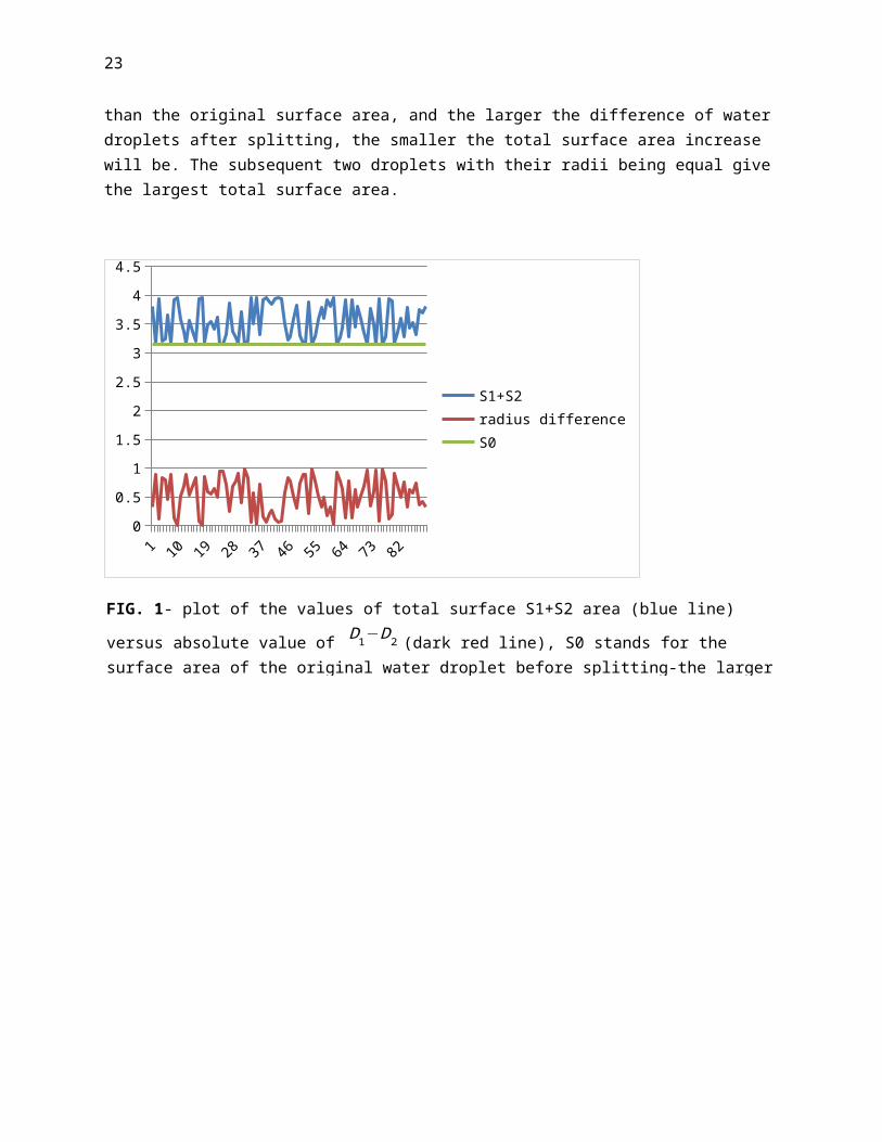
23
than the original surface area, and the larger the difference of waterdroplets after splitting, the smaller the total surface area increase will be. The subsequent two droplets with their radii being equal givethe largest total surface area.
0
0.51
1.52
2.53
3.54
4.5
S1+S2radius differenceS0
FIG. 1- plot of the values of total surface S1+S2 area (blue line)
versus absolute value of D1−D2 (dark red line), S0 stands for the surface area of the original water droplet before splitting-the larger

24
Both FIG. 1 and FIG. 2 reveal that, splitting larger water droplets into smaller ones always results in the increase of the surface area. And the more evenly the disposition of the resulted diameters is, i.e.the less difference among the resulting value of diameters, the largerexposed surface area increase can be obtained. This aforementioned hypothesis leads to conclusion that, if all droplets after splitting into a cluster have the same diameter, then they in total have the largest surface area. Otherwise, for the same number of subsequent water droplets, the cluster with less standard deviation of droplets size has a larger surface area than one with a larger value of S.D. And for the same disposition pattern of water droplets size (2), smaller
FIG. 2- plot of surface area of water droplets before and after splitting into 3 droplets; Original droplet was assumed to have 1mm diameter. And its surface area is represented by S0. S1+S2+S3 representsthe total surface area after separation. Two droplets have their diameter (mm) as random numbers between 0 and (1/2)1/3.Standard Deviation(S.D.) (yellow line) represents the difference of diameters of three

25
the size of the average size water droplets results in larger exposed surface area for evaporation.
Theorem 2: For Ranz and Marshall’s expression for mass transfer of small droplets in unbounded flow due to evaporation, the average mass
transfer coefficient hm (m/s) always increases when diameter gets smaller.
Prove:
As for sphere made of single component in the other gas species,
Reynolds number for that dropletsRe=VD
ν (7)
D is the diameter of a single water droplet, and V is the relative
velocity between sphere and surrounding fluids. Schmidt number Sc= ν
DAB, ν is the kinematic viscosity of the gas, in this case, the air, andDAB is the mass diffusion coefficient of the binary species of dropletand surrounding gas, which, in this case is for water and air. Substituting the expression for Reynolds number and Schmidt number into the expression of Sherwood number, one gets
Sh=2+0.552Red1/2ScG1 /3
=2+0.552 V1 /2D1/2
ν1 /6DAB1/3 ;
Since hm=
Sh×DABD , by substituting the expression of Sherwood number
into mass transfer coefficient, one gets
hm=2×DABD
+0.522×V1 /2D
AB2/3
ν1 /6D1/2 (8)
In equation (8), one can tell that as diameter of water droplets decreases, as is the case in spray of smaller and smaller water
droplets, the value of hm will increase in a reciprocal fashion. Thus

26
for droplets in unbounded flow with very small diameters, the evaporation rate per unit surface area of the surface of droplets can be very large. Recalling the conclusion of equation (4) which states that the increased total surface area for evaporation, together with the simultaneous increased evaporation rate per unit surface area, ensure the increase of evaporation rate of droplet clusters during a splitting or atomization operation. The magnitude of enhanced evaporation rate of the whole cluster can be very large since the diameter of the water droplets may be really small, which according toparameters of current nozzle products, can be as small as 5 micron[24]. And this is true even as Reynolds number reduces to zero, as long as Lewis number for the zero Reynolds case is in unity with that in expression [25]. Diameters of droplets in the scope of this paper rangesfrom 5µm to 1mm, but the majority of them mainly concentrated in the range of [50 µm, 170 µm], due to the lack of information for understanding and interpreting the non-equilibrium effect of drops with diameter less than the lower bound of this range. As Reynolds number increases, deviation from strokes’ drag will appear, and other expressions are needed to get the value of modified drag coefficient and drag force [26]. In addition to non-equilibrium effect of micro-sized droplets, introduction of Stefan flow which differs from Fick’s law and dense water cluster that appears in the spray process may alsoinfluence the results of calculation in this research, resulting in anexpression of drag force that deviates from stokes’ drag [27]. And Kelvin effect [28] is not considered in our calculation as well since size of water droplets in this research is still too large to make theKelvin effect to be appreciable. And except for those assumptions inside the formula. Neither do we consider the change on cohesive attraction or change of surface tension due to the change of key geometric feature of droplets- the diameter.
Footnote (1) & (2) :
(1) As R.S. Miller, et, al, have mentioned, for single component droplets with large initial size vaporizing in convective air flow, i.e., 1mm in diameter, a variety of liquid droplets models performed nearly identically, as long as the temperature of the air is significantly lower than the boiling point of water. When the initial

27
size is smaller than 50μm, however, non-equilibrium effects become significant, and that these effects are enhanced by increased slip velocity, which can invalidate this correlation. However, the slip velocity can relax rapidly in the evaporation cluster of droplets, dueto the decrease “permeability” of cluster and velocity, while diameterand Kinematic Viscosity which determine the value of Reynolds number are all influenced by enhanced vapor density, which affect both the diameter change rate, and the drag force coefficient. The later will further change the net force for droplets, making the dynamic simulation extremely difficult.
(2) The disposition pattern is defined as the feature of the distribution of droplets of different size and different number. Arrange the diameter of each droplet into a list with numerical order.And each diameter has its attendant number of droplets. If the diameters of subsequent droplets fluctuate exactly the same with another subsequent cluster of droplets (diameter-number curves have the equivalent shapes, regardless of the absolute value of diameter and number of droplets), then these two types of splitting have the same disposition pattern.
3.2 Deduction of correlation of drag force coefficient and Reynolds number and calculation of terminal velocity of droplets with differentsize
3.2.1 Explanation of the calculation method for dropwise evaporation and film evaporation
The general idea initiating the calculation for this research is to find out, for the same amount of water used in steady state operation of direct swamp cooler with a pad thickness of 6” or 150 cm, as it runs in the fashion of dropwise evaporative cooler, how much evaporation rate can be achieved? The calculation is executed in a context of droplets immersed in unbounded air flow having a constant velocity and a given initial temperature and RH. And the calculation also explores the period of time to achieve the same cooling effect for evaporation of a cluster of water droplets, versus evaporation from water film inside pads of hydro unit, for the same amount of volume both devices occupied. The dropwise evaporation rate is divided

28
into two phases- the freely falling phase for water droplets coming out of the nozzle, and the static or nearly static phase when water droplets are suspended or held on those hydro hairs and keep evaporating. Ranz and Marshall’s expression is used to calculate the second phase evaporation, and Whitaker’s expression together with Kishore and Gu’s modified drag force coefficient [29] is used to computerthe perpendicular slip velocity and evaporation rate for the first phase.
3.2.2 Deduction of the correlation between Reynolds number and drag force
For calculating the drag force coefficient with an average error of less than ±4% for Reynolds number between 1 and 200, Nanda Kishore &Sai Gu’s correction was used to calculate the drag force.
CD=24Re ;
(Re≤0.5) (9)
CD'=24e0.49Re
[1.05+0.152Re0.687e0.671 ];
(1≤Re≤200) (10)
CD'=24Re
[1.05+0.152Re0.687]=25.2Re
+3.648Re−0.313
when e=1 ; (1≤Re≤200) (11)
Expression (11) will be suitable to address the drag force of water droplets that appear in this research, since they are usually very small and safe to be regarded as perfect spheres. In order to find out that if the expression given by Whitaker is suitable when 0.5≤Re≤1, or some other expression will be more helpful to evaluate the drag force coefficient, this research further considered the extent of deviation from drag force coefficient (9) and (11), creating an approximation for drag force coefficient when 0.5≤Re≤1 .

29
Reorganize that (11) which is the modified drag force coefficient can
also be rewritten asCD'=1.05CD+1.3491 C
D0.313 . Then the deviation of CD'
from original drag force CD equals
(CD'−CD )/CD=(1.05CD+1.3491CD0.313−CD) /CD = 0.05+1.3491CD−0.687 ;
(12)
As Reynolds number varies between [0.5, 1], CD ranges within [24, 48] while CD' varies within [28.85, 54.93]. When CD=24, CD’=28.5 as Re=1; when CD=48, CD’=54.93 as Re=0.5. It further shows that CD and CD’ do not have any intersection for Re between [0.5, 1]. Since the Reynolds number in this range will appear in our calculation, it is wise to find out the approximate expression of drag force coefficient for Reynolds number varies in this interval. The approximation was obtained by regarding the curve in this range as a function linearly changing with Re. By using the value of two end points, i.e., [0.5, 48] and [1, 28.85], the function can be written as
Stokes’ Range applied for
FIG. 3- The Drag Force coefficient plotted as a function of Reynoldsnumber for sphere, noticing that for Reynolds number between [0.5, 1], an area denoted by blue patterned trapezoid, the expression for
?

30
CD''=(−38.3)Re+67.15 (13)
0.5 0.5 0.6 0.6 0.7 0.7 0.8 0.8 0.9 0.9 10
10
20
30
40
50
60
Re=[0.5, 1]Re=[0, 0.5]Re=[1, 200]
As a result, equation (9), (11) and (13) are used to calculate the drag force among the whole spectrum for Reynolds number ranging between [0, 200] by estimating the drag force coefficient when Reynolds number ranges between [0.5, 1]. It is necessary to find out the drag force which further enables the determination of the approximate terminal velocity for falling water droplets at the first stage of cooling inside the hydro unit, since water droplets from the nozzle are the first to get in contact with outside air. And the overall evaporation effect will be enhanced by the second stage of evaporative cooling of static or slow moving droplets on the hydro hairs.
3.2.3 Calculation of the terminal velocities of water droplets discharged with an initial velocity
FIG. 4-Drag Force Coefficient as a function of Re-The blue line, acurve representing the approximate expression for drag force coefficient for Reynolds number between [0.5, 1], was used for computing drag force for droplets having velocity between [0.02m,
Re
CD

31
Generally, freely flying droplets are subject to three forces, i.e. drag force, gravity, and buoyance force. And the drag force can be further divided into two directions, i.e. one in the horizontal direction caused by the movement of air due to the work done by the fan, and one in perpendicular caused by the droplets falling downwards. As very small water droplets were ejected from the nozzle,they spread out and diffuse. Since the majority of them are very smalland light weight, they are easily “gone with the wind”- horizontal drag will force them to move in a direction and velocity close to air stream. Applying net force analysis to those droplets one gets
∑F1=ρdg(π D3
6)−C1Dρg
πD2V12
8−ρgg
πD3
6=ma1=ρd(π
D36
)a1 (14)
∑Fi represents the net force present on a single droplet in a given
direction (vertical, horizontal, etc.); ρd and ρg represent density of water droplets and density of air, respectively.
This is a description of the perpendicular movement of droplets. CD will change with value of Reynolds number, and thus, the velocity. Stokes drag force coefficient will be applied to situations when Re isless than 0.5; for Re between [0.5, 1], expression of CD’’ will be applied, as has been mentioned before; CD’ however, will work in place of the other two expressions when Reynolds number varies with [1, 200]. For horizontal movement of droplets, a similar equation dominated by horizontal drag force can be written as
∑F2=C2DρgπD2V
22
8=ma2=ρd(π
D36
)a2 (15)
Since the value of Kinematic viscosity ν and velocity V is required tocalculate Re, and ν and DAB of dry air are dependent on air temperature. In order to make the discussion more grounded, two valuesfrom Monthly statistics for dry bulb temperature, i.e. the daily average 28.1°C (82.58 °F), and the maximum 41.1°C (105.98 °F) of June in Tucson were selected. However, for the following calculation of

32
evaporation rate, the vapor density of the droplets surface is dependent on their surface temperature, not the ambient air temperature [30]. Kinzer and Gunn further discovered that the surface temperature of the freely falling drops having their diameters rangingfrom 10 to 140 µm are very close to the wet bulb temperature of the ventilated medium [31]. The surface temperature of droplets will be estimated through the calculation of heat and mass transfer via the surface of droplets. The initial water temperature on the outlet of the nozzle is assumed to be the same as the tap water temperature, which is 27.1 °C (80.78 °F) in Tucson [32]. And the initial Relative Humidity of air flow equals 0.19 [33].
Velocity of falling droplets will be estimated from (12) and (13), V used in calculation is the slip velocity of flying water droplets. So for horizontal movement initiated by the air, assumption states that the water droplets will go along with air, thus the flip velocity caused by horizontal air movement will be neglected, however, the slipvelocity of the falling droplets cannot be overlooked in the perpendicular direction. Thus it is imperative to find out the approximate value of magnitude of vertical slip velocity for droplets have a diameter range in our discussion.
Method for this research of figuring out the vertical slip velocity ofdroplets with different diameters is to calculate the terminal velocity under the condition of zero net force, using the initial diameter of those droplets. For droplets experiencing falling with a zero initial velocity vertically, the maximum velocity it can reach iswhen the net force exerted on it equals zero, which can be seen in (12). For those droplets being ejected out of nozzle with an initial velocity, droplets will take shorter time to cover a certain distance,when compared to the case of zero initial velocity, or the constant speed movement with a maximum velocity in a steady state (Gravity=DragForce + Buoyance force). Since the diameter of droplets keeps changing during the falling process due to evaporation, the maximum velocity, even called steady state, also changes with time. However, from the calculation, it is not difficult to see the evident regulation that as diameter becomes smaller, droplets will also fall more slowly. The effect of dense droplets of dense cluster, which

33
resulted a numerical expression of drag force different from classic drag force expression is neglected, as the induced air purposefully dilute the dense clusters. According to the second of Newtonian kinetics, from equation (12) one further gets
∑F1=ρdg(π D3
6)−C1Dρg
πD2V12
8−ρgg
πD3
6=0
(16)
C1DρgπD2V
12
8+ρgg
πD36
=ρdg(π D3
6)
(17)
Grouping the equations of (9), (11), and (13) together with (17), the velocity value can be estimated with a precision of ±0.01m/s, through the match function of Excel. By creating a matrix with vertical slip velocity changing between [0.01m, 0.5m], and diameter changing between[50 µm, 500 µm], with a changing pace of 0.01m and 10 µm, respectively, this paper has found out the approximate solution for constant slip velocity for droplets with diameter of [50 µm, 170 µm]. The result is demonstrated as
Diameter of droplets (m)
Upper bound of slip velocity
Lower bound of slipvelocity
0.00005 0.075 m/s 0.065 m/s0.00006 0.105 m/s 0.095 m/s0.00007 0.135 m/s 0.125 m/s0.00008 0.155 m/s 0.145 m/s0.00009 0.185 m/s 0.175 m/s0.0001 0.225 m/s 0.215 m/s0.00011 0.265 m/s 0.255 m/s0.00012 0.305 m/s 0.295 m/s0.00013 0.345 m/s 0.335 m/s0.00014 0.385 m/s 0.375 m/s0.00015 0.435 m/s 0.425 m/s0.00016 0.475 m/s 0.465 m/s0.00017 0.505 m/s 0.495 m/sTable 1: Terminal Velocity for droplets having diameters ranging from 50 µm to 170 µm, which is a very important factor influencing

34
3.3 Calculation of dropwise evaporation rate and temperature dropusing state-of-art boundary condition
Horizontal Air Velocity is denoted as V2 . Perpendicular velocity of
falling water droplets (slip velocity) is denoted as V1 , Air velocity of
the outlet Vout =0.4m/s (1.31ft/s), a value derived from human thermal
comfort towards ventilation [34]. Outlet surface area Ae = 1.5'×1.5' and
inlet surface area Ai = 2'×2' . Regardless of the volume of hydro hair and
its substrates, then the horizontal velocity V2 has a correlation
V2×Ai=Vout×Ae (18)
By considering the dimensions of the inlet and the outlet, one gets V2=0.225 m/s (0.738ft/s).
Initial calculation for the air flow rate. The area of opening is similar to those area of a direct swamp cooler. Inlet

35
Distance between each tube for air flow is estimated to be 1” (0.0254m). One sheet for wrapping air channel and one sheet for wrapping water channel are regarded as one unit. The width of each unit is estimated to be 9/16”(0.0143m), thus for an inlet of 2’ by 2’,with an pad thickness of 6” and air velocity 0.225m/s, air flow rate are estimated to be 0.08361 m3/s, or 0.093 kg/s, which is estimated from air density (1.114kg/m3) under temperature of 41.1 ˚C (105.98 ˚F).The calculation for the total surface area for water film evaporation assumes that one unit have four sides, two sides for air tubes, and two sides for water tubes, which have 0.42773 m2 (4.604 ft2) in total. Thus the total surface area for evaporation for the whole pad with a dimension of 6”(0.15m) by 2’(0.6m) by 2’(0.6m) equals 5.7743 m2 (62.15 ft2). The value of Kinematic Viscosity of air ν equals 1.673*10-5, DAB has a value of 2.8156*10-5. Initial water vapor density is 0.0103 kg/m3,estimated under 41.1 ˚C; Saturated water vapor density is 0.02 kg/ m3, estimated under 22.5 ˚C- the wet bulb temperature of air medium [28].Hydraulic diameter equals 0.0046; Assuming laminar flow for the airflowing in tubes (due to low air velocity), Sherwood number equaling 2.7 is used for fully developed laminar flow, and 4.5 for the entry length. In the mass transfer entry length (0.00845m), Sherwood number is calculated to be 2.89 (considering the tilted angle of tubes), and give a total mass transfer rate of 0.000993 kg/s, and an attendant heat absorption 2397.29 W.
If this same amount of mass transfer rate is split into water dropletsof 50 µm, 60 µm and 70 µm, with a ratio of 1:1.1:1 representing its number, the total surface area for evaporation is 0.0964m2, which is
FIG. 6 a pad for swamp cooler,as the air channel tilts 15 deg. inward. Its evaporation rate (kg/s) will be estimated,

36
fairly small compared to total surface area created by the pad (5.7743m2). However, the mass transfer coefficient hm=1.18875 m/s, which can reach two order of magnitudes larger than the hm=0.01773 m/s. This hugemass transfer coefficient means that for very small water droplets, intense evaporation happens per unit surface area. Eventually, for thesame amount of water, droplets create a total mass transfer rate of 0.00108 kg/s, and an attendant heat absorption 2597.6708 W. Equation (7) (8) is used to calculate Reynolds number and Sherwood number for droplets evaporation, and for the calculation of Reynolds number of tubes, D is simply substituted by Dh
[35],
The RH increase, for dropwise mode is 0.644, or 66.4%, for film evaporation inside a pad is 0.594, or 59.4%. By referring to psychometric chart, the temperature drop for both evaporation modes can be found:
Conclusion: For water droplets cluster, if the evaporation rate keeps constant in one second, it is going to absorb 2597.67 W (8863.62 BTU/hr) which is larger than the original 2397.29 W (8179.89 BTU/hr),
FIG 7. Psychometric chart showing the Temperature drop as a function of RH; Initial Condition: RH=0.19, Temperature=41.1 ˚C. Light green line: Evaporation rate for droplets; Dark green line: Evaporation rate from water film inside the tubes of a swamp cooler

37
causing temperature to drop from 41.1 ˚C (105.98 ˚F) to 24.2 ˚C (75.56˚F), 0.8 ˚C (1.44 ˚F) lower than the evaporation achieved by internal flow inside swamp cooler pad. For the same amount of water becoming vapor, how can the heat absorption be different? This means dropwise evaporation has a faster evaporation rate, and the same amount of water that transfers to the air in one second in swamp cooler will take less than one second to evaporate in dropwise form. In reality, the evaporation rate of a cluster of droplets decreases during the evaporation process due to the decreasing of the diameter of water droplets, and it can no longer maintain the 2597.6708 W heat absorption rate, unless the newly discharged droplets undertake the work of previous droplets. If so, then the temperature drop by dropwise evaporative cooling can truly below than film evaporation from a swamp cooler pad, meaning that for the same amount of time, dropwise evaporation operates faster than swamp cooler pad, evaporating more water species than water film evaporation. Then if more water is being evaporated, then more water is required to supply to the nozzle. This is the stage of dropwise evaporative cooling.
3.4 Introduction to two phase evaporation
However, if we keep tracking the water used in the nozzle, it is not difficult to find that, when droplets get smaller, their evaporation rate for each droplet is going to become smaller, which means the total evaporation rate for a cluster of water droplets with the same number of droplets will always decrease its evaporation rate after they are exposed to air flow. Nevertheless, as long as these droplets are still evaporating in the air flow, they are contributing to the evaporative cooling, until they hit the ground. It is therefore, reasonable for us to utilize their residue cooling effect, and design a strategies to let them keep appropriate form, in which they can still evaporate via the forced air flow, in exactly a similar way whenthey are firstly discharged from the nozzle.
If the residue of tiny water droplets, can inhabit on some kind of light weighted micro structure, and evaporate in a manner similar to those evaporate in unbounded flow, then these water droplets contribute to the whole evaporation process, without asking for extra water supply from the nozzle. If all these water droplets sitting on

38
that micro structure, without coalescing. Their total number can be very large, and the effect of these droplets residue cannot be overlooked. As long as they stay on surfaces that allow them to keep dropwise form, they can continue their evaporation, cooperating with the discharging of nozzles, and lift the efficiency of water use dramatically.
3.5 Discussion on direct evaporative cooling and indirect evaporative cooling
Each phase of the aforementioned evaporation belongs to the direct evaporation of water. And this proposed concept has not considered indirect evaporative cooler, which may have greater temperature drop than proposed system. There are systems utilizing the two stages evaporation, with a heat exchanger transferring the cooling energy from the first stage evaporation to second stage evaporation, without adding humidity to the air medium that undergoes the second stage evaporation, while achieving a temperature drop, before air is humidified by water vapor in the second stage. Another option is to circulate air through a rock bed, so the air is cooled by thermal mass, which is the rock bed, before it is cooled by evaporation. Inside the rock bed, the heat inside air is transported by the conduction and convection to rocks as they come in contact with those rocks with lower temperature.
Assuming that a rock bed system, or a heat exchanger, that helps to cool the air by 7 ˚C i.e. from 41.1 ˚C to 34.1 ˚C, before its humidityincrease, then for the same parcel of air participating the previous calculation, the relative humidity is required to increase by 0.569, or 57.1%, in order to reach the same RH as the dropwise evaporation phase has done, meaning that less water is required in order to reach a relative humidity equaling 83.4%, while greater temperature drop is accomplished. This estimation tells us that our proposed evaporation mode is not “better” than traditional evaporative cooling practice, itis, nevertheless, another option to cool the air using the same principle of evaporation, while raising the efficiency of water use asthose water residue on hydro hair zone adds more humidity to the air before it complete the evaporation process. The temperature drop after

39
dropwise evaporation, still cannot exceed the temperature difference between dry bulb temperature, with an initial RH, and the correspondent wet bulb temperature. However, it should be mentioned that air can get over saturated when droplets are small enough and aerosols are absent, and Kelvin effect can cause a larger vapor pressure over the droplets surface than water film. More complex phenomena may get involved in dropwise mode which require further efforts to elucidate. And, it is possible, to combine this proposed new mode of evaporation into the state-of-art practice of two-stage evaporative cooling.
4. How it works? Proposed conceptual design
FIG. 8 Two-stage evaporative cooling, can reach a larger temperaturedrop than the proposed dropwise evaporation, by adding less humidity to the air in the 2nd stage. Brown line: Two-stage evaporative cooling

40
4.1 Space required for each phase, trajectory of water droplets and net force analysis for droplets with different size
Recall Table 1 for terminal velocity. For all the droplets larger than170 µm, the slip velocity all exceeds 0.5 m/s, whose values cannot be shown in this stage of research. Thus the following calculation and estimation for heat and mass transfer during the falling process for small water droplets is done according to the aforementioned description of boundary conditions, and resulted estimation for droplets in a range between [50 µm, 170]. However, for calculation forthe second stage evaporation, as droplets hanging on those hairs startto form and grow, the then calculation will consider diameter of droplets in a broader range.
If, as shown by calculation, that velocity of flying water droplets ona perpendicular direction will be in [0.065 m/s, 0.505 m/s] for droplets with diameter within [50 µm, 170 µm], then the horizontal velocity of the inlet of the evaporative cooler needs to be in an appropriate range in order to let those droplets scatter evenly along the right path, before the majority of them hit the hydro hair and become static. It is also intimately related to falling distance. If all the droplets land on a single, or several limited spots, water will concentrate on that area, and the micro structure for the second stage evaporation is far from fully utilized. If droplets fell faster,
FIG. 9 a honey bee carries small water droplets back to the hive to cool their nest. The hairs and leg surface serve as the micro structure hanging water droplets. Chitin and wax, both are hydrophobic material, and they can catch water droplets, allowing them to evaporate

41
majority of droplets will even hit the ground before they even have chances to reach the hydro hairs.
Before starting the research of the second stage evaporation, trackingthe movement of the droplets experiencing first stage evaporation seems very helpful. The droplets from a nozzle usually carry an initial velocity- a value that should be considered together with terminal velocity. Assuming that all the water droplets will be discharged from the nozzle with the same initial velocity, and how to determine the value for this velocity? If the velocity is too high, the average perpendicular velocity will be high during the falling phase, resulting in that a substantial proportion of droplets will reach the ground, before the water fully evaporate. If the velocity islow, perpendicular air flow will easily carry a fairly percent of themto travel a long distance, causing a drift and the over concentrated cluster of water droplets in a certain area inside the hydro hair zone. Both of them are not expected to occur in order to create a decent evaporation process. According to the document of Virginia Tech, droplets smaller than 100 microns will evaporate very fast, while, droplets larger than 150 microns in size resist evaporation to a much larger degree due to their large volume, implying that they will carry more water into the hydro hair zone. Thus the medium size seems to be working to help us define the initial velocity when droplets are discharged from the nozzle.
FIG. 10 Net force analysis of freely flying water droplets. For any droplets initially ejected, if the initial velocityequals the horizontal velocity, their drag force in horizontal and perpendicular direction should be the same. Fr1 , Fr2 , G ,

42
According to previous calculation, the horizontal air velocity equals 0.225m/s, which is very close to the 0.22m/s- the terminal velocity ofa freely flying drop with diameter of 100µm. Thus 0.22m/s was used as the discharging velocity of the orifice. Droplets larger then this diameter will have higher terminal velocities than this value, which means their vertical speed will be accelerated by a certain degree after being discharged from the orifice with this velocity and manifest a group of curves bending downwards at the beginning. However, it is important to notice that the diameter during the falling process, for most droplets, are shrinking, due to evaporation.For droplets smaller than 100 µm, their terminal velocities will be hampered due to the fact that the initial net force will be pointing upwards, while the horizontal drag force significantly influence its movement, causing their trajectories to bend upwards. For droplets with diameter around 100 µm, their initial net force in the perpendicular direction equals zero (buoyance force + drag force =gravity). As they move horizontally and evaporate, their size shrink.The reduced diameter further cause the reduction of proportion of gravity and buoyance force and their roles in the net force are weakened, and drag force starts to take the upper hand, so their trajectories is very close to a straight line, and bend upwards slightly in the freely falling phase. If this is true, then the trajectories of water droplets can be approximately illustrated as three bundles of streams. Each of them has its unique feature.

43
By studying the trajectory and velocity of droplets with different size, it is possible to give an estimation of area for freely falling,and the configuration of the hydro hair zone. Then what about the hydro hair? How their structure should be? Since the lessons from water forager bees carry water droplets using their leg structures andhairs on their legs to carry droplets, the hydrophobic material for holding water droplets are the direct mimicry for what bee did for cooling their nest during hot summer days. The more water droplets canbe captured to be stored for second stage evaporative cooling before they hit the ground, and more number of water droplets with decent size can be obtained on hydro hair system, better the evaporation for the second stage will be. Second stage works together with first stageto make the evaporative cooling more efficient in terms of water use, and faster temperature drop in a given period of time, as more heat can be absorbed when numerous droplets are kept small on hairs creating a droplets reservoir, and with every single droplet’s spherical surface exposed to air flow.
1
2
3
FIG.11 Section showing the freely falling zone and hydro hair zone. In this picture, 0.22m is the approximate distance traveled by a droplet with D= 100 µm in one second, while blue arrows represent the direction of air flow, which hasa velocity of 0.225m/s.(3)Dropletssmaller than 50 µm (represented by 1) can evaporate fully in less than 1 second, even before it reaches the hydro hair. Trajectories of droplets having D=100 µm goes along a straight line at the beginning, but will bends upward later on. Trajectories denoted by 3 are dictated by droplets with the

44
4.2 The detailed analysis on the structure of hydro hair
It has been mentioned by K. Hiratsuka, et.al that super hydrophobic surface gives a very small coefficient of friction. Thus droplets can slip away from any spot as they land on super hydrophobic surface of hairs in the hydro hair zone. A properly distributed bumps created by hydro hairs would be available to reduce the sliding movement of theselanding drops. Further, flying droplets carry an appreciable amount ofmomentum, which more or less, will be transferred to the hairs. Thus these very thin hairs have to be able to steady during collision with droplets. Due to the approximation of conservation of momentum, these hairs will be beneficial if they become elastic, and become fixed at both ends, in order to weaken the potentially damaging force in a collision by increasing the contact time for the transport of Kinetic energy. Conceptually, they can be depicted as
Droplets’ direction in respect to the plane of hydro hair units, can be exactly perpendicular, or can form a profile angle. This in turn, determine the titled angle of the surface defined by hydro hairs. Oncethe initial momentum was absorbed by the elastic hydro hairs, these droplets would directly under the influence from drag force caused by the air flow, buoyance force and gravity force of itself, and surface support from the hydro hair surface. And In terms of roughly predicting the behavior of the water droplets after “landing”, net force analysis is necessary to tell the kit of setting up the tilted
FIG. 12 Conceptual planand section of hydro hairs. The above plan is viewed from both direction as shown by the arrows; the left one shows the section.
Direction of air flow

45
angle. In addition to the aforementioned parameters, the material of both the substrate and coating needs a wider discussion. One options for the materials of this hydro hairs strings, or fibers, can be polyesters after specific treatment, which makes it superhydrophobic [36]. Problems around this issue include “do droplets simply fall on those hair and become static mechanically, or does water-coating interface somehow allow the separation of H+ and OH- that makes dropletsget charged?” [37] Indeed, N. Miljkovic and his team‘s ground breaking works on super hydrophobic material, and its interaction with tiny water droplets, recently reveals the mechanism of static charging during the growth of water nucleation for the dropwise condensation and the correspondent jumping droplets behavior, which only appears onmetallic substrate with a couple of specified hydrophobic coatings when water droplets are small enough. Detailed research on charging behavior and its application in evaporation will appear in our next paper. Currently, the net force analysis for droplets after landing onhairs consider forces is solely under kinetics framework. Assuming that in the hydro hair zone, air is saturated, for an outside temperature of 41.1˚C with RH=0.19, wet bulb temperature gives a valueof 22.5 ˚C (72.5 ˚F). Thus the kinematic Viscosity ν has a value of 1.53235*10-5 m2/s. Under such condition, the compound air has a density of 1.202 kg/m3, and water, 997.875kg/ m3. Thus the value of three external forces that exert on water droplets can be gotten

46
Table 2. Value of three forces, i.e. Drag Force, Gravityand Buoyance Force,for droplets suspended on hydro hairs, under the condition of saturated air, with
FIG. 13 under the condition of 41.1˚C and RH=0.19, Psychometric chart gives the wet bulb temperature of that parcel of air 22.5 ˚C (red line). Green line, shows the average temperature of summer days, when

47
Although the exact magnitude and direction of velocity when droplets enter the hydro hair zone is not possible to get where this research is conducted, the velocities of droplets with different size is, nevertheless, indispensable to determine the final state of water droplets. The momentum, kinetic energy and surface energy of water droplets on these hairs can be further be analyzed once the accurate computation of the velocity is obtained. Here an analysis is conductedqualitatively to elucidate the process. Table 4 shows that for droplets with diameter 50 µm or smaller, the drag force is significantly larger then Gravity. If tilted surface is treated as a perfect plane, then all the forces posturing on this droplet can be projected to two axis, i.e., one that is parallel to titled surface,
the other is perpendicular to the tilted surface. In this case, Fr2(1) ,which is the “horizontal (meaning less steep)” component of Fr2 ,
dominance the force along the surface direction. And Fs is evidently
smaller than Fr2(1) , and the Gravity’s horizontal component is too small
to be considered compared with Fr2(1) , thus even if the hydrophobic surface has coefficient of friction equaling 0.1, which is extremely large estimation for super hydrophobic material, the sum of the friction and the horizontal component of gravity still cannot rival the horizontal component of drag force. Consequently, the droplet willmove, and if other forces do not change, the droplet will accelerate, until a new rising drag force limit its moving, or it will slip away from the hairs. And because the initial direction of the momentum forms an acute angle, it will enhance the slipping process from the surface. Thus droplets with this diameter cannot be trapped by hydro hairs. However, when the surface defined by hydro hairs becomes very steep, as is the case in 14(2), gravity and drag force together pose astrong component perpendicular to

48
the surface, while the component of drag force along the surface direction becomes much smaller, in this situation, 0.1 friction from the hydro hairs may very well fix the droplets on the surface. And droplets may stay in this fashion, until its volume falls below the size of the holes. Although, the perpendicular component of the tiltedsurface in FIG. 14 (2) may force water droplets to deform and slip away from holes, even before they shrink to a size smaller than the holes, or the perpendicular component is large enough, to break the liquid membrane, causing the splitting of water droplets to happen.
Generally speaking, the tilted angle of the surface needs to be less steep for holding larger water droplets, and to be intensely steep when the target droplets are very small, which is in agreement with the magnitude of three forces illustrated in FIG. 14, and also in
FIG. 14 (1) and (2), showing thedifferent effectof net force fora single droplet, when the titled

49
consistent with the vector of final velocity before droplets land on the surface. However usually in the second phase of evaporation, the size of droplets will get larger, due to an effect of condensation termed as “Ostwald Ripening” [38], which states that the “bigger drops will grow at the expanse of smaller ones”. From Table 4, one can tell that droplets larger than 120 µm have their gravity much larger than drag force, and the tilted angle should be much more flat for the hydro hairs to hold water droplets.
FIG. 15 Drawings on the left hand side shows the range of size of water droplets. The row in the middle shows the threenets, which are correspondently designed for capturing drops having three types of size (small, medium and large). The right drawing roughly shows the net force and magnitudes of each components when they are static on the net surface. Top diagram illustrates the tension forces that give the fibers/strings/hairs the zigzag form.

50
The net of hydro hair system can be divided into different types basedon the size of their target droplets, i.e. droplets belonging to the smallest should be held by the smallest net, which should be mounted nearest to the top of this evaporative cooler, and medium sized droplets should be situated in the middle of the hydro hair, where they are supposed to receive droplets between 100 µm and 150 µm. And finally, the lower portion of the hydro hair system should be occupiedby net with the largest holes with thickest and strongest strings, where larger droplets are prevent from falling immediately to the ground.
In the real operation, the large sized droplets (D is larger than 150 µm) have significantly low evaporation rate, which will rapidly reducethe evaporation rate for water droplets, and weaken the efficiency of dropwise evaporative cooling. The control loop of monitoring the redundant water, making it as little as possible, will be part of the future research for biomimetics emulating the group wisdom of the evaporative cooling for honey bee colony.
Footnote (3): Readers may notice that in FIG. (11), the vertical dimension of the opening on the left hand side of the freely falling zone has changed to 450 mm, which is about 1’6”, being different from
FIG. 16 Orientation of the hydro hair and the 3-D section showingthe area of hydro hairs, and its possible outline, for those pumps with sensible vibrations,

51
the original discussion. The modification of dimension for the openingresults from that the trajectory analysis which shows the 1’6”, instead of 2’ is large enough to provide space for droplets flying. And the subsequent air flow rate for the indoor space reduces to 0.3m/s (0.984 ft/s)-a little bit slower than original set up 0.4m/s (1.312 ft/s). This modification shows that the size of freely flying area is determined by drop size, horizontal air velocity and initial velocity for discharging water droplets.
5. Conclusion for this research
5.1 Conclusion for the calculation of the evaporation rate and heat absorption rate
The calculation and relevant comparison is made between the freely flying mode when they are firstly discharged from the nozzle, and the film evaporation mode inside the tubes of a swamp cooler pad under theexact same climatic condition, inside the same volume, with the same amount of water supply and air flow rate, assuming that both of them operate in the 100% efficiency. The results show that the evaporation rate for water droplets cluster having diameter of 50, 60 and 70 μm can reach a heat absorption rate of 2597.671W (8863.62BTU/hr), and for the swamp cooler pad, 2397.293W (8179.89BTU/hr), with the attendant mass transfer rate 0.00108 kg/s, and 0.000993 kg/s respectively. The heat absorption further results in a temperature drop for air by 16.1 ⁰C (28.98 ⁰F) for dropwise mode, and 16.9 ⁰C (30.42 ⁰F) for pad mode, if all the heat is removed from the air. The direct evaporation of droplets from nozzle accounts for the first stage evaporation of the newly designed evaporative cooler. The total evaporation rate that the proposed device can achieve is comprised of two stages:
1) Initial freely flying stage when water droplets are discharged from the nozzle.
2) Second stage of evaporation when droplets are suspended or held by hydro hairs.
The second stage of evaporation helps the newly designed swamp cooler gain extra benefits by evaporating tiny water droplets which are the

52
residue of droplets experiencing evaporation in the first stage. This means that the newly proposed device is able to lift water use efficiency since all the water are ideally supposed to be used for evaporation, if designed properly, while achieving temperature drop noless, or more than the traditional pads system.
The condition for the aforementioned calculation are set up according to the weather data of Tucson from 722740 (TMY2), energy plus energy simulation software, which gives maximum temperature of July 41.1 ⁰C (105.98⁰F) and relative humidity (RH) equals 0.19. The original tap water temperature is the same for both calculations, which equals 27.1⁰C (80.78⁰F). The thickness for freely flying area is 6”, so is the thickness of cool tower pad. The dimension of the inlet area is 2’ ¿ 2’,and the outlet area is 1.5’ ¿ 1.5’. The air velocity at the outlet is determined firstly, to be 0.4m/s, the average value for the thermal comfort range for indoor space with no local control of sensible air speed from occupants, according to Arens. Thus the inlet air velocity is calculated to be 0.225m/s. Relative humidity increased by 64.6% and59.6%, respectively. And both of them haven’t saturated yet, having subsequent RH=83.4% and 78.4%. In such conditions, Efforts can be taken to increase the evaporation rate for the first stage, such as atomizing the water into even smaller droplets using like air atomizing nozzle. And the number of nozzles applied to this system,
FIG. 17 Temperature of air on the inner side of the freely falling area, and the inner side of the pad. Tout=24.2 ⁰C (75.56 ⁰F) for 1st stage dropwise evaporative cooling; Tout=25 ⁰C (77 ⁰F) for evaporation

53
and their alignment, and intervals between them, should be explored infuture research.
5.2 Conclusion for calculation that addresses design issues of hydro hair system for the second stage evaporative cooling
In order for the residue of droplets to experience efficient evaporation in the second stage, the design of hydro hair system, which is a multilayered net-like structure, reveals several features:
1) The size this device is not only influenced by the number of nozzle that works simultaneously during a drizzling process, but is also strongly influenced by the air velocity, which affect both the trajectories and evaporation rate for flying droplets, and droplets on hydro hairs. Since there must be enough space fordroplets to disperse during the first stage, more required space can be resulted in order to make this system function correctly, making it less flexible, or less efficient for the space they need in a building. And the efficiency of the second stage depends heavily on whether droplets can stay on hairs without touching any other large surfaces, the location of the pump needsto be adjusted to reduce the unexpected vibration that may transmitted to the hairs. And the shape of the substrates can be another important factor to determine the success rate of capturing water droplets, which can be studied and developed by parametric design in architectural realms.
FIG 18 Psychometric chart shows that the temperaturedrop as a function of RH. As RH increases from 0.19 to 0.834, and 0.19 to 0.784, Temperature drop by16.1 ⁰C and 16.9 ⁰C can be

54
2) Size of water droplets has correlation with the tilt angle defined by hydro hair plane. The larger the dimension of hydro hair is, the smaller the tilt angle would be, according to net force analysis of static water droplets on these hairs.
3) The hairs should be fixed at both ends for the terminal velocity can result in initial momentum right before droplets’ landing, which can be very intense in such a small scale. The elasticity of hairs, if there is any, can be benefit to absorb the impulse, and help to increase the success rate of capturing water droplets.
4) The diameter of these hairs varies in order to match those targetdroplets with different size. However, diameter of the hairs should be no larger than diameter of the droplets, eliminating the occurrence of sessile drops’ evaporation mode.
5) Materials of hairs should be hydrophobic or super hydrophobic, tokeep the shape intact and expose it to the air flow as large as possible. Keeping the spherical form is not the only way to increase effective surface area for evaporation, however, the concept of this design is trying to bring in new connections and possibilities of blending the recent research of new materials-the scientific part together with certain geometric features and structural properties-which pertain to the design part, to derivethe blueprint of tools that may solve many issues at once. Superhydrophobic materials can easily get themselves clean out ofthe deposits of minerals in water, and thus spare the efforts of regular maintenance and replacement of components. Density enhancement of hairs around the three sides of the zone of hydro hairs is needed in order to prevent tiny droplets and aerosols from going into the indoor space.
FIG. 19

55
6) Hydro hair system is supposed to have the potential to split water droplets, in case that the droplets may get too big simply through coalescing or Ostwald ripening and lose the benefits resulting from the very small size of water droplets.
More research is needed in order to verify the orientation and disposition of hydro hairs, and the empirical experiments are indispensable to get a better insight of all the known and unknowns mechanism when droplets collide with the hydrophobic or superhydrophobic surface. Effects like positive charging of tiny droplets with diameters below 50 μm when they condensate or encounter superhydrophobic surface coating having metallic substrates, as has recently been discovered by N. Milijkovic et.al. raise attentions for developing the highly efficient condensation process and potential power generation from atmosphere. The electrical charge of droplets can repulse one another, almost eliminating the chances of coalescing,which is very similar to one of the functions of hydro hairs. In addition to holding water droplets against air flow, the adjustment for their orientation is able to guide the trajectories of drops, or modify the size the droplets, working as a filter to create the opportunities to be combined into other systems sensitive to the disposition of the size of droplets. Can this concept of droplets-assisted evaporation lead to faster evaporation methods, for a series of applications for sustainable architecture and sustainable industrial products, such as desalination of sea water? Only time willgive us the answer.
Reference:
[1] [3] Martin Karpiscak and Mary H. Marion . Evaporative cooler wateruse. Tucson, Arizona: Publication 191045, July 1991. http://ag.arizona.edu/pubs/consumer/az9145.pdf
[2] Temp-Con “Evaporative Coolers” Temperature Control, Inc (http://temp-con.com/evaporative cooling?utm_source=GoogleCPC&utm_medium=MMHOS&utm_campaign=EVAP)

56
[4] Clear Water-Water Quality Summary of Water Supply Sources, city of Tucson Government. http://www.tucsonaz.gov/tucsonwater/clearwater? output=supply
[5] Bernd Heinrich. The Hot Blooded Insects- Strategies and Mechanisms of Thermoregulation.Harvard University Press, United States, ISBN 0-674-40838-1 1993.
[6] Newton Boggs. Water Consumption in the Bee Colony and the Proportion of Sugar and Water for Stimulative Feeding in the Spring. Colorado Agriculture College, Fort Collins, Colorado. August 26, 1924.
[7] Helmut Kovac, Anton Stabentheiner and Sigurd Schmaranzer. Thermoregulation of Water Foraging Honey Bees-Balancing of Endothermic Activities with Radiative Heat Gain and Functional Requirements. Journal of Insect Physiology 56 (2010) 1834-1845.
[8] Susanne Kühnholz and Thomas D. Seeley. The Control of Water Collection in Honey Bee Colonies. Behav Ecol Sociobiol (1997) 41: 407-422.
[9] Thomas Norgaard and Marie Decke. Fog-basking behavior and water collection efficiency in Namib Desert Darkling Beetles. Norgaard and Dacke Frontiers in Zoology 2010, 7:23
[10] [11] Frank P. Incropera, Theodore L. Bergman, Adrienne S. Lavine and David P. Dewitt. Fundamentals of Heat and Mass Transfer, 7th Edition. John Wiley and Sons (2012) ISBN 13: 9780470501979
[12] S.P. Fisenko, A.I. Petruchik and A.D. Solodukhin. Evaporative Cooling of Water in a Natural Draft Cooling Tower. International Journal of Heat and MassTransfer 45 (2002) 4683-4694
[13] Slimline Manufacturing LTD. The Theory of Evaporation enabling the Design of The Turbomister. http://www.turbomisters.com/wp-content/uploads/2011/07/design.pdf
[14] Kenneth K.S. Lau, Jose Bico, Kenneth B.K. Teo, Manish Chhowalla, Gehan A.J. Amaratunga, William I. Milne, Gareth H. Mckinley and Karen K. Gleason. Superhydrophobic Carbon Nanotube Forests. Nanoletters, 3 (12), 1701-1705, 2003

57
[15] Michael A Nilsson, Robert J Daniello and Jonathan P Rothstein. A Noval and Inexpensive Technique for Creating Superhydrophobic Surfaces Using Teflon and Sandpapers. J. Phys. D: Appl. Phys. 43 (2010) 045301 (5pp) 9
[16] Yongfang Zhong, Anthony M. Jacobi and John G. Georgiadis. Condensation and Wetting Behavior on Surfaces with Micro-Structures: Super-Hydrophobic and Super Hydrophilic. International Refrigeration and Air Conditioning Conference at Purdue, July, 2006
[17] John T. Simpson, et.al. Superhydrophobic Materials. Oak Ridge National Laboratory, U.S. Department of Energy http://web.ornl.gov/adm/partnerships/events/bridging_gap/presentations/Superhydrophobic_Materials.pdfFeburary, 2011
[18] Anna Thorvaldsson, Petra Edvinsson, Alexandera Glantz, Katia Rodriguez, Pernilla Walkensrom and Paul Gatenholm. Superhydrophobic behavior of plasma modified elecrospun cellulose nanofiber-coated microfibers. Cellulose (2012) 19: 1743-1748
[19] Pradip Kumar Dutta, Joydeep Dutta and V S Tripathi Chitin and chitosan:Chemistry, properties and applications. Journal of Scientific & Industrial Research: Vol. 63, January 2004, pp 20-31
[20] Wei Xu, Rajesh Leeladhar, Yong Tae Kang and Chang Hwan Choi. Evaporation Kinetics of Sessile Water Droplets on Micropillared Superhydrophobic Surface. Langmuir 2013, 29, 6032-6041
[21] Tom T. Huang, David G Taylor, Miroslav Dedlak, Nathan S. Mosier and Michael R. Ladisch. Microfiber-Directed Boundary Flow in Press-Fit Microdevices Fabricated from Self-Adhesive Hydrophobic Surfaces. Anal. Chem. 2005, 77, 3671-3675
[22] [37] Nenad Miljkovic, Daniel J. Preston, Ryan Enright Evelyn N. Wang. Electrostatic charging of jumping droplets. Nature Communications 4, Article number: 2517. 09/27/2013
[23][30][31]H. Yildirim Erbil. Evaporation of pure liquid sessile and spherical suspended drops: A Review. Advances in Colloid and Interface Science 170 (2012) 67-86

58
[24] Robert Grisso, Pat Hipkins and Shawn D. Askew. Nozzles: Selection and sizing Publication 442-032, Virginia Cooperative extension, http://pubs.ext.vt.edu/442/442-032/442-032_pdf.pdf.
[25][26][27] R.S. Miller, K. Harstad and J. Bellan. Evaluation of Equilibriumand Non-equilibrium Evaporation Models for Many-Droplet Gas-Liquid Flow Simulations. Jet Propulsion Laboratory, California Institute of Technology, Pasadena, CA 91109-8099
[28][38] Hans-Jürgen Butt, Karlheinz Graf, Michael Kappl. Physics and Chemistry of interfaces. VILEY-VCH Verlag GmbH & Co. KGaA, Weinheim, 2003
[29] Nanda Kishore and Sai Gu. Momentum and heat transfer phenomena of spheroid particles at moderate Reynolds and Prandtl numbers. Southampton, United Kingdom. International Journal of Heat and Mass Transfer 54 (2011) 2595-2601
[32] City of Tucson, official website Water Quality Summary of Main distributionSystem. http://www.tucsonaz.gov/tucsonwater/clearwater?output=allTabular
[33] Energy Plus Energy Simulation software, Weather Data, Tucson, 722740 (TMY2), http://apps1.eere.energy.gov/buildings/energyplus/cfm/weather_data3.cfm/region=4_north_and_central_america_wmo_region_4/country=1_usa/cname=USA
[34] Edward Arens, Stephen Turner and Hui Zhang. Moving Air for Comfort. SHRAE Journal, May 2009
[35] Hydraulic diameter, see Ref. [10] and [11], chapter 8 for more information.
[36] Igor Luzinov, et.al. Ultrahydrophobic fibers: Lotus Approach. Project No.C04-CL06, National Textile Center Annual Report: November 2007