PROJECT MANUAL - NOGERO ,YTNUOC NOTNEB - Avery ...
280
PROJECT MANUAL N O G E R O , Y T N U O C N O T N E B Avery Complex Addition/Alteration 360 Avery Avenue Corvallis, Oregon 97333 June 26, 2017 Architect: Carlson Veit Architects P.C. 3095 River Road N Salem, Oregon 97303 (503) 390-0281 Fax 390-2459 Architect's Project Number: 11916
-
Upload
khangminh22 -
Category
Documents
-
view
3 -
download
0
Transcript of PROJECT MANUAL - NOGERO ,YTNUOC NOTNEB - Avery ...

PROJECT MANUAL
NOGERO ,YTNUOC NOTNEB Avery Complex Addition/Alteration
360 Avery Avenue
Corvallis, Oregon 97333
June 26, 2017
Architect: Carlson Veit Architects P.C. 3095 River Road N Salem, Oregon 97303 (503) 390-0281 Fax 390-2459 Architect's Project Number: 11916

TABLE OF CONTENTS 00 01 10-1
Avery Complex
The following Specifications have been organized under the format of the Construction Specifications 1 Institute (CSI). Section numbers listed are for identification, and may not be consecutive. The Contractor 2 shall check his copy of the Specifications against the Table of Contents to be sure his copy is complete. 3 4 Section No. Section Title Pages 5 6 DIVISION 00 – PROCUREMENT AND CONTRACTING: By Owner 7 00 01 15 List of Drawing Sheets .......................................................................................................... 2 8 9 DIVISION 01 - GENERAL REQUIREMENTS 10 01 11 00 Summary of Work .................................................................................................................. 3 11 01 23 00 Alternates ..................................................................................................................... 1 12 01 25 00 Substitution Procedures ........................................................................................................ 1 13 Substitution Request Form .................................................................................................... 1 14 01 33 00 Submittal Procedures ............................................................................................................ 2 15 01 42 00 References ..................................................................................................................... 2 16 01 45 00 Quality Control ..................................................................................................................... 3 17 01 50 00 Temporary Facilities and Controls ........................................................................................ 4 18 01 60 00 Product Requirements ........................................................................................................... 2 19 01 71 23 Field Engineering................................................................................................................... 1 20 01 73 29 Cutting and Patching ............................................................................................................. 2 21 01 74 23 Final Cleaning ....................................................................................................................... 1 22 01 77 00 Closeout Procedures ............................................................................................................. 2 23 01 78 23 Operation and Maintenance Data ......................................................................................... 3 24 01 78 36 Warranties and Bonds ........................................................................................................... 1 25 01 78 39 Project Record Documents ................................................................................................... 2 26 27 DIVISION 02 – EXISTING CONDITIONS 28 02 41 19 Selective Structure Demolition .............................................................................................. 2 29 30 DIVISIONS 03 – CONCRETE 31 See notes on structural drawings 32 33 DIVISIONS 04 – MASONRY (Not Used) 34 35 DIVISION 05 – METALS 36 05 50 00 Metal Fabrications ................................................................................................................. 3 37 38 DIVISION 06 – WOOD, PLASTICS, AND COMPOSITES 39 06 05 73 Wood Treatment .................................................................................................................... 2 40 06 10 00 Rough Carpentry ................................................................................................................... 3 41 06 20 00 Finish Carpentry .................................................................................................................... 3 42 06 41 16 Plastic Laminate-Clad Architectural Cabinets ...................................................................... 4 43 06 42 00 Plastic Laminate .................................................................................................................... 2 44 45 DIVISION 07 - THERMAL AND MOISTURE PROTECTION 46 07 13 00 Sheet Waterproofing………………………………………………………………………………..2 47 07 21 00 Thermal Insulation ................................................................................................................ 2 48 07 25 00 Weather Barriers ................................................................................................................... 3 49 07 31 00 Asphaltic Composition Shingles ........................................................................................... 2 50 07 40 00 Roofing & Siding Panels ...................................................................................................... 4 51 07 60 00 Flashing and Sheet Metal ..................................................................................................... 5 52 07 84 00 Firestopping .......................................................................................................................... 2 53 07 92 00 Joint Sealers ......................................................................................................................... 2 54 55 56
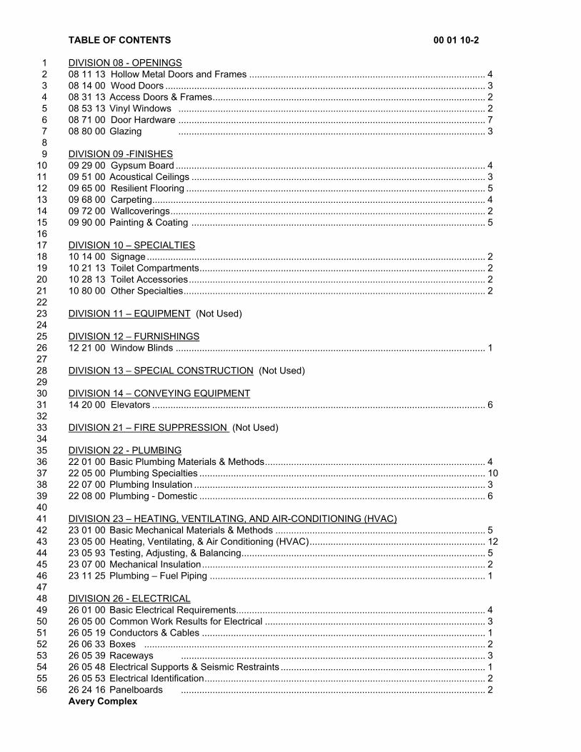
TABLE OF CONTENTS 00 01 10-2
Avery Complex
DIVISION 08 - OPENINGS 1 08 11 13 Hollow Metal Doors and Frames .......................................................................................... 4 2 08 14 00 Wood Doors .......................................................................................................................... 3 3 08 31 13 Access Doors & Frames ........................................................................................................ 2 4 08 53 13 Vinyl Windows ..................................................................................................................... 2 5 08 71 00 Door Hardware ..................................................................................................................... 7 6 08 80 00 Glazing ..................................................................................................................... 3 7 8 DIVISION 09 -FINISHES 9 09 29 00 Gypsum Board ...................................................................................................................... 4 10 09 51 00 Acoustical Ceilings ................................................................................................................ 3 11 09 65 00 Resilient Flooring .................................................................................................................. 5 12 09 68 00 Carpeting ............................................................................................................................... 4 13 09 72 00 Wallcoverings ........................................................................................................................ 2 14 09 90 00 Painting & Coating ................................................................................................................ 5 15 16 DIVISION 10 – SPECIALTIES 17 10 14 00 Signage ................................................................................................................................. 2 18 10 21 13 Toilet Compartments ............................................................................................................. 2 19 10 28 13 Toilet Accessories ................................................................................................................. 2 20 10 80 00 Other Specialties ................................................................................................................... 2 21 22 DIVISION 11 – EQUIPMENT (Not Used) 23 24 DIVISION 12 – FURNISHINGS 25 12 21 00 Window Blinds ...................................................................................................................... 1 26 27 DIVISION 13 – SPECIAL CONSTRUCTION (Not Used) 28 29 DIVISION 14 – CONVEYING EQUIPMENT 30 14 20 00 Elevators ............................................................................................................................... 6 31 32 DIVISION 21 – FIRE SUPPRESSION (Not Used) 33 34 DIVISION 22 - PLUMBING 35 22 01 00 Basic Plumbing Materials & Methods .................................................................................... 4 36 22 05 00 Plumbing Specialties ............................................................................................................. 10 37 22 07 00 Plumbing Insulation ............................................................................................................... 3 38 22 08 00 Plumbing - Domestic ............................................................................................................. 6 39 40 DIVISION 23 – HEATING, VENTILATING, AND AIR-CONDITIONING (HVAC) 41 23 01 00 Basic Mechanical Materials & Methods ................................................................................ 5 42 23 05 00 Heating, Ventilating, & Air Conditioning (HVAC) ................................................................... 12 43 23 05 93 Testing, Adjusting, & Balancing ............................................................................................. 5 44 23 07 00 Mechanical Insulation ............................................................................................................ 2 45 23 11 25 Plumbing – Fuel Piping ......................................................................................................... 1 46 47 DIVISION 26 - ELECTRICAL 48 26 01 00 Basic Electrical Requirements............................................................................................... 4 49 26 05 00 Common Work Results for Electrical .................................................................................... 3 50 26 05 19 Conductors & Cables ............................................................................................................ 1 51 26 06 33 Boxes .................................................................................................................................. 2 52 26 05 39 Raceways .................................................................................................................... 3 53 26 05 48 Electrical Supports & Seismic Restraints .............................................................................. 1 54 26 05 53 Electrical Identification ........................................................................................................... 2 55 26 24 16 Panelboards .................................................................................................................... 2 56

LIST OF DRAWING SHEETS 00 01 15-1
Avery Complex
The following drawings, dated June 26, 2017, accompany this project manual and are a part thereof: 1 2 GENERAL 3 G-001 COVER SHEET/PROJECT INFORMATION 4 G-002 EGRESS PLAN/CODE INFORMATION 5 G-003 RATED WALL ASSEMBLIES 6 G-004 FIRE STOPPING DETAILS ALLOWABLE HOLE 7 8 CIVIL 9 1 OF 13 COVER SHEET 10 2 OF 13 CONSTRUCTION NOTES 11 3 OF 13 SITE PREPARATION/EROSION & SEDIMENT CONTROL PLAN 12 4 OF 13 LAYOUT PLAN 13 5 OF 13 GRADING PLAN 14 6 OF 13 NOT USED 15 7 OF 13 PARKING LOT ISLANDS 16 8 OF 13 STANDARD DETAILS 17 9 OF 13 STANDARD DETAILS 18 10 OF 13 STANDARD DETAILS 19 11 OF 13 LANDSCAPEING & IRRIGATION PLAN 20 12 OF 13 LANDSCAPEING & IRRIGATION PLAN 21 13 OF 13 LANDSCAPEING & IRRIGATION PLAN 22 23 STRUCTURAL 24 S0.0 STRUCTURAL NOTES 25 S1.0 FOUNDATION PLAN AND FLOOR FRAMING PLAN 26 S2.0 ROOF FRAMING PLAN 27 S3.0 LATERAL PLANS 28 S4.0 STRUCTURAL SECTIONS 29 S5.0 DETAILS 30 S5.1 DETAILS 31 S5.2 DETAILS 32 S5.3 DETAILS 33 34 ARCHITECTURAL 35 A-100 SITE PLAN 36 A-101 ENLARGED SITE PLAN 37 A-102 EXISTING FLOOR PLAN 38 A-103 FIRST FLOOR PLAN 39 A-104 SECOND FLOOR PLAN 40 A-105 ATTIC PLAN 41 A-106 FIRST FLOOR REFLECTED CEILING PLAN 42 A-107 SECOND FLOOR REFLECTED CEILING PLAN 43 A-108 ROOF PLAN 44 A-201 EXTERIOR ELEVATIONS 45 A-202 INTERIOR ELEVATIONS 46 A-203 INTERIOR ELEVATIONS 47 A-301 BUILDING SECTIONS 48 A-302 BUILDING SECTIONS 49 A-303 BUILDING SECTIONS 50 A-401 ENLARGED STAIR PLANS 51 A-402 ENLARGED PLANS 52 A-501 DETAILS 53

LIST OF DRAWING SHEETS 00 01 15-2
Avery Complex
A-502 DETAILS 1 A-503 WINDOW AND DOOR DETAILS 2 A-701 FIRST FLOOR FINISH PLAN 3 A-702 SECOND FLOOR FINISH PLAN 4 5 MECHANICAL, ELECTRICAL, AND PLUMBING 6 MEP0.1 MECH, ELECT, & PLUMBING COVER SHEET 7 M1.1 FIRST FLOOR HVAC PLAN 8 M1.2 SECOND FLOOR & ATTIC HVAC PLAN 9 M3.1 HVAC SECTIONS 10 M5.1 MECHANICAL DETAILS 11 M6.1 MECHANICAL EQUIPMENT LIST 12 P1.0 PLUMBING SITE PLAN 13 P1.1 FIRST FLOOR PLUMBING PLAN 14 P1.2 SECOND FLOOR PLUMBING PLAN 15 E1.0 ELECTRICAL SITE PLAN 16 E1.1 FIRST AND SECOND FLOOR POWER PLAN 17 E1.2 ATTIC POWER AND LIGHTING PLAN 18 E2.1 FIRST AND SECOND FLOOR LIGHTING PLAN 19 E2.2 EXISTING BUILDING LIGHTING PLAN 20 E6.1 LIGHTING SCHEDULES 21 22 23 24 25 26 END OF SECTION 27 28

LIST OF DRAWING SHEETS 00 01 15-2
Avery Complex
1 MECHANICAL, ELECTRICAL, AND PLUMBING 2 MEP0.1MECH, ELECT, & PLUMBING COVER SHEET 3 M1.1 FIRST FLOOR HVAC PLAN 4 M1.2 SECOND FLOOR & ATTIC HVAC PLAN 5 M3.1 HVAC SECTIONS 6 M5.1 MECHANICAL DETAILS 7 M6.1 MECHANICAL EQUIPMENT LIST 8 P1.0 PLUMBING SITE PLAN 9 P1.1 FIRST FLOOR PLUMBING PLAN 10 P1.2 SECOND FLOOR PLUMBING PLAN 11 E1.0 ELECTRICAL SITE PLAN 12 E1.1 FIRST AND SECOND FLOOR POWER PLAN 13 E1.2 ATTIC POWER AND LIGHTING PLAN 14 E2.1 FIRST AND SECOND FLOOR LIGHTING PLAN 15 E2.2 EXISTING BUILDING LIGHTING PLAN 16 E6.1 LIGHTING SCHEDULES 17 18 19 20 21 22 END OF SECTION 23 24

SUMMARY OF WORK 01 11 00-1
Avery Complex
PROJECT DESCRIPTION 1 In general, the project comprises addition and alteration of an existing building on the Benton County 2 Public Works campus. The addition will be approximately 5200 SF elevated above the existing building. 3 A similar area of alteration to the existing one story building is also included. Construction will be wood 4 frame, steep slope roofing, an elevator, and new siding at both existing (partial) and new. Minor site 5 development includes revised parking, concrete walks, pavement repair, and fencing. The building is not 6 fire sprinklered. 7 8 SUSTAINABLE PRODUCTS AND PRACTICES 9 Wherever currently possible and practical, select products that minimize consumption of non-renewable 10 resources consume reduced amounts of energy, minimize amounts of pollution to produce, and employ 11 recycled and/or recyclable materials. Products used and/or built into this project should not contain toxic 12 materials nor off-gas toxic chemicals into the building. The Contractor is encouraged to reclaim and/or 13 recycle as much of the materials and systems removed during demolition as possible. 14 15 WORK FURNISHED AND INSTALLED BY OWNER 16 Concurrently with Work of this Contract: 17 Telephone equipment installation 18 Security systems installation 19 Voice/data wire pull and connections to equipment 20 Furniture and appliances installation 21 22 PRODUCTS FURNISHED BY OWNER AND INSTALLED BY CONTRACTOR, IF ANY 23 Church Bell Clarion system including speakers and keyboard/computer station. 24 Delivery: 25 By Owner. 26 Unloading: 27 By Owner. 28 Owner's Duties: 29 Arrange for and deliver necessary shop drawings. 30 Deliver product to site in accordance with approved construction schedule. 31 Inspect deliveries jointly with Contractor. 32 Submit claims for transportation damage. 33 Arrange for replacement of damaged, defective, missing, or otherwise unacceptable Items. 34 Arrange for manufacturer's required warranties, bond, service, and inspections. 35 Contractor's Duties: 36 Designate required delivery date for each Owner-furnished product. 37 Review any shop drawings, samples, and product data, and notify Architect about any anticipated 38 discrepancies or problems. 39 Promptly inspect delivered products, and report any damage, defective items, or missing items. 40 Handle at site, including uncrating and storing. 41 Protect products against damage and discoloration. 42 Install, connect, adjust, and where scheduled, finish products. 43 Clean, repair and touch-up, or replace when directed, products including those of other sections which 44 have been soiled, discolored, or damaged by this work. 45 46 WORK HOURS 47 Contractor shall schedule work during regular business hours, 7:00 a.m. to 6:00 p.m., Monday through 48 Friday. 49 Disruptive work that creates excessive noise, traffic, or odors shall be scheduled after hours or on 50 Saturday or Sunday. Before hours, after hours, or weekend work shall be prearranged and scheduled wit 51 the Owner’s Project Representative. 52 Contractor may be asked to cease daytime work and to reschedule if it is found to interfere with the 53 Owner’s operations. 54 55 56
SUMMARY OF WORK 01 11 00-2
Avery Complex
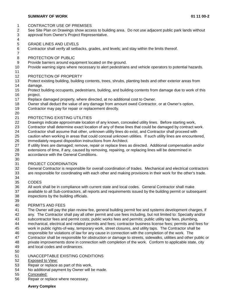
CONTRACTOR USE OF PREMISES 1 See Site Plan on Drawings show access to building area. Do not use adjacent public park lands without 2 approval from Owner’s Project Representative. 3 4 GRADE LINES AND LEVELS 5 Contractor shall verify all setbacks, grades, and levels; and stay within the limits thereof. 6 7 PROTECTION OF PUBLIC 8 Provide barriers around equipment located on the ground. 9 Provide warning signs where necessary to alert pedestrians and vehicle operators to potential hazards. 10 11 PROTECTION OF PROPERTY 12 Protect existing building, building contents, trees, shrubs, planting beds and other exterior areas from 13 damage. 14 Protect building occupants, pedestrians, building, and building contents from damage due to work of this 15 project. 16 Replace damaged property, where directed, at no additional cost to Owner. 17 Owner shall deduct the value of any damage from amount owed Contractor, or at Owner’s option, 18 Contractor may pay for repair or replacement directly. 19 20 PROTECTING EXISTING UTILITIES 21 Drawings indicate approximate location of any known, concealed utility lines. Before starting work, 22 Contractor shall determine exact location of any of these lines that could be damaged by contract work. 23 Contractor shall assume that other, unknown utility lines do exist, and Contractor shall proceed with 24 caution when working in areas that could conceal unknown utilities. If such utility lines are encountered, 25 immediately request disposition instructions from Architect. 26 If utility lines are damaged; remove, repair or replace lines as directed. Additional compensation and/or 27 extensions of time, if any, caused by removing, repairing, or replacing lines will be determined in 28 accordance with the General Conditions. 29 30 PROJECT COORDINATION 31 General Contractor is responsible for overall coordination of trades. Mechanical and electrical contractors 32 are responsible for coordinating with each other and making provisions in their work for the other's trade. 33 34 CODES 35 All work shall be in compliance with current state and local codes. General Contractor shall make 36 available to all Sub-contractors, all reports and requirements issued by the building permit or subsequent 37 inspections by the building officials. 38 39 PERMITS AND FEES 40 The Owner will pay the plan review fee, general building permit fee and systems development charges, if 41 any. The Contractor shall pay all other permit and use fees including, but not limited to: Specialty and/or 42 subcontractor fees and permit costs; public works fees and permits; public utility tap fees, plumbing, 43 mechanical, electrical and related permits and fees; contractor business license fees; permits and fees for 44 work in public rights-of-way, temporary work, street closures, and utility taps. The Contractor shall be 45 responsible for violations of law for any cause in connection with the completion of the work. The 46 Contractor shall be responsible for obstruction or damage to streets, sidewalks, utilities and other public or 47 private improvements done in connection with completion of the work. Conform to applicable state, city 48 and local codes and ordinances. 49 50 UNACCEPTABLE EXISTING CONDITIONS 51 Exposed to View: 52 Repair or replace as part of this work. 53 No additional payment by Owner will be made. 54 Concealed: 55 Repair or replace where necessary. 56

SUMMARY OF WORK 01 11 00-3
Avery Complex
Upon notification from Contractor, Owner will issue change order authorizing Contractor to perform this 1 work and contract sum will be adjusted accordingly. 2 3 4 5 END OF SECTION 6

ALTERNATES 01 23 00-1
Avery Complex
SECTION INCLUDES 1 Submission procedures. 2 Documentation of changes to contract sum/price and contract time. 3 4 REQUIREMENTS 5 Alternates quoted on Bid Form will be reviewed and accepted or rejected at Owner's option. Accepted 6 alternates will be identified in the Owner-Contractor Agreement. Coordinate related work and modify 7 surrounding work to integrate the work of each alternate. 8 9 ALTERNATE BIDS 10 Alternate No. 1 11 Base Bid: Existing exterior wall at door to remain without added roof canopy. 12 Alternate Item: Provide added roof canopy as shown on roof plan A-108 for three locations. Work to 13 include structural framing, roofing, trim, soffits, painting, lighting and anything else to make a completed 14 finished product. Bid alternate price to include one lump sum for all three roofs together. 15 16 Alternate No. 2 17 Base Bid: Existing sidewalks, curbs, site work, and landscaping in front of the building on Avery Street to 18 remain as is. 19 Alternate Item: Provide new sidewalks, site work, landscaping & irrigation per civil sheets 1-13. 20 21 22 23 24 END OF SECTION 25

SUBSTITUTION PROCEDURES 01 25 00-1
Avery Complex
PART 1 - GENERAL 1 2 SECTION INCLUDES 3 Contractor's requirements in the selection of products, manufacturers and procedures for consideration of 4 proposal substitutions. 5 6 QUALIFICATIONS 7 Architect will be sole judge of acceptability of any proposed substitution. Only approved substitutions 8 may be used on contract work. 9 Each request for substitution approval shall include: 10 Identity of product for which substitution is requested; include Specification page number. 11 Identity of substitution; include product description, drawings, photographs, performance and test 12
data, and any other information necessary for evaluation. 13 Quality comparison of proposed substitution with specified product. 14 Changes required in other work because of substitution. 15 Effect on construction Progress Schedule. 16 Cost comparison of proposed substitution with specified product. 17 Any required license fees or royalties. 18 Availability of maintenance service. 19 Source of replacement materials. 20 21 SUBSTITUTIONS DURING BID PERIOD 22 No request for substitution approval will be considered unless written request in triplicate has been 23 submitted on standard form bound herein, and has been received by Architect by 5:00 PM at least 10 24 calendar days prior to bid opening day. 25 Request submitted without self-addressed and stamped envelope will not be individually acknowledged. 26 Architect will issue Addenda prior to bid opening listing all approved substitutions. 27 28 SUBSTITUTIONS AFTER CONTRACT AWARD 29 No request for substitution approval will be considered unless written request in triplicate has been 30 submitted on standard form bound herein. 31 Approval will be granted only when: 32 Specified product can not be delivered without project delay. 33 Specified product has been discontinued. 34 Specified product has been replaced by superior product. 35 Specified product can not be guaranteed as specified. 36 Specified product will not perform properly. 37 Specified product will not fit within designated space. 38 Specified product does not comply with governing codes or regulations. 39 Substitution will be clearly in Owner's interest. 40 Architect will issue Change Order authorizing approved substitutions and revising Contract Sum where 41 appropriate. 42 43 44 END OF SECTION 45
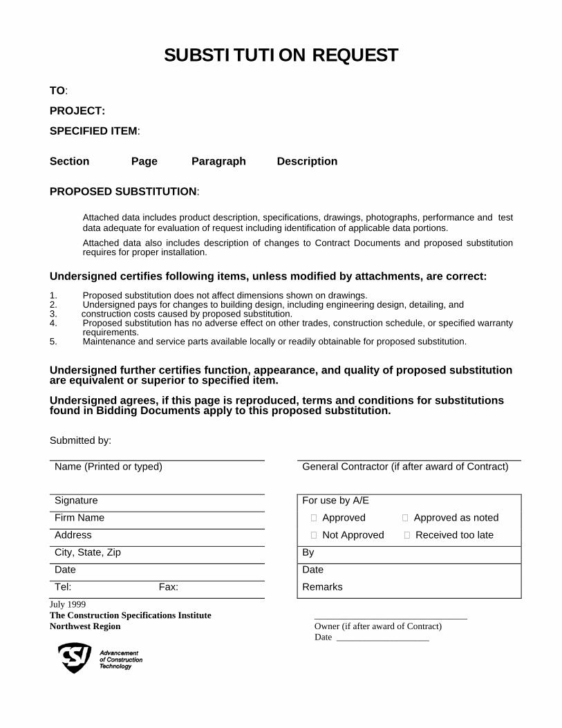
SUBSTITUTION REQUEST
TO: PROJECT: SPECIFIED ITEM: Section Page Paragraph Description PROPOSED SUBSTITUTION:
Attached data includes product description, specifications, drawings, photographs, performance and test data adequate for evaluation of request including identification of applicable data portions. Attached data also includes description of changes to Contract Documents and proposed substitution requires for proper installation. Undersigned certifies following items, unless modified by attachments, are correct: 1. Proposed substitution does not affect dimensions shown on drawings. 2. Undersigned pays for changes to building design, including engineering design, detailing, and 3. construction costs caused by proposed substitution. 4. Proposed substitution has no adverse effect on other trades, construction schedule, or specified warranty
requirements. 5. Maintenance and service parts available locally or readily obtainable for proposed substitution. Undersigned further certifies function, appearance, and quality of proposed substitution are equivalent or superior to specified item. Undersigned agrees, if this page is reproduced, terms and conditions for substitutions found in Bidding Documents apply to this proposed substitution. Submitted by: Name (Printed or typed) General Contractor (if after award of Contract)
Signature For use by A/E
Firm Name � Approved � Approved as noted
Address � Not Approved � Received too late
City, State, Zip By
Date Date
Tel: Fax: Remarks July 1999 The Construction Specifications Institute _________________________________ Northwest Region Owner (if after award of Contract)
Date ____________________
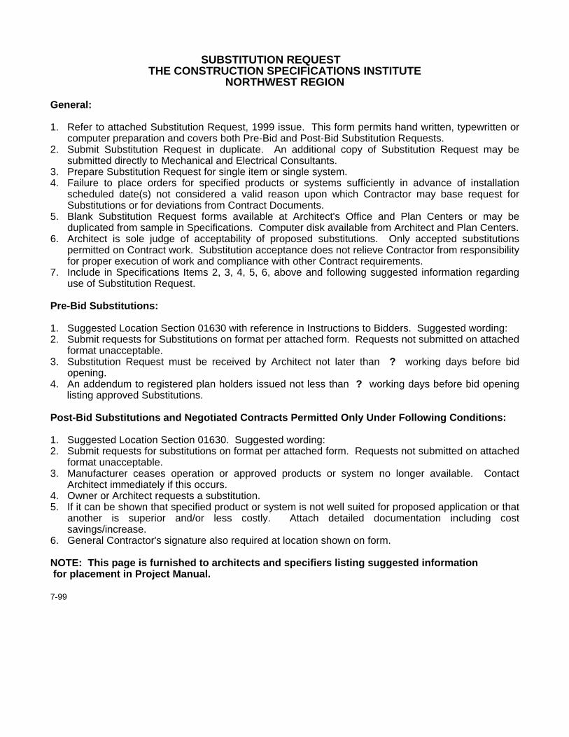
SUBSTITUTION REQUEST
THE CONSTRUCTION SPECIFICATIONS INSTITUTE NORTHWEST REGION
General: 1. Refer to attached Substitution Request, 1999 issue. This form permits hand written, typewritten or
computer preparation and covers both Pre-Bid and Post-Bid Substitution Requests. 2. Submit Substitution Request in duplicate. An additional copy of Substitution Request may be
submitted directly to Mechanical and Electrical Consultants. 3. Prepare Substitution Request for single item or single system. 4. Failure to place orders for specified products or systems sufficiently in advance of installation
scheduled date(s) not considered a valid reason upon which Contractor may base request for Substitutions or for deviations from Contract Documents.
5. Blank Substitution Request forms available at Architect's Office and Plan Centers or may be duplicated from sample in Specifications. Computer disk available from Architect and Plan Centers.
6. Architect is sole judge of acceptability of proposed substitutions. Only accepted substitutions permitted on Contract work. Substitution acceptance does not relieve Contractor from responsibility for proper execution of work and compliance with other Contract requirements.
7. Include in Specifications Items 2, 3, 4, 5, 6, above and following suggested information regarding use of Substitution Request.
Pre-Bid Substitutions: 1. Suggested Location Section 01630 with reference in Instructions to Bidders. Suggested wording: 2. Submit requests for Substitutions on format per attached form. Requests not submitted on attached
format unacceptable. 3. Substitution Request must be received by Architect not later than ? working days before bid
opening. 4. An addendum to registered plan holders issued not less than ? working days before bid opening
listing approved Substitutions. Post-Bid Substitutions and Negotiated Contracts Permitted Only Under Following Conditions: 1. Suggested Location Section 01630. Suggested wording: 2. Submit requests for substitutions on format per attached form. Requests not submitted on attached
format unacceptable. 3. Manufacturer ceases operation or approved products or system no longer available. Contact
Architect immediately if this occurs. 4. Owner or Architect requests a substitution. 5. If it can be shown that specified product or system is not well suited for proposed application or that
another is superior and/or less costly. Attach detailed documentation including cost savings/increase.
6. General Contractor's signature also required at location shown on form. NOTE: This page is furnished to architects and specifiers listing suggested information for placement in Project Manual. 7-99
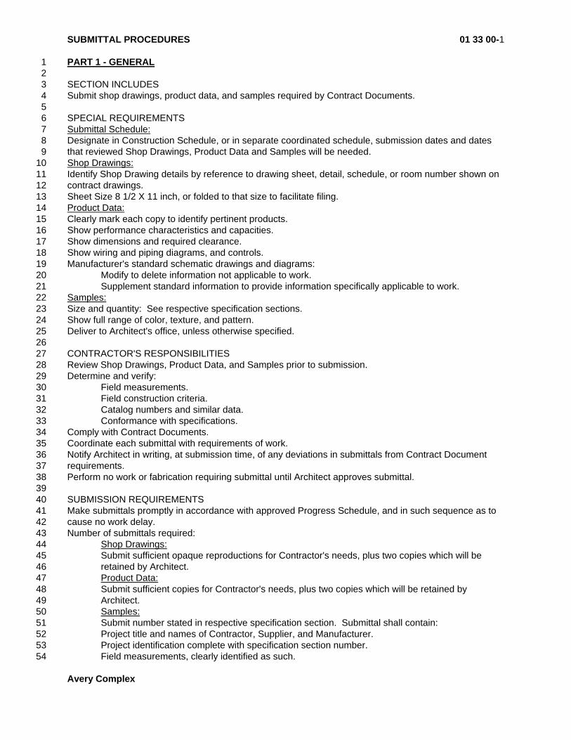
SUBMITTAL PROCEDURES 01 33 00-1
Avery Complex
PART 1 - GENERAL 1 2 SECTION INCLUDES 3 Submit shop drawings, product data, and samples required by Contract Documents. 4 5 SPECIAL REQUIREMENTS 6 Submittal Schedule: 7 Designate in Construction Schedule, or in separate coordinated schedule, submission dates and dates 8 that reviewed Shop Drawings, Product Data and Samples will be needed. 9 Shop Drawings: 10 Identify Shop Drawing details by reference to drawing sheet, detail, schedule, or room number shown on 11 contract drawings. 12 Sheet Size 8 1/2 X 11 inch, or folded to that size to facilitate filing. 13 Product Data: 14 Clearly mark each copy to identify pertinent products. 15 Show performance characteristics and capacities. 16 Show dimensions and required clearance. 17 Show wiring and piping diagrams, and controls. 18 Manufacturer's standard schematic drawings and diagrams: 19 Modify to delete information not applicable to work. 20 Supplement standard information to provide information specifically applicable to work. 21 Samples: 22 Size and quantity: See respective specification sections. 23 Show full range of color, texture, and pattern. 24 Deliver to Architect's office, unless otherwise specified. 25 26 CONTRACTOR'S RESPONSIBILITIES 27 Review Shop Drawings, Product Data, and Samples prior to submission. 28 Determine and verify: 29 Field measurements. 30 Field construction criteria. 31 Catalog numbers and similar data. 32 Conformance with specifications. 33 Comply with Contract Documents. 34 Coordinate each submittal with requirements of work. 35 Notify Architect in writing, at submission time, of any deviations in submittals from Contract Document 36 requirements. 37 Perform no work or fabrication requiring submittal until Architect approves submittal. 38 39 SUBMISSION REQUIREMENTS 40 Make submittals promptly in accordance with approved Progress Schedule, and in such sequence as to 41 cause no work delay. 42 Number of submittals required: 43 Shop Drawings: 44 Submit sufficient opaque reproductions for Contractor's needs, plus two copies which will be 45
retained by Architect. 46 Product Data: 47 Submit sufficient copies for Contractor's needs, plus two copies which will be retained by 48
Architect. 49 Samples: 50 Submit number stated in respective specification section. Submittal shall contain: 51 Project title and names of Contractor, Supplier, and Manufacturer. 52 Project identification complete with specification section number. 53 Field measurements, clearly identified as such. 54

SUBMITTAL PROCEDURES 01 33 00-2
Avery Complex
Relation to critical features and adjacent work. 1 Applicable standards, such as ASTM or Federal Specifications numbers. 2 Identification of deviations from Contract Documents. 3 Identification of resubmittal revisions. 4 At least 6 X 8 inch space on each page for Contractor's and Architect's stamps. 5 Contractor's stamp, signed and certifying that products, field measurements, field construction 6
criteria, and information submitted has been reviewed and accepted by him as accurate and 7 conforming with Contract Documents. 8
9 RESUBMISSION REQUIREMENTS 10 Make any corrections or changes in submittals required by Architect and resubmit until approved. 11 Shop Drawings and Product Data: 12 Revise initial drawings or data, and resubmit as specified for initial submittal. 13 Identify any changes made other than those requested by Architect. 14 Samples: 15 Submit new samples as required for initial submittal. 16 17 ARCHITECT'S RESPONSIBILITIES 18 Review submittals with reasonable promptness. 19 Affix signature, and indicate approval or requirements for resubmittal. 20 Return submittals to Contractor for distribution, or resubmission. 21 22 REQUIRED SUBMITTALS 23 Refer to individual sections in this Project Manual. 24 25 26 END OF SECTION 27

REFERENCES 01 42 00-1
Avery Complex
REFERENCED SPECIFICATIONS AND STANDARDS 1 For products or workmanship specified by Referenced Specification or Standard, comply with 2 requirements of the Specification or Standard, except when more rigid requirements are specified or are 3 required by governing codes. 4 Except where a specific date is specified, the date of Referenced Specification or Standard is that in 5 effect as of the date of Owner-Contractor Agreement. 6 Obtain a copy of all Referenced Specifications and Standards, and maintain at jobsite during the specific 7 work until Substantial Completion of the Project. 8 Wherever referenced Standard Specifications or Standards issued by manufacturers or other similar 9 organizations contain provisions which conflict with the Contract Documents the Contract Documents 10 shall govern. 11 12 REFERENCED REGULATORY AGENCIES 13 ADAAG Americans with Disabilities Act (ADA) Accessibility Guidelines for Buildings and 14
Facilities 15 Office on the Americans with Disabilities Act 16 Civil Rights Division 17 U.S. Department of Justice 18 Washington, D.C. 20530 19 www.access-board.gov 20 21 AASHTO American Association of State Highway and Transportation Officials 22 444 North Capital Street, NW 23 Washington, D.C 20001 24 www.aashto.org 25 26 ANSI American National Standards Institute 27 1430 Broadway 28 New York, NY 10018 29 www.ansi.org 30 31 ASHRAE American Society of Heating, Refrigeration and Air-Conditioning Engineers 32 1791 Tullie Circle NE 33 Atlanta, GA 30329 34 www.ashrae.org 35 36 ASCE American Society of Civil Engineers 37 1801 Alexander Bell Drive 38 Reston, VA 20191 39 40 ASTM American Society for Testing and Materials 41 1916 Race Street 42 Philadelphia, PA 19103 43 www.astm.org 44 45 CS Commercial Standards of the Commodities Division of the 46 Department of Commerce 47 Washington, D.C. 20006 48 www.doc.gov 49 50 Fed. Spec. Federal Specifications of the United States General Services Administration 51 Specifications and Consumer Information Distribution Section (WF SIS) 52 Washington Navy Yard, Building 197 53 Washington, D. C. 20407 54

REFERENCES 01 42 00-2
Avery Complex
www.apps.fss.gsa.gov/pub/fedspecs/iindex.cfm 1 FMG FM Global [formerly Factory Mutual (FM)] 2 1301 Atwood Avenue 3 P.O. Box 7500 4 Johnston, RI 02919 5 www.fmglobal.com 6 7 IBC International Building Code 8 Published by International Code Council (see ICC below) 9 10 ICBO International Conference of Building Officials 11 5360 Workman Mill Road 12 Whittier, CA 90601-2298 13 14 ICC International Code Council 15 5203 Leesburg Pike, Suite 708 16 Falls Church, VA 22041-3401 17 www.intlcode.org 18 19 IMC International Mechanical Code 20 Published by International Code Council (see ICC above) 21 22 NEC National Electric Code published by the 23 National Fire Protection Association 24 (See NFPA below) 25 26 NFPA National Fire Protection Association International 27 Battery March Park 28 Quincy, MA 02269 29 www.nfpa.org 30 31 OSSC Oregon Structural Specialty Code 32 Building Codes Division 33 1535 Edgewater Street NW 34 Salem, OR 97310 35 www.oregonbcd.org 36 37 PS Product Standards of the Commodities Division of the 38 Department of Commerce 39 Washington, D. C. 40 www.doc.gov 41 42 UFAS Uniform Federal Accessibility Standards 43 United States Architectural and Transportation Barriers 44 Compliance Board 45 1111 Eighteenth Street NW, Suite 501 46 Washington, D.C. 20036-3894 47 www.access-board.gov 48 49 UL Underwriter's Laboratories 50 333 Pfingston Road 51 Northbrook, Illinois 60062 52 www.ul.com 53 54 55

REFERENCES 01 42 00-3
Avery Complex
END OF SECTION 1

QUALITY CONTROL 01 45 00-1
Avery Complex
PART 1 - GENERAL 1 2 SECTION INCLUDES 3 Inspection and testing laboratory qualifications, duties, and responsibilities. Contractor's quality control 4 requirements. Contractor’s and Owner’s responsibilities. 5 6 COSTS 7 Paid by Owner: 8 For Testing Laboratory Services specified in this section, 9 For special inspections of concrete, masonry and welding specified in building code. 10 Paid by Contractor 11 For inspection and testing required by laws, ordinances, regulations, and orders of Public Authorities, but 12 not specified in this section. 13 For reinspections and retesting required because of defective work or ill-timed notices. 14 15 QUALIFICATIONS OF LABORATORY 16 Independent laboratory acceptable to Architect and Building Official. 17 Meet "Recommended Requirements for Independent Laboratory Qualification," latest edition, published 18 by American Council of Independent Laboratories, 1050 17th Street NW, Suite 1000, Washington, 19 D.C. 20038, (202) 887-5872. 20 Meet ASTM E-329 latest edition, "Standards of Recommended Practice for Inspection and Testing 21 Agencies for Concrete and Steel as used in Construction." 22 23 LABORATORY'S DUTIES 24 Provide qualified personnel for specified inspections, sampling, and testing. 25 Ascertain and certify compliance with contract documents. 26 Promptly submit written inspection and test reports to Owner's Representative, Building Official, 27 Contractor, and Architect. 28 Include the following on test reports: 29 Date issued. 30 Project title and locations. 31 Testing laboratory name and address. 32 Inspector's name. 33 Date of inspection or sampling. 34 Record of temperature and weather. 35 Date of test. 36 Identification of product tested. 37 Test location in project. 38 Type of inspection or test. 39 Observations regarding compliance with contract documents. 40 Laboratory is not authorized to: 41 Release, revoke, alter, or enlarge on contract document requirements. 42 Approve or accept any portion of work. 43 Perform any duties for Contractor. 44 45 CONTRACTOR'S RESPONSIBILITIES 46 Cooperate with laboratory personnel, provide access to work and to manufacturer's operations. 47 Provide to laboratory, representative samples of materials to be tested, in required quantities. 48 Furnish casual labor and facilities: 49 Provide access to work to be tested. 50 To obtain and handle test samples at site. 51 To facilitate inspections and tests. 52 For laboratory's exclusive use for storage and curing of test samples until removed to laboratory. 53 Notify laboratory at least 24 hours in advance of operations to allow for personnel assignments and test 54 scheduling. 55

QUALITY CONTROL 01 45 00-2
Avery Complex
Repair test holes to match original conditions. 1 2 LIABILITY 3 Laboratory service is provided for Owner's self-assurance and in no way relieves Contractor's 4 responsibility to comply with Contract Documents. 5 6 PART 2 - PRODUCTS 7 8 Not Used 9 10 PART 3 - EXECUTION 11 12 SLAB MOISTURE 13 Testing Standard: ASTM F 1869-98 standard test method for measuring vapor emission rate at interior 14 concrete slabs on grade requiring floor covering using anhydrous calcium chloride. 15 Testing Procedure: Sinak Dome Test vapor emission measuring system; Sinak Corporation, 861 Sixth 16 Avenue, Suite 411, San Diego, CA 92101, phone 800-523-3147. 17 18 EARTHWORK DENSITY 19 Method: ASTM D 698. 20 Provide tests for each 800 tons of gravel and 1 per 2,000 sq. ft. subgrade for each layer of fill and backfill, 21 for pavement beds in cuts if any, and to any other earthwork construction which will support finished 22 surfaces or structures. 23 24 ASPHALT PAVING 25 Conduct the following tests: 26 Compacted base-rock field density. 27 Placement tests per 300 tons of asphalt to determine asphalt-cement content, gradation of 28
aggregate, voids, temperature, and Marshall stability of mix. 29 Finish product core sample to check compaction and voids. 30 31 CAST-IN-PLACE CONCRETE 32 Test Concrete Slump as follows: 33 Follow ASTM C-143 and C-172. 34 Prepare tests from same batch as that employed in preparing strength test specimens, unless otherwise 35 directed. 36 If measured slump falls outside specified limits retest immediately from another portion of same load. In 37 event of second failure concrete shall be considered as failing specification requirements. 38 Test Concrete Compressive Strength as follows: 39 Follow ASTM C-31, C-39, and C-172. 40 Prepare not less than 4 test cylinders for each 100 cubic yards or less for each strength of concrete cast 41 in any one day. 42 Break 2 cylinders at 7 days of age, and unless otherwise directed break remainder at 28 days. 43 If any one set of two cylinders does not develop full design strength at 28 days of age, cores may be 44 called for. All coring costs paid by Contractor. 45 If tests indicate concrete has failed to meet specifications, replace substandard material when directed by 46 Architect. 47 Test Concrete Air Content as Follows: 48 Follow ASTM C-231. 49 Test each cylinder containing air entrainment. 50 51 STRUCTURAL STEEL 52 Inspection of fabrication shop and jobsite as follows: 53 Qualification of high-strength bolt and welding procedure and personnel. 54 Inspection of specification conformance of fabricated structural steel member and assemblies. 55
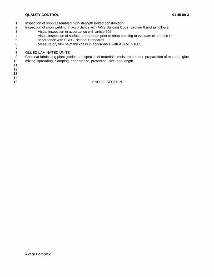
QUALITY CONTROL 01 45 00-3
Avery Complex
Inspection of shop assembled high-strength bolted construction. 1 Inspection of shop welding in accordance with AWS Building Code, Section 6 and as follows: 2 Visual inspection in accordance with article 605. 3
Visual inspection of surface preparation prior to shop painting to evaluate cleanness in 4 accordance with SSPC Pictorial Standards. 5
Measure dry film paint thickness in accordance with ASTM D-1005. 6 7 GLUED LAMINATED UNITS 8 Check at fabricating plant grades and species of materials, moisture content, preparation of material, glue 9 mixing, spreading, clamping, appearance, protection, size, and length. 10 11 12 13 14 END OF SECTION 15

TEMPORARY FACILITIES AND CONTROLS 01 50 00-1
Avery Complex
PART 1 - GENERAL 1 2 SECTION INCLUDES 3 Temporary utilities and miscellaneous temporary facilities required during construction. 4 5 JOB CONDITIONS 6 Establish and initiate use of each temporary facility at time first reasonably required for proper 7 performance of the work. Terminate use and removal of temporary facilities at earliest reasonable time 8 when no longer needed. 9 Comply with governing codes and regulations. 10 Pay required fees and easement assessments. 11 Enforce safe and sanitary practices. 12 Maintain clean facilities. 13 Prevent interference with Owner's normal use of his own facilities. 14 Prevent wasteful utility uses. 15 Should Owner occupy part of facility, Owner will pay his proportional utility cost. 16 17 PART 2 - PRODUCTS 18 19 MATERIALS AND EQUIPMENT 20 Materials and equipment may be new or used, but must be suitable and adequate in capacity for required 21 usage. 22 23 PART 3 - EXECUTION 24 25 PROJECT SIGN 26 3/4 inch waterproof plywood, 4 x 8 feet size, framed with suitable moldings. 27 Provide immediately after contract is signed, in accordance with Architect's design. 28 Paint two coats prepared paint, color selected. 29 Employ professional sign supplier approved by Architect to letter names of: 30 Project 31 Owner 32 Architect 33 Consulting Engineers 34 General Contractor 35 Secure signboard to nominal 4 x 4 inch wood posts set 4 feet into ground. 36 Place no other signs or advertisements on premises. 37 38 FIELD OFFICE 39 General: 40 Provide substantial weathertight office building on premises where directed. 41 Provide heat, electric light, and janitor service. 42 At Contractor's option, portable buildings suitable for office use may be used. 43 Do not use field office for storage buildings or personnel housing. 44 Required Furnishings: 45 1 plan table large enough to hold open set of contract drawings. 46 1 plan rack large enough to store contract drawings, including record drawings. 47 1 shelf large enough to store project manuals and other similar documents. 48 1 standard lockable, legal size, metal filing cabinet to store shop drawings and other project 49
correspondence. 50 One waste basket. 51 52 TELEPHONE 53 Land line phone not required, however, provide wall-mounted directory at a prominent location in the field 54 office listing name and business phone number of at least the following: 55

TEMPORARY FACILITIES AND CONTROLS 01 50 00-2
Avery Complex
Each Contractor and Subcontractor 1 Architect 2 Architect's Consulting Engineers 3 Testing laboratories 4 Physicians 5 Hospitals 6 Ambulance 7 Local Fire Department 8 Do not use Owner's existing telephone system. 9 10 ENVIRONMENTAL PROTECTION 11 General: 12 Establish procedures among subcontractors to prevent environmental harm (air pollution, water pollution, 13 soil erosion, excessive noise, excessive odors and similar problems). 14 Comply with environmental regulations. 15 Complete construction operations by methods that minimize pollution and contamination. 16 Noise: 17 Avoid construction operations that produce harmful noise levels. Restrict use of noisy equipment and 18 operations to hours that will have minimum affect on workers and neighboring buildings. 19 Dust Control: 20 Provide dust-tight enclosures and/or sprinkle with water where necessary to control dust. 21 Do not use enough water to cause flooding, icing, or contaminated runoff. 22 Protect existing return air duct systems against demolition dust by providing filter media across duct 23 openings. Replace dirty media with clean when necessary to protect systems. 24 Water Run-off Control: 25 Provide erosion control measures as required by Construction Documents. Provide additional measures 26 if necessary to control erosion. 27 If high water table is encountered during construction, and water removal is necessary from excavations, 28 lower water table by means of pumping, trenching below water table or other acceptable means to ensure 29 drainage, proper soil compaction and placement of materials. 30 Dispose of excess water. 31 Where practical, direct excess water to storm water drainage system. Pre-treat water if necessary. 32 Conform to anti-pollution laws and regulations. 33 34 TEMPORARY WATER 35 Water is available on site from existing building. 36 Mechanical contractor shall provide and maintain water for the following purposes: 37 Service standpipe equipped with sufficient 3/4 inch hydrants that any work Center can be 38
reached with 100 ft. extension hose. Each Contractor shall provide his own extension hoses. 39 Drinking water dispensed in single-service containers or sanitary fountains. 40 Maintain cool as practicable, clean and fresh. 41 Maintain adequate volume. 42 Protect against freezing. 43 Water, in quantities judged reasonable by Owner, will be furnished without charge by Owner. 44 Ascertain where water service is available, provide required connections, and extend system to work 45 area. 46 47 TEMPORARY TOILET FACILITIES 48 General Contractor shall provide at the rate of one fixture for each 40 workers. 49 Type: Comply with Building Code. 50 For enclosures accommodating more than one person, provide privacy screens for each toilet fixture. 51 If both men and women are working, provide separate facilities for each sex. 52 Maintain sufficient light and ventilation. 53 Maintain each toilet with toilet tissue on suitable dispenser. 54 Remove temporary toilets and use building fixtures as soon as feasible. 55

TEMPORARY FACILITIES AND CONTROLS 01 50 00-3
Avery Complex
Disinfect premises after removal and restore to specified condition. 1 Do not use Owner's existing facilities. 2 3 TEMPORARY ENCLOSURES 4 Provide sufficient enclosure to prevent infiltration of rainwater, wind and other elements, and prevent 5 undue heat loss from within enclosed area. 6 7 TEMPORARY BARRICADES 8 Provide all necessary to protect public against injury and protect project against damage and 9 unauthorized intrusion. 10 11 TEMPORARY FIRE PROTECTION 12 Provide and maintain necessary facilities and equipment to safeguard project against fire damage. 13 14 TEMPORARY FENCING 15 Provide where shown on drawings, 6 ft. high galvanized steel chain-link fencing. 16 17 TEMPORARY ELECTRICITY 18 Power: 19 Electrical Contractor shall provide and maintain structurally and electrically sound temporary power 20 distribution system as follows: 21 Sufficient 20 amp load centers that any work area can be reached with 100 foot extension cord. 22
Each Contractor shall provide his own grounded, UL approved extension cords. 23 Load centers shall include: 24 Weatherproof distribution boxes. 25 Circuit breakers for each outlet. 26 Equipment grounding continuity for entire system. 27 Power at proper voltage for: 28 Temporary field offices. 29 Temporary storage and construction buildings. 30 Temporary lighting and power. 31 Temporary heating and ventilating. 32 Pumping. 33 Testing and checking equipment. 34 Owner's facilities continuous operation during electrical services change over. 35 General Contractor and Subcontractors shall provide their own power and distribution system for field 36 welders and any other special power beyond that specified herein. 37 Lighting: 38 Provide and maintain temporary lighting as follows: 39 30 ft. candles measured 3 feet above floor in spaces during work. Energize permanent lighting 40
fixtures prior to painting, except where fixtures are mounted on walls or ceilings to be painted. 41 Maintain from 14 minutes prior to until 15 minutes past scheduled work hours. Maintain 5 ft 42 candles measured 3 feet above floor as necessary to prevent damage or injury. Maintain when 43 authorized Personnel are present. Provide light control switches at area entrances, or successive 44 areas, so personnel access to project can be through lighted areas. 45
Wiring: 46 Prevent conflict with General Construction. 47 Maintain cords clear of walkways and other heavy traffic areas. 48 Power Source: 49 Electricity, in quantities judged reasonable by Owner, will be furnished without charge by Owner. 50 Ascertain where electrical service is available, provide required connections, and extend system to work 51 area. 52 53 TEMPORARY EXTERIOR ENCLOSURES 54 Provide temporary weather-tight closure of exterior openings to accommodate acceptable working 55

TEMPORARY FACILITIES AND CONTROLS 01 50 00-4
Avery Complex
conditions and protection of products, to allow for tempory heating and maintenance of required ambient 1 temperatures identified in individual specification Sections, and to prevent entry of unauthorized persons. 2 Provide access doors with self closing hardware. 3 Provide temporary roofing as required. 4 After work is started, Contractor shall provide a watertight roof enclosure at the end of each day’s work. 5 6 TEMPORARY HEATING AND VENTILATING 7 Provide temporary heat and ventilation throughout enclosed construction areas to: 8 Facilitate work progress. 9 Protect work and products against dampness and cold. 10 Prevent moisture condensation on surfaces. 11 Provide suitable ambient temperatures and humidity levels for installation and curing of products. 12 Provide adequate ventilation to meet health regulations for safe working environment. 13 Mechanical Contractor shall expedite work so permanent facilities will be structurally, mechanically, and 14 electrically sound throughout and ready to provide "temporary" service as soon as possible. 15 Operate no permanent heating, ventilating, or air conditioning equipment without Mechanical Engineer's 16 authorization that equipment is properly installed, has clean air filters, and is otherwise properly 17 prepared. Replace temporary air filters with new units and restore system to like-new condition 18 immediately prior to turning project over to Owner. 19 Temporary portable heaters, as may be required, shall be provided by General Contractor. 20 Continue temporary heating and ventilation until Owner occupies or finally accepts project, which ever the 21 sooner. 22 Maintain ventilated areas in clean condition to avoid undue circulation of dust and air-borne particles. 23 Minimum temperatures to be maintained: 24 Generally, 24 hours a day: 40o minimum. 25 Temperatures required for work of various trades: See technical specific specification sections. 26 Fuel costs for temporary heating shall be paid by General Contractor. 27 28 TEMPORARY VERTICAL TRANSPORTATION 29 General Contractor shall provide and pay costs for temporary stairs, ramps, personnel hoists, chutes, 30 etc., required for execution of work of all trades. Subcontractors shall provide their own material hoists 31 and scaffolds. 32 Elevator: 33 Do not use new elevator unless allowed in writing by elevator manufacturer. If allowed: 34 Provide temporary wall and floor covering. 35 Provide temporary covering only when using elevator to transport materials, tools, equipment and related 36 construction items. Remove temporary covering when not required for project use. 37 Clean all elevator surfaces after removal of temporary covering. Remove dirt and debris from 38 construction operations that may be tracked into elevator. 39 40 VEHICLE PARKING AND MATERIAL STORAGE 41 Coordinate with Owner’s Representative. 42 43 TEMPORARY EQUIPMENT 44 Thermometer: 45 Maintain one 10 inch minimum size outdoor thermometer. Mount at convenient location not in direct 46 sunlight. 47 Temperature Range: Minus 20oF to plus 110oF. 48 49 FACILITIES REMOVAL 50 Remove temporary facilities, at project completion, or sooner, if directed. 51 Repair damage, if any, resulting from temporary facilities. 52 53 54 END OF SECTION 55

PRODUCT REQUIREMENTS 01 60 00-1
Avery Complex
PART 1 - GENERAL 1 2 SECTION INCLUDES 3 General requirements for transportation, handling, storage and protection of materials and equipment. 4 Contractor’s options in selection of products, manufacturers and procedures. 5 6 PERFORMANCE REQUIREMENTS 7 Materials and Equipment incorporated into work shall: 8 Conform to applicable specifications and standards. 9 Comply with size, make, type, and quantity specified, unless otherwise approved in writing. 10 Manufactured and Fabricated Products: 11 Manufactured like parts of duplicate units to standard sizes and gauges, to be interchangeable. 12 Two or more items of same kind shall be identical, and by same manufacturer. 13 Products shall be suitable for service conditions. 14 Equipment shall comply with capacity, sizes, and dimensions shown or specified, unless 15
otherwise approved in writing. 16 Do not use Materials or Equipment for any purpose other than that for which designed or specified. 17 18 CONTRACTOR'S OPTIONS 19 For products specified only by referenced standard, select any product meeting standard. 20 For products specified by naming several products, select any one complying with specifications. 21 For products specified by naming one or more products and "or accepted substitute," select any one 22 specified product or submit request for substitution as required below. 23 24 INAPPROPRIATE PRODUCTS AND METHODS 25 If Contractor believes that any specified product, method, or system is inappropriate for use he shall, if 26 possible, so notify Architect at least 5 working days prior to bid opening, and if not possible such notice 27 shall be given before performing work in question. 28 If notice of objection is not received within the specified time limits, it will be assumed by the Owner that 29 Contractor agrees that specified products, methods, and systems are not inappropriate for use on this 30 project. 31 32 SALVAGE MATERIAL 33 All salvageable material will remain the property of the Owner, unless otherwise noted or released for the 34 disposal by the Contractor. 35 36 NUMBER OF PRODUCTS REQUIRED 37 Wherever in Specifications a product is referred to in singular number, such reference shall include as 38 many such products as are shown on Drawings or are required to complete the work. 39 40 MANUFACTURER'S INSTRUCTIONS 41 Perform work in accord with Manufacturer's instructions. 42 Do not omit preparatory or installation procedures required by Manufacturer, unless specifically modified 43 or exempted by Contract Documents. 44 When Contract Documents require work to comply with Manufacturer's instructions, obtain and distribute 45 such instructions to parties performing work including two copies to Architect. Maintain one set at job site 46 during installation and until acceptance. 47 Handle, install, connect, clean, condition, and adjust products in strict accord with such instructions and in 48 conformance with specified requirements. 49 Should job conditions or specified requirements conflict with Manufacturer's instructions, consult Architect 50 for further instructions. 51 Do not proceed with work without clear instructions. 52 53 TRANSPORTATION AND HANDLING 54 Arrange product deliveries in accord with construction progress schedule; coordinate to avoid conflict with 55
PRODUCT REQUIREMENTS 01 60 00-2
Avery Complex
work and site conditions. 1 Deliver products undamaged, in Manufacturer's original containers or packaging, and with legible 2 identifying labels intact. 3 Immediately upon delivery, inspect shipments to assure that products are properly protected and 4 undamaged. 5 6 STORAGE AND PROTECTION 7 Follow Manufacturer's instructions. 8 Maintain product identity labels legible and intact. 9 Store products subject to weather-damage in weathertight enclosures. 10 Maintain storage room temperature and humidity within ranges required by Manufacturer's instructions. 11 Maintain reasonable protection against product theft and vandalism. 12 Exterior Storage: 13 Store fabricated products above ground, on blocking or skids; prevent product damage and discoloration. 14 Cover products subject to deterioration with impervious sheet coverings; provide adequate ventilation to 15 prevent condensation. 16 Store loose granular materials in well-drained area on solid surface to prevent mixing with foreign matter. 17 Inspection of Stored Products: 18 Arrange storage to permit easy access for inspection. 19 Make periodic inspections of stored products to assure that products are maintained as specified and are 20 free from damage, discoloration, and deterioration. 21 Protection after Installation: 22 Provide substantial coverings as necessary to protect installed products against damage and 23 discoloration. Remove covering when no longer needed. 24 25 26 END OF SECTION 27

FIELD ENGINEERING 01 71 23-1
Avery Complex
PART 1 - GENERAL 1 2 SECTION INCLUDES 3 Provide Field Engineering required for project, including the following: 4 Layout survey work required for execution of project. 5 Civil, structural, and other engineering necessary to execute Contractor's construction methods. 6 7 WORK BY OWNER 8 Owner's Representative will, upon request, locate existing control points and property line corner stakes 9 indicated on Drawings. 10 11 SUBMITTALS 12 Submit Engineer's names and addresses to Architect. 13 When requested, submit documentation to verify engineering accuracy to Architect. 14 Submit certificate signed by Surveyor certifying work layout conforms to Contract Documents. 15 16 QUALITY ASSURANCE 17 Engineer's Qualifications: 18 Land Surveyor: Oregon State Registered Land Surveyor. 19 Engineers: State-licensed in specific engineering to be performed. 20 Records: Maintain complete and accurate log of control for survey work as it progresses. 21 22 PART 2 - PRODUCTS 23 24 EQUIPMENT 25 Maintain at project site the following: 26 Complete transit or laser level 27 Leveling rod 28 Plumb bob 29 6 ft. and 10 ft. straight edges 30 100 ft. long measuring tape 31 32 PART 3 - EXECUTION 33 34 SURVEY REFERENCE POINTS 35 Existing Points: See Drawings. 36 Locate existing points prior to starting site work, and preserve during construction. 37 Make no changes to existing points without Architect's approval. 38 Notify Architect when any point is lost or destroyed, or requires relocation. 39 Employ Registered Surveyor to replace any lost, destroyed, or relocated points. 40 41 PROJECT LAYOUT 42 Establish at least two permanent bench marks on the site referenced to existing control points. 43 Record bench mark locations, with horizontal and vertical dimensions, on Project Record Drawings. 44 Using surveying instruments establish lines and levels for the following: 45 Site improvements. 46 Stakes for grading, fill, and topsoil placement. 47 Utility slopes and invert elevations. 48 Batter boards for structures. 49 Building wall and column locations, floor elevations, and similar elements. 50 Periodically verify layout accuracy. 51 52 END OF SECTION 53

CUTTING AND PATCHING 01 73 29-1
Avery Complex
PART 1 - GENERAL 1 2 SECTION INCLUDES 3 Procedures and limitations for cutting, removing, replacing or refinishing products or materials after initial 4 installation of such products or materials. 5 6 EXTENT OF WORK 7 Perform all cutting, fitting, and patching, including attendant excavation and backfill, required to complete 8 work or to: 9 Make work fit properly together. 10 Uncover work for installation of ill-timed work. 11 Remove and replace defective work and work not conforming to Contract Documents. 12 Remove samples of installed work for testing. 13 Provide penetrations through non-structural surfaces for mechanical and electrical work. 14 15 SUBMITTALS 16 Submit written request for cutting approval to Architect well in advance of any cutting which affects: 17 Work of Owner 18 Structural value or integrity of any completed or existing work. 19 Waterproof value or integrity of any weather-exposed or moisture-resistant work. 20 Visual qualities of any sight-exposed work. 21 Request shall include: 22 Project identification. 23 Description of affected work. 24 Necessity for cutting, alteration, or excavation. 25 Effect on Owner's work. 26 Effect on structural or weatherproof integrity on completed or existing work. 27 Description of proposed work including: 28 Extent of cutting, patching, alteration, or excavation. 29 Trades who will execute work. 30 Products proposed for use. 31 Extent of required refinishing. 32 Alternatives to cutting and patching. 33 Cost proposal, when applicable. 34 Submit written notice to Architect designating date and time work will be performed. 35 36 PART 2 - PRODUCTS 37 38 MATERIALS 39 Products similar to those specified elsewhere in this Project Manual: 40 Follow those specifications. 41 Other Products: 42 Follow Architect's instructions. 43 44 PART 3 - EXECUTION 45 46 EXISTING CONDITIONS 47 Inspect existing conditions and identify work subject to damage or movement caused by proposed cutting 48 and patching. 49 After uncovering work, inspect conditions affecting products installation or performance. Report 50 unsatisfactory and questionable conditions to Architect in writing; do not proceed with work until Architect 51 provides further instructions. 52 53 54 PREPARATION 55

CUTTING AND PATCHING 01 73 29-2
Avery Complex
Maintain adequate temporary support necessary to assure structural integrity of affected work. 1 Protect other portions of project work against damage and discoloration. 2 Protect work exposed by cutting against damage and discoloration. 3 4 PERFORMANCE 5 Provide proper surfaces for repairs. 6 Employ original installer or qualified contractor to perform cutting and patching for: 7 Weather-exposed or moisture-resistant surfaces. 8 Sight-exposed finished surfaces. 9 Restore cut or removed work with new products to provide work complete in accordance with Contract 10 Documents. 11 Fit work air-tight to pipes, sleeves, ducts, conduits, and other surface penetrations. 12 Where patching occurs refinish entire surface to provide even finish to match adjacent work as follows: 13 Continuous Surfaces: Refinish to nearest intersection. 14 Assemblies: Refinish entire unit. 15 16 CUTTING STRUCTURAL FRAMING 17 Exposed Members: 18 Not permitted, unless shown on Drawings or otherwise approved. 19 Concealed Horizontal Lumber Framing Members: 20 Notches prohibited: 21 In tension edge of nominal 4 inch or deeper members, except at member ends. 22 In middle 1/3 of member length. 23 Greater than 1/6 of member; depth. 24 Cover notches with metal plate; Simpson SS Stud Shoe, or approved. 25 Bored holes prohibited: 26 Greater than 1/3 of member depth. 27 Within 2 inches of member top or bottom. 28 Cover member edge at bored holes with metal plate; Simpson NS Nail Stopper, or approved. 29 Concealed Lumber Vertical Framing Members: 30 Maximum notching depth: 31 At exterior and bearing walls: 25 percent of member width. 32 At all other locations: 40 percent of member width. 33 Cover notches with metal plate; Simpson SS Stud Shoe, or approved. 34 Bored holes Prohibited: 35 Within 5/8 inches of member edge. 36 Within same section as cut or notch. 37 Maximum size of bored holes: 38 At Bearing Walls: 40 percent of member width. 39 At all other locations: 60 percent of member width. 40 Cover member edge at bored holes with metal plate; Simpson NS Nail Stopper, or accepted 41
substitute. 42 43 CLEANING AND REPAIRING 44 Including work of this section, clean, repair and touch-up, or replace when directed, products which have 45 been soiled, discolored, or damaged by work of this section. Remove debris from project site upon work 46 completion or sooner, if directed. 47 48 49 END OF SECTION 50

FINAL CLEANING 01 74 23-1
Avery Complex
PART 1 - GENERAL 1 2 SECTION INCLUDES 3 Cleaning and trash removal during work progress, and at work completion. 4 5 REGULATORY AGENCY REQUIREMENTS 6 Comply with governing codes, regulations, ordinances, and anti-pollution requirements. 7 8 PART 2 – PRODUCTS 9 10 CLEANING MATERIALS 11 Use only those which will not create hazards to health or property and which will not damage surfaces. 12 Use only those recommended by Manufacturer of surface to be cleaned. 13 Use only on surfaces recommended by cleaning material manufacturer. 14 15 PART 3 – EXECUTION 16 17 GENERAL 18 Follow cleaning material and surface manufacturer’s instructions. 19 20 DURING CONSTRUCTION 21 Periodically clean to maintain work, site and adjacent properties free from accumulations of waste, 22 rubbish, and windblown debris, resulting from construction operations. 23 Provide on-site containers for collection of waste, debris, and rubbish. 24 Periodically remove waste material, debris, and rubbish and legally dispose of away from project site. 25 26 DUST CONTROL 27 Clean interior surfaces prior to painting, and continue cleaning as needed until painting is complete. 28 Schedule cleaning so that resultant dust and contaminants will not fall on wet or newly coated surfaces. 29 30 FINAL CLEANING 31 Remove waste, debris, and surplus material from project site. 32 Clean grounds as follows: 33 Paved Surfaces: Remove stains, spills, and foreign substances and sweep clean. 34 Other Surfaces: Rake clean. 35 In addition to debris removal and cleaning specified in other sections, clean exposed-to-view interior and 36 exterior surfaces. 37 Employ skilled workers to perform final cleaning. 38 Remove any temporary protection and labels not required to remain. 39 Remove grease, mastic, adhesive, dust, dirt, stains, fingerprints, labels, and other foreign matter from 40 sight-exposed interior and exterior surfaces. 41 Wash and shine glazing, including mirrors. 42 Polish glossy surfaces to clear shine. 43 Vacuum carpet and similar soft materials. 44 Clean equipment surfaces; remove excess lubricants. 45 Clean and sanitize food service equipment and plumbing fixtures. 46 Ventilating system, if used during construction: 47 Permanent Filters: Clean 48 Disposable Filters: Replace 49 Clean Ducts, Blowers, and Coils: Clean 50 Clean light fixtures and lamps. 51 Remove waste, debris, and foreign matter from roofs and roof drainage system. 52 Maintain structure and components clean until substantial completion. 53
END OF SECTION 54

CLOSEOUT PROCEDURES 01 77 00-1
Avery Complex
PART 1 - GENERAL 1 2 SECTION INCLUDES 3 Contract condition requirements and specified administrative procedures in closing out work. 4 5 SUBSTANTIAL COMPLETION 6 When Contractor considers work substantially complete, as defined in General Conditions, he shall 7 submit to the Architect: 8 Written notice that work, or designated portion thereof, is substantially complete. 9 List of items to be completed or corrected. 10 Architect will, as soon as possible thereafter; make inspection to determine completion status. 11 Should Architect determine that work is not substantially complete: 12 Architect will promptly notify Contractor in writing, giving reasons therefore. 13 Contractor shall remedy work deficiencies, and send second Notice of Substantial Completion to 14
Architect. 15 Architect will reinspect. 16 When Architect concurs that work is substantially complete, he will: 17 Prepare Certificate of Substantial Completion using AIA Form G704, accompanied with 18
Contractor's list of items to be completed or corrected. 19 Submit Certificate to Owner and Contractor for their written acceptance of the responsibilities 20
assigned to them in the Certificate. 21 22 FINAL INSPECTION 23 When Contractor considers work complete, he shall submit written certification that: 24 Contract Documents have been reviewed. 25 Contractor has inspected work for compliance with Contract Documents. 26 Work has been completed in accordance with Contract Documents. 27 Equipment and Systems have been tested in presence of Owner's Representative and are 28
operational. 29 Work is complete and ready for final inspection. 30 Architect will inspect work to verify completion status as soon as possible after receipt of Contractor's 31 certification. 32 Should Architect consider work incomplete or defective: 33 Architect will promptly notify Contractor in writing, listing incomplete or defective work. 34 Contractor shall immediately remedy deficiencies, and send second written certification to 35
Architect that work is complete. 36 Architect will reinspect work. 37 When Architect finds work acceptable under Contract Documents, he shall request Contractor to make 38 closeout submittals. 39 40 REINSPECTION FEES 41 Should Architect be required to make more than two final inspections due to Contractor's failure to correct 42 specified deficiencies: 43 Owner will compensate Architect for such additional services. 44 Owner will deduct Architect's compensation amount from Contractor's final payment as follows: 45 Architect's time at $145.00 per hour. 46 Architect's employees time at currently published hourly rates. 47 Others at 1.10 times the direct cost incurred. 48 Charges will be made for necessary travel time, auto expense computed at the 49
Architect’s currently published mileage rate, and all other expenses incurred in making 50 inspections. 51
52 53 54 EVIDENCE OF PAYMENTS AND RELEASE OF LIENS 55

CLOSEOUT PROCEDURES 01 77 00-2
Avery Complex
Contractor shall submit the following: 1 Contractor's Affidavit of Payments of Debts and Claims, AIA Document G706. 2 Contractor's Affidavit of Release of Liens, AIA Document G706A including the following: 3 Consent of Contractor's Surety to Final Payment, AIA Document G707. 4 Contractor's Release of Waiver of Liens. 5 Separate releases or waivers of lien for Subcontractors, Suppliers, and others with lien 6
rights against Owner's Property, together with list of those parties. 7 Duly sign and execute all submittals before delivery to Architect. 8 9 CONTRACTOR'S CLOSEOUT SUBMITTALS TO ARCHITECT 10 Extra Materials: 11 Verify and comply with each specification section for required extra stock of materials or product. 12 Certificate of domestic water disinfection. 13 Project Record Documents, see Section 01 78 39. 14 Owner's Operating and Maintenance Manual, see Section 01 78 83. 15 16 INSTRUCTION 17 Instruct Owner or Owner's personnel in operations of all systems and equipment in accordance with 18 Section 01 78 83. 19 20 FINAL ADJUSTMENT OF ACCOUNTS 21 Submit final statement of accounting to Architect, including the following: 22 Original contract sum. 23 Additions and deductions resulting from: 24 Previous change orders. 25 Other adjustments. 26 Deductions for uncompleted work. 27 Deductions for reinspection payments. 28 Total Contact Sum, as adjusted. 29 Previous payments. 30 Sum remaining due. 31 Architect will prepare and issue final Change Order, reflecting approved adjustments to Contract Sum not 32 previously made by change orders. 33 34 FINAL APPLICATION FOR PAYMENT 35 Follow procedures specified in Supplementary Conditions, Section 00 7300. 36 37 38 END OF SECTION 39

OPERATION AND MAINTENANCE DATA 01 78 23-1
Avery Complex
PART 1 - GENERAL 1 2 SECTION INCLUDES 3 Compile product data and related information appropriate for Owner's maintenance and operation of 4 Products furnished under Contract. 5 Prepare as specified herein and in other specification sections. 6 Instruct Owner's personnel in maintenance of products and in operation of equipment and systems. 7 8 QUALITY ASSURANCE 9 Data preparation shall be done by personnel: 10 Trained and experienced in maintenance and operation of described products. 11 Completely familiar with requirements of this section. 12 Sufficiently skilled as technical writer to communicate essential data. 13 Sufficiently skilled as draftsman to competently prepare required drawings. 14 15 FORM OF SUBMITTALS 16 Prepare data in form of instructional manual for use by Owner's personnel. 17 Format: 18 Size: 8 1/2 X 11 inches. 19 Text: Manufacturer's printed data or neatly typed. 20 Drawings: 21 Reinforce edges against tear-out. 22 Bind-in with text. 23 Fold larger drawings to match size of text pages. 24 Provide fly-leaf for each separate product. 25 Identify each fly-leaf with labeled tabs. 26 Cover: Identify each volume with typed or printed title "Operating and Maintenance Instructions," 27
and list: 28 Project title 29 Identity of general subject matter contained in manual. 30 31 PART 2 - PRODUCTS 32 33 BINDERS 34 Commercial quality, three-ring type with durable and cleanable plastic covers. 35 When multiple binders are used, correlate data into related consistent groupings. 36 37 MANUAL CONTENT, GENERAL 38 Neatly typewritten table of contents for each volume, arranged in systematic order. 39 List: 40 Contractor, name of responsible principal, address, and telephone number. 41 Each product including name, address, and telephone number of: 42 Subcontractor or installer 43 Recommended maintenance contractor 44 Local source for replacement parts 45 Product name and other identifying symbols as set forth in Contract Documents. 46 Product Data: 47 Include only those sheets which are pertinent to specific product. 48 Annotate each sheet to: 49 Clearly identify product or part installed. 50 Clearly identify data applicable to installation. 51 Delete references to inapplicable data. 52 Drawings: 53 Supplement product data with drawings where necessary to clearly illustrate: 54 Relations of component parts 55

OPERATION AND MAINTENANCE DATA 01 78 23-2
Avery Complex
Control and flow diagrams 1 Do not use Project Record Documents as maintenance drawings. 2 Written Text: 3 Provide where necessary to supplement Product Data and Drawings. 4 Organize in consistent format under separate headings for different procedures. 5 Provide logical sequence of instructions for each procedure. 6 Warranties, Bonds, and Maintenance Contracts: 7 Provide copy of each. 8 Including the following: 9 Proper procedures in event of failure. 10 Instances which might affect validity or Warranties, Bonds, or Contract. 11 12 MANUAL FOR ARCHITECTURAL MATERIALS AND FINISHES 13 Include the following Manufacturer's data: 14 Catalog number, size, composition. 15 Color and texture designations. 16 Required reordering information. 17 Recommended cleaning materials and methods. 18 Cautions against detrimental cleaning materials and methods. 19 Recommended cleaning and maintenance schedule. 20 Submit specified information as called for in each specification section. 21 22 MANUAL FOR WEATHER PROTECTION MATERIALS 23 Include the following Manufacturer's data: 24 Applicable manufacturing standards. 25 Instructions for inspection, maintenance, and repair. 26 Submit specified information as called for in each specification section. 27 28 MANUAL FOR MECHANICAL EQUIPMENT AND SYSTEMS 29 Include the following Manufacturer's data: 30 Description of unit and component parts including: 31 Function, normal operating characteristics, and limiting conditions. 32 Performance curves, engineering data and tests. 33 Complete nomenclature and commercial number of replaceable parts. Operating 34
procedures including: 35 Start-up, break-in, routine and normal operating instructions. 36 Regulation, control, stopping, shut-down, and emergency instructions. 37 Summer and winter operating instructions. 38 Special operating instructions. 39 Maintenance procedures including: 40 Routine operations. 41 Trouble-shooting guide. 42 Disassembly, repair, and reassembly. 43 Alignment, adjusting, and checking. 44 Servicing and lubricating schedule, including recommended Lubricants. 45 Manufacturer's printed operating and maintenance instructions. 46 Control Systems operation sequences. 47 Parts list, illustrations, assembly drawings, and diagrams necessary for maintenance, including: 48 Life expectancy of parts subject to wear. 49 Items recommended to be stocked as spare parts. 50 As-installed control system diagrams. 51 Color-code legend, if any. 52 Valve Tag Number Chart, with location and function of each valve. 53 Submit specified information for the following: 54 Mechanical Equipment specified in Division 23. 55

OPERATION AND MAINTENANCE DATA 01 78 23-3
Avery Complex
1 MANUAL FOR ELECTRICAL EQUIPMENT AND SYSTEMS 2 Include the following Manufacturer's data: 3 Description of unit and component parts including: 4 Function, normal operating characteristics, and limiting conditions. 5 Performance curve, engineering data and tests. 6 Complete nomenclature and commercial number of replaceable parts. 7 Panelboard circuit directories indicating: 8 Electrical service. 9 Controls. 10 Communications, if any. 11 As-installed wiring color-code legend, if any. 12 Operating procedures, including: 13 Routine and normal operating instructions. 14 Sequences required. 15 Special operating instructions. 16 Maintenance procedures, including: 17 Routine operations. 18 Trouble-shooting guide. 19 Disassembly, repair, and reassembly. 20 Adjustment and checking. 21 Manufacturer's printed operating and maintenance instructions. 22 Parts list, including current prices, and recommended spare parts to be maintained in storage. 23 Submit specified information for the following: 24 Electrical equipment specified in Divisions 23 and 26. 25 26 ADDITIONAL DATA 27 Prepare and include the following: 28 Additional data when need become apparent during instruction of Owner's personnel. 29 Additional data specified in other sections of Specifications to be included. 30 31 PART 3 - EXECUTION 32 33 SUBMITTAL SCHEDULE 34 Preliminary Draft: 35 Submit two copies of proposed format. Architect will review, and return one copy with comments. 36 Final Submittal: 37 Submit, in final form, one copy of complete data 15 days prior to final inspection. 38 Copy will be returned with comments. 39 Submit one copy, in approved final form, within 10 days of final inspection. 40 41 INSTRUCTION OF OWNER'S PERSONNEL 42 Prior to final acceptance, instruct Owner's personnel in operation, adjustment, and maintenance of all 43 products, equipment, and systems. 44 Operating and Maintenance Manual shall constitute basis of instruction. 45 Submit training materials and instruction schedule for Architect's review and acceptance at least 30 days 46 prior to training session. 47 Training: 48 Location: At project site. 49 Review manual contents with Owner's personnel in detail to explain all aspects of operations and 50
maintenance. 51 END OF SECTION 52

WARRANTIES AND BONDS 01 78 36-1
Avery Complex
REQUIREMENTS INCLUDED 1 Compile specified warranties and bonds. 2 Compile specified service and maintenance contracts. 3 Review submittals to verify compliance with Contract Documents. 4 5 SUBMITTAL REQUIREMENTS 6 Assemble warranties, bonds and service and maintenance contracts, executed by each of the respective 7 Manufacturers, Suppliers, and Subcontractors. 8 Number of original signed copies required: Provide 1 for each volume of Owner's maintenance manual 9 as specified in Section 01 78 83. 10 Table of Contents: Neatly typed in orderly sequence. 11 Provide complete information for each item: 12 Product or work item. 13 Firm, with name of principal. address and telephone number. 14 Beginning date of warranty, bond, or service and maintenance contract. 15 Duration of warranty, bond, or service and maintenance contract. 16 Provide the following information for Owner's personnel: 17 Procedure in case of failure or malfunction. 18 Instances which affect warranty or bond validity. 19 Contractor, name of responsible principal, address, and telephone number. 20 21 SUBMITTAL FORM 22 Punch sheets for standard 3-ring binder. 23 Size: 8 1/2 x 11 inches. 24 Fold larger sheets to fit into Binder. 25 Cover: Identify each packet with typed or printed title "WARRANTIES AND BONDS". 26 List: 27 Title of project. 28 Name of Contractor. 29 30 SUBMITTAL TIME 31 See Section 01 78 23. 32 33 SUBMITTAL LOCATION 34 Bind into Owner's maintenance manuals specified in Section 01 78 23. 35 36 37 END OF SECTION 38 39

PROJECT RECORD DOCUMENTS 01 78 39-1
Avery Complex
PART 1 - GENERAL 1 2 SECTION INCLUDES 3 Procedures for Record Documents to be used throughout the execution of the work and at final 4 completion of the work. 5 6 SUBMITTAL 7 At Contract close-out deliver Record Documents to Architect for Owner. 8 Accompany submittal with transmittal letter in duplicate, containing: 9 Project title. 10 Date. 11 Contractor's name and address. 12 Title and number of each Record Document. 13 Signature of Contractor or his authorized representative. 14 15 PART 2 - PRODUCTS 16 17 REQUIRED DOCUMENTS 18 Maintain at project site for Owner one record copy of: 19 Contract Drawings and Specifications. 20 Addenda. 21 Change Orders and other Contract Modifications. 22 Field Orders and other written instructions. 23 Approved Shop Drawings, Product Data, and Samples. 24 Field Test Reports. 25 26 REQUIRED DRAWINGS 27 Maintain one black-line or blue-line print of Contract Drawings as "work set", marking as required to 28 record all Contract changes. 29 Prior to submittal, transfer recorded information to reproducible format. 30 Contractor may retain "work-set" for his records. 31 32 PART 3 - EXECUTION 33 34 MAINTENANCE OF DOCUMENTS AND SAMPLES 35 Store in Contractor's field office apart from documents used for construction. 36 Provide files, shelving, and cabinets necessary to safely and securely store documents and samples. 37 Maintain documents clean, dry, legible, and in good order. 38 Do not use Record Documents for construction purposes. 39 Make documents available at all times for Architect's inspection. 40 41 RECORDING 42 Label each document "Project Record" in neat, large, printed letters. 43 Record information concurrently with construction progress. 44 Do not conceal any work until required information is recorded. 45 Drawings; legibly mark to record the following actual construction: 46 Depths of foundation elements in relation to first floor elevation. 47 Horizontal and vertical locations of underground utilities and Appurtenances, referenced to 48
permanent surface improvements. 49 Location of internal utilities and appurtenances concealed in construction, referenced to visible 50
and accessible features of structure. 51 Field changes of dimensions and details. 52 Changes made by Change Order or Construction Change Directive. 53 Details not shown on original Contract Drawings. 54 Specifications and Addenda: Legibly mark to record the following: 55
PROJECT RECORD DOCUMENTS 01 78 39-2
Avery Complex
Manufacturer, trade name, catalog number, and supplier of each product actually installed. 1 Changes made by Change Order or Construction Change Directive. 2 3 4 END OF SECTION 5

SELECTIVE STRUCTURE DEMOLITION 02 41 19-1
Avery Complex
PART 1 - GENERAL 1 2 SECTION INCLUDES 3 Interior demolition such as removing partitions, doors, equipment, fixtures and components, identify and 4 cap utilities, clean up and preparation, temporary partitions. 5 6 SALVAGE 7 To Owner: 8 None. 9 To Contractor: 10 All other salvage becomes property of Contractor. It may be re-used on work if Architect judges it equal 11 to new products specified. Remove other debris from site. 12 13 COORDINATION 14 Coordinate with other trades affecting or affected by work of this section. 15 Cooperate to maintain continuous operation of Owner's activities. 16 17 PART 2 - PRODUCTS 18 19 PLYWOOD 20 Sound; thickness as required to satisfy installation and use conditions. 21 22 PLASTIC SHEETING 23 Clear or translucent polyethylene sheets, minimum 6 mil thickness. 24 25 FILTER MEDIA 26 Fiberglass, 8 inch minimum thickness, or accepted substitute. 27 28 WHEELING EQUIPMENT 29 Use only pneumatic-tired equipment. 30 31 PART 3 - EXECUTION 32 33 EXAMINATION 34 Verify that area to be demolished is vacant and not in use. 35 Do not start work until conditions are satisfactory. 36 37 PREPARATION 38 General: 39 Arrange for, and verify utility service termination including capping active lines. 40 Remove Salvage and store where directed. 41 Protect existing portions which are to remain against damage and discoloration. 42 Allow no leaks, even temporary, in existing building. 43 Barriers, Safety Guards, and Warning Lights: 44 Provide where necessary for public protection. 45 Utilities: 46 Keep active utilities intact and in continuous operation. 47 Party Walls: 48 Exercise extreme care not to damage party walls and adjacent construction. 49 50 DUST CURTAINS 51 Construct of plastic sheeting. 52 Provide where necessary or where directed to prevent dust-spread. 53 Install continuously from floor to ceiling. 54 Fasten to existing construction in such a manner to prevent sagging and accidental damage or removal. 55

SELECTIVE STRUCTURE DEMOLITION 02 41 19-2
Avery Complex
Do not damage existing construction to remain. 1 Cover joints with tape. 2 Provide temporary supports for sheeting as required. 3 Maintain dust-proof; remove only when no longer needed. 4 Provide access and egress curtains as required to maintain fire escape routes. 5 6 CLEANING AND REPAIRING 7 Allow no debris to accumulate in buildings, or on grounds, streets, or walks. 8 Haul away from site as soon as removed. Do not burn or bury materials on site. 9 Dispose of at Contractor's expense. 10 Clean, repair and touch-up, or replace when directed, adjacent property and surfaces which have been 11 soiled, discolored, or damaged by work of this section. 12 13 PROTECTION 14 Protect work specified herein against damage and discoloration. 15 Protect other work against damage and discoloration caused by work of this section. 16 17 18 19 END OF SECTION 20

METAL FABRICATIONS 05 50 00-1
Avery Complex
PART 1 - GENERAL 1 2 SECTION INCLUDES 3 Shop fabricated metal items manufactured to conventional or standard details, galvanized or prime 4 painted. 5 6 PRODUCTS FURNISHED BUT NOT INSTALLED UNDER THIS SECTION 7 Anchor bolts and loose bearing plates. 8 9 REFERENCES 10 ASTM A 36 - Structural Steel. 11 ASTM A 53 - Hot-Dipped, Zinc-coated Welded and Seamless Steel Pipe. 12 ASTM A 307 - Low-Carbon Steel Externally and Internally Threaded Fasteners. 13 ASTM A 325 - High Strength Bolts for Structural Steel Joints. 14 ASTM A 500 - Cold-formed Welded and Seamless Carbon Steel Structural Tubing in Rounds and 15 Shapes. 16 AWS D1.1 - Structural Welding Code. 17 Follow AISC Specifications and Code of Standard Practice, except as modified by these Specifications. 18 Code may be obtained from Institute. 19 20 SUBMITTALS 21 Provide in accordance with Section 01 33 00. 22 Shop Drawings: 23 Indicate shop and erection details, including cuts, copes, connections, holes, threaded fasteners, and 24 welds. 25 Show critical dimensions, required clearances, construction details, installation methods including splices, 26 attachments, and anchoring. 27 Indicate shop and field welds by ASW A2.0 welding symbols. Indicate net weld lengths. 28 Furnish anchor bolt templates, setting drawings and installation details. 29 30 QUALIFICATIONS 31 Structural Steel Fabricator: 32 Not less than 5 years experience in work of this type. 33 Structural Steel Erector: 34 Not less than 5 years experience in work of this type. 35 Welders: 36 Qualified for welds to be performed in accordance with AWS Article 5 within previous year. 37 38 DELIVERY, STORAGE, AND HANDLING 39 Deliver to jobsite in accordance with approved schedule and in proper erection sequence. 40 Include all required bolts, and other fastening devices. 41 Store structural steel members above ground on platforms, skids, or other approved supports. 42 Store other materials in weather-tight and dry locations. 43 Store packaged materials in original unbroken containers. 44 Protect against corrosion and damage. 45 46 COORDINATION 47 Coordinate with other trades affecting or affected by work of this section. 48 49 PART 2 - PRODUCTS 50 51 STEEL SHAPES, BARS, AND PLATES 52 Conform to ASTM A 36. 53 54 STANDARD STRENGTH THREADED FASTENERS 55

METAL FABRICATIONS 05 50 00-2
Avery Complex
Bolts and Nuts: Conform to ASTM A 307, Grade A. 1 Plain Washers: Conform to ANSI B 27.2. 2 3 ANCHOR BOLTS 4 Conform to ASTM A 307, Grade A. 5 6 FABRICATION 7 General: 8 Fabricate connections not specifically detailed on Drawings consistent with balance of design and strong 9 enough to develop fully members involved. 10 Stress relieve welded assemblies by heat treatment. 11 Form to accurate sizes and shapes, with sharp lines and angles, and in accordance with AISC Minimum 12 Fabrication Standards. 13 Punch and shear to leave clean surfaces. 14 Weld permanent connections; grind exposed welds smooth. Ease exposed edges to small uniform 15 radius. 16 Provide holes and connections for work of other trades. 17 Cut abutting structural members to fit with full bearing contact. 18 Form elbows and bends to uniform radii, free from buckles and twists, with finished surfaces smooth. 19 Miter and cope member intersections within 2o, fit to within 0.02 inches, and weld all around. 20 Where exposed to weather, form to exclude water; allow for expansion and contraction. 21 Do not use screws or bolts when they can be avoided; when used, countersink heads, draw up tight, and 22 nick threads to prevent loosening. 23 24 FINISHING 25 Before treating metal fabrications, remove grease, oil, dirt, loose rust, loose mill scale, and any other 26 bond-reducing materials. 27 Do not prime galvanized steel, surfaces encased in concrete, surfaces to be welded, and contact 28 surfaces to be connected with high strength friction type bolts. 29 Prime paint other surfaces as follows: 30 Paint with fabricator's standard rust inhibiting paint, medium dry film thickness: 1.0 mils. 31 32 PART 3 - EXECUTION 33 34 EXAMINATION 35 Verify that surfaces to receive fabricated steel are accurately sized and located, sound, true, even, and 36 otherwise properly prepared. 37 Prior to starting work notify General Contractor about defects requiring correction. 38 Do not start work until conditions are satisfactory. 39 40 PREPARATION 41 Verify field measurements prior to fabrication. 42 If field measurements differ slightly from Drawing dimensions modify work as required for accurate fit. If 43 measurements differ substantially notify Architect prior to fabrication. 44 Coordinate and furnish anchorages, setting drawings, diagrams, templates, instructions, and directions 45 for their installation. Coordinate delivery of such items to project site. 46 47 NON-STRUCTURAL STEEL INSTALLATION 48 General: 49 Follow approved Shop Drawings. 50 Install to true lines, plumb and level, and as detailed or required for rigidity and permanence. 51 52 53 FIELD INSPECTION 54 Do not remove staging or platforms before field connections are inspected or tested. 55

METAL FABRICATIONS 05 50 00-3
Avery Complex
Do no welding until surface to be welded and filler metal to be used have been inspected and approved. 1 Refer to Section 01 45 00 for inspection and testing details. 2 3 TOUCH-UP PAINTING 4 Touch up field connections and damaged shop treatment areas as erection proceeds. 5 Immediately prior to final covering remove rust and retreat any structural steel members showing 6 evidence of rust through shop treatment over approximately 25% or more of total shop treatment areas. 7 8 CLEANING AND REPAIRING 9 Remove loose rust, heavy mill scale, oil, dirt, and other bond-reducing foreign substances from members 10 scheduled to receive finish painting. 11 Including work of other Sections, clean, repair and touch-up, or replace when directed products which 12 have been soiled, discolored, or damaged by work of this section. 13 14 PROTECTION 15 Protect other work against damage and discoloration caused by work of this section. 16 17 18 19 END OF SECTION 20
WOOD TREATMENT 06 05 73-1
Avery Complex
PART 1 -GENERAL 1 2 SECTION INCLUDES 3 Treatment of wood products to increase their durability against decay or retard burning characteristics. 4 5 PRODUCTS FURNISHED BUT NOT INSTALLED UNDER THIS SECTION 6 Deliver to General Contractor sufficient preservative solution for field-cut treatments. 7 8 REFERENCES 9 Pressure Treatments specified hereunder refer to quality mark designations of American Wood Protection 10 Association, P.O. Box 361784, Birmingham, Alabama 35236-1784, and hereinafter referred to as AWPB. 11 Specifications may be obtained from Association. 12 13 SUBMITTALS 14 Certification: 15 Indicate moisture content of treated wood, chemical used, and retention obtained. 16 17 DELIVERY, STORAGE, AND HANDLING 18 Protect against damage, moisture, and discoloration. 19 20 EXTRA MATERIAL 21 Deliver to General Contractor sufficient brush treatment material for field-cut treatments. 22 23 COORDINATION 24 Protect other work against damage or discoloration caused by work of this section. 25 26 PART 2 - PRODUCTS 27 28 PRESERVATIVE TREATMENT 29 Provide AWPA, Standard P5, Use Standard UC4A, Copper Azole – Type B (CA-B) treatment using CA-B 30 dissolved in a solution of ethanolamine in water for wood preservative in the following locations: 31 In contact with masonry, concrete, roofing, and elsewhere shown on drawings. 32 Minimum Retention: 33 Above Ground: 0.10 pcf CA-B. 34 Ground or Fresh Water Contact: 0.21 pcf CA-B. 35 Structural Posts and Poles (Sawn or Round): 0.31 pcf CA-B. 36 37 BRUSH TREATMENT MATERIAL 38 Material: Recommended by preservative treatment manufacturer for application to field cut treated 39 lumber. 40 Treat any field cuts to pressure-treated wood. 41 42 FIRE RETARDANT TREATMENT 43 Treatment Chemical: Free of halogens, sulfates, and ammonium phosphate; Lonza “Dricon FR” or 44 accepted substitute. 45 Manufacturing Standard: AWPA C-20 for lumber and C-27 for plywood. 46 Surface Burning Characteristics: Maximum smoke developed 450; flame spread 25 when tested per 47 ASTM E-84, NFPA 255 or UL 723. 48 Wood Moisture Content: Kiln dry after treatment to maximum moisture content of 19% for lumber and 49 15% for plywood. 50 51 PART 3 - EXECUTION 52 53 EXAMINATION 54 Verify that material to receive treatment does not exceed moisture content specified for similar untreated 55

WOOD TREATMENT 06 05 73-2
Avery Complex
wood. 1 Prior to starting work notify General Contractor of conditions requiring correction. 2 Do not start work until conditions are satisfactory. 3 4 APPLICATION - PRESERVATIVE TREATED WOOD 5 General: 6 Follow referenced specifications. 7 Incise members prior to treatment. 8 Field Cuts and Brush Treatment: 9 Apply 2 liberal coats of brush treatment material to field cut surfaces. 10 11 INSTALLATION – FIRE RETARDANT TREATED WOOD 12 Do not rip or mill fire retardant treated wood. Only end cuts, drilling holes and joining cuts are permitted 13 unless the material carries a UL approved milling treatment classification. 14 Install fire retardant treated wood with hot-dipped galvanized fasteners and hardware. 15 Do not use staples for fastening plywood. Galvanized nails permitted only. 16 17 PROTECTION 18 Protect other work against damage or discoloration caused by work of this section. 19 20 21 END OF SECTION 22

ROUGH CARPENTRY 06 10 00-1
Avery Complex
PART 1 - GENERAL 1 2 SECTION INCLUDES 3 Construction of wood framework using lumber, plywood and other sheathing materials. Miscellaneous 4 blocking and curbing, concealed wood framing and furring. Includes rough hardware to join members 5 and anchor framework. 6 7 QUALITY ASSURANCE 8 Framing Lumber: 9 Grade mark and trademark of association listed below and having jurisdiction must appear on each piece 10 of material. 11 On members scheduled to receive transparent finish do not place grade mark stamp where exposed to 12 view. In lieu thereof stamp where concealed, or submit Certificate of Inspection. 13 WWPA: Western Wood Products Assn., 522 SW Fifth Avenue, Portland, OR 97204-2122. 14 APA: American Plywood Assn., 1119 A Street; Tacoma, WA 98401. 15 16 DELIVERY, STORAGE, AND HANDLING 17 Protect against moisture, damage, and discoloration. 18 Do not store wood materials in wet or damp areas, or in contact with ground. 19 Avoid overloading floor and roof framing with stored materials. 20 21 COORDINATION 22 Coordinate with other trades affecting or affected by work of this section. 23 24 PART 2 - PRODUCTS 25 26 FRAMING LUMBER 27 Material: 28 Douglas fir surfaced 4 sides to standard nominal dimensions except where rough sawn stock or special 29 shapes are indicated. 30 Grade: 31 Comply with current WWPA Standard Grading Rules as follows (or as noted in Drawings): 32 Load-Bearing Studs, Roof and Floor Joists: No. 2 and better. 33 Beams, Ledgers and Columns: No. 1, free of heart center. 34 Other Framing Lumber: Standard and better. 35 Furring, Bracing and Blocking: No. 2 and better. 36 Maximum moisture content when delivered to project: 37 All wood materials: 19%. 38 39 TREATED LUMBER 40 Preservative Treatment: Where lumber or plywood is indicated as “PT” or is specified herein to be 41 treated, comply with applicable requirements of AWPA Standards C2 (Lumber) and C9 (Plywood) and of 42 AWPB Standards listed below. Mark each treated item with the AWPB Quality Mark Requirements. 43 Treat the following items: 44
Wood sills, sleepers, blocking, furring, stripping and similar concealed members in contact with 45 masonry or concrete. 46
47 PLYWOOD UNDERLAYMENT (ULMT) 48 Grade: APA B-C grade or better, group 1, with exterior grade phenolic glue, Exposure 1. 49 Thickness: 3/8 inch where located on drawings. 50 Span Rating: Meets requirements of PS 1-95 Underlayment. 51 Sheet Size: 48 x 96 inch size unless otherwise indicated, 52 Surface Finish: Fully sanded with all plugs of solid hardwood veneer and sanded. 53 Edges: Square. 54 55

ROUGH CARPENTRY 06 10 00-2
Avery Complex
1 FASTENERS 2 Bolts: Fed. Spec. FF-B-575. 3 Nuts: Fed. Spec. FF-N-836. 4 Expansion Shields: Fed. Spec. FF-S-325. 5 Lag Screws and Lag Bolts: Fed. Spec. FF-B-561. 6 Wood Screws: Fed. Spec. FF-S-111. 7 Nails and Staples: Fed. Spec FF-N-105B. 8 Provide washers under bolt heads, lag heads, and nuts. 9 Provide all necessary for installation of work specified herein. 10 Hot-dip galvanize steel fasteners exposed to moisture or treated lumber. 11 12 FRAMING CONNECTORS 13 Zinc coated steel, code-approved, manufactured by Silver, Simpson, Timber Engineering Company, 14 USP, or accepted substitute. 15 Selected manufacturer to be used throughout entire project. 16 If specific type is not shown on Drawings, use type recommended by manufacturer. 17 Connector model numbers shown on Drawings are taken from Simpson catalog. 18 19 WOOD BLOCKING 20 Provide 2 inch nominal framing lumber behind cabinets, roofing, sheetmetal, doors, windows, finish 21 hardware including door stops, toilet room accessories, mirrors, miscellaneous specialties, building 22 equipment, drapery track, and mechanical and electrical work. Verify exact location. 23 24 ATTACHMENTS FOR WOOD ENGAGING MASONRY OR CONCRETE 25 Approved type metal plugs or inserts, spaced as directed. 26 Wood embedded in masonry or concrete not permitted unless shown on Drawings, then must be kiln 27 dried and pressure-preservative treated. 28 29 ADHESIVE 30 Glue conforming with APA Spec. AFG-01. 31 Approved manufacturers: Evans, Franklin, Georgia-Pacific, Glidden-Durkee, 3M, Weldwood, Willhold, 32 Weyerhaeuser. 33 34 PART 3 - EXECUTION 35 36 EXAMINATION 37 Verify that surfaces to receive work specified herein are rigid, secure, accurately sized and located, and 38 otherwise properly prepared. 39 Prior to starting work notify General Contractor of surfaces requiring correction. 40 Do not start work until conditions are satisfactory. 41 42 VERIFICATION OF CONDITIONS 43 Where necessary verify field measurements prior to fabrication. 44 If field measurements differ slightly from drawing dimensions, modify work as required for accurate fit. If 45 measurements differ substantially, notify Architect prior to fabrication. 46 47 INSTALLATION - GENERAL 48 Install proprietary products in accordance with manufacturer's directions. 49 Use additional fasteners to those specified herein where necessary to insure rigidity and permanence. 50 Provide washers under nuts and heads when making bolted or lag screwed connections. 51 Drive nails perpendicular to grain in lieu of toe-nailing, where feasible. 52 Machine nailing or stapling with written approval only. 53 Provide for installation and support of plumbing, heating, ventilating, and electrical work. 54 Accurately, located, cut, fit, and install work secure rigid, to true lines, plumb, and level, unless otherwise 55

ROUGH CARPENTRY 06 10 00-3
Avery Complex
indicated. 1 FRAMING CONNECTORS 2 Provide where indicated; secure with fasteners noted on drawings or as recommended by manufacturer if 3 none are noted. 4 5 WALL PLATES 6 Provide single plates at floors and bottoms of openings, double plates face-nailed together at ceilings and 7 tops of openings. Provide headers over openings. 8 Splice single plates. Stagger ends of double plates at least 4 ft. Splice plates abutting at corners. 9 Locate plate splices directly over studs. 10 11 INSTALLATION - PLYWOOD UNDERLAYMENT 12 Install underlayment smooth, sanded side up on dry subfloor. 13 Check existing subfloor for squeaks and re-fasten as necessary. 14 Inspect subfloor for evenness and flatness and make corrections to flatten uneven areas. 15 Report any discovery of dry rot to owner’s representative. 16 Install underlayment with face grain perpendicular to floor joists. 17 Stagger end joints of panels. Space panels 1/32 inch at ends and edges. 18 Do not glue underlayment to substrate. 19 Fasteners: 20 Set fasteners 3/8 to ½ inch from panel edges. 21 Fasteners to penetrate 75% to 90% of subfloor but do not protrude through bottom of subfloor. 22 Slightly countersink fasteners into surface of underlayment. 23 Install fasteners starting at an edge and move toward the opposite edge making sure the panel lies flat. 24 Do not start fasteners in the four corners of panels. 25 Nails: 4d (12 ½ gage) min., annular grooved, spaced 3 inches o.c. panel edges and 6 inches o.c. 26
across the field. 27 Staples: Chisel point, narrow crown, ¼ inch clear coated staple spaced same as for nails. 28 Screws: Flat head #8, low-root thread with reaming nibs/lugs, not less than 1 inch long, spaced 29
same as for nails. Do not use drywall screws. 30 Fasteners for 5 ply and greater than ½ inch thick panels may be spaced at 6 inches o.c. edges and 12 31 inches o.c. across the field. 32 33 CLEANING AND REPAIRING 34 Including work of other sections, clean, repair and touch-up or replace when directed, products which 35 have been soiled, discolored, or damaged by work of this section. 36 Leave surfaces ready for finishing specified in other sections. 37 Remove debris from project site upon work completion or sooner, if directed. 38 39 PROTECTION 40 Protect other work against damage or discoloration caused by work of this section. 41 42 NAILING SCHEDULE 43 Unless otherwise shown on drawings or in this specification, nailing shall be in accordance with the 44 Building Code. 45 46 47 END OF SECTION 48

FINISH CARPENTRY 06 20 00-1
Avery Complex
PART 1 - GENERAL 1 2 SECTION INCLUDES 3 Fabrication and incorporation of site-built and site-finished wood moldings, trim and paneling. 4 5 DELIVERY, STORAGE, AND HANDLING 6 Do not deliver products to jobsite until notified by General Contractor that project is conditioned and 7 prepared to handle and store products without damage or discoloration. 8 Protect against damage and discoloration. 9 10 PROJECT CONDITIONS 11 Illumination: 12 Perform no work with less than 30-ft. candles of light measured 3 ft. above floor. 13 Temperature: 14 Maintain 50oF minimum in interior spaces where finish carpentry materials are located. 15 16 PART 2 - PRODUCTS 17 18 PLYWOOD 19 US Product Standard 1-07, exterior type where exposed to moisture. 20 Each piece shall bear APA Grade mark. 21 Unless otherwise specified use Group 1 Douglas Fir; Grade "A" for exposed surfaces, "C" or better 22 elsewhere. 23 24 FIBER-CEMENT SIDING 25 Type: 26 Non-asbestos fiber-cement siding complying with ASTM C1186 Grade II, Type A, non-combustible when 27 tested in accordance with ASTM test method E136. 28 Manufacturer and Model: James Hardie Building Products Co. “Hardipanel”, Certainteed Corporation. 29 Panel Siding: 30 Thickness: 5/16 inch. 31 Sheet Sizes: 4’x8’, 4’x9’, 4’x10’ at contractor choice. 32 Texture: Hardipanel Sierra-8 vertical siding. 33 Finish: Primed. 34 Lap Siding: 35 Thickness: 5/16 inch. 36 Length: 12 foot planks. 37 Width: 7 ¼ “ with 6 inch exposure. 38 Texture: Smooth. 39 Soffit Paneling: 40 Thickness: 5/16 inch. 41 Sheet Sizes: 4’x8’, 4’x9’, 4’x10’ at contractor choice. 42 Texture: Hardipanel woodgrain. 43 Finish: Primed. 44 45 EXTERIOR TRIM 46 Contractor option to salvage existing trim for reuse. Any new trim shall match existing. 47 Species: SPF, Pre-primed, Kiln-dried. 48 Grain: Mixed 49 AWI Grade: A 50 Surface Texture: Combed. 51 Minimum Lengths: 52 Opening Trim: 1 piece, single length. 53 Standing Trim: No less than full story height. 54 Running Trim: Joints no closer than 16 ft. apart. 55

FINISH CARPENTRY 06 20 00-2
Avery Complex
1 INTERIOR TRIM 2 Contractor option to salvage existing trim for reuse. Any new trim shall match existing. 3 Frames and Trim: 4 Species: Hemlock, fir or poplar. 5 Grain: Clear, mixed. 6 AWI Grade: Custom 7 Surface Texture: Smooth 8 Minimum Lengths: 9 Opening Trim: 1 piece, single length. 10 Standing Trim: No less than full story height. 11 Running Trim: Joints no closer than 12 ft. apart. 12 13 PART 3 - EXECUTION 14 15 EXAMINATION 16 Verify that surfaces to receive finish carpentry are straight, plumb, true, and otherwise properly prepared. 17 Prior to starting work, notify General Contractor of defects requiring correction. 18 Do not start work until conditions are satisfactory. 19 20 FIELD MEASUREMENTS 21 Verify prior to fabrication. 22 If field measurements differ slightly from drawing dimensions, modify work as required for accurate fit. If 23 measurements differ substantially, notify Architect prior to fabricating work. 24 25 FIBER-CEMENT SIDING INSTALLATION 26 Vertical Panels Siding: 27 Align vertical joints between units over framing members. 28 Install furring strips to studs at locations where new finish panel to align with existing siding panel. 29 Blind nail with minimum 2 inch length hot-dipped galvanized or No. 8 X 1 ¼” screws. 30 Space fasteners 1 inch from top of unit. 31 Space fasteners minimum 3/8 inch and maximum ½ inch from unit end. 32 Drive fasteners tight, fit against trim with maximum 1/16 inch gap. Do not over-drive fasteners. 33 Maximum end gap in accordance with manufacturer’s instructions. 34 Horizontal Board Siding: 35 Install as shown on drawings. 36 Blind nail using hot-dip galvanized nails; power driven staples may be used with approval of Architect. 37 Drive boards tight, fit tight against trim, miter carefully at corners. 38 Install in 4 ft. minimum random lengths, bevel-cut end joints, and stagger at least three board widths, 39 break adjacent joints 12 inches minimum. 40 Apply paint primer to all sides before installation. 41 Soffit Paneling installation 42 Install according to manufacturer’s directions. 43 Install tight to existing framing locating vent holes toward fascia board. 44 Blind nail with minimum 4d, 2 inch length hot-dipped galvanized at 8” centers. 45 Space fasteners minimum 2 inches from corners. 46 Space fasteners minimum ½ inch from unit end. 47 48 TRIM INSTALLATION 49 Fit carefully at joints and against other members; all joints on bearings, secure with hot-dip galvanized 50 casing nails of proper size. Bevel-cut and glue end joints. 51 Set exposed nails using flathead punch 1/16 inch below wood surface. 52 53 PRODUCT CLEANING AND REPAIRING 54 Including work of other sections, clean, repair and touch-up, or replace when directed, products which 55
FINISH CARPENTRY 06 20 00-3
Avery Complex
have been soiled, discolored, or damaged by work of this section. 1 Leave surfaces ready for finishing. 2 Remove debris from site upon work completion or sooner, if directed. 3 4 PROTECTION 5 Protect other surfaces against damage or discoloration caused by work of this section. 6 7 END OF SECTION 8

PREFINISHED PANELING 06 25 00-1
Avery Complex
PART 1 - GENERAL 1 2 SECTION INCLUDES 3 Wallcoverings of prefinished panels over solid substrate for light, medium and heavy duty usage. 4 5 QUALITY ASSURANCE 6 Qualifications: 7 Workmen must have at least 2 years prior experience performing work of type specified herein, and be approved 8 by covering manufacturer. 9 Regulatory Requirements: 10 Maximum ASTM E 84 Flame Spread Rating: Class C. 11 Maximum ASTM E 84 Smoke Developed Rating: 450. 12 13 DELIVERY, STORAGE, AND HANDLING 14 Store in clean and dry storage area. 15 Protect against damage and discoloration. 16 Protect from sunlight exposure. 17 Lay panels flat. Do not stand panels on edge. 18 19 ENVIRONMENTAL REQUIREMENTS 20 Install wall covering only when air temperature and humidity conditions approximate those that will exist when 21 building is occupied. 22 Acclimate panels to installation environment minimum 24 hours prior to installation. 23 Do not install covering on surfaces which are colder than 65oF. 24 Do not install covering under less than 30 ft. candles of light measured 3 ft. above floor. 25 Notify General Contractor, if necessary, to provide additional light. 26 27 COORDINATION 28 Coordinate with other trades affecting or affected by work of this section. 29 30 PART 2 - PRODUCTS 31 32 FIBERGLASS REINFORCED PANELS 33 Panel Type: Prefinished fiberglass reinforced plastic with smooth finish surface. 34 Material: Random chopped fiberglass reinforcement, modified polyester copolymer resin mix with inorganic fillers 35 and pigments. 36 Panel Size: 4 ft. X 8 ft., or as required for installation. 37 Nominal Thickness: 0.09". 38 Color: selected from manufacturer’s standard colors.. 39 Manufacturer and Pattern: Kemlite "Glasbord-P". 40 41 ACCESSORIES 42 Moldings: Manufacturer's standard one-piece extruded plastic, color to match panel color. 43 Fasteners: Insulating nylon drive rivets, length as required for installation, color to match panels color. 44 Adhesive: Waterproof type recommended by panel manufacturer. 45 Sealant: Silicone type as specific in Section 07 92 00, color to match panel color. 46 47 PART 3 - EXECUTION 48 49 EXAMINATION 50 Verify that surfaces to receive wall and ceiling covering are true, sound, clean, dry and dust-free, free from 51 conditions that would damage covering or impair adhesive bond, and otherwise properly prepared. 52 Prior to starting work notify General Contractor about defects requiring correction, 53 Do not start work until conditions are satisfactory. 54 55

PREFINISHED PANELING 06 25 00-2
Avery Complex
PREPARATION 1 Before applying covering remove any finish hardware, electric cover plates, mechanical grilles and registers, etc. 2 which would interfere with covering application. 3 Carefully store removed items and replace following covering application. 4 5 SURFACE PREPARATION 6 Follow manufacturer's directions. 7 8 INSTALLATION 9 Follow manufacturer's directions. 10 Take special care to insure complete adhesion at joints, edges, and corners. 11 Provide minimum 1/4" gap at ceiling joint and 1/8" gap between adjacent panels. 12 Pre-drill fastener holes oversized 1/8" to allow for panel expansion and contraction. 13 Apply adhesive to entire panel surface. 14 Set panels prior to "skinning" of adhesive. 15 Press panels firmly to substrate and install fasteners. 16 Provide single row of fasteners at top and bottom of panel as recommended by panel manufacturer for adhesive 17 installation. 18 Install panels with moldings between adjacent panels, at wall corners, and exposed panel edges. 19 Apply sealant to molding channel prior to installing on panel. Apply sealant to opposite molding channel prior to 20 installing adjacent panel. 21 Allow for specified gap between adjacent panels when installing moldings. 22 Remove excess sealant. 23 24 CLEANING AND REPAIRING 25 Remove adhesive and sealant from surfaces during application. 26 Replace defective and improperly applied material. 27 Leave surfaces clean and defect-free at time of final acceptance. 28 Remove debris from project site upon work completion or sooner, if directed. 29 Including work of other sections, clean, repair and touch-up, or replace when directed, products which have been 30 soiled, discolored, or damaged by work of this section. 31 32 PROTECTION 33 Protect other work against damage and discoloration caused by work of this section. 34 35 36
END OF SECTION 37

PLASTIC LAMINATE-CLAD ARCHITECTURAL CABINETS 06 41 16-1
Avery Complex
PART 1 - GENERAL 1 2 SECTION INCLUDES 3 Shop fabricated institutional casework including base, full-height, and wall-mounted cabinets, 4 countertops, wardrobes, and other similar units. 5 6 SYSTEM DESCRIPTION 7 Casework modules of reveal overlay design with continuous countertops. 8 Exposed cabinet exterior finished with high-pressure plastic laminate. 9 Exposed cabinet interior overlaid with low-pressure plastic laminate. 10 Edges of case bodies, doors, drawers, and shelves finished with plastic laminate edge. 11 Hardware of institutional type and quality. 12 13 SUBMITTALS 14 Submit in accordance with Section 01 33 00. 15 Product Data: 16 Include manufacturer's descriptive literature for specialty items. 17 Identify each item as to location, material grade, workmanship grade, construction, finishes, and 18 hardware. 19 Provide manufacturer’s product data for composite wood and agrifiber products (including but not limited 20 to particleboard, wheatboard, strawboard, agriboard products, engineered wood components, solid-core 21 wood doors, OSB, MDF, and plywood products) verifying that these products contain no urea-22 formaldehyde resins. 23 Provide product data for field-applied paints and coatings which have a potential impact on indoor air, 24 including manufacturer’s MSDS sheets or other Product Data listing VOC content. 25 Provide product data for adhesives and sealants which have a potential impact on indoor air, including 26 manufacturer’s MSDS sheets or other Product Data listing VOC content. Provide manufacturers’ 27 documentation verifying all adhesives used to apply laminates, whether shop-applied or field-applied, 28 contain no urea-formaldehyde. 29 Shop Drawings: 30 Show profiles, joint details, and other pertinent items. 31 Show connections to adjacent work, and complete assembly, whether or not manufacturer furnishes 32 materials. 33 34 EMISSIONS STANDARDS 35 Conform to the following minimum standards for adhesive emissions: 36 Adhesive Type VOC Limits Standard 37 Adhesive Primer for Plastic: 550 g/L SCAQMD Rule #1168 38 Contact Adhesive: 80 g/L SCAQMD Rule #1168 39 Special Purpose Contact Adhesive: 250 g/L SCAQMD Rule #1168 40 Wood Adhesive: 140 g/L SCAQMD Rule #1168 41 Top & Trim Adhesive: 250 g/L SCAQMD Rule #1168 42 Aerosol Adhesives: Green Seal Standard for Commercial Adhesive GS-36 requirements. 43 Submit manufacturer’s product data listing volatile organic compound (VOC) content of products specified 44 herein. 45 Provide manufacturer’s documentation verifying that adhesives and sealants contain no urea-46 formaldehyde. 47 48 QUALITY STANDARDS 49 Except as herein modified, material and workmanship grades shall be determined by Quality Standards 50 of Architectural Woodwork Institute, current edition, published by Architectural Woodwork Institute, 5055 51 S. Chesterfield Road; Arlington, VA 22206. Institute hereinafter referred to as "AWI". 52 53 DELIVERY, STORAGE, AND HANDLING 54

PLASTIC LAMINATE-CLAD ARCHITECTURAL CABINETS 06 41 16-2
Avery Complex
Do not deliver products to job site until notified by General Contractor that project is conditioned and 1 prepared to handle and store products without damage or discoloration. 2 Protect against damage and discoloration. 3 4 PROJECT CONDITIONS 5 Illumination: 6 Perform no work with less than 30 ft. candles of light measured 3 ft. above floor. 7 Temperature: 8 Maintain 50oF minimum in interior spaces where casework and shelving are located and installed. 9 10 COORDINATION 11 Coordinate with other trades regarding work of this section. 12 13 PART 2 - PRODUCTS 14 15 MANUFACTURER 16 Institutional Line by Salem Wood Products, Kriegsco, Westmark, Anderson Woodworks, Precision 17 Cabinets, Ashlund Glass & Millwork, Fixturelogic Cabinets, Inc., Ritter Cabinet Mfg., Pacific Cabinets, 18 Inc., Specialty Cabinets, D&B Interiors, or accepted substitute. 19 20 LUMBER/WOOD 21 Concealed: Casework Contractor's choice. 22 Exposed: Alder or Beech, AWI Custom grade, vertical grain. 23 24 PLYWOOD 25 Type: 26 Douglas fir, US Product Standard PS 1-07, use exterior type where exposed to moisture or around sinks. 27 28 PARTICLE BOARD 29 Not used. 30 31 PLASTIC LAMINATE (HPDL) 32 Manufacturing Standard: Conform to NEMA Standard LD-3. 33 Exposed Surfaces: NEMA GP28, 0.030 inch thickness. 34 Post-Forming Grade: 0.042 inch material thickness for coved countertops and other forming. 35 Manufacturer, Color and Pattern: Selected by Architect. 36 Primer, Sealer and Adhesive: Water-resistant type made or recommended by plastic laminate 37 manufacturer. 38 39 PVC EDGE BANDING 40 Not used. 41 42 HARDWARE 43 Hinges: Rockford Process Control 854 five knuckle series, 44 Pulls: 3/8 inch wire type, 4” long. 45 Magnetic Catches: EPCO 1000LS, or accepted substitute. 46 Casework Locks: National Cabinet Lock #8053 at doors, #8060 at drawers. 47 Drawer Guides: Roller type, full extension, epoxy coated; Knape & Vogt 8400, 8500; Blum 430E series. 48 All Other Hardware: Manufacturer's standard. 49 50 FABRICATION 51 General: 52 Conform to AWI 400B standards for laminate clad cabinets, Premium Grade. 53 Construction: Overlay reveal, unless indicated otherwise. 54

PLASTIC LAMINATE-CLAD ARCHITECTURAL CABINETS 06 41 16-3
Avery Complex
Surfaces: Laminated plastic. 1 All Shelves adjustable unless otherwise shown. 2 Verify dimension of sinks and other items to be built into cases and counters. 3 Assemble at factory where feasible. 4 Use concealed fastenings wherever possible. 5 Use screws and bolts in addition to adhesive where required for strength and rigidity. 6 Install finish hardware specified herein at factory. 7 Materials, unless specifically noted otherwise: 8 Bases: Exterior grade 3/4 inch plywood. 9 Countertops: 3/4 inch plywood with 0.050 plastic laminate, backed with 0.020 balancing sheet. 10 Exposed materials: HPDL clad plywood. 11 Semi-exposed materials: LPDL clad plywood. 12 Concealed materials: Plywood. 13 Casework Bottoms, Ends, and Vertical Standards: 3/4 inch thick particle board. 14 Back and Side Splash: 3/4 inch particle board with 0.050 plastic laminate. 15 Shelving: 16 Up to 24 inch length: 3/4 inch plywood. 17 Over 24 inch length: 1 inch plywood. 18 Swinging Doors: 3/4 inch thick plywood. 19 Casework Backs: 20 Concealed Base Cabinets: 1/2 inch thick prefinished plywood. 21 Exposed Backs: 3/4 inch thick prefinished plywood. 22 Exposed Sides/Ends: 3/4 inch thick prefinished plywood. 23 Upper Wall Cabinets: 1/2 inch thick prefinished plywood. 24 25 Drawers: 26 Front: 3/4 inch plywood. 27 Sides: 1/2 inch thick prefinished plywood. 28 Backs: 1/2 inch thick prefinished plywood. 29 Bottoms: 1/2 inch prefinished plywood. . 30 Drawer Stops: Integral side type. Do not use drawer front as stop. 31 Edge Banding: Provide plastic laminate edge in accordance with AWI Standards. 32 Adjustable Shelf Hardware: 33 Provide bracket holes at 32 mm centers to within 6 inches of top and bottom of space where adjustable 34 shelves are shown. 35 At Sink Cabinets: 36 Hold shelves 3/4 inch back from rear face of door to provide space for ventilation. 37 38 PART 3 - EXECUTION 39 40 EXAMINATION 41 Verify that surfaces to receive casework and shelving are straight, plumb, true, solid, rigid, and otherwise 42 properly prepared. 43 Prior to starting work, notify General Contractor of defects requiring correction. 44 Do not start work until conditions are satisfactory. 45 46 FIELD MEASUREMENTS 47 Verify prior to fabricating casework and shelving. 48 If field measurements differ slightly from drawing dimensions modify Work as required for accurate fit. If 49 measurements differ substantially, notify Architect prior to fabricating work. 50 51 INSTALLATION 52 Casework to be installed factory-trained personnel. 53 Bases secured to floor and cases secured to each other and tight to adjacent walls. 54

PLASTIC LAMINATE-CLAD ARCHITECTURAL CABINETS 06 41 16-4
Avery Complex
Countertops fastened to cases and secure tight to walls. 1 Cut and drill tops, backs and other elements as required for service outlets and fixtures. 2 Provide continuous bases under in-line base casework, unless otherwise indicated. 3 Secure casework in place plumb, square, true, level, and without distortion; level where necessary with 4 concealed shims. Provide sealant at intersection of differing materials. 5 6 ADJUSTMENTS 7 Adjust moving parts to operate satisfactorily at time of final project acceptance and during warranty 8 period. 9 10 CLEANING AND REPAIRING 11 Including Work of other Sections, clean, repair, and touch-up, or replace when directed, products which 12 have been soiled, discolored, or damaged by work of this Section. 13 Remove debris from project site upon work completion or sooner, if directed. 14 15 PROTECTION 16 Protect other surfaces against damage or discoloration caused by Work of this Section. 17 18 19 END OF SECTION 20
PLASTIC LAMINATE 06 42 00-1
Avery Complex
PART 1 - GENERAL 1 2 SECTION INCLUDES 3 Application of plastic laminates to site-built or prefabricated construction, including trim and adhesives. 4 5 DELIVERY, STORAGE, AND HANDLING 6 Protect against damage and discoloration. 7 8 ENVIRONMENTAL REQUIREMENTS 9 Illumination: 10 Perform no work with less than 30 ft. candles of light measured 3 ft. above floor. 11 Temperature: 12 Maintain 65oF minimum in interior spaces where plastic laminate materials are located and installed. 13 Humidity: 14 35% minimum, 80% maximum. 15 16 SUBMITTALS 17 Provide in accordance with section 01 33 00. 18 Product Data: 19 Submit manufacturer’s product data listing volatile organic compound (VOC) content of products specified 20 herein. 21 Provide manufacturer’s documentation verifying that adhesives and sealants contain no urea-22 formaldehyde. 23 24 COORDINATION 25 Coordinate with other trades regarding work of this section. 26 27 PART 2 - PRODUCTS 28 29 PLASTIC LAMINATE 30 Conform to NEMA Standard LD-3-1985; Abet Laminati, Formica, Wilson Art, Nevamar, and Pionite. 31 Thickness: 32 Countertops and Backsplashes: NEMA GP50, 0.05 inch. 33 Elsewhere: NEMA GP28, 0.03 inch. 34 Color and Pattern: As selected by Architect. 35 36 PRIMER, SEALER AND ADHESIVE 37 Water-resistant type, made or recommended by covering manufacturer. 38 39 METAL TRIM 40 Standard aluminum edge and cove Trim; B & T Metals Chromedge, Colortrym. 41 Install in one piece lengths. Carefully miter all corner joints. 42 Provide at exposed covering edges at the following locations: 43 Backsplashes including end returns. 44 Countertop intersections with backsplash and end returns. 45 Wallcovering and wainscot exposed edges and corners. 46 47 PART 3 - EXECUTION 48 49 EXAMINATION 50 Verify that surfaces to receive covering are dry, clean, smooth, sound, well-nailed, free from conditions 51 that would damage covering or impair adhesive-bond, and otherwise properly prepared. 52 Prior to staring work notify general contractor of defects requiring correction. 53 Do not start work until conditions are satisfactory. 54 INSTALLATION - GENERAL 55

PLASTIC LAMINATE 06 42 00-2
Avery Complex
Follow manufacturer's directions 1 Match and align any patterns. 2 Make necessary covering joints with tight, nearly invisible, hairline cracks. 3 4 COUNTERTOPS 5 No "L" shaped pieces at countertop corners or longitudinal seams permitted; cross seams 12 ft. apart 6 minimum and at least 24 inches away from any counter sinks. 7 Provide cut-outs for sinks and other openings; verify size and location. 8 9 VERTICAL SURFACES 10 No longitudinal seams permitted; vertical seams 12 ft. apart minimum. 11 12 BACKSPLASH 13 Extend backsplash covering up wall to vertical height shown on drawings. 14 Return backsplash along end walls to counter front, unless otherwise indicated. 15 Butt backsplash to countertop with cove metal trim. 16 17 SELF EDGING 18 Unless otherwise shown on drawings, provide at exposed countertop edges. 19 Align with adjacent surfaces. 20 21 METAL TRIM 22 Follow manufacturer's directions. 23 Secure level, plumb, and true; miter corners. 24 At wallcovering and wainscots do not extent metal trim behind wood or rubber base, or mirrors. 25 26 CLEANING AND REPAIRING 27 Promptly remove any excess adhesive or sealant. 28 Remove any stains or markings from plastic laminate surfaces. 29 Including work of other sections, clean, repair and touch-up, or replace when directed, products which 30 have been soiled, discolored, or damaged by work of this section. 31 Remove debris from project site upon work completion, or sooner, if directed. 32 33 PROTECTION 34 Protect other materials against damage and discoloration caused by work of this section. 35 36 37 END OF SECTION 38

SHEET WATERPROOFING 07 13 00-1
PART 1 - GENERAL 1 2 SECTION INCLUDES 3 Impervious membranes applied to walls, slabs, decks, or other surfaces subject to hydrostatic head or water 4 immersion. 5 6 SUBMITTALS 7 Submit in accordance with Section 01 33 00. 8 Product Data: 9 Manufacturers data and details to include installation instructions. 10 Samples: 11 One 8 1/2" x 11" sample of membrane waterproofing. 12 13 APPLICATOR QUALIFICATIONS 14 Acceptable to membrane manufacturer and Architect. 15 16 DELIVERY, STORAGE, AND HANDLING 17 Deliver materials in original containers, manufacturer's labels thereon. 18 Label bitumen to show composition and softening point. 19 Do not remove labels or open packages until Architect inspects and accepts. 20 Store felt off ground. 21 Protect materials against damage, moisture, and extreme temperatures. 22 23 ENVIRONMENT REQUIREMENTS 24 Air temperature 40oF minimum. 25 Relative humidity, 90% maximum. 26 Do not install waterproofing during wet weather, or until work surfaces have sufficiently dried from such 27 weather. 28 29 WARRANTY 30 Waterproofing is subject to 2-year Warranty in accordance with Supplementary Conditions, Section 00 73 00. 31 32 COORDINATION 33 Coordinate with other trades affecting or affected by work of this section. 34 35 PART 2 - PRODUCTS 36 37 MANUFACTURER 38 All materials for any one membrane assembly must be products of one manufacturer. 39 40 WATERPROOFING 41 Chlorinated Polyethylene (CPE) sheet, 40 mil thickness, conforming to ASTM D-4068-81; Noble "Chloraloy 42 240," or accepted substitute. 43 Include preformed corners, solvent, primers and other materials required for complete installation. 44 45 FASTENERS AND ADHESIVE 46 Type recommended by manufacturer of material to be secured. 47 48 PART 3 - EXECUTION 49 50 EXAMINATION 51 Verify that surfaces to receive waterproofing are smooth, sound, clean, dry, and free from frost and 52 Membrane-damaging defects. 53 Prior to starting work notify General Contractor of defects requiring correction. 54 Do not start work until conditions are satisfactory. 55 56 57

SHEET WATERPROOFING 07 13 00-2
VERIFICATION OF CONDITIONS 1 Before starting work, verify that nailers, pipes, ducts, conduit, or other penetrations, if any, are in position and 2 ready to receive waterproofing. 3 4 WATERPROOFING INSTALLATION 5 General: 6 Follow manufacturer's application instructions as herein amplified. 7 Clean bonding areas at seams using cleaning solution recommended by manufacturer. 8 Roughen both surfaces to be joined with copper scrub pad or wire brush. 9 Fasten membrane seams using manufacturer’s solvent welding. Close seam and roll to remove air bubbles 10 and excess solvent. 11 Install folded interior corners, lap seams and pre-formed exterior corners lapping adjacent sheets minimum 3 12 inches. 13 Lap membrane up walls minimum 6 inches unless otherwise noted on Drawings. Adhere to walls using 14 adhesive recommended by membrane manufacturer. 15 Protective Cover: 16 After membrane has passed leakage test, pour 1 inch thick layer of cement mortar armor coat over entire 17 horizontal area of membrane. 18 19 FIELD QUALITY CONTROL 20 Notices: 21 Notify Architect at least 24 hours before starting work. 22 Tests: 23 Test installation by filling installed membrane pan with water. 24 Inspect for leakage. Check any floor drain clamping rings for leakage first. If rings leak, realign and reset 25 clamping rings and retest. 26 27 CLEANING 28 Including work of other sections, clean, repair and touch-up, or replace when directed products which have 29 been soiled, discolored, or damaged by work of this section. 30 Remove debris from project site upon work completion or sooner, if directed. 31 32 PROTECTION 33 Protect other work against damage and discoloration caused by work of this section. 34 35 36 END OF SECTION 37
THERMAL INSULATION 07 21 00-1
Avery Complex
PART 1 - GENERAL 1 2 SECTION INCLUDES 3 Thermal insulation organic or inorganic applied to walls, roofs, perimeter of foundations, and other heated 4 spaces. 5 6 DELIVERY, STORAGE, AND HANDLING 7 Deliver to project site in manufacturer's original unopened packages. 8 Label package wrappers with brand name, insulation type, and thermal rating. 9 Store materials off ground. 10 Protect against moisture and damage. 11 Do not use damaged or damp insulation. 12 13 ENVIRONMENTAL REQUIREMENTS 14 Do not install insulation when surfaces to receive insulation are wet. 15 16 COORDINATION 17 Coordinate with other trades affecting or affected by work of this section. 18 19 PART 2 - PRODUCTS 20 21 FLEXIBLE BATTS 22 Manufacturer: 23 Manufactured by Johns-Manville, US Gypsum, Owens-Corning, Certain-teed, or accepted substitute. 24 Material: 25 Glass wool or mineral wool blankets, full-length, single-piece where practicable, conforming to Fed. 26 Spec.HH-I-521 and with insulating R-value as shown on Drawings. 27 Facings: 28 Manufacturers standard kraft paper or foil vapor retarder facing conforming to Fed. Spec. HH-I-521E, 29 type II; FS 25 facing where exposed in attic. 30 Maximum Permeability Rating: 1.0 perms. 31 Extent of Work: 32 Provide blanket insulation at exterior of all heated spaces in thickness and locations as shown on 33 Drawings. 34 35 WIRE 36 Noncorrosive steel, 18 ga. minimum. 37 38 ADHESIVE 39 Manufactured or recommended by insulation manufacturer. 40 41 MECHANICAL FASTENERS 42 Type recommended by insulation manufacturer. 43 Long enough to penetrate substrate 1/2 inch, minimum. 44 45 46 47 PART 3 - EXECUTION 48 49 EXAMINATION 50 Verify that work of preceding trades is completed. 51 Verify that surfaces and spaces to receive insulation are accurately sized, located, dry, protected against 52 inclement weather, clean, and otherwise properly prepared. 53 Prior to starting work notify General Contractor of defects requiring correction. 54 Do not start work until conditions are satisfactory. 55
THERMAL INSULATION 07 21 00-2
Avery Complex
1 PREPARATION 2 Remove, or protect against projections which may damage insulation or prevent proper installation. 3 Remove bond-reducing coatings, and roughen surfaces, to receive insulation by adhesion as necessary 4 for bond. 5 Prime surfaces to receive insulation by adhesion. 6 7 INSULATION INSTALLATION - GENERAL 8 Follow manufacturer's directions. 9 Fit insulation snugly between framing without forcing. 10 Permit no gaps for air passage. 11 Carefully cut and fit insulation around pipes, conduits, and other obstructions. 12 Where pipes, conduit, and other obstructions are located in space to receive insulation, place insulation 13 between cold-in-winter surface and obstruction, compressing insulation where necessary. 14 Unless indicated otherwise, do not compress insulation more than 10%. 15 16 INSTALLATION - FLEXIBLE BATTS 17 Install insulation with vapor retarder facing to the warm-in-winter side of assembly. 18 Use full-length, single-piece batts where practicable. 19 Staple facing flanges to wood framing sides, 8 inches on center maximum. 20 Provide additional wire support as necessary to prevent insulation displacement or sagging. 21 22 INSPECTION 23 Notify Architect at least 24 hours prior to completing insulation work for inspection. 24 25 CLEANING AND REPAIRING 26 Including work of other sections, clean, repair and touch-up, or replace when directed, products which 27 have been soiled, discolored, or damaged by work of this section. 28 Remove debris from project site upon work completion or sooner, if directed. 29 30 PROTECTION 31 Protect other work against damage and discoloration caused by work of this section. 32 33 34 END OF SECTION 35

WEATHER BARRIERS 07 25 00-1
Avery Complex
PART 1 - GENERAL 1 2 SECTION INCLUDES 3 Elastic sheet vapor retarders for all exterior thermal insulation and air barrier installed as part of the 4 exterior envelope construction. 5 6 SUBMITTALS 7 Submit in accordance with Section 01 33 00. 8 Product Data: 9 Manufacturers data and details to include installation instructions. 10 11 QUALITY ASSURANCE 12 Subcontract the vapor retarder work of this section to the installer of associated work so there will be 13 undivided responsibility for the related items of work. 14 15 PROJECT CONDITIONS 16 Proceed with vapor retarder work only after substrate work has been completed. 17 The contractor shall examine the substrate and the conditions under which the vapor retarder work is to 18 be preformed. Do not proceed with the work until satisfactory conditions have been corrected. 19 Environmental Requirements: 20 Proceed with vapor retarder work only when weather conditions will permit the materials to be applied in 21 accordance with manufacturer's recommendations. 22 23 COORDINATION 24 Coordinate with other trades affecting or affected by work of this section. 25 26 PART 2 - PRODUCTS 27 28 VAPOR RETARDERS 29 Sheet Barrier Above Grade: 30
Sheet barrier above grade shall be part of batt insulation material that contains a factory applied treated 31 composition kraft paper or foil membrane on one side. Refer to Section 07 21 00 for product options. 32 Sheet Barrier Below Grade: 33 Polyolefin geomembrane sheet, 15 mils thickness, maximum permeance = 1.0; Stego Industries “Stego 34 Wrap”, Fortifiber “Moistop Ultra 15”, Raven Industries “Vapor Block 15”, Insulation Solutions “Viper II”. 35 Sheet Barrier Exposed in Attic Spaces: 36 Fire resistant type, foil-skrim-kraft facing composition, maximum flame spread rating 25, 0.02 perm rating. 37 38 WEATHER-RESISTIVE BARRIER (WRB) 39 Manufacturer and Model: Blueskin VP160 or accepted substitute. 40 Adhesive: Recommended by WRB manufacturer. 41 Seam Tape: Adhesive-backed tape recommended by WRB manufacturer. 42 Sealant: Moisture cured, medium modulus polymer modified sealing compound compatible with WRB 43 and substrate; Henry HE925 BES. 44 Extent of Work: 45 Provide at all exterior wall assemblies over sheathing. 46 47 VENTILATED RAIN SCREEN 48 Dual cavity, three dimensional high density polyethylene sheets, dimpled and grooved to provide drainage 49 and ventilation on both sides of sheet. 50 Weight: 1.56 oz. /SF. 51 Material Thickness: 0.55 mm. 52 Compressive Strength: 413 psf – ASTM C695-02a. 53 Water Vapor Transmission: 0.385 perms – ASTM E96, Method A. 54 Manufacturer and Model: Cosella-Dorken Products, Inc., DELTA-DRY, www.deltadry.com 55

WEATHER BARRIERS 07 25 00-2
Avery Complex
FLEXIBLE FLASHING/ICE AND WATER SHIELD 1 Membrane: 2 Self-adhering, rubberized SBS asphalt compound integrally laminated to cross-laminated polyethylene 3 film, 40 mils thickness, 0.05 perms maximum vapor permeance; Henry Company ”Blueskin SA” . 4 Provide at window sills and other opening sills as detailed on Drawings. 5 6 ACCESSORIES 7 Sealant: 8 Elastic, water base, flexible sealant used to seal vapor retarder materials together or to other substrates; 9 USG Acoustical Sealant. 10 Air Barrier Tape: 11 Adhesive-backed, 2 inches wide, as manufactured by air barrier manufacturer. 12 13 PART 3 - EXECUTION 14 15 EXAMINATION 16 Verify that surfaces to receive work specified herein are rigid, secure, accurately sized and located, and 17 otherwise properly prepared. 18 Prior to starting work notify General Contractor of surfaces requiring correction. 19 Do not start work until conditions are satisfactory. 20 21 PREPARATION 22 Clean substrate of projections and substances detrimental to the work; comply with recommendations of 23 the vapor retarder manufacturer. 24 Install cant strips, flashings and similar accessory items as shown, and as recommended by vapor 25 retarder manufacturer. Prime substrate where recommended by the manufacturer. 26 27 INSTALLATION - AIR BARRIER 28 General: 29 Install weather-resistive barriers according to manufacturer’s directions and details shown on Drawings. 30 Weather-Resistive Barrier: 31 Install air barrier prior to installation of doors and windows. 32 Wrap sheet edge minimum 12 inches around wall corners. 33 Extend continuous from sill plate to top plate. 34 Minimize sheet laps. Where sheet laps are necessary, lap minimum 8 inches. 35 Staple to wall sheathing at minimum 30 inches on center. 36 Smooth out all wrinkles downward. 37 Cut door and window openings with horizontal cut at opening head, center vertical cut and “Y” cut to 38 bottom corners of opening. 39 Temporarily fold side flaps out. Fold sill flap in and staple in place. 40 Flexible Flashing: 41 Install sill flashing stop. 42 Install flexible air/vapor barrier membrane over window sill. See detail on Drawings 43 44 INSTALLATION – VENTILATED RAINSCREEN 45 Install in accordance with manufacturer’s instructions. 46 Start at lowest point and work to top, running sheets horizontally, and overlapping upper sheets in shingle 47 fashion. Install with stud side facing the wall sheathing. 48 Lap sheets 3 inches horizontal and 6 inches vertical, unless otherwise indicated. Align and nest dimples 49 in overlapping layers in a shiplap shingle method. 50 Secure to substrate at edges and in field at 12 inches on center each way. 51 Do not seal or block at top or bottom of installation: leave 3/8 inch minimum air gap open for ventilation. 52 Shield gap with insect screen. 53 54 55

WEATHER BARRIERS 07 25 00-3
Avery Complex
PROTECTION 1 Protect other work against damage and discoloration caused by work of this section. 2 3 4 5 END OF SECTION 6

ASPHALT COMPOSITION SHINGLES 07 31 13-1
Avery Complex
PART 1 - GENERAL 1 2 SECTION INCLUDES 3 Asphalt shingle roofing, underlayment, ridge and valley protection and related materials. 4 5 WORK INSTALLED, BUT FURNISHED BY OTHERS 6 Install sheetmetal built into roofing. 7 8 APPLICATOR 9 Acceptable to roofing manufacturer and Architect. 10 11 SUBMITTALS 12 Submit the following for Architect's review at least 10 days prior to starting work: 13 Sample of shingle roofing to be used. 14 15 LABELS 16 Deliver material in original packages, Manufacturer's original labels thereon. 17 Do not remove labels or open packages until Architect inspects. 18 19 STORAGE OF MATERIALS 20 Store roofing off ground; store roll-goods on end. 21 Protect against damage, moisture, and extreme temperatures. 22 Do not overload building with stored materials. 23 24 ENVIRONMENTAL CONDITIONS during installation: 25 Air and surface temperature: 40oF minimum. 26 Relative humidity: 90% maximum. 27 Perform no work during wet weather, or until work surfaces have sufficiently dried from such weather. 28 29 WARRANTY 30 Roofing and flashings are subject to 2-year Warranty. 31 32 COORDINATION 33 Coordinate with other trades affecting or affected by work of this section. 34 35 PART 2 - PRODUCTS 36 37 SHINGLE ROOFING 38 Material: Asphalt impregnated fiberglass felt with mineral granule surface conforming to ASTM D 3018 39 Type I and ASTM D 3161, Type I. 40 Size: Match existing appearance on adjacent roof. 41 Type: Match existing on adjacent roof. Provide a UL Class "A" system. 42 Warranty: 40 years. 43 Color: Match existing on adjacent roof. 44 45 UNDERLAYMENT 46 Waterproofing Type: 47 Asphalt saturated fiberglass reinforced weather protection membrane, 50 mils minimum thickness, 48 adhesive-backed, Class A fire rating; GAF “Weather Watch”, Owens-Corning “WeatherLock GS”, High 49 strength polyethylene film coated on one side with rubberized asphalt, cold-applied, self-adhering; Grace 50 “Ice & Water Shield”, or similar proprietary membrane as part of the total roofing system. 51 Provide at eaves, valleys and where shown on drawings. 52 Standard Type: 53 Asphalt saturated fiberglass unperforated roofing felt, conforming to ASTM D 226, 30 pound type. 54 Provide under asphalt composition shingles at all other roof areas 55

ASPHALT COMPOSITION SHINGLES 07 31 13-2
Avery Complex
1 SHINGLE FASTENERS 2 Nails: Hot-dipped galvanized steel or aluminum roofing nails, 1 1/4 inches long with 3/8 inch diameter 3 head, 12 gage. 4 Staples: Hot-dipped galvanized steel 1 inch crown, 1 1/4 inches long, 16 gage. 5 6 PART 3 - EXECUTION 7 8 EXISTING CONDITIONS 9 Do not proceed until work which penetrates roof deck has been completed. 10 Do not proceed until surfaces to receive composition shingle roofing are smooth, sound, clean, dry and 11 free of defects. 12 Prior to starting work notify General Contractor about defects requiring correction. 13 Do not start work until conditions are satisfactory. 14 15 UNDERLAYMENT INSTALLATION 16 Standard Type: 17 Lay horizontally, perpendicular to water flow. 18 Lap over waterproofing underlayment. 19 Lap horizontal joints 2 inches minimum, vertical joints 6 inches minimum. 20 Secure to substrate with minimum possible anchorage. 21 22 COMPOSITION SHINGLE ROOFING INSTALLATION 23 Lay shingles in straight line coursing pattern parallel to ridge and eaves, with manufacturer’s 24 recommended exposure and offset. 25 Project shingles 1 inch beyond roof edges. 26 Nail tight to decking. Drive fasteners straight down, flush with shingle surface. 27 Do not drive fasteners heads into shingles. No fasteners exposed to weather permitted. 28 Use quantity of fasteners to meet wind uplift requirements. 29 Use special ridge and hip shingles for use in those locations. Start hip or ridge with triple layer of pre-cut 30 hip and ridge shingles, continue application with double thickness. 31 32 PRODUCT CLEANING AND REPAIRING 33 Including work of other sections, clean, repair and touch-up, or replace when directed products which 34 have been soiled, discolored, or damaged by work of this section. 35 Remove debris from project site at work completion or sooner, if directed. 36 37 PROTECTION OF OTHER MATERIALS 38 Protect against damage and discoloration caused by work of this section. 39 Prevent debris from entering and clogging roof drains and scuppers. 40 41 42 43 END OF SECTION 44

ROOFING AND SIDING PANELS 07 40 00-1
Avery Complex
PART 1 - GENERAL 1 2 SECTION INCLUDES 3 Preformed metal roofing and siding system, and accessories. 4 5 REFERENCES 6 General Requirements for Aluminum-Zinc Coated Sheet: ASTM A 792. 7 8 PERFORMANCE REQUIREMENTS 9 Weathertightness: 10 Fasteners: Do not penetrate roofing panels except at attachment of certain flashings and in some vertical 11 applications as detailed on the drawings. 12 Sheet Edges: Manufacturer's standard configurations which, when jointed together with adjacent panels 13 without sealant, will produce a leak-proof joint under conditions exposed to dynamic rain and wind 14 velocity of 70 mph for five minutes, as tested in accordance with the principals of NAAM, TM-1. 15 Design Loads: 16 Design entire roof system, including fasteners to withstand the following loads: 17 Positive Uniform Live Load: 25 pounds per square foot. 18 Negative Uniform Load at eaves and ridge: 15 pounds per square foot. 19 Negative Uniform Load Elsewhere: 10 pounds per square foot. 20 Conform to NFPA Design Specifications for allowable withdrawal load for sheetmetal screws into 21 plywood. 22 Thermal Movement: 23 Design roof panel and flashing attachments to accommodate thermal expansion and contraction of 24 exterior material through a -10 degrees F to a +200 degrees temperature change for the panel 25 temperatures. 26 27 SUBMITTALS 28 Provide in accordance with Section 01 33 00. 29 Manufacturer’s Data: 30 Submit copies of specifications, installation instructions, and standard detail drawings for preformed 31 roofing panels. Include current manufacturer’s product literature and design guide substantiating that 32 materials and finishes comply with specifications. 33 Samples: 34 Submit full range of manufacturer’s standard colors for color selection. 35 After color selection, submit (2) 12 inch long by full width samples for verification of pattern, texture and 36 color. 37 Shop Drawings: 38 Submit shop drawings showing details of forming, jointing, gaskets, supports, anchorages, trim, flashing, 39 and accessories. Show details of weatherproofing at edges, terminations and penetrations of the roofing 40 work. Show manufacturer's approved layout of entire work. 41 42 QUALITY ASSURANCE 43 Manufacturer’s Experience: Minimum 10 years in architectural roofing manufacturing, and minimum 10 44 years use for specified panels. Provide examples of past experience on similar projects, materials, and 45 exposure. 46 Installer’s Experience: Authorized by panel manufacturer. Installation supervisor trained by panel 47 manufacturer in proper installation of specified products. 48 49 DELIVERY, STORAGE AND HANDLING 50 Keep roofing products dry prior to installation. 51 Avoid condensation by storing all sheets in a dry location. 52 Do not allow sheets to come in contact with materials which might cause staining. Provide 53 manufacturer's approved spreader to adequately support long length panels during all handling 54 operations. Refer to manufacturer's literature for support requirements. 55 Protect all roofing system components from damage while in transit. 56 57 58

ROOFING AND SIDING PANELS 07 40 00-2
Avery Complex
COORDINATION 1 Coordinate with other trades affecting or affected by work of this section. 2 3 WARRANTY 4 Panels: 5 Prior to completion of the project submit panel manufacturers 20 year warranty against structural defects 6 or corrosion. 7 Finish: 8 Provide panel manufacturers 20 year warranty on the Kynar Fluorocarbon for durability and color fade. 9 Installer: 10 Provide subcontractor/installers 1 year guarantee on workmanship and leaks. 11 12 MAINTENANCE 13 Provide Owner with 1 gallon of touch-up paint matching roofing panel color, 40 square feet of prefinished 14 coil stock as used for flashings, and 50 color capped screws. 15 16 PART 2 - PRODUCTS 17 18 ROOFING 19 Material: 20 Metal: Prefinished steel conforming to ASTM A 446, Grade C, minimum yield strength 40,000 psi, 0.024 21 inch thickness minimum thickness. 22 Protective Coating: Zincalume or Galvalume, conforming to ASTM A 792-83, 45% zinc and 55% 23 aluminum by weight, applied to a thickness of 1.9 mils. 24 Finish:: Polyvinylidene Fluoride (PVF2). Kynar-500 70% resin finish coat applied over a 0.2 mil. baked-on 25 epoxy base primer to a total film thickness of 1.0 mil. 26 Type: 27 Flat pan standing seam with intermediate stiffening ribs, with concealed fasteners and locking seam cap. 28 Standing seam minimum 1" height, maximum 1 1/2" height. 29 Panel Width: 30 Manufacturer's standard width, 12" minimum, 18" maximum. All panels of uniform width. 31 Color: 32 As selected by Architect from manufacturer's standard color line. 33 Manufacturer: 34 AEP-Span "Snap-Seam 18", BHP "Design Span", Custom-Bilt "CB Sure-Lock Snap Seam", or accepted 35 substitute. 36 37 SIDING – Not Used 38 39 METAL SOFFITS – Not Used 40 41 UNDERLAYMENT 42 Cold-applied, self-adhering membrane composed of high-strength polyethylene film coated and 43 rubberized asphalt adhesive with disposable release sheet; Grace Construction Products “Grace Select”, 44 or accepted substitute. 45 46 SLIP SHEET 47 Rosin-sized building paper 4 lbs. per 100 sq. ft. minimum. 48 49 GUTTERS AND DOWNSPOUTS 50 Fabricate as illustrated on the drawings from material matching the roofing panel alloy, finish and color. 51 52 FLASHINGS 53 Material: Same type and finish as the roof or siding panel, but may be tempered differently to facilitate 54 forming. 55 Minimum thickness: Same as roof or siding panel. 56 Finish: Polyvinylidene Fluoride (PVF2). Kynar-500 70% resin finish coat applied over a 0.2 mil. baked-on 57 epoxy base primer to a total film thickness of 1.0 mil. 58

ROOFING AND SIDING PANELS 07 40 00-3
Avery Complex
ACCESSORIES 1 Install in accordance with manufacturer's printed instructions. 2 Anchor Clip: Stainless steel heavy base for attachment of panels for concealed installation. Allow 3 thermal movement of panels. Spacing and location as required for loading conditions. 4 Gable Clip: For attachment of end panels of each roofing or wall area. Provide attachment of flashing 5 independent of roof panel movement. 6 Ridge Closure: Manufacturer's standard channel closure with foam insert conforming to profile of panels. 7 Color and finish to match roofing. 8 Rib Closure: Manufacturer's standard closed-cell foam rubber closure to seal exposed ends of roofing 9 ribs. 10 Exposed Fastener with Color Cap: Stainless steel fastener with plastic cap to match roof panel color. 11 Exposed screw fastener to include washers with hot bonded neoprene faces. 12 Concealed Fastener: Size and pattern as approved by manufacturer. 13 Sealant Tape: Approximate 1/8" x 1" profile as recommended by manufacturer. 14 Foam Tape: Closed-cell foam rubber with adhesive, and of various profiles per manufacturer's 15 recommendations at each detail. 16 Sealant Bed: Apply per manufacturer's installation instructions to entire contact where flashings overlap. 17 Surface Sealant: Curing type, color selected by Architect. Apply continuous bead at edge of lap joints 18 cut edges of folded joints. 19 Products and materials listed above provided by roofing manufacturer. 20 21 PART 3 - EXECUTION 22 23 EXAMINATION 24 Examine substrate and conditions under which metal roofing and accessories work is to be preformed. 25 Do not proceed with installation of any work specified herein until all supporting surfaces are complete, 26 clean, true and prepared per manufacturer's instructions for application of materials. 27 28 PREPARATION 29 Verify count and alignment of panels to meet layout requirements. Repair any breaks or interruptions of 30 isolating material before commencing panel installation. 31 Do not install panels or related materials in rain, snow, or wind conditions that would result in damage to 32 panels or entrapment of water between the sheathing and the panels, or accessories. 33 34 INSTALLATION 35 Underlayment: 36 Apply underlayment in single layer according to manufacturer’s directions on clean dry deck surface. 37 Minimum installation temperature 40ºF. Lap edges 3½ inches and ends 6 inches minimum. Press 38 membrane in place. 39 Slip Sheets: 40 Install over underlayment, and secure with minimum possible anchorage. Lap joints 2 inch minimum, and 41 install in direction of water-flow. 42 Roof Panels, Siding Panels, and Metal Soffits: 43 Remove any strippable protective coatings on the metal panels after installation. Coatings may be 44 partially removed to facilitate installation. 45 Where panels are in contact with wood or other absorptive materials subject to wetting, or treated with 46 preservative, provide underlayment or manufacturer's approved elastomeric sheet adhesive or 47 mechanically attached. 48 Apply roofing anchor clips to the structure at each panel joint (12" on center) at longitudinal spacing not 49 greater than that recommended by manufacturer to allow for positive and negative uniform loads as 50 specified above. 51 No perforations permitted in panels by fasteners except flashing, closures, or trim as shown on details. 52 Install penetrations for plumbing, ventilators and any other equipment or structures that are supported by 53 the panels in accordance with manufacturer's direction. Allow for thermal movement of panels. 54 Engage anchor clip as recommended by manufacturer before positioning hook rib of adjacent panel. 55 Use manufacturer’s pan end tool to turn up the upper end of all panels to be square cut. 56 Provide channel closure as recommended by the manufacturer, at all panels cut at an angle. 57 58

ROOFING AND SIDING PANELS 07 40 00-4
Avery Complex
Flashings: 1 Install linear flashings with approved slip joints between sections. Use three part joint with backing plate 2 behind gap and anchor clip to hold joint tight. Provide approved sealant between pieces. Do not use lap 3 joints without prior approval of architect. 4 Gutters and Downspouts: 5 Form gutters and downspouts to configurations shown on drawings. 6 Fabricate downspouts in continuous lengths from gutter to termination spout. 7 At roof edges, extend gutter lining under roof panels 4 inches minimum. 8 Seal all joints watertight. 9 Do not attach gutters to roof panels in any manner. 10 Slope gutters 1/16 inch per foot. 11 12 CLEANING 13 As panels are installed, sweep clean and apply touch-up paint where required. Do not allow debris to 14 accumulate on panels. 15 Apply touch-up paint to flashings and accessories. 16 Clean away excess sealants. 17 18 PROTECTION 19 Protect other work against damage and discoloration caused by work of this section. 20 21 22 23 24 END OF SECTION 25

FLASHING AND SHEET METAL 07 60 00-1
Avery Complex
PART 1 - GENERAL 1 2 SECTION INCLUDES 3 Shop or field formed sheet metal products with waterproof joints; accessories and trim such as gutters, 4 downspouts, copings, and metal or flexible flashings for roof or wall construction. 5 6 REFERENCES 7 Architectural Sheet Metal Manual, published by the Sheet Metal and Air Conditioning Contractors’ 8 National Association (SMACNA), most current edition. 9 10 DELIVERY, STORAGE, AND HANDLING 11 Protect against damage and discoloration. 12 Store off ground. 13 14 WARRANTY 15 Warrant work weathertight for 2 years, subject to General Condition terms. 16 17 COORDINATION 18 Coordinate with other trades affecting or affected by work of this section. 19 20 PART 2 - PRODUCTS 21 22 SHEET METAL 23 Where exposed: 24 Prefinished sheet steel, 24 gauge thickness with baked-on finish both sides. Color selected by Architect. 25 Elsewhere: 26 Galvanized steel, ASTM A 525, coating designation: G-90; lock forming quality conforming to ASTM A 27 527. 28 29 NAILS 30 Flat head, wire, barbed, slating type, conforming to Fed. Spec. FF-N-105B, type 11, style 23. 31 Galvanized steel, 1 inch long, 12 gauge minimum. 32 33 REGLETS 34 Fry Springlock type SM, ST unless otherwise required for conditions of use. 35 24 gauge galvanized steel. 36 Provide with factory-formed corners and joint connectors. 37 38 SCREWS 39 Pan head, self-tapping, sheet metal type; conforming to Fed. Spec. FF-S-107; #7 by one inch long 40 minimum, cadmium plated. 41 42 RIVETS 43 1/8 inch minimum diameter, length as recommended by rivet manufacturer for materials to be joined; 44 cadmium plated. 45 46 EXPANSION ANCHORS 47 Type recommended by manufacturer for conditions of use. 48 1/4 inch diameter by 1 inch long, minimum. 49 50 SOLDER 51 ASTM B 32; 50% Tin and 50% Lead. 52 53 FLUX 54 Rosin, cut muriatic acid, or commercial preparation for material to be soldered. 55

FLASHING AND SHEET METAL 07 60 00-2
Avery Complex
SEALANT 1 Silicone type conforming to Fed. Spec. TT-S-001543; Dow, GE, or accepted substitute. 2 3 ASPHALT PLASTIC CEMENT 4 Fed. Spec. SS-C-153, Type 1. 5 6 PRIMER COATING AND UNDERCOATINGS 7 Galvanized iron primer as specified in Section 09 90 00. 8 9 ASPHALTIC COATING COMPOUND 10 Fed. Spec. TT-C-494, Type 11. 11 12 SLIP SHEET 13 Rosin-sized smooth building paper; 4 lbs. per 100 sq. ft. minimum. 14 15 FABRICATION 16 General: 17 Form to details shown on Drawings or described herein. For work not described or detailed in the 18 Drawings or Specifications, refer to SMACNA “Architectural Sheet Metal Manual”. 19 Form to shapes and dimensions shown with planes and lines in true alignment. 20 Unless otherwise shown on Drawings or specified fabricate with longest practicable lengths. 21 Hem exposed edges. 22 Angle bottom edge of vertical surfaces to form drip. 23 Cleats: 24 Same material and thickness as sheet metal. 25 26 PART 3 - EXECUTION 27 28 EXAMINATION 29 Verify that surfaces to receive sheet metal are smooth, clean, and otherwise properly prepared. 30 Verify that reglets and nailers to receive sheet metal are properly placed. 31 Prior to starting work notify General Contractor of defects that require correction. 32 Do not start work until conditions are satisfactory. 33 34 PREPARATION 35 Before fabricating sheet metal, verify shapes and dimensions of surfaces to be covered. 36 If field measurements differ slightly from Drawing dimensions modify work as required for accurate fit. If 37 measurements differ substantially notify Architect prior to fabrication. 38 39 INSTALLATION, GENERAL 40 Install work watertight, without waves, warps, buckles, tool marks, fastening stresses, distortion, or 41 defects which impair strength or mar appearance. 42 Install planes and lines to true alignment. 43 Allow for sheet metal expansion and contraction. 44 45 SEAM INSTALLATION 46 Common Lock Seams: 47 3/4 inch finish width; 4-ply loose-locked. 48 Flat Lock Seams: 49 5/8 inch finish width; 4-ply flat-locked, malleted tight; sweat full with solder. 50 Drive Lock Seams: 51 Fold back abutting edges and cover joint with 1 1/8 inch wide loose drive cap. 52 Single Corner Seams: 53 3/4 inch finish width, 3-ply loose locked. 54 Double Corner Seams: 55

FLASHING AND SHEET METAL 07 60 00-3
Avery Complex
5/8 inch finish width; 4-ply loose locked. 1 Lap Seams: 2 3 inch finish width. 3 Solder-Lap Seams: 4 1 inch finish width; sweat full with solder. 5 Cover Plate Seams: 6 Space abutting sheets 1/2 inch; cover joint with 4 inch wide cover and back-up plates set in sealant. 7 Match plates to flashing profile. 8 Secure plates to substrate with screw installed through open space between flashing sheets. 9 S-Lock Seams: 10 Form 1 1/4 inch wide "S" shaped seam on one edge of flashing sheet for concealed fastening. 11 12 CLEAT INSTALLATION 13 Space 2 feet on center, unless continuous cleats or other spacings are specified hereunder. 14 Secure spaced cleats to substrate with 2 fasteners. 15 Secure continuous cleats to substrate with fasteners spaced at 12 inch maximum centers. 16 Cover fastener heads with cleat tabs. 17 18 REGLET INSTALLATION 19 Install in accurate locations, straight, in-line, and with leak-proof joints. 20 Secure with powder-driven drive pin and stainless steel washer with neoprene facing. 21 Caulk surface-mounted reglets with sealant. 22 23 SOLDERING 24 Clean and flux metals prior to soldering. 25 Sweat solder completely through seam widths. 26 27 SEALANT INSTALLATION 28 Apply 1/4 inch diameter bead, centered in full length of joint. 29 30 ASPHALT PLASTIC CEMENT INSTALLATION 31 Trowel apply 1/8 inch thick. 32 33 PAINTING 34 Apply primer coat to exposed sheet metal surfaces specified in Section 09 90 00 to receive finish paint; l 35 1/2 mil dry film thickness. 36 Protect galvanized steel against oxidation by back-painting with undercoating, 1 1/2 mil dry film 37 thickness. 38 Protect contacting dissimilar metals against corrosion with asphaltic coating compound, 7 1/2 mil dry film 39 thickness, applied to each contacting face. 40 41 COUNTER FLASHINGS 42 Form of 26 gage galvanized steel. 43 Overlap base flashing 4 inches minimum. 44 Install bottom edge spring-tight against base flashing, or at Contractor's option secure bottom edge with 1 45 inch wide clips spaced no greater than 24 inch on center. Attach clips to substrate with concealed 46 fasteners. Reinforce clips by double-bending back over bottom edge of counter flashing 3/4 inch. 47 Lap-seam vertical joints, and apply sealant. 48 Miter, lap-seam, and close corner joints with solder. 49 Provide where roof intersects vertical surfaces and elsewhere shown on Drawings. 50 51 APRON FLASHING WHERE ROOF SLOPES AWAY FROM VERTICAL SURFACE 52 Form of 26 gage galvanized steel. 53 Extend up vertical surface 4 inches minimum and onto roof surfaces 4 inches minimum. 54 Secure top edge to substrate. 55

FLASHING AND SHEET METAL 07 60 00-4
Avery Complex
Hem bottom edge 1/2 inch. 1 Lap-seam vertical joints 3 inches minimum and apply sealant. Engage hemmed edges. 2 Miter and extend around corner 3 inches minimum and solder joints. 3 Install bottom edge spring-tight against roofing, or at Contractor's option secure with 1 inch wide clips 4 spaced at 24 inch maximum centers; attach clips to substrate with concealed fasteners. Reinforce clips 5 by double-bending back over apron flashing 3/4 inch. 6 7 EXTERNAL GUTTERS 8 Form to detail of 24 gage pre-finished steel. 9 Install continuous without intermediate joints. 10 Extend rear leg under roof edge flashing. 11 Secure with screw and ferrule at 24 inches on center. 12 Locate and shape outlet thimble to fit each downspout. 13 Size thimble 1/8 inch less than downspout, and extend 2 inches below gutter soffit. 14 Seal thimble flanges to gutter bottom. 15 16 DOWNSPOUTS 17 Form of 24 gage pre-finished steel. 18 Fabricate longitudinal joints with double corner seams. 19 Telescope upper into lower sections 1 1/2 inches minimum, strap and/or screw together. 20 At open downspout ends provide elbow bends away from building. 21 Attach to wall with 1 1/4 inch wide straps matching downspout material. 22 Locate straps at downspout tops, bottoms, horizontal joints, and at 10 ft. maximum centers. 23 Secure straps as required. 24 Except where otherwise shown on Drawings, install downspouts plumb; modify straps if necessary. 25 Extend downspouts securely into storm drain hub. 26 27 ROOF PENETRATIONS 28 General: Form of 26 gage galvanized steel. 29 Base Flashing: 30 Extend flange onto roof 8 inches minimum in all directions away from penetration and upward around 31 penetration to position at least 2 inches above roof flood line. 32 At sheet metal roofing fold upper and side edges back flange 1/2 inch. 33 Solder-lap joints. 34 Furnish to roofer for installation. 35 Counter Flashing: 36 Overlap base flashing at least 1 inch with storm collar sloped away from penetration. 37 Secure to penetration with solder. 38 39 EQUIPMENT SUPPORT FLASHING 40 Form of 18 gage galvanized steel. 41 Fully cap support. 42 Over lap base flashing 4 inches. 43 Solder-lap joints. 44 Provide sealant around penetrations, if any. 45 46 MISCELLANEOUS FLASHING 47 Provide flashing around doors, windows, louvers, and other openings in exterior walls where indicated or 48 required to maintain building watertight. 49 50 CLEANING AND REPAIRING 51 As work progresses, neutralize excess flux with 5% to 10% washing soda solution, and thoroughly rinse. 52 Including work of other sections, clean, repair and touch-up, or replace when directed products which 53 have been soiled, discolored, or damaged by work of this section. 54 Remove debris from project site upon work completion or sooner, if directed. 55

FLASHING AND SHEET METAL 07 60 00-5
Avery Complex
1 PROTECTION 2 Protect other work against damage and discoloration caused by work of this section. 3 4 END OF SECTION 5

FIRESTOPPING 07 84 00-1
Avery Complex
PART I - GENERAL 1 2 SECTION INCLUDES 3 Firestop systems necessary to fill holes or gaps in fire rated building components in order to maintain the fire 4 resistance integrity of the building. 5 6 REFERENCES 7 ASTM E 84 Surface Burning Characteristics of Building Materials. 8 ASTM 814 Fire Tests of Through Penetration Firestops. 9 UL 1479 Fire Tests of Through Penetration Firestops. 10 UL 2079 Tests for Fire Resistance of Building Joint Systems. 11 NFPA 101 Life Safety Code. 12 NFPA 70 National Electric Code. 13 UL Fire Resistance Directory, Vol. II. 14 ULC S115M 15 International Building Code (IBC) 16 17 SUBMITTALS 18 Submit in accordance with Section 01 33 00. 19 Product Data: 20 Manufacturer's literature, specifications, and application instructions. 21 22 QUALITY ASSURANCE 23 Qualifications: 24 Installation performed by a firm with expertise in firestopping or similar materials. 25 Installer licensed or otherwise approved by the firestopping material manufacturer. 26 Perform work in accordance with manufacturers written installation specification and recommendations. 27 28 DELIVERY, STORAGE, AND HANDLING 29 Deliver materials to the project in manufacturer's unopened packages or containers, fully identified as to trade name, 30 type and other identifying data. Packaging shall bear the UL. label and mixing and installation instructions as 31 applicable. 32 Store materials in a clean, dry location, protected from the weather. Damaged packages found unsuitable for use 33 shall be removed from the project. 34 35 PROJECT CONDITIONS 36 Do not proceed with installation of firestopping when temperature or humidity conditions exceed the manufacturer's 37 recommendations. 38 Provide adequate ventilation to allow proper curing of firestopping and conform to all safety requirements. 39 40 SEQUENCING AND SCHEDULING 41 Schedule installation of firestopping after installation of penetrating item and prior to concealment. 42 The Building Team shall cooperate in the coordination and scheduling of firestopping work throughout the 43 construction sequence to avoid delays in job progress. 44 Coordinate firestop work as necessary with the work of other trades. Firestop installation shall precede gypsum 45 board finishing. 46 47 PART 2 - PRODUCTS 48 49 MATERIALS 50 Manufacturer and Product Number: 51 PFP Partners, Delta, BC Canada, 800-810-1788, www.firestop.com, product number 4800DW. 52 3M Fire Barrier CP 25 WB+Caulk. 53 Firestop Material: 54

FIRESTOPPING 07 84 00-2
Avery Complex
A one component, high solids, latex base elastomeric firestop caulk. 1 Testing: 2 Conform to ASTM E 814 or UL 1479, and UL 2079. 3 Fire Rating: 4 Minimum “F” rating, one (1) hour but not less than the fire resistance rating of the floor or wall construction being 5 penetrated. 6 Provide “T” rating, when required by code authority, based on the temperature rise of the penetrating item. 7 Comply with interior finish flame spread and smoke developed requirements for the areas of installation. 8 Material Characteristics: 9 Water resistant, insoluble in water when cured, free of asbestos and hazardous ingredients. 10 Compatible with all materials used in the construction. Do not use solvent based materials, not subject to shrinkage, 11 cracking, or pull back from contact surface upon drying. 12 Flammability: No fire hazard in storage, installation, during curing, or while in service. 13 Installations subject to movement or vibration: Seal with material designed to perform under these conditions. 14 Installations subject to frequent changes of penetrating item(s): Seal with materials designed to be refitted without 15 damage to the system. 16 17 PART 3 - EXECUTION 18 19 PREPARATION 20 Verify penetrations are sized in accordance with drawings and specifications and are suitable to receive 21 firestopping.. 22 Verify that all surfaces to receive firestopping are free of oil, grease, loose mill scale, dirt, or other materials which 23 would impair satisfactory fitting or bonding or, which may affect the fire resistance rating. 24 Provide masking or drop cloths to prevent damage to adjacent areas. 25 Disconnect power to exposed cable in the work area. Inspect cable jacketing and report damage. 26 27 INSTALLATION 28 Install all materials in accordance with manufacturer's written installation specification and recommendations. 29 Do not begin firestopping application until certification has been received by the General Contractor that areas 30 requiring firestopping have been inspected by the installer and are acceptable to receive firestopping. 31 Do not proceed with firestopping installation until unsatisfactory conditions have been corrected. 32 Do not install firestopping prior to the completion of construction, with the exception of finish work. 33 Maintain proper temperature and ventilation specified in manufacture's installation instructions. 34 Protect materials subject to traffic from damage. 35 Install firestop materials prior to shelf life expiration. 36 Generalized Extent of Work: 37 Install at all penetrations through fire rated assemblies. 38 Install at top of fire rated wall assemblies at intersection of wall and structural decking. 39 Patch at existing locations where existing has been disturbed. 40 41 CLEANING AND REPAIRING 42 Including work of other sections, clean, repair, and touch-up, or replace when directed products which have been 43 damaged by work of this section. 44 Repair damaged firestopping. 45 46 FIELD QUALITY CONTROL 47 Do not cover firestop systems until they have been properly inspected and accepted by the authorities having 48 jurisdiction. 49 50 PROTECTION 51 Protect other work against damage or discoloration caused by work of this section. 52
53 END OF SECTION 54

JOINT SEALANTS 07 92 00-1
Avery Complex
PART 1 - GENERAL 1 2 SECTION INCLUDES 3 Elastomeric and non-elastomeric sealants, caulking compounds, compression seals, joint fillers and 4 related accessories. 5 6 SUBMITTALS 7 Submit manufacturer’s product data listing volatile organic compound (VOC) content of products specified 8 herein. 9 Provide manufacturer’s documentation verifying that sealants contain no urea-formaldehyde. 10 11 QUALITY ASSURANCE 12 Qualifications: 13 All sealants and/or masonry flashing assemblies shall be installed by masonry craftworkers who have 14 completed an International Masonry Institute (1-800-IMI-0988) training program or equivalent for Masonry 15 Flashing, historic preservation, PCC (Pointing, Caulking & Cleaning) or equal. Verification of training shall 16 be submitted along with verification of experience on projects of similar size or greater. 17 Mock-Up: 18 Provide a mock-up example of three stages of the assembly; 19 The joint with all existing removed and cleaned prior to backer rod. 20 The joint with backer rod and all prep prior to sealant. 21 The finished joint with sealant applied. 22 The mock-up examples may be presented at one location or several at contractor’s option. 23 Pre-Application Meeting: 24 Prior to sealant application, arrange meeting to clarify any questions about Specifications, details, and 25 application requirements. 26 Representatives of the following shall attend: 27 Owner 28 Architect 29 General Contractor 30 Sealant Contractor with Supervisor 31 Sealant Manufacturer 32 33 DELIVERY, STORAGE, AND HANDLING 34 Protect against damage. 35 Store products in original, tightly sealed containers, original labels thereon. 36 Do not exceed sealant shelf life. 37 38 ENVIRONMENTAL REQUIREMENTS 39 Perform no work when weather exceeds manufacturer's specified limits. 40 41 WARRANTY 42 Caulking and sealing subject to 5 year weatherproof warranty. 43 Prior to final project acceptance submit 2 copies of the Warranty for inclusion in Owner's Maintenance 44 Manual. 45 46 COORDINATION 47 Coordinate with other trades affecting or affected by work of this section. 48 49 PART 2 - PRODUCTS 50 51 EXTERIOR SEALANT 52 Very low-modulus, fast curing, nonsag, elastomeric, solvent-free silyl-terminated polyether polymer. 53 Manufacturer: BASF Construction Chemicals, Sonneborn, Sonolastic 150 with VLM Technology. 54 Substitutions: None. 55

JOINT SEALANTS 07 92 00-2
Avery Complex
SEALANT COLORS 1 Approximate color of adjacent surfaces, unless otherwise directed. 2 3 PRIMER AND SURFACE CONDITIONER 4 Made or recommended by manufacturer of compound or sealant. 5 6 BACKER ROD 7 Closed-cell polyethylene gasketing rod, Dow "Ethaform”. 8 Diameter: 1/4 greater than width of joint where to be installed. 9 10 PART 3 - EXECUTION 11 12 EXAMINATION 13 Inspect joints to be sealed and verify that joints are clean, dry, and free from dust, oil, grease, rust, 14 lacquer, laitance, loose mortar, or other bond-reducing matter. 15 Prior to starting work notify General Contractor of defects requiring correction. 16 17 PREPARATION 18 General: 19 Remove existing sealant and backer rod. 20 Remove dust, dirt and other foreign matter from joints to be sealed by brushing and air-blowing. 21 Priming: 22 Prime unpainted surfaces to receive sealant. 23 Apply with bristle brush. Do not flood surfaces. 24 25 BACKER ROD INSTALLATION 26 Install backer rod behind sealant in accordance with manufacturer's directions. 27 Provide in as long continuous lengths as practicable. 28 Stretch taut and force into joints to uniform depth, approximately 1/2 Joint width but not to exceed 1/2 29 inch. 30 Replace any punctured backer rod. 31 32 OTHER SEALANT INSTALLATION 33 Apply sealant in accordance with manufacturer's directions using gun-type dispenser. 34 Seal joints before applying final paint coat. 35 Fill joints and voids solid; superficial pointing with skin bead not acceptable. 36 Install flush with adjacent surfaces. 37 Tool joints smooth within 10 minutes after installation. 38 Apply sand finish to sealant at masonry joints. 39 Remove masking materials, if any, immediately after sealant installation. 40 41 APPLICATION 42 Caulk exterior joints around window frames, door frames, and louver frames and other openings in 43 exterior walls with urethane sealant. 44 Caulk spaces around utility penetrations through walls and floors with sealant. 45 46 CLEANING AND REPAIRING 47 Remove excess material as work progresses and leave surfaces neat, smooth, and clean. 48 Remove debris from project site upon work completion or sooner, if directed. 49 Including work of other sections, clean, repair and touch-up, or replace when directed, products which 50 have been soiled, discolored, or damaged by work of this section. 51 52 PROTECTION 53 Protect other work against damage and discoloration caused by work of this section. 54 55
JOINT SEALANTS 07 92 00-3
Avery Complex
END OF SECTION 1

HOLLOW METAL DOORS AND FRAMES 08 11 13-1
Avery Complex
PART 1 - GENERAL 1 2 SECTION INCLUDES 3 Shop fabricated metal doors, insulated or non-insulated, stock or custom sizes. Shop fabricated and 4 assembled or field assembled steel frames of standard profiles and measurements. 5 6 REFERENCES 7 Except as modified herein, conform to requirements of "Recommended Specifications Standard Steel 8 Doors and Frames," No. S.D.I. 100, published by Steel Door Institute 2130 Keith Building, Cleveland, 9 Ohio, 44115. 10 Conform to requirements of ANSI A151.1, Acceptance Criteria for Steel Doors and Hardware 11 Reinforcings, and ANSI A224.1, Acceptance Criteria for Painted Surfaces. 12 Specifications may be obtained from Institute. 13 14 SUBMITTALS 15 Provide in accordance with Section 01 33 00. 16 Shop Drawings: 17 Show elevations, principal construction features, and dimensions of each door type and frame type, 18 cut-outs, reinforcement, joints, welds, finish, anchoring and other pertinent details. 19 Locate and detail field splice joints for frames too large to ship in one piece. 20 Indicate instructions for making field splices. 21 Manufacturer's published details may be substituted for standard stock items, provided required 22 information is included. 23 Certificates: 24 Furnish letter from manufacturer stating that the work delivered to project conforms to these 25 Specifications. 26 Label on each unit, as defined in this section, may be substituted, at Contractor's option. 27 28 REGULATORY REQUIREMENTS 29 Fabricate doors and frames where scheduled to be fire-restrictive in accordance with Underwriters 30 Laboratories requirements. Affix UL Acceptance Label on each piece. 31 32 DELIVERY, STORAGE, AND HANDLING 33 Protect against damage and discoloration. 34 Remove door wrappings upon jobsite delivery. 35 Store doors and frames upright in protected dry area, at least one inch above ground or floor, and with at 36 least 1/4 inch between individual pieces. 37 Brace bottom ends of frame jambs against displacement. 38 39 COORDINATION 40 Coordinate with other trades affecting or affected by work of this section. 41 42 PART 2 - PRODUCTS 43 44 MATERIALS 45 General: 46 ASTM A 366 - Steel, carbon, cold-rolled, commercial quality. 47 ASTM A 525 - Steel sheet, zinc coated (galvanized) by the hot dip process, general requirements. 48 ASTM A 569 - Steel, carbon, hot-rolled sheet and strip, commercial quality. 49 ASTM A 591 - Sheet steel, cold-rolled, electrolytic zinc coated. 50 Supports and Anchors: 51 Fabricate of not less than 18 gage galvanized sheet steel. 52 Inserts, Bolts, and Fasteners: 53 General: Comply with ASTM A 153, class C or D as applicable. 54 Items built into exterior walls: Galvanized. 55

HOLLOW METAL DOORS AND FRAMES 08 11 13-2
Avery Complex
Elsewhere: Manufacturer’s standard units. 1 2 Glass and Glazing: 3 Provide glass and glazing materials which comply ANSI Z97.1 and with Section 08 80 00. 4 5 STANDARD STEEL DOORS 6 Type: Level II, Model 1, heavy duty 1-3/4 inch. 7 Style: Style F unless otherwise shown on Drawings, full flush hollow steel construction. 8 Construction: 18 gage. 9 Core: Solid foam core. 10 11 STANDARD STEEL FRAMES (HS) 12 Frame Type: 13 Construction: Full welded. 14 Frame Face: Standard 2" width. 15 Frame Depth: Shown on Drawings. 16 Gauge Construction: 17 Exterior Frames: 14 gage. 18 Interior Frames less than 40 inches wide: 16 gage. 19 Interior Frames over 40 inches wide: 14 gage. 20 Bucks: 14 gage interior, 12 gage exterior. 21 Hardware Reinforcements: 12 gage. 22 Floor Clips: 12 gage. 23 Glazing Beads: 18 gage. 24 25 KNOCK-DOWN STEEL FRAMES (KD) 26 Frame Type for Doors and Interior Relites: 27 Construction: 18 gage steel, field assembled. 28 Frame Face: Standard 2” width. 29 Frame Depth: Shown on Drawings. 30 Casings: 31 Steel type with corner alignment clips. 32 Bucks: 14 gage interior. 33 Hardware Reinforcements: 12 gage. 34 Floor Clips: 12 gage. 35 Glazing Beads: 18 gage. 36 Finish: 37 Impact-resistant baked-on polyester on primer. 38 Manufacturer: 39 S.D.S. Industries, Inc., “Timely”. 40 41 ANCHORS 42 General: 43 Follow referenced specifications. 44 To Stud Walls: 45 Full frame width and depth, welded to frame. 46 Minimum quantity: 47 Frames up to 7'-6" high: 3 per jamb. 48 Frames 7'-6" to 8'-0" high: 4 per jamb. 49 Frames higher than 8'-0": 4 anchors plus 1 additional for each 2 ft. or fraction thereof over 8'0". 50 51 FABRICATION 52 General: 53 Fabricate steel door and frame units to be rigid, neat in appearance and free from defects, warp or 54

HOLLOW METAL DOORS AND FRAMES 08 11 13-3
Avery Complex
buckle. 1 Clearly identify work that cannot be permanently factory-assembled before shipment, to assure proper 2 assembly at project site. 3 Fill surface depressions with metallic paste filler and grind to smooth finish. 4 Touch up areas where galvanized coating has been removed. 5 Fabricate with 26 gage minimum dust cover boxes at hardware mortises. 6 Fabricate with the following clearances: 7 Between doors and frames: 1/8 inch. 8 Between door sills and thresholds: 1/4 inch. 9 Between door sills and floor: 5/8 inch. 10 Between meeting edges of pairs of doors: 1/8 inch. 11 Shop Finish: 12 Dress surface irregularities to smooth surface. 13 Chemically treat and clean exposed surfaces. 14 Manufacturer's standard, bonderized, and one coat baked-on rust inhibiting prime paint. 15 At interior doors and frames: Manufacturer's standard, bonderized, and one coat baked-on rust inhibiting 16 prime paint. 17 At exterior doors and frames: Remove all soluble contaminants per SSPC-SP1 Solvent Cleaning. 18 Remove all insoluble contaminants per SSPC-SP2 or 3. Apply Tnemec Series 66 Epoxoline prime coat 19 at 2.0 – 3.0 dry mils. 20 Doors: 21 Mechanically interlock longitudinal seams of honeycomb core type doors and panels. Leave seams 22 invisible, or weld, fill and grind smooth. 23 Fabricate exterior doors with flush tops. 24 Provide astragals for double doors where removable center mullions are not provided. Provide in 25 accordance with UL requirements for labeled doors and panels. 26 Frames: 27 Accurately form and cut mitered corners of welded type frames. Weld on inside surfaces. Grind welded 28 joints to smooth uniform finish. 29 Accurately cope and securely weld butt joints of mullions and transoms of glazed lights. Grind welded 30 joints to smooth uniform finish. 31 Reinforce frames wider than four feet with 12 gage formed steel channels welded in place, flush with top 32 of frames. 33 Fire Rated Doors and Frames: 34 Fabricate fire rated steel doors, panels and frames of materials in accordance with Underwriters 35 Laboratories. 36 Place UL labels where visible in the installed position. 37 Hardware reinforcement: 38 Make standard provision for hardware listed in Section 08 71 00, in accordance with Steel Door Institute 39 publication #S.D.I. 107. 40 Reinforce for hardware listed in Hardware Schedule, Section 08 71 00. 41 Provide standard reinforcement for door closers whether or not closers are listed in Hardware Schedule. 42 43 PART 3 - EXECUTION 44 45 EXAMINATION 46 Verify that openings to receive hollow steel doors and frames are accurately sized and located, square, 47 plumb, and otherwise properly prepared. 48 Prior to starting work notify General Contractor of defects requiring correction. 49 Do not start work until conditions are satisfactory. 50 51 PREPARATION 52 Verify field dimensions prior to fabrication. 53 If minor differences exist between field measurements and drawing dimensions, modify work as required 54 for accurate fit. Notify Architect about major differences prior to fabrication. 55

HOLLOW METAL DOORS AND FRAMES 08 11 13-4
Avery Complex
1 2 INSTALLATION 3 Secure anchors to adjacent construction. 4 Set frames true with adjacent construction. 5 Accurately position work. Set doors flush with frame face. 6 Set doors plumb to hold any desired position. 7 Install glazed light frames with welded glass stops on security side. 8 Coordinate installation of glass and glazing in doors. 9 10 ADJUSTING 11 Adjust moving parts to operate satisfactorily at time of final project acceptance and during warranty 12 period. 13 14 CLEANING AND REPAIRING 15 Including work of other sections, clean, repair and touch-up, or replace when directed, products which 16 have been soiled, discolored, or damaged by work of this section. 17 Leave surfaces ready for finish painting specified in Section 09 90 00. 18 Remove debris from project site upon work completion or sooner, if directed. 19 20 PROTECTION 21 Protect other work against damage and discoloration caused by work of this section. 22 Protect contacting dissimilar materials against electrolytic corrosion. 23 24 END OF SECTION 25
WOOD DOORS 08 14 00-1
Avery Complex
PART 1 - GENERAL 1 2 SECTION INCLUDES 3 Hollow and solid core wood doors, solid wood stiles and rails and/or plastic laminate face veneer. 4 5 REFERENCES 6 For Hardwood Veneer Faced Doors: National Woodwork Manufacturer's Association Industry Standards 7 I.S.1-76. 8 Standard may be obtained from association at 400 W. Madison Street, Chicago, Ill. 60606. 9 For Softwood Doors: Fir and Hemlock Door Association, Industry Standard FHDA 5-75. 10 Standard may be obtained from Association at Yeon Building, Portland, Oregon 97204. 11 12 OPTIONS 13 Prefitting doors to frames and preparing for finish hardware specified in Section 08 71 00 may, at 14 Contractor's option, be performed at mill. 15 Flush panel doors with openings therein, may, at Contractor's option, be fabricated with stile and rail 16 cores. 17 Doors may, at Contractor’s option, be prefinished at factory. 18 19 SUBMITTALS 20 Submit in accordance with Section 01 33 00. 21 Shop Drawings: 22 Show elevations, principal construction features and dimensions of each door type. 23 24 REGULATORY REQUIREMENTS 25 Fire Resistance Rating Certification Agency: Underwriter's Laboratories, Inc. 26 27 DELIVERY, STORAGE, AND HANDLING 28 Do not deliver to jobsite until notified by General Contractor that project is conditioned and prepared to 29 handle and store products without damage or discoloration. 30 Protect against damage and discoloration. 31 Store flat on level, dry surface and in well ventilated space. 32 Cover for protection, but allow air circulation. 33 34 COORDINATION 35 Coordinate with other trades affecting or affected by work of this section. 36 37 PART 2 - PRODUCTS 38 39 CORE 40 Interior Flush Solid Core Doors: 41 Particle board type with 1 1/8 inch minimum width stiles. 42 Fire-rated Flush Doors: 43 Manufacturer's standard non-combustible type. 44 All other doors: 45 Manufacturer's standard material. 46 47 FACE 48 At doors to be stained and varnished: 49 Rotary cut, unselected birch. 50 At doors to be painted: 51 Medium density overlay or paint grade birch. 52 53 54 EDGE BAND 55

WOOD DOORS 08 14 00-2
Avery Complex
At wood veneer faced doors: 1 1/2 inch thick, minimum. 2 Species: Manufacturer's standard hardwood, matched for color. 3 4 ADHESIVE 5 Commercial Standards CS-171, Type I for exterior doors and doors exposed to moisture, Type II, 6 elsewhere. 7 8 FABRICATION 9 Conform to referenced standards "Premium" grade. 10 Prepare doors in accordance with "Standard Procedures and Recommendations for Factory Machining," 11 published by National Woodwork Manufacturer's Association. 12 At paired doors match face veneers on adjacent door sides and identify matching faces. 13 Install glass, if any, in fire-rated doors with manufacturer's standard steel stops. 14 Install glass, if any, in other doors with manufacturer's standard wood stops. 15 Tolerances: 16 Thickness: 1/16 inch plus or minus. 17 Size: 1/8 inch plus or minus; 1/32 inch for prefit doors. 18 Squareness: 1/4 inch maximum difference between opposite diagonal measurements. 19 Warp: 1/4 inch maximum space measured from horizontal, vertical, or diagonal straight edge to point of 20 maximum bow, cup or twist. 21 22 PART 3 - EXECUTION 23 24 EXAMINATION 25 Verify that door frames are correct type, accurately located and sized, square, plumb, true, and otherwise 26 properly prepared. 27 Prior to starting work notify General Contractor about defects requiring correction. 28 Do not start work until conditions are satisfactory. 29 30 PREPARATION OF DOORS FOR HANGING 31 Seal job-cut surfaces with 2 coats waterproof sealer compatible with final door finish. 32 Undercut doors as required for floor covering clearance. 33 Fit doors for width by planing; for height by sawing. Fit fire-rated doors for width by planing from lock side 34 only; for height by sawing bottom only. 35 36 INSTALLATION 37 Position doors flush with frame face. 38 Set plumb so door will hold any desired position. 39 Install with the following clearances: 40 Between doors and frames: 1/8 inch. 41 Between door sills and thresholds: 1/4 inch. 42 Between meeting edges of pairs of doors: 1/8 inch. 43 44 ADJUSTMENTS 45 Adjust moving parts to operate satisfactorily at time of final project acceptance and during warranty 46 period. 47 48 CLEANING AND REPAIRING 49 Including work of other sections, clean, repair and touch-up, or replace when directed, products which 50 have been soiled, discolored, or damaged by work of this section. 51 Leave surfaces ready for finishing specified in Section 09 90 00. 52 Remove debris from project site upon work completion or sooner, if directed. 53 54 PROTECTION 55
WOOD DOORS 08 14 00-3
Avery Complex
Protect other surfaces against damage or discoloration caused by work of this section. 1 2 3 END OF SECTION 4

ACCESS DOORS & FRAMES 08 31 13-1
Avery Complex
PART 1 - GENERAL 1 2 SECTION INCLUDES 3 Special doors operating in various methods and for various uses including hardware and controls. 4 5 SUBMITTALS 6 Provide in accordance with Section 01 33 00. 7 Shop Drawings: 8 Show elevations, principal construction features, and dimensions of each door type and frame type, 9 cut-outs, reinforcement, joints, welds, finish, anchoring and other pertinent details. 10 Locate and detail field splice joints for frames too large to ship in one piece. 11 Indicate instructions for making field splices. 12 Manufacturer's published details may be substituted for standard stock items, provided required 13 information is included. 14 Certificates: 15 Furnish letter from manufacturer stating that the work delivered to project conforms to these 16 Specifications. 17 Label on each unit, as defined in this section, may be substituted, at Contractor's option. 18 19 REGULATORY REQUIREMENTS 20 Fabricate doors, where scheduled to be fire-resistive, in accordance with Underwriters Laboratories 21 requirements. Affix U.L. Acceptance Label on each piece. 22 23 DELIVERY, STORAGE, AND HANDLING 24 Protect against damage and discoloration. 25 26 ENVIRONMENTAL REQUIREMENTS 27 Protect contacting dissimilar materials against electrolytic corrosion. 28 29 COORDINATION 30 Coordinate with other trades affecting or affected by work of this section. 31 32 PART 2 - PRODUCTS 33 34 CEILING ACCESS DOORS 35 Type: Flush, downward acting, 24 x 30 inch nominal size. 36 Manufacturer: Larsen's, Milcor Inc., Bilco. 37 Material: 14 gage door, 16 gage frames, prime coated steel. 38 Provide fire rated doors where required by Code. 39 Hardware: Concealed type hinges. 40 Number Required: Allow in Bid for all access doors, if any, indicated on Drawings, or where required by 41 Code. 42 Locks: Cylinder lock, furnish with two keys per lock. 43 44 WALL ACCESS DOORS 45 Type: Flush, side hinged, size as shown on Drawings, or required by Code. 46 Manufacturer: J.L. Industries, Milcor Inc., Larsen's. 47 Material: 14 gauge door, 16 gauge frames, prime coated steel. 48 Provide appropriate U.L. fire-resistance rating where doors are located in fire walls. 49 Hardware: Concealed type hinges. 50 Number Required: Allow in Bid for all access doors, if any, indicated on Drawings, or where required by 51 Code. 52 Locks: Cylinder lock, furnish with two keys per lock. 53 54 55

ACCESS DOORS & FRAMES 08 31 13-2
Avery Complex
PART 3 - EXECUTION 1 2 EXISTING CONDITIONS 3 Verify that openings to receive doors are square, plumb, and accurately sized and located. Prior to 4 starting work notify General Contractor of defects requiring corrections. 5 Do not start work until conditions are satisfactory. 6 7 INSTALLATION 8 Install access doors and hardware in accordance with manufacturer's directions and approved shop 9 drawings. 10 Accurately locate and anchor members plumb, square, true, rigid, secure, and with proper clearances. 11 12 ADJUSTMENTS 13 Adjust moving parts to operate satisfactorily at time of project final acceptance and during warranty 14 period. 15 16 PRODUCT CLEANING AND REPAIRING 17 Including work of other sections, clean, repair and touch-up, or replace when directed products which 18 have been soiled, discolored, or damaged by work of this section. 19 Leave surfaces ready for painting specified in Section 09 90 00. 20 Remove debris from project site upon work completion or sooner, if directed. 21 22 PROTECTION 23 Protect other work against damage and discoloration caused by work of this section. 24 25 26 27 END OF SECTION 28

VINYL WINDOWS 08 53 13-1
Avery Complex
PART 1 - GENERAL 1 2 SECTION INCLUDES 3 Shop or site installed vinyl framed windows with glazing. 4 5 PERFORMANCE REQUIREMENTS 6 Air Infiltration: ASTM E 283-91 and Building Code. 7 Water Resistance: ASTM E 547-86. 8 Structural Performance/Wind Load: ASTM E 330-90. 9 Sound Transmission Class: ASTM E 90-90 in accordance with ASTM E 413. 10 AAMA Performance Class: 101V-86 C-40 or C-70. 11 Thermal Performance: 12 Maximum Assembly U-value: 0.46. 13 Maximum Assembly Solar Heat Gain Coefficient: 0.40. 14 15 SUBMITTALS 16 Submit in accordance with Section 01 33 00. 17 18 ENVIRONMENTAL REQUIREMENTS 19 Do no glazing when temperature is below 40oF, when dust is present, or in wet weather except under 20 cover. 21 22 COORDINATION 23 Coordinate with other trades affecting or affected by work of this section. 24 25 PART 2 - PRODUCTS 26 27 VINYL WINDOWS 28 Material: 29 Extruded polyvinyl chloride (PVC), high impact, UV resistant, with extruded aluminum or roll formed steel 30 reinforcement bar where required for added strength and rigidity. 31 Frames designed to weep water away from glazing unit. 32 Frames: 33 Multi-chambered, hollow, extruded with miter cut, fusion welded corners, 0.080" wall thickness, minimum 34 3 1/4" width, interior dry glazed, white color. 35 Glass Stops and Weatherstripping: 36 Extruded vinyl stops and co-extruded flexible weatherstripping. 37 Accessories: 38 As required or recommended by window manufacturer. 39 Insect screens at opening units 40 Manufacturer and Model: 41 Milgard “Classic Series 5000”, Jeld-Wen “Builders Vinyl”, Ply Gem “400 Builder Series”. 42 43 GLAZING 44 Conform to the requirements of Section 08 80 00. 45 46 PART 3 - EXECUTION 47 48 EXAMINATION 49 Verify that openings are accurately sized and located, free of fasteners and other projections which will 50 interfere with glazing. 51 Prior to starting work notify General Contractor of defects requiring correction. 52 Do not start work until conditions are satisfactory. 53 54 PREPARATION 55 Verify opening dimensions prior to fabrication. 56 If field measurements differ slightly from drawing dimensions modify work as required for accurate fit. If 57 measurements differ substantially notify Architect prior to fabrication. 58

VINYL WINDOWS 08 53 13-2
Avery Complex
Prior to starting work, clean, dry, and remove protective coatings from glass and surfaces to be glazed. 1 2 INSTALLATION 3 General: 4 Install according to manufacturer’s instructions. 5 Install units plumb, level and square. 6 Provide shims as required to set window units. 7 Apply continuous bead of polyurethane sealant to back side of nailing flange prior to installation. Ensure 8 that window perimeter is fully sealed. 9 Glazing: 10 Factory glaze window units. 11 Contractor's Option: Oversize window units may be field glazed after frame installation using specified 12 stops and seals. 13 14 CLEANING AND REPAIRING 15 Final glass cleaning specified in Section 01 74 23. 16 Remove debris from project site upon work completion or sooner, if directed. 17 Including work of other sections, clean, repair and touch-up, or replace when directed, products which 18 have been soiled, discolored, or damaged by work of this section. 19 20 PROTECTION 21 Protect materials of other trades against damage or discoloration caused by work of this section. 22 Protect installed glazing against breakage and staining. 23 Protect exterior glass from breakage immediately upon installation, by attachment of crossed streamers 24 held away from glass. 25 Remove and replace glass which is broken, chipped, cracked, abraded, or damaged in other ways during 26 the construction period, including pieces damaged through natural causes, accidents, and vandalism. 27 28 GLAZING SCHEDULE 29 See Window Schedule on Drawings. 30 31 32 END OF SECTION 33

DOOR HARDWARE 08 71 00-1
Avery Complex
PART 1 – GENERAL 1 2 SECTION INCLUDES 3 Operating hardware and accessories for doors and windows not specifically supplied as part of the 4 manufactured item. 5 6 REFERENCES 7 Comply with applicable requirements of the following standards. Where these standards conflict with 8 other specific requirements, the most restrictive shall govern. 9 Builders Hardware Manufacturing Association (BHMA) 10 NFPA 101 Life Safety Code 11 NFPA 80 -Fire Doors and Windows 12 ANSI-A156.xx- Various Performance Standards for Finish Hardware 13 UL10C – Positive Pressure Fire Test of Door Assemblies 14 ANSI-A117.1 – Accessible and Usable Buildings and Facilities 15 DHI /ANSI A115.IG – Installation Guide for Doors and Hardware 16 ICC – International Building Code 17 Intent of Hardware Groups 18 Should items of hardware not definitely specified be required for completion of the Work, furnish such 19 items of type and quality comparable to adjacent hardware and appropriate for service required. 20 Where items of hardware aren’t definitely or correctly specified, are required for completion of the Work, a 21 written statement of such omission, error, or other discrepancy to be submitted to Architect, prior to date 22 specified for receipt of bids for clarification by addendum; or, furnish such items in the type and quality 23 established by this specification, and appropriate to the service intended. 24 25 SUBMITTALS: 26 Provide in accordance with Section 01 33 00. 27 Product Data: 28 Submit three (3) copies of manufacturer's data for each item of finish hardware. 29 Hardware Schedule: 30 At the earliest possible date, submit three (3) copies of the finish hardware schedule, organized into 31 "hardware sets" and indicating complete designation of every item required for each door opening. 32 Submit a keying schedule in accordance with the Owner's representative. 33 Templates: 34 Furnish hardware templates for fabricators of doors, frames and other work to be factory prepared for 35 hardware. Upon request, check shop drawings of such other work to conform that adequate provisions 36 will be made for installation of hardware. 37 Operating and Maintenance Manuals: 38 Complete information in care, maintenance, and adjustment, and data on repair and replacement parts, 39 and information on preservation of finishes. 40 Catalog pages for each product. 41 Parts list for each product. 42 Copy of final hardware schedule, edited to reflect, "As installed". 43 Copy of final keying schedule 44 45 QUALITY ASSURANCE 46 Distributor's Qualifications: 47 Firm with 3 years’ experience in the distribution of commercial hardware. 48 Distributor to employ full time Architectural Hardware Consultants (AHC) for the purpose of scheduling 49 and coordinating hardware and establishing keying schedule. 50 Hardware Schedule shall be prepared and signed by an AHC. 51 Installer's Qualifications: 52 Firm with 3 years experienced in installation of similar hardware to that required for this Project, including 53 specific requirements indicated. 54 55 56

DOOR HARDWARE 08 71 00-2
Avery Complex
Single Source Responsibility: 1 Except where specified in hardware schedule, furnish products of only one manufacturer for each type of 2 hardware. 3 4 REGULATORY REQUIREMENTS 5 Conform to Building Code requirements if more restrictive than those specified herein. 6 Provide UL listed hardware for labeled and 20 minute openings in conformance with requirements for 7 class of opening scheduled. 8 Underwriters Laboratories requirements have precedence over this specification where conflict exists. 9 Notify Architect of difference prior to starting work. 10 Conform to all applicable handicapped user requirements. 11 12 DELIVERY, STORAGE, AND HANDLING 13 Package each item separately, and identify with hardware schedule number. 14 Deliver to General Contractor for installation in original, unopened containers with legible labels intact. 15 Ship tagged and identified keys by registered mail to Architect. 16 Include complete set of specialized hardware maintenance and removal tools for Owner's use. Store 17 where directed by Owner. 18 Protect against theft, damage, and discoloration. 19 20 WARRANTY: 21 Manufacturer’s Warranty: 22 Closers: Life of Building 23 Exit Devices: Five Years 24 Locksets & Cylinders: Life of Building 25 All other Hardware: 26 Two years. 27 28 COORDINATION 29 Coordinate with other trades affecting or affected by work of this section. 30 31 PART 2 - PRODUCTS 32 33 MANUFACTURERS 34 Item: Manufacturer: Approved: 35 Hinges Stanley Bommer, McKinney 36 Locksets Best Sargent 8200 Series 37 Cylinders Best Sargent SFIC 38 Exit Devices Precision Von Duprin, 39 Closers Stanley D-4550 LCN 4040XP, Sargent 350 Series 40 Push/Pull Plates Trimco Burns, Rockwood 41 Protection Plates Trimco Burns, Rockwood 42 Overhead Stops ABH Rixson, Glynn Johnson 43 Door Stops Trimco Burns, Rockwood 44 Flush Bolts Trimco ABH, Burns 45 Threshold & Gasketing National Guard Reese, K.N. Crowder, Pemko 46 47 MATERIALS: 48 Hinges: 49 Shall be Five Knuckle Ball bearing hinges 50 Template screw hole locations 51 Bearings are to be fully hardened. 52 Bearing shell is to be consistent shape with barrel. 53 Minimum of 2 permanently lubricated non-detachable bearings on standard weight hinge and 4 54 permanently lubricated bearing on heavy weight hinges. 55 Equip with easily seated, non-rising pins. 56
DOOR HARDWARE 08 71 00-3
Avery Complex
Non Removable Pin screws shall be slotted stainless steel screws. 1 Hinges shall be full polished, front, back and barrel. 2 Hinge pin is to be fully plated. 3 Bearing assembly is to be installed after plating. 4 Sufficient size to allow 180-degree swing of door 5 Furnish five knuckles with flush ball bearings 6 Provide hinge type as listed in schedule. 7 Furnish 3 hinges per leaf to 7 foot 6 inch height. Add one for each additional 30 inches in height or 8 fraction thereof. 9 Tested and approved by BHMA for all applicable ANSI Standards for type, size, function and finish 10 UL10C listed for Fire rated doors. 11 Mortise Type Locks and Latches: 12 Tested and approved by BHMA for ANSI A156.13, Series 1000, Operational Grade 1, Extra-Heavy Duty, 13 Security Grade 2 and be UL10C. 14 Furnish UL or recognized independent laboratory certified mechanical operational testing to 4 million 15 cycles minimum. 16 Provide 9001-Quality Management and 14001-Environmental Management. 17 Fit ANSI A115.1 door preparation 18 Functions and design as indicated in the hardware groups 19 Solid, one-piece, 3/4-inch (19mm) throw, anti-friction latchbolt made of self-lubricating stainless steel 20 Deadbolt functions shall have 1 inch (25mm) throw bolt made of hardened stainless steel 21 Latchbolt and Deadbolt are to extend into the case a minimum of 3/8 inch (9.5mm) when fully extended 22 Auxiliary deadlatch to be made of one piece stainless steel, permanently lubricated 23 Provide sufficient curved strike lip to protect door trim 24 Lever handles must be of forged or cast brass, bronze or stainless steel construction and conform to 25 ANSI A117.1. Levers that contain a hollow cavity are not acceptable 26 Lock shall have self-aligning, thru-bolted trim 27 Levers to operate a roller bearing spindle hub mechanism 28 Mortise cylinders of lock shall have a concealed internal setscrew for securing the cylinder to the lockset. 29 The internal setscrew will be accessible only by removing the core, with the control key, from the cylinder 30 body. 31 Spindle to be designed to prevent forced entry from attacking of lever 32 Provide locksets with 7-pin removable and interchangeable core cylinders 33 Each lever to have independent spring mechanism controlling it 34 Core face must be the same finish as the lockset. 35 Exit Devices: 36 Exit devices to meet or exceed BHMA for ANSI 156.3, Grade 1. 37 Exit devices to be tested and certified by UL or by a recognized independent laboratory for mechanical 38 operational testing to 10 million cycles minimum with inspection confirming Grade 1 Loaded Forces have 39 been maintained. 40 Exit devices chassis to be investment cast steel, zinc dichromate. 41 Exit devices to have stainless steel deadlocking ¾” through latch bolt. 42 Exit devices to be equipped with sound dampening on touchbar. 43 Non-fire rated exit devices to have cylinder dogging. 44 Non-fire rated exit devices to have ¼” minimum turn hex key dogging. 45 Touchpad to be “T” style constructed of architectural metal with matching metal end caps. 46 Touchbar assembly on wide style exit devices to have a ¼” clearance to allow for vision frames. 47 All exposed exit device components to be of architectural metals and “true” architectural finishes. 48 Provide strikes as required by application. 49 Fire exit hardware to conform to UL10C and UBC 7-2. UL tested for Accident Hazard. 50 Exit device to be heavy investment cast stainless steel. The strike is to be black powder coated finish. 51 Exit devices to have field reversible handing. 52 Provide heavy duty vandal resistant lever trim with heavy duty investment cast stainless steel 53 components and extra strength shock absorbing overload springs. Lever shall not require resetting. 54 Lever design to match locksets and latchsets. 55 Provide 9001-Quality Management and 14001-Environmental Management. 56

DOOR HARDWARE 08 71 00-4
Avery Complex
Vertical Latch Assemblies to have gravity operation, no springs. 1 Cylinders: 2 Provide the necessary cylinder housings, collars, rings & springs as recommended by the manufacturer 3 for proper installation. 4 Provide the proper cylinder cams or tail piece as required to operate all locksets and other keyed 5 hardware items listed in the hardware sets. 6 Coordinate and provide as required for related sections. 7 Door Closers: 8 Tested and approved by BHMA for ANSI 156.4, Grade 1 9 UL10C certified 10 Provide 9001-Quality Management and 14001-Environmental Management. 11 Closer shall have extra-duty arms and knuckles 12 Conform to ANSI 117.1 13 Maximum 2 7/16 inch case projection with non-ferrous cover 14 Separate adjusting valves for closing and latching speed, and backcheck 15 Provide adapter plates, shim spacers and blade stop spacers as required by frame and door conditions 16 Full rack and pinion type closer with 1½“ minimum bore 17 Mount closers on non-public side of door, unless otherwise noted in specification 18 Closers shall be non-handed, non-sized and multi-sized. 19 Door Stops: 20 Provide a dome floor or wall stop for every opening as listed in the hardware sets. 21 Wall stop and floor stop shall be wrought bronze, brass or stainless steel. 22 Provide fastener suitable for wall construction. 23 Coordinate reinforcement of walls where wall stop is specified. 24 Provide dome stops where wall stops are not practical. Provide spacers or carpet riser for floor conditions 25 encountered 26 Over Head Stops: 27 Provide a concealed overhead when a wall stop cannot be used or when listed in the hardware set. 28 Concealed overhead stops shall be heavy duty bronze or stainless steel. 29 Push Plates: Provide with four beveled edges ANSI J301, .050 thickness, size as indicated in hardware 30 set. Furnish oval-head countersunk screws to match finish. 31 Kickplates: Provide with four beveled edges ANSI J102, 10 inches high by width less 2 inches on single 32 doors and 1 inch on pairs of doors. Furnish oval-head countersunk screws to match finish. 33 Door Bolts: Flush bolts for wood or metal doors. 34 Provide a set of Automatic bolts, Certified ANSI/BHMA 156.3 Type 27 at wood label doors. 35 Manual flush bolts, Certified ANSI/BHMA 156.16 at openings where allowed local authority. 36 Provide Dust Proof Strike, Certified ANSI/BHMA 156.16 at doors with flush bolts without thresholds. 37 Seals: All seals shall be finished to match adjacent frame color as close as possible. Seals shall be 38 furnished as listed in schedule. Material shall be UL listed for labeled openings. 39 Weatherstripping: Provide at head and jambs only those units where resilient or flexible seal strip is easily 40 replaceable. Where bar-type weatherstrip is used with parallel arm mounted closers install weatherstrip 41 first. 42 Weatherstrip shall be resilient seal of (Neoprene, Polyurethane, Vinyl, Pile, Nylon Brush, Silicone) 43 UL10C Positive Pressure rated seal set when required. 44 Door Bottoms/Sweeps: Surface mounted or concealed door bottom where listed in the hardware sets. 45 Door seal shall be resilient seal of (Neoprene, Polyurethane, Nylon Brush, Silicone) 46 UL10C Positive Pressure rated seal set when required. 47 Thresholds: Thresholds shall be aluminum beveled type with maximum height of ½” for conformance with 48 ADA requirements. Furnish as specified and per details. Provide fasteners and screws suitable for floor 49 conditions. 50 Silencers: Furnish silencers on all interior frames, 3 for single doors, 2 for pairs. Omit where any type of 51 seals occur. 52 53 FASTENERS 54 Provide required screws, bolts, and other fasteners. 55 Match hardware material and finish. 56

DOOR HARDWARE 08 71 00-5
Avery Complex
Use phillips head type where exposed to view. 1 2 FABRICATION 3 Make hardware for prefitted doors and frames to template. Send templates, together with hardware 4 schedule, to door and frame manufacturer not later than two weeks after hardware schedule approval. 5 Lock and latch components shall be manufactured by only one manufacturer, and carry that 6 manufacturer's warranty. 7 Fabricate joints with smooth, hair-line seams. 8 9 KEYS AND KEYING: 10 Provide keyed brass construction cores and keys during the construction period. Construction control and 11 operating keys and core shall not be part of the Owner's permanent keying system or furnished in the 12 same keyway (or key section) as the Owner's permanent keying system. Permanent cores and keys 13 (prepared according to the accepted keying schedule) will be furnished to the Owner. 14 Cylinders, removable and interchangeable core system: Best 7-pin. 15 Permanent keys and cores: Stamped with the applicable key mark for identification. These visual key 16 control marks or codes will not include the actual key cuts. Permanent keys will also be stamped "Do Not 17 Duplicate." 18 Transmit Grand Masterkeys, Masterkeys and other Security keys to Owner by Registered Mail, return 19 receipt requested. 20 Furnish keys in the following quantities: 21 1 each Grand Masterkeys 22 4 each Masterkeys 23 2 each Change keys each keyed core 24 5 each Construction masterkeys 25 1 each Control keys 26 The Owner, or the Owner's agent, will install permanent cores and return the construction cores to the 27 Hardware Supplier. Construction cores and keys remain the property of the Hardware Supplier. 28 Keying Schedule: Arrange for a keying meeting, and programming meeting with Architect Owner and 29 hardware supplier, and other involved parties to ensure locksets and locking hardware, are functionally 30 correct and keying and programming complies with project requirements. Furnish 3 typed copies of 31 keying and programming schedule to Architect. 32 33 FINISHES 34 Designations used in Hardware Schedule, and elsewhere to indicate hardware finishes are those listed in 35 ANSI/BHMA A156.18 including coordination with traditional U.S. finishes shown by certain manufacturers 36 for their products 37 Powder coat door closers to match other hardware, unless otherwise noted. 38 Aluminum items shall be finished to match predominant adjacent material. Seals to coordinate with frame 39 color. 40 41 PART 3 - EXECUTION 42 43 EXAMINATION 44 Verify that surfaces to receive finish hardware are properly prepared, including necessary backing. 45 Prior to starting work notify General Contractor of defects requiring correction. 46 Do not start work until conditions are satisfactory. 47 48 PREPARATION 49 Provide solid blocking for all wall stops. 50 Fasteners: Use fastening devices as needed to securely anchor all hardware per manufacturer's 51 templates. Self-tapping sheet metal screws are not acceptable. Do not use “Riv-Nuts” or similar 52 products. Closers on wood doors shall be through bolted. 53 54 55

DOOR HARDWARE 08 71 00-6
Avery Complex
INSTALLATION 1 Accurately locate, fit, and install square, plumb, and secure in accordance with manufacturer's directions 2 and templates. 3 Mount units at heights recommended in "Recommended Locations for Builders Hardware" by NBHA, 4 except as otherwise indicated. 5 Mount at the following heights above the floor, unless otherwise shown on drawings: 6 Top Butt: 5 inches from door top to butt top. 7 Intermediate Butt: Equal distance between top and bottoms butts. 8 Bottom Butt: 10 inches to butt bottom. 9 Knob Locks: 40 inches to knob center. 10 Dead Locks: 48 inches to cylinder center. 11 Push/Pull Latch: 45¾ inches to center of strike. 12 Pull Plates: 42 inches to pull center. 13 Push Plates: 45 inches to plate center. 14 All others: Manufacturer's standard. 15 After fitting mortised hardware to surfaces to be painted remove and store hardware in original package 16 until painting completion, then permanently install. 17 18 ADJUSTING 19 Adjust moving parts to operate satisfactorily at time of final project acceptance and during warranty 20 period. 21 22 CLEANING AND REPAIRING 23 Including work of other sections, clean, repair and touch-up, or replace when directed, products which 24 have been soiled, discolored, or damaged by work of this section. 25 Remove debris from project site upon work completion or sooner, if directed. 26 27 DEMONSTRATION 28 Instruct Owner's personnel in proper adjustment and maintenance of hardware and hardware finishes. 29 30 PROTECTION 31 Protect other surfaces against damage and discoloration caused by work of this section. 32
HARDWARE SCHEDULE: 33 Option List 34 Code Description 35 CD Cylinder Dogging 36 SN Sex Nuts 37 VIN Visual Indicator 38 Finish List 39 Code Description 40 AL Aluminum 41 626 Satin Chromium Plated 42 630 Satin Stainless Steel 43 689 Aluminum Painted 44 GREY Grey 45 US26D Chromium Plated, Dull 46 US32D Stainless Steel, Dull 47 Manufacturer List 48 Code Name 49 BE Best Access Systems 50 NA National Guard 51 PR Precision 52 SH Stanley Commercial Hardware 53 ST Stanley 54 TR Trimco 55

DOOR HARDWARE 08 71 00-7
Avery Complex
HARDWARE SETS 1 SET #1 2 3 Hinges FBB179 4 1/2 X 4 1/2 US26D ST 3 1 Exit Device 5103CD x 703A 689 PR 4 1 Door Closer QDC211 SN 689 SH 5 1 Kick Plate KO050 10" x 2" LDW CSK 630 TR 6 1 Wall Bumper 1270CX 626 TR 7 3 Door Silencers 1229A GREY TR 8 SET #2 9 3 Hinges FBB179 4 1/2 X 4 1/2 US26D ST 10 1 Passage Set 9K-ON14C STK 630 BE 11 1 Door Closer QDC211 SN 689 SH 12 1 Kick Plate KO050 10" x 2" LDW CSK 630 TR 13 1 Wall Bumper 1270CX 626 TR 14 3 Door Silencers 1229A GREY TR 15 SET #3 16 3 Hinges FBB179 4 1/2 X 4 1/2 US26D ST 17 1 Classroom Lockset 9K-7R14C STK 630 BE 18 1 Wall Bumper 1270CX 626 TR 19 3 Door Silencers 1229A GREY TR 20 SET #4 21 3 Hinges FBB179 4 1/2 X 4 1/2 US26D ST 22 1 Passage Set 9K-ON14C STK 630 BE 23 1 Wall Bumper 1270CX 626 TR 24 3 Door Silencers 1229A GREY TR 25 SET #5 26 3 Hinges FBB179 4 1/2 X 4 1/2 US26D ST 27 1 Classroom Lockset 9K-7R14C STK 630 BE 28 1 Wall Bumper 1270CX 626 TR 29 3 Door Silencers 1229A GREY TR 30 SET #6 31 3 Hinges FBB191 4 1/2 X 4 1/2 NRP US32D ST 32 1 Exit Device 5103CD x 603 689 PR 33 1 Rim Cylinder 12E-72 STD 626 BE 34 1 Door Closer QDC115 SN 689 SH 35 1 Wall Bumper 1270CX 626 TR 36 1 Closer Seal 9700 A @ Head NA 37 2 Weatherstrip 9700 E @ Jambs NA 38 1 Door Sweep 200NA NA 39 1 Threshold 2005AT AL Pemko 40 SET #7 41 3 Hinges FBB179 4 1/2 X 4 1/2 US26D ST 42 1 Privacy Set 9K-OL14C STK 630 BE 43 1 Occupancy Indicator SCH-B571 626 Schlage 44 1 Wall Bumper 1270CX 626 TR 45 3 Door Silencers 1229A GREY TR 46 SET #8 47 3 Hinges FBB191 4 1/2 X 4 1/2 NRP US32D ST 48 1 Classroom Lockset 9K-7R14C STK x 603 exterior pull trim 630 BE/PR 49 1 Door Closer QDC115 SN 689 SH 50 1 Wall Bumper 1270CX 626 TR 51 1 Closer Seal 9700 A @ Head NA 52 2 Weatherstrip 9700 E @ Jambs NA 53 1 Door Sweep 200NA NA 54 1 Handicap Threshold 2005AT AL Pemko 55 END OF SECTION 56

GLAZING 08 80 00-1
Avery Complex
PART 1 - GENERAL 1 2 SECTION INCLUDES 3 Shop or site installed glass or plastic, and glazing methods. 4 5 REFERENCES 6 Glass Association of North America (GANA) formerly Flat Glass Marketing Association (FGMA): Glazing 7 Manual. 8 American National Standards Institute (ANSI): ANSI Z97.1. 9 Safe Glass Standard: CPSC 16 CFR 1201. 10 ASTM C1036 – Standard Specification for Flat Glass 11 ASTM C1048 - Standard Specification for Heat Treated Flat Glass – Kind HS, Kind FT Coated and 12 Uncoated Glass 13 ASTM C1072 - Standard Specification for Laminated Architectural Flat Glass 14 Federal Specifications: 15 DD-G-451D: Glass, Plate, Sheet Figured (Flat, for Glazing, Mirrors, and other uses). 16 DD-G-1403B: Glass, Plate (Float), Sheet, Figured, and Spandrel (Heat Strengthened and Fully 17 Tempered). 18 DD-M-00411b & Am-1: Mirrors, Glass. 19 20 PERFORMANCE REQUIREMENTS 21 Watertight and airtight installation or each piece of glass is required unless otherwise shown. Each 22 installation must withstand normal temperature changes, wind loading, and impact loading (for operating 23 doors) without failure including loss or breakage of glass, failure of sealants or gaskets to remain 24 watertight and airtight, deterioration of glazing materials and other defects in the work. 25 Comply with Building Code requirements for maximum allowable air infiltration. 26 Provide insulating glazing assembly U-value of 0.28 winter (or better) with minimum Solar Heat Gain 27 Coefficient of 0.27. 28 29 SUBMITTALS 30 Submit in accordance with Section 01 33 00. 31 Product Data: 32 Provide structural, physical and environmental characteristics, size limitations, and special handling or 33 installation requirements. 34 Provide data on glazing sealant. Identify colors available. 35 Samples: 36 Submit two samples, 8 inches x 10 inches in size, illustrating glass unit color and design. 37 Certificates: 38 Submit sealed glass unit manufacturer's certificate indicating units meet or exceed specified 39 requirements. 40 41 DELIVERY, STORAGE, AND HANDLING 42 Schedule glass delivery to coincide with glazing schedules. 43 Original labels, showing manufacturer, quality, and thickness required for each piece of glass except 44 where label must be removed for glass-cutting. 45 Deliver other glazing materials in original containers, manufacturer's original legible labels thereon. 46 Protect against damage and discoloration. 47 48 ENVIRONMENTAL REQUIREMENTS 49 Do no glazing when temperature is below 40oF, when dust is present, or in wet weather except under 50 cover. 51 52 WARRANTY 53 Provide a written 10 year written warranty for insulating glass covering deterioration due to normal 54 conditions of use. 55

GLAZING 08 80 00-2
Avery Complex
Provide a written 5 year written warranty for laminated glass covering deterioration due to normal 1 conditions of use. 2 3 COORDINATION 4 Coordinate with other trades affecting or affected by work of this section. 5 6 PART 2 - PRODUCTS 7 8 FLOAT GLASS 9 Manufacturer: Visteon, Pilkington Libbey-Owens-Ford, Guardian Industries Corporation, PPG Industries, 10 Inc. 11 Manufacturing Standard: Fed. Spec. DD-G-451D, ASTM C1036. 12 Quality: Glazing Select. 13 Thickness: Follow building code requirements and window schedule on drawings. 14 15 TEMPERED GLASS 16 Manufacturing Standard: Fed. Spec. DD-G-1403 B (1), ASTM C1048. 17 Safety Performance Standard: CPSC 16-CFR-1201-C11. 18 Glass Type and Thickness: As specified herein and where scheduled. 19 20 INSULATING GLASS 21 Manufacturing Standard: SIGMA CB. 22 Edge Material: Dual seal silicone conforming to ASTM E 6-P3. 23 Glass Layers: 2 24 Air Space Thickness: 1/2 inch with minimum 65% minimum Argon gas fill. 25 Glass Type: 26 Exterior Face: ¼ inch clear float glass with low-e coating on surface #2, maximum emmisivity of 27
0.40, PPG Solarban 70XL. 28 Interior Face: ¼ inch clear float glass. 29 Note: As shown on the drawings, some units call for obscure glass on the interior face. 30 31 LAMINATED SAFETY GLASS 32 Fabricated from two lites of Type I, Class I, quality q3 glass laminated together with a clear vinyl 33 interlayer. 34 Glass: 1/8 inch thick each lite, ASTM C1036, ASTM C1072 35 Laminate Interlayer: Saflex Interlayer by Monsanto, or approved, in accordance with CPS 16 CFR 1201, 36 Category II Safety Glazing Standard and UL 972 Burglary rating. 37 Thickness: .060 inches. 38 39 MIRROR GLASS 40 Type: Type I, Class 1, Quality q2. 41 Thickness: 3/16 inch thick for sizes less than 10 square feet and ¼ inch thick for sizes 10 square feet 42 and larger. 43 Silvering: Silver coating with electrolytic copper plating conforming to Fed Spec. DD-M-411. 44 Coating Protection: Two coats clear varnish applied over copper backing and edges. 45 Bottom Channel: 46 "J" channel, extruded aluminum with clear anodized finish. 47 Manufacturer: U.S. Aluminum, model MM250. 48 49 GLAZING GASKETS 50 Type: As specified below and recommended by manufacturer for conditions of use. 51 For Wood and Hollow Steel Work: Closed cell foam glazing tape. 52 For Aluminum Sections: Neoprene or vinyl extruded bead recommended by Section manufacturer. 53 For Insulating Glass: Type compatible with edge sealant and recommended by insulating glass fabricator. 54 55

GLAZING 08 80 00-3
Avery Complex
SETTING BLOCKS 1 Material: Neoprene rubber with 70-90 Shore "A" durometer hardness, and compatible with glazing 2 compound and sealant. 3 Size: Fabricate wider than glass unit thickness and long enough to support glass without excessive 4 pressure on glass edge. 5 6 7 8 PART 3 - EXECUTION 9 10 EXAMINATION 11 Verify that openings to be glazed are accurately sized and located, and free of fasteners and other 12 projections which will interfere with glazing. 13 Verify that glazing surfaces are free of moisture, dirt, grease, oil or other deleterious substances. 14 Verify that steel or wood glazing rabbets and any contacting dissimilar materials are painted. 15 Prior to starting work notify General Contractor of defects requiring correction. 16 17 PREPARATION 18 Verify opening dimensions prior to fabrication; allow for glass-edge clearances. 19 If field measurements differ slightly from drawing dimensions modify work as required for accurate fit. If 20 measurements differ substantially notify Architect prior to fabrication. 21 Prior to starting work, clean, dry, and remove protective coatings from glass and surfaces to be glazed. 22 23 INSTALLATION, GENERAL 24 Follow glass manufacturer's recommendations. 25 Allow for glass expansion and contraction. 26 Do not impact glass against framing. 27 Install setting blocks placed at sill quarter points. 28 Install glass larger than 5 square feet with setting blocks placed at sill quarter points. 29 Grind and polish exposed mirror and glass edges. 30 Install glass surface waves running horizontal. 31 Shift glass with suction cups; do not use pry bar. 32 33 INSULATING GLASS INSTALLATION 34 Remove identity labels immediately after installation; save for Architect's review. 35 Follow glazing specification for sealed insulating glass units, SIGMA No. 70-7-1. 36 37 MIRROR INSTALLATION 38 Install mirrors plumb, level, after finish painting is completed, and with open ventilation space behind. 39 Install with bottom "J" channel secured to wall framing with concealed fittings and tamperproof mountings 40 and mastic adhesive elsewhere. 41 Provide mastic in coverage as recommended by manufacturer. 42 43 CLEANING AND REPAIRING 44 Remove excess glazing compound from glass and surrounding work. 45 Remove debris from project site upon work completion or sooner, if directed. 46 Including work of other sections, clean, repair and touch-up, or replace when directed, products which 47 have been soiled, discolored, or damaged by work of this section. 48 Provide thorough cleaning to interior/exterior glazing and frames. 49 50 PROTECTION 51 Protect materials of other trades against damage or discoloration caused by work of this section. 52 Protect installed glazing against breakage and staining. 53 Protect exterior glass from breakage immediately upon installation, by attachment of crossed streamers 54 held away from glass. 55

GLAZING 08 80 00-4
Avery Complex
Remove and replace glass which is broken, chipped, cracked, abraded, or damaged in other ways during 1 the construction period, including pieces damaged through natural causes, accidents, and vandalism. 2 3 4 END OF SECTION 5

GYPSUM BOARD 09 29 00-1
Avery Complex
PART 1 - GENERAL 1 2 SECTION INCLUDES 3 Light gage metal framing, acoustical treatment, gypsum board with paper or vinyl facings, and finishing of 4 board joints. 5 6 REFERENCES 7 Conform to Recommended Specifications for the Application and Finishing of Gypsum Board, 8 GA-216-1989, and "Recommended Specification: Levels of Gypsum Board Finish" as modified and 9 supplemented herein. 10 Recommended material and methods are mandatory; those proposed by Contractor as equal or 11 equivalent must be accepted by Architect. 12 Referenced Specifications may be obtained from Gypsum Association, 810 1st Street NE, Suite 510, 13 Washington D.C. 20002. 14 15 PERFORMANCE REQUIREMENTS 16 Maximum ceiling deflection: 1/360 of span. 17 Maximum deviation from true plane: 1/8 inch per 10 ft. and 1/16 inch in any running foot. 18 19 REGULATORY REQUIREMENTS 20 Where fire-rated ceilings are noted, construct to obtain specified rating as listed and rated by 21 Underwriter's Laboratories (UL). 22 23 DELIVERY, STORAGE, AND HANDLING 24 Deliver products to site with manufacturer's original labels intact and legible. 25 Identify fire-rated materials with testing agency label. 26 Protect gypsum materials against damage and discoloration and metal materials against rust. 27 Do not stack gypsum board with long lengths overhanging shorter lengths. 28 Do not overload floor system with stockpiled materials. 29 Indicate adhesive "open time" on adhesive container label. 30 31 ENVIRONMENTAL CONDITIONS 32 Maintain between 55oF and 75oF for 24 hours before and during work, and for at least 24 hours after 33 materials have dried. 34 Maintain at least 30 ft. candles of illumination measured 3 ft. above floor in work spaces during joint 35 treatment. 36 Maintain sufficient ventilation for proper joint treatment drying. 37 38 COORDINATION 39 Coordinate with other trades affecting or affected by work of this section. 40 41 PART 2 - PRODUCTS 42 43 GYPSUM BOARD 44 Manufacturing Standard: ASTM C 1396. 45 Edges: Tapered 46 Type and Thickness: 47 All locations unless otherwise noted on drawings: Type X, 5/8" thick. 48 Walls behind plumbing fixtures: Water-resistant backer board, Type X, 5/8" thick. 49 50 FURRING CHANNELS 51 Roll-formed, hot-dipped galvanized steel, hat-shaped, 25 gage minimum, hemmed edge. 52 Channel: Standard 7/8 inch deep. Verify width to fit isolation clip. 53 54 55

GYPSUM BOARD 09 29 00-2
Avery Complex
ACOUSTIC INSULATION 1 Paperless, semi-rigid, spun mineral fiber mat, (NOT Fiberglass) minimum 2 inches thick, standard 2 density, conforming to Federal Spec. HH-I-521F, Type I, ASTM C 665 and ASTM E 84. Thermafiber 3 Sound Attenuation Blankets, Roxul AFB. 4 5 ACOUSTIC SEALANT 6 Pecora BA 98, Tremco, Miracle 21, US Gypsum. 7 8 FASTENERS 9 Screws: 10 Self-tapping, self-drilling, bugle head, ASTM C 626, Type S. 11 Length: 1 5/8 inches 12 Do not use nails. 13 14 METAL TRIM 15 Casing Bead: 16 US Gypsum No. 200-A, 200-B, or as noted in drawings. 17 Corner Bead: 18 US Gypsum No. 101. 19 Control Joint/Expansion Joint (EJ): 20 US Gypsum No. 093. 21 22 STEEL STUDS (Contractor option to wood studs) 23 Material: Steel conforming to ASTM C 645. 24 Metal Finish: Galvanized in accordance with ASTM A 591. 25 Metal thickness: 26 Adjacent to door jamb: 20 gage. 27 6” and wider studs: 20 gage. 28 Elsewhere: 25 gage. 29 Accessories: Provide as required for complete installation. 30 31 JOINT TAPE 32 ASTM C 475, perforated. 33 34 JOINT COMPOUND 35 ASTM C 475. 36 37 WATER RESISTANT SEALANT 38 Silicone with mildew inhibitor conforming to Fed. Spec. TT-S-001543; GE, Dow, or accepted substitute. 39 Clear translucent color. 40 41 OTHER MATERIALS 42 Made or recommended by gypsum board manufacturer. 43 Provide all indicated or required for complete installation. 44 45 PART 3 - EXECUTION 46 47 EXAMINATION 48 Verify that surfaces to receive gypsum board are accurately located, plumb, square, true, secure, and 49 otherwise properly prepared. 50 Prior to starting work notify General Contractor of defects requiring correction. 51 Do not start work until conditions are satisfactory. 52 53 54 55

GYPSUM BOARD 09 29 00-3
Avery Complex
STEEL STUD INSTALLATION 1 General: 2 Follow manufacturer's directions. 3 Install plumb, level, true, and in accurate locations indicated. 4 Isolate stud partitions from structure to prevent transfer of loads or movement into partitions. 5 Where stud partitions stop at or slightly above ceiling, brace partition to structure as required to stabilize 6 partition. 7 Form corners and intersection with three studs. 8 Locate studs two inches from internal corners. 9 Frame for openings. 10 Provide partition-height stud adjacent to door frame jambs and secure to jambs. 11 Provide additional partition-height stud approximately 2 inches from each jamb-stud. 12 Provide reinforcing and blocking as required behind wall-mounted door stops, and to support wall-hung 13 loads such as cabinets, railings, toilet room accessories, building equipment, etc. Verify exact locations. 14 15 GYPSUM BOARD INSTALLATION 16 Install board horizontally, and extend to within 1/4 inch of floor. 17 Loosely butt joints. 18 Place tapered edges together, except at angles. 19 Do not place butt ends against tapered edges. 20 Where possible apply boards without butt joints. Where butt joints are necessary, locate as far from 21 ceiling centers as possible and stagger. 22 Support board ends and edges on framing members. 23 Maintain 3/8 inch minimum distance between fastener and board edge. 24 Dimple board surface 1/32 inch with fastener; do not fracture face paper. 25 Secure to framing as follows: 26 Wood Wall Framing: Screw at 8 inches on center along board perimeter and at 12 inches on 27
center at intermediate supports. 28 Wood Ceiling Framing: Screw at 8 inches on center along each support. 29 Metal Wall Framing: Screw at 8 inches on center along board perimeter and 12 inches on center 30
at intermediate supports. 31 Metal Ceiling Framing: Screw at 8 inches on center along each support. 32 Provide gypsum board hood over top of any recessed lighting fixtures which penetrate fire-rated gypsum 33 drywall ceilings. Maintain ceiling fire-resistance rating. 34 At stud walls constructed with deflection clips, do not attach gypsum board to deflection clips or 35 upper stud track. Attach gypsum board to studs only. Allow for structure deflection without 36 loading gypsum board panels. 37 38 SURFACE TEXTURE 39 Conform to GA 216, Level 5, smooth finish. 40 Application: 41 Apply after joints are taped and dry. 42 Follow manufacturer's directions. 43 44 JOINT, CORNER, AND EDGE TREATMENT 45 Application and finishing standard: ASTM C 840. 46 Except at attic draft stops, fill joints and fastener holes in accordance with referenced specifications. 47 Reinforce inside corners in accordance with manufacturer's directions. 48 Protect external corners and exposed edges with metal trim. 49 Provide control joints, unless otherwise shown on drawings, where and if framing changes direction, and 50 at 30 ft. maximum spacing or at 900 SF area in ceilings. 51 52 SEALANT INSTALLATION 53 Acoustic Sealant: 54 Provide sealant around electrical boxes, pipes, etc., located in or passing through sound walls. 55

GYPSUM BOARD 09 29 00-4
Avery Complex
Prior to installing gypsum board, provide acoustic sealant around sound wall perimeters in angle between 1 wall, floor and ceiling; press board into sealant forming bond between framing member face and back 2 side of board. 3 Provide in joints between sound wall perimeters and other adjacent materials. 4 Permit no voids for sound passage. 5 Water Resistant Sealant: 6 Provide at raw edges and around cutouts in water-resistant gypsum board. 7 8 ACOUSTIC SOUND BLANKET INSTALLATION 9 Install blankets in stud cavities. Friction fit securely between studs. Butt ends of blankets closely together 10 and fill all voids. Cut blankets vertically about 1 inch deep on a centerline between studs before gypsum 11 board panel is installed. 12 13 REPAIRS 14 General: 15 After installation and before finishing, correct surface damage and defects. 16 Leave surfaces clean, smooth, and ready for finishing specified in Section 09 90 00. 17 Ridging: 18 Sand ridges smooth without cutting joint tape. 19 Fill concave areas on both sides of ridge with compound and finish flush and smooth. 20 Cracks: 21 Fill with compound and finish flush and smooth. 22 23 CLEANING 24 Including work of other sections, clean, repair and touch-up, or replace when directed products which 25 have been soiled, discolored, or damaged by work of this section. 26 Leave surface ready for finishing specified in other sections. 27 Remove debris from project site upon work completion or sooner, if directed. 28 29 PROTECTION 30 Protect other work against damage and discoloration caused by work of this section. 31 32 33 END OF SECTION 34

ACOUSTICAL CEILINGS 09 51 00-1
Avery Complex
PART 1 - GENERAL 1 2 SECTION INCLUDES 3 Commonly used acoustical ceiling systems, consisting of suspension system, grid, and acoustic tiles or 4 boards. 5 6 ALTERNATES 7 Work in this section relates to Bid Alternates 1 & 2 only. 8 9 REFERENCES 10 Acoustic Systems: 11 Type of acoustic materials, types of mounting, noise reduction coefficients, and methods 12 of installation, hereinafter specified, refer to "Acoustical Ceilings: Use and Practice," published by 13 Ceilings and Interior Systems Contractors Association, 1800 Pickwick Avenue, Glenview, Illinois 60025. 14 Suspension Systems: 15 Suspension systems, hereinafter specified, refer to "Metal Suspension Systems for Acoustical Tile & 16 Lay-in Panel Ceilings," ASTM C 635, and to "Recommended Practice for Installation of Metal Ceiling 17 Suspension Systems for Acoustic Tile and Lay-in Panels," ASTM C 636. 18 19 PERFORMANCE REQUIREMENTS 20 Suspension system components fully loaded; maximum deflection: 1/360 of span in accordance with 21 ASTM C 635. 22 Finish surfaces level and true within 1/8 inch per 12 feet. 23 Fire Resistance Classification: ASTM E 119. 24 Flame Spread Classification: ASTM E 84. 25 26 SUBMITTALS 27 Product Data: 28 Submit manufacturer's specifications and installation instructions for acoustical materials, suspension 29 system and accessory products required to provide a complete system. 30 Samples: 31 Submit samples of each acoustical material specified. Samples shall show full range of texture and color 32 to be expected in completed work. 33 34 DELIVERY, STORAGE, AND HANDLING 35 Deliver in original, unopened, protective packages with manufacturer's labels indicating brand name, 36 pattern, size, thickness, and fire rating legible and intact. 37 Protect against damage and discoloration. 38 Store cartons open at each end to stabilize moisture content and temperature. 39 40 ENVIRONMENTAL REQUIREMENTS 41 Delay installation of acoustic units until work spaces are dry. 42 Maintain 65% - 75% humidity in work spaces 24 hours before, during, and 24 hours after installation. 43 Maintain uniform 55oF - 70oF temperature in work spaces 24 hours before, during, and after installation. 44 45 EXTRA MATERIALS 46 Submit one extra case of acoustic tile in unopened protective package. Store in Owner-approved 47 location. 48 49 COORDINATION 50 Coordinate with other trades affecting or affected by work of this section. 51 52 PART 2 - PRODUCTS 53 54

ACOUSTICAL CEILINGS 09 51 00-2
Avery Complex
ACOUSTIC TILES 1 Type: Fine texture, mineral fiber, square edge lay-in. 2 Manufacturers: Armstrong, Celotex, US Gypsum. 3 Sizes: 24 X 48 inch, ¾ inch thick, scored to a 24 X 24 inch appearance. 4 Finish: Factory applied paint that inhibits mold or mildew, ASTM D 3273. 5 Noise Reduction Coefficient on specified mounting: 0.50 minimum. 6 Part Number: Armstrong, Cortega, Second Look II. 7 8 METAL SUSPENSION SYSTEM 9 Type: Steel, heavy duty rating, exposed grid T-bar system. 10 Manufacturers: Donn, Armstrong, Chicago Metallic. 11 Finish: Manufacturer's standard enamel. 12 Color: Match acoustic tile. 13 Follow layout shown on drawings. 14 15 STRUTS 16 ICBO listed, adjustable, heavy duty galvanized tubing with spring steel clip at upper end and bulb clip at 17 bottom end; Donn, Roblin. 18 19 FASTENERS AND ACCESSORIES 20 Type and sizes recommended by suspension system manufacturer. 21 22 METAL EDGE TRIM 23 Corrosion-resistant steel, bonderized and enameled to match color of adjacent metal suspension system. 24 25 PART 3 - EXECUTION 26 27 EXAMINATION 28 Verify that surfaces to receive directly-attached acoustical units are even, regular, true, level within 1/8 29 inch per 12 ft. dry and free from oil, or other bond-reducing substances. 30 Verify that surfaces provided by other trades are clean, dry, dust-free, smooth, level, within 1/8 inch in 12 31 ft. and otherwise properly prepared to receive acoustic treatment. 32 Prior to starting work notify General Contractor of defects requiring correction. 33 Do not start work until conditions are satisfactory. 34 35 FIELD MEASUREMENTS 36 Verify prior to fabrication. 37 If field measurements differ slightly from drawing dimensions, modify work as required for accurate fit. If 38 measurements differ substantially notify Architect prior to fabrication. 39 40 INSTALLATION 41 General: 42 Follow standard specifications, manufacturer's directions and layout drawings, except as modified 43 hereunder. 44 Metal Suspension System: 45 Where mechanical and electrical work interferes with regular spacing of hangers provide additional 46 hangers and channels and make necessary adjustments in ceiling construction. 47 Do not attach or pass hangers through mechanical or electrical ductwork. 48 Provide framing around recessed light fixtures and other openings. 49 Maximum vertical hanger splay: 5 inches per 4 ft. 50 Acoustical Units: 51 Install units in level plane, in straight line courses, and with solid bearing on support members. 52 Minimum border unit width: 1/2 unit dimension, unless otherwise shown on Drawings. 53 Install pattern grain, if any, in one direction. 54 Seal joints around pipes, ducts, and other penetrations with sealant specified in Section 07 92 00. 55

ACOUSTICAL CEILINGS 09 51 00-3
Avery Complex
Where tile abuts vertical surfaces trim joints with metal edge trim. Attach trim to vertical surface with 1 mechanical fasteners. 2 CLEANING AND REPAIRING 3 Including work of other sections, clean, repair and touch-up, or replace when directed products which 4 have been soiled, discolored, or damaged by work of this section. 5 Remove debris from project site upon work completion, or sooner, if directed. 6 7 PROTECTION 8 Protect other work against damage and discoloration caused by work of this section. 9 10 11 12 END OF SECTION 13
RESILIENT FLOORING 09 65 00-1
Avery Complex
PART 1 - GENERAL 1 2 SECTION INCLUDES 3 Sheet vinyl, resilient tile, and linoleum flooring. Preparation of substrate surfaces. Resilient bases and 4 accessories. 5 6 SUBMITTALS 7 Provide in accordance with Section 01 33 00. 8 Samples: 9 Four full size samples of specified floor tile. 10 One 12 inch long sample of each edge strip. 11 Maintenance Instructions: 12 In accordance with Section 01 33 00, submit manufacturer’s recommended maintenance products and 13 methods to General Contractor, for inclusion on Owner's maintenance manual. 14 15 QUALITY ASSURANCE 16 General: 17 Standards: Meet requirements of Resilient Floor Covering Institute. 18 Installer Qualifications: Installer experienced in the installation of resilient flooring products in projects of 19 comparable size and complexity as this project and who is acceptable by the product manufacturer. 20 21 DELIVERY, STORAGE AND HANDLING 22 Deliver in unopened packages, manufacturer's original labels thereon. 23 Matching coverings shall bear manufacturer's run number. 24 Do not remove labels or open packages until Architect inspects. 25 Protect against damage and discoloration. 26 Store in dry place. 27 Maintain storage place temperature above 70oF for immediate 48 hours prior to and during storage. 28 29 ENVIRONMENTAL REQUIREMENTS 30 Work Space Air and Surface Temperatures: 31 Not less than 70oF 48 hours before, during, and 48 hours after laying. 32 Not lower than 55oF thereafter. 33 Work Space Ventilation: 34 When using offensive odor adhesive provide sufficient ventilation to maintain healthy and pleasant 35 environment for all trades. 36 Work Space Illumination: 37 Do not work under less than 30 foot candles measured 3 ft. above floor. 38 39 COORDINATION 40 Coordinate with other trades affecting or affected by work of this section. 41 42 PART 2 - PRODUCTS 43 44 STATIC DISSIPATIVE VINYL COMPOSITION TILE (SDT) 45 Manufacturing Standard: Fed. Spec. SS-T-312, Type IV. 46 Manufacturer: Armstrong SDT. 47 Size: 12 X 12 inch size. 48 Thickness: 1/8 inch. 49 Color: selected from manufacturer’s standard colors for up to three different colors as shown on 50 drawings. 51 Adhesive: Armstrong S-202 Static Dissipative Adhesive. 52 Polish: Armstrong S-392 Static Dissipative Polish. 53 54 55

RESILIENT FLOORING 09 65 00-2
Avery Complex
SHEET VINYL (SV) 1 Manufacturing Standard: ASTM F 1913, Type II, Class A backing, Grade 2. 2 Manufacturer: Loneseal – Loneco (Topseal) 3 Thickness: .080" gage. 4 Color: Selected by Architect. 5 6 LUXURY VINYL TILE (LVT) 7 Manufacturer: InterfaceFLOR, LLC 8 Manufacturing Standard: Class III printed vinyl plank. 9 Pattern/Style: Level Set Collections, Natural Woodgrains and Natural Stones. 10 Wear Layer: 22 Mil. 11 Thickness: 4.5 mm. 12 Size: 25 cm x 1 meter. 13 Color: Selected by Architect from standard colors. 14 15 SHEET VINYL COVE BASE 16 Sheet Vinyl: Same as floor. 17 Height: 6 inches, however, match existing adjacent if different. 18 Cove Stick: Flexco, no. 95. 19 Cove Cap: Flexco, no. 197R. 20 21 RUBBER BASE 22 Manufacturer: Burke, Johnsonite, Roppe, Flexco.. 23 Height: 4 inches, however, match existing adjacent if different. 24 Type: Coved. 25 Provide with factory formed external corners, mitered internal corners and factory-formed end stops. 26 Color: Selected by Architect from standard colors. 27 Extent of Work: At all locations where existing base has been removed and at new walls as noted on 28 drawings. 29 30 RUBBER STAIR TREADS 31 Manufacturing Standard: Resilient Thermoset Rubber (TS) Stair Treads - A.D.A. Visually-Impaired, and 32 California Title 24 Compliant. – FloorScore Certified 33 Manufacturer: Burke, Roppe, Mannington. 34 Product: Burke Rubber Visually-Impaired Safety Treads (RXX): Visually-Impaired Thermoplastic Rubber 35 (Type TP) Stair Tread with a 2” wide contrasting colored abrasive safety grit strip. 36 Pattern: Round disc or square disc. 37 Nosing: Square. 38 Thickness: 1/8 inch. 39 Color: Selected by Architect. 40 Rubber Stair Nosing at Top Landing: 41 Burke Mercer visual safety rubber nosing #577. 42 Color: Selected by Architect. 43 44 SHEET RUBBER STAIR RISER COVERING 45 Manufacturer: Burke, Roppe, Mannington. 46 Thickness: 1/8 inch thick. 47 Profile: Cove. 48 Color: Selected by Architect. 49 50 EDGING STRIPS 51 One inch wide, 1/8 inch thick, rubber base with beveled top. 52 Provide at exposed resilient flooring edges, if any. 53 Color: Black 54

RESILIENT FLOORING 09 65 00-3
Avery Complex
1 PRIMER, SEALER, CRACK FILLER, AND ADHESIVE 2 Water-resistant type, made or approved by covering manufacturer. 3 Subfloor Filler: 4 Quick setting, non shrinking, polymer modified Portland cement based skim coating compound for 5 embossed leveling, specifically formulated to smooth out and finish wood or concrete substrates prior to 6 installation of flooring. 7 Manufacturer: Merkrete Pro Patch by Parex USA, Inc. 8 9 CLEANER 10 pH neutral type approved by covering manufacturer. 11 12 FLOOR POLISH 13 Non-slip, non-yellowing, 18% metal-interlock acrylic type by Johnson/Diversey. 14 15 PART 3 - EXECUTION 16 17 EXAMINATION 18 Verify that surfaces to receive work specified herein are solid, dry, clean, level, and otherwise properly 19 prepared. 20 Verify that walls to receive base extend to within 1/4 inch of floor. 21 Perform tests for moisture and adhesion prior to application and report adverse conditions to Owner’s 22 representative in writing. 23 Prior to starting work notify Owners’ representative of defects requiring correction. 24 Do not start work until conditions are satisfactory. 25 26 PREPARATION 27 Prepare substrate in accordance with material manufacturer’s instructions such that: 28
1. Remove all substrate ridges and bumps. 29 2. Fill spots, cracks, joints, holes, threshold transitions, previous building addition transitions, and 30
other defects with subfloor/concrete filler. 31 3. Apply, trowel, and float one coat of filler to leave a smooth, flat, hard surface. This applies to all 32
locations and all substrates. 33 4. Prohibit traffic from area until filler is cured. 34 5. Clean and vacuum substrate to remove all loose debris. 35
Remove coatings from substrate surfaces to be covered that would prevent adhesive bond including but 36 not limited to curing compounds, adhesives, paint, oils, waxes, and sealers. 37 Verify that moisture in the concrete slab is within manufacturer’s specifications for tile installation. 38 Provide 1 coat of primer on sanded wood and other surfaces recommended by manufacturer. 39 40 AREAS TO BE COVERED 41 In Spaces Scheduled to have Floor Covering: 42 Also cover closet and alcove floors opening off spaces, if any, with same material. 43 Where Base is scheduled: 44 Provide around perimeter of room or space, unless otherwise indicated elsewhere. 45 Include casework, free-standing columns, pilasters and other projections, if any. 46 Stairways Scheduled to have Floor Covering: 47 Provide covering for landings, treads, risers and skirting, unless otherwise indicated elsewhere. 48 Miscellaneous: 49 Covering not required under permanently built-in casework and equipment, unless otherwise indicated 50 elsewhere. 51 52 INSTALLATION 53 General: 54 Follow manufacturer's instructions and applicable sections of referenced specifications. 55

RESILIENT FLOORING 09 65 00-4
Avery Complex
Provide clear silicone sealant at all edges of door frames and similar conditions where no base exists. 1 Where flooring is installed over building expansion joints, provide a resilient transition strip over 2 expansion joint in lieu of flooring material. Modify floor pattern as required to accommodate the transition 3 strip and verify approval from architect prior to installation. 4 Vinyl Composition and Ramp Tile: 5 At least 24 hours before installing, remove tile from shipping cartons and back-stack. 6 Install tile in "stack bond”, quarter turned, with continuous straight line joints in both directions. 7 Develop layout and Install tiles so that no tile is smaller than 5 or 6 inches. 8 Install floor tiles in strict compliance with manufacturer’s printed instructions. 9 Extend tile flooring into toed space, door reveals, into closets, and similar openings. 10 Tile joints between rooms and hallways do not have to match. 11 Lay tile square to existing tile in room. 12 Match tiles for color and pattern by using tile from matching lots/sequence as manufactured and 13 packaged. Do not use broken, chipped, or deformed tiles. 14 Install tile tightly to sub-base without open cracks, voids, raising and puckering at joints, telegraphing of 15 adhesive, spreader marks, or other surface. 16 Adhere tile flooring to substrates using full spread of adhesive applied in accordance with manufacturer’s 17 directions. 18 Scribe, cut, and fit floor tiles to permanent fixtures, built in furniture and cabinets, pipes, outlets, and 19 permanent walls, columns, and partitions. 20 Sheet Vinyl and Slip Resistant Sheet Vinyl Flooring: 21 Install with adhesive over entire floor area to be covered. 22 Install with all seams to be heat welded. Prepare heat-welded seams with special routing tool supplied for 23 this purpose and heat weld with vinyl welding rod in seams. Use methods and sequence of work in 24 conformance with written instructions of the flooring manufacturer. Finish all seams flush and free from 25 voids, recesses, and raised areas. Provide integral flash cove wall base, 6 inches high, where shown on 26 the drawings, including cove fillet support strip and top edge cap trim. Construct flash cove base in 27 accordance with the flooring manufacturer's instructions. Heat-weld seams as specified for those on the 28 floor. 29 Rubber Base: 30 Areas to receive base shall be clean, fully enclosed, weather-tight, and maintained at a uniform 31 temperature of at least 65F for 24 hours before, during, and after the installation is completed. The wall 32 base and adhesives shall be conditioned in the same manner. 33 The wall surface shall be clean, dry and free of all foreign material, such as dust, paint, grease, oils, 34 solvents, sealers, and old adhesive residue which may interfere with proper adhesion. 35 All coiled wall base shall be unrolled and allowed to lay flat for a period of at least 24 hours at 65F prior 36 to installation. 37 Wall base shall be rolled, with a J-hand roller, after installation, to ensure proper bonding. 38 Base Height: Contractor option to provide 6 inch base and cut down as needed to meet 3”, 4”, and 5” 39 conditions or, after hazardous materials abatement is completed, contractor may wish to inventory 40 existing conditions and order various heights from manufacturer. 41 Rubber Stair Treads: 42 Provide epoxy filling behind nosing to insure solid backing. 43 Stair shape shall conform closely to stair tread contour, especially where the flat part of the tread joins the 44 nosing. An epoxy caulking nose filler shall be applied to ensure a tight fit and eliminate any open spaces 45 between the step edge and stair tread nosing. Stair treads shall be trimmed to within 1/16" of the riser 46 and stringer to allow for expansion. Adhesives shall be applied per manufacturer’s instructions. The stair 47 tread and nosing portion of the stair tread shall be bonded directly to the step surface. Do not overlap 48 the nosing over resilient riser material. Stair treads shall be rolled, with a J-hand roller, after 49 installation, to ensure proper bonding 50 Sheet Rubber Stair Risers: 51 Cement directly to primed backing. 52 Cut to fit riser profile and to line with top of riser substrate. 53 Install riser covering after tread covering. 54
RESILIENT FLOORING 09 65 00-5
Avery Complex
Edging Strips: 1 Provide wherever covering edges are exposed. 2 PATCHING 3 General: 4 Where alterations occur, and where indicated, patch existing covering to remain; match existing material, 5 pattern, and color. 6 Join new covering neatly with existing covering in as good condition as found. 7 At Floor Tile: 8 Patch with full size tile only, unless otherwise approved. 9 Remove existing, less than full size tile, where required to install new full size tile. 10 Base: 11 Patch existing base with 4 ft. minimum length pieces. 12 13 CLEANING, REPAIRING, AND FINISHING 14 Field Quality Control: 15 Cleaning and finishing must be coordinated with general flooring installation to ensure proper mastic 16 curing time, usually 72 hour minimum, in accordance with manufacturer’s instructions. 17 Leave surfaces smooth and defect-free. 18 Remove debris from project site upon work completion or sooner, if directed. 19 Including work of other sections, clean, repair and touch-up, or replace when directed products which 20 have been soiled, discolored, or damaged by work of this section. 21 Clean, Seal, and Wax 22 Extent of Work: Entire school facility including the Music/Gym building and the portable classroom 23 buildings to all VCT flooring new and existing. 24 To minimize water saturation effect, lightly scrub or auto-scrub with red pad + 50 pounds pressure with a 25 pH neutral cleaner at 4 oz. per gallon. 26 After rinsing and drying apply 2 coats water based acrylic co-polymer sealer then 6 coats water based 27 acrylic co-polymer 17-18% solids metal-interlocked finish. 28 Machine-buff to smooth, dull gloss; hand-buff inaccessible areas. 29 Do not seal and wax limited -slip VCT, sheet vinyl, or ceramic tile floors. 30 Mock-up: 31 Clean, seal, and wax one classroom for review and approval by owner’s representative prior to 32 progressing to other rooms. 33 34 PROTECTION 35 Protect other work against damage and discoloration caused by work of this section. 36 Rope off work areas and/or provide necessary coverings to protect work of this section. 37 38 39 40 41
END OF SECTION 42

CARPETING 09 68 00-1
Avery Complex
PART 1 - GENERAL 1 2 SECTION INCLUDES 3 Low pile carpet materials including cushions, if any, and accessories. 4 5 INSTALLER QUALIFICATIONS 6 To be eligible to perform work specified herein Contractor must be acceptable to carpet Manufacturer and 7 have successfully completed 2 similar projects. 8 9 REGULATORY REQUIREMENTS 10 Comply with Department of Commerce Flammability Standard DOC FF 1-70. 11 Corridor and exit way carpet shall comply with National Bureau of Standards Radiant Panel Test 75-950. 12 13 SUBMITTALS 14 Provide in accordance with Section 01 33 00. 15 Bond: 16 All contractors providing work of this Section shall secure a Performance & Payment Bond executed and 17 submitted on Owner’s form in Section 00610 of this Project Manual. 18 Affidavit: 19 Submit carpet Manufacturer's affidavit which certified that: 20 Installed carpet was manufactured in accordance with Specification requirements. 21 Installer is authorized to perform work. 22 Replace non-complying products at no cost to Owner. 23 Samples: 24 Four, 12 inch square size samples of specified carpet. 25 One, 12 inch long sample of each edge strip. 26 Maintenance Instructions 27 Submit in accordance with Section 01 78 23 for inclusion in Owner's maintenance manual 4 copies of 28 manufacturer's recommendations for care, cleaning, and maintenance of installed carpet. 29 After installation thoroughly instruct Owner in care, cleaning, and maintenance of installed carpet. 30 31 MAINTENANCE MATERIALS 32 Leave with Owner excess pieces of usable carpet over 2 sq. ft. and over 12 inches in least dimension. 33 Store where directed by Owner. 34 35 PRODUCT DELIVERY 36 Deliver in original unbroken mill-wrapping, Manufacturer's register number labels thereon. 37 Do not deliver until installation is ready to start. 38 Do not remove labels or open packages until Architect reviews and accepts. 39 40 PRODUCT STORAGE AND HANDLING 41 Protect against damage and discoloration. 42 Do not store carpet rolls on end. 43 44 WORK SPACE ILLUMINATION 45 Perform no work under less than 30 ft. candles measured 3 ft. above floor. 46 47 MINIMUM AIR AND SURFACE TEMPERATURE 48 Perform no work when conditions exceed manufacturer's specified limits; 50oF minimum. 49 50 COORDINATION 51 Coordinate with other trades affecting or affected by work of this section. 52 53 WARRANTY 54 Correct defects in materials or workmanship which appear during Warranty Period by repairing and/or 55

CARPETING 09 68 00-2
Avery Complex
replacing and/or re-stretching, if necessary, at no additional cost to Owner. Lifetime limited wear, edge ravel, 1 and de-lamination warranty when used with Mannington Integra HP Backing. 2 3 PART 2 - PRODUCTS 4 5 CARPET 6 Extent of work as noted on Drawings. 7 Manufacturer: Tandus. 8 Model: Freelance 11024. 9 Size: Modular 24” x 24”. 10 Color: To be determined by architect. 11 Minimum construction requirements: 12 Construction: Stratatec Patterned Loop. 13 Face Fiber: Dynex SD Nylon. 14 Dye Method: 100% solution. 15 Gauge: 5/64. 16 Stitches Per Inch: 10. 17 Pile Thickness: .187 inches 18 Tufted Yarn Weight: 18 oz./sq. yd. 19 Primary Backing: Ethos Modular 20 Static Electricity Control Fiber: 1.4kv (AATCC 134) permanent conductive fiber. 21 Maximum Electrostatic Charge: 3.0 kilovolts at 20% relative humidity at 70oF. 22 Texture Appearance Retention Rating (TARR): Severe. 23 24 WALK-OFF MAT 25 Extent of work as noted on Drawings. 26 Manufacturer: Vangelder, Inc. 27 Model: Windsor-Tile Collection. 28 Color: To be determined by Architect. 29 Minimum construction requirements: 30 Construction: Tufted. 31 Pile Height: .275 inches. 32 Face Fiber: PA 6 solution dyed space. 33 Total Weight: 150 oz./sq. yd.. 34 Backing: Premium (ECO) bitumen. 35 36 CUSHION 37 Not required. 38 39 EDGE STRIP 40 One inch wide, thickness to match carpet height, with beveled top. 41 Provide at exposed carpet edges, if any. 42 Color: To be determined by architect. 43 44 ADHESIVE AND FLOOR FILLER 45 Non-flammable type recommended by carpet Manufacturer. 46 47 CONCRETE SEALER 48 Type recommended by carpet Manufacturer. 49 50 SEAM CEMENT 51 Non-flammable type recommended by carpet Manufacturer. 52 53 54 55

CARPETING 09 68 00-3
Avery Complex
PART 3 - EXECUTION 1 2 EXAMINATION 3 Verify that subfloor is clean, dry, level, and solid, with no projections or holes that will damage carpet system; 4 that work spaces have specified illumination, humidity, and temperature; and that surfaces are otherwise 5 properly prepared. 6 Perform tests for moisture and adhesion prior to application and report adverse conditions to Owner’s 7 representative in writing. 8 Prior to starting work notify Owners’ representative of defects requiring correction. 9 Do not start work until conditions are satisfactory. 10 11 PREPARATION 12 Fill cracks less than 1/16 inch wide and depressions less than 1/8 inch deep with latex based Portland 13 cement patching compound. 14 Notify General Contractor to correct wider cracks and deeper depressions. 15 Verify that moisture in the concrete slab is within manufacturer’s specifications for carpet installation. 16 Remove coatings from concrete surfaces to be covered that would prevent adhesive bond including but not 17 limited to curing compounds, adhesives, paint, oils, waxes, and sealers. 18 Pre-existing adhesives must be compatible, removed, covered with an approved cementious skim coat, or 19 sealed with an approved adhesive sealer. 20 Use leveling and patching compounds approved by carpet manufacturer for filling cracks, holes, and 21 depressions in concrete slab. 22 23 EDGE STRIP INSTALLATION 24 Follow Manufacturer's directions. 25 Provide edge stripping at exposed carpet edges. 26 Where carpet terminates at door openings, center edge strip under door. 27 28 ADHESIVE APPLICATION 29 Follow Manufacturer's directions. 30 Apply uniformly. 31 Apply only to area that can be covered by carpet within adhesive working-time. 32 Promptly remove spillages. 33 34 CARPET INSTALLATION 35 Follow Manufacturer's directions using direct glue-down method. 36 See drawings for installation pattern and layout. 37 Match carpet pattern at seams. 38 Lay with minimum possible seams and sections. 39 Fit neatly into breaks and recesses, against bases; around pipes and penetrations; under saddles, ventilator 40 grilles, and thresholds, and around cabinet and equipment perimeters. 41 Sew, tape, and/or cement seams in accordance with carpet Manufacturer's recommendations. 42 Coat cut edges with seam cement. 43 At seams adjacent to doors, center seam directly under door. 44 Do not locate seams in conspicuous locations, near doors to pivot points. 45 Do not install bias-cut seams. 46 Roll carpet to expel air bubbles. 47 Power stretch carpet taut; neatly finish at edges. 48 Extend carpet into toe space, door reveals, into closets, and similar openings. 49 Install tile tightly to sub-base without open cracks, voids, raising and puckering at joints, telegraphing of 50 adhesive, spreader marks, or other surface. 51 Adhere carpet to substrates using full spread of adhesive applied in accordance with manufacturer’s 52 directions. 53 Scribe, cut, and fit carpet to permanent fixtures, built in furniture and cabinets, pipes, outlets, and permanent 54 walls, columns, and partitions. 55

CARPETING 09 68 00-4
Avery Complex
CARPET TILE INSTALLATION 1 Provide trowel applied, full spread adhesive. 2 Slide tiles in from side so they are together but not too tight or compressed. 3 See drawings for installation pattern and layout. 4 Roll tiles only after 24 hours to re-adhere any tiles that may be lifting. 5 6 CLEANING AND REPAIRING 7 After all trades have completed with work, vacuum clean carpet. 8 Remove debris from project site upon work completion or sooner, if directed. 9 Including work of other sections, clean, repair and touch-up, or replace when directed, products which have 10 been soiled, discolored, or damaged by work of this section. 11 12 PROTECTION 13 Protect work specified herein, and work of other trades, against damage and discoloration caused by work of 14 this section. 15 Provide necessary coverings and barricades to protect completed work. 16 17 18 19 END OF SECTION 20
WALLCOVERINGS 09 72 00-1
Avery Complex
PART 1 - GENERAL 1 2 SECTION INCLUDES 3 Wallcoverings of paper, vinyl, vinyl coated fabrics, cork, and other prefinished panels over solid substrate for light, 4 medium and heavy duty usage. 5 6 SUBMITTALS 7 Samples: 8 In accordance with Section 01 33 00 submit the following: 9 One full width sample, 36 inches long for each color and pattern. 10 Obtain Architect's approval of samples prior to ordering materials. 11 12 QUALITY ASSURANCE 13 Regulatory Requirements: 14 Maximum ASTM E 84 Flame Spread Rating: 25. 15 Maximum ASTM E 84 Smoke Developed Rating: 50. 16 Label each package with fire rating classification. 17 18 DELIVERY, STORAGE, AND HANDLING 19 Deliver in unbroken packages with manufacturer's labels thereon. Do not remove labels or open packages until 20 Architect inspects and approves. 21 Store in clean and dry area. 22 Maintain storage area temperature above 55oF with normal humidity. 23 Do not store wall covering on end. 24 Protect against damage and discoloration. 25 24 hours prior to application, remove wall covering from its packaging and allow Covering to acclimatize to 26 installation area temperature and humidity. 27 28 ENVIRONMENTAL REQUIREMENTS 29 Install wall covering only when air temperature and humidity conditions approximate those that will exist when 30 Building is occupied. 31 Do not install covering on surfaces which are colder than 65oF. 32 Do not install covering under less than 30 ft. candles of light measured 3 ft. above floor. 33 Notify General Contractor, if necessary, to provide additional light. 34 35 COORDINATION 36 Coordinate with other trades affecting or affected by work of this section. 37 38 MAINTENANCE INSTRUCTIONS 39 Submit to General Contractor, in accordance with Section 01 78 23, two copies for inclusion in Owner's 40 Maintenance Manual. 41 Include manufacturer's recommended cleaning materials and methods, including precautions against cleaning 42 materials which may be detrimental to covering. 43 44 EXTRA STOCK 45 Provide extra rolls of full width wall covering of each color and pattern in the minimum amount of 10% of installed 46 wall coverage. 47 Wrap each color and each pattern separately, roll neatly, and secure with masking tape. 48 Store where directed by Owner. 49 50 PART 2 - PRODUCTS 51 52 VINYL WALLCOVERING (VWC) 53 Meet Fed. Spec. CCC-W-408A, Type II 54 Sheet width: 52 - 55 inches nominal. 55

WALLCOVERINGS 09 72 00-2
Avery Complex
Total weight: 20 - 21ounce minimum. 1 Manufacturer: MDC, “SoHo”. Color to be determined by Architect. 2 Extent of Work: Restrooms where indicated and covering existing wood paneling elsewhere. 3 PRIMERS, SEALERS, AND ADHESIVES 4 Type: Mildew-resistant, made or recommended by wall covering manufacturer, and type which will not exceed 5 fire-resistant limitations of specified wall covering. 6 Manufacturer: Gibson-Homans "Shur-Stik III". 7 8 PART 3 - EXECUTION 9 10 EXAMINATION 11 Verify that surfaces to receive wall covering are true, sound, clean, dry and dust-free, free from conditions that 12 would damage covering or impair adhesive bond, and otherwise properly prepared. 13 Prior to starting work notify General Contractor about defects requiring correction, 14 Do not start work until conditions are satisfactory. 15 16 PREPARATION 17 Before applying covering remove any finish hardware, electric cover plates, mechanical grilles and registers, etc. 18 which would interfere with covering application. 19 Carefully store removed items and replace following covering application. 20 21 SURFACE PREPARATION 22 Follow manufacturer's directions. 23 At existing wood paneling, provide skim coat to fill panel grooves for a smooth substrate for wall covering. 24 25 INSTALLATION 26 Follow manufacturer's directions. 27 Take special care to insure complete adhesion at joints, edges, and corners. 28 Where possible apply rolls in accordance with manufacturer's numerical sequence. 29 Reverse adjacent strips unless otherwise directed by manufacturer. 30 Cement to backing with seams carefully butted and practically invisible. 31 Horizontal seams and seams within 8 inches of external corners not permitted, except at any color and/or pattern 32 breaks. 33 Match material for any grain, color and pattern. 34 Make allowance for material shrinkage. 35 Do not extend covering more than 1/2 inch below top of wall base. 36 Work out wrinkles and air pockets. 37 38 CLEANING AND REPAIRING 39 Remove adhesive from surfaces during application. 40 Replace defective and improperly applied material. 41 Leave surfaces clean, whole, and defect-free at time of final acceptance. 42 Remove debris from project site upon work completion or sooner, if directed. 43 Including work of other sections, clean, repair and touch-up, or replace when directed, products which have been 44 soiled, discolored, or damaged by work of this section. 45 46 PROTECTION 47 Protect other work against damage and discoloration caused by work of this section. 48 49 50 51 END OF SECTION 52

PAINTING & COATING 09 90 00-1
Avery Complex
PART 1 - GENERAL 1 2 SECTION INCLUDES 3 Exterior and interior painting with transparent or opaque finishes. Includes stains, varnishes, lacquers, 4 fillers, and preparation of surfaces. 5 6 SUBMITTALS 7 Provide in accordance with Section 01 33 00. 8 Product List: 9 Before ordering, submit complete and detailed list of materials proposed for use. 10 Obtain Architect's acceptance before ordering. 11 Color Samples: 12 One Sample of each required finish, color, and sheen. Sample size 8 1/2 X 11 inches, minimum. 13 Use suitable substrate for each sample, such as stiff paper for paint and specified wood for stains. 14 Obtain Architect's acceptance before proceeding with work. 15 16 QUALITY ASSURANCE 17 Each product container shall bear manufacturer's legible label indication the following: 18 Manufacturer's Name 19 Type of Material 20 Manufacturer's Product Number 21 Manufacturer's Batch Number 22 Color 23 Instructions for reducing, where applicable. 24 25 DELIVERY, STORAGE, AND HANDLING 26 Deliver in original, unopened containers. 27 Do not open containers or remove labels until Architect inspects. 28 Store in suitable location where directed by General Contractor. 29 Protect against contamination by foreign matter. 30 Remove unacceptable materials from project site. 31 32 ENVIRONMENTAL REQUIREMENTS 33 Follow manufacturer's directions. 34 Minimum ambient air and surface temperature for 24 hours prior to and during application and until film is 35 dry hard thereafter: 40oF. 36 Do not work where dust or insects are present. 37 Do not work where inclement weather may damage surface. 38 Do not work with less than 30 foot candles of available light measured 3 ft. above floor. 39 40 EXTRA STOCK 41 Leave, in previously unopened original containers, one gallon of each top coat. 42 Label for positive identification. 43 Store on project premises where directed. 44 45 COORDINATION 46 Coordinate with other trades affecting or affected by work of this section. 47 48 PART 2 - PRODUCTS 49 50 GENERAL 51 Products for each general purpose shall be of same manufacturer. 52 Do not use products of different manufacturers over one another, except for shop prime coats specified in 53 other sections of these Specifications. 54 55

PAINTING & COATING 09 90 00-2
Avery Complex
MATERIALS 1 Select from the following Approved Products Table unless otherwise specified herein. 2 All listed products will not necessarily be employed on this project. Consult painting schedule for required 3 materials. 4 Product numbers are given to establish desired quality and do not indicate color. 5 6 COLOR 7 As selected by Architect for up to four different colors at different locations. 8 9 MIXING AND TINTING 10 Deliver paints and enamels ready-mixed to jobsite. 11 Job-mix and job-tint only when acceptable to Architect. 12 Mix only in clean, rust-resistant containers. 13 Use tinting colors recommended by manufacturer for specific type of surface. 14 Factory-add fungicidal agent to all exterior coatings and to interior coatings applied in any high humidity 15 spaces. 16 17 PART 3 - EXECUTION 18 19 EXAMINATION 20 Examine surfaces to receive coating for conditions that will adversely affect execution, permanence, and 21 Work quality. 22 Verify that General Contractor has removed door hardware. 23 Prior to starting work notify General Contractor about defects requiring correction. 24 Do not start work until conditions are satisfactory. 25 26 PREPARATION 27 Protection: 28 Cover or otherwise protect work of other trades, including walls and floors of paint storage and mixing 29 rooms. 30 Remove or otherwise protect finish hardware, accessories, plates, lighting fixtures, and similar items. 31 Post signs and install barricades as required to protect work of this section against damage or 32 discoloration. 33 Take extraordinary care to prevent fire. Open cans of paint and varnish only when needed. 34 Keep rubbing cloths and oily rags submersed in water. 35 Surface Preparation: 36 General: Remove any loose material, dirt, or dust. 37 Galvanized Metal: Thoroughly clean with surface conditioner in accordance with manufacturer's 38 instructions. 39 Etch metal with metal conditioner or in accordance with Steel Structures Painting Council Specification 7. 40 Non-Galvanized Steel: Remove any rust and scale. 41 Wood Doors: Lightly hand block-sand faces and edges with 180 grit sandpaper to remove any raised 42 grain. Do not use steel wool on oak. Remove sanding dust residue. 43 Fill any Voids. At natural finish, color filler to match wood. 44 Other Wood: Clean soiled surfaces with alcohol or approved. 45 Except at rough-sawn surfaces, hand block-sand with 180 grit sandpaper to remove any raised grain. Do 46 not use steel wool on oak. Remove sanding dust residue. 47 At opaque coating seal knots, pitch, and resinous sapwood before prime coat application. 48 Fill voids, cracks, and other defects. At natural finish, color filler to match wood. 49 Existing surfaces to be refinished: Clean thoroughly; remove loose, scaly, and other defective film, fill 50 holes and cracks. 51 Remove gloss by washing and sanding; touch-up bare spots with proper type primer. 52 53 COATING APPLICATION 54 General: 55

PAINTING & COATING 09 90 00-3
Avery Complex
Follow manufacturer's directions. 1 Do not apply initial coating until moisture content of surface to be finished is within limitations 2 recommended by paint manufacturer. Test with moisture meter. 3 Apply coating with suitable brushes, rollers, or spraying equipment as recommended by coating 4 manufacturer. 5 Do not exceed coating manufacturer's application rate. 6 Follow coating manufacturer's recommended drying time between succeeding coats. 7 Apply finish coats smooth, free of brush marks, streaks, laps, coating pile-up, and skips. 8 Keep brushes, rollers, and spraying equipment clean, dry, free from contaminates, and suitable for finish 9 required. 10 At rough or resawn wood, back-brush any spray-applied stain. 11 Leave moldings and ornaments clean and true to detail without excessive coating build-up in corners and 12 depressions. 13 Where paint abuts other materials or colors, cut paint edges clean and sharp and with no overlap. 14 Finish door tops, bottoms and edges as specified below: Remove doors from frames, if necessary. 15 Painted Work: 16 Woodwork: Immediately upon jobsite delivery prime woodwork including back-side surfaces. 17 Fill voids, cracks, nail holes and other defects. At natural finish, color filler to match wood. 18 Flat Metalwork except Doors: Apply paint with brush, roller or airless spray equipment. 19 Doors: Apply paint with roller or airless spray equipment only, do not apply with brush. 20 Face runs not permitted. 21 Stained and Natural Work: 22 Adjust finishes where necessary to obtain similar appearance between different adjacent materials. 23 24 FIELD QUALITY CONTROL 25 For each required color scheme, request Architect to inspect first finished room, space, or item for color, 26 texture, and workmanship. 27 Dry paint film thicknesses will be measured upon painting completion using Mark II Tooke Coating 28 Inspection Gage, a precision instrument designed for measuring and evaluating paint coatings. Re-coat 29 any Work measuring less than specified thickness. 30 31 CLEANING 32 Remove spills, splatters, and stains from all surfaces including other work and those in paint storage and 33 mixing rooms. 34 Unless otherwise approved, refinish entire wall or surface where portion of finish has been damaged or is 35 otherwise unacceptable. 36 Remove debris from project site upon work completion or sooner, if directed. 37 Including work of other sections, clean, repair and touch-up, or replace when directed, products which 38 have been soiled, discolored, or damaged by work of this section. 39 40 PAINTING SCHEDULE 41 General: 42 Prime coats specified below may be omitted where factory-applied shop coats are specified in other 43 Sections. 44 Prime coats specified may be omitted from existing finished surfaces, provided existing coating is sound. 45 Number of coats hereunder specified is minimum. Finished work shall be even, uniform color, and free 46 from cloudy and mottled surfaces. Apply additional coats where necessary for any deep tone colors. 47 Minimum coating thicknesses specified below include prime coat and finishing coats combined. 48 Surfaces not coated, unless otherwise shown on Drawings: 49 Items having complete factory finish. 50 Rubber, Non-ferrous metal, Elastomeric sealants, Tempered hardboard, Acoustic tile, Glass, Flooring, 51 Fire-resistance rating labels and instructional labels. 52 Exterior Galvanized Steel: 53 Paint System - 1: Urethane, semi-gloss. 54

PAINTING & COATING 09 90 00-4
Avery Complex
One coat Tnemec series 66 Epoxoline primer, 4.0 mils. 1 One coat Tnemec series 73 Endura Shield, 3.0 mils. 2 All other Exterior Ferrous Metal : 3 Paint System - 2: Urethane, semi-gloss. 4 One coat primer specified in Section 05 50 00. 5 One coat Tnemec series 73 Endura Shield, 3.0 mils. 6 Exterior Steel Doors and Frames: 7 Paint System - 3: Urethane, semi-gloss. 8 One coat primer specified in Section 08 11 13. 9 One coat Tnemec series 73 Endura Shield, 3.0 mils. 10 Exterior Building Concrete: 11 Paint System – 4: Latex Enamel 12 One coat exterior water base primer, 1.4 mils. 13 Two coats satin exterior latex enamel, 2.6 mils. 14 Total minimum dry thickness: 4.0 mils. 15 Exterior Woodwork: 16 Paint System - 5: Solid Color Stain 17 One coat heavy-bodied water base stain. 18 Apply to all surfaces of siding by dipping. 19 Apply second coat after siding installation by brush, roller or spray and back-roll. 20 Paint System - 6: Latex Enamel. 21 One coat exterior water base primer, 1.4 mils. 22 Two coats satin exterior latex enamel, 2.6 mils. 23 Total minimum dry thickness: 4.0 mils. 24 Interior Steel Doors and All Steel Frames: 25 Paint System - 9: Alkyd Enamel 26 One coat enamel undercoat. 27 Two coats semi-gloss alkyd enamel. 28 Minimum dry thickness: 3.0 mils. 29 Interior Plaster and Gypsum Board: 30 Paint System - 10: Latex Enamel, generally everywhere unless otherwise noted. 31 One coat latex primer-sealer. 32 Two coats PVA latex eggshell enamel, 2.6 mils. 33 Total minimum dry thickness: 4.2 mils. 34 Paint System - 11: Latex Enamel, Restroom walls and ceilings. 35 One coat latex primer-sealer. 36 Two coats PVA latex semi-gloss enamel, 2.6 mils. 37 Total minimum dry thickness: 4.2 mils. 38 Interior Wood Doors: 39 Paint System - 11: Stain and Lacquer 40 One coat penetrating oil stain. 41 Two coats satin gloss urethane lacquer. 42 Interior Woodwork: 43 Paint System - 12: Stain and Clear Coating 44 One coat clear prestain 45 One coat penetrating water-base stain. 46 One coat sanding sealer 47 Two coats satin gloss urethane coating. 48 Paint System - 13: Latex Enamel 49 One coat enamel undercoat, 1.9 mils. 50 Two coats semi-gloss latex enamel, 2.6 mils. 51 Total minimum dry thickness: 4.5 mils. 52 Custom-Built Wood Cabinets, Shelves including Open Shelving, and Tops, Bottoms and all Edges of 53 Cabinet Doors: 54

PAINTING & COATING 09 90 00-5
Avery Complex
Paint System - 14: Exposed Wood Surfaces 1 Finish same as similar interior woodwork. 2 Paint System - 15: Wood surfaces concealed when doors and drawers are closed 3 Two coats natural color wood sealer. 4 Paint System - 16: Backs and Sides against Exterior Walls and On-grade Slabs 5 One coat heavy paint, varnish, or sealer. 6 No surface left without some type of finish. 7 Exposed Mechanical and Electrical Work except in Mechanical or Electrical Equipment Rooms: 8 Paint System -17: Exterior Metal Work Including That on Roof 9 Prepare and paint as specified for other exterior metal of same kind. 10 Paint System - 18: Interior Metal Work: 11
One coat rust inhibiting primer to unprimed (use aluminum primer on aluminum) surfaces, 3.0 12 mils. 13
Two coats semi-gloss alkyd enamel, 2.6 mils. 14 Total minimum dry thickness: 5.6 mils. 15 Paint System - 19: Electrical Conduit, Panel Boards, and Service Boxes. 16 One coat galvanized iron primer, 4.5 mils. 17 One coat semi-gloss alkyd enamel, 2.1 mils. 18 Total minimum dry thickness: 6.6 mils. 19 Traffic Control Markings: 20 Paint System - 20: Traffic Paint 21 Two coats white traffic paint to pavements. 22 One coat red paint at no parking curb. 23 Paint parking stall lines, the ‘C’ (at compact spaces), and “no parking” areas 4 inches wide, and 24
other miscellaneous pavement markings shown on Drawings. Apply straight, true, and with 25 sharp edges. 26
27 28
END OF SECTION 29

APPROVED PRODUCTS TABLE Manufacturers | ICI Benjamin Kelly Moore Miller Pratt & PPG Rodda Sherwin Other Products | Moore Preservative Lambert Williams Concrete Block 4000 285 521 6030 Z8465 6-7 501901X B25W25 Filler – water base Masonry Primer 1010 066 247 6040 Z/F1001 6-803 505901X A24W300 Sealer – water base Wood Primer 2010 023 250 2840 Z/F1002 17-21 501601X B42W41 Sealer – water base Wood Primer 2110 176 220 240V S/D1008 6-9 701501X Y24W20 Sealer- solvent base Galvanized Iron 2000 023 1722 6023 17-21 501601X B66W1 Primer – water base Galvanized Iron 4120 28-6262 484V 6-209 709700X B50WZ30 Primer – solvent base Ferrous Metal 4020 363 1725 6023 Z/F1003 90-709 5089XXX B66W1 Primer – water base Ferrous Metal 4120 C163 1711 484V S/D1009 6-208 708195X B50WZ1 Primer – solvent base Heavy - Bodied Stain 2600 179 58 5990 Z/F1300 77-400 51100XX A15W10 Olympic, Cabot, water base Cuprinol Heavy - Bodied Stain 2700 080 1820 3900V S/D2500 77-700 71440XX A14WZ1011 Olympic, Cabot, solvent base Cuprinol Semi-transparent Stain 2710 081 57 5801V C30097 77-360 71410XX Olympic, Cabot, Exterior – solvent base Cuprinol Exterior Satin 2412 25 7100 Z/F8500 6-2000 53200XX A82 Enamel – water base Exterior Semi-gloss 2416 1250 7200 Z/F8600 6-900 54200XX A8 Enamel – water base Exterior Semi-gloss 2516 74500XX BSS Enamel – solvent base Elastomeric Coating - 2260 054 1128 7058 4-110 511301X A5 water base Pitts-flex Epoxy Enamel 4406 278/279 2650 Z/F5300 16-801 759201X B70/B60V25 Semi-gloss – water base Enamel Undercoat 1020 284 975 2840 Z/F1001 6-855 503001X B28W2000 water base Enamel Undercoat 1120 C245 985 81V S8161 6-6 703401X B49WZ2 solvent base Wallboard Primer 1030 380 95-100 1540 Z8190 6-2 507801X B28WY2000 water base Interior Eggshell 1412 286 1640 3880 Z8200 6-411 53300XX B20W200 Enamel – water base Interior Satin 1414 322 1610 7100 6-510 53200XX A87 Enamel – water base Interior Semi-gloss 4206 283 1650 7200 Z8300 6-510 54200XX B31W200 Enamel – water base Interior Semi-gloss 1516 C271 1275 6750V S8800 7-844 74500XX B34WZ Enamel – solvent base non-VOC Dry Fall 1280 M53 480 624 6-715 513701X B42W1 water base Clear Prestain 1918 236 730V S7477 77-1 716006X solvent base Clear Sanding Sealer 1918 35-10 1206V H40 705100X B26V3 solvent base Interior Stain 1700 C234 2152 700V S24-S97 77-302 716001X Minwax Voc solvent base S7423-S7443 Urethane Varnish 1908 C428 35-183 1283V R10 77-85 755100X Minwax Polycrylic Gloss – solvent base Urethane Varnish 1902 D435 35-182 1281V R11 77-89 725100X Minwax Polycrylic Satin – solvent base Traffic Paint - 19201 8000 C-78 11-3 671 B29W1 White Traffic Paint - 19210 8002 C-79 11-4 670 B29Y2 Yellow

SIGNAGE 10 14 00-1
Avery Complex
PART 1 - GENERAL 1 2 SECTION INCLUDES 3 Directories, directional items, letters, signs, and plaques of various materials used in establishing identity 4 or communication. 5 6 SUBMITTALS 7 Provide in accordance with Section 01 33 00. 8 Shop Drawings: 9 Prior to starting work submit the following for review and acceptance: 10 Layout templates 11 Color samples 12 One completed sign 13 Jobsite layout and mounting of each sign type. 14 15 DELIVERY, STORAGE, AND HANDLING 16 Protect against damage and discoloration. 17 18 COORDINATION 19 Coordinate with other trades affecting or affected by work of this section. 20 21 PART 2 - PRODUCTS 22 23 PLASTIC SIGNS 24 General: 25 Type: Injection-molded plastic, exposed edges beveled, single faced. 26 Thickness: 1/8 inch minimum. 27 Colors: Light colored lettering on contrasting background. 28 Size: Letters and numbers one inch high, plates 2 inches high X 6 inches long; pictograms 6 inches 29 square. 30 Permanent Room Signs: 31 Type Style: Optima bold, 1/32" raised pattern with Grade 2 Braille. 32 Location: Barrier free pictograms at each barrier free Toilet Room, all other room signs at each new door 33 entire project. 34 35 PART 3 - EXECUTION 36 37 EXAMINATION 38 Verify that backing and surfaces to receive signs are complete, clean, dry, secure, and otherwise properly 39 prepared. 40 Prior to starting work notify General Contractor about defects requiring corrections. 41 Do not start work until conditions are satisfactory. 42 43 FIELD MEASUREMENTS 44 Verify prior to fabrication. 45 If field measurements differ slightly from Drawing dimensions modify work as required for accurate fit. If 46 measurements differ substantially notify Architect prior to fabrication. 47 48 INSTALLATION 49 Install plumb, level, square, true, and secure. 50 Attach to wall at latch side of doors unless otherwise noted on Drawings. 51 Install with double-stick adhesive tape. 52 Mount signs at maximum 60 inches above floor to centerline of sign. All signs mounted at uniform height. 53 54 55

SIGNAGE 10 14 00-2
Avery Complex
CLEANING AND REPAIRING 1 Remove debris from project site upon work completion of sooner, if directed. 2 Including work of other sections, clean, repair and touch-up, or replace when directed products which 3 have been soiled, discolored, or damaged by work of this section. 4 5 PROTECTION 6 Protect other work against damage and discoloration caused by work of this section. 7 8 9 10 END OF SECTION 11
TOILET COMPARTMENTS 10 21 13-1
Avery Complex
PART 1 - GENERAL 1 2 SECTION INCLUDES 3 Shop fabricated enclosures, dividers and screens for toilets, showers, and dressing compartments 4 including accessories. 5 6 SUBMITTALS 7 Shop Drawings: 8 Show layouts, dimensions, colors, methods of anchoring and reinforcing, core construction, other 9 pertinent details; submit in accordance with Section 01 33 00. 10 Furnish bolt hole locations templates. 11 12 DELIVERY, STORAGE, AND HANDLING 13 Protect against damage and discoloration. 14 Deliver in manufacturer's original unopened and undamaged packages. 15 Clearly label packages with manufacturer, brand name, contents, color, stock number, and order number. 16 17 WARRANTY 18 Provide ten year warranty for panels, doors, and stiles. 19 Provide one year guarantee against defects in materials and workmanship for stainless steel hardware 20 and brackets. 21 22 COORDINATION 23 Coordinate with other trades affecting or affected by work of this section. 24 25 PART 2 - PRODUCTS 26 27 SOLID COLOR REINFORCED COMPOSITE TOILET PARTITIONS AND SCREENS 28 Material and Finishes: 29 Partitions, Stiles, Doors, and Screens: Shall be constructed of solid color reinforced composite material, 30 which is composed of dyes, organic fibrous materials, and polycarbonate/phenolic resins. Material shall 31 have non-ghosting, graffiti resistant surface integrally bonded to core through a series of manufacturing 32 steps requiring thermal and mechanical pressure. Edges shall be the same color as the surface. 33 Materials constructed of high density polyethylene (HDPE) or high density polypropylene will not be 34 acceptable. 35 Color: Selected by Architect from manufacturer's standard colors. 36 Fittings: Manufacturer's standard, non-corrosive type. 37 Compartments: 38 Type: Floor supported, overhead braced with anti-grip rails, flush partitions, doors and pilasters. 39 Manufacturer and Model: Bobrick Washroom Equipment, Inc., No. 1092.67, Vandal-Resistant, 40 Sierra Series. 41 Dimensions: 42 Refer to Drawings. 43 Maintain 32 inch minimum clear dimension at outswinging doors serving compartments for handicapped 44 users. 45 Urinal Screens: 46 Type: Wall mounted, floor supported. 47 Material and Finishes: Same as toilet partitions. 48 49 HARDWARE 50 Material: 51 All hardware to be 18-8, type 304 stainless steel with satin finish. 52 Provide vandal-resistant option at all locations. 53 Hinges: 54 Self closing, 16 gage continuous piano-hinge secured by pin-in-head Torx stainless steel machine screws 55

TOILET COMPARTMENTS 10 21 13-2
Avery Complex
into factory installed threaded brass inserts. Out-swing doors shall close tight. 1 Doors shall be furnished with two 11 gage stainless steel door stop plates with attached rubber bumpers. 2 Latch: 3 Sliding, 14 gage shall slide on nylon track secured to door by machine screws into factory installed 4 threaded brass inserts. 5 Clothes Hook: 6 Stainless steel projecting no more than 1-1/8” secured to door by through bolted, pin-in-head Torx 7 stainless steel screws. 8 Fasteners: 9 Stainless steel. 10 11 PART 3 - EXECUTION 12 13 EXAMINATION 14 Verify that surfaces to receive compartments are straight, plumb, square, secure, accurately sized and 15 located, and otherwise properly prepared. 16 Prior to starting work notify general contractor of defects requiring correction. 17 Do not start work until conditions are satisfactory. 18 Verification of Conditions: 19 Verify prior to fabrication. 20 If field measurements differ slightly from drawing dimensions, modify work as required for accurate fit. If 21 measurements differ substantially notify Architect prior to fabrication. 22 23 COMPARTMENT AND SCREEN INSTALLATION 24 Install rigid, straight, parallel, plumb, and level in accordance with Manufacturer's directions and approved 25 Shop Drawings. 26 Install with the following maximum uniform clearances: 27 Pilaster and Wall: 1 inch. 28 Panel and Wall: 1 inch. 29 Pilaster and Panel: 1/2 inch. 30 Pilaster and Door: 3/16 inch. 31 Align closed doors with adjacent panel tops and bottoms. 32 33 HARDWARE INSTALLATION 34 Follow manufacturer's directions. 35 Provide no less than 2 wall brackets; locate near panel top and bottom. 36 Conceal evidence of field drilling, cutting, and fitting. 37 38 ADJUSTMENTS 39 Adjust moving parts to operate satisfactorily at time of final project acceptance and during warrant period. 40 41 PRODUCT CLEANING AND REPAIRING 42 Including work of other sections, clean, repair and touch-up, or replace when directed, products which 43 have been soiled, discolored, or damaged by work of this section. 44 Remove debris from project site upon work completion or sooner, if directed. 45 46 PROTECTION 47 Protect other work against damage and discoloration caused by work of this section. 48 49 50 END OF SECTION 51

TOILET ACCESSORIES 10 28 13-1
Avery Complex
PART 1 - GENERAL 1 2 SECTION INCLUDES 3 Prefabricated items for use in conjunction with toilets and baths. 4 5 DELIVERY, STORAGE, AND HANDLING 6 Protect against damage and discoloration. 7 Do not remove protective covers until final project clean-up. 8 Deliver keys to Architect. 9 10 COORDINATION 11 Coordinate with other trades affecting or affected by work of this section. 12 13 PART 2 - PRODUCTS 14 15 COMBINED TOILET PAPER AND SEAT COVER DISPENSERS (C-TPD) 16 Type: Recessed in wall, double roll type, toilet seat cover, flush tumbler lock. 17 Material: Stainless steel, 18-8,type 304, 22 gage. 18 Manufacturer: Bobrick, Classic Series, B-3474. 19 Location: Men 207. 20 21 COMBINED TOILET PAPER ANDSEAT COVER DISPENSERS (C-TPD) 22 Type: Partition-mounted, serves two compartments, double roll type, toilet seat cover, and flush tumbler 23 lock. 24 Material: Stainless steel, 18-8, type 304, 22 gage. 25 Manufacturer: Bobrick, Classic Series, B-347. 26 Location: Men 113, provide one at toilet compartments where indicated. 27 28 COMBINED TOILET PAPER, SEAT COVER DISPENSERS AND SANITARY NAPKIN DISPOSAL (C-29 TPD) 30 Type: Recessed in wall, double roll type, sanitary napkin disposal, toilet seat cover, flush tumbler lock. 31 Material: Stainless steel, 18-8, type 304, 22 gage. 32 Manufacturer: Bobrick, Classic Series, B-3574. 33 Location: Women 206, provide one at toilet compartments where indicated. 34 35 COMBINED TOILET PAPER, SEAT COVER DISPENSERS AND SANITARY NAPKIN DISPOSAL (C-36 TPD) 37 Type: Partition-mounted, serves two compartments, double roll type, sanitary napkin disposal, toilet seat 38 cover, flush tumbler lock. 39 Material: Stainless steel, 18-8, type 304, 22 gage. 40 Manufacturer: Bobrick, Classic Series, B-357. 41 Location: Women 114, provide one in toilet partitions where indicated. 42 43 PAPER TOWEL DISPENSER/RECEPTOR (PTD/R) 44 Type: Recessed, equipped to dispense single-fold or multi-fold towels, with removable 12 gal. waste 45 container. 46 Material: Stainless steel. 47 Manufacturer: Bobrick B-3942. 48 Provide in toilet rooms where shown on Drawings. 49 50 LIQUID SOAP DISPENSERS (SD) 51 Type: Surface mount with corrosion resistant valve, 40 fl. oz. reservoir. 52 Material: Stainless steel. 53 Manufacturer: Bobrick B-2112. 54 55

TOILET ACCESSORIES 10 28 13-2
Avery Complex
GRAB BARS (GB) 1 Material: Satin finish stainless steel. 2 Mounting: 1 1/2 inch clearance between bar and wall; mount as shown on Drawings. 3 Manufacturer: Bobrick B-6106, or accepted substitute. 4 Provide in toilet compartments intended for handicapped users as shown on the Drawings. 5 6 MIRRORS (MI) 7 Type: Surface wall mount with channel frame. 8 Frame: Stainless steel, type 430, nominal ½ “channel one piece with mitered corners. 9 Mirror: No. 1 quality, ¼ “select float glass, guaranteed 10 years against silver spoilage. 10 Size: 24”W X 36”H 11 Manufacturer: Bobrick, B-165 2436. Provide in toilet rooms where shown on drawings. 12 13 BLOCKING AND BACKING 14 Provide all necessary. 15 Accessories are located on Drawings for Contractor's convenience. 16 Verify location, type, and quantity with Owner prior to proceeding with work. 17 18 FABRICATION 19 Fabricate units with welded corners, one piece seamless exposed flanges, and without open miters. 20 Except at coin boxes, key locked units alike. 21 22 PART 3 - EXECUTION 23 24 EXAMINATION 25 General: 26 Do not proceed until surfaces to receive accessories are smooth, clean, dry, square, sound, accurately 27 sized and located, and otherwise properly prepared. 28 Prior to starting work notify General Contractor of defects requiring correction. 29 Verification of Conditions: 30 Verify type of wall construction prior to ordering. Provide all required fasteners, clamps, adapters, etc., 31 necessary for conditions encountered. 32 33 INSTALLATION 34 Install accessories in accordance with manufacturer's directions where indicated, or directed. 35 Mount plumb, level, true, and secure with non-corrosive Fasteners. 36 37 ADJUSTMENTS 38 Adjust moving parts to operate satisfactorily at time of final project acceptance and during warranty 39 period. 40 41 CLEANING AND REPAIRING 42 Remove debris from project site upon work completion or sooner, if directed. 43 Including work of other sections, clean, repair and touch-up, or replace when directed, products which 44 have been soiled, discolored, or damaged by work of this section. 45 46 PROTECTION 47 Protect other work against damage and discoloration caused by work of this section. 48 49 50 51 END OF SECTION 52

OTHER SPECIALTIES 10 80 00-1
Avery Complex
PART 1 - GENERAL 1 2 SECTION INCLUDES 3 Collection of small specialty items not found in independent sections. 4 5 SUBMITTALS 6 Submit in accordance with Section 01 33 00. 7 Shop Drawings: 8 Show layout, dimensions, details of construction, methods of joining to other work, required clearances, 9 finishes, accessories, and other pertinent items. 10 Manufacturer's printed data or samples may be substituted, provided required information is included. 11 Approved samples in like-new condition may be used on contract work. 12 13 DELIVERY, STORAGE, AND HANDLING 14 Protect against damage and discoloration. 15 Deliver in manufacturer's original, unopened, protective wrapping with original, legible label intact. 16 17 COORDINATION 18 Coordinate with other trades affecting or affected by work of this section. 19 20 PART 2 - PRODUCTS 21 22 FIRE EXTINGUISHER CABINETS (FEC) 23 Type: Recessed, aluminum, trimmed. 24 Door: Clear acrylic plastic convex bubble. 25 Cylinder Lock: Not required. 26 Brackets: Provide with manufacturer's standard brackets to support extinguisher. 27 Painting: Paint cabinet interior with black enamel. 28 Manufacturer and Type: J. L. Industries Clear VU. 29 30 FIRE EXTINGUISHERS (FE) 31 Type: OSHA Approved, red, multi-purpose dry chemical. 32 Rating: UL rated 4A-60B: C, 10 lb capacity. 33 Fill and service extinguishers prior to substantial completion of project. 34 Install on wall bracket and in fire extinguisher cabinets where cabinets are shown on Drawings. 35 36 JANITOR'S MOP HANDLE HOLDERS 37 Bassick Hand-L-Hold 515. 38 Location: At custodial service sink in Kitchen 115. 39 Mount on nominal 1X4 board with plastic laminate finish all surfaces. 40 41 CORNER GUARDS (CG) 42 Size: 2” x 2” wings, full height from top of floor base to top of door frame. 43 Material: Solid color high impact vinyl, color selected by Architect. 44 Mounting: Surface mounted, continuous retainer screw-attached to wall. 45 Manufacturer: C/S Acrovyn SSM-20, Koroseal, Korogard G-100 Series, IPC, Pawling. 46 47 PULL DOWN STAIRS 48 Type: Folding attic ladder. 49 Material: Powder coated steel. 1 1/4”x3” side rails. 50 Weight Capacity: 570 pounds. 51 Climbing Angle: 55 degrees. 52 Size: Rough opening 30”x75”. 53 Manufacturer and Model: Rainbow Attic Stair, Model No. G-3075-10. 54

OTHER SPECIALTIES 10 80 00-2
Avery Complex
1 SHOP PAINTING 2 Factory-apply one coat rust-preventative metal primer to ferrous metal surfaces after fabrication, but 3 before installation, unless hereunder specified otherwise. 4 Substitute complete factory-finish where so specified herein. 5 6 BLOCKING AND BACKING 7 Provide where necessary. 8 Specialties are shown on Drawings for Contractor's convenience; verify location, type and extent of Work 9 before installing blocking and backing. 10 11 PART 3 - EXECUTION 12 13 EXAMINATION 14 Verify that surfaces to receive specialties are properly prepared, sized, and located. 15 Prior to starting work notify General Contractor of defects requiring correction. 16 Do not start work until conditions are satisfactory. 17 18 INSTALLATION 19 General: 20 Follow manufacturer's instructions and approved shop drawings. 21 Secure plumb, level, square, straight, and true as applicable. 22 Fire Extinguishers: 23 Mount in cabinet as approved by building official. 24 25 ADJUSTMENTS 26 Adjust moving parts to operate satisfactorily at time of final project acceptance and during warranty 27 period. 28 29 CLEANING AND REPAIRING 30 Remove debris from project site upon work completion or sooner, if directed. 31 Including work of other sections, clean, repair and touch-up, or replace when directed products which 32 have been soiled, discolored, or damaged by work of this section. 33 Leave installation clean and defect-free. 34 35 PROTECTION 36 Protect other work against damage and discoloration caused by work of this section. 37 38 39 END OF SECTION 40

WINDOW BLINDS 12 21 00-1
Avery Complex
PART 1 - GENERAL 1 2 SECTION INCLUDES 3 Furnishing and installing window blinds and hardware. 4 5 SUBMITTALS 6 Submit in accordance with Section 01 33 00. 7 Product Data: 8 For each product specified. 9 Shop Drawings: 10 Show mounting details with appropriate fasteners for specific project substrates. 11 12 PRODUCT DELIVERY, STORAGE, AND HANDLING 13 Deliver in Manufacturer’s protective container with legible identifying labels intact. 14 Store flat and above ground. Protect against moisture, damage, and discoloration. 15 16 COORDINATION 17 Coordinate with other Trades affecting or affected by Work of this Section. 18 19 PART 2 - PRODUCTS 20 21 WINDOW BLINDS 22 Type: Horizontal, spring tempered, bounce back, solid aluminum slats window covering with 23 valance free exposed headrail. 24 Manufacturer: Bali, Hunter-Douglas. 25 Model: Bali, SWF Contract. 26 Slats: Nominally 1” wide, .008” thickness with 90% recycled content. 27 Mounting: Verify to match existing. 28 Controls: Tilt left/Lift left. 29 Included Options: Heavy duty cord, cordlock, cradles, and plastic tapes. 30 Color: Selected by Architect from manufacturer’s standard. 31 Extent of Work: Existing blinds to remain. New at all new exterior windows, interior relites, and 32 interior new doors. New blinds at existing windows along Gridline 3 on First Floor. 33 34 PART 3 - EXECUTION 35 36 EXAMINATION 37 Verify that surfaces to receive work of this section are solid, true, square, plumb, accurately sized 38 and located, and otherwise properly prepared. 39 Prior to starting work notify General Contractor of defects requiring corrections. 40 Do not start work until conditions are satisfactory. 41 42 ADJUSTMENTS 43 Adjust moving parts to operate satisfactorily at time of final project acceptance and during 44 warranty period. 45 46 PRODUCT CLEANING AND REPAIRING 47 Including work of other sections, clean, repair and touch-up, or replace when directed, products 48 which have been soiled, discolored, or damaged by work of this section. 49 Remove debris from project site upon work completion or sooner, if directed. 50 51 PROTECTION 52 Protect other Work against damage and discoloration caused by work of this section. 53 54 55
END OF SECTION 56

ELEVATOR 14 20 00-1
Avery Complex
PART 1 - GENERAL 1 2 SECTION INCLUDES 3 Pre-manufactured hydraulic elevator including cab, controls, safety equipment, hoistway equipment and 4 elevator machinery. 5 6 REGULATORY REQUIREMENTS 7 Conform to National Electric Code ANSI-C1, ANSI Safety Code - A17.l, State Elevator Specialty Code and 8 other governing local codes. 9 Provide provisions for handicapped users required by Oregon Elevator Code and Oregon Structural Specialty 10 Code. 11 Provide all Code-required items, whether or not shown or specified. Charges to Owner for additional code 12 required improvements to equipment, hoistway, and electrical service, safety items, etc., will be authorized 13 only if Architect has been informed about deficiencies at least 5 working days prior to Bid Opening. 14 Prior to final project acceptance obtain, pay for, and deliver to Architect for forwarding to Owner, one year 15 State Elevator Operation Permit. Prior to warranty expiration, renew permit for one additional year. 16 17 ALLOWABLE TOLERANCES 18 Align guide rails vertically within 1/16 inch per 100 ft. 19 Install guide rails sufficiently plumb to prevent car lean or sway during ascent or descent. 20 21 SUBMITTALS 22 Submit in accordance with Section 01 33 00. 23 Product Data: 24 Submit manufacturer's product literature for each proposed system. Including: 25
Signal and operating fixtures, operating panels and indicators. 26 Cab design, dimensions and layout. 27 Hoistway-door and frame details. 28 Electrical characteristics and connection requirements. 29 Expected heat dissipation of elevator equipment in hoistway (BTU). 30 Finishes, accessories and available options with color selection charts for cab and entrances. 31 Controls, signals and operating system. 32
Shop Drawings: 33 Include the following information: 34
Plans and sections showing clear inside hoistway and pit dimensions. 35 Entrance and car details showing car interior, signal devices, buttons, lights, and graphics. 36 Equipment and signal locations. 37 Required clearances. 38 Car, guide rails, buffers and other components in hoistway. 39 Maximum rail bracket spacing. 40 Maximum rail bracket spacing. 41 Hoist beam requirements. 42 Location and sizes of access doors. 43 Location and details of hoistway door and frames. 44 Electrical characteristics and connection requirements. 45 Installation data. 46 Maximum loads imposed on building structure. 47
Operation and maintenance data: 48 Provide manufacturer's standard maintenance and operation manual. 49 50 PERFORMANCE REQUIREMENTS 51 Car Performance: 52 Car Speed: ± 5% of contract speed under any loading condition or direction of travel. 53 Car Capacity: Safely lower, stop and hold (per code) up to 125% of rated load. 54 55
ELEVATOR 14 20 00-2
Avery Complex
System Performance: 1 Vertical Vibration (maximum): 25 mg 2 Horizontal Vibration (maximum): 25 mg 3 Jerk Rate (maximum): 1.3 ft/sec3 4 Acceleration (maximum) 1.3 ft/sec2 5 In Car Noise: = 55 dB(A) 6 Leveling Accuracy: ±0.2 inches 7 Starts per hour (maximum): 120 8 9 TEST REPORTS 10 Submit 1 copy of inspection and test reports, including written certification that elevator equipment meets 11 speed, capacity, and other requirements of these Specifications. 12 13 QUALITY ASSURANCE 14 Designer Qualifications: 15 Design guide rails, brackets, anchors, and machine anchors under direct supervision of a Professional 16 Structural Engineer experienced in design of work of this type and licensed in Oregon. 17 Manufacturer’s Qualifications: 18 Company specializing in manufacturing the Products specified in this section with minimum ten years 19 documented experience. 20 Installer’s Qualifications: Employees and supervisor on payroll of elevator equipment manufacturer.” 21 Pre-Installation Meeting: 22 Convene a meeting one week prior to starting work. 23 Representatives of the following shall attend: 24
Owner’s Project Representative 25 Architect 26
General Contractor 27 Elevator Installer 28 Manufacturer’s Representative 29 Representatives of other trades requiring coordination with Elevator installation. 30
31 PRODUCT DELIVERY, STORAGE, AND HANDLING 32 Deliver components in time to meet construction schedule. 33 Protect against damage and discoloration. 34 Store delivered elevator materials in a protected environment in accordance with manufacturer 35 recommendations. Minimum storage area 10 feet by 20 feet is required adjacent to the hoistway. 36 37 CONSTRUCTION USE 38 Verify with manufacturer for conditions affecting elevator use during construction period. 39 40 COORDINATION 41 Coordinate with other trades affecting or affected by work of this section. 42 43 WARRANTY 44 Provide manufacturer’s standard warranty covering defective material and workmanship for a period of one 45 (1) year from the date of substantial. 46 47 MAINTENANCE AND SERVICE 48 Furnish monthly maintenance and emergency call-back service for 12 months after final project acceptance, 49 including: 50
Examination by competent and trained employees of elevator subcontractor. 51 All necessary adjustments, lubrication, clean, supplies, and parts to keep equipment in perfect 52 working order, excepting only such work made necessary by misuse or negligence which, in 53 Architect's opinion, are not caused by Contractor. 54
Maintenance service must be performed by elevator Manufacturer, and shall not be transferred or 55

ELEVATOR 14 20 00-3
Avery Complex
reassigned. 1 PART 2 - PRODUCTS 2 3 MATERIAL 4 Drive Piston Caisson Casing: Arc welded steel pipe, ASTM A 139, Grade A. 5 Structural Steel: Cold-rolled, stretcher-leveled, ASTM A 366. 6 Stainless Steel: ASTM A 167, type 302/304. 7 Aluminum: Anodic finish where exposed and mill finish elsewhere. 8 Prime Coat Paint: Manufacturer's standard rust-inhibiting type. 9 Finish Paint: Two component type epoxy enamel standard with Manufacturer. 10 11 ELEVATOR 12 Manufacturer and Model: 13 ThyssenKrupp Elevator, Endura HMRL. 14 Type: 15 Machine-roomless. 16 Entire hydraulic system and controller located in hoistway. 17 Accessories: 18 Provide complete with all required drive pistons, guide rails, and other necessary appurtenances. 19 Travel: 20 11’-0”, 2 stops (1 front, 1 rear) 21 Net Lifting Capacity: 22 2100 lbs. 23 Speed: 24 100 fpm upward and 100 fpm downward under full contract load. 25 Platform: 26 Size: See Drawings. 27 Machine Location: 28 Entire hydraulic system and controller located in hoistway. 29 Operation: 30 Simplex collective automatic using microprocessor-based controller. 31 Automatic operation by means of car and hall buttons. If all calls in system have been answered, car shall 32 park at the last landing served. 33 Provide car-stall protective circuit to return car to lowest landing and open door in event car does not reach 34 designated landing. Prevent car operation until elevator trouble is corrected. 35 Provide fireman's recall button at first floor to recall car to first floor. 36 Power Supply: 37 208 volt, 3-phase, 60 cycle, 20 HP, with soft start controller. 38 Lighting power supply: 39 120 Volt, single-phase, 60 cycle. 40 Stopping Accuracy: 41 ±1/4" under any loading condition or direction of travel. 42 43 HOISTWAY ENTRANCES 44 Type: Single slide type complete with doors, frames, sills, fascia plates, hanger cover plates, track, hangers, 45 hardware, and other required appurtenances. 46 Size: 3 ft. 0 inches wide by 7 ft. 0 inches high. 47 Doors: 16 gage stainless steel with vertical internal channel reinforcements, satin finish. 48 Frames: Stainless steel, satin finish. 49 Sills: Extruded aluminum. 50 Fire Rating for Entrance and Doors: UL fire-rated for 60 minutes minimum. 51 Entrance Finish: Stainless steel with No. 4 brush finish. 52 Entrance Marking Plates: Standard 4” X 4” entrance jamb tactile markings on both jambs, at all floors. 53 54 55

ELEVATOR 14 20 00-4
Avery Complex
1 CAR COMPONENTS 2 Cab: 3 Size: Clear Inside Dimensions: 6’-5 9/16” wide x 5’-5 9/16” deep. 4 Cab Height: 8 ft. 5 Clear height under suspended ceiling: 7'-4" 6 Car Guides: 7 Guide-shoes mounted to top and bottom of car. Arrange each guide-shoe assembly to maintain constant 8 contact on rail surfaces. Provide retainers in areas with seismic design requirements. 9 Car Enclosures: 10 Front Wall: 16 gage stainless steel with #4 brushed finish. 11 Side and Rear Walls: Standard plastic laminate panels. 12 Ceiling: Suspended diffuser, powder coated. 13 Accessories: 14 Provide with stainless steel handrails on side walls. 15
Protective pad hooks and quilted fire retardant protective pads: Pad to be hung from suspended 16 ceiling. 17
Threshold: Aluminum. 18 Emergency Features: 19 Emergency Car Lighting: 6-volt sealed rechargeable battery with static circuits illuminating car and providing 20 current to alarm bell in the event of building power failure. 21 Emergency Exit Contact: Provided electrical contact on car-top exit. 22 Door Operator: 23 Power type, single speed, for fully automatic, synchronized car and hoistway door operation. 24 Equip doors with safety shoes to automatically retract doors when doorway is occupied. 25 Fan: 26 One-speed 120 VAC fan mounted to structural ceiling, rubber mounted with noise baffle. 27 Conform to A17.1 code requirements. 28 Provide switch in the car-operating panel to control fan. 29 Automatic Light and Fan Shut-off: 30 LED ceiling lights and fan to automatically shut off when system is not in use and be powered back up after 31 the hall button is pushed. 32 33 HOISTWAY COMPONENTS 34 Cylinder: 35 Steel pipe of sufficient thickness and suitable for the operating pressure. 36 Provide cylinder head with drip ring, internal guide ring and self-adjusting packing. 37 Plunger: 38 Steel tubing or pipe of proper diameter machined true and smooth with fine polished finish. Provide with stop 39 ring welded to cylinder to retain plunger in cylinder. 40 Car Guide Rails: 41 Tee-section steel rails with brackets and fasteners. 42 Buffer: 43 Polyurethane type. 44 Wiring: 45 Wiring for hoistway electrical devices included in scope of the elevator system, hall panels, pit emergency 46 stop switch, and the traveling cable for the elevator car. 47 48 SIGNAL DEVICES AND FIXTURES 49 Car Operating Panel: 50 Provide car operating panel containing all push buttons, key switches, and message indicators for elevator 51 operation. Provide the following: 52
Flat applied car operating panel with bank of round metal mechanical LED illuminated buttons flush 53 mounted to panel and marked to correspond to landings served, emergency call button, door open 54 and door close buttons, switches for lights, inspection and exhaust fan. 55

ELEVATOR 14 20 00-5
Avery Complex
Connect emergency call button to bell emergency signal. 1 All buttons raised numerals with Braille markings. Red LED halo illumination with flat flush targets. 2 Target finishes: Satin stainless steel. 3
Operating Panel Features: 4 Buttons: Round flush mount LED illuminated halo, blue light, stainless steel finish, marked to correspond to 5 landings, in vertically mounted fixture. 6 Raised markings and Braille on the left hand side of each push-button. 7 Car Position Indicator at the top of and integral to the car operating panel. 8 Door open and door close buttons. 9 Light key-switch. 10 Fan key-switch. 11 Inspection key-switch. 12 Elevator Data Plate marked with elevator capacity and car number. 13 Help Button: Initiates two-way communication between car and location inside building, switching over to 14 another location if call is unanswered. Provide visual indicators for call initiation and call acknowledgement. 15 Landing Passing Signal: Chime bell sound in car to signal that the car is stopping at floor served by the 16 elevator. 17 In car stop switch (toggle or key unless local code prohibits use). 18 Firefighter’s Phase II Key-switch. 19 Call Cancel Button. 20 Car position Indicator: Digital, LED car position indicator integral to the car operating panel. 21 Hall Fixtures: 22 Provide with necessary push buttons and key switches for elevator operation. 23 Buttons: Round flush mount LED illuminated halo, blue light, stainless steel finish, marked to correspond to 24 landings, in vertically mounted fixture. 25 Hall Lanterns and Position Indicators: None. 26 Car Lantern and Chime: 27 Type: Directional lantern in car entrance visible from corridor. 28 Function: When car stops and the doors are opening, lantern shall indicate the direction in which the car is to 29 travel and a chime will sound. 30 31 FABRICATION 32 Align frames, door and car panels, and other exposed surfaces in true plane. 33 Exposed overlapping joints and open crevices not acceptable. 34 Shear or cut exposed sheets to indicated lengths without intermediate joints. 35 Bend, fold, and seam panel sheets without buckling, causing orange-peel, or distorting sheets. 36 37 FINISHING 38 General: 39 Permit no apparent defect when viewed from 3 ft. distance under 100 ft.-candle illumination. 40 Stainless Steel: 41 Grind and polish exposed surfaces to No. 4 finish. 42 Carbon Steel: 43 Concealed Welds: Grind smooth. 44 Exposed Welds: Grind smooth and polish to match adjacent surface. 45 Paint: 46
Concealed Surfaces: Prime coat paint. 47 Exposed Surfaces: Prime coat and finish paint, color selected by Architect. 48
Finish coats free from runs, sags, skips, and holidays. 49 50 PART 3 - EXECUTION 51 52 EXISTING CONDITIONS 53 Verify hoistway size, plumbness, completeness, and accuracy prior to starting work. 54 Prior to starting work notify General Contractor of defects requiring corrections. 55

ELEVATOR 14 20 00-6
Avery Complex
Do not start work until conditions are satisfactory. 1 FIELD DIMENSIONS 2 Verify prior to fabrication. 3 If field measurements differ slightly from Drawing dimensions modify work as required for accurate fit. If 4 measurements differ substantially notify Architect prior to fabrication. 5 6 ELEVATOR INSTALLATION 7 Follow Manufacturer's directions, approved Shop Drawings, and procedures outlined in the NEMI Installation 8 Manual. 9 Install guide rails continuous over full hoistway height with no joint gaps. 10 File guide rail joints and running surfaces for fine adjustment. 11 Permit equipment removal by portable hoist for maintenance. 12 13 INSPECTION AND TESTS 14 Preliminary Tests: 15 Performed by Manufacturer's experienced and qualified personnel. 16 Final Acceptance Inspection: 17 Performed by regulatory agency inspectors. 18 Testing Equipment: 19 Supplied by Manufacturer. 20 Testing Criteria: 21 Separately test under different load conditions each of the following: 22 Elevator operation. 23 Signal, control, and alarm devices. 24 Car ventilation systems. 25 26 ADJUSTMENT 27 Adjust equipment including controllers, leveling switches, generators, limit switches, stopping switches, 28 alarms, lights, and doors to operate within accepted design tolerances at time of final project acceptance and 29 during warranty Period. 30 Adjust leveling so car stops within 1/4 inch, plus or minus, of finish floor. 31 32 CLEANING AND REPAIRING 33 Remove dust, dirt, filings, grease, oil, other foreign substances, and pit accumulated water from hoistway, 34 machine room, car and equipment. 35 Remove debris from project site upon work completion or sooner, if directed. 36 Including work of other sections, clean, repair and touch-up, or replace when directed, products which have 37 been soiled, discolored or damaged by work of this section. 38 39 PROTECTION 40 Protect other work against damage and discoloration caused by work of this section. 41 42 END OF SECTION 43

BASIC PLUMBING MATERIALS & METHODS 22 01 00-1
Avery Complex
PART 1 - GENERAL 1 2 Work related to this Section is specified in other sections. Other sections of these Specifications also 3 apply even though not described here. 4 The Work under the sections in Division 22, Plumbing is to be finished and installed by experienced 5 workers skilled in the disciplines as described herein. 6 7 WORK INCLUDED 8 Provide labor and materials for a complete installation of Plumbing Systems as specified and as 9 described on the Drawings. Plumbing systems to include piping, drainage, insulation, fittings, and 10 supports as required for complete and functional system. 11 The Contractor is responsible for installation, balancing, testing, startup, and operational checkout for a 12 fully functional system. Provide check-out of all plumbing systems in accordance with manufacturer 13 procedures and specifications. Install all work parallel and plumb to building lines, unless otherwise 14 indicated. 15 The Drawings and Work Scope are not intended to be comprehensive of all work to be done under this 16 Contract. Specifications, Drawings, and Work Scope must be used in their entirety to develop full 17 understanding of the Work to be done under this Contract. 18
19 RELATED WORK 20 The Contractor is responsible to provide all labor, equipment and materials to complete all mechanical 21 and plumbing work indicated, specified within Division 22, or obviously necessary and required for a fully 22 operational system. The Contractor is also responsible for proper location and sizes for sleeves, building 23 penetrations, hangers, and supports for mechanical materials and equipment. 24 25 The Contractor is responsible for all work requiring subcontractors, such as electrical, trenching plus 26 backfilling, chases, framed openings, furring, patching, painting, roofing, curbing, blocking, and related 27 general work. 28 29 Coordinate all Work with various trades. Cutting of structural members not permitted, except as approved 30 by Structural Engineer. 31 32 REFERENCES AND STANDARDS 33 ANSI: American National Standards Institute 34 ASHRAE: American Society of Heating, Refrigeration, and Air-Conditioning Engineers, Inc. 35 ASME: American Society of Mechanical Engineers. 36 ASTM: American Society for Testing and Materials. 37 AWWA: American Water Works Association. 38 Fed. Spec.: Federal Specifications 39 IAPMO: International Association of Plumbing and Mechanical Officials. 40 OEF: 2014 Oregon Energy Efficiency Specialty Code based on the 2009 International Energy 41
Conservation Code. 42 OFC: 2014 Oregon Fire Code based on the 2009 International Fire Code. 43 OMSC: 2014 Oregon Mechanical Specialty Code based on 2012 International Mechanical Code & 44
2012 International Fuel Gas Code. 45 OPC: 2014 Oregon Plumbing Specialty Code as amended by the 2009 Uniform Plumbing Code. 46 47 OSC: 2014 Oregon Structural Specialty Code based on the 2012 International Building Code. 48 NEC: 2011 National Electrical Code (NFPA 70: National Electric Code International Electrical 49
Code Series) as amended by the 2011 Oregon Electrical Specialty Code. 50 NEMA: National Electrical Manufacturer's Association. 51 NFPA: National Fire Protection Association. 52 UL: Underwriters' Laboratory. 53 54 55 56

BASIC PLUMBING MATERIALS & METHODS 22 01 00-2
Avery Complex
PERMITS, CODES, AND STANDARDS 1 Install all work in accordance with applicable codes and standards and in accordance with manufacturer's 2 current specifications. Include all permits and inspections required by applicable codes pertaining to work 3 in this Specification. 4 5 SUBMITTALS 6 Shop Drawings: 7
After award of Contract, provide shop drawings which have been reviewed and approved by 8 Contractor, and literature showing item used, size, dimensions, capacity, rough-in, etc. 9 From manufacturer, detailing equipment assemblies and indicting dimensions, weights, loadings, 10 required clearances, method of field assembly, components, and location and size of each field 11 connection. 12 The Contract Drawings indicate the general layout of piping and various items of equipment. 13 Coordination with other trades and with field conditions will be required. For this purpose, 14 prepare Shop Drawings of all piping and equipment installations. Shop Drawings shall be 15 drawings prepared by Contractor and not reproductions or tracings of Architect’s Drawings. 16 Overlay drawings with shop drawings of other trades and check for conflicts. All drawings shall 17 be same size as Architect’s Drawings with the title block similar to Contract Drawings and 18 identifying Architect’s drawing number or any reference drawings. All drawings shall be fully 19 dimensioned including both plan and elevation dimensions. Shop drawings cannot be used to 20 make scope changes. 21 Shop drawings shall include but are not limited to: 22
Site plan to same scale as Architect’s Drawing. 23 Complete floor plans with piping and plumbing in mechanical rooms and sections of 24 congested areas to a minimum of 1/4-inch scale. 25 Fabricated Equipment: Scale and drawing sizes to suit contractor except equipment shall 26 not be less than a 1/4-inch scale. 27
Submit shop drawings for review prior to beginning fabrication. Additional shop drawings may be 28 requested when it appears that coordination issues are not being resolved in the field or when 29 there is a question as to whether contract documents are being complied with or the design intent 30 is being met. 31
Product Data: 32 Include rated capacities for each model; shipping, installed and operating weights; furnished 33 specialties; and accessories for each type of product specified. 34
Provide submittal data for the following items after award of Contract for Contractor review and approval: 35 Plumbing Fixtures 36 Floor and Roof Drains 37 Insulation - Pipe 38 Valves and Traps 39
40 CERTIFICATES 41 Furnish Owner with signed certificates stating that: 42
Systems have been thoroughly cleaned as specified. 43 Tests of piping have been made and satisfactorily concluded. 44 Lubrication of items has been completed. 45
46 DRAWINGS 47 Mechanical drawings are diagrammatic and are intended to show the approximate location of equipment 48 and piping. Dimensions given in figures on the Drawings shall take precedence over scaled dimensions; 49 and all dimensions, whether given in figures or scaled, shall be verified in the field. All piping and 50 equipment shall be installed in a manner and in locations to avoid obstruction, preserve head room and 51 keep openings and passageways clear. Contractor is required to submit shop drawings of all work 52 to be installed. Any changes or modifications from Bid documents must be approved by Engineer 53 prior to installation. 54 55 56

BASIC PLUMBING MATERIALS & METHODS 22 01 00-3
Avery Complex
GUARANTEE 1 Mechanical work, materials and equipment shall be free from defects and guaranteed for a period of one 2 year from the date of final acceptance. Any workmanship, equipment or materials proved defective due 3 to this Contract, shall be repaired or replaced without additional cost to the Owner. 4 5 CLEAN-UP 6 Keep the Work area in a safe, neat, and orderly condition during construction. Upon completion of work, 7 thoroughly clean all equipment, materials, and floor. Remove all debris or extra material resulting from 8 the Work. 9 10 OPERATION AND MAINTENANCE MANUALS 11 Submit three (3) sets of engineering data and/or specifications, operating and maintenance instructions, 12 parts lists and other relevant data for mechanical equipment. One set shall be digitized and placed on a 13 compact (optical) disc. 14 15 "AS BUILT" RECORD DRAWINGS 16 Maintain a marked set of prints at job site at all times. Show all changes from Contract Drawings, 17 whether visible or concealed. Dimension accurately from building lines, floor or wall elevations. Show 18 exact location, elevation and size of piping, conduit, access panels and door, and all other information 19 pertinent to the Work. 20 At project completion, submit one set of reproducible tracings to Engineer for approval. 21 See Contract Close-out Section for detailed requirements 22
23 PART 2 - PRODUCTS 24 25 ACCESS PANEL(S) 26 Furnish all access panels required for Mechanical Work with exact directions for locations which provide 27 for servicing of equipment. Panels shall be of approved size, adequate for valves and equipment 28 requiring service and installed above solid ceilings, behind walls or in furring, complete with correct frame 29 for type of construction involved. 30 Size, quantity and location of panels are not necessarily shown on Drawings. Use no panel smaller than 31 18-inches by 18-inches for manual access, nor smaller than 30-inches by 30-inches where personnel 32 must pass through. 33 34 ACCESS DOOR(S) 35 Provide access doors for plenum. Access door to be minimum of 20 gauge sheet metal with 16 gauge 36 frame (minimum). Provide either continuous piano hinge of 3-inches or door latching hardware according 37 to SMACNA "HVAC" Duct Construction Standards. 38 Approved Manufacturer/Model Numbers: 39
Barry Blower 40 41
SEISMIC RESTRAINTS AND BUILDING JOINTS 42 General: Provide resilient earthquake restraints with suitable structural support for all equipment as 43 specified herein and shown on the Drawings. Restraints shall be attached to structural members capable 44 of withstanding the design dynamic load specified below. Contractor shall be responsible for ensuring 45 that the dynamic load capacity of the attachment bolts and supporting structure is greater than or equal to 46 the capacity of the seismic restraint. Contractor shall also coordinate the size of concrete piers and 47 housekeeping pads to ensure adequate space for the isolators and the restraints. Design of the seismic 48 restraints shall be stamped and signed by a registered engineer. 49 50 PART 3 - EXECUTION 51 52 ACCESS PANELS 53 Install access panels in accordance with manufacturers instructions for wall/ceiling type construction. 54 Panel opening, patching, and painting by Contractor. 55 56

BASIC PLUMBING MATERIALS & METHODS 22 01 00-4
Avery Complex
SEISMIC BRACING 1 All new piping in the mechanical rooms shall comply with local codes and conform to the seismic 2 requirements to SMACNA “Seismic Restraint Manual” Guidelines for mechanical Systems, Second 3 Edition, specifically seismic bracing is required on all fuel pipe and all other piping that is 1.25 nominal 4 inches and larger in mechanical rooms and 2.5-inches and larger outside mechanical rooms. 5 All runs of pipe must have a minimum of two transverse braces and one longitudal brace. A run is 6 defined as a length of pipe without any change in direction. Branch lines may not be used to brace main 7 lines. 8 9 10 11 END OF SECTION 12
PLUMBING SPECIALTIES 22 05 00-1
Avery Complex
PART 1 - GENERAL 1 2 Work related to this Section is specified in other sections. Other sections of these Specifications also 3 apply even though not described here. 4 5 WORK INCLUDED 6 Furnish and install all materials and equipment pertaining to the plumbing system specified herein and in 7 Basic Plumbing & Materials & Methods, Section 22 01 00. 8
This includes all items of a minor nature, necessary to complete the installation, for a fully 9 functional system. 10
Plumbing specialties include: 11 pipe hangers & supports 12 identification devices 13 valves 14 general piping requirements 15
16 QUALITY ASSURANCE 17 Should any pipe be plugged, or should foaming of water systems occur, the piping shall be disconnected, 18 cleaned, and reconnected. 19 Damage to the building or systems, resulting from failure or leakage related to new work, shall be the 20 responsibility of the Contractor. 21 Electrical Components, Devices, and Accessories: 22
Listed and labeled as defined in NFPA 70, Article 100, by testing agency acceptable to authorities 23 having jurisdiction, and marked for intended use. 24
Comply with: 25 ASME B31.9, “Building Services Piping,” for fuel oil piping materials, installation, inspection, and 26 testing. 27 NFPA 30, “Flammable and Combustible Liquids Code,” and NFPA 31, “Installation of Oil Burning 28 Equipment,” for fuel oil piping materials, components, installation, inspection, and testing. 29
30 REGULATORY REQUIREMENTS 31 Conform to ANSI/ASME Boilers and Pressure Vessels Code Section 8D for manufacture of tanks. 32 Conform to Standards of Expansion Joint Manufacturer's Association. 33 34 PIPE TESTS 35 Water Pipe: 36
Test all new water piping work under 125 psig with hydrostatic pressure. Maintain for four (4) 37 hours. 38 Repair all leaks, then re-test until a satisfactory test is obtained. 39 Conform to any other tests as required by Uniform Plumbing Code as adopted by the Oregon 40 Plumbing Specialty Code. 41
Gas Pipe: 42 The natural gas pipe shall undergo an air, CO2, or nitrogen pressure test in the presence of a 43 building official. 44 A minimum pressure of 60 psig shall be maintained for not less than 30 minutes. 45
If a leak is found, it shall be repaired and the test repeated. After approved by test, all field joints shall be 46 insulated and covered. 47 Test requirements are as follows: 48
Scheduling 24 hours in advance is required with the Engineer prior to conducting verification 49 tests. 50 The Contractor is responsible for having made prior tests and repairs as necessary to ensure 51 satisfactory test results before conducting verification tests with the Engineer. 52 Verification tests are to be conducted in the presence of the Engineer, or an authorized 53 representative. 54
55 56

PLUMBING SPECIALTIES 22 05 00-2
Avery Complex
PIPE HANGERS AND SUPPORTS 1 No attempt has been made to show all required pipe supports in all locations, either on the Drawings or in 2 the details. The absence of pipe supports and details on any drawings shall not relieve the Contractor of 3 the responsibility for providing them. Conform to seismic requirements. 4 Pipe support system components shall withstand the dead loads imposed by the weight of the pipes and 5 shall have a minimum safety factor of five (5). All horizontal pipe to be supported from hangers above 6 suspended ceiling. Pipe is not to traverse roof unless specifically allowed, noted, or detailed on 7 Drawings. 8 9 EQUIPMENT AND PIPING IDENTIFICATION 10 Provide numbered brass disc and attach to each valve. 11 Submit duplicate copies of valve chart and schedule, including: 12
valve tag number 13 location 14 function 15 valve manufacturer's name 16 model number 17
Post valve chart in mechanical rooms. 18 19 EXPANSION DESIGN CRITERIA 20 Base expansion calculation on 50ºF ambient installation temperature to 210ºF for hot water heating, plus 21 30 percent safety factor. 22 Contractor approved flexible pipe shop drawing data to include maximum allowable temperature and 23 pressure rating, overall face-to-face length, live length, hose wall thickness, hose convolutions per foot 24 and per assembly, fundamental frequency of assembly, braid structure, and total number of wires in 25 braid. 26 Contractor approved expansion joint shop drawings to include maximum allowable temperature and 27 pressure rating, and maximum expansion compensation. 28 29 ACCESS 30 Provide access where valves and fittings are not exposed. 31 Coordinate size and location of access doors with Engineer. 32 Install equipment so it can be easily serviced. 33 Follow manufacturer's recommended service clearances. 34 Install circuit setters, where accessible, for balancing and future maintenance. 35 36 PART 2 - PRODUCTS 37 38 RELIEF VALVES 39 Bronze body, teflon seat, steel stem and springs, automatic direct pressure actuated, capacities ASME 40 certified and labeled. 41 Acceptable Manufacturers: 42
Bell & Gossett 43 Bailey 44 Keckley 45 Kunkle Valve Co 46 Spirax 47 Sarco 48 or approved 49
50 WATER HAMMER ARRESTOR 51 Water hammer arrestors to be piston operated, type K copper barrel with brass-threaded adaptor. 52 Arrestor shall be fully guaranteed for entire system life. 53 Acceptable Manufacturers: 54
Jay R. Smith Mfg 55 Sioux Chief 56
PLUMBING SPECIALTIES 22 05 00-3
Avery Complex
Zurn. 1 or approved 2
3 ROOF DRAINS 4 Roof drains shall be coated cast-iron with gravel stop and vandal-proof dome. Inlet area shall be not less 5 than 3-1/2 times outlet area. Size per Drawings. Provide expansion joint and under-deck clamp. 6 Approved Manufacturer/Model Numbers: 7
J.R. Smith 1010 Series Drain with 1770 Series Nozzle 8 Other Acceptable Manufacturers Similar to Approved Manufacturer/Model Numbers: 9
Josam 10 or approved 11
12 SLEEVES 13 Size sleeves large enough to allow for movement due to expansion and contraction. Provide for 14 continuous insulation wrapping. 15 Sleeves for Pipes Through: 16
Non-fire-rated Floors: 17 Form with 18 gauge galvanized steel. 18
Non-fire-rated Beams, Walls, Footings, and Potentially Wet Floors: 19 Form with steel pipe or 18 gauge galvanized steel. 20
21 Fire-Rated and Fire-Resistive Floors and Walls and Fireproofing: 22
Prefabricated fire-rated sleeves including seals. (UL listed) 23 Stuffing or Fire Stopping Insulation in Sleeves: 24
Non-combustible glass fiber-type. 25 Caulk for Sleeves: 26
Acrylic sealant of commercial quality, or as specified. 27 28 FLEXIBLE PIPE CONNECTIONS 29 Corrugated bronze, stainless steel, or Monel flexible hose, braided as required, to suit working pressures. 30 Each connection to be 6-inches long with minimum 1-inch slack. Material and metal collar connections to 31 withstand 8" W.G. pressure differential. 32 For steel piping, construct with stainless steel inner hose and braided exterior sleeve. 33 For copper piping, construct with bronze inner hose and braided exterior sleeve. 34 Use connectors suitable for minimum 125 psi and 220ºF. 35 Construct spool pieces to exact size for insertion of flexible connection. 36 Acceptable Manufacturers: 37
Wheatley 38 Griswold 39
40 PIPE HANGERS AND SUPPORTS 41 Piping shall be supported for Seismic Zone 3 application, or as described hereafter. Manufacturer's 42 catalog figure numbers are typical of the types and quality of standard pipe supports and hangers to be 43 used. All hangers, rods, clamps, protective shields, metal framing support components and hanger 44 accessories shall be galvanized or cadmium-plated. 45 Load and Safety Factor: 46
Pipe support system components shall withstand the dead loads imposed by the weight of the 47 pipes filled with water, and shall have a minimum safety factor of 5. 48
Single Horizontal Hangers: 49 Horizontal water piping shall be supported with adjustable swivel-ring, split-ring, or clevis-type 50 hangers, Grinnell Figure 104 or 260. 51 Furnish oversized hangers under all heating water piping to accommodate isolating shields. 52 Hangers for pipes over 2-inches shall be carbon steel. 53
Multiple or Trapeze Hangers: 54 Steel channels with welded spacers and hanger rods; cast-iron roll and stand for hot pipe sizes 55 6-inches and over. 56

PLUMBING SPECIALTIES 22 05 00-4
Avery Complex
Support Rods: 1 Horizontal piping hanger support rods shall attach to concrete, with inserts or flanges fastened 2 with flush shells. Steel hanger rods shall be threaded at both ends, threaded one end, or 3 continuous threaded. 4
Inserts: 5 Malleable iron case of galvanized steel shell and expander plug for threaded connection with 6 lateral adjustment, top slot for reinforcing rods, lugs for attaching to forms; size inserts to suit 7 threaded hanger rods. 8
Vertical Piping Hangers and Supports: 9 Channel and pipe straps manufactured by Unistrut. 10 Piping supports for vertical piping passing through floor sleeves shall be galvanized steel riser 11 clamps, Grinnell Figure 261. 12 Wall Support: 13
Pipe Sizes to 3-inches: Cast-iron hook. 14 Pipe Sizes 4-inches and Over: Welded-steel bracket and wrought-steel clamp. 15 Hot Pipe Sized 6-inches and Over: Adjustable steel yoke and cast-iron. 16
Floor Support: 17 Pipe Sizes to 4-inches: Cast-iron adjustable pipe saddle, lock nut nipple, floor flange, 18 and concrete pier or steel support. 19 Pipe Sizes 5-inches and Over: Adjustable cast-iron reel and stand, steel crews, and 20 concrete pier or steel support. 21
Copper Pipe Support: Adjustable, copper-plated, carbon-steel ring. 22 Acceptable Manufacturers: 23
Grinnell 24 Michigan Hanger Co. 25 Mupro 26 Pipe Shields Inc. 27 or approved 28
29 ISOLATION SHIELDS AND PROTECTIVE SADDLES 30 Isolation Shields: 31
All insulated piping shall be separated from the pipe supports by an isolating and protective 32 shield. 33 Insulated piping shall incorporate Insulshield or Pipe Shields, Inc., Model CS and CS-CW pipe 34 shields with waterproof high-density crush-proof insulation, encased in a galvanized metal 35 cover. 36 Uninsulated piping shall be supported by Insulshield or approved equal. 37
Shield for Insulated Piping: 38 1-1/2 inches and Smaller: 18 gauge galvanized steel shield over insulation in 180 degree 39 segments, minimum 6-inches long at pipe support 40 1-3/4-inches to 2-inches: 18 gauge galvanized steel shield over insulation in 180 degree 41 segments, minimum 12-inches long at pipe support 42 2½-inches and Larger: Pipe covering protective saddles. 43
Coat exposed steel hangers and supports with primer. Hangers and supports located in crawl spaces, 44 boiler or storage rooms, pipe shafts, and suspended ceiling spaces are not considered exposed. 45 46 47 48 49 50 51 52 53 54 55 56

PLUMBING SPECIALTIES 22 05 00-5
Avery Complex
PLASTIC PIPE MARKERS 1 Factory fabricated, flexible, semi-rigid plastic, pre-formed to fit around pipe or pipe covering, with flow 2 direction arrow and fluid being conveyed, as minimum information provides. Symbols and letters to be 3 clean-cut and of following size: 4 5
Outside Diameter of
Insulation or Pipe Length of
Color Field Size of Letters
3/4 to 1-1/4-inches 8-inches 1/2-inch
1-1/2 to 2-inches 8-inches 3/4-inch
2-1/2 to 6-inches 12-inches 1-1/4-inch 6 MANUAL VALVES 7 Manual valves for isolation of equipment and positive shut-off operation are to be gate or butterfly-type, 8 unless globe or ball valves are required or specified. Manual bypass valves to be butterfly, ball, or angle 9 globe-type valves. Ball valve is acceptable for gas line. For 125 psi working pressure, installed with 10 stems horizontal or above. In general, valves are to be sized same as piping unless otherwise noted. 11 Unless otherwise indicated, use valves suitable for maximum 125 psig and 250ºF. 12 Provide all valves from same manufacturer. 13 Provide suitable handwheels for gate, globe or angle, and drain valves. Provide hose bibb threads for 14 drain valves where valves are not hard piped to floor drain location. 15 Provide one plug cock wrench for every ten plug cocks sized 2-inches and smaller (minimum of one). 16 Provide manual 1/4-inch Hancock Series 4420 globe valve, or equal, on all coils and discharge side of 17 pumps. 18 Gate Valves: 19
Up to 2-inches: Non-rising stem, wedge disc, brass or bronze body, handwheel, repackable 20 under pressure. 21 Over 2-inches: Iron body, bronze trim. 22
Globe Valves: 23 Up to 2-inches: 24
Brass or bronze body and disc, rising stem, handwheel, inside screw, renewable 25 composition disc, solder for copper and screwed ends for steel, with back-seating 26 capacity, repackable under pressure. 27
Over 2-inches: 28 Iron body, bronze trim, rising stem, handwheel, OS&Y, plug-type disc, flanged ends, 29 renewable seat and disc. 30
Ball Valves: 31 2-inches and smaller: 32
Bronze, top entry body-type with straight-through flow passage, with Buna-N or teflon 33 seats and O-ring seals with hand-lever operator and balancing stops. 34 Valve shall be rated 200-pound CWP, 150-pound WOG. 35 Solder for copper pipe and thread for steel pipe ends. 36
Over 2-inches: 37 Cast-steel body, chrome-plated steel ball, teflon seat and stuffing box seals, lever handle, 38 flanged. 39
Butterfly Valves: 40 Iron body, bronze or stainless steel disc, resilient replaceable seat for service to 250ºF, wafer or 41 lug ends, extended neck, 10-position lever handle. 42
Plug Cocks: 43 Up to 2-inches: 44
Bronze body, bronze tapered plug, non-lubricated, teflon packing, threaded ends, with 45 one wrench operator for every ten plug cocks. 46 47 48

PLUMBING SPECIALTIES 22 05 00-6
Avery Complex
Over 2-inches: 1 Cast-iron body and plug, pressure-lubricated, teflon packing, flanged ends, with wrench 2 operator and set screw. 3
Water Pressure Reducing Valves: 4 Up to 2-inches: 5
Bronze body, stainless steel and thermoplastic internal parts, fabric reinforced 6 diaphragm, strainer, threaded and double union ends. 7
Acceptable Manufacturers: 8 Jamesbury 9 FNW Valve Co. 10 Red-White 11
12 GAUGE COCK 13 Bronze body, tee head. 14 Acceptable Manufacturers: 15
Ernst. 16 17 THERMOMETERS 18 Water thermometers shall be red-reading, 6-1/2-inch mercury-filled, magnifier lens tube-type, with brass 19 or plastic case, pivoting stem, and range from 40°F to 240°F for heating water. Provide separable 1/2-20 inch brass thermowell, white background with black numbers, brass or aluminum case. Scale to be 21 maximum of 2º calibration. On piping up to and including 6-inch size, extend tip of sensor into pipe 1/3 of 22 pipe diameter. Above 6-inches size, extend tip of sensor into pipe 1/2 of pipe diameter. 23 Thermometers shall be placed conspicuously for reading from the operators position but protected from 24 damage cussed by regular maintenance activities. Gauges shall be legible by a maintenance technician 25 standing on the floor unless approved by Engineer. 26 Approved Manufacturer/Model Numbers: 27
Trerice #4300 28 Other Acceptable Manufacturers Similar to Approved Manufacturer/Model Numbers: 29
Palmer 30 Taylor 31 Princo 32 Weiss 33 Wexsler 34 or approved 35
36 PRESSURE GAUGES 37 Bourdon tube-type, brass tube, brass movement 4-1/2-inch dial, black enameled case and ring dial white 38 with black letters, pressure range twice the operating pressure, scale extending over 270º of arc in both 39 psi and kilo-pascals. Gauges to be A.S.A., Grade A. 40 41 P/T TEST PORTS 42 Pressure/temperature (P/T) test ports shall be 1/2-inch NPT fittings of solid brass. Port shall be capable 43 of accepting a 1/8-inch diameter pressure or temperature gauge. Seal core shall be neoprene and rated 44 at zero leakage. 45 46 AIR VENTS 47 Automatic: Provide automatic, 1/2-inch Armstrong Ball Float or equal, at high point of system and 48 inlet/outlet of check valve. 49 Manual: Dole No. 9 coin valve, Bell & Gossett No. 4V, or equal. 50 Vent shall be rated at a minimum to perform at system static pressure plus the maximum pumping head. 51 52 53 54 55 56

PLUMBING SPECIALTIES 22 05 00-7
Avery Complex
UNIONS AND FLANGES 1 Unions flanged or threaded, as required by application; type as required to match adjacent piping. 2 Pipe Size: 3
2-inches and Under: 125 psig malleable iron, ground joint unions for threaded ferrous piping; 4 bronze unions for copper pipe, soldered joints. 5 2-1/2-inches and Larger: 125 psig forged steel slip-on flanges for ferrous piping, or cast-iron 6 flange-type with gasket (welded flanges conforming to ASTM A 181, Class 1); bronze flanges 7 for copper piping. Provide dielectric union between ferrous and non-ferrous piping. 8
9 COUPLERS 10 Straight, threaded couplers are not allowed. Plugged, tapered, threaded Tees are acceptable. 11 Acceptable Manufacturers: 12
Ford Meter Box 13 Romac 14 United Pipe & Supply 15 Victaulic 16 Wheeling-Pittsburgh 17 or approved 18
19 SOLDER 20 Soldering compound to be 95-5 silver alloy, or similar approved material. 21 22 INSULATION 23 Refer to Specifications, Section 22 07 00, Plumbing Insulation, for pipe insulation requirements. 24 25 PART 3 - EXECUTION 26 27 ROOF DRAINS, FLOOR DRAINS, AND CLEAN-OUTS 28 Coordinate cutting, and forming of roof and floor construction, to receive drains to required invert 29 elevations. 30 Install specialties in accordance with manufacturer's instructions. 31 Extend clean-outs to finish floor or wall surface. Lubricate threaded clean-out plugs with mixture of 32 graphite and linseed oil. Ensure clearance at clean-out for rodding of drainage system. 33 Encase exterior clean-outs in concrete, flush with grade. 34 35 ESCUTCHEONS 36 Escutcheons shall be provided where pipes penetrate finished walls, ceilings, or floors. Escutcheons 37 shall be securely mounted allowing clearance for expansions. 38 39 EXPANSION JOINTS 40 Install flexible pipe connectors on pipes connected to equipment supported by vibration isolation. 41 Accomplish structural work and provide equipment required to control expansion and contraction of 42 piping, loops, pipe offsets, and swing joints, and provide corrugated bellows-type expansion joints, where 43 required. 44 Install flexible connectors at right angles to displacement. 45 Install one end immediately adjacent to isolated equipment and anchor other end. 46 Rigidly anchor pipe to building structure when necessary. Provide pipe guides so that movement takes 47 place along axis of pipe only. 48 Inspection: 49
Examine piping layout and notify Architect/Engineer of additional anchors or expansion joints 50 required to adequately protect system. 51 Provide inspection services by flexible pipe manufacturer's representative and certify installation 52 is in accordance with manufacturer's recommendations and that connectors are performing 53 satisfactorily. 54
55 56

PLUMBING SPECIALTIES 22 05 00-8
Avery Complex
PIPE SUPPORTS 1 Support horizontal piping as follows: 2 3 4 5 6 7 8
9 10 11
Support horizontal non-metallic piping as follows: 12 13 14 15 16 17 18
19 20
Install hangers to provide minimum 1/2-inch space between finished covering and adjacent work. 21 Place a hanger within 12-inches of each horizontal elbow. 22 Where pipe support members are welded to structural framing, scrape, brush clean, and apply one coat 23 of zinc-rich primer to welding. 24 Use hangers with 1-1/2-inch minimum vertical adjustment. 25 Support vertical piping at every floor. 26 Where several pipes can be installed in parallel and at same elevation, provide multiple or trapeze 27 hangers. 28 Support riser piping independently of connected horizontal piping. 29 Do not penetrate roof membrane; suspend hangers from roof or floor substructure. 30 31 PLASTIC PIPE MARKERS 32 Clean surfaces of dirt and grease in preparation to receive adhesive for identification materials. Install 33 markers in accordance with manufacturer's instructions. 34 35 Equipment Identification: 36
Pumps, heat transfer equipment, tanks, and small devices such as in-line pumps. Identify with 37 metal tags. 38
39 Controls: 40
Identify control panels and major control components located outside panels with plastic 41 nameplates. 42
Valves: 43 Identify valves in main and branch piping with tags. 44 45 46
Piping: 47 Identify piping, concealed or exposed, with pipe markers. 48 Use plastic tape pipe markers or stenciled painting. 49 Tags may be used on small diameter piping. 50 Identify service, flow direction, and pressure. 51 Install in clear view and align with axis of piping. 52 Identification markers shall be a maximum of 20-feet apart on straight runs, including risers and 53 drops, adjacent to each valve and tee, at each side of penetration of structure or enclosure, and 54 at each obstruction. 55
56
Pipe Size Max. Hanger Spacing
1/2 to 1-1/4-inches 6-feet - 0-inches
1-1/2 to 2-inches 10-feet - 0-inches
2-1/2 to 3-inches 10-feet - 0-inches
4 to 5-inches 10-feet - 0-inches
Pipe Size Max. Hanger Spacing
1/2 to 1-1/4-inches 3-feet - 0-inches
1-1/2 to 2-inches 3-feet - 0-inches
2-1/2 to 3-inches 5-feet - 0-inches

PLUMBING SPECIALTIES 22 05 00-9
Avery Complex
VALVES 1 Installation: 2
Install valves with stems upright or horizontal, not inverted. Install brass male adapters on each 3 side of valves in copper piped system. Sweat solder adapters to pipe. 4
Relief Valves: 5 Provide relief valves on pressure tanks, low pressure side of reducing valves, and expansion 6 tank. 7
Select system relief valve capacity so that it is greater than make-up pressure reducing valve capacity. 8 Select equipment relief valve capacity to exceed rating of connected equipment. 9 Pipe relief valve outlet to nearest floor drain. 10 Check Valves: 11
Provide spring-loaded check valves on discharge of water pumps. 12 Butterfly Valves 13
Use butterfly valves interchangeably in place of gate and globe valves. 14 Drain Valves: 15
Provide 3/4-inch gate or ball drain valves at main shut-off valves, low points of piping, bases of 16 vertical risers, and at equipment. Pipe to nearest drain. 17
Install globe or butterfly valves for throttling service on discharge side of pump. Use circuit setters in 18 water systems for throttling service where indicated on drawing. Use non-lubricated plug cocks only 19 when shut-off or isolating valves are also provided. 20 Isolation Valves: 21
Install gate valves for shut-off and isolating service, to isolate equipment, parts of systems, or 22 vertical risers. 23
24 INSTALLATION PREPARATION 25 The equipment and materials specified herein shall be delivered f.o.b. factory with freight allowed to the 26 job site, including full-value insurance coverage while in transit. 27 The Contractor shall inspect the equipment and materials for damage upon delivery and shall 28 immediately report damage to the Engineer, and replace or repair such damage to the satisfaction of the 29 Engineer. 30 Handle equipment and materials as recommended by the manufacturer and in such a manner that will 31 prevent damage. 32 Gauges shall be placed conspicuously for reading from the operators position but protected from damage 33 cussed by regular maintenance activities. Gauges shall be legible by a maintenance technician standing 34 on the floor unless approved by Engineer. 35 36 START-UP AND ADJUSTING 37 The Contractor shall be responsible for proper operation of all plumbing systems, minor subsystems, and 38 services provided. Contractor shall coordinate start-up procedures, calibration, and system check-out 39 with all subcontractors involved. Any system operational problems shall be diagnosed; all correctional 40 procedures shall be initiated with the various subcontractors as required to bring the system into 41 compliance with the design, and the problem shall then be re-checked to verify that the system operates 42 normally. Any remaining difficulties shall be brought to the attention of the Engineer. 43 44 CLEANING 45 Thoroughly clean all parts of the installed system upon completion of work. The Contractor shall remove 46 from the premises all refuse material, crates, and rubbish arising from the work. 47 Clean interior of domestic water piping system. Remove dirt and debris as work progresses. 48 Clean and disinfect potable domestic water piping as follows: 49
Purge new piping and parts of existing piping that have been altered, extended, or repaired 50 before using. 51 Use purging and disinfecting procedures prescribed by authorities having jurisdiction; if methods 52 are not prescribed, use procedures described in either AWWA C651 or AWWA C652 or follow 53 procedures described below: 54
Flush piping system with clean, potable water until dirty water does not appear at outlets. 55 56

PLUMBING SPECIALTIES 22 05 00-10
Avery Complex
Fill and isolate system according to either of the following: 1 Fill system or part thereof with water/chlorine solution with at least 50 ppm of 2 chlorine. Isolate with valves and allow to stand for 24 hours. 3 Fill system or part thereof with water/chlorine solution with at least 200 ppm of 4 chlorine. Isolate and allow to stand for three hours. 5
Flush system with clean, potable water until no chlorine is in water coming from system 6 after the standing time. 7 Submit water samples in sterile bottles to authorities having jurisdiction. Repeat 8 procedures if biological examination shows contamination. 9
Prepare and submit reports of purging and disinfecting activities. 10 11 12
END OF SECTION 13

PLUMBING INSULATION 22 07 00-1
Avery Complex
PART 1 - GENERAL 1 2 Work related to this Section is specified in other sections. Other sections of these Specifications also 3 apply even though not described here. 4 5 WORK INCLUDED 6 Insulate all: 7
Hot Water 8 Interior Downspouts 9 Cold Water 10 Fittings 11 Valves 12 Strainers 13 Connections 14 Unions 15
Provide vapor barrier cover or jacket, except where noted otherwise. 16 17 REFERENCES AND STANDARDS 18 ASTM B209: Aluminum and Aluminum-alloy Sheet and Plate. [for exterior applications] 19 20 QUALITY ASSURANCE 21 Applicator: Company specializing in piping insulation application with a minimum of three (3) years 22 experience. 23 Materials: Insulation must be labeled on shipping cartons to conform to NFPA-90A, ASTM E84, and have 24 a permanent composite rating for insulation, jacket, adhesive of flame spread 25, and smoke developed 25 50. 26 27 SUBMITTALS 28 Submit Contractor-approved project data for Engineer review and approval. 29 Include product description, list of material, and thickness for each service and locations. 30 Submit manufacturer's installation instructions. 31 32 PART 2 - PRODUCTS 33 34 WATER PIPING 35 Insulation on all heating water supply and heating water return piping, service cold water, interior 36 downspouts, and condensate piping, both exposed and concealed, shall be sectional or one-piece, 37 molded, non-combustible, fiberglass insulation. 38
Insulation shall comply with most recent energy code standards. 39 Insulation at each pipe support is described under the applicable piping specifications. 40 Heating Water: 41
Furnish minimum 1-1/2-inch thick material for pipe less than or equal to 1.5-inch 42 diameter, 43 Furnish 2-inch thick material for pipe greater than 1.5-inch diameter. 44
Material to have thermal conductivity (k) not to exceed 0.27 Btu per inch/h - square foot - °F. 45 Approved Manufacturer/Model Numbers: 46
Owens-Corning Type 25 ASJ 47 Johnson-Manville Type AP-T. 48
Other Acceptable Manufacturers Similar to Approved Manufacturer/Model Numbers: 49 Rovanco 50 CertainTeed 51 Manville 52 or approved 53
54 55 56

PLUMBING INSULATION 22 07 00-2
Avery Complex
PIPE JACKETS 1 For pipe insulation coverings exposed to weather, use minimum 0.016-inch thick aluminum for pipe 2 insulation under 6-inches. 3
Type: 0.016-inch thick aluminum for pipe insulation. 4 Finish: Stucco embossed pattern. 5 Shapes: Elbows, tees, valves, reducers, flanges, and end caps in various sizes. 6 Moisture Barrier: Kraft or polyethylene. 7
Acceptable Manufacturers: 8 Childers 9 Manville 10 11
PVC Pipe Cover: 12 In lieu of aluminum jackets for insulation not exposed to weather, the use of foil or PVC jackets is 13 acceptable as approved by code authority. 14
Minimum PVC jacket should be 0.020-inches. 15 16 VALVE INSULATION JACKETS 17 Jackets shall contain a non-combustible insulation, wool or fiberglass, between two layers of an asbestos-18 free fabric, and shall be silicon-coated. Jackets secured by hooks and wire, or similar methods, to 19 facilitate removal. 20 Install laced insulation jackets at valve and meter locations. Submit type for approval. 21 Acceptable Manufacturers: 22
Energy Control Services (ECS) 23 or approved 24
25 ACCESSORIES 26 Insulated Pipe Clamps: 27
Manufacturer: Klo-Shure 28 Insulation Bands: 29
3/4-inch wide; stainless steel. 30 Manufacturer: Insulation Supply Inc. 31
Metal Jacket Bands: 32 3/8-inch wide; stainless steel. 33 Manufacturer: Insulation Supply Inc. 34
Adhesives: 35 Compatible with insulation. 36 Manufacturer: Insulation Supply Inc. 37
Labeling: 38 Stencil or pre-printed labels with adhesive backing. 39 Manufacturer: Insulation Supply Inc. 40
Acceptable Manufacturers: 41 Insulation Supply Inc. 42 or approved 43
44 REFRIGERANT SUCTION (RS), REFRIGERANT LIQUID (RL) 45 Inside equipment and Building: 46
Type: Elastomeric foam 47 Thickness: 48
1-1/8-inch OD and smaller: 1/2-inch insulation. 49 1-3/8-inch and larger: 1-inch insulation. 50
Outside Equipment and Building: 51 Thickness: 52
1-1/8-inch OD and smaller: 1/2-inch insulation. 53 1-3/8-inch and larger: 1-inch insulation. 54
55 56

PLUMBING INSULATION 22 07 00-3
Avery Complex
PART 3 - EXECUTION 1 2 PERFORMANCE 3 Provide and install insulation products in compliance with the manufacturer's recommendations by skilled 4 applicators directly employed and supervised by a firm specializing in this type of work. 5 6 WATER PIPE INSULATION 7 Install insulation, vapor barrier covers, jackets and labeling after piping has been tested, leaks have been 8 fixed, and piping has been approved for service. 9 On insulated piping with vapor barrier, insulate fittings, valves, unions, flanges, strainers, air separator, 10 flexible connections, and expansion joints; do not insulate over access plates or strainer blow-off outlets. 11 On insulated piping without vapor barrier, and piping conveying fluids 140ºF or less, do not insulate 12 flanges and unions at equipment such as fan coils, but bevel and seal ends of insulation at such 13 locations. 14 Neatly finish insulation at supports, protrusions, and interruptions. 15 Jackets: 16
Indoor, Concealed Applications: 17 Insulated pipes conveying fluids above ambient temperature shall have standard jackets, 18 with or without vapor barrier, factory-applied or field-applied. 19 Insulate fittings, joints, and valves with insulation of like material and thickness as 20 adjoining pipe, and finish with protective covering and adhesive. 21 PVC jackets may be used on hot water piping. 22
Indoor, Exposed Applications: 23 For pipe exposed in mechanical equipment rooms or in finished spaces, insulate as for 24 concealed applications. 25
26 STAINER INSULATION 27 Strainers should be insulated so that screens can be removed without cutting insulation. Strainer end 28 caps and blowdown valves shall be insulated with removable elastomeric insulation and shall be held in 29 place with Velcro or lacing. 30
31 DOWNSPOUTS AND CONDENSATE PIPING 32 Insulate above ground interior downspouts and condensate drain piping with 1-inch sectional fiberglass or 33 rigid phenolic foam and with vapor barrier jacket to provide condensation control. 34 35 PIPING PENETRATIONS THROUGH FIRE-RATED BARRIER 36 Install all insulated piping that penetrates a fire rated wall or floor with a solid 16 gauge metal panel 37 escutcheon that extends from pipe surface to structure, typically on each side of wall or floor. 38 39 OTHER PLUMBING 40 On each lavatory designated for wheelchair or handicapped usage, insulate exposed hot water and waste 41 piping under lavatory with 1/2-inch flexible, foamed-plastic insulation. Seal joints per manufacturer's 42 recommendations. Exposed includes piping in public accessible counter cabinets. 43
44 REFRIGERANT SUCTION (RS), REFRIGERANT LIQUID (RL) 45 Install insulation, vapor barrier covers, jackets and labeling after piping has been tested, leaks have been 46 fixed, and piping has been approved for service. 47 48 49 50 END OF SECTION 51

PLUMBING – DOMESTIC 22 08 00-1
Avery Complex
PART 1 - GENERAL 1 2 Work related to this Section is specified in other sections. Other sections of these Specifications also 3 apply even though not described here. 4 5 WORK INCLUDED 6 Furnish and install all materials and equipment pertaining to the plumbing system specified herein and in 7 Basic Plumbing Materials & Methods, Section 22 01 00. This includes all items of a minor nature, 8 necessary to complete the installation, for a fully functional system. 9 Provide and install new plumbing system as outlined on the drawings and specifications herein. 10 11 PART 2 - PRODUCTS 12 13 LAVATORY (L-1) 14 Basin: 15
White, enameled, self-rimming, cast-iron lavatory for counter top installation. Provide faucet 16 holes on 4-inch centers. 17 Coordinate size and location with cabinet counter top. 18 Approved Manufacturer/Model Numbers: 19
Kohler Model K-2905 20 American Standard Model 3301.025 21 or approved 22
L-1 Faucet: 23 Approved Manufacturer/Model Numbers: 24
Chicago 797-V317ABCP 25 Sloan Optima ETF-600 w/ vandal resistant spray head 26 or approved 27
Where indicated for handicapped use, except for projection of bowl and waste piping, install with 29-inch 28 height, 17-inch depth, and 30-inch width clearance under lavatory. 29 30 WATER CLOSETS (WC-1) 31 Bowl: 32
Floor-mounted, handicapped: 33 White, vitreous china, 18-inch high and 15 inch high for standard, floor-mounted bowl 34 with elongated rim, siphon jet with 1-1/2-inch top spud; bolt caps. 1.6 gallon flush with 35 forceful siphon jet and 2-inch fully glazed trapway. 36 Approved Manufacturer/Model Numbers: 37
Kohler Model K-4405-ETL (handicapped) 38 American Standard MADERA FloWise 15” High standard or approved. 39 40
Seat: 41 Solid white plastic, open front, extended back, less cover, complete with self-sustaining hinge. 42 Acceptable Manufacturers: 43
Kohler 44 Beneke 45 or approved 46
Flush Valve: 47 Trip Lever Type 48
Stud: 49 Approved Manufacturer/Model Numbers: 50
Kohler K9440, or appoved. 51 52
53 54 55 56

PLUMBING – DOMESTIC 22 08 00-2
Avery Complex
SERVICE SINK (S-1) 1 S-1 Bowl: 2
ASME A112.19.1; 33 X 22 X 9.625-inch, porcelain enameled (inside only) cast-iron roll-rim sink, 3 with faucet at 8-inch centers, chrome-plated strainer. Approved Manufacturer/Model Numbers: 4
Kohler Model K-5871 5 or approved 6
Food Waste Disposer: 7 40oz. grind chamber, 3 stage grind, 1 horse power motor, permanently lubricated 8 bearings, baffle for sound reduction. 9 Approved Manufacturer/Model Number 10
Insinkerator Model Evolution Excel 11 Trim: 12
ASME 112.18.1 Top-mount swivel gooseneck supply with lever handles, spout wall 13 brace, vacuum breaker, aerator spout, strainer. 14 Approved Manufacturer/Model Numbers: 15
American Standard 6409.170, or approved. 16 17
SERVICE SINK (S-2) 18 Commercial grade, 18 gauge stainless steel, self-rimming double compartment sink with four-hole faucet 19 punch and minimum 12-inch deep bowl. 20 Paddle-type levers, gooseneck faucet, aeration, and stainless steel strainer. 21 Coordinate size and location with cabinet connection. 22 Acceptable Manufacturer: 23 Kohler, or approved. 24 25 MOP SINK (MS-1): 26
Cast-iron floor sink, 28-inches x 28-inches, with acid-resisting enamel finish, coated wire rim 27 guard, supply fitting with rubber hose and wall hook, and strainer tapped for 3-inch I.P.S. drain. 28
Approved Manufacturer/Model Numbers: 29 Kohler Model K-6710 sink with K-8940 rim guard 30
Other Acceptable Manufacturers Similar to Approved Manufacturer/Model Numbers: 31 American Standard 32 or approved 33
Trim: 34 Top brace, 6” cast brass spout with vacuum breaker. Ceramic disc valves, integral 35 supply stops, vandal resistant metal lever handles, bucket hook, ¾” threaded hose end 36 Approved Manufacturer/Model Numbers: 37
American Standard 8344.012 38 or approved 39 40
DOMESTIC WATER HEATER (WH-1) 41 The domestic water heater shall be a new natural gas water heater as shown on the Drawings. The gas 42 water heater shall have a 20 gallon storage capacity. 43 Minimum thermal efficiency to be 94%. 44 Approved Manufacturer/Model Numbers: 45 State Water 46 AO Smith 47 Bradford White, or approved. 48 49 AREA DRAINS 50 Cast-iron floor drain with double drainage flange, flashing collar, adjustable nickel-bronze strainer primed 51 trap connection. 52 Strainer size: 6-inch diameter for 3-inch drain. 53 Approved Manufacturer/Model Numbers: 54
Zurn Z-415 55 Josam 30000-A 56

PLUMBING – DOMESTIC 22 08 00-3
Avery Complex
Smith 2010A 1 Wade 1100 2 or approved 3
4 TRAP PRIMERS 5 Trap Primer Valves: 6
Type: 7 Automatic brass trap primers activated by a drop in building water pressure. 8
Activation: 9 Triggered by 5 Psig fluctuation with integral backflow preventer. 10
Approved Manufacturer/Model Numbers: 11 Precision Plumbing Products "Prime Rite 12
Other Acceptable Manufacturers Similar to Approved Manufacturer/Model Numbers: 13 Jay R. Smith 14 Josam 15 Mifab 16 Sioux Chief 17 Wade 18 Watts 19 Zurn 20 or approved 21
22 BACKFLOW PREVENTER 23 Furnish and install a complete reduced pressure, backflow preventer assembly. Assembly shall consist of 24 two independently operating spring-loaded check valves, diaphragm-type differential relief valve located 25 between check valves, two ball valves, strainer and four test ports. The assembly shall have all-bronze 26 construction with stainless steel springs, bronze body ball valves and test ports. 27 Acceptable Manufacturers: 28
Watts Regulator 29 Sparco 30 Bell & Gossett 31 Febco 32 United Pipe & Supply 33 or approved 34
35 DOMESTIC WATER PIPING 36 Domestic water piping above grade and inside building shall be type L copper for 3-inches and smaller, 37 and type L copper or cast-iron water pipe for 4-inches and larger. Materials shall meet the requirements 38 of all codes and regulations as enforced by governing bodies. Provide dielectric connections as required 39 when joining piping of dissimilar metals. Brass valves for isolation are not acceptable. 40 41 MISCELLANEOUS PIPING 42 Piping for make-up water, condensate drip drain lines, relief valve discharges, and other miscellaneous 43 service piping not specified above, shall be standard weight, steel pipe, ASTM A 120 with 150-pound 44 screwed, malleable fittings, Federal Specification WW-P-521, or PVC allowed with Local Code Authority 45 approval. 46 Acceptable Manufacturers: 47
PW Pipe 48 Smith Fiberglass 49 Swagelok 50 Vanguard 51 or approved 52
53 SANITARY SEWER AND STORM DRAIN PIPING 54 Sanitary sewer and storm drain piping inside building, above and below grade, shall be steel with cast-55 iron fittings for 1-1/2-inches and smaller, and cast-iron for 2-inches and larger. Pipe outside building, 5-56

PLUMBING – DOMESTIC 22 08 00-4
Avery Complex
feet and beyond, below grade to be according to the following schedule: 1 Unpaved areas for pipe up to 12-inch diameter shall be standard concrete pipe per ASTM C14, 2 Class 1 or PVC where permitted by local code. 3 Paved areas for pipe up to 12-inch diameter shall be same as above. 4 Provide flexible watertight rubber gaskets per ASTM C443. 5
6 7 8 WATER HAMMER ARRESTOR 9 Water hammer arrestors to be piston operated, type K copper barrel with brass-threaded adaptor. 10 Acceptable Manufacturers: 11
Jay R. Smith Mfg 12 Sioux Chief 13 Zurn. 14
15 CLEAN-OUTS AND CLEAN-OUT COVERS 16 Unless otherwise specified, clean-outs shall be the same size as the pipe connected. Clean-outs located 17 inside building shall be provided with covers. Clean-outs shall be of the same material as the pipe. 18
Wall Clean-out, Interior Finished Areas: 19 Plug: Cast iron spigot ferrule with bronze, taper thread. 20 Cover: Round nickel bronze frame with cover, perimeter vandal proof screws, anchoring 21 lugs. 22 Approved Manufacturer/Model Numbers: 23
Jay R. Smith 4436-U-NB 24 Other Acceptable Manufacturers Similar to Approved Manufacturer/Model Numbers: 25
Jay R. Smith 26 Josam 27 Jonespec 28 Mifab 29 Wade 30 Watts 31 Zurn 32 or approved 33
Wall Cleanouts, Interior Unfinished Areas and Concealed: 34 Plug: Bronze, taper thread. 35 Cover: Shallow stainless steel or deep chrome plated bronze, secured to plug with 36 countersunk, vandal proof screw. 37 Approved Manufacturer/Model Numbers: 38
Jay R. Smith 4472-U (shallow) or 4715-U (deep). 39 Other Acceptable Manufacturers Similar to Approved Manufacturer/Model Numbers: 40
Jay R. Smith 41 Josam 42 Jonespec 43 Mifab 44 Wade 45 Watts 46 Zurn 47 or approved 48
Wall Cleanouts, Exterior: 49 Plug: Cast iron spigot ferrule with bronze, taper thread. 50 Cover: Square nickel bronze frame with cover, perimeter vandal proof screws, anchoring 51 lugs. 52 Approved Manufacturer/Model Numbers: 53
Jay R. Smith 4434-U-NB. 54 Other Acceptable Manufacturers Similar to Approved Manufacturer/Model Numbers: 55
Jay R. Smith 56

PLUMBING – DOMESTIC 22 08 00-5
Avery Complex
Josam 1 Jonespec 2 Mifab 3 Wade 4 Watts 5 Zurn 6 or approved 7 8
Floor Cleanouts: 9 Body: Coated cast iron two piece, adjustable. 10 Plug: Bronze, taper thread. 11 Cover: Nickel bronze, secured to body with vandal proof screws. 12 Adjustable Carpet Clamp Frame: Required when cleanout is located in carpeted area. 13 Approved Manufacturer/Model Numbers: 14
Jay R. Smith 4023 (4023-x in carpeted areas). 15 Other Acceptable Manufacturers Similar to Approved Manufacturer/Model Numbers: 16
Jay R. Smith 17 Josam 18 Jonespec 19 Mifab 20 Wade 21 Watts 22 Zurn 23 or approved 24
Outside Cleanouts: 25 Body: Cast iron, free of housing. 26 Housing: Coated cast iron, double flanged. 27 Cover: Heavy-duty cast iron, secured to housing with vandal proof screws. 28 Plug: Bronze, taper thread. 29 Approved Manufacturer/Model Numbers: 30
Jay R. Smith 4253. 31 Other Acceptable Manufacturers Similar to Approved Manufacturer/Model Numbers: 32
Jay R. Smith 33 Josam 34 Jonespec 35 Mifab 36 Wade 37 Watts 38 Zurn 39 or approved 40
41 MANHOLE 42 Cover and frame of close grain, gray cast-iron. Twenty-four-inches solid cover with finger holes. Base 43 flanged with cover recesses. Finish in pitch varnish. 44 Body of pre-cast concrete manhole rings, 48-inches in diameter, conforming to ASTM-C-478, with 45 minimum wall thickness of 4-inches. Eccentric top section tapered to receive manhole frame. Cast steps 46 in place. 47 Contour bottom of poured concrete with hand-troweled passageways of same shape and size as sewer. 48 All changes in direction with easy curvature. 49 Manhole cover Olympic No. 5942 series IV with lifting ring. Substitutions: “or approved equal” as 50 determined for this project using Substitution Procedures in Section 01 6000 - Product Requirements. 51 Finish bearing surfaces for true fit. Initial on cover to identify service in manhole. 52 Manhole steps type A, galvanized, wrought iron ASTM-A- 207. Safety-type steps, 16-feet x 9-inches x 2-53 1/2-inches, 1-inch diameter and 6-1/2-inches clear to concrete behind. 54 Seal all joints watertight with Portland Cement Mortar, standard premixed mortar per ASTMC-387 or 55 Ram-Nek high adhesion, permanently flexible, plastic gaskets. 56

PLUMBING – DOMESTIC 22 08 00-6
Avery Complex
1 2 PART 3 - EXECUTION 3 4 PLUMBING FIXTURES 5 Install traps with solder bushing. 6 Protect against damage before and after installation. 7 8 Set stainless steel sink rims in white tile cement. On self-rimming units, use soft putty or mastic under 9 bow rim. 10 Furnish and install stops with escutcheons at sinks, lavatories, water closets and drinking fountains. 11 Install each fixture with trap, easily removable for servicing and cleaning. 12 Coordinate with electrical for wiring locations on automatic sink and flush valves. 13 Provide chrome-plated rigid or flexible supplies to fixtures with loose key stops reducers, and 14 escutcheons. 15 Install components level and plumb. 16 Seal fixtures to wall and floor surfaces with sealant, color to match fixture. Maintain fixtures at the 17 following heights above finished floor: 18
Water Closet: 19 Standard: 15-inches to top of bowl rim 20 Handicapped:18-inches to top of seat 21
Lavatory: 22 Standard:31-inches to top of bowl rim 23 Handicapped:32-inches to top of seat 24
25 CLEANOUTS 26 Provide cleanouts where indicated on Drawings and additional cleanouts as required to meet code 27 requirements. 28 Install in accordance with cleanout details on drawings. 29 Location: 30
Cleanouts may be located within a 5 foot radius of where shown on drawings at Architect's 31 discretion. 32
Wall Cleanouts: 33 Provide deep cover where pipe hub extends beyond face of finished wall. 34
Floor Cleanouts: Provide floor and outside cleanouts where shown on Drawings. Cleanouts are not to be 35 deleted without Engineer's approval. 36 Extend clean-outs to finish floor or wall surface. Lubricate threaded clean-out plugs with mixture of 37 graphite and linseed oil. Ensure clearance at clean-out for rodding of drainage system. 38 Encase exterior clean-outs in concrete, flush with grade 39 40 CLEANING, START-UP, AND ADJUSTING 41 The Contractor shall be responsible for proper operation of all plumbing systems, minor subsystems, and 42 services provided. Contractor shall coordinate start-up procedures, calibration, and system check-out 43 with all subcontractors involved. Any system operational problems shall be diagnosed; all correctional 44 procedures shall be initiated with the various subcontractors as required to bring the system into 45 compliance with the design, and the problem shall then be re-checked to verify that the system operates 46 normally. Any remaining difficulties shall be brought to the attention of the Engineer. 47 Thoroughly clean all parts of the installed system upon completion of work. The Contractor shall remove 48 from the premises all refuse material, crates, and rubbish arising from the work. 49 50 51 52
END OF SECTION 53 54 55 56

BASIC MECHANICAL MATERIALS & METHODS 23 01 00-1
Avery Complex
PART 1 - GENERAL 1 2 Work related to this Section is specified in other sections. Other sections of these Specifications also 3 apply even though not described here. 4 The Work under the section in Division 23, HVAC is to be finished and installed by experienced workers 5 skilled in the disciplines as described herein. References to specific sections the mechanical are: 6
Section 23 01 00: Basic Mechanical Materials & Methods 7 Section 23 05 00: Heating, Ventilation, & Air Conditioning (HVAC) - Mechanical / Sheet 8
Metal Contractors 9 Section 23 05 93: Testing, Adjusting, & Balancing - Air / Hydronic Balancer or Balancing 10
Firm 11 Section 23 07 00: Mechanical Insulation - External Ductwork Insulation 12 Section 23 11 25: Plumbing – Fuel Piping 13
The Contractor may be qualified for one or more of the disciplines listed. Where the Contractor is not 14 qualified under the conditions of these specifications, Contractor must subcontract to a qualified firm as 15 listed above to accomplish the Work. 16 17 WORK INCLUDED 18 Mechanical/HVAC: Provide labor and materials for a complete installation of HVAC system as specified 19 and as described on the Drawings. HVAC systems to include electrical power, venting, ductwork, air 20 terminal devices, balancing, insulation, supports, and controls as required for complete and functional 21 system(s). An economy cycle for cooling with 100 percent outside air. 22
23 RELATED WORK 24 The Contractor is responsible to provide all labor, equipment and materials to complete all mechanical 25 and plumbing work indicated, specified within Division 23, or obviously necessary and required for a fully 26 operational system. The Contractor is also responsible for proper location and sizes for sleeves, building 27 penetrations, hangers, and supports for mechanical materials and equipment. 28 The Contractor is responsible for all work requiring subcontractors, such as plumbing, HVAC controls, 29 balancing, electrical, trenching plus backfilling, chases, framed openings, furring, patching, painting, 30 roofing, curbing, blocking, and related general work. 31 Coordinate all Work with various trades. Cutting of structural members not permitted, except as approved 32 by Structural Engineer. 33 34 REFERENCES AND STANDARDS 35 ANSI: American National Standards Institute 36 ASHRAE: American Society of Heating, Refrigeration, and Air-Conditioning Engineers, Inc. 37 ASME: American Society of Mechanical Engineers. 38 ASTM: American Society for Testing and Materials. 39 AWWA: American Water Works Association. 40 Fed. Spec.: Federal Specifications 41 IAPMO: International Association of Plumbing and Mechanical Officials. 42 OEF: 2014 Oregon Energy Efficiency Specialty Code based on the 2009 International Energy 43
Conservation Code. 44 OFC: 2014 Oregon Fire Code based on the 2009 International Fire Code. 45 OMSC: 2014 Oregon Mechanical Specialty Code based on 2012 International Mechanical Code 46
& 2012 International Fuel Gas Code. 47 OPC: 2014 Oregon Plumbing Specialty Code as amended by the 2009 Uniform Plumbing 48
Code. 49 OSC: 2014 Oregon Structural Specialty Code based on the 2012 International Building Code. 50 NEC: 2011 National Electrical Code (NFPA 70: National Electric Code International Electrical 51
Code Series) as amended by the 2011 Oregon Electrical Specialty Code. 52 NEMA: National Electrical Manufacturer's Association. 53 NFPA: National Fire Protection Association. 54 UL: Underwriters' Laboratory. 55 56

BASIC MECHANICAL MATERIALS & METHODS 23 01 00-2
Avery Complex
ELECTRICAL WORK 1 Division 26 specifies electrical work including wiring, conduit, disconnect switches, mounts starters, 2 convenience outlets for equipment service, and makes line voltage connections to equipment furnished 3 under Division 23, unless noted under specific item. Electrical to provide convenience outlet within 25-4 feet of all HVAC equipment for maintenance service per IMC adopted by Oregon Specialty Code. 5 6 PERMITS, CODES, AND STANDARDS 7 Install all work in accordance with applicable codes and standards and in accordance with manufacturer's 8 current specifications. Include all permits and inspections required by applicable codes pertaining to work 9 in this Specification. 10 11 SUBMITTALS 12 Shop Drawings: 13 After award of Contract, provide shop drawings which have been reviewed and approved by Contractor, 14 and literature showing item used, size, dimensions, capacity, rough-in, etc. 15 From manufacturer, detailing equipment assemblies and indicting dimensions, weights, loadings, required 16 clearances, method of field assembly, components, and location and size of each field connection. 17 Wiring Diagrams: Detail wiring for power, signal, and control systems and differentiate between 18 manufacturers installed and field installed wiring. 19 The Contract Drawings indicate the general layout of piping and various items of equipment. 20 Coordination with other trades and with field conditions will be required. For this purpose, prepare Shop 21 Drawings of all piping and equipment installations. Shop Drawings shall be drawings prepared by 22 Contractor and not reproductions or tracings of Architect’s Drawings. Overlay drawings with shop 23 drawings of other trades and check for conflicts. All drawings shall be same size as Architect’s Drawings 24 with the title block similar to Contract Drawings and identifying Architect’s drawing number or any 25 reference drawings. All drawings shall be fully dimensioned including both plan and elevation 26 dimensions. Shop drawings cannot be used to make scope changes. 27
Shop drawings shall include but are not limited to: 28 Site plan to same scale as Architect’s Drawing. 29 Complete floor plans with sheet metal, HVAC, piping, control panels, and plumbing to a minimum 30 mechanical and fan rooms and sections of congested areas to a minimum of 1/4-inch scale. 31 Fabricated Equipment: Scale and drawing sizes to suit contractor except equipment shall not be less 32 than a 1/4-inch scale. 33
Submit shop drawings for review prior to beginning fabrication. Additional shop drawings may be 34 requested when it appears that coordination issues are not being resolved in the field or when there is a 35 question as to whether contract documents are being complied with or the design intent is being met. 36 Product Data: Include rated capacities for each model; shipping, installed and operating weights; 37 furnished specialties; and accessories for each type of product specified. 38 Provide submittal data for the following items within 20 days of award of Contract for Contractor review 39 and approval: 40
Furnace System 41 Split System Dx Coils and Condenser Units (CU) 42 Automatic Control Dampers 43 Insulation - Duct 44 Grilles and Registers 45 Filters 46 Exhaust Fans 47 Louvers 48 Certification of Balance Firm 49
50 CERTIFICATES 51 Furnish Owner with signed certificates stating that: 52
Systems have been thoroughly cleaned as specified. 53 Tests of piping have been made and satisfactorily concluded. 54 Lubrication of items has been completed. 55 Cleaned set of filter media is installed and strainers have been cleaned. 56

BASIC MECHANICAL MATERIALS & METHODS 23 01 00-3
Avery Complex
DRAWINGS 1 Mechanical drawings are diagrammatic and are intended to show the approximate location of equipment 2 and piping. Dimensions given in figures on the Drawings shall take precedence over scaled dimensions; 3 and all dimensions, whether given in figures or scaled, shall be verified in the field. All piping and 4 equipment shall be installed in a manner and in locations to avoid obstruction, preserve head room and 5 keep openings and passageways clear. Contractor is required to submit shop drawings of all work 6 to be installed. Any changes or modifications from Bid documents must be approved by Engineer 7 prior to installation. 8 9 GUARANTEE 10 Mechanical work, materials and equipment shall be free from defects and guaranteed for a period of one 11 year from the date of final acceptance. Any workmanship, equipment or materials proved defective due 12 to this Contract, shall be repaired or replaced without additional cost to the Owner. 13 14 CLEAN-UP 15 Keep the Work area in a safe, neat, and orderly condition during construction. Upon completion of work, 16 thoroughly clean all equipment, materials, and floor. Remove all debris or extra material resulting from 17 the Work. 18 19 OPERATION AND MAINTENANCE MANUALS 20 Submit three (3) sets of engineering data and/or specifications, operating and maintenance instructions, 21 parts lists and other relevant data for mechanical equipment. One set shall be digitized and placed on a 22 compact (optical) disc. 23
Equipment capacity (input and output) and required maintenance actions. 24 HVAC system control maintenance and calibration information, including wiring diagrams, 25 schematics, and control sequence descriptions. Desired or field-determined setpoints shall be 26 permanently recorded on control drawings, at control devices or, for digital control systems, in 27 programming comments. 28 A complete written narrative of how each system is intended to operate. 29
30 AS BUILT" RECORD DRAWINGS 31 Maintain a marked set of prints at job site at all times. Show all changes from Contract Drawings, 32 whether visible or concealed. Dimension accurately from building lines, floor or curb elevations. Show 33 exact location, elevation and size of piping, conduit, access panels and door, and all other information 34 pertinent to the Work. 35 At project completion, submit one set of reproducible tracings to Engineer for approval. 36 See Contract Close-out Section for detailed requirements. 37
38 PART 2 - PRODUCTS 39 40 MOTORS 41 Fan motors and pump motors to be supplied by Contractor as listed on the mechanical equipment 42 schedule on the Drawings. 43 Motors to be NEMA standard with 115 percent minimum service factor and wound to operate on voltage 44 and number of phases specified in the equipment schedule, with a plus or minus 10 percent safety factor. 45 Motors to operate at a maximum of 1,750 RPM. 46 Equip single-phase motors less than 2 Hp with internal thermal protection. 47 Provide brake horsepower (bHp) required by equipment at design conditions not to exceed nameplate Hp 48 of motor unless otherwise limited. 49 Motors, unless otherwise noted, shall have permanently lubricated ball bearings. 50 Motors to have NEMA Premium Efficiency designation unless otherwise specified. 51 Motors with outside exposure shall have enclosures that are drip proof or weather proof as appropriate. 52 Motors shall have internal maintenance free, shaft grounding that is rated for the life of the motor. The 53 maximum instantaneous voltage potential across the motor bearings shall be less than 1 V over the life of 54 the motor. 55 56

BASIC MECHANICAL MATERIALS & METHODS 23 01 00-4
Avery Complex
Motors shall be rated for use with Variable Frequency Drives unless specifically stated otherwise on the 1 equipment schedule. 2 Approved Manufacturer/Model Numbers/Motors shall be: 3
Baldor Premium Efficiency series 4 or approved 5
6 STARTERS 7 Supply three-phase electrical equipment, and single-phase equipment 1/2 Hp and over, with appropriately 8 enclosed magnetic starter for providing thermal overload and no-voltage protection. 9 Equipment supplier is to furnish starter with integral hand-on-off-auto switch to suit equipment. 10 Calculate starter heater coil to Class B motor curves and provide with ambient compensation. 11 Provide protection for all three phases on three-phase current under a single NEMA enclosure. 12 Coordinate holding coil voltage with Control Contractor. 13 Unless otherwise specified, starter for each item of rooftop or exposed-to-weather equipment to be in 14 weatherproof NEMA 4 enclosure. 15 16 ACCESS PANEL(S) 17 Furnish all access panels required for Mechanical Work with exact directions for locations which provide 18 for servicing of equipment. Panels shall be of approved size, adequate for valves and equipment 19 requiring service and installed above solid ceilings, behind walls or in furring, complete with correct frame 20 for type of construction involved. 21 Size, quantity and location of panels are not necessarily shown on Drawings. Use no panel smaller than 22 18-inches by 18-inches for manual access, nor smaller than 30-inches by 30-inches where personnel 23 must pass through. 24 25 ROOF CURBS 26 Furnish roof curbs for support of all roof mounted gravity ventilators. 27
28 ACCESS DOOR(S) 29 Provide access doors for plenum. Access door to be minimum of 20 gauge sheet metal with 16 gauge 30 frame (minimum). Provide either continuous piano hinge of 3-inches or door latching hardware according 31 to SMACNA "HVAC" Duct Construction Standards. 32 Approved Manufacturer/Model Numbers: 33
Barry Blower 34 or approved 35
36 SEISMIC RESTRAINTS AND BUILDING JOINTS 37 General: Provide resilient earthquake restraints with suitable structural support for all equipment as 38 specified herein and shown on the Drawings. Restraints shall be attached to structural members capable 39 of withstanding the design dynamic load specified below. Contractor shall be responsible for ensuring 40 that the dynamic load capacity of the attachment bolts and supporting structure is greater than or equal to 41 the capacity of the seismic restraint. Contractor shall also coordinate the size of concrete piers and 42 housekeeping pads to ensure adequate space for the isolators and the restraints. Design of the seismic 43 restraints shall be stamped and signed by a registered engineer. 44 Suspended air handling units, fan coil units, and fans: 45
Seismic Restraint: Slack cables rigidly attached to suspended equipment. Attachment to 46 structure shall include an interlocking steel element with a minimum 1/4-inch thick neoprene pad 47 between the interlocking steel members. Cable shall be sized to accommodate dynamic loads up 48 to 1g in all directions without failure. Cables shall be slack during normal operation of equipment 49 and shall not compromise the efficiency of the vibration isolation hangers. 50 Floor or Platform-mounted Equipment: Equipment with or without isolators shall be anchored to 51 floor or supporting platform structure. 52
Ductwork (Excluding Fire Sprinkler and Equipment): 53 All ductwork shall be provided with seismic restraints in accordance with seismic Hazard Level 54 (SHL C) of the Seismic Restraint Manual: Guidelines for Mechanical Systems dated 1998, as 55 published by the Sheet Metal and Air Conditioning Contractors National Association, Inc. and in 56

BASIC MECHANICAL MATERIALS & METHODS 23 01 00-5
Avery Complex
accordance with the State of Oregon, Structural Specialty Code (2010 edition). 1 Approved Manufacturer/Model Numbers: 2
Pipe Shields Inc. 3 or approved. 4
5 PART 3 - EXECUTION 6 7 MOTORS AND STARTERS 8 Motors to be factory installed with fans and pumps unless otherwise indicated for field installation by 9 Contractor. 10 Contractor is responsible for inspecting and ensuring proper alignment of motors with couplings, belts, 11 and equipment. 12 13 ACCESS PANELS 14 Install access panels in accordance with manufacturers instructions for wall/ceiling type construction. 15 Panel opening, patching, and painting by Contractor. 16 17 ROOF CURBS 18 Install custom or field fabricated roof curbs around all duct or pipe penetrations through roof. Roof curbs 19 to elevate equipment and roof penetrations above snow accumulation levels. Provide cant blocking and 20 sheet metal flashing for mating of roofing material and weatherstripping to roof curb. 21
22 SEISMIC BRACING 23 All new hydronic piping in the mechanical rooms shall comply with local codes and conform to the seismic 24 requirements to SMACNA “Seismic Restraint Manual” Guidelines for mechanical Systems, Second 25 Edition, specifically seismic bracing is required on all fuel pipe and all other piping that is 1.25 nominal 26 inches and larger in mechanical rooms and 2.5-inches and larger outside mechanical rooms. 27 All runs of pipe must have a minimum of two transverse braces and one longitudal brace. A run is 28 defined as a length of pipe without any change in direction. Branch lines may not be used to brace main 29 lines. 30 31 32 33 END OF SECTION 34

HEATING, VENTILATION, & AIR CONDITIONING 23 05 00-1
Avery Complex
PART 1 - GENERAL 1 2 Work related to this Section is specified in other Sections. Other Sections of these Specifications also 3 apply even though not described here. 4 5 WORK INCLUDED 6 Furnish and install all materials and equipment pertaining to the Heating, Ventilation, and Air Conditioning 7 (HVAC) system. This includes items of a minor nature necessary to complete the installation for a fully 8 functional system. Refer to Section 15050. 9 10 REGULATIONS FOR DUCTWORK 11 Low-pressure ductwork shall be fabricated from galvanized steel. All gauges and duct construction 12 requirements shall be in accordance with the latest editions of ASHRAE Handbook, SMACNA Manual of 13 Duct and Sheet Metal Construction for Ventilating and Air Conditioning Systems, and the International 14 Mechanical Code. Where a conflict among these references arises, the most stringent source shall be 15 followed. 16 Comply with the following regulations: 17
ARI 210-Unitary Air Conditioning Equipment. 18 ASHRAE-Handbook 2005 Fundamentals; Chapter 33 - Duct Design. 19 ASHRAE -Handbook 2008 Equipment; Chapter 16 - Duct Construction. 20 ASTM A 90 -Weight of Coating on Zinc-Coated (Galvanized) Iron or Steel Articles. 21 ASTM A 525-General Requirements for Steel Sheet, Zinc-Coated (Galvanized) by the Hot-Dip 22 Process. 23 ASTM A 527-Steel Sheet, Zinc-Coated (Galvanized) by Hot-Dip Process, Lock Forming Quality. 24 NFPA 90 A/B-Installation of Warm Air Heating and Air Conditioning System. 25 SMACNA -Low Pressure Duct Construction Standards. 26 UL 181 -Factory-Made Air Ducts and Connectors. 27 National Electrical Code (2011) (NFPA 70: National Electric Code International Electrical Code 28 Series) as amended by the 2011 Oregon Electrical Specialty Code. 29 Oregon Energy Efficiency Specialty Code (2014) based on the 2009 International Energy Code. 30 Oregon Fire Code (2014) based on the 2012 International Fire Code. 31 2014 Oregon Mechanical Specialty Code based on 2012 International Mechanical Code & 2012 32 International Fuel Gas Code 33 Oregon Structural Specialty Code (2014) based on the 2002International Building Code. 34 Oregon Plumbing Specialty Code (2014) based on the 2009 Uniform Plumbing Code. 35 Oregon Residential Specialty Code (2008) based on the 2009 International Residential Code 36 (IRC). 37
38 INTERIOR DUCT INSULATION 39 Provide interior duct insulation where required for acoustic attenuation. Allow for thickness of insulation 40 to maintain free area per inside design dimensions. 41 42 SUBMITTALS 43 Refer to Section 23 01 00, Basic Mechanical Materials & Equipment, SUMITTALS. 44 45 PART 2 - PRODUCTS 46 47 CONDENSING FURNACE (F1, F-2, F-3, & F-4) 48 Provide a horizontal gas-fired, forced-air furnace with attached cooling coils and remote condensing unit. 49 The furnace shall be shipped completely factory assembled with controls installed and wired. 50 Evaporator Coil: 51
The evaporator coil shall be factory assembled and shipped ready for installation. 52 The primary surface shall be a minimum 5/8-inch outside diameter seamless copper and expanded 53 into the fin collars to provide a permanent mechanical bond. The fins shall be corrugated aluminum 54 with spacing not closer than 10 fins per inch. Headers shall be non-ferrous copper and located 55 outside of air stream. Casings shall be heavy gauge galvanized steel. Reinforcing rods shall be 56

HEATING, VENTILATION, & AIR CONDITIONING 23 05 00-2
Avery Complex
furnished so that the unsupported length does not exceed 60-inches. 1 Coil shall be provided with an appropriate base, properly sized to match the furnace. 2 The coil shall be mounted on the furnace within the supply air plenum. 3
Condensing Unit: 4 The condensing unit shall be factory assembled and shipped piped and wired. 5 The condensing unit shall be completely factory-assembled on a rugged steel channel base and be 6 individually performance tested at full and part load conditions. The unit shall be leak tested and 7 shipped with a holding refrigerant charge. Construction and ratings shall be in accordance with latest 8 ARI Standard 520 and shall comply with ANSI/ASHRAE 15 Safety Code, National Electrical Code, 9 CSA and ETL. 10 The cabinet shall be constructed of stainless steel, and weather protected for outdoor installation. 11 The unit shall be provided with PVC-coated wire guards on the fan and coil. 12 Minimum efficiency to be 11.5 EER as tested in accordance with AHRI 365 test procedures. 13
Provide the following as optional equipment: 14 Timed off control 15 Refrigerant line kit 16 Mounting base 17 Expansion valve kit 18
Approved Manufacturer/Model Numbers: 19 The furnace shall be Luxaire with capacity and performance requirements as noted on the Drawings 20
Other Acceptable Manufacturers Similar to Approved Manufacturer: 21 Lennox 22 Trane 23 York 24 or approved 25
26 TERMINAL UNIT – VARIABLE AIR VOLUME 27 Provide a new pressure independent variable air volume terminal unit. The unit shall have ½-inch 28 insulation, integral electronic controls and factory mounted, UL listed. Provide factory installed disconnect 29 switch, fuses, and safety switch. 30 Refer to Control Specifications for control options required at the unit. 31 Size as noted in the Equipment Schedule on the Drawings. 32 Approved Manufacturer/Model numbers: 33
Carnes 34 Enviro-Tec 35 Krueger 36 E. H. Price 37 Titus 38 or approved 39 40
INTERIOR DUCT INSULATION 41 Line the inside of duct with 1-inch fiberglass insulation of 1-1/2 pound density outside the building 42 exposed to weather, the first six (6) feet of fan discharge or inlet ductwork, as required for sound 43 attenuation and thermal isolation. Flexible glass fiber: ANSI/ASTM C553; K value of 0.224 at 75ºF 44 coated air side for 4,000 ft/min air velocity. 45 Provide exterior duct insulation per Section 23 07 00. 46 47 DUCTWORK 48 Provide essentially air-tight ductwork conforming with recommendations of ASHRAE, latest edition, and 49 constructed per SMACNA manual of HVAC Duct Construction Standards. Gauges, hanging, supporting 50 and bracing per IMC Table 10-A, B, C, E, and SMACNA. Maintain SMACNA manual on job site for 51 reference by workers and Engineer. Ducts, liners, sound attenuation, flexible ducts, flexible connections 52 and adhesives carry label "Incombustible", flame spread 0 - 25, NFPA-90a. 53 Sheet metal to comply with ASTM A-525, with 1-1/4 oz. coating and bear stamp of Manufacturer. 54 55 56

HEATING, VENTILATION, & AIR CONDITIONING 23 05 00-3
Avery Complex
Rectangular and Round Duct: 1 Sheet metal rectangular duct shall be essentially air tight, conforming to ASHRAE and SMACNA low 2 velocity standards, and International Mechanical Code, latest edition. 3
Duct Liners: 4 Duct liners shall be 1-inch thick, 1-1/2 lb. density glass fiber material. Liner shall be black neoprene 5 coated, matte face on exposed side and rated up to 4000 fpm velocity. 6 Approved Manufacturer/Model Numbers: 7
Owens Corning Aeroflex 8 Manville Linacoustic 9 Substitutions: “or approved equal” as determined for this project using Substitution Procedures in 10 Section 01 6000 - Product Requirements. 11
12 FURNACE THERMOSTAT 13 Programmable thermostat to have minimum weekly scheduling of 5-2 Day, 5-1-1 Day, or 7-Day with two 14 separate occupied periods per day. It shall automatically change over between heating and cooling. 15 Programming lockout and operation override also to be included. Battery and minimum battery backup 16 capability of 48 hours to maintain custom programmed schedules, set points, time and other data. 17 Replacement of battery shall not cause loss of program data. Temperature control to be based on 18 average of two remote temperature sensor locations. 19 Economizer Control Module: 20
Thermostat control module to enable/disable economizer based outdoor temperature and/or outdoor 21 enthalpy. Economizer to be first stage cooling. 22
Acceptable Manufacturers: 23 Honeywell 24 Luxaire 25 Lennox 26 York 27 Trane 28 or approved 29
30 VAV TERMINAL THERMOSTATS 31 Analog electronic thermostat for independent control of VAV damper. Provides optional modules to 32 control both fan powered and single duct variable air volume terminals in HVAC systems. The thermostat 33 provides accurate control of space temperature in an attractive low profile unit. Includes minimum and 34 maximum air volume limit adjustments. 35 Temperature Range 50°F to 90°F. Supply Voltage 18 VDC ± 3%. Analog Outputs: Flow Setpoint Voltage 36 and Heat Demand Voltage. Analog inputs: Cool/heat Select, Heat Minimum Select. Adjustments: 37 Minimum flow, Maximum flow, Heating Minimum flow, Temperature Setpoint and Temperature 38 Calibration. 39 Acceptable Manufacturers: 40
Enviro-Tec (ETST5AW analog electronic thermostat for independent control of VAV damper). 41 Substitutions: “or approved equal” as determined for this project using Substitution Procedures in 42 Section 01 6000 - Product Requirements. 43
44 VAV TERMINAL ACTUATOR 45 Direct coupled actuator for VAV terminal allows floating point control of dampers in HVAC systems. 46 Power Supply 24VAC ± 20% 50/60 Hz, 24 VDC ±10%. Transformer sizing; 3VA (class 2 power source). 47 Control Method: On/Off control and Floating point control. Overload Protection: Electronic throughout 0 to 48 95° rotation. Angle of Rotation: Maximum of 95° with adjustments by mechanical stops. Torque: 49 Minimum 35 in-lb. Direction of Rotation: Reverse terminal 2 and 3 wires. Running Time: 80 – 110 50 seconds for 35 in-lb. Manual Override: External push Button. 51 Acceptable Manufacturers: 52
Enviro-Tec (ACT24 Floating Point Control Direct Coupled Actuator. 53 Substitutions: “or approved equal” as determined for this project using Substitution Procedures in 54 Section 01 6000 - Product Requirements. 55 56

HEATING, VENTILATION, & AIR CONDITIONING 23 05 00-4
Avery Complex
CONTROL DAMPER ACTUATORS ELECTRIC DAMPER 1 Control damper actuators to be no/low maintenance type. The actuator shall be the direct coupled type, 2 enabling it to be mounted directly to the damper shaft without the need for connecting linkage. The 3 actuator may be powered by 24 VAC or 24 VDC. The actuator must have built-in overload protection to 4 prevent damage to the actuator when the actuator or damper reaches its end position. End switches are 5 not acceptable. The actuator must be UL listed. 6 7 WIRE 8 Low voltage wire for sensor inputs shall be 18 AWG Twisted Shielded Pair (TSP), Beldon #8760 or equal, 9 except as noted. 10 Low voltage wire for outputs, or wire routed in panels with line voltage wiring, shall be minimum 18 AWG 11 type THHN rated 600 Volt. Red and Black color coding required. 12 Any exposed wire in any plenum area shall be plenum-rated as per applicable code. 13 All wire to be installed to the applicable Codes and Regulations. Refer also to Electrical, Division 26. 14 15 CONDUIT AND CHANNEL 16 Electrical metallic tubing (EMT) and fittings to be UL approved and installed as per applicable code (see 17 Electrical, Division 26). 18 Wire mold is acceptable for surface mounting in occupied areas where concrete or concrete block 19 construction prevent routing wire through wall interior. All wire mold routing must be prior approved by 20 Engineer before installation. Wire mold to be UL approved. 21 Metal channel with snapping or hinged top cover for routing low voltage wiring approved by Engineer. 22 23 AIR-COOLED CONDENSING UNIT [BY MANUFACTURER] (CU-1, CU-2, CU-3, & CU-4) 24 Provide a complete air-cooled condensing unit with capacity as noted on the Drawings. 25 The condensing unit shall be completely factory-assembled on a rugged steel channel base and be 26 individually performance tested at full and part load conditions. The unit shall be leak tested and shipped 27 with a holding charge for refrigerant compatible with new system. Construction and ratings shall be in 28 accordance with latest ARI Standard 520 and shall comply with ANSI/ASHRAE 15 Safety Code, National 29 Electrical Code, CSA and ETL. 30 Compressor shall be mounted on vibration isolators to minimize noise and vibration transmission. 31 Field power connection, control inter-lock terminals and unit control system shall be centrally located in a 32 weather-proof enclosure. A sheet metal barrier shall protect service personnel against accidental contact 33 with line voltage components. Power and starting components shall include factory fusing of fan motors 34 and control circuit, starting contactors including individual contactors for each fan motor, solid-state 35 compressor sequence start timer, solid-state compressor overload protection in all three phases, inherent 36 condenser fan motor overload protection, and unit power terminal block for field connection to integral 37 disconnect switch and 110V service receptacle. 38 Safety and operating controls shall include unit controls top switch, recycling pump-down control, high 39 and low pressure switches and fan cycling controls. Terminals shall be provided for field connection of 40 power supply to the control circuit. Unit controls shall provide recycling pump-down protection at all 41 times, including time clock system shutdowns on nights and weekends. 42 Seamless copper-type ACR, ASTM B280, for air conditioning and refrigeration field service. Size 43 according to installed length as listed: 44
50-feet: 45 5/8-inch hot gas line size 46 1/2-inch liquid line size 47
100-feet: 48 7/8-inch hot gas line size 49 2/5-inch liquid line size 50
150-feet: 51 7/8-inch hot gas line size 52 5/8-inch liquid line size 53
54 55 56
HEATING, VENTILATION, & AIR CONDITIONING 23 05 00-5
Avery Complex
Acceptable Manufacturers: 1 Luxaire 2 Trane 3 Lennox 4 York 5 or approved 6
7 DIRECT EXPANSION COILS (FC-1, FC-2, FC-3, & FC-4) 8 The primary surface shall be a minimum 5/8-inch outside diameter seamless copper and expanded into 9 the fin collars to provide a permanent mechanical bond. The fins shall be corrugated aluminum with 10 spacing not closer than 10 fins per inch. Headers shall be non-ferrous copper and located outside of air 11 stream. Casings shall be heavy gauge galvanized steel. Reinforcing rods shall be furnished so that the 12 unsupported length does not exceed 60-inches. 13 The coil shall be thermal counterflow construction with same end liquid and section connections. 14 Refrigerant distributors shall be brass, pressure-type with copper distributor tubes factory-mounted. 15 16 INTERIOR DUCT INSULATION 17 Line the inside of duct with 1-inch fiberglass insulation of 1-1/2 pound density outside the building 18 exposed to weather, the first six (6) feet of fan discharge or inlet ductwork, at volume dampers and at 19 diffuser outlets, as required for sound attenuation and thermal isolation. Flexible glass fiber: ANSI/ASTM 20 C553; K value of 0.224 at 75ºF coated air side for 4,000 ft/min air velocity. 21 Insulate the ductwork exposed to weather with interior duct liner minimum R-8 insulateive value. Account 22 for and maintain interior duct dimensions as specified. 23 Provide exterior duct insulation per Section 23 07 00. 24 25 DUCTWORK 26 Provide essentially air-tight ductwork conforming with recommendations of ASHRAE, latest edition, and 27 constructed per SMACNA manual of HVAC Duct Construction Standards. Gauges, hanging, supporting 28 and bracing per IMC Table 10-A, B, C, E, and SMACNA. Maintain SMACNA manual on job site for 29 reference by workers and Engineer. Ducts, liners, sound attenuation, flexible ducts, flexible connections 30 and adhesives carry label "Incombustible", flame spread 0 - 25, NFPA-90a. 31 Sheet metal to comply with ASTM A-525, with 1-1/4 oz. coating and bear stamp of Manufacturer. 32 Rectangular and Round Duct: 33
Sheet metal rectangular duct shall be essentially air tight, conforming to ASHRAE and SMACNA low 34 velocity standards, and International Mechanical Code, latest edition. 35 Ductwork located in areas with exposed ceilings shall be spiral round or oval may be used where 36 necessary to clear obstructions. 37
Duct Liners: 38 Duct liners shall be 1-inch thick, 1-1/2 lb. density glass fiber material. Liner shall be black neoprene 39 coated, matte face on exposed side and rated up to 4000 fpm velocity. 40 Approved Manufacturers: 41
Owens Corning Aeroflex 42 Manville Linacoustic 43 or approved 44
45 DUCT ACCESSORIES 46 Turning Vanes: 47
Turning vanes shall be airfoil, double thickness type. 48 Approved Manufacturer/Model Numbers: 49
Duro-dyne "Air-Rail" frame or shop fabricated. 50 51 Volume Dampers: 52
Volume dampers shall be constructed in accordance with SMACNA details for butterfly-type dampers. 53 Approved Manufacturer/Model Numbers: 54
Duro-Dyne 3/8-inch Quadline. 55 56

HEATING, VENTILATION, & AIR CONDITIONING 23 05 00-6
Avery Complex
Duct Connectors: 1 Duct connectors shall be IMC, SMACNA, or approved manufactured joining system. 2
Branch Connections: 3 Provide 45 degree entry boots. Straight 90 degree taps are not allowed. 4 For balancing, provide volume dampers at take-offs that terminate diffusers. 5
Flexible Connectors: 6 Flexible duct connectors shall be impregnated Duroprene glass fabric, low smoke development. 7 Provide with the necessary angle, straps, bolts, or clips to secure the material to the equipment and 8 ducts.. 9
Approved Manufacturer/Model Numbers: 10 Genflex 11
Other Acceptable Manufacturers Similar to Approved Manufacturer/Model Numbers: 12 J-M 13 Fiberglass 14 Thermaflex 15 Clevaform SFV 16 or approved 17
As alternative, use up to 5-feet length of Clevaflex DB flexible, corrugated, aluminum-lined acoustical 18 duct, self-supporting between end hangers. Limit to one 90° elbow. 19 Access Doors: 20
Duct access doors shall be 12-inches X 12-inches unless otherwise indicated. 21 Where size of duct does not accommodate this door size, the door shall be as large as practical and 22 shall be constructed of a gage not less than that of the duct sheet. The doors shall be rigid and shall 23 be provided with airtight gaskets. Doors shall be continuous hinge-type with vent lock latch on 24 outside. 25
26 AUTOMATIC CONTROL DAMPERS (FC-1, FC-2, FC-3, & FC-4) 27 The automatic control damper shall be of steel construction, with opposed blade operation. The blades 28 shall have metal jamb seals, and polyurethane foam blade seals. Blades shall be fully contained within 29 the frame when in the open position. Provide damper with extended shaft. 30 The damper will be provided and installed under this portion of the Work. The actuator will be supplied 31 and installed by the Control Contractor. 32 Outside and exhaust intakes shall a maximum leakage rate of 4 cfm per square foot at 1.0-inch water 33 gauge when tested in accordance with AMCA 500D. 34 Approved Manufacturer/Model Numbers: 35
Damper shall be Ruskin RCD 45 Series, low-leakage dampers 36 Other Acceptable Manufacturers Similar to Approved Manufacturer/Model Numbers: 37
Greenheck 38 or approved 39
40 BALANCING DAMPERS 41 Provide balancing damper(s) for each supply and return outlet. 42 Balancing damper to be quadrant damper installed in ductwork with locking level for supply and return 43 outlets. 44 45 Opposed Blade Damper (OBD) located behind grille for return or exhaust outlets. OBD to be fully 46 adjustable from back of grille without removing grille face. 47 The use of OBDs may not be used for supply air outlets. 48
49 TERMINAL UNIT - VARIABLE AIR VOLUME 50 Provide a new pressure independent variable air volume terminal unit. The unit shall have ½-inch 51 insulation, integral electronic controls and factory-mounted, UL listed. Provide factory-installed access 52 panel, disconnect switch, fuses and safety switch. 53 Provide all necessary power, transformers, sensors, controllers and wiring for a fully functional system. 54 Size as noted in the Equipment Schedule on the Drawings. 55 56

HEATING, VENTILATION, & AIR CONDITIONING 23 05 00-7
Avery Complex
Approved Manufacturer/Model Numbers: 1 Price SDV 2
Other Acceptable Manufacturers Similar to Approved Manufacturer/Model Numbers: 3 Carnes 4 Enviro-Tec 5 Krueger 6 Titus 7 or approved 8
9 IN-LINE FAN (EF-1.) 10 Provide an in-line axial type fan. Fan to include housing, fan wheel, shaft, bearings, adjustable belt, belt 11 guard, and hanger supports. Fan shall be belt driven with ACCESSIBLE drive assembly. Wheels shall 12 be statically and dynamically balanced. Fan size and capacity shall be as shown on the Equipment 13 Schedule. 14 Acceptable Manufacturers: 15
Fantech 16 Greenheck 17 Barry Blower 18 Loren Cook 19 Twin City 20
21 VARIABLE FREQUENCY DRIVES 22 The Variable Frequency Drive (VFD) shall convert three-phase, 60 hertz power to adjustable voltage and 23 frequency, three-phase, AC power for motor control from 0 percent to 110 percent of base speed for each 24 of the supply fan motors and hydronic pump motors. 25 The VFD, together with all options and modifications, shall mount inside the fan system and within a 26 standard NEMA-rated enclosure, suitable for continuous and intermittent operations at ambient 27 temperatures between 32ºF and 104ºF. VFD to have storage temperature ratings of 0ºF to 120ºF. All 28 high voltage components within enclosure shall be isolated with steel covers. The complete unit shall be 29 UL approved and labeled. 30 Circuitries shall provide protection for semi-conductors. The VFD shall be capable of starting into a 31 rotating load without delay. Protective circuits shall use instantaneous trip (IET) should any of the 32 following faults occur: 33
110 percent controller maximum sine wave current rating is exceeded. 34 Output phase to phase short circuit condition. 35 High input line voltage. 36 Low input line voltage. 37 Loss of input phase. 38 External fault. This protective circuit shall permit, by means of the terminal strip, wiring of remote NC 39 safety contacts such as high static, firestat, etc., to shut down the drive. 40
The following adjustments shall be available in the controller: 41 Maximum Frequency (55 to 66 Hz). 42 Minimum Frequency (6 to 35 Hz). 43 Acceleration (2 to 120 seconds). 44 Deceleration (2 to 120 seconds). 45 Volt/Hertz ratio. 46 Voltage offset or boost torque. 47 Current limit (50 percent to 110 percent sine wave current rating). 48
The VFD shall be furnished with door-mounted operator controls, consisting of auto/manual switch, 49 start/stop (reset) switch, and manual speed control. In automatic mode, controller will follow an external 50 signal and respond to remote start/stop contact wired to terminal strip. 51 Additionally, the VFD shall be furnished with an isolated process control follower, as required to accept 52 EMCS analog output signal (0-10VDC or 4-20MA signal). 53 Coordinate with supplier of fan system for factory-installed VFD. 54 Motor leads shall not exceed maximum length recommended by the VFD manufacturer. Contractor shall 55 follow all manufacturer recommendations including the installation of filters and reactors. 56

HEATING, VENTILATION, & AIR CONDITIONING 23 05 00-8
Avery Complex
Acceptable VFD Manufacturers: 1 ABB 2 SafeTronics 3 Yaskawa 4 or approved 5
6 ROOM TO ROOM FANS 7 Built in adjustable speed switch with positive Off position. Air discharge is located on speed control side of 8 fan. Adjustable housing installed in wall 3 to 5-1/2-inchs thick. Plug-in, permanently lubricated motor is 9 120 volt, 60 Hz. Polymeric fan blades and easily accessible outlet box. UL listed. 10 Approved Manufacturer/Model numbers: 11
Broan 12 Substitutions: “or approved equal” as determined for this project using Substitution Procedures in 13 Section 01 6000 - Product Requirements. 14
15 GRAVITY VENTILATORS 16 Provide a new roof-mounted aluminum ventilator designed for use as an air exhaust unit. The cover shall 17 be detachable for access to inside of unit. Provide gravity backdraft damper and bird screen. Mount 18 ventilator on matching pre-fabricated manufacturer's roof curb, according to detail on the Drawings. Size 19 as noted on the Drawings. 20 Provide Class I low leakage motorized dampers with ventilators greater than 300 cfm per current Oregon 21 Energy Efficiency Code. 22 Provide gravity back-draft dampers for ventilators less than 300 cfm. 23 Acceptable Manufacturers: 24
Greenheck 25 Loren Cook 26 Acme 27
28 GRILLES, DIFFUSERS, AND REGISTERS 29 Ceiling Diffusers: 30
Office environment up to 9½-feet ceiling: 31 Ceiling diffusers shall have perforated face with frame style compatible with the type of ceiling used. 32 The perforated face plate shall be nominal 24-inches X 24-inches to fit ceiling module. The core 33 shall be supported separately by means of reinforcing angles for sizes greater than 12-inches x 12-34 inches. 35 Diffuser core shall have curved adjustable blades and shall be capable of delivering one-way, two-36 way, three-way and four-way, 360º horizontal ceiling pattern, and be adjustable to obtain a down air 37 pattern. Diffuser must have high anti-smudge characteristics with center aspiration. 38 Material shall be steel. Finish shall be baked-on enamel, standard white. 39 Perforated return air units shall match supply diffusers. 40 Return Air Approved Manufacturer/Model Numbers: 41
Kruger 1190 42 Price PDDR 43 Titus PMrR 44
Approved Diffusers Manufacturer/Model Numbers: 45 Krueger Series 1100, with size as shown on Drawings 46 Price PDC Series 47
Acceptable Variable Volume Diffusers: 48 Provide all necessary power, transformers, sensors, controllers and wiring for a fully functional 49 system. 50 Price PPD2 and PPSS (See Equipment Schedule) 51
Sidewall Diffusers: 52 Sidewall diffusers shall be double deflection with vertical bars in front. Both horizontal and vertical 53 bars to be adjustable for 0º to 45º deflection. Construction to be steel or aluminum with phosphate 54 coating and standard finish. Front deflection vanes to have blades set for deflection for appropriate 55 air flow pattern. 56

HEATING, VENTILATION, & AIR CONDITIONING 23 05 00-9
Avery Complex
Approved Diffuser Manufacturer/Model Numbers: 1 Krueger Series 880 2 Price 520 3 Titus 300RS 4 or approved 5
Sidewall Return Grilles: 6 Return grilles shall be steel construction, white finish with vertical blades set at 35 degree angle, 3/4-7 inch on center. 8 Approved Sidewall Return Grille Manufacturer/Model Numbers: 9
Krueger S480H 10 Price 530 11 Titus 350RS 12 or approved 13
Exhaust grilles: 14 Exhaust grilles shall be surface mount, aluminum construction, consisting of 1/2-inch by 1/2-inch by 15 1/2-inch grid (egg crate core) and extruded aluminum core. The grille shall be standard white finish. 16 Approved Exhaust Grille Manufacturer/Model Numbers: 17
Krueger EGC 18 PDDR 19 Titus 50F 20 or approved 21
22 LOUVERS 23 Louver shall be stationary outside louver of extruded aluminum with drainable blade. 24 Provide with bird screen at interior. 25 Acceptable Manufacturers: 26
E.H. Price 27 Ruskin 28 Greenheck 29 Krueger 30 or approved 31
32 FILTERS 33 Filters to be 2-inches thick disposable-type, 30% minimum efficiency. 34 Contractor shall provide two complete sets of filters for use during construction and balancing. A new set 35 shall be installed after testing. 36 Approved Manufacturer/Model Numbers: 37
Farr 30/30 38 Other Acceptable Manufacturers Similar to Approved Manufacturer/Model Numbers: 39
Blender Products 40 Cambridge 41
42 REFRIGERANT PIPE SEALS 43 Provide weather-thigh seal for vertical surface penetrations for refrigerant lines. 44 Approved Manufacturer/Model: 45 Alta Products - Sigrist 46 47 PART 3 - EXECUTION 48 49 SENSOR AND THERMOSTAT LOCATIONS 50 Refer to Drawings and confirm sensor locations with Engineer and Owners Representative. 51 Room sensors shall be installed on an interior wall, five (5) feet above the floor, located out of the supply 52 air path, near a return register, as required for accurate space temperature. 53 Room thermostats shall be mounted at four (4) feet above floor for ADA compliance. 54 Protect outdoor temperature sensing devices from sun effect, direct or indirect. 55 56

HEATING, VENTILATION, & AIR CONDITIONING 23 05 00-10
Avery Complex
INSTRUMENT MOUNTING 1 Controls are to be securely mounted. Equipment shall be installed in accordance with the manufacturer's 2 prescribed procedure. Adequately reinforce, and make air-tight, all duct and wall penetrations. Instrument 3 mounting locations must be free of vibration. Mounting of operators directly to sheet metal, lighter than 4 18 gauge, is prohibited, unless adequately reinforced. 5
6 EQUIPMENT LOCATION 7 Equipment shall be located to allow for easy access of maintenance and replacement. Equipment shall 8 be installed such that it does not interfere in any way with access to adjacent equipment, or personnel 9 traffic in the surrounding space. 10 Equipment shall be located for adequate ambient conditions, allowing for ventilation, temperature, and 11 away from water, and electrical, or other hazards. 12
13 CONDUIT, WIRING, AND CABLING 14 Run electrical wiring in conduit in exposed areas. All low voltage connections above suspended ceiling, 15 7-feet-0-inches above floor, or through vertical duct chases, may be run in neatly bundled cables, 16 adequately supported at 2-foot intervals. Room sensors in finished areas to be fed through walls where 17 feasible. Wire mold is acceptable, if finished to blend with existing finish. All wire mold routing must be 18 prior approved by Engineer before installation. 19 All Work shall be installed according to the applicable Codes. 20 Identify each wire and cable at each termination point. 21 All wiring in mechanical spaces must be in conduit. 22 Size of conduit and size/type of wire shall be the design responsibility of the Controls Contractor, except 23 as noted. 24 Provide for flexible connections to moving or vibrating equipment. 25 Provide wire with plenum-rated insulation and fire-rated, as required by applicable Code. 26 All wiring on any exposed surface run must be protected with conduit, wire mold, or approved channel. 27 Conduit to be EMT type, except as specified by Specifications or Engineer. 28
29 BENDS AND PENETRATIONS 30 Conform to Code for radii. Avoid damage or flattening. Run through walls, floors or foundations. 31 Sleeves furnished and installed by the Contractor, make watertight. All sleeves and all conduits passing 32 through sleeves shall be caulked and grouted to maintain fire-rating of wall, or ceiling. 33
34 INSTALLATION INSTRUCTIONS 35 The installation instructions presented are for clarification of the Project to the Contractor. Major 36 components, sensors, and actuators are described, but specific installation details are assumed and not 37 presented. Thus the responsibilities of the Contractor are not limited by the instructions. 38
39 PROGRAMMABLE THERMOSTATS 40 Install new programmable thermostat at location shown on the Plans. 41 Verify wiring and power requirements for new programmable thermostat with field checks and 42 manufacturer's recommendations. Mount, patch and connect new programmable thermostat to furnace. 43 Install backup batteries. Configure and program all schedules and setpoints for complete thermostat 44 control. Verify program data with Owner, prior to operation. 45 46 REFRIGERANT LINES 47 Install refrigeration specialties in accordance with manufacturer's instructions. Properly insulate and 48 support piping. 49 50 INTERIOR DUCT INSULATION 51 Ductwork liner to be installed with fiberglass insulation according to SMACNA and ASHRAE standards. 52 Interior duct insulation liner shall be installed with approved mechanical fasteners which form a positive 53 mechanical attachment to the sheet metal. Use appropriate pin and washer to fit insulation used. Also 54 coat with adhesive according to SMACNA standards. 55 Adhere with 90 percent coverage of adhesive at line contact surface to duct. Coat joints and edges with 56

HEATING, VENTILATION, & AIR CONDITIONING 23 05 00-11
Avery Complex
adhesive or provide metal nosing for edges. Longitudinal joints allowed only at corners of duct. 1 Ducts’ width less than 8-inches do not require mechanical fasteners in addition to adhesive. Mechanical 2 fasteners to traverse perimeter of duct, 4-inches from corners and not exceeding 12-inches. 3 Use metal liner "build out" or "hat sections" for turning vanes, dampers, and other devices. Vanes and 4 dampers must be installed which will not disrupt duct liner or restrict damper operations. 5 Refer to 23 07 00 for exterior duct insulation. 6 7 DUCTWORK 8 Construct and install ductwork as described on the Drawings and in accordance with SMACNA, ASHRAE, 9 and International Mechanical Code Standards. Keep ducts clean, and plug at all unused openings. 10 The installation of duct accessories shall be by a skilled installer, trained and in the employ of a firm 11 specializing in this type of work. 12 Review space carefully, prior to construction of ductwork. Provide minor offsets as required in 13 accordance with SMACNA details. Notify Engineer immediately if space conflicts arise. Install air-foil, 14 double thickness turning vanes at all changes of direction greater than 45º. 15 Duct dimensions shown on the Drawings are inside dimensions. Allow for metal and insulation thickness. 16 All exposed fasteners to be stainless steel, round head, finished appearance, or otherwise approved. 17 All ductwork shall be made airtight by taping with pressure-sensitive duct tape. Duct tape shall be Fasson 18 0805, Nashua 324, or equal. Apply duct tape in strict accordance with manufacturer's instructions. All 19 surfaces shall be clean, dry and grease-free. 20 All exterior ductwork shall be made waterproof, weatherproof, resistant to ultraviolet light, and have 21 airtight surfaces. To receive sealant, surfaces should be free from oil, dust, dirt, rust, moisture, and other 22 substances that inhibit or prevent bonding of sealant. Use United duct sealer, Hardcast, or approved 23 equal. Foil tape allowed for indoor application only. Standard duct tape is not allowed. Apply sealant in 24 accordance with manufacturer's recommendations and SMACNA standards. 25 Paint duct exposed on roof to blend with surroundings. Paint exposed interior ductwork to blend with 26 wall. 27 Weather cover: Fabricate weather-tight sheet metal covers to go over flexible connections. Provide 28 deflections to prevent water from going down sides of flexible duct. Provide weather protection for other 29 equipment exposed to outside sun or rain, such as automatic damper operators, PVC control tubing, 30 linkages, or materials which deteriorate under this condition. 31 32 DUCT ACCESSORIES 33 The installation of duct accessories shall be by a skilled installer, trained and in the employ of a firm 34 specializing in this type of work. 35 The Contractor is to install new, lined, sheet metal duct for a minimum of 4-feet downstream of volume 36 dampers, and within 6-feet of all fan discharge. 37 38 VOLUME BALANCING DAMPERS 39 Install balancing dampers in all new branch ducts, and where indicated on the Drawings. 40 Install upstream of outlets, distant enough to prevent sound transition through opening. Shaft ends shall 41 be slotted parallel to blades to indicate position of dampers' blades. Install dampers so they do not bind 42 or interfere with duct liner. Manual dampers shall have mechanical stop to assist in balancing. 43 Automatic dampers shall have operators installed by Controls Contractor. 44 45 EXHAUST FAN 46 Suspend exhaust fan and duct to roof vent with field fabricated or manufacturer's roof curb. 47
48 START-UP OF AIR HANDLER EQUIPMENT 49 Properly check air handler per manufacturer's installation and start-up procedures. 50 During construction and start-up, use air handlers with filters in place and access doors closed. Provide 51 one set of clean filters after acceptance of project completion. Any cleaning of coils or interior fan 52 housing required, due to improper operation during construction, will be the responsibility of the 53 Contractor. 54 55 56

HEATING, VENTILATION, & AIR CONDITIONING 23 05 00-12
Avery Complex
MANUFACTURER'S FIELD SERVICES 1 Prepare and start systems. Perform boiler / HVAC units checkout according to manufacturer's 2 recommendation and in presence of Owner's Representative. 3 Provide field representative for starting unit and training operator. 4 Provide combustion test and submit report. Test shall include boiler firing rate, overfire draft, gas flow 5 rate, heat input, burner manifold gas pressure, percent carbon monoxide (CO), percent oxygen (O2), 6 percent excess air, flue gas temperature at outlet, ambient temperature, net stack temperature, percent 7 stack loss, percent combustion efficiency, and heat output. 8
9 VAV TERMINAL UNITS 10 Install VAV/terminal units and controls per manufacturers instructions. Provide and install all necessary 11 power, transformers, sensors, controllers and wiring for a fully functional system. Coordinate with other 12 trades for routing and location of controls. Wiring conduit is required for exposed ceilings. Attempt to 13 hide or blend conduit and components with other ceiling elements. Refer to Control Drawings for location 14 of sensors and connected equipment. 15 16 17 18
END OF SECTION 19 20

TESTING, ADJUSTING, & BALANCING 23 05 93-1
Avery Complex
PART 1 - GENERAL 1 2 Work related to this Section is specified in other sections. Other sections of these Specifications also 3 apply even though not described here. 4 The Work consists of air balancing. Set main fan unit for full recirculation, full outside and minimum 5 outside air conditions. Take and record measurements required at each of the three conditions. Report 6 any problem on obtaining design conditions to design engineer prior to complete balance for corrective 7 action. 8 Measure each air outlet and calibrate zone terminal unit for design air quantity at each zone. Set 9 minimum and maximum conditions for variable air volume (VAV) units. Set maximum volumes at full 10 cooling conditions. Adjust volume dampers for each outlet to balance air quantities as shown on 11 Drawings. Space balancing to be done with doors closed. 12 Once all conditions have been tested, adjusted, and calibrated report any conditions outside 10% of 13 design parameters to Engineer for appropriate action or correction. 14 15 RELATED WORK 16 The Contractor may perform pipe testing for leakage and functionality. A certified independent Balance 17 Contractor is to perform and record the adjusting and balancing of flows, pressures, and recording of 18 equipment data. 19 Prior to start of Work, submit name of proposed subcontractor performing balancing services, and 20 prepare final balance reports. 21 For testing, adjusting, and balancing the system, the Contractor is responsible for the following: 22
Prepare each system for testing and balancing. 23 Cooperate with testing organization and provide access to equipment and systems. Operate systems 24 at designated times, and under conditions required for proper testing, adjusting, and balancing. 25 Notify testing organization prior to time system will be ready for testing, adjusting, and balancing in 26 order to meet construction schedule. 27 Verify installation of system to be tested is complete and in continuous operation. 28 Verify ambient conditions and related facilities are in full operation. 29
30 QUALITY CONTROL 31 Balance Contractor shall be an agency specializing in the adjusting and balancing of air and hydronic 32 systems specified in this Section, and with minimum five years documented experience. Agency shall be 33 certified or be pre-approved to perform Work under supervision of AABC (American Association of 34 Balancing Contractors) or NEBB (National Environmental Balancing Bureau). Submit name of balancing 35 firm to Engineer for approval, prior to the bid. 36 Pre-approved balancing firms are: 37
Air Introduction & Regulation (A.I.R) 38 Northwest Engineering 39 Precision Air Balance 40 Professional Air Balance 41 Pacific Coast Air Balance 42
Total system balance shall be performed in accordance with AABC National Standards for Field 43 Measurement and Instrumentation, ASHRAE - 2007 Applications Handbook Chapter 37, and NEBB 44 Procedural Standards for Testing, Balancing and Adjusting of Environmental Systems. 45 Each report form should bear signature of recorder and that of supervisor of reporting organization. The 46 report should also identify each instrument used, and latest date of calibration of each. 47 48 TESTING AND BALANCING 49 Provide Balance Data For: 50
Air Handler Units and Exhaust Fans 51 Supply Air Outlets 52 Return/Exhaust Air Outlets 53 Air Terminal Devices 54 Hydronic Heating Coils, Pump, Convectors, and Radiant Floor 55 56

TESTING, ADJUSTING, & BALANCING 23 05 93-2
Avery Complex
Sequence balancing work to commence after completion of systems and before substantial completion of 1 Project. 2 Forms shall include the following information: 3
Title Page: 4 Company name, address and phone number 5 Project name and location 6 Project Engineer 7 Project Contractor 8 Project altitude 9
Instrument List 10 Instrument Type 11 Manufacturer 12 Model 13 Serial Number 14 Range 15 Calibration date 16
Electric Motors: 17 Manufacturer 18 HP/BHP 19 Phase, voltage, amperage; nameplate, actual, no load 20 RPM 21 Service factor 22 Starter size, rating, heater elements 23
24 BALANCING - AIR 25 Air Moving Equipment: 26
Location 27 Manufacturer 28 Model 29 Air flow, specified and actual 30 Return air flow, specified and actual 31 Outside air flow, specified and actual 32 Total static pressure (total external), specified and actual 33 Inlet pressure 34 Discharge pressure 35 Fan RPM 36
V-Belt Drive: 37 Identification/location 38 Required driven RPM 39 Driven sheave, diameter and RPM 40 Belt, size and quantity 41 Motor sheave, diameter and RPM 42 Center to center distance, maximum, minimum, and actual 43
Air Distribution Terminal Unit: 44 Air terminal number 45 Room number/location 46 Terminal type 47 Terminal size 48 Design velocity 49 Design air flow 50 Test (final) velocity 51
Outlet (Grille, Register, Diffuser): 52 Location 53 Manufacturer 54 Model 55 Deflection/Pattern 56

TESTING, ADJUSTING, & BALANCING 23 05 93-3
Avery Complex
Air flow, specified and actual 1 Area Factor 2
3 PART 2 - PRODUCTS 4 5 FAN BELTS AND SHEAVES 6 Provide one additional set of sheave and belt assemblies for adjustment of fans to meet design 7 parameters if required. 8 9 PATCHING MATERIALS 10 Material: 11
Seal, patch, and repair ductwork, piping, and equipment drilled or cut for testing purposes. 12 Plastic plugs with retainers may be used to patch drilled holes in ductwork and housings. 13 Piping shall be capped with materials the same as piping system. 14 Insulation shall be neatly hemmed with metal or plastic edging, leaving test points visible for future 15 testing. 16
17 TEST INSTRUMENTS 18 Standards: Utilize instruments and equipment of type, precision, and capacity as recommended in the 19 NEBB "Procedural Standards for Testing, Adjusting, and Balancing of Environmental Systems" and AABC 20 manual MN-1. 21 Test Instruments: 22
All instruments used for measurements shall be accurate and calibration histories for each instrument 23 shall be available for examination. 24 Each test instrument shall be calibrated by an approved laboratory or by the manufacturer. 25 A representative has the right to request instrument recalibration, or the use of other instruments and 26 test methodology, where accuracy of readings is questionable. 27
Additional Instruments: 28 Permanently installed measuring instruments, such as temperature and pressure gauges, shall be 29 checked against transfer standard instruments. 30 Any instrument which does not meet specification requirement shall be replaced or recalibrated. 31
Cone Instruments: 32 The Contractor shall employ manufactured enclosure type cones, capable of air volume direct 33 readings, for all diffuser/grille/register air flow measurements. 34 The readout meters shall meet calibration requirements. 35
36 PART 3 - EXECUTION 37 38 GENERAL 39 Before commencing balance work, verify that systems are complete and operable. Ensure the following: 40
Equipment is operable and in a safe and normal condition. 41 Promptly report abnormal conditions in mechanical systems, or conditions which prevent system 42 balance. 43 Temperature control systems are installed complete and operable. 44 Proper thermal overload protection is in place for electrical equipment. 45
46 AIR BALANCE 47 Ensure the following: 48
Fan rotation is correct. 49 Final filters are clean and in place. If required, install temporary media, in addition to final filters. 50 Fire and volume dampers are in place and open. 51 Coil fins have been cleaned and combed. 52 Volume dampers are in place and open at beginning of balance. 53 Air outlets are installed and connected. 54 Duct system leakage has been minimized. 55
Permanently mark settings of dampers and other adjustment devices, allowing settings to be restored. 56

TESTING, ADJUSTING, & BALANCING 23 05 93-4
Avery Complex
Set and lock memory stops. 1 Measure air quantities at air inlets and outlets. 2 Measure static air pressure conditions on air supply units, including filter and coil pressure drops, and 3 total pressure across the fan. Make allowances for 50 percent loading of filters. 4 Adjust air handling systems to plus or minus 5 percent for supply systems, and plus or minus 10 percent 5 for return system, for figures indicated. Advise Engineer if deficiencies are generally noted to enable 6 proper corrective actions. 7 Measure air quantities, where indicated on the Drawings, and record duct traverse reports as indicated. 8 Adjust outside air automatic dampers, outside air, return air, and exhaust dampers for design conditions. 9 Where modulating dampers are provided, take measurements and balance at extreme conditions. 10 Use volume control devices to regulate air quantities, only to extent that adjustments do not create 11 objectionable air motion or sound levels. Effect volume control by duct internal devices, such as dampers 12 and splitters. 13 Vary total system air quantities by adjustment of fan speeds. Provide drive changes and increase fan 14 motor sizes as required. Vary branch air quantities by damper regulation. 15 After adjustment, take measurements to verify balance has not been disrupted or that such disruption has 16 been rectified. 17 Make Pitot Tube traverse of main supply ducts and obtain design CFM at fans. Read and adjust air 18 supply, return, and exhaust fan units to deliver design conditions at minimum OSA and at 100% OSA. 19 Test Holes: Test holes shall be in a straight duct, as far as possible downstream from elbows, bends, 20 take-offs, and other turbulence generating devices, to optimize reliability of flow measurements. 21 Adjust all automatic dampers, outside air, return air, and exhaust dampers for design conditions. 22 Where modulating dampers are provided, take measurements and balance at extreme conditions. 23 Read and record static air pressure conditions on all air handling equipment, including filters and coil 24 pressure drops, and total pressure across the fan. A Dwyer Series 400 air velocity meter or equivalent 25 shall be used for final static pressures at equipment and where critical readings are required. Make 26 allowances for 50 percent loading of filters. 27 Measure temperature conditions across all outside air, return air, and exhaust dampers to check leakage. 28 Read and record motor data and amperage draw. 29 Testing organization shall verify all controls for proper calibration and list controls requiring adjustment by 30 control engineer. 31 For Variable Air Volume (VAV) systems, establish minimum static pressure required at sensing point to 32 permit operation over entire VAV range. Adjust fan speed so that at maximum demand is at 100% of 33 VSD (variable speed drive). Adjust return fan speed so that return air volumes track with supply air 34 volume at minimum exhaust air volume. 35 Each grille, terminal unit, diffuser, and register shall be identified as to location and area served. 36 Test and record entering and leaving air temperatures across all hydronic coils. 37 Evaluate all building and room pressure conditions to determine adequate supply and return air 38 conditions. Assure proper negative and positive pressure systems are within Engineer tolerances for 39 specialty areas such as kitchen range hood and vapor hoods. 40 Evaluate all building and room pressure conditions to determine adequate performance of the system to 41 maintain temperatures without draft. 42 43 COORDINATION 44 Deficiencies noted during the course of air balancing in the mechanical installation shall be promptly 45 reported to the Engineer to allow corrective action to proceed. 46 Periodic review of progress shall be provided as required or requested. 47 48 PROCEDURES AND INSTRUMENTS, GENERAL 49 Requirements: All systems and components thereof shall be adjusted to perform as required by 50 drawings, schedule, and specifications. 51 Test Duration: Operating tests of heating and cooling coils, fans, and other equipment shall be of not less 52 than four hours duration after stabilized operating conditions have been established. Capacities shall be 53 based on temperature and air and water quantities measured during such tests. 54 Instrumentation: 55
Method of application of instrumentation shall be in accordance with the approved agenda. 56

TESTING, ADJUSTING, & BALANCING 23 05 93-5
Avery Complex
All instruments shall be applied in accordance with the manufacturer's certified instructions. 1 All labor, instruments, and appliances required shall be furnished by the Contractor. 2 Where duct's design velocity and air quantity are both less than 1,000 (fpm/cfm), air quantity may be 3 determined by measurement at terminals served. 4
Air Terminal Balancing: Generally, measurement of flow rates by means of velocity meters applied to 5 individual terminals, with or without cones or other adapters, shall be used only for balancing. 6 Measurement of air quantities at each type of air terminal (inlet and outlet) shall be determined by the 7 method approved for the balancing agenda. 8 Air Motion: Air motion and distribution shall be as shown on drawings. 9 Special Procedures: Where available pump capacity (as designed) is less than total flow requirements of 10 individual heat transfer units of system served, full flow may be simulated by the temporary restriction of 11 flow to portions of the system; specific procedures shall be delineated in the agenda. 12 13 CERTIFIED REPORTS 14 Submittals: Three (3) copies of the reports described herein, covering air and water system performance, 15 air motion (fpm), and sound pressure levels, shall be submitted prior to final tests and inspection. 16 Instrument Records. Types, serial numbers, and dates of calibration of all instruments shall be included. 17 Reports: Reports shall identify items not conforming to contract requirements, or obvious deficiencies. 18 Certification: Certification shall include checking of adherence to agenda, of calculations, of procedures, 19 and evaluation of final summaries. 20 Leave systems in proper working order, replacing belt guards, closing access doors, closing doors to 21 electrical switch boxes, and restoring thermostats to specified settings. 22 At final inspection, recheck random selections of data recorded in report. Recheck points or areas as 23 selected and witnessed by the Owner. 24 Recorded data shall represent actually measured, or observed condition. Record actual locations of flow 25 measuring stations, balancing valves and settings. 26 Submit copies of the recorded data to the Engineer, and the Owner at final inspection. Report to include 27 type of instruments used, actual date when readings are made, and outdoor temperature. 28
29 AT COMPLETION OF WORK 30 Leave systems in proper working order, replacing belt guards, closing access doors, closing doors to 31 electrical switch boxes, and restoring thermostats to specified settings. 32 At final inspection, recheck random selections of data recorded in report. Recheck points or areas as 33 selected and witnessed by the Owner. 34 Recorded data shall represent actually measured, or observed condition. Record actual locations of flow 35 measuring stations, balancing valves and settings. 36 Submit copies of the recorded data to the Engineer, and the Owner at final inspection. Report to include 37 type of instruments used, actual date when readings are made, and outdoor temperature. 38 39
40 41 42 43 END OF SECTION 44 45

MECHANICAL INSULATION 23 07 00-1
Avery Complex
PART 1 - GENERAL 1 2 Work related to this Section is specified in other sections. Other sections of these Specifications also 3 apply even though not described here. 4 5 WORK INCLUDED 6 Insulate ductwork not exposed to weather in non-conditioned spaces with external insulation and provide 7 vapor barrier, except lined ductwork or where noted otherwise. 8 Provide interior duct insulation per Section 23 05 00. 9 Provide vapor barrier cover or jacket, except where noted otherwise. 10 11 SUBMITTALS 12 Submit Contractor-approved project data for Engineer review and approval. 13 Include product description, list of material, and thickness for each service and locations. 14 Submit manufacturer's installation instructions. 15 16 PART 2 - PRODUCTS 17 18 EXTERNAL DUCT INSULATION 19 For insulation of supply ducts in protected non-conditioned spaces, which are not sound attenuated, 20 provide 1-inch thick glass fiber blanket on exterior of ducts of 0.6 density, having a vapor seal jacket. 21 External insulation of return ducts is to be done with a minimum of 1/2-inch thick glass fiber insulation 22 blanket of 0.6 density, with a vapor seal jacket. 23 Minimum R-5 insulative value for both supply and return air ducts located in unconditioned spaces. 24 Acceptable Manufacturers: 25
CertainTeed 26 Insulation Supply 27 Knauf Insulation 28 Johns Manville 29 30
REFRIGERANT SUCTION (RS), REFRIGERANT LIQUID (RL) 31 Inside equipment and Building: 32 Type: Elastomeric foam 33
Thickness: 34 1-1/8-inch OD and smaller: 1/2-inch insulation. 35 1-3/8-inch and larger: 1-inch insulation. 36
Outside Equipment and Building: 37 Thickness: 38 1-1/8-inch OD and smaller: 1/2-inch insulation. 39 1-3/8-inch and larger: 1-inch insulation. 40
41 PART 3 - EXECUTION 42 43 PERFORMANCE 44 Provide and install insulation products in compliance with the manufacturer's recommendations by skilled 45 applicators directly employed and supervised by a firm specializing in this type of work. 46 47 DUCT INSULATION 48 Ductwork to be installed with fiberglass insulation according to SMACNA and ASHRAE standards. 49 On ductwork installed in unconditioned interior space not acoustically lined, wrap external insulation tight 50 to duct. Tape and band to duct, allowing for minimum compression of duct insulation. 51 Refer to 23 05 00 for interior duct insulation application. 52 53 54 55 56

MECHANICAL INSULATION 23 07 00-2
Avery Complex
REFRIGERANT SUCTION (RS), REFRIGERANT LIQUID (RL) 1 Install insulation, vapor barrier covers, jackets and labeling after piping has been tested, leaks have been 2 fixed, and piping has been approved for service. 3 4 5 6 7 8 END OF SECTION 9
PLUMBING - FUEL PIPING 23 11 25-1
Avery Complex
PART 1 - GENERAL 1 2 Work related to this Section is specified in other sections. Other sections of these Specifications also 3 apply even though not described here. 4 5 WORK INCLUDED 6 Furnish and install all materials and equipment pertaining to the plumbing system specified herein and in 7 Basic Mechanical Materials & Methods, Section 23 01 00. This includes all items of a minor nature, 8 necessary to complete the installation, for a fully functional system. 9 Provide and install fuel gas piping, isolation valves, any necessary pressure controls, as outlined on the 10 drawings, from utility meter to end use equipment. 11 12 PART 2 - PRODUCTS 13 14 NATURAL GAS PIPING 15 Per Code as enforced by the governing bodies. 16 Above grade, 3-inches and larger shall be black steel pipe ASTM A53 or ASME B36.10, Schedule 40 with 17 malleable iron fittings. Cast-iron fittings are not allowed. Paint above-ground exterior gas piping to new 18 outside service. 19 2-1/2-inches and smaller shall be black steel pipe ASTM A53 or ASME B36.10, Schedule 40 with 20 malleable iron fittings and threaded joints. Cast-iron fittings are not allowed. 21 Vent Piping: Gas vent piping to be copper or black steel pipe. 22 23 GAS VALVES 24 Iron body, brass plugs and washers, air tested, solder or screw ends. 25 26 27 PART 3 - EXECUTION 28 29 NATURAL GAS PIPE 30 The natural gas pipe shall undergo an air, CO2, or nitrogen pressure test in the presence of a building 31 official. A minimum pressure of 60 psig shall be maintained for not less than 30 minutes. 32 Equipment Service: Prepare piping connections to equipment with flanges or unions. 33 Cleaning and Chemical Treatment: 34
After completion, fill and flush, then treat system where required. 35 Finish: 36
Prepare pipe, fittings, supports, and accessories not pre-finished, for finish painting where pipe is 37 exposed in finished area. 38 Paint above-ground exterior gas piping to new outside service. 39
Gas regulators shall vent to the outside is a safe location shown on Drawings. Vents from natural gas 40 equipment, regulators, and trains may not be manifolded. 41
42 43
44 END OF SECTION 45

BASIC ELECTRICAL REQUIREMENTS 26 01 00-1
Avery Complex
PART 1 - GENERAL 1 2 Work related to Division 26 of the Specifications is described in other Divisions. All Divisions and 3 Sections of these Specifications apply even though not described here. 4 5 WORK INCLUDED 6 This Division of the Specification covers procedures, products, methods, and other electrical aspects of 7 this Contract. Other portions of the Contract Documents may contain electrical requirements also. 8 9 DEFINITIONS 10 In modification of definitions made elsewhere in this Specification, where the words "furnish", "provide", 11 and "install" appear in this Division, or a manufacturer is indicated with item or product catalog number 12 listed, install and furnish the item complete and operating for the purpose of function intended, unless 13 otherwise noted. 14 All references to power system voltages are RMS per definition in NEC Article 100. 15 “Engineer” means the designated person or firm assigned to be the Owner’s representative regarding the 16 electrical portions of the Contract. 17 18 SUBSTITUTION REQUESTS 19 Pre-bid Substitution Requests: Follow the requirements of Section 01630, or other Contract Documents 20 that describe substitution request requirements. 21
Substitution requests must be received at least 10 days prior to the Bid opening date to be 22 considered. 23 Pre-bid substitution approvals, if granted, will be covered by an Addendum issued to all bidders. 24 So that pre-bid substitution requests may be considered in a timely manner, submission to the 25 Engineer may be made concurrently with the routing required elsewhere in the Contract 26 Documents. 27
Submit on request form included with the Specifications. If the form is not included, use an industry 28 standard form. Provide complete data substantiating compliance of the proposed substitution with 29 Contract Documents. 30 31 SUBMITTALS 32 Follow requirements of Contract Documents that describe submittal requirements. Make submittals on 33 the following items: 34
Light fixtures, or fixture components for retrofits. 35 Lighting controls. 36 Lamps (where a specific model, color, or use condition is named). 37 Wiring devices. 38 Service equipment. 39 Main Switch Sections and Distribution equipment 40 Panelboards. 41 Over-current protective devices and associated components 42 Raceway systems for use in finished areas, which includes “Wiremold” style metallic and non-43 metallic raceway. 44 Meters 45 Any product included in an equipment schedule. 46 Or as indicated in individual specification sections. 47
Provide complete data substantiating compliance of the submitted item with Contract Documents. 48 Operation and Maintenance Data: Submit the following prior to final acceptance and Contractor's request 49 for final payment for Division 26 Work in conformance with the Project Closeout requirements of the 50 General Conditions and Division 01. 51
As-built drawings and schedules. 52 Provide three complete sets of Maintenance and Operation Manuals including, but not limited to, 53 the following: 54
Schematic diagrams, installation wiring diagrams and instructions and Maintenance / 55 Operation Manuals for all signaling, control systems, and equipment. 56

BASIC ELECTRICAL REQUIREMENTS 26 01 00-2
Avery Complex
Copies of certificates of Code Authority acceptance, and test data and other special 1 guarantees, warranties, etc. specified elsewhere and/or indicated on the Drawings. 2
3 DELIVERY, STORAGE, AND HANDLING 4 Acceptance at site: 5
Do not use scratched, marred, or deformed materials. 6 Do not use fixtures, materials, or equipment in wet cartons or boxes, stored in, or exposed to rain, 7 water, dust, dirt, or snow. 8
9 SEQUENCING AND SCHEDULING 10 Cooperation with Other Crafts: Cooperate with other crafts and/or contracts as may be necessary for the 11 proper execution of the Work in the construction. 12 Prior to the installation and connection of the Division 16 Work, verify the requirements indicated in 13 Division 26 with the requirements and characteristics of the other Divisions, the Owner, and/or other 14 contractor's equipment. 15 Obtain wiring or schematic diagrams for confirmation and connections. Obtain equipment nameplate 16 data and compare to design drawings. Bring deviations to the attention of the Engineer. 17 Consult the Drawings of all other trades or crafts to avoid conflicts with cabinets, counters, equipment, 18 structural members, etc. Conflicts shall be resolved with the Engineer, prior to rough-in. 19 Safety: In accordance with generally accepted construction practices, the Contractor is solely and 20 completely responsible for conditions of the job site, including the safety of all persons and property 21 during performance of the Work. This requirement applies continuously and is not limited to normal 22 working hours. 23 24 WARRANTY 25 General Warranty: Without additional charge, replace any work or material which develops defects, 26 except from abuse, within one (1) year from final acceptance, unless otherwise noted. 27 Contractor's warranty shall includes payment toward normal cost of labor for replacement of ballasts. 28 29 PART 2 - PRODUCTS 30 31 MANUFACTURERS 32 General: Like items from one manufacturer; i.e., fixture types, switches, receptacles, breakers, panels, 33 etc., unless specifically noted otherwise on Drawings or in Contract Documents. 34 35 MATERIALS 36 Provide electrical materials of the type and quality indicated, or prior approved substitutes, new and listed 37 by the Underwriters’ Laboratories, bearing their label, wherever standards have been established and 38 label service is regularly furnished by them. Brand names and catalog numbers are used to establish 39 standards of performance and quality. The description of materials listed herein governs in the event that 40 catalog numbers do not correspond to the materials described. 41 42 ACCESSORIES 43 Special Features and Incidentals: Include special features, finishes, descriptions or requirements 44 indicated in the Contract Documents for particular items or equipment, but not included by or in the item's 45 listed catalog number. 46 Provide and install as part of the Contract work, all incidentals, hangers, brackets, supports, framing, 47 backing, signal transformers, relays, etc., not specifically mentioned herein or noted on the Drawings, but 48 required to complete the system or systems, in a safe and satisfactory working condition. 49 50 FABRICATION 51 Shop/Factory Finishing: Unless noted otherwise, modify manufacturer's products at the factory to comply 52 with any special requirements noted. The Contractor is responsible for compliance. 53 54

BASIC ELECTRICAL REQUIREMENTS 26 01 00-3
Avery Complex
1 PART 3 - EXECUTION 2 3 VERIFICATION 4 Verification of Conditions: The Bidder is expected to visit the site of proposed construction. Verify and 5 inspect the site to determine the conditions that affect this Work. No allowances will be made for 6 conditions that may be determined by cursory inspection. 7 Include in the Bid price all costs for the work and/or the materials required to comply with the Contract 8 Documents based on existing conditions, or the conditions otherwise described in the Contract 9 Documents where other work is expected to occur prior to the start of electrical construction. 10 Failure to visit the site and verify conditions affecting work of this Division does not relieve the Contractor 11 from the necessity of doing any and all work which is necessary to make all electrical installations and 12 systems complete. 13 Provide electrical equipment and distribution in accordance with NEC 240.83. Verify available (AIC) fault 14 currents and calculate available fault currents of distribution system. 15 Construction Documents: Electrical Drawings are diagrammatic, with symbols representing electrical 16 equipment, outlets, and wiring. Verify equipment ratings and loads. 17 Determine the routing and installation of electrical wiring and equipment with conditions of construction 18 and acceptance of the Engineer. 19 When deviations from the Drawings are required to make the electrical installation conform to site 20 constraints or to problems associated with other crafts, obtain the Engineer’s approval prior to making any 21 deviations from Drawings. 22 Data given herein and shown on Electrical Drawings is as exact as could be secured, but absolute 23 accuracy is not guaranteed. 24 Clarification: 25
Prior to submitting a Bid, bring to the attention of the Engineer any ambiguous, conflicting, or 26 unclear instructions. Such items will be clarified by the Engineer in Addendum form. 27 In the event that time does not permit clarification prior to Bid opening, the Drawings govern in 28 matters of quantity, the Specifications in matter of quality. In event of conflict on the Drawings or 29 in the Specifications, the greater quantity and the higher quality apply. 30
Should the Contract Documents indicate a condition conflicting with the Governing Codes and 31 Regulations, refrain from installing that portion of the Work until clarified by the Engineer. Remove and 32 correctly install, as part of the Contract Work, any Work which was installed in violation of the Governing 33 Codes. 34 35 INSTALLATION 36 Codes and Permits: 37
Comply with the latest Rules and Regulations of the Codes of the State and local authorities 38 having jurisdiction. The Contractor is responsible for reviewing the applicable Codes prior to 39 commencing the Work. 40 Furnish all materials and labor required for compliance with these Rules and Regulations. Items 41 in excess of Code requirements take precedence. 42 Unless otherwise noted in the Contract Documents, obtain and pay for all required permits, plan 43 check charges, and certificates. Deliver Certificates of Acceptance from the Code-Enforcing 44 Authorities to the Engineer. 45
46 FIELD QUALITY CONTROL 47 Tests: 48
Conduct tests of equipment and systems to demonstrate compliance with the requirements 49 specified in Division 16. 50 Provide a journeyman electrician with tools, meters, instruments, and other test equipment 51 required. Remove and replace trims, covers, fixtures, test materials, systems, methods, and 52 workmanship in the presence of the Engineer for a final review at completion of the Work. 53 In the presence of the Engineer conduct thorough tests of all control systems. Tests conducted 54 by equipment/system authorized manufacturer's representative are permitted with prior approval. 55
Inspection: Do not close in or cover Work prior to review by the Engineer. 56

BASIC ELECTRICAL REQUIREMENTS 26 01 00-4
Avery Complex
The Contractor is responsible for the cost of uncovering and making repairs where Work has been closed 1 in or covered prior to review by the Engineer. This includes trenches and conduits stubbed out from 2 buildings. 3 4 CLEANING 5 Tools and Materials: 6
Keep tools and materials in an orderly manner throughout the construction phase. 7 Upon completion of the Work, remove all excess supplies, materials, tools, etc., furnished by the 8 Electrical Contractor and subcontractors. 9
Dirt, Debris, and Dust: 10 Remove all dirt and debris caused by the execution of the electrical work from the job site at 11 frequent intervals appropriate to the progress of the Work, or as directed by the Engineer. 12 Leave the entire electrical system installed under this Contract clean, dust-free, and in proper 13 working order. 14
Other Trades: Bring unsafe or unclean conditions created by other trades or contractors that impact 15 electrical construction work to the attention of the Project Manager. 16 17 NOISE CONTROL 18 Contactors, transformers, starters, and similar noise producing devices shall not be placed on walls which 19 are common to occupied spaces, unless specifically called for on the Drawings. Where such devices 20 must be mounted on walls common to occupied spaces, they shall be mounted or isolated in such a 21 manner as to effectively prevent the transmission of their inherent noise to the occupied space. 22 Ballasts, contactors, starters, transformers, and like equipment, which are found to be noticeably noisier 23 than other similar equipment on the project, will be deemed defective and require replacement. 24 25 26 27
END OF SECTION 28

COMMON WORK RESULTS FOR ELECTRICAL 26 05 00-1
Avery Complex
PART 1 – GENERAL 1 2
RELATED DOCUMENTS 3 Drawings and general provisions of the Contract, including General and Supplementary Conditions and 4 Division 1 Specification Sections, apply to this Section. 5
6 SUMMARY 7 Section Includes: 8
Electrical equipment coordination and installation. 9 Sleeves for raceways and cables. 10 Sleeve seals. 11 Grout. 12 Common electrical installation requirements. 13
14 DEFINITIONS 15 EPDM: Ethylene-propylene-diene terpolymer rubber. 16 NBR: Acrylonitrile-butadiene rubber. 17
18 SUBMITTALS 19 Product Data: For sleeve seals. 20
21 COORDINATION 22 Coordinate arrangement, mounting, and support of electrical equipment: 23
To allow maximum possible headroom unless specific mounting heights that reduce headroom 24 are indicated. 25 To provide for ease of disconnecting the equipment with minimum interference to other installa-26 tions. 27 To allow right of way for piping and conduit installed at required slope. 28 So connecting raceways, cables, wireways, cable trays, and busways will be clear of obstructions 29 and of the working and access space of other equipment. 30
Coordinate installation of required supporting devices and set sleeves in cast-in-place concrete, masonry 31 walls, and other structural components as they are constructed. 32 Coordinate location of access panels and doors for electrical items that are behind finished surfaces or 33 otherwise concealed. 34 Coordinate sleeve selection and application with selection and application of firestopping specified. 35
36 PART 2 – PRODUCTS 37
38 SLEEVES FOR RACEWAYS AND CABLES 39 Steel Pipe Sleeves: ASTM A 53/A 53M, Type E, Grade B, Schedule 40, galvanized steel, plain ends. 40 Cast-Iron Pipe Sleeves: Cast or fabricated "wall pipe," equivalent to ductile-iron pressure pipe, with plain 41 ends and integral waterstop, unless otherwise indicated. 42 Sleeves for Rectangular Openings: Galvanized sheet steel. 43 Minimum Metal Thickness: 44
For sleeve cross-section rectangle perimeter less than 50 inches and no side more than 16 inch-45 es, thickness shall be 0.052 inch. 46 For sleeve cross-section rectangle perimeter equal to, or more than, 50 inches and 1 or more 47 sides equal to, or more than, 16 inches, thickness shall be 0.138 inch. 48
49 SLEEVE SEALS 50 Description: Modular sealing device, designed for field assembly, to fill annular space between sleeve 51 and raceway or cable. 52
Manufacturers: Subject to compliance with requirements, available manufacturers offering prod-53 ucts that may be incorporated into the Work include, but are not limited to, the following: 54 Basis-of-Design Product: Subject to compliance with requirements, provide product indicated on 55 Drawings or comparable product by one of the following: 56
Advance Products & Systems, Inc. 57 Calpico, Inc. 58

COMMON WORK RESULTS FOR ELECTRICAL 26 05 00-2
Avery Complex
Metraflex Co. 1 Pipeline Seal and Insulator, Inc. 2
Sealing Elements: EPDM interlocking links shaped to fit surface of cable or conduit. Include type 3 and number required for material and size of raceway or cable. 4 Pressure Plates: Plastic. Include two for each sealing element. 5 Connecting Bolts and Nuts: Carbon steel with corrosion-resistant coating of length required to 6 secure pressure plates to sealing elements. Include one for each sealing element. 7
8 GROUT 9 Nonmetallic, Shrinkage-Resistant Grout: ASTM C 1107, factory-packaged, nonmetallic aggregate grout, 10 noncorrosive, nonstaining, mixed with water to consistency suitable for application and a 30-minute work-11 ing time. 12
13 PART 3 EXECUTION 14
15 COMMON REQUIREMENTS FOR ELECTRICAL INSTALLATION 16 Comply with NECA 1. 17 Measure indicated mounting heights to bottom of unit for suspended items and to center of unit for wall-18 mounting items. 19 Headroom Maintenance: If mounting heights or other location criteria are not indicated, arrange and in-20 stall components and equipment to provide maximum possible headroom consistent with these require-21 ments. 22 Equipment: Install to facilitate service, maintenance, and repair or replacement of components of both 23 electrical equipment and other nearby installations. Connect in such a way as to facilitate future discon-24 necting with minimum interference with other items in the vicinity. 25 Right of Way: Give to piping systems installed at a required slope. 26
27 SLEEVE INSTALLATION FOR ELECTRICAL PENETRATIONS 28 Electrical penetrations occur when raceways, cables, wireways, cable trays, or busways penetrate con-29 crete slabs, concrete or masonry walls, or fire-rated floor and wall assemblies. 30 Concrete Slabs and Walls: Install sleeves for penetrations unless core-drilled holes or formed openings 31 are used. Install sleeves during erection of slabs and walls. 32 Use pipe sleeves unless penetration arrangement requires rectangular sleeved opening. 33 Fire-Rated Assemblies: Install sleeves for penetrations of fire-rated floor and wall assemblies unless 34 openings compatible with firestop system used are fabricated during construction of floor or wall. 35 Cut sleeves to length for mounting flush with both surfaces of walls. 36 Size pipe sleeves to provide 1/4-inch annular clear space between sleeve and raceway or cable, unless 37 indicated otherwise. 38 Seal space outside of sleeves with grout for penetrations of concrete and masonry 39
Promptly pack grout solidly between sleeve and wall so no voids remain. Tool exposed surfaces 40 smooth; protect grout while curing. 41
Interior Penetrations of Non-Fire-Rated Walls and Floors: Seal annular space between sleeve and race-42 way or cable, using joint sealant appropriate for size, depth, and location of joint. 43 Fire-Rated-Assembly Penetrations: Maintain indicated fire rating of walls, partitions, ceilings, and floors at 44 raceway and cable penetrations. Install sleeves and seal raceway and cable penetration sleeves with 45 firestop materials. 46 Aboveground, Exterior-Wall Penetrations: Seal penetrations using steel pipe sleeves and mechanical 47 sleeve seals. Select sleeve size to allow for 1-inch annular clear space between pipe and sleeve for in-48 stalling mechanical sleeve seals. 49 Underground, Exterior-Wall Penetrations: Install cast-iron pipe sleeves. Size sleeves to allow for 1-inch 50 annular clear space between raceway or cable and sleeve for installing mechanical sleeve seals. 51
52 SLEEVE-SEAL INSTALLATION 53 Install to seal exterior wall penetrations. 54 Use type and number of sealing elements recommended by manufacturer for raceway or cable material 55 and size. Position raceway or cable in center of sleeve. Assemble mechanical sleeve seals and install in 56 annular space between raceway or cable and sleeve. Tighten bolts against pressure plates that cause 57 sealing elements to expand and make watertight seal. 58

COMMON WORK RESULTS FOR ELECTRICAL 26 05 00-3
Avery Complex
1 FIRESTOPPING 2 Apply firestopping to penetrations of fire-rated floor and wall assemblies for electrical installations to re-3 store original fire-resistance rating of assembly. 4 5 6 7
END OF SECTION 8 9

CONDUCTORS & CABLES 26 05 19-1
Avery Complex
PART 1 - GENERAL 1 2 WORK INCLUDED 3 Wires and Cables. 4 Connectors. 5 Lugs and Pads. 6 7 PART 2 - PRODUCTS 8 9 MANUFACTURERS 10 Wires and Cables: Anaconda, General Electric, Hatfield, Okonite, Southwire, or equal. 11 Connectors for stranded conductors: Anderson, Burndy, Ilsco, T&B, or equal. 12 Branch Circuit Splices: Ideal, 3M, or equal. 13 14 WIRES AND CABLES 15 General Requirements: 16
Copper conductors, 600 volt insulation for line voltage circuits. 17 Conductors #10 AWG and smaller may be either solid or stranded. 18 Conductors #8 AWG and larger shall be stranded. 19 Match existing color code, if any. If not, for phases A, B, and C, use: 20
black, red, and blue on 208v systems 21 black, orange, and blue for 240v delta systems (orange is high leg) 22 brown, orange, yellow for 480v systems 23
Use code approved colors for neutral and ground conductors. 24 Use insulation types THWN, THHN, or XHHW unless noted otherwise. 25 Aluminum conductors are not permitted unless noted. 26
27 CONTROL CABLES 28 Class 2 Wiring: Unless larger conductors are required by the equipment, use 18 gauge, stranded copper, 29 two conductor minimum. Insulation shall meet the requirements of the accessible building void space if 30 required by Code. Use plenum rated cable where required. 31 32 CONNECTORS 33 Lugs: Use indent/compression type with stranded branch circuit or control conductors. 34 Solid Conductor Branch Circuits: Use spring connectors, wire nuts, for conductors #18 through #10 35 AWG. 36 Terminal Blocks: Set screw connectors of the size and type required for the circuit may be used upon 37 approval by Engineer. 38 39 PART 3 - EXECUTION 40 41 INSTALLATION 42 Conductor Installation: Install conductors in raceways having adequate, code size cross-sectional area. 43 Install conductors with care to avoid damage to insulation during installation. Do not apply greater 44 tension on conductors than recommended by manufacturer. 45 Conductor Size and Quantity: Install no conductors smaller than #12 AWG for line voltage circuits unless 46 otherwise shown. The number of conductors in a conduit run (except ground) may be indicated on 47 Drawings with diagonal hash marks on conduit run. 48 Conductors in Panels and Cabinets: Cable and tree all wires in panels and cabinets for power and 49 control. Use plastic ties in panels and cabinets. Tie and bundle feeder conductors in wireways of 50 panelboards. Hold conductors away from sharp metal edges. Add insulating trim as needed around 51 metal edges for mechanical protection. 52 53 54 55
END OF SECTION 56

BOXES 26 06 33-1
Avery Complex
PART 1 - GENERAL 1 2 WORK INCLUDED 3 Outlet Boxes. 4 Weatherproof Outlet Boxes. 5 Junction and Pull Boxes. 6 Conduit Fittings. 7 8 SYSTEM DESCRIPTION 9 Outlet System: Provide electrical boxes and fittings as required for a complete installation. Items shall 10 include but not be limited to outlet boxes, junction boxes, pull boxes, bushings and locknuts. 11 Code Compliance: Comply with governing Codes as applicable to construction and installation of 12 electrical boxes and fitting. Size boxes according to NEC Article 370, except as noted otherwise. 13 14 PART 2 - PRODUCTS 15 16 MANUFACTURERS 17 Outlet Boxes: Bowers, Raco, Legrand or equal. 18 Weatherproof Outlet Boxes: Bell, Red Dot, or equal. 19 Junction and Pull Boxes: Circle AW, Hoffman, or equal. 20 Box Extension Adapter: Bell, or equal. 21 Conduit Fittings: O-Z Gedney, Thomas and Betts, or equal. 22 23 OUTLET BOXES 24 Luminaire Outlet: Four-inch (4-inch) octagonal box, 1-½ inch deep (minimum) with d inch fixture stud if 25 required. Provide raised covers on bracket outlets and on ceiling outlets. 26 Device Outlet: Installation of one or two devices at common location, use a minimum 4-inch square, 27 minimum 1-½ inch deep. Single or two gang flush device raised covers. Raco Series 681 and 686. 28 Multiple Devices: Three or more devices at common location, install a one piece gang boxes with a one 29 piece device cover. Install one device per gang. 30 Masonry Boxes: Outlets in concrete, Raco series 690. 31 Floor boxes. Legrand Pass & Seymour PS862. 32 Construction: Provide galvanized steel interior outlet wiring boxes, of the type, shape, and size to suit 33 each location and installation; constructed with stamped knockouts in back and sides, and with threaded 34 holes and screws for securing box covers or wiring devices. 35 Accessories: Provide outlet box accessories as required for each installation, including mounting braces, 36 wallboard hangers, extension rings, fixture studs, cable clamps, and metal straps for supporting outlet 37 boxes. Accessories shall be compatible with outlet boxes being used and shall meet the requirements 38 each of wiring situations. 39 40 WEATHERPROOF OUTLET BOXES 41 Construction: Provide corrosion-resistant cast metal weatherproof outlet wiring boxes, of the type, shape, 42 and size required or specified, with threaded conduit ends. Include a cast metal face plate with spring-43 hinged waterproof cap of a suitable configuration for each application, including face plate gasket, blank 44 plugs, and corrosion-proof fasteners. Weatherproof boxes shall be constructed to have smooth sides 45 with a gray finish. 46 47 JUNCTION AND PULL BOXES 48 Construction: Provide galvanized sheet steel junction and pull boxes with screw-on covers of the type, 49 shape, and size required to suit each location and installation. Boxes shall have welded seams and shall 50 be equipped with steel nuts, bolts, screws, and washers. 51 Location: Install junction boxes and pull boxes as required for the installation of conductors, and where 52 specifically shown on the Drawings. 53 54 CONDUIT FITTINGS 55 Provide corrosion-resistant punched-steel box knockout closures, conduit locknuts, and malleable iron 56 conduit bushings of the type and size to suit each respective use and installation. 57 58

BOXES 26 06 33-2
Avery Complex
PART 3 - EXECUTION 1 2 INSTALLATION 3 Location: Locate boxes and conduit bodies so as to ensure accessibility of electrical wiring. 4 Round Boxes: Don’t use round boxes. 5 Anchoring: Secure boxes rigidly to the surface on which they are being mounted, or solidly embed boxes 6 in concrete or masonry. 7 Special Application: Provide weatherproof outlets for locations exposed to weather or moisture. 8 Knockout Closures: Provide knockout closures to cap unused knockout holes where blanks have been 9 removed. 10 11 12 13 14 15 16
END OF SECTION 17
RACEWAYS 26 05 39-1
Avery Complex
PART 1 - GENERAL 1 2 WORK INCLUDED 3 Raceways. 4 Conduit Fittings. 5 Sealant. 6 Sealing Fire Rated Penetrations. 7 Sleeves and Chases. 8 9 CONDUITS 10 Galvanized rigid conduit (GRC) shall be zinc coated mild steel pipe manufactured in accordance with UL-11 6, ANSI, and Federal Specification W-C-540 standards. 12 Intermediate metallic conduit (IMC) shall comply with UL-1242, Type J and ANSI Standards. 13 Electrical metallic conduit (EMT) shall be steel and comply with UL-797 and ANSI Standards. 14 Non-metallic plastic conduit (PVC) polyvinyl chloride, schedule 40, shall comply with Federal 15 Specifications W-C-1094 and NEMA TC 6. Carlon, Certainteed, or approved. 16 Surface metal raceway shall use snap-in cover and fittings as recommended by the manufacturer and 17 shall comply with UL 5 standard. Acceptable manufacturers: Wiremold, Walker, or equal. 18 Flexible metal conduit shall be steel and comply with UL 360, ANSI, and Federal Specifications WW-6-19 566 standards. Liquid-tight flexible metal conduit shall comply with UL 360 and ANSI Standards. 20 If permitted for use, type MC cable shall be 600v rated, aluminum or steel clad, 90 degrees C rated, with 21 an insulated ground wire. If used for direct bury installation, it shall also be wet rated with type XHHW-cu 22 conductors. 23 If permitted for use, type AC cable shall be 600v rated, aluminum or steel clad, with an aluminum bond 24 wire. Type AC cable shall not be used for isolated ground circuits. 25 Other raceway types are not permitted unless specifically called for on the Plans or elsewhere in these 26 Specifications, or specifically required to comply with codes. 27 28 FITTINGS 29 GRC and IMC shall be coupled and terminated with threaded fittings. Ends shall be bushed with 30 insulating bushings equal to T&B 1220 or 1230 series. 31 Connectors and couplings for EMT shall be steel concrete tight compression type with insulated throats 32 on connectors. Connectors shall have a T& B 5030 and 5040 series (or equal) insulating bushing. Indent 33 type connectors shall not be used. 34 Conduits piercing a building waterproof membrane shall be sealed in a manner to effectively prevent 35 leakage through the membrane using industry standard methods approved for the purpose. Where 36 possible, make roof electrical penetrations to HVAC equipment within the footprint of the equipment. 37 Flexible metal conduit shall use screw-in type connectors. Couplings and set-screw type connectors are 38 not permitted. 39 Make seal-offs with fill fiber, compound, large removable cover. All components shall be of the same 40 manufacturer. 41 Expansion couplings shall be weatherproof with bonding jumper. 42 Locknuts shall be galvanized steel. 43 44 SYSTEM DESCRIPTION 45 General Raceway System Requirements: 46
Concealed Raceway System: Conceal raceway systems throughout unless specifically noted 47 otherwise on Drawings, in the Specifications, or with prior approval of Engineer or Owner. 48 Branch Circuits: Do not change the intent of the branch circuits, or controls, or combine home 49 runs without Engineer's approval. 50 Unless otherwise indicated, provide raceway systems for lighting, power, Class 1 remote-control 51 and signaling circuits, Class 2 and 3 remote-control signaling, and communication circuits. This 52 includes raceway systems required for Mechanical and HVAC controls. Coordinate requirements 53 with other trades. 54 Raceways for low voltage systems shall be the same as for power systems. 55
Existing Systems: 56 Unless specifically noted otherwise on the Drawings, the Contractor is required to match or 57 exceed the quality of existing raceways systems when those systems are being modified, 58

RACEWAYS 26 05 39-2
Avery Complex
extended, or re-located. For the purpose of determining quality, the following list will be used, 1 with the highest quality indicated first and the lowest quality indicated last: 2
Special raceways, including wireways, troughs, explosion proof, cable trays, and coated 3 rigid conduits. 4 Rigid metallic conduit. 5 Intermediate metallic conduit (IMC). 6 Electrical metallic tubing (EMT), compression fittings. 7 Electrical metallic tubing (EMT), set screw fittings. 8 Type MC cable. 9 Type AC cable. 10 Non-metallic sheathed cable (UF, NM, etc.) 11
Some existing raceway types may be prohibited for new work. If an existing raceway system is 12 not covered in the above list, consult the Engineer. 13
New Systems: For all new circuits, or for substantial additions to existing systems, the Contractor may 14 use, where conditions are appropriate, rigid metal conduit, IMC, EMT, MC cable, or AC cable. The use of 15 non-metallic cable is not permitted unless specifically noted as approved. For raceway systems to be 16 used by other trades, use rigid metal conduit, IMC, or EMT unless otherwise noted. Non-metallic raceway 17 (PVC) is restricted to use underground or under slabs unless otherwise noted. 18 All Systems: 19
Flexible metallic conduit shall be used for final connections to lay-in light fixtures, moveable 20 equipment, and vibrating equipment. 21 In all cases, raceways shall be suitable for the environment and shall meet code requirements. 22
23 SEQUENCING AND SCHEDULING 24 Raceway System: Complete raceway installations before installing conductors or cables. Raceway 25 systems consist of conduit, tubing, duct, or other conveyances intended to route conductors, tubing, or 26 fibers. Fittings include, but are not limited to: connectors, couplings, offsets, elbows, bushings, 27 expansion and deflection fittings, and accessories. 28 Finished Surfaces: Avoid cutting in connection with finished work. Make repairs in a manner approved 29 by the Engineer. 30 31 SEALANT, THERMAL, AND FIRE-RATED PENETRATIONS 32 Maintain fire ratings at penetrations with sealant or other approved method. Use sealant at penetrations 33 for a thermal break between heated and unheated spaces. 34 35 PART 2 - PRODUCTS 36 37 MANUFACTURERS 38 Raceways: Allied Steel, Certainteed, Jones and Laughlin, Carlon, Kraloy, or equal. 39 Conduit Fittings: O-Z Gedney, Thomas-Betts, Crouse-Hinds, or equal. 40 Fire / Thermal Sealant: Specified Technology Inc., Spec Seal, 3M, or equal. 41 42 PART 3 - EXECUTION 43 44 INSTALLATION 45 Conduit Joints: Assemble conduits continuous and secure to boxes, panels, fixtures, and equipment with 46 fittings to maintain continuity. 47 Conduit Placement: Install continuous conduit and raceways for electrical power and signal systems 48 wiring. Exposed conduits are permitted in Mechanical Rooms or spaces where walls, ceilings and floors 49 will not be covered with finished materials, or where specifically noted on the Drawings. Where 50 Documents permit exposed conduit, install parallel or at right angles to building lines, tight to finished 51 surfaces, and neatly offset into boxes. 52 Do not install conduits or other electrical equipment in obvious passages, doorways, scuttles, or crawl 53 spaces where the installation would impede or block the area or the passage's intended use. Do not 54 install conduits on the surface of a building’s exterior, or on top of parapet walls, unless specifically noted 55 on the Drawings. 56 Flexible Conduit: Install a 12-inch minimum slack loop on flexible metallic conduit. 57

RACEWAYS 26 05 39-3
Avery Complex
Conduit Size: Size conduits as indicated on Drawings. Where size is not indicated, provide conduit in the 1 Code permitted size for THW conductors of quantity shown or required, whichever is greater. Increasing 2 conduit size by one trade size is acceptable without approval. Except where noted, use a minimum size 3 of 1/2-inch. Install a pull wire or nylon cord in empty raceways provided for other systems. Secure the 4 wire or cord at each end. 5 Use flexible metallic conduit for motors and equipment connections that are subject to movement or 6 vibration. For exterior locations, moist or humid atmosphere, oil or grease environments, and water spray 7 areas, use PVC coated flexible metallic conduit. 8 Floor, Ceiling, and Wall Penetrations: Provide necessary rigid conduit sleeves, openings, and chases 9 where conduits or cables are required to pass through floors, ceiling, or walls. 10 Maintain the integrity of fire ratings at penetrations of walls, ceilings, or floors. 11 12 13 14 15 16
END OF SECTION 17

ELECTRICAL SUPPORTS & SEISMIC RESTRAINTS 26 05 48-1
Avery Complex
PART 1 - GENERAL 1 2 DESCRIPTION 3 A safety factor of 4 is required for every fastening device or support for electrical equipment installed. 4 Each support must withstand at least four times the weight of the equipment it supports. 5 6 PART 2 - PRODUCTS 7 8 PRODUCTS 9 Hangers: Kindorf B-905-2A channel, H-119-D washer, C105 strap, 3/8-inch rod with ceiling flange, or 10 equal. 11 Concrete Inserts: Kindorf D-255, cast in concrete for support fasteners for loads up to 800 lbs, or equal. 12 Pipe Straps: Two-hole galvanized or malleable iron. 13 Fixture Chain: Campbell Chain Company #75031, 90-pound test with steel hooks, or equal. 14 15 PART 3 - EXECUTION 16 17 INSTALLATION 18 Provide all electrical equipment supports. 19 Verify mounting height of all fixtures or items prior to installation when heights are not indicated. 20 Install vertical support members for equipment and fixtures, straight and parallel to building walls. 21 Provide independent supports from structural members for electrical fixtures, materials, or equipment 22 installed in or on the ceiling, walls, or in void spaces and/or over furred or suspended ceilings. 23 Do not use the fastening devices of other trades as a supporting means for electrical equipment, 24 materials, or fixtures. 25 Do not use supports and/or fastening devices to support other than one particular item. 26 Support conduits within 18-inches of outlets, boxes, panels, cabinets, and deflections. 27 The maximum distance between supports for any type of raceway shall not to exceed eight (8) feet. 28 All junction boxes, pull boxes, or other conduit terminating housings located above a suspended ceiling 29 shall be securely attached or suspended to the floor above, or the roof structure, to prevent sagging and 30 swaying. 31 32 33
END OF SECTION 34

ELECTRICAL IDENTIFICATION 26 05 53-1
Avery Complex
PART 1 - GENERAL 1 2 WORK INCLUDED 3 Equipment identification labels. 4 Conductor identification numbers. 5 Branch circuit identification. 6 7 SYSTEM DESCRIPTION 8 Coordinate names, abbreviations, and other designations with equipment specified in this or other 9 Divisions of the Specification, or identified on the Drawings. 10 Fasten labels to equipment in a secure and permanent manner. 11 12 PART 2 - PRODUCTS 13 14 MANUFACTURERS 15 Engraved Labels: "Lamicoid.", or equal. 16 Conductor Numbers: Brady, or equal. 17 Circuit Labels: Kroy, or equal. 18 19 ENGRAVED LABELS 20 Melamine plastic laminate, black with white core, 1/16-inch thick. 21 Engravers standard letter style, minimum 3/16-inch high letters, all capitals. 22 Drill or punch labels for mechanical fastening except where adhesive mounting is necessary because of 23 surface. Use self tapping stainless steel screws. 24 Dymo tape labels are not acceptable. 25 26 CONDUCTOR MARKING 27 Use manufacturer's standard vinyl-cloth self-adhesive cable and conductor markers of the wraparound 28 type, pre-printed with black numbers on yellow field. 29 30 BRANCH CIRCUIT SCHEDULES 31 Where new panels are indicated on the Drawings, provide branch circuit identification schedules, 32 typewritten, clearly filled out, to identify load connected to each circuit. Numbers to correspond to 33 numbers assigned to each circuit breaker pole position. Provide two columns: odd numbers in left 34 column, even numbers in right column, with 3-inch wide line for tying connected load information. 35 Where circuiting in existing panels has changed, provide new updated panel schedule in a style and form 36 that fits in any existing panel schedule holder. 37 38 CIRCUIT LABELS 39 At all new receptacles, and all existing receptacles that are recircuited under this Contract, install a clear 40 adhesive label with a 12 to 20 point all caps basic font indicating the circuit number. Generally, labels are 41 to be applied on the receptacle plate, but other locations may be used with Owner approval where plate 42 mounting is not appropriate. Color of label text shall be such that it contrasts with the plate color to be 43 easily read. Do not use dark print if the plates are brown. 44 45 CIRCUIT BREAKER IDENTIFICATION 46
Provide permanent identification number in or on panelboard dead-front adjacent to each circuit 47 breaker pole position. Horizontal centerline of engraved numbers to correspond with centerline of 48 circuit breaker pole position. 49
50 PART 3 - EXECUTION 51 52 GRAPHICS 53 Coordinate names, abbreviations and designation used on the Drawings with equipment labels. 54 55 56 57 58

ELECTRICAL IDENTIFICATION 26 05 53-2
Avery Complex
CONDUCTOR IDENTIFICATION 1 Apply markers on each conductor for control, signaling, and communications circuits where wires of more 2 than one circuit are present. 3 Where multi-conductor cables are used for control, signaling, and communication each cable shall be 4 clearly identified. 5 Match conductor identification used in panel schedules, Shop Drawings, Contract Documents, and similar 6 previously established identification for Division 16 Work. 7 8 EQUIPMENT/SYSTEM IDENTIFICATION 9 Install an engraved label on each major unit of electrical equipment, including but not limited to the 10 following items: 11
Panels and load centers. 12 Relays and contactors. 13 Switches for mechanical equipment. 14 Control, override, or special use switches for lighting. 15
On panelboards and mains with a width greater than 22-inches, install an engraved label for each circuit 16 breaker, except for single pole breakers. On panelboards, enclosed breakers, safety switches, or other 17 similar enclosures, the engraved label shall be attached with screws. 18 19 CIRCUIT LABELS 20 Consult the Owner for any uncertainties regarding the placement of circuit labels. 21 22 APPLICATION 23 Where labels are to be applied to surfaces which require painting or any other applied finish, install 24 identification after the final finish is applied. 25 26
END OF SECTION 27 28

MOTION-SENSING LIGHTING CONTROL 26 09 23 - 1
Avery Complex
PART 1 – GENERAL 1 2
SECTION INCLUDED 3 Ultrasonic or infrared motion detectors and/or power/switch module to enable manual control of room 4 lighting. 5 6 7 DESIGN REQUIREMENTS 8 Provide switching contacts in series with room lighting control switches to enable manual control circuit 9 and provide delay off control. Where wall switch units are specified, the unit will also serve as manual 10 control. 11 12 PRODUCT DATA 13 Submit complete product data for review, include same in Operation and Maintenance Manual. 14 15 PART 2 – PRODUCTS 16 17 MANUFACTURERS 18 Ceiling-Mounted Devices: Watt Stopper, Unenco, or approved equal. If specified models are not 19 indicated on Drawings, use device appropriate for room size and configuration. 20 Wall Switch Retrofit: Leviton, Hubbell, or approved equal. Must have On-Auto-Off switch. If specified 21 models are not indicated on drawings, use device appropriate for room. 22 23 RELATED EQUIPMENT 24 Control Cable: 22 gauge, 3 conductor, red-blue-black, with overall jacket. Verify plenum conditions and 25 provide cable rated for installation conditions. 26 27 PART 3 – EXECUTION 28 29 INSTALLATION 30 Locate as shown on the Drawings or as otherwise indicated in Contract Documents. 31 In new installations, provide outlet box of sufficient volume for device. Do not allow paint to be applied to 32 the housings. 33 34 TESTING 35 Conduct a test of each installed device to verify proper operation of device and continuity of signal wiring. 36 Adjust sensitivity to provide maximum coverage without false detection. Adjust time delay as directed by 37 Owner or Engineer. 38 The Contractor shall demonstrate to the Engineer that the devices are correctly adjusted prior to final 39 acceptance. 40 41 42 43 44 45
END OF SECTION 46 47

PANELBOARDS 26 24 16-1
Avery Complex
PART 1 - GENERAL 1 2 QUALITY ASSURANCE 3 Underwriters Laboratories, Inc., listing/approval. 4 Underwriters Laboratories, Inc., Standards: 5
Panelboards - UL67 6 Cabinet and Boxes - UL50 7
National Electrical Code (NFPA). 8 NEMA Standard - PB1. 9 10 INTERRUPTING RATING (NEC 240.83C) 11 Provide panels in accordance with NEC 240.83C. Coordinate fault current (AIC) ratings for panels. If 12 available fault current is not indicated on drawings request available fault current from service utility and 13 provide fault current calculations through panels. If fault currents are provided on drawings verify before 14 purchasing panels. Notify Engineer if fault currents are not indicated on drawings or of conflicts between 15 available fault current ratings provide by service utility, distribution fault current calculations, and 16 drawings. 17 18 SUBMITTALS 19 Provide submittals for all panels. 20 Provide documentation of available fault current from service utility and distribution fault current 21 calculations. 22 23 PART 2 - PRODUCTS 24 25 PANELBOARDS 26 Panels shall use copper bussing and bolt-on circuit breakers. Separate feeder lugs shall be provided for 27 each feeder conductor. They shall be so designed that switching and protective devices can be replaced 28 without disturbing adjacent units and without removing the main bus connectors, so that circuits may be 29 changed without machine drilling or tapping. 30 Branch circuits shall be arranged using double row construction except when narrow column panels are 31 indicated. A nameplate shall be provided with panel type and ratings. 32 Unless otherwise noted, full size insulated neutral bars shall be included. Bus bar taps for panels with 33 single pole branches shall be arranged for sequence phasing of the branch circuit devices. Neutral 34 bussing shall have a suitable lug for each outgoing feeder requiring a neutral connection. A separate 35 ground bus shall be included in all panels. There shall be a neutral and ground bus space for each 36 breaker location listed as space. 37 Unless otherwise noted, panelboard boxes shall be at least 20 inches wide, and made from galvanized 38 steel. Provide minimum gutter space in accordance with the National Electrical Code. Maximum panel 39 depth shall be 5-3/4-inch, unless otherwise shown or specifically approved by the Owner. Surface panel 40 boxes shall be painted to match trim. 41 Switching device handles shall be accessible. Doors and panelboard trims shall not uncover any live 42 parts. 43 All panel doors shall be provided with a flush type combination catch and lock with two milled keys. All 44 locks shall be keyed alike. All panel trims shall be "door-in-door" construction. 45 Single pole breakers shall be full module size. Tandem breakers shall not be installed in a single module. 46 Each breaker shall be securely fastened to prevent movement and trims shall fit neatly and tightly to the 47 breaker assembly. Interrupting capacity shall be minimum 10,000 amperes, or as indicated on the 48 Drawings, and shall conform to Federal Specifications W-C-375. All 15 or 20 ampere single pole 49 breakers shall have "switching-duty" capability. 50 Panelboards shall be coated with a rust inhibiting primer and two coats of grey enamel. Trims shall be 51 separately packed and protected form scratching and marring. 52 Acceptable Manufacturers: 53
Seimens 54 GE 55 Square D 56 Cutler-Hammer 57 Challenger 58

PANELBOARDS 26 24 16-2
Avery Complex
or approved 1 2 PART 3 - EXECUTION 3 4 INSTALLATION 5 Install panels generally where noted on the Plans. Coordinate with other trades to assure adequate 6 space is available. In finished areas, panels shall be flush mounted unless specifically noted otherwise. 7 Install typewritten panel schedule indicating final as-built condition. 8 9 10 11 12 13 14
END OF SECTION 15

MOTOR STARTERS 26 24 19 - 1
Avery Complex
PART 1 – GENERAL 1 2 QUALITY ASSURANCE 3 Motor controllers and over-current protective devices shall be UL listed and labeled. 4 Submit manufacturer's installation instructions. 5 Equipment List and Ratings: List motors to be controlled, with motor identification, function and location, 6 starter characteristics, size voltage, phase and current ratings, control equipment and accessories as 7 specified. 8 Acceptable Manufacturers: 9
Allen Bradley 10 Cutler-Hammer 11 General Electric 12 Siemens 13 Square D 14 Westinghouse 15
16 EQUIPMENT 17 Busses: Copper, sized to limit current density for copper to 1200A maximum per square inch of cross-18 sectional area; minimum thickness 0.25-inch, silver-plated contact surfaces at all bolted joints. 19 Neutral Bus: Where required, full capacity, full length of motor control center. 20 Ground Bus: Twenty-five capacity, full length of motor control center. 21 Insulators and Bracings: Capable of withstanding short circuit current shown of 22,000 amps symmetrical. 22 Wiring in motor control center shall be copper, 600V insulation. 23 24 PART 2 – PRODUCTS 25 26 MOTOR CONTACTORS AND CONTROLS 27 Contactors shall be suitable for the motor and service. 28 Contactors shall have renewable contacts and replaceable coils. 29 30 OVERLOAD ELEMENTS 31
Overload elements will be as required by manufacturer or, where not provided by manufacturer, per 32 National Electric Code. 33
34 PART 3 – EXECUTION 35 36 INSTALLATION 37 Install all equipment per manufacturers requirements and National Electric Code. 38 39 40 41
END OF SECTION 42 43 44 45

SERVICE 26 24 20 - 1
Avery Complex
PART 1 – GENERAL 1 2 WORK INCLUDED 3 New building service(s), size and locations as shown on the Drawings. 4 5 COORDINATION WITH UTILITY 6 The Contractor is required to coordinate new service installations, or changes in existing services, with 7 the serving utility. Include as a part of this Specification all requirements of the serving utility. It is the 8 Contractor’s responsibility to be aware of all utility rules and requirements for new services and alterations 9 to existing services. 10 In areas served by Pacific Power (Pacificorp), "Electric Service Requirements and Guidelines" shall apply. 11 12 INTERRUPTING RATING (NEC 240.83C) 13 Provide service and service equipment in accordance with NEC 240.83C. Coordinate fault current (AIC) 14 ratings for service through the panels, fuses, and circuit breakers fed by the service. If available fault 15 current is not indicated on drawings request available fault current from service utility and provide fault 16 current calculations for one line diagram. If fault current is provided on drawings verify before purchasing 17 service equipment. Notify Engineer of conflicts between available fault current ratings provide by service 18 utility, fault current calculations for service equipment, and drawings. 19 20 SUBMITTALS 21 Provide submittals for service equipment. 22 Provide documentation of available fault current from service utility and fault current calculations to 23 service equipment 24 25 PART 2 – PRODUCTS 26 27 28 ACCEPTABLE MANUFACTURERS 29 Meter Bases and CT Enclosures: 30
Circle AW 31 Challenger 32 Square D 33 GE 34 ITE 35 Cutler-Hammer 36 or approved 37
If meters or CTs are to be placed within the main distribution switchgear, the acceptable manufacturers 38 are the same as for panelboards. 39 All service equipment must be approved by the serving utility. 40 41 PART 3 – EXECUTION 42 43 INSTALLATION 44 The Contractor is required to install a complete electrical service(s) per the Drawings and with the 45 cooperation of the serving utility. Consult the utility to determine the division of costs and labor between 46 the utility and the Contractor. All labor and materials required for a complete electrical service that 47 are not supplied by the serving utility are the responsibility of the Contractor. 48 Trenching and pavement replacement are Contractor responsibilities. Service work that requires a 49 temporary loss of service must be coordinated with the Owner. 50 51
52 END OF SECTION 53
54 55

Lighting 26 26 00 - 1
Avery Complex
PART 1 – GENERAL 1 2 SYSTEM DESCRIPTION 3 General Requirements: Provide all lighting outlets indicated on the Drawings with a fixture of the type 4 designated and appropriate for the location. Fixture symbols on the Drawings without a type designation 5 shall have a fixture the same as those used in similar or like locations. 6 Provide lamps for all fixtures; fixture design to govern type of lamp required. See the fixture schedule on 7 the Drawings. 8 Fixtures shall have bodies and trims which fit neatly and tightly to the surfaces in which they are installed 9 without light leaks or gaps. Where necessary, install heat resistant non-rubber gaskets to prevent light 10 leaks or moisture from entering between parts of the fixture and the surface to which they are mounted. 11 Fixtures shall be formed to prevent warping and sagging. Housing, trim and lens frame shall be true 12 straight (unless intentionally curved), and parallel to each other as designed. 13 Mechanical Safety: Lighting fixture closures (lens doors, trim frame, hinged housings, etc.) shall be 14 retained in a secure manner by screws, chains, captive hinges or fasteners such that they cannot be 15 accidentally dislodged during normal operation or routine maintenance. 16 Provide all lighting fixtures with a specific means for grounding their metallic wireways and housings to an 17 equipment grounding conductor. 18 Minimum 20 gauge (0.035 inch) housings except minimum 22 gauge (0.029 inch) housings will be 19 acceptable provided they have strengthening embossed rib and break formations and meet the rigidity 20 test requirements of Fed. Spec. W-F-1662. 21 When installed, any exposed fixture housing surface, trim frame, door frame, and lens frame shall be free 22 of light leaks; lens doors shall close in a light tight manner. 23 Hinged door closure frames shall operate smoothly without binding when the fixture is in the installed 24 position. Otherwise indicated latches shall function easily by finger action without the use of tools. 25 26 SUBMITTALS 27 For new fixtures or ballasts, submit cut sheets, spec sheets, shop drawings, record drawings, and 28 “Operating and Maintenance” manuals. 29 Include electrical ratings, dimension, mounting, material, required clearances, terminations, wiring and 30 connection diagrams, photometric data, reflectors, ballasts, lenses, louvers, lamps, and controls as 31 appropriate. 32 33 QUALITY ASSURANCE 34 Regulatory Requirements: All lighting fixtures specified in Division 16 must be acceptable to the Code 35 Authority for application and location as indicated in the Contract Documents. Manufacturers listed must 36 meet these requirements or decline bidding. 37 Comply with applicable American National Standards Institute (ANSI) standards pertaining to lamp 38 materials, lamp ballasts and transformers, and lighting fixtures. 39 Comply with applicable NEMA standards pertaining to lighting equipment. 40 Provide fixtures and lamp holders which comply with UL standards and have been UL listed and labeled 41 for location and use indicated. 42 Comply with Code (NEC Article 410) as applicable to installation and construction of lighting fixtures. 43 The lenses, diffusers, baffles, louvers, etc., shall comply with the fallout and retention requirements of the 44 Uniform Building Code, or other codes as adopted by the Authority having jurisdiction. Fixtures in lay-in 45 ceilings shall be mechanically secured per Code. 46 Fixtures installed under canopies, roof or open porches and similar damp or wet locations shall be UL 47 approved and labeled as suitable for damp or wet locations. 48 49 WARRANTY 50 General Warranty: Without additional charge, replace any work or material which develops defects, 51 except from abuse, within one (1) year from final acceptance, unless otherwise noted. 52 53 Lamps: 54 Lamp warranty begins on the date of Owner occupancy or final acceptance. Warranty is thirty (30) days 55 for incandescent, six (6) months for fluorescent and HID lamps. 56 Provide labor for lamp installation for thirty (30) days after final acceptance. 57

Lighting 26 26 00 - 2
Avery Complex
Ballasts: Covered by a two year warranty, based upon the installation date and the manufacturer's Code 1 dates embossed on ballast cover. 2 Approved electronic ballasts: Covered by a manufacturer's warranty that is in effect for a minimum of 3 three years after final acceptance. 4 Contractor's warranty shall includes payment toward normal cost of labor for replacement of ballasts. 5 6 PART 2 – PRODUCTS 7 8 MANUFACTURERS 9 Refer to Schedule and Notes on the Drawings. 10 11 MATERIALS 12 Metal Finishes: The manufacturer shall apply its own standard finish (unless otherwise indicated) over a 13 corrosion resistant primer, after cleaning to free the metal surfaces of rust, grease, dirt and other 14 deposits. Fixture finish shall be free of stains or evidence of rusting, blistering, or flaking. 15 Exterior finishes shall be as indicated in the Fixture Schedule or on the Drawings. Refer cases of 16 uncertain applicability to the Engineer for resolution prior to release for fabrication; provide as directed. 17 Light Transmitting Components: Unless otherwise indicated light transmitting components shall be 18 retained firmly in a metal frame by clips or clamping ring in such a manner as to allow expansion and 19 contraction of the lens without distortion or cracking. 20 Interior lensed fixtures shall use prismatic acrylic flat lenses, extruded unless otherwise noted, 0.125 inch 21 overall thickness, A12 pattern, or as specified on the fixture schedule on the Drawings. 22 Fluorescent Fixtures - Ballasts: Except where specifically noted otherwise, all ballasts for 4-foot or 8-foot 23 lamps shall be pre-approved electronic ballasts. The following are pre-approved ballast manufacturers: 24
Advance 25 Magnetek 26 Motorola 27 Valmont 28 MTI. 29
All electronic ballasts shall have been manufactured within 12 months of the time of installation, and shall 30 have a warranty period remaining after final acceptance of at least three years. 31 Emergency Ballasts: Ballasts shall be as indicated on the Drawings. Batteries shall be new and unused. 32 The battery warranty shall be manufacturer standard and shall be presented to Owner for review and 33 approval. Batteries shall be readily replaceable. 34 Provide 0ºF minimum starting temperature ballasts for fluorescent fixtures installed in refrigerated areas, 35 exterior to building, and elsewhere indicated. 36 Fluorescent Fixtures - Lamps: Unless otherwise indicated or approved on the Drawings or elsewhere in 37 the Specifications: 38
2 foot rapid start T8, Philips F17T8/TL/741 39 4 foot rapid start T8, Philips F32T8/TL741 40 8 foot slimline T8, Philips F96T8/TL741 41 8 foot high output T8, Philips F96/HO/TL741 42
Pre-heat style compact fluorescent (match wattage to fixture), Philips PL-S5W/27, PL-S7W/27, PL-43 S9W/27, PL-S13W/27, PL-C13W/27/USA. 44 HID Fixtures and Lamps - Ballasts: Provide -20ºF minimum starting temperature. 45 Constant wattage auto-transformer (CWA) types equal to Advance 73B Series except, high-leakage-46 reactance high power factor (HX-HPF) equal to Advance 72C Series acceptable for up to 100W high 47 pressure sodium lamp. 48 Ballasts for fixtures installed indoors, and where otherwise indicated, shall be encapsulated (potted) core 49 and coil type or otherwise specifically designed by the manufacturer for quiet operation. 50 HID - Lamps: For those applications where the lamps are to be used in open luminaries to light areas 51 where activities are conducted that can result in the outer envelope being broken away and where 52 prolonged exposure of a population confined to the area can occur, mercury vapor and metal halide 53 fixtures shall be equipped with an integral approved shield or self-extinguishing lamps. 54 Install high pressure sodium lamps in fixtures designated for high pressure sodium. 55 Ballasts, General: 56
Thermal Protection: Internal UL Class P with automatic reset. 57 Power Factor: Not less than 90% unless otherwise indicated. 58

Lighting 26 26 00 - 3
Avery Complex
Capacitors: PCB and other environmentally hazardous fluids not permitted. 1 Sound Ratings: A, except where A ratings are not available as standard products from any 2 manufacturers. Provide the quietest ratings available. 3 Accessibility: Serviceable with fixture in its normally installed position. 4 Input Voltage: Match branch circuit supply voltage; refer to Drawings. 5 Mounting: Bolt to fixture housing with not less than two captive bolts or studs. Use lock washers or 6 locking type nuts. 7
8 PART 3 – EXECUTION 9 10 EXAMINATION 11 Verification of Conditions: Contractor shall verify ceiling construction, recessing depth, and all other 12 construction details prior to release of fixtures for shipment. Refer cases of uncertain applicability to the 13 Engineer for resolution prior to release of fixtures for shipment. 14 The Contractor bears sole responsibility for additional expense due to errors arising after fixtures are 15 released for shipment. 16 17 INSTALLATION 18 Interface With Other Products: 19
Coordinate fabrication and installation of fixtures with the ceiling installation and the work of other 20 trades to provide a complete system which fits properly and is of neat and orderly appearance. 21 Contractor shall coordinate between the electrical and ceiling trades to ascertain approved lighting 22 fixtures are furnished in the proper sizes and installed with the proper devices (hanger clips, trim 23 frames, flanges), to match the ceiling system being installed. 24
Install lighting fixtures of types indicated where shown and at indicated heights. Confirm heights of wall 25 mounted fixtures prior to installation. Install fixtures in accordance with manufacturer's written instructions 26 and with recognized industry practices; to ensure that fixtures comply with requirements and serve 27 intended purposes. Comply with NEMA, Code and NECA's "Standard of Installation" pertaining to 28 installation of lighting fixtures. 29 Comply with special installation requirements in the Fixture Schedule and/or on the Drawings. 30 Installation of emergency ballasts shall be per manufacturers instructions. 31 Align, mount, and level the lighting fixtures uniformly. Use "ball hangers" for all suspended stem mounted 32 fixtures. 33 Avoid interference with and provide clearance for equipment. Where the indicated locations for the 34 lighting fixtures conflict with the locations for equipment, change the locations for the lighting fixture by the 35 minimum distances necessary as directed by the Engineer. 36 For suspended lighting fixtures, the mounting heights shall indicate the clearances between the bottoms 37 of the fixtures and the finished floors. 38 Where necessary, install heat resistant non-rubber gaskets to prevent light leaks and to prevent moisture 39 and insects from entering between fixture parts and/or the surface to which they are mounted. 40 Light Fixture Supports: 41
Provide support for all fixtures. Supports may be anchored to channels of the ceiling construction, to 42 the structural slab, or to structural members within a partition, or above a suspended ceiling. 43 Support the lighting fixtures without causing the ceiling or partition to deflect. 44 Maintain the fixture positions after cleaning and lamping. 45
Recessed Fixtures: 46 Type of frame to be installed for each fixture will depend upon the ceiling material installed at the 47 particular fixture location. Check with ceiling applicators and provide the proper trim, frame and 48 modify the fixture mounting type to fit the location and ceiling material. 49 Wiring: Recessed fixtures shall be installed using flexible metallic conduit with fixture conductors to 50 the branch circuit conductors in a nearby accessible junction box above the ceiling. Generally this 51 junction box is mounted and fastened to a building structural member within six feet of the fixture. 52
Junction boxes may supply several fixtures. Fixtures are to be installed for lift-out and removal from 53 ceiling pattern for easy access to the junction box, or to other materials and components above the fixture 54 without disconnecting conductors or defacing the ceiling materials. 55 Flexible connections, where permitted to exposed fixtures, shall be neat and straight, without excess 56 slack, attached to the support device. 57
58

Lighting 26 26 00 - 4
Avery Complex
Install junction boxes, flexible conduit, and high temperature insulated conductors for through wiring of 1 recessed fixtures as required. 2 3 ADJUSTING 4 Adjusting: Focusing and adjusting of floodlights, spotlights and other adjustable fixtures shall be made by 5 the Contractor with the Engineer at such time of day or night as required. 6 7 CLEANING 8 Fixtures shall be left clean at the time of acceptance of the work and shall be operating properly. The 9 Contractor is responsible for cleaning or protecting of fixtures from dirt, dust, paint, debris, etc. If fixtures 10 are dirty at completion of the project, the Contractor shall clean them at no additional cost to the Owner. 11 12 DISPOSAL OF REMOVED BALLASTS 13 Where the Drawings or other Contract Documents indicate that ballasted fixtures are to removed or 14 reballasted, existing ballasts lacking a "No PCBs" label shall be considered to have PCBs and shall be 15 collected and returned to the Owner for disposal per state and federal regulations. Disposal of such 16 ballasts by discarding is prohibited. 17 Where lamps are removed from existing light fixtures, except for incandescent lamps, collect the removed 18 lamps and return them to the Owner for disposal per state and federal regulations. Disposal of such 19 lamps by discarding is prohibited. 20 The Contractor is responsible for the proper disposal or removal or all lamps and ballasts that he brings to 21 the site that are not used, are defective, or are broken. 22 23 24 25 26 27
END OF SECTION 28 29

LOW VOLTAGE RACEWAY SYSTEMS 26 27 00-1
Avery Complex
PART 1 - GENERAL 1 2 RACEWAY SYSTEMS 3 Telephone 4 Cable TV 5 HVAC Controls 6 Computer Systems 7 8 PART 2 - PRODUCTS 9 10 MATERIALS 11 Telephone and TV Outlet Boxes: Four (4) inch square minimum with 1-gang device ring and 1-gang 12 matching split cover plate with bushed opening. 13 Conduits: 14
3/4-inch EMT for telephone, TV, and computer systems, minimum size with larger sizes indicated 15 on the Drawings. 16 For other systems, 1/2-inch EMT minimum size. 17
Pull Boxes: Sheet metal, primed and painted, screw cover. 18 Telephone/Computer/TV terminal backboards shall be 3/4-inch thick plywood, primed and painted light 19 gray on all exposed surfaces and edges. Backboards shall be smooth finished, sanded surface without 20 significant blemishes. 21 Computer Outlet Boxes: Four (4) inch square minimum with 2-gang device ring and matching 2-gang 22 blank cover plate. 23 HVAC Controls: Size per conductor requirements. Consult Mechanical Contractor. 24 25 PART 3 - EXECUTION 26 27 INSTALLATION 28 Unless noted otherwise, run conduit from box location indicated or required and extend into an accessible 29 ceiling or utility space. 30 31 32 33 34
END OF SECTION 35

WIRING DEVICES 26 27 26-1
Avery Complex
PART 1 - GENERAL 1 2 WORK INCLUDED 3 Wall Switches. 4 Receptacles. 5 Device Plates. 6 Surface Covers. 7 8 SYSTEM DESCRIPTION 9 Federal Specification Compliance: Comply with Federal Specification WS896 and WC596 for switches 10 and receptacles respectively. 11 NEMA Configuration: Comply with NEMA configurations and standards for general and special purpose 12 wiring devices. 13 Appearance: Provide line voltage light switches and receptacles of common manufacturer and identical 14 appearance. 15 16 PART 2 - PRODUCTS 17 18 MANUFACTURERS 19 Wall Switches, Receptacles, Finish Plates: 20
Arrow-Hart 21 Bryant 22 Eagle 23 General Electric 24 Hubbell 25 Leviton 26 Pass & Seymour 27 Slater. 28
29 WALL SWITCHES 30 Characteristics: 31
Toggle type, quiet acting, 20A, 120/277V, side wire only, UL listed for motor loads up to 80% of 32 rated amperage, match existing color for remodels, color per Owner or Architect for new 33 construction. 34 Leviton Model 1121, or approved equal. 35
36 RECEPTACLES 37 Characteristics: 38
Duplex, 125V, 15A, side wire only, color per Owner or Architect for new construction. 39 Leviton Model 5014-I, or approved equal. 40 Locking Receptacle, 250V, 30A, NEMA L6-30R, 3W, Flush Mount, confirm configuration for 41 various equipment. 42 Leviton 2620, or approved equal. 43
Ground Fault Interrupter (GFCI): 44 Duplex, 125 V, 15A, 20A feed-through, LED indicator light. Match existing color for remodels, 45 color per Owner or Architect for new construction. 46 Leviton Model 6598-I, or approved equal. 47
48 FINISH PLATES 49 Material: Match existing, or for new construction, color and material per Architect or Owner. If no 50 material is indicated, use satin stainless steel. 51 52 SURFACE COVERS 53 Material: Galvanized or cadmium plated steel, 1/2-inch raised industrial type with openings appropriate 54 for device(s) installed on surface outlets. 55 Cast Box and Extension Adapters: 56
Aluminum, with gasket, blank. 57 Single gang: 58

WIRING DEVICES 26 27 26-2
Avery Complex
Bell 240-ALF or equal. 1 Two gang: 2
Bell 236-ALF or equal. 3 4
FLOOR BOX COVERS: 5 Material: Galvanized or cadmium plated steel, round 4 ¼-inch in 2 flip lid cover. Legrand PS862TRT. 6
7 8 PART 3 - EXECUTION 9 10 PREPARATION 11 Devices: Advise Owner regarding proper and cautious use of all outlets. At time of substantial 12 completion, replace items which have been damaged, including those burned and scored by faulty 13 receptacles or cord caps. 14 Finish Plates and Devices: Do not install items until finish painting is complete. Scratched or splattered 15 plates and devices will not be acceptable. 16 17 INSTALLATION 18 Install devices and finish plates plumb with building lines. 19 When more than one outlet is shown on the Drawings in close proximity to each other, but at different 20 elevations, align the outlets on a common vertical center line for best appearance. Verify with the 21 Engineer. 22 23 MECHANICAL EQUIPMENT SERVICE RECEPTACLES 24 Where Contract documents indicate that mechanical equipment that operates at over 50 volts is to be 25 installed or relocated, install a 120v duplex receptacle within 25' of the equipment. The installation must 26 satisfy the requirements of the Mechanical Code (1994 UMC, Section 309, or any other applicable code) 27 and all applicable sections of the Electrical Code. If no circuit number is indicated, a circuit can be 28 extended from other service receptacles, or can be a new circuit. The Owner shall approve the circuit. 29 This requirement is waived if a code compliant 120v duplex receptacle exists within 25-feet of the new or 30 relocated mechanical equipment to the satisfaction of the Mechanical Code, and no receptacle is 31 otherwise indicated for installation. 32 33 34 35
END OF SECTION 36 37
38

LOW VOLTGE CIRCUIT PROTECTIVE DEVICES 26 28 00-1
Avery Complex
PART 1 - GENERAL 1 2 WORK INCLUDED 3 Circuit Breakers 4 Fuses 5 6 INTERRUPTING RATING (NEC 240.83C) 7 Provide over-current protection devices in accordance with NEC 240.83C. Coordinate fault current (AIC) 8 ratings for devices. If available fault current is not indicated on drawings request available fault current 9 from service utility and provide fault current calculations through over-current protective devices. If fault 10 currents are provided on drawings verify before purchasing devices. Notify Engineer if fault currents are 11 not indicated on drawings or of conflicts between available fault current ratings provide by service utility, 12 distribution fault current calculations, and drawings. 13 14 SUBMITTALS 15 Provide submittals for over-current protective devices. 16 Provide documentation of available fault current from service utility and distribution fault current 17 calculations. 18 19 PART 2 - PRODUCTS 20 21 CIRCUIT BREAKERS 22 Breakers shall be fully interchangeable without disturbing adjacent units, quick make, quick break, 23 ambient compensated, and trip indicating. Construction of the breaker shall allow the device to operate 24 manually for normal switching functions and automatically under overload and short circuit conditions. It 25 is to provide circuit and self-protection when applied within its ratings. The operating mechanism shall be 26 entirely trip-free so that contacts cannot be held closed against an abnormal over-current or short circuit 27 condition. 28 The operating handle of the breaker shall open and close all poles simultaneously. The trip unit for each 29 pole shall have elements providing inverse time delay under load condition and instantaneous magnetic 30 tripping for short circuit protection. The trip element shall operate a common trip bar which shall open all 31 poles in case of an overload or short circuit through any pole. Provide ground fault interrupter breakers 32 where require by Code, or where shown on the Drawings. 33 Circuit breakers and switches used for motor disconnects and not in sight of the motor controller shall be 34 capable of being locked in the open position. 35 Molded-case circuit breakers shall be switch rated, bolt-on type. 36 Other breaker types may be permitted if specifically noted on the Drawings. 37 Acceptable Manufacturers: same as for panelboards. 38 39 FUSES 40 Fuses up to 600 amps in size shall be Class R, current limiting, dual element, non-renewable type, or as 41 noted on the Drawings. Unless otherwise noted, use time delay fuses for motor applications, and fast 42 acting fuses for panelboard, switchboard, and mains. Consult the Engineer for fuses over 600 amps, 43 electronic equipment protection, or for uncertain applicability. 44 Acceptable Manufacturers: Gould Shawmut, Bussman, or equal. 45 46 PART 3 - EXECUTION 47 48 INSTALLATION 49 Install circuit breakers in panelboards as shown on the Drawings, on panel schedules, or as otherwise 50 indicated or required in the Contract Documents. Install fuses in fused switches, in equipment where 51 fuses were not supplied with the equipment, and at other locations shown on the Drawings or required by 52 the Contract Documents. 53 54 55 56 57 58

LOW VOLTGE CIRCUIT PROTECTIVE DEVICES 26 28 00-2
Avery Complex
ADJUSTABLE TRIP CIRCUIT BREAKERS 1 Install adjustable trip circuit breakers wherever a breaker over 100 amperes in size is required for a motor 2 load. This includes, but is not limited to, motors for pumps, fans, and elevators. 3 Adjustable trip circuit breakers shall be tested to verify proper setting. 4 5 6 7 8 9 10 11 12
END OF SECTION 13

ENCLOSED SWITCHES 26 28 16-1
Avery Complex
PART 1 - GENERAL 1 2 SUMMARY 3 This Section includes individually mounted enclosed switches; nonfusable, fusable, or circuit breaker 4 types used for the following: 5 Motor and equipment disconnecting means. 6 7 DEFINITIONS 8 SPDT: Single pole, double throw. 9 DPDP: Double pole, double throw. 10 11 SUBMITTALS 12 Product Data: For each type of switch, circuit breaker, fuse, accessory, and component indicated. 13 Include dimensions and manufacturers' technical data on features, performance, electrical characteristics, 14 ratings, installation procedures, and finishes. 15 Maintenance Data: For enclosed switches, fuses, and circuit breakers and for components to include in 16 maintenance manuals specified in Division 1. In addition to requirements specified in Division 1 Section 17 "Closeout Procedures," include the following: 18
Routine maintenance requirements for components. 19 Manufacturer's written instructions for testing and adjusting switches. 20 Time-current curves, including selectable ranges for each type of fuse. 21
Testing Agency's Field Supervisor: Person currently certified by the InterNational Electrical Testing 22 Association or National Institute for Certification in Engineering Technologies to supervise on-site testing 23 specified in Part 3. 24 Electrical Components, Devices, and Accessories: Listed and labeled as defined in NFPA 70, 25 Article 100, by a testing agency acceptable to authorities having jurisdiction, and marked for intended 26 use. 27 Comply with NEMA AB 1 and NEMA KS 1. 28 Comply with NFPA 70. 29 30 PROJECT CONDITIONS 31 Environmental Limitations: Rate equipment for continuous operation under the following conditions, 32 unless otherwise indicated: 33 Ambient Temperature: Not less than minus 22°F (minus 30°C) and not exceeding 104°F (40°C). 34 35 COORDINATION 36 Coordinate layout and installation of switches, circuit breakers, fuses, and components with other 37 construction, including conduit, piping, equipment, and adjacent surfaces. Maintain required workspace 38 clearances and required clearances for equipment access doors and panels. 39 40 EXTRA MATERIALS 41 Furnish extra materials described below that match products installed and that are packaged with 42 protective covering for storage and identified with labels describing contents. 43
Spares: For the following: 44 Fuses for Fused Switches: one of each type and rating. 45 Circuit Breaker below 200A: one of each type and rating unless a spare of the same type 46 is installed and unused in a panel. 47 Spare Indicating Lights: two of each type installed. 48
49 PART 2 - PRODUCTS 50 51 MANUFACTURERS 52 Available Manufacturers: Subject to compliance with requirements, provide products by one of the 53 following: 54
Fusible and Circuit Breaker Switches: 55 Eaton Corp.; Cutler-Hammer Products. 56 General Electric Co.; Electrical Distribution & Control Division. 57 Sidemen’s Energy & Automation, Inc. 58

ENCLOSED SWITCHES 26 28 16-2
Avery Complex
Square D Co. 1 2 ENCLOSED SWITCHES 3 Enclosed, Nonfusible Switch: NEMA KS 1, Type HD, with lockable handle. 4 Enclosed, Fusible Switch, 800 A and Smaller: NEMA KS 1, Type HD, with clips to accommodate 5 specified fuses, lockable handle with two padlocks, and interlocked with cover in closed position. 6 Enclosed Circuit Breaker: NEMA AB 1, with interrupting capacity to meet available fault currents. 7 Thermal-Magnetic Circuit Breakers: Inverse time-current element for low-level overloads, and 8 instantaneous magnetic trip element for short circuits. Adjustable magnetic trip setting for circuit-breaker 9 frame sizes 250 A and larger. 10 Adjustable Instantaneous-Trip Circuit Breakers: Magnetic trip element with front-mounted, 11 field-adjustable trip setting. 12 Electronic Trip Unit Circuit Breakers: RMS sensing; field-replaceable rating plug or field-adjustable 13 settings; with the following field-adjustable settings: 14
Instantaneous trip. 15 Long- and short-time pickup levels. 16 Long- and short-time time adjustments. 17 Ground-fault pickup level, time delay, and I2t response. 18
Current-Limiting Circuit Breakers: Frame sizes 400 A and smaller; let-through ratings less than 19 NEMA FU 1, RK-5. 20 Integrally Fused Circuit Breakers: Thermal-magnetic trip element with integral limiter-style fuse listed for 21 use with circuit breaker; trip activation on fuse opening or on opening of fuse compartment door. 22 Molded-Case Switch: Molded-case circuit breaker without trip units. 23 Molded-Case Circuit-Breaker Features and Accessories: Standard frame sizes, trip ratings, and number 24 of poles. 25 Lugs: Compression style suitable for number, size, trip ratings, and material of conductors. 26 Application Listing: Appropriate for application; Type SWD for switching fluorescent lighting loads; 27 Type HACR for heating, air-conditioning, and refrigerating equipment. 28 Auxiliary Switch: Two SPDT switches with "a" and "b" contacts; "a" contacts mimic circuit-breaker 29 contacts, "b" contacts operate in reverse of circuit-breaker contacts. 30 31 ENCLOSURES 32 NEMA AB 1 and NEMA KS 1 to meet environmental conditions of installed location. 33 Outdoor Locations: NEMA 250, Type 3R. 34 Indoor Locations: NEMA Type 1 35 36 FACTORY FINISHES 37 Manufacturer's standard prime-coat finish ready for field painting. 38 Finish: Manufacturer's standard paint applied to factory-assembled and -tested enclosures before 39 shipping. 40 41 PART 3 - EXECUTION 42 43 EXAMINATION 44 Examine elements and surfaces to receive enclosed switches and circuit breakers for compliance with 45 installation tolerances and other conditions affecting performance. 46 Proceed with installation only after unsatisfactory conditions have been corrected. 47 48 INSTALLATION 49 Install in accordance with manufacturer’s recommendations. 50 51 CONNECTIONS 52 Install equipment grounding connections for switches and circuit breakers with ground continuity to main 53 electrical ground bus. 54 Install power wiring. Install wiring between switches and circuit breakers, and control and indication 55 devices. 56 Tighten electrical connectors and terminals according to manufacturer's published torque-tightening 57 values. If manufacturer's torque values are not indicated, use those specified in UL 486A and UL 486B. 58

ENCLOSED SWITCHES 26 28 16-3
Avery Complex
1 FIELD QUALITY CONTROL 2 Testing Agency: Engage a qualified testing agency to perform specified testing. 3 Testing: After installing enclosed switches and circuit breakers and after electrical circuitry has been 4 energized, demonstrate product capability and compliance with requirements. 5 Procedures: Perform each visual and mechanical inspection and electrical test. 6 Correct malfunctioning units on-site, where possible, and retest to demonstrate compliance; otherwise, 7 replace with new units and retest. 8 9 ADJUSTING 10 Set field-adjustable switches and circuit-breaker trip ranges. 11 12 CLEANING 13 On completion of installation, inspect interior and exterior of enclosures. Remove paint splatters and 14 other spots. Vacuum dirt and debris; do not use compressed air to assist in cleaning. Repair exposed 15 surfaces to match original finish. 16 17
END OF SECTION 18 19
20

COMMON WORK RESULTS FOR COMMUNICATIONS 27 05 00-1
Avery Complex
PART 1 – GENERAL 1
RELATED DOCUMENTS 2 Drawings and general provisions of the Contract, Benton County Infrastructure Cabling and Wiring 3 Standards including General and Supplementary Conditions and Division 01 Specification Sections, apply 4 to this Section. 5
6 SUMMARY 7 Section Includes: 8 Communications equipment coordination and installation. 9 Labeling. 10 Sleeves for pathways and cables. 11 Sleeve seals. 12 Grout. 13 Common communications installation requirements. 14
15 DEFINITIONS 16 EPDM: Ethylene-propylene-diene terpolymer rubber. 17 NBR: Acrylonitrile-butadiene rubber. 18
19 SUBMITTALS 20 Product Data: For sleeve seals. 21
22 COORDINATION 23 Coordinate arrangement, mounting, and support of communications equipment: 24 To allow maximum possible headroom unless specific mounting heights that reduce headroom are 25 indicated. 26 To provide for ease of disconnecting the equipment with minimum interference to other installations. 27 To allow right of way for piping and conduit installed at required slope. 28 So connecting pathways, cables, wireways, cable trays, and busways will be clear of obstructions and of 29 the working and access space of other equipment. 30 Coordinate installation of required supporting devices and set sleeves in cast-in-place concrete, masonry 31 walls, and other structural components as they are constructed. 32 Coordinate location of access panels and doors for communications items that are behind finished 33 surfaces or otherwise concealed. Access doors and panels are specified in Division 08 Section "Access 34 Doors and Frames." 35 Coordinate sleeve selection and application with selection and application of firestopping specified in 36 Division 07 Section "Penetration Firestopping." 37
PART 2 – PRODUCTS 38
LABELING 39 Printed labels shall be permanent and compliant with ANSI/TIA–606-B. Hand printed labels shall not be 40 accepted. 41 42 SLEEVES FOR PATHWAYS AND CABLES 43 Steel Pipe Sleeves: ASTM A 53/A 53M, Type E, Grade B, Schedule 40, galvanized steel, plain ends. 44 Cast-Iron Pipe Sleeves: Cast or fabricated "wall pipe," equivalent to ductile-iron pressure pipe, with plain 45 ends and integral waterstop, unless otherwise indicated. 46 Sleeves for Rectangular Openings: Galvanized sheet steel. 47
Minimum Metal Thickness: 48 For sleeve cross-section rectangle perimeter less than 50 inches (1270 mm) and no side more than 49 16 inches (400 mm), thickness shall be 0.052 inch (1.3 mm). 50 For sleeve cross-section rectangle perimeter equal to, or more than, 50 inches (1270 mm) and 1 or 51 more sides equal to, or more than, 16 inches (400 mm), thickness shall be 0.138 inch (3.5 mm). 52 53

COMMON WORK RESULTS FOR COMMUNICATIONS 27 05 00-2
Avery Complex
SLEEVE SEALS 1 Description: Modular sealing device, designed for field assembly, to fill annular space between sleeve 2 and pathway or cable. 3 Manufacturers: Subject to compliance with requirements, available manufacturers offering products that 4 may be incorporated into the Work include, but are not limited to, the following: 5
Advance Products & Systems, Inc. 6 Calpico, Inc. 7 Metraflex Co. 8 Pipeline Seal and Insulator, Inc. 9 or approved 10
Sealing Elements: EPDM interlocking links shaped to fit surface of cable or conduit. Include type and 11 number required for material and size of pathway or cable. 12 Pressure Plates: Stainless steel. Include two for each sealing element. 13 Connecting Bolts and Nuts: Stainless steel of length required to secure pressure plates to sealing 14 elements. Include one for each sealing element. 15 16 GROUT 17 Nonmetallic, Shrinkage-Resistant Grout: ASTM C 1107, factory-packaged, nonmetallic aggregate grout, 18 noncorrosive, nonstaining, mixed with water to consistency suitable for application and a 30-minute 19 working time. 20
PART 3 – EXECUTION 21
COMMON REQUIREMENTS FOR COMMUNICATIONS INSTALLATION 22 Comply with NECA 1. 23 Measure indicated mounting heights to bottom of unit for suspended items and to center of unit for wall-24 mounting items. 25 Headroom Maintenance: If mounting heights or other location criteria are not indicated, arrange and 26 install components and equipment to provide maximum possible headroom consistent with these 27 requirements. 28 Equipment: Install to facilitate service, maintenance, and repair or replacement of components of both 29 communications equipment and other nearby installations. Connect in such a way as to facilitate future 30 disconnecting with minimum interference with other items in the vicinity. 31 Right of Way: Give to piping systems installed at a required slope. 32 33 LABEL REQUIRMENTS FOR COMMUNICATIONS 34 All the information to label wall plates, horizontal cabling, patch panels and cross-connects shall be 35 included in Information Technology cable management records. The naming and labeling conventions in 36 this section identify specific methods of implementing ANSI/EIA/TIA-606-A Standard. The 606-A 37 identifiers are shown in italics. Each character in the identifier represents a key piece of information. The 38 606-A Standard allows administrative flexibility to accommodate variations in naming conventions format 39 (Sections A2 and A5), such as alpha designations for floors. Brackets identify expansions to the 40 ANSI/EIA/TIA-606-A Standard. 41
f = [alpha] numeric character(s) designating the floor 42 s = alpha [numeric] character(s) uniquely identifying the telecommunications space 43 a = one or two alpha characters uniquely identifying the patch panel/cross-connect 44 n = two to four numeric characters designating the port 45 r = one to four numeric characters designating the room number 46
Identification and naming: 47 Jack locations are identified upon entering each room through its main entrance and sequentially 48 numbering them, 1, 2, n, from left to right (clockwise), and vertically from top to bottom, around the room. 49 Each jack position on every wall plate is sequentially lettered A, B, , left to right, then top to bottom. Room 50 identifiers frrr can be 3 or 4- character unique alphanumeric designators (i.e., 103, 206T, B09) within the 51 building (first character matching floor identifier, i.e. 1st floor, 2nd floor, Basement, respective to these 52 examples). 53
COMMON WORK RESULTS FOR COMMUNICATIONS 27 05 00-3
Avery Complex
Wall plate labeling 1 Each room’s Data, Telephone, and Audio/Visual wall plates are to be labeled to show the horizontal link 2 identifier (fs-an). This consists of the originating telecommunications space (TS), designated by (fs) and 3 patch panel port (an) where the link originates. Information Technology also requires the work area 4 identifier, wall plate, and jack identifier be labeled where the horizontal link is terminated. These are 5 mandatory data elements to be included in infrastructure records. See ANSI/EIA/TIA-606-A Section 5.2.1 6 for a list of horizontal link records requirements. 7 Port labeling 8 The Benton County data port labeling convention is fsss-ann JP-frrr, where fsss represents the originating 9 cross-connect room identifier, ann represents the originating patch panel and port number, JP represents 10 the room’s data Jack and Port location, and frrr is the destination floor/room identifier. For instance, the 11 label “202-F04-1A-206T” would identify cross-connect room 202, patch panel F, port 04, and connecting 12 jack location/position 1A in room 206T. Note that room identifiers typically use the first character(s) 13 position to specify floor(s). 14
J = one to two numeric characters designating jack location within the work space 15 P = one alpha character to represent the jack position within the wall plate 16 frrr = one to four alphanumeric characters to uniquely identify the work space 17 18
SLEEVE INSTALLATION FOR COMMUNICATIONS PENETRATIONS 19 Communications penetrations occur when pathways, cables, wireways, or cable trays penetrate concrete 20 slabs, concrete or masonry walls, or fire-rated floor and wall assemblies. 21 Concrete Slabs and Walls: Install sleeves for penetrations unless core-drilled holes or formed openings 22 are used. Install sleeves during erection of slabs and walls. 23 Use pipe sleeves unless penetration arrangement requires rectangular sleeved opening. 24 Fire-Rated Assemblies: Install sleeves for penetrations of fire-rated floor and wall assemblies unless 25 openings compatible with firestop system used are fabricated during construction of floor or wall. 26 Cut sleeves to length for mounting flush with both surfaces of walls. 27 Extend sleeves installed in floors 2 inches (50 mm) above finished floor level. 28 Size pipe sleeves to provide 1/4-inch (6.4-mm) annular clear space between sleeve and pathway or 29 cable, unless indicated otherwise. 30 Seal space outside of sleeves with grout for penetrations of concrete and masonry 31 Promptly pack grout solidly between sleeve and wall so no voids remain. Tool exposed surfaces smooth; 32 protect grout while curing. 33 Interior Penetrations of Non-Fire-Rated Walls and Floors: Seal annular space between sleeve and 34 pathway or cable, using joint sealant appropriate for size, depth, and location of joint. Comply with 35 requirements in Division 07 Section "Joint Sealants." 36 Fire-Rated-Assembly Penetrations: Maintain indicated fire rating of walls, partitions, ceilings, and floors at 37 pathway and cable penetrations. Install sleeves and seal pathway and cable penetration sleeves with 38 firestop materials. Comply with requirements in Division 07 Section "Penetration Firestopping." 39 Roof-Penetration Sleeves: Seal penetration of individual pathways and cables with flexible boot-type 40 flashing units applied in coordination with roofing work. 41 Aboveground, Exterior-Wall Penetrations: Seal penetrations using steel pipe sleeves and mechanical 42 sleeve seals. Select sleeve size to allow for 1-inch (25-mm) annular clear space between pipe and 43 sleeve for installing mechanical sleeve seals. 44 Underground, Exterior-Wall Penetrations: Install cast-iron pipe sleeves. Size sleeves to allow for 1-inch 45 (25-mm) annular clear space between pathway or cable and sleeve for installing mechanical sleeve 46 seals. 47
SLEEVE-SEAL INSTALLATION 48 Install to seal exterior wall penetrations. 49 Use type and number of sealing elements recommended by manufacturer for pathway or cable material 50 and size. Position pathway or cable in center of sleeve. Assemble mechanical sleeve seals and install in 51 annular space between pathway or cable and sleeve. Tighten bolts against pressure plates that cause 52 sealing elements to expand and make watertight seal. 53
54

COMMON WORK RESULTS FOR COMMUNICATIONS 27 05 00-4
Avery Complex
FIRESTOPPING 1 Apply firestopping to penetrations of fire-rated floor and wall assemblies for communications installations 2 to restore original fire-resistance rating of assembly. A firestop system is comprised of the item or items 3 penetrating the fire rated structure, the opening in the structure and the materials and assembly of the 4 materials used to seal the penetrated structure. Firestop systems comprise an effective block for fire, 5 smoke, heat, vapor and pressurized water stream. 6 7 All penetrations through fire-rated building structures (walls and floors) shall be sealed with an 8 appropriate firestop system. This requirement applies to through penetrations (complete penetration) and 9 membrane penetrations (through one side of a hollow fire rated structure). Any penetrating item i.e., riser 10 slots and sleeves, cables, conduit, cable tray, and raceways, etc. shall be properly firestopped. 11 12 Firestop systems shall be UL Classified to ASTM E814 (UL 1479) and shall be approved by a qualified 13 Building Inspector. Proposed systems including the UL Drawings shall be including in the submittals prior 14 to installing the firestop systems. 15 16 Firestop device systems must have ratings up to 4 hours for fire rated walls and up to 3 hours for fire 17 rated floors. Firestop putty must be remain soft and moldable for the duration of the installation. Only re-18 enterable materials shall be used. Firestop caulking shall not be used around the structured cabling 19 assemblies. 20 21 DOCUMENTATION 22 All initial installation and modifications to cable paths, backbone cabling, cross-connects, horizontal 23 wiring, termination and testing is to be documented in accordance with ANSI/TIA/EIA 606A standards. 24 Information Technology shall be furnished documentation and as-built drawings in electronic and printed 25 form for large projects and installations. Information Technology shall maintain this documentation for 26 modifications and small projects. 27 28 AS-BUILT DRAWINGS 29 Drawings are to include cable routes and outlet locations. Outlet locations shall be identified by their 30 sequential number as defined elsewhere in this document. Numbering, icons, and drawing conventions 31 used shall be consistent throughout all documentation provided. Information Technology staff will provide 32 floor plans when available in paper and/or electronic formats on which as-built construction information 33 can be added. Contractors shall annotate the base drawings and return a hard copy and electronic form. 34 35
END OF SECTION 36 37

COMMUNICATION EQUIPMENT ROOM FITTINGS 27 11 00-1
Avery Complex 1
PART 1 - GENERAL 1 2 RELATED DOCUMENTS 3 Drawings and general provisions of the Contract, including General and Supplementary Conditions and 4 Division 01 Specification Sections, apply to this Section. 5 6 SUMMARY 7 Section Includes: 8
Telecommunications mounting elements. 9 Backboards. 10 Telecommunications equipment racks and cabinets. 11 Telecommunications service entrance pathways. 12 Grounding. 13
Related Sections: 14 Division 27 Section "Communications Backbone Cabling" for voice and data cabling associated with 15 system panels and devices. 16 Division 27 Section "Communications Horizontal Cabling" for voice and data cabling associated with 17 system panels and devices. 18
19 DEFINITIONS 20 Basket Cable Tray: A fabricated structure consisting of wire mesh bottom and side rails. 21 BICSI: Building Industry Consulting Service International. 22 Channel Cable Tray: A fabricated structure consisting of a one-piece, ventilated-bottom or solid-bottom 23 channel not exceeding 6 inches (152 mm) in width. 24 Ladder Cable Tray: A fabricated structure consisting of two longitudinal side rails connected by individual 25 transverse members (rungs). 26 LAN: Local area network. 27 RCDD: Registered Communications Distribution Designer. 28 Solid-Bottom or Nonventilated Cable Tray: A fabricated structure consisting of a bottom without ventila-29 tion openings within integral or separate longitudinal side rails. 30 Trough or Ventilated Cable Tray: A fabricated structure consisting of integral or separate longitudinal rails 31 and a bottom having openings sufficient for the passage of air and using 75 percent or less of the plan 32 area of the surface to support cables. 33 34 PERFORMANCE REQUIREMENTS 35 Seismic Performance: Floor-mounted cabinets and cable pathways shall withstand the effects of earth-36 quake motions determined according to SEI/ASCE 7. 37 The term "withstand" means "the unit will remain in place without separation of any parts from the device 38 when subjected to the seismic forces specified. 39 40 SUBMITTALS 41 Product Data: For each type of product indicated. Include construction details, material descriptions, di-42 mensions of individual components and profiles, and finishes for equipment racks and cabinets. Include 43 rated capacities, operating characteristics, electrical characteristics, and furnished specialties and acces-44 sories. 45 Shop Drawings: For communications equipment room fittings. Include plans, elevations, sections, de-46 tails, and attachments to other work. 47
Detail equipment assemblies and indicate dimensions, weights, loads, required clearances, method 48 of field assembly, components, and location and size of each field connection. 49 Equipment Racks and Cabinets: Include workspace requirements and access for cable connections. 50 Grounding: Indicate location of grounding bus bar and its mounting detail showing standoff insulators 51 and wall mounting brackets. 52
Qualification Data: For Installer, qualified layout technician, installation supervisor, and field inspector. 53 Seismic Qualification Certificates: For floor-mounted cabinets, accessories, and components, from manu-54 facturer. 55 56

COMMUNICATION EQUIPMENT ROOM FITTINGS 27 11 00-2
Avery Complex 1
Basis for Certification: Indicate whether withstand certification is based on actual test of assembled 1 components or on calculation. 2 Dimensioned Outline Drawings of Equipment Unit: Identify center of gravity and locate and describe 3 mounting and anchorage provisions. Base certification on the maximum number of components ca-4 pable of being mounted in each rack type. Identify components on which certification is based. 5 Detailed description of equipment anchorage devices on which the certification is based and their in-6 stallation requirements. 7
8 QUALITY ASSURANCE 9 Installer Qualifications: Cabling Installer must have personnel certified by BICSI on staff. 10 Electrical Components, Devices, and Accessories: Listed and labeled as defined in NFPA 70, by a quali-11 fied testing agency, and marked for intended location and application. 12 Telecommunications Pathways and Spaces: Comply with TIA/EIA-568-B.2. 13 Testing: Comply with ASTM D 4566-98. 14 Grounding: Comply with ANSI-J-STD-607-A. 15 16 PROJECT CONDITIONS 17 Environmental Limitations: Do not deliver or install equipment frames and cable trays until spaces are 18 enclosed and weathertight, wet work in spaces is complete and dry, and work above ceilings is complete. 19 20 COORDINATION 21 Coordinate layout and installation of communications equipment with Owner's telecommunications and 22 LAN equipment and service suppliers. Coordinate service entrance arrangement with local exchange 23 carrier. 24
Meet jointly with telecommunications and LAN equipment suppliers, local exchange carrier repre-25 sentatives, and Owner to exchange information and agree on details of equipment arrangements and 26 installation interfaces. 27 Record agreements reached in meetings and distribute them to other participants. 28 Adjust arrangements and locations of distribution frames, cross-connects, and patch panels in 29 equipment rooms to accommodate and optimize arrangement and space requirements of telephone 30 switch and LAN equipment. 31 Adjust arrangements and locations of equipment with distribution frames, cross-connects, and patch 32 panels of cabling systems of other communications, electronic safety and security, and related sys-33 tems that share space in the equipment room. 34
Coordinate location of power raceways and receptacles with locations of communications equipment re-35 quiring electrical power to operate. 36 37 PART 2 – PRODUCTS 38 39 PATHWAYS 40 General Requirements: Comply with TIA/EIA-569-A. 41 Cable Support: NRTL labeled. Cable support brackets shall be designed to prevent degradation of cable 42 performance and pinch points that could damage cable. Cable tie slots fasten cable ties to brackets. 43
Comply with NFPA 70 and UL 2043 for fire-resistant and low-smoke-producing characteristics. 44 Support brackets with cable tie slots for fastening cable ties to brackets. 45 Lacing bars, spools, J-hooks, and D-rings. 46 Straps and other devices. 47
Cable Trays: 48 Manufacturers: Subject to compliance with requirements, available manufacturers offering products that 49 may be incorporated into the Work include, but are not limited to, the following: 50
Cable Management Solutions, Inc. 51 Cablofil Inc. 52 Cooper B-Line, Inc. 53 Cope - Tyco/Allied Tube & Conduit. 54 GS Metals Corp 55 or approved. 56

COMMUNICATION EQUIPMENT ROOM FITTINGS 27 11 00-3
Avery Complex 1
Cable Tray Materials: Metal, suitable for indoors and protected against corrosion by electroplated zinc 1 galvanizing, complying with ASTM B 633, Type 1, not less than 0.000472 inch (0.012 mm) thick 2
Basket Cable Trays: Width determined by the quantity of cables in the tray and projected growth and 3 4 inches (50 mm) deep. Wire mesh spacing shall not exceed 2 by 4 inches (50 by 100 mm). 4 Trough Cable Trays: Nominally 6 inches (150 mm)wide. 5 Ladder Cable Trays: Nominally 18 inches (455 mm] wide, and a rung spacing of 12 inches (305 mm). 6 Channel Cable Trays: One-piece construction, nominally 4 inches (100 mm wide. Slot spacing shall 7 not exceed 4-1/2 inches (115 mm) o.c. 8 Solid-Bottom Cable Trays: One-piece construction, nominally 12 inches (305 mm) wide. Provide 9 without solid covers. 10
Conduit and Boxes: Comply with requirements in Division 26 Section "Raceway and Boxes for Electrical 11 Systems." Flexible metal conduit shall not be used. 12
Outlet boxes shall be no smaller than 2 inches (50 mm) wide, 3 inches (75 mm) high, and 2-1/2 inch-13 es (64 mm) deep. 14
15 BACKBOARDS 16 Backboards: Plywood, fire-retardant treated,3/4 by 48 by 96 inches (19 by 1220 by 2440 mm). Comply 17 with requirements for plywood backing panels specified in Division 06 Section "Rough Carpentry." 18 19 EQUIPMENT FRAMES 20 Manufacturers: Subject to compliance with requirements, available manufacturers offering products that 21 may be incorporated into the Work include, but are not limited to, the following]: 22
ADC. 23 Aim Electronics; a brand of Emerson Electric Co. 24 AMP; a Tyco International Ltd. company. 25 Cooper B-Line, Inc. 26 Hubbell Premise Wiring. 27 KRONE Incorporated. 28 Leviton Voice & Data Division. 29 Middle Atlantic Products, Inc. 30 Nordex/CDT; a subsidiary of Cable Design Technologies. 31 Ortronics, Inc. 32 Panduit Corp. 33 Siemon Co. (The). 34 or approved 35
General Frame Requirements: 36 Distribution Frames: Freestanding and wall-mounting, modular-steel units designed for telecommuni-37 cations terminal support and coordinated with dimensions of units to be supported. 38 Enclosed Cabinets: Depth to accommodate rack mounted UPS, 32-inches deep minimum 39 Module Dimension: Width compatible with EIA 310 standard, 19-inch panel mounting. 40 Finish: Manufacturer's standard, baked-polyester powder coat. 41
Floor-Mounted Racks: Modular-type, steel or aluminum construction. 42 Vertical and horizontal cable management channels, top and bottom cable troughs, grounding lug, 43 and a power strip. 44 Baked-polyester powder coat finish. 45
Modular Freestanding Cabinets: 46 Removable and lockable side panels. 47 Hinged and lockable front and rear doors. 48 Adjustable feet for leveling. 49 Screened ventilation openings in the roof and rear door. 50 Cable access provisions in the roof and base. 51 Grounding bus bar. 52 Rack-mounted, 550-cfm (260-L/s) fan with filter. 53 Power strip. 54 Baked-polyester powder coat finish. 55 All cabinets keyed alike. 56
COMMUNICATION EQUIPMENT ROOM FITTINGS 27 11 00-4
Avery Complex 1
Provide the necessary strain relief, bend radius and cable routing for proper installation of high per-1 formance cross connect products, meeting all specifications of the most current revision of ANSI/TIA-2 568. 3 Have top cable trough with waterfall and built in patch/horizontal cable distribution separator. 4 Have EIA hole pattern on front and rear. 5 Be available with a 10.5” or 16.25” channel depth and four post server racks. 6 Be available with hook and loop straps for securing bulk cables inside the vertical U-channels. As-7 semble as 19” (483 mm) or 23” (584 mm) with no additional hardware. 8 Be available with three styles of vertical patch cord management: inter-bay with latches, cable man-9 agement rings, or fingerduct with covers. 10 Provide floor and ceiling access for cable management and distribution. 11 Provide pre-drilled base for floor attachment of rack. 12 Be available in standard colors of black and white. 13 Use speed nuts for easy installation. 14 Rack units imprinted or stamped top to bottom/ bottom. 15 Be manufactured by an ISO 9001 registered company. 16 17
Modular Wall Cabinets: 18 Wall mounting. 19 Steel or aluminum construction. 20 Treated to resist corrosion. 21 Lockable front and rear doors. 22 Louvered side panels. 23 Cable access provisions top and bottom. 24 Grounding lug. 25 Rack-mounted, 250-cfm (118-L/s) fan. 26 Power strip. 27 All cabinets keyed alike. 28
Cable Management for Equipment Frames: 29 Metal, with integral wire retaining fingers. 30 Baked-polyester powder coat finish. 31 Vertical cable management panels shall have front and rear channels, with covers. 32 Provide horizontal crossover cable manager at the top of each relay rack, with a minimum height of 33 two rack units each. 34
35 POWER STRIPS 36 Power Strips: Comply with UL 1363. 37 Rack mounting. 38 Six 20-A, 120-V ac, NEMA WD 6, Configuration 5-20R receptacles. 39 LED indicator lights for power and protection status. 40 LED indicator lights for reverse polarity and open outlet ground. 41 Circuit Breaker and Thermal Fusing: When protection is lost, circuit opens and cannot be reset. 42 Circuit Breaker and Thermal Fusing: Unit continues to supply power if protection is lost. 43 Cord connected with 15-foot (4.5-m) line cord. 44 Rocker-type on-off switch, illuminated when in on position. 45 Protection modes shall be line to neutral, line to ground, and neutral to ground. UL 1449 clamping volt-46 age for all 3 modes shall be not more than 330 V. 47 48 GROUNDING 49 Comply with requirements in Division 26 Section "Grounding and Bonding for Electrical Systems." for 50 grounding conductors and connectors. 51 Telecommunications Main Bus Bar: 52
Connectors: Mechanical type, cast silicon bronze, solderless compression-type wire terminals, and 53 long-barrel, two-bolt connection to ground bus bar. 54 Ground Bus Bar: Copper, minimum 1/4 inch thick by 4 inches wide (6 mm thick by 100 mm wide) 55 with 9/32-inch (7.14-mm) holes spaced 1-1/8 inches (28 mm) apart. 56

COMMUNICATION EQUIPMENT ROOM FITTINGS 27 11 00-5
Avery Complex 1
Stand-Off Insulators: Comply with UL 891 for use in switchboards, 600 V. Lexan or PVC, impulse 1 tested at 5000 V. 2
Comply with ANSI-J-STD-607-A. 3 4 LABELING 5 Comply with TIA/EIA-606-A and UL 969 for a system of labeling materials, including label stocks, laminat-6 ing adhesives, and inks used by label printers. 7
8 PART 3 - EXECUTION 9
10 ENTRANCE FACILITIES 11 Contact Owner and arrange for installation of extension of existing facilities. 12 13 INSTALLATION 14 Install entrance pathway complying with Division 26 Section "Raceway and Boxes for Electrical Systems." 15 Comply with NECA 1. 16 Comply with BICSI TDMM for layout and installation of communications equipment rooms. 17 Cable Trays: Comply with NEMA VE 2 and TIA/EIA-569-A-7. 18 Bundle, lace, and train conductors and cables to terminal points without exceeding manufacturer's limita-19 tions on bending radii. Install lacing bars and distribution spools. 20 21 FIRESTOPPING 22 Comply with requirements in Division 27 05 00 Section "Firestopping." 23 24 GROUNDING 25 Install grounding according to BICSI TDMM, "Grounding, Bonding, and Electrical Protection" Chapter. 26 Comply with ANSI-J-STD-607-A. 27 Locate grounding bus bar to minimize the length of bonding conductors. Fasten to wall allowing at least 28 2-inch (50-mm) clearance behind the grounding bus bar. Connect grounding bus bar with a minimum 29 No. 4 AWG grounding electrode conductor from grounding bus bar to suitable electrical building ground. 30 Bond metallic equipment to the grounding bus bar, using not smaller than No. 6 AWG equipment ground-31 ing conductor. 32 Bond the shield of shielded cable to the grounding bus bar in communications rooms and spaces. 33 34 IDENTIFICATION 35 Identify system components, wiring, and cabling complying with TIA/EIA-606-A. Comply with require-36 ments in Division 26 Section "Identification for Electrical Systems. "Comply with requirements in Divi-37 sion 09 Section "Interior Painting" for painting backboards. For fire-resistant plywood, do not paint over 38 manufacturer's label. 39 See Division 27 Section "Communications Horizontal Cabling" for additional identification requirements. 40 See Evaluations for discussion of TIA/EIA standard as it applies to this Section. Paint and label colors for 41 equipment identification shall comply with TIA/EIA-606-A for Class 2 level of administration including op-42 tional identification requirements of this standard. 43 Labels shall be preprinted or computer-printed type. 44
END OF SECTION 45
COMMUNICATIONS BACKBONE CABLING 27 13 00-1
Avery Complex
PART 1 - GENERAL 1 2 RELATED DOCUMENTS 3 Drawings and general provisions of the Contract, including General and Supplementary Conditions and 4 Division 01 Specification Sections, apply to this Section. 5 6 SUMMARY 7 Section Includes: 8
Pathways. 9 UTP cable. 10 Optical fiber cabling. 11 Coaxial cable. 12 Cable connecting hardware, patch panels, and cross-connects. 13 Cabling identification products. 14
15 DEFINITIONS 16 BICSI: Building Industry Consulting Service International. 17 Cross-Connect: A facility enabling the termination of cable elements and their interconnection or cross-18 connection. 19 EMI: Electromagnetic interference. 20 IDC: Insulation displacement connector. 21 LAN: Local area network. 22 RCDD: Registered Communications Distribution Designer. 23 UTP: Unshielded twisted pair. 24 25 BACKBONE CABLING DESCRIPTION 26 Backbone cabling system shall provide interconnections between communications equipment rooms, 27 main terminal space, and entrance facilities in the telecommunications cabling system structure. Cabling 28 system consists of backbone cables, intermediate and main cross-connects, mechanical terminations, 29 and patch cords or jumpers used for backbone-to-backbone cross-connection. 30 Backbone cabling cross-connects may be located in communications equipment rooms or at entrance 31 facilities. Bridged taps and splitters shall not be used as part of backbone cabling. 32 33 PERFORMANCE REQUIREMENTS 34 General Performance: Backbone cabling system shall comply with transmission standards in TIA/EIA-35 568-B.1, when tested according to test procedures of this standard. 36 37 SUBMITTALS 38 Product Data: For each type of product indicated. 39
For coaxial cable, include the following installation data for each type used: 40 Nominal OD. 41 Minimum bending radius. 42 Maximum pulling tension. 43
Shop Drawings: 44 System Labeling Schedules: Electronic copy of labeling schedules, in software and format selected 45 by Owner. 46 System Labeling Schedules: Electronic copy of labeling schedules that are part of the cabling and 47 asset identification system of the software. 48 Cabling administration drawings and printouts. 49 Wiring diagrams to show typical wiring schematics including the following: 50
Cross-connects. 51 Patch panels. 52 Patch cords. 53
Cross-connects and patch panels. Detail mounting assemblies, and show elevations and physical 54 relationship between the installed components. 55 Cable tray layout, showing cable tray route to scale, with relationship between the tray and adjacent 56

COMMUNICATIONS BACKBONE CABLING 27 13 00-2
Avery Complex
structural, electrical, and mechanical elements. Include the following: 1 Vertical and horizontal offsets and transitions. 2 Clearances for access above and to side of cable trays. 3 Vertical elevation of cable trays above the floor or bottom of ceiling structure. 4 Load calculations to show dead and live loads as not exceeding manufacturer's rating for tray and 5 its support elements. 6
Qualification Data: For Installer, qualified layout technician, installation supervisor, and field inspector. 7 Source quality-control reports. 8 Field quality-control reports. 9 Maintenance Data: For splices and connectors to include in maintenance manuals. 10 Software and Firmware Operational Documentation: 11
Software operating and upgrade manuals. 12 Program Software Backup: On magnetic media or compact disk, complete with data files. 13 Device address list. 14 Printout of software application and graphic screens. 15
16 QUALITY ASSURANCE 17 Installer Qualifications: Cabling Installer must have personnel certified by BICSI on staff. 18
Layout Responsibility: Preparation of Shop Drawings, Cabling Administration Drawings, and field 19 testing program development] by an RCDD. 20 Installation Supervision: Installation shall be under the direct supervision of Registered Technician 21 who shall be present at all times when Work of this Section is performed at Project site. 22 Testing Supervisor: Currently certified by BICSI as an RCDD to supervise on-site testing. 23
Testing Agency Qualifications: 24 Testing Agency's Field Supervisor: Currently certified by BICSI as an RCDD to supervise on-site 25 testing. 26
Surface-Burning Characteristics: As determined by testing identical products according to ASTM E 84 by 27 a qualified testing agency. Identify products with appropriate markings of applicable testing agency. 28
Flame-Spread Index: 25 or less. 29 Smoke-Developed Index: 450or less. 30
Electrical Components, Devices, and Accessories: Listed and labeled as defined in NFPA 70, by a 31 qualified testing agency, and marked for intended location and application. 32 Telecommunications Pathways and Spaces: Comply with TIA/EIA-569-A. 33 Grounding: Comply with ANSI-J-STD-607-A. 34 35 DELIVERY, STORAGE, AND HANDLING 36 Test cables upon receipt at Project site. 37 Test optical fiber cable to determine the continuity of the strand end to end. Use optical fiber flashlight. 38 Test optical fiber cable while on reels. Use an optical time domain reflectometer to verify the cable length 39 and locate cable defects, splices, and connector, including the loss value of each. Retain test data and 40 include the record in maintenance data. 41 Test each pair of UTP cable for open and short circuits. 42 43 PROJECT CONDITIONS 44 Environmental Limitations: Do not deliver or install cables and connecting materials until wet work in 45 spaces is complete and dry, and temporary HVAC system is operating and maintaining ambient 46 temperature and humidity conditions at occupancy levels during the remainder of the construction period. 47 48 COORDINATION 49 Coordinate layout and installation of telecommunications pathways and cabling with Owner's 50 telecommunications and LAN equipment and service suppliers. 51 52 EXTRA MATERIALS 53 Furnish extra materials that match products installed and that are packaged with protective covering for 54 storage and identified with labels describing contents. 55
Patch-Panel Units: One of each type. 56

COMMUNICATIONS BACKBONE CABLING 27 13 00-3
Avery Complex
Connecting Blocks: One of each type. 1 2 PART 2 – PRODUCTS 3 4 PATHWAYS 5 General Requirements: Comply with TIA/EIA-569-A. 6 Cable Support: NRTL labeled for support of Category 6 cabling, designed to prevent degradation of 7 cable performance and pinch points that could damage cable. 8
Support brackets with cable tie slots for fastening cable ties to brackets. 9 Lacing bars, spools, J-hooks, and D-rings. 10 Straps and other devices. 11
Cable Trays: 12 Manufacturers: Subject to compliance with requirements, available manufacturers offering products 13 that may be incorporated into the Work include, but are not limited to, the following: 14
Cable Management Solutions, Inc. 15 Cablofil Inc. 16 Cooper B-Line, Inc. 17 Cope - Tyco/Allied Tube & Conduit. 18 GS Metals Corp. 19
Cable Tray Material: Metal, suitable for indoors, and protected against corrosion by [electroplated 20 zinc galvanizing, complying with ASTM B 633, Type 1, not less than 0.000472 inches (0.012 mm) 21 thick] [hot-dip galvanizing, complying with ASTM A 123/A 123M, Grade 0.55, not less than 0.002165 22 inches (0.055 mm) thick. 23
Basket Cable Trays: determined by the quantity of cables in the tray. Wire mesh spacing shall 24 not exceed 2 by 4 inches (50 by 100 mm). 25
Conduit and Boxes: Comply with requirements in Division 26 Section "Raceway and Boxes for Electrical 26 Systems”. Flexible metal conduit shall not be used. 27
Outlet boxes shall be no smaller than 2 inches (50 mm) wide, 3 inches (75 mm) high, and 2-1/2 28 inches (64 mm) deep. 29
30 BACKBOARDS 31 Backboards: Plywood, 3/4 by 48 by 96 inches (19 by 1220 by 2440 mm). Comply with requirements in 32 Division 06 Section "Rough Carpentry" for plywood backing panels. 33 34 UTP CABLE 35 Manufacturers: Subject to compliance with requirements, available manufacturers offering products 36 that may be incorporated into the Work include, but are not limited to, the following: 37
Belden CDT Inc.; Electronics Division. 38 Berk-Tek; a Nexans company. 39 CommScope, Inc. 40 Draka USA. 41 Genesis Cable Products; Honeywell International, Inc. 42 KRONE Incorporated. 43 Mohawk; a division of Belden CDT. 44 Nordex/CDT; a subsidiary of Cable Design Technologies. 45 Superior Essex Inc. 46 SYSTIMAX Solutions; a CommScope Inc. brand. 47 3M. 48 Tyco Electronics/AMP Netconnect; Tyco International Ltd. 49
Description: 100-ohm, 100-pair UTP, formed into 25-pair binder groups covered with a gray 50 thermoplastic jacket and overall metallic shield. 51
Comply with ICEA S-90-661 for mechanical properties. 52 Comply with TIA/EIA-568-B.1 for performance specifications. 53 Comply with TIA/EIA-568-B.2, Category 6. 54 Listed and labeled by an NRTL acceptable to authorities having jurisdiction as complying with UL 444 55 and NFPA 70. 56

COMMUNICATIONS BACKBONE CABLING 27 13 00-4
Avery Complex
UTP CABLE HARDWARE 1 Manufacturers: Subject to compliance with requirements available manufacturers offering products that 2 may be incorporated into the Work include, but are not limited to, the following: 3
American Technology Systems Industries, Inc. 4 Dynacom Corporation. 5 Hubbell Premise Wiring. 6 KRONE Incorporated. 7 Leviton Voice & Data Division. 8 Molex Premise Networks; a division of Molex, Inc. 9 Nordex/CDT; a subsidiary of Cable Design Technologies. 10 Panduit Corp. 11 Siemon Co. (The). 12 Tyco Electronics/AMP Netconnect; Tyco International Ltd. 13
General Requirements for Cable Connecting Hardware: Comply with TIA/EIA-568-B.2, IDC type, with 14 modules designed for punch-down caps or tools. Cables shall be terminated with connecting hardware of 15 same category or higher. 16 Connecting Blocks: 110-style IDC for Category 6. Provide blocks for the number of cables terminated on 17 the block, plus 25 percent spare. Integral with connector bodies, including plugs and jacks where 18 indicated. 19 Cross-Connect: Modular array of connecting blocks arranged to terminate building cables and permit 20 interconnection between cables. 21
Number of Terminals per Field: One for each conductor in assigned cables. 22 Patch Panel: Modular panels housing multiple-numbered jack units with IDC-type connectors at each 23 jack for permanent termination of pair groups of installed cables. 24
Number of Jacks per Field: One for each four-pair conductor group of indicated cables, plus spares 25 and blank positions adequate to suit specified expansion criteria. 26
Jacks and Jack Assemblies: Modular, color-coded, eight-position modular receptacle units with integral 27 IDC-type terminals. 28 Patch Cords: Factory-made, 4-pair cables in 36-inch (900-mm) length; terminated with 8-position 29 modular plug at each end. 30
Patch cords shall have bend-relief-compliant boots and color-coded icons to ensure Category 6 31 performance. Patch cords shall have latch guards to protect against snagging. 32 Patch cords shall have color-coded boots for circuit identification. 33
34 OPTICAL FIBER CABLE 35 Manufacturers: Subject to compliance with requirements available manufacturers offering products that 36 may be incorporated into the Work include, but are not limited to, the following: 37
Berk-Tek; a Nexans company. 38 CommScope, Inc. 39 Corning Cable Systems. 40 General Cable Technologies Corporation. 41 Mohawk; a division of Belden CDT. 42 Nordex/CDT; a subsidiary of Cable Design Technologies. 43 Optical Connectivity Solutions Division; Emerson Network Power. 44 Superior Essex Inc. 45 SYSTIMAX Solutions; a CommScope Inc. brand. 46 3M. 47 Tyco Electronics/AMP Netconnect; Tyco International Ltd. 48
Description: Fiber optic cable for backbone connections, long distance runs and between cross connect 49 rooms shall be Indoor/Outdoor Optical Fiber Conductive Plenum (OFCP) Cable with interlocking armor 50 and OM3 10 Gigabit Laser Optimized for 50/125 µm Optical Fibers or Riser/Plenum Tight Buffer Optical 51 Fiber Conductive Cable. 52 Each Fiber shall be graded-index optical fiber wave-guide with nominal 50/125.tm-core/cladding diameter. 53 Comply with the latest revision of ANSI/ TIA-492AAAC. 54 Attenuation shall be measured in accordance with ANSI /TIA-455-78-B. 55 Information transmission capacity shall be measured in accordance with ANSI/ TIA-455-204 or 455-220. 56

COMMUNICATIONS BACKBONE CABLING 27 13 00-5
Avery Complex
Measurements shall be performed at 23°C ± 5°C. 1 Be suitable for use in both outdoor and indoor applications without the use of a transition at the building 2 entrance. 3 Be suitable for use in risers, plenums and horizontal applications. 4 Have a dry water blocking system for cable core and buffer tubes. 5 Be available with a fiber strand count range from 6 to 432. 6 Have a 3.0 mm sub-unit diameter. 7 Have and be marked with an UL-OFNP and OFN FT6 Flame Rating. 8 Comply with the requirements of ICEA S-83-596 & ANSI/ICEA S-87-640. 9 Strength members shall be dielectric and may be either fiberglass or aramid yarn. 10 Conductive cable shall be aluminum armored type. Interlocking armor shall be helically wound of a 11 continuous formed aluminum tape. The nominal number of convolutions shall be 48 per foot in order to 12 ensure maximum flexibility and strength. Suitable for underground or aboveground conduits. 13 Have a ripcord for overall jacket. 14 Be suitable for operation between -40°C to +75°C. Be UV resistant. 15 Be of an all-dielectric design. 16 Maximum Attenuation: 3.50 dB/km at 850 nm; 1.5dB/km at 1300 nm. 17 Minimum Modal Bandwidth: 1500 MHz/km @ 850nm for overfilled launch. OFL Bandwidth 500 MHz/km 18 @ 1300nm. Bandwidth 2000 MHz/km characterized using FOTP-220. 19 Jacket: 20
Jacket Color: Aqua for 50/125-micrometer cable 21 Cable cordage jacket, fiber, unit, and group color shall be according to TIA/EIA-598-B. 22 Imprinted with fiber count, fiber type, and aggregate length at regular intervals not to exceed 40 23 inches (1000 mm). 24
25 OPTICAL FIBER CABLE HARDWARE 26 Manufacturers: Subject to compliance with requirements, provide: 27 Basis-of-Design Product: Ortronics OR-PHD66U48 48port 110/6 port panel cat6 hd Clarity 28 Cross-Connects and Patch Panels: Modular panels housing multiple-numbered, duplex cable connect-29 ors. 30
Number of Connectors per Field: One for each fiber of cable or cables assigned to field, plus spares 31 and blank positions adequate to suit specified expansion criteria. 32 Meet category 6 component compliance and be verified by a third-party nationally recognized 33 independent testing laboratory. 34 Use low emission IDC contacts. 35 Use dual reactance technology to enhance the signal-to-noise ratio. 36 Require standard termination practices using a 110 impact tool or be a unloaded panel using High 37 Density (HDJ) jacks. 38 Use a single piece IDC housing designed to accept larger category 6 conductors. 39 Support both T568B and T568A wiring. 40 Include easy to follow wiring labels. 41 Include label fields. 42 Allow for the use of icons. 43 Include full length metal rear cable management. 44 Be available in standard or high density. 45 Be backward compatible to category 3, 5 and 5e. 46 Be center tuned to category 6 test specifications. 47
Patch Cords: Factory-made, dual-fiber cables in 36-inch (900-mm) lengths. 48 Cable Connecting Hardware: 49
Comply with Optical Fiber Connector Intermateability Standards (FOCIS) specifications of TIA/EIA-50 604-2, TIA/EIA-604-3-A, and TIA/EIA-604-12. Comply with TIA/EIA-568-B.3. 51 The type of termination used for all fiber optic cabling shall be SC or LC type connections and 52 conform to requirements of the specified fiber manufacturer. Application of which type of connector 53 shall be determined by consulting with Information Technology staff and providing details of its 54 intended use. 55 Each LC and SC Fiber Connector shall be a pre-polished fiber connector with a fiber stub. Be 56

COMMUNICATIONS BACKBONE CABLING 27 13 00-6
Avery Complex
available in single mode and multimode versions. Have a domed zirconia ferrule. Be a PC polish type 1 connector. Accept a nominal fiber diameter of 125 micrometers. Have a typical insertion loss of 0.1 2 dB for multimode and 0.2 dB for single mode. Capable of reusable termination. Have an insertion loss 3 change of less than 0.2 dB after 500 reconnects. Be stable over an operating range of -40°C to 4 +75°C. 5
Fiber Optic Rack Mount: 6 Fiber optic hardware shall be FC series and fiber optic cabinets shall provide safe reliable patch cord 7 management. Provide splicing and patching features. Provide high-density splice trays capability. Fiber 8 management tray slides forward and backward. 9
. 10 COAXIAL CABLE 11 Manufacturers: Subject to compliance with requirements, available manufacturers offering products that 12 may be incorporated into the Work include, but are not limited to, the following: 13
Alpha Wire Company. 14 Belden CDT Inc.; Electronics Division. 15 Coleman Cable, Inc.. 16 CommScope, Inc. 17 Draka USA. 18
General Coaxial Cable Requirements: Broadband type, recommended by cable manufacturer specifically 19 for broadband data transmission applications. Coaxial cable and accessories shall have 75-ohm nominal 20 impedance with a return loss of 20 dB maximum from 7 to 806 MHz. 21 RG-11/U: NFPA 70, Type CATV. 22
No. 14 AWG, solid, copper-covered steel conductor. 23 Gas-injected, foam-PE insulation. 24 Double shielded with 100 percent aluminum polyester tape and 60 percent aluminum braid. 25 Jacketed with sunlight-resistant, black PVC or PE. 26 Suitable for outdoor installations in ambient temperatures ranging from minus 40 to plus 85 deg C. 27
RG59/U: NFPA 70, Type CATVR. 28 No. 20 AWG, solid, silver-plated, copper-covered steel conductor. 29 Gas-injected, foam-PE insulation. 30 Triple shielded with 100 percent aluminum polyester tape and 95 percent aluminum braid; covered by 31 aluminum foil with grounding strip. 32 Color-coded PVC jacket. 33
RG-6/U: NFPA 70, Type CATV or CM. 34 No. 16 AWG, solid, copper-covered steel conductor; gas-injected, foam-PE insulation. 35 Double shielded with 100 percent aluminum-foil shield and 60 percent aluminum braid. 36 Jacketed with black PVC or PE. 37 Suitable for indoor installations. 38
RG59/U: NFPA 70, Type CATV. 39 No. 20 AWG, solid, copper-covered steel conductor; gas-injected, foam-PE insulation. 40 Double shielded with 100 percent aluminum polyester tape and 40 percent aluminum braid. 41 PVC jacket. 42
RG59/U (Plenum Rated): NFPA 70, Type CMP. 43 No. 20 AWG, solid, copper-covered steel conductor; foam fluorinated ethylene propylene insulation. 44 Double shielded with 100 percent aluminum-foil shield and 65 percent aluminum braid. 45 Copolymer jacket. 46
NFPA and UL compliance, listed and labeled by an NRTL acceptable to authorities having jurisdiction as 47 complying with UL 1655 and with NFPA 70, "Radio and Television Equipment" and "Community Antenna 48 Television and Radio Distribution" Articles. Types are as follows: 49
CATV Cable: Type CATV. 50 CATV Plenum Rated: Type CATVP, complying with NFPA 262. 51 CATV Riser Rated: Type CATVR, complying with UL 1666. 52 CATV Limited Rating: Type CATVX. 53
54 COAXIAL CABLE HARDWARE 55 Manufacturers: Subject to compliance with requirements, available manufacturers offering products that 56
COMMUNICATIONS BACKBONE CABLING 27 13 00-7
Avery Complex
may be incorporated into the Work include, but are not limited to, the following: 1 Aim Electronics; a brand of Emerson Electric Co. 2 Leviton Voice & Data Division. 3 Siemon Co. (The). 4
Coaxial-Cable Connectors: Type BNC, 75 ohms. 5 6 GROUNDING 7 Comply with requirements in Division 26 Section "Grounding and Bonding for Electrical Systems." for 8 grounding conductors and connectors. 9 Comply with ANSI-J-STD-607-A. 10 11 IDENTIFICATION PRODUCTS 12 Comply with TIA/EIA-606-A and UL 969 for a system of labeling materials, including label stocks, 13 laminating adhesives, and inks used by label printers. 14 15 SOURCE QUALITY CONTROL 16 Testing Agency: Engage a qualified testing agency to evaluate cables. 17 Factory test cables on reels according to TIA/EIA-568-B.1. 18 Factory test UTP cables according to TIA/EIA-568-B.2. 19 Factory test multimode optical fiber cables according to TIA/EIA-526-14-A and TIA/EIA-568-B.3. 20 Cable will be considered defective if it does not pass tests and inspections. 21 Prepare test and inspection reports. 22 23 PART 3 - EXECUTION 24 25 ENTRANCE FACILITIES 26 Coordinate backbone cabling with the protectors and demarcation point provided by communications 27 service provider. 28 29 WIRING METHODS 30 Wiring Method: Install cables in raceways and cable trays except within consoles, cabinets, desks, and 31 counters, except in accessible ceiling spaces, in attics, and in gypsum board partitions where unenclosed 32 wiring method may be used. Conceal raceway and cables except in unfinished spaces. 33
Install plenum cable in environmental air spaces, including plenum ceilings. 34 Comply with requirements for raceways and boxes specified in Division 26 Section "Raceway and 35 Boxes for Electrical Systems." 36
Wiring Method: Conceal conductors and cables in accessible ceilings, walls, and floors where possible. 37 Wiring within Enclosures: Bundle, lace, and train cables within enclosures. Connect to terminal points 38 with no excess and without exceeding manufacturer's limitations on bending radii. Provide and use lacing 39 bars and distribution spools. 40 41 INSTALLATION OF PATHWAYS 42 Cable Trays: Comply with NEMA VE 2 and TIA/EIA-569-A. 43 Comply with requirements for demarcation point, pathways, cabinets, and racks specified in Division 27 44 Section "Communications Equipment Room Fittings." Drawings indicate general arrangement of 45 pathways and fittings. 46 Comply with TIA/EIA-569-A for pull-box sizing and length of conduit and number of bends between pull 47 points. 48 Comply with requirements in Division 26 Section "Raceway and Boxes for Electrical Systems" for 49 installation of conduits and wireways. 50 Install manufactured conduit sweeps and long-radius elbows whenever possible. 51 Pathway Installation in Communications Equipment Rooms: 52
Position conduit ends adjacent to a corner on backboard where a single piece of plywood is installed, 53 or in the corner of room where multiple sheets of plywood are installed around perimeter walls of 54 room. 55 Install cable trays to route cables if conduits cannot be located in these positions. 56

COMMUNICATIONS BACKBONE CABLING 27 13 00-8
Avery Complex
Secure conduits to backboard when entering room from overhead. 1 Extend conduits 3 inches (76 mm) above finished floor. 2 Install metal conduits with grounding bushings and connect with grounding conductor to grounding 3 system. 4
Backboards: Install backboards with 96-inch (2440-mm) dimension vertical. Butt adjacent sheets tightly, 5 and form smooth gap-free corners and joints. 6 7 INSTALLATION OF CABLES 8 Comply with NECA 1. 9 General Requirements for Cabling: 10
Comply with TIA/EIA-568-B.1. 11 Comply with BICSI ITSIM, Ch. 6, "Cable Termination Practices." 12 Install 110-style IDC termination hardware unless otherwise indicated. 13 Terminate all conductors; no cable shall contain unterminated elements. Make terminations only at 14 indicated outlets, terminals, cross-connects, and patch panels. 15 Cables may not be spliced. Secure and support cables at intervals not exceeding 30 inches (760 16 mm) and not more than 6 inches (150 mm) from cabinets, boxes, fittings, outlets, racks, frames, and 17 terminals. 18 Install lacing bars to restrain cables, to prevent straining connections, and to prevent bending cables 19 to smaller radii than minimums recommended by manufacturer. 20 Bundle, lace, and train conductors to terminal points without exceeding manufacturer's limitations on 21 bending radii, but not less than radii specified in BICSI ITSIM, "Cabling Termination Practices" 22 Chapter. Use lacing bars and distribution spools. 23 Do not install bruised, kinked, scored, deformed, or abraded cable. Do not splice cable between 24 termination, tap, or junction points. Remove and discard cable if damaged during installation and 25 replace it with new cable. 26 Cold-Weather Installation: Bring cable to room temperature before dereeling. Heat lamps shall not 27 be used for heating. 28 In the communications equipment room, install a 30-foot- (10-m-) long service loop on each end of 29 cable. 30 Pulling Cable: Comply with BICSI ITSIM, Ch. 4, "Pulling Cable." Monitor cable pull tensions. 31
UTP Cable Installation: 32 Comply with TIA/EIA-568-B.2. 33 Do not untwist UTP cables more than 1/2 inch (12 mm) from the point of termination to maintain cable 34 geometry. 35
Optical Fiber Cable Installation: 36 Comply with TIA/EIA-568-B.3. 37 Cable may be terminated on connecting hardware that is rack or cabinet mounted. 38
Open-Cable Installation: 39 Install cabling with horizontal and vertical cable guides in telecommunications spaces with terminating 40 hardware and interconnection equipment. 41 Suspend UTP cable not in a wireway or pathway, a minimum of 8 inches (200 mm) above ceilings by 42 cable supports not more than 60 inches (1524 mm) apart. 43 Cable shall not be run through structural members or in contact with pipes, ducts, or other potentially 44 damaging items. 45
Installation of Cable Routed Exposed under Raised Floors: 46 Install plenum-rated cable only. 47 Install cabling after the flooring system has been installed in raised floor areas. 48 Coil cable 6 feet (1800 mm) long not less than 12 inches (300 mm) in diameter below each feed 49 point. 50
Outdoor Coaxial Cable Installation: 51 Install outdoor connections in enclosures complying with NEMA 250, Type 4X. Install corrosion-52 resistant connectors with properly designed O-rings to keep out moisture. 53 Attach antenna lead-in cable to support structure at intervals not exceeding 36 inches (915 mm). 54
Group connecting hardware for cables into separate logical fields. 55 Separation from EMI Sources: 56

COMMUNICATIONS BACKBONE CABLING 27 13 00-9
Avery Complex
Comply with BICSI TDMM and TIA/EIA-569-A recommendations for separating unshielded copper 1 voice and data communication cable from potential EMI sources, including electrical power lines and 2 equipment. 3 Separation between open communications cables or cables in nonmetallic raceways and unshielded 4 power conductors and electrical equipment shall be as follows: 5
Electrical Equipment Rating Less Than 2 kVA: A minimum of 5 inches (127 mm). 6 Electrical Equipment Rating between 2 and 5 kVA: A minimum of 12 inches (300 mm). 7 Electrical Equipment Rating More Than 5 kVA: A minimum of 24 inches (610 mm). 8
Separation between communications cables in grounded metallic raceways and unshielded power 9 lines or electrical equipment shall be as follows: 10
Electrical Equipment Rating Less Than 2 kVA: A minimum of 2-1/2 inches (64 mm). 11 Electrical Equipment Rating between 2 and 5 kVA: A minimum of 6 inches (150 mm). 12 Electrical Equipment Rating More Than 5 kVA: A minimum of 12 inches (300 mm). 13
Separation between communications cables in grounded metallic raceways and power lines and 14 electrical equipment located in grounded metallic conduits or enclosures shall be as follows: 15
Electrical Equipment Rating Less Than 2 kVA: No requirement. 16 Electrical Equipment Rating between 2 and 5 kVA: A minimum of 3 inches (76 mm). 17 Electrical Equipment Rating More Than 5 kVA: A minimum of 6 inches (150 mm). 18
Separation between Communications Cables and Electrical Motors and Transformers, 5 kVA or HP 19 and Larger: A minimum of 48 inches (1200 mm). 20
21 FIRESTOPPING 22 Comply with requirements in Division 27 Section 0500 " Firestopping." 23 24 GROUNDING 25 Install grounding according to BICSI TDMM, "Grounding, Bonding, and Electrical Protection" Chapter. 26 Comply with ANSI-J-STD-607-A. 27 Locate grounding bus bar to minimize the length of bonding conductors. Fasten to wall allowing at least 28 2-inch (50-mm) clearance behind the grounding bus bar. Connect grounding bus bar with a minimum 29 No. 4 AWG grounding electrode conductor from grounding bus bar to suitable electrical building ground. 30 Bond metallic equipment to the grounding bus bar, using not smaller than No. 6 AWG equipment 31 grounding conductor. 32 33 IDENTIFICATION 34 Identify system components, wiring, and cabling complying with TIA/EIA-606-A. Comply with 35 requirements for identification specified in Division 26 Section "Identification for Electrical Systems." 36
Administration Class: 2. 37 Color-code cross-connect fields and apply colors to voice and data service backboards, connections, 38 covers, and labels. 39
Comply with requirements in Division 09 Section "Interior Painting" for painting backboards. For fire-40 resistant plywood, do not paint over manufacturer's label. 41 See Division 27 Section "Common Work Results for Communications" for additional identification 42 requirements. See Evaluations for discussion about TIA/EIA standard as it applies to this Section.Paint 43 and label colors for equipment identification shall comply with TIA/EIA-606-A for Class 2level of 44 administration including optional identification requirements of this standard. 45 Comply with requirements in Division 27 Section "Communications Horizontal Cabling" for cable and 46 asset management software. 47 Cable Schedule: Install in a prominent location in each equipment room and wiring closet. List incoming 48 and outgoing cables and their designations, origins, and destinations. Protect with rigid frame and clear 49 plastic cover. Furnish an electronic copy of final comprehensive schedules for Project. 50 Cabling Administration Drawings: Show building floor plans with cabling administration-point labeling. 51 Identify labeling convention and show labels for telecommunications closets, backbone pathways and 52 cables, terminal hardware and positions, horizontal cables, work areas and workstation terminal positions, 53 grounding buses and pathways, and equipment grounding conductors. 54 Cable and Wire Identification: 55
Label each cable within 4 inches (100 mm) of each termination and tap, where it is accessible in a 56
COMMUNICATIONS BACKBONE CABLING 27 13 00-10
Avery Complex
cabinet or junction or outlet box, and elsewhere as indicated. 1 Each wire connected to building-mounted devices is not required to be numbered at device if color of 2 wire is consistent with associated wire connected and numbered within panel or cabinet. 3 Exposed Cables and Cables in Cable Trays and Wire Troughs: Label each cable at intervals not 4 exceeding 15 feet (4.5 m). 5 Label each terminal strip and screw terminal in each cabinet, rack, or panel. 6
Individually number wiring conductors connected to terminal strips and identify each cable or 7 wiring group being extended from a panel or cabinet to a building-mounted device with name and 8 number of particular device as shown. 9 Label each unit and field within distribution racks and frames. 10
Identification within Connector Fields in Equipment Rooms and Wiring Closets: Label each connector 11 and each discrete unit of cable-terminating and connecting hardware. Where similar jacks and plugs 12 are used for both voice and data communication cabling, use a different color for jacks and plugs of 13 each service. 14
Labels shall be preprinted or computer-printed type with printing area and font color that contrasts with 15 cable jacket color but still complies with requirements in TIA/EIA 606-A, for the following: 16
Cables use flexible vinyl or polyester that flexes as cables are bent. 17 18 FIELD QUALITY CONTROL 19 Testing Agency: Engage a qualified testing agency to perform tests and inspections. 20 Perform tests and inspections. 21 Tests and Inspections: 22
Visually inspect UTP and optical fiber jacket materials for NRTL certification markings. Inspect 23 cabling terminations in communications equipment rooms for compliance with color-coding for pin 24 assignments, and inspect cabling connections for compliance with TIA/EIA-568-B.1. 25 Visually inspect cable placement, cable termination, grounding and bonding, equipment and patch 26 cords, and labeling of all components. 27 Test UTP copper cabling for DC loop resistance, shorts, opens, intermittent faults, and polarity 28 between conductors. Test operation of shorting bars in connection blocks. Test cables after 29 termination but not cross-connection. 30
Test instruments shall meet or exceed applicable requirements in TIA/EIA-568-B.2. Perform 31 tests with a tester that complies with performance requirements in "Test Instruments 32 (Normative)" Annex, complying with measurement accuracy specified in "Measurement 33 Accuracy (Informative)" Annex. Use only test cords and adapters that are qualified by test 34 equipment manufacturer for channel or link test configuration. 35
Optical Fiber Cable Tests: 36 Test instruments shall meet or exceed applicable requirements in TIA/EIA-568-B.1. Use only test 37 cords and adapters that are qualified by test equipment manufacturer for channel or link test 38 configuration. 39 Link End-to-End Attenuation Tests: 40
Horizontal and multimode backbone link measurements: Test at 850 or 1300 nm in 41 1 direction according to TIA/EIA-526-14-A, Method B, One Reference Jumper. 42 Attenuation test results for backbone links shall be less than 2.0 dB. Attenuation test results 43 shall be less than that calculated according to equation in TIA/EIA-568-B.1. 44
Data for each measurement shall be documented. Data for submittals shall be printed in a summary 45 report that is formatted similar to Table 10.1 in BICSI TDMM, or transferred from the instrument to the 46 computer, saved as text files, and printed and submitted. 47 Remove and replace cabling where test results indicate that they do not comply with specified 48 requirements. 49 End-to-end cabling will be considered defective if it does not pass tests and inspections. 50 Prepare test and inspection reports. 51 52
END OF SECTION 53

COMMUNICATIONS HORIZONTAL CABLING 27 15 00-1
Avery Complex
PART 1 - GENERAL 1 2 RELATED DOCUMENTS 3 Drawings and general provisions of the Contract, including General and Supplementary Conditions and 4 Division 01 Specification Sections, apply to this Section. 5 6 SUMMARY 7 Section Includes: 8
Pathways. 9 UTP cabling. 10 50/125-micrometer, optical fiber cabling. 11 Coaxial cable. 12 Multiuser telecommunications outlet assemblies. 13 Cable connecting hardware, patch panels, and cross-connects. 14 Telecommunications outlet/connectors. 15 Cabling system identification products. 16 Cable management system. 17
Related Sections: 18 Division 27 Section "Communications Backbone Cabling" for voice and data cabling associated with 19 system panels and devices. 20
21 DEFINITIONS 22 Basket Cable Tray: A fabricated structure consisting of wire mesh bottom and side rails. 23 BICSI: Building Industry Consulting Service International. 24 Channel Cable Tray: A fabricated structure consisting of a one-piece, ventilated-bottom or solid-bottom 25 channel. 26 Consolidation Point: A location for interconnection between horizontal cables extending from building 27 pathways and horizontal cables extending into furniture pathways. 28 Cross-Connect: A facility enabling the termination of cable elements and their interconnection or cross-29 connection. 30 EMI: Electromagnetic interference. 31 IDC: Insulation displacement connector. 32 Ladder Cable Tray: A fabricated structure consisting of two longitudinal side rails connected by individual 33 transverse members (rungs). 34 LAN: Local area network. 35 MUTOA: Multiuser telecommunications outlet assembly, a grouping in one location of several 36 telecommunications outlet/connectors. 37 Outlet/Connectors: A connecting device in the work area on which horizontal cable or outlet cable 38 terminates. 39 RCDD: Registered Communications Distribution Designer. 40 Solid-Bottom or Nonventilated Cable Tray: A fabricated structure consisting of longitudinal side rails and 41 a bottom without ventilation openings. 42 Trough or Ventilated Cable Tray: A fabricated structure consisting of longitudinal side rails and a bottom 43 having openings for the passage of air. 44 UTP: Unshielded twisted pair. 45 46 HORIZONTAL CABLING DESCRIPTION 47 Horizontal cable and its connecting hardware provide the means of transporting signals between the 48 telecommunications outlet/connector and the horizontal cross-connect located in the communications 49 equipment room. This cabling and its connecting hardware are called "permanent link," a term that is 50 used in the testing protocols. 51
TIA/EIA-568-B.1 requires that a minimum of two telecommunications outlet/connectors be installed 52 for each work area. 53 Horizontal cabling shall contain no more than one transition point or consolidation point between the 54 horizontal cross-connect and the telecommunications outlet/connector. 55 Bridged taps and splices shall not be installed in the horizontal cabling. 56

COMMUNICATIONS HORIZONTAL CABLING 27 15 00-2
Avery Complex
Splitters shall not be installed as part of the optical fiber cabling. 1 A work area is approximately 100 sq. ft. (9.3 sq. m), and includes the components that extend from the 2 telecommunications outlet/connectors to the station equipment. 3 The maximum allowable horizontal cable length is 295 feet (90 m). This maximum allowable length does 4 not include an allowance for the length of 16 feet (4.9 m) to the workstation equipment. The maximum 5 allowable length does not include an allowance for the length of 16 feet (4.9 m) in the horizontal cross-6 connect. 7 8 PERFORMANCE REQUIREMENTS 9 General Performance: Horizontal cabling system shall comply with transmission standards in TIA/EIA-10 568-B.1, when tested according to test procedures of this standard. 11 12 SUBMITTALS 13 Product Data: For each type of product indicated. 14
For coaxial cable, include the following installation data for each type used: 15 Nominal OD. 16 Minimum bending radius. 17 Maximum pulling tension. 18
Shop Drawings: 19 System Labeling Schedules: Electronic copy of labeling schedules, in software and format selected 20 by Owner. 21 System Labeling Schedules: Electronic copy of labeling schedules that are part of the cabling and 22 asset identification system of the software. 23 Cabling administration drawings and printouts. 24 Wiring diagrams to show typical wiring schematics, including the following: 25
Cross-connects. 26 Patch panels. 27 Patch cords. 28
Cross-connects and patch panels. Detail mounting assemblies, and show elevations and physical 29 relationship between the installed components. 30 Cable tray layout, showing cable tray route to scale, with relationship between the tray and adjacent 31 structural, electrical, and mechanical elements. Include the following: 32
Vertical and horizontal offsets and transitions. 33 Clearances for access above and to side of cable trays. 34 Vertical elevation of cable trays above the floor or bottom of ceiling structure. 35 Load calculations to show dead and live loads as not exceeding manufacturer's rating for tray and 36 its support elements. 37
Samples: For workstation outlets, jacks, jack assemblies, in specified finish, one for each size and outlet 38 configuration and faceplates for color selection and evaluation of technical features. 39 Qualification Data: For Installer, qualified layout technician, installation supervisor, and field inspector. 40 Source quality-control reports. 41 Field quality-control reports. 42 Maintenance Data: For splices and connectors to include in maintenance manuals. 43 Software and Firmware Operational Documentation: 44
Software operating and upgrade manuals. 45 Program Software Backup: On magnetic media or compact disk, complete with data files. 46 Device address list. 47 Printout of software application and graphic screens. 48
49 QUALITY ASSURANCE 50 Installer Qualifications: Cabling Installer must have personnel certified by BICSI on staff. 51
Layout Responsibility: Preparation of Shop Drawingsand Cabling Administration Drawings by an 52 RCDD. 53 Installation Supervision: Installation shall be under the direct supervision of Registered Technician 54 who shall be present at all times when Work of this Section is performed at Project site. 55 Testing Supervisor: Currently certified by BICSI as an RCDD to supervise on-site testing. 56

COMMUNICATIONS HORIZONTAL CABLING 27 15 00-3
Avery Complex
Testing Agency Qualifications: An NRTL. 1 Testing Agency's Field Supervisor: Currently certified by BICSI as an RCDD to supervise on-site 2 testing. 3
Surface-Burning Characteristics: As determined by testing identical products according to ASTM E 84 by 4 a qualified testing agency. Identify products with appropriate markings of applicable testing agency. 5
Flame-Spread Index: 25 or less. 6 Smoke-Developed Index: 50 or less. 7
Electrical Components, Devices, and Accessories: Listed and labeled as defined in NFPA 70, by a 8 qualified testing agency, and marked for intended location and application. 9 Telecommunications Pathways and Spaces: Comply with TIA/EIA-569-A. 10 Grounding: Comply with ANSI-J-STD-607-A. 11 12 DELIVERY, STORAGE, AND HANDLING 13 Test cables upon receipt at Project site. 14 Test optical fiber cables to determine the continuity of the strand end to end. Use optical fiber flashlight or 15 optical loss test set. 16 Test optical fiber cables while on reels. Use an optical time domain reflectometer to verify the cable 17 length and locate cable defects, splices, and connector; including the loss value of each. Retain test data 18 and include the record in maintenance data. 19 Test each pair of UTP cable for open and short circuits. 20 21 PROJECT CONDITIONS 22 Environmental Limitations: Do not deliver or install cables and connecting materials until wet work in 23 spaces is complete and dry, and temporary HVAC system is operating and maintaining ambient 24 temperature and humidity conditions at occupancy levels during the remainder of the construction period. 25 26 COORDINATION 27 Coordinate layout and installation of telecommunications pathways and cabling with Owner's 28 telecommunications and LAN equipment and service suppliers. 29 Coordinate telecommunications outlet/connector locations with location of power receptacles at each 30 work area. 31 32 SOFTWARE SERVICE AGREEMENT 33 Technical Support: Beginning with Substantial Completion, provide software support for two years. 34 Upgrade Service: Update software to latest version at Project completion. Install and program software 35 upgrades that become available within two years from date of Substantial Completion. Upgrading 36 software shall include operating system. Upgrade shall include new or revised licenses for use of 37 software. 38
Provide 30 days' notice to Owner to allow scheduling and access to system and to allow Owner to 39 upgrade computer equipment if necessary. 40
41 EXTRA MATERIALS 42 Furnish extra materials that match products installed and that are packaged with protective covering for 43 storage and identified with labels describing contents. 44
Patch-Panel Units: One of each type. 45 Connecting Blocks: One of each type. 46 Device Plates: One of each type. 47 Multiuser Telecommunications Outlet Assemblies: Oneof each type. 48
49 PART 2 - PRODUCTS 50
51 PATHWAYS 52 General Requirements: Comply with TIA/EIA-569-A. 53 Cable Support: NRTL labeled for support of Category 6 cabling, designed to prevent degradation of 54 cable performance and pinch points that could damage cable. 55
Support brackets with cable tie slots for fastening cable ties to brackets. 56

COMMUNICATIONS HORIZONTAL CABLING 27 15 00-4
Avery Complex
Lacing bars, spools, J-hooks, and D-rings. 1 Straps and other devices. 2
Cable Trays: 3 Manufacturers: Subject to compliance with requirements, [provide products by one of the following] 4 [available manufacturers offering products that may be incorporated into the Work include, but are not 5 limited to, the following]: 6
Cable Management Solutions, Inc. 7 Cablofil Inc. 8 Cooper B-Line, Inc. 9 Cope - Tyco/Allied Tube & Conduit. 10 GS Metals Corp. 11
Cable Tray Materials: Metal, suitable for indoors, and protected against corrosion by electroplated 12 zinc galvanizing, complying with ASTM B 633, Type 1, not less than 0.000472 inch (0.012 mm) thick 13
Basket Cable Trays: 6 inches (150 mm) wide and 2 inches (50 mm) deep. 14 Wire mesh spacing shall not exceed 2 by 4 inches (50 by 100 mm). 15 Trough Cable Trays: Nominally 6 inches (150 mm) wide. 16 Ladder Cable Trays: Nominally 18 inches (455 mm) wide, and a rung spacing of 12 inches (305 17 mm). 18 Channel Cable Trays: One-piece construction, nominally 4 inches (100 mm) wide. Slot spacing 19 shall not exceed 4-1/2 inches (115 mm) o.c. 20 Solid-Bottom Cable Trays: One-piece construction, nominally 12 inches (305 mm) wide. Provide 21 without solid covers. 22
Conduit and Boxes: Comply with requirements in Division 26 Section "Raceway and Boxes for Electrical 23 Systems." Flexible metal conduit shall not be used. 24
Outlet boxes shall be no smaller than 2 inches (50 mm) wide, 3 inches (75 mm) high, and 2-1/2 25 inches (64 mm) deep. 26
27 BACKBOARDS 28 Backboards: Plywood, fire-retardant treated,]3/4 by 48 by 96 inches (19 by 1220 by 2440 mm). Comply 29 with requirements in Division 06 Section "Rough Carpentry" for plywood backing panels. 30 31 UTP CABLE 32 Manufacturers: Subject to compliance with requirements, available manufacturers offering products that 33 may be incorporated into the Work include, but are not limited to, the following: 34
Belden CDT Inc.; Electronics Division. 35 Berk-Tek; a Nexans company. 36 CommScope, Inc. 37 Draka USA. 38 Genesis Cable Products; Honeywell International, Inc. 39 KRONE Incorporated. 40 Mohawk; a division of Belden CDT. 41 Nordex/CDT; a subsidiary of Cable Design Technologies. 42 Superior Essex Inc. 43 SYSTIMAX Solutions; a CommScope, Inc. brand. 44 3M. 45 Tyco Electronics/AMP Netconnect; Tyco International Ltd. 46
Description: 100-ohm, 4-pair UTP, formed into 25-pair, binder groups covered with a blue thermoplastic 47 jacket. 48
Comply with ICEA S-90-661 for mechanical properties. 49 Comply with TIA/EIA-568-B.1 for performance specifications. 50 Comply with TIA/EIA-568-B.2, Category 6. 51 Listed and labeled by an NRTL acceptable to authorities having jurisdiction as complying with UL 444 52 and NFPA 70 for the following types: 53
54 UTP CABLE HARDWARE 55

COMMUNICATIONS HORIZONTAL CABLING 27 15 00-5
Avery Complex
Manufacturers: Subject to compliance with requirements, available manufacturers offering products that 1 may be incorporated into the Work include, but are not limited to, the following: 2
American Technology Systems Industries, Inc. 3 Dynacom Corporation. 4 Hubbell Premise Wiring. 5 KRONE Incorporated. 6 Leviton Voice & Data Division. 7 Molex Premise Networks; a division of Molex, Inc. 8 Nordex/CDT; a subsidiary of Cable Design Technologies. 9 Panduit Corp. 10 Siemon Co. (The). 11 Tyco Electronics/AMP Netconnect; Tyco International Ltd. 12
General Requirements for Cable Connecting Hardware: Comply with TIA/EIA-568-B.2, IDC type, with 13 modules designed for punch-down caps or tools. Cables shall be terminated with connecting hardware of 14 same category or higher. 15 Connecting Blocks: 110-style IDC for Category 6. Provide blocks for the number of cables terminated on 16 the block, plus 25 percent spare. Integral with connector bodies, including plugs and jacks where 17 indicated. 18 Cross-Connect: Modular array of connecting blocks arranged to terminate building cables and permit 19 interconnection between cables. 20
Number of Terminals per Field: One for each conductor in assigned cables. 21 Patch Panel: Modular panels housing multiple-numbered jack units with IDC-type connectors at each 22 jack for permanent termination of pair groups of installed cables. 23
Number of Jacks per Field: One for each four-pair conductor group of indicated cables, plus spares 24 and blank positions adequate to suit specified expansion criteria. 25
Jacks and Jack Assemblies: Modular, color-coded, eight-position modular receptacle units with integral 26 IDC-type terminals. 27 Patch Cords: Factory-made, four-pair cables in 36-inch (900 mm) lengths; terminated with eight-position 28 modular plug at each end. 29
Patch cords shall have bend-relief-compliant boots and color-coded icons to ensure Category 6 30 performance. Patch cords shall have latch guards to protect against snagging. 31 Patch cords shall have color-coded boots for circuit identification. 32 33
OPTICAL FIBER CABLE 34 Manufacturers: Basis-of-Design Product: Subject to compliance with requirements, provide: SUPERIOR 35 ESSEX 6NP4P24-BL-P-ESSPV 66-240-2A Series 77 Category 6 Non-Plenum Cable, Blue and Series 77 36 Category 6 Plenum Cable, Blue. 37 Description: TIA/EIA Category 6a plenum rated cabling shall be used for all new or replacement 38 horizontal wiring in Benton County facilities. 39 Sufficient wiring closets must be located on each floor so that horizontal wiring to each office/floor location 40 shall remain within wiring distance limits specified in industry standards. 41
Jacket Color: Aqua for 50/125-micrometer cable. 42 Cable cordage jacket, fiber, unit, and group color shall be according to TIA/EIA-598-B. 43 Imprinted with fiber count, fiber type, and aggregate length at regular intervals not to exceed 40 44 inches (1000 mm). 45
46 OPTICAL FIBER CABLE HARDWARE 47 Manufacturers: Subject to compliance with requirements, available manufacturers offering products that 48 may be incorporated into the Work include, but are not limited to, the following: 49
ADC. 50 American Technology Systems Industries, Inc. 51 Berk-Tek; a Nexans company. 52 Corning Cable Systems. 53 Dynacom Corporation. 54 Hubbell Premise Wiring. 55 Molex Premise Networks; a division of Molex, Inc. 56

COMMUNICATIONS HORIZONTAL CABLING 27 15 00-6
Avery Complex
Nordex/CDT; a subsidiary of Cable Design Technologies. 1 Optical Connectivity Solutions Division; Emerson Network Power. 2 Siemon Co. (The). 3
Cross-Connects and Patch Panels: Modular panels housing multiple-numbered, duplex cable 4 connectors. 5
Number of Connectors per Field: One for each fiber of cable or cables assigned to field, plus spares 6 and blank positions adequate to suit specified expansion criteria. 7 Meet category 6 component compliance and be verified by a third-party nationally recognized 8 independent testing laboratory. 9 Use low emission IDC contacts. 10 Use dual reactance technology to enhance the signal-to-noise ratio. 11 Require standard termination practices using a 110 impact tool or be a unloaded panel using High 12 Density (HDJ) jacks. 13 Use a single piece IDC housing designed to accept larger category 6 conductors. 14 Support both T568B and T568A wiring. 15 Include easy to follow wiring labels. 16 Include label fields. 17 Allow for the use of icons. 18 Include full length metal rear cable management. 19 Be available in standard or high density. 20 Be backward compatible to category 3, 5 and 5e. 21 Be center tuned to category 6 test specifications. 22
Patch Cords: Factory-made, dual-fiber cables in 36-inch (900-mm) lengths. 23 Cable Connecting Hardware: 24
Comply with Optical Fiber Connector Intermateability Standards (FOCIS) specifications of TIA/EIA-25 604-2, TIA/EIA-604-3-A, and TIA/EIA-604-12. Comply with TIA/EIA-568-B.3. 26 The type of termination used for all fiber optic cabling shall be SC or LC type connections and 27 conform to requirements of the specified fiber manufacturer. Application of which type of connector 28 shall be determined by consulting with Information Technology staff and providing details of its 29 intended use. 30 Each LC and SC Fiber Connector shall be a pre-polished fiber connector with a fiber stub. 31 Be available in single mode and multimode versions. 32 Have a domed zirconia ferrule. 33 Be a PC polish type connector. 34 Accept a nominal fiber diameter of 125 micrometers. 35 Have a typical insertion loss of 0.1 dB for multimode and 0.2 dB for single mode. 36 Capable of reusable termination. 37 Have an insertion loss change of less than 0.2 dB after 500 reconnects. Be stable over an operating 38 range of -40°C to +75°C. 39
40 COAXIAL CABLE 41 Manufacturers: Subject to compliance with requirements, available manufacturers offering products that 42 may be incorporated into the Work include, but are not limited to, the following: 43
Alpha Wire Company. 44 Belden CDT Inc.; Electronics Division. 45 Coleman Cable, Inc. 46 CommScope, Inc. 47 Draka USA. 48
Cable Characteristics: Broadband type, recommended by cable manufacturer specifically for broadband 49 data transmission applications. Coaxial cable and accessories shall have 75-ohm nominal impedance 50 with a return loss of 20 dB maximum from 7 to 806 MHz. 51 RG-11/U: NFPA 70, Type CATV. 52
No. 14 AWG, solid, copper-covered steel conductor. 53 Gas-injected, foam-PE insulation. 54 Double shielded with 100 percent aluminum polyester tape and 60 percent aluminum braid. 55 Jacketed with sunlight-resistant, black PVC or PE. 56

COMMUNICATIONS HORIZONTAL CABLING 27 15 00-7
Avery Complex
Suitable for outdoor installations in ambient temperatures ranging from minus 40 to plus 85 deg C. 1 RG59/U: NFPA 70, Type CATVR. 2
No. 20 AWG, solid, silver-plated, copper-covered steel conductor. 3 Gas-injected, foam-PE insulation. 4 Triple shielded with 100 percent aluminum polyester tape and 95 percent aluminum braid; covered by 5 aluminum foil with grounding strip. 6 Color-coded PVC jacket. 7
RG-6/U: NFPA 70, Type CATV or CM. 8 No. 16 AWG, solid, copper-covered steel conductor; gas-injected, foam-PE insulation. 9 Double shielded with 100 percent aluminum-foil shield and 60 percent aluminum braid. 10 Jacketed with black PVC or PE. 11 Suitable for indoor installations. 12
RG59/U: NFPA 70, Type CATV. 13 No. 20 AWG, solid, copper-covered steel conductor; gas-injected, foam-PE insulation. 14 Double shielded with 100 percent aluminum polyester tape and 40 percent aluminum braid. 15 PVC jacket. 16
RG59/U (Plenum Rated): NFPA 70, Type CMP. 17 No. 20 AWG, solid, copper-covered steel conductor; foam fluorinated ethylene propylene insulation. 18 Double shielded with 100 percent aluminum-foil shield and 65 percent aluminum braid. 19 Copolymer jacket. 20
NFPA and UL compliance, listed and labeled by an NRTL acceptable to authorities having jurisdiction as 21 complying with UL 1655 and with NFPA 70 "Radio and Television Equipment" and "Community Antenna 22 Television and Radio Distribution" Articles. Types are as follows: 23
CATV Cable: Type CATV. 24 CATV Plenum Rated: Type CATVP, complying with NFPA 262. 25 CATV Riser Rated: Type CATVR, complying with UL 1666. 26 CATV Limited Rating: Type CATVX. 27
28 COAXIAL CABLE HARDWARE 29 Manufacturers: Subject to compliance with requirements, available manufacturers offering products that 30 may be incorporated into the Work include, but are not limited to, the following: 31
Aim Electronics; a brand of Emerson Electric Co. 32 Leviton Voice & Data Division. 33 Siemon Co. (The). 34
Coaxial-Cable Connectors: Type BNC, 75 ohms. 35 36 CONSOLIDATION POINTS 37 Manufacturers: Subject to compliance with requirements, available manufacturers offering products that 38 may be incorporated into the Work include, but are not limited to, the following: 39
American Technology Systems Industries, Inc. 40 Chatsworth Products, Inc. 41 Dynacom Corporation. 42 Hubbell Premise Wiring. 43 Molex Premise Networks; a division of Molex, Inc. 44 Nordex/CDT; a subsidiary of Cable Design Technologies. 45 Ortronics, Inc. 46 Panduit Corp. 47 Siemon Co. (The). 48
Description: Consolidation points shall comply with requirements for cable connecting hardware. 49 Number of Terminals per Field: One for each conductor in assigned cables. 50 Number of Connectors per Field: 51
One for each four-pair UTP cable indicated. 52 One for each four-pair conductor group of indicated cables, plus 25 percent spare positions. 53
Mounting: Recessed in ceiling. 54 NRTL listed as complying with UL 50 and UL 1863. 55 When installed in plenums used for environmental air, NRTL listed as complying with UL 2043. 56

COMMUNICATIONS HORIZONTAL CABLING 27 15 00-8
Avery Complex
1 MULTIUSER TELECOMMUNICATIONS OUTLET ASSEMBLY (MUTOA) 2 Manufacturers: Subject to compliance with requirements, available manufacturers offering products that 3 may be incorporated into the Work include, but are not limited to, the following: 4
Chatsworth Products, Inc. 5 Hubbell Premise Wiring. 6 Molex Premise Networks; a division of Molex, Inc. 7 Nordex/CDT; a subsidiary of Cable Design Technologies. 8 Ortronics, Inc. 9 Panduit Corp. 10 Siemon Co. (The). 11
Description: MUTOAs shall meet the requirements for cable connecting hardware. 12 Number of Terminals per Field: One for each conductor in assigned cables. 13 Number of Connectors per Field: 14
One for each four-pair UTP cable indicated. 15 One for each four-pair conductor group of indicated cables, plus 25 percent spare positions. 16
Mounting: Recessed in ceiling. 17 NRTL listed as complying with UL 50 and UL 1863. 18 Label shall include maximum length of work area cords, based on TIA/EIA-568-B.1. 19 When installed in plenums used for environmental air, NRTL listed as complying with UL 2043. 20 21 22
TELECOMMUNICATIONS OUTLET/CONNECTORS 23 Jacks: 24 Basis-of-Design Product: Subject to compliance with requirements, provide: ORTRONICS OR-TJ600 25 TRACJACK C6 CLARITY T568A/B FLUSH FGWHT and ORTRONICS OR-TJ600-36 TRACJACK C6 26 CLARITY T568A/B FLUSH BLUE. 27 Description: Voice/Data jacks shall be 8-position, 8-conductor (8P8C) modular jacks and shall be 28 category 6 performance as defined by the references in this document including ANSI/TIA-568-C.2. 29 All pair combinations must be considered, with the worst-case measurement being the basis for 30 compliance. 31 Modular jack performance shall be third-party verified by a nationally recognized independent testing 32 laboratory. 33 The modular jack shall use dual reactance modular contact array. 34 The modular jack shall have low emission IDC contacts. 35 The modular jack shall use standard termination practice using 110 impact tool or if using the High 36 Density Solution, the jack shall have a lacing cap. 37 The modular jack shall be backwards compatible to category 3, 5, and 5e. 38 The modular jack shall be center tuned to category 6 test specifications. 39 Workstation Outlets: 40 Plastic Faceplate: High-impact plastic. Coordinate color with Division 26 Section "Wiring Devices." High 41 Density style, as appropriate to fit the modular jack used, UL listed and CSA certified. 42 Constructed of high impact, ABS plastic UL 94V-0 construction (except where noted otherwise). Matched 43 in color used for other utilities in the building or match the color of the raceway if installed in surface 44 raceway. 45 Easy to access for moves, adds, and changes by front removal of jack modules. 46 Recessed designation windows to facilitate labeling and identification. 47 Equipped with a clear plastic cover to protect labels in the designation window. 48 Equipped with mounting screws located under recessed designation windows. 49 ANSI/TIA-606-B work area labeling standard. 50 Compliant with the above requirements along with the following when incorporating optical fiber: 51 Be a low profile assembly. 52 Incorporate a mechanism for storage of cable and fiber slack needed for termination. 53 Position the fiber optic couplings to face downward or at a downward angle to prevent contamination. 54 Faceplates must also incorporate a shroud that protects the optical couplings from impact damage. 55
56

COMMUNICATIONS HORIZONTAL CABLING 27 15 00-9
Avery Complex
GROUNDING 1 Comply with requirements in Division 26 Section "Grounding and Bonding for Electrical Systems" for 2 grounding conductors and connectors. 3 Comply with ANSI-J-STD-607-A. 4 5 IDENTIFICATION PRODUCTS 6 Comply with TIA/EIA-606-A and UL 969 for labeling materials, including label stocks, laminating 7 adhesives, and inks used by label printers. 8 Comply with requirements in Division 26 Section "Identification for Electrical Systems." 9 10 CABLE MANAGEMENT SYSTEM 11 Manufacturers: Subject to compliance with requirements, available manufacturers offering products that 12 may be incorporated into the Work include, but are not limited to, the following: 13
iTRACS Corporation. 14 Telsoft Solutions. 15
Description: Computer-based cable management system, with integrated database and graphic 16 capabilities. 17 Document physical characteristics by recording the network, TIA/EIA details, and connections between 18 equipment and cable. 19 Information shall be presented in database view, schematic plans, or technical drawings. 20
AutoCADdrawing software shall be used as drawing and schematic plans software. 21 System shall interface with the following testing and recording devices: 22
Direct upload tests from circuit testing instrument into the personal computer. 23 Direct download circuit labeling into labeling printer. 24
25 SOURCE QUALITY CONTROL 26 Testing Agency: Engage a qualified testing agency to evaluate cables. 27 Factory test UTP and optical fiber cables on reels according to TIA/EIA-568-B.1. 28 Factory test UTP cables according to TIA/EIA-568-B.2. 29 Factory test multimode optical fiber cables according to TIA/EIA-526-14-A and TIA/EIA-568-B.3. 30 Factory-sweep test coaxial cables at frequencies from 5 MHz to 1 GHz. Sweep test shall test the 31 frequency response, or attenuation over frequency, of a cable by generating a voltage whose frequency is 32 varied through the specified frequency range and graphing the results. 33 Cable will be considered defective if it does not pass tests and inspections. 34 Prepare test and inspection reports. 35 36 PART 3 - EXECUTION 37
38 ENTRANCE FACILITIES 39 Coordinate backbone cabling with the protectors and demarcation point provided by communications 40 service provider. 41 42 WIRING METHODS 43 Wiring Method: Install cables in raceways and cable trays except within consoles, cabinets, desks, and 44 counters and except in accessible ceiling spaces, in attics, and in gypsum board partitions where 45 unenclosed wiring method may be used. Conceal raceway and cables except in unfinished spaces. 46
Install plenum cable in environmental air spaces, including plenum ceilings. 47 Comply with requirements for raceways and boxes specified in Division 26 Section "Raceway and 48 Boxes for Electrical Systems." 49
Wiring Method: Conceal conductors and cables in accessible ceilings, walls, and floors where possible. 50 Wiring within Enclosures: Bundle, lace, and train cables to terminal points with no excess and without 51 exceeding manufacturer's limitations on bending radii. Provide and use lacing bars and distribution 52 spools. 53
54 INSTALLATION OF PATHWAYS 55

COMMUNICATIONS HORIZONTAL CABLING 27 15 00-10
Avery Complex
Cable Trays: Comply with NEMA VE 2 and TIA/EIA-569-A-7. 1 Comply with requirements for demarcation point, pathways, cabinets, and racks specified in Division 27 2 Section "Communications Equipment Room Fittings." Drawings indicate general arrangement of 3 pathways and fittings. 4 Comply with TIA/EIA-569-A for pull-box sizing and length of conduit and number of bends between pull 5 points. 6 Comply with requirements in Division 26 Section "Raceway and Boxes for Electrical Systems" for 7 installation of conduits and wireways. 8 Install manufactured conduit sweeps and long-radius elbows whenever possible. 9 Pathway Installation in Communications Equipment Rooms: 10
Position conduit ends adjacent to a corner on backboard where a single piece of plywood is installed, 11 or in the corner of room where multiple sheets of plywood are installed around perimeter walls of 12 room. 13 Install cable trays to route cables if conduits cannot be located in these positions. 14 Secure conduits to backboard when entering room from overhead. 15 Extend conduits 3 inches (76 mm) above finished floor. 16 Install metal conduits with grounding bushings and connect with grounding conductor to grounding 17 system. 18
Backboards: Install backboards with 96-inch (2440-mm) dimension vertical. Butt adjacent sheets tightly, 19 and form smooth gap-free corners and joints. 20 21 INSTALLATION OF CABLES 22 Comply with NECA 1. 23 General Requirements for Cabling: 24
Comply with TIA/EIA-568-B.1. 25 Comply with BICSI ITSIM, Ch. 6, "Cable Termination Practices." 26 Install 110-style IDC termination hardware unless otherwise indicated. 27 MUTOA shall not be used as a cross-connect point. 28 Consolidation points may be used only for making a direct connection to telecommunications 29 outlet/connectors: 30
Do not use consolidation point as a cross-connect point, as a patch connection, or for direct 31 connection to workstation equipment. 32 Locate consolidation points for UTP at least 49 feet (15 m) from communications equipment 33 room. 34
Terminate conductors; no cable shall contain unterminated elements. Make terminations only at 35 indicated outlets, terminals, cross-connects, and patch panels. 36 Cables may not be spliced. Secure and support cables at intervals not exceeding 30 inches (760 37 mm) and not more than 6 inches (150 mm) from cabinets, boxes, fittings, outlets, racks, frames, and 38 terminals. 39 Install lacing bars to restrain cables, to prevent straining connections, and to prevent bending cables 40 to smaller radii than minimums recommended by manufacturer. 41 Bundle, lace, and train conductors to terminal points without exceeding manufacturer's limitations on 42 bending radii, but not less than radii specified in BICSI ITSIM, "Cabling Termination Practices" 43 Chapter. Install lacing bars and distribution spools. 44 Do not install bruised, kinked, scored, deformed, or abraded cable. Do not splice cable between 45 termination, tap, or junction points. Remove and discard cable if damaged during installation and 46 replace it with new cable. 47 Cold-Weather Installation: Bring cable to room temperature before dereeling. Heat lamps shall not 48 be used for heating. 49 In the communications equipment room, install a 10-foot- (3-m-) long service loop on each end of 50 cable. 51 Pulling Cable: Comply with BICSI ITSIM, Ch. 4, "Pulling Cable." Monitor cable pull tensions. 52
UTP Cable Installation: 53 Comply with TIA/EIA-568-B.2. 54 Do not untwist UTP cables more than 1/2 inch (12 mm) from the point of termination to maintain cable 55 geometry. 56

COMMUNICATIONS HORIZONTAL CABLING 27 15 00-11
Avery Complex
Optical Fiber Cable Installation: 1 Comply with TIA/EIA-568-B.3. 2 Cable may be terminated on connecting hardware that is rack or cabinet mounted. 3
Open-Cable Installation: 4 Install cabling with horizontal and vertical cable guides in telecommunications spaces with terminating 5 hardware and interconnection equipment. 6 Suspend UTP cable not in a wireway or pathway a minimum of 8 inches (200 mm) above ceilings by 7 cable supports not more than 60 inches (1524 mm apart. 8 Cable shall not be run through structural members or in contact with pipes, ducts, or other potentially 9 damaging items. 10
Installation of Cable Routed Exposed under Raised Floors: 11 Install plenum-rated cable only. 12 Install cabling after the flooring system has been installed in raised floor areas. 13 Coil cable 6 feet (1800 mm) long not less than 12 inches (300 mm) in diameter below each feed 14 point. 15
Outdoor Coaxial Cable Installation: 16 Install outdoor connections in enclosures complying with NEMA 250, Type 4X. Install corrosion-17 resistant connectors with properly designed O-rings to keep out moisture. 18 Attach antenna lead-in cable to support structure at intervals not exceeding 36 inches (915 mm). 19
Group connecting hardware for cables into separate logical fields. 20 Separation from EMI Sources: 21
Comply with BICSI TDMM and TIA/EIA-569-A for separating unshielded copper voice and data 22 communication cable from potential EMI sources, including electrical power lines and equipment. 23 Separation between open communications cables or cables in nonmetallic raceways and unshielded 24 power conductors and electrical equipment shall be as follows: 25
Electrical Equipment Rating Less Than 2 kVA: A minimum of 5 inches (127 mm). 26 Electrical Equipment Rating between 2 and 5 kVA: A minimum of 12 inches (300 mm). 27 Electrical Equipment Rating More Than 5 kVA: A minimum of 24 inches (610 mm). 28
Separation between communications cables in grounded metallic raceways and unshielded power 29 lines or electrical equipment shall be as follows: 30
Electrical Equipment Rating Less Than 2 kVA: A minimum of 2-1/2 inches (64 mm). 31 Electrical Equipment Rating between 2 and 5 kVA: A minimum of 6 inches (150 mm). 32 Electrical Equipment Rating More Than 5 kVA: A minimum of 12 inches (300 mm). 33
Separation between communications cables in grounded metallic raceways and power lines and 34 electrical equipment located in grounded metallic conduits or enclosures shall be as follows: 35
Electrical Equipment Rating Less Than 2 kVA: No requirement. 36 Electrical Equipment Rating between 2 and 5 kVA: A minimum of 3 inches (76 mm). 37 Electrical Equipment Rating More Than 5 kVA: A minimum of 6 inches (150 mm). 38
Separation between Communications Cables and Electrical Motors and Transformers, 5 kVA or HP 39 and Larger: A minimum of 48 inches (1200 mm). 40 Separation between Communications Cables and Fluorescent Fixtures: A minimum of 5 inches (127 41 mm). 42 43 INSTALLATION OF TELECOMMUNICATIONS OUTLET ASSEMBLY 44 Accommodate a minimum of two (2) modular jacks. 45 Additional accommodations for specific locations as noted in the plans for optical fiber and/or 46 additional copper cables as necessary. 47 Blank filler plate shall be installed when extra ports are not used. 48 Dust caps/stuffer caps shall be provided on all modular jacks. 49 Multiple jacks identified in close proximity on the drawings but not separated by a physical barrier 50 may be combined in a single assembly. 51 Determine the optimum compliant configuration based on the products proposed. 52 The same orientation and positioning of jacks and connectors shall be utilized throughout the 53 installation. 54 Prior to the installation, the contractor shall submit the proposed configuration for each outlet 55 assembly for review by Information Technology staff. 56

COMMUNICATIONS HORIZONTAL CABLING 27 15 00-12
Avery Complex
The modular jack shall incorporate a printed label strip on the dust cap module for identification 1 purposes. 2
3 FIRESTOPPING 4 Comply with requirements in Division 07 Section "Penetration Firestopping." 5 Comply with TIA/EIA-569-A, Annex A, "Firestopping." 6 Comply with BICSI TDMM, "Firestopping Systems" Article. 7 8 GROUNDING 9 Install grounding according to BICSI TDMM, "Grounding, Bonding, and Electrical Protection" Chapter. 10 Comply with ANSI-J-STD-607-A. 11 Locate grounding bus bar to minimize the length of bonding conductors. Fasten to wall allowing at least 12 2-inch (50-mm) clearance behind the grounding bus bar. Connect grounding bus bar with a minimum 13 No. 4 AWG grounding electrode conductor from grounding bus bar to suitable electrical building ground. 14 Bond metallic equipment to the grounding bus bar, using not smaller than No. 6 AWG equipment 15 grounding conductor. 16 17 IDENTIFICATION 18 Identify system components, wiring, and cabling complying with TIA/EIA-606-A. Comply with 19 requirements for identification specified in Division 26 Section "Identification for Electrical Systems." 20 See Division 27 Section "Common Work Results for Communications" for additional identification 21 requirements. 22 Cable Schedule: Post in prominent location in each equipment room and wiring closet. List incoming and 23 outgoing cables and their designations, origins, and destinations. Protect with rigid frame and clear 24 plastic cover. Furnish an electronic copy of final comprehensive schedules for Project. 25 Cabling Administration Drawings: Show building floor plans with cabling administration-point labeling. 26 Identify labeling convention and show labels for telecommunications closets, backbone pathways and 27 cables, entrance pathways and cables, terminal hardware and positions, horizontal cables, work areas 28 and workstation terminal positions, grounding buses and pathways, and equipment grounding 29 conductors. Follow convention of TIA/EIA-606-A. Furnish electronic record of all drawings, in software 30 and format selected by Owner. 31
Cable and Wire Identification: 32 Label each cable within 4 inches (100 mm) of each termination and tap, where it is accessible in a 33 cabinet or junction or outlet box, and elsewhere as indicated. 34 Each wire connected to building-mounted devices is not required to be numbered at device if color of 35 wire is consistent with associated wire connected and numbered within panel or cabinet. 36 Exposed Cables and Cables in Cable Trays and Wire Troughs: Label each cable at intervals not 37 exceeding 15 feet (4.5 m). 38 Label each terminal strip and screw terminal in each cabinet, rack, or panel. 39
Individually number wiring conductors connected to terminal strips, and identify each cable or 40 wiring group being extended from a panel or cabinet to a building-mounted device shall be 41 identified with name and number of particular device as shown. 42 Label each unit and field within distribution racks and frames. 43
Identification within Connector Fields in Equipment Rooms and Wiring Closets: Label each connector 44 and each discrete unit of cable-terminating and connecting hardware. Where similar jacks and plugs 45 are used for both voice and data communication cabling, use a different color for jacks and plugs of 46 each service. 47 Uniquely identify and label work area cables extending from the MUTOA to the work area. These 48 cables may not exceed the length stated on the MUTOA label. 49
Labels shall be preprinted or computer-printed type with printing area and font color that contrasts with 50 cable jacket color but still complies with requirements in TIA/EIA-606-A. 51
Cables use flexible vinyl or polyester that flex as cables are bent. 52 53 FIELD QUALITY CONTROL 54 Testing Agency: Engage a qualified testing agency to perform tests and inspections. 55 Perform tests and inspections. 56

COMMUNICATIONS HORIZONTAL CABLING 27 15 00-13
Avery Complex
Tests and Inspections: 1 Visually inspect UTP and optical fiber cable jacket materials for NRTL certification markings. Inspect 2 cabling terminations in communications equipment rooms for compliance with color-coding for pin 3 assignments, and inspect cabling connections for compliance with TIA/EIA-568-B.1. 4 Visually confirm Category 6, marking of outlets, cover plates, outlet/connectors, and patch panels. 5 Visually inspect cable placement, cable termination, grounding and bonding, equipment and patch 6 cords, and labeling of all components. 7 Test UTP backbone copper cabling for DC loop resistance, shorts, opens, intermittent faults, and 8 polarity between conductors. Test operation of shorting bars in connection blocks. Test cables after 9 termination but not cross-connection. 10
Test instruments shall meet or exceed applicable requirements in TIA/EIA-568-B.2. Perform tests 11 with a tester that complies with performance requirements in "Test Instruments (Normative)" 12 Annex, complying with measurement accuracy specified in "Measurement Accuracy 13 (Informative)" Annex. Use only test cords and adapters that are qualified by test equipment 14 manufacturer for channel or link test configuration. 15
Optical Fiber Cable Tests: 16 Test instruments shall meet or exceed applicable requirements in TIA/EIA-568-B.1. Use only test 17 cords and adapters that are qualified by test equipment manufacturer for channel or link test 18 configuration. 19 Link End-to-End Attenuation Tests: 20
Horizontal and multimode backbone link measurements: Test at 850 or 1300 nm in 21 1 direction according to TIA/EIA-526-14-A, Method B, One Reference Jumper. 22 Attenuation test results for backbone links shall be less than 2.0 dB. Attenuation test results 23 shall be less than that calculated according to equation in TIA/EIA-568-B.1. 24
UTP Performance Tests: 25 Test for each outlet and MUTOA. Perform the following tests according to TIA/EIA-568-B.1 and 26 TIA/EIA-568-B.2: 27
Wire map. 28 Length (physical vs. electrical, and length requirements). 29 Insertion loss. 30 Near-end crosstalk (NEXT) loss. 31 Power sum near-end crosstalk (PSNEXT) loss. 32 Equal-level far-end crosstalk (ELFEXT). 33 Power sum equal-level far-end crosstalk (PSELFEXT). 34 Return loss. 35 Propagation delay. 36 Delay skew. 37
Optical Fiber Cable Performance Tests: Perform optical fiber end-to-end link tests according to 38 TIA/EIA-568-B.1 and TIA/EIA-568-B.3. 39 Coaxial Cable Tests: Conduct tests according to Division 27 Section "Master Antenna Television 40 System." 41 Final Verification Tests: Perform verification tests for UTP[ and optical fiber] systems after the 42 complete communications cabling and workstation outlet/connectors are installed. 43
Voice Tests: These tests assume that dial tone service has been installed. Connect to the 44 network interface device at the demarcation point. Go off-hook and listen and receive a dial tone. 45 If a test number is available, make and receive a local, long distance, and digital subscription line 46 telephone call. 47 Data Tests: These tests assume the Information Technology Staff has a network installed and is 48 available to assist with testing. Connect to the network interface device at the demarcation point. 49 Log onto the network to ensure proper connection to the network. 50
Document data for each measurement. Data for submittals shall be printed in a summary report that is 51 formatted similar to Table 10.1 in BICSI TDMM, or transferred from the instrument to the computer, saved 52 as text files, and printed and submitted. 53 End-to-end cabling will be considered defective if it does not pass tests and inspections. 54 Prepare test and inspection reports. 55 56

COMMUNICATIONS HORIZONTAL CABLING 27 15 00-14
Avery Complex
DEMONSTRATION 1 Train Owner's maintenance personnel in cable-plant management operations, including changing signal 2 pathways for different workstations, rerouting signals in failed cables, and keeping records of cabling 3 assignments and revisions when extending wiring to establish new workstation outlets. 4 5 6
END OF SECTION 7

FIRE ALARM & DETECTION 28 31 00 - 1
Avery Complex
PART 1 – GENERAL 1 2 GENERAL 3 The Contractor shall install, complete and operating for the intended purpose, any fire alarm systems 4 required by Codes as adopted by the authorities having jurisdiction. 5 Included in the equipment to be installed is a smoke detector(s) with auxiliary contacts located in the 6 elevator lobby(ies) with an interconnection to the elevator controller. Provide the elevator installer with a 7 control cable pair from each smoke detector. Final connection and testing will be by the elevator installer. 8 The system shall comply with the applicable provisions of the National Fire Protection Association 9 Standard Number 72A for local system; 72B for auxiliary systems; 72C for remote station systems, and 10 meet all requirements of the local authorities having jurisdiction. 11 All equipment and devices shall be listed by the Underwriters Laboratories, Inc., or approved by Factory 12 Mutual Laboratories and shall meet Federal Specification Standards. 13 All material and equipment shall be the latest standard products of a manufacturer regularly engaged in 14 the manufacture of the products. 15 Equipment submitted for approval to bid shall be represented by a firm with a local service organization, 16 factory trained and certified. 17 All equipment located on the exterior of the building shall be weatherproof. 18
19 CONTROL PANEL 20 The fire alarm control panel shall detect the operation of any signal initiating device, indicate by 21 annunciator lamps the area of the alarm condition, operate all alarm and auxiliary devices, and in addition 22 shall function as follows: 23 A green pilot lamp shall normally be on, indicating that the system is receiving power from the building 24 service supply. A failure of the building service supply shall cause the lamp to go out and an audible 25 signal to sound at the control panel. 26 Trouble lamp and trouble buzzer, operating together, shall signal any trouble condition. Failure of the 27 building service supply, disarrangement of system wiring, or alarm condition shall cause buzzer to sound. 28 A self-restoring silencing switch shall be provided to silence the trouble buzzer which shall be so arranged 29 that the trouble lamp will remain on until the system is restored to normal. 30 The power supply, in addition to supplying a normal power LED, shall contain a battery trouble LED and 31 power supply trouble LED, all viewable on front of the enclosure. The power supply shall have the 32 capability of connecting a voltage regulator. 33 All alarm signals shall be automatically locked in at the control panel until other operating device is 34 returned to its normal condition and the panel is manually reset. A switch shall be provided on the control 35 panel for silencing the alarm devices. The manual switch and the alarm silencing switch shall be self-36 restoring type which cannot be left in an abnormal position. 37 The control panel shall provide for the connection of alarm circuits and signal initiating circuits a shown on 38 the Drawings. 39 Each signal initiating circuit and each alarm circuit shall be represented on the control panel by an amber 40 trouble lamp and a red alarm lamp. The lamps for each circuit shall be identified by a lettered name plate 41 showing the circuit number and zone destination. Circuit trouble shall be indicated by the amber alarm 42 LED lighting. Audible trouble and alarm devices shall function as hereinbefore specified. 43 Each circuit shall be supervised and shall be so arranged that a fault condition in any circuit, or group of 44 circuits, will not affect the proper operation of any other circuit. 45 Circuit breakers of fuses shall be provided on the control panel for each alarm circuit. Tripped breaker of 46 a blown fuse shall cause the audible and visual table signals to operate as hereinbefore specified. 47 The control panel cabinet shall be constructed of 16 gauge steel, shall be of dead-front construction, and 48 comply with the requirements of UL864. 49 The contractor shall establish each flow switch on a separate zone in the building fire alarm control panel, 50 such that activation of the sprinkler system shall sound an alarm. Each gate valve monitor switch shall be 51 established on the same zone as the corresponding flow switch such that movement of the gate valve 52 shall sound a trouble signal. 53 The contractor shall make provisions for future transmitting equipment to tie the fire alarm signals to a 54 central security monitoring system. 55 56 57 58

FIRE ALARM & DETECTION 28 31 00 - 2
Avery Complex
POWER SUPPLY 1 The fire alarm system main power supply shall operate on 120 volt A.C. Separate over-current protection 2 shall be provided, marked "Fire Alarm". Power supply shall comply with the applicable requirements of 3 NFPA No. 72A and 72D. 120 VAC circuit "E" panel. 4 The 120 volt AC main power shall be converted to low voltage direct current for system operation. 5 Transformer, rectifier, fuses and other power supply components shall be incorporated in the fire alarm 6 control panel, or contained in a separate panel if approved for the application. The entire system shall 7 operate on 24 volts D.C. 8 Back-up power shall be supplied through batteries which shall be housed in the control panel with the 9 charger. The capacity of the battery shall meet all NFPA requirements of Federal Specifications W-B-123 10 or W-B-137. 11 12 INITIATING DEVICES 13 Fire detecting devices shall comply with the applicable requirements of NFPA No. 72E, UL207, UL268, 14 UL521, and NFPA No. 90A. 15 Manual stations shall be single action and constructed of metal, high impact red lexan, or durable molded 16 polycarbonate material. Instructions for operating the device shall be clearly imprinted on the front of the 17 manual station. Stations shall conform to the applicable requirements of UL38. 18 Fire alarm manual call stations shall visually indicate if they have been tripped and shall not have a glass 19 or breakable element in them. 20 A common key to reset the manual stations and to open all fire alarm cabinets shall be provided. 21 22 AUDIBLE VISUAL ALARM DEVICES 23 Audible signal devices shall comply with the applicable requirements of UL464. Horns shall have a 24 minimum rating of 90DB at 10 feet and 6 inch bell units shall have a minimum rating of 84 DB at 10 feet. 25 All signal circuits shall be supervised utilizing 24 VDC polarized devices. 26 Combination bell and strobe for both audible and visual indication of alarm shall be provided. General 27 alarm bells shall be of heavy duty modular construction, weatherproof where indicated, and installed 28 where shown on the Drawings. All units shall be 6 inch except where noted on the Drawings and shall be 29 of under-dome, non-contact design with a red backed enamel finish. The strobe shall utilize a zenon 30 flashtube and have the word "FIRE" printed in red on the lens. 31 Horns shall be of heavy duty modular construction, waterproof type, with a single projector, and strobe as 32 specified above. 33 Must meet or exceed A.D.A. Standards. 34 35 APPROVED EQUIPMENT 36 Bosch FDP7024 or equal. 37 Request for approval shall be considered with accompanied by data sheets for all system components 38 and a one line diagram for this project. 39 40 ZONING 41 Zones of initiation to be established in the control panels as indicated on the Drawings. 42 43 WIRING 44 Furnish and install all required wiring in accordance with local and national codes and Article 210 of the 45 National Board of Fire Underwriters Standard Number 72. Unless otherwise specified, minimum wire size 46 shall be 16 gauge for audible alarm circuits, and 18 gauge for signal initiating circuits. 47 All wiring shall be installed in conduit. No wiring is shown on the Drawings. Verify wiring with equipment 48 supplier and increase conduit size where required. 49 50 TEST EQUIPMENT 51 Furnish test equipment for testing and calibrating all initiating devices. 52 53 PART 2 – PRODUCTS 54 55 Section not used 56 57

FIRE ALARM & DETECTION 28 31 00 - 3
Avery Complex
PART 3 – EXECUTION 1 2 Section not used 3 4 5 6
END OF SECTION 7 8

SITE CLEARING 31 10 00-1
Avery Complex
PART 1 - GENERAL 1 2 SECTION INCLUDES 3 Site clearing in preparation for site or building excavation work. 4 5 REGULATORY AGENCY REQUIREMENTS 6 Comply with all current codes, ordinances, laws, regulations, etc., governing work of this section. 7 Blasting and burning prohibited. Herbicides are prohibited. 8 9 COORDINATION 10 Coordinate with other trades affecting or affected by work of this section. 11 12 PART 2 - PRODUCTS 13 14 Not used. 15 16 PART 3 - EXECUTION 17 18 CLEARING 19 Completely clear areas to be occupied by construction and other improvements. 20 Remove shrubs, snags, brush, rubbish, and debris, if any. 21 Remove trees only where so noted on Drawings. 22 Remove willow and blackberry, if any, to not less than 12 inches below original ground surface. 23 Cut other trees, stumps, shrubs, and brush flush with or slightly below original ground surface. 24 Salvage and stockpile topsoil for re-use. 25 26 GRUBBING 27 General: 28 Remove stumps, roots larger than 1 1/2 inches in diameter, rocks larger than 4 inches, and existing 29 construction not suitable for bearing, to the following levels: 30 In areas to receive Lawn and Plants: 31 To not less than 12 inches below finish grade. 32 In areas to receive Construction and Pavement: 33 To not less than 18 inches below subgrade. 34 In other areas: 35 To not less than 6 inches below finish grade. 36 37 DISPOSAL OF CLEARED AND GRUBBED MATERIAL 38 Haul away from site daily in accordance with conditions listed above. 39 40 PROTECTION 41 Carefully maintain bench marks, monuments, and other reference points. If disturbed or destroyed, 42 replace as directed. 43 Protect workmen, passersby, and neighboring property from injury and damage. 44 Maintain paving and sidewalks clean. 45 Protect growth and construction in areas to remain undisturbed until Contract completion. 46 Protect existing trees. Leave in as good condition as found. 47 48 49 END OF SECTION 50

EARTH MOVING 31 20 00-1
Avery Complex
PART 1 - GENERAL 1 2 SECTION INCLUDES 3 Excavating, placing, stabilizing, and compacting earth at the site; including the addition of borrow and the 4 disposal of excavated material. 5 6 WORK INCLUDED BUT REIMBURSED BY OWNER 7 Should rock, as defined hereunder, be encountered, other than any exposed to view during bidding 8 period, Owner will pay extra for any necessary rock removal and take credit for earth excavation omitted, 9 in accordance with General Conditions. 10 Should unstable soil, as defined hereunder, be encountered, other than any exposed to view during 11 bidding period, Owner will pay extra for dewatering or soil removal in accordance with General 12 Conditions. Owner will not pay for removal or dewatering of unstable soil caused by reasonably 13 anticipated inclement weather or by Contractor's work at the site. 14 Should wells, cisterns, tanks, cesspools, garbage pits, etc., be encountered, other than any exposed to 15 view during bidding period, Owner will pay extra for any necessary removal and take credit for omitted 16 earth excavation, in accordance with General Conditions. 17 18 DEFINITIONS 19 Rock: 20 Material that cannot be removed by one-yard shovel, by backhoe with 9500 lb. digging force, by pick and 21 shovel, or by 200 HP crawler fitted with normal excavating equipment. Ripper attachment as might be 22 hooked into seam is not considered "normal" excavating equipment. 23 Unstable Soil: 24 Soft, loose, or wet ground that is incapable of supporting material, equipment, personnel or structure. 25 Unsuitable Fill Material: 26 Soil with more than 2% organic fragments by volume, and/or with more than optimum moisture content 27 for compaction, and/or with debris. 28 AASHTO: 29 American Assoc. of State Highway and Transportation Officials, 341 Nation Press Building, Washington, 30 D.C. 20004. 31 ASTM: 32 American Society for Testing and Materials, 100 Barr Harbor Drive, West Conshohocken, PA 19428. 33 34 SOIL BEARING TESTS 35 Should doubt exist as to bearing capacity of existing soil, refer to existing geotech report. 36 37 ENVIRONMENTAL CONDITIONS 38 Excavate fine graded surface soil during dry weather only. During wet weather suspend operations, or 39 provide at least 8 inches of crushed rock under slabs and over-excavated surfaces, and compact as 40 specified below. 41 42 TRAFFIC CONTROL 43 Unless otherwise approved by Governing Authorities, provide necessary barricades, detours, warning 44 devices, flag men, and equipment movement to maintain vehicle and pedestrian traffic on public street or 45 private walks. 46 47 COORDINATION 48 Coordinate with other trades affecting and affected by work of this section. 49 50 PART 2 - PRODUCTS 51 52 GRAVEL 53 Round, water-worn, washed, sound, durable, uniform, evenly graded rock free of soft, friable, thin, 54 elongated, or laminated pieces, disintegrated material, organic matter, oil, alkali, or other deleterious 55

EARTH MOVING 31 20 00-2
Avery Complex
substances. 1 Size: 1 1/2 inch minus. 2 CRUSHED ROCK 3 Washed, sound, durable, uniform, evenly-graded rock free of soft, friable, thin, elongated, or laminated 4 pieces, disintegrated material, organic matter, oil, alkali, or other deleterious substance. 5 Mechanically crush as follows: 6 General: 7 Fracture at least 70 percent of particles on at least 2 faces. 8 3/8 inch and larger: 9 Unfractured particles: 5 percent maximum. 10 Smaller than 3/8 inch: 11 Unfractured particles: 10 percent maximum. 12 Maximum Size: 13 1 inch. 14 Minimum Size: 15 5% maximum passing #200 Sieve. 16 Gradation: 17 Even. 18 19 SAND 20 Fine granular material, naturally produced by rock disintegration, and free from organic material, mica, 21 loam, clay, and other deleterious substances. 22 23 TOPSOIL 24 Fertile, friable, natural loam, native of locality, free from subsoil, stones, plants, roots, and other 25 extraneous matter. 26 Provide, if stockpiled topsoil is not sufficient to complete Work. 27 28 STONE RECHARGE BASE COURSE 29 See Section 32 13 43 Porous Rigid Paving and Civil Drawings. 30 31 PART 3 - EXECUTION 32 33 EXISTING CONDITIONS 34 Prior to starting work of this section verify that site clearing has been properly completed, and existing 35 grades agree with Drawings. 36 Notify General Contractor about defects requiring correction. 37 Do not start work until conditions are satisfactory. 38 39 CUTTING ASPHALT PAVEMENT, IF ANY 40 Cut prior to excavating with vertical, straight-line joints using power saw designed for cutting asphalt. 41 Extend cut 1 foot beyond each side of trench. 42 Replace to condition to at least as good as existing prior to cutting. 43 44 EXCAVATION 45 Excavating: 46 Excavate as necessary for work shown on Drawings or specified. 47 Allow ample space for concrete formwork and utility trenching. 48 Leave bearing surfaces undisturbed, level, and true. 49 Depth of Excavation: 50 Excavate to elevations no higher than shown on Drawings. 51 Notify Architect if adequate solid bearing is not reached. 52 Drawings indicate contract quantities; adjustments for variations will be made in accordance with General 53 Conditions. 54 Temporary Stockpiling of Excavated Material: 55

EARTH MOVING 31 20 00-3
Avery Complex
Locate within construction easement. 1 Unless otherwise approved, do not obstruct private or public streets, drives, walkways, or parking areas. 2 Locate at least 2 ft. from trench edges. 3 At stockpiles remaining during rainy periods, grade and cover as required to prevent compaction, erosion, 4 and water infiltration. 5 Unless otherwise indicated, stockpiling topsoil is not required if topsoil can be distributed directly to final 6 position. 7 Excess Excavation: 8 Where excavation, through Contractor's error, is carried to levels lower than those shown on Drawings, fill 9 to proper levels at Contractor's expense. 10 Fill under footings with concrete as specified in Section 03 30 00, under slabs with compacted gravel or 11 crushed rock. 12 Earth or gravel fill under footings not permitted without prior approval. 13 Shoring: 14 Brace, shore sides, or increase width of excavations as necessary to prevent cave-ins. Repair slides and 15 cave-ins should they occur. 16 Remove shoring before backfilling. 17 Water and Frost: 18 Keep bearing under footings dry and free from frost. 19 Provide and operate pumping equipment necessary to keep excavations free from standing water. 20 Should bearing surfaces be softened by water or frost, re-excavate to solid bearing and fill at Contractor's 21 expense with concrete as specified in Section 03 30 00 or structural fill. 22 23 EXCESS OR SHORTAGE OF EARTH 24 Provide additional material herein specified or needed for fills. 25 Remove from site excess material and that unsuitable for filling. 26 Use ASTM D-1557. 27 28 FILLING 29 General: 30 Remove debris and decayable matter from areas to be filled before proceeding. 31 Make fills as soon as feasible to assure thorough settlement. 32 Uniformly place fills adjacent to structures to prevent unbalanced loading. 33 Compaction of Fills: 34 95% density under slabs, and foundations; 95% under pavements; 90% elsewhere in accordance with 35 ASTM D 1557. 36 Place fills in 8 inch maximum lifts; compact with mechanical vibration. 37 Refer to Section 01 45 00 for inspection and testing details. 38 Replace slabs and pavement which develop settlement cracks during warranty period. 39 Under Pavement and Foundations: 40 Crushed rock, 6 inches minimum thickness, unless noted otherwise on drawings. 41 Under Slabs: 42 Crushed rock or gravel, 6 inches minimum thickness, unless noted otherwise on drawings. 43 Against Walls: 44 At planting beds: Topsoil. 45 Elsewhere: Crushed rock or gravel, extend from footing bottom to underside of finish grade surfacing. 46 Fills at Planting Areas: 47 Native or imported topsoil. 48 49 GRADING 50 Rough Grading: 51 Grade entire area of property to reasonably true and even surfaces. 52 Unless otherwise shown on Drawings, slope ground at 5% rate for at least 10 ft. from building walls to 53 facilitate drainage. 54 Grade to uniform levels or slopes between given grade points. 55

EARTH MOVING 31 20 00-4
Avery Complex
Round surfaces at abrupt level changes. 1 Should figures conflict with contours, consult Architect. 2 Levels: 3 Grade areas around building to the following levels: 4 Paving Walks, and other Surfaced Areas: To underside of gravel base course. 5 Lawn and/or Planting Areas: To finish grades, allowing for 12 inches of topsoil. 6 Finish Grading: 7 If subsoil has not been freshly graded, scarify at least 6 inches deep. 8 Spread topsoil over lawn and planting areas to compacted levels indicated. 9 Roll and tamp thoroughly to prevent future settlement. 10 Remove stones and clods larger than 3/4 inch in size, and all sticks and twigs. 11 Leave surfaces ready for soil preparation work by landscaper. 12 13 GRADING TOLERANCE 14 Position finish grade within 0.10 ft of grades shown on Drawings. 15 16 PRODUCT CLEANING AND REPAIRING 17 Where completed areas are disturbed by subsequent construction operations or adverse weather; scarify 18 surface, re-shape, and compact to required density prior to further construction. 19 Including work of other Sections, clean, repair and touch-up, or replace when directed, products which 20 have been soiled, discolored, or damaged by work of this Section. 21 Remove debris from project site upon work completion or sooner, if directed. 22 23 PROTECTION 24 Monuments: 25 Carefully maintain bench marks, monuments, and other reference points. 26 If disturbed or destroyed, replace as directed. 27 Existing Utilities: 28 Existing utilities shown on Drawings are located according to best available information, but accuracy is 29 not guaranteed. Contractor shall determine exact location of any of these lines that could be damaged by 30 Contract Work. 31 Contractor shall assume that other, unknown utility lines do exist, and Contractor shall proceed with 32 caution when working in areas that could conceal unknown utilities. 33 Protect active pipes encountered; notify person owning same. 34 If utility lines are damaged, remove, repair or replace lines as directed. Additional compensation and/or 35 extensions of time, if any, caused by removing, repairing, or replacing lines will be determined in 36 accordance with the General Conditions. 37 Remove inactive or abandoned utilities from within building lines. Plug or cap at least 3 feet outside 38 building lines. 39 Street Cleaning: 40 Maintain public streets and walkways clean and drains open at all times. 41 Dust Control: 42 Protect persons and property against damage and discomfort caused by dust; water where necessary 43 and when directed. 44 Existing Trees to Remain: 45 Protect against damage in accordance with Section 01 56 39. 46 Work of this Section: 47 Protect graded material against damage and compaction from traffic and erosion. 48 Provide necessary slopes and ditches to drain site during construction. Prevent soil erosion and silt 49 deposition. 50 51 Other Work: 52 Protect other work against damage and discoloration caused by work of this section. 53 54 55

EARTH MOVING 31 20 00-5
Avery Complex
1 END OF SECTION 2

EROSION AND SEDIMENTATION CONTROL 31 25 00-1
Avery Complex
PART 1 - GENERAL 1 2 SECTION INCLUDES 3 Means and methods of controlling runoff and erosion in and around the construction site. 4 5 REGULATORY AGENCY REQUIREMENTS 6 Comply with all current codes, ordinances, laws, regulations, etc., governing work of this section. 7 Blasting and burning prohibited. 8 9 COORDINATION 10 Coordinate with other trades affecting or affected by work of this section. 11 12 PART 2 - PRODUCTS 13 14 EROSION CONTROL MATTING 15 Non-woven polyester geotextile, polyvinyl chloride non-woven mat, or nylon geomatrix; Akzo, 16 Greenstreak, or accepted substitute. 17 18 SILT FENCE 19 Fabric: 20 Woven polypropylene, permeable silt fence fabric, UV resistant, 36 inch wide roll. 21 Posts: 22 2 X 2 nominal pine, Douglas fir or steel. 23 24 PART 3 - EXECUTION 25 26 INSTALLATION 27 General: 28 Install materials and systems in accordance with manufacturer’s instructions. 29 Install materials and systems in proper relation with adjacent construction. 30 Coordinate with work of other sections. 31 See construction notes on Drawings for additional installation information. 32 Silt Fence: 33 Install where shown on Drawings parallel to slope contours and perpendicular to water flow. 34 Unless otherwise shown on Drawings, bury bottom of fabric vertically 6 inches below grade. 35 Install posts on downhill side of posts. 36 Compact both sides of filter fabric trench. 37 Interlock end post of adjacent sections of fabric. 38 39 PROTECTION 40 Carefully maintain bench marks, monuments, and other reference points. If disturbed or destroyed, 41 replace as directed. 42 Maintain paving and sidewalks clean. 43 Periodically examine erosion control systems. Repair or replace damaged systems. 44 Provide additional erosion control measures or adjust existing measures if required to control erosion, 45 run-off and sedimentation. 46 47 END OF SECTION 48

ASPHALT PAVING 32 12 16-1
Avery Complex
PART 1 - GENERAL 1 2 SECTION INCLUDES 3 Asphaltic concrete paving for roads, parking areas, or sidewalks with references to asphalt standards and 4 practices. 5 6 REFERENCE STANDARD 7 Conform to standards and specifications for asphalt concrete published by Asphalt Institute, 2696 8 Research Park Drive, Lexington, KY 40511-8480, 859-288-4960, as Architect judges them applicable, 9 and as modified herein and on Drawings. 10 Copies of standards and specifications may be obtained from Institute. 11 12 SUBMITTALS 13 Evidence of Compliance: 14 Submit certificate from mixing plant stating that paving material delivered to site conforms to these 15 Specifications. 16 17 CONTRACTOR'S QUALIFICATIONS 18 Paving Contractor: Bulk asphalt concrete producer regularly engaged in producing hot-mix, hot-laid 19 asphalt concrete. 20 Sterilant Applicator: Licensed by State of Oregon. 21 22 REGULATORY REQUIREMENTS 23 Conform to requirements of City of McMinnville, if more restrictive than those herein. 24 Notify Architect of differences prior to executing work. 25 26 PRODUCT DELIVERY AND HANDLING 27 Protect asphalt mixture against excessive heat loss, and contamination by dirt or foreign matter. 28 29 ENVIRONMENTAL REQUIREMENTS 30 Minimum Air Temperature: 31 40oF during and for 12 hours immediately prior to application. Do not place asphalt paving during rain or 32 other adverse weather, except asphalt mix in transit at beginning of adverse weather may be laid 33 provided: 34 Specified mix temperature is maintained. 35 Mix has been covered during adverse weather. 36 Base to receive mix has no standing or flowing water. 37 All other Specification requirements are met. 38 Illumination: 39 Perform work only during daylight hours or under approved artificial illumination. 40 41 COORDINATION 42 Coordinate with other trades affecting or affected by work of this section. 43 44 PART 2 - PRODUCTS 45 46 GRANULAR BASE 47 Material: Sound, angular, crushed, river-run or quarry rock with 70% minimum fracture. 48 Graduation: 1 inch minus, evenly graded. If thickness exceeds 12 inches provide 3 inch minus 49 graduation from underside of 1 inch material to solid bearing. 50 Compacted thickness: 6 inches minimum. 51 52 ASPHALT PAVING AGGREGATE 53 Material: Sound angular, crushed basalt rock. 54 Graduation: 1/2 inch maximum size. 55

ASPHALT PAVING 32 12 16-2
Avery Complex
Mix: Level 3 1/2-inch ODOT mix unless otherwise required on Civil Engineering Drawings. 1 2 ASPHALT CEMENT 3 Conform to ASTM D 946, penetration grade to suit paving use and climate. 4 5 TACK COAT 6 Emulsified Asphalt; Type SS-1. 7 8 SOIL STERILANT 9 Type recommended by applicator for conditions of use. 10 Guarantee for 2 years from date of final project acceptance against allowing plant growth. 11 Provide over earth areas to receive asphalt paving. 12 13 PART 3 - EXECUTION 14 15 EXISTING CONDITIONS 16 Verify subgrade elevation and condition. 17 Do not apply asphalt paving when granular base surface is frozen or wet or until surface dries from effect 18 of such conditions. 19 Prior to starting work, notify General Contractor of defects requiring correction. Do not start work until 20 conditions are satisfactory. 21 22 TRAFFIC CONTROL 23 Control vehicular and pedestrian traffic during paving operations as required for other construction 24 activities. 25 Provide required flagmen, barricades, and warning devices for traffic movement and safety. 26 Coordinate with General Contractor to cause least project interruption. 27 28 SOIL STERILIZATION 29 Follow manufacturer's directions and State regulations,. 30 Prevent spray from drifting to lawn and plant areas. 31 32 SURFACE PREPARATION AT CONTRACTOR-DAMAGED PAVEMENT TO BE RESURFACED, IF ANY 33 Patch existing holes and depressions by removing loose and defective material and replacing with 34 asphalt-aggregate patching material. 35 Compact patching material to match adjacent, sound pavement. 36 Immediately prior to applying tack coat remove loose, foreign material. 37 38 GRANULAR BASE INSTALLATION 39 Spread, shape, and compact material deposited during same day. 40 Compact to a minimum of 95% of ASTM D 1557 density. 41 Check for unstable areas and areas requiring additional compaction by proof rolling with heavy, 42 rubber-tired rollers. Delay paving until such conditions are corrected. 43 Remove loose and foreign material from granular base surface prior to paving. 44 45 TACK COAT 46 Apply to the following previously placed contact surfaces: 47 Asphalt and concrete paving. 48 Curbs, gutters, manholes, and other structures projecting into or abutting asphalt pavement. 49 Allow surfaces to dry until material is at condition of tackiness to receive pavement. 50 51 FRAME ADJUSTMENTS 52 Set catch basin and other frames to final grade as part of this work. Include existing and new frames 53 furnished by other trades. 54 Surround set frames with compacted asphalt mixture prior to paving. Place asphalt flush with frame top, 55

ASPHALT PAVING 32 12 16-3
Avery Complex
slope to grade, and compact by hand tamping. 1 If permanent covers are not in place, provide temporary covers over openings until pavement compaction 2 is completed. 3 ASPHALT PAVING 4 Time for doing Work: 5 Delay paving as long as feasible to allow for maximum subgrade settlement. 6 Placement: 7 Spread and strike-off with paving machine wherever possible. 8 Asphalt mix temperature during placement: 250oF to 300oF. 9 Place so that compacted pavement will conform to indicated grade, cross-section, finish thickness, and 10 density. 11 Unless otherwise directed, begin placing along center line of pavement crowns, and high side of one-way 12 slope sections. 13 Place mixture in continuous operation. 14 Extend rolling to overlap previously placed paving strips. 15 Hand Placement: 16 Provide only where machine placement not possible. 17 Place mixture at rate which permits compaction before it cools excessively. 18 Joints: 19 Make joints between old and new pavements, or between successive day's work, to ensure continuous 20 bond between adjoining Work. 21 Construct joints with same texture, density, and smoothness as adjacent asphalt paving sections. 22 Remove sand, dirt, or other bond-reducing material from contact surfaces and apply tack coat. 23 Offset joints in succeeding courses not less than 24 inches. 24 Cut back previously placed course edges to expose even, vertical surface for full course thickness. 25 Stability: 26 Marshall: 1200, minimum. 27 Void Percentage: 28 Surface Course: 3% to 8%. 29 Finished Surfaces: 30 Finish with self-propelled roller capable to finish mixture to true line; compact to 92% relative maximum 31 density. 32 Start rolling longitudinally at edges, and continue toward center. Under no circumstances roll section 33 centers first. 34 Defective Work: 35 Unless otherwise approved, remove and replace defective pavement and that which does not drain 36 properly; patching not permitted. 37 Remove full course depth at deficient areas. 38 Cut sides perpendicular and parallel to traffic direction with vertical sides. 39 Apply tack coat to exposed contact surfaces prior to placing new asphalt mixture. 40 Fill with fresh, hot asphalt mixture, and compact to match adjacent paving. 41 42 TOLERANCES 43 In-Place Compacted Thickness: 44 Granular Base: Within 1/4 inch plus or minus of specified thickness. 45 Asphalt Paving: Within 1/4 inch plus or minus of specified thickness. 46 Surface Smoothness: 47 Measured parallel with and at right angles to pavement centerlines using 10 ft. straightedge; 3/16 inch 48 plus or minus. 49 50 PRODUCT CLEANING AND REPAIRING 51 Including work of other sections, clean, repair and touch-up, or replace when directed, products which 52 have been soiled, discolored, or damaged by work of this Section. Leave surfaces ready for finish 53 painting specified in Section 09900. 54 Remove excess spilled material and debris from project site upon work completion or sooner, if directed. 55
ASPHALT PAVING 32 12 16-4
Avery Complex
PROTECTION 1 Protect adjacent finished surfaces against damage or defacement by asphalt concrete and any other 2 Material or equipment employed. 3 Prohibit vehicular traffic on asphalt pavement until it has cooled and hardened, and in no case sooner 4 than 6 hours after work completion. 5 Provide required barricades and warning devices to protect pavement area until permanent coverings are 6 placed. 7 8 9 10 END OF SECTION 11

CONCRETE CURBS & GUTTERS 32 16 13-1
Avery Complex
PART 1 - GENERAL 1 2 SECTION INCLUDES 3 Mechanically extruded concrete curbs located on new or existing paved surfaces. 4 5 OPTIONS 6 Curbs may be cast-in-place concrete at General Contractor's option. Match profile of extruded curbs. 7 8 ENVIRONMENTAL REQUIREMENTS 9 Conform to requirements specified in Section 03 30 00. 10 11 COORDINATION 12 Coordinate with other trades affecting or affected by work of this section. 13 14 PART 2 - PRODUCTS 15 16 CONCRETE 17 No slump, 3,000 psi minimum 28 day compressive strength, and conforming to requirements specified in 18 Section 03 30 00. 19 20 BONDING AGENT 21 Epoxy type, Concressive #1414, or accepted substitute. 22 23 CURING COMPOUND 24 Tamms "Horncure WB 30C," or accepted substitute. 25 26 PART 3 - EXECUTION 27 28 EXISTING CONDITIONS 29 Verify that surfaces to receive curbs are completed to correct line and grade and are otherwise properly 30 prepared. 31 Notify General Contractor of defects requiring correction. 32 Do not start work until conditions are satisfactory. 33 34 BONDING AGENT INSTALLATION 35 Spread uniformly over pavement areas to receive curbs. 36 Maximum exposure time prior to curb placement: 20 minutes. If surface is not tacky reapply agent. 37 38 CURB INSTALLATION 39 Mechanically extrude to standard shape shown on Drawings. 40 Finish surface to smooth, dense, uniform texture. 41 Provide control joints at 10 feet on center maximum. 42 Install with smooth, uniform curves and transitions. Sharp and irregular direction changes not acceptable, 43 unless shown on Drawings. 44 45 CURING 46 Conform to Section 03 30 00. 47 48 TOLERANCES 49 Install straight and true within 1/4 inch per 10 feet. 50 51 CLEANING AND REPAIRING 52 Including work of other sections, clean, repair and touch-up, or replace when directed, products which 53 have been soiled, discolored, or damaged by work of this section. 54 Remove debris from project site upon work completion or sooner, if directed. 55

CONCRETE CURBS & GUTTERS 32 16 13-2
Avery Complex
When hosing-off adjacent pavement, protect curbs against water damage. 1 2 PROTECTION 3 Protect other materials against damage and discoloration caused by work of this section. 4 Protect finished work of this section against damage and discoloration until concrete has sufficiently set 5 and cured to protect itself. 6 7 8 9 10 END OF SECTION 11

CHAIN LINK FENCES AND GATES 32 31 13-1
Avery Complex
PART 1 - GENERAL 1 2 SECTION INCLUDES 3 Chain link fencing and gates of zinc coated steel including hardware and gate operators. 4 5 QUALITY ASSURANCE 6 Manufacturer: Company specializing in commercial quality chain link fencing and accessories. 7 8 REFERENCES 9 Zinc coating of products fabricated from rolled, pressed, and forged steel shapes, plates, bars, and strips: 10 ASTM A 123. 11 Installation of chain link fence: ASTM F 567 12 Hot-dipped zinc coated welded and seamless pipe: ASTM A 428. 13 14 PRODUCT DATA 15 Submit product data and manufacturer's installation instructions in accordance with Section 01 33 00. 16 17 DELIVERY, STORAGE, AND HANDLING 18 Protect against damage. 19 Store products above ground. 20 21 COORDINATION 22 Coordinate with other trades affecting and affected by work of this section. 23 24 PART 2 - PRODUCTS 25 26 MANUFACTURERS 27 Allied, Anchor Fence, US Steel, or accepted substitute. 28 29 MATERIALS 30 Framework: Galvanized steel pipe conforming to ASTM A 120, schedule 40, one piece, without joints. 31 Fabric: Galvanized steel wire fabric conforming to Fed. Spec. RR-F-191, type I. 32 33 CONCRETE MIX 34 As specified in Section 03 30 00. 35 36 COMPONENTS 37 Line Posts: 38 1.90 inch diameter steel pipe. 39 Corner and Terminal Posts: 40 2.88 inches diameter steel pipe. 41 Gate Posts: 42 3.50 inches diameter steel pipe. 43 Top Rail and Brace: 44 1.66 inch diameter steel pipe, plain end, sleeve coupled. 45 Gate Frame: 46 Cantilever type; 1.90 inch diameter steel pipe for welded fabrication. Provide braces and truss rods to 47 prevent sagging. 48 Fabric: 49 2 inch diamond mesh steel wire, interwoven, 9 gauge, top selvage twisted tight, bottom end selvage 50 knuckle end closed. 51 Caps: 52 Galvanized cast steel, sized to post dimension, set screw retained. 53 Fittings: 54 Galvanized steel sleeves, bands, clips, rail ends, tension bars, fasteners and fittings. 55

CHAIN LINK FENCES AND GATES 32 31 13-2
Avery Complex
Tension Wire: 1 Single strand galvanized steel, 6 gauge. 2 Gate Hardware: 3 Galvanized steel roller guide assemblies, one-piece track and top rail, solid rubber tire double steel wheel 4 carrier, latching hasp designed for use with a padlock, other hardware necessary for complete 5 installation. 6 7 SITE OBSCURING SLATS 8 Type: Polyvinyl chloride (PVC) or polyethylene (PE), UV resistant, rectangular cross section. 9 Color: Integral color selected by Architect from manufacturer's standard color line. 10 Weave into and fasten securely to fence fabric. 11 12 PART 3 - EXECUTION 13 14 EXAMINATION 15 Verify that surfaces prepared by other trades are accurately graded, compacted, and otherwise properly 16 prepared. 17 Prior to starting work, notify General Contractor of defects requiring correction. 18 Do not start work until conditions are satisfactory. 19 20 PREPARATION 21 If field measurements differ slightly from Drawing dimensions modify work as required for accurate fit. 22 If measurements differ substantially notify Architect prior to starting work. 23 24 INSTALLATION 25 General: 26 Fence height as shown on Drawings. 27 Posts: 28 Space line posts at intervals not exceeding 10 feet, equally spaced over length of fence segment. 29 Set posts plumb in concrete footings with top of footings level with finish grade. Slope top for water 30 runoff. 31 Provide top rail through line post tops and splice with 7 inch long rail sleeves. 32 Brace each gate and corner post back to adjacent line post with horizontal center brace and bottom brace 33 rails. 34 Fabric: 35 Stretch fabric between terminal posts or at intervals of 100 feet maximum. 36 Position bottom of fabric 1 inch maximum above finish grade. 37 Fasten fabric to top rail, line posts, braces, and bottom tension wire with wire ties spaced at maximum 15 38 inches on center. 39 Attach fabric to end, corner and gate posts with tension bars and tension bar clips. 40 Accessories: 41 Install bottom tension wire stretched taut between terminal posts. 42 Gate: 43 Install gate with fabric and barbed wire overhang to match fence. 44 45 PRODUCT CLEANING AND REPAIRING 46 Including work of other sections, clean, repair and touch-up, or replace when directed, products which 47 have been soiled, discolored, or damaged by work of this section. Remove debris from project site upon 48 work completion or sooner, if directed. 49 50 PROTECTION 51 Monuments: 52 Carefully maintain bench marks, monuments, and other reference points. 53 54 Other Work: 55

CHAIN LINK FENCES AND GATES 32 31 13-3
Avery Complex
Protect other work against damage and discoloration caused by work of this section. 1 END OF SECTION 2

WATER UTILITY DISTRIBUTION PIPING
Avery Complex
33 11 00-1
PART 1 – GENERAL 1 2 SECTION INCLUDES 3 Furnish, install, and test potable water distribution system, as shown on plans and specified herein. 4 5 QUALITY ASSURANCE 6 Permits: Construction permits required by regulating utility authority. 7 Applicable codes: Oregon Plumbing Specialty Code, City of Gresham regulations, and Rockwood Water 8 District. 9 10 CERTIFICATIONS 11 Furnish certification of compliance in conformance with general requirements. 12 Furnish the current “Certificate of Compliance” issued by the Underwriter’s Laboratories, Inc. certifying 13 that representative samples of fittings are in accordance with ANSI/NSF Standard 61 Drinking Water 14 System Components – Health Effects. 15 Installation of ductile iron pipe, cast iron fittings, or ductile iron fittings not acceptable without submittal of 16 a valid certificate. 17 18 SUBMITTALS 19 Submit six copies of shop drawings for the following items: Precast concrete vault, backflow device. 20 21 APPLICABLE MATERIALS AND CONSTRUCTION STANDARDS 22 Construction and materials shall conform to the latest edition of the Standard Construction Specifications 23 of the Department of Public Works, City of Gresham, and/or Multnomah County, unless otherwise 24 specified herein. 25 Reference to this specification is contained herein by the use of the words “Standard Specification”. 26 Where Plumbing Code standards are more restrictive, the Code shall take precedence. 27 American Society for Testing Materials (ASTM). 28 American Water Works Association (AWWA). 29 30 PART 2 PRODUCTS 31 32 WATER DISTRIBUTION PIPE AND FITTINGS 33 6 in. and Larger Ductile Iron Pipe and Fittings: Conform to Standard Specification. 34 4 in. and Smaller Polyvinyl Chloride Pipe and Fittings: Solvent welded joints, schedule 40 pressure-35 rating, conform to ASTM D1785 NSF, IAPMO listed. 36 37 LOCATOR WIRE 38 Electrically conductive tracer wire 12-gauge, insulated copper, blue color. 39 Location: Install in trench at nonmetallic water service piping. Run wire full length of installed pipe. 40 Extend each end above finished grade, clearly marked. 41 42 PRECAST CONCRETE VAULTS 43 General: 44 Dimensions, base size, and risers as noted on Drawings, standard riser section with tongue and groove 45 bearing surfaces, with step rungs. 46 Access Door: 47 Diamond plate panel with spring-assisted hinge, delete drain hole. 48 Manufacturer and Model: 49 RCP, Vault Division of Pacific International Pipe and Engineering, Inc., Portland, Oregon, phone (503) 50 285-8391, or Utility Vault Co., Wilsonville, Oregon, phone (503) 682-2844. 51 52 WATER LINE VALVES, COVERS, FIRE HYDRANTS AND BLOW OFF ASSEMBLIES 53 Conform to Standard Specification. 54 55 BACKFLOW DEVICE 56

WATER UTILITY DISTRIBUTION PIPING
Avery Complex
33 11 00-2
As noted on Drawings, approved by City of Gresham Public Works Department and Plumbing Code. 1 2 THRUST BLOCKS AND ANCHOR BLOCKS 3 Materials conforming to Standard Specification. 4 5 PART 3 EXECUTION 6 7 EXCAVATION 8 Excavating: 9 Pipeline Trench Excavation: Except when shown or specified otherwise, excavate for pipelines by the 10 open-cut trench method. 11 Bottom of Trench Minimum Width: Outside diameter of pipe plus 12 inches. 12 Bottom of Trench Maximum Width: Outside diameter of pipe plus 20 inches. 13 Excavate bottom of trench uniformly to grade of bottom of pipe. 14 Temporary Stockpiling of Excavated Material: 15 Locate within construction easement. 16 Unless otherwise approved, do not obstruct private or public streets, drives, or pedestrian walkways. 17 Locate at least 2 feet from trench edges. 18 Depth: 19 Unless otherwise shown, allow for 24 inches minimum cover over piping. 20 Excess Excavation: 21 Where excavation, through error, is carried to levels lower than those shown on Drawings, backfill to 22 proper levels at Contractor’s expense. 23 Shoring: 24 Brace, shore or increase width of excavations as necessary to prevent cave-ins. 25 Repair slides and cave-ins should they occur. 26 Remove shoring before backfilling. 27 Water and Frost: 28 Keep trenches dry and frost-free. 29 Provide and operate pumping equipment necessary to keep excavations free from standing water. 30 31 PIPE BEDDING AND PIPE INSTALLATION 32 Crushed rock, native material not acceptable, 6 inch minimum thickness. 33 Provide uniform bearing under entire length of each section. 34 Lay and joint pipe as required by Standard Specifications and recommended by pipe manufacturer. 35 36 THRUST BLOCKS AND ANCHOR BLOCKS 37 Size shown on plans, or if size not shown on plans, construct to size required by conforming to Standard 38 Specifications, for pipe size, test pressure, and pipe fittings. 39 40 TRENCH BACKFILL 41 General: 42 Remove debris and decayable matter from areas to be filled before proceeding. 43 Make fills as soon as feasible after Architect’s review and acceptance to insure thorough settlement. 44 Fills under Building Construction, Including Exterior Sidewalks and Paving: 45 Provide crushed rock from bedding to underside of overhead surfacing. 46 All Other Fills: 47 Cover pipe with at least 12 inches crushed rock. Fill remainder of trench with compacted native material. 48 Compaction of Fills: 49 95% density under slabs and footings, and pavement, 90% elsewhere in accordance with ASTM D 1557. 50 Compact fills deeper than 8 inches with mechanical vibration. 51 Should backfill show settlement during warranty period, bring area back to grade with compacted fill and 52 replace any settlement-damaged construction. 53 54 HYDROSTATIC TEST, DISINFECTION 55 Perform all tests required by Subsection 501.3.09 hydrostatic tests of Standard Specification. 56

WATER UTILITY DISTRIBUTION PIPING
Avery Complex
33 11 00-3
Meet acceptable criteria: 100 RI for 30 minutes with no loss. 1 Perform disinfection test according to Subsection 501.3.10 disinfection of Standard Specification. 2 3 CLEANING AND REPAIRING 4 Including work of other sections, clean, repair and touch-up, or replace when directed products which 5 have been soiled, discolored, or damaged by work of this section. 6 7 PROTECTION 8 Protect other work against damage and discoloration caused by work of this section. 9 10 11
12 END OF SECTION 13
14