PROJECT MANUAL - Southern Kern Unified School District
480
PROJECT MANUAL for 7 Classroom Building & 4 Restroom Building Expansion at Tropico Middle School 3180 Tropico Road Rosamond, CA 93560 SOUTHERN KERN UNIFIED SCHOOL DISTRICT 2601 Rosamond Blvd. Rosamond, CA 93560 PREPARED BY: Flewelling & Moody, Inc. 1035 West Lancaster Blvd. Lancaster, CA 93534 Project No. 2940 May 2022 DSA No. 03-122322 DSA File No. 15-71
-
Upload
khangminh22 -
Category
Documents
-
view
1 -
download
0
Transcript of PROJECT MANUAL - Southern Kern Unified School District

PROJECT MANUAL
for
7 Classroom Building &
4 Restroom Building Expansion at
Tropico Middle School 3180 Tropico Road
Rosamond, CA 93560
SOUTHERN KERN UNIFIED SCHOOL DISTRICT 2601 Rosamond Blvd. Rosamond, CA 93560
PREPARED BY:
Flewelling & Moody, Inc. 1035 West Lancaster Blvd.
Lancaster, CA 93534
Project No. 2940
May 2022
DSA No. 03-122322
DSA File No. 15-71
TEST MARK (For DSA Use Only) Prior to adding document tothe Session the Plan Reviewer shall place this test mark off thetop edge of the first sheet and change status to"INCORPORATE". If Back-check menu does not show or thecolor does not change to green, the Plan Reviewer shall fix theback-check menu. For guidance on how to fix the back-checkmenu, refer to "_DSA EPR Support > Help Desk > Fixing BackCheck Menu"

7 CLASSROOM BUILDING & 4 RESTROOM BUILDING EXPANSION AT DIRECTORY
TROPICO MIDDLE SCHOOL 000002-1
SOUTHERN KERN UNIFIED SCHOOL DISTRICT
FLEWELLING & MOODY PROJECT NO. 2940
DIRECTORY ARCHITECT FLEWELLING & MOODY, INC.
1035 West Lancaster Blvd. Lancaster, CA 93534 661.949.0771
CIVIL ENGINEER ENCOMPASS CONSULTANT GROUP (ECG) 25115 Avenue Stanford, Suite A320 Santa Clarita, CA 91355 661.600.9367 ____________________________________________________________________________ ELECTRICAL ENGINEER JMPE 5500 Ming Avenue, Suite 251 Bakersfield, CA 93309 661.831.7851 MECHANICAL ENGINEER BASKIN MECHANICAL ENGINEERS 5500 Ming Avenue, Suite 251 Bakersfield, CA 93309 661.397.2114
STRUCTURAL ENGINEER RGSE, INC. 2720 Cochran Street, Suite 8B Simi Valley, CA 93065 805.522.3379

7 CLASSROOM BUILDING & 4 RESTROOM BUILDING EXPANSION AT PROFESSIONAL SIGNATURE PAGE
TROPICO MIDDLE SCHOOL 000003-1
SOUTHERN KERN UNIFIED SCHOOL DISTRICT
FLEWELLING & MOODY PROJECT NO. 2940
PROFESSIONAL SIGNATURE PAGE ___________________________ _______________________________ ARCHITECT CIVIL ENGINEER Matthew Buchanan, C-26053 Josiah Jenison, 77454 Flewelling & Moody, Inc. Encompass Consultant Group ___________________________ _____________________________ ELECTRICAL ENGINEER MECHANICAL ENGINEER John Maloney, E-13083 Mark Baskin, M-26578 JMPE Baskin Mechanical Engineers ___________________________ STRUCTURAL ENGINEER Jeff Lubberts, S-6432 RGSE, Inc.
LACINAHCEAR K JA MES B ASKIN
9-30-22Exp.
No. M26578
MM
OFILACFOETATS AINR
EGIST
E RED PRO FESSIONA L ENGINEERR
719Ren. Date 08/31/2021Ren. Date 08/31/2023
DSAD E P A R T M E N T O F G E N E R A L S E R V I C E S
DIVISION OF THE STATE ARCHITECTDSADIVISION OF THE STATE ARCHITECTDSADIVISION OF THE STATE ARCHITECTDSADIVISION OF THE STATE ARCHITECT
IDENTIFICATION STAMP DIV. OF THE STATE ARCHITECT
APP: INC:REVIEWED FOR
SS FLS ACS
DATE:
✔ ✔ ✔
03-122322
08/16/2022
7 CLASSROOM BUILDING & 4 RESTROOM BUILDING EXPANSION AT TABLE OF CONTENTS
TROPICO MIDDLE SCHOOL 000004-1
SOUTHERN KERN UNIFIED SCHOOL DISTRICT
FLEWELLING & MOODY PROJECT NO. 2940
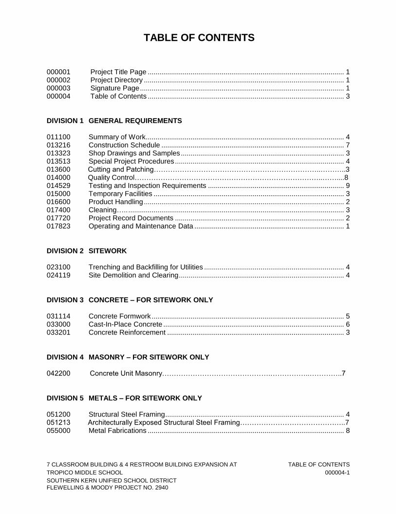
TABLE OF CONTENTS 000001 Project Title Page ..................................................................................................... 1 000002 Project Directory ....................................................................................................... 1 000003 Signature Page ......................................................................................................... 1 000004 Table of Contents ..................................................................................................... 3
DIVISION 1 GENERAL REQUIREMENTS 011100 Summary of Work ...................................................................................................... 4 013216 Construction Schedule .............................................................................................. 7 013323 Shop Drawings and Samples .................................................................................... 3 013513 Special Project Procedures ....................................................................................... 4 013600 Cutting and Patching……………………………………………………………..………..3 014000 Quality Control……………………………………………………………………..……....8 014529 Testing and Inspection Requirements ...................................................................... 9 015000 Temporary Facilities .................................................................................................. 3 016600 Product Handling ....................................................................................................... 2 017400 Cleaning….. ............................................................................................................... 3 017720 Project Record Documents ....................................................................................... 2 017823 Operating and Maintenance Data ............................................................................. 1
DIVISION 2 SITEWORK 023100 Trenching and Backfilling for Utilities ........................................................................ 4 024119 Site Demolition and Clearing ..................................................................................... 4
DIVISION 3 CONCRETE – FOR SITEWORK ONLY 031114 Concrete Formwork ................................................................................................... 5 033000 Cast-In-Place Concrete ............................................................................................. 6 033201 Concrete Reinforcement ........................................................................................... 3
DIVISION 4 MASONRY – FOR SITEWORK ONLY 042200 Concrete Unit Masonry……………………………………….……………..…………..7
DIVISION 5 METALS – FOR SITEWORK ONLY 051200 Structural Steel Framing ............................................................................................ 4 051213 Architecturally Exposed Structural Steel Framing………………………………….…..7 055000 Metal Fabrications ..................................................................................................... 8

7 CLASSROOM BUILDING & 4 RESTROOM BUILDING EXPANSION AT TABLE OF CONTENTS
TROPICO MIDDLE SCHOOL 000004-2
SOUTHERN KERN UNIFIED SCHOOL DISTRICT
FLEWELLING & MOODY PROJECT NO. 2940
DIVISION 6 WOOD AND PLASTICS - NOT USED
DIVISION 7 THERMAL AND MOISTURE PROTECTION – FOR SITEWORK ONLY 079200 Joint Sealants……………………………………………….……………………………..8
DIVISION 8 DOORS – FOR MODULAR BUILDINGS ONLY
087100 Door Hardware ........................................................................................................ 17 Catalog Cuts……………………………………………………………………………...87
DIVISION 9 FINISHES 099000 Painting……………………………………………………….……………………………9
DIVISION 10 SPECIALTIES – FOR MODULAR BUILDINGS ONLY 101400 Signage………………………………………...…………………………………………..3
DIVISION 11 EQUIPMENT – NOT USED
DIVISION 12 FURNISHINGS – NOT USED
DIVISION 13 SPECIAL CONSTRUCTION – NOT USED
DIVISION 14 CONVEYING SYSTEMS – NOT USED
DIVISION 21 FIRE PROTECTION – FOR MODULAR BUILDINGS ONLY 217200 Fire Detection and Alarm Systems .......................................................................... 30
DIVISION 22 PLUMBING – FOR SITEWORK ONLY 220000 Plumbing………………………………...………….….…………………………………10
DIVISION 23 MECHANICAL – NOT USED
89
7 CLASSROOM BUILDING & 4 RESTROOM BUILDING EXPANSION AT TABLE OF CONTENTS
TROPICO MIDDLE SCHOOL 000004-3
SOUTHERN KERN UNIFIED SCHOOL DISTRICT
FLEWELLING & MOODY PROJECT NO. 2940
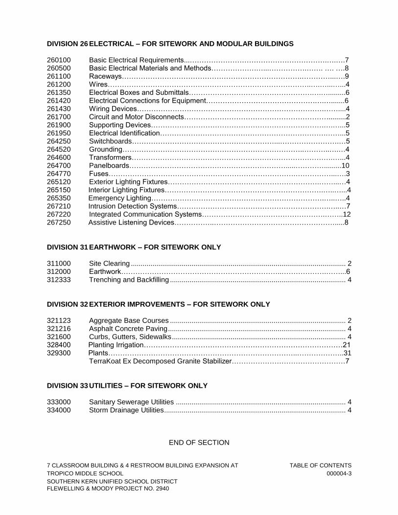
DIVISION 26 ELECTRICAL – FOR SITEWORK AND MODULAR BUILDINGS 260100 Basic Electrical Requirements...………………………………………………….….….7 260500 Basic Electrical Materials and Methods……………….…...…………….……. …. ….8 261100 Raceways………………………………………………………………….…………...….9 261200 Wires…………………………………………………………………………..….…...…...4 261350 Electrical Boxes and Submittals…………………………………………….….….........6 261420 Electrical Connections for Equipment……………………………………….….….......6 261430 Wiring Devices…………………………………………………………………….……....4 261700 Circuit and Motor Disconnects……………………………………………………..........2 261900 Supporting Devices……………………………………………………………….….…...5 261950 Electrical Identification…………………………………………………………….……...5 264250 Switchboards……………………………………………………...…………………….…5 264520 Grounding…………………………………………………………………..………..….…4 264600 Transformers………………………………………………………………………….…...4 264700 Panelboards………………………………………………………….....………….........10 264770 Fuses…………………………………………………………………….……………...….3 265120 Exterior Lighting Fixtures……………………………………………………….……...…4 265150 Interior Lighting Fixtures………………………………………………………….…..…...4 265350 Emergency Lighting……………………………………………………………….…..…..4 267210 Intrusion Detection Systems……………………………………………………….…..…7 267220 Integrated Communication Systems…………………………………………….……..12 267250 Assistive Listening Devices……………..…………………………………………….....8
DIVISION 31 EARTHWORK – FOR SITEWORK ONLY 311000 Site Clearing .............................................................................................................. 2 312000 Earthwork…………………………………………………………..……………….……...6 312333 Trenching and Backfilling .......................................................................................... 4
DIVISION 32 EXTERIOR IMPROVEMENTS – FOR SITEWORK ONLY 321123 Aggregate Base Courses .......................................................................................... 2 321216 Asphalt Concrete Paving ........................................................................................... 4 321600 Curbs, Gutters, Sidewalks ......................................................................................... 4 328400 Planting Irrigation…………………………………………………………………………21 329300 Plants……………………………………………………………………..………………..31 TerraKoat Ex Decomposed Granite Stabilizer…………………………………………7
DIVISION 33 UTILITIES – FOR SITEWORK ONLY 333000 Sanitary Sewerage Utilities ....................................................................................... 4 334000 Storm Drainage Utilities ............................................................................................. 4
END OF SECTION

7 CLASSROOM BUILDING & 4 RESTROOM BUILDING EXPANSION AT SUMMARY OF WORK
TROPICO MIDDLE SCHOOL 011100-1
SOUTHERN KERN UNIFIED SCHOOL DISTRICT
FLEWELLING & MOODY PROJECT NO. 2940
SECTION 011100 SUMMARY OF WORK
1.00 GENERAL 1.01 SUMMARY A. The Project consists of design and construction of the following items:
1. (7) 40’x94’ per the approved PC 02-118544 (2019 CBC) fully sprinklered classroom modular buildings.
2. (2) 12’x40’ per the approved PC 02-119274 (2019 CBC) fully sprinklered
restroom modular buildings.
3. (2) 12’x40’ per the approved PC 02-118577 (2019 CBC) fully sprinklered restroom modular buildings.
4. Site work to include grading and all utilities.
5. Site improvement work around new classroom and restroom buildings.
6. Walking track and playfield area
7. Site improvement work around basketball courts and workout area
8. Trash enclosure and can wash
1.02 PHASING/CONTRACTOR'S USE OF PREMISES A. Move stored products, which interfere with operations of District or other contractors. B. Obtain and pay for use of additional storage, work areas or parking needed for
operations or Contractor's employees. C. Use of site: Limit to areas directed by the District. 1. Allow District access to maintain and operate other existing facilities. 2. Permit unimpeded access by firefighting, law enforcement agencies and rescue
equipment. 3. Access to and egress from construction site shall be in strict conformance to
prearranged routes approved by the District, with the understanding that curtailment of traffic or revision of access routes may be required on short notice if the District's operations mandate such changes because of excessive noise, or problems with safety, service, or supply.
D. Partial District's occupancy: The District reserves the right to place and install
equipment in areas of the Project prior to Substantial Completion provided it doesn't interfere with normal completion of Work. This partial occupancy shall not constitute acceptance of the Work.

7 CLASSROOM BUILDING & 4 RESTROOM BUILDING EXPANSION AT SUMMARY OF WORK
TROPICO MIDDLE SCHOOL 011100-2
SOUTHERN KERN UNIFIED SCHOOL DISTRICT
FLEWELLING & MOODY PROJECT NO. 2940
1.03 WORK NOT IN CONTRACT A. The following will be provided by the District under separate contracts. 1. Encapsulation, removal and disposal of asbestos, toxic substances and other
hazardous materials.
2. Tests and inspections specified to be provided by the District in the Contract Documents.
3. Items noted NIC (Not In Contract) on the Drawings or in the Specifications. 4. Items noted OFCI (Owner Furnished Contractor Installed) on the drawings or the
specifications shall identify those items that will be purchased and delivered to project by the Owner but for which the Contractor(s) shall be responsible for all labor and materials necessary to fully and properly install the supplied items.
B. When work of this Contract requires the Contractor to make allowance for the above in
his work, and to provide supports, power, conduits, stub-outs and other services to these items, the drawings, manufacturer's data and other information necessary for Contractor's work will be provided by the District upon request.
1.04 DEFINITIONS A. In addition to other definitions included in these Specifications, the following applies to
the Work: 1. Approved, approved equal, or equal, mean as approved and accepted by the
Architect and District. 2. As necessary means essential to completion of Work. 3. As required means as required by Contract Documents. 4. As selected, as approved, as directed or words of similar import mean as
selected by, as approved by, or as accepted by the Architect. No implied meaning shall be interpreted to extend Architect's responsibility into the Contractor's area of Contractor's supervision.
5. As shown, as detailed, as indicated and words of similar import mean as
indicated on the Drawings. 6. Building Department and Authorities Having Jurisdiction: All agencies,
individually or collectively, charged by statute with administration/enforcement of requirements of the Building Code at Project location.
7. Concealed means embedded in masonry, concrete or other construction,
installed within furred spaces, within a wall/partitions or above suspended ceilings, in trenches, in crawl spaces, or in enclosures.
8. Equipment means a product with operational parts, whether motorized or
manually operated, that requires service connections such as wiring or piping.

7 CLASSROOM BUILDING & 4 RESTROOM BUILDING EXPANSION AT SUMMARY OF WORK
TROPICO MIDDLE SCHOOL 011100-3
SOUTHERN KERN UNIFIED SCHOOL DISTRICT
FLEWELLING & MOODY PROJECT NO. 2940
9. Exposed means not installed underground or concealed as defined above. 10. Fabricated means items specifically assembled or made out of selected materials
to meet individual design requirements for the Project. 11. Furnish (materials) means to supply and deliver to the Project ready for
installation and in operable condition. 12. Include/including means include/including, without limitation. 13. Install (services or labor) means to place in final position, complete, anchored,
connected, and in operable condition. 14. Interior means a space completely enclosed by walls, solid door(s), floor and
ceiling. 15. Exterior means a space which does not meet the definition for "interior" above. 16. Manufactured applies to standard units usually mass-produced. 17. Manufacturer's directions, instructions, recommendations, specifications means
manufacturer's written directions, instruction, recommendations, specifications. 18. Materials are products substantially shaped, cut, worked, mixed, finished, refined
or otherwise fabricated, processed, or installed to form part of Work. 19. Named products are items identified by manufacturer's product name, including
make or model designation, indicated in manufacturer's published product literature current as of the date of the Contract Documents.
20. Owner furnished/Contractor installed (OFCI) means that some equipment may be
Owner furnished and delivered to site by District and installed on site by Contractor under this Agreement.
21. Owner provided (OP) means items or equipment that shall be furnished and
installed under separate contract by Owner/District.Product(s) means materials, systems, and equipment, and terms of similar intent.
22. Product(s) means materials, systems, and equipment, and terms of similar intent. 23. Provide means to supply, fabricate, deliver, place, and connect, complete in-
place, ready for operation and use. When neither furnish, install nor provide is stated, provide is implied.
24. Division means Division of these Specifications except where the obvious intent
is the act or process of dividing. Divisions are groups of related Sections. 25. Section means Section of these Specifications, except where the obvious intent is
one of several components, a piece. Section is usually a basic unit of Work. 26. Shall is mandatory.

7 CLASSROOM BUILDING & 4 RESTROOM BUILDING EXPANSION AT SUMMARY OF WORK
TROPICO MIDDLE SCHOOL 011100-4
SOUTHERN KERN UNIFIED SCHOOL DISTRICT
FLEWELLING & MOODY PROJECT NO. 2940
27. Submit, submittal, submission mean submit to Architect for review, unless otherwise stated.
1.05 TITLING AND ARRANGEMENT A. Article, Paragraph and subparagraph titles and other identifications of subject matter in
Specifications are intended as an aid in locating and recognizing various requirements in beginning words of a sentence or where title establishes subject, titles are subordinate to and do not define, limit, or otherwise restrict Specification text.
B. Underlining, bolding or capitalizing of words in the text does not signify or mean that
such words convey special or unusual meaning. C. Specification text governs over titling and shall be understood to be and interpreted as
a whole. D. The order of articles, paragraphs, subparagraphs, and sub-subparagraphs in the
Specifications text is defined by the sequence of indentations. 1.06 INTERPRETATION A. Unless otherwise stated in the Contract Documents, technical words and abbreviation
contained in the Contract Documents are used in accordance with commonly understood construction industry meanings; and non-technical words and abbreviations are used in accordance with their commonly understood meanings.
B. Contract Documents may omit modifying words such as "all" and "any," and articles
such as "the" and "an," but the fact that a modifier or an article is absent from one statement and appears in another is not intended to affect the interpretation of either statement. Use of the word "including," when following any general statement, shall not be construed to limit such statement to specific items or matters, whether or not non-limiting language (such as "without limitation," "but not limited to," or words of similar import) is used with reference thereto, but rather shall be deemed to refer to all other items or matters that could reasonably fall within the broadest possible scope of such general statement.
C. Whenever context so requires, use of the singular number shall be deemed to include
the plural and vice versa. 1. Each gender shall be deemed to include any other gender, and each shall include
corporation, partnership, trust, or other legal entity whenever context so requires. 2. Captions and headings of various subdivisions of Contract Documents are
intended only as a matter of reference and convenience and in no way define, limit, or prescribe the scope or intent of Contract Documents or any subdivision thereof.
END OF SECTION

7 CLASSROOM BUILDING & 4 RESTROOM BUILDING EXPANSION AT CONSTRUCTION SCHEDULE
TROPICO MIDDLE SCHOOL 013216-1
SOUTHERN KERN UNIFIED SCHOOL DISTRICT
FLEWELLING & MOODY PROJECT NO. 2940
SECTION 013216 CONSTRUCTION SCHEDULE
1.00 GENERAL 1.01 SECTION INCLUDES
A. Construction Schedule procedures, preparation, submittal, updates, and revisions. 1.02 RELATED SECTIONS
A. Section 013323: Submittals. B. Section 017720: Project Record Documents.
1.03 SCHEDULE
A. The construction of this project will be planned and recorded with a conventional Critical Path Method (CPM) schedule. The schedule shall be used for coordination, monitoring, and payment of all work under the contract including all activity of subcontractors, vendors, suppliers, and for all submittals.
B. Contractor is responsible for preparing the schedule. All costs incurred by Contractor
in preparing the schedule shall be borne by Contractor as a part of its responsibility under this contract.
1.04 PROCEDURES
A. Baseline Construction Schedule
1. Before proceeding with any work on site, Contractor shall prepare, submit, and receive District’s approval of a Baseline Construction Schedule. This schedule shall provide a detailed breakdown of activities scheduled for the first 90 days of the project and shall include mobilization, submittals, procurement, and construction.
2. No contact work may be pursued at the site without an approved Baseline
Construction Schedule or an approved CPM schedule.
B. Within forty-five (45) calendar days after date of Notice to Proceed, Contractor shall submit, for review, a Detailed Project Schedule setting forth all requirements for complete execution of work.
C. Preparation of Detailed Project Schedule
7 CLASSROOM BUILDING & 4 RESTROOM BUILDING EXPANSION AT CONSTRUCTION SCHEDULE
TROPICO MIDDLE SCHOOL 013216-2
SOUTHERN KERN UNIFIED SCHOOL DISTRICT
FLEWELLING & MOODY PROJECT NO. 2940
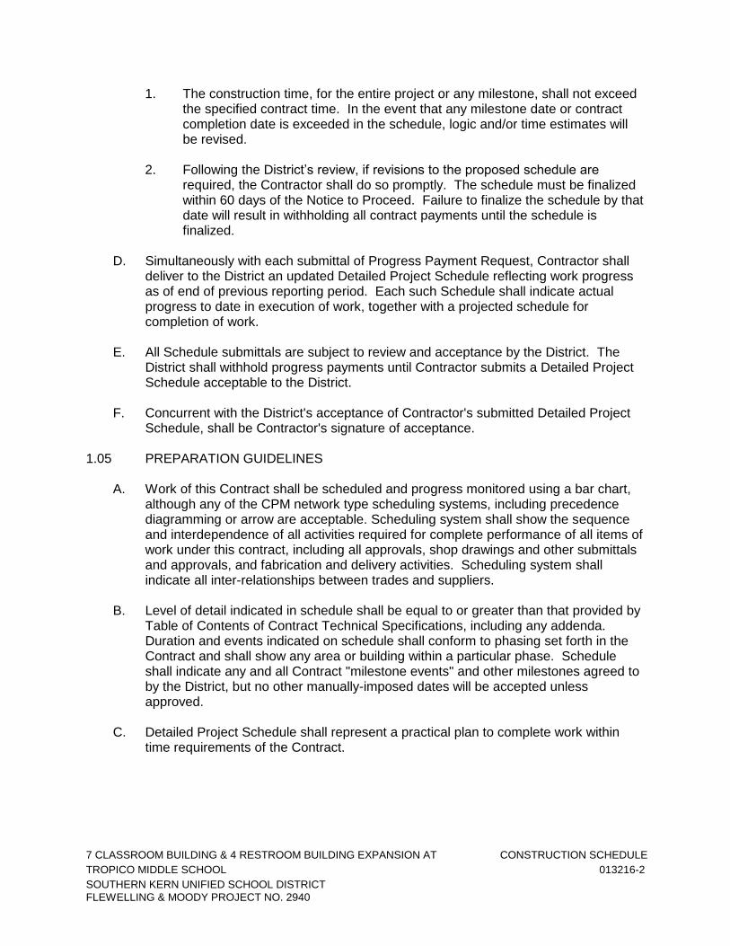
1. The construction time, for the entire project or any milestone, shall not exceed the specified contract time. In the event that any milestone date or contract completion date is exceeded in the schedule, logic and/or time estimates will be revised.
2. Following the District’s review, if revisions to the proposed schedule are
required, the Contractor shall do so promptly. The schedule must be finalized within 60 days of the Notice to Proceed. Failure to finalize the schedule by that date will result in withholding all contract payments until the schedule is finalized.
D. Simultaneously with each submittal of Progress Payment Request, Contractor shall
deliver to the District an updated Detailed Project Schedule reflecting work progress as of end of previous reporting period. Each such Schedule shall indicate actual progress to date in execution of work, together with a projected schedule for completion of work.
E. All Schedule submittals are subject to review and acceptance by the District. The
District shall withhold progress payments until Contractor submits a Detailed Project Schedule acceptable to the District.
F. Concurrent with the District's acceptance of Contractor's submitted Detailed Project
Schedule, shall be Contractor's signature of acceptance. 1.05 PREPARATION GUIDELINES
A. Work of this Contract shall be scheduled and progress monitored using a bar chart, although any of the CPM network type scheduling systems, including precedence diagramming or arrow are acceptable. Scheduling system shall show the sequence and interdependence of all activities required for complete performance of all items of work under this contract, including all approvals, shop drawings and other submittals and approvals, and fabrication and delivery activities. Scheduling system shall indicate all inter-relationships between trades and suppliers.
B. Level of detail indicated in schedule shall be equal to or greater than that provided by
Table of Contents of Contract Technical Specifications, including any addenda. Duration and events indicated on schedule shall conform to phasing set forth in the Contract and shall show any area or building within a particular phase. Schedule shall indicate any and all Contract "milestone events" and other milestones agreed to by the District, but no other manually-imposed dates will be accepted unless approved.
C. Detailed Project Schedule shall represent a practical plan to complete work within
time requirements of the Contract.

7 CLASSROOM BUILDING & 4 RESTROOM BUILDING EXPANSION AT CONSTRUCTION SCHEDULE
TROPICO MIDDLE SCHOOL 013216-3
SOUTHERN KERN UNIFIED SCHOOL DISTRICT
FLEWELLING & MOODY PROJECT NO. 2940
1. The Contractor may submit a Detailed Project Schedule depicting completion of the Work in a duration shorter than the Contract Time; provided that such Detailed Project Schedule shall not be a basis for adjustment to the Contract Price in the event that completion of the Work shall occur after the time depicted therein, nor shall such Detailed Project Schedule be the basis for any extension of the Contract Time.
2. A schedule found unacceptable by the District shall be revised by Contractor
and resubmitted.
D. Detailed Project schedule shall clearly indicate sequence of construction activities, grouped by applicable phase and sorted by areas, buildings, or facilities within phase, and shall specifically indicate:
1. Start and completion of all items of work, their major components, and interim
milestone completion dates, as determined by Contractor and the District. 2. Activities for procurement, delivery, installation of equipment, materials, and
other supplies, including:
a. Time for submittals, re-submittals, and reviews. Include decision dates for selection of finishes, if applicable.
b. Time for fabrication, and delivery of, manufactured products for work.
c. Interdependence of procurement and construction activities.
d. As applicable, dates for testing, balancing equipment, and final
inspection. E. Schedule shall be in sufficient detail to assure adequate planning and execution of
work.
1. Each activity shall range in duration no longer than two (2) weeks and shall be total of actual days required for completion, and shall include consideration of normal weather impact on completion of that activity.
2. The activities are to be described so that the work is readily identifiable and the
progress of each activity can be readily measured. For each activity, Contractor shall identify the trade or subcontractor performing the work, the duration of the activity in work days, the manpower involved by trade, the equipment involved, the location of the work, and a dollar value of the activity. The dollar value assigned to each activity is to be reasonable and based on the amount of labor, materials, and equipment involved. When added together, the dollar value of all activities are to equal the contract price.
3. Schedule shall be suitable, in judgement of the Architect, to allow monitoring
and evaluation of progress in performance of work; it shall be calendar time-scaled and, at a minimum, in a Bar Chart format.

7 CLASSROOM BUILDING & 4 RESTROOM BUILDING EXPANSION AT CONSTRUCTION SCHEDULE
TROPICO MIDDLE SCHOOL 013216-4
SOUTHERN KERN UNIFIED SCHOOL DISTRICT
FLEWELLING & MOODY PROJECT NO. 2940
4. Activities shall include:
a. Description; what is to be accomplished and where. b. Workday duration.
c. Scheduled activities shall indicate continuous flow, from left to right.
5. Identify days per week and shifts per day worked; also, non-work days and
holidays. 6. For all schedules submitted, Contractor shall provide the following:
a. Computerized sorts by:
(1) Total Float (2) Early Start (3) Area Sort (4) Trade responsibility
b. 60-day look ahead bar charts by early start. c. A narrative explaining progress to date on the project, work required in
the succeeding update period, a description of the critical path, and comments concerning potential problem areas.
d. Contract will submit four copies of each of the above.
F. Failure to include any element of work required for performance of this Contract shall
not excuse Contractor from completing work required to comply with the Contract Documents, notwithstanding acceptance of Construction Schedule.
G. Submittal of Construction Schedule shall be understood to be Contractor's
confirmation that the schedule meets requirements of the Contract Documents, and that work will be executed in sequence indicated in schedule.
1.06 REVIEWS, UPDATES, AND REVISIONS
A. The District will review and return Contractor's Detailed Project Schedule, with summary comments, within Seventeen (17) calendar days. If revisions are required, Contractor shall resubmit Schedule within fourteen (14) calendar days following receipt of the District's comments.
B. After Contractor and the District agree to a final schedule, it will become the Project
Construction Schedule and considered part of the Contract Documents. No changes to Schedule will be allowed unless mutually agreed upon with the District.
C. Contractor shall analyze and update the Detailed Project Schedule:

7 CLASSROOM BUILDING & 4 RESTROOM BUILDING EXPANSION AT CONSTRUCTION SCHEDULE
TROPICO MIDDLE SCHOOL 013216-5
SOUTHERN KERN UNIFIED SCHOOL DISTRICT
FLEWELLING & MOODY PROJECT NO. 2940
1. As part of monthly payment application, Contractor shall submit to and participate with the District in a schedule review to include:
a. Actual completion dates for work items completed during report period. b. Actual start dates for work items started during report period.
c. Estimated remaining duration for work items in progress, which will not
exceed original duration for activity.
d. Estimated start dates for work items scheduled to start during month following report period, if applicable.
e. Changes in duration of work items.
f. A summary bar chart schedule, organized first by work segment plan,
and then by area (building number or other appropriate subdivision) shall show construction progress in each area. The previous schedule shall be included in this report to compute the current performance with the original planned sequence of work.
2. In case of a change to Contractor's planned sequence of work, Contractor
shall include a narrative report with updated progress schedule which shall include, but not be limited to, a description of problem areas, current and anticipated delaying factors, and any proposed revisions for a recover plan.
3. All change orders affecting this schedule shall be clearly identified as a
separate and new activity.
4. Review of Detailed Project Schedule will not relieve Contractor of responsibility for accomplishing all work in accordance with the Contract Documents.
D. Updates: The Contractor shall submit to the District, with each payment application,
an up-to-date Detailed Project Schedule to include following:
1. Work Item Report: Detailing work items and dependencies as indicated on Bar Chart.
2. Separate listing of activities completed during reporting period.
3. Separate listing of activities which are currently in progress, indicating their
remaining duration and percentages completed.
4. Separate listing of activities which are causing delay in work progress.
5. Narrative report to define problem areas, anticipated delays, and impact on Detailed Project Schedule. Report corrective action taken, or proposed, and its effect, including effect of changes on schedules of separate contractors.

7 CLASSROOM BUILDING & 4 RESTROOM BUILDING EXPANSION AT CONSTRUCTION SCHEDULE
TROPICO MIDDLE SCHOOL 013216-6
SOUTHERN KERN UNIFIED SCHOOL DISTRICT
FLEWELLING & MOODY PROJECT NO. 2940
6. Resolution of conflict between actual work progress and schedule logic: when out-of-sequence activities develop in the Schedule because of actual construction progress, Contractor shall submit a revised schedule to conform to current job sequence and direction.
E. If, according to current updated Detailed Project Schedule, the District determines
Contractor is behind the Contract completion date or any interim milestone completion dates, considering all time extensions to which Contractor is entitled, Contractor shall submit a revised schedule, showing a workable plan and a narrative description to complete project on time. In accordance with Article 1.06, Paragraph C-2.
1. The District shall withhold progress payments until a revised schedule,
acceptable to the District, is submitted by Contractor.
F. Scheduling of change or extra work orders is responsibility of Contractor.
1. Contractor shall revise Detailed Project Schedule to incorporate all activities involved in completing change orders or extra work orders and submit it to the District for review.
G. If the District finds Contractor is entitled to extension of any completion date, under
provisions of the Contract, the District's determination of total number of days extension will be based upon current analysis of Construction Schedule, and upon data relevant to extension.
H. Contractor acknowledges and agrees that delays to non-critical activities will not be
considered a basis for a time extension unless activities become critical. Non-critical activities are those activities which, when delayed, do not affect an interim or final Contract completion date.
I. Any claim for extension of time shall be made in writing to the Architect not more than
seven (7) days after commencement of delay; otherwise, it shall be deemed finally waived for all purposes. Contractor shall provide an estimate of probable effect of such delay on progress of work as part of claim.
1.07 CONTRACTOR'S RESPONSIBILITY
A. Nothing in these requirements shall be deemed to be a usurpation of Contractor's authority and responsibility to plan and schedule work as Contractor sees fit, subject to all other requirements of Contract Documents.
B. Contractor shall provide at all times sufficient competent labor, materials, and equipment to properly carry on work and to insure completion of each part in accordance with Construction Schedule and within time agreed.
C. Contractor shall be responsible for ensuring that all submittals to the District are
accurate and consistent. Damages, including extra time and cost, caused by inaccuracies from Contractor will be compensated by Contractor.

7 CLASSROOM BUILDING & 4 RESTROOM BUILDING EXPANSION AT CONSTRUCTION SCHEDULE
TROPICO MIDDLE SCHOOL 013216-7
SOUTHERN KERN UNIFIED SCHOOL DISTRICT
FLEWELLING & MOODY PROJECT NO. 2940
1.08 SUSPENSION OF PAYMENTS
A. Initial Submittal: The District has the right to withhold progress payments until Detailed Project Schedule is accepted by the District.
B. Update Submittals: The District has the right to withhold progress payments if
Contractor fails to update and submit Detailed Project Schedule and reports as required by the District.
1.09 RECORD COPY
A. At completion of work items, submit Detailed Project Schedule reflecting "as-built" sequence.
1.10 FORM OF SUBMITTAL
A. All Detailed Project Schedule submittals shall be transmitted with a Letter of Transmittal and shall include three (3) hard copies and one (1) electronic copy.
2.00 PRODUCTS Not used. 3.00 EXECUTION Not used.
END OF SECTION

7 CLASSROOM BUILDING & 4 RESTROOM BUILDING EXPANSION AT SHOP DRAWINGS & SAMPLES
TROPICO MIDDLE SCHOOL 013323-1
SOUTHERN KERN UNIFIED SCHOOL DISTRICT
FLEWELLING & MOODY PROJECT NO. 2940
SECTION 013323 SHOP DRAWINGS AND SAMPLES
1.00 GENERAL 1.01 SUMMARY
A. This Section establishes general requirements for shop drawings and samples, and supplements similar provisions found elsewhere in the Contract Documents.
1.02 GENERAL REQUIREMENTS
A. Prior to submission to Architect, Contractor to check all shop drawings, brochures, and other such construction data for quantity, size, and dimensions. Architect will answer questions raised by Contractor, and will make determination regarding quality of material and equipment, design and arrangement decisions, and color selections, but will not be responsible for quantity, size, or dimensional errors on shop drawings. In cases of omission and obvious error, and in cases of conflict, either between details on Contract Drawings or Specifications, such questions shall be brought to the Architect's attention, and Architect will give prompt answers to such questions.
1. Colors and textures to be selected will be selected from all available colors and
textures, regardless of price ranges. For instance, where the first manufacturer listed has 20 colors or color ways available, that is the minimum number that shall be available for selection. Products of other manufacturers may be submitted, but the cost of colors considered special shall be included in the Contract Sum if their number is less than 20. When colors or textures are custom from any manufacturer, they will be so identified.
B. Carefully review subcontractors' submittals for completeness and correctness and
stamp and acknowledge such review on submittals, prior to transmitting them to Architect.
C. Close adherence to these requirements is necessary to avoid delay in processing of
shop drawings by the Architect. Deviation from these requirements may result in rejection of the submittal. Contractor will be held responsible for delays resulting from tardy and improper submittals.
D. Obtain approvals from required agencies, prior to submittal to the Architect, for all
revisions, substitutions of materials or design, including all structural deviation from the design as shown and specified.
1.03 SUBMITTALS
A. Shop drawings, minimum (District may request more):
1. One transparent vellum reproducible, reverse-reading.
2. 6 blueline prints bound in sequence.
7 CLASSROOM BUILDING & 4 RESTROOM BUILDING EXPANSION AT SHOP DRAWINGS & SAMPLES
TROPICO MIDDLE SCHOOL 013323-2
SOUTHERN KERN UNIFIED SCHOOL DISTRICT
FLEWELLING & MOODY PROJECT NO. 2940
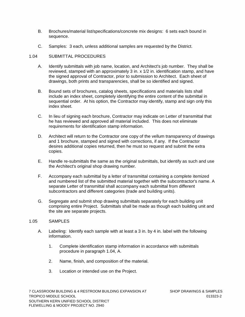
B. Brochures/material list/specifications/concrete mix designs: 6 sets each bound in sequence.
C. Samples: 3 each, unless additional samples are requested by the District.
1.04 SUBMITTAL PROCEDURES
A. Identify submittals with job name, location, and Architect's job number. They shall be reviewed, stamped with an approximately 3 in. x 1/2 in. identification stamp, and have the signed approval of Contractor, prior to submission to Architect. Each sheet of drawings, both prints and transparencies, shall be so identified and signed.
B. Bound sets of brochures, catalog sheets, specifications and materials lists shall
include an index sheet, completely identifying the entire content of the submittal in sequential order. At his option, the Contractor may identify, stamp and sign only this index sheet.
C. In lieu of signing each brochure, Contractor may indicate on Letter of transmittal that
he has reviewed and approved all material included. This does not eliminate requirements for identification stamp information.
D. Architect will return to the Contractor one copy of the vellum transparency of drawings
and 1 brochure, stamped and signed with corrections, if any. If the Contractor desires additional copies returned, then he must so request and submit the extra copies.
E. Handle re-submittals the same as the original submittals, but identify as such and use
the Architect's original shop drawing number.
F. Accompany each submittal by a letter of transmittal containing a complete itemized and numbered list of the submitted material together with the subcontractor's name. A separate Letter of transmittal shall accompany each submittal from different subcontractors and different categories (trade and building units).
G. Segregate and submit shop drawing submittals separately for each building unit
comprising entire Project. Submittals shall be made as though each building unit and the site are separate projects.
1.05 SAMPLES
A. Labeling: Identify each sample with at least a 3 in. by 4 in. label with the following information.
1. Complete identification stamp information in accordance with submittals
procedure in paragraph 1.04, A.
2. Name, finish, and composition of the material.
3. Location or intended use on the Project.

7 CLASSROOM BUILDING & 4 RESTROOM BUILDING EXPANSION AT SHOP DRAWINGS & SAMPLES
TROPICO MIDDLE SCHOOL 013323-3
SOUTHERN KERN UNIFIED SCHOOL DISTRICT
FLEWELLING & MOODY PROJECT NO. 2940
B. Size of samples: Of sufficient size to show all salient features of material or item, and which are truly representative of the extremes of variation in color, texture, finish, and construction to be expected in installed work. Samples of framed materials shall include a corner joint. Allow space for 5 in. by 3 in. Architect's review stamp.
C. Mock-ups: Specifications may require mock-ups of proposed construction elements,
using actual materials and full-size components. Such mock-ups shall be included in the Contract Sum.
D. Review of samples: After review, samples will be stamped or labeled to indicate their
review, and one sample will be returned to the Contractor.
1. Samples retained by the Architect will constitute the standard of quality and appearance of all materials of the type represented by the sample.
2. When samples are rejected, Contractor will be given reasons for rejection and
shall resubmit samples until, in the opinion of the Architect, they comply with Contract requirements.
E. At the option of the District or Architect, samples may be subject to testing. In such
event, additional samples as may be required shall be supplied by the Contractor at no additional cost.
END OF SECTION

7 CLASSROOM BUILDING & 4 RESTROOM BUILDING EXPANSION AT SPECIAL PROJECT PROCEDURES
TROPICO MIDDLE SCHOOL 013513-1
SOUTHERN KERN UNIFIED SCHOOL DISTRICT
FLEWELLING & MOODY PROJECT NO. 2940
SECTION 013513 SPECIAL PROJECT PROCEDURES
1.00 GENERAL 1.01 SUMMARY
A. General: Buildings will not be occupied while the work of this Contract is performed.
B. Existing conditions:
1. Contractor shall accept the site in the condition in which they exist at the time he is given access to begin work.
2. Before starting work, make a detailed survey of existing conditions, verify
governing dimensions at the premises against the Drawings, and examine adjoining work on which the work of this Contract is dependent.
3. No "Extra" or additional compensation will be allowed on account of differences
between actual measurements and dimensions shown.
4. Submit differences discovered during Work to Architect for interpretation before proceeding with associated work.
C. Protection:
1. While work of this Contract is in progress, protect adjacent areas, facilities,
grounds, and contents, whether private or public, from damage or harm due to the work of this Contract.
2. Cover and protect all surfaces of areas turned over to Contractor for the Work as
required to prevent soiling or damage by dust, dirt, water, fumes or otherwise, and protect other areas where Work is performed in the same manner, all as deemed adequate by the District. Prior to District's re-occupancy of any such area, clean all surfaces according to cleaning instructions as may be specified in other Sections or issued by the District.
3. Conform to following requirements where welding is performed in or on the
buildings.
a. Protection during welding: Conform to CAC. Further protect occupants and the public with portable solid vision barricades around locations where welding is performed plus sign warning against looking at welding without proper eye protection, or equivalent.
b. Fire extinguishers: Maintain a fully charged UL labeled, minimum 10 lbs.
ABC fire extinguisher at each location where welding is performed.

7 CLASSROOM BUILDING & 4 RESTROOM BUILDING EXPANSION AT SPECIAL PROJECT PROCEDURES
TROPICO MIDDLE SCHOOL 013513-2
SOUTHERN KERN UNIFIED SCHOOL DISTRICT
FLEWELLING & MOODY PROJECT NO. 2940
c. Welding smoke control: Verify locations of existing smoke detectors. Perform welding operations by methods that produce the minimum feasible smoke and fumes. Furnish portable type smoke collection and ventilating equipment as required to prevent smoke and fume nuisances. Notify the District at least 48 hours in advance if temporary deactivation of smoke detector is required to prevent false alarms from welding. District will permit deactivation of detectors only for the time welding is actually in progress.
4. Fire prevention:
a. Ensure that flammable solvents are not being used in the area. Maintain a
safe distance between place of welding and source of flammable solvents.
b. In addition, examine existing construction and backing for all combustible materials and finishes and for conditions where heat conduction in metals may bring adjoining materials to ignition temperature.
c. Use positive fire prevention measures including, without limitation, removal
and reinstallation of combustible materials, installation of temporary shields and/or heat sinks, and all other necessary measures.
5. No utility services, such as water, gas, sewers, electricity, telephone,
communication, and fire protection system serving the Buildings or parts thereof, shall be interrupted without prior written approval of the District, and other authorities having jurisdiction.
6. Damage caused by the Contractor to existing structures, grounds, pavements,
utilities or flora, or work done by others, shall be repaired by the Contractor at his expense and left in as good condition as existed before the damaging, except where such existing work is shown to be removed, or replaced by new work.
D. Access:
1. During the life of the Contract, maintain access to site, and within the site to the
buildings for fire-fighting equipment, ambulance and police vehicles.
2. Required accessways and other accessways not required but so designated by the District or Contract Documents shall not be blocked so as not to interfere with access to adjacent areas, facilities or new work area and cause least possible interference with activities of other contractors, District's personnel or the public.
1.02 SURVEY AND RE-SURVEY OF EXISTING CONDITIONS
A. Intent of Drawings is to show existing site and buildings conditions with information developed from original construction documents, field surveys, and District's records, and to generally show the extent and type of demolition required to complete the Work.
1. Information shown on the Drawings is not a guarantee of existing conditions.
7 CLASSROOM BUILDING & 4 RESTROOM BUILDING EXPANSION AT SPECIAL PROJECT PROCEDURES
TROPICO MIDDLE SCHOOL 013513-3
SOUTHERN KERN UNIFIED SCHOOL DISTRICT
FLEWELLING & MOODY PROJECT NO. 2940
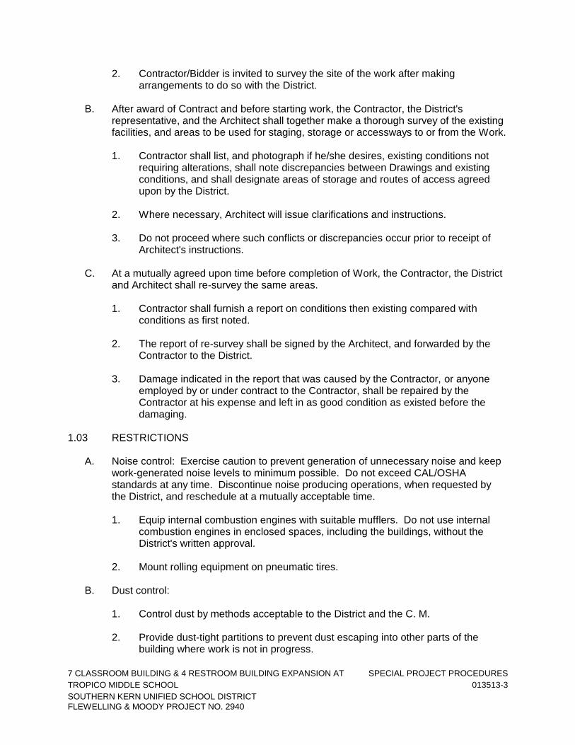
2. Contractor/Bidder is invited to survey the site of the work after making arrangements to do so with the District.
B. After award of Contract and before starting work, the Contractor, the District's
representative, and the Architect shall together make a thorough survey of the existing facilities, and areas to be used for staging, storage or accessways to or from the Work.
1. Contractor shall list, and photograph if he/she desires, existing conditions not
requiring alterations, shall note discrepancies between Drawings and existing conditions, and shall designate areas of storage and routes of access agreed upon by the District.
2. Where necessary, Architect will issue clarifications and instructions.
3. Do not proceed where such conflicts or discrepancies occur prior to receipt of
Architect's instructions. C. At a mutually agreed upon time before completion of Work, the Contractor, the District
and Architect shall re-survey the same areas.
1. Contractor shall furnish a report on conditions then existing compared with conditions as first noted.
2. The report of re-survey shall be signed by the Architect, and forwarded by the
Contractor to the District.
3. Damage indicated in the report that was caused by the Contractor, or anyone employed by or under contract to the Contractor, shall be repaired by the Contractor at his expense and left in as good condition as existed before the damaging.
1.03 RESTRICTIONS
A. Noise control: Exercise caution to prevent generation of unnecessary noise and keep work-generated noise levels to minimum possible. Do not exceed CAL/OSHA standards at any time. Discontinue noise producing operations, when requested by the District, and reschedule at a mutually acceptable time.
1. Equip internal combustion engines with suitable mufflers. Do not use internal
combustion engines in enclosed spaces, including the buildings, without the District's written approval.
2. Mount rolling equipment on pneumatic tires.
B. Dust control:
1. Control dust by methods acceptable to the District and the C. M. 2. Provide dust-tight partitions to prevent dust escaping into other parts of the
building where work is not in progress.

7 CLASSROOM BUILDING & 4 RESTROOM BUILDING EXPANSION AT SPECIAL PROJECT PROCEDURES
TROPICO MIDDLE SCHOOL 013513-4
SOUTHERN KERN UNIFIED SCHOOL DISTRICT
FLEWELLING & MOODY PROJECT NO. 2940
3. Assume liability for claims related to flying dust and debris.
C. Water control:
1. Control the use of water to prevent damage to the existing facilities and site improvements to remain. Provide wet vacuum equipment where water, such as waste cooling water from concrete sawing, is used in and adjacent to existing buildings.
2. Provide impermeable floor coverings and suitable dams to prevent damage by
water, and immediately clean-up and remove all surplus water, and water spilled in non-working areas.
D. Security: Coordinate security with the District.
1. Take all necessary precautions to keep trespassers out of work and demolition
areas.
2. Properly secure work and demolition areas from entry when work is not in progress but do not block required exitways.
END OF SECTION

7 CLASSROOM BUILDING & 4 RESTROOM BUILDING EXPANSION AT CUTTING AND PATCHING
TROPICO MIDDLE SCHOOL 013600-1
SOUTHERN KERN UNIFIED SCHOOL DISTRICT
FLEWELLING & MOODY PROJECT NO. 2940
SECTION 013600 CUTTING AND PATCHING
PART 1 – GENERAL 1.1 SUMMARY A. This Section establishes general requirements pertaining to cutting (including
excavating), fitting, and patching of the Work required to: 1. Make the several parts fit properly;
2. Uncover work to provide for installing, inspecting, or both, of ill-timed work;
3. Remove and replace work not conforming to requirements of the Contract Documents; and
4. Remove and replace defective work. B. Related work: 1. Documents affecting work of this Section include, but are not necessarily
limited to, General Conditions, Supplementary Conditions, and Sections in Division 1 of these Specifications.
2. In addition to other requirements specified, upon the District’s request uncover work to provide for inspection by the District of covered work, and remove samples of installed materials for testing.
3. Do not cut or alter work performed under separate contracts without the District’s written permission.
1.2 SUBMITTALS A. Request for District’s consent: 1. Prior to cutting which affects structural safety, submit written request to the
Project Manager for permission to proceed with cutting.
2. Should conditions of the Work, or schedule, indicate a required change of materials or methods for cutting and patching, so notify the Project Manager and secure his written permission and the required Change Order prior to proceeding.
B. Notices to the Project Manager: 1. Prior to cutting and patching performed pursuant to the District’s
instructions, submit cost estimate to the Project Manager. Secure the Project Manager’s approval of cost estimates and type of reimbursement before proceeding with cutting and patching.

7 CLASSROOM BUILDING & 4 RESTROOM BUILDING EXPANSION AT CUTTING AND PATCHING
TROPICO MIDDLE SCHOOL 013600-2
SOUTHERN KERN UNIFIED SCHOOL DISTRICT
FLEWELLING & MOODY PROJECT NO. 2940
2. Submit written notice to the Project Manager designating the time the Work will be uncovered, to provide for the District’s observation.
1.3 QUALITY ASSURANCE
A. Use adequate numbers of skilled workmen thoroughly trained and experienced in the necessary crafts and completely familiar with the specified requirements and methods needed for proper performance of the work of this Section.
PART 2 – PRODUCTS 2.1 MATERIALS A. For replacement of items removed, use materials complying with pertinent Sections
of these Specifications. 2.2 PAYMENT FOR COSTS A. The Owner will reimburse the Contractor for cutting and patching performed
pursuant to a written Change Order, after claim for such reimbursement is submitted by the Contractor. Perform other cutting and patching needed to comply with the Contract Documents at no additional cost to the Owner.
PART 3 – EXECUTION 3.1 SURFACE CONDITIONS A. Inspection: 1. Inspect existing conditions, including elements subject to movement or
damage during cutting, excavating, patching, and backfilling.
2. After uncovering the work, inspect conditions affecting installation of new work.
B. Discrepancies: 1. If uncovered conditions are not as anticipated, immediately notify the
Architect and secure needed directions.
2. Do not proceed until unsatisfactory conditions are corrected. 3.2 PREPARATION PRIOR TO CUTTING A. Provide required protection including, but not necessarily limited to, shoring,
bracing, and support to maintain structural integrity of the Work.

7 CLASSROOM BUILDING & 4 RESTROOM BUILDING EXPANSION AT CUTTING AND PATCHING
TROPICO MIDDLE SCHOOL 013600-3
SOUTHERN KERN UNIFIED SCHOOL DISTRICT
FLEWELLING & MOODY PROJECT NO. 2940
3.3 PERFORMANCE A. Perform required excavating and backfilling as required under pertinent other
Sections of these Specifications and OSHA standards for such work. 1. Perform cutting and demolition by methods which will prevent damage to
other portions of the Work and provide proper surfaces to receive installa-tion of repair and new work.
2. Perform fitting and adjusting of products to provide finished installation complying with the specified tolerances and finishes.
3. Typically chip back existing adjoining plaster surfaces to expose the lath and building paper to permit proper lapping on new infill materials.
END OF SECTION

7 CLASSROOM BUILDING & 4 RESTROOM BUILDING EXPANSION AT QUALITY CONTROL TROPICO MIDDLE SCHOOL 014000 - 1 SOUTHERN KERN UNIFIED SCHOOL DISTRICT FLEWELLING & MOODY PROJECT NO. 2940
SECTION 014000 QUALITY CONTROL
PART 1 - GENERAL
1.1 SUMMARY
A. Section includes administrative and procedural requirements for quality assurance and quality control.
B. Testing and inspecting services are required to verify compliance with requirements specified or indicated. These services do not relieve Contractor of responsibility for compliance with the Contract Document requirements.
1. Specified tests, inspections, and related actions do not limit Contractor's other quality-assurance and -control procedures that facilitate compliance with the Contract Document requirements.
2. Requirements for Contractor to provide quality-assurance and -control services
required by Architect, Owner, or authorities having jurisdiction are not limited by provisions of this Section.
C. Related Sections:
1. Divisions 2 through 33 Sections for specific test and inspection requirements.
1.2 DEFINITIONS
A. Quality-Assurance Services: Activities, actions, and procedures performed before and during execution of the Work to guard against defects and deficiencies and substantiate that proposed construction will comply with requirements.
B. Quality-Control Services: Tests, inspections, procedures, and related actions during and after execution of the Work to evaluate that actual products incorporated into the Work and completed construction comply with requirements. Services do not include contract enforcement activities performed by Architect.
C. Mockups: Full size physical assemblies that are constructed on-site. Mockups are constructed to verify selections made under sample submittals; to demonstrate aesthetic effects and, where indicated, qualities of materials and execution; to review coordination, testing, or operation; to show interface between dissimilar materials; and to demonstrate compliance with specified installation tolerances. Mockups are not Samples. Unless otherwise indicated, approved mockups establish the standard by which the Work will be judged.
D. Preconstruction Testing: Tests and inspections performed specifically for the Project before products and materials are incorporated into the Work to verify performance or compliance with specified criteria.

7 CLASSROOM BUILDING & 4 RESTROOM BUILDING EXPANSION AT QUALITY CONTROL TROPICO MIDDLE SCHOOL 014000 - 2 SOUTHERN KERN UNIFIED SCHOOL DISTRICT FLEWELLING & MOODY PROJECT NO. 2940
E. Product Testing: Tests and inspections that are performed by a testing agency qualified to conduct product testing and acceptable to authorities having jurisdiction, to establish product performance and compliance with specified requirements.
F. Source Quality-Control Testing: Tests and inspections that are performed at the source, i.e., plant, mill, factory, or shop.
G. Field Quality-Control Testing: Tests and inspections that are performed on-site for installation of the Work and for completed Work.
H. Testing Agency: An entity engaged to perform specific tests, inspections, or both. Testing laboratory shall mean the same as testing agency.
I. Installer/Applicator/Erector: Contractor or another entity engaged by Contractor as an employee, Subcontractor, or Sub-subcontractor, to perform a particular construction operation, including installation, erection, application, and similar operations.
1. Use of trade-specific terminology in referring to a trade or entity does not require that certain construction activities be performed by accredited or unionized individuals, or that requirements specified apply exclusively to specific trade or trades.
J. Experienced: When used with an entity or individual, "experienced" means having successfully completed a minimum of five previous projects similar in nature, size, and extent to this Project; being familiar with special requirements indicated; and having complied with requirements of authorities having jurisdiction.
1.3 CONFLICTING REQUIREMENTS
A. Referenced Standards: If compliance with two or more standards is specified and the standards establish different or conflicting requirements for minimum quantities or quality levels, comply with the most stringent requirement. Refer conflicting requirements that are different, but apparently equal, to Architect for a decision before proceeding.
B. Minimum Quantity or Quality Levels: The quantity or quality level shown or specified shall be the minimum provided or performed. The actual installation may comply exactly with the minimum quantity or quality specified, or it may exceed the minimum within reasonable limits. To comply with these requirements, indicated numeric values are minimum or maximum, as appropriate, for the context of requirements. Refer uncertainties to Architect for a decision before proceeding.
1.4 INFORMATIONAL SUBMITTALS
A. Contractor's Statement of Responsibility: When required by authorities having jurisdiction, submit copy of written statement of responsibility sent to authorities having jurisdiction before starting work on the following systems.
1. Seismic-force resisting system, designated seismic system, or component listed in the designated seismic system quality assurance plan prepared by the Architect.

7 CLASSROOM BUILDING & 4 RESTROOM BUILDING EXPANSION AT QUALITY CONTROL TROPICO MIDDLE SCHOOL 014000 - 3 SOUTHERN KERN UNIFIED SCHOOL DISTRICT FLEWELLING & MOODY PROJECT NO. 2940
2. Main wind-force resisting system or a wind-resisting component listed in the
wind-force-resisting system quality assurance plan prepared by the Architect.
B. Testing Agency Qualifications: For testing agencies specified in "Quality Assurance" Article to demonstrate their capabilities and experience. Include proof of qualifications in the form of a recent report on the inspection of the testing agency by a recognized authority.
1.5 REPORTS AND DOCUMENTS
A. Test and Inspection Reports: Prepare and submit certified written reports specified in other Sections. Include the following:
1. Date of issue. 2. Project title and number. 3. Name, address, and telephone number of testing agency. 4. Dates and locations of samples and tests or inspections. 5. Names of individuals making tests and inspections. 6. Description of the Work and test and inspection method. 7. Identification of product and Specification Section. 8. Complete test or inspection data. 9. Test and inspection results and an interpretation of test results. 10. Record of temperature and weather conditions at time of sample taking and
testing and inspecting. 11. Comments or professional opinion on whether tested or inspected Work complies
with the Contract Document requirements. 12. Name and signature of laboratory inspector. 13. Recommendations on retesting and re-inspecting.
B. Manufacturer's Field Reports: Prepare written information documenting tests and inspections specified in other Sections. Include the following:
1. Name, address, and telephone number of representative making report. 2. Statement on condition of substrates and their acceptability for installation of
product.

7 CLASSROOM BUILDING & 4 RESTROOM BUILDING EXPANSION AT QUALITY CONTROL TROPICO MIDDLE SCHOOL 014000 - 4 SOUTHERN KERN UNIFIED SCHOOL DISTRICT FLEWELLING & MOODY PROJECT NO. 2940
3. Summary of installation procedures being followed, whether they comply with requirements and, if not, what corrective action was taken.
4. Results of operational and other tests and a statement of whether observed
performance complies with requirements. 5. Other required items indicated in individual Specification Sections.
C. Permits, Licenses, and Certificates: For Owner's records, submit copies of permits, licenses, certifications, inspection reports, releases, jurisdictional settlements, notices, receipts for fee payments, judgments, correspondence, records, and similar documents, established for compliance with standards and regulations bearing on performance of the Work.
1.6 QUALITY ASSURANCE
A. General: Qualifications paragraphs in this article establish the minimum qualification levels required; individual Specification Sections specify additional requirements.
B. Manufacturer Qualifications: A firm experienced in manufacturing products or systems similar to those indicated for this Project and with a record of successful in-service performance, as well as sufficient production capacity to produce required units.
C. Fabricator Qualifications: A firm experienced in producing products similar to those indicated for this Project and with a record of successful in-service performance, as well as sufficient production capacity to produce required units.
D. Installer Qualifications: A firm or individual experienced in installing, erecting, or assembling work similar in material, design, and extent to that indicated for this Project, whose work has resulted in construction with a record of successful in-service performance.
E. Professional Engineer Qualifications: A professional engineer who is legally qualified to practice in jurisdiction where Project is located and who is experienced in providing engineering services of the kind indicated. Engineering services are defined as those performed for installations of the system, assembly, or products that are similar to those indicated for this Project in material, design, and extent.
F. Specialists: Certain Specification Sections require that specific construction activities shall be performed by entities who are recognized experts in those operations. Specialists shall satisfy qualification requirements indicated and shall be engaged for the activities indicated.
1. Requirements of authorities having jurisdiction shall supersede requirements for specialists.
G. Testing Agency Qualifications: An independent agency with the experience and capability to conduct testing and inspecting indicated, as documented according to ASTM E 329; and with additional qualifications specified in individual Sections; and where required by authorities having jurisdiction, that is acceptable to authorities.

7 CLASSROOM BUILDING & 4 RESTROOM BUILDING EXPANSION AT QUALITY CONTROL TROPICO MIDDLE SCHOOL 014000 - 5 SOUTHERN KERN UNIFIED SCHOOL DISTRICT FLEWELLING & MOODY PROJECT NO. 2940
H. Manufacturer's Representative Qualifications: An authorized representative of manufacturer who is trained and approved by manufacturer to observe and inspect installation of manufacturer's products that are similar in material, design, and extent to those indicated for this Project.
I. Preconstruction Testing: Where testing agency is indicated to perform preconstruction testing for compliance with specified requirements for performance and test methods, comply with the following:
1. Contractor responsibilities include the following:
a. Provide test specimens representative of proposed products and construction.
b. Submit specimens in a timely manner with sufficient time for testing and
analyzing results to prevent delaying the Work. c. When testing is complete, remove test specimens, assemblies, mockups;
do not reuse products on Project.
2. Testing Agency Responsibilities: Submit a certified written report of each test, inspection, and similar quality-assurance service to Architect, with copy to Contractor. Interpret tests and inspections and state in each report whether tested and inspected work complies with or deviates from the Contract Documents.
J. Mockups: Before installing portions of the Work requiring mockups, build mockups for each form of construction and finish required to comply with the following requirements, using materials indicated for the completed Work:
1. Build mockups in location and of size indicated or, if not indicated, as directed by Architect.
2. Notify Architect seven days in advance of dates and times when mockups will be
constructed. 3. Demonstrate the proposed range of aesthetic effects and workmanship. 4. Obtain Architect's approval of mockups before starting work, fabrication, or
construction.
a. Allow seven days for initial review and each re-review of each mockup.
5. Maintain mockups during construction in an undisturbed condition as a standard for judging the completed Work.
6. Demolish and remove mockups when directed, unless otherwise indicated.

7 CLASSROOM BUILDING & 4 RESTROOM BUILDING EXPANSION AT QUALITY CONTROL TROPICO MIDDLE SCHOOL 014000 - 6 SOUTHERN KERN UNIFIED SCHOOL DISTRICT FLEWELLING & MOODY PROJECT NO. 2940
1.7 QUALITY CONTROL
A. Owner Responsibilities: Where quality-control services are indicated as Owner's responsibility, a DSA accepted testing laboratory directly employed by the District (Owner) shall conduct all the required tests and inspections for the project.
1. Owner will furnish Contractor with names, addresses, and telephone numbers of testing agencies engaged and a description of types of testing and inspecting they are engaged to perform.
2. Costs for retesting and re-inspecting construction that replaces or is necessitated
by work that failed to comply with the Contract Documents will be charged to Contractor, and the Contract Sum will be adjusted by Change Order.
B. Contractor Responsibilities: Tests and inspections not explicitly assigned to Owner are Contractor's responsibility. Perform additional quality-control activities required to verify that the Work complies with requirements, whether specified or not.
1. Where services are indicated as Contractor's responsibility, engage a qualified testing agency to perform these quality-control services.
a. Contractor shall not employ same entity engaged by Owner, unless agreed to in writing by Owner.
2. Notify testing agencies at least 48 hours in advance of time when Work that requires testing or inspecting will be performed.
3. Where quality-control services are indicated as Contractor's responsibility, submit
a certified written report, in duplicate, of each quality-control service. 4. Testing and inspecting requested by Contractor and not required by the Contract
Documents are Contractor's responsibility. 5. Submit additional copies of each written report directly to authorities having
jurisdiction, when they so direct.
C. Manufacturer's Field Services: Where indicated, engage a manufacturer's representative to observe and inspect the Work. Manufacturer's representative's services include examination of substrates and conditions, verification of materials, inspection of completed portions of the Work, and submittal of written reports.
D. Retesting/Re-inspecting: Regardless of whether original tests or inspections were Contractor's responsibility, provide quality-control services, including retesting and re-inspecting, for construction that replaced Work that failed to comply with the Contract Documents.
E. Testing Agency Responsibilities: Cooperate with Architect and Contractor in performance of duties. Provide qualified personnel to perform required tests and inspections.
1. Notify Architect and Contractor promptly of irregularities or deficiencies observed in the Work during performance of its services.

7 CLASSROOM BUILDING & 4 RESTROOM BUILDING EXPANSION AT QUALITY CONTROL TROPICO MIDDLE SCHOOL 014000 - 7 SOUTHERN KERN UNIFIED SCHOOL DISTRICT FLEWELLING & MOODY PROJECT NO. 2940
2. Determine the location from which test samples will be taken and in which in-situ
tests are conducted. 3. Conduct and interpret tests and inspections and state in each report whether
tested and inspected work complies with or deviates from requirements. 4. Submit a certified written report, in duplicate, of each test, inspection, and similar
quality-control service through Contractor. 5. Do not release, revoke, alter, or increase the Contract Document requirements or
approve or accept any portion of the Work. 6. Do not perform any duties of Contractor.
F. Associated Services: Cooperate with agencies performing required tests, inspections, and similar quality-control services, and provide reasonable auxiliary services as requested. Notify agency sufficiently in advance of operations to permit assignment of personnel. Provide the following:
1. Access to the Work. 2. Incidental labor and facilities necessary to facilitate tests and inspections. 3. Adequate quantities of representative samples of materials that require testing
and inspecting. Assist agency in obtaining samples. 4. Facilities for storage and field curing of test samples. 5. Delivery of samples to testing agencies. 6. Preliminary design mix proposed for use for material mixes that require control by
testing agency. 7. Security and protection for samples and for testing and inspecting equipment at
Project site.
G. Coordination: Coordinate sequence of activities to accommodate required quality-assurance and -control services with a minimum of delay and to avoid necessity of removing and replacing construction to accommodate testing and inspecting.
1. Schedule times for tests, inspections, obtaining samples, and similar activities.
1.8 SPECIAL TESTS AND INSPECTIONS
A. Special Tests and Inspections: Owner will engage a qualified testing agency and/or special inspector to conduct special tests and inspections required by authorities having jurisdiction as the responsibility of Owner, as indicated in Statement of Special Inspections attached to this Section, and as follows:

7 CLASSROOM BUILDING & 4 RESTROOM BUILDING EXPANSION AT QUALITY CONTROL TROPICO MIDDLE SCHOOL 014000 - 8 SOUTHERN KERN UNIFIED SCHOOL DISTRICT FLEWELLING & MOODY PROJECT NO. 2940
B. Special Tests and Inspections: Conducted by a qualified testing agency or special inspector as required by authorities having jurisdiction, as indicated in individual Specification Sections, and as follows:
1. Verifying that manufacturer maintains detailed fabrication and quality-control procedures and reviewing the completeness and adequacy of those procedures to perform the Work.
2. Notifying Architect and Contractor promptly of irregularities and deficiencies
observed in the Work during performance of its services. 3. Submitting a certified written report of each test, inspection, and similar quality-
control service to Architect with copy to Contractor and to authorities having jurisdiction.
4. Submitting a final report of special tests and inspections at Substantial
Completion, which includes a list of unresolved deficiencies. 5. Interpreting tests and inspections and stating in each report whether tested and
inspected work complies with or deviates from the Contract Documents. 6. Retesting and re-inspecting corrected work.
PART 2 - PRODUCTS (Not Used)
PART 3 - EXECUTION
3.1 REPAIR AND PROTECTION
A. General: On completion of testing, inspecting, sample taking, and similar services, repair damaged construction and restore substrates and finishes.
1. Provide materials and comply with installation requirements specified in other Specification Sections or matching existing substrates and finishes. Restore patched areas and extend restoration into adjoining areas with durable seams that are as invisible as possible. Comply with the Contract Document requirements for cutting and patching in Division 1.
B. Protect construction exposed by or for quality-control service activities.
C. Repair and protection are Contractor's responsibility, regardless of the assignment of responsibility for quality-control services.
END OF SECTION

7 CLASSROOM BUILDING & 4 RESTROOM BUILDING EXPANSION AT TESTING AND INSPECTION
TROPICO MIDDLE SCHOOL REQUIREMENTS
SOUTHERN KERN UNIFIED SCHOOL DISTRICT 014529-1
FLEWELLING & MOODY PROJECT NO. 2940
SECTION 014529 TESTING AND INSPECTION REQUIREMENTS
1.01 SUMMARY
A. Section Includes: Cooperate with the Owner’s selected testing agency, the Project Inspector, and others responsible for testing and inspecting the Work, and assist the Owner by coordinating such testing and inspecting services as specified in this Section and/or elsewhere in the Contract Documents including the attached Division of State Architect Structural Tests and Inspections sheet (enclosed).
B. Related Work Specified Elsewhere:
1. Requirements for testing may be required in other Sections of these Specifications.
2. Where no testing requirements are specified or required by reference
standards or authorities having jurisdiction, the Owner may require such testing to be performed under current pertinent standards for testing. Payment for such testing will be made as described herein.
C. Work Not Included:
1. The Owner will select a pre-qualified independent testing laboratory and
Inspector as approved by the Division of the State Architect, Office of Regulation Services.
2. The Owner will pay for initial services of the testing laboratory as further
described hereinafter. 1.02 QUALITY ASSURANCE
A. The Owner will select an independent testing laboratory to conduct the tests. Selection of the material required to be tested shall be by the laboratory or the Owner’s representative and not by the Contractor.
B. Qualifications of Testing Laboratory: The testing laboratory shall be qualified to
the Owner’s acceptance in accordance with ASTM E 329. The testing laboratory shall be a DSA accepted testing laboratory.
C. Codes and Standards: Testing, when required, will be in accordance with
pertinent codes and regulations and with selected standards of the American Society for Testing and Materials and other organizations or agencies which publish recognized codes, standards, or tests. Refer to Article 3.04 – Required Testing of this Section.
D. The project specifications shall be in accordance with the provisions of the
Standard Specifications for Public Works Construction (SSPWC) 2012 Edition.
7 CLASSROOM BUILDING & 4 RESTROOM BUILDING EXPANSION AT TESTING AND INSPECTION
TROPICO MIDDLE SCHOOL REQUIREMENTS
SOUTHERN KERN UNIFIED SCHOOL DISTRICT 014529-2
FLEWELLING & MOODY PROJECT NO. 2940
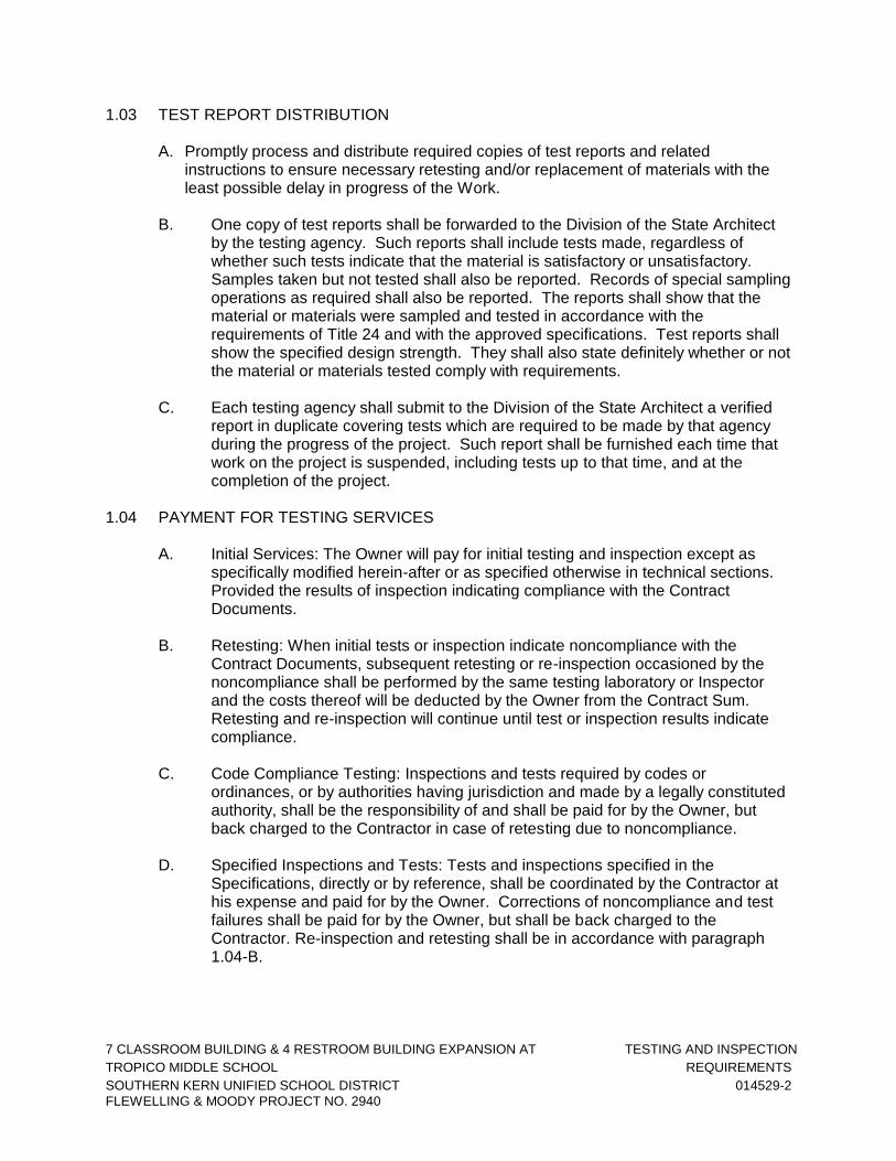
1.03 TEST REPORT DISTRIBUTION
A. Promptly process and distribute required copies of test reports and related instructions to ensure necessary retesting and/or replacement of materials with the least possible delay in progress of the Work.
B. One copy of test reports shall be forwarded to the Division of the State Architect
by the testing agency. Such reports shall include tests made, regardless of whether such tests indicate that the material is satisfactory or unsatisfactory. Samples taken but not tested shall also be reported. Records of special sampling operations as required shall also be reported. The reports shall show that the material or materials were sampled and tested in accordance with the requirements of Title 24 and with the approved specifications. Test reports shall show the specified design strength. They shall also state definitely whether or not the material or materials tested comply with requirements.
C. Each testing agency shall submit to the Division of the State Architect a verified
report in duplicate covering tests which are required to be made by that agency during the progress of the project. Such report shall be furnished each time that work on the project is suspended, including tests up to that time, and at the completion of the project.
1.04 PAYMENT FOR TESTING SERVICES
A. Initial Services: The Owner will pay for initial testing and inspection except as specifically modified herein-after or as specified otherwise in technical sections. Provided the results of inspection indicating compliance with the Contract Documents.
B. Retesting: When initial tests or inspection indicate noncompliance with the
Contract Documents, subsequent retesting or re-inspection occasioned by the noncompliance shall be performed by the same testing laboratory or Inspector and the costs thereof will be deducted by the Owner from the Contract Sum. Retesting and re-inspection will continue until test or inspection results indicate compliance.
C. Code Compliance Testing: Inspections and tests required by codes or
ordinances, or by authorities having jurisdiction and made by a legally constituted authority, shall be the responsibility of and shall be paid for by the Owner, but back charged to the Contractor in case of retesting due to noncompliance.
D. Specified Inspections and Tests: Tests and inspections specified in the
Specifications, directly or by reference, shall be coordinated by the Contractor at his expense and paid for by the Owner. Corrections of noncompliance and test failures shall be paid for by the Owner, but shall be back charged to the Contractor. Re-inspection and retesting shall be in accordance with paragraph 1.04-B.

7 CLASSROOM BUILDING & 4 RESTROOM BUILDING EXPANSION AT TESTING AND INSPECTION
TROPICO MIDDLE SCHOOL REQUIREMENTS
SOUTHERN KERN UNIFIED SCHOOL DISTRICT 014529-3
FLEWELLING & MOODY PROJECT NO. 2940
E. Contractor’s Convenience Testing: Inspecting or testing performed exclusively for the Contractor’s convenience shall be the sole responsibility of and at the expense of the Contractor.
1.05 INSPECTION BY THE OWNER
A. The Owner and his representatives will have access, for the purpose of inspection, to parts of the work and to the shops wherein the work is in preparation, and the Contractor shall maintain proper facilities and provide safe access for such inspection.
B. The Owner shall have the right to reject materials and workmanship which are
defective, and to require their correction. Rejected workmanship shall be satisfactorily corrected and rejected materials shall be removed from the premises without charge to the Owner. If the Contractor does not correct such rejected within a reasonable time, fixed by written notice, the Owner may correct rejected work and charge the expense to the Contractor.
C. Should it be considered necessary or advisable by the Owner at any time before
final acceptance of the entire work to make an examination of work already completed by removing or tearing out the same, the Contractor shall on request promptly furnish necessary facilities, labor and materials. If such work is found to be defective in respect due to fault of the Contractor or his subcontractor, he shall defray expenses of such examinations and of satisfactory reconstruction. If, however, such work is found to meet the requirements of the contract, the additional cost of labor and material necessarily involved in the examination and replacement will be allowed the Contractor.
1.06 PROJECT INSPECTOR
A. A “DSA Certified” project inspector employed by the Owner in accordance with the requirements of State of California Building Code, Title 24, Part 1, and qualified in accordance with Division of State Architect will be assigned to the work. His duties are specifically defined in Title 24, Part 1, Section 4-342, reprinted herein:
42. Duties of the Project Inspector.
(A) General: The Project Inspector shall act under the direction of the A/E/Engineer.
(B) Duties: The general duties of the Project Inspector in fulfilling his
or her responsibilities are as follows:
(1) Inspection: He or she must have actual personal knowledge, obtained by his personal inspection of the work of construction in stages of its progress, that the requirements of the approved plans and specifications are being completely executed.

7 CLASSROOM BUILDING & 4 RESTROOM BUILDING EXPANSION AT TESTING AND INSPECTION
TROPICO MIDDLE SCHOOL REQUIREMENTS
SOUTHERN KERN UNIFIED SCHOOL DISTRICT 014529-4
FLEWELLING & MOODY PROJECT NO. 2940
Inspection means complete inspection of every part of the work. Work, such as concrete work or brick work which can be inspected only as it is placed, shall require the constant presence of the Project Inspector. Other types of work which can be completely inspected after the work is installed may be carried on while the Inspector is not present. In any case, the Project Inspector must personally inspect every part of the work. In no case shall the Project Inspector have or assume duties which will prevent him or her from providing inspection.
The Project Inspector may obtain personal knowledge of the work of construction, either on-site or off-site, performed under the inspection of a Special Inspector or Assistant Inspector from the reporting of others on testing or inspection of materials and workmanship for compliance with the plans, specifications and applicable standards. The exercise of reasonable diligence to obtain the facts shall be required.
(2) Relations with A/E/Engineer: The Project Inspector shall
work under the general direction of the A/E/Engineer. Inconsistencies or seeming errors in the A/E/Engineer for his interpretation and instructions. In no case, however, shall the instruction of the A/E/Engineer be construed to cause work to be done which is not in conformity with the approved plans, specifications, and change orders.
(3) Job File: The Project Inspector shall keep a file of
approved plans and specifications (including approved addenda or change orders) on the job, and shall immediately return unapproved documents to the A/E for proper action. The Project Inspector, as a condition of his employment, shall have and maintain on the job, codes and documents referred to in the plans and specifications.
(4) Project Inspector’s Semi-Monthly Reports: The Project
Inspector shall keep the A/E/Engineer thoroughly informed as to the progress of the work by making semi-monthly reports in writing as required in Section 37.
(5) Not Used.
(6) Construction Procedure Records: The Project Inspector
shall keep a record of certain phases of construction procedure. All such records of construction procedure shall be kept on the job until the completion of the work. These records shall be made a part of the permanent school records.

7 CLASSROOM BUILDING & 4 RESTROOM BUILDING EXPANSION AT TESTING AND INSPECTION
TROPICO MIDDLE SCHOOL REQUIREMENTS
SOUTHERN KERN UNIFIED SCHOOL DISTRICT 014529-5
FLEWELLING & MOODY PROJECT NO. 2940
(7) Deviations: The Project Inspector shall notify the Contractor, in writing, of deviations from the approved plans and specifications which are not immediately corrected by the Contractor when brought to his or her attention. Copies of such notice shall be forwarded immediately to the A/E/Engineer.
Failure on the part of the Project Inspector to notify the
Contractor of deviations from the approved plans and specifications shall in no way relieve the Contractor of responsibility to complete the work covered by his or her contract in accordance with the approved plans and specifications and laws and regulations.
(8) Verified Reports: The Project and Special Inspectors shall
each make and submit to the Division of the State Architect verified reports.
The Project Inspector shall prepare and deliver to the Division of the State Architect detailed statements of fact regarding materials, operations, etc., when requested.
(c) Violations: Failure, refusal, or neglect on the part of the Inspector to notify the Contractor of work which does not comply with the requirements of the approved plans and specifications, or failure, refusal, or neglect to report immediately, in writing, such violation to the A/E/Engineer, to the School Board, and to the Division of the State Architect shall constitute a violation of the act and shall be cause for the Division of the State Architect to take action.
Note: Authority cited: Section 39152 and 81142,
Education Code. Reference: Sections 39151, 39153, 81141 and 81143, Education Code.”
B. The work of construction in stages of progress shall be subject to the personal
continuous observation of the Project Inspector as continuous observation is defined by Title 24. He shall have free access to all parts of the work at any time. The Contractor shall furnish the Project Inspector reasonable facilities for obtaining such information as may be necessary to keep him fully informed respecting the progress and manner of the work and the character of the materials. Inspection of the work shall not relieve the Contractor from obligation to fulfill this Contract.

7 CLASSROOM BUILDING & 4 RESTROOM BUILDING EXPANSION AT TESTING AND INSPECTION
TROPICO MIDDLE SCHOOL REQUIREMENTS
SOUTHERN KERN UNIFIED SCHOOL DISTRICT 014529-6
FLEWELLING & MOODY PROJECT NO. 2940
1.07 OWNER’S OTHER PERSONNEL
A. From time to time, other personnel in the employ of the Owner may inspect the Work when the Work is in progress but shall have no authority to direct the Contractor or request changes in the Work except as may be provided elsewhere in the Contract Documents.
1.08 REPRESENTATIVE OF THE DIVISION OF THE STATE ARCHITECT
A. Architect shall have access to the site in accordance with Title 24, Part 1, 4-333. B. Field Engineers and Inspectors from D.S.A. Structural Safety Section, Fire & Life
Safety Review and Access Compliance shall have access to the site in accordance with Title 24, Part 1, 4-334.
PART 2 - PRODUCTS
(Not Applicable) PART 3 - EXECUTION 3.01 COOPERATION WITH TESTING LABORATORY AND INSPECTORS
A. Inspectors and representatives of the testing laboratory shall have access to the work. Provide facilities for such access in order that the testing, inspection, and the obtaining of samples may be done properly.
B. Contractor shall deliver material specimens to the Owner’s testing lab, which
must by terms of the Contract be tested prior to inclusion in the Project, at least 45 days prior to scheduled delivery to the job site.
C. Material shipped by the Contractor from the source of supply prior to having
satisfactorily passed such testing and inspection or prior to the receipt of notice from said representative that such testing and inspection will not be required shall not be incorporated in the job.
3.02 TAKING SPECIMENS
A. Field specimens and samples for testing, unless otherwise provided in these Contract Documents, shall be selected and taken by the Testing Laboratory or Project Inspector and not the Contractor. Sampling equipment and personnel will be provided by the testing laboratory. Deliveries of specimens and samples to the testing laboratory will be performed by the testing laboratory. Soil samples for approval of import fill shall be picked-up by the Testing Laboratory.

7 CLASSROOM BUILDING & 4 RESTROOM BUILDING EXPANSION AT TESTING AND INSPECTION
TROPICO MIDDLE SCHOOL REQUIREMENTS
SOUTHERN KERN UNIFIED SCHOOL DISTRICT 014529-7
FLEWELLING & MOODY PROJECT NO. 2940
3.03 SCHEDULES FOR TESTING
A. Establishing Schedule:
1. By advance discussion with the testing laboratory selected by the Owner, determine the time required for the laboratory to perform its tests and to issue each of its findings.
2. Provide required time within the construction schedule.
B. Revising Schedule: When changes of construction schedule are necessary
during construction, coordinate such changes of schedule with the testing laboratory as required.
C. Adherence to Schedule: When the testing laboratory is ready to test according to
the determined schedules, but is prevented from testing or taking specimens due to incompleteness of the work, extra charges for testing attributable to the delay may be back-charged to the Contractor and will be deducted by the Owner from the Contract Sum.
3.04 REQUIRED TESTING
Tests and inspections for the following items, where applicable, will be required in accordance with referenced Sections/Chapters of California Building Code, 2019 Edition, Title 24, Part 2:
A. FOUNDATIONS:
1. INSPECTION:
a. Inspection of Cast-In-Place Deep Foundation 1705.8
B. CONCRETE (Chapter 19A)
1. MATERIALS:
a. Portland Cement 1704A.4.1;
1910A.2 b. Concrete Aggregates 1704A.4.1;
1903A.5 c. Not Used
d. Reinforcing Bars 1704A.4.1;
1910A.2
1705A.8

7 CLASSROOM BUILDING & 4 RESTROOM BUILDING EXPANSION AT TESTING AND INSPECTION
TROPICO MIDDLE SCHOOL REQUIREMENTS
SOUTHERN KERN UNIFIED SCHOOL DISTRICT 014529-8
FLEWELLING & MOODY PROJECT NO. 2940
2. QUALITY:
a. Strength Tests of Concrete 1903A.1; 1905A.6
3. INSPECTION:
a. Batch Plant 1705A.3.3 b. Waiver of Batch Plant 1705A.3.3.1 c. Reinforcing Bar Welding 1705A.3; Table 1704A.3 d. Post-Installed Anchors in Concrete 1705A.3.8
C. LIGHT WEIGHT METALS
1. MATERIALS
a. Alloys 2002.1
b. Identification 2002.1
2. INSPECTION
a. Welding 2003.1
D. STRUCTURAL STEEL
1. MATERIALS a. Structural Steel 2205A.1
b. Cold Form Steel 2209A.1
c. Identification 2203A.1
1705A.3
1705A.3
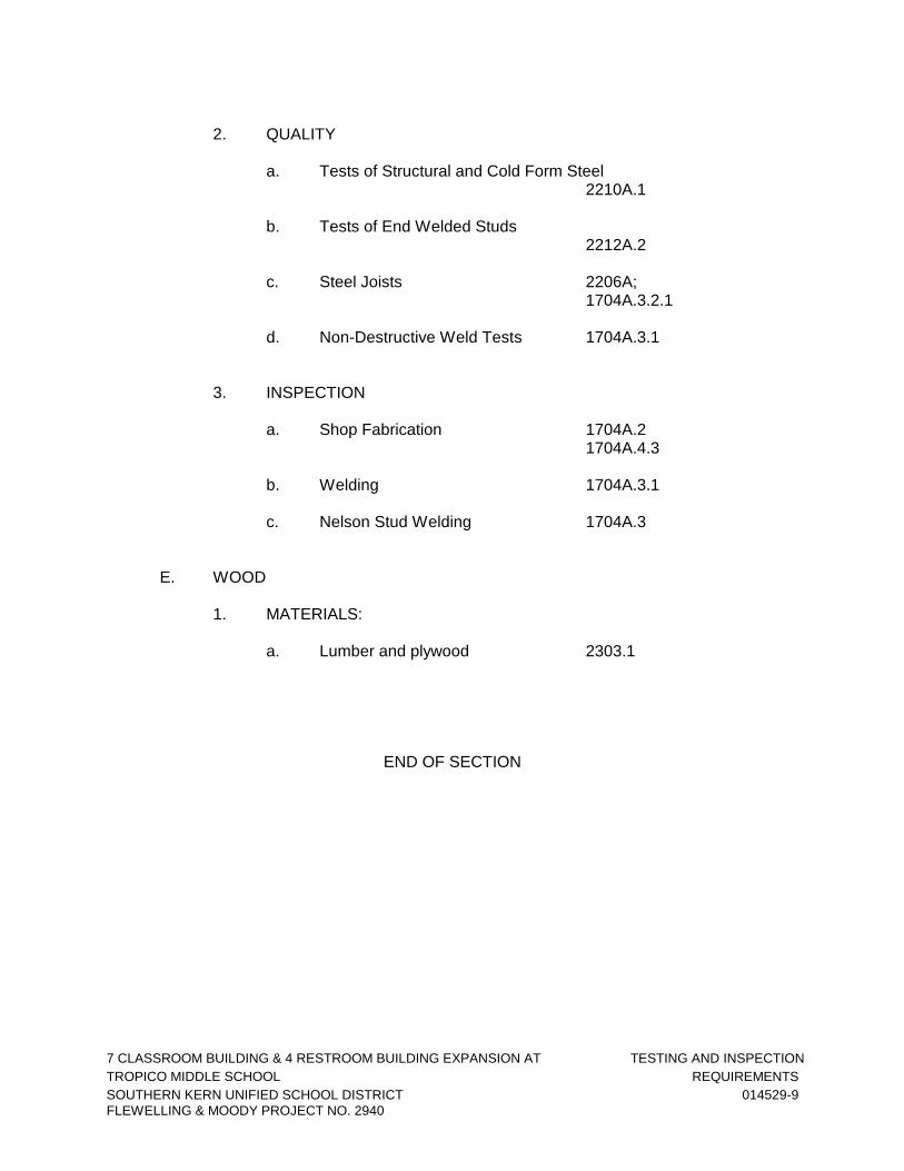
7 CLASSROOM BUILDING & 4 RESTROOM BUILDING EXPANSION AT TESTING AND INSPECTION
TROPICO MIDDLE SCHOOL REQUIREMENTS
SOUTHERN KERN UNIFIED SCHOOL DISTRICT 014529-9
FLEWELLING & MOODY PROJECT NO. 2940
2. QUALITY
a. Tests of Structural and Cold Form Steel
2210A.1
b. Tests of End Welded Studs 2212A.2
c. Steel Joists 2206A; 1704A.3.2.1 d. Non-Destructive Weld Tests 1704A.3.1
3. INSPECTION a. Shop Fabrication 1704A.2
1704A.4.3
b. Welding 1704A.3.1
c. Nelson Stud Welding 1704A.3 E. WOOD 1. MATERIALS: a. Lumber and plywood 2303.1
END OF SECTION

7 CLASSROOM BUILDING & 4 RESTROOM BUILDING EXPANSION AT TEMPORARY FACILITIES
TROPICO MIDDLE SCHOOL 015000-1
SOUTHERN KERN UNIFIED SCHOOL DISTRICT
FLEWELLING & MOODY PROJECT NO. 2940
SECTION 015000 TEMPORARY FACILITIES
PART 1 – GENERAL 1.01 SUMMARY
A. Provide all temporary facilities and controls required for the performance of the Work. B. Supervise the use of all temporary facilities and controls. Enforce compliance with
applicable standards. Prevent abuses of services. 1.02 SAFETY
A. Guard machinery, equipment, and all hazards in accordance with the safety provisions of the latest edition of the Manual of Accident Prevention in Construction, published by the Associated General Contractors of America, to the extent that such provisions are not in contravention of applicable law.
1. Protect all hazards with adequately constructed guard rails or barricades and
provide lanterns, warning lights, and the like, as necessary. Eliminate all attractive nuisance from the work and the room site.
2. To this end, dispose, store, guard, and protect the premises and all work
materials, equipment and both permanent and temporary construction so as to preclude the unauthorized use thereof by children or others and particularly to eliminate possible consequent injury to all persons.
B. Structural design of all items used in the construction of the building and not a
permanent part thereof, including, shoring for concrete and masonry work, the temporary bracing for structural steel, and the shoring of cut earth banks, its the sole responsibility of the Contractor.
1.03 SCAFFOLDING AND HOISTS
A. Furnish and maintain hoists, staging, rigging, scaffolding, and runways required in the prosecution of the work. Erect, equip and maintain such temporary work in accordance with statutes, laws, ordinances, rules or regulations of the State of California and other authorities and Insurance Companies having jurisdiction.
1.04 DUST CONTROL
A. During the life of the Contract, provide effective means of dust control both within the structure and on the surrounding site.
B. Obtain the Architect's approval before use of any means except water. C. Water all active construction areas as often as needed to control dust. D. Cover all trucks hauling soil, sand and other loose materials or require all trucks to
maintain at least 2 feet of freeboard.

7 CLASSROOM BUILDING & 4 RESTROOM BUILDING EXPANSION AT TEMPORARY FACILITIES
TROPICO MIDDLE SCHOOL 015000-2
SOUTHERN KERN UNIFIED SCHOOL DISTRICT
FLEWELLING & MOODY PROJECT NO. 2940
E. Apply water 3 times daily, or apply non-toxic soil stabilizers on all unpaved access
roads, parking areas and staging areas at construction site. F. Sweep daily with water sweeper, all paved access roads, parking areas and staging
areas at construction site. G. Sweep streets daily with water sweeper, if visible soil material is carried onto
adjacent public streets. H. Hydroseed or apply non-toxic stabilizers to inactive construction areas (previously
graded areas inactive for 10 days or more). I. Enclose, cover water twice daily or apply non-toxic soil binders to exposed stockpiles
of dirt, sand and other loose materials.
J. Limit traffic speed on unpaved roads to 15 mph.
K. Install sandbags or other erosion control measures to prevent silt runoff to public roadways.
L. Replant vegetation in disturbed areas as quickly as possible.
1.05 MAINTENANCE OF TRAFFIC
A. Maintain traffic on all streets adjacent to or leading to the site. B. Where construction operations interfere with the free movement of traffic, provide
traffic controls, flagmen or similar devices to efficiently control traffic movement. C. Provide a traffic control permit from the local authorities if required. D. Schedule delivery of materials and construction activities so that they do not interfere
with student/public traffic at drop-off and pick-up. 1.06 DEWATERING
A. Furnish and maintain all pumps or other dewatering devices required by this Work. 1.07 PROJECT OFFICE
A. Provide and maintain, for the duration of the Contract, a project office, complete with heat, light, ventilation and convenience outlets. The office shall be of sufficient size for the Contractor's personnel and operators and shall provide desk space for use by the Architect and for inspection personnel.
1.08 TELEPHONE
A. Provide and pay for all necessary temporary telephone service.

7 CLASSROOM BUILDING & 4 RESTROOM BUILDING EXPANSION AT TEMPORARY FACILITIES
TROPICO MIDDLE SCHOOL 015000-3
SOUTHERN KERN UNIFIED SCHOOL DISTRICT
FLEWELLING & MOODY PROJECT NO. 2940
B. Maintain telephone(s) in continuous service on the project site during the course of
the Work and make available at all times, free and unrestricted, to the Architect's and District's representatives for calls in direct connection with the Work.
1.09 TEMPORARY TOILETS
A. Provide temporary toilet facilities for all personnel employed on the Project. Maintain toilets in a clean and sanitary condition at all times. Remove at Project completion.
1.10 CONSTRUCTION WATER AND POWER
A. Make arrangements for all water and power required for the Project. Provide all temporary lines and arrange for billing to go directly to District. Remove temporary facilities at Project completion.
1.11 FENCES AND BARRICADES/SECURITY
A. Around the construction site, erect fences and barricades with gates, as required by local governing authorities, for security and to prevent unauthorized entry to the Work site. Maintain in good condition until completion of the Project.
1.12 SIGNS
A. Furnish and erect a ¾ in. x 48 in. x 96 in. job sign painted and lettered to identify the Project, the Architect and the Contractor. Mount on post and brace as indicated by the Architect. Sign shall be lettered by a professional sign painter, and the layout shall be as indicated by the Architect.
B. Keep the premises free from all other posters, signs, and miscellaneous decorations,
except those required by Code and to indicate unsafe conditions. 1.13 COPIES OF STANDARDS AND CODES
A. Copies of applicable referenced standards are not bound in this Project manual. B. Copies of standards and California Building Code, Title 24, Parts I and II and shall
be kept and available at the Project Site, available to the Contractor’s personnel, Sub-contractors, District, Inspectors and Architect.
END OF SECTION
7 CLASSROOM BUILDING & 4 RESTROOM BUILDING EXPANSION AT PRODUCT HANDLING
TROPICO MIDDLE SCHOOL 016600-1
SOUTHERN KERN UNIFIED SCHOOL DISTRICT
FLEWELLING & MOODY PROJECT NO. 2940
SECTION 016600 PRODUCT HANDLING
1.00 GENERAL 1.01 SUMMARY
A. Section includes:
1. This Section establishes general requirements for product handling and storage, whether on or off site, and supplements similar provisions found elsewhere in the Contract Documents.
1.02 HANDLING
A. General: Transport, deliver, handle, and store all materials and equipment used on the Project to prevent the intrusions of foreign matter, moisture, and to prevent damage. In all cases comply with the following.
1. Material and equipment manufacturer's printed instructions regarding
temperature limitations.
2. Other environmental conditions which are required to maintain original quality of materials and equipment.
B. Packaging:
1. Provide packaged materials in their manufacturer's original containers with
seals unbroken and labels intact until incorporating into the Work.
2. Wrapped or bundled materials shall clearly bear the manufacturer's name and trade mark.
C. Damaged materials: Remove damaged or otherwise unsuitable material and
equipment promptly from the site. Do not install damaged materials. 1.03 STORAGE
A. Inspect products upon delivery to ensure compliance with the Contract Documents, and to ensure that products are undamaged and properly protected.
B. Store products at the site to facilitate inspection and measurement of quantity or
counting of units.
C. Store heavy materials away from the Project structure in a manner that will not endanger the supporting construction.

7 CLASSROOM BUILDING & 4 RESTROOM BUILDING EXPANSION AT PRODUCT HANDLING
TROPICO MIDDLE SCHOOL 016600-2
SOUTHERN KERN UNIFIED SCHOOL DISTRICT
FLEWELLING & MOODY PROJECT NO. 2940
1. Do not subject slabs-on-grade to excessive loading by shoring, storage of materials or operation of construction equipment unless adequately protected by heavy planking. Maintenance of slabs in good condition is the responsibility of the Contractor who shall remove damaged areas of such slabs and replace them with new work, to the Architect's satisfaction, at no cost to the Owner.
D. Store products subject to damage by elements above ground, under cover in
weathertight enclosure, with ventilation adequate to prevent condensation. Maintain temperature and humidity within range required by manufacturer's instructions.
E. Schedule delivery to minimize long-term storage at the site and to prevent
overcrowding of construction spaces.
F. Coordinate delivery with installation time to ensure minimum holding time for items that are flammable, hazardous, easily damaged, or sensitive to deterioration, theft and other losses.
G. Locate storage piles, stacks or bins to avoid being disturbed, and protect from
damage of any sort.
H. Store materials and equipment in accord with their manufacturer's instructions, above grade, and properly protected from weather and construction activities.
I. Payment may be withheld for improperly packaged and stored materials.
1.04 PROTECTION
A. Protect all finished surfaces, including floors, jambs, and soffits of all openings used as passageways or through which materials and equipment must travel.
B. Carts, hand trucks, wheelbarrows and similar wheeled conveyances used on or in any
portion of the buildings shall be equipped with pneumatic tires, unless otherwise authorized by the Architect.
C. Keep finished surfaces clean and unmarred until the date of acceptance. D. Refer to individual Specification Sections for additional specific product handling and
protection requirements. 2.00 PRODUCTS Not used. 3.00 EXECUTION Not used.
END OF SECTION

7 CLASSROOM BUILDING & 4 RESTROOM BUILDING EXPANSION AT CLEANING
TROPICO MIDDLE SCHOOL 017400-1
SOUTHERN KERN UNIFIED SCHOOL DISTRICT
FLEWELLING & MOODY PROJECT NO. 2940
SECTION 017400 CLEANING
1.00 GENERAL 1.01 DESCRIPTION
A. Principal work in this Section:
1. Keep premises, and adjacent private and public properties free from accumulations of waste, debris and rubbish caused by construction operations.
2. At completion of Work, remove waste materials, rubbish, tools, equipment,
machinery and surplus materials, and clean all exposed surfaces. Remove remaining mock-ups and sample panels.
3. Leave Project clean and ready for occupancy.
1.02 SAFETY REQUIREMENTS
A. Standards: Maintain Project in accord with State and local safety and insurance standards.
B. Hazard control:
1. Store volatile wastes in covered metal containers, and remove from premises
daily.
2. Prevent accumulation of wastes which create hazardous conditions.
3. Provide adequate ventilation during use of volatile or noxious substances.
C. Conduct cleaning and disposal operations to comply with local ordinances and anti-pollution laws.
1. Do not burn or bury rubbish and waste materials on Project site.
2. Do not dispose of volatile wastes such as mineral spirits, oil, or paint thinner in
storm or sanitary drains. Store in containers with tight-fitting lids and remove to legal dump site or to recycling center.
2.00 PRODUCTS Not used. 3.00 EXECUTION

7 CLASSROOM BUILDING & 4 RESTROOM BUILDING EXPANSION AT CLEANING
TROPICO MIDDLE SCHOOL 017400-2
SOUTHERN KERN UNIFIED SCHOOL DISTRICT
FLEWELLING & MOODY PROJECT NO. 2940
3.01 DURING CONSTRUCTION
A. Keep premises, and adjacent private and public properties free from accumulations of waste materials and rubbish. Remove debris and dirt from public property promptly; sweep sidewalks and adjacent streets daily when soiled by work performed under this Contract.
B. Wet down materials and rubbish to lay dust and prevent it from blowing.
C. At least once a week, or more often if required, clean site and dispose of waste
materials, debris and rubbish off the site in a legal manner. Remove combustible materials such as paper and cardboard daily.
D. Provide on-site containers for collection of waste materials, debris and rubbish.
Provide a collection can at each location used as an eating area. Pick-up all garbage daily.
E. Remove waste materials, debris and rubbish from site and legally dispose of at legal
public or private dumping areas or recycling center off District's property.
F. Do not allow debris and combustible materials to accumulate in, voids, cavities, and plenums created by wall, partition, and ceiling construction. These areas must be thoroughly cleaned out before being sealed or closed off by installation of finish materials.
G. Do not allow debris to clog drains. Clean roof drains, scuppers, floor drains and area
drains free of debris. Verify that they drain properly. Keep drains clean of debris at all times.
H. Vacuum clean interior areas when ready to be painted. Refer to Section 09900 for
other provisions on preparation of surfaces to be painted.
I. Handle materials in a controlled manner with as few handling as possible; do not drop or throw materials from heights.
J. Schedule cleaning operations so that dust and other contaminants resulting from cleaning process will not fall on wet, newly painted surfaces.
3.02 FINAL CLEANING
A. Employ experienced workers, or professional cleaners, for final cleaning.
B. In preparation for Substantial Completion or Occupancy conduct final inspection of sight-exposed interior and exterior surfaces, and of concealed spaces.
C. Remove labels that are not permanent labels.
D. Clean transparent materials, including mirrors and glass in doors and windows.
Remove misplaced glazing compound and other substances. Replace chipped or broken glass and other damaged transparent materials.
7 CLASSROOM BUILDING & 4 RESTROOM BUILDING EXPANSION AT CLEANING
TROPICO MIDDLE SCHOOL 017400-3
SOUTHERN KERN UNIFIED SCHOOL DISTRICT
FLEWELLING & MOODY PROJECT NO. 2940
E. Clean exposed exterior and interior hard-surfaced finishes to a dust-free condition, free of stains, films and similar foreign substances. Restore reflective surfaces to their original reflective condition. Leave concrete floors broom clean. Vacuum carpeted surfaces.
F. Wipe surfaces of mechanical and electrical equipment. Remove excess lubrication
and other substances. Clean plumbing fixtures to a sanitary condition. Clean light fixtures and lamps.
G. Clean the site, including landscaped areas, of rubbish, litter and other foreign sub-
stances.
1. Contaminated earth:
a. Final clean-up operation includes the removal and disposal of earth contaminated or unsuitable for support of plant life in planting areas, and filling of resulting excavations with suitable soil.
b. Contaminated areas include those used for disposal of waste concrete,
mortar, plaster, masonry, and similar materials, areas in which washing out of concrete and plaster mixers or washing of tools and like cleaning operations have been performed, and areas that have been oiled, paved, or chemically-treated.
c. Do not dispose of waste oil, solvents, paints, solutions, or like penetrating
material by depositing or burying on District's property.
2. Sweep paved areas broom clean; remove stains, spills and other foreign deposits.
3. Rake grounds that are neither paved nor planted, to a smooth even-textured
surface.
H. Keep Project clean until it is occupied by District.
END OF SECTION

7 CLASSROOM BUILDING & 4 RESTROOM BUILDING EXPANSION AT PROJECT RECORD DOCUMENTS
TROPICO MIDDLE SCHOOL 017720-1
SOUTHERN KERN UNIFIED SCHOOL DISTRICT
FLEWELLING & MOODY PROJECT NO. 2940
SECTION 017720 PROJECT RECORD DOCUMENTS
1.00 GENERAL 1.01 SUMMARY
A. Section includes: General requirements for preparation, maintenance and delivery of record documents.
1.02 SUBMITTALS
A. Deliver record documents and transparencies to Architect at completion of Project.
B. Accompany submittal with transmittal letter, in duplicate, containing date, Project title and number, Contractor's name and address, title and number of each record document, certification that each document as submitted is complete and accurate, and signature of Contractor or its authorized representative.
2.00 PRODUCTS Not Used. 3.00 EXECUTION 3.01 DOCUMENT MAINTENANCE
A. Maintain one copy of the following in Contractor's field office at the site:
1. Contract Drawings, including the DSA stamped set.
2. Specifications and Addenda.
3. Reviewed shop drawings.
4. Bulletins and change orders, field change authorization and notice of clarification, and other modifications to Contract.
5. Field test records.
B. File record documents apart from constructions documents and maintain in clean, dry,
legible condition. Make record documents available for review by the Owner and Architect during regular business hours.
C. Do not use record documents for construction purpose.
D. Record documents will be subject to a monthly review by the Architect prior to
approval of each progress payment.

7 CLASSROOM BUILDING & 4 RESTROOM BUILDING EXPANSION AT PROJECT RECORD DOCUMENTS
TROPICO MIDDLE SCHOOL 017720-2
SOUTHERN KERN UNIFIED SCHOOL DISTRICT
FLEWELLING & MOODY PROJECT NO. 2940
3.02 RECORDING
A. Clearly label each document "PROJECT RECORD".
B. Keep record documents current.
C. Record and properly dimension deviations on the record drawings within 24 hours after work in affected area is completed. Dimensions shall be accurate to within 1 in.
1. Use a fine felt or nylon tip pen with waterproof colored ink for marking.
2. Legibly mark to record actual construction of the following:
a. Depths of various elements of foundation in relation to first floor level.
b. Horizontal and vertical location of underground utilities and appurtenances
referenced to permanent surface improvements. Cut-off points and point of connections of utilities.
c. Location of internal utilities and appurtenances concealed in construction
referenced to visible and accessible features of structure.
d. Field changes of dimension and detail.
e. Changes made by Change Order, Field Change Authorization and Notice of Clarification.
f. Details not on original Contract Drawings.
g. Do not permanently conceal any work until required information has been
recorded.
D. Legibly mark-up each Section of the Specifications to record the following.
1. Manufacturer, trade name, catalog number, and supplier of each product and item of equipment installed.
2. Changes made by change order, field change authorization and notice of
clarification. 3. Other matters not originally specified.
E. Maintain shop drawings as record documents. Legibly annotate to record changes
made after approval.
END OF SECTION

7 CLASSROOM BUILDING & 4 RESTROOM BUILDING EXPANSION AT OPERATING AND
TROPICO MIDDLE SCHOOL MAINTENANCE DATA
SOUTHERN KERN UNIFIED SCHOOL DISTRICT 017823-1
FLEWELLING & MOODY PROJECT NO. 2940
SECTION 017823 OPERATING AND MAINTENANCE DATA
1.00 GENERAL 1.01 SUMMARY
A. Prepare all maintenance manuals and operating instructions required by the Specifications.
B. Bind manuals and instructions in durable plastic binders as follows:
1. Identify the front cover and binding edge of the manual with the name of the
Project and
"OPERATING AND MAINTENANCE DATA."
2. Provide typewritten table of contents near the front of manual with page numbers to quickly locate the information.
3. Provide complete instructions regarding operation and maintenance of all
equipment involved, including but not limited to, start-up and shut-down procedures, and safety precautions.
4. Provide complete nomenclature of all replaceable parts, their part numbers,
current cost, and name and address of nearest vendor of parts.
5. Provide copy of guarantees and warranties issued by the equipment manufacturers.
6. Provide copy of the approved shop drawings, as applicable to the content of the
manual, with all data concerning changes made during construction.
7. Use 8-1/2 in. by 11 in. sheets, except that larger sheets may be used when folded to this size and used as a pull-out.
C. Where content of manuals include manufacturers' catalog pages, clearly indicate the
precise items included in this installation and delete, or otherwise clearly indicate all manufacturers' data with which this installation is not concerned.
D. Unless otherwise specified, provide one copy of each manual.
END OF SECTION

7 CLASSROOM BUILDING & 4 RESTROOM BUILDING EXPANSION AT TRENCHING AND BACKFILLING
TROPICO MIDDLE SCHOOL FOR UTILITIES
SOUTHERN KERN UNIFIED SCHOOL DISTRICT 023100-1
FLEWELLING & MOODY PROJECT NO. 2940
SECTION 023100 TRENCHING AND BACKFILLING FOR UTILITIES
1.00 GENERAL 1.01 SUMMARY
A. Section includes:
1. Trenching, backfilling and compacting for utilities.
2. Bedding material for pipes.
B. Related work:
1. All other trenching, shoring and bracing, backfilling, and compacting: Section 023100.
2. Installation and tests of utilities: Division 33.
1.02 QUALITY ASSURANCE
A. Obtain District's Geotechnical Engineer's approval of backfill materials, method of placement, and of the completed work of this Section.
B. Reference data: Maps, soil investigation reports, and similar reference data are made
available to Contractor for information only. District and Architect assume no responsibility for conclusions the Contractor may draw there from.
C. Reference standard:
2. Perform all work in compliance with applicable provisions of "Standard
Specifications for Public Works Construction" (SSPWC). Mention herein of section numbers refers to sections of the reference standard.
3. Where reference standard refers to "Agency," substitute the word "District."
Where reference standard is in conflict with these Specifications, these Specifications govern.
1.03 SOIL INVESTIGATION REPORT
A. Refer to the General Conditions. 1.04 WARRANTY
A. Any settling of backfill in trenches which may occur during the one-year period after Substantial Completion shall be repaired to District's satisfaction by Contractor without expense to District, including complete restoration of damaged paving, walks, and other materials or installations of every kind.
7 CLASSROOM BUILDING & 4 RESTROOM BUILDING EXPANSION AT TRENCHING AND BACKFILLING
TROPICO MIDDLE SCHOOL FOR UTILITIES
SOUTHERN KERN UNIFIED SCHOOL DISTRICT 023100-2
FLEWELLING & MOODY PROJECT NO. 2940
2.00 PRODUCTS 2.01 IMPORTED MATERIAL Not used. 2.02 ON-SITE MATERIALS
A. Materials from cuts or excavations, approved by the Geotechnical Engineer, free of debris and without soft, spongy, organic and other deleterious materials.
1. Do not use cobbles or boulders larger than 4 in. in largest dimensions at any
depth.
2. Do not use rocks greater than 2-1/2 in. in largest dimension in backfill within 12 in. of the top of pipe or structure, and within 12 in. of the top of pavement subgrade.
3. Where rocks are included in backfill, mix with suitable materials to eliminate
voids. 2.03 BEDDING MATERIALS
A. Complying with section 306.1.2.1, Bedding, of the reference standard.
3.00 EXECUTION 3.01 INSPECTION
A. Verify conditions and measurements affecting the work of this Section at site. Make sure that detrimental conditions are corrected before proceeding with installation.
3.02 PROTECTIVE MEASURES
A. Utilities: Protect existing utility lines.
B. Settlement:
1. In areas where compacted backfill has been placed, additional consolidation will occur after completion due to changes in moisture content and surcharge.
2. Install utility connections crossing this backfill to the building, and improvements
adjoining the building at the backfill line, to take into account this additional consolidation, or schedule sufficient time between backfilling operations and such improvements to allow this consolidation to take place.

7 CLASSROOM BUILDING & 4 RESTROOM BUILDING EXPANSION AT TRENCHING AND BACKFILLING
TROPICO MIDDLE SCHOOL FOR UTILITIES
SOUTHERN KERN UNIFIED SCHOOL DISTRICT 023100-3
FLEWELLING & MOODY PROJECT NO. 2940
3.03 COMPACTION CONTROL
A. Notification: Notify the Geotechnical Engineer whenever trench backfill work is being performed as part of this Section.
B. Replacement: Geotechnical Engineer will determine if work performed without
inspection meets the requirements of these Specifications. Where directed by Geotechnical Engineer, uncover and replace work performed without inspection at no additional cost to the District.
3.04 TRENCH EXCAVATION
A. Before opening any new excavations, uncover all intersecting existing utility lines located between the ground surface and one foot below the bottom of the new trench line.
1. General:
a. Where unidentified existing utilities are encountered, determine whether
these are active or abandoned.
b. Remove interfering portions of abandoned utilities and cap or plug open ends of pipe to remain.
c. The cap or plug must seal the opening in such a manner that would permit
remaining portion of the utility to be reactivated. d. Notify Architect for instructions on utilities which are determined to be
active. Any relocation work performed on an active utility without obtaining prior approval of Architect will be done at the Contractor's risk and expense.
e. Do not proceed without instructions, except to correct an immediate
hazard or emergency condition.
2. Trench width:
a. Maximum width of trench shall be 20 in. more than greatest diameter of pipe up to a point 6 in. above top of the pipe, except that it may be widened enough to place sheeting.
b. Make trenches at least 12 in. wider than greatest exterior diameter of pipe
or conduit except that trenches for concrete-encased ducts may be the same width as duct encasement.
3. Dimensional tolerance:
a. Maintain accuracy of gravity utility lines designated for gradients less than
1% to 1/8 in. at any point and cumulative within 1/2 in./100 ft.

7 CLASSROOM BUILDING & 4 RESTROOM BUILDING EXPANSION AT TRENCHING AND BACKFILLING
TROPICO MIDDLE SCHOOL FOR UTILITIES
SOUTHERN KERN UNIFIED SCHOOL DISTRICT 023100-4
FLEWELLING & MOODY PROJECT NO. 2940
b. For all gravity lines, check each section of pipe for proper gravity slope direction with a string line set over the pipe by a surveyor.
c. Non-gravity utility line subgrades shall be accurate within +2 in.
3.05 PIPE BEDDING
A. Where bedding is required, provide a minimum of 4 in. of bedding material in the bottom of the trench, in addition to the requirements of section 306-1.2.1 of the reference standard, before installing pipes or conduits.
B. Do not allow water to accumulate in the trench.
3.06 DEWATERING
A. At no time shall water be allowed to back up into pipe in place. Securely plug terminal ends of pipe before work is abandoned at end of day or when laying is interrupted.
3.07 TRENCH BACKFILL
A. Backfilling of utility trenches shall not be undertaken (1) for 24 hours after Geotechnical Engineer has been notified of same, (2) until required tests and inspections have been completed, and (3) until "as-built" location notes have been recorded.
B. Place backfill material in compliance with section 306-1.3.2 of the reference standard,
and to achieve at least 90% of the maximum density in compliance with ASTM D 1557. The top 12 in. of backfill in the building and under paved areas shall be compacted to 95% of maximum density.
C. Compaction by jetting, ponding or flooding is not permitted.
D. Remove surplus earth left after backfilling, and grade top of trench to match adjacent
grades.
E. Backfill voids left by removal of sheeting, piles, and similar sheeting supports immediately with clean sand to assure dense and complete filling of voids.
END OF SECTION

7 CLASSROOM BUILDING & 4 RESTROOM BUILDING EXPANSION AT SITE DEMOLITION AND
TROPICO MIDDLE SCHOOL CLEARING
SOUTHERN KERN UNIFIED SCHOOL DISTRICT 024119-1
FLEWELLING & MOODY PROJECT NO. 2940
SECTION 024119 SITE DEMOLITION AND CLEARING
1.00 STANDARDS 1.01 SUMMARY A. Section includes:
1. Demolition and removal from Owner’s property concrete and asphalt pavement and curbs.
2. Demolition and removal from Owner’s property landscaping, trees
designated to be removed and irrigation piping and related items.
3. Demolition and removal from Owner’s property underground utilities where shown on drawings and as required to complete project.
4. Abandon facilities and utilities. 5. Backfilling voids created by removing demolished items.
6. Contacting contaminated soils. 7. Disposal of demolished/removed items.
8. Dust control. 9. Erosion control.
10. Tree protection. 1.02 REQUIREMENTS A. Geotechnical Engineering Report has been prepared by Earth Systems for the
Tropico Middle School expansion project. Copies of this report and any addenda are available for review at the office of the Owner's Representative.
B. Construction materials and methods shall be in accordance with the site-specific
recommendations and standard specifications contained in the Geotechnical Engineering Report.
C. A Geotechnical Engineer employed by the Owner to perform observation, testing
and reporting during construction in accordance with the contract documents (hereinafter referred to as the Construction-Phase Geotechnical Engineer).
D. Observation

7 CLASSROOM BUILDING & 4 RESTROOM BUILDING EXPANSION AT SITE DEMOLITION AND
TROPICO MIDDLE SCHOOL CLEARING
SOUTHERN KERN UNIFIED SCHOOL DISTRICT 024119-2
FLEWELLING & MOODY PROJECT NO. 2940
1. Refer to Section 014529, Testing Laboratory and Inspection Services, for additional requirements.
2. Clearing and grubbing operations shall be observed by the Construction
Phase Geotechnical Engineer. 3. Demolition operations requiring excavation more than 12 inches below
existing ground surface shall be continuously observed by the Construction-Phase Geotechnical Engineer.
4. All plugging of pipelines or conduits allowed to be abandoned in place
outside of building and pavement areas shall be observed by the Construction-Phase Geotechnical Engineer.
5. Contractor shall notify the Construction-Phase Geotechnical Engineer
and the Owner's Representative at least five (5) working days prior to commencement of clearing operations.
6. The cost of observation by the Construction-Phase Geotechnical
Engineer shall be borne by the Owner. 7. The Construction-Phase Geotechnical Engineer shall certify that site
demolition was properly completed in conformance with the Drawings and Specifications. Certification shall be in the form of a report to the Owner's Representative.
2.00 MATERIALS (Not Used) 3.00 EXECUTION 3.01 LOCATING AND MARKING FACILITIES A. Before beginning clearing or other excavation, determine the location of all
existing buried conduits and structures which are to remain within the work area and mark these locations at the site with paint and/or flags.
3.02 CLEARING AND GRUBBING
A. Prior to commencing grading operations, clear the existing ground surface of areas to be graded of all organic material vegetation (except trees indicated on the Drawings to remain), whether living or dead, including large roots, as well as all trash and debris, as determined by the Construction Phase Geotechnical Engineer.
B. Prior to commencing grading operations, excavate and remove from areas to be
graded all existing non-complying fill and soil containing debris, organics, pavement and other unsuitable material as determined by the Construction Phase Geotechnical Engineer.
7 CLASSROOM BUILDING & 4 RESTROOM BUILDING EXPANSION AT SITE DEMOLITION AND
TROPICO MIDDLE SCHOOL CLEARING
SOUTHERN KERN UNIFIED SCHOOL DISTRICT 024119-3
FLEWELLING & MOODY PROJECT NO. 2940
3.03 DEMOLITION A. Where demolition areas are indicated on the Drawings and/or called for in the
Specifications, clear old pavements, old foundations, slabs, curbs, gutters, abandoned pipelines and conduits, and soils contaminated during demolition operations as determined by the Construction Phase Geotechnical Engineer, EXCEPT WHERE SUCH CLEARING OPERATIONS MAY JEOPARDIZE EXISTING TREES OR STRUCTURES TO REMAIN ("jeopardize" with respect to a tree shall mean excavation within the drip line and "jeopardize" with respect to a structure shall mean excavation below a line projected downward at a 2 horizontal to 1 vertical slope from a point 1 foot above the bottom of the foundation); in such case, request direction form the Owner's Representative before proceeding with the work.
1. In addition to demolition, which may be indicated on the Drawings, make
a thorough search for abandoned facilities such as septic systems, wells, fuel or water storage tanks, and pipelines or conduits. Remove any such abandoned facilities encountered, EXCEPT WHERE SUCH REMOVAL OPERATIONS MAY JEOPARDIZE EXISTING TREES OR STRUCTURES TO REMAIN ("jeopardize" with respect to a tree shall mean excavation within the drip line and "jeopardize" with respect to a structure shall mean excavation below a line projected downward at a 2 horizontal to 1 vertical slope from a point 1 foot above the bottom of the foundation); in such case, request direction from the Owner's Representative before proceeding with the work.
B. Abandoned facilities shall not remain in place within building and pavement
areas. Building area is defined as that area within, and extending a minimum of 5 feet outside of, the perimeter of the building and the perimeter of steps, landings, patios, walkways and the like which are contiguous with the building. Pavement area is defined as that area within, and extending a minimum of 3 feet outside of, the limits of asphalt or concrete pavement and the limits of curb, gutter, and sidewalk contiguous with the pavement.
C. If pipelines or conduits are allowed to be abandoned in place outside of building
and pavement areas, plug all exposed openings with stiff concrete placed within the pipeline/conduit to a minimum of five (5) lineal feet beyond the opening and rodded to remove voids. All such plugging operations shall be observed by the Construction-Phase Geotechnical Engineer.
3.04 BACKFILLING VOIDS A. Immediately replace voids or disturbed areas created during clearing and
demolition operations, and which extend below the recommended over-excavation depth, with native fill compacted to at least 90 percent relative compaction as determined by the latest approved edition of ASTM D1557. Do not place any fill until the underlying soil has been observed by the Construction-Phase Geotechnical Engineer. All fill and backfill shall be observed, tested and approved by the Construction-Phase Geotechnical Engineer.

7 CLASSROOM BUILDING & 4 RESTROOM BUILDING EXPANSION AT SITE DEMOLITION AND
TROPICO MIDDLE SCHOOL CLEARING
SOUTHERN KERN UNIFIED SCHOOL DISTRICT 024119-4
FLEWELLING & MOODY PROJECT NO. 2940
3.05 CONTAMINATED SOIL A. If abandoned septic tanks or fuel tanks or other potential sources of
contamination or hazardous waste are encountered or if soil, which appears to be contaminated, is encountered, immediately notify the Owner's Representative.
3.06 DISPOSAL
A. Remove from the work area, transport to a suitable location, and legally dispose of all unsuitable soil materials, rubbish, and debris resulting from clearing, demolition, and grading operations.
B. Burning is not permitted.
3.07 DUST CONTROL
A. Employ all labor, equipment and methods required to prevent construction operations from producing dust in amounts damaging to persons, property, vegetation and animals or causing a nuisance to persons occupying buildings in the vicinity of the job site. Continue dust abatement measures until relief is granted by the Owner's Representative.
1. Contractor shall be responsible for any damage caused by dust resulting
from his operations. 3.08 EROSION CONTROL A. Develop and implement an erosion control plan to provide for containment of
siltation resulting from storm and other water runoff to prevent damage to the environment and adjacent property.
3.09 TREE PROTECTION A. All clearing and grading operations within the drip line of trees to remain shall be
approved in advance and observed by Landscape Architect or Arborist employed by the Owner.
B. Comply with tree protection requirements, see specification section 02812.
4.00 SUBMITTALS (Not Used)
END OF SECTION

7 CLASSROOM BUILDING & 4 RESTROOM BUILDING EXPANSION AT CONCRETE FORMWORK
TROPICO MIDDLE SCHOOL 031114-1
SOUTHERN KERN UNIFIED SCHOOL DISTRICT
FLEWELLING & MOODY PROJECT NO. 2940
SECTION 031114 CONCRETE FORMWORK
1.00 GENERAL 1.01 SUMMARY
A. Section includes:
1. Forms for cast-in-place concrete.
2. Shoring, bracing, accessories and form coating.
B. Work installed but furnished in other Sections:
1. Inserts, bolts, anchors and other items furnished by other trades for installation in formed concrete.
1.02 QUALITY ASSURANCE
A. Lumber and plywood shall be grade-marked by a grading agency acceptable to the DSA and Title 24 CAC.
1.03 HANDLING
A. Store form facing materials above ground on framework or blocking. Protect from moisture and damage. Handle form facing materials to prevent damages which could be transferred to the concrete.
2.00 PRODUCTS 2.01 MATERIALS
A. Forms for exposed concrete surfaces: Plywood, metal, metal-framed/plywood faced, or FRP, providing continuous, flat, smooth exposed concrete surfaces. Furnish in largest practicable sizes to minimize number of joints and to conform to joint system shown on Drawings where indicated.
B. Forms for concealed concrete surfaces: Plywood, lumber, metal, or other acceptable
material. Provide lumber dressed on at least 2 edges and one side for tight fit.
C. Form ties and spreaders: Cone or snap type ties designed to be completely removed from wall, or to break off and provide minimum 1-1/2 in. coverage over ends of the portion of snap tie remaining in the concrete.
1. Do not use wire ties, wood spreaders, or embedded types in which embedded
portion is less than 1-1/2 in. from exterior face of concrete.

7 CLASSROOM BUILDING & 4 RESTROOM BUILDING EXPANSION AT CONCRETE FORMWORK
TROPICO MIDDLE SCHOOL 031114-2
SOUTHERN KERN UNIFIED SCHOOL DISTRICT
FLEWELLING & MOODY PROJECT NO. 2940
D. Chamfer strips: Extruded PVC, with 3/4 in. diagonal faces unless otherwise indicated, by The Burke Co., Greenstreak Plastic Products Co., or Sonneborn-Rexnord, Inc., or oiled softwood shapes with the same profile.
E. Form coatings: Commercial formulation form-coating compounds with a maximum
VOC of 350 mg/l that will not bond with, stain or adversely affect concrete surfaces and will not impair subsequent treatments of concrete surfaces.
F. Prefabricated construction joint keyways: Key-Loc by Form-A-Key Products Div., or
Keyed Kold Joint by The Burke Co., complete with all accessories. 3.00 EXECUTION 3.01 INSPECTION
A. Verify conditions and measurements affecting the work of this Section at site. Make sure that detrimental conditions are corrected before proceeding with installation.
3.02 FORM TYPES
A. General: Comply with the applicable provisions of ACI 347, Guide to Formwork for Concrete, and APA Design/Construction Guide, Concrete Forming.
1. Design and construction of forms is Contractor's responsibility, but shall comply
with specified requirements.
2. Form contact surfaces shall be clean, free from dents, holes and other imperfections.
3. Establish and maintain benchmarks, lines and controls necessary to achieve
specified tolerances. Take an accurate survey of the form location just prior to concrete pour.
B. Earth bank: Except for exterior face of wall footings and grade beams which must be
formed, earth banks may be used to form footings and grade beams if the soil is firm, neatly trimmed, and will retain concrete in the required size and shape.
1. The concrete coverage shall be increased as noted on the Drawings when
concrete is cast against earth.
C. Wood forms:
1. Construct with plywood panels as large as practicable. Where because of their height walls or columns have a horizontal form joints, the horizontal joint shall be aligned throughout the same floor, or area, unless otherwise acceptable to the Architect.
2. Seal joints between plywood panels flush with compound specifically designed
to seal forms, or other approved material to prevent concrete paste leakage.

7 CLASSROOM BUILDING & 4 RESTROOM BUILDING EXPANSION AT CONCRETE FORMWORK
TROPICO MIDDLE SCHOOL 031114-3
SOUTHERN KERN UNIFIED SCHOOL DISTRICT
FLEWELLING & MOODY PROJECT NO. 2940
3. Provide sharp, clean corners at form intersecting planes, without visible edges and offsets. Back joints with additional studs or girts.
4. Form recesses and projections with smooth finish materials, and install in forms
with sealed joints to prevent displacement.
5. Drill holes accurately in forms to fit ties used. Prevent leakage of concrete around tie holes. Do not drive ties through undersized or improperly prepared holes.
6. Kerf backside of wood inserts used for forming keyways, reglets, recesses and
similar treatments, to allow wood to swell without spalling concrete, and to assure easy removal.
D. Metal forms:
1. Fasten sections of forms tightly and interlock securely.
2. Provide precisely cut openings required by other trades.
3. Cut or drill forms for attaching sleeves or other items to be embedded in
concrete.
E. Re-use of forms: Form materials may be re-used if they produce finished surfaces equal to finished surfaces where new form materials are used.
1. Before re-use, thoroughly clean, recondition in every respect, suitable for their
re-use purpose.
F. Tolerances: To obtain cast-in-place concrete not exceeding the tolerances specified in Section 033000, except support form facing material to limit deflection to L/360 between supports for concrete exposed to view, and L/270 for all other concrete.
3.03 FORM CONSTRUCTION
A. Construction:
1. Rigidly support and construct forms to lines, surfaces and profiles necessary to produce concrete of the design indicated.
2. Construct forms to be removable without prying against concrete.
3. Make forms tight, without cracks or holes, to prevent leakage of mortar or loss of
fine particles from concrete.
4. Cover or fill holes that are not used and cracks that have opened-up flush with adjacent surfaces.
B. Wales and studs: Of adequate size and spacing to prevent form failure and to obtain
concrete within the tolerances specified.

7 CLASSROOM BUILDING & 4 RESTROOM BUILDING EXPANSION AT CONCRETE FORMWORK
TROPICO MIDDLE SCHOOL 031114-4
SOUTHERN KERN UNIFIED SCHOOL DISTRICT
FLEWELLING & MOODY PROJECT NO. 2940
C. Ties and spreaders: Place ties symmetrically, equally spaced, in plumb and level rows. Do not permit wood, other than built-in treated bucks or nailing blocks, to remain permanently in the forms.
D. Form contact surfaces:
1. As specified above and as best suited to prevailing conditions; may be
constructed of plywood, FRP, plastic, or steel. 2. Block plywood edges which do not occur at bearing points to eliminate joint
offsets.
E. Special features:
1. Corners: Install chamfer strips in corners of all other forms, unless otherwise indicated. Miter chamfer strip at changes in direction.
a. Corners which will be concealed in the Work may be formed either square
or chamfered.
2. Openings and recesses: Form as indicated or necessary to receive, pass and clear other work.
a. Verify sizes and locations with other trades before forming.
b. Closely cooperate in locating boxes, cans and sleeves furnished by other
trades.
F. Form release agent: Thoroughly clean forms and coat with release agent prior to initial use (except when mill-oiled) and before each reuse.
1. Apply form coating in compliance with its manufacturer's printed instructions and
coverage rates.
2. Coat steel forms with a non-staining, rust-preventative material. Rust-stained steel formwork is not acceptable.
3. Provide a coating of uniform thickness. Do not allow excess form-coating
material to accumulate in forms or to come into contact with in-place concrete against which fresh concrete will be placed.
4. Apply form coating before reinforcement is placed.
3.04 FORM REMOVAL
A. Remove forms only after concrete has developed sufficient strength to not be damaged by form removal operation, and to safely sustain its own weight and superimposed loads, as determined by testing field-cured concrete cylinders, but not sooner than specified in ACI 347 or CBC Section 1906A.2.

7 CLASSROOM BUILDING & 4 RESTROOM BUILDING EXPANSION AT CONCRETE FORMWORK
TROPICO MIDDLE SCHOOL 031114-5
SOUTHERN KERN UNIFIED SCHOOL DISTRICT
FLEWELLING & MOODY PROJECT NO. 2940
B. Take care when removing forms that concrete surfaces are not marred or gouged, and corners are true, sharp and unbroken. Do not pry against concrete when removing forms.
C. Cut-off nails flush in concealed concrete surfaces. Cut back tie wires and nails in
exposed concrete surfaces at least 1-1/2 in. Remove rod and cone ties and separators or similar devices and pull inward away from finished surfaces.
END OF SECTION

7 CLASSROOM BUILDING & 4 RESTROOM BUILDING EXPANSION AT CAST-IN-PLACE CONCRETE
TROPICO MIDDLE SCHOOL 033000-1
SOUTHERN KERN UNIFIED SCHOOL DISTRICT
FLEWELLING & MOODY PROJECT NO. 2940
SECTION 033000
CAST-IN-PLACE CONCRETE
PART 1 - GENERAL
1.1 SUMMARY
A. Section includes cast-in-place concrete, including formwork, reinforcement, concrete materials, mixture design, placement procedures, and finishes.
1.2 ACTION SUBMITTALS
A. Design Mixtures: For each concrete mixture.
B. Steel Reinforcement Shop Drawings: Placing Drawings that detail fabrication, bending, and placement.
1.3 QUALITY ASSURANCE
A. Manufacturer Qualifications: A firm experienced in manufacturing ready-mixed concrete products and that complies with ASTM C 94/C 94M requirements for production facilities and equipment.
1.4 PRECONSTRUCTION TESTING
A. Preconstruction Testing Service: Engage a qualified testing agency to perform preconstruction testing on concrete mixtures.
1.5 FIELD CONDITIONS
A. Cold-Weather Placement: Comply with ACI 306.1.
1. Do not use calcium chloride, salt, or other materials containing antifreeze agents or chemical accelerators unless otherwise specified and approved in mixture designs.
B. Hot-Weather Placement: Comply with ACI 301.
1. Do not pour concrete when the temperature exceeds 90 ̊ F or 80 ˚F when the wind exceeds 12 mph.

7 CLASSROOM BUILDING & 4 RESTROOM BUILDING EXPANSION AT CAST-IN-PLACE CONCRETE
TROPICO MIDDLE SCHOOL 033000-2
SOUTHERN KERN UNIFIED SCHOOL DISTRICT
FLEWELLING & MOODY PROJECT NO. 2940
PART 2 - PRODUCTS
2.1 CONCRETE, GENERAL
A. ACI Publications: Comply with the following unless modified by requirements in the Contract Documents:
1. ACI 301 2. ACI 117
2.2 STEEL REINFORCEMENT
A. Reinforcing Bars: ASTM A 615/A 615M, Grade 60, deformed for bar No. 5 and larger, ASTM A 615, Grade 40, deformed for No. 4 and smaller.
1. At grade beams and concrete frames, all reinforcement shall conform to ASTM A 706 rebar.
B. Low-Alloy-Steel Reinforcing Bars: ASTM A 706, deformed.
C. Where corrosion-resistant reinforcement is specified, use MMFX2 rebar ASTM A 1035 Grade 690 and 830.
2.3 CONCRETE MATERIALS
A. Cementitious Materials:
1. Portland Cement: ASTM C 150 2. Fly Ash: ASTM C 618 3. Slag Cement: ASTM C 989 4. Blended Hydraulic Cement: ASTM C 595, excluding Type IS ( > 70) and Type IT
(S > 70)
B. Normal-Weight Aggregates: ASTM C 33, graded.
1. Footings: 1” Max.
2. Slab-on-grade, grade beams: ¾” Max.
3. Elevated Struct. Slabs, Beams, Framed Columns: 3/8” Max.
4. Remainder: ¾” Max.
5. Fine Aggregate: Free of materials with deleterious reactivity to alkali in cement.
C. Lightweight Aggregate: ASTM C 330
1. Footings: 1” Max.
2. Slab-on-grade, grade beams: ¾” Max.

7 CLASSROOM BUILDING & 4 RESTROOM BUILDING EXPANSION AT CAST-IN-PLACE CONCRETE
TROPICO MIDDLE SCHOOL 033000-3
SOUTHERN KERN UNIFIED SCHOOL DISTRICT
FLEWELLING & MOODY PROJECT NO. 2940
3. Elevated Struct. Slabs, Beams, Framed Columns: 3/8” Max.
4. Remainder: ¾” Max.
5. Fine Aggregate: Free of materials with deleterious reactivity to alkali in cement.
D. Air-Entraining Admixture: ASTM C 260 where specified on plan.
E. Chemical Admixtures: Certified by manufacturer to be compatible with other admixtures and that do not contribute water-soluble chloride ions exceeding those permitted in hardened concrete. Do not use calcium chloride or admixtures containing calcium chloride.
1. Water-Reducing Admixture: ASTM C 494, Type A. 2. Retarding Admixture: ASTM C 494, Type B. 3. Water-Reducing and Retarding Admixture: ASTM C 494, Type D. 4. High-Range, Water-Reducing Admixture: ASTM C 494, Type F. 5. High-Range, Water-Reducing and Retarding Admixture: ASTM C 494, Type G. 6. Plasticizing and Retarding Admixture: ASTM C 1017, Type II.
F. Water: ASTM C 1602.
2.4 CONCRETE MIXTURES, GENERAL
A. Prepare design mixtures for each type and strength of concrete, proportioned on the basis of laboratory trial mixture or field test data, or both, according to ACI 301.
B. Cementitious Materials: Use fly ash, pozzolan, slag cement, and silica fume as needed to reduce the total amount of portland cement, which would otherwise be used, by not less than 40 percent.
C. Admixtures: Use admixtures according to manufacturer's written instructions.
1. Use water-reducing, high-range water-reducing, or plasticizing admixture in concrete, as required, for placement and workability.
2. Use water-reducing and -retarding admixture when required by high temperatures, low humidity, or other adverse placement conditions.
3. Use water-reducing admixture in pumped concrete, concrete for heavy-use industrial slabs and parking structure slabs, concrete required to be watertight, and concrete with a w/c ratio below 0.50.
2.5 CONCRETE MIXTURES FOR BUILDING ELEMENTS
A. Normal-Weight Concrete:
1. Provide concrete with the following minimum compressive strength (f’c) at 28 days unless noted otherwise:

7 CLASSROOM BUILDING & 4 RESTROOM BUILDING EXPANSION AT CAST-IN-PLACE CONCRETE
TROPICO MIDDLE SCHOOL 033000-4
SOUTHERN KERN UNIFIED SCHOOL DISTRICT
FLEWELLING & MOODY PROJECT NO. 2940
a. Slabs on grade: 3000 psi (Hardrock) b. Spread footing: 3000 psi (Hardrock) c. Continuous Footings: 3000 psi (Hardrock) d. Footing under concrete shear walls: 4000 psi (Hardrock) e. Retaining Walls: 3000 psi (Hardrock) f. Structural Slabs: 5000 psi (Hardrock) g. Columns: 4000 psi (Hardrock) h. Beams: 5000 psi (Hardrock) i. Deep Foundations (piles, caissons, etc.): 4000 psi (Hardrock) j. Other Walls: 3000 psi (Hardrock) k. Concrete over metal deck: 4000 psi (Lightweight)
2. Maximum W/C Ratio: 0.65
3. Slump Limit: 4 inches +/- 1” for footings, slab on grade, and mass concrete, and
5 inches +/- 1” for other concrete. Slump may be increased when chemical admixtures are used, provided that admixture-treated concrete has the same or lower water:cement material ratio (ACI 211 Table 6.3.1).
4. Where air entrained concrete is specified, the volume of air in the mortar fraction of concrete mix shall be 9% +/- 1%.
2.6 CONCRETE MIXING
A. Ready-Mixed Concrete: Measure, batch, mix, and deliver concrete according to ASTM C 94/C 94M, and furnish batch ticket information.
PART 3 - EXECUTION
3.1 EMBEDDED ITEM INSTALLATION
A. Place and secure anchorage devices and other embedded items required for adjoining work that is attached to or supported by cast-in-place concrete. Use setting drawings, templates, diagrams, instructions, and directions furnished with items to be embedded.
3.2 STEEL REINFORCEMENT INSTALLATION
A. General: Comply with CRSI's "Manual of Standard Practice" for fabricating, placing, and supporting reinforcement.
1. Do not cut or puncture vapor retarder. Repair damage and reseal vapor retarder before placing concrete.
3.3 JOINTS
A. General: Construct joints true to line with faces perpendicular to surface plane of concrete.

7 CLASSROOM BUILDING & 4 RESTROOM BUILDING EXPANSION AT CAST-IN-PLACE CONCRETE
TROPICO MIDDLE SCHOOL 033000-5
SOUTHERN KERN UNIFIED SCHOOL DISTRICT
FLEWELLING & MOODY PROJECT NO. 2940
B. Construction Joints: Install so strength and appearance of concrete are not impaired, at locations indicated or as approved by Architect.
C. Contraction Joints in Slabs-on-Grade: Form weakened-plane contraction joints, sectioning concrete into areas as indicated. Construct contraction joints for a depth equal to at least one-fourth of concrete thickness as follows:
3.4 WATERSTOP INSTALLATION
A. Waterstops: Install in construction joints and at other locations indicated, according to manufacturer's written instructions.
3.5 CONCRETE PLACEMENT
A. Before placing concrete, verify that installation of formwork, reinforcement, and embedded items is complete and that required inspections are completed.
B. Deposit concrete continuously in one layer or in horizontal layers of such thickness that no new concrete is placed on concrete that has hardened enough to cause seams or planes of weakness. If a section cannot be placed continuously, provide construction joints as indicated. Deposit concrete to avoid segregation.
1. Consolidate placed concrete with mechanical vibrating equipment according to ACI 301.
3.6 CONCRETE PROTECTING AND CURING
A. General: Protect freshly placed concrete from premature drying and excessive cold or hot temperatures. Comply with ACI 306.1 for cold-weather protection and ACI 301 for hot-weather protection during curing.
B. Evaporation Retarder: Apply evaporation retarder to unformed concrete surfaces if hot, dry, or windy conditions cause moisture loss approaching 0.2 lb/sq. ft. x h before and during finishing operations. Apply according to manufacturer's written instructions after placing, screeding, and bull floating or darbying concrete, but before float finishing.
C. Formed Surfaces: Cure formed concrete surfaces, including underside of beams, supported slabs, and other similar surfaces. If forms remain during curing period, moist cure after loosening forms. If removing forms before end of curing period, continue curing for remainder of curing period.
D. Cure concrete according to ACI 308.1, by one or a combination of the following methods:
1. Moisture Curing: Keep surfaces continuously moist for not less than seven days.

7 CLASSROOM BUILDING & 4 RESTROOM BUILDING EXPANSION AT CAST-IN-PLACE CONCRETE
TROPICO MIDDLE SCHOOL 033000-6
SOUTHERN KERN UNIFIED SCHOOL DISTRICT
FLEWELLING & MOODY PROJECT NO. 2940
2. Moisture-Retaining-Cover Curing: Cover concrete surfaces with moisture-
retaining cover for curing concrete, placed in widest practicable width, with sides and ends lapped at least 12 inches, and sealed by waterproof tape or adhesive. Cure for not less than seven days. Immediately repair any holes or tears during curing period, using cover material and waterproof tape.
3. Curing Compound: Apply uniformly in continuous operation by power spray or roller according to manufacturer's written instructions. Recoat areas subjected to heavy rainfall within three hours after initial application. Maintain continuity of coating and repair damage during curing period.
a. Removal: After curing period has elapsed, remove curing compound without damaging concrete surfaces by method recommended by curing compound manufacturer unless manufacturer certifies curing compound does not interfere with bonding of floor covering used on Project.
4. Curing and Sealing Compound: Apply uniformly to floors and slabs indicated in a continuous operation by power spray or roller according to manufacturer's written instructions. Recoat areas subjected to heavy rainfall within three hours after initial application. Repeat process 24 hours later and apply a second coat. Maintain continuity of coating and repair damage during curing period.
3.7 CONCRETE SURFACE REPAIRS
A. Defective Concrete: Repair and patch defective areas when approved by Architect. Remove and replace concrete that cannot be repaired and patched to Architect's approval.
3.8 FIELD QUALITY CONTROL
A. Special Inspections: Owner will engage a special inspector and qualified testing and inspecting agency to perform field tests and inspections and prepare test reports.
END OF SECTION

7 CLASSROOM BUILDING & 4 RESTROOM BUILDING EXPANSION AT CONCRETE REINFORCEMENT
TROPICO MIDDLE SCHOOL 033201-1
SOUTHERN KERN UNIFIED SCHOOL DISTRICT
FLEWELLING & MOODY PROJECT NO. 2940
SECTION 033201 CONCRETE REINFORCEMENT
1.00 GENERAL 1.01 SUMMARY
A. Section includes:
1. Reinforcing steel (rods and mesh) for cast-in-place concrete.
2. Accessories such as chairs and tie wires. 1.02 SUBMITTALS
A. Procedure: In accordance with Section 013323.
B. Shop drawings: For reinforcement deviating from that shown on the Drawings.
C. Bar drawings and schedules: With corresponding placing diagrams. Drawings shall be complete for any specific area of Project when submitted.
D. Data: Copies of mill reports and test data for reinforcing steel sampled and tested,
prior to starting this work. 1.03 QUALITY ASSURANCE
A. Codes: Conform to Part 2 of Title 24, CCR and 2019 California Building Code.
B. Source quality control: Obtain mill reports for all types and sizes of reinforcing steel.
2. Mill reports shall contain steel source, description, heat number, yield point, ultimate tensile strength, elongation percentage, bend test and chemical analysis that comply with ASTM standards.
a. If the reports show that material is satisfactory no tests will be required.
b. For foreign steel, testing as specified below will be required by a testing
laboratory acceptable to the District.
c. Certification from any other sources will not be acceptable.
3. Ensure that the material delivered for use is that represented by the mill reports and obtain copies of mill reports, examine them, certify whether the material represented complies with Specifications requirements, and make distribution of reports as required. Report chemical composition of each heat, as determined by ladle analysis.

7 CLASSROOM BUILDING & 4 RESTROOM BUILDING EXPANSION AT CONCRETE REINFORCEMENT
TROPICO MIDDLE SCHOOL 033201-2
SOUTHERN KERN UNIFIED SCHOOL DISTRICT
FLEWELLING & MOODY PROJECT NO. 2940
4. Where materials proposed for use cannot be identified, pay for an DSA approved testing laboratory to make one series of tests (tensile and bend) from each 2.5 tons, or fraction thereof, of each size and kind of reinforcing steel. Include 2 samples minimum, of sufficient length to allow tests to be made on the as-rolled bar. Include chemical analysis testing for reinforcements to be welded per CBC 1903.A.7.
1.04 HANDLING
A. Deliver reinforcement to site bundled, tagged and marked; handle to prevent damage to material. Use metal tags indicating size, length and other markings shown on placement drawings. Maintain tags after bundles are broken.
2.00 PRODUCTS 2.01 MATERIALS
A. Reinforcing steel: ASTM A 615, grade indicated on Drawings.
B. Reinforcing mesh: ASTM A 185. Provide welded wire fabric in flat sheets, not rolls.
C. Tie wire: ASTM A 82, 16 gage (minimum) annealed steel wire.
D. Supports for reinforcement: Bolsters, chairs, spacers, and other devices for spacing, supporting, and fastening reinforcing bars and welded wire fabric in place. Use wire-bar-type supports complying with CRSI specifications.
1. For slabs-on-grade, use supports with sand plates or horizontal runners where
base material will not support chair legs, or precast concrete block chairs with embedded wire ties.
2. Over vapor barriers, use precast concrete chairs to prevent puncturing of
membrane. 2.02 FABRICATION
A. General: Except as modified by the Drawings and the Specifications, comply with Chapter 7 of CRSI Manual of Standard Practice for fabrication of reinforcing steel.
B. Bending and forming:
1. Fabricate steel bars, wire and fabric of indicated sizes, lengths and gages, and
accurately form to shapes indicated by methods that will not injure the materials.
2. Heating reinforcement for bending is prohibited. Do not install bars with unscheduled kinks or bends.
C. Tolerances: Comply with ACI 117.

7 CLASSROOM BUILDING & 4 RESTROOM BUILDING EXPANSION AT CONCRETE REINFORCEMENT
TROPICO MIDDLE SCHOOL 033201-3
SOUTHERN KERN UNIFIED SCHOOL DISTRICT
FLEWELLING & MOODY PROJECT NO. 2940
3.00 EXECUTION 3.01 INSPECTION
A. Verify conditions and measurements affecting the work of this Section at site. Make sure that detrimental conditions are corrected before proceeding with installation.
3.02 PLACING
A. Placement inspection: Place reinforcement under the continuous inspection of the District's DSA Inspector.
B. Cleaning: Clean reinforcement of loose mill scale, excessive rust, oil, and other
coating that might destroy or reduce its bond before placing it.
C. Placing: Comply with the listed reference standards as applicable.
1. ACI 315, Manual of Standard Practice for Detailing Reinforced Concrete Structures.
2. CRSI, Manual of Standard Practice.
D. Spacing of reinforcement: Space reinforcement to maintain the proper distance and
clearance between parallel bars and between bars and forms.
E. Splices:
1. Do not splice reinforcing bars except where indicated. Bars shall be in contact, unless noted otherwise on the Drawings, at lapped splices and shall be firmly wired together before placing concrete.
2. Extend stubs and dowels required to receive and engage subsequent work a
sufficient length to develop the strength of the bar. Place dowel and stub bars in the forms and secure against displacement during placing of concrete.
F. Fabric reinforcement:
1. Straighten, cut to required size where required and lay flat in place. Lap fabric
one full mesh plus 2 in. Securely wire together and to other reinforcement at approximately 24 in. o.c.
2. Extend fabric to within 1 in. of expansion, construction and contraction joints.
Chair fabric as concrete is placed to insure proper embedment at position indicated.
G. Clearance: Maintain clear distances between reinforced steel and face of concrete
indicated on the Drawings.
END OF SECTION

7 CLASSROOM BUILDING & 4 RESTROOM BUILDING EXPANSION AT CONCRETE UNIT MASONRY
TROPICO MIDDLE SCHOOL 042200-1
SOUTHERN KERN UNIFIED SCHOOL DISTRICT
FLEWELLING & MOODY PROJECT NO. 2940
SECTION 042200
CONCRETE UNIT MASONRY
PART 1 - GENERAL
1.1 SUMMARY
A. Section Includes:
1. Concrete masonry units. 2. Steel reinforcing bars.
1.2 DEFINITIONS
A. CMU(s): Concrete masonry unit(s).
B. Reinforced Masonry: Masonry containing reinforcing steel in grouted cells.
1.3 ACTION SUBMITTALS
A. Mix Designs: For each type of mortar and grout. Include description of type and proportions of ingredients.
1. Include test reports for mortar mixes required to comply with property specification. Test according to ASTM C 109 for compressive strength, ASTM C 1506 for water retention, and ASTM C 91 for air content.
2. Include test reports, according to ASTM C 1019, for grout mixes required to comply with compressive strength requirement.
1.4 INFORMATIONAL SUBMITTALS
A. Material Certificates: For each type and size of product. For masonry units, include data on material properties, material test reports substantiating compliance with requirements.
1.5 FIELD CONDITIONS
A. Cold-Weather Requirements: Do not use frozen materials or materials mixed or coated with ice or frost. Do not build on frozen substrates. Remove and replace unit masonry damaged by frost or by freezing conditions. Comply with cold-weather construction requirements contained in TMS 602/ACI 530.1/ASCE 6.
B. Hot-Weather Requirements: Comply with hot-weather construction requirements contained in TMS 602/ACI 530.1/ASCE 6.

7 CLASSROOM BUILDING & 4 RESTROOM BUILDING EXPANSION AT CONCRETE UNIT MASONRY
TROPICO MIDDLE SCHOOL 042200-2
SOUTHERN KERN UNIFIED SCHOOL DISTRICT
FLEWELLING & MOODY PROJECT NO. 2940
PART 2 - PRODUCTS
2.1 UNIT MASONRY, GENERAL
A. Masonry Standard: Comply with TMS 602/ACI 530.1/ASCE 6, except as modified by requirements in the Contract Documents.
B. Defective Units: Referenced masonry unit standards may allow a certain percentage of units to contain chips, cracks, or other defects exceeding limits stated. Do not use units where such defects are exposed in the completed Work.
C. Fire-Resistance Ratings: Comply with requirements for fire-resistance-rated assembly designs indicated.
1. Where fire-resistance-rated construction is indicated, units shall be listed and labeled by a qualified testing agency acceptable to authorities having jurisdiction.
2.2 CONCRETE MASONRY UNITS
A. Shapes: Provide shapes indicated and as follows, with exposed surfaces matching exposed faces of adjacent units unless otherwise indicated.
1. Provide special shapes for lintels, corners, jambs, sashes, movement joints, headers, bonding, and other special conditions.
B. CMUs: ASTM C 90.
1. Unit Compressive Strength: Provide units with minimum average net-area compressive strength of 2000 psi.
2. Density Classification: Medium weight, unless otherwise indicated.
2.3 CONCRETE LINTELS
A. Concrete Lintels: ASTM C 1623, matching CMUs in color, texture, and density classification; and with reinforcing bars indicated. Provide lintels with net-area compressive strength not less than that of CMUs.
2.4 MORTAR AND GROUT MATERIALS
A. Portland Cement: ASTM C 150, Low alkali, Type I or II, except Type III may be used for cold-weather construction. Provide natural color or white cement as required to produce mortar color indicated.

7 CLASSROOM BUILDING & 4 RESTROOM BUILDING EXPANSION AT CONCRETE UNIT MASONRY
TROPICO MIDDLE SCHOOL 042200-3
SOUTHERN KERN UNIFIED SCHOOL DISTRICT
FLEWELLING & MOODY PROJECT NO. 2940
B. Aggregate for Mortar: ASTM C 144.
1. White-Mortar Aggregates: Natural white sand or crushed white stone.
2. Colored-Mortar Aggregates: Natural sand or crushed stone of color necessary to produce required mortar color.
C. Aggregate for Grout: ASTM C 404.
D. Cold-Weather Admixture: Nonchloride, noncorrosive, accelerating admixture complying with ASTM C 494, Type C, and recommended by manufacturer for use in masonry mortar of composition indicated.
E. Water: Potable.
2.5 REINFORCEMENT
A. Uncoated-Steel Reinforcing Bars: ASTM A 615 or ASTM A 706, Grade 60.
2.6 MORTAR AND GROUT MIXES
A. General: Do not use admixtures, including pigments, air-entraining agents, accelerators, retarders, water-repellent agents, antifreeze compounds, or other admixtures unless otherwise indicated.
1. Do not use calcium chloride in mortar or grout.
2. Use portland cement-lime mortar unless otherwise indicated.
3. For exterior masonry, use portland cement-lime mortar.
4. For reinforced masonry, use portland cement-lime mortar.
5. Add cold-weather admixture (if used) at same rate for all mortar that will be exposed to view, regardless of weather conditions, to ensure that mortar color is consistent.
B. Preblended, Dry Mortar Mix: Furnish dry mortar ingredients in form of a preblended mix. Measure quantities by weight to ensure accurate proportions, and thoroughly blend ingredients before delivering to Project site.
C. Mortar for Unit Masonry: Comply with ASTM C 270, Proportion and Property Specification. Provide the following types of mortar for applications stated unless another type is indicated.
1. For masonry below grade or in contact with earth, use Type M or Type S.
2. For reinforced masonry, use Type S or Type M.

7 CLASSROOM BUILDING & 4 RESTROOM BUILDING EXPANSION AT CONCRETE UNIT MASONRY
TROPICO MIDDLE SCHOOL 042200-4
SOUTHERN KERN UNIFIED SCHOOL DISTRICT
FLEWELLING & MOODY PROJECT NO. 2940
3. For exterior, above-grade, load-bearing and nonload-bearing walls and parapet
walls; for interior load-bearing walls; for interior nonload-bearing partitions; and for other applications where another type is not indicated, use Type M or S.
4. For interior nonload-bearing partitions, Type O may be used instead of Type N.
D. Grout for Unit Masonry: Comply with ASTM C 476.
1. Use grout of type indicated or, if not otherwise indicated, of type (fine or coarse) that will comply with TMS 602/ACI 530.1/ASCE 6 for dimensions of grout spaces and pour height.
2. Proportion grout in accordance with ASTM C 476, Table 1 or paragraph 4.2.2 for specified 28-day compressive strength indicated, but not less than 2000 psi.
PART 3 - EXECUTION
3.1 INSTALLATION, GENERAL
A. Use full-size units without cutting if possible. If cutting is required to provide a continuous pattern or to fit adjoining construction, cut units with motor-driven saws; provide clean, sharp, unchipped edges. Allow units to dry before laying unless wetting of units is specified. Install cut units with cut surfaces and, where possible, cut edges concealed.
3.2 TOLERANCES
A. Dimensions and Locations of Elements:
1. For dimensions in cross section or elevation, do not vary by more than plus 1/2 inch or minus 1/4 inch.
2. For location of elements in plan, do not vary from that indicated by more than plus or minus 1/2 inch.
3. For location of elements in elevation, do not vary from that indicated by more
than plus or minus 1/4 inch in a story height or 1/2 inch total.
B. Lines and Levels:
1. For bed joints and top surfaces of bearing walls, do not vary from level by more than 1/4 inch in 10 feet, or 1/2-inch maximum.
2. For conspicuous horizontal lines, such as lintels, sills, parapets, and reveals, do not vary from level by more than 1/8 inch in 10 feet, 1/4 inch in 20 feet, or 1/2-inch maximum.

7 CLASSROOM BUILDING & 4 RESTROOM BUILDING EXPANSION AT CONCRETE UNIT MASONRY
TROPICO MIDDLE SCHOOL 042200-5
SOUTHERN KERN UNIFIED SCHOOL DISTRICT
FLEWELLING & MOODY PROJECT NO. 2940
3. For vertical lines and surfaces, do not vary from plumb by more than 1/4 inch in 10 feet, 3/8 inch in 20 feet, or 1/2-inch maximum.
4. For conspicuous vertical lines, such as external corners, door jambs, reveals, and expansion and control joints, do not vary from plumb by more than 1/8 inch in 10 feet, 1/4 inch in 20 feet, or 1/2-inch maximum.
5. For lines and surfaces, do not vary from straight by more than 1/4 inch in 10 feet,
3/8 inch in 20 feet, or 1/2-inch maximum.
C. Joints:
1. For bed joints, do not vary from thickness indicated by more than plus or minus 1/8 inch, with a maximum thickness limited to 1/2 inch.
2. For head and collar joints, do not vary from thickness indicated by more than plus 3/8 inch or minus 1/4 inch.
3. For exposed head joints, do not vary from thickness indicated by more than plus
or minus 1/8 inch.
3.3 LAYING MASONRY WALLS
A. Lay out walls in advance for accurate spacing of surface bond patterns with uniform joint thicknesses and for accurate location of openings, movement-type joints, returns, and offsets. Avoid using less-than-half-size units, particularly at corners, jambs, and, where possible, at other locations.
B. Bond Pattern for Exposed Masonry: Unless otherwise indicated, lay exposed masonry in running bond; do not use units with less-than-nominal 4-inch horizontal face dimensions at corners or jambs.
C. Built-in Work: As construction progresses, build in items specified in this and other Sections. Fill in solidly with masonry around built-in items.
D. Fill space between steel frames and masonry solidly with mortar unless otherwise indicated.
E. Where built-in items are to be embedded in cores of hollow masonry units, place a layer of metal lath, wire mesh, or plastic mesh in the joint below, and rod mortar or grout into core.
3.4 MORTAR BEDDING AND JOINTING
A. Lay solid CMUs with completely filled bed and head joints; butter ends with sufficient mortar to fill head joints and shove into place. Do not deeply furrow bed joints or slush head joints.
B. Tool exposed joints slightly concave when thumbprint hard, using a jointer larger than joint thickness unless otherwise indicated.

7 CLASSROOM BUILDING & 4 RESTROOM BUILDING EXPANSION AT CONCRETE UNIT MASONRY
TROPICO MIDDLE SCHOOL 042200-6
SOUTHERN KERN UNIFIED SCHOOL DISTRICT
FLEWELLING & MOODY PROJECT NO. 2940
C. Cut joints flush for masonry walls to receive plaster or other direct-applied finishes (other than paint) unless otherwise indicated.
3.5 ANCHORING MASONRY TO STRUCTURAL STEEL AND CONCRETE
A. Anchor masonry to structural steel and concrete, where masonry abuts or faces structural steel or concrete, to comply with the following:
1. Provide an open space not less than 1 inch wide between masonry and structural steel or concrete unless otherwise indicated. Keep open space free of mortar and other rigid materials.
2. Anchor masonry with anchors embedded in masonry joints and attached to structure.
3. Space anchors as indicated, but not more than 24 inches o.c. vertically and 36
inches o.c. horizontally.
3.6 REINFORCED UNIT MASONRY INSTALLATION
A. Temporary Formwork and Shores: Construct formwork and shores as needed to support reinforced masonry elements during construction.
1. Construct formwork to provide shape, line, and dimensions of completed masonry as indicated. Make forms sufficiently tight to prevent leakage of mortar and grout. Brace, tie, and support forms to maintain position and shape during construction and curing of reinforced masonry.
2. Do not remove forms and shores until reinforced masonry members have hardened sufficiently to carry their own weight and that of other loads that may be placed on them during construction.
B. Placing Reinforcement: Comply with requirements in TMS 602/ACI 530.1/ASCE 6.
C. Grouting: Do not place grout until entire height of masonry to be grouted has attained enough strength to resist grout pressure.
1. Comply with requirements in TMS 602/ACI 530.1/ASCE 6 for cleanouts and for grout placement, including minimum grout space and maximum pour height.
2. Limit height of vertical grout pours to not more than 12.67 ft when the masonry has cured for 4 hours, the grout slump is maintained between 10 and 11 inches and no intermediate reinforced bond beams are placed between the tip ad the bottom of the pour height. Otherwise, place grout in lifts not exceeding 60 inches.

7 CLASSROOM BUILDING & 4 RESTROOM BUILDING EXPANSION AT CONCRETE UNIT MASONRY
TROPICO MIDDLE SCHOOL 042200-7
SOUTHERN KERN UNIFIED SCHOOL DISTRICT
FLEWELLING & MOODY PROJECT NO. 2940
3.7 FIELD QUALITY CONTROL
A. Testing and Inspecting: Owner will engage special inspectors to perform tests and inspections and prepare reports. Allow inspectors access to scaffolding and work areas as needed to perform tests and inspections. Retesting of materials that fail to comply with specified requirements shall be done at Contractor's expense.
B. Inspections: Special inspections according to Level B in TMS 402/ACI 530/ASCE 5.
1. Begin masonry construction only after inspectors have verified proportions of site-prepared mortar.
2. Place grout only after inspectors have verified compliance of grout spaces and of grades, sizes, and locations of reinforcement.
3. Place grout only after inspectors have verified proportions of site-prepared grout.
C. Testing Prior to Construction: One set of tests.
D. Testing Frequency: One set of tests for each 5000 sq. ft. of wall area or portion thereof.
E. Concrete Masonry Unit Test: For each type of unit provided, according to ASTM C 140 for compressive strength.
F. Mortar Aggregate Ratio Test (Proportion Specification): For each mix provided, according to ASTM C 780.
G. Mortar Test (Property Specification): For each mix provided, according to ASTM C 780. Test mortar for compressive strength.
H. Grout Test (Compressive Strength): For each mix provided, according to ASTM C 1019.
I. Prism Test: For each type of construction provided, according to ASTM C 1314 at seven days and at 28 days.
3.8 REPAIRING, POINTING, AND CLEANING
A. In-Progress Cleaning: Clean unit masonry as work progresses by dry brushing to remove mortar fins and smears before tooling joints.
B. Final Cleaning: After mortar is thoroughly set and cured, clean exposed masonry as follows:
1. Test cleaning methods on sample wall panel; leave one-half of panel uncleaned for comparison purposes.
2. Clean concrete masonry by applicable cleaning methods indicated in NCMA TEK 8-4A.
END OF SECTION

7 CLASSROOM BUILDING & 4 RESTROOM BUILDING EXPANSION AT STRUCTURAL STEEL FRAMING
TROPICO MIDDLE SCHOOL 051200-1
SOUTHERN KERN UNIFIED SCHOOL DISTRICT
FLEWELLING & MOODY PROJECT NO. 2940
SECTION 051200
STRUCTURAL STEEL FRAMING
PART 1 - GENERAL
1.1 SUMMARY
A. Section Includes:
1. Structural steel.
2. Grout.
B. Related Requirements:
1. Section 051213 "Architecturally Exposed Structural Steel Framing" for additional requirements for architecturally exposed structural steel.
1.2 DEFINITIONS
A. Structural Steel: Elements of the structural frame indicated on Drawings and as described in AISC 303, "Code of Standard Practice for Steel Buildings and Bridges."
1.3 PREINSTALLATION MEETINGS
A. Preinstallation Conference: Conduct conference at Project site
1.4 ACTION SUBMITTALS
A. Shop Drawings: Show fabrication of structural-steel components.
1.5 INFORMATIONAL SUBMITTALS
A. Mill test reports for structural steel, including chemical and physical properties.
B. Field quality-control and special inspection reports.
1.6 QUALITY ASSURANCE
A. Fabricator Qualifications: A qualified fabricator that participates in the AISC Quality Certification Program and is designated an AISC-Certified Plant, Category STD, or is accredited by the IAS Fabricator Inspection Program for Structural Steel (AC 172), or is certified by the City of Los Angeles.

7 CLASSROOM BUILDING & 4 RESTROOM BUILDING EXPANSION AT STRUCTURAL STEEL FRAMING
TROPICO MIDDLE SCHOOL 051200-2
SOUTHERN KERN UNIFIED SCHOOL DISTRICT
FLEWELLING & MOODY PROJECT NO. 2940
B. Installer Qualifications: A qualified installer who participates in the AISC Quality Certification Program and is designated an AISC-Certified Erector, Category CSE, or is certified by the City of Los Angeles.
C. Welding Qualifications: Qualify procedures and personnel according to AWS D1.1/D1.1M, "Structural Welding Code - Steel."
D. Comply with applicable provisions of the following specifications and documents:
1. AISC 303.
2. AISC 360.
3. RCSC's "Specification for Structural Joints Using ASTM F 3125 or F 3125 Bolts."
PART 2 - PRODUCTS
2.1 STRUCTURAL-STEEL MATERIALS
A. Per plan.
2.2 BOLTS, CONNECTORS, AND ANCHORS
A. Per plan.
2.3 GROUT
A. Per plan.
2.4 FABRICATION
A. Structural Steel: Fabricate and assemble in shop to greatest extent possible. Fabricate according to AISC 303, "Code of Standard Practice for Steel Buildings and Bridges," and to AISC 360.
B. Shear Connectors: Prepare steel surfaces as recommended by manufacturer of shear connectors. Use automatic end welding of headed-stud shear connectors according to AWS D1.1 and manufacturer's written instructions.
2.5 SHOP CONNECTIONS
A. Weld Connections: Comply with AWS D1.1 and AWS D1.8 for tolerances, appearances, welding procedure specifications, weld quality, and methods used in correcting welding work.

7 CLASSROOM BUILDING & 4 RESTROOM BUILDING EXPANSION AT STRUCTURAL STEEL FRAMING
TROPICO MIDDLE SCHOOL 051200-3
SOUTHERN KERN UNIFIED SCHOOL DISTRICT
FLEWELLING & MOODY PROJECT NO. 2940
2.6 SOURCE QUALITY CONTROL
A. Testing Agency: Engage a qualified testing agency to perform shop tests and inspections.
1. Provide testing agency with access to places where structural-steel work is being fabricated or produced to perform tests and inspections.
B. Welded Connections: Visually inspect shop-welded connections according to AWS D1.1 and the following inspection procedures, at testing agency's option:
1. Liquid Penetrant Inspection: ASTM E 165.
2. Magnetic Particle Inspection: ASTM E 709; performed on root pass and on finished weld. Cracks or zones of incomplete fusion or penetration are not accepted.
3. Ultrasonic Inspection: ASTM E 164.
4. Radiographic Inspection: ASTM E 94.
C. Prepare test and inspection reports.
PART 3 - EXECUTION
3.1 EXAMINATION
A. Verify, with certified steel erector present, elevations of concrete- and masonry-bearing surfaces and locations of anchor rods, bearing plates, and other embedments for compliance with requirements.
B. Proceed with installation only after unsatisfactory conditions have been corrected.
3.2 FIELD CONNECTIONS
A. High-Strength Bolts: Install high-strength bolts according to RCSC's "Specification for Structural Joints Using ASTM High-Strength Bolts" for type of bolt and type of joint specified.
1. Joint Type: Snug tightened, Pretensioned, Slip critical.
B. Weld Connections: Comply with AWS D1.1/D1.1M and AWS D1.8/D1.8M for tolerances, appearances, welding procedure specifications, weld quality, and methods used in correcting welding work.
1. Comply with AISC 303 and AISC 360 for bearing, alignment, adequacy of temporary connections, and removal of paint on surfaces adjacent to field welds.

7 CLASSROOM BUILDING & 4 RESTROOM BUILDING EXPANSION AT STRUCTURAL STEEL FRAMING
TROPICO MIDDLE SCHOOL 051200-4
SOUTHERN KERN UNIFIED SCHOOL DISTRICT
FLEWELLING & MOODY PROJECT NO. 2940
2. Remove backing bars or runoff tabs where indicated, back gouge, and grind steel
smooth.
3. Assemble and weld built-up sections by methods that maintain true alignment of axes without exceeding tolerances in AISC 303, "Code of Standard Practice for Steel Buildings and Bridges," for mill material.
3.3 FIELD QUALITY CONTROL
A. Special Inspections: Engage a qualified special inspector to perform the following special inspections:
1. Verify structural-steel materials and inspect steel frame joint details.
2. Verify weld materials and inspect welds.
3. Verify connection materials and inspect high-strength bolted connections.
B. Testing Agency: Engage a qualified testing agency to perform tests and inspections.
C. Bolted Connections: Inspect bolted connections according to RCSC's "Specification for Structural Joints Using High-Strength Bolts."
D. Welded Connections: Visually inspect field welds according to AWS D1.1.
1. In addition to visual inspection, test and inspect field welds according to AWS D1.1 and the following inspection procedures, at testing agency's option:
a. Liquid Penetrant Inspection: ASTM E 165.
b. Magnetic Particle Inspection: ASTM E 709; performed on root pass and on finished weld. Cracks or zones of incomplete fusion or penetration are not accepted.
c. Ultrasonic Inspection: ASTM E 164.
d. Radiographic Inspection: ASTM E 94.
END OF SECTION

7 CLASSROOM BUILDING & 4 RESTROOM BUILDING EXPANSION AT ARCHITECTURALLY EXPOSED
TROPICO MIDDLE SCHOOL STRUCTURAL STEEL FRAMING
SOUTHERN KERN UNIFIED SCHOOL DISTRICT 051213-1
FLEWELLING & MOODY PROJECT NO. 2940
SECTION 051213
ARCHITECTURALLY EXPOSED STRUCTURAL STEEL FRAMING
PART 1 - GENERAL
1.1 SUMMARY
A. Section includes architecturally exposed structural-steel (AESS).
1. Requirements in Section 051200 "Structural Steel Framing" also apply to AESS.
1.2 DEFINITIONS
A. AESS: Structural steel designated as "architecturally exposed structural steel" or "AESS" in the Contract Documents.
1.3 ACTION SUBMITTALS
A. Shop Drawings: Show fabrication of AESS components.[ Shop Drawings for structural steel may be used for AESS provided items of AESS are specifically identified and requirements below are met for AESS.]
1. Indicate welds by standard AWS symbols, distinguishing between shop and field welds, and show size, length, and type of each weld. Show backing bars that are to be removed and supplemental fillet welds where backing bars are to remain.[ Indicate grinding, finish, and profile of welds.]
2. Indicate type, size, and length of bolts, distinguishing between shop and field bolts. Identify pretensioned and slip-critical, high-strength bolted connections.[ Indicate orientation of bolt heads.]
B. Samples: Submit Samples of AESS to set quality standards for exposed welds.
1. Two steel plates, 3/8 by 8 by 4 inches (9.5 by 200 by 100 mm), with long edges joined by a groove weld[ and with weld ground smooth].
2. Steel plate, 3/8 by 8 by 8 inches (9.5 by 200 by 200 mm), with one end of a short length of rectangular steel tube, 4 by 6 by 3/8 inches (100 by 150 by 9.5 mm), welded to plate with a continuous fillet weld[ and with weld ground smooth and blended].
1.4 QUALITY ASSURANCE
A. Fabricator Qualifications: A qualified fabricator that participates in the AISC Quality Certification Program and is designated an AISC-Certified Plant, Category STD, or is accredited by the IAS Fabricator Inspection Program for Structural Steel (AC 172).
7 CLASSROOM BUILDING & 4 RESTROOM BUILDING EXPANSION AT ARCHITECTURALLY EXPOSED
TROPICO MIDDLE SCHOOL STRUCTURAL STEEL FRAMING
SOUTHERN KERN UNIFIED SCHOOL DISTRICT 051213-2
FLEWELLING & MOODY PROJECT NO. 2940
B. Installer Qualifications: A qualified installer who participates in the AISC Quality Certification Program and is designated an AISC-Certified Erector, [Category ACSE] [Category CSE].
C. Shop-Painting Applicators: Qualified according to AISC's Sophisticated Paint [Endorsement P1] [Endorsement P2] [Endorsement P3] or SSPC-QP 3, "Standard Procedure for Evaluating Qualifications of Shop Painting Applicators."
1.5 DELIVERY, STORAGE, AND HANDLING
A. Use special care in handling to prevent twisting, warping, nicking, and other damage. Store materials to permit easy access for inspection and identification. Keep steel members off ground and spaced by using pallets, dunnage, or other supports and spacers. Protect steel members and packaged materials from corrosion and deterioration.
1. Do not store materials on structure in a manner that might cause distortion, damage, or overload to members or supporting structures. Repair or replace damaged materials or structures as directed.
1.6 FIELD CONDITIONS
A. Field Measurements: Where AESS is indicated to fit against other construction, verify actual dimensions by field measurements before fabrication.
PART 2 - PRODUCTS
2.1 BOLTS, CONNECTORS, AND ANCHORS
A. Tension-Control, High-Strength Bolt-Nut-Washer Assemblies: ASTM F 1852, Type 1, round-head assemblies, consisting of steel structural bolts with splined ends, heavy-hex carbon-steel nuts, and hardened carbon-steel washers.
1. Finish: [Plain] [Mechanically deposited zinc coating].
B. Corrosion-Resisting (Weathering Steel), Tension-Control, High-Strength Bolt-Nut-Washer Assemblies: ASTM F 1852, Type 3, round-head assemblies, consisting of steel structural bolts with splined ends, heavy-hex carbon-steel nuts, and hardened carbon-steel washers.
2.2 FILLER
A. Filler: Polyester filler intended for use in repairing dents in automobile bodies.
2.3 PRIMER
A. Primer: Comply with Section 099000 " Painting".
7 CLASSROOM BUILDING & 4 RESTROOM BUILDING EXPANSION AT ARCHITECTURALLY EXPOSED
TROPICO MIDDLE SCHOOL STRUCTURAL STEEL FRAMING
SOUTHERN KERN UNIFIED SCHOOL DISTRICT 051213-3
FLEWELLING & MOODY PROJECT NO. 2940
B. Etching Cleaner for Galvanized Metal: MPI#25.
C. Galvanizing Repair Paint: [MPI#18, MPI#19, or SSPC-Paint 20] [ASTM A 780/A 780M].
2.4 FABRICATION
A. In addition to special care used to handle and fabricate AESS, comply with the following:
1. Fabricate with exposed surfaces smooth, square, and free of surface blemishes including pitting, rust, scale, and roughness.
2. Grind sheared, punched, and flame-cut edges of AESS to provide smooth surfaces and edges.
3. Fabricate AESS with exposed surfaces free of mill marks.
4. Fabricate AESS with exposed surfaces free of seams to maximum extent
possible.
5. Remove blemishes by filling or grinding or by welding and grinding, before cleaning, treating, and shop priming.
6. Fabricate with piece marks fully hidden in the completed structure or made with
media that permits full removal after erection.
7. Fabricate AESS to the tolerances specified in AISC 303 for steel that [is] [is not] designated AESS.
8. Seal-weld open ends of hollow structural sections with 3/8-inch (9.5-mm) closure
plates.
B. Curved Members: Fabricate indicated members to curved shape by rolling to final shape in fabrication shop.
1. Distortion of webs, stems, outstanding flanges, and legs of angles shall not be visible from a distance of 20 feet (6 m) under any lighting conditions.
2. Tolerances for walls of hollow steel sections after rolling shall be approximately 1/2 inch (13 mm).
C. Coping, Blocking, and Joint Gaps: Maintain uniform gaps of 1/8 inch (3.2 mm) with a tolerance of 1/32 inch (0.8 mm).
D. Bolt Holes: Cut, drill, [mechanically thermal cut,] or punch standard bolt holes perpendicular to metal surfaces.
E. Cleaning Corrosion-Resisting Structural Steel: Clean and prepare steel surfaces that are to remain unpainted according to SSPC-SP 6/NACE No. 3, "Commercial Blast Cleaning".

7 CLASSROOM BUILDING & 4 RESTROOM BUILDING EXPANSION AT ARCHITECTURALLY EXPOSED
TROPICO MIDDLE SCHOOL STRUCTURAL STEEL FRAMING
SOUTHERN KERN UNIFIED SCHOOL DISTRICT 051213-4
FLEWELLING & MOODY PROJECT NO. 2940
F. Holes: Provide holes required for securing other work to structural steel and for other work to pass through steel members.
1. Cut, drill, or punch holes perpendicular to steel surfaces. [Do not thermally cut bolt holes or enlarge holes by burning.]
2. Baseplate Holes: Cut, drill, mechanically thermal cut, or punch holes perpendicular to steel surfaces.
3. Weld threaded nuts to framing and other specialty items indicated to receive
other work.
2.5 SHOP CONNECTIONS
A. High-Strength Bolts: Shop install high-strength bolts according to RCSC's "Specification for Structural Joints Using ASTM A 325 or A 490 Bolts" for type of bolt and type of joint specified.
1. Joint Type: [Snug tightened] [Pretensioned] [Slip critical].
B. Weld Connections: Comply with AWS D1.1/D1.1M[ and AWS D1.8/D1.8M] for tolerances, appearances, welding procedure specifications, weld quality, and methods used in correcting welding work, and comply with the following:
1. Assemble and weld built-up sections by methods that will maintain true alignment of axes without exceeding specified tolerances.
2. Use weld sizes, fabrication sequence, and equipment for AESS that limit distortions to allowable tolerances.
3. Provide continuous, sealed welds at angle to gusset-plate connections and
similar locations where AESS is exposed to weather.
4. Provide continuous welds of uniform size and profile where AESS is welded.
5. Grind butt and groove welds flush to adjacent surfaces within tolerance of plus 1/16 inch, minus zero inch (plus 1.5 mm, minus zero mm).
6. Make butt and groove welds flush to adjacent surfaces within tolerance of plus
1/16 inch, minus zero inch (plus 1.5 mm, minus zero mm). Do not grind unless required for clearances or for fitting other components, or unless directed to correct unacceptable work.
7. Remove backing bars or runoff tabs; back-gouge and grind steel smooth.
8. At locations where welding on the far side of an exposed connection of AESS
occurs, grind distortions and marking of the steel to a smooth profile aligned with adjacent material.
9. Make fillet welds oversize and grind to uniform profile with smooth face and
transition.

7 CLASSROOM BUILDING & 4 RESTROOM BUILDING EXPANSION AT ARCHITECTURALLY EXPOSED
TROPICO MIDDLE SCHOOL STRUCTURAL STEEL FRAMING
SOUTHERN KERN UNIFIED SCHOOL DISTRICT 051213-5
FLEWELLING & MOODY PROJECT NO. 2940
10. Make fillet welds of uniform size and profile with exposed face smooth and
slightly concave. Do not grind unless directed to correct unacceptable work.
2.6 GALVANIZING
A. Hot-Dip Galvanized Finish: Apply zinc coating by the hot-dip process to structural steel according to ASTM A 123/A 123M.
1. Do not quench or apply post-galvanizing treatments that might interfere with paint adhesion.
2. Fill vent and drain holes that are exposed in the finished Work, unless indicated to remain as weep holes, by plugging with zinc solder and filing off smooth.
3. Galvanize [lintels] <Insert description> attached to structural-steel frame and
located in exterior walls.
2.7 SHOP PRIMING
A. Shop prime steel surfaces except the following:
1. Surfaces embedded in concrete or mortar. Extend priming of partially embedded members to a depth of 2 inches (50 mm).
2. Surfaces to be field welded.
3. Surfaces to be high-strength bolted with slip-critical connections.
4. Surfaces to receive sprayed fire-resistive materials.
5. Galvanized surfaces.
B. Surface Preparation[ for Nongalvanized Steel]:
1. SSPC-SP 3, "Power Tool Cleaning."
2. SSPC-SP 7/NACE No. 4, "Brush-off Blast Cleaning".
3. SSPC-SP 14/NACE No. 8, "Industrial Blast Cleaning".
4. SSPC-SP 11, "Power Tool Cleaning to Bare Metal".
5. SSPC-SP 6/NACE No. 3, "Commercial Blast Cleaning".
6. SSPC-SP 10/NACE No. 2, "Near-White Blast Cleaning".
C. Preparing Galvanized Steel for Shop Priming: After galvanizing, thoroughly clean steel of grease, dirt, oil, flux, and other foreign matter, and treat with etching cleaner.

7 CLASSROOM BUILDING & 4 RESTROOM BUILDING EXPANSION AT ARCHITECTURALLY EXPOSED
TROPICO MIDDLE SCHOOL STRUCTURAL STEEL FRAMING
SOUTHERN KERN UNIFIED SCHOOL DISTRICT 051213-6
FLEWELLING & MOODY PROJECT NO. 2940
D. Priming: Immediately after surface preparation, apply primer according to manufacturer's written instructions and at rate recommended by SSPC to provide a minimum dry film thickness of 1.5 mils (0.038 mm). Use priming methods that result in full coverage of joints, corners, edges, and exposed surfaces.
PART 3 - EXECUTION
3.1 EXAMINATION
A. Verify, with steel erector present, elevations of concrete- and masonry-bearing surfaces and locations of anchor rods, bearing plates, and other embedments for compliance with requirements.
1. Prepare a certified survey of bearing surfaces, anchor rods, bearing plates, and other embedments showing dimensions, locations, angles, and elevations.
B. Proceed with installation only after unsatisfactory conditions have been corrected.
3.2 PREPARATION
A. Provide temporary shores, guys, braces, and other supports during erection to keep AESS secure, plumb, and in alignment.
1. If possible, locate welded tabs for attaching temporary bracing and safety cabling where they will be concealed from view in the completed Work.
3.3 ERECTION
A. Set AESS accurately in locations and to elevations indicated and according to AISC 303 and AISC 360.
1. Erect AESS to the tolerances specified in AISC 303 for steel that [is] [is not] designated AESS.
B. Do not use thermal cutting during erection[ unless approved by Architect. Finish thermally cut sections within smoothness limits in AWS D1.1/D1.1M].
3.4 FIELD CONNECTIONS
A. High-Strength Bolts: Install high-strength bolts according to RCSC's "Specification for Structural Joints Using ASTM A 325 or A 490 Bolts" for type of bolt and type of joint specified.
1. Joint Type: [Snug tightened] [Pretensioned] [Slip critical].
2. Orient bolt heads [as indicated on Drawings] [in same direction for each connection and to maximum extent possible in same direction for similar connections].

7 CLASSROOM BUILDING & 4 RESTROOM BUILDING EXPANSION AT ARCHITECTURALLY EXPOSED
TROPICO MIDDLE SCHOOL STRUCTURAL STEEL FRAMING
SOUTHERN KERN UNIFIED SCHOOL DISTRICT 051213-7
FLEWELLING & MOODY PROJECT NO. 2940
B. Weld Connections: Comply with requirements in "Weld Connections" Paragraph in "Shop Connections" Article.
1. Remove backing bars or runoff tabs; back-gouge and grind steel smooth.
2. Remove erection bolts, fill holes, and grind smooth.
3. Fill weld access holes and grind smooth.
3.5 FIELD QUALITY CONTROL
A. Testing Agency: Owner will engage a qualified independent testing and inspecting agency to inspect AESS as specified in Section 051200 "Structural Steel Framing." The testing agency is not responsible for enforcing requirements relating to aesthetic effect.
B. Architect will observe AESS in place to determine acceptability relating to aesthetic effect.
3.6 REPAIRS AND PROTECTION
A. Remove welded tabs that were used for attaching temporary bracing and safety cabling and that are exposed to view in the completed Work. Grind steel smooth.
B. Galvanized Surfaces: Clean field welds, bolted connections, and abraded areas and repair galvanizing to comply with ASTM A 780/A 780M.
END OF SECTION

7 CLASSROOM BUILDING & 4 RESTROOM BUILDING EXPANSION AT METAL FABRICATIONS
TROPICO MIDDLE SCHOOL 055000-1
SOUTHERN KERN UNIFIED SCHOOL DISTRICT
FLEWELLING & MOODY PROJECT NO. 2940
SECTION 055000 METAL FABRICATIONS
PART 1 - GENERAL
1.1 RELATED DOCUMENTS
A. Drawings and general provisions of the Contract, including General and Supplementary Conditions and Division 01 Specification Sections, apply to this Section.
1.2 SUMMARY
A. Provide metal work complete, including the following principal items:
1. Miscellaneous metal fabrications as indicated.
2. Brackets, supports and reinforcements fabricated of steel shapes and plates as indicated or as required for completion of work.
1.3 SUBMITTALS
A. Shop Drawings: Show fabrication and installation details for metal fabrications.
1.4 QUALITY ASSURANCE
A. Welding Qualifications: Qualify procedures and personnel according to AWS D1.1/D1.1M, "Structural Welding Code - Steel".
B. Welding Qualifications: Qualify procedures and personnel according to the following:
1. AWS D1.1, "Structural Welding Code - Steel".
2. AWS D1.2, "Structural Welding Code - Aluminum".
3. AWS D1.6, "Structural Welding Code - Stainless Steel".
1.5 PROJECT CONDITIONS
A. Field Measurements: Verify actual locations of walls and other construction contiguous with metal fabrications by field measurements before fabrication.
1.6 COORDINATION
A. Coordinate selection of shop primers with topcoats to be applied over them. Comply with paint and coating manufacturers' written recommendations to ensure that shop primers and topcoats are compatible with one another.

7 CLASSROOM BUILDING & 4 RESTROOM BUILDING EXPANSION AT METAL FABRICATIONS
TROPICO MIDDLE SCHOOL 055000-2
SOUTHERN KERN UNIFIED SCHOOL DISTRICT
FLEWELLING & MOODY PROJECT NO. 2940
B. Coordinate installation of anchorages and steel weld plates and angles for casting into concrete. Furnish setting drawings, templates, and directions for installing anchorages, including sleeves, concrete inserts, anchor bolts, and items with integral anchors, that are to be embedded in concrete or masonry. Deliver such items to Project site in time for installation.
PART 2 - PRODUCTS
2.1 METALS, GENERAL
A. Metal Surfaces, General: Provide materials with smooth, flat surfaces without blemishes.
2.2 FERROUS METALS
A. Steel Plates, Shapes, and Bars: ASTM A 36.
B. Stainless-Steel Bars and Shapes: ASTM A 276, Type 304.
C. Rolled-Steel Floor Plate: ASTM A 786, rolled from plate complying with ASTM A 36or ASTM A 283, Grade C or D.
D. Rolled-Stainless-Steel Floor Plate: ASTM A 793.
E. Steel Tubing: ASTM A 500, cold-formed steel tubing.
F. Steel Pipe: ASTM A 53, standard weight (Schedule 40) unless otherwise indicated.
2.3 NONFERROUS METALS
A. Aluminum Extrusions: ASTM B 221, Alloy 6063-T6.
B. Aluminum-Alloy Rolled Tread Plate: ASTM B 632, Alloy 6061-T6.
C. Aluminum Castings: ASTM B 26, Alloy 443.0-F.
2.4 FASTENERS
A. General: Unless otherwise indicated, provide Type 304 stainless-steel fasteners for exterior use and zinc-plated fasteners with coating complying with ASTM B 633 or ASTM F 1941, Class Fe/Zn 5, at exterior walls.
1. Provide stainless-steel fasteners for fastening aluminum.
2. Provide stainless-steel fasteners for fastening stainless steel.
B. Steel Bolts and Nuts: Regular hexagon-head bolts, ASTM A 307, Grade A (ASTM F 568M, Property Class 4.6); with hex nuts, ASTM A 563 (ASTM A 563M); and, where indicated, flat washers.

7 CLASSROOM BUILDING & 4 RESTROOM BUILDING EXPANSION AT METAL FABRICATIONS
TROPICO MIDDLE SCHOOL 055000-3
SOUTHERN KERN UNIFIED SCHOOL DISTRICT
FLEWELLING & MOODY PROJECT NO. 2940
C. Anchor Bolts: ASTM F 1554, Grade 36, of dimensions indicated; with nuts, ASTM A 563; and, where indicated, flat washers.
1. Hot-dip galvanize or provide mechanically deposited, zinc coating where item being fastened is indicated to be galvanized.
D. Eyebolts: ASTM A 489.
E. Machine Screws: ASME B18.6.3.
F. Lag Screws: ASME B18.2.1.
G. Wood Screws: Flat head, ASME B18.6.1.
H. Plain Washers: Round, ASME B18.22.1.
I. Lock Washers: Helical, spring type, ASME B18.21.1.
J. Cast-in-Place Anchors in Concrete: Either threaded type or wedge type unless otherwise indicated; galvanized ferrous castings, either ASTM A 47 malleable iron or ASTM A 27/A 27M cast steel. Provide bolts, washers, and shims as needed, all hot-dip galvanized per ASTM F 2329.
K. Post-Installed Anchors: Torque-controlled expansion anchors or chemical anchors.
1. Material for Interior Locations: Carbon-steel components zinc plated to comply with ASTM B 633 or ASTM F 1941, Class Fe/Zn 5, unless otherwise indicated.
2. Material for Exterior Locations and Where Stainless Steel is Indicated: Alloy Group 1 (A1) stainless-steel bolts, ASTM F 593, and nuts, ASTM F 594.
2.5 MISCELLANEOUS MATERIALS
A. Universal Shop Primer: Fast-curing, lead- and chromate-free, universal modified-alkyd primer complying with MPI#79 and compatible with topcoat.
B. Non-shrink, Nonmetallic Grout: Factory-packaged, non-staining, noncorrosive, nongaseous grout complying with ASTM C 1107. Provide grout specifically recommended by manufacturer for interior and exterior applications.
C. Concrete: Comply with requirements in Division 03 Section "Cast-in-Place Concrete" for normal-weight, air-entrained, concrete with a minimum 28-day compressive strength of 3000 psi.
2.6 FABRICATION, GENERAL
A. Shop Assembly: Preassemble items in the shop to greatest extent possible. Use connections that maintain structural value of joined pieces.

7 CLASSROOM BUILDING & 4 RESTROOM BUILDING EXPANSION AT METAL FABRICATIONS
TROPICO MIDDLE SCHOOL 055000-4
SOUTHERN KERN UNIFIED SCHOOL DISTRICT
FLEWELLING & MOODY PROJECT NO. 2940
B. Cut, drill, and punch metals cleanly and accurately. Remove burrs and ease edges. Remove sharp or rough areas on exposed surfaces.
C. Weld corners and seams continuously to comply with the following:
1. Use materials and methods that minimize distortion and develop strength and corrosion resistance of base metals.
2. Obtain fusion without undercut or overlap.
3. Remove welding flux immediately.
4. At exposed connections, finish exposed welds and surfaces smooth and blended.
D. Form exposed connections with hairline joints, flush and smooth, using concealed fasteners or welds where possible. Locate joints where least conspicuous.
E. Fabricate seams and other connections that will be exposed to weather in a manner to exclude water. Provide weep holes where water may accumulate.
2.7 MISCELLANEOUS FRAMING
A. General: Provide steel framing and supports not specified in other Sections as needed to complete the Work.
B. Fabricate units from steel shapes, plates, and bars of welded construction unless otherwise indicated. Fabricate to sizes, shapes, and profiles indicated and as necessary to receive adjacent construction.
2.8 SHELF ANGLES
A. Fabricate shelf angles from steel angles of sizes indicated and for attachment to concrete framing.
B. Galvanize shelf angles located in exterior walls.
2.9 METAL LADDERS
A. General:
1. Comply with ANSI A14.3 unless otherwise indicated.
2. For elevator pit ladders, comply with ASME A17.1.
B. Steel Ladders:
1. Space siderails 18 inches apart unless otherwise indicated.
2. Space siderails of elevator pit ladders 12 inches apart.

7 CLASSROOM BUILDING & 4 RESTROOM BUILDING EXPANSION AT METAL FABRICATIONS
TROPICO MIDDLE SCHOOL 055000-5
SOUTHERN KERN UNIFIED SCHOOL DISTRICT
FLEWELLING & MOODY PROJECT NO. 2940
3. Siderails: Continuous, 3/8-by-2-1/2-inch steel flat bars, with eased edges.
4. Rungs: 3/4-inch- diameter steel bars.
5. Fit rungs in centerline of siderails; plug-weld and grind smooth on outer rail faces.
6. Provide nonslip abrasive surfaces on top of each rung.
7. Galvanize exterior ladders, including brackets and fasteners.
C. Aluminum Ladders:
1. Space siderails 18 inches apart unless otherwise indicated.
2. Siderails: Continuous extruded-aluminum channels or tubes, not less than 2-1/2 inches deep, 3/4-inch-wide, and 1/8 inch thick. 3. Rungs: Extruded-aluminum tubes, not less than 3/4-inch-deep and not less than
1/8-inch-thick, with ribbed tread surfaces.
4. Fit rungs in centerline of siderails; fasten by welding or with stainless-steel fasteners or brackets and aluminum rivets.
5. Support each ladder at top and bottom and not more than 60 inches o.c. with
welded or bolted aluminum brackets.
2.10 MISCELLANEOUS STEEL TRIM
A. Unless otherwise indicated, fabricate units from steel shapes, plates, and bars of profiles shown with continuously welded joints and smooth exposed edges. Miter corners and use concealed field splices where possible.
B. Provide cutouts, fittings, and anchorages as needed to coordinate assembly and installation with other work.
C. Galvanize exterior miscellaneous steel trim.
2.11 METAL BOLLARDS
A. Fabricate metal bollards from Schedule 40 steel pipe, unless otherwise noted.
1. Cap bollards with 1/4-inch- thick steel plate.
B. Fabricate bollards with 3/8-inch- thick steel baseplates for bolting to concrete slab. Drill baseplates at all four corners for 3/4-inch anchor bolts, unless otherwise noted.
C. Where noted on Drawings, fabricate sleeves for bollard anchorage from steel pipe with 1/4-inch- thick steel plate welded to bottom of sleeve.

7 CLASSROOM BUILDING & 4 RESTROOM BUILDING EXPANSION AT METAL FABRICATIONS
TROPICO MIDDLE SCHOOL 055000-6
SOUTHERN KERN UNIFIED SCHOOL DISTRICT
FLEWELLING & MOODY PROJECT NO. 2940
D. Prime bollards with zinc-rich primer.
2.12 LOOSE BEARING AND LEVELING PLATES
A. Provide loose bearing and leveling plates for steel items bearing on masonry or concrete construction. Drill plates to receive anchor bolts and for grouting.
2.13 LOOSE STEEL LINTELS
A. Fabricate loose steel lintels from steel angles and shapes of size indicated for openings and recesses in masonry walls and partitions at locations indicated.
B. Galvanize loose steel lintels located in exterior walls.
C. Prime loose steel lintels located in exterior walls with zinc-rich primer.
2.14 STEEL WELD PLATES AND ANGLES
A. Provide steel weld plates and angles not specified in other Sections, for items supported from concrete construction as needed to complete the Work. Provide each unit with no fewer than two integrally welded steel strap anchors for embedding in concrete.
2.15 FINISHES, GENERAL
A. Comply with NAAMM's "Metal Finishes Manual for Architectural and Metal Products" for recommendations for applying and designating finishes.
B. Finish metal fabrications after assembly.
2.16 STEEL AND IRON FINISHES
A. Galvanizing: Hot-dip galvanize items as indicated to comply with ASTM A 153 for steel and iron hardware and with ASTM A 123 for other steel and iron products.
B. Shop prime iron and steel items not indicated to be galvanized unless they are to be embedded in concrete, sprayed-on fireproofing, or masonry, or unless otherwise indicated.
PART 3 - EXECUTION
3.1 INSTALLATION, GENERAL
A. Cutting, Fitting, and Placement: Perform cutting, drilling, and fitting required for installing metal fabrications. Set metal fabrications accurately in location, alignment, and elevation; with edges and surfaces level, plumb, true, and free of rack; and measured from established lines and levels.

7 CLASSROOM BUILDING & 4 RESTROOM BUILDING EXPANSION AT METAL FABRICATIONS
TROPICO MIDDLE SCHOOL 055000-7
SOUTHERN KERN UNIFIED SCHOOL DISTRICT
FLEWELLING & MOODY PROJECT NO. 2940
B. Fit exposed connections accurately together to form hairline joints. Weld connections that are not to be left as exposed joints but cannot be shop welded because of shipping size limitations. Do not weld, cut, or abrade surfaces of exterior units that have been hot-dip galvanized after fabrication and are for bolted or screwed field connections.
C. Field Welding: Comply with the following requirements:
1. Use materials and methods that minimize distortion and develop strength and corrosion resistance of base metals.
2. Obtain fusion without undercut or overlap.
3. Remove welding flux immediately.
4. At exposed connections, finish exposed welds and surfaces smooth and blended.
D. Fastening to In-Place Construction: Provide anchorage devices and fasteners where metal fabrications are required to be fastened to in-place construction.
E. Provide temporary bracing or anchors in formwork for items that are to be built into concrete, masonry, or similar construction.
3.2 INSTALLING METAL BOLLARDS
A. Fill metal-capped bollards solidly with concrete and allow concrete to cure seven days before installing.
B. Anchor bollards to existing construction with expansion anchors, chemical anchors or anchor bolts. Provide four 3/4-inch bolts at each bollard unless otherwise indicated.
C. Where noted on Drawings, anchor bollards in concrete with pipe sleeves preset and anchored into concrete. Fill annular space around bollard solidly with non-shrink, nonmetallic grout.
D. Where noted on Drawings, anchor bollards in place with concrete footings. Place concrete and vibrate or tamp for consolidation. Support and brace bollards in position until concrete has cured.
E. Fill bollards solidly with concrete, mounding top surface to shed water.
3.3 INSTALLING BEARING AND LEVELING PLATES
A. Clean concrete and masonry bearing surfaces of bond-reducing materials, and roughen to improve bond to surfaces. Clean bottom surface of plates.
B. Set bearing and leveling plates on wedges, shims, or leveling nuts. After bearing members have been positioned and plumbed, tighten anchor bolts. Do not remove wedges or shims but, if protruding, cut off flush with edge of bearing plate before packing with grout.
7 CLASSROOM BUILDING & 4 RESTROOM BUILDING EXPANSION AT METAL FABRICATIONS
TROPICO MIDDLE SCHOOL 055000-8
SOUTHERN KERN UNIFIED SCHOOL DISTRICT
FLEWELLING & MOODY PROJECT NO. 2940
C. Pack grout solidly between bearing surfaces and plates to ensure that no voids remain.
3.4 ADJUSTING AND CLEANING
A. Touchup Painting: Immediately after erection, clean field welds, bolted connections, and abraded areas. Paint uncoated and abraded areas with the same material as used for shop painting to comply with SSPC-PA 1 for touching up shop-painted surfaces.
B. Galvanized Surfaces: Clean field welds, bolted connections, and abraded areas and repair galvanizing to comply with ASTM A 780.
END OF SECTION

7 CLASSROOM BUILDING & 4 RESTROOM BUILDING EXPANSION AT TROPICO MIDDLE SCHOOL JOINT SEALANTS SOUTHERN KERN UNIFIED SCHOOL DISTRICT 079200-1 FLEWELLING & MOODY PROJECT NO. 2940
SECTION 079200 JOINT SEALANTS
PART 1 - GENERAL
1.1 SUMMARY
A. Section Includes:
1. Silicone joint sealants.
2. Urethane joint sealants.
3. Latex joint sealants.
4. Preformed joint sealants.
1.2 PRECONSTRUCTION TESTING
A. Preconstruction Compatibility and Adhesion Testing: Submit to joint-sealant manufacturers eight samples of materials that will contact or affect joint sealants. Use ASTM C 1087 or manufacturer's standard test method to determine whether priming and other specific joint preparation techniques are required to obtain rapid, optimum adhesion of joint sealants to joint substrates.
B. Preconstruction Field-Adhesion Testing: Before installing sealants, field test their adhesion to Project joint substrates. Test joint sealants according to Method A, Field-Applied Sealant Joint Hand Pull Tab, in Appendix X1 in ASTM C 1193 or Method A, Tail Procedure, in ASTM C 1521.
1.3 SUBMITTALS
A. Product Data: For each joint-sealant product indicated.
B. Samples: For each kind and color of joint sealant required.
C. Joint-Sealant Schedule: Include the following information:
1. Joint-sealant application, joint location, and designation.
2. Joint-sealant manufacturer and product name.
3. Joint-sealant formulation.
4. Joint-sealant color.
D. Product test reports.
E. Preconstruction compatibility and adhesion test reports.

7 CLASSROOM BUILDING & 4 RESTROOM BUILDING EXPANSION AT TROPICO MIDDLE SCHOOL JOINT SEALANTS SOUTHERN KERN UNIFIED SCHOOL DISTRICT 079200-2 FLEWELLING & MOODY PROJECT NO. 2940
F. Preconstruction field-adhesion test reports.
G. Field-adhesion test reports.
H. Warranties.
1.4 QUALITY ASSURANCE
A. Testing Agency Qualifications: Qualified according to ASTM C 1021 to conduct the testing indicated.
B. Pre-installation Conference: Conduct conference at Project site.
1.5 WARRANTY
A. Special Installer's Warranty: Manufacturer's standard form in which Installer agrees to repair or replace joint sealants that do not comply with performance and other requirements specified in this Section within specified warranty period.
1. Warranty Period: Two years from date of Substantial Completion.
PART 2 - PRODUCTS
2.1 MATERIALS, GENERAL
A. VOC Content of Interior Sealants: Provide sealants and sealant primers for use inside the weatherproofing system that comply with the following limits for VOC content when calculated according to 40 CFR 59, Part 59, Subpart D (EPA Method 24):
1. Architectural Sealants: 250 g/L.
2. Sealant Primers for Nonporous Substrates: 250 g/L.
3. Sealant Primers for Porous Substrates: 775 g/L.
B. Liquid-Applied Joint Sealants: Comply with ASTM C 920 and other requirements indicated for each liquid-applied joint sealant specified, including those referencing ASTM C 920 classifications for type, grade, class, and uses related to exposure and joint substrates.
1. Suitability for Immersion in Liquids. Where sealants are indicated for Use I for joints that will be continuously immersed in liquids, provide products that have undergone testing according to ASTM C 1247. Liquid used for testing sealants is deionized water, unless otherwise indicated.
C. Stain-Test-Response Characteristics: Where sealants are specified to be non-staining to porous substrates, provide products that have undergone testing according to ASTM C 1248 and have not stained porous joint substrates indicated for Project.

7 CLASSROOM BUILDING & 4 RESTROOM BUILDING EXPANSION AT TROPICO MIDDLE SCHOOL JOINT SEALANTS SOUTHERN KERN UNIFIED SCHOOL DISTRICT 079200-3 FLEWELLING & MOODY PROJECT NO. 2940
2.2 SILICONE JOINT SEALANTS
A. Neutral-Curing Silicone Joint Sealant: ASTM C 920.
1. Manufacturers: Subject to compliance with requirements, provide products by one of the following:
a. BASF Building Systems.
b. Dow Corning Corporation.
c. GE Advanced Materials - Silicones.
d. Pecora Corporation.
e. Polymeric Systems, Inc.
f. Schnee-Morehead, Inc.
g. Sika Corporation; Construction Products Division.
h. Tremco Incorporated.
2. Type: Single component (S) or multicomponent (M).
3. Grade: Pourable (P) or nonsag (NS).
4. Class: 100/50.
5. Uses Related to Exposure: Traffic (T).
2.3 LATEX JOINT SEALANTS
A. Latex Joint Sealant [LS-<#>]: Acrylic latex or siliconized acrylic latex, ASTM C 834, Type OP, Grade NF.
1. Manufacturers: Subject to compliance with requirements, provide products by one of the following:
a. BASF Building Systems.
b. Bostik, Inc.
c. Pecora Corporation.
d. Schnee-Morehead, Inc.
e. Tremco Incorporated.

7 CLASSROOM BUILDING & 4 RESTROOM BUILDING EXPANSION AT TROPICO MIDDLE SCHOOL JOINT SEALANTS SOUTHERN KERN UNIFIED SCHOOL DISTRICT 079200-4 FLEWELLING & MOODY PROJECT NO. 2940
2.4 JOINT SEALANT BACKING
A. Cylindrical Sealant Backings: ASTM C 1330, Type C (closed-cell material with a surface skin) and of size and density to control sealant depth and otherwise contribute to producing optimum sealant performance.
B. Bond-Breaker Tape: Polyethylene tape or other plastic tape recommended by sealant manufacturer.
2.5 MISCELLANEOUS MATERIALS
A. Primer: Material recommended by joint-sealant manufacturer where required for adhesion of sealant to joint substrates indicated, as determined from preconstruction joint-sealant-substrate tests and field tests.
B. Cleaners for Nonporous Surfaces: Chemical cleaners acceptable to manufacturers of sealants and sealant backing materials.
C. Masking Tape: Nonstaining, nonabsorbent material compatible with joint sealants and surfaces adjacent to joints.
PART 3 - EXECUTION
3.1 PREPARATION
A. Surface Cleaning of Joints: Clean out joints immediately before installing joint sealants to comply with joint-sealant manufacturer's written instructions.
1. Remove laitance and form-release agents from concrete.
2. Clean nonporous joint substrate surfaces with chemical cleaners or other means that do not stain, harm substrates, or leave residues capable of interfering with adhesion of joint sealants.
B. Joint Priming: Prime joint substrates where recommended by joint-sealant manufacturer or as indicated by preconstruction joint-sealant-substrate tests or prior experience. Apply primer to comply with joint-sealant manufacturer's written instructions. Confine primers to areas of joint-sealant bond; do not allow spillage or migration onto adjoining surfaces.
C. Masking Tape: Use masking tape where required to prevent contact of sealant or primer with adjoining surfaces that otherwise would be permanently stained or damaged by such contact or by cleaning methods required to remove sealant smears. Remove tape immediately after tooling without disturbing joint seal.

7 CLASSROOM BUILDING & 4 RESTROOM BUILDING EXPANSION AT TROPICO MIDDLE SCHOOL JOINT SEALANTS SOUTHERN KERN UNIFIED SCHOOL DISTRICT 079200-5 FLEWELLING & MOODY PROJECT NO. 2940
3.2 INSTALLATION
A. Sealant Installation Standard: Comply with recommendations in ASTM C 1193 for use of joint sealants as applicable to materials, applications, and conditions indicated.
B. Install sealant backings of kind indicated to support sealants during application and at position required to produce cross-sectional shapes and depths of installed sealants relative to joint widths that allow optimum sealant movement capability.
1. Do not leave gaps between ends of sealant backings.
2. Do not stretch, twist, puncture, or tear sealant backings.
3. Remove absorbent sealant backings that have become wet before sealant application and replace them with dry materials.
C. Install bond-breaker tape behind sealants where sealant backings are not used between sealants and backs of joints.
D. Install sealants using proven techniques that comply with the following and at the same time backings are installed:
1. Place sealants so they directly contact and fully wet joint substrates.
2. Completely fill recesses in each joint configuration.
3. Produce uniform, cross-sectional shapes and depths relative to joint widths that allow optimum sealant movement capability.
E. Tooling of Nonsag Sealants: Immediately after sealant application and before skinning or curing begins, tool sealants according to requirements specified in subparagraphs below to form smooth, uniform beads of configuration indicated; to eliminate air pockets; and to ensure contact and adhesion of sealant with sides of joint.
1. Remove excess sealant from surfaces adjacent to joints.
2. Use tooling agents that are approved in writing by sealant manufacturer and that do not discolor sealants or adjacent surfaces.
3. Provide concave joint profile per Figure 8A in ASTM C 1193, unless otherwise indicated.
F. Acoustical Sealant Installation: Comply with ASTM C 919 and with manufacturer's written recommendations.
G. Clean off excess sealant or sealant smears adjacent to joints as the Work progresses by methods and with cleaning materials approved in writing by manufacturers of joint sealants and of products in which joints occur.
3.3 FIELD QUALITY CONTROL
A. Field-Adhesion Testing: Field test joint-sealant adhesion to joint substrates as follows:

7 CLASSROOM BUILDING & 4 RESTROOM BUILDING EXPANSION AT TROPICO MIDDLE SCHOOL JOINT SEALANTS SOUTHERN KERN UNIFIED SCHOOL DISTRICT 079200-6 FLEWELLING & MOODY PROJECT NO. 2940
1. Extent of Testing: Test completed and cured sealant joints as follows:
a. Perform 5 tests for the first 500 feet (300 m)] of joint length for each kind of sealant and joint substrate.
b. Perform 1 test for each 1000 feet (300 m) of joint length thereafter.
2. Test Method: Test joint sealants according to Method A, Field-Applied Sealant Joint Hand Pull Tab, in Appendix X1 in ASTM C 1193 or Method A, Tail Procedure, in ASTM C 1521.
B. Evaluation of Field-Adhesion Test Results: Sealants not evidencing adhesive failure from testing or noncompliance with other indicated requirements will be considered satisfactory. Remove sealants that fail to adhere to joint substrates during testing or to comply with other requirements. Retest failed applications until test results prove sealants comply with indicated requirements.
3.4 JOINT-SEALANT SCHEDULE
A. Joint-Sealant Application: Exterior joints in horizontal traffic surfaces.
1. Joint Locations:
a. Isolation and contraction joints in cast-in-place concrete slabs.
b. Tile control and expansion joints.
c. Joints between different materials listed above.
d. Other joints as indicated.
2. Joint Sealant: Silicone.
3. Joint-Sealant Color: As selected by Architect from manufacturer's full range of colors.
B. Joint-Sealant Application: Exterior joints in vertical surfaces and horizontal non-traffic surfaces.
1. Joint Locations:
a. Construction joints in cast-in-place concrete.
b. Control and expansion joints in unit masonry.
c. Joints between different materials listed above.
d. Perimeter joints between materials listed above and frames of doors, windows and louvers.
e. Control and expansion joints in ceilings and other overhead surfaces.
f. Other joints as indicated.

7 CLASSROOM BUILDING & 4 RESTROOM BUILDING EXPANSION AT TROPICO MIDDLE SCHOOL JOINT SEALANTS SOUTHERN KERN UNIFIED SCHOOL DISTRICT 079200-7 FLEWELLING & MOODY PROJECT NO. 2940
2. Joint Sealant: Silicone.
3. Joint-Sealant Color: As selected by Architect from manufacturer's full range of colors.
C. Joint-Sealant Application: Interior joints in horizontal traffic surfaces.
1. Joint Locations:
a. Isolation joints in cast-in-place concrete slabs.
b. Control and expansion joints in tile flooring.
c. Other joints as indicated.
2. Joint Sealant: Silicone.
3. Joint-Sealant Color: As selected by Architect from manufacturer's full range of colors
D. Joint-Sealant Application: Interior joints in vertical surfaces and horizontal non-traffic surfaces.
1. Joint Locations:
a. Control and expansion joints on exposed interior surfaces of exterior walls.
b. Perimeter joints of exterior openings where indicated.
c. Tile control and expansion joints.
d. Vertical joints on exposed surfaces of interior unit masonry, concrete, walls and partitions.
e. Perimeter joints between interior wall surfaces and frames of interior doors windows and elevator entrances.
f. Other joints as indicated.
2. Joint Sealant: Latex.
3. Joint-Sealant Color: As selected by Architect from manufacturer's full range of colors.
E. Joint-Sealant Application: Mildew-resistant interior joints in vertical surfaces and horizontal non-traffic surfaces.
1. Joint Sealant Location:
a. Joints between plumbing fixtures and adjoining walls, floors, and counters.
b. Tile control and expansion joints where indicated.
c. Other joints as indicated.

7 CLASSROOM BUILDING & 4 RESTROOM BUILDING EXPANSION AT TROPICO MIDDLE SCHOOL JOINT SEALANTS SOUTHERN KERN UNIFIED SCHOOL DISTRICT 079200-8 FLEWELLING & MOODY PROJECT NO. 2940
2. Joint Sealant: Silicone.
3. Joint-Sealant Color: As selected by Architect from manufacturer's full range of colors.
END OF SECTION

7 CLASSROOM BUILDING & 4 RESTROOM BUILDING EXPANSION AT DOOR HARDWARE TROPICO MIDDLE SCHOOL 087100-1 SOUTHERN KERN UNIFIED SCHOOL DISTRICT FLEWELLING & MOODY PROJECT NO. 2940
SECTION 087100
DOOR HARDWARE
PART 1 - GENERAL
1.1 SUMMARY
A. Section Includes:
1. Door hardware, including electric hardware. 2. Battery-powered electronic credential access control locks. 3. Card Access control system. 4. Cylinders for doors fabricated with locking hardware.
B. Related Divisions:
1. Division 06 – door hardware installation 2. Division 07 – sealant at exterior thresholds 3. Division 08 – metal doors and frames.
C. Specific Omissions: Hardware for the following is specified or indicated elsewhere.
1. Windows. 2. Cabinets, including open wall shelving and locks. 3. Signs. 4. Toilet accessories, including grab bars. 5. Installation. 6. Rough hardware. 7. Access doors and panels. 8. Corner Guards.
1.2 REFERENCES:
A. Use date of standard in effect as of Bid date.
1. American National Standards Institute
a) ANSI 156.18 – Materials and Finishes. 2. BHMA – Builders Hardware Manufacturers Association 3. 2019 California Building Code
a) Chapter 11B – Accessibility To Public Buildings, Public Accommodations, Commercial Buildings and Public Housing
4. DHI – Door and Hardware Institute
5. WHI – Warnock Hersey Incorporated State of California Building Code 6. Local applicable codes 7. SDI – Steel Door Institute 8. NAAMM – National Association of Architectural Metal Manufacturers
B. Abbreviations
1. Manufacturers: see table at 2.1.A of this section. 2. Finishes: see 2.8 of this section.

7 CLASSROOM BUILDING & 4 RESTROOM BUILDING EXPANSION AT DOOR HARDWARE TROPICO MIDDLE SCHOOL 087100-2 SOUTHERN KERN UNIFIED SCHOOL DISTRICT FLEWELLING & MOODY PROJECT NO. 2940
1.3 SUBMITTALS & SUBSTITUTIONS
A. SUBMITTALS: Submit six copies of schedule per D. Only submittals printed one sided will be accepted and reviewed. Organize vertically formatted schedule into “Hardware Sets” with index of doors and headings, indicating complete designations of every item required for each door or opening. Minimum 10pt font size. Include following information:
1. Type, style, function, size, quantity and finish of hardware items. 2. Use BHMA Finish codes per ANSI A156.18. 3. Name, part number and manufacturer of each item. 4. Fastenings and other pertinent information. 5. Location of hardware set coordinated with floor plans and door schedule. 6. Explanation of abbreviations, symbols, and codes contained in schedule. 7. Mounting locations for hardware. 8. Door and frame sizes, materials and degrees of swing. 9. List of manufacturers used and their nearest representative with address
and phone number. 10. Catalog cuts. 11. Manufacturer’s technical data and installation instructions for electronic
hardware.
B. Bid and submit manufacturer’s updated/improved item if scheduled item is discontinued.
C. Deviations: Highlight, encircle or otherwise identify deviations from “Schedule of Finish Hardware” on submittal with notations clearly designating those portions as deviating from this section.
D. If discrepancy between drawings and scheduled material in this section, bid the more expensive of the two choices, note the discrepancy in the submittal and request direction from Architect for resolution.
E. Substitutions per Division 1. Include product data and indicate benefit to the Project. Furnish operating samples on request.
F. Items listed with no substitute manufacturers have been requested by Owner to meet existing standard.
G. Furnish as-built/as-installed schedule with closeout documents, including keying schedule, riser and point-to-point wiring diagrams, manufacturers’ installation, adjustment and maintenance information, and supplier’s final inspection report.
1.4 QUALITY ASSURANCE:
A. Qualifications:
1. Hardware supplier: direct factory contract supplier who employs a hardware consultant, available at reasonable times during course of work for project hardware consultation to Owner, Architect and Contractor.
a) Responsible for detailing, scheduling and ordering of finish hardware. Detailing implies that the submitted schedule of hardware is correct and complete for the intended function and performance of the openings.

7 CLASSROOM BUILDING & 4 RESTROOM BUILDING EXPANSION AT DOOR HARDWARE TROPICO MIDDLE SCHOOL 087100-3 SOUTHERN KERN UNIFIED SCHOOL DISTRICT FLEWELLING & MOODY PROJECT NO. 2940
B. Hardware: Free of defects, blemishes and excessive play. Obtain each kind of hardware (latch and locksets, exit devices, hinges and closers) from one manufacturer.
C. Exit Doors: Operable from inside with single motion without the use of a key or special knowledge or effort.
D. Furnish hardware items required to complete the work in accordance with specified performance level and design intent, complying with manufacturers’ instructions and code requirements.
1.5 DELIVERY, STORAGE AND HANDLING:
A. Delivery: coordinate delivery to appropriate locations (shop or field).
1. Permanent keys and cores: secured delivery direct to Owner’s representative.
B. Acceptance at Site: Items individually packaged in manufacturers’ original containers, complete with proper fasteners and related pieces. Clearly mark packages to indicate contents, locations in hardware schedule and door numbers.
C. Storage: Provide securely locked storage area for hardware, protect from moisture, sunlight, paint, chemicals, dust, excessive heat and cold, etc.
1.6 PROJECT CONDITIONS AND COORDINATION:
A. Where exact types of hardware specified are not adaptable to finished shape or size of members requiring hardware, provide suitable types having as nearly as practical the same operation and quality as type specified, subject to Architect’s approval.
B. Coordination: Coordinate hardware with other work. Furnish hardware items of proper design for use on doors and frames of the thickness, profile, swing, security and similar requirements indicated, as necessary for proper installation and function, regardless of omissions or conflicts in the information on the Contract Documents. Furnish related trades with the following information:
1. Location of embedded and attached items to concrete. 2. Location of wall-mounted hardware, including wall stops. 3. Location of finish floor materials and floor-mounted hardware. 4. At masonry construction, coordinate with the anchoring and hollow metal
supplier prior to frame installation by placing a strip of insulation, wood, or foam, on the back of the hollow metal frame behind the rabbet section for continuous hinges, as well as at rim panic hardware strike locations, silencers, coordinators, and door closer arm locations. When the frame is grouted in place, the backing will allow drilling and tapping without dulling or breaking the installer’s bits.
5. Coordinate: flush top rails of doors at outswinging exteriors, and throughout where adhesive-mounted seals occur.
6. Manufacturers’ templates to door and frame fabricators.
C. Check Shop Drawings for doors and entrances to confirm that adequate provisions will be made for proper hardware installation.
7 CLASSROOM BUILDING & 4 RESTROOM BUILDING EXPANSION AT DOOR HARDWARE TROPICO MIDDLE SCHOOL 087100-4 SOUTHERN KERN UNIFIED SCHOOL DISTRICT FLEWELLING & MOODY PROJECT NO. 2940
D. Environmental considerations: segregate unused recyclable paper and paper product packaging, uninstalled metals, and plastics, and have these sent to a recycling center.
1.7 WARRANTY:
A. Part of respective manufacturers’ regular terms of sale. Provide manufacturers’ written warranties.
B. Include factory order numbers with close-out documents to validate warranty information, required for Owner in making future warranty claims:
C. Minimum warranties:
1. Locksets: Three years
2. Stand Alone Electric Locks One year
3. Exit Devices: Three years mechanical
4. Closers: Thirty years mechanical
5. Hinges: One year
6. Other Hardware Two years
1.8 COMMISSIONING:
A. Conduct these tests prior to request for certificate of substantial completion:
1. With installer present, test door hardware operation with climate control system and stairwell pressurization system both at rest and while in full operation.
2. With installer, access control contractor and electrical contractor present, test electrical, electronic and electro-pneumatic hardware systems for satisfactory operation.
1.9 REGULATORY REQUIREMENTS:
A. Locate latching hardware between 34 inches to 44 inches above the finished floor, per-2019 California Building Code, Section 11B-404.2.7.
1. Panic hardware: locate between 36 inches to 44 inches above the finished floor.
B. Handles, pull, latches, locks, other operable parts:
1. Readily openable from egress side with one hand and without tight grasping, tight pinching, or twisting of the wrist to operate. 2019 California Building Code Section 11B-309.4.
2. Force required to activate the operable parts: 5.0 pounds maximum, per 2019 California Building Code Section 11B-309.4.
C. Adjust doors to open with not more than 5.0-pounds pressure to open at exterior doors and 5.0-pounds at interior doors. As allowed per 2019 California Building Code Section 11B-404.2.9, local authority may increase the allowable pressure for fire doors to achieve positive latching, but not to exceed 15-pounds.
7 CLASSROOM BUILDING & 4 RESTROOM BUILDING EXPANSION AT DOOR HARDWARE TROPICO MIDDLE SCHOOL 087100-5 SOUTHERN KERN UNIFIED SCHOOL DISTRICT FLEWELLING & MOODY PROJECT NO. 2940
1. Exception: exterior doors’ pressure-to-open may be increased to 8.5-pounds if: at a single location, and one of a bank of eight leafs or fraction of eight, and one leaf of this bank is fitted with a low- or high-energy operator.
D. Adjust door closer sweep periods so that from an open position of 90 degrees, the door will take at least 5 seconds to move to a point 12 degrees from the latch, measured to the landing side of the door, per 2019 California Building Code Section 11B-404.2.8.
E. Smooth surfaces at bottom 10 inches of push sides of doors, facilitating push-open with wheelchair footrests, per 2019 California Building Code Section 11B-404.2.10.
1. Applied kickplates and armor plates: bevel the left and right edges; free of sharp or abrasive edges.
1. Tempered glass doors without stiles: bottom rail may be less than 10 inches if top leading edge is tapered 60 degrees minimum.
F. Door opening clear width no less than 32 inches, measured from face of frame stop, or edge of inactive leaf of pair of doors, to door face with door opened to 90 degrees. Hardware projection not a factor in clear width if located above 30 inches and below 80 inches, and the hardware projects no more than 4 inches. 2019 California Building Code Section 11B-404.2.3.
1. Exception: doors not requiring full passage through the opening, that is, to spaces less than 24 inches in depth, may have the clear opening width reduced to 20 inches. Example: shallow closets.
2. Door closers and overhead stops: not less than 78 inches above the finished floor or ground, per 2019 California Building Code 11B-307.4.
G. Thresholds: floor or landing no more than 0.50 inches below the top of the threshold of the doorway, per 2019 California Building Code Section 11B-404.2.5. Vertical rise no more than 0.25 inches, change in level between 0.25 inches and 0.50 inches: beveled to slope no greater than 1:2 (50 percent slope). 2019 California Building Code Section 11B-303.2 & ~.3.
H. Floor stops: Do not locate in path of travel. Locate no more than 4 inches from walls, per DSA Policy #99-08 (Access).
I. Pairs of doors with independently-activated hardware both leafs: limit swing of right-hand or right-hand-reverse leaf to 90 degrees to protect persons reading wall-mounted tactile signage, per 2019 California Building Code Section 11B-703.4.2.
J. Door and door hardware encroachment: when door is swung fully-open into means-of-egress path, the door may not encroach/project more than 7 inches into the required exit width, with the exception of door release hardware such as lockset levers or panic hardware. These hardware items must be located no less than 34-inches and no more than 48-inches above the floor/ground. 2019 California Building Code, Section 1005.7.1.

7 CLASSROOM BUILDING & 4 RESTROOM BUILDING EXPANSION AT DOOR HARDWARE TROPICO MIDDLE SCHOOL 087100-6 SOUTHERN KERN UNIFIED SCHOOL DISTRICT FLEWELLING & MOODY PROJECT NO. 2940
K. New buildings that are included in public schools (kindergarten through 12th grade) state funded projects and receiving state funding pursuant to Leroy F. Green, School Facilities Act of 1998, California Education Code Sections 17070.10 through 17079, and that are submitted to the Division of the State Architect for plan review after July 1, 2011 in accordance with the Education Code 17075.50, shall include locks that allow doors to classrooms and any room with an occupancy of five or more persons to be locked from the inside. The locks shall conform to the specification and requirements found in Section 1010.1.9. 2019 California Building Code Section 1010.1.11 Exceptions:
1. Doors that are locked from the outside at all times such as, but not limited to, janitor’s closet, electrical room, storage room, boiler room, elevator equipment room and pupil restroom.
2. Reconstruction projects that utilize original plans in accordance with California Administrative Code, Section 4-314.
3. Existing relocatable buildings that are relocated within same site in accordance with California Administrative Code, Section 4-314.

7 CLASSROOM BUILDING & 4 RESTROOM BUILDING EXPANSION AT DOOR HARDWARE TROPICO MIDDLE SCHOOL 087100-7 SOUTHERN KERN UNIFIED SCHOOL DISTRICT FLEWELLING & MOODY PROJECT NO. 2940
PART 2 PRODUCTS
2.1 MANUFACTURERS:
A. Listed acceptable alternate manufacturers: these will be considered; submit for review products with equivalent function and features of scheduled products.
ITEM: MANUFACTURER: ACCEPTABLE ALTERNATE:
Hinges (IVE) Ives Owner standard
Continuous Hinges (IVE) Ives Owner standard
Key System (SCH) Schlage Owner standard
Mechanical Locks (SCH) Schlage Owner standard
Electronic Locks (SCE) Schlage Electronics Owner standard
Exit Devices (VON) Von Duprin Owner standard
Closers (LCN) LCN Owner standard
Kickplates (IVE) Ives Owner standard
Stops & Holders (IVE) Ives Owner standard
Thresholds (ZER) Zero Owner standard
Seals & Bottoms (ZER) Zero Owner standard
2.2 HINGING METHODS:
A. Drawings typically depict doors at 90 degrees, doors will actually swing to maximum allowable. Use wide-throw conventional or continuous hinges as needed up to 8 inches in width to allow door to stand parallel to wall for true 180-degree opening. Advise architect if 8-inch width is insufficient.
B. Conform to manufacturer’s published hinge selection standard for door dimensions, weight and frequency, and to hinge selection as scheduled. Where manufacturer’s standard exceeds the scheduled product, furnish the heavier of the two choices, notify Architect of deviation from scheduled hardware.
C. Conventional Hinges: Steel or stainless-steel pins and approved bearings. Hinge open widths minimum, but of sufficient throw to permit maximum door swing.
1. Out-swinging exterior doors: non-ferrous with non-removable (NRP) pins and security studs.
2. Non-ferrous material exteriors and at doors subject to corrosive atmospheric conditions.
D. Continuous Hinges:
1. Geared-type aluminum.

7 CLASSROOM BUILDING & 4 RESTROOM BUILDING EXPANSION AT DOOR HARDWARE TROPICO MIDDLE SCHOOL 087100-8 SOUTHERN KERN UNIFIED SCHOOL DISTRICT FLEWELLING & MOODY PROJECT NO. 2940
a) Use wide-throw units where needed for maximum degree of swing, advise architect if commonly available hinges are insufficient.
b) If units are used at storefront openings, color-coordinate hinge finish with storefront color. Custom anodizing and custom powdercoat finishes subject to Architect approval.
2.3 LOCKSETS, LATCHSETS, DEADBOLTS:
A. Mortise Locksets and Latchsets: as scheduled.
1. Chassis: cold-rolled steel, handing field-changeable without disassembly. 2. Universal lock case – 10 functions in one case. 3. Floating mounting tabs automatically adjusts to fit a beveled door edge. 4. Latchbolts: 0.75 inch throw stainless steel anti-friction type. 5. Lever Trim: through-bolted, accessible design, cast lever or solid
extruded bar type levers as scheduled. Filled hollow tube design unacceptable.
a) Spindles: security design independent breakaway. Breakage of outside lever does not allow access to inside lever’s hubworks to gain wrongful entry.
b) Inside lever applied by screwless shank mounting – no exposed trim mount screws.
c) Levers rotate up or down for ease of use. d) Vandalgard locks: locked lever freely rotates down while
remaining securely locked. This feature prevents damage to internal lock components when subjected to excessive force.
6. Furnish solid cylinder collars with wave springs. Wall of collar to cover rim of mortise cylinder.
7. Turnpieces: accessible offset turn-lever design not requiring pinching or twisting motions to operate.
8. Deadbolts: stainless steel 1-inch throw. 9. Strikes: 16 gage curved steel, bronze or brass with 1 inch deep box
construction, lips of sufficient length to clear trim and protect clothing. 10. Scheduled Lock Series and Design: Schlage L series, 06A design. 11. Certifications:
a) ANSI A156.13, 1994, Grade 1 Operational. b) ANSI/ASTM F476-84 Grade 31 UL Listed.
12. Accessibility: Require not more than 5 lb to retract the latchbolt or deadbolt, or both, per CBC 2019 11B-404.2.7 and 11B-309.4.
13. Accepted substitutions: None.
2.4 ELECTRONIC ACCESS CONTROL LOCKSETS AND EXIT DEVICE TRIM
A. Manufacturers:
1. Scheduled Manufacturer and Product:
a. Schlage CO Series

7 CLASSROOM BUILDING & 4 RESTROOM BUILDING EXPANSION AT DOOR HARDWARE TROPICO MIDDLE SCHOOL 087100-9 SOUTHERN KERN UNIFIED SCHOOL DISTRICT FLEWELLING & MOODY PROJECT NO. 2940
2. Acceptable Manufacturers and Products:
a. No Substitute
B. Requirements:
1. Provide offline electronic access control products that comply with the following requirements:
a. Listed, UL 294 - The Standard of Safety for Access Control System Units. b. Compliant with ANSI/BHMA A156.25 Grade 1 Operation and Security. c. Certified to UL10C, FCC Part15, Florida Building Code Standards TAS 201
large missile impact, TAS 202 and TAS 203. d. Compliant with ASTM E330 for door assemblies. e. Compliant with ICC / ANSI A117.1, NFPA 101, NFPA 80, and Industry
Canada RSS-210.
2. Functions: Provide functions as scheduled that are field configurable without taking the offline electronic product off the door.
3. Emergency Override: Provide mechanical key override; cylinders: Refer to “KEYING” article, herein.
4. Levers:
a. Vandal Resistance: Exterior (secure side) lever rotates freely while door remains locked, preventing damage to internal lock components from vandalism by excessive force.
b. Provide pressure cast zinc plated, non-handed lever trim that operates independently of non-locking levers.
c. Style: Rhodes (RHO).
5. Power Supply: 4 AA batteries
a. Provide electronic access control locks and/or exit device trim with the ability to communicate battery status.
6. Features:
a. Visual tri-colored LED indicators that indicate activation, operational systems status, system error conditions and low power conditions.
b. Visual bi-colored LED indicator on interior that can indicate secured/unsecured status of device to occupants on interior.
c. Audible feedback that can be enabled or disabled. d. Onboard processor with memory capacity of 2,000 event audit history, up to
16 time zones and up to 32 calendar events. e. Central verification time of less than 1 second f. Tamper-Resistant Screws: Tamper torx screws on inside escutcheon for
increased security.
7. Access:
a. Proximity 1) 125kHz frequency with a read range up to 1.25 inches. 2) Compatible credentials: 125kHz clamshell/fob, ISO card, key fob, PVC
disk

7 CLASSROOM BUILDING & 4 RESTROOM BUILDING EXPANSION AT DOOR HARDWARE TROPICO MIDDLE SCHOOL 087100-10 SOUTHERN KERN UNIFIED SCHOOL DISTRICT FLEWELLING & MOODY PROJECT NO. 2940
3) Compatible manufacturers: Schlage, ISONAS, HID, GE/CASI, AWID
8. Operation:
a. Provide electronic access control locks and/or exit device trim with the ability to be configured at door by handheld programming device the length of time device is unlocked upon access grant.
b. Provide electronic access control locks and/or exit device trim with the ability to communicate identifying information such as firmware versions, hardware versions, serial numbers, and manufacturing dates by handheld programming device.
2.5 EXIT DEVICES / PANIC HARDWARE
A. General features:
1. Independent lab-tested 1,000,000 cycles. 2. Push-through push-pad design. No exposed push-pad fasteners, no
exposed cavities when operated. Return stroke fluid dampeners and rubber bottoming dampeners, plus anti-rattle devices.
3. Deadlocking latchbolts, 0.75 inch projection. 4. End caps: impact-resistant, flush-mounted. No raised edges or lips to
catch carts or other equipment. 5. No exposed screws to show through glass doors. 6. Non-handed basic device design with center case interchangeable with
all functions, no extra parts required to effect change of function. 7. Releasable in normal operation with 15-pound maximum operating force
per UBC Standard 10-4, and with 32-pound maximum pressure under 250-pound load to the door.
8. Accessibility: Require not more than 5 lb to retract the latchbolt, per CBC 2019 11B-404.2.7 and 11B-309.4.
a) Mechanical method: Von Duprin “AX-“ feature, where touchpad directly retracts the latchbolt with 5 lb or less of force. Provide testing lab certification confirming that the mechanical device is independent third-party tested to meet this 5 lb requirement.
B. Specific features:
1. Non-Fire Rated Devices: cylinder dogging with security indicator. 2. Lever Trim: breakaway type, forged brass or bronze escutcheon min. 0.130
inch thickness, compression spring drive, match lockset lever design. 3. Accepted substitutions: None.
2.6 CLOSERS
A. Surface Closers: 4011/4111
1. Full rack-and-pinion type cylinder with removable non-ferrous cover and cast iron body. Double heat-treated pinion shaft, single piece forged piston, chrome-silicon steel spring.
2. ISO 2000 certified. Units stamped with date-of-manufacture code. 3. Independent lab-tested 10,000,000 cycles.
7 CLASSROOM BUILDING & 4 RESTROOM BUILDING EXPANSION AT DOOR HARDWARE TROPICO MIDDLE SCHOOL 087100-11 SOUTHERN KERN UNIFIED SCHOOL DISTRICT FLEWELLING & MOODY PROJECT NO. 2940
4. Non-sized and adjustable. Place closers inside building, stairs and rooms.
5. Plates, brackets and special templating when needed for interface with particular header, door and wall conditions and neighboring hardware.
6. Advanced Variable Backcheck (AVB): where scheduled, these units commence backcheck at approximately 45 degrees.
7. Adjust doors to open with not more than 5.0-pounds pressure to open at exterior doors and 5.0-pounds at interior doors. As allowed per 2019 California Building Code Section 11B-404.2.9, local authority may increase the allowable pressure for fire doors to achieve positive latching, but not to exceed 15-pounds.
a) Exception: exterior doors’ pressure-to-open may be increased to 8.5-pounds if: at a single location, and one of a bank of eight leafs or fraction of eight, and one leaf of this bank is fitted with a low- or high-energy operator.
8. Separate adjusting valves for closing speed, latching speed and backcheck, fourth valve for delayed action where scheduled.
9. Extra-duty arms (EDA) at exterior doors scheduled with parallel arm units. EDA arms: rigid main and forearm, reinforced elbow.
10. Exterior door closers: tested to 100 hours of ASTM B117 salt spray test, furnish data on request.
11. Exterior doors: seasonal adjustments not required for temperatures form 120 degrees F to -30 degrees F, furnish checking fluid data on request.
12. Non-flaming fluid, will not fuel door or floor covering fires. 13. Pressure Relief Valves (PRV) not permitted. 14. Accepted substitutions: None.
2.7 OTHER HARDWARE
A. Kick Plates: Four beveled edges, .050 inches minimum thickness, height and width as scheduled. Sheet-metal screws of bronze or stainless steel to match other hardware.
B. Door Stops: Provide stops to protect walls, casework or other hardware.
1. Unless otherwise noted in Hardware Sets, provide floor type with appropriate fasteners. Where floor type cannot be used, provide wall type. If neither can be used, provide overhead type.
C. Seals: Four-fingered type at head & jambs. Inelastic, rigid back, not subject to stretching. Self-compensating for warp, thermal bow, door settling, and out-of-plumb. Adhesive warranted for life of installation.
1. Proposed substitutions: submit for approval. 2. Three-fingered type at hinge jambs of doors fitted with continuous hinges
where jamb leaf of hinge is fastened to the frame reveal.
D. Thresholds: As scheduled and per details. Comply with CBC 2019 11B-404.2.5. Substitute products: certify that the products equal or exceed specified material’s thickness. Proposed substitutions: submit for approval.
1. Saddle thresholds: 0.125 inches minimum thickness.

7 CLASSROOM BUILDING & 4 RESTROOM BUILDING EXPANSION AT DOOR HARDWARE TROPICO MIDDLE SCHOOL 087100-12 SOUTHERN KERN UNIFIED SCHOOL DISTRICT FLEWELLING & MOODY PROJECT NO. 2940
2. Exteriors: Seal perimeter to exclude water and vermin. Use sealant complying with requirements in Division 7 "Thermal and Moisture Protection". Minimum 0.25 inch diameter fasteners and lead expansion shield anchors, or Red-Head #SFS-1420 (or approved equivalent) Flat Head Sleeve Anchors. National Guard Products’ “COMBO” or Pemko Manufacturing’s “FHSL”.
3. Plastic plugs with wood or sheet metal screws are not an acceptable substitute for specified fastening methods.
4. Fasteners: Generally, exposed screws to be Phillips or Robertson drive. Pinned TORX drive at high security areas. Flat head sleeve anchors (FHSL) may be slotted drive. Sheet metal and wood screws: full-thread. Sleeve nuts: full length to prevent door compression.
E. Through-bolts: Do not use. Coordinate with wood doors; ensure provision of proper blocking to support wood screws for mounting panic hardware and door closers. Coordinate with metal doors and frames; ensure provision of proper reinforcement to support machine screws for mounting panic hardware and door closers.
1. Exception: surface-mounted overhead stops, holders, and friction stays.
2.8 FINISH:
A. Generally: BHMA 626 Satin Chromium.
1. Areas using BHMA 626: furnish push-plates, pulls and protection plates of BHMA 630, Satin Stainless Steel, unless otherwise scheduled.
B. Door closers: factory powder coated to match other hardware, unless otherwise noted.
2.9 KEYING REQUIREMENTS:
A. Key System: Schlage Classic Primus high-security utility-patented keyway, interchangeable core throughout. Utility patent protection to extend at least until 2014. Key blanks available only from factory-direct sources, not available from after-market key blank manufacturers. For estimate use factory GMK charge. Initiate and conduct meeting(s) with Owner and Allegion representatives to determine system keyway(s), keybow styles, structure, stamping, degree of physical security and degree of geographic exclusivity. Furnish Owner’s written approval of the system; do not order keys or cylinders without written confirmation of actual requirements from the Owner. Owner will install permanent cylinders/cores.
1. Existing factory-registered master key system. 2. Primus Level 3G 3. Construction keying: furnish temporary keyed-alike cores. Remove at
substantial completion and install permanent cylinders/cores in Owner’s presence. Demonstrate that construction key no longer operates.
4. Temporary cylinders/cores remain supplier’s property. 5. Furnish 10 construction keys, unless otherwise instructed by Owner. 6. Furnish 2 construction control keys, unless otherwise instructed by
Owner. 7. Furnish 2 Emergency keys per each L9485 Faculty Restroom Lock
7 CLASSROOM BUILDING & 4 RESTROOM BUILDING EXPANSION AT DOOR HARDWARE TROPICO MIDDLE SCHOOL 087100-13 SOUTHERN KERN UNIFIED SCHOOL DISTRICT FLEWELLING & MOODY PROJECT NO. 2940
8. Key Cylinders: furnish 6-pin solid brass construction, unless otherwise instructed by Owner.
B. Cylinders/cores: keyed at factory of lock manufacturer where permanent records are maintained. Locksets and cylinders same manufacturer.
C. Permanent keys: use secured shipment direct from point of origination to Owner.
1. For estimate: 3 keys per change combination, 5 master keys per group, 5 grand-master keys, 3 control keys, unless otherwise instructed by Owner.
2. For estimate: VKC stamping plus “DO NOT DUPLICATE”.
D. Bitting List: use secured shipment direct from point of origination to Owner at completion.
PART 3 - EXECUTION
3.1 ACCEPTABLE INSTALLERS:
A. Can read and understand manufacturers’ templates, suppliers’ hardware schedule and printed installation instructions. Can readily distinguish drywall screws from manufacturers’ furnished fasteners. Available to meet with manufacturers’ representatives and related trades to discuss installation of hardware.
3.2 PREPARATION:
A. Ensure that walls and frames are square and plumb before hardware installation. Make corrections before commencing hardware installation. Installation denotes acceptance of wall/frame condition.
A. Locate hardware per SDI-100 and applicable building, fire, life-safety, accessibility, and security codes.
1. Notify Architect of code conflicts before ordering material. 1. Locate latching hardware between 34 inches to 44 inches above the
finished floor, per California Building Code, Section 1008.1.9.2 and 11B-404.2.7. 2. Locate panic hardware between 36 inches to 44 inches above the
finished floor.
3.3 INSTALLATION
A. Install hardware per manufacturer’s instructions and recommendations. Do not install surface-mounted items until finishes have been completed on substrate. Set units level, plumb and true to line and location. Adjust and reinforce attachment substrate for proper installation and operation. Remove and reinstall or replace work deemed defective by Architect.
1. Gaskets: install jamb-applied gaskets before closers, overhead stops, rim strikes, etc; fasten hardware over and through these seals. Install sweeps across bottoms of doors before astragals, cope sweeps around bottom pivots, trim astragals to tops of sweeps.
2. Use manufacturers' fasteners furnished with hardware items, or submit Request for Substitution with Architect.

7 CLASSROOM BUILDING & 4 RESTROOM BUILDING EXPANSION AT DOOR HARDWARE TROPICO MIDDLE SCHOOL 087100-14 SOUTHERN KERN UNIFIED SCHOOL DISTRICT FLEWELLING & MOODY PROJECT NO. 2940
3. Replace fasteners damaged by power-driven tools.
B. Locate floor stops no more than 4 inches from walls and not within paths of travel. See paragraph 2.2 regarding hinge widths, door should be well clear of point of wall reveal. Point of door contact no closer to the hinge edge than half the door width. Where situation is questionable or difficult, contact Architect for direction.
3.4. ADJUSTING
A. Adjust and check for proper operation and function. Replace units, which cannot be adjusted to operate freely and smoothly.
1. Hardware damaged by improper installation or adjustment methods: repair or replace to Owner’s satisfaction.
2. Adjust doors to fully latch with no more than 1 pound of pressure.
a) Door closer valves: turn valves clockwise until at bottom – do not force. Turn valves back out one and one-half turns and begin adjustment process from that point. Do not force valves beyond three full turns counterclockwise.
3. Adjust door closers per 1.9 this section.
B. Final inspection: Installer to provide letter to Owner that upon completion installer has visited the Project and has accomplished the following:
1. Has re-adjusted hardware. 2. Has evaluated maintenance procedures and recommend changes or
additions and instructed Owner’s personnel. 3. Has identified items that have deteriorated or failed. 4. Has submitted written report identifying problems.
3.5 DEMONSTRATION:
A. Demonstrate mechanical hardware and electrical, electronic and pneumatic hardware systems, including adjustment and maintenance procedures.
3.6 PROTECTION/CLEANING:
A. Cover installed hardware, protect from paint, cleaning agents, weathering, carts/barrows, etc. Remove covering materials and clean hardware just prior to substantial completion.
B. Clean adjacent wall, frame and door surfaces soiled from installation / reinstallation process.
3.7 SCHEDULE OF FINISH HARDWARE
A. See door schedule in drawings for hardware set assignments.
B. Do not order material until submittal has been reviewed, stamped, and signed by Architect’s door hardware consultant.

7 CLASSROOM BUILDING & 4 RESTROOM BUILDING EXPANSION AT DOOR HARDWARE TROPICO MIDDLE SCHOOL 087100-15 SOUTHERN KERN UNIFIED SCHOOL DISTRICT FLEWELLING & MOODY PROJECT NO. 2940
C. The hardware sets represent the design intent and direction of the owner and architect. They are a guideline only and should not be considered a detailed hardware schedule. Discrepancies, conflicting hardware and missing items should be brought to the attention of the architect with corrections made prior to the bidding process. Omitted items not included in a hardware set should be scheduled with the appropriate additional hardware required for proper application and functionality.
Opt. #: OPT0232569-V4
HARDWARE GROUP NO. 01 Provide each SGL door(s) with the following:
1 EA CONT. HINGE 112XY 628 IVE
1 EA CLASSROOM SECURITY LV9071T 06N L283-711 626 SCH
2 EA PRIMUS CORE 20-740 626 SCH
1 EA LOCK GUARD LG12 630 IVE
1 EA SURFACE CLOSER 4111 AVB EDA 689 LCN
1 EA KICK PLATE 8400 10" X 2" LDW B-CS 630 IVE
1 EA FLOOR STOP FS18L/FS18S AS REQ'D BLK IVE
1 SET GASKETING 429AA-S AA ZER
1 EA DOOR SWEEP 39A A ZER
1 EA THRESHOLD 547A-223 OR AS DETAILED A ZER
HARDWARE GROUP NO. 02 Provide each SGL door(s) with the following:
3 EA HINGE 3CB1HW 4.5 X 4.5 652 IVE
1 EA STOREROOM LOCK LV9080T 06N 626 SCH
1 EA PRIMUS CORE 20-740 626 SCH
1 EA KICK PLATE 8400 10" X 2" LDW B-CS 630 IVE
1 EA FLOOR STOP FS436/FS438 AS REQ'D 626 IVE
1 SET GASKETING 429AA-S AA ZER
HARDWARE GROUP NO. 03 Provide each SGL door(s) with the following:
1 EA CONT. HINGE 112XY 628 IVE
1 EA PANIC HARDWARE CDSI-PA-AX-98-L-06 630 VON
1 EA RIM CYLINDER 20-057 ICX 626 SCH
1 EA MORTISE CYLINDER 20-061 ICX XQ11-948 36-083 626 SCH
2 EA PRIMUS CORE 20-740 626 SCH
1 EA SURFACE CLOSER 4111 AVB EDA 689 LCN
1 EA KICK PLATE 8400 10" X 2" LDW B-CS 630 IVE
1 EA FLOOR STOP FS18L/FS18S AS REQ'D BLK IVE
1 SET GASKETING 429AA-S AA ZER
1 EA DOOR SWEEP 39A A ZER
1 EA THRESHOLD 547A-223 OR AS DETAILED A ZER

7 CLASSROOM BUILDING & 4 RESTROOM BUILDING EXPANSION AT DOOR HARDWARE TROPICO MIDDLE SCHOOL 087100-16 SOUTHERN KERN UNIFIED SCHOOL DISTRICT FLEWELLING & MOODY PROJECT NO. 2940
HARDWARE GROUP NO. 04 Provide each SGL door(s) with the following:
1 EA CONT. HINGE 112XY 628 IVE
1 EA PRIVACY INDICATOR LOCK
LV9456T 06N L583-363 L283-722 626 SCH
1 EA FSIC CORE 30-120 626 SCH
1 EA LOCK GUARD LG12 630 IVE
1 EA SURFACE CLOSER 4111 AVB SCUSH 689 LCN
1 EA KICK PLATE 8400 10" X 2" LDW B-CS 630 IVE
1 SET GASKETING 429AA-S AA ZER
1 EA DOOR SWEEP 39A A ZER
1 EA THRESHOLD 547A-223 OR AS DETAILED A ZER
HARDWARE GROUP NO. 05 Provide each SGL door(s) with the following:
1 EA CONT. HINGE 112XY 628 IVE
1 EA ELEC PRIVACY LOCK CO-200-MS-40-PR-RHO-J 4B BATTERY OPERATED
626 SCE
1 EA PRIMUS CORE 20-740 626 SCH
1 EA FSIC CORE 23-030 ICX 622 SCH
1 EA LOCK GUARD LG12 630 IVE
1 EA SURFACE CLOSER 4111 AVB SCUSH 689 LCN
1 EA KICK PLATE 8400 10" X 2" LDW B-CS 630 IVE
1 SET GASKETING 429AA-S AA ZER
1 EA DOOR SWEEP 39A A ZER
1 EA THRESHOLD 547A-223 OR AS DETAILED A ZER
1 EA MULTITECH ENROLLMENT READER
MT20 USB BLK SCE
1 EA CREDENTIAL 7510 SPV GWT SCE
1 EA SCHLAGE READER SXPR-SFT-1 SCE
1 EA ACCESSORIES SUS-A-CABLE-47282796 SCE
HARDWARE GROUP NO. 06 Provide each SGL door(s) with the following:
1 EA CONT. HINGE 112XY 628 IVE
1 EA STOREROOM LOCK LV9080T 06N 626 SCH
1 EA PRIMUS CORE 20-740 626 SCH
1 EA LOCK GUARD LG12 630 IVE
1 EA SURFACE CLOSER 4111 AVB SHCUSH 689 LCN
1 EA KICK PLATE 8400 10" X 2" LDW B-CS 630 IVE
1 SET GASKETING 429AA-S AA ZER
1 EA DOOR SWEEP 39A A ZER
1 EA THRESHOLD 547A-223 OR AS DETAILED A ZER

7 CLASSROOM BUILDING & 4 RESTROOM BUILDING EXPANSION AT DOOR HARDWARE TROPICO MIDDLE SCHOOL 087100-17 SOUTHERN KERN UNIFIED SCHOOL DISTRICT FLEWELLING & MOODY PROJECT NO. 2940
HARDWARE GROUP NO. 07 Provide each SGL door(s) with the following:
1 SET GATE CLOSER MAMMOTH-180 689 LOX
1 EA PANIC HARDWARE CDSI-PA-AX-98-NL-WH 630 VON
1 EA RIM CYLINDER 20-057 ICX 626 SCH
1 EA MORTISE CYLINDER 20-061 ICX XQ11-948 36-083 626 SCH
2 EA PRIMUS CORE 20-740 626 SCH
1 EA WELD-IN LOCK BX K-BXED-V990NL-2 600 KEE
1 EA CLOSER BRACKET KIT CLB-MAMMOTH 689 LOX
1 EA FLOOR STOP FS18L/FS18S AS REQ'D BLK IVE
1 SET NOTE REMAINDER OF HARDWARE BY GATE MANUFACTURER/SUPPLIER
B/O
HARDWARE GROUP NO. 08 Provide each SGL door(s) with the following:
1 EA STOREROOM LOCK LV9080T 06N 626 SCH
1 EA PRIMUS CORE 20-740 626 SCH
1 EA WELD-IN LOCK BX K-BXED-V990NL-2 600 KEE
SET NOTE REMAINDER OF HARDWARE BY GATE MANUFACTURER/SUPPLIER
B/O
HARDWARE GROUP NO. 09 Provide each PR door(s) with the following:
1 EA PADLOCK L/CYL-FSIC KS43F3200 606 SCH
1 EA PRIMUS CORE 20-740 626 SCH
HARDWARE GROUP NO. 10 Provide each PR door(s) with the following:
1 EA PANIC HARDWARE CDSI-PA-AX-98-EO 643E VON
1 EA ELEC PANIC HARDWARE QELX-PA-AX-98-NL-OP-110MD-CON
643E VON
1 EA SURFACE CLOSER 4111 AVB EDA 695 LCN
1 EA SURFACE CLOSER 4111 AVB SCUSH 695 LCN
1 EA MOUNTING PLATE 4110-18 SRT AS REQ'D 695 LCN
1 EA THRESHOLD 547A-223 OR AS DETAILED A ZER
EA NOTE REUSE BALANCE OF EXISTING DOOR, FRAME AND HARDWARE
HARDWARE GROUP NO. 11 Provide each SGL door(s) with the following:
1 EA PANIC HARDWARE CDSI-PA-AX-98-NL-OP-110MD 626 VON
1 EA DOOR PULL VR910 NL SNB 630 IVE
1 EA SURFACE CLOSER 4111 AVB SCUSH 689 LCN
1 EA THRESHOLD 547A-223 OR AS DETAILED A ZER
EA NOTE REUSE BALANCE OF EXISTING DOOR, FRAME AND HARDWARE
END OF SECTION

Catalog Cuts
For
Tropico Middle School Expansion Project
Sorted By DHI Sequence
Prepared By
David Harder
Created On 8/3/2022
Generated By
7 CLASSROOM BUILDING & 4 RESTROOM BUILDING EXPANSION AT DOOR HARDWARETROPICO MIDDLE SCHOOL CATALOG CUTSSOUTHERN KERN UNIFIED SCHOOL DISTRICT 087100FLEWELLING & MOODY PROJECT NO. 2940 87 PAGES89 PAGES

Table of ContentsMfr Catalog Number Description ItemID Page #IVE 112XY CONT. HINGE 4IVE 3CB1HW 4.5 X 4.5 HINGE 5LOX MAMMOTH-180 GATE CLOSER 7SCH LV9071T 06N L283-711 CLASSROOM SECURITY 17SCH LV9080T 06N STOREROOM LOCK 17SCH LV9456T 06N L583-363 L283-
722PRIVACY INDICATOR LOCK 17
SCE CO-200-MS-40-PR-RHO-J 4B BATTERY OPERATED
ELEC PRIVACY LOCK 42
SCH KS43F3200 PADLOCK L/CYL-FSIC NAVON CDSI-PA-AX-98-EO PANIC HARDWARE 46VON CDSI-PA-AX-98-L-06 PANIC HARDWARE 46VON CDSI-PA-AX-98-NL-OP-110MD PANIC HARDWARE 46VON CDSI-PA-AX-98-NL-WH PANIC HARDWARE 46VON QELX-PA-AX-98-NL-OP-
110MD-CONELEC PANIC HARDWARE 46
SCH 20-057 ICX RIM CYLINDER 62SCH 20-061 ICX XQ11-948 36-083 MORTISE CYLINDER 63SCH 30-120 FSIC CORE NASCH 20-740 PRIMUS CORE 63SCH 23-030 ICX FSIC CORE 63IVE LG12 LOCK GUARD 67KEE K-BXED-V990NL-2 WELD-IN LOCK BX 69IVE VR910 NL SNB DOOR PULL 70LOX CLB-MAMMOTH CLOSER BRACKET KIT NALCN 4111 AVB EDA SURFACE CLOSER 71LCN 4111 AVB EDA SURFACE CLOSER 71LCN 4111 AVB SCUSH SURFACE CLOSER 71LCN 4111 AVB SCUSH SURFACE CLOSER 71LCN 4111 AVB SHCUSH SURFACE CLOSER 71LCN 4110-18 SRT AS REQ'D MOUNTING PLATE NAIVE 8400 10" X 2" LDW B-CS KICK PLATE 77IVE FS18L/FS18S AS REQ'D FLOOR STOP 79IVE FS436/FS438 AS REQ'D FLOOR STOP 80ZER 429AA-S GASKETING 81ZER 39A DOOR SWEEP 82ZER 547A-223 OR AS DETAILED THRESHOLD 83SCE MT20 USB MULTITECH ENROLLMENT
READER84
SCE 7510 SPV CREDENTIAL 86SCE SXPR-SFT-1 SCHLAGE READER NASCE SUS-A-CABLE-47282796 ACCESSORIES 88B/O REMAINDER OF HARDWARE
BY GATE MANUFACTURER/SUPPLIER
NOTE NA

Mfr Catalog Number Description ItemID Page #REUSE BALANCE OF EXISTING DOOR, FRAME AND HARDWARE
NOTE NA

Ives Architectural XY Series hinges17
Aluminum Geared Hinges
Options: Optional Mounting Hardware:HT Hospital Tip TEK/WD 1/2 Self Drill, Self Tap
1/2 WoodEPT Electric Power Transfer WD Wood Door and FrameTWP CON Electrical Through Wire Panel
with Allegion Connect
Available Accessory Kits:Security Screws - Hollow Metal Security Screws - WoodThread Forming Screws
112XY Full Mortise - Narrow Frame and Door Leaf
UL10C certified Meets ANSI 156 .26 for 150 lbs and 300 lbs .
• For 1 3/4" Doors• Patented center loaded, interlocking bearing design• Non Handed for custom cut lengths• Flush Mounted, No inset• 48" Maximum Door Width• Beveled or Square Edge Doors• Frame guidance lip is extended further for retrofit applications to cover
existing heavy weight architectural hinge preps• For doors weighing up to 450 pounds without reinforcing, 600 pounds
with reinforcing• For lead-lined application consult factory for engineering specials
Standard lengths 83", 85", 95", 119"
Standard Mounting Hardware12-24 x 3/4" Steel Self Drilling / Self Tapping Phillips Head Screw
FinishesClear Anodized (US28), Dark Bronze Anodized (313AN)Custom Anodizing and Painting are available, consult factory
1 9/16"
2 5/16"
Bevel Edge
5/16" Clearance for Square Edge Door11/32" Clearance for Beveled Edge Door
For Single Door ApplicationsFor pairs of doors see chart and general information

Ives Architectural hardware products
Architectural Hinges
BPulls &
PlatesA
5H
inges & Pivots
CFlush Bolts &
CoordinatorsD
Latches, Catches & Bolts
EStopsF
Exterior Hardw
areG
Miscellaneous H
ardware
A5
Meets ANSI/BHMA A156 .1A8133 – SteelA5133 – Stainless SteelA2133 – Brass
3PB1 3 Knuckle, Plain Bearing Full Mortise Hinge • Forstandardweightdoors • Lowfrequencyusage • Packedwithwoodandmetalscrews Not for use with a door closer.
Options•NRP,Non-RemovablePin•SH,SecurityStud•HT,HospitalTip•RC,RoundCorners-1/4"or5/8"Radius•SEC,SecurityFasteners-Pin-in-Socket
DimensionsSize (Inches) Size (mm) Gauge3 .5 x 3 .5 90 x 90 0 .1344 x 4 102 x 102 0 .1344 .5 x 4 114 x 102 0 .1344 .5 x 4 .5 114 x 114 0 .1345 x 4 .5 127 x 114 0 .134
Meets ANSI/BHMA A156 .1A8112 – SteelA5112 – Stainless SteelA2112 – Brass
3CB1 3 Knuckle, Concealed Bearing Full Mortise Hinge • Forstandardweightdoors • Mediumfrequencyusage • Packedwithwoodandmetalscrews
Options•NRP,Non-RemovablePin•SH,Securitystud•HT,HospitalTip•RC,RoundCorners-1/4"or5/8"Radius•SEC,SecurityFastners-Pin-in-Socket
DimensionsSize (Inches) Size (mm) Gauge3 .5 x 3 .5 90 x 90 0 .1344 x 4 102 x 102 0 .1344 .5 x 4 114 x 102 0 .1344 .5 x 4 .5 114 x 114 0 .1345 x 4 .5 127 x 114 0 .134
Finishes brassIves Finish US3 US4 US10 US10B US10A US11 US15 US26 US26D
BHMA 605 606 612 613 614 616 619 625 626
Finishes steelIves Finish USP US3 US4 US10 US10B US10A US11 US15 US26 US26D
BHMA 600 632 633 639 640 641 643 646 651 652
Finishes stainless steelIves Finish US32 US32D
BHMA 629 630

Ives Architectural hardware productsA6
Architectural Hinges
BPu
lls &
Pla
tes
A6
Hin
ges
& P
ivot
sC
Flus
h Bo
lts &
Coo
rdin
ator
sD
Latc
hes,
Cat
ches
& B
olts
E Stop
sF
Exte
rior H
ardw
are
GM
isce
llane
ous H
ardw
are
Meets ANSI/BHMA A156 .7K81071F – SteelK51071F – Stainless Steel
UL listed for use with fire rated doors
3SP1 3 Knuckle Spring Full Mortise Hinge • Forautomaticclosingofdoors • Packedwithwoodandmetalscrews
Options•HT,HospitalTip•RC,RoundCorners-1/4"or5/8"Radius•SEC,SecurityFastners-Pin-in-Socket
DimensionsSize (Inches) Size (mm) Gauge4 x 4 102 x 102 0 .1344 .5 x 4 114 x 102 0 .1344 .5 x 4 .5 114 x 114 0 .134
Meets ANSI/BHMA A156 .1A8112 – SteelA5112 – Stainless SteelA2112 – Brass
3CB1HW 3 Knuckle, Concealed Bearing Full Mortise Hinge • Forheavyweightdoors • Highfrequencyusage • Packedwithwoodandmetalscrews
Options•NRP,Non-RemovablePin•SH,Securitystud•HT,HospitalTip•RC,RoundCorners-1/4"or5/8"Radius•SEC,SecurityFastners-Pin-in-Socket
DimensionsSize (Inches) Size (mm) Gauge4 .5 x 4 114 x 102 0 .1804 .5 x 4 .5 114 x 114 0 .1805 x 4 .5 127 x 114 0 .1905 x 5 127 x 127 0 .190
Finishes brassIves Finish US3 US4 US10 US10B US10A US11 US15 US26 US26D
BHMA 605 606 612 613 614 616 619 625 626
Finishes steelIves Finish USP US3 US4 US10 US10B US10A US11 US15 US26 US26D
BHMA 600 632 633 639 640 641 643 646 651 652
Finishes stainless steelIves Finish US32 US32D
BHMA 629 630

USER GUIDEENGLISH
ENGLISH USA
NEDERLANDS
FRANçAIS
DEUTSCH
MAMMOTH-180

• As manufacturer of this product, we guarantee that we have taken all the necessary steps in order for this product to comply with the current safety requirements.
CopyrightCopyright © 2014 Locinox. All rights reserved.This product incorporates copyright protected technology that is protected by a number of EU patent method claims and other intellectual property rights owned by the Locinox Corporation and other rightholders.Use of this copyright protected technology must be authorized by the Locinox Corporation. Reverse engineering or disassembly is prohibited. No part of this publication can either be reproduced, communicated, transcribed, stored in a retrieval system or be translated into any language in any form or by any means, whether electronic, mechanical, magnetic, optical, chemical, manual or otherwise, unless explicit written consent has been given by the copyright holder.
NoticeThe contents of this publication is subject to change. The company reserves the right to alter the contents of this publication at any time and without notice. The contents of this publication may contain inaccuracies or typographical errors and is supplied forinformational use only.
Technical SupportIf you require any additional information or assistance during the installation, please contact your dealer, who will be able to provide the latest information. Alternatively, you can visit the Locinox website for more technical information or e-mail us on [email protected]

32
ENG
LISH U
SA
Manual - English USA1. IntroductionThank you for choosing a Locinox gatecloser! Please read the following instructions carefully before mounting the Mammoth-180 & Dino to your swing gate. Enclosed you will find all relevant user information concerning the Mammoth.
2. Package ContentsPlease check if your package contains the following items:
MAMMOTH-180
Please contact your supplier should any of the above items be damaged or missing.
1 Mammoth-180
2 Dino
3 Allen keys 10 - 5 - 3 mm
4 Cover cap (1x) & Setscrew (2x)
5 Hexplugs
6 Drilling templates for Mammoth-180
7 Drilling templates for Dino
3. Specifications•Max Weight: 330 lbs.•Max Width: 60 inches (for heavy gate)•Max opening angle: 180°•Hinge Gap: 9/16” to 1- 3/8” adjustable•Temperature range: Stable: -4° F to +140° F (-20° C to
+70°C)•Vertical Adjustment: 3/4”•Horizontal Adjustment: 3/4”•Smooth or Snap closing action•Mounting Mammoth: 4 QFs, Dino: 4 QFs•Drilling Templates Included (2 for Mammoth, 2 for Dino)•Shipping weight: 10 lbs.
UP
* T E M P - 0 0 0 0 2 2 *
Doc. Nr. : TEMP-000022
MAMMOTH 180
140
mm
- 5
- 1/
2”
Ø 1
5 m
mØ
5/8
ӯ
15
mm
Ø 5
/8”
20 mm
25/32”
40 m
m -
1-9/
16”
* T E M P - 0 0 0 0 2 3 *
Doc. Nr. : TEMP-000023
DINO
20 mm
25/32”
Ø 15 m
m - Ø
5/8”
UP
* T E M P - 0 0 0 0 2 2 *
Doc. Nr. : TEMP-000022
MAMMOTH 180
140
mm
- 5
- 1/
2”
Ø 1
5 m
mØ
5/8
ӯ
15
mm
Ø 5
/8”
20 mm
25/32”
40 m
m -
1-9/
16”
* T E M P - 0 0 0 0 2 3 *
Doc. Nr. : TEMP-000023
DINO
20 mm
25/32”
Ø 15 m
m - Ø
5/8”
1
2
3
4
5 7
6

MAMMOTH-180 33
ENG
LISH
USA
4. Dimensions
5. Choose the turning-direction of your gate
5-9/
16”
5-9/
16”
15-3
/4”
2-3/
8”4-11/32”
5-9/
16”
Ø 5/8” (8x)
2-3/
8”
4-11
/32”
1-9/
16”
4-11/32”
2”
2”
2-3/
8”
4-11/32”
15-3
/4”
5-9/
16”
2”
Ø 5/8” (8x)
1-9/
16”
2-3/
8”
4-11
/32”
1-9/
16”
2”
25/32”
25/3
2”
25/32”25/3
2”
1-9/
16”
4-11/32”
Before preparing your profiles, decide if you have a left- or right hand gate. The fixing of Mammoth-180 and Dino is different for each situation!
A Left hand gate
A Left hand gate
B Right hand gate
B Right hand gate

34
ENG
LISH U
SA
6. Profile preparation
UP
* T E M P - 0 0 0 0 2 2 *
Doc. Nr. : TEMP-000022
MAMMOTH 180
140 m
m -
5 -
1/2”
Ø 1
5 m
mØ
5/8”
Ø 1
5 m
mØ
5/8”
20 mm
25/32”
UP
* T E M P - 0 0 0 0 2 2 *
Doc. Nr. :
TEMP-000022
MAMMOTH 180
140 m
m -
5 -
1/2”
Ø 1
5 m
mØ
5/8”
Ø 1
5 m
mØ
5/8”
20 mm
25/32”
40
mm
- 1
-9/1
6”
* T E M P - 0 0 0 0 2 3 *
Doc. Nr. : TEMP-000023
DINO
20 mm
25/32”
Ø 1
5 m
m - Ø
5/8
”40
mm
- 1
-9/1
6”
* T E M P - 0 0 0 0 2 3 *
Doc. Nr. :
TEMP-000023
DINO
20 mm
25/32”
Ø 1
5 m
m - Ø
5/8
”
UP
* T E M P - 0 0 0 0 2 2 *
Doc. Nr. : TEMP-000022
MAMMOTH 180
140 m
m -
5 -
1/2
”
Ø 1
5 m
mØ
5/8
ӯ
15 m
mØ
5/8
”
20 mm
25/32”
UP
* T E M P - 0 0 0 0 2 2 *
Doc. Nr. :
TEMP-000022
MAMMOTH 180
140 m
m -
5 -
1/2”
Ø 1
5 m
mØ
5/8”
Ø 1
5 m
mØ
5/8”
20 mm
25/32”
40 m
m -
1-9
/16”
* T E M P - 0 0 0 0 2 3 *
Doc. Nr. : TEMP-000023
DINO
20 mm
25/32”
Ø 1
5 m
m - Ø
5/8
”
40 m
m -
1-9
/16”
* T E M P - 0 0 0 0 2 3 *
Doc. Nr. :
TEMP-000023
DINO
20 mm
25/32”
Ø 1
5 m
m - Ø
5/8”
There are four templates included, two for the Mammoth-180 and two for the Dino. Use blocks to hold the gate in place, set the gate into its installed position. Align both sets of templates with the alignment marks .
Fig. 6A.1 Fig. 6B.1
40
mm
- 1
-9/1
6”
* T E M P - 0 0 0 0 2 3 *
Doc. Nr. :
TEMP-000023
DINO
20 mm
25/32”
Ø 1
5 m
m - Ø
5/8
”
UP
* T E M P - 0 0 0 0 2 2 *
Doc. Nr. :
TEMP-000022
MAMMOTH 180
14
0 m
m -
5
- 1
/2
”
Ø 1
5 m
mØ
5/8
ӯ
15
mm
Ø 5
/8
”
20 mm
25/32”
UP
* T E M P - 0 0 0 0 2 2 *
Doc. Nr. : TEMP-000022
MAMMOTH 180
140 m
m -
5 -
1/2”
Ø 1
5 m
mØ
5/8”
Ø 1
5 m
mØ
5/8”
20 mm
25/32”
UP
* T E M P - 0 0 0 0 2 2 *
Doc. Nr. :
TEMP-000022
MAMMOTH 180
140 m
m -
5 -
1/2”
Ø 1
5 m
mØ
5/8”
Ø 1
5 m
mØ
5/8”
20 mm
25/32”
40 m
m -
1-9
/16”
* T E M P - 0 0 0 0 2 3 *
Doc. Nr. : TEMP-000023
DINO
20 mm
25/32”
Ø 1
5 m
m - Ø
5/8”
40 m
m -
1-9
/16”
* T E M P - 0 0 0 0 2 3 *
Doc. Nr. :
TEMP-000023
DINO
20 mm
25/32”
Ø 1
5 m
m - Ø
5/8”
After aligning stick the templates to gate and post.
Fig. 6A.2 Fig. 6B.2
A Left hand gate B Right hand gate
A Left hand gate B Right hand gate

MAMMOTH-180 35
ENG
LISH
USA
Center punch the gate and post for the holes, REMOVE THE TEMPLATES, and then drill the holes as marked.
Fig. 6A.3
Fig. 7A
Fig. 6B.3
Fig. 7B
40
mm
- 1
-9/16”
* T E M P - 0 0 0 0 2 3 *
Doc. Nr. :
TEMP-000023
DINO
20 mm
25/32”
Ø 1
5 m
m - Ø
5/8”
UP
* T E M P - 0 0 0 0 2 2 *
Doc. Nr. :
TEMP-000022
MAMMOTH 180
140 m
m -
5 -
1/2”
Ø 1
5 m
mØ
5/8”
Ø 1
5 m
mØ
5/8”
20 mm
25/32”
UP
* T E M P - 0 0 0 0 2 2 *
Doc. Nr. : TEMP-000022
MAMMOTH 180
140 m
m -
5 -
1/2”
Ø 1
5 m
mØ
5/8”
Ø 1
5 m
mØ
5/8”
20 mm
25/32”
UP
* T E M P - 0 0 0 0 2 2 *
Doc. Nr. :
TEMP-000022
MAMMOTH 180
140 m
m -
5 -
1/2”
Ø 1
5 m
mØ
5/8”
Ø 1
5 m
mØ
5/8”
20 mm
25/32”
40 m
m -
1-9
/16”
* T E M P - 0 0 0 0 2 3 *
Doc. Nr. : TEMP-000023
DINO
20 mm
25/32”
Ø 1
5 m
m - Ø
5/8”
40
mm
- 1
-9/16”
* T E M P - 0 0 0 0 2 3 *
Doc. Nr. :
TEMP-000023
DINO
20 mm
25/32”
Ø 1
5 m
m - Ø
5/8”
7. Mammoth-180 and Dino preparationRemove the covercap and slide out the Quick-Fix cover.

36
ENG
LISH U
SA
After mounting the left side, install and tighten the right side hardware.
Fig. 8A.1
Fig. 8A.2
Fig. 8B.1
Fig. 8B.2
8. Mounting the gatecloserPlace the Mammoth-180 on the gate or post and tighten the Quick-Fix bolts. Always start by mounting the left side hardware (L-wing side). Repeat this process for the Dino.
A Left hand gate B Right hand gate
2-dimensionally adjustable (2 x 2-3/4”)
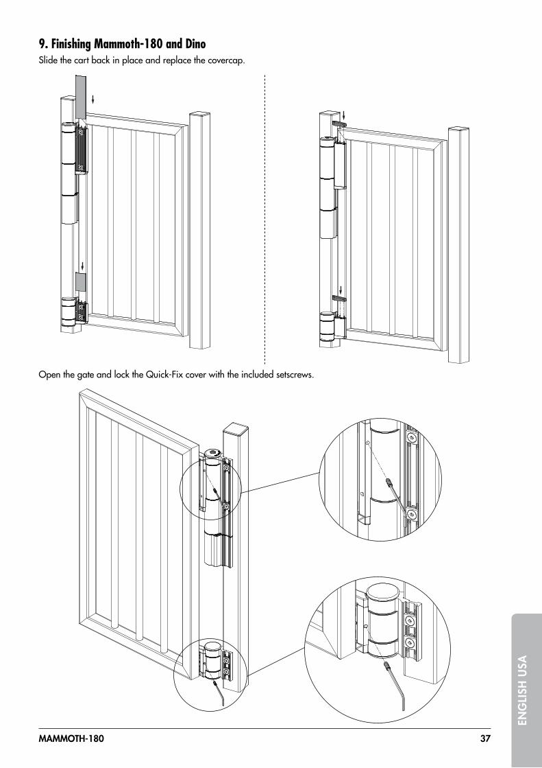
MAMMOTH-180 37
ENG
LISH
USA
9. Finishing Mammoth-180 and DinoSlide the cart back in place and replace the covercap.
Open the gate and lock the Quick-Fix cover with the included setscrews.

38
ENG
LISH U
SA
10. Speed and final snap adjustmentFinal snap and speed can be adjusted by means of the included 3 mm Allen key.
11. Force adjustment
+
Out of the box, the Mammoth 180° is set to its maximum closing-force: 15 Nm. We advise not to adjust the closing-force unless you have a specific application that requires a lower opening force.Start by removing the cover cap. Insert the Allen key and push down firmly to disengage the spring. Turn the screw clockwise to decrease the spring force. Max 180° of closing force adjustment. DO NOT use excessive force on the Allen key while adjusting the force.
12. Finalising the installationAfter installing the Mammoth-180 you can proceed with the installation of your Locinox lock and keep. After the speed, closing force, and final snap action have been tested to your satisfaction, install the cap on the force adjustment screw.
Speed
Final snap

Copyright © 2014 Locinox. All rights reserved.All specifications and figures are subject to change without notice.
Locinox nv - Mannebeekstraat 21 - B-8790 - Waregem - BelgiumTel. +32 (0)56 77 27 66 - Fax. +32 (0)56 77 69 26E-mail: [email protected] - Web: www.locinox.com
* M A N U - 0 0 0 2 0 1 *
2014-10-22 - rev 2

Overview
Finishes
The Schlage� L Series has long been the benchmark for Grade 1 mortise locks. Beyond strength and security – it offers flexibility to meet most needs. Fifty mechanical functions include ten that can be field configured from one universal lock case and ten electrified functions are regularly used as part of electronic access control systems. L Series locks have the ability to suite across electronic, tubular, exit trim, and multi-point locks to integrate seamlessly into any environment. The series features an array of security options including 180-degree visibility status indicators and support for multiple keyway families and cylinder types including Primus� XP high-security cylinders.
Grade 1, mortise locks
L Series
605Bright Brass
622Matte Black
606Satin Brass
630Satin Stainless
619Satin Nickel
629Bright Stainless
625Bright Chrome
609Antique Brass
630AMSatin Stainless, Antimicrobial
626AMSatin Chrome, Antimicrobial
612Satin Bronze
643eAged Bronze
626Satin Chrome
613Oil Rubbed Bronze
1 Available on standard levers only, not available on Latitude, Longitude, Accent, Asti, or Merano
2 Not available on Accent, Asti, or Merano
1 1
2 2 2

Grade 1, mortise locks
L Series
M Collection decorative lever styles1
M51851 - Knurled tactile warning
M52852 - Knurled tactile warning
M53 M54
M55 M56 M61 � Handed
M57
M62 � Handed
2
2
Dimensions
Lever Width Projection
M51 4.5" 3.2"
M52 4.5" 3"
M53 4.35" 3.2"
M54 4.35" 2.75"
M55 4.3" 3"
M56 4.6" 3"
M57 4.5" 2.9"
M61 4.5" 3.2"
M62 4.5" 2.7"
M63 4.5" 3.2"
Leverprojection
Lever width
X
L full face: 1.75"L concealed: 1.75"
N full face: 2.5675"
1 M Collection not available in 612 and 613 finishes. 2 Available in 629, 630, and 630AM only.
Leverprojection
Lever width
X
A: 2.125"B: 2.5625"
C, AVA, MER: 2.625"
L full face: 1.75"L concealed: 1.75"
N full face: 2.5675"
8"
M63 � Handed

Grade 1, mortise locks
L Series
M Collection decorative lever styles1
Dimensions
Lever Width Projection
M81 4.8" 2.9"
M82 4.8" 2.9"
M83 4.6" 2.9"
M84 5.1" 3"
M85 4.9" 3.3"
ME1 5.5" 3"
ME2 5.2" 2.8"
ME3 5.1" 3.2"
Return to door meets 1⁄2" requirement for all levers shown on this page.
ME18ME1 - Milled tactile warning
� Handed
ME28ME2 - Milled tactile warning
� Handed
ME38ME3 - Milled tactile warning
ME1, ME2 and ME3 ergonomic levers designed with
Gensler as product design consultant.
M83 M84
M85 � Handed
M81881 - Knurled tactile warning
M82
Leverprojection
Lever width
X
A: 2.125"B: 2.5625"
C, AVA, MER: 2.625"
L full face: 1.75"L concealed: 1.75"
N full face: 2.5675"
8"
Leverprojection
Lever width
X
A: 2.125"B: 2.5625"
C, AVA, MER: 2.625"
L full face: 1.75"L concealed: 1.75"
N full face: 2.5675"
8"

Grade 1, mortise locks
L Series
Standard lever and knob styles
01801 - Milled tactile warning
02802 - Knurled tactile warning
03803 - Knurled tactile warning
05805 - Milled tactile warning
06806 - Milled tactile warning
07807 - Milled tactile warning
12812 - Milled tactile warning
� Handed
17817 - Milled tactile warning
18818 - Milled tactile warning
Dimensions
Lever Width Projection
01 3.875" 2.688"
02 4.75" 2.813"
03 4.75" 2.813"
05 3.75" 2.875"
06 4.625" 2.5"
07 4.625" 2.875"
12 4.625" 3.063"
17 4.75" 3"
18 4.875" 2.688"
Accent (ACC) 4.125" 3.125"
Return to door meets 1⁄2" requirement for 03, 06 and 17 levers.
Leverprojection
Lever width
X
L full face: 1.75"
Leverprojection
Lever width
X
A: 2.125"B: 2.5625"
L full face: 1.75"L concealed: 1.75"
N full face: 2.5675"
Accent (ACC)1
� Handed
1 Not available in 612, 613, 629, or 630 finishes.

Grade 1, mortise locks
L Series
Standard lever and knob styles
41 42Omega (OME)
Dimensions
Lever Width Projection
Asti (AST) 4" 2.625"
Latitude (LAT) 4.75" 2.563"
Longitude (LON) 4.875" 2.563"
Merano (MER) 4" 3.125"
Omega (OME) 5.063" 3.313"
41 2.211" 2.34"
42 2.132" 2.538"
Return to door meets 1⁄2" requirement for Longitude and Omega levers.
Knobwidth
Projection
Projection
Rosediameter
Rosediameter
Projection
Rosediameter
Leverwidth
Knobwidth
Asti (AST)1 � Handed
Latitude (LAT)2 Longitude (LON)2 Merano (MER)1 � Handed
Leverprojection
Lever width
X
A: 2.125"B: 2.5625"
C, AVA, MER: 2.625"
L full face: 1.75"L concealed: 1.75"
N full face: 2.5675"
8"
Leverprojection
Lever width
X
A: 2.125"B: 2.5625"
C, AVA, MER: 2.625"
L full face: 1.75"L concealed: 1.75"
N full face: 2.5675"
8"
1 Not available in 612, 613, 629, or 630 finishes.2 Not available in 612 or 613 finishes.

Grade 1, mortise locks
L Series
Escutcheons Roses
L full faceSpecify by adding ‘L’ after lever design.
A roseAvailable for use on L Series knob and lever designs. Specify by adding ‘A’ after lever designFinishes: available in all L Series finishes.
B roseAvailable for use on L Series knob and lever designs. Specify by adding ‘B’ after lever design.Finishes: available in all L Series finishes.
C roseAvailable for use on L Series knob and lever designs. Specify by adding ‘C’ after lever design.Finishes: 605, 606, 609, 619, 622, 625, 626, 629, 630, 643e
AVA roseAvailable for use on ACC lever, other levers upon request.Finishes: 605, 606, 609, 619, 622, 625, 626, 643e
MER roseAvailable for use on MER lever, other levers upon request.Finishes: 605, 606, 609, 619, 622, 625, 626, 643e
L concealedSpecify by adding ‘C’ suffix to function and by adding ‘L’ after lever design.
N full faceSpecify by adding ‘N’ after lever design.
Dimensions
Rose Diameter
A 2.125"
B 2.5625"
C 2.625"
AVA 2.625"
MER 2.625"
Escutcheon Width Height
L full face 1.75" 8"
L concealed 1.75" 8"
N full face 2.5" 7.875"
Rosediameter
Escutcheonwidth
Escutcheonheight
Rosediameter
Escutcheonwidth
Escutcheonheight

Grade 1, mortise locks
L Series
Thumbturns Indicators
Standard turn 09-509
Cylinder Thumbturn Cointurn
Thumbturn Emergency key indicator
Cointurn
Cylinder
Emergency key indicator
ADA turn09-509 x L583-363Not available with L9463 and L463
Escutcheon Escutcheon Escutcheon
Escutcheon Sectional Sectional
SectionalSectional
Locked OccupiedDo Not Disturb
Unlocked Unoccupied
Inside trim L283-711 L283-712 L283-713 L283-714
Outside trim L283-721 L283-722 L283-723 L283-724

Grade 1, mortise locks
L Series
Ligature resistant solutions
1 Only available in 630 and 630AM finishes.2 Not available with Vandlgard option.3 Only available in 630 finish.
Dimensions
Width Height Projection
SL1 4.5" 3.13"
SK1 3.125" 2.3125"
HSLR 6" 13.17" 2.27"
Knobwidth
Projection
Projection
Rosediameter
Rosediameter
Projection
Rosediameter
Leverwidth
Knobwidth
Leverprojection
Lever width
X
A: 2.125" 2.5625"
R: 2.625"
L full face: 1.75"L concealed: 1.75"
N full face: 2.5675"
8"
Leverprojection
Lever width
X
A: 2.125"B: 2.5625"
C, AVA, MER: 2.625"
L full face: 1.75"L concealed: 1.75"
N full face: 2.5675"
8"
SL1 1, 2 SK1 1,2
Specifications and certifications
SL1 SK1 HSLR
Accepted by OHM � � �
ADA compliant � - �
Suitable for:
High risk areas - � �
Medium risk areas � � �
Low risk areas � � �
Caution: Cone shaped door knobs and thumbturns do not compliant with ADA requirements
for graspability.
HSLR 2,3
� Handed
Width
Height
Projection

Grade 1, mortise locks
L Series
Cylinder Knob/lever ThumbturnThumbturn cylinder
Coin turn Solid spindleTwo-piece spindle
Emergency thumbturn
Electrified function
Non-keyed functions
� Latchbolt retracted by lever/knob from either side
� Deadbolt actuated by inside thumbturn � Throwing deadbolt locks outside knob/lever � Inside lever retracts both deadbolt and
latchbolt and unlocks outside lever � To unlock from outside remove emergency
button, insert emergency thumbturn in access hole and rotate
� Inside lever always free for immediate egress
Schlage L9440 LV9440 ANSI F19
Privacy with deadbolt
� Latchbolt retracted by lever/knob from either side unless outside lever is locked by inside thumbturn or outside coin turn
� Actuating inside lever, closing door, or rotating outside coin turn unlocks outside lever
� Available in rose trim only
Schlage L9044 LV9044 ANSI -
Privacy with coin turn outside
Schlage L9040 LV9040ANSI F22
Bath/bedroom privacy lock
Schlage L9025 ANSI F31
Exit lock
Schlage L9010ANSI F01
Passage latch
� Latchbolt retracted by lever/knob from either side unless outside lever is locked by inside thumbturn
� Actuating inside lever or closing door unlocks outside lever
� To unlock from outside remove emergency button, insert emergency thumbturn in access hole and rotate
� Inside knob/lever is always free for immediate egress
� No outside trim � Inside lever always free for immediate egress
� Latchbolt retracted by lever/knob from either side at all times
� Inside lever always free for immediate egress
Vandlgard� protection available on functions noted with an “LV” option.
Vandlgard allows the outside lever to rotate freely down when locked to limit the ability of vandals to apply excessive force to the chassis helping to prevent damage to internal components.
Coin turn for lock with rose trim
Optional 180 degree messaging
indicator available Optional 180 degree messaging
indicator available
Optional 180 degree messaging
indicator available
Optional HSLR trim available
Optional HSLR trim available

Grade 1, mortise locks
L Series
Cylinder Knob/lever ThumbturnThumbturn cylinder
Coin turn Solid spindleTwo-piece spindle
Emergency thumbturn
Electrified function
Non-keyed functions
� Latchbolt retracted by knob/lever from either side
� Deadbolt actuated by inside thumbturn or outside coin turn
� Throwing deadbolt locks outside knob/lever � Inside lever retracts both deadbolt and
latchbolt and unlocks outside lever � Rotating coin turn retracts deadbolt and
unlocks outside lever � Inside lever always free for immediate egress � Available with rose trim only
Schlage L9444 LV9444 ANSI -
Privacy with deadbolt and coin turn outside
Coin turn for lock with rose trim
Optional 180 degree messaging
indicator available
Optional HSLR trim available

Grade 1, mortise locks
L Series
Cylinder Knob/lever ThumbturnThumbturn cylinder
Coin turn Solid spindleTwo-piece spindle
Emergency thumbturn
Electrified function
Non-keyed dummy functions
� Fixed lever/knob on both sides � Includes lock case and blank armor plate
In a double-door application where the dummy will be used
as the strike order 10-091 armored front strike separately.
Schlage L9176ANSI -
Full dummy trim with lock case
Schlage L9175ANSI -
Half dummy trim with lock case
Schlage L0172ANSI -
Full dummy trim
Schlage L0170ANSI -
Half dummy trim
� Fixed lever/knob on one side � Includes lock case and blank armor plate
� Fixed lever/knob on both sides � Fixed lever/knob on one side

Grade 1, mortise locks
L Series
Cylinder Knob/lever ThumbturnThumbturn cylinder
Coin turn Solid spindleTwo-piece spindle
Emergency thumbturn
Electrified function
Single cylinder non-deadbolt functions
Schlage L9070 LV9070ANSI F05
Classroom lock
Schlage L9056 LV9056ANSI -
L9050 with automatic unlocking
� Latchbolt retracted by lever/knob from either side unless outside lever is locked by key
� Unlocked from outside by key � Auxiliary latch deadlocks latchbolt when
door is locked � Inside lever always free for immediate egress
� Latchbolt retracted by knob/lever from either side unless outside is made inoperative by key outside or by rotating inside thumbturn
� Outside knob/lever unlocked by key outside, thumbturn or closing door
� Rotating inside knob/lever simultaneously retracts latchbolt and unlocks outside knob/lever
� Auxiliary latch deadlocks latchbolt when door is locked
� Inside knob/lever is always free for immediate egress
� Latchbolt retracted by knob/lever from either side unless outside is made inoperative by key outside or by turning inside thumbturn
� When outside is locked, latchbolt is retracted by key outside or by knob/lever inside
� Outside knob/lever remains locked until thumbturn is returned to vertical or unlocked by key
� Auxiliary latch deadlocks latchbolt when door is locked
� Inside knob/lever is always free for immediate egress
Schlage L9050 LV9050ANSI F04
Office and inner entry lock
� No outside trim � Outside cylinder retracts latchbolt � Inside lever always free for immediate egress � Auxiliary latch deadlocks latchbolt when
door is locked
Schlage L9026ANSI -
Exit lock with cylinder
Schlage L9080 LV9080ANSI F07
Storeroom lock
� Latchbolt retracted by lever/knob inside or key outside
� Outside lever/knob is always inoperable � Auxiliary latch deadlocks latchbolt when
door is locked � Inside lever always free for immediate egress
� Latchbolt retracted by lever/knob from either side unless outside lever is locked by key
� When locked, latchbolt retracted by key or inside lever
� Auxiliary latch deadlocks latchbolt when door is locked
� Holdback feature activated by turning inside lever/knob and rotating key 360°
� Inside lever always free for immediate egress
Schlage L9076 LV9076ANSI F06
Classroom holdback lock
Optional 180 degree messaging
indicator available
Optional 180 degree messaging
indicator available
Optional 180 degree messaging
indicator available
Optional HSLR trim available Optional HSLR trim available
Optional HSLR trim available
Optional HSLR trim available

Grade 1, mortise locks
L Series
Cylinder Knob/lever ThumbturnThumbturn cylinder
Coin turn Solid spindleTwo-piece spindle
Emergency thumbturn
Electrified function
Single cylinder deadbolt functions
Schlage L9465ANSI -
Closet/storeroom lock
� Latchbolt retracted by lever/knob from either side
� Deadbolt actuation by key
� Latchbolt retracted by outside key or inside knob/lever
� Outside knob/lever always fixed � Deadbolt actuation by outside key or inside
thumbturn � Inside knob/lever actuation retracts both
deadbolt and latchbolt � Auxiliary latch deadlocks latchbolt when
door is locked � Inside lever always free for immediate egress
Schlage L9480 LV9480ANSI -
Storeroom lock with deadbolt
Schlage L9473ANSI F21
Dormitory/bedroom lock
� Latchbolt retracted by lever/knob from either side
� Deadbolt actuation by outside key or inside thumbturn
� Latchbolt retracted by lever/knob from either side
� Deadbolt actuation by key or thumbturn rotation
� Throwing deadbolt locks outside lever/knob � Turning inside knob/lever retracts both
deadbolt and latchbolt and unlocks outside lever/knob
� Inside lever always free for immediate egress
Schlage L9456 LV9456ANSI F13
Corridor lock
Schlage L9453 LV9453ANSI F20
Entrance lock
� Latchbolt retracted by lever/knob from either side unless outside locked by 20° thumbturn rotation
� Deadbolt actuation through 90° thumbturn rotation
� When locked, outside key or inside lever/knob retracts both deadbolt and latchbolt
� Outside lever/knob locked until thumbturn is restored to vertical position
� Throwing deadbolt locks outside lever/knob � Auxiliary latch deadlocks latchbolt when
door is locked � Inside lever always free for immediate egress
� Latchbolt retracted by outside key or inside knob/lever
� Outside knob/lever always fixed � Deadbolt actuation by thumbturn � All keys (except emergency) inoperative
when deadbolt is thrown � Inside knob/lever retracts both deadbolt and
latchbolt � Auxiliary latch deadlocks latchbolt when
door is locked � Inside lever always free for immediate egress
Schlage L9485 LV9485ANSI -
Faculty/hotel/restroom lock
Optional 180 degree messaging
indicator available
Optional 180 degree messaging
indicator available
Optional 180 degree messaging
indicator available
Optional HSLR trim available
Optional HSLR trim available Optional HSLR trim available
Optional HSLR trim available
Optional HSLR trim available
Optional HSLR trim available

Grade 1, mortise locks
L Series
Cylinder Knob/lever ThumbturnThumbturn cylinder
Coin turn Solid spindleTwo-piece spindle
Emergency thumbturn
Electrified function
Single cylinder deadbolt functions
� Latchbolt retracted by outside key or inside knob/lever
� Outside knob/lever always fixed � Deadbolt actuation by thumbturn � When deadbolt is thrown “DO NOT
DISTURB” message is displayed and all keys (except emergency) become inoperative
� Inside knob/lever retracts both deadbolt and latchbolt
� Auxiliary latch deadlocks latchbolt when door is locked
� Inside lever always free for immediate egress
� Latchbolt retracted by outside key or inside knob/lever
� Outside knob/lever always fixed � Deadbolt actuation by thumbturn � When deadbolt is thrown “OCCUPIED”
message is displayed and all keys (except emergency) become inoperative
� Inside knob/lever retracts both deadbolt and latchbolt
� Auxiliary latch deadlocks latchbolt when door is locked
� Inside lever always free for immediate egress
Schlage L9486 LV9486ANSI F15
L/LV9485 with 09-611 “DO NOT DISTURB” indicator for rose trim
Schlage L9486xL583-375 LV9486xL583-375ANSI -
L/LV9485 with “OCCUPIED” indicator for rose trim
Schlage L9496ANSI -
Privacy with 09-611 “OCCUPIED” indicator for rose trim
� Latchbolt retracted by knob/lever from either side
� Deadbolt actuation by outside key or inside thumbturn
� Thrown deadbolt displays “OCCUPIED” message and locks outside lever
� Inside knob/lever retracts both deadbolt and latchbolt and unlocks outside lever
� Inside lever always free for immediate egress
Adds hotel occupancy indicator (09-611)
for lock with A or B roses on sectional trim.
Message: “DO NOT DISTURB”.
Adds hotel occupancy indicator (09-611)
for lock with A or B roses on sectional trim.
Message: “OCCUPIED”.
Adds hotel occupancy indicator (09-611)
for lock with A or B roses on sectional trim.
Message: “OCCUPIED”.

Grade 1, mortise locks
L Series
Cylinder Knob/lever ThumbturnThumbturn cylinder
Coin turn Solid spindleTwo-piece spindle
Emergency thumbturn
Electrified function
Double cylinder non-deadbolt functions
Schlage L9082 LV9082ANSI F30
Institution lock
� Latchbolt retracted by key from either side � Knob/lever on both sides always inoperative � Auxiliary latch deadlocks latchbolt when
door is locked
Caution: Double cylinder locks on any door, in any structure
requiring use of a key to achieve egress can create a life
safety hazard in times of emergency and their use is not
recommended. Installation should be in accordance with
existing codes only.
Schlage L9060 LV9060ANSI F09
Apartment entrance lock
� Latchbolt retracted by knob/lever from either side unless outside is locked by key from inside
� When locked, latchbolt retracted by key outside or knob/lever inside
� Auxiliary latch deadlocks latchbolt when door is locked
� Inside knob/lever is always free for immediate egress
� Latchbolt retracted by knob/lever from either side unless outside is locked by key from either side
� When locked, latchbolt retracted by outside key or inside knob/lever
� Auxiliary latch deadlocks latchbolt when door is locked
� Inside knob/lever always free for immediate egress
Schlage L9071 LV9071ANSI F32
Classroom security lock
� Latchbolt retracted by knob/lever from either side unless outside is locked by key from either side
� When locked, latchbolt retracted by key outside or knob/lever inside
� Auxiliary latch deadlocks latchbolt when door is locked
� Rotate inside lever/knob and turn key 360º to enable holdback feature
� Inside knob/lever always free for immediate egress
Schlage L9077 LV9077ANSI -
Classroom security holdback lock
Optional 180 degree messaging
indicator available Optional 180 degree messaging
indicator available
Optional 180 degree messaging
indicator available
Optional 180 degree messaging
indicator available
Optional HSLR trim available
Optional HSLR trim available
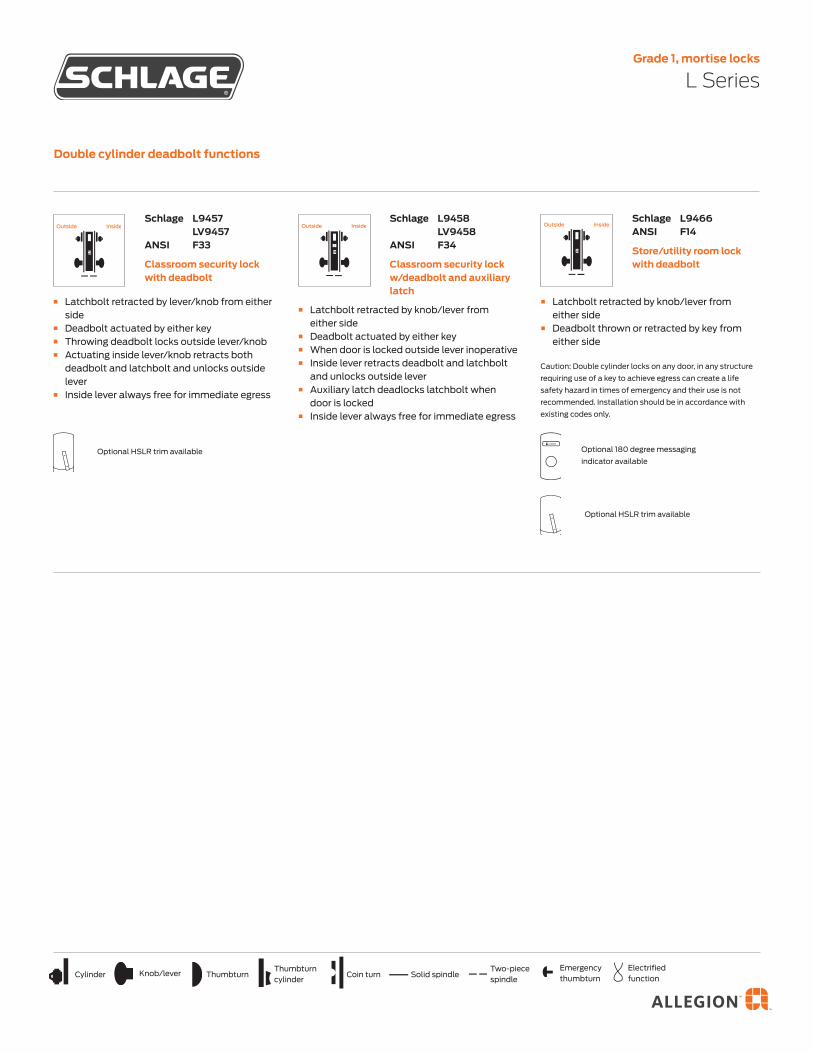
Grade 1, mortise locks
L Series
Cylinder Knob/lever ThumbturnThumbturn cylinder
Coin turn Solid spindleTwo-piece spindle
Emergency thumbturn
Electrified function
Double cylinder deadbolt functions
� Latchbolt retracted by lever/knob from either side
� Deadbolt actuated by either key � Throwing deadbolt locks outside lever/knob � Actuating inside lever/knob retracts both
deadbolt and latchbolt and unlocks outside lever
� Inside lever always free for immediate egress
Schlage L9457 LV9457ANSI F33
Classroom security lock with deadbolt
� Latchbolt retracted by knob/lever from either side
� Deadbolt actuated by either key � When door is locked outside lever inoperative � Inside lever retracts deadbolt and latchbolt
and unlocks outside lever � Auxiliary latch deadlocks latchbolt when
door is locked � Inside lever always free for immediate egress
Schlage L9458 LV9458ANSI F34
Classroom security lock w/deadbolt and auxiliary latch
Schlage L9466ANSI F14
Store/utility room lock with deadbolt
� Latchbolt retracted by knob/lever from either side
� Deadbolt thrown or retracted by key from either side
Caution: Double cylinder locks on any door, in any structure
requiring use of a key to achieve egress can create a life
safety hazard in times of emergency and their use is not
recommended. Installation should be in accordance with
existing codes only.
Optional 180 degree messaging
indicator availableOptional HSLR trim available
Optional HSLR trim available

Grade 1, mortise locks
L Series
Cylinder Knob/lever ThumbturnThumbturn cylinder
Coin turn Solid spindleTwo-piece spindle
Emergency thumbturn
Electrified function
Mortise deadlock functions
� Deadbolt actuated by key � No trim opposite side
Schlage L9464ANSI F18
Cylinder lock
� Deadbolt actuated by key � Thumbturn retracts deadbolt but cannot
extend it
Schlage L9463ANSI F29
Classroom lock
Schlage L9462ANSI F16
Double cylinder lock
Schlage L9460ANSI F17
Cylinder x thumbturn lock
� Deadbolt actuated by either key
Caution: Double cylinder locks on any door, in any structure,
requiring the use of a key to achieve egress can create a life
safety hazard in times of emergency and their use is not
recommended. Installation should be in accordance with
existing codes only.
� Deadbolt actuated by key or thumbturn
Optional 180 degree messaging
indicator available
Optional 180 degree messaging
indicator available
Optional 180 degree messaging
indicator available
Optional 180 degree messaging
indicator available

Grade 1, mortise locks
L Series
Cylinder Knob/lever ThumbturnThumbturn cylinder
Coin turn Solid spindleTwo-piece spindle
Emergency thumbturn
Electrified function
Small mortise deadlock functions
� Deadbolt actuated by key or thumbturn � When deadbolt is thrown “OCCUPIED”
message is displayed
Schlage L496ANSI -
Deadbolt with “OCCUPIED” indicator
� Deadbolt actuated by thumbturn � No trim opposite side
Schlage L480ANSI -
Door bolt
Schlage L464 ANSI E06081
Cylinder lock
Schlage L463ANSI E06091
Classroom lock
Schlage L462ANSI E06061
Double cylinder lock
� Deadbolt actuated by key � No trim opposite side
� Deadbolt actuated by key � Thumbturn retracts deadbolt but cannot
extend it
� Deadbolt actuated by either key
Caution: Double cylinder locks on any door, in any structure,
requiring use of a key to achieve egress can create a life
safety hazard in times of emergency and their use is not
recommended. Installation should be in accordance with
existing codes only.
� Deadbolt actuated by key or thumbturn
Schlage L460ANSI E06071
Cylinder x thumbturn lock
Optional 180 degree messaging
indicator available
Optional 180 degree messaging
indicator available
Optional 180 degree messaging
indicator available
Optional 180 degree messaging
indicator available
Optional 180 degree messaging
indicator available
Optional 180 degree messaging indicator
available

Grade 1, mortise locks
L Series
Cylinder Knob/lever ThumbturnThumbturn cylinder
Coin turn Solid spindleTwo-piece spindle
Emergency thumbturn
Electrified function
Special functions
L9460 x XL11-886 � Deadbolt actuation by key or thumbturn � Outside lever always fixed � Inside lever active when deadbolt is thrown � Inside lever retracts deadbolt
L9462 x XL11-886 � Same as L9460 x XL11-886 except deadbolt
actuated by key from either side
L9464 x XL11-886 � Same as L9460 x XL11-886 except deadbolt
actuated by key from one side
Schlage L9460, L9462, L9464 x XL11-886
ANSI -
Deadbolt with retraction by inside lever or knob
� Knob/lever both sides fixed � Deadbolt thrown or retracted by key outside
or thumbturn inside � Specify per XL11-635
Schlage L9460 x XL11-635ANSI -
L9460 with fixed dummy trim
Schlage L9412 x XL11-907ANSI -
Exit lock with deadbolt
Schlage L9066 x XL11-897ANSI -
Storeroom lock
Schlage L0940 x XL11-446 LV9040 x XL11-446ANSI -
Privacy with turn both sides
� Latchbolt retracted by inside lever � Outside lever always fixed � Thumbturn actuates deadbolt � Inside lever retracts deadbolt and latchbolt � Auxiliary latch deadlocks latchbolt when
door is locked
� Either key retracts latchbolt � Either key locks or unlocks both levers
Caution: Double cylinder locks on any door, in any structure
requiring use of a key to achieve egress can create a life
safety hazard in times of emergency and their use is not
recommended. Installation should be in accordance with
existing codes only.
� Latchbolt retracted by either lever � Rotating either thumbturn locks outside
lever � Actuating inside lever, closing door, or
rotating either thumbturn unlocks outside lever
� Knob/lever both sides active � Lock case and armor front included � Can receive deadbolt with XL11-743 armor
front
Schlage L9110 x XL11-741ANSI -
Double dummy with active trim
Optional 180 degree messaging
indicator available
Optional 180 degree messaging
indicator available
Optional 180 degree messaging
indicator available

Grade 1, mortise locks
L Series
Cylinder Knob/lever ThumbturnThumbturn cylinder
Coin turn Solid spindleTwo-piece spindle
Emergency thumbturn
Electrified function
Special functions
Schlage L9485 x XL11-557ANSI -
Prison function lock
� Latchbolt retracted by outside key or inside knob/lever
� Outside knob/lever always free spinning � Deadbolt actuation by guard key � Inside knob/lever fixed when deadbolt is
thrown � Prisoner key only retracts latchbolt � Tamper resistant Torx screws standard
� Latchbolt retracted by either key � Both levers always inoperative � Deadbolt actuated by either key � Auxiliary latch deadlocks latchbolt when
door is locked
Caution: Double cylinder locks on any door, in any structure
requiring use of a key to achieve egress can create a life
safety hazard in times of emergency and their use is not
recommended. Installation should be in accordance with
existing codes only.
Schlage L9482 x XL11-543 LV9482 x XL11-543ANSI -
Institutional lock with deadbolt

Grade 1, mortise locks
L Series
Cylinder Knob/lever ThumbturnThumbturn cylinder
Coin turn Solid spindleTwo-piece spindle
Emergency thumbturn
Electrified function
Electrified locks functions
Schlage L9095EL L9095EUANSI -
Electrically locked or electrically unlocked both levers (double cylinder)
� Both levers/knobs continuously locked (EL) or unlocked (EU) by 12V or 24V DC
� Latchbolt retracted by either key � Auxiliary latch deadlocks latchbolt when
door is locked � EL: Switch or power failure unlocks both
levers/knobs and allows knob/lever to retract latchbolt
� EU: Switch or power failure locks both levers/knobs
Schlage L9091EL L9091EUANSI -
Electrically locking/unlocking both levers (no cylinder)
Schlage L9090EL L9090EUANSI F13
Electrically locking/unlocking outside lever (no cylinder)
� Both levers/knobs continuously locked (EL) or unlocked (EU) by 12V or 24V DC
� Auxiliary latch deadlocks latchbolt when door is locked
� Outside lever/knob continuously locked (EL) or unlocked (EU) by 12V or 24V DC
� Auxiliary latch deadlocks latchbolt when door is locked
� Inside lever/knob always free for immediate egress
� Outside lever/knob continuously locked (EL) or unlocked (EU) by 12V or 24V DC
� Lathbolt retracted by either key or by inside lever/knob
� Auxiliary latch deadlocks latchbolt when door is locked
� Inside lever/knob always free for immediate egress
Schlage L9094EL L9094EUANSI -
Electrically locking/unlocking outside lever (double cylinder)
� Both levers/knobs continuously locked (EL) or unlocked (EU) by 12V or 24V DC
� Latchbolt retracted by key outside � Auxiliary latch deadlocks latchbolt when
door is locked
Schlage L9093EL L9093EUANSI -
Electrically locking/unlocking both levers (outside cylinder)
� Outside lever/knob continuously locked (EL) or unlocked (EU) by 12V or 24V DC
� Latchbolt retracted by lever/knob inside or key outside
� Auxiliary latch deadlocks latchbolt when door is locked
� Inside lever/knob always free for immediate egress
� EL: Switch or power failure allows outside lever/knob to retract latchbolt
� EU: Switch or power failure locks (EU) outside lever/knob
Schlage L9092EL L9092EUANSI -
Electrically locking/unlocking outside lever (single cylinder)
Optional HSLR trim available
Optional HSLR trim available
Optional HSLR trim available
Optional HSLR trim available

Grade 1, mortise locks
L Series
Cylinder Knob/lever ThumbturnThumbturn cylinder
Coin turn Solid spindleTwo-piece spindle
Emergency thumbturn
Electrified function
Electrified locks functions
� Both levers continuously locked (EL) or unlocked (EU) 12V or 24V DC
� Deadbolt actuation by either key � When unlocked both levers retract deadbolt
and open door � Auxiliary latch deadlocks latchbolt when
door is locked
Schlage L9495EL L9495EUANSI -
Electrically locking/unlocking both levers (double cylinder with deadbolt)
� Outside lever continuously locked (EL) or unlocked (EU) 12V or 24V DC
� Deadbolt actuation by either key � Inside lever retracts both deadbolt and
latchbolt � For EU outside lever retracts deadbolt and
latchbolt � Auxiliary latch deadlocks latchbolt when
door is locked � Inside lever always free for immediate egress
Schlage L9494EL L9494EUANSI -
Electrically locking/unlocking outside lever (double cylinder with deadbolt)
Schlage L9493EL L9493EUANSI -
Electrically locking/unlocking both levers (outside cylinder, inside thumbturn with deadbolt)
Schlage L9492EL L9492EUANSI -
Electrically locking/unlocking outside lever (outside cylinder, inside thumbturn with deadbolt)
� Deadbolt actuation by key or thumbturn � Inside lever retracts both deadbolt and
latchbolt � For EU both levers retract deadbolt and
latchbolt � Auxiliary latch deadlocks latchbolt when
door is locked
� Outside lever continuously locked (EL) or unlocked (EU) 12V or 24V DC
� Deadbolt actuation by key or thumbturn � Inside lever retracts both deadbolt and
latchbolt � For EU outside lever retracts deadbolt and
latchbolt � Auxiliary latch deadlocks latchbolt when
door is locked � Inside lever always free for immediate egress
Available electrified options include:
RX Request to Exit
LX Latch bolt monitor
DPS Door Position Switch
DM Deadbolt monitor (DM)
Optional HSLR trim available
Optional HSLR trim available
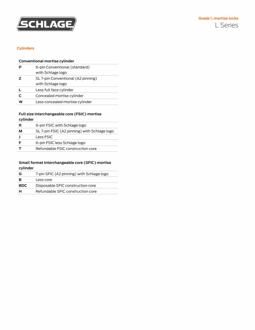
Grade 1, mortise locks
L Series
Cylinders
Conventional mortise cylinderP 6-pin Conventional (standard)
with Schlage logo
Z SL 7-pin Conventional (A2 pinning) with Schlage logo
L Less full face cylinder
C Concealed mortise cylinder
W Less concealed mortise cylinder
Full size interchangeable core (FSIC) mortise cylinderR 6-pin FSIC with Schlage logo
M SL 7-pin FSIC (A2 pinning) with Schlage logo
J Less FSIC
F 6-pin FSIC less Schlage logo
T Refundable FSIC construction core
Small format interchangeable core (SFIC) mortise cylinderG 7-pin SFIC (A2 pinning) with Schlage logo
B Less core
BDC Disposable SFIC construction core
H Refundable SFIC construction core

Grade 1, mortise locks
L Series
Specifications
ChassisCase material CRS with zinc dichromate plating
Case size L9000 Series: 4 7⁄16" x 6 1⁄16" x 1"(113 mm x 154 mm x 25 mm)L400 Series: 4 7⁄16" x 3 5⁄8" x 1"(113 mm x 92 mm x 25 mm)
Spacing Knob or lever to cylinder: 3 7⁄8" (98 mm); Knob or lever to thumbturn hub: 2 11⁄16" (68 mm)
Door thickness Standard: 1 3⁄4" (44 mm)Optional: 1 3⁄8" (35 mm) to 2 1⁄2" (64 mm)Over 2 1⁄2" (64 mm) door ranges vary by function. Specify door thickness if other than 1 3⁄4" and position in door EE, EI, EO, ED
TrimHanding L9000 Series: Field-reversible without disassembly
L400 Series: Non-handed
Lever/knob Lever designs: forged brass or bronze and cast stainless steelKnob designs: heavy-duty wrought brass, bronze or stainless steel
Rose/escutcheon
L full face and concealed: Cold-forged brass, bronze and stainless steel N full face: Heavy wrought reinforced brass, bronze and stainless steelRoses: A ,B, C: wrought brass or bronze and stainless steel; AVA and MER: forged brass
Combinations Available with knob both sides, lever both sides, or knob/lever combinations. Roses cannot be combined with escutcheons.
LatchBackset 2 3⁄4" (70 mm) only
Armor L9000 SeriesStandard: 1 1⁄4" x 8" x 7⁄32" (32 mm x 203 mm x 6 mm)Optional: 1 1⁄16" x 8" x 7⁄32" (27 mm x 203 mm x 6 mm)L400 Series: Standard: 1 1⁄4" x 5 9⁄16" x 7⁄32"(32 mm x 141 mm x 6 mm)
Latch 3⁄4" (19 mm) throw stainless steel latch with anti-friction tongue
Deadbolt 1" (25 mm) throw stainless steel deadbolt
Strike L9000 SeriesStandard: ANSI curved lip strike 1 1⁄4" x 4 7⁄8" (32 mm x 124 mm) x 1 3⁄16" (30 mm) lip to center with dust boxOptional: Extended lip strike options (7⁄8", 1", 1 1⁄2", 1 3⁄4", 2")L400 SeriesStandard: 1 1⁄8" x 3 1⁄2" (29 mm x 89 mm) with dust boxOptional: 1 1⁄4" x 4 7⁄8"(32 mm x 124 mm) with dust box

Grade 1, mortise locks
L Series
Specifications
www.allegion.com/us
© 2019 Allegion 013141, Rev. 07/2019
KeyingCylinder format 6-pin Conventional mortise cylinder (standard); also available in concealed
mortise cylinder, FSIC, SFIC and 7-pin SL cylinder formats plus less cylinder options.
Keyway Patented Everest 29 S123 (standard); also available in open, restricted, and Primus XP security levels with available master keying and construction keying.
Wired electrifiedInput voltage 12V or 24V DC for L909X
Operating mode Fail Safe or Fail Secure via switch on chassis
Current draw 0.23 amps maximum;0.01 amps holding
Request to Exit Rating: 3A @ 125V AC/2A @ 30V DC. Available on all L909X and L949X electrified functions. Also available option for the following mechanical functions: L9010/50/56/70/71/80 and L9453/56/58/65/66/80/85.
Latch bolt monitor
Available on all L909x and L949x electrified and L9010/25/26/50/56/70/71/80/82 and L9453/56/65/66/80/85 mechanical functions.
Door position sensor
Internal available on L909x electrified and L9010/80/82 mechanical functions; external available on all functions.
Deadbolt monitor
Available on L949x electrified and L9453/56/57/58/80/85/86/96 mechanical functions
Warranty3 year limited mechanical and1 year limited electromechanical
CertificationsANSI/BHMA L/LV9000: ANSI/BHMA A156.13-2017 Series 1000, Grade 1 operation and
security; with FSIC Grade 2; with SFIC Grade 3L400: ANSI/BHMA A156.36, Grade 1
ICC Complies with ICC A117.1 Accessible and Usable Buildings and Facilities
UL/cUL Mechanical: UL 10C and CAN/ULC-S104 3 hour fire listed; all locks listed for A label single doors, 4' x 10' and pairs 8' x 10'Electrified: UL/ULC listed for single-point locking applications; UL listed for 3-hour fire door (except L9076 and L9077)
CA Fire Code All levers with a return to door of 1⁄2" (64 mm) or less comply
FL Building Code
Miami-Dade NOA's and Florida Building Commission listings
Federal BAA compliant, all functions
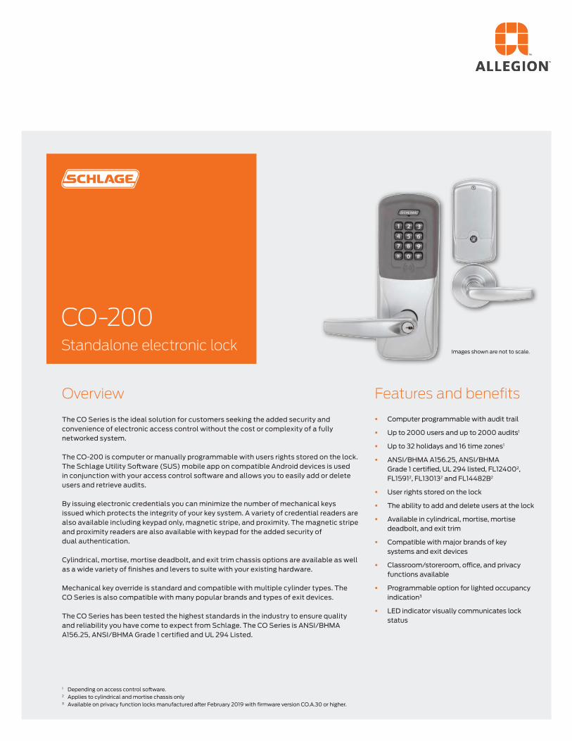
Overview
The CO Series is the ideal solution for customers seeking the added security and convenience of electronic access control without the cost or complexity of a fully networked system.
The CO-200 is computer or manually programmable with users rights stored on the lock. The Schlage Utility Software (SUS) mobile app on compatible Android devices is used in conjunction with your access control software and allows you to easily add or delete users and retrieve audits.
By issuing electronic credentials you can minimize the number of mechanical keys issued which protects the integrity of your key system. A variety of credential readers are also available including keypad only, magnetic stripe, and proximity. The magnetic stripe and proximity readers are also available with keypad for the added security of dual authentication.
Cylindrical, mortise, mortise deadbolt, and exit trim chassis options are available as well as a wide variety of finishes and levers to suite with your existing hardware.
Mechanical key override is standard and compatible with multiple cylinder types. The CO Series is also compatible with many popular brands and types of exit devices.
The CO Series has been tested the highest standards in the industry to ensure quality and reliability you have come to expect from Schlage. The CO Series is ANSI/BHMA A156.25, ANSI/BHMA Grade 1 certified and UL 294 Listed.
Features and benefits
§ Computer programmable with audit trail
§ Up to 2000 users and up to 2000 audits1
§ Up to 32 holidays and 16 time zones1
§ ANSI/BHMA A156.25, ANSI/BHMA Grade 1 certified, UL 294 listed, FL124002, FL15912, FL130132 and FL14482B2
§ User rights stored on the lock
§ The ability to add and delete users at the lock
§ Available in cylindrical, mortise, mortise deadbolt, and exit trim
§ Compatible with major brands of key systems and exit devices
§ Classroom/storeroom, office, and privacy functions available
§ Programmable option for lighted occupancy indication3
§ LED indicator visually communicates lock status
1 Depending on access control software.2 Applies to cylindrical and mortise chassis only3 Available on privacy function locks manufactured after February 2019 with firmware version CO.A.30 or higher.
Images shown are not to scale.
CO-200 Standalone electronic lock

Schlage • CO-200
Exterior of the lock
Mortise deadbolt
Interior of the lock
Cylindrical
CO-200 electronic lock specificationsUsers Up to 2,0001
Audits Up to 2,0001
Credential verification time ≤ 1 second
Visual/audible communications Tri-colored LED’s and audible indicators
Power supply 4 AA batteries (standard off the shelf: included)
Voltage range 4 VDC to 7 VDC
Max current requirement Up to 250 mA
Battery life Up to 2 yrs with 4AA batteries
Operating temperature - exterior -31° to 151°F (-35° to 66°C)
Operating temperature - interior 32° to 120°F (0° to 49°C) due to batteries
Operating humidity 0 - 100% non-condensing
Certifications ANSI/BHMA A156.25, ANSI/BHMA Grade 1, UL 294, UL 10C, UL Canada, FCC Part 15, ADA
Functions § Classroom/storeroom2
§ Office2
§ Privacy3
Standard status signals § Mechanical key override
§ Battery status - indicated by flashing LED lights
§ Access granted/access denied
§ Programming commands
§ Occupied - indicated by red LED light (privacy function only)
1 Depending on access control software.2 Classroom/storeroom and office function not available with mortise deadbolt option. To ensure safety, all functions always allow for free egress.3 Door position switch is required for cylindrical and mortise chassis with privacy function.
Schlage Utility Software § Initialize lock and accessories § Field configure devices
- Credential reader formats - Lock function - Unlock period - Failure mode - Audible alarm on/off
Schlage Utility SoftwareThe Schlage Utility Software (SUS) mobile app on compatible Android mobile devices and SUS-A cable provides an easy way to manage people, audits and locks for simple access control management.
§ Service and diagnostics - Battery status - Validate hardware and software revision
- Troubleshooting status signals - Firmware upgrades
§ New device template simplifies configuration

Schlage • CO-200
Available CO-200
reader options
Proximity ProximityKEYPAD+
Keypad Magnetic stripeKEYPAD+
Magnetic stripe
The combo proximity keyfobs with iButton® option are available which allows you to manage proximity and iButton® technologies in the same facility.
Full cylinder Full Size Interchangeable Core
Small Format Interchangeable Core
Mechanical specificationsChassis Cylindrical Mortise Exit trim
Handing Handed to order, field reversible
ANSI standard (Meets or exceeds)
A156.25A156.2 Series 4000Grade 1
A156.25 A156.13 Series 1000Grade 1
A156.25A156.3
Door thickness 1 3⁄4" standard, 1 3⁄8" to 2 3⁄4" optional (available in 1⁄8" increments)
BacksetStandard: 2 3⁄4"Optional: 2 3⁄8", 3 3⁄4", 5"
2 3⁄4" only Defined by exit device
Latch boltStandard: 1⁄2" throw Optional: 3⁄4" throw
Standard: 3⁄4" throw Optional: 1" throw on mortise deadbolt
Provided by exit device
Levers Pressure cast zinc, plated
StrikeStandard: 1 3⁄16" lip, ANSI, 1 1⁄4" x 4 7⁄8"Optional: Additional configurations available please see price book
Provided by exit device
Cylinder and keys
Schlage 6-pin Everest 29 S123 keyway Conventional cylinder with two patented keys standard. Additional options available including SFIC, FSIC and competitor brands. See lever and cylinder compatibility data sheet (010432)
Exit device compatibility
See CO Series exit trim compatibility data sheet (004183)
Reader specificationsKeypad Magnetic stripe Proximity
Frequency standards
N/A ABA, ISO76XX standard high and low coercivity
125 kHz
Maximum read range
N/A N/A (swipe card) up to 1.25"
Compatibility 3-6 digit pin code Triple track reader (1, 2 or 3), field configurable
Schlage, ISONAS™,HID®, GE/CASI ProxLiteTM and AWID®
Compatible Schlage credentials
N/A Configurable to read complete track 1, 2 or 3
125 kHz clamshell, ISO card, ISO card with magnetic stripe, keyfob, and PVC disk (7000 Series)
Style/layout 12-button, 3x4 matrix
Option for 12-button, 3x4 matrix
Option for 12-button, 3x4 matrix

About Allegion
Allegion (NYSE: ALLE) is a global pioneer in seamless access, with leading brands like CISA®, Interflex®, LCN®, Schlage®, SimonsVoss® and Von Duprin®. Focusing on security around the door and adjacent areas, Allegion secures people and assets with a range of solutions for homes, businesses, schools and institutions. Allegion had $2.7 billion in revenue in 2020, and its security products are sold around the world. For more, visit www.allegion.com
Ordering informationAvailable through one of our GSA schedule 84 approved distributions
Selections correspond with the numbers above
Standard options are indicated in bold. See price book for specific configuration options.
7 Finish626 Satin chrome605 Bright brass606 Satin brass612 Satin bronze619 Satin nickel625 Bright chrome643e Aged bronze626AM Satin chrome antimicrobial
8 Lever cylinder typeP6 Schlage 6-pin Conventional
key-in-lever cylinderSee price book for other SFIC, FSIC and less cylinder options available. Compatible with Schlage, Sargent, Corbin, Medeco and Yale.
9 Keyway typeS123 Everest 29See price book for other available keyway options including restricted keyways in Primus XP high security cylinders and master keying
10 HandingRH Right handed RHR Right handed reverseLH Left handedLHR Left handed reverse
Field reversible
11 Backset and latch or armor frontCylindrical13-049 2 3⁄4" backset, deadlatch,
square corner, 1 1⁄8" x 2 1⁄4" Mortise 09-663 Armor front, 1 1⁄4" wide,
square cornerSee price book for mortise deadbolt and other backset and latch options or armor front options
12 StrikeCylindrical 10-025 1 3⁄16" lip, ANSI, no box, 1 1⁄4" x 4 7⁄8" Mortise 10-072 1 3⁄16" lip, 1 1⁄4" x 4 7⁄8" square corner, box See price book for other available strikes
13 Door thickness1 3⁄4"Other thicknesses available between 1 3⁄8" and 2 3⁄4"
See price book for detail
3 ChassisCY CylindricalMS MortiseMD Mortise deadbolt993R Exit trim – Rim/CVC/CVR993S Exit trim – SVR993M Exit trim – mortise993DT Exit dummy trim
4 Function70 Classroom/storeroom50 Office40 Privacy
5 ReaderKP KeypadMS Magnetic stripe MSK Magnetic stripe + keypad PR ProximityPRK Proximity + keypad
6 LeverATH Athens BRK BoardwalkBRW BroadwayLAT LatitudeLON LongitudeRHO RhodesSPA SpartaTLR Tubular Available with tactile warning options
CO-200-CY-70-PR- SPA - 626-P6-S123 -RH -13-049-10-025 -1 3⁄4
Ser
ies
Cla
ss
Cha
ssis
Func
tion
Rea
der
Leve
r st
yle
Fini
sh
Leve
r cy
lind
er
Key
ing
typ
e
Han
din
g
Str
ike
Doo
r th
ickn
ess
Bac
kset
an
d la
tch
3 41 2 5 6 7 8 9 10 11 12 13
Required fields Factory defaults and options
Allegion, the Allegion logo, Schlage, the Schlage logo, XceedID and Falcon are
trademarks of Allegion plc, its subsidiaries and/or affiliates in the United States and
other countries. All other trademarks are the property of their respective owners.
Finishes
Cool tone finishes
Warm tone finishes
Lever stylesConventional cylinders shown, SFIC and FSIC also available.
Athens Broadway
Sparta
Boardwalk Latitude
TubularLongitude Rhodes
© 2021 Allegion
004185, Rev. 09/21
www.allegion.com/us
605 Bright brass
606 Satin brass
612 Satin bronze
643e Aged bronze
619 Satin nickel
626 Satin chrome
626AM Satin chrome with antimicrobial
625 Bright chrome

Overview
Device types
The 98/99 Series devices are heavy-duty push pads. The 98 Series has a smooth mechanism case, while the 99 Series has a grooved mechanism case. The 98/99 Series has been certified to the highest industry standards and are used in schools, hospitals and government buildings.
Exit device
98/99 Series
99 Series featuresgrooved mechanism case
98 Series features smooth mechanism case
Rim device 75 Mortise lock device
47WDC Concealed vertical rod wood door device 1
27 Surface mounted vertical rod device 1
49 Concealed vertical cable device 2
47 Concealed vertical rod device, 5⁄16" throw 1
48 Concealed vertical rod device, 5⁄8" top, 1 1⁄2" bottom throw
50WDC Concealed vertical cable wood door device
57 Three-point latch device
1 Also available less bottom rod (LBR)
2 Also available less bottom latch (LBL)

Finishes
Due to the many variations in monitors and printers, color samples may appear different than the physical product. Contact your local sales representative for a physical color sample.
98/99 SeriesExit device
605Bright Brass
622Matte Black
606Satin Brass
630Satin Stainless
693Black
619Satin Nickel
625Bright Chrome
630AMSatin Stainless, Antimicrobial
710Dark Brown, Anodized
626AMSatin Chrome, Antimicrobial
628Aluminum, Clear Anodized
612Satin Bronze
643eAged Bronze
626Satin Chrome

Trim functions
98/99 SeriesExit device
NL Night latch
� Key retracts latchbolt � Rim and 1 ¼" mortise
cylinder
TP Thumbpiece
� Key locks and unlocks � Rim and 1 ¼" mortise
cylinder
TPBE Thumbpiece, blank escutcheon
� Blank escutcheon always operable (no cylinder, use with DT trim)
TL Turn lever
� Key locks and unlocks (use with DT trim)
� 1 ¼" mortise cylinder
TLBE Turn lever, blank escutcheon
� Blank escutcheon always operable (no cylinder, use with DT trim)
TLOP Turn lever, optional pull
EO No outside trim
� Exit only
DT Dummy trim
� Pull when dogged (not recommended for fire device)
NLOP Night latch
� Key retracts latchbolt, pull required
HL Hospital latch
� Key locks and unlocks � 1 ¼" mortise cylinder
LBE1 Lever, blank escutcheon
KBE Knob, blank escutcheon
� Always operable (no cylinder)
L Lever
K Knob
� Key locks and unlocks � Rim and 1 ¼" mortise
cylinder � Handed, reversible
lever � Electrified lever
operation available
LDT Lever, dummy trim
KDT Knob, dummy trim
� Pull when dogged
LNL Lever, night latch
KNL Knob, night latch
� Key retracts latchbolt � Rim and 1 ¼" mortise
cylinder � Handed, reversible lever
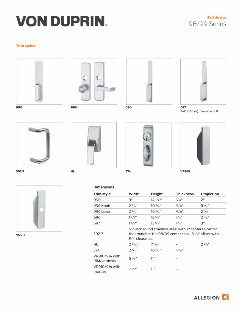
Trim styles
98/99 SeriesExit device
Dimensions
Trim style Width Height Thickness Projection
990 3" 14 3⁄16" 3⁄32" 2"
996 Knob 2 3⁄4" 10 3⁄4" 27⁄32" 3 1⁄4"
996 Lever 2 3⁄4" 10 3⁄4" 27⁄32" 2 7⁄8"
696 1 5⁄8" 13 1⁄2" 3⁄16" 2 1⁄6"
697 1 5⁄8" 13 1⁄2" 3⁄16" 3"
392-7
3⁄4" inch round stainless steel with 7" center to center that matches the 98/99 center case. 3 1⁄2" offset with 11⁄2" clearance.
HL 2 9⁄16" 7 7⁄8" - 2 5⁄8"
374 2 3⁄4" 10 3⁄4" 27⁄32"
VR910/914 with RIM/verticals
5 1⁄2" 11" -
VR910/914 with mortise
7 1⁄4" 11" -
990 996 696 6973/4" (19mm) diameter pull
392-7 HL 374 VR910
VR914

Lever styles
Decorative levers
98/99 SeriesExit device
M51 � Knurling available
M53
M571
M52 � Knurling available
M56
M621 � Handed
M55
M54
M61 � Handed
Dimensions
Lever Width Projection
M51 4.5" 2.5"
M52 4.5" 2.4"
M53 4.4" 2.4"
M54 4.4" 2.3"
M55 4.4" 2.7"
M56 4.5" 2.3"
M57 4.5" 2.7"
M61 4.5" 2.7"
M62 4.6" 2.4"
Escutcheonwidth
EscutcheonHeightLever
width
Projection Leverwidth
1 Available in stainless steel substrate only
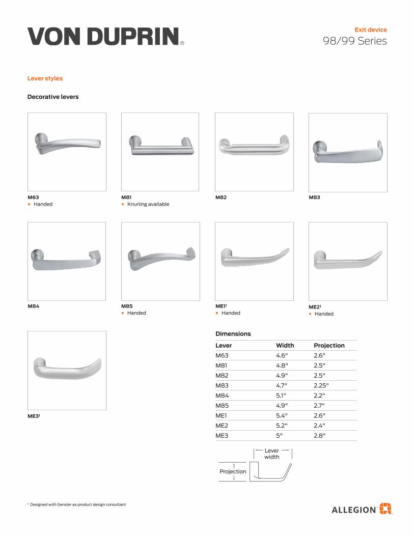
Lever styles
Decorative levers
98/99 SeriesExit device
Dimensions
Lever Width Projection
M63 4.6" 2.6"
M81 4.8" 2.5"
M82 4.9" 2.5"
M83 4.7" 2.25"
M84 5.1" 2.2"
M85 4.9" 2.7"
ME1 5.4" 2.6"
ME2 5.2" 2.4"
ME3 5" 2.8"
M83
M85 � Handed
M84
ME31
ME21 � Handed
ME11 � Handed
1 Designed with Gensler as product design consultant
M81 � Knurling available
M63 � Handed
M82
Escutcheonwidth
EscutcheonHeightLever
width
Projection Leverwidth

Lever styles
Standard levers
98/99 SeriesExit device
01 03 � Knurling available
12 � Handed
02 � Knurling available
07 � Suites with Schlage Athens
06 � Default lever � Suites with Schlage Rhodes � Knurling available
05
16 � Suites with Schlage Omega
Dimensions
Lever Width Projection
01 4.0" 2.1"
02 4.75" 2.3"
03 4.75" 2.813"
05 3.75" 2.8"
06 4.7" 2.1"
07 4.6" 2.3"
12 4.3" 2.9"
16 5.05" 2.66"
Escutcheonwidth
EscutcheonHeightLever
width
Projection Leverwidth

Lever styles
Standard levers
98/99 SeriesExit device
Merano (MER) � Handed
Longitude (LON)Latitude (LAT)
Accent (ACC) � Handed
1817 � Suites with Schlage Sparta � Knurling available
Asti (AST) � Handed
Escutcheonwidth
EscutcheonHeightLever
width
Projection Leverwidth
Dimensions
Lever Width Projection
17 4.7" 2.3"
18 4.75" 2.4"
Accent (ACC) 4.4" 3.1"
Asti (AST) 4.2" 2.5"
Merano (MER) 4.1" 2.5"
Latitude (LAT) 4.6" 2.3"
Longitude (LON) 4.9" 2.3"
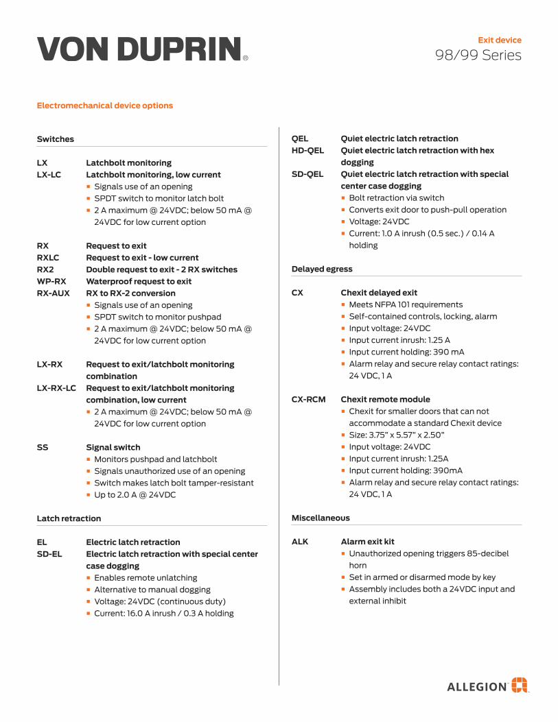
Electromechanical device options
98/99 SeriesExit device
QEL Quiet electric latch retractionHD-QEL Quiet electric latch retraction with hex
doggingSD-QEL Quiet electric latch retraction with special
center case dogging � Bolt retraction via switch � Converts exit door to push-pull operation � Voltage: 24VDC � Current: 1.0 A inrush (0.5 sec.) / 0.14 A
holding
Delayed egress
CX Chexit delayed exit � Meets NFPA 101 requirements � Self-contained controls, locking, alarm � Input voltage: 24VDC � Input current inrush: 1.25 A � Input current holding: 390 mA � Alarm relay and secure relay contact ratings:
24 VDC, 1 A
CX-RCM Chexit remote module � Chexit for smaller doors that can not
accommodate a standard Chexit device � Size: 3.75” x 5.57” x 2.50” � Input voltage: 24VDC � Input current inrush: 1.25A � Input current holding: 390mA � Alarm relay and secure relay contact ratings:
24 VDC, 1 A
Miscellaneous
ALK Alarm exit kit � Unauthorized opening triggers 85-decibel
horn � Set in armed or disarmed mode by key � Assembly includes both a 24VDC input and
external inhibit
Switches
LX Latchbolt monitoringLX-LC Latchbolt monitoring, low current
� Signals use of an opening � SPDT switch to monitor latch bolt � 2 A maximum @ 24VDC; below 50 mA @
24VDC for low current option
RX Request to exitRXLC Request to exit - low currentRX2 Double request to exit - 2 RX switchesWP-RX Waterproof request to exitRX-AUX RX to RX-2 conversion
� Signals use of an opening � SPDT switch to monitor pushpad � 2 A maximum @ 24VDC; below 50 mA @
24VDC for low current option
LX-RX Request to exit/latchbolt monitoring combination
LX-RX-LC Request to exit/latchbolt monitoring combination, low current
� 2 A maximum @ 24VDC; below 50 mA @ 24VDC for low current option
SS Signal switch � Monitors pushpad and latchbolt � Signals unauthorized use of an opening � Switch makes latch bolt tamper-resistant � Up to 2.0 A @ 24VDC
Latch retraction
EL Electric latch retractionSD-EL Electric latch retraction with special center
case dogging � Enables remote unlatching � Alternative to manual dogging � Voltage: 24VDC (continuous duty) � Current: 16.0 A inrush / 0.3 A holding

Electromechanical device options
CON Allegion Connect � Common connectors to connect various
door hardware all the way to the power supply
E996 Electric locking and unlocking trim � Remains latched while unlocked � Remote electrical control � Voltage: 24VDC (Continuous Duty) � Current: 0.22 amps
E7500 Electric mortise lock device � Voltage: 12 or 24VDC � Current: 0.60 amps @ 12VDC, 0.30 amps @
24VDC
98/99 SeriesExit device

Electromechanical device optionsMatrix shows available options per device type but does not represent compatibly across multiple options.
Switches Latch retractionDelayed egress
Misc
LX
LX-L
C
RX
RX
LC
RX
2
WP
-RX
LX-R
X
LX-R
X-L
C
SS
EL
SD
-EL
QE
L
HD
-QE
L
SD
-QE
L
CX
CX
-RC
M
ALK
CO
N
E9
96
Mor
tise
9899 � � � � � � � � � � � � � � � � � � �
98F99F � � � � � � � � � � � � � � � �
XP98XP99 � � � � � � � � � � � � � � � � �
XP98-FXP99-F � � � � � � � � � � � � � �
98759975 � � � � � � � � � � � � � � � �
9875-F9975-F � � � � � � � � � � � � �
98279927 � � � � � � � � � � � � � � � � � � �
9827-F9927-F � � � � � � � � � � � � � � � �
98579957 � � � � � � � � � � � � � � � � � � �
9857-F9957-F � � � � � � � � � � � � � � � �
98479947 � � � � � � � � � � � � � � � � � � �
9847-F 9947-F � � � � � � � � � � � � � � � �
98489948 � � � � � � � � � � � � � � � � � � �
9848-F9948-F � � � � � � � � � � � � � � � �
98499949 �1 � � � � � � � � � � � � � � � � � �
9849-F9949-F �1 � � � � � � � � � � � � � � �
9847WDC9947WDC � � � � � � � � � � � � � � � � � � �
9847WDC-F9947WDC-F � � � � � � � � � � � � � � � �
9850WDC9950WDC � � � � � � � � � � � � � � � � � � �
9850WDC-F9950WDC-F � � � � � � � � � � � � � � � �
1 For 98/9949 devices, LX switch monitors trim input or electric dogging of EL/QEL devices. LX switch does not monitor latchbolt condition.
98/99 SeriesExit device

Mechanical device options
Dogging
CD Cylinder dogging, panic only
CD-CX Center case cylinder dogging for Chexit devices
CI Cylinder dogging indicator � Battery-operated dogging indicator in
cylinder format with red light visible from over 75 feet away
DI Dogging indicator � Battery-operated dogging indicator in hex
format with red light visible from over 75 feet away
LD Less dogging
SD Special center case dogging � Center case cylinder dogging
Classroom security
-2 Double cylinder � Inside key cylinder locks/unlocks outside trim
-2SI Double cylinder with security indicator � Inside key cylinder locks/unlocks outside trim
with visible indicators that provide status of door
CDSI Cylinder dogging with indicator � Provides visible lock/unlock indicators
showing whether device is dogged or undogged
HDSI Hex dogging with indicator � Provides visible lock/unlock indicators
showing whether device is dogged or undogged
98/99 SeriesExit device
Environmental
PN Pneumatic latch retraction � For areas where electrical devices banned � Special linkage for mechanical or pneumatic
dogging
QM Quiet mechanical option � Provides damper-controlled relatching of
device
INS Insulclad kits � Kits with longer fasteners or parts for
Insulclad doors
AM Anti-microbial finish
Weatherized
WH Weep holes � Drainage (weep) holes in mechanism case
WS Windstorm � Severe weather certified/tested � FEMA and ICC compliant � Tornado and hurricane tested
California code
AX Accessible device � UL certified to meet new 5 lb. maximum
operating force requirement � Exceeds ANSI/BHMA requirements
Latches
PL Pullman latch � Latches are always extended � Most commonly used in conjunction with
electric strikes and LBR-less bottom rod application

Mechanical device options
Touch bar trim
RSS Red silk screen � Red silk-screened lettered touchbar trim
PUSH PUSH � Touchbar trim embossed PUSH
SG Safety glow � Self-illuminating touchpad � Glows brightly during low or no light
conditions
KN Knurled touchbar � Tactile warning applied to device
BRAILLE Braille � Vision impaired touchpad � Raised letter and Braille
98/99 SeriesExit device
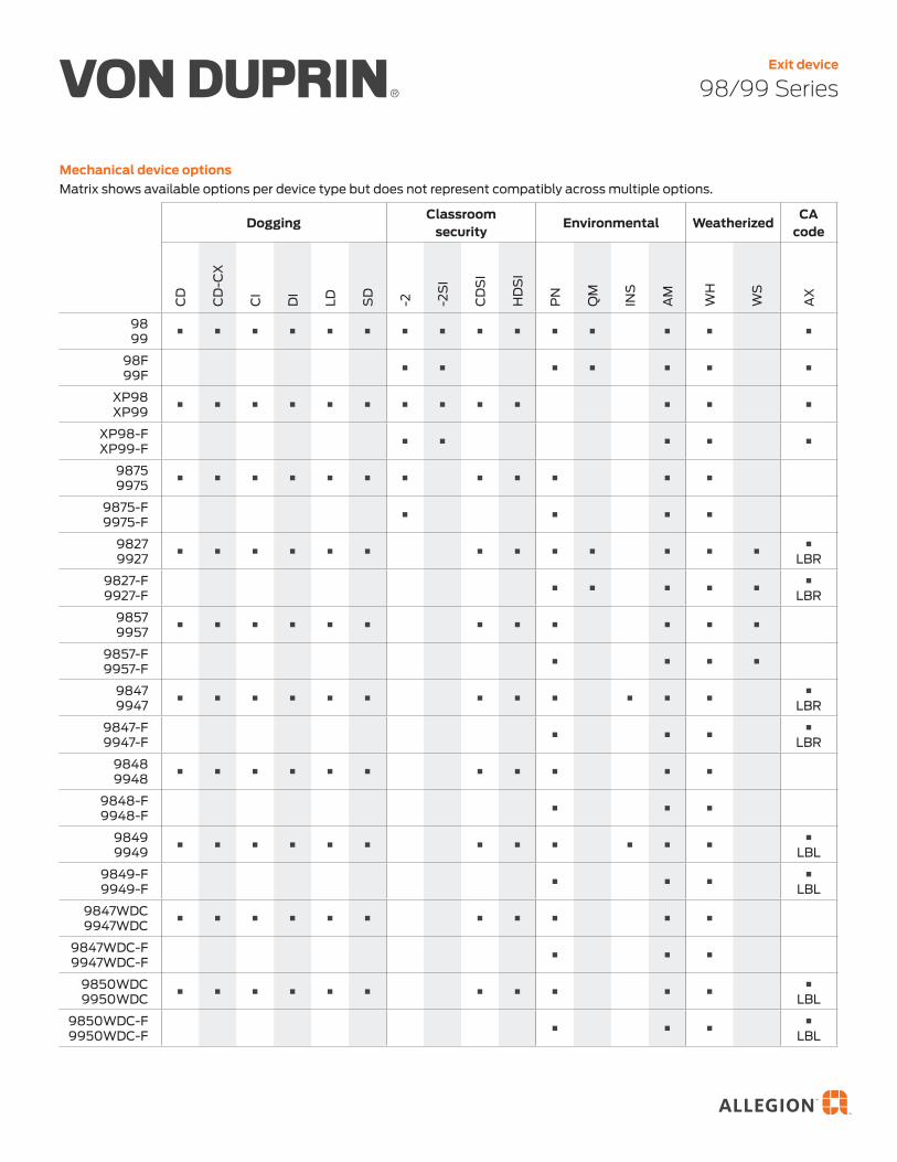
Mechanical device optionsMatrix shows available options per device type but does not represent compatibly across multiple options.
DoggingClassroom
securityEnvironmental Weatherized
CA code
CD
CD
-CX
CI
DI
LD SD
-2 -2S
I
CD
SI
HD
SI
PN
QM
INS
AM
WH
WS
AX
9899 � � � � � � � � � � � � � � �
98F99F � � � � � � �
XP98XP99 � � � � � � � � � � � � �
XP98-FXP99-F � � � � �
98759975 � � � � � � � � � � � �
9875-F9975-F � � � �
98279927 � � � � � � � � � � � � �
�LBR
9827-F9927-F � � � � �
�LBR
98579957 � � � � � � � � � � � �
9857-F9957-F � � � �
98479947 � � � � � � � � � � � �
�LBR
9847-F 9947-F � � �
�LBR
98489948 � � � � � � � � � � �
9848-F9948-F � � �
98499949 � � � � � � � � � � � �
�LBL
9849-F9949-F � � �
�LBL
9847WDC9947WDC � � � � � � � � � � �
9847WDC-F9947WDC-F � � �
9850WDC9950WDC � � � � � � � � � � �
�LBL
9850WDC-F9950WDC-F � � �
�LBL
98/99 SeriesExit device

Mechanical device optionsMatrix shows available options per device type but does not represent compatibly across multiple options.
98/99 SeriesExit device
Latches Touch bar trimP
L
RS
S
PU
SH
SG
KN
BR
AIL
LE
9899 � � � � �
98F99F � � � � �
XP98XP99 � � � � �
XP98-FXP99-F � � � � �
98759975 � � � � �
9875-F9975-F � � � � �
98279927 � � � � � �
9827-F9927-F � � � � �
98579957 � � � � �
9857-F9957-F � � � � �
98479947 � � � � � �
9847-F 9947-F � � � � �
98489948 � � � � �
9848-F9948-F � � � � �
98499949 � � � � �
9849-F9949-F � � � � �
9847WDC9947WDC � � � � �
9847WDC-F9947WDC-F � � � � �
9850WDC9950WDC � � � � �
9850WDC-F9950WDC-F � � � � �

Specifications
www.allegion.com/us
Dimensions
98/99 SeriesExit device
Accessibility � Force to depress push pad − AX device: 5 lbs − Standard device: 15 lbs
� Push pad projection − Neutral: 3 13⁄16" (97 mm) − Depressed: 3 1⁄16" (78 mm)
Certifications/approvals
All Von Duprin 98/99 exit devices are ANSI/BHMA Certified. Please refer to the BHMA Certified Products Directory for specific listings.
Mounting height 39 13⁄16" (1011 mm)39 11⁄16" (1008 mm) with mullion
Warranty 36 months from the date of placing the product in operation
© 2019 Allegion 013139, Rev. 11/2019

Cylinders for Adams rite 4070 Series deadlocks
Number Core mechanism Collar
20-091 Conventional core 3⁄16" + 3⁄8" blocking rings
20-722 Primus core 3⁄16" + 3⁄8" blocking rings
20-722-XP Primus XP core 3⁄16" + 3⁄8" blocking rings
20-090 Housing less core None
Interchangeable core rim cylinders for exit devices
Number Core mechanism
20-057 Conventional core
20-757 Primus core
20-757-XP Primus XP core
20-079 Housing only, less core
Available in 605, 606, 609, 612, 613, 619, 625, 626, and 643e finish.
Cylinders for Adams rite MS and 4700 Series Lori 4500 Series and Corbin russwin DL3000 Series
Number Core mechanism Collar
26-098 Conventional core Compression ring & spring
20-062 Conventional core 3⁄16" + 3⁄8" blocking rings
20-766 Primus core 3⁄16" + 3⁄8" blocking rings
20-766-XP Primus XP core 3⁄16" + 3⁄8" blocking rings
20-060 Housing less core None
These cylinders include set screw pack B220-050 for Adams Rite locks.
K510-711Adams Rite
MS cam
B520-378Adams Rite4070 cam
Notes 1. Mortise cylinders available 605, 606, 609, 612, 613, 619, 625, 626, and 643e finish. Cores furnished 606 and 626 only. 2. To differentiate between Classic and Everest 29, specify keyway. Example: C or CP (Classic), S123 (Everest 29). 3. All cylinders are 1 1⁄2" long. 4. Specify LKB if 0-bitted Primus XP cylinders are required less key blanks.
Cores
Full size interchangeable core cylinders for exit devices, aluminum door, etc.
34 • Schlage • Key systems, cylinders and keys reference guide


Cylinder Only Compr. Ring & Spring With Blocking Ring


Ives Architectural hardware productsF2
Lock Guards
BPu
lls &
Pla
tes
AH
inge
s &
Piv
ots
CFl
ush
Bolt
s & C
oord
inat
ors
DLa
tche
s, C
atch
es &
Bol
tsE Stop
sF2
Exte
rior H
ardw
are
GM
isce
llane
ous H
ardw
are
LG1 Lock GuardLG7 • Unitsarenon-handedandincorporatesecurityframepinto
prevent separation of the door and frame . LG7 does not incorporate the security frame pin
• Unitcoversthelatchboltareaofthedoorandlock,therebyproviding added protection from burglars, vandals or normal abuse .
• Idealforusewithmortiseorcylindricallocks. • Easyinstallation. • Throughboltedwithcarriageboltsandnuts. • Availableinavarietyofmaterials,13gaugestainlesssteel,
12 gauge steel and brass material .
Dimensions3" Wide x 11-1/2" HighBolt center to center: 10-1/2"
LG10 Lock Guard • Ideallysuitedforusewithroseorescutcheon2-3/4"wideorless. • ForusewithType86MortiseandType161CylindricalLocks
(ANSI 156 .13 Series 1000 and ANSI 156 .2 Series 4000) . • Noexposedfastenersonfaceofunit. • Uniquedesignprovidesmaximumsecurity,virtuallyeliminatingthe
opening between door and frame at the latch point . • Availablein13GaugeStainlessSteelor12GaugeSteel.
Dimensions2-1/2" Wide x 9-1/2" HighStud center to center: 8-1/2"
FinishesIves Number USP* US2G* US4* US10* US32D SP313*
BHMA 600 603 606 612 630 695
* not available on LP7
FinishesIves Number USP US32D
BHMA 600 630

Ives Architectural hardware productsF3
Lock Guards
BPulls &
PlatesA
Hinges &
PivotsC
Flush Bolts & Coordinators
DLatches, Catches &
BoltsEStops
F3
Exterior Hardw
areG
Miscellaneous H
ardware
LG11 Lock Guard • Designedforuseonaluminumdoorswithlatch-typelocks
or doors equipped with electric strikes . • UnitisHanded-Specifyleftorrighthandwhenordering. • Noexposedfastenersonfaceofunit. • Uniquedesignprovidesmaximumsecurity,virtuallyeliminatingthe
opening between door and frame at latch point . • Availablein13GaugeStainlessSteelor12GaugeSteel.
Dimensions2-1/2" Wide x 9-1/2" HighStud center to center: 8-1/2"
LG12 Lock Guard • Narrowdesignunitforuseonroseorescutcheon3-1/2"orless. • ForusewithType86MortiseandType161CylinderLocks
(ANSI 156 .13 Series 1000 and ANSI 156 .2 Series 4000) . • Noexposedfastenersonfaceofunit. • Uniquedesignprovidesmaximumsecurity,virtuallyeliminatingtheopening
between door and frame at the latch point . • Availablein13GaugeStainlessSteelor12GaugeSteel
Dimensions1-1/2" Wide x 9-1/2" High
Stud center to center: 8-1/2”
FinishesIves Number US32D SP313
BHMA 630 695
FinishesIves Number USP US32D
BHMA 600 630

K-BXED-V990NL-2
Weldable Box
Type: Panic Hardware
Dimensions:
4 ”W x 15”H x 2”D
Materials Available:
14 Gauge Steel..........K-BXED-V990NL-2
.125 Gauge Aluminum.......K-BXED-V990NL-A2
Notes: Weldable Box For Von Duprin 99 Rim Exit
Device W/ 990NL Trim - Gate Friendly
4”
15”
2”
www.keedex.com • 714-993-4300
This rendering is NOT to scale and dimensions are
NOT exact. For precise technical information, please
refer to the template for the lock you are using.
13 1/4”
8 1/8”8 1/8”
∅3/8”
∅3/8” ∅3/8”
∅3/8”∅3/8”
∅3/8”
4 1/2”
1 1/8”1 1/8” ∅1/4”∅1/4”
4 1/2”

Ives Architectural hardware productsB13
Vandal Resistant Trim
B13
Pulls & Plates
AH
inges & Pivots
CFlush Bolts &
CoordinatorsD
Latches, Catches & Bolts
EStopsF
Exterior Hardw
areG
Miscellaneous H
ardware
VR910-DT With black gripVR914-DT Without black grip • ForusewithVonDuprin98/99Seriesrimandverticalrodexitdevice • Non-handed • Thru-boltsdirecttotheexitdevice • Pulloperationonly. Thru-Bolt Clearance Width Height Pattern Grip to Door Projection
5-1/4” 11” 1-3/8” wide x 7” high 1-1/2” 1-7/8”
VR910-NL With black gripVR914-NL Without black grip • ForusewithVonDuprin98/99rimandverticalrodexitdevice • Non-handed • Thru-boltsdirecttotheexitdevice
Thru-Bolt Clearance Width Height Pattern Grip to Door Projection
5-1/4” 11” 1-3/8” wide x 7” high 1-1/2” 1-7/8”
VR910M-DT With black gripVR914M-DT Without black grip • ForusewithVonDuprin9875/9975mortiselockexitdevice • Non-handed • Thru-boltsdirecttotheexitdevice
Thru-Bolt Clearance Width Height Pattern Grip to Door Projection
7-1/4” 11” 1-3/8” wide x 7” high 1-1/2” 1-7/8”
VR910M-NL RHR With black gripVR910M-NL LHR With black gripVR914M-NL RHR Without black gripVR914M-NL LHR Without black grip • ForusewithVonDuprin9875/9975Seriesmortiselockexitdevice • Thru-boltsdirecttotheexitdevice • Nightlatchoperation(cylindernotfurnished) Thru-Bolt Clearance Width Height Pattern Grip to Door Projection
7-1/4” 11” 1-3/8” wide x 7” high 1-1/2” 1-7/8”
Finishes US Finish US32D
BHMA 630
Finishes US Finish US32D
BHMA 630
Finishes US Finish US32D
BHMA 630
Finishes US Finish US32D
BHMA 630

Overview
Cylinder
Mounting
Parallel arm (push side)
Available cylinder options
DEL Delayed action cylinder
AVB Advanced variable backcheck
SizingAdjustable spring size 1-5, or sized 6 Includes patented Green Dial
� 4111 (adjustable from size 1 to 5) � 4116 (Size 6; DEL, SHCUSH or HCUSH arm
not available)
HandingHanded
4111(6)-3071Cast iron cylinder assembly
The 4110 is LCN’s best performing heavy duty closer with an adjustable spring and possible hold-open point beyond 140 degrees, meeting ADA requirements. Backed by a 30 year warranty, the cast iron body and all weather fluid offer versatility in high traffic applications.
4110 SeriesSurface mounted closer

4110 SeriesSurface mounted closer
CoversFinishes
Available finish options
MTLPC Brite metallic: Custom powder coat finish, which resembles that of 651 or 652 plated finish.
SRI For installations where a higher level of protection against weather conditions, or the effects of a potentially corrosive atmosphere is required, LCN offers a special rust inhibiting (SRI) process. Ferrous metal components receive an SRI pretreatment and a standard powder coat finish of your choice, or a custom powder coat finish for a nominal additional cost. Closers treated with the SRI process exceed the 100 hour protection level available with standard LCN powder coated finishes.
632Bright Brass
633Satin Brass
639Satin Bronze
616Satin Bronze, Blackened
646Satin Nickel
651Bright Chrome
652Satin Chrome
Metal plated finishes
Powder coat finishes
689Aluminum
690Statuary Bronze
691Light Bronze
693Black
695Dark Bronze
696Brass
150+ additional custom colors available using the RAL numbering system
4110-72MCMetal cover
� Handed � Required for plated finishes
and custom powder coat finishes
� Optional
4110-72Plastic cover
� Non-handed � Standard
Standard cover
Optional cover

4110 SeriesSurface mounted closer
Arms
4110-3049EDAHold-open arm
� Handed � Optional � Provides hold-open function,
adjustable at shoe
4110-3077EDA/ 62GExtra duty arm
� Non-handed � Features forged, solid
steel main and forearm for potentially abusive installations
� Optional 4110-62G thick hub shoe for blade stop clearance
4110-3077CNSCush-N-Stop arm
� Non-handed � Features solid forged steel
main arm and forearm with built-in stop in soffit shoe
4110-3077SCNSSpring CUSH arm
� Non-handed � For abusive applications
features solid forged steel main arm and forearm with spring loaded stop in the soffit shoe
� Optional
4110-3049FLFusible link arm
� Handed � Releases hold-open function
adjustable at shoe when exposed to temperatures above 165° F
� Optional � NOTE: Check local codes
before specifying FL arms. NOT A life safety product!
4110-3049CNSHCUSH arm
� Non-handed � Provides hold-open function
with templated stop/ hold-open points.
� Handle controls hold-open function
4110-3077EDAExtra duty arm
� Non-handed � Features forged, solid
steel main and forearm for potentially abusive installations
4110-3049SCNSSpring HCUSH arm
� Non-handed � For abusive applications
features solid forged steel main arm and forearm with spring loaded stop in the soffit shoe
� Handle controls hold-open function
� Optional

4110 SeriesSurface mounted closer
Installation accessories
4110-18Plate
� Required for push side mount where top rail is less than 5 1/8˝ (130 mm), measured from the stop
� Requires minimum 2˝ (51 mm) minimum top rail
4110-61Blade stop spacer
� Lowers parallel arm shoe to clear 1/2˝ (13 mm) blade stop
FastenersSelf-reaming and tapping screws included standard
Fastener pack options
TBSRT TB1 with self-reaming and tapping screws
WMS Wood and machine screw
TBWMS TB1, wood and machine screw
TORX TORX machine screw
TBTRX TB1 and TORX machine screw
1 Specify door thickness if other than 1 3/4"
4110-30CUSH shoe support
� Provides anchorage for fifth screw used with CUSH arm, where reveal is less than 3 1/16˝ (78 mm)
4110-419PA flush panel adapter
� Provides horizontal mounting surface for CUSH shoe on single rabetted or flush frame

4110 SeriesSurface mounted closer
Dimensions and mounting
Parallel arm (push side) mounting
2-1/4"57 mm
5-1/8"130 mm
5-1/2"140 mm
3-1/2"89 mm
14-1/16"357 mm
4"102 mm
5-1/8”130 mm
12-1/4"311 mm
4110-18
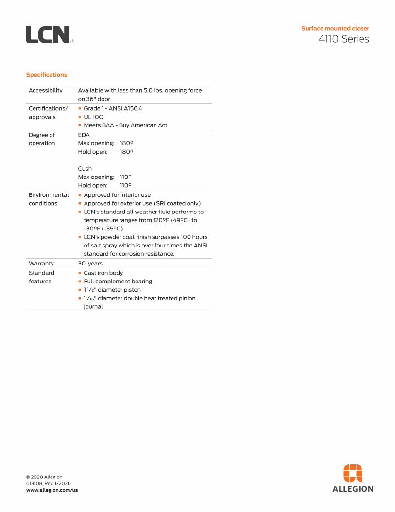
4110 SeriesSurface mounted closer
Specifications
www.allegion.com/us
© 2020 Allegion 013108, Rev. 1/2020
Accessibility Available with less than 5.0 lbs. opening force on 36" door
Certifications/approvals
� Grade 1 - ANSI A156.4 � UL 10C � Meets BAA - Buy American Act
Degree of operation
EDAMax opening: 180°Hold open: 180°
CushMax opening: 110°Hold open: 110°
Environmental conditions
� Approved for interior use � Approved for exterior use (SRI coated only) � LCN’s standard all weather fluid performs to
temperature ranges from 120°F (49°C) to -30°F (-35°C)
� LCN’s powder coat finish surpasses 100 hours of salt spray which is over four times the ANSI standard for corrosion resistance.
Warranty 30 years
Standard features
� Cast iron body � Full complement bearing � 1 1/2" diameter piston � 11/16" diameter double heat treated pinion
journal

Ives Architectural hardware productsB14
Protection Plates
B14
Pulls
& P
late
sA
Hin
ges
& P
ivot
sC
Flus
h Bo
lts &
Coo
rdin
ator
sD
Latc
hes,
Cat
ches
& B
olts
E Stop
sF
Exte
rior H
ardw
are
GM
isce
llane
ous H
ardw
are
8400 Series Protection Plates • Doorprotectionplatesareavailablein.050”thickbrass,stainless
steel or aluminum; and 1/8” thick high impact polyethylene in clear or black .
• Beveledgeoptions;specifyB4Eforallfouredges. • Mountingscrewpackfurnishedstandard,16screwsperpack.
Optional screw packs are available for TEK or TORK screw heads . Refer to the following chart for ordering .
• SpecifyNMHfornomountingholes.(Notavailableon8402) • SpecifyNMH-Afornomountingholeswithadhesive.(Notavailableon8402) • SpecifyCSforcountersunkmountingholes. • SpecifyERSpreppedwithextrarowofscrews. Kickplate Gasket Tape Tape is recommended when using a
brass plate on a metal door to reduce tarnishing from electrolytic oxidation . One tape pack will cover an the perimeters of a 8” x 34” kickplate . Order 8401 Gasket Tape .
8400 Protection Plate8402 (UL)* Protection Plate*UL mark appears in upper right corner. Factory supplied screws must be used.Number of screw packs required by plate size (specify TEK Screws or TORK screws) .
22”-25” 26”-33” 34”-41” 42”-48”4”-8” 1 1 1 19”-16” 1 1 1 117”-24” 1 1 1 225”-32” 1 1 2 233”-40” 1 2 2 241”-48” 2 2 2 2
Finishes brass 24” x 48” max. sizeUS Number US3 US4 US10 US10B US15 US26 US26D
BHMA 605 606 612 613 619 625 626
Finishes stainless steelUS Number US32 US32D
BHMA 629 630
Finishes aluminumUS Number US28
BHMA 628
Finishes plasticClear and Black
Residential Grade Kickplates available Carded only, finishes PA28, PA3, PA619, PA716, B3, B505, B619, B716

Ives Architectural hardware productsB18
Protection Plates
B18
Pulls
& P
late
sA
Hin
ges
& P
ivot
sC
Flus
h Bo
lts &
Coo
rdin
ator
sD
Latc
hes,
Cat
ches
& B
olts
E Stop
sF
Exte
rior H
ardw
are
GM
isce
llane
ous H
ardw
are
Mop Plates • Protectthebottomofthepullsideofdoorsubjecttocleaning
and mopping procedures . • SizeRanges:4”to6”high,22”to48”wide
Kick Plates • Protectthebottomofthepushsideofdoorssubjectto
scuffing from foot traffic . •Recommendedforalldoorssubjecttonormaluse
(especially doors using a closer) . • SizeRanges:8”to24”high,22”to48”wide
Stretcher Plates • Protectdoorsatspecificareaswhereconsistentcontactis
made by stretchers, service carts or other equipment . • Usuallyappliedtopushsideofdoors. • Specify“B4E”Optionforbevelededges. • SizeRanges:6”to8”high,22”to48”wide
Armor Plates • Protectlowerhalfofdoorsfromabusebyhardcarts,
trucks and rough usage . • Usuallyappliedtopushsideofsingledoorsandbothsides
of double acting doors . • SizeRanges:26”to48”high,22”to48”wide

Ives Architectural hardware productsE5
Floor Stops
BPulls &
PlatesA
Hinges &
PivotsC
Flush Bolts & Coordinators
DLatches, Catches &
BoltsE
5Stops
FExterior H
ardware
GM
iscellaneous Hardw
are
FS18SFS18L Floor Stops • SecurityDoorStopsdesignedforuseinhighvandalismareas. • Moldedfromblackflameresistant,resilientmaterialarounda
heavy-duty stud . • Oncegroutedinconcrete,leavesnoexposedfastenerstobe
tampered with or removed . • Idealforjailorsecuritycellareaswherefloormountedstopsarerequired. • FS18Lalsoidealforconcretewallapplications.
DimensionsFS18S Height: 1-1/2” FS18L Height: 3-1/2”
FS18S Diameter: 2” FS18L Diameter: 2”
FS18S Stud Length: 2-1/2” FS18L Stud Length: 2-1/2”
FS18LFS18S
FS434 Floor Stop • Burnishedwroughtsteel. • Forundercutdoorsupto1-1/2”. • Packedwithscrewsandplasticanchors. • Replaceablesoft,resilientgrayrubber.
DimensionsOverall Height: 2-5/8”
Base Size: 1-1/2” W x 2-3/4” L
Finishes Ives Number USC
BHMA 604
430 Floor Door Stop • Burnishedwroughtsteel. • Forundercutdoorsupto1-1/2”. • Packedwithscrewsandplasticanchors. • Replaceablesoft,resilientgrayrubber.
DimensionsOverall Height: 1-5/16”
Base Diameter: 1-1/4”
Finishes brassIves Number B3 B4 B5 B10B B15 B26 B26D
BHMA 605 606 609 613 619 625 626
Finishes aluminumIves Number A3* A5 A14 A92
BHMA 666 669 673
* only available in Slim-Pak of 25
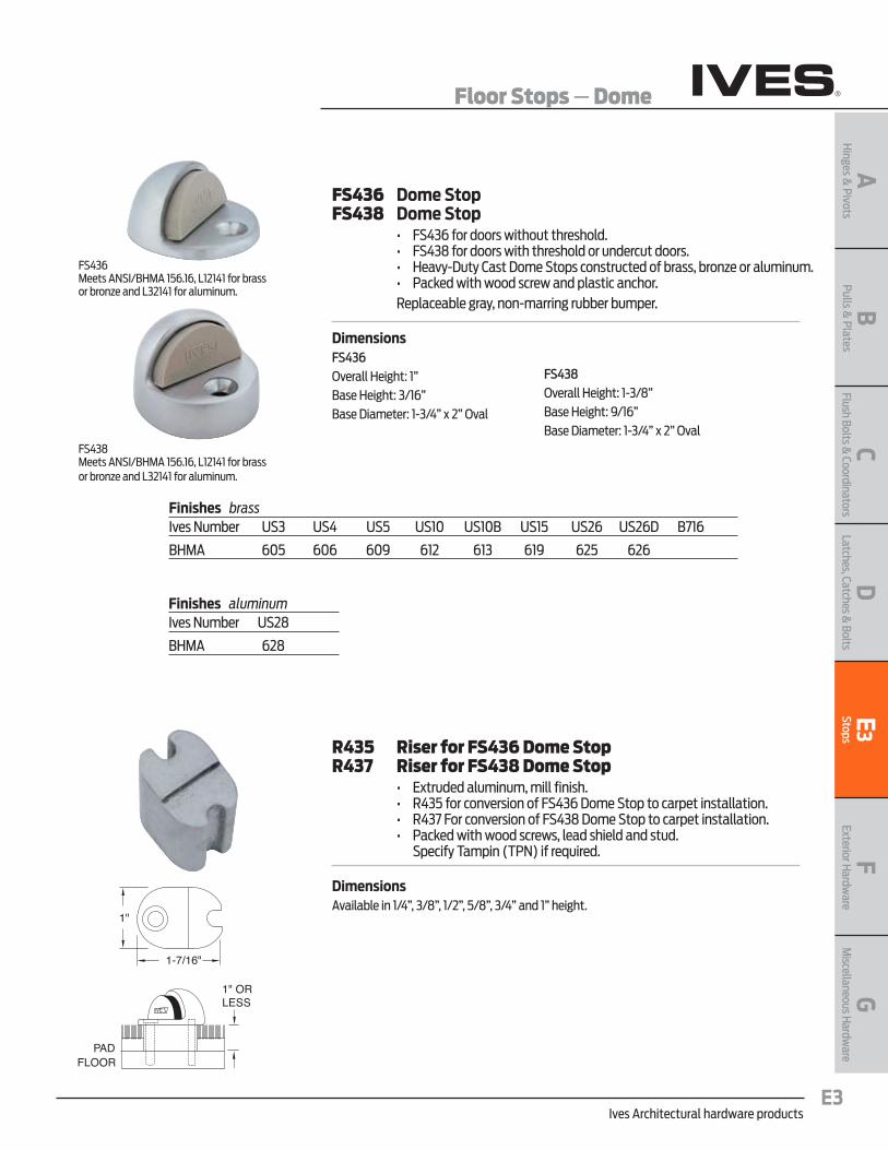
Ives Architectural hardware productsE3
Floor Stops — Dome
BPulls &
PlatesA
Hinges &
PivotsC
Flush Bolts & Coordinators
DLatches, Catches &
BoltsE
3Stops
FExterior H
ardware
GM
iscellaneous Hardw
are
FS436 Dome StopFS438 Dome Stop • FS436fordoorswithoutthreshold. • FS438fordoorswiththresholdorundercutdoors. • Heavy-DutyCastDomeStopsconstructedofbrass,bronzeoraluminum. • Packedwithwoodscrewandplasticanchor. Replaceable gray, non-marring rubber bumper .
DimensionsFS436Overall Height: 1” Base Height: 3/16”Base Diameter: 1-3/4” x 2” Oval
PADFLOOR
1" ORLESS
1"
1-7/16"
R435 Riser for FS436 Dome StopR437 Riser for FS438 Dome Stop • Extrudedaluminum,millfinish. • R435forconversionofFS436DomeStoptocarpetinstallation. • R437ForconversionofFS438DomeStoptocarpetinstallation. • Packedwithwoodscrews,leadshieldandstud.
Specify Tampin (TPN) if required .
DimensionsAvailable in 1/4”, 3/8”, 1/2”, 5/8”, 3/4” and 1” height .
FS438Meets ANSI/BHMA 156 .16, L12141 for brassor bronze and L32141 for aluminum .
Finishes brassIves Number US3 US4 US5 US10 US10B US15 US26 US26D B716
BHMA 605 606 609 612 613 619 625 626
Finishes aluminumIves Number US28
BHMA 628
FS436Meets ANSI/BHMA 156 .16, L12141 for brassor bronze and L32141 for aluminum .
FS438Overall Height: 1-3/8” Base Height: 9/16” Base Diameter: 1-3/4” x 2” Oval
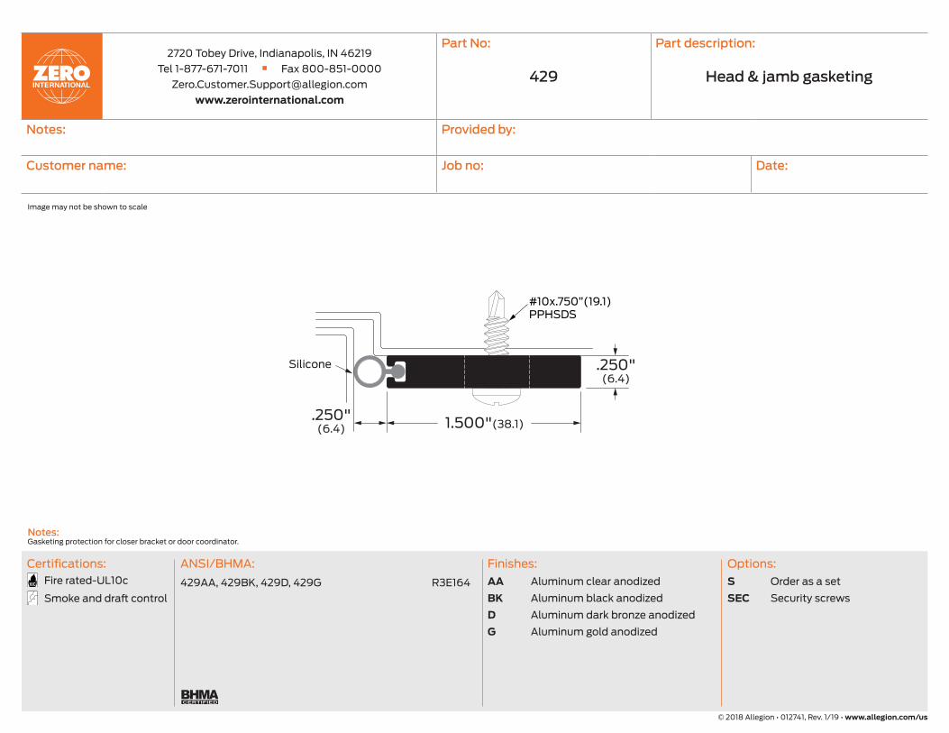
2720 Tobey Drive, Indianapolis, IN 46219
Tel 1-877-671-7011 n Fax 800-851-0000
www.zerointernational.com
Part No: Part description:
Notes: Provided by:
Customer name: Job no: Date:
Head & jamb gasketing
Image may not be shown to scale
© 2018 Allegion • 012741, Rev. 1/19 • www.allegion.com/us
Options:
S Order as a set
SEC Security screws
Finishes:
AA Aluminum clear anodized
BK Aluminum black anodized
D Aluminum dark bronze anodized
G Aluminum gold anodized
ANSI/BHMA:
429AA, 429BK, 429D, 429G R3E164
Certifications:
Fire rated-UL10c
Smoke and draft control
Notes: Gasketing protection for closer bracket or door coordinator.
429
Silicone
429
1.500"(38.1).250"(6.4)
.250"(6.4)
#10x.750”(19.1)PPHSDS
Powered by TCPDF (www.tcpdf.org)
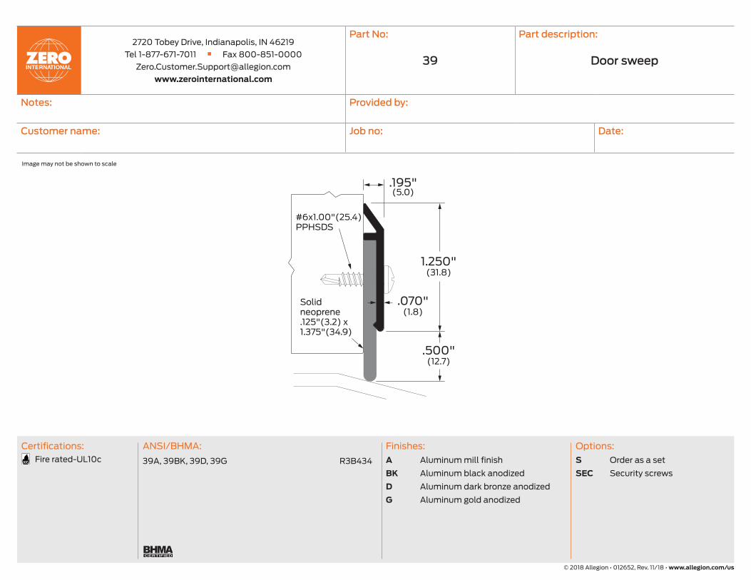
2720 Tobey Drive, Indianapolis, IN 46219
Tel 1-877-671-7011 n Fax 800-851-0000
www.zerointernational.com
Part No: Part description:
Notes: Provided by:
Customer name: Job no: Date:
Door sweep
Image may not be shown to scale
© 2018 Allegion • 012652, Rev. 11/18 • www.allegion.com/us
ANSI/BHMA:
39A, 39BK, 39D, 39G R3B434
Certifications:
Fire rated-UL10c
Finishes:
A Aluminum mill finish
BK Aluminum black anodized
D Aluminum dark bronze anodized
G Aluminum gold anodized
Options:
S Order as a set
SEC Security screws
39
Solid neoprene.125"(3.2) x 1.375"(34.9)
.195"(5.0)
.070"(1.8)
1.250"(31.8)
.500"(12.7)
#6x1.00"(25.4)PPHSDS
Powered by TCPDF (www.tcpdf.org)

2720 Tobey Drive, Indianapolis, IN 46219
Tel 1-877-671-7011 n Fax 800-851-0000
www.zerointernational.com
Part No: Part description:
Notes: Provided by:
Customer name: Job no: Date:
Saddle threshold
Image may not be shown to scale
© 2018 Allegion • 012518, Rev. 11/18 • www.allegion.com/us
Notes: Supplied without mounting holes.
Options:
E Epoxy abrasive tread
EL Photoluminescent and abrasive epoxy tread
V3 Full body strength fill
EV3 Epoxy and full body strength fill
ELV3 Photoluminescent and abrasive epoxy tread, full body strength fill
Finishes:
A Aluminum mill finish
BK Aluminum black anodized
D Aluminum dark bronze anodized
G Aluminum gold anodized
ANSI/BHMA:
547A, 547BK, 547D, 547G J32100, J32130
547A-E, 547BK-E, 547D-E, 547G-E J32200, J32230
Certifications:
Fire rated-UL10c
ADA Accessible
547
.250"(6.4)
.140"(3.6)
7.00"(177.8)
2.00"(50.8).188"(4.8)
Powered by TCPDF (www.tcpdf.org)

OverviewSchlage® offers a comprehensive portfolio of electronic access control solution products. Create a simple enrollment process with the Schlage CRM2 magnetic stripe enrollment reader, Schlage CRP2 proximity enrollment reader or the Schlage MT20 USB multi-technology enrollment reader with ENGAGE technology.
Features and benefitsCRM2 Magnetic Stripe Credential Enrollment Reader and CRP2 Proximity Credential Enrollment Reader
§ Design allows easy enrollment of credentials into the Schlage Express access control system (version 4.0 and higher)
§ Eliminates the need for manual data entry and provide error-free identification and security throughout the facility
§ Allows for keystrokes to be added before and after the card’s data, providing flexibility and data customization
§ Reads data from any data track location on the card
§ USB connectivity
§ Plug-and-play functionality
The Schlage MT20 Multi-Technology Enrollment Reader
§ Design simplifies the enrollment of smart and multi-technology credentials
§ Access rights can be assigned to a user without property staff having to visit the lock
§ USB cable powers the device
§ Use Wi-Fi connection for enrollment including no-tour credentials
§ Use a computer and the ENGAGE web app to easily enroll credentials
§ Recognizes Schlage smart and multi-technology credentials
§ Limited Lifetime Warranty
CYBERSECURITYLearn about Allegion’s commitment
Enrollment readers

Allegion (NYSE: ALLE) is a global pioneer in safety and security, with leading brands like CISA®, Interflex®, LCN®, Schlage®, SimonsVoss® and Von Duprin®. Focusing on security around the door and adjacent areas, Allegion produces a range of solutions for homes, businesses, schools and other institutions. Allegion is a $2 billion company, with products sold in almost 130 countries. For more, visit www.allegion.com.
About Allegion
Model MT20
Reader type USB
Software and operating system requirements
N/A - USB
Bit formats recognized 26A, 32X, 34N, 34S, 35C, 37X, 37H, 40X
Technologies supported Schlage ProximityHID® Proximity GE/CASI ProxLite®
AWID® ProximityLenelProx®
Schlage MIFARE Classic Secure SectorSchlage MIFARE Plus Secure SectorSchlage MIFARE DESFire EV1 or EV2 with PACSA Secure SectorDESFire® CSN HID iClass® CSNInside Contactless PicoTag® CSNST Microelectronics® CSN Texas Instruments Tag-It® Serial NumberPhillips I-Code® CSN
Physical dimensions (L x W x H)
5.56" x 2.00" x .695"
Operating temperatures 32° to 104° F (0° to 40° C)
Weight 4.1 oz
Power supply Connect to powered USB port or via USB power supply
Interface USB
Current requirement 160 mA
Default configuration CE-401-073, for use with ENGAGE web applicaton
Octal output CE-401-061, for use with SMS Express
FC/BID output CE-401-060 (SUSB89 default,) for use as keystroke emulator
BID only CE-401-069, for use as keystroke emulator
Allegion, the Allegion logo, Schlage, and the Schlage logo are trademarks of Allegion plc, its subsidiaries and/or affiliates in the United States and other countries. All
other trademarks are the property of their respective owners.
© 2021 Allegion
010523, Rev. 03/21
www.allegion.com/us
Model CRP2
Typical maximum read range1.0" – 3.0" (2.5 – 7.6 cm) dependent upon proximity card type and environmental conditions
Dimensions (H x W x D) 3 3⁄8" x 2" x 0.6"
Weight 0.45 lbs (12.7g)
Power supply and interface USB self-powered
Indicators Tri-state LED, beeper
Transmit frequency 125 kHz
Operating temperature range -22° to 150°F (-30° to 65°C)
Operating humidity range 5% to 95% relative humidity, non-condensing
Storage temperature range -40° to 185°F (-40° to 85°C)
Certifications FCC, United States; CE Mark Europe, C-tic Australia, RoHS
Warranty One year for material/workmanship and defects
Model CRM2
Desktop dimensions(H x W x D)
3.674" x 1.325" x 1.193" (93.32 x 33.65 x 30.3 mm); Optional base: 3.375" x 3.5" x 0.5" (86 x 89 x 13 mm)
Desktop weight 4.6 oz (136 g); Base: 13 oz (369 g)
Media thickness 0.015" (0.127 mm) to 0.038" (1.14 mm)
Slot width 0.040" (1.0 mm)
Swipe speed 3 to 60 inches per second, bi-directional
Power supply and interface USB: self-powered; RS-232 [DB9F] model: 5V supplied by either PS/2 keyboard pass-through or USB power tap
Indicators Tri-state LED, beeper
Operating temperature range 32° to 131°F (0° to 55°C)
Operating humidity range 5% to 95% relative humidity, non-condensing
Storage temperature range -22° to 158°F (-30° to 70°C)
Cable length 6 foot articulated cable
Operating life 1,000,000 cycles minimum
Warranty One year for material/workmanship and defects

Overview
Schlage® proximity credentials provide a convenient access control solution for facilities with less demanding security needs. Schlage proximity credentials are compatible with most industry-leading proximity readers, allowing them to easily integrate with new and existing proximity access control systems. From highly durable clamshell-style cards to the standard ISO style cards, keyfobs or PVC adhesive disks, Schlage offers a variety of credential formats to support a broad range of access control applications.
Features and benefits
§ 125 kHz proximity technology available in multiple form factors
§ Easily integrates into existing proximity systems
§ CardTrax account tracking program helps keep track of card numbers at no additional cost
§ Lifetime warranty against manufacturer’s defects
§ Custom artwork and laser engraving available
§ Available in ISO style cards and can include a magnetic stripe.
§ Available in multiple memory capacities
Proximity credentials

Allegion, the Allegion logo, Schlage and the Schlage logo are trademarks of Allegion plc, its subsidiaries and/or affiliates in the United
States and other countries. All other trademarks are the property of their respective owners.
1 ISO glossy white style credentials are made from composite material, are printable, and can include a magnetic stripe as an option 2 Add M1 to the model number for a magnetic stripe when ordering. Vertical slot punch not available on magnetic stripe cards. 3 Add SPV (vertical) or SPH (horizontal) your credential order for a slot punch. Vertical slot punch comes standard on all clamshell order. Vertical and horizontal slot punch are optional on ISO cards. Vertical slot punch not available on magnetic stripe cards.
125 kHz proximity credentialsModel number 7410 7510 7610 7610T 7010
Credential type Clamshell ISO glossy white1 Keyfob Thin keyfob PVC adhesive disk
Credential technology; ISO standard
Proximity Proximity Proximity Proximity Proximity
Magnetic Stripe available
No Yes2 No No No
Dimensions (H x W x T) 3.37" x 2.125" x 0.075" 3.37" x 2.125" x 0.033" 2" x 1.24" x 0.38" 1.77" x 1.18" x .06" 1.38 or 35 mm diameter
Slot punch3 (printed guide included on ISO cards)
Vertical (standard) Vertical or horizontal (optional)
Keyring Keyring N/A
Warranty Limited lifetime - Credentials have a lifetime warranty against manufacturers defects. See sales policy for complete warranty details.
Allegion (NYSE: ALLE) is a global pioneer in safety and security, with leading brands like CISA®, Interflex®, LCN®, Schlage®, SimonsVoss® and Von Duprin®. Focusing on security around the door and adjacent areas, Allegion produces a range of solutions for homes, businesses, schools and other institutions. Allegion is a $2 billion company, with products sold in almost 130 countries. For more, visit www.allegion.com.
About Allegion
© 2021 Allegion
005426, Rev. 03/21
www.allegion.com/us

OverviewThe Schlage Utility Software (SUS) mobile app for Android devices is designed specifically for use with the SUS-A cable to set up and act as the link between access control software and select Schlage® electronic locks and accessories. This new SUS mobile app and cable replaces the legacy SUS and HHD solution.
The SUS and SUS-A cable are used with networked and offline locks to initialize and configure devices, test operational status, perform ongoing system maintenance and update device firmware.
In addition, for offline devices, the SUS solution is utilized to transfer access control data from the Schlage Express access control software (such as authorized user lists) via the mobile device and cable to the locks or accessories. SUS is also utilized to download audit trail information from locks to the mobile device and then transfer that data to Schlage Express for analysis and storage.
The intuitive screen layout of the free SUS mobile app provides easy navigation during use. The SUS-A cable is an all-in-one solution with separate connectors – USB-A for our USB enabled devices and a 2-pin serial connection for our serial enabled devices – to connect the mobile device to the locks.
Features and benefits § Intuitive, free SUS mobile app
for Android devices
§ Single cable for Schlage AD and CO Series locks and select legacy devices
§ Facilitates initialization of locks and accessories
§ Configures and tests devices
§ Simplifies firmware updates
§ Import/Export Device Configuration feature simplifies configuration process
§ Ability to reclass Schlage AD Series locks
§ Manager and Operator user modes
Schlage Utility Software (SUS) utilizing the SUS-A cable

About Allegion
Allegion (NYSE: ALLE) is a global pioneer in seamless access, with leading brands like CISA®, Interflex®, LCN®, Schlage®, SimonsVoss® and Von Duprin®. Focusing on security around the door and adjacent areas, Allegion secures people and assets with a range of solutions for homes, businesses, schools and institutions. Allegion had $2.7 billion in revenue in 2020, and its security products are sold around the world. For more, visit www.allegion.com
Features and specificationsInitialize lock and accessories Yes
Field configure devices § Credential reader formats § Lock function § Unlock period § Failure mode § Audible alarm on/off
Offline devices § Manage up to 100 unique door files § Retrieve audit trails from up to 100 devices
Networked devices § Communication settings § Validate status monitor
Service and diagnostics § Battery status § Validate hardware and software revision § Troubleshooting status signals § Firmware upgrades
© 2021 Allegion
013622, Rev. 09/21
www.allegion.com/us
Android mobile deviceRecommendations
§ Android Pie 9.0 or newer (minimum SDK 28) § For optimum performance, the SUS mobile
app has been tested with flagship Android devices from major manufacturers including:
− Google Pixel 3 or newer − Moto G6 or newer − Samsung S8 or newer
§ Mobile phones are not available for purchase from Allegion
§ Cellular plan is not required § Apple devices are not compatible with the
SUS and SUS-A cable solution
Ordering information § 47282796 SUS A-KIT– USB and 2-pin Android cable § SUS mobile app for compatible Android devices running Android Pie 9.0 or newer is available at no charge in
the Google Play store – search for “Schlage Utility Software - SUS”
Device compatibilitySUS mobile app and SUS-A cable are compatible with the following Schlage devices
§ AD-400/401/402, AD-300/301/302, AD-200/201/250 locks, AD Series readers
§ CO-200/220/250 locks § PIM400 (RSI and TD2), WPR400/401, PIB300, WRI400,
CT5000 controller § BE367/FE210 (SPED) locks
Firmware requirements § Device firmware needs to be at a minimum version to function
correctly with the SUS mobile app and SUS-A cable § Please reference the Specifications tab here for more
information

7 CLASSROOM BUILDING & 4 RESTROOM BUILDING EXPANSION AT PAINTING
TROPICO MIDDLE SCHOOL 099000-1
SOUTHERN KERN UNIFIED SCHOOL DISTRICT
FLEWELLING & MOODY PROJECT NO. 2940
SECTION 099000 PAINTING
1.00 GENERAL 1.01 SUMMARY
A. This Section Includes Paints and Coatings as follows:
1. Painting and finishing all interior and exterior exposed surfaces throughout the Project, except as excluded in Paragraph B below.
2. Surface preparation, priming and coats of paint specified herein are in addition
to shop priming and surface treatment specified in other Sections.
3. Paint all exposed surfaces whether or not colors are designated, except where natural finish of the material is obviously intended or specifically noted as a surface not to be painted. Where items or surfaces are not specifically mentioned, paint these the same as adjacent similar materials or areas.
B. Painting Specified Elsewhere:
1. Shop priming of ferrous metal items included under miscellaneous metal
fabrications, hollow metal work, and similar work.
2. Finished (not primed) mechanical and electrical equipment including light fixtures, switchgear and distribution cabinets, except as specified in Article 3.04 herein.
3. Pavement Markings and Wheel Stops 4. Signage: Section 101400.
5. Piping Identification: Division 22.
C. Painting not Included: Do not paint the following surfaces.
1. Concrete Paving or Flatwork (unless indicated paint).
3. Insulation and its facing.
4. Roofing.
5. Finish hardware, except those items noted USP.
6. Finished metal surfaces such as anodized aluminum, stainless steel, chromium-plating, copper, bronze, brass and similar finished materials will not require finish painting.
7. Painting is not required (unless noted paint), on walls or ceilings in concealed
and inaccessible areas such as furred areas, pipe spaces, duct shafts and elevator shafts.

7 CLASSROOM BUILDING & 4 RESTROOM BUILDING EXPANSION AT PAINTING
TROPICO MIDDLE SCHOOL 099000-2
SOUTHERN KERN UNIFIED SCHOOL DISTRICT
FLEWELLING & MOODY PROJECT NO. 2940
8. Operating Parts, Labels and Nameplates:
a. Do not paint moving parts of operating units, mechanical and electrical parts, such as valve and damper operator linkages, sinkages, sensing devices, motor and fan shafts.
b. Do not paint over any nameplates, Code required labels, such as UL and
FM, or any equipment identification, performance rating, name, or nomenclature plates.
1.02 SUBMITTALS
A. Procedure: In accordance with Section 013323.
B. Materials: 1. Copies of complete materials list, identified by manufacturer's name and product
label or stock number.
2. Prepare list in the form of a repetition of the specified paint finishes, with the addition of the specific product intended for each coat.
C. Color Samples:
1. 8-1/2 in. x 11 in. samples of each color for painted finishes. 2. For transparent finishes, prepare the samples on wood specie, which will be
used for the Project; 12 in. for lumber; 12 in. square for veneered panels.
D. Certification: Duplicate copies of manufacturer's affidavit with each shipment of materials delivered to the jobsite certifying that each material furnished complies with specified requirements.
1.03 QUALITY ASSURANCE
A. Compliance with Air Quality Regulations: VOC of coatings used for this work shall not exceed limits prescribed by law.
B. Sample Panels:
1. Apply sample paint finishes (approximately 10 ft. square) of each color scheme to wall areas, as directed by the Architect. Refer to this section for painting cement plaster sample panel and also for painting gypsum board mock-up.
2. Obtain Architect's approval of sample panels before proceeding further.
Approved sample panels will be used as a standard for the Project, and if properly identified may remain a part of the Work.
3. Final acceptance of colors will be from job-applied samples.

7 CLASSROOM BUILDING & 4 RESTROOM BUILDING EXPANSION AT PAINTING
TROPICO MIDDLE SCHOOL 099000-3
SOUTHERN KERN UNIFIED SCHOOL DISTRICT
FLEWELLING & MOODY PROJECT NO. 2940
1.04 JOB CONDITIONS
A. Environmental Requirements:
1. Comply with paint manufacturer's recommendations for environmental conditions regarding paint application. Provide adequate heating and ventilating to maintain environmental conditions recommended by paint manufacturer.
2. Do not apply finish in areas where dust is being generated.
B. Provide drop cloths, shields, barricades and other protection necessary to safeguard
adjacent surfaces not to be painted.
1. Post signs immediately after painting.
2. Provide and maintain protection as required to protect finished work from damage until its acceptance.
C. Illuminate work area during installation to provide the same or greater level of
illumination, as required to properly perform the work, as will occur in the room or space after the building is in operation.
1.05 HANDLING
A. Procedure: In compliance with Section 016600. B. General: Take all necessary precautions to prevent fire. Remove soiled rags and
other waste items from premises at the end of each day's work. 1.06 WARRANTY
A. Color of exterior surfaces painted as part of the Work of this Section shall, at the end of one year, have remained free from serious fading when compared to a control sample of the original paint.
B. Paint shall have its original adherence at the end of one year and there shall be no
evidence of blisters, running, peeling, scaling, chalking, streaks, or stains at the end of this period.
C. Washing painted surfaces with alkali-free soap and water shall remove surface dirt
from painted surfaces without producing deteriorating effects. 1.07 MAINTENANCE MATERIAL
A. With closeout submittals deliver one identified unopened gallon of each type and color of paint material used on the Project to the District for future paint touch-up.
B. In addition to manufacturer’s label, identify with room number, floor of area, type of
paint, color and sheen, as applicable, for future identification.

7 CLASSROOM BUILDING & 4 RESTROOM BUILDING EXPANSION AT PAINTING
TROPICO MIDDLE SCHOOL 099000-4
SOUTHERN KERN UNIFIED SCHOOL DISTRICT
FLEWELLING & MOODY PROJECT NO. 2940
2.00 PRODUCTS 2.01 PAINT
A. Definition: The term "paint" as used in this Section means all coating system components, including primers, emulsions, enamels, varnishes, stains, lacquers, sealers, fillers, and other applied materials whether used as prime, intermediate or finish coat.
B. Quality and Manufacture: Insofar as practicable each paint shall be factory-mixed to
match approved samples and colors, and be of a consistency permitting immediate application. Use best quality grade regularly manufactured by PPG Paints, except as may be specified below.
C. Paint Uniformity and Compatibility:
1. Paint shall be boxed at the job site or factory-batched to ensure color uniformity
and consistency. This includes the required maintenance materials.
2. Provide finish coats compatible with prime coats used.
a. Review other Sections of these Specifications, in which prime coats are specified, and manufacturer's data for shop-primed surfaces to be painted.
b. Be responsible for compatibility of the total coating system.
3. Provide barrier coats over incompatible primer or remove and reprime.
4. Products of more than one approved manufacturer may be used, except that all
products applied on a surface shall be by the same manufacturer. 2.02 COLOR SCHEDULES
A. The Architect will prepare a color schedule with samples for guidance in painting. B. The Architect may select, allocate, and vary colors on different surfaces throughout
the Work, subject to the following:
1. Exterior Work: A maximum of 5 different colors will be used, with variations for trim, doors, miscellaneous work, and metal work.
2. Dark Tones: A maximum of 10 dark tones will be used as accent colors for interior.
3.00 EXECUTION 3.01 INSPECTION
A. Examine surfaces to be painted for conditions that would adversely affect the permanence and quality of this work. Make sure that unsuitable conditions are corrected before proceeding with painting.

7 CLASSROOM BUILDING & 4 RESTROOM BUILDING EXPANSION AT PAINTING
TROPICO MIDDLE SCHOOL 099000-5
SOUTHERN KERN UNIFIED SCHOOL DISTRICT
FLEWELLING & MOODY PROJECT NO. 2940
3.02 SURFACE PREPARATION
A. Prepare surfaces to receive specified finishes in compliance with paint manufacturer's printed instructions and the following:
1. Galvanized Steel:
a. Clean with commercial phosphoric acid solution or prepared product
approved by the paint manufacturer for pretreatment.
b. Then recoat within the time limit recommended by the primer manufacturer.
2. Shop-Coated Metal: Remove oil, grease, dirt and foreign matter. Spot prime
abraded surfaces with compatible primer.
3. Shop-Finished Metal: Sand to provide a mechanical bond with field applied finishes, or use a commercial preparation specifically formulated to improve paint bond.
4. Unprimed Ferrous Metal: Remove rust, mill scale, oil and other foreign matter.
5. Factory-Primed Equipment: Repair damaged primer; remove rust and clean to
bright metal where appropriate. Sand or etch primer to permit bonding of finish coats. Clean surfaces thoroughly before applying additional coats.
6. Plaster:
a. Clean surfaces of dirt, laitance, encrustations and foreign matter.
b. Patch cracks, holes, pits and other imperfections, not patched under other
Sections, flush and smooth with adjacent surfaces.
c. Do not apply sealer or paint when the moisture content of the surfaces to be painted exceeds 8%. Touch-up suction spots after priming with an additional prime coat until all surfaces show a uniform coating.
7. Gypsum Board:
a. Remove dust, loose particles or other matter that would prevent proper
paint adhesion.
b. Check to see that joints and screw heads are properly covered with joint compound and sanded smooth and flush with adjacent surfaces.
8. Wood:
a. Sandpaper smooth and dust clean. Remove handling marks and raised
grain.

7 CLASSROOM BUILDING & 4 RESTROOM BUILDING EXPANSION AT PAINTING
TROPICO MIDDLE SCHOOL 099000-6
SOUTHERN KERN UNIFIED SCHOOL DISTRICT
FLEWELLING & MOODY PROJECT NO. 2940
b. Fill nail holes, cracks and depressions with wood filler, colored to match finish for wood scheduled to receive a transparent finish. Use a tack cloth on wood to receive a transparent finish to remove sanding dust.
9. Other Materials not Covered Above: Prepare to receive paint in compliance
with the paint manufacturer's printed instructions.
B. Hardware: 1. Remove all hardware, hardware accessories, machined surfaces, plates,
lighting fixtures and similar items in place and not to be painted, or provide surface- applied protection prior to surface preparation and painting.
2. Following completion of painting each space or area, reinstall the removed item
by workmen skilled in the trades involved.
C. Phasing: Program cleaning and painting so that dust and other contaminants from the cleaning process will not fall on wet, newly painted surfaces.
3.03 PAINT PREPARATION
A. Open paint containers only as required for use. Mix paint in designated areas.
B. Thoroughly stir and agitate paint to uniformly smooth consistency suitable for proper application.
C. Do not reduce, change or use any materials except in compliance with manufacturer's
printed instructions.
D. In all cases, prepare and handle paint to prevent deterioration and inclusion of foreign matter.
3.04 APPLICATION
A. General:
1. For doors scheduled to receive a transparent finish, seal top and bottom with a heavy coat of spar varnish immediately after trimming.
2. Where the 2 faces differ in color or finish, finish the edges to match the door
face visible when the door is open.
3. Apply paint only under conditions that will insure finishes free from blemishes and defects. Leave corners with no undue amount of paint buildup.
4. Use a slightly different shade for each coat of paint so that it may be readily
identified.

7 CLASSROOM BUILDING & 4 RESTROOM BUILDING EXPANSION AT PAINTING
TROPICO MIDDLE SCHOOL 099000-7
SOUTHERN KERN UNIFIED SCHOOL DISTRICT
FLEWELLING & MOODY PROJECT NO. 2940
5. Primer and intermediate coats shall be unscarred and completely integral when succeeding coats are applied. Sand and dust between each coat to remove defects visible from a distance of 5 ft.
6. Remove paint spillage and spatters on adjacent surfaces so as not to damage
the surface being cleaned.
a. Perform patching and repairs required because of painting operations.
b. Refinish entire panel or assembly where portion of finish has been damaged or is not acceptable to the Architect.
7. Paint interior surfaces of ducts, where visible thru registers and grilles, with a flat
non-specular black paint.
8. Unless otherwise directed by the Architect, spray-paint exposed surfaces of ceiling diffusers, air return grilles, speakers and other electrical and mechanical items, except smoke detectors and sprinkler heads, in painted ceilings to match the ceilings, whether these items are primed or factory-finished.
9. Number of Coats:
a. The number of coats and paint film thickness required is the same
regardless of the application method. Do not apply succeeding coats until the previous coat has completely dried.
b. The number of coats specified is the minimum required for complete
coverage and uniformity of color.
c. Apply additional coats when undercoats, stains, or other conditions show through the final finish until the finish is of uniform color and appearance.
10. Paint surfaces behind movable equipment and furniture the same as similar
exposed surfaces. Paint surfaces behind permanently fixed equipment or furniture with prime coat only.
11. Paint interior surfaces, which are a continuation of exterior surfaces, subject to
exterior exposure (such as an out-swinging door), with the applicable exterior coating system.
12. For opaque finishes, completely cover surfaces to be painted to provide an
opaque, smooth surface of uniform finish, color, appearance, and coverage. Painted surfaces with cloudiness, spotting, holidays, laps, brush marks, runs, sags, ropiness or other imperfections will not be acceptable.
13. For transparent finishes, apply multiple coats to produce a glass-smooth surface
film of even luster, free of laps, cloudiness, color irregularity, runs, brush marks, orange peel, nail holes, and other surface imperfections.
14. Completed work shall match approved samples, as determined by the Architect.
Remove, refinish, or repaint work not complying with specified requirements.

7 CLASSROOM BUILDING & 4 RESTROOM BUILDING EXPANSION AT PAINTING
TROPICO MIDDLE SCHOOL 099000-8
SOUTHERN KERN UNIFIED SCHOOL DISTRICT
FLEWELLING & MOODY PROJECT NO. 2940
B. Application Method: In general the application method, brush, roller or spray, is the Contractor’s option.
C. Priming:
1. Prime bare metal scheduled to be painted, and not embedded in concrete and
masonry, immediately upon delivery to the site.
2. Time lapse between priming and application of second coat shall be as short as possible.
D. Shop Primed Metal:
1. Apply 2 finish coats of paint to match adjoining surfaces, as directed by the
Architect, to shop primed mechanical equipment. This work includes but is not limited to interior of fire hose cabinets, air grilles, ceiling diffusers, electrical and telephone panels, and access panels.
2. Paint conduits, outlets and pull boxes, and mechanical equipment exposed to
view, such as covered and uncovered piping and ductwork, pumps, compressors, air conditioning equipment and tanks as specified in this Section.
3. Paint the back side of access panels, removable or hinged covers to match the
exposed surfaces.
E. Miscellaneous Painting: Surfaces to be painted and not specifically described herein, shall be painted with a product specifically manufactured or prepared for the material and surface to be painted with a prime and 2 finish coats.
3.05 PAINT FINISH SCHEDULE
A. Finish all surfaces in compliance with the following schedule. Catalog names and numbers refer to product as manufactured by Dunn Edwards Corp., except as otherwise specified.
B. Exterior Surfaces:
1. Concrete, Concrete Masonry Units, Portland Cement Plaster, and Stucco:
1st Coat - PPG 4-503 Perma-Crete Concrete & Stucco Primer, Alkali Resistant 2nd & 3rd Coats - PPG 6-901xi Speedhide Ext 100% Acrylic Semi-Gloss.
2. Steel, Iron, Galvanized, Copper: 1st Coat - PPG 90-709 Pitt-Tech Acrylic Industrial DTM Primer.
2nd & 3rd Coats - 90-374 (Gloss) 90-474 (Satin) Pitt-Tech Acrylic Industrial DTM Enamel.
3. Exterior Wood Surfaces:
1st Coat - PPG 17-921xi Seal Grip Int/Ext Universal Sealer/Primer. 2nd & 3rd Coats - PPG 6-901xi Speedhide Ext 100% Acrylic Semi-Gloss.

7 CLASSROOM BUILDING & 4 RESTROOM BUILDING EXPANSION AT PAINTING
TROPICO MIDDLE SCHOOL 099000-9
SOUTHERN KERN UNIFIED SCHOOL DISTRICT
FLEWELLING & MOODY PROJECT NO. 2940
4. Metal Doors & Frames:
1st Coat (pre-primed surface) - PPG 17-921xi Seal Grip Int/Ext Universal Sealer/Prime (bare metal) PPG 90-709 Pitt-Tech Acrylic Industrial DTM Primer.
2nd & 3rd Coats - PPG 6-901xi Speedhide Ext 100% Acrylic Semi-Gloss.
5. Ferrous Metal - Extreme Corrosion Protection for Industrial Applications: 1st Coat - PPG Amercoat 68 HS VOC 3 Component Zinc Rich Epoxy Primer 2nd Coat - PPG Amerlock 2 Two Component High Solids Epoxy
3rd Coat - PPG Amershield VOC Two Component Polyester Acrylic Polyurethane
C. Interior Surfaces:
1. Gypsum Board, Plaster, & Concrete: 1st Coat - PPG 6-2 Speedhide Interior Latex Sealer 2nd & 3rd Coats - PPG 6-500 Speedhide Interior Latex Semi-Gloss
2. Steel, (ferrous) Iron, Galvanized & Copper:
1st Coat - PPG 90-709 Pitt-Tech Acrylic Industrial DTM Primer 2nd & 3rd Coats - 90-374 (Gloss) 90-474 (Satin) Pitt-Tech Acrylic Industrial DTM Enamel
3. Wood, Painted: 1st Coat - PPG 17-921xi Seal Grip Int/Ext Universal Sealer/Primer 2nd & 3rd Coats - PPG 6-500 Speedhide Interior Latex Semi-Gloss
4. Wood, Finished: Stain if Desired Finish - PPG Deft Acrylic Polyurethane
END OF SECTION

7 CLASSROOM BUILDING & 4 RESTROOM BUILDING EXPANSION AT SIGNAGE
TROPICO MIDDLE SCHOOL 101400-1
SOUTHERN KERN UNIFIED SCHOOL DISTRICT
FLEWELLING & MOODY PROJECT NO. 2940
SECTION 101400
SIGNAGE 1.00 GENERAL
A. Requirements of Division 1 apply to this Section. 1.01 SCOPE
A. Signage as shown on the drawings and as specified, including but not limited to the following major items:
1. Disabled access parking signs and gate signs.
2. Building identification signs.
1.02 RELATED WORK SPECIFIED ELSEWHERE
A. Paint finish 1.03 SUBMITTALS
A. Type face and colors - submit per Section 013323. 1.04 DESIGN
A. Work shall conform to Americans with Disabilities Act, ANSI A-117.1.\
B. Raised characters shall comply with 11B-703.2
C. Braille shall comply with 11B-703.3
D. Visual characters shall comply with 11B-703.5
E. Approved Systems (Manufacturers):
1. ASI/Modulex, Inc. (213) 645-1400.
2. Kroy, (800) 733-5769.
3. Mowhawk Sign Systems, Inc. (518) 370-3433.
4. California Contract, (818) 503-7241.

7 CLASSROOM BUILDING & 4 RESTROOM BUILDING EXPANSION AT SIGNAGE
TROPICO MIDDLE SCHOOL 101400-2
SOUTHERN KERN UNIFIED SCHOOL DISTRICT
FLEWELLING & MOODY PROJECT NO. 2940
2.00 MATERIALS 2.01 PLAQUE SIGNS
A. Number Signs: Mount on a base - 1 1/8" inch high x 5 inches long. Type face - modified Helvetica. Number size 9/16 inch high. Provide Braille symbols. Secure adjacent to door, where indicated. Similar to: ASI infinity; SPE-SA.
B. Text Signs: Mount on a base - 1 1/8-inch-high x varying lengths. Type face -
modified Helvetica. Letter size - 9/16" inch high, supper and lower case. Provide Braille symbols. Secure adjacent to door, where indicated. Similar to: ASI infinity; SPE-SA.
C. Occupancy Sign: Where required and noted on the drawings. Header 2 1/2-inch-
high with letters 1 1/4 inches high. Text letter size 9/16 high. Type faces modified Helvetica upper and lower case. Mount to a common base. Similar to: ASI infinity; SPG-SA.
2.02 PERMANENT TEXT SIGNS
A. Directional and informational signs required by Title 24 CCR and the ADA as shown on the drawings shall have the test silver or vinyl die cut in signs as noted. Similar to ASI infinity SOG-SA.
2.03 PERMANENT TEXT - EXTERIOR
A. Size as required to provide text stated using 1-inch-high letters, upper and lower case modified Helvetica, and other text.
B. Material: Fiberglass base, with urethane finish and silk screened graphics,
protected with a transparent matte finish. Similar to ASI GOF series. C. Mounting: Screws 1/4-inch diameter, corrosion and vandal resistant, self drilling.
2.04 Not Used 2.05 DISABLE ACCESS SIGNS, OCCUPANCY SIGNS
A. Header 1 3/4" high with silk screened baked enamel letters 1" high. Type face": - modified Helvetica upper and lower case.
B. Header shall slide into an aluminum frame with a smooth panel base of a size
required to accommodate the text indicated. Text letter size - 9/16", upper and lower case. Mounting of the base - vandalproof wood screws into solid backing. Provide locking type clear plastic cover. Modulex System "Interior 10".
C. Free-standing exterior disabled signs, traffic control and other exterior signs:
Traffic Control Service, Inc. (800) 222-8274, Zumar Industries (323) 724-8450 or Western Highway Products, Inc. (714) 761-4811.

7 CLASSROOM BUILDING & 4 RESTROOM BUILDING EXPANSION AT SIGNAGE
TROPICO MIDDLE SCHOOL 101400-3
SOUTHERN KERN UNIFIED SCHOOL DISTRICT
FLEWELLING & MOODY PROJECT NO. 2940
2.06 EXTERIOR BUILDING IDENTIFICATION SIGNS
A. Non-illuminated, reverse channel, brushed aluminum where and as shown on the drawings. Contact Innerface Sign Systems, Inc. 5320 Webb Parkway, Lilburn (Atlanta), GA 30047, (800) 445-4796.
3.00 EXECUTION 3.01 PERMANENT TEXT
A. Permanent text not indicated in Contract Drawings will be furnished at the time that submittals are returned.
3.02 INSTALLATION
A. Install where indicated. Signs shall be a complete vandal resistant installation. Fasteners shall be concealed, in drilled holes, counter sunk where indicated. Signs shall align with adjacent lines and edges, be level, flat on the mounting surface.
B. Free-standing information/direction exterior signs: Shall be mounted on a 2” x 2”
galvanized tube steel post that has pre-drilled with mounting holes. The post shall be anchored into a 12” x 18” deep concrete footing.
C. Building Wall Signs: Install as recommended by the manufacturer. Fasteners
shall be concealed, in drilled holes, counter sunk where indicated. Signs shall align with adjacent lines and edges, be level, flat on the mounting surface.
END OF SECTION

7 CLASSROOM BUILDING & 4 RESTROOM BUILDING EXPANSION AT FIRE DETECTION AND
TROPICO MIDDLE SCHOOL ALARM SYSTEMS
SOUTHERN KERN UNIFIED SCHOOL DISTRICT 217200-1
FLEWELLING & MOODY PROJECT NO. 2940
SECTION 217200
FIRE DETECTION AND ALARM SYSTEM
PART 1 - GENERAL
1.01 DESCRIPTION
A. This section of the specification includes the furnishing, installation, connection and
testing of the microprocessor controlled, intelligent reporting fire alarm equipment
required to form a complete, operative, coordinated system. It shall include, but not
be limited to, alarm initiating devices, alarm notification appliances, Fire Alarm Control
Panel (FACP), auxiliary control devices, annunciators, and wiring as shown on the
drawings and specified herein.
B. The fire alarm system shall comply with requirements of NFPA Standard 72 for
Protected Premises Signaling Systems except as modified and supplemented by this
specification. The system shall be electrically supervised and monitor the integrity of
all conductors.
C. The fire alarm system shall be manufactured by an ISO 9001 certified company and
meet the requirements of BS EN9001: ANSI/ASQC Q9001-1994.
D. The FACP and peripheral devices shall be manufactured 100% by a single U.S.
manufacturer (or division thereof).
E. The system and its components shall be Underwriters Laboratories, Inc. listed under
the appropriate UL testing standard as listed herein for fire alarm applications and the
installation shall be in compliance with the UL listing.
F. The installing company shall employ NICET (minimum Level II Fire Alarm
Technology) technicians on site to guide the final checkout and to ensure the
systems integrity.
1.2 SCOPE
A. A new intelligent reporting, microprocessor controlled fire detection system shall be
installed in accordance to the project specifications and drawings.
B. Basic Performance:
1. Alarm, trouble and supervisory signals from all intelligent reporting devices shall
be encoded on NFPA Style 4 (Class B) Signaling Line Circuits (SLC).
2. Initiation Device Circuits (IDC) shall be wired Class A (NFPA Style D) as part of
an addressable device connected by the SLC Circuit.
3. Notification Appliance Circuits (NAC) shall be wired Class A (NFPA Style Z) as
part of an addressable device connected by the SLC Circuit.

7 CLASSROOM BUILDING & 4 RESTROOM BUILDING EXPANSION AT FIRE DETECTION AND
TROPICO MIDDLE SCHOOL ALARM SYSTEMS
SOUTHERN KERN UNIFIED SCHOOL DISTRICT 217200-2
FLEWELLING & MOODY PROJECT NO. 2940
4. On Style 6 or 7 (Class A) configurations a single ground fault or open circuit on
the system Signaling Line Circuit shall not cause system malfunction, loss of
operating power or the ability to report an alarm.
5. Alarm signals arriving at the FACP shall not be lost following a primary power
failure (or outage) until the alarm signal is processed and recorded.
1.3 BASIC SYSTEM FUNCTIONAL OPERATION
A. When a fire alarm condition is detected and reported by one of the system initiating
devices, the following functions shall immediately occur:
1. The system alarm LED on the system display shall flash.
2. A local piezo electric signal in the control panel shall sound.
3. A backlit LCD display shall indicate all information associated with the fire alarm
condition, including the type of alarm point and its location within the protected
premises.
4. Printing and history storage equipment shall log the information associated each
new fire alarm control panel condition, along with time and date of occurrence.
5. All system output programs assigned via control-by-event interlock programming
to be activated by the particular point in alarm shall be executed, and the
associated system outputs (notification appliances and/or relays) shall be
activated.
1.4 SUBMITTALS
A. General:
1. Two copies of all submittals shall be submitted to the Architect/Engineer for
review.
2. All references to manufacturer's model numbers and other pertinent information
herein is intended to establish minimum standards of performance, function and
quality. Equivalent compatible UL-listed equipment from other manufacturers
may be substituted for the specified equipment as long as the minimum
standards are met.
3. For equipment other than that specified, the contractor shall supply proof that
such substitute equipment equals or exceeds the features, functions,
performance, and quality of the specified equipment.
B. Shop Drawings:
1. Sufficient information, clearly presented, shall be included to determine
compliance with drawings and specifications.

7 CLASSROOM BUILDING & 4 RESTROOM BUILDING EXPANSION AT FIRE DETECTION AND
TROPICO MIDDLE SCHOOL ALARM SYSTEMS
SOUTHERN KERN UNIFIED SCHOOL DISTRICT 217200-3
FLEWELLING & MOODY PROJECT NO. 2940
2. Include manufacturer's name(s), model numbers, ratings, power requirements,
equipment layout, device arrangement, complete wiring point-to-point diagrams,
and conduit layouts.
3. Show annunciator layout, configurations, and terminations.
C. Manuals:
1. Submit simultaneously with the shop drawings, complete operating and
maintenance manuals listing the manufacturer's name(s), including technical
data sheets.
2. Wiring diagrams shall indicate internal wiring for each device and the
interconnections between the items of equipment.
3. Provide a clear and concise description of operation that gives, in detail, the
information required to properly operate the equipment and system.
D. Software Modifications:
1. Provide the services of a factory trained and authorized technician to perform all
system software modifications, upgrades or changes. Response time of the
technician to the site shall not exceed 4 hours.
2. Provide all hardware, software, programming tools and documentation
necessary to modify the fire alarm system on site. Modification includes addition
and deletion of devices, circuits, zones and changes to system operation and
custom label changes for devices or zones. The system structure and software
shall place no limit on the type or extent of software modifications on-site.
E. Certifications: Together with the shop drawing submittal, submit a certification from
the major equipment manufacturer indicating that the proposed supervisor of the
installation and the proposed performer of contract maintenance is an authorized
representative of the major equipment manufacturer. Include names and addresses
in the certification.
1.4 GUARANTY
A. All work performed and all material and equipment furnished under this contract shall
be free from defects and shall remain so for a period of at least one (1) year from the
date of acceptance. The full cost of maintenance, labor and materials required to
correct any defect during this one-year period shall be included in the submittal bid.
1.5 POST CONTRACT MAINTENANCE
A. Complete maintenance and repair service for the fire alarm system shall be available
from a factory trained authorized representative of the manufacturer of the major
equipment for a period of five (5) years after expiration of the guaranty.

7 CLASSROOM BUILDING & 4 RESTROOM BUILDING EXPANSION AT FIRE DETECTION AND
TROPICO MIDDLE SCHOOL ALARM SYSTEMS
SOUTHERN KERN UNIFIED SCHOOL DISTRICT 217200-4
FLEWELLING & MOODY PROJECT NO. 2940
B. As part of the bid/proposal, include a quote for a maintenance contract to provide all
maintenance, tests, and repairs described below. Include also a quote for
unscheduled maintenance/repairs, including hourly rates for technicians trained on
this equipment, and response travel costs for each year of the maintenance period.
Submittals that do not identify all post contract maintenance costs will not be
accepted. Rates and costs shall be valid for the period of five (5) years after
expiration of the guaranty.
C. Maintenance and testing shall be on a semiannual basis or as required by the AHJ. A
preventive maintenance schedule shall be provided by the contractor describing the
protocol for preventive maintenance. The schedule shall include:
1. Systematic examination, adjustment and cleaning of all detectors, manual fire
alarm stations, control panels, power supplies, relays, waterflow switches and all
accessories of the fire alarm system.
2. Each circuit in the fire alarm system shall be tested semiannually.
3. Each smoke detector shall be tested in accordance with the requirements of
NFPA 72 Chapter 7.
1.6 POST CONTRACT EXPANSIONS
A. The contractor shall have the ability to provide parts and labor to expand the system
specified, if so requested, for a period of five (5) years from the date of acceptance.
B. As part of the submittal, include a quotation for all parts and material, and all
installation and test labor as needed to increase the number of intelligent or
addressable devices by ten percent (10%). This quotation shall include intelligent
smoke detectors, intelligent heat detectors, addressable manual stations,
addressable monitor modules and addressable modules equal in number to one tenth
of the number required to meet this specification (list actual quantity of each type).
C. The quotation shall include installation, test labor, and labor to reprogram the system
for this 10% expansion. If additional FACP hardware is required, include the material
and labor necessary to install this hardware.
D. Do not include cost of conduit or wire or the cost to install conduit or wire except for
labor to make final connections at the FACP and at each intelligent addressable
device. Do not include the cost of conventional peripherals or the cost of initiating
devices or notification appliances connected to the addressable monitor/control
modules.
E. Submittals that do not include this estimate of post contract expansion cost will not be
accepted.
1.7 APPLICABLE STANDARDS AND SPECIFICATIONS
A. The specifications and standards listed below form a part of this specification. The
system shall fully comply with the latest issue of these standards, if applicable.
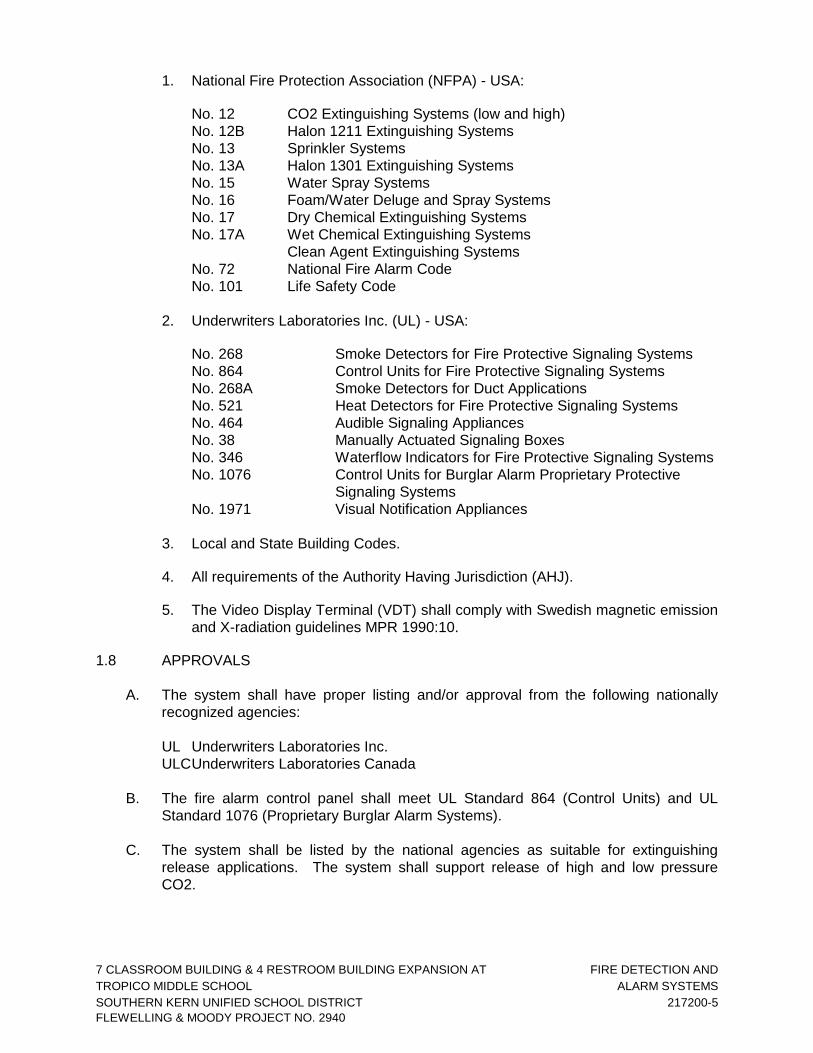
7 CLASSROOM BUILDING & 4 RESTROOM BUILDING EXPANSION AT FIRE DETECTION AND
TROPICO MIDDLE SCHOOL ALARM SYSTEMS
SOUTHERN KERN UNIFIED SCHOOL DISTRICT 217200-5
FLEWELLING & MOODY PROJECT NO. 2940
1. National Fire Protection Association (NFPA) - USA:
No. 12 CO2 Extinguishing Systems (low and high)
No. 12B Halon 1211 Extinguishing Systems
No. 13 Sprinkler Systems
No. 13A Halon 1301 Extinguishing Systems
No. 15 Water Spray Systems
No. 16 Foam/Water Deluge and Spray Systems
No. 17 Dry Chemical Extinguishing Systems
No. 17A Wet Chemical Extinguishing Systems
Clean Agent Extinguishing Systems
No. 72 National Fire Alarm Code
No. 101 Life Safety Code
2. Underwriters Laboratories Inc. (UL) - USA:
No. 268 Smoke Detectors for Fire Protective Signaling Systems
No. 864 Control Units for Fire Protective Signaling Systems
No. 268A Smoke Detectors for Duct Applications
No. 521 Heat Detectors for Fire Protective Signaling Systems
No. 464 Audible Signaling Appliances
No. 38 Manually Actuated Signaling Boxes
No. 346 Waterflow Indicators for Fire Protective Signaling Systems
No. 1076 Control Units for Burglar Alarm Proprietary Protective
Signaling Systems
No. 1971 Visual Notification Appliances
3. Local and State Building Codes.
4. All requirements of the Authority Having Jurisdiction (AHJ).
5. The Video Display Terminal (VDT) shall comply with Swedish magnetic emission
and X-radiation guidelines MPR 1990:10.
1.8 APPROVALS
A. The system shall have proper listing and/or approval from the following nationally
recognized agencies:
UL Underwriters Laboratories Inc.
ULC Underwriters Laboratories Canada
B. The fire alarm control panel shall meet UL Standard 864 (Control Units) and UL
Standard 1076 (Proprietary Burglar Alarm Systems).
C. The system shall be listed by the national agencies as suitable for extinguishing
release applications. The system shall support release of high and low pressure
CO2.
7 CLASSROOM BUILDING & 4 RESTROOM BUILDING EXPANSION AT FIRE DETECTION AND
TROPICO MIDDLE SCHOOL ALARM SYSTEMS
SOUTHERN KERN UNIFIED SCHOOL DISTRICT 217200-6
FLEWELLING & MOODY PROJECT NO. 2940
PART 2 - PRODUCTS
2.1 EQUIPMENT AND MATERIAL, GENERAL
A. All equipment and components shall be new, and the manufacturer's current model.
The materials, appliances, equipment and devices shall be tested and listed by a
nationally recognized approvals agency for use as part of a protective signaling
system, meeting the National Fire Alarm Code.
B. All equipment and components shall be installed in strict compliance with
manufacturers' recommendations. Consult the manufacturer's installation manuals for
all wiring diagrams, schematics, physical equipment sizes, etc., before beginning
system installation.
C. All equipment shall be attached to walls and ceiling/floor assemblies and shall be held
firmly in place (e.g., detectors shall not be supported solely by suspended ceilings).
Fasteners and supports shall be adequate to support the required load.
2.2 CONDUIT AND WIRE:
A. Conduit:
1. Conduit shall be in accordance with The California Electrical Code (CEC), local
and state requirements.
2. Where required, all wiring shall be installed in conduit or raceway. Conduit fill
shall not exceed 40 percent of interior cross sectional area where three or more
cables are contained within a single conduit.
3. Cable must be separated from any open conductors of power, or Class 1
circuits, and shall not be placed in any conduit, junction box or raceway
containing these conductors, per CEC Article 760-55.
4. Wiring for 24-volt DC control, alarm notification, emergency communication and
similar power-limited auxiliary functions may be run in the same conduit as
initiating and signaling line circuits. All circuits shall be provided with transient
suppression devices and the system shall be designed to permit simultaneous
operation of all circuits without interference or loss of signals.
5. Conduit shall not enter the fire alarm control panel, or any other remotely
mounted control panel equipment or backboxes, except where conduit entry is
specified by the FACP manufacturer.
6. Conduit shall be 3/4-inch (19.1 mm) minimum.
B. Wire:
1. All fire alarm system wiring shall be new.

7 CLASSROOM BUILDING & 4 RESTROOM BUILDING EXPANSION AT FIRE DETECTION AND
TROPICO MIDDLE SCHOOL ALARM SYSTEMS
SOUTHERN KERN UNIFIED SCHOOL DISTRICT 217200-7
FLEWELLING & MOODY PROJECT NO. 2940
2. Wiring shall be in accordance with local, state and national codes (e.g., CEC
Article 760) and as recommended by the manufacturer of the fire alarm system.
Number and size of conductors shall be as recommended by the fire alarm
system manufacturer, but not less than 18 AWG (1.02 mm) for Initiating Device
Circuits and Signaling Line Circuits, and 14 AWG (1.63 mm) for Notification
Appliance Circuits.
3. All wire and cable shall be listed and/or approved by a recognized testing agency
for use with a protective signaling system.
4. Wire and cable not installed in conduit shall have a fire resistance rating suitable
for the installation as indicated in NFPA 70 (e.g., FPLR).
5. Wiring used for the multiplex communication circuit (SLC) shall be twisted and
unshielded and support a minimum wiring distance of 12,500 feet. The design of
the system shall permit use of IDC and NAC wiring in the same conduit with the
SLC communication circuit.
6. All field wiring shall be electrically supervised for open circuit and ground fault.
7. The fire alarm control panel shall be capable of t-tapping Class B (NFPA Style 4)
Signaling Line Circuits (SLCs). Systems that do not allow or have restrictions in,
for example, the amount of t-taps, length of t-taps etc., are not acceptable.
C. Terminal Boxes, Junction Boxes and Cabinets: All boxes and cabinets shall be UL
listed for their use and purpose.
D. Initiating circuits shall be arranged to serve like categories (manual, smoke,
waterflow). Mixed category circuitry shall not be permitted except on signaling line
circuits connected to intelligent reporting devices.
E. The fire alarm control panel shall be connected to a separate dedicated branch
circuit, maximum 20 amperes. This circuit shall be labeled at the main power
distribution panel as FIRE ALARM. Fire alarm control panel primary power wiring
shall be 12 AWG. The control panel cabinet shall be grounded securely to either a
cold water pipe or grounding rod.
2.3 MAIN FIRE ALARM CONTROL PANEL OR NETWORK NODE:
A. Main FACP or network node shall be a NOTIFIER Model NFS2-640 and shall contain
a microprocessor based Central Processing Unit (CPU) and power supply in an
economical space saving single board design. The CPU shall communicate with and
control the following types of equipment used to make up the system: intelligent
addressable smoke and thermal (heat) detectors, addressable modules, printer,
annunciators, and other system controlled devices.
B. Operator Control:
1. Acknowledge Switch:

7 CLASSROOM BUILDING & 4 RESTROOM BUILDING EXPANSION AT FIRE DETECTION AND
TROPICO MIDDLE SCHOOL ALARM SYSTEMS
SOUTHERN KERN UNIFIED SCHOOL DISTRICT 217200-8
FLEWELLING & MOODY PROJECT NO. 2940
a. Activation of the control panel acknowledge switch in response to new
alarms and/or troubles shall silence the local panel piezo electric signal and
change the alarm and trouble LEDs from flashing mode to steady-ON mode.
If multiple alarm or trouble conditions exist, depression of this switch shall
advance the LCD display to the next alarm or trouble condition.
b. Depression of the Acknowledge switch shall also silence all remote
annunciator piezo sounders.
2. Alarm Silence Switch: Activation of the alarm silence switch shall cause all
programmed alarm notification appliances and relays to return to the normal
condition after an alarm condition. The selection of notification circuits and relays
that are silenceable by this switch shall be fully field programmable within the
confines of all applicable standards. The FACP software shall include silence
inhibit and auto-silence timers.
3. Alarm Activate (Drill) Switch: The Alarm Activate switch shall activate all
notification appliance circuits. The drill function shall latch until the panel is
silenced or reset.
4. System Reset Switch: Activation of the System Reset switch shall cause all
electronically-latched initiating devices, appliances or software zones, as well as
all associated output devices and circuits, to return to their normal condition.
5. Lamp Test: The Lamp Test switch shall activate all local system LEDs, light
each segment of the liquid crystal display and display the panel software revision
for service personal.
C. System Capacity and General Operation:
1. The control panel or each network node shall provide, or be capable of
expansion to 636 intelligent/addressable devices.
2. The control panel or each network node shall include Form-C alarm, trouble,
supervisory, and security relays rated at a minimum of 2.0 amps @ 30 VDC.
3. It shall also include four Class B (NFPA Style Y) or Class A (NFPA Style Z)
programmable Notification Appliance Circuits.
4. The Notification Appliance Circuits shall be programmable to Syncronize with
System Sensor, Gentex and Wheelock Notification Appliances.
5. The system shall include a full featured operator interface control and
annunciation panel that shall include a backlit Liquid Crystal Display (LCD),
individual color coded system status LEDs, and an alphanumeric keypad with
easy touch rubber keys for the field programming and control of the fire alarm
system.
6. The system shall be programmable, configurable, and expandable in the field
without the need for special tools, PROM programmers or PC based
programmers. It shall not require replacement of memory ICs to facilitate
programming changes.

7 CLASSROOM BUILDING & 4 RESTROOM BUILDING EXPANSION AT FIRE DETECTION AND
TROPICO MIDDLE SCHOOL ALARM SYSTEMS
SOUTHERN KERN UNIFIED SCHOOL DISTRICT 217200-9
FLEWELLING & MOODY PROJECT NO. 2940
7. The system shall allow the programming of any input to activate any output or
group of outputs. Systems that have limited programming (such as general
alarm), have complicated programming (such as a diode matrix), or require a
laptop personal computer are not considered suitable substitutes.
8. The FACP shall support up to 20 logic equations, including "and," "or," and "not,"
or time delay equations to be used for advanced programming. Logic equations
shall require the use of a PC with a software utility designed for programming.
9. The FACP or each network node shall provide the following features:
a. Drift compensation to extend detector accuracy over life. Drift compensation
shall also include a smoothing feature, allowing transient noise signals to be
filtered out.
b. Detector sensitivity test, meeting requirements of NFPA 72, Chapter 7.
c. Maintenance alert, with two levels (maintenance alert/maintenance urgent),
to warn of excessive smoke detector dirt or dust accumulation.
d. Nine sensitivity levels for alarm, selected by detector. The alarm level range
shall be .5 to 2.35 percent per foot for photoelectric detectors and 0.5 to 2.5
percent per foot for ionization detectors. The system shall also support
sensitive advanced detection laser detectors with an alarm level range of
.03 percent per foot to 1.0 percent per foot. The system shall also include
up to nine levels of Pre-alarm, selected by detector, to indicate impending
alarms to maintenance personnel.
e. The ability to display or print system reports.
f. Alarm verification, with counters and a trouble indication to alert
maintenance personnel when a detector enters verification 20 times.
g. PAS pre-signal, meeting NFPA 72 3-8.3 requirements.
h. Rapid manual station reporting (under 3 seconds) and shall meet NFPA 72
Chapter 1 requirements for activation of notification circuits within 10
seconds of initiating device activation.
i. Periodic detector test, conducted automatically by the software.
j. Self-optimizing pre-alarm for advanced fire warning, which allows each
detector to learn its particular environment and set its pre-alarm level to just
above normal peaks.
k. Cross zoning with the capability of counting: two detectors in alarm, two
software zones in alarm, or one smoke detector and one thermal detector.
l. Walk test, with a check for two detectors set to same address.
m. Control-by-time for non-fire operations, with holiday schedules.

7 CLASSROOM BUILDING & 4 RESTROOM BUILDING EXPANSION AT FIRE DETECTION AND
TROPICO MIDDLE SCHOOL ALARM SYSTEMS
SOUTHERN KERN UNIFIED SCHOOL DISTRICT 217200-10
FLEWELLING & MOODY PROJECT NO. 2940
n. Day/night automatic adjustment of detector sensitivity.
o. Device blink control for sleeping areas.
10. The FACP shall be capable of coding main panel node notification circuits in
March Time (120 PPM), Temporal (NFPA 72 A-2-2.2.2), and California Code.
Panel notification circuits (NAC 1,2,3 and 4) shall also support Two-Stage
operation, Canadian Dual Stage (3 minutes) and Canadian Dual Stage (5
minutes). Two stage operation shall allow 20 Pulses Per Minute (PPM) on alarm
and 120 PPM after 5 minutes or when a second device activates. Canadian
Dual stage is the same as Two-Stage except will only switch to second stage by
activation of Drill Switch 3 or 5-minute timer. The panel shall also provide a
coding option that will synchronize specific strobe lights designed to accept a
specific "sync pulse."
11. Network Communication: The FACP shall be capable of communicating on a
Local Area Network (LAN), a firmware package that utilizes a peer-to-peer,
inherently regenerative communication format and protocol.
D. Central Microprocessor:
1. The microprocessor shall be a state-of-the-art, high speed, 16-bit RISC device
and it shall communicate with, monitor and control all external interfaces. It shall
include an EPROM for system program storage, Flash memory for building-
specific program storage, and a "watch dog" timer circuit to detect and report
microprocessor failure.
2. The microprocessor shall contain and execute all control-by-event programs for
specific action to be taken if an alarm condition is detected by the system.
Control-by-event equations shall be held in non-volatile programmable memory,
and shall not be lost even if system primary and secondary power failure occurs.
3. The microprocessor shall also provide a real-time clock for time annotation of
system displays, printer, and history file. The time-of-day and date shall not be
lost if system primary and secondary power supplies fail. The real time clock may
also be used to control non-fire functions at programmed time-of-day, day-of-
week, and day-of-year.
4. A special program check function shall be provided to detect common operator
errors.
5. An auto-program (self-learn) function shall be provided to quickly install initial
functions and make the system operational.

7 CLASSROOM BUILDING & 4 RESTROOM BUILDING EXPANSION AT FIRE DETECTION AND
TROPICO MIDDLE SCHOOL ALARM SYSTEMS
SOUTHERN KERN UNIFIED SCHOOL DISTRICT 217200-11
FLEWELLING & MOODY PROJECT NO. 2940
6. For flexibility and to ensure program validity, an optional Windows(TM) based
program utility shall be available. This program shall be used to off-line program
the system with batch upload/download, and have the ability to upgrade the
manufacturers (FLASH) system code changes. This program shall also have a
verification utility, which scans the program files, identifying possible errors. It
shall also have the ability to compare old program files to new ones, identifying
differences in the two files to allow complete testing of any system operating
changes. This shall be in incompliance with the NFPA 72 requirements for
testing after system modification.
E. System Display:
1. The system shall support the following display mode options:
a. The CPU with no display option shall allow the fire alarm control panel to
function as a data-gathering panel when the panel is connected to a network
with a Network Control Station (NCS) or Network Control Annunciator
(NCA). In this application, the NCS or NCA shall provide all of the
necessary controls and indicators to be used by the system operator.
Programming of the CPU may be accomplished from the NCS or by use of
a laptop PC with the software programming utility connected directly to the
CPU.
b. 80-character display option. The display shall include an 80-character
backlit alphanumeric Liquid Crystal Display (LCD) and a full PC style
QWERTY keypad.
c. 640-character display option. The design of the CPU shall provide for a
configuration with the 640 Character display mounted on the front of the
CPU in place of the standard 80-character display.
2. The display shall provide all the controls and indicators used by the system
operator:
a. The 80-character display shall include the following operator control
switches: ACKNOWLEDGE, ALARM SILENCE, ALARM ACTIVATE (drill),
SYSTEM RESET, and LAMP TEST.
b. The 640-character display shall include the following operator control
switches: ACKNOWLEDGE, ALARM SILENCE, ALARM ACTIVATE (drill),
SYSTEM RESET, and LAMP TEST.
3. The display shall annunciate status information and custom alphanumeric labels
for all intelligent detectors, addressable modules, internal panel circuits, and
software zones.
4. The display shall also provide Light-Emitting Diodes.

7 CLASSROOM BUILDING & 4 RESTROOM BUILDING EXPANSION AT FIRE DETECTION AND
TROPICO MIDDLE SCHOOL ALARM SYSTEMS
SOUTHERN KERN UNIFIED SCHOOL DISTRICT 217200-12
FLEWELLING & MOODY PROJECT NO. 2940
a. The 80-character display shall provide 12 Light-Emitting-Diodes (LEDs), that
indicate the status of the following system parameters: AC POWER, FIRE
ALARM, PREALARM WARNING, SECURITY ALARM, SUPERVISORY
SIGNAL, SYSTEM TROUBLE, DISABLED POINTS, ALARM SILENCED,
Controls Active, Pre-Discharge, Discharge and Abort.
5. The 640-character display shall provide 11 Light-Emitting-Diodes (LEDs), that
indicate the status of the following system parameters: AC POWER, FIRE
ALARM, PREALARM WARNING, SECURITY ALARM, SUPERVISORY EVENT,
SYSTEM TROUBLE, ALARM SILENCED, DISABLED POINTS, OTHER
EVENTS, CPU FAILURE and Controls Active.
6. The display shall have QWERTY type keypad.
a. The 80-character display keypad shall be an easy to use QWERTY type
keypad, similar to a PC keyboard. This shall be part of the standard system
and have the capability to command all system functions, entry of any
alphabetic or numeric information, and field programming. Two different
password levels shall be provided to prevent unauthorized system control or
programming.
b. The 640-character display shall use 10 "soft" keys for screen navigation or
to accomplish dedicated programming functions. Full programming access
shall require use of a laptop and the proper programming utility.
7. The system shall support the display of battery charging current and voltage on
the 80-character LCD display.
F. Signaling Line Circuits (SLC):
1. Each FACP or FACP network node shall support up to two SLCs. Each SLC
interface shall provide power to and communicate with up to 159 intelligent
detectors (ionization, photoelectric or thermal) and 159 intelligent modules
(monitor or control) for a loop capacity of 318 devices. The addition of the
optional second loop shall double the device capacity, supporting a total of 636
devices. Each SLC shall be capable of NFPA 72 Style 4, Style 6, or Style 7
(Class A or B) wiring.
2. CPU shall receive analog information from all intelligent detectors to be
processed to determine whether normal, alarm, prealarm, or trouble conditions
exist for each detector. The software shall automatically maintain the detector's
desired sensitivity level by adjusting for the effects of environmental factors,
including the accumulation of dust in each detector. The analog information shall
also be used for automatic detector testing and for the automatic determination
of detector maintenance requirements.
G. Serial Interfaces:
1. The system shall include two serial EIA-232 interfaces. Each interface shall be a
means of connecting UL Listed Information Technology Equipment (ITE)
peripherals.
7 CLASSROOM BUILDING & 4 RESTROOM BUILDING EXPANSION AT FIRE DETECTION AND
TROPICO MIDDLE SCHOOL ALARM SYSTEMS
SOUTHERN KERN UNIFIED SCHOOL DISTRICT 217200-13
FLEWELLING & MOODY PROJECT NO. 2940
a. One EIA-232 interface shall be used to connect an UL-Listed 40 or 80
column printer. Printers that are not UL-Listed are not considered
acceptable substitutes.
b. One EIA-232 interface shall be used to connect an UL-Listed 40 or 80
column printer. Printers that are not UL-Listed are not considered
acceptable substitutes.
c. One EIA-232 interface shall be used to connect a UL-listed CRT terminal.
This interface shall include special protocol methods that allow off-site
monitoring of the FACP over standard dial-up phone lines. This ancillary
capability shall allow remote readout of all status information, including
analog values, and shall not interfere with or degrade FACP operations
when used. It shall allow remote FACP Acknowledge, Reset, or Signal
Silence in this mode. It shall also allow adjustment of detector sensitivity and
readout of the history file.
d. The system shall include an EIA-485 port for the serial connection of
optional annunciators and remote LCD displays.
e. The EIA-485 interface may be used for network connection to a proprietary-
receiving unit.
H. Enclosures:
1. The control panel shall be housed in a UL-listed cabinet suitable for surface or
semi-flush mounting. The cabinet and front shall be corrosion protected, given a
rust-resistant prime coat, and manufacturer's standard finish.
2. The back box and door shall be constructed of 0.060 steel with provisions for
electrical conduit connections into the sides and top.
3. The door shall provide a key lock and shall include a glass or other transparent
opening for viewing of all indicators. For convenience, the door may be site
configured for either right or left hand hinging.
I. Power Supply:
1. A high tech off-line switching power supply shall be available for the fire alarm
control panel or network node and provide 6.0 amps of available power for the
control panel and peripheral devices.
2. Provisions will be made to allow the audio-visual power to be increased as
required by adding modular expansion audio-visual power supplies.
3. Positive-Temperature-Coefficient (PTC) thermistors, circuit breakers, or other
over-current protection shall be provided on all power outputs. The power supply
shall provide an integral battery charger for use with batteries up to 55 AH or
may be used with an external battery and charger system. Battery arrangement
may be configured in the field.

7 CLASSROOM BUILDING & 4 RESTROOM BUILDING EXPANSION AT FIRE DETECTION AND
TROPICO MIDDLE SCHOOL ALARM SYSTEMS
SOUTHERN KERN UNIFIED SCHOOL DISTRICT 217200-14
FLEWELLING & MOODY PROJECT NO. 2940
4. The power supply shall continuously monitor all field wires for earth ground
conditions, and shall have the following LED indicators:
Ground Fault LED
AC Power Fail LED
NAC on LED (4)
5. The main power supply shall operate on 120 VAC, 60 Hz, and shall provide all
necessary power for the FACP.
6. The main power supply shall provide a battery charger using dual-rate charging
techniques for fast battery recharge and be capable of charging batteries up to
200 AH.
7. All circuits shall be power-limited, per UL864 requirements.
J. Auxiliary Field Power Supply – Addressable:
1. The auxiliary addressable power supply is a remote 24 VDC power supply used
to power Notification Devices and field devices that require regulated 24VDC
power. The power supply shall also include and charge backup batteries.
2. The addressable power supply for the fire alarm system shall provide up a
minimum of 6.0 amps of 24-volt DC regulated power for Notification Appliance
Circuit (NAC) power or 5 amps of 24-volt DC general power. The power supply
shall have an additional .5 amps of 24 VDC auxiliary power for use within the
same cabinet as the power supply. It shall include an integral charger designed
to charge 7.0 - 25.0-amp hour batteries.
3. The addressable power supply shall provide four individually addressable
Notification Appliance Circuits that may be configured as two Class "A" and two
Class "B" or four Class "B" only circuits. All circuits shall be power-limited per UL
864 requirements.
4. The addressable power supply shall provide built-in synchronization for certain
Notification Appliances on each circuit without the need for additional
synchronization modules. The power supply's output circuits shall be individually
selected for synchronization. A single addressable power supply shall be capable
of supporting both synchronized and non-synchronized Notification Devices at
the same time.
5. The addressable power supply shall operate on 120 or 240 VAC, 50/60 Hz.
6. The interface to the power supply from the Fire Alarm Control Panel (FACP)
shall be via the Signaling Line Circuit (SLC) or other multiplexed means Power
supplies that do not use an intelligent interface are not suitable substitutes. The
required wiring from the FACP to the addressable power supply shall be a single
unshielded twisted pair wire. Data on the SLC shall be transmitted between 24
VDC, 5 VDC and 0 VDC at approximately 3.33k baud.

7 CLASSROOM BUILDING & 4 RESTROOM BUILDING EXPANSION AT FIRE DETECTION AND
TROPICO MIDDLE SCHOOL ALARM SYSTEMS
SOUTHERN KERN UNIFIED SCHOOL DISTRICT 217200-15
FLEWELLING & MOODY PROJECT NO. 2940
7. The addressable power supply shall supervise for battery charging failure, AC
power loss, power brownout, battery failure, NAC loss, and optional ground fault
detection. In the event of a trouble condition, the addressable power supply shall
report the incident and the applicable address to the FACP via the SLC.
8. The addressable power supply shall have an AC Power Loss Delay option. If this
option is utilized and the addressable power supply experiences an AC power
loss, reporting of the incident to the FACP will be delayed. A delay time of eight
or sixteen hours shall be Dip-switch selected.
9. The addressable power supply shall have an option for Canadian Trouble
Reporting and this option shall be Dip-switch selectable.
10. The addressable power supply mounts in either the FACP backbox or it's own
dedicated surface mounted backbox with cover.
11. Each of the power supply's four output circuits shall be DIP-switch selected for
Notification Appliance Circuit or General Purpose 24 VDC power. Any output
circuit shall be able to provide up to 2.5 amps of 24 VDC power.
12. The addressable power supply's output circuits shall be individually supervised
when they are selected to be either a Notification Appliance Circuit when wired
Class "A" or by the use of and end-of-line resistor. When the power supply's
output circuit is selected as General 24VDC power, the circuit shall be
individually supervised when an end-of-line relay is used.
13. When selected for Notification Appliance Circuits, the output circuits shall be
individually DIP-switch selectable for Steady, March Time, Dual Stage or
Temporal.
14. When selected as a Notification Appliance Circuit, the output circuits of the
addressable power supply shall have the option to be coded by the use of a
universal zone coder.
15. The addressable power supply shall interface and synchronize with other power
supplies of the same type. The required wiring to interface multiple addressable
power supplies shall be a single unshielded, twisted pair wire.
16. An individual or multiple interfaced addressable power supplies shall have the
option to use an external charger for battery charging. Interfaced power supplies
shall have the option to share backup battery power.
K. Field Charging Power Supply (FCPS): The FCPS is a device designed for use as
either a remote 24-volt power supply or used to power Notification Appliances.
1. The FCPS shall offer up to 6.0 amps (4.0 amps continuous) of regulated 24-volt
power. It shall include an integral charger designed to charge 7.0-amp hour
batteries and to support 60 hour standby.

7 CLASSROOM BUILDING & 4 RESTROOM BUILDING EXPANSION AT FIRE DETECTION AND
TROPICO MIDDLE SCHOOL ALARM SYSTEMS
SOUTHERN KERN UNIFIED SCHOOL DISTRICT 217200-16
FLEWELLING & MOODY PROJECT NO. 2940
2. The Field Charging Power Supply shall have two input triggers. The input trigger
shall be a Notification Appliance Circuit (from the fire alarm control panel) or a
relay. Four outputs (two Style Y or Z and two style Y) shall be available for
connection to the Notification devices.
3. The FCPS shall include an attractive surface mount backbox.
4. The Field Charging Power Supply shall include the ability to delay the AC fail
delay per NFPA requirements.
5. The FCPS include power limited circuitry, per 1995 UL standards.
L. Specific System Operations:
1. Smoke Detector Sensitivity Adjust: A means shall be provided for adjusting the
sensitivity of any or all addressable intelligent detectors in the system from the
system keypad. Sensitivity range shall be within the allowed UL window and
have a minimum of 9 levels.
2. Alarm Verification: Each of the intelligent addressable smoke detectors in the
system may be independently selected and enabled to be an alarm verified
detector. The alarm verification delay shall be programmable from 5 to 30
seconds and each detector shall be able to be selected for verification. The
FACP shall keep a count of the number of times that each detector has entered
the verification cycle. These counters may be displayed and reset by the proper
operator commands.
3. Point Disable: Any addressable device or conventional circuit in the system may
be enabled or disabled through the system keypad.
4. Point Read: The system shall be able to display or print the following point status
diagnostic functions:
a. Device status
b. Device type
c. Custom device label
d. View analog detector values
e. Device zone assignments
f. All program parameters
5. System Status Reports: Upon command from an operator of the system, a
status report will be generated and printed, listing all system status.

7 CLASSROOM BUILDING & 4 RESTROOM BUILDING EXPANSION AT FIRE DETECTION AND
TROPICO MIDDLE SCHOOL ALARM SYSTEMS
SOUTHERN KERN UNIFIED SCHOOL DISTRICT 217200-17
FLEWELLING & MOODY PROJECT NO. 2940
6. System History Recording and Reporting: The fire alarm control panel shall
contain a history buffer that will be capable of storing up to 800 events. Up to
200 events shall be dedicated to alarm and the remaining events are general
purpose. Systems that do not have dedicated alarm storage, where events are
overridden by non-alarm type events, are not suitable substitutes. Each of these
activations will be stored and time and date stamped with the actual time of the
activation. The contents of the history buffer may be manually reviewed, one
event at a time, or printed in its entirety. The history buffer shall use non-volatile
memory. Systems that use volatile memory for history storage are not
acceptable substitutes.
7. Automatic Detector Maintenance Alert: The fire alarm control panel shall
automatically interrogate each intelligent detector and shall analyze the detector
responses over a period of time. If any intelligent detector in the system
responds with a reading that is above or below normal limits, then the system will
enter the trouble mode, and the particular detector will be annunciated on the
system display, and printed on the optional printer. This feature shall in no way
inhibit the receipt of alarm conditions in the system, nor shall it require any
special hardware, special tools or computer expertise to perform.
8. Pre-Alarm Function: The system shall provide two levels of pre-alarm warning to
give advance notice of a possible fire situation. Both pre-alarm levels shall be
fully field adjustable. The first level shall give an audible indication at the panel.
The second level shall give an audible indication and may also activate control
relays. The system shall also have the ability to activate local detector sounder
bases at the pre-alarm level, to assist in avoiding nuisance alarms.
9. Software Zones: The FACP shall provide 100 software zones, 10 additional
special function zones, 10 releasing zones, and 20 logic zones.
10. The fire alarm control panel shall include a walk test feature. It shall include the
ability to test initiating device circuits and notification appliance circuits from the
field without returning to the panel to reset the system. Operation shall be as
follows:
a. Alarming an initiating device shall activate programmed outputs, which are
selected to participate in walk test, for 3 seconds.
b. Introducing a trouble into the initiating device shall activate the programmed
outputs for 8 seconds.
c. All devices tested in walk test shall be recorded in the history buffer.
11. Waterflow Operation: An alarm from a waterflow detection device shall activate
the appropriate alarm message on the main panel display, turn on all
programmed notification appliance circuits and shall not be affected by the signal
silence switch.
12. Supervisory Operation: An alarm from a supervisory device shall cause the
appropriate indication on the system display, light a common supervisory LED,
but will not cause the system to enter the trouble mode.

7 CLASSROOM BUILDING & 4 RESTROOM BUILDING EXPANSION AT FIRE DETECTION AND
TROPICO MIDDLE SCHOOL ALARM SYSTEMS
SOUTHERN KERN UNIFIED SCHOOL DISTRICT 217200-18
FLEWELLING & MOODY PROJECT NO. 2940
13. Signal Silence Operation: The FACP shall have the ability to program each
output circuit (notification, relay, speaker etc) to deactivate upon depression of
the signal silence switch.
14. Non-Alarm Input Operation: Any addressable initiating device in the system may
be used as a non-alarm input to monitor normally open contact type devices.
Non-alarm functions are a lower priority than fire alarm initiating devices.
15. Combo Zone: A special type code shall be available to allow waterflow and
supervisory devices to share a common addressable module. Waterflow devices
shall be wired in parallel, supervisory devices in series.
2.4 SYSTEM COMPONENTS:
A. Strobe lights shall meet the requirements of the ADA, UL Standard 1971, be fully
synchronized, and shall meet the following criteria:
1. The maximum pulse duration shall be 2/10 of one second
2. Strobe intensity shall meet the requirements of UL 1971.
3. The flash rate shall meet the requirements of UL 1971.
B. Manual Fire Alarm Stations:
1. Manual fire alarm stations shall be non-code, non-breakglass type, equipped
with key lock so that they may be tested without operating the handle.
2. Stations must be designed such that after an actual activation, they cannot be
restored to normal except by key reset.
3. An operated station shall automatically condition itself so as to be visually
detected, as operated, at a minimum distance of 100 feet (30.5 m) front or side.
4. Manual stations shall be constructed of high impact Lexan, with operating
instructions provided on the cover. The word FIRE shall appear on the manual
station in letters one half inch (12.7 mm) in size or larger.
C. Conventional Photoelectric Area Smoke Detectors:
1. Photoelectric smoke detectors shall be a 24 VDC, two wire, ceiling-mounted,
light scattering type using an LED light source.
2. Each detector shall contain a remote LED output and a built-in test switch.
3. Detector shall be provided on a twist-lock base.
4. It shall be possible to perform a calibrated sensitivity and performance test on
the detector without the need for the generation of smoke. The test method shall
test all detector circuits.

7 CLASSROOM BUILDING & 4 RESTROOM BUILDING EXPANSION AT FIRE DETECTION AND
TROPICO MIDDLE SCHOOL ALARM SYSTEMS
SOUTHERN KERN UNIFIED SCHOOL DISTRICT 217200-19
FLEWELLING & MOODY PROJECT NO. 2940
5. A visual indication of an alarm shall be provided by dual latching Light Emitting
Diodes (LEDs), on the detector, which may be seen from ground level over 360
degrees. These LEDs shall flash at least every 10 seconds, indicating that power
is applied to the detector.
6. The detector shall not go into alarm when exposed to air velocities of up to 3000
feet (914.4 m) per minute.
7. The detector screen and cover assembly shall be easily removable for field
cleaning of the detector chamber.
8. All field wire connections shall be made to the base through the use of a
clamping plate and screw.
D. Conventional Ionization Type Area Smoke Detectors:
1. Ionization type smoke detectors shall be a two wire, 24 VDC type using a dual
unipolar chamber.
2. Each detector shall contain a remote LED output and a built-in test switch.
3. Detector shall be provided on a twist-lock base.
4. It shall be possible to perform a calibration sensitivity and performance test on
the detector without the need for the generation of smoke.
5. A visual indication of an alarm shall be provided by dual latching Light Emitting
Diodes (LEDs) over 360 degrees, on the detector, which may be seen from
ground level. This LED shall flash every 10 seconds, indicating that power is
applied to the detector.
6. The detector shall not alarm when exposed to air velocities of up to 1,200 feet
(365.76 m) per minute. The detector screen and cover assembly shall be easily
removable for field cleaning of the detector chamber.
7. All field wire connections shall be made to the base through the use of a
clamping plate and screw.
E. Duct Smoke Detectors: Duct smoke detectors shall be a 24 VDC type with visual
alarm and power indicators, and a reset switch. Each detector shall be installed upon
the composite supply/return air ducts(s), with properly sized air sampling tubes.
F. Automatic Conventional Heat Detectors:
1. Automatic heat detectors shall have a combination rate of rise and fixed
temperature rated at 135 degrees Fahrenheit (57.2 Celsius) for areas where
ambient temperatures do not exceed 100 degrees (37.7 Celsius), and 200
degrees (93.33 Celsius) for areas where the temperature does not exceed 150
degrees (65.5 Celsius).
2. Automatic heat detectors shall be a low profile, ceiling mount type with positive
indication of activation.
7 CLASSROOM BUILDING & 4 RESTROOM BUILDING EXPANSION AT FIRE DETECTION AND
TROPICO MIDDLE SCHOOL ALARM SYSTEMS
SOUTHERN KERN UNIFIED SCHOOL DISTRICT 217200-20
FLEWELLING & MOODY PROJECT NO. 2940
3. The rate of rise element shall consist of an air chamber, a flexible metal
diaphragm, and a factory calibrated, moisture-proof, trouble free vent, and shall
operate when the rate of temperature rise exceeds 15 degrees F (9.4 degrees C)
per minute.
4. The fixed temperature element shall consist of a fusible alloy retainer and
actuator shaft.
5. Automatic heat detectors shall have a smooth ceiling rating of 2500 square feet
(762 square meters).
G. Waterflow Indicator:
1. Waterflow Switches shall be an integral, mechanical, non-coded, non-
accumulative retard type.
2. Waterflow Switches shall have an alarm transmission delay time which is
conveniently adjustable from 0 to 60 seconds. Initial settings shall be 30-45
seconds.
3. All waterflow switches shall come from a single manufacturer and series.
4. Waterflow switches shall be provided and connected under this section but
installed by the mechanical contractor.
5. Where possible, locate waterflow switches a minimum of one (1) foot from a
fitting which changes the direction of the flow and a minimum of three (3) feet
from a valve.
H. Sprinkler and Standpipe Valve Supervisory Switches:
1. Each sprinkler system water supply control valve riser, zone control valve, and
standpipe system riser control valve shall be equipped with a supervisory switch.
Standpipe hose valves, and test and drain valves shall not be equipped with
supervisory switches.
2. PIV (post indicator valve) or main gate valves shall be equipped with a
supervisory switch.
3. The switch shall be mounted so as not to interfere with the normal operation of
the valve and adjusted to operate within two revolutions toward the closed
position of the valve control, or when the stem has moved no more than one-fifth
of the distance from its normal position.
4. The supervisory switch shall be contained in a weatherproof aluminum housing,
which shall provide a 3/4 inch (19 mm) conduit entrance and incorporate the
necessary facilities for attachment to the valves.
5. The switch housing shall be finished in red baked enamel.

7 CLASSROOM BUILDING & 4 RESTROOM BUILDING EXPANSION AT FIRE DETECTION AND
TROPICO MIDDLE SCHOOL ALARM SYSTEMS
SOUTHERN KERN UNIFIED SCHOOL DISTRICT 217200-21
FLEWELLING & MOODY PROJECT NO. 2940
6. The entire installed assembly shall be tamper proof and arranged to cause a
switch operation if the housing cover is removed, or if the unit is removed from
its mounting.
7. Valve supervisory switches shall be provided and connected under this section
and installed by mechanical contractor.
a. This unit shall provide for each zone: alarm indications, using a red alarm
and yellow trouble long-life LEDs and control switches for the control of fire
alarm control panel functions. The annunciator will also have an ON-LINE
LED, local piezo electric signal, local acknowledge/ lamp test switch, and
custom slide-in zone/function identification labels.
b. Switches shall be available for remote annunciation and control of output
points in the system, system acknowledge, telephone zone select, speaker
select, global signal silence, and global system reset within the confines of
all applicable standards.
I. Alphanumeric LCD Type Annunciator:
1. The alphanumeric display annunciator shall be a supervised, remotely located
back-lit LCD display containing a minimum of eighty (80) characters for alarm
annunciation in clear English text.
2. The LCD annunciator shall display all alarm and trouble conditions in the system.
3. An audible indication of alarm shall be integral to the alphanumeric display.
4. The display shall be UL listed for fire alarm application.
5. It shall be possible to connect up to 32 LCD displays and be capable of wiring
distances up to 6,000 feet from the control panel.
6. The annunciator shall connect to a separate, dedicated "terminal mode" EIA-485
interface. This is a two-wire loop connection and shall be capable of distances to
6,000 feet. Each terminal mode LCD display shall mimic the main control panel.
7. The system shall allow a minimum of 32 terminal mode LCD annunciators. Up to
10 LCD annunciators shall be capable of the following system functions:
Acknowledge, Signal Silence and Reset, which shall be protected from
unauthorized use by a keyswitch or password.
8. The LED annunciator shall offer an interface to a graphic style annunciator and
provide each of the features listed above.
J. Portable Emergency Telephone Handset Jack:
1. Portable emergency telephone handset jacks shall be flush mounted on stainless
steel plates as indicated on the plans. Jacks shall be approved for emergency
telephone system application.

7 CLASSROOM BUILDING & 4 RESTROOM BUILDING EXPANSION AT FIRE DETECTION AND
TROPICO MIDDLE SCHOOL ALARM SYSTEMS
SOUTHERN KERN UNIFIED SCHOOL DISTRICT 217200-22
FLEWELLING & MOODY PROJECT NO. 2940
2. Insertion of a portable handset plug into a jack shall send a signal to the fire
command center, which shall audibly and visually indicate the on-line condition,
and shall sound a "ring" indication in the handset.
3. The two-way emergency telephone system shall support a minimum of seven (7)
handsets on line without degradation of the signal.
K. Fixed Emergency Telephone Handset:
1. The telephone cabinet shall be painted red and clearly labeled as "Emergency
Telephone." The cabinets shall be located where shown on drawings.
2. The handset cradle shall have a switch connection so that lifting the handset off
of the cradle shall send a signal to the fire command center, which shall audibly
and visually indicate its on-line (off-hook) condition.
3. On activating the remote phone, the phone earpiece shall sound a telephone ring
signal until the master handset is lifted.
4. The two-way emergency telephone system shall support a minimum of seven (7)
handsets on line without degradation of the signal.
L. All interfaces and associated equipment are to be protected so that they will not be
affected by voltage surges or line transients consistent with UL standard 864.
M. Universal Digital Alarm Communicator Transmitter (UDACT). The UDACT is an
interface for communicating digital information between a fire alarm control panel and
an UL-Listed central station.
1. The UDACT shall be compact in size, mounting in a standard module position of
the fire alarm control cabinet. Optionally, the UDACT shall have the ability for
remote mounting, up to 6,000 feet from the fire alarm control panel. The wire
connections between the UDACT and the control panel shall be supervised with
one pair for power and one pair for multiplexed communication of overall system
status. Systems that utilize relay contact closures are not acceptable.
2. The UDACT shall include connections for dual telephone lines (with voltage
detect), per UL/NFPA/FCC requirements. It shall include the ability for split
reporting of panel events up to three different telephone numbers.
3. The UDACT shall be completely field programmable from a built-in keypad and
4-character red, seven segment display.
4. The UDACT shall be capable of transmitting events in at least 15 different
formats. This ensures compatibility with existing and future transmission formats.
5. Communication shall include vital system status such as:
- Independent Zone (Alarm, trouble, non-alarm, supervisory)
- Independent Addressable Device Status
- AC (Mains) Power Loss
- Low Battery and Earth Fault

7 CLASSROOM BUILDING & 4 RESTROOM BUILDING EXPANSION AT FIRE DETECTION AND
TROPICO MIDDLE SCHOOL ALARM SYSTEMS
SOUTHERN KERN UNIFIED SCHOOL DISTRICT 217200-23
FLEWELLING & MOODY PROJECT NO. 2940
- System Off Normal
- 12 and 24 Hour Test Signal
- Abnormal Test Signal (per UL requirements)
- EIA-485 Communications Failure
- Phone Line Failure
6. The UDACT shall support independent zone/point reporting when used in the
Contact ID format. In this format the UDACT shall support transmission of up to
2,040 points. This enables the central station to have exact details concerning
the origin of the fire or response emergency.
N. Field Wiring Terminal Blocks: For ease of service all panel I/O wiring terminal blocks
shall be removable, plug-in types and have sufficient capacity for #18 to #12 AWG
wire. Terminal blocks that are permanently fixed are not acceptable.
O. Printer:
1. The printer shall provide hard-copy printout of all changes in status of the system
and shall time-stamp such printouts with the current time-of-day and date. The
printer shall be standard carriage with 80-characters per line and shall use
standard pin-feed paper. The printer shall be enclosed in a separate cabinet
suitable for placement on a desktop or table. The printer shall communicate with
the control panel using an interface complying with Electrical Industries
Association standard EIA-232D. Power to the printer shall be 120 VAC @ 60 Hz.
2. The system shall have a strip printer capable of being mounted directly in the
main FACP enclosure. Alarms shall be printed in easy-to-read RED, other
messages, such as a trouble, shall be printed in BLACK. This printer shall
receive power from the system power supply and shall operate via battery back-
up if AC mains are lost. The strip printer shall be UL 864 listed.
3. The system shall have a strip printer capable of being mounted directly in the
main FACP enclosure. Alarms shall be printed in easy-to-read RED, other
messages, such as a trouble, shall be printed in BLACK. This printer shall
receive power from the system power supply and shall operate via battery back-
up if AC mains are lost. The strip printer shall be UL 864 listed.
P. Video Display Terminal:
1. The Video Display Terminal shall provide a visual display and an audible alert of
all changes in status of the system and shall annotate such displays with the
current time-of-day and date.
2. The Video Display Terminal shall be enclosed in a cabinet suitable for placement
on a desktop or table.
3. A detachable keyboard shall be provided that may be used for programming,
testing, and control of the system. Individual keys shall be provided on the
keyboard for the ACKNOWLEDGE, RESET, LAMP TEST, SYSTEM TEST, and
SIGNAL SILENCE functions of the control panel.

7 CLASSROOM BUILDING & 4 RESTROOM BUILDING EXPANSION AT FIRE DETECTION AND
TROPICO MIDDLE SCHOOL ALARM SYSTEMS
SOUTHERN KERN UNIFIED SCHOOL DISTRICT 217200-24
FLEWELLING & MOODY PROJECT NO. 2940
4. The video display terminal shall include a count of all alarms and troubles in the
system, as well as a count of all alarms and trouble requiring acknowledgment.
These counts shall be continuously displayed during all FACP operations.
2.5 SYSTEM COMPONENTS - ADDRESSABLE DEVICES
A. Addressable Devices – General:
1. Addressable devices shall use simple to install and maintain decade, decimal
address switches. Devices shall be capable of being set to an address in a
range of 001 to 159.
2. Addressable devices, which use a binary-coded address setting method, such as
a DIP-switch, are not an allowable substitute.
3. Detectors shall be intelligent (analog) and addressable, and shall connect with
two wires to the fire alarm control panel Signaling Line Circuits.
4. Addressable smoke and thermal detectors shall provide dual alarm and
power/polling LEDs. Both LEDs shall flash green under normal conditions,
indicating that the detector is operational and in regular communication with the
control panel, and both LEDs shall be placed into steady red illumination by the
control panel, indicating that an alarm condition has been detected. If required,
the LED flash shall have the ability to be removed from the system program. An
output connection shall also be provided in the base to connect an external
remote alarm LED.
5. The fire alarm control panel shall permit detector sensitivity adjustment through
field programming of the system. The panel on a time-of-day basis shall
automatically adjust sensitivity.
6. Using software in the FACP, detectors shall automatically compensate for dust
accumulation and other slow environmental changes that may affect their
performance. The detectors shall be listed by UL as meeting the calibrated
sensitivity test requirements of NFPA Standard 72, Chapter 7.
7. The detectors shall be ceiling-mount and shall include a separate twist-lock base
with tamper proof feature. Bases shall include a sounder base with a built-in
(local) sounder rated at 85 DBA minimum, a relay base and an isolator base
designed for Style 7 applications.
8. The detectors shall provide a test means whereby they will simulate an alarm
condition and report that condition to the control panel. Such a test may be
initiated at the detector itself (by activating a magnetic switch) or initiated
remotely on command from the control panel.
9. Detectors shall also store an internal identifying type code that the control panel
shall use to identify the type of device (ION, PHOTO, THERMAL).
7 CLASSROOM BUILDING & 4 RESTROOM BUILDING EXPANSION AT FIRE DETECTION AND
TROPICO MIDDLE SCHOOL ALARM SYSTEMS
SOUTHERN KERN UNIFIED SCHOOL DISTRICT 217200-25
FLEWELLING & MOODY PROJECT NO. 2940
10. Detectors will operate in an analog fashion, where the detector simply measures
its designed environment variable and transmits an analog value to the FACP
based on real-time measured values. The FACP software, not the detector, shall
make the alarm/normal decision, thereby allowing the sensitivity of each detector
to be set in the FACP program and allowing the system operator to view the
current analog value of each detector.
11. Addressable devices shall store an internal identifying code that the control panel
shall use to identify the type of device.
12. A magnetic test switch shall be provided to test detectors and modules.
Detectors shall report an indication of an analog value reaching 100% of the
alarm threshold.
13. Addressable modules shall mount in a 4-inch square (101.6 mm square), 2-1/8
inch (54 mm) deep electrical box. An optional surface mount Lexan enclosure
shall be available.
B. Addressable Manual Fire Alarm Box (manual station):
1. Addressable manual fire alarm boxes shall, on command from the control panel,
send data to the panel representing the state of the manual switch and the
addressable communication module status. They shall use a key operated test-
reset lock, and shall be designed so that after actual emergency operation, they
cannot be restored to normal use except by the use of a key.
2. All operated stations shall have a positive, visual indication of operation and
utilize a key type reset.
3. Manual fire alarm boxes shall be constructed of Lexan with clearly visible
operating instructions provided on the cover. The word FIRE shall appear on the
front of the stations in raised letters, 1.75 inches (44 mm) or larger.
C. Intelligent Photoelectric Smoke Detector: The detectors shall use the photoelectric
(light-scattering) principal to measure smoke density and shall, on command from the
control panel, send data to the panel representing the analog level of smoke density.
D. Intelligent Laser Photo Smoke Detector:
1. The intelligent laser photo smoke detector shall be a spot type detector that
incorporates an extremely bright laser diode and an integral lens that focuses
the light beam to a very small volume near a receiving photo sensor. The
scattering of smoke particles shall activate the photo sensor.
2. The laser detector shall have conductive plastic so that dust accumulation is
reduced significantly.
3. The intelligent laser photo detector shall have nine sensitivity levels and be
sensitive to a minimum obscuration of 0.03 percent per foot.
4. The laser detector shall not require expensive conduit, special fittings or PVC
pipe.

7 CLASSROOM BUILDING & 4 RESTROOM BUILDING EXPANSION AT FIRE DETECTION AND
TROPICO MIDDLE SCHOOL ALARM SYSTEMS
SOUTHERN KERN UNIFIED SCHOOL DISTRICT 217200-26
FLEWELLING & MOODY PROJECT NO. 2940
5. The intelligent laser photo detector shall support standard, relay, isolator and
sounder detector bases.
6. The laser photo detector shall not require other cleaning requirements than
those listed in NFPA 72. Replacement, refurbishment or specialized cleaning of
the detector head shall not be required.
7. The laser photo detector shall include two bicolor LEDs that flash green in
normal operation and turn on steady red in alarm.
E. Intelligent Ionization Smoke Detector: The detectors shall use the dual-chamber
ionization principal to measure products of combustion and shall, on command from
the control panel, send data to the panel representing the analog level of products of
combustion.
F. Intelligent Multi Criteria Acclimating Detector:
1. The intelligent multi criteria Acclimate detector shall be an addressable device
that is designed to monitor a minimum of photoelectric and thermal technologies
in a single sensing device. The design shall include the ability to adapt to its
environment by utilizing a built-in microprocessor to determine it's environment
and choose the appropriate sensing settings. The detector design shall allow a
wide sensitivity window, no less than 1 to 4% per foot obscuration. This detector
shall utilize advanced electronics that react to slow smoldering fires and thermal
properties all within a single sensing device.
2. The microprocessor design shall be capable of selecting the appropriate
sensitivity levels based on the environment type it is in (office, manufacturing,
kitchen etc.) and then have the ability to automatically change the setting as the
environment changes (as walls are moved or as the occupancy changes).
3. The intelligent multi criteria detection device shall include the ability to combine
the signal of the thermal sensor with the signal of the photoelectric signal in an
effort to react hastily in the event of a fire situation. It shall also include the
inherent ability to distinguish between a fire condition and a false alarm condition
by examining the characteristics of the thermal and smoke sensing chambers
and comparing them to a database of actual fire and deceptive phenomena.
G. Intelligent Thermal Detectors: Thermal detectors shall be intelligent addressable
devices rated at 135 degrees Fahrenheit (58 degrees Celsius) and have a rate-of-rise
element rated at 15 degrees F (9.4 degrees C) per minute. It shall connect via two
wires to the fire alarm control panel signaling line circuit.
H. Hostile-Area Smoke Detector:
1. The detector shall be designed to provide early warning smoke detection in
environments where traditional smoke detectors are not practical.
2. The detector shall have a filter system to remove particles down to 25 microns.

7 CLASSROOM BUILDING & 4 RESTROOM BUILDING EXPANSION AT FIRE DETECTION AND
TROPICO MIDDLE SCHOOL ALARM SYSTEMS
SOUTHERN KERN UNIFIED SCHOOL DISTRICT 217200-27
FLEWELLING & MOODY PROJECT NO. 2940
3. This filter system shall remove unwanted airborne particles and water mist. This
shall allow the detector to operate in environments where traditional smoke
detectors would have nuisance alarms.
4. The filter system shall consist of 2 filters one of which is field replaceable.
5. The filter system shall have an intake fan to draw air and smoke through the
filters into the sensing chamber.
6. The filter system shall be supervised so that if the filter is clogged or the fan fails
the control panel reports trouble.
7. The filter system shall be powered from 24 VDC separate from the SLC
communications.
8. The detector shall utilize a photoelectric sensing chamber.
I. Addressable Dry Contact Monitor Module:
1. Addressable monitor modules shall be provided to connect one supervised IDC
zone of conventional alarm initiating devices (any N.O. dry contact device) to
one of the fire alarm control panel SLCs.
2. The IDC zone shall be suitable for Style D or Style B operation. An LED shall be
provided that shall flash under normal conditions, indicating that the monitor
module is operational and in regular communication with the control panel.
3. For difficult to reach areas, the monitor module shall be available in a miniature
package and shall be no larger than 2-3/4 inch (70 mm) x 1-1/4 inch (31.7 mm) x
1/2 inch (12.7 mm). This version need not include Style D or an LED.
J. Two Wire Detector Monitor Module:
1. Addressable monitor modules shall be provided to connect one supervised IDC
zone of conventional 2-wire smoke detectors or alarm initiating devices (any
N.O. dry contact device).
2. The IDC zone may be wired for Class A or B (Style D or Style B) operation. An
LED shall be provided that shall flash under normal conditions, indicating that the
monitor module is operational and in regular communication with the control
panel.
K. Addressable Control Module:
1. Addressable control modules shall be provided to supervise and control the
operation of one conventional NACs of compatible, 24 VDC powered, polarized
audio/visual notification appliances.
2. The control module NAC may be wired for Style Z or Style Y (Class A/B) with up
to 1 amp of inductive A/V signal, or 2 amps of resistive A/V signal operation.

7 CLASSROOM BUILDING & 4 RESTROOM BUILDING EXPANSION AT FIRE DETECTION AND
TROPICO MIDDLE SCHOOL ALARM SYSTEMS
SOUTHERN KERN UNIFIED SCHOOL DISTRICT 217200-28
FLEWELLING & MOODY PROJECT NO. 2940
3. Audio/visual power shall be provided by a separate supervised power circuit from
the main fire alarm control panel or from a supervised UL listed remote power
supply.
4. The control module shall be suitable for pilot duty applications and rated for a
minimum of 0.6 amps at 30 VDC.
L. Addressable Relay Module: Addressable Relay Modules shall be available for HVAC
control and other building functions. The relay shall be form C and rated for a
minimum of 2.0 Amps resistive or 1.0 Amps inductive. The relay coil shall be
magnetically latched to reduce wiring connection requirements, and to insure that
100% of all auxiliary relay or NACs may be energized at the same time on the same
pair of wires.
M. Isolator Module:
1. Isolator modules shall be provided to automatically isolate wire-to-wire short
circuits on an SLC Class A or Class B branch. The isolator module shall limit the
number of modules or detectors that may be rendered inoperative by a short
circuit fault on the SLC loop segment or branch. At least one isolator module
shall be provided for each floor or protected zone of the building.
2. If a wire-to-wire short occurs, the isolator module shall automatically open-circuit
(disconnect) the SLC. When the short circuit condition is corrected, the isolator
module shall automatically reconnect the isolated section.
3. The isolator module shall not require address-setting, and its operations shall be
totally automatic. It shall not be necessary to replace or reset an isolator module
after its normal operation.
4. The isolator module shall provide a single LED that shall flash to indicate that the
isolator is operational and shall illuminate steadily to indicate that a short circuit
condition has been detected and isolated.
N. Smoke Control Annunciator:
1. On/Auto/Off switches and status indicators (LEDS) shall be provided for
monitoring and manual control of each fan, damper, HVAC control unit, stairwell
pressurization fan, and smoke exhaust fan. To ensure compliance the units
supplied shall meet the following UL categories: UUKL, PAZX, UDTZ, QVAX as
well as the requirements of NFPA 90A, HVAC, and NFPA 92A & 92B, Smoke
Control. The control System shall be field programmable for either 90A operation
or 92A/B operation to allow for future use and system expansion.
2. The OFF LED shall be Yellow, the ON LED shall be green, the Trouble/Fault
LED shall be Amber/Orange for each switch. The Trouble/Fault indicator shall
indicate a trouble in the control and/or monitor points associated with that switch.
In addition, each group of eight switches shall have two LEDS and one
momentary switch which allow the following functions: An Amber LED to indicate
an OFF-NORMAL switch position, in the ON or OFF position; A Green LED to
indicate ALL AUTO switch position; A Local Acknowledge/Lamp Test momentary
switch.

7 CLASSROOM BUILDING & 4 RESTROOM BUILDING EXPANSION AT FIRE DETECTION AND
TROPICO MIDDLE SCHOOL ALARM SYSTEMS
SOUTHERN KERN UNIFIED SCHOOL DISTRICT 217200-29
FLEWELLING & MOODY PROJECT NO. 2940
3. Each switch shall have the capability to monitor and control two addressable
inputs and two addressable outputs. In all modes, the ON and OFF indicators
shall continuously follow the device status not the switch position. Positive
feedback shall be employed to verify correct operation of the device being
controlled. Systems that indicate on/off/auto by physical switch position only are
not acceptable.
4. All HVAC switches (i.e., limit switches, vane switches, etc.) shall be provided and
installed by the HVAC contractor.
5. It shall be possible to meet the requirements mentioned above utilizing wall
mounted custom graphic.
26 BATTERIES
A. The battery shall have sufficient capacity to power the fire alarm system for not less
than twenty-four hours plus 5 minutes of alarm upon a normal AC power failure.
B. The batteries are to be completely maintenance free. No liquids are required. Fluid
level checks for refilling, spills, and leakage shall not be required.
C. If necessary to meet standby requirements, external battery and charger systems may
be used.
PART 3 - EXECUTION
3.1 INSTALLATION
A. Installation shall be in accordance with the CEC, NFPA 72, local and state codes, as
shown on the drawings, and as recommended by the major equipment manufacturer.
B. All conduit, junction boxes, conduit supports and hangers shall be concealed in
finished areas and may be exposed in unfinished areas. Smoke detectors shall not be
installed prior to the system programming and test period. If construction is ongoing
during this period, measures shall be taken to protect smoke detectors from
contamination and physical damage.
C. All fire detection and alarm system devices, control panels and remote annunciators
shall be flush mounted when located in finished areas and may be surface mounted
when located in unfinished areas.
D. Manual fire alarm boxes shall be suitable for surface mounting or semi-flush mounting
as shown on the plans, and shall be installed not less than 42 inches (1067 mm), nor
more than 48 inches (122 mm) above the finished floor.
3.2 TEST
7 CLASSROOM BUILDING & 4 RESTROOM BUILDING EXPANSION AT FIRE DETECTION AND
TROPICO MIDDLE SCHOOL ALARM SYSTEMS
SOUTHERN KERN UNIFIED SCHOOL DISTRICT 217200-30
FLEWELLING & MOODY PROJECT NO. 2940
The service of a competent, factory-trained engineer or technician authorized by the
manufacturer of the fire alarm equipment shall be provided to technically supervise
and participate during all of the adjustments and tests for the system. All testing shall
be in accordance with NFPA 72, Chapter 7.
A. Before energizing the cables and wires, check for correct connections and test for
short circuits, ground faults, continuity, and insulation.
B. Close each sprinkler system flow valve and verify proper supervisory alarm at the
FACP.
C. Verify activation of all waterflow switches.
D. Open initiating device circuits and verify that the trouble signal actuates.
E. Open and short signaling line circuits and verify that the trouble signal actuates.
F. Open and short notification appliance circuits and verify that trouble signal actuates.
G. Ground all circuits and verify response of trouble signals.
H. Check presence and audibility of tone at all alarm notification devices.
I. Check installation, supervision, and operation of all intelligent smoke detectors using
the walk test.
J. Each of the alarm conditions that the system is required to detect should be
introduced on the system. Verify the proper receipt and the proper processing of the
signal at the FACP and the correct activation of the control points.
K. When the system is equipped with optional features, the manufacturer's manual shall
be consulted to determine the proper testing procedures. This is intended to address
such items as verifying controls performed by individually addressed or grouped
devices, sensitivity monitoring, verification functionality and similar.
3.3 FINAL INSPECTION
A. At the final inspection, a factory-trained representative of the manufacturer of the
major equipment shall demonstrate that the system functions properly in every
respect.
3.4 INSTRUCTION:
A. Instruction shall be provided as required for operating the system. Hands-on
demonstrations of the operation of all system components and the entire system
including program changes and functions shall be provided.
B. The contractor and/or the systems manufacturer's representatives shall provide a
typewritten "Sequence of Operation".
END OF SECTION

7 CLASSROOM BUILDING & 4 RESTROOM BUILDING EXPANSION AT PLUMBING
TROPICO MIDDLE SCHOOL 220000-1
SOUTHERN KERN UNIFIED SCHOOL DISTRICT
FLEWELLING & MOODY PROJECT NO. 2940
SECTION 220000 PLUMBING
PART 1 - GENERAL
A. SCOPE.
1. Work Included. Provide all labor, materials and services necessary for complete, lawful and operating systems as shown or noted on the drawings or as specified here. The work includes, but is not necessarily limited to, the following:
a) A complete system of natural gas fuel piping including connection to existing
medium poressure gas main, pressure regulators, and connections to all gas utilizing equipment.
b) Final connections to equipment provided in other sections of these specifications
or indicated as furnished by owner and installed by the contractor.
B. CODES AND STANDARDS
2. All work and materials shall conform with current rules and regulations of applicable codes. Nothing in these Drawings or Specifications is to be construed to permit work not conforming to these codes. Should the Drawings or Specifications call for material or methods of construction of a higher quality or standard than required by these codes, the Drawings and Specifications shall govern.
3. Applicable codes and standards shall include but are not necessarily limited to:
a) California Code Of Regulations:
1) Title 8, Industrial Relations
2) Title 17, Public Health
3) Title 19, Public Safety
4) Title 21, Public Works
5) Title 24, Energy Regulations
b) California Building Code.
c) California Mechanical Code
d) California Plumbing Code
e) Local Codes and Ordinances

7 CLASSROOM BUILDING & 4 RESTROOM BUILDING EXPANSION AT PLUMBING
TROPICO MIDDLE SCHOOL 220000-2
SOUTHERN KERN UNIFIED SCHOOL DISTRICT
FLEWELLING & MOODY PROJECT NO. 2940
f) American Gas Association (AGA)
g) Air Moving and Conditioning Association (AMCA)
h) American National Standards Institute (ANSI)
i) Air Conditioning and Refrigeration Institute (ARI)
j) American Society of Heating, Refrigerating, and Air Conditioning Engineers
k) American Society of Mechanical Engineers (ASME)
l) American Society for Testing and Materials (ASTM)
m) American Water Works Association (AWWA)
n) Cast Iron Soil Pipe Institute (CISPI)
o) National Electrical Code (NEC)
p) National Electrical Manufacturers Association (NEMA)
q) National Fire Protection Association (NFPA)
r) National Sanitation Foundation (NSF)
s) Occupational Safety and Health Act (OSHA)
t) Plumbing and Drainage Institute (PDI)
u) Sheet Metal and Air Conditioning Contractors National Association (SMACNA)
v) Underwriters' Laboratory (UL)
w) Requirements of local, state, and federal enforcing authorities codes and amendments to preceding codes shall be applicable to work performed under this specification.
x) Americans with Disabilities Act. Accessibility Guidelines for Buildings and Facilities. (ADAAG).
y) Guidelines for Seismic Restraints of Mechanical Systems and Plumbing Piping Systems as published by the sheet metal Industry fund of Los Angeles, California.

7 CLASSROOM BUILDING & 4 RESTROOM BUILDING EXPANSION AT PLUMBING
TROPICO MIDDLE SCHOOL 220000-3
SOUTHERN KERN UNIFIED SCHOOL DISTRICT
FLEWELLING & MOODY PROJECT NO. 2940
C. PERMITS AND FEES
1. The Contractor shall take out all permits and arrange for all tests in connection with such work as required. All charges are to be included in the work. All charges or fees for service connections, meters, etc., shall be included in the work.
D. COORDINATION OF WORK
1. Before starting any work, thoroughly examine all existing and newly completed
underlying and adjoining work and conditions upon which the installation of this work is in any way dependent for the workmanship required by the Contract Documents. Report to the Architect and Engineer in writing any and all conditions which might adversely affect this work and limit ability to perform the required workmanship.
2. Layout of materials, equipment and systems is generally diagrammatic unless specifically dimensioned. The actual locations of all materials, piping, ductwork, fixtures, equipment, supports, etc., shall be carefully planned, prior to installation of any work, to avoid all interference’s with each other, or with structural, electrical or architectural elements. Verify the proper voltage and phase of all equipment with the electrical plans. All conflicts shall be called to the attention of the Engineer prior to the installation of any work or the ordering of any equipment.
3. Because of the small scale of the drawings, it is not possible to indicate all offsets, fittings, and accessories that may be required. Carefully investigate the mechanical, electrical, structural, architectural drawings and field conditions that could affect the work to be performed and arrange such work accordingly. Provide the required piping and ductwork offsets, fittings, and accessories to meet such conditions.
4. Spaces provided in the design of the building shall be utilized and the work shall be kept within walls or furring lines established on the drawings. Any discrepancy between Architectural or Mechanical drawings with respect to wall or furring locations and dimensions shall be brought to the Architect's attention for resolution before proceeding with installation.
5. Any work which is done as an addition, expansion, or remodel of and existing system shall be compatible with that system.
E. MANUFACTURER'S RECOMMENDATIONS
1. All material, equipment, and devices, etc., shall be installed in a manner meeting
approval of the manufacturer of the particular item. The Contractor shall make himself available of all installation manuals, brochures, and procedures that the manufacturer issues for the equipment and material. Contractor shall be held responsible for all installations contrary to the manufacturer's recommendations. Contractor shall make all necessary changes and revisions to achieve such compliance.

7 CLASSROOM BUILDING & 4 RESTROOM BUILDING EXPANSION AT PLUMBING
TROPICO MIDDLE SCHOOL 220000-4
SOUTHERN KERN UNIFIED SCHOOL DISTRICT
FLEWELLING & MOODY PROJECT NO. 2940
F. GUARANTEE
1. Guarantee shall be in accordance with the General Conditions. These Specifications may extend the period of the guarantee for certain items. Where such extensions are called for, or where items are normally provided with guarantee periods in excess of that called for in the General Conditions, the certificate of guarantee shall be furnished to the Owner.
G. DAMAGES BY LEAKS
1. The Contractor shall be responsible for damages caused by leaks in the temporary
or permanent piping or mechanical systems prior to completion of work and during the period of the guarantee.
H. SUBMITTALS
1. Shop Drawings. Within 30 days of contract award, the Contractor shall submit six copies of shop drawings for all materials, equipment, etc., proposed for use on this project. Material or equipment shall not be ordered or installed until written review is processed by the Engineer. Any item omitted from the submittal shall be provided as specified without substitution. All shop drawings must comply with the following:
a) Shop drawings are required for all material and equipment items and shall
include manufacturer's name and catalog numbers, dimensions, capacities, performance curves, and all other characteristics and accessories as listed in the contract documents. Descriptive literature shall be current manufacturer's brochures and submittal sheets.
b) All shop drawings shall be submitted at one time in a three hole binder with title sheet including Project Title, Architect, Engineer, Contractor, table of contents, and indexed tabs dividing each group of materials or item of equipment. All items shall be identified by the specification paragraph number for which the are proposed. All equipment shall also be identified by the mark number as indicated on drawings. Submittals shall bear the stamp of certification by the Contractor as evidence that the Contract Documents (Specifications and Drawings) have been thoroughly checked.
c) All capacities, characteristics, and accessories called for in the specifications or on the drawings shall be high-lighted, circled or underlined on the shop drawings. Data must be complete enough to permit detailed comparison of every significant characteristic which is specified, scheduled or detailed.

7 CLASSROOM BUILDING & 4 RESTROOM BUILDING EXPANSION AT PLUMBING
TROPICO MIDDLE SCHOOL 220000-5
SOUTHERN KERN UNIFIED SCHOOL DISTRICT
FLEWELLING & MOODY PROJECT NO. 2940
1. Review. Submittals will be reviewed for general conformance with the design concept, but this review does not guarantee quantity shown, nor does it supersede the responsibility of the Contractor to provide all materials, equipment and installation in accordance with the drawings and specifications. The Contractor shall agree that shop drawing submittals processed by the Engineer are not Change Orders; that the purpose of shop drawing submittals by the Contractor is to demonstrate to the Engineer that the Contractor understands the design concept, that he demonstrates his understanding by indicating which equipment and material he intends to furnish and install and by detailing the fabrication and installation methods he intends to use.
a) If deviations, discrepancies or conflicts between shop drawings and design
drawings and specifications are discovered either prior to or after shop drawing submittals are processed by the Engineer, the design drawings and specifications shall control and shall be followed. Submittals for products and equipment offered as an alternate to that specified will require, if accepted by the Engineer, resubmission of the Title 24 Energy Compliance Calculations if the specified product or equipment was included within the scope of the approved calculations on file with the reviewing authority. The cost of preparing resubmission will be the responsibility of the Contractor.
I. OPENINGS, CUTTING AND PATCHING
1. The locations and dimensions for openings through walls, floors, ceilings,
foundations, footings, etc. required to accomplish the work under this Specification Division shall be provided under this Division. Except as noted below, the actual openings and the required cutting and patching shall be provided by other Divisions. Coring through existing concrete or masonry walls, floors or asphaltic concrete required to accomplish the work under this Specification Division shall be provided under this Division. Restoration of all surfaces shall be provided by other Divisions. Cutting or coring shall not impair the strength of the structure. Any damage resulting from this work shall be repaired at the Contractor's expense to the satisfaction of the Architect and Engineer.
J. EXCAVATION AND BACKFILLING
1. Excavation and backfilling for work to be done under this Specification Section shall
be done under this Section. All underground lines outside buildings shall be 2'-0" minimum backfill cover unless a greater depth of cover is recommended by the pipe manufacturer for the particular application. Width at top of pipe shall be 16" plus the outside width of pipe. Provide all shoring where required by site conditions.
2. Backfill
a) 6" Below, Around, and to 12" Above Pipe. Material shall be sand. Place Carefully around and on top of pipe, taking care not to disturb piping, consolidate with vibrator.

7 CLASSROOM BUILDING & 4 RESTROOM BUILDING EXPANSION AT PLUMBING
TROPICO MIDDLE SCHOOL 220000-6
SOUTHERN KERN UNIFIED SCHOOL DISTRICT
FLEWELLING & MOODY PROJECT NO. 2940
b) One Foot Above Pipe to Grade. Material shall be sandy or silty loam, free of lumps, laid in 6" layers, uniformly mixed to proper moisture and compacted to required density. If backfill is determined to be suitable and required compaction is demonstrated by laboratory test, water compaction in 6" layers may be used, subject to review by Engineer.
3. Compaction. Compact to density of 95% within building and under walkways,
driveways, traffic areas, paved areas, etc. and to 90% elsewhere. Demonstrate proper compaction by testing at 8" above top of pipe. Perform test at every 100' of trench. If a test fails, the compaction shall be re-worked in both directions back to test points that passed, before re-testing.
4. Electrical conduit shall not be run in excavations provided for mechanical systems.
5. Excavation and backfilling in a public right-of-way shall be done in strict accordance with the agency having jurisdiction.
K. HANGERS AND SUPPORTS.
1. Provide all hangers and supports for the proper installation of equipment and
materials under this Section of the Specification.
2. Any structural element required to properly hang or support piping, ducts, or equipment, etc., provided under this Specification Section and not shown on the Architectural or Structural Drawings shall be provided under this Specification Section.
L. CONTINUITY OF SERVICES
1. All existing services and systems shall be maintained except for short intervals when connections are to be made. The contractor shall be responsible for any interruptions of services and shall repair damage done to any existing service caused by the work.
2. If utilities not indicated on the drawings are uncovered during excavation, the Contractor shall notify the architect immediately for further instructions.
M. FLASHING
1. Whenever any part of the Mechanical System(s) must penetrate the roof or outside
wall, the openings shall be flashed and counter-flashed absolutely water tight with minimum 22 gauge galvanized sheet metal, prime coated. Flashing aprons shall extend not less than eight inches (8") from the duct, pipe, or supporting member in all directions unless detailed otherwise. All penetrations shall be flashed following the procedures of the National Roofing Contractor's Association.

7 CLASSROOM BUILDING & 4 RESTROOM BUILDING EXPANSION AT PLUMBING
TROPICO MIDDLE SCHOOL 220000-7
SOUTHERN KERN UNIFIED SCHOOL DISTRICT
FLEWELLING & MOODY PROJECT NO. 2940
N. PAINTING
1. Paint all black iron supports, hangers, anchors, etc., and all uninsulated black iron pipe work installed in weather exposed locations with one coat of rust resisting primer.
O. SYSTEM IDENTIFICATION
1. Above Grade Piping. Provide markers on piping which is either exposed or
concealed in accessible spaces. For piping systems, other than drain and vent lines, indicate the fluid conveyed or its abbreviation, by stenciled marking or decals, and include arrows to indicated direction of flow. Locate markers at end of lines, near major branches and other interruptions including equipment in the line, where lines pass through floors, walls or ceilings or otherwise pass into inaccessible spaces, and at 50' maximum intervals along exposed portions of lines. Marking of short branches and repetitive branches of equipment connections are not required. Decals pasted, glued, or adhered to piping or insulation shall be Seton "Setmark", or equivalent. Decals or stencils shall be applied after the painting of all piping systems is complete and after preliminary acceptance of piping system. Decals and stencils shall comply with ANSI and OSHA specifications with respect to marker size, color, and legend.
2. Below Grade Piping. Bury a continuous, pre-printed, bright colored plastic ribbon
marker with each underground pipe. Locate directly over buried pipe, 6" to 8" below grade
P. DEFINITIONS
1. Provide. The term "provide" as used in these specifications or on the Drawing shall
mean furnish and install.
2. Piping. The term "piping" as used in these Specifications or on the Drawings shall mean all pipe, fittings, nipples, valves, unions, hangers, and thermal insulation, etc., as may be required for a complete and functional system.
PART 2 - MATERIALS
A. General
1. All material shall be in conformance with current specifications of American Society of Testing Materials (ASTM) and CBC Section 1118 B.
B. Piping
1. Gas Piping
a) Inside Building and Above Grade
7 CLASSROOM BUILDING & 4 RESTROOM BUILDING EXPANSION AT PLUMBING
TROPICO MIDDLE SCHOOL 220000-8
SOUTHERN KERN UNIFIED SCHOOL DISTRICT
FLEWELLING & MOODY PROJECT NO. 2940
1) 2" and Smaller. Black steel pipe Schedule 40 with 150 psi threaded black malleable fitting. All joints shall be treated with code approved pipe dope. Flexible appliance connectors shall be convoluted stainless steel with dielectric couplings, AGA for indoor and outdoor use. Connector shall be AGA certified laboratory approved for vibration resistance.
b) Outside Building Below Grade
1) Black steel pipe Schedule 40 with welded fittings and joints. Protect as
specified elsewhere in this section.
2) Polyethylene pipe and fittings, ANSI B31.8. ASTM D 2513, DuPont Alloy "A" or Nipak
C. Valves
1. Plug Valves
a) Lubricated plug cock. Cast iron or semi-steel body and plug. 200 PSI WOG.
Flanged. Wrench handle. U.L. listed for gas distribution. Resun R-1430 Walworth 1700 F. Ball valves with U.L. listing for gas distribution and equivalent or higher pressure rating may be substituted for 2" and smaller plug valves. Apollo, Watts.
D. Piping Protective Wrap
1. All galvanized or black steel piping buried below grade shall be factory coated with
Scotchkote 101 Epoxy Resin as manufactured by 3M Company, or "X-tru-Coat" as manufactured by Pipe Line Service Corp. Field joints shall be wrapped by Scotchrap #50 or coated with Scotchkote 302 as recommended by manufacturer. In lieu of above, pipe may be machine-wrapped with Scotchrap #51. 50% lapped with joints per above.
2. Provide a continuous test of all pipe covering, including field joints, prior to
backfilling. This test shall be made using a “Holiday Detector” as manufactured by Tinker and Rascor Co., or approved equal. Test at an electrical voltage of 10,000 volts D.C.. Any wrap holiday found shall be patched and retested. This test shall be done in the presence of the owner’s inspector.
E. Yard Boxes and Covers
1. One piece precast concrete with cast iron cover labeled "Sewer", "Gas", "Water",
etc., as required. Provide traffic weight cover in traffic areas. Provide 6" minimum length "Thinwall" series 2000 6" diameter pipe extension to valves installed deeper than boxes. Install in workman like manner. Multiple boxes located on same centerline parallel to building exterior wall. Provide 6" concrete apron in non-paved areas.

7 CLASSROOM BUILDING & 4 RESTROOM BUILDING EXPANSION AT PLUMBING
TROPICO MIDDLE SCHOOL 220000-9
SOUTHERN KERN UNIFIED SCHOOL DISTRICT
FLEWELLING & MOODY PROJECT NO. 2940
PART 3 - EQUIPMENT
A. No Applicable PART 4 - INSTALLATION
A. Piping
1. Constantly coordinate work with that of other trades so as to prevent any interference with this installation.
2. Piping shall be run in alignment with building walls and all turns and bends shall be
made with standard fittings. Springing or forcing piping into place will not be permitted.
3. Gas Piping shall be pitched to drain to dirt legs at low points. No unions shall be
installed except at connections to equipment. Provide shutoff and dirt leg to each equipment connection. Only equipment mounted on vibration isolators shall be connected with flexible connectors. Under floor piping shall be sleeved and vented. Plastic pipe and fittings shall be joined in accordance with manufacturer's recommendations. Metal to plastic transition fittings shall be installed at all transitions. Install 14-gauge tracer wire alongside the pipe. Terminate tracer 6" above grade at both ends.
4. Pipe Joints
a) Pipe joints shall be smooth inside and cut pipe ends shall be thoroughly reamed
to remove all burr.
b) After general tests, any leaky connections shall be remade with new material. The use of thread cementor caulking to make joints tight is not permitted.
c) All ends and openings in all pipe and fittings shall be taped or plugged
immediately after installation to exclude dirt until fixtures are installed and/or until final connections are made.
5. Reducers
a) Pipe size reduction shall be made with eccentric reducing fittings to eliminate air
pockets. No bushings shall be used unless specifically noted. Close nipples shall not be used.
B. Tests and Adjustments
1. General

7 CLASSROOM BUILDING & 4 RESTROOM BUILDING EXPANSION AT PLUMBING
TROPICO MIDDLE SCHOOL 220000-10
SOUTHERN KERN UNIFIED SCHOOL DISTRICT
FLEWELLING & MOODY PROJECT NO. 2940
a) Unless otherwise directed, tests shall be witnessed by a representative of the
Engineer. Work to be concealed shall not be enclosed until prescribed tests are made. Should any work been closed before such tests, the Contractor shall, at his expense, uncover, test and repair all work to original conditions. Leak's and defects shown by tests shall be repaired and entire work retested. Tests may be made in section, however, all connections between sections previously tested and new section shall be included in the new test.
a) Pressure Systems
1) There shall be no drop in pressure during test except that due to ambient
temperature changes. All components of system not rated for test pressure shall be isolated from system before test is made.
2) Gas Piping. Maintain 100 psig air pressure for 4 hours.
END OF SECTION

7 CLASSROOM BUILDING & 4 RESTROOM BUILDING EXPANSION AT BASIC ELECTRICAL REQUIREMENTS
TROPICO MIDDLE SCHOOL 260100-1
SOUTHERN KERN UNIFIED SCHOOL DISTRICT
FLEWELLING & MOODY PROJECT NO. 2940
SECTION 260100
BASIC ELECTRICAL REQUIREMENTS
PART 1 - GENERAL
1.1 RELATED DOCUMENTS
1. Drawings and general provisions of Contract, including General and
Supplementary Conditions and Division 1 Specification Sections, apply to this and
the other sections of Division 16.
1.2 SUMMARY
1. This Section includes general administrative and procedural requirements for
electrical installations. The following administrative and procedural requirements
are included in this Section to expand the requirements specified in Division 1:
Submittals.
Record documents.
Rough-ins.
Electrical installations.
Cutting and patching.
2. Related Sections: The following sections contain requirements that relate to this
section:
A. Division 15 Section "ELEMENTARY REQUIREMENTS FOR MECH-
ANICAL EQUIPMENT," for factory-installed motors, controllers, accesso-
ries, and connections.
B. Division 16 Section "BASIC ELECTRICAL MATERIALS AND METHODS,"
for materials and methods common to the remainder of Division 16, plus
general related specifications including:
C. Access to electrical installations.
D. Excavation for electrical installations within the building boundaries and
from building to utility connections.
1.3 SUBMITTALS
1. General: Follow the procedures specified in Division 1 Section "SUBMITTALS".
2. Additional copies may be required by individual sections of these Specifications.

7 CLASSROOM BUILDING & 4 RESTROOM BUILDING EXPANSION AT BASIC ELECTRICAL REQUIREMENTS
TROPICO MIDDLE SCHOOL 260100-2
SOUTHERN KERN UNIFIED SCHOOL DISTRICT
FLEWELLING & MOODY PROJECT NO. 2940
1.4 RECORD DOCUMENTS
1. Prepare record documents in accordance with the requirements in Division 1
Section "PROJECT CLOSEOUT". In addition to the requirements specified in
Division 1, indicate installed conditions for:
A. Major raceway systems, size and location, for both exterior and interior;
locations of control devices; distribution and branch electrical circuitry; and
fuse and circuit breaker size and arrangements.
B. Equipment locations (exposed and concealed), dimensioned from promi-
nent building lines.
C. Approved substitutions, Contract Modifications, and actual equipment and
materials installed.
2. Engage the services of a Land Surveyor or Professional Engineer registered in the
state in which the project is located as specified in Division 1 Section "FIELD
ENGINEERING" to record the locations and invert elevations of underground
installations.
1.5 DELIVERY, STORAGE, AND HANDLING
1. Deliver products to the project properly identified with names, model numbers,
typed, grades, compliance labels, and other information needed for identification.
PART 2 - PRODUCTS
NOT APPLICABLE
PART 3 - EXECUTION
3.1 SITE VISITS, COORDINATION OF CONTRACT DOCUMENTS, VERIFICATION OF
DIMENSIONS
1. Examine existing conditions as applicable. Become acquainted with Specifications
and Drawings for all portions of the Project. Notify Owner's Representative of
apparent discrepancies and of inconsistency between the Specifications and the
existing conditions. Secure and follow Owner's Representative's instructions. The
Drawings serve as working drawings only, indicating diagrammatically the general
layout of the systems and their various components and equipment.

7 CLASSROOM BUILDING & 4 RESTROOM BUILDING EXPANSION AT BASIC ELECTRICAL REQUIREMENTS
TROPICO MIDDLE SCHOOL 260100-3
SOUTHERN KERN UNIFIED SCHOOL DISTRICT
FLEWELLING & MOODY PROJECT NO. 2940
2. Scaled and figured dimensions are approximate and are given for estimate
purposes only. Carefully check and verify dimensions and sizes in order to deter-
mine if equipment and materials will fit together and if the dimensions of the
assembly are compatible with the space provided. Where equipment is furnished
by others, verify that dimensions and requirements for assembly are compatible
with the space provided before proceeding with the roughing-in connections. Field
verifications of locations shown on Drawings are necessary since actual locations,
distances, mounting heights, etc., may be affected by field conditions. The right is
reserved to make reasonable changes in locations of equipment or other features
shown on Drawings prior to rough-in without additional cost to the Owner.
3. Where apparatus and equipment have been indicated on the Drawings,
dimensions have been taken from typical equipment of the class indicated.
Carefully check the Drawings to see that the contemplated equipment will fit into
the spaces provided, regardless of whether or not it may have been approved for
quality and utility as an equal.
4. Rough in all equipment, fixtures, etc., as designated on the Drawings and as
specified herein. The Drawings indicate only the approximate location of rough-ins.
The exact rough-in locations must be determined from large-scale certified
Drawings. The Contractor shall obtain all certified rough-in information before
progressing with any Work for rough-in connections.
5. Be responsible for providing outlets and services of proper size at the required
locations.
6. Coordinate requirements of equipment furnished by others, prior to ordering and
installation.
7. No allowance will be made for extra expense due to failure or neglect to follow
foregoing directives.
3.2 ROUGH-IN
1. Verify final locations for rough-ins with field measurements and with the
requirements of the actual equipment to be connected.
2. Refer to equipment specifications in Divisions 2 through 16 for rough-in
requirements.
3.3 ELECTRICAL INSTALLATIONS
1. General: Sequence, coordinate, and integrate the various elements of electrical
systems, materials, and equipment. Comply with the following requirements:
2. Coordinate electrical systems, equipment, and materials installation with other
building components.
3. Verify all dimensions by field measurements.

7 CLASSROOM BUILDING & 4 RESTROOM BUILDING EXPANSION AT BASIC ELECTRICAL REQUIREMENTS
TROPICO MIDDLE SCHOOL 260100-4
SOUTHERN KERN UNIFIED SCHOOL DISTRICT
FLEWELLING & MOODY PROJECT NO. 2940
4. Arrange for chases, slots, and openings in other building components during
progress of construction, to allow for electrical installations.
5. Coordinate the installation of required supporting devices and sleeves to be set in
poured-in-place concrete and other structural components, as they are
constructed.
6. Sequence, coordinate, and integrate installations of electrical materials and
equipment for efficient flow of the Work. Give particular attention to large
equipment requiring positioning prior to closing in the building.
7. Where mounting heights are not detailed or dimensioned, install systems,
materials, and equipment to provide the maximum headroom possible.
8. Coordinate connection of electrical systems with exterior underground utilities and
services. Comply with requirements of governing regulations, franchised service
companies, and controlling agencies. Provide required connection for each
service: Telephone, cable TV and Power.
9. Install systems, materials, and equipment to conform with approved submittal data,
including coordination drawings, to greatest extent possible. Conform to
arrangements indicated by the Contract Documents, recognizing that portions of
the Work are shown only in diagrammatic form. Where coordination requirements
conflict with individual system requirements, refer conflict to the Architect.
10. Install systems, materials, and equipment level and plumb, parallel and
perpendicular to other building systems and components, where installed exposed
in finished spaces.
11. Install electrical equipment to facilitate servicing, maintenance, and repair or
replacement of equipment components. As much as practical, connect equipment
for ease of disconnecting, with minimum of interference with other installations.
12. Install systems, materials, and equipment giving right-of- way priority to systems
required to be installed at a specified slope.
3.4 CUTTING AND PATCHING
1. General: Perform cutting and patching in accordance with Division 1 Section
"CUTTING AND PATCHING". In addition to the requirements specified in Division
1, the following requirements apply:
A. Perform cutting, fitting, and patching of electrical equipment and materials
required to:
B. Uncover Work to provide for installation of ill-timed Work.
C. Remove and replace defective Work.

7 CLASSROOM BUILDING & 4 RESTROOM BUILDING EXPANSION AT BASIC ELECTRICAL REQUIREMENTS
TROPICO MIDDLE SCHOOL 260100-5
SOUTHERN KERN UNIFIED SCHOOL DISTRICT
FLEWELLING & MOODY PROJECT NO. 2940
D. Remove and replace Work not conforming to requirements of the Contract
Documents.
3.5 VERIFICATION OF DIMENSIONS
1. Scaled and figured dimensions are approximate only. Before proceeding with
Work, carefully check and verify dimensions, etc., on architectural Drawings, and
be responsible for properly fitting equipment and materials together and to the
structure in spaces provided.
2. Drawings are essentially diagrammatic, and many offsets, bends, pull boxes,
special fittings, and exact locations are not indicated. Carefully study Drawings and
premises in order to determine best methods, exact locations, routes, building
obstructions, etc., and install apparatus and equipment in available locations.
Install apparatus and equipment in manner and locations to avoid obstructions,
preserve headroom, and keep openings and passageways clear.
3.6 IDENTIFICATION OF EQUIPMENT
1. All electrical equipment shall be labeled, tagged, stamped, or otherwise identified
in accordance with the following schedule:
A. Branch Circuit Panelboards:
a. Panel identification shall be stenciled with 2" high white paint letters on
inside face of door. In addition to panel designation, panels on
emergency power shall also be stenciled to indicate the branch of the
emergency system to which they are connected.
b. Circuit directory shall be a two-column, typewritten card under a plastic
cover inside the door. Each odd numbered circuit shall be in
sequence in the left column and the even numbered circuit in the right
column (e.g., 1, 3, 5..., 2, 4, 6...). Each circuit shall be identified as to
the use and room name(s) or area(s). Confirm room names and/or
room numbers with the Architect prior to project completion. Circuit
breaker identification shall be by permanently installed metal numbers
or plastic numbers under acrylic plastic. "Paste-on" numbers will not
be accepted. Refer to "Panelboards" section for additional
requirements.
B. Distribution Panelboards: Identification shall be with 1" x 4" laminated, white
on black, micarta nameplates on each major component, each with name
and/or number of unit and other pertinent data as required. Emergency
power distribution panels shall be identified with white on red micarta
nameplates. Letters shall be no less than 3/8" high.
C. Circuit breakers and safety switches shall be identified by number and name
with 3/4" x 1-1/2" laminated micarta nameplates with 3/16" high letters
mounted adjacent to circuit breaker or switch.
7 CLASSROOM BUILDING & 4 RESTROOM BUILDING EXPANSION AT BASIC ELECTRICAL REQUIREMENTS
TROPICO MIDDLE SCHOOL 260100-6
SOUTHERN KERN UNIFIED SCHOOL DISTRICT
FLEWELLING & MOODY PROJECT NO. 2940
D. Miscellaneous equipment (electrical), such as individually mounted starters,
step-down transformers, pull boxes, junction boxes, etc., shall be identified
as required by the use of such equipment with plates as for distribution
panelboards.
E. In general, the installed nameplates, as herein called for shall also clearly
indicate its use, area served, circuit identification, voltage and any other
useful data.
F. All auxiliary systems, including communications, shall be labeled to indicate
function.
G. Motor control and motor control centers shall be labeled with the
identification given on drawing schedules.
3.7 WIRING OF EQUIPMENT FURNISHED UNDER OTHER SECTIONS
1. All electrical wiring including power wiring and control wiring (except as specified
under Automatic Temperature Control), including raceways, wiring, outlet and
junction boxes, and labor for installation of the wiring and equipment shall be
included in this section of the Specifications.
2. All control devices, and starters not in motor control centers, for equipment
furnished under the Air Conditioning section (except as specified under Automatic
Temperature Control paragraph), Plumbing section, Fire Sprinkler or Lawn
Sprinkler section are to be furnished under that particular section and installed
under this section.
3. Wiring diagrams complete with all connection details shall be furnished under
each respective section.
4. Coordinate requirements with Division 15 sections prior to ordering and
installation.
5. Comply with requirements of Article 430 of the California Electrical Code.
3.8 MOUNTING
1. Provide materials and accessories necessary to properly mount and secure
equipment furnished and/or installed under the electrical Work. This includes but
is not limited to such items as conduit, outlets, junction boxes, switches, relays,
disconnect switches, lighting fixtures, cabinets, and transformers.
2. Inserts and Anchors shall be:
A. Furnished and installed for support of Work under this Division.
B. Adjustable concrete hanger inserts installed in new concrete work as
manufactured by Grinnell or as approved.
7 CLASSROOM BUILDING & 4 RESTROOM BUILDING EXPANSION AT BASIC ELECTRICAL REQUIREMENTS
TROPICO MIDDLE SCHOOL 260100-7
SOUTHERN KERN UNIFIED SCHOOL DISTRICT
FLEWELLING & MOODY PROJECT NO. 2940
C. Installed in locations as approved by Architect.
D. Expandable lead type anchors installed in existing concrete with minimum
surface damage, as manufactured by Ackerman-Johnson, Pierce, Diamond
or Hilti.
E. Toggle bolts, or "molly anchors", where installed in concrete block walls.
F. Complete with 3/16" or heavier steel backup plate where used to support
heavy items. Through-bolts or backup plate shall be concealed from view,
except as otherwise indicated.
3. Mounting of equipment that is of such size as to be freestanding and that
equipment which cannot conveniently be located on walls, such as motor starters,
etc., shall be rigidly supported on a framework of galvanized steel angle, Unistrut
or as approved.
4. Furnish and install sleeves for the installation of Work under all sections of this
Division. Sleeves through floors, roof and walls shall be as described in conduit
section.
3.9 INSTALLERS QUALIFICATIONS
1. Installer must have completed an indentured IBEW/NECA apprenticeship
program.
2. Foreman must be a Journeyman Wireman with at least ten years experience in
the field.
3.10 GROUNDING
1. Grounding shall be executed in accordance with applicable codes and regulations
of the State of California, California Electrical Code and local authorities having
jurisdiction as well as any additional provisions specified or shown on Drawings.
2. Grounding bushings shall be used wherever conduits are grounded. Feeder
conduits to panels and air conditioners shall have grounding bushings.
3. Grounding conductors should be located to permit, the shortest and most direct
path to ground. Connections shall be readily accessible for inspection and
connections shall not be permanently concealed in floors or walls.
4. Non-current carrying metallic parts of electrical equipment and raceways shall be
securely grounded to the common system ground. In all locations, ground
conductors shall be run through conduits and shall be securely bonded to the
conduit at the entrance and exit. The conduit for the grounding conductors shall
be continuous from the point of attachment to cabinets or equipment to the
grounding electrode, and shall be securely fastened to the ground clamp fittings.

7 CLASSROOM BUILDING & 4 RESTROOM BUILDING EXPANSION AT BASIC ELECTRICAL REQUIREMENTS
TROPICO MIDDLE SCHOOL 260100-8
SOUTHERN KERN UNIFIED SCHOOL DISTRICT
FLEWELLING & MOODY PROJECT NO. 2940
5. Ground connections to equipment shall be made with an approved type of
exothermic weld or shall be bolted or clamped to equipment or conduit. Sheet
metal strap types of ground clamps shall not be used. Contact surfaces shall be
thoroughly cleaned and bright before connection is made so as to ensure a good
metal to metal contact.
6. Where nonmetallic conduit is used, ground shall be achieved through use of a
separate, green-insulated, copper, code-size, ground conductor included in the
conduit.
7. Bonding of cold water piping system shall be achieved at the service entrance. A
copper saddle shall be installed over the copper pipe at the location of the clamp
to avoid damage to the pipe.
END OF SECTION

7 CLASSROOM BUILDING & 4 RESTROOM BUILDING EXPANSION AT BASIC ELECTRICAL
TROPICO MIDDLE SCHOOL MATERIALS AND METHODS
SOUTHERN KERN UNIFIED SCHOOL DISTRICT 260500-1
FLEWELLING & MOODY PROJECT NO. 2940
SECTION 260500
BASIC ELECTRICAL MATERIALS AND METHODS
PART 1 - GENERAL
1.1 RELATED DOCUMENTS
1. Drawings and general provisions of Contract, including General and
Supplementary Conditions and Division 1 Specification Sections, apply to this
section.
2. Requirements specified in Division 16 Section "Basic Electrical Requirements"
apply to this Section.
1.2 SUMMARY
1. This Section includes limited scope general construction materials and methods for
application with electrical installations as follows:
A. Excavation for underground utilities and service, including underground
raceways, vaults, and equipment.
B. Miscellaneous metals for support of electrical materials and equipment.
C. Wood grounds, nailers, blocking, fasteners, and anchorage for support of
electrical materials and equipment.
D. Joint sealers for sealing around electrical materials and equipment; and for
sealing penetrations in fire and smoke barriers, floors, and foundation
walls.
1.3 DEFINITIONS
1. The following definitions apply to excavation operations:
A. Additional Excavation: Where excavation has reached required subgrade
elevations, if unsuitable bearing materials are encountered, continue
excavation until suitable bearing materials are reached. The Contract Sum
may be adjusted by an appropriate Contract Modification.
B. Subbase: As used in this Section refers to the compacted soil layer used in
pavement systems between the subgrade and the pavement base course
material.
C. Subgrade: As used in this Section refers to the compacted soil immediately
below the slab or pavement system.
2. Unauthorized excavation consists of removal of materials beyond indicated
subgrade elevations or dimensions without specific direction of the Architect.

7 CLASSROOM BUILDING & 4 RESTROOM BUILDING EXPANSION AT BASIC ELECTRICAL
TROPICO MIDDLE SCHOOL MATERIALS AND METHODS
SOUTHERN KERN UNIFIED SCHOOL DISTRICT 260500-2
FLEWELLING & MOODY PROJECT NO. 2940
1.4 SUBMITTALS
1. General: Submit the following in accordance with Conditions of Contract and
Division 1 Specification Sections.
A. Product data for the following products: Joint sealers.
B. Shop drawings detailing fabrication and installation for metal fabrications,
and wood supports and anchorage for electrical materials and equipment.
C. Samples of joint sealer, consisting of strips of actual products showing full
range of colors available for each product.
1.5 QUALITY ASSURANCE
1. Installer Qualifications: Engage an experienced Installer for the installation and
application joint sealers.
1.6 DELIVERY, STORAGE, AND HANDLING
1. Deliver joint sealer materials in original unopened containers or bundles with labels
informing about manufacturer, product name and designation, color, expiration
period for use, pot life, curing time, and mixing instructions for multi-component
materials.
2. Store and handle joint sealer materials in compliance with the manufacturers'
recommendations to prevent their deterioration and damage.
1.7 PROJECT CONDITIONS
1. Conditions Affecting Excavations: The following project conditions apply:
2. Protect structures, utilities, sidewalks, pavements, and other facilities from damage
caused by settlement, lateral movement, undermining, washout, and other hazards
created by excavation operations.
3. Site Information: Subgrade conditions were investigated during the design of the
Project. Reports of these investigations are available for information only; data in
the reports are not intended as representations or warranties of accuracy or
continuity of conditions. The Owner will not be responsible for interpretations or
conclusions drawn from this information.
4. Existing Utilities: Locate existing underground utilities in excavation areas. If utilities
are indicated to remain, support and protect services during excavation operations.
5. Use of explosives is not permitted.
6. Environmental Conditions: Apply joint sealers under temperature and humidity
conditions within the limits permitted by the joint sealer manufacturer. Do not apply
joint sealers to wet substrates.

7 CLASSROOM BUILDING & 4 RESTROOM BUILDING EXPANSION AT BASIC ELECTRICAL
TROPICO MIDDLE SCHOOL MATERIALS AND METHODS
SOUTHERN KERN UNIFIED SCHOOL DISTRICT 260500-3
FLEWELLING & MOODY PROJECT NO. 2940
1.8 SEQUENCE AND SCHEDULING
1. Coordinate the connection of electrical service with the Owner and the utility
company.
PART 2 - PRODUCTS
2.1 SOIL MATERIALS
1. Subbase Material: Naturally or artificially graded mixture of natural or crushed
gravel, crushed stone, crushed slag, or natural or crushed sand.
2. Drainage Fill: Washed, evenly graded mixture of crushed stone, or crushed or
uncrushed gravel, with 100 percent passing a 1-1/2 inch sieve, and not more than
5 percent passing a No. 4 sieve.
3. Backfill and Fill Materials: Materials complying with ASTM D2487 soil classification
groups GW, GP, GM, SM, SW, and SP; free of clay, rock, or gravel larger than 2
inches in any dimension; debris; waste; frozen materials; and vegetable and other
deleterious matter.
2.2 JOINT SEALERS
1. General: Joint sealers, joint fillers, and other related materials compatible with each
other and with joint substrates under conditions of service and application.
2. Colors: As selected by the Architect from manufacturer's standard colors.
3. Elastomeric Joint Sealers: Provide the following types:
4. One-part, nonacid-curing, silicone sealant complying with ASTM C 920, Type S,
Grade NS, Class 25, for uses in non- traffic areas for masonry, glass, aluminum,
and other substrates recommended by the sealant manufacturer.
5. Available Products: Subject to compliance with requirements, products which may
be incorporated in the Work include, but are not limited to, the following:
One-Part, Nonacid-Curing, Silicone Sealant:
"Chem-Calk N-Cure 2000," Bostic Construction Products Div.
"Dow Corning 790," Dow Corning Corp.
"Silglaze N SCS 2501," General Electric Co.
"Silpruf SCS 2000," General Electric Co.
"864," Pecora Corp.
"Rhodorsil 5C," Rhone-Poulenc, Inc.
"Spectrum 1," Tremco, Inc.
"Spectrum 2," Tremco, Inc.
"Dow Corning 795," Dow Corning Corp.
"Rhodorsil 6B," Rhone-Poulenc, Inc.

7 CLASSROOM BUILDING & 4 RESTROOM BUILDING EXPANSION AT BASIC ELECTRICAL
TROPICO MIDDLE SCHOOL MATERIALS AND METHODS
SOUTHERN KERN UNIFIED SCHOOL DISTRICT 260500-4
FLEWELLING & MOODY PROJECT NO. 2940
"Rhodorsil 70," Rhone-Poulenc, Inc.
"Omniseal," Sonneborn Building Products Div.
"Chem-Calk 100," Bostik Construction Products Div.
"Gesil N SCS 2600," General Electric Co.
One-Part, Mildew-Resistant, Silicone Sealant:
"Dow Corning 786," Dow Corning Corp.
"SCS 1702 Sanitary," General Electric Co.
"863 #345 White," Pecora Corp.
"Rhodorsil 6B White," Rhone-Poulenc, Inc.
"Proglaze White," Tremco Corp.
"OmniPlus," Sonneborn Building Products Div.
6. Acrylic-Emulsion Sealants: One-part, nonsag, mildew-resistant, paintable
complying with ASTM C834 recommended for exposed applications on interior and
protected exterior locations involving joint movement of not more plus or minus 5
percent.
7. Available Products: Subject to compliance with requirements, products which may
be incorporated in the Work include, but are not limited to, the following:
"Chem-Calk 600," Bostic Construction Products Div.
"AC-20," Pecora Corp.
"Sonolac," Sonneborn Building Products Div.
"Tremco Acrylic Latex 834," Tremco, Inc.
8. Fire-Resistant Joint Sealers: Two-part, foamed-in-place, silicone sealant
formulated for use in through-penetration fire- stopping around cables, conduit,
pipes, and duct penetrations through fire-rated walls and floors. Sealants and
accessories shall have fire-resistance ratings indicated, as established by testing
identical assemblies in accordance with ASTM E 814, by Underwriters'
Laboratories, Inc., or other testing and inspection agency acceptable to authorities
having jurisdiction.
9. Available Products: Subject to compliance with requirements, products which may
be incorporated in the Work include, but are not limited to, the following:
"Dow Corning Fire Stop Foam," Dow Corning Corp.
"Pensil 851," General Electric Co.
PART 3 - EXECUTION
3.1 EXAMINATION
1. Examine substrates, areas, and conditions, with Installer present, for compliance
with requirements for installation tolerances and other conditions affecting
installation and application of joint sealers and access panels. Do not proceed with
installation until unsatisfactory conditions have been corrected.

7 CLASSROOM BUILDING & 4 RESTROOM BUILDING EXPANSION AT BASIC ELECTRICAL
TROPICO MIDDLE SCHOOL MATERIALS AND METHODS
SOUTHERN KERN UNIFIED SCHOOL DISTRICT 260500-5
FLEWELLING & MOODY PROJECT NO. 2940
3.2 PREPARATION FOR JOINT SEALERS
1. Surface Cleaning for Joint Sealers: Clean surfaces of joints immediately before
applying joint sealers to comply with recommendations of joint sealer
manufacturer.
2. Apply joint sealer primer to substrates as recommended by joint sealer
manufacturer. Protect adjacent areas from spillage and migration of primers, using
masking tape. Remove tape immediately after tooling without disturbing joint seal.
3.3 EXCAVATION
1. Slope sides of excavations to comply with local codes and ordinances. Shore and
brace as required for stability of excavation.
2. Shoring and Bracing: Establish requirements for trench shoring and bracing to
comply with local codes and authorities. Maintain shoring and bracing in
excavations regardless of time period excavations will be open.
A. Remove shoring and bracing when no longer required. Where sheeting is
allowed to remain, cut top of sheeting at an elevation of 30 inches below
finished grade elevation.
3. Install sediment and erosion control measures in accordance with local codes and
ordinances.
4. Dewatering: Prevent surface water and subsurface or ground water from flowing
into excavations and from flooding project site and surrounding area.
A. Do not allow water to accumulate in excavations. Remove water to prevent
softening of bearing materials. Provide and maintain dewatering system
components necessary to convey water away from excavations.
B. Establish and maintain temporary drainage ditches and other diversions
outside excavation limits to convey surface water to collecting or run-off
areas. Do not use trench excavations as temporary drainage ditches.
5. Material Storage: Stockpile satisfactory excavated materials where directed, until
required for backfill or fill. Place, grade, and shape stockpiles for proper drainage.
A. Locate and retain soil materials away from edge of excavations. Do not
store within drip-line of trees indicated to remain.
B. Remove and legally dispose of excess excavated materials and materials
not acceptable for use as backfill or fill.
6. Excavation for Underground Vaults and Electrical Structures: Conform to
elevations and dimensions shown with a tolerance of plus or minus 0.10 foot; plus
a sufficient distance to permit placing and removal of concrete formwork,
installation of services, other construction, and for inspection.

7 CLASSROOM BUILDING & 4 RESTROOM BUILDING EXPANSION AT BASIC ELECTRICAL
TROPICO MIDDLE SCHOOL MATERIALS AND METHODS
SOUTHERN KERN UNIFIED SCHOOL DISTRICT 260500-6
FLEWELLING & MOODY PROJECT NO. 2940
A. Excavate, by hand, areas within drip-line of large trees. Protect the root
system from damage and dry-out. Maintain moist conditions for root system
and cover exposed roots with burlap. Paint root cuts of 1 inch in diameter
and larger with emulsified asphalt tree paint.
B. Take care not to disturb bottom of excavation. Excavate by hand to final
grade just before concrete reinforcement is placed.
7. Trenching: Excavate trenches for electrical installations as follows:
A. Excavate trenches to the uniform width, sufficiently wide to provide ample
working room and a minimum of 6 to 9 inches clearance on both sides of
raceways and equipment.
B. Excavate trenches to depth indicated or required.
C. Limit the length of open trench to that in which installations can be made
and the trench backfilled within the same day.
D. Where rock is encountered, carry excavation below required elevation and
backfill with a layer of crushed stone or gravel prior to installation of
raceways and equipment. Provide a minimum of 6 inches of stone or gravel
cushion between rock bearing surface and electrical installations.
8. Backfilling and Filling: Place soil materials in layers to required subgrade elevations
for each area classification listed below, using materials specified in Part 2 of this
Section.
A. Under walks and pavements, use a combination of subbase materials and
excavated or borrowed materials.
B. Under building slabs, use drainage fill materials.
C. Under piping and equipment, use subbase materials where required over
rock bearing surface and for correction of unauthorized excavation.
D. For raceways less than 30 inches below surface of roadways, provide
4-inch-thick concrete base slab support. After installation of raceways,
provide a 4-inch thick concrete encasement (sides and top) prior to
backfilling and placement of roadway subbase.
E. Other areas, use excavated or borrowed materials.
9. Backfill excavation as promptly as work permits, but not until completion of the
following:
A. Inspection, testing, approval, and locations of underground utilities have
been recorded.
B. Removal of concrete formwork.

7 CLASSROOM BUILDING & 4 RESTROOM BUILDING EXPANSION AT BASIC ELECTRICAL
TROPICO MIDDLE SCHOOL MATERIALS AND METHODS
SOUTHERN KERN UNIFIED SCHOOL DISTRICT 260500-7
FLEWELLING & MOODY PROJECT NO. 2940
C. Removal of shoring and bracing, and backfilling of voids.
D. Removal of trash and debris.
10. Placement and Compaction: Place backfill and fill materials in layers of not more
than 8 inches in loose depth for material compacted by heavy equipment, and not
more than 4 inches in loose depth for material compacted by hand-operated
tampers.
11. Before compaction, moisten or aerate each layer as necessary to provide optimum
moisture content. Compact each layer to required percentage of maximum dry
density or relative dry density for each area classification specified below. Do not
place backfill or fill material on surfaces that are muddy, frozen, or contain frost or
ice.
12. Place backfill and fill materials evenly adjacent to structures, piping, and equipment
to required elevations. Prevent displacement of raceways and equipment by
carrying material uniformly around them to approximately same elevation in each
lift.
13. Compaction: Control soil compaction during construction, providing minimum
percentage of density specified for each area classification indicated below.
A. Percentage of Maximum Density Requirements: Compact soil to not less
than the following percentages of maximum density for soils which exhibit a
well-defined moisture-density relationship (cohesive soils), determined in
accordance with ASTM D 1557 and not less than the following percentages
of relative density, determined in accordance with ASTM D 2049, for soils
which will not exhibit a well-defined moisture-density relationship (cohe-
sionless soils).
1. Areas Under Structures, Building Slabs and Steps, Pavements:
Compact top 12 inches of subgrade and each later of backfill or fill
material to 90 percent maximum density for cohesive material, or
95 percent relative density for cohesionless material.
2. Areas Under Walkways: Compact top 6 inches of subgrade and
each layer of backfill or fill material to 90 percent maximum density
for cohesive material, or 95 percent relative density for cohe-
sionless soils.
3. Other Areas: Compact top 6 inches of subgrade and each layer of
backfill or fill material to 85 percent maximum density for cohesive
soils, and 90 percent relative density for cohesionless soils.
B. Moisture Control: Where subgrade or layer of soil material must be
moisture conditioned before compaction, uniformly apply water. Apply
water in minimum quantity necessary to achieve required moisture content
and to prevent water appearing on surface during, or subsequent to,
compaction operations.
7 CLASSROOM BUILDING & 4 RESTROOM BUILDING EXPANSION AT BASIC ELECTRICAL
TROPICO MIDDLE SCHOOL MATERIALS AND METHODS
SOUTHERN KERN UNIFIED SCHOOL DISTRICT 260500-8
FLEWELLING & MOODY PROJECT NO. 2940
14. Subsidence: Where subsidence occurs at electrical installation excavations during
the period 12 months after Substantial Completion, remove surface treatment (i.e.,
pavement, lawn, or other finish), add backfill material, compact to specified
conditions, and replace surface treatment. Restore appearance, quality, and
condition of surface or finish to match adjacent areas.
3.4 ERECTION OF METAL SUPPORTS AND ANCHORAGE
1. Cut, fit, and place miscellaneous metal fabrications accurately in location,
alignment, and elevation to support and anchor electrical materials and equipment.
3.5 ERECTION OF WOOD SUPPORTS AND ANCHORAGE
1. Cut, fit, and place wood grounds, nailers, blocking, and anchorage accurately in
location, alignment, and elevation to support and anchor electrical materials and
equipment.
2. Select fastener sizes that will not penetrate members where opposite side will be
exposed to view or will receive finish materials. Make tight connections between
members. Install fasteners without splitting wood members.
3. Attach to substrates as required to support applied loads.
3.6 APPLICATION OF JOINT SEALERS
1. Comply with joint sealer manufacturers' printed application instructions applicable
to products and applications indicated, except where more stringent requirements
apply.
A. Comply with recommendations of ASTM C 962 for use of elastomeric joint
sealants.
B. Comply with recommendations of ASTM C 790 for use of acrylic-emulsion
joint sealants.
2. Tooling: Immediately after sealant application and prior to time shinning or curing
beings, tool sealants to form smooth, uniform beads; to eliminate air pockets; and
to ensure contact and adhesion of sealant with sides of joint. Remove excess
sealants from surfaces adjacent to joint. Do not use tooling agents that discolor
sealants or adjacent surfaces or are not approved by sealant manufacturer.
3. Installation of Fire-Stopping Sealant: Install sealant, including forming, packing,
and other accessory materials, to fill openings around electrical services
penetrating floors and walls, to provide fire-stops with fire-resistance ratings
indicated for floor or wall assembly in which penetration occurs. Comply with
installation requirements established by testing and inspecting agency.
END OF SECTION

7 CLASSROOM BUILDING & 4 RESTROOM BUILDING EXPANSION AT RACEWAYS
TROPICO MIDDLE SCHOOL 261100-1
SOUTHERN KERN UNIFIED SCHOOL DISTRICT
FLEWELLING & MOODY PROJECT NO. 2940
SECTION 261100
RACEWAYS
PART 1 - GENERAL
1.01 RELATED DOCUMENTS
1. Drawings and general provisions of Contract, including General and
Supplementary Conditions and Division 1 Specification Sections, apply to this and
the other sections of Division 16.
1.02 DESCRIPTION OF WORK
1. Extent of raceway work is indicated by drawings and schedules.
2. Types of raceways specified in this section include the following:
Electrical metallic tubing (EMT).
Flexible metal conduit.
Liquid-tight flexible metal conduit.
Underground plastic utilities duct.
Rigid metal conduit.
Rigid nonmetallic conduit.
Surface metal raceways.
1.03 QUALITY ASSURANCE
1. Manufacturers: Firms regularly engaged in manufacture of raceway systems of
types and sizes required, whose products have been in satisfactory use in similar
service for not less than 5 years.
2. Installer's Qualifications: Firm with at least 3 years of successful installation
experience on projects with electrical raceway work similar to that required for this
project.
3. Codes and Standards:
A. NEMA Compliance: Comply with applicable requirements of NEMA
Standards Publications pertaining to raceways.
B. UL Compliance and Labeling: Comply with applicable requirements of UL
safety standards pertaining to electrical raceway systems. Provide raceway
products and components which have been UL-listed and labeled.
C. CEC Compliance: Comply with applicable requirements of CEC pertaining
to construction and installation of raceway systems.

7 CLASSROOM BUILDING & 4 RESTROOM BUILDING EXPANSION AT RACEWAYS
TROPICO MIDDLE SCHOOL 261100-2
SOUTHERN KERN UNIFIED SCHOOL DISTRICT
FLEWELLING & MOODY PROJECT NO. 2940
1.004 SUBMITTALS
1. Product Data: Submit manufacturer's technical product data, including
specifications and installation instructions, for each type of raceway system
required. Include data substantiating that materials comply with requirements.
PART 2 - PRODUCTS
2.1 METAL CONDUIT AND TUBING
1. General: Provide metal conduit, tubing and fittings of types, grades, sizes and
weights (wall thicknesses) for each service indicated. Where types and grades are
not indicated, provide proper selection determined by Installer to fulfill wiring
requirements, and comply with applicable portions of CEC for raceways.
2. Rigid Steel Conduit: Provide rigid steel, zinc-coated, threaded type conforming to
FS WW-C-581, ANSI C80.1 and UL 6.
A. Provide zinc coating fused to inside and outside walls.
3. Intermediate Steel Conduit: Intermediate steel conduit shall not be used on this
project.
4. Flexible Metal Conduit: FS WW-C-566 and UL 1. Formed from continuous length
of spirally wound, interlocked zinc-coated strip steel.
5. Liquid-tight Flexible Metal Conduit: Provide liquid-tight flexible metal conduit;
construct of single strip, flexible, continuous, interlocked, and double-wrapped
steel; galvanized inside and outside; coat with liquid-tight jacket of flexible polyvinyl
chloride (PVC).
6. Rigid Metal Conduit Fittings: Cast malleable iron, galvanized or cadmium plated,
conforming to FS WW-F-408.
A. Use Type 1 fittings for raintight connections.
B. Use Type 2 fittings for concrete tight connections.
C. Use Type 3 fittings for other miscellaneous connections.
7. Flexible Metal Conduit Fittings: Provide conduit fittings for use with flexible steel
conduit of threadless hinged clamp type.
A. Straight Terminal Connectors: One piece body, female end with clamp and
deep slotted machine screw for securing conduit, and male threaded end
provided with locknut.
B. 45 deg. or 90 deg. Terminal Angle Connectors: Two-piece body construc-
tion with removable upper section, female end with clamp and deep slotted
machine screw for securing conduit, and male threaded end provided with
locknut.

7 CLASSROOM BUILDING & 4 RESTROOM BUILDING EXPANSION AT RACEWAYS
TROPICO MIDDLE SCHOOL 261100-3
SOUTHERN KERN UNIFIED SCHOOL DISTRICT
FLEWELLING & MOODY PROJECT NO. 2940
8. Liquid-tight Flexible Metal Conduit Fittings: FS W-F-406, Type 1, Class 3, Style G.
Provide cadmium plated, malleable iron fittings with compression type steel ferrule
and neoprene gasket sealing rings, with insulated, or noninsulated throat.
9. Electrical Metallic Tubing (EMT): FS WW-C-563, ANSI C80.3 and UL 797.
A. Provide zinc coating fused to inside and outside walls.
10. EMT Fittings: FS W-F-408.
A. Use Type 1 fittings for raintight connections.
B. Use Type 2 fittings for concrete tight connections.
C. Use Type 3 set screw, steel insulated throat-type fittings for miscellaneous
connections.
D. Insulated throat bushings shall be used for terminating conduit smaller than
1-1/4”.
2.02 NONMETALLIC CONDUIT AND DUCTS
1. Provide nonmetallic conduit and fittings of types, sizes and weights for each
service indicated. Where types and grades are not indicated, provide proper
selection determined by Installer to fulfill wiring requirements which comply with
provisions of CEC for raceways.
2. Bituminous Fiber Duct and Fittings: Shall not be used. Class 1200 for direct burial
in heavy traffic areas, Class 2000 for extremely heavy traffic areas.
3. Asbestos-Cement Conduit and Fittings: Shall not be used.
4. Electrical Plastic Conduit:
A. Heavy Wall Conduit: Schedule 40, 90 C, UL-rated, construct of polyvinyl
chloride and conforming to NEMA TC-2, for direct burial, UL-listed and in
conformity with CEC Article 347.
B. Extra Heavy Wall Conduit: Schedule 80, UL-rated, construct of polyvinyl
chloride compound C-200 PVC, and UL-listed in accordance with CEC
Article 347 for direct burial, and for conduit risers.
5. PVC Conduit Fittings: NEMA TC 3, mate and match to conduit or tubing type and
material.
6. Underground PVC Plastic Utilities Duct: Shall not be used. Type II for direct burial.
7. Conduit Accessories: Provide conduit, accessories of types, sizes, and materials,
complying with manufacturer's published product information, which mate and
match with conduit.

7 CLASSROOM BUILDING & 4 RESTROOM BUILDING EXPANSION AT RACEWAYS
TROPICO MIDDLE SCHOOL 261100-4
SOUTHERN KERN UNIFIED SCHOOL DISTRICT
FLEWELLING & MOODY PROJECT NO. 2940
8. Conduit Bodies: Provide galvanized cast-metal conduit bodies of types, shapes
and sizes as required to fulfill job requirements and CEC requirements. Construct
conduit bodies with threaded- conduit-entrance ends, removable covers, either
cast or of galvanized steel, and corrosion-resistant screws.
9. Available Manufacturers: Subject to compliance with requirements, manufacturers
offering conduit bodies which may be incorporated in the work include, but are not
limited to, the following:
Appleton Electric; Div of Emerson Electric Co.
Arrow-Hart Div; Crouse-Hinds Co.
Bell Electric Div; Square D co.
Gould, Inc.
Killark Electric Mfg. Co.
O-Z/Gedney Div; General Signal Co.
Spring City Electrical Mfg. Co.
2.03 SURFACE METAL RACEWAYS
1. Boxes for Surface Raceways: Designed, manufactured and supplied by raceway
manufacturer for use with specified raceway.
2. Available Manufacturers: Subject to compliance with requirements, manufacturers
offering surface metal raceways which may be incorporated in the work include,
but are not limited to, the following:
B-Line Systems, Inc.
Midland-Ross Corp.
Power-Strut Div; Youngstown Sheet and Tube Co.
Panduit Company
Wiremold Company
Hubbell
PART 3 - EXECUTION
3.01 INSPECTION
1. Examine areas and conditions under which raceways are to be installed, and
substrate which will support raceways. Notify Contractor in writing of conditions
detrimental to proper completion of the Work. Do not proceed with work until
unsatisfactory conditions have been corrected in manner acceptable to Installer.
3.02 INSTALLATION OF RACEWAYS
1. General: Install raceways as indicated; in accordance with manufacturer's written
installation instructions, and in compliance with CEC, and NECA's "Standards of
Installation". Install units plumb and level, and maintain manufacturer's
recommended clearances.

7 CLASSROOM BUILDING & 4 RESTROOM BUILDING EXPANSION AT RACEWAYS
TROPICO MIDDLE SCHOOL 261100-5
SOUTHERN KERN UNIFIED SCHOOL DISTRICT
FLEWELLING & MOODY PROJECT NO. 2940
2. Coordinate with other work including wires/cables, boxes, and panel work, as
necessary to interface installation of electrical raceways and components with
other work.
3.03 INSTALLATION OF CONDUITS
1. General: Install concealed conduits either in walls, slabs, or above hung ceilings.
Use surface metal raceways.
A. Mechanically fasten together metal conduits, enclosures, and raceways for
conductors to form continuous electrical conductor. Connect to electrical
boxes, fittings and cabinets to provide electrical continuity and firm
mechanical assembly.
B. Avoid use of dissimilar metals throughout system to eliminate possibility of
electrolysis. Where dissimilar metals are in contact, coat surfaces with
corrosion inhibiting compound before assembling.
C. Install miscellaneous fittings such as reducers, chase nipples, 3-piece
unions, split couplings, and plugs that have been specifically designed and
manufactured for their particular application. Install expansion fittings in
raceways every 200' linear run or wherever structural expansion joints are
crossed.
D. Use roughing-in dimensions of electrically operated unit furnished by
supplier. Set conduit and boxes for connection to units only after receiving
review of dimensions and after checking location with other trades.
E. Provide nylon pull cord in empty conduits where indicated.
F. Test all conduits required to be installed, but left empty, test with ball
mandrel. Clear any conduit which rejects ball mandrel. Pay costs involved
for restoration of conduit and surrounding surfaces to original condition.
2. Conduit Installation: Provide rigid steel zinc-coated conduit where exposed on
walls, installed outdoors or subject to physical damage. Follow minimum
requirements in other areas as follows:
A. Use rigid steel zinc-coated conduit in mechanical equipment rooms,
electrical equipment rooms, for exposed exterior conduit runs, wherever
subject to physical damage, and for main feeder circuits.
B. Use steel zinc-coated EMT in all areas unless noted otherwise.
C. Use flexible conduit from outlet boxes to recessed lighting fixtures, and final
24" of connection to motors, or control items subject to movement or
vibration.
D. Use liquid-tight flexible conduit where subjected to one or more of the
following conditions:

7 CLASSROOM BUILDING & 4 RESTROOM BUILDING EXPANSION AT RACEWAYS
TROPICO MIDDLE SCHOOL 261100-6
SOUTHERN KERN UNIFIED SCHOOL DISTRICT
FLEWELLING & MOODY PROJECT NO. 2940
1. Exterior location.
2. Moist or humid atmosphere where condensate can be expected to
accumulate.
3. Subjected to water spray or dripping oil, water or grease.
4. Use plastic conduit where buried in earth.
3. Cut conduits straight, properly ream, and cut threads for heavy wall conduit deep
and clean.
4. Field-bend conduit with benders designed for purpose so as not to distort nor vary
internal diameter.
5. Size conduits to meet CEC, except no conduit smaller than a 3/4 inch diameter
shall be used.
6. Fasten conduit terminations in sheet metal enclosures by 2 locknuts, and terminate
with bushing. Install locknuts inside and outside enclosure.
7. Conduits are not to cross pipe shafts, or ventilating duct openings.
8. Keep conduits a minimum distance of 6" from parallel runs of flues, hot water pipes
or other sources of heat. Wherever possible, install horizontal raceway runs above
water and steam piping.
9. Use of running threads at conduit joints and terminations is prohibited. Where
required, use 3-piece union or split coupling.
10. Complete installation of electrical raceways before starting installing of
cables/wires within raceways.
11. Concealed Conduits:
A. Metallic raceways installed underground or in floors below grade, or outside
are to have conduit threads painted with corrosion inhibiting compound
before couplings are assembled. Draw up coupling and conduit sufficiently
tight to ensure watertightness.
B. For floors-on-grade, install conduits under concrete slabs.
C. Install underground conduits minimum of 24" below finished grade.
12. Conduits in Concrete Slabs:
A. Place conduits between bottom reinforcing steel and top reinforcing steel.
B. Place conduits either parallel, or at 90 degrees, to main reinforcing steel.

7 CLASSROOM BUILDING & 4 RESTROOM BUILDING EXPANSION AT RACEWAYS
TROPICO MIDDLE SCHOOL 261100-7
SOUTHERN KERN UNIFIED SCHOOL DISTRICT
FLEWELLING & MOODY PROJECT NO. 2940
C. Separate conduits by not less than diameter of largest conduit to ensure
proper concrete bond.
D. Conduits crossing in slab must be reviewed for proper cover by Engineer.
E. Embedded conduit diameter is not to exceed 1/3 of slab thickness.
6. Install conduits as not to damage or run through structural members. Avoid
horizontal or cross runs in building partitions or side walls.
7. Exposed Conduits:
A. Install exposed conduits and extensions from concealed conduit systems
neatly, parallel with, or at right angles to walls of building.
B. Install exposed conduit work as not to interfere with ceiling inserts, lights or
ventilation ducts or outlets.
C. Support exposed conduits by use of hangers, clamps, or clips. Support
conduits on each side of bends and on spacing not to exceed following: up
to 1": 6'-0"; 1-1/4" and over: 8'-0".
D. Run conduits for outlets on waterproof walls exposed. Set anchors for
supporting conduit on waterproof wall in waterproof cement.
E. Above requirements for exposed conduits also apply to conduits installed in
space above hung ceilings, and in crawl spaces.
15. Non-Metallic Conduits:
1. Make solvents cemented joints in accordance with recommendations of
manufacturer.
2. Install PVC conduits in accordance with CEC and in compliance with local
utility practices.
16. Conduit Fittings:
1. Construct locknuts for securing conduit to metal enclosure with sharp edge
for digging into metal, and ridged outside circumference for proper
fastening.
2. Insulated throat bushings shall be used for terminating conduits smaller
than 1-1/4".
3. Install insulated type bushings for terminating conduits 1- 1/4" and larger.
Bushings are to have flared bottom and ribbed sides. Upper edge to have
phenolic insulating ring molded into bushing.
4. Bushing of standard or insulated type to have screw type grounding
terminal.

7 CLASSROOM BUILDING & 4 RESTROOM BUILDING EXPANSION AT RACEWAYS
TROPICO MIDDLE SCHOOL 261100-8
SOUTHERN KERN UNIFIED SCHOOL DISTRICT
FLEWELLING & MOODY PROJECT NO. 2940
5. Miscellaneous fittings such as reducers, chase nipples, 3- piece unions,
split couplings, and plugs to be specifically designed for their particular
application.
3.04 INSTALLATION OF RACEWAYS
1. General: Mechanically assembly metal enclosures, and raceways for conductors to
form continuous electrical conductor, and connect to electrical boxes, fittings and
cabinets as to provide effective electrical continuity and rigid mechanical assembly.
A. Avoid use of dissimilar metals throughout system to eliminate possibility of
electrolysis. Where dissimilar metals are in contact, coat all surfaces with
corrosion inhibiting compound before assembling.
B. Install expansion fittings in all raceways wherever structural expansion
joints are crossed.
C. Make changes in direction of raceway run with proper fittings, supplied by
raceway manufacturer. No field bends of raceway sections will be
permitted.
D. Properly support and anchor raceways for their entire length by structural
materials. Raceways are not to span any space unsupported.
E. Use boxes as supplied by raceway manufacturer wherever junction pull or
devices boxes are required. Standard electrical "handy" boxes, etc. shall
not be permitted for use with surface raceway installations.
3.05 INSTALLATION OF CONDUIT
1. Underground conduit.
A. Keep interior of conduit clean and clear. Clean underground conduits by
pulling a mandrel through conduit run followed with a swab before pulling
wire.
B. Reroute conduit from locations shown on the Drawings where it is
necessary to clear obstructions.
C. Provide junction or pull boxes where required for pulling conductors due to
excessive number of bends or length of conduit runs.
D. Bury underground conduit, except those under buildings, a minimum of 24
inches below finished grade. Conduits under roadways shall be a minimum
of 36 inches below finished grade. Conduit runs 3/4 inch and smaller in
slabs shall be located above vapor barriers. Bury conduit runs larger than
3/4 inch to a minimum depth of 12 inches below floor slabs.

7 CLASSROOM BUILDING & 4 RESTROOM BUILDING EXPANSION AT RACEWAYS
TROPICO MIDDLE SCHOOL 261100-9
SOUTHERN KERN UNIFIED SCHOOL DISTRICT
FLEWELLING & MOODY PROJECT NO. 2940
E. Standard factory ells shall not be used in underground service conduits or
other long underground runs. Field bends shall not be flattened or kinked
and shall not materially reduce the internal diameter of the conduit. Bends
in long underground runs shall be made in long sweeping bends. Do not
bend at couplings. Approved conduit bending methods shall be used.
F. All conduit runs shall have a code size insulated grounding conductor.
G. Properly separate two or more conduits installed underground in a common
concrete envelope with approved factory made conduit spacers.
H. Locate conduit stub-outs dimensionally from building or curb lines on
Record Drawings.
I. Pull wires shall be installed in empty conduits including telephone conduits
and stub-outs, No. 12 AWG, type "THWN" insulated copper wire or 1/8-
inch polyethylene rope shall be used.
2. Exposed/Concealed Conduit:
A. Provide secure mounting facilities for conduits. Wire or plumbers tape shall
not be used for hanging conduit. Strap shall be factory made of the one hole
malleable iron or two hole galvanized clamp type.
B. Provide expansion couplings wherever conduits cross expansion joints.
C. Run conduit at right angles or parallel to structural members, walls, floors
and ceilings. Where several conduits are run together or suspended, they
shall be hung on Unistrut trapezes with minimum 3/8-inch rod hangers.
D. Cut ends of conduit square and ream to remove burrs or sharp edges.
Terminate conduits properly with bushings, locknuts, etc. Terminate one (1)
inch and larger conduits with insulated bushings.
E. Render conduits projecting through the roofing watertight by proper
flashings. Securely fasten a sheet metal cap and tighten bank or storm
collar to the conduits. Extend flashing a minimum of six (6) inches in all
directions. Coordinate and install roof flashing for conduits to the satisfaction
of the Project Manager.
F. All conduit runs shall have a code size insulated grounding conductor.
G. Pull wires shall be installed in empty conduits including telephone conduits
and stub-outs, No. 12 AWG, type "THWN" insulated copper wire or 1/8-inch
polyethylene rope shall be used.
H. Flexible conduit connections shall comply with CEC Section 350-22.
I. Provide wrapped, rigid, galvanized, steel conduit for all 90’s and stub-ups.
Wrapping shall extend at least 12” above grade for all stubups.
END OF SECTION

7 CLASSROOM BUILDING & 4 RESTROOM BUILDING EXPANSION AT WIRES
TROPICO MIDDLE SCHOOL 261200-1
SOUTHERN KERN UNIFIED SCHOOL DISTRICT
FLEWELLING & MOODY PROJECT NO. 2940
SECTION 261200
WIRES
PART 1 - GENERAL
1.01 RELATED DOCUMENTS
1. Drawings and general provisions of Contract, including General and
Supplementary Conditions and Division 1 Specification Sections, apply to this
sections.
1.02 SUMMARY
1. This Section includes wires for power, lighting, signal, control and related systems
rated 600 volts and less.
1.03 SUBMITTALS
1. Product Data for electrical wires.
1.04 QUALITY ASSURANCE
1. Regulatory Requirements: Comply with provisions of the following code:
A. NFPA 70 "National Electrical Code".
2. UL Compliance: Provide components which are listed and labeled by UL under the
following standards.
A. UL Std. 83 Thermoplastic-Insulated Wires.
3. NEMA/ICEA Compliance: Provide components which comply with the following
standards:
WC-5 Thermoplastic-Insulated Wire for the Transmission and Distribution of
Electrical Energy.
WC-7 Cross Linked Thermosetting Polyethylene-Insulated Wire for the
Transmission and Distribution of Electrical Energy.
WC-8 Ethylene-Propylene-Rubber-Insulated Wire for the Transmission and
Distribution of Electrical Energy.
4. IEEE Compliance: Provide components which comply with the following standard.
Std. 82 Test procedures for Impulse Voltage Tests on Insulated Conductors.

7 CLASSROOM BUILDING & 4 RESTROOM BUILDING EXPANSION AT WIRES
TROPICO MIDDLE SCHOOL 261200-2
SOUTHERN KERN UNIFIED SCHOOL DISTRICT
FLEWELLING & MOODY PROJECT NO. 2940
PART 2 - PRODUCTS
2.01 MANUFACTURERS
1. Available Manufacturers: Subject to compliance with requirements, manufacturers
offering products which may be incorporated in the work include, but are not limited
to, the following:
A. Wire:
American Insulated Wire Corp.
Carol Cable Co. Inc.
Houston Wire Co.
Rome Cable Co.
Senator Wire and Cable Co.
Southwire Company.
AMP
2.02 WIRES
1. General: Provide wire and cable suitable for the temperature, conditions and
location where installed.
2. Conductors: Provide solid conductors for power and lighting circuits no. 10 AWG
and smaller. Provide stranded conductors for sizes No. 8 AWG and larger. Any
deviation from this must be approved in writing by the Engineer.
3. Conductor Material: copper for all wires and cables.
4. Insulation: Provide THHN/THWN insulation for all conductors size 500MCM and
larger, and no. 8 AWG and smaller. For all other sizes provide THW,
THHN/THWN or XHHW insulation as appropriate for the locations where installed.
5. Color Coding for phase identification in accordance with Table 1 in Part 3 below.
6. Minimum site conductor shall be #12 AWG.
7. Conductors shall be stranded.
2.03 CONNECTORS FOR CONDUCTORS
1. Provide UL-listed factory-fabricated, solderless metal connectors of sizes,
ampacity ratings, materials, types and classes for applications and for services
indicated. Use connectors with temperature ratings equal to or greater than those
of the wires upon which used.

7 CLASSROOM BUILDING & 4 RESTROOM BUILDING EXPANSION AT WIRES
TROPICO MIDDLE SCHOOL 261200-3
SOUTHERN KERN UNIFIED SCHOOL DISTRICT
FLEWELLING & MOODY PROJECT NO. 2940
PART 3 - EXECUTION
3.01 WIRING METHOD
1. Use the following wiring methods as indicated:
A. Wire: install all wire in raceway. No cables shall be used.
3.02 INSTALLATION OF WIRES
1. General: Install electrical wires, and connectors in compliance with CEC.
2. Pull conductors simultaneously where more than one is being installed in same
raceway. Use UL listed pulling compound or lubricant, where necessary. Lubricant
shall be the type that evaporates over time.
3. Use pulling means including, fish tape, cable, rope, and basket weave wire grips
which will not damage cables or raceways. Do not use rope hitches for pulling
attachment to wire or cable.
4. Keep conductor splices to minimum.
5. Install splice and tap connectors which possess equivalent or better mechanical
strength and insulation rating than conductors being spliced.
6. Use splice and tap connectors which are compatible with conductor material.
7. Kearneys or split bolt connectors shall not be used. Lug kits shall be used.
8. Provide adequate length of conductors within electrical enclosures and train the
conductors to terminal points with no excess. Bundle multiple conductors, with
conductors larger than No. 10 AWG cabled in individual circuits. Make terminations
so there is no bare conductor at the terminal.
9. Tighten electrical connectors and terminals, including screws and bolts, in
accordance with manufacturer's published torque tightening values. Where
manufacturer's torquing requirements are not indicated, tighten connectors and
terminals to comply with tightening torques specified in UL 486A and UL 486B.
Provide a letter certifying that all terminations have been properly torqued.
10. Conductors shall be continuous between outlets or junction boxes and no splices
shall be made except in outlet boxes, pull boxes, panelboard gutters or handholes.
11. Joints, splices and taps No. l0 or smaller (including fixture pigtails) shall be
connected with "floating spring" type connectors. No. 8 and larger shall be
connected with solderless connectors of 100% electrolytic copper. Split-bolt
connectors are not acceptable.
12. Tighten pressure type lugs on panels and equipment, and then retighten 24 hours
or more later after energizing. Provide written report of torque values on lugs.

7 CLASSROOM BUILDING & 4 RESTROOM BUILDING EXPANSION AT WIRES
TROPICO MIDDLE SCHOOL 261200-4
SOUTHERN KERN UNIFIED SCHOOL DISTRICT
FLEWELLING & MOODY PROJECT NO. 2940
13. Oil or grease shall not be used when pulling conductors. Use U.L. approved cable
lubrication only.
14. Lace or train conductors neatly in panels, cabinets and equipment. Use plastic wire
ties to route conductors at edge of enclosure away from overcurrent devices.
15. Branch circuits shall be color coded in compliance with Section 210-5 of the
California Electrical Code. Colored tape is not acceptable.
16. All wiring, both line and low voltage, shall be installed in conduit unless otherwise
noted.
3.03 FIELD QUALITY CONTROL
1. Prior to energizing, test wires for electrical continuity and for short-circuits. Test
each level of wiring for rated voltage. Meggar each feeder prior to energizing.
2. Tag:
A. Branch circuits shall be left tagged with circuit numbers in gutters and
junction boxes where unused circuits terminate.
B. Feeder conductors shall be tagged as phase "A" or "B" or "C".
C. The method of tagging shall be with adhesive preprinted tape numbered or
lettered wrap around tags. Colored tape is not acceptable.
D. Tagging shall be applied after wire is installed in conduit.
E. Feeders in panel or equipment shall be tagged by phase letter in each panel
or equipment.
F. Where it is impractical to use printed markers on certain wires or cables,
use blank tape with identification marked thereon with indelible pencil.
3. TABLE 1: Color Coding for Phase Identification:
A. Color code secondary service, feeder, and branch circuit conductors with
factory applied color as follows:
208y/120Volts Phase 480Y 277 VOLTS
Black A Yellow
Red B Brown
Blue C Orange
White Neutral White
Green Ground Green
Green w/Orange stripe Isolated Ground
END OF SECTION

7 CLASSROOM BUILDING & 4 RESTROOM BUILDING EXPANSION AT ELECTRICAL BOXES
TROPICO MIDDLE SCHOOL AND SUBMITTALS
SOUTHERN KERN UNIFIED SCHOOL DISTRICT 261350-1
FLEWELLING & MOODY PROJECT NO. 2940
SECTION 261350
ELECTRICAL BOXES AND FITTINGS
PART 1 – GENERAL
1.01 RELATED DOCUMENTS
1. Drawings and general provisions of Contract, including General and
Supplementary Conditions and Division-1 Specification sections, apply to work of
this section.
1.02 DESCRIPTION OF WORK
1. Extent of electrical box and associated fitting work is indicated by drawings and
schedules.
2. Types of electrical boxes and fittings specified in this section include the following:
Outlet boxes.
Junction boxes.
Pull boxes.
Floor boxes.
Bushings.
Locknuts.
Knock-out closures.
1.03 QUALITY ASSURANCE
1. Manufacturers: Firms regularly engaged in manufacture of electrical boxes and
fittings, of types, sizes, and capacities required, whose products have been in
satisfactory use in similar service for not less than 3 years.
2. Installer’s Qualifications: Firm with at least 3 years of successful installation
experience on projects utilizing electrical boxes and fittings similar to those
required for this project.
3. CEC Compliance: Comply with CEC as applicable to construction and installation
of electrical wiring boxes and fittings.
4. UL Compliance: Comply with applicable requirements of UL 50, UL 514-Series,
and UL 886 pertaining to electrical boxes and fittings. Provide electrical boxes and
fittings which are UL- listed and labeled.
5. NEMA Compliance: Comply with applicable requirements of NEMA Stds/Pub No.’s
OS1, OS2 and Pub 250 pertaining to outlet and device boxes, covers and box
supports.
6. Federal Specification Compliance: Comply with applicable requirements of FS
W-C-586, “Electrical Cast Metal Conduit Outlet Boxes, Bodies and Entrance
Caps”.
7 CLASSROOM BUILDING & 4 RESTROOM BUILDING EXPANSION AT ELECTRICAL BOXES
TROPICO MIDDLE SCHOOL AND SUBMITTALS
SOUTHERN KERN UNIFIED SCHOOL DISTRICT 261350-2
FLEWELLING & MOODY PROJECT NO. 2940
1.04 SUBMITTALS
1. Product Data: Submit manufacturer’s data on electrical boxes and fittings.
PART 2 – PRODUCTS
2.01 FABRICATED MATERIALS
1. Outlet Boxes: Provide galvanized coated flat rolled sheet-steel outlet wiring boxes,
of shapes, cubic inch capacities, and sizes, including box depths as indicated,
suitable for installation at respective locations. Construct outlet boxes with
mounting holes, and with cable and conduit-size knockout openings in bottom and
sides. Provide boxes with threaded screw holes, with corrosion-resistant cover and
grounding screws for fastening surface and device type box covers, and for
equipment type grounding.
A. Outlet Box Accessories: Provide outlet box accessories as required for
each installation, including box supports, mounting ears and brackets,
wallboard hangers, box extension rings, fixture studs, cable clamps and
metal straps for supporting outlet boxes, which are compatible with outlet
boxes being used to fulfill installation requirements for individual wiring
situations. Choice of accessories is Installer’s code-compliance option.
2. Device Boxes: Provide galvanized coated flat rolled sheet-steel non-gangable
device boxes, of shapes, cubic inch capacities, and sizes, including box depths as
indicated, suitable for installation at respective locations. Construct device boxes
for flush mounting with mounting holes, and with cable-size knockout openings in
bottom and ends, and with threaded screw holes in end plates for fastening
devices. Provide cable clamps and corrosion-resistant screws for fastening cable
clamps, and for equipment type grounding.
A. Device Box Accessories: Provide device box accessories as required for
each installation, including mounting brackets, device box extensions,
switch box supports, plaster ears, and plaster board expandable grip
fasteners, which are compatible with device boxes being utilized to fulfill
installation requirements for individual wiring situations. Choice of
accessories is Installer’s code-compliance option.
3. Available Manufacturers: Subject to compliance with requirements, manufacturers
offering outlet boxes which may be incorporated in the work include, but are not
limited to, the following:
Crouse-Hinds
Raco
Steel City
OZ/Gedney

7 CLASSROOM BUILDING & 4 RESTROOM BUILDING EXPANSION AT ELECTRICAL BOXES
TROPICO MIDDLE SCHOOL AND SUBMITTALS
SOUTHERN KERN UNIFIED SCHOOL DISTRICT 261350-3
FLEWELLING & MOODY PROJECT NO. 2940
4. Raintight Outlet Boxes: Provide corrosion-resistant cast-metal raintight outlet wiring
boxes, of types, shapes and sizes, including depth of boxes, with threaded conduit
holes for fastening electrical conduit, cast-metal face plates with spring- hinged
watertight caps suitably configured for each application, including face plate
gaskets and corrosion-resistant plugs and fasteners.
5. Available Manufacturers: Subject to compliance with requirements, manufacturers
offering raintight outlet boxes which may be incorporated in the work include, but
are not limited to, the following:
Appleton Electric; Emerson Electric Co.
Arrow-Hart Div; Crouse-Hinds Co.
Bell Electric; Square D Company
Eagle Electric Mfg. Co., Inc.
Gould, Inc.
Harvey Hubbell, Inc.
OZ/Gedney; General Signal Co.
Pass and Seymour, Inc.
6. Junction and Pull Boxes: Provide galvanized code-gage sheet steel junction and
pull boxes, with screw-on covers; of types, shapes and sizes, to suit each
respective location and installation; with welded seams and equipped with stainless
steel nuts, bolts, screws and washers.
7. Available Manufacturers: Subject to compliance with requirements, manufacturers
offering junction and pull boxes which may be incorporated in the work include, but
are not limited to, the following:
Adalet-PLM Div., Scott Fetzer Co.
Appleton Electric; Emerson Electric Co.
Arrow-Hart Div; Crouse-Hinds Co.
Bell Electric; Square D Company
GTE Corporation
Keystone Columbia, Inc.
OZ/Gedney Co.; General Signal Co.
Spring City Electrical Mfg. Co.
8. Floor Boxes: Provide adjustable floor boxes as indicated, with threaded-conduit-
entrance ends, and vertical adjusting rings, gaskets, brass floor plates.
9. Available Manufacturers: Subject to compliance with requirements, manufacturers
offering floor boxes which may be incorporated in the work include, but are not
limited to, the following:
Wiremold Company
10. Bushings, Knockout Closures and Locknuts: Provide corrosion- resistant box
knockout closures, conduit locknuts and malleable iron conduit bushings, offset
connectors, of types and sizes, to suit respective installation requirements and
applications.

7 CLASSROOM BUILDING & 4 RESTROOM BUILDING EXPANSION AT ELECTRICAL BOXES
TROPICO MIDDLE SCHOOL AND SUBMITTALS
SOUTHERN KERN UNIFIED SCHOOL DISTRICT 261350-4
FLEWELLING & MOODY PROJECT NO. 2940
11. Available Manufacturers: Subject to compliance with requirements, manufacturers
offering bushings, knockout closures, locknuts, and connectors which may be
incorporated in the work include, but are not limited to, the following:
Adalet-PLM Div; Scott Fetzer Co.
AMP, Inc.
Arrow-Hart Div; Crouse-Hinds Co.
Appleton Electric Co.; Emerson Electric Co.
Bell Electric; Square D Co.
Midland-Ross Corp.
Midwest Electric; Cooper Industries Inc.
OZ/Gedney Co.; General Signal Co.
RACO Div.; Harvey Hubbell Inc.
Thomas & Betts Co., Inc.
PART 3 – EXECUTION
3.01 INSTALLATION OF ELECTRICAL BOXES AND FITTINGS
1. General: Install electrical boxes and fittings as indicated, in accordance with
manufacturer’s written instructions, applicable requirements of CEC and NECA’s
“Standard of Installation”, and in accordance with recognized industry practices to
fulfill project requirements.
2. Coordinate installation of electrical boxes and fittings with wire, wiring devices, and
raceway installation work.
3. Provide weathertight outlets for interior and exterior locations exposed to weather
or moisture.
4. Provide knockout closures to cap unused knockout holes where blanks have been
removed.
5. Install electrical boxes in those locations which ensure ready accessibility to
enclosed electrical wiring.
6. Avoid installing boxes back-to-back in walls. Provide separation of one stud wall
section between outlet boxes in opposite sides of common wall. Provide resilient
pads on outlet boxes in common walls of offices, classrooms, administration areas.
7. Do not install aluminum products in concrete.
8. Position recessed outlet boxes accurately to allow for surface finish thickness.
9. Set floor boxes level and flush with finish flooring material.
10. Do not use round boxes where conduit must enter box through side of box, which
would result in difficult and insecure connections when fastened with locknut or
bushing on rounded surfaces.

7 CLASSROOM BUILDING & 4 RESTROOM BUILDING EXPANSION AT ELECTRICAL BOXES
TROPICO MIDDLE SCHOOL AND SUBMITTALS
SOUTHERN KERN UNIFIED SCHOOL DISTRICT 261350-5
FLEWELLING & MOODY PROJECT NO. 2940
11. Fasten electrical boxes firmly and rigidly to substrates, or structural surfaces to
which attached, or solidly embed electrical boxes in concrete or masonry.
12. Provide electrical connections for installed boxes.
13. Subsequent to installation of boxes, protect boxes from construction debris and
damage.
3.02 OUTLET, JUNCTION AND PULL BOXES
1. Outlet boxes and junction boxes shall be galvanized one-piece pressed steel,
knockout type. The size of each box shall be determined by the number of wires or
conduits or size of conduits entering the box, but shall not be less than 4" square
and 1-1/2" deep unless otherwise noted. All boxes shall be UL listed.
2. Minimum box size for data and telephone outlets shall be 4" square and 2-1/8"
deep.
3. Single gang boxes in concrete, for fixture outlets, shall be 4-3/8" octagonal
concrete boxes, 2-1/2" deep minimum.
4. Single gang boxes in concrete, for wiring devices, shall be 3-1/2" deep, 3-3/4" long
and 1-7/8" wide.
5. Single gang outlet boxes installed in concrete or masonry walls shall be a minimum
of 3-1/2" deep, 4" long and 2" wide, set flush with the wall and provided with a
single gang wall plate.
6. Install wood blocking for outlet boxes in a rigid, workmanlike manner using new
material where wood studs are used. Provide rigid support to avoid twisting of
outlet boxes where steel studs are used.
7. Locknuts shall be used on both sides of conduit connections to box or panel, in
addition to bushing. Where a larger size opening occurs than size of conduit, use
reducing washers.
8. Exposed boxes shall be weatherproof, threaded or hub condulet with gasketed
condulet cover suitable for device installed or with blank cover plate when condulet
is used as a junction box. Condulet wire fill capacity shall not be exceeded.
9. Recessed weatherproof outlets or junction boxes shall be equipped with neoprene
gasketed covers.
10. Large size junction or pull boxes shall be fabricated from code gauge sheet steel.
Where located indoors, finish shall be gray enamel and covers shall be secured
with screws. Where exposed to weather, they shall be weatherproof, NEMA 3R,
and rain-tight and hot-dip galvanized after fabrication; also, they shall have
weatherproof gaskets, flat covers and galvanized iron screws. Provide knockouts
and/or threaded hubs as required for the conduit used. Boxes in finished areas
shall be prime painted.

7 CLASSROOM BUILDING & 4 RESTROOM BUILDING EXPANSION AT ELECTRICAL BOXES
TROPICO MIDDLE SCHOOL AND SUBMITTALS
SOUTHERN KERN UNIFIED SCHOOL DISTRICT 261350-6
FLEWELLING & MOODY PROJECT NO. 2940
11. Any unused, removed knockouts shall be filled with a K.O. cover.
12. Provide bonding or grounding from metal conduit terminating in J.B.S. with
concentric KO’s.
3.03 GROUNDING
1. Upon completion of installation work, properly ground electrical boxes and
demonstrate compliance with requirements.
END OF SECTION

7 CLASSROOM BUILDING & 4 RESTROOM BUILDING EXPANSION AT ELECTRICAL CONNECTIONS
TROPICO MIDDLE SCHOOL FOR EQUIPMENT
SOUTHERN KERN UNIFIED SCHOOL DISTRICT 261420-1
FLEWELLING & MOODY PROJECT NO. 2940
SECTION 261420
ELECTRICAL CONNECTIONS FOR EQUIPMENT
PART 1 - GENERAL
1.01 RELATED DOCUMENTS:
1. Drawings and general provisions of Contract, including General and
Supplementary Conditions and Division 1 Specification Sections, apply to this
section.
1.02 DESCRIPTION OF WORK:
1. Extent of electrical connections for equipment is indicated by drawings and
schedules. Electrical connections are hereby defined to include connections used
for providing electrical power to equipment.
2. Applications of electrical power connections specified in this section include the
following:
A. From electrical source to motor starters.
B. From motor starters to motors.
C. To lighting fixtures.
D. To grounds including earthing connections.
E. To master units of communication, signal, fire alarm, clock and bell, sound,
and video systems.
3. Electrical connections for equipment, not furnished as integral part of equipment,
are specified in Division-15 and other Division-16 sections, and are work of this
section.
4. Motor starters and controllers, not furnished as integral part of equipment, are
specified in applicable Division-16 sections, and are work of this section.
5. Refer to Division-15 sections for motor starters and controllers furnished integrally
with equipment; not work of this section.
6. Junction boxes and disconnect switches required for connecting motors and other
electrical units of equipment are specified in applicable Division-16 sections, and
are work of this section.
7. Electrical identification for conductors is specified in Division-16 section, "Electrical
Identification", and is work of this section.

7 CLASSROOM BUILDING & 4 RESTROOM BUILDING EXPANSION AT ELECTRICAL CONNECTIONS
TROPICO MIDDLE SCHOOL FOR EQUIPMENT
SOUTHERN KERN UNIFIED SCHOOL DISTRICT 261420-2
FLEWELLING & MOODY PROJECT NO. 2940
8. Raceways and wires required for connecting motors and other electrical units of
equipment are specified in applicable Division-16 sections, and are work of this
section.
9. Refer to other Division-16 sections for junction boxes and disconnect switches
required for connecting motors and other electrical units of equipment; not work of
this section.
10. Refer to Division-15 sections for control system wiring; not work of this section.
11. Refer to sections of other Divisions for specific individual equipment power
requirements, not work of this section.
1.03 QUALITY ASSURANCE
1. Manufacturers: Firms regularly engaged in manufacture of electrical connectors
and terminals, of types and ratings required, and ancillary connection materials,
including electrical insulating tape, soldering fluxes, and cable ties, whose products
have been in satisfactory use in similar service for not less than 5 years.
2. Installer's Qualifications: Firms with at least 2 years of successful installation
experience with projects utilizing electrical connections for equipment similar to that
required for this project.
3. CEC Compliance: Comply with applicable requirements of CEC as to type
products used and installation of electrical power connections (terminals and
splices), for junction boxes, motor starters, and disconnect switches.
4. IEEE Compliance: Comply with Std 241 "IEEE Recommended Practice for Electric
Power Systems in Commercial Buildings" pertaining to connections and
terminations.
5. ANSI Compliance: Comply with applicable requirements of ANSI/NEMA and
ANSI/EIA standards pertaining to products and installation of electrical connections
for equipment.
6. UL Compliance: Comply with UL Std 486A, "Wire Connectors and Soldering Lugs
for Use With Copper Conductors" including, but not limited to, tightening of
electrical connectors to torque values indicated. Provide electrical connection
products and materials which are UL-listed and -labeled.
7. ETL Compliance: Provide electrical connection products and materials which are
ETL-listed and -labeled.
1.04 SUBMITTALS
1. Product Data: Submit manufacturer's data on electrical connections for equipment
products and materials.

7 CLASSROOM BUILDING & 4 RESTROOM BUILDING EXPANSION AT ELECTRICAL CONNECTIONS
TROPICO MIDDLE SCHOOL FOR EQUIPMENT
SOUTHERN KERN UNIFIED SCHOOL DISTRICT 261420-3
FLEWELLING & MOODY PROJECT NO. 2940
1.05 DELIVERY, STORAGE, AND HANDLING
1. Deliver electrical connection products wrapped in proper factory- fabricated type
containers.
2. Store electrical connection products in original cartons and protect from weather,
construction traffic and debris.
3. Handle electrical connection products carefully to prevent breakage, denting, and
scoring finish.
PART 2 - PRODUCTS
2.01 ACCEPTABLE MANUFACTURERS
1. Available Manufacturers: Subject to compliance with requirements, manufacturers
offering products which may be incorporated in the work include, but are not limited
to, the following:
Adalet-PLM Div, Scott and Fetzer Co.
Allen-Stevens Conduit Fittings Corp.
AMP Incorporated.
Appleton Electric Co.
Arrow-Hart Div, Crouse Hinds Co.
Burndy Corporation.
Eagle Electric Mfg. Co., Inc.
General Electric Co.
Gould, Inc.
Harvey Hubbell Inc.
Ideal Industries, Inc.
Pyle National Co.
Reliable Electric Co.
Square D Company.
Thomas and Betts Corp.
2.02 MATERIALS AND COMPONENTS
1. General: For each electrical connection indicated, provide complete assembly of
materials, including but not necessarily limited to, pressure connectors, terminals
(lugs), electrical insulating tape, electrical solder, electrical soldering flux,
heat-shrinkage insulating tubing, cable ties, solderless wire- nuts, and other items
and accessories as needed to complete splices and terminations of types
indicated.
2. Metal Conduit, Tubing and Fittings:

7 CLASSROOM BUILDING & 4 RESTROOM BUILDING EXPANSION AT ELECTRICAL CONNECTIONS
TROPICO MIDDLE SCHOOL FOR EQUIPMENT
SOUTHERN KERN UNIFIED SCHOOL DISTRICT 261420-4
FLEWELLING & MOODY PROJECT NO. 2940
A. Provide metal conduit, tubing and fittings of types, grades, sizes and
weights (wall thicknesses) indicated for each type service. Where types
and grades are not indicated, provide proper selection as determined by
Installer to fulfill wiring requirements and comply with CEC requirements for
raceways. Provide products complying with Division-16 basic electrical
materials and methods section "Raceways", and in accordance with the
following listing of metal conduit, tubing and fittings:
Rigid steel conduit:
Rigid metal conduit fittings.
Electrical metallic tubing.
EMT fittings.
Flexible metal conduit.
Flexible metal conduit fittings.
Liquid-tight flexible metal conduit.
Liquid-tight flexible metal conduit fittings.
3. Wires and Connectors:
A. General: Provide wires and connectors complying with Division-16 section
"Wires and Cables".
B. Wires: Unless otherwise indicated, provide wires/cables (conductors) for
electrical connections which match, including sizes and ratings, of wires
which are supplying electrical power. Provide copper conductors with
conductivity of not less than 98% at 20 deg. C (68 deg. F).
C. Connectors and Terminals: Provide electrical connectors and terminals
which mate and match, including sizes and ratings, with equipment
terminals and are recommended by equipment manufacturer for intended
applications.
D. Electrical Connection Accessories: Provide electrical insulating tape,
heat-shrinkable insulating tubing and boots, electrical solder, electrical
soldering flux, wirenuts and cable ties and recommended for use by
accessories manufacturers for type services indicated.
PART 3 - EXECUTION
3.01 INSPECTION
1. Inspect area and conditions under which electrical connections for equipment are
to be installed and notify Contractor in writing of conditions detrimental to proper
completion of the work. Do not proceed with the work until satisfactory conditions
have been corrected in a manner acceptable to Installer.

7 CLASSROOM BUILDING & 4 RESTROOM BUILDING EXPANSION AT ELECTRICAL CONNECTIONS
TROPICO MIDDLE SCHOOL FOR EQUIPMENT
SOUTHERN KERN UNIFIED SCHOOL DISTRICT 261420-5
FLEWELLING & MOODY PROJECT NO. 2940
3.02 INSTALLATION OF ELECTRICAL CONNECTIONS:
1. Install electrical connections as indicated; in accordance with equipment
manufacturer's written instructions and with recognized industry practices, and
complying with applicable requirements of UL, CEC and NECA's "Standard of
Installation" to ensure that products fulfill requirements.
2. Coordinate with other work, including wires/cables, raceway and equipment
installation, as necessary to properly interface installation of electrical connections
for equipment with other work.
3. Connect electrical power supply conductors to equipment conductors in
accordance with equipment manufacturer's written instructions and wiring
diagrams. Mate and match conductors of electrical connections for proper interface
between electrical power supplies and installed equipment.
4. Cover splices with electrical insulating material equivalent to, or of greater
insulation resistivity rating, than electrical insulation rating of those conductors
being spliced.
5. Prepare cables and wires, by cutting and stripping covering armor, jacket, and
insulation properly to ensure uniform and neat appearance where cables and wires
are terminated. Exercise care to avoid cutting through tapes which will remain on
conductors. Also avoid "ringing" copper conductors while skinning wire.
6. Trim cables and wires as short as practicable and arrange routing to facilitate
inspection, testing and maintenance.
7. Tighten connectors and terminals, including screws and bolts, in accordance with
equipment manufacturers published torque tightening values for equipment
connectors. Accomplish tightening by utilizing proper torquing tools, including
torque screwdriver, beam-type torque wrench, and ratchet wrench with adjustable
torque settings. Where manufacturer's torquing requirements are not available,
tighten connectors and terminals to comply with torquing values contained in UL's
486A.
8. Provide flexible conduit for motor connections, and other electrical equipment
connections, where subject to movement and vibration.
9. Provide liquid-tight flexible conduit for connection of motors and other electrical
equipment where subject to movement and vibration, and also where connections
are subjected to one or more of the following conditions:
Exterior location.
Moist or humid atmosphere where condensate can be expected to accumulate.
Corrosive atmosphere.
Water spray.
Dripping oil, grease, or water.

7 CLASSROOM BUILDING & 4 RESTROOM BUILDING EXPANSION AT ELECTRICAL CONNECTIONS
TROPICO MIDDLE SCHOOL FOR EQUIPMENT
SOUTHERN KERN UNIFIED SCHOOL DISTRICT 261420-6
FLEWELLING & MOODY PROJECT NO. 2940
10. Fasten identification markers to each electrical power supply wire conductors
which indicates their voltage, phase and feeder number in accordance with
Division-16 section "Electrical Identification". Affix markers on each terminal
conductor, as close as possible to the point of connection.
3.03 FIELD QUALITY CONTROL
1. Wire: install all wire in raceway.
3.04 INSTALLATION OF WIRES:
1. General: Install electrical wires and connectors in compliance with CEC.
2. Pull conductors simultaneously where more than one is being installed in same
raceway. Use UL listed pulling compound or lubricant, where necessary.
3. Use pulling means including, fish tape, cable, rope, which will not damage wires or
raceways. Do not use rope hitches for pulling attachment to wire or cable.
4. Keep conductor splices to minimum.
5. Install splice and tap connectors which possess equivalent or better mechanical
strength and insulation rating than conductors being spliced.
6. Use splice and tap connectors which are compatible with conductor material.
7. Provide adequate length of conductors within electrical enclosures and train the
conductors to terminal points with no excess. Bundle multiple conductors, with
conductors larger than No. 10 AWG cabled in individual circuits. Make terminations
so there is no bare conductor at the terminal.
8. Tighten electrical connectors and terminals, including screws and bolts, in
accordance with manufacturer's published torque tightening values. Where
manufacturer's torquing requirements are not indicated, tighten connectors and
terminals to comply with tightening torques specified in UL 486A and UL 486B.
3.05 FIELD QUALITY CONTROL
1. Upon completion of installation of electrical connections, and after circuitry has
been energized with rated power source, test connections to demonstrate
capability and compliance with requirements. Ensure that direction of rotation of
each motor fulfills requirement. Correct malfunctioning units at site, then retest to
demonstrate compliance.
END OF SECTION

7 CLASSROOM BUILDING & 4 RESTROOM BUILDING EXPANSION AT WIRING DEVICES
TROPICO MIDDLE SCHOOL 261430-1
SOUTHERN KERN UNIFIED SCHOOL DISTRICT
FLEWELLING & MOODY PROJECT NO. 2940
SECTION 261430
WIRING DEVICES
PART 1 - GENERAL
1.01 RELATED DOCUMENTS:
1. Drawings and general provisions of Contract, including General and
Supplementary Conditions and Division 1 Specification Sections, apply to this
section.
2. Requirements of the following Division 26 sections apply to this section:
Basic Electrical Requirements.
1.02 SUMMARY
1. This Section includes the following:
A. Receptacles
B. Ground Fault Circuit Interrupter Receptacles
C. Isolated Ground Receptacles
D. Snap Switches
E. Wall Plates
2. Related Sections: The following sections contain requirements that relate to this
section:
3. Division 26 Section "Circuit and Motor Disconnects" for devices other than snap
switches and plug/receptacle sets used as disconnects for motors.
4. Division 26 Section "Electrical Identification" for requirements for legends to be
engraved on wall plates.
1.03 SUBMITTALS
1. Product data for each type of product specified.
2. Samples of those products indicated for sample submission in Architect's
comments on product data submittal. Include color and finish samples of device
plates and other items per Architect's request.
1.04 QUALITY ASSURANCE
1. Regulatory Requirements: Comply with provisions of the following codes.
A. NFPA 70 "National Electrical Code".

7 CLASSROOM BUILDING & 4 RESTROOM BUILDING EXPANSION AT WIRING DEVICES
TROPICO MIDDLE SCHOOL 261430-2
SOUTHERN KERN UNIFIED SCHOOL DISTRICT
FLEWELLING & MOODY PROJECT NO. 2940
B. UL and NEMA Compliance: Provide wiring devices which are listed and
labeled by UL and comply with applicable UL and NEMA standards.
1.05 SEQUENCE AND SCHEDULING
1. Schedule installation of finish plates after the surface upon which they are installed
has received final finish. Do not rely on painter to remove and reinstall plates.
PART 2 - PRODUCTS
2.01 MANUFACTURERS
1. Available Manufacturers: Subject to compliance with requirements, manufacturers
offering products which may be incorporated in the work include, but are not limited
to, the following:
Bryant Electric Co.
Crouse-Hinds Co.
Eagle Electric Mfg. Co., Inc.
General Electric Co.
Hubbell Inc.
Leviton, Inc.
Pass and Seymour Inc.
Slater Electric Co.
Steel City; Midland-Ross Corp.
Walker Division-Butler Mfg. Co.
2.02 WIRING DEVICES
1. General: Provide wiring devices, in types, characteristics, grades, colors, and
electrical ratings for applications indicated which are UL listed and which comply
with NEMA WD 1 and other applicable UL and NEMA standards. Provide white
color devices and stainless steel plates except as otherwise indicated. Verify color
selections with Architect.
2. Receptacles: All receptacles shall be NEMA 5-20R, specification grade, white,
Decora Plus style, unless noted otherwise. No NEMA 5-15R receptacles shall be
used.
3. Ground-Fault Interrupter (GFI) Receptacles: Provide "feed-thru" type ground-fault
circuit interrupter, with integral heavy-duty NEMA 5-20R duplex receptacles
arranged to protect connected downstream receptacles on same circuit. Provide
unit designed for installation in a 2- 3/4 inch deep outlet box without adapter,
grounding type, Class A, Group 1, per UL Standard 94.3.
4. Isolated Ground (IG) Receptacles: Provide NEMA 5-20R isolated ground
receptacle with ground contacts separated from the mounting strap. Isolated
ground receptacles shall comply with UL standard #498, ANSI #C73, and NEMA
WD-6.

7 CLASSROOM BUILDING & 4 RESTROOM BUILDING EXPANSION AT WIRING DEVICES
TROPICO MIDDLE SCHOOL 261430-3
SOUTHERN KERN UNIFIED SCHOOL DISTRICT
FLEWELLING & MOODY PROJECT NO. 2940
5. Snap Switches: quiet type AC switches, White, 20 amp, specification grade,
Decora Plus style. Comply with UL 20 and NEMA WD1.
2.03 WIRING DEVICE ACCESSORIES
1. Wall Plates: single and combination, of types, sizes, and with ganging and cutouts
as indicated. Provide plates which mate and match with wiring devices to which
attached. Provide metal screws for securing plates to. Provide stainless steel wall
plates. Provide wall plates with engraved legend where indicated. Conform to
requirements of Section "Electrical Identification". Provide plates possessing the
following additional construction features:
A. Material and Finish: 0.04 inch thick, type 302 satin finished stainless steel.
PART 3 - EXECUTION
3.01 INSTALLATION OF WIRING DEVICES AND ACCESSORIES
1. Install wiring devices and accessories as indicated, in accordance with
manufacturer's written instructions, applicable requirements of CEC and in
accordance with recognized industry practices to fulfill project requirements.
2. Coordinate with other work, including painting, electrical boxes and wiring
installations, as necessary to interfere installation of wiring devices with other
Work.
3. Install wiring devices only in electrical boxes which are clean; free from building
materials, dirt, and debris.
4. Install galvanized steel wallplates in unfinished spaces.
5. Install wiring devices after wiring work is completed.
6. Install wall plates after painting work is completed.
7. Tighten connectors and terminals, including screws and bolts, in accordance with
equipment manufacturer's published torque tightening values for wiring devices.
Where manufacturer's torquing requirements are not indicated, tighten connectors
and terminals to comply with tightening torques specified in UL Standard 486A.
Use properly scaled torque indicating hand tool. Provide letter certifying that all
connectors and terminals have been properly torqued.
3.02 PROTECTION
1. Protect installed components from damage. Replace damaged items prior to final
acceptance.

7 CLASSROOM BUILDING & 4 RESTROOM BUILDING EXPANSION AT WIRING DEVICES
TROPICO MIDDLE SCHOOL 261430-4
SOUTHERN KERN UNIFIED SCHOOL DISTRICT
FLEWELLING & MOODY PROJECT NO. 2940
3.03 FIELD QUALITY CONTROL
1. Testing: Prior to energizing circuits, test wiring for electrical continuity, and for
short-circuits. Ensure proper polarity of connections is maintained. Subsequent to
energizing, test wiring devices and demonstrate compliance with requirements,
operating each operable device at least six times.
2. Test ground fault interrupter operation with both local and remote fault simulations
in accordance with manufacturer recommendations.
3. Provide letter certifying that all wiring devices are operating properly.
END OF SECTION

7 CLASSROOM BUILDING & 4 RESTROOM BUILDING EXPANSION AT CIRCUIT AND MOTOR DISCONNECTS
TROPICO MIDDLE SCHOOL 261700-1
SOUTHERN KERN UNIFIED SCHOOL DISTRICT
FLEWELLING & MOODY PROJECT NO. 2940
SECTION 261700
CIRCUIT AND MOTOR DISCONNECTS
PART 1 - GENERAL
1.01 RELATED DOCUMENTS
1. Drawings and general provisions of Contract, including General and
Supplementary Conditions and Division 1 Specification Sections, apply to this
section.
2. Requirements of the following Division 16 sections apply to this section:
Basic Electrical Requirements.
Fuses
1.02 SUMMARY
1. This Section includes circuit and motor disconnects.
2. Related Sections: The following sections contain requirements that relate to this
section:
3. Division 26 Section "Wiring Devices" for snap switches used as motor disconnects.
4. Division 26 Section "Motor Controllers" for combination type starters which
incorporate disconnect switches in the same enclosure as the starter and manual
motor starters which include the disconnect function as part of the starter switch
assembly.
1.03 SUBMITTALS
1. Product data for each type of product specified.
1.04 QUALITY ASSURANCE
1. Electrical Component Standards: Provide components complying with NFPA 70
"National Electrical Code" and which are listed and labeled by UL. Comply with UL
Standard 98 and NEMA Standard KS 1.
PART 2 - PRODUCTS
2.01 MANUFACTURERS
Square D Co.

7 CLASSROOM BUILDING & 4 RESTROOM BUILDING EXPANSION AT CIRCUIT AND MOTOR DISCONNECTS
TROPICO MIDDLE SCHOOL 261700-2
SOUTHERN KERN UNIFIED SCHOOL DISTRICT
FLEWELLING & MOODY PROJECT NO. 2940
2.02 CIRCUIT AND MOTOR DISCONNECT SWITCHES
1. General: Provide circuit and motor disconnect switches in types, sizes, duties,
features, ratings, and enclosures as indicated. Provide NEMA 1 enclosure except
for outdoor switches, and other indicated locations provide NEMA 3R enclosures
with raintight hubs. For motor and motor starter disconnects, provide units with
horsepower ratings suitable to the loads.
2. Fusible Switches: Heavy duty switches, with fuses of classes and current ratings
indicated. See Section "FUSES" for specifications. Where current limiting fuses are
indicated, provide switches with non-interchangeable feature suitable only for
current limiting type fuses.
3. Non-Fusible Disconnects: Heavy duty switches of classes and current ratings as
indicated.
2.03 ACCESSORIES
1. Electrical Interlocks: Provide number and arrangement of interlock contacts in
switches as indicated.
PART 3 - EXECUTION
3.01 INSTALLATION OF CIRCUIT AND MOTOR DISCONNECTS
1. General: Provide circuit and motor disconnect switches as indicated and where
required by the above Code. Comply with switch manufacturers' printed installation
instructions.
3.02 FIELD QUALITY CONTROL
1. Testing: Subsequent to completion of installation of electrical disconnect switches,
energize circuits and demonstrate capability and compliance with requirements.
Except as otherwise indicated, do not test switches by operating them under load.
However, demonstrate switch operation through six opening/closing cycles with
circuit unloaded. Open each switch enclosure for inspection of interior, mechanical
and electrical connections, fuse installation, and for verification of type and rating
of fuses installed. Correct deficiencies then retest to demonstrate compliance.
Remove and replace defective units with new units and retest.
END OF SECTION

7 CLASSROOM BUILDING & 4 RESTROOM BUILDING EXPANSION AT SUPPORTING DEVICES
TROPICO MIDDLE SCHOOL 261900-1
SOUTHERN KERN UNIFIED SCHOOL DISTRICT
FLEWELLING & MOODY PROJECT NO. 2940
SECTION 261900
SUPPORTING DEVICES
PART 1 - GENERAL
1.01 RELATED DOCUMENTS
1. Drawings and general provisions of Contract, including General and
Supplementary Conditions and Division 1 Specification Sections, apply to work of
this section.
1.02 DESCRIPTION OF WORK
1. Extent of supports, anchors, sleeves and seals is indicated by drawings and
schedules and/or specified in other Division-16 sections.
2. Types of supports, anchors, sleeves and seals specified in this section include the
following:
Clevis hangers.
I-beam clamps.
One-hole conduit straps.
Two-hole conduit straps.
Round steel rods.
Lead expansion anchors.
Toggle bolts.
Wall and floor seals.
3. Supports, anchors, sleeves and seals furnished as part of factory-fabricated
equipment, are specified as part of that equipment assembly in other Division-16
sections.
4. Supports, anchors, sleeves and seals shall have current International Code
COuncil (ICC) or OSHPD preapproval of manufacturer’s certification (OPM)
certification numbers.
1.03 QUALITY ASSURANCE
1. Manufacturers: Firms regularly engaged in manufacture of supporting devices, of
types, sizes, and ratings required, whose products have been in satisfactory use in
similar service for not less than 3 years.
2. Installer's Qualifications: Firm with at least 3 years of successful installation
experience with projects utilizing electrical supporting device work similar to that
required for this project.
3. CEC Compliance: Comply with CEC requirements as applicable to construction
and installation of electrical supporting devices.

7 CLASSROOM BUILDING & 4 RESTROOM BUILDING EXPANSION AT SUPPORTING DEVICES
TROPICO MIDDLE SCHOOL 261900-2
SOUTHERN KERN UNIFIED SCHOOL DISTRICT
FLEWELLING & MOODY PROJECT NO. 2940
4. MSS Compliance: Comply with applicable MSS standard requirements pertaining
to fabrication and installation practices for pipe hangers and supports.
5. NECA Compliance: Comply with National Electrical Contractors Association's
"Standard of Installation" pertaining to anchors, fasteners, hangers, supports, and
equipment mounting.
6. UL Compliance: Provide electrical components which are UL listed and labeled.
7. FS Compliance: Comply with Federal Specification FF-S-760 pertaining to
retaining straps for conduit, pipe and cable.
1.04 SUBMITTALS
1. Product Data: Submit manufacturer's data on supporting devices including catalog
cuts, specifications, and installation instructions, for each type of support, anchor,
sleeve and seal.
2. Shop Drawings: Submit dimensioned drawings of fabricated products, indicating
details of fabrication and materials.
PART 2 - PRODUCTS
2.01 MANUFACTURED SUPPORTING DEVICES
1. General: Provide supporting devices which comply with manufacturer's standard
materials, design and construction in accordance with published product
information, and as required for complete installation; and as herein specified.
Where more than one type of supporting device meets indicated requirements,
selection is Installer's option.
2. Supports: Provide supporting devices of types, sizes and materials indicated; and
having the following construction features:
A. Clevis Hangers: For supporting 2" rigid metal conduit; galvanized steel; with
1/2" dia. hole for round steel rod; approximately 54 pounds per 100 units.
B. Reducing Couplings: Steel rod reducing coupling, 1/2" x 5/8"; black steel;
approximately 16 pounds per 100 units.
C. I-Beam Clamps: Black steel, 1-1/4" x 3/16" stock; 3/8" cross bolt; flange
width 2"; approximately 52 pounds per 100 units.
D. One-Hole Conduit Straps: For supporting 3/4" rigid metal conduit;
galvanized steel; approximately 7 pounds per 100 units.
E. Two-Hole Conduit Straps: For supporting 3/4" rigid metal conduit,
galvanized steel; 3/4" strap width; and 2-1/8" between center of screw
holes.

7 CLASSROOM BUILDING & 4 RESTROOM BUILDING EXPANSION AT SUPPORTING DEVICES
TROPICO MIDDLE SCHOOL 261900-3
SOUTHERN KERN UNIFIED SCHOOL DISTRICT
FLEWELLING & MOODY PROJECT NO. 2940
F. Hexagon Nuts: For 1/2" rod size; galvanized steel; approximately 4 pounds
per 100 units.
G. Round Steel Rod: Black steel; 1/2" dia.; approximately 67 pounds per 100
feet.
H. Offset Conduit Clamps: For supporting 2" rigid metal conduit; black steel;
approximately 200 pounds per 100 units.
3. Anchors: Provide anchors of types, sizes and materials indicated, with the following
construction features:
A. Lead Expansion Anchors: 1/2"; approximately 38 pounds per 100 units.
B. Toggle Bolts: Springhead; 3/16" x 4"; approximately 5 pounds per 100
units.
C. Available Manufacturers: Subject to compliance with requirements,
manufacturers offering anchors which may be incorporated in the work
include, but are not limited to, the following:
Abbeon Cal Inc.
Ackerman Johnson Fastening Systems, Inc.
Elcen Metal Products Co.
Ideal Industries, Inc.
Joslyn Mfg and Supply Co.
McGraw Edison Co.
Rawlplug Co. Inc.
Star Expansion Co.
U.S. Expansion Bolt Co.
D. Anchors shall have current ICC or OPM numbers.
4. Sleeves and Seals: Provide sleeves and seals, of types, sizes and materials
indicated, with the following construction features:
A. Wall and Floor Seals: Provide factory-assembled watertight wall and floor
seals, of types and sizes indicated; suitable for sealing around conduit,
pipe, or tubing passing through concrete floors and walls. Construct seals
with steel sleeves, malleable iron body, neoprene sealing grommets and
rings, metal pressure rings, pressure clamps, and cap screws.
5. U-Channel Strut Systems: Provide U-channel strut system for supporting electrical
equipment, 12-gage hot-dip galvanized steel, of types and sizes indicated;
construct with 9/16" dia. holes, 8" o.c. on top surface, with standard green finish,
and with the following fittings which mate and match with U-channel:
7 CLASSROOM BUILDING & 4 RESTROOM BUILDING EXPANSION AT SUPPORTING DEVICES
TROPICO MIDDLE SCHOOL 261900-4
SOUTHERN KERN UNIFIED SCHOOL DISTRICT
FLEWELLING & MOODY PROJECT NO. 2940
Fixture hangers.
Channel hangers.
End caps.
Beam clamps.
Wiring studs.
Thinwall conduit clamps.
Rigid conduit clamps.
Conduit hangers.
U-bolts.
6. Available Manufacturers: Subject to compliance with requirements, manufacturers
offering channel systems which may be incorporated in the work include, but are
not limited to, the following:
Allied Tube and Conduit Corp.
B-Line Systems, Inc.
Elcen Metal Products Co.
Greenfield Mfg Co., Inc.
Midland-Ross Corp.
OZ/Gedney Div; General Signal Corp.
Power-Strut Div; Van Huffel Tube Corp.
Unistrut Div; GTE Products Corp.
7. Anchors shall have current ICC or OPM numbers.
2.02 FABRICATED SUPPORTING DEVICES
1. Pipe Sleeves: Provide pipe sleeves of one of the following:
A. Sheet Metal: Fabricate from galvanized sheet metal; round tube closed with
snaplock joint, welded spiral seams, or welded longitudinal joint. Fabricate
sleeves from the following gage metal: 3" and smaller, 20-gage; 4" to 6",
16-gage; over 6", 14-gage.
B. Steel Pipe: Fabricate from Schedule 40 galvanized steel pipe; remove
burrs.
C. Iron Pipe: Fabricate from cast-iron or ductile-iron pipe; remove burrs.
D. Plastic Pipe: Fabricate from Schedule 80 PVC plastic pipe; remove burrs.
2. Sleeve Seals: Provide sleeves for piping which penetrates foundation walls below
grade, or exterior walls. Calk between sleeve and pipe with non-toxic, UL-classified
calking material to ensure watertight seal.
3. Sleeve Seals: Provide modular mechanical type seals, consisting of interlocking
synthetic rubber links shaped to continuously fill annular space between pipe and
sleeve, connected with bolts and pressure plates which cause rubber sealing
elements to expand when tightened, providing watertight seal and electrical
insulation.
7 CLASSROOM BUILDING & 4 RESTROOM BUILDING EXPANSION AT SUPPORTING DEVICES
TROPICO MIDDLE SCHOOL 261900-5
SOUTHERN KERN UNIFIED SCHOOL DISTRICT
FLEWELLING & MOODY PROJECT NO. 2940
PART 3 - EXECUTION
3.01 INSTALLATION OF SUPPORTING DEVICES
1. Install hangers, anchors, sleeves and seals as indicated, in accordance with
manufacturer's written instructions and with recognized industry practices to insure
supporting devices comply with requirements. Comply with requirements of NECA
and CEC for installation of supporting devices.
2. Coordinate with other electrical work, including raceway and wiring work, as
necessary to interface installation of supporting devices with other work.
3. Install hangers, supports, clamps and attachments to support piping properly from
building structure. Arrange for grouping of parallel runs of horizontal conduits to be
supported together on trapeze type hangers where possible. Install supports with
spacings indicated and in compliance with CEC requirements.
4. Torque sleeve seal nuts, complying with manufacturer's recommended values.
Ensure that sealing grommets expand to form watertight seal.
END OF SECTION

7 CLASSROOM BUILDING & 4 RESTROOM BUILDING EXPANSION AT ELECTRICAL IDENTIFICATION
TROPICO MIDDLE SCHOOL 261950-1
SOUTHERN KERN UNIFIED SCHOOL DISTRICT
FLEWELLING & MOODY PROJECT NO. 2940
SECTION 261950
ELECTRICAL IDENTIFICATION
PART 1 - GENERAL
1.01 RELATED DOCUMENTS
1. Drawings and general provisions of Contract, including General and
Supplementary Conditions and Division 1 Specification Sections, apply to work of
this section.
2. Division 26 “Basic Electrical Materials and Methods” section apply to work specified
in this section.
1.02 DESCRIPTION OF WORK
1. Extent of electrical identification work is indicated by drawings and schedules.
2. Types of electrical identification work specified in this section include the following:
A. Electrical power, control and communication conductors.
B. Equipment/system identification signs.
3. Refer to Division 1 general requirements section, "Identification Systems", for
equipment and system nameplates, and performance data; not work of this
section.
1.03 QUALITY ASSURANCE
1. Manufacturers: Firms regularly engaged in manufacture of electrical identification
products of types required, whose products have been in satisfactory use in similar
service for not less than 3 years.
2. Installer's Qualifications: Firm with at least 3 years of successful installation
experience with projects utilizing electrical identification work similar to that
required for this project.
3. CEC Compliance: Comply with CEC as applicable to installation of identifying
labels and markers for wiring and equipment.
4. UL Compliance: Comply with applicable requirements of UL Std 696, "Marking and
Labeling Systems", pertaining to electrical identification systems.
5. ANSI Compliance: Comply with applicable requirements of ANSI Std A13.1,
"Scheme for the Identification of Piping Systems".
6. NEMA Compliance: Comply with applicable requirements of NEMA Std No's.
WC-1 and WC-2 pertaining to identification of power and control conductors.

7 CLASSROOM BUILDING & 4 RESTROOM BUILDING EXPANSION AT ELECTRICAL IDENTIFICATION
TROPICO MIDDLE SCHOOL 261950-2
SOUTHERN KERN UNIFIED SCHOOL DISTRICT
FLEWELLING & MOODY PROJECT NO. 2940
1.04 SUBMITTALS
1. Product Data: Submit manufacturer's data on electrical identification materials and
products.
2. Samples: Submit samples of each color, lettering style and other graphic
representation required for each identification material or system.
PART 2 - PRODUCTS
2.01 ACCEPTABLE MANUFACTURERS
1. Available Manufacturers: Subject to compliance with requirements, manufacturers
offering electrical identification products which may be incorporated in the work
include, but not limited to, the following:
Alarm Supply Co., Inc.
Brady, W.H. Co.
Calpico Inc.
Cole-Flex Corp.
Direct Safety Corp.
George-Ingraham Corp.
Griffolyn Company
Ideal Industries, Inc.
LEM Products, Inc.
Markal Company
National Band and Tag Co.
Panduit Corp.
Radar Engineers Div.; EPIC Corp.
Seton Name Plate Co.
Tesa Corp.
2.02 ELECTRICAL IDENTIFICATION MATERIALS
1. General: Except as otherwise indicated, provide manufacturer's standard products
of categories and types required for each application. Where more than single type
is specified for an application, selection is Installer's option, but provide single
selection for each application.
2. Color Coded Conduit Markers: Provide manufacturer's standard pre-printed,
flexible or semi-rigid, permanent, plastic-sheet conduit markers, extending 360
degrees around conduits; designed for attachment to conduit by adhesive,
adhesive lap joint of marker, matching adhesive plastic tape at each end marker,
or pretensioned snap- on. Except as otherwise indicated, provide lettering which
indicates voltage of conductor(s) in conduit. Provide 8" minimum length for 2" and
smaller conduit, 12" length for larger conduit.

7 CLASSROOM BUILDING & 4 RESTROOM BUILDING EXPANSION AT ELECTRICAL IDENTIFICATION
TROPICO MIDDLE SCHOOL 261950-3
SOUTHERN KERN UNIFIED SCHOOL DISTRICT
FLEWELLING & MOODY PROJECT NO. 2940
A. Colors: Unless otherwise indicated or required by governing regulations,
provide white markers with black letters.
3. Color-Coded Plastic Tape: Provide manufacturer's standard self-adhesive vinyl
tape not less than 3 mils thick by 1-1/2" wide.
4. Conductor Identification Bands:
A. General: Provide manufacturer's standard aluminum wrap-around
conductor markers, of size required for proper application, and numbered
to show circuit identification.
B. General: Provide manufacturer's standard vinyl-cloth self-adhesive
conductor markers of wrap-around type, either prenumbered plastic coated
type, or write-on type with clear plastic self-adhesive cover flap; numbered
to show circuit identification.
5. Self-Adhesive Plastic Signs: Provide manufacturer's standard, self-adhesive or
pressure-sensitive, pre-printed, flexible vinyl signs for operational instructions or
warnings; of sizes suitable for application areas and adequate for visibility, with
proper wording for each application, e.g., 208V, EXHAUST FAN, RECTIFIER.
A. Colors: Unless otherwise indicated, or required by governing regulations,
provide white signs with black lettering.
6. Baked Enamel Danger Signs: Provide manufacturer's standard "DANGER" signs
of baked enamel finish on 20-gage steel; of standard red, black and white
graphics; 14" x 10" size except where 10" x 7" is the largest size which can be
applied where needed, and except where larger size is needed for adequate
vision; with recognized standard explanation wording, e.g., HIGH VOLTAGE,
KEEP AWAY, DO NOT TOUCH SWITCH.
7. Engraved Plastic-Laminate Signs:
A. General: Provide engraving stock melamine plastic laminate, complying
with FS L-P-387, in sizes and thicknesses indicated, engraved with
engraver's standard letter style of sizes and wording indicated, black face
and white core plies (letter color) except as otherwise indicated, punched
for mechanical fastening except where adhesive mounting is necessary
because of substrate.
Thickness: 1/16", except as otherwise indicated.
B. Fasteners: Self-tapping stainless steel screws, except contact-type
permanent adhesive where screws cannot or should not penetrate
substrate.

7 CLASSROOM BUILDING & 4 RESTROOM BUILDING EXPANSION AT ELECTRICAL IDENTIFICATION
TROPICO MIDDLE SCHOOL 261950-4
SOUTHERN KERN UNIFIED SCHOOL DISTRICT
FLEWELLING & MOODY PROJECT NO. 2940
2.03 LETTERING AND GRAPHICS
1. General: Coordinate names, abbreviations and other designations used in
electrical identification work, with corresponding designations shown, specified or
scheduled. Provide numbers, lettering and wording as indicated or, if not otherwise
indicated, as recommended by manufacturer or as required for proper identification
and operation/maintenance of electrical systems and equipment. Comply with
ANSI A13.1 pertaining to minimum sizes for letters and numbers.
PART 3 - EXECUTION
3.01 APPLICATION AND INSTALLATION
1. General Installation Requirements: Install electrical identification products as
indicated, in accordance with manufacturer's written instructions, and requirements
of CEC.
2. Coordination: Where identification is to be applied to surfaces which require finish,
install identification after completion of painting.
3. Regulations: Comply with governing regulations and requests of governing
authorities for identification of electrical work.
4. Conduit Identification: Where electrical conduit is exposed in spaces with exposed
mechanical piping which is identified by color-coded method, apply color-coded
identification on electrical conduit in manner similar to piping identification. Except
as otherwise indicated, use white as coded color for conduit per 16195 – 2.2.2.
5. Conductor Identification: Apply conductor identification, including voltage, phase
and feeder number, on each conductor in each box/enclosure/cabinet where wires
of more than one circuit or communication/signal system are present, except
where another form of identification (such as color-coded conductors) is provided.
Match identification with marking system used in panelboards, shop drawings,
contract documents, and similar previously established identification for project's
electrical work.
6. Equipment/Systems Identification: Install engraved plastic-laminate sign on each
major unit of electrical equipment in building; including central or master unit of
each electrical system including communication/ control/signal systems, unless
unit is specified with its own self-explanatory identification or signal system. Except
as otherwise indicated, provide single line of text, 1/2" high lettering on 1-1/2" high
sign (2" high where 2 lines are required), white lettering in black field. Provide text
matching terminology and numbering of the contract documents and shop
drawings. Provide signs for each unit of the following categories of electrical work:
A. Panelboards, electrical cabinets and enclosures.
B. Access panel/doors to electrical facilities.

7 CLASSROOM BUILDING & 4 RESTROOM BUILDING EXPANSION AT ELECTRICAL IDENTIFICATION
TROPICO MIDDLE SCHOOL 261950-5
SOUTHERN KERN UNIFIED SCHOOL DISTRICT
FLEWELLING & MOODY PROJECT NO. 2940
C. Electrical switchboard.
D. Telephone switching equipment.
E. Integrated telecommunications system panels and cabinets equipment.
F. Fire alarm system equipment panels and cabinets.
G. Mechanical equipment disconnect switches.
7. Install signs at locations indicated or, where not otherwise indicated, at location for
best convenience or viewing without interference with operation and maintenance
of equipment. Secure to substrate with fasteners, except use adhesive where
fasteners should not or cannot penetrate substrate.
8. Device Installation: Provide engraved nameplates on all multigang switchbanks,
special receptacles and where indicated on the drawings.
END OF SECTION

7 CLASSROOM BUILDING & 4 RESTROOM BUILDING EXPANSION AT SWITCHBOARDS
TROPICO MIDDLE SCHOOL 264250-1
SOUTHERN KERN UNIFIED SCHOOL DISTRICT
FLEWELLING & MOODY PROJECT NO. 2940
SECTION 264250
SWITCHBOARDS
PART 1 - GENERAL
1.01 RELATED DOCUMENTS
1. Drawings and general provisions of Contract, including General and
Supplementary Conditions and Division 1 Specification Sections, apply to work of
this section.
1.02 SUMMARY
1. Extent of switchboard work is indicated by drawings and schedules.
1.03 SUBMITTALS
1. Product Data: Submit manufacturer's data on switchboards including, but not
limited to, voltages, number of phases, frequencies, and short-circuit and
continuous current ratings. Provide application data for main and branch
circuit-breakers, sections, main buses, and basic insulation levels.
2. Shop Drawings: Submit layout drawings of switchboards showing accurately
scaled basic equipment sections including auxiliary compartments, section
components, and combination sections.
3. Wiring Diagrams: Submit wiring diagrams for switchboards showing connections to
electrical power feeders and distribution branches. Differentiate between portions
of wiring that are manufacturer-installed and portions that are field-installed.
1.04 QUALITY ASSURANCE
1. Manufacturer's Qualifications: Firms regularly engaged in the manufacture of
switchboards, of types, sizes and capacities required, and whose products have
been in satisfactory use in similar service for not less than 5 years.
2. Installer's Qualifications: Firm with at least 5 years of successful installation
experience on projects utilizing switchboards units similar to that required for this
project.
3. Codes and Standards:
A. Electrical Code Compliance: Comply with applicable local code require-
ments of the authority having jurisdiction, and that portion of the CEC,
which pertains to installation, and construction of switchboards.

7 CLASSROOM BUILDING & 4 RESTROOM BUILDING EXPANSION AT SWITCHBOARDS
TROPICO MIDDLE SCHOOL 264250-2
SOUTHERN KERN UNIFIED SCHOOL DISTRICT
FLEWELLING & MOODY PROJECT NO. 2940
B. UL Compliance: Comply with applicable requirements of UL 486A, "Wire
Connectors and Soldering Lugs for Use with Copper Conductors", UL 489,
"Molded-Case Circuit Breakers and Circuit Breaker Enclosures," and UL
891, "Dead-Front Electrical Switchboards," pertaining to installation and
construction of switchboards. Provide switchboards and components,
which are UL-listed and labeled.
C. IEEE Compliance: Comply with applicable requirements of IEEE Std 241,
"Recommended Practice for Electric Power Systems in Commercial
Building," pertaining to switchboards.
D. ANSI Compliance: Comply with applicable requirements of ANSI standards
pertaining to switchboard assemblies.
E. NEMA Compliance: Comply with applicable portions of NEMA Stds
Pub/No. PB 2, "Dead-front Distribution Switchboards"; PB 2.1, "General
Instruction for Proper Handling, Installation, Operation and Maintenance of
Deadfront Distribution Switchboards Rated 600 Volts or Less," and SG 3,
"Low-Voltage Power Circuit Breakers," pertaining to switchboard
assemblies.
1.05 DELIVERY, STORAGE AND HANDLING
1. Deliver switchboards and components properly packaged and mounted on pallets,
or skids to facilitate handling of heavy items. Utilize factory-fabricated type
containers or wrappings for switchboards and components, which protect
equipment from damage. Install gravity-measuring meters in containers, which
indicates whether container has been bumped or dropped. Return G-meters to
manufacturer for reuse upon delivery of switchboards. Inspect equipment to
ensure that no damage has occurred during shipment.
2. Store switchboard equipment in original packaging and protect from weather and
construction traffic. Wherever possible, store indoors; where necessary to store
outdoors, store above grade and enclose with watertight wrapping.
3. Handle switchboard equipment carefully to prevent physical damage to equipment
and components. Remove packaging, including the opening of crates and
containers, avoiding the use of excessive hammering and jarring which would
damage the electrical equipment contained therein. Do not install damaged
equipment; remove from site and replace damaged equipment with new.
1.06 SEQUENCING AND SCHEDULING
1. Schedule delivery of switchboard equipment, which permits ready building ingress
for large equipment components to their designated installation spaces.
Coordinate delivery of equipment with the installation of other building
components.

7 CLASSROOM BUILDING & 4 RESTROOM BUILDING EXPANSION AT SWITCHBOARDS
TROPICO MIDDLE SCHOOL 264250-3
SOUTHERN KERN UNIFIED SCHOOL DISTRICT
FLEWELLING & MOODY PROJECT NO. 2940
2. Coordinate the size and location of concrete equipment pads. Cast anchor bolt
inserts into pad. Concrete, reinforcement, and formwork requirements are
specified in Division 3.
3. Coordinate with other electrical work including raceways, electrical boxes and
fittings, and wiring work, as necessary to interface installation of switchboards with
other work.
1.07 MAINTENANCE
1. Maintenance Stock, Fuses: For types and ratings required, furnish additional
fuses, amounting to one unit for every installed units.
PART 2 - PRODUCTS
2.01 MANUFACTURERS
Square D Co.
2.02 ELECTRICAL SECTIONS AND COMPONENTS
1. General: Except as otherwise indicated, provide switchboards and ancillary
components of types, sizes, characteristics, and ratings indicated, which comply
with manufacturer's standard design, materials, components, and construction in
accordance with published product information, and as required for complete
installation.
A. Installation: NEMA Type 3R for exterior.
2. Main Switchboard "MSB":
A. The main switchboard shall have a dead front, dead rear with floor standing
standardized sections, including underground pull section, metering and
distribution section. The bus size and circuit breaker trip settings shall be as
indicated on the Drawings. Circuit breakers shall be provided with means for
padlocking in the "Off" position. Sections shall be provided with full height
bussing. The switchboard shall have facilities for the power company's
meters and test apparatus. Sequence of metering shall be as required by
the serving utility company. All sections shall be finished in baked grey
enamel. Bussing shall be copper. Ground bus and solid neutral shall be
provided. Provide plastic laminated nameplate. Support switchboard in
accordance with manufacturer's requirements. Provide all required seismic
bracing.
B. Main circuit breaker shall be listed and marked for service entrance.
C. Circuit breakers shall be bolt-on type, plastic molded case, trip free with
quick-make, quick break operating mechanism.

7 CLASSROOM BUILDING & 4 RESTROOM BUILDING EXPANSION AT SWITCHBOARDS
TROPICO MIDDLE SCHOOL 264250-4
SOUTHERN KERN UNIFIED SCHOOL DISTRICT
FLEWELLING & MOODY PROJECT NO. 2940
D. The switchboard sections shall be constructed to conform to the latest
sections of applicable IEEE Standards and ANSI Standards. The circuit
breakers shall have short-circuit AIC ratings as indicated on the Drawings.
E. Provide plastic, engraved, laminated nameplates for switchboard
identification as well as each circuit breaker. Provide a separate plastic,
engraved, laminated nameplate with the meter's address.
3. Enclosures: Construct dead-front switchboards, suitable for floor mounting, with
front and rear cabling/wiring accessibility, and conduit accessibility as indicated.
Provide welded steel channel framework; hinge wireway front covers to permit
ready access to branch circuit-breaker load side terminals. Coat enclosures with
manufacturer's standard corrosive-resistant finish.
4. Circuit Breakers: Except as otherwise indicated, provide circuit breakers and
ancillary components, of types, sizes, ratings and electrical characteristics
indicated, which comply with manufacturer's standard design, materials,
components, and construction in accordance with published product information,
and as required for a complete installation. All circuit breakers 100 amp and larger
shall be tested by an independent testing lab prior to arriving on site.
5. Molded-Case Circuit Breakers: Provide factory-assembled, molded- case circuit
breakers of frame sizes indicated; with RMS symmetrical interrupting ratings
indicated. Provide breakers with permanent thermal and instantaneous magnetic
trips in each pole. Construct with overcenter, trip-free, toggle-type operating
mechanisms with quick-make, quick-break action and positive handle trip
indication. Construct breakers for mounting and operating in a physical position
and operating in an ambient temperature of 40 deg C. Provide breakers with
mechanical screw type removable connector lugs, AL/CU rated, and with NEMA
Type 1 general purpose enclosures. Switchboards shall have provisions for
mounting additional circuit breakers without adding mounting hardware. All molded
case circuit breakers 100 amp and larger shall be tested by an independent lab
prior to arriving on site.
6. Busing: Provide switchboard busing with sufficient cross-sectional area to fulfill UL
891 pertaining to temperature rise. Construct through-bus of tin-plated copper with
ampacity rating and with short-circuit current rating as indicated.
7. Metering: Provide metering compartments for CT's, PT's and instrument transfer
switches, and connect meters for sequence metering. Mount meters recessed in
front doors and install meter wiring and lacing with sufficient flexibility at hinged
edge of meter front mounting plates to prevent damage.
PART 3 - EXECUTION
3.01 EXAMINATION
1. Examine areas and conditions under which switchboards and components are to
be installed, and notify Contractor in writing of conditions detrimental to proper
completion of the work. Do not proceed with the work until unsatisfactory
conditions have been corrected in a manner acceptable to the Installer.

7 CLASSROOM BUILDING & 4 RESTROOM BUILDING EXPANSION AT SWITCHBOARDS
TROPICO MIDDLE SCHOOL 264250-5
SOUTHERN KERN UNIFIED SCHOOL DISTRICT
FLEWELLING & MOODY PROJECT NO. 2940
3.02 INSTALLATION OF SWITCHBOARDS
1. Install switchboards as indicated, in accordance with manufacturer's written
instructions, and with recognized industry practices; complying with applicable
requirements of CEC, NEMA's Stds Pub/No. PB 2.1, and NECA's "Standard of
Installation".
2. Tighten connectors and terminals, including screws and bolts, in accordance with
equipment manufacturer's published torque tightening values for equipment
connectors. Where manufacturer's torquing requirements are not indicated, tighten
connectors and terminals to comply with tightening torques specified in UL Stds
486 A and B, and the National Electrical Code. Provide a letter certifying that all
lugs have been properly torqued.
3. Support and brace switchboard in accordance with structural detail.
3.03 FIELD QUALITY CONTROL
1. Prior to energization of circuitry, check all accessible connections to manufacturer's
torque tightening specifications.
2. Prior to energization of switchboards, check with ground resistance tester phase-
to-phase and phase-to-ground insulation resistance levels to ensure requirements
are fulfilled.
3. Prior to energization, check switchboards for electrical continuity of circuits, and for
short-circuits, and verify rated voltage.
3.04 ADJUSTING AND CLEANING
1. Adjust operating mechanisms for free mechanical movement.
2. Touch-up scratched or marred surfaces to match original finishes.
3.5 GROUNDING
1. Provide equipment grounding connections for switchboards as indicated. Tighten
connections to comply with tightening torques specified in UL Std 486A to assure
permanent and effective grounds.
3.06 DEMONSTRATION
1. Subsequent to wire hook-ups, energize switchboards and demonstrate functioning
in accordance with requirements. Where necessary, correct malfunctioning units,
and then retest to demonstrate compliance.
END OF SECTION

7 CLASSROOM BUILDING & 4 RESTROOM BUILDING EXPANSION AT GROUNDING
TROPICO MIDDLE SCHOOL 264520-1
SOUTHERN KERN UNIFIED SCHOOL DISTRICT
FLEWELLING & MOODY PROJECT NO. 2940
SECTION 264520
GROUNDING
PART 1 - GENERAL
1.01 RELATED DOCUMENTS:
1. Drawings and general provisions of Contract, including General and
Supplementary Conditions and Division 1 Specification Sections, apply to work of
this section.
2. Requirements of this section apply to electrical grounding and bonding work
specified elsewhere in these specifications.
1.02 SUMMARY
1. Extent of electrical grounding and bonding work is indicated by drawings and
schedules and as specified herein. Grounding and bonding work is defined to
encompass systems, circuits, and equipment.
2. Types of electrical grounding and bonding work specified in this section include the
following:
Solidly grounded.
3. Applications of electrical grounding and bonding work in this section includes the
following:
Underground metal piping.
Underground metal water piping.
Underground metal structures.
Metal building frames.
Electrical power systems.
Grounding electrodes.
Raceways.
Service equipment.
Enclosures.
Equipment.
Lighting standards.
Signs.
4. Refer to other Division-16 sections for wires/cables, electrical raceways, boxes and
fittings, and wiring devices which are required in conjunction with electrical
grounding and bonding work; not work of this section.
1.03 SUBMITTALS
1. Product Data: Submit manufacturer's data on grounding and bonding products and
associated accessories.

7 CLASSROOM BUILDING & 4 RESTROOM BUILDING EXPANSION AT GROUNDING
TROPICO MIDDLE SCHOOL 264520-2
SOUTHERN KERN UNIFIED SCHOOL DISTRICT
FLEWELLING & MOODY PROJECT NO. 2940
1.04 QUALITY ASSURANCE
1. Manufacturer's Qualifications: Firms regularly engaged in the manufacture of
grounding and bonding materials, including stranded cable, copper braid and bus,
grounding electrodes and plate electrodes, and bonding jumpers whose products
have been in satisfactory use in similar service for not less than 5 years.
2. Installer's Qualifications: Firm with at least 3 years of successful installation
experience on projects with electrical grounding work similar to that required for
project.
3. Codes and Standards:
A. Electrical Code Compliance: Comply with applicable local code require-
ments of the authority having jurisdiction, and CEC as applicable to
electrical grounding and bonding, pertaining to systems, circuits and
equipment.
B. UL Compliance: Comply with applicable requirements of UL Standards
No.'s 467, "Electrical Grounding and Bonding Equipment", and 869,
"Electrical Service Equipment", pertaining to grounding and bonding of
systems, circuits and equipment. In addition, comply with UL Std 486A,
"Wire Connectors and Soldering Lugs for Use with Copper Conductors."
Provide grounding and bonding products which are UL-listed and labeled
for their intended usage.
C. IEEE Compliance: Comply with applicable requirements and recommended
installation practices of IEEE Standards 80, 81, 141 and 142 pertaining to
grounding and bonding of systems, circuits and equipment.
PART 2 - PRODUCTS
2.01 MANUFACTURERS
1. Available Manufacturers: Subject to compliance with requirements, manufacturers
offering grounding and bonding products which may be incorporated in the work
include, but not limited to, the following:
Adalet-PLM Div; Scott Fetzer Co.
Burndy Corporation.
Cadweld Div; Erico Products Inc.
Crouse-Hinds Div; Cooper Industries.
Eagle Electric Mfg. Co.
Ideal Industries, Inc.
Joslyn Corporation.
Okonite Company.
OZ Gedney Div; General Signal Corp.
Thomas and Betts Corp.
2.02 GROUNDING AND BONDING

7 CLASSROOM BUILDING & 4 RESTROOM BUILDING EXPANSION AT GROUNDING
TROPICO MIDDLE SCHOOL 264520-3
SOUTHERN KERN UNIFIED SCHOOL DISTRICT
FLEWELLING & MOODY PROJECT NO. 2940
1. General: Except as otherwise indicated, provide electrical ground and bonding
systems indicated; with assembly of materials, including, but not limited to, wires,
connectors, solderless lug terminals, grounding electrodes, bonding jumper braid,
and additional accessories needed for a complete installation. Where more than
one type component product meets indicated requirements, selection is Installer's
option. Where materials or components are not indicated, provide products which
comply with CEC,UL, and IEEE requirements and with established industry
standards for those applications indicated.
2. Conductors: Unless otherwise indicated, provide electrical grounding conductors
for grounding system connections that match power supply wiring materials and
are sized according to CEC.
3. Ground Rods: Copper-clad steel rod; 10' long, 5/8" diameter.
4. Bonding Jumper Braid: Copper braided tape, constructed of 30- gage bare copper
wires and properly sized for indicated applications.
5. Ground Electrodes: Grounding Electrodes: Steel with copper welded exterior, 5/8"
dia. by 10 feet.
6. Electrical Grounding Connection Accessories: Provide electrical insulating tape,
heat-shrinkable insulating tubing, welding materials, bonding straps, as
recommended by accessories manufacturers for type service indicated.
7. Field Welding: Comply with AWS Code for procedures, appearance, and quality of
welds; and for methods used in correcting welding work. Provide welded
connections where grounding conductors connect to underground grounding and
plate electrodes.
PART 3 - EXECUTION
3.01 EXAMINATION
1. Examine areas and conditions under which electrical grounding and bonding
connections are to be made and notify Contractor in writing of conditions
detrimental to proper completion of the work. Do not proceed with the work until
unsatisfactory conditions have been corrected in a manner acceptable to the
Installer.
3.02 INSTALLATION OF ELECTRICAL GROUNDING AND BONDING SYSTEMS
1. General: Install electrical grounding and bonding systems as indicated, in
accordance with manufacturer's instructions, and applicable portions of CEC,
NECA's "Standard of Installation", and in accordance with recognized industry
practices to ensure that products comply with requirements.
2. Coordinate with other electrical work as necessary to interface installation of
electrical grounding and bonding system work with other work.
3. Weld grounding conductors to underground grounding electrodes.

7 CLASSROOM BUILDING & 4 RESTROOM BUILDING EXPANSION AT GROUNDING
TROPICO MIDDLE SCHOOL 264520-4
SOUTHERN KERN UNIFIED SCHOOL DISTRICT
FLEWELLING & MOODY PROJECT NO. 2940
4. Ground electrical service system neutral at service entrance equipment to
grounding electrodes.
5. Ground each separately-derived system neutral to:
A. Effectively grounded metallic water pipe.
B. Effectively grounded structural steel member.
C. Separate grounding electrode.
6. Connect together system neutral, service equipment enclosures, exposed
noncurrent carrying metal parts of electrical equipment, metal raceways systems,
grounding conductors in raceways and cables, receptacle ground connectors, and
plumbing systems.
7. Terminate feeder and branch circuit insulated equipment grounding conductors
with grounding lug, bus, or bushing.
8. Connect grounding electrode conductors to 1-inch diameter, or greater, metallic
cold water pipe using a suitably sized ground clamp. Provide connections to
flanged piping at street side of flange.
9. Tighten grounding and bonding connectors and terminals, including screws and
bolts, in accordance with manufacturer's published torque tightening values for
connectors and bolts. Where manufacturer's torquing requirements are not
indicated, tighten connections to comply with tightening torque values specified in
UL 486A to assure permanent and effective grounding.
10. Install braided type bonding jumpers with code-sized ground clamps on water
meter piping to electrically bypass water meters.
11. Route grounding connections and conductors to ground and protective devices in
shortest and straightest paths as possible to minimize transient voltage rises.
12. Apply corrosion-resistant finish to field-connections, buried metallic grounding and
bonding products, and places where factory applied protective coatings have been
destroyed, which are subjected to corrosive action.
13. Install clamp-on connectors on clean metal contact surfaces, to ensure electrical
conductivity and circuit integrity.
3.03 FIELD QUALITY
1. Upon completion of installation of electrical grounding and bonding systems, test
ground resistance with ground resistance tester. Where tests show resistance-
to-ground is over 25 ohms, take appropriate action to reduce resistance to 25
ohms, or less, by driving additional ground rods; then retest to demonstrate
compliance.
END OF SECTION

7 CLASSROOM BUILDING & 4 RESTROOM BUILDING EXPANSION AT TRANSFORMERS
TROPICO MIDDLE SCHOOL 264600-1
SOUTHERN KERN UNIFIED SCHOOL DISTRICT
FLEWELLING & MOODY PROJECT NO. 2940
SECTION 264600
TRANSFORMERS
PART 1 - GENERAL
1.01 RELATED DOCUMENTS
1. Drawings and general provisions of Contract, including General and
Supplementary Conditions and Division 1 Specification Sections, apply to work of
this section.
2. Division 26 “Basic Electrical Materials and Methods” section apply to work specified
in this section.
1.02 DESCRIPTION OF WORK
1. Extent of transformer work is indicated by drawings and schedules.
2. Types of transformers specified in this section include the following:
Dry-type transformers.
3. Refer to other Division 26 sections for electrical wiring connections required in
conjunction with transformers; not work of this section.
4. Electrical wiring connections for transformers are specified in applicable Division
26 sections.
5. Refer to Division 26 sections for vibration and sound isolation work required in
connection with transformers; not work of this section.
1.03 QUALITY ASSURANCE
1. Manufacturer's: Firms regularly engaged in manufacture of power/distribution
transformers of types and ratings required, whose products have been in
satisfactory use in similar service for not less than 5 years.
2. Installer's Qualifications: A firm with at least 5 years of successful installation
experience on projects utilizing electrical power and distribution transformers
similar to those required for this project.
3. CEC Compliance: Comply with CEC as applicable to installation and construction
of electrical power/ distribution transformers.
4. NEMA Compliance: Comply with NEMA as applicable portions of NEMA Std.
Pub/No.'s TR 1 and TR 27 pertaining to power/ distribution transformers.
5. ANSI Compliance: Comply with applicable requirements of ANSI Standards
C57-Series pertaining to power/distribution transformers.

7 CLASSROOM BUILDING & 4 RESTROOM BUILDING EXPANSION AT TRANSFORMERS
TROPICO MIDDLE SCHOOL 264600-2
SOUTHERN KERN UNIFIED SCHOOL DISTRICT
FLEWELLING & MOODY PROJECT NO. 2940
6. NEMA Compliance: Comply with requirements of NEMA Std. Pub/No.'s ST 20;
"Dry-Type Transformers for General Applications", TR 1, and TR 27.
7. UL Compliance: Comply with applicable requirements of ANSI/UL 506; "Safety
Standard for Specialty Transformers". Provide power/distribution transformers and
components which are uL-listed and labeled.
8. NESC Compliance: Comply with applicable requirements of National Electrical
Safety Code (ANSI Std C2) pertaining to indoor and outdoor installation of
transformers.
1.04 SUBMITTALS
1. Product Data: Submit manufacturer's technical product data including rated kVA,
frequency, primary and secondary voltages, percent taps, polarity, impedance and
certification of transformer performance efficiency at indicated loads, percentage
regulation at 100% and 80% power factor, no-load and full-load losses in watts, %
impedance at 75 deg. C, hot-spot and average temperature rise above 40 deg. C
ambient temperature, sound level in decibels, and standard published data.
2. Shop Drawings: Submit manufacturer's drawings indicating dimensions, and
weight loadings for transformer installations, showing layouts, mountings and
supports, spatial relationship to panelboards and associated equipment, include
transformer connections to electrical equipment.
3. Wiring Diagrams: Submit wiring protection and control diagrams for power
distribution transformers. Clearly differentiate between portions of wiring that are
manufacturer-installed and portions to be field-installed.
PART 2 - PRODUCTS
2.01 ACCEPTABLE MANUFACTURERS
Square D Company
MGM Transformer Company
Sorgel Electrical Div; Square D Company
2.02 POWER/DISTRIBUTION TRANSFORMERS
1. General: Except as otherwise indicated, provide manufacturer's standard materials
and components as indicated by published product information, designed and
constructed as recommended by manufacturer, and as required for complete
installation.

7 CLASSROOM BUILDING & 4 RESTROOM BUILDING EXPANSION AT TRANSFORMERS
TROPICO MIDDLE SCHOOL 264600-3
SOUTHERN KERN UNIFIED SCHOOL DISTRICT
FLEWELLING & MOODY PROJECT NO. 2940
2. Dry-Type Distribution Transformers (above 45 kVA): Provide factory-assembled,
general-purpose, ventilated, dry-type distribution transformers where shown; of
sizes, characteristics, and rated capacities indicated; 3-phase, 60-hertz, 5.75%
impedance; with 480 volt delta-connected, primaries; and 208/120 volt, 4 wires
wye-connected, with grounded neutral. Provide primary windings with 6 taps; 2,
2-1/2% increments above full-rated voltage and 4, 2-1/2% increments below
full-rated voltage for de-energized tap-changing operation. Insulate with Class 220
insulation. Rate transformer for continuous operation at rated kVA; limit
transformer surface temperature rise to maximum of 65 deg. C. Provide terminal
enclosure, with hinged cover, to accommodate primary and secondary coil wiring
connections and electrical supply raceway terminal connector. Provide terminal
board with clamp type connectors. Limit terminal compartment temperature to 75
deg. C when transformer is operating continuously at rated load with ambient
temperature of 40 deg. C. Provide wiring connections suitable for copper or
aluminum wiring. Integrally mount vibration isolation supports between core and
coil assembly and transformer enclosure; electrically ground core and coils to
transformer enclosure by means of flexible metal grounding strap. Do not exceed
maximum sound-level rating of 50 db as determined in accordance with ANSI/
NEMA standards. Provide transformers with fully-enclosed weather-resistant steel
enclosures, and lifting lugs. Apply manufacturer's standard light gray outdoor
enamel over cleaned and phosphatized steel enclosure. Provide transformers
suitable for floor mounting.
3. Transformer windings shall be copper.
4. Equipment/System Identification: Provide equipment/system identification name-
plates complying with Division-16 Basic Electrical Materials and Methods section
"Electrical Identification" in accordance with the following listing:
5. Finishes: Coat interior and exterior surfaces of transformer, including bolted joints,
with manufacturer's standard color baked-on enamel.
PART 3 - EXECUTION
3.01 INSPECTION
1. Installer must examine areas and conditions under which power- distribution
transformers and ancillary equipment are to be installed, and notify Contractor in
writing of conditions detrimental to proper completion of the work. Do not proceed
with the work until satisfactory conditions have been corrected in a manner
acceptable to Installer.
3.02 INSTALLATION OF TRANSFORMERS
1. Install transformers as indicated, complying with manufacturer's written
instructions, applicable requirements of CEC, NESC, NEMA, ANSI and IEEE
standards, and in accordance with recognized industry practices to ensure that
products fulfill requirements.
7 CLASSROOM BUILDING & 4 RESTROOM BUILDING EXPANSION AT TRANSFORMERS
TROPICO MIDDLE SCHOOL 264600-4
SOUTHERN KERN UNIFIED SCHOOL DISTRICT
FLEWELLING & MOODY PROJECT NO. 2940
2. Coordinate transformer installation work with electrical raceway and wire/cable
work, as necessary for proper interface.
3. Install units on vibration mounts; comply with manufacturer's indicated installation
method, if any.
4. Connect transformer units to electrical wiring system; comply with requirements of
other Division-16 sections.
5. Tighten electrical connectors and terminals, including screws and bolts, in
accordance with equipment manufacturer's published torque tightening valves for
equipment connectors. Where manufacturer's torquing requirements are not
indicated, tighten connectors and terminals to comply with tightening torques
specified in UL Std 486A and B.
3.03 GROUNDING
1. Provide equipment grounding connections for power-distribution transformers as
indicated. Tighten connections to comply with tightening torques specified in UL
Std 486A to assure permanent and effective grounds.
3.04 TESTING
1. Prior to energization of transformers, check all accessible connections for
compliance with manufacturer's torque tightening specifications.
2. Prior to energization, check circuitry for electrical continuity, and for short-circuits.
3. Upon completion of installation of transformers, energize primary circuitry at rated
voltage and frequency from normal power source, and test transformers, including,
but not limited to, audible sound levels, to demonstrate capability and compliance
with requirements. Where possible, correct malfunctioning units at site, then retest
to demonstrate compliance; otherwise, remove and replace with new units or
components, and proceed with retesting.
END OF SECTION

7 CLASSROOM BUILDING & 4 RESTROOM BUILDING EXPANSION AT PANELBOARDS
TROPICO MIDDLE SCHOOL 264700-1
SOUTHERN KERN UNIFIED SCHOOL DISTRICT
FLEWELLING & MOODY PROJECT NO. 2940
SECTION 264700
PANELBOARDS
PART 1 - GENERAL
1.01 SECTION INCLUDES
1. Power Distribution Panelboard: Furnish and install distribution panelboard(s) as
specified herein and where shown on the associated schedules on Drawings.
2. Lighting and Appliance Panelboard: Furnish and install lighting and appliance
panelboard(s) as specified herein and where shown on the associated schedules
on Drawings.
1.02 REFERENCES:
The panelboard(s) and circuit breaker(s) referenced herein are designed and manufac-
tured according to the latest revision of the following Specifications.
1. NEMA PB-1 - Panelboards.
2. NEMA PB-1.1 - Instructions for Safe Installation, Operation and Maintenance of
Panelboards Rated 600 Volts or Less.
3. NEMA AB 1 - Molded Case Circuit Breakers.
4. NEMA KS 1 - Enclosed and Miscellaneous Distribution Equipment Switches (600
Volts Maximum).
5. UL 50 - Enclosures for Electrical Equipment.
6. UL 67 - Panelboards.
7. UL 489 - Molded-Case Circuit Breakers and Circuit Breaker Enclosures.
1.03 POWER DISTRIBUTION PANELBOARDS
1. Interior:
A. Shall be rated 600 VAC. Continuous main current ratings as indicated on
associated schedules on Drawings not to exceed 1200 amperes maximum.
Panelboard bus current ratings shall be determined by heat-rise tests
conducted in accordance with UL 67.
B. Provide UL Listed short circuit current ratings (SCCR) as indicated on the
associated schedules on Drawings not to exceed the lowest interrupting
capacity rating of any circuit breaker installed with a maximum of 200,000
rms symmetrical amperes. Main lug and main breaker panelboards shall be
suitable for use as Service Equipment when application requirements
comply with UL 67 and CEC Articles 230-F and -G.

7 CLASSROOM BUILDING & 4 RESTROOM BUILDING EXPANSION AT PANELBOARDS
TROPICO MIDDLE SCHOOL 264700-2
SOUTHERN KERN UNIFIED SCHOOL DISTRICT
FLEWELLING & MOODY PROJECT NO. 2940
C. The panelboard interior shall have three flat bus bars stacked and aligned
vertically with glass reinforced polyester insulators laminated between
phases. The molded polyester insulators shall support and provide phase
isolation to the entire length of bus.
D. The bussing shall be fully rated with sequentially phased branch
distribution. Panelboard bussing shall be plated copper. The entire
interleaved assembly shall be contained between two (2) U-shaped steel
channels, permanently secured to a galvanized steel-mounting pan by
fasteners employing the use of a tamper-resistant warning label.
E. Interior trim shall be of dead-front construction to shield user from all
energized parts. Main circuit breakers through 800 amperes shall be
vertically mounted. Main circuit breaker and main lug interiors shall be field
convertible for top or bottom incoming feed.
F. Equipment ground bar shall be bonded per plan. Ground bar shall be
copper. Solid neutral shall be equipped with a full capacity grounding strap
for service entrance applications. Gutter-mounted neutral will not be
acceptable.
G. Nameplates shall contain system information and catalog number or
factory order number. Interior wiring diagram, neutral wiring diagram, UL
Listed label, and Short Circuit Current Rating shall be provided. Leveling
provisions shall be provided for flush mounted applications.
2. Molded Case Circuit Breakers - Mains and Branches:
A. Common Characteristics:
1) Circuit breakers shall be constructed in accordance with the
following standards:
UL 489 Federal Specification W-C-375B/GEN
NEMA AB1 CSA 22.2, No. 5-M91
IEC 157-1 BS 4752
2) Circuit breakers shall be constructed using glass reinforced
polyester insulating material providing superior dielectric strength.
Current-carrying components shall be completely isolated from the
handle and the accessory mounting area.
3) Circuit breakers shall have an overcenter, trip-free, toggle operating
mechanism which will provide quick-make, quick-break contact
action. The circuit breaker shall have common tripping of all poles.
4) Circuit breakers shall have a push-to-trip button for maintenance
and testing purposes.
7 CLASSROOM BUILDING & 4 RESTROOM BUILDING EXPANSION AT PANELBOARDS
TROPICO MIDDLE SCHOOL 264700-3
SOUTHERN KERN UNIFIED SCHOOL DISTRICT
FLEWELLING & MOODY PROJECT NO. 2940
5) Circuit breaker escutcheon shall have international I/O markings, in
addition to standard ON/OFF markings. Circuit breaker handle
accessories shall provide provisions for locking handle in the ON or
OFF position.
6) Breaker faceplate shall indicate rated ampacity. Breaker faceplate
shall indicate UL and IEC certification standards with applicable
voltage systems and corresponding AIR ratings.
7) Circuit breakers shall be factory sealed and shall have a date code
on the face of the circuit breaker. Poles shall be labeled with
respective phase designations.
8) Lugs shall be UL Listed to accept solid or stranded [copper and
aluminum conductors] [copper conductors only]. Lugs shall be
suitable for 90o C rated wire, sized according to the 75o C
temperature rating per CEC Table 310-16]. Lug body shall be
bolted in place; snap-in designs are not acceptable.
(a) Circuit breakers shall be UL Listed for use with the following
accessories: Shunt Trip, Under Voltage Trip, Auxiliary
Switch, Alarm Switch, Ground Fault Shunt Trip, Electrical
Operators, Cylinder Locks, Mechanical Lugs Kits,
Compression Lugs Kits, and Handle Accessories.
9) Two- and three-pole circuit breakers shall have an internal common
trip crossbar to provide simultaneous tripping. Circuit breaker frame
sizes above 100 amperes shall have a single magnetic trip
adjustment located on the front of the breaker, which allows the
user to simultaneously select the desired trip level of all poles.
10) Standard circuit breakers up to 250 amperes at 600 VAC shall be
UL Listed with HACR ratings.
11) Enclosures:
(a) Type 1 Boxes:
1. Boxes shall be galvanized steel constructed in
accordance with UL 50 requirements. Zinc-coated
galvannealed steel will not be acceptable.
2. Boxes shall have removable blank endwalls and
interior mounting studs. Interior support bracket shall
be provided for ease of interior installation.
3. Maximum enclosure dimensions shall be 42 in. wide
and 9.5 in. deep.
7 CLASSROOM BUILDING & 4 RESTROOM BUILDING EXPANSION AT PANELBOARDS
TROPICO MIDDLE SCHOOL 264700-4
SOUTHERN KERN UNIFIED SCHOOL DISTRICT
FLEWELLING & MOODY PROJECT NO. 2940
(b) Type 1 Trim Fronts:
1. Trim front steel shall meet strength and rigidity
requirements per UL 50 standards. Shall have an
ANSI 49 medium gray enamel electrodeposited over
cleaned phosphatized steel.
2. Trim front shall be [4-piece surface] [1- piece with
door] [hinged 1-piece with door] available in [flush]
[surface] mount. Trim front door shall have rounded
corners and edges free of burrs. A clear plastic
directory cardholder shall be mounted on the inside
of the door.
3. Locks shall be cylindrical tumbler type with larger
enclosures requiring sliding vault locks with 3-point
latching. All lock assemblies shall be keyed alike.
Two (2) keys shall be provided with each lock.
(c) Type 3R, 3S, 5 and 12:
1. Enclosures shall be constructed in accordance with
UL 50 requirements. Endwalls shall be welded and
sealed. Enclosures shall be painted with ANSI 49
gray enamel electrodeposited over cleaned
phosphatized steel.
2. All doors shall be gasketed and be equipped with a
tumbler type vault lock and two (2) additional trunk
type latches. A clear plastic directory cardholder
shall be mounted on the inside of door. All lock
assemblies shall be keyed alike. Two (2) keys shall
be provided with each lock.
3. Maximum enclosure dimensions shall not exceed 42
in. wide and 12.95 in. deep.
1.04 LIGHTING AND APPLIANCE PANELBOARD
1. Interior:
A. Shall be rated for 240 VAC/48 VDC maximum. Continuous main current
ratings, as indicated on associated schedules, not to exceed 600 amperes
maximum.
B. Minimum short circuit current rating: As indicated on schedules in rms
symmetrical amperes at 240 VAC.

7 CLASSROOM BUILDING & 4 RESTROOM BUILDING EXPANSION AT PANELBOARDS
TROPICO MIDDLE SCHOOL 264700-5
SOUTHERN KERN UNIFIED SCHOOL DISTRICT
FLEWELLING & MOODY PROJECT NO. 2940
C. Provide one (1) continuous bus bar per phase. Each bus bar shall have
sequentially phased branch circuit connectors suitable for plug-on or bolt-
on branch circuit breakers. The bussing shall be fully rated. Panelboard bus
current ratings shall be determined by heat-rise tests conducted in
accordance with UL 67. Bussing rated 100-400 amperes shall be
aluminum. Bussing rated for 600 amperes shall be copper as standard
construction. Panelboards shall be suitable for use as Service Equipment
when application requirements comply with UL 67 and CEC Articles 230-F
and G.
D. All current-carrying parts shall be insulated from ground and phase-to-
phase by Noryl high dielectric strength thermoplastic or equivalent.
E. Split solid neutral shall be plated and located in the mains compartment up
to 225 amperes so all incoming neutral cable may be of the same length.
F. Interior trim shall be of dead-front construction to shield user from
energized parts. Dead-front trim shall have pre-formed twistouts covering
unused mounting space.
G. Nameplates shall contain system information and catalog number or
factory order number. Interior wiring diagram, neutral wiring diagram, UL
Listed label and short circuit current rating shall be displayed on the interior
or in a booklet format.
H. Interiors shall be field converted for top or bottom incoming feed. Main and
sub-feed circuit breakers shall be vertically mounted. Main lug interiors up
to 400 amperes shall be field convertible to main breaker. Interior leveling
provisions shall be provided for flush mounted applications.
2. Main Circuit Breaker:
A. Main circuit breakers shall have an overcenter, trip-free, toggle mechanism
which will provide quick-make, quick-break contact action. Circuit breakers
shall have a permanent trip unit with thermal and magnetic trip elements in
each pole. Each thermal element shall be true rms sensing and be factory
calibrated to operate in a 40o C ambient environment. Thermal elements
shall be ambient compensating above 40o C.
B. Two- and three-pole circuit breakers shall have common tripping of all
poles. Circuit breakers frame sizes above 100 amperes shall have a single
magnetic trip adjustment located on the front of the circuit breaker, which
allows the user to simultaneously select the desired trip level of all poles.
Circuit breakers shall have a push-to-trip button for maintenance and
testing purposes.
C. Breaker handle and faceplate shall indicate rated ampacity. Standard
construction circuit breakers shall be UL Listed for reverse connection
without restrictive line or load markings.

7 CLASSROOM BUILDING & 4 RESTROOM BUILDING EXPANSION AT PANELBOARDS
TROPICO MIDDLE SCHOOL 264700-6
SOUTHERN KERN UNIFIED SCHOOL DISTRICT
FLEWELLING & MOODY PROJECT NO. 2940
D. Circuit breaker escutcheon shall have international I/O markings, in
addition to standard ON/OFF markings. Circuit breaker handle accessories
shall provide provisions for locking handle in the ON or OFF position.
E. Lugs shall be UL Listed to accept solid or stranded copper conductors only.
Lugs shall be suitable for 90o C rated wire, sized according to the 75o C
temperature rating per CEC Table 310-16. Lug body shall be bolted in
place; snap-in designs are not acceptable.
3. Branch Circuit Breakers:
A. Circuit breakers shall be UL Listed with amperage ratings, interrupting
ratings, and number of poles as indicated on the panelboard schedules.
B. Molded case branch circuit breakers shall have bolt-on type bus
connectors.
C. Circuit breakers shall have an overcenter toggle mechanism which will
provide quick-make, quick-break contact action. Circuit breakers shall have
thermal and magnetic trip elements in each pole. Two- and three-pole
circuit breakers shall have common tripping of all poles.
D. There shall be two forms of visible trip indication. The breaker handle shall
reside in a position between ON and OFF.
E. The exposed faceplates of all branch circuit breakers shall be flush with
one another.
F. Lugs shall be UL Listed to accept solid or stranded copper conductors only.
Lugs shall be suitable for 90o C rated wire, sized according to the 75o C
temperature rating per CEC Table 310-16.
4. Enclosures:
A. Type 1 Boxes:
1) Boxes shall be galvanized steel constructed in accordance with UL
50 requirements. Galvanized steel will not be acceptable.
2) Boxes shall have removable endwalls with knockouts located on
one end. Boxes shall have welded interior mounting studs. Interior
mounting brackets are not required.
3) Box width shall be [20 in wide] [14 in wide] [8.625 in wide - NQOB
column width only].

7 CLASSROOM BUILDING & 4 RESTROOM BUILDING EXPANSION AT PANELBOARDS
TROPICO MIDDLE SCHOOL 264700-7
SOUTHERN KERN UNIFIED SCHOOL DISTRICT
FLEWELLING & MOODY PROJECT NO. 2940
B. Type 1 Fronts:
1) Front shall meet strength and rigidity requirements per UL 50
standards. Fronts shall have ANSI 49 gray enamel electrodeposited
over cleaned phosphatized steel.
2) Fronts shall be hinged 1-piece with door. Mounting shall be as
indicated on associated schedules.
C. Type 3R, 3S, 5, and 12:
1) Enclosures shall be constructed in accordance with UL 50
requirements. Enclosures shall be painted with ANSI 49 gray
enamel electrodeposited over cleaned phosphatized steel.
2) All doors shall be gasketed and equipped with a tumbler type vault
lock and two (2) additional trunk type latches. All lock assemblies
shall be keyed alike. Two (2) keys shall be provided with each lock.
A clear plastic directory cardholder shall be mounted on the inside
of door.
3) Maximum enclosure dimensions shall not exceed 20 in. wide and
6.5 in. deep.
PART 2 – PRODUCTS
2.01 GENERAL
1. All materials shall meet or exceed all applicable referenced standards, federal, state
and local requirements, and conform to codes and ordinances of authorities having
jurisdiction.
2.02 MANUFACTURERS
1. Panelboards:
A. Square D Company.
2.03 PANELBOARD CONSTRUCTION
1. Provide deadfront circuit breaker type panelboards as scheduled.
2. Enclosure shall be NEMA Type 1 unless otherwise indicated on the Contract
Documents.
3. Provide cabinet front with full-height hinged door. Cabinet front shall be cleaned and
finished with ANSI 49 or ANSI 61 gray enamel over a rust-inhibiting phosphatized
coating. One door over the interior and an additional hinged dead front cover over
interior and wireway (door-in-door). Full-height front cover hinged to box with
concealed trim clamps. Provide flush door locks.

7 CLASSROOM BUILDING & 4 RESTROOM BUILDING EXPANSION AT PANELBOARDS
TROPICO MIDDLE SCHOOL 264700-8
SOUTHERN KERN UNIFIED SCHOOL DISTRICT
FLEWELLING & MOODY PROJECT NO. 2940
4. Panelboard boxes (cans) shall be galvanized steel with all cut edges galvanized.
Boxes shall not have pre-punched knockouts. All conduit knockouts shall be made in
the field.
5. Bus shall be tin-plated copper and braced for the maximum available fault current.
Minimum bus ampacity shall be 100 amperes.
6. Circuit breaker phase connector straps that connect the main bus to individual circuit
breakers shall be tin-plated copper.
7. Provide a 1 inch x ¼ inch tin-plated copper ground bus in all panelboards. The
ground bus shall be drilled to accept lugs for all grounding conductors. Mount
ground bus on brackets to allow easy installation of bolts, nuts and lockwashers
used to attach ground lugs.
8. Provide a tin-plated copper neutral bus with the same ampacity rating as the phase
bus. Neutral bus shall be isolated from the ground bus.
9. All lugs for phase, neutral and ground buses shall be copper or tin-plated copper.
10. Provide compression connectors where conductors terminate directly to bus. (MLO
panels).
11. Panelboard electrical ratings and configurations are indicated in the Contract
Documents.
12. Circuit directory shall be typewritten and mounted behind clear, heat-resistant plastic
in a metal frame, tack welded on the inside of each panel door. List the minimum
circuit breaker ampere interrupting capacity on the circuit directory. List minimum
panel required interrupting capacity.
13. Load center type panelboards are not acceptable. Panelboards shall be full bussed,
entire length of panel; 100 ampere panelboard minimum 30-circuits; 225 ampere
panelboard minimum 42-circuits.
2.04 SWITCHING AND OVERCURRENT PROTECTIVE DEVICES
1. Provide molded case circuit breakers of manufacturer’s standard industrial
construction, with integral inverse time delay thermal and instantaneous trip. Provide
bolt-on circuit breakers for 208Y/120V, 120/240V panels and 480Y/277V panels.
2. Circuit breakers shall be 125 VDC/240 AC rated for nominal 208Y/120V panels and
480Y/277V rated for nominal 480Y/277V panels. Minimum interrupting ratings shall
be 10,000 amperes for 120/208V circuits and 14,000 amperes for 277/480V circuits,
unless higher rating noted on the Contract Documents.
3. Breakers 225 ampere through 400 ampere shall have continuously adjustable
magnetic pick-ups of approximately five to ten times trip rating.
4. Multi-pole breakers shall be two or three pole as specified. Handle ties are not
permitted.

7 CLASSROOM BUILDING & 4 RESTROOM BUILDING EXPANSION AT PANELBOARDS
TROPICO MIDDLE SCHOOL 264700-9
SOUTHERN KERN UNIFIED SCHOOL DISTRICT
FLEWELLING & MOODY PROJECT NO. 2940
5. Circuit breaker interrupting rating shall be greater than the available short circuit
current listed for the panelboard in which the circuit breaker is installed.
6. Panels shall be fully rated. All overcurrent devices shall be capable of interrupting
the available fault current.
PART 3 - EXECUTION
3.01 INSTALLATION
1. Installation shall meet or exceed all applicable federal, state and local requirements,
referenced standards and conform to codes and ordinances of authorities having
jurisdiction.
2. All installation shall be in accordance with manufacturer’s published
recommendations.
3. Anchor enclosures firmly to metal framing (Unistrut). Metal framing shall be
structurally secured to walls and structural surfaces, ensuring that they are
permanently and mechanically secured.
4. At the completion of the electrical system, check each phase of all panels under full
load and arrange so that all phases shall carry the same load as near as possible.
5. Stub 5 (five) empty ¾ inch conduits to an accessible location above the ceiling out of
each recessed panelboard.
6. Install panelboards such that the center of the circuit breaker in the highest position
will not be more than 6-1/2 feet above the floor.
7. Temporary Doors:
a. Protect panelboard cabinets by a temporary door until the panelboard is
energized.
b. Temporary doors shall be ¼ inch thick plywood or equivalent rigid material.
c. Temporary doors shall be installed when the cabinet is installed and shall remain
closed at all times except when work is being performed inside the panelboard.
8. Permanent Doors and Trim:
a. Install permanent doors and trim immediately before panelboards are energized.
b. Maintain permanent doors and trim in factory condition after installation.
c. Doors shall remain closed at all times except when the panelboard is de-
energized and work is taking place within the panelboard.
9. Cabinets:
a. Maintain cabinet interiors “white glove” clean at all times.

7 CLASSROOM BUILDING & 4 RESTROOM BUILDING EXPANSION AT PANELBOARDS
TROPICO MIDDLE SCHOOL 264700-10
SOUTHERN KERN UNIFIED SCHOOL DISTRICT
FLEWELLING & MOODY PROJECT NO. 2940
b. Cabinet exteriors shall be maintained free of mud, spray-on insulation, paint
spray and all substances not placed on the exterior surface by the panelboard
manufacturer.
10. Nameplates:
a. Label each panelboard with a black laminated rigid phenolic nameplate with
white core, minimum 3/16 inch high engraved letters.
b. Identify panelboard name, voltage, amperage rating with main lugs only or main
circuit breaker, and location of main feed.
c. Emergency panelboard nameplates shall be red with white letters. Identify panel
board name, voltage, amperage rating with main lugs only or main circuit
breaker, and name and location of emergency generator serving panelboard.
11. Panel cabinets shall not be used as raceways or pull boxes for adjacent equipment.
Panel cabinets shall not contain wire splices. Panel wiring shall be installed in a
neat and workmanlike manner with wire conforming to the contours of the cabinet.
Wire bundles shall be wire tied and installed in a manner to protect wire insulation
from cover screws and other sharp edges. All phase conductors shall be labeled
with a circuit number, readily visible to the panelboard front without removing the
dead front cover. All neutral conductors shall be labeled with the circuit number,
which they are associated with, within three inches of their termination point.
END OF SECTION

7 CLASSROOM BUILDING & 4 RESTROOM BUILDING EXPANSION AT FUSES
TROPICO MIDDLE SCHOOL 264770-1
SOUTHERN KERN UNIFIED SCHOOL DISTRICT
FLEWELLING & MOODY PROJECT NO. 2940
SECTION 264770
FUSES
PART 1 - GENERAL
1.01 RELATED DOCUMENTS
1. Drawings and general provisions of Contract, including General and
Supplementary Conditions and Division 1 Specification Sections, apply to work of
this section.
1.02 SUMMARY
1. Extent of fuse work required by this section is indicated by drawings, and by
requirements of this section.
2. Refer to other Division-16 sections for the following items; not work of this section.
Motor disconnects.
1.03 SYSTEM DESCRIPTION
1. Types of fuses specified in this section include the following:
Class L time-delay.
Class RK1 time-delay.
Class RK1 and Class J current-limiting.
Class RK 5 time-delay.
Class T current-limiting.
1.04 SUBMITTALS
1. Product Data: Submit manufacturer's technical product data on fuses, including
specifications, electrical characteristics, installation instructions, furnished
specialties and accessories. In addition, include voltages and current ratings,
interrupting ratings, current limitation ratings, time-current trip characteristic curves,
and mounting requirements.
1.05 QUALITY ASSURANCE
1. Manufacturer's Qualifications: Firms regularly engaged in manufacture of fuses of
types and sizes required, whose products have been in satisfactory use in similar
service for not less than 5 years.
2. Codes and Standards:
A. UL Compliance and Labeling: Comply with applicable provisions of UL
198D "High-Interrupting-Capacity Class K Fuses". Provide overcurrent
protective devices which are UL-listed and labeled.

7 CLASSROOM BUILDING & 4 RESTROOM BUILDING EXPANSION AT FUSES
TROPICO MIDDLE SCHOOL 264770-2
SOUTHERN KERN UNIFIED SCHOOL DISTRICT
FLEWELLING & MOODY PROJECT NO. 2940
B. CEC Compliance: Comply with CEC as applicable to construction and
installation of fuseable devices.
C. ANSI Compliance: Comply with applicable requirements of ANSI C97.1
"Low-Voltage Cartridge Fuses 600 Volts or Less".
1.06 MAINTENANCE
1. Extra Materials: Maintenance Stock, Fuses: For types and ratings required, furnish
additional fuses, amounting to one unit for every 5 installed units, but not less than
one set of 3 of each kind.
PART 2 - PRODUCTS
2.01 MANUFACTURERS
1. Manufacturers: Subject to compliance with requirements, provide fuses of one of
the following:
Bussman Div; Cooper Industries.
Reliance Fuse Div; Federal Pacific Electric Co.
Shawmut Div; Gould Inc.
2.02 FUSES
1. General: Except as otherwise indicated, provide fuses of types, sizes, ratings, and
average time-current and peak let-through current characteristics as those
indicated, which comply with manufacturer's standard design, materials, and
constructed in accordance with published product information, and with industry
standards and configurations.
2. Class L Time-Delay Fuses: Provide UL Class L time-delay fuses rated 600-volts,
60 Hz, with ampacity and symmetrical interrupting current rating as indicated for
protecting transformers, motors, and circuit breakers.
3. Class RK1 Time-Delay Fuses: Provide UL Class RK1 time-delay fuses rated
600-volts, 60 Hz, with ampacity and symmetrical interrupting current rating as
indicated for protecting motors and circuit-breakers.
4. Class RK1 Current-Limiting Fuses: Provide UL Class RK1 current- limiting fuses
rated 250-volts, 60 Hz, with ampacity and symmetrical interrupting current rating
indicated.
5. Class RK5 Time-Delay Fuses: Provide UL Class RK5 time-delay fuses rated
600-volts, 60 Hz, with ampacity and symmetrical interrupting current rating as
indicated for protecting motors.
6. Class T Fuses: Provide UL Class T fuses rated 600-volts, 60 Hz, with ampacity
and symmetrical interrupting current rating as indicated.

7 CLASSROOM BUILDING & 4 RESTROOM BUILDING EXPANSION AT FUSES
TROPICO MIDDLE SCHOOL 264770-3
SOUTHERN KERN UNIFIED SCHOOL DISTRICT
FLEWELLING & MOODY PROJECT NO. 2940
PART 3 - EXECUTION
3.01 EXAMINATION
1. Examine areas and conditions under which fuses are to be installed, and notify
Contractor in writing of conditions detrimental to proper completion of work. Do not
proceed with work until unsatisfactory conditions have been corrected in a manner
acceptable to Installer.
3.02 INSTALLATION OF FUSES
1. Install fuses as indicated, in accordance with manufacturer's written instructions
and with recognized industry practices to ensure that protective devices comply
with requirements. Comply with CEC, and NEMA standards for installation of
fuses.
2. Coordinate with other work, including electrical wiring, as necessary, to interface
installation of fuses with other work.
3. Install fuses in fused switches as indicated.
4. Provide three (3) spare fuses of each type indicated.
3.03 FIELD QUALITY CONTROL
1. Prior to energization of fuseable devices, test devices for continuity of circuitry and
for short-circuits. Replace malfunctioning units with new units, and then
demonstrate compliance with requirements.
END OF SECTION

7 CLASSROOM BUILDING & 4 RESTROOM BUILDING EXPANSION AT EXTERIOR LIGHTING FIXTURES
TROPICO MIDDLE SCHOOL 265120-1
SOUTHERN KERN UNIFIED SCHOOL DISTRICT
FLEWELLING & MOODY PROJECT NO. 2940
SECTION 265120
EXTERIOR LIGHTING FIXTURES
PART 1 - GENERAL
1.01 RELATED DOCUMENTS
1. Drawings and general provisions of Contract, including General and
Supplementary Conditions and Division 1 Specification Sections, apply to work of
this section.
2. Division 26 “Basic Electrical Materials and Methods” sections apply to work
specified in this section.
1.02 SUMMARY
1. Extent of exterior lighting fixture work is indicated by drawings and schedules.
2. All light fixtures are LED.
3. Applications of exterior lighting fixtures required for this project include the
following:
Outdoor area lighting.
Outdoor security lighting.
1.03 SUBMITTALS
1. Product Data: Submit manufacturer's product data and installation instructions on
each type exterior building lighting fixture and component.
1.04 QUALITY ASSURANCE
1. Manufacturer's Qualifications: Firms regularly engaged in the manufacture of
exterior lighting fixtures of types and ratings required, whose products have been
in satisfactory use in similar service for not less than 5 years.
2. Installer's Qualifications: Firms with at least 3 years of successful installation
experience on projects with exterior lighting fixture work similar to that required for
this project.
3. Codes and Standards:
A. Electrical Code Compliance: Comply with applicable local code require-
ments of the authority having jurisdiction and CEC Article 225, 250, 410,
and 501 as applicable to installation, and construction of exterior building
lighting fixtures.

7 CLASSROOM BUILDING & 4 RESTROOM BUILDING EXPANSION AT EXTERIOR LIGHTING FIXTURES
TROPICO MIDDLE SCHOOL 265120-2
SOUTHERN KERN UNIFIED SCHOOL DISTRICT
FLEWELLING & MOODY PROJECT NO. 2940
B. NEMA Compliance: Comply with applicable requirements of NEMA Stds
Pub/No. LE 2 pertaining to lighting equipment.
C. IES Compliance: Comply with IES RP-8, 19, 20 and PB-15 pertaining to
exterior, parking, and roadway lighting practices and fixtures.
D. UL Compliance: Comply with requirements of UL standards, including UL
486A and B, pertaining to exterior lighting fixtures. Provide exterior lighting
fixtures and components which are UL-listed and labeled.
E. NFPA Compliance: Comply with applicable requirements of NFPA 78,
"Lightning Protection Code," pertaining to installation of exterior lighting
fixtures.
1.05 DELIVERY, STORAGE, AND HANDLING
1. Deliver exterior lighting fixtures in factory-fabricated containers or wrappings, which
properly protect fixtures from construction debris and physical damage.
2. Store exterior lighting fixtures in original wrappings in a clean dry space. Protect
from weather, dirt, fumes, water, construction debris, and damage.
3. Handle exterior lighting fixtures carefully to prevent damage, breaking, and scoring.
Do not install damaged fixtures or components; remove units from site and replace
with new.
1.06 SEQUENCING AND SCHEDULING
1. Coordinate with other electrical work including wires/cables, electrical boxes and
fittings, and raceways, to properly interface installation of exterior lighting fixtures
with other work.
2. Sequence exterior lighting installation with other work to reduce possibility of
damage and soiling of fixtures during remainder of construction period.
1.07 MAINTENANCE
1. Maintenance Data: Submit maintenance data and parts list for each exterior
lighting fixture and accessory; including "trouble- shooting" maintenance guide.
Include that data, product data, and shop drawings in a maintenance manual; in
accordance with requirements of Division 1.
PART 2 - PRODUCTS
2.01 MANUFACTURERS
1. Available Manufacturers: Subject to compliance with requirements, manufacturers
offering products which may be incorporated in the work include, but are not limited
to those shown on the fixture schedule on the drawings.

7 CLASSROOM BUILDING & 4 RESTROOM BUILDING EXPANSION AT EXTERIOR LIGHTING FIXTURES
TROPICO MIDDLE SCHOOL 265120-3
SOUTHERN KERN UNIFIED SCHOOL DISTRICT
FLEWELLING & MOODY PROJECT NO. 2940
2.02 EXTERIOR LIGHTING FIXTURES
1. General: Provide lighting fixtures, of sizes, types and ratings indicated; complete
with, but not limited to, housings, drivers, LEDs and wiring.
2. Wiring: Provide electrical wiring within fixture which are suitable for connection to
branch circuit wiring as follows:
CEC Type AF for 120 volt, minimum No. 18 AWG.
CEC Type SF-2 for 277 volt, minimum No. 18 AWG.
PART 3 - EXECUTION
3.01 EXAMINATION
1. Examine areas and conditions under which lighting fixtures are to be installed, and
substrate which will support lighting fixtures. Notify Contractor in writing of
conditions detrimental to proper completion of the work. Do not proceed with the
work until unsatisfactory conditions have been corrected in manner acceptable to
Installer.
3.02 INSTALLATION OF EXTERIOR LIGHTING FIXTURES
1. Install exterior lighting fixtures at locations and heights as indicated, in accordance
with fixture manufacturer's written instructions, applicable requirements of CEC,
NECA's "Standard of Installation," NEMA standards, and with recognized industry
practices to ensure that lighting fixtures fulfill requirements.
2. Tighten connectors and terminals, including screws and bolts, in accordance with
equipment manufacturer's published torque tightening values for equipment
connectors. Where manufacturer's torquing requirements are not indicated, tighten
connectors and terminals to comply with tightening torques specified in UL Stds
486A and B, and the National Electrical Code.
3. Fasten electrical lighting fixtures and brackets securely to indicated structural
supports, including poles/standards; and ensure that installed fixtures are plum and
level.
3.03 GROUNDING
1. Provide equipment grounding connections for exterior lighting fixtures as indicated.
Tighten connections to comply with tightening torques specified in UL Std. 486A to
assure permanent and effective grounds.
3.04 FIELD QUALITY CONTROL
1. Replace defective and burned out fixtures for a period of one year following the
Date of Substantial Completion.

7 CLASSROOM BUILDING & 4 RESTROOM BUILDING EXPANSION AT EXTERIOR LIGHTING FIXTURES
TROPICO MIDDLE SCHOOL 265120-4
SOUTHERN KERN UNIFIED SCHOOL DISTRICT
FLEWELLING & MOODY PROJECT NO. 2940
2. At Date of Substantial Completion, replace exterior lighting fixtures which are
observed to be noticeably dimmed after Contractor's use and testing, as judged by
Architect.
3.05 ADJUSTING AND CLEANING
1. Aim adjustable lighting fixtures in night test of system. Verify that measured
illuminance values comply with design values.
2. Clean lighting fixtures of dirt and debris upon completion of installation.
3.06 DEMONSTRATION
1. Upon completion of installation of exterior lighting fixtures, and associated electrical
supply circuitry, apply electrical energy to circuitry to demonstrate capability and
compliance with requirements. Where possible, correct malfunctioning units at site,
then retest to demonstrate compliance; otherwise, remove and replace with new
units, and proceed with retesting.
END OF SECTION

7 CLASSROOM BUILDING & 4 RESTROOM BUILDING EXPANSION AT INTERIOR LIGHTING FIXTURES
TROPICO MIDDLE SCHOOL 265150-1
SOUTHERN KERN UNIFIED SCHOOL DISTRICT
FLEWELLING & MOODY PROJECT NO. 2940
SECTION 265150
INTERIOR LIGHTING FIXTURES
PART 1 - GENERAL
1.01 RELATED DOCUMENTS
1. Drawings and general provisions of Contract, including General and
Supplementary Conditions and Division 1 Specification Sections, apply to work of
this section.
1.02 SUMMARY
1. Extent, location, and details of interior lighting fixture work are indicated on
drawings and in schedules.
2. All interior lighting fixtures are LED
1.03 SUBMITTALS
1. Product Data: Submit manufacturer's product data and installation instructions on
each type interior building lighting fixture and component.
1.04 QUALITY ASSURANCE
1. Manufacturer's Qualifications: Firms regularly engaged in the manufacture of
interior lighting fixtures of sizes, types and ratings required, whose products have
been in satisfactory use in similar service for not less than 5 years.
2. Installer's Qualifications: Firms with at least 3 years of successful installation
experience on projects with interior lighting fixtures work similar to that required for
this project.
3. Codes and Standards:
A. Electrical Code Compliance: Comply with applicable local code
requirements of the authority having jurisdiction and CEC Article 220, 410,
and 510 as applicable to installation, and construction of interior building
lighting fixtures.
B. NEMA Compliance: Comply with applicable requirements of NEMA Stds
Pub/No.'s LE 1 and LE 2 pertaining to lighting equipment.
C. IES Compliance: Comply with IES RP-1 pertaining to office lighting
practices and RP-15, regarding selection of illuminance values for interior
office lighting.

7 CLASSROOM BUILDING & 4 RESTROOM BUILDING EXPANSION AT INTERIOR LIGHTING FIXTURES
TROPICO MIDDLE SCHOOL 265150-2
SOUTHERN KERN UNIFIED SCHOOL DISTRICT
FLEWELLING & MOODY PROJECT NO. 2940
D. UL Compliance: Comply with UL standards, including UL 486A and B,
pertaining to interior lighting fixtures. Provide interior lighting fixtures and
components which are UL- listed and labeled.
E. CBM Labels: Provide fluorescent lamp ballasts which comply with Certified
Ballast Manufacturers Association standards and carry the CMB label.
1.05 DELIVERY, STORAGE, AND HANDLING
1. Deliver interior lighting fixtures in factory-fabricated containers or wrappings, which
properly protect fixtures from damage.
2. Store interior lighting fixtures in original packaging. Store inside well-ventilated area
protected from weather, moisture, soiling, extreme temperatures, humidity, laid flat
and blocked off ground.
3. Handle interior lighting fixtures carefully to prevent damage, breaking, and scoring
of finishes. Do not install damaged units or components; replace with new.
1.06 SEQUENCING AND SCHEDULING
1. Coordinate with other work including wires, electrical boxes and fittings, and
raceways, to properly interface installation of interior lighting fixtures with other
work.
2. Sequence interior lighting installation with other work to minimize possibility of
damage and soiling during remainder of construction.
PART 2 - PRODUCTS
2.01 MANUFACTURERS
1. Available Manufacturers: Subject to compliance with requirements, manufacturers
offering products which may be incorporated in the work include, but are not limited
to those listed on the Fixture Schedule on the Drawings.
2.02 FIXTURES
1. General: Provide lighting fixtures, of sizes, types and ratings indicated on the
Fixture Schedule. Ship fixtures factory-assembled, with those components required
for a complete installation.
2. Wiring: Provide electrical wiring within fixture suitable for connecting to branch
circuit wiring as follows:
CEC Type AF for 120 volt, minimum No. 18 AWG.

7 CLASSROOM BUILDING & 4 RESTROOM BUILDING EXPANSION AT INTERIOR LIGHTING FIXTURES
TROPICO MIDDLE SCHOOL 265150-3
SOUTHERN KERN UNIFIED SCHOOL DISTRICT
FLEWELLING & MOODY PROJECT NO. 2940
PART 3 - EXECUTION
3.01 EXAMINATION
1. Examine areas and conditions under which lighting fixtures are to be installed, and
substrate for supporting lighting fixtures. Notify Contractor in writing of conditions
detrimental to proper completion of the work. Do not proceed with work until
unsatisfactory conditions have been corrected in manner acceptable to Installer.
3.02 INSTALLATION OF INTERIOR LIGHTING FIXTURES:
1. Install interior lighting fixtures at locations and heights as indicated, in accordance
with fixture manufacturer's written instructions, applicable requirements of CEC,
NECA's "Standard of Installation," NEMA standards, and with recognized industry
practices to ensure that lighting fixtures fulfill requirements.
2. Provide fixtures and/or fixture outlet boxes with hangers to properly support fixture
weight. Submit design of hangers, method of fastening, other than indicated or
specified herein, for review by Architect.
3. Install flush mounted fixtures properly to eliminate light leakage between fixture
frame and finished surface.
4. Provide plaster frames for recessed fixtures installed in other than suspended grid
type acoustical ceiling systems. Brace frames temporarily to prevent distortion
during handling.
5. Fasten fixtures securely to indicated structural supports; and ensure that cable-
hung fixtures are plumb and level.
6. Tighten connectors and terminals, including screws and bolts, in accordance with
equipment manufacturer's published torque tightening values for equipment
connectors. Where manufacturer's torquing requirements are not indicated, tighten
connectors and terminals to comply with tightening torques specified in UL Stds
486A and B, and the National Electrical Code.
7. Support surface mounted fixtures greater than 2 feet in length at a point in addition
to the outlet box fixture stud.
3.03 FIELD QUALITY CONTROL
1. Replace defective fixtures for a period of one year following the Date of Substantial
Completion.
2. At Date of Substantial Completion, replace lamps in interior lighting fixtures which
are observed to be noticeably dimmed after Contractor's use and testing, as
judged by Engineer.

7 CLASSROOM BUILDING & 4 RESTROOM BUILDING EXPANSION AT INTERIOR LIGHTING FIXTURES
TROPICO MIDDLE SCHOOL 265150-4
SOUTHERN KERN UNIFIED SCHOOL DISTRICT
FLEWELLING & MOODY PROJECT NO. 2940
3.04 ADJUSTING AND CLEANING
1. Clean interior lighting fixtures of dirt and construction debris upon completion of
installation. Clean fingerprints and smudges from lenses.
2. Protect installed fixtures from damage during remainder of construction period.
3. Until site is cleaned up, protective plastic, shipped with light fixtures, should remain
on fixtures.
3.05 GROUNDING
1. Provide equipment grounding connections for interior lighting fixtures as required
by code. Tighten connections to comply with tightening torques specified in UL Std
486A to assure permanent and effective grounds.
3.06 DEMONSTRATION
1. Upon completion of installation of interior lighting fixtures, and after building
circuitry has been energized, apply electrical energy to demonstrate capability and
compliance with requirements. Where possible, correct malfunctioning units at site,
then retest to demonstrate compliance; otherwise, remove and replace with new
units, and proceed with retesting.
END OF SECTION

7 CLASSROOM BUILDING & 4 RESTROOM BUILDING EXPANSION AT EMERGENCY LIGHTING
TROPICO MIDDLE SCHOOL 265350-1
SOUTHERN KERN UNIFIED SCHOOL DISTRICT
FLEWELLING & MOODY PROJECT NO. 2940
SECTION 265350
EMERGENCY LIGHTING
PART 1 - GENERAL
1.01 RELATED DOCUMENTS
1. Drawings and general provisions of Contract, including General and
Supplementary Conditions and Division 1 Specification Sections, apply to work of
this section.
1.02 DESCRIPTION OF WORK
1. Extent of emergency lighting work is indicated by drawings and schedules.
2. Types of emergency lighting fixtures in this section include the following:
A. Emergency battery ballasts.
B. Exit fixtures.
1.03 QUALITY ASSURANCE
1. Manufacturer's Qualifications: Firms regularly engaged in manufacture of
emergency lighting fixtures of types and ratings required, whose products have
been in satisfactory use in similar service for not less than 5 years.
2. Installer's Qualifications: Firms with at least 3 years of successful installation
experience on projects with emergency lighting work similar to that required for
project.
3. Codes and Standards:
A. CEC Compliance: Comply with CEC as applicable to installation and
construction of emergency lighting.
B. NEMA Compliance: Comply with applicable requirements of NEMA Std
Pub No.'s 1B 4, 1B 5, and FA 1 pertaining to emergency lighting.
C. UL Compliance: Provide emergency lighting fixtures which are UL-listed
and labeled and comply with UL 924.
D. NFPA Compliance: Comply with applicable requirements of and NFPA 101,
"Life Safety Code".
1.04 SUBMITTALS
1. Product Data: Submit manufacturer's technical product data on emergency lighting
fixtures.

7 CLASSROOM BUILDING & 4 RESTROOM BUILDING EXPANSION AT EMERGENCY LIGHTING
TROPICO MIDDLE SCHOOL 265350-2
SOUTHERN KERN UNIFIED SCHOOL DISTRICT
FLEWELLING & MOODY PROJECT NO. 2940
1.05 DELIVERY, STORAGE, AND HANDLING
1. Handle lighting fixtures carefully to prevent damage, breaking, and scoring. Do not
install damaged fixtures or components; replace with new.
2. Store lighting fixtures in clean dry place. Protect from weather, dirt, fumes, water,
construction debris, and physical damage.
PART 2 - PRODUCTS
2.01 ACCEPTABLE MANUFACTURERS
1. Manufacturers: Subject to compliance with requirements, provide emergency
lighting of one of the following (for each type of emergency lighting fixture):
Isolite Corp.
Lithonia Lighting Inc.
Dual Lite
2. Exit Fixtures:
Isolite Corp.
Lithonia Lighting Inc.
Dual Lite
2.02 EMERGENCY LIGHTING DRIVERS
1. General: Provide battery drivers of sizes, types and ratings indicated.
2. Wiring: Provide wiring within fixtures for connection to branch circuit wiring as
follows:
CEC Type AF for 120 volt, minimum No. 18 AWG.
3. Battery: Provide sealed, maintenance-free, lead cadmium battery with a rated
capacity of 24 watts. Battery shall recharge in 24 hours after a 90 minute
discharge. Battery shall have low voltage disconnect to prevent damage from over
discharge.
2.03 EMERGENCY EXIT SIGN
1. Construction: Provide engineering-grade thermoplastic housing that is impact
resistant with soft, rounded corners. Housing shall be ivory white. Unit shall have
universal removable directional arrow inserts. Color panels shall be made of
reinforced, impact-resistant fiberglass. Unit shall have LED lamps.

7 CLASSROOM BUILDING & 4 RESTROOM BUILDING EXPANSION AT EMERGENCY LIGHTING
TROPICO MIDDLE SCHOOL 265350-3
SOUTHERN KERN UNIFIED SCHOOL DISTRICT
FLEWELLING & MOODY PROJECT NO. 2940
2. Battery: Provide sealed, maintenance-free, lead cadmium battery with a rated
capacity of 24 watts. Battery shall recharge in 24 hours after a 90 minute
discharge. Battery shall have low voltage disconnect to prevent damage from over
discharge.
3. Electronics: Provide unit with integral self-diagnostic system which continually
monitors lamps, battery and charger boards, signals failure with visual and audible
alarms. Charger shall be current-limited to maximum battery life and maximize
energy consumption. Charger circuitry shall have short circuit protection to protect
circuitry. Thermal protection shall be provided to adjust charge current to prevent
overheating. Thermal compensation shall be provided to adjust charger output to
optimize ambient temperature charging. Charge voltage shall be regulated to
maintain constant charge voltage at different line voltages to prevent over/under
charging. Charger output shall be filtered to minimize charge voltage nipple. Unit
shall have AC/LVD reset to permit unit testing at installation and to ensure full 90
minute discharge.
4. Mounting: Unit shall have universal mounting - top, end or back. Mounting canopy
shall be provided for top or end mounting. Mounting and arrows shall be as
indicated on drawings.
PART 3 - EXECUTION
3.01 INSPECTION
1. Examine areas and conditions under which emergency lighting is to be installed,
and substrate which will support lighting fixtures. Do not proceed with work until
unsatisfactory conditions have been corrected in manner acceptable to Installer.
3.02 INSTALLATION OF EMERGENCY LIGHTING FIXTURES
1. Install emergency lighting fixtures at locations and heights as indicated, in
accordance with fixture manufacturer's written instructions, applicable
requirements of CEC, NECA's "Standard of Installation", NEMA standards, and
with recognized industry practices to ensure that lighting fixtures fulfill
requirements.
2. Coordinate with other electrical work as appropriate to properly interface
installation of emergency lighting fixtures with other work.
3.03 ADJUSTING AND CLEANING
1. Clean emergency lighting fixtures of dirt and debris upon completion of installation.
2. Protect installed fixtures from damage during remainder of construction period.

7 CLASSROOM BUILDING & 4 RESTROOM BUILDING EXPANSION AT EMERGENCY LIGHTING
TROPICO MIDDLE SCHOOL 265350-4
SOUTHERN KERN UNIFIED SCHOOL DISTRICT
FLEWELLING & MOODY PROJECT NO. 2940
3.04 GROUNDING
1. Provide equipment grounding connections for emergency lighting fixtures as
required by Code. Tighten connections to comply with tightening torques specified
in UL Std 486A to assure permanent and effective grounds.
3.05 FIELD QUALITY CONTROL
1. Upon completion of installation of emergency lighting fixtures, and after building
circuitry has been energized with normal power source, apply electrical energy to
demonstrate capability and compliance with requirements. Test emergency lighting
to demonstrate operation under emergency conditions. Where possible, correct
malfunctioning units at site, then retest to demonstrate compliance; otherwise,
remove and replace with new units, and proceed with retesting.
END OF SECTION

7 CLASSROOM BUILDING & 4 RESTROOM BUILDING EXPANSION AT INTRUSION DETECTION SYSTEMS
TROPICO MIDDLE SCHOOL 267210-1
SOUTHERN KERN UNIFIED SCHOOL DISTRICT
FLEWELLING & MOODY PROJECT NO. 2940
SECTION 267210 INTRUSION DETECTION SYSTEMS
PART 1 – GENERAL 1.01 SECTION INCLUDES:
A. Provide an operable intrusion detection system. System shall entirely stand-alone and be composed of 4 basic elements: detecting, processing, transmitting and receiving. Components are as follows:
1. Infrared motion detectors and associated power supplies, batteries, and
cables.
2. Door switches and cables.
3. Controller, annunciator, extension modules, power modules and batteries.
4. Connection to telephone terminal blocks.
5. Telephone connectors and cables.
6. Connection to fire alarm control panel.
7. Installation of power and signal circuits for all equipment, including associated raceway, wiring and terminal cabinets as required for a complete and operable system.
1.02 RELATED SECTIONS
A. Section 260100: Basic Electrical Requirements
B. Section 217200: Fire Detection and Alarm System
1.03 SUBMITTALS
A. Submit in accordance with Sections 013323: SUBMITTALS.
B. Manufacturer’s Data: Catalog cut sheet, technical data and descriptive literature on all hardware components, products shown on PART 2 shall be furnished. Data shall be clearly marked and noted to identify specific ranges, model numbers, sizes and other pertinent data.
C. Shop Drawings:
1. Submit drawings showing typical wire connections and cable types for Detector wiring, for Security Key Switch & Indicator plates, for a remote security panel and for a main security panel. These shall be connection diagrams, showing all wires and terminals, including terminal strips, connections to batteries, power supplies, etc.

7 CLASSROOM BUILDING & 4 RESTROOM BUILDING EXPANSION AT INTRUSION DETECTION SYSTEMS
TROPICO MIDDLE SCHOOL 267210-2
SOUTHERN KERN UNIFIED SCHOOL DISTRICT
FLEWELLING & MOODY PROJECT NO. 2940
2. Submit scale drawings with dimensions showing mechanical layout of all intrusion detection equipment, including cabinets and interconnecting conduit for the Main Security Panel, a typical Remote Security Panel and a Security Key Switch & Indicator panel, identifying all parts by manufacturer and part number. Submit drawings showing mounting details for the motion detectors appropriate to each ceiling type present in the job.
3. Entire system shall be supported by engineering documentation including:
a. Floor plans showing all components, raceway, and terminal boxes
and cabling.
b. Block diagram showing all connections in a manner following the floor plan layout.
c. Zone schedule showing code number and its protected area.
d. Infrared motion detector mounting and all other necessary details.
D. Each submittal shall be bound and shall contain an index organized vertically by
assembly and item number and horizontally by columns. The first assembly shall be the major head end equipment. The leftmost column shall be the item number; next shall be the description, followed by the applicable specification section number, followed by the specified item, which is followed by the submitted item. The rightmost column shall be for notes, which shall be used to reference the reason for submitting items other than as specified.
E. Each submittal shall contain product data sheets or catalog cut sheets for each
item listed in the Index. These shall be arranged in the same order as the index and if more than one item is shown, the submitted items shall be highlighted or marked with an arrow. The product data shall be sufficiently detailed to allow the Engineer to evaluate the suitability of the product and to allow other trades to provide necessary coordination.
F. Drawings that are specific to this specification section shall be included in the
submittal. “A” size (8 ½ x 11), and “B” size (11 x 17), shall be bound into the manual. Larger drawings shall be folded and inserted into transparent envelopes that are bound into the manual.
G. Installation drawings which show devices from many specification sections shall
be submitted separately. Contractor shall submit eight blue line copies and one reproducible copy of all such installation drawings.
H. Contractor shall provide size copies of complete submittal package.

7 CLASSROOM BUILDING & 4 RESTROOM BUILDING EXPANSION AT INTRUSION DETECTION SYSTEMS
TROPICO MIDDLE SCHOOL 267210-3
SOUTHERN KERN UNIFIED SCHOOL DISTRICT
FLEWELLING & MOODY PROJECT NO. 2940
I. Operation and Maintenance Manual: Provide 3 complete bound sets at time of final inspection. Folders shall be loose leaf equal to Ambert #525 with project identified on exterior. It shall include a page with site and project name, date of completion, name of General Contractor, Electrical and Security Contractors describing all materials used by make and number, a page with site code and all zone codes with areas served, materials, brochures, wiring and connection diagrams of equipment, plot plan of site showing conduit and cable runs between termination, cable identification, and floor plans showing all equipment. Provide an index of material in bound set including page numbers. Include manufacturer’s maintenance transparencies of each site plot plan and floor plans on 24” x 36” sheets and on set on diskette in AutoCAD-14 format.
1.04 QUALITY ASSURANCE
A. License Required: In addition to C-10 Contractor’s license, the intrusion detection system installing contractor shall have a valid state burglar alarm permit and shall include a copy of both the C-10 and the burglar alarm permit in the material list submission.
B. Contractor s hall have completed five projects of similar scope or shall provide
other evidence acceptable to the District of experience and competence and shall have a service organization capable of responding to warranty service requests within twenty-four hours of receipt of written notification. Contractor shall include in the material list submission a list of projects with the telephone number of the customer’s client contact for each project and a letter signed by a corporate officer, a partner or the owner of the contracting company describing the service capability of the company and stating the company’s commitment to maintain that service capability through the warranty period.
PART 2 - PRODUCTS 2.01 MATERIALS
A. Infrared Motion Detectors
1. Wall Mount Motion Detector: The Manufacturers Radionics D9650T is an ASIC-based, wall mounted, passive infrared intrusion detector with a built-in POPIT. It uses Motion Analyzer II signal processing to reduce false alarms. Motion Analyzer II uses multiple thresholds and timing windows to analyze timing, amplitude, duration, and polarity of signals to make an alarm decision. Three sensitivity settings (standard, intermediate, and high) allow adjustment for each application. The D9650T will not signal an alarm on extreme levels of heat and light produced by heaters, air conditioners, hot and cold drafts, sunlight, lightning, or moving headlights. The Motion Monitor supervisions feature verifies that the detector has a clear view of the detection area. If the detector has not alarmed at least once during the s elected supervision interval (4 or 30 days), a trouble condition is indicated. Three coverage patterns and four mounting options allow installation flexibility.

7 CLASSROOM BUILDING & 4 RESTROOM BUILDING EXPANSION AT INTRUSION DETECTION SYSTEMS
TROPICO MIDDLE SCHOOL 267210-4
SOUTHERN KERN UNIFIED SCHOOL DISTRICT
FLEWELLING & MOODY PROJECT NO. 2940
2. Ceiling Mount Motion Detector: The Manufacturers Radionics D9660CMT is a ceiling mount, 360º passive infrared intrusion detector with a built-in POPIT. It is equipped with advanced PIR detection and supervision circuits and is designed to provide an alarm condition upon detection of an intruder passing through its area of coverage. The D9660CMT uses the patented Motion Analyzer II feature to reduce false alarms. Motion Analyzer II uses multiple thresholds and timing windows to analyze timing, amplitude, duration, and polarity of signals to make an alarm decision. Three PIR sensitivity settings are available. The D9660CMT will not signal an alarm on extreme levels of heat and light produced by heaters, air conditioners, hot and cold drafts, sunlight, lightning, or moving headlights. The Motion Monitor supervision feature verifies that the detector has a clear view of the detection area. If the detector has not alarmed at least once during the selected supervision interval (4 or 30 days), a trouble condition is indicated. The 9660CMT’s field replaceable, mirrored optics allow it to be mounted on ceilings from 8 ft. to 18 ft. (2.4m to 5.5m) in height.
3. Test Features: Three externally visible high-output alarm LEDs (visible from any angle) flash to indicate trouble condition. Internal noise voltage test pins provide precise pattern location and background disturbance evaluation using a standard analog meter and the TC6000 Test Cord.
4. Supervision Features: PIR Supervision – Provides trouble output in the event PIR circuitry fails. Motion Monitor – Switch-selectable 4 and 30 day timers verify that there is a clear view of the protection area.
B. Door Switches:
1. Door switch shall be recessed mounted, high security magnet type and shall be Flair Electronics MSS 100-8TW for steel doors and RMS-56TW for wood doors, or approved equal. A J-box shall be installed 6” above each door switch facing inside of a room.
2. Special surface-mounted, watertight aluminum boxes to accommodate
Flair surface mounted magnetic door switch on outside of walk-in freezer and refrigerator.
C. Cables:
1. Zone cables shall be, as follows:
a. 4 conductor, #22 West Penn 240, for power and detector contact
for indoor applications.
b. 4 conductor, #18 West Penn AQ 244 for detector contact and power for outdoor and underground applications.

7 CLASSROOM BUILDING & 4 RESTROOM BUILDING EXPANSION AT INTRUSION DETECTION SYSTEMS
TROPICO MIDDLE SCHOOL 267210-5
SOUTHERN KERN UNIFIED SCHOOL DISTRICT
FLEWELLING & MOODY PROJECT NO. 2940
2. Door switch wire shall be two #22 West Penn 221 or approved equal. Larger size conductor shall be used when higher mechanical strength is required.
3. Combus cables shall be 4 #18 West Penn 244 or approved equal, for indoor applications and West Penn AQ 244 for outdoor applications.
4. Phone line cord shall be North Supply #S-480976 or 8/C standard cable
with molded conductor.
5. Power cable shall be 2 #12 for 120 VAC and 2 #18 for 16 VAC.
6. All wire shall meet FR-1 Flame Test and shall be UL listed.
7. All wire and cables shall be indexed with a code marker and identified on a sheet, copy of which shall be left in equipment and placed in as-built data.
8. All wire and cables shall be installed in raceway.
D. Controller:
1. The security system panel shall be a Radionics D9412 Intrusion Control
System. The system shall be capable of providing the features listed and appropriate features utilized in the system design available in the D9412 Control / Communicator. The system shall be capable of providing Intrusion and Fire detection inputs in excess of 1,000’ from the Intrusion Control Panel. This expansion shall be capable of powering the expansion modules and detection devices if needed on a 2 conductor cable with individual point identification locally and transmitted to the central dispatch.
2. Controller shall be housed in a sheet metal cabinet. Cabinet shall have
provisions for installation of a key flush lock.
E. Zone Expansion Module:
1. The D8125 and D9127U/T expansion modules are a proven multiplex technology combining zone/point supervision with individual device addressing on one pair of wires. The control / communicators use the D8125 to provide for expansion beyond the standard number of zones up to a total of 240 points of protection. Each D8125 module can fully supervise 120 D9127U/T (Untampered and Tampered) POPITs (Point of Protection Input Transponders).
2. The module shall be furnished with auxiliary power supply for motion
detectors. A stand-by battery shall be furnished to provide a minimum of 6 hours back-up protection.
3. The expansion module shall be housed in a sheet metal cabinet. Cabinet
shall have provisions for installation of a key flush lock.

7 CLASSROOM BUILDING & 4 RESTROOM BUILDING EXPANSION AT INTRUSION DETECTION SYSTEMS
TROPICO MIDDLE SCHOOL 267210-6
SOUTHERN KERN UNIFIED SCHOOL DISTRICT
FLEWELLING & MOODY PROJECT NO. 2940
F. Liquid Crystal Display Keypad:
1. The D1255 features an illuminated keypad, a 16-character vacuum fluorescent display, and programmable test annunciation of up to 246 points. A pull-up reference card and labeled keypad provide a quick reference to common command center features and system displays. The built-in speaker emits distinct warning tones. As Installer press each key, the speaker can emit a muted beep to indicate that Installer entry was accepted.
G. Locks/Keys:
1. The District shall provide zone by-pass and arm-disarm key-switches to
the contractor. Arrangements for it shall be made with the electronics inspector.
2. Single gang ring or single gang deep wiremold box for the Contractor
shall provide keyswitches.
3. One stand alarm cable shall be provided between nearest panel and key switch location.
4. Each panel door shall have provision for a flush type lock, Corbin or
equivalent.
PART 3 - EXECUTION 3.01 SYSTEM INSTALLATION AND OPERATION REQUIREMENTS
A. Motion detectors shall be “on” at all times, unless noted otherwise. Main security key switch turns zone alarms on and off and reports to the central station. Alarms are annunciated at all times in the site annunciator when the switch is either in the “ON” or “OFF” position, but will not report to the central station when the switch is in the “OFF” position.
B. 90 degree motion detector shall be located at the corner of a room, facing away
from sunlight, heating elements, HVAC outlets and any turbulent air movements. 360 degree motion detectors shall be located in the center of the room. The District Inspector shall confirm these on site.
C. Fire alarm report sprinkler replay circuit shall be connected to Controller to
annunciate and report to central monitoring station 24 hours a day regardless of whether system is “on” or “off”.
D. Provide lock-on device on all circuit breakers serving security equipment.
Determine panel locations. E. Provide by-pass key-switch to building area, if needed.

7 CLASSROOM BUILDING & 4 RESTROOM BUILDING EXPANSION AT INTRUSION DETECTION SYSTEMS
TROPICO MIDDLE SCHOOL 267210-7
SOUTHERN KERN UNIFIED SCHOOL DISTRICT
FLEWELLING & MOODY PROJECT NO. 2940
3.02 WIRING INSTALLATION
A. Provide all 120V wiring, as required, for all equipment in conduit. Low voltage wiring from transformer to controller shall be in raceway. Wiring from sensor to controller or terminal cabinet shall be in raceway.
B. All wiring shall conform to the California Electrical Code.
3.03 WIRE TERMINATING
A. All conductors shall be terminated on M-66 type (punch) blocks and all wire shall be color coded.
1. All wire shall have code marker tags and be indexed in all equipment and
noted on as-built drawings, also on index sheet or cards placed in equipment and in as-built data folder.
2. Leave an index sheet or card in all terminals and equipment cabinets and
include a site zone plot plan in relay cabinet. B. Provide terminal boxes with terminals for termination of wiring even though they
may not be indicated on drawings. 3.04 TESTING
A. The Intrusion Detection System shall detect entry through a door-switched door or motion of a body taking more than 2 steps in an area secured with motion detection equipment. System shall be complete and properly operating prior to calling for test. The Inspector and Contractor shall walk test system before or after normal building hours, holidays or Saturdays at District’s option and Contractor shall make minor necessary adjustments to system in presence of the Inspector. Contractor shall coordinate time of test with the District Inspector. When all zones have been tested and found to be acceptable to the Inspector, a time test shall be performed by connection to the District’s alarm test bed.
3.05 SPARE PARTS
A. The following new spare parts shall be furnished to the District in unopened boxes, as a condition of final payment.
1. 10% spare infrared motion detectors of each type, and 10% spare door
switches of each type. (minimum quantity of one of each type)
2. One spare controller and expansion module of each type.
3. One spare LCD keypad.
END OF SECTION

7 CLASSROOM BUILDING & 4 RESTROOM BUILDING EXPANSION AT INTEGRATED
TROPICO MIDDLE SCHOOL COMMUNICATION SYSTEMS
SOUTHERN KERN UNIFIED SCHOOL DISTRICT 267220-1
FLEWELLING & MOODY PROJECT NO. 2940
SECTION 267220
INTEGRATED COMMUNICATION SYSTEMS
PART 1 – GENERAL
1.01 GENERAL REQUIREMENTS
A. Related Documents: Drawings and General Provisions of Contract, including General
and Supplementary conditions and Division 0 and Division 1 Specification Sections,
apply to work of this Section.
B. General:
1. All bids shall be based on the equipment as specified herein. The catalog numbers
and model designations are that of the Class Connection and CEC. The System is
designed to connect to the district wide Class Connection XPE Network and to
integrate to the existing CEC System. Any other system must be approved by the
specifying authority prior to bid.
2. Bidders wishing to submit alternate equipment shall submit to the specifying
authority, at least 10 days prior to bid opening, the equipment proposed to provide
a precise functional equivalent system to meet specifications. Bidder shall provide
adequate information prior to bid date such as specification sheets, working
drawings, shop drawings, and a demonstration of the system. Bidder shall provide
a “line by line” comparison between the specified system and the alternate system.
Any alternate system must be able to provide 100% of the specified functions. It
shall be the Bidders responsibility to provide enough information so the specifying
authority can assure the Owner that the alternate system “meets or exceeds” the
specified system. The bidder shall also provide the FCC registration number of the
proposed system. Alternate supplier-contractor must also provide a list to include
six installations of the identical system proposed which have been in operation for
a period of two years including school name, school address, contact person, and
telephone number. Requests for pre-approval that do not include all of the above
information will be sent back “REJECTED” without comment.
3. Final approval of the alternate system shall be determined at the time of job
completion. Failure to provide the "precise functional equivalent" shall result in the
removal of the alternate system at the contractor's expense.
1.02 SCOPE OF WORK
A. Furnish and install all equipment, accessories, and materials in accordance with
these specifications and drawings to provide a complete and operating Integrated
Communications System consisting of Telephone (Telephone System provided by
owner), Intercommunication and Public Address System.
B. Telephone service with public utilities shall be arranged by the owner, in
conjunction with the equipment supplier.

7 CLASSROOM BUILDING & 4 RESTROOM BUILDING EXPANSION AT INTEGRATED
TROPICO MIDDLE SCHOOL COMMUNICATION SYSTEMS
SOUTHERN KERN UNIFIED SCHOOL DISTRICT 267220-2
FLEWELLING & MOODY PROJECT NO. 2940
C. The contractor shall provide all equipment, labor, and material necessary for a
complete and satisfactory operation systems per plans and specifications.
Systems shall be installed and wired in conduit provided by others.
D. The intent of this specification is to maximize communications between the
classroom and administrative areas while enhancing school safety and reducing
maintenance and operational cost.
E. Under this specification, the system shall provide a complete Communication
System for the Administrative, Classroom, Cafeteria, Library, and Recreational
areas.
F. The Communication System shall provide distribution of intercom, overhead
paging, emergency paging, class change time tones, and emergency tones and
program material and on board emergency messaging.
1.03 SUBMITTALS
A. A complete set of manufacturer's Specification Sheets shall be submitted on all
items including cable types.
B. Submit outline drawing of system control cabinet showing relative position of all
major components.
C. Submit FCC registration number on separate documentation with the ringer
equivalency of the proposed integrated telephone system. This documentation is
mandatory, all submittals without FCC registration information will automatically be
rejected.
D. Submit wiring diagrams showing typical connections for all equipment.
E. Submit a certificate of completion of installation and service training from the
system manufacturer.
PART 2 – PRODUCTS
2.01 SERVICE AND MAINTENANCE
A. The contractor shall provide a one year warranty of the installed system against
defects in material and workmanship. All labor and materials shall be provided at
no expense to the owner during normal working hours. The warranty period shall
begin on the date of acceptance by the owner/engineer.
B. The contractor shall, at the owner's request, make available a service contract
offering continuing factory authorized service of this system after the initial
warranty period.
C. The system manufacturer shall maintain engineering and service departments
capable of rendering advice regarding installation and final adjustment of the
system.

7 CLASSROOM BUILDING & 4 RESTROOM BUILDING EXPANSION AT INTEGRATED
TROPICO MIDDLE SCHOOL COMMUNICATION SYSTEMS
SOUTHERN KERN UNIFIED SCHOOL DISTRICT 267220-3
FLEWELLING & MOODY PROJECT NO. 2940
2.02 QUALITY ASSURANCE
A. All items of equipment shall be designed by the manufacturer to function as a
complete system and shall be accompanied by the manufacturer's complete
service notes and drawings detailing all interconnections. Existing cable shall be
used.
B. The contractor shall be an established communications and electronics contractor
that has had, and currently maintains, a locally run and operated business for at
least five years. The contractor shall be a duly authorized distributor of the
equipment supplied with full manufacturer's warranty privileges.
C. The contractor shall show satisfactory evidence, upon request, that he maintains a
fully equipped service organization capable of furnishing adequate inspection and
service to the system. The contractor shall maintain at his facility the necessary
spare parts in the proper proportion as recommended by the manufacturer to
maintain and service the equipment being supplied.
D. Except where specifically noted otherwise, all equipment supplied shall be the
standard product of a single manufacturer of known reputation and experience in
the industry. The supplying contractor shall have attended the manufacturer's
installation and service school. A certificate of this training shall be provided with
the contractor's submittal.
E. The communication system supplied shall be listed by Underwriter's Laboratories
under UL Standard 1459. A copy of the UL listing card for the proposed system
shall be included with the contractor's submittal.
2.03 CONTRACTOR QUALIFICATIONS
A. The bidder shall submit at least the following information to verify that the bidder
has the necessary experience and qualifications to perform the specified work:
B. A detailed brochure describing the firm’s capabilities, present agreements with
specified manufacturer’s that they are authorized to install the specified
equipment.
C. Certify that all work shall be performed by an experienced audio systems
engineering contractor having at least 10 years direct experience with the
components, devices and equipment specified herein and of similar scope.
D. Certify that the contractor shall have been a factory authorized engineering
contractor for all products specified herein for at least the last 5 years at the time
of the bid.
E. Certify that the contractor shall maintain a staff of qualified technicians able to
respond to service requests. At least one staff technician shall have a minimum of
5 years experience servicing the products specified herein at the component level.
F. Certify that the contractor shall be a licensed California contractor holding a C-7
class license.
7 CLASSROOM BUILDING & 4 RESTROOM BUILDING EXPANSION AT INTEGRATED
TROPICO MIDDLE SCHOOL COMMUNICATION SYSTEMS
SOUTHERN KERN UNIFIED SCHOOL DISTRICT 267220-4
FLEWELLING & MOODY PROJECT NO. 2940
G. Certify that the contractor shall be involved solely with the engineering and
installation of audio, video and control systems consistent with the scope of work
described herein and as shown on the drawings. Electrical contractors
specializing in the installation of power systems, lighting and associated conduits,
wiring, fixtures and accessories or C-7 contractors who cannot show they have
installed at least 15 projects similar to this one shall not be acceptable for this
work.
H. Certify that the contractor shall have on staff a registered communications
designer (RCDD) who shall approve and stamp the final drawings and supervise
the installation of the systems.
I. Certify that the contractor maintains on staff the services of C-EST trained
technicians. At least 50% of all installers and technicians who work on this project
must have a C-EST. Copies of each certificate shall be included.
J. Certify that the contractor shall have on staff, an experienced engineer with at
least 5 years direct experience with the scope of the system design and shall
possess a degree in Electrical Engineering with direct experience in system work
at the construction level. In lieu of a formal degree, the engineer must have
experience on at least 5 projects of similar scope where a licensed Electrical
Engineer has been required.
K. And certify that all installation technicians have at least 3 years direct experience
with systems installations of similar scope.
2.04 WIRING
A. System wiring and equipment installation shall be in accordance with good
engineering practices as established by the EIA and the CEC. Wiring shall meet all
state and local electrical codes. All wiring shall test free from all grounds and
shorts.
B. All wiring shall be listed for the intended purpose. The intercom shall use CAT 3
(three) or 5 (five) UTP U.L. listed cable. All classrooms shall be homerun.
C. All interior wiring shall be in accordance with new construction guidelines
suggested by the Manufacturer; including the speaker and the call-in switch and/or
telephone handset.
2.05 PROTECTION
A. The contractor shall provide all necessary transient protection on the AC power
feed and on all station lines leaving or entering the building.
B. The contractor shall note in his system drawings, the type and location of these
protection devices as well as all wiring information.
2.06 MATERIAL AND SYSTEM FUNCTIONS AND OPERATIONS
A. Acceptable Manufacturers:

7 CLASSROOM BUILDING & 4 RESTROOM BUILDING EXPANSION AT INTEGRATED
TROPICO MIDDLE SCHOOL COMMUNICATION SYSTEMS
SOUTHERN KERN UNIFIED SCHOOL DISTRICT 267220-5
FLEWELLING & MOODY PROJECT NO. 2940
1. The intercom system equipment model numbers specified herein are that of
the CLASS CONNECTION XPE and Cisco and AMP and Sumitumo.
2. The intent is to establish a standard of quality, function and features. It is the
responsibility of the bidder to insure that the proposed product meets or
exceeds every standard set forth in these specifications.
3. The functions and features specified are vital to the operation of this facility;
therefore, inclusion in the list of acceptable manufacturers does not release
the contractor from strict compliance with the requirements of this
specification.
4. The intercom system shall be a Class Connection System and phone system
shall be a Cisco Call Manager system. All equals must be pre-approved in
addendum form at least ten (10) days prior to bid. Equals shall not be
allowed after the bid.
5. Unless otherwise noted in this specification, classroom telephones and
administrative telephones shall be connected to the NEC System. The Class
Connection XPE and Cisco systems shall be interconnected to provide
seamless integration between the two systems.
6. The system shall be a Class Connection XPE System, or pre-approved
equal. All equals must be pre-approved in addendum form at least ten (10)
days prior to bid. Equals shall not be allowed after the bid.
B. Voice Communication and Sound System:
1. The Communication System shall provide at least the following functions and
features:
a. Direct dialed, hands-free, two-way communication from all administrative
telephones to any location equipped with a talkback speaker.
b. Automatic gain control on intercom speech to assure constant talkback
speech level.
c. Microprocessor based system capable of handling up to 720 points
(seven hundred twenty). A point is defined as a call-in switch or a
speaker output.
d. System shall be modular in design and capable of expanding in
increments of 48 points allowing for budget flexibility and expandability.
e. System shall interface with any telephone system, thus allowing the
school(s) to upgrade or replace their telephone system without suffering
a requirement to replace, or lose any feature of, their internal
communications (intercom) system. Any system that limits system
features based upon any selected telephone system, and/or is
proprietary to one or only a few telephone systems shall not be
acceptable.

7 CLASSROOM BUILDING & 4 RESTROOM BUILDING EXPANSION AT INTEGRATED
TROPICO MIDDLE SCHOOL COMMUNICATION SYSTEMS
SOUTHERN KERN UNIFIED SCHOOL DISTRICT 267220-6
FLEWELLING & MOODY PROJECT NO. 2940
f. Automatically sound a tone or play a pre-page WAV file over any
loudspeaker connected for two-way communication to alert the
classroom teacher that this two-way call has been established. This is
intended to prevent unauthorized monitoring. The privacy tone must
repeat every 15 (fifteen) seconds.
g. Distribution of emergency announcement(s) from any authorized
telephone to all areas furnished with a loudspeaker. Emergency
announcements shall have the highest system priority.
h. Distribution of general announcements from any administrative
telephone, staff telephone, or classroom telephone. The system shall be
capable of providing all-call, group call, multiple group call, or dial-on-
the-fly page groups.
i. Classroom speakers shall be software assignable to any or all of 72
(seventy-two) audio groups.
j. Provide the ability to define and archive unlimited time tone schedules
with up to 255 events per schedule. Each scheduled event shall be
capable of controlling any one of 6 (six) internal tones; user selected
custom audio/voice phrases, audio from any of 3 auxiliary sources or up
to 40 relays for building control. Each scheduled audio event shall be
distributable to up to 72 audio groups. The system shall feature the
ability to automatically initiate up to 8 schedules per day, based upon the
day of the week or calendar dates up to one year in advance. Up to 8
daily schedules shall operate simultaneously. Schedule administration,
modification and creation functions must be available through
administration PC software. Systems that do not allow the school to
manage their own schedules with PC software do not offer calendar
based scheduling up to one year in advance or require separate page
and time groups shall not be acceptable.
k. Provide 1, 2, 3 or 4 digits numbering plan, thus allowing the classroom
speaker and the classroom telephone to be the same architectural
number.
l. Provide facilities for up to 7 (seven) call-in priority levels. Each
classroom call button shall be assignable to any one or two of these
priority levels. The call button priority levels shall have the capacity to
change state on a time of day basis. The priority levels shall be as
follows:
1. Normal
2. Security
3. Normal/Emergency
4. Urgent/Emergency
5. Overhead Ring
6. Emergency Only
7. Ignore

7 CLASSROOM BUILDING & 4 RESTROOM BUILDING EXPANSION AT INTEGRATED
TROPICO MIDDLE SCHOOL COMMUNICATION SYSTEMS
SOUTHERN KERN UNIFIED SCHOOL DISTRICT 267220-7
FLEWELLING & MOODY PROJECT NO. 2940
2. Call button priority levels shall determine call queue placement. Emergency
calls will be answered first; urgent calls second and normal calls last.
3. System shall be capable of placing intercoms call on hold in order to perform
other administrative functions.
4. Any classroom/area loudspeaker must have the flexibility to be programmed
as a testing room. A testing room shall be excluded from receiving general
announcements, class change tones, group announcements and program
material. The testing room must receive emergency tones and announce-
ments. A dial code must be provided that will access these testing rooms at
the same time, allowing for an announcement to the testing rooms for
applications such as standardized testing. The testing rooms may be
reactivated to normal operation at any time by the administration staff as
needed. Testing rooms shall automatically be reset to normal operation
before start of class the next day.
5. Programmable features shall be stored in non-volatile memory and shall not
be lost due to power failures.
6. Classroom initiated intercom calls must be able to be assigned to ring at
specific administrative ports. These administrative ports shall have the
flexibility to be forwarded to other administrative ports should a call go
unanswered or should the assigned administrative port be busy.
7. Facilities to annunciate incoming intercom calls at multiple administrative
phones simultaneously. Calls may be answered from any of the
administrative telephones by simply lifting handset, dialing the room number
or pressing a button on telephone. Once answered, the call will automatically
be cancelled for other administrative phones.
8. System functionality must include the capability to manually distribute up to 5
(five) alert emergency tones via pushbuttons, contact closure, or dial up
tones from any administrative telephone. These tones shall be customizable
with respect to cadence, type and duration. Dial up tones must only be
accessible by authorized users.
9. The system must provide a minimum of 4 (four) ports to be connected to the
telephone system from the intercom system. These 4 (four) intercom lines
shall provide built-in Enhanced Caller Line Identification which will visually
announce the name of the teacher or location, the architectural classroom
number, and the status of the call-in level; thus allowing interfacing to any
telephone system. Systems that require integration to a specific telephone
system or systems in order to offer this feature, or any system feature, shall
not be acceptable.

7 CLASSROOM BUILDING & 4 RESTROOM BUILDING EXPANSION AT INTEGRATED
TROPICO MIDDLE SCHOOL COMMUNICATION SYSTEMS
SOUTHERN KERN UNIFIED SCHOOL DISTRICT 267220-8
FLEWELLING & MOODY PROJECT NO. 2940
10. The system shall have the ability to control all system relays. Relays shall be
controlled through the administrative software, DTMF controlled,
automatically cycle at a programmed time of day, follow time schedule
events, follow time group events, follow security calls, and follow emergency
and ADA calls. All relays must be software programmable with the flexibility
to change as required.
11. The system shall provide at least three simultaneously operating, non-
restrictive program distribution channels. The audio program material shall
be controlled and distributed with administration PC software allowing simple
and easy changes. Systems that require manual operated switch-banks or
cumbersome DTMF telephone codes for distribution shall not be acceptable.
12. The Communication System shall feature the capability to operate a system
of cameras such that visual and audible communication may be seamlessly
synchronized. The resulting system of cameras and intercom (visual
intercom) shall feature a capacity of at least 192 camera locations and 4
administrative monitors. The system shall provide functionality such that
each monitor can display a full motion visual broadcast of the area
corresponding to any active intercom path. The camera system shall feature
a PC based setup utility and shall use standard UTP infrastructure. Systems
that do not offer the capability to seamlessly integrate with a camera system
as described above shall not be acceptable.
13. The Communication System shall feature voice call progress. When 2 or
more system users attempt to announce into the same area, the
unsuccessful user shall be notified via a voice message. When a user’s
announcement attempt is overridden by a higher priority announcement, the
overridden user shall be notified via a voice message.
14. The system shall have the ability to store WAV files directly onto the CPU
and shall not be lost due to power outage.
15. The WAV files shall be activated via the Administration Software, Telephone
and/or Telephone system, and/or pushbuttons.
16. The WAV files shall be programmable as to what level of priority they can be
broadcast. They shall be programmable as to override any class change
tones, normal all call, music, and intercom in the event of an emergency.
17. The WAV files shall also have the ability to be broadcast into any one or all of
the 72 audio groups as well to any zone within the system.
18. The WAV files shall be have the ability to be broadcast via a schedule for any
day of the week or time of the day. They shall also have the ability to be
broadcast for any duration of time and repeat number of plays with the ability
to select how long the duration is between each repeated broadcast.

7 CLASSROOM BUILDING & 4 RESTROOM BUILDING EXPANSION AT INTEGRATED
TROPICO MIDDLE SCHOOL COMMUNICATION SYSTEMS
SOUTHERN KERN UNIFIED SCHOOL DISTRICT 267220-9
FLEWELLING & MOODY PROJECT NO. 2940
19. The WAV files shall be able to be broadcast via a pushbutton. When this
pushbutton is activated it shall be programmable to select which WAV file is
broadcast, the priority level, where it is broadcast, and how many times it
shall play.
20. The WAV files shall also have the ability to be a part of the class change
tones within the system. These files shall be able to replace any tone within
the class change schedules as to offer the flexibility of customizable tones
and or phrases in this class change mode.
21. The WAV files shall be programmable as to replace the hands-free alert
tone, repeated alert tone, or the all call alert tones.
22. The system shall be compatible with a NEAX 2000 IPS PBX and be able to
use standard touch tone phones from the PBX to make zone and all-call
announcements. Use standard DTMF phone to communicate to any
intercom station and provide two-way communication to a loudspeaker.
23. Provide simultaneous communications paths which include two intercom
channels; Intercom between two ACC’s or between an ACC and any
standard dial telephone from the NEC NEAX 2000 PBX, Intercom between
an ACC or telephone from the NEC NEAX 2000 PBX system and any remote
system, Page announcements to any remote stations or group of stations
from an ACC or telephone from the NEC NEAX 2000 PBX system.
C. Intercom Control Unit:
1. Shall be capable of expanding to 720 (seven hundred twenty) points. A
point is defined as a call-in switch or speaker output.
2. Provide pre-alert tone to classroom for intercom calls and general
announcements.
3. Ability to program and control the built-in master clock with unlimited events
and unlimited time schedules with multiple audio groups.
4. Ability to produce user defined tone signals for time tones or emergency
tones.
5. Ability to select the tone on an all-call basis from any, or selected,
administrative telephones.
6. Provide an RS-232 and Ethernet, which will give ability to monitor operations
and functions of the systems.
7. Provide off-site programming and diagnostics of the system. It shall also be
capable of determining basic circuit faults.
8. The system shall be capable of simultaneous conversations between
administrative ports.

7 CLASSROOM BUILDING & 4 RESTROOM BUILDING EXPANSION AT INTEGRATED
TROPICO MIDDLE SCHOOL COMMUNICATION SYSTEMS
SOUTHERN KERN UNIFIED SCHOOL DISTRICT 267220-10
FLEWELLING & MOODY PROJECT NO. 2940
9. The system shall have a Windows® based PC administration programming
tool which allows the administrative personnel to easily manage Audio
Sources, Class Change schedules, paging groups, time updates, holiday
schedules and day/night mode operation from their desktop PC. It shall
also have the ability to activate on board WAV files on a schedule and/or
immediately in the event of an emergency at the highest priority override
level. Systems that require propriety consoles, special LCD displays or
solely utilize DTMF for changes to perform these functions shall not be
acceptable.
10. System shall provide calendar based scheduling up to one year in advance.
11. The system shall be programmable via Ethernet or direct COM port cable
connection.
12. System shall be capable of utilizing 25-volt type speakers. Systems that
require re-tapping existing classroom 25-volt speakers shall not be
acceptable.
13. System speakers shall be capable of utilizing traditional 25 volt type wiring.
14. Provide 8 (eight) unrestricted audio paths for communication between administrative
phones, program material, time tone distribution, and paging.
15. Provide 6 (six) software programmable pushbutton inputs that can be used to
activate tones, emergency tones, time tones, schedules, set system time, force a
holiday schedule, door entry, etc.
16. Provide 8 (eight) software programmable output contact closures which can be
activated manually to turn on cameras, unlock doors, emergency lockdown, etc., or
automatically via Master Time Control Center.
17. Provide voice-synthesized call-in, which allows the administrative telephones to hear
the incoming intercom call’s room number over the handset.
18. Provide call confirmation tone at speaker when an intercom call is placed. This
verifies that the call has been placed in queue. If the call is upgraded to an
emergency, a second confirmation tone shall be activated.
19. Automatically announce the architectural room number over any one, group, or all
speakers if an emergency call-in goes unanswered. Systems that do not announce
emergency call-ins shall not be acceptable.
20. Provide Emergency Override On Board Voice Messaging via the following methods:
a. Any authorized PC on the schools LAN/WAN
b. Any authorized telephone
c. Any pushbutton

7 CLASSROOM BUILDING & 4 RESTROOM BUILDING EXPANSION AT INTEGRATED
TROPICO MIDDLE SCHOOL COMMUNICATION SYSTEMS
SOUTHERN KERN UNIFIED SCHOOL DISTRICT 267220-11
FLEWELLING & MOODY PROJECT NO. 2940
D. Telephone System: The telephone system shall consist of a Cisco Call Manager,
classroom VoIP telephones, administrative VoIP telephones, and all associated
material, hardware, wiring, and options described herein to provide a complete
working system which shall meet the specified requirements. The system shall
provide communications between IP Dterms and also provide CCIS network
connections with other Systems.
PART 3 - EXECUTION
3.01 GENERAL
A. Maintain a competent supervisor and supporting technical personnel during the
entire installation. Change of supervision during the project is not acceptable
without prior approval from the Owner.
B. Furnish and install all materials, devices, components, and equipment required for
complete, operational systems.
C. Perform the Work of this specification in accordance with acknowledged
Professional and Industry standards and practices.
D. Interpret any errors or conflicts discovered in the Drawings or specifications so as
to accomplish the intent of the Drawings and specifications, and furnish and install
all items necessary to complete the interpretation of these Specifications
Documents to the satisfaction of the Owner without additional expense to the
Owner. In all cases where a device or part of equipment is referred to in these
specifications in singular number, each such reference shall apply to as many
such devices or parts as are required to complete the installation.
3.02 INSTALLATION
A. The conduit, outlets, terminal cabinets, etc., which form a part of the rough-in
work shall be furnished and installed complete by the Electrical Contractor.
B. The balance of the system, including installation of the communication
equipment, making all connections, etc., shall be performed by the
manufacturer's authorized representative, and the entire responsibility of the
system, its operation, function, testing and complete maintenance for one (1) year
after final acceptance by the Owner, shall be the responsibility of this
subcontractor.
C. All communication connections throughout the system shall be crimped by means
of AMP lugs in all junction boxes. At telephone backboards and in terminal
cabinets, all wiring shall be neatly laced, EZ code marked at both ends and
terminated on Siemons S66M1-50-C punch blocks or approved equal, quantity as
required.
3.03 TESTING
A. At the completion of the project, provide all testing required to satisfy the Architect
that the general performance criteria of paragraph 2.01 herein has been met.

7 CLASSROOM BUILDING & 4 RESTROOM BUILDING EXPANSION AT INTEGRATED
TROPICO MIDDLE SCHOOL COMMUNICATION SYSTEMS
SOUTHERN KERN UNIFIED SCHOOL DISTRICT 267220-12
FLEWELLING & MOODY PROJECT NO. 2940
B. Submit written test reports, graphs and plans attesting to the compliance to this
criteria.
3.04 OPERATION, MAINTENANCE INFORMATION AND TRAINING
A. Upon completion of work, the electronics contractor shall submit all record
drawings, including system single line block diagrams and wiring diagrams, etc.
B. The Electronics Contractor shall also provide a complete set of manufacturer's
specification sheets on all major items of equipment, including operating
instruction, where relevant.
C. Additionally, the Electronics Contractor shall dedicate no less than 16 working
hours, upon completion of system to thoroughly familiarize owner’s representative
and staff with all aspects of the system operation.
3.05 WARRANTY
A. In addition to the warranties required under General conditions and under Section
16010 of this Division, provide the warranty described following:
B. All equipment provided under this specification shall be warranted to be free from
defects in materials and workmanship for a period of 12 months from the notice of
completion.
C. The Electronics Contractor shall maintain, regular service facilities and provide a
qualified technician familiar with the work of this specification at the site, within 8
hours of receipt of a notice of malfunction from the Owner. The Electronics
Contractor shall provide the Owner with the number of a telephone attended 24
hours a day and 7 days a week, to be called in the event of a malfunction. As
part of this warranty, the sound contractor shall provide, at no expense to the
Owner, and at the Owner's request, all material, devices, equipment, and
personnel necessary and shall endeavor to provide alternate facilities, services,
and system for the duration of repairs to any defective work of this section.
D. All repairs and service under warranty shall be at the jobsite unless in violation of
manufacturer's warranty, wherein contractor shall provide substitute equipment
for the duration of repairs. Transportation of substitute or test equipment and
personnel to and from the jobsite shall be at no expense to the owner.
E. All repair and service work under warranty work, except emergency repairs can
be performed during regular working hours of regular working days. Emergency
repairs shall be made when a system or component malfunctions during use, and
shall be performed on an immediate basis. All work shall be performed by
personnel in the employ of contractor, having specific experience in the work of
this specification and shall not be subcontracted or assigned to another company
for service, unless Owner has approved such assignment in writing, in which
event contractor shall nevertheless be responsible to the Owner for such work.
END OF SECTION

7 CLASSROOM BUILDING & 4 RESTROOM BUILDING EXPANSION AT ASSISTIVE LISTENING
TROPICO MIDDLE SCHOOL DEVICES
SOUTHERN KERN UNIFIED SCHOOL DISTRICT 267250-1
FLEWELLING & MOODY PROJECT NO. 2940
SECTION 267250
ASSISTIVE LISTENING DEVICES
PART 1 - GENERAL
1.01 RELATED DOCUMENTS
A. Drawings and general provisions of Contract, including General and Supplementary
Conditions and Division-1 Specification sections, apply to work of this section.
B. Refer to other sections of these specifications for electrical service to transmitter for the
assistive listening system.
1.02 SUMMARY
A. Extent of the assistive listening system work is indicated on drawings and by provisions of
this section; and is defined to include the entire and complete system necessary to provide
a personal assistive listening system. A designated sign must be displayed notifying the
public that Assistive Listening Devices are available.
B. Components of the assistive listening system are listed below. Contractor is required to
provide all necessary components of the system even if not listed.
C. The system must operate in the radio frequency band and be able to accept line level or
microphone level inputs. Personal receivers with earphones and batteries must be
included and the quantity provided must satisfy the A.D.A. requirements of 4% of the
occupancy. The receivers should be stored in a location readily accessible for distribution
to the public. Please provide the proper number of LA-166 devices per table below.
Capacity of Seating in
Assembly Area
Minimum Number of
Required Receivers
Minimum Number of
Required Receivers
Required to be Hearing-aid
Compatible (using Listen
LA-166)
50 or less 2 2
51 to 200 2, plus 1 per 25 seats
over 50 seats*
2
201 to 500 2, plus 1 per 25 seats
over 50 seats*
1 per 4 receivers*
501 to 1000 20, plus 1 per 33 seats
over 500 seats*
1 per 4 receivers*
1001 to 2000 35, plus 1 per 50 seats
over 1000 seats*
1 per 4 receivers*
2001 and over 55 plus 1 per 100 seats
over 2000 seats*
1 per 4 receivers*
*Or fraction thereof

7 CLASSROOM BUILDING & 4 RESTROOM BUILDING EXPANSION AT ASSISTED LISTENING
TROPICO MIDDLE SCHOOL DEVICES
SOUTHERN KERN UNIFIED SCHOOL DISTRICT 267250-2
FLEWELLING & MOODY PROJECT NO. 2940
1.03 QUALITY ASSURANCE
A. Installer Qualifications: Manufacturer representative or authorized agent of assistive
listening system manufacturer for minimum of three years. Minimum of three years
experience installing assistive listening systems.
B. The Integrated Systems Contractor (Factory Authorized Dealer) must certify that it
maintains on staff the services of Certified Electronic Systems Technicians (C-EST)
trained technicians. At least 50% of all installers and technicians who work on this project
must be a Certified Electronic Systems Technician. The lead foreman (C-EST) shall have
a minimum of five (5) years experience in installation of these types of systems and shall
be factory authorized to work on the specified systems.
C. The Integrated Systems Contractor (Factory Authorized Dealer) shall also maintain on
staff or provide the services of a Registered Communications Distribution Designer
(RCDD). The RCDD shall have a minimum of five (5) years experience in infrastructure
design. The RCDD shall review, approve, and stamp all infrastructure design documents
to insure compliance with National Communications Standards and Practices as outlines
by BICSI (Building Industry Consulting Service International), CEC (California Electrical
Code), and any state and local requirements. The name, address, and telephone number
of the RCDD assigned to this project must be included in the Contractor’s documents and
subsequent submittal package.
D. Manufacturer Qualifications: Regularly engaged for the past three years in the
manufacture of assistive listening systems.
E. Regularly have maintained for a minimum of three years a service facility within 100 miles
of the building site.
F. Regulatory Requirements and Permits:
G. The contractor shall apply and pay for all necessary permits and inspections as required
for the installation.
H. Electrical Code: Comply with "National Electrical Code" (NFPA 70/ANSI C1) NFPA.
I. U.L. Listing: All equipment shall be U.L. listed.
J. Applicable Standards: Unit shall be designed and manufactured in accordance with the
following standards:
California Building Code, Title 24.
Underwriters Laboratories (U.L.)
National Electric Code (N.E.C.)
American Society for Testing Materials (A.S.T.M.)
American Welding Society (A.W.S.)

7 CLASSROOM BUILDING & 4 RESTROOM BUILDING EXPANSION AT ASSISTIVE LISTENING
TROPICO MIDDLE SCHOOL DEVICES
SOUTHERN KERN UNIFIED SCHOOL DISTRICT 267250-3
FLEWELLING & MOODY PROJECT NO. 2940
1.04 SUBMITTALS
A. Product Data: Submit manufacturer's complete technical product data and installation
instructions, indicating capacities, sizes, performances, operations, controls, finishes and
similar information.
B. Samples: Submit samples of finishes.
C. Maintenance Manuals: Submit bound manuals for the assistive listening system with
operating and maintenance instructions, parts listing with sources indicated,
recommended parts inventory listing, emergency instructions and similar information.
1.05 PRODUCT DELIVERY, STORAGE AND HANDLING
A. Deliver materials in manufacture's original, unopened protective packaging.
B. Store materials in original protective packaging. Protect equipment and exposed finishes
during transportation and erection against damage and stains by other trades.
1.06 INSTRUCTION AND MAINTENANCE
A. Instruct Owner's personnel in proper operation and maintenance of the assistive listening
system. Train Owner's personnel in procedures to follow in identifying sources of
operations failures or malfunctions.
1.06 WARRANTY
A. Warranty period: 1 year after the date of completion.
B. Refer to end of Specification Section 01740, Warranties and Bonds, for Special Limited
Project Warranty Form to be utilized for this section of work.
PART 2 - PRODUCTS
2.01 ACCEPTABLE MANUFACTURERS:
A. Available Manufacturers: Subject to compliance with requirements, manufacturers
offering, assistive listening systems, which may be incorporated in the work, include, but
are not limited to, the following:
Listen Technologies

7 CLASSROOM BUILDING & 4 RESTROOM BUILDING EXPANSION AT ASSISTED LISTENING
TROPICO MIDDLE SCHOOL DEVICES
SOUTHERN KERN UNIFIED SCHOOL DISTRICT 267250-4
FLEWELLING & MOODY PROJECT NO. 2940
2.02 MATERIALS AND COMPONENTS:
A. General: Provide manufacturer's standard pre-engineered assistive listening systems,
which will comply with or fulfill requirements of schedule sheets and drawings. Where
not otherwise indicated, provide manufacturer's products as indicated in published
product literature. All materials, appliances, and equipment except that furnished by the
Owner shall be new bear U.L. Label and of the make, brand, or quality specified or as
accepted by the Architect as herein provided. This shall also apply to all parts of the work
whether or not number refers to this particular paragraph.
B. All apparatus, conduit systems, etc. shall be installed and interconnected so as to form
complete systems, as herein, specified and/or shown on all the accompanying drawings.
This Contractor shall include wire, cable, electronics, and all other incidental items
required providing a complete functional system.
C. Transmitter: Furnish and install an FM wireless assistive listening system for use by the
hearing-impaired. The assistive listening system (ALS) shall be capable of broadcasting
on 57 channels and be frequency agile. The ALS system shall have 80dB SNR or
greater, end-to-end. Receivers shall be frequency agile and frequency set with a "seek"
button. The receiver will incorporate a stereo headset jack that allows the user to plug in
either a mono or stereo headset and listen to audio normally. The portable receivers and
transmitters shall incorporate automatic battery charging circuitry for recharging of Ni-
MH batteries. Listen Technologies Corporation products are specified.
LT-800 Specifications
Specification LT-800-072 LT-800-216
RF RF Frequency
Range 72.025 - 75.950 MHz 216.025 - 216.975 MHz
Number of
Channels 57 (17 wide, 40 narrow) 57 (19 wide, 38 narrow)
Frequency
Accuracy +/- .005% stability 0 to 50C
Transmitter
Stability 50 PPM
Output Power 8,000uV at 3 m 100mW (Max allowed by
FCC)
Antenna Several available. See www.ListenTech.com for details
Antenna
Connector Reverse BNC BNC
Compliance FCC Part 15, Industry
Canada BNC
Audio ** All system specifications are wireless end-to-end
System Frequency
Response 50 Hz - 15 kHz (±3dB) 50 Hz - 10 kHz (± 3dB)

7 CLASSROOM BUILDING & 4 RESTROOM BUILDING EXPANSION AT ASSISTIVE LISTENING
TROPICO MIDDLE SCHOOL DEVICES
SOUTHERN KERN UNIFIED SCHOOL DISTRICT 267250-5
FLEWELLING & MOODY PROJECT NO. 2940
"System Signal to
Noise Ratio(A-
weighted)"
SQ enabled: 80 dB; SQ
disabled 60 dB
SQ enabled: 80 dB; SQ
disabled 50 dB
System Distortion
<2% total harmonic
distortion (THD) at 80%
deviation
<2% total harmonic
distortion (THD) at 80%
deviation
Audio Input 1
Rear panel. Female-XLR and 1/4 in combo connector,
balanced, 0/-55 dBu (line/mic) nominal input level
adjustable, -30/+21 dBu (mic/line) maximum input level,
impedance 20k/1k ohms (line/mic), phantom power
+12VDC
Audio Input 2
Rear panel. (2) Phono connectors, unbalanced, -
10/+10dBu nominal input level adjustable, +30dBu
maximum, impedance 100k ohms.
Combined Audio
Output (Mix)
Rear panel. (2) Phono connectors, unbalanced, 0 dBu
nominal output level, +19 dBu maximum, impedance 10
ohms.
Headphone Output
Front panel. (1) 3.5 mm connector, unbalanced, adjustable
output level, maximum, impedance 10 ohms. 350mW, 32
ohms, 3.5 mm stereo.
Compliance FCC Part 15, Industry
Canada BNC
Controls Front Panel
Power, Test Tone on/off, Channel up/down, Input Level,
Mix Level, Contour, Headset Level
Rear Panel Input 1 Level (Line, Mic, Mic-Phantom Power), Input 2
Level (-10/+10 dBu), RF Power (low, mid, high)
Internal
Adjustments Compression ratio for audio processor
Programming SQ on/off, Processing on/off
Indicators Input 1 and Input
2, Mix VU Meters 8 Green, 2 Red
SQ and
Processing Indicated by a green LED when on
RF Power Indicated on the LCD Display
Power Red LED illuminates when the unit is powered up
LCD Display Channel designation, lock status, RF Power Level,
programming
Test Tone Red LED illuminates when test tone enabled
Power Power Supply
Type In-line power supply, Listen part number LA-201
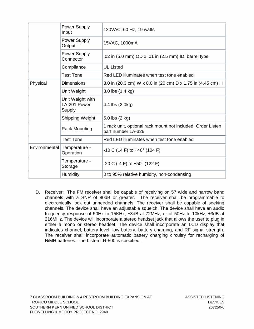
7 CLASSROOM BUILDING & 4 RESTROOM BUILDING EXPANSION AT ASSISTED LISTENING
TROPICO MIDDLE SCHOOL DEVICES
SOUTHERN KERN UNIFIED SCHOOL DISTRICT 267250-6
FLEWELLING & MOODY PROJECT NO. 2940
Power Supply
Input 120VAC, 60 Hz, 19 watts
Power Supply
Output 15VAC, 1000mA
Power Supply
Connector .02 in (5.0 mm) OD x .01 in (2.5 mm) ID, barrel type
Compliance UL Listed
Test Tone Red LED illuminates when test tone enabled
Physical Dimensions 8.0 in (20.3 cm) W x 8.0 in (20 cm) D x 1.75 in (4.45 cm) H
Unit Weight 3.0 lbs (1.4 kg)
Unit Weight with
LA-201 Power
Supply
4.4 lbs (2.0kg)
Shipping Weight 5.0 lbs (2 kg)
Rack Mounting 1 rack unit, optional rack mount not included. Order Listen
part number LA-326.
Test Tone Red LED illuminates when test tone enabled
Environmental Temperature -
Operation -10 C (14 F) to +40° (104 F)
Temperature -
Storage -20 C (-4 F) to +50° (122 F)
Humidity 0 to 95% relative humidity, non-condensing
D. Receiver: The FM receiver shall be capable of receiving on 57 wide and narrow band
channels with a SNR of 80dB or greater. The receiver shall be programmable to
electronically lock out unneeded channels. The receiver shall be capable of seeking
channels. The device shall have an adjustable squelch. The device shall have an audio
frequency response of 50Hz to 15KHz, ±3dB at 72MHz, or of 50Hz to 10kHz, ±3dB at
216MHz. The device will incorporate a stereo headset jack that allows the user to plug in
either a mono or stereo headset. The device shall incorporate an LCD display that
indicates channel, battery level, low battery, battery charging, and RF signal strength.
The receiver shall incorporate automatic battery charging circuitry for recharging of
NiMH batteries. The Listen LR-500 is specified.

7 CLASSROOM BUILDING & 4 RESTROOM BUILDING EXPANSION AT ASSISTIVE LISTENING
TROPICO MIDDLE SCHOOL DEVICES
SOUTHERN KERN UNIFIED SCHOOL DISTRICT 267250-7
FLEWELLING & MOODY PROJECT NO. 2940
LR-500 Specifications
Specification LR-500-072 LR-500-216
RF
RF Frequency
Range 72.025 - 75.950 MHz 216.025 - 216.975 MHz
Number of
Channels 57 (17 wide, 40 narrow) 57 (19 wide, 38 narrow)
Sensitivity .6uV typical, 1 uV maximum for 12dB SINAD
Frequency
Accuracy ± .005% stability 0° to 50°C (32° to 122° F)
Antenna Uses earphone cable
Antenna
Connector 3.5mm connector
Squelch Programmable in 20 steps
Compliance FCC Part 15, Industry Canada
Audio
** All system specifications are wireless end-to-end
System
Frequency
Response
63Hz - 15kHz (±3dB) 63Hz - 10kHz (±3dB)
System Signal
to Noise Ratio
(A-weighted)
SQ enabled: 80dB; SQ
disabled 60dB
SQ enabled: 80dB; SQ
disabled 50dB
System
Distortion <2% total harmonic distortion (THD) at 80% deviation
Output
3.5mm connectors, unbalanced, 0dBu nominal output
level,
16mW maximum, impedance 32 Ohms
Controls
Set Up Controls
Programmable channel selection (see below),
alkaline/NiMH batteries
and squelch, SQ enable/disable
User Controls Volume, channel UP/DOWN, SEEK. All controls
except volume are electronically lockable.
Programming
Unit can be programmed so that only desired
channels are displayed. Squelch can be adjusted for
sensitivity and signal capture control. Channel
selection can be locked by holding the SEEK button 5
seconds.
Indicators
LCD Display
Indicates channel, RF signal strength, lock status,
squelch, battey power level and channel
programming.
LED
Red, illuminates when unit is on. Flashes when
batteries are low. Flashes when charging. Flashes
when locked and user attempts to seek to another
channel.
Power Battery Type Two AA batteries, alkaline or NiMH

7 CLASSROOM BUILDING & 4 RESTROOM BUILDING EXPANSION AT ASSISTED LISTENING
TROPICO MIDDLE SCHOOL DEVICES
SOUTHERN KERN UNIFIED SCHOOL DISTRICT 267250-8
FLEWELLING & MOODY PROJECT NO. 2940
Battery Life
(Listen
batteries)
30 hours alkaline (LA-361), 15 hours NiMH
rechargeable (LA-362)
Battery
Charging (NiMH
only)
Fully automatic, 14 hours
Power Supply
Connector
2.3mm OD by 0.7mm ID, barrel type connector.
7.5VDC, center positive <250mA. Drop in contact
points for use with Listen charging cases.
Compliance UL Listed
Physical
Dimensions 3.0 in x 1.0 in x 5 in WxDxH (7.6cm x 2.5cm x 13.cm)
Unit Weight 3.9oz (111g)
Unit Weight with
batteries 5.8 oz (164.4g)
Shipping Weight 1.0 lbs (453.6kg)
Door
Manually lockable. UP, DOWN and SEEK through
door, other
controls behind door (see Controls above).
Environmental
Temperature -
Operation -10° to 40°C (14° to 104° F)
Temperature -
Storage -20° to 50°C (-4° to 122° F)
Humidity 0 to 95% relative humidity, non-condensing
E. Earplug: Please provide Listen LA-164 Single earplugs to match the quantity of receivers
provided.
F. Charging Case: Please provide one Listen LA-323 4- Unit Charging/Carrying Case with
Removable Lid.
G. Hearing Assistance System
Transmitter
Operates with radio frequency
Personal receivers included with earphones
PART 3 - EXECUTION
3.01 INSTALLATION
A. General: Comply with manufacturer's instructions and recommendations for work during
installation. Assistive Listening System to be installed and coordinated with the installation
of the Sound System.
END OF SECTION

7 CLASSROOM BUILDING & 4 RESTROOM BUILDING EXPANSION AT SITE CLEARING
TROPICO MIDDLE SCHOOL 311000-1
SOUTHERN KERN UNIFIED SCHOOL DISTRICT
FLEWELLING & MOODY PROJECT NO. 2940
SECTION 311000 SITE CLEARING
1.00 GENERAL
1.01 SUMMARY
A. This Section requires the selective removal and subsequent off-site disposal of the following:
1. Removal and offsite disposal of grass and root mat.
2. Demolition of asphalt concrete and pavements as indicated on the drawings to straight, neatly saw cut surface.
3. All other removals which may or may not been shown on plans as required for the project construction.
1.02 SITE CONDITIONS
A. Protections: Contractor shall provide temporary barricades and other forms of protection to protect general public from injury due to demolition work.
B. Traffic: Conduct demolition operations and debris removal to ensure minimum interference with roads, streets, walks, bike paths, and other adjacent occupied or used facilities. Access must be coordinated with District’s Representative.
C. Utility Services: Maintain all existing utilities to remain in service and protect them against damage during demolition operations.
D. Environmental Controls: Use water sprinkling, temporary enclosures, and other methods to limit dust and dirt migration. Comply with governing regulations and County Air Pollution Control District pertaining to environmental protection. Do not use water when it may create hazardous or objectionable conditions such as flooding and pollution.
1.03 REFERENCES
A. Standard Specifications for Public Works Construction (Green Book), latest edition.
2.0 PRODUCTS (NOT APPLICABLE)
3.0 EXECUTION
3.01 DEMOLITION
A. General: Perform demolition work in a systematic manner. Use such methods as required to complete work indicated on drawings in accordance with governing regulations.

7 CLASSROOM BUILDING & 4 RESTROOM BUILDING EXPANSION AT SITE CLEARING
TROPICO MIDDLE SCHOOL 311000-2
SOUTHERN KERN UNIFIED SCHOOL DISTRICT
FLEWELLING & MOODY PROJECT NO. 2940
B. Provide services for effective air and water pollution controls as required by County Air Pollution Control District regulations.
C. Prior to commencing grading operations, soil containing debris, organics, pavement, or other unsuitable materials, shall be stripped from the foundation and pavement areas. Demolition areas shall be cleared of old foundations, slabs, abandoned utilities, tree roots, and soil disturbed during the demolition process. Depressions or disturbed areas left from the removal of such material shall be replaced with compacted fill under observation by the Geotechnical representative.
3.02 DISPOSAL OF DEMOLISHED MATERIALS
A. Remove from Project site debris, rubbish, and other materials resulting from demolition operations. Transport and legally dispose of off site.
B. If hazardous materials are encountered during demolition operations, contact District’s Representative.
C. Burning of removed materials is not permitted on project site.
3.03 HAZARDOUS MATERIALS
A. Except as otherwise specified, in the event Contractor encounters on the Project site material reasonably believed to be asbestos, polychlorinated biphenyl (PCB), or other hazardous materials which have not been rendered harmless, Contractor shall immediately stop Work in the area affected and report the condition to the District’s Representative in writing. The Work in the affected area shall not thereafter be resumed except by written agreement of the Contractor if in fact the material is asbestos, PCB, or other hazardous materials and has not been rendered harmless. The Work in the affected area shall be resumed in the absence of asbestos, PCB, or other hazardous materials, or when such materials have been rendered harmless.
B. Construction involving asbestos cement (transite) pipe shall be performed by qualified personnel in accordance with the standards and specifications set forth by American Water Works Association (AWWA), the Occupational Safety and Health Act (OSHA) and the Environmental Protection Agency (EPA), as well as location jurisdictional codes.
3.04 CLEANUP AND REPAIR
A. General: Upon completion of demolition work, remove tools, equipment and demolished materials from site.
1. Repair demolition performed in excess of that required. Return elements of construction and surfaces to existing condition prior to start of operations. Repair adjacent construction or surfaces soiled or damaged by demolition work.
END OF SECTION

7 CLASSROOM BUILDING & 4 RESTROOM BUILDING EXPANSION AT EARTHWORK
TROPICO MIDDLE SCHOOL 312000-1
SOUTHERN KERN UNIFIED SCHOOL DISTRICT
FLEWELLING & MOODY PROJECT NO. 2940
SECTION 312000 EARTHWORK
1.00 GENERAL
1.01 SUMMARY
A. Section includes: Excavation, Compaction and Fill.
1.02 REFERENCE
A. Standard Specifications for Public Works Construction (SSPWC), latest edition.
B. Geotechnical Engineering and Geohazards Report, Tropico Middle School Expansion Project, dated April 27, 2022, File No. 300234-002, prepared by Earth Systems Pacific and shall be superseded by the most current version.
1.03 QUALITY ASSURANCE
A. Codes and Standards: Perform earthwork in compliance with applicable requirements of governing authorities having jurisdiction.
1. Standard Specifications for Public Works Construction (SSPWC), latest edition.
2. CAL/OSHA Construction Safety Order Requirements.
B. Soil Testing Service
1. The District will engage a soil testing service to include testing soil materials proposed for use in the Work and for quality control testing during grading operations.
2. Samples of materials shall be furnished to the testing service by the Contractor at least one week before their anticipated use.
3. Work for this Section includes smoothing out areas for density tests and otherwise facilitate testing work, as directed.
4. Shoring Systems: Pre-engineered systems, clearly labeled as such, may be used. Refer to the Geotechnical Study for further requirements.
1.04 PROJECT CONDITIONS
A. The Contractor shall visit the site and familiarize himself with existing site conditions.
B. Additional test borings and other exploratory operations may be made by the Contractor at no cost or liability to the District.

7 CLASSROOM BUILDING & 4 RESTROOM BUILDING EXPANSION AT EARTHWORK
TROPICO MIDDLE SCHOOL 312000-2
SOUTHERN KERN UNIFIED SCHOOL DISTRICT
FLEWELLING & MOODY PROJECT NO. 2940
C. Existing Utilities:
1. Where uncharted or incorrectly charted piping or other utilities are encountered during excavation, consult District 's Representative immediately for directions. Cooperate with the District’s Representative in keeping respective services and facilities in operation. Repair damaged utilities to the satisfaction of the District’s Representative at no cost to the District. Disturbed trench sections shall be replaced in kind.
2. Contractor to coordinate with the District 's Representative to obtain all required permits and schedule inspections.
D. Protection of Subgrade: Do not allow equipment to pump, rut, or disturb subgrade, stripped areas, or other areas prepared for Project.
E. Contractor shall implement measures to prevent soil erosion, and where possible, sediment shall be retained onsite.
F. Contractor shall implement all necessary recommendations contained in the Geotechnical Study.
2.00 PRODUCTS (Not Applicable)
3.00 EXECUTION
3.01 SITE PREPARATION
A. General:
1. Remove vegetation, improvements, or obstructions interfering with installation of new construction. Transport and legally dispose of off site. Removal includes stumps and roots. Contractor shall utilize the best construction method to minimize the erosive effect from the removal of site vegetation.
2. Carefully and cleanly cut roots and branches of trees indicated to be left standing, where such roots and branches obstruct new construction. Paint cuts over one inch in size with tree pruning compound. Care shall be taken so as not to scar any area of the tree's bark.
3. In order to protect from sediment, transfer or contamination from urban run-off during construction, the following grading and erosion control practices shall be followed:
a. If grading occurs during the rainy season (November through April), sediment traps, barriers, covers or other methods shall be used to reduce erosion and sedimentation.
7 CLASSROOM BUILDING & 4 RESTROOM BUILDING EXPANSION AT EARTHWORK
TROPICO MIDDLE SCHOOL 312000-3
SOUTHERN KERN UNIFIED SCHOOL DISTRICT
FLEWELLING & MOODY PROJECT NO. 2940
b. Excavated materials shall not be deposited or stored where the material can be washed away by high water or storm run-off.
c. Grading operations on site shall be conducted so as to prevent damaging effects of sediment production and dust on the site and on adjoining properties.
d. When vegetation has to be removed on site, the methods shall be one that minimizes the erosive effects from the removal.
e. Exposure of soil to erosion by removing vegetation shall be limited to the area required for construction operations. The construction area shall be fenced to define the project.
f. Temporary mulching, seeding, or other suitable stabilization shall be used to protect areas during construction or other land disturbance activities on site.
g. Topsoil, removed from the surface in preparation for grading and construction activities on Campus is to be stored on or near the site and protected from erosion while grading operations are underway, provided that such storage may not be located where it would cause suffocation of root systems of trees to be preserved. After completion of such grading, topsoil is to be restored to exposed cut and fill embankments of building pads so as to provide a suitable base of seeding and planting.
h. Sediment basins, sediment traps, or similar control measures shall be installed before extensive clearing and grading operations begin for site development.
i. Water or dust palliatives shall be applied to exposed earth services as necessary to control dust emissions.
j. Revegetation or stabilization of exposed earth surfaces shall take place as soon as possible.
B. Removals
1. Clear the site of trees, shrubs, and other vegetation, which is indicated to be removed.
2. Completely remove stumps, roots, and other debris to avoid problems with future utilities.
3. Use only hand methods for grubbing inside the drip line of trees indicated to be left standing.

7 CLASSROOM BUILDING & 4 RESTROOM BUILDING EXPANSION AT EARTHWORK
TROPICO MIDDLE SCHOOL 312000-4
SOUTHERN KERN UNIFIED SCHOOL DISTRICT
FLEWELLING & MOODY PROJECT NO. 2940
4. Existing fills, soil containing debris, organics, pavement, or other unsuitable materials shall be excavated and removed prior to commencing grading operations. Demolition areas shall be cleared of old foundations, slabs, abandoned utilities, landscaping, and soils disturbed during the demolition process. Depressions or disturbed areas left from the removal of such material shall be replaced with compacted fill.
5. The limits and depths for removal of existing fill materials shall be evaluated by project soils engineer during grading.
6. Revegetation or stabilization of exposed earth surface shall take place as soon as possible.
C. Removal of Improvements
1. Remove above-grade and below-grade improvements necessary to permit construction and other work as indicated.
2. Remove from site and legally dispose of off-site, existing fill materials, soil debris, or other unsuitable materials prior to commencing grading operations.
3.02 EXCAVATION
A. Excavation for Pavements: Cut surface under pavements to comply with cross-sections, elevations and grades as shown, within a tolerance of plus or minus 0.04 foot.
B. Excavation for Planting Areas: Conform to cross-sections, elevations and dimensions shown, within a tolerance of plus or minus 0.10 foot.
3.03 COMPACTION
A. General: Control soil compaction during construction providing minimum percentage of density specified for each area, under the provisions of the Geotechnical Study.
B. Percentage of Maximum Density Requirements: Compact soil to not less than the percentages of maximum dry density specified in the Geotechnical Study and in accordance with ASTM D1557-91 method of compaction.
C. Moisture Control:
1. When moisture content of exposed scarified soil and/or full material is below that sufficient to achieve recommended compaction, water shall be added to the soil and/or fill. While water is being added, soil shall be bladed and mixed to provide relatively uniform moisture content throughout the material.
2. When moisture content of exposed scarified soil and/or fill material is excessive, material shall be aerated by blading or other methods. Fill placed in pavement areas shall be compacted at near optimum moisture content. Jetting is not permitted for compaction.

7 CLASSROOM BUILDING & 4 RESTROOM BUILDING EXPANSION AT EARTHWORK
TROPICO MIDDLE SCHOOL 312000-5
SOUTHERN KERN UNIFIED SCHOOL DISTRICT
FLEWELLING & MOODY PROJECT NO. 2940
3.04 FILL
A. In all excavations, use satisfactory excavated or borrow material sampled and tested by the District’s Testing Laboratory. Fill selection shall be per Geotechnical Study.
B. Fill excavations as promptly as Work permits, but not until completion of the following:
1. Acceptance by District’s Representative of construction below finish grade including, where applicable, waterproofing, damp-proofing, and drainage pipe.
2. Examination, testing, approval and recording locations of underground utilities.
3. Removal of concrete formwork.
4. Removal of shoring and bracing and backfilling of voids with satisfactory materials.
5. Removal of trash and debris.
6. Permanent or temporary horizontal bracing is in place on horizontally supported walls.
7. Protect excavations by methods required to prevent cave-in or loose soil from falling into excavation.
C. Continual dust control, as required by the District, and in accordance with County Air Pollution Control District’s Standards shall be required for the project construction.
3.05 GRADING
A. General: To provide support for building floor slabs, all existing fill and unsuitable natural soils shall be excavated and replaced as properly compacted fill.
B. Compaction: After grading, compact subgrade surfaces to the depth and percentage of compaction for each area classification.
C. Fill placement and grading operations shall be performed only under the observation of the District’s Testing Laboratory.
D. The exterior grades around building areas shall be sloped to drain away from the buildings to prevent ponding of water adjacent to foundations.
E. Grading operation shall be conducted so as to prevent damaging effects of sediment product and dust on the site and adjoining properties.
3.06 DISPOSAL OF EXCESS AND WASTE MATERIALS
A. Transport excess excavated material and legally dispose of off site.

7 CLASSROOM BUILDING & 4 RESTROOM BUILDING EXPANSION AT EARTHWORK
TROPICO MIDDLE SCHOOL 312000-6
SOUTHERN KERN UNIFIED SCHOOL DISTRICT
FLEWELLING & MOODY PROJECT NO. 2940
3.07 FIELD QUALITY CONTROL
A. Quality Control Testing During Construction: District’s Testing Laboratory will observe, test and approve subgrades and fill layers before further construction Work can be performed. The District’s Representative will determine the frequency of tests. Subgrade: Allow at least one field density test of subgrade to be made for every 2000 sq. ft. of paved area, but in no case less than 3 tests.
B. Field examination and testing will be performed by the District’s Testing Laboratory. The Contractor shall cooperate with such testing and shall give the District’s Representative advance notice of grading scheduling.
C. Frequency of Tests for Trenching: As specified in Geotechnical Study Section 8 and as determined by the District’s Representative.
D. If in the opinion of the District’s Representative, based on soil testing reports and observations, subgrades or fills which have been placed are below specified density, provide corrective work as specified at no additional expense to the District, and pay for retesting of the soil.
3.08 PROTECTION
A. Protect newly graded areas from traffic and erosion. Keep free of trash and debris.
B. Repair and re-establish grades in settled, eroded, and rutted areas to specified tolerances.
C. Reconditioning Compacted Areas: Where completed compacted areas are disturbed by subsequent construction operations or adverse weather, scarify surface, reshape, compact to required density and provide other corrective work as specified, with retesting, prior to further construction.
END OF SECTION

7 CLASSROOM BUILDING & 4 RESTROOM BUILDING EXPANSION AT TRENCHING AND BACKFILLING
TROPICO MIDDLE SCHOOL 312333 - 1
SOUTHERN KERN UNIFIED SCHOOL DISTRICT
FLEWELLING & MOODY PROJECT NO. 2940
SECTION 312333 TRENCHING AND BACKFILLING
1.00 GENERAL
1.01 SUMMARY
A. Excavating trenches for construction of utilities.
B. Trench backfill materials.
C. Backfilling and compacting requirements.
1.02 REFERENCES
A. Standard Specifications for Public Works Construction (SSPWC), latest edition.
B. Geotechnical Engineering and Geohazards Report, Tropico Middle School Expansion
Project, dated April 27, 2022, File No. 300234-002, prepared by Earth Systems Pacific
and shall be superseded by the most current version.
1.03 SUBMITTALS
A. Materials source.
B. Sand equivalent test reports per ASTM D2419.
C. Certificates.
D. Drawings for shoring, bracing, sloping, or other provisions for worker protection for any excavation shall conform to the requirements of the CAL/OSHA Construction Safety Orders Requirements.
1.04 EXISTING UTILITIES
A. Drawings show existing major underground utilities from reference drawings. Prior to excavation, the Contractor shall notify the District’s Representative to obtain any additional information which may be applicable to the Work.
B. Any incident of a utility being inadvertently damaged by the Contractor shall be immediately shutoff and then be immediately repaired by the Contractor at no cost to the District.
C. Contractor to pothole all utility connections and verify exact size, location and material prior to beginning construction and notify engineer of any discrepancies.
2.00 MATERIALS

7 CLASSROOM BUILDING & 4 RESTROOM BUILDING EXPANSION AT TRENCHING AND BACKFILLING
TROPICO MIDDLE SCHOOL 312333 - 2
SOUTHERN KERN UNIFIED SCHOOL DISTRICT
FLEWELLING & MOODY PROJECT NO. 2940
2.01 APPROVALS
A. Imported material shall be approved by the District’s Representative prior to being brought to the site. Provide a sample of the material in sufficient quantity for the District’s Representative’s use in evaluating the material.
2.02 TRENCH BACKFILL MATERIAL
A. Sand bedding shall have a sand equivalent (SE) of 30 or greater. The SE shall be evaluated during grading. Materials shall conform to the specification of the Geotechnical Study.
B. Backfill material shall conform to the requirements of Section 217-2 of the SSPWC.
C. Aggregate base course shall be per Plan.
D. Topsoil removed from trenches shall be stockpiled at locations approved by the District’s Representative.
2.03 SOURCE QUALITY CONTROL
A. Inspection and testing shall be performed by the District’s Representative.
3.00 EXECUTION
3.01 PREPARATION
A. Identify required lines, levels, contours, and datum.
3.02 TRENCH EXCAVATION
A. All saw cutting shall be neat, straight cuts and shall conform to Section 306-3 of the SSPWC. All cuts shall be square unless otherwise specifically noted on plans.
B. Trench excavation shall conform to Section 306-3 of the SSPWC and the following requirements:
1. The bottom of the trench shall be graded and prepared to provide a firm and uniform bearing throughout the entire length of the pipe barrel. Suitable excavations shall be made to receive the bell of the pipe and the joint shall not bear upon the bottom of the trench. All adjustments to line and grade shall be made by scraping away or filling in with sand under the body of the pipe and not by wedging or blocking.

7 CLASSROOM BUILDING & 4 RESTROOM BUILDING EXPANSION AT TRENCHING AND BACKFILLING
TROPICO MIDDLE SCHOOL 312333 - 3
SOUTHERN KERN UNIFIED SCHOOL DISTRICT
FLEWELLING & MOODY PROJECT NO. 2940
2. If the trench is excavated below the required grade, correct any part of the trench excavated below the grade, at no additional cost to the District per the Geotechnical Study. Place the backfill material over the full width of trench in compacted layers not exceeding 6 inches deep to the established grade with allowance for the pipe base. If shoring is required, the trenches shall be shored and braced in accordance with the Trench Construction Safety Orders of the Division of Industrial Safety.
3. When subgrade is encountered that in the opinion of the District’s Representative is unsuitable for pipe support, the District’s Representative may order the excavation to be carried to an approved depth below the bottom of the pipe and backfilled with sand, to the lines and grades shown on the drawings and specified by the District’s Representative.
4. The minimum width of the trench at the top of the pipe zone shall be as necessary to install the pipe. The utility lines shall be centered in the trench. In the event of (1) actual physical interference between existing crossing subsurface utilities and the proposed utility lines and (2) vertical discrepancy in connecting proposed utility lines to existing utility system, a minimum clearance of 0.5 feet between the utility line and the crossing, interfering utility shall be provided, unless otherwise indicated on the plans.
5. Where existing utilities or tree roots are to be protected, trench excavation shall be by hand. No mechanical excavating equipment shall be used within 6 inches of any utility or root.
6. Trenching machinery may be used for excavations provided the specified trench width can be maintained.
3.03 TRENCH BACKFILL
A. Pipe bedding and trench backfill materials: pipe bedding shall be either crushed rock or sand as specified on the plans. Sand bedding and backfill for utilities shall consist of material having a sand equivalent of at least 30. The backfill material shall be placed within the pipe zone that extends from the bottom of the pipe to at least 12 inches above the top of the pipe for the full width of the trench. The horizontal distance between the spring line of the pipe and the side walls of the trench shall be such that bedding material can be properly placed and compacted below the haunches of the pipe. Pipe bedding and pipe zone backfill shall be compacted to at least 95 percent relative compaction. Backfill material placement shall conform to provisions of Geotechnical Study.
B. Trench backfill placed above the pipe zone shall consist of suitable onsite or imported soil per Geotechnical Study. Mechanical compaction of trench backfill shall be performed and water consolidation (jetting) methods of compaction shall not be permitted. Trench backfill in landscape areas shall be compacted to a minimum of 90 percent relative compaction or per landscape specifications.
C. Trench Backfilling shall conform to the requirements of Sections 306-12 of the SSPWC and Geotechnical Study:
7 CLASSROOM BUILDING & 4 RESTROOM BUILDING EXPANSION AT TRENCHING AND BACKFILLING
TROPICO MIDDLE SCHOOL 312333 - 4
SOUTHERN KERN UNIFIED SCHOOL DISTRICT
FLEWELLING & MOODY PROJECT NO. 2940
1. During the process of laying pipe in trenches, sufficient material shall be carefully placed and hand tamped about the pipe to hold it firmly to established line and grade. Oversized material, broken rock or shale, if encountered, shall not be used for backfill.
2. No motor driven mechanical compacting equipment shall be used over pipelines until the backfill has been compacted to 12 inches over the crown of the pipe.
3. All backfill material shall be deposited in horizontal layers not exceeding the thickness specified in Section 306-12 of the SSPWC and not exceeding 8 inches in thickness. The distribution of materials shall be such that all material following compaction and consolidation will form a homogeneous mass free of voids, pockets, streaks or other imperfections. Backfilling shall be done with earth free from lumps, hardpan, chunks, paving material, organic matter or other deleterious substances.
4. Jetting of bedding or backfill material to obtain specific moisture content or for compaction shall not be permitted. If encountered, existing fill in the utility excavation shall be excavated and recompacted or removed and replaced with new fill materials per requirements of Section 2.02.
5. Compaction of all backfill material for trenches, pavements or structures, shall be per provisions of the Geotechnical Study. Appropriate warning detector tape shall be placed over all utilities.
6. Prior to final cleanup or resurfacing, the District’s Representative shall take compaction tests in any backfill area and at any depth, with the Contractor providing equipment and operator to assist in such test. If any such compaction test fails, the Contractor shall correct such failure and pay for any retesting that is required. The District’s Representative shall make as many tests as he feels is required to receive a satisfactory and acceptable job.
3.04 STOCKPILING
A. Stockpiling of imported materials or excavated materials shall direct surface water away from approved stockpile site to prevent erosion.
B. After stockpiles are removed, leave area in a clean and neat condition.
3.05 FIELD QUALITY CONTROL
A. Inspection and testing shall be performed by District’s Representative.
END OF SECTION

7 CLASSROOM BUILDING & 4 RESTROOM BUILDING EXPANSION AT AGGREGATE BASE COURSES
TROPICO MIDDLE SCHOOL 321123 - 1
SOUTHERN KERN UNIFIED SCHOOL DISTRICT
FLEWELLING & MOODY PROJECT NO. 2940
SECTION 321123 AGGREGATE BASE COURSES
1.00 GENERAL
1.01 SUMMARY
A. Aggregate base course for curbs, gutters, sidewalks, and fire access driveway.
1.02 RELATED SECTIONS
A. Section 312000 Earthwork.
B. Section 321216 Asphalt Concrete Paving.
C. Section 321600 Curbs, Gutters, Sidewalks.
1.03 REFERENCES
A. Standard Specifications for Public Works (SSPWC), latest edition.
B. ASTM Standards.
C. State Standard Specifications (SSS), Caltrans, latest edition.
D. Geotechnical Engineering and Geohazards Report, Tropico Middle School Expansion Project, dated April 27, 2022, File No. 300234-002, prepared by Earth Systems Pacific and shall be superseded by the most current version.
1.04 SUBMITTALS:
A. Submit material samples and reports in accordance with requirements of District.
B. Submit samples in sufficient quantities for material testing.
2.00 PRODUCTS
2.01 MATERIALS
A. Aggregate Base Material shall be Class 2 Aggregate Base conforming to SSS Section 26-1.02A. Aggregate Base shall have a minimum sand equivalence of 22 and a minimum R-value of 78 and shall be free of organic materials and other deleterious substances.
B. Aggregate Base materials used within building areas shall be free of asphaltic materials.

7 CLASSROOM BUILDING & 4 RESTROOM BUILDING EXPANSION AT AGGREGATE BASE COURSES
TROPICO MIDDLE SCHOOL 321123 - 2
SOUTHERN KERN UNIFIED SCHOOL DISTRICT
FLEWELLING & MOODY PROJECT NO. 2940
3.00 EXECUTION
3.01 EXAMINATION
A. Verify substrate has been inspected; gradients and elevations are correct, and dry.
3.02 AGGREGATE BASE PLACEMENT
A. Aggregate base placement shall conform to the provisions of the SSPWC, Section 301-2.
B. Level and contour surfaces to elevations and gradients indicated.
C. Add water to assist compaction. If excess water is apparent, remove aggregate and aerate to reduce moisture content.
D. Where the required aggregate base thickness is 6 inches or less, the watered base may be spread and compacted in one layer. Where the required thickness is more than 6 inches, the aggregate base material shall be spread and compacted in 2 or more layers of approximately equal thickness. The maximum compacted thickness of any one layer shall not exceed 6 inches.
E. Aggregate base course shall be dense and unyielding upon proof-rolling with full water truck.
3.03 TOLERANCES
A. Flatness: Maximum variation of 1/4 inch.
B. Scheduled Compacted Thickness shall conform to the provisions of the SSPWC Section 301-2.2.
3.04 FIELD QUALITY CONTROL
A. Inspection and testing shall be performed by the District's Testing Laboratory. Compaction testing will be performed in accordance with ASTM D1557, latest edition.
B. If tests indicate work does not meet specified requirements, remove work, replace and retest at Contractor's expense.
END OF SECTION

7 CLASSROOM BUILDING & 4 RESTROOM BUILDING EXPANSION AT ASPHALT CONCRETE PAVING
TROPICO MIDDLE SCHOOL 321216- 1
SOUTHERN KERN UNIFIED SCHOOL DISTRICT
FLEWELLING & MOODY PROJECT NO. 2940
SECTION 321216 ASPHALT CONCRETE PAVING
1.00 GENERAL
1.01 SUMMARY
A. Asphaltic concrete paving for parking lots and driveway pavements.
1.02 RELATED SECTIONS
A. Section 312000 Earthwork.
B. Section 321123 Aggregate Base Courses.
1.03 REFERENCES
A. Standard Specifications for Public Works Construction (SSPWC), latest edition.
B. ASTM Standards.
C. Geotechnical Engineering and Geohazards Report, Tropico Middle School Expansion Project, dated April 27, 2022, File No. 300234-002, prepared by Earth Systems Pacific and shall be superseded by the most current version.
1.04 SUBMITTALS
A. Submit asphalt concrete mix design(s) for approval of the District Representative.
1.05 TESTING AND INSPECTION
A. Testing and inspection of asphalt pavement mix(es) and testing of placed stabilizing base course and asphalt pavement will be performed by the District's Testing Laboratory. Testing and inspection will be performed so as to minimize disruption of work.
B. Allow the District's Testing Laboratory access to the mixing plant for verification of weights or proportions, character of materials used and determination of temperatures used in the preparation of asphaltic concrete mix.
2.00 PRODUCTS
2.01 GENERAL
A. Provide the aggregate base, and bituminous surface conforming to the requirements of the Standard Specifications for Public Works Construction (SSPWC).

7 CLASSROOM BUILDING & 4 RESTROOM BUILDING EXPANSION AT ASPHALT CONCRETE PAVING
TROPICO MIDDLE SCHOOL 321216- 2
SOUTHERN KERN UNIFIED SCHOOL DISTRICT
FLEWELLING & MOODY PROJECT NO. 2940
2.02 PAVING MATERIALS
A. Asphalt Concrete: Asphalt concrete material shall be C2-PG 70-10 per SSPWC Section 203-6. The grading and proportioning of aggregates shall be such that the combined mineral aggregate conforms to the specified requirements.
B. Asphalt Emulsion: SSPWC Section 203-3, Grade SS-1h.
C. Prime Coat: Grade SC-70 per SSPWC Section 203-2.
D. Aggregates for base course shall conform to requirements of Specification Section 321123, Aggregate Base Course.
2.03 ASPHALT PAVEMENT MIX
A. Combine mineral constituents in proportions to produce a mixture conforming to requirements of the SSPWC Section 203-6.
B. Percentage by weight of asphalt cement in mixture shall be in accordance with SSPWC Section 203-6.
C. Maintain thorough and uniform mixture.
D. Bring asphalt and mineral constituents to required temperatures before mixing. Ensure aggregates are sufficiently dry so as not to cause foaming in mixture.
3.00 EXECUTION
3.01 GENERAL
A. Execute Work in accordance with SSPWC Section 302 and the Geotechnical Study.
3.02 PREPARATION
A. Ensure grading of subgrade to required elevation. Subgrade preparation shall be per SSPWC Section 301.
B. Before final rolling, shape entire section, add additional sub-soil if necessary, and compact subgrade to provide grades, elevation and cross-section indicated. Points of finished subgrade surface shall be within 0.04 foot of elevations indicated on the Drawings.
3.03 BASE COURSE
A. Place aggregate base in accordance with requirements of SSPWC Section 301 and to the thickness shown on the Drawings. Grade and compact in 6-inch layers to at least 95 percent of compaction (ASTM D1557).

7 CLASSROOM BUILDING & 4 RESTROOM BUILDING EXPANSION AT ASPHALT CONCRETE PAVING
TROPICO MIDDLE SCHOOL 321216- 3
SOUTHERN KERN UNIFIED SCHOOL DISTRICT
FLEWELLING & MOODY PROJECT NO. 2940
3.04 MAINTENANCE
A. Maintain the base course until the asphaltic pavement is in place. Maintenance shall include drainage, rolling, shaping and water as necessary to maintain the course in proper condition. Maintain sufficient moisture at the surface to prevent a dusty condition. Areas of completed base course that are damaged shall be conditioned, reshaped and re-compacted in accordance with the requirements of the Specifications without additional cost to the District.
3.05 TACK COAT
A. Prior to the application of the asphalt concrete, a paint binder (tack coat) shall be applied to all surfaces of walkway, curbs, gutters, manholes and drainage structures which will be in contact with asphalt pavement per SSPWC Section 302-5.4.
B. Coat surfaces of catch basins which are to remain free of asphalt with oil, or provide equivalent protection, to prevent asphalt adhesion.
3.06 PRIME COAT
A. Prior to the application of the asphalt concrete, a prime coat shall be applied at a rate of 0.20 to 0.40 gallons per square yard.
3.07 ASPHALT CONCRETE
A. Requirements: The bituminous concrete shall consist of mineral aggregate, uniformly mixed with bituminous material in a central plant in accordance with SSPWC Section 203-6. The percentage of asphalt binder shall be in accordance with SSPWC Section 203-6. The mixing plant and construction equipment shall conform to the requirements of SSPWC Sections 203-6 and 302-5.
B. Placing: Deliver bituminous mixtures to the work site temperatures specified in SSPWC Section 302-5.5. Spread and place in accordance with SSPC Section 302-5.5. Asphalt surface shall be fog-sealed.
C. Compaction: Initial or breakdown rolling and the final rolling of the uppermost layer of the asphalt concrete shall be in accordance with SSPWC Section 302-5.6. Compaction by vehicular traffic shall not be permitted.
3.08 JOINING PAVEMENT
A. Carefully make joints between old and new pavements or between successive days work in such manner as to insure a continuous bond between old and new sections of the course in accordance with SSPWC Section 302.
B. Expose and clean edges of existing pavement. Cut edge to straight, vertical surfaces. Paint all joints with a uniform coat of tack coat before the fresh mixture is placed. Prepare joints in the new pavement in accordance with SSPWC Section 302-5.7.

7 CLASSROOM BUILDING & 4 RESTROOM BUILDING EXPANSION AT ASPHALT CONCRETE PAVING
TROPICO MIDDLE SCHOOL 321216- 4
SOUTHERN KERN UNIFIED SCHOOL DISTRICT
FLEWELLING & MOODY PROJECT NO. 2940
3.09 JOINING NON-PAVED AREAS
A. Where paving will join landscape or other non-hardscape area a redwood header shall be installed.
3.10 TOLERANCES
A. Flatness: Maximum variation of 1/8 inch when measured with a 10-foot straight edge.
B. Variation from True Elevation: Within 1/4 inch.
3.11 FIELD QUALITY CONTROL
A. Inspection and testing shall be performed by the District’s Testing Laboratory.
B. Field inspection and testing will be performed by the District's Testing Laboratory. The Contractor shall cooperate with such testing and shall give the District Representative advance notice of paving scheduling. Sufficient “Advance Notice” shall be determined by the District Representative.
C. If tests indicate materials do not meet specified requirement, replace material and retest at no additional cost to the District.
D. Frequency of Test: As determined by the District’s Testing Laboratory.
3.12 PROTECTION
A. After placement, protect pavement from mechanical injury.
END OF SECTION

7 CLASSROOM BUILDING & 4 RESTROOM BUILDING EXPANSION AT CURBS, GUTTERS, SIDEWALKS
TROPICO MIDDLE SCHOOL 321600- 1
SOUTHERN KERN UNIFIED SCHOOL DISTRICT
FLEWELLING & MOODY PROJECT NO. 2940
SECTION 321600 CURBS, GUTTERS, SIDEWALKS
1.00 GENERAL
1.01 SUMMARY
A. Concrete for curbs, gutters, sidewalks.
1.02 RELATED SECTIONS
A. Section 312000 – Earthwork
1.03 REFERENCES
A. Standard Specifications for Public Works Construction (SSPWC), latest edition.
B. Geotechnical Engineering and Geohazards Report, Tropico Middle School Expansion Project, dated April 27, 2022, File No. 300234-002, prepared by Earth Systems Pacific and shall be superseded by the most current version.
C. ASTM Standards.
1.04 SUBMITTALS
A. Submit the following:
1. Product Data: Provide data on admixtures and curing compounds.
2. Concrete mix design(s).
3. Certificates from the batch plant.
1.05 QUALITY ASSURANCE
A. Perform Work in accordance with the SSPWC, latest edition; and ASTM Standards, latest edition.
B. Obtain cementitious materials from same source throughout.
1.06 ENVIRONMENTAL REQUIREMENTS
A. Do not place concrete when base surface temperature is less than 40 degrees F or surface is wet.

7 CLASSROOM BUILDING & 4 RESTROOM BUILDING EXPANSION AT CURBS, GUTTERS, SIDEWALKS
TROPICO MIDDLE SCHOOL 321600- 2
SOUTHERN KERN UNIFIED SCHOOL DISTRICT
FLEWELLING & MOODY PROJECT NO. 2940
2.00 PRODUCTS
2.01 FORM MATERIALS
A. Form Materials: Section 303-5 of the SSPWC.
2.02 CONCRETE MATERIALS
A. Concrete Material for Curbs and Walks (Path of Travel):
1. Class 520-C-2500. Portland cement concrete per Standard Specifications for Public Works Construction Section 201-1.
2. Concrete reinforcements shall be constructed per the Project Plans and Specifications.
2.03 ACCESSORIES
A. Curing Compound shall conform to SSPWC Section 201-4. Pigmented compound shall not demonstrate any residual coloring of the concrete after one week.
2.04 CONCRETE MIX
A. Mix and deliver concrete in accordance with ASTM C94.
B. Use accelerating admixtures in cold weather only when approved by the District's Representative. Use of admixtures will not relax cold weather placement requirements.
C. Use calcium chloride only when approved by the District’s Representative.
D. Use set retarding admixtures during hot weather only when approved by the District’s Representative.
2.05 CONCRETE REINFORCEMENT
A. Concrete reinforcement shall conform to SSPWC Section 201-2.
2.06 SOURCE QUALITY CONTROL
A. Provide certificates of compliance from the batch plant.
3.00 EXECUTION
3.01 EXAMINATION
A. Verify compacted subgrade is acceptable and ready to support imposed loads.
B. Verify gradients and elevations of subgrade are correct.

7 CLASSROOM BUILDING & 4 RESTROOM BUILDING EXPANSION AT CURBS, GUTTERS, SIDEWALKS
TROPICO MIDDLE SCHOOL 321600- 3
SOUTHERN KERN UNIFIED SCHOOL DISTRICT
FLEWELLING & MOODY PROJECT NO. 2940
3.02 PREPARATION
A. Moisten subgrade to minimize absorption of water from fresh concrete. Over excavate subgrade to a depth of 2 feet below existing or finish grade whichever is deeper. Scarify excavation bottom to 12”, moisture condition to near or over optimum moisture content and recompact to 90% relative compaction. Place engineered fill in lifts, compacted to 90% relative compaction with upper 1 foot compacted to 95% relative compaction in parking and drive areas. Refer to geotechnical report for site subgrade preparation recommendations.
B. Coat surfaces of catch basin frames with oil to prevent bond with concrete pavement.
C. Notify District’s Representative a minimum of 24 hours prior to commencement of concrete placement operations.
3.03 FORMING
A. Place and secure forms to correct location, dimension, and profile.
B. Assemble formwork to permit easy stripping and dismantling without damaging concrete.
C. Place joint filler vertical in position, in straight lines. Secure to formwork during concrete placement.
3.04 PLACING CONCRETE
A. Place concrete in accordance with SSPWC Section 303-5.
B. Install ½” thick fiberboard expansion joint and snap cap. Seal with Sikaflex self-leveling sealant after removal of snap cap (typical).
C. Construct weakened plane joints conforming to SSPWC Section 303-5.4.3, 1 ¼” inch deep, at intervals not exceeding 12 feet.
D. The top edges of curbs shall have 0.5" radius.
3.05 FINISHING
A. Concrete finishes shall be per SSPWC Section 303-5.5.
B. Portland cement concrete paving in all accessible routes of travel shall have slip resistant finish.
C. Walkway grades in excess of 5% shall conform to requirements of Section 11B-401 of the latest edition of the California Building Code.
D. Place curing compound in accordance with SSPWC Section 303-5.6 on exposed concrete surfaces immediately after finishing. Apply in accordance with manufacturer's instructions.

7 CLASSROOM BUILDING & 4 RESTROOM BUILDING EXPANSION AT CURBS, GUTTERS, SIDEWALKS
TROPICO MIDDLE SCHOOL 321600- 4
SOUTHERN KERN UNIFIED SCHOOL DISTRICT
FLEWELLING & MOODY PROJECT NO. 2940
3.06 FIELD QUALITY CONTROL
A. Inspection and testing shall be performed by the District’s Testing Laboratory.
B. District’s Testing Laboratory will perform slump and compressive strength tests.
C. Contractor shall maintain records of placed concrete items. Record date, location of pour, quantity, air temperature, and test samples taken.
3.07 PROTECTION
A. Immediately after placement, protect pavement from premature drying, excessive hot or cold temperatures, vandalism and mechanical injury.
B. It is the Contractor's responsibility to replace all concrete work subject to vandalism and graffiti at no extra cost to the District.
END OF SECTION

7 CLASSROOM BUILDING & 4 RESTROOM BUILDING EXPANSION AT PLANTING IRRIGATION
TROPICO MIDDLE SCHOOL 328400-1
SOUTHERN KERN UNIFIED SCHOOL DISTRICT
FLEWELLING & MOODY PROJECT NO. 2940
SECTION 328400 PLANTING IRRIGATION
PART 1 - GENERAL
1.1 RELATED DOCUMENTS
A. General Conditions and Supplementary Conditions apply to this section.
1.2 WORK INCLUDED
A. Supply material, pipe, pipe fittings, automatic valves, wiring, and labor to install a fully automatic sprinkler system. Restore any existing landscaping disturbed during the installation.
1.3 RELATED SECTIONS
A. Section 329300 - Plants
B. Section 220000 - Plumbing
1.4 QUALITY ASSURANCE & REQUIREMENTS
A. Obtain and pay for any and all permits and inspections as required.
B. Follow manufacturer's directions and detailed drawings in all cases when the manufacturers of products used in this contract furnish directions covering points not included in the drawings and specifications.
C. All local, municipal and state laws, and rules and regulations governing or relating to any portion of this work are hereby incorporated into and made a part of these specifications, and their provisions shall be carried out by the Contractor. Anything contained in these specifications shall not be construed as conflicting with any such rules and regulations, or the requirements of the same. However, when these specifications and drawings call for or describe materials, workmanship, or construction of a better quality, higher standard, or larger size than is required by such rules and regulations, the provisions of these specifications and drawings shall take precedence.
D. Superintendent:
1. A superintendent satisfactory to the Owner's Representative shall be present on the site at all times during progress of the work.
2. Do not change the Superintendent except with the consent of the Architect.
3. The Superintendent shall be authorized to represent the Contractor.

7 CLASSROOM BUILDING & 4 RESTROOM BUILDING EXPANSION AT PLANTING IRRIGATION
TROPICO MIDDLE SCHOOL 328400-2
SOUTHERN KERN UNIFIED SCHOOL DISTRICT
FLEWELLING & MOODY PROJECT NO. 2940
E. Explanation of Drawings:
1. Due to the scale of drawings, it is not possible to indicate all offsets, fittings, sleeves, etc., which may be required. Carefully investigate the structural and finish conditions affecting this work and plan work accordingly, furnishing such offsets, fittings, sleeves, etc., as may be required to meet site conditions. Drawings are generally diagrammatic and indicative of the work to be installed. Install the work in such a manner as to avoid conflicts between irrigation systems, planting and architectural features.
2. The word Architect as used herein refers to the Owner's authorized representative.
3. Furnish and install all work called for on the drawings by notes or details whether or not specifically mentioned in the specifications.
4. Do not install the irrigation system as shown on the drawings when it is obvious in the field that obstructions, grade differences or discrepancies in area dimensions exist that might not have been considered in engineering. Bring such obstructions or differences to the attention of the Architect. Failure to do so will mean the Contractor is responsible for any revisions necessary.
5. Do not purchase or install materials as noted in legend on drawing when it is obvious there is an oversight or discrepancy. Failure to obtain prior material approval may result in rejection by the Architect. The Contractor will be responsible for any revisions necessary due to his failure to bring material discrepancies to the attention of Architect, or failure to comply with material submittals.
6. Coordinate as necessary the work of this Section which is allied with the work of other trades.
7. It is the intent of the drawings and specifications to describe a complete irrigation system providing uniform water coverage. If the plans or specifications appear in any way to be incomplete, misleading, conflicting, or subject to misinterpretation, it is the Contractor's responsibility to bring these concerns to the Architect's attention before bidding. If the Contractor fails to do so, the Contractor must accept the Architect's interpretation and any potential related financial impact that may occur.
F. Electrical wiring, controls, motors, and devices shall be Underwriters Laboratories listed, and labeled U.L.
1.5 SUBMITTALS
A. Material List:
1. Furnish the articles, equipment, materials, or processes specified by name in the drawings and specifications. Substitution is allowed only with prior written approval of the Architect.

7 CLASSROOM BUILDING & 4 RESTROOM BUILDING EXPANSION AT PLANTING IRRIGATION
TROPICO MIDDLE SCHOOL 328400-3
SOUTHERN KERN UNIFIED SCHOOL DISTRICT
FLEWELLING & MOODY PROJECT NO. 2940
2. Submit complete material list prior to performing any work. Material list shall include the manufacturer name, model number and description of all proposed materials and equipment.
3. Equipment or materials installed or furnished without prior approval of the Architect may be rejected and the Contractor required to remove such materials from the site at the Contractor’s own expense.
4. If equipment proposed for use is as specified, a material list ONLY is required, and it is UNNECESSARY to submit manufacturer descriptive catalogs with submittal.
B. Record Drawings:
1. Provide and maintain up to date and complete project record documents (set of blueline prints). Update daily and show all changes from the original drawings and specifications, as well as exact "as-built" locations, and sizes and types of equipment. Prints for this purpose may be acquired from the Architect. Keep this set of drawings on site and use only for such recording.
2. These drawings shall also serve as work progress prints and shall be the basis for measurement and payment for work completed. Drawings must be available at all times for site reviews, in a location designated by the Architect. Should the record blueline progress prints be unavailable for review or fail to be up to date at the time of any site reviews (refer to Section 3.02-B-3 - Observation Schedule), it will be assumed no work has been completed and the Contractor will be assessed the cost of that site visit at the current billing rate of the Architect. No other inspections will take place until payment of that assessment.
3. Make neat and legible notations daily on the record progress prints as the work proceeds, showing the work as actually installed. Should equipment location differ from plan, indicate the new location in a graphic manner, matching the original symbols in the irrigation legend.
4. Before the final site review, transfer all information from the record prints to computer-generated reproducible drawings (or other approved method), and submit these reproducible drawings along with related CAD disk to the Architect for approval prior to preparing controller chart.
5. Dimension the following locations from two permanent points of reference (building corners, sidewalks, road intersections, etc.):
a. connection to existing water lines
b. gate valves
c. existing automatic controller(s) within project limit of work
d. existing backflow prevention unit(s) within project limit of work
e. tracer wires (main line routing)

7 CLASSROOM BUILDING & 4 RESTROOM BUILDING EXPANSION AT PLANTING IRRIGATION
TROPICO MIDDLE SCHOOL 328400-4
SOUTHERN KERN UNIFIED SCHOOL DISTRICT
FLEWELLING & MOODY PROJECT NO. 2940
f. remote control valves
g. quick coupling valves
h. main line routing (every 50 ft.) and all directional turns.
i. sleeves and conduits
6. On or before the date of the final site review, deliver the updated and completed reproducible drawings to the Architect. Delivery of these drawings does not relieve the Contractor of responsibility for furnishing any required information that may have been omitted from the prints.
C. Controller Charts:
1. Record drawings must be approved by the Architect before controller charts are prepared.
2. Provide two controller charts for each controller installed.
3. The chart shall show the area controlled by the automatic controller and shall be the maximum size controller door will allow.
4. The chart shall be based on a record drawing, reduced to the maximum size that will fit inside controller housing (printed on two sides if required for graphic clarity).
5. The chart shall be a photocopy or black line print with colors to differentiate areas of coverage for each hydro-zone, using pastel or transparent colors.
6. When completed and approved, hermetically seal the chart between two pieces of plastic (thickness of each piece being minimum 10 mils).
7. These charts must be completed and approved prior to final acceptance of the irrigation system. Installation will not be accepted without charts.
D. Operation and Maintenance Manuals:
1. Prepare and deliver to the Architect within 10 calendar days prior to completion of construction two hardcover three ring binders containing the following information:
a. Index sheet stating Contractor's address and telephone number
b. List of equipment with names, addresses, and telephone numbers of local manufacturer representative
c. Catalog and parts sheets regarding material and equipment installed under this contract
d. Warranty statement

7 CLASSROOM BUILDING & 4 RESTROOM BUILDING EXPANSION AT PLANTING IRRIGATION
TROPICO MIDDLE SCHOOL 328400-5
SOUTHERN KERN UNIFIED SCHOOL DISTRICT
FLEWELLING & MOODY PROJECT NO. 2940
e. Complete operating and maintenance instruction on all major equipment
2. In addition to these maintenance manuals, instruct Owner's maintenance personnel regarding operation of major equipment and show written evidence to the Architect at the conclusion of the project that this service has been rendered.
E. Equipment to be Furnished:
1. Supply as part of this contract the following tools:
a. Two keys for opening valve boxes
b. One quick coupler key and matching hose swivel (per five quick coupling valves)
c. One 5 foot valve key for operation of gate valve
3. Turn over this equipment to the Owner at the conclusion of the project. Before final acceptance can occur, written evidence that the Owner has received materials must be shown to the Architect.
1.6 PRODUCT DELIVERY, STORAGE AND HANDLING
A. Exercise care in handling, loading, unloading, and storing p.v.c. pipe and fittings. Transport p.v.c. pipe in a vehicle which allows the length of pipe to lie flat, to avoid undue bending or concentrated external load at any point. Any section of pipe dented or damaged must be discarded or, if installed, must be replaced with new piping.
B. Cover any pipe stored outdoors to protect it from sunlight.
1.7 SUBSTITUTIONS
A. To request substitution of any equipment or material in lieu of equipment or material listed on the irrigation drawings and in the specifications, provide the following information to the Architect for approval:
1. Statement indicating the reason for making the substitution, using a separate sheet of paper for each requested substitution
2. Descriptive catalog literature and performance charts (if available) for each requested substitution
3. Hydraulic calculations for proposed substitution, as applicable
4. Itemized list of proposed substitution(s), noting difference in material and labor costs between substitution and item originally specified

7 CLASSROOM BUILDING & 4 RESTROOM BUILDING EXPANSION AT PLANTING IRRIGATION
TROPICO MIDDLE SCHOOL 328400-6
SOUTHERN KERN UNIFIED SCHOOL DISTRICT
FLEWELLING & MOODY PROJECT NO. 2940
5. Written confirmation that Owner has received any credit resulting from approved substitution (with a copy sent to Architect)
B. Approval of any substitution or alternate will be based on information and/or samples provided by the Contractor.
C. Responsibility for the total performance of any substitution to equal or surpass the item originally specified in every respect rests with the Contractor.
D. If the Architect determines the substitution has proven to be unsatisfactory, it shall be removed and replaced with the originally specified item as part of the work of this contract (both materials and labor).
E. The Architect shall be solely responsible for accepting or rejecting any substitution as equal to equipment and materials listed on the irrigation drawings and in the specifications.
1.8 WARRANTY
A. Sprinkler irrigation system warranty shall be according to the following form. The general and supplementary conditions of these specifications shall be filed with the Owner or his representative prior to acceptance of the irrigation system.
B. Manufacturer warranties do not relieve the Contractor of his liability under the warranty. Such warranties only supplement the warranty.
C. Include a copy of the warranty form in the Operations and Maintenance Manual.
D. The following warranty form shall be typed on Contractor's letterhead:
WARRANTY FOR SPRINKLER IRRIGATION SYSTEM
We hereby warranty that the sprinkler irrigation system we have furnished and installed is free from defects in materials and workmanship, and the work has been completed in accordance with the drawings and specifications, ordinary wear and tear, unusual abuse or neglect excepted. We agree to repair or replace any defects in material or workmanship which may develop during a period of one year from the date of acceptance, and also to repair or replace any damage resulting from the repairing or replacing of such defects, at no additional cost to the Owner. We will perform such repairs or replacements within three days after receipt of written notice. In the event of our failure to perform such repairs or replacements within a reasonable time after receipt of written notice from Owner, we authorize the Owner to proceed to complete said repairs or replacements at our expense and we will pay the costs and charges therefor upon demand.
PROJECT:
CONTRACTOR:
ADDRESS:
PHONE NO.:

7 CLASSROOM BUILDING & 4 RESTROOM BUILDING EXPANSION AT PLANTING IRRIGATION
TROPICO MIDDLE SCHOOL 328400-7
SOUTHERN KERN UNIFIED SCHOOL DISTRICT
FLEWELLING & MOODY PROJECT NO. 2940
BY:
DATE OF ACCEPTANCE:
BY:
1.9 TEMPORARY REPAIRS
A. The Owner reserves the right to make temporary repairs as necessary to keep the sprinkler system equipment in operating condition. The exercise of this right by the Owner will not relieve the Contractor of responsibilities under the terms of the guarantee as herein specified.
PART 2 - PRODUCTS
2.1 MATERIALS
A. Use only new materials of manufacturer and type noted on drawings and as specified herein, or approved equal.
2.2 PIPE & FITTINGS
A. Pressure main line piping and fittings sizes 1-1/2 inches and smaller shall be p.v.c. Schedule 40.
B. Pressure main line piping and fittings sizes 2 inches to 4 inches shall be p.v.c. class 315.
C. Non-pressure lines (in-line drip tubing header lines) shall be p.v.c. Schedule 40. (1/2 inch pipe is not permitted.)
D. Non-pressure lines (buried) shall be p.v.c Schedule 40. (1/2 inch pipe is not permitted.)
E. Non-pressure lines (on-surface) shall p.v.c. Schedule 40, u.v.r. (ultra-violet resistant)
F. Sleeves or conduit lines smaller shall be p.v.c. Schedule 40.
G. All p.v.c. pipe and fittings shall conform to following specific requirements:
1. P.v.c. (Solvent Weld)
a. Pipe shall be manufactured from virgin polyvinyl chloride compound in accordance with ASTM D 1784 or ASTM D 2241, cell classification 12454 B, hydrostatic design stress rating not less than 2,000 p.s.i.

7 CLASSROOM BUILDING & 4 RESTROOM BUILDING EXPANSION AT PLANTING IRRIGATION
TROPICO MIDDLE SCHOOL 328400-8
SOUTHERN KERN UNIFIED SCHOOL DISTRICT
FLEWELLING & MOODY PROJECT NO. 2940
b. Fittings (solvent weld or thread) shall be standard weight, Schedule 40, side gated, injection molded p.v.c., complying with ASTM D 1784, cell classification 13454 B, including threads when required.
2. P.v.c. nipples shall be Schedule 80, with molded threads.
3. All p.v.c. pipe must bear the following markings:
a. Manufacturer name
b. Nominal pipe size
c. Schedule or class
d. Date of extrusion
4. Solvent cement and primer for p.v.c. solvent-weld pipe and fittings shall be of type and installation method prescribed by the manufacturer.
5. Surface installed p.v.c. pipe and fittings shall be schedule 40 and contain additional compound for ultra-violet resistance.
6. Solvent vement and primer for p.v.c. solvent-weld pipe and fittings shall be of type and installation method prescribed by the manufacturer.
H. In-Line Emitter Tubing and Accessories:
1. Tubing is a continuous self-cleaning, recycled content, pressure
compensating dripline with built-in check valve and be Cupron® copper oxide infused for root intrusion deterrent. This low volume dripline has integral and evenly spaced pressure compensating check valve emitters welded to the inside of the tubing that is made with recycled content and is available with emitter discharge rate of 0.53 gallons per hour [GPH]) evenly spaced at 12” on center.
2. Each emitter shall have the ability to independently regulate discharge rates, with an inlet pressure range of 21.8 - 58 pounds per square inch (psi), at a constant flow and with a manufacturer’s coefficient of variability of 0.03 or less. Recommended operating pressure shall be between 21.8 - 58 psi. The emitter discharge rate shall be 0.53 gallons per hour (G.P.H.) utilizing a combination of turbulent flow and reduced pressure compensation by molded silicone diaphragm. The emitters shall be capable of continuously cleaning themselves while in operation and have an anti-siphon feature which prevents debris from entering outlet at system shutdown. The dripline shall be available with 12” spacing between emitters unless otherwise specified. For subsurface installation, tubing depth shall be 4” to 6". Maximum system pressure shall be 58 psi for maximum fitting integrity. Filtration shall be 120 mesh or finer. Bending radius shall not be smaller than 7" in order to avoid kinking of tubing.

7 CLASSROOM BUILDING & 4 RESTROOM BUILDING EXPANSION AT PLANTING IRRIGATION
TROPICO MIDDLE SCHOOL 328400-9
SOUTHERN KERN UNIFIED SCHOOL DISTRICT
FLEWELLING & MOODY PROJECT NO. 2940
3. Fittings shall be constructed in one of the following end configurations: Barbed insert fittings only, Male pipe threads (MPT) with barbed insert fittings, or Female pipe threads (FPT) with barbed insert fittings.
4. All fittings shall be constructed of injection molded, brown plastic having a nominal outside dimension of 17mm (0.56”). Female and male threaded ends shall be capable of mating to standard PVC pipe with tapered threads.
F. Brass Pipe and Fittings:
1. Brass pipe shall be 85 percent red brass, American National Standard Institute (ANSI), Schedule 40 screwed pipe.
2. Fittings shall be medium brass, screwed 125 pound class.
G. Copper Pipe and Fittings:
Pipe shall be Type K, hard tempered.
Fittings shall be wrought copper, solder joint type.
Joints shall be soldered with silver solder, 45 percent silver, 15 percent copper, 16 percent zinc, 24 percent cadmium, solidus at 1125 F. and liquidus at 1145 F.
2.3 SMALL TURF SPRINKLER HEADS
A. Sprinklers shall be similar in all respects to type noted in legend on drawing.
B. Heads shall have screw adjustments.
C. Nozzle shall rise a minimum of 6 inches.
D. Body shall be equipped with a built-in check valve.
E. Provide pressure compensating screens (pcs) as noted on drawing.
F. Provide variable arc nozzles as necessary in irregular corners and due to planting area configuration.
G. Use pressure regulating type heads where noted.
2.4 ROTARY SPRINKLER HEADS
A. Heads shall be gear driven pop-up sprinkler heads, with rubber cover and built-in check valve.
B. Part circle heads shall have variable arc setting.
C. Nozzles shall be matched precipitation type as noted on plan.

7 CLASSROOM BUILDING & 4 RESTROOM BUILDING EXPANSION AT PLANTING IRRIGATION
TROPICO MIDDLE SCHOOL 328400-10
SOUTHERN KERN UNIFIED SCHOOL DISTRICT
FLEWELLING & MOODY PROJECT NO. 2940
2.5 TRACER WIRES
A. Install No. 14 polyethylene coated copper tracer wire with all non-metallic irrigation main lines, Paige P7079D or equal.
2.6 ELECTRICAL (LOW VOLTAGE)
A. Make connections between controller and remote control valves using direct burial AWG-UF 600 volt wire, insulation thickness 3/64 inch, utilizing low density, high molecular weight polyethylene insulation.
B. Waterproof splices (where permitted) using King Connectors or equal, and house in a box. Boxes for other irrigation uses may be utilized for this purpose when approved by Architect.
C. Wire shall be minimum #14 UF 600 volt underground wiring. Common wire shall be white, and all other wires any color except white.
D. All low voltage wires installed on-structure shall be installed inside conduit. Conduit provided under electrical section. Installation shall be coordinated with General Contractor prior to start of construction.
E. No multi-wire cables will be accepted.
2.6 GATE VALVES
A. Valves 3 inches and smaller shall be ASTM B 62 bronze body, 150 pound saturated steam rated with screwed joints, non-rising stem, screwed bonnet, and solid disc, unless otherwise noted on drawings. Provide with hand wheel.
2.7 QUICK COUPLING VALVES
A. Valves shall have brass body, 150 pound class, with 3/4 inch female threads opening at base permitting operation with a special connecting device (coupler) designed for this purpose.
B. Provide the controller assembly with a terminal strip clearly marking the positions for one rain sensor device. Wire the terminal strip through a clearly marked on/off switch mounted on the face of the controller to provide sensing bypass capability.
2.8 REMOTE CONTROL VALVES
A. Valve shall be spring-loaded, packless diaphragm activated, normally closed type with a glass-filled nylon body, equipped with flow control and pressure regulation capabilities when noted on drawing.
B. Valve solenoid shall be 24 volt a.c. 4.5 watt maximum, 500 mili-amp maximum surge, corrosion-proof, stainless steel construction, epoxy encapsulated to form a single integral unit.

7 CLASSROOM BUILDING & 4 RESTROOM BUILDING EXPANSION AT PLANTING IRRIGATION
TROPICO MIDDLE SCHOOL 328400-11
SOUTHERN KERN UNIFIED SCHOOL DISTRICT
FLEWELLING & MOODY PROJECT NO. 2940
C. Valve shall be equipped with an internal bleeder to permit operation in the field without power at the controller.
2.10 VALVE BOXES
A. Valve boxes shall be fabricated from a durable plastic material resistant to weather, sunlight and chemical action of soils, with green covers.
B. Remote control valves shall be installed in rectangular plastic boxes, NDS Products or approved equal, with bolt down hinged covers.
C. Gate valves and quick coupling valves shall have 10 inch round plastic boxes with exterior as required to properly protect valve, NDS Products or approved equal.
2.11 TREE IRRIGATORS/BUBBLER HEADS
A. Bubbler heads shall be similar in all respects to type shown in detail and sprinkler legend.
B. Provide assemblies as indicated on drawings (including vents) for tree well applications.
C. Use Teflon tape on all threaded fittings.
D. Install bubbler head away from walkway to minimize pedestrian hazard and unsightly conditions whenever possible.
E. Nozzles shall be as specified in legend.
F. Install check valve on riser as required for low head drainage.
G. Provide pressure compensating screens (pcs) as noted on drawing.
H. Refer to typical spacing of heads per drawing and adjust as required for actual field conditions.
PART 3 - EXECUTION
3.1 SITE CONDITIONS
A. All scaled dimensions are approximate. Check and verify all dimensions per Architect's approval prior to proceeding with work under this section.
B. Exercise extreme care in excavating and working near existing utilities. Coordinate excavations with underground service alert and utility companies. Damage to utilities caused by operations or neglect shall be repaired at Contractor’s expense. Check existing utility drawings for locations.

7 CLASSROOM BUILDING & 4 RESTROOM BUILDING EXPANSION AT PLANTING IRRIGATION
TROPICO MIDDLE SCHOOL 328400-12
SOUTHERN KERN UNIFIED SCHOOL DISTRICT
FLEWELLING & MOODY PROJECT NO. 2940
C. Coordinate installation of sprinkler irrigation materials, including pipe, so there will be NO interference with utilities or other construction, or difficulty in planting trees, shrubs, and ground covers.
D. Carefully check all grades to ensure work on the sprinkler irrigation system may safely commence.
3.2 PREPARATION
A. Water Supply:
1. The Owner will provide new meters and pay all costs incurred.
2. Connect sprinkler irrigation system to water supply points of connection as indicated on the drawings. Verify exact location on site, prior to start of construction.
3. Connections as shown on drawings are approximate. Minor deviations (plus or minus 20 feet) required by actual site conditions shall be a part of this contract.
4. Coordinate connection to meters, water outlets, etc. with General Contractor and other trades on site to ensure proper connection, prior to start of construction.
5. Coordinate pipe crossing hardscapes, walks, etc., with appropriate trades to minimize disturbance to finish product. If a preferable route is noted on site, contact Architect to discuss alternative and obtain approval of same.
B. Observation Schedule:
1. Notify the Architect in advance for the following observation meetings, according to the time indicated:
a. Pre-job conference - 5 days
b. Backflow assembly and automatic controller location - 48 hours
c. Pressure supply line and control wire installation and testing - 48 hours
d. Lateral line and sprinkler installation - 48 hours
e. Coverage test - 48 hours
f. Final site review - 5 days
2. When observations are conducted by other than the Architect, show evidence in writing when and by whom these observations were made.

7 CLASSROOM BUILDING & 4 RESTROOM BUILDING EXPANSION AT PLANTING IRRIGATION
TROPICO MIDDLE SCHOOL 328400-13
SOUTHERN KERN UNIFIED SCHOOL DISTRICT
FLEWELLING & MOODY PROJECT NO. 2940
3. Maintain a set of current and up to date plans on the job site at all times. No site observations will commence without record drawings and current plans. In the event the Contractor calls for a site visit without record drawings, without current plans, without completing previously noted corrections, or without preparing the system for said visit, he shall be responsible for reimbursing the Architect based on his current billing rates per hour (portal to portal, plus transportation costs) for the inconvenience. No subsequent site visits will be scheduled until this charge has been paid.
C. Physical Layout:
1. All piping or equipment shown diagrammatically on drawings outside planting areas shall be installed inside planting area whenever possible, to exact dimensions noted in construction details unless otherwise approved.
2. Prior to installation, stake out all pressure supply line routing and sprinkler head locations.
3. Entire layout shall be approved by Architect prior to installation.
3.3 INSTALLATION
A. Piping:
1. Install all plastic pipe and fittings according to manufacturer instructions.
2. All lines shall have a minimum clearance of 6 inches from each other and from lines of other trades. Parallel lines shall not be installed directly over one another.
3. Coordinate installation of piping shown through walls as required with General Contractor to avoid penetrating walls if possible. If penetration is necessary, coordinate and waterproof.
4. Install concrete thrust blocks in accordance with pipe manufacturer recommendations for pressure supply piping 3 inches and larger.
5. Scale of drawing may not permit indicating all sleeves and conduits required. Provide sleeves and conduits for all piping or low voltage wires under paved and on-structure areas. Refer to sections that pertain to sleeving material, size, etc.
6. All major plumbing work using copper pipe shall be performed by a licensed and bonded Plumbing Contractor. Irrigation Contractor shall obtain all permits required.
7. Coordinate installation of piping shown through walls as required with General Contractor to avoid penetrating walls if possible. If penetration is necessary, coordinate and waterproof.

7 CLASSROOM BUILDING & 4 RESTROOM BUILDING EXPANSION AT PLANTING IRRIGATION
TROPICO MIDDLE SCHOOL 328400-14
SOUTHERN KERN UNIFIED SCHOOL DISTRICT
FLEWELLING & MOODY PROJECT NO. 2940
8. Scale of drawing may not permit indicating all sleeving required. Provide sleeves for all piping under paved areas. Refer to sections that pertain to sleeving material, size, etc.
B. Trenching:
1. Excavate trenches to required depths. Follow approved layout for each system.
2. Trench bottom shall be flat to ensure piping is supported continuously at prepared grade.
3. Where lines occur under paved areas, consider dimension to be below the subgrade.
4. Provide minimum coverage as follows:
a. Pressure supply lines (2 inches and smaller): 18 inches, unless otherwise noted on drawing.
b. Pressure supply lines (2-1/2 inches to 3 inches): 24 inches, unless otherwise noted on drawing.
c. Pressure supply lines under paving (2 inches and smaller): 24 inches, unless otherwise noted on drawing.
d. Pressure supply lines (2-1/2 inches to 3 inches): 30 inches, unless otherwise noted on drawing.
e. Non-pressure lines: 12 inches, unless otherwise noted on drawing.
f. Non-pressure lines under paving: 18 inches, unless otherwise noted on drawing.
g. Control wire: 18 inches, unless otherwise noted on drawing.
C. Tracer Wires:
1. Carefully place tracer wire on bottom of trench under vertical projection of pipe, avoiding stress from backfilling and running wire continuously throughout the length of pipe.
2. Tracer wire shall follow main line pipe and branch lines, terminating in a yard box with a gate valve that controls these main irrigation lines. Provide sufficient wire to reach surface grade, bending back end of wire to form a loop, and attach a Dymo-Tape type plastic label noting “TRACER WIRE.”
3. All splices shall be made using Scotch-lok or equal, encased in epoxy resin to provide a permanent U.L. approved watertight connection.
4. Record locations of tracer wires and their termination points on as-built drawings.
7 CLASSROOM BUILDING & 4 RESTROOM BUILDING EXPANSION AT PLANTING IRRIGATION
TROPICO MIDDLE SCHOOL 328400-15
SOUTHERN KERN UNIFIED SCHOOL DISTRICT
FLEWELLING & MOODY PROJECT NO. 2940
D. Backfilling:
1. Buried pipe in trenches shall be center loaded only until all required tests are performed. Carefully backfill trenches with approved excavated materials such as earth, loam, sandy clay, sand, or other approved materials free from large clods of earth or stones. Mechanically compact backfill in landscaped areas to a dry density equal to adjacent undisturbed soil in planting areas. Backfill must conform to adjacent grades without dips, depressions, humps or other surface irregularities.
2. Place fine granular material backfill on all lines initially. No foreign matter larger than 1/2 inch in size will be permitted in the initial backfill.
3. Flooding of trenches will be permitted only with approval of the Architect.
4. If settlement occurs and subsequent adjustments in pipe, valves, sprinkler heads, lawn, planting, etc. are necessary, make all such adjustments without cost to the Owner.
E. Trenching and Backfill Under Paving:
1. Backfill trenches located in heavy clay soil under areas where paving, asphaltic concrete or concrete will be installed shall have sand 6 inches below and 3 inches above the pipe. Compact in layers to 95 percent compaction using manual or mechanical tamping devices. Compact trenches for piping to equal the compaction of the existing adjacent undisturbed soil and leave in a firm, unyielding condition. All trenches shall be flush with the adjoining grade. Pressure test all piping under paving prior to the paving work.
2. Install piping under existing walks by jacking, boring or hydraulic driving. Cut or break sidewalks and/or concrete as necessary and replace paving as a part of the contract cost. Obtain permission from the Architect to cut or break sidewalks and/or concrete. No hydraulic driving will be permitted under asphaltic concrete paving.
3. Coordinate installation of piping and sleeves under paved areas with General Contractor.
4. Install all p.v.c. piping crossing hardscape in a sleeve two pipe sizes larger than the piping, or as noted on drawing. Install wires under paving in separate sleeve of size required, or as authorized.
F. Assemblies:
1. Routing of sprinkler irrigation lines as indicated on the drawings is diagrammatic. Install lines and various assemblies to conform to details on plans.
2. Install NO multiple assemblies in plastic lines. Provide each assembly with its own outlet.

7 CLASSROOM BUILDING & 4 RESTROOM BUILDING EXPANSION AT PLANTING IRRIGATION
TROPICO MIDDLE SCHOOL 328400-16
SOUTHERN KERN UNIFIED SCHOOL DISTRICT
FLEWELLING & MOODY PROJECT NO. 2940
3. Perform all directional changes on pressure supply line using 45 degree elbows. No 90 degree elbows will be permitted without approval of Architect.
4. No more than one size may be used when reducing or increasing a fitting outlet, unless approved by Architect.
5. Install all assemblies specified herein in accordance with respective detail. In absence of detail drawings or specifications pertaining to specific items required to complete work, perform such work in accordance with best standard practice, with prior approval of the Architect.
6. Thoroughly clean p.v.c. pipe and fittings of dirt, dust and moisture before installation. Installation and solvent welding methods shall be as recommended by the pipe and fitting manufacturer.
7. On p.v.c. to metal connections, work the metal connections first. Use Teflon tape or approved equal on all threaded p.v.c. to p.v.c. and on all threaded p.v.c. to metal joints, with only light wrench pressure. Where threaded p.v.c. connections are required, use threaded p.v.c. adapters into which the pipe may be welded.
8. Verify exact location of all major equipment with the Architect before installation.
8. Install remote control valves in shrub areas and perpendicular to hardscape unless otherwise approved. Final location and configuration shall be approved by Landscape Architect prior to backfilling and finalizing installation.
9. Unless otherwise approved, locate quick coupling valves within 12 inches of hardscape or at separation between shrub and lawn areas. Final installed location to be approved by Landscape Architect prior to final installation.
12. Locate tree irrigators at each tree. Install as indicated on drawings, including vents, strainers, etc.
G. Automatic Controller (Existing):
1. Existing automatic controllers on site and within project limit of work shall remain and protected and kept operational during construction.
H. Flushing of System:
1. After all new sprinkler pipelines and risers are in place and connected, all necessary diversion work has been completed, and prior to installation of sprinkler heads, open the control valves and flush out the system using adequate pressure.
2. Install sprinkler heads only after the system has been flushed to the complete satisfaction of the Architect.

7 CLASSROOM BUILDING & 4 RESTROOM BUILDING EXPANSION AT PLANTING IRRIGATION
TROPICO MIDDLE SCHOOL 328400-17
SOUTHERN KERN UNIFIED SCHOOL DISTRICT
FLEWELLING & MOODY PROJECT NO. 2940
I. Sprinkler Heads:
1. Install the sprinkler systems per the drawings and according to their respective detail.
J. Valve Boxes:
1. Install all buried valves and equipment in the specified box.
2. Fill area under box with a minimum of 3 cubic feet of 3/4 inch gravel for remote control valves and two cubic feet for gate valves and quick coupling valves, before box is installed.
3. Attach identification tags to each remote control valve, showing number that corresponds with controller sequence. Tags shall be manufactured of polyurethane Behr Desopaid, yellow in color with black letters, 2-3/4 inches by 2-1/4 inches. When connecting to existing controller, sequence numbers shall match sequencing on existing controller. Exact sequence to be determined on site.
4. Brand sequence number of each valve in minimum 2 inch high numerals into box top.
5. Install valve boxes in shrub areas unless otherwise approved.
6. Install valve boxes square to one another and to edges of adjacent hardscape, unless otherwise approved by Architect.
K. Electrical Supply:
1. Place low voltage wiring in the same trench and alongside of main lines unless otherwise approved.
2. When more than one wire is placed in a trench, tape wires together at maximum 12 feet on center.
3. Provide a 12 inch expansion loop at each connection and directional change for low voltage wires and two feet for stub outs.
4. Use a continuous wire between controller and remote control valves. Except as otherwise approved, do not splice wire at any point. Enclose all approved splices in an U.L. approved junction box.
5. Provide each controller with separate ground wire.
6. Provide pull box for low voltage wires approximately every 200 feet along continuous lineal runs.
L. Protective Pipe Covering:
1. Clean buried pipe & fittings of all foreign substances and film.
2. Coat all surfaces with adhesive primer.

7 CLASSROOM BUILDING & 4 RESTROOM BUILDING EXPANSION AT PLANTING IRRIGATION
TROPICO MIDDLE SCHOOL 328400-18
SOUTHERN KERN UNIFIED SCHOOL DISTRICT
FLEWELLING & MOODY PROJECT NO. 2940
3. Wrap pipe & fittings with three layers of polyvinyl chloride tape. Overlap each layer approximately two thirds the width of tape without stretching.
4. Total wrap thickness shall be no less than 10 mils over all surfaces, with no voids.
5. Wrap all piping, fittings, and equipment noted to be frost protected with three layers of burlap, secured with one wrap of p.v.c. tape.
3.4 FIELD QUALITY CONTROL
A. Adjustment of the System:
1. Adjust all sprinkler heads and valves for optimum performance.
2. If it is determined that adjustments in the irrigation equipment will provide proper or more adequate coverage, make such adjustments prior to planting.
B. Testing of Irrigation System:
1. Test all pressure lines under hydrostatic pressure of 150 pounds per square inch or 50 pounds more than normal static pressure (whichever is greater), and prove watertight.
2. Testing of pressure main lines must occur prior to installation of electric control valves, hose bibs or any other equipment that might prevent a proper test from being performed.
3. Test all piping under paved areas under hydrostatic pressure of 150 pounds per square inch, and prove watertight prior to paving.
4. Sustain pressure in lines for minimum 4 hours, unless otherwise authorized. If leaks develop (more than 5 percent), replace joints and repeat test until entire system is proven watertight.
5. All hydrostatic tests shall be conducted only in the presence of the Architect or other duly authorized representative of the Owner. Do not completely backfill pipe until it has been inspected, tested and approved in writing.
6. Furnish necessary force pump and all other test equipment if permanent connection is unavailable.
7. When the sprinkler irrigation system is completed, perform a coverage test in the presence of the Architect to confirm that water coverage for planting areas is complete and adequate. Furnish all materials and perform all work required to correct any inadequacies of coverage due to deviations from plans, or where the system has been willfully installed as indicated on the drawings when it is obviously inadequate without notifying the Architect. This test shall be accomplished before any planting occurs.

7 CLASSROOM BUILDING & 4 RESTROOM BUILDING EXPANSION AT PLANTING IRRIGATION
TROPICO MIDDLE SCHOOL 328400-19
SOUTHERN KERN UNIFIED SCHOOL DISTRICT
FLEWELLING & MOODY PROJECT NO. 2940
8. Provide handheld walkie-talkie or personnel as necessary to accomplish this task expeditiously.
9. Upon completion of each phase of work, test and adjust entire system to meet site requirements.
10. Test any low voltage wiring more than 50 feet long installed under paving for continuity prior to paving.
C. Final Observation Prior to Acceptance:
1. Operate each system in its entirety for the Architect at time of final observation. Any items deemed unacceptable by the Architect due to noncompliance with the specifications and drawings shall be corrected to the complete satisfaction of the Architect.
2. Operate the following at conclusion of maintenance period to confirm proper performance:
a. existing automatic controller
b. remote control valves (entire system from existing controller)
c. operate system with existing booster pump
3. Evidence must be shown to the Architect that the Owner has received all required equipment, controller charts, record drawings, etc. before final observation can occur.
D. Conclusion of Maintenance Period:
1. At end of maintenance period, submit written confirmation to Architect that the system is operating properly, as per final acceptance, and note any changes/adjustments made during maintenance period. Based on this, Architect may request additional site review.
3.5 EXISTING LANDSCAPING/IRRIGATION
A. Protect all existing landscaping. Any existing landscaping removed or damaged shall be properly replaced, including sod, as directed by the Architect.
B. Verify that fencing has been provided around trees, located at the dripline (line of furthest branch of tree plus 3 feet). Notify Architect to review and approve final location of the proposed irrigation system layout and trenching in the vicinity of existing trees to be retained.
C. Do not excavate or install irrigation materials or equipment within the dripline of existing trees. Do not permit sprinkler heads to spray onto or within 5 feet of the trunks of existing trees. Use all possible care to avoid injury to trees and tree roots. Excavate by hand in areas where 2 inch and larger roots occur. Tunnel under all roots 2 inches and larger in diameter and heavily wrap with burlap, to prevent scarring or excessive drying.

7 CLASSROOM BUILDING & 4 RESTROOM BUILDING EXPANSION AT PLANTING IRRIGATION
TROPICO MIDDLE SCHOOL 328400-20
SOUTHERN KERN UNIFIED SCHOOL DISTRICT
FLEWELLING & MOODY PROJECT NO. 2940
D. Do not use ditching machine within the dripline of existing trees. In no case shall more than two sides of an existing tree be trenched for irrigation lines. Confirm trenching locations at existing trees with Owner to obtain approval prior to trenching. Where roots are encountered outside the dripline, hand trim the wall of the trench adjacent to the tree, making clean cuts through. Paint roots 1 inch and larger in diameter with two coats of Tree Seal, or equivalent. Close trenches adjacent to tree within 24 hours. Where this is not possible, shade the side of the trench adjacent to the tree with burlap or canvas.
E. All existing irrigation not a part of this phase of construction shall be protected and kept operational during construction. Installing contractor shall coordinate with W.U.S.D. maintenance personnel, prior to start of construction to minimize or avoid unnecessary damage or disruption to normal operation of existing systems.
F. All damaged existing irrigation shall be repaired and or replaced to match existing conditions. W.U.S.D. maintenance personnel to approve all repair/replacements made.
G. Refer to plans for additional information.
3.6 MAINTENANCE
A. The entire sprinkler irrigation system shall be operated automatically for a period of seven days prior to any planting.
B. The Architect reserves the right to waive or shorten the operation period.
C. After maintenance period, demonstrate in presence of the Architect that the system is in proper operating order.
3.7 CLEANUP
A. Perform cleanup as each portion of the work progresses. Remove refuse and excess dirt from the site and sweep or wash down all walks and paving. Repair any damage to the work of others and return to original condition.
3.8 OPERATING INSTRUCTIONS
A. Train Owner's maintenance personnel in proper operation of all major equipment. Provide written confirmation of the person(s) so trained to the Architect.
B. During maintenance period, establish infiltration rate of soil in all areas (particularly slopes). Schedule automatic controller to not exceed saturation point, and program repeat cycles as required to meet landscape needs while avoiding runoff. At conclusion of maintenance period, provide a typed record of the watering schedules for each valve during maintenance, including various schedules due to seasonal changes.
7 CLASSROOM BUILDING & 4 RESTROOM BUILDING EXPANSION AT PLANTING IRRIGATION
TROPICO MIDDLE SCHOOL 328400-21
SOUTHERN KERN UNIFIED SCHOOL DISTRICT
FLEWELLING & MOODY PROJECT NO. 2940
3.9 EXISTING LANDSCAPING
H. Protect all existing landscaping. Any existing landscaping removed or damaged shall be properly replaced, including sod, as directed by the Architect.
I. Verify that fencing has been provided around trees, located at the dripline (line of furthest branch of tree plus 3 feet). Notify Architect to review and approve final location of the proposed irrigation system layout and trenching in the vicinity of existing trees to be retained.
J. Do not excavate or install irrigation materials or equipment within the dripline of existing trees. Do not permit sprinkler heads to spray onto or within 5 feet of the trunks of existing trees. Use all possible care to avoid injury to trees and tree roots. Excavate by hand in areas where 2 inch and larger roots occur. Tunnel under all roots 2 inches and larger in diameter and heavily wrap with burlap, to prevent scarring or excessive drying.
K. Do not use ditching machine within the dripline of existing trees. In no case shall more than two sides of an existing tree be trenched for irrigation lines. Confirm trenching locations at existing trees with Owner to obtain approval prior to trenching. Where roots are encountered outside the dripline, hand trim the wall of the trench adjacent to the tree, making clean cuts through. Paint roots 1 inch and larger in diameter with two coats of Tree Seal, or equivalent. Close trenches adjacent to tree within 24 hours. Where this is not possible, shade the side of the trench adjacent to the tree with burlap or canvas.
3.10- SERVICES/DATA TO BE PROVIDED BY THE CONTRACTOR
A. Water schedules
B. Training of Owner's personnel in proper operation of all major equipment
C. Equipment to be supplied per Section 1.5, E.
END OF SECTION

7 CLASSROOM BUILDING & 4 RESTROOM BUILDING EXPANSION AT PLANTS
TROPICO MIDDLE SCHOOL 329300-1
SOUTHERN KERN UNIFIED SCHOOL DISTRICT
FLEWELLING & MOODY PROJECT NO. 2940
SECTION 329300 PLANTS
PART 1 - GENERAL
1.1 RELATED DOCUMENTS
A. Drawings and general provisions of the Contract, including General and Supplementary Conditions and Division 01 Specification Sections, apply to this Section.
1.2 SUMMARY
A. Section Includes:
1. Plants. 2. Planting soils. 3. Tree stabilization. 4. Landscape edgings.
B. Related Sections:
1. Division 31 Section "Site Clearing" for topsoil stripping and stockpiling. 2. Division 31 Section "Earthwork" for excavation, filling and backfilling, and rough
grading. 3. Division 32 Section "Planting Irrigation" for turf irrigation. 4. Division 33 Section "Storm Drainage Utilities" for below-grade drainage of
landscaped areas, paved areas, and wall perimeters.
1.3 ALLOWANCES
A. Allowances for plants are specified in Division 01 Section "Allowances."
1. Perform planting work under quantity allowances and only as authorized. Authorized work includes work required by Drawings and the Specifications and work authorized in writing by Landscape Architect.
2. Notify Landscape Architect weekly of extent of work performed that is attributable to quantity allowances.
3. Perform work that exceeds quantity allowances only as authorized by Change Orders.
B. Furnish trees as part of tree allowance.
7 CLASSROOM BUILDING & 4 RESTROOM BUILDING EXPANSION AT PLANTS
TROPICO MIDDLE SCHOOL 329300-2
SOUTHERN KERN UNIFIED SCHOOL DISTRICT
FLEWELLING & MOODY PROJECT NO. 2940
1.4 UNIT PRICES
A. Work of this Section is affected by unit prices specified in Division 01 Section "Unit Prices".
1. Unit prices apply to authorized work covered by quantity allowances.
2. Unit prices apply to additions to and deletions from Work as authorized by Change Orders.
1.5 DEFINITIONS
A. Backfill: The earth used to replace or the act of replacing earth in an excavation.
B. Container-Grown Stock: Healthy, vigorous, well-rooted plants grown in a container, with a well-established root system reaching sides of container and maintaining a firm ball when removed from container. Container shall be rigid enough to hold ball shape and protect root mass during shipping and be sized according to ANSI Z60.1 for type and size of plant required.
C. Finish Grade: Elevation of finished surface of planting soil.
D. Manufactured Topsoil: Soil produced off-site by homogeneously blending mineral soils or sand with stabilized organic soil amendments to produce topsoil or planting soil.
E. Pesticide: A substance or mixture intended for preventing, destroying, repelling, or mitigating a pest. This includes insecticides, miticides, herbicides, fungicides, rodenticides, and molluscicides. It also includes substances or mixtures intended for use as a plant regulator, defoliant, or desiccant.
F. Pests: Living organisms that occur where they are not desired, or that cause damage to plants, animals, or people. These include insects, mites, grubs, mollusks (snails and slugs), rodents (gophers, moles, and mice), unwanted plants (weeds), fungi, bacteria, and viruses.
G. Planting Area: Areas to be planted.
H. Planting Soil: Standardized topsoil; existing, native surface topsoil; existing, in-place surface soil; imported topsoil; or manufactured topsoil that is modified with soil amendments and perhaps fertilizers to produce a soil mixture best for plant growth.
I. Plant; Plants; Plant Material: These terms refer to vegetation in general, including trees, shrubs, vines, ground covers, ornamental grasses, bulbs, corms, tubers, or herbaceous vegetation.
J. Root Flare: Also called "trunk flare". The area at the base of the plant's stem or trunk where the stem or trunk broadens to form roots; the area of transition between the root system and the stem or trunk.

7 CLASSROOM BUILDING & 4 RESTROOM BUILDING EXPANSION AT PLANTS
TROPICO MIDDLE SCHOOL 329300-3
SOUTHERN KERN UNIFIED SCHOOL DISTRICT
FLEWELLING & MOODY PROJECT NO. 2940
K. Stem Girdling Roots: Roots that encircle the stems (trunks) of trees below the soil surface.
L. Subgrade: Surface or elevation of subsoil remaining after excavation is complete, or the top surface of a fill or backfill before planting soil is placed.
M. Subsoil: All soil beneath the topsoil layer of the soil profile, and typified by the lack of organic matter and soil organisms.
N. Surface Soil: Soil that is present at the top layer of the existing soil profile at the Project site. In undisturbed areas, the surface soil is typically topsoil; but in disturbed areas such as urban environments, the surface soil can be subsoil.
1.6 SUBMITTALS
A. Product Data: For each type of product indicated, including soils.
1. Plant Materials: Include quantities, sizes, quality, and sources for plant materials.
2. Pesticides and Herbicides: Include product label and manufacturer's application instructions specific to the Project.
3. Plant Photographs: Include color photographs in digital format of each required species and size of plant material as it will be furnished to the Project. Take photographs from an angle depicting true size and condition of the typical plant to be furnished. Include a scale rod or other measuring device in each photograph. Identify each photograph with the full scientific name of the plant, plant size, and name of the growing nursery.
B. Samples for Verification: For each of the following:
1. Manufactured Topsoil Backfill: 1 quart volume of manufactured topsoil required; in sealed plastic bags labeled with composition of materials by percentage of weight and source. Sample shall be typical of the lot of material to be furnished; provide an accurate representation of color, texture, and organic makeup.
2. Organic Mulch: 1 quart volume of organic mulch required; in sealed plastic bags labeled with composition of materials by percentage of weight and source of mulch. Each Sample shall be typical of the lot of material to be furnished; provide an accurate representation of color, texture, and organic makeup.
3. Mineral Mulch (Decomposed Granite): 5 lb. of each mineral mulch required, in sealed plastic bags labeled with source of mulch. Sample shall be typical of the lot of material to be delivered and installed on the site; provide an accurate indication of color, texture, and makeup of the material.
4. Weed Control Barrier: 12 by 12 inches.

7 CLASSROOM BUILDING & 4 RESTROOM BUILDING EXPANSION AT PLANTS
TROPICO MIDDLE SCHOOL 329300-4
SOUTHERN KERN UNIFIED SCHOOL DISTRICT
FLEWELLING & MOODY PROJECT NO. 2940
5. Edging Materials and Accessories: Manufacturer's standard size, to verify color selected.
6. Root Barrier: Width of panel by 12 inches.
7. Artificial Turf: Manufacturer’s standard sample size.
C. Qualification Data: For qualified landscape installer. Include list of similar projects completed by installer demonstrating installer's capabilities and experience. Include project names, addresses, and year completed, and include names and addresses of owners' contact persons.
D. Product Certificates: For each type of manufactured product, from manufacturer, and complying with the following:
1. Manufacturer's certified analysis of standard products.
2. Analysis of other materials by a recognized laboratory made according to
methods established by the Association of Official Analytical Chemists, where applicable.
E. Maintenance Instructions: Recommended procedures to be established by Owner for maintenance of plants during a calendar year. Submit before start of required maintenance periods.
F. Warranty: Sample of special warranty.
1.7 AGRICULTURAL SUITABILITY ANALYSIS OF SOIL
A. Soil Analysis: For each unamended soil type, furnish soil analysis and a written report by a qualified soil-testing laboratory. Contractor shall collect soil from the existing front yard after significant grading work has been performed but prior to landscape work commencing. Soil reports shall be prepared by Soil and Plant Laboratory in Orange, CA (714) 282-8777 or Wallace Laboratories in El Segundo, CA (310) 615-0116 or equal.
B. Components of Soil Analysis:
1. Must include pH measurement in the Saturation Extract, Electrical Conductivity of the saturation extract and Sodium Adsorption Ratio of the saturation extract. The approved procedures are the following:
pH Method 21 Saturation Extract Method 2 Sodium Adsorption Ratio Method 20b

7 CLASSROOM BUILDING & 4 RESTROOM BUILDING EXPANSION AT PLANTS
TROPICO MIDDLE SCHOOL 329300-5
SOUTHERN KERN UNIFIED SCHOOL DISTRICT
FLEWELLING & MOODY PROJECT NO. 2940
Methods of the United States Salinity Laboratory as published in the Agricultural Handbook Number 60 entitled "Diagnosis and Improvement of Saline and Alkali Soils".
2. The following nutrients and elements must be determined with an American Society of Agronomy or Soil Science Society of America approved extraction method. Interpretation data must be given citing concentrations which are considered to be low, medium and high:
a. boron, calcium, copper, iron, magnesium, manganese, molybdenum, phosphorus, potassium, sodium, sulfur, and zinc.
b. The approved methods are those cited by the Council on Soil Testing and Plant Analysis and those methods currently published by Soil Science Society of America manuals, Communications in Soil Science and Plant Analysis, Soil Science and Soil Science Society of America Journal. Approved methods for phosphorus are Bray Pl, Bray P2, Olsen P, DTPA, ammonium acetate, and ammonium bicarbonate-DTPA. Approved methods for boron are hot water extract and ammonium bicarbonate-DTPA extract.
3. The saturation extract must be analyzed for calcium, magnesium, sodium, boron,
chloride, phosphorus, nitrate and sulfate.
4. The following trace metals must be measured by the DTPA extract:
aluminum, arsenic, cadmium, chromium, cobalt, lead, lithium, nickel, selenium, silver, strontium, tin and vanadium.
5. The presence of calcium carbonate and/or magnesium carbonate must be
determined.
6. Soil Texture (gravel, sand, silt and clay) must be determined. Determine organic matter content by the measurement of organic carbon. The quality of the organic matter shall be determined by measuring organic carbon and total nitrogen.
7. Interpretation of nutritional deficiencies or excesses and potential toxicities must
be given.
C. Copies of the soil test results shall be provided to the Landscape Architect for review and confirmation of final soil amendment program proposed by the Installer.
1.8 QUALITY ASSURANCE
A. Installer's Field Supervision: Require Installer to maintain an experienced full-time supervisor on Project site when work is in progress.
1. Pesticide Applicator: State licensed, commercial.

7 CLASSROOM BUILDING & 4 RESTROOM BUILDING EXPANSION AT PLANTS
TROPICO MIDDLE SCHOOL 329300-6
SOUTHERN KERN UNIFIED SCHOOL DISTRICT
FLEWELLING & MOODY PROJECT NO. 2940
B. Provide quality, size, genus, species, and variety of plants indicated, complying with applicable requirements in ANSI Z60.1.
1. Selection of trees will be made by Landscape Architect, who will tag plants at their place of growth before they are prepared for delivery.
C. Measurements: Measure according to ANSI Z60.1. Do not prune to obtain required sizes.
1. Trees and Shrubs: Measure with branches and trunks or canes in their normal position. Take height measurements from or near the top of the root flare for field-grown stock and container grown stock. Measure main body of tree or shrub for height and spread; do not measure branches or roots tip to tip. Take caliper measurements 36 inches above the root flare for trees.
2. Other Plants: Measure with stems, petioles, and foliage in their normal position.
D. Plant Material Observation: Landscape Architect may observe plant material either at place of growth or at site before planting for compliance with requirements for genus, species, variety, cultivar, size, and quality. Landscape Architect retains right to observe trees and shrubs further for size and condition of balls and root systems, pests, disease symptoms, injuries, and latent defects and to reject unsatisfactory or defective material at any time during progress of work. Remove rejected trees or shrubs immediately from Project site.
1. Notify Landscape Architect of sources of planting materials seven business days in advance of delivery to site.
2. Contractor shall arrange for site observation/field visits with Landscape Architect:
a. At the time of tree and/or shrub plant delivery and layout but prior to planting.
b. At completion of substantial planting operations being completed for final inspection to establish the beginning of the 90 day maintenance period.
c. At the end of the 90 day maintenance period to determine acceptable
turnover to the District for maintenance. Warranty time periods begin at the beginning of the 90 day maintenance period.
E. Substitutions: substitutions for indicated plant materials must be approved by the Landscape Architect prior to delivery and are made at no additional cost to the owner.
F. Pre-installation Conference: Conduct conference at project site.

7 CLASSROOM BUILDING & 4 RESTROOM BUILDING EXPANSION AT PLANTS
TROPICO MIDDLE SCHOOL 329300-7
SOUTHERN KERN UNIFIED SCHOOL DISTRICT
FLEWELLING & MOODY PROJECT NO. 2940
1.9 DELIVERY, STORAGE, AND HANDLING
A. Packaged Materials: Deliver packaged materials in original, unopened containers showing weight, certified analysis, name and address of manufacturer, and indication of conformance with state and federal laws if applicable.
B. Bulk Materials:
1. Do not dump or store bulk materials near structures, utilities, walkways and pavements, or on existing planting areas or plants.
2. Provide erosion-control measures to prevent erosion or displacement of bulk materials, discharge of soil-bearing water runoff, and airborne dust reaching adjacent properties, water conveyance systems, or walkways.
3. Accompany each delivery of bulk fertilizers and soil amendments with appropriate certificates.
C. Do not prune trees and shrubs before delivery. Protect bark, branches, and root systems from sun scald, drying, wind burn, sweating, whipping, and other handling and tying damage. Do not bend or bind-tie trees or shrubs in such a manner as to destroy their natural shape. Provide protective covering of plants during shipping and delivery. Do not drop plants during delivery and handling.
D. Handle planting stock by root ball.
E. Deliver plants after preparations for planting have been completed, and install immediately. If planting is delayed more than six hours after delivery, set plants and trees in their appropriate aspect (sun, filtered sun, or shade), protect from weather and mechanical damage, and keep roots moist.
1.10 PROJECT CONDITIONS
A. Field Measurements: Verify actual grade elevations, service and utility locations, irrigation system components, and dimensions of plantings and construction contiguous with new plantings by field measurements before proceeding with planting work.
B. Weather Limitations: Proceed with planting only when existing and forecasted weather conditions permit planting to be performed when beneficial and optimum results may be obtained. Apply products during favorable weather conditions according to manufacturer's written instructions and warranty requirements.
1.11 WARRANTY
A. Special Warranty: Installer agrees to repair or replace plantings and accessories that fail in materials, workmanship, or growth within specified warranty period.

7 CLASSROOM BUILDING & 4 RESTROOM BUILDING EXPANSION AT PLANTS
TROPICO MIDDLE SCHOOL 329300-8
SOUTHERN KERN UNIFIED SCHOOL DISTRICT
FLEWELLING & MOODY PROJECT NO. 2940
1. Failures include, but are not limited to, the following:
a. Death and unsatisfactory growth, except for defects resulting from abuse, lack of adequate maintenance, or neglect by Owner, or incidents that are beyond Contractor's control.
b. Structural failures including plantings falling or blowing over.
2. Warranty Periods from Date of substantial completion:
a. Trees: 12 months.
b. Shrubs, Vines, and Ornamental Grasses: 6 months.
c. Ground Covers, Biennials, Perennials, and Other Plants: 6 months.
d. Annuals: 3 months.
3. Include the following remedial actions as a minimum:
a. Immediately remove dead plants and replace unless required to plant in the succeeding planting season.
b. Replace plants that are more than 25 percent dead or in an unhealthy condition at end of warranty period.
c. A limit of one replacement of each plant will be required except for losses
or replacements due to failure to comply with requirements.
d. Provide extended warranty for period equal to original warranty period, for replaced plant material.
1.12 MAINTENANCE SERVICE
A. Initial Maintenance Service: Provide maintenance by skilled employees of landscape installer. Maintain as required in Part 3. Begin maintenance immediately after plants are installed and continue until plantings are acceptably healthy and well established but for not less than maintenance period below.
1. Maintenance Period for Trees and Shrubs: 3 months from date of planting completion & once the first punch list has been completed by the Landscape Architect.
2. Maintenance Period for Ground Cover and Other Plants: 3 months from date of planting completion & once the first punch list has been completed by the Landscape Architect.
7 CLASSROOM BUILDING & 4 RESTROOM BUILDING EXPANSION AT PLANTS
TROPICO MIDDLE SCHOOL 329300-9
SOUTHERN KERN UNIFIED SCHOOL DISTRICT
FLEWELLING & MOODY PROJECT NO. 2940
PART 2 - PRODUCTS
2.1 PLANT MATERIAL
A. General: Furnish nursery-grown plants true to genus, species, variety, cultivar, stem form, shearing, and other features indicated in Plant Schedule or Plant Legend shown on Drawings and complying with ANSI Z60.1; and with healthy root systems developed by transplanting or root pruning. Provide well-shaped, fully branched, healthy, vigorous stock, densely foliated when in leaf and free of disease, pests, eggs, larvae, and defects such as knots, sun scald, injuries, abrasions, and disfigurement.
B. Root-Ball Depth: Furnish trees and shrubs with root balls measured from top of root ball, which shall begin at root flare according to ANSI Z60.1. Root flare shall be visible before planting.
C. Provide healthy, disease-free plants of species and variety shown or listed, with well-established root systems reaching to sides of the container to maintain a firm ball, but not with excessive root growth encircling the container. Provide only plants that are acclimated to outdoor conditions of the equivalent climate zone as outlined in Sunset Western Garden Book before delivery.
2.2 INORGANIC SOIL AMENDMENTS
A. Agricultural Gypsum: Minimum 90 percent calcium sulfate, finely ground with 90 percent passing through No. 50 sieve.
B. Sand: Clean, washed, natural or manufactured, and free of toxic materials.
2.3 ORGANIC SOIL AMENDMENTS
A. Types of acceptable products are composts, manures, mushroom composts, straw, alfalfa, peat mosses, etc. low in salts, low in heavy metals, free from weed seeds, free of pathogens, and other deleterious materials.
B. Composted wood products are conditionally acceptable [stable humus must be present. Wood based products are not acceptable which are based on redwood or cedar.
C. Organic soil amendment shall contain the follow:
1. Humus material shall have an acid-soluble ash content of no less than 6% and no more than 20%.
2. The pH of the material shall be between 6 and 7.5.
3. The salt content shall be less than 10 millimho/cm @ 25° C. on a saturated paste extract.

7 CLASSROOM BUILDING & 4 RESTROOM BUILDING EXPANSION AT PLANTS
TROPICO MIDDLE SCHOOL 329300-10
SOUTHERN KERN UNIFIED SCHOOL DISTRICT
FLEWELLING & MOODY PROJECT NO. 2940
4. Boron content of the saturated extract shall be less than 1.0 parts per million.
5. Silicon content (acid-insoluble ash) shall be less than 50%.
6. Calcium carbonate shall not be present if to be applied on alkaline soils.
7. Sludge-based materials are not acceptable.
8. Carbon:nitrogen ratio is less than 25:1.
9. The compost shall be aerobic without malodorous presence of decomposition products.
10. The maximum particle size shall be 0.5 inch, 80% or more shall pass a No. 4
screen for soil amending.
D. Maximum total permissible pollutant concentrations in amendment in parts per million on a dry weight basis:
arsenic 20 copper 150 selenium 50 cadmium 15 lead 200 silver 10 chromium 300 mercury 10 vanadium 500 cobalt 50 molybdenum 20 zinc 300 nickel 100
Higher amounts of salinity or boron may be present if the soils are to be preleached to reduce the excess or if the plant species will tolerate the salinity and/or boron.
2.4 FERTILIZERS
A. Triple Superphosphate: (0-45-0) – a minimum of 45 percent available phosphoric acid.
B. Commercial Fertilizer: Commercial-grade complete fertilizer of neutral character, consisting of fast- and slow-release nitrogen, 50 percent derived from natural organic sources of urea formaldehyde, phosphorous, and potassium in the following composition:
1. Ammonium nitrate (34-0-0) – 17% nitrogen derived from ammoniacal nitrogen and 17% nitrogen derived from nitrate nitrogen.
2. Ammonium sulfate: (21-0-0) – 21% nitrogen derived from ammoniacal nitrogen.
3. Potassium sulfate (0-0-50) – 50% potash derived from sulfate of potash.
4. 12-12-12 fertilizer – 12% nitrogen, 12% phosphorus oxide and 12% potash.
C. Slow-Release Fertilizer: Granular or pelleted fertilizer consisting of 50 percent water-insoluble nitrogen, phosphorus, and potassium in the following composition:

7 CLASSROOM BUILDING & 4 RESTROOM BUILDING EXPANSION AT PLANTS
TROPICO MIDDLE SCHOOL 329300-11
SOUTHERN KERN UNIFIED SCHOOL DISTRICT
FLEWELLING & MOODY PROJECT NO. 2940
1. Urea formaldehyde (38-0-0) – A class of insoluble nitrogenous materials slowly available to plants.
2. Sulfur-coated Urea – 40% Urea and 30% Sulfur coated with a sealant.
D. Planting Tablets: Tightly compressed chip type, long-lasting, slow-release, commercial-grade planting fertilizer in tablet form. Tablets shall break down with soil bacteria, converting nutrients into a form that can be absorbed by plant roots.
1. Size: 21 gram tablets.
2. Nutrient Composition: 20 percent nitrogen, 10 percent phosphorous, and 5 percent potassium, by weight plus micronutrients.
2.5 PLANTING SOILS
A. Planting Soil: shall be site native soil for planting on grade. Verify suitability of soil to produce viable planting soil by submitting a minimum of 3 separate soil samples to a testing laboratory such as Wallace Laboratories or Soil and Plant Laboratories. Soil samples (approximately 1 quart each) shall be taken from 3 distinct areas of the project from a depth of about 6” to 12” below the surface. Submit testing results to Landscape Architect for review and recommendations for modifications to the amendment rates shown below.
B. Site native soil shall be clean soil of roots, plants, sod, stones, clods, clay lumps, pockets of coarse sand, concrete slurry, concrete layers or chunks, cement, plaster, building debris, and other extraneous materials harmful to plant growth. It shall not be infested with nematodes or other undesirable disease-causing organisms such as insects and plant pathogens. Topsoil shall be friable and have sufficient structure in order to give good tilth and aeration to the soil.
1. Gradation limits - soil shall be a sandy loam, loam, or clay loam. The definition of soil texture shall be the USDA classification scheme. Gravel over ¼-inch in diameter shall be less than 20% by weight.
2. Permeability Rate - Hydraulic conductivity rate shall be not less than one inch per hour nor more than 20 inches per hour when tested in accordance with the USDA Handbook Number 60, method 34b or other approved methods.
3. Fertility - The range of the essential elemental concentration in soil shall be as follows:

7 CLASSROOM BUILDING & 4 RESTROOM BUILDING EXPANSION AT PLANTS
TROPICO MIDDLE SCHOOL 329300-12
SOUTHERN KERN UNIFIED SCHOOL DISTRICT
FLEWELLING & MOODY PROJECT NO. 2940
Ammonium Bicarbonate/DTPA Extraction parts per million (mg/kilogram dry weight basis
phosphorus 2 – 40 potassium 40 – 220 iron 2 – 35 manganese 0.3 – 6 zinc 0.6 – 8 copper 0.1 – 5 boron 0.2 – 1 magnesium 50 – 150 sodium 0 – 100 sulfur 25 – 500 molybdenum 0.1 – 2 Fertility - Concentration of nutrients for final acceptance:
Ammonium Bicarbonate/DTPA Extraction parts per million (mg/kilogram dry weight basis
phosphorus 10 - 40 potassium 100 - 220 iron 24- 35 manganese 0.6 - 6 zinc 1 - 8 copper 0.3 - 5 boron 0.2 - 1 magnesium 50 - 150 sodium 0 - 100 sulfur 25 - 500 molybdenum 0.1 - 2
4. Acidity - The soil pH range measured in the saturation extract (Method 21a, USDA Handbook Number 60) shall be 6.0 - 7.9.
5. Salinity - The salinity range measured in the saturation extract (Method 3a, USDA Handbook Number 60) shall be 0.5 - 2.5 dS/m.
6. Chloride - The maximum concentration of soluble chloride in the saturation extract (Method 3a, USDA Handbook Number 60) shall be 150 mg/l (parts per million).
7. Boron - The maximum concentration of soluble boron in the saturation extract (Method 3a, USDA Handbook Number 60) shall be 1 mg/l (parts per million).
8. Sodium Adsorption Ratio (SAR) - The maximum SAR shall be 3 measured per Method 20b, USDA Handbook Number 60.
7 CLASSROOM BUILDING & 4 RESTROOM BUILDING EXPANSION AT PLANTS
TROPICO MIDDLE SCHOOL 329300-13
SOUTHERN KERN UNIFIED SCHOOL DISTRICT
FLEWELLING & MOODY PROJECT NO. 2940
9. Aluminum – Available aluminum measured with the Ammonium Bicarbonate/DTPA Extraction shall be less than 3 parts per million.
10. Soil Organic Matter Content - Sufficient soil organic matter shall be present to impart good physical soil properties but not be excessive to cause toxicity or cause excessive reduction in the volume of soil due to decomposition of organic matter. The desirable range is 3% to 5%. The carbon:nitrogen ratio should be about 10. A high carbon:nitrogen ratio can indicate the presence of hydrocarbons or non-humified organic matter.
11. Calcium Carbonate Content - Free calcium carbonate (limestone) shall not be present for acid-loving plants.
12. Heavy Metals - The maximum permissible elemental concentration in the soil shall not exceed the following concentrations:
Ammonium Bicarbonate/DTPA Extraction parts per million (mg/kilogram dry weight basis
arsenic 1 cadmium 1 chromium 10 cobalt 2 lead 30 mercury 1 nickel 5 selenium 3 silver 0.5 vanadium 3 If the soil pH is between 6 and 7, the maximum permissible elemental concentra-tion shall be reduced 50%. If the soil pH is less than 6.0, the maximum permissi-ble elemental concentration shall be reduced 75%. No more than three metals shall be present at 50% or more of the above values.
13. Phytotoxic constituent, herbicides, hydrocarbons etc. - Germination and growth of monocots and dicots shall not be restricted more than 10%. Total petroleum hydrocarbons shall not exceed 50 mg/kg dry soil measured per the modified EPA Method No. 8015. Total aromatic volatile organic hydrocarbons (benzene, toluene, xylene and ethylbenzene) shall not exceed 0.5 mg/kg dry soil measured per EPA Methods No. 8020.
C. Mix native soil on grade with the following soil amendments and fertilizers in the following quantities to produce planting soil per 1,000 sq. ft. and rototill to a 6” depth (FOR BIDDING PURPOSES ONLY – SOIL ANALYSIS RECOMMENDATIONS SHALL SUPERCEDE THESE QUANTITIES AND RATIOS):

7 CLASSROOM BUILDING & 4 RESTROOM BUILDING EXPANSION AT PLANTS
TROPICO MIDDLE SCHOOL 329300-14
SOUTHERN KERN UNIFIED SCHOOL DISTRICT
FLEWELLING & MOODY PROJECT NO. 2940
1. Ratio of Loose Compost to Topsoil: 4 cu. yds. 2. Weight of Agricultural Gypsum: 30 lbs. 3. Weight of Triple Superphosphate: 20 lbs. 4. Weight of Commercial Fertilizer: 35 lbs. 5. Weight of Slow-Release Fertilizer: 30 lbs. If recommendations from the soils laboratory indicate the incorporation of additional materials, or the quantities of specified materials should be changed, submit a revised cost for the work based on unit costs provided.
D. Till the soil by rototilling or other approved method of blending in crossing directions to incorporate soil amendments evenly to a depth of 6" thoroughness of mix may be approved by the Landscape Architect.
E. Contractor shall not bury soils high in organic matter or use imported topsoils high in organic matter to depths greater than 6 inches.
F. Finish grade of all planting areas shall be 1 inch below grade of all types of adjacent pavement.
2.6 MULCHES
A. Mineral Mulch: Decomposed Granite – see plans. Decomposed granite work shall consist of furnishing and placing decomposed granite, including site preparation and edging, as shown on the plans and in conformance with these special provisions, and as directed by the Landscape Architect.
1. Decomposed granite shall be 3/8” minus material and shall conform to the following:
Grading Requirements (AASHTO T11-82 and T27-82 )
U.S. Sieve Size Percent Passing
#3/8” 100
#4 95-100
#8 75-80
#16 55-65
#30 40-50
#50 25-35
#100 20-25
#200 to 5-15
2. Stabilized Decomposed granite shall be as described above and include a
stabilizer binder: a. Patented, non-toxic, organic binder that is a colorless and odorless
concentrated powder that binds decomposed granite or crushed 3/8” or ¼” minus aggregate.

7 CLASSROOM BUILDING & 4 RESTROOM BUILDING EXPANSION AT PLANTS
TROPICO MIDDLE SCHOOL 329300-15
SOUTHERN KERN UNIFIED SCHOOL DISTRICT
FLEWELLING & MOODY PROJECT NO. 2940
b. Product to have 64% pre-consumer recycled content.
c. Product shall have 25 years’ experience at same formulation.
3. The color of decomposed granite shall be standard tan color. The Contractor shall submit a 5lb sample of decomposed granite to the Landscape Architect for approval prior to delivery of materials to the site.
2.7 WEED-CONTROL BARRIERS
A. Nonwoven Geotextile Filter Fabric: Polypropylene or polyester fabric, 3 oz./sq. yd. minimum, composed of fibers formed into a stable network so that fibers retain their relative position. Fabric shall be inert to biological degradation and resist naturally-encountered chemicals, alkalis, and acids.
B. Weed control fabric shall conform to the following: Specification Minimum Requirement
Grab Tensile Strength 59 kg Grab Elongation 60% UV Resistance 70% @ 150 hours Mass 102 grams/square meter
C. Staples shall be 50-mm wide, 200-mm in length, and 11-gauge wire.
D. A copy of the manufacturer’s product sheet together with instructions for installation shall be furnished to the Landscape Architect 5 days before installation.
E. A Certificate of Compliance for the weed control mat shall be furnished to the Landscape Architect in conformance with the provisions in Section 6-1.07, "Certificates of Compliance," of the Standard Specifications.
2.8 PESTICIDES
A. General: Pesticide registered and approved by EPA, acceptable to authorities having jurisdiction, and of type recommended by manufacturer for each specific problem and as required for Project conditions and application. Do not use restricted pesticides unless authorized in writing by authorities having jurisdiction.
B. Pre-Emergent Herbicide (Selective and Non-Selective): Effective for controlling the germination or growth of weeds within planted areas at the soil level directly below the mulch layer.
C. Post-Emergent Herbicide (Selective and Non-Selective): Effective for controlling weed growth that has already germinated.

7 CLASSROOM BUILDING & 4 RESTROOM BUILDING EXPANSION AT PLANTS
TROPICO MIDDLE SCHOOL 329300-16
SOUTHERN KERN UNIFIED SCHOOL DISTRICT
FLEWELLING & MOODY PROJECT NO. 2940
2.9 TREE STABILIZATION MATERIALS
A. Stakes and Guys:
1. Upright and Guy Stakes: Galvanized metal pipes, 2” diameter x 10ft. minimum length. All trees to be triple staked.
2. Flexible Ties: Wide rubber or elastic bands or straps of length required to reach stakes or turnbuckles. a. “ArborTie”, Soft Polypropylene materials by Deep Root, Inc. San Francisco,
California.
b. “Cinch” tie – 24” minimum length.
c. “Gro Strait” tire rubber ties minimum 18” wide, 14 gauge galvanized wire tie rails.
2.10 LANDSCAPE EDGINGS
A. Concrete mow strips: see Architect or Civil Engineer’s plans.
2.11 MISCELLANEOUS PRODUCTS
A. Root Barrier: Black, molded, modular panels manufactured with 50 percent recycled polyethylene plastic with ultraviolet inhibitors, 85 mils thick, with vertical root deflecting ribs protruding 3/4 inch out from panel, and each panel 24 inches wide.
B. Filter Fabric: Nonwoven geotextile manufactured for separation applications and made of polypropylene, polyolefin, or polyester fibers or combination of them.
C. Artificial Turf: Olive Lush product by Easy Turf (877) 838-1587 – Code: GF-LIT-R-O. Pile Yarn Type UV-Resistant Polyethylene – 3/8” gauge with a pile height of 1-5/8” and face weight of 65 oz.
D. Jute Matting: shall be of a uniform open plain weave, single jute yarn, not varying in thickness by more than one half its normal diameter. Jute matting shall be furnished in rolled strips as follows: Length, approximately 50 to 75 yards, width, 45 inches to 50 inches. Ludlow Soil Saver No. 48, or equal.
PART 3 - EXECUTION
3.1 EXAMINATION
A. Examine areas to receive plants for compliance with requirements and conditions affecting installation and performance.

7 CLASSROOM BUILDING & 4 RESTROOM BUILDING EXPANSION AT PLANTS
TROPICO MIDDLE SCHOOL 329300-17
SOUTHERN KERN UNIFIED SCHOOL DISTRICT
FLEWELLING & MOODY PROJECT NO. 2940
1. Verify that no foreign or deleterious material or liquid such as paint, paint washout, concrete slurry, concrete layers or chunks, cement, plaster, oils, gasoline, diesel fuel, paint thinner, turpentine, tar, roofing compound, or acid has been deposited in soil within a planting area.
2. Do not mix or place soils and soil amendments in frozen, wet, or muddy conditions.
3. Suspend soil spreading, grading, and tilling operations during periods of excessive soil moisture until the moisture content reaches acceptable levels to attain the required results.
4. Uniformly moisten excessively dry soil that is not workable and which is too dusty.
B. Proceed with installation only after unsatisfactory conditions have been corrected.
C. If contamination by foreign or deleterious material or liquid is present in soil within a planting area, remove the soil and contamination as directed by Landscape Architect and replace with new planting soil.
3.2 PREPARATION
A. Protect structures, utilities, sidewalks, pavements, and other facilities and existing plants from damage caused by other planting operations.
B. Install erosion-control measures to prevent erosion or displacement of soils and discharge of soil-bearing water runoff or airborne dust to adjacent properties and walkways.
C. Lay out individual tree and shrub locations and areas for multiple plantings. Stake locations, outline areas, adjust locations when requested, and obtain Landscape Architect's acceptance of layout before excavating or planting. Make minor adjustments as required.
D. Wrap trees and shrubs with burlap fabric over trunks, branches, stems, twigs, and foliage to protect from wind and other damage during digging, handling, and transportation.
3.3 STABILIZED DECOMPOSED GRANITE INSTALLATION
A. Verify proper drainage has been established allowing water to easily drain across the surface of the decomposed granite without leaving standing water or causing erosion.
B. Before proceeding with installation, notify the Landscape Architect if unsuitable site/base conditions exist.

7 CLASSROOM BUILDING & 4 RESTROOM BUILDING EXPANSION AT PLANTS
TROPICO MIDDLE SCHOOL 329300-18
SOUTHERN KERN UNIFIED SCHOOL DISTRICT
FLEWELLING & MOODY PROJECT NO. 2940
C. Stabilizer shall be thoroughly pre-mixed at a rate of 15lbs per 1-ton of aggregate by the manufacturer’s recommendations using an approved mechanical blending apparatus. Always blend stabilizer and aggregate dry.
D. After pre-blending, placed stabilized aggregate directly on prepared sub-grade. Level to desired grade and cross section. Depth of pathways shall be 3”.
E. Watering: water heavily for full-depth moisture penetration of profile to activate the stabilizer. Apply 25-45 gallons of water per ton to achieve saturation. Randomly test for depth using a probing device which reaches full depth.
F. Contractor shall wait a minimum of 6-72 hours or until such time that the stabilized aggregate is able to accept compaction from a 1 to 5 ton roller without separation, plowing or any other physical compromise of the aggregate. If surface aggregate dries significantly quicker than the subsurface material, lightly mist the surface before compaction.
G. Compact stabilizer aggregate to 85% relative compaction by equipment such as; a 2 to 5 ton double drum roller making 3 to 4 passes. Do not use a vibratory plate compactor or vibration feature roller. If pumping or pancaking of the surface occurs, surface is still too wet to roll.
H. Take care in compacting surfaces when adjacent to planting and irrigation systems, use 8” or 10” hand tamp. Installation of stabilized aggregate greater than 3” thick shall be installed in lifts of approximately half the total depth.
I. Lightly spray surface area following compaction. Do not disturb aggregate surface with spray action.
J. Finished surface shall be smooth, uniform, and solid with no evidence of chipping or cracking. Loose material shall not be present on the surface after installation but may appear after use or environmental conditions. Any significant irregularities in path surface shall be repaired to the uniformity of the entire installation.
K. Contractor shall provide protection around surface during the drying period which may take 12 to 72 hours after completion depending on weather conditions. Irrigation may need to be restricted until the drying period is complete.
3.4 PLANTING AREA ESTABLISHMENT
A. Loosen subgrade of planting areas to a minimum depth of 6 inches. Remove stones larger than 1 inch in any dimension and sticks, roots, rubbish, and other extraneous matter and legally dispose of them off Owner's property.
1. Apply soil amendments and fertilizer per soil analysis recommendations on surface and thoroughly blend planting soil but not less than required to meet finish grades after natural settlement. Do not spread if planting soil or subgrade is muddy or excessively wet.

7 CLASSROOM BUILDING & 4 RESTROOM BUILDING EXPANSION AT PLANTS
TROPICO MIDDLE SCHOOL 329300-19
SOUTHERN KERN UNIFIED SCHOOL DISTRICT
FLEWELLING & MOODY PROJECT NO. 2940
a. Delay mixing fertilizer with planting soil if planting will not proceed within a few days.
B. Finish Grading: Grade planting areas to a smooth, uniform surface plane with loose, uniformly fine texture. Roll and rake, remove ridges, and fill depressions to meet finish grades.
C. Before planting, obtain Landscape Architect's acceptance of finish grading; restore planting areas if eroded or otherwise disturbed after finish grading.
D. Additional Agricultural Suitability Soil Testing shall be performed within 3 to 5 days after soil amendment and watering has occurred. Three (3) samples shall be taken from similar but not exactly the same locations as before. Test results shall be submitted to the Landscape Architect for review and possible additional amendment recommendations. Planting operations can not begin until soil tests have been reviewed.
3.5 EXCAVATION FOR TREES AND SHRUBS
A. Planting Pits and Trenches: Excavate circular planting pits with sides sloping inward at a 45-degree angle. Excavations with vertical sides are not acceptable. Trim perimeter of bottom leaving center area of bottom raised slightly to support root ball and assist in drainage away from center. Do not further disturb base. Ensure that root ball will sit on undisturbed base soil to prevent settling. Scarify sides of planting pit smeared or smoothed during excavation.
1. Excavate approximately three times as wide as ball diameter for container-grown stock.
2. Do not excavate deeper than depth of the root ball, measured from the root flare to the bottom of the root ball.
3. If area under the plant was initially dug too deep, add soil to raise it to the correct level and thoroughly tamp the added soil to prevent settling.
4. Maintain required angles of repose of adjacent materials as shown on the Drawings. Do not excavate subgrades of adjacent paving, structures, hardscapes, or other new or existing improvements.
5. Maintain supervision of excavations during working hours.
6. Keep excavations covered or otherwise protected when unattended by Installer’s personnel.
B. Subsoil and topsoil removed from excavations may be used as planting soil.
C. Obstructions: Notify Landscape Architect if unexpected rock or obstructions detrimental to trees or shrubs are encountered in excavations.

7 CLASSROOM BUILDING & 4 RESTROOM BUILDING EXPANSION AT PLANTS
TROPICO MIDDLE SCHOOL 329300-20
SOUTHERN KERN UNIFIED SCHOOL DISTRICT
FLEWELLING & MOODY PROJECT NO. 2940
1. Hardpan Layer: Drill 6-inch diameter holes, 24 inches apart, into free-draining strata or to a depth of 10 feet, whichever is less, and backfill with free-draining material.
2. Utility lines, pipes, and vaults.
D. Drainage: Notify Landscape Architect if subsoil conditions evidence unexpected water seepage or retention in tree or shrub planting pits.
E. Fill excavations with water and allow to percolate away before positioning trees and shrubs.
3.6 TREE, SHRUB, AND VINE PLANTING
A. Before planting, verify that root flare is visible at top of root ball according to ANSI Z60.1. If root flare is not visible, remove soil in a level manner from the root ball to where the top-most root emerges from the trunk. After soil removal to expose the root flare, verify that root ball still meets size requirements.
B. Remove stem girdling roots and kinked roots. Remove injured roots by cutting cleanly; do not break.
C. Set container-grown stock plumb and in center of planting pit or trench with root flare 2 inches adjacent finish grades.
1. Use planting soil for backfill.
2. Carefully remove root ball from container without damaging root ball or plant.
3. Backfill around root ball in layers, tamping to settle soil and eliminate voids and air pockets. When planting pit is approximately one-half filled, water thoroughly before placing remainder of backfill. Repeat watering until no more water is absorbed.
4. Place planting tablets in each planting pit when pit is approximately one-half filled; in amounts recommended in soil reports from soil-testing laboratory. Place tablets beside the root ball about 1 inch from root tips; do not place tablets in bottom of the hole.
5. Continue backfilling process. Water again after placing and tamping final layer of soil.
D. When planting on slopes, set the plant so the root flare on the uphill side is flush with the surrounding soil on the slope; the edge of the root ball on the downhill side will be above the surrounding soil. Apply enough soil to cover the downhill side of the root ball.

7 CLASSROOM BUILDING & 4 RESTROOM BUILDING EXPANSION AT PLANTS
TROPICO MIDDLE SCHOOL 329300-21
SOUTHERN KERN UNIFIED SCHOOL DISTRICT
FLEWELLING & MOODY PROJECT NO. 2940
E. Water basins shall be constructed for plantings on slopes from available site soil and shall provide a large enough watering basin to fully surround the outside edge of the rootball and provide for a long term 6” of water depth during the establishment period.
3.7 TREE, SHRUB, AND VINE PRUNING
A. Remove only dead, dying, or broken branches. Do not prune for shape.
B. Prune, thin, and shape trees, shrubs, and vines as directed by Landscape Architect.
C. Prune, thin, and shape trees, shrubs, and vines according to standard professional horticultural and arboricultural practices. Unless otherwise indicated by Landscape Architect, do not cut tree leaders; remove only injured, dying, or dead branches from trees and shrubs; and prune to retain natural character.
D. Do not apply pruning paint to wounds.
3.8 SODDED TURF INSTALLATION
A. Complete fine grading and specified soil preparation before lawn installation.
B. Apply starter fertilizer per supplier’s recommendations.
C. Sod or Roll Sod: type, thickness, and areas of installation shall be in accordance with Drawings and Specifications.
D. Remove roll sod netting prior to installation.
E. Thickness of sod or roll sod shall be recommended thickness below finish grade. Complete soil conditioning and fine grading before installation. Do not operate heavy equipment over completed sub-grade. Sub-grade shall be moist when sod is installed. Install sod with closely fitted joints and stagger ends of strips. Plug opening with sod or topsoil.
F. Lightly irrigate within two hours after installing sod and before rolling. Roll seams and joints until sod is well bonded to sub-grade.
G. Water area thoroughly to penetrate sub-grade at least 8 inches. Repeat watering as necessary to keep sod moist until rooted in sub-grade. Protect sod areas against foot traffic until sod is well established. Replace damaged areas with new sod.
H. Sod installation shall be complete at least 12 weeks prior to the opening of school.
I. Repair of existing or newly installed sod area:
1. Rake, drag, float and roll seed bed as often as necessary to produce a true, uniform, and smooth seed bed. Remove debris, stones, etcetera.

7 CLASSROOM BUILDING & 4 RESTROOM BUILDING EXPANSION AT PLANTS
TROPICO MIDDLE SCHOOL 329300-22
SOUTHERN KERN UNIFIED SCHOOL DISTRICT
FLEWELLING & MOODY PROJECT NO. 2940
2. Prior to any lawn installation, obtain approval on fine grading of bed for sod areas.
3. Water seed bed thoroughly until a moisture penetration of 8 inches is achieved.
4. Place new sod to fill in damaged areas so that no gaps, depressions, or rough edges are visible.
5. Irrigate immediately after completion and irrigate as frequently as necessary to assure establishment of the areas most vunerable to stress and temperature extremes.
6. Good turf coverage will be required before final acceptance of work.
7. Protect new sod from damage by erosion, trespass or any source. Safeguards and temporary fencing shall be erected where necessary, and precautions taken to prevent excessive runoff.
3.9 HYDROMULCH
A. Certification of Materials: The hydroseed applicator shall be responsible for submitting all seed bag certification tags and a signed certificate list of the quantity and type of materials used in the hydroseed installation.
B. Inspection: Site shall be properly prepared; weed control shall have been effective; coverage and other tests required in the Irrigation Section completed and depressions or other irregularities that resulted corrected; irrigation sprinklers shall have been programmed so its operation is compatible with the hydroseed work. Do not start seeding until all unsatisfactory conditions have been corrected.
C. Within three days after trees in turf areas have been planted, apply the hydroseed mixture.
D. Hydroseed Slurry Mix on Flat Ground will be a slurry mix containing mulch, seed, fertilizer and an organic stabilizer binder and green dye to insure even application:
1. Conwed 100% Wood Fiber at 2000 lbs. per acre. 2. Ecology Controls M-Binder at 150 lbs. per acre. 3. AM-120 Mycorrhizal Inoculum-Desert Suite at 60 lbs. per acre. 4. Seed Mix as specified – supplied by S&S Seeds
E. E. Hydroseed Slurry Mix on 2:1 slopes or greater will be a slurry mix containing mulch, seed, fertilizer and an organic stabilizer binder and green dye to insure even application:

7 CLASSROOM BUILDING & 4 RESTROOM BUILDING EXPANSION AT PLANTS
TROPICO MIDDLE SCHOOL 329300-23
SOUTHERN KERN UNIFIED SCHOOL DISTRICT
FLEWELLING & MOODY PROJECT NO. 2940
1. Flexterra flexible growth medium at 3,500 lbs. per acre. 2. AM-120 Mycorrihizal inoculums at 60 lbs. per acre. 3. Tri C Humate at 800 lbs. per acre. 4. Seed Mix as specified – supplied by S&S Seeds
F. Hydroseed Slurry Mix of Athletic Turf Fields will contain a slurry mix containing mulch, seed, fertilizer, and an organic stabilizer binder and green dye to insure even application.
1. Agrono-Mulch: 1,500 lbs. / acre 2. Agrono-Tac binder: 120 lbs. / acre 3. Pre-Emergent Herbicide: Tupersan at 12 lbs. / acre 4. Seed rate: 15 lbs. / 1,000 sq. ft.
G. Hydro-Mulching Application:
1. Equipment: Hydraulic equipment used for the application of the fertilizer seed and slurry of prepared wood pulp shall be of the “Super Hydro-Seed” type as approved by the Landscape Architect. The equipment shall have a built-in agitation system and operating capacity sufficient to agitate, suspend, and homogeneously mix a slurry containing not less than 40 lbs. of fiber mulch plus a combined total of 7 lbs. Fertilizer solids for each 100 gallons of water.
2. The slurry distribution lines shall be large enough to prevent stoppage and shall be equipped with a set of hydraulic spray nozzles which will have a minimum capacity of 1, 500 gallons, and shall be mounted on a traveling unit, either self-propelled or drawn by a separate unit, which will place the slurry tank and spray nozzle within sufficient proximity to the areas to be seeded.
3. Preparation: Prepare at site of the work.
a. Add water to tank, with equipment operating at half-speed.
b. When water level reaches height of agitator shaft and good recirculation has been established, add the seed.
c. After adding the seed and when the tank is at least 1/3 filled with water, add the fertilizer.
d. Increase to full speed when tank is ½ filled with water.
e. Start adding wood pulp mulch; all to be added by the time tank is between 2/3 and 3/4 filled.
4. Application: Begin spraying as soon as tank is full.

7 CLASSROOM BUILDING & 4 RESTROOM BUILDING EXPANSION AT PLANTS
TROPICO MIDDLE SCHOOL 329300-24
SOUTHERN KERN UNIFIED SCHOOL DISTRICT
FLEWELLING & MOODY PROJECT NO. 2940
a. Apply slurry in an even uniform visible coat; use an arched stream in a sweeping motion so slurry will fall like rain allowing wood fibers to build on each other until a proper coating and required coverage has been achieved.
b. Reseed any bare or damaged areas as required to provide proper coverage.
5. Time Limit for use of Slurry Mixture: Slurry mixture must be applied within four
hours of mixing, or it will be rejected and removed from the project at the Contractor’s expense.
6. Protection: Special care should be exercised by the Contractor in preventing any of the slurry to be sprayed inside any reservoir basin or onto drainage ditches and channels which may impede the free flow of rain or irrigation water. Any slurry spilled onto restricted areas shall be cleaned up at the Contractor’s expense.
a. It shall be the responsibility of the applicator to assure himself the site is properly prepared, the irrigation system is operating and programmed not to affect the results of his operations, and that the weed control has been effective.
b. The applicator shall be responsible for notifying the Contractor and Architect if he feels that the site is not properly prepared.
c. The applicator shall take responsibility for repairing all damage created by his equipment. Repairs shall be blended and floated to match surrounding areas and reseeded.
H. Watering: After hydromulching, all seeded areas shall be thoroughly watered with a fine spray. Lawns shall be kept continually moist by watering as often as required.
I. Seed shall be evenly sown at a time when little or no wind is blowing.
J. Reseeding: Any lawn areas that do not show a prompt germination of grass shall be re-seeded at 10 day intervals until an acceptable stand of grass is assured.
K. Clean-Up: Contractor shall remove all debris and equipment upon completion of operations and clean off all over-flow of hydromulch from walks, walls and fences.
L. After lawn or turf areas have been prepared and sown, erect enclosing protection fences.
1. 1. Fences shall consist of 2 strands of #12 gauge galvanized wire strung on not
less than 2 x 2 x 48" long stakes firmly driven into ground a minimum distance of 1'-0". Stakes shall be set at not more than 10'-0" centers with one wire 2" below top and the other 12" above ground. Upon notification by the District, Contractor shall remove fences and dispose of them off site.

7 CLASSROOM BUILDING & 4 RESTROOM BUILDING EXPANSION AT PLANTS
TROPICO MIDDLE SCHOOL 329300-25
SOUTHERN KERN UNIFIED SCHOOL DISTRICT
FLEWELLING & MOODY PROJECT NO. 2940
3.10 TREE STABILIZATION
A. Install trunk stabilization as follows unless otherwise indicated:
1. Upright Staking and Tying: Stake 15 gallon, 24-inch box, and 36-inch box trees – see detail on Sheet L2.02.
2. Use a minimum of three metal stakes of length required to penetrate at least 18-inches below bottom of backfilled excavation and to extend a minimum 6 ft. above grade. Set vertical stakes and space to avoid penetrating root balls or root masses.
3. Space stakes equally around trees. Larger trees or low branch/multi-trunk trees shall be guyed.
4. Support trees with bands of flexible ties at contact points with tree trunk. Allow enough slack to avoid rigid restraint of tree.
3.11 ROOT-BARRIER INSTALLATION
A. Install root barrier where trees are planted within 48 inches of paving or other hardscape elements, such as walls, curbs, and walkways unless otherwise shown on Drawings.
B. Align root barrier vertically and run it linearly along and adjacent to the paving or other hardscape elements to be protected from invasive roots.
C. Install root barrier continuously for a distance of 5 feet in each direction from the tree trunk, for a total distance of 10 feet per tree. If trees are spaced closer, use a single continuous piece of root barrier.
1. Position top of root barrier flush with finish grade.
2. Overlap root barrier a minimum of 12 inches at joints.
3. Do not distort or bend root barrier during construction activities.
4. Do not install root barrier surrounding the root ball of tree.
3.12 GROUND COVER AND PLANT PLANTING
A. Set out and space ground cover and plants other than trees, shrubs, and vines as indicated in even rows with triangular spacing.
B. Use planting soil for backfill.
C. Dig holes large enough to allow spreading of roots.

7 CLASSROOM BUILDING & 4 RESTROOM BUILDING EXPANSION AT PLANTS
TROPICO MIDDLE SCHOOL 329300-26
SOUTHERN KERN UNIFIED SCHOOL DISTRICT
FLEWELLING & MOODY PROJECT NO. 2940
D. For rooted cutting plants supplied in flats, plant each in a manner that will minimally disturb the root system but to a depth not less than two nodes.
E. Work soil around roots to eliminate air pockets and leave a slight saucer indentation around plants to hold water.
F. Water thoroughly after planting, taking care not to cover plant crowns with wet soil.
G. Protect plants from hot sun and wind; remove protection if plants show evidence of recovery from transplanting shock.
3.13 PLANTING AREA TOPDRESSING
A. Decomposed Granite: apply at 2” layer of non-stabilized decomposed granite. Make adjustments in rough grading by keeping grades at least minimum below adjacent paved areas so finish grade can be flush with adjacent paving to reduce trip hazard.
B. Shall be applied to all shrub areas except turf and hydroseed slopes with jute netting.
C. Sloped Planting Areas: all planting areas with slopes greater than 4:1 shall receive a cover of jute netting for soil stabilization and erosion control.
3.14 EDGING INSTALLATION
A. Concrete Mow Strips: install concrete mow strips prior to planting all shrub or smaller plant materials but after tree and irrigation installation.
3.15 PLANT MAINTENANCE
A. Maintain plantings by pruning, cultivating, watering, weeding, fertilizing, mulching, restoring planting saucers, adjusting and repairing tree-stabilization devices, resetting to proper grades or vertical position, and performing other operations as required to establish healthy, viable plantings. Spray or treat as required to keep trees and shrubs free of insects and disease.
B. Fill in as necessary soil subsidence that may occur because of settling or other processes. Replace mulch materials damaged or lost in areas of subsidence.
C. Apply treatments as required to keep plant materials, planted areas, and soils free of pests and pathogens or disease. Use integrated pest management practices whenever possible to minimize the use of pesticides and reduce hazards. Treatments include physical controls such as hosing off foliage, mechanical controls such as traps, and biological control agents.

7 CLASSROOM BUILDING & 4 RESTROOM BUILDING EXPANSION AT PLANTS
TROPICO MIDDLE SCHOOL 329300-27
SOUTHERN KERN UNIFIED SCHOOL DISTRICT
FLEWELLING & MOODY PROJECT NO. 2940
3.16 BANK STABILIZATION
A. Where non-turf slopes on banks exceed a grade of 4:1, or if so indicated on Drawings, one or more of following bank stabilization methods shall be used:
B. Jute Matting:
1. Surface of slopes receiving matting shall be smooth and sufficiently loose to permit bedding of mesh fabric.
2. Roll matting onto slope vertically or horizontally overlapping 2" at edge and 6" at end of rolls. Secure to ground with #12 gage steel wire staples 6" deep at 3'-0" maximum on center at seams and 2'-0" maximum on center at outer perimeter to hold matting down. Extend matting 2'-0" beyond toe of slope. Bury ends of roll 8" deep to anchor on top or toe of slope.
3. After matting is secured in place, tamp or roll with approved equipment to press firmly into soil. Matting shall be flush with ground surface over entire sloped area so that flow of water will be over matting.
4. Plant groundcover through matting.
5. Maintain jute matting in good condition until all work of landscape planting has been completed and accepted by the District. Repair eroded areas and replace and restaple loose or undermined matting.
6. In addition to above, refer to and follow recommendations of jute mesh manufacturer.
3.17 PESTICIDE APPLICATION
A. Apply pesticides and other chemical products and biological control agents in accordance with authorities having jurisdiction and manufacturer's written recommendations. Coordinate applications with Owner's operations and others in proximity to the Work. Notify Owner before each application is performed.
B. Pre-Emergent Herbicides (Selective and Non-Selective): Apply to tree, shrub, and ground-cover areas in accordance with manufacturer's written recommendations. Do not apply to seeded areas.
C. Post-Emergent Herbicides (Selective and Non-Selective): Apply only as necessary to treat already-germinated weeds and in accordance with manufacturer's written recommendations.
3.18 FINAL INSPECTION
A. Schedule the following inspections and notify the Landscape Architect and/or the District Inspector:

7 CLASSROOM BUILDING & 4 RESTROOM BUILDING EXPANSION AT PLANTS
TROPICO MIDDLE SCHOOL 329300-28
SOUTHERN KERN UNIFIED SCHOOL DISTRICT
FLEWELLING & MOODY PROJECT NO. 2940
1. When lawn or turf areas are finished graded, ready for sodding.
2. When planting, sowing and all other indicated or specified work, except maintenance work, has been completed.
3. Final inspection at the completion of the maintenance period.
B. All plant materials shall be subject to inspection and approval of the District before planting.
C. After completion of all construction and planting operations, request for a check inspection. Allow at least two (2) calendar days notice prior to inspection. This inspection, with the approval of the District, will establish the start of the landscape maintenance period. If the Landscape Architect determines the work to be substantially complete and in conformance with the plans and specifications the Contractor will be advised that the basic maintenance period has started. In order to be substantially complete, at least the following must have been finished.
1. All fine grading, including elimination of low points that hold runoff.
2. A complete and operable irrigation system.
3. Installation of all plant materials.
4. Uniform germination of seeded areas.
5. Minor pick-up items may be completed during the basic maintenance period such as:
a. Replacement of damaged or non-conforming plant material.
b. Restaking or tying of trees.
c. Removal of watering basins.
d. Filling of settled areas caused by application of normal water.
e. Reseeding of bare and sparse areas in the retention basin shall be done
within 30 days of the start of maintenance period to insure at least 60 days of growth before requesting an end of maintenance inspection.
D. At the end of the 90 day minimum maintenance period and when all pick-up items have been completed, and a dense and uniform turf exists, the Contractor may request a final inspection. Allow at least (2) calendar days notice prior to inspection. The Contractor will be advised by the Landscape Architect at the final inspection that he will recommend that the work is or is not satisfactory.

7 CLASSROOM BUILDING & 4 RESTROOM BUILDING EXPANSION AT PLANTS
TROPICO MIDDLE SCHOOL 329300-29
SOUTHERN KERN UNIFIED SCHOOL DISTRICT
FLEWELLING & MOODY PROJECT NO. 2940
1. During the final inspection, the Landscape Architect will arrange with the Contractor to take an additional soil sample on site under the Landscape Architect’s direction for testing of soil conditions after amendments and landscape operations are complete. Contractor shall be responsible for arranging the shipping of and cost of soil testing. Results and recommendations of the soil test shall be sent to the Landscape Architect and the Contractor shall follow soil amendment and corrective recommendations provided therein.
2. If the work is satisfactory, the basic maintenance period will end on the date of the final inspection.
3. If the work is unsatisfactory, the basic maintenance period will continue at no additional expense to the Owner until the work has been completed, inspected, and approved by the Landscape Architect.
E. Guarantee: All trees shall be guaranteed for one year or a yearly growing cycle depending on the time of planting. All plant materials shall be guaranteed for a period of at least 90 days following planting which die or decline as a result of the planting or maintenance operation. Guarantees as required by other sections of these specifications shall be in effect after final inspection and acceptance by the Owner.
F. Maintenance Period Extension: The Owner shall have the option to extend the maintenance period in 30 day increments for a maximum of 90 days. If the maintenance period is extended by the Owner, the unit price for the first 30-day maintenance periods.
3.19 MAINTENANCE
A. Contractor shall continuously maintain all areas included in Contract during progress of work, maintenance period, and until final acceptance of work.
B. Maintenance period shall be for a minimum of 90 calendar days.
C. If plant materials are not acceptable at end of Contract, maintenance shall be continued by Contractor until acceptance by the District.
D. Maintenance shall include continuous operations of watering, weeding, mowing, rolling, trimming, edging, cultivating, fertilizing, spraying, insect and pest control, re-seeding, replacement or any other operations necessary to ensure good normal growth. Contractor shall be responsible for applying lawn moth control sprays or other materials, as often as may be required to protect lawns and turf during entire Contract period.
E. During installation period and during maintenance period, Contractor shall be responsible for maintaining adequate protection for all areas. Any damaged plantings shall be replaced at Contractor's expense.
F. At completion of maintenance period all plant materials shall be live, healthy, undamaged and free of infestations.

7 CLASSROOM BUILDING & 4 RESTROOM BUILDING EXPANSION AT PLANTS
TROPICO MIDDLE SCHOOL 329300-30
SOUTHERN KERN UNIFIED SCHOOL DISTRICT
FLEWELLING & MOODY PROJECT NO. 2940
G. All lawn areas shall be completely covered with growing grass at time of final acceptance, leaving no barren spots larger than 3" x 3". Inferior plantings shall be replaced and brought to a satisfactory condition before final acceptance of work. All areas shall be neatly raked and free of weeds.
H. Mowing: All turf areas shall be mowed with a hand propelled reel mower for the first cutting. The cutting blade shall be sharpened prior to the first cutting. The cutting height shall be set 2” above grade. All clippings shall be removed from turf after each mowing. The turf shall be mowed at least two times prior to final inspection, or as directed by the Landscape Architect.
I. Replacements: Contractor shall replace any and all plant materials and grass that is dead or damaged. Replacements shall meet requirements for original plantings.
J. All planted areas shall be kept free of debris and shall be cultivated and weeded at not more than 10 day intervals. Grass, when 3" high, shall be mowed to a 1-1/2" height. Once established, grass shall be mowed at least once per week during maintenance period.
K. Water all plantings adequately to ensure complete germination of seed and continued growth of plants.
L. In areas that do not have sprinkler coverage or which may require supplemental deep watering. This shall be accomplished by hose watering or temporary sprinklers on stands.
M. Adjust all sprinkler heads in each area and zone of exposure so that optimum amount of water is applied according to capabilities of equipment and system on site.
N. Chemical herbicides may be used to control weeds when approved by the District IPM Coordinator.
O. Weed Control On Groundcover And Shrub Beds: Apply pre-emergent herbicide after planting. Herbicide shall be approved for use by the State and County and shall have minimal detrimental effect on groundcover plants. Rate and method of application shall conform to the written recommendations of manufacturer.
P. Maintenance Fertilization Program for Entire Site:
1. Uniformly broadcast Sulfur-Coated Urea (37-0-0) at the rate of 5 lbs. per 1,000 sq. ft. approximately 45 days after planting, with repeat applications every 60-90 days or as growth or color indicate.
2. In Spring of the following year after planting, substitute a complete fertilizer such as 16-6-8, or equal, for the Sulfur-Coated Urea at the rate of 6 lbs. per 1,000 square feet.
Q. Lawn Areas - Turf Areas:

7 CLASSROOM BUILDING & 4 RESTROOM BUILDING EXPANSION AT PLANTS
TROPICO MIDDLE SCHOOL 329300-31
SOUTHERN KERN UNIFIED SCHOOL DISTRICT
FLEWELLING & MOODY PROJECT NO. 2940
1. Upon observing any lawn spreading into shrubs or groundcover areas, Contractor shall initiate a program of mechanical removal and maintain this program throughout maintenance period.
2. Any lawn appearing in paved areas shall receive an application of soil sterilant with the approval of the District IPM Coordinator.
3. Lawn Weed Control: At first appearance of any broadleaf weed germinating in lawn areas, Contractor shall remove same. If weeds persist or if damage resulting from this operation becomes objectionable. Contractor shall control weed growth with a selective weed killer with approval of the District IPM Coordinator, and maintain such control throughout the maintenance period.
R. Pruning Trees, Shrubs and Groundcover Areas:
1. Pruning shall be performed only at direction of the District Tree Surgeon and only by a qualified pruner.
2. All pruning shears, saws, etc. shall be sterilized prior to pruning each tree by total immersion in a solution of mercuric chloride or formalin.
3. All cuts larger than 3/4" diameter shall be immediately sealed with a compound produced specifically for that purpose such as "Tree Seal".
S. Insect and Fungus Control: Contractor shall be alert for signs of insect presence or presence of damage from plant fungi. Upon locating such evidence, Contractor shall report matter to the District Pest Control Specialist and take remedial action as directed by the District IPM Coordinator
T. Every 30 days during the maintenance period, before the application of fertilizer, the contractor shall obtain an agricultural suitability test for each of the areas tested previously following the same methods. Test results shall be forwarded to the Landscape Architect for review in determining final acceptance.
3.20 CLEANUP AND PROTECTION
A. During planting, keep adjacent paving and construction clean and work area in an orderly condition.
B. Protect plants from damage due to landscape operations and operations of other contractors and trades. Maintain protection during installation and maintenance periods. Treat, repair, or replace damaged plantings.
C. After installation and before substantial completion, remove nursery tags, nursery stakes, tie tape, labels, wire, burlap, and other debris from plant material, planting areas, and Project site.
END OF SECTION

DESCRIPTION: TerraKoat EX Stabilizer is a unique blend of acrylic polymers & pine tree rosin designed to bind togethera wide variety of small aggregates commonly referred to as decomposed granites (dg): pathway mixes, crusher runs, etc.
FEATURES
TerraKoat EX Stabilizer is easy to apply and is the only stabilizer of it's kind. "There truly is no equal."
• Easy to apply process.
• Creates a strong bond on a wide variety of aggregates.
• Resists surface erosion from both rain water and foot traffic.
• Easy to maintain.• Reduces dust, gravel migration and erosion.
• Allows for the use of patio/pathway year round.• No special tools or skills required to build.
• Build using local aggregates.• Will not harm plants or aquatic life.
• EPA-compliant.
INSTRUCTIONS FOR NEW INSTALLATION 1. AGGREGATE SELECTION FOR FINAL SURFACE: Select an aggregate that contains a variety of
sizes. For instance, crushed stone mixes such as 3/8 minus, 1/4 minus or 3/16 minus work well with TerraKoat EX Stabilizer, Single size aggregates like 3/8 clean rock or pea gravel are not suitable.
2. STRUCTURAL STONE BASE PREPARATION: Before starting the actual project, factors such as climate, native soil type, amount of use, should be taken into consideration. As a rule of thumb, “The better the base preparation, the better the results.” For optimum performance, install 4 to 6 in. of 3/4 minus crushed stone, then compact using a vibratory plate compactor.In restricted areas where a compactor will not fit, use a hand tamper.
3. SURFACE AGGREGATE: For a 2"compacted depth, spread 3" of DG over the compacted structuralstone base. This will compact down to 2" in step #6. Rake or screed to the desired level, and slope to allow water run off. Do not compact until after TerraKoat EX Stabilizer has been applied.
4.
APPLY THE TerraKoat EX Stabilizer: For smaller projects use a watering can with a shower head spout or pump sprayer to apply. For larger projects a powered sprayer or distributor truck can be used to apply the TerraKoat EX Stabilizer to the surface. Apply the Stabilizer at the rate of 20 Sqft. per gallon for residential pedestrian use, or 12 Sqft per gallon for commercial pedestrian use. Till the stabilizer into the DG. The TerraKoat EX Stabilizer should fully penetrate throughought the DG.
5.
TerraKoat EX Decomposed Granite Stabilizer
6.
TOP KOAT: No sooner than 3 hours and no later than 24 hours apply TerraKoat EX Stabilizer pump type sprayer, over the area at the rate of 60 sqft per gallon. Allow 24 to 48 hours before use.
Application Instructions
PRE-WATER THE SURFACE water the surface with a garden hose. Water needs to percolate to the bottom of the DG. The DG should be moist but not muddy. Adding to much water can cause cracking . Wait 30 to 90 minutes + - before adding TerraKoat EX Stabilizer.
7.
(407) 442-7334
Page 1 of 2
Important Information: If you are using TerraKoat EX Concentrate, be sure to dilute 4 parts water to 1 part TerraKoat EX Concentrate before application.
COMPACTION: While surface is still damp but not saturated, compact the surface with a vibratory plate compactor for smaller projects, or a ride on roller in static mode for largere projects. Two or three passes are recommended. In locations where a compactor is not feasible a hand tamper may be used. The better the compaction, the better the results.
7 CLASSROOM BUILDING & 4 RESTROOM BUILDING EXPANSION AT PLANTSTROPICO MIDDLE SCHOOL TERRAKOAT EX DECOMPOSED GRANITE STABILIZERSOUTHERN KERN UNIFIED SCHOOL DISTRICT 329300FLEWELLING & MOODY PROJECT NO. 2940 7 PAGES

TERRAKOAT EX DECOMPOSED GRANITE STABILIZER
1.
2.
INSTRUCTIONS FOR MAINTENANCE
1. In order to extend the life of your DG we recommend that a maintenance Koat of DG-RainKoat Decomposed Granite Weather Seal be to be applied annually. Preferably before the rainy season. Apply DG-RainKoat at the rate of 60 sqft per gallon. For added protectection against harsher weather, A second coat can be applied. DG-RainKoat is sold @www.TerraKoat.com
IMPORTANT
• In locations where the plate compactor or ride on roller will not reach use a hand tamper or a block of wood and a hammer compact corners and other hard to reach areas.
• All crushed stone aggregates are not created equal, when in doubt, do a test area.• TerraKoat EX Stabilizer does work on sands, but sands are not considered as strong “structurally speaking” as acrushed stone mix with larger size stones like a 3/8 minus would have.• TerraKoat EX Stabilizer does not make concrete, expect that some surface aggregates may become loose over time.• In some instances a crack may appear, if the foundation is not well prepared.• Slope the surface so water will run off.• Form or taper the edges (if you choose to form, leave them in place when done).• Allow 24 to 48 hours at a temperatureabove 60°F (16°C) for surface to cure.• Do not apply TerraKoat EX Stabilizer if rain is expected within 48 hours.• Please store TerraKoat EX Stabilizer container at above 32°F (0°C).
Divide your coverage surface into sections to ensure a equal application of the product.
WARRANTY:
TerraKoat International warrants this product to be free from defects. TerraKoat International cannot guarantee final results as it has no control over surface and sub-surface preparation and product application.Where permitted by law, TerraKoat International makes no other warranties with respect to this product, express or implied, including without limitation the implied warranties of merchantability or fitness for particular purpose. The purchaser shall be responsible to orchestrate their own tests to determine the suitability of this product for their particular purpose.TerraKoat International’s liability shall be limited in all events to supplying sufficient product to re-treat the specific areas to which product proven to be defective has been applied. Acceptance and use of this product absolves TerraKoat International from any other liability, from any and all sources, including liability for incidental, consequential or resultant damages whether due to breach of warranty, negligence or strict liability. This warranty may not be modified or extended by representatives of TerraKoat International, its distributors or dealers, independent contractors, clients or end-users of any kind.
Page 2 of 2
•
Scarify or rototill 1 inch of the surface, break up any clumps until it has the consistancy of untreated DG. Add new DG as needed.
Follow steps 3 to 7 of instructions for new installation on page
REBUILDING AN EXISTING SURFACE
Avoid temperatures below 50° or above 85° F for any phase of the installation. On warmer days it is best to install inthe morning.
•
with an appication rate of 30 sqft per gallon.

®TECHNISOIL SAFETY DATA SHEET
TechniSoil G3® Pathway Stabilizer
1c r081913 TechniSoil Global Inc., G3® Pathway Stabilizer Safety Data Sheet
1. PRODUCT & COMPANY IDENTIFICATION
TRADE NAME: TechniSoi l Global , Inc.PRODUCT NAME: G3® Pathway Stabilizer DISTR IBUTED BY:TechniSoi l Global , Inc. 5660 Wests ide Rd. Redding, CA 96001Tol l Free: 877.356.2250
2. COMPOSITION / INFORMATION ON INGREDIENTS
COMPONENT: RANGE: CAS NO:
Proprietary Polymer Blend 5.8% – 30.8% Not Hazardous
Water 69.2% – 94.2% Not Hazardous
Volatile organic compound (VOC) levels for this product are < = 5g/l.
3. HAZARDS IDENTIFICATION
EMERGENCY OVERVIEWPHYSICAL APPEARANCE:
HAZARD SUMMARY: CAUT ION!
Form: Liquid Color: White, MilkyOdor: Acrylic
Inhalation of vapor or mist can cause headache, nausea and irritation of the nose, throat, and lungs. May cause eye and skin irritation
Potential Health Effects Primary Routes of Entry: Inhalation, Eye contact, Skin contact Eyes: Direct contact with material can cause the following: slight irritation Skin: Prolonged or repeated skin contact can cause the following: slight irritation Inhalation: Inhalation of vapor or mist can cause the following: irritation of nose, throat, and lungs headache nausea
4. F IRST AID MEASURES Inhalation: Move to fresh air. Skin contact: Wash with water and soap as a precaution. If skin irritation persists, call a physician. Eye contact: Rinse with plenty of water. If eye irritation persists, consult a specialist. Ingestion: Drink 1 or 2 glasses of water. Consult a physician if needed. Never give anything by mouth to an unconscious person.
5. FIRE FIGHTING MEASURES
Flash point: Noncombustible Lower explosion limit: Not ApplicableUpper explosion limit: Not Applicable Thermal decomposition: May yield acrylic monomers.Suitable extinguishing media: Media appropriate for surrounding fire. Specific hazards during fire fighting: Material can splatter above 100C/212F. Dried product can burn. Special protective equipment for fire-fighters: Wear self-contained breathing apparatus and protective suit.
2 4 - H O U R E M E R G E N C Y T E L E P H O N E N U M B E R :
Chemtrec: US: 800-424-9300INTL: 703-527-3887
TerraKoat International
TerraKoat EXTerraKoat International 2665 Santa Rosa AvenueSanta Rosa CA 95407707-681-8058
TERRAKOAT EXSAFETYTERRAKOAT EX SAFETY DATA SHEET
TRADE NAME:PRODUCT NAME:DISTRIBUTED BY:
TRADE NAME: TerraKoat InternationalPRODUCT NAME : TerraKoat EX
DISTRIBUTEDE BY: TerraKoat International2665 Santa Rosa AvenueSanta Rosa, CA 95407707-681-8058

®TECHNISOIL SAFETY DATA SHEET
TechniSoil G3® Pathway Stabilizer
2c r081913 TechniSoil Global Inc., G3® Pathway Stabilizer Safety Data Sheet
6. ACCIDENTAL RELEASE MEASURES
PERSONAL PRECAUTIONS Use personal protective equipment. Keep people away from and upwind of spill/leak. Material can create slippery conditions.
ENVIRONMENTAL PRECAUTIONS Keep spills and cleaning runoff out of municipal sewers and open bodies of water. METHODS FOR CLEANING UP Contain spills immediately with inert materials (e.g., sand, earth). Transfer liquids and solid diking material to separate suitable containers for recovery or disposal.
7. HANDLING & STORAGE HANDL INGAvoid contact with eyes, skin and clothing. Wash thoroughly after handling. Keep container tightly closed. Do not breathe vapors, mist or gas. Further information on storage conditions: Keep from freezing - product stability may be affected. Stir well before use. STORAGE Storage temperature: 40 - 90 °F (4.44 - 32.2 °C) Other data: Monomer vapors can be evolved when material is heated during processing operations. See SECTION 8, for types of ventilation required. NOTE: Formaldehyde will be generated under acidic conditions. Maintain adequate ventilation under these conditions to prevent exposure to formaldehyde above the Rohm and Haas Co. recommended ceiling of 0.3 ppm.
8. EXPOSURE CONTROLS / PERSONAL PROTECTION
EXPOSURE L IMIT(S) Exposure limits are listed below, if they exist.
COMPONENTS REGULAT ION L IST ING TYPE VALUE
------------------------------------ Not Applicable ------------------------------------
EYE PROTECTION: Safety glasses with side-shields Eye protection worn must be compatible with respiratory protection system employed. HAND PROTECTION: The glove(s) listed below may provide protection against permeation. (Gloves of other chemically resistant materials may not provide adequate protection): Neoprene gloves published by the American Conference of Governmental Industrial Hygienists for information on the design, installation, use, and maintenance of exhaust systems.
TERRAKOAT EX SAFETY DATA SHEET

®TECHNISOIL SAFETY DATA SHEET
TechniSoil G3® Pathway Stabilizer
3c r081913 TechniSoil Global Inc., G3® Pathway Stabilizer Safety Data Sheet
8. EXPOSURE CONTROLS /PERSONAL PROTECTION(CONTINUED)
RESPIRATORY PROTECTION: A respiratory protection program meeting OSHA 1910.134 and ANSI Z88.2 requirements or equivalent must be followed whenever workplace conditions warrant a respirator’s use. None required if airborne concentrations are maintained below the exposure limit listed in Exposure Limit Information. For airborne concentrations up to 10 times the exposure limit, wear a properly fitted NIOSH approved (or equivalent) half-mask, air-purifying respirator. Air-purifying respirators should be equipped with NIOSH approved (or equivalent) N95 filters. If oil mist is present, use R95 or P95 filters. PROTECTIVE MEASURES: Facilities storing or utilizing this material should be equipped with an eyewash facility. ENGINEERING MEASURES: Use local exhaust ventilation with a minimum capture velocity of 100 ft/min. (0.5 m/sec.) at the point of vapor evolution. Refer to the current edition of Industri-al Ventilation: A Manual of Recommended Practice published by the American Conference of Governmental Industrial Hygienists for information on the design, installation, use, and main-tenance of exhaust systems.
9. PHYSICAL ANDCHEMICAL PROPERTIES
APPEARANCEForm: liquid Colour: white milky Odor:
COMPONENT VALUE
pH 7.0 - 9.0
Boiling point/boiling range 100 °C ( 212.00 °F) Water
Melting point/range 0 °C ( 32 °F)
Flash point Noncombustible
Lower explosion limit Not Applicable
Upper explosion limit Not Applicable
Vapour pressure 17.0 mmHg at 20 °C (68.00 °F) Water
Relative vapour density <1.0 Water
Water solubility Miscible
Relative density 1.00 - 1.20
Viscosity, dynamic 250.000 mPa.s maximum
Evaporation rate <1.00 Water
Percent volatility 49 - 51 % Water
Volatile organic compounds(VOC)
g/
NOTE: The physical data presented above are typical values and should not be construed as a specification.
10. STABIL ITY & REACTIVITY Hazardous reactionsMaterials to avoid
Polymerization
None known. StableThere are no known materials which are incompatible with this product.Product will not undergo polymerization.
TERRAKOAT EX SAFETY DATA SHEET

®TECHNISOIL SAFETY DATA SHEET
TechniSoil G3® Pathway Stabilizer
4c r081913 TechniSoil Global Inc., G3® Pathway Stabilizer Safety Data Sheet
11. TOXICOLOGICAL INFORMATION
No data are available for this material. The information shown is based on profiles of compositionally similar materials.
Acute oral toxicity LD50 rat > 5,000 mg/kg
Acute dermal toxicity LD50 rabbit > 5,000 mg/kg
Skin irritation rabbit May cause transient irritation.
Eye irritation rabbit No eye irritation
12. ECOLOGICAL INFORMATION
THERE IS NO DATA AVAILABLE FOR THIS PRODUCT.
13. DISPOSAL CONSIDERATIONS
ENVIRONMENTAL PRECAUTIONSKeep spills and cleaning runoff out of municipal sewers and open bodies of water. DISPOSAL WASTE CLASSIFICATION: When a decision is made to discard this material as supplied, it does not meet RCRA’s characteristic definition of ignitability, corrosivity, or reactivity, and is not listed in 40 CFR 261.33. The toxicity characteristic (TC), however, has not been evaluated by the Toxicity Characteristic Leaching Procedure (TCLP). Coagulate the emulsion by the stepwise addition of ferric chloride and lime. Remove the clear supernatant and flush to a chemical sewer. For disposal, incinerate or landfill at a permitted facility in accordance with local, state, and federal regulations.
14. TRANSPORT INFORMATION
DOT Not regulated for transport
IMO/IMDG Not regulated (Not hazardous)
15. REGULATORY INFORMATION
WORKPLACE CLASSIFICATION
This product is considered non-hazardous under the OSHA Hazard Communication Standard (29CFR1910.1200). This product is not a ‘controlled product’ under the Canadian Workplace Hazardous Materials Information System (WHMIS).
SARA TITLE I I I : SECTION 311/312 CATEGORIZATIONS (40CFR370):
This product is not a hazardous chemical under 29CFR 1910.1200, and therefore is not covered by Title III of SARA.
SARA TITLE I I I : SECTION 313 INFORMATION (40CFR372)
This product does not contain a chemical which is listed in Section 313 at or above de minimis concentrations.
CERCLA INFORMATION (40CFR302.4)
Releases of this material to air, land, or water are not reportable to the National Response Center under the Comprehensive Environmental Response, Compensa-tion, and Liability Act (CERCLA) or to state and local emergency planning committees under the Superfund Amendments and Reauthorization Act (SARA) Title III Section 304.
TERRAKOAT EX SAFETY DATA SHEET

®TECHNISOIL SAFETY DATA SHEET
TechniSoil G3® Pathway Stabilizer
5c r081913 TechniSoil Global Inc., G3® Pathway Stabilizer Safety Data Sheet
15. REGULATORY INFORMATION (CONT INUED)
US. TOXIC SUBSTANCES CONTROL ACT (TSCA):
All components of this product are in compliance with the inventory listing requirements of the U.S. Toxic Substances Control Act (TSCA) Chemical Substance Inventory.
PENNSYLVANIA Any material listed as “Not Hazardous” in the CAS REG NO. column of SECTION 2, Composition/Information On Ingredients, of this MSDS is a trade secret under the provisions of the Pennsylvania Worker and Community Right-to-Know Act.
16. OTHER INFORMATION HAZARD RATING:
HEALTH FIRE REACTIVITY
HMIS 1 0 0
LEGEND
ACGIH American Conference of Governmental Industrial Hygienists
BAC Butyl acetate
OSHA Occupational Safety and Health Administration
PEL Permissible Exposure Limit
STEL Short Term Exposure Limit (STEL)
TLV Threshold Limit Value
TWA Time Weighted Average (TWA)
“|“ Bar denotes a revision from prior SDS
The information provided in this Safety Data Sheet is correct to the best of our knowledge, information and belief at the date of its publication. The information given is designed only as a guidance for safe handling, use, pro-cessing, storage, transportation, disposal and release and is not to be considered a warranty or quality specification. The information relates only to the specific material designated and may not be valid for such material used in combination with any other materials or in any process, unless specified in the text.
TERRAKOAT EX SAFETY DATA SHEET

7 CLASSROOM BUILDING & 4 RESTROOM BUILDING EXPANSION AT SANITARY SEWERAGE UTILITIES
TROPICO MIDDLE SCHOOL 333000- 1
SOUTHERN KERN UNIFIED SCHOOL DISTRICT
FLEWELLING & MOODY PROJECT NO. 2940
SECTION 333000 SANITARY SEWERAGE UTILITIES
1.00 GENERAL
1.01 SUMMARY
A. Site sanitary sewerage piping, fittings, accessories and bedding.
B. Cleanouts.
1.02 RELATED SECTIONS
A. Section 312000 Earthwork.
B. Section 312333 Trenching and Backfilling.
1.03 REFERENCES
A. Standard Specifications for Public Works Construction SSPWC (Green Book), latest edition.
B. ASTM Standards.
C. Rosamond Community Services District – Design Standards.
1.04 SUBMITTALS
A. Submit:
1. Product Data: Provide data indicating pipe, pipe accessories and appurtenances, and manhole covers.
2. Manufacturer's Installation Instructions: Indicate special procedures required to install products specified.
3. Manufacturer's Certificate: Certify that products meet or exceed specified requirements.
4. Manufacturer’s Certificate: Certify that installers are certified for installing plastic pipe.
1.05 PROJECT RECORD DOCUMENTS
A. Submit Record Drawings: Record location of pipe runs, connections, manholes, cleanouts, and invert elevations.
B. Identify and describe unexpected variations to subsoil conditions or discovery of uncharted utilities.

7 CLASSROOM BUILDING & 4 RESTROOM BUILDING EXPANSION AT SANITARY SEWERAGE UTILITIES
TROPICO MIDDLE SCHOOL 333000- 2
SOUTHERN KERN UNIFIED SCHOOL DISTRICT
FLEWELLING & MOODY PROJECT NO. 2940
1.06 REGULATORY REQUIREMENTS
A. Conform to California Title 24 (CCR) Part 5, latest edition, for installation of the Work of this section.
B. Minimum separation distance and requirements between water, reclaimed water and sewer pipes per the State of California, Department of Health Services shall be established.
2.00 PRODUCTS
2.01 SEWER PIPE MATERIALS AND ACCESSORIES
A. Polyvinyl Chloride (PVC) Pipe for Gravity Sewer: ASTM 3034-SDR35 Ring-Tite Polyvinyl Chloride (PVC) gravity sewer pipe and fittings; inside nominal diameter as indicated on Drawings. PVC pipe shall use “locked-in” rubber sealing ring conforming to ASTM D-3212. Joints using flexible Elastomeric Seals. Minimum pipe stiffness at 5% deflection shall be 46 psi for all sizes when tested in accordance with ASTM Method of Test D2412.
2.02 CLEANOUTS
A. Form and cast-in-place, Class 618-CLE-4000 P concrete base pad, with provisions for sewer pipe end section.
B. Frame and cover shall be Christy G3 or equal, lettered “sewer”.
2.03 BEDDING MATERIALS
A. Refer to Specification Section 312333 Trenching and Backfilling for Bedding Material.
3.00 EXECUTION
3.01 EXAMINATION
A. Verify that trench cut and/or excavation base is ready to receive work and excavations, dimensions, and elevations are as indicated on drawings.
3.02 PREPARATION
A. Hand trim excavations to required elevations. Correct over excavation with granular fill.
B. Remove large stones or other hard matter, which could damage pipe or impede consistent backfilling or compaction.

7 CLASSROOM BUILDING & 4 RESTROOM BUILDING EXPANSION AT SANITARY SEWERAGE UTILITIES
TROPICO MIDDLE SCHOOL 333000- 3
SOUTHERN KERN UNIFIED SCHOOL DISTRICT
FLEWELLING & MOODY PROJECT NO. 2940
3.03 BEDDING
A. Excavate pipe trench in accordance with Specification Section 312333. Hand trim excavation for accurate placement of pipe to elevations indicated on drawings.
B. Place bedding material at trench bottom, level materials in continuous layer not exceeding 6 inches compacted depth, compact to minimum of 95 percent of maximum dry density.
C. Maintain optimum moisture content of bedding material to attain required compaction density.
3.04 INSTALLATION - PIPE
A. Install pipe, fittings and accessories in accordance with manufacturer's instructions.
B. Sewer pipeline shall be placed from downstream to upstream beginning at the downstream connection to the existing sewers.
C. Lay pipe to slope gradients noted on drawings; with maximum variation from true slope of 1/8 inch in 10 feet.
D. Install bedding along sides and over top of pipe to minimum compacted thickness of 12 inches; compacted to a minimum of 95 percent of maximum dry density.
E. Refer to Specification Section 312333 for Trenching Requirements. Do not displace or damage pipe when compacting.
F. The compaction of the backfill material along the sides and one foot above the pipe shall be done with hand tampers to protect the pipe.
3.05 INSTALLATION – CLEANOUTS
A. From bottom of excavation clean and smooth to correct elevation.
B. Establish elevations and pipe inverts for inlets and outlets as indicated on drawings.
C. Mount lid and frame level in grout, secured to cone section to elevation indicated on drawings.
3.06 FIELD QUALITY CONTROL
A. Preliminary Tests: The Contractor may perform any tests desired which are not harmful to the lines before backfilling is completed.
B. Cleaning: Before final tests are performed for acceptance of any sewer pipe, clean the pipe by inflatable rubber ball method.
C. Perform air pressure test per SSPWC Section 501-6.4.

7 CLASSROOM BUILDING & 4 RESTROOM BUILDING EXPANSION AT SANITARY SEWERAGE UTILITIES
TROPICO MIDDLE SCHOOL 333000- 4
SOUTHERN KERN UNIFIED SCHOOL DISTRICT
FLEWELLING & MOODY PROJECT NO. 2940
D. Repairs, if necessary: If the leakage or infiltration is greater than the amount specified, the pipe shall be overhauled and re-laid if necessary, by the Contractor, at its own expense, until the joints will hold satisfactorily.
E. Regardless of the results of the above tests, any visible evidence of individual leaks shall be corrected by the Contractor to the satisfaction of the District’s Representative.
F. Cleaning Sewer: After all backfilling, compaction testing and paving is completed, sewer lines shall be cleaned by Inflatable Rubber Ball Method, flushed and cleaned, before acceptance by the District’s Representative and connection to their sewer system is made.
G. The Contractor shall furnish all sewer line plugs necessary for blocking off all lines as required by the District’s Representative until final acceptance.
3.07 PROTECTION
A. Protect finished installation.
B. Protect pipe and aggregate cover from damage or displacement until backfilling operation is in progress.
END OF SECTION

7 CLASSROOM BUILDING & 4 RESTROOM BUILDING EXPANSION AT STORM DRAINAGE UTILITIES
TROPICO MIDDLE SCHOOL 334000- 1
SOUTHERN KERN UNIFIED SCHOOL DISTRICT
FLEWELLING & MOODY PROJECT NO. 2940
SECTION 334000 STORM DRAINAGE UTILITIES
1.00 GENERAL
1.01 SUMMARY
A. Storm drainage piping, fittings, accessories, and bedding.
B. Catch basins.
C. Manholes.
D. Inlet and outlet structures.
1.02 RELATED SECTIONS
A. Section 312000 Earthwork.
B. Section 312333 Trenching and Backfilling.
1.03 REFERENCES
A. Standard Specifications for Public Works Construction (SSPWC), latest edition.
B. ASTM Standards.
C. Kern County Drainage Standards.
1.04 SUBMITTALS
A. Submit the following in accordance with provisions in Division 1:
1. Product Data: Provide data indicating pipe, pipe accessories and catch basin grates.
2. Manufacturer's Installation Instructions: Indicate special procedures required to install Products specified.
3. Manufacturer's Certificate: Certify that products meet or exceed specified requirements.
4. Layout diagram for storm drain components per plan.
1.05 PROJECT RECORD DOCUMENTS
A. Submit record drawings. Accurately record locations of pipe runs, connections, catch basins, structures, manholes and invert elevations.

7 CLASSROOM BUILDING & 4 RESTROOM BUILDING EXPANSION AT STORM DRAINAGE UTILITIES
TROPICO MIDDLE SCHOOL 334000- 2
SOUTHERN KERN UNIFIED SCHOOL DISTRICT
FLEWELLING & MOODY PROJECT NO. 2940
B. Identify and describe unexpected variations to subsoil conditions or discovery of uncharted utilities.
1.06 FIELD MEASUREMENTS
A. Verify that field measurements and elevations are as indicated on drawings.
B. Complete pothole work per plans and notify the District of any discrepancy prior to commencing construction.
1.07 COORDINATION
A. Coordinate the work with connection to existing storm drain mains, and trenching.
2.00 PRODUCTS
2.01 PIPE MATERIALS
A. 12” Dia and Under: Polyvinyl Chloride (PVC) Pipe with watertight joints, per SSPWC Section 207-17.
B. 18” Dia and Larger: High Density Polyethylene (HDPE) Pipe (N-12 WT) with watertight joints, per SSPWC Section 207-18.
2.02 PIPE ACCESSORIES
A. PVC: Elastomeric Gasket watertight joints per SSPWC Section 207-17.3.2.
B. HDPE: Watertight Joints per SSPWC Section 207-18.4.1.
2.03 CATCH BASINS AND MANHOLES
A. Precast catch basins shall include grate, as manufactured by Brooks Precast or approved equal.
B. Maholes shall be per SPPWC Std Plan 321-2.
2.04 METAL
A. All exposed metal parts are to be galvanized in accordance with SSPWC, Section 210-3.
2.05 CONCRETE
A. All concrete shall be Class 560-C-3250, per SSPWC Section 201.
2.06 BEDDING MATERIALS
A. Refer to Specification Section 312333 Trenching and Backfilling for Bedding Material.

7 CLASSROOM BUILDING & 4 RESTROOM BUILDING EXPANSION AT STORM DRAINAGE UTILITIES
TROPICO MIDDLE SCHOOL 334000- 3
SOUTHERN KERN UNIFIED SCHOOL DISTRICT
FLEWELLING & MOODY PROJECT NO. 2940
2.07 FILTER FABRIC
A. Filter fabric shall be non-woven geotextile filter fabric Mirafi 140N or approved equal.
3.00 EXECUTION
3.01 EXAMINATION
A. Verify that trench cut is ready to receive Work and excavations, dimensions, and elevations are as indicated on Drawings.
3.02 PREPARATION
A. Hand trim excavations to required elevations. Correct over excavation with compacted bedding material.
B. Remove large stones or other hard matter, which could damage piping or impede consistent backfilling or compaction.
3.03 BEDDING
A. Excavate pipe trench in accordance with Specification Section 312333. Hand trim excavation for accurate placement of pipe to elevations indicated on Drawings.
B. Place bedding material in trench bottom, level materials in continuous layer. Bedding shall be 4" thickness for pipe diameters less than or equal to 24” and 6” thickness for pipe diameters greater than 24” and shall be per SSPWC Section 217-1.2.
3.04 INSTALLATION - PIPE
A. Install pipe, fittings, and accessories in accordance with manufacturer's instructions and per SSPWC Section 207.
B. Lay pipe to slope gradients noted on drawings with maximum variation from true slope of 1/8 inch in 10 feet.
C. Install backfill along sides and over top of pipe. Provide backfill over top of pipe to minimum compacted thickness of 12 inches, compacted to a minimum of 95 percent of maximum dry density.
D. Refer to Specification Section 312333 for Trenching Requirements. Do not displace or damage pipe when compacting.
E. The compaction of the backfill material along the sides and one foot above the pipe shall be done with hand tampers or equal to protect the pipe.
3.05 INSTALLATION - CATCH BASINS, MANHOLES
A. Form bottom of excavation clean and smooth to correct elevation.

7 CLASSROOM BUILDING & 4 RESTROOM BUILDING EXPANSION AT STORM DRAINAGE UTILITIES
TROPICO MIDDLE SCHOOL 334000- 4
SOUTHERN KERN UNIFIED SCHOOL DISTRICT
FLEWELLING & MOODY PROJECT NO. 2940
B. Form and place cast-in-place concrete base with provisions for storm drainage pipe end sections.
C. Level top surface of concrete base to receive shaft sections.
D. Establish elevations and pipe inverts for inlets and outlets as indicated on drawings.
E. Compact top 12" of native materials below the bottom of catch basins and manholes to minimum 95 percent of maximum dry density.
3.06 FIELD QUALITY CONTROL
A. Inspection and testing shall be performed by the District’s representative.
B. Request inspection prior to and immediately after placing backfill cover over pipe.
C. If tests indicate work does not meet specified requirements, remove work, replace and retest at no cost to the District.
3.07 PROTECTION
A. Protect pipe and backfill cover from damage or displacement until backfilling operation is in progress.
END OF SECTION