PROJECT MANUAL - Clovis Unified School District
273
PROJECT MANUAL CONTRACTUAL – LEGAL REQUIREMENTS TECHNICAL SPECIFICATIONS FOR CLOVIS UNIFIED SCHOOL DISTRICT DISTRICT OFFICE SERVER ROOM CHILLER REPLACEMENT TETER Project No.: 20-11764 District Bid No.: DSA File No.: N/A DSA Appl. No.: N/A Set No.:
-
Upload
khangminh22 -
Category
Documents
-
view
4 -
download
0
Transcript of PROJECT MANUAL - Clovis Unified School District

PROJECT MANUAL
CONTRACTUAL – LEGAL REQUIREMENTS
TECHNICAL SPECIFICATIONS
FOR
CLOVIS UNIFIED SCHOOL DISTRICT
DISTRICT OFFICE SERVER ROOM
CHILLER REPLACEMENT
TETER Project No.: 20-11764
District Bid No.:
DSA File No.: N/A
DSA Appl. No.: N/A
Set No.:

20-11764 SEALS PAGE 00 01 07 - 1 of 1
SECTION 00 01 07 SEALS PAGE
_________________________________ Mechanical Engineer Jonathan Schlundt Teter, LLP 7535 North Palm Ave., Suite 201 Fresno, California 93711 Phone: (559) 437-0887 Fax: (559) 438-7554
_________________________________ Electrical Engineer Corey Stone Teter, LLP 7535 North Palm Ave., Suite 201 Fresno, California 93711 Phone: (559) 437-0887 Fax: (559) 438-7554
ED
JO
N
A
T
H
A
N
T
D
N
U
L
H
C
S
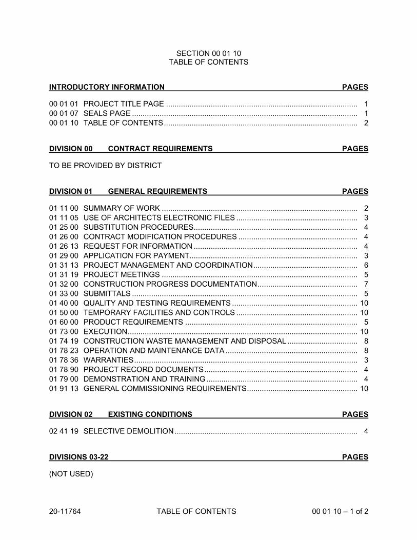
20-11764 TABLE OF CONTENTS 00 01 10 – 1 of 2
SECTION 00 01 10 TABLE OF CONTENTS
INTRODUCTORY INFORMATION PAGES
00 01 01 PROJECT TITLE PAGE .......................................................................................... 1
00 01 07 SEALS PAGE .......................................................................................................... 1
00 01 10 TABLE OF CONTENTS ........................................................................................... 2
DIVISION 00 CONTRACT REQUIREMENTS PAGES
TO BE PROVIDED BY DISTRICT
DIVISION 01 GENERAL REQUIREMENTS PAGES
01 11 00 SUMMARY OF WORK ............................................................................................ 2
01 11 05 USE OF ARCHITECTS ELECTRONIC FILES ......................................................... 3
01 25 00 SUBSTITUTION PROCEDURES ............................................................................. 4
01 26 00 CONTRACT MODIFICATION PROCEDURES ........................................................ 4
01 26 13 REQUEST FOR INFORMATION ............................................................................. 4
01 29 00 APPLICATION FOR PAYMENT............................................................................... 3
01 31 13 PROJECT MANAGEMENT AND COORDINATION ................................................. 6
01 31 19 PROJECT MEETINGS ............................................................................................ 5
01 32 00 CONSTRUCTION PROGRESS DOCUMENTATION ............................................... 7
01 33 00 SUBMITTALS .......................................................................................................... 5
01 40 00 QUALITY AND TESTING REQUIREMENTS ........................................................... 10
01 50 00 TEMPORARY FACILITIES AND CONTROLS ......................................................... 10
01 60 00 PRODUCT REQUIREMENTS ................................................................................. 5
01 73 00 EXECUTION ............................................................................................................ 10
01 74 19 CONSTRUCTION WASTE MANAGEMENT AND DISPOSAL ................................. 8
01 78 23 OPERATION AND MAINTENANCE DATA .............................................................. 8
01 78 36 WARRANTIES ......................................................................................................... 3
01 78 90 PROJECT RECORD DOCUMENTS ........................................................................ 4
01 79 00 DEMONSTRATION AND TRAINING ....................................................................... 4
01 91 13 GENERAL COMMISSIONING REQUIREMENTS .................................................... 10
DIVISION 02 EXISTING CONDITIONS PAGES
02 41 19 SELECTIVE DEMOLITION ...................................................................................... 4
DIVISIONS 03-22 PAGES
(NOT USED)

20-11764 TABLE OF CONTENTS 00 01 10 – 2 of 2
DIVISION 23 MECHANICAL/PLUMBING PAGES
23 05 00 COMMON WORK RESULTS FOR HVAC ............................................................... 7
23 05 13 COMMON MOTOR REQUIREMENTS FOR HVAC EQUIPMENT ........................... 3
23 05 23 GENERAL-DUTY VALVES FOR HVAC PIPING………………………………………..12
23 05 29 HANGERS AND SUPPORTS FOR HVAC PIPING AND EQUIPMENT .................... 7
23 05 53 IDENTIFICATION FOR HVAC PIPING AND EQUIPMENT ...................................... 4
23 05 93 TESTING, ADJUSTING, AND BALANCING FOR HVAC ......................................... 10
23 07 00 HVAC INSULATION ................................................................................................ 17
23 21 13 HYDRONIC PIPING ................................................................................................. 13
23 21 23 HYDRONIC PUMPS ................................................................................................ 6
23 64 23 SCROLL WATER CHILLERS .................................................................................. 11
DIVISION 25 INTEGRATED AUTOMATION PAGES
25 50 00 DIRECT DIGITAL CONTROL AND ENERGY MANAGEMENT SYSTEM ................ 15
DIVISION 26 ELECTRICAL PAGES
26 00 00 SUMMARY OF ELECTRICAL WORK ...................................................................... 4
26 01 00 GENERAL CONDITIONS FOR ELECTRICAL WORK ............................................. 9
26 05 00 BASIC ELECTRICAL MATERIALS AND METHODS………………………………......19
26 05 26 GROUNDING .......................................................................................................... 6
26 95 00 ELECTRICAL ACCEPTANCE TESTS ..................................................................... 7
DIVISIONS 27-33 PAGES
(NOT USED)
END OF SECTION

20-11764 SUMMARY OF WORK 01 11 00 - 1 of 2
SECTION 01 11 00 SUMMARY OF WORK
PART 1 - GENERAL
1.1 RELATED DOCUMENTS
A. Drawings and general provisions of the Contract, including General and Supplementary Conditions and other Division 01 Specification Sections, apply to this Section.
1.2 WORK COVERED BY CONTRACT DOCUMENTS
A. Work includes the replacement of the existing air-cooled chiller system that serves the Data Center at the District Office, located at 1450 Herndon Avenue, Clovis, California for the Clovis Unified School District as Owner.
1. Summary of construction activities include, but are not necessarily limited to:
a. Removal of existing air-cooled chillers, free cooling modules, pumps, tanks, and associated exterior chilled water piping.
b. Installation of new air-cooled chillers, pumps, tanks and exterior chilled water piping. Re-use existing concrete pad. Re-use existing pipe supports as available.
2. The description of work above is not all-inclusive and is solely provided as a summary for the convenience of the Contractor; refer to Drawing and Specifications for extent of work.
B. Contract Documents were prepared for the Project by Teter LLP, 7535 North Palm Street, Suite 201, Fresno, CA 93711.
1.3 RELATED REQUIREMENTS
A. Related requirements include, but are not necessarily limited to:
1. Division 00 Specification Section 00100 “Instructions to Bidders”. 2. Division 00 Specification Section 00300 “Bid Proposal Form”. 3. Division 00 Specification Section 00500 “Agreement Between Owner and
Contractor”. 4. Division 00 Specification Section 00700 “General Conditions”.
1.4 CONTRACTOR USE OF PREMISES
A. Use of the Site: Limit use of the premises to immediate area around the construction site and in other areas affected by the project work. Confine operations to immediate area around the buildings. Do not disturb portions of the site or building beyond the areas in which the Work is indicated as required.

20-11764 SUMMARY OF WORK 01 11 00 - 2 of 2
1. Driveways and Entrances: Vehicle access shall be off North Locan Avenue, keep driveways and entrances serving the premises clears and available to the Owner, the Owner’s employees, and emergency vehicles at all times. Do not use these areas for parking or storage of materials. Schedule deliveries to minimize space and time requirements for storage of materials and equipment on-site.
B. Owner’s use of existing buildings: Owner will use existing buildings surrounding the work area. Contractor shall be responsible for the installation of a perimeter fence and gates to restrict access to the area and keep elementary school age children away from the work. Take precautions as necessary to protect the buildings and its occupants during the construction period.
C. Assume full responsibility of protection and safekeeping of Contractor’s and Owner’s materials stored on premises. Coordination with Inspector the location of materials stored on premises. Provide barricades, barriers and enclosures as required to ensure student and faculty safety from material stored on premises.
D. Move any stored products which interfere with operations of Owner.
E. Obtain and pay for use of additional storage or work areas needed for operations.
F. Lock automotive type vehicles, such as passenger cars and trucks and other mechanized or motorized construction equipment, when parked and unattended, so as to prevent unauthorized use. Do not leave such vehicles or equipment unattended with the motor running or the ignition key in place.
G. Personal vehicles are not to be parked on site. Vehicles shall be parked in public right-of-way of North Locan Avenue as allowed by the City of Clovis.
1.5 OWNER OCCUPANCY AND ACCEPTANCE OF THE WORK
A. The Architect will prepare a Certificate of Substantial Completion for the Work prior to Owner occupancy and acceptance of the work.
END OF SECTION

20-11764 USE OF ARCHITECTS ELECTRONIC FILES 01 11 05 - 1 of 3
SECTION 01 11 05 USE OF ARCHITECTS ELECTRONIC FILES
PART 1 - GENERAL
1.1 RELATED DOCUMENTS
A. Drawings and general provisions of the Contract, including General and Supplementary Conditions and other Division 01 Specification Sections, apply to this Section.
1.2 SUMMARY
A. Section includes Administrative and procedural requirements for use of Architect’s electronic files.
B. Related Sections:
1. Division 01 Section “Project Management and Coordination.” 2. Division 01 Section “Submittal Procedures.” 3. Division 01 Section “Project Record Drawings.”
1.3 USE OF ARCHITECT’S ELECTRONIC FILES
A. Architect may make available to Contractor digital data files of Architect’s Drawings for use in preparing shop drawings, coordination drawings, and project record drawings.
1. Architect makes no representations as to the accuracy or completeness of digital data files as they relate to Drawings.
2. Files will be supplied on a CD ROM diskette, DWG format, which shall be returned to the Architect at the end of the Project with the Project Close-out Documents.
3. The cost of the CD ROM shall be as indicated on the “ELECTRONIC DATA FILE DISTRIBUTION WAIVER OF LIABILITY FORM” included at the end of this Specification Section. The cost shall be paid by direct payment to the Architect and shall be attached to the Waiver of Liability Form at the time of request.
B. Contractor, Subcontractors, and Suppliers of this Project shall jointly execute a waiver of Liability for each use of the Architects electronic files and shall be responsible for the use of electronic files.
1. Liability Form: “ELECTRONIC DATA FILE DISTRIBUTION WAIVER OF LIABILITY FORM” included at the end of this Specification Section.
C. The use of the electronic files shall only be used for this Project and for the identified purposes noted on the “ELECTRONIC DATA FILE DISTRIBUTION WAIVER OF LIABILITY FORM.” The CD ROM or any files contained on it shall not be duplicated without written permission of the Architect.

20-11764 USE OF ARCHITECTS ELECTRONIC FILES 01 11 05 - 2 of 3
PART 2 - PRODUCTS (Not Used)
PART 3 - EXECUTION (Not Used)
END OF SECTION
(Electronic Data File Distribution Waiver of Liability included on the following page)

20-11764 USE OF ARCHITECTS ELECTRONIC FILES 01 11 05 - 3 of 3
ELECTRONIC DATA FILE DISTRIBUTION WAIVER OF LIABILITY TETER, LLP 7535 North Palm, Suite 201 Fresno, California 93711 Project: _____________________________________________________________________ Intended Use: ________________________________________________________________ Any electronic data, files or information provided under this Agreement are the property of the above listed Professionals and consultants (Team). It is understood and agreed that the information contained in these electronic data file shall not be copied or duplicated for any use other than the project for which they were created. It is understood by the undersigned that compatibility of this electronic media with other systems is not guaranteed, and conversion to other systems is done at the user’s own risk. The user hereby agrees and recognizes that designs, plans and data stored on electronic media including, but not limited to, computer disk and magnetic tape, may be subject to undetectable alteration and/or uncontrollable deterioration. It is agreed by the undersigned that the Team shall not be liable for the completeness or accuracy of any material provided on electronic media. The undersigned agrees to defend, hold harmless and indemnify the Team and its officers, directors, employees, agents and consultants for any and all claims, losses, costs or damage whatsoever arising out of, resulting from, or in any way related to the use of electronic data files provided hereunder, whether that use is authorized or unauthorized. The user further agrees to defend, indemnify and hold harmless the Team its officers, directors, employees, agents and consultants from any and all claims, damages, losses, expenses and injuries arising out of the modification of the electronic data files by the user or by anyone obtaining said files through or from the user. The Team bears no responsibility for the information in the electronic data files once it leaves the offices of TETER, LLP. The undersigned understands that the electronic data files is subject to applicable copyright laws of the United States and agrees to be bound by same. Upon our receipt of this agreement duly executed by an Officer of your firm you may request the Data files on CD for a fee of $200.
Name (Print/Sign): _________________________________________________ Date: ____________
Firm: ___________________________________________________________ __________________
Phone and email: _________________________________________________ __________________
Name (Print/Sign): _________________________________________________ Date: ____________
Firm: ___________________________________________________________ __________________
Phone and email: _________________________________________________ __________________
Name (Print/Sign): _________________________________________________ Date: ____________
Firm: ___________________________________________________________ __________________
Phone and email: _________________________________________________ __________________

20-11764 SUBSTITUTION PROCEDURES 01 25 00 - 1 of 4
SECTION 01 25 00 SUBSTITUTION PROCEDURES
PART 1 - GENERAL
1.1 RELATED DOCUMENTS
A. Drawings and general provisions of the Contract, including General and Supplementary Conditions and other Division 01 Specification Sections, apply to this Section.
1.2 SUMMARY
A. Section includes administrative and procedural requirements for substitutions.
B. Related Sections:
1. Division 00 Section “Instructions to Bidders” and other Division 00 Sections as applicable to substitution requests prior to submission of bids.
2. Division 01 Section “Contract Modification Procedures” for changes to DSA approved Construction Documents.”
3. Division 01 Section "Product Requirements" for requirements for submitting comparable product submittals for products by listed manufacturers.
4. Divisions 02 through 33 Sections for specific requirements and limitations for substitutions.
1.3 DEFINITIONS
A. Substitutions: Changes in products, materials, equipment, and methods of construction from those required by the Contract Documents and proposed by Contractor.
1. Substitutions for Cause: Changes proposed by Contractor that are required due to changed Project conditions, such as unavailability of product, regulatory changes, or unavailability of required warranty terms.
2. Substitutions for Convenience: Changes proposed by Contractor that are not required in order to meet other Project requirements but may offer advantage to the Owner.
1.4 SUBMITTALS
A. Substitution Requests: Submit four (4) paper copies of each request for consideration. Identify product or fabrication or installation method to be replaced. Include Specification Section number and title and Drawing numbers and titles.
1. Substitution Request Form: Use form provided at the end of this Section.

20-11764 SUBSTITUTION PROCEDURES 01 25 00 - 2 of 4
2. Documentation: Show compliance with requirements for substitutions and the following, as applicable:
a. Statement indicating why specified product or fabrication or installation cannot be provided, if applicable.
b. Coordination information, including a list of changes or modifications needed to other parts of the Work and to construction performed by Owner and separate contractors that will be necessary to accommodate proposed substitution.
c. Detailed comparison of significant qualities of proposed substitution with those of the Work specified. Include annotated copy of applicable specification section. Significant qualities may include attributes such as performance, weight, size, durability, visual effect, sustainable design characteristics, warranties, and specific features and requirements indicated. Indicate deviations, if any, from the Work specified.
d. Product Data, including drawings and descriptions of products and fabrication and installation procedures.
e. Samples, where applicable or requested. f. Certificates and qualification data, where applicable or requested. g. List of similar installations for completed projects with project names and
addresses and names and addresses of architects and owners. h. Material test reports from a qualified testing agency indicating and
interpreting test results for compliance with requirements indicated. i. Research reports evidencing compliance with building code in effect for
Project, from ICC-ES. j. Detailed comparison of Contractor's construction schedule using proposed
substitution with products specified for the Work, including effect on the overall Contract Time. If specified product or method of construction cannot be provided within the Contract Time, include letter from manufacturer, on manufacturer's letterhead, stating date of receipt of purchase order, lack of availability, or delays in delivery.
k. Cost information, including a proposal of change, if any, in the Contract Sum.
l. Contractor's certification that proposed substitution complies with requirements in the Contract Documents except as indicated in substitution request, is compatible with related materials, and is appropriate for applications indicated.
m. Contractor's waiver of rights to additional payment or time that may subsequently become necessary because of failure of proposed substitution to produce indicated results.
3. Architect's Action: If necessary, Architect will request additional information or documentation for evaluation within 7 days of receipt of a request for substitution. Architect will notify Contractor of acceptance or rejection of proposed substitution within 15 days of receipt of request, or 7 days of receipt of additional information or documentation, whichever is later.
a. Forms of Acceptance:
1) Substitutions Prior to Bid: Addenda will be issued for substitutions accepted prior to bid.

20-11764 SUBSTITUTION PROCEDURES 01 25 00 - 3 of 4
2) Substitutions After Award of Contract: Change Order, Construction Change Directive, or Architect's Supplemental Instructions for minor changes in the Work.
b. Use product specified if Architect does not issue a decision on use of a proposed substitution within time allocated.
1.5 QUALITY ASSURANCE
A. Compatibility of Substitutions: Investigate and document compatibility of proposed substitution with related products and materials. Engage qualified testing agency to perform compatibility tests recommended by manufacturers.
1.6 PROCEDURES
A. Coordination: Revise or adjust affected work as necessary to integrate work of the approved substitutions.
PART 2 - PRODUCTS
2.1 SUBSTITUTIONS
A. Request for Substitutions shall be submitted in accordance with Article 30. SUBSTITUTIONS, of the General Conditions for General Contract (Version: 4/2012)
PART 3 - EXECUTION (Not Used)
END OF SECTION
(Substitution Request Form included on the following page)

20-11764 SUBSTITUTION PROCEDURES 01 25 00 - 4 of 4
SUBSTITUTION REQUEST FORM FOR: District Office Chiller Replacement – Clovis Unified School District We hereby submit for your consideration the following product instead of the specified item for the above project: SECTION PARAGRAPH SPECIFIED ITEM ________________________________ __________________________________ __________________________________ Proposed Substitution: _______________________________________________________________________________________ Attach complete technical data, including laboratory tests, if applicable. Include complete information on changes to Drawings and/or Specifications which proposed substitution will require for its proposed installation. Fill in the blanks below: A. Does the substitution affect dimension on Drawings: __________________________________________________________________________________________________ B. Will the undersigned pay for changes to the building design, including engineering and detailing costs caused by the requested substitution? __________________________________________________________________________________________________ C. What affect does substitution have on other trades? __________________________________________________________________________________________________ D. Difference between proposed substitution and specified item? __________________________________________________________________________________________________ E. Manufacturer's guarantees of the proposed and specified items are: ________ Same ________ Different (explain on attachment) F. Cost difference between proposed substitution and specified item - savings to Owner? __________________________________________________________________________________________________ The undersigned states that the function, appearance and quality are equivalent or superior to the specified item and will be at no additional cost to the Owner. Submitted to the Architect by: Signature: ______________________________________ For Use by Design Consultant Firm: ______________________________________ Accepted ________ Accepted as Noted ________ Address: ______________________________________ Not Accepted ________ Received Too Late ________ ______________________________________ Date: ______________________________________ By: _________________________________________ Telephone: ______________________________________ Date: _________________________________________ Remarks: ______________________________________________________________________________________________

20-11764 CONTRACT MODIFICATION PROCEDURES 01 26 00 - 1 of 4
SECTION 01 26 00 CONTRACT MODIFICATION PROCEDURES
PART 1 - GENERAL
1.1 RELATED DOCUMENTS
A. Drawings and general provisions of the Contract, including General and Supplementary Conditions and other Division 01 Specification Sections, apply to this Section.
1.2 SUMMARY
A. Section includes administrative and procedural requirements for handling and processing Contract modifications.
B. Related Requirements:
1. Division 00 Sections as applicable to contract requirements and modifications. 2. Division 01 Section "Substitution Procedures" for administrative procedures for
handling requests for substitutions made after the Contract award.
1.3 DEFINITIONS
A. Contract Modification: A change to the Contract Agreement between the Owner and the Contractor affecting the Contract Documents, the Contract Time, and/or the Contract Amount.
B. Change Order (CO): A document defining Contract Modifications. Change Orders shall be issued by the Architect and signed by the Architect, Owner, and Contractor.
C. Architect’s Change Directive (ACD): A form utilized by the Architect directing the Contractor to proceed with a change. ACD’s shall be issued by the Architect and shall be signed by the Contractor, Owner, and Architect.
D. Architect’s Supplemental Instruction (ASI): For minor changes in the Work not involving adjustment to the Contract Sum or the Contract Time, the Architect will issue Architect’s Supplemental Instructions authorizing such changes.
E. Changes to the Construction Documents: Revisions, deletions, additions, and/or product substitutions to the final approved construction documents.
1.4 CHANGES TO THE CONSTRUCTION DOCUMENTS, GOVERNING AGENCY APPROVAL
A. Governing Agency Review and Approval: Changes to the Construction Documents are subject to review and approval by the authorities having jurisdiction.

20-11764 CONTRACT MODIFICATION PROCEDURES 01 26 00 - 2 of 4
1.5 ARCHITECT’S SUPPLEMENTAL INSTRUCTION
A. Architect’s Supplemental Instruction (ASI): For minor changes in the Work not involving adjustment to the Contract Sum or the Contract Time, the Architect will issue Architect’s Supplemental Instructions authorizing such changes.
1. Architect’s Supplemental Instructions affecting changes to the Construction Documents shall be subject to governing agency review and approval.
2. Contractor’s Response:
a. Contractor shall perform the work indicated in the Architect’s Supplemental Instruction without adjustment to the Contract Sum or the Contract Time.
b. If the Contractor determines that an adjustment to the Contract Sum or the Contract Time is necessary due to the Architect’s Supplemental Instruction, the Contractor shall respond to the Architect’s Supplemental Instruction as if it were an Architect/Owner initiated Proposal Request.
1.6 ARCHITECT’S CHANGE DIRECTIVE
A. Architect’s Change Directive (ACD): Architect may issue an Architect’s Change Directive on Architect’s standard form to instruct Contractor to proceed with a change in the Work for subsequent inclusion in a Change Order.
1. Architect’s Change Directive contains a complete description of change in the Work. It also designates method to be followed to determine change in the Contract Sum or the Contract Time.
2. Architect’s Change Directives affecting structural, fire/life safety, and/or access compliance shall be accompanied by appropriate approved Authority Having Jurisdiction documentation.
3. Architect’s Change Directive shall be issued by the Architect and shall be signed by the Architect, Owner, and Contractor.
B. Documentation by Contractor: Maintain detailed records on a time and material basis of work required by the Architect’s Change Directive.
1. After completion of change, submit an itemized account and supporting data necessary to substantiate cost and time adjustments to the Contract.
1.7 PROPOSAL REQUESTS
A. General: Proposal Requests allow the Contractor to respond to proposed changes in the Work that involve an adjustment to the Contract Sum or the Contract Time. Proposal Requests are not instructions to stop work in progress or execute proposed changes. Upon Owner's approval of a Proposal Request, Architect will issue a Change Order instructing the Contractor to proceed with the proposed changes (Refer to Part 1 Article “Change Order Procedures”).
B. Architect/Owner-Initiated Proposal Requests: Architect will issue a detailed description of proposed changes in the Work that may require adjustment to the Contract Sum or

20-11764 CONTRACT MODIFICATION PROCEDURES 01 26 00 - 3 of 4
the Contract Time. If necessary, the description will include supplemental or revised Drawings and Specifications.
1. Contractor’s Response: Within time specified in Proposal Request, or not more than 7 days after receipt of Proposal Request when not otherwise specified, submit a quotation estimating cost adjustments to the Contract Sum and the Contract Time necessary to execute the change.
a. Include a list of quantities of products required or eliminated and unit costs, with total amount of purchases and credits to be made. If requested, furnish survey data to substantiate quantities.
b. Indicate applicable taxes, delivery charges, equipment rental, and amounts of trade discounts.
c. Include costs of labor and supervision directly attributable to the change. d. Include an updated Contractor's construction schedule that indicates the
effect of the change, including, but not limited to, changes in activity duration, start and finish times, and activity relationship. Use available total float before requesting an extension of the Contract Time.
e. Quotation Form: Use forms acceptable to Architect.
C. Contractor-Initiated Proposals: If conditions require modifications to the Contract, Contractor may initiate a claim by submitting a request for a change to Architect.
1. Include a statement outlining reasons for the change and the effect of the change on the Work. Provide a complete description of the proposed change. Indicate the effect of the proposed change on the Contract Sum and the Contract Time.
2. Include a list of quantities of products required or eliminated and unit costs, with total amount of purchases and credits to be made. If requested, furnish survey data to substantiate quantities.
3. Indicate applicable taxes, delivery charges, equipment rental, and amounts of trade discounts.
4. Include costs of labor and supervision directly attributable to the change. 5. Include an updated Contractor's construction schedule that indicates the effect of
the change, including, but not limited to, changes in activity duration, start and finish times, and activity relationship. Use available total float before requesting an extension of the Contract Time.
6. Comply with requirements in Division 01 Section "Substitution Procedures" if the proposed change requires substitution of one product or system for product or system specified.
7. Proposal Request Form: Use form acceptable to Architect.
D. Architect’s Response: Within 7 days after receipt of Contractor’s response to Architect/Owner initiated Proposal Request or Contractor’s Proposal, Architect will:
1. Issue a Change Order for accepted proposals. 2. Notify the Contractor of unaccepted proposals. 3. Issue an Architect’s Change Directive where changes are necessary for the
progress of the Work and changes to the Contract Sum and the Contract Time are in dispute.

20-11764 CONTRACT MODIFICATION PROCEDURES 01 26 00 - 4 of 4
1.8 CHANGE ORDER PROCEDURES
A. On Owner's approval of a Proposal Request, Architect will issue a Change Order for signatures of Owner and Contractor on form provided by Architect.
1. Change Orders affecting changes to the Construction Documents shall be subject to governing agency review and approval.
PART 2 - PRODUCTS (Not Used)
PART 3 - EXECUTION (Not Used)
END OF SECTION

20-11764 REQUEST FOR INFORMATION 01 26 13 - 1 of 4
SECTION 01 26 13 REQUEST FOR INFORMATION
PART 1 - GENERAL
1.1 RELATED DOCUMENTS
A. Drawings and general provisions of the Contract, including General and Supplementary Conditions and other Division 01 Specification Sections, apply to this Section.
1.2 SUMMARY
A. Section includes administrative and procedural provisions for preparation, submittal and response to Contractor’s Request for Information (RFI’s) during construction of project.
B. Related Sections:
1. General Conditions of the Contract.
1.3 DEFINITIONS
A. PDF, Portable Document Format: An open standard file format licensed by Adobe Systems used for representing documents in a device-independent and display resolution-independent fixed-layout document format.
B. RFI, Request for Information: Request from Contractor seeking information required by or clarification of the Contract Documents.
1.2 SUBMITTAL PROCEDURES
A. General Submittal Procedure Requirements: Submit RFI’s via email as PDF electronic files.
1. RFI Form: Use RFI form included at end of this Section or form acceptable to Architect. Upon request from the Contractor, the form at the end of this section will be made available in WORD format from the Architect.
2. Attachments: Attachments shall be in PDF electronic file format.

20-11764 REQUEST FOR INFORMATION 01 26 13 - 2 of 4
1.3 REQUESTS FOR INFORMATION (RFIs)
A. General: Immediately on discovery of the need for additional information or interpretation of the Contract Documents, Contractor shall prepare and submit an RFI in the form specified.
1. Architect will return RFIs submitted to Architect by other entities controlled by Contractor with no response.
2. Coordinate and submit RFIs in a prompt manner so as to avoid delays in Contractor's work or work of subcontractors.
B. Content of the RFI: Include a detailed, legible description of item needing information or interpretation and the following:
1. Project name. 2. Project number. 3. Date. 4. Name of Contractor. 5. Name of Architect 6. RFI number, numbered sequentially. 7. RFI subject. 8. Specification Section number and title and related paragraphs, as appropriate. 9. Drawing number and detail references, as appropriate. 10. Field dimensions and conditions, as appropriate. 11. Contractor's suggested resolution. If Contractor's solution(s) impacts the
Contract Time or the Contract Sum, Contractor shall state impact in the RFI. 12. Contractor's signature. 13. Attachments: Include sketches, descriptions, measurements, photos, Product
Data, Shop Drawings, coordination drawings, and other information necessary to fully describe items needing interpretation.
a. Include dimensions, thicknesses, structural grid references, and details of affected materials, assemblies, and attachments on attached sketches.
C. Architect's Action: Architect will review each RFI, determine action required, and respond. Allow 10 working days for Architect's response for each RFI. RFIs received by Architect after 1:00 p.m. will be considered as received the following working day.
1. The following RFIs will be returned without action:
a. Requests for approval of submittals. b. Requests for approval of substitutions. c. Requests for approval of Contractor’s means and methods. d. Requests for coordination information already indicated in the Contract
Documents. e. Requests for adjustments in the Contract Time or the Contract Sum. f. Requests for interpretation of Architect's actions on submittals. g. Incomplete RFIs or inaccurately prepared RFIs.

20-11764 REQUEST FOR INFORMATION 01 26 13 - 3 of 4
2. Architect's action may include a request for additional information, in which case Architect's time for response will date from time of receipt of additional information.
3. Architect's action on RFIs that may result in a change to the Contract Time or the Contract Sum may be eligible for Contractor to submit Change Proposal according to Division 01 Section "Contract Modification Procedures."
a. If Contractor believes the RFI response warrants change in the Contract Time or the Contract Sum, notify Architect in writing within 10 days of receipt of the RFI response.
4. Distribution: One electronic copy of each completed RFI review shall be distributed by the Architect to the Contractor and the Owner.
D. RFI Log: Prepare, maintain, and submit a tabular log of RFIs organized by the sequential RFI number. Submit log weekly unless otherwise directed in writing by Architect. Include the following:
1. Project name. 2. Name and address of Contractor. 3. Name and address of Architect. 4. RFI number including RFIs that were returned without action or withdrawn. 5. RFI description. 6. Date the RFI was submitted. 7. Date Architect's response was received.
E. On receipt of Architect's action, update the RFI log and immediately distribute the RFI response to affected parties. Review response and notify Architect within 7 days if Contractor disagrees with response.
F. Contractor’s Expense for RFI’s: Architect will review and respond to legitimate RFI’s at no additional cost to the Contractor. RFI’s determined by the Architect to be flagrant or unnecessary will have the expense for the Architect’s time paid by the Owner with the amount being deducted from the Contract Sum. The expense will be based on an hourly rate in accordance with the Architect’s standard hourly rate schedule in effect at the time the work is performed with a minimum of one hour for each flagrant or unnecessary RFI.
PART 2 - PRODUCTS (Not Used)
PART 3 - EXECUTION (Not Used)
END OF SECTION
(REQUEST FOR INFORMATION form included on the following page)
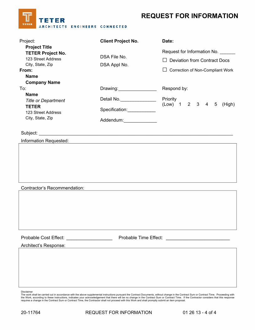
20-11764 REQUEST FOR INFORMATION 01 26 13 - 4 of 4
REQUEST FOR INFORMATION
Project:
Project Title
TETER Project No.
123 Street Address
City, State, Zip
Client Project No.
DSA File No.
DSA Appl No.
Date: Request for Information No. ______
□ Deviation from Contract Docs
□ Correction of Non-Compliant Work
From:
Name
Company Name
To:
Name
Title or Department
TETER
123 Street Address
City, State, Zip
Drawing:_______________ Detail No.______________ Specification:___________ Addendum:_____________
Respond by: Priority (Low) 1 2 3 4 5 (High)
Subject: ____________________________________________________________________________
Information Requested:
Contractor’s Recommendation:
Probable Cost Effect: __________________ Probable Time Effect: _________________________
Architect’s Response:
Disclaimer The work shall be carried out in accordance with the above supplemental instructions pursuant the Contract Documents, without change in the Contract Sum or Contract Time. Proceeding with the Work, according to these instructions, indicates your acknowledgement that there will be no change in the Contract Sum or Contract Time. If the Contractor considers that this response requires a change in the Contract Sum or Contract Time, the Contractor shall not proceed with this Work and shall promptly submit an item proposal.

20-11764 APPLICATION FOR PAYMENT 01 29 00 – 1 of 3
SECTION 01 29 00 APPLICATION FOR PAYMENT
PART 1 - GENERAL
1.1 RELATED DOCUMENTS
A. Drawings and general provisions of the Contract, including General and Supplementary Conditions and other Division 01 Specification Sections, apply to this Section.
1.2 SUMMARY
A. This section includes the administrative and procedural requirements for the Schedule of Values:
1. Provide a Schedule of Values (Detailed Cost Allocation breakdown) assigned to the various portions of the Work.
2. Upon request by Architect, support values given with data that will substantiate their correctness.
3. Use of the Schedule of Values will be the basis for reviewing the Contractors Application for Payment. No payment will be made without the Architect’s review of the approved Schedule of Values.
4. The Schedule of Values shall cover and be cross-referenced to the activities shown on the Construction Schedule.
B. Related Sections: The following Sections contain requirements that relate to this Section:
1. Drawings and general provisions of the Contract, including General and Special (or Supplementary) Conditions and Division 1 Specification Sections, apply to this Section.
1.3 1.2 SUBMITTALS
A. Submit according to Specification Section Submittal Procedures.
1. General Requirements:
a. Submit Schedule of Values on form provided by the General Contractor:
1) Within 10 days of Notice to Proceed. 2) Owner will review Schedule. 3) Revise Schedule as required by Owner. 4) No review of an Application for Payment will be undertaken without an
approved Schedule of Values.

20-11764 APPLICATION FOR PAYMENT 01 29 00 – 2 of 3
2. Form of Hard Copy Schedule:
a. General: Use CBS activities as a format outline for listing division of the Work for the Project as provided by the General Contractor.
b. Project Site Costs: Detailed Cost Allocation breakdown indicating trade/activity including labor, equipment, and materials for the Project Site that is compatible with the Contractor's Means and Methods for construction. Provide separate break down for material and labor when appropriate for material delivery. Overhead, profit and bonding costs are to be detailed separately and not included with the labor and material costs.
1) When the project site is of sufficient size to warrant, break the site costs down into areas compatible with the Contractor's Means and Methods for construction sequences.
c. Building Costs: Detailed Cost Allocation breakdown indicating trade/activity including labor, equipment, and materials for the Project per Building that is compatible with the Contractor's Means and Methods for it's construction sequences. Provide separate break down for material and labor when appropriate for material delivery. Overhead, profit and bonding costs are to be detailed separately and not included with the labor and material costs.
3. Content of Schedule:
a. Itemize separate line item costs for the Project for each of the following:
1) DIVISION 00 through DIVISION 01 General Cost Items:
a) Performance Bond and Labor and Material Bond. b) Field Supervision and Layout. c) Temporary Utilities, Controls and Buildings.
2) DIVISION 02 through DIVISION 32 Cost Items:
a) Cost for Work required by each Section (labor, equipment, and materials only).
b) Costs for a portion of the Work required by a Section (labor, equipment, and materials only) when required for proper decision of payment or by this specification.
c) Specific itemized costs (labor, equipment, and materials only) in the stated unit of measurement shall be included, but not limited to, the following sections:
b. Breakdown costs into:
1) Delivered cost of products(s) including tax. 2) Installed cost excluding overhead and profit. 3) Add Contractor’s and subcontractor’s overhead and profit costs after
subtotal and provide a final total.
c. Sum of total costs listed in Schedule shall equal total Contract Sum.

20-11764 APPLICATION FOR PAYMENT 01 29 00 – 3 of 3
PART 2 - PRODUCTS
(NOT APPLICABLE)
PART 3 - EXECUTION
(NOT APPLICABLE)
END OF SECTION
20-11764 PROJECT MANAGEMENT AND COORDINATION 01 31 13 - 1 of 6
SECTION 01 31 13 PROJECT MANAGEMENT AND COORDINATION
PART 1 - GENERAL
1.1 RELATED DOCUMENTS
A. Drawings and general provisions of the Contract, including General and Supplementary Conditions and other Division 01 Specification Sections, apply to this Section.
1.2 SUMMARY
A. Section includes administrative provisions for coordinating construction operations on Project including, but not limited to, the following:
1. General project coordination procedures. 2. Administrative and supervisory personnel. 3. Coordination drawings.
B. Related Sections:
1. Division 01 Section "Construction Progress Documentation" for preparing and submitting Contractor's construction schedule.
2. Division 01 Section "Execution" for procedures for coordinating general installation and field-engineering services, including establishment of benchmarks and control points.
1.3 SUBMITTALS
A. List of Key Personnel Names: Within 14 calendar days of starting construction operations, submit a list of key personnel assignments, including superintendent and other personnel in attendance at Project site. Identify individuals and their duties and responsibilities; list addresses and telephone numbers, including home, office, and cellular telephone numbers and email addresses. Provide names, addresses, and telephone numbers of individuals assigned as alternates in the absence of individuals assigned to Project.
1. Post copies of list in project meeting room, in temporary field office, and by each temporary telephone. Keep list current at all times.

20-11764 PROJECT MANAGEMENT AND COORDINATION 01 31 13 - 2 of 6
B. Coordination Drawings:
1. Initial Submittal: Submit 3 printed copies of each coordination drawing for each condition where Coordination Drawings are required.
2. Project Closeout:
a. Submit 3 printed “Record” copies of each coordination drawing for each condition where Coordination Drawings are required.
b. Submit “Record” electronic coordination drawing files.
1.4 COORDINATION PROCEDURES
A. Coordination: Coordinate construction operations included in different Sections of the Specifications to ensure efficient and orderly installation of each part of the Work. Coordinate construction operations, included in different Sections, that depend on each other for proper installation, connection, and operation.
1. Schedule construction operations in sequence required to obtain the best results where installation of one part of the Work depends on installation of other components, before or after its own installation.
2. Coordinate installation of different components to ensure maximum performance and accessibility for required maintenance, service, and repair.
3. Make adequate provisions to accommodate items scheduled for later installation.
B. Prepare memoranda for distribution to each party involved, outlining special procedures required for coordination. Include such items as required notices, reports, and list of attendees at meetings.
1. Prepare similar memoranda for Owner and separate contractors if coordination of their Work is required.
C. Administrative Procedures: Coordinate scheduling and timing of required administrative procedures with other construction activities to avoid conflicts and to ensure orderly progress of the Work. Such administrative activities include, but are not limited to, the following:
1. Preparation of Contractor's construction schedule. 2. Preparation of the schedule of values. 3. Installation and removal of temporary facilities and controls. 4. Delivery and processing of submittals. 5. Progress meetings. 6. Preinstallation conferences. 7. Startup and adjustment of systems. 8. Project closeout activities.
20-11764 PROJECT MANAGEMENT AND COORDINATION 01 31 13 - 3 of 6
D. Conservation: Coordinate construction activities to ensure that operations are carried out with consideration given to conservation of energy, water, and materials. Coordinate use of temporary utilities to minimize waste.
1. Salvage materials and equipment involved in performance of, but not actually incorporated into, the Work. Refer to other Sections for disposition of salvaged materials that are designated as Owner's property.
PART 2 - PRODUCTS
2.1 COORDINATION DRAWINGS
A. Coordination Drawings, General: Prepare coordination drawings in accordance with requirements in individual Sections, where installation is not completely shown on Shop Drawings, where limited space availability necessitates coordination, or if coordination is required to facilitate integration of products and materials fabricated or installed by more than one entity. Coordination Drawings shall include the work of multiple trades on the same drawing. Prepare Coordination Drawings in addition to Shop Drawings required in individual Sections.
1. Content: Project-specific information, drawn accurately to a scale large enough to indicate and resolve conflicts. Do not base coordination drawings on standard printed data. Include the following information, as applicable:
a. Use applicable Drawings as a basis for preparation of coordination drawings. Prepare sections, elevations, and details as needed to describe relationship of various systems and components.
b. Coordinate the addition of trade-specific information to the coordination drawings by multiple contractors in a sequence that best provides for coordination of the information and resolution of conflicts between installed components before submitting for review.
c. Indicate functional and spatial relationships of components of architectural, structural, civil, mechanical, and electrical systems.
d. Indicate space requirements for routine maintenance and for anticipated replacement of components during the life of the installation.
e. Show location and size of access doors required for access to concealed dampers, valves, and other controls.
f. Indicate required installation sequences. g. Indicate dimensions shown on the Drawings. Specifically note dimensions
that appear to be in conflict with submitted equipment and minimum clearance requirements. Provide alternate sketches to Architect indicating proposed resolution of such conflicts. Minor dimension changes and difficult installations will not be considered changes to the Contract.

20-11764 PROJECT MANAGEMENT AND COORDINATION 01 31 13 - 4 of 6
B. Coordination Drawings, Required: Coordination drawings shall include plans, elevations, sections, and details of the Work for each trade as required to adequately represent the work. Clearly indicate and identify conflicts between components for review by Architect. Provide Coordination Drawings as follows:
1. Overhead Work and Work Above Finished Ceilings: Include subframing for support of ceiling and wall systems, conduit and piping runs, plumbing, mechanical, and electrical equipment, and related Work. Locate components to accommodate layout of light fixtures indicated on Drawings. Show the work of each trade including, but not limited to, pipe runs, mechanical ductwork, cable trays, conduit runs, and bracing and supports.
a. Indicate locations of all dampers, valves, cleanouts and other devices requiring human access for maintenance and repair. Where access panels are required, show locations and indicate size.
b. Show the height above finish floor each item, demonstrating sufficient space for installation and maintenance. Indicate sizes of ducts, piping and similar items.
c. Layout of work shall be done in such a manner to avoid conflicts between the work of different trades, finish ceiling heights, soffits, light fixtures or other finish work at ceilings and soffits.
d. Should unavoidable conflicts occur that affect finish ceiling and soffit heights, methods of installations, methods of construction or means of accessibility, the contractor shall clearly identify each location for review by the Architect.
2. Equipment Rooms and Outdoor Service Yards: Show work above and below grade including mechanical, plumbing, fire protection, fire alarm, and electrical equipment, and related supports, accessories, and utility connections. Include the following information:
a. Equipment: Show equipment and locations, utility connections, and working and service clearances.
b. Utilities: Show above and below grade utilities; indicate heights and below grade elevations, sizes of piping and conduit, dimensions between utilities and between utilities and other obstructions including concrete footings for other work. Show locations of all shut-off and isolation valves, cleanouts, filters, and other devices requiring human access for maintenance and repair.
c. Enclosures: Show limits of enclosure including walls, doors, fences, and gates; confirm door and gate access width for equipment.
d. Dimensions: Indicate dimensions as appropriate to insure adequate clearance will be provided for installation, service, and operation of equipment; include horizontal and vertical dimensions between utilities to insure clearance for installation of utilities. Include vertical dimension(s) of equipment and distances to overhead obstructions where applicable.

20-11764 PROJECT MANAGEMENT AND COORDINATION 01 31 13 - 5 of 6
3. Roof Mounted Equipment: Show equipment that will be located on the roof, include the following:
a. Equipment locations and horizontal distances between equipment. b. Locations of roof penetrations, sizes of penetrations, and indicate the
horizontal distance between penetrations and roof mounted equipment. c. Pipe and conduit runs including locations and type(s) of supports. d. Distance between all roof mounted equipment and roof drainage features.
Equipment shall be located so as to not obstruct roof drainage; provide at least 24 inches between equipment platforms and valleys formed by the intersection of roof planes and crickets.
4. Underground Site Utilities and Utilities Below Slabs on Grade within Building Areas: Where underground utilities cross other utilities, penetrate footings, underground structures or other obstructions; show the work that will be placed underground; include the following information:
a. Indicate types and sizes of utility piping and elevations below grade. b. Show footings and other underground structures; where unavoidable
conflicts occur between underground structures/footings and utilities, indicate depths below grade and clearly identify locations for sleeving for review by Architect.
C. Preparation: Prepare coordination drawings electronically using same digital data software program, version, and operating system as the Architect’s original Drawings (DWG files).
1. Submittal Format:
a. Electronic Format: Submit electronic drawing files using Portable Data File (PDF) format.
b. Printed Format: Submit plotted drawings on opaque bond paper not of at least 8.5 inches by 11 inches and not larger than 24 inches by 36 inches.
2. Architect will furnish Contractor digital data files of base drawings as appropriate for use in preparing coordination digital data files.
a. Architect makes no representations as to the accuracy or completeness of digital data files as they relate to the Drawings.
b. Digital Data Software Program: The Drawings are available in DWG format.
c. Contractor shall execute a data licensing agreement in the form of an Agreement form acceptable to the Owner and Architect.
D. Review: Architect will review coordination drawings to confirm that the Work is being coordinated, but not for the details of the coordination, which are the Contractor's responsibility. If the Architect determines that the coordination drawings are not being prepared in sufficient scope or detail, or are otherwise deficient, the Architect will so inform the Contractor, who shall make changes as directed and resubmit.

20-11764 PROJECT MANAGEMENT AND COORDINATION 01 31 13 - 6 of 6
PART 3 - EXECUTION
3.1 GENERAL COORDINATION PROVISIONS
A. Examination of Conditions: Require the Installer of each major component to examine both the substrate and conditions under which Work is to be performed. Do not proceed until unsatisfactory conditions have been corrected in an acceptable manner.
3.2 CLEANING AND PROTECTION
A. Clean and protect construction in progress and adjoining materials in place, during handling and installation. Apply protective covering where required to assure protection from damage or deterioration at Substantial Completion.
B. Clean and provide maintenance on completed construction as frequently as necessary through the remainder of the construction period.
C. Limiting Exposures: Supervise construction operations to assure that no part of the construction, completed or in progress, is subject to harmful, dangerous, damaging, or otherwise deleterious exposure during the construction period.
END OF SECTION

20-11764 PROJECT MEETINGS 01 31 19 - 1 of 5
SECTION 01 31 19 PROJECT MEETINGS
PART 1 - GENERAL
1.1 RELATED DOCUMENTS
A. Drawings and general provisions of the Contract, including General and Supplementary Conditions and other Division 01 Specification Sections, apply to this Section.
1.2 SUMMARY
A. Section includes administrative provisions for project meetings, including, but not limited to, the following:
1. Preconstruction conferences. 2. Preinstallation conferences. 3. Progress meetings. 4. Project Closeout Conference.
B. Related requirements include but are not limited to the following:
1. Division 01 Sections as applicable to project management.
1.3 PRECONSTRUCTION CONFERENCE
A. Preconstruction Conference: Schedule a preconstruction conference before starting construction at the project site, at a time convenient to the Owner, Inspector of Record, and the Architect, but no later than 14 days after execution of the Agreement. Hold the conference at the Project Site or another convenient location. Owner and Architect to conduct the meeting to review responsibilities and personnel assignments.
B. Attendees: Authorized representatives of the Owner, Architect, and their consultants; the Contractor and its superintendent shall attend the conference. Major subcontractors and other concerned parties shall be invited to attend the conference, but attendance is not mandatory. Participants at the conference shall be familiar with the Project and authorized to conclude matters relating to the Work.
C. Agenda: Discuss items of significance that could affect progress, including but not limited to the following:
1. Tentative construction schedule. 2. Critical work sequencing and long-lead items. 3. Designation of key personnel and their duties. 4. Lines of communication. 5. Procedures for processing field decisions and Change Orders. 6. Procedures for processing Applications for Payment.

20-11764 PROJECT MEETINGS 01 31 19 - 2 of 5
7. Procedures for RFI’s. 8. Procedures for testing and inspection. 9. Submittal procedures. 10. Sustainability requirements including construction waste management and
disposal. 11. Preparation of record documents. 12. Use of the premises. 13. Work restrictions and working hours. 14. Temporary facilities and controls. 15. Parking availability. 16. Office, work, and storage areas. 17. Equipment deliveries and priorities. 18. Safety procedures and first aid. 19. Security. 20. Housekeeping. 21. Owner’s alcohol, drug and tobacco policy.
D. Minutes: Contractor shall record significant discussions and agreements achieved. Distribute the meeting minutes to everyone concerned, including Owner, Inspector of Record, and Architect, within three days of the meeting.
1.4 PREINSTALLATION CONFERENCES
A. Preinstallation Conferences: Conduct a preinstallation conference at the Project Site before each construction activity that requires coordination with other construction.
B. Attendees: Installers and representatives of manufacturers and fabricators involved in or affected by the installation, and its coordination or integration with other materials and installations that have preceded or will follow, shall attend the meeting. Advise the Owner, Inspector of Record, and Architect of scheduled meeting dates.
C. Agenda: Review the progress of other construction activities and preparations for the particular activity under consideration at each preinstallation conference, including requirements for the following:
1. Contract Documents. 2. Options. 3. Related RFI’s, Proposal Requests, and Change Orders. 4. Purchases. 5. Deliveries. 6. Submittals. 7. Sustainability requirements. 8. Possible conflicts. 9. Compatibility problems. 10. Time schedules. 11. Weather limitations. 12. Manufacturer's written instructions. 13. Warranty requirements. 14. Compatibility of materials. 15. Acceptability of substrates.

20-11764 PROJECT MEETINGS 01 31 19 - 3 of 5
16. Temporary facilities. 17. Space and access limitations. 18. Regulations of authorities having jurisdiction. 19. Safety. 20. Testing and ionspecting requirements. 21. Required performance results. 22. Recording requirements. 23. Protection. 24. Record significant conference discussions, agreements, disagreements,
including corrective measures and actions. 25. Promptly distribute minutes of the meeting to each party present and to other
parties requiring information, including the Owner and the Architect. 26. Do not proceed with the installation if the conference cannot be successfully
concluded. Initiate whatever actions are necessary to resolve impediments to performance of Work and reconvene the conference at the earliest feasible date.
D. Minutes: Contractor shall record significant discussions and agreements achieved. Distribute the meeting minutes to everyone concerned, including Owner, Inspector of Record, and Architect, within three days of the meeting.
1.5 PROGRESS MEETINGS
A. Progress Meetings: Conduct progress meetings at the Project Site at regular intervals to be established by the Architect, Inspector of Record, Contractor, and Owner.
1. Coordinate dates of meetings with preparation of the payment request.
B. Attendees: In addition to representatives of the Owner and Architect, each subcontractor, supplier, and other entity concerned with current progress or involved in planning, coordination, or performance of future activities shall be represented at these meetings. All participants at the conference shall be familiar with the Project and authorized to conclude matters relating to the Work.
C. Agenda: Review and correct or approve minutes of the previous progress meeting. Review other items of significance that could affect progress. Include topics for discussion as appropriate to the status of the Project. Review proposed percentages of work completed for current months progress payment.
1. Contractor's Construction Schedule: Review progress since the last meeting. Determine whether each activity is on time, ahead of schedule, or behind schedule, in relation to Contractor's construction schedule. Determine how construction behind schedule will be expedited; secure commitments from parties involved to do so. Discuss whether schedule revisions are required to ensure that current and subsequent activities will be completed within the Contract Time.
2. Review the present and future needs of each entity present, including the following:
a. Interface requirements. b. Sequence of operation. c. Status of submittals.

20-11764 PROJECT MEETINGS 01 31 19 - 4 of 5
d. Status of Sustainability documentation. e. Deliveries. f. Off-site fabrication. g. Access. h. Site utilization. i. Temporary facilities and services. j. Status of correction of deficient items. k. Field observations. l. Status of RFI’s, Proposal Requests, and Change Orders. m. Progress cleaning. n. Quality and work standards. o. Documentation of information for payment requests. p. Request for Information
D. Minutes: Contractor shall record significant discussions and agreements achieved. Distribute the meeting minutes to everyone concerned, including Owner, Inspector of Record, and Architect, within three days of the meeting.
E. Schedule Updating: Revise the Contractor's Construction Schedule after each progress meeting where revisions to the schedule have been made or recognized. Issue the revised schedule to the Owner, the Architect, and all other parties involved in the project. Failure to revise and keep current the Contractor’s construction schedule may be grounds for returning Application for Payment unreviewed.
1.6 PROJECT CLOSEOUT CONFERENCE
A. Project Closeout Conference: Conduct a project closeout conference, at a time convenient to Owner and Architect, but not less than 90 days prior to the scheduled date of Substantial Completion. Conduct the conference to review requirements and responsibilities related to Project closeout.
B. Attendees: Authorized representatives of Owner, Architect and their consultants; Contractor and its superintendent. Participants at the meeting shall be familiar with Project and authorized to conclude matters relating to the Work.
C. Agenda: Discuss items of significance that could affect or delay Project closeout, including the following:
1. Preparation of record documents. 2. Procedures required prior to inspection for Substantial Completion and for final
inspection for acceptance. 3. Submittal of written warranties. 4. Requirements for completing Sustainability documentation. 5. Requirements for preparing operations and maintenance data. 6. Requirements for delivery of material samples, attic stock, and spare parts. 7. Requirements for demonstration and training. 8. Preparation of Contractor's punch list. 9. Procedures for processing Applications for Payment at Substantial Completion
and for final payment. 10. Submittal procedures.

20-11764 PROJECT MEETINGS 01 31 19 - 5 of 5
11. Responsibility for removing temporary facilities and controls.
D. Minutes: Contractor shall record significant discussions and agreements achieved. Distribute the meeting minutes to everyone concerned, including Owner, Inspector of Record, and Architect, within three days of the meeting.
PART 2 - PRODUCTS
(Not Used)
PART 3 - EXECUTION
(Not Used)
END OF SECTION

20-11764 CONSTRUCTION PROGRESS DOCUMENTATION 01 32 00 - 1 of 7
SECTION 01 32 00 CONSTRUCTION PROGRESS DOCUMENTATION
PART 1 - GENERAL
1.1 RELATED DOCUMENTS
A. Drawings and general provisions of the Contract, including General and Supplementary Conditions and other Division 01 Specification Sections, apply to this Section.
1.2 SUMMARY
A. Section includes administrative and procedural requirements for documenting the progress of construction during performance of the Work, including the following:
1. Contractor's construction schedule. 2. Special reports.
B. Related Sections include but are not limited to the following:
1. Division 01 Section "Submittal Procedures" for submitting schedules and reports. 2. Division 01 Section "Quality and Testing Requirements" for submitting a
schedule of tests and inspections.
1.3 DEFINITIONS
A. Activity: A discrete part of a project that can be identified for planning, scheduling, monitoring, and controlling the construction project. Activities included in a construction schedule consume time and resources.
1. Critical Activity: An activity on the critical path that must start and finish on the planned early start and finish times.
2. Predecessor Activity: An activity that precedes another activity in the network. 3. Successor Activity: An activity that follows another activity in the network.
B. CPM: Critical path method, which is a method of planning and scheduling a construction project where activities are arranged based on activity relationships. Network calculations determine when activities can be performed and the critical path of the Project.
C. Critical Path: The longest connected chain of interdependent activities through the network schedule that establishes the minimum overall Project duration and contains no float.
D. Event: The starting or ending point of an activity.
E. Float: The measure of leeway in starting and completing an activity.

20-11764 CONSTRUCTION PROGRESS DOCUMENTATION 01 32 00 - 2 of 7
1. Float time is not for the exclusive use or benefit of either Owner or Contractor, but is a jointly owned, expiring Project resource available to both parties as needed to meet schedule milestones and Contract completion date.
2. Free float is the amount of time an activity can be delayed without adversely affecting the early start of the successor activity.
3. Total float is the measure of leeway in starting or completing an activity without adversely affecting the planned Project completion date.
F. Milestone: An activity, which occurs in an instant and thus has no time duration, a key or critical point in time for reference or measurement.
1.4 SUBMITTALS
A. Format for Submittals: Submit required submittals in the following format:
1. Working electronic copy of schedule file, where indicated. 2. PDF electronic file.
B. Startup Network Diagram: Of size required to display entire network for entire construction period. Show logic ties for activities.
C. Contractor's Construction Schedule: Initial schedule, of size required to display entire schedule for entire construction period.
1. Submit electronic copy of schedule labeled to comply with requirements for submittals. Include type of schedule (initial or updated) and date on label.
D. Construction Schedule Updating Reports: Submit with Applications for Payment.
E. Special Reports: Submit at time of unusual event.
1.5 QUALITY ASSURANCE
A. Prescheduling Conference: Conduct conference at Project site to comply with requirements in Division 01 Section "Project Meetings." Review methods and procedures related to the preliminary construction schedule and Contractor's construction schedule, including, but not limited to, the following: 1. Discuss constraints, if applicable. 2. Review delivery dates for Owner-furnished products. 3. Review schedule for work of Owner's separate contracts. 4. Review submittal requirements and procedures. 5. Review time required for review of submittals and resubmittals. 6. Review requirements for tests and inspections by independent testing and
inspecting agencies. 7. Review time required for Project closeout and Owner startup procedures,
including commissioning activities. 8. Review and finalize list of construction activities to be included in schedule. 9. Review procedures for updating schedule.

20-11764 CONSTRUCTION PROGRESS DOCUMENTATION 01 32 00 - 3 of 7
1.6 COORDINATION
A. Coordinate preparation and processing of schedules with performance of construction activities and with scheduling of separate contractors.
B. Coordinate Contractor's construction schedule with the submittal schedule and other required schedules.
1. Secure time commitments for performing critical elements of the Work from entities involved.
2. Coordinate each construction activity in the network with other activities and schedule them in proper sequence.
PART 2 - PRODUCTS
2.1 CONTRACTOR'S CONSTRUCTION SCHEDULE, GENERAL
A. Time Frame: Extend schedule from date established for the Notice to Proceed to date of final completion.
1. Contract completion date shall not be changed by submission of a schedule that shows an early completion date, unless specifically authorized by Change Order.
B. Activities: Treat each story or separate area as a separate numbered activity for each main element of the Work. Comply with the following:
1. Activity Duration: Define activities so no activity is longer than 20 days, unless specifically allowed by Architect.
2. Procurement Activities: Include procurement process activities for the following long lead items and major items, requiring a cycle of more than 60 days, as separate activities in schedule. Procurement cycle activities include, but are not limited to, submittals, approvals, purchasing, fabrication, and delivery.
3. Submittal Review Time: Include review and resubmittal times indicated in Division 01 Section "Submittal Procedures" in schedule. Coordinate submittal review times in Contractor's construction schedule with submittal schedule.
4. Startup and Testing Time: Include no fewer than 15 days for startup and testing. 5. Completion: Indicate completion in advance of date established for completion,
and allow time for Architect's administrative procedures necessary for certification of completion.
6. Punch List and Final Completion: Include not more than 30 days for completion of punch list items and final completion.
C. Constraints: Include constraints and work restrictions indicated in the Contract Documents and as follows in schedule, and show how the sequence of the Work is affected.
1. Phasing: Arrange list of activities on schedule by phase. 2. Work by Owner: Include a separate activity for each portion of the Work
performed by Owner.

20-11764 CONSTRUCTION PROGRESS DOCUMENTATION 01 32 00 - 4 of 7
3. Products Ordered in Advance: Include a separate activity for each product. Include delivery date indicated in Division 01 Section "Summary." Delivery dates indicated stipulate the earliest possible delivery date.
4. Owner-Furnished Products: Include a separate activity for each product. Include delivery date indicated in Division 01 Section "Summary." Delivery dates indicated stipulate the earliest possible delivery date.
5. Work Restrictions: Show the effect of the following items on the schedule:
a. Coordination with existing construction. b. Limitations of continued occupancies. c. Uninterruptible services. d. Partial occupancy before Substantial Completion. e. Use of premises restrictions. f. Provisions for future construction. g. Seasonal variations. h. Environmental control.
6. Work Stages: Indicate important stages of construction for each major portion of the Work, including, but not limited to, the following:
a. Submittals. b. Purchases. c. Mockups. d. Fabrication. e. Sample testing. f. Deliveries. g. Installation. h. Tests and inspections. i. Adjusting. j. Curing. k. Startup and placement into final use and operation.
7. Construction Areas: Identify each major area of construction for each major portion of the Work. Indicate where each construction activity within a major area must be sequenced or integrated with other construction activities to provide for the following:
a. Structural completion. b. Temporary enclosure and space conditioning. c. Permanent space enclosure. d. Completion of mechanical installation. e. Completion of electrical installation. f. Substantial Completion.
D. Milestones: Include milestones indicated in the Contract Documents in schedule, including, but not limited to, the Notice to Proceed, Substantial Completion, and final completion.
E. Contract Modifications: For each proposed contract modification and concurrent with its submission, prepare a time-impact analysis to demonstrate the effect of the proposed change on the overall project schedule.

20-11764 CONSTRUCTION PROGRESS DOCUMENTATION 01 32 00 - 5 of 7
F. Upcoming Work Summary: Prepare summary report indicating activities scheduled to occur or commence prior to submittal of next schedule update. Summarize the following issues:
1. Unresolved issues. 2. Unanswered Requests for Information. 3. Rejected or unreturned submittals. 4. Notations on returned submittals. 5. Pending modifications affecting the Work and Contract Time.
G. Recovery Schedule: When periodic update indicates the Work is 14 or more calendar days behind the current approved schedule, submit a separate recovery schedule indicating means by which Contractor intends to regain compliance with the schedule. Indicate changes to working hours, working days, crew sizes, and equipment required to achieve compliance, and date by which recovery will be accomplished.
H. Computer Scheduling Software: Prepare schedules using current version of a program that has been developed specifically to manage construction schedules.
2.2 CONTRACTOR'S CONSTRUCTION SCHEDULE (CPM SCHEDULE)
A. General: Prepare network diagrams using AON (activity-on-node) format.
B. CPM Schedule: Prepare Contractor's construction schedule using a time-scaled CPM network analysis diagram for the Work.
1. Develop network diagram in sufficient time to submit CPM schedule so it can be accepted for use no later than 30 days after date established for the Notice to Proceed.
a. Failure to include any work item required for performance of this Contract shall not excuse Contractor from completing all work within applicable completion dates, regardless of Architect's approval of the schedule.
2. Conduct educational workshops to train and inform key Project personnel, including subcontractors' personnel, in proper methods of providing data and using CPM schedule information.
3. Establish procedures for monitoring and updating CPM schedule and for reporting progress. Coordinate procedures with progress meeting and payment request dates.
4. Use "one workday" as the unit of time for individual activities. Indicate nonworking days and holidays incorporated into the schedule in order to coordinate with the Contract Time.
C. CPM Schedule Preparation: Prepare a list of all activities required to complete the Work. Prepare a skeleton network to identify probable critical paths.
1. Activities: Indicate the estimated time duration, sequence requirements, and relationship of each activity in relation to other activities. Include estimated time frames for the following activities:

20-11764 CONSTRUCTION PROGRESS DOCUMENTATION 01 32 00 - 6 of 7
a. Preparation and processing of submittals. b. Mobilization and demobilization. c. Purchase of materials. d. Delivery. e. Fabrication. f. Utility interruptions. g. Installation. h. Work by Owner that may affect or be affected by Contractor's activities. i. Testing j. Commissioning. k. Punch list and final completion. l. Activities occurring following final completion.
2. Critical Path Activities: Identify critical path activities, including those for interim completion dates. Scheduled start and completion dates shall be consistent with Contract milestone dates.
3. Processing: Process data to produce output data on a computer-drawn, time-scaled network. Revise data, reorganize activity sequences, and reproduce as often as necessary to produce the CPM schedule within the limitations of the Contract Time.
4. Format: Mark the critical path. Locate the critical path near center of network; locate paths with most float near the edges.
a. Subnetworks on separate sheets are permissible for activities clearly off the critical path.
D. Contract Modifications: For each proposed contract modification and concurrent with its submission, prepare a time-impact analysis using a network fragment to demonstrate the effect of the proposed change on the overall project schedule.
E. Initial Issue of Schedule: Prepare initial network diagram from a sorted activity list indicating straight "early start-total float." Identify critical activities. Prepare tabulated reports showing the following:
1. Contractor or subcontractor and the Work or activity. 2. Description of activity. 3. Main events of activity. 4. Immediate preceding and succeeding activities. 5. Early and late start dates. 6. Early and late finish dates. 7. Activity duration in workdays. 8. Total float or slack time. 9. Average size of workforce.
F. Schedule Updating: Concurrent with making revisions to schedule, prepare tabulated reports showing the following:
1. Identification of activities that have changed. 2. Changes in early and late start dates. 3. Changes in early and late finish dates. 4. Changes in activity durations in workdays.
20-11764 CONSTRUCTION PROGRESS DOCUMENTATION 01 32 00 - 7 of 7
5. Changes in the critical path. 6. Changes in total float or slack time. 7. Changes in the Contract Time.
2.3 SPECIAL REPORTS
A. Reporting Unusual Events: When an event of an unusual and significant nature occurs at Project site, whether or not related directly to the Work, prepare and submit a special report. List chain of events, persons participating, response by Contractor's personnel, evaluation of results or effects, and similar pertinent information. Advise Owner in advance when these events are known or predictable.
1. Submit special reports directly to Owner within one day of an occurrence. Distribute copies of report to parties affected by the occurrence.
B. Field Condition Reports: Immediately on discovery of a difference between field conditions and the Contract Documents, prepare a detailed report. Submit with a request for information. Include a detailed description of the differing conditions, together with recommendations for changing the Contract Documents.
PART 3 - EXECUTION
3.1 CONTRACTOR'S CONSTRUCTION SCHEDULE
A. Contractor's Construction Schedule Updating: At progress meetings, update schedule to reflect actual construction progress and activities. Issue schedule one week before each regularly scheduled progress meeting.
1. Revise schedule immediately after each meeting or other activity where revisions have been recognized or made. Issue updated schedule concurrently with the report of each such meeting.
2. Include a report with updated schedule that indicates every change, including, but not limited to, changes in logic, durations, actual starts and finishes, and activity durations.
3. As the Work progresses, indicate final completion percentage for each activity.
B. Distribution: Distribute copies of approved schedule to Architect, Owner, Inspector of Record, separate contractors, testing and inspecting agencies, and other parties identified by Contractor with a need-to-know schedule responsibility.
1. Post copies in Project meeting rooms and temporary field offices. 2. When revisions are made, distribute updated schedules to the same parties and
post in the same locations. Delete parties from distribution when they have completed their assigned portion of the Work and are no longer involved in performance of construction activities.
END OF SECTION

20-11764 SUBMITTALS 01 33 00 - 1 of 5
SECTION 01 33 00 SUBMITTALS
PART 1 - GENERAL
1.1 SUMMARY
A. This Section includes the following:
1. Provide all material, labor, equipment and services necessary to completely provide all required submittals and other related items necessary to complete the Project as indicated by the Contract Documents.
B. Related Sections: The following Sections contain requirements that relate to this Section:
1. ALL DIVISION 00 SPECIFICATION SECTIONS 2. ALL DIVISION 01 SPECIFICATION SECTIONS 3. ALL DIVISION 02 THRU 32 SPECIFICATION SECTIONS
1.2 DEFINITIONS
A. Contractor’s responsibilities:
1. The Contractor shall check, verify, and be responsible for all field measurements. 2. The Contractor shall submit to the Architect a shop drawings and submittal time
schedule indicating when the required shop drawings and submittals will be submitted to the Architect.
a. The schedule shall be submitted within 15 days of the notice to proceed. b. The following items (shown on the Required Submittal Transmittal Form)
shall be provided for each submittal:
1) Projected Submittal Date 2) Lead Time for the Material 3) Start date of the activity involving the material
3. The Contractor shall submit copies, checked and approved by him for all submittals required for the work of the various trades. Submittals shall be delivered promptly so delays in delivery of materials or execution of the work will be avoided.
a. The Contractor (or Subcontractor) shall mark-up the submittals as to project specifics. If the specifications contains a schedule prepared by the Architect (i.e. paint symbols such as DW-1, M-1, CB-1, etc., or tile symbols such as CT-1,CT-2, or SYS-A, SYS-B, etc.), then the submittal will also contain those designations as to which products go where. Submittals without project specifics will be returned to the Contractor as not being properly prepared.
4. The Contractor shall stamp the Submittals utilizing any language requested by the Owner in the General Conditions.
20-11764 SUBMITTALS 01 33 00 - 2 of 5
a. Substitutions on shop drawings or in product submittals will be considered in accordance with Specification Section SUBSTITUTION PROCEDURES. Submittals containing unacceptable items will be rejected.
5. The Contractor shall make any corrections required by the Architect during the Architect’s initial review, and re-submit the required corrected copies for final review and distribution.
B. Architect’s responsibilities:
1. The Architect will make any desired corrections with reasonable promptness, and return the submittal to the Contractor.
2. The Architect’s review of such drawings or schedules shall not relieve the Contractor of responsibility for deviations from the drawings or specifications, unless he has, in writing, called the Architect’s attention to such deviations at the time of submission, and secured written acceptance.
C. The following list of items, definitions and required quantities is a minimum required for this project. Verify with Division 15 and Division 16 sections for additional quantities required within those divisions.
1. Product Data: Illustrations, standard schedules, performance charts, instructions, brochures, diagrams, other product information, color choices and/or manufacturer’s catalog sheets shall be specially prepared for the Project (marked-up with project specifics) and shall be submitted in sequential sets for each category of work:
a. ..... Quantity: Unless otherwise indicated in the Contract Documents, provide Eight (4) sets.
b. MSDS (Material Safety Data Sheets): MSDS are required, but it is recognized that applicable federal and state laws require the submission of these data sheets to an Owner. MSDS shall be turned over to the Owner (without review by the Architect or it’s consultants) in compliance with federal and state laws.
2. Shop Drawings: Newly prepared information, drawn to accurate scale, consisting of drawings, diagrams, schedules, and other data specifically prepared for the Project by the Contractor, a Subcontractor, manufacturer, supplier or distributor to illustrate some portion of the Project. Do not reproduce Contract Documents or copy Standard information as the basis of Shop Drawings, as standard information prepared without specific reference to the Project is not considered Shop Drawings.
a. Quantity: One (1) electronic copy uploaded via Owner’s construction management software; or, where electronic copies are not feasible for transmittal or review, four (4) printed copies.
1) The contractor shall receive the marked-up prints and provide the required number of sets to the owner, architect, CM, subcontractor, manufacturer’s and/or material suppliers.

20-11764 SUBMITTALS 01 33 00 - 3 of 5
3. Samples: Physical examples specially prepared for the Project (marked-up with project specifics) which illustrate materials, equipment, or workmanship and establish standards by which the Work will be judged.
a. ..... Quantity:
1) Unless otherwise indicated in the Contract Documents, provide Four (4) sets.
b. ..... Color samples shall be submitted on 8-1/2” x 11” cards for all colors scheduling paint types specified utilizing the paint symbols designated by the Architect in the drawings and specifications.
c. ...... Manufactured devices or equipment items:
1) Quantity: One (1) sample, returned to supplier and which, when approved, may be incorporated into the Project.
4. Quality Assurance/Control submittals: Consists of design data, test reports, certificates, manufacturers in instructions, and /or manufacturer’s field reports.
a. Quantity:
1) Unless otherwise indicated in the Contract Documents, provide Six (4) sets and one (1) electronic copy.
5. Closeout submittals: Maintenance data, operating manuals, project record documents, engineering calculations, and/or warranties shall be submitted for when required in the various specification sections:
a. Quantity:
1) Unless otherwise indicated in the Contract Documents, provide Two (3) sets and 3 electronic copies.
6. Field Samples: Sample panels of in place construction, or selected area of completed substrates or work showing the anticipated compliance with specified characteristics in order to establish a standard of quality.
a. Quantity:
1) See specific specification section requirements.
7. Mockups: Full-sized erected assemblies, used for coordination purposes or for testing in a laboratory, or required for approval in a finish form before the actual Project construction begins.
a. Quantity:
1) See specific specification section requirements.

20-11764 SUBMITTALS 01 33 00 - 4 of 5
8. Contractor Safety Program: For verification purposes only. The program will be stored in the General Contractor’s Jobsite Office for reference. The program will not be reviewed or commented upon..
a. Quantity:
1) Unless otherwise indicated in the Contract Documents, provide One (1) set.
9. Coordination Drawings: Full-sized shop drawings, used for coordination purposes with other trades.
a. Quantity:
1) Unless otherwise indicated in the Contract Documents, provide sets for other involved trades.
10. Daily Reports: Provide at the end of each work day one copy to the General Contractor.
a. Quantity:
1) Unless otherwise indicated in the Contract Documents, provide One (1) copy.
11. Safety Meeting Minutes: Provide at the end of each work week, one copy to the General Contractor.
a. Quantity:
1) Unless otherwise indicated in the Contract Documents, provide One (1) copy.
D. Substitution, Claim and Dispute Submittals:
1. Any disputes relating to this Contract, which are not disposed of by agreement shall be promptly submitted in accordance with the GENERAL CONDITIONS, as a claim to and decided by the Architect who shall issue a written decision on the dispute.
2. Adequate supporting data shall include, but is not limited; a statement of the reasons for the asserted entitlement, the certified payroll, invoice for material and equipment rental, and an itemized breakdown of any adjustment sought.
3. If no “SUBMISSION UNDER PENALTY OF PERJURY” clause is provided within the GENERAL CONDITIONS, then the Contractor shall certify, at the time of submission of a claim, as follows:

20-11764 SUBMITTALS 01 33 00 - 5 of 5
SUBMISSION UNDER PENALTY OF PERJURY
“I _________________________________, being the_____________________________
(Must be an officer), declare under penalty of perjury under the laws of the State of California, and do personally certify and attest that: I have thoroughly reviewed the attached claim for additional compensation and/or extension of time, and know its contents, and said claim is made in good faith; the supporting data is truthful and accurate; that the amount required accurately reflects the contract adjustment for which the Contractor believes the Owner is liable; and further, that I am familiar with California Penal Code Section 72 and California Government Code Section 12560, et seq, pertaining to false claims, and further know and understand that submission of certification of a false claim may lead to fines, imprisonment and/or other severe legal consequences.
By: ____________________________________________ Contractor’s Signature ____________________________________________ Contractor’s Typed Name Date: ____________________________________________
4. Submission of a claim, properly certified, with all required supporting
documentation, and written rejection or denial or all or part of the claim by Owner, is a condition precedent to any action, proceeding, litigation, suit or demand for arbitration by Contractor.
PART 2 - PRODUCTS
(Not Applicable)
PART 3 - EXECUTION
(Not Applicable)
END OF SECTION

20-11764 QUALITY AND TESTING REQUIREMENTS 01 40 00 - 1 of 10
SECTION 01 40 00 QUALITY AND TESTING REQUIREMENTS
PART 1 - GENERAL
1.1 RELATED DOCUMENTS
A. Drawings and general provisions of the Contract, including General and Supplementary Conditions and other Division 01 Specification Sections, apply to this Section.
1.2 SUMMARY
A. Section includes administrative and procedural requirements for quality assurance and quality control including but not limited to the following:
1. General quality requirements. 2. Reports and documents. 3. Contractor’s responsibilities in regard to testing and inspections. 4. Inspector of Record (IOR). 5. Testing Agency. 6. Governing agency testing and inspection requirements.
B. Testing and inspecting services are required to verify compliance with requirements specified or indicated. These services do not relieve Contractor of responsibility for compliance with the Contract Document requirements.
1. Specific quality-assurance and control requirements for individual construction activities are specified in the Sections that specify those activities. Requirements in those Sections may also cover production of standard products.
2. Specified tests, inspections, and related actions do not limit Contractor's other quality-assurance and control procedures that facilitate compliance with the Contract Document requirements.
3. Requirements for Contractor to provide quality-assurance and control services required by Architect, Owner, or authorities having jurisdiction are not limited by provisions of this Section.
C. Related Requirements:
1. Divisions 02 through 33 Sections for specific test and inspection requirements.
2. Tests Reports: One copy of all test reports shall be forwarded to the Division of the State Architect by the testing agency. Such reports shall include all the tests made, regardless of whether such tests indicate that the material is satisfactory or unsatisfactory. Samples taken but not tested shall also be reported. Records of special sampling operations as required shall also be reported. The reports shall show that the material or materials were sampled and tested in accordance with the requirements of Title 24 and with the approved specifications. Test

20-11764 QUALITY AND TESTING REQUIREMENTS 01 40 00 - 2 of 10
reports shall show the specified design strength. They shall also state defiantly whether or not the material or materials tested comply with requirements.
3. Verification of Test Reports: Each testing agency shall submit to the Division of the State Architect a verified report in duplicate covering all the tests which are required to be made by that agency during the progress of the project. Such report shall be furnished each time that work on the project is suspended, covering the tests up to that time, and at the completion of the project, covering all tests.
4. Inspection by the Owner:
a. The Owner and his representatives shall at all times have access for the purpose of inspection to all parts of the work and to the shops wherein the work is in preparation, and the Contractor shall at all times maintain proper facilities and provide safe access for such inspection.
b. The Owner shall have the right to reject materials and workmanship which are defective, or to require their correction. Rejected workmanship shall be satisfactorily corrected and rejected materials shall be removed from the premises without charge to the Owner. If the Contractor does no correct such rejected work within a reasonable time, fixed by written notice, the Owner may correct same and charge expense to the Contractor.
c. Should it be considered necessary or advisable by the Owner at any time before final acceptance of the entire work to make an examination of the work already completed by removing or tearing out the same, the Contractor shall on request promptly furnish all necessary facilities, labor and materials. If such work is found to be defective in any respect due to the fault of the Contractor or his subcontractor, he shall defray all expenses of such examinations and of satisfactory reconstruction. If however, such work is found to meet the requirements of the Contract, the additional cost of labor and material necessarily involved in the examination and replacement shall be allowed the Contractor.
5. Inspector – Owner’s:
a. An Inspector employed by the Owner, in accordance with the requirements of the California Code of Regulations, Title 24 will be assigned to the work. His duties are specifically defined in Title 24, Part I, Sec. 4-342.
b. The work of construction in all stages of progress shall be subject to the personal continuous observation of the Inspector. He shall have free access to any or all parts of the work at any time. The Contractor shall furnish the Inspector reasonable facilities for obtaining such information as may be necessary to keep him fully informed respecting the progress and manner of the work and the character of materials. Inspection of the work shall not relieve the Contractor from any obligation to fulfill this contract.
6. Inspector – Owner – Field Office: The Contractor shall provide for the use of the Owner’s Inspector a temporary office to be located as directed by the Inspector and to be maintained until removal is authorized by the Owner. This office shall of substantial water proof construction with adequate natural light and ventilation by means of stock design windows. The door shall have a lock. A table satisfactory for the study of plans and two chairs shall be provided by the Contractor. The Contractor shall provide and pay for adequate electric lights,

20-11764 QUALITY AND TESTING REQUIREMENTS 01 40 00 - 3 of 10
private local telephone service with a loud exterior bell, and adequate heat for this field office until the completion of the Contract.
1.3 DEFINITIONS
A. Quality-Assurance Services: Activities, actions, and procedures performed before and during execution of the Work to guard against defects and deficiencies and substantiate that proposed construction will comply with requirements.
B. Quality-Control Services: Tests, inspections, procedures, and related actions during and after execution of the Work to evaluate that actual products incorporated into the Work and completed construction comply with requirements. Services do not include contract enforcement activities performed by Architect.
C. Preconstruction Testing: Tests and inspections performed specifically for Project before products and materials are incorporated into the Work, to verify performance or compliance with specified criteria.
D. Product Testing: Tests and inspections that are performed by an NRTL, an NVLAP, or a testing agency qualified to conduct product testing and acceptable to authorities having jurisdiction, to establish product performance and compliance with specified requirements.
E. Source Quality-Control Testing: Tests and inspections that are performed at the source, e.g., plant, mill, factory, or shop.
F. Field Quality-Control Testing: Tests and inspections that are performed on-site for installation of the Work and for completed Work.
G. Testing Agency: An entity engaged to perform specific tests, inspections, or both. Testing laboratory shall mean the same as testing agency.
H. Installer/Applicator/Erector: Contractor or another entity engaged by Contractor as an employee, Subcontractor, or Sub-subcontractor, to perform a particular construction operation, including installation, erection, application, and similar operations.
1. Use of trade-specific terminology in referring to a trade or entity does not require that certain construction activities be performed by accredited or unionized individuals, or that requirements specified apply exclusively to specific trade(s).
I. Experienced: When used with an entity or individual, "experienced" means having successfully completed a minimum of 5 previous projects similar in nature, size, and extent to this Project; being familiar with special requirements indicated; and having complied with requirements of authorities having jurisdiction.
1.4 CONFLICTING REQUIREMENTS
A. Referenced Standards: If compliance with two or more standards is specified and the standards establish different or conflicting requirements for minimum quantities or

20-11764 QUALITY AND TESTING REQUIREMENTS 01 40 00 - 4 of 10
quality levels, comply with the most stringent requirement. Refer conflicting requirements that are different, but apparently equal, to Architect for a decision before proceeding.
B. Minimum Quantity or Quality Levels: The quantity or quality level shown or specified shall be the minimum provided or performed. The actual installation may comply exactly with the minimum quantity or quality specified, or it may exceed the minimum within reasonable limits. To comply with these requirements, indicated numeric values are minimum or maximum, as appropriate, for the context of requirements. Refer uncertainties to Architect for a decision before proceeding.
1.5 REPORTS AND DOCUMENTS
A. Test and Inspection Reports: Prepare and submit certified written reports specified in other Sections. Reports shall be prepared by the person performing the testing and inspecting. Include the following:
1. Date of issue. 2. Project title and number. 3. Name, address, and telephone number of testing agency. 4. Dates and locations of samples and tests or inspections. 5. Names of individuals making tests and inspections. 6. Description of the Work and test and inspection method. 7. Identification of product and Specification Section. 8. Complete test or inspection data. 9. Test and inspection results and an interpretation of test results. 10. Record of temperature and weather conditions at time of sample taking and
testing and inspecting. 11. Comments or professional opinion on whether tested or inspected Work complies
with the Contract Document requirements. 12. Name and signature of laboratory inspector. 13. Recommendations on retesting and reinspecting.
B. Manufacturer's Technical Representative's Field Reports: Provide written report documenting tests and inspections specified in other Sections. Reports shall be prepared by Manufacturer's technical representative performing the testing and inspecting. Include the following:
1. Name, address, and telephone number of technical representative making report. 2. Statement on condition of substrates and their acceptability for installation of
product. 3. Statement that products at Project site comply with requirements. 4. Summary of installation procedures being followed, whether they comply with
requirements and, if not, what corrective action was taken. 5. Results of operational and other tests and a statement of whether observed
performance complies with requirements. 6. Statement whether conditions, products, and installation will affect warranty. 7. Other required items indicated in individual Specification Sections.
20-11764 QUALITY AND TESTING REQUIREMENTS 01 40 00 - 5 of 10
C. Factory-Authorized Service Representative's Reports: Provide written report documenting tests and inspections specified in other Sections. Reports shall be prepared by Factory-authorized service representative performing the testing and inspecting. Include the following:
1. Name, address, and telephone number of factory-authorized service representative making report.
2. Statement that equipment complies with requirements. 3. Results of operational and other tests and a statement of whether observed
performance complies with requirements. 4. Statement whether conditions, products, and installation will affect warranty. 5. Other required items indicated in individual Specification Sections.
D. Permits, Licenses, and Certificates: For Owner's records, submit copies of permits, licenses, certifications, inspection reports, releases, jurisdictional settlements, notices, receipts for fee payments, judgments, correspondence, records, and similar documents, established for compliance with standards and regulations bearing on performance of the Work.
1.6 QUALITY ASSURANCE
A. General: Qualifications paragraphs in this article establish the minimum qualification levels required; individual Specification Sections specify additional requirements.
B. Manufacturer Qualifications: A firm experienced in manufacturing products or systems similar to those indicated for this Project and with a record of successful in-service performance, as well as sufficient production capacity to produce required units.
C. Fabricator Qualifications: A firm experienced in producing products similar to those indicated for this Project and with a record of successful in-service performance, as well as sufficient production capacity to produce required units.
D. Installer Qualifications: A firm or individual experienced in installing, erecting, or assembling work similar in material, design, and extent to that indicated for this Project, whose work has resulted in construction with a record of successful in-service performance.
E. Professional Engineer Qualifications: A professional engineer who is legally licensed to practice in the state where Project is located and who is experienced in providing engineering services of the kind indicated. Engineering services are defined as those performed for installations of the system, assembly, or product that are similar in material, design, and extent to those indicated for this Project.
F. Testing Agency Qualifications: An NRTL, an NVLAP, or an independent agency with the experience and capability to conduct testing and inspecting indicated, as documented according to ASTM E 329; and with additional qualifications specified in individual Sections; and, where required by authorities having jurisdiction, that is acceptable to authorities.
1. NRTL: A nationally recognized testing laboratory according to 29 CFR 1910.7.

20-11764 QUALITY AND TESTING REQUIREMENTS 01 40 00 - 6 of 10
2. NVLAP: A testing agency accredited according to NIST's National Voluntary Laboratory Accreditation Program.
G. Manufacturer's Technical Representative Qualifications: An authorized representative of manufacturer who is trained and approved by manufacturer to observe and inspect installation of manufacturer's products that are similar in material, design, and extent to those indicated for this Project.
H. Factory-Authorized Service Representative Qualifications: An authorized representative of manufacturer who is trained and approved by manufacturer to inspect installation of manufacturer's products that are similar in material, design, and extent to those indicated for this Project.
I. Preconstruction Testing: Where testing agency is indicated to perform preconstruction testing for compliance with specified requirements for performance and test methods, comply with the following:
1. Contractor responsibilities include the following:
a. Provide test specimens representative of proposed products and construction.
b. Submit specimens in a timely manner with sufficient time for testing and analyzing results to prevent delaying the Work.
c. Provide sizes and configurations of test assemblies, mockups, and laboratory mockups to adequately demonstrate capability of products to comply with performance requirements.
d. Build site-assembled test assemblies and mockups using installers who will perform same tasks for Project.
e. Build laboratory mockups at testing facility using personnel, products, and methods of construction indicated for the completed Work.
f. When testing is complete, remove test specimens, assemblies, and mockups; do not reuse products on Project.
2. Testing Agency Responsibilities: Submit a written report of each test, inspection, and similar quality-assurance service to Architect, with copy to Contractor. Interpret tests and inspections and state in each report whether tested and inspected work complies with or deviates from the Contract Documents.
1.7 INSPECTOR OF RECORD
A. General: Owner will employ an Inspector of Record (IOR) for continuous inspection of the Work. Inspector of Record shall be acceptable to Architect and approved by the Division of the State Architect.
1. Inspector of Record shall act under the direction of the Architect and shall be subject to supervision by a representative of the Division of the State Architect.
B. Qualifications for Inspector of Record: Qualifications for the Inspector of Record shall be as stated in the California Code of Regulations, Title 24, Part 1, 2019 California

20-11764 QUALITY AND TESTING REQUIREMENTS 01 40 00 - 7 of 10
Administrative Code, Section 4-333.1. Inspector of Record shall be certified under one of the following classes:
1. Class 1: May inspect any project. 2. Class 2: May inspect any project except a project containing one or more new
large structures with a primary lateral load resisting system of steel, masonry, or concrete.
3. Class 3: May inspect projects containing alterations to approved buildings, site placement of relocatable buildings, and construction of minor structures.
4. Class 4: May inspect site placement of relocatable buildings and associated site work.
C. Duties of the Inspector of Record: Duties of the Inspector of Record shall be as stated in the California Code of Regulations, Title 24, Part 1, 2019 California Administrative Code, Sections 4-333(b) and 4-342, and include the following:
1. Provide continuous inspection of the work. 2. Maintain files and records of approved plans and specifications including
addenda and change orders. 3. Prepare semi-monthly reports of the progress of the work and submit copies to
the Architect and the Division of the State Architect. 4. Notify the Division of the State Architect at the following times:
a. At the start of construction of the project or restart of construction if work has suspended for a period of 2 or more weeks.
b. At least 48 hours in advance of the time when foundation trenches will be complete, ready for footing forms.
c. At least 48 hours in advance of the first placement of foundation concrete and 24 hours in advance of any subsequent or significant concrete placement.
d. When all work on the project has been suspended for a period of more than 2 weeks.
5. Prepare and maintain records of certain phases of construction including but not limited to the following:
a. Concrete placing operations. Show date and time of placing concrete and the time and date of removal of forms in each portion of the structure.
b. Welding operations. The record shall include identification marks of welders, lists of defective welds, and manner of correction of defects.
6. Notify the Contractor, in writing, of any deviations from the approved construction documents.
7. Prepare and submit IOR’s Verified Report as required by AHJ.
1.8 TESTING AGENCY
A. General: Where quality-control services are indicated as Owner's responsibility, Owner will engage a qualified testing agency to conduct tests and inspections required by authorities having jurisdiction. Testing agency shall be acceptable to Architect and the

20-11764 QUALITY AND TESTING REQUIREMENTS 01 40 00 - 8 of 10
Division of the State Architect. Requirements for tests and testing agency shall be as stated in the California Code of Regulations, Title 24, Part 1, 2019 California Administrative Code, Section 4-335.
1. Costs for testing agency services will be paid by the Owner. 2. Costs for retesting and reinspecting construction that replaces or is necessitated
by work that failed to comply with the Contract Documents will be paid by the Owner and the amount will be deducted from the Contract Sum by Change Order.
B. Testing Agency Responsibilities: Cooperate with Architect and Contractor in performance of duties. Provide qualified personnel to perform required tests and inspections.
1. Perform testing as required by the Contract Documents. 2. Determine the location from which test samples will be taken and in which in-situ
tests are conducted. 3. Taking all test specimens. 4. Prepare written reports of tests and inspections, and submit reports of each test,
inspection, and similar quality-control service to Architect, Division of the State Architect, and Contractor.
5. Interpreting tests and inspections and stating in each report whether tested and inspected work complies with or deviates from the Contract Documents.
6. Notify Architect and Contractor promptly of irregularities or deficiencies observed in the Work during performance of its services.
7. Verifying that manufacturer maintains detailed fabrication and quality-control procedures and reviews the completeness and adequacy of those procedures to perform the Work.
8. Retesting and reinspecting corrected work. 9. Do not release, revoke, alter, or increase the Contract Document requirements or
approve or accept any portion of the Work. 10. Do not perform any duties of Contractor.
1.9 CONTRACTOR REQUIREMENTS
A. Contractor Responsibilities: Tests and inspections not explicitly assigned to Owner are Contractor's responsibility. Perform additional quality-control activities required to verify that the Work complies with requirements, whether specified or not.
1. Unless otherwise indicated, provide quality-control services specified and those required by authorities having jurisdiction. Perform quality-control services required of Contractor by authorities having jurisdiction, whether specified or not.
2. Where services are indicated as Contractor's responsibility, engage a qualified testing agency to perform these quality-control services.
a. Contractor shall not employ same entity engaged by Owner, unless agreed to in writing by Owner.
3. Notify testing agencies at least 24 hours in advance of time when Work that requires testing or inspecting will be performed.

20-11764 QUALITY AND TESTING REQUIREMENTS 01 40 00 - 9 of 10
4. Where quality-control services are indicated as Contractor's responsibility, submit a certified written report, in duplicate, of each quality-control service.
5. Testing and inspecting requested by Contractor and not required by the Contract Documents are Contractor's responsibility.
6. Submit additional copies of each written report directly to authorities having jurisdiction, when they so direct.
7. Cooperate with agencies performing required tests, inspections, and similar quality-control services, and provide reasonable auxiliary services as requested. Notify agency sufficiently in advance of operations to permit assignment of personnel. Provide the following:
a. Access to the Work. b. Incidental labor and facilities necessary to facilitate tests and inspections. c. Adequate quantities of representative samples of materials that require
testing and inspecting. Assist agency in obtaining samples. d. Facilities for storage and field curing of test samples. e. Preliminary design mix proposed for use for material mixes that require
control by testing agency. f. Security and protection for samples and for testing and inspecting
equipment at Project site.
8. Coordinate sequence of activities to accommodate required quality-assurance and control services with a minimum of delay and to avoid necessity of removing and replacing construction to accommodate testing and inspecting.
a. Schedule times for tests, inspections, obtaining samples, and similar activities.
B. Manufacturer's Field Services: Where indicated, engage a factory-authorized service representative to inspect field-assembled components and equipment installation, including service connections. Report results in writing as specified in Division 01 Section "Submittal Procedures."
C. Manufacturer's Technical Services: Where indicated, engage a manufacturer's technical representative to observe and inspect the Work. Manufacturer's technical representative's services include participation in preinstallation conferences, examination of substrates and conditions, verification of materials, observation of Installer activities, inspection of completed portions of the Work, and submittal of written reports.
1.10 TESTS AND INSPECTIONS
A. Structural Tests and Inspections shall be as specified in Division 02 through 33 Sections for specific materials and as required by form DSA-103 which lists tests and inspections required by AHJ as applicable to Project conditions.

20-11764 QUALITY AND TESTING REQUIREMENTS 01 40 00 - 10 of 10
PART 2 - PRODUCTS (Not Used)
PART 3 - EXECUTION
3.1 TEST AND INSPECTION LOG
A. Test and Inspection Log: Prepare a record of tests and inspections. Include the following:
1. Date test or inspection was conducted. 2. Description of the Work tested or inspected. 3. Date test or inspection results were transmitted to Architect. 4. Identification of testing agency or special inspector conducting test or inspection.
B. Maintain log at Project site. Post changes and revisions as they occur. Provide access to test and inspection log for Architect's reference during normal working hours.
3.2 REPAIR AND PROTECTION
A. General: On completion of testing, inspecting, sample taking, and similar services, repair damaged construction and restore substrates and finishes.
1. Provide materials and comply with installation requirements specified in other Specification Sections or matching existing substrates and finishes. Restore patched areas and extend restoration into adjoining areas with durable seams that are as invisible as possible. Comply with the Contract Document requirements for cutting and patching in Division 01 Section "Execution."
B. Protect construction exposed by or for quality-control service activities.
C. Repair and protection are Contractor's responsibility, regardless of the assignment of responsibility for quality-control services.
END OF SECTION

20-11764 TEMPORARY FACILITIES AND CONTROLS 01 50 00 - 1 of 10
SECTION 01 50 00 TEMPORARY FACILITIES AND CONTROLS
PART 1 - GENERAL
1.1 RELATED DOCUMENTS
A. Drawings and general provisions of the Contract, including General and Supplementary Conditions and other Division 01 Specification Sections, apply to this Section.
1.2 SUMMARY
A. This Section includes the following:
1. requirements for temporary utilities, support facilities, security and protection facilities, and fire safety during construction.
2. Provide all material, labor, equipment and services necessary to completely install all materials, accessories and other related items necessary to complete the Project as indicated by the Contract Documents.
B. Related Sections: The following Project Manual Sections contain requirements that relate to this section:
1. ALL DIVISION 00 SPECIFICATION SECTIONS. 2. ALL DIVISION 01 SPECIFICATION SECTIONS. 3. 02 41 09 SELECTIVE DEMOLITION 4. ALL DIVISION 09 SPECIFICATION SECTIONS. 5. ALL DIVISION 20 THROUGH 26 SPECIFICATION SECTIONS.
1.3 QUALITY ASSURANCE
A. Regulatory Requirements:
1. In accordance with DIVISION 01 SPECIFICATION SECTIONS, and the following:
a. CARB: Materials and equipment used for this Project shall comply with the current applicable regulations of the California Air Resources Board [CARB] and the Environmental Protection Agency [EPA]. Regulatory changes may affect the formulation, availability, or use of the specified coatings
1.4 PROJECT CONDITIONS OR SITE CONDITIONS
A. Environmental requirements:

20-11764 TEMPORARY FACILITIES AND CONTROLS 01 50 00 - 2 of 10
1. Dust control: Perform work in a manner as to minimize the spread of dust and flying particles. Thoroughly moisten all surfaces as required to prevent dust from being a nuisance to the public, neighbors and concurrent performance of other on-site work.
a. The General Contractor shall prepare a Dust Prevention and Control Plan and obtain review and approval of the Air Pollution Control District (APCD) and the Architect in the area where the Project is located prior to beginning Construction. The Contractor(s) shall abide by and implement the plan as it relates to its own work.
b. The Plan shall specify the methods of control that will be utilized, demonstrate the availability of needed equipment and personnel, and identify a responsible individual who, if needed, can authorize implementation of additional measures. Construction will comply with all applicable elements of the APCD's Regulations. The Dust Prevention and Control Plan shall include the following:
1) Prior to construction:
a) All material excavated or graded shall be sufficiently watered to prevent excessive amounts of dust.
b) All clearing, grading, earth moving, or excavation shall cease during periods of high winds when dust control measures are unable to avoid visible dust plumes.
c) All material transported off site shall be either sufficiently watered or securely covered to prevent excessive amounts of dust.
d) The area disturbed by clearing, earth moving, or excavation activities shall be minimized at all times.
2) During construction all portions shall be sufficiently watered to prevent excessive amounts of dust. Such wetting shall only be to the extent required to keep the soil particles in a moist condition and not to the extent that erosion of surface soils occurs.
3) To control general fugitive dust:
a) On-site vehicle speed shall be limited to 15 MPH. b) All areas with vehicle traffic shall be watered periodically for
stabilization of dust emissions. c) During rough grading and construction, streets adjacent to the
project site shall be cleaned as required to remove silt which may have accumulated from construction activities.
2. Burning: No burning will be allowed on-site. 3. Noise Control:
a. Stationary noise sources shall be of a low-noise emission design, consistent with the best available noise reduction technology.
b. The hours of operation of noise-generating equipment shall be restricted to 6:00 a.m. to 7:00 p.m. Monday through Friday, and to 8:00 a.m. to 6:00 p.m. on Saturday and Sunday.

20-11764 TEMPORARY FACILITIES AND CONTROLS 01 50 00 - 3 of 10
c. Mufflers shall be required on all gas and diesel-powered equipment.
B. Existing Conditions:
1. Examine site and compare it with the drawings and specifications. Thoroughly investigate and verify conditions under which the work is to be performed. No allowance will be made for extra work resulting from negligence or failure to be acquainted with all available information concerning conditions necessary to estimate the difficulty or cost of the work.
2. Conduct work so as not to interfere unnecessarily with adjacent roads, streets, drives and walks.
3. Cultural Resources:
a. The Contractor(s) is advised of the possibility that cultural resources may be discovered during project activities.
b. If any cultural or paleontological materials are uncovered during project activities, work in the area or any area reasonably suspected to overlie adjacent remains shall be stopped and the Architect advised of the discovery. The Architect will notify the appropriate agency and the work shall remain stopped until professional cultural resources evaluation and/or data recovery excavation can be planned and implemented. Appropriate measures to protect remains from accidents, looting, and vandalism shall be implemented immediately on discovery.
c. If human remains are discovered, the work in the area or any area reasonably suspected to overlie adjacent remains shall be stopped and the County Coroner and the Architect shall be notified immediately. Appropriate measures to protect remains from accidents, looting, and vandalism shall be implemented immediately on discovery. The work shall remain stopped until professional cultural resources evaluation and/or recovery excavation can be planned and implemented.
4. Site Access:
a. The grading and preparation of the Contractors Storage and Staging area shall be performed in accordance with the requirements of the Storm Water Pollution Prevention Plan (SWPPP), if any. If no SWPPP is required, then allow site access in accordance with local governmental requirements. Site access (and their requirements) shall be maintained for the duration of the work or this Project.
5. Traffic Control:
a. Conduct Work so as not to interfere unnecessarily with adjacent roads, streets, drives and walks and as required by local authorities. Provide and maintain access facilities as required to perform Work. Repair all damage as a result of Work performed on Project to adjacent roads, streets, drives and walks. Restore to condition as good as existed at commencement of the Work.
b. The Contractor(s) shall prepare a Traffic Control Plan and obtain review and approval of the Plan by the local City Engineer or County Engineer, as appropriate, and the Architect prior to beginning Construction. The

20-11764 TEMPORARY FACILITIES AND CONTROLS 01 50 00 - 4 of 10
Contractor(s) shall abide by and implement the plan as it relates to its own work.
1) The Plan shall include information on construction timing and phasing, and the proposed methods of alleviating potential hazardous and/or inconvenient conditions. Such methods can include, but are not limited to, the use of flagmen, barricades, signs, warning lights, detours, phased lane closures, coordination with adjacent property owners, and coordination with law enforcement, fire protection and other emergency service agencies.
PART 2 - PRODUCTS
2.1 EQUIPMENT
A. General:
1. The following list of facilities and services shall be provided and maintained throughout the construction period by the Contractor(s) or unless specifically noted otherwise. The Contractor(s) shall assume all responsibility for the provision and maintenance of these facilities and services and for the provision of public safety where the operations under this contract interface with public areas.
B. Temporary Heat/Ventilation:
1. The Contractor(s) shall provide temporary heat required by their construction activities, for curing or drying of completed installations or protection of installed construction from adverse effects of low temperatures or high humidity. Select UL or FM approved equipment that will not have a harmful effect on completed installations or elements being installed. Coordinate ventilation requirements to produce the ambient condition required and minimize consumption of energy.
a. Heating Facilities: Except where use of the permanent system is authorized, provide vented self-contained LP gas or fuel oil heaters with individual space thermostatic controls.
b. Use of gasoline-burning space heaters, open flame, or salamander type heating units is prohibited.
2. Provide as required to maintain specified conditions for construction operations to protect materials and finishes from damage due to temperature or humidity.
3. Prior to operation of permanent facilities for temporary purposes, verify that installation is approved for operation, and that filters are in place. Provide and pay for operation, maintenance.
4. Provide ventilation of enclosed areas to cure materials, to disperse humidity, and to prevent accumulations of dust, fumes, vapors, or gases for own work.
C. Water:
20-11764 TEMPORARY FACILITIES AND CONTROLS 01 50 00 - 5 of 10
1. Provide service required for own construction operations from on-site sources. Subcontractors to provide meters for own work.
D. Storm Water during Construction:
1. Grade site to drain. Maintain excavations free of water. Provide and operate pumping equipment for own work. The General Contractor will provide for general water control on site and subcontractor shall provide for own work. Provide service required for own construction operations
E. Electrical Service:
1. The Contractor(s) shall provide service required for construction operations, with branch wiring and distribution boxes located to allow service and lighting by means of construction-type power cords AS
2. Permanent lighting may be used during construction. Maintain lighting and make routine repairs.
F. Communications:
1. Telephone(s):
a. Provide telephone service for own work.
G. Sanitary Facilities:
1. The Contractor will provide and maintain sanitary facilities.
H. Access Facilities:
1. All weather roads and lay down areas will be provided and maintained by the General Contractor as shown in the access plan. All other provisions for access (and removal of same) to areas of the site not shown shall be the responsibility of the Contractor(s) at no additional cost to the Owner.
2. Provide such access facilities to the construction areas as are necessary and required for carrying on the work and they shall be kept passable at all times.
3. The Contractor(s) shall be responsible for any damage to streets, curbs and sidewalks due to the use of such facilities, and such damaged portions shall be repaired as required to place them in as good condition as existed before commencement of the work.
4. Contractor(s) shall comply in every respect with applicable Building Codes regarding the use of public streets and sidewalks and the proper barricading and lighting of public thoroughfares surrounding their construction activities.
I. Field Offices and Sheds:
1. Office: Provide and maintain as required for own work. 2. Storage Sheds for Tools, Materials, and Equipment:
a. Weather-tight, with adequate space for organized storage and access, and lighting for inspection of stored materials.

20-11764 TEMPORARY FACILITIES AND CONTROLS 01 50 00 - 6 of 10
J. Project Signs:
1. No project signs bearing Contractor, Owner or Architect name will be allowed on the site without prior approval by the Owner.
K. Material and Equipment incorporated into the work:
1. Conform to applicable specifications and standards. 2. Comply with size, make, type and quality specified, or as specifically approved in
writing by the Architect. 3. Manufactured and Fabricated Products:
a. Design, fabricate and assemble in accord with the best engineering and shop practices.
b. Manufacture like parts of duplicate units to standard sizes and gages, to be interchangeable.
c. Two or more items of the same kind shall be identical, by the same manufacturer
d. Products shall be suitable for service conditions. e. Equipment capacities, sizes and dimensions shown or specified shall be
adhered to unless variations are specifically approved in writing.
4. Do not use material or equipment for any purpose other than that for which it is designed or is specified.
5. Manufacturer’s Instructions of Materials and Equipment:
a. When Contract Documents require that installation of work shall comply with manufacturer's printed instructions, obtain and distribute copies of such instructions to parties involved in the installation, including two copies to Architect.
1) Maintain one set of complete instructions at the job site during installation and until completion.
b. Handle, install, connect, clean, conditions and adjust products in strict accord with such instructions and in conformity with specified requirements.
1) Should job conditions or specified requirements conflict with manufacturer's instructions, consult with Architect for further instructions.
2) Do not proceed with work without clear instructions. .
c. Perform work in accordance with manufacturer's instructions. Do not omit any preparatory step or installation procedure unless specifically modified or exempted by Contract Document.

20-11764 TEMPORARY FACILITIES AND CONTROLS 01 50 00 - 7 of 10
PART 3 - EXECUTION
3.1 EXAMINATION
A. Site verification of conditions:
1. Report unacceptable conditions to the Architect. Do not begin work until unacceptable conditions have been corrected.
2. Execution of work under this specification section shall constitute acceptance of existing conditions.
3.2 PREPARATION
A. Surface preparation:
1. The Prime Contractor(s) shall protect certain trees as indicated on the drawings and remove other trees, stumps, shrubs, grass, debris, concrete and asphaltic concrete walks, and paving to the extent indicated on the drawings; and any other obstruction on the site before proceeding with the Work.
2. Unless otherwise indicated, all such items shall be disposed of by the Prime Contractor(s) away from the premises.
3. Prior to starting Work, the Prime Contractor(s) shall notify the Architect of his intent to commence work. Hose bibbs, utility lines, etc., to be abandoned within the construction area shall be removed by the Prime Contractor(s) and stubbed off outside the limits of construction.
4. Refer to drawings showing utilities to remain within the construction area and special construction indicated for their protection.
a. If, during excavation of site, utility lines are uncovered (water, electric, sewer, etc.) not shown on the drawings, Work must stop and Architect notified promptly for his review and action.
B. Transportation and Handling of Materials and Equipment:
1. Arrange deliveries of products in accordance with the Construction Manager’s construction schedules, and coordinate to avoid conflict with work and conditions at the site.
a. Deliver products in undamaged condition, in manufacturer's original containers or packaging, with identifying labels intact and legible.
b. Immediately on delivery, inspect shipments to assure compliance with requirements of Contract Documents and approved submittals, and that products are properly protected and undamaged.
2. Provide equipment and personnel to handle products by methods to prevent soiling or damage to products or packaging.
C. Storage and Protection of Materials and Equipment:
20-11764 TEMPORARY FACILITIES AND CONTROLS 01 50 00 - 8 of 10
1. Store products in accordance with manufacturer's instructions, with seals and labels intact and legible.
a. Store products subject to damage by the elements in weathertight enclosures.
b. Maintain temperature and humidity within the ranges required by manufacturer's instructions.
2. Exterior Storage:
a. Store fabricated products above the ground, on blocking or skids, to prevent soiling or staining. Cover products which, are subject to deterioration with impervious sheet coverings, provide adequate ventilation to avoid condensation.
b. Store loose granular materials in a well-drained area on solid surfaces to prevent mixing with foreign matter.
3. Arrange storage in a manner to provide easy access for inspection. Make periodic inspections of stored products to assure that products are maintained under specified conditions, and free from damage or deterioration. -
4. Protection After Installation:
a. Provide substantial coverings as necessary to protect installed products from damage from traffic and subsequent construction operations. Remove when no longer needed.
3.3 CONSTRUCTION
A. General:
1. Perform Work and provide and maintain services and facilities in accordance with the requirements of all regulatory agencies having jurisdiction.
2. Remove services, facilities and temporary connections upon completion of the Project.
3. Services to be provided and maintained from commencement of Work until final acceptance.
B. Use of Property:
1. Contractors shall cooperate with other contractors and the Owner in the use of the site facilities and shall adjust their operations to maintain harmonious relations and uninterrupted progress of the Work.
3.4 FIELD QUALITY CONTROL
A. Site Grades, Lines and Levels:
1. Locations and elevations of the structure to be built under this contract are shown on the drawings.

20-11764 TEMPORARY FACILITIES AND CONTROLS 01 50 00 - 9 of 10
a. If any inconsistency therein is not brought to the attention of the Architect, in writing, prior to commencement of structural operations, the Prime Contractor(s) shall be held responsible for the proper locations and elevations as intended.
2. Elevations shown for various parts of the Work refer to an established bench mark elevation.
a. The Prime Contractor(s) shall lay out the work and establish necessary markers, bench marks, batter boards and stakes, and shall be responsible for the accuracy of same.
b. The Prime Contractor(s) shall lay out the exact location of all partitions as a guide to all trades and to other contractors.
3.5 CLEANING
A. The Prime Contractor(s) shall at all times keep the premises free from accumulations of waste materials or rubbish caused by its employees or Work. At the completion of the Work, the Prime Contractor(s) shall remove all rubbish from and about the building and all tools, scaffolding and surplus materials and shall leave the Work "broom clean" or its equivalent.
1. Control accumulation of waste materials and rubbish; periodically dispose of off-site.
2. Clean interior areas prior to start of finish work; maintain areas free of dust and other contaminants during finishing operations.
3. Keep project site and interior of building free of waste materials and rubbish that might pose a threat to persons on the job site.
B. Removal:
1. Remove temporary materials, equipment, services, and construction prior to Substantial completion inspection.
2. Clean and repair damage caused by installation or use of temporary facilities. 3. Remove underground installations to a depth of 2 feet; grade site as indicated.
3.6 PROTECTION
A. The Contractor(s) will provide general barriers to prevent public entry such as fencing.
1. Provide temporary weather-tight closures of openings in exterior surfaces to provide acceptable working conditions and protection for materials, to allow for temporary heating, and to prevent entry of unauthorized persons.
B. The Contractor will carry a “Builder’s Risk Policy” for its own protection.
1. Prime Contractor(s) shall provide security program and facilities to protect their work, from unauthorized entry, vandalism, and theft. Damages to project before Notice of Substantial Completion will be the Prime Contractor(s) responsibility.

20-11764 TEMPORARY FACILITIES AND CONTROLS 01 50 00 - 10 of 10
C. Contractor(s) is to furnish, install and remove all barriers necessary for safety and protection of the work, materials, equipment and tools.
1. Provide temporary protection for installed products. Control traffic in immediate area to minimized damage.
2. Provide protective coverings at walls, projections, jambs, sills, and soffits of openings. Protect finished floors and stairs from traffic, movement of heavy objects, and storage.
3. Prohibit traffic and storage on waterproofed and roofed surfaces, on lawn and landscaped areas.
D. Install and maintain shelter as may be necessary to protect completed Work and existing structures from damage and disfigurement by the elements and other natural causes.
E. Any portion of Work damaged or disfigured prior to final acceptance shall be properly, neatly and satisfactorily reconstructed or repaired and the Project left without defects at final acceptance.
END OF SECTION

20-11764 PRODUCT REQUIREMENTS 01 60 00 - 1 of 5
SECTION 01 60 00 PRODUCT REQUIREMENTS
PART 1 - GENERAL 1.1 RELATED DOCUMENTS
A. Drawings and general provisions of the Contract, including General and
Supplementary Conditions and Division 01 Specification Sections, apply to this Section.
1.2 SUMMARY
A. This Section includes administrative and procedural requirements governing the
Contractor's selection of products for use in the Project.
B. Related Sections: The following Sections contain requirements that relate to this Section:
1. Division 01 Section "Submittals". 2. Division 01 Section "Substitution Procedures".
1.3 DEFINITIONS
A. Definitions used in this Article are not intended to change the meaning of other
terms used in the Contract Documents, such as "specialties," "systems," "structure," "finishes," "accessories," and similar terms. Such terms are self-explanatory and have well-recognized meanings in the construction industry.
1. "Products" are items purchased for incorporation in the Work, whether
purchased for the Project or taken from previously purchased stock. The term "product" includes the terms "material," "equipment," "system," and terms of similar intent.
2. "Named Products" are items identified by the manufacturer's product name, including make or model number or other designation, shown or listed in the manufacturer's published product literature, that is current as of the date of the Contract Documents.
3. "Materials" are products substantially shaped, cut, worked, mixed, finished,
refined or otherwise fabricated, processed, or installed to form a part of the Work.
4. "Equipment" is a product with operational parts, whether motorized or
manually operated, that requires service connections, such as wiring or piping.

20-11764 PRODUCT REQUIREMENTS 01 60 00 - 2 of 5
1.4 QUALITY ASSURANCE
A. Source Limitations: To the fullest extent possible, provide products of the same
kind from a single source.
1. When specified products are available only from sources that do not, or cannot, produce a quantity adequate to complete project requirements in a timely manner, consult with the Architect to determine the most important product qualities before proceeding. Qualities may include attributes, such as visual appearance, strength, durability, or compatibility. When a determination has been made, select products from sources producing products that possess these qualities, to the fullest extent possible.
B. Compatibility of Options: When the Contractor is given the option of selecting between 2 or more products for use on the Project, the product selected shall be compatible with products previously selected, even if previously selected products were also options.
C . Nameplates: Except for required labels and operating data, do not attach or
imprint manufacturer's or producer's nameplates or trademarks on exposed surfaces of products that will be exposed to view in occupied spaces or on the exterior.
1. Labels: Locate required product labels and stamps on concealed surfaces
or, where required for observation after installation, on accessible surfaces that are not conspicuous.
2. Equipment Nameplates: Provide a permanent nameplate on each item of
service-connected or power-operated equipment. Locate on an easily accessible surface that is inconspicuous in occupied spaces. The nameplate shall contain the following information and other essential operating data:
a. Name of product and manufacturer. b. Model and serial number. c. Capacity. d. Speed. e. Ratings.
1.5 PRODUCT DELIVERY, STORAGE, AND HANDLING
A. Deliver, store, and handle products according to the manufacturer's
recommendations, using means and methods that will prevent damage, deterioration, and loss, including theft.
1. Schedule delivery to minimize long-term storage at the site and to prevent
overcrowding of construction spaces. 2. Coordinate delivery with installation time to assure minimum holding time for
items that are flammable, hazardous, easily damaged, or sensitive to deterioration, theft, and other losses.

20-11764 PRODUCT REQUIREMENTS 01 60 00 - 3 of 5
3. Deliver products to the site in an undamaged condition in the manufacturer's original sealed container or other packaging system, complete with labels and instructions for handling, storing, unpacking, protecting, and installing.
4. Inspect products upon delivery to ensure compliance with the Contract Documents and to ensure that products are undamaged and properly protected.
5. Store products at the site in a manner that will facilitate inspection and measurement of quantity or counting of units.
6. Store heavy materials away from the Project structure in a manner that will not endanger the supporting construction.
7. Store products subject to damage by the elements above ground, under cover in a weathertight enclosure, with ventilation adequate to prevent condensation. Maintain temperature and humidity within range required by manufacturer's instructions.
PART 2 - PRODUCTS 2.1 PRODUCT SELECTION
A. General Product Requirements: Provide products that comply with the Contract
Documents, that are undamaged and, unless otherwise indicated, new at the time of installation.
1. Provide products complete with accessories, trim, finish, safety guards, and other devices and details needed for a complete installation and the intended use and effect.
2. Standard Products: Where available, provide standard products of types that have been produced and used successfully in similar situations on other projects.
B. Product Selection Procedures: The Contract Documents and governing
regulations govern product selection. Procedures governing product selection include the following:
1. Proprietary Specification Requirements: Where Specifications name only a
single product or manufacturer, provide the product indicated. No substitutions will be permitted.
2. Semiproprietary Specification Requirements: Where Specifications name 2 or more products or manufacturers, provide 1 of the products indicated. No substitutions will be permitted.
a. Where Specifications specify products or manufacturers by name,
accompanied by the term "or equal" or "or approved equal," comply with the Contract Document provisions concerning "substitutions" to obtain approval for use of an unnamed product.
3. Nonproprietary Specifications: When Specifications list products or
manufacturers that are available and may be incorporated in the Work, but do

20-11764 PRODUCT REQUIREMENTS 01 60 00 - 4 of 5
not restrict the Contractor to use of these products only, the Contractor may propose any available product that complies with Contract requirements. Comply with Contract Document provisions concerning "substitutions" to obtain approval for use of an unnamed product.
4. Descriptive Specification Requirements: Where Specifications describe a
product or assembly, listing exact characteristics required, with or without use of a brand or trade name, provide a product or assembly that provides the characteristics and otherwise complies with Contract requirements.
5. Performance Specification Requirements: Where Specifications require
compliance with performance requirements, provide products that comply with these requirements and are recommended by the manufacturer for the application indicated.
a. Manufacturer's recommendations may be contained in published
product literature or by the manufacturer's certification of performance.
6. Compliance with Standards, Codes, and Regulations: Where Specifications only require compliance with an imposed code, standard, or regulation, select a product that complies with the standards, codes, or regulations specified.
7. Visual Matching: Where Specifications require matching an established
Sample, the Architect's decision will be final on whether a proposed product matches satisfactorily.
a. Where no product available within the specified category matches
satisfactorily and complies with other specified requirements, comply with provisions of the Contract Documents concerning "substitutions" for selection of a matching product in another product category.
8. Visual Selection: Where specified product requirements include the phrase
"... as selected from manufacturer's colors, patterns, textures ..." or a similar phrase, select a product and manufacturer that complies with other specified requirements. The Architect will select the color, pattern, and texture from the product line selected.
9. Allowances: Refer to individual Specification Sections for allowances that
control product selection and for procedures required for processing such selections.

20-11764 PRODUCT REQUIREMENTS 01 60 00 - 5 of 5
PART 3 - EXECUTION 3.1 INSTALLATION OF PRODUCTS
A. Comply with manufacturer's instructions and recommendations for installation of
products in the applications indicated. Anchor each product securely in place, accurately located and aligned with other Work.
1. Clean exposed surfaces and protect as necessary to ensure freedom from
damage and deterioration at time of Substantial Completion.
END OF SECTION

20-11764 EXECUTION 01 73 00 - 1 of 10
SECTION 01 73 00 EXECUTION
PART 1 - GENERAL
1.1 RELATED DOCUMENTS
A. Drawings and general provisions of the Contract, including General and Supplementary Conditions and other Division 01 Specification Sections, apply to this Section.
1.2 SUMMARY
A. Section includes general administrative and procedural requirements governing execution of the Work including, but not limited to, the following:
1. Construction layout. 2. Field engineering and surveying. 3. Installation of the Work. 4. Cutting and patching. 5. Coordination of Owner-installed products. 6. Progress cleaning. 7. Starting and adjusting. 8. Protection of installed construction. 9. Correction of the Work.
B. Related Requirements:
1. Division 01 Section "Summary of Work" for limits on use of Project site. 2. Division 02 Section "Selective Demolition" for demolition and removal of selected
portions of the building.
1.3 DEFINITIONS
A. Cutting: Removal of in-place construction necessary to permit installation or performance of other work.
B. Patching: Fitting and repair work required to restore construction to original conditions after installation of other work.
1.4 QUALITY ASSURANCE
A. Land Surveyor Qualifications: A professional land surveyor who is legally qualified to practice in jurisdiction where Project is located and who is experienced in providing land-surveying services of the kind indicated.

20-11764 EXECUTION 01 73 00 - 2 of 10
B. Cutting and Patching: Comply with requirements for and limitations on cutting and patching of construction elements.
1. Structural Elements: When cutting of structural elements must be performed, notify Architect of locations and details of cutting and await directions from Architect before proceeding. Shore, brace, and support structural elements during cutting and patching. Do not cut and patch structural elements in a manner that could change their load-carrying capacity or increase deflection.
2. Operational Elements: Do not cut and patch operating elements and related components in a manner that results in reducing their capacity to perform as intended or that results in increased maintenance or decreased operational life or safety. Operational elements include the following:
a. Primary operational systems and equipment. b. Fire separation assemblies. c. Air or smoke barriers. d. Fire-suppression systems. e. Mechanical systems piping and ducts. f. Control systems. g. Communication systems. h. Fire-detection and alarm systems. i. Conveying systems. j. Electrical wiring systems. k. Operating systems of special construction.
3. Other Construction Elements: Do not cut and patch other construction elements or components in a manner that could change their load-carrying capacity, that results in reducing their capacity to perform as intended, or that results in increased maintenance or decreased operational life or safety. Other construction elements include but are not limited to the following:
a. Water, moisture, or vapor barriers. b. Membranes and flashings. c. Sprayed fire-resistive material. d. Equipment supports. e. Piping, ductwork, vessels, and equipment.
4. Visual Elements: Cut and patch construction in a manner that results in no visual evidence of cutting and patching. Do not cut and patch exposed construction in a manner that would, in Architect's opinion, reduce the building's aesthetic qualities. Remove and replace construction that has been cut and patched in a visually unsatisfactory manner.
C. Manufacturer's Installation Instructions: Obtain and maintain on-site manufacturer's written recommendations and instructions for installation of products and equipment.
20-11764 EXECUTION 01 73 00 - 3 of 10
PART 2 - PRODUCTS
2.1 MATERIALS
A. General: Comply with requirements specified in other Sections.
1. For projects requiring compliance with sustainable design and construction practices and procedures, use products for patching that comply with requirements in Division 01 sustainable design requirements Section.
B. In-Place Materials: Use materials for patching identical to in-place materials. For exposed surfaces, use materials that visually match in-place adjacent surfaces to the fullest extent possible.
1. If identical materials are unavailable or cannot be used, use materials that, when installed, will provide a match acceptable to Architect for the visual and functional performance of in-place materials.
PART 3 - EXECUTION
3.1 EXAMINATION
A. Existing Conditions: The existence and location of underground and other utilities and construction indicated as existing are not guaranteed. Before beginning sitework, investigate and verify the existence and location of underground utilities, and other construction affecting the Work.
1. Before construction, verify the location and invert elevation at points of connection of sanitary sewer, storm sewer, and water-service piping; underground electrical services, and other utilities.
2. Furnish location data for work related to Project that must be performed by public utilities serving Project site.
B. Examination and Acceptance of Conditions: Before proceeding with each component of the Work, examine substrates, areas, and conditions, with Installer or Applicator present where indicated, for compliance with requirements for installation tolerances and other conditions affecting performance. Record observations.
1. Examine roughing-in for mechanical and electrical systems to verify actual locations of connections before equipment and fixture installation.
2. Examine walls, floors, and roofs for suitable conditions where products and systems are to be installed.
3. Verify compatibility with and suitability of substrates, including compatibility with existing finishes or primers.
C. Written Report: Where a written report listing conditions detrimental to performance of the Work is required by other Sections, include the following:
1. Description of the Work.
20-11764 EXECUTION 01 73 00 - 4 of 10
2. List of detrimental conditions, including substrates. 3. List of unacceptable installation tolerances. 4. Recommended corrections.
D. Proceed with installation only after unsatisfactory conditions have been corrected. Proceeding with the Work indicates acceptance of surfaces and conditions.
3.2 PREPARATION
A. Existing Utility Information: Furnish information to local utility and Owner that is necessary to adjust, move, or relocate existing utility structures, utility poles, lines, services, or other utility appurtenances located in or affected by construction. Coordinate with authorities having jurisdiction.
B. Field Measurements: Take field measurements as required to fit the Work properly. Recheck measurements before installing each product. Where portions of the Work are indicated to fit to other construction, verify dimensions of other construction by field measurements before fabrication. Coordinate fabrication schedule with construction progress to avoid delaying the Work.
C. Space Requirements: Verify space requirements and dimensions of items shown diagrammatically on Drawings.
D. Review of Contract Documents and Field Conditions: Immediately on discovery of the need for clarification of the Contract Documents caused by differing field conditions outside the control of Contractor, submit a request for information to Architect according to requirements in Division 01 Section "Request for Information."
3.3 CONSTRUCTION LAYOUT
A. Verification: Before proceeding to lay out the Work, verify layout information shown on Drawings, in relation to the property survey and existing benchmarks. If discrepancies are discovered, notify Architect promptly.
B. General: Engage a land surveyor to lay out the Work using accepted surveying practices.
1. Establish benchmarks and control points to set lines and levels at each story of construction and elsewhere as needed to locate each element of Project.
2. Establish limits on use of Project site. 3. Establish dimensions within tolerances indicated. Do not scale Drawings to
obtain required dimensions. 4. Inform installers of lines and levels to which they must comply. 5. Check the location, level and plumb, of every major element as the Work
progresses. 6. Notify Architect when deviations from required lines and levels exceed allowable
tolerances. 7. Close site surveys with an error of closure equal to or less than the standard
established by authorities having jurisdiction.
20-11764 EXECUTION 01 73 00 - 5 of 10
C. Site Improvements: Locate and lay out site improvements, including pavements, grading, fill and topsoil placement, utility slopes, and rim and invert elevations.
D. Building Lines and Levels: Locate and lay out control lines and levels for structures, building foundations, column grids, and floor levels, including those required for mechanical and electrical work. Transfer survey markings and elevations for use with control lines and levels. Level foundations and piers from two or more locations.
E. Record Log: Maintain a log of layout control work. Record deviations from required lines and levels. Include beginning and ending dates and times of surveys, weather conditions, name and duty of each survey party member, and types of instruments and tapes used. Make the log available for reference by Architect.
3.4 FIELD ENGINEERING
A. Reference Points: Locate existing permanent benchmarks, control points, and similar reference points before beginning the Work. Preserve and protect permanent benchmarks and control points during construction operations.
1. Do not change or relocate existing benchmarks or control points without prior written approval of Architect. Report lost or destroyed permanent benchmarks or control points promptly. Report the need to relocate permanent benchmarks or control points to Architect before proceeding.
2. Replace lost or destroyed permanent benchmarks and control points promptly. Base replacements on the original survey control points.
3. Where the actual location or elevation of layout points cannot be marked, provide temporary reference points sufficient to locate the Work.
4. Remove temporary reference points when no longer needed. Restore marked construction to its original condition.
B. Certified Survey: On completion of site drainage features, foundation walls, major site improvements, and other work requiring field-engineering services, prepare a certified survey showing dimensions, locations, angles, and elevations of construction and sitework.
C. Final Property Survey: Engage a professional engineer to prepare a final property survey showing significant features (real property) for Project. Include on the survey a certification, signed by professional engineer, that principal metes, bounds, lines, and levels of Project are accurately positioned as shown on the survey.
1. Show boundary lines, monuments, streets, site improvements and utilities, existing improvements and significant vegetation, adjoining properties, acreage, grade contours, and the distance and bearing from a site corner to a legal point.
3.5 INSTALLATION
A. General: Locate the Work and components of the Work accurately, in correct alignment and elevation, as indicated.

20-11764 EXECUTION 01 73 00 - 6 of 10
1. Make vertical work plumb and make horizontal work level. 2. Where space is limited, install components to maximize space available for
maintenance and ease of removal for replacement. 3. Conceal pipes, ducts, and wiring in finished areas unless otherwise indicated. 4. Maintain minimum headroom clearance of 96 inches in occupied spaces and 90
inches in unoccupied spaces.
B. Comply with manufacturer's written instructions and recommendations for installing products in applications indicated.
C. Install products at the time and under conditions that will ensure the best possible results. Maintain conditions required for product performance until Substantial Completion.
D. Conduct construction operations so no part of the Work is subjected to damaging operations or loading in excess of that expected during normal conditions of occupancy.
E. Sequence the Work and allow adequate clearances to accommodate movement of construction items on site and placement in permanent locations.
F. Tools and Equipment: Do not use tools or equipment that produce harmful noise levels.
G. Templates: Obtain and distribute to the parties involved templates for work specified to be factory prepared and field installed. Check Shop Drawings of other work to confirm that adequate provisions are made for locating and installing products to comply with indicated requirements.
H. Attachment: Provide blocking and attachment plates and anchors and fasteners of adequate size and number to securely anchor each component in place, accurately located and aligned with other portions of the Work. Where size and type of attachments are not indicated, verify size and type required for load conditions.
1. Mounting Heights: Where mounting heights are not indicated, mount components at heights directed by Architect.
2. Allow for building movement, including thermal expansion and contraction. 3. Coordinate installation of anchorages. Furnish setting drawings, templates, and
directions for installing anchorages, including sleeves, concrete inserts, anchor bolts, and items with integral anchors, that are to be embedded in concrete or masonry. Deliver such items to Project site in time for installation.
I. Joints: Make joints of uniform width. Where joint locations in exposed work are not indicated, arrange joints for the best visual effect. Fit exposed connections together to form hairline joints.
J. Hazardous Materials: Use products, cleaners, and installation materials that are not considered hazardous.

20-11764 EXECUTION 01 73 00 - 7 of 10
3.6 CUTTING AND PATCHING
A. Cutting and Patching, General: Employ skilled workers to perform cutting and patching. Proceed with cutting and patching at the earliest feasible time, and complete without delay.
1. Cut in-place construction to provide for installation of other components or performance of other construction, and subsequently patch as required to restore surfaces to their original condition.
B. Existing Warranties: Remove, replace, patch, and repair materials and surfaces cut or damaged during installation or cutting and patching operations, by methods and with materials so as not to void existing warranties.
C. Temporary Support: Provide temporary support of work to be cut.
D. Protection: Protect in-place construction during cutting and patching to prevent damage. Provide protection from adverse weather conditions for portions of Project that might be exposed during cutting and patching operations.
E. Adjacent Occupied Areas: Where interference with use of adjoining areas or interruption of free passage to adjoining areas is unavoidable, coordinate cutting and patching according to requirements in Division 01 Section "Summary."
F. Existing Utility Services and Mechanical/Electrical Systems: Where existing services/systems are required to be removed, relocated, or abandoned, bypass such services/systems before cutting to prevent interruption to occupied areas.
G. Cutting: Cut in-place construction by sawing, drilling, breaking, chipping, grinding, and similar operations, including excavation, using methods least likely to damage elements retained or adjoining construction. If possible, review proposed procedures with original Installer; comply with original Installer's written recommendations.
1. In general, use hand or small power tools designed for sawing and grinding, not hammering and chopping. Cut holes and slots neatly to minimum size required, and with minimum disturbance of adjacent surfaces. Temporarily cover openings when not in use.
2. Finished Surfaces: Cut or drill from the exposed or finished side into concealed surfaces.
3. Concrete and Masonry: Cut using a cutting machine, such as an abrasive saw or a diamond-core drill.
4. Excavating and Backfilling: Comply with requirements in applicable Division 31 Sections where required by cutting and patching operations.
5. Mechanical and Electrical Services: Cut off pipe or conduit in walls or partitions to be removed. Cap, valve, or plug and seal remaining portion of pipe or conduit to prevent entrance of moisture or other foreign matter after cutting.
6. Proceed with patching after construction operations requiring cutting are complete.
H. Patching: Patch construction by filling, repairing, refinishing, closing up, and similar operations following performance of other work. Patch with durable seams that are as

20-11764 EXECUTION 01 73 00 - 8 of 10
invisible as practicable. Provide materials and comply with installation requirements specified in other Sections, where applicable.
1. Inspection: Where feasible, test and inspect patched areas after completion to demonstrate physical integrity of installation.
2. Exposed Finishes: Restore exposed finishes of patched areas and extend finish restoration into retained adjoining construction in a manner that will minimize evidence of patching and refinishing.
a. Clean piping, conduit, and similar features before applying paint or other finishing materials.
b. Restore damaged pipe covering to its original condition.
3. Floors and Walls: Where walls or partitions that are removed extend one finished area into another, patch and repair floor and wall surfaces in the new space. Provide an even surface of uniform finish, color, texture, and appearance. Remove in-place floor and wall coverings and replace with new materials, if necessary, to achieve uniform color and appearance.
a. Where patching occurs in a painted surface, prepare substrate and apply primer and intermediate paint coats appropriate for substrate over the patch, and apply final paint coat over entire unbroken surface containing the patch. Provide additional coats until patch blends with adjacent surfaces.
4. Ceilings: Patch, repair, or rehang in-place ceilings as necessary to provide an even-plane surface of uniform appearance.
5. Exterior Building Enclosure: Patch components in a manner that restores enclosure to a weathertight condition and ensures thermal and moisture integrity of building enclosure.
I. Cleaning: Clean areas and spaces where cutting and patching are performed. Remove paint, mortar, oils, putty, and similar materials from adjacent finished surfaces.
3.7 OWNER-INSTALLED PRODUCTS
A. Site Access: Provide access to Project site for Owner's construction personnel.
B. Coordination: Coordinate construction and operations of the Work with work performed by Owner's construction personnel.
1. Construction Schedule: Inform Owner of Contractor's preferred construction schedule for Owner's portion of the Work. Adjust construction schedule based on a mutually agreeable timetable. Notify Owner if changes to schedule are required due to differences in actual construction progress.
2. Preinstallation Conferences: Include Owner's construction personnel at preinstallation conferences covering portions of the Work that are to receive Owner's work. Attend preinstallation conferences conducted by Owner's construction personnel if portions of the Work depend on Owner's construction.

20-11764 EXECUTION 01 73 00 - 9 of 10
3.8 PROGRESS CLEANING
A. General: Clean Project site and work areas daily, including common areas. Enforce requirements strictly. Dispose of materials lawfully.
1. Comply with requirements in NFPA 241 for removal of combustible waste materials and debris.
2. Do not hold waste materials more than seven days during normal weather or three days if the temperature is expected to rise above 80 deg F.
3. Containerize hazardous and unsanitary waste materials separately from other waste. Mark containers appropriately and dispose of legally, according to regulations.
a. Use containers intended for holding waste materials of type to be stored.
B. Site: Maintain Project site free of waste materials and debris.
C. Work Areas: Clean areas where work is in progress to the level of cleanliness necessary for proper execution of the Work.
1. Remove liquid spills promptly. 2. Where dust would impair proper execution of the Work, broom-clean or vacuum
the entire work area, as appropriate.
D. Installed Work: Keep installed work clean. Clean installed surfaces according to written instructions of manufacturer or fabricator of product installed, using only cleaning materials specifically recommended. If specific cleaning materials are not recommended, use cleaning materials that are not hazardous to health or property and that will not damage exposed surfaces.
E. Concealed Spaces: Remove debris from concealed spaces before enclosing the space.
F. Exposed Surfaces in Finished Areas: Clean exposed surfaces and protect as necessary to ensure freedom from damage and deterioration at time of Substantial Completion.
G. Waste Disposal: Do not bury or burn waste materials on-site. Do not wash waste materials down sewers or into waterways. Comply with waste disposal requirements in Division 01 Section "Construction Waste Management and Disposal”.
H. During handling and installation, clean and protect construction in progress and adjoining materials already in place. Apply protective covering where required to ensure protection from damage or deterioration at Substantial Completion.
I. Clean and provide maintenance on completed construction as frequently as necessary through the remainder of the construction period. Adjust and lubricate operable components to ensure operability without damaging effects.
J. Limiting Exposures: Supervise construction operations to assure that no part of the construction, completed or in progress, is subject to harmful, dangerous, damaging, or otherwise deleterious exposure during the construction period.

20-11764 EXECUTION 01 73 00 - 10 of 10
3.9 STARTING AND ADJUSTING
A. Coordinate startup and adjusting of equipment and operating components with requirements in Division 01 Section "General Commissioning Requirements."
B. Start equipment and operating components to confirm proper operation. Remove malfunctioning units, replace with new units, and retest.
C. Adjust equipment for proper operation. Adjust operating components for proper operation without binding.
D. Test each piece of equipment to verify proper operation. Test and adjust controls and safeties. Replace damaged and malfunctioning controls and equipment.
E. Manufacturer's Field Service: Comply with qualification requirements in Division 01 Section "Quality Requirements."
3.10 PROTECTION OF INSTALLED CONSTRUCTION
A. Provide final protection and maintain conditions that ensure installed Work is without damage or deterioration at time of Substantial Completion.
B. Comply with manufacturer's written instructions for temperature and relative humidity.
END OF SECTION
20-11764 CONSTRUCTION WASTE MANAGEMENT AND DISPOSAL
01 74 19 - 1 of 8
SECTION 01 74 19 CONSTRUCTION WASTE MANAGEMENT AND DISPOSAL
PART 1 - GENERAL
1.1 RELATED DOCUMENTS
A. Drawings and general provisions of the Contract, including General and Supplementary Conditions and other Division 01 Specification Sections, apply to this Section.
1.2 SUMMARY
A. Section includes administrative and procedural requirements for the following:
1. Salvaging nonhazardous construction and demolition waste. 2. Recycling nonhazardous construction and demolition waste. 3. Disposing of nonhazardous construction and demolition waste.
1.3 DEFINITIONS
A. Construction Waste: Building and site improvement materials and other solid waste resulting from construction, remodeling, renovation, or repair operations. Construction waste includes packaging.
B. Demolition Waste: Building and site improvement materials resulting from demolition or selective demolition operations.
C. Disposal: Removal off-site of demolition and construction waste and subsequent sale, recycling, reuse, or deposit in landfill or incinerator acceptable to authorities having jurisdiction.
D. Recycle: Recovery of demolition or construction waste for subsequent processing in preparation for reuse.
E. Salvage: Recovery of demolition or construction waste and subsequent sale or reuse in another facility.
F. Salvage and Reuse: Recovery of demolition or construction waste and subsequent incorporation into the Work.
1.4 PERFORMANCE REQUIREMENTS
A. General: Achieve end-of-Project rates for salvage/recycling of 65 percent by weight of total non-hazardous solid waste generated by the Work. Practice efficient waste management in the use of materials in the course of the Work. Use all reasonable
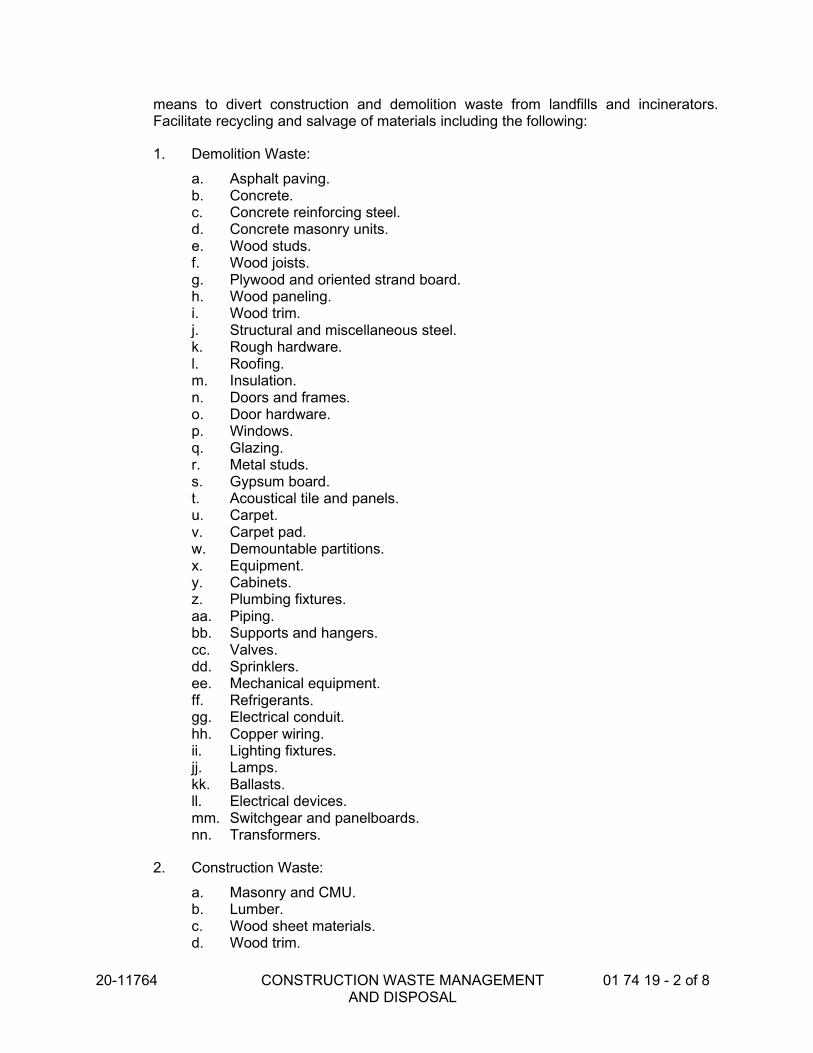
20-11764 CONSTRUCTION WASTE MANAGEMENT AND DISPOSAL
01 74 19 - 2 of 8
means to divert construction and demolition waste from landfills and incinerators. Facilitate recycling and salvage of materials including the following:
1. Demolition Waste:
a. Asphalt paving. b. Concrete. c. Concrete reinforcing steel. d. Concrete masonry units. e. Wood studs. f. Wood joists. g. Plywood and oriented strand board. h. Wood paneling. i. Wood trim. j. Structural and miscellaneous steel. k. Rough hardware. l. Roofing. m. Insulation. n. Doors and frames. o. Door hardware. p. Windows. q. Glazing. r. Metal studs. s. Gypsum board. t. Acoustical tile and panels. u. Carpet. v. Carpet pad. w. Demountable partitions. x. Equipment. y. Cabinets. z. Plumbing fixtures. aa. Piping. bb. Supports and hangers. cc. Valves. dd. Sprinklers. ee. Mechanical equipment. ff. Refrigerants. gg. Electrical conduit. hh. Copper wiring. ii. Lighting fixtures. jj. Lamps. kk. Ballasts. ll. Electrical devices. mm. Switchgear and panelboards. nn. Transformers.
2. Construction Waste:
a. Masonry and CMU. b. Lumber. c. Wood sheet materials. d. Wood trim.

20-11764 CONSTRUCTION WASTE MANAGEMENT AND DISPOSAL
01 74 19 - 3 of 8
e. Metals. f. Roofing. g. Insulation. h. Carpet and pad. i. Gypsum board. j. Piping. k. Electrical conduit. l. Packaging: Regardless of salvage/recycle goal indicated in "General"
Paragraph above, salvage or recycle 100 percent of the following uncontaminated packaging materials:
1) Paper. 2) Cardboard. 3) Boxes. 4) Plastic sheet and film. 5) Polystyrene packaging. 6) Wood crates. 7) Plastic pails.
1.5 ACTION SUBMITTALS
A. Waste Management Plan: Submit plan within 30 days of date established for the Notice to Proceed. Plan shall:
1. Identify licensed haulers and processors of recyclables 2. Identify markets for salvaged materials 3. Employ deconstruction, salvage, and recycling strategies and processes 4. Include waste auditing 5. Document the cost for recycling, salvaging, and reusing materials 6. Address recycling of acoustical ceiling tiles, corrugated cardboard, metals,
concrete brick, asphalt, beverage containers, clean dimensional wood, plastic, glass, gypsum board, and carpet
7. Identify products that can be returned to product manufacturer as part of a closed loop system
8. Source reduction of materials and packaging on the jobsite
B. Compliance Calculations
1. 65% of non-hazardous construction site waste must be recycled, composted, and/or salvaged. Contractor must provide compliance calculations for verification.
2. Compliance calculations must be based on weight. Shipments that cannot be weighed can be estimated based on their volume and density
3. Recycle Rate (%) = (Recycled Waste [tons] / Recycled Waste [tons] + Disposed Waste [tons]) x 100
1.6 INFORMATIONAL SUBMITTALS
A. Waste Reduction Progress Reports: Concurrent with each Application for Payment, submit report. Include the following information:

20-11764 CONSTRUCTION WASTE MANAGEMENT AND DISPOSAL
01 74 19 - 4 of 8
1. Material category. 2. Generation point of waste. 3. Total quantity of waste in tons. 4. Quantity of waste salvaged, both estimated and actual in tons. 5. Quantity of waste recycled, both estimated and actual in tons. 6. Total quantity of waste recovered (salvaged plus recycled) in tons. 7. Total quantity of waste recovered (salvaged plus recycled) as a percentage of
total waste.
B. Before request for Substantial Completion, submit calculated end-of-Project rates for salvage, recycling, and disposal as a percentage of total waste generated by the Work, signed by Contractor, tabulating total waste material, quantities diverted and means by which it is diverted, and statement that requirements for the credit have been met.
1.7 QUALITY ASSURANCE
A. Refrigerant Recovery Technician Qualifications: Certified by EPA-approved certification program.
B. Regulatory Requirements: Comply with hauling and disposal regulations of authorities having jurisdiction.
C. Waste Management Conference: Conduct conference at Project site to comply with requirements in Division 01 Section "Project Management and Coordination." Review methods and procedures related to waste management including, but not limited to, the following:
1. Review and discuss waste management plan including responsibilities of waste management coordinator.
2. Review requirements for documenting quantities of each type of waste and its disposition.
3. Review and finalize procedures for materials separation and verify availability of containers and bins needed to avoid delays.
4. Review procedures for periodic waste collection and transportation to recycling and disposal facilities.
5. Review waste management requirements for each trade.
PART 2 - PRODUCTS (Not Used)
PART 3 - EXECUTION
3.1 PLAN IMPLEMENTATION
A. General: Implement approved waste management plan. Provide handling, containers, storage, signage, transportation, and other items as required to implement waste management plan during the entire duration of the Contract.
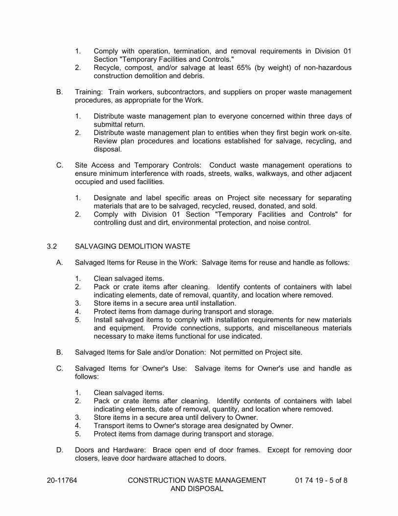
20-11764 CONSTRUCTION WASTE MANAGEMENT AND DISPOSAL
01 74 19 - 5 of 8
1. Comply with operation, termination, and removal requirements in Division 01 Section "Temporary Facilities and Controls."
2. Recycle, compost, and/or salvage at least 65% (by weight) of non-hazardous construction demolition and debris.
B. Training: Train workers, subcontractors, and suppliers on proper waste management procedures, as appropriate for the Work.
1. Distribute waste management plan to everyone concerned within three days of submittal return.
2. Distribute waste management plan to entities when they first begin work on-site. Review plan procedures and locations established for salvage, recycling, and disposal.
C. Site Access and Temporary Controls: Conduct waste management operations to ensure minimum interference with roads, streets, walks, walkways, and other adjacent occupied and used facilities.
1. Designate and label specific areas on Project site necessary for separating materials that are to be salvaged, recycled, reused, donated, and sold.
2. Comply with Division 01 Section "Temporary Facilities and Controls" for controlling dust and dirt, environmental protection, and noise control.
3.2 SALVAGING DEMOLITION WASTE
A. Salvaged Items for Reuse in the Work: Salvage items for reuse and handle as follows:
1. Clean salvaged items. 2. Pack or crate items after cleaning. Identify contents of containers with label
indicating elements, date of removal, quantity, and location where removed. 3. Store items in a secure area until installation. 4. Protect items from damage during transport and storage. 5. Install salvaged items to comply with installation requirements for new materials
and equipment. Provide connections, supports, and miscellaneous materials necessary to make items functional for use indicated.
B. Salvaged Items for Sale and/or Donation: Not permitted on Project site.
C. Salvaged Items for Owner's Use: Salvage items for Owner's use and handle as follows:
1. Clean salvaged items. 2. Pack or crate items after cleaning. Identify contents of containers with label
indicating elements, date of removal, quantity, and location where removed. 3. Store items in a secure area until delivery to Owner. 4. Transport items to Owner's storage area designated by Owner. 5. Protect items from damage during transport and storage.
D. Doors and Hardware: Brace open end of door frames. Except for removing door closers, leave door hardware attached to doors.

20-11764 CONSTRUCTION WASTE MANAGEMENT AND DISPOSAL
01 74 19 - 6 of 8
E. Equipment: Drain tanks, piping, and fixtures. Seal openings with caps or plugs. Protect equipment from exposure to weather.
F. Plumbing Fixtures: Separate by type and size.
G. Lighting Fixtures: Separate lamps by type and protect from breakage.
H. Electrical Devices: Separate switches, receptacles, switchgear, transformers, meters, panelboards, circuit breakers, and other devices by type.
3.3 RECYCLING DEMOLITION AND CONSTRUCTION WASTE, GENERAL
A. General: Recycle paper and beverage containers used by on-site workers.
B. Recycling Receivers and Processors: Refer to local county websites for the county in which the Project is located for listings of available recycling receivers and processors, and materials accepted.
C. Recycling Incentives: Revenues, savings, rebates, tax credits, and other incentives received for recycling waste materials shall accrue to Contractor.
D. Preparation of Waste: Prepare and maintain recyclable waste materials according to recycling or reuse facility requirements. Maintain materials free of dirt, adhesives, solvents, petroleum contamination, and other substances deleterious to the recycling process.
E. Procedures: Separate recyclable waste from other waste materials, trash, and debris. Separate recyclable waste by type at Project site to the maximum extent practical according to approved construction waste management plan.
1. Provide appropriately marked containers or bins for controlling recyclable waste until removed from Project site. Include list of acceptable and unacceptable materials at each container and bin.
a. Inspect containers and bins for contamination and remove contaminated materials if found.
2. Stockpile processed materials on-site without intermixing with other materials. Place, grade, and shape stockpiles to drain surface water. Cover to prevent windblown dust.
3. Stockpile materials away from construction area. Do not store within drip line of remaining trees.
4. Store components off the ground and protect from the weather. 5. Remove recyclable waste from Owner's property and transport to recycling
receiver or processor.
3.4 RECYCLING DEMOLITION WASTE
A. Asphalt Paving: Break up and transport paving to asphalt-recycling facility.

20-11764 CONSTRUCTION WASTE MANAGEMENT AND DISPOSAL
01 74 19 - 7 of 8
B. Concrete: Remove reinforcement and other metals from concrete and sort with other metals.
C. Masonry: Remove metal reinforcement, anchors, and ties from masonry and sort with other metals.
1. Clean and stack undamaged, whole masonry units on wood pallets.
D. Wood Materials: Sort and stack members according to size, type, and length. Separate lumber, engineered wood products, panel products, and treated wood materials.
E. Metals: Separate metals by type.
1. Structural Steel: Stack members according to size, type of member, and length. 2. Remove and dispose of bolts, nuts, washers, and other rough hardware.
F. Asphalt Shingle Roofing: Separate organic and glass-fiber asphalt shingles and felts. Remove and dispose of nails, staples, and accessories.
G. Gypsum Board: Stack large clean pieces on wood pallets or in container and store in a dry location. Remove edge trim and sort with other metals. Remove and dispose of fasteners.
H. Acoustical Ceiling Panels and Tile: Stack large clean pieces on wood pallets and store in a dry location.
I. Metal Suspension System: Separate metal members including trim, and other metals from acoustical panels and tile and sort with other metals.
J. Carpet and Pad: Roll large pieces tightly after removing debris, trash, adhesive, and tack strips.
1. Store clean, dry carpet and pad in a closed container or trailer provided by Carpet Reclamation Agency or carpet recycler.
K. Carpet Tile: Remove debris, trash, and adhesive.
1. Stack tile on pallet and store clean, dry carpet in a closed container or trailer provided by Carpet Reclamation Agency or carpet recycler.
L. Metal Piping: Reduce piping to straight lengths and store by type and size. Separate supports, hangers, valves, sprinklers, and other components by type and size.
M. Metal Conduit: Reduce conduit to straight lengths and store by type and size.
3.5 RECYCLING CONSTRUCTION WASTE
A. Packaging:

20-11764 CONSTRUCTION WASTE MANAGEMENT AND DISPOSAL
01 74 19 - 8 of 8
1. Cardboard and Boxes: Break down packaging into flat sheets. Bundle and store in a dry location.
2. Polystyrene Packaging: Separate and bag materials. 3. Pallets: As much as possible, require deliveries using pallets to remove pallets
from Project site. For pallets that remain on-site, break down pallets into component wood pieces and comply with requirements for recycling wood.
4. Crates: Break down crates into component wood pieces and comply with requirements for recycling wood.
B. Wood Materials:
1. Clean Cut-Offs of Lumber: Grind or chip into small pieces. 2. Clean Sawdust: Bag sawdust that does not contain painted or treated wood.
C. Gypsum Board: Stack large clean pieces on wood pallets or in container and store in a dry location.
3.6 DISPOSAL OF WASTE
A. General: Except for items or materials to be salvaged, recycled, or otherwise reused, remove waste materials from Project site and legally dispose of them in a landfill or incinerator acceptable to authorities having jurisdiction.
1. Except as otherwise specified, do not allow waste materials that are to be disposed of accumulate on-site.
2. Remove and transport debris in a manner that will prevent spillage on adjacent surfaces and areas.
B. Burning: Do not burn waste materials.
C. Disposal: Remove waste materials from Owner's property and legally dispose of them.
END OF SECTION

20-11764 OPERATION AND MAINTENANCE DATA 01 78 23 – 1 of 8
SECTION 01 78 23 OPERATION AND MAINTENANCE DATA
PART 1 - GENERAL
1.1 RELATED DOCUMENTS
A. Drawings and general provisions of the Contract, including General and Supplementary Conditions and other Division 01 Specification Sections, apply to this Section.
1.2 SUMMARY
A. Section includes administrative and procedural requirements for preparing operation and maintenance manuals, including the following:
1. Operation and maintenance documentation directory. 2. Emergency manuals. 3. Operation manuals for systems, subsystems, and equipment. 4. Product maintenance manuals. 5. Systems and equipment maintenance manuals.
B. Related Sections:
1. Division 01 Section "Submittals” for submitting copies of submittals for operation and maintenance manuals.
2. Division 01 Section "Demonstration and Training" for demonstration and training materials.
3. Divisions 02 through 33 Sections for specific operation and maintenance manual requirements for the Work in those Sections.
1.3 DEFINITIONS
A. System: An organized collection of parts, equipment, or subsystems united by regular interaction.
B. Subsystem: A portion of a system with characteristics similar to a system. 1.4 SUBMITTALS
A. Operation and Maintenance Manuals: Operations and maintenance manual content is specified in individual specification sections to be reviewed at the time of Section submittals. Submit reviewed manual content formatted and organized as required by this Section. Where applicable, clarify and update reviewed manual content to correspond to modifications and field conditions.
1. Format: Submit operations and maintenance manuals in the following format:

20-11764 OPERATION AND MAINTENANCE DATA 01 78 23 – 2 of 8
a. 3 paper copies. Include a complete operation and maintenance directory. Enclose title pages and directories in clear plastic sleeves. Architect will return 2 copies.
2. Initial Manual Submittal: Submit draft copy of each manual at least 30 days before commencing demonstration and training. Architect will comment on whether general scope and content of manual are acceptable.
3. Final Manual Submittal: Submit each manual in final form prior to requesting inspection for Substantial Completion and at least 15 days before commencing demonstration and training. Architect will return copy with comments.
a. Correct or modify each manual to comply with Architect's comments. Submit copies of each corrected manual within 15 days of receipt of Architect's comments and prior to commencing demonstration and training.
PART 2 - PRODUCTS
2.1 OPERATION AND MAINTENANCE DOCUMENTATION DIRECTORY
A. Organization: Include a section in the directory for each of the following:
1. List of documents. 2. List of systems. 3. List of equipment. 4. Table of contents.
B. List of Systems and Subsystems: List systems alphabetically. Include references to operation and maintenance manuals that contain information about each system.
C. List of Equipment: List equipment for each system, organized alphabetically by system. For pieces of equipment not part of system, list alphabetically in separate list.
D. Tables of Contents: Include a table of contents for each emergency, operation, and maintenance manual.
E. Identification: In the documentation directory and in each operation and maintenance manual, identify each system, subsystem, and piece of equipment with same designation used in the Contract Documents. If no designation exists, assign a designation according to ASHRAE Guideline 4, "Preparation of Operating and Maintenance Documentation for Building Systems."
2.2 REQUIREMENTS FOR EMERGENCY, OPERATION, AND MAINTENANCE MANUALS
A. Organization: Unless otherwise indicated, organize each manual into a separate section for each system and subsystem, and a separate section for each piece of equipment not part of a system. Each manual shall contain the following materials, in the order listed:

20-11764 OPERATION AND MAINTENANCE DATA 01 78 23 – 3 of 8
1. Title page. 2. Table of contents. 3. Manual contents.
B. Title Page: Include the following information:
1. Subject matter included in manual. 2. Name and address of Project. 3. Name and address of Owner. 4. Date of submittal. 5. Name and contact information for Contractor. 6. Name and contact information for Installer and/or Subcontractor. 7. Name and contact information for Architect. 8. Names and contact information for major consultants to the Architect that
designed the systems contained in the manuals. 9. Cross-reference to related systems in other operation and maintenance manuals.
C. Table of Contents: List each product included in manual, identified by product name, indexed to the content of the volume, and cross-referenced to Specification Section number in Project Manual.
1. If operation or maintenance documentation requires more than one volume to accommodate data, include comprehensive table of contents for all volumes in each volume of the set.
D. Manual Contents: Organize into sets of manageable size. Arrange contents alphabetically by system, subsystem, and equipment. If possible, assemble instructions for subsystems, equipment, and components of one system into a single binder.
E. Manuals, Paper Copy: Submit manuals in the form of hard copy, bound and labeled volumes.
1. Binders: Heavy-duty, three-ring, vinyl-covered, loose-leaf binders, in thickness necessary to accommodate contents, sized to hold 8-1/2-by-11-inch paper; with clear plastic sleeve on spine to hold label describing contents and with pockets inside covers to hold folded oversize sheets.
a. If two or more binders are necessary to accommodate data of a system, organize data in each binder into groupings by subsystem and related components. Cross-reference other binders if necessary to provide essential information for proper operation or maintenance of equipment or system.
b. Identify each binder on front and spine, with printed title "OPERATION AND MAINTENANCE MANUAL," Project title or name, and subject matter of contents, and indicate Specification Section number on bottom of spine. Indicate volume number for multiple-volume sets.
2. Dividers: Heavy-paper dividers with plastic-covered tabs for each section of the manual. Mark each tab to indicate contents. Include typed list of products and major components of equipment included in the section on each divider, cross-referenced to Specification Section number and title of Project Manual.

20-11764 OPERATION AND MAINTENANCE DATA 01 78 23 – 4 of 8
3. Protective Plastic Sleeves: Transparent plastic sleeves designed to enclose diagnostic software storage media for computerized electronic equipment.
4. Supplementary Text: Prepared on 8-1/2-by-11-inch white bond paper. 5. Drawings: Attach reinforced, punched binder tabs on drawings and bind with
text.
a. If oversize drawings are necessary, fold drawings to same size as text pages and use as foldouts.
b. If drawings are too large to be used as foldouts, fold and place drawings in labeled envelopes and bind envelopes in rear of manual. At appropriate locations in manual, insert typewritten pages indicating drawing titles, descriptions of contents, and drawing locations.
2.3 EMERGENCY MANUALS
A. Content: Organize manual into a separate section for each of the following:
1. Type of emergency. 2. Emergency instructions. 3. Emergency procedures.
B. Type of Emergency: Where applicable for each type of emergency indicated below, include instructions and procedures for each system, subsystem, piece of equipment, and component:
1. Fire. 2. Flood. 3. Gas leak. 4. Water leak. 5. Power failure. 6. Water outage. 7. System, subsystem, or equipment failure. 8. Chemical release or spill.
C. Emergency Instructions: Describe and explain warnings, trouble indications, error messages, and similar codes and signals. Include responsibilities of Owner's operating personnel for notification of Installer, supplier, and manufacturer to maintain warranties.
D. Emergency Procedures: Include the following, as applicable:
1. Instructions on stopping. 2. Shutdown instructions for each type of emergency. 3. Operating instructions for conditions outside normal operating limits. 4. Required sequences for electric or electronic systems. 5. Special operating instructions and procedures.
2.4 OPERATION MANUALS
A. Content: In addition to requirements in this Section, include operation data required in individual Specification Sections and the following information:

20-11764 OPERATION AND MAINTENANCE DATA 01 78 23 – 5 of 8
1. System, subsystem, and equipment descriptions. Use designations for systems and equipment indicated on Contract Documents.
2. Performance and design criteria if Contractor is delegated design responsibility. 3. Operating standards. 4. Operating procedures. 5. Operating logs. 6. Wiring diagrams. 7. Control diagrams. 8. Piped system diagrams. 9. Precautions against improper use. 10. License requirements including inspection and renewal dates.
B. Descriptions: Include the following:
1. Product name and model number. Use designations for products indicated on Contract Documents.
2. Manufacturer's name. 3. Equipment identification with serial number of each component. 4. Equipment function. 5. Operating characteristics. 6. Limiting conditions. 7. Performance curves. 8. Engineering data and tests. 9. Complete nomenclature and number of replacement parts.
C. Operating Procedures: Include the following, as applicable:
1. Startup procedures. 2. Equipment or system break-in procedures. 3. Routine and normal operating instructions. 4. Regulation and control procedures. 5. Instructions on stopping. 6. Normal shutdown instructions. 7. Seasonal and weekend operating instructions. 8. Required sequences for electric or electronic systems. 9. Special operating instructions and procedures.
D. Systems and Equipment Controls: Describe the sequence of operation, and diagram controls as installed.
E. Piped Systems: Diagram piping as installed, and identify color-coding where required for identification.
2.5 PRODUCT MAINTENANCE MANUALS
A. Content: Organize manual into a separate section for each product, material, and finish. Include source information, product information, maintenance procedures, repair materials and sources, and warranties and bonds, as described below.

20-11764 OPERATION AND MAINTENANCE DATA 01 78 23 – 6 of 8
B. Source Information: List each product included in manual, identified by product name and arranged to match manual's table of contents. For each product, list name, address, and telephone number of Installer or supplier and maintenance service agent, and cross-reference Specification Section number and title in Project Manual and drawing or schedule designation or identifier where applicable.
C. Product Information: Include the following, as applicable:
1. Product name and model number. 2. Manufacturer's name. 3. Color, pattern, and texture. 4. Material and chemical composition. 5. Reordering information for specially manufactured products.
D. Maintenance Procedures: Include manufacturer's written recommendations and the following:
1. Inspection procedures. 2. Types of cleaning agents to be used and methods of cleaning. 3. List of cleaning agents and methods of cleaning detrimental to product. 4. Schedule for routine cleaning and maintenance. 5. Repair instructions.
E. Repair Materials and Sources: Include lists of materials and local sources of materials and related services.
F. Warranties and Bonds: Include copies of warranties and bonds and lists of circumstances and conditions that would affect validity of warranties or bonds.
1. Include procedures to follow and required notifications for warranty claims.
2.6 SYSTEMS AND EQUIPMENT MAINTENANCE MANUALS
A. Content: For each system, subsystem, and piece of equipment not part of a system, include source information, manufacturers' maintenance documentation, maintenance procedures, maintenance and service schedules, spare parts list and source information, maintenance service contracts, and warranty and bond information, as described below.
B. Source Information: List each system, subsystem, and piece of equipment included in manual, identified by product name and arranged to match manual's table of contents. For each product, list name, address, and telephone number of Installer or supplier and maintenance service agent, and cross-reference Specification Section number and title in Project Manual and drawing or schedule designation or identifier where applicable.
C. Manufacturers' Maintenance Documentation: Manufacturers' maintenance documentation including the following information for each component part or piece of equipment:
1. Standard maintenance instructions and bulletins.

20-11764 OPERATION AND MAINTENANCE DATA 01 78 23 – 7 of 8
2. Drawings, diagrams, and instructions required for maintenance, including disassembly and component removal, replacement, and assembly.
3. Identification and nomenclature of parts and components. 4. List of items recommended to be stocked as spare parts.
D. Maintenance Procedures: Include the following information and items that detail essential maintenance procedures:
1. Test and inspection instructions. 2. Troubleshooting guide. 3. Precautions against improper maintenance. 4. Disassembly; component removal, repair, and replacement; and reassembly
instructions. 5. Aligning, adjusting, and checking instructions. 6. Demonstration and training video recording, if available.
E. Maintenance and Service Schedules: Include service and lubrication requirements, list of required lubricants for equipment, and separate schedules for preventive and routine maintenance and service with standard time allotment.
1. Scheduled Maintenance and Service: Tabulate actions for daily, weekly, monthly, quarterly, semiannual, and annual frequencies.
2. Maintenance and Service Record: Include manufacturers' forms for recording maintenance.
F. Spare Parts List and Source Information: Include lists of replacement and repair parts, with parts identified and cross-referenced to manufacturers' maintenance documentation and local sources of maintenance materials and related services.
G. Maintenance Service Contracts: Include copies of maintenance agreements with name and telephone number of service agent.
H. Warranties and Bonds: Include copies of warranties and bonds and lists of circumstances and conditions that would affect validity of warranties or bonds.
1. Include procedures to follow and required notifications for warranty claims.
PART 3 - EXECUTION
3.1 MANUAL PREPARATION
A. Operation and Maintenance Documentation Directory: Prepare a separate manual that provides an organized reference to emergency, operation, and maintenance manuals.
B. Emergency Manual: Assemble a complete set of emergency information indicating procedures for use by emergency personnel and by Owner's operating personnel for types of emergencies indicated.

20-11764 OPERATION AND MAINTENANCE DATA 01 78 23 – 8 of 8
C. Product Maintenance Manual: Assemble a complete set of maintenance data indicating care and maintenance of each product, material, and finish incorporated into the Work.
D. Operation and Maintenance Manuals: Assemble a complete set of operation and maintenance data indicating operation and maintenance of each system, subsystem, and piece of equipment not part of a system.
1. Engage a factory-authorized service representative to assemble and prepare information for each system, subsystem, and piece of equipment not part of a system.
2. Prepare a separate manual for each system and subsystem, in the form of an instructional manual for use by Owner's operating personnel.
E. Manufacturers' Data: Where manuals contain manufacturers' standard printed data, include only sheets pertinent to product or component installed. Mark each sheet to identify each product or component incorporated into the Work. If data include more than one item in a tabular format, identify each item using appropriate references from the Contract Documents. Identify data applicable to the Work and delete references to information not applicable.
1. Prepare supplementary text if manufacturers' standard printed data are not available and where the information is necessary for proper operation and maintenance of equipment or systems.
F. Drawings: Prepare drawings supplementing manufacturers' printed data to illustrate the relationship of component parts of equipment and systems and to illustrate control sequence and flow diagrams. Coordinate these drawings with information contained in record Drawings to ensure correct illustration of completed installation.
1. Do not use original project record documents as part of operation and maintenance manuals.
2. Comply with requirements of newly prepared record Drawings in Division 01 Section "Project Record Documents."
G. Comply with Division 01 Section "Closeout Procedures" for schedule for submitting operation and maintenance documentation.
END OF SECTION

20-11764 WARRANTIES 01 78 36 - 1 of 3
SECTION 01 78 36 WARRANTIES
PART 1 - GENERAL 1.1 RELATED DOCUMENTS
A. Drawings and general provisions of the Contract, including General and
Supplementary Conditions and Division 01 Specification Sections, apply to this Section.
1.2 SUMMARY
A. This Section includes administrative and procedural requirements for warranties
required by the Contract Documents, including manufacturers standard warranties on products and special warranties.
1. Refer to the General Conditions and for terms of the Contractor's period for
correction of the Work.
B. Disclaimers and Limitations: Manufacturer's disclaimers and limitations on product warranties do not relieve the Contractor of the warranty on the Work that incorporates the products. Manufacturer's disclaimers and limitations on product warranties do not relieve suppliers, manufacturers, and subcontractors required to countersign special warranties with the Contractor.
1.3 DEFINITIONS
A. Standard product warranties are preprinted written warranties published by
individual manufacturers for particular products and are specifically endorsed by the manufacturer to the Owner.
B. Special warranties are written warranties required by or incorporated in the
Contract Documents, either to extend time limits provided by standard warranties or to provide greater rights for the Owner.
1.4 WARRANTY REQUIREMENTS
A. Related Damages and Losses: When correcting failed or damaged warranted
construction, remove and replace construction that has been damaged as a result of such failure or must be removed and replaced to provide access for correction of warranted construction.
B. Reinstatement of Warranty: When Work covered by a warranty has failed and
been corrected by replacement or rebuilding, reinstate the warranty by written

20-11764 WARRANTIES 01 78 36 - 2 of 3
endorsement. The reinstated warranty shall be equal to the original warranty with an equitable adjustment for depreciation.
C. Replacement Cost: Upon determination that Work covered by a warranty has
failed, replace or rebuild the Work to an acceptable condition complying with requirements of the Contract Documents. The Contractor is responsible for the cost of replacing or rebuilding defective Work regardless of whether the Owner has benefited from use of the Work through a portion of its anticipated useful service life.
D. Owner's Recourse: Expressed warranties made to the Owner are in addition to
implied warranties and shall not limit the duties, obligations, rights, and remedies otherwise available under the law. Expressed warranty periods shall not be interpreted as limitations on the time in which the Owner can enforce such other duties, obligations, rights, or remedies.
1. Rejection of Warranties: The Owner reserves the right to reject warranties
and to limit selection to products with warranties not in conflict with requirements of the Contract Documents.
E. Where the Contract Documents require a special warranty, or similar
commitment on the Work or part of the Work, the Owner reserves the right to refuse to accept the Work, until the Contractor presents evidence that entities required to countersign such commitments are willing to do so.
1.5 SUBMITTALS
A. Submit written warranties to the Architect prior to the date certified for Substantial
Completion. If the Architect's Certificate of Substantial Completion designates a commencement date for warranties other than the date of Substantial Completion for the Work, or a designated portion of the Work, submit written warranties upon request of the Architect.
B. When the Contract Documents require the Contractor, or the Contractor and a
subcontractor, supplier or manufacturer to execute a special warranty, prepare a written document that contains appropriate terms and identification, ready for execution by the required parties. Submit a draft to the Owner, through the Architect, for approval prior to final execution.
1. Refer to Divisions 2 through 32 Sections for specific content requirements
and particular requirements for submitting special warranties.
C. Form of Submittal: At Final Completion compile 2 copies of each required warranty properly executed by the Contractor, or by the Contractor, subcontractor, supplier, or manufacturer. Organize the warranty documents into an orderly sequence based on the table of contents of the Project Manual
D. Bind warranties and bonds in heavy-duty, commercial-quality, durable 3-ring,
vinyl-covered loose-leaf binders, thickness as necessary to accommodate contents, and sized to receive 8-1/2-by-11-inch paper.

20-11764 WARRANTIES 01 78 36 - 3 of 3
1. Provide a table of contents for the manual indicating specification section
and title of warranty. 2. Provide heavy paper dividers with celluloid covered tabs for each separate
warranty. Mark the tab to identify the product or installation. Provide a typed description of the product or installation, including the name of the product, and the name, address, and telephone number of the Installer.
3. Identify each binder on the front and spine with the typed or printed title "WARRANTIES," Project title or name, and name of the Contractor.
4. Provide additional copies of each required warranty as necessary for inclusion in each operation and maintenance manual.
PART 2 - PRODUCTS (Not Applicable) PART 3 - EXECUTION 3.1 LIST OF WARRANTIES
A. Schedule: Provide warranties on products and installations as specified in the
following Sections:
1. As listed in individual Divisions.
END OF SECTION

20-11764 PROJECT RECORD DOCUMENTS 01 78 90 – 1 of 4
SECTION 01 78 90 PROJECT RECORD DOCUMENTS
PART 1 - GENERAL
1.1 DESCRIPTION
A. Work Included: Provide all material, labor, equipment and services necessary to main-tain and revise all record documents and other related items necessary to complete the Project as indicated by the Contract Documents unless specifically excluded.
1.2 SUMMARY
A. This Section includes the following:
1. Provide all material, labor, equipment and services necessary to completely in-stall all materials, accessories and other related items necessary to complete the Project as indicated by the Contract Documents.
B. Related Sections: The following Sections contain requirements that relate to this Sec-tion:
1. Drawings and general provisions of the Contract, including General and Special (or Supplementary) Conditions and Division 1 Specification Sections, and the fol-lowing apply to this Section.
a. ALL DIVISIONS
1.3 DEFINITIONS
A. PROJECTS “AS-BUILT” DOCUMENTS: A set of Contract Documents used for re-cording of actual construction information during the course of construction. The re-cording of construction information shall be kept on the Contract Drawings and Pro-ject Manual (which includes the Specifications). The construction information shall also include al Addenda, Change Orders and Modification Documents.
i) The positing of on the “AS-BUILT” Documents: Drawings, Addenda, Change Orders
and Modification Documents (which includes Supplemental Instructions, Request for
Information, Construction Change Directives, etc.). They shall be neatly and clearly
drafted, in a readable manor, in the same quality as the Original Contract Documents
and capable of being reproduced or photocopied.
ii) The Posting of said items shall be posted to the back side of the corresponding
drawing and or sheet. The said positing shall not be reduced no more than half its
original size. An additional sheet may be required for postings if the “Changes or
Clarifications” do not fit on the back side of corresponding drawing.
1.4 MAINTENANCE OF DOCUMENTS
A. Maintain at job site one copy of the following:

20-11764 PROJECT RECORD DOCUMENTS 01 78 90 – 2 of 4
1. Contract Drawings.
a. “As-Built” Record Drawings. b. “Project Record” Drawings.
2. Project Manual/Specifications. 3. Addenda. 4. Reviewed shop drawings/ 5. Change Orders. 6. Other modifications to Contract. 7. Field test records.
B. Store documents in field office apart form documents used for construction.
C. Provide files and racks for storage of documents.
D. File documents in accordance with Project Filing Format or Uniform Construction In-dex.
E. Maintain documents in clean, dry, legible condition.
F. Do not use record documents for construction purposes.
G. Make documents available at all times for inspection by Architect, Owner and Owner’s Inspector.
1.5 RECORDING ON CONTRACT DOCUMENTS
A. Provide red pencil or ink (contrasting color) for all marking of the “As-Built” and Draw-ings. The time required for transferring the documentation shall be part of the “Contrac-tor’s Overhead Expense”.
B. For all Electrical, Mechanical, Fire Sprinkler, Plumbing and Structural steel drawings: Provide 1 set of hard copy and 1 set of electronic record documents for all work asso-ciated with the package. Drawings shall be computer drawn format with color delinea-tion of utilities for clarity if necessary.
C. Label each document “As-Built” respectively in 1-inch high printed letters.
D. Keep record documents current. The contractor is responsible for updating and trans-fer of information to the Project Record Set.
1. “Project Record” Drawings shall be kept current at all times. The Project Inspec-tor will review the “Project Record” Drawings for the Architect at the time Pay-ment Requests are processed. Should the “Project Record” Drawings not be current and up to date in relation to the “As-Built” set, the Architect reserves the right to hold the Payment Request until compliance with the Contract Documents has occurred.
E. Do not permanently conceal any work until required information has been recorded.

20-11764 PROJECT RECORD DOCUMENTS 01 78 90 – 3 of 4
F. Legible mark the “Project Record” documents in the same quality as the Original Con-tract Documents as a record of actual construction for:
1. Elevation for finish grade for all points indicated on Site Grading Plan. 2. Depths of various elements of foundation in relation to first floor finish elevation. 3. Horizontal and vertical location of underground utilities and appurtenances refer-
enced to visible and accessible features of structure. 4. Location of internal utilities and appurtenances concealed in construction refer-
enced to visible and accessible features of structure. 5. Field changes of dimension and detail. 6. Changes made by Change Order or other modification document. 7. Details not on original Contract Documents 8. Each public address speaker- indicate speaker location and either Architectural
number or Port number assigned to that speaker
G. Specifications and Addenda: Legibly mark up in the same quality as the Original Con-tract Documents each section to record:
1. Manufacturer, trade name, catalog number and supplier of each product and item of equipment actually installed.
2. Changes made by Change Order or other modification document. 3. Other matters not originally specified.
H. Shop Drawings: Maintain like the “Project Record” Drawing documents and legibly mark up in the same quality as the Original Contract Documents shop drawings to rec-ord changes made after review.
I. Project Record Drawings: The General Contractor will store the record documents in the jobsite office.
1. The time required for transferring the documentation shall also be part of the Contractor’s overhead expense.
2. The Contractor shall transfer all changes, notations, etc. from the “Project Rec-ord” Drawings to the xerographic drawings in the same quality as the Original Contract Documents.
1.6 SUBMITTAL
A. Prior to final Application of Payment, complete “As-Built” documents, completed Speci-fications and Addenda documents, completed Shop Drawings documents and submit to the Architect one hard copy, once finalized submit one electronic copy.
B. Accompany submittal with transmittal letter, in duplicate containing:
1. Date. 2. Project title and number. 3. Contractor’s name and address. 4. Title and number of each record document. 5. Certification that each document as submitted is complete and accurate. 6. Signature of Contractor.

20-11764 PROJECT RECORD DOCUMENTS 01 78 90 – 4 of 4
PART 2 - PRODUCTS
As described in Part 1.
PART 3 - EXECUTION
As described in Part 1.
END OF SECTION

20-11764 DEMONSTRATION AND TRAINING 01 79 00 – 1 of 4
SECTION 01 79 00 DEMONSTRATION AND TRAINING
PART 1 - GENERAL
1.1 RELATED DOCUMENTS
A. Drawings and general provisions of the Contract, including General and Supplementary Conditions and other Division 01 Specification Sections, apply to this Section.
1.2 SUMMARY
A. Section includes administrative and procedural requirements for instructing Owner's personnel in demonstration and training of operation and maintenance of systems, subsystems, and equipment.
B. Related Sections:
1. Division 01 Section “Operation and Maintenance Data” for operation and maintenance manuals and data.
2. Divisions 02 through 33 Sections for specific requirements for demonstration and training for products in those Sections.
1.3 SUBMITTALS
A. Training materials in addition to Operation and Maintenance manuals required in Division 01 Section “Operation and Maintenance Data.”
B. Instruction Program Schedule: Submit outline schedule of instructional program that includes and coordinates programs for all products, equipment, and systems requiring demonstration and training. Schedule shall include a list of training sessions, proposed dates, times, length of instruction time.
1. Schedule shall be coordinated and finalized with the Owner.
1.4 QUALITY ASSURANCE
A. Instructor Qualifications: A factory-authorized service representative experienced in operation and maintenance procedures and training of Owner’s personnel.
1.5 COORDINATION
A. Coordinate instruction schedule with Owner, adjust schedule as required to minimize disrupting Owner's operations.

20-11764 DEMONSTRATION AND TRAINING 01 79 00 – 2 of 4
B. Coordinate instructors, including providing notification of dates, times, length of instruction time, and course content.
C. Coordinate content of training sessions with content of approved operation and maintenance manuals. Do not submit instruction program until operation and maintenance data has been reviewed and approved by Architect.
PART 2 - PRODUCTS
2.1 INSTRUCTION PROGRAM
A. Provide instruction programs that include training sessions for each system and for equipment not part of a system, as required by individual Specification Sections. Include instruction for the following as applicable to the system, equipment, or component:
1. Basis of System Design, Operational Requirements, and Criteria: Include the following:
a. System, subsystem, and equipment descriptions. b. Operating standards. c. Regulatory requirements. d. Equipment function. e. Operating characteristics. f. Limiting conditions. g. Performance curves.
2. Documentation: Review the following items in detail:
a. Emergency manuals. b. Operations manuals. c. Maintenance manuals. d. Project record documents. e. Identification systems. f. Warranties and bonds. g. Maintenance service agreements and similar continuing commitments.
3. Emergencies: Include the following, as applicable:
a. Instructions on meaning of warnings, trouble indications, and error messages.
b. Instructions on stopping. c. Shutdown instructions for each type of emergency. d. Operating instructions for conditions outside of normal operating limits. e. Sequences for electric or electronic systems. f. Special operating instructions and procedures.
4. Operations: Include the following, as applicable:
a. Startup procedures. b. Equipment or system break-in procedures.

20-11764 DEMONSTRATION AND TRAINING 01 79 00 – 3 of 4
c. Routine and normal operating instructions. d. Regulation and control procedures. e. Control sequences. f. Safety procedures. g. Instructions on stopping. h. Normal shutdown instructions. i. Operating procedures for emergencies. j. Operating procedures for system, subsystem, or equipment failure. k. Seasonal and weekend operating instructions. l. Required sequences for electric or electronic systems. m. Special operating instructions and procedures.
5. Adjustments: Include the following:
a. Alignments. b. Checking adjustments. c. Noise and vibration adjustments. d. Economy and efficiency adjustments.
6. Troubleshooting: Include the following:
a. Diagnostic instructions. b. Test and inspection procedures.
7. Maintenance: Include the following:
a. Inspection procedures. b. Types of cleaning agents to be used and methods of cleaning. c. List of cleaning agents and methods of cleaning detrimental to product. d. Procedures for routine cleaning e. Procedures for preventive maintenance. f. Procedures for routine maintenance. g. Instruction on use of special tools.
8. Repairs: Include the following:
a. Diagnosis instructions. b. Repair instructions. c. Disassembly; component removal, repair, and replacement; and
reassembly instructions. d. Instructions for identifying parts and components. e. Review of spare parts needed for operation and maintenance.
PART 3 - EXECUTION
3.1 PREPARATION
A. Assemble educational materials necessary for instruction and training. Assemble training manuals organized in coordination with requirements in Division 01 Section "Operations and Maintenance Data."

20-11764 DEMONSTRATION AND TRAINING 01 79 00 – 4 of 4
B. Coordinate with Owner for number of instruction times, location, and number of participants.
C. Set up instructional equipment at instruction location.
3.2 INSTRUCTION
A. Instruct Owner's personnel to adjust, operate, and maintain systems, subsystems, and equipment not part of a system.
1. Owner will furnish Contractor with names and positions of participants.
B. Scheduling: Provide instruction at mutually agreed on times. For equipment that requires seasonal operation, provide similar instruction at start of each season.
1. Schedule initial training with Owner, through Architect with at least 7 days' advance notice.
C. Cleanup: Collect used and leftover educational materials and give to Owner. Remove instructional equipment. Restore systems and equipment to condition existing before initial training use.
END OF SECTION

20-11764 GENERAL COMMISSIONING REQUIREMENTS 01 91 13 - 1 of 10
SECTION 01 91 13 GENERAL COMMISSIONING REQUIREMENTS
PART 1 GENERAL 1.1 SUMMARY
A. Section includes:
1. Building commissioning of the following systems:
a. HVAC components and equipment. b. HVAC system: interaction of cooling, heating, and comfort
delivery systems. c. Building Automation System (BAS): control hardware and
software, sequence of operations, and integration of factory controls with BAS.
d. Lighting Control System and interface with daylighting. e. Domestic hot water systems.
2. Monitoring of the following procedures:
a. Building flush out as described in Section 230500 Common Work Results for HVAC.
B. The Owner, Architect/Engineer, and Commissioning Agent are not responsible for construction means, methods, job safety, or management function related to commissioning on the job site.
C. Related Sections:
1. Division 23 Section “Commissioning of HVAC” for commissioning process activities for HVAC systems, assemblies, equipment, and components
2.
1.2 DEFINITIONS
A. Basis of Design - The basis of design is the documentation of the primary thought processes and assumptions behind design decisions that were made to meet the Owner’s Project Requirements. The basis of design describes the systems, components, conditions and methods chosen to meet the intent. Some reiterating of the Owner’s Project Requirements may be included.
B. Commissioning – Commissioning is a comprehensive and systematic process to verify that the building systems perform as designed to meet the Owner’s requirements. Commissioning during the construction, acceptance, and warranty phases is intended to achieve the following specific objectives:
1. Verify and document that equipment is installed and started per manufacturer’s recommendations, industry accepted minimum standards, and the Contract Documents.

20-11764 GENERAL COMMISSIONING REQUIREMENTS 01 91 13 - 2 of 10
2. Verify and document that equipment and systems receive complete operational checkout by installing contractors.
3. Verify and document equipment and system performance. 4. Verify the completeness of operations and maintenance materials. 5. Ensure that the Owner’s operating personnel are adequately trained on the
operation and maintenance of building equipment.
The commissioning process does not take away from or reduce the responsibility of the system designers or installing contractors to provide a finished and fully functioning product.
C. Commissioning Plan - an overall plan that provides the structure, schedule and coordination planning for the commissioning process.
D. Deficiency - a condition in the installation or function of a component, piece of equipment or system that is not in compliance with the Contract Documents, does not perform properly or is not complying with the Owner’s Project Requirements.
E. Owner’s Project Requirements - a dynamic document that provides the explanation of the ideas, concepts and criteria that are considered to be very important to the Owner. It is initially the outcome of the programming and conceptual design phases.
F. Functional Performance Test - test of the dynamic function and operation of equipment and systems using manual (direct observation) or monitoring methods. Functional testing is the dynamic testing of systems (rather than just components) under full operation (e.g., the chiller pump is tested interactively with the chiller functions to see if the pump ramps up and down to maintain the differential pressure setpoint). Systems are tested under various modes, such as during low cooling or heating loads, high loads, component failures, unoccupied, varying outside air temperatures, fire alarm, power failure, etc. The systems are run through all the control system’s sequences of operation and components are verified to be responding as the sequences state. Traditional air or water test and balancing (TAB) is not functional testing, in the commissioning sense of the word. TAB’s primary work is setting up the system flows and pressures as specified, while functional testing is verifying that which has already been set up. The Commissioning Agent develops the functional test procedures in a sequential written form, coordinates, oversees and documents the actual testing, which is usually performed by the installing contractor or vendor. Functional Performance Tests are performed after prefunctional checklists and startup are complete.
G. Manual Test - using hand-held instruments, immediate control system readouts or direct observation to verify performance (contrasted to analyzing monitored data taken over time to make the “observation”).
H. Monitoring - the recording of parameters (flow, current, status, pressure, etc.) of equipment operation using dataloggers or the trending capabilities of control systems.
I. Non-Compliance - see Deficiency.
J. Non-Conformance - see Deficiency.

20-11764 GENERAL COMMISSIONING REQUIREMENTS 01 91 13 - 3 of 10
K. Prefunctional Checklist - a list of items to inspect and elementary component tests to conduct to verify proper installation of equipment, provided by the Commissioning Agent to the contractor. Prefunctional checklists are primarily static inspections and procedures to prepare the equipment or system for initial operation (e.g., belt tension, oil levels OK, labels affixed, gages in place, sensors calibrated, etc.). However, some prefunctional checklist items entail simple testing of the function of a component, a piece of equipment or system (such as measuring the voltage imbalance on a three-phase pump motor of a chiller system). The word “prefunctional” refers to before functional testing. Prefunctional checklists augment and are combined with the manufacturer’s start-up checklist.
L. Seasonal Performance Tests - Functional Performance Test that are deferred until the system(s) will experience conditions closer to their design conditions.
M. Warranty Period - warranty period for entire project, including equipment components. Warranty begins at Substantial Completion and extends for at least one year, unless specifically noted otherwise in the Contract Documents and accepted submittals.
1.3 COORDINATION
A. Perform commissioning services to expedite the testing process and minimize unnecessary delays, while not compromising the integrity of the procedures.
B. Commissioning Agent shall provide overall coordination and management of the commissioning program as specified herein.
C. Commissioning Team: The commissioning process will require cooperation of the Contractor, subcontractors, vendors, Architect/Engineer, Commissioning Agent, and Owner. The commissioning team shall be comprised of the following.
1. Contractor
a. Project Manager b. Test Engineer
2. Subcontractors: As appropriate to product or system being commissioned.
3. Commissioning Agent
a. Project Manager b. Project Engineers
4. Owner Representative(s). 5. Architect/Engineer
a. Architect b. MEP engineers
D. Progress Meetings: Attend construction job-site meetings, as necessary, to monitor construction and commissioning progress. Coordinate with contractor to address coordination, deficiency resolution and planning issues.

20-11764 GENERAL COMMISSIONING REQUIREMENTS 01 91 13 - 4 of 10
1. Plan and coordinate additional meetings as required to progress the work.
E. Site Observations: Perform site visits, as necessary, to observe component and system installations.
F. Functional Testing Coordination:
1. Equipment shall not be “temporarily” started for commissioning. 2. Functional performance testing shall not begin until pre-functional, start-
up and TAB is completed for a given system. 3. The controls system and equipment it controls shall not be functionally
tested until all points have been calibrated and pre-functional checklists are completed.
1.4 QUALITY CONTROL
A. Qualifications for Commissioning Agents: Engage commissioning service personnel, that specialize in the types of inspections and tests to be performed.
1. Inspection and testing service agencies must satisfy the qualifications of, and perform in accordance with the requirements of the Building Commissioning Association (BCA).
1.5 SUBMITTALS
A. Commissioning Agent shall submit the following:
1. Basis of Design and Owner’s Project Requirements.
a. Update as necessary during the work to reflect the progress on the components and systems. Submit to the Architect for distribution to the project team.
2. Commissioning Plan: Submit within 30 calendar days of authorization to proceed.
a. Update as necessary during the work to reflect the progress on the components and systems. Forward updates to the Architect for distribution to the project team.
3. Commissioning Schedule: Submit with Commissioning Plan.
a. Update as necessary during the work to reflect the progress on the components and systems. Architect for distribution to the project team.
4. Functional performance test forms: Submit minimum 30 calendar days prior to testing.
5. Deficiency Report and Resolution Record: Document items of non-compliance in materials, installation or operation. Document the results from start-up/pre-functional checklists, functional performance testing, and short-term diagnostic monitoring. Include details of the components or systems found to be non-compliant with the drawings and

20-11764 GENERAL COMMISSIONING REQUIREMENTS 01 91 13 - 5 of 10
specifications. Identify adjustments and alterations required to correct the system operation, and identify who is responsible for making the corrective changes.
a. Update as necessary during the work to reflect the progress on the components and systems. Forward updates to the Green Consultant in a timely manner.
6. Final Commissioning Report: Compile a final Commissioning Report. Summarize all of the tasks, findings, conclusions, and recommendations of the commissioning process. Indicate the actual performance of the building systems in reference to the Owner’s Project Requirements and contract documents. Include completed pre-functional inspection checklists, functional performance testing records, diagnostic monitoring results, identified deficiencies, recommendations, and a summary of commissioning activities.
7. O&M Submittals:
a. Training plan: Training plan shall include for each training session:
1) Dates, start and finish times, and locations; 2) Outline of the information to be presented; 3) Names and qualifications of the presenters; 4) List of texts and other materials required to support training.
b. Systems Manual.
PART 2 PRODUCTS
2.1 TEST EQUIPMENT
A. Instrumentation shall meet the following standards:
1. Be of sufficient quality and accuracy to test and measure system performance within the tolerances required to determine adequate performance.
2. Be calibrated on the manufacturer’s recommended intervals with calibration tags permanently affixed to the instrument being used.
3. Be maintained in good repair and operation condition throughout the duration of use on this project.
B. All standard testing equipment required to perform startup and initial checkout and required functional performance testing shall be provided by the contractor for the equipment being tested.
C. Datalogging equipment or software required to test equipment will be provided by the Commissioning Agent, but shall not become the property of the Owner.
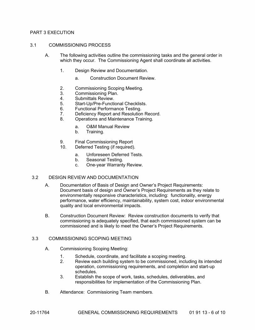
20-11764 GENERAL COMMISSIONING REQUIREMENTS 01 91 13 - 6 of 10
PART 3 EXECUTION
3.1 COMMISSIONING PROCESS
A. The following activities outline the commissioning tasks and the general order in which they occur. The Commissioning Agent shall coordinate all activities.
1. Design Review and Documentation.
a. Construction Document Review.
2. Commissioning Scoping Meeting. 3. Commissioning Plan. 4. Submittals Review. 5. Start-Up/Pre-Functional Checklists. 6. Functional Performance Testing. 7. Deficiency Report and Resolution Record. 8. Operations and Maintenance Training.
a. O&M Manual Review b. Training.
9. Final Commissioning Report 10. Deferred Testing (if required).
a. Unforeseen Deferred Tests. b. Seasonal Testing. c. One-year Warranty Review.
3.2 DESIGN REVIEW AND DOCUMENTATION
A. Documentation of Basis of Design and Owner’s Project Requirements: Document basis of design and Owner’s Project Requirements as they relate to environmentally responsive characteristics, including: functionality, energy performance, water efficiency, maintainability, system cost, indoor environmental quality and local environmental impacts.
B. Construction Document Review: Review construction documents to verify that commissioning is adequately specified, that each commissioned system can be commissioned and is likely to meet the Owner’s Project Requirements.
3.3 COMMISSIONING SCOPING MEETING
A. Commissioning Scoping Meeting:
1. Schedule, coordinate, and facilitate a scoping meeting. 2. Review each building system to be commissioned, including its intended
operation, commissioning requirements, and completion and start-up schedules.
3. Establish the scope of work, tasks, schedules, deliverables, and responsibilities for implementation of the Commissioning Plan.
B. Attendance: Commissioning Team members.

20-11764 GENERAL COMMISSIONING REQUIREMENTS 01 91 13 - 7 of 10
3.4 COMMISSIONING PLAN
A. Commissioning Plan: Develop a commissioning plan to identify how commissioning activities will be integrated into general construction and trade activities. The commissioning plan shall identify how commissioning responsibilities are distributed. The intent of this plan is to evoke questions, expose issues, and resolve them with input from the entire commissioning team early in construction.
1 Identify who will be responsible for producing the various procedures, reports, Owner notifications and forms.
2. Include the commissioning schedule. 3. Describe the test/acceptance procedure.
3.5 SUBMITTALS REVIEW
A. Submittal Review: Review the contractor submittals to verify that the equipment and systems provided meet the requirements of the Contract Documents and Owner’s Project Requirements.
3.6 START-UP/PRE-FUNCTIONAL CHECKLISTS
A. Start-Up/Pre-Functional Checklists: Coordinate start-up plans and documentation formats, including providing contractor with pre-functional checklists to be completed during the startup process.
1. Manufacturer’s start-up checklists and other technical documentation guidelines may be used as the basis for pre-functional checklists.
B. Start-Up/Pre-Functional Checklist shall help verify that the systems are complete and operational, so that the functional performance testing can be scheduled.
3.7 FUNCTIONAL PERFORMANCE TESTING
A. Functional Performance Testing: Test procedures shall fully describe system configuration and steps required for each test; appropriately documented so that another party can repeat the tests with virtually identical results.
1. Test Methods; Functional performance testing and verification may be achieved by direct manipulation of system inputs (i.e. heating or cooling sensors), manipulation of system inputs with the building automation system (i.e. software override of sensor inputs), trend logs of system inputs and outputs using the building automation system, or short-term monitoring of system inputs and outputs using stand alone data loggers. A combination of methods may be required to completely test the complete sequence of operations. The Commissioning Agent shall determine which method, or combination, is most appropriate.
2. Setup: Each test procedure shall be performed under conditions that simulate normal operating conditions as closely as possible. Where equipment requires integral safety devices to stop/prevent equipment operation unless minimum safety standards or conditions are met,

20-11764 GENERAL COMMISSIONING REQUIREMENTS 01 91 13 - 8 of 10
functional performance test procedures shall demonstrate the actual performance of safety shutoffs in a real or closely-simulated conditions of failure.
3. Sampling: Multiple identical pieces of non-life-safety or non-critical equipment may be functionally tested using a sampling strategy. The sampling strategy shall be developed by the Commissioning Agent. If, after three attempts at testing the specified sample percentage, failures are still present, then all remaining units shall be tested at the contractors’ expense.
B. Develop functional performance test procedures for equipment and systems. Identify specific test procedures and forms to verify and document proper operation of each piece of equipment and system. Coordinate test procedures with the contractor for feasibility, safety, equipment and warranty protection. Functional performance test forms shall include the following information:
1. System and equipment or component name(s). 2. Equipment location and ID number. 3. Date. 4. Project name. 5. Participating parties. 6. Instructions for setting up the test, including special cautions, alarm limits,
etc. 7. Specific step-by-step procedures to execute the test. 8. Acceptance criteria of proper performance with a Yes / No check box. 9. A section for comments.
C. Coordinate, observe and record the results of contractor’s functional performance testing.
1. Coordinate retesting as necessary until satisfactory performance is verified.
2. Verify the intended operation of individual components and system interactions under various conditions and modes of operation.
3.8 BUILDING FLUSH-OUT
A. After construction ends, monitor the building flush-out procedures for removal of pollutants prior to occupancy. Building flush-out may take place before or after occupancy of the building subject to compliance with the requirements in Section 230500 Common Work Results for HVAC.
3.9 DEFICIENCY REPORT AND RESOLUTION RECORD
A. Deficiency Report and Resolution Record: Document items of non-compliance in materials, installation or operation.
B. Non-Conformance. Non-conformance and deficiencies observed shall be addressed immediately, in terms of notification to responsible parties, and providing recommended actions to correct deficiencies.

20-11764 GENERAL COMMISSIONING REQUIREMENTS 01 91 13 - 9 of 10
1. Corrections of minor deficiencies identified may be made during the tests at the discretion of the Commissioning Agent. In such cases the deficiency and resolution shall be documented on the procedure form.
2. For identified deficiencies:
a. If there is no dispute on the deficiency and the responsibility to correct it:
1) The Commissioning Agent documents the deficiency and the adjustments or alterations required to correct it. The contractor corrects the deficiency and notifies the Commissioning Agent that the equipment is ready to be retested.
2) The Commissioning Agent reschedules the test and the test is repeated.
b. If there is a dispute about a deficiency or who is responsible:
1) The deficiency is documented on the non-compliance form and a copy given to the Architect
2) Resolutions are made at the lowest management level possible. Additional parties are brought into the discussions as needed. Contractor shall have responsibility for resolving construction deficiencies. If a design revision is deemed necessary and approved by Owner, Architect/Engineer shall have responsibility for providing design revision.
3) The Commissioning Agent documents the resolution process.
4) Once the interpretation and resolution have been decided, the appropriate party corrects the deficiency and notifies the Commissioning Agent that the equipment is ready to be retested. The Commissioning Agent reschedules the test and the test is repeated until satisfactory performance is achieved.
3. Cost of Retesting: Costs for retesting shall be charged to the Contractor.
3.10 OPERATIONS AND MAINTENANCE TRAINING
A. O&M Manual: Review the operation and maintenance manuals compiled by the contractor for completeness and for adherence to the requirements of the specifications.
1. Obtain additional materials from contractor as necessary to stress and enhance the importance of system interactions, troubleshooting, and long-term preventative maintenance and operation.
B. Training: Develop a Training Plan. Coordinate and review the training programs for Owner’s personnel.
1. Obtain additional materials from contractor as necessary to stress and enhance the importance of system interactions, troubleshooting, and long-term preventative maintenance and operation.

20-11764 GENERAL COMMISSIONING REQUIREMENTS 01 91 13 - 10 of 10
2. Provide a short introduction for all school staff explaining how classrooms systems work such as lighting and temperature controls and features a special workshop for facility personnel.
3.13 FINAL COMMISSIONING REPORT
A. Final Commissioning Report: Compile final commissioning report. Summarize all of the tasks, findings, conclusions, and recommendations of the commissioning process.
3.14 DEFERRED TESTING
A. Unforeseen Deferred Tests: If a test cannot be completed due to the building structure, required occupancy condition, or other deficiency, the functional testing may be delayed upon recommendation of the Commissioning Agent and the approval of the Owner. These tests are conducted in the same manner as the seasonal tests as soon as possible.
B. One-year-Warranty Review: Conduct warranty review of all commissioned systems one year after project completion. Review the current building operation with the facility maintenance staff. The review shall include outstanding issues from original or seasonal testing. Interview facility staff to identify concerns with building operation. Provide suggestions for improvements and assist owner in developing reports or documentation to remedy problems.
1. Update O&M manuals as necessary due to the testing.
3.14 EQUIPMENT & SYSTEM SCHEDULE
A. The following equipment shall be commissioned in this project.
System Equipment Check
HVAC System Air-Cooled Chillers
BAS System
END OF SECTION

20-11764 SELECTIVE DEMOLITION 02 41 19 - 1 of 4
SECTION 02 41 19 SELECTIVE DEMOLITION
PART 1 - GENERAL
1.1 RELATED DOCUMENTS
A. Drawings and general provisions of the Contract, including General and Supplementary Conditions and other Division 01 Specification Sections, apply to this Section.
1.2 SUMMARY
A. This Section includes the following:
1. Demolition and removal of selected site elements.
B. Related Sections include the following:
1. Division 01 Section "Temporary Facilities and Controls" for temporary construction and environmental-protection measures for selective demolition operations.
2. Division 01 Section "Execution" for cutting and patching procedures.
1.3 DEFINITIONS
A. Remove: Detach items from existing construction and legally dispose of them off-site, unless indicated to be salvaged or reinstalled.
B. Remove and Salvage to Owner: Detach item from existing construction in a manner to prevent damage and deliver to Owner ready for reuse.
C. Remove and Salvage for Reinstallation: Detach item from existing construction in a manner to prevent damage, prepare for reuse, and securely store item until it is to be reinstalled at locations indicated.
D. Existing to Remain: Existing items or improvements that are to remain and not be removed. Existing items to remain shall be protected from damage during the course of construction.
1.4 MATERIALS OWNERSHIP
A. Unless otherwise indicated, demolition waste becomes property of Contractor.

20-11764 SELECTIVE DEMOLITION 02 41 19 - 2 of 4
1.5 QUALITY ASSURANCE
A. Demolition Firm Qualifications: An experienced firm that has specialized in demolition work similar in material and extent to that indicated for this Project.
B. Regulatory Requirements: Comply with governing EPA notification regulations before beginning selective demolition. Comply with hauling and disposal regulations of authorities having jurisdiction.
C. Standards: Comply with ANSI A10.6 and NFPA 241.
D. Predemolition Conference: Conduct conference at Project site to comply with requirements in Division 01 Section "Project Management and Coordination." Review methods and procedures related to selective demolition.
1.6 PROJECT CONDITIONS
A. Conditions existing at time of inspection for bidding purpose will be maintained by Owner as far as practical.
B. Owner will occupy portions of building immediately adjacent to selective demolition area. Conduct selective demolition so Owner's operations will not be disrupted.
C. Notify Architect of discrepancies between existing conditions and Drawings before proceeding with selective demolition.
D. Utility Services: Maintain existing utilities indicated to remain in service and protect them against damage during selective demolition operations.
1. Maintain fire-protection facilities in service during selective demolition operations.
E. Storage or sale of removed items or materials on-site is not permitted.
PART 2 - PRODUCTS (Not Used)
PART 3 - EXECUTION
3.1 EXAMINATION
A. Verify that any utilities that may be impacted have been disconnected and capped before starting selective demolition operations.
B. Survey existing conditions and correlate with requirements indicated to determine extent of selective demolition required.
1. If unanticipated mechanical, electrical, or structural elements are encountered and found to be in conflict with intended function or design, investigate and measure the nature and extent of conflict. Promptly submit a written report to Architect.

20-11764 SELECTIVE DEMOLITION 02 41 19 - 3 of 4
C. Inventory and provide photographs of conditions that might be misconstrued as damage caused by salvage operations.
3.2 PREPARATION AND PROTECTION
A. Site Access and Temporary Controls: Conduct selective demolition and debris-removal operations to ensure minimum interference with roads, streets, walks, walkways, and other adjacent occupied and used facilities.
1. Comply with requirements for access and protection specified in Division 01 Section "Temporary Facilities and Controls."
B. Temporary Facilities: Provide temporary barricades and other protection required to prevent injury to people and damage to adjacent buildings and facilities to remain.
1. Provide temporary weather protection, during interval between selective demolition of existing construction on exterior surfaces and new construction, to prevent water leakage and damage to structure and interior areas.
2. Protect walls, ceilings, floors, and other existing finish work that are to remain or that are exposed during selective demolition operations.
3.3 UTILITY SERVICES AND MECHANICAL/ELECTRICAL SYSTEMS
A. Existing Services/Systems to Remain: Maintain services/systems indicated to remain and protect them against damage.
3.4 SELECTIVE DEMOLITION, GENERAL
A. General: Remove existing construction only to the extent required by new construction and as indicated. Use methods required to complete the Work within limitations of governing regulations and as follows:
1. Dispose of demolished items and materials promptly.
B. Existing Items to Remain: Protect construction indicated to remain against damage and soiling during selective demolition. When permitted by Architect, items may be removed to a suitable, protected storage location during selective demolition and reinstalled in their original locations after selective demolition operations are complete.
1. Items removed, salvaged, and reinstalled for the Contractor’s convenience shall be considered the same as items to be removed and salvaged for reinstallation.
3.5 SELECTIVE DEMOLITION PROCEDURES FOR SPECIFIC MATERIALS
A. Concrete Slabs-on-Grade: Using power-driven saw, cut perimeter of area to be demolished, then break up and remove.
1. Where possible or feasible, cut concrete at existing joints.

20-11764 SELECTIVE DEMOLITION 02 41 19 - 4 of 4
3.6 DISPOSAL OF DEMOLISHED MATERIALS
A. Remove demolition waste materials from Project site and legally dispose of them in an EPA-approved construction and demolition waste landfill acceptable to authorities having jurisdiction.
1. Do not allow demolished materials to accumulate on-site. 2. Remove and transport debris in accordance with local regulations and in a
manner that will prevent spillage on adjacent surfaces and areas.
B. Burning: Do not burn demolished materials.
3.7 CLEANING
A. Clean adjacent structures and improvements of dust, dirt, and debris caused by selective demolition operations. Return adjacent areas to condition existing before selective demolition operations began.
END OF SECTION

20-11764 COMMON WORK RESULTS FOR HVAC 23 05 00 - 1 of 7
SECTION 23 05 00 COMMON WORK RESULTS FOR HVAC
PART 1 - GENERAL
1.1 RELATED DOCUMENTS
A. Drawings and general provisions of the Contract, including General and Supplementary Conditions and Division 01 Specification Sections, apply to this Section.
1.2 SUMMARY
A. This Section includes the following:
1. Piping materials and installation instructions common to most piping systems. 2. Escutcheons. 3. HVAC demolition. 4. Equipment installation requirements common to equipment sections. 5. Painting and finishing. 6. Supports and anchorages.
1.3 DEFINITIONS
A. Finished Spaces: Spaces other than mechanical and electrical equipment rooms, furred spaces, pipe and duct chases, unheated spaces immediately below roof, spaces above ceilings, unexcavated spaces, crawlspaces, and tunnels.
B. Exposed, Interior Installations: Exposed to view indoors. Examples include finished occupied spaces and mechanical equipment rooms.
C. Exposed, Exterior Installations: Exposed to view outdoors or subject to outdoor ambient temperatures and weather conditions. Examples include rooftop locations.
D. Concealed, Interior Installations: Concealed from view and protected from physical contact by building occupants. Examples include above ceilings and chases.
E. Concealed, Exterior Installations: Concealed from view and protected from weather conditions and physical contact by building occupants but subject to outdoor ambient temperatures. Examples include installations within unheated shelters.
F. The following are industry abbreviations for plastic materials:
1. CPVC: Chlorinated polyvinyl chloride plastic. 2. PE: Polyethylene plastic. 3. PVC: Polyvinyl chloride plastic.
G. The following are industry abbreviations for rubber materials:
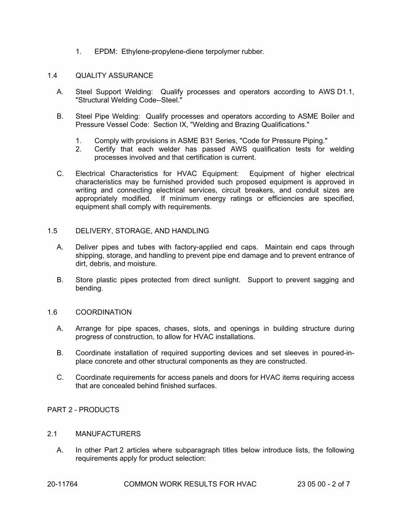
20-11764 COMMON WORK RESULTS FOR HVAC 23 05 00 - 2 of 7
1. EPDM: Ethylene-propylene-diene terpolymer rubber.
1.4 QUALITY ASSURANCE
A. Steel Support Welding: Qualify processes and operators according to AWS D1.1, "Structural Welding Code--Steel."
B. Steel Pipe Welding: Qualify processes and operators according to ASME Boiler and Pressure Vessel Code: Section IX, "Welding and Brazing Qualifications."
1. Comply with provisions in ASME B31 Series, "Code for Pressure Piping." 2. Certify that each welder has passed AWS qualification tests for welding
processes involved and that certification is current.
C. Electrical Characteristics for HVAC Equipment: Equipment of higher electrical characteristics may be furnished provided such proposed equipment is approved in writing and connecting electrical services, circuit breakers, and conduit sizes are appropriately modified. If minimum energy ratings or efficiencies are specified, equipment shall comply with requirements.
1.5 DELIVERY, STORAGE, AND HANDLING
A. Deliver pipes and tubes with factory-applied end caps. Maintain end caps through shipping, storage, and handling to prevent pipe end damage and to prevent entrance of dirt, debris, and moisture.
B. Store plastic pipes protected from direct sunlight. Support to prevent sagging and bending.
1.6 COORDINATION
A. Arrange for pipe spaces, chases, slots, and openings in building structure during progress of construction, to allow for HVAC installations.
B. Coordinate installation of required supporting devices and set sleeves in poured-in-place concrete and other structural components as they are constructed.
C. Coordinate requirements for access panels and doors for HVAC items requiring access that are concealed behind finished surfaces.
PART 2 - PRODUCTS
2.1 MANUFACTURERS
A. In other Part 2 articles where subparagraph titles below introduce lists, the following requirements apply for product selection:
20-11764 COMMON WORK RESULTS FOR HVAC 23 05 00 - 3 of 7
1. Manufacturers: Subject to compliance with requirements, provide products by the manufacturers specified.
2.2 PIPE, TUBE, AND FITTINGS
A. Refer to individual Division 23 piping Sections for pipe, tube, and fitting materials and joining methods.
B. Pipe Threads: ASME B1.20.1 for factory-threaded pipe and pipe fittings.
2.3 JOINING MATERIALS
A. Refer to individual Division 23 piping Sections for special joining materials not listed below.
B. Pipe-Flange Gasket Materials: Suitable for chemical and thermal conditions of piping system contents.
1. ASME B16.21, nonmetallic, flat, asbestos-free, 1/8-inch maximum thickness unless thickness or specific material is indicated.
a. Full-Face Type: For flat-face, Class 125, cast-iron and cast-bronze flanges.
b. Narrow-Face Type: For raised-face, Class 250, cast-iron and steel flanges.
2. AWWA C110, rubber, flat face, 1/8-inch thick, unless otherwise indicated; and full-face or ring type, unless otherwise indicated.
C. Flange Bolts and Nuts: ASME B18.2.1, carbon steel, unless otherwise indicated.
D. Solder Filler Metals: ASTM B 32, lead-free alloys. Include water-flushable flux according to ASTM B 813.
E. Brazing Filler Metals: AWS A5.8, BCuP Series, copper-phosphorus alloys for general-duty brazing, unless otherwise indicated; and AWS A5.8, BAg1, silver alloy for refrigerant piping, unless otherwise indicated.
2.4 ESCUTCHEONS
A. Description: Manufactured wall and ceiling escutcheons and floor plates, with an ID to closely fit around pipe, tube, and insulation of insulated piping and an OD that completely covers opening.
B. One-Piece, Deep-Pattern Type: Deep-drawn, box-shaped brass with polished chrome-plated finish.
C. One-Piece, Cast-Brass Type: With set screw.
1. Finish: Polished chrome-plated.
20-11764 COMMON WORK RESULTS FOR HVAC 23 05 00 - 4 of 7
D. Split-Casting, Cast-Brass Type: With concealed hinge and set screw.
1. Finish: Polished chrome-plated.
PART 3 - EXECUTION
3.1 HVAC DEMOLITION
A. Refer to Division 01 Section "Cutting and Patching" and Division 02 Section "Selective Structure Demolition" for general demolition requirements and procedures.
B. Disconnect, demolish, and remove HVAC systems, equipment, and components indicated to be removed.
1. Piping to Be Removed: Remove portion of piping indicated to be removed and cap or plug remaining piping with same or compatible piping material.
2. Piping to Be Abandoned in Place: Drain piping and cap or plug piping with same or compatible piping material.
3. Equipment to Be Removed: Disconnect and cap services and remove equipment.
4. Equipment to Be Removed and Reinstalled: Disconnect and cap services and remove, clean, and store equipment; when appropriate, reinstall, reconnect, and make equipment operational.
5. Equipment to Be Removed and Salvaged: Disconnect and cap services and remove equipment and deliver to Owner.
C. If pipe, insulation, or equipment to remain is damaged in appearance or is unserviceable, remove damaged or unserviceable portions and replace with new products of equal capacity and quality.
3.2 PIPING SYSTEMS - COMMON REQUIREMENTS
A. Install piping according to the following requirements and Division 23 Sections specifying piping systems.
B. Drawing plans, schematics, and diagrams indicate general location and arrangement of piping systems. Indicated locations and arrangements were used to size pipe and calculate friction loss, expansion, pump sizing, and other design considerations. Install piping as indicated unless deviations to layout are approved on Coordination Drawings.
C. Install piping in concealed locations, unless otherwise indicated and except in equipment rooms and service areas.
D. Install piping indicated to be exposed and piping in equipment rooms and service areas at right angles or parallel to building walls. Diagonal runs are prohibited unless specifically indicated otherwise.
E. Install piping above accessible ceilings to allow sufficient space for ceiling panel removal.
20-11764 COMMON WORK RESULTS FOR HVAC 23 05 00 - 5 of 7
F. Install piping to permit valve servicing.
G. Install piping at indicated slopes.
H. Install piping free of sags and bends.
I. Install fittings for changes in direction and branch connections.
J. Install piping to allow application of insulation.
K. Select system components with pressure rating equal to or greater than system operating pressure.
L. Install escutcheons for penetrations of walls, ceilings, and floors according to the following:
1. New Piping:
a. Piping with Fitting or Sleeve Protruding from Wall: One-piece, deep-pattern type.
b. Chrome-Plated Piping: One-piece, cast-brass type with polished chrome-plated finish.
c. Insulated Piping: One-piece, stamped-steel type with spring clips. d. Bare Piping at Wall and Floor Penetrations in Finished Spaces: One-piece,
cast-brass type with polished chrome-plated finish. e. Bare Piping at Wall and Floor Penetrations in Finished Spaces: One-piece,
stamped-steel type.
M. Verify final equipment locations for roughing-in.
N. Refer to equipment specifications in other Sections of these Specifications for roughing-in requirements.
3.3 PIPING JOINT CONSTRUCTION
A. Join pipe and fittings according to the following requirements and Division 23 Sections specifying piping systems.
B. Ream ends of pipes and tubes and remove burrs. Bevel plain ends of steel pipe.
C. Remove scale, slag, dirt, and debris from inside and outside of pipe and fittings before assembly.
D. Soldered Joints: Apply ASTM B 813, water-flushable flux, unless otherwise indicated, to tube end. Construct joints according to ASTM B 828 or CDA's "Copper Tube Handbook," using lead-free solder alloy complying with ASTM B 32.
E. Brazed Joints: Construct joints according to AWS's "Brazing Handbook," "Pipe and Tube" Chapter, using copper-phosphorus brazing filler metal complying with AWS A5.8.

20-11764 COMMON WORK RESULTS FOR HVAC 23 05 00 - 6 of 7
F. Welded Joints: Construct joints according to AWS D10.12, using qualified processes and welding operators according to Part 1 "Quality Assurance" Article.
G. Flanged Joints: Select appropriate gasket material, size, type, and thickness for service application. Install gasket concentrically positioned. Use suitable lubricants on bolt threads.
3.4 PIPING CONNECTIONS
A. Make connections according to the following, unless otherwise indicated:
1. Install unions, in piping NPS 2 and smaller, adjacent to each valve and at final connection to each piece of equipment.
2. Install flanges, in piping NPS 2-1/2 and larger, adjacent to flanged valves and at final connection to each piece of equipment.
3.5 EQUIPMENT INSTALLATION - COMMON REQUIREMENTS
A. Install equipment to allow maximum possible headroom unless specific mounting heights are not indicated.
B. Install equipment level and plumb, parallel and perpendicular to other building systems and components in exposed interior spaces, unless otherwise indicated.
C. Install HVAC equipment to facilitate service, maintenance, and repair or replacement of components. Connect equipment for ease of disconnecting, with minimum interference to other installations. Extend grease fittings to accessible locations.
D. Install equipment to allow right of way for piping installed at required slope.
3.6 ACCESS TO VALVE AND EQUIPMENT
A. Access shall be possible where valves, expansion joints, fire dampers, motors, filters, control devices, and any other equipment requiring access for servicing, repairs, or maintenance are located in walls, soffits, chases, and/or above ceilings.
B. Definition of Accessible:
1. Valves and dampers may be operated. 2. Control devices may be adjusted. 3. Fire dampers may be reset. 4. Equipment access panels may be opened. 5. Normal maintenance work such as replacement of filters, lubrication of bearings,
etc., may be performed readily within arm’s reach of access opening. 6. It shall not be necessary to crawl through furred ceiling space to perform such
operations.
C. Install piping, equipment and accessories to permit easy access for maintenance.

20-11764 COMMON WORK RESULTS FOR HVAC 23 05 00 - 7 of 7
D. Group concealed valves, expansion joints, controls, dampers and equipment requiring service access, so as to be freely accessible through access doors and to minimize the number of access doors required.
E. Relocate piping equipment and accessories as required, at no extra cost to afford proper maintenance access.
F. Coordinate location of access panels with applicable trades installing walls or ceiling.
1. Coordinate panel locations with lights and other architectural features. 2. Submit proposed panel locations to Architect for review.
G. Arrange for location and marking of removable files in splined ceilings where access panels are not installed.
3.7 ERECTION OF METAL SUPPORTS AND ANCHORAGES
A. Cut, fit, and place miscellaneous metal supports accurately in location, alignment, and elevation to support and anchor HVAC materials and equipment.
B. Field Welding: Comply with AWS D1.1.
3.8 ERECTION OF WOOD SUPPORTS AND ANCHORAGES
A. Cut, fit, and place wood grounds, nailers, blocking, and anchorages to support, and anchor HVAC materials and equipment.
B. Select fastener sizes that will not penetrate members if opposite side will be exposed to view or will receive finish materials. Tighten connections between members. Install fasteners without splitting wood members.
C. Attach to substrates as required to support applied loads.
END OF SECTION

20-11764 COMMON MOTOR REQUIREMENTS FOR HVAC EQUIPMENT
23 05 13 - 1 of 3
SECTION 23 05 13 COMMON MOTOR REQUIREMENTS FOR HVAC EQUIPMENT
PART 1 - GENERAL
1.1 RELATED DOCUMENTS
A. Drawings and general provisions of the Contract, including General and Supplementary Conditions and Division 01 Specification Sections, apply to this Section.
1.2 SUMMARY
A. Section includes general requirements for single-phase and polyphase, general-purpose, horizontal, small and medium, squirrel-cage induction motors for use on ac power systems up to 600 V and installed at equipment manufacturer's factory or shipped separately by equipment manufacturer for field installation.
1.3 COORDINATION
A. Coordinate features of motors, installed units, and accessory devices to be compatible with the following:
1. Motor controllers. 2. Torque, speed, and horsepower requirements of the load. 3. Ratings and characteristics of supply circuit and required control sequence. 4. Ambient and environmental conditions of installation location.
PART 2 - PRODUCTS
2.1 GENERAL MOTOR REQUIREMENTS
A. Comply with requirements in this Section except when stricter requirements are specified in HVAC equipment schedules or Sections.
B. Comply with NEMA MG 1 unless otherwise indicated.
C. Comply with IEEE 841 for severe-duty motors.
2.2 MOTOR CHARACTERISTICS
A. Duty: Continuous duty at ambient temperature of 40 deg C and at altitude of 3300 feet above sea level.

20-11764 COMMON MOTOR REQUIREMENTS FOR HVAC EQUIPMENT
23 05 13 - 2 of 3
B. Capacity and Torque Characteristics: Sufficient to start, accelerate, and operate connected loads at designated speeds, at installed altitude and environment, with indicated operating sequence, and without exceeding nameplate ratings or considering service factor.
2.3 POLYPHASE MOTORS
A. Description: NEMA MG 1, Design B, medium induction motor.
B. Efficiency: Energy efficient, as defined in NEMA MG 1.
C. Service Factor: 1.15.
D. Multispeed Motors: Variable torque.
1. For motors with 2:1 speed ratio, consequent pole, single winding. 2. For motors with other than 2:1 speed ratio, separate winding for each speed.
E. Multispeed Motors: Separate winding for each speed.
F. Rotor: Random-wound, squirrel cage.
G. Bearings: Regreasable, shielded, antifriction ball bearings suitable for radial and thrust loading.
H. Temperature Rise: Match insulation rating.
I. Insulation: Class F.
J. Code Letter Designation:
1. Motors 15 HP and Larger: NEMA starting Code F or Code G. 2. Motors Smaller than 15 HP: Manufacturer's standard starting characteristic.
K. Enclosure Material: Cast iron for motor frame sizes 324T and larger; rolled steel for motor frame sizes smaller than 324T.
2.4 POLYPHASE MOTORS WITH ADDITIONAL REQUIREMENTS
A. Motors Used with Reduced-Voltage and Multispeed Controllers: Match wiring connection requirements for controller with required motor leads. Provide terminals in motor terminal box, suited to control method.
B. Motors Used with Variable Frequency Controllers: Ratings, characteristics, and features coordinated with and approved by controller manufacturer.
1. Windings: Copper magnet wire with moisture-resistant insulation varnish, designed and tested to resist transient spikes, high frequencies, and short time rise pulses produced by pulse-width modulated inverters.

20-11764 COMMON MOTOR REQUIREMENTS FOR HVAC EQUIPMENT
23 05 13 - 3 of 3
2. Energy- and Premium-Efficient Motors: Class B temperature rise; Class F insulation.
3. Inverter-Duty Motors: Class F temperature rise; Class H insulation. 4. Thermal Protection: Comply with NEMA MG 1 requirements for thermally
protected motors.
C. Severe-Duty Motors: Comply with IEEE 841, with 1.15 minimum service factor.
2.5 SINGLE-PHASE MOTORS
A. Motors larger than 1/20 hp shall be DC electronic commutation type (ECM) specifically designed for fan applications. Prewired to the specific voltage and phase. Internal motor shall convert AC supplied to the fan to DC power to operate the motor. Motor shall be controllable down to 20% of full speed. Speed shall be controlled by either potentiometer dial mounted on the motor or by a 0-10 VDC signal. Motor shall be a minimum of 85% efficient at all speeds.
B. Bearings: Permanently lubricated, heavy duty ball bearings suitable for radial and thrust loading.
C. Motors: 1/20 HP and Smaller: Shaded-pole type.
D. Thermal Protection: Internal protection to automatically open power supply circuit to motor when winding temperature exceeds a safe value calibrated to temperature rating of motor insulation. Thermal-protection device shall automatically reset when motor temperature returns to normal range.
PART 3 - EXECUTION (Not Applicable)
END OF SECTION

20-11764 GENERAL-DUTY VALVES FOR HVAC PIPING 23 05 23 - 1 of 12
SECTION 23 05 23 GENERAL-DUTY VALVES FOR HVAC PIPING
PART 1 - GENERAL
1.1 RELATED DOCUMENTS
A. Drawings and general provisions of the Contract, including General and Supplementary Conditions and Division 01 Specification Sections, apply to this Section.
1.2 SUMMARY
A. Section Includes:
1. Brass ball valves. 2. Bronze ball valves. 3. Iron ball valves. 4. Iron, single-flange butterfly valves. 5. High-performance butterfly valves. 6. Bronze lift check valves. 7. Bronze swing check valves. 8. Iron swing check valves. 9. Iron, center-guided check valves. 10. Bronze gate valves. 11. Iron gate valves. 12. Iron globe valves. 13. Chainwheels.
B. Related Sections:
1. Division 23 HVAC piping Sections for specialty valves applicable to those Sections only.
2. Division 23 Section "Identification for HVAC Piping and Equipment" for valve tags and schedules.
1.3 DEFINITIONS
A. CWP: Cold working pressure.
B. EPDM: Ethylene propylene copolymer rubber.
C. NBR: Acrylonitrile-butadiene, Buna-N, or nitrile rubber.
D. NRS: Nonrising stem.
E. OS&Y: Outside screw and yoke.

20-11764 GENERAL-DUTY VALVES FOR HVAC PIPING 23 05 23 - 2 of 12
F. RS: Rising stem.
G. SWP: Steam working pressure.
1.4 SUBMITTALS
A. Product Data: For each type of valve indicated.
1.5 QUALITY ASSURANCE
A. Source Limitations for Valves: Obtain each type of valve from single source from single manufacturer.
B. ASME Compliance:
1. ASME B16.10 and ASME B16.34 for ferrous valve dimensions and design criteria.
2. ASME B31.1 for power piping valves. 3. ASME B31.9 for building services piping valves.
1.6 DELIVERY, STORAGE, AND HANDLING
A. Prepare valves for shipping as follows:
1. Protect internal parts against rust and corrosion. 2. Protect threads, flange faces, grooves, and weld ends. 3. Set angle, gate, and globe valves closed to prevent rattling. 4. Set ball and plug valves open to minimize exposure of functional surfaces. 5. Set butterfly valves closed or slightly open. 6. Block check valves in either closed or open position.
B. Use the following precautions during storage:
1. Maintain valve end protection. 2. Store valves indoors and maintain at higher than ambient dew point temperature.
If outdoor storage is necessary, store valves off the ground in watertight enclosures.
C. Use sling to handle large valves; rig sling to avoid damage to exposed parts. Do not use handwheels or stems as lifting or rigging points.
PART 2 - PRODUCTS
2.1 GENERAL REQUIREMENTS FOR VALVES
A. Refer to HVAC valve schedule articles for applications of valves.

20-11764 GENERAL-DUTY VALVES FOR HVAC PIPING 23 05 23 - 3 of 12
B. Valve Pressure and Temperature Ratings: Not less than indicated and as required for system pressures and temperatures.
C. Valve Sizes: Same as upstream piping unless otherwise indicated.
D. Valve Actuator Types:
1. Gear Actuator: For quarter-turn valves NPS 8 and larger. 2. Handwheel: For valves other than quarter-turn types. 3. Handlever: For quarter-turn valves NPS 6 and smaller. 4. Chainwheel: Device for attachment to valve handwheel, stem, or other actuator;
of size and with chain for mounting height, as indicated in the "Valve Installation" Article.
E. Valves in Insulated Piping: With 2-inch stem extensions and the following features:
1. Gate Valves: With rising stem. 2. Ball Valves: With extended operating handle of non-thermal-conductive material,
and protective sleeve that allows operation of valve without breaking the vapor seal or disturbing insulation.
3. Butterfly Valves: With extended neck.
F. Valve-End Connections:
1. Flanged: With flanges according to ASME B16.1 for iron valves. 2. Grooved: With grooves according to AWWA C606. 3. Solder Joint: With sockets according to ASME B16.18. 4. Threaded: With threads according to ASME B1.20.1.
G. Valve Bypass and Drain Connections: MSS SP-45.
2.2 BRASS BALL VALVES
A. Two-Piece, Full-Port, Brass Ball Valves with Brass Trim:
1. Manufacturers: Subject to compliance with requirements, provide products by one of the following:
a. Crane Co.; Crane Valve Group; Crane Valves. b. Crane Co.; Crane Valve Group; Jenkins Valves. c. Flow-Tek, Inc.; a subsidiary of Bray International, Inc. d. Hammond Valve. e. Jomar International, LTD. f. Milwaukee Valve Company. g. NIBCO INC.
2. Description:
a. Standard: MSS SP-110. b. SWP Rating: 150 psig.

20-11764 GENERAL-DUTY VALVES FOR HVAC PIPING 23 05 23 - 4 of 12
c. CWP Rating: 600 psig. d. Body Design: Two piece. e. Body Material: Forged brass. f. Ends: Threaded. g. Seats: PTFE or TFE. h. Stem: Brass. i. Ball: Chrome-plated brass. j. Port: Full.
2.3 BRONZE BALL VALVES
A. Two-Piece, Full-Port, Bronze Ball Valves with Bronze Trim:
1. Manufacturers: Subject to compliance with requirements, provide products by one of the following:
a. American Valve, Inc. b. Conbraco Industries, Inc.; Apollo Valves. c. Crane Co.; Crane Valve Group; Crane Valves. d. Hammond Valve. e. Milwaukee Valve Company. f. NIBCO INC. g. Watts Regulator Co.; a division of Watts Water Technologies, Inc.
2. Description:
a. Standard: MSS SP-110. b. SWP Rating: 150 psig. c. CWP Rating: 600 psig. d. Body Design: Two piece. e. Body Material: Bronze. f. Ends: Threaded. g. Seats: PTFE or TFE. h. Stem: Bronze. i. Ball: Chrome-plated brass. j. Port: Full.
2.4 IRON BALL VALVES
A. Class 125, Iron Ball Valves:
1. Manufacturers: Subject to compliance with requirements, provide products by one of the following:
a. American Valve, Inc. b. Conbraco Industries, Inc.; Apollo Valves. c. Milwaukee Valve Company. d. NIBCO INC. e. Watts Regulator Co.; a division of Watts Water Technologies, Inc.

20-11764 GENERAL-DUTY VALVES FOR HVAC PIPING 23 05 23 - 5 of 12
2. Description:
a. Standard: MSS SP-72. b. CWP Rating: 200 psig. c. Body Design: Split body. d. Body Material: ASTM A 126, gray iron. e. Ends: Flanged. f. Seats: PTFE or TFE. g. Stem: Stainless steel. h. Ball: Stainless steel. i. Port: Full.
2.5 IRON, SINGLE-FLANGE BUTTERFLY VALVES
A. 200 CWP, Iron, Single-Flange Butterfly Valves with EPDM Seat and Aluminum-Bronze Disc:
1. Manufacturers: Subject to compliance with requirements, provide products by one of the following:
a. Conbraco Industries, Inc.; Apollo Valves. b. Cooper Cameron Valves; a division of Cooper Cameron Corp. c. Crane Co.; Crane Valve Group; Jenkins Valves. d. Crane Co.; Crane Valve Group; Stockham Division. e. DeZurik Water Controls. f. Flo Fab Inc. g. Hammond Valve. h. Milwaukee Valve Company. i. NIBCO INC. j. Watts Regulator Co.; a division of Watts Water Technologies, Inc.
2. Description:
a. Standard: MSS SP-67, Type I. b. CWP Rating: 200 psig. c. Body Design: Lug type; suitable for bidirectional dead-end service at rated
pressure without use of downstream flange. d. Body Material: ASTM A 126, cast iron or ASTM A 536, ductile iron. e. Seat: EPDM. f. Stem: One- or two-piece stainless steel. g. Disc: Aluminum bronze.
2.6 HIGH-PERFORMANCE BUTTERFLY VALVES
A. Class 150, Single-Flange, High-Performance Butterfly Valves:
1. Manufacturers: Subject to compliance with requirements, provide products by one of the following: a. Crane Co.; Crane Valve Group; Flowseal.

20-11764 GENERAL-DUTY VALVES FOR HVAC PIPING 23 05 23 - 6 of 12
b. Crane Co.; Crane Valve Group; Stockham Division. c. DeZurik Water Controls. d. Hammond Valve. e. Milwaukee Valve Company. f. NIBCO INC. g. Process Development & Control, Inc. h. Tyco Valves & Controls; a unit of Tyco Flow Control.
2. Description:
a. Standard: MSS SP-68. b. CWP Rating: 285 psig at 100 deg F. c. Body Design: Lug type; suitable for bidirectional dead-end service at rated
pressure without use of downstream flange. d. Body Material: Carbon steel, cast iron, ductile iron, or stainless steel. e. Seat: Reinforced PTFE or metal. f. Stem: Stainless steel; offset from seat plane. g. Disc: Carbon steel. h. Service: Bidirectional.
2.7 BRONZE LIFT CHECK VALVES
A. Class 125, Lift Check Valves with Bronze Disc:
1. Manufacturers: Subject to compliance with requirements, provide products by one of the following:
a. Crane Co.; Crane Valve Group; Crane Valves. b. Crane Co.; Crane Valve Group; Jenkins Valves. c. Crane Co.; Crane Valve Group; Stockham Division.
2. Description:
a. Standard: MSS SP-80, Type 1. b. CWP Rating: 200 psig. c. Body Design: Vertical flow. d. Body Material: ASTM B 61 or ASTM B 62, bronze. e. Ends: Threaded. f. Disc: Bronze.
2.8 BRONZE SWING CHECK VALVES
A. Class 150, Bronze Swing Check Valves with Bronze Disc:
1. Manufacturers: Subject to compliance with requirements, provide products by one of the following:
a. American Valve, Inc. b. Crane Co.; Crane Valve Group; Crane Valves.

20-11764 GENERAL-DUTY VALVES FOR HVAC PIPING 23 05 23 - 7 of 12
c. Crane Co.; Crane Valve Group; Jenkins Valves. d. Crane Co.; Crane Valve Group; Stockham Division. e. Milwaukee Valve Company. f. NIBCO INC.
2. Description:
a. Standard: MSS SP-80, Type 3. b. CWP Rating: 300 psig. c. Body Design: Horizontal flow. d. Body Material: ASTM B 62, bronze. e. Ends: Threaded. f. Disc: Bronze.
2.9 IRON SWING CHECK VALVES
A. Class 125, Iron Swing Check Valves with Metal Seats:
1. Manufacturers: Subject to compliance with requirements, provide products by one of the following:
a. Crane Co.; Crane Valve Group; Crane Valves. b. Crane Co.; Crane Valve Group; Jenkins Valves. c. Crane Co.; Crane Valve Group; Stockham Division. d. Hammond Valve. e. Milwaukee Valve Company. f. NIBCO INC. g. Watts Regulator Co.; a division of Watts Water Technologies, Inc.
2. Description:
a. Standard: MSS SP-71, Type I. b. NPS 2-1/2 to NPS 12, CWP Rating: 200 psig. c. NPS 14 to NPS 24, CWP Rating: 150 psig. d. Body Design: Clear or full waterway. e. Body Material: ASTM A 126, gray iron with bolted bonnet. f. Ends: Flanged. g. Trim: Bronze. h. Gasket: Asbestos free.
B. Class 250, Iron Swing Check Valves with Metal Seats:
1. Manufacturers: Subject to compliance with requirements, provide products by one of the following:
a. Crane Co.; Crane Valve Group; Crane Valves. b. Crane Co.; Crane Valve Group; Jenkins Valves. c. Crane Co.; Crane Valve Group; Stockham Division. d. Hammond Valve. e. Milwaukee Valve Company.

20-11764 GENERAL-DUTY VALVES FOR HVAC PIPING 23 05 23 - 8 of 12
f. NIBCO INC. g. Watts Regulator Co.; a division of Watts Water Technologies, Inc.
2. Description:
a. Standard: MSS SP-71, Type I. b. NPS 2-1/2 to NPS 12, CWP Rating: 500 psig. c. NPS 14 to NPS 24, CWP Rating: 300 psig. d. Body Design: Clear or full waterway. e. Body Material: ASTM A 126, gray iron with bolted bonnet. f. Ends: Flanged. g. Trim: Bronze. h. Gasket: Asbestos free.
2.10 IRON GATE VALVES
A. Class 125, NRS, Iron Gate Valves:
1. Manufacturers: Subject to compliance with requirements, provide products by one of the following:
a. Crane Co.; Crane Valve Group; Crane Valves. b. Crane Co.; Crane Valve Group; Jenkins Valves. c. Crane Co.; Crane Valve Group; Stockham Division. d. Hammond Valve. e. Milwaukee Valve Company. f. NIBCO INC. g. Watts Regulator Co.; a division of Watts Water Technologies, Inc.
2. Description:
a. Standard: MSS SP-70, Type I. b. NPS 2-1/2 to NPS 12, CWP Rating: 200 psig. c. NPS 14 to NPS 24, CWP Rating: 150 psig. d. Body Material: ASTM A 126, gray iron with bolted bonnet. e. Ends: Flanged. f. Trim: Bronze. g. Disc: Solid wedge. h. Packing and Gasket: Asbestos free.
B. Class 250, OS&Y, Iron Gate Valves:
1. Manufacturers: Subject to compliance with requirements, provide products by one of the following:
a. Crane Co.; Crane Valve Group; Crane Valves. b. Crane Co.; Crane Valve Group; Stockham Division. c. Hammond Valve. d. Milwaukee Valve Company. e. NIBCO INC.

20-11764 GENERAL-DUTY VALVES FOR HVAC PIPING 23 05 23 - 9 of 12
f. Watts Regulator Co.; a division of Watts Water Technologies, Inc.
2. Description:
a. Standard: MSS SP-70, Type I. b. NPS 2-1/2 to NPS 12, CWP Rating: 500 psig. c. NPS 14 to NPS 24, CWP Rating: 300 psig. d. Body Material: ASTM A 126, gray iron with bolted bonnet. e. Ends: Flanged. f. Trim: Bronze. g. Disc: Solid wedge. h. Packing and Gasket: Asbestos free.
2.11 IRON GLOBE VALVES
A. Class 125, Iron Globe Valves:
1. Manufacturers: Subject to compliance with requirements, provide products by one of the following:
a. Crane Co.; Crane Valve Group; Crane Valves. b. Crane Co.; Crane Valve Group; Jenkins Valves. c. Crane Co.; Crane Valve Group; Stockham Division. d. Hammond Valve. e. Milwaukee Valve Company. f. NIBCO INC. g. Watts Regulator Co.; a division of Watts Water Technologies, Inc.
2. Description:
a. Standard: MSS SP-85, Type I. b. CWP Rating: 200 psig. c. Body Material: ASTM A 126, gray iron with bolted bonnet. d. Ends: Flanged. e. Trim: Bronze. f. Packing and Gasket: Asbestos free.
B. Class 250, Iron Globe Valves:
1. Manufacturers: Subject to compliance with requirements, provide products by one of the following:
a. Crane Co.; Crane Valve Group; Crane Valves. b. Crane Co.; Crane Valve Group; Jenkins Valves. c. Crane Co.; Crane Valve Group; Stockham Division. d. Hammond Valve. e. Milwaukee Valve Company. f. NIBCO INC. g. Watts Regulator Co.; a division of Watts Water Technologies, Inc.

20-11764 GENERAL-DUTY VALVES FOR HVAC PIPING 23 05 23 - 10 of 12
2. Description:
a. Standard: MSS SP-85, Type I. b. CWP Rating: 500 psig. c. Body Material: ASTM A 126, gray iron with bolted bonnet. d. Ends: Flanged. e. Trim: Bronze. f. Packing and Gasket: Asbestos free.
2.12 CHAINWHEELS
A. Manufacturers: Subject to compliance with requirements, provide products by one of the following:
1. Babbitt Steam Specialty Co. 2. Roto Hammer Industries. 3. Trumbull Industries.
B. Description: Valve actuation assembly with sprocket rim, brackets, and chain.
1. Brackets: Type, number, size, and fasteners required to mount actuator on valve.
2. Attachment: For connection to ball, butterfly and plug valve stems. 3. Sprocket Rim with Chain Guides: Ductile or cast iron, of type and size required
for valve. 4. Chain: Hot-dip, galvanized steel, of size required to fit sprocket rim.
PART 3 - EXECUTION
3.1 EXAMINATION
A. Examine valve interior for cleanliness, freedom from foreign matter, and corrosion. Remove special packing materials, such as blocks, used to prevent disc movement during shipping and handling.
B. Operate valves in positions from fully open to fully closed. Examine guides and seats made accessible by such operations.
C. Examine threads on valve and mating pipe for form and cleanliness.
D. Examine mating flange faces for conditions that might cause leakage. Check bolting for proper size, length, and material. Verify that gasket is of proper size, that its material composition is suitable for service, and that it is free from defects and damage.
E. Do not attempt to repair defective valves; replace with new valves.

20-11764 GENERAL-DUTY VALVES FOR HVAC PIPING 23 05 23 - 11 of 12
3.2 VALVE INSTALLATION
A. Install valves with unions or flanges at each piece of equipment arranged to allow service, maintenance, and equipment removal without system shutdown.
B. Locate valves for easy access and provide separate support where necessary.
C. Install valves in horizontal piping with stem at or above center of pipe.
D. Install valves in position to allow full stem movement.
E. Install chainwheels on operators for all valves NPS 4 and larger and more than 96 inches above floor. Extend chains to 60 inches above finished floor.
F. Install check valves for proper direction of flow and as follows:
1. Swing Check Valves: In horizontal position with hinge pin level. 2. Center-Guided Check Valves: In horizontal or vertical position, between flanges. 3. Lift Check Valves: With stem upright and plumb.
3.3 ADJUSTING
A. Adjust or replace valve packing after piping systems have been tested and put into service but before final adjusting and balancing. Replace valves if persistent leaking occurs.
3.4 GENERAL REQUIREMENTS FOR VALVE APPLICATIONS
A. If valve applications are not indicated, use the following:
1. Shutoff Service: Ball or butterfly valves. 2. Butterfly Valve Dead-End Service: Single-flange (lug) type. 3. Pump-Discharge Check Valves:
a. NPS 2-1/2 and Larger: Iron swing check valves with lever and weight or with spring or iron, center-guided, resilient-seat check valves.
B. If valves with specified SWP classes or CWP ratings are not available, the same types of valves with higher SWP classes or CWP ratings may be substituted.
C. Select valves, except wafer types, with the following end connections:
1. For Copper Tubing, NPS 2 and Smaller: Threaded ends except where solder-joint valve-end option is indicated in valve schedules below.
2. For Copper Tubing, NPS 2-1/2 to NPS 4: Flanged ends except where threaded valve-end option is indicated in valve schedules below.
3. For Copper Tubing, NPS 5 and Larger: Flanged ends. 4. For Steel Piping, NPS 2 and Smaller: Threaded ends. 5. For Steel Piping, NPS 2-1/2 to NPS 4: Flanged ends except where threaded
valve-end option is indicated in valve schedules below. 6. For Steel Piping, NPS 5 and Larger: Flanged ends.

20-11764 GENERAL-DUTY VALVES FOR HVAC PIPING 23 05 23 - 12 of 12
3.5 HEATING-WATER VALVE SCHEDULE
A. Pipe NPS 2 and Smaller: 1. Ball Valves: Two-piece, full port, brass or bronze with stainless-steel trim. 2. Bronze Swing Check Valves: Class 150, bronze disc. 3. Bronze Globe Valves: Class 150, nonmetallic disc.
B. Pipe NPS 2-1/2 and Larger:
1. Iron Valves, NPS 2-1/2 to NPS 4: May be provided with threaded ends instead of flanged ends.
2. Iron Ball Valves, NPS 2-1/2 to NPS 10: Class 150. 3. Iron, Single-Flange Butterfly Valves, NPS 2-1/2 to NPS 12: 200 CWP, EPDM
seat, aluminum-bronze disc. 4. High-Performance Butterfly Valves: Class 150, single flange. 5. Iron Swing Check Valves: Class 125, metal seats. 6. Iron, Center-Guided Check Valves: Class 150, globe, metal resilient seat. 7. Iron Globe Valves, NPS 2-1/2 to NPS 12: Class 125.
END OF SECTION
20-11764 HANGERS AND SUPPORTS FOR HVAC PIPING AND EQUIPMENT
23 05 29 - 1 of 7
SECTION 23 05 29 HANGERS AND SUPPORTS FOR HVAC PIPING AND EQUIPMENT
PART 1 - GENERAL
1.1 RELATED DOCUMENTS
A. Drawings and general provisions of the Contract, including General and Supplementary Conditions and Division 01 Specification Sections, apply to this Section.
1.2 SUMMARY
A. Section Includes:
1. Metal pipe hangers and supports. 2. Trapeze pipe hangers. 3. Metal framing systems. 4. Thermal-hanger shield inserts. 5. Fastener systems. 6. Pipe stands. 7. Equipment supports.
1.3 DEFINITIONS
A. MSS: Manufacturers Standardization Society of The Valve and Fittings Industry Inc.
1.4 PERFORMANCE REQUIREMENTS
A. Delegated Design: Design trapeze pipe hangers and equipment supports, including comprehensive engineering analysis by a qualified professional engineer, using performance requirements and design criteria indicated.
B. Structural Performance: Hangers and supports for HVAC piping and equipment shall withstand the effects of gravity loads and stresses within limits and under conditions indicated according to ASCE/SEI 7.
1. Design supports for multiple pipes, including pipe stands, capable of supporting combined weight of supported systems, system contents, and test water.
1.5 SUBMITTALS
A. Product Data: For each type of product indicated.
B. Welding certificates.

20-11764 HANGERS AND SUPPORTS FOR HVAC PIPING AND EQUIPMENT
23 05 29 - 2 of 7
1.6 QUALITY ASSURANCE
A. Structural Steel Welding Qualifications: Qualify procedures and personnel according to AWS D1.1/D1.1M, "Structural Welding Code - Steel."
B. Pipe Welding Qualifications: Qualify procedures and operators according to ASME Boiler and Pressure Vessel Code.
PART 2 - PRODUCTS
2.1 METAL PIPE HANGERS AND SUPPORTS
A. Carbon-Steel Pipe Hangers and Supports:
1. Description: MSS SP-58, Types 1 through 58, factory-fabricated components. 2. Galvanized Metallic Coatings: Pregalvanized or hot dipped. 3. Nonmetallic Coatings: Plastic coating, jacket, or liner. 4. Padded Hangers: Hanger with fiberglass or other pipe insulation pad or cushion
to support bearing surface of piping. 5. Hanger Rods: Continuous-thread rod, nuts, and washer made of carbon steel.
B. Stainless-Steel Pipe Hangers and Supports:
1. Description: MSS SP-58, Types 1 through 58, factory-fabricated components. 2. Padded Hangers: Hanger with fiberglass or other pipe insulation pad or cushion
to support bearing surface of piping. 3. Hanger Rods: Continuous-thread rod, nuts, and washer made of stainless steel.
2.2 TRAPEZE PIPE HANGERS
A. Description: MSS SP-69, Type 59, shop- or field-fabricated pipe-support assembly made from structural carbon-steel shapes with MSS SP-58 carbon-steel hanger rods, nuts, saddles, and U-bolts.
2.3 METAL FRAMING SYSTEMS
A. MFMA Manufacturer Metal Framing Systems:
1. Manufacturers: Subject to compliance with requirements, provide products by one of the following:
a. Cooper B-Line, Inc. b. Flex-Strut Inc. c. GS Metals Corp. d. Thomas & Betts Corporation. e. Unistrut Corporation; Tyco International, Ltd.

20-11764 HANGERS AND SUPPORTS FOR HVAC PIPING AND EQUIPMENT
23 05 29 - 3 of 7
2. Description: Shop- or field-fabricated pipe-support assembly for supporting multiple parallel pipes.
3. Standard: MFMA-4. 4. Channels: Continuous slotted steel channel with inturned lips. 5. Channel Nuts: Formed or stamped steel nuts or other devices designed to fit into
channel slot and, when tightened, prevent slipping along channel. 6. Paint Coating: Epoxy or Acrylic.
2.4 THERMAL-HANGER SHIELD INSERTS
A. Insulation-Insert Material for Cold Piping: ASTM C 552, Type II cellular glass with 100-psig (688-kPa) or ASTM C 591, Type VI, Grade 1 polyisocyanurate with 125-psig (862-kPa) minimum compressive strength and vapor barrier.
B. Insulation-Insert Material for Hot Piping: ASTM C 552, Type II cellular glass with 100-psig (688-kPa) or ASTM C 591, Type VI, Grade 1 polyisocyanurate with 125-psig (862-kPa) minimum compressive strength.
C. For Trapeze or Clamped Systems: Insert and shield shall cover entire circumference of pipe.
D. For Clevis or Band Hangers: Insert and shield shall cover lower 180 degrees of pipe.
E. Insert Length: Extend 2 inches (50 mm) beyond sheet metal shield for piping operating below ambient air temperature.
2.5 FASTENER SYSTEMS
A. Powder-Actuated Fasteners: Threaded-steel stud, for use in hardened portland cement concrete with pull-out, tension, and shear capacities appropriate for supported loads and building materials where used.
B. Mechanical-Expansion Anchors: Insert-wedge-type, zinc-coated steel anchors, for use in hardened portland cement concrete; with pull-out, tension, and shear capacities appropriate for supported loads and building materials where used.
2.6 PIPE STANDS
A. General Requirements for Pipe Stands: Shop- or field-fabricated assemblies made of manufactured corrosion-resistant components to support roof-mounted piping.
2.7 EQUIPMENT SUPPORTS
A. Description: Welded, shop- or field-fabricated equipment support made from structural carbon-steel shapes.

20-11764 HANGERS AND SUPPORTS FOR HVAC PIPING AND EQUIPMENT
23 05 29 - 4 of 7
2.8 MISCELLANEOUS MATERIALS
A. Structural Steel: ASTM A 36/A 36M, carbon-steel plates, shapes, and bars; black and galvanized.
B. Grout: ASTM C 1107, factory-mixed and -packaged, dry, hydraulic-cement, non-shrink and nonmetallic grout; suitable for interior and exterior applications.
1. Properties: Non-staining, noncorrosive, and nongaseous. 2. Design Mix: 5000-psi, 28-day compressive strength.
PART 3 - EXECUTION
3.1 HANGER AND SUPPORT INSTALLATION
A. Fastener System Installation:
1. Install mechanical-expansion anchors in concrete after concrete is placed and completely cured. Install fasteners according to manufacturer's written instructions.
B. Pipe Stand Installation:
1. Pipe Stand Types except Curb-Mounted Type: Assemble components and mount on smooth roof surface.
C. Install hangers and supports complete with necessary attachments, inserts, bolts, rods, nuts, washers, and other accessories.
D. Equipment Support Installation: Fabricate from welded-structural-steel shapes.
E. Install hangers and supports to allow controlled thermal and seismic movement of piping systems, to permit freedom of movement between pipe anchors, and to facilitate action of expansion joints, expansion loops, expansion bends, and similar units.
F. Load Distribution: Install hangers and supports so that piping live and dead loads and stresses from movement will not be transmitted to connected equipment.
G. Insulated Piping:
1. Attach clamps and spacers to piping:
a. Piping Operating above Ambient Temperature: Clamp may protect through insulation.
b. Piping Operating below Ambient Temperature: Use thermal-hanger shield insert with clamp sized to match OD of insert.
c. Do not exceed pipe stress limits allowed by ASME B31.9 for building services piping.

20-11764 HANGERS AND SUPPORTS FOR HVAC PIPING AND EQUIPMENT
23 05 29 - 5 of 7
2. Install MSS-SP-58, Type 39, protection saddles if insulation without vapor barrier is indicated. Fill interior voids with insulation that matches adjoining insulation.
3. Install MSS SP-58, Type 40, protective shields on cold piping with vapor barrier. Shields shall span an arc of 180 degrees.
a. Option: Thermal-hanger shield inserts may be used. Include steel weight-distribution plate for pipe NPS 4 (DN 100) and larger if pipe is installed on rollers.
4. Shield Dimensions for Pipe: Not less than the following:
a. NPS 1/4 to NPS 3-1/2 (DN 8 to DN 90): 12 inches long and 0.048 inch thick.
b. NPS 4 (DN 100): 12 inches long and 0.06 inch thick.
5. Thermal-Hanger Shields: Install with insulation same thickness as piping insulation.
3.2 EQUIPMENT SUPPORTS
A. Fabricate structural-steel stands to suspend equipment from structure overhead or to support equipment above floor.
B. Grouting: Place grout under supports for equipment and make bearing surface smooth.
C. Provide lateral bracing, to prevent swaying, for equipment supports.
3.3 METAL FABRICATIONS
A. Cut, drill, and fit miscellaneous metal fabrications for equipment supports.
B. Fit exposed connections together to form hairline joints. Field weld connections that cannot be shop welded because of shipping size limitations.
C. Field Welding: Comply with AWS D1.1/D1.1M procedures for shielded, metal arc welding; appearance and quality of welds; and methods used in correcting welding work; and with the following:
1. Use materials and methods that minimize distortion and develop strength and corrosion resistance of base metals.
2. Obtain fusion without undercut or overlap. 3. Remove welding flux immediately. 4. Finish welds at exposed connections so no roughness shows after finishing and
so contours of welded surfaces match adjacent contours.

20-11764 HANGERS AND SUPPORTS FOR HVAC PIPING AND EQUIPMENT
23 05 29 - 6 of 7
3.4 ADJUSTING
A. Hanger Adjustments: Adjust hangers to distribute loads equally on attachments and to achieve indicated slope of pipe.
B. Trim excess length of continuous-thread hanger and support rods to 1-1/2 inches.
3.5 HANGER AND SUPPORT SCHEDULE
A. Specific hanger and support requirements are in Sections specifying piping systems and equipment.
B. Comply with MSS SP-69 for pipe-hanger selections and applications that are not specified in piping system Sections.
C. Use hangers and supports with galvanized metallic coatings for piping and equipment that will not have field-applied finish.
D. Use nonmetallic coatings on attachments for electrolytic protection where attachments are in direct contact with copper tubing.
E. Use carbon-steel pipe hangers and supports and metal trapeze pipe hangers and attachments for general service applications.
F. Use stainless-steel pipe hangers and stainless-steel attachment for hostile environment applications.
G. Use thermal-hanger shield inserts for insulated piping and tubing.
H. Horizontal-Piping Hangers and Supports: Unless otherwise indicated and except as specified in piping system Sections, install the following types:
1. Adjustable, Steel Clevis Hangers (MSS Type 1): For suspension of noninsulated or insulated, stationary pipes NPS 1/2 to NPS 30.
2. Carbon- or Alloy-Steel, Double-Bolt Pipe Clamps (MSS Type 3): For suspension of pipes NPS 3/4 to NPS 36, requiring clamp flexibility and up to 4 inches of insulation.
3. U-Bolts (MSS Type 24): For support of heavy pipes NPS 1/2 to NPS 30. 4. Clips (MSS Type 26): For support of insulated pipes not subject to expansion or
contraction. 5. Pipe Stanchion Saddles (MSS Type 37): For support of pipes NPS 4 to NPS 36,
with steel-pipe base stanchion support and cast-iron floor flange or carbon-steel plate, and with U-bolt to retain pipe.
6. Single-Pipe Rolls (MSS Type 41): For suspension of pipes NPS 1 to NPS 30, from two rods if longitudinal movement caused by expansion and contraction might occur.
I. Hanger-Rod Attachments: Unless otherwise indicated and except as specified in piping system Sections, install the following types:

20-11764 HANGERS AND SUPPORTS FOR HVAC PIPING AND EQUIPMENT
23 05 29 - 7 of 7
1. Steel Turnbuckles (MSS Type 13): For adjustment up to 6 inches for heavy loads.
2. Steel Clevises (MSS Type 14): For 120 to 450 deg F piping installations.
J. Building Attachments: Unless otherwise indicated and except as specified in piping system Sections, install the following types:
1. Steel or Malleable Concrete Inserts (MSS Type 18): For upper attachment to suspend pipe hangers from concrete ceiling.
2. Side-Beam or Channel Clamps (MSS Type 20): For attaching to bottom flange of beams, channels, or angles.
3. Center-Beam Clamps (MSS Type 21): For attaching to center of bottom flange of beams.
4. C-Clamps (MSS Type 23): For structural shapes. 5. Side-Beam Brackets (MSS Type 34): For sides of steel or wooden beams.
K. Saddles and Shields: Unless otherwise indicated and except as specified in piping system Sections, install the following types:
1. Steel-Pipe-Covering Protection Saddles (MSS Type 39): To fill interior voids with insulation that matches adjoining insulation.
2. Protection Shields (MSS Type 40): Of length recommended in writing by manufacturer to prevent crushing insulation.
3. Thermal-Hanger Shield Inserts: For supporting insulated pipe.
L. Use powder-actuated fasteners or mechanical-expansion anchors instead of building attachments where required in concrete construction.
END OF SECTION
20-11764 IDENTIFICATION FOR HVAC PIPING AND EQUIPMENT 23 05 53 - 1 of 4
SECTION 230553 IDENTIFICATION FOR HVAC PIPING AND EQUIPMENT
PART 1 - GENERAL
1.1 RELATED DOCUMENTS
A. Drawings and general provisions of the Contract, including General and Supplementary Conditions and Division 01 Specification Sections, apply to this Section.
1.2 SUMMARY
A. Section Includes:
1. Equipment labels. 2. Pipe labels. 3. Valve tags.
1.3 SUBMITTALS
A. Product Data: For each type of product indicated.
B. Equipment Label Schedule: Include a listing of all equipment to be labeled with the proposed content for each label.
C. Valve numbering scheme.
D. Valve Schedules: For each piping system to include in maintenance manuals.
1.4 COORDINATION
A. Coordinate installation of identifying devices with completion of covering and painting of surfaces where devices are to be applied.
B. Coordinate installation of identifying devices with locations of access panels and doors.
C. Install identifying devices before installing acoustical ceilings and similar concealment.
PART 2 - PRODUCTS
2.1 EQUIPMENT LABELS
A. Plastic Labels for Equipment:

20-11764 IDENTIFICATION FOR HVAC PIPING AND EQUIPMENT 23 05 53 - 2 of 4
1. Material and Thickness: Multilayer, multicolor, plastic labels for mechanical engraving, 1/8 inch thick, and having predrilled holes for attachment hardware.
2. Letter Color: Black. 3. Background Color: White. 4. Maximum Temperature: Able to withstand temperatures up to 160 deg F. 5. Minimum Label Size: Length and width vary for required label content, but not
less than 2-1/2 by 3/4 inch. 6. Minimum Letter Size: 1/4 inch for name of units if viewing distance is less than
24 inches, 1/2 inch for viewing distances up to 72 inches. Include secondary lettering two-thirds to three-fourths the size of principal lettering.
7. Fasteners: Stainless-steel rivets or self-tapping screws.
B. Label Content: Include equipment's Drawing designation or unique equipment number, Drawing numbers where equipment is indicated (plans, details, and schedules), plus the Specification Section number and title where equipment is specified.
C. Equipment Label Schedule: For each item of equipment to be labeled, on 8-1/2-by-11-inch bond paper. Tabulate equipment identification number and identify Drawing numbers where equipment is indicated (plans, details, and schedules), plus the Specification Section number and title where equipment is specified. Equipment schedule shall be included in operation and maintenance data.
2.2 PIPE LABELS
A. General Requirements for Manufactured Pipe Labels: Preprinted, color-coded, with lettering indicating service, and showing flow direction.
B. Pretensioned Pipe Labels: Precoiled, semirigid plastic formed to cover full circumference of pipe and to attach to pipe without fasteners or adhesive.
C. Self-Adhesive Pipe Labels: Printed plastic with contact-type, permanent-adhesive backing.
D. Pipe Label Contents: Include identification of piping service using same designations or abbreviations as used on Drawings, pipe size, and an arrow indicating flow direction.
1. Flow-Direction Arrows: Integral with piping system service lettering to accommodate both directions, or as separate unit on each pipe label to indicate flow direction.
2. Lettering Size: At least 1-1/2 inches high.
2.3 VALVE TAGS
A. Valve Tags: Stamped or engraved with 1/4-inch letters for piping system abbreviation and 1/2-inch numbers.
1. Tag Material: Brass, 0.032-inch minimum thickness, and having predrilled or stamped holes for attachment hardware.
2. Fasteners: Brass beaded chain.

20-11764 IDENTIFICATION FOR HVAC PIPING AND EQUIPMENT 23 05 53 - 3 of 4
B. Valve Schedules: For each piping system, on 8-1/2-by-11-inch bond paper. Tabulate valve number, piping system, system abbreviation (as shown on valve tag), location of valve (room or space), normal-operating position (open, closed, or modulating), and variations for identification. Mark valves for emergency shutoff and similar special uses.
1. Valve-tag schedule shall be included in operation and maintenance data.
PART 3 - EXECUTION
3.1 PREPARATION
A. Clean piping and equipment surfaces of substances that could impair bond of identification devices, including dirt, oil, grease, release agents, and incompatible primers, paints, and encapsulants.
3.2 EQUIPMENT LABEL INSTALLATION
A. Install or permanently fasten labels on each major item of mechanical equipment.
B. Locate equipment labels where accessible and visible.
3.3 PIPE LABEL INSTALLATION
A. Locate pipe labels where piping is exposed or above accessible ceilings in finished spaces; machine rooms; accessible maintenance spaces such as shafts, tunnels, and plenums; and exterior exposed locations as follows:
1. Near each valve and control device. 2. Near each branch connection, excluding short takeoffs for fixtures and terminal
units. Where flow pattern is not obvious, mark each pipe at branch. 3. Near penetrations through walls, floors, ceilings, and inaccessible enclosures. 4. At access doors, manholes, and similar access points that permit view of
concealed piping. 5. Near major equipment items and other points of origination and termination. 6. Spaced at maximum intervals of 50 feet along each run. Reduce intervals to 25
feet in areas of congested piping and equipment.
B. Pipe Label Color Schedule:
1. Chilled-Water Piping:
a. Background Color: Blue. b. Letter Color: Black.

20-11764 IDENTIFICATION FOR HVAC PIPING AND EQUIPMENT 23 05 53 - 4 of 4
3.4 VALVE-TAG INSTALLATION
A. Install tags on valves and control devices in piping systems, except check valves; valves within factory-fabricated equipment units; shutoff valves; faucets; convenience and lawn-watering hose connections; and HVAC terminal devices and similar roughing-in connections of end-use fixtures and units. List tagged valves in a valve schedule.
B. Valve-Tag Application Schedule: Tag valves according to size, shape, and color scheme and with captions similar to those indicated in the following subparagraphs:
1. Valve-Tag Size and Shape:
a. Chilled Water: 1-1/2 inches, round.
2. Valve-Tag Color:
a. Chilled Water: Natural.
3. Letter Color:
a. Chilled Water: Black.
END OF SECTION

20-11764 TESTING, ADJUSTING AND BALANCING FOR HVAC 23 05 93 - 1 of 10
SECTION 23 05 93 TESTING, ADJUSTING, AND BALANCING FOR HVAC
PART 1 - GENERAL
1.1 RELATED DOCUMENTS
A. Drawings and general provisions of the Contract, including General and Supplementary Conditions and Division 01 Specification Sections, apply to this Section.
1.2 SUMMARY
A. Section Includes:
1. Balancing Hydronic Piping Systems:
a. Variable-flow hydronic systems.
1.3 DEFINITIONS
A. AABC: Associated Air Balance Council.
B. NEBB: National Environmental Balancing Bureau.
C. TAB: Testing, adjusting, and balancing.
D. TABB: Testing, Adjusting, and Balancing Bureau.
E. TAB Specialist: An entity engaged to perform TAB Work.
1.4 SUBMITTALS
A. Qualification Data: Within 45 days of Contractor's Notice to Proceed, submit documentation that the TAB contractor and this Project's TAB team members meet the qualifications specified in "Quality Assurance" Article.
B. Certified TAB reports.
1.5 QUALITY ASSURANCE
A. TAB Contractor Qualifications: Engage a TAB entity certified by AABC or NEBB with a minimum of 10 years of successful testing, adjusting, and balancing experience.
1. TAB Field Supervisor: Employee of the TAB contractor and certified by AABC or NEBB.

20-11764 TESTING, ADJUSTING AND BALANCING FOR HVAC 23 05 93 - 2 of 10
2. TAB Technician: Employee of the TAB contractor and who is certified by AABC or NEBB as a TAB technician.
1.6 PROJECT CONDITIONS
A. Full Owner Occupancy: Owner will occupy the site and existing building during entire TAB period. Cooperate with Owner during TAB operations to minimize conflicts with Owner's operations.
1.7 COORDINATION
A. Notice: Provide seven days' advance notice for each test. Include scheduled test dates and times.
B. Perform TAB after leakage and pressure tests on air and water distribution systems have been satisfactorily completed.
PART 2 - PRODUCTS (Not Applicable)
PART 3 - EXECUTION
3.1 EXAMINATION
A. Examine the Contract Documents to become familiar with Project requirements and to discover conditions in systems' designs that may preclude proper TAB of systems and equipment.
B. Examine systems for installed balancing devices, such as test ports, gage cocks, thermometer wells, flow-control devices, balancing valves and fittings, and manual volume dampers. Verify that locations of these balancing devices are accessible.
C. Examine the approved submittals for HVAC systems and equipment.
D. Examine design data including HVAC system descriptions, statements of design assumptions for environmental conditions and systems' output, and statements of philosophies and assumptions about HVAC system and equipment controls.
E. Examine equipment performance data including fan and pump curves.
1. Relate performance data to Project conditions and requirements, including system effects that can create undesired or unpredicted conditions that cause reduced capacities in all or part of a system.
F. Examine system and equipment installations and verify that field quality-control testing, cleaning, and adjusting specified in individual Sections have been performed.
G. Examine test reports specified in individual system and equipment Sections.
20-11764 TESTING, ADJUSTING AND BALANCING FOR HVAC 23 05 93 - 3 of 10
H. Examine HVAC equipment and filters and verify that bearings are greased, belts are aligned and tight, and equipment with functioning controls is ready for operation.
I. Examine strainers. Verify that startup screens are replaced by permanent screens with indicated perforations.
J. Examine three-way valves for proper installation for their intended function of diverting or mixing fluid flows.
K. Examine system pumps to ensure absence of entrained air in the suction piping.
L. Examine operating safety interlocks and controls on HVAC equipment.
M. Report deficiencies discovered before and during performance of TAB procedures. Observe and record system reactions to changes in conditions. Record default set points if different from indicated values.
3.2 PREPARATION
A. Complete system-readiness checks and prepare reports. Verify the following:
1. Permanent electrical-power wiring is complete. 2. Hydronic systems are filled, clean, and free of air. 3. Automatic temperature-control systems are operational. 4. Equipment and duct access doors are securely closed. 5. Isolating and balancing valves are open and control valves are operational.
3.3 GENERAL PROCEDURES FOR TESTING AND BALANCING
A. Perform testing and balancing procedures on each system according to the procedures contained in AABC's "National Standards for Total System Balance" or NEBB’s “Procedural Standards for TAB,” and in this Section.
B. Cut insulation, ducts, pipes, and equipment cabinets for installation of test probes to the minimum extent necessary for TAB procedures.
1. After testing and balancing, patch probe holes in ducts with same material and thickness as used to construct ducts.
2. Install and join new insulation that matches removed materials. Restore insulation, coverings, vapor barrier, and finish according to Division 23 Section "HVAC Insulation."
C. Mark equipment and balancing devices, including damper-control positions, valve position indicators, fan-speed-control levers, and similar controls and devices, with paint or other suitable, permanent identification material to show final settings.
D. Take and report testing and balancing measurements in inch-pound (IP) units.

20-11764 TESTING, ADJUSTING AND BALANCING FOR HVAC 23 05 93 - 4 of 10
GENERAL PROCEDURES FOR HYDRONIC SYSTEMS
E. Prepare test reports with pertinent design data, and number in sequence starting at pump to end of system. Check the sum of branch-circuit flows against the approved pump flow rate. Correct variations that exceed plus or minus 5 percent.
F. Prepare schematic diagrams of systems' "as-built" piping layouts.
G. Prepare hydronic systems for testing and balancing according to the following, in addition to the general preparation procedures specified above:
1. Open all manual valves for maximum flow. 2. Check liquid level in expansion tank. 3. Check makeup water-station pressure gage for adequate pressure for highest
vent. 4. Check flow-control valves for specified sequence of operation, and set at
indicated flow. 5. Set differential-pressure control valves at the specified differential pressure. Do
not set at fully closed position when pump is positive-displacement type unless several terminal valves are kept open.
6. Set system controls so automatic valves are wide open to heat exchangers. 7. Check pump-motor load. If motor is overloaded, throttle main flow-balancing
device so motor nameplate rating is not exceeded. 8. Check air vents for a forceful liquid flow exiting from vents when manually
operated.
3.4 PROCEDURES FOR CONSTANT-FLOW HYDRONIC SYSTEMS
A. Measure water flow at pumps. Use the following procedures except for positive-displacement pumps:
1. Verify impeller size by operating the pump with the discharge valve closed. Read pressure differential across the pump. Convert pressure to head and correct for differences in gage heights. Note the point on manufacturer's pump curve at zero flow and verify that the pump has the intended impeller size.
a. If impeller sizes must be adjusted to achieve pump performance, obtain approval from [Architect] [or] [Construction Manager] [or] [Commissioning Authority] and comply with requirements in Division 23 Section "Hydronic Pumps."
2. Check system resistance. With all valves open, read pressure differential across the pump and mark pump manufacturer's head-capacity curve. Adjust pump discharge valve until indicated water flow is achieved.
a. Monitor motor performance during procedures and do not operate motors in overload conditions.
3. Verify pump-motor brake horsepower. Calculate the intended brake horsepower for the system based on pump manufacturer's performance data. Compare

20-11764 TESTING, ADJUSTING AND BALANCING FOR HVAC 23 05 93 - 5 of 10
calculated brake horsepower with nameplate data on the pump motor. Report conditions where actual amperage exceeds motor nameplate amperage.
4. Report flow rates that are not within plus or minus 10 percent of design.
B. Measure flow at all automatic flow control valves to verify that valves are functioning as designed.
C. Measure flow at all pressure-independent characterized control valves, with valves in fully open position, to verify that valves are functioning as designed.
D. Set calibrated balancing valves, if installed, at calculated presettings.
E. Measure flow at all stations and adjust, where necessary, to obtain first balance.
1. System components that have Cv rating or an accurately cataloged flow-pressure-drop relationship may be used as a flow-indicating device.
F. Measure flow at main balancing station and set main balancing device to achieve flow that is 5 percent greater than indicated flow.
G. Adjust balancing stations to within specified tolerances of indicated flow rate as follows:
1. Determine the balancing station with the highest percentage over indicated flow. 2. Adjust each station in turn, beginning with the station with the highest percentage
over indicated flow and proceeding to the station with the lowest percentage over indicated flow.
3. Record settings and mark balancing devices.
H. Measure pump flow rate and make final measurements of pump amperage, voltage, rpm, pump heads, and systems' pressures and temperatures including outdoor-air temperature.
I. Measure the differential-pressure-control-valve settings existing at the conclusion of balancing.
J. Check settings and operation of each safety valve. Record settings.
3.5 PROCEDURES FOR VARIABLE-FLOW HYDRONIC SYSTEMS
A. Balance systems with automatic two- and three-way control valves by setting systems at maximum flow through heat-exchange terminals and proceed as specified above for hydronic systems.
3.6 PROCEDURES FOR MOTORS
A. Motors, 1/2 HP and Larger: Test at final balanced conditions and record the following data:
1. Manufacturer's name, model number, and serial number. 2. Motor horsepower rating.

20-11764 TESTING, ADJUSTING AND BALANCING FOR HVAC 23 05 93 - 6 of 10
3. Motor rpm. 4. Efficiency rating. 5. Nameplate and measured voltage, each phase. 6. Nameplate and measured amperage, each phase. 7. Starter thermal-protection-element rating.
B. Motors Driven by Variable-Frequency Controllers: Test for proper operation at speeds varying from minimum to maximum. Test the manual bypass of the controller to prove proper operation. Record observations including name of controller manufacturer, model number, serial number, and nameplate data.
3.7 PROCEDURES FOR CHILLERS
A. Balance water flow through each evaporator and condenser to within specified tolerances of indicated flow with all pumps operating. With only one chiller operating in a multiple chiller installation, do not exceed the flow for the maximum tube velocity recommended by the chiller manufacturer. Measure and record the following data with each chiller operating at design conditions:
1. Evaporator-water entering and leaving temperatures, pressure drop, and water flow.
2. For water-cooled chillers, condenser-water entering and leaving temperatures, pressure drop, and water flow.
3. Evaporator and condenser refrigerant temperatures and pressures, using instruments furnished by chiller manufacturer.
4. Power factor if factory-installed instrumentation is furnished for measuring kilowatts.
5. Kilowatt input if factory-installed instrumentation is furnished for measuring kilowatts.
6. Capacity: Calculate in tons of cooling. 7. For air-cooled chillers, verify condenser-fan rotation and record fan and motor
data including number of fans and entering- and leaving-air temperatures.
3.8 PROCEDURES FOR TESTING, ADJUSTING, AND BALANCING EXISTING SYSTEMS
A. Perform a preconstruction inspection of existing equipment that is to remain and be reused.
1. Check the condition of coils. 2. Check the operation of the drain pan and condensate-drain trap. 3. Report on the operating condition of the equipment and the results of the
measurements taken. Report deficiencies.
B. Before performing testing and balancing of existing systems, inspect existing equipment that is to remain and be reused to verify that existing equipment has been cleaned and refurbished. Verify the following:
1. Coils are clean and fins combed.

20-11764 TESTING, ADJUSTING AND BALANCING FOR HVAC 23 05 93 - 7 of 10
2. Drain pans are clean. 3. Deficiencies noted in the preconstruction report are corrected.
C. Perform testing and balancing of existing systems to the extent that existing systems are affected by the renovation work.
3.9 TOLERANCES
A. Set HVAC system's air flow rates and water flow rates within the following tolerances:
1. Cooling-Water Flow Rate: Plus or minus 10 percent.
3.10 REPORTING
A. Initial Construction-Phase Report: Based on examination of the Contract Documents as specified in "Examination" Article, prepare a report on the adequacy of design for systems' balancing devices. Recommend changes and additions to systems' balancing devices to facilitate proper performance measuring and balancing. Recommend changes and additions to HVAC systems and general construction to allow access for performance measuring and balancing devices.
3.11 FINAL REPORT
A. General: Prepare a certified written report; tabulate and divide the report into separate sections for tested systems and balanced systems.
1. Include a certification sheet at the front of the report's binder, signed and sealed by the certified testing and balancing engineer.
2. Include a list of instruments used for procedures, along with proof of calibration.
B. Final Report Contents: In addition to certified field-report data, include the following:
1. Pump curves. 2. Fan curves. 3. Manufacturers' test data. 4. Field test reports prepared by system and equipment installers. 5. Other information relative to equipment performance; do not include Shop
Drawings and product data.
C. General Report Data: In addition to form titles and entries, include the following data:
1. Title page. 2. Name and address of the TAB contractor. 3. Project name. 4. Project location. 5. Architect's name and address. 6. Engineer's name and address. 7. Contractor's name and address. 8. Report date.

20-11764 TESTING, ADJUSTING AND BALANCING FOR HVAC 23 05 93 - 8 of 10
9. Signature of TAB supervisor who certifies the report. 10. Table of Contents with the total number of pages defined for each section of the
report. Number each page in the report. 11. Summary of contents including the following:
a. Indicated versus final performance. b. Notable characteristics of systems. c. Description of system operation sequence if it varies from the Contract
Documents.
12. Nomenclature sheets for each item of equipment. 13. Data for terminal units, including manufacturer's name, type, size, and fittings. 14. Notes to explain why certain final data in the body of reports vary from indicated
values. 15. Test conditions for pump performance forms including the following:
a. Cooling coil, wet- and dry-bulb conditions. b. Other system operating conditions that affect performance.
D. System Diagrams: Include schematic layouts of air and hydronic distribution systems. Present each system with single-line diagram and include the following:
1. Water flow rates. 2. Pipe and valve sizes and locations. 3. Terminal units. 4. Balancing stations. 5. Position of balancing devices.
E. System-Coil Reports: For reheat coils and water coils of terminal units, include the following:
1. Unit Data:
a. System and air-handling-unit identification. b. Location and zone. c. Room or riser served. d. Coil make and size. e. Flowmeter type.
2. Test Data (Indicated and Actual Values):
a. Air flow rate in cfm (L/s). b. Entering-water temperature in deg F (deg C). c. Leaving-water temperature in deg F (deg C). d. Water pressure drop in feet of head or psig (kPa). e. Entering-air temperature in deg F (deg C). f. Leaving-air temperature in deg F (deg C).
F. Pump Test Reports: Calculate impeller size by plotting the shutoff head on pump curves and include the following:

20-11764 TESTING, ADJUSTING AND BALANCING FOR HVAC 23 05 93 - 9 of 10
1. Unit Data:
a. Unit identification. b. Location. c. Service. d. Make and size. e. Model number and serial number. f. Water flow rate in gpm (L/s). g. Water pressure differential in feet of head or psig (kPa). h. Required net positive suction head in feet of head or psig (kPa). i. Pump rpm. j. Impeller diameter in inches (mm). k. Motor make and frame size. l. Motor horsepower and rpm. m. Voltage at each connection. n. Amperage for each phase. o. Full-load amperage and service factor. p. Seal type.
2. Test Data (Indicated and Actual Values):
a. Static head in feet of head or psig (kPa). b. Pump shutoff pressure in feet of head or psig (kPa). c. Actual impeller size in inches (mm). d. Full-open flow rate in gpm (L/s). e. Full-open pressure in feet of head or psig (kPa). f. Final discharge pressure in feet of head or psig (kPa). g. Final suction pressure in feet of head or psig (kPa). h. Final total pressure in feet of head or psig (kPa). i. Final water flow rate in gpm (L/s). j. Voltage at each connection. k. Amperage for each phase.
G. Instrument Calibration Reports:
1. Report Data:
a. Instrument type and make. b. Serial number. c. Application. d. Dates of use. e. Dates of calibration.
3.12 INSPECTIONS
A. Initial Inspection:
1. After testing and balancing are complete, operate each system and randomly check measurements to verify that the system is operating according to the final test and balance readings documented in the final report.

20-11764 TESTING, ADJUSTING AND BALANCING FOR HVAC 23 05 93 - 10 of 10
2. Check the following for each system:
a. Measure water flow of at least 5 percent of terminals. b. Verify that balancing devices are marked with final balance position. c. Note deviations from the Contract Documents in the final report.
B. Final Inspection:
1. After initial inspection is complete and documentation by random checks verifies that testing and balancing are complete and accurately documented in the final report, request that a final inspection be made by Architect.
2. The TAB contractor's test and balance engineer shall conduct the inspection in the presence of Architect shall randomly select measurements, documented in the final report, to be rechecked. Rechecking shall be limited to either 10 percent of the total measurements recorded or the extent of measurements that can be accomplished in a normal 8-hour business day.
3. If rechecks yield measurements that differ from the measurements documented in the final report by more than the tolerances allowed, the measurements shall be noted as "FAILED."
4. If the number of "FAILED" measurements is greater than 10 percent of the total measurements checked during the final inspection, the testing and balancing shall be considered incomplete and shall be rejected.
C. TAB Work will be considered defective if it does not pass final inspections. If TAB Work fails, proceed as follows:
1. Recheck all measurements and make adjustments. Revise the final report and balancing device settings to include all changes; resubmit the final report and request a second final inspection.
2. If the second final inspection also fails, Owner may contract the services of another TAB contractor to complete TAB Work according to the Contract Documents and deduct the cost of the services from the original TAB contractor's final payment.
D. Prepare test and inspection reports.
3.13 ADDITIONAL TESTS
A. Within 90 days of completing TAB, perform additional TAB to verify that balanced conditions are being maintained throughout and to correct unusual conditions.
B. Seasonal Periods: If initial TAB procedures were not performed during near-peak summer and winter conditions, perform additional TAB during near-peak summer and winter conditions.
END OF SECTION

20-11764 HVAC INSULATION 23 07 00 - 1 of 17
SECTION 23 07 00 HVAC INSULATION
PART 1 - GENERAL
1.1 RELATED DOCUMENTS
A. Drawings and general provisions of the Contract, including General and Supplementary Conditions and Division 01 Specification Sections, apply to this Section.
1.2 SUMMARY
A. Section Includes:
1. Insulation Materials:
a. Flexible elastomeric. b. Mineral fiber.
2. Insulating cements. 3. Adhesives. 4. Mastics. 5. Lagging adhesives. 6. Sealants. 7. Factory-applied jackets. 8. Field-applied fabric-reinforcing mesh. 9. Field-applied cloths. 10. Field-applied jackets. 11. Tapes. 12. Securements. 13. Corner angles.
1.3 SUBMITTALS
A. Product Data: For each type of product indicated.
1.4 QUALITY ASSURANCE
A. Installer Qualifications: Skilled mechanics who have successfully completed an apprenticeship program or another craft training program certified by the Department of Labor, Bureau of Apprenticeship and Training.
B. Fire-Test-Response Characteristics: Insulation and related materials shall have fire-test-response characteristics indicated, as determined by testing identical products per ASTM E 84, by a testing and inspecting agency acceptable to authorities having jurisdiction. Factory label insulation and jacket materials and adhesive, mastic, tapes,

20-11764 HVAC INSULATION 23 07 00 - 2 of 17
and cement material containers, with appropriate markings of applicable testing and inspecting agency.
1. Insulation Installed Indoors: Flame-spread index of 25 or less, and smoke-developed index of 50 or less.
2. Insulation Installed Outdoors: Flame-spread index of 75 or less, and smoke-developed index of 150 or less.
1.5 DELIVERY, STORAGE, AND HANDLING
A. Packaging: Insulation material containers shall be marked by manufacturer with appropriate ASTM standard designation, type and grade, and maximum use temperature.
1.6 COORDINATION
A. Coordinate size and location of supports, hangers, and insulation shields specified in Division 23 Section "Hangers and Supports for HVAC Piping and Equipment."
B. Coordinate clearance requirements with piping Installer for piping insulation application, duct Installer for duct insulation application, and equipment Installer for equipment insulation application. Before preparing piping and ductwork Shop Drawings, establish and maintain clearance requirements for installation of insulation and field-applied jackets and finishes and for space required for maintenance.
1.7 SCHEDULING
A. Schedule insulation application after pressure testing systems and, where required, after installing and testing heat tracing. Insulation application may begin on segments that have satisfactory test results.
B. Complete installation and concealment of plastic materials as rapidly as possible in each area of construction.
PART 2 - PRODUCTS
2.1 INSULATION MATERIALS
A. Comply with requirements in Part 3 schedule articles for where insulating materials shall be applied.
B. Products shall not contain asbestos, lead, mercury, or mercury compounds.
C. Products that come in contact with stainless steel shall have a leachable chloride content of less than 50 ppm when tested according to ASTM C 871.

20-11764 HVAC INSULATION 23 07 00 - 3 of 17
D. Insulation materials for use on austenitic stainless steel shall be qualified as acceptable according to ASTM C 795.
E. Foam insulation materials shall not use CFC or HCFC blowing agents in the manufacturing process.
F. Flexible Elastomeric: Closed-cell, sponge- or expanded-rubber materials. Comply with ASTM C 534, Type I for tubular materials and Type II for sheet materials.
1. Products: Subject to compliance with requirements, available products that may be incorporated into the Work include, but are not limited to, the following:
a. Aeroflex USA Inc.; Aerocel. b. Armacell LLC; AP Armaflex. c. RBX Corporation; Insul-Sheet 1800 and Insul-Tube 180.
G. Mineral-Fiber, Preformed Pipe Insulation:
1. Products: Subject to compliance with requirements, available products that may be incorporated into the Work include, but are not limited to, the following:
a. Fibrex Insulations Inc.; Coreplus 1200. b. Johns Manville; Micro-Lok. c. Knauf Insulation; 1000 Pipe Insulation. d. Manson Insulation Inc.; Alley-K. e. Owens Corning; Fiberglas Pipe Insulation.
2. Type I, 850 deg F Materials: Mineral or glass fibers bonded with a thermosetting resin. Comply with ASTM C 547, Type I, Grade A, with factory-applied ASJ. Factory-applied jacket requirements are specified in "Factory-Applied Jackets" Article.
H. Mineral-Fiber, Pipe and Tank Insulation: Mineral or glass fibers bonded with a thermosetting resin. Semirigid board material with factory-applied FSK jacket complying with ASTM C 1393, Type II or Type IIIA Category 2, or with properties similar to ASTM C 612, Type IB. Nominal density is 2.5 lb/cu. ft. or more. Thermal conductivity (k-value) at 100 deg F is 0.29 Btu x in./h x sq. ft. x deg F or less. Factory-applied jacket requirements are specified in "Factory-Applied Jackets" Article.
1. Products: Subject to compliance with requirements, available products that may be incorporated into the Work include, but are not limited to, the following:
a. CertainTeed Corp.; CrimpWrap. b. Johns Manville; MicroFlex. c. Knauf Insulation; Pipe and Tank Insulation. d. Manson Insulation Inc.; AK Flex. e. Owens Corning; Fiberglas Pipe and Tank Insulation.

20-11764 HVAC INSULATION 23 07 00 - 4 of 17
2.2 INSULATING CEMENTS
A. Mineral-Fiber Insulating Cement: Comply with ASTM C 195.
B. Mineral-Fiber, Hydraulic-Setting Insulating and Finishing Cement: Comply with ASTM C 449/C 449M.
2.3 ADHESIVES
A. Materials shall be compatible with insulation materials, jackets, and substrates and for bonding insulation to itself and to surfaces to be insulated, unless otherwise indicated.
B. Flexible Elastomeric and Polyolefin Adhesive: Comply with MIL-A-24179A, Type II, Class I.
1. For indoor applications, use adhesive that has a VOC content of 50 g/L or less when calculated according to 40 CFR 59, Subpart D (EPA Method 24).
C. Mineral-Fiber Adhesive: Comply with MIL-A-3316C, Class 2, Grade A.
1. For indoor applications, use adhesive that has a VOC content of 80 g/L or less when calculated according to 40 CFR 59, Subpart D (EPA Method 24).
D. ASJ Adhesive, and FSK and PVDC Jacket Adhesive: Comply with MIL-A-3316C, Class 2, Grade A for bonding insulation jacket lap seams and joints.
1. For indoor applications, use adhesive that has a VOC content of 50 g/L or less when calculated according to 40 CFR 59, Subpart D (EPA Method 24).
E. PVC Jacket Adhesive: Compatible with PVC jacket.
1. For indoor applications, use adhesive that has a VOC content of 50 g/L or less when calculated according to 40 CFR 59, Subpart D (EPA Method 24).
2.4 MASTICS
A. Materials shall be compatible with insulation materials, jackets, and substrates; comply with MIL-C-19565C, Type II.
B. Vapor-Barrier Mastic: Water based; suitable for indoor and outdoor use on below ambient services.
1. Products: Subject to compliance with requirements, available products that may be incorporated into the Work include, but are not limited to, the following:
a. Childers Products, Division of ITW; CP-35. b. Foster Products Corporation, H. B. Fuller Company; 30-90. c. ITW TACC, Division of Illinois Tool Works; CB-50. d. Marathon Industries, Inc.; 590. e. Mon-Eco Industries, Inc.; 55-40.

20-11764 HVAC INSULATION 23 07 00 - 5 of 17
f. Vimasco Corporation; 749.
2. Water-Vapor Permeance: ASTM E 96, Procedure B, 0.013 perm at 43-mil dry film thickness.
3. Service Temperature Range: Minus 20 to plus 180 deg F. 4. Solids Content: ASTM D 1644, 59 percent by volume and 71 percent by weight. 5. Color: White.
2.5 LAGGING ADHESIVES
A. Description: Comply with MIL-A-3316C Class I, Grade A and shall be compatible with insulation materials, jackets, and substrates.
1. Products: Subject to compliance with requirements, available products that may be incorporated into the Work include, but are not limited to, the following:
a. Childers Products, Division of ITW; CP-52. b. Foster Products Corporation, H. B. Fuller Company; 81-42. c. Marathon Industries, Inc.; 130. d. Mon-Eco Industries, Inc.; 11-30. e. Vimasco Corporation; 136.
2. Fire-resistant, water-based lagging adhesive and coating for use indoors to adhere fire-resistant lagging cloths over duct, equipment, and pipe insulation.
3. Service Temperature Range: Minus 50 to plus 180 deg F. 4. Color: White.
2.6 SEALANTS
A. Joint Sealants:
1. Materials shall be compatible with insulation materials, jackets, and substrates. 2. Permanently flexible, elastomeric sealant. 3. Service Temperature Range: Minus 100 to plus 300 deg F. 4. Color: White or gray. 5. For indoor applications, use sealants that have a VOC content of 250 g/L or less
when calculated according to 40 CFR 59, Subpart D (EPA Method 24).
B. FSK and Metal Jacket Flashing Sealants:
1. Products: Subject to compliance with requirements, available products that may be incorporated into the Work include, but are not limited to, the following:
a. Childers Products, Division of ITW; CP-76-8. b. Foster Products Corporation, H. B. Fuller Company; 95-44. c. Marathon Industries, Inc.; 405. d. Mon-Eco Industries, Inc.; 44-05. e. Vimasco Corporation; 750.

20-11764 HVAC INSULATION 23 07 00 - 6 of 17
2. Materials shall be compatible with insulation materials, jackets, and substrates. 3. Fire- and water-resistant, flexible, elastomeric sealant. 4. Service Temperature Range: Minus 40 to plus 250 deg F. 5. Color: Aluminum. 6. For indoor applications, use sealants that have a VOC content of 250 g/L or less
when calculated according to 40 CFR 59, Subpart D (EPA Method 24).
C. ASJ Flashing Sealants, and Vinyl, PVDC, and PVC Jacket Flashing Sealants:
1. Products: Subject to compliance with requirements, available products that may be incorporated into the Work include, but are not limited to, the following:
a. Childers Products, Division of ITW; CP-76.
2. Materials shall be compatible with insulation materials, jackets, and substrates. 3. Fire- and water-resistant, flexible, elastomeric sealant. 4. Service Temperature Range: Minus 40 to plus 250 deg F. 5. Color: White. 6. For indoor applications, use sealants that have a VOC content of 250 g/L or less
when calculated according to 40 CFR 59, Subpart D (EPA Method 24).
2.7 FACTORY-APPLIED JACKETS
A. Insulation system schedules indicate factory-applied jackets on various applications. When factory-applied jackets are indicated, comply with the following:
1. ASJ-SSL: ASJ with self-sealing, pressure-sensitive, acrylic-based adhesive covered by a removable protective strip; complying with ASTM C 1136, Type I.
2.8 FIELD-APPLIED FABRIC-REINFORCING MESH
A. Woven Glass-Fiber Fabric for Pipe Insulation: Approximately 2 oz./sq. yd. with a thread count of 10 strands by 10 strands/sq. inch for covering pipe and pipe fittings.
B. Woven Glass-Fiber Fabric for Equipment Insulation: Approximately 6 oz./sq. yd. with a thread count of 5 strands by 5 strands/sq. inch for covering equipment.
2.9 FIELD-APPLIED CLOTHS
A. Woven Glass-Fiber Fabric: Comply with MIL-C-20079H, Type I, plain weave, and presized a minimum of 8 oz./sq. yd.
1. Products: Subject to compliance with requirements, available products that may be incorporated into the Work include, but are not limited to, the following:
a. Alpha Associates, Inc.; Alpha-Maritex 84215 and 84217/9485RW, Luben 59.

20-11764 HVAC INSULATION 23 07 00 - 7 of 17
2.10 FIELD-APPLIED JACKETS
A. Field-applied jackets shall comply with ASTM C 921, Type I, unless otherwise indicated.
B. PVC Jacket: High-impact-resistant, UV-resistant PVC complying with ASTM D 1784, Class 16354-C; thickness as scheduled; roll stock ready for shop or field cutting and forming. Thickness is indicated in field-applied jacket schedules.
1. Products: Subject to compliance with requirements, available products that may be incorporated into the Work include, but are not limited to, the following:
a. Johns Manville; Zeston. b. P.I.C. Plastics, Inc.; FG Series. c. Proto PVC Corporation; LoSmoke. d. Speedline Corporation; SmokeSafe. e.
2. Adhesive: As recommended by jacket material manufacturer. 3. Color: White. 4. Factory-fabricated fitting covers to match jacket if available; otherwise, field
fabricate.
a. Shapes: 45- and 90-degree, short- and long-radius elbows, tees, valves, flanges, unions, reducers, end caps, soil-pipe hubs, traps, mechanical joints, and P-trap and supply covers for lavatories.
5. Factory-fabricated tank heads and tank side panels.
C. Metal Jacket:
1. Products: Subject to compliance with requirements, available products that may be incorporated into the Work include, but are not limited to, the following:
a. Childers Products, Division of ITW; Metal Jacketing Systems. b. PABCO Metals Corporation; Surefit. c. RPR Products, Inc.; Insul-Mate.
2. Aluminum Jacket: Comply with ASTM B 209, Alloy 3003, 3005, 3105 or 5005, Temper H-14.
a. Finish and thickness are indicated in field-applied jacket schedules. b. Moisture Barrier for Indoor Applications: 1-mil-thick, heat-bonded
polyethylene and kraft paper. c. Moisture Barrier for Outdoor Applications: 3-mil-thick, heat-bonded
polyethylene and kraft paper. d. Factory-Fabricated Fitting Covers:
1) Same material, finish, and thickness as jacket. 2) Preformed 2-piece or gore, 45- and 90-degree, short- and long-radius
elbows.

20-11764 HVAC INSULATION 23 07 00 - 8 of 17
3) Tee covers. 4) Flange and union covers. 5) End caps. 6) Beveled collars. 7) Valve covers. 8) Field fabricate fitting covers only if factory-fabricated fitting covers are
not available.
2.11 TAPES
A. ASJ Tape: White vapor-retarder tape matching factory-applied jacket with acrylic adhesive, complying with ASTM C 1136.
1. Width: 3 inches. 2. Thickness: 11.5 mils. 3. Adhesion: 90 ounces force/inch in width. 4. Elongation: 2 percent. 5. Tensile Strength: 40 lbf/inch in width. 6. ASJ Tape Disks and Squares: Precut disks or squares of ASJ tape.
B. FSK Tape: Foil-face, vapor-retarder tape matching factory-applied jacket with acrylic adhesive; complying with ASTM C 1136.
1. Width: 3 inches. 2. Thickness: 6.5 mils. 3. Adhesion: 90 ounces force/inch in width. 4. Elongation: 2 percent. 5. Tensile Strength: 40 lbf/inch in width. 6. FSK Tape Disks and Squares: Precut disks or squares of FSK tape.
2.12 SECUREMENTS
A. Bands:
1. Products: Subject to compliance with requirements, available products that may be incorporated into the Work include, but are not limited to, the following:
a. Childers Products; Bands. b. PABCO Metals Corporation; Bands. c. RPR Products, Inc.; Bands.
2. Aluminum: ASTM B 209, Alloy 3003, 3005, 3105, or 5005; Temper H-14, 0.020 inch thick, 3/4 inch wide with closed seal.
B. Insulation Pins and Hangers:
1. Capacitor-Discharge-Weld Pins: Copper- or zinc-coated steel pin, fully annealed for capacitor-discharge welding, 0.106-inch-diameter shank, length to suit depth of insulation indicated.

20-11764 HVAC INSULATION 23 07 00 - 9 of 17
a. Products: Subject to compliance with requirements, available products that may be incorporated into the Work include, but are not limited to, the following:
1) AGM Industries, Inc.; CWP-1. 2) GEMCO; CD. 3) Midwest Fasteners, Inc.; CD. 4) Nelson Stud Welding; TPA, TPC, and TPS.
2. Cupped-Head, Capacitor-Discharge-Weld Pins: Copper- or zinc-coated steel pin, fully annealed for capacitor-discharge welding, 0.106-inch-diameter shank, length to suit depth of insulation indicated with integral 1-1/2-inch galvanized carbon-steel washer.
a. Products: Subject to compliance with requirements, available products that may be incorporated into the Work include, but are not limited to, the following:
1) AGM Industries, Inc.; CWP-1. 2) GEMCO; Cupped Head Weld Pin. 3) Midwest Fasteners, Inc.; Cupped Head. 4) Nelson Stud Welding; CHP.
3. Insulation-Retaining Washers: Self-locking washers formed from 0.016-inch-thick, galvanized-steel sheet, with beveled edge sized as required to hold insulation securely in place but not less than 1-1/2 inches in diameter.
a. Products: Subject to compliance with requirements, available products that may be incorporated into the Work include, but are not limited to, the following:
1) AGM Industries, Inc.; RC-150. 2) GEMCO; R-150. 3) Midwest Fasteners, Inc.; WA-150. 4) Nelson Stud Welding; Speed Clips.
b. Protect ends with capped self-locking washers incorporating a spring steel insert to ensure permanent retention of cap in exposed locations.
2.13 CORNER ANGLES
A. PVC Corner Angles: 30 mils thick, minimum 1 by 1 inch, PVC according to ASTM D 1784, Class 16354-C. White or color-coded to match adjacent surface.
B. Aluminum Corner Angles: 0.040 inch thick, minimum 1 by 1 inch, aluminum according to ASTM B 209, Alloy 3003, 3005, 3105 or 5005; Temper H-14.

20-11764 HVAC INSULATION 23 07 00 - 10 of 17
PART 3 - EXECUTION
3.1 EXAMINATION
A. Examine substrates and conditions for compliance with requirements for installation and other conditions affecting performance of insulation application.
1. Verify that systems and equipment to be insulated have been tested and are free of defects.
2. Verify that surfaces to be insulated are clean and dry. 3. Proceed with installation only after unsatisfactory conditions have been
corrected.
3.2 PREPARATION
A. Surface Preparation: Clean and dry surfaces to receive insulation. Remove materials that will adversely affect insulation application.
B. Surface Preparation: Clean and prepare surfaces to be insulated. Before insulating, apply a corrosion coating to insulated surfaces as follows:
1. Stainless Steel: Coat 300 series stainless steel with an epoxy primer 5 mils thick and an epoxy finish 5 mils thick if operating in a temperature range between 140 and 300 deg F. Consult coating manufacturer for appropriate coating materials and application methods for operating temperature range.
2. Carbon Steel: Coat carbon steel operating at a service temperature between 32 and 300 deg F with an epoxy coating. Consult coating manufacturer for appropriate coating materials and application methods for operating temperature range.
C. Coordinate insulation installation with the trade installing heat tracing. Comply with requirements for heat tracing that apply to insulation.
D. Mix insulating cements with clean potable water; if insulating cements are to be in contact with stainless-steel surfaces, use demineralized water.
3.3 GENERAL INSTALLATION REQUIREMENTS
A. Install insulation materials, accessories, and finishes with smooth, straight, and even surfaces; free of voids throughout the length of equipment, ducts and fittings, and piping including fittings, valves, and specialties.
B. Install insulation materials, forms, vapor barriers or retarders, jackets, and thicknesses required for each item of equipment, duct system, and pipe system as specified in insulation system schedules.
C. Install accessories compatible with insulation materials and suitable for the service. Install accessories that do not corrode, soften, or otherwise attack insulation or jacket in either wet or dry state.

20-11764 HVAC INSULATION 23 07 00 - 11 of 17
D. Install insulation with longitudinal seams at top and bottom of horizontal runs.
E. Install multiple layers of insulation with longitudinal and end seams staggered.
F. Do not weld brackets, clips, or other attachment devices to piping, fittings, and specialties.
G. Keep insulation materials dry during application and finishing.
H. Install insulation with tight longitudinal seams and end joints. Bond seams and joints with adhesive recommended by insulation material manufacturer.
I. Install insulation with least number of joints practical.
J. Where vapor barrier is indicated, seal joints, seams, and penetrations in insulation at hangers, supports, anchors, and other projections with vapor-barrier mastic.
1. Install insulation continuously through hangers and around anchor attachments. 2. For insulation application where vapor barriers are indicated, extend insulation on
anchor legs from point of attachment to supported item to point of attachment to structure. Taper and seal ends at attachment to structure with vapor-barrier mastic.
3. Install insert materials and install insulation to tightly join the insert. Seal insulation to insulation inserts with adhesive or sealing compound recommended by insulation material manufacturer.
4. Cover inserts with jacket material matching adjacent pipe insulation. Install shields over jacket, arranged to protect jacket from tear or puncture by hanger, support, and shield.
K. Apply adhesives, mastics, and sealants at manufacturer's recommended coverage rate and wet and dry film thicknesses.
L. Install insulation with factory-applied jackets as follows:
1. Draw jacket tight and smooth. 2. Cover circumferential joints with 3-inch-wide strips, of same material as insulation
jacket. Secure strips with adhesive and outward clinching staples along both edges of strip, spaced 4 inches o.c.
3. Overlap jacket longitudinal seams at least 1-1/2 inches. Install insulation with longitudinal seams at bottom of pipe. Clean and dry surface to receive self-sealing lap. Staple laps with outward clinching staples along edge at 4 inches o.c.
a. For below ambient services, apply vapor-barrier mastic over staples.
4. Cover joints and seams with tape as recommended by insulation material manufacturer to maintain vapor seal.
5. Where vapor barriers are indicated, apply vapor-barrier mastic on seams and joints and at ends adjacent to duct and pipe flanges and fittings.

20-11764 HVAC INSULATION 23 07 00 - 12 of 17
M. Cut insulation in a manner to avoid compressing insulation more than 75 percent of its nominal thickness.
N. Finish installation with systems at operating conditions. Repair joint separations and cracking due to thermal movement.
O. Repair damaged insulation facings by applying same facing material over damaged areas. Extend patches at least 4 inches beyond damaged areas. Adhere, staple, and seal patches similar to butt joints.
P. For above ambient services, do not install insulation to the following:
1. Vibration-control devices. 2. Testing agency labels and stamps. 3. Nameplates and data plates. 4. Manholes. 5. Handholes. 6. Cleanouts.
3.4 PENETRATIONS
A. Insulation Installation at Aboveground Exterior Wall Penetrations: Install insulation continuously through wall penetrations.
1. Seal penetrations with flashing sealant. 2. For applications requiring only indoor insulation, terminate insulation inside wall
surface and seal with joint sealant. For applications requiring indoor and outdoor insulation, install insulation for outdoor applications tightly joined to indoor insulation ends. Seal joint with joint sealant.
3. Extend jacket of outdoor insulation outside wall flashing and overlap wall flashing at least 2 inches.
4. Seal jacket to wall flashing with flashing sealant.
B. Insulation Installation at Interior Wall and Partition Penetrations (That Are Not Fire Rated): Install insulation continuously through walls and partitions.
C. Insulation Installation at Fire-Rated Wall and Partition Penetrations: Install insulation continuously through penetrations of fire-rated walls and partitions. Terminate insulation at fire damper sleeves for fire-rated wall and partition penetrations. Externally insulate damper sleeves to match adjacent insulation and overlap duct insulation at least 2 inches.
1. Comply with requirements in Division 07 Section "Penetration Firestopping" firestopping and fire-resistive joint sealers.
3.5 EQUIPMENT, TANK, AND VESSEL INSULATION INSTALLATION
A. Mineral Fiber, Pipe and Tank Insulation Installation for Tanks and Vessels: Secure insulation with adhesive and anchor pins and speed washers.

20-11764 HVAC INSULATION 23 07 00 - 13 of 17
1. Apply adhesives according to manufacturer's recommended coverage rates per unit area, for 100 percent coverage of tank and vessel surfaces.
2. Groove and score insulation materials to fit as closely as possible to equipment, including contours. Bevel insulation edges for cylindrical surfaces for tight joints. Stagger end joints.
3. Protect exposed corners with secured corner angles. 4. Install adhesively attached or self-sticking insulation hangers and speed washers
on sides of tanks and vessels as follows:
a. Do not weld anchor pins to ASME-labeled pressure vessels. b. Select insulation hangers and adhesive that are compatible with service
temperature and with substrate. c. On tanks and vessels, maximum anchor-pin spacing is 3 inches from
insulation end joints, and 16 inches o.c. in both directions. d. Do not overcompress insulation during installation. e. Cut and miter insulation segments to fit curved sides and domed heads of
tanks and vessels. f. Impale insulation over anchor pins and attach speed washers. g. Cut excess portion of pins extending beyond speed washers or bend
parallel with insulation surface. Cover exposed pins and washers with tape matching insulation facing.
5. Secure each layer of insulation with stainless-steel or aluminum bands. Select band material compatible with insulation materials.
6. Where insulation hangers on equipment and vessels are not permitted or practical and where insulation support rings are not provided, install a girdle network for securing insulation. Stretch prestressed aircraft cable around the diameter of vessel and make taut with clamps, turnbuckles, or breather springs. Place one circumferential girdle around equipment approximately 6 inches from each end. Install wire or cable between two circumferential girdles 12 inches o.c. Install a wire ring around each end and around outer periphery of center openings, and stretch prestressed aircraft cable radially from the wire ring to nearest circumferential girdle. Install additional circumferential girdles along the body of equipment or tank at a minimum spacing of 48 inches o.c. Use this network for securing insulation with tie wire or bands.
7. Stagger joints between insulation layers at least 3 inches. 8. Install insulation in removable segments on equipment access doors, manholes,
handholes, and other elements that require frequent removal for service and inspection.
9. Bevel and seal insulation ends around manholes, handholes, ASME stamps, and nameplates.
10. For equipment with surface temperatures below ambient, apply mastic to open ends, joints, seams, breaks, and punctures in insulation.
B. Flexible Elastomeric Thermal Insulation Installation for Tanks and Vessels: Install insulation over entire surface of tanks and vessels.
1. Apply 100 percent coverage of adhesive to surface with manufacturer's recommended adhesive.
2. Seal longitudinal seams and end joints.

20-11764 HVAC INSULATION 23 07 00 - 14 of 17
C. Insulation Installation on Pumps:
1. Fabricate metal boxes lined with insulation. Fit boxes around pumps and coincide box joints with splits in pump casings. Fabricate joints with outward bolted flanges. Bolt flanges on 6-inch centers, starting at corners. Install 3/8-inch-diameter fasteners with wing nuts. Alternatively, secure the box sections together using a latching mechanism.
2. Fabricate boxes from aluminum, at least 0.050 inch thick. 3. For below ambient services, install a vapor barrier at seams, joints, and
penetrations. Seal between flanges with replaceable gasket material to form a vapor barrier.
3.6 GENERAL PIPE INSULATION INSTALLATION
A. Requirements in this article generally apply to all insulation materials except where more specific requirements are specified in various pipe insulation material installation articles.
B. Insulation Installation on Fittings, Valves, Strainers, Flanges, and Unions:
1. Install insulation over fittings, valves, strainers, flanges, unions, and other specialties with continuous thermal and vapor-retarder integrity, unless otherwise indicated.
2. Insulate pipe elbows using preformed fitting insulation or mitered fittings made from same material and density as adjacent pipe insulation. Each piece shall be butted tightly against adjoining piece and bonded with adhesive. Fill joints, seams, voids, and irregular surfaces with insulating cement finished to a smooth, hard, and uniform contour that is uniform with adjoining pipe insulation.
3. Insulate tee fittings with preformed fitting insulation or sectional pipe insulation of same material and thickness as used for adjacent pipe. Cut sectional pipe insulation to fit. Butt each section closely to the next and hold in place with tie wire. Bond pieces with adhesive.
4. Insulate valves using preformed fitting insulation or sectional pipe insulation of same material, density, and thickness as used for adjacent pipe. Overlap adjoining pipe insulation by not less than two times the thickness of pipe insulation, or one pipe diameter, whichever is thicker. For valves, insulate up to and including the bonnets, valve stuffing-box studs, bolts, and nuts. Fill joints, seams, and irregular surfaces with insulating cement.
5. Insulate strainers using preformed fitting insulation or sectional pipe insulation of same material, density, and thickness as used for adjacent pipe. Overlap adjoining pipe insulation by not less than two times the thickness of pipe insulation, or one pipe diameter, whichever is thicker. Fill joints, seams, and irregular surfaces with insulating cement. Insulate strainers so strainer basket flange or plug can be easily removed and replaced without damaging the insulation and jacket. Provide a removable reusable insulation cover. For below ambient services, provide a design that maintains vapor barrier.
6. Insulate flanges and unions using a section of oversized preformed pipe insulation. Overlap adjoining pipe insulation by not less than two times the thickness of pipe insulation, or one pipe diameter, whichever is thicker.

20-11764 HVAC INSULATION 23 07 00 - 15 of 17
7. Cover segmented insulated surfaces with a layer of finishing cement and coat with a mastic. Install vapor-barrier mastic for below ambient services and a breather mastic for above ambient services. Reinforce the mastic with fabric-reinforcing mesh. Trowel the mastic to a smooth and well-shaped contour.
8. For services not specified to receive a field-applied jacket except for flexible elastomeric and polyolefin, install fitted PVC cover over elbows, tees, strainers, valves, flanges, and unions. Terminate ends with PVC end caps. Tape PVC covers to adjoining insulation facing using PVC tape.
9. Stencil or label the outside insulation jacket of each union with the word "UNION." Match size and color of pipe labels.
C. Insulate instrument connections for thermometers, pressure gages, pressure temperature taps, test connections, flow meters, sensors, switches, and transmitters on insulated pipes, vessels, and equipment. Shape insulation at these connections by tapering it to and around the connection with insulating cement and finish with finishing cement, mastic, and flashing sealant.
D. Install removable insulation covers at locations indicated. Installation shall conform to the following:
1. Make removable flange and union insulation from sectional pipe insulation of same thickness as that on adjoining pipe. Install same insulation jacket as adjoining pipe insulation.
2. When flange and union covers are made from sectional pipe insulation, extend insulation from flanges or union long at least two times the insulation thickness over adjacent pipe insulation on each side of flange or union. Secure flange cover in place with stainless-steel or aluminum bands. Select band material compatible with insulation and jacket.
3. Construct removable valve insulation covers in same manner as for flanges except divide the two-part section on the vertical center line of valve body.
4. When covers are made from block insulation, make two halves, each consisting of mitered blocks wired to stainless-steel fabric. Secure this wire frame, with its attached insulation, to flanges with tie wire. Extend insulation at least 2 inches over adjacent pipe insulation on each side of valve. Fill space between flange or union cover and pipe insulation with insulating cement. Finish cover assembly with insulating cement applied in two coats. After first coat is dry, apply and trowel second coat to a smooth finish.
5. Unless a PVC jacket is indicated in field-applied jacket schedules, finish exposed surfaces with a metal jacket.
3.7 FIELD-APPLIED JACKET INSTALLATION
A. Where PVC jackets are indicated, install with 1-inch overlap at longitudinal seams and end joints; for horizontal applications, install with longitudinal seams along top and bottom of tanks and vessels. Seal with manufacturer's recommended adhesive.
1. Apply two continuous beads of adhesive to seams and joints, one bead under lap and the finish bead along seam and joint edge.

20-11764 HVAC INSULATION 23 07 00 - 16 of 17
B. Where metal jackets are indicated, install with 2-inch overlap at longitudinal seams and end joints. Overlap longitudinal seams arranged to shed water. Seal end joints with weatherproof sealant recommended by insulation manufacturer. Secure jacket with stainless-steel bands 12 inches o.c. and at end joints.
3.8 EQUIPMENT INSULATION SCHEDULE
A. Insulation materials and thicknesses are identified below. If more than one material is listed for a type of equipment, selection from materials listed is Contractor's option.
B. Insulate indoor and outdoor equipment in paragraphs below that is not factory insulated.
C. Chillers: Insulate cold surfaces on chillers, including, but not limited to, evaporator bundles, condenser bundles, suction piping, compressor inlets, tube sheets, water boxes, and nozzles with the following:
1. Flexible Elastomeric: 1 inch thick.
D. Chilled-water pump insulation shall be the following:
1. Flexible Elastomeric: 1 inch thick.
E. Chilled-water expansion/compression tank insulation shall be one of the following:
1. Flexible Elastomeric: 1 inch thick.
F. Chilled-water air-separator insulation shall be one of the following:
1. Flexible Elastomeric: 1 inch thick.
3.9 PIPING INSULATION SCHEDULE, GENERAL
A. Acceptable preformed pipe and tubular insulation materials and thicknesses are identified for each piping system and pipe size range. If more than one material is listed for a piping system, selection from materials listed is Contractor's option.
B. Items Not Insulated: Unless otherwise indicated, do not install insulation on the following:
1. Drainage piping located in crawl spaces. 2. Underground piping. 3. Chrome-plated pipes and fittings unless there is a potential for personnel injury.
3.10 OUTDOOR, ABOVEGROUND PIPING INSULATION SCHEDULE
A. Chilled Water Supply and Return:
1. All Pipe Sizes: Insulation shall be the following:

20-11764 HVAC INSULATION 23 07 00 - 17 of 17
a. Mineral-Fiber, Preformed Pipe Insulation, Type I: 1-1/2 inches thick.
3.11 OUTDOOR, FIELD-APPLIED JACKET SCHEDULE
A. Install jacket over insulation material. For insulation with factory-applied jacket, install the field-applied jacket over the factory-applied jacket.
B. If more than one material is listed, selection from materials listed is Contractor's option.
C. Piping, Concealed:
1. Aluminum, Smooth: 0.020 thick.
D. Piping, Exposed:
1. Aluminum, Smooth: 0.020 thick.
END OF SECTION

20-11764 HYDRONIC PIPING 23 21 13 - 1 of 13
SECTION 232113 HYDRONIC PIPING
PART 1 - GENERAL
1.1 RELATED DOCUMENTS
A. Drawings and general provisions of the Contract, including General and Supplementary Conditions and Division 01 Specification Sections, apply to this Section.
1.2 SUMMARY
A. This Section includes pipe and fitting materials, joining methods, special-duty valves, and specialties for the following:
1. Chilled-water piping. 2. Makeup-water piping.
B. Related Sections include the following:
1. Division 23 Section "Hydronic Pumps" for pumps, motors, and accessories for hydronic piping.
1.3 PERFORMANCE REQUIREMENTS
A. Hydronic piping components and installation shall be capable of withstanding the following minimum working pressure and temperature:
1. Chilled-Water Piping: 150 psig at 200 deg F. 2. Makeup-Water Piping: 80 psig at 150 deg F. 3. Condensate-Drain Piping: 150 deg F. 4. Air-Vent Piping: 200 deg F. 5. Safety-Valve-Inlet and -Outlet Piping: Equal to the pressure of the piping system
to which it is attached.
1.4 SUBMITTALS
A. Product Data: For each type of product indicated.
B. Operation and Maintenance Data: For air control devices, hydronic specialties, and special-duty valves to include in emergency, operation, and maintenance manuals.
C. Water Analysis: Submit a copy of the water analysis to illustrate water quality available at Project site.

20-11764 HYDRONIC PIPING 23 21 13 - 2 of 13
1.5 QUALITY ASSURANCE
A. ASME Compliance: Comply with ASME B31.9, “Building Services Piping,” for materials, products, and installation. Safety valves and pressure vessels shall bear the appropriate ASME label. Fabricate and stamp air separators and expansion tanks to comply with ASME Boiler and Pressure Vessel Code: Section VIII, Division 01.
1.6 EXTRA MATERIALS
A. Water-Treatment Chemicals: Furnish enough chemicals for initial system startup and for preventive maintenance for one year from date of Substantial Completion.
PART 2 - PRODUCTS
2.1 COPPER TUBE AND FITTINGS
A. Drawn-Temper Copper Tubing: ASTM B 88, Type L.
B. Wrought-Copper Fittings: ASME B16.22.
1. Available Manufacturers: Subject to compliance with requirements, manufacturers offering products that may be incorporated into the Work include, but are not limited to, the following:
a. Anvil International, Inc. b. S. P. Fittings; a division of Star Pipe Products. c. Victaulic Company of America.
C. Wrought-Copper Unions: ASME B16.22.
2.2 STEEL PIPE AND FITTINGS
A. Steel Pipe: ASTM A 53/A 53M, black steel with plain ends; type, grade, and wall thickness as indicated in Part 3 "Piping Applications" Article.
B. Cast-Iron Threaded Fittings: ASME B16.4; Classes 125 and 250 as indicated in Part 3 "Piping Applications" Article.
C. Malleable-Iron Threaded Fittings: ASME B16.3, Classes 150 and 300 as indicated in Part 3 "Piping Applications" Article.
D. Malleable-Iron Unions: ASME B16.39; Classes 150, 250, and 300 as indicated in Part 3 "Piping Applications" Article.
E. Cast-Iron Pipe Flanges and Flanged Fittings: ASME B16.1, Classes 25, 125, and 250; raised ground face, and bolt holes spot faced as indicated in Part 3 "Piping Applications" Article.

20-11764 HYDRONIC PIPING 23 21 13 - 3 of 13
F. Wrought-Steel Fittings: ASTM A 234/A 234M, wall thickness to match adjoining pipe.
G. Wrought Cast- and Forged-Steel Flanges and Flanged Fittings: ASME B16.5, including bolts, nuts, and gaskets of the following material group, end connections, and facings:
1. Material Group: 1.1. 2. End Connections: Butt welding. 3. Facings: Raised face.
H. Grooved Mechanical-Joint Fittings and Couplings:
1. NOT PERMITTED.
2.3 JOINING MATERIALS
A. Pipe-Flange Gasket Materials: Suitable for chemical and thermal conditions of piping system contents.
1. ASME B16.21, nonmetallic, flat, asbestos free, 1/8-inch maximum thickness unless thickness or specific material is indicated.
a. Full-Face Type: For flat-face, Class 125, cast-iron and cast-bronze flanges.
b. Narrow-Face Type: For raised-face, Class 250, cast-iron and steel flanges.
B. Flange Bolts and Nuts: ASME B18.2.1, carbon steel, unless otherwise indicated.
C. Plastic, Pipe-Flange Gasket, Bolts, and Nuts: Type and material recommended by piping system manufacturer, unless otherwise indicated.
D. Solder Filler Metals: ASTM B 32, lead-free alloys. Include water-flushable flux according to ASTM B 813.
E. Brazing Filler Metals: AWS A5.8, BCuP Series, copper-phosphorus alloys for joining copper with copper; or BAg-1, silver alloy for joining copper with bronze or steel.
F. Welding Filler Metals: Comply with AWS D10.12/D10.12M for welding materials appropriate for wall thickness and chemical analysis of steel pipe being welded.
G. Gasket Material: Thickness, material, and type suitable for fluid to be handled and working temperatures and pressures.
2.4 VALVES
A. Gate, Globe, Check, Ball, and Butterfly Valves: Comply with requirements specified in Division 23 Section "General-Duty Valves for HVAC Piping."
B. Automatic Temperature-Control Valves, Actuators, and Sensors: Comply with requirements specified in Division 23 Section "Instrumentation and Control for HVAC."

20-11764 HYDRONIC PIPING 23 21 13 - 4 of 13
C. Bronze, Calibrated-Orifice, Balancing Valves:
1. Manufacturers: Subject to compliance with requirements, provide products by one of the following:
a. Armstrong Pumps, Inc. b. Bell & Gossett Domestic Pump; a division of ITT Industries. c. Flow Design Inc. d. Griswold Controls. e. Taco.
2. Body: Bronze, ball or plug type with calibrated orifice or venturi. 3. Ball: Brass or stainless steel. 4. Plug: Resin. 5. Seat: PTFE. 6. End Connections: Threaded or socket. 7. Pressure Gage Connections: Integral seals for portable differential pressure
meter. 8. Handle Style: Lever, with memory stop to retain set position. 9. CWP Rating: Minimum 125 psig. 10. Maximum Operating Temperature: 250 deg F.
D. Cast-Iron or Steel, Calibrated-Orifice, Balancing Valves:
1. Manufacturers: Subject to compliance with requirements, provide products by one of the following:
a. Armstrong Pumps, Inc. b. Bell & Gossett Domestic Pump; a division of ITT Industries. c. Flow Design Inc. d. Griswold Controls. e. Taco.
2. Body: Cast-iron or steel body, ball, plug, or globe pattern with calibrated orifice or venturi.
3. Ball: Brass or stainless steel. 4. Stem Seals: EPDM O-rings. 5. Disc: Glass and carbon-filled PTFE. 6. Seat: PTFE. 7. End Connections: Flanged or grooved. 8. Pressure Gage Connections: Integral seals for portable differential pressure
meter. 9. Handle Style: Lever, with memory stop to retain set position. 10. CWP Rating: Minimum 125 psig. 11. Maximum Operating Temperature: 250 deg F.
E. Diaphragm-Operated, Pressure-Reducing Valves:
1. Manufacturers: Subject to compliance with requirements, provide products by one of the following:

20-11764 HYDRONIC PIPING 23 21 13 - 5 of 13
a. Amtrol, Inc. b. Armstrong Pumps, Inc. c. Bell & Gossett Domestic Pump; a division of ITT Industries. d. Watts Regulator Co.; a division of Watts Water Technologies, Inc.
2. Body: Bronze or brass. 3. Disc: Glass and carbon-filled PTFE. 4. Seat: Brass. 5. Stem Seals: EPDM O-rings. 6. Diaphragm: EPT. 7. Low inlet-pressure check valve. 8. Inlet Strainer: Stainless Steel, removable without system shutdown. 9. Valve Seat and Stem: Noncorrosive. 10. Valve Size, Capacity, and Operating Pressure: Selected to suit system in which
installed, with operating pressure and capacity factory set and field adjustable.
F. Diaphragm-Operated Safety Valves:
1. Manufacturers: Subject to compliance with requirements, provide products by one of the following:
a. Amtrol, Inc. b. Armstrong Pumps, Inc. c. Bell & Gossett Domestic Pump; a division of ITT Industries. d. Watts Regulator Co.; a division of Watts Water Technologies, Inc.
2. Body: Bronze or brass. 3. Disc: Glass and carbon-filled PTFE. 4. Seat: Brass. 5. Stem Seals: EPDM O-rings. 6. Diaphragm: EPT. 7. Wetted, Internal Work Parts: Brass and rubber. 8. Inlet Strainer: Stainless Steel, removable without system shutdown. 9. Valve Seat and Stem: Noncorrosive. 10. Valve Size, Capacity, and Operating Pressure: Comply with ASME Boiler and
Pressure Vessel Code: Section IV, and selected to suit system in which installed, with operating pressure and capacity factory set and field adjustable.
2.5 AIR CONTROL DEVICES
A. Manufacturers: Subject to compliance with requirements, provide products by one of the following:
1. Amtrol, Inc. 2. Armstrong Pumps, Inc. 3. Bell & Gossett Domestic Pump; a division of ITT Industries. 4. Taco.
B. Manual Air Vents:

20-11764 HYDRONIC PIPING 23 21 13 - 6 of 13
1. Body: Bronze. 2. Internal Parts: Nonferrous. 3. Operator: Screwdriver or thumbscrew. 4. Inlet Connection: NPS 1/2. 5. Discharge Connection: NPS 1/8. 6. CWP Rating: 150 psig. 7. Maximum Operating Temperature: 225 deg F.
C. Automatic Air Vents:
1. Body: Bronze or cast iron. 2. Internal Parts: Nonferrous. 3. Operator: Noncorrosive metal float. 4. Inlet Connection: NPS 1/2. 5. Discharge Connection: NPS 1/4. 6. CWP Rating: 150 psig. 7. Maximum Operating Temperature: 240 deg F.
D. Bladder-Type Expansion Tanks:
1. Tank: Welded steel, rated for 125-psig working pressure and 375 deg F maximum operating temperature. Factory test with taps fabricated and supports installed and labeled according to ASME Boiler and Pressure Vessel Code: Section VIII, Division 1.
2. Bladder: Securely sealed into tank to separate air charge from system water to maintain required expansion capacity.
3. Air-Charge Fittings: Schrader valve, stainless steel with EPDM seats.
E. In-Line Air Separators:
1. Tank: One-piece cast iron with an integral weir constructed to decelerate system flow to maximize air separation.
2. Maximum Working Pressure: Up to 175 psig. 3. Maximum Operating Temperature: Up to 300 deg F.
F. Air Purgers:
1. Body: Cast iron with internal baffles that slow the water velocity to separate the air from solution and divert it to the vent for quick removal.
2. Maximum Working Pressure: 150 psig. 3. Maximum Operating Temperature: 250 deg F.
2.6 CHEMICAL TREATMENT
A. Bypass Chemical Feeder: Welded steel construction; 125-psig working pressure; 5-gal. capacity; with fill funnel and inlet, outlet, and drain valves.
1. Chemicals: Specially formulated, based on analysis of makeup water, to prevent accumulation of scale and corrosion in piping and connected equipment.

20-11764 HYDRONIC PIPING 23 21 13 - 7 of 13
2.7 HYDRONIC PIPING SPECIALTIES
A. Y-Pattern Strainers:
1. Body: ASTM A 126, Class B, cast iron with bolted cover and bottom drain connection.
2. End Connections: Threaded ends for NPS 2 and smaller; flanged ends for NPS 2-1/2 and larger.
3. Strainer Screen: 40-mesh startup strainer, and perforated stainless-steel basket with 50 percent free area.
4. CWP Rating: 125 psig.
B. Stainless-Steel Bellow, Flexible Connectors:
1. Body: Stainless-steel bellows with woven, flexible, bronze, wire-reinforcing protective jacket.
2. End Connections: Threaded or flanged to match equipment connected. 3. Performance: Capable of 3/4-inch misalignment. 4. CWP Rating: 150 psig. 5. Maximum Operating Temperature: 250 deg F.
PART 3 - EXECUTION
3.1 PIPING APPLICATIONS
A. Chilled-water piping, aboveground, NPS 2 and smaller, shall be any of the following:
1. Type L, drawn-temper copper tubing, wrought-copper fittings, and soldered joints.
2. Schedule 40 steel pipe; Class 150, malleable-iron fittings; cast-iron flanges and flange fittings; and threaded joints.
B. Chilled-water piping, aboveground, NPS 2-1/2 and larger, shall be the following:
1. Schedule 40 steel pipe, wrought-steel fittings and wrought-cast or forged-steel flanges and flange fittings, and welded and flanged joints.
C. Makeup-water piping installed aboveground shall be the following:
1. Type L drawn-temper copper tubing, wrought-copper fittings, and soldered joints.
D. Drain Piping: Type M, drawn-temper copper tubing, wrought-copper fittings, and soldered joints.
E. Air-Vent Piping:
1. Inlet: Same as service where installed with metal-to-plastic transition fittings for plastic piping systems according to the piping manufacturer’s written instructions.
2. Outlet: Type K, annealed-temper copper tubing with soldered or flared joints.

20-11764 HYDRONIC PIPING 23 21 13 - 8 of 13
F. Safety-Valve-Inlet and -Outlet Piping for Hot-Water Piping: Same materials and joining methods as for piping specified for the service in which safety valve is installed with metal-to-plastic transition fittings for plastic piping systems according to the piping manufacturer’s written instructions.
3.2 VALVE APPLICATIONS
A. Install shutoff-duty valves at each branch connection to supply mains, and at supply connection to each piece of equipment.
B. Install throttling-duty valves at each branch connection to return main.
C. Install calibrated-orifice, balancing valves in the return pipe of each heating or cooling terminal.
D. Install check valves at each pump discharge and elsewhere as required to control flow direction.
E. Install pressure-reducing valves at makeup-water connection to regulate system fill pressure.
3.3 PIPING INSTALLATIONS
A. Drawing plans, schematics, and diagrams indicate general location and arrangement of piping systems. Indicate piping locations and arrangements if such were used to size pipe and calculate friction loss, expansion, pump sizing, and other design considerations. Install piping as indicated unless deviations to layout are approved on Coordination Drawings.
B. Install piping in concealed locations, unless otherwise indicated and except in equipment rooms and service areas.
C. Install piping indicated to be exposed and piping in equipment rooms and service areas at right angles or parallel to building walls. Diagonal runs are prohibited unless specifically indicated otherwise.
D. Install piping above accessible ceilings to allow sufficient space for ceiling panel removal.
E. Install piping to permit valve servicing.
F. Install piping at indicated slopes.
G. Install piping free of sags and bends.
H. Install fittings for changes in direction and branch connections.
I. Install piping to allow application of insulation.

20-11764 HYDRONIC PIPING 23 21 13 - 9 of 13
J. Select system components with pressure rating equal to or greater than system operating pressure.
K. Install groups of pipes parallel to each other, spaced to permit applying insulation and servicing of valves.
L. Install drains, consisting of a tee fitting, NPS 3/4 ball valve, and short NPS 3/4 threaded nipple with cap, at low points in piping system mains and elsewhere as required for system drainage.
M. Install piping at a uniform grade of 0.2 percent upward in direction of flow.
N. Reduce pipe sizes using eccentric reducer fitting installed with level side up.
O. Install branch connections to mains using tee fittings in main pipe, with the branch connected to the bottom of the main pipe. For up-feed risers, connect the branch to the top of the main pipe.
P. Install valves according to Division 23 Section "General-Duty Valves for HVAC Piping."
Q. Install unions in piping, NPS 2 and smaller, adjacent to valves, at final connections of equipment, and elsewhere as indicated.
R. Install flanges in piping, NPS 2-1/2 and larger, at final connections of equipment and elsewhere as indicated.
S. Install strainers on inlet side of each control valve, pressure-reducing valve, solenoid valve, in-line pump, and elsewhere as indicated. Install NPS 3/4 nipple and ball valve in blowdown connection of strainers NPS 2 and larger. Match size of strainer blowoff connection for strainers smaller than NPS 2.
T. Install expansion loops, expansion joints, anchors, and pipe alignment guides as specified in Division 23 Section "Expansion Fittings and Loops for HVAC Piping."
U. Identify piping as specified in Division 23 Section "Identification for HVAC Piping and Equipment."
3.4 HANGERS AND SUPPORTS
A. Hanger, support, and anchor devices are specified in Division 23 Section "Hangers and Supports for HVAC Piping and Equipment." Comply with the following requirements for maximum spacing of supports.
B. Seismic restraints are specified in Division 23 Section "Vibration and Seismic Controls for HVAC Piping and Equipment."
C. Install the following pipe attachments:
1. Adjustable steel clevis hangers for individual horizontal piping less than 20 feet long.

20-11764 HYDRONIC PIPING 23 21 13 - 10 of 13
2. Adjustable roller hangers and spring hangers for individual horizontal piping 20 feet or longer.
3. Pipe Roller: MSS SP-58, Type 44 for multiple horizontal piping 20 feet or longer, supported on a trapeze.
4. Spring hangers to support vertical runs. 5. Provide copper-clad hangers and supports for hangers and supports in direct
contact with copper pipe. 6. On plastic pipe, install pads or cushions on bearing surfaces to prevent hanger
from scratching pipe.
3.5 PIPE JOINT CONSTRUCTION
A. Join pipe and fittings according to the following requirements and Division 23 Sections specifying piping systems.
B. Ream ends of pipes and tubes and remove burrs. Bevel plain ends of steel pipe.
C. Remove scale, slag, dirt, and debris from inside and outside of pipe and fittings before assembly.
D. Soldered Joints: Apply ASTM B 813, water-flushable flux, unless otherwise indicated, to tube end. Construct joints according to ASTM B 828 or CDA's "Copper Tube Handbook," using lead-free solder alloy complying with ASTM B 32.
E. Brazed Joints: Construct joints according to AWS's "Brazing Handbook," "Pipe and Tube" Chapter, using copper-phosphorus brazing filler metal complying with AWS A5.8.
F. Threaded Joints: Thread pipe with tapered pipe threads according to ASME B1.20.1. Cut threads full and clean using sharp dies. Ream threaded pipe ends to remove burrs and restore full ID. Join pipe fittings and valves as follows:
1. Apply appropriate tape or thread compound to external pipe threads unless dry seal threading is specified.
2. Damaged Threads: Do not use pipe or pipe fittings with threads that are corroded or damaged. Do not use pipe sections that have cracked or open welds.
G. Welded Joints: Construct joints according to AWS D10.12/D10.12M, using qualified processes and welding operators according to Part 1 "Quality Assurance" Article.
H. Flanged Joints: Select appropriate gasket material, size, type, and thickness for service application. Install gasket concentrically positioned. Use suitable lubricants on bolt threads.
3.6 HYDRONIC SPECIALTIES INSTALLATION
A. Install manual air vents at high points in piping, at heat-transfer coils, and elsewhere as required for system air venting.

20-11764 HYDRONIC PIPING 23 21 13 - 11 of 13
B. Install automatic air vents at high points of system piping in mechanical equipment rooms only. Manual vents at heat-transfer coils and elsewhere as required for air venting.
C. Install in-line air separators in pump suction. Install drain valve on air separators NPS 2 and larger.
D. Install bypass chemical feeders in each hydronic system where indicated, in upright position with top of funnel not more than 48 inches above the floor. Install feeder in minimum NPS 3/4 bypass line, from main with full-size, full-port, ball valve in the main between bypass connections. Install NPS 3/4 pipe from chemical feeder drain, to nearest equipment drain and include a full-size, full-port, ball valve.
E. Install expansion tanks on the floor. Vent and purge air from hydronic system, and ensure tank is properly charged with air to suit system Project requirements.
3.7 CHEMICAL TREATMENT
A. Perform an analysis of makeup water to determine type and quantities of chemical treatment needed to keep system free of scale, corrosion, and fouling, and to sustain the following water characteristics:
1. pH: 9.0 to 10.5. 2. "P" Alkalinity: 100 to 500 ppm. 3. Boron: 100 to 200 ppm. 4. Chemical Oxygen Demand: Maximum 100 ppm. 5. Corrosion Inhibitor:
a. Sodium Nitrate: 1000 to 1500 ppm. b. Molybdate: 200 to 300 ppm. c. Chromate: 200 to 300 ppm. d. Sodium Nitrate Plus Molybdate: 100 to 200 ppm each. e. Chromate Plus Molybdate: 50 to 100 ppm each.
6. Soluble Copper: Maximum 0.20 ppm. 7. Tolyiriazole Copper and Yellow Metal Corrosion Inhibitor: Minimum 10 ppm. 8. Total Suspended Solids: Maximum 10 ppm. 9. Ammonia: Maximum 20 ppm. 10. Free Caustic Alkalinity: Maximum 20 ppm. 11. Microbiological Limits:
a. Total Aerobic Plate Count: Maximum 1000 organisms/ml. b. Total Anaerobic Plate Count: Maximum 100 organisms/ml. c. Nitrate Reducers: 100 organisms/ml. d. Sulfate Reducers: Maximum 0 organisms/ml. e. Iron Bacteria: Maximum 0 organisms/ml.
B. Fill system with fresh water and add liquid alkaline compound with emulsifying agents and detergents to remove grease and petroleum products from piping. Circulate

20-11764 HYDRONIC PIPING 23 21 13 - 12 of 13
solution for a minimum of 24 hours, drain, clean strainer screens, and refill with fresh water.
C. Add initial chemical treatment and maintain water quality in ranges noted above for the first year of operation.
3.8 FIELD QUALITY CONTROL
A. Prepare hydronic piping according to ASME B31.9 and as follows:
1. Leave joints, including welds, uninsulated and exposed for examination during test.
2. Provide temporary restraints for expansion joints that cannot sustain reactions due to test pressure. If temporary restraints are impractical, isolate expansion joints from testing.
3. Flush hydronic piping systems with clean water; then remove and clean or replace strainer screens.
4. Isolate equipment from piping. If a valve is used to isolate equipment, its closure shall be capable of sealing against test pressure without damage to valve. Install blinds in flanged joints to isolate equipment.
5. Install safety valve, set at a pressure no more than one-third higher than test pressure, to protect against damage by expanding liquid or other source of overpressure during test.
B. Perform the following tests on hydronic piping:
1. Use ambient temperature water as a testing medium unless there is risk of damage due to freezing. Another liquid that is safe for workers and compatible with piping may be used.
2. While filling system, use vents installed at high points of system to release air. Use drains installed at low points for complete draining of test liquid.
3. Isolate expansion tanks and determine that hydronic system is full of water. 4. Subject piping system to hydrostatic test pressure that is not less than 1.5 times
the system's working pressure. Test pressure shall not exceed maximum pressure for any vessel, pump, valve, or other component in system under test. Verify that stress due to pressure at bottom of vertical runs does not exceed 90 percent of specified minimum yield strength or 1.7 times "SE" value in Appendix A in ASME B31.9, "Building Services Piping."
5. After hydrostatic test pressure has been applied for at least 10 minutes, examine piping, joints, and connections for leakage. Eliminate leaks by tightening, repairing, or replacing components, and repeat hydrostatic test until there are no leaks.
6. Prepare written report of testing.
C. Perform the following before operating the system:
1. Open manual valves fully. 2. Inspect pumps for proper rotation. 3. Set makeup pressure-reducing valves for required system pressure.

20-11764 HYDRONIC PIPING 23 21 13 - 13 of 13
4. Inspect air vents at high points of system and determine if all are installed and operating freely (automatic type), or bleed air completely (manual type).
5. Set temperature controls so all coils are calling for full flow. 6. Inspect and set operating temperatures of hydronic equipment, such as boilers,
chillers, cooling towers, to specified values. 7. Verify lubrication of motors and bearings.
END OF SECTION

20-11764 HYDRONIC PUMPS 232123 - 1 of 6
SECTION 23 21 23 HYDRONIC PUMPS
PART 1 - GENERAL
1.1 RELATED DOCUMENTS
A. Drawings and general provisions of the Contract, including General and Supplementary Conditions and Division 01 Specification Sections, apply to this Section.
1.2 SUMMARY
A. This Section includes the following:
1. Close-coupled, base-mounted, end-suction centrifugal pumps. 2. Close-coupled, in-line centrifugal pumps.
1.3 DEFINITIONS
A. Buna-N: Nitrile rubber.
B. EPT: Ethylene propylene terpolymer.
1.4 SUBMITTALS
A. Product Data: Include certified performance curves and rated capacities, operating characteristics, furnished specialties, final impeller dimensions, and accessories for each type of product indicated. Indicate pump's operating point on curves.
B. Shop Drawings: Show pump layout and connections. Include setting drawings with templates for installing foundation and anchor bolts and other anchorages.
1. Wiring Diagrams: Power, signal, and control wiring.
C. Operation and Maintenance Data: For pumps to include in emergency, operation, and maintenance manuals.
1.5 QUALITY ASSURANCE
A. Source Limitations: Obtain hydronic pumps through one source from a single manufacturer.
B. Product Options: Drawings indicate size, profiles, and dimensional requirements of hydronic pumps and are based on the specific system indicated. Refer to Division 01 Section "Product Requirements."

20-11764 HYDRONIC PUMPS 232123 - 2 of 6
C. Electrical Components, Devices, and Accessories: Listed and labeled as defined in NFPA 70, Article 100, by a testing agency acceptable to authorities having jurisdiction, and marked for intended use.
D. UL Compliance: Comply with UL 778 for motor-operated water pumps.
1.6 DELIVERY, STORAGE, AND HANDLING
A. Manufacturer's Preparation for Shipping: Clean flanges and exposed machined metal surfaces and treat with anticorrosion compound after assembly and testing. Protect flanges, pipe openings, and nozzles with wooden flange covers or with screwed-in plugs.
B. Store pumps in dry location.
C. Retain protective covers for flanges and protective coatings during storage.
D. Protect bearings and couplings against damage from sand, grit, and other foreign matter.
E. Comply with pump manufacturer's written rigging instructions.
1.7 COORDINATION
A. Coordinate size and location of concrete bases. Cast anchor-bolt inserts into bases. Concrete, reinforcement, and formwork requirements are specified in Division 03.
PART 2 - PRODUCTS
2.1 MANUFACTURERS
A. Manufacturers: Subject to compliance with requirements, provide products by one of the manufacturers specified.
2.2 CLOSE-COUPLED, BASE-MOUNTED, END-SUCTION CENTRIFUGAL PUMPS
A. Available Manufacturers:
1. Bell & Gossett; Div. of ITT Industries. 2. Armstrong Pumps Inc. 3. Taco, Inc. 4. Grundfos Pumps Corporation.
B. Description: Factory-assembled and -tested, centrifugal, overhung-impeller, separately coupled, end-suction pump as defined in HI 1.1-1.2 and HI 1.3; designed for base mounting, with pump and motor shafts horizontal. Rate pump for 175-psig minimum working pressure and a continuous water temperature of 200 deg F.

20-11764 HYDRONIC PUMPS 232123 - 3 of 6
C. Pump Construction:
1. Casing: Radially split, cast iron, with replaceable bronze wear rings, drain plug at bottom and air vent at top of volute, threaded gage tappings at inlet and outlet, and flanged connections.
2. Impeller: ASTM B 584, cast bronze; statically and dynamically balanced, keyed to shaft, and secured with a locking cap screw. Trim impeller to match specified performance.
3. Pump Shaft: Stainless steel. 4. Mechanical Seal: Carbon rotating ring against a ceramic seat held by a stainless-
steel spring, and Buna-N bellows and gasket. 5. Pump Bearings: Permanently lubricated ball bearings. 6. Motor: Single speed, with grease-lubricated ball bearings, unless otherwise
indicated; rigidly mounted to pump casing with integral pump support. Comply with requirements in Division 23 Section “Common Motor Requirements for HVAC Equipment.”
D. Mounting Frame: Welded-steel frame and cross members, factory fabricated from ASTM A 36/A 36M channels and angles. Fabricate to mount pump casing, coupling guard, and motor.
2.3 CLOSE-COUPLED, IN-LINE CENTRIFUGAL PUMPS
A. Available Manufacturers:
1. Bell & Gossett; Div. of ITT Industries. 2. Armstrong Pumps Inc. 3. Taco, Inc. 4. Grundfos Pumps Corporation
B. Description: Factory-assembled and -tested, centrifugal, overhung-impeller, close-coupled, in-line pump as defined in HI 1.1-1.2 and HI 1.3; designed for installation with pump and motor shafts mounted horizontally or vertically. Rate pump for 175-psig minimum working pressure and a continuous water temperature of 200 deg F.
C. Pump Construction:
1. Casing: Radially split, cast iron, with replaceable bronze wear rings, threaded gage tappings at inlet and outlet, and threaded companion flange connections.
2. Impeller: ASTM B 584, cast bronze; statically and dynamically balanced, keyed to shaft, and secured with a locking cap screw. Trim impeller to match specified performance.
3. Pump Shaft: Stainless steel. 4. Mechanical Seal: Carbon rotating ring against a ceramic seat held by a stainless-
steel spring, and Buna-N bellows and gasket. Include water slinger on shaft between motor and seal.
5. Packing Seal: Stuffing box, with a minimum of four rings of graphite-impregnated braided yarn with bronze lantern ring between center two graphite rings, and bronze packing gland.
6. Pump Bearings: Permanently lubricated ball bearings.

20-11764 HYDRONIC PUMPS 232123 - 4 of 6
D. Motor: Single speed, with [permanently lubricated] [grease-lubicated] ball bearings, unless otherwise indicated; and rigidly mounted to pump casing. Comply with requirements in Division 23 Section “Common Motor Requirements for HVAC Equipment.”
2.4 PUMP SPECIALTY FITTINGS
A. Suction Diffuser: Angle pattern, 175-psig pressure rating, cast-iron body and end cap, pump-inlet fitting; with bronze startup and bronze or stainless-steel permanent strainers; bronze or stainless-steel straightening vanes; drain plug; and factory-fabricated support.
PART 3 - EXECUTION
3.1 EXAMINATION
A. Examine equipment foundations and anchor-bolt locations for compliance with requirements for installation tolerances and other conditions affecting performance of work.
B. Examine roughing-in for piping systems to verify actual locations of piping connections before pump installation.
C. Examine foundations and inertia bases for suitable conditions where pumps are to be installed.
D. Proceed with installation only after unsatisfactory conditions have been corrected.
3.2 ALIGNMENT
A. Align pump and motor shafts and piping connections after setting on foundation, grout has been set and foundation bolts have been tightened, and piping connections have been made.
B. Comply with pump and coupling manufacturers' written instructions.
C. Adjust pump and motor shafts for angular and offset alignment by methods specified in HI 1.1-1.5, "Centrifugal Pumps for Nomenclature, Definitions, Application and Operation.”
D. After alignment is correct, tighten foundation bolts evenly but not too firmly. Completely fill baseplate with nonshrink, nonmetallic grout while metal blocks and shims or wedges are in place. After grout has cured, fully tighten foundation bolts.

20-11764 HYDRONIC PUMPS 232123 - 5 of 6
3.3 CONNECTIONS
A. Piping installation requirements are specified in other Division 23 Sections. Drawings indicate general arrangement of piping, fittings, and specialties.
B. Install piping adjacent to machine to allow service and maintenance.
C. Connect piping to pumps. Install valves that are same size as piping connected to pumps.
D. Install suction and discharge pipe sizes equal to or greater than diameter of pump nozzles.
E. Install check valve and throttling valve on discharge side of pumps.
F. Install Y-type strainer suction diffuser and shutoff valve on suction side of pumps.
G. Install flexible connectors on suction and discharge sides of base-mounted pumps between pump casing and valves.
H. Install pressure gages on pump suction and discharge, at integral pressure-gage tapping, or install single gage with multiple input selector valve.
I. Install electrical connections for power, controls, and devices.
J. Ground equipment according to Division 26.
K. Connect wiring according to Division 26.
3.4 STARTUP SERVICE
A. Engage a factory-authorized service representative to perform startup service.
1. Complete installation and startup checks according to manufacturer's written instructions.
2. Check piping connections for tightness. 3. Clean strainers on suction piping. 4. Perform the following startup checks for each pump before starting:
a. Verify bearing lubrication. b. Verify that pump is free to rotate by hand and that pump for handling hot
liquid is free to rotate with pump hot and cold. If pump is bound or drags, do not operate until cause of trouble is determined and corrected.
c. Verify that pump is rotating in the correct direction.
5. Prime pump by opening suction valves and closing drains, and prepare pump for operation.
6. Start motor. 7. Open discharge valve slowly.

20-11764 HYDRONIC PUMPS 232123 - 6 of 6
3.5 DEMONSTRATION
A. Engage a factory-authorized service representative to train Owner’s maintenance personnel to adjust, operate, and maintain hydronic pumps. Refer to Division 01 Section “Demonstration and Training.”
END OF SECTION
20-11764 SCROLL WATER CHILLERS 236423 - 1 of 11
SECTION 236423 SCROLL WATER CHILLERS
PART 1 - GENERAL
1.1 RELATED DOCUMENTS
A. Drawings and general provisions of the Contract, including General and Supplementary Conditions and Division 01 Specification Sections, apply to this Section.
1.2 SUMMARY
A. Section Includes:
1. Air-cooled modular chiller system consisting of individual chiller modules that are assembled on site. Each chiller module shall be completely factory wired and tested prior to shipment. Each module shall include a compressor, evaporator, air-cooled condenser, and controls. Controls shall be designed to allow the master controller to operate the standby modules in the event of a malfunction of any standby controller. The controls shall also be designed to operate on a distributed master control system which allows each individual microprocessor to operate on its own temperature sensor if there is a failure of the master microprocessor.
1.3 DEFINITIONS
A. COP: Coefficient of performance. The ratio of the rate of heat removal to the rate of energy input using consistent units for any given set of rating conditions.
B. EER: Energy-efficiency ratio. The ratio of the cooling capacity given in terms of Btu/h to the total power input given in terms of watts at any given set of rating conditions.
C. IPLV: Integrated part-load value. A single number part-load efficiency figure of merit calculated per the method defined by ARI 550/590 and referenced to ARI standard rating conditions.
D. kW/Ton: The ratio of total power input of the chiller in kilowatts to the net refrigerating capacity in tons at any given set of rating conditions.
E. NPLV: Nonstandard part-load value. A single number part-load efficiency figure of merit calculated per the method defined by ARI 550/590 and intended for operating conditions other than the ARI standard rating conditions.

20-11764 SCROLL WATER CHILLERS 236423 - 2 of 11
1.4 PERFORMANCE REQUIREMENTS
A. Seismic Performance: Scroll water chillers shall withstand the effects of earthquake motions determined according to SEI/ASCE 7.
1. The term "withstand" means "the unit will remain in place without separation of any parts from the device when subjected to the seismic forces specified and the unit will be fully operational after the seismic event."
1.5 SUBMITTALS
A. Product Data: For each type of product indicated, including refrigerant, rated capacities, operating characteristics, furnished specialties, and accessories.
1. Performance at ARI standard conditions and at conditions indicated. 2. Performance at ARI standard unloading conditions. 3. Minimum evaporator flow rate. 4. Refrigerant capacity of water chiller. 5. Oil capacity of water chiller. 6. Fluid capacity of evaporator. 7. Fluid capacity of condenser. 8. Characteristics of safety relief valves. 9. Minimum entering condenser-water temperature. 10. Performance at varying capacity with constant design condenser-water
temperature. Repeat performance at varying capacity for different condenser-water temperatures from design to minimum in 5 deg F increments.
11. Minimum entering condenser-air temperature 12. Performance at varying capacity with constant design entering condenser-air
temperature. Repeat performance at varying capacity for different entering condenser-air temperatures from design to minimum in 10 deg F increments.
B. Operation and Maintenance Data: For each water chiller to include in emergency, operation, and maintenance manuals.
C. Warranty: Sample of special warranty.
1.6 QUALITY ASSURANCE
A. ARI Certification: Certify chiller according to ARI 590 certification program.
B. ARI Rating: Rate water chiller performance according to requirements in ARI 550/590, "Water Chilling Packages Using the Vapor Compression Cycle."
C. ASHRAE Compliance: ASHRAE 15 for safety code for mechanical refrigeration.

20-11764 SCROLL WATER CHILLERS 236423 - 3 of 11
1.7 DELIVERY, STORAGE, AND HANDLING
A. Comply with manufacturer’s installation instructions for rigging, unloading, and transporting chiller modules.
B. Protect chiller modules on site from physical damage after unloading.
1.8 COORDINATION
A. Coordinate sizes and locations of concrete bases with actual equipment provided.
B. Coordinate sizes, locations, and anchoring attachments of structural-steel support structures.
1.9 WARRANTY
A. Special Warranty: Manufacturer's standard form in which manufacturer agrees to repair or replace components of water chillers that fail in materials or workmanship within specified period.
1. Entire Chiller System Warranty Period: One year warranty for parts from date of Substantial Completion.
2. Compressor Warranty Period: Five years from date of Substantial Completion.
PART 2 - PRODUCTS
2.1 PACKAGED AIR-COOLED WATER CHILLERS
A. Manufacturers: Subject to compliance with requirements, provide products by one of the following:
1. Carrier Corporation; a United Technologies company. 2. Arctic Chiller. (Basis of Design) 3. York International Corporation.
B. Description: Factory-assembled and run-tested water chiller complete with base and frame, condenser casing, compressors, compressor motors and motor controllers, evaporator, condenser coils, condenser fans and motors, electrical power, controls, and accessories.
C. Fabricate base, frame, and attachment to water chiller components strong enough to resist movement during a seismic event when water chiller base is anchored to field support structure.

20-11764 SCROLL WATER CHILLERS 236423 - 4 of 11
D. Cabinet:
1. Base: Galvanized-steel base extending the perimeter of water chiller. Secure frame, compressors, and evaporator to base to provide a single-piece unit.
2. Frame: Rigid galvanized-steel frame secured to base and designed to support cabinet, condenser, control panel, and other chiller components not directly supported from base.
3. Casing: Galvanized steel. 4. Finish: Coat base, frame, and casing with a corrosion-resistant coating capable
of withstanding a 500-hour salt-spray test according to ASTM B 117.
E. Compressors:
1. Description: Positive-displacement direct drive with hermetically sealed casing. 2. Each compressor provided with suction and discharge service valves, crankcase
oil heater, and suction strainer. 3. Operating Speed: Nominal 3600 rpm for 60-Hz applications. 4. Capacity Control: On-off compressor cycling. 5. Oil Lubrication System: Automatic pump with strainer, sight glass, filling
connection, filter with magnetic plug, and initial oil charge. 6. Vibration Isolation: Mount individual compressors on vibration isolators.
F. Compressor Motors:
1. Hermetically sealed and cooled by refrigerant suction gas. 2. High-torque, two-pole induction type with inherent thermal-overload protection on
each phase.
G. Compressor Motor Controllers:
1. Across the Line: NEMA ICS 2, Class A, full voltage, non-reversing.
H. Refrigeration:
1. Refrigerant: R-407c or R-410a. Classified as Safety Group A1 according to ASHRAE 34.
2. Refrigerant Compatibility: Parts exposed to refrigerants shall be fully compatible with refrigerants, and pressure components shall be rated for refrigerant pressures.
3. Refrigerant Circuit: Each circuit shall include a thermal-expansion valve, refrigerant charging connections, a hot-gas muffler, compressor suction and discharge shutoff valves, a liquid-line shutoff valve, a replaceable-core filter-dryer, a sight glass with moisture indicator, a liquid-line solenoid valve, and an insulated suction line.
4. Refrigerant Isolation: Factory install positive shutoff isolation valves in the compressor discharge line and the refrigerant liquid-line to allow the isolation and storage of the refrigerant charge in the chiller condenser.

20-11764 SCROLL WATER CHILLERS 236423 - 5 of 11
I. Evaporator:
1. Brazed-plate, single circuit evaporator.
a. Direct-expansion, single-pass, brazed-plate design. b. Type 316 stainless-steel construction. c. Code Compliance: Tested and stamped according to ASME Boiler and
Pressure Vessel Code. d. Fluid Nozzles: Terminate with mechanical-coupling end connections for
connection to field piping.
2. Heater: Factory-installed and -wired electric heater with integral controls designed to protect the evaporator to minus 20 deg F.
3. Remote Mounting: Designed for remote field mounting where indicated. Provide kit for field installation.
4. Provide factory installed and tested thermal dispersion flow sensor.
J. Air-Cooled Condenser:
1. Plate-fin coil with integral subcooling on each circuit, rated at 450 psig.
a. Construct coils of copper tubes mechanically bonded to aluminum fins. b. Coat coils with a baked epoxy corrosion-resistant coating after fabrication. c. Hail Protection: Provide condenser coils with louvers, baffles, or hoods to
protect against hail damage.
2. Fans: Highly efficient Electronically Commutated Motors (ECM) with statically and dynamically balanced fan blades, arranged for vertical air discharge.
3. Fan Motors: Totally enclosed non-ventilating (TENV) or totally enclosed air over (TEAO) enclosure, with permanently lubricated bearings, and having built-in overcurrent- and thermal-overload protection.
4. Fan Guards: Steel safety guards with corrosion-resistant coating.
K. Electrical Power:
1. Factory-installed and -wired switches, motor controllers, transformers, and other electrical devices necessary shall provide a single-point field power connection to water chiller.
2. House in a unit-mounted, NEMA 250, Type 3R enclosure with hinged access door with lock and key or padlock and key.
3. Wiring shall be numbered and color-coded to match wiring diagram. 4. Install factory wiring outside of an enclosure in a raceway. 5. Field power interface shall be to NEMA KS 1, heavy-duty, nonfused disconnect
switch. 6. Provide branch power circuit to each motor and to controls with one of the
following disconnecting means:
a. NEMA KS 1, heavy-duty, fusible switch with rejection-type fuse clips rated for fuses. Select and size fuses to provide Type 2 protection according to IEC 60947-4-1.
b. NEMA KS 1, heavy-duty, nonfusible switch.

20-11764 SCROLL WATER CHILLERS 236423 - 6 of 11
c. NEMA AB 1, motor-circuit protector (circuit breaker) with field-adjustable, short-circuit trip coordinated with motor locked-rotor amperes.
7. Provide each motor with overcurrent protection. 8. Overload relay sized according to UL 1995, or an integral component of water
chiller control microprocessor. 9. Phase-Failure and Undervoltage: Solid-state sensing with adjustable settings. 10. Provide power factor correction capacitors to correct power factor to [0.90] [0.95]
at full load. 11. Transformer: Unit-mounted transformer with primary and secondary fuses and
sized with enough capacity to operate electrical load plus spare capacity.
a. Power unit-mounted controls where indicated. b. Power unit-mounted, ground fault interrupt (GFI) duplex receptacle.
12. Control Relays: Auxiliary and adjustable time-delay relays. 13. Indicate the following for water chiller electrical power supply:
a. Current, phase to phase, for all three phases. b. Voltage, phase to phase and phase to neutral for all three phases. c. Three-phase real power (kilowatts). d. Three-phase reactive power (kilovolt amperes reactive). e. Power factor. f. Running log of total power versus time (kilowatt hours). g. Fault log, with time and date of each.
14. Power Distribution Panel:
a. The power distribution panel is factory wired for load side power to each individual module(s) breaker. Each module breaker shall include a lock out tag out for safety purposes. Each module’s electrical supply wiring shall be enclosed in liquid tight conduit and shall be factory engineered, pre-assembled and shipped with each module for field connection from the module’s electrical panel into the power distribution panel on the chiller module.
b. The power distribution panel shall include a phase monitor to protect against low voltage, phase unbalance, phase loss, and phase reversal conditions and will shut the system down to avoid damage.
c. Modular chillers requiring a separate and dedicated power feed to each module shall include an individual disconnect switch with lock out tag out, and phase monitor for each separate power feed.
d. Main power distribution panel shall carry an SCCR rating of 22500 A minimum.
L. Controls:
1. Master chiller module shall incorporate the master microprocessor controller. The master microprocessor shall communicate with the remaining microprocessor in each module via a local network communications protocol. The master controller shall read all analog and fault port values from all standby module controllers and shall pass these values to the Building Automation System via BACnet.

20-11764 SCROLL WATER CHILLERS 236423 - 7 of 11
2. Controls shall be designed to allow the master controller to operate remaining slave modules in the event of a malfunction of any standby controller. The controls shall also be designed to operate on a distributed master control system which allows each individual standby microprocessor to operate on its own temperature sensor if there is a failure of the master microprocessor.
3. Each chiller control system shall include: high and low pressure transmitters to provide indication of refrigeration pressures in each circuit; high and low refrigeration pressure alarms including shutting down the responsible compressor(s); anti-short cycling compressor timers; minimum compressor run timers; connection to Building Automation System.
4. The microprocessor shall provide the following minimum functions and alarms:
a. Adjustable fluid temperature set point. b. Multiple stage compressor control, including compressor rotation to provide
even compressor usage and wear. c. High and low fluid temperature alarm set points. d. Fluid inlet and outlet temperature. e. Suction and discharge refrigeration pressures. f. Compressor run status. g. Current alarm status. h. Demand load. i. Compressor run hours. j. Alarm logging with minimum of previously 100 logged alarms with time and
date of each occurrence. k. Remote start stop input.
5. Building Automation System Interface: Factory-installed hardware and software
to enable building automation system to monitor, control, and display water chiller status and alarms.
a. ASHRAE 135 (BACnet) or LonTalk communication interface with building automation system shall enable building automation system operator to remotely control and monitor the water chiller from an operator workstation. Control features and monitoring points displayed locally at water chiller control panel shall be available through building automation system.
6. Interface Panel: An operator 7” touch screen interface panel with graphical display shall be installed on the master module to allow chiller operation monitoring, adjustment of user set points, and alarm monitoring.
M. Insulation:
1. Material: Closed-cell, flexible elastomeric, thermal insulation complying with ASTM C 534, Type I, for tubular materials and Type II, for sheet materials.
2. Thickness: 1-1/2 inches. 3. Factory-applied insulation over cold surfaces of water chiller components.
a. Adhesive: As recommended by insulation manufacturer and applied to 100 percent of insulation contact surface. Seal seams and joints.
20-11764 SCROLL WATER CHILLERS 236423 - 8 of 11
4. Apply protective coating to exposed surfaces of insulation.
N. Accessories:
1. Factory-furnished, chilled-water flow switches for field installation. 2. Individual compressor suction and discharge pressure gages with shutoff valves
for each refrigeration circuit. 3. Factory-furnished neoprene isolators for field installation. 4. Tank and Pump Module: The chiller modules shall be shipped as a separate
module and assembled on site. The module shall be fully factory tested prior to shipment. Electrical supply shall be via factory provided assembled wiring in flexible, liquid tight conduit and factory connected to the load distribution panel on the end of the module. The module shall contain: a. Dual lead/lag redundant 3600 RPM cast iron bronze fitted centrifugal pumps each
sized to provide the design flow rate at the design pressure head. Each pump shall
have a cast bronze dynamically balanced impeller, stainless steel shaft, carbon
ceramic seal with stainless steel nuts and bolts. The pumps shall include inlet and
discharge ports for venting and draining.
b. Reservoir: The chiller shall have a factory-mounted pressurized stainless-steel
storage reservoir to provide for system expansion and thermal storage for close
temperature control of the leaving chiller fluid. The tank shall have a working
pressure of not less than 125 psi and include a pressure relief valve set to operate at
100 psi to prevent over pressurization. The tank shall have a vacuum vent valve to
prevent collapse of the tank under severe fluid discharge conditions.
c. Discharge check valve and suction and discharge isolation valves.
d. Discharge pressure gauges.
e. Microprocessor controller with automatic lead/lag switching of pumps on time and
failure.
f. Roll grooved connections.
g. 30-gallon diaphragm expansion tank.
h. Single point power supply with circuit breaker for each module for branch circuit
overload protection.
i. Phase monitor for low voltage, phase imbalance, phase loss, and phase reversal.
2.2 SOURCE QUALITY CONTROL
A. Perform functional test of water chillers before shipping.
B. Factory performance test water chillers, before shipping, according to ARI 550/590, "Water Chilling Packages Using the Vapor Compression Cycle."
C. Factory test and inspect evaporator according to ASME Boiler and Pressure Vessel Code: Section VIII, Division 1. Stamp with ASME label.
D. For water chillers located outdoors, rate sound power level according to ARI 370 procedure.

20-11764 SCROLL WATER CHILLERS 236423 - 9 of 11
PART 3 - EXECUTION
3.1 EXAMINATION
A. Before water chiller installation, examine roughing-in for equipment support, anchor-bolt sizes and locations, piping, and electrical connections to verify actual locations, sizes, and other conditions affecting water chiller performance, maintenance, and operations.
1. Water chiller locations indicated on Drawings are approximate. Determine exact locations before roughing-in for piping and electrical connections.
B. Proceed with installation only after unsatisfactory conditions have been corrected.
3.2 WATER CHILLER INSTALLATION
A. Install water chillers on support structure indicated.
B. Equipment Mounting: Install water chiller on concrete bases using elastomeric pads. Comply with requirements in Division 03 Section "Cast-in-Place Concrete." Comply with requirements for vibration isolation devices specified in Division 23 Section "Vibration and Seismic Controls for HVAC Piping and Equipment."
1. Minimum Deflection: 1/4 inch. 2. Install dowel rods to connect concrete base to concrete floor. Unless otherwise
indicated, install dowel rods on 18-inch centers around the full perimeter of concrete base.
3. For supported equipment, install epoxy-coated anchor bolts that extend through concrete base and anchor into structural concrete floor.
4. Place and secure anchorage devices. Use setting drawings, templates, diagrams, instructions, and directions furnished with items to be embedded.
5. Install anchor bolts to elevations required for proper attachment to supported equipment.
C. Equipment Mounting: Install water chiller on concrete bases. Comply with requirements in Division 03 Section "Cast-in-Place Concrete.”
1. Install dowel rods to connect concrete base to concrete floor. Unless otherwise indicated, install dowel rods on 18-inch centers around the full perimeter of concrete base.
2. For supported equipment, install epoxy-coated anchor bolts that extend through concrete base and anchor into structural concrete floor.
3. Place and secure anchorage devices. Use setting drawings, templates, diagrams, instructions, and directions furnished with items to be embedded.
4. Install anchor bolts to elevations required for proper attachment to supported equipment.
D. Maintain manufacturer's recommended clearances for service and maintenance.

20-11764 SCROLL WATER CHILLERS 236423 - 10 of 11
E. Charge water chiller with refrigerant if not factory charged and fill with oil if not factory installed.
F. Install separate devices furnished by manufacturer and not factory installed.
3.3 CONNECTIONS
A. Comply with requirements in Division 23 Section "Hydronic Piping" Drawings indicate general arrangement of piping, fittings, and specialties.
B. Install piping adjacent to chiller to allow service and maintenance.
C. Evaporator Fluid Connections: Connect to evaporator inlet with shutoff valve, strainer, flexible connector, thermometer, and plugged tee with pressure gage. Connect to evaporator outlet with shutoff valve, balancing valve, flexible connector, flow switch, thermometer, plugged tee with pressure gage, flow meter, and drain connection with valve. Make connections to water chiller with a union, flange, or mechanical coupling.
D. Refrigerant Pressure Relief Valve Connections: For water chillers installed indoors, extend vent piping to the outside without valves or restrictions. Comply with ASHRAE 15.
E. Connect each drain connection with a union and drain pipe and extend pipe, full size of connection, to floor drain. Provide a shutoff valve at each connection if required.
3.4 STARTUP SERVICE
A. Engage a factory-authorized service representative to perform startup service.
B. Inspect field-assembled components, equipment installation, and piping and electrical connections for proper assemblies, installations, and connections.
C. Complete installation and startup checks according to manufacturer's written instructions and perform the following:
1. Verify that refrigerant charge is sufficient and water chiller has been leak tested. 2. Verify that pumps are installed and functional. 3. Verify that thermometers and gages are installed. 4. Operate water chiller for run-in period. 5. Check bearing lubrication and oil levels. 6. Verify that refrigerant pressure relief device for chillers installed indoors is vented
outside. 7. Verify proper motor rotation. 8. Verify static deflection of vibration isolators, including deflection during water
chiller startup and shutdown. 9. Verify and record performance of chilled-water flow and low-temperature
interlocks. 10. Verify and record performance of water chiller protection devices.

20-11764 SCROLL WATER CHILLERS 236423 - 11 of 11
11. Test and adjust controls and safeties. Replace damaged or malfunctioning controls and equipment.
D. Prepare a written startup report that records results of tests and inspections.
END OF SECTION

20-11764 DIRECT DIGITAL CONTROL
AND ENERGY MANAGEMENT SYSTEM 25 50 00 - 1 of 15
SECTION 25 50 00
DIRECT DIGITAL CONTROL AND ENERGY MANAGEMENT SYSTEM
PART 1 - GENERAL
1.1 GENERAL MECHANICAL PROVISIONS:
A. The General Mechanical Provisions of Div 23 shall form a part of this Section with
the same force and effect as though repeated here.
1.2 SCOPE:
A. General: The direct digital control and energy management system (DDC/EMS)
includes control panels, control devices, valves, actuators, all line and low voltage
control and interlock wiring (including wiring to controllers, switches, timers, relays,
etc.) and conduit and related equipment, as required for proper operation of all
equipment. Provide all equipment, programming, labor, materials and services
necessary for a complete, lawful and operating DDC/EMS as shown or noted on
the drawings and as specified herein. All control wiring, line and low voltage shall
be installed in conduit. Power wiring, power to DDC/EMS control panels and
disconnect switches are included in the Electrical Specifications, except that power
wiring for control devices such as controllers, valves, etc., is included in the control
system. Electrical work shall be in accordance with Electrical Specifications. The
system shall be direct digital control/electric. The control system shall be direct
digital; Schneider TAC I/A, Reliable Distech, Allerton, or Honeywell. The system
shall be Niagara 4 based with open license supervisory controller and must be
compatible with existing district-wide system. The protocol shall be LonWorks or
BACnet. The system shall communicate over the District’s Ethernet LAN/WAN,
and shall include the latest upgrading (software and firmware) during the warranty
period. The data wiring shall have an Ethernet connection at the DDC/EMS
network control panel. A Graphical User Interface (GUI) must reside on the
District’s server and be integrated into the District’s current GUI maintained on the
District’s server. The design of the total installed system shall be based on such
systems, which are the District standards. Coordinate with Division 23, Heating,
Ventilating and Air Conditioning and with Division 26. Comply with ASHRAE 55
and Title 24.
B. Contractor Qualifications: All controls shall be furnished and installed by a
Contractor who is licensed, certified or contracted by the controls manufacturer for
design, installation, start-up and service of their product. The Contractor must have
factory supplied training and support. The Contractor must have sufficient
personnel to respond to a trouble call at the site within four hours. The Contractor's
local manager shall have a minimum of five years experience in the design,

20-11764 DIRECT DIGITAL CONTROL
AND ENERGY MANAGEMENT SYSTEM 25 50 00 - 2 of 15
installation, start-up and service of similar systems. The Contractor shall submit a
list of at least five projects which are similar in size, scope and contract value to
this project. This list shall include the Owner's contact person, phone number and
controls contract value.
C. Submittals: Within 60 days of contract award, submit eight (8) copies of shop
drawings showing the following aspects of the DDC/EMS system (CAD file with
DXF format if required of floor and site plans can be secured from the Architect).
1. All termination points, terminal cabinets, and cabling.
2. Schedule of input and output points.
3. Locations of all visible DDC/EMS system components (i.e. interior and
exterior sensors, terminal strips, panels, trench and pull boxes, etc.),
identifying specifically any exposed conduit.
4. Descriptive literature for all material and equipment items shall include
manufacturer's name and catalog numbers, dimensions, capacities, and all
other characteristics and accessories as listed in the specifications or on
the drawings.
5. Submit copies of forms to be used for testing and verification showing all
data which is to be recorded. Three copies of complete report shall be
submitted for review.
6. Sequences of operation for all controlled equipment.
D. Utility Interfacing: Coordinate interface via District Ethernet connections furnished
by Supplier to Owner's Ethernet network. The DDC/EMS Contractor shall interface
with the PG&E electric meter to allow DDC/EMS monitoring and logging of
electricity usage, and pay any costs to the utility for such as to comply with PG&E
installation requirements.
E. Installation and Operation Manuals: Furnish Installation and Operating Manuals for
all components. These manuals shall contain full documentation which shall
include, without being limited to, the following:
1. General description and specifications.
2. Installation and initial checkout procedures.
3. Complete alignment and calibration procedures for all components.
4. Detailed schematics and assembly drawings.
5. LON and/or BacNET architecture diagrams
6. Sequence of Operations
7. Controller points lists

20-11764 DIRECT DIGITAL CONTROL
AND ENERGY MANAGEMENT SYSTEM 25 50 00 - 3 of 15
1.3 SYSTEM ARCHITECTURE
A. DDC/EMS Equipment: The main controller shall contain the network
communications and information management programs providing integrated
global control, trend logging, local and remote alarming and fully menu driven user
interface. The local network controller must be an intelligent, stand-alone
microprocessor based controller which can have a variety of configurations based
on their application.
B. Campus-Wide Data Transfer System: The DDC/EMS shop drawings shall indicate
where all equipment items are to be located for input and output to complete the
system. The conduit/cabling system shall inter-tie these points as required to
complete one system to meet the design criteria herein. Conduit shall be used for
all EMS wiring whenever access is limited (hard-lid, walls, etc). When EMS wiring
is installed in/above accessible areas (such as T-bar ceilings), free-air with J-hooks
and wire-ties is acceptable. However, EMS wiring cannot be intermixed or
bundled with any other cabling/wiring (Fire Alarm, internet, etc). System high
speed communication shall be hardwired using a Belden shielded cable as
recommended by DDC manufacturer.
C. User Interface Communication: The user may communicate with the DDC/EMS
system with a workstation located at the District Office over the WAN, with a
remote workstation, with an On-Campus Operator Workstation, or with a Lap-Top
computer (Service Tool).
D. Standard Network Support: All Master Controllers, Workstation(s) and File Server
shall be capable of residing directly on the owner’s Ethernet TCP/IP LAN/WAN.
Furthermore, the Master Controllers, Workstation(s) and File Server shall be
capable of using standard, commercially available, off-the-shelf Ethernet
infrastructure components such as routers, switches and hubs. With this design the
owner may utilize the investment of an existing or new enterprise network or
structured cabling system. This also allows the option of the maintenance of the
LAN/WAN to be performed by the owner’s Information Technology Department as
all devices utilize standard TCP/IP components. If the DDC/EMS contractor needs
an additional data port that is not already provided, its installation must be
coordinated with the District’s IT department (and IT infrastructure contractor if
applicable) and will be installed and the DDC/EMS contractor’s expense. As a
result, the DDC/EMS contractor needs to ensure any additional data port
locations are clearly indicated and that the existing EMS data ports they intend to
utilize are addressed/identified prior to construction so they are not damaged or
removed. This coordination should occur between the District’s Construction
Office, IT department, DDC/EMS operator, IT infrastructure contractor (if
applicable), and the project’s general construction contractor manager.

20-11764 DIRECT DIGITAL CONTROL
AND ENERGY MANAGEMENT SYSTEM 25 50 00 - 4 of 15
PART 2 - PRODUCTS
2.1 GENERAL:
A. General Requirements: The Electronic Microprocessor Based Direct Digital Control
and Energy Management System (DDC/EMS) shall monitor the data environment
and perform control functions in relation to a programmed strategy and the status
of the data environment. The system shall use solid state computer-based digital
and analog technology. The system shall be standard with the manufacturer to
insure on-going parts availability and trained technical support. The DDC/EMS
shall be of the user programmable type requiring no special computer education
for operation. All necessary instruction manuals and user orientation training shall
be supplied by the manufacturer or agent thereof. The DDC/EMS shall be UL listed
as a Direct Digital Control and Energy Management System. The programmable
control requirements of the DDC/EMS shall include, but not be limited to:
SCHEDULED OCCUPANCY ROUTINES INCLUDING HOLIDAYS
CUSTOM TAILORED REPORTING
ACCUMULATING RUN TIME
CRITICAL CONDITION ALARMING
FLUID FLOW SWITCH AND CONTROL ALARMING
PID CONTROL ON ANALOG OUTPUTS
HOT WATER RESET
DAY/NIGHT SETBACK
ECONOMIZER/PURGE
CUSTOM TAILORED REPORTING
POINT OVERRIDE ABILITY FOR EVERY DIGITAL AND ANALOG OUTPUT
SEPARATE MODES AS REQUIRED BY CONTROL SEQUENCE
ALL EXTERIOR LIGHTING CIRCUITS CONTROLLED BY SYSTEM
B. Environment: The DDC/EMS shall operate in an environment of 40-120 degrees F
and 10-95% relative humidity. Sensors and control elements shall operate under
the temperature, pressure, humidity, and vibration conditions normally encountered
in the installed location. The DDC/EMS shall maintain accuracy as follows:
1. +/- 0.5 F for the space temperatures in the 0 F - 130 F range.
2. +/- 0.5 F for duct temperatures in the 40 F - 130 F range.
3. +/- 1.0 F for outside air temperatures in the -30 - 230 F range.
4. +/- 1.0 F for water temperature in the 30 - 230 F range.
5. KWH and KW monitoring within 1.0%.
C. Battery Backup: The system shall be tolerant of power failure and hold memory for
a minimum of 12 hours. On power restoration, the system shall automatically and
without operator intervention of execution of manual restart procedures:
1. Come On Line.
2. Update all monitored functions.

20-11764 DIRECT DIGITAL CONTROL
AND ENERGY MANAGEMENT SYSTEM 25 50 00 - 5 of 15
3. Resume operation based on current time and status.
4. Implement special building start-up strategies as required.
5. Log time of power outages and start-ups.
D. Program Storage: The system shall also be capable of interfacing with a mass
storage device, for use in uploading and downloading programs to the DDC/EMS.
2.2 SYSTEMS DESCRIPTION:
A. Modular Design/Expandability: The DDC/EMS shall be of a modular design
providing distributed processing capability, and allowing future expansion of both
input/output points and processing/control functions. The modular DDC/EMS shall
be configured on the main/local concept. The main controller shall have the
capability of adding local controllers and the local controllers shall be capable of
adding I/O modules.
B. Main (Master) Description: The master shall function as the overall system
coordinator, accept control programs, perform automated energy management
functions, control peripheral devices and perform all necessary mathematical
calculations. The master shall be a microcomputer of modular design. The word
size shall be 16 bits or larger, with a memory cycle time less than 1 microsecond.
All chips shall be second sourced. The master shall have the following:
1. Protected Access: Key lock protected access to output override switches
and internal circuitry.
2. Memory: The master shall have memory required for systems operation
and diagnostics or MCP software.
3. Real Time Clock: The master shall have a battery backed uninterruptable
"Real Time Clock". The accuracy shall be within ten seconds per day. The
RTC shall provide the following information: Time of Day, Day, Month,
Year, and Day of Week. The system shall be programmed to automatically
correct the clock for day-light savings time and leap years and Time Sync
with the District’s server.
4. Power: The master shall operate from 120 VAC +/- 20%, 60 Hz. Line
voltages below the operating range of the system shall be considered
outages. The master shall have over voltage surge protection, and require
no additional AC power signal conditioning.
5. Parallel Processing: The master shall be capable of parallel processing,
executing separate control programs simultaneously. Any control program
may affect control of another program if desired. Each program shall have
full access to all I/0 facilities of the processors.
6. Communications Processor: Each master shall provide communication to
the District’s server, Workstation(s) (LAN) and the field buses. In addition,
each master must have communications ports that support portable service
tool and connection to third party controllers such as a chiller control panel
or Variable Frequency Drives.

20-11764 DIRECT DIGITAL CONTROL
AND ENERGY MANAGEMENT SYSTEM 25 50 00 - 6 of 15
7. Uninterruptable Functions: Control functions shall not be interrupted due to
program entry or other user communications.
C. Local Controller Units: The local units function as a stand-alone controller and as
an Input/Output interface of the DDC/EMS and the Data Environment.
1. HVAC units must be fully controlled by a controller connected to the
DDC/EMS that can be fully programmed by the DDC/EMS contractor.
2. Monitoring: Local units shall be used to connect the data environment to
the system and contain all necessary Input/Output functions to read field
sensors and operate controlled equipment based on internal instructions or
instructions from the Master. The units shall be fully supervised to detect
failures. The units shall report the status of all points in its data environment
at the rate of at least once every second. Local units shall connect directly
to the Master with a twisted pair shielded RS-485 interface.
3. Unit Failure: Upon failure of the unit (including transmission failure), the unit
shall automatically fail off or to a predetermined state for three-way valves.
All local units must run independently in the event of a central unit failure
(including transmission failure) in bypass mode via the thermostat.
4. Power: The unit shall operate from 120 VAC, +/-20%, 60 Hz, 220 VAC, +/-
20%, 50 Hz or 24 VAC +/- 20%, 50/60 Hz power. For voltages below the
operating threshold the unit shall totally shutdown and de-energize its
outputs.
5. LAN and/or Field Bus: Each unit shall communicate with any unit through
the RS-485 interface LAN and/or field bus.
6. Auxiliary Port: Each unit shall be equipped with an auxiliary port to allow
local interrogation of input and output values, and keyboard override of
outputs through laptop.
2.3 INPUT/OUTPUT CAPABILITY:
A. Inputs: The DDC/EMS shall accept information in the form of a temperature,
voltage, digital signal (on-off) or pulse counter.
1. Analog Inputs: The Analog Input (AI) function shall monitor each analog
input, perform A/D conversion, and hold the digital value in a buffer for
interrogation. The A/D conversion shall have a minimum resolution of 10
bits. Input ranges shall be within the range of 0-10 VDC.
2. Digital Inputs: The Digital Input (DI) function shall accept dry contact
closures and voltage level or resistance level (5VDC reference voltage)
transitions. A voltage level below 1 volt or a resistance below 500 ohms
shall be read as ON (closed), a voltage level above 3 volts or a resistance
above 1400 ohms shall be read as OFF (open).
3. Pulse Accumulator Inputs: The pulse accumulator function shall have the
same characteristics as the DI, except that, in addition, a buffer shall be

20-11764 DIRECT DIGITAL CONTROL
AND ENERGY MANAGEMENT SYSTEM 25 50 00 - 7 of 15
included to totalize pulses between interrogations. Each input shall accept
pulses at a minimum of 2 per second.
4. Temperature Inputs: Temperature inputs originating from a thermistor shall
be monitored and buffered as an AI, except that, automatic conversion to
degrees F shall occur without any additional signal conditioning.
5. Input Wiring: All analog inputs shall be two wire devices, with shielded wire
for accurate operation.
B. Outputs:
1. Master and local controllers - Form C relay outputs rated at 5 amp, 24
VAC/DC or 2 amp, 30 VAC for on/off or Pulse Width Modulation for
maintained operation of field devices. Output pulse width shall be
selectable between 0.1 and 3200 seconds with a minimum resolution of 0.1
seconds. Isolation and protection against voltage surges shall be provided.
Central plant controllers shall be equipped with an ON/OFF/AUTO switch
to manually obtain either output state. Manual overrides shall be reported
to the master at each update. An LED shall be provided to indicate the
state of each digital output.
2. All digital and analog output points on every controller must have an
override (highest priority) input point in the controller’s point list in the
JACE. This override point must be clearly labeled and identifiable. For
example, “DO1ovrd” would be the point to override Digital Output 1.
2.4 SOFTWARE:
A. User Software: Provide software (required upgrades) for Laptop Computer
(Service Tool), District office workstation, District server.
B. Software Features:
1. Mathematical Requirements: The DDC/EMS shall have a math package
capable of addition, subtraction, multiplication, division, square root, greater
than and less than functions, minimum and maximum selection functions,
and up to five levels of parenthesis for computation of variables. Control
commands may be executed based on these calculated variables which
are available to the program on a global basis. Math expressions may be
used in action and exit commands of control program. The mathematical
software shall be capable of mixed mode arithmetic, utilizing Boolean logic
statements in combination with basic arithmetic to provide conditional
mathematical computations.
2. Passwords: The DDC/EMS shall have multiple levels of user
programmable passwords in addition to a master password, for
programming security. Separate passwords may be user programmed.
Level of password will define user's access level and ability to change
system.

20-11764 DIRECT DIGITAL CONTROL
AND ENERGY MANAGEMENT SYSTEM 25 50 00 - 8 of 15
3. Trend Logging: The DDC/EMS shall trend log variables. Any system
variable (inputs, outputs, numerals, can be trend logged.
4. Messages: The DDC/EMS shall provide alarming, preventative
maintenance and status reporting messages.
5. Documentation Format: The programming language of the DDC/EMS shall
be plain English based such that a printout of the control program shall
serve as the primary documentation for the system.
6. Micro Processor Integrity Checking: Each DDC/EMS microprocessor shall
continuously monitor and check itself and produce error messages in the
event of a malfunction.
7. Data Plotting: The DDC/EMS shall provide plots of values of system
variables on a graph. Graphs may consist of combinations of up to 3
system variables at a time from the history logs.
C. Color Graphics Requirements Provide color graphics which allow user to access
and change (based on user access level) all schedules, set points, and all digital
and analog outputs directly through the user graphics. Real time data shall
continuously be updated. Navigation between the screens (forward and
backwards) shall be accomplished with the use of a mouse. The minimum graphic
screens shall include the following:
1. Site lay-out locations of all equipment being controlled, control component
locations, and spaces served. Provide multiple screens-minimum of 1
screen per building plus site and others as needed for clarity. By "clicking"
mouse on the desired equipment area a flow diagram will be displayed for
the related equipment (as described below - Item 2). By "clicking" the
mouse on a conditioned space, a graphic display of the zone conditions (as
described below - Item 3) will be displayed.
2. Each building must have a graphical summary page of all the zones in that
building that displays zone temperature, set point, discharge air
temperature, and fan command.
3. Zone & HVAC Equipment Description on GUI: Each item of HVAC
equipment must be clearly identified by what area it serves and its unit
number. For example, if HC-2A serves Classroom 4, the GUI should list
it as “Classroom 4, HC-2A.” It should NOT be listed as only “HC-2A” or
“Classroom 4.”
4. Flow diagrams shall be provided for each HVAC system, such as air-
handling system, chilled water system, hot water system, condenser water
system, package unit system, brine system with all inputs and outputs
dynamically displayed.
5. Each temperature control zone shall have a screen providing set points,
temperatures, and related HVAC system status data.
6. Scheduling screens allowing On/Off times to be set.
7. Automatic demand shed controls: Provide “Disabled”, “Manual Control” and
“Automatic Demand Shed Control” selection buttons for automatic demand
shed control to meet Title 24 requirements. Demand shed control shall
reset all cooling setpoints 4°F above default setpoint.

20-11764 DIRECT DIGITAL CONTROL
AND ENERGY MANAGEMENT SYSTEM 25 50 00 - 9 of 15
D. Software Manual: The software manual shall describe programming and testing,
starting with a system overview and proceeding to a detailed description of each
software feature. The manual shall instruct the user on programming or
reprogramming any portion of the system. This shall include all control programs,
variables, set points, time periods, messages, passwords and other information
necessary to load, alter, test and execute the system. The manual shall include
commands, editing and writing control programs, printouts and logs, mathematical
calculations, and instructions on modifying any control point, verifying error status,
changing passwords, and initiating or disabling control programs.
E. Software Licenses: The owner shall be named the license holder of all software
associated with any and all incremental work on the project(s). The intent is to
insure that the installed Niagara AX products be completely open for integrations.
Owner shall be free to direct the modification of the software license, regardless of
supplier. In addition, the Owner shall receive ownership of all job-specific software
configuration documentation, data files, and application-level software developed
for this project. This shall include all custom, job-specific software code and
documentation for all configuration and programming that is generated for a given
project and/or configured for use within Niagara Framework (Niagara AX) based
controllers and/or servers and any related LAN/WAN/Intranet and Internet
connected routers and devices. Any and all required IDs and passwords for
access to any component or software program shall be provided to the Owner.
2.5 USER INTERFACE:
A. LAN Connections: If an additional LAN connection is needed, the conduit and
cable from LAN rack is to be installed by electrical contractor. The planned
location of all LAN connections (new and existing) to EMS equipment must be
coordinated with the District’s networking staff and EMS staff as early as possible.
Final connections will be made by DDC/EMS Contractor.
B. Direct Computer Communication: The DDC/EMS shall have a computer
compatible communication mode for communication with other intelligent devices,
which performs data integrity checking, with automatic retransmission of data when
errors are detected.
C. JACE software must include all applications to make all folders viewable and
accessible in the JACE. Install DDC/EMS software on server, and furnish
Software license to District. Coordinate hardware requirements with District.

20-11764 DIRECT DIGITAL CONTROL
AND ENERGY MANAGEMENT SYSTEM 25 50 00 - 10 of 15
2.6 SYSTEM COMPONENTS:
A. Control Components:
1. Wall Switches: Plates for all wall switches and timers shall match those
specified in Division 26.
2. Labels: All labels, signs, etc. shall be engraved, laminated plastic, white on
black background, 1/8" high lettering, minimum.
3. Temperature Sensors:
a. Sensor Type: All temperature sensors shall be made of a highly
stable, precision thermistor material accurate to within ±0.36
Degrees F. Identify each temperature sensor with a "Lamicoid"
label keyed to the control system as-built drawings.
b. Room Sensor: Room temperature sensor shall have Executive
Decorator housing with programmable visible temperature
indication. Housing shall include an occupancy override,
temperature setpoint adjustment and a service tool jack.
c. Vandal Resistant Room Sensor: Where noted, shall be a blank
stainless steel wall plate with the sensing element bonded to the
back side. The plate back shall be insulated to reduce wall
temperature influence.
d. Duct Sensor: Duct temperature sensor shall be a probe type
element with 9 inch insertion length. Element shall be installed
where air mixture provides a true temperature indication. Where
adequate mixing is not practical, the duct temperature sensor shall
have an averaging type thermistor element, installed across the
entire cross section of the duct.
e. Outdoor Air Sensor: Outdoor air temperature sensor shall be a
probe type element mounted in a ventilated, treated white PVC sun
shield to minimize radiant energy effects. The sensor and sun
shield shall be mounted on a weatherproof outlet box for outdoor
installation.
f. Low Differential Air Pressure Applications (0” to 5” W.C.): The
differential pressure transmitter shall be of industrial quality and
transmit a linear, 4 to 20 mA output in response to variation of
differential pressure or air pressure sensing points. Non-
interactive zero and span adjustments, adjustable from the outside
cover. (0.00 - 1.00” to 5.00”) W.C. input differential pressure
ranges. 4-20 mA output. Maintain accuracy up to 20 to 1 ratio
turndown. Reference Accuracy: +0.2% of full span.
g. CO2 Sensor: The sensor shall have a five year recommended
calibration interval. In addition, the sensor shall be provided with
a five-year calibration guarantee, providing for free factory
replacement if the sensor is found to be out of calibration within
five years of the purchase date. The sensor shall have accuracy of
±50 ppm and repeatability of ±20 ppm. All adjustments to the
20-11764 DIRECT DIGITAL CONTROL
AND ENERGY MANAGEMENT SYSTEM 25 50 00 - 11 of 15
sensor including output scaling, elevation adjustment, relay set
point, relay dead-band, linear or exponential output, and single
point calibration shall be made via on-board push buttons and
LCD display. The LCD display must be covered by a solid door
and only viewable when the door is opened for adjustments.
4. Temperature Control Panels: Each panel and each control device or
readout on the front of the panel shall be identified with a laminated plastic
label with 1/4" high engraved lettering, white on black background. Pilot
lights shall be the push-to-test type.
5. Smoke Detectors: Furnished and installed by Division 26. Power and fire
alarm wiring by Division 28. Control wiring by Division 23. Coordinate with
Division 26.
6. Status Sensor: Current sensing status sensor (with sensitivity adjustment
for belt loss detection).
7. Electric Actuators:
a. General: Fully modulating, UL listed. Visual position indicator,
manual override and clear weather shield where exposed to
weather. 24 volt. Belimo.
B. Lighting Contactors: Lighting contactor with metal enclosure will be furnished,
installed, and wired to the lighting panel by the electrical contractor. See electrical
contract documents for location. The DDC/EMS Contractor shall provide low
voltage relay(s) required at the contactor panel and wire to the contactors to
complete the DDC/EMS side of the lighting control. DDC/EMS Contractor shall
provide required photo cells. Relays shall be suitable for up to 277 volts.
C. Lightning Arrestor and Surge Suppressors: Shall be provided as approved and/or
manufactured by the DDC/EMS equipment manufacturer.
D. Conduit: Conduit to be a minimum 1" diameter, and to have at least 25% spare
capacity, except drops to room sensors may be run in ½” conduit. Conduit shall be
run in electrical or mechanical trenches wherever possible. Site conduit (building
to building) will be installed (and terminated inside the building) by Division 26.
PART 3 - EXECUTION
3.1 GENERAL INSTALLATION:
A. General: All electrical work shall be in accordance with the California Electrical
Code and the Electrical Specification Sections. All electric/electronic systems shall
be hardwired in conduit. When EMS wiring is installed in/above accessible areas
(such as T-bar ceilings), free-air with J-hooks and wire-ties is acceptable.
However, EMS wiring cannot be intermixed or bundled with any other

20-11764 DIRECT DIGITAL CONTROL
AND ENERGY MANAGEMENT SYSTEM 25 50 00 - 12 of 15
cabling/wiring (Fire Alarm, internet, etc). Wiring shall be concealed in walls, above
the ceilings, or below grade unless otherwise noted. Exposed wiring shall run
parallel to room surfaces; location shall be approved by the Architect. No structural
member shall be weakened by cutting, notching, boring or otherwise. Provide a
120 volt circuit for each device requiring external power. Dedicated circuits shall be
provided where required. Any devices or wiring exposed to the weather shall be
protected in weatherproof enclosures such as NEMA 3R and weatherproof
conduit.
B. Labeling of System: DDC/EMS Contractor shall provide complete labeling of all
terminals at all panels or equipment terminal strips and wiring equal to Brady
marking on wires and number on terminals in sequence corresponding to control
diagram.
C. Programming:
1. The Direct Digital Control and Energy Management System (DDC/EMS)
operational program shall be provided by the DDC/EMS Contractor. The
DDC/EMS Contractor shall be responsible for programming the system and
shall coordinate the scheduling (on/off times) with the Owner. Prior to start-
up, the DDC/EMS Contractor shall provide any testing program he feels
necessary to fully test the operation of the various components.
2. The DDC/EMS Contractor shall load the operational program into the
DDC/EMS controller from his office via the District’s network (via VPN) or at
the job site via a direct connect cable. Prior to starting up the system, the
DDC/EMS Contractor shall:
a. Confirm that the control system has been connected to the District’s
LAN/WAN and that the LAN/Wan is working.
b. Confirm the functionality of the DDC/EMS controllers and all input
points by reading the input values, and comparing them with a
measured temperature, pressure, voltage, current, or resistance as
appropriate. Calibrate all transducers as required.
c. Confirm the functionality of all digital output points by manual
operational of the relay contacts. Use proper discretion in starting
and stopping equipment.
d. Confirm the functionality of all analog output points by manually
imposing an adjustable voltage on the appropriate circuit to check
proper operation of the controlled device. Calibrate all transducers
as required.
e. The DDC/EMS Contractor shall notify the General Contractor (one
week in advance of) when the system will be ready for loading and
testing the operational program. The DDC/EMS Contractor's start-
up technician shall be present while the program is being loaded
and shall communicate with the programmer prior and after
program loading to confirm proper operation.

20-11764 DIRECT DIGITAL CONTROL
AND ENERGY MANAGEMENT SYSTEM 25 50 00 - 13 of 15
D. Training: Prior to final acceptance, the DDC/EMS Contractor shall provide
operational training to the Owner's personnel. The training sessions shall include a
complete demonstration of the system. Dates and times of the training sessions
shall be coordinated through the Owner not less than one week prior to session. A
total of 40 hours of instruction shall be provided. The DDC/EMS Contractor shall
maintain a log of training sessions including dates, times and names/titles of those
attending. The DDC/EMS Contractor shall submit a copy of this log on request.
E. Testing and Acceptance: The DDC/EMS Contractor shall furnish a complete and
operating system. The DDC/EMS Contractor shall also verify, in the presence of
the Owner, the system accuracy and proper function of each controlled device and
sensor. The following items shall be successfully demonstrated prior to acceptance
by the Owner:
1. All system outputs including controllers, relays, and other control devices
shall be addressed and start/stop functions demonstrated.
2. All inputs shall be displayed and all event-initiated functions shall be
demonstrated.
3. Demonstrate program integrity and power restore sequence during and
after a power failure and restoration.
4. Deliver all Record Drawings, wiring diagrams, equipment specifications,
installation and Operation Manuals and other documentation as required to
describe the system.
5. Complete operator training in the use, programming, and operation of the
system.
F. Start-up of the System:
1. The start-up period starts when the following conditions are met:
a. The DDC/EMS system and all involved HVAC equipment have
been installed, connected to the DDC/EMS system and are ready to
operate.
b. A start-up meeting has been conducted with representative of the
General Contractor, Architect/Engineer, maintenance staff, and the
DDC/EMS Contractor.
c. Consensus is reached, by the representatives at the above
referenced meeting that it is appropriate for the start-up process to
start.
2. The alarm pagers called by the control system during the start-up period
shall be the pagers carried by the Mechanical Contractor and/or DDC/EMS
Contractor as appropriate. The Mechanical Contractor and DDC/EMS
Contractor shall respond to all pages from the control system and work
cooperatively to insure that the building environmental standards are
maintained.

20-11764 DIRECT DIGITAL CONTROL
AND ENERGY MANAGEMENT SYSTEM 25 50 00 - 14 of 15
3. The start-up process shall be completed and the warranty period shall start
when the following conditions are met.
a. All training to be provided as part of the project has been
completed.
b. No "alarm" or "condition reports" are being generated by the
DDC/EMS system for seven (7) calendar days (168 hours) due to
incomplete or inaccurate installation or programming.
c. All adjustments and "fine tuning" of the system have been
completed.
G. Verification: A written testing and start-up report must be submitted for approval
before acceptance. In addition to the DDC/EMS Contractor's testing and start-up
report, the Owner may independently verify the test results. The report on test
results shall include setpoints and operating ranges of all components.
3.2 SEQUENCE OF OPERATION:
A. Constant Primary Flow, Modular Chilled Water System with Standby Module:
1. The chiller is designed to operate with high voltage power supplied to the
unit at all times. This will provide power to the compressor crankcase
heaters, and minimize liquid refrigerant from migrating to the compressor
sumps.
2. As long as there is power on the system, the master module’s electronic
isolation shall be initially provided with full power input driving each valve
fully open. The electronic valve on the standby module shall remain closed.
The lead module shall rotate every 168 hours as long as the master
microprocessor is functional.
3. The chiller system is enabled when the system on/off switch on the remote
interface panel is energized, and the remote start/stop relay is enabled
through the BMS.
4. For systems with a tank and pump module, the lead chiller pump shall
energize when the chiller is enabled. If the flow switch within the tank and
pump module closes within the time delay period, the primary pump
continues to operate. Should the primary pump fail to start or close the flow
switch within the time delay period, this pump will be shut down, and the
secondary pump will activate. An alarm signal will be generated providing
an indication of primary pump failure on the microprocessor controller.
5. Once the flow is established and the system demand (based on leaving
fluid temperature) indicates that there is a requirement for cooling, the lead
compressor of the lead chiller module will energize provided all safeties of
that refrigeration circuit are satisfied.

20-11764 DIRECT DIGITAL CONTROL
AND ENERGY MANAGEMENT SYSTEM 25 50 00 - 15 of 15
6. As the system demand continues to increase, the second compressor of
the lead chiller module will energize provided all safeties on that circuit are
satisfied.
7. If the system fluid temperature warms and there is an indication of failure
on the operating module (due to a compressor failure, high head pressure
cut out, etc.) the module shuts down, its electronic isolation valve closes
and the designated standby module’s electronic isolation valve opens. The
standby chiller lead compressor shall stage on followed by the second
compressor – if required – 5 minutes later.
8. On a decrease in the system demand such that the leaving fluid
temperature reaches the set point minus the differential (1 F), a
compressor shall de-energize in the reverse sequence that it came on –
assuming the minimum run time of 5 minutes has been satisfied.
9. The master microprocessor shall provide a new lead chiller module once a
week to even out the run time between the modules.
END OF SECTION

20-11764 SUMMARY OF ELECTRICAL WORK 26 00 00 - 1 of 4
SECTION 26 00 00 SUMMARY OF ELECTRICAL WORK
PART 1 - GENERAL
1.1 RELATED DOCUMENTS
A. Drawings and general provisions of the Contract, including General and Supplementary Conditions and Division 01 Specification Sections shall form a part of this Section, with the same force and effect as though repeated here.
1.2 SUMMARY
A. In general, the Electrical Work described herein consists of the modification of existing electrical, lighting and signal systems in place and the installation of new electrical, lighting and signal systems equipment. All work shall be completed as directed by the Owner's authorized representative, in accordance with the Contract, Specifications and Construction Documents listed below.
1. General Conditions of Contract
2. Specifications:
Section Title
26 00 00 Summary of Electrical Work
26 01 00 General Conditions for Electrical Work
26 05 00 Basic Electrical Materials and Methods
26 05 26 Grounding
26 95 00 Electrical Acceptance Tests
3. Electrical Construction Drawings as listed on the Drawing Index of the Construction Drawing set:
Number Title
E200 Demolition Electrical Plan
E201 Power Plan
E800 Electrical Notes & Symbol Legend
B. This Section includes all necessary and required work to complete the construction as indicated in the Drawings, called for by notes or schedules, or specified herein. This work includes the furnishing of all permits, labor, supervision, services, materials, tools, equipment, testing, transportation and miscellaneous expenses, and the performance of all operations necessary to or incidental to completion of lawful and operating electrical power, lighting and signal systems, whether or not specifically mentioned.
C. All work not shown in complete detail shall be installed per the CEC and in conformance with the best standard practice for the trade. Any deviation from the

20-11764 SUMMARY OF ELECTRICAL WORK 26 00 00 - 2 of 4
approved Drawings shall be submitted in writing to the Engineer and Owner for approval prior to the installation of the work in question.
D. This work shall include, but not necessarily be limited to, the following elements:
1. Demolition and Phasing:
a. De-energize, disconnect and remove electrical feeds to devices and equipment being removed or relocated.
b. Disconnect and remove existing electrical facilities in areas of remodel and demolition that are not to be reused.
c. Make temporary feeds and connections to areas and equipment to allow phased construction and continuing operation.
2. Grounding
a. Grounding system including installations of grounding conductors as shown.
b. Testing of grounding system as outlined in Section 269500.
3. Building Electrical and Mechanical Systems:
a. Electrical work associated with mechanical equipment, including conduit, conductor, disconnect switches and motor starters.
b. Furnish roof jacks for the weatherproofing of each electrical conduit penetrating the roof. Roof jacks shall be of the material specified for the specific roofing system and shall be delivered to the general contractor/construction manager for installation by the roofing contractor.
c. Connection to all equipment as furnished by other Sections of these Specifications or as listed on Drawings as furnished by Owner.
d. Provide new branch circuits and feeders to replace those demolished. Circuits and feeders are to be hidden in walls where wall surfaces are being replaced.
4. Equipment Connections
a. Provide equipment connections and coordination in accordance with manufacturer’s recommendations and product submittals.
b. Provide equipment connections and disconnect switches as required for the following equipment:
1) Mechanical equipment.
E. Work specifically excluded from this Division.
1. Furnishing of motors.
F. It shall be understood that the existing conduit with its wiring is presently active (hot), in operation with its pertinent equipment.

20-11764 SUMMARY OF ELECTRICAL WORK 26 00 00 - 3 of 4
G. It shall be noted that this construction work will be planned and executed during ongoing operation of the facility. Any modifications to the existing equipment currently in operation shall be done during scheduled shutdowns and coordinated with the Owner's authorized representative and facility operating personnel to assure minimum downtime.
H. In order to avoid disruption to facility operations, certain items of work must be completed before other items of work can be started. Contractor shall coordinate with the Owner's authorized representative as to the sequence of construction activities.
I. Drawings showing equipment layout, conduit runs, conduit sizes, number of wires, wire types, wire groupings and size will not be furnished. It shall be the Contractor's responsibility to prepare such drawings in accordance with specifications, project requirements and code to facilitate the installation.
J. Furnish, install and connect all above grade grounding materials and make aboveground connections of underground cables to equipment and/or structural steel as shown on the construction drawings and as required by code.
K. Size, furnish, install and connect new conduit, conduit fittings, and seal fittings, expansion fittings and supports. This includes above grade as well as underground.
L. Size, furnish, and install junction, pull and terminal boxes, in accordance to code requirements and as shown on the construction drawings.
M. Size, furnish and install all supports required for conduit installation, supports required for the installation of the equipment furnished by this Contractor and equipment furnished by others but installed by this Contractor.
N. Size and field cut the openings for conduits passing through building walls and/or floors. Close and seal all openings after conduits have been installed and/or removed. Closing shall be compatible with, or of the same material as wall and/or floor.
O. Furnish and install markers indicating voltage levels (e.g., 277/480V, 120/208V, etc.) for all of the electrical equipment.
P. Furnish and install new nameplates per specifications on new motor control centers, motors and on all local control stations, control panels, disconnect switches, push button stations, instrument devices, etc.
Q. Furnish and install wire tags in accordance with the specifications indicating wire number as shown on electrical schematics, one line, three line diagrams and specifications.
R. Furnish, install and connect all power, control and instrumentation cable, including all necessary cable lugs, connectors and terminations.

20-11764 SUMMARY OF ELECTRICAL WORK 26 00 00 - 4 of 4
S. Perform all testing per the Specifications and report to Owner's field representative in a timely manner so as not to impede the scheduled completion of the Contract.
T. Furnish all material, labor and testing equipment necessary to check out and test the complete power distribution, control and pneumatic systems for all process and utility equipment in strict accordance with specifications. This shall include check out/start up of systems and/or equipment as directed by Owner.
U. Prime paint all uncoated carbon steel items furnished by Contractor.
PART 2 - NOT USED
PART 3 - NOT USED
END OF SECTION 26 00 00

20-11764 GENERAL CONDITIONS FOR ELECTRICAL WORK 26 01 00 - 1 of 9
SECTION 26 01 00 GENERAL CONDITIONS FOR ELECTRICAL WORK
PART 1 - GENERAL
1.1 RELATED DOCUMENTS
A. Drawings and general provisions of the Contract, including General and Supplementary Conditions and Division 01 Specification Sections shall form a part of this Section, with the same force and effect as though repeated here.
1.2 SUMMARY
A. The provisions of this Section shall apply to all of the following Sections of Divisions 26 of these Specifications and shall be considered a part of these Sections.
1.3 QUALITY ASSURANCE
A. All work and materials shall fully comply with current rules and regulations of all applicable codes. Nothing in these Drawings or Specifications shall be interpreted as to permit any work not in compliance with these codes. Where work is detailed and/or specified to a more restrictive standard or higher requirement, that standard or requirement shall govern such work. Applicable codes include, but are not limited to, the following:
1. California Code of Regulations (CCR)
a. Title 8, Industrial Relations
b. Title 17, Public Health
c. Title 24, Building Standards
2. 2019 California Building Code.
3. 2019 California Fire Code.
4. 2019 California Electrical Code.
5. Local Codes.
B. All electrical components, devices and accessories shall be listed with Underwriters Laboratories, Inc. (or other testing agency acceptable to authorities having jurisdiction), shall meet their requirements, shall bear their label wherever standards have been established and label service is regularly furnished by that agency, and shall be marked for intended use.
1.4 PERMITS, FEES AND TAXES

20-11764 GENERAL CONDITIONS FOR ELECTRICAL WORK 26 01 00 - 2 of 9
A. The Contractor shall secure all necessary permits and pay all required fees and taxes. He shall notify the proper authorities and have the work inspected and tested as required by jurisdictional requirements, pay all charges in connection therewith, and shall present to the Owner properly signed certificates of inspection. Acceptance of the work will not be considered until such certificates have been delivered.
B. The Owner shall pay all utility company charges related to the new services. This shall include any required street lighting charges.
1.5 EXISTING CONDITIONS
A. The Contractor shall carefully examine the site and existing buildings, compare them with Drawings and Specifications, and shall have satisfied himself as to the conditions to be encountered during the performance of the work. No subsequent allowance shall be made on his behalf for any additional expense he may incur due to failure or neglect of Contractor to examine site and to include existing conditions in bid.
B. Any work done as an addition, expansion, or remodel of an existing system shall be compatible with that system.
C. The Contractor shall examine all record drawings made available by the Owner to locate existing underground systems, utilities, conduits, and pipes prior to installing the electrical distribution system. The Contractor shall also examine the site for possible locations of sprinkler pipes. Any damage done to the existing systems during the course of the electrical work, whose locations could be reasonably determined, shall be repaired to the satisfaction of the Owner and the utility or agency involved, at the expense of the Contractor.
1.6 CONDUCT OF THE WORK
A. The Contractor shall maintain on the job a competent foreman or a superintendent at all times to superintend the Work.
1.7 INTERPRETATION OF DRAWINGS AND SPECIFICATIONS
A. The Engineer’s decision will be final on interpretation of the Drawings and Specifications. Whenever the words “AS MAY BE DIRECTED”, “SUITABLE”, or “APPROVED EQUAL”, or other words of similar intent and meaning are used, implying that judgment is to be exercised, it is understood that it is in reference to the judgement of the Engineer.
1.8 SUBMITTALS
A. See Specification Section 013300, SUBMITTAL PROCEDURES, for additional information and requirements.

20-11764 GENERAL CONDITIONS FOR ELECTRICAL WORK 26 01 00 - 3 of 9
B. Shop Drawings and Product Data
1. In addition to the provisions of Specification Section 013300, SUBMITTAL PROCEDURES, all Shop Drawings and Product Data shall comply with the following requirements:
a. The Contractor shall submit for review, complete sets of Shop Drawings and Product Data brochures for materials and equipment as required by each section of the Specifications.
b. All Shop Drawings and Product Data shall be submitted at one time in a neat and orderly fashion in a suitable binder with a Title Sheet including Project, Engineer and Contractor, Table of Contents, and indexed tabs dividing each group of materials or item of equipment. The Specification paragraph number for which they are proposed shall identify all items. The mark number as indicated on Drawings shall also identify all equipment and fixtures.
c. Shop Drawings and Product Data submittal shall include manufacturer’s name and catalog numbers, dimensions, loads, and all other characteristics and accessories as listed in the Specifications or on the Drawings. All loads, characteristics, and accessories called for in the Specifications or on the Drawings shall be highlighted, circled or underlined on the Shop Drawings and Product Data. Descriptive literature shall be current factory brochures and submittal sheets.
d. FAX submittals are not acceptable.
e. Material or equipment shall not be ordered or installed until the Engineer processes the written review. Any item omitted from the submittal shall be provided as specified without substitution.
f. Prior to submission of the Shop Drawings and Project Data, Contractor shall review and certify that they meet the requirements of the Contract Documents.
g. A minimum period of two weeks, exclusive of transmittal time, will be required each time Shop Drawings and/or Product Data are submitted or resubmitted for review. The Contractor shall consider this time when scheduling a submittal date.
C. Submittal Review
1. Submittals will be reviewed for general conformance with the design concept, but this review does not guarantee quantity shown, nor does it supersede the responsibility of the Contractor to provide all materials, equipment and installation in accordance with the Drawings and Specifications.
2. The Contractor shall agree that Shop Drawings and Product Data submittals processed by the Engineer are not Change Orders and that the purpose of Shop Drawings and Product Data submittals by the Contractor is to demonstrate to the Engineer that the Contractor

20-11764 GENERAL CONDITIONS FOR ELECTRICAL WORK 26 01 00 - 4 of 9
understands the design concept. The Contractor demonstrates his understanding by indicating which equipment and material he intends to furnish and install and by detailing the fabrication and installation methods he intends to use.
3. It shall be clearly understood that the noting of some errors, but the overlooking of others, does not grant the Contractor permission to proceed in error or in conflict with Contract Documents. The Contractor shall agree that if deviations, discrepancies or conflicts between Shop Drawings and Design Drawings and Specifications are discovered either prior to or after Shop Drawing submittals are processed by the Engineer, the Design Drawings and Specifications shall control and shall be followed.
4. If a resubmittal is required, submit a complete copy of the Engineer’s review letter requiring such with the resubmittal.
D. Substitutions
1. See Specification Section 012500, SUBSTITUTION PROCEDURES, for additional information and requirements.
2. In addition to the provisions of Specification Section 012500, SUBSTITUTION PROCEDURES, Substitutions shall comply with the following requirements:
a. Manufacturers, model numbers and other pertinent information listed in the Specifications or on the Drawings are intended to establish minimum standards of performance, function and quality. Unless otherwise noted, the Contractor may submit equivalent compatible UL-listed equipment from other manufacturers for review, as long as the minimum standards are met.
b. Calculations and other detailed data indicating how the item was selected shall be included for items that are not specified. Data must be complete enough to permit detailed comparison of every significant feature, function, performance, and quality characteristic that is specified, scheduled or detailed. The comparison must prove that the substituted item equals or exceeds the requirements of the specified item.
c. The Contractor shall assume full responsibility that substituted items or procedures will meet the Specification and job requirements and shall be responsible for the cost of redesign and modifications to the work caused by these items.
d. At the Engineer’s request, the Contractor shall furnish locations where equipment similar to the substituted equipment is installed and operating along with the user’s phone numbers and contact person. Satisfactory operation and service history will be considered in the acceptance or rejection of the proposed substitution.
E. Record Drawings

20-11764 GENERAL CONDITIONS FOR ELECTRICAL WORK 26 01 00 - 5 of 9
1. See Specification Section 017839, PROJECT RECORD DOCUMENTS, for additional information and requirements.
2. In addition to the provisions of Specification Section 017839, PROJECT RECORD DOCUMENTS, Record Drawings shall comply with the following requirements:
a. At the beginning of the Project, one print of each applicable Drawing will be issued to the Contractor specifically for use in preparing Record Drawings. As the work progresses, the Contractor shall maintain a record of all deviations in the work from that indicated on the Drawings. Final locations of all underground work shall be recorded by depth from finished grade and by offset distance from permanent surface structures, e.g. building, curbs, walks. The original Drawings will be made available to the Contractor, from which he shall have made, a set of reproducible Drawings. The Contractor shall then transfer the changes, notations, etc. from the marked-up prints to the reproducible Drawings. The Record Drawings (marked-up prints and reproducibles) shall be submitted to the Engineer for review, after first securing the Inspector’s verification by signature.
F. Operations and Maintenance Instructions
1. See Specification Section 017823, OPERATION AND MAINTENANCE DATA, for additional information and requirements.
2. In addition to the provisions of Specification Section 017823, OPERATION AND MAINTENANCE DATA Operations and Maintenance Instructions shall comply with the following requirements:
a. Three copies of Operation and Maintenance Instructions and Wiring Diagrams for all equipment shall be submitted to the Engineer. All instructions shall be clearly identified by marking them with the same designation as the equipment item to which they apply (e.g. UPS-1). All Wiring Diagrams shall agree with reviewed Shop Drawings and indicate the exact field installation.
b. All instructions shall be submitted at the same time and shall be bound in a suitable binder with tabs dividing each type of equipment (e.g. MCC, UPS, etc.). Each binder shall be labeled indicating “Operating and Maintenance Instructions, Project Title, Contractor, Date” and shall have a Table of Contents listing all items included.
c. The Contractor shall verbally instruct the Owner’s maintenance staff in the operation and maintenance of all equipment and systems. The Engineer’s office shall be notified 48 hours prior to this meeting.
d. The Contractor shall prepare a letter indicating that all Operation and Maintenance Instructions (printed and verbal) have been given to the Owner, to the Owner’s satisfaction. This letter shall be

20-11764 GENERAL CONDITIONS FOR ELECTRICAL WORK 26 01 00 - 6 of 9
acknowledged (signed) by the Owner and submitted to the Engineer.
1.9 COORDINATION
A. See Specification Section 013113, PROJECT MANAGEMENT AND COORDINATION, for additional information and requirements.
B. Electrical Drawings are essentially diagrammatic, unless specifically dimensioned. Some work may be shown offset for clarity. The actual locations of all materials, conduits, fixtures, supports, etc. shall be carefully planned prior to installation of any work in order to avoid all interferences with each other, or with architectural, civil, mechanical, plumbing, structural or other elements.
C. While the size and location of equipment are shown to scale wherever possible, all dimensions and conduit/conductor data shall be verified in the field.
D. Where the work requires connections to be made to equipment furnished and set in place by others, the Contractor shall obtain exact rough-in dimensions from the manufacturer of such equipment and he shall install the connections in a neat and workmanlike manner.
E. If discrepancies are discovered between Drawings and Specifications requirements, the more stringent requirement shall apply.
F. All conflicts shall be called to the attention of the Architect and the Engineer prior to the installation of any work or the ordering of any equipment.
G. No work shall be prefabricated or installed prior to this coordination. No additional compensation will be considered to the Contractor for any prefabrication or installation performed prior to this coordination.
1.10 SCHEDULING
A. All work shall be scheduled subject to the review of the Architect, Engineer and the Owner. No work shall interfere with the operation of the existing facilities on or adjacent to the site. The Contractor shall have at all times, as conditions permit, a sufficient force of workmen and quantity of materials to install the work for which contracted, as rapidly as possible consistent with good work, and shall cause no delay to other Contractors engaged upon this project or to the Owner.
1.11 WARRANTY
A. See Specification Section 017836, WARRANTIES, for additional information and requirements.
B. Guarantee shall be in accordance with the General Conditions. These Specifications may extend the period of the guarantee for certain items. Where such extension are called for, or where items are normally provided with

20-11764 GENERAL CONDITIONS FOR ELECTRICAL WORK 26 01 00 - 7 of 9
guarantee periods in excess of that called for in the General Conditions, the Certificate of Guarantee shall be furnished to the Owner through the Engineer.
C. Contractor shall deliver to the Owner a written guarantee on all workmanship, materials and equipment for a period of one (1) year from the date of acceptance by the Owner. Any work found to be faulty during that period of time shall be corrected at once, upon written notification, at the expense of the Contractor. This shall include repair or replacement of the premises that may be damaged as a result of faulty work and materials furnished.
PART 2 - PRODUCTS
2.1 MATERIALS AND EQUIPMENT
A. Materials and equipment shall be new unless otherwise noted.
B. Materials and equipment of a given type shall be by the same manufacturer.
C. Materials and equipment shall be covered or otherwise protected during construction as required to maintain the material and equipment in new factory condition until project acceptance. Upon completion of work and prior to final inspection, Contractor shall thoroughly clean all exposed fixtures, trim and equipment, and shall leave the entire installation in neat, clean, and useable condition. Materials and equipment shall be free of dents, scratches, marks, shipping tags, and all defacing features at time of project acceptance.
D. The Contractor shall order materials and equipment in a timely manner to prevent any delay in the construction schedule, and he shall bear any penalty by vendors to meet schedules.
E. Verify all dimensional information to ensure proper clearance for installation of equipment. Check all materials and equipment after arrival on the jobsite and verify compliance with the Contract Documents.
PART 3 - EXECUTION
3.1 DEMOLITION
A. The Contractor shall protect existing electrical equipment and installations that are not indicated to be removed. If damaged or disturbed in the course of the Work, remove damaged portions and install new products of equal capacity, quality, and functionality.
B. Exposed electrical equipment and installations, indicated to be demolished, shall be removed in their entirety.
C. Buried raceway and wiring, indicated to be abandoned in place, shall be cut 2 inches below the surface of adjacent construction and removed in its entirety.

20-11764 GENERAL CONDITIONS FOR ELECTRICAL WORK 26 01 00 - 8 of 9
Raceways abandoned in place shall be capped and disturbed surfaces shall be patched to match existing finish.
D. Demolished material shall be removed from Project site.
E. Components indicated for relocation shall be removed, stored, cleaned, reinstalled, reconnected, and made operational.
3.2 CUTTING AND PATCHING
A. The Contractor shall perform all cutting and drilling, or other work, required to provide openings in walls, ceilings, floors, footings, foundations or other structures necessary to accomplish work under this Specification Division. The cutting shall be performed by skilled mechanics of the trades involved.
B. Cutting or coring shall not impair the strength of the structure. Any damage resulting from this work shall be repaired at the Contractor’s expense to the satisfaction of the Architect.
C. Wherever possible, work shall be done in a concealed and neat workmanlike manner requiring the least amount of cutting of studs, plates and woodwork. Such cutting or notching is allowed only after consultation with and by permission of the Engineer.
D. The Contractor shall repair and refinish disturbed finish materials and other surfaces to accurately match adjacent undisturbed new or existing structures and surfaces and shall install new fireproofing where existing fire-stopping has been disturbed. The repair and refinishing of materials and other surfaces shall be by skilled mechanics of the trades involved.
E. All cuts are to be clean with no chipping. Where chipping occurs as a result of work in a cut area, a new clean cut shall be made immediately prior to patching.
3.3 SEISMIC ANCHORAGE AND BRACING
A. Equipment Anchorage
1. All electrical equipment and components shall be anchored and installed per the details on the approved construction documents. Where no detail is indicated, the following components shall be anchored or braced to meet the force and displacements requirements prescribed in the 2019 CBC and ASCE 7-10 Chapter 13, 26, and 30:
a. All permanent equipment and components
b. Temporary or movable equipment that is permanently attached (e.g. hard wired) to building utility electrical service.
c. Movable equipment which is stationed in one place for more than 8 hours and heavier than 400 pounds are required to be anchored with temporary attachments.

20-11764 GENERAL CONDITIONS FOR ELECTRICAL WORK 26 01 00 - 9 of 9
2. The attachment of the following electrical components shall be positively attached to the structure, but need not be detailed on the plans. These components shall have flexible connections provided between the components and associated conduit.
a. Components weighting less than 400 pounds and have a center of mass located 4 feet or less above the adjacent floor or roof level that directly support the components.
b. Components weighting less than 20 pounds, or in the case of distributed systems, less than 5 pounds per foot, which are suspended from a roof or floor or hung from a wall.
For those elements that do not require details on the approved drawings, the installation shall be subject to the approval of the Structural Engineer of Record and the DSA Structural Engineer. The project inspector will verify that all components and equipment have been anchored in accordance with above requirements.
B. Electrical Distribution System Bracing
1. Electrical distribution systems shall be braced to comply with the forces and displacements prescribed in ASCE 7-10 Section 13.3 as defined in ASCE 7-10 Section 13.6.8, 13.6.7, 13.6.5.6, and 2016 CBC, Sections 1616A.1.23, 1616A.1.24, 1616A.1.25, and 1616A.1.26.
2. The bracing and attachments to the structure shall be detailed on the approved drawings or they shall comply with one of the OSHPD Pre-Approvals (OPM#).
3. Copies of the manual shall be available on the jobsite prior to the start of hanging and bracing of the electrical distribution systems.
4. The Structural Engineer of Record shall verify the adequacy of the structure to support the hanger and brace loads.
3.4 CLEANING AND PROTECTION
A. The Contractor shall, progressively and at completion of the job, thoroughly clean all of his work including outlets, fittings, and devices, and inspect exposed finishes. The Contractor shall remove all burrs, dirt, grease, paint spots, stains, labels, tags, rust, foreign material, and construction debris resulting from his work.
B. The Contractor shall protect equipment and installations and maintain conditions to ensure that coatings, finishes, and cabinets are without damage or deterioration at time of Substantial Completion.
END OF SECTION 26 01 00

20-11764 BASIC ELECTRICAL MATERIALS AND METHODS 26 05 00 - 1 of 19
SECTION 26 05 00 BASIC ELECTRICAL MATERIALS AND METHODS
PART 1 - GENERAL
1.1 RELATED DOCUMENTS
A. Drawings and general provisions of the Contract, including General and Supplementary Conditions and Division 01 Specification Sections shall form a part of this Section, with the same force and effect as though repeated here.
1.2 SUMMARY
A. See Section 260000
1.3 STANDARDS
A. NEMA 250 Standard for Enclosures for Electrical Equipment (1000 Volts Maximum)
PART 2 - PRODUCTS
2.1 RACEWAYS AND FITTINGS
A. Galvanized rigid steel conduit (GRC) shall meet ANSI C80.1, and be heavy wall, hot dipped galvanized inside and out, with threaded ends, for use with threaded type fittings.
B. Galvanized intermediate metallic conduit (IMC) shall meet ANSI C80.6, be zinc-coated steel and have threaded fittings.
C. Galvanized electrical metallic tubing (EMT) shall meet ANSI C80.3, and be continuous, seamless steel tubing, galvanized or sherardized on exterior, coated on interior with smooth hard finish of lacquer, varnish or enamel, with steel set-screw, steel compression or die-cast compression type fittings. Provide concrete-tight type compression fittings where required and rain-tight wet location listed compression fittings for outdoor locations.
D. Rigid non-metallic conduit (RNC) shall meet NEMA TC 2, be Schedule 40 PVC,
suitable for 90°C, with solvent cemented type NEMA TC3 fittings.
E. Flexible metallic conduit (FMC) shall be single strip, continuous, flexible interlocked double-wrapped steel, hot dip galvanized inside and out forming smooth internal wiring channel, with steel, compression type fittings.

20-11764 BASIC ELECTRICAL MATERIALS AND METHODS 26 05 00 - 2 of 19
F. Liquid-tight flexible metallic conduit (LFMC) shall be same as FMC except with inert sunlight-resistant, mineral-oil-resistant watertight plastic outer jacket. Fittings shall be cast malleable iron body and gland nut, cadmium plated with one-piece brass grounding bushings threaded to interior of conduit. Spiral molded vinyl-sealing ring between gland nut and bushing and nylon-insulated throat.
G. All raceway fittings shall be specifically designed for the raceway type with which used.
2.2 CONDUCTORS
A. All conductors shall be delivered to the site in their original unbroken packages, plainly marked or tagged with UL labels, size, type of wire, type of insulation, name of the manufacturing company and trade name of the wire.
B. All conductors shall be minimum of 98% conductivity soft drawn copper. Conductors #8 AWG and larger shall be stranded type “THWN/THHN”, 600 Volt insulation. Conductors #10 AWG and smaller shall be solid copper “THWN/THHN”, 600 Volt insulation.
C. Insulation shall be Thermoplastic Type rated at 75 degrees C. minimum.
2.3 PULL BOXES AND WIREWAYS
A. Pullboxes and Enclosures for outdoor use shall be NEMA 250, Type 3R or Type 4, unless otherwise noted.
B. Pullboxes and Enclosures for indoor use shall be NEMA 250, Type 1, unless otherwise noted.
C. Wireways shall be constructed in accordance with UL 870 for wireways, auxiliary gutters and associated fittings. Every component including lengths, connectors and fittings shall be UL Listed.
D. Wireways and auxiliary gutters shall have continuous removable cover secured with screws and keyhole slots. Hinged cover shall be provided where installed above suspended ceiling.
E. Fabricated sheet steel pull boxes shall be installed only in dry, protected locations and shall be furnished with knockouts and removable screw cover. Box shall be finished with one coat of zinc chromate and a coat of primer sealer and where exposed to public view shall be painted to match the surrounding surface.
F. Weatherproof sheet steel pull boxes shall be fabricated of code gauge galvanized sheet steel with two coats of rust resistant finish and shall be furnished with gasket and made completely weathertight.
2.4 WIRING DEVICES AND MATERIALS

20-11764 BASIC ELECTRICAL MATERIALS AND METHODS 26 05 00 - 3 of 19
A. Outlet Boxes shall meet NEMA OS1 and be galvanized code gauge steel. Boxes in masonry shall be square cornered. Boxes exposed to weather or in wet locations shall be Type FD cast metal with external threaded hubs and gasketed cover and shall meet NEMA FB1.
B. Outlet box extensions shall be U.L. listed and shall be attached to box with threaded metal screws. “Flash Guards” are not permitted to be used as box extensions.
C. Approved manufacturers of metal boxes are Circle AW, Crouse-Hinds, Steel City or equal.
D. Receptacles:
1. Duplex Receptacles:
a. Duplex Receptacles shall be tamper-resistant, full gang size, polarized duplex, parallel blade, U-grounding slot, specification grade, rated at 20 amperes, 125 volts and designed for split feed service.
b. Receptacles served by normal power circuits shall be ivory, grey, white or brown, dependent upon room wall finish and as direct by Architect. Receptacles served by emergency power circuits shall be red.
c. Duplex receptacles shall be Hubbell HBL5362WTR series, or equivalent.
2. GFCI Receptacles:
a. GFCI receptacles shall be weather-resistant, tamper-resistant, duplex, feed-through type, with integral NEMA WD 6, Configuration 5-20R duplex receptacle arranged to protect connected downstream receptacles on same circuit. Units shall be designed for installation in a 2-3/4-inch deep outlet box without an adapter.
b. Duplex GFCI receptacles shall be Hubbell #GFTWRST20W series, or equivalent to match regular duplex receptacles.
3. Receptacles for Owner-furnished equipment shall match that equipment’s plug configuration.
4. Other Receptacles: Other receptacles shall match the plug configuration and ratings required for the utilization equipment that is served.
E. Device cover plates shall be provided and installed at all wiring devices, switches, outlets, and similar applications, and shall be as directed by architect. Pull boxes and junction boxes to which no fixture is to be attached shall be fitted with blank cover plates painted to match surrounding. All cover plates installed on rated walls shall be brushed stainless steel. Cover plates for receptacles in wet locations shall have an enclosure that is weatherproof whether or not the attachment plug cap is inserted and shall be identified as “extra-duty”. Cover plates installed at switches used for lighting control in all multiple occupant

20-11764 BASIC ELECTRICAL MATERIALS AND METHODS 26 05 00 - 4 of 19
restrooms, all hallways and corridors, and in other locations where lockable cover plates are indicated on the Drawings shall be the dustproof locking stainless steel cover Legrand model WP26-L.
2.5 DISCONNECTING DEVICES
A. Disconnecting devices shall be provided as shown and/or as required by CEC.
B. Motor-rated switches shall be toggle-type, quick make-quick break, rated 2 HP, 250 VAC, with number of poles as required. They shall be equipped with overload heaters rated for overload protection of loads controlled.
C. Motor-rated switches shall be flush-mounted adjacent to load controlled. Where flush mounting is not possible, switches shall be surface mounted in NEMA enclosure suitable for environment in which installed.
D. Disconnect switches shall be 250V or 600V class, rated heavy-duty, horsepower rated, quick-make, quick-break, dead-front type and provided with proper number of poles.
E. Disconnect Switches shall be self contained in a NEMA 1 gasketed enclosure (NEMA 3R where installed outdoors) and externally operable from the front.
F. Fusible disconnect switches shall be equipped with rejection type clips suitable for UL Class R fuses up to 600A and suitable for UL Class L fuses above 600A. Fuse interrupting rating shall be 200,000 RMS symmetrical amperes.
G. Circuit breakers utilized as disconnecting devices shall comply with the requirements stated in other articles of this section and CEC.
2.6 FUSES
A. Subject to compliance with requirements, provide products by one of the following manufacturers:
1. Bussman
2. Gould Shawmut
3. Littlefuse.
B. Fuses 600 amperes and below shall be UL Class RK1, 200,000 RMS symmetrical amperes interrupting rating.
C. Fuses 601 amperes through 4000 amperes shall be UL Class L, 200,000 RMS symmetrical amperes interrupting rating.
2.7 INDIVIDUAL MOTOR CONTROLLERS:

20-11764 BASIC ELECTRICAL MATERIALS AND METHODS 26 05 00 - 5 of 19
A. Individual Motor Controllers shall be self contained in NEMA 1 gasketed enclosure (NEMA 3R where installed outdoors) and externally operable from the front.
B. Individual Motor Controllers shall be full-voltage non-reversing (FVNR) type combination magnetic starters for motors of ½ HP to 60 HP. Individual Motor Controllers shall be reduced voltage, non-reversing, autotransformer type combination magnetic starters for motors 75 HP and larger.
2.8 MAGNETIC STARTERS FOR MECHANICAL EQUIPMENT
A. All magnetic starters for mechanical equipment shall be furnished with integral 120VAC control transformers, sized to handle the starter and all controls connected to it – pilots, EP valves, etc.
B. All magnetic starters for mechanical equipment shall be provided with auxiliary contacts as required for interlock to EMS System. An allowance of at least one auxiliary contact per starter shall be estimated.
2.9 SUPPORTING DEVICES
A. Supporting devices shall be constructed of cold-formed steel, with a corrosion-resistant coating acceptable to authorities having jurisdiction.
B. Metal items for use outdoors or in damp locations shall be hot-dipped galvanized steel.
C. Slotted-steel channel supports shall have flanged edges turned toward the web, and 9/16-inch diameter slotted holes at a maximum of 2 inches on center, in the web.
1. Channel thickness shall be selected to suit structural loading.
2. Fittings and accessories shall be products of the same manufacturer as the channel supports.
D. Raceway and cable supports shall be manufactured clevis hangers, riser clamps, straps, threaded C-clamps with retainers, ceiling trapeze hangers, wall brackets, and spring-steel clamps or click-type hangers.
E. Pipe sleeves shall be ASTM A 53, Type E, Grade A, Schedule 40, galvanized steel, with plain ends.
F. Cable supports for vertical conduit shall be a factory-fabricated assembly consisting of threaded body and insulating wedging plug for non-armored electrical cables in riser conduits. Plugs shall have number and size of conductor gripping holes as required to suit individual risers. Body shall be constructed of malleable-iron casting with hot-dip galvanized finish.

20-11764 BASIC ELECTRICAL MATERIALS AND METHODS 26 05 00 - 6 of 19
G. Concrete anchors shall be steel bolts with expansion anchors requiring a drilled hole. Powder driven anchors are not acceptable.
H. Toggle bolts shall be all-steel springhead type.
2.10 ELECTRICAL IDENTIFICATION
A. Identification devices shall be a single type of product for each application category. Colors shall be as prescribed by ANSI A13.1, CEC, and these Specifications.
B. Raceway and cable labels shall comply with ANSI A13.1, Table 3, for minimum size of letters for legend and minimum length of color field for each raceway and cable size.
1. Pre-tensioned, wraparound plastic sleeves shall be a flexible, preprinted, color-coded, acrylic band sized to suit the diameter of the item it identifies.
2. Preprinted, flexible, self-adhesive, vinyl labels shall have a legend, over-laminated with a clear, weather- and chemical-resistant coating.
3. Color shall be black letters on orange background.
4. Legend shall indicate voltage.
C. Self-adhesive colored marking tape for raceways, wires and cables shall be vinyl tape, not less than 1 inch wide by 3 mils thick.
D. Underground Warning Tape shall be vinyl tape, compounded for permanent direct-burial service, not less than 6 inches wide by 4 mils thick, embedded with a continuous metallic strip or core, brightly-colored, continuously-printed with a legend that indicates the type of underground line.
E. Tape markers for wire shall be vinyl or vinyl-cloth, self-adhesive, wraparound type with preprinted numbers and letters.
F. Color-coding cable ties shall be made of Type 6/6 nylon, be self-locking type and of colors to suit coding scheme.
G. Engraved plastic labels, signs and instruction plates shall be made from black (or red as noted) Bakelite laminate engraving stock with a white core, punched or drilled for mechanical fasteners. It shall have a minimum thickness of 1/16-inch for signs up to 20 sq. in. and a minimum thickness of 1/8-inch for larger sizes.
H. Interior Warning and Caution signs shall comply with 29 CFR, Chapter XVII, Part 1910.145 and shall be preprinted, aluminum, baked-enamel-finish signs, punched or drilled for mechanical fasteners, with colors, legend, and size appropriate to the application.

20-11764 BASIC ELECTRICAL MATERIALS AND METHODS 26 05 00 - 7 of 19
I. Exterior Warning and Caution signs shall comply with 29 CFR, Chapter XVII, Part 1910.145 and shall be weather-resistant, non-fading, preprinted, cellulose-acetate butyrate signs with 0.0396-inch, galvanized-steel backing, with colors, legend, and size appropriate to the application. They shall be equipped with 1/4-inch grommets in each corner for mounting.
J. Fasteners for nameplates and signs shall be self-tapping, stainless-steel screws or No. 10/32 stainless-steel machine screws with nuts and flat and lock washers.
K. Circuit Identification – A typewritten circuit directory shall be provided at each panelboard and switchboard in accordance with CEC Article 408.4(A). The Contractor shall develop and prepare the circuit identification description based on the as-built condition.
2.11 TOUCHUP PAINT
A. Touch-up paint shall be equipment manufacturer’s paint selected to match installed equipment finish.
B. Touch-up paint on galvanized surfaces shall be zinc-rich paint recommended by item manufacturer.
PART 3 - EXECUTION
3.1 ELECTRICAL INSTALLATION
A. All material, equipment, devices, etc., shall be installed in accordance with the recommendations of the manufacturer of the particular item. The Contractor shall be responsible for all installations contrary to the manufacturer’s recommendations. The Contractor shall make all necessary changes and revisions to achieve such compliance. Manufacturer’s installation instructions shall be delivered to and maintained at the job site throughout the construction of the project.
B. The layout and installation of electrical work shall be coordinated with the overall construction schedule to prevent delay in completion of the project.
C. Dimensions and information regarding accurate locations of equipment and structural limitations and finish shall be verified with other sections.
D. The drawings do not show all raceway, wiring, offsets, bends, special fittings, junction or pull boxes necessary to meet job conditions. Items not shown as indicated, where are clearly necessary for proper operation or installation of systems shown, shall be provided as required, at no increase in contract price.
E. Materials and Components shall be installed level, plumb, and parallel and perpendicular to other building systems and components, unless otherwise indicated.

20-11764 BASIC ELECTRICAL MATERIALS AND METHODS 26 05 00 - 8 of 19
F. Electrical equipment, outlets, junctions and pull boxes shall be installed in accessible locations, avoiding obstructions, preserving maximum headroom, and keeping openings and passageways clear.
G. Equipment shall be installed to facilitate service, maintenance, and repair or replacement of components. It shall be connected for ease of disconnecting, with minimum interference with other installations. Minor adjustments in the locations of equipment shall be made where necessary providing such adjustments do not adversely affect function of the equipment. Major adjustments for the location of equipment shall be previously approved and detailed on the Record Drawings.
H. Right of Way shall be given to raceways and piping systems installed at a required slope.
3.2 RACEWAY APPLICATION
A. Galvanized Rigid Steel Conduit (GRC) may be used in all locations. Where installed in direct contact with earth, conduit shall be wrapped with two layers of half-lapped 10-mil PVC tape for a total thickness of 40-mil or have a factory applied 40-mil PVC coating.
B. Galvanized Rigid Steel Conduit (GRC) shall be used where exposed to physical damage, indoors where exposed to moisture, in exposed outdoor installations, in systems higher than 600 volts, and where required by code.
C. Galvanized Intermediate Metallic Conduit (IMC) may be used in indoor locations not in direct contact with earth.
D. Galvanized Electrical Metallic Tubing (EMT) may be used in dry indoor locations according to the following criteria:
1. It is not subject to physical damage.
2. It is not in direct contact with earth.
3. It is not in concrete slabs.
4. It is not in a hazardous area.
E. Rigid Non-Metallic Conduit (RNC) Schedule 40 PVC may be used underground or below concrete slabs on grade. Rigid Non-Metallic Conduit (RNC) Schedule 80 PVC may be used to pass through concrete slabs. Rigid Non-Metallic Conduit (RNC) may be used in compliance with utility company requirements for utility service conduits. Rigid Non-Metallic Conduit (RNC) shall not be installed above grade or above finished floor level.
F. Liquid-tight Flexible Metallic Conduit (LFMC) may be used in all locations to make final connections to motors, transformers, or other mechanical equipment (not to exceed 24 inches in length) or lighting fixtures (not to exceed 72 inches in length). Where specifically approved by the Engineer, LFMC may be used to

20-11764 BASIC ELECTRICAL MATERIALS AND METHODS 26 05 00 - 9 of 19
facilitate wiring in tight locations or in other conditions that make the use of other conduit impracticable.
G. Flexible Metallic Conduit (FMC) may be used in dry locations to make final connections to motors, transformers, or other mechanical equipment (not to exceed 24 inches in length) or lighting fixtures (not to exceed 72 inches in length). Where specifically approved by the Engineer, FMC may be used to facilitate wiring in tight locations or in other conditions that make the use of other conduit impracticable.
3.3 RACEWAY INSTALLATION
A. General
1. Expansion joints shall be provided at building expansion joints or as required due to length of run or difference in temperatures.
2. All fittings that are exposed or in damp areas shall have sealing glands and proper gasket.
3. In general, all conduits shall be sloping to drain. Bends that place a trap in a conduit shall be avoided. Provided drip fitting as required. Dux-Seal high ends of all underground raceways.
4. All conduit runs shall be mechanically and electrically continuous from outlet to outlet. Conduit size or type shall not be changed between outlets.
5. All empty raceways shall be equipped with pull lines, capped and labeled. Pull lines shall be 3/16” polypropylene, No. 14 AWG zinc-coated steel or monofilament plastic line with not less than 200-lb tensile strength. Leave at least 24 inches of slack with identification tag at each end of the pull wire.
6. Minimum size of any conduit for lighting, power and signal shall be ¾” conduit unless shown otherwise.
7. Use temporary raceway caps to prevent foreign matter from entering. Immediately prior to installation of conductors, conduit shall be blown and swept free of foreign materials. All conduit stubs for future, both above and below grade, shall be capped. Run conduits for spare panelboard circuits to attic or accessible spaces.
8. Make conduit bends and offsets so ID is not reduced. Keep legs of bends in the same plane and straight legs of offsets parallel, unless otherwise indicated.
9. Make bends in exposed parallel or banked runs from same centerline to make bends parallel. Use factory elbows only where elbows can be installed parallel; otherwise, provide field bends for exposed parallel raceways.

20-11764 BASIC ELECTRICAL MATERIALS AND METHODS 26 05 00 - 10 of 19
10. There shall be no more than the equivalent of four quarter bends (360-degrees total) between pull points such as pull boxes, outlet boxes or conduit bodies, in one run of conduit.
11. Install raceways and cables at least 6 inches away from parallel runs of flues and steam or hot-water pipes. Locate horizontal raceway runs above water and steam piping.
12. Conduits shall be securely fastened to building structure at intervals not greater than ten feet.
13. Conduit shall be square cut and reamed if required to full size, with thread full cut and true.
14. Conduits shall be jointed by approved couplings with ends of conduits tightly butted. Non-insulating compound shall be used in making up joints below grade or inside on grade to insure a watertight system.
15. Conduit connections to outlet boxes or cabinets shall be made with approved connectors, using locknuts and insulated throat bushings.
16. Complete raceway installation before starting conductor installation.
17. Contractor shall provide rubber grommets to fasten galvanized conduit to exterior structures made of dissimilar metals at all exterior locations to prevent galvanic corrosion.
18. Contractor shall provide rubber grommets to fasten galvanized conduit to supports which are also used by other systems utilizing piping of dissimilar metals to prevent galvanic corrosion.
B. Interior
1. Conceal raceways and cables, unless otherwise indicated, within finished walls, ceilings, and floors.
2. All concealed conduits shall be installed in as direct a line as possible between outlets. No more than four quarter bends, or their equivalent, will be allowed between outlets. Feeder conduits shall follow arrangement shown on plans unless a change is authorized. Branch circuit conduits shall, in general, follow arrangement as shown as far as structural conditions permit. All exposed runs shall parallel buildings, walls, or partitions, and be supported on Kindorf Hangers to meet Title 24, Part 3, CEC.
C. Exterior
1. Exterior conduit including the sweep below grade and the vertical riser shall be galvanized rigid steel conduit, except where rigid non-metallic conduit is required for utility service conduits by the serving utility company.
2. No rigid non-metallic conduit (RNC) shall be installed above grade.

20-11764 BASIC ELECTRICAL MATERIALS AND METHODS 26 05 00 - 11 of 19
D. Flexible Conduit
1. LFMC or FMC shall be used to connect motors and equipment subject to vibration, noise transmission, or movement to junction boxes, with a maximum length of 24-inches.
2. Install separate ground conductor across flexible connections.
3. Flexible conduits shall be independently suspended.
3.4 METAL CLAD TYPE MC CABLE APPLICATION
A. Branch circuits may be Type MC cable only where they are completely concealed within walls or above ceilings.
B. Type MC cable shall not be permitted for feeders.
C. Type MC cable shall not be permitted underground.
3.5 CONDUCTOR APPLICATION
A. Feeders and branch circuits shall be Type THHN/THWN insulated conductors in raceway.
B. Underground feeders and branch circuits shall be Type THWN or single-wire, Type UF insulated conductors in raceway.
C. Branch circuits for other than lighting circuits shall be Type THW or THHN/THWN insulated conductors in raceway. Lighting branch circuits shall be Type THW or THHN/THWN insulated conductors in raceway where exposed and may be metal-clad cable where concealed in ceilings and gypsum board partitions.
D. ”Minimum conductor size shall be #12 for power and lighting, #14 for 120V control circuits and #18 for 24V control circuits.
E. Remote control, signaling and power-limited circuits shall be Type THHN/THWN insulated conductors in raceway for Classes 1, 2, and 3, unless otherwise indicated.
3.6 CONDUCTOR INSTALLATION
A. Conductors shall be continuous from outlet to outlet, no splices shall be made except within outlet or junction boxes.
B. Wiring at outlets shall be installed with at least 12 inches of slack conductor at each outlet.

20-11764 BASIC ELECTRICAL MATERIALS AND METHODS 26 05 00 - 12 of 19
C. Outlet and component connections shall be made to wiring systems and to ground. Electrical connectors and terminals shall be tightened according to manufacturer’s published torque-tightening values. Torque values specified in UL 486A shall be used where manufacturer’s torque values are not indicated.
D. Wire in panels, cabinets, pull boxes, and wiring gutters shall be squared, labeled, and neatly grouped with cable ties and fanned out to the terminals.
E. All branch circuits, fixture wiring joints, splices, and taps for conductors #10 and smaller shall be made with 3M “Scotchlock” connectors, or approved equal.
F. All branch circuits, fixture wiring joints, splices, and taps for conductors #8 and larger shall be made with two-bolt type solderless connectors or T & B “color keyed” compression lugs.
G. Bolt-type solderless connectors shall be torqued with a torque wrench according to the manufacturer’s recommendations, and then retightened after 24-48 hours before taping. Owners’ inspector shall be informed of this procedure during the waiting period and shall witness the act of retightening.
H. Connectors and lugs for terminating stranded conductors #8 and larger shall be machine crimp compression type.
I. All splices shall be taped with Scotch #88 plastic electrical tape with “Scotch Fill” where necessary for a smooth joint. Scotch #27 or #2520 shall be used for other than normal temperatures or conditions. All connections and splices shall be electrically perfect and in strict accordance with all code requirements.
J. No splices shall be made below grade in a manhole or pullholes without Engineer’s written approval, and then shall be encapsulated with 3M potting kits per 3M Specifications. For larger gauge wire where 3M potting kits are prohibited Contractor shall use submersible UL listed Polaris connectors by NSi.
3.7 WIREWAY AND AUXILIARY GUTTER APPLICATION
A. Wireways and auxiliary gutters shall be used above and below panelboards, lighting relay cabinets, and terminal cabinets to accommodate large concentrations of wires.
3.8 PULL BOXES AND WIREWAYS:
A. Boxes shall be installed square and plumb. An engraved nameplate shall be installed on each box indicating its function. Nameplate shall be installed on the exterior of each box in unfinished areas and on the interior of each box in finished areas.
B. Wireways shall be installed with strip-type connectors with self-retained mounting screws. Hangers with two piece, hook together features shall be used to permit

20-11764 BASIC ELECTRICAL MATERIALS AND METHODS 26 05 00 - 13 of 19
preassembly of wireway and hanger bottom plate before hanging on a preinstalled upper bracket.
C. Pull and junction boxes shall be installed as shown to ease the pulling of wire and to comply with CEC requirements.
3.9 WIRING DEVICES AND MATERIALS
A. Outlets shall be mounted at 18” minimum above finished floor unless otherwise noted.
B. The locations of outlets shown on drawings shall be located with respect to work of others and to be symmetrical with room layout.
C. Outlets in architectural patterned surfaces such as tile and finish panels shall be centered on intersections of four panels or in exact center of panels, unless otherwise shown on architectural plans or directed by Architect.
D. Outlet boxes for concealed work shall be one-piece steel knock out type with zinc coating. Boxes shall not be smaller than 4” square nominal size, unless otherwise indicated. Extension rings, plaster rings, and covers shall be provided as necessary for flush finish.
E. The Contractor shall inform himself of wall thickness throughout the building and shall provide outlet boxes of suitable depth that can be flush mounted and yet will be deep enough to contain the particular apparatus involved. Location of exposed pull or junction boxes will be subject to the Architect’s approval.
F. Outlet boxes on opposite sides of walls shall not be placed back-to-back, nor shall “through” boxes be employed (except where specifically permitted on the drawings by note).
G. Switches shall be mounted 48” to top of device box above finished floor unless otherwise noted.
H. Where more than one switch occurs at the same location, use multiple gang outlet boxes covered by a single plate; provide box partitions as required by the N.E.C.
I. Bar hangers shall be used to support outlet boxes in stud or furred partitions and ceilings. Attachment screws, devices, etc., shall be of the proper type to secure boxes to metal studs complemented by expansion shields to concrete and masonry.
J. All outlet boxes and particularly those supporting fixtures shall be securely anchored in place in an approved manner. Support outlet boxes and fixtures in acoustic ceiling areas from building structures, not from acoustic ceilings. All lighting fixture outlets shall be coordinated with mechanical, architectural, or other equipment to eliminate conflicts and provide a workable, neat installation.

20-11764 BASIC ELECTRICAL MATERIALS AND METHODS 26 05 00 - 14 of 19
K. Approved knock out holes shall be provided. Outlet boxes from which light fixtures will be suspended shall be equipped with 3/8” fixture studs fastened through from back of box.
L. Surface boxes of the cast metal threaded hub type with suitable gasketed covers shall be used for exposed conduit runs less than 5’ above a finished floor or where waterproof boxes are required.
M. Floor boxes shall be adjustable, brass trimmed with carpet flanges where carpet is indicated on architectural drawings.
N. Set floor boxes level and trim after installation to fit flush to finished floor surface.
O. Masonry boxes shall have conduit entrances to rear of box with depth as required to clear masonry.
P. Boxes shall be sized for number of conductors entering box.
Q. Wiring devices shall be securely fastened to the outlet box. Where the outlet box covers are back from the finished walls, the device shall be built out with washers so that it is rigidly held in place to the box. Metal extenders shall be provided in flammable construction per CEC.
R. All device screw slots shall be left in a vertical orientation.
S. Connect wiring device grounding terminal to branch-circuit equipment grounding conductor and to outlet box with bonding jumper.
T. Connect ground terminal of isolated-ground receptacles to isolated-ground conductor routed to designated isolated equipment ground terminal of electrical system.
3.10 DISCONNECT DEVICES
A. Thoroughly examine site conditions for acceptance of disconnects switch installation to verify conformance with manufacturer and specification tolerances. Do not commence with installation until all conditions are made satisfactory.
B. Coordinate locations of switches and equipment in the field to provide code required clearances in front of switches and to insure that switches are in sight of the controllers as described in NEC Article 430.
C. Install disconnect switches where indicated on the Drawings.
D. Install fuses in fusible disconnect switches.
E. Include construction channel and mounting hardware as required to support disconnect switch.

20-11764 BASIC ELECTRICAL MATERIALS AND METHODS 26 05 00 - 15 of 19
F. Provide engraved, machine screw retained nameplate on each disconnect switch. Name plate shall identify equipment and panelboard + branch circuit breaker.
3.11 SUPPORTING DEVICE APPLICATION
A. Hot-dip galvanized materials or nonmetallic channel and angle system components shall be used in damp locations and outdoors.
B. Steel materials shall be used in dry locations.
C. Support clamps for PVC raceways shall be click-type clamp system.
D. Strength of supports shall be adequate to carry present and future loads, times a safety factor of at least four with a minimum of 200-lb design load.
3.12 SUPPORT INSTALLATION
A. Install support devices to securely and permanently fasten and support electrical components.
B. Install individual and multiple raceway hangers and riser clamps to support raceways. Provide U-bolts, clamps, attachments, and other hardware necessary for hanger assemblies and for securing hanger rods and conduits.
C. Support parallel runs of horizontal raceways together on trapeze- or bracket-type hangers.
D. Size supports for multiple raceway installations so capacity can be increased by a 25 percent minimum in the future.
E. Support individual horizontal raceways with separate, malleable-iron pipe hangers or clamps.
F. Install 1/4-inch diameter or larger threaded steel hanger rods, unless otherwise indicated.
G. Spring-steel fasteners specifically designed for supporting single conduits or tubing may be used instead of malleable-iron hangers for 1-1/2-inch and smaller raceways serving lighting and receptacle branch circuits above suspended ceilings and for fastening raceways to slotted channel and angle supports.
H. Arrange supports in vertical runs so the weight of raceways and enclosed conductors is carried entirely by raceway supports, with no weight load on raceway terminals.
I. Simultaneously install vertical conductor supports with conductors.
J. Separately support cast boxes that are threaded to raceways and used for fixture support. Support sheet-metal boxes directly from the building structure or by bar

20-11764 BASIC ELECTRICAL MATERIALS AND METHODS 26 05 00 - 16 of 19
hangers. If bar hangers are used, attach bar to raceways on opposite sides of the box and support the raceway with an approved fastener not more than 24 inches from the box.
K. Install metal channel racks for mounting cabinets, panelboards, disconnect switches, control enclosures, pull and junction boxes, transformers, and other devices unless components are mounted directly to structural elements of adequate strength.
L. Install sleeves for cable and raceway penetrations of concrete slabs and walls unless core-drilled holes are used. Install sleeves for cable and raceway penetrations of masonry and fire-rated gypsum walls and of all other fire-rated floor and wall assemblies. Install sleeves during erection of concrete and masonry walls.
M. Securely fasten electrical items and their supports to the building structure, according to the following criteria, unless otherwise noted:
1. Wood – wood screws or screw-type nails.
2. Masonry – toggle bolts on hollow masonry units, expansion bolts on solid masonry units.
3. New Concrete – concrete inserts with machine screws and bolts.
4. Existing Concrete – expansion bolts.
5. Steel – welded threaded studs or spring-tension clamps on steel. Field welding shall comply with AWS D1.1. Welding to steel structure may be used only for threaded studs, not for conduits, pipe straps, or other items.
6. Light Steel – sheet-metal screws.
7. Fasteners shall be selected so the load applied to each fastener does not exceed 25 percent of its proof-test load.
3.13 ELECTRICAL IDENTIFICATION
A. Each conductor of every system shall be permanently tagged in each panelboard, pull box, J-box, etc., in compliance with the Occupational Safety and Health Administration (OSHA).
B. Brady labels shall be used to identify terminals and destination of feeders, branch circuits, signal and control circuits, etc., at all terminations, junction boxes and pull boxes, and shall be coordinated with the nameplates in all boxes and equipment.
C. All terminals in the switchboards, panels, relays, switches, devices, starter terminals, etc., shall have Brady labels for identification to identify both ends of all wiring.

20-11764 BASIC ELECTRICAL MATERIALS AND METHODS 26 05 00 - 17 of 19
D. The Contractor shall furnish and install 1” x 3” x 3/32” thick laminated black Bakelite nameplates with a white core (unless specifically shown as red) engraved to produce white letters on black background for all items of electrical equipment, including 2-pole and 3-pole circuit breakers, panelboards, starters, relays, time switches and disconnect switches.
E. All devices shall have their branch circuit identified on the back side of device plate with a permanent type black marker, i.e. CT A-21. Identify panelboard and circuit number from which receptacles are served. Use machine-printed, pressure-sensitive, abrasion-resistant label tape on face of plate and durable wire markers or tags within outlet boxes.
F. Coordinate names, abbreviations, colors, and other designations used for electrical identification with corresponding designations indicated in the Contract Documents or required by codes and standards. Use consistent designations throughout Project.
G. Panels having single-pole circuit breakers shall be provided with typed schedules mounted in welded metal holders behind plastic.
H. Clean surfaces that are to receive self-adhesive identification products before applying.
I. Where three or more switches are ganged, and elsewhere as indicated, identify each switch with approved legend engraved on wall plate.
J. Tag and label circuits designated to be extended in the future. Identify source and circuit numbers in each cabinet, pull and junction box, and outlet box. Color-coding may be used for voltage and phase identification.
K. Install continuous underground plastic markers during trench backfilling, for exterior underground power, control, signal, and communication lines located directly above power and communication lines. Locate 6 to 8 inches below finished grade. If width of multiple lines installed in a common trench or concrete envelope does not exceed 16 inches, overall, use a single line marker.
L. All power conductors shall be identified in accordance with the following schedule:
1. 120/208V, 3 Phase, 4 Wire System.
a. Phase A: Black.
b. Phase B: Red.
c. Phase C: Blue.
d. Neutral: White.
e. Ground: Green
2. 277/480V, 3 Phase, 4 Wire System.
a. Phase A: Brown.

20-11764 BASIC ELECTRICAL MATERIALS AND METHODS 26 05 00 - 18 of 19
b. Phase B: Orange.
c. Phase C: Yellow.
d. Neutral: White with a colored stripe or gray.
e. Ground: Green.
M. Install warning, caution, and instruction signs where required to comply with 29 CFR, Chapter XVII, Part 1910.145, and where needed to ensure safe operation and maintenance of electrical systems and of items to which they connect. Install engraved plastic-laminated instruction signs with approved legend where instructions are needed for system or equipment operation. Install metal-backed butyrate signs for outdoor items.
3.14 UTILITY COMPANY ELECTRICITY-METERING EQUIPMENT
A. Equipment shall be installed according to governing electric utility company’s written requirements. Grounding and empty conduits shall be provided as required by utility company.
3.15 FIRESTOPPING
A. Seal all penetrations for work of this section through fire rated floors, walls and ceilings to prevent the spread of smoke, fire, toxic gas or water through the penetration, either before, during, or after the fire. The fire and temperature ratings of the penetration assembly shall be at least that of the floor, wall, or ceiling into which it is installed so that the original fire rating of the floor or wall is maintained as required by Article 300.21 of the California Electrical Code (CEC).
B. Where applicable, provide OZ Type CFSF/I and CAFSF/I fire seal fittings for conduit and cable penetrations through concrete and masonry walls, floors, slabs and similar structures. Where applicable, provide 3M fire barrier sealing penetration system, and/or Thomas and Bett Flame Safe Fire Stop System, and/or Chase Foam fire stop system, including wall wrap, partitions, caps and other accessories as required. All manufacturers’ instructions and recommendations for installation of sealing fittings and barrier sealing systems.
C. The Contractor shall repair and refinish disturbed finish materials and other surfaces to match adjacent undisturbed new structures, surfaces and shall install new fireproofing where existing firestopping has been disturbed. The repair and refinishing of materials and other surfaces shall be by skilled mechanics of the trades involved.
3.16 REFINISHING AND TOUCHUP PAINTING
A. The Contractor shall clean damaged and disturbed areas and apply primer, intermediate, and finish coats to suit the degree of damage at each location. He shall follow paint manufacturer’s written instructions for surface preparation and for timing and application of successive coats.

20-11764 BASIC ELECTRICAL MATERIALS AND METHODS 26 05 00 - 19 of 19
B. Damage to galvanized finishes shall be repaired with zinc-rich paint recommended by manufacturer.
C. Damage to PVC or paint finishes shall be repaired with matching touchup coating recommended by manufacturer.
3.17 SYSTEM TESTING AND STARTUP
A. Refer to Specification Section 26 95 00 “Electrical Acceptance Tests” for minimum required systems testing and startup.
END OF SECTION 26 05 00

20-11764 GROUNDING 26 05 26 - 1 of 6
SECTION 26 05 26 GROUNDING
PART 1 - GENERAL
1.1 RELATED DOCUMENTS
A. Drawings and general provisions of the Contract, including General and Supplementary Conditions and Division 01 Specification Sections shall form a part of this Section, with the same force and effect as though repeated here.
1.2 SUMMARY
A. This Section includes grounding of electrical systems and equipment and basic requirements for grounding for protection of life, equipment, circuits, and systems. Grounding requirements specified in this Section may be supplemented in other Sections of these Specifications.
1.3 SUBMITTALS
A. Submittals for this Section shall be made according to the Conditions of the Contract, Division 01 Specification Sections and Specification Section 260100.
B. Product Data for grounding rods, connectors and connection materials, and grounding fittings.
C. Qualification data for firms specified in "Quality Assurance" Article to demonstrate their capabilities and experience.
D. Field tests and observation reports certified by the testing organization and indicating and interpreting the test reports for compliance with performance requirements.
1.4 QUALITY ASSURANCE
A. Testing Agency Qualifications: A "Nationally Recognized Testing Laboratory" (NRTL) as defined in OSHA Regulation 1910.7, or a full member company of the InterNational Electrical Testing Association (NETA).
1. Testing Agency Field Supervision: Use persons currently certified by NETA or the National Institute for Certification in Engineering Technologies to supervise on-site testing specified in Part 3.
B. Comply with UL 467.

20-11764 GROUNDING 26 05 26 - 2 of 6
PART 2 - PRODUCTS
2.1 MANUFACTURERS
A. Manufacturers: Subject to compliance with requirements, provide products by one of the following:
1. Chance: A. B. Chance Co.
2. Erico Inc.; Electrical Products Group.
3. Galvan Industries, Inc.
4. Lyncole XIT Grounding.
5. Raco, Inc.
6. Thomas & Betts, Electrical.
2.2 GROUNDING AND BONDING PRODUCTS
A. Where types, sizes, ratings, and quantities indicated are in excess of California Electrical Code (CEC) requirements, the more stringent requirements and the greater size, rating, and quantity indications govern.
2.3 WIRE AND CABLE GROUNDING CONDUCTORS
A. Conform to CEC Table 8, except as otherwise indicated, for conductor properties, including stranding.
1. Material: Copper.
B. Equipment Grounding Conductors: Insulated with green color insulation.
C. Grounding-Electrode Conductors: Stranded cable.
D. Isolated Grounding Conductors: Insulated with green color, yellow striping insulation.
E. Bare Copper Conductors: Conform to the following:
1. Solid Conductors: ASTM B 3.
2. Assembly of Stranded Conductors: ASTM B 8.
3. Tinned Conductors: ASTM B 33.
2.4 MISCELLANEOUS CONDUCTORS
A. Grounding Bus: Bare, annealed-copper bars of rectangular cross section.

20-11764 GROUNDING 26 05 26 - 3 of 6
B. Braided Bonding Jumpers: Copper tape, braided No. 30 AWG bare copper wire, terminated with copper ferrules.
C. Bonding Straps: Soft copper, 0.05 inch thick and 2 inches wide, except as indicated.
2.5 CONNECTOR PRODUCTS
A. Grounding connections shall be exothermic welded, bolted clamp terminal, or pressure connector type.
B. Exothermic-Welded Connections shall be provided in kit form and selected per manufacturer's written instructions for specific types, sizes, and combinations of conductors and connected items.
C. Bolted Clamp connectors shall be heavy-duty type.
D. Pressure connectors shall be high-conductivity-plated units.
PART 3 - EXECUTION
3.1 GENERAL
A. The conduit system, supports, cabinets, switchboards, etc., and neutral conductors must be permanently and effectively grounded by means of approved ground clamps, in accordance with Title 24 of the California Code of Regulations. The neutral shall only be grounded at the main service location unless specifically noted otherwise on the drawings or required by the California Electrical Code.
B. This Contractor shall exercise every precaution to obtain good contacts at all panel boxes, pull boxes, etc. Where it is not possible to obtain good contacts, the conduits shall be bonded around the boxes with a #6 AWG gauge, THWN wire with ground clamps.
3.2 APPLICATION
A. General
1. All equipment cases, motor frames, etc. shall be completely grounded to satisfy applicable code requirements.
2. The interior hot and cold water piping and the interior above ground gas piping shall be bonded to the building service equipment per CEC 250.104.
3. Do not use underground gas piping as a grounding electrode.

20-11764 GROUNDING 26 05 26 - 4 of 6
B. Equipment Grounding Conductor
1. Pull an Equipment Grounding Conductor, insulated green, in ALL conduits, both metallic and non-metallic, unless they are designated for telephone or data cables.
2. Each disconnect switch shall have an Equipment Grounding Conductor (lay in wire type) which shall be used for grounding the disconnect enclosure. The ground wire shall continue and be connected to the enclosure of the equipment served.
3. Feeders and branch circuits shall be provided with an insulated grounding conductor run with the circuit conductors. This grounding conductor shall be in addition to the ground path provided by the continuously grounded metallic raceway system that encloses the phase and neutral conductors.
4. Comply with CEC Article 250 for types, sizes, and quantities of Equipment Grounding Conductors, except where specific types, larger sizes, or more conductors than required by CEC are indicated.
C. Air-Duct Equipment Circuits
1. Install an Equipment Grounding Conductor to duct-mounted electrical devices operating at 120 V and above, including air cleaners and heaters. Bond conductor to each unit and to air duct.
3.3 INSTALLATION
A. General: Ground electrical systems and equipment according to CEC requirements, except where Drawings or Specifications exceed CEC requirements.
B. Grounding Conductors: Route along the shortest and straightest paths possible, except as otherwise indicated. Avoid obstructing access or placing conductors where they may be subjected to strain, impact, or damage.
C. Bond interior metal piping systems and metal air ducts to equipment grounding conductors of associated pumps, fans, blowers, electric heaters, and air cleaners. Use braided-type bonding straps.
3.4 CONNECTIONS
A. General: Make connections so possibility of galvanic action or electrolysis is minimized. Select connectors, connection hardware, conductors, and connection methods so metals in direct contact will be galvanically compatible.
1. Use electroplated or hot-tin-coated materials to assure high conductivity and to make contact points closer in order of galvanic series.
2. Make connections with clean, bare metal at points of contact.

20-11764 GROUNDING 26 05 26 - 5 of 6
3. Make aluminum-to-steel connections with stainless-steel separators and mechanical clamps.
4. Make aluminum-to-galvanized steel connections with tin-plated copper jumpers and mechanical clamps.
5. Coat and seal connections having dissimilar metals with inert material to prevent future penetration of moisture to contact surfaces.
B. Exothermic-Welded Connections: Use for connections to structural steel and for underground connections, except those at test wells. Comply with manufacturer's written instructions. Welds that are puffed up or that show convex surfaces indicating improper cleaning are not acceptable.
C. Equipment Grounding-Wire Terminations: For No. 8 AWG and larger, use pressure-type grounding lugs. No. 10 AWG and smaller grounding conductors may be terminated with winged pressure-type connectors.
D. Non-contact Metal Raceway Terminations: Where metallic raceways or metallic sheathed cables terminate at metal housings without mechanical and electrical connection to the housing, terminate each metallic raceway or metallic sheathed cable with a grounding bushing. Connect grounding bushings with a bare grounding conductor to grounding bus or terminal in housing. Bond electrically non-continuous conduits or sheathed cables at both entrances and exits with grounding bushings and bare grounding conductors, except as otherwise indicated.
E. Tighten screws and bolts for grounding and bonding connectors and terminals according to manufacturer's published torque-tightening values. Where these requirements are not available, use those specified in UL 486A and UL 486B.
F. Compression-Type Connections: Use hydraulic compression tools to provide correct circumferential pressure for compression connectors. Use tools and dies recommended by manufacturer of connectors. Provide embossing die code or other standard method to make a visible indication that a connector has been adequately compressed on grounding conductor.
G. Moisture Protection: Where insulated grounding conductors are connected to grounding rods or grounding buses, insulate entire area of connection and seal against moisture penetration of insulation and cable.
3.5 FIELD QUALITY CONTROL
A. Refer to Specification Section 269500 “Electrical Acceptance Tests” for minimum required testing of Grounding System.
3.6 ADJUSTING AND CLEANING
A. Restore surface features at areas disturbed by work of this Section. Reestablish original grades, except as otherwise indicated. Restore areas disturbed by
20-11764 GROUNDING 26 05 26 - 6 of 6
trenching, storing of dirt, cable laying, and other activities to their original condition. Include topsoiling, fertilizing, liming, seeding, sodding, sprigging, and mulching. Restore disturbed paving as indicated.
END OF SECTION 26 05 26
20-11764 ELECTRICAL ACCEPTANCE TESTS 26 95 00 - 1 of 7
SECTION 26 95 00 ELECTRICAL ACCEPTANCE TESTS
PART 1 - GENERAL
1.1 SUMMARY
A. This Section defines the Electrical Acceptance Tests and checks that shall be made on all electrical equipment and wiring to ensure compliance with all applicable Codes and Standards, and with the requirements of the Contract Documents.
B. All electrical equipment testing and related costs shall be included in the Contractor’s bid.
1.2 GENERAL REQUIREMENTS
A. The Contractor shall test equipment of all kinds installed on this project to determine whether it fulfills the requirements of these Specifications. The Contractor shall furnish all labor necessary to adjust the operation of the apparatus and make the connections for the tests. After the tests have been completed, the Contractor shall restore all connections, apparatus, etc., to their original condition.
B. Contractor shall obtain approval from the architect of proposed independent testing agency(s) before any testing is started.
C. Electrical systems, equipment and materials shall be tested prior to final acceptance of the work.
1.3 CODES AND STANDARDS
A. 2016 California Electrical Code (CEC).
B. National Electrical Manufacturer’s Association (NEMA).
C. Manufacturer’s Instructions and Maintenance Manual applicable to each particular apparatus.
D. OSHA Rules and Regulation.
E. National Electrical Testing Association (NETA) “Acceptance Testing Specifications”.
F. Procedures as directed by Engineer.
20-11764 ELECTRICAL ACCEPTANCE TESTS 26 95 00 - 2 of 7
1.4 CARE AND PRECAUTIONS
A. Contractor shall be responsible for any damage to equipment or material due to improper test procedures or test apparatus handling, and shall replace or restore to original condition, any damaged equipment or material.
B. Contractor shall furnish and use safety devices such as rubber gloves and blankets, protective screens, barriers, and danger signs to adequately protect and warn all personnel in the vicinity of the tests.
1.5 EQUIPMENT TO BE TESTED BY CONTRACTOR
A. Perform the visual inspections, manual operations and tests on systems and equipment as described in Part 3, "Execution".
B. Molded Case Circuit Breakers Rated Less Than 100A
C. Power Cable
D. Disconnect Switches
E. Motors
1.6 SUBMITTALS
A. Submittals for this Section shall be made according to the Conditions of the Contract, Division 01 Specification Sections and Specification Section 260100.
B. Test Reports
1. Provide written test reports, signed and dated, for all tests prior to acceptance of the tested equipment by the Owner.
PART 2 - PRODUCTS
2.1 TESTING EQUIPMENT
A. Furnish suitable electrical instruments including voltmeters, ammeters, wattmeters, tachometers and all other equipment necessary to perform tests specified.
B. Make necessary openings in circuits for testing instruments and place and connect all instruments, equipment and devices necessary for the tests. Upon completion of tests, remove instruments and instrument connections and restore all circuits to permanent condition.
2.2 TESTING COORDINATION

20-11764 ELECTRICAL ACCEPTANCE TESTS 26 95 00 - 3 of 7
A. Coordinate activities and cooperate with others on the Project to ensure that systems are energized when required, when loads are applied, and that other requirements of this Section of the Specifications are carried out in a timely, coordinated basis.
B. Conduct tests in the presence of the Construction Manager. Notify the Construction Manager seven calendar days or more in advance when any test is to be performed, and do not start tests without the permission of the Construction Manager.
C. Make up no permanent connections until correct phase sequence of all equipment is determined.
PART 3 - EXECUTION
3.1 GENERAL
A. The Contractor shall provide Acceptance Testing on the entire Electrical System. Certain of this testing shall be performed by an Independent Testing Agency as indicated.
B. Acceptance Testing shall include Visual Inspections, Manual Operations, Electrical Tests, and Functional Testing.
C. Whenever possible, all Visual Inspections, Manual Operations and Electrical Tests shall be made just prior to energizing the equipment or circuits, and shall be coordinated with the field schedule and field conditions.
D. Test reports on megger, dielectric absorption and high potential tests shall include the ambient temperature and relative humidity existing at the time of the tests.
E. Should any piece of apparatus or any material or work fail during any of these Tests, it shall be immediately removed and be replaced by perfect material by this Contractor at his expense and the portion of the work replaced be again tested by the Contractor.
F. Before testing and energizing a system, all necessary precautions shall be taken to ensure the safety of personnel and equipment. All conductors and all electrical equipment shall be properly insulated and enclosed. All enclosures for conductors and equipment shall be properly grounded. Insulation resistance measurements must have been made and approved on all conductors and energized parts of electrical equipment.
1. During actual testing, the Contractor or Independent Testing Agency shall:
a. Ensure that temporary power terminations are connected in such a manner that commercial power may be restored in forty-five minutes upon request.

20-11764 ELECTRICAL ACCEPTANCE TESTS 26 95 00 - 4 of 7
b. Place temporary power cables out of the way in a safe manner that provides no hazard to personnel or equipment in the area.
c. Provide all special connections required.
d. Conduct all tests in presence of the representative except where advised this would not be necessary.
G. The entire installation shall be free from short circuits and improper grounds. Panels and circuits shall be tested for grounds and shorts with mains disconnected from the feeder, branches connected, lamps removed or omitted from the sockets and all wall switches closed. Each individual circuit shall be tested at the panel with the equipment connected for proper operation
H. The following minimum tests are required, but shall not be limited to this list. Tests will be supervised and witnessed by the Construction Manager:
1. Proper phase rotation.
2. Short circuits.
3. Improper grounds.
4. Power and control electrical circuits for circuit continuity and function test.
I. Furnish all personnel, labor, meters, instruments, cable, connections, equipment and apparatus necessary for making all tests.
J. Check and test all switchboards, transformers, panelboards, feeders, power and control cables, communication system devices and wiring, and all connections to all equipment.
K. After wires and cables are in place and connected to devices and equipment, the system shall be tested for short circuits, improper grounds, and other faults. If fault condition is present, the trouble shall be rectified and the wiring system shall be retested.
L. A voltage test shall be made at each lighting panel, distribution panel and at the last outlet on each circuit. If drop in potential exceeds one percent, correct the condition by locating the ground or high resistance splice or connection and retest.
M. Any wiring device, electrical apparatus, or lighting fixture grounded or shorted on any integral "live" part, shall be removed and the trouble rectified by replacing the defective parts or materials.
N. All final tests shall be witnessed by the Construction Manager and three copies of the verified test results shall be given to the Architect/Engineer and Construction Manager promptly upon completion of a test.
O. Provide assistance to the various equipment manufacturers' field engineers as required in the testing and adjusting of the electrical power and control

20-11764 ELECTRICAL ACCEPTANCE TESTS 26 95 00 - 5 of 7
equipment. Cooperation shall be such that a minimum of time is required for equipment testing.
P. The Owner reserves the right to operate any system or equipment prior to final completion and acceptance of the work. Such preliminary operation shall not be construed as an acceptance of any work. Each piece of equipment and all of the systems shall be adjusted to insure proper functioning and shall be left in first class operating condition.
3.2 VISUAL INSPECTIONS
A. Prior to Manual Operation and Electrical Testing, perform Visual Inspections to verify the following:
1. The equipment is completely and properly installed.
2. The equipment is free from damage and defects.
3. Shipping blocks and restraints have been removed.
4. Electrical terminations have been properly tightened.
5. The equipment has been properly aligned.
6. The equipment has been properly lubricated.
7. The ventilation louvers are open and unobstructed.
8. Voltages and phases have been properly identified.
9. Terminations in control panels have been properly identified.
10. The equipment is ready to be tested
3.3 MANUAL OPERATION
A. Prior to any Electrical Testing, mechanical devices shall be exercised or rotated manually to verify that they operate properly and freely.
3.4 ELECTRICAL TESTS BY CONTRACTOR
A. Molded Case Circuit Breakers rated less than 100A
1. Circuit breakers will be operated manually several times to ensure smooth operation.
2. Molded case will be inspected for cracks.
3. Rated current will be passed through each phase and millivolt readings taken across contacts.

20-11764 ELECTRICAL ACCEPTANCE TESTS 26 95 00 - 6 of 7
4. Time current characteristic tests will be performed by passing 300% rated current through each phase and monitoring trip time.
5. Instantaneous pickup current will be determined by finding the current level at which the breaker trips out in less than 2 cycles.
6. Insulation resistance tests will be performed at 1000 Volts DC.
7. Circuit breaker covers will be removed on unsealed units and checked for cracks. Interphase barriers and arc chutes to be inspected. All bolts and lugs will be tightened. All internal auxiliary devices will be inspected.
8. Contacts, shunts, etc., will be visually inspected for wear and alignment.
9. Inverse trip time, instantaneous pickup current and millivolt drop across contacts, insulation resistance values, as well as deficiencies causing breaker to function outside published limits will be recorded. Times will then be compared with manufacturer’s or NEMA published values.
B. Power Cable
1. The 600-volt insulated wires and cables shall be factory tested prior to shipment in accordance with ICEA Standards for the insulation specified.
2. Perform a continuity check and a 1,000 volt DC megger test on 600 volt power cables No. 6 AWG and larger.
a. The megger test shall be performed between each pair of conductors and from each conductor to ground.
b. The megger test shall be performed for 15 seconds or until the insulation resistance value stabilizes.
c. The insulation resistance between conductors and from each conductor to ground shall be 100 megohms minimum in one minute or less. In addition, the lowest insulation resistance value shall not differ from the highest value by more than 20 percent.
3. Phase conductors, if shorted, grounded or at fault shall be removed, shall be replaced and the wiring system shall be retested.
C. Disconnect Switches
1. Check for cleanliness of contacts, operation, etc.
2. Lubricate contacts and mechanical devices.
3. Check fuse-clip tightness.
4. Perform a 1,000-volt megger test on disconnect switches rated for 600V and at 500 volts for disconnect switches rated for 240V.
D. Motors
1. Perform a 1,000-volt megger test on 460 volt, 3 phase motors, and a 500 volt megger test on 200-230 volt, 3 phase motors.

20-11764 ELECTRICAL ACCEPTANCE TESTS 26 95 00 - 7 of 7
2. “Bump” motors to verify proper direction of rotation.
3. Run motors and check for vibration and overheating.
3.5 FUNCTIONAL TESTING
A. All automatic and manual functions shall be checked for proper operation.
B. All indicating circuits, lights and alarms shall be tested for correct operation. Burned out indicators shall be re-lamped.
C. Upon completion of the Work, place the entire installation in operation, test for proper function, and show systems and equipment to be free of defects.
END OF SECTION 26 95 00