PROGRAMING LOGIC CONTROL SYSTEMS - Near East ...
91
PROGRAMING LOGIC CONTROL SYSTEMS Near East University ]acuity of Engineering Electrical Ck Electronics Dept . • ..
-
Upload
khangminh22 -
Category
Documents
-
view
5 -
download
0
Transcript of PROGRAMING LOGIC CONTROL SYSTEMS - Near East ...

PROGRAMINGLOGIC CONTROL
SYSTEMS
Near East University ]acuity of Engineering
Electrical Ck Electronics Dept .
•..

CONTENTS
Introduction
CHAPTER 1 Programing Logıc Control SystemOverviewP.L.C.s Block DiagramTypical Processor UnitProcessorMemoryInput/Output SystemsAnalog 1/0 moduleInput module terminal boardOutput module terminal boardAlternating current interface input and output moduleInterposing relay connectionTypical addressing formatsPrograming devicesProcesscontrol aplicationModified process control aplicationNumber systems and codesNumber systems comparisionsWeighted value in the decimal systemConvertlnq a binary number to a decimal numberA 16-Bit wordConverting a decimal number to a binary numberConverting an octal number to a decimal numberConverting an octal number to binary numberHexadecimal numbering systemThe BCD representetion of a decimal numberP.L.C.numberconversionMemory organization
"
CHAPTER 2 Basics of PLC programingUser Program and Data TableInput and output image tableScan sequenceMonitoring a relay ladder lo~ic diagramContinuedBasic set of instructions that Performfunctions similar to relay functionsLadder rang and 1/0 connection diagramParallel path instructionNested branch and typical PLC matrixlimitatiton diagramInternal control relaySimple program using the examine on instructionSimple program using the examine of instructionand start stop programOutput latch and output unlatch instructionPLC documentationTimer and counter instructionBlack formatted timer instructionOn - delay ti mer ti merOf delay programmed timer
a
Page no:
223456-789910-11121314ıs16171819202121-222222-232323-242424-25
2526-2728293031
• 323334
353636-37
373839-4041424344

Retentive on delay alarm ProgramCoil - Formatted Counter instructionCoil - Formatted Counterand reset instructionBlock formatted counter programOne - Shat ,or transitional, contact programUp dovn counter program
454647 484949-50
CHAPTER 3 Data manipülation instructionWord data and file dataWord - level move instructionEqual instructionLessthan and greater than instructionGreater than or equal to instruction limittest instructionSet point temperature control programAdd and subtract instructionMultiply instruction
so5152 5354-55
565758-5960
CHAPTER 4 Shift register and sequencer instructionDivi de instructionConveting celcius temperature to FahrenheitAdd and or instructionNot and file to file copy instructionShift registersShift register sprayFourdword sequenceUsinga mask word and sequencer instructionConclusion
60 616262-6364-65666768 69 70
.••..
b

INTRODUCTION
In the world of automation, the, programmable logic controller (PLC) hasbecome a standart for control It now not only replaces the earlier relay controls but
ı. ı has taken over many additional control functions. All basic instructions arediscussed, and conversion from relay ladder diagrams to logic ladder diagrams isemphasized.
The need for low-cost, versatile and easily commissioned controllers hasresulted in the development of programmable-control systems - standard unitsbased on a hardware CPU and memory for the control of machines or processes.Originally designed as a replacement for the hard-wired relay and timer logic tobe found in traditional control panels, PLCs provide ease and flexibility of controlbased en programming and executing simple logic instructions (often in ladderdiagram form). PLCs have internal functions such as timers, counters and shiftregisters, making sophisticated control possible using even the smallest PLC.
A programmable controller operates by examining the imput signals from aprocess and carrying out logic instructions (which have been programmed into itsmemory) on these input signals, producing ouput signals to drive processequipment or machinery. Standart interfaces built in to PLCs allow them to bedirectly connected to process octuotors and transducers (e.g. pumps and valves)without the need for intermediate circuitry orrelous.
•..
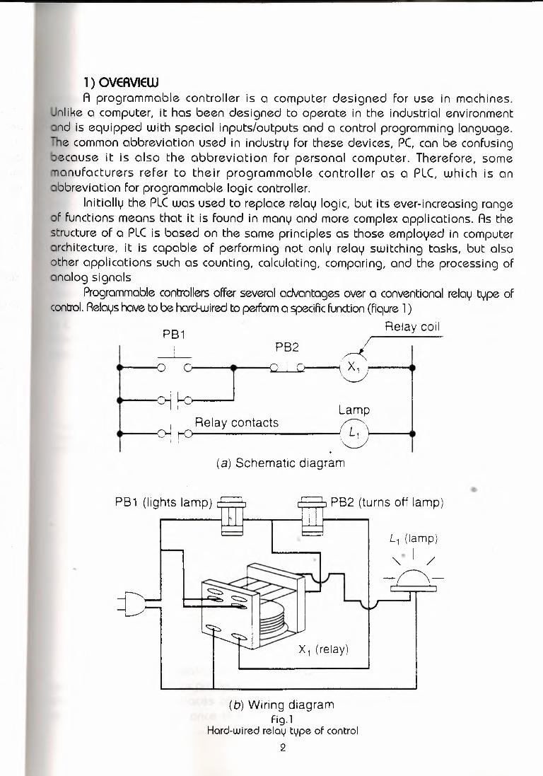
1) OVERVIEWA programmable controller is a computer designed for use in machines.
nlike a computer, it has been designed to operate in the industrial environmentnd is equipped with special inputs/outputs and a control programming language.e common abbreviation used in industry for these devices, PC, can be confusing
ecause it is also the abbreviation for personal computer. Therefore, someanufacturers refer to their programmable controller as a PLC, which is an
abbreviation for programmable logic controller.Initially the PLC was used to replace relay logic, but its ever-increasing range
of functions means that it is found in many and more complex applications. As thestructure of a PLC is based on the same principles as those employed in computerarchitecture, it is capable of performing not only relay switching tasks, but alsoother applications such as counting, calculating, comparing, and the processing ofanalog signals
Programmable controllers offer several advantages over a conventional relay type ofcontrol. Relays have to be hard-wiredto perform a specific function (fiqure 1 )
Relay coilPB1
o •PB2
- ! -
c-j f-::_J-----( ) I C ),,---,,,,,ı.A--........- \ X01--•
• o- ~ Relay contactsI I
Lampr>I L I •. 1 I'"'-../
(a) Schematic diagram
L1 (lamp)
"'-. I /..
X 1 (relay)
(b) Wiring diagramFig. l
Hard-wired relay type of control2

. ,·•· ... (
When the system requirements change, the relay wiring has to be changedmodified, which requires time. In extreme cases, such as in the auto industry,
mplete control panels had to be replaced since it was not ecoomically feasiblerewire the old panels with each model changeover. The programmable controller
as eliminated much of the hand wiring associated with conventional relayşontrol circuits. It is small and inexpensive compared to equivalent relay-basedocess control systems. Programmable controlers also offer solid-state reliability,
ower consumption, and ease of expandability. If an application has more than acif-dozen relays, it probably will be less expensive to install a PLC. Simulating aundred relays, timers, and counters is not a problem even on small PLCs.
A personal computer can be made into a programmable controller if yourovide some way for the computer to receive information form devices such aushbuttons or switches. You also need a program to process the inputs and
decide the means of turning OFF and ON load devices. A typical PLC can bedivided into three parts, as illustrated in the block diagram of Fig. 2 These threecomponents are the central processing unit (CPU), the input/output ( 1 /0) section,and the programming device. The programmable controller is an event-drivendevice, which means that an event taking place in the field will result in anoperation or output taking pice.
mInput _:ı:ı I
H o~Outpu:rıt Central usensıng n
t ~ ' /loaddevices p processing
p devicesu unit I / 't ut e
Programmingdevice • •
Fig. 2PLC block diagram
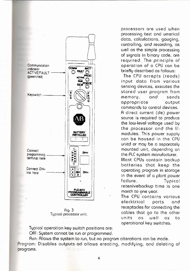
The central processing unit (CPU) is the heart of the PLC system. A typicalcentral processing unit or processor is shown in Fig. 3. The CPU is a microprocessorbased system that replaces control relays, counters, timers, and sequencers. Aprocessor appears only once in a PLC, and it can be either a one-bit or a word
3
CommunicationindicatorACTIVE/FAULT ı(green/red)
Keyswrtch -----
I
IIConnect -ıprogrammıng
terminal here ,
Connect DH+lınk here -----
..
processors are used whenprocessing text and umericaldata, calculations, gauging,controlling, and recording, aswell as the simple processingof signals in binary code, arerequired. The principle ofoperation of a CPU can bebriefly described as follows:The CPU accepts (reads)
input data from varioussensing devices, executes thestored user program frommemory, and sendsappropriate outputcommands to control devices.A direct current (de) powersource is required to producethe low-level voltage used bythe processor and the 1/:modules. This power supplycan be housed in the CPUunitd or may be a separatelymounted unit, depending onthe PLC system manufacturer.Most CPUs contain backupbatteries that keep theoperating program in storagein the event of a plant powerfailure. Typicalretenivebackup time is onemonth to one year.••The CPU contains variouselecktrical parts andreceptacles for connecting thecables that go to the otherunits as well as tooperational key switches.
M BATToıwuoPROC
ACTIVE o~.MACE , ••. b
R~p·U RM O
G ,
(O
Bı\TTERVIHSTAU.ED
I I I I
PLC-aNOPROGRAMIWIU:
CONT'ROUER
Fig. 3Typical processor unit.
Typical operation key switch positions are:OFF: System cannot be run or programmed.Run: Allows the system to run, but no program alterations can be made.
Program: Disables outputs ad allows ereating, modifying, and deleting ofprograms.
4

processor memory module is a major part of the CPU housing (Fig. 4)Memory is where the control plan or program is held or stored in the
ntroller. The information stored in the memory relates to the way the input andtput data should be processed. The complexity of the program determines theount of memory required. Memory elements store individual pieces of
formation called bits (for binary digits). he actual control program is held withinlectronic memory storage components, such as the RAMs and EEPROMs. Theocessing unit scans data from the input and output modules and stores their
onditions in the memory. The processor unit then scans the user program stored in
Pushbutton I CPU I Power I I••• LampI.
ClPushbutton I 1IH C: CJ)
Load(I) il ICJ)(1) poweroo o...c,-~ ~
Externalpower
Memory----Fig. 4
Processor memory
the memoryand makesdecisions that causeoutputs to change.Memory can be placed lnte two categories: volatile and nonvolatile. Volatile
memorywill lose its stored information if qll operating power is lost or removed.Volatile memory is easily altered and quite suitable for most applications whensupported by battery backup. Nonvolatile memory can retain stored informationwhen power is removed accidentally or intentionally. PLCs make use of manydifferent types of volatile and nonvolatile memory devices. Following is ageneralized description of a few of the more commontypes:
RAM. Randomaccessmemory (RAM) is designed so that information can bejritten into or read from the memory. Today's controllers, for the most parts, usethe CMOS-RAMjith battery support for user program memory. RAM provides anexcellentmeans for easily creating and altering a program.
ROM. Read-only memory (ROM) is designed so that information stored inmemory can only be read and, under ordinary circumstances,cannot be changed.lnfrmation foud in the ROM is placed there by the manufacturerfor the internal use
5

EEPROM.Elecktrically erasable programmable read-only memory (EEPROM)sa nonvolatile memory that offers the same programming flexibility as does RAM.
provides permament storage of the program but can be easily changed usingstandard programming devices.
The 1/0 section of a PLC sqconslsts of input modules and output modules.E 1/0 system forms the interface by which fıeld devices are connected to the
ontroller. The purpose of this interface is to condition the various signals receivedom or sent to external fıeld devices. Input devices such as pushbuttons, limit
switches, sensors, selecktor switches, and thumbwhell switches are hard-wired toerminals on the input modules. Output devices such as small motors, motor
starters, solenoid valves, and indicator lights are hard-wired to the terminals one output modules. These devices are also referred to as "fıeld" or "real-word"
inputs and outputs. The terms fıelds or real-word" are used to distinguish actualexternal devices that exist and must be physically wired from the internal user
rogram that duplicates the function of relays, timers, and counters. Somerogrammable controllers have separate modules for inputs and outputs; othersave the inputs and outputs connected as an integral part of the controller (Fig.Sa)
When the module is slid into the rack, it makes an electrical connection with aseries of contacts called the backplane, located at the rear of the rack. The PLCprocessor is also connected to the backplane and can communicate with all themodules in the rack [see Fig. 5 b)
Input interface modules accepts signals from the machine or process devices(e.g., 120 V ac) and convert them into signals (e.g., 5 V de) that can be used bythe controller. Output interface modules convert controller signals (e.g., 5 V de)into external signals (e.g., 120 V ac) used to control the machine or process. Thereare many types of inputs and outputs that can be connected to a programmablecontroller, and they can all be divided into two groups: digital (alsa known asdiscrete) and analog.
That digital inputs and outputs are those that operate because of changesin a discrete state or level. Analog inputs and outputs change continuously over avariable range.
The most common type of 1/0 interface module is the discrete type. This typeof interface connects fıeld input devices of tlte ON/OFF nature such as selector••switches, pushbuttons, and limit switches. liikewise, output control is limited todevices such as lights, small motors, solenoids, and motor starters that requiresimple ON/OFF switching. Analog inputs and outputs are used in more complexcontrol applications such as furnace temperature control (Fig. 6
Each 1/0 module is powered by some fıeldsupplied voltage source. (Fig. 7)Since these voltages can be of different magnitudes or types, 1/0 modules
are available at various ac and de voltage and current ratings. Both voltage andcurrent must match the electrical requirements of the system to which it isconnected. There are typically 4, 8, 12, 16, or 32 terminals per module. PLCmanufacturers have a wide variety of input and out put modules available. The
7

Transducer1 - ~~~~~~~
Temperaturesensingelement
Valve controller
Furnace temperature control
Fig. 6Analog 1/0 module
analog 1/0 modules provide an interface to a variety of analog signals, includingoth voltage (e.g., 1- to 5-V) and current (e.g., 4- to 20-mA) ranges.
Signals are connected to the PLC though input modules. Input modulesperform four tasks in the PLC control system:
They sense when a signal is received from a sensor on the machine.They convert the input signal to the correct voltage level for the particular
PLC. -They isolate the PLC from fıuctuations in the input signal's voltage or c._urrent.They send a signal to the PLC indicating which sensor originated the sfgnal.
(fig. 8) shows a simplifıed block and wiring diagram for one input of a typical acf!>
interfcce input module. The input circuit is composed of two basic section: thepower section and the logic section. The power and logic sections are normallycoupled together with a circuit, which elecktriçally separates -the two. When thepushbutton is closed, 120 V ac is applied to the bridge rectifıer through resistorsAl and R2. This produces a low-level de voltage, which is applied across the LEDof the optical isolator. the zener diode (ZD) voltage rating sets the minimum levelof voltage that can be detected. When light from the LED strikes thephototransistor, it switches into conduction, and the status of the pushbutton iscommunicated in logis or low-leved de voltage to the processor. The opticalisolator not only sperates the higher ac input voltage from the logic circuits butalso prevents damage to the processor due to line voltage transients. Opticalisolation also helps reduce the effects of elecktrical noise, common in the industrialenviroment, which can cause erratic operation of the processor. Coupling andisolation can also be accomplished by use of a pulse transformer or reed relay.
8

Inputfield----devıce
L2L1 120 V aclı,1 PB I ~ I I I Input
, , I status,O, -4': ı indicator
iInput moduleterminal board
(a) Typical discrete four-point. 120-V ac. input module
120 V ac:....___~
I
\_OutputfielddeviceI
i
F;~Ir '--' ~Module blown
fuse indicator
Output moduleterminal board
(b) Typical discrete four-point, 120-V ac. 4-Aoutput moduleFig. 7
1/0 module powered by a field-supplied voltage source
9
The output interfacemodule of aprogrammable controlleracts as a switch to supplypower From the userpower supply to operatethe output. The outputunder the control of theprogram is Fed From theprocessor to a logic circuitthat will receive and storethe processor commandthat is required to makean output become active.The output switchingdevices most often usedto switch power to theload in programmablecontrollers are:
Relay For ac or deloads
Triac For ac loads onlyTransistors For de
loads onlyThe output module
has a Function similar tothat of the input moduleexcept in reversesorder.(fig. 9) shows a simplifıedblock and wiring diagramof a typical ac interfaceoutputmodule. As part ofits normal operations, theprocessor sets the outputstatus according to thelogic program. When theprocessor calls For anoutput, a voltage isapplied across the LED ofthe isolator. The LED thenemits light, whichswitches thephototranssistor into

Power Logic
-, / _ Input statusindicator
_L- - t Zener ----=-:::ı...•• Input Bridge diode It.; V ac) signal rectifier level I- -+ detection
-----,Isolator ı_, Logic To processor
(5 V de)
(a) Block diagram
Bridgerectifier
_LL, • ot o •• ~
(120 V ac)
L2-i _ ___..• ~
Opticalisolator
•r r T _JJ__ .....----.ILIE!.~ıo
DI
: (5 V de)
- - I
To logiccircuitry
(b) Wirıng diagram
Fig. 8Alternating current interface input module
conduction.This in turn. Switches the triac intoconductions, which, in turn, terns onhe lamp. Since the triac conducts in either direction, the output to the lamp is
alternating current.That the triac, rather than having ON end OFF status, actually has LOWand
HIGH resistance levels, respectively. In its OFF state (HIGH r:esistance),a small•currentsleakage of a few milliamperes still flows trough the triac.
As with input circuits, the output intrface is usually provided with LEDs thatindicate the status of each output. In addition, if th module contains a fuse, a fusestatus indicator may also be used.
Output interface modules are normally designed to handle currents in the 2-to 3-A range. To protect the output module circuits, specified currentratings shouldnot be exceeded. For controlling larger loads, suchas large motor starter as shownin Fig. l O When a control relay is used in this manner, it is called an interposingrelay.
Analog input interface modules contain the circuitry necessary to acceptanalog voltage or current signals from analog field devices. These inputs are
10

\__
Logic Power
ut statusindicator r-{ r-ı Lamp
output- Lı- -·- - - ...J - ı \..J
c) From I Logic I I Isolator ı Electronic ( 120 V ac):L processor '- 1 swıtch
. . L2
(a) Block diagram
Lamp outputOpticalisolatorı
L_ L,
1 I'"" Triac
Signal from ilinternal logic I EI ~
circuitry I D(5 V de)
-,III
(120 V ac)
Fuser---
(b) Wiring diagram
Fig. 9Alternating current interface output module
converted form and analog to a digital value by an analog-to-digital (A/D)converter circuit. The converslon-volue. which is proportional to the analog signal,is expressed as a 12-bit binary or as a three-digit binary-coded decimal (BCD) foruse by the processor. Analog input sensing devices include _.temperature, light,
•spee.d,pressure, and position transduers.The analog output interface module receives digital data from the processor
that is converted into a proportional voltage or current to control an analog fielddevice. The digital data is passed through a digital-to-analog (D/A) convertercircuit to produce the necessary analog form. Analog output devices include smallmotors, valves, analog meters, and seven-segment displays.
Each port or terminal on input and output modules is asigned a uniqueaddress number This address, is used by the processor to identify the location ofthe device in order to monitor or control it. The type of the module and the actualphysical location of the terminal determines the programming address. Theaddressing format of inputs and outputs depends on the particular PLC used and
11

±
~LLlı!
M M MOL
Motorstarter
coilT,
Interposingrelay coil
Fig. lOInterposing relay connection
con normally be found in the particular PLC's user's manual. These addresses cane represented in decimal, octal, or hexadecimal terms depending upon thember system used by the PLC.
The micro PLC format illutrated in (Fig. 11 a) uses a limited number of pointsf control. Each input and output device must have a specific address. With therge PLC rack installation shown in Fig. (11 b) the loction of a module within a
ock and the terminal number of a module to which an input or output device isconnected will determine the address of the device.
The programmable controller system requires two power supplies. Oneprovides the power necessary for field devices and output loads to operate and isprovided by the programmable controller user. The second power supply isprovided internally or as a module that is part of the programmable controllersystem. This power supply provides internal direct current to operate the processorlogic circuitry and 1/0 assemblies. the voltage that it provides will depend on thetype of integrated circuits (ICs) within the system. If the system is made up oftransistor-transistor logic (TTL) ICs, the internal power supply will be 5 V, but if theintegrated circuit is a complementary metal oxide semiconductor (CMOS) type, thepower supply voltage will be in the range of 3 V to 18 V.
The programming device provides the primary means by which the user cancommunicate with the circuits of the programmable controller It allows the user toenter, edit, and monitor programs by connecting into the processor unit andallowing access to the user memory. the programming unit can be a liquid crystal
12
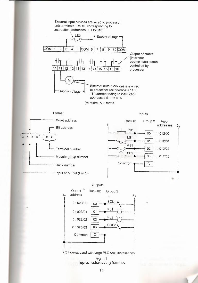
External input devices are wired to processorunit terminals 1 to 1 O, corresponding toinstruction addresses 001 to 010
~S~supply voltage
COMI 1 10 ICOM
upply voltage
External output devices are wiredto processor unit terminals 11 to16, corresponding to instructionaddresses 011 to 016
(a) Micro PLC format
Format
Rack number
Inputs
Rack 01 Group 2 InputL, addresses L2
_L_ PB1~1:012/00
LS1~J:012/01
PS1~I:012/02
PB2Ir~ 1:012/03
Common ---rel
J Wmd address
r Bit address
~-~~
t L Terminal number
L_ Module group number
'--------- Input or output (I or 0)
Outputs
L, Output ~ Rack 02 Group 3
address L2
O: 023/00 ~L1A I •O : 023/01 ~~/
/-,O: 023/02 ~
• PL2 '~/
O: 023/03 ~ ~ S0L2
Common
(b) Format used with large PLC rack installations
Fig. 11Typical addressing formats
13

,:::ı·ı·
,J lı/
(a) Handheld programming device
I \
Software
~
,ım ' ,,,,.,,, ı ffi\'1·1 ''.I
(b) PLC has one program in memory at a time
Fig. 12Programming devices
display (LCD) handheld terminal, a single-line LED display unit, or a keyboard ando video display unit. The video display offers -the advantage "of displaying largeamounts of logic on the screen, simplifying the interpretatin of the program. theprogramming unit communicates with the processor via a serial or parallel datacommunications link. If the programming unit is not in use, it may be unpluggedand removed. Removing the programming unit will not affect the operation of theuser program. A personal computer jith appropriate software can also act as aprogram terminal, making it possible to carry out the programming away from thephysical location of the programmable controller. When the program is complete, itis saved to some form of mass storage and downloaded to the programmablecontroller when required.
A handlend device is shown in (Fig. 12) The display is usually an LED orliquid-crystal display (LCD), and the keyboard consists of numeric keys,
14

ProcessMotor
Relayladder
diagram
~----120Vac ·t [ııPressure Temperature
switch switch~r ~ r-.. ? · Motorstarter
coil
Process vat
:>essuresensor
ch
//
Temperaturesensor switch------
Manual?pushbuttonswitch
Manualpushbutton
IPLC ladder diagram
Input modulewiring connections Control logıc
Output modulewiring connection
ıı
Pressure 001• Ü-. o Pressure
switchTemperature
switch_____ ___,ı 011
Temperature 002• o..... ()
I 011 ~ ,Motorstarter
coilI
001 002
_ı_003
Manual003
Manualpushbutton
Fig. 13Process control application
rogramming instruction keys, and special function keys. To change the program ine PLC, it is necessary either to enter a nej program directly from the keyboard or
o download one from the hard disk while online.When programmable controllers were first introduced, the ladder diagram wasselected to be the fundamental programming format because it was well known inthe elecktrical and elecktronics industry.
To get an idea of how a PLC operates, consider the simple process controlapplication illustrated in (fig 13) Here a mixer motor is to be used to automaticallystir the liquid in a vat when the temperature and pressure reach preset values. Inaddition, direct manual operation of the motor is provided by means of a separatepushbutton station. the process is monitored with temperature and pressuresensor switches that dose their respective contacts when conditions reach their
15

14-------120Vac >+ Ilı
Pressure Temperatureswitch switch
~).
Motorstarter
coil_J_
Manualpushbutton
(a) Hard-wired relay circuit requires rewiring forchanged application
Input modulewiring connections •
ı,
l P~ss~e 001 ~Iıl Pressure
switch
Control logic
Temperatureswitch
Output modulewiring connection
011 I ~l e
Motorstarter
coil
011
001 002
_l_ 003 . () ~Manual
003 Manual
pushbutton
(b) PLC system-requires only that control logic bechanged; all input and output module connectionsremain the same
Fig. 14Modified processcontrol application.
eset values.This control problem can be solved using the relay method for motor control
shown in the relay ladder diagram. The motor starter coil (M) is energized whenoth the pressure and temperature switches are closed or when the manualushbutton is pressed.
Now let's look at the way a PLC might be used for this application. The sameinput field devices (pressure switch, temperature swiitch, and pushbutton) are
16

. these devices are hard-wired to an appropriate input module ad dress1---ding to the manufacturer's addressing format. the same output field device
or starter coil) is also used. this device is hard-wired to an appropriate output-.uvle address according to the manufacturer's addressing format.
Next, the PLC ladder control logic diagram is constructed and programmedthe memory of the CPU. A typical ladder logic diagram for this process isn. The format used is similar to the layout of the hard-wired relay ladder
it. the individual symbols represent instructions and the numbers represent thection addresses. When programming the controller, these instructions are
ered one by one into the processor memory from the operator terminaloard. Instructions are stored in the user program portion of the processorory.
To operate the program, the controller is placed in the RUn mode, orrating cycle. During each operating cycle, the controller examines the status oft devices, executes the user program, and changes outputs accordingly. Each -I
an be thought of as a set of normally open (NO) contacts. The -( )- can beidered to represent a coil that, when energized, will close a set of contacts. Inladder logic diagram shown, the coil 011 is energized when contacts 001 andare closed or jhen contact 003 is closed. Either of these conditions provides a
tinuous path from left to right across the rung that includes the coil.The RUN operation of the controller can be described by the following
uence of events. First, the inputs are examined and their status is recorded incontroller's memory ( a closed contact is recorded as a signal that is called a
ic 1 and an open contact by a signal that is called a logic O). Then tho ladderagram is evaluated, with each internal contact given OPEN or CLOSED statuscording to the record. If these contacts provide current path from left to right in
diagram, the out put coil memory location is given a logic 1 value and thetput module interface contacts will close. If there is no conducting potheon theogram rung, the output coil memory location is set to logic O and the outputodule interface contacts uıll] be open. the completion of one cycle of this
sequence by the controller is called a scan. the can time, the time required for oneII cycle, provides a measure of the speed of response of the P••LC.
As mentioned, one of the important featü'res of a PLC is the ease with whiche program can be changed. For example, assume that our original process control
ircuit for the mixing operation must be modified as shown in the relay ladderiagram. the change requires that the manual pushbutton control be permitted to
operate at any pressure but not unless the specified temperature setting has beeneached.
If a relay system were used, it would require some rewiring of the system toachieve the desired change (Fig. 14 a) However, if a PLC system were used, norewiring would be necessary. The inputs an outputs are still the same. All that isrequired is to change the PLC ladder logic diagram as shown (Fig. 14 b)
2) NUMBER SYSTEMS AND CODES
17

Knowledge of number systems other than the decimal numbering system isite useful when working with PLCs or with almost any type of digital equipment.s is true because a basic requirement of these devices is to represent, store,
operate on numbers. In general, PLCs work on binary numbers in one form orother: these are used to represent various codes or quantities. Often the
programmer needs to beable to perform conversionbetween the systems, andto perform math functionswithin each system.The decimal system, which ismost common to us, has abase of 1 O. The base of anumber system determinesthe total number of differentsymbols or digits used bythat system. For instance, inthe decimal system, 1 Ouniquie numbers or digits -the digits O through 9-areused. (Figure 15) shows acomparison between fourcommonnumbering systems;decimal (base 1 O), octal(base 8), hexadecimal(base16), and binary (base 2).Note that all numberingsystemsstart at zero.
Decimal Octal Hexadecimal Binary
i o oI 1 1 <
!2 10
I3 11 4 100 5 101 6 110 7 111 8 1000 9 1001
10 I 1010 I 1011
1100 1 H)1
i415
1617202122 23 24
EF
10
1110 1111
10000 10001 10010
1617181920
11121314
1001 ·110100
ig. 15 Numbersystem comparisons.
The value of a decimal number depends on the digits· that make up theumberand the place value of each digit. A place (weight) value is assigned to
eachposition that a digit would hold from right to left. In the decimal system theirst position, starting from the furthest right position, is O: the second is 1: and so
on up to the last position. the weighted value of each position can be expressedas the base ( 1 O in this case) raised to the power of the position. For the decimalsystem,then, the position weights are 1, 1 O, 100, 1000, and so on. (Figure 16) onpage 340 illustrates the way the value of a decimal numbercan be calculated bymultiplying eachdigit by the weight of its position and summingthe results.
The binary numbering system (base 2) is the basis of all digital systens.Twostates exist in digital equipment, an ON states which is representative of one
18

Decimalnumber
1 I 9 I 6 I 2
2 X 1 00 = 2 X 1 = 2
..____ 6 X 101 = 6 X 10 = 60
..__ 9 X 102 = 9 X 100 = 900
1 X 1 03 = 1 X 1 000 = 1 OQQ
196210
(Sum of products)Fig. 16
Weighted value in the decimal system
), and an OFF condition, which is representative of zero (O). the ON condition incircuit is approximately equal to supply voltage, and the OFF to zero volts oround. A third state may exist in some logic circuits to produce tri-state logic. This
dition is a high-impedance or no-voltage state and is not considered in theary system.
Theonly allowable digits in a binary numberingsystem are zero (O) and one). Since the binary system uses only two digits, each position of a::.binarymbercan go through only two changes,and then a 1 is carried to the immediate
position.The decimal equitvalent of a binary number is calculated in a mannersimilar
that used for a decimal number. this time the weighted values of the positionse 1, 2, 3, 8, 16, 32, 64, and so on. Insteadof being 1 O raised to the power ofe position, the weighted value is 2 raised to the power of the position. Figure7) shows how the binary number 1 Ol 011 Ol is converted to its decimaluivalent: 173.
Each digit of a binary number is known as a bit. In a PLC the processoremery element consists of hundredsor thousands of locations. These locations,r registers, are referred to as words. Eachword is capable of storing data in theom of binary digits, or bits. Thenumberof bits that a word can store depends one type of PLC system used. Eight-bit and sixteen-bit words are hte most common.
s the technology continues to develop, 32-bit or larger words will be possible.its can also be grouped within a word into bytes. Usuallya group of 8 bits is a
19

Binarynumber
I
i.
111011\oj1J1lo\1I
-
2
X 20: 1 X
Ü X 21 : Ü X
1 X 22 = 1 X
1 X 23 = 1 X
Ü X 24 = Ü X
1 X 25 = 1 X
Ü X 26 = Ü X
1 = 1
2= o4= 4
8= 8
16 = o32 = 32
64 = o1 X 27 = 1 X 128 = 128
Decimal number 17310
(Sum of products)
Fig. 17converting a binary number to a decimal number.
yte, and a group of 1 or more bytes is a word. (Figure 18) illustrates a 16-bit..•ord made up of 2 bytes. The least significant bit (LSB) is the digi't that
epresents the smallest value and the most significant bit (MSB) is the digit thatepresents the largest value. A bit within the word can exist only in two states: aogical 1 or ON condition or a logical O or OFF condition.
••.. MSB Bit LSB
i . i i[ o I 1 ! 1 Jo lo J 1 J 1 J oJ o I o! 1 J 1 J 1 I o J 1 J 1 l
r Upperbyte f· Lowerbyte ~ı..__ 16-bit word--------
Fig. 18A 16-bi t word
20

Decimal number
~?3 witha remainderof I 1 I LSB
23 + 2 = 11 with a remainder of»>
11 + 2 = 5 with a remainder of»>5 + 2 = 2 with a remainder of.>:
2 + 2 = 1 with a remainder of.>:1 + 2 = with a remainder of I 1 I MSB
1
1
1
1
o1
Binarynumber-..ı 101111
Fig. 19Converting a decimal number to a binary number.
41612;ı' t t t '8
Octal /number
The size of the programmable controller memory relates to the amount ofer program that can be stored. If a memory size is 884 words, then it canually store 14,144 (884xl 6) bits of information using 16-bit words or 7072
884 x 8) using 8-bit words. Therefore, when comparing different PLC systems, youst know the number of bits per word of memory in order tho determine the
--- 2 X 80 = 2 X 1 = 2
"----- 6 X 81 = 6 X 8 = 48
------4x 82 = 4x64 = 256Decimal number 30610
(Sum of products)
Fig. 20Converting an octal number to a decimal number
21

Octal number 41 61 2
Binaryo I 1 I O ~ number1 I o I O 1 I 1 I O
Fig. 21Converting an octal number to binary number
ive capacity of the systems' memories. Normally programmable controllers dorequire storage space above 128 Kand in many instances need a memory sizely 1 K to 2 k.To convert a decimal number to its binary equivalent, we must perform a
ies of divisions by 2. (Figure 19) illustrates the conversion of the decimalber 47 to binary. We start by dividing the decimal number by 2. If there is nocinder, a O is placed in the LSB. The result of the division is brought down, andprocess repeated until the result of successive divisions has been reduced to
To express a number in the binary system requires many more digits than indecimal system. Too many binary digits can become cumbersome to read or
ite. To solve this problem, other related numbering systems are brought intose.
The octal numbering system, a base 8 system, is often used inicroprocessor, computer, and programmable controller systems because 8 dataits make up a byte of information which can be addressed by the PLC user orogrammer. In some instances, programmable controller manufacturers use thetal system to number wiring terminals, programmable controller racks, and otherC hardware. The octal number system makes use of 8 digits: O through 7. As in
11 other number systems, each digit in an octal number has a weighted decimal..lue according to its position. (Figure 20) illustrates how the octal number 462 is
onverted to its decimal equivalent: 306.
As mentioned, octal is used as a convenient means of handling large binaryumbers. For example, the octal number 462 can be converted to its binary
equivalent by assembling the 3-bit groups as illustrated in (Fig. 21) Thus, octal462 is binary 10011001 O and decimal 306. Notice the simplicity of the notation.The octal 462 is much easier to read and write than its binary equivalent.
The hexadecimal (hex) number system provides even shorter notation than
22
Hexnumber
1 I BI 7
7 X 160= 7 X 1 = 7---11x161= 11x 16=176
1 X 162= 1 X 256 = 256Decimal number __. 43910
(Sum of products)
(a) Converting a hexadecımalnumber to a decimal number
Hexnumber 1 I BI 7
1 I 1Binarynumber010 1 I 1 I O I 1
(b) Converting a hexadecimalnurnberto a binary number
Fig. 22Hexadecimal numbering system •
•
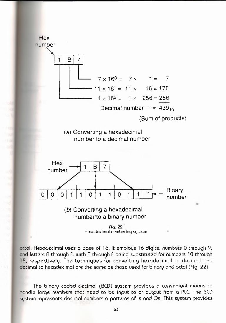
etol. Hexadecimal uses a base of 16. It employs 16 digits: numbers O through 9,nd letters A through F, with A through F being substituted for numbers 1 O through
15, respectively. The techniques for converting hexadecimal to decimal anddecimal to hexadecimal are the same as those used for binary and octal (Fig. 22)
The binary coded decimal (BCD) system provides a convenient means tohandle large numbers that need to be input to or output from a PLC. The BCDsystem represents decimal numbers a patterns of ls and Os. This system provides
23

BCDmber
O I 1
Decimal number
1 1 o 1 I 1 I BCD
4 bits used for each decimal digitFig. 23
The BCD representation of a decimal number
PLC
6 4 1 9 BCD Binary (1 7 6 (•to ı-- Processor~ to ~
binary BCD
Input Output..._ module •... ..•.. module ı..-rack rack
(a) PLC processors function inbinary, not BCD or decimal
Input Ar
,..TOD------.To BCDSourcel N7:23Destination 0:20
•
(b) Example of convert-to-decimal instruction
Fig. 24PLC number conversion
a means of converting a code readily handled by humans (decimal) to a codeeadily handled by the equipment (benary).
The BCD code employs 4 binary bits, with the weights of 1, 2, 4, and 8, torepresent each numeral in the decimal system. This is referred to as the 8421code, since 8421 is the natural binary progression. the BCD representation of a
24

al number is obtained by replacing each decimal digit by its BCD equivalent.istinçuish the BCD numbering system from a binary system, a BCD designation
ced to the right of the units digit. the BCD representation of the decimal3 is illustrated in Fig.
Scientific calculators are available to convert numbers back an forth betweenal, binary, octal, and hexadecimal. They are inexpensive and easy to use, for
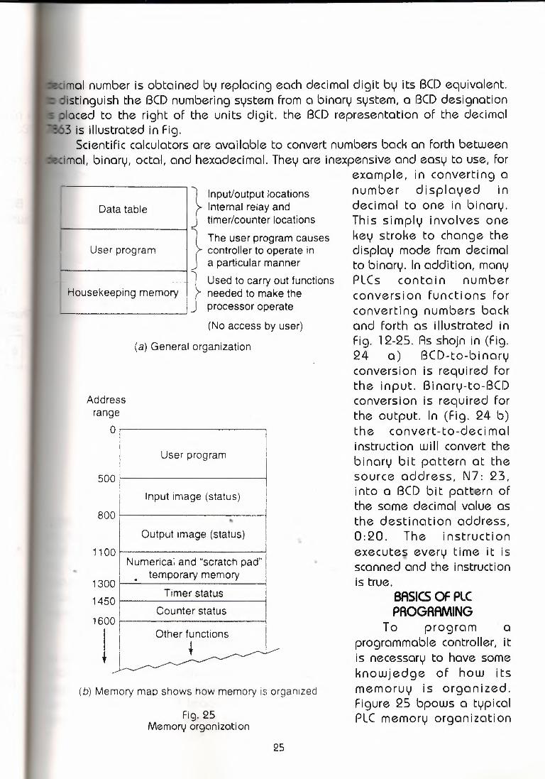
example, in converting anumber displayed indecimal to one in binary.This simply involves onekey stroke to change thedisplay mode Fram decimalto binary. In addition, manyPLCs contain numberconversion functions forconverting numbers backand forth as illustrated inFig. 12-25. As shojn in (Fig.24 a) BCD-to-binaryconversion is required forthe input. Binary-to-BCDconversion is required forthe output. In (Fig. 24 b)the convert-to-dee ima Iinstruction w i II convert thebinary bit pattern at thesource address, N7: 23,into a BCD bit pattern ofthe same decimal value asthe destination address,0:20. The instructionexecute.s every time it isscanned and the instruction
}
Input/output locationsInternal relay andtimer/counter locations
---------~ } The user program causesUser program I controller to operate in
a particular manner
... 1} Used to carry out functionsHousekeeping memory needed to make the
processor operate------------'
(No access by user)
Data table
(a) General organization
Addressrange
orl
500
User program I
' Input image (status)
"Output image (status)
Numerical and "scratch pad" I. temporary memory
Timer statusCounter status
..800
1100
1300
1450
1600
! IOther functıons
~
(b) Memory map shows how memory is organızed
Fig. 25Memory organization
25
is true.BASICS OF PLCPROGRAMING
To program aprogrammable controller, itis necessary to have someknowjedge of how itsmemoruy is organized.Figure 25 bpows a typicalPLC memory organization

n as a memory map. The individual sections, their order, and the sectionst will vary and may be fixed or variable depending on the manufacturer andI. .The user program is where the programmedlogic ladder diagram is enteredstored (Fig. 26) The user program will accdunt for most of the total memoruygiven PLC system. It contains teh logic that controls the machineoperation!.instructionsthat are programmedin a ladder of memory.
Processor
input
r:-- ~iJ---~
I-~ı~Memory
I
User program
~
H ~ H ____, ~
He~:=~Power supply I I Bits
1
Memory
OutputWord
17 1615 14 13 12 11 1 O 07 06 05 04 03 02 O 1 00ı , I o ı , I 1 i 1 ı , I o ı , ı , ı , ı , I o I o i o ı , I o I I 020. I\
!J ~ON OFF
(a) User program will account tor most ot the total memory(b) Word address-020;
bit address-02012 is ON,and 02004 is OFF
Fig. 26User program
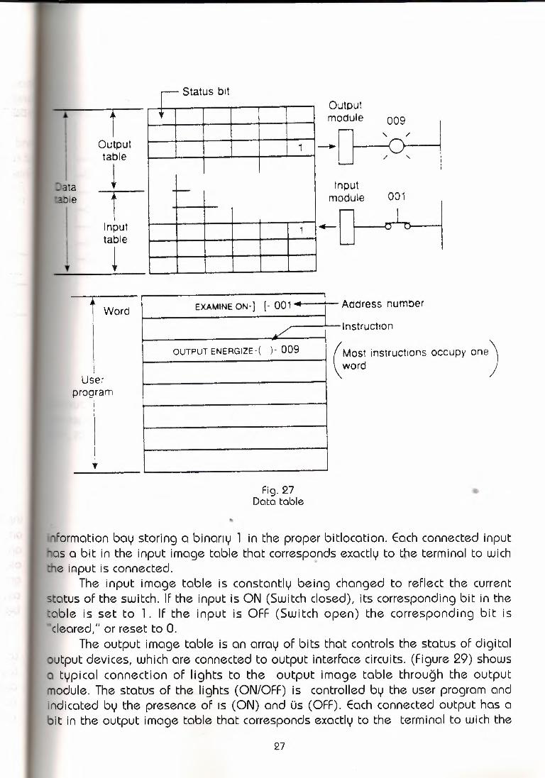
Thedata tale stores program.This includessuch information as teh status ofut and output devices (Fig. 2J.) , timer and countervalues, data storage, and so
, Contents of the data table can be dlvlqed into two categories: status datad numbersor codes. Status is ON/OFtype of information represented by ls and•, stored in unigue bit locations. Numberor code information is represented byoups of bits stored in unigue register or word locations. The address nummersigned to an instrucution associates it with o particular status bit. Tihs bit willeither ON (logic 1) or OFF (LogicO), indicating jhether the instruction is
TRUE OR FALSEThe data table can be divided into the following theree sections according
o tih teylpe of information to be remembered; input image table, output imageable,and timer and counter storağe, The input image table stores the satatus ofigital inputs, which are connectedtu input interface circuits. (Figureshows typicalonnectionsto the input image table throuğh thi input module. When the siwitch islosed, the processor detects a voltage at the input terminal and recordks that
26

Status bit
ata:able
ıOutputtableıT
Inputtableı
I
;
1
--1
Outputmodule 009
' /_.~'-,Input
module 001
r,._
\ Word EXAMINE ON-] [- 001 -
/OUTPUT ENERGIZE-( )- 009
Address number
Use:program
I
lnstructıon
(Most instructions occupy one)word
Fig. 27Data table
formation bay storing a binarıy l in the proper bitlocation. Each connected inputsa bit in the input image table that corresponds exactly to the terminal to wich•e input is connected.
The input image table is constantly being changed to reflect the currentatus of the switch. If the input is ON (Switch closed), its corresponding bit in theble is set to l. If the input is OFF (Switch open) the corresponding bit is
cleared," or reset to O.The output image table ls an array of bits that controls the status of digital
utput devices, which are connected to output interface circuits. (Figure 29) showstypical connection of lights to the output image table throuğh the output
odule. The status of the lights (ON/OFF) is controlled by the user program anddicated by the presence of ıs (ON) and üs (OFF). Each connected output has ait in the output image table that corresponds exactly to the terminal to wich the
27

Rack 1
C Hl L1
Module group 2Terminals
00-07 ~ I
c?-ıı
Input image table 111 o
__ı_ 00
c?-01
.x., 02
03
_L I~:I 06
AC LOW
r--L7
L2
Fig. 28Input image table
put is connected. If the program calls for a specific output to be ON, itsesponding bit in the table is set to 1. IF the programcalls forr the output to be, its correspondingbit in the table is set to O.
Rack ıMG3
I I. Output image table I 0008 AC Hl
L--------1031a
Fig. 29Output image table
28

O I 1CDmber
1 I BCD
4 bits used for each decimal digitFig. 23
The BCD representation of a decimal number
bwheel orI
PLC Decimaler input readout
4 I 1 I 9 I • I I BCD Binary (1 7 6 5to Processor to
binary BCD
Inputmodule
rack
Outputmodule
rack
(a) PLC processors function inbinary, not BCD or decimal
InputA !TOD[ To BCD
® Source N7:23Destination 0:20
(b) Example of convert-to-decimal instruction
Fig. 24PLC number conversion
means of converting a code readily handled by humans (decimal) to a codeeadily handled by the equipment (benary).
The BCD code employs 4 binary bits, with the weights of 1, 2, 4, and 8, toepresent each numeral in the decimal system. This is referred to as the 8421ode, since 8421 is the natural binary progression. the BCD representation of a
24
Imo] number is obtained by replacing each decimal digit by its BCD equivalent.istinguish the BCD numbering system from a binary system, a BCD designationlaced to the right of the units digit. the BCD representation of the decimal3 is illustrated in Fig.
Scientific calculators are available to convert numbers back an forth betweenimal, binary, octal, and hexadecimal. They are inexpensive and easy to use, for
example, in converting anumber di splayed indecimal to one in binary.This simply involves onekey stroke to change thedisplay mode Fram decimalto binary. In addition, manyPLCs contain numberconversion functions forconverting numbers backand forth as illustrated inFig. 12-25. As shojn in (Fig.24 a) BCD-to-bi naryconversion is required forthe input. Binary-to-BCDconversion is required forthe output. In (Fig. 24 b)the convert-to-deci malinstruction w i 11 convert thebinary bit pattern at thesource address, N7: 23,into a BCD bit pattern ofthe same decimal value asthe destination address,0:20. The instructionexe cuteş every time it isscanned and the instruction
}
Input/output locationsInternal relay andtimer/counter locations
ı------------ı } The user program causesUser program I controller to operate in
a particular manner
}
Used to carry out functionsneeded to make theprocessor operate~----------' (No access by user)
Data table
Housekeeping memory
(a) General organization
Addressrange
500
User program I
Input image (status)
"'Output image (status)
Numerical and "scratch pad" I. temporary memory
Timer statusCounter status
,,
800
1100
..1300
1450
1600
1Other f unctıons
•(b) Memory map shows how memory is organızed
Fig. 25Memory organization
25
is true .BASICS OF PLC PAOGAAN\ING
To program aprogrammable controller, itis necessary to have someknowjedge of how itsmemoruy is organized.Figure 25 bpows a typicalPLC memory organization

n as a memory map. The individual sections, their order, and the sectionst will vary and may be fixed or variable depending on the manufacturerandI.The user program is where the programmedlogic ladder diagram is enteredstored (Fig. 26) The user program will accdunt for most of the total memoruygiven PLC system. It contains teh logic that controls the machineoperation!.instructionsthat are programmedin a ladder of memory.
Processor Memory
Inputr-:--
•-:......_, I
Output: Memory
i I User programH~::: >-<>---< ~
H ~~:=~IıI
II-
Word
17 1615 1413 12 11 1O07060504 03 02 01 00I 1 I o I 1 I 1 i 1 ı , I o! 1 I 1 i 1 I 1 I o i o i o I 1 I o I I 020.. I\
!J ~~ y
Bits
~Power supply
l(a) User prcqrarn will account for most of the total memory
(b) Word address-020;bit address-02012 is ON,
and 02004 is OFF
Fig. 26User program
Thedata tale stores program.This includessuch information as teh status ofut and output devices (Fig. 2J) , timer and countervalues, data storage, and so
, Contentsof the data table can be dlvlded into two categories: status datad numbersor codes. Status is ON/OFtype of information represented by ls and•, stored in unigue bit locations. Numberor code information is represented bycups of bits stored in unigue register or word locations. The address nummersigned to an instrucution associates it with o particular status bit. Tihs bit willeither ON (Logic 1) or OFF (LogicO), indicating jhether the instruction is
TRUE OR FALSEThe data table can be divided into the following theree sections according
o tih teylpe of information to be remembered; input image table, output imageble,and timer and counter storağe, The input image table stores the satatus ofigital inputs, which are connectedtu input interface circuits. (Figureshows typicalonnectionsto the input image table throuğh thi input module. When the siwitch islosed, the processor detects a voltage at the input terminal and recordks that
26
Status bıtI•
1
--
1
Outputmodule 009
' /_.~-,Input
module 001
r._
tOutputtableıata
Ile
Inputtableı
j Word EXAMINE ON-] [- 001 .; I
/OUTPUT ENERGIZE-( )- 009
Address number
Userprogram
I
lnstructıon
(Most instructıons occupy one)word
Fig. 27Data table
formation bay storing a binarıy l in the proper bitlocation. Each connected inputas a bit in the input image table that corresponds exactly to the terminal to wichı,e input is connected.
The input image table is constantly being changed to reflect the currentstatus of the switch. If the input is ON (Switch closed), its corresponding bit in theable is set to 1. If the input is OFF (Switch open) the corresponding bit is'cleared," or reset to O.
The output image table is an array of bits that controls the status of digitaloutput devices, which are connected to output interface circuits. (Figure 29) showsa typical connection of lights to the output image table throuğh the outputmodule. The status of the lights (ON/OFF) is controlled by the user program andindicated by the presence of ıs (ON) and üs (OFF). Each connected output has abit in the output image table that corresponds exactly to the terminal to wich the
27

Rack 1
- Hl L1
Module group 2Terminals
00-07~ I.x.. ıı
Input image table 111 o
_ı__ o o I~~.x..02
_L I~:_L o oo,o
06
AC LOW
r-L7
L2
Fig. 28Input image table
tput is connected. If the program calls for a specific output to be ON, itsrrespondingbit in the table is set to l. If the programcalls forr the output to beF, its correspondingbit in the table is set to O.
Rack 1MG 3I I
. Output image table I 0008
..
AC Hl
L ı osz,
Fig. 29Output image table
28

Read inputs
Adjustoutputs
Run program
(a) Typical scan cycle
Horizontal scanningorder
..
End of ladder
Verticalscanning
order Returnfor
nextscan
•
(b) Scanning can be verticalor horizontal
Fig. 30Scan sequence
29

During each operating cycle,the processor reads all theinputs,takes these values,and according to the userprogram energizes ordeenergizes the outputs.Thisprocess is knojn asa scan.The scan is normally acontinuous and seguentialprocess of readi ing thestatus of inputs, evaluatingthe control logic,andupdating the outputs.(Figure30 Illus trates this process.AScan its inputs and generateappropriate controlresponses at itsoutputs.Scan time varieswith program content andlength. A scan can take from
Fig. 31 about 1 to 20 ms. If aMonitoring a relay ladder logic diyagram controler has to react to an
ihput signal that changesates tji states tjice during the scan time, it is possible that the PLC willnever bele to detect this change. The scan time of a PLC should be knojn to ensure that
sccnnlnç is faster than any field device operation.The term PLC programming language refers tu the method bay which the user
cornrnunlcctes information to the PLC. Relay ladder logic was the first and) mostpopular language available on the PLC, and it is still popular. Most PLCs on the
arket today can be programed either exclusively or partially in relay ladder logic.Relay ladder logic is a graphical progrqmming language designed to closely
epresent teh apperance of a wrid relay system. It offers conslcproble advantagesor Pl..C control. Not only is it reasonably intuitive, especially for techniscians withelay experience, it is particularly effective in an on-line mode when the PLC isactually performing control, Operation of the logic is apparent from thehighlighting of the various relay contacts and coils on screen, identifying the logicstate in real time (Fig 31)
The ladder diagram language is basically a symbolic set of instructions usedto create the controller program. These ladder instruction symbols are arranged toobtian the desired contrl logic that be entered into the memory of teh PLC .Because the instruction set is composed of contact symbols lader diagramlanguage is also referred to as contact symbology. Representations of contactsand coils are the basici saymbolsof the logicladderdiagraminstructionset (Fig.32)
ır~ i
30

. EXAMINE ON instruction.
Symbol
B. EXAMINE OFF instruction.
Symbol
---ıır-Typically represents any inputto the control logic.
The input can be a connected switchor pushbutton, a contactfrom a connected output, or acontact from an internal output.
Has a bit-level address.
The status bit will be either1 (ON) or O (OFF).
The status bit is examined foran OFF condition.
If the status bit is O (OFF), thenthe instruction is TRUE.
If the status bit is 1 (ON}, thenthe instructıon is FALSE.
•17 16 15 14 13 12 11 10 07 06 05 04 03 02 O 1 00
I I I I I I I I I I I 11 I ı I ı I ı:012
'1:012""1/f--
Typically represents any inputto control logic.
The input can be a connected switchor pushbutton, a contactfrom a connected output, or acontact from an internal output.
Has a bit-level address.
The status bit will be either1 (ON) or O (OFF).
The status bit is examined foran ON condition.
If the status bit is 1 (ON), thenthe instruction is TRUE.
04Instruction is FALSE
If the status bit is O (OFF), thenthe instructon is FALSE.
1716 15 14 13 12 11 1 O 07 06 05 04 03 02 01 00
I i I I ı I I I I I I I 1 I I I ı I 1:012
'1:012-ı f--
04Instruction ıs TRUE
..I I I I I I I I I I J ı ı I I 1:012
1:012""1 f--
04Instruction is FALSE
( Continued on next page.) Fig. 32
(Continued)
31
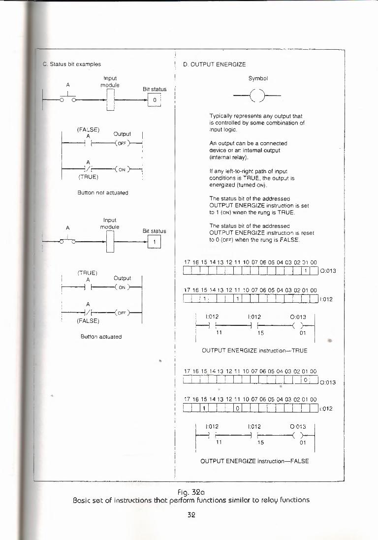
C. Status bit examples D. OUTPUT ENERGIZE
A
~_Lr-
Inputmodule
Symbol
Bit status
o -()-
(FALSE)A Output
I --1 OFF
I A L--ı/' ON
I (T~UE)
Typically represents any output thatis controlled by some combination ofinput logic.
An output can be a connecteddevice or an internal output(internal relay).
If any left-to-right path of inputconditions ıs TRUE, the output isenergized (turned ON).
Button not actuatedThe status bit of the addressedOUTPUT ENERGIZE instruction ıs setto 1 (ON) when the rung is TRUE.
AInput
moduleBit status
The status bit of the addressedOUTPUT ENERGIZE instruction is resetto O (OFF) when the rung is FALSE.
(TRUE)A
1 7 16 1 5 14 13 12 11 10 07 06 05 04 03 02 O 1 00
! ! I I I ı I ı I I ı I I I 11 ı I 0:013Outp~
A~---< ON.
(FA~~E) ,OFF >-ı17 16 15 14 1 3 12 11 1 O 07 06 05 04 03 02 01 00
! I I 1 I I I I 1 I I I I I I I I I I ı:012
Button actuated
I 1:012f--ı ı-----1
I
1:012
11 15
0:0~
01 IOUTPUT ENERGIZE instruction- TRUE
17 16 15 14 13 12 11 10 07 06 05 04 03 02 01 00
ı ı i ·1 I I I I I I I I I I I o I lo:013•..17 16 15 14 1 3 12 11 1 O 07 06 05 04 03 02 O 1 00
I ı, I I I I o I I I I I I ı I I lı:012
~012
I - 11 15
0:0~
01 I
1:012
OUTPUT ENERGIZE instruction-FALSE
Fig. 32aBasic set of instructions that perform functions similar to relay functions
32
Activesupply
Neutralsupply
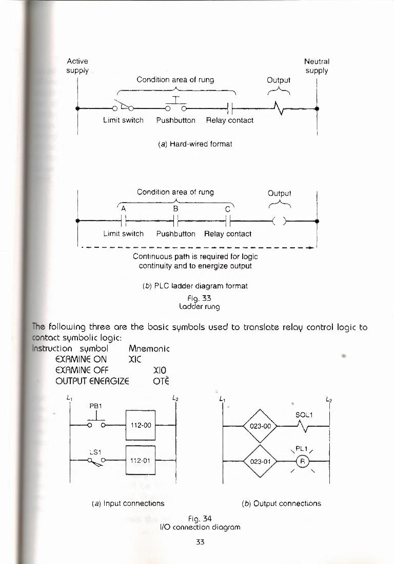
Condition area of rung Outputr='>,
• ~___Io I~-----Limit switch Pushbutton Relay contact
(a) Hard-wired format
Output
A B C' ~ ••~~__Jı I
~· -----'(
Condition area of rung
Limit switch Pushbutton Relay contact
·----------------------------~ Contınuous path is required for logic
continuity and to energize output
(b) PLC ladder diagram formatFig. 33
Ladder rung
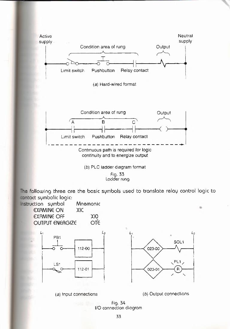
The following three are the basic symbols used to translate relay control logic toontact symbolic logic:nstruction symbol
EXAMINE ONEXAMINE OFFOUTPUT ENERGIZE
MnemonicXIC
xıoOTE
L,
LSı
112-00-
112-01u'
L, •.. PB1_J_
(a) Input connections (b) Output connectıons
Fig. 341/0 connection diagram
33

The main function of the logic ladder diagram program is to control outputsed on input conditions. This control is accomplished throuğh the use of what is
erred to as a ladder rung. ın general, a rung consists of a set of inputditions,represented by contact instructions, and an output instruction at the
of the rung represented bay the coil symbol (Fig 33) Each contact or coilmbol is referenced with an address number that identifies what is bein
luated and what is being controlled. The same contact instructioın can be usedoughout the program whenever that condition needs to be evaluated. For antput to be activated or energized, at least one left-to-right path of contacts mustclosed. O complete closed path is referred to as having logic continuity.en logic continuity exists in at least one path the rung condition is said to be
UE, The rung condition is FALSE IF no path has continuity.
Word address
I11 O
One branch
/
close instruction
012
Two branchopen
instructions I 11 O
00 16
01 "-Bit number
Fig. 35Parallel path instructions.
To complete the entry of a relay-type iqstructlon.uu must assign an addresseumber to it.This munber will indicate what PLC inputis conner_ted to what input
device and what PLC output will drive what output device. The assignment of 1 /Oaddress is some times included in the 1 /O connection diagram as shown in (Fig 34)ınputs and outputs are typically represented buy sguares and diamonds,espectively.
Branch instructions are used to create paralel paths of input conditioninstructions.This allows more than one combination of input conditions (OR Logic)u establish logic continuity in a rung. (Figure 35) illustrates o simple branching
condition. TKhe rung will be TRUE A branch START instruction is used to beğineach paralel logic brancl. A single branch CLOSE instruction is used to close theparallel branch.
In some PLC models the programming of a branch circuit within a brnanch
34

A B
repeatedE
( a) Nested branch (b) Eliminated nested branch
Fig. 36Nested branch
it o a nested barnch cüannot be done directly. It is possible, however, togram a logically eguivalent Programming morğe than the allowable series
ents or parallel branches will resultin an error massağe. Also there is a furtheritation wihth some PLCs:there can be onlay one output per rung. and the
ut must belocated on the right-hand end of a rung.
, • Max. 10 contacts _____.j' ' ' • • I
L Only one outputper rung
Located at the endof the rung
•..
Fig. 37Typical PLC matrix limitation diagram
Most PLCs have an areo of the memoruy allocated for what are known asternal storage bits.These storage bits are also called internal outpus, internal
oils, intenal The internal output operates just as any output that is controlled byrogrammed logic; however, the output is used strictly fofinternal output doesnot
directly control an output device.An internal control relay can be used when a circuit reguires more series
35

Octal number 41 6 I 2
Binaryo I 1 I O ~ number1 I o I o 1 I 1 I O
Fig. 21Converting an octal number to binary number
otive capacity of the systems' memories. Normallyprogrammable controllersdot require storage space above 128 Kand in many instancesneed a memorysizeonly 1 K to 2 k.
To convert a decimal number to its binary equivalent, we must perform aseries of divisions by 2. (Figure 19) illustrates the conversion of the decimal
mber47 to binary. We start by dividing the decimal numberby 2. If there is noremainder,a O is placed in the LSB. The result of the division is brought down, and
e process repeated until the result of successivedivisions has been reduced to
To expressa number in the binary system requires many more digits than ine decimal system. Too many binary digits can become cumbersometo read orrite. To solve this problem, other related numbering systems are brought intose.
The octal numbering system, a base 8 system, is often used inicroprocessor,computer, and programmable controller systems because 8 dataits make up a byte of information which can be addressed by the PLC user orrogrammer. In some instances, programmable controller manufacturers use the
octal system to number wiring terminals, programmablecontroller racks,and otherLC hardware. The octal number system rnokesuse of 8 digits: O through 7. As in
all other number systems, each digit in an octal number has a11 weighted decimalvalue.according to its position. (Figure20) illushates how the octal number462 isconvertedto its decimal equivalent: 306.
As mentioned, octal is used as a convenient means of handling large binarynumbers. For example, the octal number 462 can be converted to its binaryequivalent by assembling the 3-bit groups as illustrated in (Fig. 21) Thus, octal462 is binary l0011001 O and decimal 306. Notice the simplicity of the notation.Theoctal 462 is mucheasier to read and write than its binary equivalent.
The hexadecimal (hex) number system provides even shorter notation than
22

Hexnumber
1 I BI 7
7 X 160= 7 X 1 = 7---11x161= 11x 16=176
1 X 162= 1 X 256 = 256Decimal number ____.. 43910
(Sum of products)
(a) Converting a hexadecimalnumber to a decimal number
Hexnumber 1 I BI 7
1 I 1Binarynumber010 1 I 1 I O I 1
(b) Converting a hexadecimalnumber to a binary number
Fig. 22"Hexadecimal numbering system •..
octal. Hexadecimal uses a base of 16. It employs 16 digits: numbers O through 9,and letters A through F, with A through F being substituted for numbers l O through15, respectively. The techniques for converting hexadecimal to decimal anddecimal to hexadecimal are the same as those used for binary and octal (Fig. 22)
The binary coded decimal (BCD) system provides a convenient means tohandle large numbers that need to be input to or output from a PLC. The BCDsystem represents decimal numbers a patterns of ls and Os. This system provides
23

Decimal number
O I 1 1 O I 1 o 1 I 1 I BCD
4 bits used for each decimal digitFig. 23
The BCD representation of a decimal number
bwheel or I PLC I Decimalreadout
61411191 • I I BCD H H Binary I I (1 7 6 5to Processor to
binary BCD
Inputmodule
rack
Outputmodule
rack
(a) PLC processors function inbinary, not BCD or decimal
Input A !TOD[ ® To BCD
Source N7:23Destination 0:20
•..(b) Example of convert-to-decimal instruction
Fig. 24PLC number conversion
a means of converting a code readily handled by humans (decimal) to a codereadily handled by the equipment (benary).
The BCD code employs 4 binary bits, with the weights of 1, 2, 4, and 8, torepresent each numeral in the decimal system. This is referred to as the 8421code, since 8421 is the natural binary progression. the BCD representation of a
24

imal number is obtained by replacing each decimal digit by its BCD equivalent.istinguish the BCD numbering system from a binary system, a BCD designationlaced to the right of the units digit. the BCD representation of the decimal3 is illustrated in Fig.
Scientific calculators are available to convert numbers back an forth betweenimal, binary, octal, and hexadecimal. They are inexpensive and easy to use, for
example, in converting anumber displayed indecimal to one in binary.This simply involves onekey stroke to change thedisplay mode Fram decimalto binary. In addition, manyPLCs contain numberconversion functions forconverting numbers backand forth as illustrated inFig. 12-25. As shojn in (Fig.24 a) BCD-to-binaryconversion is required forthe input. Binary-to-BCDconversion is required forthe output. In (Fig. 24 b)the convert-to-deci malinstruction will convert thebinary bit pattern at thesource address, N7: 23,into a BCD bit pattern ofthe same decimal value asthe destination address,0:20. The instructionexe cuteş every time it isscanned and the instruction
}
Input/output locationsInternal relay andtimer/counter locations
:-----------. } The user program causesUser program I controller to operate in
a particular manner
}
Used to carry out functionsneeded to make theprocessor operate_________ __,
(No access by user)
Data table
Housekeeping memory
(a) General organization
Addressrange
500
User program I
! Input image (status)
~Output image (status)
Numerical and "scratch pad" I• temporary memory I
Timer status ICounter status
800
1100
..1300
1450
1600
! IOther functıons
t
(b) Memory map shows how memory is organızed
Fig. 25Memory organization
25
is true.BASICS OF PLC PROGRAMING
To program aprogrammable controller, itis necessary to have someknowjedge of how itsmemoruy is organized.Figure 25 bpows a typicalPLC memory organization

n as a memory map. The individual sections, their order, and the sectionst will vary and may be fixed or variable depending on the manufacturer andI.The user program is where the programmed logic ladder diagram is enteredstored (Fig. 26) The user program will accdunt for most of the total memoruygiven PLC system. It contains teh logic that controls the machine operation!.instructions that are programmed in a ladder of memory.
Processor Memory
input
r:-~~I
~
!c-
- I
I: Memory !I I1
I User program j !.~:~=~ I~CH H H~ J
Output
Power supply
Word
1 7 16 15 14 1 3 12 11 1 O 07 06 05 04 03 02 O 1 00ı , I o ı , ı , i 1 ı , I o! 1 ı , i 1 I 1 I o I o i o ı , I o I I 020.. Poı
~1
~ VBits
~
l(a) User program will account tor most ot the total memory
(b) Word address-020;bit address-02012 is ON,and 02004 is OFF
Fig. 26User program
The data tale stores program. This includes such information as teh status ofput and output devices (Fig. 27~) , timer and counter values, data storage, and so
, Contents of the data table can be divid.•ed into two categories: status datand numbers or codes. Status is ON/OF type of information represented by ls and•s, stored in unigue bit locations. Number or cbde information is represented byroups of bits stored in unigue register or word locations. The address nummerssigned to an instrucution associates it with o particular status bit. Tihs bit wille either ON (logic 1) or OFF (Logic O), indicating jhether the instruction is
TRUE OR FALSEThe data table can be divided into the following theree sections according
o tih teylpe of information to be remembered; input image table, output imageable,and timer and counter storağe, The input image table stores the satatus of
digital inputs, which are connected tu input interface circuits. (Figure shows typicalconnections to the input image table throuğh thi input module. When the siwitch isclosed, the processor detects a voltage at the input terminal and recordks that
26

Status bıtOutputmodule 009
' /_.~-,Input
module 001
ı.,_
I•1
--
1
ıOutputtableı
e T Inputtableı
EXAMINE ON-] [- 001 .; I
/OUTPUT ENERGIZE-( )- 009
Address numberI Wordlnstructıon
(Most instructıons occupy one)word
use.program
Fig. 27Data table
formation bay storing a binarıy 1 in the proper bitlocation. Each connected inputsa bit in the input image table that corresponds exactly to the terminal to wich•e input is connected.
The input image table is constantly being changed to reflect the currentstatus of the switch. If the input is ON (Switch closed), its corresponding bit in theable is set to 1. If the input is OFF (Switch open) the corresponding bit iscleared," or reset to O.
The output image table is an array of bits that controls the status of digitaloutput devices, which are connected to output interface circuits. (Figure 29) showsa typical connection of lights to the output image table throuğh the outputmodule. The status of the lights (ON/OFF) is controlled by the user program andindicated by the presence of ıs (ON) and üs (OFF). Each connected output has abit in the output image table that corresponds exactly to the terminal to wich the
27

Rack ı
c Hl L1
Module group 2Terminals
00-07 t\ I.x.. ııInput image table I""
.x.. o 00
.x.. oı
.x.; o 02
o,: I~:__Lo o
06
AC LOW
~7
L2
Fig. 28Input image table
tput is connected. If the program calls for a specific output to be ON, itsesponding bit in the table is set to l. IF the programcalls forr the output to be
F, its correspondingbit in the table is set to O.
Rack ıMG3I I
. Output image table I 0008 AC Hl
~~~~~~~~~~=== 037a
Fig. 29Output image table
28

Read inputs
Adjustoutputs
Run program
(a) Typical scan cycle
Horizontal scanningorder
End of ladder
Verticalscanning
order Returnfor
nextscan
•
(b) Scanning can be verticalor horizontal
Fig. 30Scan sequence
29

During each operating cycle,the processor reads all theinputs,takes these values,and according to the userprogram energizes ordeenergizes the outputs.Thisprocess is knojn asa scan.The scan is normally acontinuous and seguentialprocess of re·ad ii ng thestatus of inputs, evaluatingthe control logic,andupdating the outputs.(Figure30 Illus trates this process.AScan its inputs and generateappropriate controlresponses at itsoutputs.Scan time varieswith program content andlength. A scan can take from
Fig. 31 about 1 to 20 ms. If aMonitoring a relay ladder logic diyagram controler has to react to an
ihput signal that changestes tji states tjice during the scan time, it is possible that the PLC willnever bee to detect this change. The scan time of a PLC should be knojn to ensure thatnnlnq is faster than any field device operation.
The term PLC programming language refers tu the method bay which the usermunicates information to the PLC. Relay ladder logic was the first and most
pular language available on the PLC, and it is still popular. Most PLCs on therket today can be programed either exclusively or partially in relay ladder logic.
Relay ladder logic is a graphical proqrçrnmlnç language designed to closelyresent teh apperance of a wrid relay system. It offers conslqeroble advantagesPLC control. Not only is it reasonably intuitive, especially for techniscians with
lay experience, it is particularly effective in an on-line mode when the PLC isctually performing control, Operation of the logic is apparent from theighlighting of the various relay contacts and coils on screen, identifying the logicate in real time (Fig 31)
The ladder diagram language is basically a symbolic set of instructions usedo create the controller program. These ladder instruction symbols are arranged tobtian the desired contrl logic that be entered into the memory of teh PLC .ecause the instruction set is composed of contact symbols lader diagramnguage is also referred to as contact symbology. Representations of contacts
codcoils are the basici saymbolsof the logicladderdiagraminstructionset (Fig.32)
I~~ i
30

A. EXAMINE ON instruction. B. EXAMINE OFF instruction.
Symbol Symbol
I -ıır-Typically represents any inputto control logic.
Typically represents any inputto the control logic.
The input can be a connected switchor pushbutton, a contactfrom a connected output, or acontact from an internal output.
The input can be a connected switchor pushbutton, a contactfrom a connected output, or acontact from an internal output.
Has a bit-level address. Has a bit-level address.
The status bit will be either1 (ON) or O (OFF).
The status bit will be either1 (ON) or O (OFF).
The status bit is examined foran ON condition.
The status bit is examined foran OFF condition.
If the status bit is 1 (ON), thenthe instruction is TRUE.
If the status bit is O (OFF), thenthe instruction is TRUE.
If the status bit is O (OFF), thenthe instructon is FALSE.
If the status bit is 1 (ON), thenthe instruction is FALSE.
I I I I I I I I I I ı I l ı:01217 16 15 14 13 12 11 10 07 06 05 04 03 02 O 1 00
I I ı l ı:012I I I i I I I I I I I I ol1:012 t~If- ~~~~~__.j
04Instruction is TRUE
1:012~ f-
04Instruction is TRUE
•1,1- •
I I I I ı I I ı ı I1:012
~ f- J 1:012~If- Jı ı ı I ı:012 I I I I I I I I I I I I I I l 1:012
04 04Instruction is FALSE Instruction is FALSE
Fig. 32(Continued)
( Continued on next page.)
31

: Status bit examples
InputmoduleA
__L_--0 o-----
Bit status
D. OUTPUT ENERGIZE
Symbol
o
Typically represents any output thatis controlled by some combination ofinput logic.
An output can be a connecteddevice or an internal output(internal relay).
If any left-to-right path of inputconditions is TRUE, the output isenergized (turned ON).
The status bit of the addressedOUTPUT ENERGIZE instruction ıs setto 1 (ON) when the rung is TRUE.
The status bit of the addressedOUTPUT ENERGIZE instruction is resetto O (OFF) when the rung is FALSE.
17 16 15 14 13 12 11 1 O 07 06 05 04 03 02 O 1 00
! ! I I I I I I I I I I I I 11 I I 0:013
17 16 15 14 13 12 11 1 O 07 06 05 04 03 02 01 00
I i I 1 I I I I 1 I I I I I I I I I I ı:012
~012 1:012 0:0~
I 11 15 01 I
OUTPUT ENERGIZE instruction-TRUE
17 16 15 14 13 12 11 1 O 07 06 05 04 03 02 01 00
ı ı I · 1 I I I I I I I I I I I o I 10·013. .•17 16 15 14 13 12 11 1 O 07 06 05 04 03 02 01 00
i I ı, I I I I o I I I I I I I I I lı:012
~012
I · 11
1:012 0:0~
o, I
(FALSE) OutputA OFF
II A L--ı/[---(oNI (T~UE)
Button not actuated
AInput
moduleBit status
15
(TRUE)A Outp~Af---{ ON.
(FA{~E) ,OFF~
Button actuated
OUTPUT ENERGIZE instruction-FALSE
Fig. 32a Basic set of instructions that perform functions similar to relay functions
32
Activesupply
Neutralsupply
Condition area of rung Output
~
• ~_Io 1----~Limit switch Pushbutton Relay contact
(a) Hard-wired format
Condition area of rung Outputr='>, A B C
•Limit switch Pushbutton Relay contact
·----------------------------- Continuous path is required for logic
continuity and to energize output
(b) PLC ladder diagram formatFig. 33
Ladder rung
following three are the basic symbols used to translate relay control logic totact symbolic logic:
truction symbolEXAMINE ONEXAMINE OFFOUTPUT ENERGIZE
MnemonicXIC
xıoOTE
L, L, •
112-00'-'
- 112-01.,.,,'
PB1_J_
LS1
(a) Input connections (b) Output connections
Fig. 341/0 connection diagram
33

The main function of the logic ladder diagram program is to control outputson input conditions. This control is accomplished throuğh the use of what is
ed to as a ladder rung. ın general, a rung consists of a set of inputitions,represented by contact instructions, and an output instruction at theof the rung represented bay the coil symbol (Fig 33) Each contact or coilol is referenced with an address number that identifies what is beinted and what is being controlled. The same contact instructioın can be usedhout the program whenever that condition needs to be evaluated. For an
t to be activated or energized, at least one left-to-right path of contacts mustosed. O complete closed path is referred to as having logic continuity.
logic continuity exists in at least one path the rung condition is said to be, The rung condition is FALSE If no path has continuity.
Word address
I110
One branchclose instruction
/012r \-- -Two branch
openinstruction..:_ j 11 O
00 16
01 "-Bit number
Fig. 35Parallel path instructions.
To complete the entry of a relay-type instructton.uu must assign an addressember to it.This munber will indicate what PLC inputis connegted to what input
device and what PLC output will drive what output device. The assignment of 1 /Oaddress is some times included in the 1 /O connection diagram as shown in (Fig 34)
puts and outputs are typically represented buy sguares and diamonds,espectively.
Branch instructions are used to create paralel paths of input conditionnstructions.This allows more than one combination of input conditions (OR Logic)
tu establish logic continuity in a rung. (Figure 35) illustrates o simple branchingcondition. TKhe rung will be TRUE A branch START instruction is used to beğineach paralel logic brancl. A single branch CLOSE instruction is used to close theparallel branch.
In some PLC models the programming of a branch circuit within a brnanch
34

C y
~ntactinstruction
C repeated
A B A
( a) Nested branch (b) Eliminated nested branch
Fig. 36Nested branch
uit o a nested barnch cüannot be done directly. It is possible, however, togram a logically eguivalent Programming morğe than the allowable seriesments or parallel branches will resultin an error massağe. Also there is a furtheritation wihth some PLCs:there can be onlay one output per rung. and the
tput must belocated on the right-hand end of a rung.
,,. Max. 10 contacts~' ' . . . '
l Only one outputper rung
Max. 7parallel
linesLocated at the end
of the rung
•
Fig. 37Typical PLC matrix limitation diagram
Most PLCs have an areo of the memoruy allocated for what are known asnternal storage bits.These storage bits are also called internal outpus, internaloils, intenal The internal output operates just as any output that is controlled byrogrammed logic; however, the output is used strictly fofinternal output doesnot
directly control an output device.An internal control relay can be used when a circuit reguires more series
35

Internalrelay
I 1 2 3 4 5 6 7 coilRung 1 rl H H H H H Hr-(
8 9 10 11 12Rung2rHHHHHI
tInternal
relaycontact
(HDisc~te Ioutput
Fig. 38Internal control relay
tacts than the rung allows (Figure 38) shows a circuit that allowjs for only 7ies contacts when 12 are actually reguired for the programmed logic. To solve
is problem, the contacts are split into two rungsas shown. The first rung containsof the reguired contacts and is programmedto an internal relay. The address of
internal relay would also be the address of the internal raley would also beaddress of thi first EXAMINEON contact on the secondrung.
The remaingn 5 contacts are programmed, follewed by the discretetput.The advantage of an internal storage ibt is that it does not unnecessarilyupy a physical output.simple program using the EXAMINEON instruction is shown in (Fig. 39) This
PB1_J_
PB2/
/ . '..(a) Hard-wired circuit
H H [ CH(b) User program providing the same results
Fig. 39Simple program using the examine on instruction
36

PB1
_J_
CR1/
/ '(a) Hard-wired circuit
(b) User program providing the same resultsFig. 40
Simple program using the examine off instruction
ure shows a hard-wired circuit and a user program that provides the sameults.You will note that both the NO and the NC pushbuttons are representedy the EXAMINE ON symbol.
This is because the normal state of an input (NO or NC) doesnot matter tocontroler.
at does matter is that output, then the EXAMINE ON instruction is used. Sinceth PBI and PB2 mustbe closed to energize the pilot light, the EXAMINEON
Inputs Program • Outputs
StopMotor M
Stop PB output..._..---1 1----r--, I c
OLStart PB
Start
M
Fig. 41Start/stop program
37

Instruction MnemonicSymbol
Output latch
Output unlatch
OTL
OTU
-(L)-
-(U)-
---ı L) XXXLatch coil Same
address
__ _, 'ı XXXU .ı Unlatch coil
(a) Latch and unlatch coils have same address
ON 0:013· LH Latch
10
OFF 0:013uH Unlatch
10
O:Q13I (' -, I oI .. \ ) utputı 10
17 16 15 14 13 12 11 1 O 07 06 05 04 03 02 01 00
: l i r ! ! I I ! ! I I l ! ! I l 0:013
•
(b) Control logic
Fig. 42Output latch and output unlatch instructions
38
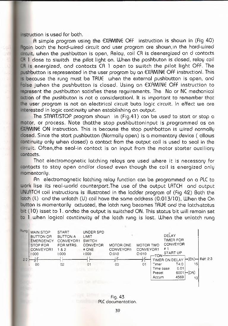
truction is used for both.A simple program using the EXAMINE OFF instruction is shown in (Fig 40)
in both the hard-wired circuit and user program are shown,ın the hard-wiredcult. when the pushbutton is open, Relay, coil CR is deenergized an d contactsl close to siwitch the pilot light on. When the poshbuton is closed, relay coilis energized, and contacts CR l open to switch the pilot light OFF. The
shbutton is represented in the user programby an EXAMINE OFF instruction!.Thisbecause the rung must be TRUE when the external pushbutton is open, andise jwhen the pushbutton is closed. Using an EXAMINEOFF instruction toresent the pushbutton satisfies these reguirements. The No or NC mechanicalion of the pushbuton is not a consideration!. It is important to remember thatuser program is not an electirical circuit buta logic circuit. In effect we are
erested in logic continuity when establishing an output.The START/STOP program shown in (Fig.41) can be used to start or stop a
otor, or process. Note thatthe stop pushbuttoninput is programmed as anıMINE ON instruction. This is because the stop pushbotton is wired normally
sed. Since the start pushbutton (Normallyopen) is a momentarydevice ( allowstinuity only when closed) a contact from the output coil is used to seal in the
cuit. Often.the seal-in contact is an input from the motor starter auxiliarytacts.
That electromagnetic latching relays are used where it is necessary forntacts to stay open and/or closed even though the coi I is energized only
omentarily.An electromagnetic latching relay function can be programmed on a PLC to
ork lise its real-world counterpart.The use of the output LATCH and outputLATCH coil instructions is illustrated in the ladder program of (Fig 42) Both the
tch (L) and the unlatch (U) coil have the same address (0:013/1O), When the Ontton is momentarily actuated, the latch rung becomesTRUE and the lotchsstotus
it (1 O) isset to 1. andso the output is switched ON. Thisstatus bit will remain seto 1 when logical coıntinuity of the latch rung is lost. When the unlatch rung
..g I MAIN STOP START UNDER SPD •
BUTION OR BUTION A LIMIT • DELAYEMERGENCY CONVEYOR 1 SWITCH TIMER FORSTOP FOR FOR MTRS. CONVEYOR MOTOR ONE MOTOR TINO CONVEYORCONVEYOR1 1 & 2 #ONE CONVEYOR1 CONVEYOR1 # 11:000 1:000 1:000 0:010 0:010 TON START UP
2:2 Hf-------1 ; I +r JttıMER ON DELAY ı<ENr-1 Ref: 2:300 02 01 00 01 Timer T4:0 15
Time base 0.01Preset 6001 ı<DN)Aceum 4569 13
Fig. 43PLC documentation.
39

omes TRUE (OFF button Actuated), the status bit (1 O) is reset to O ond so thetput is siwitched OFF. The LATCH/UNLATCH instruction is retentive on power lost.tis to say. If the relay is latched, it will remain latched if power is lost and thentored.
The method of entergn a program is throuğgh the operator terminalborad or handheld programming device. The ladder diagram is entered byhing keys on the key board in a prescibed seguence. The results are displayedeither the CRT of a desktop programer or wihth an LED or LCD for a hadhed
ogrammerl.Because hardware and programming technigues varay uwiht ecahnufacturer, it is necessary to refer to the programming manual for a specific PLCdetermine how the instructions are entered.
The programming devica can also be used to select the varioufs processordes of operation. Again, the number of different operating modes and the
ethod of accessing them varies wiht the manufacturer. Regardless of PLCdel.some common operatign modes are CLEAR MEMORY, PROGRAM.TEST,d RUN.
Mode DescriptionCLEAR MEMORY Used to erase tha contents of teh on-board RAM memory.PROGRAM Used tu enter a new program or update an existing one in the
ernal RAM memoryTEST Used to operate or monitor the user program withhout energizing any
tputsRUN Used to execute the user programInput devices are monitored and output devices are energized accordingly.After you enter the rungs in your ladder program, you may want to document
hat the instrucion or rung does for someone else who may be maintainin theogram. The use of personal computers and programable controler manufacturer
software allows guality documentation to be produced (Fig 43).Documentation may include rung, instruction, and address comments as well
s rung cross references where repeatedlyused addresses are cross-referenced tong numbers.
A programmable graphic interface can be connected to cçmrnunlcote With aLC to replace pushbuttons, pilot lights, thumbıiıheels. and other operator control
panel devicesese luminescent touchscreens provide an operator interface that operates like
aditional hard-wired control panels. Features include:Pushbuttons and pilot lights are replaced by realistic-looking icoıcıs.The
machine operator needs only to tocuh the display panel to activate the. ushbuttons.Seguential operations can be shown in graphich format for easier wiewing of theoperation.The operator can change timer and counter presets buy touching the numericeypad graphic on the touchscreen.
40

The screen can show alarms, complete with time of occurrence and location.Variables can be displayed as they change over time.
TIMER AND COUNTER INSTRUCTION The advantage of PLC timers and counters is that their settings can be
ily altered, or the number of them used in a circuit can bi increased oreased, by programming changes without wiring changes. Counter and timerressesare usually specified by the programmablecontroller manUfacturerandlocated in a specific area of the data organization table.The number of timerscountres that can be programmed depends upon the model of PLC you are
g. However, the availability usually far exceeds the reguirement.Timersand countersare output instructions.
Timeraddress
Type of timer /~xxx
f EoN~t PR: YYY
Contactdetermines /TB: 0.1 srungcontinuity AC: 000 \
Tımer preset value / Timebase
Time accumulated ofor current value timer
Fig. 44Coil-formatted timer instructions •..
In general.there are three different timers: the on-delay timer (TON),the offdelay timer (TOF),and the retentive timer on(RTO).
Thereare two tifferent counter instructionsthecount-upcounter (CTU) and thecountdown counter (CTD).Areset instruction is reguired to reset both retentiveimer instructionsand the counter instructions.
PLC timers provide the same functions as mechanicaland electronic timingrelays. that timers are used to activate or de-activate a device after o presetıntervolof time.
There are two methods used to represnet o timer instruction withn a PLC's
41

Control line
Preset timeTime base
Accumulated time
Reset line
Fig. 45Block-formatted timer instructions
Output line
Not-output line
ic ladder program.The first depicts the timer instruction as a relay coil similar tot illustradet in (Fig 44) The timer is assigned an address as well as beingntified as a timer. Also included as part of the timer instruction is the timese of the timer the timer's preset value or timedelay period, and the
cumulated value or current time-delay period for the timer. When thi timer rungs logic continuity, the timer begins counting time-based intervals and times untile accumulated time eguals the preset time, the output is energized and themed output contact associadet with the output is closed. The timed contact can
oe used throughut the program as a NO or NC contact as many times as you;,wish.The second timer format is referred to as a block format. (Fig 45) Illustrates a
••neric block format. The timer black has two input conditions associated wihth:the control/and reset. The control line controls the actual timing operation of theimer.The reset line resets the timer's accugıulated value -to zero. Ali blockormatted timers provide at least one output signal from the timer. When a
singleoutput is provided. It is used to signal the completion of the timing cycle. Fordual-output timer instructions, the second output signal operates in the reverse
ode. Whenever the timer has not reached its timed-out state, the second outputis on And the first output remains OFF. As soon as the timer reaches its timed-outstate, the second output is turned OFF and the first output is turned ON.
The on-delay timer(TON) is the most commonly used timer. The on-delayimer operatesso that when the rung containing the timer is true, the timer time
out period, an output is made active. The timed output becomes active sometimeafter the timer becomesacvtive;bence teh timer is said to have an ON delay, (Fig46) shows aladder diagram containing o typical on-delay timer.The timer
42

TON~~~~~~~-,TIMER ON DELAYTimerTime basePresetAccumulated
Output BInput A
T4:01 :O10o
Output C.DN)
T4:0 Output B Output D
ENT4:0 Output C
TIT4:0 Output D
.I
ON
(a) Ladder diagram
ON
Input condition A OFF
ON
Timer-enable bit OFF
Timer-timing bitON r-1 IOFF _J L---JON
Timer-done bit OFF ---------------'__......ıos
Timer accumulated ovalue
4s
(b) Timing diagram
Fig. 46On-delay timer
nstruction conssits of there date tablewords: }I •
the côntrol word, the preset uıord.ond the accumuladet word.Control word I.The control word uses three bits: the enable bit (EN),the time-timing bit (TI)
and the done bit (DN).The enable bit is true (has status of 1) whenever the timer instruction is
false, the enable bit is false (has status of O)The timer-timing bit is true whenever the accumulated value of the timer is
changing, which means the timer is timing.When the timer is not timing, the accumulated value is not changing.so the
timertiming bit is false.The done bit changes state whenever the accumulated value reaches the
43

set value.set World
The preset valueis the set pointof the timer, that is, the value up to whichtimer will time.
Accumulated world.The accumulated value is the value that increments as thi timer is timing.
accumulated value will stop incrementign when its value reaches the presetlue.
This timer instruction reguires you to enter a time base, which is either 1. OO.Ol for long or short time delays. The actual preset time interval is the time
Logic ladder program
Input
~
001 901ı 1TOF/
I . ! PR: 15TB: 1 s
Output
... ,
~I CI:
001
II
" /
) ~ '/ "901 009
(a) Programmed circuit
•Input condition
S1
TRUE
FALSE
Timedperiod L _ OFF delay _Ir- timed duration -----ı •..
Timedoutput 009
Preset value= accumulated value }
TRUE
FALSE
(b) Timing diagram
Fig. 47Off-delay programmed timer
44

e multiplied by the value stored in the timer's preset woırd. The actualmulated time interval is the time base multiplied bay the value stored in ther's accumulated word. The timeris activated by closing the switch.
The preset time for this timer is l O s,at which time output D will bergized. When the swich is closed, the timer begins countign, and counts
ilthe accumulated time eguals the prest value; the output is then energized. Ifswitch is opened before the timer is timed out, the accumulated time is
:omaically reset to zerdo. This timer configuration is termed nonretentive sinceof power flow toı the timer causses the timer instruction tu reset. This timing
ration is that of on ON-DELAY timer, since output D is switched on l O s afterswitch has been actuadet from the OFF to the ON position.
In (Fig 47) the timing diagram first shows the timer timing to 4 s and thening FALSE, The timer resets.end both the timertiming bit and the enable bit go
E. The accumulated value also resets to O. Input A then goes TRUE Again andains TRUE in execes of l O s. When the accumulated value reaches l O s. When
Logic ladder program OutputL2
I001 901 HornI R'
PR: 60TB: 1 s
901 009
I (
002 901I
_RTR-
" Fig. 48Retentive on-delay alarm program
•
Inputs
Pressure switch ,---,>----ı001
Reset~
Key switcho 1002
e accumulated value reaches l O s. the done bit (DN) goes form FALSE toTRUEnd the timer-timing bit (TI) Goes from TRUE to FALSE, When input A goes FALSE,e timer instruction goes FALSE and also resets, at which time the control bits
are all reset and the accumulated value resets to O.The off-delay timer (TOF) operation will keep the output energized for a
imed period after the rung containing the timer has gone false. The programmingof an off-delay timer using the coil-formatted timer instruction. If logic continuity islost.the timer begins counting time-based intervals unti I the accumaleted timeeguals the programmed preset value. When the switch connected to input 001 isfirst closed, timed output 009 is set to l immediately and the lamp is switched
45

If this switch is now opened, logic continuity is lost and the timer beginsting. After 15 s. when teh accumulated time eğuals kthe preset time, theut is reset tu O and the lamp switches OFF. If logic continuity is gainede the timer is timed out.the accumulated time is reset to zero. That is whytimer is classified as nonretentive.The PLC programmed tenetive on-delayr (ATO) operates in the same ways as the nonretentive on-delay timer (TON)one major exceptioın.This is a retentive timer reset (ATA) instruction.Unlike
TON, the ATO will hold its accumulated value when thi timer rung goes FALSEwilli continue timing here it left off whenthe timer rung goes TRUE again. This
er must be accompanied by a timer RESET Instruction to resete themulated value of the timer to zero. The ATA instruction isthe only automaticas of resetting the accumulated value of a retentive timer.The ATA instructiont be addressed to the same word as the ATO instruction. Normally, then the
cumulated value of the referenced timer is reset to zero.The program in ('Fig 48 )shows a practical for on.ATO. The ATO timer detects
enever a piping system has sustained a cumulative overpressure condition ofs . At that point, a horn is automatically sounded to call attention to the!function. When alerterd, maintenance personnel can silence the alarm byitching the key switch sl to the RESET (contact closed) position. After the
oblem has been corrected, the alarm system can be reactivated buy switchingkey swiutch the key switch to the ON (contact open) position.
The counter instructions allow for the countingof events and the controllingother events based on the accumulated count. Counters operate on transitionhen than length of time. Programmed counters can count up, count dojn, or be
Type ofcounter Counter address
~xx/f €TU• ı
1Incrementscounter by 1for eachFALSE-toTR U E transition
.-- ..••PR: Y'YYAC:0001
Accumulatedcounter value
•..
Preset countervalue
Fig. 49Coil-formatted counter instruction.
46\

bined tu count up and dojn and reguire a reset instruction.PLC countershave programing formats similar to timer formats.A coil
·ogramming format, similar to that shown in (Fig.49)ls used by some manufacturers. The counter is assigned an address as well
eing identified as o counter.Alsoincluded as part of the counter instruction aree counter's preset value and the current accumaleted count for thenter.The up-counter increments its accumulated value by 1 each timethe countermakes a FALSE to TRUE transition.
When the accumulated count eguals the preset conut,the output isergized, and the counter output is closed.The counter contact can be usedouğhout the programas an No or NC contact asmany times as you wish.
A counter reset instruction, which permits the counter to be reset, is alsoed in conjunction with the counter instruction. Up-Counters are always reset to
era. Downcounters may be reset to zero or to some preset value. Someanufacturers include the reset function as a part of the general counterstruction, while others dedicate a separete instruction for resetting of theunter. (Figure 50)
Shows a generic coil-formatted counter instruction with a separetestruction forresetting the counter. When programmed, the counter reset coil (TR)given the same reference address as the counter (CTU) that it is to reset. The
set instruction is activated whenever the CTR rung condition is TRUE.
XXX----
1 €ru, ,İ PR:YYY
Count AC: ooorung
Sameaddress
XXX.. I
.. r~ II Reset
Resets rungcounterwhenclosed
•
Fig. 50Coil-formatted counter and reset instruction
47

Outputline
Figure51 Showsa generic block-formatted counter the type of counter (up ordown) along with the counterspreset value and accumulatedor currentvalue. Theounter has two input conditions associted with it :COUNTand Reset. All PLCounters operate, or count, on the leading edge of the input signal.The counter
Count line Preset value
Type ofcounter
Accumulatedvalue
Reset line
Fig.51Block-formatted counter instruction.
Logic ladder program
InputsI
Outputs
L, 001 901 L2
\
Rung 1 I (CTUI
~1PR: 007
''.--o 001 ~009I ' 901 009
Rung 2 ı--ı I (
1PB2~ o \ 002 ıI "
I I 901 010Rung 3
002 901Rung 4 I I f (CTR'ı I
Fig. 52Simple up-counter program
48

either increment or decrement whenever the count input transfer from an OFFe to an ON state. The counter will not operate on the trailing edge, or ON-totransition, of the input condition. Most PLC counters are normally retentive.
That is to say, whater count was contained in the counter at the time of aessor shutdown will be restored to the counter on powerup.The counter mayeset, however , if the reset condition is activated at the time of poweroration.
KThe-up counter output instruction will increment by l each time thented event occurs. (Figure 52) shows the program and timing diagram for apie up-counter. This control application is designed to turn the green pilot lightand the red pilot light OFF after an accumulated count of 7. Operating
hbutton PBI provides the OFF-to-ON transition pulses that are counted by theuter. The preset value of the counter is set for 007. Each FALSE-to-TRUE
nsition of rung l increasses the counter's accumulated value by l. After 7lses, or count when the preset counter value eguals the accumaleted counterlue,output 901 is energized. As a result, rung 2 becomes TRUE, energizingtput 009 to swit the red pilot light ON. At the same time,rung 3 becomes FALSE,
One-shotA relay contact output
I tr CT
.ırıggerinput
A Internalrelay coil
Fig. 53One-shot, or transitional, contoct program •
de-Energizing output Ol O to switch the green pilot light OFF.The counter is reset by closing pushbuton PB 2, which makes rung 4 TRUE
and resets the acciumulated count to zero. Counting can resume when rung 4 goesFALSE again.(Figure 53) shows the program for a oneshot or transitonal, contact circuit ogftenused to automatically clear or reset a counter. The program generates an outputpulse that, when triggered, goes OFF. The one-shot can be triggered form amomentary signal or from one that comes ON and stays ON for some time.
Whichever is used, the one-shot is triggered by the leading edge (OFF to
49\

Inputs Logic ladder program Outputs
CTUL2
':"'~"~ Count-up countercs.z ~cu I Output A
CounterPreset 10Accumulated o
Input B I I ~ON) I Output B_j_o o
CTO
':"'~_J--~f"~ Count-down counterkcu' I Output C
Counter C5:2Preset 10Accumulated o
'ON)
C5:2 Output A
cuC5:2 Output B
CDOutput CC5:2
-J [ON
\ Input C C5:2~ ı--~~~~~~~~~---<RES>-~~~--,
Fig. 54Up-down counter program
ON) transition o2f the input signal. It stays ON for one scan and then goes OFF. Itstays OFF Untilthe trigger goes OFF, and then comes ON again.The one-shot iserfect for resetting both counters and timers since it stays ON for one scan=-onluy.
The down-counter outpu~ instruction will count dowen or decrement by 1each time ecach time the coundet event occurs.
Each time the down count event· occurs, the accumulated value isdecremented. Ronmally a down- counter is used in conjunctlorr uılth an up-countero form an up/down-counter. (Figure 54)
Show the program for a black-for-matted up/down-counter program. Note thathe same addresse is given the up-counter instruction.the down-counter
instruction, and the reset instruction.Allthere instructions will be looking at thesame address in the counter file. When input A goes from FALSE to TRUE , onecount is addet tothe unts is added to the occurnuloted value. Wheninput B goesfrom FALSE to TRUE , one count is subtracted from the accumulated value.
5) DATA MANIPULATION INSTRUCTIONS Data manipulation instructions enable the programmable controler to take
on some of the gualities of a computer system. Most PLCs now have this ability tomanipulate data that is stored in memory. It is this extra computer characteristic
so

Section ofmemory map
Word or register Binary bit
/ d~t~ıoı i I 1 IOI ı 11 jı 1011 ıo,to,, ,,,,,
l lJ u ı ı u u ı ı o ı ı ı -'I o ı, o 1 1 1 0 1 , 1 0 1 0 1 O 1 1o , 1 0 , o o o 0 1 o , 1 O 1 1, , 1 O , o 1 , , , o , 1 ô 00, , .o 1 , 10 10 10 o , 0 1 1 O ın 1o o O 1 110 1 , 1 1 10 1 0 1 1 1o o o o 110 010 010 , , , ô 1 11 , o , ı 10 , , , , ;1 , 1 1 , 1
File data or multiple words
Fig. 55Word data and file data.
at gives the PLC capabilities that go far beyond the convetnional relayuivalent instructions.
Data manipulation involves the transfer of data, operatin on data with mathnctioıns, data conversions, data comparison and logical operations on data.ere are two basic classes of instructionsto accomplish this: instructions that
peğrate on word data, and those that operate on file data, which is multipleords. (Figure 55) illustrates the difference between word data and file data.
Data transfer instructions simply involve the transfer of the contents from oneword or register to another. Figüre 56 illustrates wordlevel move lnstructtons.Dotcransfer instructions can address almost any location in thememory . Prestored
values can be automatically retsved and placed in any new location.That location maybe the preset register for a timer or counter or even an
output register that controls a 7-segment display.. .
.• Allen-Bradley PLC -2 protocol, the PUT • instruction is used with the GETinstruction to form a data transfer rung.
When input 110/1 O is TRUE, the GET/PUT instructions tell the processor toget the numeric value 005 stored in word 020 and put it into word 130, ın everycase the PUT instruction must be precedded by a GET instruction. In Fig 12-58 (B)The Allen-Bradley PLC-5 protocol.the block-formatted moıve (MOV) instruction isused to copy data form a source in the source, N 7:56 , is being copied into theaddreess indicated in the destination, N 7: 60. This yalue Will be copied everytime the instruction is scanned and the instruction is TRUE, When the rung goesFALSE, the destination address will retain the value, unlessit is changed elsewherein the program. The instruction may be programmed with input conditions
51

Control contact instruction
I 120 030 035 01 O*
103 [GJ [= J (yyy
.> Changingvariable
100<,
Referencevalue
(a) Allen-Bradley PLC-2 protocol: Output 010-02 will beenergized when input 120-03 is TRUE and the valuein word 030 is equal to the reference value 100 inword 035 .
.- EQU -------
~~u~:elA N?~~ I Outp~Source B N7:1 ( 1
25
(b) Allen-Bradley PLC-5 protocol: When the valuein source A equals the value in source B, theinstruction is TRUE, causing output A to go TRUE.Source A or source B could also be a constantstored in the instruction.
..• Fig. 56Word-level move instruction.
•
02
preceding it, or it may be programmed unconditionally.Data-Compare instructions compare thi data stored in two or more words ( or
reğisters) and make decisions based on the program instructions (Figs 57 to 61 ).Nmericvalues in two words of memoruy can be compared for each of the followingconditions depending on the PLC:NameMnemonic SymbolLESS THAN LESEQUAL TO EQUGREATER THAN GRT
52
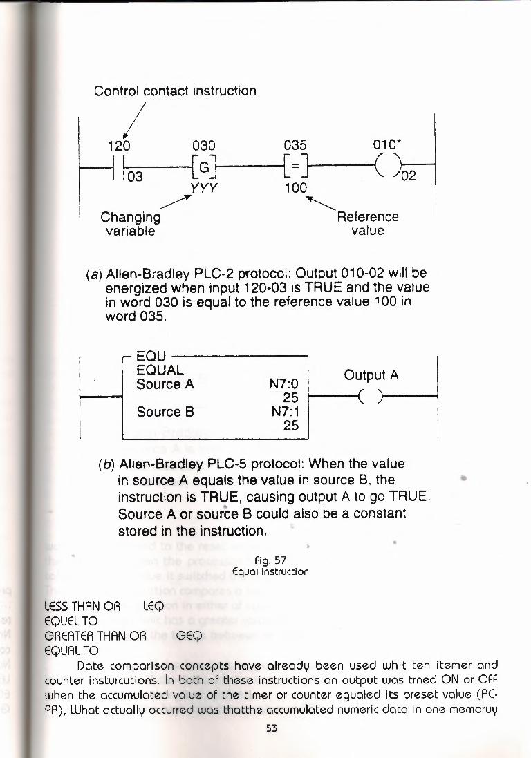
Control contact instruction
I 120 030 035 01 O*
~ 103 [G] [=] (yyy
-> Changingvariable
02100
'Referencevalue
(a) Allen-Bradley PLC-2 protocol: Output 010-02 will beenergized when input 120-03 is TRUE and the valuein word 030 is equal to the reference value 100 inword 035.
~EQU~~~~~~-
~~u~~elA N?~~ I Outp~N7:1 ( 1
25Source B
(b) Allen-Bradley PLC-5 protocol: When the valuein source A equals the value in source B, theinstruction is TRUE, causing output A to go TRUE ..,Source A or source B could also be a constantstored in the instruction.
•..Fig. 57
Equal instruction
LESS THAN OR LEQEQUEL TOGREATER THAN OR GEQEQUAL TO
Date comparison concepts have already been used whit teh itemer andcounter insturcutions. In both of these instructions an output was trned ON or OFFwhen the accumulated value of the timer or counter egualed its preset value (ACPR), What actually occurred was thatthe accumulated numeric data in one memoruy
53

120 030 035 010·
I 03 [G] [<] ( ./02yyy 100
Changing-: <.
Referencevariable value
(a) Allen-Bradley PLC-2 protocol: Output 010-02 will beenergized when input 120-03 is TRUE and the valuein word 030 is less than the reference value 100 inword 035.
LESLESS THANSource A
Source B
Output AN7:13
33~---..N7:23
48
(b) Allen-Bradley PLC-5 protocol: When the value insource A is less than the value stored in source 8,the instruction is TRUE, and output A will be TRUE;otherwise, output A will be FALSE.
Fig. 58less than instruction.
word was compared to the reset value of another memoruywôrd on each scanofthe procesor. When the processor saw that the accumulated value was egualto(=)the preset value it switched the output ON or OFF.The limit test instruction comparesa test value to values in the low limit and in thehigh limit. ıt can function in either of two ways:
If the high limit has a greater value than the low limit, hten the instruction istrue if the value of the test is between or egUal to the values of the hgih limit andthe low limit.
If the value of the low limit is greater than the value of the high limit, theinstruction is true if the value of the test is egual to orless than the low limit oregual to or greater than the high limit.
In (Fig 62) the high limit has a value of 50. and the low limit a value of 25.54

t 20 035 030 010~·
I 03 [ GJ [ < J C 02100 YYY
Reference / "'- Changing 1
value variable
The instruction is TRUE, then forvalues of the test form 25throuğh 50.b The instruction asshown is TRUE Because the valueof the test is 48.ln (Fig 620) thehigh limit has a value of 50. andthe low limit a value of 100. Theinstruction is TRUE, then for testvalues of 50 and lesss than 50.and 100 and greater than 100.The instruction as shown is TRUEbecause the test value is1 25. The use of comparisoninstructions is generallaystraightforward. However, onecommon programming errorinvolves th i use ofg theseinstruction in a PLC program tocontrol the flow of a raw material
(a) Allen-Bradley PLC-2 protocol: Output 010-02 will beenergized when input 120-03 is TRUE and the value inword 030 is greater than the reference value 100 inword 035.
GRT~~~~~~~~GREATER THANSource A
Source B
N12:10124
FS:11555
(b) Allen-Bradley PLC-5 protocol: When thevalue at source A is greater than the valueat source B. the instruction is TRUE andoutput A will be TRUE; otherwise,it is FALSE.
Fig. 59Greater than instruction.
into vessel. The receiving vessel has its wieğht continuously monitored by the PLCProgram as it fills.When the weight reaches a preset value, the flowis cutoff.Wnille the vessel, fills the PLC preforms o comparison between the vesselscurrent weight and a predetermined constant programmed in the processor. If theprogrammer uses only the EQUAL TO Instruction, the instruction becomes TRUE andthe flow is stopped. However should the supply system leak additional inaterialinto the vessel. the total weigh of the material could rise above the preset value,causing the instruction to go FALSE ıand the vessel to overg i 11. The ~20 030 03s 01~
simplest solution toı this problem is I 03 [ GJ I [<] I C .102yyy 100
to program the comparison instn.tctionas GREATER THN OR EQUALTO.Thisway any execess materila entering • value
the Vessel Will not affect the filling (a)Allln-BradleyPLC-2protocol:.Output010-02willbe.· energızed when ınput 120-03 ıs TRUE and the value ın
operation ıt may be necessary in word030islessthanorequaltothereferencevalue, , 100 ın word 035.
some cases, to include additionalprogramming to indicate a seriousoverfill condition.
Set point control in its simplestform compares an input value, suchas an analog or thumbwheel inputs,to a set point value. A discreteoutput signal is provided if the inputvalue is less than, eguol to, or
H LEQLESS THAN OR EQUALSource A 55
Source B N7:101 [I i . 75
Ootp~
I
(b) Allen-Bradley PLC-5 protocol: When the valueat source A is less than or equal to the valueat source 8, the instruction is TRUE andoutput A will be TRUE; otherwise. it is FALSE.
Fig. 60Lessthan or equal to intruction.
55

greater than the set point value.The temperatuer control
program of (Fig 63) is oneexample of set point simpleOFF/ON control of the electricbeating elements of an oven. Theoven is tu maintain an averağesetpoint temperature of 600 F, witha variation of about l percentbetween teh OFF nod On cycles.Therefore, the electric heaters willbe turned On when thetemperatuere of the oven is 597 for less and stay ON unti I thetemperature risse to 603 F ormore. The electric heaters stay Offunti I the tempretature drorpsdown to 597 F, at which time thecycle repeats itself. Rung 2contains a GET/LESS OR EQUAL
TO logic instruction and rung 3 contains the eguivalent of a GET/GREATER THANOR EQUAL TO logic instruction. _LIM------~
Rung 4 contains the logic I [ LIMITTEST(CIRC)Low lımıtfor switching the heaters ON andOFF according to the high andlow set points. Rung l containsthe logic that allows thethermocouple temperature to bemonitored by the LED displayboard.
In complek industrialmachine or process control, it isne ces soru to carry outmathematical functions rangingfrom basic arithmetic, such asadd, subtract, divide, andmultply, to complex mathematicsused in flow measurement andPID control. Mathinstructionsallow the PLC toperform arithmetic functions onvalues stored in memory words(Figs64 to 67)
(a) Allen-BradleyPLC-2protocol:Output010-02will beenergizedwhen input 120-03is TRUE and the valuein word 30 is greater than or equal to the referencevalue 100in word 035.
GEO-------GREATERTHAN OR EQUALSourceA N?:555
1007N7:12
23SourceB
(b) Allen-BradleyPLC-5protocol:When the valueat sourceA is greater than or equal to the valueat sourceB, the instructionis TRUE andoutputA will be TRUE; otherwise,outputAwill be FALSE.
Fig. 61Greater than or equal to instruction.
N72225
N?:2348
N?:2450
Output
Test
High limit
25 50
FALSE(< 25) TRUE ~ALSE (> 50)
(a) High limit is 50, and low limit is 25
H-LIM
LIMITTEST (CIRC)Low limit N?:28 I Output F
100Test N?:29I'
125High limit N?:27
t : 50 I' I
50 100
TRUE($ 50) FALSE ~RUE(~ 100i
(b) Hıgh limit is 50, and low limit is 100
Fig. 62Limit test instruction.
56
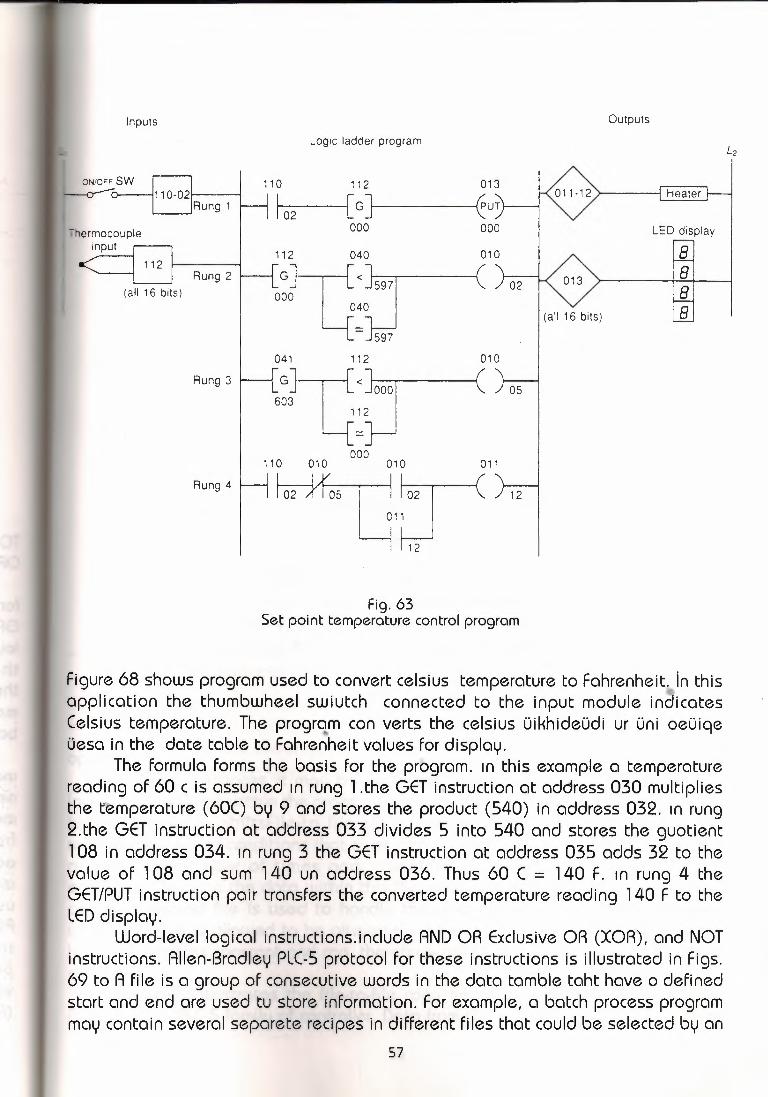
Inputs
111 o-02c--:-;L__JHung 1 I
~hermocoupleinput .-----,-
Rung 2(all 16 bits)
Rung 3
Rung 4
Outputs
Logic ladder program
110 112
I 02 [G J I000
013011-12 Heater
12. 8
LED display--,88
0401~Jt<J597000 040
-J597 010
112 (
o:]t<Joool603 112
=}---J
(all 16 bits)
05
000110 010 010 011~~:r2 .011
12
Fig. 63Set point temperature control program
Figure 68 shows program used to convert celsius temperature to Fahrenheit)n thisapplication the thumbwheel swiutch connected to the input module indicatesCelsius temperature. The progrqm con verts the celsius üikhideüdi ur üni oeüiqeüesa in the date table to Fahrenheit values for display.
The formula forms the basis for the program. ın this example a temperaturereading of 60 c is assumed ın rung l.the GET instruction at address 030 multipliesthe t:emperature (60() by 9 and stores the product (540) in address 032. ın rung2.the GET instruction at address 033 divides 5 into 540 and stores the guotient108 in address 034. ın rung 3 the GET instruction at address 035 adds 32 to thevalue of 108 and sum 140 un address 036. Thus 60 C = 140 F. ın rung 4 theGET/PUT instruction pair transfers the converted temperature reading 140 F to theLED display.
Word-level logical instructions.include AND OR ExclusiveOR (XOR), and NOTinstructions. Allen-Bradley PLC-5 protocol for these instructions is illustrated in Figs.69 to A file is a group of consecutive words in the data tamble taht have o definedstart and end are used tu store information. For example, a batch process programmay contain several separete recipes in different files that could be selected by an
57

I 1.11 030 031 032·
H !o5 [G] [G] (·)-1 105 080 185
(a) Allen-Bradley PLC-2 protocol: When input device 111 /05is TRUE, the value of word 030 (105) is added to thevalue of word 031 (080) and the sum (185) is stored inword 032.
ADDADD
Input AI
Source A N7:0; r 25
Source B N7:150
Destınation N7:275
(b) Allen-Bradley PLC-5 protocol: When inputdevice A is TRUE, the value stored ataddress N7:0 (25) is added to the value storedat address N7: 1 (50) and the sum is storedat address location N7:2 (75).
Fig. 64ADD instruction.
operator.In some instances it may be necessary. to shift complete files from one
locotlon to anothen within the programmable controler memory. Such data shift aretermed file-tofile shiftsFile-to file shifts are used when the data in one filerepresents a set of conditions that must interact with the programmable controllerprogram a nummber of times and, therefore, must remain intact after eachoperation. Because the data within this file must also bechanged by the programaction. A second file is used to handle the data changes, and the informationwithin that file is allowed to be altered by the program. The tada in the first file,however, remains constant and can, therefore, becalled upon tu be used a numberof times.
Figure 73 illustrates the file-to-file copy instruction protocol used with theAllen Bradley PLC-5 family of controller, Data from the expressionfile N 7:20 will be
58

. I
r111 030 031 032
105 [c] [c] (-105 080 025
(a) Allen -Bradley PLC-2 protocol: SUBTRACT instructionrung. When input device 111/05 is TRUE, the value ofword 031 (080) is subtracted from the value of word 030(105), and the difference (025) is stored in word 032.Only positive values can be used with some PLCs.
1SUBI SUBTRACTI Source AI
Destination
N7:50243585 ı---~
N7:51-342
Source B
..
(b) Allen-Bradley PLC-5 protocol: Allows negativevalues to be used. Here the instruction isprogrammed unconditionally, i.e., the subtractoperation will take place every time the instructionis scanned.The value stored at the addressindicated in source Bis subtracted from the valuestored at the address indicated in source A, and..the answer is stored at the address locationindicated in the oestınation. Also, this exampleshows the instruction with a constant enteredin source 8. A constant may be entered ineither source A or source 8, and it isstored in the instruction.
Fig. 65Subtract instruction.
copied into the testination file N7:SO .The length of the two files is set by thevalue entered in the control element word. R 6: 1 LEN ın this instruction we havealso used the ALL mode, which menas all of the data will be transferred in the firstscan in which the FAL instruction sees a FALSE-toTRUE transition. The DN bit will
59

~11030 031 032 03wRung 1 !05 [G] [G] (x) (x I123 061 007 503H32 034 033 035 010
Rung 2 G] [ J [G] [ J C .,,10I 007 503
(a) Allen-Bradley PLC-2 protocol: When input device 111 /05is TRUE, the value of word 030 (123) is multiplied bythe value of word 031 (061 ), and the product (7 503)is stored in word 032 (007) and word 033 (503). As aresult, rung 2 will become TRUE, turning output 010/1 OON.
Input A[
~MUL~~~~~~~~MULTIPLYSource A
Destination
FB:101.55
N7:30 ...__~5
FB:117.75
l Source B
(b) Allen-Bradley PLC-5 protocol: Value storedat the address indicated in source A, FB:1 O,being multiplied by the value stored at theaddress in source 8, N7:30, the result beingstored at the address in the destination, F8: 11.
Fig. 66MULTIPLY instruction.ı, •..
also come ON in that scan.,unless an error occurs in the transfer of data, in whichcase the ER bit will be set, the instruction will stop operation at that position,and then the scan will continue at teh next instruction.
SHlfT REGISTER AND SEQUENCER INSTRUCTIONS The shift register instruction is often used with conveyors to monitor and
control the flow of the individual parts. In general, it can be used in the control ofmachines and processes in which parts are continually shifted from one positionto the next.
You can program a shift register to shift status data either right or left. Thisis accomplished by shifting either status or values through data files. When
60

111 030 031 032 033 IRung 1 H 105 [G] [G] (-c-) C-c-H
150 040 003 750 I032 034 033 035 010 I
'I
Rung2HG] [ J [G] [=] (~003 750
(a) Allen-Bradley PLC-2 protocol:When input device 111/05is TRUE, the value of word 030 (150) is divided by thevalue of word 031 (040), and the quotient is stored inwords 032 and 033 (003.750 or 3.75). As a result, rung2 will become TRUE, turning output 010/1O ON.
Input A[
.-- DIV ---------.DIVIDESource A
Destination
N7:50100
N7:556
N7:6017
l Source B
(b) Allen-Bradley PLC-5 protocol: The exampledivides the value stored at source A's address(N7:50) by the value stored at source B's address(N7:55) and stores the result at the destination'saddress (N7: 60). Note that the result stored at thedestination address is rounded off. If the remainderis 0.5 or above, the result is rounded up. If fheremainder is less than 0.5, the answer is roundeddown.
Fig. 67DIVIDE istruction.
tracking parts on a status basic, bit shift registers are used. Bit shift instructionswill shift bit status from a source bit address, through a data file, and out to anunload bit, one bit at a times. there are two bit shift instructions: bit shift left(BSL), which shifts bit status from a lower address number to a higher addressnumber through a data file; and the bit shift right (BSA),which shifts data from ahigher address number to a lower address number through a data file. (Figure 74
61
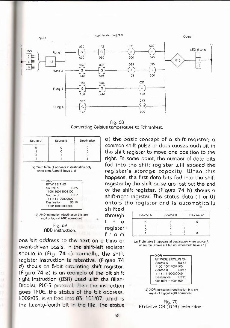
Logic ladder program
030 112 031 032
GJ [GJ (x) (x009 060 000 540
032 033 034 035
GJ [GJ (+) (+_540 005 108 000
034 036 037
GJ [G] (+108 032 140
037 013- "G PUT
/
140 000
Inputs
L,
Rung 1
Rung 3
Rung 4
Output
LED display
013,-,ı_ı
Fig. 68Converting Celsius temperature to Fahrenheit.
Source A Source 6 Destination
o o o1 o oo 1 o1 1 1
(a) Truth table (1 appears in destination onlywhen both A and 6 have a 1)
AND-------61TWISE ANDSource A 63:51100110011001100Source 6 63:71111111100000000Destination 83:101100110000000000
(b) AND instruction (destination bits areresult of logical AND operation)
Fig. 69ADD instruction.
a) the basic concept of a shift register; acommonshift pulse or clockcauseseach bit inthe shift register to move one position to theright. At some point, the number of data bitsfed into the shift register will exceed theregister's storage capacity. When thishappens, the fırst data bits fed into the shiftregister by the shift pulse are lost out the endof the shift register. (Figure 74 b) shows ashift-right register. The status data (1 or O)enters the register and is outomottcollushiftedthrought h eregisterf r o m
one bit address to the next on a time orevent-driven basis. In the shift-left registershown in (Fig. 74 c) normally, the shiftregister instruction is retentive. (Figure 74d) shows an 8-bit circulating shift register.(Figure 74 e) is an example of the bit shiftright instruction (BSA) used with the AllenBradley PLC-5 protocol. Jhen the instructiongoes TRUE, the status of the bit address,1:002/05, is shifted into B3: 101 /07, which isthe twenty-fourth bit in the file. The status
62
Source A Source B Destination
o o o1 o 1o 1 11 • o
"(a) Truth table (1 appears at destination when source A
or source B have a 1 but not when both have a 1)
XOR------BITWISE EXCLUS ORSource A 83: 151100110011001100Sources B3:171111111100000000Destination B3:250011001111001100
(b) XOR instruction (destination bits areresult of logical XOR operation)
Fig. 70EXclusiveOR (XOR) instruction.

II Source A Source B DestinationII o o o
1 I o 1o 1 ,
I!1 1 1
(a) Truth table (1 does not appear at destinationonly when both source A and source B are O)
ORBITWISE INCLUS ORSource A 83: 11100110011001100Source B 83:21111111100000000Destination 83:201111111111001100
(b) OR instruction (destination bits areresult of logical OR operation)
•Fig. 71OR instruction.
of all of the bits in the file are sliifted one position to the right, through the lengthof 24 bts. The status of B3: l00/00 is shifted to the unload bit, R6: l/UL. Thestatuspreviously in the unload bit is lost. ,. •
.• (Figure 75) illustrates a spray painting operation controlled by a shiftregister. The shift register's function is used to keep track of the items to besprayed. As the parts pass along the production line, the shift register bit patternsrepresent the items on thi conveyor hangers to be painted. the logic of thisoperation is suchthat when a part to be painted and a part hanger occurtogether,indicated by the simultaneous operation of LS1 and LS2, a logical l is input intothe shift register. The logiccal l will cause the undercoat spray gun to operate,and, five steps later, when a l occursin the shift register, the top coat spray gunis operated. limit swtch 3 counts the parts as they exit the oven. The countobtained by limit switch l and limit switch 3 should be equal at the end of thespray painting run and is an indication that the parts commencing the sray
63

5...,_ estınation
o
(a) Truth tameand thethe 1 s
etween source As changed to 1 s and
(b) ation bits areperation)
painting run equalindicates that thethe operation of the --
Sequencer ir..s- _sequencer i nstruc: ·tnstnıctlon functi oto control output oe- -The programming ::i ~f-~atS. ~~1vary between programmable controllermanufacturers, but ::--,e ,~ ::oncepts are the same. The sequence of eventscontrolled by the sec·-~~ s,~ bv the bit panttern of each consecutiveword and the numbe .. :f r:::o-.:s s: ~ 'sequence.
(Figure 76) s;..:.s ~ ..~, :c: i••~;pical sequencer output instruction works. Inthis example, 16 liç-:s ı~ ..:sac b OlA:puts. Each light represents one bit address( 1 through 16) of c _ -~-:ct ~ 0501_ 1he lights are programmed in a four-stepsequence to simula:e _:e, q:.:e:.ı:::t:._a cf itwcrway traffic lights.
Data is enterec -L, := .uı::J!l!IE fie for each sequencer step as illustrated.
s..uu~,eted it. A logical : in the shift registero be sprayed and therefore inhibits
control machines that operate in aam memory. The, sequencer outputechanical drum switch, which is used

-- FALFILE ARITH/LOGICAL
lnpuw Control R6:1Length 6 I (EN.
Position oMode All HoN)Destination #N7:50
Expression528 r-(ER)
#N7:20
Expression#N7:20
Destination#N7:50
r N7:20I
528
621
778
986
342
135
528
621
778
986
342
135 N7:55
N7:50
File
l N7:25
Fig. 73File-to-file copy instruction.
Using the programmer, binary lnforrnctlon ( 1 s and Os") that reflects thedesired light sequence is entered into each word of the file. For ease ofprogramming, some PLCs allow the word file data to be entered using the octal,hexadecimal, BCD, or similar number system. When this is the case, the requiredbinary information for each sequencer step must first be converted to whatevernumber system is employed by the PLC. This information is the entered with theprogrammer into the word file.
Once the data has been entered into the word file of the sequencer, the PLCis ready to control the lights. When the sequencer is activated and advanced tostep 1, the binary information in word 060 of the file is transferred into word 050of the output. As a result, lights 1 and 12 will be switched ON and all the rest willremain OFF. Advancing the sequencer to step 2 will transfer the data from word
65

Data in= 1___J
!JUUULIShitt data
(clock)
Register200
Jo[1J1lolol1lol1!1!1!0[1!0Jol1!Original data in initial position
Register200
New data in shift right position
(a) Basic concept of shift register
Most significantbit address
!18 17 16 15 14 13 12 11
1 or O+ + -F + + -F -F + +(b) Shift right register
Least significantbit address
18 17 16 15 14 13 12 11I-,- ...,- :f :f + + + :f +1 or(
Status data shifts on each FALSE to TRUE transition of SQO
( c) Shitt left register
l- -! ' + :f + ~( d) 6-bit circulating shift register
.. II~pu
I
BS • I
EN~;
DN)
H -- SHIFT RIGHT
I •• J #B3:100 I
L Control R6:1Bit address 1:002/05Length 24
(e) Example of bit shift right instruction (BSR)used with Allen-Bradley PLC-5 protocol
Fig. 74Shift registers.
66

Limitswitch 1
Oven 1 Oven 2
switch 3Undercoat
spray gun 1Top coat
spray gun 2 ~ rage11
Fig. 75Shift register spray painting application.
061 into word 050. As a result, lights 1, 8, and 12 will be On and all the rest willbe OFF. Advancing the sequencer to step 3 will transfer the data form word 062into word 050. As a result, lights 4 and 9 will be On and all the rest will be OFF,Advancing the sequencer to step 4 will transfer the data from word 050. As aresult, lights 4, 5, and 9 will be ON and all the rest will be OFF. When the last stepis reached, the sequencer is either automatically or manually reset to step 1.
When a sequenceroperates on an entire output word, there may be outputsassociated with the word that do not need to be controlled by the sequencer. Inour example, bits 2, 3, 5, 7, l O, 11, 13, 14, 15, and 16 of output word 050 are notused by the sequencerbut could be usd elsewhere in the program. .
To prevent the sequencer from controlling these bits of the output uTord, amask word (040) is used. The use of a mask word is illustrated in (Fig. 77) mask
••word file to the output word. For each bit of output word 050 that the sequenceristo control, the corresponding bit of mask word 040 must be set to l. All other bitsof output word 050 are set to O and therefore.con be used independently of thesequencer.
To program a sequencer instruction into a PLC, an input file is created whichholds the bit pattrent of the sequence read from a numberof input words, and anoutput file is used to output the sequence to the required devices. The bit patternof the mask word controls which outputs are made active. Sequencer instructionsare usually retentive, and there is an upper limit as to tha number of externaloutputs and steps that can be operated upon by a single instruction. Manysequencer instructions reset the sequencer automatically to step l uponcompletion of the last sequence step. Other instructions provide an individualreset control line or a combination of both. (Figure 78) illustrates a typical blockformatted sequencer instruction.
67

Step 1 : Bits 1 and 12 are ON Step 2: Bits1, 8, and 12 are ON
-, 1 / 2 3 4 -, 1 /
G),O o 0 G) ,O o 0/ /5 6 7 8
' 8 /
0 o o 0 0 o o Q/ -,
9 10 11 "- 12 / "- 12 /
® o o/ G) ® o o/ G) -, -,13 14 15 16
o o o o o o o oStep 3: Bits 4 and 9 are ON Step 4: Bits 4, 5, and 9 are ON
' 4 / ' 4 /
0 o 0 G) ® r-. o 0V / V-, / <,
' :, /
0 o o 0 G) o o 0/ "
' 9 / ' 9 /G) () o ,0 G) o o ®''--"'' 01 / -, / "
o o o o o o o o(a) Sequencer steps
16 15 14 13 12 1' 10 8 8 ~ 6 5 ,: 3 2
Word 050 I O I O · I O I O I o"' J O I C [ O . I O j O [ O j O I O i o i o I o I Output
r Word 060 o o o I o 1 o o o o ~ o o o o I o'! o I 1I
o · o 1o o o C 1 o o o 1 o o o o 1
o o o o o o C i 1 o o o o ; o o oo o o o o o o ı ~ o I o o 1 1 , O o oI
..Four- Word 061wordfile Word 062
L Word 063
(b) Binary information tor each sequencer step
Fig. 76Four-word sequence
68
Step 1
Steo 2
Step 3
Sterı 4

A seque- =~ µ ':_PU ::cm be event-driven or time-driven. An event-drivensequencer ope:-=:.:es -• = whonical stepper switch that increments by one step
i::. ~.=.: •_.: ~ ~ -~ ~o 9 8 7 6 5 4 3 2
Word 050 I : - - - ~ -· :, !I ~ J O I O I O I O I O j O I O I O ! O I Output- ... - : Wlo'ii
Word 040 I : I c I : : II •., ="' ·= i 1 11~ fofo~ ı 1 ı 1 ı o ı o ı , ı Mask
:., ı O I O I O I O I O I O I O I O I 1 I Step 1Word 060 I : - - . - .- - -Word 061 I C - : ! - . c ' o I 1 I o I o I o I o I o I o I 1 I Step 2- - -Word 062 I C - : I: :: ::: I C • I o I o I o I o I 1 I o I o I o I Step 3- -Word 063 I C ı-:f - - ' - : ı: c I ~ I o I o I o I 1 I ı I o I o I o I Step 4- - .
for each pulse ap ·drum switch that i
~rıtn£..<1rtvensequencer operates like a mechanicalafter a preset time period.
OUTPUT#N7:1
"' OFOF0:014
Centro A6:201 •.. , ... erıçtn 4
Position o
ct ion.
69

CONCLUSION The Programing logic control system ensures that kegs are distrubuted to
washing and fiiling lanes a manner which keeps lane starvation at the minumumlevel. The system automatically resets the flowmeter set points and carries outstandart deviation calculations to ensure that fi i Ii ng is accurate. Automaticrecalibration facilities are provided to take account of the need to wash and filldifferent sizes of kegs during the operating periods. The gas pressure in every kegis checked againist master transducers to ensure that the required pressures areachieved.Comprehensive on-line monitoring facilities are provided, which include the numerof kegs washed, filled, and rejected. Full details of the reasons why kegs arerejected are provided in tabulated from on enalde production problems to bequickly identified.
\~-
70
•