Logic Families
13
8/5/2019 1 Logic Families • RTL – Resistor-Transistor Logic • DTL – Diode-Transistor Logic • TTL – Transistor-Transistor Logic • ECL – Emitter-Coupled Logic • MOS – Metal-oxide semiconductor • CMOS – Complementary MOS Diode based Logic Diode based Logic
-
Upload
khangminh22 -
Category
Documents
-
view
0 -
download
0
Transcript of Logic Families
8/5/2019
1
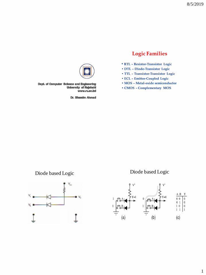
Logic Families
• RTL – Resistor-Transistor Logic
• DTL – Diode-Transistor Logic
• TTL – Transistor-Transistor Logic
• ECL – Emitter-Coupled Logic
• MOS – Metal-oxide semiconductor
• CMOS – Complementary MOS
Diode based Logic Diode based Logic
8/5/2019
2
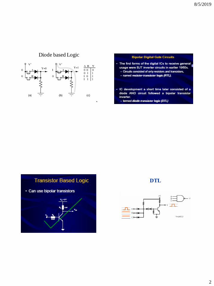
Diode based Logic
DTL
8/5/2019
3
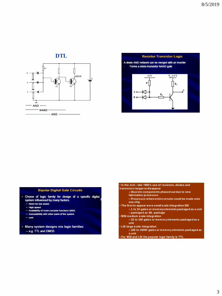
DTL
• In the mid – late 1960’s use of resistors, diodes and
transistors began to disappear
– Discrete components phased out due to new
fabrication processes
– Processes where entire circuits could be made onto
one chip
• The first to appear were small scale integration SSI
– 1 to 10 gates or memory elements packaged as a unit
– packaged as DIL package
• MSI medium scale integration
– 10 to 100 gates or memory elements packaged as a
unit
• LSI large scale integration
– 100 to 10000 gates or memory elements packaged as
a unit
• For MSI and LSI the popular logic family is TTL
8/5/2019
4
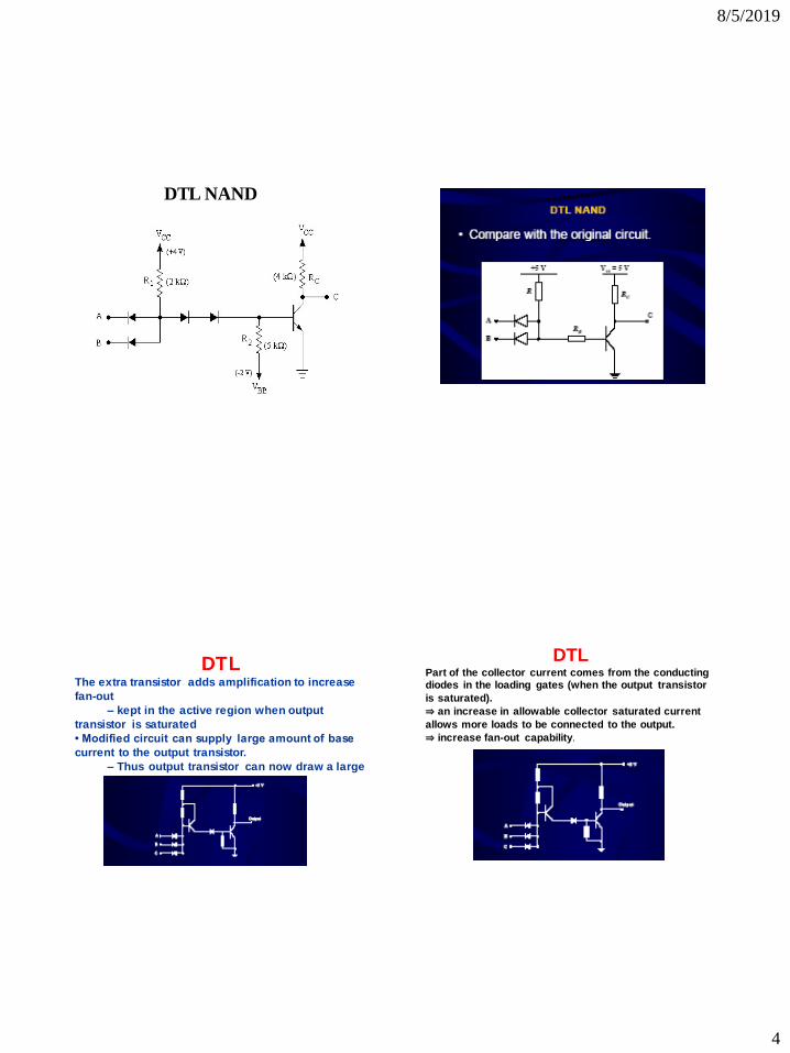
DTL NAND
DTL The extra transistor adds amplification to increase
fan-out
– kept in the active region when output
transistor is saturated
• Modified circuit can supply large amount of base
current to the output transistor.
– Thus output transistor can now draw a large
DTL Part of the collector current comes from the conducting diodes in the loading gates (when the output transistor
is saturated).
⇒ an increase in allowable collector saturated current
allows more loads to be connected to the output.
⇒ increase fan-out capability.
8/5/2019
5
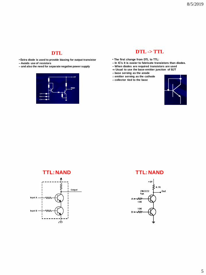
DTL
• Extra diode is used to provide biasing for output transistor
– Avoids use of resistors – and also the need for separate negative power supply
DTL -> TTL
• The first change from DTL to TTL:
– In IC’s it is easier to fabricate transistors than diodes.
– When diodes are required transistors are used ⇒ Usual to use the base-emitter junction of BJT
∴ base serving as the anode
∴ emitter serving as the cathode
∴ collector tied to the base
TTL: NAND TTL: NAND
8/5/2019
6
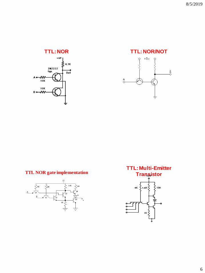
TTL: NOR TTL: NOR/NOT
TTL NOR gate implementation
TTL: Multi-Emitter Transistor
8/5/2019
7
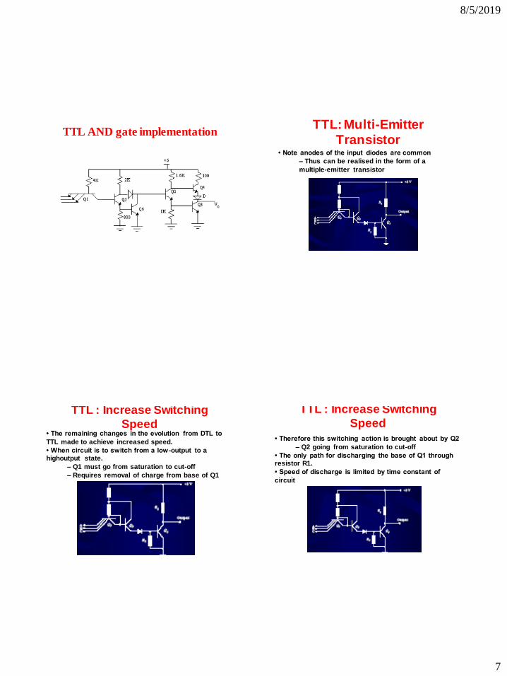
TTL AND gate implementation
TTL: Multi-Emitter
Transistor
• Note anodes of the input diodes are common
– Thus can be realised in the form of a
multiple-emitter transistor
TTL : Increase Switching
Speed
• The remaining changes in the evolution from DTL to
TTL made to achieve increased speed.
• When circuit is to switch from a low -output to a highoutput state.
– Q1 must go from saturation to cut-off
– Requires removal of charge from base of Q1
TTL : Increase Switching
Speed • Therefore this switching action is brought about by Q2
– Q2 going from saturation to cut-off
• The only path for discharging the base of Q1 through resistor R1.
• Speed of discharge is limited by time constant of
circuit.
8/5/2019
8
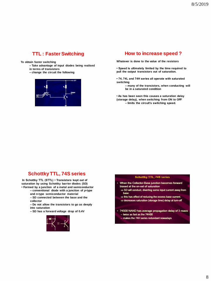
TTL : Faster Switching
To obtain faster switching
– Take advantage of input diodes being realised
in terms of transistors – change the circuit the following
How to increase speed ?
Whatever is done to the value of the resistors
• Speed is ultimately limited by the time required to pull the output transistors out of saturation.
• 74, 74L and 74H series all operate with saturated
switching
– many of the transistors, when conducting will be in a saturated condition
• As has been seen this causes a saturation delay
(storage delay), when switching from ON to OFF
– limits the circuit’s switching speed.
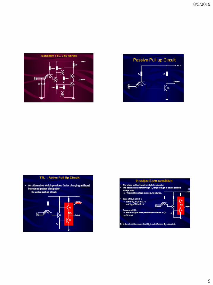
Schottky TTL, 74S series In Schottky TTL (STTL) • Transistors kept out of
saturation by using Schottky barrier diodes (SD)
• Formed by a junction of a metal and semiconductor – conventional diode with a junction of p-type
and n-type semiconductor material
– SD connected between the base and the
collector
– Do not allow the transistors to go as deeply into saturation
– SD has a forward voltage drop of 0.4V
8/5/2019
9
8/5/2019
10
8/5/2019
11
8/5/2019
12
8/5/2019
13