Proceedings I R# E - World Radio History
192
-
Upload
khangminh22 -
Category
Documents
-
view
2 -
download
0
Transcript of Proceedings I R# E - World Radio History
Proceedings of the I R# E
A Journal of Communications and Electronic Engineering
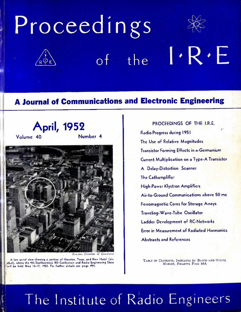
April, 1952 Volume 40 Number 4
I 1 auston C ha mber ,,f
A low aerial view showing a portion of Houston, Texas, and Rice Hotel (cir-cled), where the 4th Southwestern IRE Conference and Radio Engineering Show will be held May 16-17, 1952. For further details see page 494.
PROCEEDINGS OF THE I.R.E.
Radio Progress during 1951
The Use of Relative Magnitudes
Transistor Forming Effects in n-Germanium
Current Multiplication on a Type-A Transistor
A Delay-Distortion Scanner
The Cathamplifier
High-Power Klystron Amplifiers
Air-to-Ground Communications above 50 mc
Ferromagnetic Cores for Storage Arrays
Traveling-Wave-Tube Oscillator
Ladder Development of RC-Networks
Error in Measurement of Radiated Harmonics
Abstracts and References
TABLE OF CONTENTS, INDICATED BY BLACK-AND-W HITE MARGIN, FOLLOWS PAGE MA
The Institute of Radio Engineers
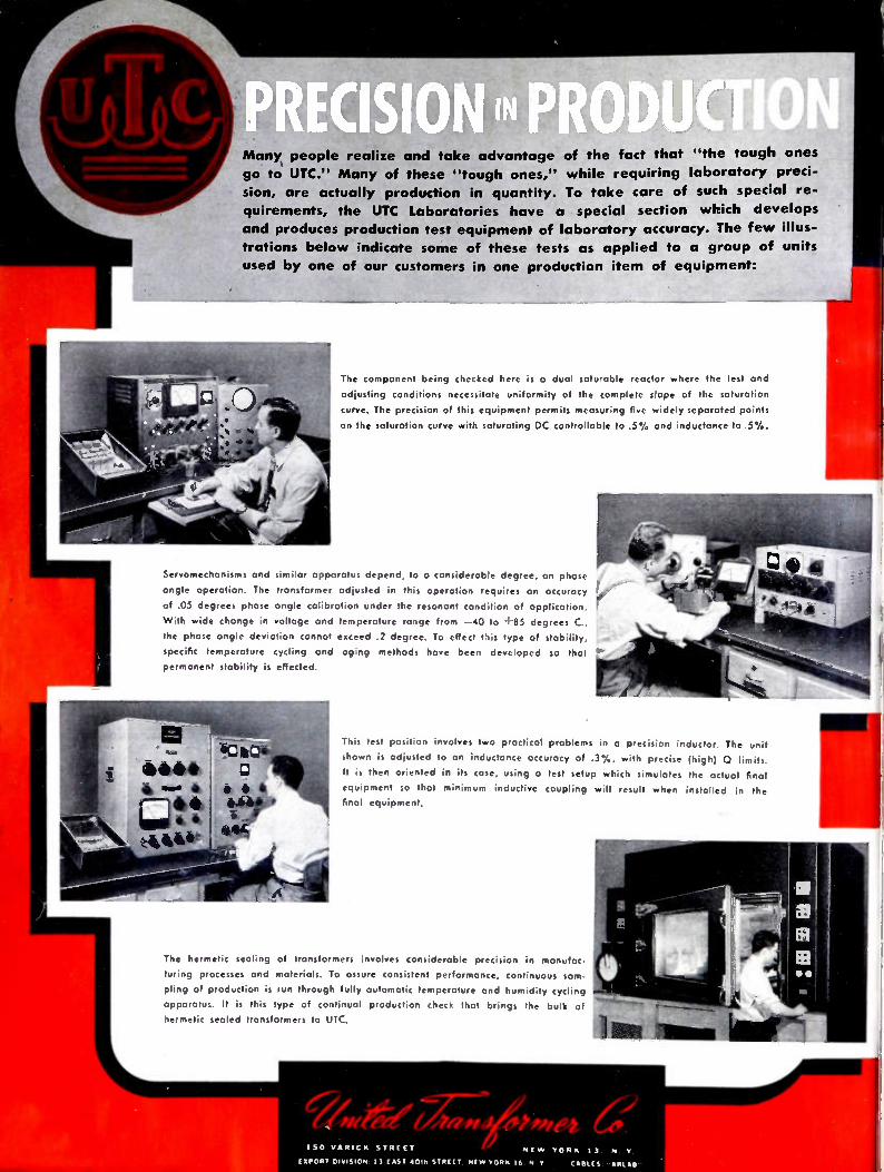
Many, people realize and take advantage of the fact that "the tough ones
go to UTC." Many of these "tough ones," while requiring laboratory preci-
sion, are actually production in quantity. To take care of such special re-
quirements, the UTC Laboratories have a special section which develops
and produces production test equipment of laboratory accuracy. The few illus-
trations below indicate some of these tests as applied to a group of units
used by one of our customers in one production item of equipment:
The component being checked here is a dual saturable reactor where the test and
adjusting conditions necessitate uniformity of the complete slope of the saturation
curve. The precision of this equipment permits measuring five widely separated points
on the saturotion curve with saturating DC controllable to .5 % and inductance to .5%.
Servomechonisms and similar apporalus depend, to a considerable degree, on phase
angle operation. The transformer adjusted in this operation requires an accuracy
of .05 degrees phase angle calibration under the resonant condition of application.
With wide change in voltage and temperature range from —40 to 4 ' 85 degrees C.,
the phase angle deviation cannot exceed .2 degree. To effect this type of stability,
specific temperature cycling and og.ng methods have been developed so that
permanent stability is effected.
This test position involves two practical problems in a precision inductor. The unit
shown is adjusted to an inductance accuracy of .3%, with precise (high) 0 limits.
It is then oriented in its case, using a test setup which simulates the actual final
equipment so that minimum inductive coupling will result when installed in the
final equipment.
The hermetic sealing of transformers involves considerable precision in manufac-
turing processes and materials. To assure consistent performance, continuous sam-
pling of production is run through fully automatic temperature and humidity cycling
apparatus. It is this type of continual production check that brings the bulk of
hermetic sealed transformers to UTC.
1 SO VA RI C K ST RE ET NE W YO R K 13, N. V.
(SPORT DIVISION 13 EAST 4055 STREET N M YORK IS N V M ILES.

1411111 01111 011111111 M1 Mikallidi
National Conference on AIRBORNE ELECTRONICS
May 12, 13, 14
Biltmore Hotel, Dayton, Ohio
The IRE Professional group on Airborne Electronics joins with the Dayton Section in sponsoring the 1952 NATIONAL CONFERENCE ON AIRBORNE ELECTRONICS May 12, 13, 14. The Conference committee, working with research laboratories, universities, and electronic and aircraft indus-tries have made arrangements for the largest and best Con-ference held to date! Over 70 papers will be presented cov-ering over 14 general topics including communication, navi-gation propagation, computers, instrumentation, antennas, components and vacuum tubes. In addition to a high-powered technical conference, complete with a display of commercial equipment, there will be an excellent social
program. For information write the Dayton Section, IRE c/o Far Hill,
P.O. Box 44, Dayton 9, Ohio
CINCINNATI ENGINEERING BUILDING
Spring Technical Conference
Cincinnati IRE
The Spring Technical Conference will be held Saturday, April 19, 1952 at the Engineering Society Headquarters Building, Woodburn and McMillan Street, Cincinnati, Ohio. Advance registration and reservations for hotel accommo-dations and for the Luncheon and Banquet may be made by
mail. Registration may also be made at the door the morning of the conference. Papers concerning UHF Television, Color Television and the Megacycle Meter will be presented.
May 16 4, 1952
Rice Hotel, Houston, Texas
The Southwestern IRE Conference will feature technical
papers on eight major radio subjects:
• Microwave and V.H.F. Communications
• Audio
• Instruments
• Geophysics
• Airborne Electronics
• Components
• Broadcast & T.V. • "Ham" Engineering
A wide variety of radio-electronic products and services will be on display at the Show to be held in conjunction with the Conference. About 40 firms are exhibiting, and spe-cial emphasis will be on their products in the fields of Audio, Geophysics and Instrumentation.
Announcing the dates:
1953 IRE National Convention
and Radio Engineering Show
March 23-26, 1953; New York City
Also See Page 2A Calendar
NEREM New England Radio Engineering Meeting
The 5th annual Radio Engineering Meeting of the North Atlantic Region will be held on Saturday, May 10, 1952 at the Copley Plaza Hotel, Copley Square,
Boston.
Featuring the radio engineer's role in the present emergency, the technical program for this one-day event will include papers on Test Instruments, Color Television, High Frequency, Instrumentation and Ra-
diation.
IRE Meetings and Exhibits Speed Electronic Progress!
['k W !Ch.(/' .,, • ',P lit k i . R. E. Apt II, I r) ...:, ‘ 0 no 1. A), No. 4. l'iii,11.11,.1 itilkly by the I ii,tIllitc ol Radio Engine, t,. I i, , .,t 1 East 79 Street, New York 21, N.Y. I'm e per copy: members of the Institute of Radio Engineers $1,00 ; non-members $2.25. Yearl y subscription price: to members $9.00; to non-member. In United States, Canada and U.S. Possessions $18.00; to non•members in foreign countries $19.00. Entered 115 second class matter, October 26, 1927, .it the post office at Menasha, Wisconsin, under the act of March 3, 1879. Acceptance for mailing at a special rate of postage is provided for in the act of February 28, 1925 , embodied in Paragraph 4, Section 412, P. L. and i. authorized October 26, 1927. Printed in U.S.A.
Table of Contents will be found following page 64A
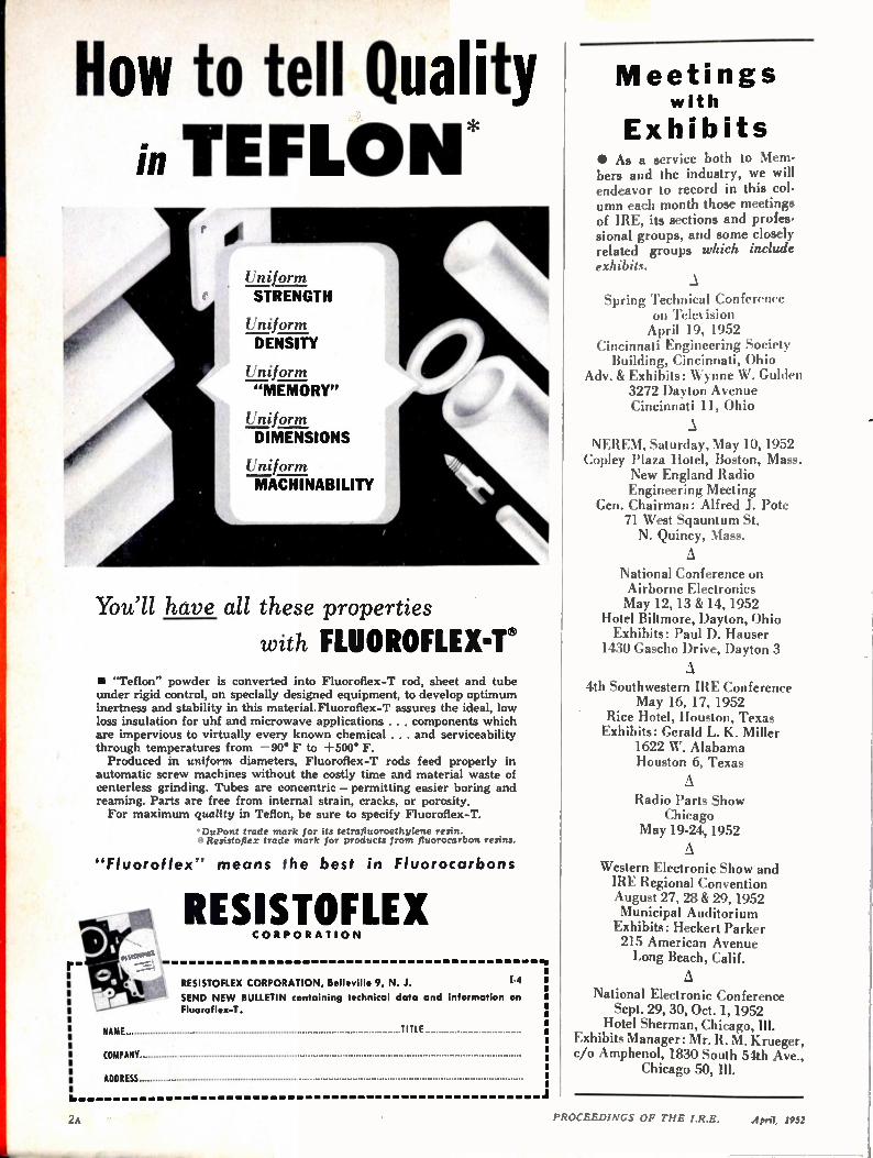
How to tell Quality TEFLON*
Uniform
STRENGTH
Uniform DENSITY
n
DIMENSIONS
ITniform
MACHINABILITY
You'll have all these properties
with FLUOROFLEX-T® • "Teflon" powder is converted into Fluoroflex-T rod, sheet and tube under rigid control, on specially designed equipment, to develop optimum inertness and stability in this material.Fluoroflex-T assures the ideal, low loss insulation for uhf and microwave applications . . . components which are impervious to virtually every known chemical . . . and serviceability through temperatures from —90° F to +500° F. Produced in uniform diameters, Fluoroflex-T rods feed properly in
automatic screw machines without the costly time and material waste of centerless grinding. Tubes are concentric — permitting easier boring and reaming. Parts are free from internal strain, cracks, or porosity. For maximum quality in Teflon, be sure to specify Fluoroflex-T.
*DuPont trade mark for its tetralluoroethylene resin. Resistoflex trade mark for products from fluorocarbon resins.
"Fluoroflex" means the best in Fluorocarbons
NAME
RESISTOFLEX CORP OR ATI O N
RESISTOFLEX CORPORATION, Belleville 9, N. J. 1-4
SEND NEW BULLETIN containing technical data and information on Fluoroflex-T.
TITLE
COMPANY
ADDRESS
Meetings with
Exhibits • As a set vice both to Mem-bers and the industry, we will endeavor to record in this col-umn each month those meetings of IRE, its sections and profes-sional groups, and some closely related groups which include exhibits.
Spring Technical Conference on Television April 19, 1952
Cincinnati Engineering Society Building, Cincinnati, Ohio
Adv. & Exhibits: Wynne W. Gulden 3272 Dayton Avenue Cincinnati 11, Ohio
NEREM, Saturday, May 10, 1952 Copley Plaza Hotel, Boston, Mass.
New England Radio Engineering Meeting
Gen. Chairman: Alfred J. Pote 71 West Sqauntum St. N. Quincy, Mass.
A National Conference on Airborne Electronics May 12, 13 & 14, 1952
Hotel Biltmore, Dayton, Ohio Exhibits: Paul D. Hauser 1430 Gascho Drive, Dayton 3
A 4th Southwestern IRE Conference
May 16, 17, 1952 Rice Hotel, Houston, Texas Exhibits: Gerald L. K. Miller
1622 W. Alabama Houston 6, Texas
A Radio Parts Show
Chicago May 19-24, 1952
A Western Electronic Show and IRE Regional Convention August 27, 28 & 29, 1952 Municipal Auditorium Exhibits: Heckert Parker 215 American Avenue Long Beach, Calif.
A National Electronic Conference Sept. 29, 30, Oct. 1, 1952 Hotel Sherman, Chicago, Ill.
Exhibits Manager: Mr. R. M. Krueger, c/o Amphenol, 1830 South 54th Ave.,
Chicago 50, Ill.
U.
2A PROCEEDINGS OF THE I.R.E. Aprit, 1932

MEET JAN-R-26A!
Designed to withstand the rigid Characteristic G humidity tests of the most
stringent specification of them all—JAN-R-26A— Sprague's new Blue Jacket Wire-Wound Resistors
give trouble-free service in military electronic and electrical equipment exposed to extremely
damp climates ! These outstanding new members of the Sprague resistor family are now available in tab terminal styles RW29 through RW39 in wattage
ratings up to 166 watts. You'll find the complete Blue Jacket Story with performance specifications in Engineering Bulletin 110, just off the press. Get your copy without delay.
YOU'LL KNOW THESE REMARKABLE RESISTORS BY
THEIR VITREOUS ENAMEL BRIGHT BLUE JACKETS
PI ONEERS IN ELECTRIC
AND ELECTR O NIC DEVEL OP ME NT
* Trademark
SPRAGUE ELECTRIC CO MPANY • NORTH ADA MS, MASSACHUSETTS
PROCEEDINGS OF TIIE I.R.E. April, 1952 3A

3 A Bell scientist adjusts electron diffraction camera. Electrons are projected on the specimen at glancing angles. They rebound in patterns which tell the ar-rangement of the atoms . help show how telephone materials can be improved.
lectrons probe the future
1 Electron micrograph of an alloy of aluminum, nickel, -nbalt and iron. Magnification 20,000 diameters.
•
2 Cooled from high temperature irs a magnetic field, the alloy becomes a powerful, permanent magnet. Note changed structure. Black bars reveal formation of precipitate parallel to the applied field Each bar is a permanent magnet.
140 1111111 m milli m moilimili miti m 111111111111111111011111111 mt 1,11111fill IIIIIIIIIIIIIIIIIIIIIIIIIII
IN 1927, Bell Laboratories physicists demonstrated that moving electrons behave like light waves, and thus launched the new science of electron optics.
Now, through the electron beams of the electron microscope and electron diffraction camera, scientists learn crucial details about the properties of metals far beyond the reach of optical microscopes or chemical analysis.
At the Laboratories, electron beams have revealed the minute formations which produce the vigor of the permanent magnets used in telephone ringers and magnetron tubes for radar. The same techniques help show what makes an alloy hard, a cath-ode emit more electrons and how germanium must be processed to make good Transistors.
This is the kind of research which digs deep inside materials to discover how they can be made better for your telephone system ... and for the many devices which the Laboratories are now devel-oping for national defense.
BELL TELEPHONE LABORATORIES
4 Diffraction pattern of polished germanium Is minute impurities which would degrade the per-
formance of a Transistor.
Improving telephone service for Americo
provides careers for creative men in
scientific and technical fields.
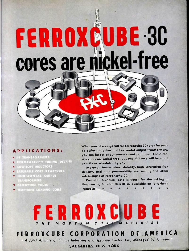
• FERROX cores are
uII
APPLIC ATI O N S:
,I-F TRANSFORMER'S' PERMEABILITY TUNING DEVICE LOW-LOSS INDUCTORS SATURABLE CORE REACTORS • HORIZONTAL OUTPUT TRANSFORMERS DEFLECTION YOKES TELEPHONE LOADING COILS
UBE le kel-free
When your drawings call for Ferroxcube 3C cores for your
TV deflection yokes and horizontal output transformers,
you can forget about procurement problems. These fer-
rite cores are nickel-free .... and delivery will be made
exactly as scheduled by you!
Improved temperature stability, high saturation flux
density, and high permeability are among the other
advantages of Ferroxcube 3C.
Complete technical data is yours for the asking in
Engineering Bulletin FC-5101A, available on letterhead
requests.
OXCUBE T H E M O D E R N C O A T E R I A L
FERROXCUBE CORPORATION OF AMERICA A Joint Affiliate of Philips Industries and Sprague Electric Co., Managed by Sprague
SAUGERTIES, NE W YORK
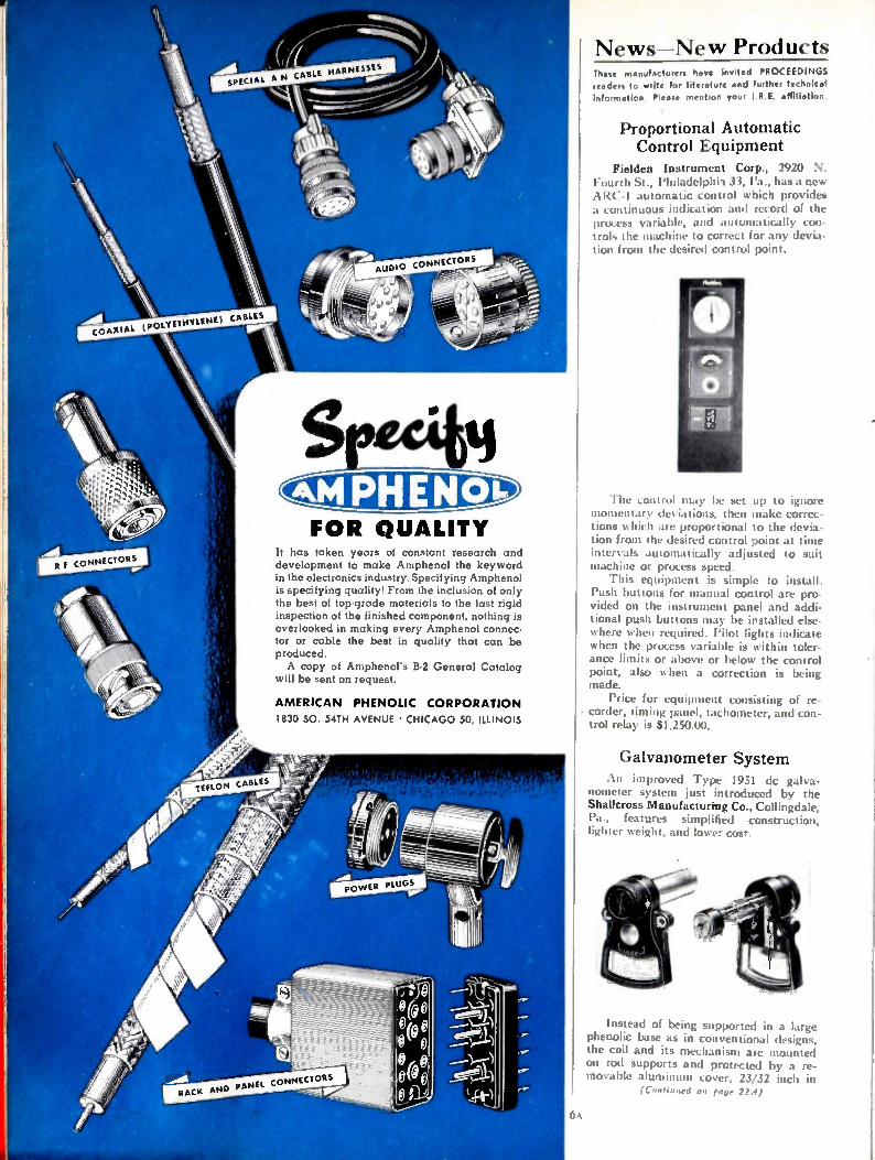
ecitti FOR QUALITY
It has taken years of constant research and development to make Amphenol the keyword in the electronics industry. Specifying Amphenol is specifying quality! From the inclusion of only the best of top-grade materials to the last rigid inspection of the finished component, nothing is overlooked in making every Amphenol connec-tor or cable the best in quality that cap be produced. A copy of Amphenors B-2 General Catalog
will be sent on request.
AMERICAN PHENOLIC CORPORATION 1830 50. 54TH AVENUE • CHICAGO 50, ILLINOIS
6A
News—New Products These manufacturers have Invited PROCEEDINGS readers to write for literature and further technical information. Please mention your I R.E. affiliation.
Proportional Automatic Control Equipment
FieIdea Instrument Corp., 2920 N. Fourth St., Philadelphii 33, l'a., has a new ARC-1 automatic control which provides a continuous indication and record of the process variable, and automatically con-trols the machine to correct for any devia-tion front the desired control point.
The control may be set up to ignore momentary deviations, then make correc-tions which are proportional to the devia-tion from the desired control point at time intervals automatically adjusted to suit machine or process speed. This equipment is simple to install.
Push buttons for manual control are pro-vided on the instrument panel and addi-tional push buttons may be installed else-where when required. Pilot lights indicate when the process variable is within toler-ance limits or above or below the control point, also when a correction is being made. Price for equipment consisting of re-
corder, timing panel, tachometer, and con-trol relay is $1,250.00.
Galvanometer System An improved Type 1951 dc galva-
nometer system just introduced by the Shallcross Manufacturing Co., Collingdale, Pa., features simplified construction, lighter weight, and lower cost.
Instead of being supported in a large phenolic base as in conventional designs, the coil and its mechanism are mounted on rod supports and protected by a re-movable aluminum cover, 23/32 inch in
(Continued on rage 22A)

COMPLETE LINE OF CORES
TO MEET YOUR NEEDS
* Furnished in four standard permeabilities —125, 60, 26 and 14.
* Available in a wide range of sizes to obtain nominal in-ductances as high as 281 mh 1000 turns.
* These toroidal cores are given various types of enamel and varnish finishes, some of which permit winding with heavy Formex insulated wire without supplementary insu-lation over the core.
HIGH Q TOROIDS for use in
Loading Coils, Filters, Broadband
Carrier Systems and Networks
for frequencies up to 200 K C
• For high Q in a small volume, characterized by low eddy current and hysteresis losses, ARNOLD Moly Permalloy Powder Toroidal Cores are commercially available to meet high standards of physical and electrical requirements. They provide constant permeability over a wide range of flux density. The 125 Mu cores are recom-mended for use up to 15 kc, 60 Mu at 10 to 50 kc, 26 Mu at 30 to 75 kc, and 14 Mu at 50 to 200 kc. Many of these cores may be furnished stabilized to provide constant permeability (+0.1%) over a specific temperature range.
• 'Manufactured under license arrangements with Western Electric Company
•
•
nri THE ARNOLD ENGINEERING COMPANY SUBSIDIARY OF ALLEGHENY LUDLUM STEEL CORPORATION
General Office & Plant: Marengo, Illinois
PROCEEDINGS OF THE

low-lacc miniature TUBE SOCKETS
..............
. " .......................................... GREAT........ DIELECTRIC....................... . .................................
.... HIGH SAFE OPERATING TEMPERATURE
-Cost no more ihan PHENOLIC TYPES
These glass-bonded mica sockets are pro-duced by an exclusive MYCALEX process that reduces their cost to the level of phenolic sockets. Electrical characteristics are far supe-rior to phenolics while dimensional accuracy and uniformity exceed that of ceramic types.
MYCALEX miniature tube sockets, avail-able in 7-pin and 9-pin types, are injection molded with great precision and fully meet RT MA standards. They are produced in two grades, described as follows, to meet diver-sified requirements.
SINCE 1919
0"41. T H E I N $ U L â T. R
TRADE MARK M O PAT Off
OFFER ALL THESE ADVANTAGES:
.... . • • • • CLOSER TOLERANCES
LO WER DIELECTRIC LOSS
••• 4111b. Alb
j iti lle2311111 t:
MYCALEX 410 is priced comparable to mica-filled phenolics. Loss factor is only .015 at 1 mc., insulation resistance 10,000 megohms. Conforms fully to Grade L-4B under N. M.E.S. JAN-I-10 "Insulating Ma-terials Ceramic, Radio, Class L."
MYCALEX 410X is low in cost but insulat-ing properties greatly exceed those of ordi-nary materials. Loss factor is only one-fourth that of phenolics (.083 at 1 mc.) but cost is the same. Insulation resistance 10,000 megohms.
MYCALEX TUBE SOCKET CORPORATION Under Exclusive License of
MYCALEX CORPORATION OF AMERICA
30 ROCKEFELLER PLAZA, NE W YORK 20, N. Y.
MYCALEX CORPORATION OF AMERICA Owners of 'MYCALEX' Patents and Trade-Marks
heLutle Offices. 30 ROCKEFELLER PLAZA, NEW YORK 20 -- Plant & General Offices CLIFTON, N.J.
P FEDINGS OF TIIE I.R.E. April, 1052

OR TRAFFIC CONTROL
BY GUARDIAN "SPOT" YOUR CONTROL PROBLEMS Small . . . to save weight and space in radar and guided missile
equipment, Guardian Relays prove that quality still comes in
small packages. Basic ... flexible .. . government approved.
Guardian Relays are ruggedly built and hermetically sealed to
withstand every atmospheric condition, including the rigors of
supersonic flight. Guardian Relays, specified in devices that count—detect—indicate—direct—shoot —convey—compute—sort—
package—vend—meter—hold the answer to your control prob-
lem. Write.
AN-3324-1 D.C. AN-3320A D.C.
,
101(4 : 4
0 0 0 1
more than 900 cars per minute!
This unit tabs 900 or more overlapping cars per minute at split-second con-tact. As car wheels hit a pneumatic tube stretched across traffic lanes the compression closes an electrical con-tact on a diaphragm, operating a Guardian Series 125 D.C. relay. The relay responds to every impulse but the counter unit registers only every other impulse to compensate for rear wheel contact.
SERIES 125 D.C. RELAY
Series 595 D.C. Series 610 A.C.-615 D.C.
WRITE— WIRE—TELETYPE—PHONE NO W!
GUARDIAN ELECTRIC 1628-D W. WALNUT STREET CHICAGO 12, ILLINOIS
A CONF UTE SIMI Of &&&&&& $ERVING AMERIERN 114011 ..1Sr
Series 695 D.C.
ppr.r / fr/% , ‘,/ I I I i
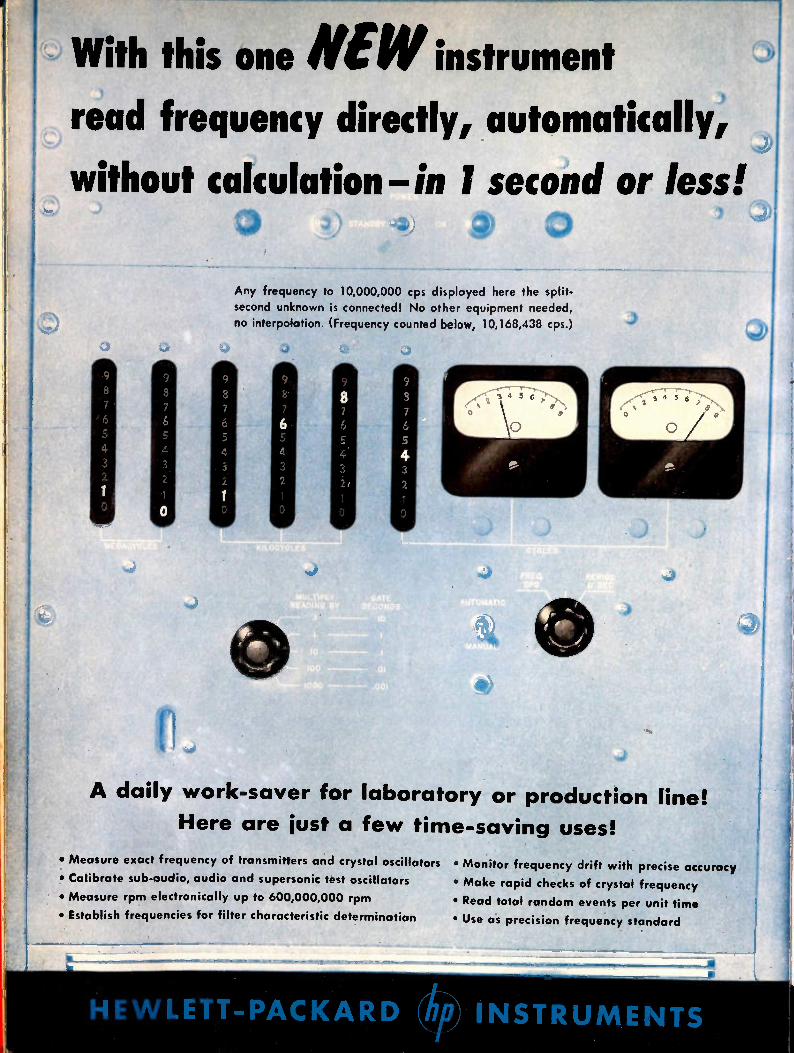
With this one NE W instrument .2)
read frequency directly, automatically, .3
without calculation—in I second or less!
%.)
Any frequency to 10,000,000 cps displayed here the split-second unknown is connected! No other equipment needed,
no interpolation. (Frequency counted below, 10,168,438 cps.)
j .011
A daily work-saver for laboratory or production line!
Here are just a few time-saving uses!
• Measure exact frequency of transmitters and crystal oscillators
• Calibrate sub-audio, audio and supersonic test oscillators
• Measure rpm electronically up to 600,000,000 rpm
• Establish frequencies for filter characteristic determination
• Monitor frequency drift with precise accuracy
• Make rapid checks of crystal frequency
• Read total random events per unit time
• Use as precision frequency standard
HE WLETT-PACKARD INSTRUMENTS
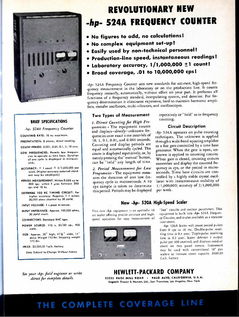
BRIEF SPECIFICATIONS
-hp- 524A Frequency Counter
COUNTING RATE: 10 mc maximum.
PRESENTATION 8 places, direct reading.
COUNT PERIOD: 0.001, 0.01, 0.1, 1, 10 secs.
LOW FREQUENCIES: Permits low frequen-cies to operate as time base. Duration
of one cycle is displayed in microsec-onds.
ACCURACY: ± 1 count ± 2/1,000,000 per week. (Higher accuracy external stand-
ard may be employed.)
PERIOD MEASUREMENT: Within 0.03% up to 300 cps: within 1 µsec between 300 cps and 10 kc.
EXTERNAL 100 KC TIMING CIRCUIT: For higher accuracy. Requires 1 v across
50,000 ohms shunted by 30 glad.
INPUT VOLTAGE: 1 v peak minimum.
INPUT IMPEDANCE: Approx. 100,000 ohms, 30 Airfd shunt.
CONNECTORS: Standard BNC type.
POWER SOURCE: 115 v, 50/60 cps, 400
watts.
SIZE: Approx. 28" high, 21 3/4" wide, 14" deep. Weight 115 lbs. Shipping weight
175 lbs.
PRICE: $2,000.00 f.o.b. factory.
Data Subject to Change Without Notice
See your -hp- field engineer or write direct for complete details.
REVOLUTIONARY NEW
-hp- 524A FREQUENCY COUNTER
• No figures to add, no calculations!
• No complex equipment set-up!
• Easily used by non-technical personnel!
• Production-line speed, instantaneous readings!
• Laboratory accuracy, 1/1,000,000 -±1 count!
• Broad coverage, .01 to 10,000,000 cps!
-hp- 524A Frequency Counter sets new standards for accurate, high-speed fre-quency measurement in the laboratory or on the production line. It counts frequency instantly, automatically, without effort on your part. It performs all functions of a frequency standard, interpolating system, and detector. For fre-quency determination it eliminates expensive, hard-to-maintain harmonic ampli-fiers, transfer oscillators, multi-vibrators, and oscilloscopes.
Two Types of Measurement
1. Direct Counting for High Fre-quencies • The equipment counts and displays—directly—unknown fre-quencies over exact time interials of 10, 1, 0.1, 0.01, and 0.001 seconds. Counting and display periods are equal and automatically cycled. The count is displayed repetitively; or, by merely pressing the"manual" button, can be "held" any length of time.
2. Period Measurement for Low Frequencies • The equipment meas-ures the duration of one low fre-quency cycle in microseconds. A 10 cps sample is taken to determine this period. Periods may be displayed
New
repetitively or "held" as in frequency counting.
Circuit Description
-hp- 524A operates on pulse counting techniques. The unknown is applied through a wide-band squaring amplifier to a fast gate controlled by a time base generator. When the gate is open, un-known is applied to counting circuits. When gate is closed, counting circuits remember and display the counted fre-quency in cps, or the period in micro-seconds. Time base circuits are con-trolled by a highly stable crystal oscil-lator with instantaneous stability of 1 1,000,000; accuracy of 2/1,000,000 per week.
-hp- 520A High-Speed Scaler
This new -hp- equipment is an aperiodic 10 mc scaler offering precise accuracy and high'
speed operation for easy measurement of
"fast" circuits and nuclear parameters. This equipment is built into -hp- 524A Frequen-cy Counter, and is also available as a separate
instrument. -hp- 520A Scaler will count period pulses
from 0 cps to 10 mc. Double-pulse resol-ving time is 0.1 µsec. Triple-pulse resolving time is 0.2 µsec. Scaler delivers 1 output pulse per 100 received, and displays residual count on two panel meters. Instrument may be used with conventional 10 pps
scalers to increase count capacity. $600.00
f.o.b. factory.
HEWLETT-PACKARD COMPANY 2322D PAGE MILL ROAD • PALO ALTO, CALIFORNIA, U.S.A. Export: frazar & Hansen, Ltd., San Francisco, Los Angeles, New York
THE CO MPLETE COVERAGE LINE
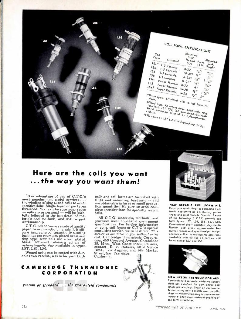
FORM SPECIFICAForm TIONS
coil M ounting Stud
Thread Form MOounted.A.
SIzit 0.D. Heigh, LST * L. Ceramic 8-32 fit" 114s" - lS6 1-5 Ceramic 10-32* Vs"
LS L. Ceramic 14-28* I !Si" LS@ L. Ceramic °4-28* 2 '37'' ISM Paper Phenolic 8-32 Vs"
LS3 Paper Phenolic 114-28 ;V I .84" LS4t Paper Phenolic %" 2"
*These types provided with spring focks for slaps.
trelrxinetolitresisilltcsol.511ei vaavieoaadviousilloatilee br.linoc:
fined tr:rminols secured bsy nylon-phenolic collars.
°I.STL same as LST but with slug locking spring.
Here are the coils you want ...the way you want them!
Take advantage of one of C.T.C.'s most popular and useful services . the winding of slug tuned coils to exact specifications. Single layer or pie types furnished. You can be sure your specs — military or personal — will be faith-fully followed to the last detail of ma-terials and methods, and with expert workmanship. C.T.C. coil forms are made of quality
paper base phenolic or grade L-5 sili-cone impregnated ceramic. Mounting bushings are cadmium plated brass and ring type terminals are silver plated brass. 'Terminal retaining collars of nylon-phenolic also available in types 1ST, LS5, LS6. Wound units can be coated with dur-
able resin varnish, wax or lacquer. Both
coils and coil forms are furnished with • slugs and mounting hardware — and are obtainable in large or small produc-tion quantities. Be sure to send com-plete specifications for specially wound coils.
All C.T.C. materials, methods, and processes meet applicable government specifications. For further information on coils, coil forms or C.T.C.'s special consulting service, write us direct. This service is available to you without extra cost. Cambridge Thermionic Corpora-tion, 456 Concord Avenue, Cambridge 38, Mass. West Coast manufacturers, contact: E. V. Roberts, 5014 Venice Blvd., Los Angeles, and 988 Market Street, San Francisco, California.
CA M B RI D GE THE R MI O NI C CO R P O R ATI O N
Custom or standard . . . the iMarantre,/
1
NE W CERAMIC COIL FORM KIT. Helps you spark ideas in designing elec-tronic equipment or developing proto-types and pilot models. Contains 3 each of the following 5 C.T.C. ceramic coil form types: 1ST, L96, LS6, 1.57, LS8. Color-coded chart simplifies slug-identi-fication and gives approximate fre-quency ranges and specifications. Nylon. phenolic collars to replace metallic rings available with kit for all ceramic coil forms except 157 and 158.
NE W NYLON-PHENOLIC COLLARS. Terminals held securely; solder ; spaces doubled; excellent for both b.filor and single pie windings. Show an increase in 0 and many new benefits over metallic rings — without impairing in any way the moisture- and fungus-resistant qualities of coil form assemblies.
PROCEEDINGS OF THE I.R.E. April, 2952
Eo 6..aa Pc, Difetse,/
• • • his relia • e
17-7 0-
110''
•Itac-*****
• •••
......
-
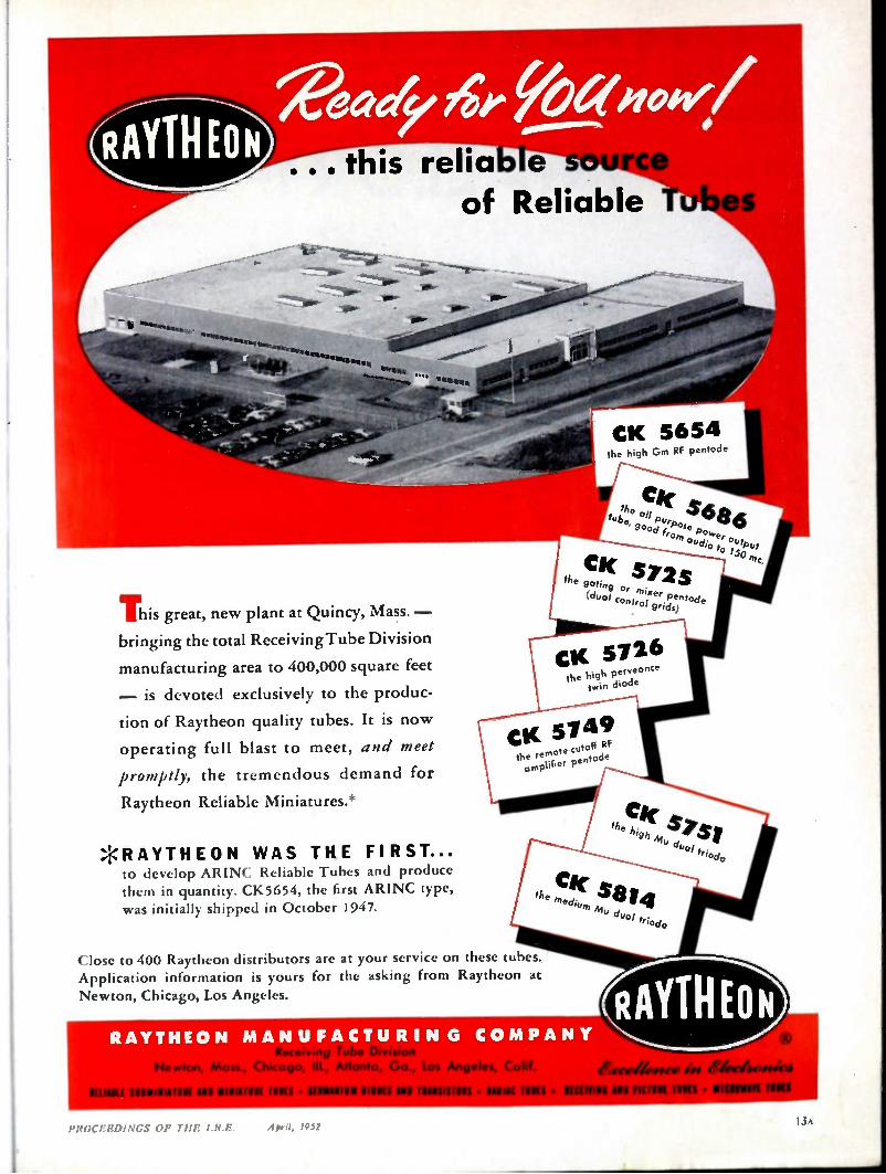
This great, new plant at Quincy, Mass. — bringing the total Receiving Tube Division
manufacturing area to 400,000 square feet
— is devoted exclusively to the produc-
tion of Raytheon quality tubes. It is now
operating full blast to meet, and meet
promptly, the tremendous demand for
Raytheon Reliable Miniatures.*
*RAYTHEON WAS THE FIRST... to develop ARINt. Reliable Tubes and produce them in quantity. CK5654, the first ARI NC type, was initially shipped in October 1947.
of Reliable
-
CI( 572dos the gatin
(du of c er Panted °etre!i4 e g c't M
CK 5726 the high perveonce
twin diode
CK 5749 he remote•cutoff RF amplifier pentode
Close to 400 Raytheon distributors are at your service on these tubes. Application information is yours for the asking from Raytheon at
Newton, Chicago, Los Angeles.
CK 5654 the high Gm RF pentode
CV( a. _6 86 the purpos fu60, 900a
f :P°K'er output -udio to 150,77c.
CI( t. the kw , 411, 14 .3 PS 1
"riode
Ci med,„ MS 14 7,1riode
RAYTHEON MAN UFACTU RI N G CO MPANY
• • •
1111111111111111 All 111111,111111 MIS • IIIIANIOU 11111t1 A1111 IIINSI MIS • IASIIC IUSCI•
RAYTHEON .revilepsee ept
WING API PICIllit MIR •
PR()CERDINGS OF TI!!? I.R.E.
--- here and here ri
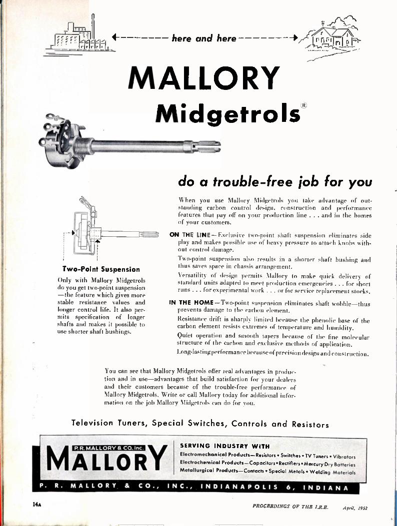
MALLORY Midgetrols
Two-Point Suspension
Only with Mallory Midgetrols do you get two-point suspension —the feature which gives more stable resistance values and longer control life. It also per-mits specification of longer shafts and makes it possible to use shorter shaft bushings.
do a trouble-free job for you When you use Mallory Midgetrols you take advantage of out-standing carbon control design, construction and performance features that pay off on your production line . . . and in the homes of your customers.
ON THE LINE—Exclusive two-point shaft suspension eliminates side play and wakes possible use of heavy pressure to attach knobs with-out control damage.
Two-point suspension also results in a shorter shaft bushing and thus saves space in chassis arrangement.
Versatility of design permits Mallory to make quick delivery of standard units adapted to meet production emergencies ... for short runs . . . for experimental work . . . or for service replacement stocks.
IN THE HOME—Two-point suspension eliminates shaft wobble—thus prevents damage to the carbon element.
Resistance drift is sharply limited because the phenolic base of the carbon element resists extremes of temperature and humidity.
Quiet operation and smooth tapers because of the fine molecular structure of the carbon and exclusive methods of application.
Long-lasting performance because of precision design and construction.
You can see that Mallory Midgetrols offer real advantages in produc-tion and in use—advantages that build satisfaction for your dealers and their customers because of the trouble-free performance of Mallory Midgetrols. Write or call Mallory today for additional infor-mation on the job Mallory Midgetrols can do for you.
Television Tuners, Special Switches, Controls and Resistors
MALLORY P. R. MALLORY a Ca. inc. SERVI N G INDUSTRY WITH
Electromechanical Products—Resistors • Switches • TV Tuners • Vibrators
Electrochemical Products—Capacitors • Rectifiers • Mercury Dry Batteries
Metallurgical Products—Contacts • Special Metals • Welding Materials
P. R. MALL ORY & CO., INC., INDIA N AP OLIS 6, IN DI A N A
14A PROCEEDINGS OF THE I.R.E. April, 1952

LARE RELAY• • • the Type "R" combines extremely small size with unusual sensitivity and long life
CLARE Type "R" RELAY
Approximately Actual Size
SPECIFICATIONS
WEIGHT Approximately 2 ounces
COIL Single or double wound
ARMATURE Single or double arm
CONTACT ASSEMBLY Form A to C. rilwornurri of
springs in each pileup.
MOUNTING Two #4-40 tapped holes in end of
heelpiece
DIMENSIONAL DRAWING OF
CLARE Type "R" RELAY
• This new CLARE Type "R" d-c Relay embodies many features of the famous CLARE Type "K" Relay, which was the first to combine the advantages of a tele-phone-type relay with the small size, light weight and resistance to vibration required to meet the rigid demands of aircraft service.
In appearance, the Type "R" resembles the Type "K", but, through hardly notice-able structural differences, CLARE has given the new Type "R" even greater sensitivity and operating range. Both relays use the same contact springs, but the Type "R" coil is longer and of larger diameter, to provide greater winding space. Life expectancy of the new relay has been not only increased but multiplied.
The CLARE Type "R" Relay retains in an improved form the reed armature sus-pension which discerning engineers have come to recognize as one of the subtler reasons for the superior performance of CLARE Type "K" Relays over other relays of comparable size and somewhat similar appearance.
The Type "R" is available as either an open or hermetically sealed relay. Clare sales engineers are located in principal cities to give you firsthand information on this new relay and to cooperate with you on any complex relay problem. Call them or write to C. P. Clare St Co., 4719 West Sunnyside Avenue, Chicago 30, Illinois. In Canada: Canadian Line Materials Ltd., Toronto 13. Cable Address: CLARELAY.,
Write for CLARE Bulletin No. 715
CLARE RELAYS First in the Industrial Field

nesiAned for Appliration
Grid Ilip Meters
Millen Grid Dip Meters are available to meet all various laboratory and servicing requirements.
The 90662 Industrial Grid Dip Nleter completely calibrated for laboratory use with a range from 225 kc. to 300 mc. incorporates features desired for both industrial and laboratory application, including three wire grounding type power cord and suitable carrying case. The 90661 Industrial Grid Dip Meter is similar to the 90662 except for a reduced range of 1.7 to 300 mc. It likewise incorporates the three wire grounding type cord and metal carrying case.
The 90651 Standard Grid Dip Meter is a somewhat less expensive version of the grid dip meter. The calibration while adequate for general usage is not as complete as in the ease of the industrial model. It is supplied without grounding lead and without carrying case. The range is 1.7 to 300 me. Extra inductors available extends range to 220 kc.
The Millen Grid Dip Meter is a calibrated stable liF oscillator unit with a meter to read grid current. The frequency deter ttt i t ling coil is plugged into the unit so that it may be used as a probe.
These instruments are complete with a built-in transformer type A.C. power supply arid interminal terminal board to provide connections for battery operation where it is desirable to use the unit on antenna measure-ments and other usages where A.C. power is not available. Compactness
has been achieved without loss of performance or convenience of usage. The incorporation of the power supply, oscillator and probe into a single unit provides a convenient device for checking all types of circuits. The indicating instrument is a standard 2 inch General Electric instrument with an easy to read scale. The calibrated dial is a large 270° drum dial which provides seven direct reading scales, plus an addit• al •ersal scale, all with the same length and readability. Each range has its indi-vidual plug-in probe completely enclosed in a contour fitting polystyrene case for assurance of pernianenee of calibrat as well as to prevent any possibility of mechanical damage or of unintent al contact with the components of the circuit being tested.
The Grid Dip Meters may be used as: 1. A Grid Dip Oscillator 2. An Oscillating Detector 3. A Signal Generator 4. An Indicating Absorption Wavemeter
The most common usage of the Grid Dip Meter is as an oscillating frequency meter to determine the resonant frequencies of de-energized tuned circuits.
Size of Grid Dip Meter only (less probe): 7 in. x 314s in. x 3% in.
l6S PROCEEDINGS OF THE I.R.E. April, 1952
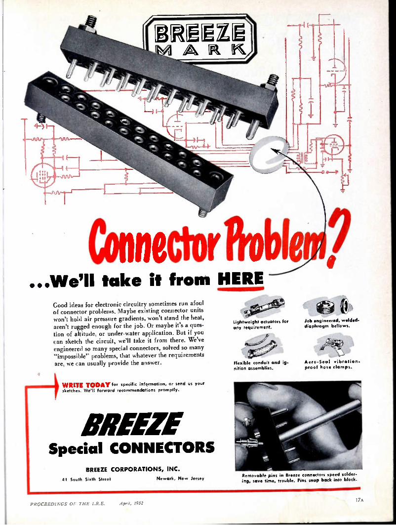
Connector Probtl? ...We'll take it from HERE
Good ideas for electronic circuitry sometimes run afoul of connector problems. Maybe existing connector units won't hold air pressure gradients, won't stand the heat, aren't rugged enough for the job. Or maybe it's a ques-tion of altitude, or under-water application. But if you can sketch the circuit, we'll take it from there. We've engineered so many special connectors, solved so many "impossible" problems, that whatever the requirements are, we can usually provide the answer.
WRITE TODAY for specific information, or send us your sketches. Well forward recommendations promptly.
BREEZE Special CONNECTORS
BREEZE CORPORATIONS, INC.
41 South Sixth Street Newark, New Jersey
°01 Lightweight actuators for Job engineered, welded.
any requirement.
Flexible conduit and ig-nition assemblies.
diaphragm bellows.
d 7W 4
Aero-Seal vibration. proof hose clamps.
Removable pins in Breeze connectors speed solder-ing, save time, trouble. Pins snap back into block.
PROCEEDINGS or TI1E IR E. April, 1952

11.147, TIRE 11)• • • *One Eimac 3X2500A3 ... after
[ 11,000 hours of FM broadcast service on 94.9 Mc
GEORGE D. TATE
Chief Engineer
WMIIC
Before Eimac tubes are put out to pasture, they earn their retirement.
Here's a typical story:
TEXTILE BROADCAST! NC COMPA
GREENVILLE. S. C.
SanEitel-McCullough, Inc.
Dear BSriurneo:, California
Tboµght you may be Interested to know that we have over 11,000 hours of use. just retired one of your 30500A3 tubes with a little
This tube was used In our PM Station which operates on 94.9 Mc. with an ERP of 79,000 watts; this meana an Input of 10,5000 watts which l5 my opinion is pushin any pair of tubes for PM service.
g amps. at 3900 volts. Thls tube had to operate at a plate current of 1.35
We are highly pleased wIth this tube.
Very truly youra,
Radio Station wunc-onc-Pm
George D. Tate Chief Rnglneer
* For complete technical data on the 3X2500A3 or
3X2500F3 triodes...or any other Eimac tube, write:
EITEL- McCULLOUGH, INC • S A N B R U N O, C A L I F O R N I A
EXP ORT AGENTS: FRAZAR & HANSEN • 301 CLAY STREET • SAN FRANCISC O 11, CALIF ORNIA
18A PROCEEDINGS OF THE I.R.E. April, 1952
MUST YOUR EQUIPMENT BE
RADIO INTERFERENCE FREE?
IF YOURS IS A TOUGH RF INTERFERENCE
PROBLEM - LET FILTRON SOLVE IT....
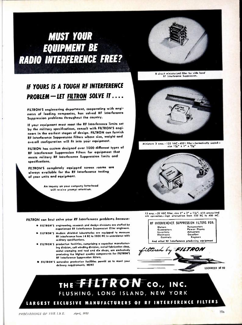
15 amp.-28 VDC filter, size 2" x 2" x 114", with pressurized AN connectors- high attenuation from 150 KC to 400 MC.
FILTRON'S engineering department, cooperating with engi-neers of leading companies, has solved RF Interference
Suppression problems throughout the country.
If your equipment must meet the RF Interference limits set
by the military specifications, consult with FILTRON'S engi-neers in the earliest stages of design. FILTRON can furnish
RF Interference Suppression Filters whose size, weight and
overall configuration will fit into your equipment.
FILTRON has custom designed over 1000 different types of
RF Interference Suppression Filters for equipment that
meets military RF Interference Suppression limits and
specifications.
FILTRON'S completely equipped screen rooms
always available for the RF Interference testing
of your units and equipment.
An inquiry on your company letterhead
will receive prompt attention.
FILTRON can best solve your RF Interference problems because:
• FILTRON'S engineering, research and design divisions are staffed by experienced RF Interference Suppression filter engineers.
• FILTRON'S modern shielded laboratories are equipped to measure RF Interference from 14 KC to 1000 MC in accordance with
military specifications.
• El LTRON'S production facilities, comprising a capacitor manufactur-ing division, toil winding division, metal fabrication shop,
metal stamping and tool and die shops, are exclusively
producing the highest quality components for FILTRON'S
RE Interference Suppression Filters.
• 'RIPON'S extensive production facilities permit us to meet your
delivery requirements. NOW!
8 circuit miniaturized filter for wide band RF Interference Suppression.
Miniature 3 amp. -125 VAC -400̂' filter -hermetically tooled - size 11/4 " x 1" a 11A4"
RI INTERFERENCE SUPPRESSION FILTERS FOR Motors Generators Inverters Electronic Controls
Dynamotor% Power Plants Actuators Gasoline Engines
And other RF Interference producing equipment
F/LTROAf
THE -1-4-L-T RIO N-CO., INC. FLUSHING, LONG ISLAND, NE W YORK
LARGEST EXCLUSIVE MANUFACTURERS OF RF INTERFERENCE FILTERS
PROCERDINGS OF THE I.R.E. April, 1952
LOCKHEED XF•90
19
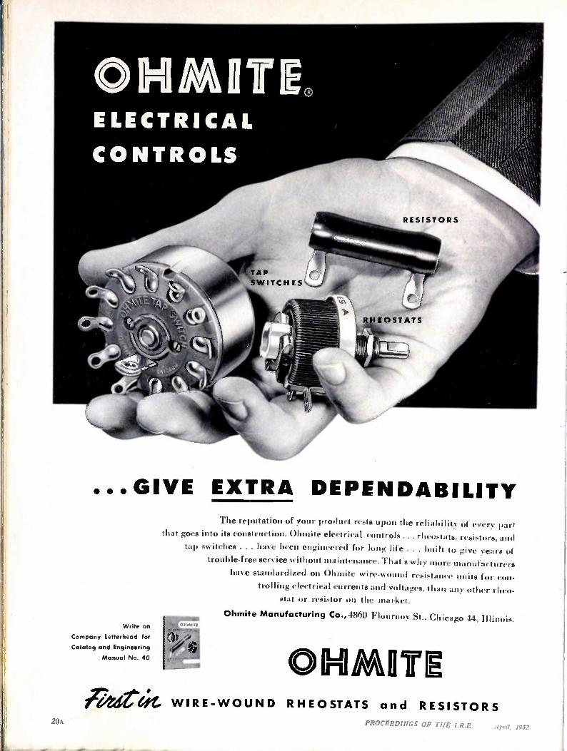
...GIVE EXTRA DEPENDABILITY
Write on
Company Letterhead for
Catalog and Engineering
Manual No. 40
The reputation of your product rests upon the reliabilit of cvery part
that goes into its construction. Ohmite electrical controls ... rheostats. resistors. and
tap switches . . . have been engineered for long life . . . built to give years Of
trouble-free service without maintenance. That's why more manufacturers
have standardized on Ohmite wire-wound resistance units for con-
trolling electrical currents and voltages, than any other rheo-stat or resistor on the market.
Ohmite Manufacturing Co., •1860 Flourno y St., Chicago 44, Illinois. quomu (11
(0,1)
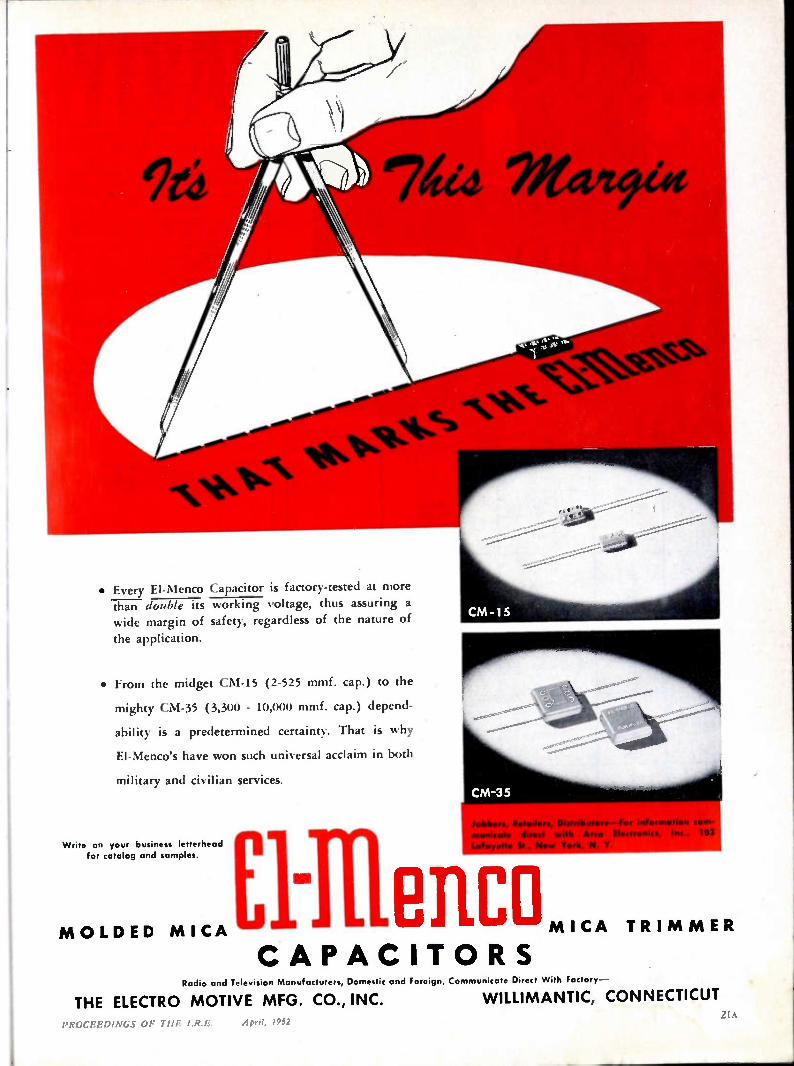
• Every El-Menco Capacitor is factory-tested at more than double its working voltage, thus assuring a wide margin of safety, regardless of the nature of
the application.
• From the midget CM-15 (2-525 trunf. cap.) to the
mighty CM-35 (3,300 - 10,000 mmf. cap.) depend-
ability is a predetermined certainty. That is why
El-Menco's have won such universal acclaim in both
military and civilian services.
Write on your business letterhead for catalog and samples.
W eihas, Distributere —For information corn-
Elillenco M OLDED MICA MICA TRI M MER
CAPACIT ORS
., 103
Radio and Television Manufacturers, Domestic and Foreign, Communicate Direct With Factory —
THE ELECTRO MOTIVE MFG. CO., INC. WILLIMANTIC, CONNECTICUT
pRocEED/NGs oli
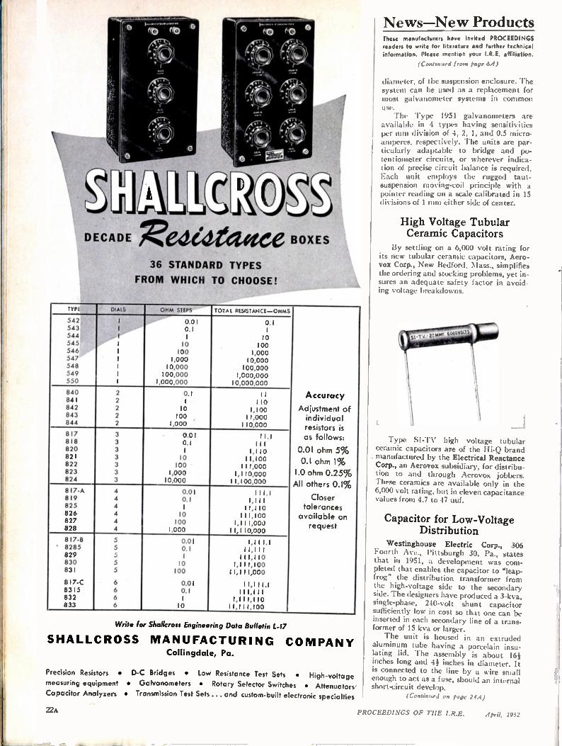
DECADE Redealace BOXES 36 STANDARD TYPES
FROM WHICH TO CHOOSE!
Ili DIALS orm STEPS TOTAL RESISTANCE —OHMS
54. 1 0.01 0.1 543 1 0.1 1 544 I 1 10 543 I 10 100 546 I 100 1,000 547 1 1,000 10,000 548 I 10,000 100,000 549 1 100,000 1,000,000 550 1 1,000,000 10,000,000
840 2 0.1 1 i Accuracy 841 2 1 110 842 2 10 1,100 Adjustment of 843 2 100 11,000 individual 844 2 1,000 110,000 resistors is 817 3 0.01 I 1.1 as follows: 818 3 0.1 1 1 1 820 3 1 1,110 0.01 ohm 5% 821 822
3 3
10 100
11,100 I 11,000
0.1 ohm 1% 823 3 1,000 1,110,000 1.0 ohm 0.25 % 824 3 10,000 11,100,000 All others 0.1 % 8 I 7-A 4 0.01 111.1 819 4 0.1 1,111 Closer 825 4 1 11,110 tolerances 826 4 10 1 1 1,100 available on 827 828
4 4
100 1,000
1,111,000 11,110,000
request
8 I 7-B 5 0.01 1,111.1 ' 8285 5 0.1 11,11 I 829 5 1 111,110 830 5 10 1,1 I 1,100 831 5 100 11,111,000
8 I 7-C 6 0.01 11,1 I 1.1 8315 6 0.1 111,111 832 6 1 1,111,110 833 6 10 11,111,100
Write for Sholkross Engineering Data Bulletin L-17
SHALLCROSS MANUFACTURING CO MPANY Collingdale, Pa.
Precision Resistors • D-C Bridges • Low Resistance Test Sets • High-voltage
measuring equipment • Galvanometers • Rotary Selector Switches • Attenuotors Capacitor Analyzers • Transmission Test Sets ... and custom-built electronic specialties
News—New Products These manufacturers have invited PROCEEDINGS readers to write for literature and further technical information. Please mention your I.R.E. affiliation.
(Continued Irons page 64)
diameter, of the suspension enclosure. The system can be used as a replacement for most galvanometer systems in common use. The Type 1951 galvanometers are
available in 4 types having sensitivities per mm division of 4, 2, 1, and 0.5 micro-amperes, respectively. The units are par-ticularly adaptable to bridge and po-tentiometer circuits, or wherever indica-tion of precise circuit balance is required. Each unit employs the rugged taut-suspension moving-coil principle with a pointer reading on a scale calibrated in 15 divisions of 1 min either side of center.
High Voltage Tubular Ceramic Capacitors
By settling on a 6,000 volt rating for its new tubular ceramic capacitors, Aero-vox Corp., New Bedford, Mass., simplifies the ordering and stocking problems, yet in-sures an adequate safety factor in avoid-ing voltage breakdowns.
1 _
Type SI-TV high voltage tubular ceramic capacitors are of the Hi-Q brand manufactured by the Electrical Reactance Corp., an Aerovox subsidiary, for distribu-tion to and through Aerovox jobbers. These ceramics are available only in the 6,000 volt rating, but in eleven capacitance values from 4.7 to 47 uuf.
Capacitor for Low-Voltage Distribution
Westinghouse Electric Corp., 306 Fourth Ave., Pittsburgh 30, Pa., states that in 1951, a development was com-pleted that enables the capacitor to "leap-frog" the distribution transformer from the high-voltage side to the secondary side. The designers have produced a 3-kva, single-phase, 240-volt shunt capacitor sufficiently low in cost so that one can be inserted in each secondary line of a trans-former of 15 kva or larger. The unit is housed in an extruded
aluminum tube having a porcelain insu-lating lid. The assembly is about 16f inches long and 4f inches in diameter. It is connected to the line by a wire small enough to act as a fuse, should an internal short-circuit develop.
(Continued on page 244)
22A PROCEEDINGS OF THE I.R.E. April, 1952
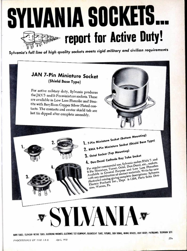
SYLVAN IA SOCKETS... report for Active Duty!
Sylvania's full line of high quality sockets meets rigid military and civilian requirements
JAN 7-Pin Miniature Socket (Shield Base Type)
For active military duty, Sylvania produces
the JAN 7- and 9-Pin miniature sockets. These are available in Low Loss Phenolic and Stea-tite with Beryllium Copper Silver Plated con-
tacts. The contacts and center shield tab are hot tin dipped after complete assembly.
1. 7-Pin Miniature Socket (Bottom
mounting)
2. RMA 9-Pin Miniature Socket (Shield Base Iype)
3. Octal Socket (lop Mounting) 4. Duo-Decal Cathode Ray Tube Socket For regular commercial us e, Sylvania makes IIMA 7- and I
9-Pin Miniature, 'Turret, Octal, DUO LOSS
etc., sockets.
Available in General Purpose and Low Loss Phenolics with any combination of contact materials. Write for new illustrated ca talog giving complete descriptions: Sylvan Electric Products Inc., Dept. A-1304, Parts Sales Divi-
sion, Warren, Pa.
SYLVAN IA RADIO TUBES, TELEVISION PICTURE TUBES. ELECTRONIC PRODUCTS. ELECTRONIC TEST EQUIPMENT, FLUORESCENT TUBES, FIXTURES, SIGN TUBING, WIRING DEVICES, LIGHT BULBS PHOTOLAMPS TELEVISION SETS
23A PROCEEDINGS OF THE IRE. April, 19.52
News—New Products
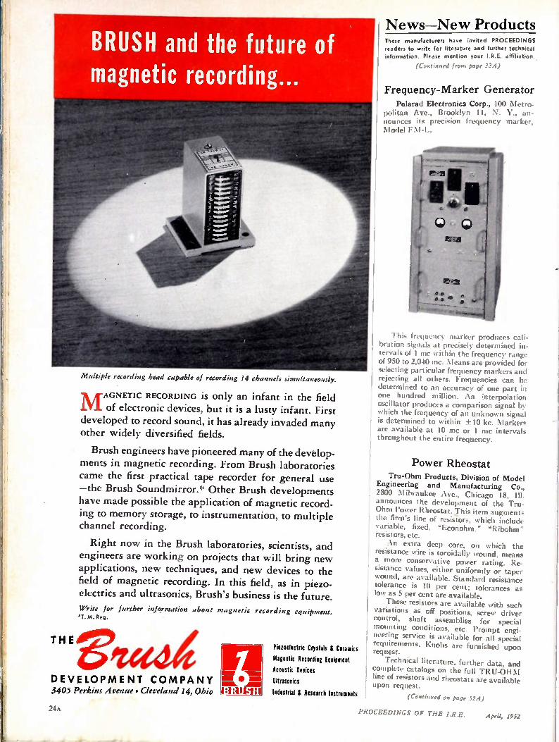
BRUSH and the future of magnetic recording...
Multiple recording head capable of recording 14 channels simultaneously,
M AGNETIC RECORDING is only an infant in the field of electronic devices, but it is a lusty infant. First
developed to record sound, it has already invaded many other widely diversified fields.
Brush engineers have pioneered many of the develop-ments in magnetic recording. From Brush laboratories came the first practical tape recorder for general use —the Brush Soundmirror.* Other Brush developments have made possible the application of magnetic record-ing to memory storage, to instrumentation, to multiple channel recording.
Right now in the Brush laboratories, scientists, and engineers are working on projects that will bring new applications, new techniques, and new devices to the field of magnetic recording. In this field, as in piezo-electrics and ultrasonics, Brush's business is the future.
Write for further information about magnetic recording equipment. •T. M. Reg.
THE
DEVELOPMENT COMPANY 3405 Perkins Avenue • Cleveland 14, Ohio
24
FA • Piezoelectric Crystals & Ceramics
Magnetic Recording Equipment
Acoustic Devices
Ultrasonics
Mistrial & Research Instruments
These manufacturers have invited PROCEEDINGS readers to write for literature and further technical
information. Please mention your I.R.E. affiliation.
(Continued from page 224)
Frequency-Marker Generator
Polarad Electronics Corp., 100 Metro-politan Ave., Brooklyn 11, N. Y., an-nounce, its precision frequency marker, Model I'
This frequency marker produces cali-bration signals at precisely determined in-tervals of 1 mc within the frequency range of 950 to 2,040 mc. Means are provided for selecting particular frequency markers and rejecting all others. Frequencies can be determined to an accuracy of one part in one hundred million. An ;nterpolation oscillator produces a comparison signal by which the frequency of an unknown signal is determined to within +10 kc. Marker, are available at 10 mc or 1 mc intervals throughout the entire frequency.
Power Rheostat Tru-Ohm Products, Division of Model
Engineering and Manufacturing Co., 2800 Mikaukee Ave., Chicago 18, announces the development of the Tru-Ohm Power Rheostat. This item augments the firm's line of resistors, which include variable, fixed, "Econohm," "Ribohm" resistors, etc. An extra deep core, on which the
resistance wire is toroidally wound, means a more conservative power rating. Re-sistance values, either uniformly or taper wound, are available. Standard resistance tolerance is 10 per cent; tolerances as low as 5 per cent are available. These resistors are available with such
variations as off positions, screw driver control, shaft assemblies for special mounting conditions, etc. Prompt engi-neering service is available for all special requirements. Knobs are furnished upon request.
Technical literature, further data, and complete catalogs on the full TRU-OHM line of resistors and rheostats are available upon request.
(Continued on page 524)
PROCEEDINGS OF THE I.R.E. April, 1952
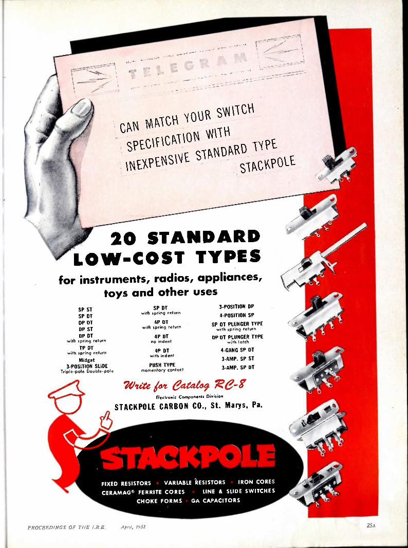
20 STANDARD LO W-COST TYPES
for instruments, radios, appliances, toys and other uses
SP ST SP DT DP DT DP ST DP DT
with spring return
TP DT with spring return
Midget 3-POSITION SLIDE
Triple-pole Double-pole
SP DT with spring return
4P DT with spring return
4P DT no indent
4P DT with indent
PUSH TYPE momentary contact
3-POSITION DP
4-POSITION SP
SP DT PLUNGER TYPE with spring return
DP DT PLUNGER TYPE with latch
4-GANG SP DT
3-AMP. SP ST
3-AMP. SP DT
Veite kvt eared" Re-gr Electronic Components Division
STACKPOLE CARBON CO., St. Marys, Pa.
FIXED RESISTORS VARIABLE RESISTORS IRON CORES
CERAMAG* FERRITE CORES LINE a SLIDE SWITCHES
CHOKE FORMS GA CAPACITORS
April, 1952 PROCEEDINGS OF TI1E I.R.E.
e,(4
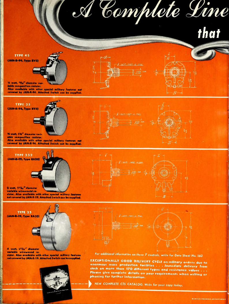
TYPE 45
V. won, ISis" diameter var-iable composition resistor. Also available with other special military features not covered by JAN-K-94. Attached Switch can itip supplied.
(JAN-1-94, Typ• RV3)
SS watt, 11/2 " diameter vari-able composition resistor.
Also available witl ether special military features not covered by JAN-1-94. Attached Switch can be supplied.
-. 2 watt, 1944" (flame*, • variable wirewound re-sistor. Also available with other special military features 110i covered by JAN-R-19. Attached Switch can tie supplied.
(JAN-R-19, Type RA30)
4 WWI, 111/2 2" diameter variable wIrewound re-slider. Also available with other special military features nef covered by JAN-1-19. Attached Switch can be supplied.
s2fo° °64.
—
I I
w ne
that,
For additional information on these 7 controls, write for Data Sheet No. 160
EXCEPTI ONALLY GOOD DELIVERY CYCLE on military orders due to enormous mass production facilities . . . Immediate delivery from
stock on more than 170 different types and resistance values .
Please give complete details on your requirements when writing o phoning for further information.
NEW COMPLETE CTS CATALOG. Write for your copy today.
IIUOT ON BRO W NS •OVCRTISIMG
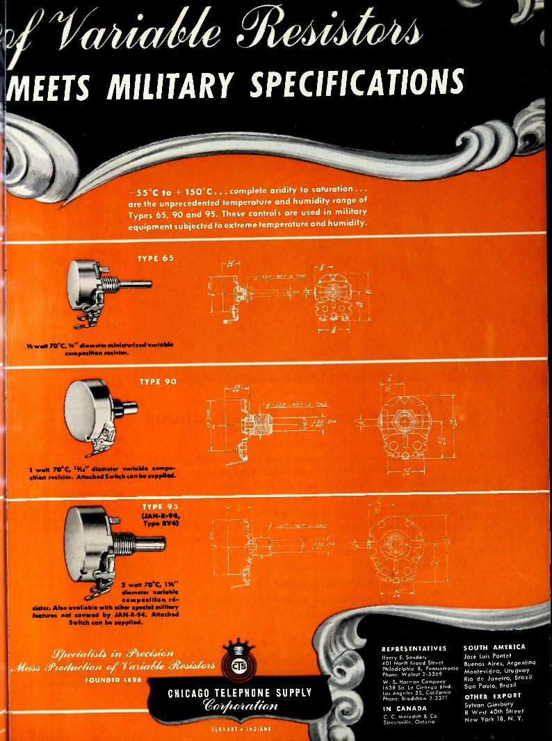
/ itia14 .MEETS MILITARY SPECIFICATIONS
—55°C to • 150-C... complete aridity to saturation...
are the unprecedented temperature and humidity range of
Types 65, 90 and 95. These controls are used in military
equipment subjected to extreme temperature and humidity.
TYPE 65
Yn art 7CrC, %" diameter miniaturized variable composition
TYPE 90
I watt 70°C, "As" diameter variable ceesiseu siu•n resistor. Attached Switch can be supplied.
TYPE 95
2 watt 70°C, 11/4 " diameter variable composition r•-
sister. Also available with other special military features not covered by JAN-R-94. Attached
is be supplied.
I.-Alf: NI 1,:_t_rn0
r-
- NCA- -2 71.62_
,21,11. 0/A
2 ,10 11,4
eiheria1,44 in Aecision , It Aa44 ,A di oerfiefli of 1 itt45rik ..) l ( e, FOUNDED 1890
CHICAGO TELEPHONE SUPPLY
ELKHART • INDIANA
REPRESENTATIVES Henry E. Sanders 401 North Broad Street Philadelphia 8, Pennsylvania Phone, Walnut 2-5369 W. S. Harmon Company 1638 So. La Cienega Blvd. Los Angeles 35, California Phone, Bradshaw 2.3321
IN CANADA C. C. Meredith & Co. Streetsville, Ontario
SOUTH AMERICA
Jose Luis Pontet Buenos Aires, Argentina
Montevideo, Uruguay Rio de Janeiro, Brazil Sao Paulo, Brazil
OTHER EXPORT Sylvan Ginsbury 8 West 40th Street New York 18, N. Y.

SAFE Capacitor Specifications
• From tiniest metallized-paper capacitor symbolizing miniaturiza-tion, to giant oil capacitor for atom-smashing Betatron, you are SAFE in specifying Aerovox. For Aero-vox makes all categories, types, sizes and ratings. More than that: with a background experience second to none, Aerovox engi-
neers are always ready to study your circuitry, components, operat-ing conditions and anticipated life. Thus capacitor selection is custom-fitted to your exact require-ments. And that is why Aerovox capacitors have such outstanding service records.
• Literature on request. Submit
that capacitance problem for engineering aid and quotations.
INTERFERENCE FILTERS For military and civilian
needs, particularly air-craft and radio-equipped vehicles.
MICA CAPACITORS Dozens of different types, including low-loss mold-ed casings and the silver micas.
MOLDED PAPER
TUBULARS For extra-severe service. Aerolene impregnant eliminates necessity of stocking both oil and wax tubulars. No deteri-
oration in stock.
OIL CAPACITORS From tiniest tubulars to
giant steel-case units in ratings up to 50,000 volts.
HIGH-TEMPERATURE
MINIATURES Hermetically-sealed with vitrified ceramic seal, in
tubular metal case.
METALLIZED-PAPER Full utilization of space-saving factor, together
with self-healing feature.
MICRO-MINIATURES Molded thermo-plastic tubulars. Two sizes: 3/16" d. x 7/16" 1.; 1/4 " d. x 9/16" I.
ELECTROLYTICS Widest choice of con-tainers, terminals, mount-ings, combinations. In 85° C. and higher temper-ature ratings.
TH E H O M E O F C A P A CI T O R C R A F T S M A N S HI P
AEROVOX CORPORATION, NE W BEDFORD, MASS., U.S. A. Export: 41 E. 42nd St., New York 17, N. Y. • Cable: AEROCAP, N. Y. • In Canada: AEROVOX CANADA LTD., Hamilton, Ont.
S A L E S O F FI C E S N A L L PRI N C I P A L CI TI E S
2S A PROCEEDINGS OF THE I.R.E. April
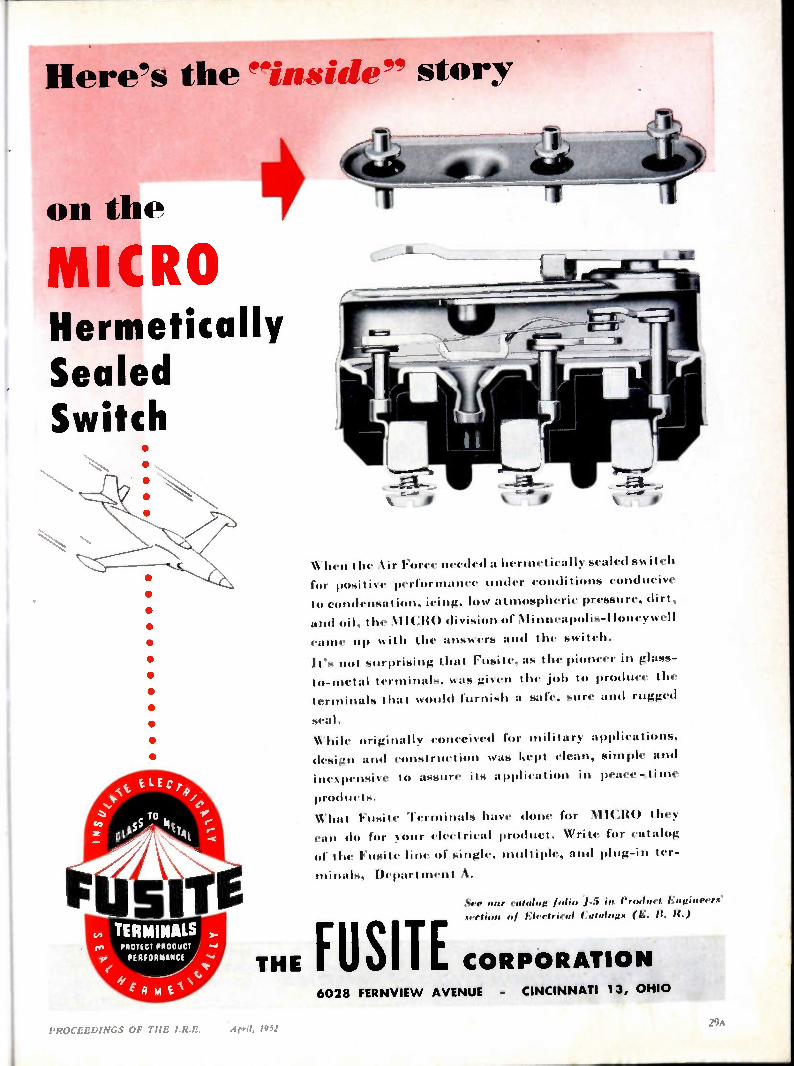
Here's the "inside" story
on the
MICRO Hermetically Sealed Switch
ELE C t4,/e,
TO 55 , 144
01-4 141 r-;
TERMINALS co PROTECT PROOUCT
yr PERFORMANCE 111"
\' I. A IA E A
When the Air Force needed a hermetically sealed switch
for positive performance under conditions conducive
to condensation, icing, low at mospheric pressure, dirt,
and oil, the \l l( division of Alinneapolis-lloneywell
came up with the answers and the switch.
It's not surprising that Fusite, as the pioneer in glass-
to-metal terminals, was given the job to produce the
terminals that would furnish a safe, sure and rugged
hilc on conceived for in applications,
414-4...!ii and construction was kept clean, simple and
pensive to assure its application in peace-ti me
pr.•41nets.
‘‘ hat Fusite Terminals have done for MICRO they
4•:m do for your electrical product. Write for catalog
4.1. the hosite line of single, in and plug-in ter-
minals, Depart ment A.
See our catalog /olio J-.5 in Product Engineere Rect . ol Electrical fatalogx (E. B. H.)
THE FUME CORPORATION 6028 FERNVIE W AVENUE - CINCINNATI 13, OHIO
PROCEEDINGS OF TIIE I.R.E. iipril, 1932
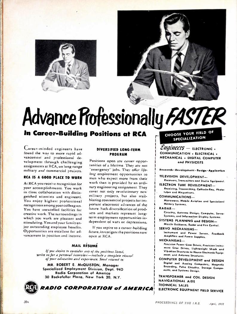
Advance ftoressionally TASTER In Career-Building Positions at RCA
Career-minded engineers have found the way to more rapid ad-
vancement and professional de-velopment through challenging assignments at RCA, on long-range military and commercial projects.
RCA IS A GOOD PLACE TO WORK
At RCA you receive recognition for your accomplishments. You work in close collaboration with distin-guished scientists and engineers.
You enjoy highest professional recognition among your colleagues. You have unexcelled facilities for creative work. The surroundings in which you work are pleasant and stimulating. You and your family en-joy outstanding employee benefits. Opportunities are excellent for ad-vancement in position and income.
DIVERSIFIED LONG-TERM
PROGRAM
Positions open are career oppor-tunities of a lifetime. They are not .'emergency" jobs. They offer life-long employment opportunities to men who expect more from their work than is provided by an ordi-nary engineering assignment. They cover not only revolutionary new military projects, but also trail-blazing commercial projects for im-portant electronic advances of the future. Such diversification of prod-ucts and markets represent long-term employment opportunities in-dependent of wars or depressions.
If you aspire to a career-building future, investigate the positions now open at RCA.
MAIL RESUME
If you desire to consider any of tht positions listed, write us for a personal interview—include a complete resume;
of your education and experience. Send resume to:
MR. ROBERT E. McOUISTON, Manager Specialized Employment Division, Dept. 94D
Radio Corporation of America 30 Rockefeller Plaza, New York 20, N.Y.
RA DIO Val!
CORPORATIO N of A MERICA
r-CHOOSE YOUR FIELD OF
SPECIALIZATION
et/gaffers - ELECTRONIC.
COMMUNICATION • ELECTRICAL •
MECHANICAL • DIGITAL COMPUTER
and PHYSICISTS
Research • Development • Design -Application
TELEVISION DEVELOPMENT _ Receivers, Transmitters and Studio Equipment.
ELECTRON TUBE DEVELOPMENT _ Receiving, Transmitting, Cathode-Ray, Photo-
tubes and Magnetrons.
COMMUNICATIONS _
Microwave, Mobile Aviation and Specialized
Military Systems.
RADAR —
Circuitry, Antenna Design, Computer, Servo-Systems, and Information Display Systems.
SYSTEMS PLANNING and DESIGN —
Missile Guidance, Radar and Fire Control.
SERVO MECHANISMS
Instrument and Power Servos, Feedback
Amplifiers and Power Supplies.
MECHANISMS
Precision Power Gear Drives, Precision Instru-
ment Gear Drives, Lightweight Shock and
Vibration Structures to House Electronic Equip-ment, and Antenna Structures.
COMPUTER DEVELOPMENT and DESIGN
Digital and Analog Computers, Magnetic
Recording, Pulse Circuitry, Storage Compo-nents, and Systems Design.
TRANSFORMER and COIL DESIGN NAVIGATIONAL AIDS
TECHNICAL SALES
ELECTRONIC EQUIPMENT FIELD SERVICE
PROCEEDINGS OF THE I.R.E. April, 1932

Let Buss RISES Help Protect Your Reputation
user of/ /4'4 friderials
. /2 For
OP. TELEVISION • RADIO • RADAR
‘‘- INSTRUMENTS • CONTROLS • AVIONICS
o mPLETE LINE or
PU
plus companion lines of BUSS Fuse Clips, Blocks and Fuse Holders. Made in many types to make it easy to select the fuse and fuse mounting needed to give .required protection.
co 41
41,
The makers of BUSS Fuses take every pre-caution to be sure that the highest standards of quality are maintained. EVERY BUSS FUSE IS ELECTRONICALLY TESTED. A sensitive test-ing device rejects any fuse that is not correctly calibrated, properly constructed and right in all physical dimensions.
This insistence on perfection is the reason why you can always rely on BUSS Fuses. Manu-facturers and service men the country over have learned they can depend on BUSS Fuses for the right protection under all service con-ditions.
Here's another reason why it pays to
SEND THE COUPON (or complete facts . . .
41ERCIAL AND
f" INDusl°N
standardize on BUSS Fuses: You can get all your fuses from one source. The line is complete — dual-element (slow blowing), renewable and one-time types . . . in sizes from 1/500 ampere
up.
If you have a special problem concerning elec-trical protection, let our engineers help you select the right fuse — or design a new fuse, or fuse mounting, to meet your needs. Our staff of engi-neers and laboratory are at your service.
OD
rBUSSMANN Mfg. Co. (Division of McGraw Electric Co.) University at Jefferson, St. Louis 7, Mo.
Please send me bulletin IRE containing complete facts on BUSS small dimension fuses and fuse holders.
I Name
Title
ICompany
I Address
I City & Zone Slate _ I R E452
PROCEEDINGS OF THE I.R.E. Apra, 1952 MA

494 feet above Philadelphia's busiest streets
Most city building codes are easily complied with, but na-ture's caprices are unpredictable. So, when both the building's owners and WPEN's engineers laid plans for a new AM-FM station atop their new mid-town building they called on Blaw-Knox to design, fabricate and erect a safe antenna tower. Their choice was based on the fact that Blaw-Knox has an un-equaled record for successful tower installations in congested areas. WPEN's structure is de-signed to carry the additional load of TV bays if and when required.
BLA W-KNOX DIVISI ON OF BLA W-KNOX COMPANY
2037 Farmers Bank Building
Pittsburgh, Pa.
(41 G1ra-FIT;RI
PROCEEDINGS OF TIIF !Rd,. It Pil
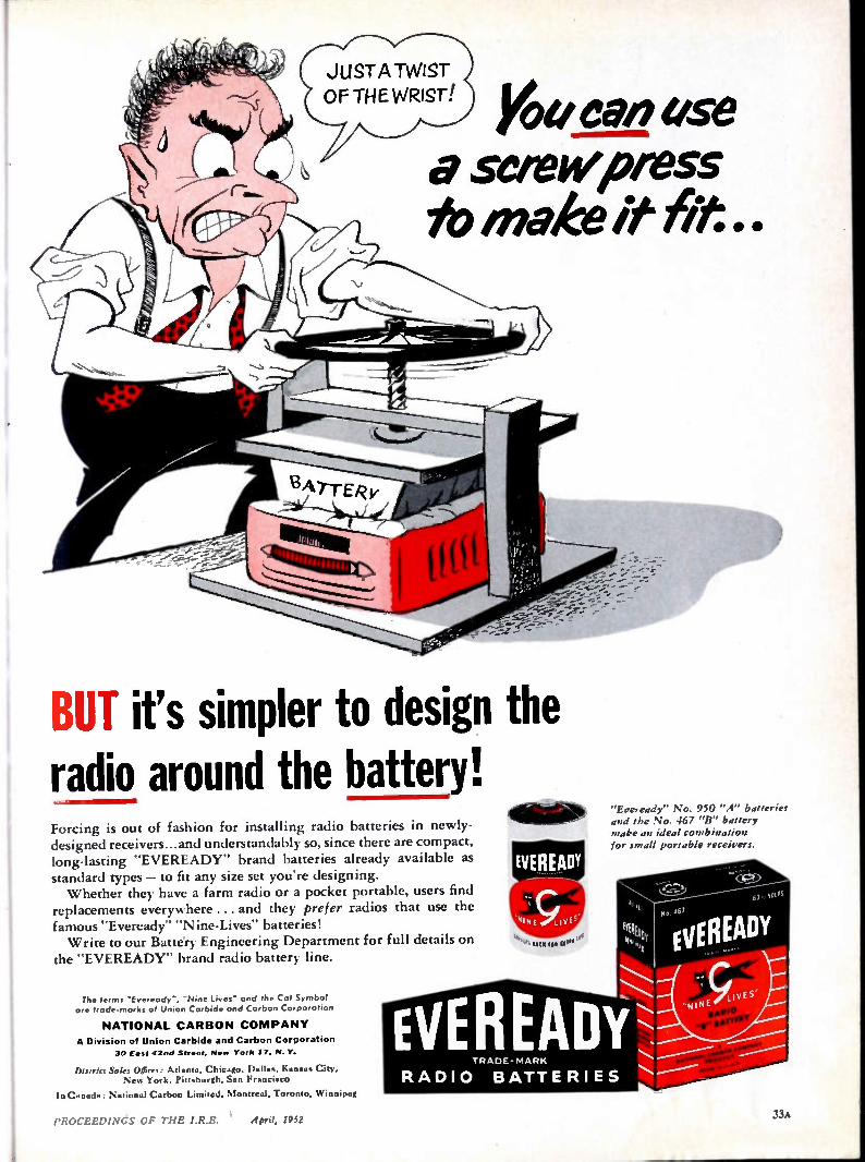
Yoe/ Ceti use a setewpmss to make it fit . .
'7-eon
_
BUT it's simpler to design the radio around the battery! Forcing is out of fashion for installing radio batteries in newly-designed receivers.., and understandably so, since there are compact, long-lasting "EVEREADY" brand batteries already available as standard types — to fit any size set you're designing. Whether they have a farm radio or a pocket portable, users find
replacements everywhere ... and they prefer radios that use the famous "Eveready" "Nine-Lives" batteries! Write to our Battery Engineering Department for full details on
the "EVEREADY" brand radio battery line.
The terms 'Eveready", 'Nine Lives end the Cot Symbol are froda-morks of Union Carbide and Carbon Corporation
NATI ONAL C ARBON CO MPANY
A Division of Union Carbide and Carbon Corporation 30 East 42nd Strwst, New York 17. N. Y.
District Sales Offices: Atlanta, Chicago. Kan... City. New York, Pittsburgh. San Francisco
In Canada: National Carbon Limited. Montreal. Toronto. Winnipeg
EVEREADY
"Ereready" No. 950 "A" batteries
and the No. 467 "B" battery make an ideal combination
for small portable receivers.
• 4I NE LIVE S"
EVEREADY R D R
R A DI O B ATTE RIE S
IWS
No 4'
Evil; EADY
„NINE LIVES
PROCEEDINGS OF THE I.R.E. April, 1952 33ti

LENZ ELECTRIC MANUFACTURING CO.
Supplying the NERVE SYSTEM for Electronic Equipment
SPECIAL HARNESSES,
CABLES and CORDS for
FASTER, ECONOMICAL
ASSEMBLY
•
Constructed of Wires Conforming to Joint Army, Navy and Air Corps Specifications
•
Consult LENZ on any of your wiring problems
1751 North Western Avenue • Chicago 47, Illinois
IN BUSINESS SINCE 1904
PROCEEDINGS OF TIIE I.R E. April, 19.;.?

THE TYPE 256-D
A high-precision time-measuring device designed for general-purpose functions in laboratory work.
The calibrated sweep delay of the Type 256-D will measure time intervals up to 1000 microseconds with an accuracy of ±-0.15 of the full scale ranges of 100 p-secs. or 1000 ii-secs. A movable marker indicates the portion of the sweep which
is expanded on shorter delayed sweeps. Delayed sweeps are of 4-, 10-, and 25-microsecond durations. Undelayed sweeps are available in six ranges from 4- to 4500-microseconds.
Response of the video amplifier is within -± 1 db at 20 cps;
down less than 3 db at 8 mc, no more than 6 db at 11 mc. Sensitivity is 0.7 peak-to-peak volt per inch. Pulse response is such that a rise time of 0.01 microsecond will be repro-duced as a rise time of 0.04 microsecond or less.
Crystal-controlled timing markers calibrate the delay cir-cuits. Delayed and undelayed sweeps may be started by external trigger pulses of either polarity or by built-in trigger generator providing 1 microsecond pulses of either polarity, having a rise time of 0.3 microsecond and amplitude greater than 100 volts. Trigger repetition rates up to 2000 P. P. S.
are available.
aid la PRECISION IN YARDS
THE TYPE 256-E
Electrically similar to the Type 256-D. Calibrations in yards instead of microseconds. Designed especially as test equip-ment for electronic ranging systems, or as an accessory unit
for radar systems.
Provides undelayed sweeps of 800, 2000, 4000, 20,000 and 200,000 yards in addition to a 4500-microsecond sweep. Delayed sweeps of 800, 2000 and 4000 yards may also be
selected.
Do filo NT away/tat*
Instrument Division, ALLEN B. DU MONT LABORATORIES, Inc., 1500 Main Ave., Clifton, N.).
PROCEEDINGS OF TIIE I.R.E. 4fn1, lij2 A
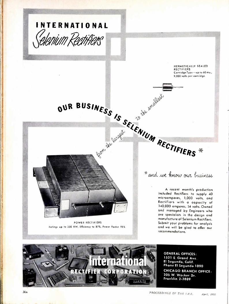
INTERNATIONAL
ehookeeNex
B US iNtss
PO WER RECTIFIERS
Ratings up to 250 KW, Efficiency to 87%, Power Factor 95%
HERMETICALLY SEALED RECTIFIERS Cartridge Type — up to 60 ma,
9,000 volts per cartridge.
4//1/41
l'tctiriERs * avtd, Aye -Gto-ta owt, tiwkezd,
A recent month's production included Rectifiers to supply 40 microamperes, 1,000 volts, and
Rectifiers with a capacity of 140,000 amperes, 14 volts. Owned
and managed by Engineers who are specialists in the design and manufacture of Selenium Rectifiers. Submit your problems for analysis and we will be glad to offer our recommendations.
GENERAL OFFICES: 1521 E. Grand Ave. El Segundo, Calif. Phone El Segundo 1890
CHICAGO BRANCH OFFICE: 205 W. Wacker Dr. Franklin 2-3889
36A PROCEEDINGS OF TIIE IRE. April. 19:;.2
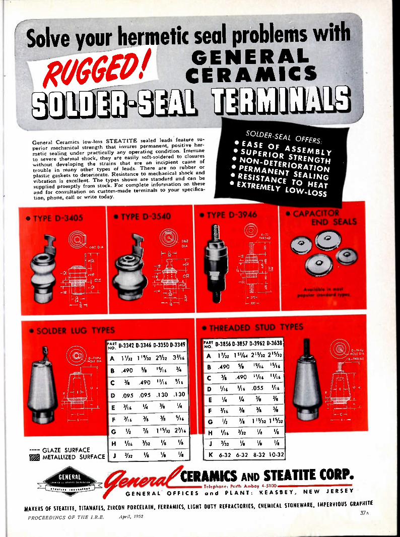
Solve your hermetic seal problems with
N O W :EERNB
General Ceramics low-loss STEATITE sealed leads feature su-perior mechanical strength that insures permanent, positive her-metic sealing under practically any operating condition. Immune to severe thermal shock, they are easily soft-soldered to closures without developing the strains that are an incipient cause of trouble in many other types of leads. There are no rubber or plastic gaskets to deteriorate. Resistance to mechanical shock and vibration is excellent. The types shown are standard and can be supplied promptly from stock. For complete information on these and for consultation on custom-made terminals to your specifica-
tion, phone, call or write today.
• SOLDER LUG TYPE
-- -- GLAZE SURFACE
METALLIZED SURFACE
NO.ART D-3342 D-3346 0-3350 D-3349
A 1 1/32 1 ' Y32 2%2 3 Yi 4
B .490 Ye '5A6 1/4
.490 I V 1 3/11 14 // 16
.095 .095 .130 .130
3/ /16 1/4 3/6 1/4
3/16 Ys Ye 5A4
1/2 7/s 1 '1/2 2 27A 6
GE NER AL
SOLDER SEAL OFFERS
• EASE OF ASSEMBLY • SUPERIOR STRENGTH • NON—DETERIORATION • PERMANENT SEALING • RESISTANCE TO HEAT • EXTREMELY LO W-LOSS
• THREADED STUD TYPES
"du D-3856 D-3857 D-3962 D-3638 NO.
A 17/32 1 51/44 211/2 2 2 15/3
B .490 5/6 IsA 4 1s/14
C 3/1
K 6-32 6-3 2 8-3 2 1 0-3 2
CERAMICS AND STEATITE CORP. Telephone. Perth Amboy 4 5100
OFFICES and PL A NT: KE ASBEY, NE W JERSE Y
MAKERS OF STEATITE, TITANATES, ZIRCON PORCELAIN, FERRAMICS, LIGHT DUTY REFRACTORIES, CHEMICAL STONEWARE, IMPERVIOUS GRAPHITE 37 \
PROCEEDINGS OF 111E I.R.E. April, 1952
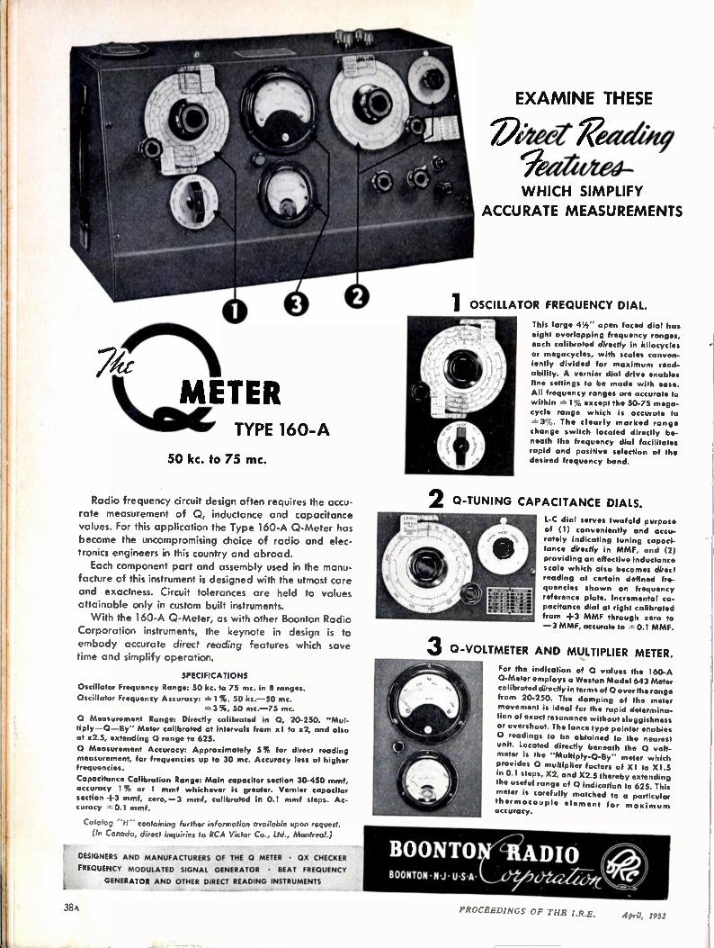
11 11:clIETER TYPE 160-A
50 kc. to 75 mc.
2 Radio frequency circuit design often requires the accu-rate measurement of 0, inductance and capacitance values. For this application the Type 160-A Q-Meter has become the uncompromising choice of radio and elec-tronics engineers in this country and abroad.
Each component part and assembly used in the manu-facture of this instrument is designed with the utmost care and exactness. Circuit tolerances are held to values attainable only in custom built instruments. With the 160-A 0-Meter, as with other Boonton Radio
Corporation instruments, the keynote in design is to embody accurate direct reading features which save time and simplify operation.
SPECIFICATIONS
Oscillator Frequency Range: 50 kc. to 75 mc. in 8 ranges.
Oscillator Frequency Accuracy: 1 %, 50 kc. -50 mc.
3 %, 50 mc. -75 mc.
O Measurement Range: Directly calibrated in 0, 20-250. "Mul-
tiply —0 —By" Meter calibrated at intervals from x 1 to x2, and also at x2.5, extending 0 range to 625.
0 Measurement Accuracy: Approximately 5% for direct reading measurement, for frequencies up to 30 mc. Accuracy less at higher frequencies.
Capacitance Calibration Range: Main capacitor section 30-450 mmf, accuracy 1% or 1 mmf whichever is greater. Vernier capacitor section +3 mmf, zero, -3 mmf, calibrated in 0.1 mmf steps. Ac-curacy *0.1 mmf.
Catalog containing further information available upon request.
(In Canada, direct inquiries to RCA Victor Co., Ltd., Montreal.)
DESIc,NERS AND MANUFACTURERS OF THE 0 METER • OX CHECKER
FREQUENCY MODULATED SIGNAL GENERATOR • BEAT FREQUENCY
GENERATOR AND OTHER DIRECT READING INSTRUMENTS
3
II
EXAMINE THESE
VPaetWeaduti WHICH SIMPLIFY SIMPLIFY
ACCURATE MEASUREMENTS
OSCILLATOR FREQUENCY DIAL.
This large 41/2 " open faced dial has eight overlapping frequency ranges, each calibrated directly in kilocycles or megacycles, with scales conven-iently divided for maximum read-ability. A vernier dial drive enables fine settings to be made with ease.
All frequency ranges are accurate to within 1% except the 50-75 mega-
cycle range which is accurate to 3%. The clearly marked range
change switch located directly be-
neath the frequency dial facilitates rapid and positive selection of the desired frequency band.
0-TUNING CAPACITANCE DIALS.
L-C dial serves twofold purpose of (1) conveniently and accu-rately indicating tuning capaci-tance directly in MMF, and (2)
providing an effective inductance scale which also becomes direct reading at certain defined fre-quencies shown on frequency reference plate. Incremental ca-pacitance dial at right calibrated
from +3 MMF through zero to —3 MMF, accurate to 0.1 MMF.
Q-VOLTMETER AND MULTIPLIER METER.
For the indication of 0 values the 160-A
0-Meter employs a Weston Model 643 Meter calibrated directly in terms of 0 over the range
from 20-250. The damping of the meter movement is ideal for the rapid determina-tion of exact resonance without sluggishness
or overshoot. The lance type pointer enables
0 readings to be obtained to the nearest unit. Located directly beneath the 0 volt-meter is the "Multiply-O-By" meter which provides 0 multiplier factors of X1 to X1.5 in 0.1 steps, X2, and X2.5 thereby extending the useful range of 0 indication to 625. This meter is carefully matched to a particular
thermocouple element for maxi mu m accuracy.
38 PROCEEDINGS OF THE I.R.E. April, 1952

picistoici DE O. /1.9
/9)c-
GAP"-
'674'4; 14'4' 416 11-0
0,6)0 '1
An instruction sheet recently received from a valued cus-tomer. The company knew the properties it wanted . . . and left it to Plastoid to work out the details.
The finished job . . . a custom-engineered SYNKOTE 3/4 " cable with 30 individually-shielded conductors, fungus-re-sistant, flexible, designed to "take it" at —50*C or +60°C I
PLASI n . 42-61 24th Street Long Island City 1, N. Y.
Make it?
effitette#1 -WE KNO W HO W!
Here, in two simple photographs, is a
perfect illustration of Plastoid's service to
the electronic industry.
For your wire or cable needs, get in touch
with Plastoid. In addition to supplying all
standard constructions, our excellent staff of
engineers and production men will gladly
cooperate with you in designing — and
producing — cable to fit your requirements.
DEPENDABLE
Multi-Conductor Cables
HO OK-UP WIRE • AIRCRAFT CABLE • TV WIRE • COAXIAL CABLE
NYLON JACKETING • HIGH TEMPERATURE WIRE • MULTI-CONDUCTOR CABLES
PROCEEDINGS OF TIIE IRE. A;ra, PA:2 39A
ACTUAL SIZE
1
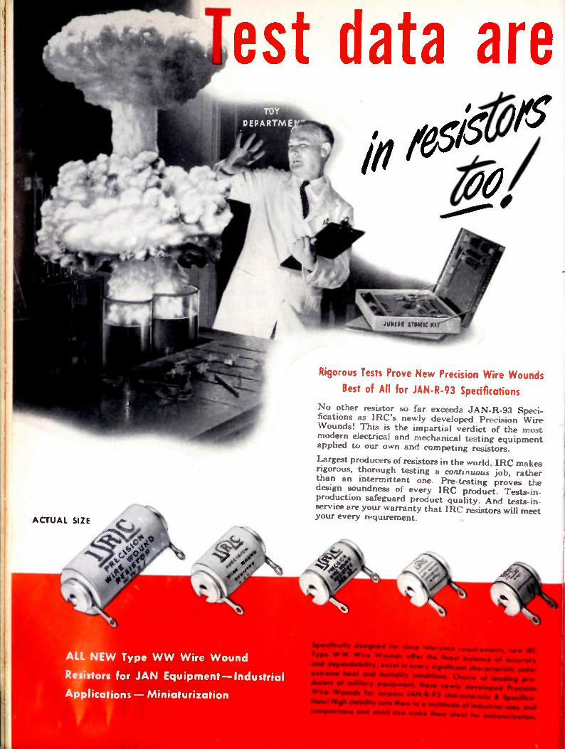
est data are ill 1 01'5
00/
ALL NEW Type WW Wire Wound
Resistors for JAN Equipment—Industrial
Applications — Miniaturization
Rigorous Tests Prove New Precision Wire Wounds
Best of All for JAN-R-93 Specifications
No other resistor so far exceeds JAN-R-93 Speci-fications as IRC's newly developed Precision Wire Wounds! This is the impartial verdict of the most modern electrical and mechanical testing equipment applied to our own and competing resistors.
Largest producers of resistors in the world, IRC makes rigorous, thorough testing a continuous job, rather than an intermittent one. Pre-testing proves the design soundness of every IRC product. Tests-in-production safeguard product quality. And tests-in-service are your warranty that IRC resistors will meet your every requirement.
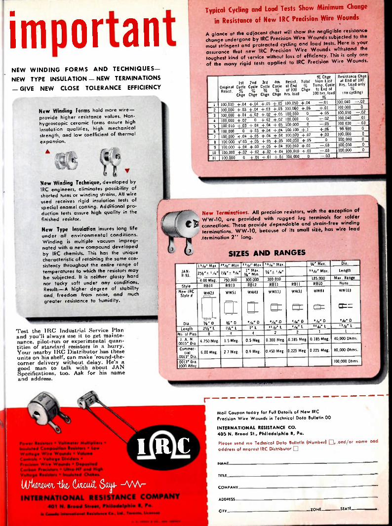
important NE W WINDING FORMS AND TECHNIQUES-
NE W TYPE INSULATION - NEW TERMINATIONS
- GIVE NEW CLOSE TOLERANCE EFFICIENCY
New Winding Forms hold more wire -provide higher resistance values. Non-hygroscopic ceramic forms assure high insulation qualities, high mechanical strength, and low coefficient of thermal
expansion.
•
4), e: V
New Winding Technique, developed by IRC engineers, eliminates possibility of
shorted turns or winding strains. All wire used receives rigid insulation tests of special enamel coating. Additional pro-duction tests assure high quality in the
finished resistor.
New Type Insulation insures long life under all environmental conditions.
Winding is multiple vacuum impreg-
nated with a new compound developed
by IRC chemists. This has the unique characteristic of retaining the some con-
sistency throughout the entire range of
temperatures to which the resistors may
be subjected. It is neither glassy hard
nor tacky soft under any conditions. Result, -A higher degree of stability
and freedom from noise, and much
greater resistance to humidity.
Test the 1RC Industrial Service Plan and you'll always use it to get mainte-nance, pilot-run or experimental quan-tities of standard resistors in a hurry. Your nearby IRC Distributor has these units on his shelf, can make 'round-the-corner delivery without delay. He's a good man to talk with about JAN Specifications, too. Ask for his name and address.
Typical Cycling and Load Tests Show Minimum Change
in Resistance of New IRC Precision Wire Wounds
A glance at the adjacent chart will show the negligible resistance change undergone by IRC Precision Wire Wounds subjected to the most stringent and protracted cycling and load tests. Here is your assurance that new IRC Precision Wire W ounds withstand the toughest kind of service without loss of efficiency. This is only one of the many rigid tests applied to IRC Precision Wire Wounds.
Ist 2nd 3rd 4th Original Cycle Cycle Cycle Cycle Resist. % %, %, %
Chge Chge Chge Chge
Resist. at End of 100 Isis. load
Total % Chge
, Chge from last Temp. Cycle to End of 100 his, load
%
Resistance Chge at End of i00 His. Load only
% I no cycling ,
I 100,010 +.04 +04 +.05 +.05 100,050 +.04 -.01 100,040 -.02
2 100,000 +03 +04 +.03 +.05 100,060 +.06 4-.01 100,000 0
3 100.000 +.01 +.02 +.02 +.05 100,000 0 +.05 100,050 -.02
4 100.000 +02 0 +.02 +.02 100,000 0 -.02 100,040 -.01
5 100,010 +03 +04 +.04 +.05 100.000 0 -.05 100.030 -.03
6 100,000 0 +.03 +04 +.04 100.100 +.1 +.06 99,980 0
7 100.000 +.04 +.05 +04 +04 100.070 +07 +03 100,000 0
8 100,000 -1=03 +.05 +.05 +.05 100.050 +.05 0 100.000 0
9 100.000 +04 +03 +.05 +04 100.010 +.01 -.03 100,050 0
10 100.000 +.02 +.02 +.02 + 04 100.010 +.01 -.03 100.000 0
II 100.000 0 + .01 +.01 +.03 100,000 0 -.03
New Terminations. All precision resistors, with the exception of W W-10, are provided with rugged lug terminals for solder connections. These provide dependable and strain-free winding terminations. W W-10, because of its small size, has wire lead
termination 2'' long.
SIZES AND RANGES
I ,h2" Max. "42" Max. "A2" Max. ',AI," Max. a/4" Max. Dia.
JAN- R.93. 2Y.'± '/14" I1/4 "± Ms" j):: °Mt': W i 'A." I 5/32' Max. Length
4.00 Meg. 750,000 300.000 300,000 185.000 Max. Range
Style RBI4 8813 12812 RBII RBII RBIO None
New IRC Style 0
Dia
WW21
•,., 7/6" _ D
WW51
.1- _
WW411
FT = WW111
VW D
WW31
= Vie D
WW8.1 WW101
=-...-.. Ms' D
,:l_ Mii' D ?A' 0 'A,' D
Length 21/4 " l PA" L I" L 31 /32' L ,A,' L ".4x" I. "h2" L
No. of Pies 8 4 4 2 2 1 1
1 A. N. 0015' M
4.250 Meg. 1.5 Meg. 0.5 Meg. 0.300 Meg. 0.185 Me g. 0.185 Me g. 40,000 Ohms. . a. Commer-oal
0013' Dia. 6.00 Meg. 2.7 Meg. 0.9 Meg. 0.450 Meg. 0.225 Meg. 0.225 Meg. 80,000 Ohms.
.0013" Dia. 1000 Alloy
100,000 Ohms.
TERNATIONAL HS COMPANY 401 N Broad Street, Phslodelphso B, Po
I. (done. Istid oets••••1111•11,111,00•• C. lid Tio.coni•
Moil Coupon today for Full Details of New IRC Precision Wire Wounds in Technical Data Bulletin 00
INTERNATIONAL RESISTANCE CO.
405 N. Broad St., Philadelphia B, Pa.
Please send me Technical Data Bulletin (Number) ID, and/or name and address of nearest IRC Distributor D
NAME
TITLE
COMPANY
ADDRESS
CITY ZONE.---- -STATE
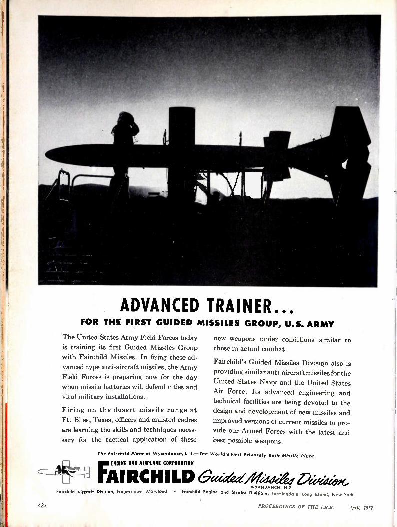
ADVANCED TRAINER... FOR THE FIRST GUIDED MISSILES GROUP, U.S. ARMY
The United States Army Field Forces toda
is training its first Guided Missiles Group
with Fairchild Missiles. In firing these ad-
vanced type anti-aircraft missiles, the Army
Field Forces is preparing now for the day
when missile batteries will defend cities and
vital military installations.
Firing on the desert missile range at
Ft. Bliss, Texas, officers and enlisted cadres
are learning the skills and techniques neces-
sary for the tactical application of these
new weapons under conditions similar to those in actual combat.
Fairchild's Guided Missiles Divisiqn also is
providing similar anti-aircraft missiles for the
United States Navy and the United States
Air Force. Its advanced engineering and
technical facilities are being devoted to the
design and development of new missiles and
improved versions of current missiles to pro-
vide our Armed Forces with the latest and best possible weapons.
The Fairchild Plant at Wyandanch, L. I.—The World's First Privately Built Missile Plant
FENGINE AND AIRPLANE CORPORATION
Al RCH I LD Gei,:aayfriadeeed ici.je„wOve WYANDANCH, N.Y.
Fairchild Aircraft Division, Hagerstown, MarYlond • Fairchild Engine and Strafes Divisions, Farmingdale, Long Island, New York
47A PROCEEDINGS OF THE I.R.E. April, 1952

If you
want to
in your assemblies,
ma" power resistors
* The green-colored power resistors so conspicuous these days in dependable radio-electronic and elec-trical assemblies, are GREENOHMS. No tougher resistors made. That statement is sustained by labora-tory tests. Likewise by countless case histories out in the field.
Unimpaired wire winding firmly imbedded in exclu-sive cold-setting inorganic cement. Exceptional heat
Greenohm Jr. — point-to-point 'fired power resis-tor sealed in ceramic tubular casing. 4, 7 and 8 watt.
In the heavy-weight division — fixed and adjustable Greenohms — up to 200 wort
"
conduction and surface radiation. Heavy overloads handled without damage. Severe heat-shock resistance permits extreme on-off operation without flinching. And Greenohms last and last.
Choice of standard types. Also in virtually unlimited special types. Wide selection of resistance values, wattages, taps, terminals, mountings. And remember, Greenohms cost less though they offer you more!
Flat Greenohms for flat In the bantam-weight mounting individually, division — 5 and 10 watt or for stacked arrays. 30 fixed Greenohms. to 75 watt.
Standees — convenient above-chassis mounting Greenohms in ceramic casings. 10 to 25 watt.
you can stand pat with clarostat
M M
Engineering data on request. Send us your
What is the ideal resistance value? That's easy. With the Clarostot Power Resistor Decode Box inserted in actual circuit, handling actual load, you try the six knobs for anything from 1 to 999,999 ohms. When right operating conditions are attained, read resistance directly off dials. Quick, simple, positive, economical.
resistance
or control requirements for engineering aid
and quotations. Try Greenohms! — .Naar 4111111 .11111111
Controls and Resistors - - CLAROSIAT MFG. CO., INC., DOVER, NEW HAMPSHIRE In Canada: Canadian Marconi Co., Ltd., Toronto, Ontario
PROCEEDINGS OF THE I.R.E. April, 1952

our assistance, simply ask your Revere Distributor.
He will be glad to put you in touch with us, without obligation.
Ii
metals for electronic applications...see REVERE!
• This Raytheon Magnetron is just one of a number using Revere Metals—and Revere know-how. Revere
and Raytheon work closely together, consulting on
such matters as the properties of copper and brass,
brazing methods, machining, suitability of metals for
glass-to-metal seals, and so on. In other words, Revere
goes much beyond merely supplying metals. Through
the Revere Technical Advisory Service our knowledge and skill are available. They have proved invaluable to
many companies. And by the way, do not forget that
this collaboration is freely given. If you purchase
from distributors and would like to avail yourself of
Raytheon Magnetron, Type RK5j26, made by Raytheon Manufacturing Co., Waltham, Mass. This is a super-high frequency, pulse-type, tunable magnetron cavity oscillator, to oper-ate in the 23.3 centimeter band. It is capable of delivering 700 kilo-watts of peak power under pulsed conditions.
REPERE COPPER AND BRASS INCORPORATED
Founded by Paul Reuere in 1801
230 Park Avenue, New York 17, N. Y. • •
Mills: Baltimore, Md.; Chicago and Clinton. III.: Detroit, Mich.; Los Angeles and Riverside. Ca/q.: New Bedford, Mass.; Rome, N. Y. —
Sales Offices in Principal Cities. Distributors Er e where
SEE "MEET THE PRESS" ON NBC TELEVISION EVERY SUNDAY
44A PROCEEDINGS OF THE I.R.E. April, 1952

When you buy AlSiMag ceramics you get:
1. Engineering know-how accumulated during half a century of specialization.
2. Unexcelled production facilities.
3. The widest choice of ceramic materials available in the industry.
4. Equipment of a size and completeness that can handle YOUR job.
5. Research which has constantly improved known ceramics and has led in the develop-ment of new special-purpose ceramics.
6. The highest quality custom made ceramics, delivered when and as promised.
One of the most important questions is: "Can they deliver on time and according to promise?"
American Lava Corporation has equipment of a
size and completeness which is not matched in the
industry. A book showing about 200 pictures of equipment producing AlSiMag technical ceramics has just been published. This book will give you a good idea of the size, versatility and skill of our
organization. We'll be glad to send you a copy if you'll request our booklet "50 Years of Progress." As you look through it we believe you'll agree that
we have the equipment and know-how to handle
YOUR job.
50T H YE A R OF CER A MIC LE A DERS HIP
AMERICAN LAVA CORPORATION CH ATT A N O O G A 5, TE N NESSEE
OFFICES, METROPOLITAN AREA, 671 Brood St., Newark, N. .I„ Mitchell 2-8159 • PHILADELPHIA, 1649 North Broad Si., St•sitnson 4 2873
SOUTH WEST: John A. Green Co., M S Oriole Drive, Doflat 9, Dis,on 9918 • NE W ENGLAND, 1374 Massachusetts Are., Cambridge, Mo m, Kirkland 7 4498
LOS ANGELES, 232 South ,Hill St., Mutual 9076 • CHICAGO, 228 North LaSalle St., Central 6.1721 • ST. LOUIS, 1123 Washington Are., Garli•ld 1959
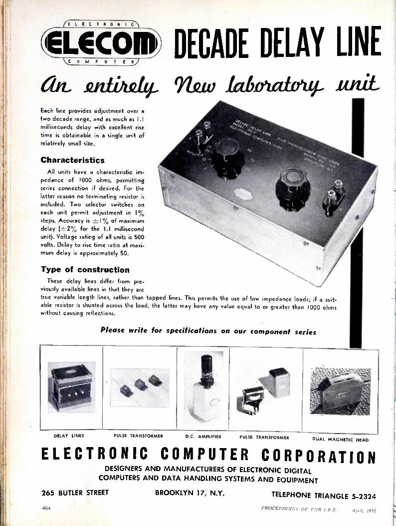
E• *,04?*c DECADE DELAY LINE áit futtild2.4 911fuv labnutiow- _unit. Each line provides adjustment over a two decade range, and as much as 1.1 milliseconds delay with excellent rise time is obtainable in a single unit of relatively small size.
Characteristics
All units have a characteristic im-pedance of 1000 ohms, permitting series connection if desired. For the latter reason no terminating resistor is included. Two selector switches on each unit permit adjustment in I% steps. Accuracy is -± I% of maximum delay (-±2% for the 1.1 millisecond unit). Voltage rating of all units is 500 volts. Delay to rise time ratio at maxi-mum delay is approximately 50.
Type of construction
These delay lines differ from pre-viously available lines in that they are
true variable length lines, rather than tapped lines. This permits the use of low impedance loads; if a suit-able resistor is shunted across the load, the latter may have any value equal to or greater than 1000 ohms without causing reflections.
Please write for specifications on our component series
PULSE TRANSFORMER DELAY LINES PULSE TRANSFORMER D.C. AMPLIFIER DUAL MAGNETIC HEAD
ELECTRONIC COMPUTER CORPORATION DESIGNERS AND MANUFACTURERS OF ELECTRONIC DIGITAL
COMPUTERS AND DATA HANDLING SYSTEMS AND EQUIPMENT
265 BUTLER STREET BROOKLYN 17, N.Y. TELEPHONE TRIANGLE 5-2324
PROCEEDEvc.r HE THE I.R.E.
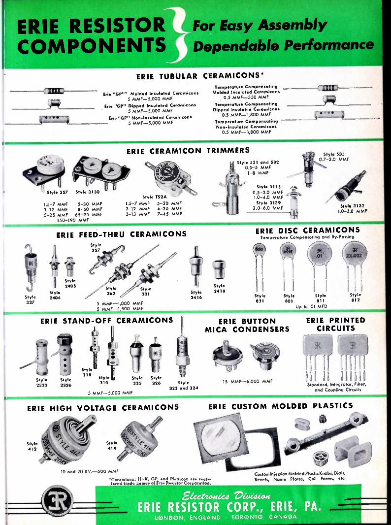
ERIE RESIS COMPO
p_,•••
1•1111../
ERIE
or Easy Assembly
Dependable Performance
TUBULAR CERAMICONS*
Erie "GP"" Molded Insulated Ceramicons 5 MMF-5,000 MMF
Erie "GP" Dipped Insulated Ceramicons 5 MMF-5,000 MMF
Erie "GP" Non-Insulated Ceramicons 5 MMF-5,000 MMF
Style 327
Style 557 Style 3130
1.5-7 MMF 5-30 MMF 3-12 MMF 8-50 MMF 5-25 MMF 65-95 MMF
150-190 MMF :4•N MO MMII MIL
I'
Temperature Compensating Molded Insulated Ceramicons
0.5 MMF-550 MMF
Temperature Compensating Dipped Insulated Ceramicons
0.5 MMF-1,800 MMF
Temperature Compensating - Non-Insulated Ceramicons 0.5 MMF-1,800 MMF
imL
ERIE CERAMICON TRIMMERS
Style TS2A
1.5-7 MMF 5-20 MMF 3-12 MMF 4-30 MMF 3-13 MMF 7-45 MMF
ERIE FEED-THRU CERAMICONS
Fl Style 2405
Style 2404
ERIE
Style 2322
Style 357 "jr....7
tl* .Y
V -1111111111111•1!1-
Style 362 321
Style
5 MMF -1,000 MMF 5 MMF -1,500 MMF
STAND-OFF CERAMICONS
•
• • *
Style 2336
ERIE HIGH
1 k L • • •
Style 318
Style 319
5 MMF ?SF
Style
F
325 Style 326
,r Style
Style 2418 2416
Style 323 and 324
VOLTAGE CERAMICONS
Style 531 and 532 0.5-5 MMF 1-8 MMF
Style 3115 0.5-3.0 MMF 1.0-4.0 MMF Style 3139 2.0-6.0 MMF Style 3132
1.0-3.8 MMF
Style 535 0.7-3.0 MMF
ERIE DISC CERAMICONS Temperature Compensating and By•Passing
1
Style 831
11 !1=111111111111110-
Style Style 801 811
Up to .01 MFD
Style 812
ERIE BUTTON MICA CONDENSERS
15 MMF -6,000 MMF
ERIE PRINTED CIRCUITS
TTII Standard, Integrator, Filter, and Coupling Circuits
ERIE CUSTOM MOLDED PLASTICS
10 and 20 KV. -500 MMF
*Ceramicon, Hi-K, GP, and Plezicon are regis-tered trade names of Erie Resistor Corporation.
V,1940%,,i
Custom Injection Molded Plastic Knobs, Dials, Bezels, Name Plates, Coil Forms, etc.
&ea/tow:ed. rleadzag ERIE RESISTOR CORP., ERIE, PA.
LONDON, ENGLAND TORONTO CANADA
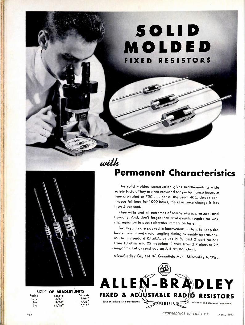
SIZES OF BRADLEYUNITS Rating Length Diameter Yvw 3/8" 9/64" 1-w 9/16" 7/32" 2-w 11/16" 5/16"
with Permanent Characteristics
The solid molded construction gives Bradleyunits a wide
safety factor. They are not crowded for performance because
they are rated at 70C . . . not at the usual 40C. Under con-
tinuous full load for 1000 hours, the resistance change is less
than 5 per cent.
They withstand all extremes of temperature, pressure, and
humidity. And, don't forget that Bradleyunits require no wax
impregnation to pass salt water immersion tests.
Bradleyunits are packed in honeycomb cartons to keep the
leads straight and avoid tangling during assembly operations.
Made in standard R.T.M.A. values in 1/2 and 2 watt ratings
from 10 ohms and 22 megohms; 1 watt from 2.7 ohms to 22
megohms. Let us send you an A-B resistor chart.
Allen-Bradley Co., 114 W. Greenfield Ave., Milwaukee 4, Wis.
/ry- AD ALLEti-BR LEY (,t)
FIXED & STABLE RADIO RESISTORS Sold "Ci "ivelY to manufacture" ==.01.1111.1TY of radio and electronic equipment
48A PROCEEDINGS OF THE I.R.E. April, 1952
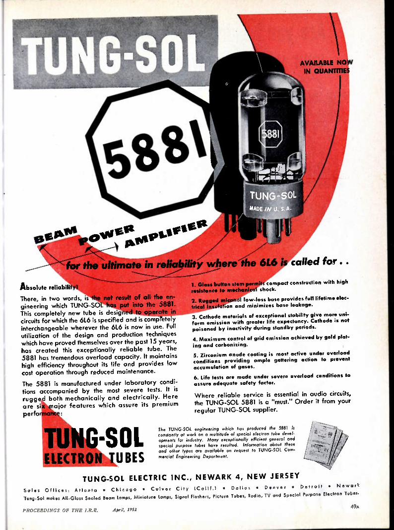
AVAILABLE NOW IN QUANTITIES
for the in reliability where iie 6L6 is called for.
Absolute reliability!
There, in two words, is the net result of all the en-gineering which TUNG-SOL has put into the 5881. This completely new tube is designed to operate in circuits for which the 61.6 is specified and is completely interchangeable wherever the 6L6 is now in use. Full utilization of the design and production techniques which have proved themselves over the past 15 years, has created this exceptionally reliable tube. The 5881 has tremendous overload capacity. It maintains high efficiency throughout its life and provides low cost operation through reduced maintenance.
The 5881 is manufactured under laboratory condi-tions accompanied by the most severe tests. It is rugged both mechanically and electrically. Here are six major features which assure its premium performance:
TUNG-SOL ELECTRON TUBES
1. Glass button stem permits compact construction with high
resistance to mechanical shock.
2. Rugged micanol low-loss base provides full lifetime elec-trical insulation and minimizes base leakage.
3. Cathode materials of exceptional stability give more uni-form emission with greater life expectancy. Cathode is not poisoned by inactivity during standby periods.
4. Maximum control of grid emission achieved by gold plat-
ing and carbonizing.
5. Zirconium anode coating is most active under overload conditions providing ample gettering action to prevent accumulation of gases.
6. Life tests are made under severe overload conditions to assure adequate safety factor.
Where reliable service is essential in audio circuits, the TUNG-SOL 5881 is a "must." Order it from your regular TUNG-SOL supplier.
The TUNG-SOL engineering which has produced the 5881 is constantly at work on a multitude of special electron tube devel-opments for industry. Many exceptionally efficient general and special purpose tubes hove resulted. Information about these and other types are available on request to TUNG-SOL Com-mercial Engineering Deportment.
TU NG-S OL ELECTRIC INC., NE WARK 4, NE W JERSEY
Soles Offices: Atlanta • Chicago • Culver City (Calif.) • Dallas • Denver • Detroit • Newark
Tung-Sol makes All-Glass Sealed Beam lamps, Miniature lamps, Signal Flashers, Picture Tubes, Radio, TV and Special Purpose Electron Tubes.
49A PROCEEDINGS OF THE I.R.E. A prtl, 1952
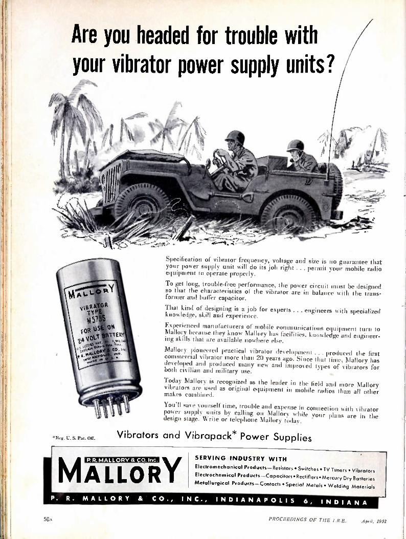
Are you headed for trouble with your vibrator power supply units?
'Reg. U. S. Pat. Off.
Specification of vibrator frequency, voltage and size is no guarantee that your power supply unit will do its job right ... permit your mobile radio equipment to operate properly.
To get long, trouble-free performance, the power circuit must be designed so that the characteristics of the vibrator are in balance with the trans-former and buffer capacitor.
That kind of designing is a job for experts ... engineers with specialized knowledge, skill and experience.
Experienced manufacturers of mobile communications equipment turn to Mallory because they know Mallory has facilities, knowledge and engineer-ing skills that are available nowhere else.
Mallory pioneered practical vibrator development ... produced the first commercial vibrator more than 20 years ago. Since that time, Mallory has developed and produced many new and improved types of vibrators for both civilian and military use.
Today Mallory is recognized as the leader in the field and more Mallory vibrators are used as original equipment in mobile radios than all other makes combined.
You'll save yourself time, trouble and expense in connection is ith vibrator power supply units by calling on Mallory while your plans are in the design stage. Write or telephone Mallory today.
Vibrators and Vibrapack* Power Supplies
MALLORY P.R. MALLORV a CO..Inc. SERVI N G INDUSTRY WITH
Electromechanical Products—Resistors • Switches • TV Tuners • Vibrators
Electrochemical Products—Capacitors • Rectifiers • Mercury Dry Batteries
Metallurgical Products—Contacts • Special Metals • Welding Materials
P. R. M A L L O R Y & C O., IN C., IN DI A N A P O LI S 6, IN DI A N A
50A PROCEEDINGS OF THE I.R.E. April 1952
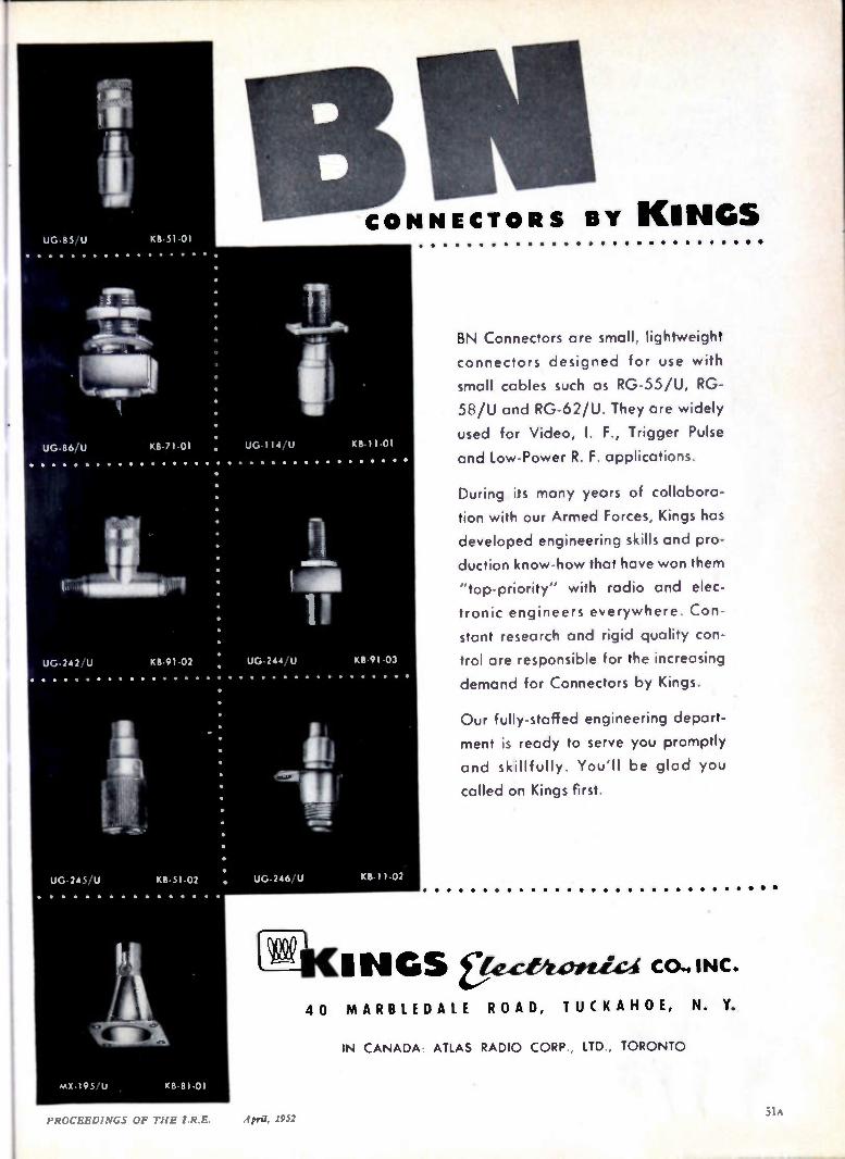
UG-8.5 U KB 51.01
UG-86/U KB.71.01
UG-242/U KII-91-02
UG-2,15/U KB-51-02
vx 105 L, KB S1.01
1 11 11 1 CONNECTORS BY KINGS
UG 114 U K 1-11-01
UG-244/U KB 01 03
UG-246/U MI I -02
BN Connectors are small, lightweight
connectors designed for use with
small cables such as RG-55/U, RG-
58/U and RG-62/U. They are widely
used for Video, I. F., Trigger Pulse
and low-Power R. F. applications.
During its many years of collabora-
tion with our Armed Forces, Kings has
developed engineering skills and pro-
duction know-how that have won them
"top-priority" with radio and elec-
tronic engineers everywhere. Con-
stant research and rigid quality con-
trol are responsible for the increasing
demand for Connectors by Kings.
Our fully-staffed engineering depart-
ment is ready to serve you promptly
and skillfully. You'll be glad you
called on Kings first.
INGS t.ezt.stortic.4 40 MARBLEDALE ROAD, TUCK AHOE, N. Y.
IN CANADA ATLAS RADIO CORP, LTD, TORONTO
PROCEEDI.VGS OF THE IR E. April, 1952
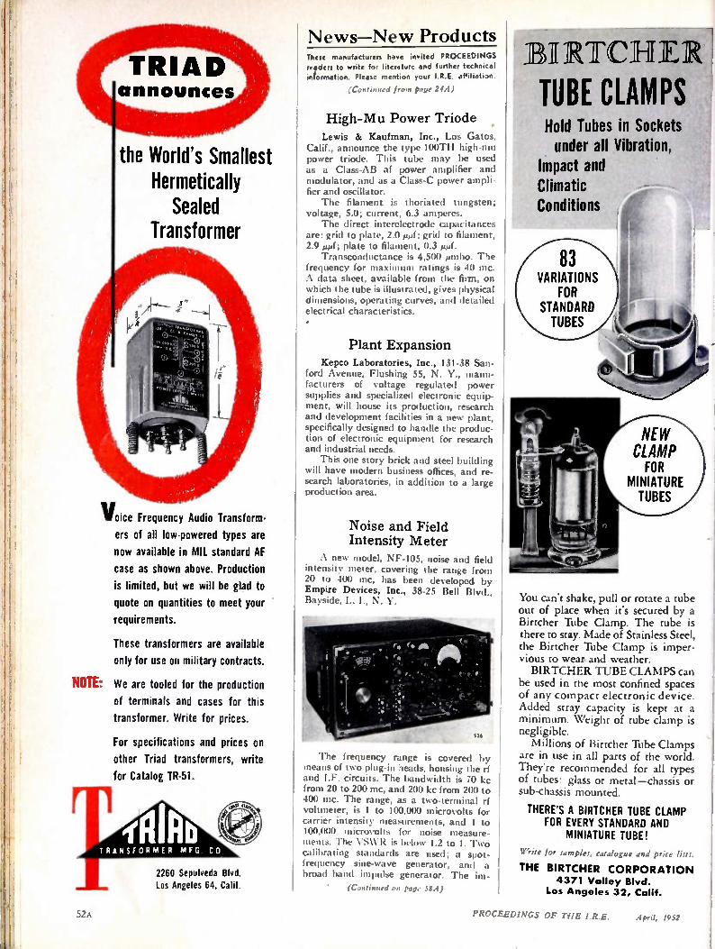
the World's Smallest Hermetically Sealed
Transformer
Voice Frequency Audio Transform-ers of all low-powered types are
now available in MIL standard AF
case as shown above. Production
is limited, but we will be glad to
quote on quantities to meet your
requirements.
These transformers are available
only for use on military contracts.
NOTE: We are tooled for the production of terminals and cases for this
transformer. Write for prices.
For specifications and prices on
other Triad transformers, write
for Catalog TR-51.
TRANSFORMER MEG CO
2260 Sepulveda Blvd. Los Angeles 64, Calif.
News—New Products These manufacturers have invited PROCEEDINGS refders to write for literature and further technical information. Please mention your I.R.E. affiliation.
(Continued from page 24A)
High-Mu Power Triode Lewis & Kaufman, Inc., Los Gatos,
Calif., announce the type 100TH high-mu power triode. This tube may be used as a Class-AB af power amplifier and modulator, and as a Class-C power ampli-fier and oscillator. The filament is thoriated tungsten;
voltage, 5.0; current, 6.3 amperes. The direct interelectrode capacitances
are: grid to plate, 2.0 µµf; grid to filament, 2.9 i.sµf; plate to filament, 0.3 pArf. Transconductance is 4,500 Amho. The
frequency for maximum ratings is 40 mc. A data sheet, available from the firm, on which the tube is illustrated, gives physical dimensions, operating curves, and detailed electrical characteristics. •
Plant Expansion Kepco Laboratories, Inc., 131-38 San-
ford Avenue, Flushing 55, N. Y., manu-facturers of voltage regulated power supplies and specialized electronic equip-ment, will house its production, research and development facilities in a new plant, specifically designed to handle the produc-tion of electronic equipment for research and industrial needs. This one story brick and steel building
will have modern business offices, and re-search laboratories, in addition to a large production area.
Noise and Field Intensity Meter
A new model, NF-105, noise and field intensity meter, covering the range from 20 to 400 mc, has been developed by Empire Devices, Inc., 38-25 Bell Blvd., Bayside, L. I., N. V.
The frequency range is covered by means of two plug-in heads, housing the rf and I.F. circuits. The bandwidth is 70 kc from 20 to 200 mc, and 200 kc from 200 to 400 mc. The range, as a two-terminal rf voltmeter, is 1 to 100,000 microvolts for carrier intensity measurements, and 1 to 100,000 microvolts for noise measure-ments. The VSWR is below 1.2 to 1. Two calibrating standards are used; a spot-frequency sine-wave generator, and a broad band impulse generator. The im-
• (Continued on page 58A)
It) IIRTCHIER
TUBE CLAMPS Hold Tubes in Sockets under all Vibration,
Impact and Climatic Conditions
You can't shake, pull or rotate a tube out of place when it's secured by a Birtcher Tube Clamp. The tube is there to stay. Made of Stainless Steel, the Birtcher Tube Clamp is imper-vious to wear and weather. BIRTCHER TUBE CLAMPS can
be used in the most confined spaces of any compact electronic device. Added stray capacity is kept at a minimum. Weight of tube clamp is negligible. Millions of Birtcher Tube Clamps
are in use in all parts of the world. They're recommended for all types of tubes: glass or metal—chassis or sub-chassis mounted.
THERE'S A BIRTCHER TUBE CLAMP FOR EVERY STANDARD AND
MINIATURE TUBE!
Write for tamplet. catalogue and price lists.
THE BIRTCHER CORPORATION 4371 Valley Blvd.
Los Angeles 32, Calif.
52A PROCEEDINGS OF THE I.R.E. April, 1952

KOLLS MAN for products of precision and dependability Aircraft Instruments and Controls • • • Miniature
AC Motors for Indicating and Remote Control
Applications • • • Optical Parts and Optical Devices
Radio Communications and Navigation Equipment
Today, Kollsman works without pause toward the fulfillment of America's defense needs. And to our nation's research scientists, the skill, ingenuity and creative drive of Kollsman Research Laboratories are available for the solution of instrumentation and control problems.
KOLLSMAN INSTRUMENT CORPORATION EL MHURST, NE W YORK GLENDALE, CALIF ORNIA
SUGGI otAPY
S t a n dait d C OI L P R O D U CT S C O IN C.
53A PROCEEDINGS OF THE I.R.E. Aprsl, 1952
ASSOCIATED
ILIFFE UBLICATIONS
Up-to-date news of every British development WIRELESS WORLD. Britain's chief technical magazine in
the general field of radio, television and electronics. Founded
over go years ago, it provides a complete and accurate
survey of the newest British techniques in design and
manufacture. Articles of a high standard cover every phase
of radio and allied technical practice, with news items on
the wider aspects of international radio. Theoretical articles
by recognised experts deal with new developments, while
design data and circuits for every application are published.
WIRELESS WORLD is indispensable to technicians of all grades
and is read in all parts of the world.
Published monthly, $4.5o a year.
WIRELESS ENGINEER—the magazine of radio research and
progress —is produced for research engineers, designers and
students in the fields of radio, television and electronics. Its
editorial policy is to publish only original work, and its highly
specialized content is accepted as the authoritative source of
information for advanced workers everywhere. The magazine's
Editorial Advisory Board contains representatives of the
National Physical Laboratory, the British Broadcasting Cor-
poration, and the British Post Office. Regular features include
an Abstracts and References Section compiled by the Radio
Research Organization of the Department of Scientific and
Industrial Research. Published monthly, S7 .00 a year.
RECE NT EDIT ORI AL CO NTE NTS
Speech Reinforcement in Reverberant Auditoria: Use of Time
Delays and Line-source Loudspeakers. Magnetic Recording:
Mechanism of Asymmetrical Hysteresis. Valve Voltmeter
without Cilibration Drift: " Infinite-input, Zero-output-
resistance" Adaptor for D.C. Voltmeters.
Visibility of Radar Echoes. Shunt-Regulated Amplifiers.
Dielectric Lens Aerial. Directional-Coupler Errors.
Impedance Changes in Image Iconoscopes. Precision
Calibrator for Low Frequency Phase-Meters. Television
Camera Tubes.
M AI L T HIS O R D E R T O D A Y
To ILIFI-E & SONS LIMITED, DORSE I HOUSE, STAMFORD STREET, LONDON, S.E.1, ENGLAND
Plecse forward for 12 months. Payment is being made*
NAME
ADDRESS
C ITY ZONE STATE
*Payment can be made by Banker's Draft or International Money Order.
54A PROCEEDINGS OF THE I.R.E. April, 1952
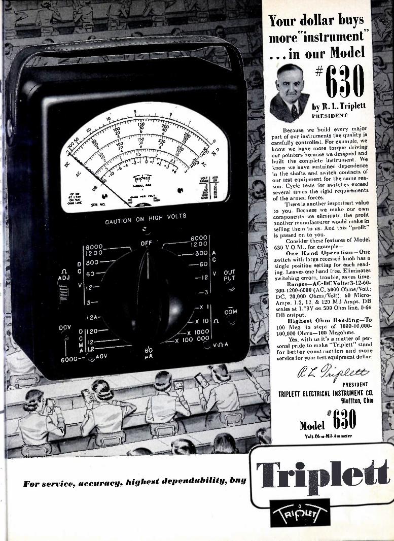
CAUTION ON HIGH VOLTS
6000 200
300
60 ,
12 —
6000 12 00
OUT PUT
For service, accuracy, highest dependability, buy
Your dollar buys more instrument ,e•
... in our Model
#ft 094 au by R. L.Triplett PRESIDENT
Because we build every major part of our instruments the quality is carefully controlled. For example, we know we have more torque driving our pointers because we designed and built the complete instrument. We know we have sustained dependence in the shafts and switch contacts of our test equipment for the same rea-son. Cycle tests for switches exceed several times the rigid requirements of the armed forces.
There is another important value to you. Because we make our own components we eliminate the profit another manufacturer would make in selling them to us. And this "profit" is passed on to you.
Consider these features of Model 630 V.O.M., for example—
One Hand Operation—One switch with large recessed knob has a single position setting for each read-ing. Leaves one hand free. Eliminates switching errors, trouble, saves time.
Ranges—AC-DC Volts: 3-12-60-300-1200-6000 (AC, 5000 Ohms/Volt; DC, 20,000 Ohms/Volt). 60 Micro-Amps. 1.2, 12, & 120 Mil Amps. DB scales at 1.73V on 500 Ohm line, 0-66 DB output.
Highest Ohm Reading—To 100 Meg. in steps of 1000-10,000-100,000 Ohms-100 Megohms.
Yes, with us it's a matter of per-sonal pride to make "Triplett" stand for better construction and more service for your test equipment dollar.
PRESIDENT
TRIPLETT ELECTRICAL INSTRUMENT CO. Bluffton, Ohio #630
Model Volt-Ohm-Mil-Ammeter
Triplett
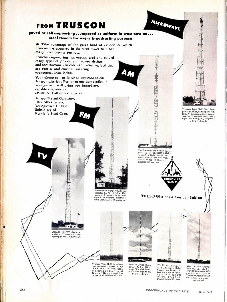
FRO M TRUSCON guyed or self-supporting.. tapered or uniform in cross-section...
steel towers for every broadcasting purpose
• Take advantage of the great fund of experience which Truscon has acquired in the steel tower field for every broadcasting purpose.
Truscon engineering has encountered and solved many types of problems in tower design and construction. Truscon manufacturing facilities are precise and efficient, assuring economical installation.
Your phone call or letter to any convenient Truscon district office, or to our home office in Youngstown, will bring you immediate, capable engineering assistance. Call or write today.
Truscon® Steel Company, 1072 Albert Street, Youngstown 1, Ohio Subsidiary of Republic Steel Corp.
14.
WSA M FM-TV, Saginaw, Michigan, Truscon Self-Sup-porting Tower.386 feet high.
TrusconSelf-SupportingTower, operated by WEMP-FM, Mil-waukee, Wisconsin, is 410 feet high with Western Electric 6 Unit Cloverleaf FM antenna.
N MI Truscon Type H-30 Self-Sup-porting Tower. operated by WEXL-FM. Detroit, Mich., supports an 8-boy General Electric F. M antenna and rises to an overall height of425 feet.
Truscon Type H-80 Self-Sup-porting Tower, at relay station KEB-8111, Linden, N. J. (oper-ated by Transcontinental Ga• Pipe Line Company, Houston)
is 175 feet high.
This Guyed Truscon St eel Radio Tower operated by KOCY,Okla-home City. Okla.. is 849 feet above ground. 938 feet high overall to top of General Electric FM antenna.
TRUSCON a name you can build on
M OM Truscon Guyed Radio Tower. W RY. Okla-homa City. Oklahoma, is 956 feet high to top
of FM antenna.
WUSJ- FM. Lockport, N. Y., Truscon Self-Supporting Tower, 135 feet high and support-ing a GE 4-bay FM antenna 42 feet high. Overall height 177 feet.
This 240 foot Truscon Tower, operated by WTCH, Shawano, Wis-consin, has 25 x 48 Truscon Ground Screen to assure an excel-
lent signal.
S6A PROCEEDINGS OF THE I.R.E. April. 1952

Terminals and Headers are Available in RMA Color Code.
••• • • •
••••.
::•I : •.e• ..
••••. .••• • • • • •II ... ••_ . . • • • • • •
• •••• •
• .• • • • •• - • •• • • • • • • ••• ••
• ••• .•••. 0 S. • • •• • * • •• •• A K:
Submit your own problems in this highly exacting field to our specialist-engineers. They are eager to be of help. Write for your copy of our new 32-page brochure, the most complete and informative presentation ever made on hermetic seals.
. 600" 1. 000 Oui/side 2imeivsiod4
HE R M E TI C/ s new multi-terminal headers 600 Series with 14 terminals and 1000 Series with 21 terminals, both utilizing the same configuration, are models of precision electronic engineering.
600 Series has 14 terminals; 10 on a pitch circle of .350" dia. and 4 on a pitch circle of .140" in an outside dimension of .600" in any configuration
shown. 1000 Series has 14 terminals in the outer pitch circle of .656" and 7 terminals on the inner pitch circle of .312" in an outside dimension of 1.000" in any configuration shown.
These new units join HERMETIC's already well-known ceramic-metal, multi-terminal headers: 750 Series, 800 Series und 900 Series. All of units listed are also available in standard or spe-cial tubular arrangements.
In addition to their exclusive design features, they will withstand mass spectrometer leak tests,-55 °F sub-zero conditions, swamp test, temperature cycling, high vacuum, high pressure, salt water immersion and spray, etc. They are the only headers you can hot tin dip at 525 ° F. for easy assembly soldering for a strain and fissure-free sealed part with resistance of over 10,000 meg-ohms.
29 South 6th Streit, • Newark 7, N•w Jersey
PROCEEDINGS OF TIIE IRE. Arril, 1952
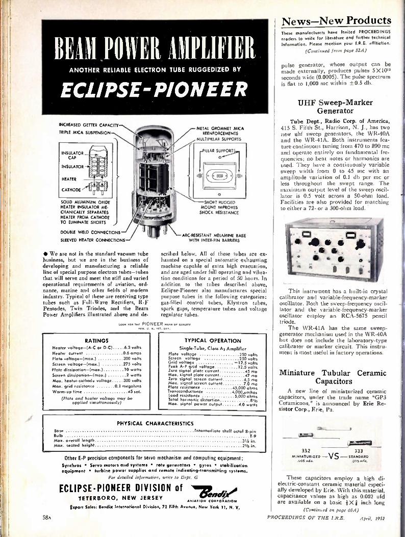
News—New Products
BEAM POWER AMPLIFIER ANOTHER RELIABLE ELECTRON TUBE RUGGEDIZED BY
ECLIPSE-PIONEER
INCREASED GETTER CAPACITY
TRIPLE MICA SUSPENSION
SOLID ALUMINUM OXIDE HEATER INSULATOR ME-CHANICALLY SEPARATES HEATER FROM CATHODE TO ELIMINATE SHORTS
DOUBLE WELD CONNECTIONS
SLEEVED HEATER CONNECTIONS
• We are not in the standard vacuum tube business, but we are in the business of developing and manufacturing a reliable line of special purpose electron tubes—tubes that will serve and meet the stiff and varied operational requirements of aviation, ord-nance, marine and other fields of modern industry. Typical of these are receiving type tubes such as Full-Wave Rectifiers, R-F Pentodes, Twin Triodes, and the Beam Power Amplifiers illustrated above and de-
METAL GROMMET MICA REENFORCEMENTS
MULTIPILLAR SUPPORTS
SHORT RUGGED MOUNT IMPROVES SHOCK RESISTANCE
ARC-RESISTANT MELAMINE BASE WITH INTER-PIN BARRIERS
scribed below. All of these tubes are ex-hausted on a special automatic exhausting machine capable of extra high evacuation, and are aged under fall operating and vibra-tion conditions for a period of 50 hours. In addition to the tubes described above, Eclipse-Pioneer also manufactures special purpose tubes in the following categories: gas-filled control tubes, Klystron tubes, spark gaps, temperature tubes and voltage regulator tubes.
LOOK /OA THE PIONEER HARK Of QUALITY
PCO. U. S. PAT. orr.
RATINGS Heater voltage—(A-C or D-C) 6 3 volts
Heater current 0 6 amps Plate voltage—(max.) 300 volts Screen voltage—(max.) 275 volts Plato dissipation—(max.) 10 watts Screen dissipotion—(max.) 2 watts Max. heater-cathode voltage 300 volts Max. grid resistance 0 megohms Warm-up time 45 sec.
(Plate and heater voltage may be applied simultaneously)
TYPICAL OPERATION Single-Tube, Class Ai Amplifier
Plate voltage 250 volts Screen voltage 250 volts Grid voltage —12.5 volts Peak A-F grid voltage 12.5 volts Zero signal plate current 45 ma Max. signal plate current 17 ma Zero signal screen current 4 5 ma Max. signal screen current 70 ma Plate resistance 45,000 ohms Transconductance 4 000..vmhos Load resistance 5 000 ohms Total harmonic distortion 8% Max. signal power output 40 watts
Base Bulb Max. overall length Max. seated height
PHYSICAL CHARACTERISTICS Intermediate sheli octal 8-pin T-9
31/4 in.
Other ET precision components for servo mechanism and computing equipment: Synchros • Servo motors and systems • rate generators • gyros • stabilization equipment • turbine power supplies and remote indicating-transmitting systems.
For .letalltd uritr to Dept. G
ECLIPSE-PIONEER DIVISION of TETERBORO, NEW JERSEY
AVIATION CORPORATION
(sport Sales: Bondix International Division, 72 Fifth Avenue, New York 11, N. Y,
58A
These manufacturers have invited PROCEEDINGS readers to write for literature and further technical
information. Please mention your I.R.E. affiliation.
(Continued from page 524)
pulse generator, whose output can be made externally, produces pulses 5X 10" seconds wide (0.0005). The pulse spectrum is fiat to 1,000 inc within ± 0.5 db.
UHF Sweep-Marker Generator
Tube Dept., Radio Corp. of America, 415 S. Fifth St., Harrison, N. J., has two new uhf sweep generators, the WR-40A and the WR-41A. Both instruments fea-ture continuous tuning from 470 to 890 mc and operate entirely on fundamental fre-quencies; no beat notes or harmonics are used. They have a continuously variable sweep width from 0 to 45 mc with an amplitude variation of 0.1 db per mc or less throughout the swept range. The maximum output level of the sweep oscil-lator is 0.5 volt across a 50-ohm load. Facilities are also provided for matching to either a 72- or a 300-ohm load.
This instrument has a built-in crystal calibrator and variable-frequency-marker oscillator. Both the sweep-frequency oscil-lator and the variable-frequency-marker oscillator employ an RCA-5675 pencil triode. The WR-41A has the same sweep-
generator mechanism used in the WR-40A but does not include the laboratory-type calibrator or marker circuit. This instru-ment is most useful in factory operations.
Miniature Tubular Ceramic Capacitors
A new line of miniaturized ceramic capacitors, under the trade name "GP3 Ceramicons," is announced by Erie Re-sistor Corp., Erie, Pa.
Amop 332 333
MINIATURIZED — V S — STANDARD .005 mid. 005 med.
These capacitors employ a high di-electric-constant ceramic material especi-ally developed by Erie. With this material, capacitance values as high as 0.002 ufd are available on a basic Xi inch long
(Continued on page 60 4)
PROCEEDINGS OF THE I.R.E. April, 1952
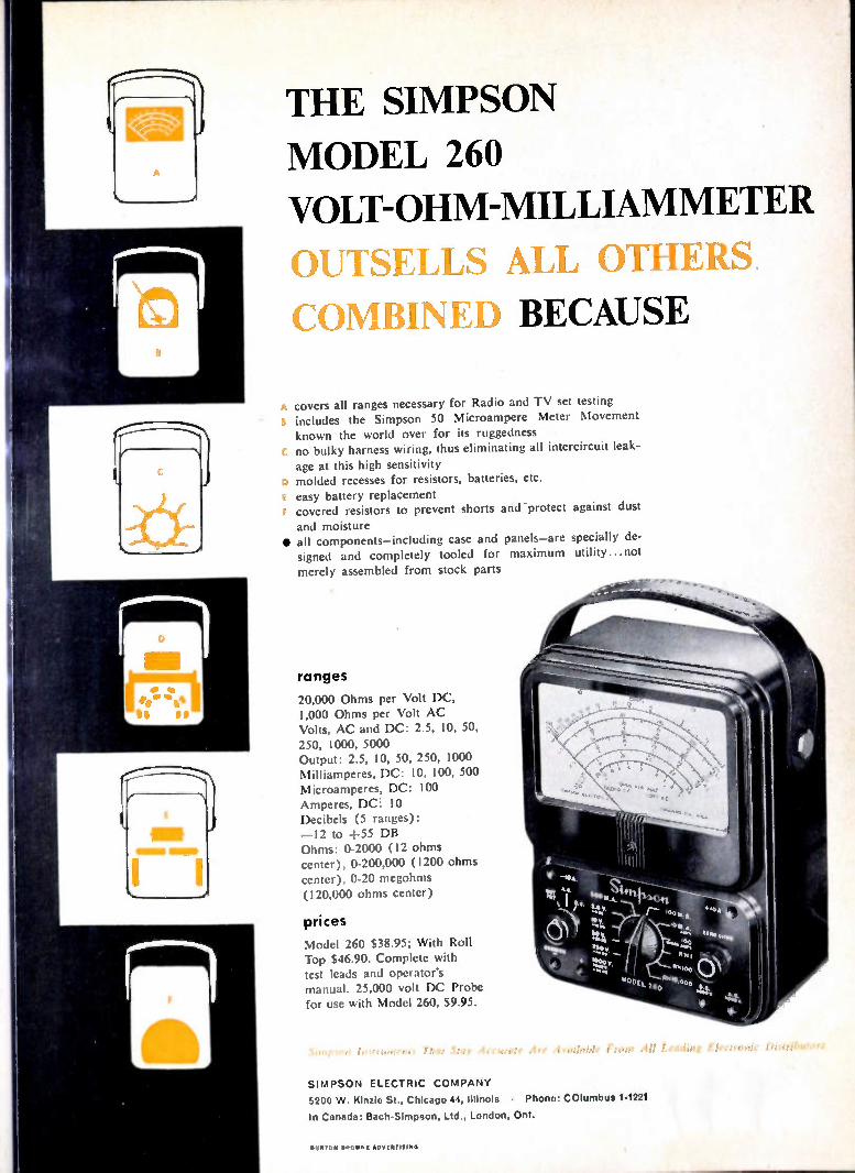
THE SIMPSON
MODEL 260
VOLT-OHM-MILLIAMMETER
OUTSELLS ALL OTHERS
COMBINED BECAUSE
A covers all ranges necessary for Radio and TV set testing • includes the Simpson 50 Microampere Meter Movement known the world over for its ruggedness
c no bulky harness wiring, thus eliminating all intercircuit leak-
age at this high sensitivity o molded recesses for resistors, batteries, etc. easy battery replacement covered resistors to prevent shorts and protect against dust
and moisture • all components—including case and panels—are specially de-signed and completely tooled for maximum utility...not
merely assembled from stock parts
ranges
20,000 Ohms per Volt DC, 1,000 Ohms per Volt AC Volts, AC and DC: 2.5, 10, 50,
250, 1000, 5000 Output: 2.5, 10, 50, 250, 1000 Milliamperes, DC: 10, 100, 500 Microamperes, DC: 100
Amperes, DC! 10 Decibels (5 ranges): —12 to +55 DB Ohms: 0-2000 (12 ohms center), 0-200,000 (1200 ohms center), 0-20 megohms (120,000 ohms center)
prices Model 260 $38.95; With Roll Top $46.90. Complete with test leads and operator's manual. 25,000 volt DC Probe for use with Model 260, $9.95.
SIMPSON ELECTRIC COMPANY
5200 W. Kinzie St., Chicago 44, Illinois • Phone: COlumbue 1-1221
In Canada: Bach-Simpson, Ltd., London, Ont.
1111111011111101,111t IIIIINO
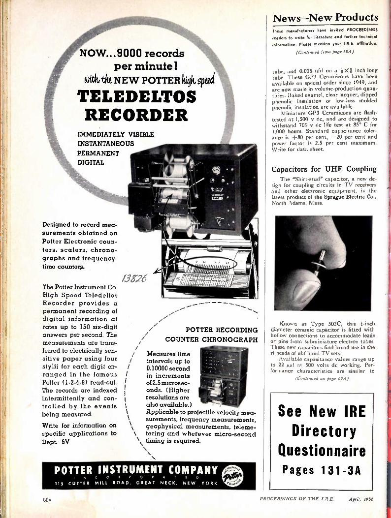
News—New Products
NOW...9000 records per minute]
witivtitt NE W POTTER Itiqk speed
TELEDELTOS RECORDER
IMMEDIATELY VISIBLE
INSTANTANEOUS
PERMANENT
DIGITAL
Designed to record mea-
surements obtained on Potter Electronic coun-ters, scalers, chrono-graphs and frequency-time counters.
The Potter Instrument Co. High Speed Teledeltos Recorder provides a permanent recording of digital information at rates up to 150 six-digit answers per second. The measurements are trans-ferred to electrically sen-sitive paper using four styli for each digit ar-ranged in the famous Potter (1-2-4-8) read-out. The records are indexed intermittently and con-trolled by the events being measured.
Write for information on specific applications to Dept. 5V
1.38-26
arerm
IE,..,,z. .... . I o t,
i ,• .'
- • •
aI IN iff ci ik 4 1).(f a iim air
)1,116._ . 1 \ 2_---wnrommumll,
.. //
//
POTTER RECORDING
COUNTER CHRONOGRAPH
Measures time intervals up to 0.10000 second in increments of 2.5 microsec-onds. (Higher resolutions are also available.) Applicable to projectile velocity mea-surements, frequency measurements,
\ geophysical measurements, teleme-\ tering and wherever micro-second
• \ timing is required. • • •
POTTER INSTRUMENT COMPANY I N C 0 5 P 0 5 A l
115 CUTTER MILL. ROAD, GREAT NECK, NE W YORK
These manufacturers have invited PROCEEDINGS
readers to write for literature and further technical
information. Please mention your I.R.E. affiliation.
(Continued from page 384)
tube, and 0.005 ufd on a iXi inch long tube. These GP3 Ceramicons have been available on special order since 1949, and are now made in volume-production quan-tities. Baked enamel, clear lacquer, dipped phenolic insulation or low-loss molded phenolic insulation are available. Miniature GP3 Ceramicons are flash-
tested at 1,500 v dc, and are designed to withstand 700 v dc life test at 85° C for 1,000 hours. Standard capacitance toler-ance is +80 per cent, —20 per cent and power factor is 2.5 per cent maximum. Write for data sheet.
Capacitors for UHF Coupling The "Shirt-stud" capacitor, a new de-
sign for coupling circuits in TV receivers and other electronic equipment, is the latest product of the Sprague Electric Co., North Adams, Mass.
Known as Type 502C, this Finch diameter ceramic capacitor is fitted with hollow connections to accommodate leads or pins from subminiature electron tubes. These new capacitors find broad use in the rf heads of uhf band TV sets. Available capaoitance values range up
to 22 tamf at 500 volts dc working. Per-formance characteristics are similar to
(Continued on page 624)
See New IRE Directory
Questionnaire Pages 131-3A
60A PROCEEDINGS OF THE I.R.E. April, 1952
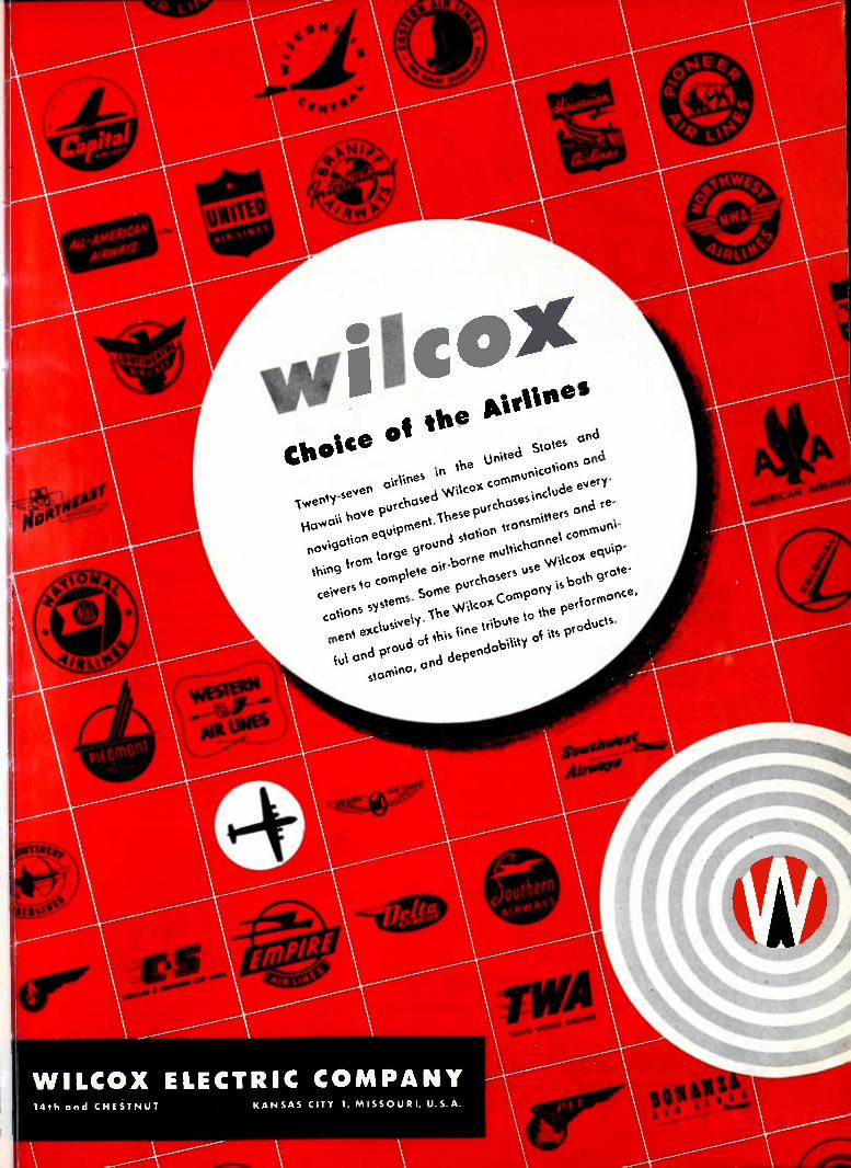
MrVioes
lv4enty-seven o‘r1Mes 'n
\e Un1ted Stoles ond
1.0,0011 hove purchase d re-
d \N‘1cox corornuMcol1ons ond
nov\got1on ese purchoses1nc\ude every-
th1ng krom 1orge ground stonon tronsrMtters on equ\pment.lh
ce1vers to comp\ete o‘r -borne mu\t\chonne1 CO
cot1ons systems. Some purchosers use \ffAcor. eau\p-
ment exc\us\ve1y. The \N't\cov. Company 1s beortohr monce
gro te-
ku1 ond proud ok th‘s Ole tr1bute to the pk ,
storMno, do
ond depen b11\ty ok 1ts products.
WILCOX ELECTRIC COMPANY 14th and CHE STNUT KA NSAS CITY 1, MISS OURI, U.S. A.
46,10iiNti
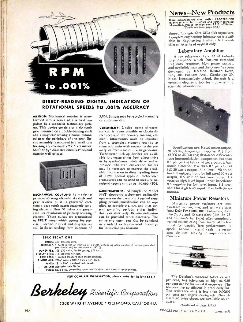
DIRECT-READING DIGITAL INDICATION OF
ROTATIONAL SPEEDS TO .001% ACCURACY
METHOD: Mechanical rotation is trans-formed into a series of electrical im-pulses by a magnetic tachometer pick-up. This device consists of a 60 tooth gear mounted on a double-bearing shaft and a magnetic sensing element mount-ed near the periphery of the gear. En-tire assembly is mounted in a small cast housing approximately 7 x 5 x 3 inches. Shaft of 1/4" diameter extends 4" beyond outside wall of case.
MECHANICAL COUPLING is made to primary rotating element. As shaft and gear revolve pulse is generated each time a gear tooth passes magnetic sens-ing element. Thus 60 pulses are gener-ated per revolution of primary rotating element. These pulses are transmitted to EPUT meter which counts for pre-cise i second interval and displays re-sult in direct-reading form in terms of
RPM. System may be recycled manually or automatically.
VERSATILITY: Under some circum-stances, it is not possible to obtain di-rect access to the primary rotating ele-ment. Information must be obtained from a secondary element rotating at some odd ratio with respect to the pri-mary, or from a motor driven generator. Tachometer pick-up devices are avail-able to operate either from direct drive or by synchronous motor drive and to provide whatever conversion factors may be necessary to express the avail-able information in direct-reading form of RPM. Special types of tachometer transducers can be used to measure ro-tational speeds as high as 100,000 RPM.
MODIFICATIONS: Although the Model 554T electronic tachometer ordinarily operates on the basis of a 1 second sam-pling period, modification- can be sup-plied to provide 0.1, 0.5, and 10.0 sec-ond sampling periods, either indivi-dually or selectively. Remote indication can be provided when necessary. The entire equipment can also be supplied in standard explosion-proof housings for industrial installations.
SPECIFICATIONS
RANGE: ACCURACY:
POWER RED. DISPLAY TIME: TIME BASE: DIMENSIONS:
PANEL: WEIGHT: PRICE:
300-100,000 rpm. 1 event (cycle or fraction of a cycle, depending upon number of pulses generated per revolution) to maximum of .001%. 105-130 volts, 50-60 cycles, 175 watts. 1-5 seconds variable. 1 second standard (see modifications). 207/4" wide x 101/2 " high x 15" deep. 19" x 87if." standard rack panel. Approximately 68 lbs. $875 plus, depending upon modifications and special requirements.
FOR COMPLETE INFORMATION, please write for Bulletin 5 5 4-P
Scied,klic C 2200 WRIGHT AVENUE • RICHMOND, CALIFORNIA
News—New Products These manufacturers have invited PROCEEDINGS readers to write for literature and further technical information. Please mention your I.R.E. affiliation.
(Continued from page 62A)
those of Sprague Cera- Mite disk capacitors. Complete engineering information is avail-able in Engineering Bulletin 605 avail-able on letterhead request only.
Laboratory Amplifier A new relay-rack Type 221-A Labora-
tory Amplifier which features extended frequency response, high power output, and negligible hum and distortion has been developed by Hermon Hosmer Scott, Inc., 385 Putnam Ave., Cambridge 39, Mass. Inexpensively priced, the unit is a versatile electronic tool for industrial and scientific laboratories.
Specifications are: Rated power output, 20 watts; frequency response flat from 12,000 to 55,000 cps; first-order difference-tone intermodulation component less than 0.1 per cent at full rated peak output; har-monic distortion less than 0.5 per cent at full 20 watts output; hum level-90 db be-low full output; input for full rated 20 watt output, 0.5 volt on low level input, 1.5 volts on high level input; input impedance 0.5 megohm for low level input, 1.5 meg-ohms for high level input. Free bulletin on reauest.
Miniature Power Resistors Miniature power resistors are now
available in two, five, and ten watt sizes from Dale Products, Inc., Columbus, Neb. The 2-, 5-, and 10-watt sizes (like the 25-and 50- made by Dale) offer completely welded constructicnkfrom terminal to ter-minal for trouble free performance. A special silicone material seals the resist-ance element, making it impervious to moisture.
The Dalohm's standard tolerance is I per cent, but tolerances as high as 0.05 per cent can be furnished if necessary. The temperature co-efficient is practically flat. The resistance shift is less than 0.00002 per cent per degree centigrade. New il-lustrated price sheets are available on re-quest.
6.2 \
(Continued on page 1104)
PROCEEDINGS OF THE I.R.E. April, 1952
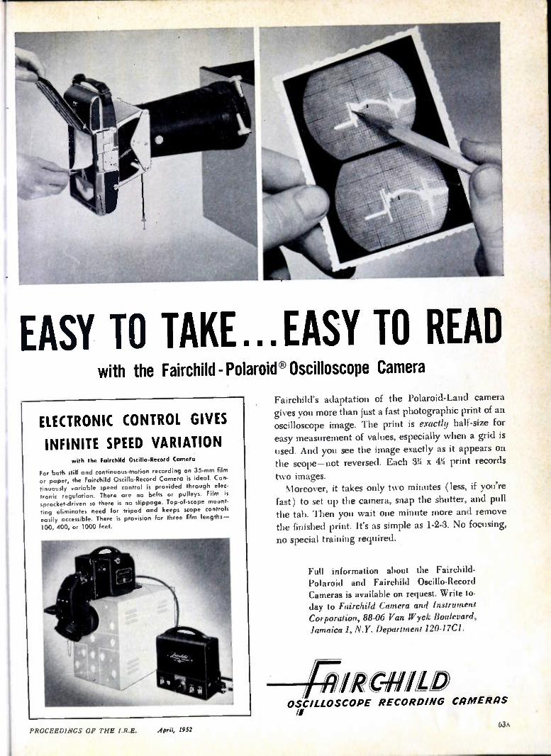
EASY TO TAKE...EASY TO READ with the Fairchild - Polaroid® Oscilloscope Camera
ELECTRONIC CONTROL GIVES
INFINITE SPEED VARIATION with the Fairchild Oscillo-Record Camera
For both still and continuous-motion recording on 35-mm film or paper, the Fairchild Oscillo-Record Camera is ideal. Con-tinuously variable speed control is provided through elec-tronic regulation. There are no belts or pulleys. Film is sprocket-driven so there is no slippage. Top-of-scope mount-sing eliminates need for tripod and keeps scope controls easily accessible. There is provision for three film lengths-
100, 400, or 1000 feet.
Fairchild's adaptation of the Polaroid-Land camera gives you more than just a fast photographic print of an oscilloscope image. The print is exactly half-size for
easy measurement of values, especially when a grid is
used. And you see the image exactly as it appears on the scope—not reversed. Each 3% x 4% print records
two images. Moreover, it takes only two minutes (less, if you're
fast) to set up the camera, snap the shutter, and pull the tab. Then you wait one minute more and remove the finished print. It's as simple as 1-2-3. No focusing,
no special training required.
Full information about the Fairchild-Polaroid and Fairchild Oscillo-Record Cameras is available on request. Write to-day to Fairchild Camera and Instrument Corporation, 88-06 Van Wyck Boulevard, Jamaica 1, N.Y. Department 120-17C1.
111C-MLIO OSCILLOSCOPE RECORDING cnmERns
April, 1952 PROCEEDINGS OF THE I.R.E.

ill RCA-6166
(Typical Operation in Class B or Grid-
Modulated Class C Television Service, Grid-Drive Circuit, 54 to 216 Mc)
DC Plate Voltage
DC Grid-No. 2 Voltage
DC Grid-No. 1 Voltage* Peak RF Grid-No. 1 Voltage
DC Plate Current*
Driver Power Output (Approx.)' Power Output (Approx.)'
5800 volts
1200 volts
—130 volts 375 volts 3.45 amp
800 watts
12,000 watts
RCA-6181
(Typical Operation in Class B or Bias-
Modulated Class C Television Service, Cathode-Drive Circuit at 900 Mc)
DC Plate Voltage 1800 volts
DC Grid-No. 2 Voltage 475 volts DC Cathode-to-Grid-No. 1 Voltage* 75 volts
Peak RF Grid-No. 1 Voltage 120 volts
DC Plate Current* 1.7 amp Driver Power Output (Approx.)' 200 watts
Useful Power Output (Approx.)' 1200 watts
•At synchron .ng level
A/t Wforced-air-cooled TXpower tetrodes 00P.
THE new RCA-6166 and 6181 ... developed for TV and radio services ... represent the successful application of forced-air cooling to power tetrodes designed to operate at high efficiency at the higher frequencies. The use of forced-air cooling simplifies transmitter design and effects substantial operating economies.
Both tubes feature coaxial-electrode structures, and are particularly suited to operation in circuits of the coaxial-cylinder type.
The RCA-6166 VHF tetrode uses a time-proved thoriated-tungsten filament that permits substantial savings in filament power.
The RCA-6181 UHF tetrode has an indirectly heated, low-temperature, coated cathode of the matrix type for long serviceability. Further, it features seals between a low-loss ceramic and a high-conductivity metal to provide high-efficiency uhf performance.
For complete technical data on these or any other RCA tubes, write RCA, Commercial Engineering, Section DR47, Harrison, New Jersey . . . or contact your nearest RCA Field Office . . .
FIELD OFFICES: (East) Humboldt 5-3900, 415 S. 5th St.. Harrison, N.J. (Midwest)Whitehall 4-2900, 589 E. Illinois St., Chicago, Ill. (West) Madison 9-3671, 420 S. San Pedro St., Los Angeles, Calif.
RADIO CORPORATION of A MERICA ELECTRO N TUBES HA R RISO N, N. J.
•
64A PROCEEDINGS OF THE I.R.E.

rf BOARD OF 'DIRECTORS, 1952' PROCEEDINGS OF THE I.R.E.
D. B. Sinclair President
Harold L. Kirke Vice-President
W. R. G. Baker Treasurer
Haraden Pratt Secretary
Alfred N. Goldsmith Editor
• R. F. Guy 4enior Past President I. S. Coggeshall
Junior Past President
1952
• S. L. Bailey K. C. Black H. F. Dart (2) W. R. Hewlett P. L. Hoover (4)
I A. V. Loughren 1 J. W. McRae A. B. Oxley (8)
1 -W. M. Rust (6)
( 1952-1953
G. H. Browning (I) W. H. Doherty A. W. Graf (5) R. L. Sink (7) G. R. Town Irving Wolff (3)
1952-1954
J. D. Ryder Ernst Weber
•
Harold R. Zeamans General Counsel
•
George W. Bailey Executive Secretary
Laurence G. Cumming Technical Secretary
•
Pub/jibed Monthly by
The Institute of Radio Engineers, Inc.
VOLUME 40 A fpl11, 1952 NUMBER 4
Changes of address ; (with advance notice of 1 fifteen days) and corn-. mUnications regarding / subscriptions and pay-• ments should be mailed 1 to the Secretary of the Institute, at 450 Ahnaip St., Menasha, Wiscon-sin, or I East 79 Street, New York 21, N. Y. ;All rights of republica-tinn including transla-tion into foreign lan-guages, are reserved by the Institute. Abstracts of papers with mention of their source may be printed. Requests for
i republication privileges should be addressed to
• The Institute of Radio Ehgineers.
• Numeral. In parentheses following Directors names /designate Region number.
PROCEEDINGS OF THE I.R.E.
Alois W. Graf, Director, 1952-1953 386
The Role of Private Industry in Military Research and Development John N. Dyer 387
Radio Progress during 1951
4180. Fundamental Considerations Regarding the Use of Relative Mag-nitudes J W Horton 440
4181. Transistor Forming Effects in n-Type Germanium.. L. B. Valdes 445
4182. Current Multiplication in the Type-A Transistor... W. R. Sittner 448
4183. A Scanner for Rapid Measurement of Envelope Delay Distortion Loyd E. Hunt and W. J. Albersheim 454
4184. Correction to "Input Admittance Characteristics of a Tune'd Cou-pled Circuit" R D. Teasdale and R. A. Martin 459
4185. The Cathamplifier C. A. Parry 460
4186. Recent Developments in High-Power Klystron Amplifiers V. Learned and C. Veronda 465
4187. Gapless Coverage in Air-to-Ground Communications at Frequen-cies Above 50 mc Kenneth A. Norton and Philip L. Rice 470
4188. A Coincident-Current Magnetic Memory Cell for the Storage of Digital Information William N. Papian 475
4189. An Internal Feedback Traveling-Wave-Tube Oscillator E M. T Jones 478
4190. A Note on the Ladder Development of RC-Networks E A. Guillemin
388
482
4191. A Source of Error in the Measurement of Radiated Harmonics... F M Greene 486
4192. Discussion on "The Statistical Properties of Noise Applied to Radar-Range Performance".. .L. V. Blake, S. M. Kaplan and R. W. McFall 487
Contributors ID PROCEEDINGS OF THE I.R.E. 490
INSTITUTE NEWS AND RADIO NOTES
Technical Committee Notes 492
Professional Group News... 493
I RE-AIEE-RTMA Symposium on Progress in Quality Electronic Com-poner ts 494
IRE People . ............. 495
4193. Abstracts and Reference 497
News-New Products 6A Memberships 83A
Section Meetings.... 71A Positions Wanted 94A
Student Branch Meeting, 79A Positions Open 96A
Advertising Index 135A
Copyright. 1952, by The Institute of Radio Engineers, Inc.
EDITORIAL DEPARTMENT
Alfred N. Goldsmith Editor
E. K. Gannett
Technical Editor
Marita D. Sands
Assistant Editor
•
ADVERTISING DEPARTMENT
William C. Copp
Advertising Manager
Lillian Petranek
Assistant Advertising Manager
•
BOARD OF EDITORS
Alfred N. Goldsmith
Chairman
PAPERS REVIEW COMM ITTEE
George F. Metcalf Chairman
ADMINISTRATIVE COMMITTEE OF THE BOARD OF EDITORS
Alfred N. Goldsmith Chairman
Responsibility for the contents of papers published in the
PROCEEDINGS OF THE I.R.E. rests upon the authors. Statements made in papers
are not binding on the Institute or its members.
•
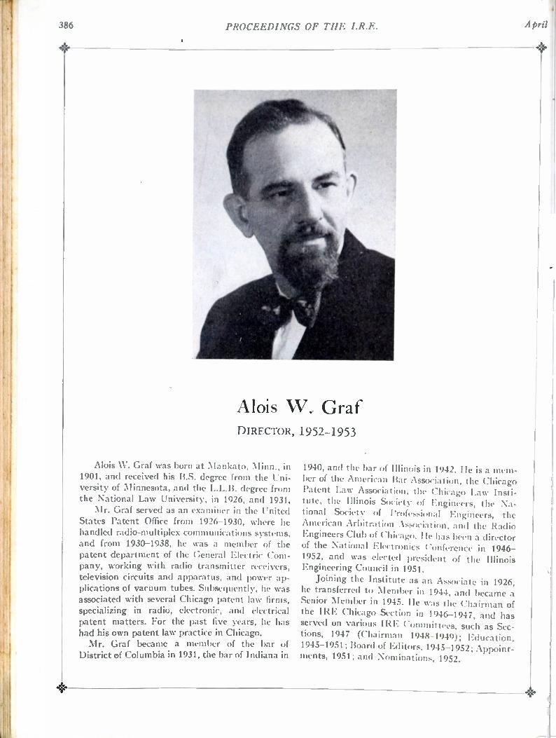
386 PROCEEDINGS OF THE I.R.E.
•
Alois W. Graf DIRECTOR, 1952-1953
Alois W. Graf was born at Mankato, Minn., in 1901, and received his B.S. degree from the Uni-versity of Minnesota, and the L.L.B. degree from the National Law University, in 1926, and 1931. Mr. Graf served as an examiner in the United
States Patent Office from 1926-1930, where he handled radio-multiplex communications systems, and from 1930-1938, he was a member of the patent department of the General Electric Com-pany, working with radio transmitter receivers, television circuits and apparatus, and power ap-plications of vacuum tubes. Subsequently, he was associated with several Chicago patent law firms, specializing in radio, electronic, and electrical patent matters. For the past five years, he has had his own patent law practice in Chicago. Mr. Graf became a member of the bar of
District of Columbia in 1931, the bar of Indiana in
1940, and the bar of Illinois in 1942. He is a mem-ber of the American Bar Association, the Chicago Patent Law Association, the Chicago Law Insti-tute, the Illinois Society of Engineers, the Na-tional Society of Professional 1-2ngineers, the American Arbitration Association, and the Radio Engineers Club of Chicago. He has been a director of the National Electronics Conference in 1946-1952, and was elected president of the Illinois Engineering Council in 1951.
Joining the Institute as an Associate in 1926, he transferred to Member in 1944, and became a Senior Member in 1945. He was the Chairman of the IRE Chicago Section in 1946-1947, and has served on various IRE Committees, such as Sec-tions, 1947 (Chairman 1948-1949); Education, 1945-1951; Board of Editors, 1945-1952; Appoint-ments, 1951; and Nominations, 1952.
PROCEEDINGS OF THE I.R.E. 387
The Role of Private Industry in Military Research and Development
JOHN N. DYER
Engineers working in an industry concerned with the development and production of equipment of military significance for the government, render an invaluable service. Under suitable circumstances, the effectiveness of this service can be enhanced. These favorable circumstances include a desirable co-ordination and continuing relationship between engineers developing equipment and those who later use it in the field. Such co-ordination is described in the following guest editorial, prepared by a Fellow of the IRE who is Vice President and Director of Research of the Airborne Instruments Laboratory.—
The Editor.
This nation is diverting more research, develop-ment, and production to military needs than ever before in peacetime. Much of the effort, especially in the fields with which members of this Institute are concerned, is performed by private industry. By contrast, Russia is carrying out forced-draft research and development by tight government control. Should war be forced upon us, we have confi-
dence in our ability to win the race of developing. new and improved weapons for war. One reason for this confidence is the freedom from governmental control enjoyed by private enterprise in this coun-try. To keep this freedom, which is vital to our technological progress, private enterprise must do its part to ensure that military research and de-velopment are efficiently conducted. The rate of progress on military research and
development is a function of the behavior of the communication channel between operational prob-lems and the research and development program. The contractual agreement must necessarily define the objective as completely and specifically as pos-sible. However, because of the inherently narrow bandwidth that exists for the flow of information through a contract, the government and the con-tractor have a responsibility to devise methods to add feedback around this part of the communica-tion channel. (Oscillations which may result from
such practices can be avoided by careful design.) Research and development engineers should make
it their business to keep fully informed on the prog-ress of thp operational problem. In this way both they and their management can aid in guiding the program to the best interests of the nation. It is unfortunate that the completion of a con-
tract frequently terminates the association of the research and development personnel with the mili-tary problem; the system engineering needed to , integrate the technique or device that came out of the contract into an operational situation is carried
out without the benefit of feedback from the de-velopment engineer to the user. This lack of fur-ther association after a contract is complete is a weakness of our present national effort. In our haste to develop new military devices, develop-mental personnel are not being afforded sufficient opportunity to follow their equipment through the operational stages. Often the problems that arise in the use of a new device are fully as important to its success as those solved in the development. If we are given close association between devel-
opment engineers and military problems, from the conception to the large scale use of a new military device, we will be able to ensure more effective use of our technical manpower and more reliable and efficient military equipment.
388 PROCEEDINGS OF THE I.R.E. April
Radio Progress During 1951*
Introduction HE YEAR 1951 was filled with para doxe s for it was a year when employment managers of manu-
facturing companies visited the prospect; when, despite material shortages, prices of equipment for the home-entertainment field dropped appreciably; when substantial gains in television coverage were obtained, notwithstanding the freeze that still curtailed the erec-tion of new stations.; when the establishment of official standards for a color-television system spurred the de-velopment of many ingenious methods using principles widely divergent from that legal standard; when sub-stantial progress was attained in reliability of circuits, despite a trend toward smaller components that run hotter; when the solution of many vexing technical problems in radio circuits and materials introduced new handicaps because of resulting wider applications hav-ing stiffer requirements. The reports that follow cover a wide range of engi-
neering fields, compiled by the technical committees of the Institute. The year has seen a number of develop-ments of a broad over-all nature—in new materials, pro-duction techniques, and constructional philosophies. One of the most important of these is the attention
given to equipment reliability, with many new com-ponents and tubes and new assembly methods that show great promise of giving trustworthy operation. Stand-ards with rating limits to provide reliability were set up for many more components by industrial committees. Over 50 new tubes having specific characteristics for in-dustrial or military needs—such as rugged construction, low noise, long life, or balanced or controlled character-istics of some sort—were registered. A number of sym-posia and conferences were convoked to call attention to design, installation, and maintenance factors that pro-vide more trustworthy operation of electronic equip-ment. Progress was noted in assembly methods of electronic
equipment, such as unitized construction, emblocked units or cast-resin embedments, and printed and other types of preformed circuits. The greatest gains were in materials and techniqugs of assembly that combined miniaturization and reliability despite higher operating temperatures. (1) A. W. Rogers and B. A. Diebold, "Improved components
and materials for reliable electronic equipment," Elec. Mfg., vol. 48, pp. 114-119; December, 1951.
(2) G. E. Devey, "Reliable electronic equipment," Elec. Mfg., vol. 48, pp. 107-109, 216; January, 1951.
(3) "Application of Tubes in Guided Missiles for Maximum Re-liability," Symposium, Panel on Electron Tubes, Research and Development Board, 139 Center Street, New York, N. Y.
(4) A. E. Javitz, "Cast resin embedments," Elec. Mfg., vol. 48, pp. 103-118; September, 1951.
* Decimal classification: R090.1. Original manuscript received by the Institute, February 7, 1952. This report is based on material from the 1951 Annual Review Committee of The Institute of Radio Engineers, as co-ordinated by the Chairman.
Looking over the record of new tubes, at least those officially registered with the RTMA Data Bureau, in-dicates that some 48 types and sizes of cathode-ray tubes were announced during the year, 46 types adopted for home entertainment (radio and TV receivers and the like); 56 receiving-tube types having special character-istics or capabilities for industrial, military, or other uses where the operating conditions are different than found in home receivers; 18 transmitting tubes; and 25 special-purpose tubes, including thyratrons, counter tubes, and the like. Considering the "receiver"-type tube sizes and styles,
more varieties having special characteristics appeared than did new types for home-receiver services. This in-dicates the great amount of attention being applied to critical services where utmost reliability is required. Much of the activity centered on cathode-ray tubes,
more than 5 million having been produced during the year, over 4.4 million of which went into new television receivers. The trend through the year was toward di-rect-view rectangular screen tubes, some 88 per cent at present having screens larger than 16 inches and more than one-third 18 inches or larger. Some idea of the impact of electronic tubes on modern
living can be gathered by pondering on the number of tubes of the "receiver" types manufactured last year in the United States only—more than 256 million tubes of the various types being produced for new equipment alone, including government purchases, with some 119 mi.lion more provided for the replacement and export • market, according to RTNIA compilations. In addition, of course a great many special-purpose tubes and trans-mitting tubes were produced that are not included in the above tabulation.
The report that follows is divided into the subjects listed below.
Electron Tubes and Semicon-ductors
Audio Techniques Electroacoustics Information Theory lation Systems
Circuit Theory Radio Transmitters Receivers Video Techniques Television Systems
Facsimile Vehicular Communications Navigation Aids \Vave P?opagation
and Modu- Antennas, Waveguides, and Transmission Lines
Industrial Electronics Electronic Computers Quality Control Instrumentation Piezoelectricity
Symbols and Abbreviations
Electron Tubes and Semiconductors
Small High-Vacuum Tubes
New Tube Developments: A new low-noise double tri-ode was developed for use as a radio-frequency amplifier in television input circuits. With "driven-grounded-grid" input circuits, the tube showed improvement in performance over previously available types for noise figure, image rejection, and gain.
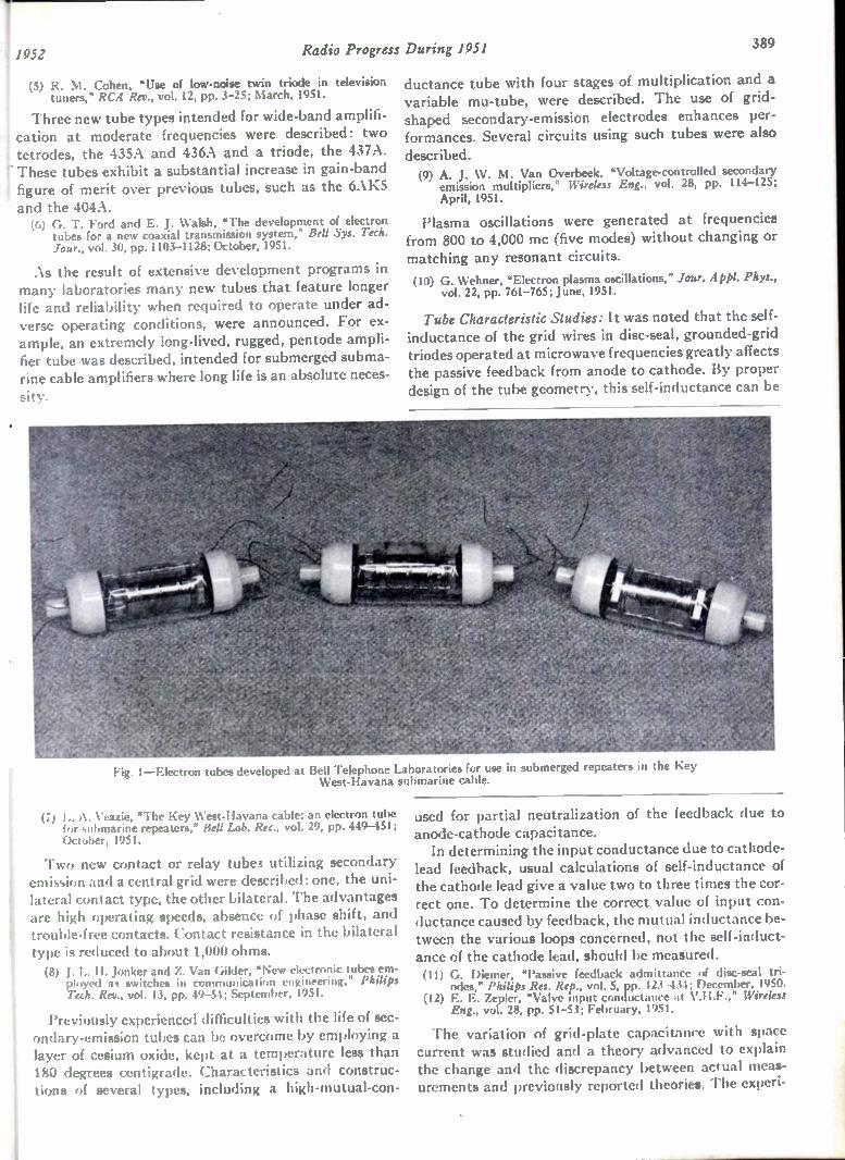
11952 Radio Progress During 1951 389
(5) R. M. Cohen, 'Use of low-noise twin triode in television tuners," RCA Rev., vol. 12, pp. 3-25; March, 1951.
Three new tube types intended for wide-band amplifi-f cation at moderate frequencies were described: two tetrodes, the 435A and 436A and a triode, the 437A. r These tubes exhibit a substantial increase in gain-band i figure of merit over previous tubes, such as the 6AK5 , and the 404A.
(6) G. T. Ford and E. J. Walsh, "The development of electron tubes for a new coaxial transmission system," Bell Sys. Tech. Jour., vol. 30, pp. 1103-1128; October, 1951.
As the result of extensive development programs in many laboratories many new tubes that feature longer life and reliability when required to operate under ad-verse operating conditions, were announced. For ex-ample, an extremely long-lived, rugged, pentode ampli-fier tube was described, intended for submerged subma-rine cable amplifiers where long life is an absolute neces-
sity.
Fig. 1—Electron tubes developed at Bell Telephone Laboratories for use in submerged repeaters in the Key West-Havana submarine cable.
(7) E. A. Veazie, "The Key West-Havana cable: an electron tube for submarine repeaters," Bell Lab. Rec., vol. 29, pp. 449-451; October, 1951.
Two new contact or relay tubes utilizing secondary emission and a central grid were described: one, the uni-lateral contact type, the other bilateral. The advantages are high operating speeds, absence of phase shift, and trouble-free contacts. Contact resistance in the bilateral type is reduced to about 1,000 ohms. (8) J. L. H. Jonker and Z. Van Gilder, "New electronic tubes em-
ployed as switches in communication engineering," Philips Tech. Rev., vol. 13, pp. 49-54; September, 1951.
Previously experienced difficulties with the life of sec-ondary-emission tubes can be overcome by employing a layer of cesium oxide, kept at a temperature less than 180 degrees centigrade. Characteristics and construc-tions of several types, including a high-mutual-con-
ductance tube with four stages of multiplication and a variable mu-tube, were described. The use of grid-shaped secondary-emission electrodes enhances per-formances. Several circuits using such tubes were also
described. (9) A. J. W. M. Van Overbeek, "Voltage-controlled secondary
emission multipliers," Wireless Eng., vol. 28, pp. 114-125; April, 1951.
Plasma oscillations were generated at frequencies from 800 to 4,000 mc (five modes) without changing or matching any resonant circuits.
(10) G. Wehner, "Electron plasma oscillations," Jour. App!. Phys.. vol. 22, pp. 761-765; June, 1951.
Tube Characteristic Studies: It was noted that the self-inductance of the grid wires in disc-seal, grounded-grid triodes operated at microwave frequencies greatly affects the passive feedback from anode to cathode. By proper design of the tube geometry, this self-inductance can be
used for partial neutralization of the feedback due to anode-cathode capacitance. In determining the input conductance due to cathode-
lead feedback, usual calculations of self-inductance of the cathode lead give a value two to three times the cor-rect one. To determine the correct value of input con-ductance caused by feedback, the mutual inductance be-tween the various loops concerned, not the self-induct-ance of the cathode lead, should be measured. (11) G. Diemer, "Passive feedback admittance of disc-seal tri-
odes," Philips Res. Rep., vol. 5, pp. 423-434; December, 1950. (12) E. E. Zepler, "Valve Input conductance at VHF.," Wireless
Eng., vol. 28, pp. 51-53; February, 1951.
The variation of grid-plate capacitance with space current was studied and a theory advanced to explain the change and the discrepancy between actual ineas-urements and previously reported theories. The experi-

390 PROCEEDINGS OF THE I.R.E. April
mental data were compared with theoretical calcula-tions.
A transit-time theory was developed for the conduct-ance of a diode in the exponential region of its character-istic, which reduces the discrepancy between theory and experiment previously found in close-spaced diodes. The value of this conductance at low negative voltages may exceed the total emission conductance even in the mi-crowave band.
(13) E. E. Zepler and S. S. Srivastava, "Interelectrode impedances in triodes and pentodes," Wireless Eng., vol. 28, pp. 146-150; May, 1951.
(14) G. Diemer, "Microwave diode conductance in the exponential region of the chat'acteristic," Philips Res. Rep., vol. 6, pp. 211-223; June, 1951.
Calculations were made of the phenomena that deter-mine the internal resistance of pentodes. For output pentodes the electrostatic influence of the anode voltag( on the cathode current appears to be the main factor. For high-frequency pentodes, the two main causes are the primary electrons that are repelled in the neighbor-hood of the suppressor-grid wires and returned to the screen grid, and the reflected electrons from the anode that can pass the suppressor grid and reach the screen grid. Since both these phenomena depend on the elec-trode voltages, the current distribution between screen and anode is affected by anode-voltage variations. Other calculations made can be used to derive the
electrostatic amplification factor of a planar triode for all possible wire diameters and grid-to-plate distances. Formulas were deduced for more accurate calculation of the effective potential in a planar triode. (15) J. L. H. Jonker, "The internal resistance of a pentode,"
Philips Res. Rep., vol. 6, pp. 1-13; February, 1951. (16) P. H. J. A. Kleijnen, "The penetration factor and the po-
tential field of a planar triode," Philips Res. Rep., vol. 6, pp. 15-33; February, 1951.
In one analysis, the small-signal behavior of a nega-tively biased triode was represented as a r configuration for convenience in analyzing complex circuitry involv-ing transmission networks and associated tubes. To avoid the use of fictitious voltage or current generators, the grid-anode element was allowed to assume negative values in its real component. The theory was checked by computing the driving-point impedance and voltage gain for various tube orientations in different types of circuit configurations and by comparing them with ex-perimental data. (17) A. W. Keen, "Triode transmission networks," Wireless Eng.,
vol. 28, pp. 56-66; February, 1951.
A tube-characteristic tracer was described that may be operated manually or automatically. Automatic trac-ing permits greatly reduced operating times, and results in improved accuracy of measurements in high-current regions of tube operations. (18) J. Arnold, "Electronic tracing of tube characteristics," Syl-
vania Tech., vol. 4, pp. 14-17; January, 1951.
Many papers were published on the problem of tube reliability. Reliability was stated as not only a function of design and quality but also one of the relationship be-
tween tube ratings and operating conditions. Subminia-ture tubes were asserted to give inherently superior re-liable operation under conditions of shock and vibra-tions, and it was shown that a statistical analysis of the records of subminiature tubes for a 500-hour life-test-period can be used to predict the life expectancy of a lot up to 5,000 hours. In airborne communication and navi-gational equipment, tube failure during the first 1,000 hours was reduced from 30 to 3.2 per cent under the program for improvement in construction and manufac-turing techniques sponsored by Aeronautical Radio, Inc.
Fig. 2—Reliable tubes are electrically life-tested on new 48-hour sta-bilization equipment installed at the tube-manufacturing plant in Harrison, N. J. RCA).
(19) M. A. Acheson and E. M. McElwee, "Concerning the reliabil-ity of electron tubes," Sylvania Tech., vol. 4, pp. 38-40; April, 1951.
(20) J. R. Steen, "The JETEC approach to the tube reliability problem," PROC. I.R.E., vol. 39, pp. 998-1000; September, 1951.
(21) P. T. Weeks, "Reliability in miniature and subminiature tubes," PROC. I.R.E., vol. 39, pp. 499-503; May, 1951.
(22) E. M. McElwee, "Statistical evaluation of life expectancy of vacuum tubes designed for long-life operation," PROC. I.R.E., vol. 39, pp. 137-141; February, 1951.
(23) G. Gage, "High reliability miniature tubes," Electronics, vol. 23, pp. 66-68; December, 1950.
(24) J. D. Fahnestock, "Military requirements for subminiature tubes," Electronics, vol. 24, pp. 108-109; April, 1951.
Cathodes: A cathode design was described having im-proved tube reliability obtained by combining high-emission density and good mechanical strength with good temperature-emission characteristic and excellent resistance to high-voltage and high-speed gas ions. The structure contained a reservoir of barium strontium-car-bonate emitting material. Experience data on the life of electron tubes as dependent on oxide-coated cathode life showed that the latter might be almostly indefinitely long were it not for the formation of cathode-interface resistance.
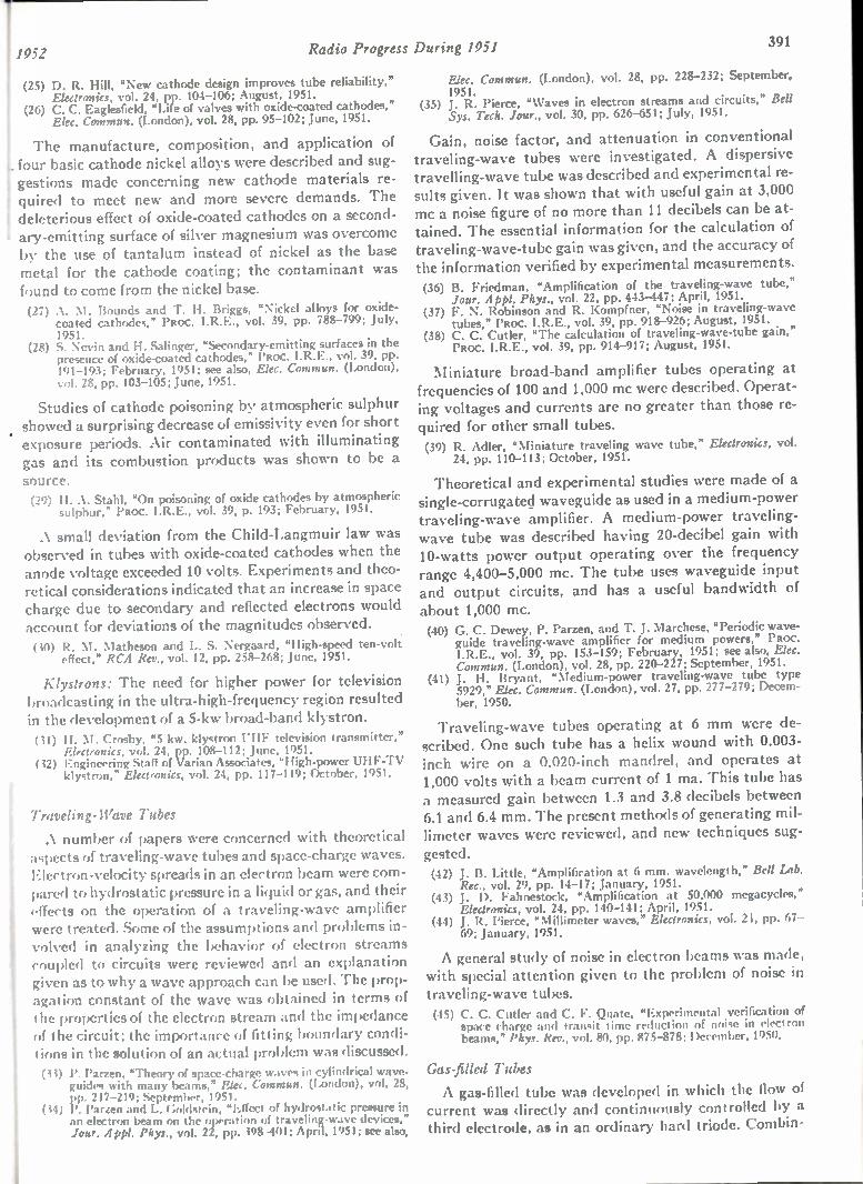
1952 Radio Progress During 1951 391
(25) D. R. Hill, 'New cathode design improves tube reliability," Ekaranics, vol. 24, pp. 104-106; August, 1951.
(26) C. C. Eaglesfield, "Life of valves with oxide-coated cathodes," Elec. Commun. (London), vol. 28, pp. 95-102; June, 1951.
The manufacture, composition, and application of four basic cathode nickel alloys were described and sug-gestions made concerning new cathode materials re-quired to meet new and more severe demands. The deleterious effect of oxide-coated cathodes on a second-ary-emitting surface of silver magnesium was overcome by the use of tantalum instead of nickel as the base metal for the cathode coating; the contaminant was found to come from the nickel base. (27) A. M. Bounds and T. H. Briggs, "Nickel alloys for oxide-
coated cathodes," PROC. I.R.E., vol. 39, pp. 788-799; July, 1951.
(28) S. Nevin and H. Salinger, "Secondary-emitting surfaces in the presence of oxide-coated cathodes," PROC. I.R.E., vol. 39, pp. 191-193; February, 1951; see also, Elec. Commun. (London), vol. 28, pp. 103-105; June, 1951.
Studies of cathode poisoning by atmospheric sulphur showed a surprising decrease of emissivity even for short exposure periods. Air contaminated with illuminating gas and its combustion products was shown to be a source. (29) H. A. Stahl, "On poisoning of oxide cathodes by atmospheric
sulphur," PROC. I.R.E., vol. 39, p. 193; February, 1951.
A small deviation from the Child-Langmuir law was observed in tubes with oxide-coated cathodes when the anode voltage exceeded 10 volts. Experiments and theo-retical considerations indicated that an increase in space charge due to secondary and reflected electrons would account for deviations of the magnitudes observed. (30) R. M. Matheson and L. S. Nergaard, "High-speed ten-volt
effect," RCA Rev., vol. 12, pp. 258-268; June, 1951.
Klystrons: The need for higher power for television broadcasting in the ultra-high-frequency region resulted in the development of a 5-kw broad-band klystron. (31) H. M. Crosby, "5 kw. klystron UHF television transmitter,"
Electronics, vol. 24, pp. 108-112; June, 1951. (32) Engineering Staff of Varian Associates, "High-power UHF-TV
klystron," Electronics, vol. 24, pp. 117-119; October, 1951.
Traveling-Wave Tubes
A number of papers were concerned with theoretical aspects of traveling-wave tubes and space-charge waves. Electron-velocity spreads in an electron beam were com-pared to hydrostatic pressure in a liquid or gas, and their effects on the operation of a traveling-wave amplifier were treated. Some of the assumptions and problems in-volved in analyzing the behavior of electron streams coupled to circuits were reviewed and an explanation given as to why a wave approach can be used. The prop-agation constant of the wave was obtained in terms of the properties of the electron stream and the impedance of the circuit; the importance of fitting boundary condi-tions in the solution of an actual problem was discussed. (33) P. Parzen, *Theory of space-charge waves in cylindrical wave-
guides with many beams," Elec. Commun. (London), vol. 28, pp. 217-219; September, 1951.
(34) I'. Parzen and L. Goldstein, "Effect of hydrostatic pressure in an electron beam on the operation of traveling-wave devices," Jour. Appt. Phys., vol. 22, pp. 398-401; April, 1951; see also,
Elec. Commun. (London), vol. 28, pp. 228-232; September, 1951.
(35) J. R. Pierce, "Waves in electron streams and circuits," Bell Sys. Tech. Jour., vol. 30, pp. 626-651; July, 1951.
Gain, noise factor, and attenuation in conventional traveling-wave tubes were investigated. A dispersive travelling-wave tube was described and experimental re-sults given. It was shown that with useful gain at 3,000 mc a noise figure of no more than 11 decibels can be at-tained. The essential information for the calculation of traveling-wave-tube gain was given, and the accuracy of the information verified by experimental measurements. (36) B. Friedman, "Amplification of the traveling-wave tube,"
Jour. Appl. Phys., vol. 22, pp. 443-447; April, 1951. (37) F. N. Robinson and R. Kompfner, "Noise in traveling-wave
tubes," PROC. I.R.E., vol. 39, pp. 918-926; August, 1951. (38) C. C. Cutler, "The calculation of traveling-wave-tube gain,"
PROC. I.R.E., vol. 39, pp. 914-917; August, 1951.
Miniature broad-band amplifier tubes operating at frequencies of 100 and 1,000 mc were described. Operat-ing voltages and currents are no greater than those re-quired for other small tubes. (39) R. Adler, "Miniature traveling wave tube," Electronics, vol.
24, pp. 110-113; October, 1951.
Theoretical and experimental studies were made of a single-corrugatecl waveguide as used in a medium-power traveling-wave amplifier. A medium-power traveling-wave tube was described having 20-decibel gain with 10-watts power output operating over the frequency range 4,400-5,000 mc. The tube uses waveguide input and output circuits, and has a useful bandwidth of about 1,000 mc. (40) G. C. Dewey, P. Parzen, and T. J. Marchese, "Periodic wave-
guide traveling-wave amplifier for medium powers," PROC. I.R.E., vol. 39, pp. 153-159; February, 1951; see also, Elec. Commun. (London), vol. 28, pp. 220-227; September, 1951.
(41) J. H. Bryant, "Medium-power traveling-wave tube type 5929," Elec. Commun. (London), vol. 27, pp. 277-279; Decem-ber, 1950.
Traveling-wave tubes operating at 6 mm were de-scribed. One such tube has a helix wound with 0.003-inch wire on a 0.020-inch mandrel, and operates at 1,000 volts with a beam current of 1 ma. This tube has a measured gain between 1.3 and 3.8 decibels between 6.1 and 6.4 mm. The present methods of generating mil-limeter waves were reviewed, and new techniques sug-gested. (42) J. B. Little, "Amplification at 6 mm. wavelength," Bell Lab.
Rec., vol. 29, pp. 14-17; January, 1951. (43) J. D. Fahnestock, "Amplification at 50,000 megacycles,"
Electronics, vol. 24, pp. 140-141; April, 1951. (44) J. R. Pierce, "Millimeter waves," Electronics, vol. 24, pp. 67-
69; January, 1951.
A general study of noise in electron beams was made, with special attention given to the problem of noise in traveling-wave tubes. (45) C. C. Cutler and C. F. Quate, "Experimental verification of
space charge and transit time reduction of noise in electron beams," Phys. Rev., vol. 80, pp. 875-878; December, 1950.
Gas-filled Tubes
A gas-filled tube was developed in which the flow of current was directly and continuously controlled by a third electrode, as in an ordinary hard triode. Combin-
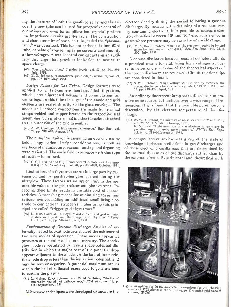
392 PROCEEDINGS OF THE I.R.E. April
ing the features of both the gas-filled relay and the tri-ode, the new tube can be used for progressive control of operations and even for amplification, especially where low impedance circuits are desirable. The construction and characteristics of one such tube, called the "plasma-tron," was described. This is a hot-cathode, helium-filled tube, capable of controlling large currents continuously at low voltages. A small control current acts on an auxil-iary discharge that provides ionization to neutralize space charge. (46) "Gas discharge tubes," Wireless World, vol. 57, pp. 293-294;
July, 1951. (47) E. 0. Johnson, "Controllable gas diode," Electronics, vol. 24,
pp. 107-109; May, 1951.
Design Factors for Gas Tubes: Design features were applied to a 12.5-ampere inert-gas-filled thyratron, which permit increased voltage and commutation-fac-tor ratings. In this tube the edges of the anode and grid elements are sealed directly to the glass envelope. The anode and cathode connections are made by terminal straps welded and copper brazed to the respective seal assemblies. The grid terminal is a short bracket attached to the outer rim of the grid assembly.
(48) A. W. Coolidge, "A high current thyratron," Elec. Eng., vol. 70, pp. 698-699; August, 1951.
The pumpless ignitron is assuming an ever-increasing field of application. Design considerations, as well as methods of manufacture, vacuum testing, and degassing were reviewed. The early field experience with this type of rectifier is outlined. (49) C. C. Herskind and E. J. Remscheid, "Development of a pump.
less ignitron," Elec. Eng., vol. 70, pp. 855-858; October, 1951 .
Limitations of a thyratron are set in large part by grid emission and by positive-ion-glow current during the afterglow. These factors set an upper limit to the per-missible value of the grid resistor and plate current. Ex-ceeding these limits results in unstable control charac-teristics. A promising means for minimizing these limi-tations involves adding an additional small firing elec-trode to conventional structures. Tubes using this prin-cipal are called "trigger-grid thyratrons." (50) L. NIalter and M. R. Boyd, "Grid current and grid emission
studies in thyratrons—the trigger grid thyratron," PROC. I.R.E., vol. 39, pp. 636-642; June, 1951.
Fundamentals of Gaseous Discharge: Studies of ex-ternally heated hot-cathode arcs showed the existence of two new modes of operation. These modes appear at pressures of the order of 1 mm of mercury. The anode-glow mode is postulated to have a space-potential dis-tribution in which the major part of the potential drop appears adjacent to the anode. In the ball-of-fire mode, the anode drop is less than the ionization potential, and may be zero or negative. A potential maximum occurs within the ball of sufficient magnitude to generate ions to sustain the plasma. (51) L. Mailer, E. 0. Johnson, and W. M. Webster, "Studies of
externally heated hot cathode arcs," RCA Rev., vol. 12, p.
415; September, 1951. Fig. 3—Amplifier for 20-kw air-cooled transmitter for vhf, showi ig
cluster of 5762 triodes in the output stage. Grounded-grid circuits Microwave techniques were developed to measure the are used (RCA).
electron density during the period following a gaseous discharge. By measuring the detuning of a resonant cav-ity containing electrons, it is possible to measure elec-tron densities between 10° and 101° electrons per cc in gases whose pressure may be varied over a wide range. (52) M. A. Biondi, "Measurement of the electron density in ionized
gases by microwave techniques," Rev. Sci. Instr., vol. 22, p. 500; July, 1951.
A corona discharge between coaxial cylinders affords a practical means for stabilizing high voltages at cur-rents below one ma. Some of the theoretical aspects of the corona discharge are reviewed. Circuit relationships are considered in detail.
(53) S. IV. Lichtman, "High-voltage stabilization by means of the corona discharge between coaxial cylinders," PROC. vol. 39, pp. 419-424; April, 1951.
An ordinary fluorescent lamp was utilized as a micro-wave noise source. It functions over a wide range of fre-quencies. It was found that the available noise power is determined by the electron temperature of the dis-charge. (54) W. W. Mumford, "A microwave noise source," Bell Lab. Rec.,
vol. 29, pp. 116-120; February, 1951. K. S. Knol, "Determination of the electron temperature in gas discharges by noise measurements," Philips Res. Rep., vol. 6, pp. 288-302; August, 1951.
A comprehensive review was given of the state of knowledge of plasma oscillations in gas discharges and of those electronic oscillations that are determined by the internal dynamics of the discharge rather than by the external circuit. Experimental and theoretical work

Iwas reviewed and a new mathematical formulation l given for oscillations in "irrotational" streams. The most 1 important targets for research were pointed out. l (55) D. Gabor, "Plasma oscillations," Brit. Jour. App!. Phys., vol.
2, pp. 209-218; August, 1951. .. Methods of measuring the rate of loss of ions in tri-
odes by observation of grid current immediately after conduction were described. (56) K. W. Hess, "Measuring the deionization time of gas-filled
diodes and triodes," Philips Tech. Rev., vol. 12, pp. 178-184; December, 1950.
High-Frequency Tubes
A continuation of the development of tubes for very-and ultra-high-frequency applications was apparent from the announcements of new types by manufactur-ers. In most instances, improvement in ruggedness and short low-impedance connections to electrodes were the principal features. Calculation and measurement of tube characteristics were treated in several papers.
Fig. 4—A new "pencil triode," a medium-mu type that is capable of producing peak output of more than 1,000 watts in plate-pulsed service at frequencies up to 3,300 mc (RCA).
(57) A. M. Hardie, "l'ulse technique in high-power valve develop-ment," Metrop. Vick. Gas., vol. 23, pp. 350-360; April, 1951 .
(58) H. M. Wagner, "Tube characteristic tracer using pulse tech-niques," Electronics, vol. 24, pp. 110-114; April, 1951.
(59) E. E. Spitzer, "Principles of the electrical rating of high. vacuum power tubes," Paoc. I.R.E., vol. 39, pp. 60-69; Janu-ary, 1951.
(60) Abd EI-Samie Mostafa, "Electron tube performance with large applied voltages," PROC. I.R.E., vol. 39, pp. 70-73; January, 1951.
A number of tubes of somewhat novel constructions were described. A planar-grid triode and a push-pull
1952 Radio Progress During 1951 393
tetrode for power in the very- and ultra-high-frequency region are examples. (61) C. E. Fay, D. A. S. Hale, and R. J. Kircher, "A 1.5 kw. 500
mc. grounded-grid triode," PROC. I.R.E., vol. 39, pp. 800-803; July, 1951.
(62) E. G. Dorgelo and P. Zijlstra, "Two transmitting valves for use in mobile installations," Philips Tech. Rev., vol. 12, pp. 157-165; December, 1950.
Cooling Techniques: The cooling of power tubes was discussed with consideration of the use of water evapo-ration. Methods of evaluating thermal resistances and of determining operating temperatures and heat losses by means of thermal circuits were determined for electron tubes, and furnished an accurate basis for adequate ven-tilation and cooling designs. (63) C. Beurtheret, "Cooling of electron tubes by vaporization of
water," Onde Elect., vol. 31, pp. 271-276; June, 1951. (64) B. 0. Buckland, "Electron-tube heat-transfer data," Elec.
Eng., vol. 70, pp. 962-966; November, 1951.
Magnetrons
Considerable interest was shown in the effect of space charge in both planar and cylindrical magnetrons, and numerous reports on developments appeared. (65) G. A. Boutry and ). L. Delcroix, "The space-charge in a mag-
netron under static cut-off conditions: planar or quasiplanar magnetron," Compt. Rend. (Paris), vol. 232, pp. 1413-1415; April 9, 1951._
(66) J. L. Delcroix and G. A. Boutry, "The space-charge in a mag-netron under static cut-off conditions: cylindrical magnetron," Comp:. Rend. (Paris), vol. 232, pp. 1653-1655; April 30, 1951.
(67) D. L. Reverdin, "Electron optical exploration of space-charge in a cut-off magnetron," Jour. A ppl. Phys., vol. 22, pp. 257-262; March, 1951.
(68) H. W. Welch, Jr., "Effects of space charge on frequency char-acteristics of magnetrons," PROC. I.R.E., vol. 38, pp. 1434--1449; December, 1950.
(69) H. W. Welch, Jr. and W. G. Dow, "Analysis of synchronous conditions in the cylindrical magnetron space-charge," Jour. App!. Phys., vol. 22, pp. 433-438; April, 1951.
A theoretical study of mode separation for strapped magnetrons was described. In another report the use of butterfly resonators in split-anode magnetron struc-tures was analyzed. (70) A. W. Aikin, "A mode-separation theory for heavily-strapped
magnetrons," Brit. Res. Rep., Ref. 12/51. (Science Abstracts B, vol. 54, p. 515, 3864; 1951.)
(71) H. J. Reich, J. C. May, J. G. Skalnik, and R. L. Ungvary, "Some aspects of split-anode magnetron operation," PROC. I .R.E., vol. 38, pp. 1428-1433; December, 1950.
Application of magnetrons for dielectric heating was described. (72) R. B. Nelson, "Magnetrons for dielectric heating," Elec. Eng.,
vol. 70, pp. 627-633; July, 1951.
Various aspects of magnetron design were considered in reports from several sources. A paper on the location of electron orbits in a nonoscillating magnetron ap-peared. (73) G. A. Espersen and B. Arlin, "Low-voltage tunable X-band
magnetron development," Tek-Tech, vol. 10, pp. 50-51; June, 1951; and pp. 30-31; July, 1951.
(74) A. W. Aikin, "Magnetron design. The hole and slot resona-tor," Brit. Res. Rep., Ref. 11/51. (Science Abstracts B, vol. 54, p. 515, 3865; 1951.)
(75) R. Svensson, "Experimental investigation of the electron ro-bits in a magnetron," Paoc. I.R.E., vol. 39, p. 838; July, 1951.
Semiconductors
Increasingly precise knowledge of how semiconduct-ing devices operate is leading to the realization of new
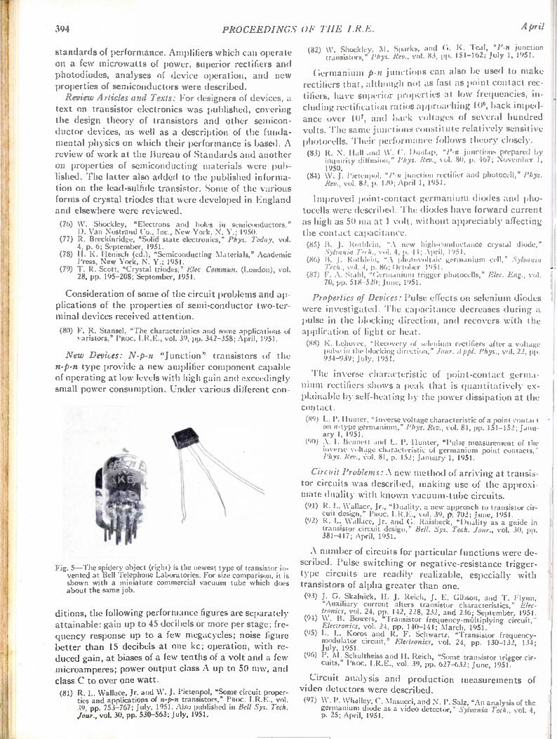
394 PROCEEDINGS OF THE I.R.E. April
standards of performance. Amplifiers which can operate on a few microwatts of power, superior rectifiers and photodiodes, analyses of device operation, and new properties of semiconductors were described. Review Articles and Texts: For designers of devices, a
text on transistor electronics was published, covering the design theory of transistors and other semicon-ductor devices, as well as a description of the funda-mental physics on which their performance is based. A review of work at the Bureau of Standards and another on properties of semiconducting materials were pub-lished. The latter also added to the published informa-tion on the lead-sulfide transistor. Some of the various forms of crystal triodes that were developed in England and elsewhere were reviewed.
(76) XV. Shockley, "Electrons and holes in semiconductors," D. Van Nostrand Co., Inc., New York, N. Y.; 1950.
(77) R. Breckinridge, "Solid state electronics," Phys. Today, vol. 4, p. 6; September, 1951.
(78) H. K. Henisch (ed.), "Semiconducting Materials," Academic Press, New York, N. Y.; 1951.
(79) T. R. Scott, "Crystal triodes," Elec. Commun. (London), vol. 28, pp. 195-208; September, 1951.
Consideration of some of the circuit problems and ap-plications of the properties of semi-conductor two-ter-minal devices received attention.
(80) F. R. Stansel, "The characteristics and some applications of aristors," PROC. 1.R.E., vol. 39, pp. 342-358; April, 1951.
New Devices: N-p-n "Junction" transistors of the n-p-n type provide a new amplifier component capable of operating at low levels with high gain and exceedingly small power consumption. Under various different con-
Fig. 5—The spidery object (right) is the newest type of transistor in-vented at Bell Telephone Laboratories. For size comparison, it is shown with a miniature commercial vacuum tube which does about the same job.
ditions, the following performance figures are separately attainable: gain up to 45 decibels or more per stage; fre-quency response up to a few megacycles; noise figure better than 15 decibels at one kc; operation, with re-duced gain, at biases of a few tenths of a volt and a few microamperes; power output class A up to 50 mw, and class C to over one watt. (81) R. L. Wallace, Jr. and W. J. Pietenpol, "Some circuit proper-
ties and applications of n-p-n transistors," PROC. 1.R.E., vol. 39, pp. 753-767; July, 1951. Also published in Bell Sys. Tech. Jour., vol. 30, pp. 530-563; July, 1951.
(82) W. Shockley, M. Sparks, and G. K. Teal, "P-n junction transistors," l'hys. Rev., vol. 83, pp. 151-162; July 1, 1951.
Germanium p-n junctions can also be used to make rectifiers that, although not as fast as point contact rec-tifiers, have superior properties at low frequencies, in-cluding rectification ratios approaching 106, back imped-ance over 10, and back voltages of several hundred volts. The same junctions constitute relatively sensitive photocells. Their performance follows theory closely. (83) R. N. Hall and W. C. Dunlap, "P-n junctions prepared by
impurity diffusion," Phys. Rev., vol. 80, p. 467; November 1, 1950.
(84) W. J. Pietenpol, "P-n junction rectifier and photocell," Phys. Rev., vol. 82, p. 120; April 1, 1951.
Improved point-contact germanium diodes and pho-tocells were described. The diodes have forward current as high as 50 ma at 1 volt, without appreciably affecting the contact capacitance. (85) B. J. Rothlein, "A new high-conductance crystal diode,"
Sylvania Tech., vol. 4, p. 44; April, 1951. (86) B. J. Rothlein, "A photovoltaic germanium cell," Sylvania
Tech., vol. 4, p. 86; October, 1951. (87) F. A. Stahl, "Germanium trigger photocells," Elec. Eng., vol.
70, pp. 518-520; June, 1951.
Properties of Devices: Pulse effects on selenium diodes were investigated. The capacitance decreases during a pulse in the blocking direction, and recovers with the application of light or heat. (88) K. Lehovec, "Recovery of selenium rectifiers after a voltage
pulse in the blocking direction," Jour. Appl. Phys., vol. 22, pp. 934-939; July, 1951.
The inverse characteristic of point-contact germa-nium rectifiers shows a peak that is quantitatively ex-plainable by self-heating by the power dissipation at the contact. (89) L. I'. Hunter, "Inverse voltage characteristic of a point contact
on n-type germanium," Phys. Rev., vol. 81, pp. 151-152; Janu-
(90) aAr.y11:131c915tille.tt and L. P. Hunter, "Pulse measurement of the inverse voltage characteristic of germanium point contacts," Phys. Rev., vol. 81, p. 152; January 1, 1951.
Circuit Problems: A new method of arriving at transis-tor circuits was described, making use of the approxi-mate duality with known vacuum-tube circuits. (91) R. L. kVallace, Jr., "Duality, a new approach to transistor cir-
cuit design," PROC. I.R.E., vol. 39, ft. 702; June, 1951. (92) R. L. Wallace, Jr. and G. Raisbeck, "Duality as a guide in
transistor circuit design," Bell. Sys. Tech. Jour., vol. 30, pp. 381-417; April, 1951.
A number of circuits for particular functions were de-scribed. Pulse switching or negative-resistance trigger-type circuits are readily realizable, especially with transistors of alpha greater than one. (93) J. G. Skalnick, H. J. Reich, J. E. Gibson, and T. Flynn,
"Auxiliary current alters transistor characteristics," Elec-tronics, vol. 24, pp. 142, 228, 232, and 236; September, 1951.
(94) \V. B. Bowers, "Transistor frequency-mUltiplying circuit," Electronics, vol. 24, pp. 140-141; March, 1951.
(95) L. L. Koros and R. F. Schwartz, "Transistor frequency-modulator circuit," Electronics, vol. 24, pp. 130-132, 134; July, 1951.
(96) P. M. Schultheiss and H. Reich, "Some transistor trigger cir-cuits," PROC. I.R.E., vol. 39, pp. 627-632; June, 1951.
Circuit analysis and production measurements of video detectors were described. (97) W. P. Whalley, C. NIasucci, and N. P. Salz, "An analysis of the
germanium diode as a video detector," Sylvania Tech., vol. 4, p. 25; April, 1951.

1952 Radio Progress During 1951 395
Device Development: Device design theory, namely, the relation between the structure of the device and its engineering properties, was further elaborated. Besides the book (76), the following paper on the electronic as-) pects of transistors appeared. (98) R. C. Prim, "Some results concerning the partial differential
equations describing the flow of holes and electrons in semi-conductors," Bell. Sys. Tech. Jour., vol. 30, pp. 1174-1213; October, 1951.
Diffusion and diode theories of rectification in semi-conductors were compared to experiment for copper ox-ide, selenium, and germanium. (99) E. Billig, "Application of the image force model to the theory
of contact rectification and of rectifier breakdown," Proc. Roy. Soc., vol. 207, p. 156; June 22, 1951.
(100) P. T. Landsberg, "The theory of direct-current characteris-tics of rectifiers," Proc. Roy. Soc., vol. 206, p. 463; May 22, 1951.
(101) P. T. Landsberg, "Contributions to the theory of heterogene-ous barrier-layer rectifiers," Proc. Roy. Soc., vol. 206, p. 477; May 22, 1951.
pressure is in agreement with theory. Antimony in the metal points of germanium contact rectifiers in concen-trations as small as 0.001 per cent can influence the rec-tifying properties. (108) A. R. Moore and F. Herman, "Electron bombardment in-
duced conductivity in germanium point-contact rectifiers," Phys. Rev., vol. 81, pp. 472-473; February I, 1951.
(109) A. W. Ewald, "On the photoconductivity of thallous sulfide cells," Phys. Rev., vol. 81, pp. 607-611; February 15, 1951.
(110) K. Lehovec, C. A. Accardo, and E. Jamgochian, "Injected light emission of silicon carbide crystals," Phys. Rev., vol. 83, pp. 603-607; August 1, 1951.
(111) K. B. McAfee, E. J. Ryder, W. Shockley, and M. Sparks, "Observations of Zener current in germanium p-n junctions," Phys. Rev., vol. 83, pp. 650-651; August 1, 1951.
(112) W. Shockley, "Hot electrons in germanium and ohm's law," Bell Sys. Tech. Jour., vol. 30, pp. 990-1034; October, 1951.
(113) H. H. Hall, J. Bardeen, and G. L. Pearson, "The effects of pressure and temperature on the resistance of p-n junctions in germanium," Phys. Rev., vol. 84, pp. 129-132; October I, 1951.
(114) W. G. Pfann, "Significance of composition of contact point in rectifying junctions on germanium," Phys. Rev., vol. 81, p. 882; March 1, 1951.
Measurement techniques for rapid oscilloscopic test-ing of transistors were described. An evaluation of transistor quality can be quickly made during assem-bling and forming. (102) R. W. Haegele, "A visual transistor test method and its ap-
plication to collector forming," Sylvania Tech., vol. 4, p. 61; July, 1951.
Measurement techniques for properties of semicon-ducting material that are of interest for device design, such as barrier location, were described. The point-con-tact method locates a barrier whose position appears to be somewhat dependent on the nature of the metal used. The recombination of anomalous carriers, which termi-nates their life, takes place largely on the surface of small samples. (103) F. A. Stahl, "Effect of the probe metal in locating a p-n barrier
in germanium," Sylvania Tech., vol. 4, p. 61; July, 1951. (104) J. R. Haynes and W. Shockley, "The mobility and life of in-
jected holes and electrons in germanium," Phys. Rev., vol. 81, pp. 835-843; March 1, 1951.
(105) F. S. Goucher, "Measurement of hole diffusion in n-type germanium," Phys. Rev., vol. 81, p. 475; February 1, 1951.
Junctions of the p-n type, which have both superior properties and unusually close agreement of such prop-erties with theoretical expectations, have been pre-pared. (10(i) G. K. Teal, M. Sparks, and E. Buehler, "Growth of ger-
manium single crystals containing p-n junctions," Phys. Rev., , vol. 81, p. 637; February 15, 1951. I (107) F. S. Goucher, G. L. Pearson, M. Sparks, G. K. 'Teal, and
W. Shockley, "Theory and experiment for a germanium p-n junction," Phys. Rev., vol. 81, p. 637; February 15, 1951.
A variety of semiconductor properties fundamental for device design were measured. Among these are the conductivity induced by electron bombardment of a barrier in germanium and by the photoconductivity of thallous sulfide. The recombination of injected charge carriers in silicon carbide produces light of a spectrum nearly independent of current, with production of about one quantum per million electrons in a particular case. The reverse current of a p-n junction rectifier increases sharply--the Zener effect-- when a saturation voltage is exceeded. Also in high fields, the mobility of electrons in germanium decreases. The response of p-n junctions to
Cathode-Ray and Television-Tube Design Considerations
A technique for investigating the optical properties of electron lenses was described which used a circularly ro-tating electron beam, minimizing space-charge effects and alignment problems. Results of applying the method to magnetic lenses were discussed. (115) D. E. George, R. G. E. Hutter, and H. Cooperstein, "The
rotating beam method for investigating electron lenses," Sylvania Tech., vol. 4, pp. 41-43; April, 1951.
Cathode-Ray Tube Production: During the year the continued trend toward larger direct-view picture tubes resulted in substantially all production being placed on sizes with a 16-inch or larger screen. Round-screen and rectangular-screen versions in all popular sizes appea&d with both all-glass and metal-glass envelopes. Shortages of critical materials spurred interest in elec-
trostatically focused cathode-ray tubes; as a result, co-balt containing permanent magnets and copper-wire-wound electromagnets for focusing lenses did not have to be used. Gun designs evolved in which saddle-type electrostatic lenses that require low- or zero-voltage focusing potentials were used. The latter type can be made interchangeable with its magnetically focused counterpart. Further improvements in cathode-ray tubes include
the use of a cylindrical face plate with the axis vertical so that the specular reflection of most room lights can be reduced. Other techniques for reducing specular reflec-tion include special surface treatment of the glass face. Direct-view picture tubes reached the 30-inch diameter size and were designed to operate with associated deflec-tion components at a scanning angle of 90 degrees. A dif-ferent theoretical approach to the correction of deflec-tion defocusing in electrically deflected tubes was made. (116) C. Graham, "How new automatic-focus picture tube op-
erates," Radio and Trim. Retailing, pp. 56, 57; December, 1951. (117) G. S. Szegho, M. E. Amdursky, and W. 0. Reed, "Low-
reflection picture tubes," Electronics, vol. 24, pp. 97-99; January, 1951.
(118) H. E. 'Thomas, "Wide angle picture tubes," Radio and Tele,. News, vol. 16, pp. 3-6; September, 1951.
(119) J. E. Rosenthal, "Correction of deflection defocusing in cathode-ray tubes," PROC. I.R.E., vol. 39, pp. 10-15; January, 1951.
396 PROCEEDINGS OF THE I.R.E. April
Audio Techniques The normal progress in audio techniques appears to
have been vitally affected by the impact of the defense program. This is apparent as much from the absence of the normal volume of published reports as from pub-lished material definitely bearing out this statement. A suggestion of this nature is apparent in an industrial sound system that, in addition to providing the usual paging, music distribution, and briefing possibilities, also places particular stress on those emergency fea-tures that are necessary to protect personnel in all-out war. The accent on this particular system is the passing of information and instructions in case of hazard. A sec-ond article deals with the effect of music on mass-pro-duction.
(120) H. S. Morris, "Industrial survival of sound systems," Audio Eng., vol. 35, pp. 24, 25, 37, 38, 39; May, 1951.
(121) J. Goodman, "Music and mass production," Audio Eng., vol. 35, pp. 23, 44, 45, 46; September, 1951.
The application of transistors may prove to be a ma-jor development in the audio field. Definite advances were made in control of point-contact transistors through manufacturing techniques, among which should be mentioned the effect of wide contact spacing. The transistor has been developed to the point of application in certain systems in which stress on reliability is of the utmost importance. The n-p-n-type junction transistor is of particular
significance because of its desirable, and in some cases, astonishing characteristics. In particular, this type is reported to have a relatively low noise figure and ex-hibits complete freedom from short-circuit instability, thus making it adaptable to a wide range of circuit ap-plications. It also has high gain; power gains of the order of 40 to 50 db per stage were obtained. Voltage or current amplifications of 3040 1,000 times per stage were reported. The unit is extremely rugged and com-pact; operating units no larger than 3/16 inch in di-ameter, excluding the necessary pigtail connections for leads, were constructed. Its power-handling capacity is somewhat limited. However, units of 2-watt power dis-sipation were built; this power-handling capacity is sufficient for a large number of audio applications. This transistor has complete freedom from microphonics, and hence can work under all applications involving vibra-tion and shock. The transistor operates with exceedingly small power
consumption, and has high efficiency since it requires no filament voltage. Efficiencies of the order of 49 per cent can be obtained in Class-A operation against a theoretically realizable 50 per cent. Units have been operated with an input power as small as 6 microam-peres at 0.01 volt or a power consumption per stage of 0.6 mw. (122) A. S. Windeler, "The junction transistor," Bell Lab. Rec., vol.
24, pp. 378-381; August, 1951. (123) B. N. Slade, "A high-performance transistor with wide spacing
between contacts,* RCA Rev.,!vol. II, pp. 517-526; December, 1950.
(124) R. L. Wallace, Jr. and W. J. Pietrpol, "Some circuit properties and applications of n-p-n transistors,* Bell Sys. Tech. Jour., vol. 30, pt. 3, pp. 530-563; July, 1951.
Important contributions to magnetic recording and reproducing, and to electroacoustic transducers were reported. In magnetic recording, the suggestion was made that the drop in response at high frequencies in recording-reproducing systems results not from self-demagnetization, as previously thought, but from fail-ure to obtain intimate contact between the recorder-reproducer head and the recording medium. On the basis of experimental work, as well as on an idealized theoretical analysis, it is stated that the spacing loss in decibels is 55 times the logarithm to the base ten of the ratio of the effective head spacing from the media to the wavelength of the recorded signal in the media. It has been suggested that variation of intimate contact with the moving medium accounts, in part, for that distortion variously known as "noise behind the signal" or "modulation noise." Informative articles on the relation between sensitiv-
ity, directivity, and linearity of direct-radiator-type loudspeakers were published. It is reported that uni-form directivity with respect to frequency is much more important than sensitivity and, in particular, that it is undesirable to obtain high sensitivity in a loudspeaker by sacrificing uniform response, good transient re-sponse, low nonlinear distortion, and uniform directiv-ity.
A new type of magnetic recording medium, known as "magnetic rubber," which is particularly suited to those applications requiring several repeated uses of the re-cording medium, was announced. More practical means for the binaural recording and
reproduction of sound through the use of magnetic re-cording equipment were commercialized. (125) R. 1.. Wall ice, Jr., "Reproduction of magnetic signals," Bell
Sys. Tech. Jour., vol. 30, pt. 2, no. 1145-1173; October, 1951. (126) H. F. Olson, "Sensitivity, directivity and linearity of direct
radiator loudspeakers," Audio Eng.. vol. 34, pp. 15-17; October, 1950.
(127) "Magnetic Rubber," Rev. Sci. Instr., vol. 23; November, 1951.
A two-way wire intercommunication system was pro-duced for school-to-home use, which makes it possible for confined children to participate in classroom work while in their own homes. The use.of recording and re-producing equipment to furnish automatic telephone-answering service in the absence of the subscriber was reported. A multiple-purpose tone arm for broadcast use on the three record speeds was described.
(128) "BTL development benefits labs family," Bell Lab. Rec., vol. c 29, pt. 4, p. 173; April, 1951.
(129) L. J. Anderson and C. R. Johnson, "New broadcast light pick-up and tone arm," Audio Eng., vol. 35, pp. 18, 20-21, 39; March, 1951.
(130) F. V. Welch, "Want to hire a 'telephone sitter'?," Telephony, vol. 140, pp. 13-14; February 17, 1951.
Additional work on automatic regulation of system gain was reported; also, the problem of the automatic compensation for the drift of gain in a dc amplifier was discussed at some length and circuits for its effectual reduction were described.
(131) G. A. Singer, "Performance and operation of a new limiting amplifier," Audio Eng., vol. 34, pp. 18-19, 69-70; November, 1950.
(132) F. R. Smith, "Automatic stabilization of high-impedance d-c amplifiers," Electronics, vol. 24, p. 124; February, 1951.
1 3 1952 Radio Progress During 1951 97
A stroboscopic spectrometer for audio-frequency work operates by modulating a light source with the signal to be resolved and by viewing it with a strobo-scopic screen. A range of 60 to 6,000 cycles can be cov-• ered. An instrument for visual analysis of complex r audio wave forms presents a three-dimensional display.
A device for displaying the space patterns of sound I waves was described. This device uses a probe pickup to , scan the sound field, and the amplified probe output : controls the brilliance of a lamp fixed to the probe. A camera set for time exposure records the light-intensity variations of the lamp as it moves across the scanned field, and forms a pattern on the film of the amplitude distribution of the signal. In addition, means of ob-taining simple flexible wave filters of various types through the use of appropriate amplifier techniques were described. These articles reported that it is possi-ble to obtain low-pass, high-pass, band-pass, and vari-able high-pass filters from RC networks and feedback-
• type amplifiers through the skillful use of design tech-
niques. (133) F. A. Fischer, "Stroboscopic audio frequency spectrometer,"
Fermeldetech. Z, vol. 3, pp. 74-180; May, 1950. (134) H. R. Foster and E. E. Crump, "Methods and instruments for
the visual analysis of complex audio waveforms," Proc. NEC (Chicago), vol. 5, pp. 564-572; 1949.
(135) W. E. Koch and F. K. Harvey, "A photographic method for displaying sound wave and microwave space patterns," Bell Sys. Tech. Jour., vol. 30, pt. 3, pp. 564-587; July, 1951.
(136) A. Peterson, 'Continuously adjustable low and high-pass filters for audio frequencies," Proc. NEC (Chicago), vol. 5, pp. 550-555; 1949.
(137) C. C. Shumard, "Design of high-pass, low-pass, and band-pass filters using R-C networks and direct current amplifiers with feed back," RCA Rev., vol. 11, pp. 534-564; December, 1950.
rather than 1,000, cycles per inch of tape travel per second resulting in machines of lower tape speeds. (140) Audio Rec., vol. 7, pp. 3-10; August—September, 1951.
Tape speeds now range from 30 to 1/ inches per sec-ond in submultiple steps in accordance with RTM A Standards and recommendations. The highest speed is used primarily for master recording in the phonograph field. Speeds of 15 and 7i inches per second are used for broadcasting and commercial applications, and lower speeds of 31 and 1/ inches a second for home recording. The use of magnetic film in the motion-picture indus-
try for original sound recording increased greatly. Standards concerned with track position, width, and separation were proposed. (141) "Proposed American standards," Jour. Soc. Mot. Pic. and
Telev. Eng., vol. 57, pp. 71-74; July, 1951. (142) G. Lewin, "Synchronous }-inch magnetic
picture productions," Jour. Soc. Mot. Pic. vol. 56, pp. 664-671; June, 1951.
A 16-mm projector equipped for magnetic recording was introduced. The magnetic track can be added either to new or processed film, and is located over the surface normally used for the photographic sound track. The sound may be added while the picture is being viewed. (143) E. E. Masterson, F. L. Putzrath, and H. E. Roys, "Magnetic
sound on 16-mm edge-coated film," Jour. Soc. Mot. Pic. and Telev. Eng., vol. 57, pp. 559-566; December, 1951.
The theory involved in recording with ac bias was further investigated. The results of a study of signal loss during reproduction was reported. (144) R. E. Zenner, "Magnetic recording with ac bias," PROC.
I.R.E., vol. 39, pp. 141-146; February, 1951. (145) 0. W. Muckenhirn, "Recording de-magnetization in mag-.
netic recording," PROC. I.R.E., vol. 39, pp. 891-897; August, 1951.
(146) R. L. Wallace, Jr., "The reproduction of magnetically recorded signals," Bell Sys. Tech. Jour., vol. 30, pp. 1145-1173; October, 1951.
Sound Recording and Reproduction
Preliminary work was started which establishes re-cording characteristics permitting international ex-change of both disks and tapes. A recording character-istic for disks, utilizing a 50-Asec rise time, appears to be an acceptable high-frequency pre-emphasis char-acteristic for most countries. Agreement with the mag-netic-tape standards proposed by the National Associ-ation of Radio and Television Broadcasters is good, but problems exist because of the difficulty in determining the magnitude of the level recorded on the tape. (138) "AES standard playback curve," Audio Eng., vol. 35, p. 22;
January, 1951. (139) "NARTB Recording and Reproducing Standards," 1771 "N"
St., N.W., Washington, D. C.; June, 1951.
The use of fine-groove records, both 45 and 33i rpm, increased greatly, and improvements in both disks and instruments were apparent. Heated-stylus record-ing became more common, especially for fine-groove disks. Some improvements in both media and equipment
were made in the magnetic-recording field. Increased uniformity and a reduction in modulation noise was ap-parent, helped no doubt by the development of mag-netic tape for use in the telemetering and computer field, where the requirements are more exacting in some respects than those for sound recording. Many designers are now thinking in terms of 2,000,
tape for motion and Telev. Eng.,
Electroacoustics Wave and Vibration Theory
The problem of sound transmission in a medium of continuously varying refractive index has received further attention for both air and water. It was con-cluded that frequencies above 70 cycles will be totally absorbed in the stratosphere. The phenomenon of duct transmission in water was put on a firmer basis, leading to a modified ray-acoustic concept that includes dif-fraction. The volume-viscosity concept has been used to ex-
plain absorption in resonators and progressive waves. In certain triatomic gases the effect overrides that of shear viscosity. A continuing study of the unidirectional forces arising
from the interaction of a wave and an obstacle indicates that forces due to wave asymmetry may be considerably larger than those due to radiation pressure. The growth of subharmonics from a direct-radiator
speaker was studied experimentally. When compared with theory, it was verified that, under ordinary condi-tions, the rate of growth will not be undesirably large. In boundary-value problems, a more general concept a
398 PROCEEDINGS OF THE I.R.E. April
acoustic impedance has proved necessary. In one at-tack on the problem, it was defined as the quotient of intensity by the product of the normal velocity and its conjugate.
(147) N. A. Haskell, "Asymptotic approximation for normal modes in sound-channel propagation," Jour. App!. Phys., vol. 22, pp.t.157-168; February, 1951.
(148) H. Lu, "Volume viscosities and compressibilities from acoustic phenomena," Jour. Acous. Soc. Amer., vol. 23, pp. 12-15; aripary, 1951.
(149) . T. Westervelt, "The theory of steady forces caused by sound waves," Jour. Acous. Soc. Amer., vol. 23, pp. 312-315; May, 1951.
(150) 0. K. Mawardi, "On the generalization of the concept of im-pedance in acoustics," Jour. Acous. Soc. Amer., vol. 23, pp. 571-576; September, 1951.
Room Acoustics and Absorption
Perforated acoustic materials, especially those in which the perforated sheet is backed by a porous blanket and an air space, are being used in increasing quantities. An analytical study led to a useful set of de-sign charts; the agreement with experiment is good. Ex-perimental results on the absorption coefficients of flat, splayed, and cylindrical panels of }-inch plywood are available. Improvements in the box method of compar-ing acoustical materials were reported in one of the few releases of information on this topic. The perennial problem of optimum adjustment of a speech-reinforce-ment system received considerable experimental atten-tion. For maximum intelligibility it appears that the direct speech should arrive 5 to 35 milliseconds ahead of that reproduced, and the level of the latter should be no more than 7 db above that of the former. (151) U. Ingird and R. H. Bolt, "Absorption characteristics of
acoustic materials with perforated facings," Jour. Acous. Soc. Amer., vol. 23, pp. 533-540; September, 1951.
(152) R. W. Kenworthy and T. D. Burnham, "Absorption coef-ficients of fir plywood panels," Jour. Acous. Soc. Amer., vol. 23, pp. 531-532; September, 1951.
(153) C. B. Boenning, S. F. Huber, and T. Mariner, "A modification of the box method of determining relative sound absorption coefficients," Jour. Acous. Soc. Amer., vol. 23, pp. 114-115; January, 1951.
(154) P. H. Parkin and W. H. Scholes, "Recent developments in speech-reinforcement systems," Wireless World, vol. 57, pp. 44-50; February, 1951.
Physiological Acoustics and Psychcacoustics
A major event in this field was publication of the papers given at the Speech Communication Conference at M.I.T. Information theory, linguistics, phonetics, cochlear mechanics, masking, and visible speech were some of the topics discussed. Especially interesting was preliminary work on the type of communication pat-tern permitted in an organization and its effect on rapid-ity of accomplishment and morale. There is some indi-cation that these ends are not completely compatible. In the field of vowel analysis, an electrical analogue
of the vocal tract has been constructed with fair-to-good reproduction of vowel sounds. Further investigation into the surprisingly high intelligibility of speech that has been subjected to differentiation and then to in-finite peak clipping gives results in accord with simple information theory. A straightforward method of cal-culating the loudness of complex tones was reduced to practice. The given spectrum is divided into bands of pitch-interval 300 to 600 mels, and the loudness values
for each *band are added. Good agreement with experi-ment and with more elaborate analytical methods was obtained. (155) "Proceedings of the speech communications conference at
M.I.T.," Jour. Acous. Soc. Amer., vol. 22, pp. 689-806; November, 1950.
(156) L. L. Beranek, J. L. Marshall, A. L. Cudworth, and E. P. G. Peterson, "Calculation and measurement of the loudness of sounds," Jour. Acous. Soc. Amer., vol. 23, P. 261; May, 1951.
Ultrasonics
Progress in this field was characterized by an insist-ence on measuring significant quantities and on a closer delineating of the causes of the effects observed. Greater attention is being paid to routine applications in indus-try and medicine. A re-evaluation of the elastic strength of piezoelectric sources indicates that in water very short pulses of high intensity may be transmitted. Quartz should support 2,000 watt/cm' and ADP, 220 watt/cm'. Experimental values up to 1,000 watt/cm2 have been obtained for quartz. Thus it is still superior to barium titanate, at least for plane waves. However, the latter material has greater flexibility of form. For example, a radially polarized hollow cylinder exhibits a longitudinal resonance on excitation. By affixing a reso-nant, tapered, solid metal horn on one end, amplifica-tion of the motion is obtained; in one arrangement used for wear testing, the amplitude was about one mil at 18 kc. Further work in ultrasonics has included a de-tailed long-term study of the effects on tissues, means for outlining brain tumors, and means for mechanical control of crystal resonance over a total range of about an octave.
(157) G. M. Naimark, J. Klair, and W. A. Mosher, "A bibliography on sonic and ultrasonic vibration: biological, biochemical and
• biophysical application," Jour. Frank. Inst., vol. 251, pp. 279- - 299; February, 1951; also pp. 402-408; March, 1951.
(158) B. E. Noltingk, "Ultrasonic generators for high powers," Jour. Brit. I.R.E., vol. 11, pp. 11-19; January, 1951.
(159) American Society for Testing Materials, Symposium on Ultra-sonic Testing, ASTM Special Publication 101; 1951.
(160) B. Curry, et al., "Bibliography, Supersonics or Ultrasonics 1926 to 1945 with Supplement to 1950," Oklahoma A. and M. Re-search Foundation; 1951.
Instruments and Measurements
All of acoustics and audio engineering, and the meas-urement field in particular, will be helped by the issu-ance of American Standard Acoustical Terminology, which defines over 500 terms. In the audiometer field, the problems of specifying for calibration and use have been examined; it is concluded that present specifica-tions are achievable and reasonable. Most of the activity concerning microphones appears to be in the production of unobtrusive stick-type structure for television. While no radically different measurement techniques
were disclosed, several novel instruments were intro-duced: a sound-level meter utilizing a well-stabilized loudspeaker as a source of known pressure level; an infrasonic oscillator offering rapid frequency stabiliza-tion by integrating and shaping the output of a bistable circuit; a polar recorder offering linear or square-root radius vector; an ultraspeed recorder obtaining its logarithmic characteristic from biased varistors, and achieving speeds up to 10,000 db per second; a two-
:•
1952
signal audio oscillator for intermodulation measure-ments by the constant-difference-frequency method; a magnetostriction oscillator of one kw input at 24 kc, and an active surface of 20 cm2; and an acoustic in-tensity meter utilizing the radiation pressure of progres-
rsive waves in a water load. (161) American Standards Association, "American Standard Acous-
tical Terminology," ASA Standard Z 24.1-1951. New York, N. Y.; 1951.
Industrial Acoustics
For some time there has been a noticeable trend to-ward putting acoustics to work in testing, processing, and controlling. Among the more recent devices avail-able on the market is a ball-mill control that adjusts the feed for maximum sound output, this having been found to be the criterion used by human operators. An ultrasonic soldering iron featuring magnetostrictive drive of the bit at 20 kc provides a "sonic flux" that permits fine aluminum and copper wires to be joined without removal of the insulation. Garage-door opening may be controlled from a car
by selective pickup of an ultrasonic air whistle in the car. Still in the laboratory stage are devices for meas-urement of fluid velocity, and for ultrasonography by formation of a latent sound shadow image on a photo-graphic plate. There is active thinking on means for achieving high acoustic powers efficiently and simply so as to make possible many industrial applications that are now of laboratory interest only. (162) W. B. Hess, R. C. Swingal, and S. K. Waldorf, "Measuring
water velocity by an ultrasonic method," Elec. Eng., vol. 69, p. 983; November, 1950.
(163) G. S. Bennett, "A note on the activation of photographic emul-sions by ultrasonic waves," Jour. Acous. Soc. Amer., vol. 23, pp. 478-480; July, 1951.
Information Theory and Modulation Systems
Radio Progress During 1951 399
be used, producing high transmitter efficiency in appli-
cations that permit its use. (165) G. Grammer, "D. S. R. C. radio telephony," QST, vol. 35,
pp. 1-16; May, 1951.
The effect of nonlinear quantization on quantization
distortion was studied. (166) P. F. Panter and W. Dite, "Quantization distortion in pulse-
count modulation with nonuniform spacing of levels." PROC. I.R.E., vol. 39, pp. 44-48; January, 1951.
Primary attention has been centered on the informa-tion-theory approaches, while comparatively little work was reported on conventional modulation systems tech-niques. Significant advances in apparatus refinements were noted, such as a report of a study of distortion in frequency-modulation relay systems. Some work on multipath characteristics of frequency
and amplitude modulations tended to show that, con-trary to previous belief, FM may be superior to AM under conditions of heavy multipath interference.
(164) L. E. Thompson, "Distortion in multichannel frequency modu-lation relay systems," RCA Rev., vol. 11, pp. 453-464; Decem-ber, 1950.
A study of cross talk in time-division multiplex sys-tems showed the effects of bandwidth on cross talk, and indicated, also, that poor low-frequency response can be used to compensate for poor high-frequency response. (167) S. Moskowitz, L. Diven, and L. Feit, "Crosstalk considerations
in time-division multiplex systems," PROC. I.R.E., vol. 38, pp. 1330-1336; November, 1950.
Many papers were published in the field of informa-tion theory, and several symposia were held. Activity was aimed primarily at the application and extension of the theory, rather than toward new basic reasoning. However, some work was done to derive the basic pre-cepts of information theory by new methods. (168) L. Brillouin, "Maxwell's demon cannot operate—information
and entropy," Jour. Appl. Phys., vol. 22, pp. 334-343; March, 1951.
(169) D. Gabor, "Communication theory and physics," Phil. Meg., vol. 41, pp. 1 t61-1187; November, 1950.
(170) E. Reich, "Definition of information," PROC. I.R.E., vol. 39, p. 290; March, 1951.
The laboratories of the Telecommunications Re-search Establishment in Great Britain analyzed the radar problem on the basis of information theory; they derived relations for the information present in a radar signal and obtained new detection-process criteria that correlate very well with observed data. They regard the operator as a computer which, given the a priori dis-tribution of probability of signals in noise and the ob-served waveform, deduces a new probability of signal being present at any given range. This analysis was de-veloped by first studying the theory of observation and then applying statistical techniques to these results. These papers describe a coherent and fairly complete
approach to the radar-detection problem. In addition to this work, however, progress was reported in the radar field along somewhat more conventional lines. (171) P. M. Woodward and I. L. Davies, "A theory of radar in-
formation," Phil. Mag., vol. 41, pp. 1001-1017; October, 1950. (172) P. M. Woodward, "The decoding of radar information," Tele-
communication Research Establishment, Tech. Note 76. (173) 1. L. Davies, "Theory of radar information—existence prob-
abilities for signals in noise," Telecommunication Research Establishment, Tech. Note 109.
(174) S. M. Kaplan and R. W. McFall, "The statistical properties of noise applied to radar range performance," PROC. I.R.E., vol. 39, pp. 56-60; January, 1951.
Extending amplitude-modulation percentages to over one hundred, a technique called "double-sideband re-duced-carrier transmission," was pushed still further. In this system, a slightly unbalanced balanced modula-tor is used to generate double sidebands with a rela-tively large carrier leak. Reception, with some distor-tion, is possible in voice-communication circuits, and exalted-carrier techniques may be used to remove this distortion. Modulation percentages as high as 1,000 can
The technique of integrating received signals from pulse to pulse to obtain an improved signal-to-noise ratio has been known for some years, but the complex-ity of the apparatus required has been forbidding. An equipment for performing this operation by the use of a storage tube was successfully demonstrated. This equipment is capable of integrating the effects of ten successive pulses and of obtaining considerable signal-to-noise improvement thereby.

400 PROCEEDINGS OF THE I.R.E. April
(175) J. V. Harrington and T. F. Rogers, "Signal-to-noise improve-ment through integration in a storage tube," PRoc. I.R.E., vol. 38, pp. 1197-1203; October, 1950.
Since storage and delay are essential elements of any communication system operating close to maximum theoretical capacity, the optimum value of storage and methods for obtaining it were studied.
(176) A. J. Lephakis, "Storage devices for communications," Elec-tronics, vol. 23, pp. 69-73; December, 1950.
Information theory was also applied to periodic radio systems of many types, primarily navigational sys-tems. This work showed that the limitations on resolu-tion of a navigational system are determined by the bandwidth of the transmitter and limitations on in-formation rate by the bandwidth of the receiver. (177) M. Leifer and N. Marchand, "The design of periodic radio sys-
tems," Sylvania Tech., vol. 3, pp. 18-21; October, 1950. (178) M. Leifer and N. Marchand, "Cross-Correlation and the Op-
timum Signal-to-Noise Ratio for Periodic Systems," Presented, I.R.E. National Convention, New York, N. Y.; March 19-22, 1951.
(179) M. Leifer and N. Marchand, "Cross-Correlation in Periodic Radio Systems," Presented, I.R.E. Conference on Airborne Electronics, Dayton, Ohio; May, 1951.
The work on radar and navigational aids was pri-marily concerned with obtaining resolution and high signal-to-noise ratio with limited power and band-width. Other mechanisms for achieving this result in-volved the use of correlation techniques. The descrip-tion of a practical electronic correlator using sampling techniques and taking the autocorrelation function by plotting a series of points for various delays over a long period of time was given, and techniques for using the results obtained with such a machine for the improve-ment of detection of signals in noise were published. (180) T. P. Cheatham, Jr., "An Electronic Correlator," Research
Laboratory of Electronics, Massachusetts Institute of Tech-nology Report 122; March 28, 1951.
(181) Y. W. Lee, T. P. Cheatham, Jr., and J. B. Wiesner, "Applica-tion of correlation analysis to the detection of periodic signals in noise," PROC. I.R.E., vol. 38, pp. 1165-1171; October, 1950.
(182) Y. W. Lee and L. G. Kraft, "Detection of Repetitive Signals in Noise by Correlation," Presented, I.R.E. National Conven-tion, New York, N. Y.; March 19-22, 1951.
An introduction to the correlation function, better known to statisticians than to the communications en-gineers, was published.
(183) D. A. Bell, "The auto-correlation function," Wireless Eng., vol. 28, pp. 31-32; January, 1951.
A simple relation was derived showing that the in-formation content per symbol of a message could be easily obtained from the autocorrelation function.
(184) P. Elias, "A note on auto-correlation and entropy," PRoc. I.R.E., vol. 39, p. 839; July, 1951.
The autocorrelation technique was also applied to the computation of spectra, interference, and cross talk in time-division multiplex systems.
(185) E. R. Kretzmer, "An application of auto-correlation analysis " Jour. Math. Phys., vol. 29, 1313. 179-190; October, 1950.
(186) L. A. Zadeh, "Correlation functions and spectra of phase and delay modulated signals," PROC. I.R.E., vol. 39, pp. 425-428; April, 1951.
One of the prime applications of communication the-ory has been toward reducing the bandwidth necessary for transmitting various types of information. While not
stemming from this source, the application of the mixed-highs principle to color television is an excellent exam-ple of the combination of frequency-division multiplex and time-division multiplex techniques producing a marked reduction in the bandwidth heretofore thought necessary for picture transmission. Consideration has also been given to the amount of information actually present in a television picture.
(187) R. B. Dome, "Spectrum utilization in color television," PROC. I .R.F., vol. 39, pp. 1323-1331; October, 1951.
(188) Y. Delbord, 'Television and the transmission of information," Ann. Telecomm., vol. 6, pp. 11-22; January, 1951.
The possibility of the transmission of television by pulse-code modulation techniques was also studied. It was found that surprisingly few levels were required to transmit adequate pictures and that a small amount of noise reduced the number of levels necessary by tending to obliterate the abrupt change in brightness from one level to the next. The use of coding techniques to reduce bandwidth in picture transmission was discussed in an unpublished paper.
(189) W. M. Goodall, "Television by pulse-code-modulation," Bell Sys. Tech. Jour., vol. 30, pp. 33-49; January, 1951.
(190) A. E. Laemmel, "Coding Processes for Bandwidth Reduction in Picture Transmission," Presented, I.R.E. National Conven-tion, New York, N. Y.; March 19-22, 1951.
Much work is currently in progress on the application of statistical techniques to the reduction of bandwidth required for transmission of acceptable speech. A con-ference on speech communication was held at M.I.T. in the summer of 1950, and the papers were reported in the Journal of Acoustical Society of America, vol. 22, pp. 689-806; November, 1950.
The problem of speech transmission has been studied, both with regard to the equipment and to the human phases. Studies of the ear and hearing mechanisms have been made to determine how much information the ear • can actually handle and to discover new facts about the mechanism of hearing.
(191) A. R. Tunturi, "The Auditory Cortex and Information The-ory," Presented, Western I.R.E. Convention, San Fran( isco, Calif.; August 22-24, 1951.
Progress has been made on the anal) sis of speech sounds and their visual presentation. Studies of the short-time autocorrelation function of speech sounds, moments, and other statistical properties have been an-alyzed carefully in an attempt to use these properties to distinguish automatically between one speech sound and another. Work has also been done on the use of spectroanalysis, using the presence or absence of several bands in the voice spectrum to indicate various speech sounds.
(192) H. Seki and S. Muroga, "Some Considerations Regarding Encoding, Decoding, and Recording of Speech," Radio Regu-latory Comm., Tokyo, Japan.
The elimination of conventional voice communication from links now using this technique was discussed in an effort to provide improved narrow-band communica-tion in the approach control area of an airport. The al-ternative presented was a form of symbolic display. (193) W. G. Tuller, "Application of the information theory to sys-
tem design," Elec. Eng., vol. 70, pp. 124-126; February, 1951.
1
1952 Radto Progress
(194) J. Loeb, "Application of Shannon's communication theory to telecontrol, telemetry, or measurement," Ann. Tekcomm., vol. 6, pp. 67-76; March, 1951.
(195) M. H. Nichols and L. L. Rauch, "Radio telemetry," Rev. Sci. Instr., vol. 22, pp. 1-29; January, 1951.
This work was primarily concerned with the study of various types of modulation from the communication theory viewpoint and with an analysis of their ap-plicability to the telemetering problem. A somewhat similar analysis, although not restricted to telemetering,
was also presented. (196) R. Piloty, "The assessment of modulation systems using the
communication theory concept of channel capacity," Arch. elekt. Obertragung, vol. 4, pp. 493-508; December, 1950.
Further work has been done on the general analysis of communication systems from the point of view of band-width reduction. Most of this work was reported as a result of two symposia, held at the Royal Society (Lon-don) in September, 1950 (reference 201), and at the Sor-bonne in France in April—May, 1950. The latter was re-ported in Ann Tele-Comm., vol. 5; October, 1950. (197) B. Mandelbrot, "Adaptation of message to transmission line:
part I—quantity of information," Compt. Rend. Acad. Sci. (Paris), vol. 232, pp. 1638-1640; April 30, 1951.
(198) R. Feron and C. Fouregard, "Information and regression," Compt. Rend. Acad. Sci. (Paris), vol. 232, pp. 1636-1638; April 30, 1951.
(199) I'. !garcon, "Frequency compression," Ann. Tekcomm., vol. 5, pp. 321-337; October, 1950.
(200) P. Chavasse, "Application of means used for assessing the quality of telephone transmission," Ann. Tekcomm., vol. 5, pp. 427-440; December, 1950.
(201) W. Jackson, "Information theory," Nature (London), vol. 167, pp. 20-22; January 6, 1951.
Analysis was made of the information content of printed English to determine the degree of prediction possible and the amount of entropy contained. (202) C. E. Shannon, "Prediction and entropy of printed English,"
Bell Sys. Tech. Jour., vol. 30, pp. 50-64; January, 1951.
Circuit Theory Linear Lumped-Constant Passive Circuits
The long search for a systematic method of equalizer design was brought appreciably closer to the goal through Darlington's development of the potential-theory analogue. The method has been successfully em-ployed in the equalization of several hundred-decibels discrimination in line loss by networks of several hun-dred elements. Studies suggesting alternate techniques were reported at the summer meeting of the IRE in San Francisco. (203) S. Darlington, "The potential analogue method of network
synthesis," Bell Sys. Tech. Jour., vol. 30, pp. 315-365; April, 1951.
Interest in networks restricted to resistive and ca-pacitive elements has continued. (204) H. J. Orchard, "The synthesis of RC networks to have pre-
scribed transfer functions," PROC. I.R.E., vol. 39, pp. 428-432; April, 1951.
(205) A. Fialkow and 1. Gerst, "The transfer function of an R-C ladder network," Jour ,Math. Phys., vol. 30, pp 49-72; July, 1951.
(206) R. R. Kenyon, "Response characteristics of resistance-react-ance ladder networks," PROC. I.R.E., vol. 39, pp. 557-559; May, 1951.
(207) H. Epstein, "Synthesis of passive RC networks with gains greater than unity," Paoc. I.R.E., vol. 39, pp. 833-835; July, 1951.
(208) J. T. Fleck and P. F. Ordung, "The realization of a transfer
During 1951 401
ratio by means of a resistor-capacitor ladder network," PROC. I.R.E., vol. 39, pp. 1069-1074; September, 1951.
(209) L. Storch, "The multisection RC filter network problem," PROC. I.R.E., vol. 39, pp. 1456-1458; November, 1951.
The standards on network topology were published early in the year. Topological aspects that electrical networks have in common with quite diverse physical situations formed a symposium topic for the 1951 IRE National Convention, "New Extensions of Network
Theory." (210) "Standards on circuits: definitions of terms in network topol-
ogy, 1950," PROC. I.R.E., vol. 39, pp. 27-29; January, 1951. (211) Papers 38, 39, 40, and 41, "1951 IRE National Convention
Program," PROC. I.R.E., vol. 39, pp. 292-315; March, 1951.
Linear-Varying Parameter and Nonlinear Circuits
In addition to the usual nibbling at the standard problems in this field, a trend has appeared during the year directing attention away from the old chestnuts perennially resistant to all but brute-force procedures. In papers 93 and 94 presented at the IRE National Convention, Singleton and White discussed thoroughly quantized models, which are identifiable with actual systems only by assumption of idealized sampling, switching, and storage processes with complete sup-pression or concealment of transitory conditions be-tween discrete states. Such assumptions are in accord with present interest in digital transmission. They offer promise in the exploration of nonlinear filters capable of selecting signals on a statistical basis where linear methods based on separation in the time or frequency domain fail.
Time-Domain Analysis and Synthesis
Although surprisingly little was published on this subject, there has been some progress: Graduate stu-dents at several universities are attacking the problems encountered in synthesizing a network that is to have a prescribed time response. The major problem is one of approximation. Well-
known methods exist for "exact" synthesis of a network whose performance characteristics have been specified by one or more rational functions of frequency. The as-yet-unsolved problem is to find a general method for determining the particular rational frequency function whose corresponding time response will best approxi-mate the desired time response to within arbitrarily specified tolerances in the time domain. There is hope for early publication of at least one solution. The similarities of the mathematical methods of cir-
cuit analysis to those of other well-developed scientific fields were illuminated by several papers presented at the IRE National Convention. Of particular interest was paper 122 on the representation of time series by generating functions of the type commonly used in probability theory. These generating functions possess many of the properties that make the Laplace trans-form so useful in circuit analysis; yet they have a very simple development in the time domain, which provides a systematic approach to the treatment of empirically determined time series. In paper 41, reference (211), the similarity between the methods of mathematical
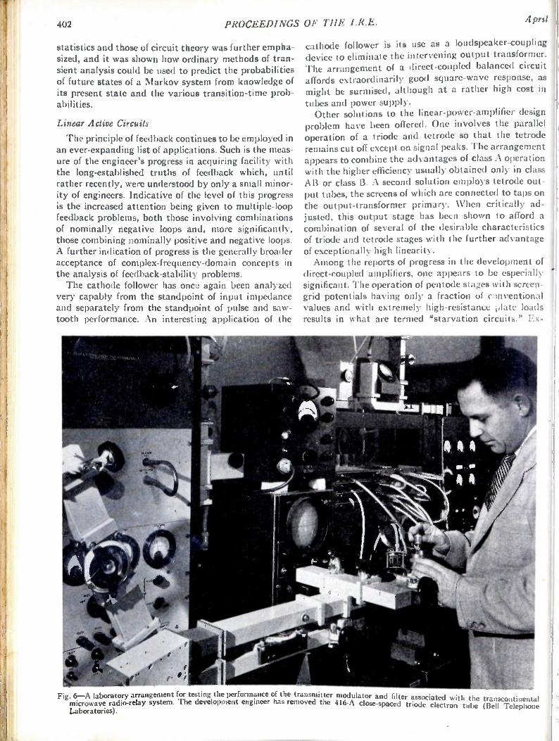
402 PROCEEDINGS OF THE I.R.E. April
statistics and those of circuit theory was further empha-sized, and it was shown how ordinary methods of tran-sient analysis could be used to predict the probabilities of future states of a Markov system from knowledge of its present state and the various transition-time prob-abilities.
Linear Active Circuits
The principle of feedback continues to be employed in an ever-expanding list of applications. Such is the meas-ure of the engineer's progress in acquiring facility with the long-established truths of feedback which, until rather recently, were understood by only a small minor-ity of engineers. Indicative of the level of this progress is the increased attention being given to multiple-loop feedback problems, both those involving combinations of nominally negative loops and, more significantly, those combining nominally positive and negative loops. A further indication of progress is the generally broader acceptance of complex-frequency-domain concepts in the analysis of feedback-stability problems. The cathode follower has once again been analyzed
very capably from the standpoint of input impedance and separately from the standpoint of pulse and saw-tooth performance. An interesting application of the
cathode follower is its use as a loudspeaker-coupling device to eliminate the intervening output transformer. The arrangement of a direct-coupled balanced circuit affords extraordinarily good square-wave response, as might be surmised, although at a rather high cost in
tubes and power supply. Other solutions to the linear-power-amplifier design
problem have been offered. One involves the parallel operation of a triode and tetrode so that the tetrode remains cut off except on signal peaks. The arrangement appears to combine the advantages of class A operation with the higher efficiency usually obtained only in class AB or class B. A second solution employs tetrode out-put tubes, the screens of which are connected to taps on the output-transformer primary. When critically ad-justed, this output stage has becn shown to afford a combination of several of the desirable characteristics of triode and tetrode stages with the further advantage of exceptionally high linearity. Among the reports of progress in the development of
direct-coupled amplifiers, one appears to be especially significant. The operation of pentode stages with screen-grid potentials having only a fraction of clnventional values and with extremely high-resistance plate loads results in what are termed "starvation circuits." Ex-
Fig. 6—A laboratory arrangement for testing the performance of the transmitter modulator and filter associated with the transcontinental microwave radio-relay system. The development engineer has removed the 416-A close-spaced triode electron tube (Bell Telephone Laboratories).
J952 Radio Progress During 1951 403
1:remely high stage gains are possible with this mode )f tube operation, and fewer circuit components are leeded.
Radio Transmitters Common Carrier Radio Relay A regular two-way coast-to-coast relay service for
television broadcasting and communication, made avail-able in September, was first used for the transcon-tinental telecasting of the opening address of the Japanese Peace Treaty Conference in San Francisco. This microwave relay system is 2,992 miles long, and is composed of 107 stations, spaced an average of 28.2 miles apart. All but 18 of these stations are unattended, operating automatically. This network makes it possi-ble to interconnect 94 TV stations in 53 cities. Exten-sions to this service are being installed between major centers of population. (212) J. B. Maggie, "Terminals for the TD-2 radio relay system,"
Bell Lab. Rec., vol. 29, pp. 314-317,323; July, 1951. (213) G. R. Frantz, "Repeaters for the TD-2 radio relay system,"
Bell Lab. Rec., vol. 29, pp. 356-360; August, 1951. (214) L. Espenschied, "Coast-to-coast radio relay system opens,"
Bell Lab. Rec., vol. 29, pp. 427-428; September, 1951. (215) T. J. Grieser and A. C. Peterson, "A broad-band transcon-
tinental radio relay system," Elec. Eng., vol. 70, pp. 810-815; September, 1951.
(216) A. A. Roetken, K. D. Smith, and R. %V. Friis, "The TD-2 microwave relay system," Bell Sys. Tech. Jour., vol. 30, p. 1041; October, 1951.
Microwave Communication The past year has seen a tremendous expansion in the
use of microwave communication systems for railroads, pipe lines, utilities, turnpike traffic control, telephone and telegraph traffic, civil and military service, and operational control of transmitters. New uses for micro-waves are continually being developed. (217) J. K. Kulansky, "Multiplex ringdown panel," FM-TV, vol.
10, pp. 21-22; November, 1950. (218) F. B. Gunter, "Multiplex design," FM-TV, vol. 10, pp. 16-18;
November, 1950. (219) D. Samuelson, "Mid-valley microwave relay," FM-TV, vol. 11,
pp. 23-25; February, 1951. (220) Staff Paper, "High frequency, remote supervisory control, and
communication engineering," The Brown Boveri Rev., vol. 38, p. 77; January-March, 1951.
(221) R. V. Rector and W. E. Sutter, "Microwave systems for 960 and 2,000 MC," Trans. AIEE, vol. 69, pp. 1100-1109; June, 1950.
(222) R. F. Stevens and T. W. Stringfield, "Microwave applications to Bonneville Power Administration system," Elec. Eng., vol. 70, pp. 29-33; January, 1951.
(223) S. J. Ross, "Very high frequency and ultra high frequency radio links in the Australian Post Office Communication Net-work," Inst. Engrs. (Australia), vol. 23, pp. 11-20; January-February, 1951.
(224) F. B. Gunter, "940-960 megacycle communications equipment for industrial application," Elec. Eng., vol. 70, pp. 573-578; July, 1951.
(225) B. Lauterburg, "New high frequency telephone system for electric railways," Techn. Mitteilungen, vol. 29, pp. 137-144; April, 1951.
(226) F. A. Gunther, "Multiplex FM design," FM-TV, vol. 11, pp. 19-21; January, 1951.
(227) L. E. Thompson, "Distortion in multichannel frequency modulation relay systems," RCA Rev., vol. 11, pp. 453-464; December, 1950.
Television Relaying Television relaying has greatly expanded in the United
States and England. More than 80 per cent of the channel miles use microwaves, the remainder coaxial cable. In-creased use of television relaying has been done in the
fields of studio-transmitter links, field equipment, and facilities for providing remote stations with network programs. (228) Staff Paper, "Portable microwave television link," Elec. Com-
mun. (London), vol. 27, pp. 295-297; December, 1950. (229) A. H. Mumford, C. F. Booth and R. W. White, "The Lon-
don/Castleton experimental radio-relay system," P. 0. Elec. Eng. Jour., vol. 43, pp. 93-99;' July, 1950.
(230) V. Learned, "The klystron mixer applied to television relay-ing," PROC. I.R.E., vol. 38, pp. 1033-1035; September, 1950.
(231) M. J. L. Pulling, "Television from France, metre- and cen-timeter-wave radio links between London and Calais," Wire-less World, vol. 56, pp. 353-354; October, 1950.
(232) M. Silver, et at., "Video design considerations in a TV re-peater link," Tele-Tech., vol. 10, pp. 28-30,61; January, 1951.
(233) B. W. Southwell, "Los Angeles to San Francisco microwave relay," Tek.-Tech., vol. 10, pp. 44-45,83; February, 1951.
(234) J. Packer, "Microwave television links," Radio and Telev. News, Radio-Electronic Dept., vol. 16, pp. 14A-15A, 29A-31A; April, 1951.
(235) R. J. Clayton, et a/., "London-Birmingham television radio-relay link," Eng., vol. 171, pp. 447-449; April 13,1951.
(236) R. J. Clayton, et a/., "London-Birmingham television radio-relay link," Proc. IEE (London), vol. 98, pp. 204-223, 224-227; July, 1951.
(237) H. G. Miller and L. Staschover, "Television-Link sound di-plexer," Elec. Commun. (London), vol. 28, pp. 100-109; June, 1951.
Citizen Band
The use of the citizen radio band in the United States had increased from 390 to 651 licenses by the end of the third quarter. This type of service seems to be increasing about 25 licenses per month. (238) Staff Paper, "Miniature walkie-talkie," Wireless World, vol.
57, pp. 323-324; August, 1951.
International Broadcasting and Communication
Considerable expansion in the international broad-casting and communication field took place during the year, mainly as to the better utilization of the spectrum by means of single sideband transmitters and multi-channel operation, which permit closer spacing of fre-
quencies. (239) V. J. Tyler, "A general purpose remote control system for radio
transmitters," Marconi Rev., vol. 15, pp. 61-81; 2nd Quarter, 1951.
(240) G. E. Hansel!, "Transmitter diversity applied to machine telegraph radio circuits," RCA Rev., vol. 11, pp. 508-516; December, 1950.
(241) N. Lund, "Methods of measuring adjacent band radiation from radio transmitters," PROC. I.R.E., vol. 39, pp. 653-656; June, 1951.
(242) G. T. Royden, "Suppression of harmonics in radio trans-mitters," Elec. Commun. (London), vol. 28, pp. 112-120; June, 1951.
(243) G. T. Royden, "Transmission-line balance indicator for trans-mitters," Elec. Commun. (London), vol. 28, pp. 110-111; June, 1951.
(244) E. T. Wrathall and C. P. Beanland, "The single-sideband sys-tem of high frequency radio transmission," Marconi Rev.. vol. 14, pp. 2-22; 1st Quarter, 1951.
(245) F. Ellrodt, "The equipment of the Frankfort-on-the-Main radio station for transoceanic transmission," FTZ, vol. 3, pp. 346-355; September, 1950.
(246) G. Schwarzbeck, "Ultrashort wave transmitters," Forts d. Radiotechnik, vol. 12, pp. 176-192; 1950-51.
(247) R. Terlecki, et al., "B.T.R. frequency-shift radiotelegraph equipment," Strowger Jour., vol. 7, pp. 98-103; July, 1950.
AM Broadcasting
Applications continued to be filed with the Federal Communications Commission for AM broadcasting stations. Licensed stations increased from 2,178 to 2,272 at the end of the third quarter, at which time there were before the Commission 270 applications for new sta-tions. There were also 178 applications for changes in
404 PROCEEDINGS OF THE I.R.E. April
facilities. Commercial use of unattended broadcast transmitters was made in England during the year.
(248) Staff Paper, "The new Daventry transmitter," Jour. Brit. I.R.E., vol. 11, pp. 136; April, 1951.
(249) R. G. Kitchen, "An 8 channel transmitter for an experimental carrier wire-broadcasting system," Jour. Brit. I.R.E., vol. II, pp. 295-339; August, 1951.
(250) N. D. Webster, "Economical 5 K.W. transmitter," Electronics, vol. 24, pp. 115-117: May, 1951.
(251) Staff Paper, "Daventry third programme transmitter," Elec. Eng., vol. 23, p. 166; May, 1951.
(252) Staff Paper, 'Broadcasting transmitters," The Brown Boveri Rev., vol. 38, pp. 79-80; January-March, 1951.
(253) L. B. Petery, "Air-Cooled 5-10 K.W. A.M. Broadcast trans-mitter," Tek-Tech., vol. 9, pp. 28-29, 64-65; November, 1950.
(254) E. S. Harris, "New 1 K.W. H.F. transmitter for communica-tion or broadcast. service," G. E. Co., Telecommun., vol. 5, pp. 106-123; July, 1950.
(255) M. Beurtheret, "Justification of the improvement of quality standards of radio broadcasting transmitters," Onde elec., vol. 31, pp. 184-187; April, 1951.
(256) R. J. Newman, "All new 250-watt transmitter," Broadcast News, vol. 63, pp. 8-13; March-April, 1951.
(257) Staff Paper, "150-K.W. medium-wave broadcast transmitter at Daventry," Eng., vol. 171, pp. 506-507; April 27, 1951.
(258) R. W. Hallows, "New Daventry station; 200 K.W. transmitter design for unattended working," Wireless World, vol. 57, pp. 236-238; June, 1951.
(259) W. Bilrck, "Recent developments in transmitter construction and its physical principles," Forts d. Radiotechnik, vol. 12, pp. 302-326; 1950-51.
(260) G. Stein, "New 150 K.W. radio broadcasting stations in Sundsvaal and Gothenburg," Tek. (Sweden), pp. 22-37; 1951.
FM Broadcasting
General activity in FM broadcasting was less than previous years. The number of licenses outstanding in the United States increased from 513 to 544, and special temporary authorizations were decreased from 163 to 96.
(261) J. Ruston, "A simple crystal discriminator for FM oscillator stabilization," PROC. I.R.E.' vol. 39, pp. 783-788; July, 1951.
(262) H. Rakshit and N. L. Sarkar, "Simple method of producing wide-band frequency modulation," Indian Jour. Phys., vol. 24, pp. 207-222; May, 1950.
(263) G. Brauer, "Lorenz 10 K.W. ultra short wave transmitter for frequency modulation broadcasting," FTZ, vol. 3, pp. 292-296; August, 1950.
(264) L. Rohde, et al., "High power frequency modulation broadcast transmitter," Frequenz, vol. 4, pp. 219-228; September, 1950.
(265) A. A. Gerlach, "Distortion—band-pass considerations in angu-lar modulation," PROC. I.R.E., vol. 38, pp 1203-1207; October, 1950.
(266) F. A. Gunther, "Multiplex FM designs," FM-TV, vol. 11, pp. 19-21; January, 1951.
(267) H. Schutzendithel, "The new frequency-modulated 10 K.W. ultra-short wave radio broadcast transmitter in Hamburg," Elec. Tech. Zeit., vol. 71, pp. 675-679; December, 1950.
(268) J. H. Kopp, "Comments about new frequency modulation cir-cuits," Funk-Technik (Berlin), vol. 6, pp. 240-241; 1951.
(269) J. H. H. Merriman and R. W. White, "The application of fre-quency modulation to VHF multichannel radiotelephony," Proc. IEE (London), vol. 98, p. 56; January, 1951.
TV Broadcasting
Interest in television broadcasting continued to grow despite the continuation of the "freeze" by the Federal Communications Commission of applications for new construction permits. By the end of the third quarter 432 vhf and 16 uhf applications for new television sta-tions were on file. The number of licensed stations in the United States has increased from 107 to 108 stations. No more construction permits will be granted until the "freeze" lifts. The interest in television increased in other countries, particularly Mexico, Cuba, Brazil, and England. Development work in television transmitters was ac-
tive, with work on vhf transmitters in the direction of
increasing power to 20-25 kw and uhf transmitters to
1-5 kw output. (270) W. M. Goodall, "Television by pulse code modulation,"Bell
Sys. Tech. Jour., vol. 30, pp. 33-49; January, 1951. (271) H. M. Crosby, "Five-KW klystron UHF television transmit-
ter," Electronics, vol. 24, pp. 108-112; June, 1951. (272) J. Ruston, "Measuring TV transmitter amplitude characteris-
tics," Tek-Tech., vol. 10, pp. 30-31, 69-72; September, 1951. (273) V. J. Cooper, "Shunt regulated amplifiers," Wireless Eng., vol.
28, pp. 132-145; May 1951. (274) D. G. Fink, "Television, broadcasting in the United States
1927-1950," PROC. I.R.E., vol. 39, pp. 116-123; February, 1951.
(275) E. T. Emmo and E. Jones, "The video output stage," Elec. Eng. (London), vol. 22, pp. 408-413, 454-460; October and November, 1950.
(276) R. G. Peters, "U.H.F. amplifier design," Telev. Eng., vol. 2, pp. 10-11; July, 1951.
Receivers Very-High-Frequency Black-and- White Television
Much engineering time has necessarily been devoted to circumventing material shortages occasioned by the world situation. The Radio-Television Manufacturers Association has set up material bureaus to advise in-dustry on methods of conserving critical materials. Par-ticularly successful was the development of picture tubes having electrostatic focus accomplished by low fixed voltages. Focusing coils and, in some cases, con-trol units, were eliminated, thus resulting in a consider-able saving of critical materials.
(277) "Saving critical materials," Elec. Mfg., vol. 48, pp. 102-105 256. 258. 260; December, 1951. Also. Mater. Bur. Bull. Radio-Teiev. Mfg. Assoc.; 1951.
(278) 'Conservation of raw materials," Tele-Tech., vol. 10, pp.39, 72, 74; April, 1951.
(279) L. E. Swedlund and R. Saunders, "Material-saving picture tube," Electronics, vol. 24, pp. 118-120; April, 1951.
'Other components receiving attention include the fol-lowing: full-focus yokes for increasing the picture area over which good focus is maintained; cylindrical-faced tubes, which permit the elimination of room-light reflec-tions from the screen area; new damper tubes with high heater-to-cathode insulation, which reduces sweep-cir-cuit capacitance and the need for one filament winding; and wide-angle deflection picture tubes and associated sweep components, which decrease the cabinet depth for large-screen pictures.
(280) J. Pell, "The cosine defection yoke," TV Eng., vol. 2, pp. 10-11; June, 1951.
(281) H. W. Grossbohlin, "The design of 90° deflection picture tubes," Tele.-Tech., vol. 10, pp. 42-44; August, 1951.
Low-noise circuits, such as the cascode, and improved low-noise tubes were developed for the tuner section of the receiver, or for boosters. The IRE Receivers Com-mittee standard on methods of measuring spurious radi-ation was published and, in conjunction with RTNIA committees, test sites were set up and checked. Tele-vision receivers having greatly reduced oscillator radia-tion are being manufactured.
(282) G. Voyles, "A cascode type antenna-mounted TV booster," Radio and Telev., vol. 46, pp. 54-55, 90-91; July, 1951.
(283) "Standards on radio receivers: Open field method of measure-ment of spurious radiation from frequency modulation and television broadcast receivers," PROC. I.R.E., vol. 39, pp. 803-806; July, 1951.
(284) J. Van Duyne, "Suppression of local oscillator radiation in television receivers," Presented, I RE-RTMA Fall Meeting, Toronto, Canada; October 29, 1951.
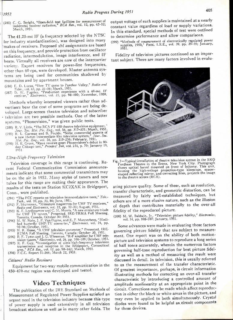
1952 Radio Progress During 1951 405
, (285) C. G. Seright, "Open-field test facilities for measurement of incidental receiver radiation," RCA Rev., vol. 12, pp. 45-52; March, 1951.
The 41.25-mc IF (a frequency selected by the NTSC for industry standardization), was designed into many makes of receivers. Proposed uhf assignments are based on this frequency, and provide protection from oscillator radiation, intermodulation, image interference, and IF beats. Virtually all receivers are now of the intercarrier variety. Export receivers for power-line frequencies, other than 60 cps, were developed. laster antenna sys-tems are being used for communities shadowed by mountains and by apartment houses. (286) E. D. Lucas, "How TV came to Panther Valley," Radio and
Telev., vol. 45, pp. 31-34; March, 1951. (287) D. W. Pugsley, "Production experience with a 40-mc. IF
receiver," Electronics, vol. 23, pp. 98-100; November, 1950.
NIethods whereby interested viewers rather than ad-vertisers bear the cost of some programs are being de-veloped. Large-screen theatre television and subscriber - television are two possible methods. One of the latter systems, "Phonevision," was given public tests. (288) R. V. Little, "The RCA PT-I00 theatre television equipment,"
Jour. Soc. Mot. Pic. Eng., vol. 56, pp. 317-331; March, 1951. (289) R. L. Garman and B. Foulds. "Some commercial aspects of
a new 16-mm intermediate film television system," Jour. Soc. Mot. Pic. Eng., vol. 56, pp. 219-226; February, 1951.
(290) H. E. Green, "Rave reviews greet Phonevisions's debut in 90. day Chicago test," Printers' Ink, vol. 234, p. 79; January 19, 1951.
Ultra-High- Frequency Television Television coverage in this range is continuing. Re-
cent Federal Communication Commission announce-ments indicate that some commercial transmitters may be on the air in 1952. Many styles of tuners and new tubes for this range are making their appearance. The results of the tests on Station KC2XAK in Bridgeport, Conn., were published. (291) "The FCC reports on television intermodulation tests," Tek.-
Tech., vol. 10, pp. 33, 86; June, 1951. (292) F. Shunaman, "Miniature magnetron for UHF TV receivers,"
Radio and Electronics, vol. 22, pp. 32-33; August, 1951. (293) K. E. Loofbourrow and C. M. Morris, "A new miniature triode
for UHF TV tuners," Presented, IRE-TRMA Fall Meeting, Toronto, Canada, October 30; 1951.
(294) M. W. Slate, J. P. Van Duyne, and E. F. Mannerberg, "Modi-fied butterfly UHF-TV converter," Electronics, vol. 24, pp. 92-96; October, 1951.
(295) H. R. Hesse, "A UHF television converter," Presented, IRE-RTMA Fall Meeting, Toronto, Canada; October 30, 1951.
(296) B. F. Tyson and J. G. Wiessman, "R-F amplifier for UHF tele-vision tuners," Electronics, vol. 24, pp. 106-109; October, 1951.
(297) R. F. Guy, "Investigation of ultra-high-frequency television transmission and reception in the Bridgeport, Connecticut area," RCA Rev., vol. 12, pp. 98-142; March, 1951.
(298) F.C.C. Report 51-244; March 22, 1951.
Citizens' Radio Receivers Equipment for two-way mobile communication in the
450-470-mc region was developed and tested.
Video Techniques The publication of the IRE Standard on Methods of
Measurement of Regulated Power Supplies satisfied an urgent need in the television industry because this type of power supply is used extensively in all television broadcast stations as well as in many other fields. The
output voltage of such supplies is maintained at a nearly constant value regardless of load or supply variations. In this standard, special methods of test were outlined to determine performance and allow comparisons. (299) "Methods of measurement of electronically regulated power
supplies, 1950," PROC. I.R.E., vol. 39, pp. 29-35; January, 1951.
Fidelity of television pictures continued as an impor-tant subject. There are many factors involved in evalu-
Fig. 7—Typical installation of theatre television system in the RKO Fordham Theatre in the Bronx, New York City. Photograph shows optical barrel mounted on front of balcony. This unit, housing the high-voltage projection-type kinescope, saucer-shaped reflecting mirror, and correcting lines, projects the image to the theatre screen (RCA).
ating picture quality. Some of these, such as resolution, transfer characteristic, and geometric distortion, can be measured by fairly well-established techniques, but others are of a more elusive nature, such as the illusion of depth that contributes materially to the over-all fidelity of the reproduced picture. (300) M. W. Baldwin, Jr., "Television picture fidelity," Electronics,
vol. 24, pp. 106-107; January, 1951.
Some advances were made in evaluating those factors governing picture fidelity that are subject to measure-ment. One report was on the ability of both motion-picture and television systems to reproduce a long series of half tones accurately, wherein the numerous factors governing half-tone reproduction for best picture fidel-ity as well as a method of measuring the result were discussed in detail. In television, this is usually referred to as the measurement of the transfer characteristic. Of greatest importance, perhaps, is circuit information illustrating methods for correcting an over-all transfer characteristic by introducing a controlled amount of amplitude nonlinearity at an appropriate point in the circuit. Corrections may be made which affect reproduc-tion in either the black or white areas in the picture, and may even be applied to both simultaneously. Crystal diodes were found to be helpful as circuit components for these devices.

406 PROCEEDINGS OF THE I.R.E. AprilT
(301) 0. H. Schade, "Image gradation, graininess and sharpness en television and motion picture systems," Jour. Soc. Mot. Pic. and Telev. Eng., vol. 56, pp. 137-177; February, 1951.
(302) R. Kuehn, "Crystal diodes in TV studio equipment," Electron-ics, vol. 23, pp. 114-116; December, 1950.
An interesting comparison between the techniques used in measuring resolution of motion-picture film and of a television system was the result of IRE committee activity. Since different types of test patterns are used in the two fields, an evaluation of one in terms of the other is particularly valuable in those activities where the two techniques overlap, such as in television re-cording. (303) H. J. Schafly, "Same comparative factors of picture resolution
in television and film industries," PROC. I.R.E., vol. 39, pp. 6-10; January, 1951.
Continued emphasis has been placed on the impor-tance of improving the television images obtained from motion-picture film. Several articles have appeared dis-cussing the merits of the various pickup tubes employed in commercial film cameras, including the iconoscope, image orthicon, image dissector, and image iconoscope. Each of these tubes appears to have some unique ad-vantages as well as defects, making a choice between them rather difficult. Suggestions are included for best operating conditions and circuit adjustments, which should be helpful to those employing these tubes. (304) K. B. Benson and A. Ettlinger, "Practical use of iconoscopes
and image orthicons as film pickup devices," Jour. Soc. Mot. Pic. and Telev. Eng., vol. 57, pp. 9-14; July, 1951.
(305) R. L. Garman and R. W. Lee, 'Image tubes and techniques in TV film camera chains," Jour. Soc. Mot. Pic. and Telev. Eng., vol. 56, pp. 52-64; January, 1951.
(306) R. Theile, "Image iconoscope for improved TV film scanning," Tele.-Tech., pp. 44-46; November, 1951.
A continuous-type film projector for television appli-cations was developed, having two features designed to
Fig. 8—Dual scanner. The FTL-82A television flying-spot scanner pictured above is used to convert slide information to a video sig-nal suitable for television broadcasting. Developed by Federal Telecommunication Laboratories, Inc., it enables the effective and commercial handling of commercials, test patterns, spot news, and other television-slide information.
overcome difficulties encountered with such projectors. One is an electromechanical servo system that auto-matically compensates for slight irregularities in film motion so that an image having negligible vertical
"jump" is obtained. A second feature is a system for auto-matically eliminating the flicker caused by light varia-tion resulting from the normal movement of the rotat-ing mirrors. This projector can be used in conjunction , with a flying-spot scanner to permit improved reproduc-
tion from film. (307) D. G. Fink, "Continuous film scanner for TV," Electronics, vol.
24, pp. 114-116; July, 1951.
Several new techniques were developed in the field of television recording on film. The first, called "area masking," is used for improving detail contrast in the release print intended for projection on a television-film camera. The contrast range is not increased beyond that which the pickup tube, such as an iconoscope, can accept without serious distortion in the highlights. The general effect is an increase in picture sharpness without causing a loss of detail in either the dark or light areas of the pictures. This is accomplished entirely by photo-graphic means. Although this adds some complexity to the developing process, it is undoubtedly justified by improved over-all results. In addition, two methods for improving picture sharpness electrically by aperture correction or by "crispening" circuits were also proposed.
(308) P. J. Herbst, R. 0. Drew, and S. W. Johnson, "Electrical and photographic compensation in television film reproduction," Jour. Soc. Mot. Pic. and Telcv. Eng., pp. 289-307; October, 1951.
(309) P. C. Goldmark and J. M. Hollywood, "A new technique for improving the sharpness of television pictures," Jour. Soc. Mot. Pic. and Telev. Eng., pp. 382-396; October, 1951.
Another technique is the rapid processing of televi-sion-film recordings so that they can be used within several minutes after the images are recorded.
(310) R. L. Garman and B. Foulds, "Some commercial aspects of a new 16 mm intermediate film television system," Jour. Soc. Mot. Pic. and Telev. Eng., vol. 56, pp. 219-226; February, 1951.
Improvements in television cameras and associated equipment were described. Simplified and improved op-eration is made possible by the use of remote iris con-trol as well as remote focus and remote lens-turret con-trol. Continued emphasis is being placed on devices for special effects. One of these is an amplifier capable of utilizing special keying signals to allow selected parts of one picture to be inserted in another. Another device, called the "Genlock," makes it possible to obtain such effects even though one picture source is located at a point remote from the other. Accurate lock-in between two widely separated synchronizing generators is re-quired to make this effect possible.
(311) R. L. Garman and J. E. Cope, "Simplified operation keynoted in new TV equipment," Tele.-Tech., vol. 10, p. 48; October, 1951.
(312) W. L. Hurford, "Combined special effects amplifier for tele-vision," Tek.-Tech., pp. 50-53; November, 1951.
(313) J. H. Roe, "The Genlock," Jour. Soc. Mot. Pic. and Telev. Eng., vol. 56, pp. 232-234; February, 1951.
Several unconventional approaches to the television scanning process were proposed although their use may be confined largely to special applications. In one of these proposals, a scanning beam of constant current is velocity modulated by the video signal so that high-velocity portions of the scanning path will be repro-
1
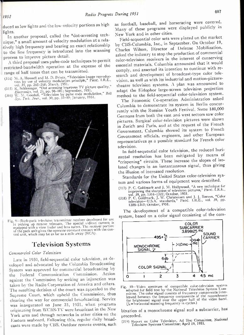
11952
duced as low lights and the low-velocity portions as high
lights. In another proposal, called the "dot-arresting tech-
nique," a small amount of velocity modulation at a rela-lively high frequency and bearing an exact relationship to the line frequency is introduced into the scanning process to improve picture detail. A third proposal uses pulse-code techniques to permit
restricted-bandwidth operation at the expense of the range of half tones that can be transmitted. (314) M. A. Honnell and M. D. Prince, "Television image reproduc-
tion by use of velocity modulation principle," PROC. I.R.E., vol. 39, pp. 265-268; March, 1951.
(315) K. Schlesinger, "Dot arresting improves TV picture quality," Electronics, vol. 24, pp. 96-101; September, 1951.
(316) W. M. Goodall, "Television by pulse code modulation," Bell Sys. Tech. Jour., vol. 30, pp. 33-49; January, 1951.
Fig. 9—Back-pack television transmitter receiver developed for use in picking up remote telecasts. The special vidicon camera is equipped with a view finder and lens turret. The receiver portion of the pack unit gives the operator constant contact with the con-trol unit, which may be as far as a mile away (RCA).
Radio Progress During 1951
as football, baseball, and horseracing were covered. Many of these programs were displayed publicly in New York and in other cities. Field-sequential color sets were placed on the market
by CBS-Columbia, Inc., in September. On October 19, Charles Wilson, Director of Defense Mobilization, asked the industry to stop the production of commercial color-television receivers in the interest of conserving essential materials. Columbia announced that it would comply, and asserted its intention to continue with re-search and development of broadcast-type color tele-vision, as well as with its industrial and motion-picture-theatre television systems. A plan was announced to adapt the Eidophor large-screen television projection method to the field-sequential color-television system. The Economic Co-operation Administration asked
Columbia to demonstrate its system in Berlin concur-rently with the Russian Youth Festival. Some 180,000 Germans from both the east and west sectors saw color pictures. Surgical color-television pictures were shown in Zurich and Paris, and at the request of the French Government, Columbia showed its system to French Government officials, engineers, and other European representatives as a possible standard for French color
television. In field-sequential color television, the reduced hori-
zontal resolution has been mitigated by means of "crispening" circuits. These increase the slopes of iso-lated changes in an instantaneous signal, thus giving the illusion of increased resolution. Standards for the United States color-television sys-
tem and various forms of equipment were described. (317) P. C. Goldmark and J. M. Hollywood, "A new technique for
improving the sharpness of television pictures," PROC. I.R.E., vol. 39, pp. 1314-1322; October, 1951.
(318) P. C. Goldmark, J. W. Christensen and J. J. Reeves, "Color television—U.S.A. standards," PROC. I.R.E., vol. 39, pp. 1288-1313; October, 1951.
The development of a compatible color-television system, based on a color signal consisting of the com-
Television Systems Commercial Color Television
Late in 1950, field-sequential color television, as de-veloped and advocated by the Columbia Broadcasting System was approved for commercial broadcasting by the Federal Communication Commission. Action against the Commission by seeking an injunction was taken by the Radio Corporation of America and others. The resulting decision of the court was appealed to the Supreme Court, which upheld the Commission, thus clearing the way for commercial broadcasting. Service was inaugurated on June 25, 1951, when programs originating from WCBS-TV were broadcast in the New York area and through networks in other cities on the Eastern seaboard. Following this, regular daily broad-casts were made by CBS. Outdoor remote events, such
407
495 x fh 2
MONOCHROME SIGNAL
COLOR SUBCARRIER 3.898125 mc
SOUND
, CARRIER
l•- > 1.0mc l rn: t
— — 1-6db • • I
COLOR SIGNA LA
0 I 2 3 4 45 mC
rg. 10—Video spectrum of compatible color-television system adopted for field test by the National Television System Com-mittee. The color signal consists of frequency components inter-leaved between the frequency components of the monochrome (or brightness) signal over the upper half of the video band.
horizontal scanning frequency in cycles.)
bination of a monochrome signal and a subcarrier, has proceeded. (319) Report on Color Television, Ad Hoc Committee, National
Television Systems Committee; April 19, 1951.
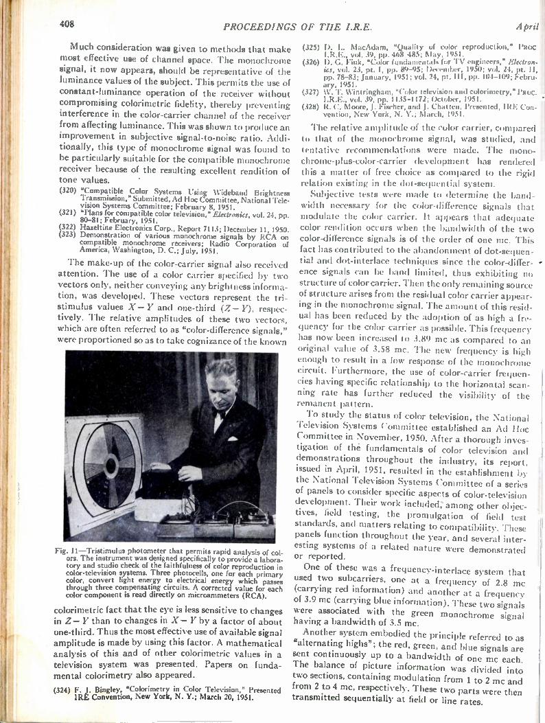
408 PROCEEDINGS OF THE I.R.E. April i
Much consideration was given to methods that make most effective use of channel space. The monochrome signal, it now appears, should be representative of the luminance values of the subject. This permits the use of constant-luminance operation of the receiver without compromising colorimetric fidelity, thereby preventing interference in the color-carrier channel of the receiver from affecting luminance. This was shown to produce an improvement in subjective signal-to-noise ratio. Addi-tionally, this type of monochrome signal was found to be particularly suitable for the compatible monochrome receiver because of the resulting excellent rendition of tone values. (320) "Compatible Color Systems Using Wideband Brightness
Transmission," Submitted, Ad Hoc Committee, National Tele-vision Systems Committee; February 8, 1951.
(321) "Plans for compatible color television," Electronics, vol. 24, pp. 80-81; February, 1951.
(322) Hazeltine Electronics Corp., Report 7113; December 11, 1950. (323) Demonstration of various monochrome signals by RCA on
compatible monochrome receivers; Radio Corporation of America, Washington, D. C.; July, 1951.
The make-up of the color-carrier signal also received attention. The use of a color carrier specified by two vectors only, neither conveying any brightness informa-tion, was developed. These vectors represent the tri-stimulus values X — Y and one-third (Z— Y), respec-tively. The relative amplitudes of these two vectors, which are often referred to as "color-difference signals," were proportioned so as to take cognizance of the known
Fig. 11—Tristimulus photometer that permits rapid analysis of col-ors. The instrument was designed specifically to provide a labora-tory and studio check of the faithfulness of color reproduction in color-television systems. Three photocells, one for each primary color, convert light energy to electrical energy which passes through three compensating circuits. A corrected value for each color component is read directly on microammeters (RCA).
colorimetric fact that the eye is less sensitive to changes in Z— Y than to changes in X— Y by a factor of about one-third. Thus the most effective use of available signal amplitude is made by using this factor. A mathematical analysis of this and of other colorimetric values in a television system was presented. Papers on funda-mental colorimetry also appeared.
(324) F. J. Bingley, "Colorimetry in Color Television," Presented IRE Convention, New York, N. Y.; March 20, 1951.
(325) D. L. MacAdam, "Quality of color reproduction," Paoc I.R.E., vol. 39, pp. 468-485; May, 1951.
(326) D. G. Fink, "Color fundamentals for TV engineers," Electron-ics, vol. 23, pt. I, pp. 89-95; December, 1950; vol. 24, pt. II, pp. 78-83; January, 1951; vol. 24, pt. III, pp. 104-109; Febru-ary, 1951.
(327) W. T. Wintringharn, "Color television and colorimetry," PROC. I.R.E., vol. 39, pp. 1135-1172; October, 1951.
(328) R. C. Moore, J. Fischer, and J. Chattel), Presented, IRE Con-vention, New York, N. Y.; March, 1951.
The relative amplitude of the color carrier, compared to that of the monochrome signal, was studied, and tentative recommendations were made. The mono chrome-plus-color-carrier development has rendered this a matter of free choice as compared to the rigid relation existing in the dot-sequential system. Subjective tests were made to determine the band-
width necessary for the color-difference signals that modulate the color carrier. It appears that adequate color rendition occurs when the bandwidth of the two color-difference signals is of the order of one mc. This fact has contributed to the abandonment of dot-sequen-tial and dot-interlace techniques since the color-differ-ence signals can be band limited, thus exhibiting no structure of color carrier. Then the only remaining source of structure arises from the residual color carrier appear-ing in the monochrome signal. The amount of this resid-ual has been reduced by the adoption of as high a fre-quency for the color carrier as possible. This frequency has now been increased to 3.89 mc as compared to an original value of 3.58 mc. The new frequency is high enough to result in a low response of the monochrome circuit. Furthermore, the use of color-carrier frequen-cies having specific relationship to the horizontal scan-ning rate has further reduced the visibility of the remanent pattern.
To study the status of color television, the National Television Systems Committee established an Ad Hoc Committee in November, 1950. After a thorough inves-tigation of the fundamentals of color television and demonstrations throughout the industry, its report, issued in April, 1951, resulted in the establishment by the National Television Systems Committee of a series of panels to consider specific aspects of color-television development. Their work included,' among other objec-tives, field testing, the promulgation of field test standards, and matters relating to compatibility. These panels function throughout the year, and several inter-esting systems of a related nature were demonstrated or reported.
One of these was a frequency-interlace system that used two subcarriers, one at a frequency of 2.8 mc (carrying red information) and another at a frequency of 3.9 mc (carrying blue information). These two signals were associated with the green monochrome signal having a bandwidth of 3.5 mc.
Another system embodied the principle referred to as "alternating highs"; the red, green, and blue signals are sent continuously up to a bandwidth of one mc each. The balance of picture information was divided into two sections, containing modulation from 1 to 2 mc and from 2 to 4 mc, respectively. These two parts were then transmitted sequentially at field or line rates.
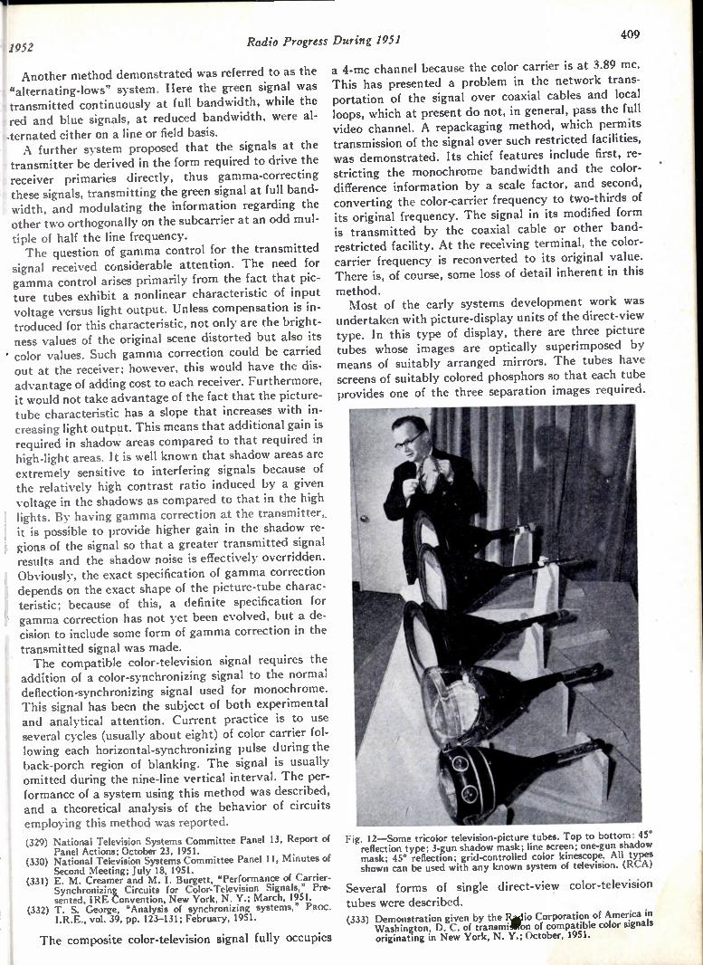
11952 Radio Progress During 1951 '
Another method demonstrated was referred to as the "alternating-lows" system. Here the green signal was transmitted continuously at full bandwidth, while the red and blue signals, at reduced bandwidth, were al-•ternated either on a line or field basis. A further system proposed that the signals at the
transmitter be derived in the form required to drive the receiver primaries directly, thus gamma-correcting these signals, transmitting the green signal at full band-width, and modulating the information regarding the other two orthogonally on the subcarrier at an odd mul-tiple of half the line frequency. The question of gamma control for the transmitted
signal received considerable attention. The need for gamma control arises primarily from the fact that pic-ture tubes exhibit a nonlinear characteristic of input voltage versus light output. Unless compensation is in-troduced for this characteristic, not only are the bright-ness values of the original scene distorted but also its ' color values. Such gamma correction could be carried out at the receiver; however, this would have the dis-advantage of adding cost to each receiver. Furthermore, it would not take advantage of the fact that the picture-tube characteristic has a slope that increases with in-creasing light output. This means that additional gain is required in shadow areas compared to that required in high-light areas. It is well known that shadow areas are extremely sensitive to interfering signals because of the relatively high contrast ratio induced by a given voltage in the shadows as compared to that in the high
! lights. By having gamma correction at the transmitter,. i it is possible to provide higher gain in the shadow re-gions of the signal so that a greater transmitted signal results and the shadow noise is effectively overridden.
I Obviously, the exact specification of gamma correction i depends on the exact shape of the picture-tube charac-t teristic; because of this, a definite specification for ? gamma correction has not yet been evolved, but a de-cision to include some form of gamma correction in the
I transmitted signal was made. The compatible color-television signal requires the
addition of a color-synchronizing signal to the normal deflection-synchronizing signal used for monochrome. This signal has been the subject of both experimental and analytical attention. Current practice is to use several cycles (usually about eight) of color carrier fol-lowing each horizontal-synchronizing pulse during the back-porch region of blanking. The signal is usually omitted during the nine-line vertical interval. The per-formance of a system using this method was described, and a theoretical analysis of the behavior of circuits
employing this method was reported.
(329) National Television Systems Committee Panel 13, Report of Panel Actions; October 23, 1951.
(330) National Television Systems Committee Panel 11, Minutes of Second Meeting; July 18, 1951.
(331) E. M. Creamer and M. I. Burgett, "Performance of Carrier-Synchronizing Circuits for Color-Television Signals," Pre-sented, IRE Convention, New York, N. Y.; March, 1951.
(332) T. S. George, "Analysis of synchronizing systems," PROC. I.R.E., vol. 39, pp. 123-131; February, 1951.
The composite color-television signal fully occupies
409
a 4-mc channel because the color carrier is at 3.89 mc. This has presented a problem in the network trans-portation of the signal over coaxial cables and local loops, which at present do not, in general, pass the full video channel. A repackaging method, which permits transmission of the signal over such restricted facilities, was demonstrated. Its chief features include first, re-stricting the monochrome bandwidth and the color-difference information by a scale factor, and second, converting the color-carrier frequency to two-thirds of its original frequency. The signal in its modified form is transmitted by the coaxial cable or other band-restricted facility. At the receiving terminal, the color-carrier frequency is reconverted to its original value. There is, of course, some loss of detail inherent in this method. Most of the early systems development work was
undertaken with picture-display units of the direct-view type. In this type of display, there are three picture tubes whose images are optically superimposed by means of suitably arranged mirrors. The tubes have screens of suitably colored phosphors so that each tube provides one of the three separation images required.
Fig. 12—Some tricolor television-picture tubes. Top to bottom: 45° reflection type; 3-gun shadow mask; line screen; one-gun shadow mask; 45° reflection; grid-controlled color kinescope. All types shown can be used with any known system of television. (RCA)
Several forms of single direct-view color-television tubes were described. (333) Demonstration given by the Radio Corporation of America in
Washington, D. C. of transmillfon of compatible color signals originating in New York, N. Y.; October, 1951.

410 PROCEEDINGS OF THE I.R.E. April
Fig. 13—Uhf antenna of the type installed at the experimental sta-tion, Stratford, Conn. Slots can be stacked in sufficient number to give the desired gain. he prototype shown operates in the 529-535-mc channel and lilt a gain of about 20. It is 40 feet high and 11 inches in diameter (NBC).
(334) A series of articles on color television, PROC. I.R.E.; October, 1951.
(335) R. Dressler, 'The Chromatron," Presented, RTMA-IRE Ra-dio Fall Meeting, Toronto, Canada; October, 1951.
Ultra-High-Frequency Television
As a result of a gradual accumulation of technica information covering transmitters, receivers, and prop agation in the ultra-high-frequencies, the Federal Corn munications Cornmission formulated proposed stand ards and rules to guide the growth of television in the 470-890 mc region, which was tentatively set aside for that purpose in 1945. These proposed rules and stand-ards represent the integration of information acquired in various research projects over a period of six years. Among the more significant of these was a test projec t using experimental station Kt '2X.1K in Bridgepor t, Conn. Its transmitter employed multitube cavities op-erating as tripler and power-amplifier stages to provide an output power at one kw at the peak of the sync hron iz-ing pulses. The transmitting an tenna cons isted of a stee l tube containing half-wave radiating slots, the upper an d lower halves each made up of eleven layers of slots with four equally space d slots per layer , giving a power gain of 17.3. Utilizing this fac ility, man y manu factur ing companies field tested prototypes of their rece ivers an d converters. Another approach to the pro blem of obta ining ade-
quate power at uhf for telev ision transm itters was through the use of klystrons . A sing le tube of this type provided an output of 5 kw.
(336) D. G. Fink, "Telev ision Broa dcast ing in the United State 1927-1950," PROC. I.R.E., vo l. 39, pp. 116-123 ; February 1951.
(337) R. F. Guy, "Inves tiga tion of ultra -high-frequency televisioi transmission and rece ption in the Bridgeport, Connecticu area," RCA Rev., vol. 12, pp. 98-142 ; Marc h, 1951 .
(338) H. M. Crosby, "Five -kw klystron uhf te lev ision transmitter, " Electronics, vol. 24, pp. 108-112 ; June, 1951.
(339) L. 0. Krause, "Sidefire helix uhf-TV transmitting antenna, " Electronics, vol. 24, pp. 107-109 ; August, 1951.
(340) "Tilting of antenna increases uhf TV station signal strength, " Elec. Eng., vol. 70, p. 651 ; July, 1951 .
(341) R. Guenther, "Radio re lay des ign data 60 to 600 mc, " PROC. I.R.E., vol. 39, pp. 1027-1034 ; Septem ber, 1951.
(342) K. H. Cook and R. G. Artman, "UHF-TV propagation meas-urements," Tele.-Tech., vo l. 10, pp. 50-51; March, 1951; pp. 52-54; April, 1951.
(343) R. G. Peters, "I "HF-RF amplifier des ign ," Teter. Eng., vo l. 2, pp. 10-11; July, 1951.
(344) J. H. Battison, "Day with uhf-TV at KC2XAK, Bridgeport, uhf conversion strips for use in TV tuners, " Tek -Tech., vol. 10, p. 32; July, 1951.
(345) W. H. Sayer, Jr. an d E. Mehrbac h, "Uhf transmitter uses beer -
barrel cavity," Electronics, vo l. 24, pp. 125 -127; December, 1951.
(346) B. M. Ely, "Uhf transm ission line problems, " Telco. Eng., vol. 2, pp. 12-27; Novem ber , 1951
(347) B. M. Ely, "Report on first I.R.E.-uhf symposium, " Teter. Eng., vol. 2, pp. 10-28 ; Octo ber, 1951.
Another antenna struc ture deve loped for this band made use of the trave ling -wave pr inc iple. The antenna radiator was spiraled aroun d the supporting tower. A power gain of 20 was prov ided by a four -bay antenna. Experiments were initiated to determ ine the result
of tilting the main beam of an antenna having a narrow pattern in the vertical plane , with regard to both its effect on field strength in the serv ice area and on tropospheric propagation . These tests were conducted on 530.25 and 850 mc at Bridge port. The antennas con-
,
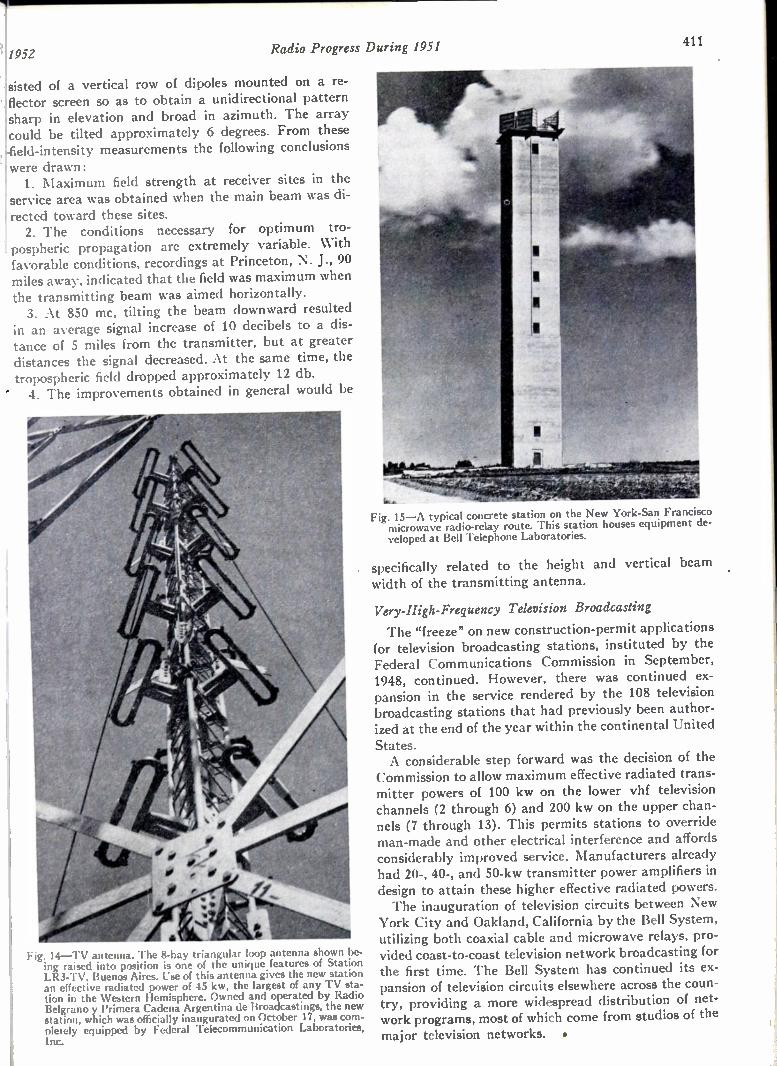
1952 Radio Progress During 1951 411
sisted of a vertical row of dipoles mounted on a re-flector screen so as to obtain a unidirectional pattern sharp in elevation and broad in azimuth. The array could be tilted approximately 6 degrees. From these .field-intensity measurements the following conclusions were drawn: 1. Maximum field strength at receiver sites in the
service area was obtained when the main beam was di-! rected toward these sites. 2. The conditions necessary for optimum tro-
pospheric propagation are extremely variable. With favorable conditions, recordings at Princeton, N. J., 90 miles away, indicated that the field was maximum when the transmitting beam was aimed horizontally. 3. At 850 mc, tilting the beam downward resulted
in an average signal increase of 10 decibels to a dis-tance of 5 miles from the transmitter, but at greater distances the signal decreased. At the same time, the tropospheric field dropped approximately 12 db. ' 4. The improvements obtained in general would be
Fig. 14—TV antenna. The 'angular loop antenna shown be-ing raised into position is one of the unique features of Station LR3-TV, Buenos Aires. Use of this antenna gives the new station an effective radiated power of 45 kw, the largest of any TV sta-tion in the Western Hemisphere. Owned and operated by Radio Belgrano y Primera Cadena Argentina de Broadcastings, the new station, which was officially inaugurated on October 17, was com-pletely equipped by Federal Telecommunication Laboratories, Inc.
_ Fig. 15—A typical concrete station on the New York-San Francisco microwave radio-relay route. This station houses equipment de-veloped at Bell Telephone Laboratories.
specifically related to the height and vertical beam width of the transmitting antenna.
Very-High-Frequency Television Broadcasting
The "freeze" on new construction-permit applications for television broadcasting stations, instituted by the Federal Communications Commission in September, 1948, continued. However, there was continued ex-pansion in the service rendered by the 108 television broadcasting stations that had previously been author-ized at the end of the year within the continental United
States. A considerable step forward was the decision of the
Commission to allow maximum effective radiated trans-mitter powers of 100 kw on the lower vhf television channels (2 through 6) and 200 kw on the upper chan-nels (7 through 13). This permits stations to override man-made and other electrical interference and affords considerably improved service. Manufacturers already had 20-, 40-, and 50-kw transmitter power amplifiers in design to attain these higher effective radiated powers. The inauguration of television circuits between New
York City and Oakland, California by the Bell System, utilizing both coaxial cable and microwave relays, pro-vided coast-to-coast television network broadcasting for the first time. The Bell System has continued its ex-pansion of television circuits elsewhere across the coun-try, providing a more widespread distribution of net-work programs, most of which come from studios of the major television networks. •
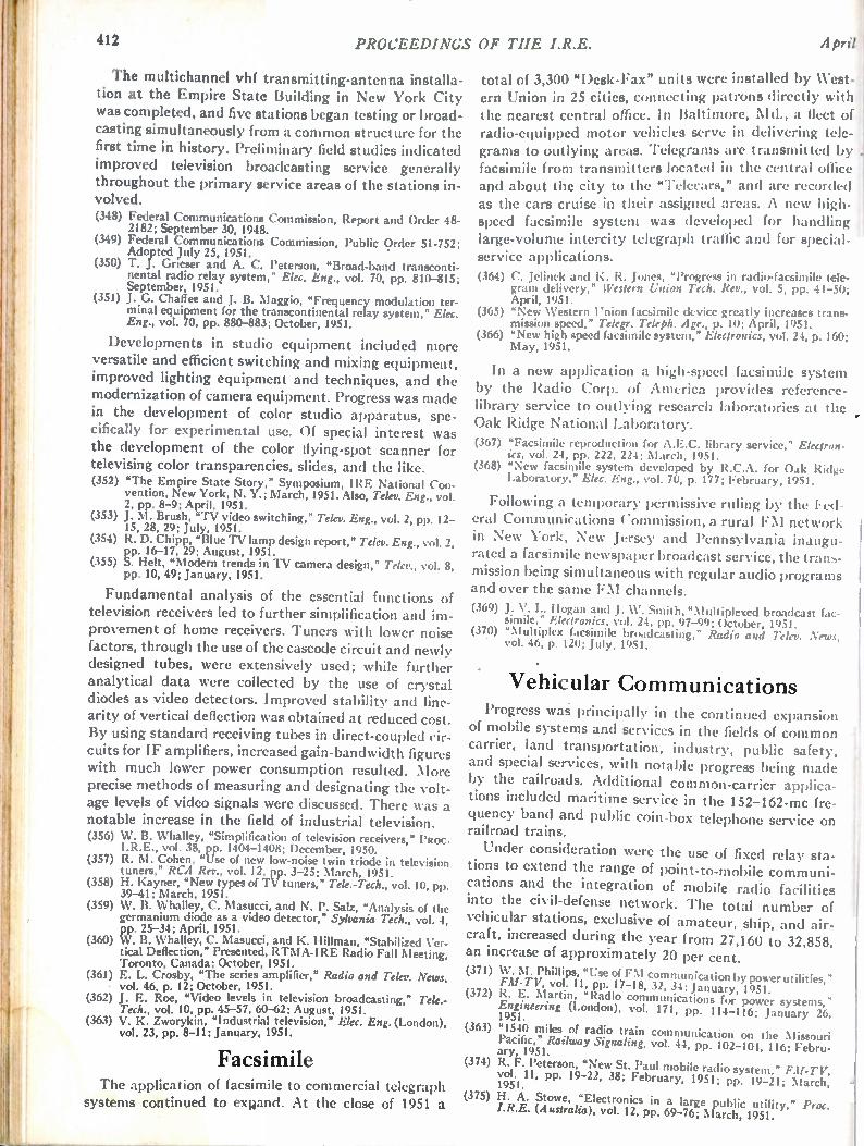
412 PROCEEDINGS OF THE I.R.E. April
The multichannel vhf transmitting-antenna installa tion at the Empire State Building in New York City was completed, and five stations began testing or broad casting simultaneously from a common structure for the first time in history. Preliminary field studies indicated improved television broadcasting service generally throughout the primary service areas of the stations in-volved. (348) Federal Communications Commission, Report and Order 48-
2182; September 30, 1948. (349) Federal Communications Commission, Public Order 51-752;
Adopted July 25, 1951. (350) T. J. Gneser and A. C. Peterson, 'Broad-band transconti-
nental radio relay system," Elec. Eng., vol. 70, pp. 810-815; September, 1951.
(351) J. G. Chaffee and J. B. Maggio, "Frequency modulation ter-minal equipment for the transcontinental relay system," Elec. Eng., vol. 70, pp. 880-883; October, 1951.
Developments in studio equipment included more versatile and efficient switching and mixing equipment, improved lighting equipment and techniques, and the modernization of camera equipment. Progress was made in the development of color studio apparatus, spe-cifically for experimental use. Of special interest was the development of the color flying-spot scanner for televising color transparencies, slides, and the like. (352) "The Empire State Story," Symposium, IRE National Con-
vention, New York, N. Y.; March, 1951. Also, Telev. Eng., vol. 2, pp. 8-9; April, 1951.
(353) J. M. Brush, "TV video switching," Telev. Eng., vol. 2, pp. 12-15, 28, 29; July, 1951.
(354) R. D. Chipp, "Blue TV lamp design report," Telev. Eng., vol. 2, pp. 16-17, 29; August, 1951.
(355) S. Helt, "Modern trends in TV camera design," Telev., vol. 8, pp. 10, 49; January, 1951.
Fundamental analysis of the essential functions of television receivers led to further simplification and im-provement of home receivers. Tuners with lower noise factors, through the use of the cascode circuit and newly designed tubes, were extensively used; while further analytical data were collected by the use of crystal diodes as video detectors. Improved stability and line-arity of vertical deflection was obtained at reduced cost. By using standard receiving tubes in direct-coupled cir-cuits for IF amplifiers, increased gain-bandwidth figures with much lower power consumption resulted. More precise methods of measuring and designating the volt-age levels of video signals were discussed. There was a notable increase in the field of industrial television. (356) W. B. Whalley, "Simplification of television receivers," PROC.
I. R.E., vol. 38, pp. 1404-1408; December, 1950. (357) R. M. Cohen, "Use of new low-noise twin triode in television
tuners," RCA Rev., vol. 12, pp. 3-25; March, 1951. (358) H. Kayner, "New types of TV tuners," Tek.-Tech., vol. 10, pp.
39-41; March, 1951. (359) W. B. Whalley, C. Masucci, and N. P. Salz, "Analysis of the
germanium diode as a video detector," Sylvania Tech., vol. 4, pp. 25-34; April, 1951.
(360) W. B. Whalley, C. Masucci, and K. Hillman, "Stabilized Ver-tical Deflection," Presented, RTMA-IRE Radio Fall Meeting, Toronto, Canada; October, 1951.
(361) E. L. Crosby, "The series amplifier," Radio and Telev. News, • vol. 46, p. 12; October, 1951.
(362) J. E. Roe, "Video levels in television broadcasting," Tek.-Tech., vol. 10, pp. 45-57, 60-62; August, 1951.
(363) V. K. Zworykin, "Industrial television," Elec. Eng. (London), vol. 23, pp. 8-11; January, 1951.
Facsimile The application of facsimile to commercial telegraph
systems continued to expand. At the close of 1951 a
total of 3,300 "Desk-Fax" units were installed by West-ern Union in 25 cities, connecting patrons directly with the nearest central office. In Baltimore, Md., a fleet of radio-equipped motor vehicles serve in delivering tele-grams to outlying areas. Telegrams are transmitted by facsimile from transmitters located in the central office and about the city to the "Telecars," and are recorded as the cars cruise in their assigned areas. A new high-speed facsimile system was developed for handling large-volume intercity telegraph traffic and for special-service applications. (364) C. Jelinek and K. R. Jones, "Progress in radio-facsimile tele-
gram delivery," Western Union Tech. Rev., vol. 5, pp. 41-50; April, 1951.
(365) "New Western Union facsimile device greatly increases trans-mission speed," Telegr. Tekph. Age., p. 10; April, 1951.
(366) "New high speed facsimile system," Electronics, vol. 24, p. 160; May, 1951.
In a new application a high-speed facsimile system by the Radio Corp. of America provides reference-library service to outlying research laboratories at the Oak Ridge National Laboratory.
(367) "Facsimile reproduction for A.E.C. library service," Electron-ics, vol. 24, pp. 222, 224; March, 1951.
(368) "New facsimile system developed by R.C.A. for Oak Ridge Laboratory," Elec. Eng., vol. 70, p. 177; February, 1951.
Following a temporary permissive ruling by the Fed-eral Communications Commission, a rural FM network in New York, New Jersey and Pennsylvania inaugu-rated a facsimile newspaper broadcast service, the trans-mission being simultaneous with regular audio programs and over the same FM channels.
(369) J. V. L. Hogan and J. IV. Smith, "Multiplexed broadcast fac-simile," Electronics, vol. 24, pp. 97-99; October, 1951.
(370) "Multiplex facsimile broadcasting," Radio and Telev. News, ' vol. 46, p. 120; July, 1951.
• Vehicular Coin in unications Progress was principally hi the continued expansion
of mobile systems and services in the fields of common carrier, land transportation, industry, public safety, and special services, with notable progress being made by the railroads. Additional common-carrier applica-tions included maritime service in'the 152-162-mc fre-quency band and public coin-box telephone service on railroad trains.
Under consideration were the use of fixed relay sta-tions to extend the range of point-to-mobile communi-cations and the integration of mobile radio facilities into the civil-defense network. The total number of vehicular stations, exclusive of amateur, ship, and air-craft, increased during the year from 27,160 to 32,858, an increase of approximately 20 per cent. (371) W. M. Phillips, "Use of FM communication by power utilities,"
FM-TV, vol. 11, pp. 17-18, 32, 34; January, 1951. (372) R. E. Martin, "Radio communications for power systems,"
Engineering (London), vol. 171, pp. 114-116; January 26, 1951. (363) "1540 miles of radio train communication on the Missouri
Pacific," Railway Signaling, vol. 44, pp. 102-104, 116; Febru-ary, 1951. (374) R. F. Peterson, "New St. Paul mobile radio system," FM-TV,
vol. 11, pp. 19-22, 38; February, 1951; pp. 19-21; March, 1951.
(375) H. A. Stowe, "Electronics in a large public utility," Proc. I.R.E. (Australia), vol. 12, pp. 69-76; March, 1951.
•
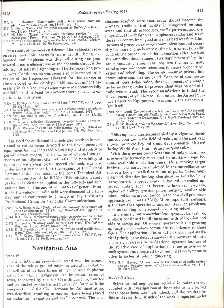
Radio Progress During 1951 413
•
;376) N. F. Harmon, "Community civil defense communications plan," Elearonics, vol. 24, pp. 88-91; July, 1951.
377) L. Geno, "Police and fire radio system at Buffalo," FM-TV, vol. 11, pp. 13-17; July, 1951.
(378) N. Monk, "Experimental radio telephone service for train passengers," PROC. I.R.E., vol. 39; pp. 873-881; August, 1951.
(379) "Train to dispatcher radio on the Northern Pacific," Modern Railroads, vol. 6, pp. 66-70; September, 1951.
As a result of the increased demand for vehicular radio services, available channels were rapidly being ex-hausted and emphasis was directed during the year toward a more efficient use of the channels through the addition of selective signaling and better operating pro-cedures. Consideration was given also to increased utili-zation of the frequencies allocated for this service in the uhf band in the vicinity of 450 mc. Equipment op-erating in this frequency range was made commercially available, and at least two systems were placed in ex-perimental operation.
(380) L. P. Morris, "Equipment for 450 mc," FM-TV, vol. 11, pp. 26-28; March, 1951.
(381) L. A. Dorff, "Operational study of a highway mobile telephone system." Elec. Eng., vol. 70; pp. 236-241; March, 1951.
(382) "450 mc mobile equipment," FM-TV, vol. 11, pp. 17, 38; May, 1951.
(383) "Electronic selective dispatcher permits private conversa-tions," Elec. Eng., vol. 70, p. 753; August, 1951.
(384) E. M. Webster, "Vehicular radio communication, Utilization and expansion," Telegr. Teleph. Age., pp. 7-8, 10; December, 1951.
The need for additional channels also resulted in con-tinued attention being directed to the development of equipment having increased selectivity and stability to permit closer geographical spacing of channel assign-ments on an adjacent channel basis. The possibility of operation with even closer spaced channels was also under investigation and, at the request of the Federal Communication Commission, the Joint Technical Ad-visory Committee of the RTNIA-IRE initiated a study of channel splitting as applied to the 152-162- and 450-460-mc bands. This and other matters of general inter-est in the vehicular radio field were discussed at a two-day annual conference in Chicago of the Institute's Professional Group on Vehicular Communications.
(385) R. A. Beers, et al., "Design of mobile two-way radio communi-cation equipment at 152-174 mc," Broadcast News, pp. 56-65; January-February, 1951.
(386) D. E. Noble, "Improved communciation equipment for mobile use," Tele.-Tech. vol. 10, pp. 36-39, 66-67; February, 1951 .
(387) C. London, "Railway radio takes a new step," Westinghouse' 1, Eng., vol. 11, pp. 47-49; March, 195 1. (388) H. H. Davids and T. J. Foster, "Crowded-band mobile equip-
ment," Electronics, vol. 24, pp. 102-105; July, 1951. (389) T. S. Eader, "Equipment performance specs.," FM-TV, vol.
! 11, pp. 22-24, 38-39; September, 1951.
Navigation Aids General
The outstanding operational trend was the ascend-ance of the role of ground radar for aircraft navigation as well as of various forms of harbor and shipborne radar for marine navigation. An important series of tests, sponsored by the Air Co-ordinating Committee and conducted by the United States Air Force with the co-operation of the Civil Aeronautics Administration, was described, resulting in new emphasis being placed on radar for navigation and traffic control. The con-
clusions reached were that radar should become the primary traffic-control facility in congested terminal areas and that all procedures, traffic patterns, and dis-plays should be designed to supplement radar and serve the radar controller in good as well as bad weather. Lim-itations of present-day voice communications and neces-sity for more channels were outlined. In en-route traffic control, the proper use of the navigation aides, such as the omnidirectional ranges later supplemented by dis-tance-measuring equipment, requires the use of new, rapid ground-air communications to assure proper sepa-ration and scheduling. The development of private-line communications was indicated. Because of the limita-tions of present-day radar, the development of a simple airborne transponder to provide identification and alti-tude was started. The recommendations included the development of a high-resolution radar, the Airport Sur-face Detection Equipment, for scanning the airport sur-face itself. (390) "Air Traffic Control and the National Security," Air Co-ordi-
nating Committee, Air Traffic Control and Navigation Panel, Superintendent of Documents, U. S. Gov't. Printing Office; De-cember, 1950.
(391) D. W. Rentzel, "Air traffic control," Aero. Eng. Rev., vol. 10, pp. 18, 21, 41; May 1951.
This emphasis was accompanied by a vigorous devel-
opment program in the field of radar, and the past year showed progress beyond those developments initiated during World War II for military purposes alone. With the growing operational use of radar, many im-
provements formerly restricted to military usage be-came available to civilian users. Thus, moving-target-
indication circuitry is employed in the surveillance ra-dar sets being installed at major airports. Video map-ping and direction-finding identification are also being incorporated. Improvements in ground-controlled ap-proach radar, such as better cathode-ray displays, higher reliability, greater power output, smaller side lobes, and so on, are contained in the new civil precision-approach radar sets (PAR). More important, perhaps, is the fact that operational and maintenance problems, such as training of personnel, are being solved. In a similar, but somewhat less spectacular fashion,
progress continued in all the other fields of location and aids to navigation. Of some importance is the growing application of modern communication theory to these fields. The application of information theory and statis-tical principles to detect signals in the presence of noise yields rich rewards in navigational systems because of the relative ease of application of these principles to such systems as compared to communication systems or other branches of radio engineering.
(392) N. L. Harvey, °A new basis for the analysis of radio naviga-tion and detection systems," Sylvania Tech., vol. 3, pp. 15-18; October, 1950.
Radar Systems •
Scientific and engineering activity in radar theory, coupled with investigations of the mechanisms affecting radar operations, was high indeed, and the results pro-lific and rewarding. Much of the work is reported under
414 PROCEEDINGS OF THE I.R.E. . April I
antennas, propagation, circuits, measurements, and the like.
From the over-all point of view, the past year was notable not only from the analytical and theoretical as-pects but also from the practical and operational sides. Production of radar equipment was higher than ever, large-scale installations for both military and civil use were made, and the radio engineers were beginning to cope with the first headaches of establishing sound and universal maintenance. From a fundamental point of view, radar systems
were studied to determine how to increase the reliability and range. The bandwidth of the conventional pulse radar is many times greater than is required by the amount of information conveyed. Application of a com-munication theory coupled with statistical methods was widely used in order to organize better the method of at-tacking the problem.
(393) P. M. Woodward and I. L. Davies, "A theory of radar infor-mation," Phil. Mag., vol. 41, pp. 1001-1017; October, 1950.
(394) C. E. Corum, "Signal-to-Noise Improvement by Pulse Inte-gration," Report 3699, U. S. Naval Research Laboratory, Washington 25, D. C., 11 pp.; July, 1950.
(395) P. M. Woodward, "Information theory and the design of ra-dar receivers," PROC. I.R.E., vol. 39, pp. 1521-1524; Decem-ber, 1951.
Not only was the basic character of the radar signal examined but the utility of the signal in the presence of noise in connection with various displays was deter-mined. Methods for calculating the ratio of signal strength to noise for any desired probability of detec-tion were devised. Particular attention was given to returns comprising only a small number of signal pulses. The effect of changing characteristics of the signal, such as pulse-repetition frequency, antenna beamwidth, pulse duration, as well as biasing and limiting, was con-sidered in deriving detection probability. Some consid-eration was given to dark-tube operation and video pulse stretching.
(396) S. M. Kaplan and R. W. McFall, "The statistical properties of noise applied to radar range performance," PROC. I.R.E., vol. 39, pp. 56-60; January, 1951.
(397) A. W. Ross, "Visibility of radar echoes," Wireless Eng., vol. 28, pp. 79-92; March, 1951.
In addition to theoretical investigations, efforts to re-cord radar-reflection data for analysis was evident dur-ing the year.
(398) V. C. Pineo and R. C. Peck, "A circuit for simultaneously re-cording the range, amplitude and duration of radar type re-flections," Rev. Sci. Instr., vol. 22, p. 112; February, 1951.
Measurements and studies of the reflecting area and polarization of target reflectors were reported at the an-nual convention of the IRE last March. (See Papers 138 and 139, PROC. I.R.E., vol. 39, p. 308; March, 1951.) One of the most important developments did not ap-pear in published form although results obtained were described at this convention. (399) W. D. White, "The use of circular polarization as a means of
reducing radar prectpitation returns," Airborne Instrument Laboratory, Mineola, N. Y.
It was found that, using circular polarization, both the signal return and the return from precipitation were reduced from that obtained from a linear polarization,
but the interfering signals from precipitation were so much more attenuated that a net gain of better than 15 db was obtained both at 3,000 mc and 9,000 mc. The improvement was in accord with the theoretical expec-tations, except against wet snow where practically the same gain was obtained as against heavy rain. Similar experiments in Great Britain yielded comparable re-sults. Studies were made of the azimuthal resolution capa-
bilities of the radar system as related to the antenna beamwidth or size of antenna aperture. Various means of enhancing the resolution, such as the "super gain" an-tenna and the application of filter-equalization tech-niques, were investigated. No essential improvement in resolution appeared to be obtainable above that de-rived from the beamwidth considerations.
(400) J. Freedman, "Resolution in radar systems," PROC. I.R.E., vol. 39, pp. 813-818; July, 1951.
Not only did the studies cover radar systems in gen-eral, but particular types of radar systems were ana-lyzed. In a conical-scanning tracking radar, four sources of angular jitter were analyzed. These sources, which were evaluated analytically, are (1) fluctuations in re-ceived signal strength due to target aspect changes and interference phenomena, (2) fluctuations in angle of ar-rival due to the wander of the effective center of radia-tion of the radar echo, (3) receiver noise, and (4) residual jitter due to mechanical and electrical backlash.
(401) C. E. Brockner, "Angular jitter in conventional conical-scan-ning, automatic-tracking radar systems," PROC. I.R.E., vol. 39, pp. 51-55; January, 1951.
In addition to improving the radar itself, continued progress was made in the development of radar trans-ponders that give a much stronger return than the radar reflection itself, eliminate the clutter problem by re-sponding at a.different frequency than the radar, and provide facilities for coding information such as iden-tity, altitude, and the like.
(402) J. W. Busby, "New crystal controlled radar beacon," Tek.-Tech., vol. 10, pp. 24-26; January, 1951.
(403) R. S. Butts, "Miniature radar transponder beacon," Electron-ics, vol. 24, pp. 104-107; Septembeg, 1951.
(404) R. S. Styles, "Prevention of echo interference in double-pulse coded interrogator-responder systems," Aust. Jour. Appl. sci., vol. 2, pp. 26-42; March, 1951.
The utilization of integration and filtering techniques for improving radar performance has been limited to performing such operations after detection or in the video-frequency circuits. Considerable gain could be ob-tained if the integration could be accomplished before detection. However, a limit is imposed on the amount of filtering that can be accomplished if the radar source has an unstable frequency characteristic. As a result of the foregoing, the past year saw the beginning of develop-ment of high-power sources other than magnetrons, in particular, klystron amplifiers.
Progress was made in preventing echo interference in interrogator responder systems which use pulse-multi-plex methods for channel selection.
(405) W. F. Marshall, "Microwave generators with crystal control," Ekctronics, vol. 24, pp. 92-95; November, 1951.
•••

1952 Radio Progress During 1951 415
The improved radar system requires high-quality, low-jitter, high-reliability modulators. Considerable work was done in this field, and particularly interesting is the magnetic modulator that reduces the number of vacuum tubes required. (406) H. Tigler, "High voltage pulse modulators for radar pulse
transmitters," Arch. elekt. (Ubertragung), vol. 5, pp. 47-51, 91-98; January-February, 1951.
I (407) W. S. Melville, "The use of saturable reactors as discharge de-vices for pulse generators," Proc. IEE (London), vol. 98, pt. III, pp. 185-207; May, 1951.
Marine Radar
A rapidly growing field is that of marine radar, and the past year saw its greatest annual growth. Not only were a greater number of ships equipped with radar sets for navigation under poor visibility conditions, but the use of radar beacons for marking known locations and the beginnings of harbor radar for traffic control by means of radio communications from shore to ship was evidenced. This activity is not confined to the United States. Great Britain and France also are finding these systems of great aid to marine navigation. The engineer-ing effort in this field was largely one of system design and application. Contrasted to other fields in naviga-tion, the literature available to all is relatively abun-
dant.
(408)
(409)
(410)
(411)
(412)
Fig. 16—Three shipboard radar antennas for 3.2-cm operation (RCA).
E. J. Isbister and J. W. Busby, "Ramark beacons," Navigation, vol. 2, pp. 357-363; June, 1951. R. W. M. Braham, "Harbor radar systems," Navigation, vol. 2, pp. 371-374; June, 1951. C. E. Moore, "New developments in radar for merchant ma-rine service," RCA Rev., vol. 11, pp. 465-481; December, 1950. F. W. Garrett, "The design and application of a marine radar system," Marconi Rev., vol. 14, pp. 23-38; 1st Quarter, 1951. J. A. Saxton and H. G. Hopkins, "Some adverse influences of meteorological factors on marine navigational radar," Proc. IEE (London), vol. 98, pt. III, pp. 26-36; January 1951.
A ir- Traffic Control
The provision of ground-based radar in terminal areas has made possible the greatest single improvement
in traffic control in the last decade. Successive approach intervals of three minutes are now routine at those air-ports having radars and trained radar controllers. There seems little doubt that the future traffic-control system will be built on the firm cornerstone of surveillance ra-
dar. One of the first steps is the introduction of simple air-
borne transponder beacons. These will provide longer distance radar coverage, freedom from ground echoes, and simple aircraft identification. Component charac-teristics for such a transponder have been drawn up by
Development Board the Air Navigation (ANDB),
Fig. 17—First commercial installation of Model DTB, uhf, distance-measuring equipment (DME), installed at CAA omnidirectional station VOR, Wilton, Conn. The DME radiator mounts above the radome which houses the VOR antenna system. The DME, which includes duplicate transponders and monitors, operates continuously and unattended. If either unit fails, the duplicate spare is automatically switched into operation (Hazeltine Elec-tronics Corp.).
which is sponsoring this development. Present develop-ment effort is devoted toward devices that will aid the controller in making better use of radar information, i.e., in data reduction and computation aids. Sufficient information was gained during the year to
show that ground-surveillance radar supplemented by airborne transponders, used in conjunction with VOR and DME, and now being developed by simulation and operational tests, will be completely sufficient to handle traffic of mixed aircraft types at a rate of 30 operations per hour on a single runway and single-type aircraft traffic at a rate of 45 per hour. For higher traffic rates, the basic traffic-control radar will need to be operated with different procedures and will need to be supple-mented by somewhat more sophisticated data-reduction devices. These devices will have the purpose of relieving controllers of some of their more mechanical tasks. Ex-amples are radar automatic tracking circuits (which will, incidentally, measure ground speed), filtered dis-plays showing aircraft location and identity, and se-quencing devices which will automatically select the most efficient order of aircraft arrival at entry to final approach. (413) "Summary Progress Report," Air Navigation Development
Board, Washington, D. C., pp. 3, 4, 26, 27, 30, 31, 32; July, 1951.
A group of ten psychologists completed an investiga-
416 PROCEEDINGS OF THE I.R.E. Apri
tion initiated by the ANDB in December, 1949 on the application of the principles and techniques of human engineering to the improvement of air-navigation and traffic-control systems. Their report treats this subject in detail, and also presents a recommended long-range program of psychological research to parallel the equip-ment and system developments. The most significant conclusions of these studies are: (1) Humans surpass present-day machines in detection threshold, pattern perception, improvisation, inductive reasoning, and judgment. (2) Present-day machines surpass humans in rapidity of response, smooth precise application of force, performance of repetitive tasks, and deductive reasoning. (3) Including human elements in a system in-creases flexibility in adapting it to changing demands. (4) On the whole, man is poorly designed for many monitoring tasks, and caution should be exercised in as-suming that he can successfully monitor complex auto-matic machines and take over if the machines break down. Engineers should seriously consider systems in which machines would monitor men!
(414) P. M. Fitts, "Human Engineering in an Effective Air Naviga -tion and Traffic-Control System ," National Research Council, NRC Committee on Aviation Psychology, ‘Vashington, D. C.; March, 1951.
An important study was devoted to the effect of a va-riety of parameters associated with final approach and landing on the minimum time intervals between succes-sive arrivals. Several of these are: safety rules, variabil-ity of speeds for each type of aircraft, mixture of air-craft types, number and location of taxi exits, length of the common approach path, instrumentation errors, wind, condition of the runway, and so on. The effect of these parameters on runway acceptance rate was dis-cussed in detail:
(415) L. R. Philpott, "The External Acceptance Rate of an Airport," ANDB Technical Memorandum 3; June 22, 1951.
The use of simulators to set up various traffic-control situations saw considerable employment. One analysis was based on the use of a specially developed slide rule. To check the method, a comparison of the acceptance rates that might be achieved with a fixed-block, termi-nal-area traffic-control system was worked out utilizing the slide rule, then it was compared with previous stud-ies that used more involved computation procedures. The results showed that the method was quite accurate.
(416) S. M. Berkowitz, "Analysis of a Fixed-Block Terminal Area, Air Traffic Control System," Technical Report #F-2164-2, Franklin Institute, Philadelphia 3, Pa.; May 1, 1951.
(417) R. B. Coulson and V. D. Burgmann, "An investigation into air traffic control by a simulation method," Jour. Inst. Nov., vol. 4, pp. 34-65; January, 1951.
Some studies were conducted on a pictorial simulator of air traffic. Optical projectors were used, the images being projected on a large screen with each light spot representing an aircraft in motion. The movement of the light spot could be controlled for straight or curved flight or could be made to follow automatically a radar return. The results of the study showed that such de-
vices could be useful for training traffic controllers or for studying traffic situations. (418) "Evaluation of Navascreen," Report No. 145, Technical De
velopment and Evaluation Center, Civil Aeronautics Adrnin istration, Indianapolis, hid.; May 1951.
An interesting study which involved the application of information theory to communications in the traffic. control problem appeared during the year. This study was particularly concerned with the private-line com-munication problem. The facilities required to transmit certain standard control messages from a traffic-control center to aircraft were assessed, and it was shown that any surplus channel capacity can be used as redundancy for improving operation at low signal-to-noise ratios. ,
(419) W. G. Tuller, "Application of the information theory to sys-tem design," Elec. Eng., vol. 70, pp. 124-126; February, 1951.
(420) R. B. Adler and S. J. Fricker, "The Flow of Scheduled Air Traffic," Technical Report 198, Research Laboratory of Elec-tronics, Massachusetts Institute of Technology, Cambridge, Mass.; May 2, 1951.
(421) "Evaluation of Proposed Air Traffic Control Procedures in the Washington Terminal Area by Simulation Techniques," Tech-nical Development and Evaluation Center Report 147; July, 1951.
Short-Distance Navigation
Engineering activity in the field of short-distance nav-igation continued high, the over-all effort being greater than in radar but more directed to immediate opera-tional needs rather than to fundamental investigations. The leading contender for attention was the omnibear-ing-distance system of air navigation.
(422) P. C. Sandretto, "Rho-theta system of air navigation." Elec. Commun. (London), vol. 27, pp. 268-276; December, 1950.
(423) D. 0. Fraser, "The American plan for air traffic control," Jour. Inst. Nay., vol. 4, pp. 214-231; July, 1951.
(424) R. C. Borden, C. C. Trout, and E. C. Williams, "Description . and evaluation of 100-channel distance-measuring equipment,",
PROC. I.R.E., vol. 39, pp. 612-618; June, 1951. (425) H. C. Hurley, S. R. Anderson, and H. F. Keary, "The Civil
Aeronautics Administration omnirange," PROC. I.R.E., vol. 39, pp. 1506-1520; December, 1951.
All station § of a total planned program of 426-vhf omnidirectional-range ('OR) stations are now installed in the United States and its possessions, and most of , these have been commissioned and are available for use. At each of these sites there will be added a uhf distance-measuring equipment (D E) within the next few years, the combination to provide virtually complete conti-nental coverage by these internationally standardized navigational aids. The coverage and accuracy of three stations of this sort were tested during the year to evalu-ate the long-term utility of the system as well as its worth for the immediate future. These tests showed that, except in the vicinity of unusual terrain conditions, aircraft position can be determined with a precision of 2 to 3 degrees in azimuth and to within 0.5 per cent of distance-to-station at distances to 100 miles from the ground station. The omnidirectional range exhibited large cones of confusion over the transmitter and was subject to errors due to the altitude of the aircraft ("course pushing"). When the test aircraft was shielded from the station by terrain, e.g., mountains, a consid-erable deterioration in accuracy, as well as signal at-tenuation, was experienced. These measured accuracies
1952 Radio Progress During 1951 417
seem completely adequate for en-route and terminal-area navigation for any traffic densities foreseen for the next ten years. So far as use in the long-term future is concerned, higher traffic densities may demand greater navigational accuracies. (426) W. R. Rambo, J. S. Prichard, D. P. Duffy, R. C. Wheeler,
A. E. Dusseau, Jr., and S. Goldstein, "Final Report on Evalu-ation of Omni-bearing-Distance System of Air Navigation," Airborne Instruments Laboratory Reports 540-1 (Summary) and 540-2 (two volumes), Mineola, N. Y.; October, 1950.
As vhf omnidirectional-range (VOR) coverage was ex-tended into the mountainous areas of the western and northwestern United States, difficult siting problems were encountered. A theoretical consideration of the problem was conducted by the Civil Aeronautics Ad-ministration, and a practical and economical solution was proposed. This was later verified by flight tests on two experimental installations. (427) "Mountain Top VOR Site Flight Tests," Technical Develop-
ment and Evaluation Center Report 139, Civil Aeronautics Administration; March, 1951.
Measurements made to observe the accuracy of the VOR information have established that vertical polari-zation from the pedestals that support the antennas contribute a small error, which may be reduced by using an antenna array of vertical elements parasitically ex-cited and so phased as to cancel the vertical radiation
from the pedestals. An interesting development completed during the
year was a cage antenna for the vhf omnidirectional range. The antenna consists of a rotating dipole inside a vertical cylindrical cage composed of vertically spaced conductors whose dimensions are suitable for proper. matching of the dipole to obtain maximum radiation properties. The cage serves to suppress unwanted ver-tical polarization and emphasize horizontal polarization. End effects which might serve as a parasitic generator of unwanted polarization are reduced by extending the
t cylindrical cage above the radiating cage. "Course-push-ing" effects caused by vertically polarized signals were
ig greatly reduced, octantal and quadrantal errors were re-duced by virtue of the single antenna source, and a fairly narrow cone of confusion approximately 20 de-grees wide resulted. Somewhat simpler installation ad-justment and maintenance appears possible. A means for reducing reflection errors in azimuthal
navigation systems employing phase measurements, such as in the vhf omnidirectional range, was proposed. This method averages the readings obtained from an omnirange facility at several frequencies. A mathemati-cal analysis shows that the errors can be reduced by such means or by frequency modulation. (428) M. K. Goldstein, "Reduction of Reflection Errors in Certain
Navigation Systems," Air Navigation Development Board Technical Memorandum 52, Washington 25, D. C.; May 15, 1951.
The distance-measuring equipment (DME), the com-panion to the vhf omnidirectional range, was not quite so fortunate in seeing operational use, but development
, activity remained high. A microwave system utilizing phase measurement of a continuous-wave signal trans-
mitted from the aircraft to the ground and relayed back at a slightly different frequency was described as well as some of the excellent results in accuracy that were ob-
tained. (429) J. Lyman and G. B. Litchford, "Distance measuring equip-
ment for the terminal area," Aero. Eng. Rev., vol. 10, pp. 48-55; May, 1951.
The Australians described a DME which was devel-oped for operation at 200 mc. While similar to the corre-sponding DME apparatus adopted in this country, it differs in the smaller number of channels and the method of multiplexing. (430) D. G. Lindsay, J. P. Blom, and J. D. Gilchrist, "Distance-
measuring equipment for civil aircraft," Proc. I .R.E. (Austra-lia), vol. 11, pp. 307-315; December, 1950.
The Air Navigation Development Board continued work initiated last year, and has made significant prog-ress in the DME field. The program which previously had been concentrated on the development of equip-ment intended for commercial airlines and military air-craft was expanded to consider the design of equipment suitable for private-type aircraft. Design and construc-tion of a light-weight interrogator, with somewhat re-duced performance in the interest of lower cost and weight, has been-initiated. Development of a miniatur-ized interrogator intended for use in civil and military aircraft has also been initiated. (431) R. C. Borden, C. C. Trout, E. C. Williams, "Uhf Distance-
Measuring Equipment for Air Navigation," TD-114, and "Evaluation of 100-Channel Distance-Measuring Equipment," TD-119, Civil Aeronautics Administration, Indianapolis, Ind.; 1951.
Development models of a pictorial computer for polar co-ordinate navigation were demonstrated. This instru-ment shows the pilot the position of his aircrart on a map of the area over which he is flying. Azimuth and dis-tance information are supplied by the VOR and DME. The models demonstrated were of the simple portable type. Further development is progressing on two other designs intended for mounting on the aircraft instru-ment panel; one of these features automatic tuning and chart selection. (432) "The TDEC Course Line and Pictorial Computer Programs,"
Technical Development and Evaluation Center Report 138, Civil Aeronautics Administration, Indianapolis, Ind.; May, 1951.
Base-Reference Navigational Systems
The base-reference navigational systems may be di-vided into (1) the relatively short-range systems that rely on ground- or surface-wave propagation and have high accuracy and (2) those which utilize sky-wave propagation, to cover greater distances at reduced ac-curacies due to the uncertainties of the ionosphere. In the former category, work continued on shoran
which utilizes pulsed emissions in the upper vhf band; Decca, which uses continuous-wave emissions and phase-measurement techniques in the medium-frequency band; and Raydist, which operates in a similar fashion to Decca in the high-frequency band. An important anal-ysis of the effects of meteorological conditions on the

418 PROCEEDINGS OF THE I.R.E.
measurement of distances dealt with two effects, that of a changing index of refraction of atmosphere on the bending of the ray path and that of meteorological con-ditions on the velocity of propagation itself.
(433) C. I. Aslakson and 0. 0. Fickeissen, 'The effect of meteorologi-cal conditions on the measurement of long distances by elec-tronics," Trans. Amer. Geophys. Union, vol. 31, pp. 816-826; December, 1950.
The Raydist system was further evaluated.
(434) F. S. Howell, "Experimental results of continuous-wave navi-gation systems," PROC. I.R.E., vol. 39, P. 841; July, 1951.
(435) W. D. Perrault, "Raydist traces planes path with pinpoint accuracy," Amer. Aviation, vol. 14, pp. 29-30; March 19, 1951.
Refinements on Decca continued, especially on im-proving the utilization of the meter indicator.
(436) F. J. Hewitt, "A new method of testing the mark V Decca navigator receiver in high noise levels," Trans. S. Afr. Inst. Elec. Eng., vol. 42, pp. 111-125; March, 1951.
(437) "Automatic course plotting," Wireless World, vol. 57, pp. 143-144; April, 1951.
In the second category of base-reference systems, those using sky waves, the relative advantages and dis-advantages of the narrow- and medium-base-line sys-tems which are directional or azimuthal in character were becoming more apparent when compared with the wide-base-line or hyperbolic systems. For nonmilitary use, the advantages of simplicity and low cost of the former weighed heavily in their favor despite the greater accuracy of the wide-base systems. Tests on the Consol (sonne) system, the medium-
base-line azimuthal system, were finished during the year by the United States Air Force. Embracing one year of evaluation, the tests showed that, with a spacing of three wavelengths at 193 kc and with 14 kw radiated, bearings having a root-mean-square error of one-third of a degree for day and night are obtainable consistently at distances of 1,500 nautical miles with the excellent reliability expected of a navigation system, especially when narrow-band receivers having a predetection band width of 50 cycles were used. The indication is aural. The accuracy of the system is highest close to the per-pendicular bisector of the base line and lowest at angles which are not close to the base line normal.
(438) "Consol—a Radio Aid to Navigation," H.M. Stationery Office, London (MCAP 59); September-October, 1950.
(439) C. E. Ingalls, "Evaluation of Radio Set AN/FRN-5," A. F. Technical Report 6234, Rome Air Development Center, Rome, N. Y.; March, 1951.
(440) "Data Evaluation and Analysis of Radio Set AN/FRN-5," Engineering School Bull., North Carolina State College, N. C., Contract W28-099 ac-434, Rome Air Development Center, Rome, N. Y.; July 15, 1951.
(441) "The Performance of the Consol System of Navigation in High Atmospheric Noise Levels," South African Council for Sci-entific and Industrial Research Report No. ETR-11, Telecom-munications Research Laboratory, Pretoria, South Africa; March, 1951.
The Navaglobe system, first announced in 1946, has finally been brought to the testing and evaluation stage. It is an azimuthal system employing narrow-band transmission and reception as in the Consol system. It differs from Consol in having a triangular base line with only 0.4-wavelength spacing and in employing visual rather than aural indication. It is a kind of omnidirec-
tional radio range. The installation consists of three towers, which are spaced less than a mile apart. These towers produce a switched pattern in space. The air-borne equipment is small and lightweight. An indication is in the form of a special bearing selector and cross-pointer instrument. Bearings can be read to better than 0.5 degree. The ground equipment has means for com-pensating for site errors. The airborne receiver is de-signed for an extremely narrow bandwidth so that sig-nals can be read in the presence of noise. Reading can be ' obtained with one degree error when the equivalent 3-kc bandwidth noise is 100 times the signal. Base-reference navigation systems can be made more
accurate by spacing the antennas very far apart. In this manner, a large number of electrical degrees represent I only a few space degrees, but the tilt of the ionosphere becomes a limiting factor. Navaglobe, therefore, has at-tempted to obtain its accuracy by refining its instru-ments instead of spacing the antennas far apart. Using the propagation data that has been taken with the sys-tem during the past year, it appears that the root-mean-square error of Navaglobe will be 0.5 degree, and the range 1,500 miles. Instrumentation errors and polariza-tion errors have shown themselves to be less than ex-pected. (442) P. R. Adams and P. C. Sandretto, "Long Distance Navigation
Requirements and the Navaglobe Developments," Presented, Institute of Navigation, Washington, D. C.; March 9, 1951.
(443) R. H. Woodward and 0. Goldberg, "Radio Wave Propagation over Long Distances at 100 KC." Presented, Ithaca, N. Y.; September 9, 1951. Copies available from Rome Air Develop-ment Center, Rome, N. Y.
The wide-based systems, such as loran, made no spec-tacular progress, but some investigations showed what may be expected. Research carried out on the west coast in conjunction with a low-frequency loran trans-mitter radiating pulses having one megawatt peak power at 100 kc on the east coast showed that reliable ranges of 2,200 nautical miles are obtainable. (444) J. A. Blickensderfer, "Applications of Certain Statistical Con-
cepts in Designing Selective Systems," Technical Report No. 7, Project on Low Frequency Navigation Systems, Electronics Research Laboratory, Stanford University, Calif.
(445) "Monthly Reports on Status of Research on Low Frequency Navigation Systems," Electronics Research Laboratory, Stan-ford University, Contract W28-099 ac-157, Rome Air Devel-opment Center, Rome, N. Y.; November, 1950—November, 1951.
(446) R. H. Myers, "Design of a loran transmitter," Elec. Common (London), vol. 28, pp. 31-45; March 1951.
(447) "Ocean Electronic Navigation Aids," U. S. Coast Guard. Washington, D. C.
An operational summary of marine navigational sys-tems was presented at a symposium at the Royal Geo-graphical Society in May, 1950. The papers which were published included marine position-fixing systems in use today, use of direction finding at sea, the adoption of Decca as an aid to navigation at sea, and the use of Con-sol in the fishing fleet.
(448) "Marine radio position fixing systems," Jour. Inst. Nov., vol. .3, pp. 317-356; October, 1950.
Missile Guidance
A significant number of articles describing missile-guidance systems and problems were published.

1952 Radio Progress During 1951 419
(449) G. R. Urquhart, "Proportional radio control," Aero Digest, vol. 62, pp. 20, 21, 73, 74, 91; February, 1951.
(450) G. A. Long, "Missile guidance," Navigation, vol. 2, pp. 290-294; December, 1950.
(451) R. Drenick, "The perturbation calculus in missile ballistics," Jour. Frank. Inst., vol. 251, pp. 423-436; April, 1951.
(452) S. Herrick, "Rocket Navigation," Navigation, vol. 2, pp. 259-272; December, 1950.
(453) J. C. Bellamy, "Instruments for upper atmosphere and inter-planetary navigation," Navigation, vol. 2, pp. 272-275; Decem-ber, 1950.
A discussion concerning the damping characteristics of components, such as stable platforms, integrating ac-celerometers, and the like, used in airborne navigational
aids appeared. (454) W. Wrigley, "Schuler tuning characteristics in navigational
instruments," Navigation, vol. 2, pp. 282-290; December, 1950.
The application of the Doppler effect in the develop-pent of apparatus for measuring the velocity of projec-tiles and guided missiles and the design of electronic • fuses for shells were described.
. (455) U. Tiberio, "Radar apparatus using the Doppler effect," Elet-troticnia, vol. 38, pp. 266-278; June, 1951. (In Italian.)
Aircraft-Terminal Aids
Continued activity in electronic aids for navigation in the terminal area furthered progress in this field. The outstanding accomplishments were the initiation of widespread use of airport surveillance and precision-ap-proach radar, the development of a "baby" omnidirec-tional range for terminal-area use, completion of devel-opment and initiation for test of an automatic ground-controlled-approach radar (GCA), several significant improvements in the instrument landing systems (ILS), and the continued development of high-definition, short range radar techniques for controlling traffic on the air-port surface itself. The widely installed and internationally standardized
ILS fixed-beam approach aid, particularly when moni-tored by precision approach radar (PAR), has proven quite satisfactory to operational minima of 200-foot ceil-ing and half-mile visibility. Under worse weather, addi-tional guidance (e.g., approach lights) has been found necessary. This limitation comes about because of the inability of the system to provide sufficiently accurate guidance with respect to a flared glide path, and to pro-vide a heading reference sufficient to allow killing drift just prior to touchdown. In addition, both systems im-pose limitations on airport acceptance rate because of the relatively long straight approach path that must be flown by all aircraft. For complete guidance to touchdown, an accurate
electronic airborne altimeter and an exponential flare-out computer were developed and found satisfactory for vertical guidance. (456) "Summary Progress Report," Air Navigation Development
Board, Washington, D. C., pp. 5, 12, 25; July 1, 1951.
The Civil Aeronautics Administration's Technical Development and Evaluation Center at Indianapolis explored the possibility of applying a vhf omnidirec-tional range as a terminal-area navigational aid by con-
structing a small, low-powered omnirange having its an-tenna array on the ground. A self-contained, battery-operated, crystal-controlled transmitter was developed to provide a marker signal for the terminal omnirange at points four or five miles from the airport. The marker signal is provided by heterodyning the omnirange car-rier with a keyed signal from the transmitter. Tests were sufficiently successful so that additional installations are being planned. A system for automatically tracking an aircraft in dis-
tance, azimuth, and elevation during its approach for a landing by utilizing the GCA radar outputs was com-pleted and is being evaluated. (457) J. T. NIcNaney, "Automatic GCA," Electronics, vol. 24, pp.
82-87; February, 1951. (458) A. Moisson, "Blind landing control type A B," Rev. tech. Comp.
franc Thomson-Houston, no. 15, pp. 5-18; 1951. (In French.)
Certain traffic-control features of the automatic GCA (or Automatic PAR as it is becoming known) have been selected by the Air Navigation Development Board, and embodied into an attachment for civil ground-con-trolled-approach radar sets to permit automatic spacing and maintenance of safe separations among aircraft ap-proaching an airfield using any type of approach or landing facility. .This is being evaluated by the Civil Aeronautics Administration. The first production unit of a new glide-slope trans-
mitter was installed and tested at the Indianapolis Mu-nicipal Airport. This new equipment employs the null-reference antenna system developed at Technical De-velopment and Evaluation Center. This improved an-tenna array provides a path in space that is only negligibly affected by heavy snowfall. With the null-reference antenna array, the response of the course-deviation indicator was found to be substantially improved, particularly when the airplane is below the
glide path. Substantial progress has been made in improving the
performance of the vhf instrument-landing localizer through the use of antenna arrays with greatly increased directivity, thus minimizing the effects of spurious re-flections. Apertures of the order of 80 to 100 feet are used. This results in a null pattern that has its maxima about 5 degrees either side of the central null. Three types of directive array have been used: (1) cylindrical paraboloid, one wavelength (or 9 feet high) with a quar-ter-wave rim and having a focal distance of 3/2 wave-length; (2) linear broadside array of 18 half-wave di-poles with back screen; (3) slotted waveguide broadside array with 18 probe-fed vertical slots.
Direction Finding
Activities in direction finding continued in the inves-tigation of errors and extension of the frequency range in which the direction-finding technique may be em-ployed. Several important improvements on automatic and instantaneous equipments tailored for high-speed aircraft were described. (459) J. H. Moon, "The development of the aircraft automatic radio
compass," Jour. Inst. Nay., vol. 3, pp. 393-403; October, 1950.
420 PROCEEDINGS OF THE I.R.E. Apra
(460) J. Rhys Jones, "Instantaneous direction finding," Electronic Eng. (London), vol. 22, pp. 481-482; November, 1950.
(461) P. G. Hansel, "Polarization errors of radio direction finders; a proposed classification," PROC. I.R.E., vol. 39, p. 970; August, 1951.
(462) J. H. Moon, "Calibration of aircraft direction finders with particular reference to site selection," Marconi Rev., pp. 101-112; 1951.
(463) W. Runge, M. Strohhacker, and A. Troost, "The 'Telegon' di-rection-finder," Tekfunken Zig., vol. 24, pp. 75-81; June, 1951. (In German.)
Experiments with apparatus covering the band from 4 to 15 mc showed that with coaxial loops spaced 100 meters apart, each having a receiver carefully matched to the other, it was possible to measure the angle of ar-rival of radio waves reflected from the ionosphere to within one degree in the horizontal plane and to within one and a half degrees in the vertical plane so long as the arrival angle exceeded 30 degrees.
(464) W. Ross, E. N. Bramley, and G. E. Ashwell, "A phase-compar-ison method of measuring the direction of arrival of ionospheric radio waves," Proc. IEE (London), vol. 98, pt. III; pp. 294-302; July, 1951. (Paper 1134.)
Typical of the trend to extend direction-finding tech-niques to higher and higher frequencies was exploratory work in measuring the angle of arrival in the vertical plane of a complex wave in the microwave region. The arriving wave is a composite of the direct ray and the ground-reflected ray. Equipment used at 9,300 mc con-sisted of three separate antennas and receivers. The up-per and lower antennas were separated at a vertical dis-tance of 10 feet so that an angle of arrival of 0.01 degree gave a 6-degree phase difference. With the three sepa-rate sources, six parameters can be measured corre-sponding to the phase and amplitude at each point source. Since two must be used as reference, four rela-tive quantities are measured so that sets of equations can be solved for angle of arrival and amplitude of di-rect and ground-reflected rays. This method gives prom-ise of being able to measure low vertical angles of arrival with great precision, and may be useful for radar equip-ment.
(465) F. E. Brooks, Jr., "A receiver for measuring angle of arrival in a complex wave," PROC. I.R.E., vol. 39, pp. 407-411; April, 1951.
(466) K. Morita, "Direction finder and flow meter for centimeter waves," PROC. I.R.E., vol. 39, pp. 1529-1534; December, 1951.
Instruments
Considerable emphasis continued in the field of in-strumentation of navigational and traffic-control de-vices. Most of the emphasis was on forms of display, ar-rangement of instruments, and comparison of meter-type pictorial displays for airborne use.
(467) 0. W. Newmark, "Blind flying panels and instruments," Jour. Inst. Nay., vol. 4, pp. 201-205; April, 1951.
(468) W. L. Webb, "Aircraft navigation instruments," Elec. Eng., vol. 70, pp. 384-388; May, 1951.
(469) W. D. Perrault, "CAA to evaluate three pictorial computer designs," Amer. Aviation, vol. 14, pp. 30,31,33,36; December 11,1950.
(470) K. Witmer, "On modern radio navigation instruments," (in German), Bull. schweis. electrotech. Ver., vol. 42, pp. 125-135; March 10,1951.
Wave Propagation
Ionospheric Propagation
Radio-wave propagation in the ionosphere abounds with many facets. For an index to the published mate-. rial, the reader is referred to "Abstracts and Refer-ences," compiled by the Radio Research Organization of the Department of Scientific and Industrial Research, London, England and carried in each issue of the PRO-CEEDINGS OF THE I.R.E.; and to "List of Recent Publi-cations," compiled by W. E. Scott and carried in each issue of the Journal of Geophysical Research. Only a I limited number of representative, published papers have t been recorded in the present report. However, a consid-s. erable amount of additional material drawn from IRE-URSI and other conference programs, and from tech-nical reports and progress reports produced under; government contracts, has been included. It is now recognized that the geomagnetic field is an I
outstanding factor in ionospheric radio-wave propaga-tion. In fact, we now know that for one to see the mani-fold aspects of the ionosphere in their proper perspec-tive, it is essential to think about the hydrodynamics of the atmospheric ocean, considering both the regular be-havior and the perturbations known to be closely re-lated to solar irregularities.
(471) D. F. Martyn, "Theory of Magnetic Storms and Auroras," Presented, Ninth General Assembly, URSI, Zurich, Switzer-land; September, 1950.
There also is a growing consciousness of the extrater-restrial factors, other than directly solar, that both af-fect the ionosphere and are affected by it. The twinkling of radio stars and of moon echoes, the radar observation of meteor trails, and attempts to measure ionizing and tidal effects due to the moon are examples of these. It is now recognized that just as the ionosphere may confine a radio signal to the earth, so it may also prevent such a signal from reaching the surface of the earth from out-side the ionosphere. Ionospheric winds are under active study by observation of the drift of meteor trails and the movement of fading patterns along the ground from ver-tical-incidence signals.
Compelling evidence is accumulating that sunspots are not fundamental to solar activity associated with geomagnetic and ionospheric disturbances. Solar obser-vations using the coronagraph indicate that in the highly conductive solar atmosphere (chromosphere and corona) prominences will follow the lines of magnetic force and, with the local concentration of prominence material, the moving gas will break through the lines of force and descend towards the photosphere, carrying the lines of force with it. This will concentrate the lines of force, resulting in intensified magnetic fields at the level of the photosphere, a major characteristic of sunspots. Earlier work also supports the idea that the spots them-selves are but superficial manifestations. The criteria for solar activity in solar-ionospheric correlations stem from chromospheric and coronal as well as sunspot measure-
f,
1952 Radio Progress During 1951 421
ment9. Activity ratings are applied to individual solar . regions rather than to the whole disk on a given day. The usefulness of extraterrestrial sources of radio
noise and of radar echoes from extraterrestrial objects, -for exploring the upper ionosphere above the cut-off fre-quency, was first pointed out in 1948. It was observed earlier that there is a reduction of galactic noise during a sudden ionospheric disturbance. This affords a means of estimating D-layer ionization and certain ionospheric effects noted during dawn observations on solar noise. Neither a nonsymmetrical F layer nor a G layer has been able to account for the great deviation of the source (sun), observed at radio frequencies, or of its rapid vari-ation with altitude. From these facts, it seems that a horizontally stratified F layer model must be given up in favor of one involving horizontal irregularities. Recent work in radio astronomy gives further evidence in this direction. Correlation was found between fluctuations of the discrete sources in Cygnus and Cassiopeia and ' spread F echoes. Correlation of the fluctuations in spaced receivers previously indicated the source of the irregular variations to be principally the terrestrial ionosphere. The observations are consistent with dif-fraction at an irregular ionosphere, the lateral dimen-sions of the irregularities being of the order of 5 km. A diurnal variation in the occurrence of the irregular ionization is found, with the onset of the maximum oc-curring at about 0100, local time. (472) G. H. Munro, "Travelling disturbances in the ionosphere,"
Proc. Roy. Soc. A., vol. 202, pp. 208-223; 1950. (473) M. Ryle and A. Hewish, "The effects of the terrestrial iono-
sphere on the radio waves from discrete sources in the galaxy," • Mon. Not. R. Asir. Soc., vol. 110, pp. 381-394; 1950.
The observed speed of slow fading of moon echoes produced on about 29 mc per second is evidently also consistent with an ionospheric origin. The following ma-i jor discrepancies in the orthodox ray-theory treatment ; were found: (1) Observed echo intensities are well below theoretical values. (2) Minimum altitudes at which echoes are first detected are unexpectedly high. These anomalies correlate closely with the critical frequency of the F2 region. The results indicate the presence of hori-zontal irregularities in the ionosphere or the failure of the ray-theory treatment at very oblique incidence.
(474) F. J. Kerr and C. A. Shain, "Moon echoes and transmission through the ionosphere," PROC. I.R.E., vol. 39, pp. 230-242; March, 1951.
Meteor ionization trails were successfully observed by radar techniques, affording information both on me-teors and the ionosphere. Measurements of meteor de-celerations led to the conclusion that either the formula for the scattering of radio waves from a meteor trail needs revision or that the density of air at 100-km height is lower by a factor of three or more than the value given in the tables of the National Advisory Com-mittee on Aeronautics. Measurements on the polariza-tion of meteor echoes indicate that ionization densities may be greater than are usually assumed and that exist-ing theories are not compatible with this result. It was
concluded from theoretical considerations that laminar flow of a meteoric ionization path may increase the du-ration by as much as four times. Some progress has been made on the determination of diffusion coefficients from the dependence of the rate of decay of meteoric echoes on the radio frequency used. Statistical analysis of the velocities of 11,000 meteors
observed over a period of 15 months led to the conclu-sion that all, or nearly all, meteors down to the eighth visual magnitude are members of the solar system. No definite interstellar meteors were found. In this work, photoelectric techniques were adapted to the automatic recording of meteors with a sensitivity adequate for sec-ond-magnitude meteors. (475) A. Aspinall, J. A. Clegg, and G. S. Hawkins, "A radio echo
apparatus for the delineation of meteor radiants," Phil. Meg., vol. 42, pp. 504-514; 1951.
(476) D. W. R. McKinley, "Meteor velocities determined by radio observations," Astrophys. Jour., vol. 113, pp. 225-227; March, 1951.
(477) J. Feinstein, "The interpretation of radar echoes from meteor trails," Jour. Geophys. Res., vol. 56, pp. 37-51; March, 1951.
(478) L. A. Manning and M. E. Van Valkenberg, "The Polarization Characteristics of Meteoric Echoes," Presented, I RE-URSI Meetings, Cornell University, Ithaca, N. Y.; October 8-10, 1951.
(479) T. N. Gautier, "The Effect of Laminar Flow on the Duration of Meteor Echoes," Presented, IRE-URSI Meeting, Cornell University, Ithica, N. Y., October 8-10, 1951.
(480) V. C. Pineo, "Experimental Determination of Rates of Decay of Meteoric Echoes as Functions of Wave Frequency and Height," Presented, IRE-URSI Meeting, Cornell University, Ithaca, N. Y.; October 8-10, 1951.
Ionospheric winds were measured by the drift of fad-ing patterns along the ground, using vertical propaga-tion. The program is too young to have produced com-prehensive information, but winds of 100-300 meters per second are commonly indicated. Although they may be observed in any horizontal direction at one time or another, temporal trends are becoming apparent. Marked differences were found between E- and F-layer winds. Measurement of the drift and turbulence of meteoric ionization is being used for wind information. An accuracy of 420/(number of meteors)'12 km per hour is calculated. So far, the results of this technique have shown only very rough correlation with the fading meas-
urements. (481) R. Greenstone, "Systematic Ionospheric Winds," Presented
IRE-URSI Meeting, Cornell University, Ithaca, N. Y.; Oc-tober 8-10, 1951; J. H. Chapman, "Fading of Radio Waves from the Ionosphere," Presented, IRE-URSI Meeting, Cor-nell University, Ithaca, N. Y.; October 8-10, 1951. Radio Physics Laboratory, Defence Research Board, Ottawa, Can-ada, Report 4; August 1, 1950.
(482) L. A. Manning and A. M. Peterson, "Meteoric Echo Measure-ment of Ionospheric Drift and Turbulence," Presented, I RE-URSI Meeting, Cornell University, Ithaca, N. Y.; October 8-10, 1951.
Tidal effects in the atmospheric ocean are still being sought. Although they constitute an essential part of some theoretical considerations, no clearly positive ex-perimental evidence has yet been presented. A somewhat different group of phenomena may be
said to be in the province of the communication engi-neer. Outstanding of these is the prediction on a world-wide basis of optimum usable high-frequencies for

422 PROCEEDINGS OF THE I.R.E. April
ionospheric paths. Data for these predictions are furnished by many co-operating groups throughout the world using sweep frequency, vertical-incidence record-ers. World-wide predictions are available to the public from the Central Radio Propagation Laboratory (CRPL), National Bureau of Standards at Washing-ton, D. C. An evaluation of the effectiveness of this pro-gram was published. Although, on the average, agree-ment is good, discrepancies remain which need further examination after the elimination of known sources of error. In a few cases, comparisons of predicted and ac-tual times of fades due to ionospheric absorption were made. Although the agreement between these times is reasonably good, it is believed that predictions of the actual field strength may be in error by large amounts. (483) T. N. Gautier, M. B. Harrington, and R. W. Knecht, "On the
Question of the Magnitude of the Solar Lunal Variation in Radio Field Strength," Presented, IRE-URSI Meeting, Cor-nell University, Ithaca, N. Y.; October 8-10, 1951.
(484) A. F. Wilkins and C. M. Minnis, "Comparison of ionospheric radio transmission forecasts with practical results," Proc. IEE (London), vol. 98, pt. III, pp. 209-220; 1951.
A useful slide rule for the solution of spherical tri-angle problems in long-distance radio communication was described. Improved sweep-frequency recorders were built. New progress was made in forecasting the ionospheric and magnetic disturbances that have a deleterious effect on practical radio communications. Advance forecasts (1 to 25 days ahead) were expanded in March to give more detail and background informa-tion. The regular schedule of these forecasts was changed from weekly to semiweekly in September. (485) D. V. Dickson, "Nomogram and slide-rule for solution of
spherical triangle problems found in radio communications," Jour. Geophys. Res., vol. 56, pp. 163-17S; 1951.
(486) R. Naismith and R. Bailey, "An automaric ionospheric re-corder for the frequency range 0.55-17 mc/s," Proc. IEE (Lon-don), vol. 98, pt. III, pp. 11-18; 1951. See also, R. Bailey, "Aperiodic aerials," Wireless Eng., vol. 28, pp. 208-214; July, 1951. CRPL has now equipment designated Model C-3 and RPL has new equipment designated Model LG-17.
(487) Due to CRPL and RPL.
The other forecasting services of the Central Radio Propagation Laboratory—warning notices on W WV and regular daily forecasts—were extended on an ex-perimental basis in February by forecasts for ensuing 12-hour periods issued at approximately 6-hour inter-vals. These forecasts all refer to propagation over North Atlantic paths. In October, the inauguration of a North Pacific radio-disturbance service was announced. Ad-vance forecasts issued at Anchorage, Alaska are in-tended to apply specifically to communication condi-tions in the North Pacific and Alaskan area. The de-velopment of an Arctic high-frequency prediction serv-ice is well underway. This has required the preparation of polar contour charts of foF2 for each hour of zero meridian time extrapolated to sunspot number zero and of corresponding charts of Frlayer sensitivity to sun-spot number. Calculations of the apparent magnetic field wa from measurements of critical frequency differences, low
and h-f„, in the E-layer near the nort h magnet ic tha pole show large semidiurnal var iation . These are var
thought to be due to a variable concentration qf ions rising to 4,000 times the free-electron density. (488) J. C. W. Scott, "The gyro-frequency in the arctic E-Iayer ,"
Jour. Geophys. Res., vol. 56, pp. 1-16; March, 1951.
II
tt
, it night. Daytime attenuation is high in the vicinity of 00 kc and low at frequencies of the order of 16 kc. ?olarization is approximately circular in the range of 16 :o 130 kc at short distances, but is linear at distances veater than about 400 km on 16 kc. Substantial prog--ess was also made at the very low frequencies through the study of the propagation of radio atmospherics. It is found that when the distance to the source is greater than about 1,000 km there is marked attenuation of fre-quency components below 10 kc, particularly during the day. The main features of the oscillatory and sharp-im-pulse types of wave forms are explained by assuming that the earth and ionosphere constitute the walls of a waveguide, the upper surface of which is an imperfect
conductor. (494) R. N. Bracewell, K. G. Budden, J. A. Ratcliffe, T. W. Straker,
and K. Weekes, "The ionospheric propagation of low- and very-low-frequency radio waves over distances less than 1000 km," Proc. IEE (London), vol. 98, pt. III, pp. 221-236; May, 1951.
. (495) C. Williams, "Low-frequency radio-wave propagation by the ionosphere, with particular reference to long-distance naviga-tion," Proc. IEE (London), vol. 98, pt. III, pp. 81-103; 1951.
(496) F. F. Gardner, "The use of atmospherics to study the propaga-tion of very long radio waves," Phil. Mag., vol. 41, pp. 1259-1269; December, 1950. P. W. A. Bowe, "The waveforms of atmospherics and the propagation of very low frequency radio waves," Phil. Meg., vol. 42, pp. 121-138; February, 1951.
(497) K. G. Budden, "The propagation of a radio atmospheric," Phil. Mag., vol. 42, pp. 1-19; January, 1951.
Further work was done on the recording of atmos-pherics for the purpose of determining the distance to the source and the height of the reflecting region. The 1 application of an audio spectrograph, which uses a fre-quency-time-intensity display to show the spectrum of audio-frequency waveforms, for the study of "whis-tlers," "swishes," "tweeks," and "rumblers" was de-scribed. The splitting of reflected pulses (vertical inci-dence) into two or more components raised some basic questions, and differences of opinion, regarding the na-ture of the reflecting region. In one analysis of night-time results on 100 and 325 kc, it was concluded that the observed splitting could be explained only if the E-re-gion were assumed to contain translucent reflecting layers in the height range 90 to 130 km. Another group of investigators contends that splitting can be explained adequately on the basis of magnetoionic effects occur-ring in a single, relatively thick layer. The former thesis may be supported by results obtained in England us-ing loran pulses on frequencies between 0.7 to 2.0 mc,
'952 Radio Progress During 1951
wave propagation at low frequencies where the usual ray theory is a poor approximation. (498) J. M. Watts and J. N. Brown, "Effects of ionosphere dis-
turbances on low frequency propagation," Jour. Geophys. Res., vol. 56, pp. 403-408; September, 1951.
(499) A. H. Benner, "Vertical-incidence ionosphere absorption at 150 kc," PROC. I.R.E., vol. 39, pp. 186-190; February., 1951.
(500) J. J. Gibbons and R. J. Nertney, "A method for obtaining the wave solutions of ionospherically reflected long waves, includ-ing all variables and their height variation, Jour. Geophys.
• Res., vol. 56, pp. 355-371; September, 1951.
Contrasted with these efforts were those at very high frequencies above the usual "maximum usable high fre-quencies" defined for regular high-frequency iono-spheric communication. Here, activity was concerned with E-sporadic and aurora-supported propagation and with the scattering effects of the normal ionosphere. A study of 456 reports of long-distance television reception indicates that those cases reported in the interval 200 to 500 miles were tropospherically propagated, whereas those in the interval 500 to 1,500 miles were propagated by single-hop reflection from E-sporadic. (501) E. K. Smith, "The Effect of Sporadic E on Television Recep-
tion," Presented, I RE-URSI Meeting, Cornell University, Ithaca, N. Y.; October 8-10, 1951. Technical Report No. 7, Under Contract W36-039-sc-44518, Cornell University, Ithaca, N. Y.; October 1,1951.
A study of reports by radio amateurs on supposed "auroral propagation" and of visual observations of strong northern lights displays showed that the two oc-cur at approximately the same time. From observations of aurora-propagated amateur signals, the following properties were determined: Rapid fading occurs with major random components up to about 100 to 300 c at carrier frequencies of 50 and 144 mc, respectively; di-rectional antennas at both transmitting and receiving locations must be pointed in the general direction of visible aurora; received signals usually retain in large degree the transmitter polarization, whether horizontal or vertical; amplitude modulation, although badly garbled, is sometimes intelligible at the lower carrier frequencies; frequency modulation is not intelligible; in many cases the signal-amplitude probability distribu-tion is close to the Rayleigh distribution; times of open-ings vary from shortly after noon until approximately dawn„and over periods of a few minutes to many hours; distances of over a thousand miles may be covered. It has been shown that auroral propagation manifests it-self as horizontal bars on television screens when receiv-
and interpreted as indicating a primary reflection height ers are tuned to distant stations. at 90 to 97 km and subsidiary reflection heights at 120 Pulse echoes were obtained at 50 and 100 mc from to 130 km, 105 to 110 km, and 70 to 76 km (daytime aurora. Results indicated that echoes occur from within, only). It was found that irregularities in the records or close to, certain types of visible aurora; that echoes at taken at Washington of vertical-incidence pulse meas- these frequencies do not occur from aurora more than 15 urements at 160 kc correlated closely with geomagnetic degrees above the horizon; and that they are due to k-index figures. One year's measurements of the peak scattering from centers of high electron density, which amplitudes of the strongest E-region vertical-incidence are constantly forming and disappearing. The fact that echoes at 150 kc were reported. The seasonal variation echoes do not come from aurora more than 15 degrees of attenuation was found to be inconsistent with the above the horizon suggests that there may be an ab-empirical law describing the diurnal variation. Progress sorbing region below the aurora. was made on the task of developing a suitable theory of However, McKinley (National Research Council-
423
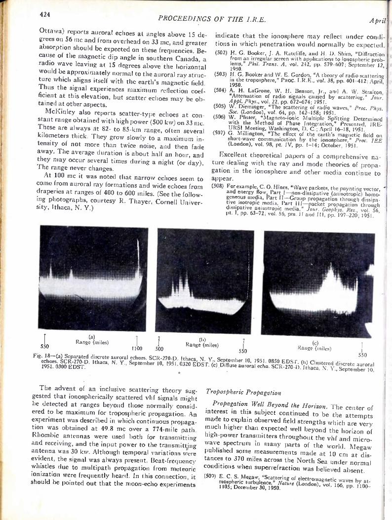
424 PROCEEDINGS OF THE I.R.E.
Ottawa) reports auroral echoes at angles above 15 de-grees on 56 mc and from overhead on 33 mc, and greater absorption should be expected on these frequencies. Be-cause of the magnetic dip angle in southern Canada, a radio wave leaving at 15 degrees above the horizontal would be approximately normal to the auroral ray struc-ture which aligns itself with the earth's magnetic field. Thus the signal experiences maximum reflection coef-ficient at this elevation, but scatter echoes may be ob-tained at other aspects.
McKinley also reports scatter-type echoes at con-stant range obtained with high power (500 kw) on 33 me. These are always at 82- to 85-km range, often several kilometers thick. They grow slowly to a maximum in-tensity of not more than twice noise, and then fade away. The average duration is about half an hour, and they may occur several times during a night (or day). The range never changes.
At 100 mc it was noted that narrow echoes seem to come from auroral ray formations and wide echoes from draperies at ranges of 400 to 600 miles. (See the follow-ing photographs, courtesy R. Thayer, Cornell Univer-sit)', Ithaca, N. Y.)
550
(a) Range (miles) I
1100 500
April
indicate that the ionosphere may reflect under condi-tions in which penetration would normally be expected.
(502) H. G. Booker, J. A. Ratcliffe, and H. D. Shim, "Diffraction from an irregular screen with applications to ionospheric prob-lems," Phil. Trans. A, vol. 242, pp. 579-607; September 12, 1950.
(503) H. G. Booker and W. E. Gordon, "A theory of radio scattering in the troposphere," PROC. I.R.E., vol. 38, pp. 401-412; April, 1950.
(504) A. H. LaGrone, W. H. Benson, Jr., and A. W. Straiton, "Attenuation of radio signals caused by scattering," Jour. Appl. Phys., vol. 22, pp. 672-674; 1951.
(505) W. Dieminger, "The scattering of radio waves," Proc. Phys. Soc. (London), vol. 64, pp. 142-158; 1951.
(506) W. Pfister, "Magneto-ionic Multiple Splitting Determined with the Method of Phase Integration," Presented, IRE-URSI Meeting, Washington, D. C.; April 16-18, 1951.
(507) G. Millington, "The effect of the earth's magnetic field on short-wave communication by the ionosphere," Proc. 1EE (London), vol. 98, pt. IV, pp. 1-14; October, 1951.
Excellent theoretical papers of a comprehensive na-ture dealing with the ray and mode theories of propa-gation in the ionosphere and other media continue to appear. (508) For example, C. 0. Hines, "Wave packets, the poynting vector,
and energy low, Part I—non-dissipative (anisotropic) homo-geneous media, Part II—Group propagation through dissipa-tiye. isotropic media, Part III—packet propagation through dissipative anisotropic media," Jour. Geophys. Res., vol. 56, pt. I, pp. 63-72; vol. 56, pts. II and III, pp. 197-220; 1951.
(b) Range (miles)
550
(c) Range (miles)
550 Fig. I8—(a) Separated discrete auroral echoes. SCR-270-D. Ithaca, N. Y., September 10, 1951. 0850 EDST. (b) Clustered discrete auroral echoes. SCR-270-D. Ithaca, N. Y., September 10, 1951. 0320 EDST. (C) Diffuse auroral echo. SCR-270-D. Ithaca, N. Y., September 10, 1951. 0300 EDST.
• •
The advent of an inclusive scattering theory sug-gested that ionospherically scattered vhf signals might be detected at ranges beyond those normally consid-ered to be maximum for tropospheric propagation. An experiment was described in which continuous propaga-tion was obtained at 49.8 mc over a 774-mile path. Rhombic antennas were used both for transmitting and receiving, and the input power to the transmitt.ing antenna was 30 kw. Although temporal variations were evident, the signal was always present. Beat-frequency whistles due to multipath propagation from meteoric ionization were frequently heard. In this connection, it should be pointed out that the moon-echo experiments
Tropospheric Propagation
Propagation Well Beyond the Horizon. The center of interest in this subject continued to be the attempts made to explain observed field strengths which are very much higher than expected well beyond the horizon of high-power transmitters throughout the vhf and micro-wave spectrum in many parts of the world. Megaw published some measurements made at 10 cm at dis-tances to 370 miles across the North Sea under normal conditions when superrefraction was believed absent.
(509) E. C. S. Megaw, "Scattering of electromagnetic waves by at-mospheric turbulence," Nature (London), vol. 166, pp. 1100-1105; December 30, 1950.
1'1952
These observations extend to greater ranges the phe-
no menon first discovered by Katzin in the Caribbean in 1945 (later confirmed by him in the Pacific) of greatly .reduced attenuation per mile at 10 cm beyond about 90 miles, in what has come to be called the "scatter re-
gion." (510) M. Katzin, "Signal Fluctuation in Long-Range Over-Water
Propagation," Symposium on Tropospheric Wave Propaga-tion, Naval Electronics Report 173, San Diego, Calif., pp. 94-97.
Attenuation of the average field strength at long ranges is observed to be a few tenths of a decibel per mile, rather than several decibels as predicted by con-ventional theory for the normal atmosphere over a curved earth. Nlegaw interpreted his measurements in terms of the hypothesis of scattering from index-of-refraction fluctuations associated with atmospheric turbulence. Independent evidence for the order of mag-• nitude of atmospheric turbulence was deduced by him Direct measurements of fluctuations in the refractive from astronomical measurements on the twinkling of • index of the atmosphere at microwave frequencies,
stars. using the important new technique of the recordin g microwave refractometer were reported by Birnbaum.Toward the end of the year, Feinstein published
the suggestion that partial reflections from the normal (517) G. Birnbaum, "Fluctuations in the refractive index of the tropospheric stratification may contribute importantly atmosphere at microwave frequencies," Phys. Rev., vol. 82, to propagation well beyond the horizon. pp. 110-111; April 1,1951.
(511) J. Feinstein, "Tropospheric propagation beyond the horizon," Air is drawn through holes in the end plates of a Jour. App!. Phys., vol. 22, pp. 1292-1293; October, 1951. microwave cavity, and the frequency difference be-
This notion follows logically from the im portant paper tween two such cavities is measured to deduce the index fluctuations of the air with very small time lag. When
by Bremmer. (See (514).) coupled with rapid temperature measurements, the
(512) H. Bremmer, "The propagation of electromagnetic waves m icrowave refractometer may be used for extremely through a stratified medium and its WKB approximation for oblique incidence," Physica, vol. 15, pp. 593-608; August, rapid measurement of the humidity of a small sample 1949. of air.
(513) H. Bremmer, "WKB approximation as the first term of a geo-metric-optical series," Commun. Pure and App!. Math., vol. Mathematical Theory. Volume 13 of the Radiation 4, pp. 105-115; June, 1951. Laboratory series, "The Propagation of Short Radio
Waves," a series of theoretical papers, originally pre-sented at a symposium on electromagnetic waves at New York University in June, 1950, appeared in the quarterly, Communications on Pure and Applied Mathe-matics. The latter also carried more than 10 papers having application to the theory of tropospheric
propagation. (518) Communications on Pure and Applied Mathematics, Pub-
lished quarterly by the Institute of Mathematics and Me-chanics, New York University, New York, N. Y.; December, 1950; and all issues of vol. 4; 1951.
425 Radio Progress During 1951
(514) J. A. Saxton, 'The propagation of metre radio waves beyond the normal horizon, Jour. IEE (London), vol. 98, pt. III, pp. 360-382; September, 1951.
At 100 rim some experimental observations were inter-preted by the University of Texas group in terms of the hypothesis of scattering from turbulence. (515) A. W. Straiton, D. F. Metcalf, and C. W. Tolbert, "A study
of tropospheric scattering of radio waves," PROC. I.R.E., vol. 39, pp. 643-648; June, 1951.
Gerks made the following statement on propagation at 412 mc from a high-power transmitter: "For com-munication grade of service, it appears entirely feasible to operate a 100-mile link with low, directional antennas and about 10 kw of transmitter power with a probabil-ity of satisfactory field strength more than 90 per cent
of the time." (516) I. H. Gerks, "Propagation at 412 megacycles from a high-power
transmitter," PROC. I.R.E., vol. 39, pp. 1374-1382; November, 1951.
He showed that for any plane-stratified medium tra-versed by plane waves there must exist what he called a "scattering coefficient" per unit thickness, which de-scribes the new waves that must be produced by a wave passing obliquely through the medium, thus encounter-ing continuously changing index of refraction of the inhomogeneous stratified medium. Two papers on the subject of reflections from the normal troposphere were presented at the Ithaca meeting of URSI-I RE in October. Interest will probably continue to increase in the study of these persistent, though weak and fading, fields well beyond the horizon, because all three current hypotheses as to their cause (scattering from at-mospheric turbulence, rough earth, or tropospheric stratification) seem to imply that the field should be persistent and not so highly variable as the stronger nonoptical fields associated with atmospheric ducts, elevated refracting layers, or scattering from insects. Scattering from turbulence at the low end of the
vhf band is discussed in relation to British measure-ments in two papers from the National Physical Lab-
oratory.
The subject matter is too recondite to summarize in the space available. Two papers published in 1950 by Booker and Clemmow gave a simplified physical inter-pretation of such well-known phenomena as diffraction around a straight edge and the Sommerfeld theory of radio propagation over a flat earth.
(519) H. G. Booker and P. C. Clemmow, "The concept of an angular spectrum of plane waves, and its relation to that of polar di-agram and aperture distribution," Jour. IEE (London), vol. 97, pt. III, pp. 11-17; January, 1950.
(520) H. G. Booker and P. C. Clemmow, "A relation between the Sommerfeld theory of radio propagation over a fiat earth and the theory of diffraction at a straight edge," Jour. IEE (London), vol. 97, pt. III, pp. 18-27; January, 1950.
426 PROCEEDINGS OF THE J.R.E. Apri
Broadcasting. Continuing prospective use of uhf fre-quencies for television broadcasting stimulated work on propagation questions of particular interest to a broad-caster. A committee of the International Radio Con-sultative Committee reviewed briefly the known answers to the question, "What tropospheric propaga-tion data should be used in determining the geographi-cal separation between television transmitting stations?"
(521) Statement concerning tropospheric wave propagation. Report of U. S. Preparatory Committee for the International Con-sultative Committee on Radio, Serial 769 (revised); April 3, 1951. Document published by Telecommunications Policy Staff, Department of State.
A report by the Federal Communications Commis sion collected together data from many sources on the variability of uhf fields within line of sight and derived empirical results of use in frequency allocation.
(522) H. Fine, "UHF propagation within line of sight," Federal Com-munications Commission TRR Report 2.4.12; June I, 1951. Gerks gave statistical summaries of space variability of fields at 412 mc in Iowa.
Velocity of Propagation. Aslakson reported new meas-urements of the velocity of propagation with improved shoran-type equipment.
(523) C. I. Aslakson, "A new measurement of the velocity of radio waves," Nature (London), vol. 168, pp. 505-506; September 22, 1951.
He deduces from these and other recent results a pro-visional recommended value of the velocity of propaga-tion of electromagnetic waves in vacuo of 299,793.1 km a value 17.1 km higher than that widely accepted before World War II from optical measurements alone. The relation of this new value to the interrelated "best" values of other constants of atomic physics was indi-cated.
(524) J. A. Bearden and H M. Watts, "A re-evaluation of the fun-damental atomic constants," Phys. Rev., vol. 81, pp. 73-81; January, 1951.
(525) J. W. M. DuMond and E. R. Cohen, "Least-squares adjusted values of the constants as of December, 1950," Phys. Rev., vol. 82, pp. 555-556; May 15, 1951.
International Activities. Part 1 of the proceedings of the 1950 general assembly of the International Scien-tific Radio Union was published. It contains a bibli-ography and brief reviews of work done in many branches of scientific radio, especially in some of the smaller countries, whose contributions appear only in-frequently in the widely circulated journals of the larger countries.
(526) Proceedings of the General Assembly held in Zurich, Inter-national Scientific Radio Union, 42 rue des Minimes, Brussels; September 11-22, 1950. (Copies may be purchased from the secretary of the United States National Committee of the Union, Dr. A. H. Waynick, Pennsylvania State College, State College, Pa., at ;4.60.)
Radio Astronomy
Solar Radio Waves. Measurements of solar radio emis-sion throughout the radio-frequency band were used to obtain a re-evaluation of the temperature-height dis-tribution in the solar atmosphere. The extension of the
measurements to 3.5 X10'° cycles (8 mm) contributed to this determination.
(527) J. P. Hagen, "Temperature gradient in the sun's atmosphere measured at radio frequencies," Ap. Jour., vol. 113, pp. 547-566; May, 1951.
(528) J. H. Piddington, "The derivation of a model solar chromo-sphere from radio data," Proc. Roy. Soc. A., vol. 203, pp. 417-434; October 10, 1950.
(529) J. C. Jaeger and K. C. Westfold, "Equivalent path and absorp-tion for electromagnetic radiation in the solar corona," A ust. Jour. Sci. Res. A., vol. 3, pp. 376-386; September, 1950.
Studies were made of the variation of the radiation from the quiet sun over several years, and a distinct decrease was observed on the 3,000-, 2,800-, 1,200-, and , 600-mc frequencies. The distribution of radio emission on the solar disk was studied at 81 mc.
(530) A. E. Covington, "Some characteristics of 10.7-centimetre solar noise," Jour. Roy. Astron. Soc. (Canada), vol. 45, pt. I, pp. 15-22; January-February, 1951; pt. II, pp. 49-61; March-April, 1951.
(531) W. N. Christiansen and J. V. Hindman, "A long-period change in radio-frequency radiation from the 'quiet' sun at decimetre wave-lengths," Nature (London), vol. 167, pp. 635-637; April 21, 1951.
(532) K. E. Machin, "Distribution of radiation across the solar disk at a frequency of 81.5 Mc/s," Nature (London), vol. 167, pp. 889-891; June 2, 1951.
Measurements of the polarization of radio waves from the sun on 600 mc during the partial eclipse of Novem-ber 1, 1948 were interpreted as setting an upper limit of 11 gauss to the general magnetic field of the sun.
(533) S. F. Smerd, "The polarization of thermal 'solar noise' and a determination of the sun's general magnetic field," Aust. Jour. Sci. Res. A., vol. 3, pp. 265-273; June, 1950.
A major contribution was the development of a means of rapidly scanning the intensity of solar radio waves over a large frequency range. By its use, frequency-time variation of wave intensity over a frequency range from 70 to 130 mc was obtained.
(534) "Meeting of the Royal Astronomical Society," Observatory, vol. 70, pp. 55-62; April, 1950.
(535) J. P. Wild and L. I.. McCready, "Observations of the spectrum of high-intensity solar radiation at metre wavelengths,"Aust. Jour. Sci. Res. A., vol. 3, pts. 1 and 2, pp. 387-408; September, 1950; pt. 3, pp. 541-557; December, 1950; vol. 4, pt. 4, pp. 36-50; March, 1951.
The solar eclipse of September 12, 1950 was observed at frequencies of 10,000, 3,000, 480, 200, 100, and 60 mc. Measurements made on the eclipse of April 28, 1949 were analyzed.
(536) F. T. Haddock, C. H. Mayer, T. P. McCullough, R. White, and R. M. Sloanaker, "The measurement of 3 and 10 centi-meter radiation during the total solar eclipse of September 12, 1950," Astron. Jour., vol. 56, pp. 38-39; April 1951.
(537) J. P. Hagen, "Naval Research Laboratory eclipse expedition to Attu, Alaska, September 12, 1950," Astron. Jour., vol. 56, pp. 39-40; April, 1951.
(538) G. Reber and E. Beck, "The measurement of 65 centimeter radiation during the total eclipse of September 12, 1950," Astron. Jour., vol. 56, p. 47; April, 1951.
(539) T. Hatanaka, S. Suzu ki, an d F. Moriyama, "Preliminary Re-port on the Observation of the Solar Radio Noise at the Par-tial Eclipse on September 12, 1950," Issued by Eclipse Com-mittee, Science Council of Japan, 1951, Reprinted as Tokyo Astronomical Observatory Reprint 79.
(540) J. P. Hagen, F. T. Haddock, and G. Reber, "NRL Aleutian radio eclipse expedition," Sky and Telescope, vol. 10, pp. 109, 111-113; March, 1951.
(541) M. Laffineur, R. Ntichard, R. Servajean, and J. L. Steinberg, "Observations radioelectriques de l'eclipse de soleil du 28
1952 Radio Progress During 1951 427
Avril 1949," Ann. d'Astrophys., vol. 13, pp. 337-342; July— ; September, 1950; Reprinted as a contribution to I.A.P.B. 53.
[ An instrument was developed by Payne-Scott and r
Little that determines automatically the place of origin rand polarization of a burst at 100 mc. (542) R. N. Bracewell, "An instrumental development in radio
astronomy," Observatory, vol. 70, pp. 185-186; October, 1950.
The further observational studies of solar activity ,
i were paralleled by advances in theoretical analysis. (543) E. J. Blum and J. F. Denisse, "Comparaison des rayonnements
radioelectriques recus de soleil sur deux frequences voisines," Compt. Rend. (Paris), vol. 231, pp. 1214-1216; November 27, 1950.
1 (544) E. J. Blum, J. F. Denisse, and J. L. Steinberg, "Etude des orages radioelectriques solaires de faible intensite," Compt. Rend. (Paris), vol. 232, pp. 387-389; January 29, 1951.
; (545) E. J. Blum, J. F. Denisse, and J. L. Steinberg,„"Sur l'intrepre-tation des sursauts radioelectriques solaires, Contpt. Rend. (Paris), vol. 232, pp 483-485: February 5, 1951.
I (546) NV. N. Christiansen, J. V. Hindman, A. G. Little, R. Payne-Scott, D. E. Yabsley, and C. W. Allen, "Radio observations of two large solar disturbances," Aust. Jour. Sci. Res. A., vol. 4, pp. 51-61; March, 1951.
' (547) J. H. Piddington and H. C. Minnett, "Solar radio-frequency emission from localized regions at very high temperatures," Aust. Jour. Sci. Res. A., vol. 4, pp. 131-157; June, 1951.
(548) M. A. Ellison, "Source points of radio noise bursts associated with solar flares," Nature (London), vol. 167, pp. 941-942; June 9, 1951.
(549) A. E. Covington, "Circular polarization of 10.7-centimetre solar noise bursts," Jour. Roy. Astron. Soc. (Canada), vol. 45, pp. 157-161; July—August, 1951.
(550) A. Maxwell, "Radio emission from the sunspot of central meridian passage 1950 June 14," Observatory, vol. 71, pp. 72-74; April, 1951.
(551) G. Reber, "Motion in the solar atmosphere as deduced from radio measurements," Science, vol. 113, pp. 312-314; March 23, 1951.
(552) T. Hatanaka, Y. Sekido, Y. Miyazaki, and M. Wada, "Solar Radio Outburst and Increase of Cosmic-Ray Intensities on September 20, 1950," Report on Ionosphere Research in Japan., vol. 5; 1951; Reprinted, Tokyo Astronomical Observatory Re-
print 80. " (553) J. F. Denisse, "Contribution a l'etude des emissions radio-
electriques solaires," Ann. d'Astrophys., vol. 13, pp. 181-202; April—June, 1950.
(554) B. Kwal, "Les ondes electromagnitiques emises par les protons rapides dans les champs magnetiques intenses, et la correlation entre le rayonnement cosmique et les bruits radio-klectriques du soleil et de la galaxie," Compt. Rend. (Paris), vol. 231, pp. 1057-1059; November 13, 1950.
(555) K. C. Westfold, "The interpretation of the magneto-ionic theory," Jour. Atmos. Terr. Phys., vol. I, pp: 152-186; 1951.
(556) B. Kwal, "Sur le rayonnement electromagnettque des protons cosmiques dans les champs magnetiques intenses des objets celestes," Jour. Phys. Radium, vol. 12, pp. 66-67; January, 1951.
(557) B. Kwal, "Sur une possibilite d'interpreter les 'bruits' radio- cosmic rays. electriques du soled et de la galaxie comme rayonnement des protons des radiations cosmiques dans les champs mag- Galactic radio emission from the hyperfine structure netiques intenses du soleil et des autres objects celestes," line of hydrogen at 1,420 mc has been observed on Ann. d A strophys., vol. 141 pp. 189-198; May—June, 1951.
(558) V. A. Bailey, "The relativistic theory of electro-magneto-ionic three continents. The motion of these interstellar hydro-waves," Phys. Rev., vol. 83, pp. 439-454; July 15, 1951. gen clouds has been observed by the Doppler shift.
(559) J. Feinstein and H. K. Sen, "Radio wave generation by multi-stream charge interaction," Phys. Rev., vol. 83, pp. 405-412; (576) J. G Bolton and K. C. Westfold, "Galactic radiation at radio July 15, 1951. frequencies, Part 3. Galactic structure," Aust. Jour. Sci. Res.
(560) S. F. Smerd, "A radio-frequency representation of the solar A., vol. 3, pp. 251-264; June, 1950. atmosphere," Proc. IEE (London), vol. 97, pt. III, pp. 447— (577) G. Westerhout and J. H. Oort, "A comparison of the intensity 452; November, 1950. distribution of radio-frequency radiation with a model of the
(561) Y. Rocard, "Sur un mecanisme d'emission radioelectrique galactic system," B.A.N., vol. 11, pp. 323-333; August 26, coronale," Contpt. Rend. (Paris), vol. 232, pp. 598-600; Febru- 1951. ary 12, 1951. (578) A. Unsold, "Cosmic radiation and cosmic magnetic fields,
(562) S. A. Korff and Y. Beers, "The solar atmosphere and the origin Part 1. Origin and propagation of cosmic rays in our galaxy," of radiofrequency radiation," Phys. Rev., vol. 80, pp. 489-490; Phys. Rev., vol. 82, pp. 857-863; June 15, 1951. November 1, 1950. (579) V. L. Ginzburg, "Cosmic rays as a source of galactic radio-
(563) U. C. Guha, "Reversal of polarization of microwaves from radiation," Doklady Akademiia Nauk S.S.S.R., vol. 76, pp. sun-spots," Indian Jour. Phys., vol. 25, pp. 8-16; January, 377-380; 1951. 1951. Also, Proc. Indian Assoc. Cultivation Sci., no. 34. (580) H. I. Ewen, E. M. Purcell, C. A. Muller, J. H. Oort, and
(564) C. deJager, M. Minnaert, and C. A. Muller, "Absence of hy- J. L. Pawsey, "Observation of a line in the galactic radio drogen radiation of wavelength 21 cm. in the sun," Nature spectrum," Nature (London), vol. 168, pp. 356-358; Septem-(London), vol. 168, p. 391; September 1, 1951. ber I, 1951.
(565) J. F. Denisse, J. L. Steinberg, and S. Zisler, "Contrele de l'activite geomagnetique par les centres d'activite solaires distingues par leurs proprietes radioelectriques," Conipt. Rend. (Paris), vol. 232, pp. 2290-2292; June 18, 1951.
Galactic Radio Waves. The number of known discrete sources of radio emission in the galaxy was increased and the determinations of the positions of the more in-tense sources improved. A search for long-period varia-tions of intensity yielded negative results. The effects of the ionosphere on radiation from point sources was studied further. Observations of the point source in Taurus (Crab Nebula) indicated the intensity of radia-tion to be independent of frequency whereas several other discrete sources show an intensity decrease with
increase of frequency. The distribution of radio-frequency radiation from
the galaxy on a frequency of 200 mc has been reported by observers from both hemispheres. (566) M. Ryle, F. G. Smith, and B. Elsmore, "A preliminary survey
of the radio stars in the Northern Hemisphere," Mon. Not. R. Asir. Soc., vol. 110, pp. 508-523; 1950.
(567) F. G. Smith, "An accurate determination of the positions of four radio stars," Nature (London), vol. 168, pp. 555; Septem-ber 29, 1951.
(568) M. Ryle, "Radio astronomy," Rep. Progr. Phys. (London), vol. 13, pp. 184-246; 1950.
(569) M. Ryle and B. Elsmore, "A search for long-period variations in the intensity of radio stars," Nature (London), vol. 168, pp. 555-556; September 29, 1951.
(570) B. Y. Mills and A. B. Thomas, "Observations of the source of radio-frequency radiation in the constellation of Cygnus," Aust. Jour. Sci. Res. A., vol. 4, pp. 158-171; June, 1951.
(571) M. Ryle and A. Hewish, "The effects of the terrestrial ion-osphere on the radio waves from discrete sources in the galaxy," Mon. Not. R. Asir. Soc., vol. 110, pp. 381-394; 1950.
(572) C. L. Seeger, "Some observations of the variable 205 mc/s radiation of Cygnus A," Jour. Geophys. Res., vol. 56, pp. 239-258; June, 1951.
(573) G. J. Stanley and 0. B. Slee, "Galactic radiation at radio frequencies. Part 2, The discrete sources," Aust. Jour. Sci. Res. A., vol. 3, pp. 234-250; June, 1950.
(574) C. L. Seeger and R. E. Williamson, "The pole of the galaxy as determined from measurements at 205 mc. sec.," Ap. Jour., vol. 113, pp. 21-49; January, 1951.
(575) C. W. Allen and C. S. Gum, "Survey of galactic radio-noise at 200 mc/s.," Aust. Jour. Sci. Res. A., vol. 3, pp. 224-233; June, 1950.
Models of the galactic structure have been based on the measured distributions of radio-frequency radiation for the galaxy. Attempts have been made to relate the origin of galactic radio-frequency emission to that of

428 PROCEEDINGS OF THE I.R.E. April
Antennas, Waveguides, and Transmission Lines
Surface-wave propagation continued to receive at-tention in the literature.
(581) S. S. Attwood, "Surface wave propagation over a coated plane conductor," Jour. App!. Phys., vol. 22, pp. 504-509; April, 1951.
(582) G. Goubau, "Single-conductor surface-wave transmission line," PROC. I.R.E., vol. 39, pp. 619-624; June, 1951.
Rectangular and circular waveguides having two di-electrics were treated theoretically.
(583) A. Banos, Jr., D. S. Saxon, and H. Gruen, "Propagation char-acteristics in a coaxial structure with two dielectrics," Jour. App!. Phys., vol. 22, pp. 117-123; February, 1951.
(584) J. van Bladel and T. J. Higgins, "Cut-off frequency in two-dielectric layered rectangular waveguides," Jour. App!. Phys., vol. 22, pp. 329-334; March, 1951.
A tunable waveguide filter was described that has a symmetrical pass-band response.
(585) W. Sichak and H. Augenblick, "Tunable waveguide filter," PROC. I.R.E., vol. 39, pp. 1055-1059; September, 1951.
A mathematical analysis of waveguide junctions and an approximate theory of the directional coupler were given.
(586) D. M. Kearns, "Analysis of symmetrical waveguide junctions," Jour. Res. Natl. Bur. Stand., vol. 46, pp. 267-282; April, 1951.
(587) F. Bolinder, "Approximate theory of the directional coupler," PRoc. I.R.E., vol. 39, p. 291; March, 1951.
Two quite different types of delay lines were de scribed.
(588) E. M. Bradburd, "Magnetostrictive delay line," Elec. Corn mun. (London), vol. 28, pp. 46-53; March, 1951.
(589) A. N. Wang, "Magnetic delay-line storage," PROC. I.R.E., vol 39, pp. 401-407; April, 1951.
A marked reduction of skin-effect losses in transmis-sion lines appears possible by proper lamination of the conductors.
590) A. M. Clogston, "Reduction of skin-effect losses by the use of laminated conductors," PROC. I.R.E., vol. 39, pp. 767-782; July, 1951.
A general formula for the radiation resistance of a two-wire line was derived in one paper, and measured results on a resonant quarter-wave section were given in another paper.
(591) J. E. Storer and R. King, "Radiation resistance of a two-wire line," PROC. I.R.E., vol. 39, pp. 1408-1412; November, 1951.
(592) F. M. Leslie, "Radiation from resonant quarter-wave trans-mission lines," Wireless Eng., vol. 28, pp. 70-72; March, 1951.
Several papers appeared covering various aspects of transmission-line theory and measurement.
(593) A. E. Laemmel, N. Marcuvitz, and A. A. Oliner, "Approxima-tion methods in radial transmission-line theory with applica-tions to horns," Pa m. I.R.E., vol. 39, pp. 959-965; August, 1951.
(594) H. Meinke, "The behavicr of electromagnetic waves in highly nonuniform lines," Z. angew. Phys., vol. 22, pp. 473-478; December, 1950.
(595) H. A. Wheeler, "Transmission-line impedance curves," PROC. I.R.E. vol. 39, pp. 1400-1403; December, 1950.
(596) H. E. Sorrow, W. E. Ryan, and R. C. Ellenwood, "Evaluation of coaxial slotted-line impedance measurements," PROC. T.R.E., vol. 39, pp. 162-168; Febt uary, 1951.
A number of reports on the antenna investigations of the Cruft Laboratory Group appeared.
(597) E. D. Hartig, R. King, T., Morita, D. G. Wilson, "The meas-urement of antenna impedance using a receiving antenna," PROC. I.R.E., vol. 39, p. 1459; November, 1951.
(598) T. Morita, "Theory of the Concentric-Slot Antenna," Pre-sented, IRE National Convention, New York, N.Y.; March, 1951.
(599) J. V. N. Granger and 'I'. Morita, "Radio-frequency current distribution on aircraft structures," PROC. 1.R.E., vol. 39, pp. 932-938; August, 1951.
(600) R. King, "Theory of collinear antennas," Jour. App!. Phys., vol. 21, pp. 1232-1251; December, 1950.
(601) C. H. Papas and R. King, "R..diation from wide-angle conical antennas fed by a coaxial line," PROC. I.R.E., vol. 39, pp. 49-51; January, 1951.
Industrial Electronics Professional Growth
Several books were published by industrial engineers and by professors engaged in training students in en-gineering and applied physics.
(602) R. R. Benedict, "Introduction to Industrial Electronics, Prentice-Hall, New York, N. Y.; 1951.
(603) J. M. Cage, "Theory and Application of Industrial Electron ics," McGraw-Hill Book Co., Inc., New York, N. Y.; 1951.
(604) D. P. Eckman, "Industrial Instrumentation," John Wiley and Sons, Inc., New York, N. Y.; 1951.
(605) J. D. Trimmer, "Response of Physical Systems," John Wiley and Sons, Inc., New York, N. Y.; 1951.
(606) R. C. Walker, "The Industrial Application of Gas-filled Tri-odes (Thyratrons)," Chapman and Hall, London; 1951.
(607) G. M. Chute, "Electronic Motor and Welder Controls," McGraw-Hill Book Co., Inc., New York, N. Y.; 1951.
The first four of these are valuable for textbook pur-poses, while the other two are primarily suited for direct applications in the respective fields. The academic growth of industrial electronics is evidenced by the fact that many schools and universities offer courses on this subject. Also, a Professional Group on Industrial Elec-tronics was established by the Institute during the year.
Radio-Frequency Heating
During the past three years, four books appeared on induction and dielectric heating, presenting the tech-nical basis of these applications of radio-frequency heating.
(608) L. Hartshorn, "Radio-Frequency Heating," George Allen and Unwin, Ltd., London; 1949.
(609) L. L. Langton, "Radio-Frequency Heating Equipment," Pit man Publishing Co., New York, N. Y.; 1949.
(610) F. W. Curtis, "High-Frequency Induction Heating," McGraw-Hill Book Co., Inc., New York, N. Y., 2nd Ed.; 1950.
(611) H. F. Trewman, ed., "Electronics in the Factory," Pitman Publishing Co., Ltd., London; 1949.
The impedances encountered in radio-frequency heat-ing are frequently outside the ranges covered by com-mercial measuring equipment, and an extension of these ranges was discussed.
(612) R. E. Lafferty, "Extended Q-meter measurements," Elec-tronics, vol. 24, p. 125; November, 1951.
(613) A. Colombani, "Induction heating of a hollow sphere," Jour. Phys. Radium, vol. 12, pp. 26-30; January, 1951.
' 1952
Several specific problems in which energy absorption is a function of thickness in an alternating field were
treated. A review of the 1950 literature on dielectric heating
-was published, and includes work on dielectrics of con-siderable importance to those engaged in insulation ap-
plications. Industrial insulation and dielectric problems were presented at a conference on electrical insulation. (614) "Digest of the Literature on Dielectrics," vol. 14, National
Academy of Sciences, National Research Council; March, 1951.
(615) "1950 Annual Report of the Conference on Electrical In-sulation," National Research Council; March, 1951.
Special Applications
Progress was made in special instrumentation for de-termining the internal friction of materials vibrating at frequencies from 50 to 10,000 cycles. Industrial appli-cations continued to use television and several physical processes, such as nuclear resonance, for measuring and controlling magnetic fields, mass spectrometer, con-trols, and the like. Television has increased the demand for nonconducting magnetic materials. Considerable ef-fort went into establishing suitable measuring methods and equipment. Open-circuit-transformer voltage meas-urements for circuits easily applied to the specimens are
used for evaluation. (616) A. D. N. Smith, "An electronic instrument for the measure-
ment of the damping capacity of materials," Jour. Sci. Instr., vol. 28, pp. 106-108; April, 1951.
(617) M. Andrieux and M. Fraize, "Instrument for production test of permeability of magnetic circuits," Onde Elect., vol. 31, pp. 65-69; February, 1951.
Radio Progress During 1951
(621) L. A. Pipes, "Steady-State and Transient Analysis of an Idealized Series Connected Magnetic Amplifier," Technical Paper 51-390, Presented, American Institute of Electrical Engineers, Fall Meeting, Cleveland, Ohio; 1951.
The Pipes' paper considers the saturable reactor with-out feedback, using the methods of nonlinear mechanics. Definitions are proposed for the "time constant" of such a nonlinear device, and the dependence of the time con-stant on the initial conditions is pointed out. (622) S. B. Cohen, "Analysis and design of self-saturable magnetic
amplifiers," PROC. I.R.E., vol. 39, pp. 1009-1020; September,
1951.
A theoretical analysis was made of the amplifier with feedback, and the relation of gain and time response was stated. A number of circuits were included and ap-plications of magnetic amplifiers in servo systems shown. A listing of the comparative advantages of mag-netic and electronic amplifiers pointed out the limita-
tions of each. (623) "Magnetic Amplifiers, a Rising Star in Naval Electronics,"
Pamphlet NavShips 900,172, Electronics Design and Develop-ment Division, Navy Department, Bureau of Ships, Washing-ton 25, D. C.
429
Magnetic Amplifiers
By using magnetic amplifiers, signals up to 20 mc and higher were amplified successfully, and operation at signal levels of 10-12 watt and less was reported. The input impedance can be as high as 100,000 ohms and gain-time-constant ratios of more than 106 per second were achieved. Most of these performances were ob-tained under carefully controlled laboratory conditions, and may be taken as upper limits at this time. There are, however, many applications where more conservative figures would satisfy a given need. A particularly useful and complete bibliography on
magnetic amplifiers and devices covering about 90 pat-ents and over 900 papers, published from 1903 to early
1951, appeared. In view of the completeness of this work, no references
prior to May, 1951 are listed here. Several articles were published on the theoretical aspects of magnetic ampli-
fiers. (618) J. G. Miles, "Bibliography of Magnetic Amplifier Devices and
the Saturable Reactor Art," Technical Paper 50-388; Pre-sented, American Institute of Electrical Engineers Fall Meet-ing, Cleveland, Ohio; 1951.
(619) R. A. Ramey, "On the mechanics of Magnetic Amplifier Op-eration," Technical Paper 50-217, Presented, American Institute of Electrical Engineers Summer Meeting, Toronto, Canada; 1951.
620) R. A. Ramey, "On the Control of Magnetic Amplifiers," Technical Paper 51-389, Presented, American Institute of Electrical Engineers Fall Meeting, Cleveland, Ohio; 1951.
The history and many applications of magnetic am-plifiers are presented in a descriptive booklet. It includes a representative list of manufacturers of magnetic am-plifiers and components and a bibliography of over 800 patents and papers, from 624 B.C. to about July, 1951. The increased importance of electronic principles in
commerce and industry is evident by the greater atten-tion given such courses in engineering colleges. A survey of 90 accredited engineering schools at the college or university level, with at least one school in each state of the union reporting, was completed. The field was assumed to include electronic instrumentation, elec-tronic control, and electronic power, including both high-frequency heating and rectification. Approximately half of the schools reporting offer an
electrical-engineering course at the senior and graduate levels that treats all three topics: instrumentation, con-trol, and power. Somewhat less than half of these schools place these courses on the required list, and in practically every case industrial electronics is preceded by a course in basic electronics. About 30 per cent of the other schools attempt to
cover relevant topics in other courses. The amount of "servo" theory included in courses in
industrial electronics varies widely. About 65 per cent of the courses include some of the theory, and in about 10 per cent of the schools, a separate course in servo theory is available to seniors. Employers seem to at-tach considerable importance to the combination of electronics and servomechanisms.
Electronic Computers
Analog Computers
Analog computing techniques, applied to a very wide variety of new problems, both in direct computing and
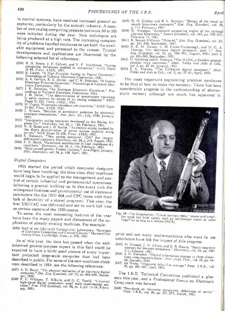
430 PROCEEDINGS OF THE I.R.E.
in control systems, have received increased general ceptance, particularly by the aircraft industry. A nu ber of new analog computing projects (estimate 30 to 5 were initiated during the year. New techniques a being produced at a high rate. The increasing comple ity of problems handled continues to tax both the ava able equipment and personnel to the utmost. Typic developments and applications are illustrated by t following selected list of references:
ac-m-0) re
il-al he
(624) R. H. Strotz, J. F. Calvert, and N. F. Morehouse, "Analog computing techniques applied to economics," AIEE Paper 51-93, Trans. A IEE; 1951.
(625) B. Lippe!, "A High-Precision Analog to Digital Converter," Proceedings of National Electronic Conference; 1951.
(626) A. A. Gerlach, R. E. Zenner, and C. N. Pederson, "A Precise Electronic Function Generator," Proceedings of National Elec-tronic Conference; 1951.
(627) J. F. Reintijes, "An Analogue Electronic Correlator," Pro-ceedings of National Electronic Conference; 1951.
(628) J. H. Neher, "The determination of temperature transients in cable systems by means of an analog computer," AIEE Paper 51-253. Trans. AIEE.; 1951.
(629) W. PageIs, "A portable electronic pile simulator," AIEE Paper 51-262, Trans. A LEE; 1951.
(630) J. Winson, "Solution of aeroelastie problems by electronic analogue computation," Jour. Aero. Sci.; July, 1950; January, 1951.
(631) "Inexpensive analog computer developed by the Boeing Air-plane Co.," Electronics, vol. 24, p. 124; February, 1951.
(632) W. B. Boost and J. D. Rector, "An electric analog method for the direct determination of power system stability swing curves," AIEE Paper 51-338, Trans. AIEE; 1951.
(633) S. Bosworth, "New analog computer; IDA" (for integro differential analyzer), Electronics, vol. 24, p. 216; August, 1951.
(634) F. R. Smith, "Automatic stabilization of high impedance d-c amplifiers," Electronics, vol. 24, p. 124; February, 1951.
(635) "Sixty second genius: Project typhoon," A ero Digest; January, 1951; Electronics, vol. 24, P. 138; April, 1951.
Digital Computers
1951 started the period which computer designers have long been heralding: the time when their machines would begin to be applied to the management and con-trol of certain industrial and governmental operations, following a gradual building up to this event with the widespread business and governmental use of electronic calculators like the IBM 604 and CPC (even with their lack of flexibility of a stored program). This year, the first UNIVAC was delivered and set to work full time on certain aspects of the 1950 census.
To some, the most interesting features of the year have been the many papers and discussions of the ap-plication of already existing machines. For example:
(636) Staff of the (Harvard) Computation Laboratory, 'Synthesis of Electronic Computing and Control Circuits," Harvard Uni-versity Press, Cambridge, Mass., p. 278; 1951.
As of this year, the time has passed when the well-informed general-purpose expert in this field could be expected to have a fairly good picture of every impor-tant projected large-scale computer that had been described in public. For some of the new machines which were described in 1951, see the following references:
(637) A. D. Booth, "The physical realization of an electronic digital computer," Elec. Eng. (London), vol. 22, pp. 492-498; Decem-ber, 1950.
(638) F. C. Williams, T. Kilburn, and G. C. Tootill, "Universal high-speed digital computers: small scale experimental ma-chine," Proc. IEE (London), vol. 98, pt. 2, pp. 13-28; Febru-ary, 1951.
April
(639) D. H. Gridley and B. L. Sarahan, "Design of the naval re-search laboratory computer," Elec. Eng. (London), vol. 70, p. 111; February, 1951.
(640) M. Woodger, "Automatic computing engine of the nationa physical laboratory," Nature (London), vol. 167, pp. 270-271 February 17, 1951.
(641) R. Stuant-Williams, "Nimrod," Elec. Eng. (London), vol. 23 pp. 344-348; September, 1951.
(642) R. C. M. Barnes, E. H. Cooke-Yarborough, and D. G. A. Thomas, "An electronic digital computer, part 1," Elec. Eng. (London), vol. 23, pp. 286-291; August, 1951; part 2, pp. 341-343; September, 1951.
(643) G. Kjellberg and G. Neovius, "The BARK, a Swedish general-purpose relay computer," Math. Tables and Aids to Cak., vol. 5, pp. 29-34; January, 1951.
(644) P. L. Morton, "The California digital computer," Math. Tables and Aids to Ca/c., vol. 5, pp. 57-61; April, 1951.
The most important engineering problem continues to be that of how to make the memory. There has been considerable progress in the understanding of electro-static memory although not much has appeared in
"illdalLiLLLAILL
Fig. 19—The Graphechon, "visual memory tobe," stores and al pl I - ties weak but brief signal, such as oscilloscope traces or radar "pips" for as long as a minute (RCA).
print and not many mathematicians who want to use calculators have felt the impact of this progress.
(645) M. Kincaid, J. M. Adden, and R. B. Hanna, "Static magnetic memory for low-cost computers," Electronics, vol. 24, pp. 108-1 1 1 ; January, 1951.
(646) J. W. Forrester, "Digital information storage in three dimen-sions using magnetic cores," Jour. A ppl. Phys., vol. 22, pp. 44-48; January, 1951.
(647) An Wang, "Magnetic delay-line storage," PROC. I.R.E., vol. 39, pp. 401-407; April, 1951.
The I.R.E. Technical Committee published a glos-sary this year, and a Professional Group on Electronic Computers was formed.
(648) "Standards on electronic computers: definitions of terms," PROC. I.R.E., vol. 39, pp. 271-277; March, 1951.
11952 Radio Progress
Quality Control Considerable activity in general quality control and
' in applying associated statistical techniques to indus-Ltrial problems, including those associated with the radio and electronic arts, was evident. The rearmament pro-:gram intensified the need for better quality, not only at lower cost but also with less waste, scrap, shrinkage,
and loss of time. Such objectives can be attained through the appli-
cation of quality-control principles, both in the design and production of military electronic equipment. Papers relating specifically to design include those of Farrell and Lutzker, while many of the others apply equally well to both objectives.
(649) J. A. Davies, "Quality Evaluation of General Electric Com-pany's ARINC Tubes," Quality Control Conference Papers 1951, Presented, Convention, American Society for Quality Control, Cleveland, Ohio, p. 89; May 23-24,1951.
(650) E. B. Farrell, "The control chart as a tool for analyzing experi-- mental data," PROC. I.R.E., vol. 39, pp. 132-137; February,
1951. (651) L. G. Hector, "Quality Control in the Plant of Sonotone Cor-
poration," Presented, Conference on Quality Control, Rutgers University, New Brunswick, N. J.; September 15,1951.
(652) E. M. Jeffery, "Quality control in tube and component or ac-cessory manufacture," Telev. Eng., vol. 1, p. 40; November, 1950.
(653) J. M. Juran, "Quality-Control Handbook," McGraw-Hill Book Co., Inc., New York, N. Y., Section 13, pp. 653-680.
(654) L. Lutzker, "Quality control in TV receiver production," Telev. Eng., vol. 1, p. 6; February, 1950.
(655) L. Lutzker, "Statistical methods in research and develop-ment," PROC. I.R.E., vol. 38, p. 1253; November, 1950.
(656) E. M. McElwee, "Statistical evaluation of life expectancy of vacuum tubes designed for long-life operation," PROC. I.R.E., vol. 39, pp. 137-141; February, 1951.
Instrumentation
Audio-Frequency Measurements
Measurements of the amplitude and phase of the mo-tion of some dynamic loudspeaker cones, explored by a capacitor-probe technique, show the break-up of the cone motion when the frequency of the driving force is in the vicinity of a natural mode. This technique aids in determining how these modes should be damped to pro-duce a more uniform response from the speaker system.
During 1951
measuring equipment for making the various inter-
modulation tests.
(659) A. P. G. Peterson, "Intermodulation distortion," Gen. Rad. Exper., vol. 25, pp. 1-8; March, 1951.
A study of the effects of peak clipping, center clip-ping, linear rectification, and parabolic rectification on the intelligibility of speech showed that no satisfactory correlation is obtained between the results of harmonic-distortion tests on the nonlinear systems and the cor-responding speech intelligibility. (660) J. C. R. Licklider and R. Held, "Effects of various types of
nonlinear distortion upon the intelligibility of speech, Pre-sented, Acoustical Society of America, Chicago, III.; October 23,1951.
A method of calculating loudness of noise from the measured sound-pressure level in frequency bands in-vestigated recently (a modification of some earlier pro-posals) gave results that agree well with presently
available subjective data.
(661) L. L. Beranek, J. L. Marshall, A. L. Cudworth, and A. P. G. Peterson, "Calculation and measurement of the loudness of sounds," Jour. Acous. Soc. Amer., vol. 23, pp. 261-260; May, 1951. •
A compact, novel warble-tone source for acoustic measurements was described. The desired logarithmic variation of frequency with dial setting was obtained by using a capacitor-type piston attenuator as part of an electronic reactance circuit. The desired warble limits were then obtained by varying the gain in the re-
actance circuit. (662) C. G. Mayo and D. G. Beadle, "Equipment for acoustic meas-
urements, Elec. Eng. (London), vol. 23, pt. 2, pp. 368-373; October, 1951.
(657) M. S. Corrington and M. C. Kidd, "Amplitude and pulse measurements on loudspeaker cones," PROC. I.R.E., vol. 39, pp. 1021-1026; September, 1951.
An automatic procedure for determining harmonic distortion as a function of frequency was set up and ap-plied to the measurement of distortion in loudspeakers. Automatic techniques are necessary because of the rapid variations in distortion with frequency.
(658) H. F. Olson and D. F. Pennie, "An automatic nonlinear dis-tortion analyzer," RCA Rev., vol. 12, pp. 35-44; March, 1951.
Problems relating to the measurement of intermodu-lation were explored further by distortion measure-ments on a hearing aid, showing the necessity of con-sidering the over-all system and the need for versatile
431
A comprehensive study of the data available on the effects of high noise levels on hearing has led to tenta-tive criteria for use in noise studies. For long-time ex-posures, the suggested level in a critical band, above which damage to hearing may occur, is 85 db above the standard reference level. This level is probably appre-ciably too low for low-frequency sounds, and further studies are in progress. For the first time, however, this study has made available a reference that can be used in interpreting objective measurements of noise levels in the audio range, and it has pointed up the need for more extensive use of frequency analysis of high-level sounds in conjunction with audiometric data.
(663) K. D. Kryter, "The effects of noise on man," Jour. Speech and Hearing Disorders, Monograph Supplement 1; September, 1950.
Another study has led to criteria for acceptable noise levels in various types of offices. The measurements used as the basis for rating these noise levels are the three-octave-band levels in the range from 600 to 4,800
cycles. (664) L. L. Beranek, 'Noise Control in Office and Factory Spaces,"
Transactions of Chemical Engineering Conferences, Bulletin 18, Industrial Hygiene Foundation of America, Pittsburgh, Pa., pp. 26-33; 1951.
432 PROCEEDINGS OF THE I.R.E. April
Audio-frequency measuring techniques were applied in a number of novel ways to extend the already large number of applications to the measurement of non-electrical quantities, for example, volume, speed, and structural defects.
(665) P. K. Jurgen, "Sound waves test cylinder heads," Electronics, vol. 24, pp. 90-91; October, 1951.
(666) 0. V. Riley, "Precision measurement of shaft speeds," Elec-tronics, vol. 24, pp. 104-105; October, 1951.
(667) R. D. Kodis and R. Shaw, "Crawler detects gun-barrel cracks," Electronics, vol. 24, pp. 92-95; October, 1951.
Video-Frequency Measurements
It was reported that the amplitude and phase char-acteristics of a linear video network may be determined from square-wave data obtained experimentally. A sim-ple accurate method uses tables prepared on the as-sumption that the square-wave or step-wave response can be simulated by a finite number of sine x/x func-tions.
(668) H. A. Samulon, "Spectrum analysis of transient response curves," PROC. I.R.E., vol. 39, pp. 175-186; February, 1951.
AC bridges should be checked occasionally with sec-ondary standards. The. construction of such standards was discussed in two papers.
(669) W. H. Ward, M. H. Oliver, and S. J. Fray, "H.F. resistance standards and their use in the calibration of an admittance bridge up to 60 mc/s.," Jour. IEE (London), vol. 97, pt. 3, pp. 438-446; November, 1950.
(670) R. A. Kempf, "Coaxial impedance standards," Bell Sys. Tech. Jour., vol. 30, pp. 689-705; July, 1951.
Radio-Telemetry Systems and Techniques
The increase in the application of radio telemetry in the dual fields of defense and industry was rapid and most varied. Leading the way is the well-known FM/FM system that remains the only standardized type of radio telemetering although the Research De-velopment Board is considering other systems. From the system point of view, more complete analy-
sis was made of the several characteriitics that deter-mine the suitability of a particular system for a given application. These studies include a review of phase and amplitude distortion, bandwidth, and information re-sponse limitations, and space and weight considera-tions, while maintaining specified accuracy and near-to-perfect reliability. The basic standards of frequency response and commutated signal rates set up by the Research Development Board were widely adopted, and proved of great value in the design of many instal-lations for special applications where it was essential to provide the minimum of equipment consistent with realizing the test objectives. Pulse systems are used to a lesser degree. One type
has proved very successful, especially for very confined installations involving a considerable number of rela-tively low-frequency information channels. In a pro-gram sponsored by the Bureau of Aeronautics, a pulse-position-modulation system was developed that multi-plexes up to 50,000 samples per second.
For airborne applications, the more exacting pulse-code-modulation system has not yet been reduced to a practical size, but it should find considerable utilization for ground-based telemetering links, and where space is not at a premium.
Radio-Frequency Transmitters. The increasing conges-tion of radio links operating within the narrow bands permitted by the Federal Communications Commission led to an intensive development of a crystal-controlled FM radio transmitter. A number of prototypes are emerging, and one or two will shortly be in production for special programs. The use of more rugged vacuum tubes, both miniature and subminiature types, was in-corporated in recent transmitter circuits, as has been the practice for many airborne electronic component sub-assemblies.
Subcarrier Oscillators and Other General-Purpose Air-borne Units. Improved types of voltage-controlled, bridge-controlled, and inductance-controlled oscillators were developed by several organizations. Greater sta-bility and resistance to extreme physical conditions are the outstanding characteristics of these and other gen-eral-purpose units, such as amplifiers, phase-shift recti-fiers, voltage compressors, and limiters. The use of series filament connections operating from a 28-volt dc supply and of ac-heated filaments were also adopted for certa;n projects.
Pickups. The trend away from variable-inductance pickups toward potentiometer types continued. The lat-ter were redesigned to improve their stability and relia-bility, and some units promise to achieve the same stand-ards in these qualities as were accepted for inductance pickups in the past. The strain-gage type of pickup has also received considerable attention, and is still em-ployed in a number of programs. Its use might be ex-tended if the new, bridge-controlled oscillators prove as reliable as the voltage-controlled oscillator. ..
ecemng-Station Equipment. Although not so vital to frequency modulation at present as the crystal-con-trolled transmitter, the crystal-controlled FM receiver is the subject of considerable thought and some develop-ment effort. The existing receivers were improved and their range extended. Some progress was made in an effort to reduce the over-all dimensions of receiving-station equipment.
New types of band-pass and low-pass filters of the balanced type were designed. A method was devised for driving an oscilloscope from a balanced output without having the instrument case above ground and for im-proving the stability of its zero when recording dc data. In the field of recording, the problem of a primary
magnetic-tape recorder for telemetering signals is be-lieved to have been solved by a novel drive technique. Other groups designed circuits to reduce wow and flutter to negligible proportions for magnetic-tape recordings. Systems were developed to place timing or other pulses on the tape along with the signals and a calibration fre-quency. New and improved models of well-known mag-
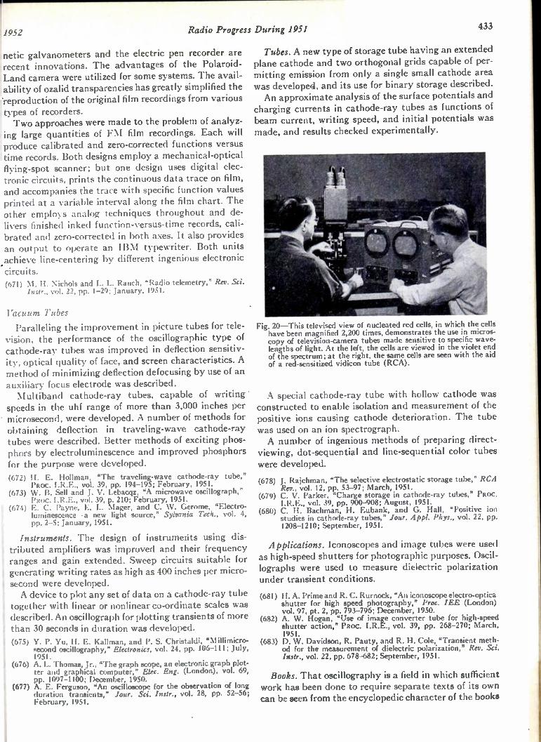
1952 Radio Progress During 1951 433
netic galvanometers and the electric pen recorder are recent innovations. The advantages of the Polaroid-Land camera were utilized for some systems. The avail-ability of ozalid transparencies has greatly simplified the 'reproduction of the original film recordings from various types of recorders. Two approaches were made to the problem of analyz-
ing large quantities of FM film recordings. Each will produce calibrated and zero-corrected functions versus time records. Both designs employ a mechanical-optical flying-spot scanner; but one design uses digital elec-tronic circuits, prints the continuous data trace on film, and accompanies the trace with specific function values printed at a variable interval along the film chart. The other employs analog techniques throughout and de-livers finished inked function-versus-time records, cali-brated and zero-corrected in both axes. It also provides an output to operate an IBM typewriter. Both units .achieve line-centering by different ingenious electronic circuits. (671) M. H. Nichols and L. L. Rauch. "Radio telemetry," Rev. Sci.
Instr., vol. 22, pp. 1-29; January, 1951.
Vacuum Tubes
Paralleling the improvement in picture tubes for tele-vision, the performance of the oscillographic type of cathode-ray tubes was improved in deflection sensitiv-ity, optical quality of face, and screen characteristics. A method of minimizing deflection defocusing by use of an auxiliary focus electrode was described. Multiband cathode-ray tubes, capable of writing
speeds in the uhf range of more than 3,000 inches per microsecond, were developed. A number of methods for obtaining deflection in traveling-wave cathode-ray tubes were described. Better methods of exciting phos-phors by electroluminescence and improved phosphors for the purpose were developed. (672) H. E. Hollman, "The traveling-wave cathode-ray tube,"
PROC. I.R.E., vol. 39, pp. 194-195; February, 1951. (673) W. B. Sell and J. V. Lebacqz, "A microwave oscillograph,"
PROC. I.R.E., vol. 39, p. 210; February, 1951. (674) E. C. Payne, E. L. Mager, and C. W. Gerome, "Electro-
luminescence—a new light source," Sylvania Tech., vol. 4, pp. 2-5; January, 1951.
Instruments. The design of instruments using dis-tributed amplifiers was improved and their frequency t ranges and gain extended. Sweep circuits suitable for generating writing rates as high as 400 inches per micro-second were developed. A device to plot any set of data on a cathode-ray tube
together with linear or nonlinear co-ordinate scales was described. An oscillograph for plotting transients of more than 30 seconds in duration was developed. (675) Y. P. Yu, H. E. Kallman, and P. S. Christaldi, "Millimicro-
second oscillography," Ekctronics, vol. 24, pp. 106-111; July, 1951.
(676) A. L. Thomas, Jr., "The graph scope, an electronic graph plot-ter and graphical computer," Elec. Eng. (London), vol. 69. pp. 1097-1100; December, 1950.
(677) A. E. Ferguson, "An oscilloscope for the observation of long duration transients," /our. Sci. Instr., vol. 28, pp. 52-56; February, 1951.
Tubes. A new type of storage tube having an extended plane cathode and two orthogonal grids capable of per-mitting emission from only a single small cathode area was developed, and its use for binary storage described. An approximate analysis of the surface potentials and
charging currents in cathode-ray tubes as functions of beam current, writing speed, and initial potentials was made, and results checked experimentally.
Fig. 20—This televised view of nucleated red cells, in which the cells have been magnified 2,200 times, demonstrates the use in micros-copy of television-camera tubes made sensitive to specific wave-lengths of light. At the left, the cells are viewed in the violet end of the spectrum; at the right, the same cells are seen with the aid of a red-sensitized vidicon tube (RCA).
A special cathode-ray tube with hollow cathode was constructed to enable isolation and measurement of the positive ions causing cathode deterioration. The tube was used on an ion spectrograph. A number of ingenious methods of preparing direct-
viewing, dot-sequential and line-sequential color tubes were developed.
(678) J. Rajchman, "The selective electrostatic storage tube," RCA Rev., vol. 12, pp. 53-97; March, 1951.
(679) C. V. Parker, "Charge storage in cathode-ray tubes," PROC. I.R.E., vol. 39, pp. 900-908; August, 1951.
(680) C. H. Bachman, H. Eubank, and G. Hall, "Positive ion studies in cathode-ray tubes," Jour. Appl. Phys., vol. 22, pp. 1208-1210; September, 1951.
Applications. Iconoscopes and image tubes were used as high-speed shutters for photographic purposes. Oscil-lographs were used to measure dielectric polarization under transient conditions.
(681) H. A. Prime and R. C. Rurnock, "An iconoscope electro-optica shutter for high speed photography," Proc. IEE (London) vol. 97, pt. 2, pp. 793-796; December, 1950.
(682) A. W. Hogan, "Use of image converter tube for high-speed shutter action," PROC. I.R.E., vol. 39, pp. 268-270; March, 1951.
(683) D. W. Davidson, R. Pauty, and R. H. Cole, "Transient meth-od for the measurement of dielectric polarization," Rev. Sci. Instr., vol. 22, pp. 678-682; September, 1951.
Books. That oscillography is a field in which sufficient work has been done to require separate texts of its own can be seen from the encyclopedic character of the books
434 PROCEEDINGS OF THE I.R.E. April
published dealing specifically with cathode-ray oscillog-raphy.
(684) 0. S. Puckle, "Time Bases," Chapman and Hall Ltd., Lon-don; 1951.
Dielectrics
There are three simple measurable properties of di-electric materials that are commonly utilized in prac-tice: dielectric constant, power factor, and dielectric strength. Information on these properties has become increasingly important not only to designers and manu-facturers of electronic equipment but also to the scien-tist who is studying molecular structure. The Conference on Electrical Insulation, sponsored
by the Division of Engineering and Industrial Research of the National Research Council, has an annual meet-ing of research workers who present papers and ex-change information on research activities in the several scientific and technical fields of dielectrics and insula-tion. The Conference publishes each year an Annual Report that abstracts the papers and reviews the activi-ties of the Conference for that year. In addition, it publishes each year a comprehensive
Digest of Literature on Dielectrics, in which are con-tained reviews prepared by authorities in the respective fields of dielectrics. These reviews consist of brief but explicit and interesting statements of developments and results. Numerous references are provided for those de-siring further details.
At the 20th Annual (1951) Conference on Electrical Insulation were symposia on dielectric measurements, insulation applications, and dielectric properties of mat-ter, as well as several round-table discussions on these topics. The sessions on measurements indicated consid-erable interest in evaluating the resistance of high-qual-ity insulating materials. A direct method for measuring the dielectric properties of gases was described having a sensitivity of one part in 108, which determines the di-electric susceptibility of gases to four significant figures. In contrast to the usual beat-frequency method, which gives dielectric constant only, it can also be used to de-termine absorptions in gases, using a frequency range of around one mc. The formation of films on metals in hydrocarbons sub-
jected to dielectric stresses was another topic of inter-est to those using conductors in fluids. A soaplike de-posit is formed. The rate and thickness is dependent upon the dielectric stress.
A sharper emphasis was placed on standardizing measuring techniques and test conditions so that the complex dielectric constant can be determined. The real component is a measure of the dielectric constant and the imaginary component, the loss factor. The National Bureau of Standards reported an RF dielectrics meas-urements service in the frequency range from 10 kc to approximately 600 mc for solid dielectric specimens and a limited calibration service for gases and liquids. Tem-
perature and humidity are other parameters that are available at some frequencies. Complete information on any dielectric material re-
quires measuring equipment capable of furnishing data over the frequency range from zero to 300,000 mc. Other factors that frequently require consideration are temperature, pressure, field strength, and the geometry of the specimen. It is now possible to obtain results over this frequency spectrum, although not without some dif-ficulty in certain regions. From about one cycle to several megacycles, bridges produce the most accurate results. Below one cycle, recourse is had to current-time curves. From approximately one to 600 mc the resonance meth-od is preferred. From 100 kc to 30 mc the resonance method competes with the bridges; above 100 mc the resonance apparatus becomes a cavity. At frequencies above 300 mc the lumped parameters are replaced by distributed parameters in coaxial lines, waveguides, or cavities, and standing-wave patterns or resonance curves become the means for evaluation. These various schemes are under study in the process of establishing suitable standards. Progress continued in general and theoretical re-
search on dielectrics. Microwave spectroscopy contin-ued its spectacular advance in providing accurate dipole moments and molecular parameters. Measurements of the dielectric constant and loss of polar and nonpolar liquids at microwave frequencies were abundant, and several well-known gases were evaluated with increased accuracy at microwave frequencies. In the field of solid dielectrics, great interest was
shown in the conduction processes of ionic crystals, and the theory of the static dielectric constant of ionic crystals became better understood. Many investiga-tions were made of the dielectric properties of ferro-electrics, semiconductors, ceramics (barium titanate in particular), oxide films, and many other compositions of interest in the theoretical and practical applications of dielectrics.
Magnetics
Ferromagnetic ferrites and magnetic amplifiers shared wide interest and discussion, and were the subjects of many papers and several symposia. In the field of theo-retical magnetism, articles on antiferromagnetism and domain-wall motion reported the steady advance in charting the mechanisms of magnetic behavior. Mag-netic measurements served a varied and essential role in linking theory, development, and application. The development and use of ferrites continued as en-
gineers studied and evaluated the design advantages and limitations of these unique ferromagnetic non-metals. For certain applications, they advantageously fill the gap between solid metals and powders. In many fields, particularly carrier and higher frequencies, they offer combinations of properties and design possibilities not otherwise available. Components for which ferrites are being used or explored include radio and television

1952 Radio Progress During 1951 435
coils and transformers, filter and loading coils, radio-an-tenna rods, high-frequency magnetic amplifiers, record-ing heads, concentrators for high-frequency heating, pulse transformers and harmonic generators, miniature ' components, magnetostrictive oscillators, and parts for small machines and measuring instruments. The resonance-type behavior of permeability and
magnetic loss associated with frequency and dimensions, as well as the dielectric properties of the materials, are undergoing intensive study and measurements from the standpoint of understanding the basic mechanisms and of utilizing the effects in high-frequency attenuators or waveguide components. The concept of complex per-meability is being widely used in theory and analysis of measurement data. (685) R. L. Harvey, I. J. Hegyi, and H. W. Leverenz, "Ferromag-
netic spinels for radio frequencies," RCA Rev., vol. 11, pp. 321-363; September, 1950.
(686) M. J. 0. Strutt, "Ferromagnetic materials and ferrites," Wireless Eng., vol. 27, pp. 277-284; December, 1950.
(687) M. Kornetzki, "Test results obtained with ferrite cores of high permeability," Z. angew. Phys., vol. 3, pp. 5-9; January, 1951 (In German.)
(688) R. Herr, "Mixed ferrites for recording heads," Electronics, vol. 24, pp. 124-125; April, 1951.
(689) H. A. Goldsmith, "Ferromagnetic ceramics," Product Eng., vol. 22, pp. 97-102; April, 1951.
(690) V. E. Legg, "Ferrites: new magnetic material for communica-tion engineering," Bell Lab. Rec., vol. 29, pp. 203-208; May, 1951.
(691) F. G. Brockman, "Structure and properties of ferrites," Elec-trical Eng., vol. 70, pp. 489-494; June, 1951.
(692) E. Both, "Ferrite materials permit improved designs of mag-netic devices," Materials and Methods, vol. 34, pp. 76-79; July 1951.
(693) G. T. Rodo and A. Terris, "Magnetization processes in a fer-rite," Phys. Rev., vol. 83, p. 177; July 1, 1951.
(694) F. Wagenknecht, "Dielectric and magnetic properties of fer-rites at high frequencies," Frequens, vol. 5, pp. 145-155, 186-189; June-July, 1951. (In German.)
The year was a period of consolidation for the mag-netic amplifier. The applications of the well-known, self-saturating and self-excited circuits were extended greatly. A basically new magnetic-amplifier circuit was proposed in Paper 51-217 of the American Institute of Electrical Engineers which promises superior perform-ance in certain types of systems. First steps were taken toward setting up standards and ratings of magnetic
i amplifiers, and attempts were made to develop a simple engineering approach toward the design and selection of magnetic amplifiers for specific applications. (695) Progress Report of the AIEE Magnetic Amplifier Subcom-
mittee, American Institute of Electrical Engineers, Paper 51-71.
(696) R. A. Ramey, "On the Mechanics of Magnetic Amplifier Operation," American Institute of Electrical Engineers, Paper 51-217.
(697) J. G. Miles, "Types of Magnetic Amplifiers—A Survey," Transcript of paper delivered at the Winter General Meeting of the American Institute of Electrical Engineers, New York, N. Y.; January 24, 1951. Available from Engineering Research Associates, Incorporated, St. Paul, Minn.
(698) W. J. Dornhoefer and V. H. Krummeuacher, "Applying mag-netic amplifiers" (four parts), Elec. Mfg., vol. 47, pp. 94-99, 232; March, 1951; vol. 47, pp. 112-117, 240; April, 1951; vol. 48, pp. 106-112, 244; August, 1951; vol. 48, pp. 92-97, 242; September, 1951.
(699) R. Feinberg, "High-gain magnetic amplifier—theory of the self-excited transductor," Wireless Eng., vol. 28, pp. 151-155; May, 1951.
(700) J. M. Manley, "Some general properties of magnetic ampli-fiers," PROC. i.R.E., vol. 39, pp. 242-251; March, 1951.
(701) J. G. Miles, "Bibliography of Magnetic Amplifier Devices and Saturable Reactor Art," American Institute of Electrical En-gineers, Paper 51-388.
Work has continued on the measurement and applica-tion of magnetic powder cores. The Metal Powder As-sociation issued a tentative Preferred Iron Core Dimen-sional Specification 11-51T, March, 1951, and a Data Sheet, June 1, 1951. The March, 1951 issue of the Journal de Physique et le
Radium contains 49 papers presented at the Interna-tional Symposium on Ferromagnetism and Antiferro-magnetism in Grenoble in 1950. These articles present a broad and comprehensive sweep of modern magnetics. A book by Bozorth on ferromagnetism, published in
1951, is a complete, well-organized, and up-to-date treatment of the subject. (702) R. M. Bozorth, "Ferromagnetism," D. Van Nostrand Com-
pany, Inc., New York, N. Y.; 1st Ed., 968 pp.; 1951. (703) V. G. Welsby, "Theory and Design of Inductance Coils,"
McDonald and Co., London, 180 pp.; 1951. (704) H. Wilde, "Measurements of iron-core coils at frequencies be-
tween one cycle and one megacycle," Arch. Tech., vol. 180, pp. T39-T40; April, 1951. (In German.)
(705) 0. I. Butler and H. R. Chablani, "High-frequency magnetiza-tion of ferromagnetic laminae," Wireless Eng., vol. 28, pp. 92-97; March, 1951.
(706) R. Millership and F. V. Webster, "High-frequency permeabil-ity of ferromaknetic materials," Proc. Phys. Soc. (London), vol. 63, pp. 783-795; October 1, 1950.
(707) R. Feldheller and H. Hettich, "Variation with frequency of the magnetic after-effect in powder cores," Z. angew. Phys., vol. 2, pp. 494-499; December, 1950.
(708) A. von Engel, "Advances in the field of magnetic measuring methods for constant fields," Arch. Tech. (Messen), vol. 179, pp. T132-T133; December, 1950. (In German.)
(709) P. M. Prache and R. Cozenave, "Measurement of permeabil-ity and magnetic losses of straight samples," Cables and Trans. (Paris), vol. 4, pp. 216-233; July, 1950. "Cylindrical coil theory and calculation of reluctance or resistance between ends on straight core and infinity," Cables and Trans. (Paris), vol. 5, pp. 60-67; January, 1951.
(710) J. M. Kelly, "Magnetic field measurements with peaking strips," Rev. Sci. Instr., vol. 22, pp. 256-258; April, 1951.
(711) E. G. Thurlby, "High permeability Sendust'opowder core rings," Metal Frog., vol. 60, pp. 83-87; October, 1951.
(712) H. J. Williams, W. Shockley, and C. Kittel, "Studies of the propagation velocity of a ferromagnetic domain boundary," Phys. Rev., vol. 80, pp. 1090-1094; December 15, 1950.
(713) C. Kittel, "Ferromagnetic resonance," Jour. Phys. Radium, vol. 12, pp. 291-302; March, 1951.
(714) J. H. von Vleck, "Recent developments in the theory of anti-ferromagnetism," Jour. Phys. Radium, vol. 12, pp. 262-274; March, 1951.
(715) K. Hoselitz, "Recent progress in the field of permanent mag-nets," Jour. Phys. Radium, vol. 12, pp. 448-458; March, 1951.
Nuclear Instrumentation
Advances in radiation-measuring instruments for health protection (including civil defense) were primar-ily in the form of practical improvements. The reliabil-ity of many types of instruments was increased, the power consumption lowered, and the weight and size reduced. Few new principles were employed. (716) W. C. Elmore, H. Kallman, C. E. Mandeville, W. J. Ladniak,
and L. D. Marinelli, "Practical aspects of radioactivity instru-ments," Nucleonics, vol. 8, pp. S-2-S-32; June, 1951.
(717) R. L. Butenhoff, "Instrumentation in civil defense," Elec. Eng. (London), vol. 70, pp. 287-290; April, 1951.
There was a gradual increase in the industrial appli-cation of nucleonics. This includes a wider use of radio-active-tracer techniques for the solution of various
436 PROCEEDINGS OF THE I .R.E. Aprill
problems and also beta-ray thickness measuring meth-ods for control and other purposes.
(718) J. L. Putman, "Radioisotopes techniques conference—Oxford, 1951," Nucleonics, vol. 9, pp. 5-16; October, 1951.
In the field of nuclear science, many advances were made in measuring techniques, the more important be-ing the further exploration of the capabilities of the scintillation counter. This made possible both time and energy measurements that were beyond the range of earlier instruments. Measurements of high-energy par-ticles both from cosmic rays and from machines by means of scintillation counters received particular at-tention.
Piezoelectricity Highly significant advancement was noted in the field
of piezoelectricity during the year. The controlled growth of piezoelectric crystals in sizes suitable for com-mercial and military use is now an accomplished fact. His success in growing quartz and other crystals, out-lined in several excellent papers describing these devel-opments in the Bell Telephone Laboratories, won for Walker, during the year, the Louis Edward Levy Medal of the Franklin Institute. The basic method is essen-tially that which Hale and the Brush Development Company found to give startling growths in 1947. The value of the exchange of information among technical groups is thus illustrated.
Essential features of the methods now in use are: (1) the use of crystalline quartz as the nutrient source for replenishing the solution, (2) the placement of this source at the higher-temperature base of the vertical autoclave, (3) the use of the natural thermal circulation of the solution to transport the quartz to the somewhat cooler seeds situated higher up in the autoclave, and (4) the provision that the alkaline solution fill the auto-clave to 80 per cent of capacity before sealing and heat-ing to above the critical temperature of water (approxi-mately 450 degrees C). Earlier difficulties, which re-sulted in choking off the growth during the first day or so, are thus eliminated. Use has sometimes been made of a replaceable steel inner tube in the autoclave. Yields from a single autoclave in a month's run have been described by Walker and Buehler, producing sev-eral crystals weighing, in all, one pound, with the largest one over three-fourths pound. Sustained growth rates are achieved of up to 0.10 inch per day. Somewhat larger yields but slower growth rates have been reported by the Brush Development Company, using a somewhat dif-ferent technique, with yields running up to 7 pounds per autoclave, with the largest crystal weighing one pound. Larger autoclaves now under construction and yields running several times greater should follow. In England, work is reported in which the direction
of extension of the Z-cut seeds by the deposit is along the optic (Z-) axis, and amounts to 14 mm added as the total extension. In contrast, deposits in the United
States build upon the minor rhombohedral faces, which are essentially the faces of the seed plates used here. It appears that between the synthetic quartz and the nat-ural crystal no differences are found in refractive indices or in X-ray diffraction data, and the oscillator perform-ance of the synthetic material is in no way inferior to that of the natural.
(719) A. C. Walker, "Growing piezoelectric crystals," Jour. Frank. Inst., vol. 250, pp. 481-524; December, 1950.
(720) A. C. Walker, "Growing quartz crystals for military needs," Electronics, vol. 24, pp. 96-99; April, 1951.
(721) Brush Development Company, "Artificial Quartz Crystals," Ninth Quarterly Progress Report, U. S. Signal Corps under Contract W36-039-sc-38190; March 15, 1951.
(722) C. S. Brown, R. C. Kell, L. A. Thomas, N. Wooster, and W. A. Wooster, 'Growth of large quartz crystals," Nature (London), vol. 167, pp. 940-941; June 9, 1951.
Other reports in the quartz growth and crystallo-graphic fields include studies on optimum conditions of hydrothermal conversion of quartz, with the develop-ment of a theory to account for the transfer and several papers on twinning and detwinning of quartz-type structures. One of the latter introduces the term "piezo-crescence" for the transformation, by pressure, of one crystal orientation into another, which, under the ap-plied pressure, is favored from the principle of le Chatelier. In another paper, the X-ray irradiation of quartz, which, as is well known, modifies its elastic properties as well as its color, is the subject of further study.
(723) J. F. Corwin and A. C. Swinnerton, "The growth of quartz in alkali halide solutions," Jour. Amer. Chem. Soc., vol. 73, pp. 3598-3601; August, 1951.
(724) L. A. Thomas and W. A. Wooster, "Piezocrescence—The growth of Dauphine twinning in quartz under stress," Proc. ' Roy. Soc. A., vol. 208, pp. 43-62; August 7, 1951.
(725) J. W. Gruner and L. Gardiner, "Twinning studies of quartz type structures," Tech. Infor. Pilot, U14900, pp. 2685; April 26, 1951. Quarterly Progress Report 19, University of Minne-sota, on Contract W36-039-sc-32006; June 1—September 1, 1950.
(726) F. P. Phelps and W. J. Howard, "Detwinning quartz crystals," Tech. Infor. Pilot, U17181, pp. 3121; August 20, 1951. Quarterly Progress Report 8, National Bureau of Standards, on Contract PHIBP-50-6; January 31, 1951.
(727) G. Forman, "A study of color centers produced in quartz by X-radiation," Jour. Opt. Soc. Amer., vol. 41, pp. 377-380; June, 1951.
The review article listed will be fund to be interest-ing. With the extended interest in all crystals that may be piezoelectric, it is well to note the publication, during the year, of an index of crystal properties and angles and also a book on crystal growth.
(728) K. Lonsdale, "Facts about crystals," Amer. Scien., vol. ?9, pp. 577-589; 1951.
(729) T. V. Barker, "The Barker index of crystals," Acta Cry:!., vol. 4, pp. 191-192; 1951.
(730) H. E. Buckley, "Crystal Growth," John Wiley and Sons, Inc., New York, N. Y., and Chapman and Hall, London, 571 pp.; 1951. For review, see Proc. Phys. Soc. A., vol. 64, p. 952; October, 1951.
Ferroelectricity
Active search has continued for the essential struc-tural factors that are responsible for the ferroelectric property. A strong case is presented for the role of an oxygen octahedron surrounding a metal atom as such

11952
a key, in the case of those crystals that do not contain hydrogen. (731) B. T. Matthias, "Ferroelectricity," Sciences, vol. 113, pp. 591-
596; 1951.
A number of new ferroelectric crystals have been found and the properties of many determined. None of these shows more than a single Curie point; this leaves Rochelle salt as apparently something of a freak of na-ture since it has lower temperature limit to its ferroelec-tric region. In about sixty articles published in this field, current interest was centered largely in the con-tribution that studies of the ferroelectric property may make to solid-state physics rather than in a search for immediate engineering applications (except possibly in the barium titanate ceramics). The properties of both single crystals and multi-
crystalline ceramic aggregates were studied. The paral-lelism between ferroelectricity and ferromagnetism was .further emphasized as the studies of the motioh of the domain boundaries in the former are carried on while magnetic domain walls are similarly followed. Also, an-tiferroelectricity, as well as antiferromagnetism, re-ceived attention. A phenomenological theory of barium
Fig. 21 —Controlled growth of quartz crystals. Each of the four large and clear crystals on the horizontal frame weighs at least one-half pound. The very clear crystal in the foreground weighs three-fourths pound, and that in the background weighs over one pound (Bell Telephone Laboratories).
titanate, proposed in 1949, has not been extended to give expressions for piezoelectric, dielectric, and elastic con-stants in terms of other physical constants of the mate-rial. Japanese workers show lead zirconate to be very weakly ferroelectric along one axis and strongly antifer-roelectric at right angles to this. (732) A. F. Devonshire, "Theory of barium titanate—Part II,"
Phil. Mag., vol. 42, pp. 1065-1079; October, 1951. (733) M. H. Cohen, "Ferroelectricity versus antiferroelectricity in
Radio Progress During 1951 437
barium titanate," Phys. Rev., vol. 84, p. 369; 1951. Letter to Editor.
(734) K. H. Stewart, "Domain wall movement in a single crystal," Proc. Phys. Soc. A., vol. 63, pp. 761-765; July, 1950.
(735) G. Shirane, E. Sawaguchi, and Y. Takagi, "Dielectric proper-ties of lead zirconate," Phys. Rev., vol. 84; 476-481; November 1, 1951.
Among the more practical papers (as distinguished from those dealing with fundamental physics) are some on the ageing of ferroelectric ceramics, on methods of synthesizing the materials and of removing twinning, and on the applications of ceramic transducers. One re-port describes the development of a ceramically driven cutting tool that provides amplitudes of motion of the tool of 1.5 mils at a frequency of 18 kc. (736) W. R. Eubank and L. E. Schilberg, "Aging of BaTiO8 ceram-
ics," Phys. Rev., vol. 81, p. 651; February 15, 1951. (737) Glenco Corp., "Development and application of barium
titanate ceramics as non-linear circuit elements," Tech. Infor. Pilot, U14829, p. 2688; April 18, 1951. Final Quarterly Report, Contract W36-039-sc-44606; August 15, 1950.
(738) Harshaw Chemical Co., "Barium titanate and related crystal growth," Tech. Infor. Pilot, U16875, p. 3055; August 2, 1951. First Quarterly Report, Contract DA36-039-sc-74; January 31, 1951.
(739) E. A. Wood, "Detwinning ferroelectric crystals," Bell sys. Tech. Jour., vol. 30, pt. 1, pp. 945-955; October, 1951.
(740) W. P. Mason and R. F. Wick, "A barium titanate transducer capable of large motion at an ultrasonic frequency," Jour. Acous. Soc. Amer., vol. 23, pp. 209-214; March, 1951.
Ultrasonics
Only that part of the field of ultrasonics that is pri-marily concerned with the design and performance of the source or of the pick-up lies strictly within the scope of a review on piezoelectricity. Among such papers may be noted the description of a variable-frequency reson-ance system for generating waves. (741) W. J. Fry, R. Fry and W. Hall, "Variat!le resonant frequency
438 PROCEEDINGS OF THE I.R.E. April
crystal systems," Jour. Acous. Soc. Amer., vol. 23, pp. 94-100; January, 1951.
(742) W. L. Hall and W. J. Fry, "Design of variable resonant fre-quency crystal transducers," Rev. Sci. Instr., vol. 22, pp. 155-161; March, 1951.
(743) G. Bolz, "Theoretische und experimentelle untersuchungen der schwingungen und des strahlungswiderstan des eines ultra -schallquarzes," (Theoretical and experimental investigations of the vibration and radiation resistance of an ultrasonic quartz), Z. angew. Phys., vol. 2, pp. 119-127; March, 1950.
(744) G. W. Swanson, Jr. and W. T. Thomson, "The design of resonant quartz-crystal ultrasonic transducers for research purposes," Jour. Appi. Mech., pp. 427-430; December, 1950.
Several contributions to the broader field of ultra-sonics itself should be noted, several papers (not here listed) relate to ultrasonic absorption, and it was shown that progress is being made on the location of changes in tissue structure deep within the human body by ab-sorption and/or reflection. A basic paper on current methods of measuring wave velocity is listed. The ap-plication of quartz transducers to measure the complex propagation constants of materials has resulted in a beautiful study of ultrasonic transmission in poly-crystalline solids, and in the determination of the elas-tic and thermal or piezoelectric constants of some single crystals. Elastic constants of zincblende by an X-ray method are reported from England. Although not in its present form an application of piezoelectricity, the de-sign of an ultrasonic soldering iron with a magnetostric-tive d: ive suggests, in view of the large amplitudes that have been noted above for a ceramic transducer, a pos-sible application for piezoelectricity. Cavitation in the molten solder in contact with the metal face tears the oxide film from the metal so that alloying can occur, a technique that is said to be suitable for tinning alumi-num. The sound pattern of an X-cut quartz crystal with the theoretically interesting Straubel contour has been found to be much more uniform in front of the face of the crystal than that produced by a square crystal.
(745) G. W. Willard, "Improved methods for measuring ultrasonic velocity," Jour. Acous. Soc. Amer., vol. 23, pp. 83-93; January 1951.
(746) H. J. McSkimin, W. L. Bond, E. Buehler, and C. K. Teal, "Measurement of the elastic constants of silicon single crystals and their thermal coefficients," Phys. Rev., vol. 83, p. 1080; 1951.
(747) H. J. McSkimin, "A method for determining the propagation constants of plastics at ultrasonic frequencies," Jour. Acous. Soc. Amer., vol. 23, pp. 429-434; July, 1951.
(748) W. L. Bond, W. P. Mason, and H. J. McSkitnin, "Elastic and electromechanical coupling coefficients of single crystal barium titanate," Phys. Rev., vol. 82, p. 442; 1951.
(749) E. Prince and W. A. Wooster, "The elastic constants of zinc-en e, determined from thermal diffuse scattering of X-rays,"
Ada. Cryst., vol. 4, p. 191; 1951. (750) B. E. Noltingk and E. A. Neppiras, "Ultrasonic soldering
irons," Jour. Sci. Instr., vol. 28, pp. 50-52; 1951. (751) E. W. Samuel and R. S. Shankland, "The sound field of a
Straubel X-cut crystal," Jour. Acous. Soc. Amer., vol. 22, pp. 589-592; September, 1950.
Vigoureux has published a book (in English) on ultra-sonics, containing many references. Also, a bibliography on ultrasonics, containing about 650 entries (copies of which are stated to have been deposited in a number of public and university libraries), was prepared. The gen-eral concept of radiation resistance has received re-newed consideration, with a clarification of some basic confusions.
(752) P. Vigoureux, "Ultrasonics," John Wiley and Sons, Inc., New York, N. Y., 163 pp.; 1951. For review, see Science, vol. 114, p. 470; 1951.
(753) B. Curry and E. Hsi, "Bibliography on supersonics or ultra-sonics," Jour. Acous. Soc. Amer., vol. 23, p. 245; March, 1951
(754) F. E. Borgnis, "Theory of Acoustic Radiation Pressure," Technical Report 1, Contract Nonr-220(02), California In-stitute of Technology, Pasadena, Calif.; July 25, 1951. Sub-mitted by W. G. Cady, Project Director.
Resonators, Oscillators, and Transmitters
Experimental studies of vibrating plates continue, and progress has been made in confirmation of the theory on contour modes. Stroboscopically illuminated interferometer patterns of the vibrations of a quartz plate were photographed in England. Attention is called to an important contribution to the theory of thickness-shear resonances of rectangular plates, with marked suc-cess in predicting the experimental frequencies for a long series of secondary modes.
(755) R. Dechmann, "Contour modes of square plates excited piezo-electrically and determination of elastic and piezoelectric co-efficients," Proc. Phys. Soc. (London), vol. 64B, pp. 323-337; April 1, 1951.
(756) R. Bechmann and P. L. Parsons, "Piezoelectric behaviour of partially plated square plates vibrating in contour modes," Proc. Phys. Soc. (London), vol. 64B, pp. 706-712; August 1, 1951.
(757) S. Tolansky and W. Bardsley, "Interferometric studies on the vibration of piezoelectric plates," Proc. Phys. Soc. (London), vol. 64, pp. 224-230; March 1, 1951.
(758) R. D. Mindlin, "Thickness-sheer and flexural vibrations of crystal plates," Jour. Appl. Phys., vol. 22, pp. 316-323; March, 1951.
Extensions of the measurement of elastic and piezo-electric constants of quartz to high temperatures were made available, on the one hand, for determining the angles of cut which produce the lowest coefficient of temperature when operating and, on the other hand, for obtaining information gathered from a study of the transition from alpha to beta quartz. The current status of test oscillators for checking resonator performance and measurements of the characteristics of crystal units themselves are authoritatively given in two papers. There is a further study of the suppression of overtones by electrode geometry. A capacitance bridge for the megacycle range is described in which the unbalanced electromotive forces are rectified by a germanium recti-fier. The bridge is particularly suitable for examining vibrational modes and measuring the Q of piezoelectric resonators or transducers. A German text on crystal-filter circuits, which appeared two years ago, deals with the laws and principles of filter design, equivalent cir-cuits for the crystals themslves, and examples of filters adjustment and measurement.
(759) W. P. Mason, "Zero temperature coefficient quartz crystals for very high temperatures," Bell Sys. Tech. Jour., vol. 30, pp. 366-380; April, 1951.
(760) R. K. Cook and P. G. Weissler, "Piezoelectric constants of alpha- and beta-quartz at various temperatures," Phys. Rev., vol. 80, pp. 712-716; November 15, 1950.
(761) L. F. Koerner, "Progress in development of test oscillators for crystal units," PROC. I.R.E., vol. 39, pp. 16-26; January, 1951.
(762) L. F. Koerner, "Measurement of chracteristics of crystal units," PROC. I.R.E., vol. 39, p. 1115; September, 1951. Ab-stract 1958.
(763) J. J. Vormer, "Crystal plates without overtones," PROC. I.R.E., vol. 39, pp. 1086-1087; September, 1951.

1952 Radio Progress During 1951 439
r (764) J. S. Mendouse, P. D. Goodman, and W. G. Cady, "A ca-pacitance bridge for high frequencies," Rev. Sci. Instr., vol., 21 pp. 1002-1009; December, 1950.
' (765) W. Herzog, "Siebschaltungen mit Schwingkristallen," (Crystal Filter Circuits), Dieterichsche Verlagsbuchhandlung, Wies-baden, pp. 361,45 DM; 1949.
Two crystal-controlled transmitters were described, and a crystal discriminator was designed for a television sound transmitter. An analysis of feedback oscillator theory dealt with a particular crystal oscillator circuit as its illustration.
(766) J. W. Busby, "New crystal controlled Radar beacon," Tek.-Tech., vol. 10, pp. 24-26,70; January, 1951.
(767) R. H. Myers, "Design of a loran transmitter," Elec. Comma. (London), vol. 28, pp. 31-45; March, 1951.
(768) J. Ruston, "A simple crystal discriminator for FM oscillator stabilization," PROC. I.R.E., vol. 39, pp. 783-788; July, 1951.
(769) E. J. Post and H. F. Pit, "Alternate wax? in the analysis of a feedback oscillator and its application, PROC. I.R.E., vol. 39, pp. 169-174; February, 1951.
A report was given of a series of researches into the use of crystal resonators for indicating atmospheric tem-perature, pressure, and humidity through changes in their resonance properties. Instruments are produced for recording meteorological quantities piezoelectrically. A series of papers described the current status of tech-niques of manufacturing quartz oscillator plates and the instruments that are used in the several stages of this process.
(770) P. Goldsmith, et al., "Investigations of use of crystals as meteorological elements for measurements of temperature, pressure, and humidity," Tech. Infor. Pilot, U13633, p. 2468; May 21,1951. Quarterly Progress Report 9, Armour Research Foundation on Contract W36-039-sc-36852; September 1, 1950.
(771) W. Parrish, "The manufacture of quartz oscillator plates. I— How the required cuts are obtained," Philips Tech. Rev., vol. 11, pp. 323-332; May, 1950.
(772) W. Parrish, "The manufacture of quartz oscillator plates. I I— Control of the cutting angles by X-ray diffraction," Philips Tech. Rev., vol. 11, pp. 351-360; June, 1950.
(773) W. Parrish, "The manufacture of quartz oscillator plates. III— Lapping and final frequency adjustment of the blanks," Philips Tech. Rev., vol. 12, pp. 166-176; December, 1950.
The Chairman's address to the Radio Section of the Institute of Electrical Engineering for the current year traces the history of the tightening demands on fre-quency tolerances and of the progress of the crystal art in making such tolerances practicable. He suggests that within a few years "quartz clocks may become available with annual frequency ageing rates of less than one part in Ur and capable of continuous operation for a period of several years." The current British Post Office quartz rings of the Essen type show considerably less ageing after manufacture than do GT-cut plats. Another pa-per gives the history and present status of American fre-quency standards at the National Bureau of Standards.
(774) C. F. Booth, "The evolution of frequency control," Proc. IEE (London), vol. 98, pt. 3, pp. 1-10; January, 1951.
(775) W. D. George, "Quartz-crystal frequency standards," PROC. I.R.E., vol. 39, pp. 1115; September, 1951. Abstract 1958.
Symbols and Abbreviations Several standards on symbols, reference designations
for use with graphical symbols, and abbreviations of electrical terms were published during 1951: (776) "Standards on Abbreviations of Radio Electronic Terms,
1951," PROC. I.R.E., vol. 39, pp. 397-400; April, 1951. (777) RTMA Standard TR-115, "Symbols and Designations for
Single Line Diagrams for Audio Facilities," Radio-Television Manufacturers Association, New York, N. Y.; June, 195.
(778) MIL-STD-16, "Military Standard Reference Designations for Electrical and Electronic Symbols," Munitions Board Stand-ards Agency, Department of Defense, Washington 25, D. C.; February, 1951.
(779) NEMA Publication IC1-1949, "Standards for Industrial Con-trol." Part 21, "Terminal Markings" and Part 33, "Device Designations," Reissued in Revised Form. National Electrical Manufacturers Association, New York, N. Y.; October, 1951.
ACKNOWLEDGEMENT
Each year the Annual Report is the work of many re-viewers, each of whom are given an assignment in the particular field in which he is an expert. These assign-ments are made by the Standards Committee of the In-stitute, and thus cover all the technical committees. The individual reports are assembled and correlated into a single review by the editorial board of the Annual Re-view Committee, which, for the year 1951, was com-posed of the following persons: R. R. Batcher, Chairman R. T. Hamlett T. H. Clark H. P. Westman J. D. Crawford L. E. Whittemore
G. L. Van Deusen
This group also arranged for the illustrations, in-cluded for the first time. The individual section reports were prepared by the
following contributors: Electron Tubes and Semiconductors: E. M. Boone, C. E. Fay, T. J. Henry, R. C. Hergenrother, M. E. Hines, E. C. Homer, E. M. Hurlburt, I. Meth, W. T. Millis, G. O'Neill, R. M. Ryder, W. G. Shepherd, R. W. Slinkman, and H. L. Thorson
Audio Techniques: H. W. Angustadt Sound Recording and Reproducing: H. E. Roys Electroacoustics: V. Salmon Information Theory and Modulation Systems: W. G. Tuller Circuit Theory: W. R. Bennett, R. L. Dietzold, W. H. Huggins, and W. A. Lynch
Radio Transmitters: T. J. Boerner, M. R. Briggs, H. R. Butler, H. Goldberg, P. J. Herbst, A. E. Kerwien, L. A. Looney, J. Rus-ton, and I. R. Weir
Receivers: L. M. Harris Video Techniques: W. J. Poch Television Systems: F. J. Binglei, R. M. Bowie, E. T. Dickey, P. Goldmark, S. Helt, and W. Whalley
Facsimile: J. H. Hackenberg Vehicular Communications: N. Monk Navigation Aids: H. Davis Wave Propagation: C. R. Burrows, T. J. Carroll, M. G. Morgan, and H. W. Wells
Antennas, Waveguides, and Transmission Lines: E. C. Jordan Industrial Electronics: J. M. Cage, J. L. Dalke, and C. F. Spitzer Electronic Computers (Analog): E. L. Harder; (Digital): N. Roches-ter
Quality Control: J. R. Steen Measurements: P. S. thristaldi, J. L. Dalke, G. L. Fredendall, T. J. Gaffney, W. J. Mayo-Wells, G. A. Morton, C. D. Owens, A. Peter-son, J. R. Steen
Piezoelectricity: K. S. Van Dyke Standards: II. R. Terhune
440 PROCEEDINGS OF THE I.R.E. April
Fundamental Considerations Regarding the Use of Relative Magnitudes* J. W. HORTONt, FELLOW, IRE
Which two values of power are meant when a standing-wave ratio is expressed in decibels?. Which two values of power are meant when a television signal-noise ratio is expressed in decibels? Which two values of power are meant when the contrast range of a picture is expressed in decibels? Can you figure out what is meant when the statistical variance of a quantity, no matter what it is, is expressed in decibels? In short, have you noticed the meaning of decibel is being extended to a point of real ambiguity? The Standards Committee of the Institute finds it so. The practice is so widespread that it is guardedly
admitted in standard definitions, including some recently published by IRE.' Such official concession confuses rather than clarifies the issue.
In the following paper, Dr. Horton does something about it. He proposes that we put a stop to loose use of the decibel, and he shows one way to do it by describing what seems to be a reasonable alternative. The Standards Committee of IRE has recommended publication of Dr. Horton's paper to stimulate thought and to provoke criticism. We invite written comments. Write the Technical Secretary, The In-stitute of Radio Engineers, 1 East 79 Street, New York 21, N. Y. —Standards Committee of the I.R.E.
Summary—In order to facilitate the use of relative magnitudes, the convenience of which for certain purposes has been demonstrated by the decibel, an examination is made of the fundamental relations applying to such quantities. Relative magnitudes are defined as quantities changes in which are expressed as ratios, which combine
by multiplication, as distinguished from absolute magnitudes changes in which are expressed as differences, which combine by addition, it is shown that there are two number systems, conforming concurrently to the decimal system, by which relative magnitudes may be evaluated, and that the quantity 10°1 is the basic ele-mentary number by which these two systems are related. The role of this number in computations with relative magnitudes is, in some respects, analogous to the role of the unit in computations with absolute magnitudes. It is suggested that the word "logit" is an appropriate designation for this quantity. Methods of employing this quantity, and the advantages of so doing, are discussed briefly.
THERE ARE many problems in which quantities are more conveniently expressed as relative mag-nitudes than as absolute magnitudes. There are,
in fact, situations in which relative magnitudes are of primary significance while absolute magnitudes are both
unknown and irrelevant. These are so often encountered when dealing with energy-transmission systems that transmission losses of standard magnitude are com-monly identified with standard relative powers or stand-ard relative voltages. The standard relative power iden-tified with the decibel has proved to be of exceptional utility. This has led, not infrequently, to proposals that the decibel be used for the evaluation of physical quantities other than power. It has even been sug-gested that it be used for the measurement of intervals on the frequency spectrum. The objective, of course, is to express such quantities as relative magnitudes. To use the term "decibel" for any relativemagnitude other than a relative power would, however, sadly confuse
* Decimal classification: R030. Original manuscript received by the Institute, July 19, 1951; revised manuscript received January 2, 1952. t U. S. Navy Underwater Sound Laboratory, Fort Trumbull,
New London, Conn. 1 51 IRE 6.S1 Standards on Electroacoustics, Definitions of
Terms, 1951. See "Sound Pressure Level" and "Velocity Level."
the general with the specific. It would be quite as im-proper to call a standard relative frequrncy a "decibel," the name universally identified with a standard relative power, as it would be to call a standard absolute fre-quency a "watt," the name universally identified with a standard absolute power. It must be understood that restrictions on the use of
the decibel do not in any way impose restrictions on the use of relative magnitudes. The point which must be emphasized, however, is that when relative magnitudes are used with quantities other than power, or simply as generalized quantities, they must, in each case, be given distinctive and specific designations. The need for un-ambiguous terminology is no less urgent when dealing with relative magnitudes than when dealing with ab-solute magnitudes.
GENERAL RELATIONS
The fundamental distinction between relative and absolute magnitudes is that changes in relative magni-tude are expressed as ratios whereas changes in absolute magnitude are expressed as differences. As a conse-quence of this, changes in relative magnitude combine by multiplication whereas changes in absolute magni-tude combine by addition.
Absolute magnitudes may be represented graphically by a scale formed by laying off a succession of equal intervals, each corresponding to a standard change in absolute magnitude, or standard difference. These in-tervals, and their subdivisions, are usually numbered in accordance with the decimal system, although unfortu-nate examples are to be found in foot rules and other archaic scales. Interval numbers are conventionally associated with the final boundaries of their respective increments of length. Each numerical value thus indi-cates the number of intervals between the point with which it is identified and the beginning of the scale. The initial boundary is consequently numbered zero, to indicate that no interval has yet been laid off.
1952 Horton: The Use of Relative Magnitudes 441
On such a scale the absolute magnitude corresponding to any point is equal to the sum of the standard changes in absolute magnitude represented by the intervals oc-cupying the length between that point and the initial point. This may be expressed symbolically by writing a given absolute magnitude as
A = na. (1)
Here n is the number of standard changes in absolute magnitude, or standard differences, a, which must be added together to equal the change in absolute magni-tude in going from zero absolute magnitude to the given absolute magnitude. When dealing with absolute magnitudes the standard
change is a unit difference. That is, a = 1, and the given change in absolute magnitude, A, is numerically equal to the number, n, of standard if tervals by which it is represented. The absolute-magnitude scale, then, is the same as a scale of values of the quantity n. Relative magnitudes, also, may be represented
graphically by a scale formed by laying off a numbered succession of equal intervals. Each of these intervals corresponds to a standard change in relative magnitude, or standard ratio. The ratio represented by the total interval between
the initial point of this scale and any other point is the ratio between absolute magnitudes identified, either ex-plicitly or implicitly, with these two points. The quan-tity identified with any given point is thus said to be expressed as a relative magnitude referred to the quan-tity identified with the initial point. In the case of an absolute-magnitude scale the quantity identified with the initial point is always zero. In the case of a relative-magnitude scale the quantity identified with the initial point is always finite. It is imperative that the nature and value of this finite reference quantity be clearly understood at all times. On a scale of relative magnitudes the relative magni-
tude corresponding go any point is the product of the standard changes in relative magnitude represented by the intervals occupying the length between this point and the initial point. This may be represented sym-bolically by writing a given relative magnitude as
R = (2)
Here m is the number of standard changes in relative magnitude, or standard ratios, r, which must be multi-plied together to equal the change in relative magnitude in going from the reference quantity to the given rela-tive magnitude. Boundary points on a scale of relative magnitudes
may be marked either with values of the actual ratios, R, which they represent or with values of the index, m, with which these ratios are identified. There are, in other words, two scales which may be used for the graphical representation of relative magnitudes. With these are associated two systems of numbers which may be used for computations in which these quantities ap-
pear. The scale of numbers of standard ratios is a linear scale; the values represented by its intervals combine by addition. The scale of actual ratios is an exponential scale; the values represented by its intervals combine by multiplication. There are computational advantages to expressing
changes in relative magnitude in terms of equivalent numbers of standard ratios rather than in terms of actual ratios. Operations which, with the latter, require multiplication or division are performed with the former by addition or subtraction. Involution and evolution are similarly replaced by multiplication and division. We are already familiar with this simplification through acquaintance with the decibel. The initial point on any of the scales which have been
described is the point which indicates that no interval, representing a change in value, has yet been laid off. On a linear scale of numbers of standard ratios, as on a scale of absolute magnitudes, this point is identified with the difference zero, this being the quantity which may be added to another without changing its value. On an exponential scale of actual ratios, or actual rela-tive magnitudes, this point is identified with the ratio unity, this being the quantity by which another may be multiplied without changing its value. On a scale of ab-solute magnitudes this point is known as zero point. For a linear scale of numbers of standard ratios it may be described as zero index point; for an exponential scale of ratio values it would be the unit ratio point. The quantitative relations between the two number
systems which may be used for the evaluation of rela-tive magnitudes are uniquely established by the value of the standard ratio. It is desirable that this value be such that the two systems shall conform concurrently to the decimal system. To examine these relations, let any given ratio be ex-
pressed as some power of a fixed base number and the equivalent number of standard ratios as some multiple of this same base number. That is, let R= br and m =yb. The standard ratio is then r = Rum = brio. It is thus evident that, for any standard ratio, r, the ratio of the exponent, x, to the coefficient, y, is a constant inde-pendent of the value, R, of the given ratio. When the value of the standard ratio is r = VI°, this constant becomes x/y =1. It is, therefore, always possible to find a value for the standard ratio such that when any given ratio is expressed as a power of some fixed base number and the equivalent number of standard ratios as a mul-tiple of this same base number the exponent and the coefficient shall always be equal. This relation between any given ratio and the
equivalent number of standard ratios assumes its most convenient form when the base number is 10, the base of the decimal system. This requires that the standard ratio be given such a value that m = kl0 when R=10k, or that its value be
r = R11. = (mk)Ilkio 100.1. (3)
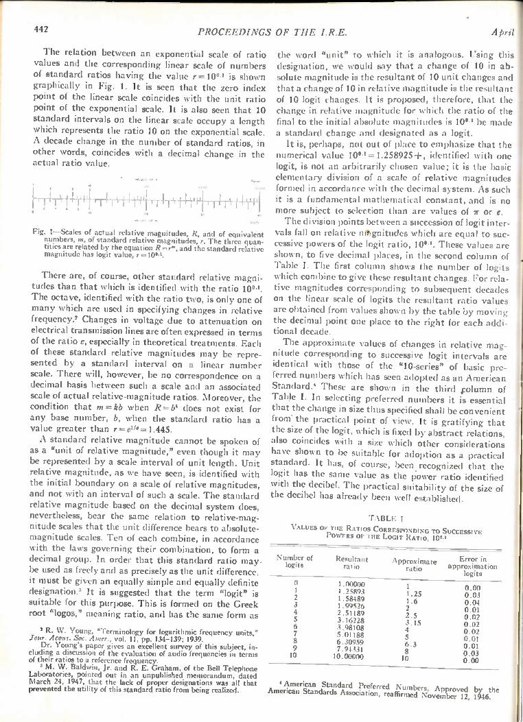
442 PROCEEDINGS OF THE I.R.E. April
The relation between an exponential scale of ratio values and the corresponding linear scale of numbers of standard ratios having the value r =10°.' is shown graphically in Fig. 1. It is seen that the zero index point of the linear scale coincides with the unit ratio point of the exponential scale. It is also seen that 10 standard intervals on the linear scale occupy a length which represents the ratio 10 on the exponential scale. A decade change in the number of standard ratios, in other words, coincides with a decimal change in the actual ratio value.
1 9
1-PFLIir
011.019 O. •
1 I I /0 •0
Fig. 1-Scales of actual relative magnitudes, R, and of equivalent numbers, m, of standard relative magnitudes, r. The three quan-tities are related by the equation R= and the standard relative magnitude has logit value, r =10° '.
There are, of course, other standard relative magni-tudes than that which is identified with the ratio 10". The octave, identified with the ratio two, is only one of many which are used in specifying changes in relative frequency.' Changes in voltage due to attenuation on electrical transmission lines are often expressed in terms of the ratio e, especially in theoretical treatments. Each of these standard relative magnitudes may be repre-sented by a standard interval on a linear number scale. There will, however, be no correspondence on a decimal basis between such a scale and an associated scale of actual relative-magnitude ratios. Moreover, the condition that m=kb when R=bk does not exist for any base number, b, when the standard ratio has a value greater than r eue= 1.445. A standard relative magnitude cannot be spoken of
as a "unit of relative magnitude," even though it may be represented by a scale interval of unit length. Unit relative magnitude, as we have seen, is identified with the initial boundary on a scale of relative magnitudes, and not with an interval of such a scale. The standard relative magnitude based on the decimal system does, nevertheless, bear the same relation to relative-mag-nitude scales that the unit difference bears to absolute-magnitude scales. Ten of each combine, in accordance with the laws governing their combination, to form a decimal group. In order that this standard ratio may. be used as freely and as precisely as the unit difference, it must be given an equally simple and equally definite designation. It is suggested that the term "log e is suitable for this purpose. This is formed on the Greek root "logos," meaning ratio, and has the same form as
2 R. NV. Young, "Terminology for logarithmic frequency units," Jour. Acous. Soc. Amer., vol. 11, pp. 134-139; 1939. Dr. Young's paper gives an excellent survey of this subject, in-
cluding a discussion of the evaluation of audio frequencies in terms of their ratios to a reference frequency.
3 M. W. Baldwin, Jr. and R. E. Graham, of the Bell Telephone Laboratories, pointed out in an unpublished memorandum, dated March 24, 1947, that the lack of proper designations was all that prevented the utility of this standard ratio from being realized.
the word "unit" to which it is analogous. Using this designation, we would say that a change of 10 in ab-solute magnitude is the resultant of 10 unit changes and that a change of 10 in relative magnitude is the resultant of 10 logit changes. It is proposed, therefore, that the change in relative magnitude for which the ratio of the final to the initial absolute magnitudes is 10" be made a standard change and designated as a logit. It is, perhaps, not out of place to emphasize that the
numerical value 10°'=1.258925+, identified with one logit, is not an arbitrarily chosen value; it is the basic elementary division of a scale of relative magnitudes formed in accordance with the decimal system. As such it is a fundamental mathematical constant, and is no more subject to selection than are values of ir or e. The division points between a succession of logit inter-
vals fall on relative mtgnitudes which are equal to suc-cessive powers of the logit ratio, 10°1. These values arc shown, to five decimal places, in the second column of Table I. The first column shows the number of logits which combine to give these resultant changes. For rela-tive magnitudes corresponding to subsequent decades on the linear scale of logits the resultant ratio values are obtained from values shown by the table by moving the decimal point one place to the right for each addi-tional decade.
The approximate values of changes in relative mag-nitude corresponding to successive logit intervals are identical with those of the "10-series" of basic pre-ferred numbers which has seen adopted as an American Standard.' These are shown in the third column of Tabk I. In selecting preferred numbers it is essential that the change in size thus specified shall be convenient from the practical point of view. It is gratifying that the size of the logit, which is fixed by abstract relations, also coincides with a size which other considerations have shown to be suitable for adoption as a practical standard. It has, of course, been. recognized that the logit has the same value as the power ratio identified with the decibel. The practical suitability of the size of the decibel has already been well established.
TABLE I
VALUES OF TIIE RATIOS CORRESPONDING TO SUCCESSIVE POWERS OF THE LOGIT RATIO, 10°3
Number of Resultant logits ratio
Approximate ratio
Error in approximation
logits
0 1.00000 1 1.25893 2 1.58489 3 1.99526 4 2.51189 5 3.16228 6 3.98108 7 5.01188 8 6.30959 9 7.94331 10 10.00000
1 0.00 1.25 0.03 1.6 0.04 2 0.01 2.5 0.02 3.15 0.02 4 0.02 5 0.01 6.3 0.01 8 0.03 10 0.00
by the American Standards A•ssociation, reaffirmed November 12, 1946.
American Standard Preferred Numbers, Approved
F!952 Horton: The Use of Relative Magnitudes 443
The number of logits corresponding to any given I dative magnitude, R, is computed by solving (2) for :he quantity m when r = 10". In general,
m = log, R. (4)
If the number 10°3 were to be represented by a con-venient symbol, this general expression could be con-verted into a specific expression by replacing the sub-script r by this symbol. The notation may be made even more compact by using the operator "lgt," ab-breviated from the word "logit," to represent the ex-pression "logarithm to the base 100.1." For numerical . computations logarithms to the base 10 may be used in .accordance with the working formula •
log R m — — 10 log R = lgt R. (5)
log r
When dealing with absolute magnitudes of physical _quantities, it is necessary that both the nature and the amount of the quantity designated as a unit change be specified. Units of physical quantities have, or are as-sumed to have, unique physical emboliments. The standard change in absolute magnitude may be altered without altering the numerical value which represents it. When dealing with the relative magnitudes of physi-cal quantities, only the nature of the quantity desig-nated as a logit—or other standard change—must be specified. Logits of physical quantities do not have unique physical embodiments. The standard change in the relative magnitude of any physical quantity may be altered only by altering the numerical value which rep-resents it. The standard change in the relative magni-tude of any physical quantity may thus be adequately designated by qualifying the general designation for the standard relative magnitude, which indicates its nu-merical value, by an adjective which indicates the na-ture of the quantity. A standard change in relative length, having the value d2/cli = 10", would thus be I described as a "length logit." This designation by description is the practice fol-
lowed when the transmission loss, now known as the decibel, was first proposed as a standard. Until its t utility had been established, it was referred to as a 1, "transmission unit." In a similar manner it will be t satisfactory to describe a standard change in relative t magnitude as a "length logit" or as a "mass logit" until a more distinctive nomenclature is shown to be justi-fied. Our immediate needs as to symbols may be satis-fied by appending the letter "1" to the conventional symbol for the nature of the quantity in question. The symbol indicating that some quantity is expressed in current logits would then be ii, for mass logits it would be ml, for length logits dl, and so on. On the basis of the foregoing the change in power
identified with a decibel is seen to be a power logit. Being a standard transmission loss, the decibel is often used, sometimes incorrectly, for the evaluation of changes in electrical voltage or in acoustical pressure. A change in such a quantity which, because of unique cor-
respondence to a power change, may properly be identi-fied with one decibel has the value 10 "; the ratio associated with one voltage logit is, by definition, 10". The change in voltage identified with one voltage logit is thus seen to be the square of that identified with one decibel. The number of voltage logits identified with a given voltage ratio is, on the other hand, one half the number of decibels identified with that ratio. When dealing with absolute magnitudes, the number
of standard changes which is equivalent to a given change varies inversely as the size of the standard change. When dealing with relative magnitudes, the number of standard changes which is equivalent to a given change varies inversely as the logarithm of the standard change. Due account must be taken of this relation if decimal prefixes are to be used in connection with relative-magnitude standards. If the effect of the operation indicated by the prefix is to divide the number of standards equivalent to some given ratio by a power of ten, the value of the standard must have been raised to that power for which the same power of ten is the exponent. The power ratio designated by the decibel, in other words, is not one tenth the ratio designated by the bel, but is the tenth root of that ratio.
DIMENSIONAL RELATIONS
It is often said that relative magnitudes are dimen-sionless. This concept requires re-examination if we are to evaluate relative magnitudes in the manner described in the preceding paragraphs. It is true that the dimen-sional equation for the ratio of two absolute magnitudes of like kind reduces to unity. This means that the value of the standard change in absolute magnitude has lost its significance. Significance has, however, been ac-quired by the value of the standard change in relative magnitude. The nature of the physical quantity in ques-tion is as pertinent to operations with relative magni-tudes as to those with absolute magnitudes. When dealing with relative magnitudes, information as to the nature and value of standard quantities must be made as conveniently available as when dealing with abso-lute magnitudes. This may be done by symbols having the same general properties as the dimensional designa-tions used with absolute magnitudes. As an example, consider the attenuation coefficient
showing the rate at which transmitted energy decays with distance. It is sometimes said that this quantity has the dimensions of a reciprocal length. This is neces-sary but not sufficient. It is true that this coefficient is the reciprocal of the distance over which some definite change in relative power, or some definite change in relative voltage, takes place. It is, however, as necessary to know the value of the ratio expressing this change and the physical nature of the quantity which changes as it is to know the distance. The symbol "db/kyd" supplies all of this information. Consider, also, two quantities so related that values
of one are proportional to some power of values of the other. If relative magnitudes of the first are plotted
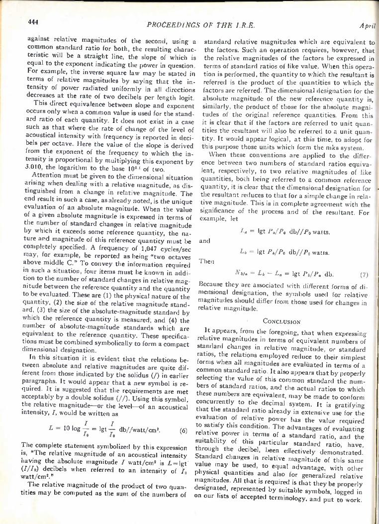
444 PROCEEDINGS OP THE I.R.E. A i
against relative magnitudes of the second, using common standard ratio for both, the resulting charac teristic will be a straight line, the slope of which i equal to the exponent indicating the power in question For example, the inverse square law may be stated i terms of relative magnitudes by saying that the in tensity of power radiated uniformly in all direction decreases at the rate of two decibels per length logit This direct equivalence between slope and exponen
occurs only when a common value is used for the stand ard ratio of each quantity. It does not exist in a case such as that where the rate of change of the level o acoustical intensity with frequency is reported in deci bels per octave. Here the value of the slope is derived from the exponen t of the frequency to which the in-tensity is proportional by mu ltiplying this exponent by 3.010, the logar ithm to the base 10" of two. Attention must be given to the dimens iona l situation
arising when dealing with a re lat ive magn itude, as dis-tinguished from a change in re lat ive magn itude. The end result in suc h a case , as alrea dy noted, is the unique evaluation of an abso lute magn itude. When the value of a given absolute magn itu de is expressed in terms of the number of standar d changes in re lat ive magnitude by which it excee ds some re ference quantity, the na-ture and magnitude of this re ference quant ity must be completely specified. A frequency of 1,047 cycles/sec may, for example, be reporte d as being "two octaves above middle C." To convey the information required in such a situation , four items must be known in addi-tion to the number of stan dar d changes in relative mag-nitude between the reference quant ity and the quantity to be evaluated. These are (1) the phys ical nature of the quantity, (2) the size of the re lat ive magn itude stand-
ard, (3) the size of the absolute-magnitude standar d by which the reference quant ity is measured, and (4) the number of absolute-magn itu de stan dards which are equivalent to the re ference quant ity. These specifica-tions must be combined sym bolica lly to form a compact dimensional des igna tion . In this situation it is ev ident that the relations be-
tween absolute and re lative magn itu des are quite dif-ferent from those indicate d by the sol idus (/) in earlier paragraphs. It would appear that a new sym bol is re-quired. It is sugges ted that the requ irements are met
acceptably by a double solidus (//). Using this symbol, the relative magnitude— or the level — of an acoustical intensity, I, wou ld be wr itten as
L 10 log — = lgt — dbllwatt/cm2. (6) /0 /0
The complete statemen t sym bolize d by th is expression is, "The relative magn itude of an acoust ical intensity having the absolute magn itu de I watt /cm' is L = lgt (///o) decibels when re ferre d to an intens ity of /o watt/cm'." The relative magnitude of the pro duct of two quan-
tities may be computed as the sum of the num bers of
a standard relative magnitudes which are equivalent to - the factors. Such an operation requires, however, that s the relative magnitudes of the factors be expressed in . terms of standard ratios of like value. When this opera-n tion is performed, the quantity to which the resultan t is - referred is the product of the quantities to which the s factors are referred. The dimensional designation for the . absolute magnitude of the new reference quantity is, t similarly, the product of those for the absolute magn i-- tudes of the original reference quantities . From this it is clear that if the factors are referre d to un it quan -
f tities the resultant will also be re ferre d to a un it quan -- tity. It would appear logical, at this time , to adopt for
this purpose those units which form the mks system. When these conventions are applied to the differ-
ence between two numbers of standard ratios equiva-lent, respectively, to two relative magnitudes of like quantities, both being referred to a common reference quantity, it is clear that the dimensional designation for the resultant reduces to that for a simple change in rela-tive magnitude. This is in complete agreement with the significance of the process and of the resultant. For example, let
and
Then
La = lgt Pa/Po db//Po watts.
= lgt Pb/Po db//Po watts.
Nola =- Lb — I,„ = lgt Pb/P„ db. (7)
Because they are associated with different forms of di-mensional designation, the symbols used for relative magnitudes should differ from those used for changes in relative magnitude.
• CONCLUSION
It appears, from the foregoing, that when expressing relative magnitudes in terms of equivalent numbers of standard changes in relative magnitude, or standard ratios, the relations employed reduce to their simplest forms when all magnitudes are evalaated in terms of a common standard ratio. It also appears that by properly selecting the value of this common standard the num-bers of standard ratios, and the actual ratios to which these numbers are equivalent, may be made to conform concurrently to the decimal system. It is gratifying that the standard ratio already in extensive use for the evaluation of relative power has the value required to satisfy this condition. The advantages of evaluating relative power in terms of a standard ratio, and the suitability of this particular standard ratio, have, through the decibel, been effectively demonstrated. Standard changes in relative magnitude of this same value may be used, to equal advantage, with other physical quantities and also for generalized relative magnitudes. All that is required is that they be properly designated, represented by suitable symbols, logged in on our lists of accepted terminology, and put to work.
.1

1952 PROCEEDINGS OF THE I.R.E. 445
Transistor Forming Effects in n-Type Germanium* L. B. VALDESt, ASSOCIATE, IRE
Summary—Some of the effects of electrical forming of the col-lector of an n-type germanium transistor are discussed. Evidence is presented for the existence of a region of p-type germanium under-neath the formed electrode, together with some indication of the size of the formed region. These experiments lend support to the p-n hook mechanism in
that they explain the observed high values of alpha in transistors.
This relation is discussed.
INTRODUCTION
/T HAS BEEN REALIZED for some time that forming the collector enhances transistor action.' In other words, forming increases the alpha (cur-
rent multiplication factor) of the transistor. This forming process is therefore very important in
- controlling the properties of the device. In this paper the results of several experiments which give some un-derstanding of what takes place at the collector of the n-type germanium transistor during forming will be summarized. There is a good understanding of the behavior of an
unformed point contact on n-type germanium. Bardeen has suggested that surface states produce a bending of the energy levels at the surface.2 This produces a double layer of charge extending to a depth on the order of 10-4 cm into the semiconductor and, consequently, a barrier at the point contact. Thus, an unformed point. has a low forward resistance and a high reverse resist-, ance (good rectifier). Forming in the transistor sense (passage of large currents in the reverse direction) is known to reduce the reverse resistance of the collector, besides increasing the alpha of the transistor.
EXPERIMENTAL RESULTS
The material used in these investigations was ob-tained from polycrystalline ingots of n-type germanium and about 2 cm in diameter and 5 cm long, prepared by Theuerer and Scaff.° These ingots were cut trans-versely to obtain approximately round slices of 50 X10-2 cm thickness. The slices were, in turn, soldered to a brass base (ohmic contact), and the top surface was ground and chemically etched. The etch showeci the grain boundaries clearly so that each experiment could be confined to a single crystal.
• Decimal classification: R282.12. Original manuscript received by the institute, June 18, 1951; revised manuscript received Janu-ary 25, 1952.
Bell Telephone Laboratories, Murray Hill Laboratory, Murray Hill, N. J. I J. Bardeen and W. H. Brattain, 'Physical principles of tran-
sistor action," Bell Tel. Labs. Jour., vol. 28, pp. 239-277; April, 1949. J. Bardeen and W. G. Pfann, "Effects of electrical forming on the
rectifying barriers of n- and p-germanium transistors," Phys. Rev., vol. 77, p. 401; 1950.
2 J. Bardeen, 'Surface states and rectification at a metal semi-conductor contact," Phys. Rev., vol. 71, pp. 717-727; May 15, 1947.
H. C. Torrey and C. A. Whitmer, "Crystal rectifiers," McGraw-Hill Book Co., New York, N. Y., p. 304; 1948.
The points used were 0.013-cm (0.005-inch) diameter phosphor-bronze wires, cut diagonally to form a chisel-shaped point (as in transistors). They were mounted in a micromanipulator by a phosphor-bronze spring that related deflection to applied force. In all cases force ap-plied to the point was about 25 X108 dynes. The first experiment was a measurement of the dc
floating potential on the surface of a germanium slice near a point biased in the reverse direction. The experi-mental setup was as shown in Fig. 1, and consisted of
FIXED
COLLECTOR
MOVABLE PROBE
GERMANIUM
Fig. 1—Circuit for the measurement of floating potentials.
two points lowered to the surface by means of a micro-manipulator. The biased point was kept fixed while the movable point was used as an exploratory probe for the potential measurements.
40
Ui
Ui
30
4
Ui I- 20 a.
4 10 0 -J
BEFORE FORMING
AFTER FORMING
00 10 x10.3 20 x10-3 30x10-3 40 x10-3 50x10-3 DISTANCE OF PROBE FROM FORMED ELECTRODE-CM
Fig. 2—Floating potentials.
In Fig. 2 the floating potential (expressed as a per-centage of the bias voltage applied to the 'fixed point) is plotted versus the separation between the two points. In the unformed case the measured potentials were very small (as is expected from the model derived from the surface-states hypothesis2), and they decreased with in-
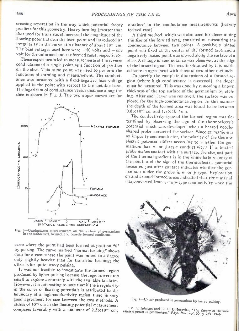
446 PROCEEDINGS OF THE I.R.E. April
creasing separation in the way which potential theory predicts for this geometry. Heavy forming (greater than that used for transistors) increased the magnitude of the floating potential near the fixed point and introduced an irregularity in the curve at a distance of about 10-2 cm. The bias voltages used here were —50 volts and —one volt for the unformed and the formed cases, respectively. These experiments led to measurements of the reverse
conductance of a single point as a function of position on the slice. This same point was used to perform the functions of forming and measurement. The conduct-ance was measured .with a fixed-negative bias voltage applied to the point with respect to the metallic base. The logarithm of conductance versus distance along the slice is shown in Fig. 3. The two upper curves are for
CONDUCTANCE- MICROMHOS
1000
100
10
U.
HEAVILY FORMED
FORMED
UNFORMED
-20x10 -3 -10x10 -3 0 10X10-3 20X10 -3 DISTANCE ALONG THE SURFACE-CM
Fig. 3—Conductance measurements on the surface of germanium in the uniformed, formed, and heavily formed conditions.
cases where the point had been formed at position "0" by pulsing. The curve marked "normal forming" shows data for a case where the point was pulsed to a degree only slightly heavier than for transistor forming; the other is for quite heavy pulsing. It was not feasible to investigate the formed region
produced by ligher pulsing because the regions were too small to explore accurately with the available facilities. However, it is interesting to note that if the irregularity in the curve of floating potentials is attributed to the boundary of a high-conductivity region there is very good agreement for size between the two methods. A radius of 10-2 cm in the floating potential measurement compares favorably with a diameter of 2.2 X10⁻² cm,
obtained in the conductance measurements (heavily formed case). A third method, which was also used for determining
the size of the formed area, consisted of measuring the conductance between two points. A positively biased point was fixed at the center of the formed area and a negatively biased point was moved along the surface of a slice. A change in conductance was observed at the edge of the formed region. The results obtained by this meth-od were in agreement with those of two other methods. To specify the complete dimensions of a formed re-
gion (where high conductance is observed), the depth must be measured. This was done by removing a known thickness of the top surface of the germanium by etch-ing. After each layer was removed, the surface was ex-plored for the high-conductance region. In this manner the depth of the formed area was found to be between 0.8 X10⁻³ cm and 1.7 X10⁻³ cm. The conductivity type of the formed region was de-
termined by observing the sign of the thermoelectric potential which was developed when a heated needle-shaped probe contacted the surface. Since germanium is an impurity semiconductor, the polarity of the thermo-electric potential differs according to whether the ger-manium has n- or p-type conductivity.* If a heated probe makes contact with the surface, the steepest part of the thermal gradient is in the immediate vicinity of the point, and the sign of the thermoelectric potential measured just after contact indicates whether the ger-manium under the probe is n- or p-type. Exploration on and around formed areas indicated that the material was. converted from n- to p-type conductivity when the
Fig. 4—Crater produced in germanium by heavy pulsing.
' V. A. Johnson and K. Lark-Horovitz, "The theory of thermo-electric power in germanium," Phys. Rev., vol. 69, p. 259; 1946.

F1952 Valdes: Transistor Forming Effects in n-Type Germanium 447
point was pulsed extremely heavily. It is suspected that tighter pulsing produces such a small converted region that detection is difficult. The formation of the p-region under conditions of ex-
Iremely heavy pulsing can probably be attributed to thermal effects. It is known' that a high-temperature heat treatment of n-type germanium converts it to p-type. There is reason to believe that the temperature under the point during forming is high. Sometimes cra-ters, such as that shown in Fig. 4, are produced as a re-sult of extremely heavy pulsing. This crater is about 3.7 X10⁻² cm long, 1.0 X 10⁻² cm wide, and 0.2 X10⁻² cm deep. Melting has also been observed under the point after lighter forming. The conversion of the conductiv-ity type occurring on forming may be the result of lat-tice dislocations or of thermal diffusion of impurities.'
DISCUSSION OF EXPERIMENTAL RESULTS
The physical picture of transistor forming, i.e., the production of a region of high-conductivity, p-type mate-rial under the formed electrode, is quite consistent with the observed changes in electrical properties. The model of a double layer of charge and a barrier at the point contact no longer holds after forming. The contact re-sistance has been appreciably lowered, and most of the resistance can be attributed to the barrier between the p-region produced by forming and the body of the n-type semiconductor. This explains the sharp drop in floating potential ob-
served in moving the probe across the p-n junction (Fig. 2). The spreading resistance in the p-type region accounts for part of the potential drop. The conductance measurements (Fig. 3) show that
when the point is outside the formed region, the high resistance of an unformed point contact is observed. This resistance is reasonably uniform and much lower when the point is inside the formed area since most of the resistance is across the large area p-n barrier. A comparison between the conductance and the size of formed area (assuming it to be circular) for the two I degrees of forming in Fig. 3 shows that these quantities are approximately proportional. This would correspond to approximately the same resistance per unit area of the p-n barrier.
MECHANISMS FOR HIGH ALPHA
The theoretical upper limit on alpha on the basis of space-charge neutralization only is 1-1-b, where b is the ratio of the mobility of electrons to the mobility of holes. Using the most recent values of mobility,' it is found that alpha must be less than 3.1. Much higher values have been observed; and in order to explain these, two
6 Torrey and Whitmer "Crystal Rectifiers," McGraw-Hill Book Co., New York, N. Y., p. 365; 1946.
6 The author, in collaboration with J. D. Struthers, studied the diffusion of copper into germanium from phosphor-bronze points. Results indicated that 5X 10²⁰ atoms/cm' of copper are introduced into the formed region of the germanium by extremely heavy pulsing.
7 G. L. Pearson, J. R. Haynes, and W. Shockley, "Comment on mobility anomalies in germanium," Phys. Rev., vol. 78, p. 295; 1950.
theories have been proposed.' The first is the trap the-ory,' and the second is the p-n hook theory," which will be discussed here. The purpose in discussing the p-n hook theory is to
cite the above evidence supporting this theory. A physi-cal picture of the p-n hook region is shown in Fig. 5.
cfr. ,..-METAL POINT (C)
N REGION (N 1)
P REGION .(f),../
N TYPE SEMICONDUCTOR (N2)
Fig. 5—Formed area.
The n-type region (NI) directly under the collector must be so small that it can not be detected by the particular thermo-electric potential probe used in the experiments. However, experiments showing that donors are needed in the collector point for best forming results suggest that such a small n-region may exist." The p-n hook region produces high alphas because
holes coming from the emitter enter the p-region; these are slowed down in their travel toward the collector be-cause they have arrived at the lowest energy level for holes. It should be noted that holes tend to travel uphill in energy diagrams, such as Fig. 6. This retardation in
FERMI
LEVEL
METAL (-)
SEMICONDUCTOR (+)
FILLED BAND
CONDUCTION BAND
Fig. 6—Energy-band picture of a formed collector with the electric field applied.
their drift velocity means that many more electrons (moving with their usual velocity) are required to bal-ance the hole charge, thus corresponding to an increase in the maximum possible alpha. Another way to look at this is to focus attention on
the barrier for electron flow from the metal to the semi-
' W. Shockley, "Theories of high values of alpha for collector contacts on germanium," Phys. Rev., vol. 78, p. 294; 1950. Also, W. Shockley, M. Sparks, and G. K. Teal, "p—n junction transistors," Phys. Rev., vol. 83, p. 151; 1951.
Evidence for the trap theory may be found in W. R. Sittner, "Current multiplication in the type-A transistor," PROC. I.R.E., pp. 448-454; this issue.
W. Shockley, "Electrons and Holes in Semiconductors," D. Van Nostrand Co. Inc., New York, N. Y., p. 111; 1950.
G. Pfann, "Significance of composition of contact point in rectifying junctions on germanium," Phys. Rev., vol. 81, p. 882; 1951.
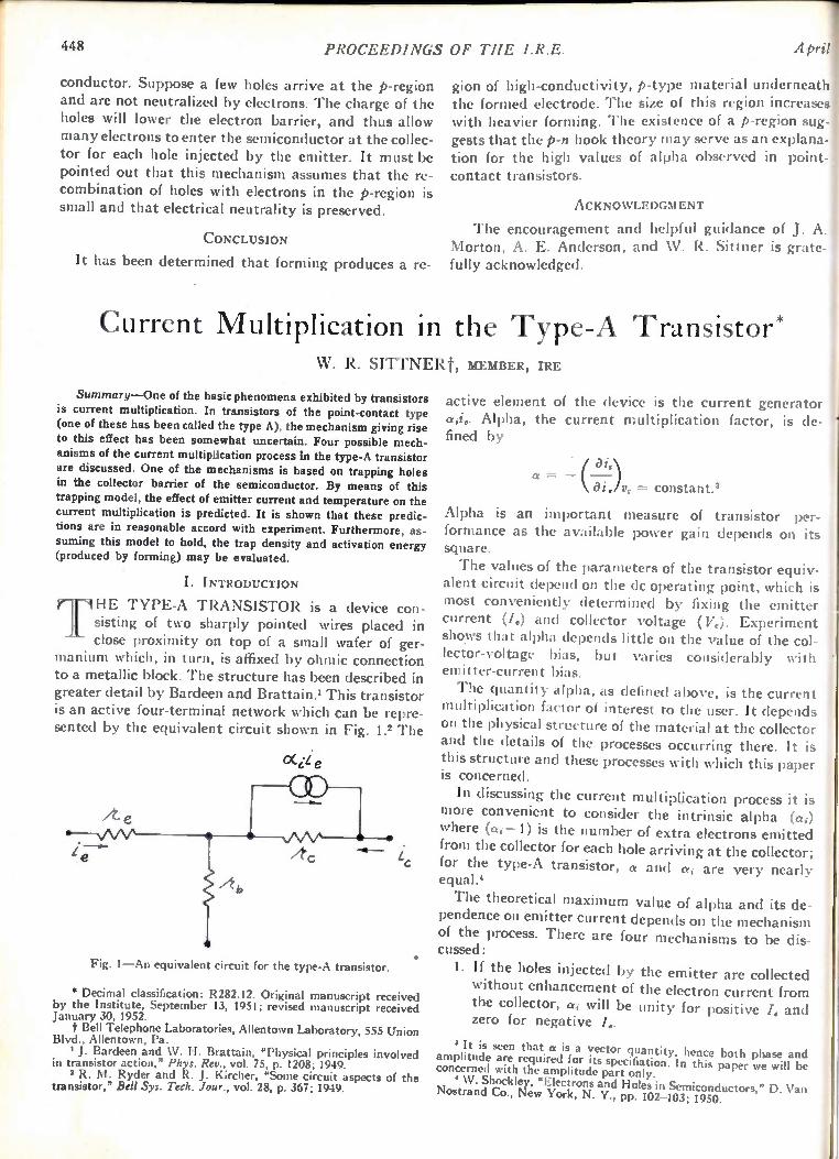
448 PROCEEDINGS OF THE I.R.E.
conductor. Suppose a few holes arrive at the p-region and are not neutralized by electrons. The charge of the holes will lower the electron barrier, and thus allow many electrons to enter the semiconductor at the collec-tor for each hole injected by the emitter. It must be pointed out that this mechanism assumes that the re-combination of holes with electrons in the p-region is small and that electrical neutrality is preserved.
CONCLUSION
It has been determined that forming produces a re-
A pr l
gion of high-conductivity, p-type material underneath the formed electrode. The size of this region increases with heavier forming. The existence of a p-region sug-gests that the p-n hook theory may serve as an explana-tion for the high values of alpha observed in point-contact transistors.
ACKNOWLEDGMENT
The encouragement and helpful guidance of J. A. Morton, A. E. Anderson, and XV. R. Sittner is grate-fully acknowledged.
Current Multiplication in the Type-A Transistor* W. R. SITTNERt, MEMBER, IRE
Summary—One of the basic phenomena exhibited by transistors is current multiplication. In transistors of the point-contact type (one of these has been called the type A), the mechanism giving rise to this effect has been somewhat uncertain. Four possible mech-anisms of the current multiplication process in the type-A transistor
are discussed. One of the mechanisms is based on trapping holes in the collector barrier of the semiconductor. By means of this trapping model, the effect of emitter current and temperature on the current multiplication is predicted. It is shown that these predic-tions are in reasonable accord with experiment. Furthermore, as-suming this model to hold, the trap density and activation energy (produced by forming) may be evaluated.
I. INTRODUCTION r-r HE TYPE-A TRANSISTOR is a dev ice con -• sisting of two sharply pointed wires placed in close proximity on top of a small wafer of ger-
manium which, in turn, is affixed by ohmic connection to a metallic block. The structure has been described in greater detail by Bardeen and Brattain.1 This transistor is an active four-terminal network which can be repre-sented by the equivalent circuit shown in Fig. 1.2 The
C4iie
Fig. 1—An equivalent circuit for the type-A transistor.
• Decimal classification: R282.12. Original manuscript received by the Institute, September 13, 1951; revised manuscript received January 30, 1952.
t Bell Telephone Laboratories, Allentown Laboratory, 555 Union Blvd., Allentown, Pa.
1 J. Bardeen and W. H. Brattain, "Physical principles involved in transistor action," Phys. Rev., vol. 75, p. 1208; 1949.
2 R. M. Ryder and R. J. Kircher, "Some circuit aspects of the transistor," Bell Sys. Tech. Jour., vol. 28, p. 367; 1949.
•
active element of the device is the current generator ad.. Alpha, the current multiplication factor, is de- r fined by
=
ai)v, = constant.'
Alpha is an important measure of transistor per-formance as the available power ga in depen ds on its square. I
The values of the parameters of the transistor equiv-alent circuit depend on the dc operating point, which is most conveniently determined by fixing the emitter current (I.) and collector voltage (17c). Experiment shows that alpha depends little on the value of the col-lector-voltage bias, but varies considerably with emitter-current bias.
The quantity alpha, as defined above, is the current multiplication factor of interest to the user. It depends on the physical structure of the material at the collector and the details of the processes occurring there. It is this structure and these processes with which this paper is concerned.
In discussing the current multiplication process it is more convenient to consider the intrinsic alpha (ai) where (ai-1) is the number of extra electrons emitted from the collector for each hole arriving at the collector; for the type-A transistor, a and a; are very nearly equal.'
The theoretical maximum value of alpha and its de-pendence on emitter current depends on the mechanism of the process. There are four mechanisms to be dis-cussed:
1. If the holes injected by the emitter are collected without enhancement of the electron current from the collector, ai will be unity for positive I. and zero for negative I..
3 It is seen that a is a vector quantity, hence both phase and amplitude are required for its specifiation. In this paper we will be concerned with the amplitude part only.
4 W. Shockley, "Electrons and Holes in Semiconductors," D. Van Nostrand Co., New York, N. Y., pp. 102-103; 1950.

1952 Sinner: Current Multiplication in the Type-A Transistor 449
Phis relation is shown in Fig. 2(a).
3
2
A-NO ENHANCEMENT
a-,
3
2
0 15 B- ENHANCED ELEC TRON EMISSION
of 5
4
3
2
0 1.0 M A Is
C-TYPICAL EXPERIMENTAL CURVE
Fig. 2—(a) Predicted curve of alpha versus emitter current without enhancement. (b) Predicted curve with enhanced emission. (c)
• Typical experimental curve.
2. If the density of holes flowing into the collector becomes comparable to the density of fixed donor ions in the collector barrier, the space charge in the barrier will be altered by a significant amount and will correspondingly alter the flow of electrons from the collector as suggested by Bardeen and Brattain.' If we assume a uniform collector bar-rier, the maximum value of ai predicted by this mechanism is 1-Fb, where b is the ratio of electron to hole mobility in germanium.5 This is true be-cause there is no enhanced field when the ratio of enhanced electron current to hole current equals b. An a, versus I. curve, like Fig. 2(b), would be predicted for this case; ai should be unity for small I. because this corresponds to a low density of collected holes. Measurements 6 on germanium filaments indicate that b = 2.1, hence the maxi-mum value of ai should be 3.1. The dotted portion of this curve (intermediate values of I.) indicates only that ai should increase monotonically toward the maximum value.
W. Shockley, "Theories of high values of alpha for collector con-
tacts on germanium," Phys. Rev., vol. 78, p. 294; 1950. • G. L. Pearson, J. R. Haynes, and W. Shockley, "Comment on
mobility anomalies in germanium," Phys. Rev., vol. 78, p. 295; 1950.
A typical experimental curve of a versus I. for the type-A transistor is shown in Fig. 2(c). The second model discussed appears to account for the values of a at large I., but is in disagreement with experiment at low I.. Two modifications of the second mechanism which can bring theory into closer agreement with ex-periment have been made by Shockley.6 These are the third and fourth mechanisms to be discussed. 3. The first modification is called the p-n hook theory, and is based on the existence at the col-lector of an electron potential-energy configuration described by Fig. 3. Suppose there is a thin region P of p-type material separating the collector re-gion N1, taken to be n-type, from the base NI, also taken to be n-type. Holes arriving at P will be held by the potential-energy minimum (holes tend to flow uphill in this diagram), and will bias the n-p junction N1— P forward, provoking an electron flow from N1 into P. If P is thin, the elec-trons will diffuse through it and fall through the potential drop N2—P; N2—P is a n -p junction biased in reverse by the collector voltage. It is seen that high values of ai can arise in this way. The experiments relating to this theory are dis-
cussed elsewhere."
F ERMI LEVEL
METAL )
N,
0- 7
SEMICONDUCTOR 1+)
CONDUCTION BAND
FILLED BAND
P-N HOOK MODEL FOR HIGH ALPHA
Fig. 3—Electron potential-energy diagram showing the p-n hook model for high alpha.
4. The second of these explanations is called the "trap theory." If the barrier region contains a density of traps capable of holding holes, then the holes will be delayed in this region and the hole
space charge increased. The electron space charge will be correspondingly increased, thus leading to large electron currents and large values of a.
This theory is discussed more fully in Section II. In this paper it is proposed to: (a) give an approxi-
mate analysis of the a versus I. characteristic, based on the trapping mechanism (this is an application to the
7 L. 13. Valdes, "Transistor forming effects in n-type germanium," PROC. IR E., pp. 445-448; this issue.
" W. G. Pfann, "Significance of composition of contact-point in rectifying junctions on germaniuit," Phys. Rec., vol. 81, p. 882; 1951.
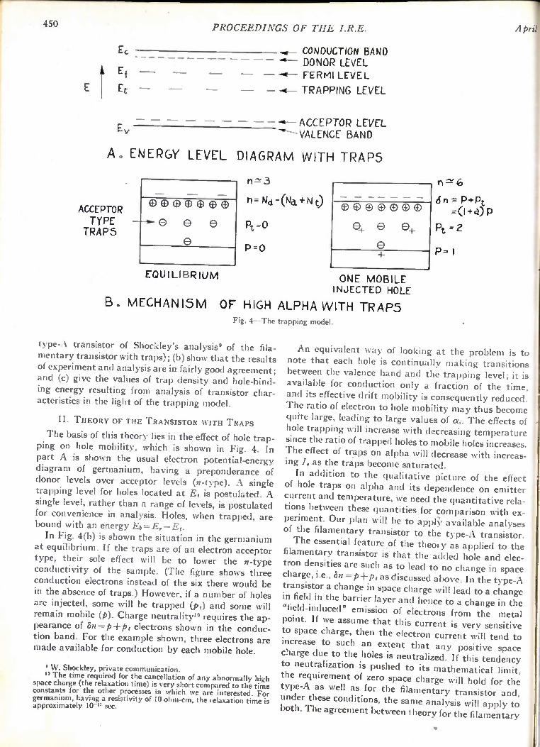
450 PROCEEDINGS OF THE I.R.E. Ap l
1 Ec
Ef —
Ec —
E v
CONDUCTION BAND '4— DONOR LEVEL
-411-- FERMI LEVEL
— TRAPPING LEVEL
— — ACCEPTOR LEVEL -4"--- VALENCE BAND
A. ENERGY LEVEL DIAGRAM WITH TRAPS
ACCEPTOR TYPE TRAPS
EQUILIBRIUM
n 3
n= Nc1 -(Nd.+ N
Pt =0
P.0
ED 0 0 0 0
0 0 e,
ONE MOBILE INJECTED HOLE
B. MECHANISM OF HIGH ALPHA VVITH TRAPS Fig. 4--The trapping model.
type-:\ transistor of Shockley's analysis9 of the fila-mentary transistor with traps); (b) show that the results of experiment and analysis are in fairly good agreement; and (c) give the values of trap density and hole-bind-ing energy resulting from analysis of transistor char-acteristics in the light of the trapping model.
II. THEORY OF THE TRANSISTOR WITH TRAPS
The basis of this theory lies in the effect of hole trap-ping on hole mobility, which is shown in Fig. 4. In part A is shown the usual electron potential-energy diagram of germanium, having a preponderance of donor levels over acceptor levels (n-type). A single trapping level for holes located at Et is postulated. A single level, rather than a range of levels, is postulated for convenience in analysis. Holes, when trapped, are bound with an energy Eb=E.—Et.
In Fig. 4(b) is shown the situation in the germanium at equilibrium. If the traps are of an electron acceptor type, their sole effect will be to lower the n-type conductivity of the sample. (The figure shows three conduction electrons instead of the six there would be in the absence of traps.) However, if a number of holes are injected, some will be trapped (p,) and some will remain mobile (p). Charge neutrality" requires the ap-pearance of 45,1---p+p, electrons shown in the conduc-tion band. For the example shown, three electrons are made available for conduction by each mobile hole.
9 W. Shockley, private communication. 10 The time required for the cancellation of any abnormally high
space charge (the relaxation time) is very short compared to the time constants for the other processes in which we are interested. For germanium, having a resistivity of 10 ohm-cm, the relaxation time is approximately 10-" sec.
n---se 6
6n = P+Pt
Pt =2
I
An equivalent way of looking at the problem is to note that each hole is continually making transitions between the valence band and the trapping level; it is available for conduction only a fraction of the time, and its effective drift mobility is consequently reduced. The ratio of electron to hole mobility may thus become quite large, leading to large values of ai. The effects of hole trapping will increase with decreasing temperature since the ratio of trapped holes to mobile holes increases. The effect of traps on alpha will decrease with increas-ing I. as the traps become saturated.
In addition to the qualitative picture of the effect t of hole traps on alpha and its dependence on emitter current and temperature, we need the quantitative rela-tions between these quantities for comparison with ex-periment. Our plan will be to appry available analyses of the filamentary transistor to the type-A transistor. The essential feature of the theory as applied to the
filamentary transistor is that the added hole and elec-tron densities are such as to lead to no change in space charge, i.e., Sn=p+p t as discussed above. In the type-A transistor a change in space charge will lead to a change in field in the barrier layer and hence to a change in the "field-induced" emission of electrons from the metal point. If we assume that this current is very sensitive to space charge, then the electron current will tend to increase to such an extent that any positive space charge due to the holes is neutralized. If this tendency to neutralization is pushed to its mathematical limit, the requirement of zero space charge will hold for the type-A as well as for the filamentary transistor and, under these conditions, the same analysis will apply to both. The agreement between theory for the filamentary
1'952 Sinner: Current Multiplication
:ase and experiment for the type A, presented below, ;uggests that the sensitivity of reverse current to space-:barge changes exerts a strong stabilizing influence on
:he space charge. The filamentary transistor has been described by
Shockley, Pearson, and Haynes." Their expressions for :he increase in collector current due to emitter current
Ind alpha are
= + b),
where W.= hole current from emitter
ai = -y(1 b).
(1)
(2)
These expressions have been applied to the type-A
transistor by Brown." a The effort of hole traps on the performance of the
filamentary transistor has been analyzed by Shockley.' The part of this treatment which is pertinent to this paper is reproduced in Appendix II. In the presence of traps relations (1) and (2) become
ab ) = — -y I (1 b , (1.1)
where
1 + G'I.
p, density of trapped holes = =
density of mobile holes
for the case of small injected hole density; (a is called the trapping ratio.)
G' = 'Y
A( Ng \ qmi, —17,
aiL
N = trap density A =cross-sectional area of filament = mobility of holes in absence of traps
q= value of electron charge Ve/L =electric field in the interaction region.
By differentiation of (1.1) we obtain
ab a, = -y (1 b +
(1 +G'I„)) •
The above expressions will be applied to the type-A transistor by taking A to be the area of the collector point contact (10-° cm2) and V,IL to be the collector potential divided by the thickness of the collector bar-rier (10- cm). By examination of (2.1) we can predict the following: 1. When /.= 0, then ai=am„.=7(1+b+ba); am.z may be indefinitely large since the trapping ratio, a, may have any positive value. Also, a..z should increase with decreasing temperature as the trap-ping ratio increases with decreasing temperature, as shown in Appendix I.
" W. Shockley, G. L. Pearson, and J. R. Haynes, "Hole injection in germanium--quantitative studies and filamentary transistors," Bell Sys. Tech. Jour., vol. 28, p. 344; 1949.
J. B. Brown, "Magnetically biased transistor," Phys. Rev., vol. 76, pp. 1736-1737; 1949.
(2.1)
in the Type-A Transistor 451
2. When I. is large, then a; = «mi. =7(1 +b). This oc-curs because the traps are saturated.
3. When I. has such a value
arum amin (I.') that a, =
2
then (1 1-CI.')2= 2. Therefore, G' =0.414//.'. Thus we can determine G' and hence Ng from (1.11). This method of determining N. will be called the "curve-fitting" method since it is based on fitting a theoretical expression to an experi-mental curve.
4. By combining conclusions 1 and 2 above, we can obtain the trapping ratio
aingx — a m in ( 1 + 11 )
a = • «mi.
There is a second, and partially independent, method of finding the trap density Nt. A plot of the expected relation between ,6,/, and I. (1.1) is shown in Fig. 5.
•
le
Fig. 5—Theoretical curve for increase in collector current due to emitter current versus emitter current.
For large I. this curve approaches a straight line which, if extended, intersects the A/, axis at a value The current L1/.' can be considered as resulting from traps having a density Ng. In the absence of emitter current there is a dc collector current of magnitude lc due to the voltage bias. This current is due to a density of free electrons N, which can be determined from the con-ductivity of the germanium. It is plausible to expect, and not difficult" to show, that
Ale' Ng = .
Measurement of the conductivity of the germanium, together with A/I and I on the transistor, permits computation of Ng. The experimental curves of A/. versus I. have the shape shown in Fig. 5, and and I. were measured on the transistors studied. The sample conductivity was known only approximately, but values of Pie obtained by this method agree approximately with those obtained by the curve-fitting method.
" For the filamentary transistor; if the assumption of space-charge stabilization applies, then the filamentary analysis applies to the type A, also, as discussed above.
(3)
452 PROCEEDINGS OF THE April
The remaining problem is to find the trapping en-ergy. In Appendix I it is shown that
Ng a .2 ----e-Rwhr.
1$1, (4)
By determining trapping ratio as a function of tempera-ture, we can obtain Eb from the slope of the In a versus 1/T plot. Also, if we take the usual value for N v", we have
a = N, e- EbIkr.
10" (4. 1)
One can then evaluate Eb from a single measurement of trapping ratio.
III. EXPERIMENTAL RESULTS
Equipment was constructed for presenting a versus I. on an oscilloscope. A test signal of 12 kc, having an amplitudeof one microampere, was superimposed on a 60-cycle emitter current sweep. The small amplitude of test signal permits valid measurement of a down to very low values of I. Means of changing the temperature of the transistor under study were provided, also, provision for presenting A/, versus I. on the oscilloscope.
U NI T CB92
28 -
26
24
22
20
h3
/6
- /0'2
/2
6
4
2
0
7 - 68 °C
2.5%.
THEORCT/CAL 7 7 CURVE
.1 /N MA
Fig. 6-Alpha versus emitter current at three temperatures with a comparison to the theoretical curve.
./8
14 The effective density of states in the valence band (N.) is known from semiconductor theory to be
N. CrInskT)" = 10" cm-3 .
A considerable fraction of the type-A transistors cur-rently manufactured have a>3 at small I.. In Fig. 6 we show the a - I. characteristic at three temperatures for a typical unit of this type. The theoretical curve [a plot of (2.1)] for the lowest temperature is drawn in for comparison with experiment. The essential agree-ment between the shape of the curves suggests that trapping is responsible for the large values of a. It should be recalled that the theoretical and experimental curves are made to coincide at three values of W e= 0, /„ = 00, /.=one intermediate point) by choice of the parameters 7, a, and G'. The maximum alpha, trapping ratio, trap density,
and hole-binding energy for two transistors at four temperatures are given in Tible I. Eb is obtained, as explained in (4.1), and Eb* is obtained from the In a versus 1/T plots.
T=298K°
I 'Hit
a
IT, in cm 3 El, in ev
ra... a
7'=274K°i
TABLE
C1392 CB84
4.4 .3.2 2.0 1.0
7.2 X101, 6.7 X10¹² 0.31 0.31
6.0 7.0 .3.8 2.6
9.2X10¹² 9.6 X10¹² 0.35 0.33
ra.m.. 13.0 9.0 a T=-258K°1
Ne Eb
[arm:.
8.2 3.3
2.9X10' 1.9 X10" 0.30 0.27
19.0 15.4 a 16.3 10.0
T= 237K°
E b
(Eb*
7.7X10'3
0.30 0.29 0.28 0.28
It is noted from Table I that the trapping ratio in-creases with decreasing temperature as predicted. Also, the curve of In a versus 1/T is a straight line from which the binding energy Eb* is found. This result is in essen-tial agreement with the binding energy Eb determined from (4.1).
It will be recalled that we assumed a particular trap density in our trapping model. We observe from Table I, however, that Ng increases considerably with de-creasing temperature. This suggests that the hole traps actually occur with a range of energy levels and not at a single level. As the temperature is lowered, the more shallow traps become effective, hence increasing the ob-served trap density. The measured value of hole-bind-ing energy is expected to be the maximum value (cor-responding to the most tightly bound holes).
IV. CONCLUSIONS
The semiquantitative agreement between the ob-served behavior of alpha with emitter current and
11952 Sittner: Current Multiplication in the Type-A Transistor 453
::emperature and that predicted on the basis of a hole-:rapping mechanism strongly suggests that this mecha-nism is responsible for the large values of alpha at low remitter current. The sharp dependence of a on emitter rturrent and temperature indicates a relatively small number of very stable traps. The values of hole-binding energy obtained by two
methods are in agreement. The trap density, as well as the hole-binding energy, has a reasonable magnitude. The lack of complete agreement between the pre-
dicted and experimental curves of a versus I. indicates that (a) the model may be improved by assuming a band of trap energy levels, and (b) the effects of traps in the collector barrier region may be more complicated than those produced by traps in the body of the semi-
conductor. As indicated above, an analysis of the filamentary
transistor has been applied to the type A where its validity is not entirely certain. However, the agreement "between theory and experiment leads to the belief hole trapping is responsible for the observed phenomena.
V. ACKNOWLEDGMENTS
The assistance of L. B. Valdes, who designed the cir-cuit for oscilloscopic presentation of the curves, and R. L. Rulison, who made the bulk of the measurements,
is gratefully acknowledged.
APPENDIX I
A. Relation Between Trapping Ratio and Temperature
Since the holes obey the Fermi statistics,
and
Pt = 1 kr
1 + eet-Efikr
1
N. 1 e(EI-E01kT eE, kT
(1)
(2)
where E is defined in Fig. 4. Ni = density of hole traps N„ = effective density of states in valence band.
The simplification is valid since Ef — El and F,—F,, >>kT. Combining (1) and (2), we have
Ps N, a = =
N
APPENDIX II
A. Relation Between Increase in Collector Current Due to Emitter Current versus Emitter Current
If we have a hole density p in the presence of a den-sity (N,— p,) of vacant hole traps, then
rate of trapping = A p(I —
where A is a constant.
(1)
The rate of release of holes is expected to be propor-
tional to pi,
or
rate of emission of holes = Bpi.
The steady-state requires
Ap(Ni — p,) = Bp,
Pg = N g
1
By manipulation of (1) of Appendix I, it can shown that B/A=-(N,/a), so that (3) becomes
rearranging
Pt = N,
1 +
1
Pt _ = a
ap 1 + --
N,
•
(2)
(3)
be
(4)
• (5)
We now need to find the effect of trapped holes on the mobility. The presence of an injected charge density p will induce an added electron charge density p, giving rise to the added electron-current density.
(Thing = qbAppE since b = -1L-1- • (6)
If P, of the injected holes are trapped per ems, elec-trical neutrality indicates the electron current will be
ppb(p pi)E (7)
as though the mobility ratio were not b but b' where
= b (P +
b' •
Since the value of a in the type-A transistor is
a = (1 + b)7
(8)
(9)
(same as for the filamentary transistor with the added as-sumption of no loss of holes in the short distance be-tween emitter and collector), the effect of trapping will be to raise a to a new value, shown by use of b' from (8).
'Pe a = (1 + 11)7 = (1 + b(1 --)) 7. (10)
The total induced added current (which according to the sign convention of Fig. 1 will be negative) due to an emitter current I, will then be, after substitution from (5) into (10),

454 PROCEEDINGS OF THE I.R.E. April
= — (1 + b')-yr.
1 + b
1 + N,
The problem now is to express p in terms of easily observable quantities. This is obtained from the con-ductivity expression
a (11)
up
ye 71, = — (gi.ipp)A,
where
7/6= hole current to collector V, /L-"4field at the collector A =area of contact.
(12)
Then,
where
ap a L-yI, - - =
N, N, qmpA 1
'Y =
A I qmp Ns\
k a iL
(13)
Substituting into (11), we find the increase in collec-tor current to be
= — ab (14) (1 + b + 1 + (7/,
A Scanner for Rapid Measurement of Envelope Delay Distortion*
LOYD E. HUNTt, SENIOR MEMBER, ME, AND W. J. ALBERSHEIAlt, SENIOR MEMBER, IRE
Summary—A measuring device is described which instanta-neously displays the envelope delay-frequency characteristic on a cathode-ray screen. Loop and one-way measurements of long-distance radio networks can be carried out. The frequency range extends from 60 to 80 megacycles; the limits of accuracy are 1 milli-microsecond or 2 per cent of the measured delay range. Comparison of two characteristics can be carried out by superposition of al-ternate scanning traces. The device has been found useful in measuring the delay dis-
tortion of the TD-2 radio-relay system and in designing and adjusting the delay equalizers needed to correct it.
THE WORK described below grew out of the nee d for measuring equipment adapted to wide-band, long-distance radio-relay systems. The transmis-
sion properties of such a system can be found by meas-uring its propagation factor as a complex function of frequency. The real component of this function is the amplitude characteristic; the imaginary is the phase characteristic. Measurement of amplitude characteris-tics is a well-advanced art, but the present authors were faced with the necessity of developing equipment which could instantaneously measure and trace the phase char-acteristic or an equivalent function. It can be shown that the baseband signal transmitted
by amplitude or frequency modulation of a high-frequency carrier is not distorted by a linear change of phase with frequency. Such a phase gradient is unavoid-able in long-distance circuits. It equals the transmission time of the radio signal, and is variously called the "group time" or the "envelope delay." In a transcon-tinental radio relay the fixed part of this gradient is very large, exceeding 100,000 radians per megacycle. It is
• Decimal classification: R246 X R480. Original manuscript re-ceived by the Institute, December 11, 1950; revised manuscript re-ceived, April 27, 1951. t Bell Telephone Laboratories, Deal, N. J.
therefore both impractical and unnecessary to measure the absolute value of the phase constant. The significant parameter is the deviation of this phase-frequency gradient from a constant value. Our problem, therefore, resolved itself into that of providing rapid and sensitive means for measurement of envelope delay distortion. Reliable point-by-point methods for the measurement
of radio-frequency delay distortion have been available for some time.' More recently, automatic equipment has been developed which, within a few minutes, records the transmission characteristic of a video system on a paper strip.' However, for the lineup and maintenance of a long-distance radio relay containing a large number of variable components, existing methods were con-sidered prohibitively time consuming. The writers, therefore, undertook to develop an
equipment capable of scanning the delay distortion in a small fraction of a second within .a frequency band adjustable up to a maximum width of 20 mc. The first models of this equipment which are described in this paper have been completed and successfully operated. Some of the uses to which this model equipment has been put are the following:
1. Measurement of over-all systems—delay charac-teristics (loops and one-way radio relays).
2. Viewing of delay changes due to insertion of equal-izers and retuning of circuit components.
3. Terminal impedance matching.
4. Adjustment and manufacturing control of delay equalizers by superposition of their characteristics upon that of a standard.
I D. H. Ring, "The measurement of delay distortion in microwave repeaters," Bell Sys. Tech. Jour., Vol. 27, pp. 247-264; April, 1948.
2 H. A. Etheridge, "Automatic delay and gain recorder," unpub-lished memorandum.
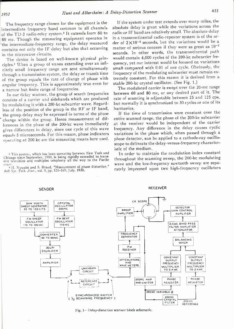
1.1952
The frequency range chosen for the equipment is the intermediate frequency band common to all channels of the TD-2 radio-relay system.' It extends from 60 to 80 mc. Though the measuring equipment operates in the intermediate-frequency range, the delay measured contains not only the IF delay but also that occurring
in the microwave circuits. The device is based on well-known physical prin-
ciples.* When a group of waves extending over an infi-nitely small frequency range are sent simultaneously through a transmission system, the delay or transit time of the group equals the rate of change of phase with angular frequency. This is approximately true even for a narrow but finite range of frequencies. In our delay scanner, the group of search frequencies
consists of a carrier and sidebands which are produced by modulating it with a 200-kc subcarrier wave. Regard-less of the position of the group in the RF or IF band, the group delay may be expressed in terms of the phase change within the group. Hence measurement of dif-ferences in the phase of the 200-kc wave immediately gives differences in delay, since one cycle of this wave equals 5 microseconds. For this reason, phase indicators operating at 200 kc are the measuring means here used.
3 This system, which has been operating between New York and Chicago since September, 1950, is being rapidly extended to trans-mit television and multiplex telephony all the way to the Pacific coast.
H. Nyquist and S. Brand, "Measurement of phase distortion," Bell Syc. Tech. Jour., vol. 9, pp. 522-549; July, 1930.
SENDER
SAW TOOTH SWEEP GENERATOR 25 TO 120 CPS
F m SWEEP OSCILLATOR 170 TO 190MC
CRYSTAL OSCILLATOR 200 KC
FM BEAT OSCILLATOR 110MC
CONVERTER 60 TO 8064C
DELAY EQUALIZER
AMPLIFIER
UNKNOWN CIRCUIT
ISYNCHRONIZED SWITCH ( 3f2 SCANNING FREQUENCY )
Hunt and Albersheim: A Delay-Distortion Scanner 455
If the system under test extends over many miles, the absolute delay is great while the variations across the radio or IF band are relatively small. The absolute delay in a transcontinental radio-repeater system is of the or-der of 2 X10⁻² seconds, but the variations would be a matter of serious concern if they were as great as 10-7 seconds. In other words, the transcontinental path would contain 4,000 cycles of the 200-kc subcarrier fre-quency, yet our interest would be focused on variations small compared with 0.01 of one cycle. Obviously, the frequency of the modulating subcarrier must remain ex-tremely constant. For this reason it is derived from a stable 200-kc crystal oscillator. (See Fig. 1.) The modulated carrier is swept over the 20-mc range
between 60 and 80 mc, or any desired part of it. The rate of scanning is adjustable between 25 and 125 cps, but normally it is synchronized to 30 cycles or one of its
harmonics. If the time of transmission were constant over the
entire scanned range, the phase of the 200-kc subcarrier at the receiver would be independent of the carrier frequency. Any difference in the delay causes cyclic variations in the phase which, when passed through a phase detector, ean be applied to a cathode-ray oscillo-scope to delineate the delay-versus-frequency character-istic of the medium. In order to maintain the modulation index constant
throughout the scanning sweep, the 200-kc modulating wave and the low-frequency sawtooth sweep are sepa-rately impressed upon two high-frequency oscillators
CR SCOPE
I SWEEP
AMPLIFIER
FREQUENC1 SEPARATOR
FM RECEIVER
ATTENuATORS AND
WAVE METERS
• TIIEFE-RENCit CIR- CUIT I
_J
RECEIVER
200KC AMP AND LIMITER
DETECTOR GAIN CONTROL AMPLIFIER
2 4MC BAND PASS FILTER AMPLIFIER ATTENUATOR
BALANCING MIXER
CONSTANT CONSTANT OUTPUT OUTPUT FREQUENCY FREQUENCY MULTIPLIER MULTIPLIER TO 2.4 MC TO 2.4 MC
PHASE ADJUSTER
f
200KC VARIABLE 4) 200 NC CRYSTAL FILTER
PHASE ADJUSTER
2 00 14 C REFERENCE
Fig. 1—Delay-distortion scanner block schematic.
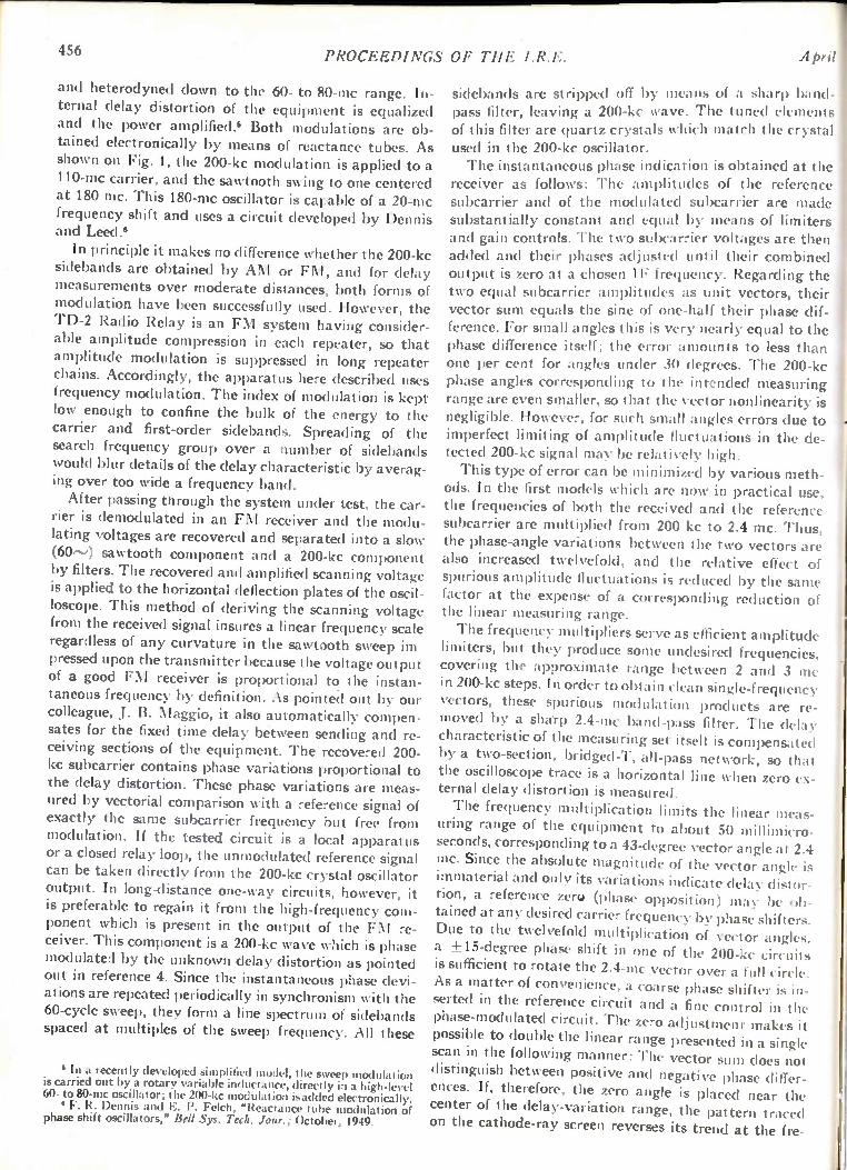
456 PROCEEDINGS OF THE I.R.E. April
and heterodyned down to the 60- to 80-mc range. In-ternal delay distortion of the equipment is equalized and the power amplified. Both modulations are ob-tained electronically by means of reactance tubes. As shown on Fig. 1, the 200-kc modulation is applied to a 110-mc carrier, and the sawtooth swing to one centered at 180 mc. This 180-mc oscillator is capable of a 20-mc frequency shift and uses a circuit developed by Dennis and Leed .6
In principle it makes no difference whether the 200-kc sidebands are obtained by AM or FM, and for delay measurements over moderate distances, both forms of modulation have been successfully used. However, the TD-2 Radio Relay is an FM system having consider-able amplitude compression in each repeater, so that amplitude modulation is suppressed in long repeater chains. Accordingly, the apparatus here described uses frequency modulation. The index of modulation is kept low enough to confine the bulk of the energy to the carrier and first-order sidebands. Spreading of the search frequency group over a number of sidebands would blur details of the delay characteristic by averag-ing over too wide a frequency band. After passing through the system under test, the car-
rier is demodulated in an FM receiver and the modu-lating voltages are recovered and separated into a slow
sawtooth component and a 200-kc component by filters. The recovered and amplified scanning voltage is applied to the horizontal deflection plates of the oscil-loscope. This method of deriving the scanning voltage from the received signal insures a linear frequency scale regardless of any curvature in the sawtooth sweep im pressed upon the transmitter because the voltage output of a good FM receiver is proportional to the instan-taneous frequency by definition. As pointed out by our colleague, J. B. Maggio, it also automatically compen-sates for the fixed time delay between sending and re-ceiving sections of the equipment. The recovered 200-kc subcarrier contains phase variations proportional to the delay distortion. These phase variations are meas-ured by vectorial comparison with a reference signal of exactly the same subcarrier frequency but free from modulation. If the tested circuit is a local apparatus or a closed relay loop, the unmoclulated reference signal can be taken directly from the 200-kc crystal oscillator output. In long-distance one-way circuits, however, it is preferable to regain it from the high-frequency com-ponent which is present in the output of the FM re-ceiver. This component is a 200-kc wave which is phase modulated by the unknown delay distortion as pointed out in reference 4. Since the instantaneous phase devi-ations are repeated periodically in synchronism with the 60-cycle sweep, they form a line spectrum of sidebands spaced at multiples of the sweep frequency. All these
6 In a recently developed simplified model, the sweep modulation is carried out by a rotary variable inductance, directly in a high-level 60- to 80-mc oscillator; the 200-kc modulation isadded electronically.
6 F. R. Dennis and E. P. Felch, "Reactance tube modulation of phase shift oscillators," Bell Sys. Tech. Jour.; October, 1949.
sidebands are stripped off by means of a sharp band pass filter, leaving a 200-kc wave. The tuned elements of this filter are quartz crystals which match the crystal used in the 200-kc oscillator. The instantaneous phase indication is obtained at the
receiver as follows: The amplitudes of the reference subcarrier and of the modulated subcarrier are made substantially constant and equal by means of limiters and gain controls. The two subcarrier voltages are then added and their phases adjusted until their combined output is zero at a chosen IF frequency. Regarding the two equal subcarrier amplitudes as unit vectors, their vector sum equals the sine of one-half their phase dif-ference. For small angles this is very nearly equal to the phase difference itself; the error amounts to less than one per cent for angles under 30 degrees. The 200-kc phase angles corresponding to the intended measuring range are even smaller, so that the vector nonlinearity is negligible. However, for such small angles errors due to imperfect limiting of amplitude fluctuations in the de-tected 200-kc signal may be relatively high. This type of error can be minimized by various meth-
ods. In the first models which are now in practical use, the frequencies of both the received and the reference subcarrier are multiplied from 200 kc to 2.4 mc. Thus, the phase-angle variations between the two vectors are
also increased twelvefold, and the relative effect of spurious amplitude fluctuations is reduced by the same factor at the expense of a corresponding reduction of the linear measuring range.
The frequency multipliers serve as efficient amplitude limiters, but they produce some undesired frequencies, covering the approximate range between 2 and 3 mc in 200-kc steps. In order to obtain clean single-frequency vectors, these spurious modulation products are re-moved by a sharp 2.4-mc band-pass filter. The delay characteristic of the measuring set itself is compensated by a two-section, bridged-T, all-pass network, so that the oscilloscope trace is a horizontal line when zero ex-ternal delay distortion is measured.
The frequency multiplication limits the linear meas-uring range of the equipment to about 50 millimicro-seconds, corresponding to a 43-degree vector angle at 2.4 mc. Since the absolute magnitude of the vector angle is immaterial and only its variations indicate delay distor-tion, a reference zero (phase opposition) may be ob-tained at any desired carrier frequency by phase shifters. Due to the twelvefold multiplication of vector angles, a ± 15-degree phase shift in one of the 200-kc circuits is sufficient to rotate the 2.4-mc vector over a full circle. As a matter of convenience, a coarse phase shifter is in-serted in the reference circuit and a fine control in the phase-modulated circuit. The zero adjustment makes it possible to double the linear range presented in a single scan in the following manner: The vector sum does not distinguish between positive and negative phase differ-ences. If, therefore, the zero angle is placed near the center of the delay-variation range, the pattern traced on the cathode-ray screen reverses its trend at the fre-
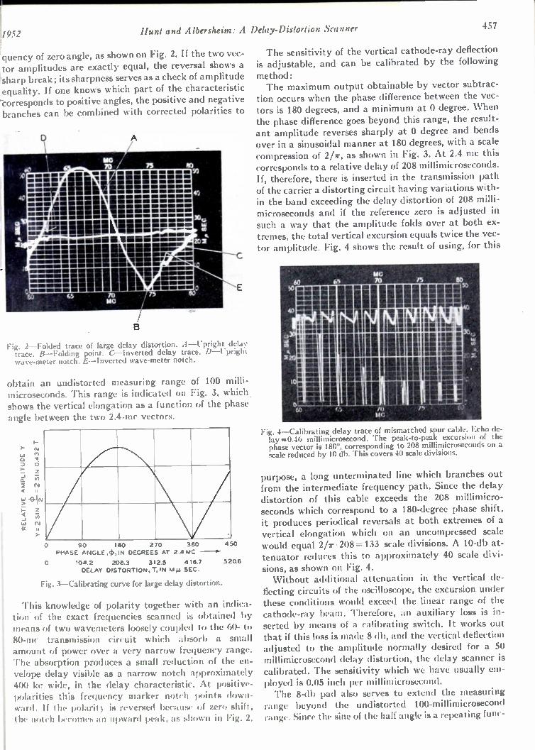
40
11952 Hunt and Albersheim: A
iquency of zero angle, as shown on Fig. 2. If the two vec-,tor amplitudes are exactly equal, the reversal shows a sharp break; its sharpness serves as a check of amplitude equality. If one knows which part of the characteristic -corresponds to positive angles, the positive and negative branches can be combined with corrected polarities to
P.'
M OO MI WA iti M MIII M M M i n : 4 r = MOP iii iv
m mil M M A m ilv e m o m mia m m -- ---F. .....------- --- - MI . = MI = AEI M IN NI E is IN ow mi mii OM U M W = imo M M A MOM MOO M WOM M OM M M = M MOI M 4•Noisr j• • • e n sis u mi me m mie _ m u NU M im M ill M M MI M M W M OI M M m emili m vi ' mew ailui l l rill ilINI MIIM MONI MINII N M eV 4•1.8 IN on so a Iss p n wo m m us• Mir .441110 El MO M S in mi IN NO 1114 r- -....---• VW - - - -- -- - oil BIO =IM w. - - are al ill MI Ili ili a a a WANES annisssms, . V igsraisMOMOM ILIMMO MM MZ issimmoisommemmso 11\111 . .1111•11i7 AEI /
M M MUNI M MIMI M M I MI M MIP A \ M IM M OI M MIO M M MIiIIIII M M. A MM OI
111111 111r4 VA :ELI
•
GS 70
4.4
0
Fig. 2—Folded trace of large delay distortion. A—Upright delay trace. B—Folding point. C—Inverted delay trace. D—Upright wave-meter notch. E—Inverted wave-meter notch.
Delay-Distortion Scanner 457
The sensitivity of the vertical cathode-ray deflection is adjustable, and can be calibrated by the following
method: The maximum output obtainable by vector subtrac-
tion occurs when the phase difference between the vec-tors is 180 degrees, and a minimum at 0 degree. When the phase difference goes beyond this range, the result-ant amplitude reverses sharply at 0 degree and bends over in a sinusoidal manner at 180 degrees, with a scale compression of 2/r, as shown in Fig. 3. At 2.4 mc this corresponds to a relative delay of 208 millimicroseconds. If, therefore, there is inserted in the transmission path of the carrier a distorting circuit having variations with-in the band exceeding the delay distortion of 208 milli-microseconds and if the reference zero is adjusted in such a way that the amplitude folds over at both ex-tremes, the total vertical excursion equals twice the vec-tor amplitude. Fig. 4 shows the result of using, for this
obtain an undistorted measuring range of 100 milli-microseconds. This range is indicated on Fig. 3, which . shows the vertical elongation as a function of the phase angle between the two 2.4-mc vectors.
1•1
o-
a. 2
$-•
(7)
11
>-
0 90 180 270 360 450
PHASE ANGLE .4>, IN DEGREES AT 2.41.4C - -0-
0 104.2 208.3 312 5 418.7 5208 DELAY DISTORTION, T, IN Mp. SEC.
Fig. 3—Calibrating curve for large delay distortion.
This knowledge of polarity together with an indica-tion of the exact frequencies scanned is obtained by means of two wavemeters loosely coupled to the 60- to 80-mc transmission circuit which absorb a small amount of power over a very narrow frequency range. The absorption produces a small reduction of the en-velope delay visible as a narrow notch approximately 400 kc wide, in the delay characteristic. At positive-polarities this frequency marker notch points down-ward. If the polarity is reversed because of zero shift, the notch becomes an upward peak, as shown in Fig. 2.
Fig. 4—Calibrating delay trace of mismatched spur cable. Echo de-lay =0.46 millimicrosecond. The peak-to-peak excursion of the phase vector is 180°, corresponding to 208 millimicroseconds on a scale reduced by 10 db. This covers 40 scale divisions.
purpose, a long unterminated line which branches out from the intermediate frequency path. Since the delay distortion of this cable exceeds the 208 millimicro-seconds which correspond to a 180-degree phase shift, it produces periodical reversals at both extremes of a vertical elongation which on an uncompressed scale would equal 2/r • 208=133 scale divisions. A 10-db at-tenuator reduces this to approximately 40 scale divi-sions, as shown on Fig. 4. Without additional attenuation in the vertical de-
flecting circuits of the oscilloscope, the excursion under these conditions would exceed the linear range of the cathode-ray beam. Therefore, an auxiliary loss is in-serted by means of a calibrating switch. It works out that if this loss is made 8 db, and the vertical deflection adjusted to the amplitude normally desired for a 50 millimicrosecond delay distortion, the delay scanner is calibrated. The sensitivity which we have usually em-ployed is 0.05 inch per millimicrosecond. The 8-db pad also serves to extend the measuring
range beyond the undistorted 100-millimicrosecond range. Since the sine of the half angle is a repeating func-

458 PROCEEDINGS OF THE I.R.E. April
tion, the nonlinear measuring range is unlimited (as indicated by the continuation of the calibrating curve in Fig. 3 beyond 360 degrees), showing a gradual re-versal with a minimum of sensitivity at all odd mul-tiples and a sharp reversal with a maximum of sensi-tivity at all even multiples of 208 millimicroseconds from the reference zero. By shifting the reference zero to make sensitive regions overlap in repeated readings, the total delay range of 460 millimicroseconds in a long-distance circuit has been measured with an uncertainty of less than 2 per cent. In the simplified model the reference angle between
the 200-kc reference signal and the phase-modulated received signal is not zero but a finite angle irP, preferably between 30 and 45 degrees. The amplitude ratio of the received to the reference vector is made equal to cos ck. It can be shown that this arrangement measures small phase modulations with the same linearity as the sys-tem using equal vectors, but suppresses the first-order effects of small amplitude fluctuations. This circuit is schematically shown on Fig. 5(a) and explained by the vector diagram of Fig. 5(b).
200 KC
REFERENCE CARRIER
200 KC
VARIABLE
PHASE
3600 PHASE
ADJUSTER
GAIN CONTROL AMP
1,BALANCE
e AEASURE )1 PHASE AND
AMPLITUDE
SHIFTER
MIXER
AMP
CALIBRATING VIBRATOR
RECTI-FIER
(a)
(b)
TO VERTICAL
SCOPE DEFLECTOR AMP
Fig. 5—Simplified phase indicator. qb=reference phase angle. 6= small variations of phase angle.
By means of an auxiliary vibrating switch it is pos-sible to connect alternate scans to two vector positions differing by a standard angle, for instance 1.44 degrees, which corresponds to 20 millimicroseconds. Calibration is obtained by setting the vertical gain control to a one-inch separation between traces.
A single instrument which combines transmitting and receiving equipment is only capable of measuring delay distortion of local equipment and of extended transmis-sion systems looped back so that the demodulated saw-tooth and 200-kc components are available at the in-strument. If it is desired to measure the delay distortion of a long transmission circuit in one direction only, the sending part of the equipment (or its duplicate) js re-moved to the distant transmitting end of the circuit. Permanent records of the delay-distortion character-
istics are obtained with a camera attachment. A lighting arrangement permits the calibration scale to be illumi-nated independently. The record usually consists of a double exposure, one indicating the small residual delay distortion of the equipment itself (called "base line") with the illuminated scale superimposed, and the second showing the characteristic when the unknown circuit is added. For exact measurements the equipment residual is subtracted. During the second exposure the auxiliary illumination may be extinguished to avoid overexpos-ing the scale. Such reference base line appears in Fig. 2. For quick testing and adjusting of local equipment
such as delay equalizers, it may be desirable to compare the delay characteristic of the unit under test with that of a reference standard. For this purpose a double switch has been provided which alternately connects the input and output of the test circuit to the unknown equipment and to the reference standard, in synchro-nism with the scanning frequency. The characteristics of the two pieces of equipment are traced alternately at such a rate as to appear to the eye to be superimposed. Two such superimposed characteristics are photo-graphed on Fig. 6.
Fig. 6—Superimposed characteristics of two equalizers.
The delay scanner can be used for the testing and adjustment of impedance matches as follows: In order to match a network, such as an amplifier or
equalizer, to the line impedance of 75 ohms, it is con-nected in series with a long 75-ohm transmission line having a fixed delay, for instance, T=0.25 microsecond, and its delay characteristic is observed. A small-known
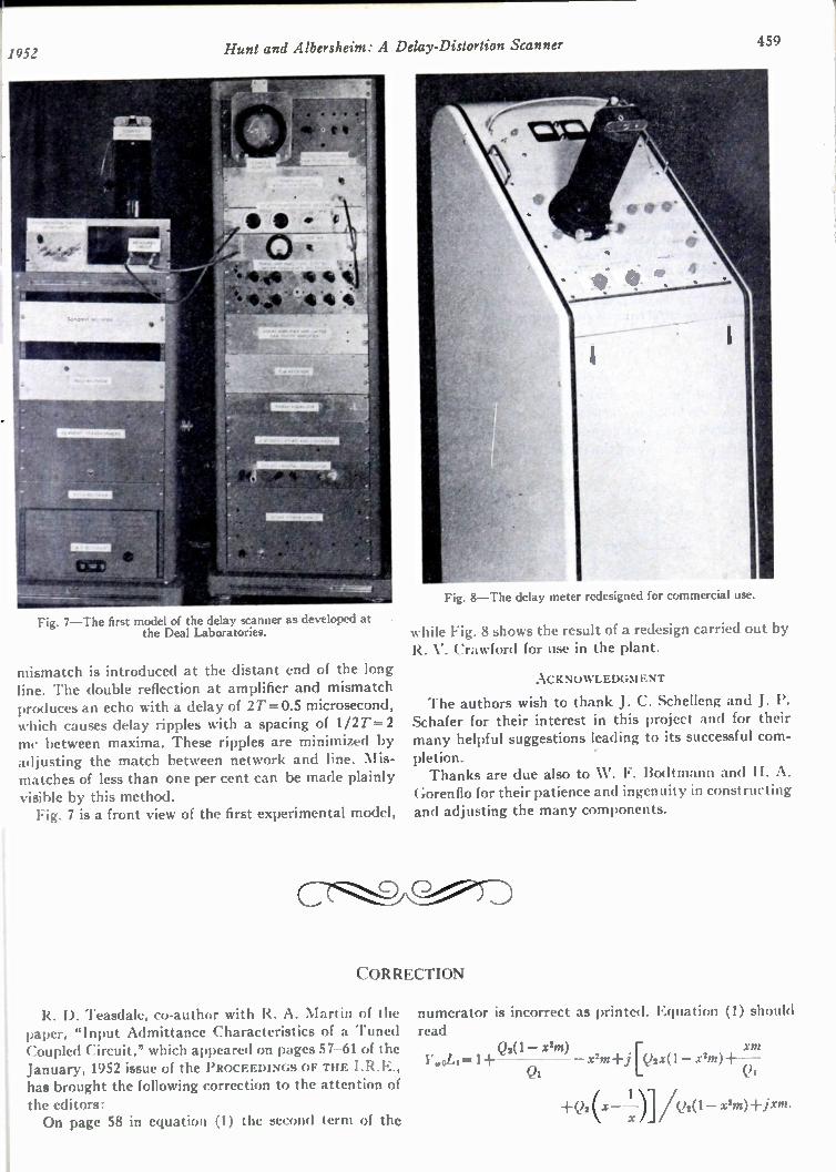
1052 Hunt and Albersheim: A Delay-Distortion Scanner 459
Fig. 7—The first model of the delay scanner as developed at the Deal Laboratories.
mismatch is introduced at the distant end of the long line. The double reflection at amplifier and mismatch produces an echo with a delay of 2T= 0.5 microsecond, which causes delay ripples with a spacing of 1/2T= 2 mc between maxima. These ripples are minimized by adjusting the match between network and line. Mis-matches of less than one per cent can be made plainly visible by this method. Fig. 7 is a front view of the first experimental model,
Fig. 8—The delay meter redesigned for commercial use.
while Fig. 8 shows the result of a redesign carried out by R. V. Crawford for use in the plant.
ACKNOWLEDGMENT
The authors wish to thank J. C. Schelleng and J. P. Schafer for their interest in this project and for their many helpful suggestions leading to its successful com-
pletion. Thanks are due also to W. F. Bodtmann and H. A.
Gorenflo for their patience and ingenuity in constructing and adjusting the many components.
CORRECTION
R. D. Teasdale, co-author with R. A. Martin of the paper, "Input Admittance Characteristics of a Tuned Coupled Circuit," which appeared on pages 57-61 of the January, 1952 issue of the PROCEEDINGS OF THE I.R.E., has brought the following correction to the attention of the editors: On page 58 in equation (1) the second term of the
numerator is incorrect as printed. Equation (1) should read
11.0L1= 1+ Q2(1— X2M) XM
Z2ni+i [Q2X(1 — Q1 Qi
1 +Q2 (x— —)1 A)2(1— xlm)+jxm.

460 PROCEEDINGS OF THE I.R.E.
The Cathamplifier* C. A. PARRYt
Summary—This paper discusses an amplifier circuit with high input impedance which permits push-pull operation from an unbal-anced source.
A voltage, proportional to the total circulating current of the push-pull system, is obtained from a transformer connected in the cathode circuits of the output valves. Over-all performance similar to usual push-pull operation may be obtained.
The possibility of a single- or two-mode oscillator is also dis-cussed.
Because of the simplicity, and general application of this circuit, some of the more useful formulas are developed in detail.
I. BASIC THEORY
/N Fig. 1, T is an ideal choke, with an exact center tap, and the whole power due to /1 /2 is considered to be developed in the load resister R. In such a case
the voltages developed across each half of the winding are equal irrespective of the ratio 11/12.
'61r2S1 6-6-rb - _ _ _
Fig. 1—Basic circuit.
12
Let Ri = effective resistance offered current /1 R2 = effective resistance offered current /2.
./1//2= We have
e2/ R = e11/2 — e12/2
2e/ R = 11 — 12 (1)
11/R1 = 12/R2 = e/ 2 (2)
102 = RI/R1 = V. (3)
Substituting in (1),
4/R = 1/R2 — 1/R2, (4)
whence
R 1 = R(1' — 1)/41 (5)
R2 = R(I' — 1)/4. (6)
II. CIRCUIT APPLICATION AND BASIC CONDITIONS FOR BALANCE
Fig. 2 shows how the basic circuit is applied to an amplifier in order to obtain push-pull operation. The voltage developed across winding N3 is applied to the
1April
grid of valve 2 in the correct phase, the resister R being varied to obtain ac plate-current balance.
Fig. 2—Basic circuit applied to two valves. .1n unbalanced voltage E causes push-pull operation by virtue of the transformer 7'.
Let
Nil(Ni -I- N2) =
G1 =
G2 =
T = e2/ e
mutual conductance of valve 1
mutual conductance of valve 2.
(7)
Also assume negligible distortion and that T is an ideal transformer. In Fig. 2
and
From (2),
1 2 = V2G2
Ii = 'GI} (8)
'i(;1/ I -2(;.? = 1'. (9)
Ri• = 172G2R2 = e /2. (10)
For equilibrium conditions
V2 = e2 ei — e/2, 11
where
(/1 — /2) • Ro (12)
and using (2)
e• Ro (1 1 Cl = — • — --).
2 R1 R2
From (5) and (6), with due regard to the sign of L.
2e• Ro (1.- — 1 e1 = - (13)
R 1' 1
From (7), (11), and (13),
V2 = Te — e/ 2 + 2eR011 — I\
R s.,V + 1)
* Decimal classification: R363.222. Reprinted from the Proceed- Simplifying and using (10) ings of the Institution of Radio Engineers, Australia, vol. II, pp. 199-204, August, 1950, by the courtesy of the Institution of Radio Engi- 1/2 2R00- — 1)) 1-2G2 1 neers, Australia. 2G2Ri (T — = . t Lister Research Co., 333 George St., Sydney, Austra lia. R(I' + 1) (14)
1
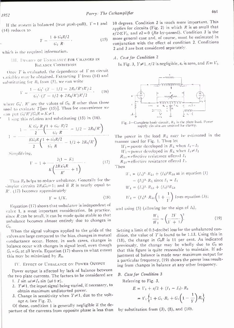
1952 Parry: The Cathamplifier 461
If the system is balanced (true push-pull), Y=1 and
(14) reduces to
1 + G2R/2 T=
G2. R• (15)
which is the required information.
III. DEGREE OF UNBALANCE FOR CHANGES IN BALANCE CONDITIONS
Once T is evaluated, the dependence of 17 on circuit variables may be obtained. Extracting Y from (14) and substituting for RI from (5), we can write
1 — G2'• (1' — 1/2 — 2Ro/R')/V/2 (16) 1"
= G 2'• (T — 1/2 + 2Ro/R')R72
where G2', R' are the values of Gs, R other than those used to evaluate T[see (15)]. Thus for convenience we can put G2'R'/G2R = K Using this relation and substituting (15) in (16),
1 KG4R ± G2 ' R/2 2 1/2 — 2Ro/R)
G2' R
KG2R G2R/2 2 ( (;2R 1/2 + 2R0/
=
2(1 — K) 1" = 1 + (17)
K f2Roc2R R'
Thus Ro helps to reduce unbalance. Generally for the simpler circuits 2RoG2=-----1; and if R is nearly equal to R', (17) becomes approximately
= 1/K. (18)
Equation (17) shows that unbalance is independent of valve 1, a most important consideration. In practice, since R can be small, it can be made quite stable so that unbalance becomes almost entirely due to changes in
G2. When the signal voltages applied to the grids of the
valves are large compared to the bias, changes in mutual conductance occur. Hence, in such cases, changes in balance occur with changes in signal level, even though G1= G2 at all levels. Equation (17) shows to what extent
this may be minimized by Ro.
IV. EFFECT OF UNBALANCE ON POWER OUTPUT
Power output is affected by lack of balance between the two plate currents. The factors to be considered are 1. I sin cut 0 /2 sin (cot+r). 2. Y 1, the input signal being varied, if necessary, to obtain maximum undistorted power.
3. Change in sensitivity when Y01, due to the volt-age el (see Fig. 2).
Of these, condition 1 is generally negligible if the de-parture of the currents from opposite phase is less than
10 degrees. Condition 2 is much more important. This applies for circuits (Fig. 2) in which R is so small that e/ MITI, and e2=0 (Ro by-passed). Condition 3 is the more general case and, of course, must be estimated in conjunction with the effect of condition 2. Conditions 2 and 3 are best considered separately.
A. Case for Condition 2
In Fig. 3, Y01, e/2 is negligible, er is zero, and E- 171.
Fig. 3—Complete basic circuit; RL is the plate load. lower supply circuits are omitted for clarity.
The power in the load RL may be estimated in the manner used for Fig. I. Thus let WI= power developed in R. when /I= /2 11-2=power developed in RL when /I 0 /2 RLI =effective resistance offered /I R L2 = effective resistance offered 12.
Then
11.1 = (/1)2•RLI (12) 2RL2 as in equation (1)
= (/2)2.RL since /1 = /2
= (/1)2. Rti (12) 2RL2
IF, = (fi)'' RLI(1 from equation (3);
and using (5) (allowing for the sign of /2),
11"1 ( 21'
W2 — \17 1) •
Setting a limit of 0.5-decibel loss for the unbalanced con-dition, the value of Y is found to be 1.13. Using this in (18), the change in G2R is 11 per cent. As indicated previously, the change may be wholly due to G2 so that this figure is quite reasonable to maintain. If ad-justment of balance is made near maximum output for a particular frequency, (19) shows the power loss result-ing from changes in balance at any other frequency.
B. Case for Condition 3
Referring to Fig. 3,
E = V1-1- e/2 ± (II — I2) • Ro
= 1.1{1 Gi• Ri Gi(1 — —y1) Ro}
by substitution from (3), (8), and (10).
(19)
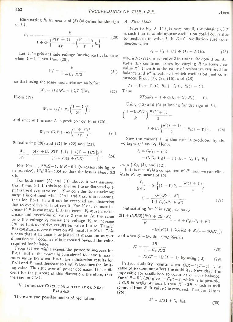
462 PROCEEDINGS OF THE I.R.E. April
Eliminating R1 by means of (5) (allowing for the sign of /2),
171 =
— . R(1' + 1) + (1' — 1
1 + GI { ) } 4Y Ro
Let V11= grid-cathode voltage for the particular case when Y=1. Then from (20),
IVf II = - — - , 1 + GI. R/2
so that using the same nomenclature as before
IVI = (/1)2RL = (GIVI')2RL.
From (19)
(20)
(21)
(22)
W2 = (ii)2' RL (-1 24;--7 —1)2;
and since in this case /1 is produced by V1 of (20),
112 = (GIVI)2- (I 4- 17 )2. (23) 2Y
Substituting (20) and (21) in (22) and (23),
IV, {411 GI[R(Y &1 1) + 4(Y — 1) } 2 (24)
112 (1 1')(2 Gil?)
For Y=1.1, 2R0G 1, GI/Z=0.4 (a reasonable figure in practice), W1/W2= 1.04 so that the loss is about 0.2 db.
For both cases (A) and (B) above, it was assumed that Y was >1. If this is so, the limit to undistorted out-put is the drive on valve 1. If we consider that maximum output is obtained when Y=1 and that E is constant, then for Y> 1, VI will not be exceeded and distortion due to overdrive will not result. For Y<1, /2 must in-crease if E is constant. If /2 increases, V2 must also in-ccease and overdrive of valve 2 results. At the same time the voltage el causes the voltage VI to increase (20) so that overdrive results on valve 1, also. Thus if E is constant, severe distortion will result for Y<1. This means that if balance is adjusted at maximum output distortion will occur as R is increased beyond the value required for balance.
From (2) we might expect the power to increase for Y<1. But if the power is considered to have a maxi-mum value WI when Y=1, then distortion results for Y <1 and E must decrease so that V2 becomes the limit-ing value. Thus the over-all power decreases. It is suffi-cient for the purpose of this discussion, therefore, that we assume Y>1.
V. INHERENT CIRCUIT STABILITY AT OR NEAR BALANCE
There are two possible modes of oscillation:
A. First Mode
Refer to Fig. 3. If I is very small, the phasing of T is such that it would appear oscillation could occur due to feedback in valve 2. If E=0, oscillation just com-mences when
e2 = l'2 e/ 2 ± (12 — 11)R0, (25)
where /2> /1 because valve 2 initiates the condition. As-sume this condition arises by varying R to some new value R'. Then R is the value of resistance required for balance and R' is value at which oscillation just com-mences. From (7), (8), (10), and (25)
Te = V2 + V2 •G2 • R2 V2 'G2 • Ro(1 — 1'). Thus
2 TG2R2 = 1 G2R2 + G2' Ro (1 — 1').
Using (15) and (6) (allowing for the sign of /2),
1 G2R/2 R'(1' ± 1)
R ) 2
+ 1)
2 Ro(1 — 1')}. (26)
Now the current /1 in this case is produced by the voltages e/2 and el. Hence,
Ii = Gi(ei — e/2)
= [G2 • V2(1 — V) •Ro — G4 ' V2 R21
from (10), (3), and (12).
In this case R2 is a component of R', and we can elim-inate R2 by means of (6).
11 le(1 G21/2 = GI {(1 — 1')R0 —
4 r
G1(4/4 —
4 + G1(4/20 R')
Substituting for Y in (26), we have
2(1 G2R/2)(k(1 2G1. RIO
(27)
= 4 + G;(4R0 R')
G2[R1(1 2GiRo) Ro(4 2GIR')];
and when GI =G2, this simplifies to
2R R' =
(28) 1 — GI. R/2
= R(2T — 1)/(7' — 1) by using (15). (29)
Perfect stability results when GIR = 2(T= 1). The value of Ro does not affect the stability. Note that it is impossible for oscillation to occur at or near balance. For if R=R', (29) gives —GIR =2, which is impossible. If GR is negligibly small, then R' =2R, which is well removed from R. If valve 1 is removed, Y=0; and from (26),
R' = 2R(1 + G2. Ro). (30)

11:52
Again, in the limiting case when Ro = 0, R' =2R, which
is a satisfactory value.
Parry: The
B. Second Mode
Fig. 4 shows diagrammatically the equivalent circuit at a high frequency. The grid circuit will consist of the
Valve 2
(a)
Fig. 4—The equivalent of circuit (a) at high frequencies is shown in (b). Cs is stray capacity, Ls leakage inductance, and Rs secondary resistance.
Voir. 2
(b)
Calhamplifier 463
network comprising leakage inductance Ls, self-capac-ity Cs, and effective secondary resistance Rs.
R„ = (Rs + T2R),
where Rs is the secondary resistance. The impedance of this circuit near resonance is Ls' Cs Rn so that if Rn is sufficiently small and Ls large a high impedance may result. Feedback from other parts of the circuit, prin-cipally the anodes, can, therefore, produce oscillation. Since LsICs • Rn will be a maximum when R=0, oscil-lation may occur if R is too small. Generally, R is suffi-ciently large to eliminate this problem. As an alterna-tive, the balance adjustment may be accomplished by means of a variable resistance across the secondary of
T instead of across the primary. The control R may, therefore, be used to control oscil-
lation in either mode since for mode A. the value must be large while for B. it must be small; thus oscillation can be made to occur on either side of the balance ad-justment. R may also be used as a control for a highly selective amplifier circuit.
VI. Loss OF SENSITIVITY AT BALANCE DUE TO DEGENERATION
Referring to Fig. 2, it is seen that a loss of sensitivity occurs due to e/2. From (21)
E = V Al GI. R/2)
so that the sensitivity is reduced by the factor
(1 + Gi.R/2).
By substitution from (15), the loss factor may also be
expressed as
TAT —1/2). (31)
VII. BALANCE FOR NOISES ORIGINATING IN THE POWER SUPPLY
Fig. 5 is the circuit for examination of this aspect of operation. Let
Rp1= plate resistance valve 1 R92= plate resistance valve 2 E„ = noise voltage in high-voltage supply.
We have
V1 = — (e/2 er)
V2 = Te — (e/2 er)
Ii = E/ R,1 — Gi(e/ 2 ± e,)
12 = En/R2 — G2(e/ 2 ± e,) TeG2.
From (2) and (6)
Te = 1/2. [TI2R(Y —
If R„1= Ro and G1= G2,
/I — /2 = — 1/2. [Tr2RG2(Y — 1)]
from (32) and (33). Hence,
Y — 1 = 1/2. [TR(1 — Y) — G2]
for which Y=1. We would expect balance to be independent of the
adjustment of R. Balance does depend, however, on the operating characteristics of the valves so that some further control (such as bias or slope) may be provided to adjust this. A simple test of this adjustment is pos-sible with the circuit. For at balance Te= 0, and no volt-age is developed across the secondary of T; thus it is sufficient to observe the grid voltage of valve 2.
(32)
(33)
(34)
Fig. 5—Equivalent circuit for the examination of noise voltage E,, originating in the high-tension power supply.
VIII. DISTORTION
The ac plate currents of the valves may be expressed by the usual series,
/1 = aVi Wi2 (35)
12 = — a'V2 ± 111722 — c' V23 ± • (36)
The total circulating current is the difference between these currents. Usually it is assumed that the coefficients of the two valves are equal (a=a', b=b', and so on), and this will be accepted in the following analysis: From (35) and (36) the current for any particular
coefficient may be expressed in the form
= WITin nth component for valve 1
= W (—V2)" nth component for valve 2.

464 PROCEEDINGS OF THE I.R.E. April
The total circulating current for any particular coeffi-cient will depend on the feedback voltages e, e,, and Te (Fig. 6), occurring for that particular component.
Fig. 6—Basic circuit used for discussion on distortion.
Thus
= WV," — (e/2 er)a
I,,2 = 1V(— V2)" (-1)"(—e/2 er Te)a
since coefficients beyond a for the feedback voltages are negligible. Even components cancel out as with normal push-pull; and for the odd components we have
/„1 — /„2 = 110'i" — (—V2)" ea + Tea, (37)
where n is an odd number. From (1)
e = — 1„2)R/2. (38)
Substituting in (37) and using (15), we obtain
(2T — 1) mi - r.2 = v,. - (-172)-1 (39)
Since the distortion in the assumed case is entirely due to odd components, the total distortion is reduced by the factor T/(2T — 1). Thus distortion reduction is half the gain reduction (31).
IX. CHOICE OF BALANCE RESISTOR AND SIGNAL LEVEL
FOR ADJUSTMENT OF AC PLATE CURRENTS
A. Balance Resistor
The ultimate value for R is a compromise. The re-quirements are perhaps best examined by expressing GIR in terms of T in the various equations. For maxi-mum possible stability (29) T=1; the loss factor (31) is then 2, and the distortion reduction factor (39) is 1. If minimum ac plate resistance is required, then R must be small, which requires T> 1. Again if R is too small, there is a greater tendency for oscillation in mode 2 unless other precautions are taken. It would appear that the ultimate choice is for a value of T very close to 1.
B. Signal Level
From (18), Yoc (1/K); from (16), K ocG2'/G2. Since G2 CC E, it follows that YocE (Fig. 2). Thus to obtain maximum power [(24) Y=1], balance adjustments should be made at the maximum value of E. However, even harmonics are only cancelled if Vi= V2 (37). If a Oa', then when Y= I, V10 V2. If a bias or slope ad-justment is also provided, it would appear desirable to adjust at maximum output so that a =a'. This results
in maximum output and minimum distortion. How-
ever, it is sometimes desirable to adjust this extra bal-ance when E= 0 so that a =a' at low signal level, and minimum noise from the high-tension supply at zero signal is obtained. If this is so, then at the maximum value of E it is unlikely that a =a'. The balance adjust-ment R would then be made to obtain minimum distor-tion at maximum possible output. Since this would oc-cur when VI= V, if a Oa', 1'01, and the maximum possible output would be slightly less than obtained with Y=1.
X. CoNcLusioN
The circuit under discussion has interesting possibili-ties. Push-pull operation is possible, yet the input im-pedance of the circuit is high. Thus the output stages may be preceded by a high-gain voltage amplifier, per-mitting an extremely compact amplifier unit. This also simplifies the problem of applying inverse feedback over the whole amplifier. The adjustment required for push-pull operation is quite simple and the stability of bal-ance, as well as the inherent circuit stability, is quite good. Cancellation of noise voltages from the power supply is unaffected by the balance adjustment. Slight improvement of distortion may be obtained without ex-cessive loss of sensitivity. It can be expected that changes in balance will occur with signal level, but this should not be any great disadvantage. The circuit permits an easy observation on the adjustment of the operating characteristic when this is provided.
Fig. 7—An interesting modification.
Two modes of oscillation which are independently ad-justable are possible. This indicates- that the circuit could be used as a highly selective amplifier incorporat-ing a variable selectivity control. Fig. 7 is an interesting
Sits. T
Fig. 8—Showing the relation between the various formulas, and the transformation-ratio T.
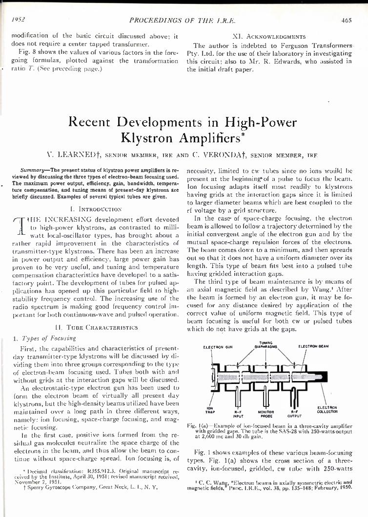
1952 PROCEEDINGS OF THE I.R.E. 465
modification of the basic circuit discussed above; it does not require a center tapped transformer. Fig. 8 shows the values of various factors in the fore-
going formulas, plotted against the transformation ratio T. (See preceding page.)
XI. ACKNOWLEDGMENTS
The author is indebted to Ferguson Transformers, Pty. Ltd. for the use of their laboratory in investigating this circuit; also to Mr. R. Edwards, who assisted in the initial draft paper.
Recent Developments in High-Power Klystron Amplifiers*
V. LEARNEDt, SENIOR MEMBER, IRE AND C. VERONDAt, SENIOR MEMBER, IRE
Summary—The present status of klystron power amplifiers is re-viewed by discussing the three types of electron-beam focusing used. The maximum power output, efficiency, gain, bandwidth, tempera-ture compensation, and tuning means of present-day klystrons are briefly discussed. Examples of several typical tubes are given.
I. INTRODUCTION
THE INCREASING development effort devoted to high-power klystrons, as contrasted to milli-
watt local-oscillator types, has brought about a rather rapid improvement in the characteristics of transmitter-type klystrons. There has been an increase in power output and efficiency, large power gain has proven to be very useful, and tuning and temperature compensation characteristics have developed to a satis-factory point. The development of tubes for pulsed ap-plications has opened up this particular field to high-stability frequency control. The increasing use of the radio spectrum is making good frequency control im-portant for both continuous-wave and pulsed operation.
II. TUBE CHARACTERISTICS
1. Types of Focusing
First, the capabilities and characteristics of present-day transmitter-type klystrons will be discussed by di-viding them into three groups corresponding to the type of electron-beam focusing used. Tubes both with and without grids at the interaction gaps will be discussed. An electrostatic-type electron gun has been used to
form the electron beam of virtually all present day klystrons, but the high-density beams utilized have been maintained over a long path in three different ways, namely: ion focusing, space-charge focusing, and mag-netic focusing. In the first case, positive ions formed from the re-
sidual gas molecules neutralize the space charge of the electrons in the beam, and thus allow the beam to con-tinue without space-charge spread. Ion focusing is, of
• Decimal classification: R355.912.3. Original manuscript re-ceived by the Institute, April 30, 1951; revised manuscript received, November 2, 1951.
Sperry Gyroscope Company, Great Neck, L. I., N. Y.
necessity, limited to cw tubes since no ions wotild be present at the beginning* of a pulse to focus the beam. Ion focusing adapts itself most readily to klystrons having grids at the interaction gaps since it is limited to larger diameter beams which are best coupled to the rf voltage by a grid structure. In the case- of space-charge focusing, the electron
beam is allowed to follow a trajectory determined by the initial convergent angle of the electron gun and by the mutual space-charge repulsion forces of the electrons. The beam comes down to a minimum, and then spreads out so that it does not have a uniform diameter over its length. This type of beam fits best into a pulsed tube having gridded interaction gaps. The third type of beam maintenance is by means of
an axial magnetic field as described by Wang.' After the beam is formed by an electron gun, it may be fo-cused for any distance desired by application of the correct value of uniform magnetic field. This type of beam focusing is useful for both cw or pulsed tubes which do not have grids at the gaps.
ELECTRON GUN
ION TRAP MOH OR
PROBE INPUT
TUNING DIAPHRAGMS ELECTRON BEAM
R-F OUTPUT
ELECTRON COLLECTOR
Fig. 1(a)—Example of ion-focused beam in a three-cavity amplifier with gridded gaps. The tube is the SAS-28 with 250-watts output at 2,600 mc and 30 db gain.
Fig. 1 shows examples of these various beam-focusing types. Fig. 1(a) shows the cross section of a three-cavity, ion-focused, gridded, cw tube with 250-watts
C. C. Wang, "Electron beams in axially symmetric electric and magnetic fields," PROC. I.R.E., vol. 38, pp. 135-148; February, 1950.
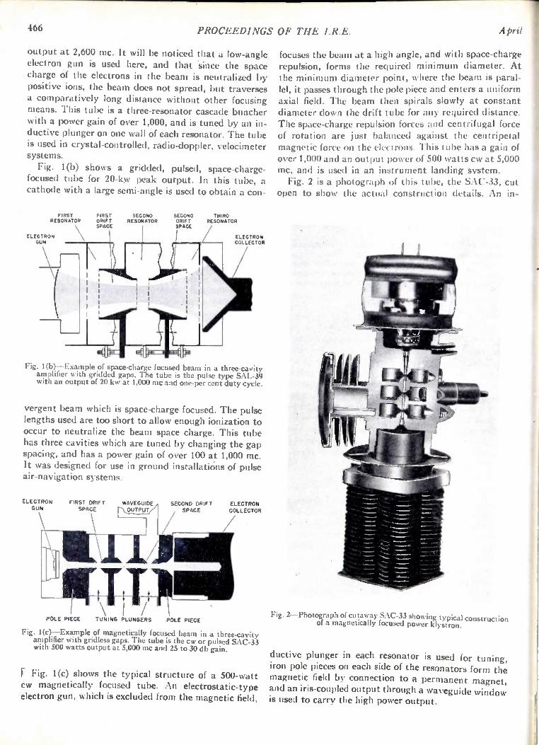
466 PROCEEDINGS OF THE I.R.E. April
output at 2,600 mc. It will be noticed that a low-angle electron gun is used here, and that 'since the space charge of the electrons in the beam is neutralized by positive ions, the beam does not spread, but traverses a comparatively long distance without other focusing means. This tube is a three-resonator cascade buncher with a power gain of over 1,000, and is tuned by an in-ductive plunger on one wall of each resonator. The tube is used in crystal-controlled, radio-doppler, velocimeter systems.
Fig. 1(b) shows a gridded, pulsed, space-charge-focused tube for 20-kyv peak output. In this tube, a cathode with a large semi-angle is used to obtain a con-
FIRST RESONATOR
ELECTRON GUN
( FIRST DRIFT SPACE
SECOND RESONATOR
SECOND DRIFT SPACE
I I
THIRD RESONATOR
ELECTRON COLLECTOR
Fig. 1(b) —Example of space-charge focused beam in a three-cavity amplifier with gridded gaps. The tube is the pulse type SAL-39 with an output of 20 kw at 1,000 mc and one-per cent duty cycle.
vergent beam which is space-charge focused. The pulse lengths used are too short to allow enough ionization to occur to neutralize the beam space charge. This tube has three cavities which are tuned by changing the gap spacing, and has a power gain of over 100 at 1,000 mc. It was designed for use in ground installations of pulse air-navigation systems.
ELECTRON GUN
FIRST DRIFT SPACE
WAVEGUIDE OUTPUT
SECOND DRIFT ELECTRON SPACE COLLECTOR
POLE PIECE TUNING PLUNGERS POLE PIECE
Fig. 1(c)—Example of magnetically focused beam in a three-cavity amplifier with gridless gaps. The tube is the cw or pulsed SAC-33 with 500 watts output at 5,000 mc and 25 to 30 db gain.
F Fig. 1(c) shows the typical structure of a 500-watt cw magnetically focused tube. An electrostatic-type electron gun, which is excluded from the magnetic field,
focuses the beam at a high angle, and with space-charge repulsion, forms the required minimum diameter. At the minimum diameter point, where the beam is paral-lel, it passes through the pole piece and enters a uniform axial field. The beam then spirals slowly at constant diameter down the drift tube for any required distance. The space-charge repulsion forces and centrifugal force of rotation are just balanced against the centripetal magnetic force on the electrons. This tube has a gain of over 1,000 and an output power of 500 watts cw at 5,000 mc, and is used in an instrument landing system. Fig. 2 is a photograph of this tube, the SAC-33, cut
open to show the actual construction details. An in-
Fig. 2—Photograph of cutaway SAC-33 showing typical construction of a magnetically focused power klystron.
ductive plunger in each resonator is used for tuning, iron pole pieces on each side of the resonators form the magnetic field by connection to a permanent magnet,
and an iris-coupled output through a waveguide window is used to carry the high power output.

1952 Learned and Veronda: High-Power Klystron Amplifiers 467
2. Maximum Power
The maximum power output available in the present state of the art for the various types of klystrons utiliz-ing a solid cylindrical electron beam is shown in Fig. 3.
10
5
POWER OUTPUT - WATTS
0,000
0,000 PRESENT -W
5,000 GRIDDED
1,000
500
100 GRI MED EFFICIENCY ',....,
50
10 -
•
5 -
I1 100 500 1,000
FREQUENCY -MC/SEC
Fig. 3—Approximate ultimate power data for klystrons. The solid line is for gridded tubes and the shaded region the average power for pulsed tubes.
100
50
10
5
EFFICIENCY - %
10,000
This assumes power density as the limiting factor by causing excessive local heating. Cathode current den-sity is not a limitation with modern gun optics and cathode materials. The ordinate is cw power output or average pulse power. The shaded region gives the range for various designs of gridless tubes. For example, at 3,000 mc this is about 10 kw, or several megawatts peak at low-duty cycles. The ultimate power is greater at lower frequencies
because the amount of beam power transmitted can in-crease as the square of the wavelength for constant radial electrical dimensions. To avoid difficulties with space-charge repulsion limitations, the best way to in-crease the beam power is to raise the beam voltage. For a gridded tube, the drift-tube diameter is limited in size by the variation of gap voltage with radius as the diameter of the grid approaches a half wavelength. Hence, the limiting power varies as the square of the wavelength. For a gridless tube, the diameter of the drift-tube is limited by electrical beam-to-gap coupling considerations. For constant electrical interaction pa-rameters, the increase in voltage at longer wavelengths allows a further increase in physical size of the tube. The factors combine to give a relationship of power output varying somewhat faster than the inverse cube of the frequency. The maximum power limit for gridded tubes is set by
the temperature of the grids. The temperature limit occurs when thermionic electron emission from the hot grids causes heavy electronic gap loading. This occurs before burn out of the grid is imminent. For the lower
frequency tubes (below 5,000 mc) the grid cooling is accomplished primarily by radiation because the grids are relatively long. Above about 5,000 mc the primary contribution to grid cooling is made by conduction. Present cw techniques in gridded tubes allow power amplifiers to be built up to about 10,000 mc and mul-tipliers and reflex tubes to about 60,000 mc. The limit of pulse powers for gridless tubes is usually
greater than that power which gives the same average power as for a cw tube at the same frequency. This is true with pulse tubes because higher beam voltages are used which allow a larger structure and thus a higher average power-dissipation ability. Pulse klystrons for microsecond pulses, with peak power outputs of several megawatts and power gains in the thousands, are prac-tical.
3. Efficiency
Also plotted on the chart of Fig. 3 is an efficiency versus frequency line for gridded power klystron ampli-fiers whose power output is near the ultimate limit. The efficiency curve is fairly flat up to around 3,000 mc, and then starts to drop. This dropping off at the higher fre-quencies results from smaller input power, thus making circuit losses more significant. The circuit losses them-selves also increase at the higher frequencies. Further-more, the physical size of tube parts becomes small and percentage grid interception increases since the vanes cannot be reduced proportionately because of mechani-cal limitations. When mechanical tolerances become troublesome, they cause a reduction in efficiency. The efficiency of two resonator klystrons can be 58
per cent, theoretically; while if gain in a three-resonator klystron is sacrificed, a higher efficiency is theoretically obtainable. However, practical considerations usually limit the obtainable plate efficiency of power klystrons to around 30 per cent in the region of 3,000 mc. At high powers under unusual design circumstances, efficiencies of 40 per cent are realizable. The input power division between losses and useful
output power is shown in Fig. 4. In a gridded tube, some beam electrons are lost because of interception by the grids. This reduces the possible efficiency from the theoretical 58 per cent. A loss of 18 per cent for a two-cavity tube is typical except at higher frequencies (above 3,000 to 5,000 mc) where the loss becomes progressively greater. The electronic conversion ef-ficiency might be around 50 per cent instead of the theoretical 58 per cent because of unevenness of bunch-ing across the diameter of the beam. Three-fifths of this rf energy may reach the useful load, although higher cir-cuit efficiencies can sometimes be realized. The unde-sired losses include 6 per cent of the beam power taken by transit-time electron loading, 6 per cent by slow secondary electron loading, and 4 per cent by rf losses in the output resonator. The transit-time loading arises since the electrons
take a finite time to cross the gap, and can therefore be
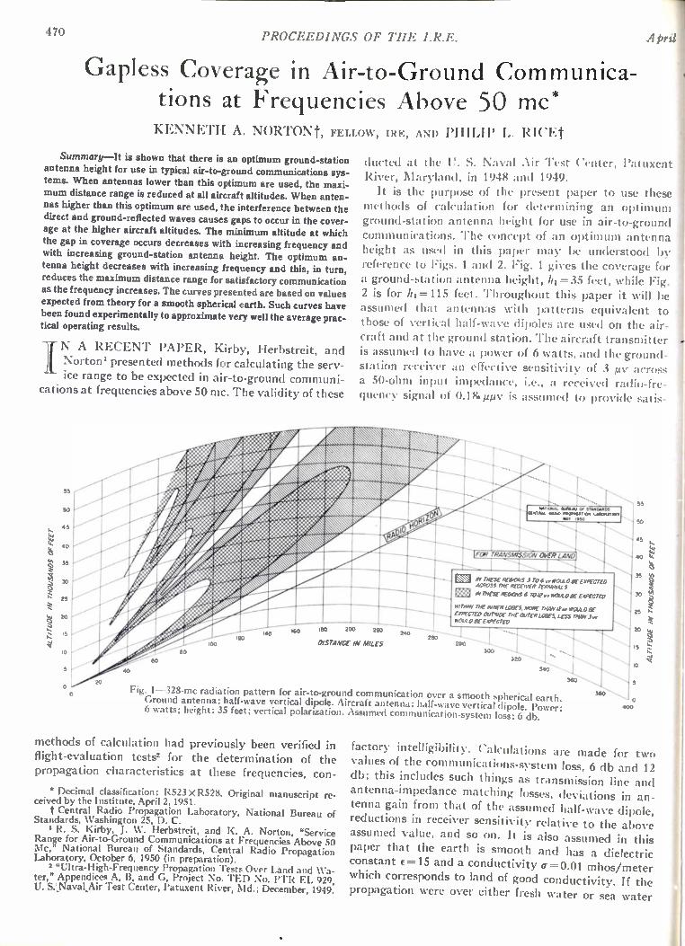
470 PROCEEDINGS OF THE I.R.E. April
Gapless Coverage in Air-to-Ground Communica-tions at Frequencies Above 50 mc* KENNETH A. NORTONt, FELLOW, IRE, AND PHILIP I. R H 'Et
Summary—It is shown that there is an optimum ground-station antenna height for use in typical air-to-ground communications sys-tems. When antennas lower than this optimum are used, the maxi-mum distance range is reduced at all aircraft altitudes. When anten-nas higher than this optimum are used, the interference between the direct and ground-reflected waves causes gaps to occur in the cover-age at the higher aircraft altitudes. The minimum altitude at which the gap in coverage occurs decreases with increasing frequency and with increasing ground-station antenna height. The optimum an-
tenna height decreases with increasing frequency and this, in turn, reduces the maximum distance range for satisfactory communication as the frequency increases. The curves presented are based on values expected from theory for a smooth spherical earth. Such curves have been found experimentally to approximate very well the average prac-tical operating results.
Jr N A RECENT PAPER, Kirby, Herbstreit, and Norton' presented methods for calculating the serv-
ice range to be expected in air-to-ground communi-
cations at frequencies above 50 mc. The validity of these
ALT/ WOE IN THOUSANDS Or FEET
55
50
45
40
5
30
25
20
15
10 ,
0
dee /
ducted at the U. S. Naval Air Test Center, Patuxent
River, Maryland, in 1948 and 1949.
It is the purpose of the present paper to use these
methods of calculation for determining an optimum
ground-station antenna height for use in air-to-ground
communications. The concept of an optimu m antenna
height as used in this paper may be understood by
reference to Figs. 1 and 2. Fig. 1 gives the coverage for
a ground-station antenna height, 111=35 feet, while Fig. 2 is for /11=115 feet. Throughout this paper it will be
assumed that antennas with patterns equivalent to
those of vertical half-wave dipoles are used on the air-
craft and at the ground station. The aircraft transmitter
is assumed to have a power of 6 watts, and the ground-
station receiver an effective sensitivity of 3 pv across
a 50-ohm input impedance, i.e., a received radio-fre-
quency signal of 0.18.µµv is assu med to provide satis-
N \ N
N\ , ‘,
... ,s- 0
i f ̀‘ 0 1111 IIIII
4 , 01111111 1111111 I
100
180 240
FOR TRANSMISSION OVER LAND
1 - 5. THESE REGIONS 3 TO 6 x. Troup ExPEcTED ACROSS ITTE PECENER IthIONALS
THESE RECTOV5 6 TO It Ar 5 40 5. EXPECTED
wimp' THE INNER LODES, MORE THAN /2,.. woucoliE EXPECTED OC/15/0E TNT OuTERLatTES, LC55 NAN Jvr W O W BE EXPECTED
Fig. 1--328-mc radiation pattern for air-to-ground communication over a smooth spherical earth. Ground antenna: half-wave vertical dipole. Aircraft antenna: half-wave vertical dipole. Power: 6 watts; height: 35 feet; vertical polarization. Assumed communication-system loss: 6 db.
methods of calculation had previously been verified in
flight-evaluation tests' for the determination of the
propagation characteristics at these frequencies, con-
* Decimal classification: R523 X R528. Original manuscript re-ceived by the Institute. April 2, 1951. I' Central Radio Propagation Laboratory, National Bureau of
Standards, Washington 25, D. C. R. S. Kirby, J. W. Herbstreit, and K. A. Norton, "Service
Range for Air-to-Ground Communications at Frequencies Above 50 Mc," National Bureau of Standards, Central Radio Propagation Laboratory, October 6, 1950 (in preparation).
2 "Ultra-High-Frequency Propagation Tests Over Land and Wa-ter," Appendices A, B, and G, Project No. TED No. PTR EL 929, U. S..Naval_Air Test Center, Patuxent River, Md.; December, 1949.
55
50
factory intelligibility. Calculations are made for two
values of the communications-system loss, 6 db and 12
db; this includes such things as transmission line and
antenna-impedance matching losses, deviations in an-
tenna gain from that of the assumed half-wave dipole,
reductions in receiver sensitivity relative to the above
assumed value, and so on. It is also assumed in this
paper that the earth is smooth and has a dielectric
constant e = 15 and a conductivity 0=0.01 mhos/meter
which corresponds to land of good conductivity. If the
propagation were over either fresh water or sea water
•
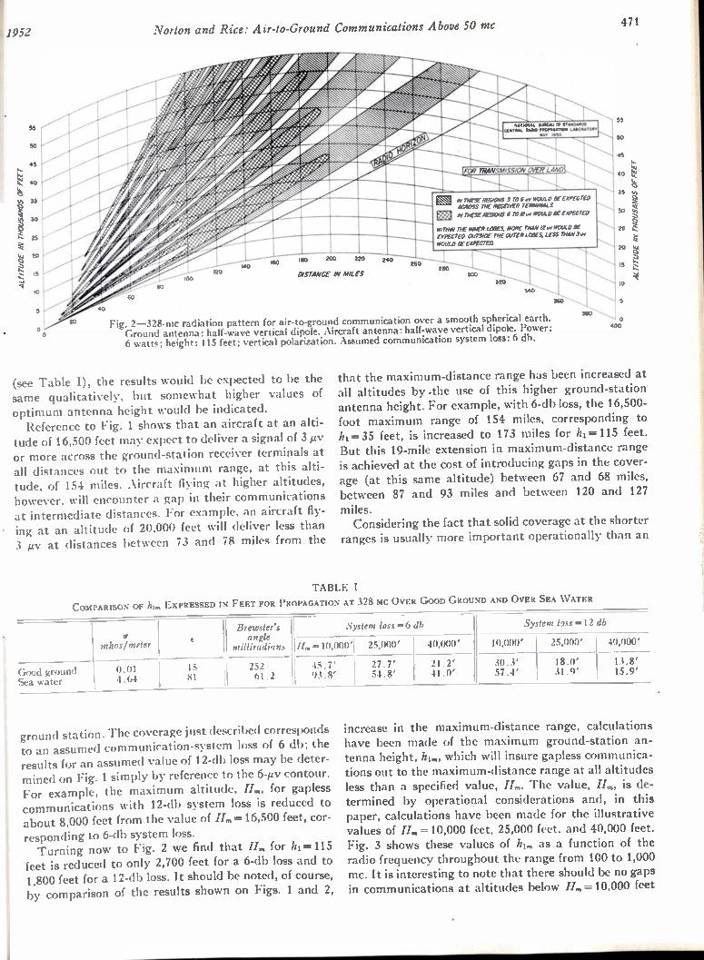
Norton and Rice: Air-to-Ground Communications Above 50 mc 471 !1952
45
4.1
30
25
20
5
0
120 100
150 220
DISTANCE IN MILES
240
TRANSMISSION OVER LAND
AV THESE REGIONS 5 ro 6 WI WOULD BE EXPECTED ACROSS THE RECEIVER TERMINALS
IN THESE REGIONS 6 TO /244,1604E0 ii6EKPECTE0
WffNIN TIE INNER LCIWS, MORE THAN IX., WOULD BE EXPECTED OUTSIDE THE OUTER LODES, LESS THAN Jur WOULD BE EXPECTED
250
320
00
Fig. 2-328-mc radiation pattern for air-to-ground communication over a smooth spherical earth. Ground antenna: half-wave vertical dipole. Aircraft antenna: half-wave vertical dipole. Power: 6 watts; height: 115 feet; vertical polarization. Assumed communication system loss: 6 db.
(see Table I), the results would be expected to be the same qualitatively, but somewhat higher values of optimum antenna height would be indicated. Reference to Fig. 1 shows that an aircraft at an alti-
tude of 16,500 feet may expect to deliver a signal of 3 iv or more across the ground-station receiver terminals at all distances out to the maximum range, at this alti-tude, of 154 miles. Aircraft flying at higher altitudes, however, will encounter a gap in their communications at intermediate distances. For example, an aircraft fly-ing at an altitude of 20,000 feet will deliver less than 3 ptv at distances between 73 and 78 miles from the
55
45
40
35
30
25
20
15
10
ALrauDE IN rHousANos or FEET
that the maximum-distance range has been increased at all altitudes by -the use of this higher ground-station antenna height. For example, with 6-db loss, the 16,500-foot maximum range of 154 miles, corresponding to hi= 35 feet, is increased to 173 miles for h1= 115 feet. But this 19-mile extension in maximum-distance range is achieved at the cost of introducing gaps in the cover-age (at this same altitude) between 67 and 68 miles, between 87 and 93 miles and between 120 and 127
miles. Considering the fact that solid coverage at the shorter
ranges is usually more important operationally than an
TABLE I
COMPARISON OF hi„, EXPRESSED IN FEET FOR PROPAGATION AT 328 hic OVER GOOD GROUND AND OVER SEA WATER
Goed ground Sea water
mhos/meter
0.01 4.64
Brewster's angle 1,
milliradians 11.= 10,0001 25,000'
System loss =6 db System loss =12 db
40,000'
15 252 45.7' 81 61.2 93.8'
27.7' 54.8'
21.2' 41.0'
10,000' 25,000' 40,000'
30.3' 57.4'
18.0' I 13.8' 31.9' 15.9'
ground station. The coverage just described corresponds to an assumed communication-system loss of 6 db; the results for an assumed value of 12-db loss may be deter-mined on Fig. 1 simply by reference to the 6-1.tv contour. For example, the maximum altitude, H„„ for gapless communications with 12-db system loss is reduced to about 8,000 feet from the value of H„,= 16,500 feet, cor-
responding to 6-db system loss. Turning now to Fig. 2 we find that H„, for h1= 115
feet is reduced to only 2,700 feet for a 6-db loss and to 1,800 feet for a 12-db loss. It should be noted, of course, by comparison of the results shown on Figs. 1 and 2,
increase in the maximum-distance range, calculations have been made of the maximum ground-station an-tenna height, him, which will insure gapless communica-tions out to the maximum-distance range at all altitudes less than a specified value, H„,. The value, H„„ is de-termined by operational considerations and, in this paper, calculations have been made for the illustrative values of /L.= 10,000 feet, 25,000 feet, and 40,000 feet. Fig. 3 shows these values of h1„, as a function of the radio frequency throughout the range from 100 to 1,000 mc. It is interesting to note that there should be no gaps in communications at altitudes below H„,= 10,000 feet
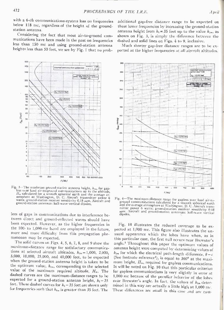
472 PROCEEDINGS OF THE 1.R.F. April
with a 6-db communications-system loss on frequencies below 118 mc, regardless of the height of the ground-station antenna.
Considering the fact that most air-to-ground com-munications have been made in the past on frequencies less than 150 mc and using ground-station antenna heights less than 50 feet, we see by Fig. 1 that no prob-
100 90 80
70
GO
50 L_
40
30
40,000
20
15
13 9
2100
Assam./ comnivoicohonl 61,5
,
150 200
IMO
I T-40 lids
I I I 500 600 700 8039001000
Fig. 3—The maximum ground-station antenna height, 121„„ for gap-less over land air-to-ground communications up to the altitude, II„, calculated for a smooth spherical earth and the average at-mosphere at Washington, D. C. Aircraft transmitter power 6 watts; ground-station receiver sensitivity 0.18 µAw. Aircraft and ground-station antennas: half-wave vertical dipoles.
lem of gaps in communications due to interference be-tween direct and ground-reflected waves should have been expected. However, as the higher frequencies in the 100- to 1,000-mc band are employed in the future, more and more difficulty from this propagation phe-nomenon may be expected. The solid curves on Figs. 4, 5, 6, 7, 8, and 9 show the
maximum-distance range for satisfactory communica-tions at selected aircraft altitudes, h2,„ = 1,000, 2,000, 5,000, 10,000, 25,000, and 40,000 feet, to be expected when the ground-station antenna height is taken to be the optimum value, hl„„ corresponding to the selected value of the maximum required altitude, H„,. The dashed curves are the maximum-distance ranges to be expected for a ground-station antenna height, hl = 35 feet. These dashed curves for hl =35 feet are shown only for frequencies such that hl„, is greater than 35 feet. The
additional gap-free distance range to be expected on these lower frequencies by increasing the ground-station antenna height from It, =35 feet up to the value h1,„, as shown on Fig. 3, is simply the difference between the dashed and solid lines on Figs. 4 to 9, inclusive. Much shorter gap-free distance ranges are to be ex-
pected at the higher frequencies at all aircraft altitudes.
aerneel nantrowycoN n 3,140, lOss • 6 ae
Ai, • 0,000 /66/
Fig. 4—The maximum-distance range for gapless over land air-to-ground communications calculated for a smooth spherical earth and the average atmosphere at Washington, D. C. Aircraft trans-mitter power 6 watts; ground-station receiver sensitivity 0.18 AiAiw. Aircraft and ground-station antennas: half-wave vertical dipoles.
Fig. 10 illustrates the reduced coverage to be ex-pected at 1,000 mc. This figure also illustrates the un-usual appearance which the lobes have when, as in this particular case, the first null occurs near Brewster's angle.' Throughout this paper the optimum values of antenna height were computed by determining values of h1„, for which the electrical path-length difference, 6—c (See footnote reference'), is equal to 360° at the maxi-mum height, H„„ required for gapless communications. It will be noted on Fig. 10 that this particular criterion for gapless communications is very slightly in error at 1,000 mc because of the peculiar behavior of the lobes near Brewster's angle. In fact, the values of hl„, deter-mined in this way are actually a little high at 1,000 mc. These differences are small in this case and are corn-
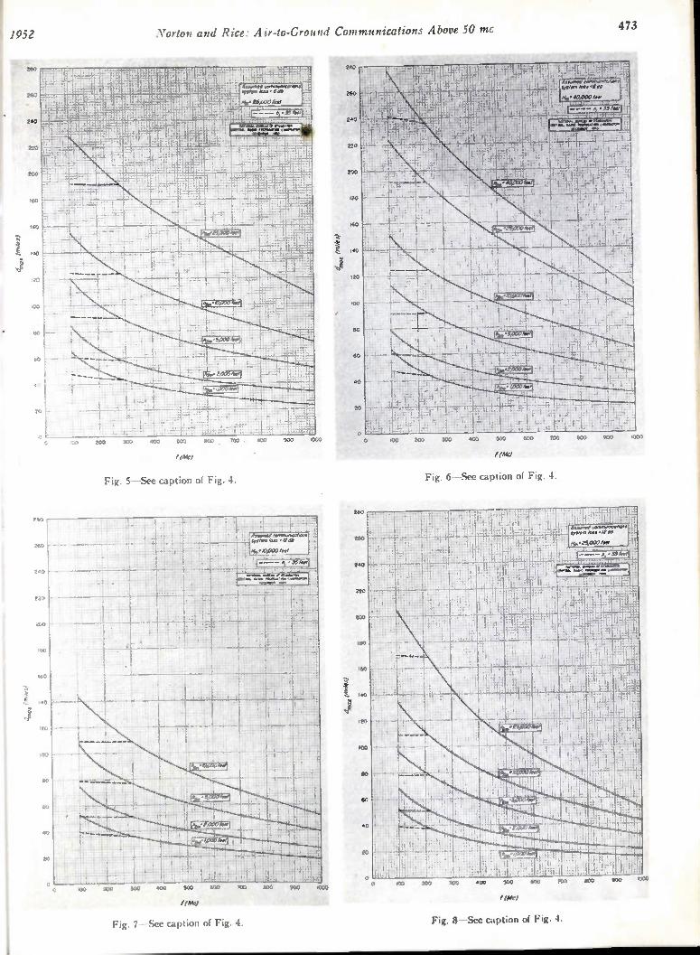
1952 Norton and Rice: Air-to-Ground Communications Above 50 mc 473
/ WO
Fig. 5—See caption of Fig. 4.
600 900 .000
Fig. 6—See caption of Fig. 4.
(Mc/
Fig. 7 See caption of Fig. 4. Fig. 8—See caption of Fig. 4.
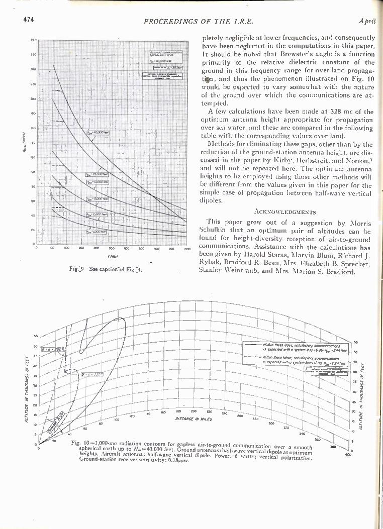
474 PROCEEDINGS OF THE I.R.E. April 1 ALTITUDE IN THOUSANDS OF FEET
28
240
220
200
180
160
20
100
eo
so
55
45
30
15
10
k0.0 300
Asueired nO;i7u.),"a nom vsNal loss• 1240
• 40,00040
J ti 900 SOO GOO 200 BOO
ftitt
Fig.:9- -See caption:of_Fig.:4.
120 140
1000
pletely negligible at lower frequencies, and consequently have been neglected in the computations in this paper. It should be noted that Brewster's angle is a function primarily of the relative dielectric constant of the ground in this frequency range for over land propaga-In, and thus the phenomenon illustrated on Fig. 10 would be expected to vary somewhat with the nature of the ground over which the communications are at-tempted. A few calculations have been made at 328 mc of the
optimum antenna height appropriate for propagation over sea water, and these are compared in the following table with the corresponding values over land. Methods for eliminating these gaps, other than by the
reduction of the ground-station antenna height, are dis-cussed in the paper by Kirby, Herbstreit, and Norton,' and will not be repeated here. The optimum antenna heights to be employed using those other methods will be different from the values given in this paper for the simple case of propagation between half-wave vertical dipoles.
ACKNOWLEDGMENTS
This paper grew out of a suggestion by Morris Schulkin that an optimum pair of altitudes can be found for height-diversity reception of air-to-ground communications. Assistance with the calculations has been given by Harold Staras, Marvin Blum, Richard J. Rybak, Bradford R. Bean, Mrs. Elizabeth B. Sprecker, Stanley Weintraub, and Mrs. Marion S. Bradford.
180 200 220
0/STANCE IN MILES 280
240
Mem, these lobes, satisfactory communications
a expected with a system loss • 6c1b; he,,, -344/eel
-- Want, mese tubes, satisfactory communications Is expected ow/ 0 system kss.t2 ot, Itim .2.24 feet
_
260
300
Fig. 10-1,000-mc radiation contours for gapless air-to-ground communication over a smooth spherical earth up to H,..= 40,000 feet. Ground antennas: half-wave vertical dipole at optimum heights. Aircraft antenna: half-wave vertical dipole. Power: 6 watts; vertical polarization. Ground-station receiver sensitivity: 0.1£1pAw.
360
U1111011.1 1,
55
so
10
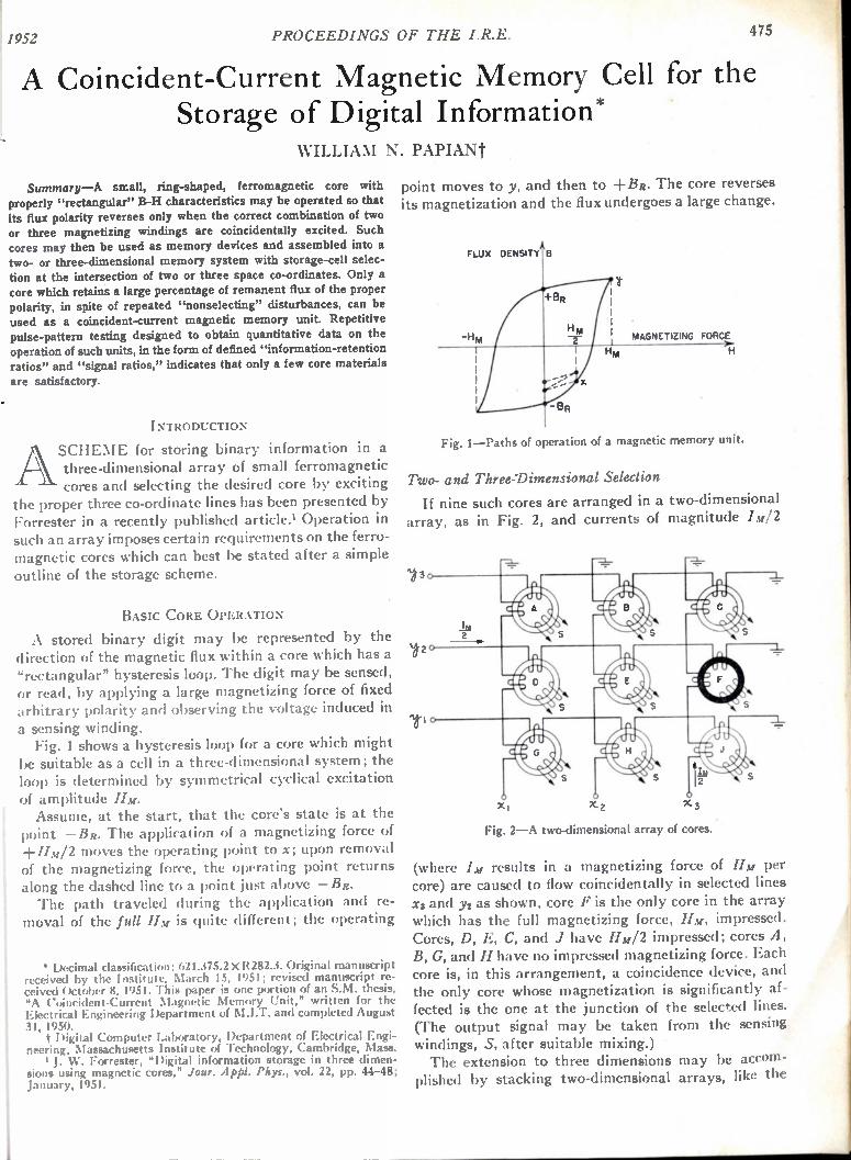
1952 PROCEEDINGS OF THE I.R.E. 475
A Coincident-Current Magnetic Memory Cell for the Storage of Digital Information*
WILLIA NI N. PAPIANt
Summary—A small, ring-shaped, ferromagnetic core with properly "rectangular" B-H characteristics may be operated so that
its flux polarity reverses only when the correct combination of two or three magnetizing windings are coincidentally excited. Such
cores may then be used as memory devices and assembled into a two- or three-dimensional memory system with storage-cell selec-tion at the intersection of two or three space co-ordinates. Only a core which retains a large percentage of renument flux of the proper polarity, in spite of repeated "nonselecting" disturbances, can be
used as a coincident-current magnetic memory unit. Repetitive pulse-pattern testing designed to obtain quantitative data on the operation of such units, in the form of defined "information-retention ratios" and "signal ratios," indicates that only a few core materials
are satisfactory.
INTRODUCTION
ASCHEME for storing binary information in a three-dimensional array of small ferromagnetic cores and selecting the desired core by exciting
the proper three co-ordinate lines has been presented by Forrester in a recently published article.' Operation in such an array imposes certain requirements on the ferro-magnetic cores which can best be stated after a simple outline of the storage scheme.
BASIC CORE OPERATION
A stored binary digit may be represented by the direction of the magnetic flux within a core which has a "rectangular" hysteresis loop. The digit may be sensed, or read, by applying a large magnetizing force of fixed arbitrary polarity and observing the voltage induced in a sensing winding. Fig. 1 shows a hysteresis loop for a core which might
be suitable as a cell in a three-dimensional system; the loop is determined by symmetrical cyclical excitation of amplitude 11m. Assume, at the start, that the core's state is at the
point —Be. The application of a magnetizing force of +Hm/2 moves the operating point to x; upon removal of the magnetizing force, the operating point returns along the dashed line to a point just above —BR. The path traveled during the application and re-
moval of the full II m is quite different; the operating
Decimal classification: 621.375.2 X R282.3. Original manuscript received by the Institute, March 15, 1951; revised manuscript re-ceived October 8, 1951. This paper is one portion of an S.M. thesis, "A Coincident-Current Magnetic Memory Unit," written for the Electrical Engineering Department of M.I.T. and completed August 31, 1950.
t Digital Computer Laboratory, Department of Electrical Engi-neering, Massachusetts Institute of Technology, Cambridge, Mass.
J. W. Forrester, "Digital information storage in three dimen-sions using magnetic cores," Jour. Appl. Pkys., vol. 22, pp. 44-48; January, 1951.
point moves to y, and then to +BR. The core reverses its magnetization and the flux undergoes a large change.
FLUX DENSIT 8
-H MAGNETIZING FORCE
HM H
Fig. 1—Paths of operation of a magnetic memory unit.
Two- and Three-Dimensional Selection
If nine such cores are arranged in a two-dimensional array, as in Fig. 2, and currents of magnitude /m/2
Fig. 2—A two-dimensional array of cores.
(where IM results in a magnetizing force of II m per core) are caused to flow coincidentally in selected lines x3 and y2 as shown, core F is the only core in the array which has the full magnetizing force, HM, impressed. Cores, D, E, C, and J have Hu/2 impressed; cores A, B, G, and H have no impressed magnetizing force. Each core is, in this arrangement, a coincidence device, and the only core whose magnetization is significantly af-fected is the one at the junction of the selected lines. (The output signal may be taken from the sensing windings, S, after suitable mixing.) The extension to three dimensions may be accom-
plished by stacking two-dimensional arrays, like the

476 PROCEEDINGS OF TIIE I.R.E. April
ones of Fig. 2, along a z axis, with corresponding x lines connected in common and corresponding y lines con-nected in common. In this arrangement the application of Hm/2 to an x line and a y line results in the selection of a line of cores parallel to the z axis. All of these cores, except a desired one, may be "unselected" by the appli-cation of minus HM/2 to the cores in each z plane, ex-cept the one containing the desired core.
Greater Selecting-Current Ratios
Variations on the selection scheme described above have been devised which impose less stringent require-ments on the core. It is possible for the core to have to discriminate between currents which bear 3:1, 5:1, or greater ratios to each other;" advantage may be taken of these greater current ratios to reduce switching times, increase signal-to-noise ratios, or relax some of the hysteresis-loop requirements. The cost is an addi-tional increase in the electronic equipment surrounding the system for each increase in the H ratio.
The discussion that follows is concerned with core requirements for operation with a 2:1 selecting-current ratio. A core that operates satisfactorily with a 2:1 ratio will have a high margin of reliability at greater ratios.
INFORMATION- RETENTION AND SIGNAL RATIOS
• The ONE-to-ZERO output-signal ratio is an im-portant criterion by which to judge a simple magnetic binary storage unit. However, this ratio is insufficient for judging a coincident-current unit of the type de-scribed, and a set of new criteria have been set up for that purpose.
Information Retention
Refer back to Fig. 1 and let an "undisturbed ONE" be defined as the —BR flux-state of the core and an "undistured ZERO" as the +BR state. Let a "read' pulse of H be arbitrarily fixed at +Hm so that reading a ONE results in a large flux change and a correspond-ingly large output pulse, and reading a ZERO gives a small output pulse. A ZERO is, then, "written" by an -1-Hm pulse also, and a ONE is written by an —H., pulse.
Recall that selecting one core in a two- or three-di-dimensional array results in the application of Hm/2, called a "nonselecting" pulse, to cores elsewhere in the array. The application of repeated nonselecting read pulses to a core containing a ONE tends to run the state of that core up along the B axis, as indicated by the dashed lines in Fig. 1, disturbing or destroying its information. When the hysteresis loop is properly rec-
"Ferromagnetic and Ferroelectric Cores," Summary Report No. 26, Section 3.4, Digital Computer Laboratory, M.I.T., Cambridge, Mass.; Second Quarter, 1951.
3 R. R. Everett, "Selection Systems for Magnetic Core Storage," kngineering Note E-413, an internal document of the Digital Com-puter Laboratory, M.I.T., Cambridge, Mass.; August 7, 1951.
tangular and all parameters correctly adjusted, the op-erating point moves up the axis only to some asymptotic position not far above the point —Bk. This is the situa-tion for a core which operates satisfactorily in the coincident-current scheme. A core which contained iii i listurbed ONE and has ou
been subjected to a large wiloher of nonselect ing read pulses is considered to hold a "disturbed ()N E." By the above reasoning, the disturbed-ON I. output is usually lower than the undisturbed-ON I. output. In an analogous manner, repeated nonselecting
write-ON I.: pulses will run the core's operating point front +13h downward, increasing the size of a ZERO output pulse so that a disturbed-ZERO output is usually larger than an undisturbed-ZERO output.
Signal Ratios
Since nonselecting disturbances may reduce the out signal front a core containing a ONE and increase
the output front a core containing a ZERO, the ratio of the disturbed-ONE output to the disturbed-ZERO output, called the "disturbed-signal ratio," is a critical measure of a core's performance as a coincident-current memory unit. This ratio approaches infinity in the ideal case, and should be much greater than one if reasona-ble discrimination between the binary digits is to be obtained.
The application of a nottselecting pulse to a core results in a voltage output, called a "nonselecting output," that is, a form of noise. The rat io of a dist urbed - ONE output to a nonselecting out called the "non-selecting signal ratio," is another important criterion of operation. Like the disturbed-signal tatio, it approaches infinity in the ideal case and should be much greater than 1 for satisfactory operation.
Hysteresis Loop Shapes The two ratios mentioned above aloe functions,
largely, of the shape of a core's B-H loop. The values of the ratios approach the indicated ideals as the rectangu-larity of the hysteresis loop increases.
H2
HiA 2
BR Hi
Fig. 3—An idealization of a B-H loop.
H2<2H,
From the idealized hysteresis loop of Fig. 3, sonn• necessary conditions for coincident-current operation

11952 Pa plan: Ferromagnetic Cores for Storage Arrays 477
may be stated. A loop must exist for which the follow-ing relations hold true:
HM > 112,
H M — < Hi, 2
where HI and H2 are the points at which the B-H curve changes direction abruptly. Combining these gives one general requirement on the hysteresis loop shape,
112 < 2111.
Experimental results give qualitative support to this general requirement.
Experimental Results
Cores were tested to ascertain signal ratios, B-H characteristics, and response times. Where possible, the testing was accomplished repetitively and at a high rate, and results were presented on an oscilloscope.
Test Technique
Previous considerations lead directly to the mag-netizing pulse patterns desired for signal testing. Two of these patterns are illustrated in Fig. 4; mode a con-
Hm 0-
4 MODE g, CHECK UNDISTURBED ONE
LJ HM Hm T
MODE b, CHECK DISTURBED ONE
Fig. 4—Core-testing pulse patterns of H.
sists of alternate-polarity, full-amplitude pulses for checking an undisturbed ONE; mode b checks a dis-turbed ONE by interspersing a large number of half-amplitude, nonselecting pulses between the negative (write-ONE) pulse and the positive (read) pulse. The response to the nonselecting pulses may also be observed during mode b operation. Other modes check for undis-turbed and disturbed ZER0s. (Pulse amplitudes, lengths, spacing, and the number of intervening non-selecting pulses are independently variable.) Core B-H characteristics were generally observed at
low frequencies by the usual methods. Response times were taken to be the lengths of the
disturbed-ONE output pulses, and the length of the test pulses was kept somewhat larger than this.
Optimum Results
Many cores were tested. The problem was well bracketed by two of them, one metallic, the other a magnetic ferrite.
The best metallic core, made by Allegheny Ludlum of one-mil "Silectron" tape, has excellent signal ratios; its response time, during the reading of a ONE, is about 25 microseconds. Scope traces for this core, for the disturbed-ONE
mode and the disturbed-ZERO mode, are shown in Fig. 5; arrows point to the pertinent output pulses. The
DISTURBED ONE
DISTURBED ZERO
Fig. 5—Coincident-current test results, best metallic core.
disturbed-signal _ratio and the nonselecting signal ratio are both obtainable from these traces. (The time scale is 5 microseconds per large division.) The negative trace in the upper photograph is the core output when the ONE is written; the heavy center trace combines the large number of nonselecting outputs which follow the writing; and the final disturbed-ONE output shows as the large positive pulse. The positive trace in the lower photograph is the output from the read or write-ZERO operation; the interspersed nonselecting write-ONE pulses merge in tile heavy negative trace.
DISTURBED ri ONE = MA N
E n
DISTURBED
ZERO
4= P M
OPTIMUM Hm >OPTIMUM
Fig. 6—Coincident-current test results, best ferritic core.
A very promising material for high-speed work in this field is magnetic ferrite. Good results were obtained with a General Ceramics and Steatite core, which has fair signal ratios and a response time near one-half microsecond. Fig. 6 shows scope photographs for this core under
two conditions. The first column was taken for Hu
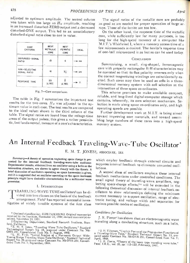
478 PROCEEDINGS OF THE I.R.E. April
adjusted to optimum amplitude. The second column was taken with too large an HM amplitude, resulting in an increased disturbed-ZERO output and a decreased disturbed-ONE output. This led to an unsatisfactory disturbed-signal ratio close to one in value.
CORE CRITERIA
BEST METALLIC
CORE
BEST FERRIT1C
CORE IDEAL
DISTURBED -SIGNAL RATIO 13 6 -30. 00
NON -SELECTING SIGNAL RATIO 16 3i --3. 00
RESPONSE TIME 25
.SEC i
p. SEC --O. 0
Fig. 7—Core comparisons.
The table in Fig. 7 summarizes the important test results for the two cores. Hm was adjusted to the op-timum value in each case. The test results are compared to the ideal values shown in the third column of the table. The signal ratios are found from the voltage-time areas of the output pulses; this gives a rather pessimis-tic, but fundamental, measure of a core's characteristics.
The signal ratios of the metallic core are probably as good as are needed for proper operation of large ar-rays. Those of the ferrite are too low. On the other hand, the response time of the metallic
core, while sufficiently low for many purposes, is too long for the high-speed memory of a computer like M.I.T.'s Whirlwind I, where a memory access time of a few microseconds is desired. The ferrite's response time of one-half microsecond is as fast as can be used today.
CONCLUSION
Summarizing, a small, ring-shaped, ferromagnetic core with properly rectangular B-H characteristics may be operated so that its flux polarity reverses only when the correct magnetizing windings are coincidentally ex-cited. Such cores may then be used as cells in a three-dimensional memory system with cell selection at the intersection of three space co-ordinates. This scheme promises to make available compact,
reliable, and long-lived digital-computer storage which contains, inherently, its own selection mechanism. Se-lection is made along space co-ordinates only, and high operating speeds are possible. Further development work at M.I.T. is being aimed
toward improving core materials, and toward assem-bling large numbers of these cores into a high-speed memory system.
An Internal Feedback Traveling- Wave-Tube Oscillator E. M. T. JONESt, ASSOCIATE, IRE
Summary—A theory of operation neglecting space charge is pre-sented for the internal feedback traveling-wave-tube oscillator. Experimental results, obtained from an oscillator using a helix as the interaction structure, are shown to agree closely with the theory. A brief discussion of oscillators operating on space harmonics is given, and it is suggested that an oscillator operating on the space-harmonic principle might have desirable characteristics for a millimeter wave generator.
I. INTRODUCTION
RAVELING-WAVE-TUBE oscillators' can be di-vided into two classes on the basis of the feedback arrangement. Field' has reported successful inves-
tigation of widely tunable systems of the first class
* Decimal classification: R339.2 X R355.912. Original manuscript received by the Institute, November 22, 1950; revised manuscript re-ceived, November 23, 1951. f Engineering Department, Stanford Research Institute, Stan-
ford, California. E. M. T. Jones, "Traveling Wave Tube Oscillators," Stanford
Technological Report No. 28, prepared under Contract No. -N6-ONR-251, Consolidated Task No. 7; August, 1950.
I L. M. FiAcl, "Initial Studies of a Harmonic Output Wide-Tuning Range Traveling-Wave Tube Oscillator," Stanford Technical Report No. 20, prepared under Contract No. N6-0NR-251, Consoli-dated Task No. 7; September, 1949.
which employ feedback through external circuits and suppress internal feedback to eliminate unwanted oscil-lations.
A second class of oscillators employs these internal feedback mechanisms under controlled conditions. The small signal theory of traveling-wave, amplifiers, neg-lecting space-charge effects," will be extended in the following theoretical discussion of internal feedback os-cillators to show relationships defining the minimum current necessary to support oscillation, range of elec-tronic tuning, and voltage width and separation for various possible modes of oscillation.
Conditions for Oscillation
J. R. Pierce' has shown that an electromagnetic wave traveling along a conducting structure, such as a helix,
3 J. H. Tillotson, "Explicit Forms of the Propagation Functions of a Traveling-Wave Tube," Stanford Technical Report No. 13, pre-pared under Contract No. N6-0NR-251, Consolidated Task No. 7; April, 1949. ' J. R. Pierce, "Theory of the beam type traveling wave tube,"
PROC. I.R.E., vol. 35, pp. 112-123; February, 1947.
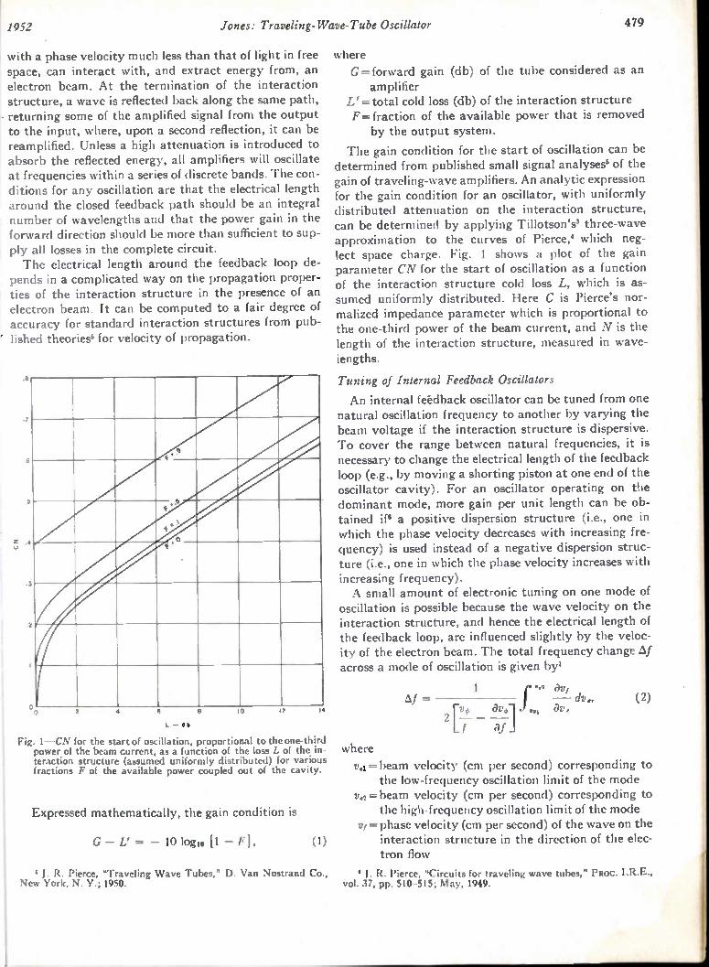
1 1952 Jones: Traveling- Wave-Tube Oscillator 479
with a phase velocity much less than that of light in free space, can interact with, and extract energy from, an electron beam. At the termination of the interaction structure, a wave is reflected back along the same path, returning some of the amplified signal from the output to the input, where, upon a second reflection, it can be reamplified. Unless a high attenuation is introduced to absorb the reflected energy, all amplifiers will oscillate at frequencies within a series of discrete bands. The con-ditions for any oscillation are that the electrical length around the closed feedback path should be an integral number of wavelengths and that the power gain in the forward direction should be more than sufficient to sup-ply all losses in the complete circuit. The electrical length around the feedback loop de-
pends in a complicated way on the propagation proper-ties of the interaction structure in the presence of an electron beam. It can be computed to a fair degree of accuracy for standard interaction structures from pub-lished theoriess for velocity of propagation.
.6
7
6
5
2 A
.3
oo 2 4 6
L —db
10 12 14
Fig. 1—CN for the start of oscillation, proportional to the one-third power of the beam current, as a function of the loss L of the in-teraction structure (assumed uniformly distributed) for various fractions F of the available power coupled out of the cavity.
Expressed mathematically, the gain condition is
G — L' = — 10 logo [1 — F] , (I)
5 J. R. Pierce, 'Traveling Wave Tubes," D. Van Nostrand Co., New York, N. Y.; 1950.
where G = forward gain (db) of the tube considered as an amplifier
L' = total cold loss (db) of the interaction structure F= fraction of the available power that is removed by the output system.
The gain condition for the start of oscillation can be determined from published small signal analyses' of the gain of traveling-wave amplifiers. An analytic expression for the gain condition for an oscillator, with uniformly distributed attenuation on the interaction structure, can be determined by applying Tillotson's' three-wave approximation to the curves of Pierce,' which neg-lect space charge. Fig. 1 shows a plot of the gain parameter CN for the start of oscillation as a function of the interaction structure cold loss L, which is as-sumed uniformly distributed. Here C is Pierce's nor-malized impedance parameter which is proportional to the one-third power of the beam current, and N is the length of the interaction structure, measured in wave-iengths.
Tuning of Internal Feedback Oscillators
An internal feedback oscillator can be tuned from one natural oscillation frequency to another by varying the beam voltage if the interaction structure is dispersive. To cover the range between natural frequencies, it is necessary to change the electrical length of the feedback loop (e.g., by moving a shorting piston at one end of the oscillator cavity). For an oscillator operating on the dominant mode, more gain per unit length can be ob-tained if' a positive dispersion structure (i.e., one in which the phase velocity decreases with increasing fre-quency) is used instead of a negative dispersion struc-ture (i.e., one in which the phase velocity increases with increasing frequency). A small amount of electronic tuning on one mode of
oscillation is possible because the wave velocity on the interaction structure, and hence the electrical length of the feedback loop, are influenced slightly by the veloc-ity of the electron beam. The total frequency change Af across a mode of oscillation is given by'
r.„„, 3 av, = Af — dye. (2) . 01 J av,
2 [—v — I ai
where
va = beam velocity (cm per second) corresponding to the low-frequency oscillation limit of the mode
v.2= beam velocity (cm per second) corresponding to the high-frequency oscillation limit of the mode = phase velocity (cm per second) of the wave on the interaction structure in the direction of the elec-tron flow
J. R. Pierce, "Circuits for traveling wave tubes," PROC. 1.R.E., vol. 37, pp. 510-515; May, 1949.
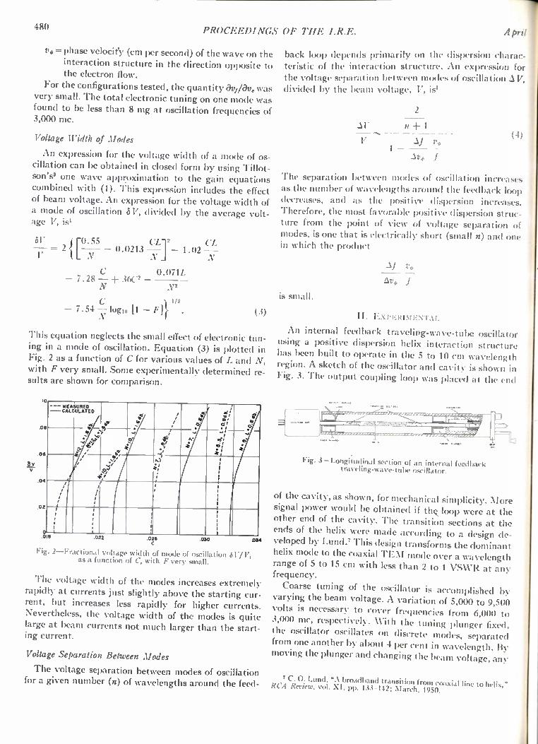
480 PROCEEDINGS OF THE I.R.E. April
v. = phase velocify (cm per second) of the wave on the interaction structure in the direction opposite to the electron flow.
For the configurations tested, the quantity avilay. was very small. The total electronic tuning on one mode was found to be less than 8 mg at oscillation frequencies of 3,000 mc.
Voltage Width of Modes
An expression for the voltage width of a mode of os-cillation can be obtained in closed form by using Tillot-son's' one wave approximation to the gain equations combined with (1). This expression includes the effect of beam voltage. An expression for the voltage width of a mode of oscillation & V, divided by the average volt-age V, is'
= 2 { r 55 0.0213 —C1 2 — 1.02 V CL N
0.071L — 7 . 28 — 360
1/2
— 7.54 — logio [1 — 1]} . (3)
This equation neglects the small effect of electronic tun-ing in a mode of oscillation. Equation (3) is plotted in Fig. 2 as a function of C for various values of L and N, with F very small. Some experimentally determined re-sults are shown for comparison.
8v
10
00
06
.04
02
--- MEASURED — CALCULATED
1
0 ' 018
gi for
49'
.022 .026
Fig. 2—Fractional voltage width of mode of oscillation 61.7/11, as a function of C, with F very small.
The voltage width of the modes increases extremely rapidly at currents just slightly above the starting cur-rent, but increases less rapidly for higher currents. Nevertheless, the voltage width of the modes is quite large at beam currents not much larger than the start-ing current.
tit
Voltage Separation Between Modes
The voltage separation between modes of oscillation for a given number (n) of wavelengths around the feed-
back loop depends primarily on the dispersion charac-teristic of the interaction structure. An expression for the voltage separation between modes of oscillation V. divided by the beam voltage, V, is'
2
V n + 1
V ro
Av4, f
(4)
The separation between modes of oscillation increases as the number of wavelengths around the feedback loop decreases, and as the positive dispersion increases. Therefore, the most favorable positive dispersion struc-ture from the point of view of voltage separation of modes, is one that is electrically short (small n) and one in which the product
is small.
II. ExrEximENT.kr.
An internal feedback traveling-wave-tube oscillator using a positive dispersion helix interaction structure has been built to operate in the 5 to 10 cm wavelength region. A sketch of the oscillator and cavity is shown in Fig. 3. The output coupling loop was placed at the end
zzz.nrzrz-z-E2,77-.'"'
Fig. 3—Longitudinal section of an internal feedback traveling-wave-tube oscillator.
of the cavity, as shown, for mechanical simplicity. More
signal power would be obtained if thc. loop were at the other end of the cavity. The transition sections at the ends of the helix were made according to a design de-veloped by Lund.' This design transforms the dominant helix mode to the coaxial TEM mode over a wavelength range of 5 to 15 cm with less than 2 to 1 VSIVR at any frequency.
Coarse tuning of the oscillator is accomplished varying the beam voltage. A variation of 5,000 to 9,500 volts is necessary to cover frequencies from 6,000 to 3,000 mc, respectively. XVith the tuning plunger fixed, the oscillator oscillates on discrete modes, separated from one another by about 4 per cent in wavelength. By moving the plunger and changing the beam voltage, any
7 C. 0. Lund, "A broadband transition from coaxial line to II' RCA Review, vol. XI, pp. 133-142; March, 1950.
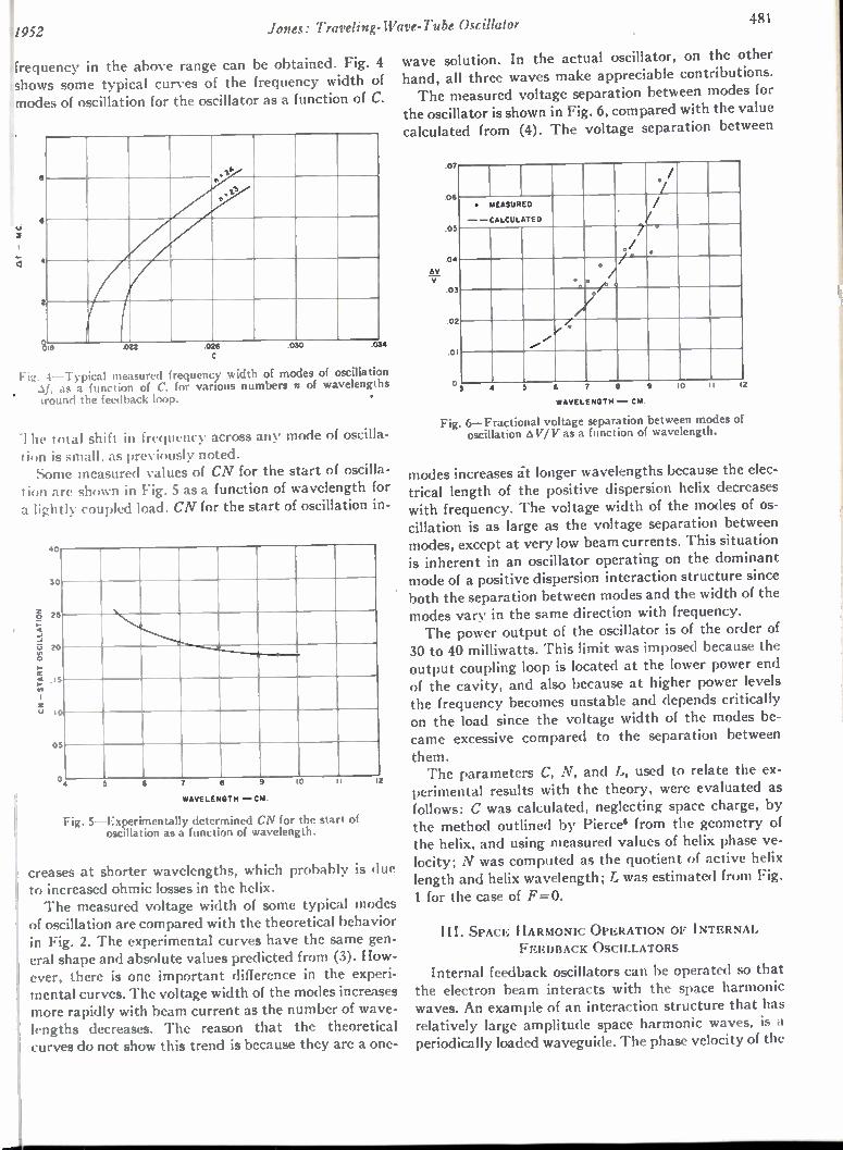
1952 Jones: Traveling- Wave-Tube Oscillator S 481
Frequency in the above range can be obtained. Fig. 4 shows some typical curves of the frequency width of modes of oscillation for the oscillator as a function of C.
.1.6
1, t*
I
t
a .022 .026 .030 .0
6
C
, Fig. 4 Typical measured frequency width of modes of oscillation as a function of C, for various numbers n of wavelengths
around the feedback loop. •
The total shift in frequency across any mode of oscilla-tion is small, as previously noted. Some measured values of CN for the start of oscilla-
tion are shown in Fig. 5 as a function of wavelength for a lightly coupled load. CN for the start of oscillation in-
CN - START OSCILLATION
40
50
25
, i5
10
.05
0.
I20
‘ 4 7 8 9 10 11
WAVELENGTH — CM.
Fig. 5—Experimentally determined CN for the start of oscillation as a function of wavelength.
creases at shorter wavelengths, which probably is due to increased ohmic losses in the helix. The measured voltage width of some typical modes
of oscillation are compared with the theoretical behavior in Fig. 2. The experimental curves have the same gen-eral shape and absolute values predicted from (3). How-ever, there is one important difference in the experi-mental curves. The voltage width of the modes increases more rapidly with beam current as the number of wave-lengths decreases. The reason that the theoretical curves do not show this trend is because they are a one-
wave solution. In the actual oscillator, on the other hand, all three waves make appreciable contributions. The measured voltage separation between modes for
the oscillator is shown in Fig. 6, compared with the value calculated from (4). The voltage separation between
.07
06
05
04
AVV
0
0
0
I /
1 '/.
. MEASURED
- -CALCULATED
. /
/
7 ./
-
* . . .
0 / , I
I-
/
/ .• • * '
I
4 6
WAVELENGTH — CM.
Fig. 6—Fractional voltage separation between modes of oscillation ED V/V as a function of wavelength.
modes increases it longer wavelengths because the elec-trical length of the positive dispersion helix decreases with frequency. The voltage width of the modes of os-cillation is as large as the voltage separation between modes, except at very low beam currents. This situation is inherent in an oscillator operating on the dominant mode of a positive dispersion interaction structure since both the separation between modes and the width of the modes vary in the same direction with frequency. The power output of the oscillator is of the order of
30 to 40 milliwatts. This limit was imposed because the output coupling loop is located at the lower power end of the cavity, and also because at higher power levels the frequency becomes unstable and depends critically on the load since the voltage width of the modes be-came excessive compared to the separation between
them. The parameters C, N, and L, used to relate the ex-
perimental results with the theory, were evaluated as follows: C was calculated, neglecting space charge, by the method outlined by Pierce from the geometry of the helix, and using measured values of helix phase ve-locity; N was computed as the quotient of active helix length and helix wavelength; L was estimated from Fig.
1 for the case of F=0.
III. SPACE HARMONIC OPERATION OF INTERNAL FEEDBACK OSCILLATORS
Internal feedback oscillators can be operated so that the electron beam interacts with the space harmonic waves. An example of an interaction structure that has relatively large amplitude space harmonic waves, is a periodically loaded waveguide. The phase velocity of the
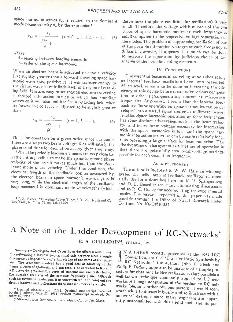
482 PROCEEDINGS OF THE I.R.E.
space harmonic waves v,. is related to the dominant mode phase velocity v, by the expression°
V. v*, — (s = 0, ±1, ±2, 2, • • •
Si,, + 1
), (5)
where
d = spacing between loading elements s = order of the spate harmonic.
When an electron beam is adjusted to have a velocity just slightly greater than a forward traveling space har-monic wave (i.e., positive s), it will transfer energy to the circuit wave since it finds itself in a region of retard-ing field. It is also easy to see that an electron traversing a shorted interaction structure which has standing waves on it will also find itself in a retarding field when its forward velocity, v, is adjusted to be slightly greater than
vo„ = V.
sv. _ 1
fd
(s = 1, 2, • • • ). (6)
Thus, for operation on a given order space harmonic, there are always two beam voltages that will satisfy the phase conditions for oscillation at any given frequency. When the periodic loading elements are very close to-
gether, it is possible to make the space harmonic phase velocity of the circuit waves much less than the dom-inant mode phase velocity. Under this condition, the electrical length of the feedback loop as measured by the electron beam in space harmonic wavelengths is very long, while the electrical length of the feedback loop measured in dominant mode wavelengths (which
J. R. Pierce, "Traveling Wave Tubes," D. Van Nostrand Co., New York, N. Y., p. 72, eq. 4.61; 1950.
A P I
determines the phase condition for oscillation) is very small. Therefore, the voltage width of each of the two types of space harmonic modes at each frequency is small compared to the respective voltage separations of the modes. The problem of suppressing oscillation of one of the possible interaction voltages at each frequency is difficult. However, it appears that much can be done to increase the separation by judicious choice of the spacing of the periodic loading elements.
IV. CONCLUSIONS
The essential features of traveling-wave tubes acting as internal feedback oscillators have been presented. Much work remains to be done on increasing the effi-ciency of this device before it can offer serious competi-tion to other signal-generating sources at microwave frequencies. At present, it seems that the internal feed-back oscillator operating on space harmonics can be de-veloped into a useful signal source at millimeter wave-lengths. Space harmonic operation at these frequencies has some distinct advantages, such as the beam veloc-ity, and hence beam voltage necessary for interaction with the space harmonics is low, and the space har-monic interaction structure can be made relatively long, thus providing a large surface for head radiation. The disadvantage of this system as a method of operation is that there are potentially two beam-voltage settings possible for each oscillation frequency.
ACKNOWLEDGMENT
The author is indebted to W. W. Harman who sug-gested the helix internal feedback oscillator in essen-tially • the form described here, to K. R. Spangenberg and D. L. Benedict for many stimulating discussions, and to R. C. Honey for accumulating the experimental results. The research reported in this paper was made possible through the Office of Naval Research under Contract No. N6-0NR-251.
A Note on the Ladder Development of RC-Networks* E. A. GUILLEMINt, FELLOW, IRE
Summary—Darlington and Cauer have described a useful way of synthesizing a lossless two-terminal-pair network from a single driving-point impedance and a knowledge of the zeros of transmis-sion. The procedure involved has a good deal of similarity to the
Brune process of synthesis, and can readily be extended to RL and RC networks provided the zeros of transmission are restricted to the negative real axis of the complex frequency plane. Although such an extension is obvious, it seems worth while to point out the details involved and to illustrate these with a numerical example.
• Decimal classification: R143. Original manuscript received by the Institute, May 22, 1951; revised manuscript received, Oc-tober 10, 1951. t Massachusetts Institute of Technology, Cambridge, Mass.
/N A PAPER recently presented at the 1951 IRE Convention, entitled "Transfer Ratio Synthesis by RC Networks," the authors John T. Fleck and
Philip F. Ordung appear to be unaware of a simple pro-cedure for obtaining ladder realizations that parallels a well-known technique commonly applied to LC net-works. Although adaptation of the method to RC net-works follows a rather obvious pattern, it would seem worth while to discuss it briefly and to illustrate with a numerical example since many engineers are appar-ently unacquainted with this useful tool, and its por-
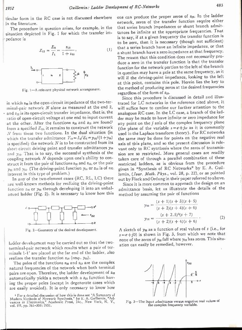
; 1952 Guillemin: Ladder Development of RC-Networks 483
ticular form in the RC case is not discussed elsewhere in the literature. The procedure in question arises, for example, in the
situation depicted in Fig. 1 for which the transfer im-r pedance is
E2 Z12 Z12 =
Il 1 + Z22
Fig. 1—A relevant physical network arrangement.
(1)
in which z22 is the open-circuit impedance of the two-ter-minal-pair network N alone as measured at the end 2, - and z12 is its open-circuit transfer impedance, that is, the ratio of open-circuit voltage at one end to input current at the other. After the functions z22 and z12 are found' from a specified Z12, it remains to construct the network N from these two functions. In the dual situation (in which the transfer admittance Y22 /2/ E1 Y12/( 1 + y22)
is specified) the network N is to be constructed from its short-circuit driving point and transfer admittances yn and y12. That is to say, the successful synthesis of the coupling network N depends upon one's ability to con-struct it from the pair of functions 522 and 512, or the pair y22 and y12. (The driving-point function 3,22 or 211 is of no. interest in this type of problem.) In any of the two-element cases (RC, RL, LC) there
are well-known methods for realizing the driving-point function z22 or yn through developing it into an unbal-anced ladder (Fig. 2). It is necessary to know how this
'22
10 1 1 — 0 2
Fig. 2—Geometry of the desired development.
ladder development may be carried out so that the two-terminal-pair network which results when a pair of ter-minals 1-1' are placed at the far end of the ladder, also realizes the transfer function zn (resp. y22). The poles of the functions z22 and 512 are the complex
natural frequencies of the network when both terminal pairs are open. Therefore, the ladder development of z22 automatically yields a network with a z12 function hav-ing the proper poles (except in degenerate cases which are easily avoided). It is only necessary to know how
For a detailed discussion of how this is done see "A Summary of Modern Methods of Network Synthesis," by E. A. Guillemin, "Ad-vances in Electronics," Academic Press, Inc., New York, N. Y., vol. III, pp. 261-303; 1951.
one can produce the proper zeros of 42. In the ladder network, zeros of the transfer function require either that series branch impedances or shunt branch admit-tances be infinite at the appropriate frequencies. That is to say, if at a given frequency the transfer function is to be zero, then it is necessary (though not sufficient) that a series branch have an infinite impedance, or that a shunt branch have a zero impedance at that frequency. The reason that this condition does not necessarily pro-duce a zero in the transfer function is that the transfer function for the network portion to the left of the branch in question may have a pole at the same frequency, as it will if the driving-point impedance, looking to the left at this point, contains this pole. Herein lies the key to the method of producing zeros at the desired frequencies regardless of the form of z22. Since this procedure is discussed in detail and illus-
trated for LC networks in the reference cited above, it will suffice here to confine our further attention to the analogous RC case. In the LC case, a branch of the lad-der may be made to have infinite or zero impedance for any point on the j axis of the complex frequency plane (the plane of the variable s =0--Fjo.) as it is commonly used in the Laplace transform theory). For RC networks the same may be done for points on the negative real axis of this plane, and so the present discussion is rele-vant only to RC synthesis where the zeros of transmis-sion are so restricted. More general cases are readily taken care of through a parallel combination of these restricted ladders, as is obvious from the procedure given in "Synthesis of RC Networks" by E. A. Guil-lemin, (Jour. Math. Phys., vol. 28, p. 22), or as pointed out by Fleck and Ordung in their paper referred to above. Since it is more common to approach the design on an
admittance basis, let us illustrate the details of the method by assuming the pair of functions
Y22
Y12 =
(s 1)(s d- 3)(s -p 5) (s -F 2)(s -F 4)(s -p 6) (s 2.5)2(s -I- 7)
(s + 2)(s ± 4)(s ± 6)
A sketch of yn as a function of real values of s (i.e., for s=cr-FjO) is shown in Fig. 3, from which we note that none of the zeros of y22 fall where y12 has zeros. This situ-ation can easily be remedied, however.
(2)
Fig. 3—The input admittance versus negative real values of the complex frequency variable.
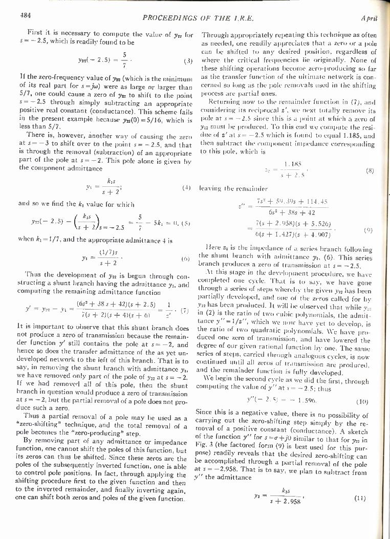
484 PROCEEDINGS OF THE I.R.E. April
First it is necessary to compute the value of y22 for s = —2.5, which is readily found to be
5 Y22( — 2.5) = —7 • (3)
If the zero-frequency value of y22 (which is the minimum of its real part for s=j4.) were as large or larger than 5/7, one could cause a zero of y22 to shift to the point s= —2.5 through simply subtracting an appropriate positive real constant (conductance). This scheme fails in the present example because y22(0) =5/16, which is less than 5/7. There is, however, another way of causing the zero
at s= —3 to shift over to the point s= —2.5, and that is through the removal (subtraction) of an appropriate part of the pole at s = —2. This pole alone is given by the component admittance
kis y1 =
s + 2'
and so we find the ki value for which
Y22( — 2 . 5) kis \
+ 2/s= —2.5
(4)
5 = — — Ski = 0, (5) 7
when kl= 1/7, and the appropriate admittance 4 is
(1/7)s y1 = (6)
s + 2
Thus the development of y22 is begun through con-structing a shunt branch having the admittance yi, and computing the remaining admittance function
(6s2 + 38 s + 42)(s + 2.5) 1 y' = y22 — yi = = — • (7)
7(s ± 2)(s + 4)(s + 6) z'
It is important to observe that this shunt branch does not produce a zero of transmission because the remain-der function y' still contains the pole at s= —2, and hence so does the transfer admittance of the as yet un-developed network to the left of this branch. That is to say, in removing the shunt branch with admittance we have removed only part of the pole of y22 at s = —2. If we had removed all of this pole, then the shunt branch in question would produce a zero of transmission at s= —2, but the partial removal of a pole does not pro-duce such a zero.
Thus a partial removal of a pole may be used as a "zero-shifting" technique, and the total removal of a pole becomes the "zero-producing" step. By removing part of any admittance or impedance
function, one cannot shift the poles of this function, but its zeros can thus be shifted. Since these zeros are the poles of the subsequently inverted function, one is able to control pole positions. In fact, through applying the shifting procedure first to the given function and then to the inverted remainder, and finally inverting again, one can shift both zeros and poles of the given function.
Through appropriately repeating this technique as often as needed, one readily appreciates that a zero or a pole can be shifted to any desired position, regardless of where the critical frequencies lie originally. None of these shifting operations become zero-producing so far as the transfer function of the ultimate network is con-cerned so long as the pole removals used in the shifting process are partial ones. Returning now to the remainder function in (7), and
considering its reciprocal z', we next totally remove its pole at s= —2.5 since this is a point at which a zero of Y12 must be produced. To this end we compute the resi-due of z' at s = —2.5 which is found to equal 1.185, and then subtract the component impedance corresponding to this pole, which is
1.185 =
s + 2.5
leaving the remainder
= 72 + 59.39s + 114.45 z"
6s2 + 38s + 42
7(s -I- 2.958)(s + 5.526)
6(s + 1.427)(s + 4.907)
Here z2 is the impedance of a series branch following the shunt branch with admittance Yi, (6). This series branch produces a zero of transmission at s = —2.5. At this stage in the development procedure, we have
completed one cycle. That is to say, we have gone through a series of steps whereby the given y22 has been partially developed, and one of the zeros called for by Y12 has been produced. It will be observed that while y22 in (2) is the ratio of two cubic polynomials, the admit-tance y" =1/z", which we now have yet to develop, is the ratio of two quadratic polynomials. We have pro-duced one zero of transmission, and have lowered the degree of our given rational function by one. The sari), series of steps, carried through analogous cycles, is now continued until all zeros of transmission are produced. and the remainder function is fully developed.
We begin the second cycle as we did the first, through computing the value of y" at s = —2.5; thus
y"( — 2.5) = — 1.596. (to )
Since this is a negative value, there is no possibility of carrying out the zero-shifting step simply by the re-moval of a positive constant (conductance). A sketch of the function y" for s =cr+j0 similar to that for y22 in Fig. 3 (the factored form (9) is best used for this pur-pose) readily reveals that the desired zero-shifting can be accomplished through a partial removal of the pole at s= —2.958. That is to say, we plan to subtract from y" the admittance
(8)
Y3 =
k3S
s + 2.958
(9)
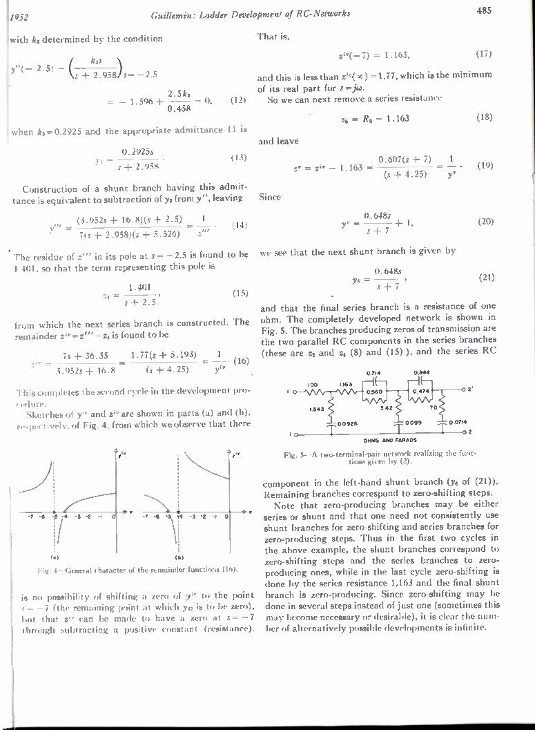
1952 Guillemin: Ladder Development of RC-Networks 485
with k3 determined by the condition That is,
y"(— 2.5) k3s
ks + 2.958)s= —2.5
= — 1.596 + 2.5k3 = 0, (12) 0.458
when k3= 0.2925 and the appropriate admittance 11 is
0.2925s = s + 2.958
(13)
Construction of a shunt branch having this admit-tance is equivalent to subtraction of y3 from y", leaving
(3.952s + 16.8)(s + 2.5) 1 (14)
7(s + 2.958)(s + 5.526) =
The residue of z" in its pole at s= —2.5 is found to be 1 401. so that the term representing this pole is
1.401 :4 =
S ± 2.5 (15)
from which the next series branch is constructed. The remainder zir = zi" —z4 is found to be
is + 36.35 1.77(s + 5.193) 1 = --• (16)
3.952s + 16.8 (s + 4.25) y"
This completes the second cycle in the development pro-
. cedure. Sketches of y'r and zir are shown in parts (a) and (b),
• respectively, of Fig. 4, from which we observe that there
la)
Fig. 4—General character of the remainder functions (16).
is no possibility of shifting a zero of y" to the point s = — 7 (the remaining point at which 3,12 is to be zero), but that z" can be made to have a zero at s= —7 through subtracting a positive constant (resistance).
zir(-7) = 1.163, (17)
and this is less than zir( ) = 1.77, which is the minimum of its real part for s =jco. So we can next remove a series resistance
and leave
Since
Z6 = R6 = 1.163 (18)
0.607(s + 7) 1 zy = z" — 1.163 = = — • (19)
(s+4.25) yv
0.648s = -I- 1, s + 7
we see that the next shunt branch is given by
0.648s YR
s +
(20)
(21)
and that the final series branch is a resistance of one ohm. The completely developed network is shown in Fig. 5. The branches producing zeros of transmission are the two parallel RC components in the series branches (these are z2 and z3 (8) and (15) ), and the series RC
1 0
100 1.163
1.543
oc.92,
0/14
HF-0560
342
OHMS AND FARADS
Fig. 5--A two-terminal-pair network realizing the func-tions given by (2).
component in the left-hand shunt branch (Ys of (21)). Remaining branches correspond to zero-shifting steps. Note that zero-producing branches may be either
series or shunt and that one need not consistently use shunt branches for zero-shifting and series branches for zero-producing steps. Thus in the first two cycles in the above example, the shunt branches correspond to zero-shifting steps and the series branches to zero-producing ones, while in the last cycle zero-shifting is done by the series resistance 1.163 and the final shunt branch is zero-producing. Since zero-shifting may be done in several steps instead of just one (sometimes this may become necessary or desirable), it is clear the num-ber of alternatively possible developments is infinite.

486 PROCEEDINGS OF THE I.R.E. April
A Source of Error in the Measurement of Radiated Harmonics* F. M . GREENEt, II:EMBER, IRE
Summary —A source of error known to be present in vhf field-intensity meters employing broadband radio-frequency input cir-cuits, has been briefly investigated. The error is caused by harmonic generation in the receiver resulting from insufficient selectivity, and nonlinearity of rf or mixer stages in the presence of a strong funda-mental. The magnitudes of the second and third harmonics gener-ated internally were determined as a function of the level of the applied rf fundamental for a receiver having one particular type of rf input circuit. Errors in the measurement of the fundamental, caused
by intermodulation occurring in the presence of a stronger interfering carrier of different frequency, are also briefly discussed.
I. INTRODUCTION
APOSSIBLE SOURCE of error in the measurement of spurious harmonic fields produced by radio transmitting stations, particularly in the vhf
band (30 to 300 mc), has been briefly investigated. The error in question is usually most serious in the case of measurements made with certain types of field-intensity meters employing an rf input attenuator and wide-band untuned circuits preceding the first radio-frequency am-plifier or mixer stages of the receiver. The error is caused by harmonic generation, occurring in these stages as a result of insufficient selectivity, and their nonlinearity in the presence of a strong fundamental. The degree of the nonlinearity will be a function of the design and mode of operation of these circuits. As a result, the har-monic level indicated by the field-intensity meter may often be appreciably higher than the true level.
II. HARMONIC GENERATION
A simplified grounded-grid input circuit similar to the type employed in some commercial field-intensity sets designed for this frequency range, is shown in Fig. 1.
r-- - .=) _..STAGE TOT uFNIRESDT
CIRCUIT
ADJUSTABLE ATTENUATOR
PAD zz 5 z
co —6, LU
0 ° Z
CL F FIELD INTENSITY METER —
Fig. —A typical untuned grounded-grid rf input circuit similar to that used in some commercial types of vhf field-intensity meters at the present time.
This particular circuit arrangement is often used be-cause it provides a means for obtaining a reasonably
* Decimal classification: R271. Original manuscript received by the Institute, March 27, 1950; revised manuscript received, October 22, 1951.
t Central Radio Propagation Laboratory, National Bureau of Standards, Washington 25, D. C.
accurate broad-band termination for the rf input atten-uator, as well as a fairly low noise figure for the receiver. Unless precautions are taken, its use may often result in some inaccuracy or inconvenience of operation when harmonic measurements are being made.
,,. TEST SET-UP
. RF CO-Ax CO-AX GENERATOR — L P FILTER L P FILTER H BALUNI
30 /
, FIELD
TO INPUT INTENSITY METER
/
40
50
60 2ND HARMONIC /
i
i
cr................. v........... ../..< " "
70 3 RD HARMONIC
loio —
NDICATED INPUT—MILLIVOLTS ( FUNDAMENTAL)
Fig. 2---.Measured harmonic levels generated internally as a function of the applied rf input voltage for a receiver employing the type of input circuit shown in Fig. 1.
1000
In order to measure the harmonic content of a given rf field in terms of the fundamental, the field-intensity meter is usually first tuned to the fundamental, and the input attenuator adjusted to give an on-scale indication of the output meter. The difficulty then arises when th( set is tuned to the relatively weak field harmonic, and most of the rf attenuation is removed io still obtain an on-scale indication. Since the fundamental is still pres-ent in the input circuit, the first stages will be operated considerably above their intended input-voltage level. resulting in nonlinear operation and the generation of appreciable harmonics.
As an example, the indicated second- and third-har-monic levels in db below the fundamental rf input are shown in Fig. 2 for a receiver employing a 6J4 in the grounded-grid input circuit of Fig. 1. The plate voltage was approximately 100 v, and the cathode bias devel-oped was 1.0 v. These harmonic levels were those pro-duced entirely within the input stages for the case in which the fundamental input level remained unchanged while measuring the harmonic. The harmonics present in the output of the signal generator used in making this test were maintained at least 100 db below the funda-mental by employing two high-rejection low-pass co-
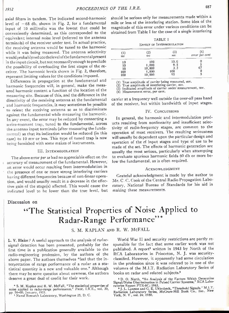
I 1952 PROCEEDINGS OF THE I.R.E. 487
t axial filters in tandem. The indicated second-harmonic level of —68 db, shown in Fig. 2, for a fundamental input of 10 millivolts was the lowest that could be conveniently determined, as this corresponded to the equivalent internal noise level (referred to the antenna terminals) of the receiver under test. In actual practice, the receiving antenna would be tuned to the harmonic while it was being measured. The antenna selectivity would probably reduce the level of the fundamental present in the input circuit, but not necessarily enough to preclude the possibility of overloading the first stages of the re-• ceiver. The harmonic levels shown in Fig. 2, therefore, • represent limiting values for the conditions imposed.
Differences in propagation at the fundamental and harmonic frequencies will, in general, make the meas-ured harmonic content a function of the location of the measuring site. Because of this, and the difference in the directivity of the receiving antenna at the fundamental and harmonic frequencies, it may sometimes be possible to orient the receiving antenna so as to discriminate against the fundamental while measuring the harmonic. In any event, the error may be reduced by connecting a series-resonant trap, tuned to the fundamental, across the antenna input terminals (after measuring the funda-mental) so that its indication would be reduced (in this case) to 10 my or less. This type of tuned trap is now being furnished with some makes of instruments.
III. INTERMODULATION
The above error per se had no appreciable effect on the accuracy of measurement of the fundamental. However,' an error would occur resulting from intermodulation in the presence of one or more strong interfering carriers having different frequencies because of non-linear opera-tion, and would usually result in a decrease in the effec-tive gain of the stage(s) affected. This would cause the indicated level to be lower than the true level, but
Discussion on
should be serious only for measurements made within a mile or less of the interfering station. Some idea of the magnitude of this error under various conditions can be obtained from Table I for the case of a single interfering
TABLE I
EFFECT OF INTERMODULATION
(2) my
(3) Inv
(4) error per cent
10 10 10 100 100
100 1,000 10,000 1,000 10,000
10.0 9.5 3.3
100 95
67
5
(1) True amplitude of carrier being measured, my. (2) True amplitude of interfering carrier, my. (3) Indicated amplitude of carrier under measurement, my. (4) Measurement error, per cent.
carrier at a frequency well outside the over-all pass band of the receiver, but within bandwidth of input stages.
IV. CONCLUSIONS
In general, the harmonic and intermodulation prod-ucts resulting from nonlinearity and insufficient selec-tivity of radio-frequency stages, are common to the operation of most receivers. The resulting seriousness will usually be dependent upon the particular design and operation of the rf input stages and type of use to be made of the set. The effects of harmonic generation are usually the most serious, particularly when attempting to evaluate spurious harmonic fields 60 db or more be-low the fundamental, as is often required.
ACKNOWLEDGMENT
Grateful acknowledgment is made by the author to Mr. C. C. Cook of the Central Radio Propagation Labo-ratory, National Bureau of Standards for his aid in making these measurements.
"The Statistical Properties of Noise Applied to Radar-Range Performance"* S. M. KAPLAN AND R. W. McFALL
L. V. Blake:' A useful approach to the analysis of radar-signal detection has been presented, probably for the first time in a publication generally available to the radio-engineering profession, by the authors of the above paper. The authors themselves "feel that the in-terpretation of range performance of a radar as a sta-tistical quantity is a new and valuable one." Although there may be some question about newness, the authors deserve a great deal of credit for their work.
• S. M. Kaplan and R. W. McFall, "The statistical properties of noise applied to radar-range performance," PROC. I.R.E., vol. 39, pp. 56-60; January, 1951. ' Naval Research Laboratory, Washington 25, D. C.
World War II and security restrictions are partly re-sponsible for the fact that some earlier work was not published. A report' written in 1943 by North of the RCA Laboratories in Princeton, N. J. was security-classified. However, it apparently had some circulation in the profession since it was referred to in one of the volumes of the M.I.T. Radiation Laboratory Series of books on radar and related subjects.'
2 D. 0. North, "An Analysis of the Factors Which Determine Signal/Noise Discrimination in Pulsed Carrier Systems," RCA Labo-ratories Report PTR-6C; 1943.
J. L. Lawson and G. E. Uhlenbeck, "Threshold Signals," M.I.T. Radiation Laboratory Series, McGraw-Hill Book Co., Inc., New York, N. Y., vol. 24; 1950.
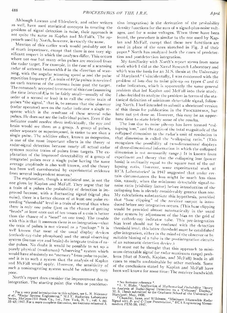
488
Although Lawson and Uhlenbeck, and other writ as well, have used statistical concepts in treating t problem of signal detection in noise, their approach not quite the same as Kaplan and McFall's. The a proach used by North, however, is exactly the same. Mention of this earlier work would probably not
of much importance, except that there is one very s nificant respect in which the analyses differ. This occu where not one but many echo pulses are received fro the radar target. For example, in the case of a scanni radar of antenna beamwidth 0 in the direction of sca fling, with the angular scanning speed co and the pul repetition frequency F, a train of OF/co pulses is receiv on each traverse of the antenna beam past the targ File commonly accepted treatment of this case (assumi the time interval 0/co to be fairly small—usually of t order of a second or less) is to call the entire train pulses "the signal," that is, to assume that the obsery (radar operator) sees on the radar indicator a single r sponse which is the resultant of these several cc pulses. He does not see the individual pulses. Even if t indicator could resolve them individually, the eye an brain would see them as a group. A group of pulse either separate or superimposed, is easier to see than single pulse. The additive effect, known as integratio is one of the most important effects in the theory radar-signal detection because nearly all actual rada systems receive trains of pulses from targets. The e planation of the improved detectability of a group integrated pulses over a single pulse having the sam average amplitude is also well known, and the theor has been well corroborated by experimental evidenc from several independent sources.' The explanation, though a statistical one, is not th
one given by Kaplan and McFall. They argue that fo a train of n pulses the probability of detection is im proved because, with a fluctuating signal (signal plu noise), there is a better chance of at least one pulse ex ceeding "threshold" level in a train of several than whe there is only one pulse (just as the chance of gettin "heads" at least once out of ten tosses of a coin is bette than the chance of a "head" on one toss). The troubl with this is that it assumes there is no integration —tha the train of pulses is not viewed as a "package." It i well known that most of the usual display device (cathode-ray-tube phosphors) and the usual observin system (human eye and brain) do integrate trains of ra dar pulses. No doubt it would be possible to set up a purely physical (nonhuman) "observing" system which would have absolutely no "memory" from pulse to pulse and it is to such a system that the analysis of Kaplan and McFall would apply. However, the sensitivity o such a nonintegrating system would be relatively veil poor.
North's report does consider the improvement due to integration. The starting point (for video or postdetec-
4 For a very good introduction to this subject, see L. N. Ridenour el al., "Radar System Engineering," M.I.T. Radiation Laboratory Series, McGraw-Hill Book Co., Inc., New York, N. Y., vol. 1, pp. 35-45; 1947. For a more complete discussion, see footnote reference 3.
l i PROCEEDINGS OF 7'11E I.R.E. April
ers tion integration) is the derivation of the probability he density functions for the sum of n signal-plus-noise volt-is ages, and for n noise voltages. When these have been p- found, the procedure is similar to the one used by Kap-
lan and McFall, except that these new functions are be used in place of the ones sketched in Fig. 3 of their ig- paper.' North has analyzed both the rases of predetec-rs tion and postdetection integration. ni My familiarity with North's report stems from some ng work which I did at the Naval Research Laboratory and n- which was the basis for an M.S. thesis at the University Sc of Maryland. Coincidentally, I was concerned with the ed problem of loss due to noise pile-up on types C and G et. radar indicators, which is apparently the same general ng problem that led Kaplan and McFall into their study. he I also decided to analyze the Problem in terms of the sta-of tistical definition of minimum detectable signal, follow-er ing North. I had intended to submit a shortened version e- of this thesis for publication in the PROCEEDINGS, but ho have not yet done so. However, this may be an oppor-he tune time to state briefly some of the results.
The loss due to noise pile-up has been termed "col-s, lapsing loss," and the ratio of the total magnitude of the a collapsed dimension to the radar's unit of resolution in n, that dimension is called the "collapsing ratio." (T1d-of recognizes the possibility of two-dimensional displa ✓ of three-dimensional information in which the collapsed x- dimension is nut necessarily range.) It is known from of experiment Anil In.ory that the collapsing loss (power e basis) is ordin,u-11\ equal to the square root of the col - y lapsing ratio. However, some experimental work at
e RCA Laboratories' in 1947 suggested that under cer-tain circumstances the loss might be much less than
e this, namely, when the minimum detectable signal-to-✓ noise ratio (visibility factor) before introduction of the - collapsing loss is already considerably greater than one. s My calculations substantiate this hypothesis, provided - that "base clipping" of the receiver output is intro n duced before any integration occurs. (This base clipping g would be provided almost automatically in the usual ✓ radar system by adjustment of the bias on the grid e the cathode-ray indicator tube. This pre-integration t bias level should not be confused with the detection s threshold level; this latter threshold must be established s after integration, either in the mind of the observer or g suitable biasing of a tube in the postintegration circuit-, - of an automatic detection device.)
It must not be thought that this approach to mini-mum detectable signal (or radar maximum range) prob-
, lems (that of North, Kaplan, and McFall) leads in all cases to results unobtainable by other methods. Some
f of the conclusions stated by Kaplan and McFall have been well known for some time: The receiver bandwidth
See footnote reference *. L. V. Blake, "Application of Mathematical Probability Theor):
to Analysis of Radar -Signa l Detect ion on a 'Collapsed' Display, " M. S. Thesis submitted to the Graduate School of the University of Maryland; May, 1950.
7 Chandler, lams, and Wilkinson, "Minimum Discernible Radar Signal with B- and C-Type Presentation," RCA Engineering Memo-randum PEM-58; 1947.
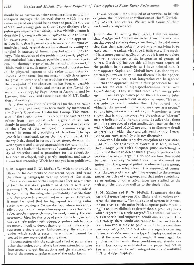
1952 Kaplan and McFall: Statistical Properties of Noise Applied to Radar-Range Performance 489
should be as narrow as other considerations permit; on collapsed displays the interval during which the re-ceiver is gated on should be as short as possible (by use of STC and a range gate in C- or G-type displays); long -pulses give improved sensitivity; a low visibility factor is desirable (!); range-collapsed displays may be enhanced by pulse stretching. The chief merit of this approach, as I see it, is that it permits one to make a mathematical analysis of radar-signal detection without becoming en-• tangled in matters of human psychology and physio-logy. This reduction of the problem to a purely physical and statistical basis makes possible a much more rigor-ous and thorough type of mathematical analysis and, I I think, leads to a much more fundamental understanding of the physical aspects of the radar-target detection process. At the same time one must not belittle or ignore the great importance of also studying the problem from the viewpoint of the observer, as has been so capably done by Haeff, Guthrie, and others at the Naval Re-search Laboratory, by Payne-Scott of Australia, and by Lawson, Uhlenbeck, and associates at the M.I.T. Radia-
tion Laboratory. A further application of statistical methods to radar
maximum-range theory has been made by members of the Navy's Operations Evaluation Group. This exten-sion of the theory takes into account the fact that the echoes from many actual radar targets fluctuate ran-domly in amplitude. For this reason (as well as because of the effect of receiver noise), maximum range is treated in terms of probability of detection. The ap-proach is operational, rather than purely physical. The theory is developed in terms of a continuously scanning radar system and a target approaching the radar at high speed. This leads to the concept of cumulative probabil-ity of detection, and a procedure for its calculation has been developed, using partly empirical and partly theoretical reasoning. Work has not yet been published.
S. M. Kaplan and R. W. McFall: We wish to thank Mr. Blake for his comments on our recent paper, and trust the following paragraphs clear up points of discussion. We are well aware of the integration effect; as a matter
of fact the statistical problem as it occurs with slow-scanning PPI, B- and A-type displays has been solved by computing the integrated probability distributions and then proceeding as outlined in our paper. However, it must be noted that for high-speed scanning radar systems employing a C-type display, where no energy pile-up occurs from sweep-to-sweep on the cathode-ray tube, another approach must be used, namely the one presented. Also, for this type of system it is true, in fact, that a single pulse (with adequate pulse stretching) is no more difficult to detect than a group of pulses which represent a single target. Unfortunately, the situations under which such a system is employed cannot be treated in any more detail at this time. In connection with the statistical effect of parameters
other than noise, our analysis has been extended to take into account target fluctuations and Vie statistical ef-fect of the nonrectangular shape of the radar beam.
It was not our intent, implied or otherwise, to belittle or ignore the important contributions of Haeff, Guthrie, Payne-Scott, and others. We are well aware of their work and its importance.
L. V. Blake: In reading their paper, I did not realize that Kaplan and McFall restricted their analysis to a special type of radar system, even though they did men-tion that their particular interest was in applying it to rapid-scanning radars with type C indicators. The meth-od is of more general applicability, but it is not complete without a treatment of the integration of groups of pulses. North did include this all-important aspect of the problem in his analysis, as I have pointed out. It now appears Kaplan and McFall have also done it; re-grettably, however, they did not discuss it in their paper. I am not convinced that integration can be ignored
and that the approach taken in their paper can be used even for the case of high-speed-scanning radar with type C display. They said that there is "no energy pile-up . . . from sweep-to-sweep" on the cathode-ray tube. But, as I have pointed out in my discussion, "Even if the indicator could resolve them (the pulses) indi-vidually, the eye-and brain would see them as a group," so that integration would still occur. Experiments have shown that it is not necessary for the pulses to "pile-up" on the indicator. At the same time, I realize that there could be some special radar application, such as the one which Kaplan and McFall are unable to discuss in detail at present, to which their analysis would apply. I men-tioned one such possibility in my discussion. However, I do take tentative exception to their state-
ment, " . . . for this type of system it is true, in fact, that a single pulse (with adequate pulse stretching) is no more difficult to detect than a group of pulses which represent a single target." I do not see how this could be true under any circumstances. The statement re-quires that the group of pulses be observed as a group, and this implies integration. It is assumed, of course, that the power of the single pulse is equal to the average power per pulse of the group, and that pulse stretching, range gating, or other advantages are applied to the pulses of the group as well as to the single pulse.
S. M. Kaplan and R. W. McFall: It. appears that the basic difference between Mr. Blake and ourselves con-cerns the statement, "for this type of system it is true, in fact, that a single pulse (with adequate pulse stretch-ing) is no more difficult to detect than a group of pulses which represent a single target." This statement under certain special and important conditions is correct. Un-fortunately, these conditions cannot be discussed in de-tail. However, it may be pointed out that a condition can very easily be obtained whereby signals occurring during successive sweeps in a type C display do not over-lap if the scan rate is fast enough. It must again be emphasized that under these conditions signal enhance-ment does occur, as indicated in our paper, but not in the same manner as with integration in conventional PPI or A-type displays.
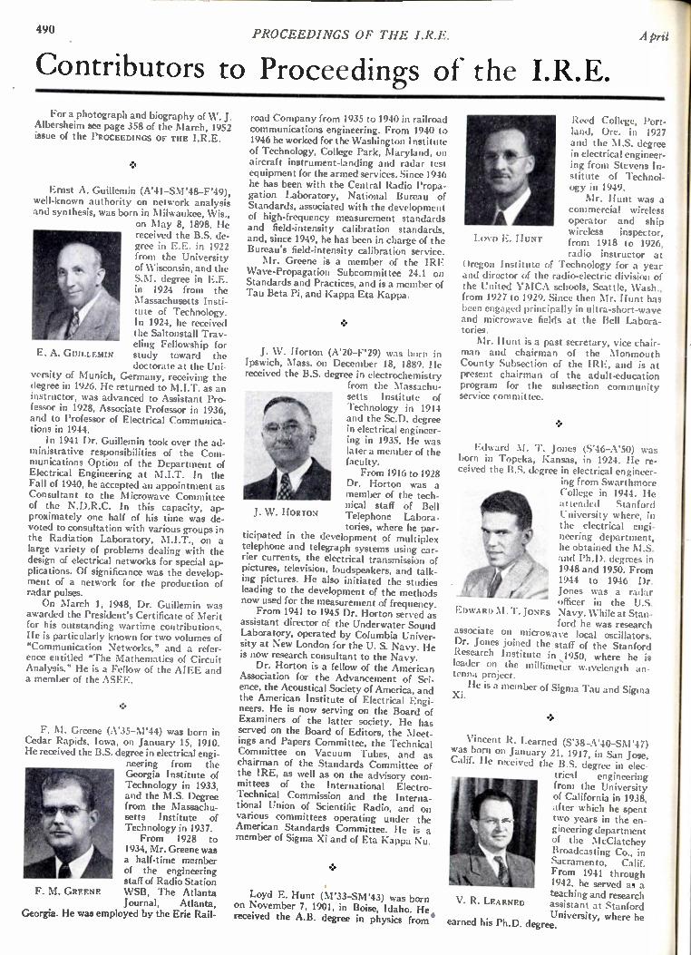
-11 490 PROCEEDINGS OF THE I.R.E. April
Contributors to Proceedings of the I.R.E. For a photograph and biography of W. J.
Albersheim see page 358 of the March, 1952 issue of the PROCEEDINGS OF THE I.R.E.
Ernst A. Guillemin (A'41-SM'48-F'49), well-known authority on network analysis and synthesis, was born in Milwaukee, Wis.,
on May 8, 1898. He received the B.S. de-gree in E.E. in 1922 from the University of Wisconsin, and the S.M. degree in E.E. in 1924 from the Massachusetts Insti-tute of Technology. In 1924, he received the Saltonstall Trav-eling Fellowship for study toward the doctorate at the Uni-
versity of Munich, Germany, receiving the degree in 1926. He returned to M.I.T. as an instructor, was advanced to Assistant Pro-fessor in 1928, Associate Professor in 1936, and to Professor of Electrical Communica-tions in 1944. In 1941 Dr. Guillemin took over the ad-
ministrative responsibilities of the Com-munications Option of the Department of Electrical Engineering at M.I.T. In the Fall of 1940, he accepted an appointment as Consultant to the Microwave Committee of the N.D.R.C. In this capacity, ap-proximately one half of his time was de-voted to consultation with various groups in the Radiation Laboratory, M.I.T., on a large variety of problems dealing with the design of electrical networks for special ap-plications. Of significance was the develop-ment of a network for the production of radar pulses. On March 1, 1948, Dr. Guillemin was
awarded the President's Certificate of Merit for his outstanding wartime contributions. He is particularly known for two volumes of "Communication Networks," and a refer-ence entitled "The Mathematics of Circuit Analysis." He is a Fellow of the AIEE and a member of the ASEE.
E. A. GUILLEMIN
F. M. Greene (A'35-M'44) was born in Cedar Rapids, Iowa, on January 15, 1910. He received the B.S. degree in electrical engi-
neering from the Georgia Institute of Technology in 1933, and the M.S. Degree from the Massachu-setts Institute of Technology in 1937. From 1928 to
1934, Mr. Greene was a half-time member of the engineering staff of Radio Station WSB, The Atlanta Journal, Atlanta,
Georgia. He was employed by the Erie Rail-
F. M. GREENE
road Company from 1935 to 1940 in railroad communications engineering. From 1940 to 1946 he worked for the Washington Institute of Technology, College Park, Maryland, on aircraft instrument-landing and radar test equipment for the armed services. Since 1946 he has been with the Central Radio Propa-gation Laboratory, National Bureau of Standards, associated with the development of high-frequency measurement standards and field-intensity calibration standards, and, since 1949, he has been in charge of the Bureau's field-intensity calibration service. Mr. Greene is a member of the IRE
Wave-Propagation Subcommittee 24.1 on Standards and Practices, and is a member of Tau Beta Pi, and Kappa Eta Kappa.
J. W. Horton (A'20-F'29) was born in Ipswich, Mass. on December 18, 1889. He received the B.S. degree in electrochemistry
from the Massachu-setts Institute of Technology in 1914 and the Sc.D. degree in electrical engineer-ing in 1935. He was later a member of the faculty. From 1916 to 1928
Dr. Horton was a member of the tech-nical staff of Bell Telephone Labora • tories, where he par-
ticipated in the development of multiplex telephone and telegraph systems using car-rier currents, the electrical transmission of pictures, television, loudspeakers, and talk-ing pictures. He also initiated the studies leading to the development of the methods now used for the measurement of frequency. From 1941 to 1945 Dr. Horton served as
assistant director of the Underwater Sound Laboratory, operated by Columbia Univer-sity at New London for the U. S. Navy. He is now research consultant to the Navy. Dr. Horton is a fellow of the American
Association for the Advancement of Sci-ence, the Acoustical Society of America, and the American Institute of Electrical Engi-neers. He is now serving on the Board of Examiners of the latter society. He has served on the Board of Editors, the Meet-ings and Papers Committee, the Technical Committee on Vacuum Tubes, and as chairman of the Standards Committee of the IRE, as well as on the advisory com-mittees of the International Electro-Technical Commission and the Interna-tional Union of Scientific Radio, and on various committees operating under the American Standards Committee. He is a member of Sigma Xi and of Eta Kappa Nu.
J. W. HORTON
Loyd E. Hunt (M'33-SM'43) was born on November 7, 1901, in Boise, Idaho. He. received the A.B. degree in physics from
LOYD E. HUNT
Reed College, Port-land, Ore. in 1927 and the M.S. degree in electrical engineer-ing from Stevens In-stitute of Technol-ogy in 1949. Mr. Hunt was a
commercial wireless operator and ship wireless inspector, from 1918 to 1926, radio instructor at
Oregon Institute of Technology for a year and director of the radio-electric division of the United YMCA schools, Seattle, Wash., from 1927 to 1929. Since then Mr. Hunt has been engaged principally in ultra-short-wave and microwave fields at the Bell Labora-tories. Mr. Hunt is a past secretary, vice chair-
man and chairman of the Monmouth County Subsection of the IRE, and is at present chairman of the adult-education program for the subsection community service committee.
Edward M. 1'. Jones (S'46-A'50) was born in Topeka, Kansas, in 1924. He re-ceived the B.S. degree in electrical engineer-
ing from Swarthmore College in 1944. He at tended Stanford University where, in the electrical engi-neering department, he obtained the M.S. and Ph.D. degrees in 1948 and 1950. From 1944 to 1946 Dr. Jones was a radar officer in the U.S.
EDWARD M. T. JONES Navy. While at Stan-ford he was research
associate on microwave local oscillators. Dr. Jones joined the staff of the Stanford Research Institute in 1950, where he is leader on the millimeier wavelength an-tenna project.
Xi. He is a mem ber of Sigma Tau and Sigma
Vincent R. Learned (S'38-A'40-SN1'47) was born on January 21, 1917, in San Jose, Calif. He received the B.S. degree in elec-
trical engineering from the University of California in 1938, after which he spent two years in the en-gineering department of the NIcClatchey Broadcasting Co., in Sacramento, Calif. From 1941 through 1942, he served as a teaching and research assistant at Stanford University, where he
earned his Ph.D. degree.
V. R. LEARNED
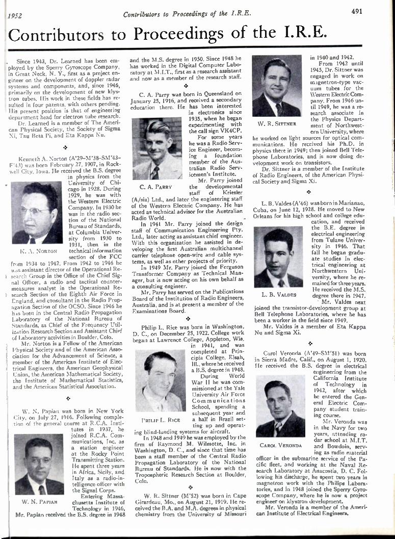
1952 Contributors to Proceedings of the I.R.E. 491
K. A. NORTON
Contributors to Proceedings of the I.R.E.
.. Since 1943, Dr. Learned has been em-ployed by the Sperry Gyroscope Company, in Great Neck, N. Y., first as a project en-t gineer on the development of doppler radar t systems and components, and, since 1946, • primarily on the development of new klys-t tron tubes. His work in these fields has re-I suited in four patents, with others pending. His present position is that of engineering department head for electron tube research. Dr. Learned is a member of The Ameri-
i can Physical Society, the Society of Sigma : Xi, Tau Beta Pi, and Eta Kappa Nu.
Kenneth A. Norton (A'29-M'38-SM'43-F'43) was born February 27, 1907, in Rock-well City, Iowa. He received the B.S. degree
in physics from the University of Chi-cago in 1928. During 1929, he was with the Western Electric Company. In 1930 he was in the radio sec-tion of the National Bureau of Standards, at Columbia Univer-sity from 1930 to 1931, then in the technical information section of the FCC
from 1934 to 1942. From 1942 to 1946 he was assistant director of the Operational Re-search Group in the Office of the Chief Sig-nal Officer, a radio and tactical counter-measures analyst in the Operational Re-search Section of the Eighth Air Force in England, and consultant in the Radio Prop-agation Section of the OCSO. Since 1946 he has been in the Central Radio Propagation Laboratory of the National Bureau of Standards, as Chief of the Frequency Util-ization Research Section and Assistant Chief of Laboratory activities in Boulder, Cob. Mr. Norton is a Fellow of the American
Physical Society and of the American Asso-ciation for the Advancement of Science, a member of the American Institute of Elec-trical Engineers, the American Geophysical Union, the American Mathematical Society, the Institute of Mathematical Statistics, and the American Statistical Association.
W. N. Papian was born in New York City, on July 27, 1916. Following comple-tion of the general course at R.C.A. Insti-
tutes in 1937, he joined R.C.A. Com-munications, Inc. as a station engineer at the Rocky Point Transmitting Station. He spent three years in Africa, Sicily, and Italy as a radio-in-telligence officer with the Signal Corps. Entering Massa-
chusetts Institute of Technology in 1946,
Mr. Papian received the B.S. degree in 1948
440. 7
1 1111 W. N. PAPIAN
and the M.S. degree in 1950. Since 1948 he has worked in the Digital Computer Labo-ratory at M.I.T., first as a research assistant and now as a member of the research staff.
• C. A. Parry was born in Queensland on
January 25, 1916, and received a secondary education there. He has been interested
in electronics since 1935, when he began experimenting with the call sign VK4CP. For some years
he was a Radio Serv-ice Engineer, becom-ing a foundation member of the Aus-tralian Radio Serv-icemen's Institute. Mr. Parry joined
the developmental staff of Kriesler
(A/sia) Ltd., and later the engineering staff of the Western Electric Company. He has acted as technical advisor for the Australian Radio World. In 1941 Mr. Parry joined the design
staff of Communication Engineering Pty. Ltd., later acting as assistant chief engineer. With this organization he assisted in de-veloping the first Australian multichannel carrier telephone open-wire and cable sys-tems, as well as other projects of priority. In 1949 Mr. Parry joined the Ferguson
Transformer Company as Technical Man-ager, but is now acting on his own behalf as a consulting engineer. Mr. Parry has served on the Publications
Board of the Institution of Radio Engineers, Australia, and is at present a member of the Examinations Board.
C. A. PARRY
Philip L. Rice was born in Washington, D. C., on December 25, 1922. College work began at Lawrence College, Appleton, Wis.
in 1941, and was completed at Prin-cipia College, Elsah, Ill., where he received a B.S. degree in 1948. During World
War II he was com-missioned at the Yale University Air Force Communications School, spending a subsequent year and
PHILIP L. Rice a half in Brazil set-ting up and operat-
ing blind-landing systems for aircraft. In 1948 and 1949 he was employed by the
firm of Raymond M. Wilmotte, Inc. in Washington, D. C., and since that time has been a staff member of the Central Radio Propagation Laboratory of the National Bureau of Standards. He is now with the Tropospheric Research Section at Boulder, Cob.
W. R. Sittner (M'52) was born in Cape Girardeau, Mo., on August 21, 1919. He re-ceived the B.A. and M.A. degrees in physical chemistry from the University of Missouri
CAROL VERONDA
L. B. VALDES
XV. R. SITTNER
in 1940 and 1942. From 1942 until
1945, Dr. Sittner was engaged in work on mignetron-type vac-uum tubes for the Western Electric Com-pany. From 1946 un-til 1949, he was a re-search associate in the Physics Depart-ment of Northwest-ern University, where
he worked on light sources for optical com-munications. He received his Ph.D. in physics there in 1949; then joined Bell Tele-phone Laboratories, and is now doing de-velopment work on transistors. Dr. Sittner is a member of the Institute
of Radio Engineers, of the American Physi-cal Society and Sigma Xi.
L. B. Valdes (A'46) was born in Marianao, Cuba, on June 12, 1928. He moved to New Orleans for his high school and college edu-
cation, and received the B.E. degree in electrical engineering from Tulane Univer-sity in 1946. That fall he began gradu-ate studies in elec-trical engineering at Northwestern Uni-versity, where he re-mained for three years. He received the M.S. degree there in 1947. • Mr. Valdes next
joined the transistor-development group at Bell Telephone Laboratories, where he has been a worker in the field since 1949. Mr. Valdes is a member of Eta Kappa
Nu and Sigma Xi.
Carol Veronda (A'49-S111'51) was born in Sierra Madre, Calif., on August 1, 1920. He received the B.S. degree in electrical
engineering from the California Institute of Technology in 1942, after which he entered the Gen-eral Electric Com-pany student train-ing course. Mr. Veronda was
in the Navy for two years, attending ra-dar school at M.I.T. and Bowdoin, serv-ing as radio material
officer in the submarine service of the Pa-cific fleet, and working at the Naval Re-search Laboratory at Anacostia, D. C. Fol-lowing his discharge, he spent two years in magnetron work with the Philips Labora-tories, and in 1948 joined the Sperry Gyro-scope Company, where he is now a project engineer on klystron development. Mr. Veronda is a member of the Ameri-
can Institute of Electrical Engineers.

.102 PROCEEDINGS OF THE I.R.E. April
Institute News and Radio Notes
TECHNICAL COMMITTEE NOTES
The Standards Committee met on Feb-ruary 14, with M. W. Baldwin, Jr., as Acting Chairman. The proposed "Standards on Gas-Filled Counter Tubes: Definitions of Terms" and the "Standards on Electron Tubes: Methods of Testing Gas-Filled Radi-ation Counter Tubes," which were approved by the Standards Committee, were sent to the Executive Committee for action at their February 26, meeting. Work has started on the revision of the Standards Manual. The Standards Committee decided not to re-quest the Editorial Department to approve the republication of Part I of the Pulse Definitions, after Part II is published. Part II of the Pulse Definitions was recently ap-proved by the Executive Committee. The Standards Committee voted to send a rec-ommendation to the Executive Committee, asking that no change be made in the pres- i ent method of publishing standards, and that, publication in the PROCEEDINGS be t continued. The proposed "Standards on Re-ceivers: Definitions of Terms" are still under I consideration by the Standards Comm ittee . t The Circuits Committee convened on
January 18, under the Chairmanship of C. H. Page. At the request of its former chair- 2 man, Ernst Weber, VV. A. Lynch was ap- f pointed Chairman of Subcommittee 4.7. h Professor Lynch agreed to hold a Subcom- R mittee meeting prior to the next full Corn- S mittee meeting to discuss the newly propose d S definition of Phase Margin. R. L. Dietzold ta reported on his liaison with the Oscillogra - a phy Committee in relation to distor tion definitions. Definitions proposed by W. R. t Bennett for Subcommittee 4.4 were ac- ti cepted. Under the chairmanship of R. J. Wise, t
the Facsimile Committee met on January 4. p J. H. Hackenberg presented a list of pro- c posed definitions which would be applicable si to both mechanical and electronic scanning n techniques. C. J. Young submitted a sim ilar tu list, which he presented at the November 2 E meeting, and which he proposed to substi- D tute for that list applicable to electronic scanning techniques. It was decided to con- on sider both lists simultaneously. I. H. Franze l submitted a list of definitions of "Recording Su Techniques" to replace and supplement the m somewhat obsolete definitions of the 1942 re standards. The Industrial Electronics Committee, (1.
under the Chairmanship of John Dalke, me t te on November 15, 1951. It was decided that un the IRE would cancel plans to co-sponsor th the AIEE meeting on Induction and Dielec - to tric Heating and would definitely plan on Ch the co-sponsorship for the next meeting. W. Si C. Rudd reported on plans for the meeting , a which was held on February 19-20, 1952, at pil the Carter Hotel in Cleveland. C. F. Spitzer, Tr Chairman of Subcommittee 10.1 on Defini- pr tions, distributed a list of definitions turned M over to him by J. M. Cage and also a brief rev history, dating back to 1949, of the IRE to work on these definitions. This list of defini- ma tions was approved by the Committee. There la t was a discussion of material for the Annual co Report, and Mr. Spitzer read a summary he its had prepared on the subject of magnetic M
amplifiers. A question arose as to whether magnetic amplifiers came within the scope of the committee. Mr. Spitzer who is a mem -ber of the AIEE Committee on Magnet ic Amplifiers pointed out that the su bject , which is of great importance, might even tu-ally warrant having a se para te IRE Com -mittee. It was decided to inc lude the su bject of magnetic amplifiers in the Annua l Report. The Committee agreed to establish a new Subcommittee on Magnetic Am plifiers , an d Mr. Dalke appointed C. F. Spitzer to ac t as Chairman. It was repor ted that the "Rec -ommended Practice for Measur ing Field Intensities from Indus trial an d other Equ ip-ment" has been approved an d will be ava il-able from the AIEE in re print form soon. Copies of this documen t have been dis-tributed to Committee mem bers . On January 18, the Electron Dev ices
Committee met, with G. D. O'Neill as Act -ng Chairman. It was dec ided by the Com -mittee to invite the AIEE as co -sponsor of he Conference on Semicon duc tor Dev ices. R. M. Ryder reported that the Univers ity of llinois has formally inv ited this Con ference o use its facilities dur ing June 19-20, 1952. The invitation has been accepte d. P. A. Redhead reported that accommodations for 50 conferees were reserve d for the Con -erence on Electron Tube Researc h, to be eld on June 16-17, 1952, in Ottawa. R. M . yder, Chairman of the Subcommittee on olid State Devices, has announce d that this ubcommittee would be reorgan ize d, an d sk groups appointed to wr ite definitions nd methods of test. This work will be done n close collaboration with the corresponding echnical group of the AIEE. The Defini-ons on Noise were approved and R. M. yder and H. J. Reich will prepare a revised ext of the Noise Measurements for final ap-royal by this Committee. G. D. O'Neill, hairman of the recently formed Profes-onal Group on Electron Devices, an-ounced the approval of the Group's consti-tion, by-laws, and the nine members of the xecutive Committee, by the IRE Board of irectors. The Radio Transmitters Committee met January 28, under the Chairmanship of . R. Briggs. H. R. Butler, Chairman of the bcommittee on Radio Telegraph Trans-itters up to 50 mc, reported that he had ceived at the last meeting of his Subcom-ittee revised portions of the Standard lethods of Testing Telegraph Transmit-rs) from all members who had promised to dertake the work of revision. As soon as is material is arranged, it will be presented the main Committee. J. B. Heffelfinger, airman of the Subcommittee on Double deband AM Transmitters, reported that ramework (in outline form) had been corn-ed for a Standard on Double Sideband ansmitters: Methods of Testing, which he esented to the Committee for comments. r. Briggs asked Committee members to iew the outline and to forward comments Mr. Heffelfinger. Harold Goldberg, Chair-n of the Subcommittee on Pulse-Modu-ed Transmitters, announced that his Sub-mmittee had completed the first draft of proposed Standards on Methods of
easurement of Pulse Quantities. He asked
for comments from Committee members. A. E. Kerwien, Chairman of the Subcommittee on Single Sideband Radio Communication Transmitters, announced the reorganizing of his Subcommittee. Mr. Kerwien said that the Subcommittee had previously adopted some definitions for submission to the main Committee, but that it was believed that these should now be reviewed by the re-established Subcommittee. A draft of meth-ods for testing such conditions as radio-power output of transmitters and spurious outputs, applicable to single sideband trans-mitters had been prepared, although more work remains to be done. The Electroacoustics Committee, under
the Chairmanship of W. D. Goodale, de-cided to draft Standards on Methods of Testing Loudspeakers.
Calendar of
COMING EVENTS
Radio and Television Show, Man-chester, England, April 23-May 3
IRE Cincinnati Section, Spring Tech-nical Conference, Cincinnati Engi-neering Societies Building, Cin-cinnati, Ohio, April 19
URSI-IRE Spring Meeting, National Bureau of Standards, Washington, D. C., April 21-24
I EE Television Convention, London, England, April 28-May 3
Association for Computing Machin-ery Meeting, Mellon Institute, Pittsburgh, Pa., May 2-3
IRE-AIEE-RTMA Symposium on Progress in Quality Electronic Components, Washington, D. C., May 5-7
IRE New England Radio Engineering Meeting, Copley-Plaza Hotel, Bos-tion, Mass., May 10
IRE National Conference on Airborne Electronics, Hotel Biltmore, Day-ton, Ohio, May 12-14
The Society for Experimental Stress Analysis Meeting, Indianapolis, Ind., May 14-16
4th Southwestern IRE Conference and Radio Engineering Show, Rice Hotel, Houston, Tex., May 16-17
Radio Parts and Electronic Equip-ment Show, Conrad Hilton Hotel, Chicago, Ill., May 19-22
IRE-AIEE Conference on Semicon-ductor Devices, University of Illi-nois, Urbana, Ill., June 19-20
1952 IRE Western Convention, Mu-nicipal Auditorium, Long Beach, Calif., August 27-29
National Electronics Conference, Sherman Hotel, Chicago, Ill., September 29-October 1
IRE-RTMA Radio Fall Meeting, Syracuse, N. Y., October 20-22
1
1052 Institute News and Radio Notes 493
Professional Group News
AIRBORNE ELECTRONICS
The National Conference on Airborne Electronics will be held on May 12-14, in Dayton, Ohio. Subjects of the technical ses-sions will be outstanding, and it is expected that the conference will surpass last year's. A successful one day meeting was held by
the Airborne Electronics Group on January 30, as part of the five day Convention of the
I Institute of Aeronautical Sciences.
ANTENNAS AND PROPAGATION
The first and second issues of the TRANS-ACTIONS by the Antennas and Propagation Group have been collected and mailed to its members. Additional copies may be obtained by applying to the IRE Headquarters. The Group on Antennas and Propaga-
tion will hold a joint Spring Technical Meeting with the USA National Committee of the URSI, at the National Bureau of Standards, April 21-24, Washington, D. C.
AUDIO
The Papers Study Committee, under the Chairmanship of Hugh Knowles, will study for content and publication medium all papers and technical editorials published heretofore by the Audio Group. J. K. Hilliard, Chairman of the Commit-
tee on Advertising, has announced that any organization, corporation, or person, for the amount of $25.00 annually, is eligible for listing in six consecutive issues of the IRE-PGA TRANSACTIONS. The listing will consist of two lines, one giving the name and street address of the advertiser and one indicating the product of service. Each line is to be not in excess of 72 characters. To date, six ad-vertisers have submitted material. The Boston Chapter of the Audio Group
held a conference at the Massachusetts In-stitute of Technology, on January 15, under the Chairmanship of E. C. Dyett. The paper, "A Low-Cost Loudspeaker Assembly," by J. J. Baruch, was presented.
ELECTRONIC COMPUTERS
The Constitution of the recently formed Group on Electronic Computers has been approved by the Professional Groups Com-mittee. The Los Angeles Chapter of the Group
on Electronic Computers is sponsoring an Electronic Computers Symposium, April 30-May 1, on the campus of the University of California. Included in the two-day meeting will be two panel discussions, on Utilization of Germanium Diodes, and Designing for Maximum Reliability. Papers will be pre-sented on: Magnetic Devices, Analog De-vices, Input-Output Devices, and Program-ming and Coding. The keynote of the symposium, "Engineering Tomorrow's Com-puters," will be offered by H. D. Huskey of the Institute for Numerical Analysis, National Bureau of Standards, University of California.
ENGINEERING MANAGEMENT
A dinner meeting was held by the Group on Engineering Management in Syracuse, N. Y., with Ralph Galbraith, of Syracuse
University, as the principal speaker. Dr. Galbraith's subject was "Management of Research in Engineering Laboratories."
GROUP CONVENTION SYMPOSIA
The following Professional Groups spon-sored symposia at the 1952 IRE National Convention: Airborne Electronics, Antennas and Propagation, Audio, Broadcast and Television Receivers, Broadcast Transmis-sion Systems, Circuit Theory, Electron De-vices, Electronic Computers, Engineering Management, Industrial Electronics, In-formation Theory, Instrumentation, Quality Control, Radio Telemetry and Remote Con-trol, and Vehicular Communications.
INDUSTRIAL ELECTRONICS
The Group on Industrial Electronics will hold a Symposium on "Electronics and Ma-chines," May 22-23, at the Palmer House, in Chicago, Ill.
INFORMATION THEORY
A bibliography on Information Theory has been published by this group and mailed to all its members.
INSTRUMENTATION
A symposium on Progress in Quality Electronic Components, under the sponsor-ship of AI EE-I RE-RTMA, has been sched-uled for May 5-7, in Washington, D. C. The Group on Instrumentation has also ap-proved acting as co-sponsors to the West Coast Symposium on Components, which is planned for next year.
NEW GROUPS The petition for the formation of a Group
on Medical Electronics has been approved by the Professional Groups Committee. Also approved by the Committee was the petition for the formation of a Group on Microwave Electronics. This petition will be acted upon by the Executive Committee. A Planning Committee held a meeting in
February, with representatives of the United States Army, Navy, and Air Force, Interna-tional Telephone and Telegraph, American Telephone and Telegraph, Western Union, Press Services, and others, who are interested in forming a new Wire Communications (Point-to-Point) Professional Group.
NUCLEAR SCIENCE
The Group on Nuclear Science is plan-ning a conference in the United States, the latter part of this year, equivalent to that of the Nuclear Instrumentation Conference held in England. The Nuclear Science Group participated
in a joint symposium with the AIEE in February, at Washington, D. C. The sym-posium was on "Scintillation Counters."
PROFESSIONAL GROUPS COMMITTEE
A "Task Force" on publication procedure has been appointed by the Professional Groups Committee, to work on new policies for establishing a uniform Group Publica-tion Policy. The Professional Groups Committee held
a get-together meeting at the IRE National Convention. Special tables were arranged for the Professional Groups at the Presi-dent's Luncheon during the Convention.
QUALITY CONTROL
E. K. Wimpy, of CBS, has been ap-pointed Chairman to the Paper-Control Committee of the Quality Control Group.
SOUTHWESTERN IRE CONFERENCE PROMISES RECORD SUCCESS The Fourth Southwestern IRE Confer-
ence and Radio Engineering Show, sched-uled for May 16-17, 1952, at the Rice Hotel, Houston, Tex., promises to be the largest and most comprehensive IRE Conference and Show yet held in that district. The Houston IRE Section, host and
sponsor of the Conference, has made record strides in the planning of both the technical and social program. A wide variety of radio-electronic products and services will be on display at the Radio Engineering Show, and early figures indicate that 40 or more na-tional manufacturers will participate. The companies who will supply speakers
and authorities on technical sessions are among the following: Microwave and VHF Communication: Fed-eral Telephone & Radio Ccrporation; General Electric Corporation; Motorola, Incorporated; Philco Corporation; and RCA Victor.
Audio: Paul Klipsch Company. Instruments: Instruments, Incorporated, 0. W. Graham, "Radioactive Liquid Level Measurements"; Leeds and North-rup, A. J. Williams, Jr., "DC Amplifier Developments"; Berkely Scientific Cor-poration, Merle C. Burns, "Nuclear In-struments in the Petroleum Industry"; Humble Oil and Refining Corporation, F. J. Feagin, "A Continuously Record-ing Dielectric Meter."
Geophysics: Magnolia Petroleum Com-pany, F. J. McDonal, "An Electronic Fourier Analyzer."
Airborne Electronics: FCC, Colonel E. White; Bendix Aviation Corporation, Mr. Meecham; and ANDB, Frank White.
Components: Thomas and Skinner Steel Company, James Ireland, "Permanent Magnets"; Bell Telephone Laboratories, J. Campbel, Jr., "Transistors."
Ham Engineering: Eimac Company, John Reinartz, "TVI."
Broadcast and Television: A Earl Cullum and Associates. IRE President D. B. Sinclair, of the
General Radio Company will address the Conference, and Commander T. A. M. Craven, consulting engineer, of Washing-ton, D. C., will speak at the banquet Satur-day evening, May 17. Commander Craven's topic will be, "Television Spectrum Alloca-tions." A new feature of the Conference this year
will be a program of entertainment for the wives which will include a tea, luncheon, fashion shows, and a tour of the Houston beauty spots.
494 PROCEEDINGS OF THE I.R.E. A prii
IRE-AIEE-RTMA Symposium on Progress in Quality Electronic Components
ROGER SMITH HOTEL, WASHINGTON, D. C., May 5-7, 1952
A Components Symposium to be held in Washington, D. C., May 3-7, will be spon-sored by the Institute of Radio Engineers, the American Institute of Electrical Engi-neers, and the Radio-Television Manufac-turers Association, with active participation by the Research and Development Board and other agencies of the United States De-partment of Defense, and the National Bu-reau of Standards. Headquarters will be at the Roger Smith Hotel, where registration facilities will be available beginning Sunday evening, May 4. Technical sessions will be held in the Department of Interior audi-torium. The following program will be pre-sented:
Monday, 10:00 A.M., May 5
WELCOME
Chairman, Symposium Committee, J. G. Reid, Jr., National Bureau of Standards, Washington, D. C.
Session I
ELECTRONICS TODAY
Chairman, A. V. Astrin, Acting Director, National Bureau of Standards,
Washington, D. C.
"Electronic Production Requirements from Industry's Viewpoint," Glen McDaniel, President, Radio Television Manufac-turers Association.
"Electronics in the Defense Production Program," J. A. Milling, Chairman, Electronics Production Board, Defense Production Administration, Washing-ton, D. C.
"Some Factors in Today's Electronics Pro-duction," Rawson Bennett, U. S. Navy, Bureau of Ships, Washington, D. C.
"Reliability of Military Electronics," E. A. Speakman, Vice Chairman, Research and Development Board, Department of Defense, Washington, D. C.
"Electronic Components in Continental Europe," C. B. Lindstrand, U. S. Air Force, Electronics Production Resources Agency, Department of Defense, Wash-ington, D. C.
"Electronic Components in Great Britain," W. A. G. Dummer, Telecommunications Research Establishment, (England).
"Electronic Components in Soviet Russia," G. W. King, U. S. Air Force, Air Tech-nical Information Center, Wright-Pat-terson Air Force Base, Dayton, Ohio.
Monday Afternoon, May 5
Session II—Part A
BASIC M A I ERIALS
Chairman, J. N. Koenig, Rutgers University, New Brunswick, N. J.
"Recent Developments in Ceramic Dielec-trics," E. J. Smoke, Rutgers University, New Brunswick, N. J.
"Metallic Refractories, New Materials for the Electrical Industry," Robert Stein-itz, American Electro Metal Corp., Yonkers, N. Y.
"Some Fluorochemicals for Electrical Ap-plications," N. M. Bashara, Minnesota Mining and Manufacturing Co., St. Paul, Minn.
"Manufacture of Mica Paper for Insula-tion," R. L. Griffeth and E. R. Young-love, Mica Insulator Co., Schenectady, N. Y.
"Progress in the Use of Teflon, Including Soldering and Cementing," M. A. Rud-ner, U. S. Gasket Co., Camden, N. Y.
Session II—Part B
ADVANCES IN MINIATURIZATION
Chairman, Cledo Brunetti, Stanford Research Institute, Palo Alto, Calif.
"Compact Assembly Methods," S. T. Danko, Signal Corps Engineering Labo-ratories, Fort Monmouth, N. J.
"Reproducibility of Printed Components," W. H. Hannahs and J. Eng, Sylvania Electric Products, Inc., Bayside, L. I., N. Y.
"Miniaturized Components for Transistor Application," P. S. Darnell, Bell Tele-phone Laboratories, Inc., Murray Hill, N. J.
Tuesday Morning, May 6
Session III—Part A
PROGRESS IN BASIC COMPONENTS
Chairman, Ernst Weber, Polytechnic Institute of Brooklyn, Brooklyn, N. Y.
"Adhesive Tape Resistors," R. L. Davis, National Bureau of Standards, Washing-ton, D. C.
"Metallic Film Resistors," C. T. Graham, Polytechnic Research and Development Co., Brooklyn, N. Y.
"E-C Glass Resistors," J. K. Davis, Corning Glass Works, Corning, N. Y.
"Stability of Standard Component Resist-ors," C. K.'Hooper, Westinghouse Elec-tric Corp., Baltimore, Md.
"Progress in the Field of Resistors," Jesse Marsten, International Resistance Co., Philadelphia, Pa.
Session III--Part B
CAPACITORS
Chairman, R. C. Sprague, Sprague Electric Co., North Adams, Mass.
"Capacitors for High Temperature Opera-tion," J. W. Schell, Erie Resistor Corp., Erie, Pa.
"Expected Performance of Glass Capaci-tors," Gail Smith, Corning Glass Works, Corning, N. Y.
"Tantalytic Capacitors," L. W. Foster, Gen-eral Electric Co., Hudson Falls, N. Y.
Session III —Part C
COILS, INDUCTORS, AND TRANSFORMERS
Chairman, R. C. Sprague
"Progress in Size and Performance of Trans-formers," G. E. Wilson, General Electric Co., Fort Wayne, Ind.
"Ferrite Inductor Cores," W. W. Stifler, Jr., Ferroxcube Corp. of America, Saugerties, N. Y.
Tuesday Afternoon, May 6
Session IV—Part A
MIISCELLANEOUS COMPONENTS
Chairman, J. H. Miller, Weston Electrical Instrument Corp., Newark, N. J.
"Selection of Fuse Protection for Electronic Circuits," E. V. Sundt, Littlefuse Inc Chicago, Ill.
"Design Factors Influencing the Reliability of Relays," J. R. Fry, Bell Telephone Laboratories, Inc., New York, N. Y.
"Vibrators for the Armed Services," K. M. Schafer, P. R. Mallory and Co., Inc.,
• Indianapolis, Ind.
"Indicating Instruments for Use Under Severe Conditions," F. X. Lamb, Wes-ton Electrical Instrument Corp., Newark. N. J.
"Influence of Wire and Cable on Improved Components," F. NI, Oberlander, RCA, Camden, N. J.
"Teflon Wire," C. E. Dodge, Jr., Warren Wire Co., Pownal, Vt.
Session IV—Part B
DESIGN AND PRODUCTION METHODS
Chairman, M. R. Briggs, Westinghouse Electric Corp., Baltimore, Md.
"Unitized Packaging by the Laminar Meth-od," D. G. Heitert, Emerson Electric Manufacturing Co., St. Louis, Mo.
"Heat Transfer from Electronic Compo-nents," Walter Robinson, Ohio State Uni-versity Research Foundation, Columbus, Ohio.
"Packaging Principles Employing Plastics and Printed Wiring to Improve Reli-ability," W. J. Clarke and N. J. Eich, Bell Telephone Laboratories, Inc., Mur-ray Hill, N. J.
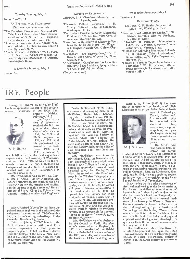
495 !1952 Institute News and Radio Notes
Tuesday Evening, May 6
Session V—Part A
AN EVENING WITH TRANSISTORS Chairman, (to be announced)
r "The Transistor Development Status at Bell Telephone Laboratories," (with demon-stration), W. R. Sittner, Bell Telephone Laboratories, Inc. Allentown, Pa.
f "Transistor Power Amplifiers," (with dem-onstration), R. F. Shea, General Electric Co., Syracuse, N. Y.
"Availability of Transistors," W. F. Starr, U. S. Army, Electronics Production Re-sources Agency, Department of Defense, Washington, D. C.
Wednesday Morning, May 7
Session VI
IRE People
ASPECTS OF RELIABILITY
Chairman, J. A. Chambers, Motorola, Inc., Phoenix, Ariz.
"Electronic Failure Prediction," J. H. Muncy, National Bureau of Standards, Washington, D. C.
"Part Failure Problem in Navy Electronics Equipment," M. M. Tall, Vitro Corp. of America, Silver Springs, Md.
"How Can the Reliability of Electronic Sys-tems Be Improved Now?" W. Wagen-seil, Hughes Aircraft Co., Culver City, Calif.
"Component Part Specifications," D. E. Brown, Vitro Corp. of America, Silver Springs, Md.
"A Component Manufacturer Looks at Re-liability," Leon Podolsky, Sprague Elec-tric Co., North Adams, Mass.
(To be announced)
Wednesday Afternoon, May 7
Session VII
ELECTRON TUBES
Chairman, C. R. Banks, Aeronautical Radio, Inc., Washington, D. C.
"Sealed-in-Glass Germanium Diodes," J. W. Dawson, Sylvania Electric Products, Inc., Boston, Mass.
"Reliability of Premium Subminiature Tubes," P. T. Weeks, Raytheon Manu-facturing Co., Newton, Mass.
"Method for Achieving Maximum Reliabil-ity in Vacuum Tube Applications," R. L. Kelly, RCA Tube Department, Harrison, N. J.
"Failure of Vacuum Tubes from Interface Formation," W. H. Kliever, Minne-apolis-Honeywell Regulator Co., Min-neapolis, Minn.
George H. Brown (A'30—VA'39—F'41) has been appointed director of the systems research laboratory at the RCA Lab-
oratories Division, Princeton, N. J. Dr. Brown, a na-
tive of Wisconsin, received the B.S. de-gree at the Univer-sity of Wisconsin in 1930, the M.S. and Ph.D. degrees in 1931, and 1933, and his professional de-gree of E.E. in 1942. From 1930 until 1933, he was a re-
search fellow in the electrical engineering department at the University of Wisconsin, and from 1933 to 1942, he was with the re-search division of the RCA Manufacturing Company, at Camden, N.J. He has been as-sociated with the RCA Laboratories at Princeton since 1942. Dr. Brown has served on the IRE Com-
mittees of, Annual Review, Antennas, and Papers Procurement, and received the IRE Fellow Award for his, "studies and publioa-tions in the field of radio antennas." He is a member of Sigma Xi, and a Fellow of the American Institute of Electrical Engineers.
G. H. BROWN
Albert Axelrod (S'49—A'50) has been ap-pointed senior engineer in the advanced de-velopment laboratories of CBS-Columbia Inc., a manufacturing subsidiary of the Columbia Broadcasting System. Prior to joining CBS-Columbia, Mr.
Axelrod was connected with Loral Elec-tronics Corporation, for three years as project engineer. He holds a B.E.E. degree from the College of the City of New York, and is a member of the American Institute of Electrical Engineers and Eta Kappa Nu engineering fraternity.
Leslie McMichael (M'20—F'25), chairman and managing director of McMichael Radio Ltd., London, Eng., died recently. His age was 67. Known for his many contributions
to the British radio industry, Mr. McMichael began his experimental radio work as early as 1903. In 1913, in association with R. H. Klein, he organized the Wireless Society of London, which later became the Radio Society of Great Britain. He spent many years in close association with the Society, holding the office of vice president and later honorary secretary. Mr. McMichael was born in
Birkenhead, Eng., on November 17, 1884, and received his technical train-ing at Mason College in Birmingham, and as an apprentice at several noted electrical companies. During World War I, he served with the Royal Air-force in the Wireless Telegraphy Sec-tion. His early years were spent in wireless research with various com-panies, and in 1911-1920, he owned and operated his own radio station in the London district. In 1921, he opened his first factory for radio equipment at Slough, Bucks, Eng. In the course of Mr. McMichael's pro-fessional career, he brought out sev-eral radio patents, and did useful re-search work in relation to synthetic crystal, being responsible for a crystal known as "radiocite," a manufactured all-sensitive galena. Mr. McMichael was the chairman
for the Council of Radio Manufac-turer's Association in England, in 1932, and President of the British IRE, in 1944-1946. He was a Fellow of the IRE, Australia, and a member of the Institute of Electrical Engineers.
M. J. 0. STRUTT
Max J. 0. Strutt (SM'46) has been elected director of the Institute of High Electrotechnics at the Swiss Federal Insti-
tute of Technology, Zurich, Switzerland. His work will largely be connected with electronic tubes, transistors, magnetic amplifiers, and gas-discharges, including their applications for , illumination pur-poses. Dr. Strutt, who
was born in 1903, re-ceived his formal
education at the University and Institute of Technology of Munich, from 1921-1924, and the E.E. and D.Tech.Sc. degrees from the Institute of Technology, Delft, Holland, in 1926, and 1927, respectively. In 1927, he be-came the consulting research engineer of the Philips Company Ltd., at Eindhoven, Hol-land, and in 1948, he was appointed profes-sor in the faculty of electricity at the Swiss Federal Institute of Technology. Since taking up his duties as professor of
electrical engineering at the Swiss institute, Dr. Strutt has delivered several series of lectures in the University of London and in the Instituto Nacional de Electronica at Madrid, Spain, as well as at several insti-tutes of technology in Western Germany. He was awarded a honorary doctorate in electrical engineering by the Institute of Technology at Karlsruhe, Western Ger-many, at its 125th jubilee, for his achieve-ments in the field of technical and physical applications of the high- and ultra-high fre-quencies. He is the author of numerous pub-lications in this field. Dr. Strutt is a member of the Royal In-
stitute of Engineers at the Hague, the Dutch Physical Society, the Swiss Electrotechnical Society at Zurich, the Physical Society of Zurich, and the Swiss Society of Sciences at Berne.
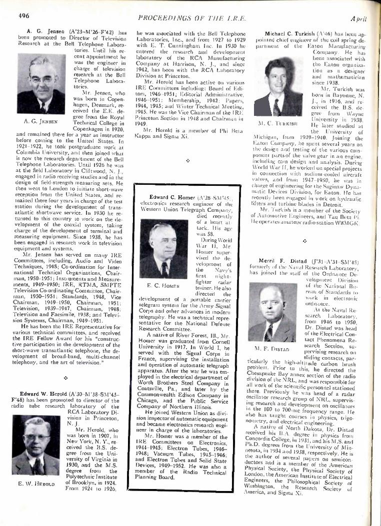
496 PROCEEDINGS OF THE I.R.E. April
E. W. HEItotaa
A. G. Jensen (A'23-M'26--F'42) has been promoted to Director of Television Research at the Bell Telephone Labora-
tories. Until his re-cent appointment he was the engineer in charge of television research at the Bell Telephone Labora-tories. Mr. Jensen, who
was born in Copen-hagen, Denmark, re-ceived the E.E. de-gree from the Royal Technical College in Copenhagen in 1920,
for a year as instructor the United States. In
JENSEN
and remained there before coming to 1921-1922, he took postgraduate work at Columbia University, and then joined what is now the research department of the Bell Telephone Laboratories. Until 1926 he was at the field Laboratory in Cliftwood, N. J., engaged in radio receiving studies and in the design of field-strength measuring sets. He then went to London to initiate short-wave reception from the United States, and re mained there four years in charge of the test station during the development of trans-atlantic shortwave service. In 1930 he re-turned to this country to work on the de-velopment of the coaxial system, taking charge of the development of terminal and measuring equipment. Since 1938, he has been engaged in research work in television equipment and systems. Mr. Jensen has served on many IRE
Committees, including, Audio and Video Techniques, 1948; Co-ordination for Inter-national Technical Organizations, Chair-man, 1950-1951; Instruments and Measure-ments, 1949-1950; IRE, RTMA, SMPTE Television Co-ordinating Committee, Chair-man, 1950-1951; Standards, 1948, Vice Chairman, 1949-1950, Chairman, 1951; Television, 1939-1947, Chairman, 1948; Television and Facsimile, 1938; and Televi-sion Systems, Chairman, 1949-1951. He has been the IRE Representative for
various technical committees, and received the IRE Fellow Award for his "construc-tive participation in the development of the short-wave transatlantic telephone, the de-velopment of broad-band, multi-channel telephony, and the art of television."
Edward W. Herold (A'30-M'38-SM'43-F'48) has been promoted to director of the radio tube research laboratory of the
RCA Laboratory Di-vision in Princeton, N. J. Mr. Herold, who
was born in 1907, in New York, N. Y., re-ceived the B.S. de-gree from the Uni-versity of Virginia in 1930, and the M.S. degree from the Polytechnic Institute of Brooklyn, in 1924. From 1924 to 1926,
he was associated with the Bell Telephone Laboratories, Inc., and from 1927 to 1929 with E. T. Cunningham Inc. In 1930 he entered the research and development laboratory of the RCA Manufacturing Company at Harrison, N. J., and since 1942, has been with the RCA Laboratory Division at Princeton. Mr. Herold has been active on various
IRE Committees including: Board of Edi-tors, 1946-1951; Editorial Administrative, 1946-1951; Membership, 1942; Papers, 1944,1945; and Winter Technical Meeting, 1945. He was the Vice Chairman of the IRE Princeton Section in 1948 and Chairman in 1949. Mr. Herold is a member of Phi Beta
Kappa and Sigma Xi.
Edward C. Homer (A'28 -SNI '45), leuronics research engineer of the \ \estern Union Telegraph Company,
died recently of a heart at-tack. His age was 58. During \Vorld
War II, Mr. Homer super-vised the de-velopment of the Navy's first night-fighter radar trainer. He also directed the
development of a portable carrier telegram system for the Army Signal Corps and other advances in modern telegraphy. He was a technical repre-sentative for the National Defense Research Committee. A native of River Forest, Ill., Mr.
Homer was graduated from Cornell University in 1917. In World I, he served with the Signal Corps in France, supervising the installation and operation of automatic telegraph apparatus. After the war he was em-ployed in the electrical department of Worth Brothers Steel Company in Coatsville, Pa., and later by the Commonwealth Edison Company in Chicago, and the Public Service Company of Northern Illinois. He joined Western Union as divi-
sion inspector of automatic equipment and became electronics research engi-neer in charge of the laboratories. Mr. Homer was a member of the
IRE Committees on Electronics, 1944-1945; Electron Tubes, 1946-1948; Vacuum Tubes, 1945-1946; and Electron Tubes and Solid State Devices, 1949-1952. He was also a member of the Radio Technical Planning Board.
1%. C. 110N11
Michael C. Turkish (A'46) has been ap-pointed chief engineer of the coil spring de-partment of the Eaton Manufacturing
Company. He has been associated with the Eaton organiza-tion as a designer and mathematician since 1938. Mr. Turkish was
born in Bayonne, N. J., in 1916, and re-ceived the B.S. de-gree from Wayne University in 1938. He later studied at the University of
Michigan, from 1939-1940. Joining the Eaton Company, he spent several years on the design and testing of the various com-ponent parts of the valve gear in an engine, including catn design and analysis. During World War II, he worked on special projects in connection with sodium-cooled aircraft valves, and from 1947-1950, he was in charge of engineering for the Saginaw Dyna-matic Devices Division, for Eaton. He has recently been engaged in work on hydraulic lifters and turbine blades in Detroit. Mr. Turkish is a member of the Society
of Automotive Engineers, and Tau Beta l'i. He operates amateur radio station W8N1GK.
M. C. TURKISH
Merril F. Distad (F31-A'31-SI1r45 formerly of the Naval Research Laborator \ has joined the staff of the Ordna ig• r).
velopment I , of the National lilt-reau of Standards to work in electronic ordnance. At the Naval Re-
search Laboratory, from 1946 to 1950, Dr. Distad was head of the Electrical Con-tact Phenomena Re-search Section, su-pervising research on sliding contacts, par-
ticularly the high-altitude carbon brush problem. Prior to this, he directed the Chesapeake Bay annex section of the radio division of the NRL, and was responsible for all work of the scientific personnel stationed there. Previously he was head of a radar oscillator research group of NRL, supervis-ing research and development on oscillators in the 100 to 700-mc frequency range. He also has taught courses in physics, trigo-nometry, and electrical engineering. A native of North Dakota, Dr. Distad
received his B.A. degree in physics from Concordia College, in 1931, and his M.S. and Ph.D. degrees from the University of Min-nesota, in 1934 and 1938, respectively. He is the author of several papers on semicon-ductors and is a member of the American Physical Society, the Physical Society of London, the American Institute of Electrical Engineers, the Philosophical Society of Washington, the Research Society of America, and Sigma Xi.
M. F. DISTAD

IQ-;2 PROCEEDINGS OF THE I.R.E. 497
Abstracts and References Compiled by the Radio Research Organization of the Department of Scientific and Industrial Research,
London, England, and Published by Arrangement with That Department and the Wireless Engineer, London, England
NOTE: The Institute of Radio Engineers does not have available copies of the publications mentioned in these pages, nor does it have reprints of the articles abstracted. Correspondence regarding these articles and requests for their
procurement should be addressed to the individual publications, not to the IRE.
Acoustics and Audio Frequencies Antennas and Transmission Lines Circuits and Circuit Elements General Physics Geophysical and Extraterrestrial Phe-nomena
Location and Aids to Navigation Materials and Subsidiary Techniques. . Mathematics Measurements and Test Gear Other Applications of Radio and Elec-tronics
Propagation of Waves Reception Stations and Communication Systems Subsidiary Apparatus Television and Phototelegraphy Transmission Tubes and Thermionics Miscellaneous
497 497 499 501
502 503 503 504 504
506 507 508 508 509 509 511 511 512
"1 lie number in heavy type at the upper I'-it of each Abstract is its Universal Decimal Classification number and is not to be confused with the Decimal Classification used by the United States National Bureau of Standards. The number in heavy type at the top right is the serial number of the Abstract. DC numbers marked with a dagger (t) must be regarded as provisional.
ACOUSTICS AND AUDIO FREQUENCIES
534.321.9 562 Making Ultrasonic Waves Visible —R.
Hanel. (Radio Tech. (Vienna), vol. 27, pp. 325-329; August, 1951.) Description of simple schlieren equipment developed at the Tech-nische Hochschule, Vienna.
534.321.9-14 563 Ultrasonic Measurements on Liquids —
C. E. Mu!dere. (Tijdschr. sad. Radiogenoot., vol. 16, pp. 155-169; July, 1951.) Review of methods of investigation.
534.41:534.78 564 The Sound-Film Spectrograph —an Instru-
ment for the Acoustic Analysis of Speech and Other Rapidly Changing Sounds —B. H. Edgardh. (IVA (Stockholm), vol. 22, no. 5, pp. 134-153; 1951. In German.) The sound to be analyzed is recorded either on film or mag-netic tape in a number of parallel tracks, each corresponding to the frequency range of a par-ticular bandpass filter. The equipment is com-pared with the Bell Telephone visible-speech spectrograph.
534.84 565 The Acoustics of Ancient Theatres —
F. Canac. (Rev. Sri. (Paris), vol. 89, pp. 151-166; May/June, 1951.) Investigation of the design and acoustic properties of historical open-air theatres, many photographs of which are reproduced, and discussion of the results of particular testa made using logatomes and by a stroboscopic ripple-tank method for the theatres at Orange and Vaison, France.
534.844.5 566 The Use of Artificial Reverberation in the
Theatre —A. Moles. (Ann. Ti',commun., vol. 6, pp. 245-249; August/September, 195 0 The Introduction of artificial reverberation, pro-duced by means of an auxiliary echo room,
The Annual Index to these Abstracts and References, covering those published in the PROC. I.R.E. from February, 1951, through January, 1952, may be obtained for 2s.8d. postage included from the Wireless Engineer, Dorset House, Stamford St., London S.E., England. This index includes a list of the journals abstracted together with the addresses of their publishers.
enables artistic requirements to be satisfied. without impairing the intelligibility of speech. The relation between intelligibility and the slope of the sound-decay curve is given in a simple form and is verified experimentally.
534.846 567 Acoustics of the Royal Festival Hall, Lon-
don —P. H. Parkin. (Nature (London), vol 168, no. 4268, pp. 264-266; August 18, 1951.) A brief discussion of considerations taken into account in the design of the hall. The difficulty in interpreting the subjective criteria of the_ musician in terms of physical quantities is stressed. Data are given for reverberation time and noise level due to external sources, and comments of eminent musicians on the high quality of the hall are included.
534.861.1 568 Recording Studio Design —P. A. Shears.
(Wireless World, vol. 57, pp. 355-360; Septem-ber, 1951.) Various types of frequency distor-tion which may be caused by unsuitable studio design are discussed and the two typical de-fects of excessive reverberation time at low frequencies and "flutter echo" at high fre-quencies are illustrated in a three-dimensional characteristic. An empirical relation between optimum reverberation time and hall volume is extrapolated to give guidance in the design of small studios. In large halls any natural resonances are usually at frequencies too low to give trouble, but in studios with volumes of the order of 3,000 feet, such resonances may occur in the range 50 to 150 cps. Wall construc-tions and treatments for absorbing excess en-ergy over various frequency ranges are de-scribed, with numerical detail.
534.861.1 569 Broadcasting Studios with Sound-Diffusing
Walls —C. Tutino and G. Sacerdote. (Poste e Telecom., vol. 19, pp. 5-15; January, 1951.) An account of work recently carried out on studios in Milan and Turin. The walls and ceilings were lined with plaster moulded into semi-cylindrical shapes of uniform length but vary-ing diameter, the moulds being arranged in groups disposed alternately horizontally and vertically so that the wall surface was as ir-regular as possible. Typical dimensions were: length, 90 cm; diameter, 16 to 32 cm. With this arrangement no resonance effects were de-tectable at frequencies within the combined range of violin and cello. Measurements were made on models and in the studios themselves to determine the effect of the arrangements on the acoustic properties of the rooms; experi-ments are still in progress.
534.874.1 I-621.396.6211:519.241.i 570 Perturbation and Correlation Methods for
Enhancing the Space Resolution of Directional Receivers Hunt. (See 790.)
621.395.61/.62 571 Reciprocity Relations for Electroacoustic
Transducers and their Universal Electrical Equivalents—F. A. Fischer. (Arch. deli. Obertragung, vol. 5, pp. 382-384; August, 1951.)
621.395.623.8 572 Speech-Reinforcement System Evaluation
—L. L. Beranek, W. H. Radford, J. A. Kessler and J. B. Wiesner. (Paoc. I.R.E., vol. 39, pp. 1401-1408; November, 1951.) Assessment for six auditoria using subjective rating tests, word-articulation tests and a new "terminal-word" test. A graphical method is presented for calculating the effect of the frequency re-sponse of the system, the reverberation time of the room, directivity of the loudspeaker and room noise. A flat response from 400 to 4,000 cps is needed for good intelligibility; room re-verberation has little effect if the loudspeaker system is sufficiently directive.
621.395.623.8 573 The Universal Radiator, a New Develop-
ment in Radiator-Group Technique —K. Feik. (Elektrotech. (Berlin), vol. 5, pp. 365-372; August, 1951.) Formulas are given from which the directional characteristics of radiator groups, their power and amplification factor, can be determined. Results are presented for various types including (a) circular groups, (b) linear groups, (c) twin circular groups, and (d) combinations of circular and twin groups. Practical combinations for directional and all-round transmission are discussed.
621.396.611.21:621.317.382 574 Power Measurements on Ultrasonic Quartz
Oscillators--St limit/ and Waldick. (See 734.)
ANTENNAS AND TRANSMISSION LINES
621.315.212.011.2/.3 575 Effective Resistance and Effective In-
ductance of Current-Carrying Conductors at High Frequencies--- W. Taeger. (Funk u. Ton, vol. 5, pp. 422-429; August, 1951.) Considera-tion of a straight conductor such as the inner conductor of a coaxial cable, shows that at hf the current distribution is not the same at all points of the cross-section, but that between the center and the surface of the conductor there is a great difference of both current mag-nitude and phase. The resulting increase of effective resistance and decrease of inductance, as dependent on the frequency and on the diameter of the conductor, is calculated and shown graphically.
1621.392-1- 621.396.67j: 621.397.5 576 Practical TV Antenna and Transmission-
Line Considerations—(Radioironics, vol. 16, pp. 155-179; August, 1951.) An account is given in simple terms of the fundamentals of
498 PROCEEDINGS OF THE I.R.E. April
radio emission and propagation and of the manner of operation of antennas and transmis-sion lines. Various types of antenna and array useful for television reception are described and illustrated; performance is discussed, with nu-merical examples.
621 .392.017.13:621.3.011.22 577 Radiation Resistance of a Two- Wire Line —
J. E. Storer and R. King. (Paoc. I.R.E., vol. 39, pp. 1408-1412; November, 1951.) A gen-eral formula for the radiation resistance is de-rived by integration of the normal component of the Poynting vector over a large sphere surrounding the line. The result is in agreement with that computed by other methods. For-mulas are presented for the special cases of a lossless system and a nonresonant line.
621.392.018.781' 578 Pulse Distortion in RC and LG Lines —
K. Steinbuch. (Arch. dela. oberlragung, vol. 5, pp. 354-360; August, 1951.)The symbols R, C, L and G denote respectively the series re-sistance, shunt capacitance, series inductance and shunt conductance of a line. Thin-wire cables used in the af range are typical RC lines. Lines characterized mainly by L and G are of little practical importance, but are never-theless of interest since coils and transformers with iron cores have an LG line as circuit equiv-alent. Use of the error integral in conjunction with operational calculus enables formulas to be derived permitting numerical calculation of signal transmission along both types of line. Undistorted transmission and reflection effects are discussed. The theory is applied to the transmission of a broadcasting program on the phantom circuit of a line without coil loading, which can be regarded as an RC line.
621.392.09 579 Cylindrical Surface-Wave Transmission
Lines —H. M. Schmidt. (Z. angew. Phys., vol. 3, pp. 272-279; July, 1951.) A comprehensive analysis of the theory, principles and charac-teristics of dielectric-covered transmission lines. The results of other workers in the field are summarized and 31 references are given.
621.392.26t:621.317.329 580 Determination of Aperture Parameters by
Electrolytic-Tank Measurements—Cohn. (See 725.)
621.392.26t :621.39.09 581 Propagation of U.H.F. Electromagnetic
Waves in Waveguides of Circular Cross-Sec-tion: Part 2—H. Frilhauf. (Eleklrolech. (Berlin), vol. 5, pp. 315-321; July, 1951.) Formulas analogous to those for rectangular waveguides (35 of February) are here derived for circular waveguides.
621.392.26t :621.396.611.39 582 Directional-Coupler Errors —F. A. Benson.
(Wireless Eng., vol. 28, pp. 371-372; Decem-ber, 1951.) In the type of coupler using two windows a X/4 apart, errors in measurements of voltage swr or power may result from reflec-tions at the windows. The errors depend on the relative phase of the transmitted and reflected waves and on the phases of the reflections at the windows.
621.396.67 583 Distribution of Radiation Resistance along
a Rod Aerial: Aerial as Coil Line with Trans-former Coupling —O. Zinke. (Funk u. Ton, vol. 5, pp. 393-399; August, 1951.) An equiva-lent circuit is considered in which the an-tenna is represented by an iterative network of coils and capacitors whose values differ along the line. This circuit enables the distribution of the radiation resistance along the antenna to be determined. The analysis also gives a simple explanation of the frequency depend-ence of the resistance. This agrees, for antennas with current maximum at the foot (electiically
short antennas or those excited in odd harmon-ics), with the frequency dependence determined by integration of the radiation intensity in the distant field.
621.396.67 584 Plane Aerials of Small Width —S. Zisler.
(Ann. Telicommun., vol. 6, pp. 214-222; August/September, 1951.) Theory is developed by considering the plane antenna as a system of parallel linear conductors whose number tends to infinity. Kirshhoff's equations are ap-plied and simple expressions are derived for the current distribution and input impedance; results are in good agreement with values found by experiment. Radiation characteristics are also calculated.
621.396.67:621.317.336 585 The Measurement of Antenna Impedance
Using a Receiving Antenna —E. 0. Hartig, R. King, T. Morita and D. G. Wilson. (Paoc. I.R.E., vol. 39, pp. 1458-1460; November, 1951.) Energy from a remote transmitter ex-cites a receiving antenna erected vertically over a large conducting plane and base-loaded by a vertical slotted coaxial cavity of variable length. Resonance-curve measurements enable the antenna impedance to be determined. Curves of the measured impedance as a func-tion of the electrical length of the antenna are given. Excellent agreement is obtained with the impedance values for the same antenna when base-driven through the slotted section. Both sets of measurements are in good agree-ment with the King-Middleton second-order theory.
621.396.67.011.21 586
The Impedance of an Antenna over a Large Circular Screen —J. E. Storer. (Jour. App!. Phys., vol. 22, pp. 1058-1066; August, 1951.) " ... treats the problem of an antenna erected vertically in the center of a circular screen. An integral equation is obtained for the electric field in the plane of the screen, outside the screen. This equation is solved approximately by the use of a variational principle, and a for-mula is obtained for the change of antenna im-pedance as a function of the diameter of the screen."
621.396.67.011.21 587
Influence of a Plane Reflector on the Input Impedance of a Thick Cylinder —S. Zisler. (Ann. rilecommun., vol. 6, pp. 205-212; July, 1951.) Data are presented in tables and graphs for facilitating the calculation of the input im-pedance of a cylindrical antenna with a plane reflector, using the double-line theory previous-ly developed (2645 of 1951).
621.396.67.011.21 588 Mutual Impedance of Wire Aerials —
L. Lewin. (Wireless Eng., vol. 28, pp. 352-355; December, 1951.) For the general case of two straight wire antennas carrying sinusoidal cur-rents it is possible to evaluate the mutual im-pedance in terms of the Si and Ci functions. A demonstration of the method for the case of two coplanar X/2 dipoles is given. The special cases of dipoles parallel or forming an X or V are studied. See also 589 below (Med hurst), 1932 "Abstracts," p. 585 (Carter) and 1933 "Ab-stracts," p. 214 (Murray).
621.396.67.011.21 589 Dipole Aerials in Close Proximity—R. G.
Medhurst. (Wireless Eng., vol. 28, pp. 356-358; December, 1951.) A treatment of the problem of finding the mutual impedance of crossed half-wave dipoles, leading to a solution in terms of Si and Ci functions. Owing to the assumption of zero thickness of the wires, the limiting cases of the V and X arrangements when the included angle becomes zero, and of the parallel arrangement when the distance becomes zero, give different values for the
mutual reactance. See also 588 above (Lewin), 1932 "Abstracts," p. 585 (Carter) and 1933 "Abstracts," p. 214 (Murray).
621.396.67.018.4241' 590 The Folded Fan as a Broad-Band Antenna
— R. L. Linton, Jr. (Paoc. I.R.E. (London), vol. 39, pp. 1436-1444; November, 1951.) The results of model studies in the frequency range 100 to 1,350 mc are used to design a naval an-tenna operating within the communication band of 2 to 27 mc, having a 4 to 1 frequency range and a maximum power loss of 18.5 per cent, due to mismatch when connected to a 52-11 line.
621.396.671 +621.396.11 591 Application of the Compensation Theorem
to Certain Radiation and Propagation Prob-lems —C. D. Monteath. (Proc. 1.E.E. (Lon-don), Part IV, vol. 98, pp. 23-30; October, 1951.) Summary abstracted in 2648 of 1951.
621.396.671 592 Current and Charge Distributions on An-
tennas and Open-Wire Lines —D. J. Angel akos. (Jour. App!. Phys., vol. 22, pp. 910-915, July, 1951.) Results of measurements on cylin-drical antennas and their feeders are shown graphically. The presence of a stub support modifies the distributions on the antenna only near the junction of the antenna, feeder and stub, but for antenna loads near antiresonance the distributions on the feeder as well as the impedances of the system are altered consider-ably. A corrective network for the region of the junction is discussed.
621.396.676 593 The Design of an Omni-directional Aerial
System for the Frequency Range 225-400 Mc/s—F. A. Kitchen. (Proc. I.E.E. (London), Part III, vol. 98, pp. 409-415. Discussion, pp 465-470; November, 1951.) Description of the development of a double-conical monopole an-tenna with counterpoise skirt suitable for in-stallation on the yard-arm of a naval vessel. The antenna dimensions were finally adjusted after a series of measurements of impedance at frequencies within the operating range. Ex-perimental data indicated that the semi-perimeter of the antenna in any vertical plane should be approximately one wavelength at 300 mc, the mid-band second-order-resonance frequency. Results are given of measurements of the variation of terminal impedance, voltage SWR and radiation pattern with frequency. A coaxial 7241 feeder is connected directly to the two radiating elements, no matching trans-former being necessary.
621 .396 .67 6.001.57:621.317.336 594 The Use of Complementary Slots in Air-
craft-Antenna Impedance Measurements — J. T. Bolljahn and J. V. N. Granger. (Proc. I.R.E. (London), vol. 39, pp. 1445-1448; November, 1951.) Description of a method for eliminating the effect of the feeder cable in measurements of wing-cap and tail-cap an-tenna impedances with the aid of models. The method gives greater measurement accuracy than that obtainable with conventional tech-niques, but its use is restricted to simple types of antenna. Typical measurement results are given.
621.396.677 595
A Vertical Nonrotating Directional An-tenna System —J. K. Chapman. (QST, vol. 35, pp. 20-23; July, 1951.) A receiving antenna system for amateur use on 6, 10 and 20 m. Three vertical dipoles are arranged equi-distantly. Any two are fed in antiphase to give coverage over a 120° sector. The main beam in the vertical plane covers all useful elevations on all three working frequency bands. A considerable saving in mast height relative to a horizontal antenna is claimed.
Abstracts and References 499
621.396.677 596 Radiation Field of Helical Antennas with
Sinusoidal Current —E. T. Kornhauser. (Jour. , App!. Phys., vol. 22, pp. 887-891; July, 1951.) A rigorous formula for the radiation field of a ' helical antenna is derived, assuming a current -distribution determined experimentally by Kraus (3033 of 1947). For a helix of several turns this formula yields results very nearly the same as those obtained by Kraus's approximate method (1860 of 1949), but computation is simpler and the formula is applicable to helixes with a nonintegral number of turns.
621.396.677: 621.317.335-3t Artificial Dielectrics for
Sliarpless. (See 727.)
621.396.677.6.029.6t 621.396.931/.9331.2 598 Rotating H-Type Adcock Direction-Finders
for Metre and Decimetre Wavelengths — II. G. Hopkins and F. Horner. (Proc. I EE (London), Part IV, vol. 98, pp. 112-126; October, 1951.) "Instruments of high precision for the range 26-600 mc (0.5-12 m wave-; length) are described and details of their per-formance are given. The direction-finders at the lower end of this frequency range are of high sensitivity and have seen considerable practical service. Development has proceeded largely on empirical lines, but from this work a fair appreciation has now been obtained of the fundamental factors affecting performance and of the practical means for taking them into account. Some progress has been made, for ,(xample, in understanding the cause of polari-zation errors, which are of importance in some —but not all —df applications at these fre-quencies."
538.566 + 621.396.67 599 Electromagnetic Waves and Radiating Sys-
tems [Book Reviewl—E. C. Jordan. Publishers: Prentice-Hall, New York, N. V., 710 pp., 32s. 6d. (Brit. Jour. App!. Phys., vol. 2, pp. 205-206; July, 1951.) A comprehensive treatise of an introductory character, but not over-simplified; vector analysis is used as the basis of the treatment.
597 Microwaves -
621.392.26t 600 Advanced Theory of Waveguides [Book
Reviewl—L. Lewin. Publishers: Iliffe & Sons, London), 192 pp., 30s. (Wireless Eng., vol. 28, p. 374; December, 1951.) "Covers posts, diaphragms, windows, steps, tapers and T-i unctions in waveguides. Radiation from wave-guides is treated as well as propagation in loaded and corrugated guides."
CIRCUITS AND CIRCUIT ELEMENTS
621.3.012.8 601 Electrical-Equivalent Circuits —K. Kupf-
milller. (Fernmeldetech. Z., vol. 4, pp. 337-346; August, 1951.) Detailed review of their appli-cation in the representation of electrodynamic, physical and physico-chemical phenomena.
621.3.013.5:621.3.011.23:621.314.2.045 602 The Calculation of the Magnetic Field of
Rectangular Conductors in a Closed Slot, and its Application to the Reactance of Trans-former Windings—E. Billig. (Proc. I.E.E. (London), Part IV, vol. 98, pp. 55-64; October, 1 1951.) "The magnetic vector potential of 1 current-carrying conductors in a rectangular 1 slot is the same as that due to an infinite I number of images of these conductors from all f the four walla of the slot. A solution of this 1 problem can thus be obtained in the form of a I Fourier series, periodic in both the x and y directions, the constants of the solution being determined by the boundary conditions, i.e., , by the dimensions of the slot and of the con-ductors, and by the currents passing through
I them. Expressions for the magnetic vector po-tential due to any conductor arrangement can
thus be developed, and these lend themselves to considerable simplification without undue loss of accuracy."
621.3.015.71- : 621.387.4i' 603 A Sweep-Type Differential and Integral
Discriminator —E. Fairstein. (Rev. Sci. Instr., vol. 22, pp. 761-765; October, 1951.) A circuit is described for determining the pulse-height distributions from scintillation counters, pro-portional counters, parallel-plate counters and other pulse sources. It will operate with any positive-output amplifier of rise time 0.1 us and output limited to 100V.
621.3.015.7f: 621.387.4t 604 A High-Precision Pulse-Height Analyzer
of Moderately High Speed —G. W. Hutchin-son and G. G. Scarrott. (Phil. Mag., vol. 42, pp. 792-806; July, 1951.) Designed for nuclear research work. Information is stored in an ul-trasonic delay line and displayed on a cr screen. The accuracy of channel width and the linear-ity of response are both within 1 part in 1,000. The storage capacity may be varied to give 60 channels of up to 106 pulses each, 80 channels of up to 3 X 10⁶ pulses each, or 120 channels of up to 1,023 pulses each, with a maximum counting rate of 1,600 per second.
621.314.2+621.318.4 605 Winding Space Determination —N. H.
Crowhurst. (Electronic Eng. (London), vol. 23, pp. 302-306; August, 1951.) The factors con-trolling the choice of wire gauge, insulation and winding methods for transformers and chokes are briefly summarized. The use of abacs for simplifying the calculations involved is described with examples.
621.314.2 606 Calculation of Small Transformers —E.
Donauer. (Funk u. Ton, vol. 5, pp. 369-374; July, 1951.) Design formulas and curves are given which are applicable to multi-winding transformers suitable for power packs and using either M or E-I stampings. A numerical example is worked out.
621.314.58 607 The Magnetic Modulator —R. Feinberg.
(Radio Tech. Dig. (France), vol. 5, nos. 4 and 5, pp. 217-226 and 281-287; 1951.) French version of 338 of March.
621.316.726.078.3:621.3.015.3 608 Transient Response of a Narrow-Band Au-
tomatic Frequency-Control System —T. Mil-ler. (Paoc. I.R.E., vol. 39, pp. 1433-1436; November, 1951.) Description of a method of analyzing the response of afc systems op-erating in conjunction with, narrow-band-pass filters. A time lag, equivalent to the reciprocal of the bandwidth, is assigned to the filter. Cir-cuit parameters are determined for the case of operation at nearly critical damping. The equa-tions of the system are derived by means of the Laplace transform, and the transient response of the system to a step change of input fre-quency is evaluated by the method of residues.
621.318.423:621.3.011.22 609 The Resistance of Round- Wire Single-
Layer Inductance Coils —A. H. M. Arnold. (Proc. I EE, Part IV, vol. 98, pp. 94-100; October, 1951.) "Butterworth's two formulas for the resistance of short coils with a finite number of turns are merged into a single formula valid for coils of any length and having any number of turns. Numerical values ot the functions appearing in the formula are given in tables. The formula is shown to give results in reasonable agreement with the experimental figures of Medhurst (1694 of 1947) and Hick-man (Bureau of Standards Scientific Paper No. 472)."
621.318.572 610 A Comprehensive Counting System for
Nuclear Physics Research —N. F. Moody, W. D. Howell, W. J. Batten and R. H. Taplin. (Rev. Sci. Instr., vol. 22, pp. 439-461; July, 1951.) A method of constructing counting systems from a number of standardized sub-units is described. Details of the design of these sub-units are given, the aim being to attain versatility of function and reliability in per-formance. The synthesis of various instru-ments from these sub-units is described. Further sections of the survey to be published later will deal with amplitude analyzers.
621.319.53: 621.316.729 611 The Controlled Tripping of High-Voltage
Impulse Generators —A. S. Husbands and J. B. Iligham. (Jour. Sci. Instrum., vol. 28, pp. 242-245; August, 1951.) A triggered spark-gap and associated circuits are described which enable a generator to be discharged in syn-chronism with measuring equipment such as a cro or rotating-mirror camera. A tripping pulse of only about 5 kv is required; the tripping of a single-stage generator can be performed with-in 0.1 us of a predetermined short delay time.
621.319.53:621.396.619 612 High-Power Pulse Generator with Con-
trolled Spark-Gap—E. Prokott. (Fernmelde-tech. Z., vol. 4, pp. 347-351; August, 1951.) Description of a compressed-air spark generator with repetition frequency 8-18 kc, and investi-gation of its suitability as a modulator for tele-communication purposes.
621.392: 517.433 613 Operational Approach to Nonlinear Circuit
Analysis--G. H. Cohen. (Jour. Frank. Inst., vol. 252, p. 63; July, 1951.) Correction to paper noted in 3077 of 1949.
621.392: 517.544.2 614 The One-Sided Green's Function —Miller.
(See 711.)
621.392:621.317.3.083.4 615 Double-T Networks for Null Measure-
ments at High Frequency —Samal. (See 724.)
621.392.43 616 High-Frequency Matching Transformer —
F. Steiner. (Os!. Z. Telegr. Teleph. Funk Fernsehtech., vol. 5, pp. 93-100; July/August, 1951.) In a tuned wide-band matching trans-former, reactance developed in the damped parallel-tuned secondary circuit at frequencies away from resonance gives rise to large varia-tions of apparent input impedance. Design formulas are derived for a transformer in which the series-tuned primary circuit par-tially compensates for these variations.
621.392.5 617 Application of Matrices to Four-Terminal-
Network Problems —H. P. Biggar. (Electronic Eng. (London), vol. 23, pp. 307-311; August, 1951.) The relation of matrices to network equations is explained and simple matrix alge-bra is applied to the derivation of a constant-resistance equalizer with balanced input and unbalanced output.
621.392.5:621.3.015.3 618 Transient Response. Conditions for Mono-
tonic Characteristics —I. F. Macdiarmicl (Wireless Eng., vol. 28, pp. 330-334; Novem-ber, 1951.) The necessary and sufficient condi-tions for a monotonic transient response are considered for the case of a network to which a unit current-step is applied. The location of the zeros of the impedance function on the com-plex-frequency plane is shown to be as impor-tant as the location of the poles. Conditions for monotonic transient response are derived for networks having two poles and two zeros in the complex-frequency plane; the results are applied in discussion of a compensated anode load fed by a triode valve.
500 PROCEEDINGS OF THE I.R.E. April
621.392.5:621.3.015.7f: 621.3.018.7 619 Pulse Distortion —a H. Moss. (Prot IEE,
Part IV, vol. 98, pp. 37-42; October, 1951.) "For wave forms of simple shapes certain fea-tures may be defined: content, epoch, spread, skewness, squatness, etc., which are affected in a very simple way by passage through a linear system (which is regular at low frequen-cies). In fact, by proper definition, they are affected only additively by constants which are independent of the applied wave form, and characteristic only of the system. These in-variants for the pulses and for the system cor-respond to the cumulants used to describe sta-tistical distributions."
621.392.5:681.142 620 A Design of an Ultrasonic Delay-Line —
T. Gold. (Phil. Meg., vol. 42, pp. 787-791; July, 1951.) Design and construction details of a vertical folded Hg delay line, for use in an electronic memory unit, giving a delay of 1.2 ms with a bandwidth of several mc.
621.392.5.001.8 621 Linear Elctromechanical Quadripoles —U.
John. (Frequenz, vol. 5, pp. 166-173 and 190-192; June and July, 1951.) Analysis of the applicability of electrical circuit theory to elec-tromechanical phenomena. General equations for the forward and backward dynamic im-pedances and over-all damping of a passive transducing circuit are derived and developed for application to specific circuits. A detailed mathematical treatment is given for an elec-trostriction process.
62L392.52 622 Design of Electric Wave Filters with the
Aid of the Electrolytic Tank —A. R. Boothroyd. (Proc IEE (London), Part IV. vol. 98, pp. 65-93; October, 1951. Summary, ibid., Part III, vol. 98, pp. 486-492; November, 1951.) The analogue representation (in terms of complex frequency) of the properties of image-parame-ter transfer functions of the Zobel type by current flow in an electrolyte tank provides a convenient method for determining filter in-sertion-loss characteristics. The tanks used are developments of the double-layer tank de-scribed by Boothroyd, Cherry and Makar (2743 of 1949). A transformation is developed by means of which the approximation problem can be solved for a specified low-pass-filter insertion loss, the poles and zeros of the inser-tion modulus function of the filter being ac-curately determined by simple measurements in the electrolyte tank.
621.392.52 623 The Multisection RC Filter Network Prob-
lem—L. Storch. (Paoc. I.R.E., vol. 39, pp. 1456-1458; November, 1951.) Two methods for deriving the filter characteristics from the basic circuit equations are described. The meth-ods, unlike that of Tschudi (1622 of 1950), take nothing for granted but Ohm's and Kirch-hoff's laws. The first, a finite-difference meth-od, leads to the solution almost immediately. The second method makes use of image parameters suitable for cascade connection of symmetrical structures.
621.392.52:538.221 624 Ferrites as Magnetostrictive Resonators
and their Application as Electrical Filter Ele-ments—C. W. Diethelm. (Tech. Mill. schweiz Telegr.-TelephVerw., vol. 29, pp. 281-297; August I, 1951. In German, with French sum-mary.) Methods of production and magnetic properties of MgZn, CoZn and NiZn mixed fer-rites are discussed. Measurements show that NiZn ferrite with Zn ferrite content 0 to 40 per cent exhibits a strong magnetostriction ef-fect and relatively high permeability with prac-tically no eddy-current losses. Q-factor lies be-tween 1,000 and 3,000. Two bridge-type filter
circuits with a 4-kc pass band at 40 and 80 kc respectively are described. The power trans-mitted in the pass band is about 1 mw.
621.392.52:621.396.611.4 625 Microwave Filters employing a Single Cav-
ity Excited in More than One Mode — Wei-Guan Lin. (Jour. Appi. Phys., vol. 22, pp. 989-1001; August, 1951.) A cavity resonator with input and output couplings constitutes a network with two pairs of terminals and with an infinite number of possible modes of oscillation. In some cavities of special shape, several degenerate modes with identical nat-ural frequencies can occur. In a single cavity, these degenerate modes can be coupled to-gether to form a chain of coupled circuits by perturbation of the otherwise ideal geometrical configuration of the cavity. The filter charac-teristics of such devices are analyzed and ap-plied to the design of multi-mode filters. Ex-perimental models of 2-, 3-, and 5-mode filters are described, with insertion-loss curves.
62 L392.52 : 621.397.61 626 The Vestigal-Sideband Filter for the Sut-
ton Coldfield Television Station —E. C. Cork (Proc. I EE (London), Part III, vol. 98, pp. 460-464. Discussion, pp. 465-470; November, 1951.) The specification of the filter is outlined and the reason for the choice of a comple-mentary constant-resistance network filter of the Norton type is explained. The basic design formulas relevant to the chosen network are given, with information on the inversion and replacement of lumped elements by coaxial lines. The results of measurements on the per-formance of the adopted practical circuit show agreement with that of the idealized network.
621.392.52.072.6 627 Alignment and Adjustment by Synchro-
nously Tuned Multiple-Resonant-Circuit Filters — M. Dishal. (Paoc. I.R.E., vol. 39, pp. 1448-1455; November, 1951.) The method described for rapidly tuning a filter is to couple very loosely a detector to the first resonator and then to tune consecutively all odd-numbered resonators for maximum detector output and all even-numbered resonators for minimum detector output, ensuring that all resonators following the one being tuned are completely detuned. The theory of the method is given and the technique of adjustment of circuit con-stants in the filter is considered.
621.396.6+621.385 628 New Radio Components in the World
Market —M. Alixant. (Radio Tech. Dig. (France), vol. 5, nos. 1-3, pp. 3-61, 67-89 and 170-177; 1951.) Classified review giving de-tails of new components and apparatus now available in Europe and America; tables of valve characteristics are included.
621.396.6: 655.3 629 Practical Assembly of Printed Circuits —
R. Singer. (Electronique (Paris), pp. 18-20 and 13-17; May and June, 1951.)
621.396.611.1 630 Some Sawtooth Oscillations —T. Vogel.
(Ann. Telecommun., vol. 6, pp. 182-190; July, 1951.) An analytical study is made of circuit systems in which abrupt alternations between two states occur. Approximate solutions are found by applying Poincare's method of tra-jectories, the sawtooth being represented by a mathematical discontinuity of a certain order. Starting with the multivibrator as a particular example, generalized equations are developed; the periodic solutions found satisfactorily rep-resent the operation of the circuit.
621.396.611.34/.35:621.3.015.7f 631 RC-Coupling Network for Pulse Transmis-
sion. Criteria for Maximum Pulse Sharpness—
H. Moss. (Wireless Eng., vol. 28, pp. 345-349; November, 1951.) Analysis for a RC differen-tiator circuit acting in conjunction with a nor-mal intervalve-coupling network leads to ex-pressions defining the conditions for maximum pulse sharpness. Experimental results confirm the theory.
621.396.611.4 632 On the Influence of Circular Holes in Elec-
tromagnetic Cavity Resonators — W. Klein. (Z. angew. Phys., vol. 3, pp. 253-259; July, 1951.) Experimental investigation at wave-lengths of 10 and 25 cm of the alteration of resonance wavelength and damping due to apertures in a cavity wall. The limits of appli-cation of theory are determined by examination of the experimental results. Two or more cavity resonators with an aperture in the common wall constitute a system of coupled circuits for which a theory is developed for determination of the coupling factor. As in coupled circuits for medium frequencies, there is a critical value of coupling above which the wave form in the secondary cavity is of the double-hump type.
62L396.615.17/.18 633 Arrangement for Division and Multiplica-
tion of Frequencies and Frequency Bands— H. Wilstner. (Funk u. Ton, vol. 5, pp. 374-376; July, 1951.) Short description of a method (patent applied for) by which the multiplica-tion or division can be effected without the occurrence of harmonics or combination fre-quencies. A tuned circuit is used in conjunction with either a rectifier or valve input circuit
621.396.615.17 634 Synchronizer for 100-kcis Square- Wave
Generator —L. C. Hedrick. (Rev. Sci. Instr., vol. 22, P. 537; July, 1951.) The generators previously described (851 of 1950) have been found defective owing to lack of stability in the synchronizer. A new synchronizer is here de-scribed which has proved entirely satisfactory, one unit having been run continuously for a week without loss of synchronism.
62L396.615.17 635 A Generator for Pulses of Variable Length
—A. Gilardini. (Paste e Telecomunicazioni, vol. 19, pp. 401-406; August, 1951.) Analysis of May's circuit (853 of 1950) and suggested • modification by connection of one of the diodes of a 6AL5 valve across the terminals of the grid resistor of one valve, the other diode being applied to the input of the following amplifier stage as ordinary dc restorer. This results in
perfect linearity of the pulse length character-istic, and constant pulse amplitude as the pulse length is varied.
621.396.615.17.029.64 636 Harmonic Generation in the U.H.F. Region
by Means of Germanium Crystal Diodes— F. D. Lewis. (Gen. Rod. Exper., vol. 26, pp. 6-8; July, 1951.) Diodes were used to derive up to the second and fifth harmonics of 900-and 400-mc oscillators respectively. The avail-able power falls from about 60 mw at 500 mc to 2mw at 2,000 mc for Type-1N34A diodes. Circuit data are given. The maximum power output from Si crystals is only about 30 per cent of that from Ge crystals in the range 400-1,000 mc.
621.396.645 637 Design of Input Circuit of a Capacitor-
Microphone Amplifier —U. Kirsc I net (Arch. elekt. Obertragung, vol. 5, pp. 385-391; August, 1951.) The reaction of the acoustical-mechani-cal system of a capacitor microphone on the electrical system results in a complex internal impedance. Amplifier design is discussed with special reference to this and to polarization voltage, distortion and the input resistance of the valve used. See also 18 of February.
IQ2 Abstracts and References 501
621.396.645: 621.317.3 638 Degree of Amplification of Amplifiers for
Electrical Measurements —P. Moller. (Arch. tech. Messen, pp. T94-T95; August, 1951.) Review of the characteristics of the various types of amplifier, with 29 references.
621.396.645 : 621.385.3/.4: 546.289 639 Transistor Amplifiers: Part I—Operation
and Characteristics —H. Fricke. (Arch. tech. .1fessen, pp. T80-T81; July, 1951.) Review with 24 references.
621.396.645: 621.385.3/.4: 546.289 640 Transistor Amplifiers: Part 2—Circuits and
Construction Types —H. Fricke. (Arch. tech. Messen, pp. T82-T83; July, 1951.) Review with 18 references.
621.396.645.012.8 641 Network Representation of Input and Out-
put Admittances of Amplifiers—F. W. Smith. (PROC. I.R.E., vol. 39, p. 1331; October, 1951.) Correction to 2392 of 1951.
621.396.645.371 642 Negative Feedback Amplifiers with De-
sired Amplitude-Frequency Characteristics— V. J. Cooper. (Jour. Telev. Soc., vol. 6, pp. 233-245; April/June, 1951.) Four types of feedback which provide flat characteristics are defined. An analysis of single- and two-stage amplifiers indicates how the required charac-teristics may be achieved. Response curves ob-tained experimentally with amplifiers of up to three stages support the theoretical conclusions and demonstrate the advantages of two of the types of feedback considered.
621.396.822: 519.2 643 Expected Number of Crossings of Axis by
Linearly Increasing Function plus Noise — Lehan. (See 715.)
GENERAL PHYSICS
530.145:51 644 Mathematical Aspects of the Quantum
Theory of Fields: Parts 1 and 2—K. 0. Friedrichs. (Commun. pure appl. Math., vol. 4, pp. 161-224; August, 1951.) The introduction sets out the ground to be covered, with re-marks about functional and spectral represen-tation. Part 1 is concerned with field operators under the headings: simultaneous spectral representation of infinitely many operators; commutation rules and improper operators; the differential equations; the energy interval; motivation of the configuration space repre-sentation. Part 2 deals with particle representa-tion as follows: biquantization; occupation number representation; annihilation and crea-tion operators; time variation of these operators and representation of field operators; trace operators; oscillators; Hermite functionals and integration over the Hilbert space. Parts 3-6 to follow.
534.372 645 On the Damping of Vibrating Cylindrical
Rods by the Surrounding Medium—H. 0. Kneser. (Z. angew. Phys., vol. 3, tr. 113-117; March/April, 1951.)
535.13 646 An Asymptotic Solution of Maxwell's
Equations— M. Kline. (Commun, pure appl. Math., vol. 4, pp. 225-262; August, 1951.) The electromagnetic field due to an arbitrary charge distribution with harmonic time behavior is related to the pulse field produced by the same distribution suddenly placed in space at time £=0. Asymptotic expansions for the field in the harmonic case can be obtained if certain discontinuities in the pulse solution are known. A method is given whereby the required dis-continuities can be determined without finding the complete pulse solution. The asymptotic expansions give the geometrical-optics ap-
proximation to the time harmonic field in the limit when the wavelength approaches zero. The theory can be applied to the problem of the field created by a dipole in an inhomo-geneous medium and it may be possible to extend it to deal with more elaborate situations.
The form of the asymptotic expansion given and its derivation from Duhamel's principle are due to the work of the late R. K. Lune-berg, who also commenced work on the deriva-tion of the ordinary differential equations for the coefficients of the expansion from discon-tinuity conditions. The portions of this paper which repeat Luneberg's work are included for completeness, as the material was not pub-lished before his death.
535.37:621.32 647 Luminous Capacitors: a New Light Source
Based on Electro-Luminescence —(Elec. Times, vol. 120, pp. 100-105; July 19, 1951.) See 1341 of 1951 (Payne, Mager and Jerome).
536.49:621.319.4 648 On the Thermo-Dielectric Effect —J. C.
Ribeiro. (An. Acad. brazil. Cienc., vol. 22, pp. 325-348; September 30, 1950. In English.) Description and discussion of an effect ob-served in a capacitor whose dielectric is partly in the solid and partly in the liquid state, one of the plates being in contact with the solid and the other with the liquid phase; when solidification or melting occurs at the interface, an electric current is produced. The effect may be responsible for certain phenomena of at-mospheric electricity.
537.311.31 649 Metallic Conduction—The 'Internal Size
Effect.'— D. K. C. Macdonald. (Phil. Mag., vol. 42, pp. 756-761; July, 1951.) The effect of internal structural discontinuities in limiting the electron mean free path in metals is con-sidered as an explanation of the anomalous re-sistance and magnetoresistance of gold and other metals at low temperatures and of the anomalous magnetoresistance of ferromagnetic metals.
537.523.4. 650 Observations on the Electrical Breakdown
of Gases at 2,800 Mc/s —W. A. Prowse and VV. Jasinski. (Proc. IEE (London), Part IV, pp. 101-111; October, 1951.) "Electrical dis-charges at 2,800 mc are produced in a nosed-in cavity type of resonator by energizing it from a pulsed magnetron. Individual pulses of various durations in the range 0.25 is to 2.5 pa are em-ployed. Electrons are provided in mid gap by the short ultraviolet radiation from an auxil-iary dc spark actuated from the circuit used to trigger the power pulse."
538.525.6 651 Dielectric Constant and Electron Density
in a Gas Discharge —R. E. B. Makinson, P. C. Thonemann, R. B. King and J. V. Ramsay. (Proc. Phys. Soc. (London), vol. 64, pp. 665-670; August I, 1951.) Measurements at fre-quencies of the order of 1 kc were made of the impedance of a coaxial transmission line ter-minating in a small electrode immersed in the plasma of a low-pressure discharge in Hg vapor. The possible use of such impedance measurements to determine electron density is discussed.
537.525.6 652 Plasma Oscillations— D. Gabor. (Brit.
Jour. Appt. Phys., vol. 2, pp. 209-218; August, 1951.) A comprehensive review of plasma oscil-lations and of electronic oscillations determined by the internal dynamics of a discharge rather than by the outer circuit. A new mathematical formulation is given for oscillations in irrota-tional streams. Research is needed particularly on the following: electronic processes in magne-trons; theory of vortex motion; and the estab-
lishment of a satisfactory model for radiating stellar atmospheres.
537.525.6:537.562 653 Measurement of the Electron Density in
Ionized Gases by Microwave Techniques— M. A. Biondi. (Rev. sci. Instrum., vol. 22, pp. 500-502; July, 1951.) Measurements are made during the period following a discharge through the gas, the electron-density changes being de-termined from the detuning of a cavity resona-tor. Densities from 106 to 1010 electrons per cins can be measured.
537.525.6: 538.56 654 On Oscillations in Electron Streams —
R. Q. Twiss. (Proc. Phys. Soc. (London), vol. 64, pp. 654-665; August I, 1951.) The substitu-tion method of determining the possibility of oscillation in electron streams, in which the dis-persion equation is examined for complex roots of io in terms of the propagation vector k, is critically discussed. This method of analysis does not have physical meaning unless the boundary and initial conditions are taken into account. In the infinite plasma treated by Bohm and Gross (88 and 89 of 1950) it is not possible to distinguish formally between ampli-fication and instability; this ambiguity may be resolved by postulating boundary and initial conditions, e.g. those of the two planes z=0 and z=d. A two-velocity electron stream is dis-cussed in detail, the analysis using the Laplace transform being given in an appendix. It is concluded that in the unidimensional case the longitudinal plasma oscillation can only become unstable if feedback arises from a reverse electron beam, or from a wave reflected from a surface of discontinuity or boundary of the plasma.
537.525.6: 538.561: 523.5 655 Plasma Oscillations in Meteor Trails —
J. A. Clegg and R. L. Closs. (Proc. Phys. Soc. (London), vol. 64, pp. 718-719; August 1, 1951.) An account of radar observations on X/4 m of the columns of ionization produced during the Geminid shower of December 1948. Antennas with orthogonal polarizations were adjustable so that the electric vector was along or transverse to the trail. The echoes were clas-sified as of short (<0.15 second) or long (>0.15 second) duration. The ratio transverse/longi-tudinal polarization amplitude exceeded unity but decreased during the lifetime of the larger echoes. The observations are regarded as evi-dence of plasma resonance in the majority of trails observed.
537.533.8 656 Fundamentals of Secondary-Electron Emis-
sion —M. A. Pomerantz and J. F. Marshall. (PRoc. I.R.E., vol. 39, pp. 1367-1373; Novem-ber, 1951.) Review of basic phenomena and of various theories, none of which appear entirely satisfactory.
537.566: 538.566 657 The Ionization and Luminescence of
Flames —P. Goercke, E. Saenger and I. Bredt. (Ann. Telecommun., vol. 6, pp. 250-260; August/September, 1951.) Measurements of the reflection of electromagnetic waves from the exhaust gases of rockets show that the de-gree of ionization is much higher than hitherto assumed. Theory in accordance with these findings is developed by taking account of the fact that the gas is not in an equilibrium state.
537.568 658 Concerning the Mechanism of Electron-
Ion Recombination—M. A. Biondi and T. Hol-stein. (Phys. Rev., vol. 82, pp. 962-963) June 15, 1951.) Discussion of investigations by vari-ous workers.
537.71 659 An Introduction to the Rationalized M.K.S.
System of Units —C. F. Nicholson. (Brit.
502 PROCEEDINGS OF THE I.R.E.
Jour. App!. Phys., vol. 2, pp. 177-182; July, 1951.)
538 .311 :621.318.423:513.647.1 660 Wave Propagation on Helical Wires —
W. Sollfrey. (Jour. app!. Phys., vol. 22, pp. 905-910; July, 1951.) The field equations and boundary conditions are formulated exactly and a solution is obtained in terms of powers of the ratio of wire thickness to distance between turns. A new coordinate system is introduced in which a helical wire of circular cross-section appears as a surface with one coordinate con-stant. Maxwell's equations and the em bound-ary conditions are expressed in terms of this system and a perturbation method is applied to obtain approximate solutions of the equa-tions. The results indicate a principal mode which is propagated along the wire with the velocity of light. The theory also predicts transverse electric fields on the axis, of the same order of magnitude as the longitudinal fields. These transverse fields determine the minimum magnetic field required to maintain a stable electron beam along the axis.
538.566 661 Propagation in the Non-homogeneous At-
mosphere —B. Friedman. (Commun. pure app!. Math., vol. 4, pp. 317-350; August, 1951.) A new exposition of the theory of propagation over a spherical earth where the dielectric constant of the atmosphere varies radially from the earth's center. The methods and results are similar to those of Watson, van der Pol, Brem-mer and Rydbeck, with some novelties as fol-lows: (a) the dielectric constant is taken as a single function of position instead of having different functions in different regions; (b) the contour integral for the Hertz potential is care-fully examined; this integral vanishes over the infinite semi-circle, even for an arbitrary at-mosphere; the potential may then be expressed as a sum of residues plus an integral which vanishes identically for a perfectly conducting earth, and is small compared with the first term of the residue series when the complex di-electric constant of the earth is much larger than that of the atmosphere; (c) it is empha-sized that the propagation problem reduces to the eigenvalue problem for an ordinary differ-ential equation, so that the W.K.B. method should be applied; (d) the degree of accuracy of the flat-earth theory as an approximation of the exact spherical-earth theory is considered; (e) a new approach is made to the case of tropospheric propagation in the presence of a duct, and the solution is expressed in terms of Hankel functions of order one-quarter.
538.566 662 Electric Waves along a Dielectric Cylinder
surrounded by a Dielectric, One or Both of the Media being Plasma—W. 0. Schumann. (Z. Naturf, vol. 5a, pp. 181-191; April, 1950.) The following cases are analyzed: (a) dielectric cylinder in plasma atmosphere, (6) plasma cylinder in dielectric atmosphere, (c) plasma cylinder in plasma atmosphere. The stationary waves formed between two plane conducting sheets perpendicular to the cylinder axis are also investigated. In consequence of the dis-persion of the dielectric constant of a plasma and since it can have a negative value, many types of wave are possible. In most cases propagation is possible only within a limited frequency range. The phase velocity may in-crease or decrease considerably with the fre-quency. Surface waves, with low phase and group velocities and strong energy concentra-tion close to the surface of the cylinder, are possible in all cases.
538.566:535.13 663 Field Representations in Spherically Strat-
ified Regions—N. Marcuvitz. (Commun. pure app!. Math., vol. 4, pp. 263-315; August,
1951.) A general method is given whereby a representation may be obtained of the ern field produced by prescribed sources in a spherically stratified medium. The field is expressed by a superposition of mode functions chosen to per-mit a simple evaluation of the associated am-plitude functions. In this way Maxwell's equa-tions are transformed so that the solution is reduced to that of scalar equations for guided waves along the r or 0 directions. The prob-lem thus becomes that of the solution, as a function of the mode index, of an ordinary second-order inhomogeneous equation. A pro-cedure for the solution of the eigenvalue pr lem set by this equation is described; the of the 6 function is involved. Complete sets mode functions for use in typical problems derived. The application of the results tamed to practical problems in terrestrial radio wave propagation is pointed out.
538.566 : 535.312 664 Reflection of Electromagnetic Waves from
Slightly Rough Surfaces —S. O. Rice. (Com-mun. pure app!. Math., vol. 4, pp. 351-378; August, 1951.) Theoretical treatment of re-flection from a perfectly conducting surface which has small random deviations from a plane. From expressions for the field com-ponents average values are found in order to obtain the reflection coefficient, which is found to depend on polarization in a way similar to that of an almost perfectly conducting plane. A modified form of the reflection analysis is used to study propagation along the surface. Reflection from an imperfectly conducting rough surface is also considered briefly.
621.3.064.43 665 Arcing at Electrical Contacts on Closure:
Part 1—Dependence upon Surface Conditions and Circuit Parameters—L. H. Germer. (Jour. App!. Phys., vol. 22, pp. 955-964; July, 1951.)
538.114 + 538.221 666 Ferromagnetism [Book Reviewl —R. M.
Bozorth. Publishers: D. Van Nostrand Co., New York, 1951, 968 pp., $17.50. (Jour. Frank. Inst., vol. 252, p. 93; July, 1951.) "It is a book . .. that will be useful to the physi-cist interested in the fundamentals of ferro-magnetism, to the metallurgist working with magnetic materials, and to the design engineer adapting new methods and materials to appara-tus needs .. . extremely valuable as a survey of the field and as a source for further refer-ences."
GEOPHYSICAL AND EXTRATER-RESTRIAL PHENOMENA
523.7 667 The Possible Nature and Electromagnetic
Origin of the Observed Pulsations of the Di-ameter of the Sun—L. Gialanella. (Rend. Accad. nos. Lintel, vol. 11, pp. 60-62; July/ August, 1951.)
523.72 + 523.8]: 621.396.822 668 Radio Astronomy —J. S. Hey. (Sci. Progr.,
vol. 39, pp. 427-448; July, 1951.) An outline of the general principles of extraterrestrial radio noise reception, illustrated by examples from recent work.
550 669 Transactions of Oslo Meeting [of the In-
ternational Union of Geodesy and Geophysics] August 19-28, 1948 —J. W. Joyce, Ed. (hit. Ass. tem Mat. Elec. Bull., No. 13, 568 pp.. 1950.) These Transactions include national reports on research done up to 1947 on ter-restrial magnetism, atmospheric electricity, the ionosphere and related subjects, together with the text or title of numerous papers pre-sented at the meeting.
550.384 670 Typical Daily Variations of the Geomag-
netic Field Components at Potsdam, and their
Interpretation —J. Bartels. (Z. Met., vol. 5, pp. 236-239; July/August, 1951.) The mean daily curves were calculated for the solstice periods, for quiet days with zero and with high relative sunspot nunber, and for uniformly dis-turbed days. An unexpectedly strong variation with sunspot number is found for the quiet-day curves in winter. This indicates that the physi-cal nature of the solar W radiation varies with solar activity; the height of the ionosphere layers ionized by the W radiation varies in-versely as the sunspot number.
550.384.3 671 ob- The Analysis of the Geomagnetic Secular use Variation —F. J. Lowes and S. K. Runcorn. of (Philos. Trans. A, vol. 243, pp. 525-546; are
August 16, 1951.) The analysis shows that the ob- major part of the secular variation field for
epoch 1922-1925 is explained by about twelve vertical dipoles below the surface of the earth's core. "The depth of the dipoles confirms that the origin of the secular variation must lie in the core of the earth; because of the high elec-trical conductivity of the core material it must in fact be due to a thin current sheet at the surface of the core, and this interpretation also gives an explanation for the existence of only vertical sources. The presence of only vertical sources, and in particular the presence of sev-eral near the equator, does not support the existence of the toroidal field, which is an essential step in Bullard's dynamo theory of the main field."
551.510.535 672 Note on Triple Splitting in the Ionosphere —
W. Becker. (Z. angew. Phys., vol. 3, pp. 83-88; March/April, 1951.) Marked variation of the polarization coefficient with height can occur if the collision frequency approaches a critical value, even when the ionization gradient is small. This value defines the region of transi-tion from quasitransverse to quasilongitudinal propagation. Conditions for reflection and ab-sorption of the ordinary and extraordinary waves are determined from a short mathematical analysis. The sharpness of the trace of the third component observed in echo-sounding at vari-able frequency is explained by the fact that such echoes can only be received in the direc-tion of the earth's magnetic field.
551.510.535 673 , Notes on the Height Fluctuation of the Ionosphere }.5 Layer —R. Eyfrig. (Z. angew. Phys., vol. 3, pp. 96-103; March/April, 1951.) Analysis of data from numerous stations rela-tive to the dependence of the (M 3,000) F--layer factor on the relative sunspot number. The running 12-monthly means for 1944-1947 show a nearly linear relation for almost all sta-
tions. After the solar-cycle peak the muf factor rises sharply for one group of stations and de-creases further for a second group. The stations of both groups appear to be distributed geo-graphically at random. Huancayo is an excep-tion, monthly means show the highest linear correlation, - 0.966 for midday and - 0.961 for midnight values (see also 890 of 1950). For midday values the magnetic equator represents a line of symmetry; for midnight values the effect of geographical latitude is predominant.
551 .510.535:621.3.087.4 674 Echo Sounding of the Ionosphere at
Oblique Incidence— W. Dieminger. (Z. angew. Phys., vol. 3, pp. 90-96; March/April, 1951.) Review of methods of synchronizing trans-mitter and receiver for fixed- and variable-frequency working. Traces recorded using quartz-clock synchronization for pulse recep-tion and receiver tuning are shown, and results are briefly discussed.
551.510.535:621.396.11 675 Spectral Representation of Space-Wave
Reception and the Ionosphere —Spork. (See 780.)

152 Abstracts and References 503
551.510.535(98) 676 Thickness of Winter F Layer in Polar Re-
gions —M. W. Jones. (Trans. Amer. Geophys. Union, vol. 31, Part 1, pp. 187-190; April, 1950.) The half-thickness t of the F layer, as
I calculated by the Booker-Seaton method, for i..the winter months at College, Alaska, de-- creased from a monthly mean of 24 km for 1941-1942 to 13 km for 1943-1944. This de-, crease coincides with the decrease in total sun-spot number. For the period October-Decem-ber 1948 the mean value of I was 60 km and the ' 5-fold increase is believed to correspond with increase in sunspot number. Contour graphs show the mean diurnal variations of t for each month of the above-mentioned periods.
551.594 677 New Electric Effect in Icing by Sleet
Formation in Naturally Supercooled Mists— ! 1. Luecler. (Z. angew. Phys., vol. 3, pp. 247-253; July, 1951.) Measurements were made of the charge acquired by ice forming on an earthed metal rod rotating in a supercooled mist on a mountain peak. This charge is nega-tive. Results indicate that particles of vapor settle only partly as ice, the remainder re-bounding in liquid form with a positive charge.
551.594.6 678 A Note on the Similarity of Certain At-
mospherics Waveforms —W. F. Zetrouer and W. J. Kessler. (Jour. Frank. Inst., vol. 252, pp. 137 -141; August, 1951.) Photographic records of atmospherics associated with particular thunderstorms observed in Florida are dis-• ussed. Of 104 night-time wave forms identifi-able with a surface cold front extending over t he midwestern states, 55 per cent had similar tine structure. Of 520 day-time wave forms associated with a surface cold front moving over the edge of the Gulf Stream 41 per cent were of similar type.
551.594.6:621.3.018.7.087.4/.5 679 Automatic Atmospherics-Waveform Re-
corder —C. Clarke and D. E. Mortimer. ( Wire-le,s Eng., vol. 28, pp. 359-370; December, 1951.) A description of equipment for recording
• t he changes in electric field constituting the at-mospherics due to lightning discharges. The amplifier is aperiodic and covers the range 100 ps-100 kcps. At maximum gain, an input sig-nal of 8mv is required to give full-scale deflec-tion on a 6-inch cr tube. The wave form appears on two cr tubes simultaneously, linear single-stroke timebases of short and long duration respectively serving to display on one tube the initial hf portion of the wave, and on the other
: the If "tail" associated with distant atmos-pherics. The timebases are triggered by the atmospheric. After each exposure on the two
• 35-mm-film cameras, the film is automatically moved on to the next frame, 40 exposures per minute being possible. Provision is made for synchronization with the Meteorological Office network of cr direction finders so that the origin of each recorded atmospheric may be determined.
LOCATION AND AIDS TO NAVIGATION
621.396.9 : 551.578.1 /.4 680 A Quantitative Study of the 'Bright
Band' in Radar Precipitation Echoes —P. A. Austin and A. C. Bemis. (Jour. Met., vol. 7, pp. 145-151; April, 1950.) Observations and measurements of the bright band are presented and discussed. The theory attributing the phe-nomenon to the coalescence and melting of snowflakes affords an adequate explanation.
621.396.9: 551.578.1 681 IVertical Recording of Rain by Radar — S. K. II. Forsgren and 0. F. Perers. (Ada Polyt. (Stockholm), no. 87, 19 pp.; 1951.) Re-
port of observations with radar equipment operated on a wavelength of 3.2 cm with out-put power of 7.5 kw, pulse duration 0.5 is and repetition rate 300 per second. Anomalous echo patterns are illustrated and discussed. A record showing a triple echo is in good agree-ment with theoretical curves for multiple re-flections from a scattering layer.
621.396.933 682 The American Plan for Air Traffic Control:
A Description of SC31 —D. 0. Fraser. (Jour. Inst. Nov., vol. 4, pp. 213-231. Discussion, pp. 232-236; July, 1951.) Summary of a report by the Radio Technical Commission for Aero-nautics which outlines a comprehensive scheme for the development of control facilities during the next 15 years. The functions of the various ground and airborne units of equipment are described briefly and an example of the use of the facilities is given.
621.396.933 683 Modern Aircraft Safety Equipment —K.
Witmer. (Bull. schweiz. elektrotech. Ver., vol. 42, pp. 125-135; March 10, 1951. In German.) A review of the principles and operation of radio communication equipment, radio bea-cons, df systems, radar navigation aids, air traffic control systems, and aids to landing in bad weather conditions.
MATERIALS AND SUBSIDIARY TECHNIQUES
533.5 684 - Molecular Flow in Connected Tubes —
W. Harries. (Z. angew. Phys., vol. 3, pp. 296-300; August, 1951.) Probability theory is used in an analysis of molecular flow problems en-countered in vacuum technique.
535.37:539.234 685 Transparent Luminescent Films —F. J.
Studer, D. A. Cusano and A. H. Young. (Jour. Opt. Soc. Amer., vol. 41, p. 559; August, 1951.) Two methods of producing such films are de-scribed. In the first, a clear film of the phosphor is deposited on a heated glass surface by the reaction of appropriate vaporized materials. The second method consists in evaporating a film of ZnF2 onto a glass surface and then con-verting it to ZnS by heating in a stream of H2S. The best films, made by the first method, are Mn-activated ZnS films. They have ap-proximately half the brightness of conven-tional television phosphors and have orange-yellow luminescence.
535.37:621.385.832 686 Phosphors for Cathode-Ray Tubes —L.
Levy and D. NV. West. (Jour. Telev. Soc., vol. 6, pp. 178-183; January/March 1951.) The properties of various phosphors are discussed critically in relation to the characteristics of Cr tube screens for direct-viewing and projec-tion television, also for certain radar applica-tions.
537.226.2 687 A General Law including as Particular
Cases the Various Empirical Formulae pro-posed by Various Authors to represent the Variation of Dielectric Constant of a Solvent as a Function of Temperature —T. Erben. (Bull. tech. Univ. Istanbul, vol. 3, no. 1, pp. 45-60; 1950. In French.)
537.312.6: 621.315.592t 688 Manufacture, Regulating Action and Ap-
plications of Thermistors—E. Meyer-Hartwig and II. Federspiel. (Bull. schweiz. elektrotech. Ver., vol. 42, pp. 135-142; March 10, 1951. In French.) The physical properties of the mate-rials used in thermistors are described, manu-facturing processes are outlined for low-power and high-power units, and examples of their use are illustrated.
538.221 689 Magnetic Materials and Ferromagnetism —
A. E. de Barr. (Research (London), vol. 4, pp. 366-371; August, 1951.) A survey paper dis-cussing the properties of modern magnetic materials in the light of domain theory of ferromagnetism.
538.221 690 On the Dielectric and Magnetic Properties
of some Ferrites at High Frequency —F. Wagenknecht. (Frequenz, vol. 5, pp. 145-155 and 186-190; June and July, 1951.) Report of investigations of ferrites of Mg, Mn, Fe, Ni, Cu, Pb and CuPb in the frequency range 170-3,285 mc. The system FeO-Fe203 was spe-cially dealt with. Preparation of the samples is described; their properties and factors in-fluencing them are tabulated and discussed in relation to molecular structure.
538.221 691 Resistance Anomalies in a High-Permeabil-
ity Nickel-Iron-Molybdenum Alloy —F. Assmus and F. Pfeifer. (Z. Metallk., vol. 42, pp. 294-299; October, 1951.) Variations of permeability and resistance of supermalloy subjected to addi-tional tempering are investigated. As well as the expected increase of permeability, increase of cold resistance is observed, together with dependence of hot resistance on rate of cooling. These effects differ from those observed in permalloy but are similar to those observed in other alloys, e.g. Ni-Cr.
538.221:669.15 692 Iron-Silicon Alloys Heat Treated in a Mag-
netic Field —M. Goertz. (Jour. Appl. Phys., vol. 22, pp. 964-965; July, 1951.) Heat treat-ment of Fe-Si alloys in a magnetic field results in much improved magnetic properties, the highest maximum permeability being ob-tained in an alloy with about 6.5 per cent Si. For a single crystal of this composition, mag-netic annealing nearly closed the hysteresis loop and increased the maximum permeability from 5 X10, to 3.8X 10,, the highest value yet reported.
539.234: 546.57: 537.312 693 Temperature Variation of the Electrical
Properties of Films containing Cavities —J. P. Borel. (C. R. Acad. Sci., Paris, vol. 233, pp. 296-297; July 23. 1951.) The electrical re-sistance of Ag films of thickness less than 10 mg does not obey Ohm's Law; such films are lacunary in character. The voltage/current ratio increases irreversibly with temperature in the range 15°C-150°C. For films of thickness 11-12 mg the corresponding variation is re-versible.
539.234:546.57:537.312 694 Variation of the Resistivity of Thin Metal
Films as a Function of Thickness and Tempera-ture —J. P. Borel. (Hely. Phys. Ada, vol. 24, pp. 389-400; September 20, 1951. In French.) See 693 above.
546.212:621.3.011.5 695 The Dielectric Behaviour of Water in
Water-Dioxan Mixtures —H. F. Cook. (Trans. Faraday Sot., vol. 47, pp. 751-755; July, 1951.) Report of investigation at microwave frequencies. The experimentally derived static dielectric constants of mixtures are analyzed in terms of Kirkwood's theory for liquid dielec-trics. The relaxation time of water in water-dioxan mixtures is greater than the value in pure water by a factor of approximately 2 at the greatest concentrations investigated.
546.23:537.311.33 696 Conductivity and Hall Effect of Micro-
crystalline Selenium containing Iodine Im-purities —K. W. Plessner. (Proc. Phys. Soc. (London), vol. 64, pp. 681-690; August 1, 1951.) The increase in conductivity arising from Increased iodine content is due not to an

504 PROCEEDINGS OF THE
increase in current. carriers, but to an increase in their apparent mobility owing to modifica-tion of the intergranular barriers. The con-ductivity of specimens of the same dimensions prepared under different crystallizing condi-tions is shown to increase with increasing size of microcrystals. Carrier concentration de-creases with temperature, in agreement with X-ray diffraction evidence of greater crystal perfection at higher temperatures.
546.23 : 548.55: 537.311.33 697 Conductivity, Hall Effect and Thermoelec-
tric Power of Selenium Single Crystals— K. W. Pleasner. (Proc. Phys. Soc., vol. 64, pp. 671-681; August I, 1951.) Single crystals were grown from the vapor phase. Conductivity obeys the law a-as exp (- eE/ki) with eE 0.13 eV. Ohm's Law is not obeyed for -applied fields >5V/cm. Both thermoelectric power and Hall effect rise slightly with increasing temperature, indicating a decreasing concentration of cur-rent carriers (positive holes). The evidence points to the existence of intergranular barriers in single crystals.
546.23:548.55:537.311.33 698 Electrical Properties of Selenium: Part 1—
Single Crystals—H. W. Henkels. (Jour. appl. Phys., vol. 22, pp. 916-925; July, 1951.) The dark resistivity of crystals grown in a melt was studied as a function of axis orientation, temperature, field, and time of application of field. The large values found for thermoelectric power indicate hole conduction with a hole density of the order of 101,/cm,, the density decreasing with temperature increase above room temperature. Mobilities and activation energies were also determined.
546.47-31:537.311.33 699
Some Electrical Properties of Zinc Oxide Semiconductor—E. E. Hahn. (Jour. Appl. Phys., vol. 22, pp. 855-863; July, 1951.) Re-sults and discussion of conductivity and Hall-coefficient measurements.
546.48-31+546.74-31 700 Some Conduction Properties of the Oxides
of Cadmium and Nickel—C. A. Hogarth. (Proc. Phys. Soc., vol. 64, pp. 691-700; August 1, 1951.) Results of measurements of electrical conductivity and thermoelectric power of CdO and NiO at temperatures up to 500°C and at various pressures of the surrounding oxygen are shown graphically; they are in general agreement with theory.
546.74:548.55 701 Some New Bitter Patterns on a Single
Crystal of Nickel—L. F. Bates and G. W. Wilson. (Proc. Phys. Soc., vol. 64, pp. 691-695; August 1, 1951.) An investigation of domain magnetization processes using the ex-perimental technique originated by Bitter.
546.814.221 702 The Conductivity/Temperature Charac-
teristics of Lead Sulphide: The Influence of Oxygen and of the Rate of Heating— W. Ehrenberg and J. Hirsch. (Proc. Phys. Soc., vol. 64, pp. 700-706; August 1, 1951.) Equip-ment is described for recording conductivity /temperature curves at heating rates up to 5,000°C per second, and the results of extensive measurements on PbS in an oxygen atmosphere are discussed.
546.817.221:535.61-15:535.345.1 703 Infrared Transmission of Galena—W.
Paul, D. A. Jones and R. V. Jones. (Proc. Phys. Soc., vol. 64, pp. 528-529; June I, 1951.) Single crystals of galena were found to be sensibly opaque up to about 3p, beyond which the transmission rose sharply to a maximum at about 4.50, then falling more slowly to a low value at 10ii. The rise of transmission beyond 3# coincides with the sharp fall in the photo-
conductivity of thin films of PbS at loom temperature and also in the photovoltaic effect shown by crystals with point contacts.
548.0:537.228.1 704 Piezoelectric Behaviour of Partially Plated
Square Plates Vibrating in Contour Modes — R. Bechmann and P. L. Parsons. (Proc. Phys. Soc., vol. 64, pp. 706-712; August 1, 1951.) A continuation of work described previously [2208 of 1951 (Bechmann)]. Measurements on square crystals are used to check the theoreti-cal solution for the motion. For the longi-tudinal mode-2 described by Ekstein (423 of 1945) a particularly sensitive test of the theory is possible. Experiment confirms that with a critical size of electrodes the piezeoelectric excitation vanishes.
548.0:549.514.51:539.37 705 Piezocrescence —the Growth of Dauphine
Twinning in Quartz under Stress —L. A. Thomas and W. A. Wooster. (Proc. Roy. Soc. A, vol. 208, pp. 43-62; August 7, 1951.) The behavior of plates and bars of quartz, held at about 400°C while they were twisted or bent by external means, or while strained by means of a lengthwise temperature gradient, is ex-plained in terms of a reversible phenomenon, the growth of one crystallographic orientation out of another under the influence of stress, for which the term 'piezocrescence' is proposed. Piezocrescence may also be expected in other crystals such as titanates, felspars and boracite.
621.314.63 706 Effect of Temperature on the Height of
Potential Barriers and on the Breakdown Voltage of Contact Rectifiers—E. Billig. (Proc. Phys. Soc., vol. 64, pp. 752-753; August I, 1951.) Measurements of the contact resistance of standard Se, Ge and Si rectifiers indicate a barrier of constant height for temperatures above room temperature. The decrease ob-served at lower temperatures suggests that the barrier disappears at absolute zero. In some rectifiers (e.g. Se) the breakdown voltage is lowered by a decrease in temperature, while in others (e.g. Ge contact rectifiers) the turnover voltage increases at low temperatures, at least down to the temperature of liquid air.
621.315.61 707 On High Frequency Power Loss of Dielec-
trics— K. Higasi and Y. Ozaw.i. (Jour. Phys. Soc. Japan., vol. 6, pp. 280-281; July/August, 1951.) Power loss in a dielectric is not deter-mined directly by the loss tangent but is re-lated to the hf conductivity a. Thus a maxi-mum value of tan 6 can occur at some frequency without resonance absorption. It is suggested that the a/frequency curve be used as a criterion of resonance.
621.315.612.4 708 Properties of Beryllium-Barium Titanate
Dielectrics—E. N. Bunting, G. R. Shelton, A. S. Creamer and B. Jaffe. (Bur. Stand. J. Res., vol. 47, pp. 15-24; July, 1951.) Dielec-trics having compositions in the system Be0-BaTiOrTiO2 were matured at 1,240°-1,525°C. Data are given for the composition, heat treat-ment, absorption and shrinkage. The dielectric constant (K) and the reciprocal of the !power factor (Q) were determined at various tempera-tures from -60° to 200°C; measurement fre-quencies used were 50 kc, 130 kc, 1 mc, 20 mc and 3 kmc. The linear thermal expansion over the range 25°-700°C was found to vary from 0.58 to 0.77 per cent. The resistivity at 200°C decreased in some cases by a factor of 10, over a few days; for specimens of some compositions K and Q changed with time. Results are tabu-lated.
537.525 709 Dielectric Breakdown of Solids [Book Re-
viewi--S. Whitehead. Publishers: Oxford Uni-versity Press, London, 271 pp., 25s. (Elec. Rev. (London), vol. 149, p. 208; July 27, 1951.)
An account of theoretical and expe i.tal work carried out by the Electrical Research! Association.
MATHE MATICS
512.972 710 Practical Transformation Methods for
Tensors of the Third and Fourth Orders—R. Beclimann. (Arch. elekt. Obertragung, vol. 5, pp. 360 -362; August, 1951.) Methods useful in treatment of the elastic and piezoelectric properties of crystals.
517.544.2: 621.392 711 The One-Sided Green's Function—K. S.
Miller. (Jour. Appl. Phys., vol. 22, pp. 1054-1057; August, 1951.) Discussion of the prop-erties of the function and of its relation to the impulsive response of a linear network.
517.63 712 The Solution of Boundary-Value Problems
by Multiple Laplace Transformations—T. A. Estrin and T. J. Higgins. (Jour. Frank. Inst., vol. 252, pp. 153--167; August, 1951.)
517.944 713 Solutions of Some Partial Differential
Equations (with Tables)—L. Weinberg. (Jour. Frank. Inst., vol. 252, pp. 43-62; July, 1951.) Discussion, exemplification and tabulation of the solutions of Laplace's equation, Poisson's equation, the diffusion equation, the wave equation, the damped-wave equation and Helmholtz's equation.
518.3 714 Construction of Three-Dimensional Nomo-
graphs--W. H. Burrows. (Indus. Eng. Chem, vol. 43, pp. 1823-1826; August, 1951.) .1 simple theoretical approach is presented, ap-plicable to all formulas capable of representa-tion in a nomogram with a planar index sur-face; the construction is made on a hyperbolic co-ordinate system.
519.2: 621.396.822 715 Expected Number of Crossings of Axis by
Linearly Increasing Function plus Noise— F. W. Lehan. (Jour. Appl. Phys., vol. 22, pp. 1067-1069; August, 1951.) "The expected num-ber of times the function e(0=a1-FeN(1)crosses the I axis in a positive direction prior to any given time is calculated, where eN(t) is a ran-dom noise function of arbitrary power spec-trum. The solution is given as the product of two functions. Curves are presented for the two functions."
517:621.3.015.3:6213 716 Transient Analysis in Electrical Engineer-
ing [Book Reviewl —s. "Fick Publishers: Prentice-Hall, New York, 1951, 306 pp., $5.50. (Jour. Frank. Inst., vol. 252, p. 208; August, 1951.) "Designed for a stiff undergraduate course." Differential equations and operational methods are used.
MEASUREMENTS AND TEST GEAR
620.178.16:621.315.3 717 The Testing of Fine Wires for Telecom-
munication Apparatus—R. C. Woods and J. K. Martin. (Proc. ILL, Part II, vol. 98, pp. 529-536. Discussion, pp. 536-538; August, 1951.) Existing acceptance and quality tests are dis-cussed, abrasion and electrical breakdown are considered in greater detail and the need for new tests and for appreciation of the limita-tions of existing ones is stressed.
621.3.018.41(083.74) 718 Standard Frequency Transmissions -
(Wireless World, vol. 57, p. 378; September, 1951.) Details are given of the four standard-frequency signals radiated by the B.B.C. The 200-kc signal is particularly useful; guaranteed accuracy is to within 1 part in 10, of the

1952 Abstracts and References 505
nominal frequency, actual accuracy even greater. The frequency stability of the B.B.C.'s ordinary transmissions is also discussed briefly.
621.3.087.4:551.510.535 719 A 16-kw Panoramic Ionospheric Recorder
--R. Lindquist. (Ada Poly:. (Stockholm), No. 85, 41 pp.; 1951.) For another account see 1425 of 1951.
621.3.087.6:1621-526 :611.396.615 720 A Servo Drive for Heterodyne Oscillators —
". Slonczewski. (Elec. Eng., vol. 70, p. 683; .‘ugust, 1951.) Summary of A.I.E.E. 1951 Slimmer General Meeting paper. A method for ,weeping a test oscillator through its frequency range while some characteristic of the device under test is being recorded. The frequency varies linearly with time, which simplifies the
I analysis of the records.
621.316.8:621.396.822 721 A Low-Frequency Noise-Voltage Generator
-II. Schneider. (Funk u. Ton, vol. 5, pp. 337-143; July, 1951.) Equipment is described which gives, in the frequency range lc-20kc, an effec-tive voltage of 5V across a 600-2 matched load. Peak noise voltages are about three times the effective values. A wire resistor serves as the noise source; the thermal noise in the range 50 -90 kc is aperiodically amplified and then t ransposed to the desired range by means of a ring modulator, using an auxiliary frequency of 70 kc. The power-supply unit includes a Sreinlein stabilization system. Full circuit de-tails of both generator and supply unit are ei ven.
621.317.3:621.396.611.21.011 722 New Methods for the Determination of
Electric Constants of Vibrating Piezo-electric Crystals--P. G. Ventouratos. (Broom Jour., vol. 58, pp. 227-230; August, 1951.) The effec-t ive Q and R of a quartz-crystal resonator are determined (a) from cro measurements of the decrement of the oscillations in a circuit in-cluding the crystal, on suddenly cutting off the by supply, (b) by bridge measurement of the equivalent shunt resistance of the crystal at resonance. The effective L and C of the crystal re then easily calculated from simple formulas.
621.317.3:621.396.645 723 Degree of Amplification of Amplifiers for
Electrical Measurements —F. Moeller. (Arch. tech. Messen, pp. T94-T95; August, 1951.1 Re-view of the characteristics of the various types of amplifier, with 29 references.
621.317.3.083.4:621.392 724 Double-T Networks for Null Measure-
ments at High Frequency —E. Samal. (Arch. tech. Messen, p. T86; August, 1951.) Equiva-lent circuits are given for various T networks, and expressions for the transfer impedance of a double-T network giving zero output voltage are derived. Circuits specially suitable for R, 1. or C null measurements at frequencies up to about 60 mc are described and their particular advantages enumerated.
621.317.329: 621.392.26t 725 Determination of Aperture Parameters by
Electrolytic-Tank Measurements—S. B. Cohn. (Paoc. I.R.E., vol. 39, pp. 1416-1421; Novem-ber, 1951.) Results of measurements of mag-netic polarizability are given for rectangular apertures and for slot, cross-, rosette-, dumb-bell-, and H-shaped apertures with slot ends rounded.
621.317.331 726 Methods for the Measurement of Very
High Electrical Resistances and Low Capaci-tances-11. Tellez Plasencia. (Rev. gin. ilea., vol. 60, pp. 209-221; May, 1951.) A method for measuring resistances of the order of 1012 S1 uses a current which is constant and inde-pendent of voltage; this current is obtained from a saturated ion generator or the anode
circuit of a diode. Voltages are measured with an electrostatic instrument. Calibration meth-ods are discussed; a piezoelectric device may be used.
621.317.335.3: 621.396.677 727 Artificial Dielectrics for Microwaves— W. M.
Sharpless. (Paoc. I.R.E., vol. 39, pp. 1389-1393; November, 1951.) Description of a pro-cedure for measuring the permittivity and loss factor for metal-strip-loaded pseudo-dielectrics, making use of a short-circuited coaxial line. Formulas based on transmission-line theory are provided for determining approximately the dielectric properties of certain loading con-figurations.
621.317.336 728 A Precise Sweep-Frequency Method of
Vector Impedance Measurement —D. A. Als-berg. (Pitoc. I.R.E., vol. 39, p. 1393; Novem-ber, 1951.) An impedance is determined from the insertion loss and phase shift which result when it is inserted in a transmission line terminated at both ends by its characteristic impedance. Insertion loss and phase shift can be converted directly to impedance by use of special charts, whose derivation is outlined. Equipment previously described (2836 of 1949) has been modified and sweep-frequency meas-urements from 50 kc to 20 mc can now be made with a possible accuracy to within ± 0.05 per cent for impedances of about 75 H.
621.317.336: 621.396.67 729 The Measurement of Antenna Impedance
using a Receiving Antenna —Hartig, King, Morita and Wilson. (See 585.)
621.317.336: 621.396.676.001.57 730 The Use of Complementary Slots in Air-
craft-Antenna Impedance Measurements — Bolljahn and Granger. (See 594.)
621.317.353 731 A New Measurement Apparatus for Mains-
Voltage Overtones—W. Wilshaus. (Elek-trotech. Z., vol. 72, pp. 408-410; July I, 1951.) An overtone-meter is described, in which the deflection of a wattmeter indicates the in-stantaneous amplitude of the overtones. The error may be calculated from curves or may be balanced out; in the latter case its magnitude is reduced to <1 per cent of the measured value.
621.317.361 732 Frequency Measurement by the Capacitor
Charge Method —H. Weidemann. (Arch. tech. Messen, pp. T87-T88; August, 1951.) Detailed description of the method in which an incoming sine wave, whose frequency is to be deter-mined, is transformed into a rectangular wave by means of a multistage amplifier. This rec-tangular wave is differentiated, at the point where its value is zero, by an RC circuit whose time constant corresponds to the highest measurement frequency. The dc mean value of the capacitor charging current is then pro-portional to the measurement frequency. The accuracy of the method is discussed.
621.317.382:621.3.015.71' 733 Measurement of Power at the Peaks of
Periodic High-Frequency Pulses — W. Hassel-beck. (Funk u. Ton, vol. 5, pp. 344-350; July, 1951.) Peak pulse power is derived from mean power by use of a form factor whose physical significance is explained and for which a method of measurement is described.
621.317.382:621.396.611.21 734 Power Measurements on Ultrasonic Quartz
Oscillators— W. Schmitz and L. Walclick. (Z. angew. Phys., vol. 3, pp. 281-288; August, 1951.) So that the measurements can be made during normal operation without disturbing the radiation field, an electrical method is used. This is based on a development of the
equivalent circuit of the crystal, in which its equivalent resistance is decomposed into three measurable components, viz., (a) internal re-sistance, (b) resistance due to holder, and (c) radiation resistance. Results are presented and discussed.
621.317.71/.72 735 New Moving-Coil Standard Instrument —
(Arch. tech. Messen, p. Fl; July, 1951.) Im-provements in the AEG instrument include an Alni magnet giving a much stronger field in the gap (3,500-5,000 gauss) and a new coil system. Temperature compensation is pro-vided. At 20°C the reading error at any point of the uniform scale in no case exceeds 0.1-0.2 per cent of the full-scale reading.
621.317.725 736 Linear Diode Voltmeter. Response to Ran-
domly Recurrent Impulses —R. E. Burgess. (Wireless Eng., vol. 28, pp. 342-344; Novem-ber, 1951.) "The response of an ideal linear diode voltmeter to randomly recurrent im-pulses is evaluated in terms of the parameters of the impulses and the time constants of the voltmeter. The rectification efficiency is shown to be slightly greater than that for regularly recurrent impulses of the same average re-currence frequency."
621.317.733 :621.317.33531" 737 A Bridge for the Measurement of the
Dielectric Constants of Gases —W. F. Lovering and L. Wiltshire.) Proc. IEE, Part II, vol. 98, pp. 557-563; August, 1951.) The criteria of sensitivity and stability required for the de-termination of the dielectric constants of gases are discussed; these can be met by the use of an ac bridge, a suitable design of which is de-scribed. Results of measurements on several gases and on water vapor are given.
621.317.755 738 Oscillograph with Electronic Commutator
for Four Recordings —B. Bladier. (Rev. gin. elect., vol. 60, pp. 195-203; May, 1951.) A cro using a time-division system.
621.317.755 739 A Fiftyfold Momentary Beam Intensifica-
tion for a High-Voltage Cold-Cathode Oscillo-graph —J. H. Park. (Bur. Stand. Jour. Res., vol. 47, pp. 87-93; August, 1951.) Circuit de-vices are described for superposing steeply rising voltage pulses on the steady direct voltage of 50 kv normally applied to the dis-charge tube producing the electron beam. The beam intensity is momentarily increased up to fiftyfold, and legible traces are obtained with writing speeds as high as 9,100 incheshts. For a shorter account see Tech. Bull. Nat. Bur. Stand., vol. 35, pp. 148-150; October, 1951.
621.317.755.621.3.012.2 740 Circle-Diagram Recorder for the Audio-
Frequency Range -0. Schafer and H. Eber-hardt. (Arch. dela. Obertragung, vol. 5, pp. 377-382; August, 1951.) The apparatus de-scribed comprises an at generator, preamplifier, ring modulator and low-pass filter, final ampli-fier and cr tube. This enables complex im-pedances, conductances and transformation ratios to be measured in the range 50c-10kc. By continuous variation of a parameter, gen-erally the frequency, the circle diagram can be displayed, compared with a standard curve and photographed. Parts of the equipment are suitable for measurements on complex im-pedances or can be used as a complex com-pensator.
621.317.755:621.397.5 741 Oscillographic Representation of Tele-
vision Signals—K. R. Sturley. (Radio Tech. Dig., Awn (France), vol. 5, pp. 227-235 and 289-292; 1951.) French version of 447 of February.

506 PROCEEDINGS OF THE I.R.E.
621.317.757 742 Results of Measurements on the Rounded-
Signal [radiotelephony) Transmitter at Lyon-la-Doua —A. Tchernicheff. (Ann. Telecom-mun., vol. 6, pp. 191-196; July, 1951.) Meas-urements were made with the spectrometer previously described (3056 of 1951) (a) to study the use of the instrument, (b) to examine the performance of the transmitter, and (c) to investigate generally the restriction of spectra. Results are illustrated by oscillo-grams and periodograms of various signals.
621.317.761 743 Accurate Direct-Reading Frequency-
Measurement Equipment, 30c/s-30Mc/s— L. R. M. Vos de Wael. (Trldschr. ned. Radio-genoot., vol. 16, pp. 171-184; July, 1951.) The equipment consists essentially of a multivibra-tor circuit fed from a 100-kc standard source and providing multiples of 1 mc up to 29 mc, a mixing circuit, and an electronic counter ranging from 30 c to 1 mc. Results are given directly on the counter and on the single knob controlling the selection of a suitable harmonic. Accuracy of measurement is of the order of 1 part in 107, ± 1 c.
621.317.763.029.64 744 Design of Cavity-Resonator Wavemeters
for Cm Waves —M. L. Toppinga. (Tijdschr. ned. Radiogertoot., vol. 16, pp. 185-207; July, 1951.) A graphical method of deriving design data is described and is applied to the design of a cavity wavemeter for the 5-7-cm band. The elimination of unwanted modes is dis-cussed and the method of calibration is de-scribed. The accuracy achieved Is of the order of 1 part in 1,000.
621.396.621:621.396.619.13 745 A New Method for Predicting the Adjacent-
Channel Performance of Mobile Radio Equip-meats by Graphical Analysis —T. S. Eader. (FM-TV, vol. 11, pp. 21-24, 39; September, 1951.) Various methods of testing the selec-tivity of fm communication receivers are dis-cussed; the I.R.E. method is preferred, in which two modulated signals are applied simultaneously, one signal having a desired carrier frequency and the other a frequency adjustably spaced from the first. To determine for a given receiver whether interference will be caused first by (a) break-through of ad-jacent-channel modulation, (b) desensitization produced by the adjacent-channel carrier or (c) on-frequency noise produced by the ad-jacent-channel transmitter, a three-stage graphical procedure is developed comprising (a) preparation of transmitter sideband dis-tribution curves, (b) preparation of receiver interference characteristics and (c) graphical application of curves (a) to curves (b). Methods are also given for the measurement of band-width, which should be specified separately from selectivity.
621.317.3.029.5/.6 746 High-Frequency Measurements [Book Re-
viewl—A. Hund. Publishers: McGraw-Hill, New York, 2nd ed. 1951, 631 pp., $10.00. (Paoc. I.R.E., vol. 39, p. 1472; November, 1951.) "This second edition ... has been re-vised extensively... 'high frequency' now is interpreted to include all frequencies above 20 kilocycles per second up to super high fre-quencies (microwaves) . ... With this timely revision, the book will retain its leadership in the frequency range of greatest interest to practical radio engineers."
OTHER APPLICATIONS OF RADIO AND ELECTRONICS
531.768:546.431.824-31 747 Miniature Piezoelectric Accelerometer —
(Tech. Bull. Nat. Bur. Stand., vol. 35, pp. 141-142; October, 1951.) The device described is
intended for direct measurement of mechanical vibrations and for testing the frequency re-sponse of vibration generators. The pickup comprises a BaTiO3 disk of thickness 1/16 inch and diameter J inch, stacked between a base and a metal loading block; it weighs <0.1 ounce. The response curve is flat within 20 per cent between 50 c and 6 kc, and rises to a slight peak between 10 and 18 kc.
531.768:546.431.824-31 748 Self-Generating Accelerometers —G. K.
Guttwein and A. 1. Dranetz. (Electronics, vol. 24, pp. 120-123; October, 1951.) The charac-teristics and advantages are discussed of com-pression and bending types of accelerometer using piezoelectric BaTiOs ceramic elements. The useful range of a typical unit is from 0.0221 to 6001; the corresponding output-voltage range of 1 mv-27v can be measured with normal equipment. Readings are hardly affected by temperature or humidity.
538.569.2.047 749 Dielectric Behaviour of Human Blood at
Microwave Frequencies—H. F. Cook. (Nature (London), vol. 168, pp. 247-248; August 11, 1951.) Measurements of the dielectric con-stant of human blood over the frequency range 1.78X10*-2.36X10¹⁸ c are reported; coaxial-line and waveguide methods were used. Ex-perimental results are discussed in relation to dielectric theory.
620.178.3 750 Electrically Excited Resonant-Type Fatigue
Testing Equipment —T. J. Dolan. (ASTM Bull., pp. 60-68; July, 1951.) An application of a valve-maintained tuning-fork circuit, with electronic calibration and control.
620.179.16 751 Supersonic Flaw Detection —(Overseas Eng.,
vol. 25, pp. 32-34; August, 1951.) Description of two British commercial equipments, with details of the various probes available.
621.315.612.4:546.431.824-31 752 An Electrostatically Induced Permanent
Memory —C. F. Pulvari. (Jour. Appl. Phys., vol. 22, pp. 1039-1044; August, 1951.) The pos-sibility of using a ferroelectric substance (BaTiO3) as a medium for storing information is discussed. Preliminary experiments were performed to determine the necessary condi-tions for inscribing and erasing electrostatic preorientation in BaTiO3 ceramics at a tem-perature somewhat below the Curie point. The results suggest the possibility of a memory de-vice that can be operated in the range of audio-frequencies or higher.
621.317.755:612.82 753 A Toposcopic Display System applied to
Neurophysiology —W. Grey Walter and H. W. Shipton. (Jour. Brit. Inst. Radio Eng., vol. 11, pp. 260-273; July, 1951.) Simultaneous records of the electrical activity in a region containing spaced signal sources, e.g. the brain, are visually displayed on a system of 22 cr tubes arranged to represent a simple map of the brain. The design of the electronic equipment is discussed. Records are shown illustrative of the application to the electroencephalographic problems of the distribution and frequency of normal rhythm, the location of abnormal ac-tivity, and the geometry and frequency of the electrical responses evoked by photic stimula-tion.
621.317.755:621.4 754 The Standard-Sunbury Engine Indicator
'Mark 6'—E. S. L. Beale and R. Stansfield. (Engineer (London), vol. 142, pp. 215-217 and 246-248; August 17 and 24, 1951.) A detailed description of an improved cro engine indica-tor. The pickup heads are of an electromagnetic type with good high-frequency response. The timing errors introduced by the crankshaft
degree-marker wheel and by the amplifier response have been reduced to <0.1° at 6,000 rpm. Switching between different pickups and the degree marker is instantaneous, with no float of the base line.
621.365.54/.55t 755 Radio Frequency Heating in Industry —R.
Smith. (GEC Jour., vol. 18, pp. 157-168; July, 1951.) The characteristic features of dielectric and induction heating are described and in-dustrial applications are indicated; rates of energy transfer obtained with rf heating are compared with those obtained by other methods.
621.365.54/.55t 756 Matching Problem, Efficiency and Recent
Applications of High-Frequency Heating— R. Wdlcbli. (Bull. schweis. elektrotech. Ver., vol. 42, pp. 525-531; July 28, 1951. In Ger-man.) A simple formula for the efficiency of the inductive heating of metals is derived and the calculation of the matching of the work to the hi generator is explained. From the formula the effect of the various factors concerned in the design of the work coil is discussed. Ex-amples of resent applications of both inductive and capacitive heating are described.
621.365.54/.55t 757 Application of Tubes in Heating Equip-
ment —H. J. Dailey and C. H. Scullin. (Elec-tronics, vol. 24, pp. 216, 240; October, 1951.) Discussion of the physical and electrical factors concerned in obtaining maximum service from tubes used in hf-heating generators.
621.38.001.8 758 Applied Electronics —C. A. Taylor. (Na-
ture (London), vol. 168, pp. 283-284; August 18, 1951.) Brief description of wide variety of electronic devices exhibited at Manchester Col-lege of Technology, July, 1951.
621.384.0:621.313.291 759 Pulsed Air Core Series Disk Generator for
Production of High Magnetic Fields —R. I. Strough and E. F. Shrader. (Rev. Sci. Instr., vol. 22, pp. 578-582; August, 1951.) A device is described which can store a large quantity of energy efficiently in the form of kinetic energy of rotation, and convert it rapidly into useful electromagnetic energy by using the rotating mass as the armature of a series-wound homo-pola, generator. When operated under short-circuit conditions, a current pulse of 56 ka maximum is obtained in the single-turn series field coil. Generators of this type may be useful as sources of magnetic field for air-core beta-trons and synchrotrons.
62 1.384.6:621.316.721 760 Magnet Current Stabilizer —H. S. Som-
mers, Jr., P. R. Weiss and W. Halpern. (Rev. Sci. Instr., vol. 22, pp. 612-618; August, 1951.) Design and performance of a feedback amplifier for controlling the current of a 40-kw electro-magnet are described; fluctuations at fre-quencies >10-ac are kept below 1 part in 10,.
621.384.611.2t 761 Forced Betatron Oscillation in a Synchro-
tron with Straight Sections —N. M. Blachman. (Rev. Sci. Instr., vol. 22, pp. 569-571; Augu.t. 1951.)
621.384.612.1t 762 A Dee Biasing System for a Frequency
Modulated Cyclotron —L. L. Davenport, L. Lavetelli, R. A. Mack, A. J. Pote and N. F. Ramsey. (Rev. Sci. Instr., vol. 22, pp. 601-604; August, 1951.)
621.385.833 763
Spherical-Aberration Correction of Electron Lenses by means of Image-Forming Elements without Rotational Symmetry —R. Seeliger. (Optik, vol. 8, pp. 311-317; July, 1951.)
! 105 Abstracts and References 507
621.385.833 764 55-kV Electron Microscope —(Engineer
(London), vol. 192, pp. 266-268; August 31, 1951.) An instrument suitable for routine ex-amination of specimens. It uses three image-forming lenses and a fourth lense to control the electron beam intensity. The 55 kv elec-tron-gun supply is given by an air-insulated hf dc source and is stabilized to within 4 v. Magnifications up to 12,000 times can be at-•.dned. The specified :•esolving. power of the l'ype-EM4 is better than 100 A.
621.387.4t 765 Radiation and Particle Detectors in Modern
Nucleonic Instruments —D. Taylor. (Jour. Rrit. Inst. Radio Eng., vol. 11, pp. 247-259; July, 1951.) A review of electronic measuring instruments used to monitor the emission of short-wave radiation and charged or un-charged particles, with particular emphasis on t heir long-term stabilities. A typical process-control instrument is described which has an accuracy to within ± 1 per cent over long periods, for the continuous routine control of a particles in solutions.
621.387.4241' 766 The Slow Discharge in a Non-Self-
' Quenching Geiger-Mueller Counter —NV. E. Ramsey. (Jour. Frank. Inst., vol. 252, pp. 143-151; August, 1951.)
621.387.424f 767 The Gas Filling and some Characteristics
of Bromine-Quenched Geiger-Miiller Counters - I). II. Le Croissette and J. Yarwood. (Jour. i. Instr., vol. 28, pp. 225-228; August, 1951.)
62I.387.424t 768 A Toroidal Geiger Counter—C. P. Haigh.
Nature (London), vol. 168, pp. 246-247; ‘ugust 11, 1951.) Description of an experi-mental counter constructed to give sensitivity nearly independent of source position over a limited region.
621.387.462t 769 Ionization Pulses and Charge Transport
Mechanism in Diamond —H. Ess and J. Rossel. //e/v. Phys. Acta., vol. 24, pp. 247-278; July 10, 1951. In French.)
621.398 770 Radio Telearchics —( Wireless World, vol
57, pp. 342-346; September, 1951.) Systems are discussed for the remote control of ap-paratus by radio, with particular reference to the control of aircraft and boats. Methods for transmitting instructions of both on-off and continuous-control types are considered; radio aspects are examined, and electromechanical equipment at the receiver is described. See also 1747 of 1951 (Lankester and Dreier).
621.398:621.396.712 771 Remote-Control System for F. M. Broad-
cast Stations—P. Whitney. (Tele-Tech, vol. 10, pp. 32-35, 78 and 44-45, 80; August and September, 1951.) Description, with detailed circuit diagrams, of a system in use at Win-chester, Va., for controlling and monitoring an unattended broadcasting transmitter over 20 miles away. Six tones in the range 18-30 kc, applied at a low modulation level to the auxili-ary transmitter linking the studio to the remote transmitter, are used for control purposes. In the monitoring equipment the sampling vol-tages derived from the meter readings are used to modulate a 30-kc subcarrier which, in turn, modulates the fm broadcasting transmitter to a degree not >5 per cent. A special receiver in the studio is tuned to the subcarrier to derive all meter readings.
621.791.3: 535.61-1 772 Electronic Control of Soldering Tempera-
tures by Infra-red Radiation—Deribere and J. C. Stern. (Electronique (Paris), pp. 4-7;
August/September, 1951.) The radiation from the work pieces is interrupted by the teeth of a rotating wheel and then falls on a com-pensated bolometer. The resulting modulated signal is amplified and used to control the heating system.
PROPAGATION OF WAVES
538.566 773 The Zenneck Ground Wave —G. Goubau.
(Z. angew. Phys., vol. 3, pp. 103-107; March/ April, 1951.) Analysis showing that the Zenneck wave is physically possible; the prob-lem is analogous to that of the excitation of an open waveguide. There is an orthogonal rela-tion between the ground wave and the space wave, from which the amplitude of the former can be calculated.
538.566 774 Propagation in a Non-homogeneous Atmos-
phere —Friedman (See 661.)
538.566:535.13 775 Field Representations in Spherically Strati-
fied Regions. —Nlarcuvitz. (See 663.)
621.396.11+621.396.671 776 Application of the Compensation Theorem
to Certain Radiation and Propagation Problems — Monteath. (See 591.)
621.396.11:538.566 777 The Ground Wave of a Transmitter —H.
Ott. (Z. angew Phys., vol. 3, pp. 123-134; March/April, 1951.) An analysis of the field - radiated from conducting and dielectric sur-faces. The ground wave is affected by the ex-istence of the Schmidt "head wave" (3117 of 1949), which takes energy from it; this, and not ground absorption, is the main reason for the rapid attenuation of the ground wave. The electric and magnetic field strengths within the ground wave are investigated, together with the phase relations for any values of ground constants. The greatest height of the mean downward-curved energy flux, which gives a quantitative indication of range of the wave in free space, is determined for the whole of the field.
621.396.11+538.5661:550.38 778 The Effect of the Earth's Magnetic Field on
Short Wave Communication by the Ionosphere —G. Millington. (Proc. IEE, Part IV, vol. 98, pp. 1-14; October, 1951.) Summary abstracted in 2805 of 1951.
621.396.11:551.510.535 779 Scattering of Radio Waves and Undulation
in the Ionosphere —S. S. Banerjee, R. R. Mehrotra and V. D. Rajan. (Science and Cul-ture (Calcutta), vol. 17, pp. 45-46; July, 1951.) Reception of scattered echoes from the F re-gion, using low-power pulse ionospheric sound-ing equipment, is described. Scattering of the ordinary ray occurred at frequencies im-mediately below the penetration frequency, and is attributed to the presence of irregular ities at the level to which the rays penetrated.
621.396.11:551.510.535 780 Spectral Representation of Space- Wave
Reception and the Ionosphere —A. Spork. (Ost. Z. Telegr. Teleph. Funk Fernsehtech., vol. 5, pp. 100-110; July/August, 1951.) An account of the formation and structure of the ionosphere and its influence on radio propagation, il-lustrated by records of reception obtained with wide-band apparatus developed by lierzan.
621.396.11:551.510.535 781 Influence of the Earth's Magnetic Field on
Group Velocity and Propagation Time of Radio Waves in the Ionosphere —II. Poever-lein. (Z. angew. Phys., vol. 3, pp. 135-143; March/April, 1951.) The vertical component of group velocity of a reflected wave is deter-
mined theoretically, assuring a plane iono-sphere and linear ionization gradient. At verti-cal incidence, compared with velocities in the absence of the earth's field the velocity of the extraordinary wave is less while that of the ordinary wave is greater over part of its path and less over another part. At oblique incidence in the region of reflection for steeply incident rays the vertical component of velocity in-creases with increasing angle of incidence. Comparison of critical frequencies for the ordi-nary wave at vertical and oblique incidence under certain conditions may provide a test for the validity of the theoretical conclusions.
621.396.11: 551.510.535 782 Some Calculations of Ray Paths in the
Ionosphere —S. K. H. Forsgren. (Ado polyt. (Stockholm), no. 85, 23 pp; 1951.) The refrac-tive index for the ordinary and the extraordi-nary ray has been computed as a function of direction, for some cases frequently met with, taking account of the influence of electronic collisions on the curve form. With the aid of a graphic method due to Poeverlein (2875 of 1950), ray paths have been calculated for vertical incidence, zero losses, and a parabolic electron-density distribution. Approximate for-mulas are given for the horizontal deviation of the ordinary and extraordinary rays for vertical incidence. Maximum deviation occurs for fre-quencies near the critical frequency of the layer and may be large enough to make any determi-nation of gyrofrequency from critical-fre-quency measurements unreliable.
621.396.11:551.510.553(98) 783 Polar Blackouts recorded at the Kiruna
Observatory —R. Lindquist. (A cla polyt. (Stock-holm), no. 85, 25 pp; 1951.) Report and dis-cussion of observations, beginning in October 1948, with a panoramic recorder covering the range 1-16 mc in 30 seconds. The results obtained indicate that polar blackouts are due to the impact of some ionizing agent. This view is supported by the close correlation between blackouts, magnetic disturbances, auroras, and the appearance of a certain type of sporadic-E reflection (termed NI), and also by the increase of Fs-layer ionization frequently noted immediately after a blackout. The diurnal distribution of blackouts is similar to that of the current in the auroral zone. There is a tendency for blackouts to recur at about the same time on two or more successive days. This may be of interest in the prediction of propagation conditions.
621.396.11:621.317.087.4 784 Notes on the Analysis of Radio-Propagation
Data —R. P. Decker. (Puoc. I.R.E., vol. 39, pp. 1382-1388; November, 1951.) Statistical analysis of observations on the propagation of 410-mc signals over distances of 86 and 134 miles. The equipment for indicating the per-centage of time for which a number of pre-selected signal levels were exceeded is de-scribed.
621.396.11:621317.353.3f 785 Ionospheric Cross-Modulation —I. J. Shaw.
(Wireless Eng., vol. 28, pp. 335-342; Novem-ber, 1951.) A survey of the theory of cross modulation and of recent experimental work. The experimental technique for the measure-ment of the amplitude and phase of the modu-lation transferred to the wanted carrier is described and details of the equipment are given. From measurements using several pairs of B.B.C. stations, a value for the collision frequency was derived. Experimental con-firmation was obtained of the laws of variation of cross modulation with (a) modulation fre-quency, (b) radio frequency, (c) power, and (d) modulation depth of the disturbing wave. Variations at sunrise were contrary to expecta-tions. Self-distortion due to the frequency-

508 PROCEEDINGs OF TUE I.R.E. Apri l
dependent absorption of erica gy by the iono-sphere is also discussed.
621.396.11.029.45 786 The Reflection of Very-Low-Frequency
Radio Waves at the Surface of a Sharply Bounded Ionosphere with Superimposed Mag-netic Field—K, G. Budden. (Phil. Meg., vol. 42, pp. 833-850; August, 1951.) A homogene-ous ionosphere is assumed. The quasilongitudi-nal approximation to the magneto-ionic theory [3306 of 1935 (Booker)) is used, the reflection coefficients being then independent of the horizontal direction of the transmission path. Values derived from the theory are compared with the experimental observations reported in 2522 of 1951 (Bracewell et al.). There is some qualitative agreement for frequencies of 16 kc and above, but the theory is likely to be most useful for investigating propagation at fre-quencies of 10 kc and below, used in studying atmospherics.
621.396.11.029.62 787 Radio Propagation Experiments carried out
between Monte Serpeddi (Cagliari) and Monte Cavo (Rome) on Metre Wavelengths during the Period January-May 1949—A. Ascione and C. Micheletta. (Poste e Telecomun., vol. 19, pp. 251-262; May, 1951.) A full descrip-tion is given of the transmitting and receiving gear for this 33-me link, and of the precautions taken to ensure that the various parts of the system operated under known and stable con-ditions. The path is 392 km long, almost en-tirely over sea, and 170 km of it lies outside the optical range. The recording program was so planned that sample coverage for all hours of the day and night was obtained. Three main types of record could be distinguished: (a) con-stant-level, associated with very fine, calm weather; (6) slowly fluctuating, associated with unsettled weather; (c) rapidly and irregularly fluctuating, during or immediately preceding and following showers of hail or snow. Anti-cyclones were characterized by high-level sig-nals. The passage of a cold front followed by a warm belt led to a slow decrease followed by a rapid rise in signal intensity. Observations during fog agreed with those reported in 2061 of 1948 (Smith-Rose and Stickland), while wind always adversely affected the signal. In general the practical results obtained were very much better than those expected from theoretical calculations. The experiments are being continued.
621.396.11.029.63 788 Propagation at 412 Mc/s from a High-
Power Transmitter—I. H. Gerks. (Paoc. I.R.E., vol. 39, pp. 1374-1382; November, 1951.) "Extended measurements are reported which indicate the existence of pronounced nocturnal superrefraction during an appreci-able percentage of the summer and of very persistent scattering by atmospheric turbulence near the surface in all seasons. The measure-ments were taken over rolling midwestern ter-rain at a distance of about 100 miles. Mobile road tests were made to supplement the fixed-point measurements and to provide an approxi-mate indication of the relation between field strength and distance. Antenna tests were made to show the effects of antenna height at large distance. Graphs are provided which show the effects of distance, terrain, antenna height, and time upon the field strength. The practical significance of the results in the broadcast and communication fields is in-dicated."
621.396.11.029.64 789 Microwave Propagation in the Optical
Range -0. F. Perers, B. K. E. Stjernberg and S. K. H. Forsgren. (Acta poly!. (Stockholm). no. 87, 20 pp; 1951.) A report of observations of transmissions from Mosseberg, Gothen-burg, on wavelengths of 10, 3 and 1 cm. The
transmitter height was 105 in, the altitude of the 10-cm and 3-cm receivers being 50 in and that of the 1-cm receiver 55 m, the respective ranges being 13.5 and 6.5 km., so that both paths were well within the optical range. Re-sults are shown graphically and Interesting cases of attenuation due to rain and snow, of refraction effects, and of parallel and anti-parallel X-band and S-band fading, are discussed.
RECEPTION
519.241.1:1534.874.1+621.396.621 790 Perturbation and Correlation Methods for
Enhancing the Space Resolution of Direc-tional Receivers —F. V. Hunt. (Pa m. I.R.E., vol. 39, p. 840; July, 1951.) An assessment is made of the application of techniques for for correlation with respect to space variables as well as with respect to the time variable. A simple example illustrates the use of the technique.
621.396./3971.6 791 40th Paris Fair —(Radio prof. (Paris),
pp. 17-27; May, 1951.) Illustrated description of radio and television receivers exhibited. For other accounts see T.S.F. pour Tous, vol. 27, pp. 213-217; June, 1951, and Toute la Radio, pp. 168-170; June, 1951.
621.396.621:621.396.619.13 792 A New Method for Predicting the Adjacent-
Channel Performance of Mobile Radio Equip-ments by Graphical Analysis —Eader. (See 745)
621.396.621.029.63 793 Receivers. for Use at 460 Mc/s—E, G.
Hamer and L. J. Herbst. (Wireless Eng., vol. 28, pp. 323-329; November, 1951.) A discussion of design considerations with partic-ular reference to receiver signal/noise ratio. The performance of tubes and circuits both as rf and if amplifiers is discussed. Circuits are shown of (a) a low-noise if amplifier used for determining noise-factor data (tabulated for various tube types), (6) a typical receiver com-prising earthed-grid rf amplifier and earthed-grid mixer.
621.396.621.53 794 Gated-Beam Mixer—S. Rubin and G. E.
Boggs. (Electronics, vol. 24, pp. 196, 212; October, 1951.) Discussion of the use of a Type-6BN6 tube as a mixer, preferably with outer-grid injection, the oscillator being con-nected to the third grid. Performance is satis-factory, in view of high transconductance, low space-charge coupling and low capacitance be-tween control grids.
621.396.622 795 The Relative Advantages of Coherent and
Incoherent Detectors: A Study of their Output Noise Spectra under Various Conditions— R. A. Smith. (Proc. IEE, Part IV, vol. 98, pp. 43-54;, October, 1951.) Summary ab-stracted in 255 of February.
621.396.822:519.272.119 796 Study of Some Statistical Patterns relative
to Problems of Background Noise —A. Blanc-Lapierre. (Rev. Sci. (Paris), vol. 89, pp. 139-150; May/June, 1951.) The identity of the variable v in the integral expressing the theorem of Loeve with the physical concept of frequency is noted. Spectral distribution of mean noise power in an amplifier is shown to correspond with a correlation function. Ampli-fier noise is treated theoretically with reference to a Poisson distribution, and two main spectra are identified; these are associated with flicker effect and with shot effect.
STATIONS AND COMMUNICATION SYSTEMS
621.39.001.11 797 Time and Frequency Uncertainty in Wave-
form Analysis—P. M. Woodward (Phil. Meg., vol. 42, pp. 883- 891; August, 1951.) "The concept of a structural time-constant is intro-duced by considering the time auto-correlation function of any wave form, and a structural frequency-constant is similarly defined in terms of the spectral auto-correlation function. By setting up a combined time and frequency auto-correlation function x, an absolute time-frequency constant is obtained. Its value is always unity, and it is suggested that this expresses tinie and frequency uncertainty more precisely than the relation Olaf k if. To illustrate the function x, two special wave forms are considered, namely, the complex Gaussian pulse and the real Gaussian pulse-t rain. "
621.395.97 798 An 8-Channel Transmitter for an Experi-
mental Carrier Wire-Broadcasting System--R. G. Kitchen. (Jour. Brit. IRE, vol. 11, pp. 295-337. Discussion, pp. 338-339; August, 1951.) The electrical and mechanical features are described of a transmitter which provides eight carrier frequencies evenly spaced between 55 kc and 209 kc, at a level of 100 my. on each channel. The system is suitable for broad-casting over the existing telephone network. Test equipment, audio and visual monitoring facilities, and power supplies are incorporated A selective alarm system in conjunction with unit construction facilitates maintenance. Circuit and performance details are given.
621.396.324 799 Transmitter Diversity Applied to Machine
Telegraph Radio Circuits—G. E. Hansell. (Telegr. Tele ph. Age, vol. 69, pp. 12-14,27; August, 1951.) Tests have shown that trans-mitter diversity is as effective in overcoming fading effects as receiver diversity. The systena described used two transmitting antennas 1,500 feet apart, radiating at 15.49 mc, the respective carriers being separated by 200 cps; frequency-shift modulation was applied. Ar-rangements were made for having both trans-mitters, or one only, operative during alternate 5-minute periods. The results for reception in New York of signals from California showed a gain of from 12 to 30 db in favor of the diversity arrangement. The system has many applications where receiver diversity is im-practicable or uneconomical.
621.396.4 800 Some Trends in Development in the Trans-
mission of Information--11. F. Mayer and E. (Frequenz, vol. 5, pp. 156-166; June,
1951.) Review of wide-band carrier-current and directional radio systems and of the appli-cations of vhf and uhf techniques in multi-channel communication. ••
621.396 .44 :621 .31 5.052.631+621.317.083.7
801 Single-Sideband Equipment and High-
Speed Cyclic Telemetry for Carrier-Current Operation on High-Voltage Lines -11. Bloch. (Tech. Mill. schweiz. Telegr.-Teleph V erw., vol. 29, pp. 298-305; August, 1, 1951. In French and in German.) Description of Brown Boveri equipment exhibited at the 1951 Swiss Fair in Basle.
621.396.619.11 +621.396.619.13 802 The Distribution of Energy in Randomly
Modulated Waves— D. Middleton. (Phil. Mag., vol. 42, pp. 689-707; July, 1951.) The theory of fm and phm by normal random noise is developed, as a model for speech-modulated carriers. The effect of spectral shape of the modulating noise on the intensity distri-bution of the modulated carrier is considered, and it is found that the lowest-frequency com-ponents of the modulation are most significant. The limiting cases of very slow frequency deviation are specially considered and it is
1052 Abstracts and References 509
found that such adiabatic sweeps spread the original spectrum. The parallel case of am by normal random noise is similarly discussed, including the effects of possible over-modula-tion.
621.396.65.029.621.63 803 The Turin-Piacenza Experimental Radio
I Link —L. Pivano. (Poste e Telecomun., vol. 19, pp. 170-178; March, 1951.) Turin is linked by cable to the Pino Observatory, the ,ite of one terminal, the other being at Rocca .11 Stradella, which was originally linked by wire to Piacenza but is being developed as a repeater station. A further extension of the link from Rocca di Stradella to Milan is under onstruction. Working frequencies are: — Turin-Rocca di Stradella, 160 and 174 mc; Rocca di Stradella-Piacenza, 620 and 680 mc; Rocca di Stradella-Milan, 650 and 690 mc. 8-channel multiplex operation as part of the
t public telephone service is either already taking I place or envisaged for both branches. Details of equipment, planning and operational experi-. -nce are given.
621.396.65.029.63 804 The Parameters of a Decimetre-Wave
System with Pulse-Time Modulation (Pulse-. Phase Modulation) —K. O. Schmidt. (Fernmel-detech. Z., vol. 4, pp. 362-368; August, 1951.) A diagram based on resistance noise shows necessary signal levels throughout the corn-
' munication chain. The attainment of these values in a pm system, possible improvements in gain, and reduction of attenuation losses, are discussed with reference to the loss charac-teristics of coaxial cables, waveguides and the transmission path.
621.396.7(45) 805 Present and Planned on Broadcasting Serv-
ice for Italy —G. Provenza. (Poste e Tele-, omun., vol. 19, pp. 343-346; July, 1951.)
621.396.712:621.396.66 806 Automatic Broadcast Program Monitor—
A. A. McK. (Electronics, vol. 24, pp. 124-127; )ctober, 1951.) See also 1491 of 1951 (Rantzen, Peachey and Gunn-Russell).
621.396.712:621.396.66 807 A Supervisory Instrument for Standard
Broadcast Stations—E. D. Cook and H. R. Summerhayes, Jr. (Gen. Elect. Rev., vol. 54, pp. 29-36; July, 1951.) Details are given of a multipurpose instrument for monitoring the carrier level, frequency and modulation charac-teristics of am broadcast stations over a wide range of input voltages with good accuracy.
621.396.712: 621.398 808 Remote-Control System for F.M. Broad-
cast Stations—Whitney. (See 771.)
621.396.712(083.81) 809 Guide to Broadcasting Stations. [Book
Notice)—Publishers: Wireless World, Dorset House, Stamford Street, London SE 1, 6th ed., 94 pp., 2s. (Wireless Eng., vol. 28, p. 349; November, 1951.) Includes frequencies and other details of European stations and of sw broadcasting stations in 117 countries.
SUBSIDIARY APPARATUS
621-526 810 Combination Open-Cycle Closed-Cycle con-
trol Systems—J. R. Moore. (Pkoc. IR E., vol. 39, pp. 1421-1432; November, 1951.
621-526 811 A General Theory of Sampling Servo
Systems —D. F. Lawden (Proc. IEE, Part IV, vol. 98, pp. 31-36; October, 1951.)
621.314.263 812 Study of Harmonic Power Generation —
P. E. Russell and H. A. Peterson. (Elect. Eng., N.Y., vol. 70, p. 690; August, 1951.) Summary
of A.I.E.E. Great Lakes Meeting paper, May, 1951. A harmonic power generator may consist of an iron-cored reactor, to which a sinusoidal voltage is applied, followed by circuits which select the derived harmonic. Such a circuit has been analyzed on a differential analyzer.
621.314.634 813 Recovery of Selenium Rectifiers site; a
Voltage Pulse in the Blocking Direction —K. Lehovec. (Jour. Appl. Phys., vol. 22, pp. 934-939; July, 1951.) The effect of the voltage pulse is to decrease temporarily the capacitance of the rectifier. Recovery to the original capacitance value is investigated as a function of pulse height, pulse duration, and tempera-ture. Increase of recovery speed under illumi-nation indicates that the process is electronic and not ionic.
621.316.722 814 General Theory of Voltage Stabilizers —
J. J. Gilvarry and D. F. Rutland (Rev. Sci. Inst., vol. 22, pp. 464-468; July, 1951.) The general linear voltage stabilizer can be repre-sented by an active four-terminal network specified by four parameters. Methods of calcu-lating stabilizer performance are given which require four independent measurements; knowl-edge of the stabilizer circuits is unnecessary. The theory is confirmed by experiment on a degenerative stabilizer for which the approxi-mations of the three-parameter theory are con-siderably in error.
621.316.933.3 815 Latest Developments in the Design of
Resorbit Arresters — W. Zoller. (Brown Boveri Rev., vol. 38, pp. 105-114; April, 1951.) Arresters are now produced with a rated dis-charge capacity of 5 to 10 ka and a maximum discharge capacity 20 times greater, and the Resorbit resistance material can now cope with low lightning currents of long duration as well as with hv surges. Different types now avail-able are illustrated and the effects of rain, fog, external capacitance to earth, and steep fronted waves are considered.
621-526 816 Servomechanisms and Regulating System
Design [Book Review[ —H. Chestnut and R. Mayer. Publishers. J. Wiley & Sons, New York, 1951, 505 pp., $7.75. (Jour. Frank. Inst., vol. 252, p. 96; July, 1951.) "This book . .. is intended for the training of design and application engineers in the principles of feedback control."
TELEVISION AND PHOTOTELEGRAPHY
621.396./3971.6 817 40th Paris Fair--(See 791.)
621.397 818 Phototelegraphy by Wire —V. Castell.
(Tech. Mitt. schweiz. Telegr.-TelephVerw., vol. 29, pp. 309-312; August 1, 1951.) French version of paper abstracted in 3123 of 1951.
621.397.2:621.396.65 819 The Paris-Lille Television Radio-Relay
Link —(Radio franc, no. 5, pp. 6-10; May, 1951. Telev. Franc., no. 71, pp. 7-10, 15; June, 1951.) Brief illustrated description of the system. The 210-km path is covered in three stages. The Eiffel Tower transmitter radiates the fm video signal on 945 mc ± 15 mc from a dipole with parabolic reflector. The reradiated frequencies at the two relay stations are re-spectively 910 and 945 mc, an if of 85 mc serving for signal amplification prior to re-transmission at the higher frequency.
621.397.2:621.396.65 820 The London-Birmingham Television Radio-
Relay Link—R. J. Clayton, D. C. Espley, G. W. S. Griffith and J. M. C. Pinkham. (Proc. IRE, Part I, vol. 98, pp. 204-223;
July, 1951. Discussion, pp. 224-227; Summary, ibid., Part III, vol. 98, pp. 472-476; July, 1951.) A comprehensive account of the com-plete system and its operation. See also 2026 of 1950 (Mumford and Booth) and back refer-ence.
621.397.24/.26 821 Television from Calais —W. D. Richardson
and W. N. Anderson. (Jour. Telev. Soc., vol. 6, pp. 214-218; April/June, 1951.) A general description of preliminary tests and of the equipment used for linking Calais with London. See also 459 of 1951 (Pulling).
621.397.24 822 The Transmission of Television Signals on
Telephone Lines—T. Kilvington. (Jour. Telev. Soc., vol. 6, pp. 197-203; January/March, 1951.) Due to the widely varying impedance characteristics of telephone circuits, 64 con-stant-impedance, non-resonant equalizer sec-tions, with fixed half-loss frequencies ranging from 15 kc to 4.67 mc and fixed zero-frequency loss from to 3 db, are needed in each repeater unit for B.B.C. outside-broadcasts transmis-sions over ordinary telephone lines, in order to equalize the gain over the frequency range 50 cps to 3 mc. See also 2552 of 1951 (Bridge-water).
621.397.5 823 Velocity-Modulation in Television-Image
Reproduction—A. B. Thomas. (Pkoc. I.R.E., vol. 39, p. 1341; October, 1951.) Comment on paper abstracted in 2296 of 1951 (Honnell and Prince), pointing out that the method therein described is not velocity modulation but could more suitably be described by some such term as 'displacement modulation.'
621.397.5:535.62 824 Alternative Approaches to Color Television
— D. G. Fink. (Pkoc. I.R.E., vol. 39, pp. 1124-1134; October, 1951.) Review of principles, capabilities and limitations of the field-sequential and color-subcarrier systems of color television.
621.397.5:535.62 825 Color Television and Colorimetry —W. T.
Wintringliam. (Pkoc. I.R.E., vol. 39, pp. 1135-1172; October, 1951.) An outline of modern 3-color theory, with discussion of its application to the problems of color television. 67 refer-ences.
621.397.5:535.623 826 Recent Improvements in Band-Shared
Simultaneous Color-Television Systems — B. D. Loughlin. (Pkoc. I.R.E., vol. 39, pp. 1264-1279; October, 1951.) The "dot-sequen-tial" system of color television which requires a total bandwidth of only 4 mc is described; a band-shared method is employed. The ad-vantages of a constant-luminance system are discussed and developments are considered which result in improvement in the color picture itself and also in reception of the transmissions by black-and-white receiving sets. Color errors due to crosstalk are dis-cussed; these may be largely eliminated by the use of periodic reversals of the color sequence in the color subcarrier. This sequence is actually reversed in adjacent lines, so that the opposite color errors lie close together and are averaged out by the eye.
621.397.5:535.623 827 Analysis of Dot-Sequential Color Television
— N. Marchand, H. R. Holloway and M. Leifer. (Pkoc. I.R.E., vol. 39, pp. 1280-1287; October, 1951.) (See 465 of 1951.)
621.397.5:535.623 828 A New Technique for Improving the Sharp-
ness of Television Pictures —P. C. Goldmark and J. M. Hollywood —(Pkoc. I.R.E., vol. 39, pp. 1314-1322; October, 1951.) In a band-
510 PROCEEDINGS OF THE I.R.E. April
width-limited television system the rise time of a step input can be reduced by adding to the signal another wave form derived from it by nonlinear circuit arrangements. Methods of doing this are discussed and results achieved are described.
621.397.5:535,623 829 Spectrum Utilization in Color Television—
R. B. Dome. (Pitoc. I.R.E., vol. 39, pp. 1323-1331; October, 1951.) The frequency spectrum of the 6-mc channel, now standard in the United States for black-and-white or monochrome television transmissions, may be utilized in several ways for the transmission of color. television images. The three sets of data associ-ated with color television systems may be transmitted by time-division multiplex, by frequency-division multiplex, or•by combina-tions of these two methods. One of the latter methods, called "alternating lows," is discussed in some detail, and some of the working cir-cuits for this method are presented. See also 3131 of 1951.
621.397.5: 535.623 830 Subjective Sharpness of Additive Color
Pictures —M. W. Baldwin, Jr. (Paoc. I.R.E., vol. 39, pp. 1173-1176; October, 1951.) 1951 I.R.E. National Convention paper. Descrip-tion of tests which indicated that an observer's sensitivity to lack of sharpness in color pictures is greatest for the green component and least for the blue. In monochrome (white, red, green or blue) the sensitivity is equal to that for the green component in color pictures.
621.397.5:535.6231(083.74) 831 Color Television —U.S.A. Standard —P. C.
Goldmark, J. W. Christensen and J. J. Reeves. (Paoc. I.R.E., vol. 39, pp. 1288-1313; October, 1951.) Section 1 deals with the standards established by the Federal Communications Commission and discusses their colorimetric significance. Section 2 is concerned with the design and performance of typical commercial color-television receivers. Section 3 describes the modification of existing black-and-white studio equipment to render it suitable for color television. Section 4 discusses applica-tions of color television other than for broad-casting and describes industrial color-television equipment known under the name "Vericolor."
621.397.5:621.317.755 832 Oscillographic Representation of Television
Signals —Sturley. (See 741.)
621.397.5(083.74) 833 Video Levels in TV Broadcasting—J. H.
Roe. (Tele-Tech., vol. 10, pp. 45-47, 64; August, 1951.) A review of progress made in standardizing and measuring the levels of the components of television signals with the object of improving performance and of facili-tating the exchange of programs via land-line networks.
621.397.61 834 The Vision Transmitter for the Sutton
Coldlield Television Station —E. A. Nind and E. McP. Leyton. (Proc. IEE, Part HI, vol. 98, pp. 442-459. Discussion, pp. 465-470; November, 1951.) A general description, with additional details of novel parts of the equip-ment. Aspects of design that are discussed include the general arrangement of the trans-mitter, the rf and modulation amplifiers and associated circuits, special features of the power-supply, control, monitoring and super-visory facilities, and testing equipment.
621.397.61 835 Automatic Synchronizing Generator for
TV—C. Ellis. (TV Eng., vol. 2, pp. 20-22, 25 and 22-23; August and September, 1951.) The master oscillator is a stabilized multivi-brator running at twice the line frequency. This is divided by an odd number to produce
the field frequency and is halved in another channel to produce the line frequency. The division and gating are performed by binary scaler circuits, multiple feedback being intro-duced to give the odd-number division. The different required pulse widths are produced by using delay lines.
621.397.61:621.326 836 Blue TV Lamp Design Report —R. D.
Chipp. (TV Eng. vol. 2, pp. 16-17, 29; August, 1951.) An incandescent lamp partially enclosed in a translucent blue reflector, and mounted inside an ordinary reflector, provides light with a spectrum suitable for television studio use.
621.397.61:621.392.52 837 The Vestigial-Sideband Filter for the
Sutton Coldlield Television Station —Cork. (See 626.)
621.397.611.21 838 Practical Use of Iconoscopes and Image
Orthicons as Film Pickup Devices—K. B. Benson and A. Ettlinger. (Jour. Soc. Moi. Pia. Tales. Eng., vol. 57, pp. 9-14; July, 1951.)
Problems involved in current practice are dis-cussed in relation to fundamental theory.
621.397.62 839 The English Electric [Col Television Re-
ceiver —D, J. Fewings. (Jour. Tales. Soc., vol. 6, pp. 184-192; January-March, 1951.) The circuit design is fully described.
621.397.62:621.385.832 840 The 'Ion Spot' Problem in Television—L.
Chretien. (T.S.F. pour Tous, vol. 27, pp. 221-225; June, 1951.) The mechanism causing staining of the screen in cr tubes is discussed, and known remedies are described.
621.397.62:621.396.615.17 841 Timebase for Television Receivers—E.
Kinne. (Funk st. Ton. vol. 5, pp. 429-434; July, 1951.)
621.397.621.2 842 The Design and Operation of Television
Cathode-Ray Tubes—L. S. Allard. (Electronic Eng., vol. 23, pp. 292-297; August, 1951.) Discussion with special reference to electron guns and deflection systems.
621.397.621.2:535.623 843 Methods Suitable for Television Color
Kinescopes—E. W. Herold. (Paoc. I.R.E., vol. 39, pp. 1177-1185; October, 1951. RCA Rev., vol. 12, Part II, pp. 445-465; September, 1951.) A brief description of various practical systems involving excitation of suitable phos-phors by an electron beam is given under the following headings: accurate beam-scanning method; signal control by scanning-beam position; adjacent image method; multiple. color phosphor screen; beam control at
phosphor screen for changing color; and direc-tion-sensitive color screens.
621.397.621.2:535.623 844 A Three-Gun Shadow-Mask Color Kine-
scope —H. B. Law. (Paoc. I.R.E., vol. 39, pp. 1186-1194; October, 1951. RCA Rev., vol. 12, Part II, pp. 466-486; September, 1951.) The three phosphor colors are arranged in groups of three dots forming an equilateral triangle, and each dot is illuminated by one only of the beams from three electron guns. A thin perforated metal sheet close to the screen has one hole for each trio of phosphor dots; the electron beams are inclined to one another so that each beam as it scans falls on only one dot of the trio. The design geometry of the mask and screen arrangements for maximum efficiency of operation are considered. Construc-tion details of the assembly are given. Experi-mental tubes have been demonstrated success-fully.
621.397.621.2:535.62 845 A One-Gun Shadow-Mask Color Kine-
scope —R. R. Law. (Paoc. I.R.E., vol. 39, pp. 1194-1201; October, 1951. RCA Rev., vol. 12, Part II, pp. 487-502; September, 1951.) Color selection is accomplished by controlling the direction of incidence of a single electron beam at a screen so designed that the color of light emitted is determined by the angle of incidence. The beam may be shared in time sequence or continuously between the three primary colors. The chief problems associated with this system are in the design of the elec-tron-optical system for deflecting the beam into different color positions and, for sequential presentation, in the blanking-off of the beam between different color positions. Practical solutions of these and other problems are described.
621.397.621.2:535.623 846 A 45-Degree Reflection-Type Color Kine-
scope —P. K. Weimer and N. Rynn. (Paoc. I.R.E., vol. 39, pp. 1201-1211; October, 1951. RCA Rev., vol. 12, Part II, pp. 503-526; Sep-tember, 1951.) A single electron beam scans, at an angle of incidence of 45°, the back of a per-forated metal plate which is coated with red, green and blue phosphor strips on the front. It is mounted parallel to a glass plate coated with a transparent conducting film. The elec-trons passing through the slots are reflected back on to the phosphors by an electric field applied between the plates, and variation of this field shifts the beam from one color phosphor to another. Features of this system and its variants are simplicity of screen con-struction, small color-switching power re-quired, and automatic registry of the three colors. Good results have been obtained with experimental tubes.
621.397.621.2:535.623 847 A Grid-Controlled Color Kinescope —S. V.
Forgue. (Pacic. I.R.E., vol. 39, pp. 1212-1218; October, 1951. RCA Rev., vol. 12, Part II, pp. 527-541; September, 1951.) A series of closely spaced screens is used, each coated with a different color phosphor and separated from each other by control grids whose potentials determine which phosphor is scanned. Indi-vidual excitation, or any combination of the primary colors may thus be obtained. Details of screen design and construction are con-sidered. Two- and three-color experimental tubes have been operated with the R.C.A. color-system signal.
621.397.621.2.535.623 848
Development and Operation of a Line-Screen Color Kinescope —D. S. Bond, F. H. Nicoll and D. G. Moore. (Paoc. I.R.E., vol. 39, pp. 1218-1230; October, '1951. RCA Rev., vol. 12, Part II, 542-567; September, 1951.) The screen consists of a cyclic arrangement of many narrow parallel phosphor strips of the three primary colors. In the method principally investigated the scanning lines are parallel to the phosphor strips, a stepped deflection volt-age being used to produce scanning of each of the three adjacent phosphors during each line of the scan. The required registration of scanning lines with the screen elements is obtained by means of a servo circuit deriving control information from secondary-emission-signal areas on the screen. Tubes of 16-inch envelope diameter have given pictures of high horizontal definition and adequate color purity.
621.397.621.2:535.623 849 Phosphor-Screen Application in Color
Kinescopes —N. S. Freedman and K. M. McLaughlin. (Pacic. I.R.E., vol 39, pp. 1230-1236; October, 1951. RCA Rev., vol. 12, Part II, pp. 568-582; September, 1951.) Describes the technique of preparing cr tube screens composed of dots or lines of three different

1952 Abstracts and References 511
color phosphors. The pattern for each color is produced by forcing the phosphor, suspended in a lacquer, through a gelatine stencil sup-ported by a steel mesh; it is located to an accuracy of better than 0.001 inch over the entire screen.
621.397.621.2:535.623 850 Three-Beam Guns for Color Kinescopes—
H. C. Nloodey and D. D. Van Ormer. (PRoc. IRE., vol. 39, pp. 1236-1240; October, 1951. RCA Rev., vol. 12, Part II, pp. 583-592; September, 1951.) The gun principally de-scribed consists of three guns aligned with axes parallel, equidistant from the assembly axis, and evenly spaced round it. Separate leads are provided for cathodes and grids 1 and 2 of each gun; the potentials of grids 3 and 4 may be varied to maintain beam focus and convergence during scanning. Construction details of this gun are given, and also of certain other types.
621.397.621.2:535.623 851 Mechanical Design of Aperture-Mask Tri-
color Kinescopes—B. E. Barnes and R. D. Faulkner. (PRoc. I.R.E., vol. 39, pp. 1241-1245; October, 1951. RCA Rev., vol. 12, Part II, pp. 593-602; September, 1951.
621.397.621.2:535.623 852 Effects of Screen Tolerances on Operating
Characteristics of Aperture-Mask Tr-color Kinescopes—D. D. Van Ormer and D. C. Ballard. (Paoc. IRE., vol. 39, pp. 1245-1249; October, 1951. RCA Rev., vol. 12, Part II, pp. 603-611; September, 1951.)
621.397.621.2:535.623 853 Deflection and Convergence in Color Kine-
scopes—A. W. Friend. (PRoc. IRE., vol. 39, pp. 1249-1263; October, 1951. RCA Rev., vol. 12, Part II, pp. 612-644; September, 1951.) A method is described for obtaining deflection with satisfactory convergence of the beam when a shadow-mask color kinescope is used. The convergence at each point of the screen was studied with the aid of a conical scan produced by a rotating magnetic field; it could be corrected by adjustments of the deflec-tion yoke or of the convergence lens. A method applicable to single-beam line-screen color kinescopes is also described briefly.
621.397.7 854 The Sutton ColdfieId Television Broad-
casting Station—P. A. T. Bevan and H. Page (Proc. IEE, Part III, vol. 98, pp. 416-441. Discussion, pp. 465-470; November, 1951.) A description is given of the design, construc-tion and service performance of the station, which operates on sound and vision carrier frequencies of 58.25 mc and 61.75 respectively. The relation of the operating channel to the frequency allocation plan for the United Kingdom and the reasons for using vestigial-sideband vision transmission are discussed. The choice of site, the sources of power and the layout of the buildings are considered. The vision transmitter is of the high-power
modulated type giving a peak-white power output of 42kw, and the amplitude/frequency characteristic is shaped by means of a vestigial-sideband filter. The sound transmitter has a final stage of the earthed-grid coaxial-line power-amplifier type capable of being tuned over the band 41-68 mc and giving a power output of 12 kw. The control and cooling equipment and the measured performance characteristics for both transmitters are described. The vision and sound signals are supplied
by separate transmission lines to a combining diplexer at the top of a 750 foot mast and are radiated from the same antenna system. This consists of two rings of vortical folded dipoles, each ring having four unite, the phase changing progressively round the rings In steps of 90°.
The method of obtaining this phase relation and of adjusting the admittance/frequency characteristic of the complete system to give a voltage swr of better than 0.96 over the re-quired band is described. A field-strength map of the service area is included.
621.397.82 855 Observer Reaction to Low-Frequency
Interference in Television Pictures —A. D. Fowler. (PRoc. I.R.E., vol. 39, pp. 1332-1336; October, 1951.) Report of tests to determine how much low-frequency interference can be tolerated in black-and white television pictures. See also 751 of 1951 (Mertz et al.).
621.397.828 856 The Overtone Crystal Oscillator against
TVI —E. J. Pearcey. (Short Wave Mag., vol. 9, pp. 278-282; July, 1951.) Consideration of the choice of fundamental frequency of the crystal in a hf or vhf amateur transmitter and the use of overtone operation to minimize interference with television reception from the British sta-tions.
TRANSMISSION
621.396.619:621.319.53 857 High-Power Pulse Generator with Con-
trolled Spark-Cap—Prokott. (Sec 612).
TUBES AND THERMIONICS
621.383.2 858 Lithium-Antimony Photoelectric Cathodes
— N. Schaetti and W. Baumgartner. (Le Vide, vol. 6, pp. 1041-1045; July/September, 1951.) The properties of Li-Sb and Cs-Sb photo-cathodes are compared. Because of their inherently lower thermionic emission, the former are more suitable for use in photomulti-pliers for scintillation counters.
621.383.2.032.21:537.312.5 859 Photoconductivity of Composite Photo-
emissive Cathodes —S. Pakswer and W. 0. Reed. (Jour. Appi. Phys., vol. 22, pp. 987-988; July, 1951.) Discussion of investigations on semitransparent photoemissive coatings of Ag-O-Cs, Sb-Cs, and PbS-Cs.
621.383.4:546.817.241 860 Photoconductivity in the Infrared Region
of the Spectrum: Part 1—The Preparation and Properties of Photoconductive Films of Lead Telluride —O. Simpson and G. B. B. M. Sutherland. (Phil. Trans., See. A, vol. 243, pp. 547-564; August 16, 1951.) "The method of preparation of photoconductive films of lead telluride is described. Details are given of the construction of cells suitable for infrared detec-tion in spectroscopic applications. Lead telluride is not photosensitive at room tem-perature, but is strongly photoconductive at temperatures in the region of - 190°C. The conductivity of lead telluride as a function of the applied voltage, and the wavelength and intensity of illumination has been investigated, for seven films of widely different conductivity, at liquid-air temperature. The application of the photoconductive effect to infrared detec-tion is discussed, and attention is drawn to the effect of any background of thermal radiation on the performance of a cooled photoconduc-tor."
621.383.4: 546.817.241 861 Photoconductivity in the Infrared Region
of the Spectrum: Part 2—The Mechanism of Photoconductivity in Lead Telluride-0. Simp-son. (Phil. Trans., See. A, vol. 243, pp. 564-584; August 16, 1951.) "A method is described by which thin semi-conducting films of nearly stoichiomaric lead telluride can be prepared by evaporation, in a sequence with increasing impurity of lead. The conductivity and infra-red photoconductivity of the specimens has been investigated as a function of temperature and of lead impurity. It is found that the
magnitude of the photo-effect is a function of the dark conductivity, and depends only on the quantity of excess lead. The absorption of oxygen at room temperature is equivalent to the removal of excess lead; the presence of oxygen is not a requirement for the appearance of photoconductivity. These observations are used to draw conclusions concerning the mechanism of the photoconductivity. It is shown that all the phenomena can be ex-plained by a single lattice model, without recourse to internal potential barriers or in-homogeneities in the composition of the samples."
621.385+621.396.6 862 New Radio Components in the World
Market—Alixant. (See 628.)
621.385 863 The JETEC Approach to the Tube-Re-
liability Problem. —J. R. Steen (PRoc. I.R.E., vol. 39, pp. 998-1000; September, 1951.) An outline of statistical methods of assessing reliability and of procedures considered by the Joint Electron-Tube Engineering Council as necessary for the production of more reliable types of tube.
621.385.011 864 On the Rigorous Calculation of the Trans-
conductance of Planar Systems on the Basis of Potential Theory. -0. Heymann. (Frequenz, vol. 5, pp. 57-62 and 97-107; March and April, 1951.) The method developed avoids mathe-matical difficulties of the image techniques. Neglecting space charge, the anode and cathode are represented as plane surfaces, the grid as an infinite series of parallel equidistant wires. The potentials due to the charges on these surfaces are expressed in Fourier series. Treating these charges as individual Maxwell grids and inserting the boundary conditions to be satisfied at the three electrodes, an infinite set of equations is derived from which the approximate values of the Fourier coefficients can be calculated. Examples illustrate the value of the general equations.
621.385.012.6 865 Electron-Tube Performance with Large
Applied Voltages —A. E. S. Mostafa. (PRoc. IRE., vol. 39, p. 1432; November, 1951.) Correction to paper abstracted in 1517 of 1951.
621.385.029.62/.63 866 Miniature Traveling- Wave Tube —R. Adler
(Electronics, vol. 24, pp. 110-113; October, 1951). The operation and characteristics of an experimental model are described. Gain per unit length and noise figures are satisfac-tory for miniature wide-band amplifier tubes working at frequencies between 100 and 1,000 mc. Operating voltages and currents are similar to those required for other small tubes. Vari-ous modifications of the experimental model are discussed.
621.385.029.62/.63 867 Traveling-Wave Amplification by means of
Coupled Transmission Lines — W. E. Mathews. (Pxoc. IRE., vol. 39, pp. 1044-1051; Septem-ber, 1951.) The theory of interaction between coupled transmission lines moving relative to each other is developed, and conditions yielding waves increasing exponentially with distance are found. The case of lossless lines, one moving and one stationary, is analyzed in detail, the results being applicable to the helix traveling-wave tube. The most fundamental qualitative finding is that amplification results from interaction between the forward wave on the stationary line and the backward wave on the moving line, so that when the translational velocity of the moving line is sufficient ly greater than the natural propagation velocity of that line, the backward wave is actually made to
512 PROCEEDINGS OF THE I.R.A.
move forward in approximate synchronism with the forward wave on the stationary line. Gain occurs over a small but finite range of the translational velocity, maximum gain being obtained when the two waves concerned are very nearly in perfect synchronism. The theory suggests the possibility of traveling-wave ampli-fication in systems other than electrical, and a mechanical traveling-wave oscillator has been built; this was demonstrated at the I.R.E. Conference on Electron Devices. Princeton, June 1949.
621.385.032.216 868 On the Initial Decay of Oxide-Coated
Cathodes —T. Hibi and K. Ishikawa. (Jour. Appl. Phys., vol. 22, pp. 986-987; July, 1951.) Investigation of the effect produced on the decay by heating getter deposit's in tubes.
621.385.032.216:546.841.3 869 Conductivity and Other Electrical Proper-
ties of Thoria in Vacuo —G. Mesnard and R. Uzan. (Le Vide, vol. 6, pp. 1052-1062 and 1091-1097; July/September and November, 1951.) Details are given of experimental tubes used for the measurement of the resistance, thermoelectric emf and thermal conductivity of thoria. The purest available material was used; this was initially in the form of an amor-phous powder, which crystallized on heat treatment. Results are presented and dis-cussed in relation to possible mechanisms involved. See also 2730 of 1951 (Mesnard).
621.385.3: 546.289 : 621.396.822 870 Theory of Noise in the Transistor—Y.
Watanabe and N. Honda. (Sci. Rep. Res. Inst. Tohoku Univ., Sc,'. B., vol. 1/2, pp. 313-325; March, 1951.) The noise power produced in the collector path of a transistor is consid-ered theoretically. The magnitude and fre-quency dependence of this noise, which is due to the fluctuation of the number of holes in the bulk germanium, is shown to agree with experimental results.
621.385.3: 621.396.615.14 871 Electron Transit Time Affected by the
Initial Velocity of Emitted Electrons from the Cathode and the Field Irregularity around the Grid Wires in a Triode —Y. Koike and S. Yamanaka. (Sci. Rep. Res. Inst. Tohoku Univ., Ser. B, vol. 1/2, pp. 349-364; March, 1951.) Higher values are obtained for the limiting frequency of a triode oscillator than are expected from theory. Two factors, the initial velocity of electrons emitted from the
cathode and the irregular field around the grid, are analyzed theoretically to show their effect in decreasing the electron transit time.
621.385.38 872 Gas Discharge Tubes--( Wireless World,
vol. 57, pp. 293-294; July, 1951.) Brief account of operation and application of the uplasmatron n
[see also 2869 of 1951 (Johnson)], a French tube described by Beeson (879 below), and a corona-discharge stabilizer tube.
621.385.38 873 A New Amplifier Arrangement —R. Beeson.
(Tonic la Radio, pp. 110-112; May, 1951.) Description of the construction and operation of a gas-discharge triode with continuous grid control, and its application in an amplifier for photoelectric currents. See also 2869 of 1951 (Johnson)
621.385.38 874 A High-Current Thyratron —A. W. Coolidge
Jr. (Elect. Eng., vol. 70, pp. 698-699; August, 1951.) 1951 A.I.E.E. Winter General Meeting paper. Description of the thyratron Type GL-5855, with peak and average current ratings of 150 and 12.5A respectively, a 2.5-V cathode and an anode voltage rating of 1,500 V. Construction details are given, one feature being the use of rigid strap connections instead of a tube base.
621.385.38 875 The Thyratron Grid Spike —M. P. Givens.
(Rev. Sri. Instr., vol. 22, pp. 533-534; July, 1951.) When a thyratron fires, the control grid assumes a high positive potential for a short time. The explanation is that the grid is then acting only as a probe in the tube and rises rapidly to anode potential. An experi-ment confirming this is described.
621.385.832 876 An Electrostatic-Tube Storage System —
A. J. Lephakis. (Paoc. I.R.E., vol. 39, pp. 1413-1415; November, 1951.) Binary pulses are stored as an array of discrete spots of charge, using a 2-channel system with two M.I.T. es storage tubes (1034 of 1951). The sequence of incoming pulses is preserved during storage but the time relation of pulses recovered from storage is determined by an independent pulse source. The capacity of each channel is 256 pulses; upper frequency limits are respec-tively 3.3+104 per second and 7+104 per second for the storage of pulsesand for supply-ing stored pulses.
621.396.615.141.2 877 The Magnetron in the Condition of Static
Space Charge: Magnetrons with Axial Anode — J. L. Delcroix. (C. R. Acad. Sri. (Paris), vol. 233, pp. 546-547; August 20, 1951.) The study of the bidromic state for this type of magnetron does not involve any of the diffi-culties associated with the classical magnetron (i.e. with axial cathode). The electron transit time remains finite for all values of Wa (where b is the radius of the cut-off surface and a that of the cathode); as lila approaches unity, the conditions approach those for the plane magnetron.
621.396.615.142.2 878 The Effects of Grid Mesh on the Per-
formance Characteristics of Klystrons—S. Uda and J. Ikeuchi. (Sri. Rep. Res. Inst. Tohoku Univ., Sc,'. B, vol. 1/2, pp. 105-116; January, 1951.)
621.396.615.142.2 879 Electron Oscillation of the Reflex Klystron
— M. Ishida and Y. Ibaraki. (Sri. Rep. Res. Inst. Tohoku Univ., Ser. B, vol. 1/2, pp. 327-336; March, 1951.) An electron oscillation, independent of the cavity, is obtained with the parallel-plane electrode structure of a reflex klystron. The characteristics of this oscillation are studied theoretically and experimentally and compared with the velocity-modulation oscillation.
MISCELLANEOUS
001.891:621.396 880 University Research in Physics: Part 2—
Research in Physics at Cambridge University. Radio Research —J. A. Teegan. (Beama Jour., vol. 58, pp. 205-209; July, 1951.) A short general account of work in progress, including studies of (a) the fading of waves reflected from the ionosphere, (b) ionospheric cross-modulation, and (c) radiation from the surface of the sun and from galactic and extra-galactic sources.
001.891:621.396.029.6 881 Study Centre for Microwave Physics:
Activities during 1950—N. Carrara. (Ricerca Sc., vol. 21, pp. 1161-1165; July, 1951.) Increasing activity at the C.N.R. Centre at Florence is reported; subjects investigated include properties of evanescent waves, ab-sorption of microwaves by ionized gases, acceleration of electrons by means of micro-waves, solar noise, microwave measurements, and microwave radio communication.