PROCEEDINGS - EFTF
395
1er Forum Europden Temps-Frdquence 1st European Time and Frequency Forum PROCEEDINGS 18-19-20 Mars 1987 March 18-19-20 1987
-
Upload
khangminh22 -
Category
Documents
-
view
2 -
download
0
Transcript of PROCEEDINGS - EFTF
1er Forum Europden Temps-Frdquence
1st European Time and Frequency Forum
PROCEEDINGS
18-19-20 Mars 1987
March 18-19-20 1987
1ER FORUM EUROPEEN
TEMPS-FREQUENCE
Organisi par l es Communautis Scient i f iques de Besan~on (FRANCE 1 e t de NeuchBtel (SUISSE)
18 - 19 - 20 Mars 1987
1ST EUROPEAN TIME AND
FREQUENCY FORUM
Organised by the Sc ien t i f i c Communini t i e s o f Besan~on (FRANCE) and NeuchBtel (SWITZERLAND)
18 - 19 - 20 March 1987
Le KURSAAL
Place Granvelle
25000 - BESANCON (FRANCE)

Ces actes ont 6t6 imprim6s avec l'aide du CONSEIL GENERAL DU DOUBS et par
les soins de son imprimerie.
These proceedings have been printed by courtesy of "CONSEIL GENERAL DU
DOUBS" in its printing office.

IER FORUM EUROPEEN TEMPS-FREQUENCE 1ST EUROPEAN TIME AND FREQUENCY FORUM
Pr6s iden t - Chairman ......................... Pro f . R.J. BESSON S e c r 6 t a i r e G6n6ral - General Secre ta ry . . . . . . . A. REMOND
COMITE FONDATEUR - FOUNDER COMMITTEE
R . BESSON L .C .E .P. /E .N. S .M.M. Besanqon, FRANCE
M. ECABERT F.S.R.M., Neuchdtel , SUISSE
J.J. GAGNEPAIN L .P.M. O./C .N .R.S. Besanqon, FRANCE
A. REMOND OBSERVATOIRE Besanqon, FRANCE
B. SCHLUETER OSA Neuchdtel , SUISSE
P. KARTASCHOFF P.T.T. Berne, SUISSE
F. JOUFFROY CETEHOR Besanqon, FRANCE
Avec l e soutien de : With support o f :
M i n i s t b r e de l a Recherche e t de l tEnseignement Sup6r ieur , R6gion de Franche-Comt6, Conse i l G6ngral du Doubs, V i l l e de Besanqon, C.N.R. S., D.R.E.T., C.N.E.S., C.N.E.T., S.F.M.C., Eco le Na t i ona le Supdr ieure de Mgcanique e t des Microtechniques, U n i v e r s i t 6 de Franche-Comt6, C6t6hor, Observa to i re de Besanqon, e t Labo ra to i r es : L.C.E.P. e t L.P.M.O.
R6publ ique Canton de Neuchzte l , V i l l e de Neuchi i te l , O f f i c e F6d6ra l de Mg t ro l og ie (Berne) , Fondat ion Suisse pour l a Recherche en Microtechnique, S.M.H. (Bienne) , OSCILLOQUARTZ SA (Neuchs te l ) , HASLER (Berne), P.T.B. (R.F.A. ) . P. T.T. Suisse (Berne) , U n i v e r s i t 6 de Neuchdtel , Ambassade de France (Berne) , Communautd de T r a v a i l du Jura (Franco-Suisse), Groupe Recherche e t I n n o v a t i o n Technologique, Agence S p a t i a l e Europeenne, DFVLR (Porzwahn - R.F.A.), Soc i6 t6 Suisse de Chronometric, Observa to i re de Neuchstel .
iii

COMITE SCIENTIFIQUE - SCIENTIFIC COMMITTEE
C. AUDOIN - L.H.A. - France
J. BEAUSSIER - ONERA - France
R. BESSON - E.N.S.M.M. - France
M. BRUNET - C.N.E.S. - France
G. BUSCA - OSA - Suisse
H. de BOER - P.T.B. - Allemagne
H. DUCHAUSSOY - D.R.E.T. - France
J.J. GAGNEPAIN - L.P.M.O. - France
E. GRAF - OSA - Suisse
M. GRANVEAUD - L.P.T.F. - France
B. GUINOT - B.I.P.M. - France
P. HARTL - U n i v e r s i t g S t u t t g a r t - Allemagne
3. HENAFF - C.N.E.T. - France
P. KARTASCHOFF - P.T.T. - Suisse
D. KIRCHER - U n i v e r s i t g Graz - A u t r i c h e
S. LESCHIUTTA - 1.E.N. T o r i n o - Z t a l i e
C. MAERFELD - THOMSON DTAS - C i n t r a
G. NARD - SERCEL - France
B. OEHMANN - STA - Su6de
L. PROST - OFMET - Suisse
J. RUTMAN - C.E.P.E. - France
S. STARKER - DFVLR - Allemagne
B. SERENE - European Space Agency
F. von WILLISEN - ASULAB - Suisse
W. ZINGG - ETA - Suisse
OVERSEAS CORRESPONDING MEMBERS
D r A BALLATO - ERADCOM - U.S.A.
Dr K. HRUSKA - York U n i v e r s i t y - Canada
D r K. NAKAGIRZ - RRL - Japon
Dr J. VANIER - NRC - Canada
D r F.L. WALLS - NBS - U.S.A.
Dr 6 . WZNKLER - USMO - U.S.A.
Dr N. YANNONI - US A i r Fo rce - RADC-ESE - U.S.A.

EXPOSANTS - EXHIBITORS
- C.Q.E. - 2, rue Rober t K e l l e r - Z . I . - 10150 PONT STE MARIE
- C.N.E.T. - 38-40, rue du G6n6ral L e c l e r c - 92131 I S S Y LES MOULINEAUX
- OSCILLOQUARTZ SA - CH 2002 - NEUCHATEL
- SERCEL - B.P. 64 - 44471 CARQUEFOU
- C.N.E.S. - Centre de TOULOUSE
- D.R.E.T. - 26, bou levard V i c t o r - 75996 PARIS ARMEES
- Q.K.P. - 30, bou levard G a l l i g n i - 92392 VILLENEUVE LA GARENNE
- RACAL DANA - 18, avenue D u t a r t r e - 78150 LE CHESNAY
- SCHLUMBERGER ENERTEC INSTRUMENTS - 25, bou levard J o f f r e - 54000 NANCY
- SCHOTT GLASWERKE - C h r i s t o p h e r Dorner Str. 29 D - 8300 LANDSHUT
- S.Z.C.N. - 4, rue du Radar - 74008 ANNECY
- TECHNIPHONE - 13610 LE PUY STE REPARADE

LEGENDE DU QUARTZ ET DU CORINDON
2 1 6 t a i t une f o i s un Quartz p i6 ton (1
Gambadant dans l a Grand'Rue, b Besanqon, il heurta un Corindon,
1 Y n t e r p e l l a , bougon : "Etranger, que v iens- tu v i b r e r dans ma r6g ion ?"
"Je v iens" d i t l 'humble Corindon, "apprendre l e rythme de t e s chansons".
Suppl iant par une f l e x i o n , "Veux-tu, ma i t re Quar tz , me donner une leqon ?"
Le Quartz, b c e t t e inat tendue r6ponse, se h i sse sur ses ta lons , s 1 6 t i r e , d 'un
bond en t re en v i b r a t i o n s .
Le Corindon se f i g e d 'admi ra t i on devant l e s doubles, l e s t r i p l e s r o t a t i o n s .
La lueur p i6zo6 lec t r i que e s t f 66 r i que : l e Quar tz danse comme une a p p a r i t i o n .
Soudain, un 6 c l a i r imbgc i le , 6gar6, s t r i e l a v i l l e .
Le Quartz, f r 6ng t i que f r e l o n , e s t secou6 de f r i s s o n s . (2 ) I1 v a c i l l e , exp i re dans un b r u i t d ' i n f r a s o n s ....
Le Corindon v i b r a longtemps sous l t 6mo t ion .
11 d e v i n t a l l e r g i q u e au champ g l e c t r i q u e .
C 'es t l a ra i son pour l a q u e l l e Quartz e t Corindon ne peuvent v i b r e r 2 l ' un i sson .
L. Kor r igan E.D.
(P ro f . E. DZEULESAINT
Besanqon, 19 mars 1987)
(1) Cet te v a r i b t 6 n a t u r e l l e a to ta lement d isparu . Cependant, l a dgmarche o s c i l l a n t e des jeunes b i son t i nes l a i s s e perplexe quelques h i s t o r i e n s .
(2 ) I 1 e x i s t e p l u s i e u r s vers ions du drame. Le l e c t e u r conna l t probablement c e l l e des grGlons. La mort au champ d'honneur G lec t r ique , retenue i c i , e s t assez p l a u s i b l e . De t ~ u t e faqon, s ' i l d e v a i t S t r e b nouveau quest ion du Quar t z au deuxieme Forum Temps-FrGquence, l a c r i t i q u e des d i f f 6 r e n t e s vers ions s ' i rnposera i t .

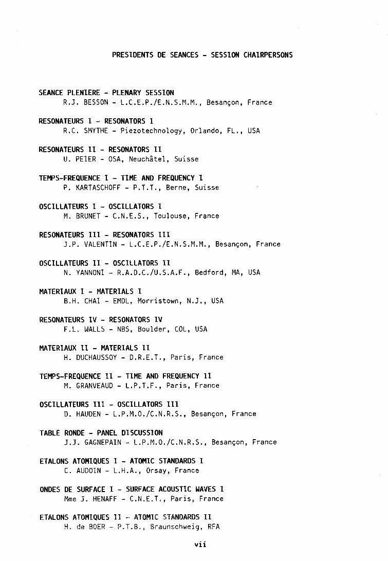
PRESIDENTS DE SEANCES - SESSION CHAIRPERSONS
SEANCE PLENIERE - PLENARY SESSION R.J. BESSON - L.C.E.P./E.N.S.M.M., Besan~on, France
RESONATEURS I - RESONATORS 1 R.C. SMYTHE - Piezotechnology, Orlando, FL., USA
RESONATEURS 11 - RESONATORS 11 U. PEZER - OSA, Neuchztel , Suisse
TEMPS-FREQUENCE 1 - T I M E AND FREQUENCY I P. KARTASCHOFF - P.T.T., Berne, Suisse
OSCILLATEURS I - OSCILLATORS 1 M. BRUNET - C.N.E.S., Toulouse, France
RESONATEURS 111 - RESONATORS I11 J.P. VALENTIN - L.C.E.P./E.N.S.M.M., Besanqon, France
OSCILLATEURS 11 - OSCILLATORS 11 N. YANNONI - R.A.D.C./U.S.A.F., Bedford, MA, USA
MATERIAUX 1 - MATERIALS 1 B.H. C H A I - EMDL, Morr istown, N.J., USA
RESONATEURS I V - RESONATORS 1 V F.L. WALLS - NBS, Boulder, COL, USA
MATERIAUX I1 - MATERIALS I1 H. DUCHAUSSOY - D.R.E.T., Pa r i s , France
TEMPS-FREQUENCE 11 - TIME AND FREQUENCY I1 M. GRANVEAUD - L.P.T.F., Pa r i s , France
OSCILLATEURS 111 - OSCILLATORS 111 D. HAUDEN - L.P.M.O./C.N.R.S., Besanqon, France
TABLE RONDE - PANEL DISCUSSION J.J. GAGNEPAIN - L.P.M.o./c.N.R.s., Besanqon, France
ETALONS ATOMIQUES 1 - ATOMIC STANDARDS 1 C . AUDOIN - L.H.A., Orsay, France
ONDES DE SURFACE I - SURFACE ACOUSTIC WAVES I Mrne J. HENAFF - C.N.E.T., Pa r i s , France
ETALONS ATOMlQUES 1% - ATOMIC STANDARDS 11 H. de BOER - P.T.B., Braunschweig, RFA
v i i

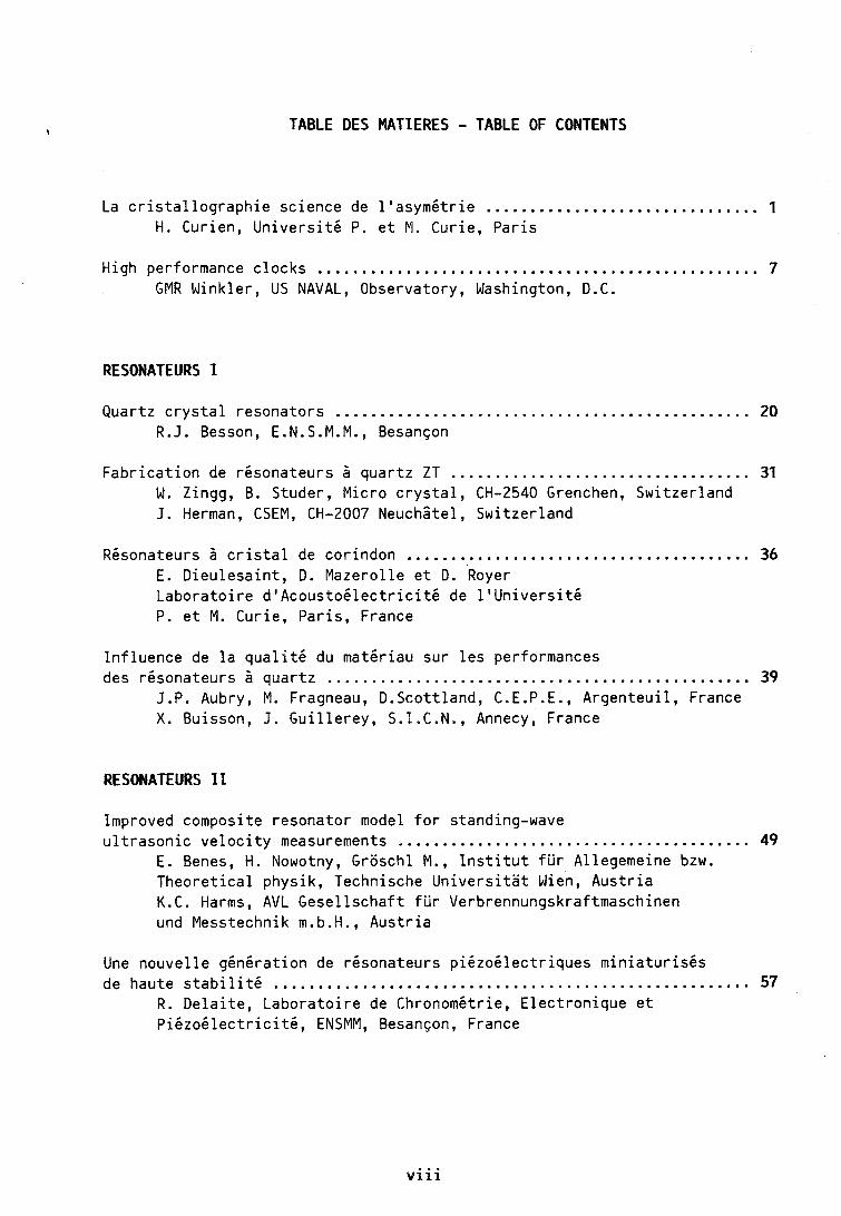
TABLE DES MATIERES - TABLE OF CONTENTS
............................... La c r i s t a l l o g r a p h i e science de l ' a s y m g t r i e 1 H. Curien, U n i v e r s i t g P. e t M. Curie, Pa r i s
High performance c locks ............................................... 7 GMR Winkler, US NAVAL, Observatory, Washington, D.C.
RESONATEURS I
Quartz c r y s t a l resonators ............................................... 20 R.J. Besson, E.N.S.M.M., Besanson
Fabr i ca t i on de r6sonateurs 2 quartz ZT .................................. 31 W. Zingg, B. Studer, Micro c r y s t a l , CH-2540 Grenchen, Switzer land J. Herman, CSEM, CH-2007 Neuch i te l , Swi tzer land
R6sonateurs 2 c r i s t a l de corindon ....................................... 36 E. D ieu lesa in t , D. Mazerol le e t D. ' ~ o ~ e r Labora to i re d tAcous to61ec t r i c i t 6 de l t U n i v e r s i t 6 P. e t M. Curie, Par is , France
In f l uence de l a q u a l i t 6 du matdriau sur l e s performances des r6sonateurs 2 quartz ................................................ 39
J.P. Aubry, M. Fragneau, D.Scottland, C.E.P.E., Argenteu i l , France X. Buisson, J. Gu i l l e rey , S . I . C . N . , Annecy, France
RESONATEURS I1
Improved composite resonator model f o r standing-wave u l t r a s o n i c v e l o c i t y measurements ........................................ 49
E. Benes, H. Nowotny, Groschl M., I n s t i t u t f u r Allegemeine bzw. Theore t ica l physik, Technische U n i v e r s i t a t Wien, Aus t r i a K.C. Harms, AVL Gesel lschaf t f u r Verbrennungskraftmaschinen und Messtechnik m.b.H., Aus t r i a
Une nouvel le g6n6rat ion de r6sonateurs p i6zo6 lec t r iques m in ia tu r i sgs de haute s t a b i l i t g ...................................................... 57
R. De la i t e , Labora to i re de Chronom6trie, E lect ronique e t P i6zo6 lec t r i c i t i 5 , ENSMM, Besan~on, France
v i i i

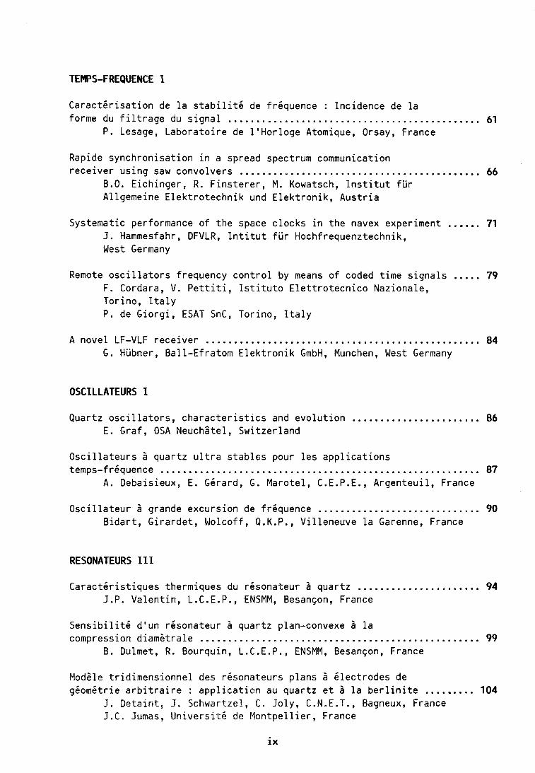
TEMPS-FREQUENCE 1
Carac tg r i sa t i on de l a s t a b i l i t 6 de fr6quence : Incidence de l a ............................................. forme du f i l t r a g e du s i g n a l 61
P. Lesage, Labora to i re de 1'Horloge Atomique, Orsay, France
Rapide synchronisat ion i n a spread spectrum communication rece iver us ing saw convolvers ........................................... 66
B.O. Eichinger , R. F ins te re r , M. Kowatsch, I n s t i t u t f u r Allgemeine E lek t ro techn ik und E lek t ron i k , Aus t r i a
...... Systematic performance o f the space c locks i n the navex experiment 71 J. Hammesfahr, DFVLR, I n t i t u t f u r Hochfrequenztechnik, West Germany
..... Remote o s c i l l a t o r s frequency c o n t r o l by means of coded t ime s igna ls 79 F. Cordara, V. P e t t i t i , I s t i t u t o E l e t t r o t e c n i c o Nazionale, Torino, I t a l y P. de Giorg i , ESAT SnC, Torino, I t a l y
A novel LF-VLF rece iver ................................................. 84 G. Hubner, Bal l -Efratom E l e k t r o n i k GmbH, Munchen, West Germany
OSCILLATEURS I
Quartz o s c i l l a t o r s , c h a r a c t e r i s t i c s and evo lu t i on ....................... 86 E. Graf, OSA Neuchstel, Swi tzer land
O s c i l l a t e u r s 2 quartz u l t r a s tab les pour l e s a p p l i c a t i o n s temps-fr6quence ......................................................... 87
A. Debaisieux, E. GCrard, G. Marote l , C.E.P.E., Argenteu i l , France
O s c i l l a t e u r 2 grande excurs ion de fr6quence ............................. 90 B i d a r t , G i ra rdet , Wolcoff , Q.K.P., V i l leneuve l a Garenne, France
RESONATEURS 111
Carac t6r is t iques thermiques du r6sonateur 2 quartz ...................... 94 J.P. Valent in , L.C.E.P., ENSMM, Besanson, France
S e n s i b i l i t 6 d 'un r6sonateur b quartz plan-convexe 2 l a .................................................. compression d iam6tra le 99
B. Dulmet, R. Bourquin, L.C.E.P., ENSMM, Besanson, France
Mod6le t r id imens ionne l des r6sonateurs plans 2 6 lec t rodes de gkomktr ie a r b i t r a i r e : a p p l i c a t i o n au quar tz e t $ l a b e r l i n i t e ......... 104
J. Deta in t , J . Schwartzel, C, Jo ly , C.N.E.T., Bagneux, France J.C. Jumas, Un ivers i tG de Mon tpe l l i e r , France

Calcul de pe r tu rba t i on avec 616ments f i n i s appl iqu6 aux rhsonateurs 2 quartz ................................................... 117
M. Trumpy, ETA SA, Grenchen, Swi tzer land
OSCILLATEURS I1
O s c i l l a t e u r s 2 quartz 2 1 GHz u t i l i s 6 en synthsse microonde ............ 125 M. O l i v i e r , J. Groslambert, Labora to i re de Physique e t M6tro logie des Osc i l l a teu rs , Besanson, France J. Chauvin, C.E.P.E., Argenteu i l , France
La mont6e en frgquence des f i l t r e s p i6zog lec t r iques 2 ondes de volume .............................................................. 129
B. D 'Albaret , Wolcoff , Q.K.P., V i l leneuve l a Garenne, France
Automatic temperature t e s t system f o r BVA resonators based on IEC 444 .. 136 U.R. Peier , OSA Osc i l l oqua r t z , Neuchztel, Swi tzer land
T rans fe r t de temps. Moyens rad io6 lec t r i ques op6ra t ionne ls .............. 143 M. D'Amico, Techniphone, Le Puy Ste Rgparade, France
The synchronous o s c i l l a t o r s and the coherent phase-locked synchronous o s c i l l a t o r s .......................................................... 148
V. Uzunoglu, F a i r c h i l d Communications & E lec t ron i cs , Compagny i n Germantown, USA M.H. White, Lehigh U n i v e r s i t y i n Bethlehem, USA
MATERIAUX I
Etude de d6fauts ponctuels dans l e s rgsonateurs 2 quar tz ............................................. par e f f e t 6 lec t ro6 las t i que 153
R. Brendel, L.P.M.O., Besanson, France
Simulat ion num6rique des p r o f i l s de sur face de quar tz obtenus par usinage chimique .................................................... 159
C.R. T e l l i e r , N. V i a l l e , JL Vaterkowski, L.C.E.P., ENSMM, Besangon, France
Contr6 le par spectroscopie i n f ra rouge d 'un b loc de quar tz de synthsse . . 168 F. Mart in , B. V iard, P. Zecchini , H. Mgrigoux, Labora to i re de C r i s t a l l o g r a p h i e e t Chimie Mingrale, Besanson, France
Con t r i bu t i on 5 l a r g a l i s a t i o n d'une lame t r i p l e r o t a t i o n dans l e quar tz . ........................................................ 172
J.F. Darces, M. Moussetad, H. Mgrigoux, Labora to i re de C r i s t a l l o g r a p h i e e t Chimie MinGrale, Besanqon, France
M6thode g6n6rale de c o p r 6 c i p i t a t i o n pour l ' o b t e n t i o n d'Cl6ments c6rarnique.s p i6zo6 lec t r iques t r & s homogines ............................. 176
L. Eyraud, P. Eyraud, Labora to i re de Ggnie E lec t r i que e t Fe r ro6 lec t r i que de 1'IZNSA de Lyon, Vi l leurbanne, France

RESONATEURS I V
Capteur de pression ?I quar tz v i b r a n t type 51 ........................... 179 G. de Sorbier, St6 Crouzet, Valence, France
In f l uence de l ' 6 t a t de sur face sur l e c o e f f i c i e n t de q u a l i t 6 des rgsonateurs 2 quar tz ....................................... 184
T. Deguin, R. Bourquin, L.C.E.P., E.N.S.M.M., Besanson, France
D i s p o s i t i f s min ia tures en t a n t a l a t e de l i t h i u m d6coup6s par l a s e r avec suspensions in t6gr6es ................................... 189
R. Lefevre, C . Jo l y , C.N.E.T., Bagneux, France
Analyse des m6canismes de s e n s i b i l i t h s acchl6rom6tr ique e t baromgtrique des r6sonateurs 2 quartz de type QAS ................... 195
J.P. Aubry, M. Fragneau, C.E.P.E., Argenteui l , France J.C. Craveur, F. Deyzac, D. Janiaud, ONERA, C h a t i l l o n , France
MATERIAUX 11
Eva luat ion o f b e r l i n i t e grown a t h igh temperatures ..................... 204 B.H.T. Chai, J.P. Hou, E l e c t r o n i c Ma te r i a l s and Devices Laboratory, Morristown, USA
Obtent ion de c r i s t a u x de b e r l i n i t e 2 haut fac teur de sur tens ion ........ 205 J.C. Jumas, A. Goi f fon, E. P h i l i p p o t , Labora to i re de Physico- chimie des mat6riaux inorganiques, Un ive rs i t g de Mon tpe l l i e r , France Y . Toudic, J. Schwartzel, J. Deta in t , C.N.E.T., Bagneux, France X. Buisson, R. Arnaud, S.Z.C.N., Annecy, France
Defects i n syn the t i c & b e r l i n i t e : l a t t i c e de fec ts and water i n take : comparison w i t h quar tz ............................................... 209
B. Boulogne, P. Cordier, J.C. Doukhan, Labora to i re de s t r u c t u r e e t p ropr iE t6s de 1 ' 6 t a t so l i de , U n i v e r s i t g de L i l l e , V i l leneuve dlAscq, France
The ma te r ia l e l e c t r o e l a s t i c constants o f quar tz determined by the resonators method .................................................. 215
C. Hruska, P i e z o e l e c t r i c i t y Research Laboratory, York Un ive rs i t y , Downsview, Canada R. Brendel, L.P.M.O., Besanson, France
Mapping o f the e l e c t r o e l a s t i c e f f e c t i n quar tz based on fundamental m a t e r i a l constants ..................................................... 222
E. K i t t i n g e r , J. Tichy, Z n s t i t u t f u r Experimentalphysik, U n i v e r s i t a t Znnsbruck, Aus t r i a

TEMPS-FREQUENCE I 1
Signal a c q u i s i t i o n and p o s i t i o n f i n d i n g equipment f o r VHF/UHF based on t ime and frequency c o r r e l a t i o n ................................ 226
K.G. P f a f f , C. P l a t h GMBH, Hamburg, West Germany
Nav-sat t ime synchronizat ion study ..................................... 231 G. Busca, OSA Osc i l l oqua r t z , Neuchztel, Swi tzer land
U t i l i s a t i o n des signaux du G.P.S. en mode d i f f 6 r e n t i e l instantan6 pour l e s a p p l i c a t i o n s temps-frgquence de haute p r g c i s i o n ............... 237
G. Nard, J. Rabian, R. Gounon, SERCEL SA, Carquefou, France
GPS f o r t ime and frequency measurements ................................ 249 G.F. Knoernschild, Rockwell I n t e r n a t i o n a l Corporat ion, Cedar Rapids, Lowa, USA
OSCILLATEURS III
O s c i l l a t e u r 2 quartz thermostat~/compens6 .............................. 256 F. Deyzac, ONERA, C h a t i l l o n , France
TCXO 5 compensation numgrique .......................................... 262 P. Genoud, P. Rochat, OSA Osc i l loquar tz , Neuchztel , Swi tzer land
Compensation s t a t i q u e e t dynamique en tempgrature d 'un o s c i l l a t e u r S quartz bi-mode ....................................................... 267
S. Ga l l i ou , M. Mourey, L.C.E.P., E.N.S.M.M., Besancjon, France
Analyse th6or ique du b r u i t en l / f des r6sonateurs 2 quartz ............. 273 M. Planat , L.P.M.O., Besancjon, France
Table ronde : Nouvel les technologies pour l e s r6sonateurs e t l e s o s c i l l a t e u r s ......................................... 277 J. J. Gagnepain, L.P.M.O. /C.N.R. S., Besancjon, France D. Hauden, L.P.M.O., Besancjon, France
ETALONS ATOMIQUES I
Uses o f p rec ise t ime and frequency ..................................... 279 S. Leschiut ta, U. P isan i , I s t i t u t o E l e t t r o t e c n i c o Nazionale, Torino, I t a l y
Design o f a commercial cesium tube ..................................... 284 P. Thomann, G . Busca, H. Schweda, L. Johnson, J.C. Sapin, OSA Osc i l loquar tz , Neuchi te l , Switzer land
Understanding environmental s e n s i t i v i t y and ageing o f cesium beam frequency standards ............................................ 288
A . de Marchi, I s t i t u t o E l e t t r o t e c n i c o Nazionale, Torino, I t a l y
xii

R6sonateur 2 j e t de c6sium 2 pompage opt ique. D6terminat ion du rappor t s i g n a l sur b r u i t .............................................. 294
V . Giordano, A. Hamel, G . Thgobald, P. Cerez, C. Audoin, L.H.A., Orsay, France V. Candel ier, C.E.P.E., Argenteu i l , France
ONDES DE SURFACE
The growth o f long T 1 VSq c r y s t a l s ..................................... 298 Z.K. Kun, R.W. de ine r t , W.E. Gaida, Westinghouse R&d Center, P i t tsburgh, USA
In f l uence des param6tres technologiques sur l a s t a b i l i t 6 en frequence des r6sonateurs 2 ondes de surface ..................................... 301
S. C a l i s t i , Ph. Defranould, Thomson-Sintra ASM Department TAS, Valbonne, France D. Hauden, L.P.M.O., Besanqon, France
Design aspects o f saw gas sensors implemented i n s i l i c o n ............... 306 A . Venema, M.J. Vellekoop, E. Nieuwkoop, E l e c t r i c a l Engineering Facul ty , D e l f t , The Netherlands
D i s p o s i t i f s 2 ondes de sur face insens ib les aux con t ra in tes planes ...... 311 E. B i g l e r , D. Hauden, L.P.M.O., Besan~on, France G. Thgobald, L.H.A., Orsay, France
Analys is and measurements o f t ransducer end r a d i a t i o n i n saw f i l t e r s on s t rong ly coup l ing substrates ........................................ 315
A.R. Baghai-Wadji, 0. Manner, S. Selberherr, F. S e i f e r t , I n s t i t u t f u r Allgemeine E lek t ro techn ik une E lek t ron i k , Technische U n i v e r s i t a t Wien, Aus t r i a
.......... Bessel type fresnel-zone i n t e r d i g i t a l t ransducer f o r focusing 320 S. Shiokawa, Facu l ty o f Engineering, Shizuoka Un ive rs i t y , Hamamatu T. Nomura, Shibaura I n s t i t u t e o f Technology, Tokyo R. Hidaka, T. Mori izumi, I n t e r n a t i o n a l Cooperation Center f o r Science and Technology, Tokyo I n s t i t u t e o f Technology, Tokyo, Japan
ETALONS ATOMIQUES I1
Environmental e f f e c t s on cesium c locks kept a t the ien-Torino and ispt-Roma t ime and frequency l a b o r a t o r i e s .............................. 324
F. Cordara, V. P e t t i t i , I s t i t u t o E l e t t r o t e c n i c o Nazionale, Torino, I t a l y G. T i g n a n e l l i , I s t i t u t o Superiore d e l l e Poste e Telecommicazioni, Roma, I t a l y
x i i i

Study o f h i g h performance pass ive rub id ium standard : p h y s i c a l ................................................................ package 331
G. Busca, OSA O s c i l l o q u a r t z , Neuchstel , Swi tze r land P. L ihua, Wuhan I n s t i t u t e o f Physics, Academia S in ica , China
Accord automatique de l a c a v i t 6 rgsonnante d 'hor loges B .................................... HydrogGne : r 6 s u l t a t s p r 6 l i m i n a i r e s 334
N. Yahyabey, R. B a r i l l e t , J. Viennet, C . Audoin, L.H.A., Orsay, France
A new automat ic c a v i t y t u n i n g f o r a c t i v e H masers ...................... 339 G. Busca, L. Johnson, OSA O s c i l l o q u a r t z , NeuchBtel , Swi tzer land
Experiences w i t h H-masers e fos 1 and e fos 3 a t t h e Fundamental S t a t i o n W e t t z e l l ..................................................... 342
W. Sh lu te r , I n s t i t u t f u r Angewandte Geodasie, W e t t z e l l , Ko t z t i ng , Fed. Rep. Germany
Two years performance o f t h e medicina VLBI t i m i n g s t a t i o n .............. 348 R. Ambrosini, Z s t i t u t o D i Radioastronomia, Bologna, I t a l y
The hydrogen maser LSRH H3 i n o p e r a t i o n a l use a t t h e westerbork syn thes is r a d i o te lescope ........................................................ 353
L.H. Sondaar, Nether lands Foundat ion f o r Radio Astronomy, The Nether lands
x i v

PREMIER COLLOQUE EUROPEEN "TEMPS FREQUENCE" - BESANCON -
LA CRISTALLOGRAPHIE, SCIENCE DE L'ASYMETRIE
Allocution par M. Hubert CURIEN
Mesdames, Messieurs, je voulais d'abord me joindre h notre ami pour remercier les autorites suisses et les autorites frangaises qui IZOUS oitt fait I'honneur d'assister tr I'ouverture de ce colloque.
Nous sommes particuliirement heureux de voir que ce colloque est urte realisation internationale et qu'elle se passe ici dans la , Ville de Besangon. Permettez-nzoi en votre nom ir tous de remercier et de feliciter les organisateurs de ce colloque et tout specialement M. BESSON qui vient de I'ouvrir a I'instant et qui est President du Conzite Fondateur de cette serie dont le premier Forum se tieizt aujourd'hui et aussi le President du Comite dlOrganisation M. REMOND qui it'a pas nzerzage sa peine pour I'organisatioiz de cette reunion.
Reunion exemplaire d'abord puisque nous vertoizs de le dire, M . BESSON nous I'a precise tout a l'heure, elle est internationale. Je sais bien qu'elle est essentiellentent biitationale puisqu'elle est suisse et frangaise nlais vous I'avez dit tout-a-l'heure, ntoir cher Colligue, vous avez invite a ce colloque des personnalites venant non seulenzent de quelques pays europeeizs voisins nzais aussi les nzeilleurs specialistes des U S A daizs le dornaiite.
Ce sont donc des discussions extr&ntement pronzetteuses qui sont devant nous pour ces 3 jours, de rewzion. I1 n'est pas du tout indiffe'rent de coitstater que cette reunion se lient ici en Franche-Comte a Besancoir et qu'alternativentent elle se tiendra a Besangon et a Neuchritel. C'est ett e f f e t une tradition que la mesure du temps soit cultivee, soil travaillee daizs ces deux eitdroits, en France ici en Fraizche-Conzte et en Suisse d a m le cantoil de Neuchfitel.
Ceci an~trle ri uize reflexioit immediate, c'est que nous corzrzaissoizs bieit les di f f icul tes qu'a traversees I'iizdustrie de la ntesure du temps, I'industrie horlogere au cours des derniBres annees et nous voyons bien qu'une industrie traditionnelle m i m e si la tradition est tres fortement implantee dans un pays court les plus grands risques si elle n'est pas soutenue par une recherche tr is active et tres impliquee dans l'ensemble de la science.
Quelquefois, on pense qu'il faut surtout orienter la recherche et le developpenzeizt dans les donzaines qui sent les plus nouveaux et qu'il y a des domairtes qui sont raisonirablemerzt classiques et en tous cas dairs lesquels rzous avorts les uns ou les autres une grande tradition et que la, la recherche est peut-itre ntoiizs urgente. C'est presque le contraire qui est vrai.
C'est la, ou 1'011 a une bonne tradition qu'il faut / a conserver et, pour la conserver, si on 17e s'appuie pas sur des bases nouvelles, si oiz n'ilargit pas sa connaissance, on est h peu pres stir que les autres le feroizt ir votre place et que votre tradition entrera dans les livres d'histoire mais n'entrera pas dans les rubriques ecortomiques ou y eiztrera par la mauvaise porte.
Je peirse que cette region airzsi que nos anzis suisses ont nzontre I'exemple et oizt fail les efforts izecessaires pour qu'u l'industrie locale vienne s'adjoindre une recherche qui soit extrimement vivaizte ; d'ailleurs la tradition irzdustrielle de cette region va aussi de pair avec une tradition scientifique puisque de tous temps, on a vu fleurir ici des etudes extrimement poussees et renomntees dans la mesure du temps.

Le miracle, c'est que I'on puisse faire des montres extraordinairement fideles a des prix tels que Iron puisse en o f f r i r a des enfants de d i x ans sans avoir peur qu'ils les cassent. C'est urte difference essentielle entre ce qu'il se passe ntaintenant et ce qu'il se passait il y a 40 a m . La montre precise n'est plus un objet de luxe. C'est vraiment l'objet courant. Quand on imagine toute la technologie qu'il y a la-dedans, on voit bien aussi I'astuce qui a ete necessaire pour passer de la connaissance a u11 processus de grand rendement et de production relativement bon marche.
La rentarque que je voulais faire a propos des ntatkriaux et plus particuliPrernet~t du quartz qui va occuper une bonne part de ce colloque, cJest que tous ceux d'entre vous qui ont eu I'occasion de faire des cours sur la cristallographie, sur les materiaux, ortt eu le sentinzent que pour les etudiants, un cristal est d'autant plus seduisant qu'il est plus symetrique et que lorsqu'ort decrit les classes de syntetrie aux itudiants et qu'on morttre qu'il y en a qui sont plus symetriques que d'autres, la tendance rtaturelle est de perrser que le Bon Dieu n'a pas kte tres gentil avec les cristaux qui ?re sorrt pas tres symetriques.
Alors que c'est exactement le coirtraire qu'il faut essayer de faire comprendre aux etudiants. U?t cristal qui a ntoilzs de symetrie n'est pas du tout un cristal boiteux mais utt cristal utile. Plus un cristal est asyntetrique, plus il est utile ( j e schematise u?t peu). Le quartz n'est devenu un materiau de trbs grande performance que parce qu'il est naturellement dipourvu d'un certain nornbre de symetries et notantrnent de centre de syntetrie et qu'il peut developper une polarisatiorr Plectrique, qu'orz peut l'exciter electriquement etc ...
Cette philosophie que l'asymetrie cree I'application est certairreme~rt I'une des norio?rs qui rnaintenatrt trarrsparait dans l'enseignenteitt de la cristallographie et dans la maniere doirt ort travaille sur les cristaux.
Je parle d'autant plus volontiers de cristallographie que je I'enseigne de ja depuis un certain temps, mais en regardartt la philosophie d'un enseignement de science, on s'aper~oit que dans tous les dontai?tes, il y a eu urre epoque oil on etait jamais si content que lorsque I'orz trouvait que quelque chose, un phenomene ou une substance etait symetrique et puis urte Ppoque qui est maintenant la ndtre qui est celle oic 011 est jamais plus content que quand on dkcouvre que quelque chose n'est pas symetrique ou qu'on sait faire disparaitre, rompre wre symetrie.
Ceci est vrai lorsque vous vous intkressez a la matitre cortdensee : les cristaux, mais c'est vrai aussi lorsque vous vous interessez aux particules ilimentaires. Vous savez I'importance fondamentale que prennent les regles de ruprure de la symetrie dans les raisoniteme~rts et les experiences que I'on peut faire sur les particules les plus fondamerttales pas loin d'ici d'ailleurs, au "CERN par exemple.
Quarrd je parle de symktrie et de rupture de symetrie, je peitse naturellement ci la symetrie qu'on appelle la synzetrie d'orientation. C'est-a-dire le fait qu'un cristal n'ait pas de centre de symetrie, c'est-a-dire que ses propriktes darrs urre direction ?re soierrt pas les m&mes dans un sens et d a m I'autre.
Mais je parle aussi d'un autre type de syntitrie que les connaisseurs appellerrt la symetrie d e translation, c'est-;I-dire le fait que d a m urre matiere bien cristallisee, itous avons un arrangement triplement periodique c'est-a-dire qu'on ramene l'edi f ice en coi'nciderrce stricte avec lui-m&nte simplement par un jeu de translations ou encore que darrs cet edifice, si vous imaginez un observateur d I'ichelle de I'atome, cet observateur vous le mettez en un errdroit, il voit urr certain paysage, vous pouves le translater d a m la matiere et vous pouves trouver urle i~tfirrite de points regulierentent repartis en lesquels il voit exactement le m&me paysage. C'est aussi une synzetrie de translatiort.
La encore, les preoccupations ortt blorntement change depuis quelques annees chez les scientifiques.
Autrefois, naturellernerrt la matiere qu'on aimait bien etudier, c'etait la matiire la plus symetrique, c'est-a-dire la ntieux ordortnee et on etait fort heureux de pouvoir etudier des cristaux parfaitement periodiques, duns l'espace parce que ceci permettait de nzettre en oeuvre avec une grande efficacite toutes les methodes d e diffraction : quand on envoie utze onde sur quelque chose qui est parfaitemettt periodique, on met immediatement en marche tous les ref lexes du physicien sur la transformke de Fourier, tous les reflexes du calculateur qui vont avec et les choses s'arrangent tres bien.
Finalement, on a essaye de ddbrouiller les proprietes de la matiere le plus possible en s'appuyant sur l'etude de la matiere triplentent periodique et puis on s'est apercu encore une fois que d a m l'industrie, duns les applications, la matiere qui avait des defauts etait d'une part la plus frequente et d'autre part souvent la plus intkressanfe et que beaucoup de proprietes de cette matiire ou de ces mate'riaux conzme oiz dit maintenant, provenaient esserrfiellemertt des de fauts.
Donc l'idee a ete de connuitre la structure des d t fau t s et d'en maitriser la presence ou l'absence en tous cas la densite ou le comportement, dans les ntaieriaux que l'orr voulait utiliser.
Ceci n'a fait que croitre considerablentent depuis une trentaine d'annees et des laboratoires qui etaient essentiellentent consacres a l'etude de la matikre la plus triplement - periodique possible ont glisse progressivement vers l'etude de la matiere bourree d'infidelites a cette triple periodicite pour comprendre quelle etait la nature de ces in fidelites, quelle etait la nature de ces dP fauts et ert profiter pour le meilleur usage de ntateriaux soit classiques, soit nouveaux. Je parlais tout-a-l'heure des deux grands du dontaine des ntateriaux : le siliciunt et l'oxyde de siliciunz S i 02.
Les defauts duns le silicium jouent un r61e tout-a- fait fondarnetrtal puisqu'ils coirditionnent duns une large mesure les propriktes semi-conductrices. S i vous prenez un silicium absolument sans impurett, sans defaut, il n'a pas du tout les proprietes que vous esperez ; c'est en mettant les intpuretes, c'est en corttrblattt les defauts que vous fabriquez tous les dispositifs que ['on connait.
D'ailleurs le paradoxe est souverzt le suzvant : pour avoir un cristal imparfait, on part d'un cristal imparfait, on le rend parfait et Li partir de ce cristal rendu parfait, orz le rend imparfait. Pourquoi ? Parce que qua~zd on vous le livre imparfait, vous savez qu'il est inzparfait nzais vous ne l'avez pas contrbld et ses intperfections ne sont peut-itre pas celles que vous voulez, vous, y mettre. Le plus sintple, c'est de les faire toutes disparaitre, de faire le cristal le plus parfait possible et ensuite vous reintroduisez mais savemment, a la demairde, de fagon contrdlee, tous les defauts que vous voulez.
C'est exactenteizt le jeu auquel se livrent tous les fabricants de composants electroniques et c'est izaturellement aussi le jeu des fabricaitts sur d'autres materiaux dont la silice.
La silice, contme le silicium d'ailleurs, est aussi interessante lorsqu'elle est absolume?tt parfaite ou absolunzent imparfaite.
Est-ce que 1'011 ne va pas m i m e fabriquer de siliciunt duns l'espace, ce qui rz'est pas absolurnetrt gratuit. On n'ert fait pas encore beaucoup duns l'espace nlais il est possible qu'on en fasse un peu plus dans l'avenir. La, or1 est parfaitemetrt tranquille et on peut elaborer des cristaux sans defaut, mais maintenant il y a aussi un tres grand inter&; pour le siliciunz vitreux, c'est-a-dire parfaitement imparfait oil vraintent la structure cristalline n'existe plus du tout : on s'est apercu que ce siliciunz Sr l'etat vitreux etait aussi urre substance fort renzarquable duns ses applicatioits par exenzple pour la cortversiort photoelectrique.
Mais en fait , c'est un peu tricher, parce que ce silicium parfaiteme?It intparfait est surtout itztiressant parce qu'il absorbe de I'hydrogPne et c'est parce qu'il absorbe de l'hydrogkne qu'il a des propriites interessantes.
Morz exemple etait choisi simplement pour morztrer que, finalemerzt, quand on s'irsieresse a la symetrie ou a la perfection de I'arrangement des atomes datts la matiere condensee, les deux extrimes sont egalenzent i?zteressants : l'extr&me du cristal absolument parfait et I'extr&me du solide absolument intparfait et que, entre les deux, on peut jouer. La silice est ?zaturellement aussi darzs cette cate'gorie puisque d'une part vous vous intdressez essentiellemer~t au quartz parfaitement cristallise mais d'autres s'interessent au verre de silice qui a ete tres longtemps le type m&me de la matiere condensee desorganisde c'est-ci-dire de la matiPre conderzsee qui ne presentait pas de triple periodicite.
Cette a f fa i re de triple periodicit6 nz'anzene a vous proposer une autre remarque encore. C'est que, depuis quelques annees, on s'est aperqu que la triple periodicite, ort pouvait y trouver des failles nun seulemertt sous la forme de quelques defauts , mais sous des formes beaucoup plus fondamentales et le premier exemple qu'on ait trouve sent des alliages qui ont la periodicit6 d'un cristal et, en plus, une periodicite de repartition des deux composants de I'alliage. Te l est le cas, par exemple, duns les alliages d'or et de cuivre.
S i bien qu'on a decouvert a cette occasion des cristaux qui avaient duns une nt&nte direction deux periodicites : la periodicite de I'arrangemerzt des atonles quelque soit leur nature (vous oubliez la nature des atomes) et la periodicite des atomes par nature, qui est irtcommensurable par rapport a I'autre ; c'est-a-dire que vous avez une repartition qui est certes periodique, mais a une periodicite qui n'a rien a voir avec la periodicite cristalline.
Et selon que vous faites des traitements therntiques appropries, ou que vous changiez la conzpositiort de I'alliage, la periodicilk de la repartitiort cuivre or varie corztirzuemerzt done dans un ntime echantillon. Vous avez urze periodicite cristallirze et utze autre qui est la periodicite de repartition des atomes.
Pour les cristallographes, c'est wz peu di f f ici le a avaler, car ils vivent duns un &tat triplement periodique et traitent leurs a f fa ires en pensant a une seule et m i m e periodicite pour toutes les proprietes du cristal.
Premier coup de canif a l'asynzetrie de position allant vers ce type que je rze dirais pas de desordre mais d'un ordre superpose et qui n'est pas reductible au premier. Depuis on a trouve biert d'autres exenzples.
Le deuxiPme grand exemple est duns le domaine du magne'tisme.
Daizs les annees 50, simultane'ment au Japon et en France, on a trouvP des substances qu'orz appelle mainteizant des helimagrzetiques, magnetisnze en helice. Si vous considdrez I'arrangement des monzents magnetiques des atomes, ils forment une helice et le pas de cette helice est incontmerzsurable avec le pas de la periodicite de I'arrangement des atonzes. DeuxiPnle exemple oh, duns un m&me individu cristallin, on a deux periodicites qui n'ont rien a voir I'une avec I'autre, qui sont incommensurables et qui cohabitent, darts le m&nte individu cristallin, duns le m&nze edifice, duns le m i m e assemblage cristallin.
Depuis, on a encore trouvk bien d'autres exenzples. Disorrs u?t mot de ce que I'orz appelle les modes mous. S i vous considdrez I'agitatiorr thermique des atomes duns les cristaux, vous pouver la resoudre comme etant la superpositiorz d'ondes de de'placements qui se propagent duns le cristal.
I1 peut se faire que, si vous conside'rez une de ces ondes, son amplitude se nzette c i croitre, en m i m e temps que sa frequerzce baisse. La frequence baisse jusqu'a devenir nulle : alors cela devient une onde de deformatiorz statique.
Ceci peut vous conduire a des proprittes qui vous irtteressent, vous particuliPrenzent, puisque cela peut conduire a des proprietes ferroelectriques fort i?ztkressantes.
PHENOMENES ALEATOIRES DANS LA PHYSIQUE MODERNE
Doric la nouvelle cristallographie a apporte duns nos laboratoires tout un retzouveau d'idees qui ont eu des consequences profondes sur la ntarziPre dont les applicatiorzs pouvaient Etre cotzpes ci partir des principes fondanzentaux et je suis stir que vous aurez I'occasion d'evoquer cette question au cours de vos discussions lors de ce Forum. L'une des avances qui me frappent le plus duns la physique modente, c'est l'elegance avec laquelle on suit mainterzant etudier les phenomenes aleatoires.
Je parlais de d i f a u t s : parlons plus generalement de phenon.ztnes aleatoires. La cortnaissance et le traitement physique et nzathinzatique des phhzomenes aleatoires olzt constitue une espkce de revolution chez tous les experimeiztateurs. Nous sonzmes mainteizant beaucoup mieux arnzes pour distitrguer ce qui est ale'atoire de ce qui ne I'est pas, c'est-a-dire pour extraire un signal d'urz bruit de fond.
Augnzenter le contraste entre ce qui est interessant et le bruit de fond qui vietzt le cacher, les ordinateurs pernzetteizt de le faire tou jours plus e f ficacernenr.
On a fait des avances tout-a- fait coitsiderables duns ce domaiize-la. Je crois que finalentelzt c'est parce qu'on a su traiter des choses qui paraissaient hors de portee, ir la limite de /'experience deterministe, c'est parce qu'olz suit traiter ces choses-lh que rnaiittenant on suit realiser des ntesures beaucoup plus precises.
Sachant traiter les phenonzenes aleatoires, vous Etes capables d'aller beaucoup plus loiiz duns la nzesure et c'est airzsi qu'on gagne des puissartces de I0 duns les differerztes rnesures et, en particulier, dans la mesure du temps.
DES EQUIPEMENTS MODERNES POUR DES SCIENCES AVANCEES
Je voudrais conclure. I1 me sentble tout-&- fait forzdamental et c'est a votre gloire a vous qui vous occupez de mesure du temps et des frequences, de comprendre que la science avance esserztiellerne~rt au m&me rythme que les methodes de nzesure et que les iizstrunzents de ntesure. S i un laboratoire n'a pas les equipements les plus modernes, il fera la science que les autres faisaient avant lui, et cela ne serf pas a grand chose de refaire la science que d'autres ont de ja faite.
I1 faut que nos laboratoires soierlt le mieux equipes possible avec les meilleurs instrume>zts possibles, c'est une premiere nkcessite. Mais, il faut aussi que les chercheurs se rendent compte qu'il n'y a pas darzs la cornnzulzaute scienti f ique deux categories de personnes : ceux qui construisent les instrumertts et ceux qui les utilisent. S i on arrivait ri urle physique (ou a une chimie ou ri ulte biologic) qui soit ainsi bipartite, les fabricarzts d'instruntents et les utilisateurs d'instruments, prenzierement les instruments ne progresseraierzt pas et deuxihn~ement les utilisateurs des instruments n'en tireraient pas le nzeilleur pro fit . I1 faut qu'il y ait ujte parfaite syn~biose entre les fabricarzts d'iustrumetzts et leurs utilisateurs. I1 ne su f f i t pas pour firer le meilleur profit d'un instrument d'en lire la notice, il faut en conzprendre parfaitement le fonctionnemertt. Ce que vous faites en mesure du temps, des frequences, en etude de tous les phenonzerzes qui sJattachent a cette mesure du tenzps me parait de ce point de vue exemplaire. C'est parce que vous &tes a la fois experintentateur sur les methodes elles-m&mes et r&alisateur des instrunzents qu'il vous est permis de prendre la nzesure des d i f f icu l t i s et finalement de realiser les instrunzents les plus perforntants.
Je souhaite vivement que ces progres continuent, s'acceltrent m&me et je vous souhaite ri tous duns vos recherches le meilleur succes.
1 er Forum EuropCen Temps-Fr6quence - 1987
High Performance Clocks
Gernot M. R. Winkler U.S. Naval Observatory
Washington, D.C.
ABSTRACT
The ax iom o f physical t ime measurernerit is reviewed and principles f o r the selection and operation o f high-performance clocks given. A t the present state o f the art, the concept o f a high-performance clock implies the use o f a frequency discr iminator which is based on quantum mechanical principles (the atomic, ionic, o r molecular package). This device is used to regulate the frequency o f a stable oscillator,i, e., a quartz crysta l oscillator.
Performance character ist ics are discussed and the state o f the a r t o f t imekeeping reviewed. Long-term timekeeping requires the cornbination o f groups o f operating clocks, the readings o f which are processed i n some a lgor i thm fo r t l ie derivatiori o f t ime scales which al low a long-term t ime tagging o f events w i t h a rea l t ime precision o f t l ie order o f one nanosecond (ns).
General Principles
The basic pr inciple which governs the physical measurement o f t ime is t ha t we say tha t equal t ime intervals have elapsed when we can demonstrate t ha t the same process has taken place. Given the unavoidable imperfect ions i n everything, we have t o re f ine this by including s ta t is t ica l concepts i n our techniques so tha t we are able t o specify the degree o f ident i ty o f the clock process which we use i n the establishment o f a scale o f t ime. In other words we have t o combine several nearly ident ical processes ( into groups o f clocks) as a basis fo r our s ta t is t ica l measures o f the degree o f ident i ty o f these t ime intervals used i n the construct ion o f our t ime scale.
Bu t we can ident i fy a second requirement on the basis o f our fundamental principle: We w i l l have t o take every precaut.ion i n shielding the repeating c lock processes frorn the rest o f the universe i n order t o al low as near ly an ident ical repet i t ion over and over again. This means t ha t cornmensurate w i t h the performance o f our clocks we have t o provide also the necessary stable environment for the long periods over which our t irne rneasurernents w i l l take place. This required stabi l i ty o f the clock environment is rnost impor tant f o r temperature, magnetic fields, and humidi ty, i n t ha t order. Clearly, shocks and vibrat ion must also be avoided (Figure 1). The required environmental stabi l i ty necessarily includes the personnel who operate, o r better, who guard over, and evaluate the operation of, these high performance clocks, The clocks represent, a f t e r all, some o f the highest technology devices i n rout ine use and the precision o f the measurements is the highest i n the whole f ie ld o f metrology.
Finally we can derive a th i rd statement f r om our basic principle. There is no way to assure true long t e rm process ident i ty i n any macroscopic (i.e., composed o f a huge number o f molecules) device. Any k ind o f mechanical clock, however sophisticated, w i l l inevitably suffer f r o m spontaneous changes i n i t s mate r ia l (aging) and i t w i l l no t be possible to shield a macroscopic device frorn the ubiquitous changes which are the resu l t o f the actions o f the rest o f the universe. It is t rue tha t changes i n mater ia l aging can be minimized by reducing the operating temperature o f the clock process. If we br ing the temperature o f a resonating quartz c rys ta l close to the absolute zero po in t o f
tt?~~~p?r:-l:ure, aging i r l frequency would be precluded in this deep freeze. The sarne thing would be true for frequer~cy determining microwave cavities. Indeed this expectation has been borne out to some extent in experiments with superconducting cavities and with supercooled crystals as resonators (1). In practical realizations, however, it has riot yet been possible to overcorne otl~er effects, such as vibrations due to acoustic sensitivity of the device, or other mechanical deformations, and for now it is not possible to use such supercooled macroscopic oscillators for practical, long-terrn timekeeping.
For these reasons, the ideal timekeeping process is one which is based on a quantum mechanical transition between the states of microscopic particles, i. e., of atorns, ions, or molecules. It is one of the basic assumptions of atomic physics that the energy difference between these rnicroscopic states depends only on the magnitude of any electric or magnetic fields present but is not otherwise a function of time (if we ignore exotic circumstances such as an operation near black holes where the tidal forces would distort the atorns and make timekeeping rather difficult). In other words, atoms do not age and most of current astrophysics is based on the assumption that atoms everywhere and a t all times behave the same way as they do here in a terrestrial laboratory. Indeed, we use the spectral lines of all of these "atomic clocks" for the determination of the speed (and other parameters) of the celestial objects which we observe. For terrestrial timekeeping applications, however, there has to be a careful choice of which line we want to use as reference in order to optimize the performance of our clocks.
Optical transitions are used as a frequency reference in LASERS, but for timekeepin applications the transition used should be a microwave transition with a line width (LW 7 as narrow as possible. Actually it is the Q of the line which is important (Q = FILW). This implies that the state from which the transition takes place must be long living and we must be able to observe the atoms for as long a time as possible without disturbing them. A relatively narrow line allows a very accurate frequency lock of the interro- gating quartz crystal oscillator which is an indispensible part of every atomic clock in use today. The frequency synthesis and frequency multiplication into the microwave region is unproblematic in contrast to a rnultiplication into the optical region which is much more difficult and much less reliable for continuous long time clock operation. Other requirements for a useful clock transition are a first order insensitivity in regards to weak magnetic fields, and the use of heavy atoms which can be easily detected. Cesium has one of the lowest ionization potentials and this, together with its weight and energy levels, has been a major factor in its selection as a favored clock element, There are additional considerations which affect a desirable good signal-to-noise ratio (this produces good short time stability), but for these details we refer to References 2 and 3.
Performance Characterization and Perforrnance Limitations
Keeping in mind our fundamental time measurement axiom, we derive performance measures in the following way. We measure the clock errors in regular intervals and investigate their trends and statistical fluctuations. All desired information must, therefore, be contained in a table of these clock errors and their first and higher differences. Such a table is shown as Table 1 (taken from Reference 4 which gives more details, background and additional references). This is different from an approach which would consider frequency error as the basic quantity. In this case one would have to be concerned with measurement "dead times," However, i f we start with time errors then we do not have to worry about this and we also have immediately available the whole set of time series analysis with well established methods for modeling and prediction. The basic model is a difference equation which leads to the ARMA and ARIMA models as discussed in Reference 7. Here we can discuss only the most fundamental aspects as they pertain to the evaluation and use of clocks.
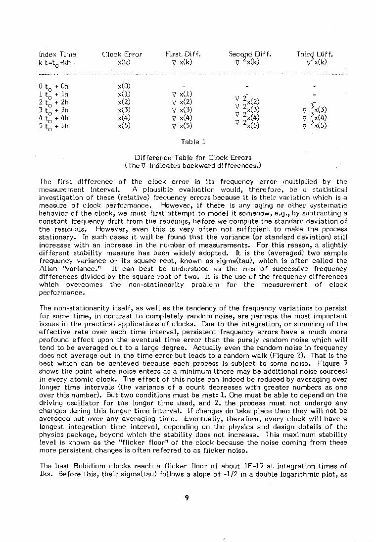
Index Time Clock Error F i rs t U i f f . Seco d Dif f . i' T h i r j U i f f . k t=to+kh ~ ( k ) v ~ ( k ) v ~ ( k ) v ~ ( k )
Table 1
Dif ference Table for Clock Errors (The V indicates backward differences.)
The f i r s t d i f ference o f the clock error is i t s frequency error mul t ip l ied by the measurement interval. A plausible evaluation would, therefore, be a s ta t is t ica l investigation o f these (relat ive) frequency errors because it is the i r var iat ion which is a measure o f c lock performance. However, i f there is any aging o r other systernatic behavior o f the clock, we must f i r s t a t tempt t o model it somehow, e,g., by subtracting a constant frequency d r i f t f r om the readings, before we compute the standard deviat ion o f the residuals. However, even this is very o f ten n o t suf f ic ient t o make the process stationary. In such cases i t w i l l be found t ha t the variance (or standard deviation) s t i l l increases w i t h an increase i n the number o f measurements. For th is reason, a sl ight ly d i f ferent s tab i l i ty measure has been widely adopted. It is the (averaged) two sample frequency variance or i t s square root, known as sigma(tau1, which is o f t en cal led the Al lan "variance," It can best be understood as the rms o f successive frequency differences divided by the square roo t o f two. It is the use o f the frequency differences which overcomes the non-stationarity problem f o r the measurement o f clock performance.
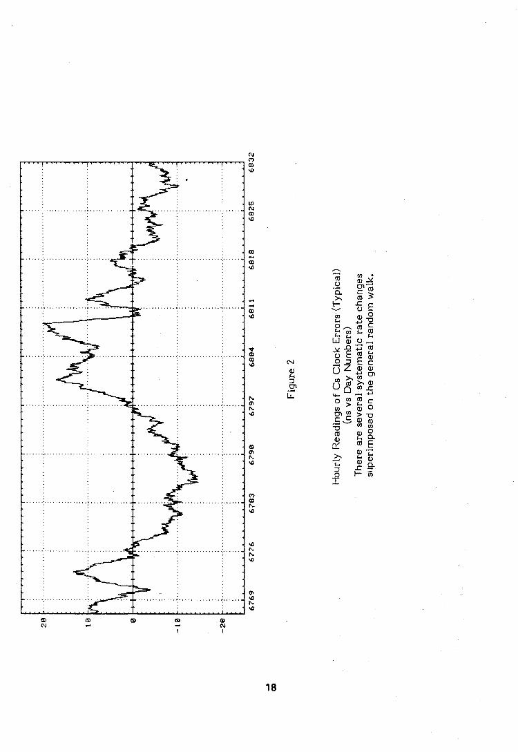
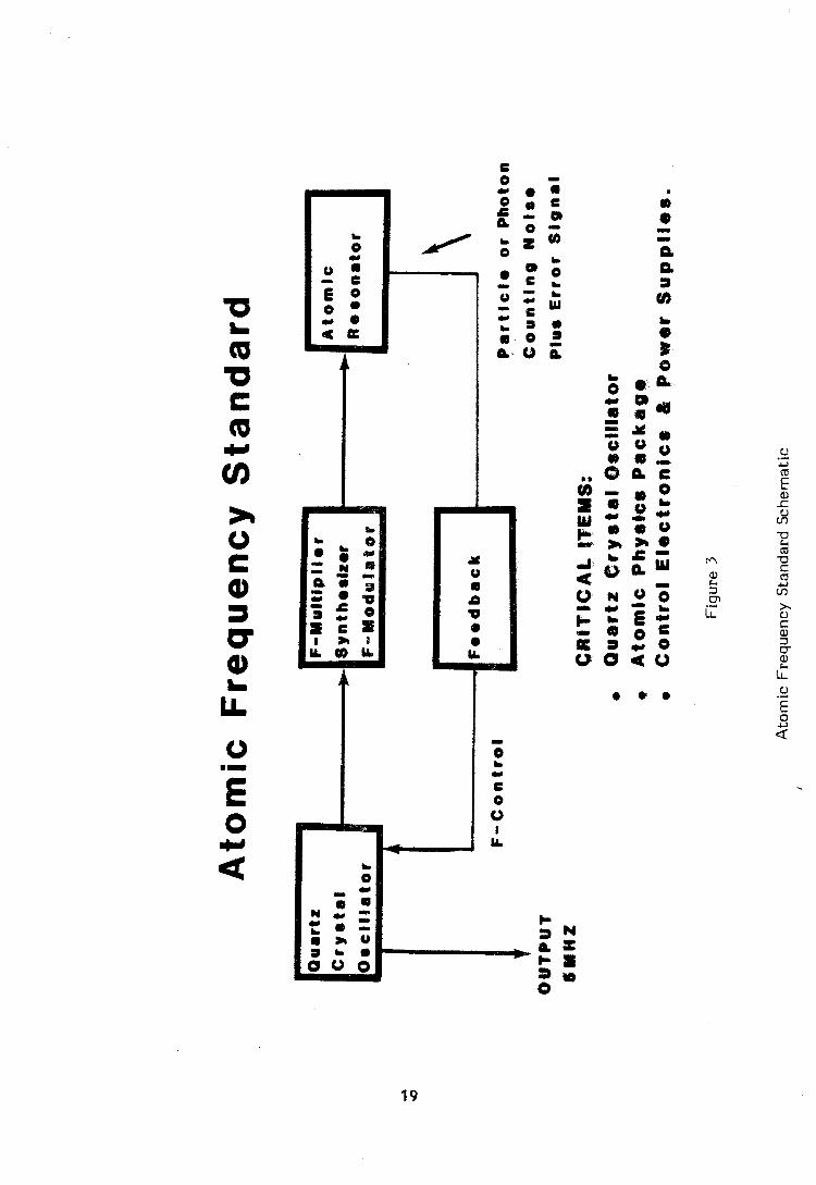
The non-stationarity i tsel f , as w e l l as the tendency o f the frequency variations t o persist for some time, i n contrast t o completely random noise, are perhaps the most impor tant issues i n the pract ica l applications o f clocks. Due t o the integration, o r summing o f the e f fec t i ve ra te over each t ime interval, persistent frequency errors have a much more profound e f f ec t upon the eventual t ime e r ro r than the purely random noise which w i l l tend to be averaged ou t t o a large degree. Actual ly even the random noise i n frequency does not average ou t i n the t ime error bu t leads t o a random walk (Figure 2). That is the best which can be achieved because each process is subject t o some noise. Figure 3 shows the point where noise enters as a min imum (there may be addi t ional noise sources) i n every atomic clock. The e f f e c t o f th is noise can indeed be reduced by averaging over longer t ime intervals (the variance o f a count decreases w i t h greater numbers as one over this number), Bu t t w o conditions must be met: 1. One must be able t o depend on the dr iv ing oscil lator for the longer t ime used, and 2. the process must no t undergo any changes during this longer t ime interval. I f changes do take place then they w i l l no t be averaged out over any averaging time. Eventually, therefore, every c lock w i l l have a longest integrat ion t ime interval, depending on the physics and design detai ls o f the physics package, beyond which the stabi l i ty does no t increase. This maximum stab i l i ty leve l is known as the " f l icker f loor" o f the clock because the noise coming f r o m these more persistent changes is o f ten re fer red to as f l icker noise.
The best Rubidium clocks reach a f l icker f loor o f about 1E-13 a t integrat ion t imes o f lks . Before this, the i r sigma(tau) fol lows a slope o f -112 i n a double logar i thmic plot, as
would be expected i f the in terna l noise is white. For longer integrat ion (tacr lks), we observe d r i f t s o f frequency which are character ist ic o f this type o f clock. The best Cesium clocks, i n contrast, show a superior long-term per for~nance w i t h a f l icker f loor o f 1E-14 ( tau = several days). A f t e r tha t the Cesiurn clock, i n general, does no t show dr i f t s bu t is subject to other long t e rm changes disturbing the atornic resonance frequency i tse l f or introducing biases i n our observation o f th is frequency.
The whole a r t o f high performance clock making, therefore, consists i n f inding a process which rninimizes these f l icker noise contributions, and i n designing a clock so tha t the ef fects o f the environment have the least inf luence upon the ra te o f the clock. The f i r s t requirement is to be satisf ied by the use o f a tomic transit ions w i t h high Q, as mentioned above. The second requirement leads t o inore compl icated considerations. O f course, the designer can and must use regulation o f supply voltages, instrument temperatures, magnetic shielding, power level o f the microwave signal w i t h which the atomic resonance w i l l be probed, etc. For these reasons, a we l l designed clock wi l l , e.g., have no e f fec t i ve temperature coef f ic ient i n f i r s t order. In other words, a deliberate temperature change w i l l no t produce a reproducible frequency change; such changes w i l l be buried i n the random variations. The same thing should be t rue f o r the other parameters o f concern. However, th is is unfortunately n o t the whole story. First, there is aging o f components which w i l l soon l e t the instr,urnent d r i f t ou t o f adjustment, w i t h the result, that a f t e r a while, there w i l l be some influence o f these environmental parameters upon our ab i l i ty to observe and use the invariable undisturbed atomic frequency reference.
Second, we have to look a t the clock n o t as the sum o f i t s components b u t as a system where everything is i n interact ion w i t h everything else. Assume we make a step change o f the input voltage. This w i l l immediately be regulated and cancelled by the in terna l voltage regulators so t ha t the individual c lock modules w i l l no t (or should not) see a voltage change. However, they w i l l see a secondary ef fect . Any e f fec t i ve cont ro l requires some change o f conditions which w i l l eventually, o f ten a f t e r considerable delays, be seen by other components. Very o f ten some spontaneous changes w i l l t rave l around the system so tha t this system t o sorne degree does no t have a def in i te equi l ibr ium point; w i th in l im i t s it d r i f t s around. I n the case mentioned, the voltage cont ro l w i l l change the internal power dissipation, a t the expense o f sett ing up new temperature gradients, which i n tu rn w i l l change the power consumption o f the major modules, forcing futher actions o f the voltage control ler, etc. . It is possible t o el iminate the long t e r m e f f e c t o f the disturbances by simply measuring and accounting f o r the variations i n a process o f cal ibration. This is, o f course, what the laboratories which operate the laboratory absolute frequency standards do occasionally. It could also be done i n a continuous, automatic way i n the new USNO prototype Mercury Ion Storage Frequency Standard bu i l t by Dr. Cutler's group i n the Hewlett-Packard laboratories. Instead o f a t tempt ing to per fec t the various controls f o r the system parameters, such as Hg+ and He pressures, pumping l ight intensity, the thermal veloci ty o f the Hg ions, etc., a computer can measure them w i t h transducers and apply computed correct ions numerical ly according t o previously established measurements. A t this t ime, this is no t being done. However, the computer con t ro l o f a l l servos does al low a l inear izat ion o f the loops and a substantial de-coupling o f these effects. This is, i n my opinion, a major reason fo r the prel iminary resul t t ha t we cannot yet see a f l icker leve l for this clock ( the other being i t s extremely high Q).
Operation o f Clock Ensembles
For reasons of re l iab i l i ty it is usually necessary t o operate rnore than one clock a t a location. This o f fers the second benef i t t ha t by judicious averaging o f the clock
readings, a be t te r and much more rel iable t i m e measurement system can be obtained
than with any individual clock, however excellent , Various algorittirns have been developed for this purpose, the most important of them, naturally, t h e system used by the BIH. A curious dialectic governs the si tuation, however. If one has 160 or Inore clocks in the system, a s the BIH has, t h e deta i ls of t h e algorithrn begin t o render dirninishing additional benefits. On the o ther hand, for srnall clock se ts , the sole rel iance on sophisticated s ta t is t ics begins to lose i t s justification. But averaging of clock readings in a sys tem of clocks is more than a means for improving the stabil i ty of t ime scales. It provides t h e only means t o evaluate t h e ac tua l clock performance. We can only measure t h e clock errors listed in Table 1 if we use a s a reference a computed group t i m e scale o r we use t h e variances of t h e r a t e differences of individual clock pairs and combine them into a sys tem of redundant equations. These can be solved for the individual clock sigma(tau) values a s discussed, e,g., in Reference 8.
The variances obtained in one o r the other way a r e o f ten used a s input t o a weighting scheme which assigns weights proportional t o the inverse square of t h e sigma(tau) values. But in doing this we face several problems, particularly with small clock sets. The most serious of these problems is t h a t the t au which can be chosen for t h e sigmas can hardly be a s long a s t h e t imes over which we like t o stabil ize t h e tirne scale because the re is not suff ic ient clock life t ime available for a determination of good es t imates which by t h a t t ime have becorne obsolete anyway. This leads t o sornewhat illusory gains because the sigma(tau) values a r e a function of t h e tau, and clocks with good performance over 5 day intervals may be poor performers aver longer intervals and vice versa. Reference 7 describes a sys tem which does not use weights, exact ly for this reason, Of course, a necessary condition for a l l meaningful clock averaging must be t h a t t h e clocks operate in stat ist ically uncorrelated environments. Otherwise, t h e gains of averaging and filtering would also be illusory.
One more comment may be useful. It appears extremely beneficial if we combine clocks based on di f ferent design types in our system. Such combinations of radically di f ferent hardware can exploit t o the fullest t h e good aspec t s of each type without becoming impaired by the individual shortcomings. A recen t example would be the combination of the outstanding shor t and medium t e r m stability of the Hydrogen MASER with a device which can provide a very long-term capability such a s the Hg+ prototype a t the USNO, t o be discussed below. It is, of course, the same principle which has been used by the BIH for years where a very large clock ensemble is being used a s a "flywheel," with long t e r m input f rom t h e laboratory absolute frequency standards.
Three Types of Atomic Clocks
Rubidium Vapor, Cesium Bearn, and ilydrogen MASER atomic clocks have been in general use fo r over 25 years. Their basic capabil i t ies a r e well understood (5) . However, this does not mean t h a t R&D on these devices has stopped, On t h e contrary, during the last several years we have seen a resumption of e f fo r t s t o improve shortcomings in the th ree types of clocks. In t h e case of t h e Rubidium clock, t h e emphasis is on a longer life t ime of the discharge rubidium larnp and on the reduction of the long terrn frequency drif t . The Cesium clock is undergoing a potentially more radical transformation. The direction is toward a l l digital electronics and/or replacing the s t a t e separation by magnetic beam deflection and subsequent par t ic le detect ion with a n opt ical pumping and optical detection beam apparatus a s proposed by the National Bureau of Standards group. Such a n arrangement would do away with t h e heavy deflection magnets which also cause problems with s t ray magnetic fields in the transition region. The price for such advantages is t h e additional problem of frequency stabilization of the LASER pumping frequency. In the c a s e of the Hydrogen MASER t h e most massive e f fo r t s a r e going in the direction of making a n industrially produced device ou t of th is laboratory s t a r
perforrner. The mot ivat ion is the planned increased use o f MASERS i n Vl-UI and i n space applications.
One could s impl i fy and say that the performance o f these devices is comrnensurate w i t h the i r pr ice which increases f r om about 10 - 20k$ for Rubidiurn clocks t o 40 - 50k$ for Cesium bearn clocks and t o 200 - 400k$ f o r the MASERS. Hut there is much more t o consider. It is t rue t ha t the MASER is the star perforrner arnong the clocks. Bu t th is is real ly t rue only up t o measurement tirnes o f about one week. I ts inherent d r i f t (which can be par t ia l ly el iminated a t sorne expense w i t h an automatic cav i ty tuner), the dependence o f i t s frequency on the chemica l rnagic o f the w a l l shi f t , and additional, ill- understood e f fec ts i n the resonance cav i ty sornehow lirnit the very long-term performance.
A t this t i m e (wi thout the discussed possible changes i n the Cesium bearn concept) the Rubidium clock is the simpler and sl ight ly more rel iable clock. It also has a be t te r short terrn s tab i l i ty vs. the Cesium clock which is the clock o f choice f o r long-term t ime- keeping applications. For a l l applications which only require a t im ing stabi l i ty fo r periods shorter than several hours, the Rubidium clock should be specified. There is a word o f caut ion to be remembered, however. The d r i f t o f th is device necessitates constant frequency adjustments and this rnay amount t o such an operational burden t ha t Cesium clocks w i l l be purchased despite the considerably higher price.
The Mercury Ion Frequency Standard
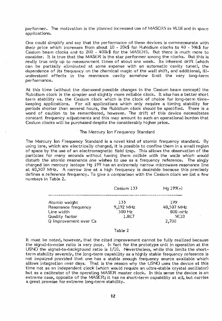
The Mercury Ion Frequency Standard is a novel k ind o f a tomic frequency standard. By using ions, which are e lect r ica l ly charged, it is possible t o conf ine them i n a smal l region o f space by the use o f an electromagnetic f ie ld trap. This al lows the observation o f the part ic les f o r many seconds wi thout having them collicle w i t h the walls which would disturb the atomic resonance one wishes t o use as a frequency reference. The singly charged ion mercury isotope Hg 199 has an extremely narrow microwave resonance l ine a t 40,507 MHz. A narrow l ine a t a high frequency is desirable because this precisely defines a reference frequency, To give a comparison w i t h the Cesium clock we l i s t a few numbers i n Table 2.
Cesium 133 H g 199(+)
Atomic weight 133 199 Resonance frequency 9,192 MHz 40,507 MHz L ine w id th 500 Hz 800 mHz Qual i ty factor 1.8E7 5E10 Q Improvement over Cs 2,700
Table 2
It must be noted, however, that the c i t ed improvement cannot be fu l ly real ized because the signal- tonoise ra t io is very poor. In f ac t f o r the prototype un i t i n operation a t the USNO the signal-to-background ra t i o is 1/10. Nevertheless, while this l im i ts the short- t e r m stabi l i ty severely, the long-term capabi l i ty as a highly stable frequency reference is no t impaired provided t ha t one has a stable enough frequency source available which al lows integrat ion over days. That is the reason why the USNO uses the device a t th is t ime no t as an independent c lock (which would require an ultra-stable c rys ta l osci l lator) b u t as a cal ibrator o f the operating MASER master clock. I n th is sense the device is an extreme case, opposite o f the MASER; it has no short- term capabi l i ty a t all, bu t carries a great promise f o r extreme long-term stabil i ty.
Principle o f Operation:
By f i r i ng electrons in to the Hg vapor, isons are generated and are kept i n the R F trap. About 2 mil l ion ions f o rm a cloud. Their mot ion is gently slowed down by the presence o f low pressure Hel ium (1E-5 Torr). A t t ha t pressure the Hel ium pressure shift, i.e., the frequency change of the Hg resonance, is s l ight and can be accurately calibrated, The actua l resonance, o r c lock transit ion, is observed in a way sirnilar t o t ha t used by the Rubidium clock.
I n addi t ion t o Hg 199 which has a hyperf ine structure there is also another isotope o f Hg, which does n o t have a hyperf ine structure (Hg 202). A very strong U.V. l ine a t 194 nrn is generated w i t h this isotope i n a mercury discharge. This l i gh t is absorbed by the upper state o f the clock transi t ion i n Hg 199(+) t o br ing the ions in to a higher (optical) state f r om which they then re lax in to both lower states. Through the pumping action, how- ever, the upper (clock) state w i l l be quickly de-populated and a l l ions end up i n the lower (clock) state which does no t absorb the pumping l ight. F rom this moment on the vapor is transparent and no relaxat ion fluorescence can be observed. If, however, one exposes these ions t o the clock resonance frequency, then they w i l l be moved into the upper c lock state and can again absorb light. The f ac t t ha t they absorb l ight is observed through the fluorescence when they f a l l i n to the lower op t i ca l levels. The fluorescence, therefore, is the means t o detect the clock transition.
The frequency measurement is per formed i n a steadily repeating sequence o f pumping (discharge is on), exposure w i t h the microwave resonance frequency, and observation o f the fluorescence a t the nex t pumping cycle. Each cyc le lasts 2.5 seconds. By averaging such measurement cycles over several hours, a resolution o f one p a r t in ten t o the fourteenth can easily be achieved. A prototype instrument o f this k ind has been con- structed by the Hewlett-Packard Laboratories i n Palo Alto, California, and was delivered to the USNO i n July 1986. It is now a par t o f the USNO master c lock system. For detai ls see Reference (6).
The purpose o f the use o f such a prototype laboratory instrument i n an operational environment is the accumulation o f p rac t i ca l experience which can lead to further improvements i n the design and construction. The experience so far, a l i t t l e more than seven months o f almost uninterrupted operation a t the USNO, is very encouraging. As had been expected, the mercury lamp had t o be replaced a f t e r about six months o f use, A few minor electronic problems were corrected on the spot. It has been extremely he lp fu l tha t much o f the electronics is standard H P equipment.
O f greatest interest i n th is device is whether and how fa r towards long measurement intervals is the noise purely random. As far as it is purely random, averaging over long intervals w i l l provide genuine gains i n frequency measurement capabil i ty. I n other words, we want t o know where the " f l icker f loor" o f th is c lock is. This is no t an easy task t o do fo r a c lock which seems t o be capable o f greater long-term stabi l i ty than any other available a t the USNO. The specif ic problems encountered are a substantial temperature sensit ivity o f the prototype ( in i t ia l ly it has been as high as 5E-14 per degree C), the noise i n the prel iminary Cesium t i m e scale o f the USNO which is used f o r steering the Master Clock MASER, and the long t imes o f completely uninterrupted operation required o f everything connected w i t h the measurement set-up f o r a rel iable measurement w i t h resolutions o f be t te r than 1E-15.
Moreover, several t imes there were deliberate interruptions w i t h resul t ing discontinuit ies when changes i n some operating parameters had t o be made. On the basis o f the data
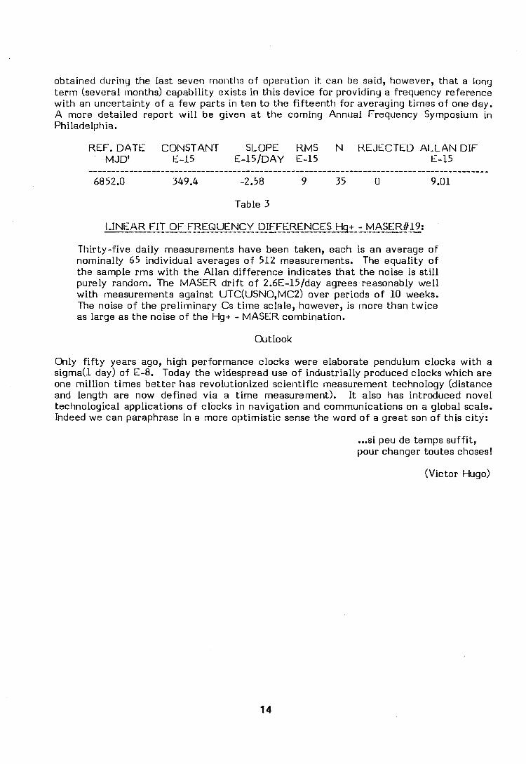
obtained during the last seven rmontlis o f operation it can be said, however, that a long t e rm (several rnoriths) capabi l i ty exists i n this device fo r providing a frequency reference w i t h an uncertainty o f a few parts i n ten t o the f i f teen th f o r averaging tirnes o f one day. A more detai led repor t w i l l be given a t the corning Annual Frequency Syrnposiurn i n Philadelphia.
REF. DATE CONSTANT SLOPE RMS N REJECTED A L L A N DIF M JD' E-15 E-15/DAY E-15 E-15
Table 3
L INEAR FIT O F FREQUENCY DIFFERENCES H q t - MASER#19: ----------------.--------.---- -------- --
Thi r ty- f ive dai ly measurements have been taken, each is an average o f nominally 65 individual averages o f 512 measurements. The equality o f the sample rms w i t h the Al lan di f ference indicates tha t the noise is s t i l l purely random. The MASER d r i f t o f 2.6E-15/day agrees reasonably we l l w i t h measurements against UTC(USN0,MCZ) over periods o f 10 weeks. The noise o f the prel iminary Cs t irne sclale, however, is more than tw ice as large as the noise o f the H g t - MASER combination.
Outlook
Only f i f t y years ago, high performance clocks were elaborate pendulum clocks w i t h a sigrna(1 day) o f E-8. Today the widespread use o f industrial ly produced clocks which are one mi l l i on t imes be t te r has revolutionized scient i f ic rneasurernent technology (distance and length are now defined v ia a t ime rneasurernent). It also has introduced novel technological applications o f clocks i n navigat ion and communications on a global scale. Indeed we can paraphrase i n a more opt imis t ic sense the word o f a great son o f this c i ty :
... si peu de temps suff i t , pour changer toutes choses!
(Victor Hugo)
Notes and Literature
1. The state of cryogenic oscillators, i.e., supercooled crystal resonators and superconducting cavity oscillatars remains in flux. Such devices could be built for a much lower price than Hydrogen Masers and they could compete with them in applica- tions such as Very Long Baseline Radio Interferometry (VLBI). However, no such device has actually left the R&D laboratories where they continue to be investigated. A fine report on some recent progress a t the Radio Research Laboratory of Japan with good literature references is:
Bokuji Komiyarna (1985) "A 9.2 GHz Superconducting Cavity Stabilized Oscillator" in Proceedings of the 39th Annual Symposium on Frequency Control (PASFC), pp. 159 - 165.
2. A general survey of the state of R&D in atornic frequency standards has been given b y Hellwig in 1974. Even though some newer developinents are of course not covered, this is still an excellent and cornprehensive article which is highly recommended:
Helmut Hellwig (1974) "Atomic Frequency Standards: A Survey" in 20th PASFC, pp. 315 - 339. See also Proceedings IEEE 63 (2), 212 - 229,
3. For an introduction into the whole field of timekeeping with its applications see the following review article with many references:
Louis Marton (ed) (1977) "Advances in Electronics and Electron Physics" Volume 44, chapter 2. Academic Press.
4. The literature on clock characterization is voluminous. It is, by and large, a specialization of time series analysis and statistics. The following brief review is cited not because I think it is the best but because it emphasizes the necessary separation of trends and systematics before any statistical evaluation of the residuals should be attempted:
Gernot M. K. Winkler (1976)"A Brief Review of Frequency Stability Measures" Proceedings 8th PTTI Applications and Planning Meeting pp. 489-527.
The necessity of separating systernatics from the data before a statistical analysis has recently been quzstioned on technical grounds. This is probably a justified idea for the purpose of the paper cited but should not be followed in general. The separation is still the rule:
D. A. Dickey, Wm. R. Bell, and R. El. Miller (1986) "Unit Roots in Time Series Models: Tests and implication^,^^ The American Statistician 40/1 pp. 12-28. See p. 14.
The CCIR Study Group VII has issued a comprehensive report which is probably today the most up-to-date and most comprehensive reference on this subject:
CCIR Report 580-1 "Characterization of Frequency and Phase Noise."
5. CCIR Report 364-4 "Performance of Standard Frequency Generators" gives a very comprehensive overview of the capabilities and problems of high performance frequency standards and stable frequency generators. In this author's opinion, the actual performance of some industrially produced Cesium clocks (high performance version) is
not suf f ic ient ly re f lec ted i n th is report. It also does no t emphasize the, o f ten considerable, di f ference i n performance between a new device and the same device a f t e r a couple o f years o f continuous operation. Two addit ional reports are pert inent:
CCIR Report 737-1 Rel iab i l i ty o f Time and Frequency Standards," and CCIH Report 898 "Performance and Rel iab i l i ty o f Reference Clocks."
A l l o f these reports can be found i n the CCIR Green Book Volume VII.
6. M. Jardino, e t al., (1980) "Mercury Ion Frequency Standard: Prel iminary Results." 34th PASFC, p. 353.
The prototype device actual ly i n use a t the USNO has been described in:
Leonard S. Cutler, e t al. (1981) "A Trapped Mercury 199 Ion Frequency Standard." 13th PTT I Applications and Planning Meeting pp. 563 - 578.
7. Donald B. Perc iva l (1978) "The U.S. Naval Observatory Clock Tirne Scales" IEEE Transactions on Instrumentat ion and Measurement, Vol. IM-27, Nr. 4, December 1978.
8. M. A. Weiss and D. W. Al lan (1986) "Using Mult ip le Reference Stations to Separate the Variances o f Noise Components i n the Global Positioning System" 40th PASFC, pp. 394-404.
This paper documents the most recent and the most involved application o f what s tar ted out as the "three-cornered hat" method o f variance separation. It also gives ear l ier references on the application o f the method f o r the measurement o f c lock variances.
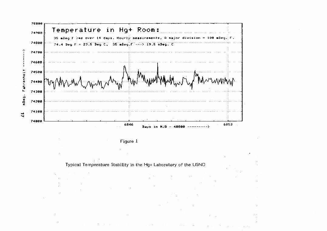
74908 Temperature i n tig+ Room: 35 mDeg F r m s over 14 days. Hourly measurements. major d ~ v l s l o n = 108 mDeg. F.
74880 7 4 . 4 Dep F = 23.5 ~e~ C. 3g r ~ e ~ . . ~ - - -> 19.5 rDog. C
6846 Days i n M J D - 48080 --------->
Figure 1
Typical Temperature Stability in the Hg+ Laboratory of t h e USNO

l e r Forum Europ ien Temps-Friquence - 1987
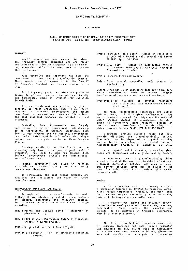
QUARTZ CRYSTAL RESONATORS
R.J. BESSON
ECOLE NATIONALE SUPERlEURE DE MECANIQUE ET DES MICROTECHNIQUES Route de Gray - La B o u l o i e - 25030 BESANCON CEDEX - FRANCE
ABSTRACT 1918 : N icho lson ( B e l l Labs) - Pa ten t on o s c i l l a t i n g c i r c u i t w i t h Roche l le s a l t c r y s t a l ( U S P a t e n t
Quar tz o s c i l l a t o r s a r e p resen t i n a lmos t 2212845, A p r i l 10 1918). any f requency c o n t r o l equipment and a r e r e a l l y t h e workhorses o f t ime and f requency. As a consequen- 1920 : W.G. Cady - Pa ten t on o s c i l l a t i n g c i r c u i t ce, tremendous e f f o r t has been made t o improve w i t h 3 vacuum tubes and q u a r t z c r y s t a l resona to r t h e i r performance. ( i n feed back c i r c u i t ) .
A l s o demanding and i m p o r t a n t has been t h e development o f new q u a r t z p i e z o e l e c t r i c sensors. Then, q u a r t z c r y s t a l resona to r i s t h e "hear t " o f f requency s tandards and sensor equipments as w e l l .
I n t h i s paper, q u a r t z resona to rs a r e p resen ted t r y i n g t o p r o v i d e i m p o r t a n t concepts and t o d i g o u t fundamental i deas o f i n t e r e s t f o r e v o l u t i o n i n t h i s f i e l d .
As s h o r t h i s t o r i c a l rev iew p r o v i d i n g genera l concepts i s f i r s t p resen ted . Then, s i n c e r e c e n t p rog ress i n resona to r unders tand ing and des ign have l e a d t o overcome most p r e v i o u s l i m i t a t i o n s , t h e l a s t i m p o r t a n t advances a r e p o i n t e d o u t and d iscussed.
B a s i c a l l y , l a t e improvements a r e l a r g e l y due e i t h e r t o b e t t e r t h e o r e t i c a l unders tand ing o r t o improvements o f boundary c o n d i t i o n s . Bo th l e a d t o new concepts and new designs. Consequences a r e doub ly r o t a t e d c r y s t a l s , m u l t i - e l e c t r o d e c o n f i g u - r a t i o n , use o f a c r y s t a l on two o r t h r e e f requen- c i e s .. .
Boundary c o n d i t i o n s a t t h e l i m i t s o f t h e v i b r a t i n g body have t o be p a i d a g r e a t dea l o f a t t e n t i o n . T h i s l eads t o some new designs which i n c l u d e "unelect roded" c r y s t a l s and "quar tz auto- mounted" resona to rs .
Recent improvements a r e g i v e n i n r e l a t i o n w i t h d i f f e r e n t des igns. Low g and f a s t warm-up des igns a r e i l l u s t r a t e d .
I n conc lus ion , t h e most r e c e n t advances a r e t a b u l a t e d and i n d i c a t i o n s a r e g i v e n on f u t u r e p o s s i b l e t rends .
INTRODUCTION AND HlSTORlCAL REVIEW
To b e g i n w i t h , i t i s p robab ly u s e f u l t o r e c a l l h i s t o r y o f p i e z o e l e c t r i c i t y and o f i t s a p p l i c a t i o n s t o sensors, resona to rs and f requency c o n t r o l . I n t h i s domain, p r i n c i p a l m i l e s t o n e s may be i n d i c a t e d as f o l l o w :
1880 : P i e r r e and Jacques C u r i e - D iscovery o f p i e z o e l e c t r i c i t y .
1893 : L o r d K e l v i n - M i c r o s c o p i c t h e o r y o f p i e z o e l e c - t r i c i t y i n q u a r t z c r y s t a l .
1910 : V o i g t - Lehrbuch der K r i s t a l l Phys ik .
1921 : P i e r c e ' s f i r s t o s c i l l a t o r .
1926 : F i r s t c r y s t a l c o n t r o l l e d r a d i o s t a t i o n i n New York c i t y .
B e f o r e wor ld war 11 an i n c r e a s i n g i n t e r e s t i n m i l i t a r y r a d i o communications c o u l d be n o t i c e d , however f a b r i c a t i o n o f r e s o n a t o r s was on an a r t i s a n b a s i s .
1939-1945 : 130 m i l l i o n s o f c r y s t a l r e s o n a t o r s and o s c i l l a t o r s were manufactured d u r i n g w o r l d war 11.
I n f a c t , p i e z o e l e c t r i c r e s o n a t o r s a r e s o l i d s ( p l a t e s , bars, ... ) o f a g i v e n c o n f i g u r a t i o n shape and dimensions p repared f rom h i g h q u a l i t y m a t e r i a l under p r e c i s e c o n t r o l o f o r i e n t a t i o n . Geometric shape i s fundamental s i n c e f requency depends on one o r s e v e r a l d imensions o f t h e v i b r a t i n g s o l i d which t u r n s o u t t o be a CAVITY FOR ACOUSTIC WAVES.
E l e c t r o d e s p r o v i d e e l e c t r i c f i e l d b u t o n l y c e r t a i n v i b r a t i o n s a r e p i e z o e l e c t r i c a l l y d r i v e n . E l e c t r o d e s can be depos i ted on c r y s t a l o r t h e y can be l o c a t e d v e r y c l o s e t o t h e c r y s t a l ( s o s a i d " e l e c t r o d e l e s s " c r y s t a l ) . To summarize we have:
- a c r y s t a l s o l i d v i b r a t i n g a c c o r d i n g g i v e n modes and f requenc ies w i t h a g i v e n q u a l i t y f a c t o r ,
- e l e c t r o d e s used t o p i e z o e l e c t r i c a l l y d r i v e v i b r a t i o n s and a t t h e same t i m e t o d e t e c t v i b r a t i o n s . C l a s s i c a l d i s t i n c t i o n between b u l k a c o u s t i c waves and s u r f a c e a c o u s t i c waves has o f course t o be made ( i n t h i s paper B.A.W. dev ices w i l l r a t h e r be cons ide red) .
N o t i c e
- f o r resona to rs used i n f requency c o n t r o l , a p a r t i c u l a r i n t e r e s t i s devoted t o f requency v a r i a - t i o n s versus temperature. A c t u a l l y , t h e user l o o k s f o r t u r n over temperatures which p r o v i d e t h e work ing p o i n t s o f t h e temperature c o n t r o l l e d ovens.
- f requency may depend and a c t u a l l y depends on v a r i o u s e x t e r n a l parameters ( temperature, p ressure , a c c e l e r a t i o n , f o r c e . . .etc,). The r e s o n a t o r can be made t o be s e n s i t i v e i n f requency dependance, t h e n i t i s used as a sensor .
The f i r s t p i e z o e l e c t r i c resona to rs were used by Langevin N icho lson and Cady. Cady 's resona to r was i n v e n t e d i n 1920 o i v i n a r i s e t o f a b r i c a t i o n
19j4-1918 : - Work on ultrasonic detection a t a r t i s a n r a t e u n t i l s c o n d wor ld war. E l e c t r o d e s
i n water . were n o t depos i ted on t h e c r y s t a l b u t techno logy

c o u l d n o t take advantage o f i t . Between 1944 and 1948, R.A. Sykes i n t r o d u c e d e l e c t r o d e s depos i ted on t h e c r y s t a l and i n 1952, A.M. Warner i n t r o d u c e d energy t r a p p i n g . The Warner 's techn ique i s s t i l l used nowadays w i t h o u t any major change. A f t e r 1974 doub ly r o t a t e d c u t s began t o be used f o l l o w i n g recommandations o f Eern isse , B a l l a t o and Besanc;onts group. These doub ly r o t a t e d c u t s had more o r l e s s been prev iewed s i n c e 1938 and they c o u l d overcome some l i m i t a t i o n s o f t h e r e g u l a r AT c u t Warner's resona to r . I n t h e l a s t f i f t e e n years s e v e r a l new resona to rs have been i n t r o d u c e d (BVA resona to rs , f l a t pack, resona to rs , m i n i a t u r e resona to rs , composl- t e resona to rs , UHF r e s o n a t o r s and so on ) .
I n f a c t , q u a r t z o s c i l l a t o r s a r e p resen t i n a lmost any t i m e o r f requency c o n t r o l equipment. P i e z o e l e c t r i c sensors a r e w i d e l y used e s p e c i a l l y as p r e c i s i o n sensors. As a consequence tremendous e f f o r t has been made towards b e t t e r p i e z o e l e c t r i c resona to rs e s p e c i a l l y d u r i n g t h e two l a s t decades. The t e n l a s t years were s p e c i a l l y demanding f o r much b e t t e r resona to rs and i n f a c t i m p o r t a n t advances have been made i n t h e f i e l d . Recent p rog ress i n resona to r unders tand ing and des ign leads t o overcome most p r e v i o u s l i m i t a t i o n s . As a r e s u l t , a s i n g l e c r y s t a l o s c i l l a t o r can now p r o v i d e , a t t h e same t ime , e x c e l l e n t s h o r t te rm s t a b i l i t y and e x c e l l e n t l o n g te rm d r i f t . Fas t warm-up can be o b t a i n e d t o g e t h e r w i t h o t h e r e x c e l l e n t c h a r a c t e r i s t i c s . A l s o impress ive (and necessary) i s t h e achievement
11 o f v e r y s m a l l g s e n s i t i v i t y (some 10- /g ) .
Improvements o f p i e z o e l e c t r i c resona to r i s p a r t i c u l a r y necessary f o r l ower aging,, b e t t e r the rma l s t a b i l i t y , l ower the rma l t r a n s i e n t s and lower env i ronmenta l dependence ( v i b r a t i o n shock, a c c e l e r a t i o n , r a d i a t i o n s , . . ) . B a s i c a l l y , improvements c o u l d come f rom e f f o r t s i n many domains ( b e t t e r theory , b e t t e r o r new p i e z o e l e c t r i c m a t e r i a l , b e t t e r des ign, b e t t e r p rocess ing , . . . ) . I n f a c t , l a t e improvements a r e l a r g e l y due e i t h e r t o b e t t e r THEORETICAL UNDERSTANDING o r t o b e t t e r c o n s i d e r a t i o n and achievement o f BOUNDARY CONDITZONS. Both l e a d t o new concepts and new des ign y i e l d i n g b e t t e r s h o r t te rm s t a b i l i t y , a g i n g r a t e s , the rma l charac te - r i s t i c s , g and env i ronmenta l s e n s i t i v i t i e s . A l s o due t o pass ive methods (1 ) (2 ) improvements on resona to r a lone can be c l e a r l y seen. I n a d d i t i o n i t may be t i m e f o r new concepts i n resona to rs .
I n f a c t , f o r somebody who i s n o t t o o much impressed by t h e e x t r a o r d i n a r y amount o f a v a i l a b l e l i t e r a t u r e on resona to rs , each s tep o f t h e resona to r des ign can be recons ide red . T h i s sometimes a r i s e s ques t ions which, a t f i r s t , l o o k a lmos t c h i l d i s h . Fo r example :
Why do c r y s t a l s have u s u a l l y c i r c u l a r o r r e c t a n g u l a r shapes and s p h e r i c a l con tours ?
The answer i s t h a t q u a r t z does n o t ca re b u t i t i s u s u a l l y e a s i e r t o d e a l w i t h those shapes and con tours . I f c o r r e c t l y handled t h i s i n t e r r o g a - t i o n can l e a d t o i n t e r e s t i n g new shapes o r con tours . Techn ica l f e a s i b i l i t y o r (and) even t r a d i t i o n o f t e n determines t h e f a b r i c a t i o n method. I n a d d i t i o n , i t i s so d e l i c a t e t o make e x c e l l e n t resona to rs t h a t t h e s l i g h t e s t change can be c r i t i c a l . T h i s does n o t encourage t h e use o f new concepts ; i t promotes t h e advantages o f e s t a b l i s h e d procedures. Bu t , t h e o r e t i c a l unders tand ing has been c o n s i d e r a b l y improved and technology has f a s t evolved. I n o t h e r words, impor tan t f u r t h e r advances a r e s t i l l p o s s i b l e and probable. Bu t t h i s w i l l be ve ry d i f f i c u l t . P a r t o f t h e problem i s t h a t every s tep o f t h e f a b r i c a t i o n process has t o be e x c e l l e n t ; any f a i l u r e anywhere can mask an improvement n e v e r t h e l e s s achieved, To b e g i n w i t h , improvement o f t h e m a t e r i a l q u a l i t y i s slow and d i f f i c u l t though ve ry impress ive e f f o r t i s made i n t h a t domain . . . and q u a r t z m a t e r i a l i s n o t y e t cha l lenged i n many a p p l i c a t i o n s .
I - BRIEF PRESENTATION OF QUARTZ CRYSTAL RESONATORS
The resona to r o u t l i n e d i n p r e v i o u s s e c t i o n may be rep resen ted on F i g . 1. Quest ion marks show t h e main p o i n t s o f i n t e r e s t and sources o f d i f f i c u l - t i e s f o r c r y s t a l manu fac tu re rs . Of impor tance i s t h e f a c t t h a t t h e e x t e r n a l w o r l d u n f o r t u n a t e l y i s a source o f v i b r a t i o n s , a c c e l e r a t i o n s , temperature and p ressure v a r i a t i o n s ...
The u s u a l e q u i v a l e n t c i r c u i t o f F i g . 2 i s v a l i d around a resonan t f requency. The i n t r i n s i c Q . f a c t o r o f a resona to r i s g i v e n by :
- (1. = -5-
WI1 S
where c i s t h e r o t a t e d e l a s t i c c o e f f i c i e n t ( p i e z o e l e c - t r i c e f f e c t i n c l u d e d ) ,
n i s t h e v i s c o s i t y cons tan t . s Then t h e q u a l i t y f a c t o r Q o f an a c t u a l resona to r depends :
- on t h e i n t r i n s i c Qi, i . e . , on t h e a c t u a l
c u t , f requency and rl (a BT c u t b a s i c a l l y y i e l d s
1.6 t i m e s t h e Q f a c t o r o f an AT c u t ) ,
- on t h e c o n s t r u c t i o n o f t h e r e s o n a t o r ( i d e a l l y one would aim t o o b t a i n one s i n g l e resonan t f requency o n l y and i n t r o d u c e no o t h e r l o s s e s t h a n m a t e r i a l l o s s e s ) .
The c r y s t a l ~ n a n u f a c t u r e r i s u s u a l l y ve ry c a r e f u l check ing t h e f o l l o w i n g :
a ) Frequency tempera tu re b e h a v i o r
Fo r a b u l k resona to r h i g h f requency t h i c k n e s s shear v i b r a t i n g t h e f requency f a t a tempera tu re T between - 200°C and + 200°C i s g i v e n by :
where f = fo f o r T = To
a, b , c a r e f u n c t i o n s of t h e r o t a t e d m a t e r i a l cons tan ts f o r a g i v e n mode o f v i b r a t i o n .
The s i n g l y r o t a t e d AT c u t (C mode v i b r a t i n g ) i s one f o r which : a = b = 0. T h i s c u t w i l l p r o v i d e us w i t h an i n t e r e s t i n g behav io r versus temperature s i n c e two " t u r n over" p o i n t s a r e a v a i l a b l e on t h e p l o t o f f requency ve rsus tempera tu re t h u s g i v i n g r i s e t o temperature s t a b i l i z a t i o n . L e t us assume now t h a t a d d i t i o n a l i n t e r e s t i n g p r o p e r t i e s a r e needed. For i n s t a n c e m in ima l n o n l i n e a r e f f e c t s o r independance ve rsus s t r e s s e s i n t h e p l a n e o f t h e c u t a r e des i red . One more degree o f freedom must be used t h u s l e a d i n g t o doub ly r o t a t e d c u t s o f F i g . 3. S i n g l y r o t a t e d c u t s correspond t o @ = 0.
S i m i l a r c o n s i d e r a t i o n s t o those developed f o r b u l k resona to rs can be developed f o r S . A . W . dev ices and g i v e ve ry p r o m i s i n g c u t s as a r e s u l t .
b ) Modes of m o t i o n
I f t h e c r y s t a l v i b r a t e s , t h e co r respond ing waves propagate and may form s t a n d i n g wave p a t t e r n s f o r g i v e n f requenc ies . Those f requenc ies a r e resonan t f requenc ies . The co r respond ing p a t t e r n s a r e c a l l e d resonance o f mot ion. Complete unders tand ing and i n v e s t i g a t i o n o f those modes a r e needed f o r any improvement i n q u a r t z c r y s t a l des ign. U s u a l l y , t h e rad io f requency spectrum o f a r e s o n a t o r i s
very compl icated ( b u t s t i l l does n o t comprise v i b r a t i o n s which do n o t g i v e r i s e t o an e l e c t r i c resonance), and i t s complete i n v e s t i g a t i o n needs t h e o r e t i c a l developments, toge ther w i t h accurate a n a l y s i s X-ray topography scanning e l e c t r o n microscopy ,b:ntetferometry, holography o r so.
Be fo re go ing t o more d e t a i l s i t i s impor tan t t o p o i n t o u t t h e e x t r a o r d i n a r y l a r g e v a r i e t y o f c r y s t a l resona to rs . I n f a c t , t h e p i e z o e l e c t r i c resona to r domain has been cons iderab ly extended f o r example t o watch m i n i a t u r e c r y s t a l s , UHF resona- t o r s f o r t h e GHz range ( F i g . 4 shows such a c r y s t a l c h e m i c a l l y etched) o r composite b u l k resona to rs ( F i g . 5).
A l s o impor tan t i s t h e f a c t t h a t l a s t two decades improvements have r e a l l y been tremendous. T h i s w i l l be d iscussed i n t h e n e x t sec t ions .
11 - RESONATOR UNDERSTANDING TOGETHER WITH THEORY
VERIFICATION I S MOST IMPORTANT AND FRUITFUL
A/ B e t t e r t h e o r e t i c a l unders tand in o f r e s o n a t o r have b rough t i n many res:lts d u r i q t h e l a s t decade
As p o i n t e d o u t (3) by Pr . V.E. Bottom, one problem, i n t h e quar tz c r y s t a l business, has been, i n t h e pas t , a r e l a t i v e l a c k o f research and develop- ment toge ther w i t h d i f f i c u l t i e s f o r p i e z o e l e c t r i c i t y t o be p a r t o f programs i n Schools o f E l e c t r i c a l Engineer ing. However, t h e l a s t decade has b rough t o u t impor tan t advances i n fundamental understanding o f p i e z o e l e c t r i c resonators. We w i l l t r y t o g i v e some examples i n t h e n e x t sec t ions .
l / A n a l y s i s o f t h e v i b r a t i o n f r m a t h r e e dimensional p o i n t o f v i e w .
As p o i n t e d o u t by Hafner(4) i n h i s e x c e l l e n t rev iew paper t e n years ago, t h e s u b j e c t i s one o f t h e most d i f f i c u l t i n c l a s s i c a l phys ics . T i e r s t e n had a l ready i n d i c a t e d many ways t o s o l u t i o n (5) when he gave i n 1974 f i r s t s o l u t i o n s (6) f o r t rapped energy resona to rs o p e r a t i n g i n over tones o f t h i c k n e s s shear. Mass l o a d i n g was a l r e a d y i n v o l v e d b u t n o t t h e r a d i u s o f c u r v a t u r e o f a contoured c r y s t a l . T h i s was f i r s t proposed by Wi lson (7) u s i n g an approximate a n a l y t i c method, thus y i e l d i n g expressions f o r over tone f requenc ies and d isp lacements i n AT c u t c r y s t a l s and g i v i n g access t o comparison w i t h X rays Lang's topographs. However t h e r e l a t i o n w i t h c o u p l i n g between modes was n o t i n v e s t i g a t e d . I n 1977, T i e r s t e n and Smythe (8) gave an a n a l y t i c s o l u t i o n i n t r o d u c i n g contour and c o u p l i n g by a n a l y t i c methods and v a l i d f o r AT-cut quar tz c r y s t a l resona to rs ( t h e paper i n c l u d e d a comparison e x h i b i t i n g e x c e l l e n t agreement between c a l c u l a t e d and measured f requen- c i e s ) . Damping was f u r t h e r in t roduced i n 1978 u s i n g (9) T i e r s t e n ' s model. I n f a c t , mass load ing , c o n t o u r i n g and boundary c o n d i t i o n s i m p l y c o u p l i n g e f f e c t s ( e s p e c i a l l y i n doubly r o t a t e d c u t s ) which, then, have t o be s tud ied .
- Coupl ing has been i n v e s t i g a t e d between t h i c k n e s s modes themselves.
T h i s was t h e case o f work performed by T i e r s t e n and Stevens (10) (11) u s i n g an a n a l y t i c method which rep laced mechanical d isp lacement by i t s decomposi t ion on t h e e igenvec to rs t r i a d o f C h r i s t o f - f e l ' s problem. Th is was a l s o t h e case o f work done by Bourquin (12) u s i n g an a n a l y t i c method and by Dulmet (13) u s i n g a semi -ana ly t i c p e r t u r b a t i o n method v a l i d f o r AT and SC cu ts . L a t e r improvement by i n t r o d u c t i o n o f temperature was per formed and was presented i n 1984 (14) l e a d i n g t o e f f e c t s o f c o u p l i n g on f requency spectrum and
f requency versus temperature behaviour o f contoured resona to rs . The improvement i s ob ta ined through use o f " e f f e c t i v e e l a s t i c c o e f f i c i e n t s " in t roduced by Bourquin and Dulmet (15)(16)(17) . I t t u r n s o u t t h a t i n f l u e n c e o f t h e cho ice o f t h e s t a t e o f re fe rence on temperature c o e f f i c i e n t s o f e l a s t i c c o e f f i c i e n t s i s ve ry impor tan t . F i n a l l y , an i n t e r e s - t i n g s p e c i a l case has been i n v e s t i g a t e d and presented r e c e n t l y (18) . Strong c o u p l i n g a r i s i n g from modes hav ing c l o s e f requencies and d i f f e r e n t the rma l s e n s i t i v i t i e s i s i n v e s t i g a t e d thus g i v i n g one p o s s i b l e mechanism f o r c e r t a i n "acc idents" o c c u r i n g on t h e f requency versus temperature curves ( F i g . 6 ) .
- Coup l ing has a l s o been i n v e s t i g a t e d between t h i c k n e s s modes and o t h e r k i n d s o f v i b r a t i o n ( i n c l u d i n g f l e x u r a l )
T h i s has been t h e case o f t h e work per formed by Milsom E l l i o t t and Redwood (19). ( T h i s t h r e e d imensional t h e o r y adresses m i n i a t u r e resonators, uses a p e r t u r b a t i o n method and u t i l i s e s complex wave numbers). Coupl ing between t h i c k n e s s modes and o t h e r modes i s a l s o l a r g e l y i n v e s t i g a t e d by M i n d l i n and h i s d i s c i p l e 5 ( u s i n g M i n d l i n ' s s p e c i a l method) (20) (21 ) (22) .
I t i s t o be p o i n t e d o u t t h a t t h e l a s t paper by Lee and Yong adresses doubly r o t a t e d p l a t e s and shows how f requency temperature behaviour i s a f f e c t e d by p l a t e dimensions and o r i e n t a t i o n s .
- As a c o n c l u s i o n : i t can be s a i d t h a t tremen- dous advance has been made i n t h e a n a l y s i s of t h e v i b r a t i o n from a t h r e e d imensional p o i n t o f view. I n our op in ion , f u r t h e r improvements should come from i n c l u d i n g EDGE BOUNDARY CONDITIONS which have n o t been considered except f o r cho ice o f mount ing p o i n t s o r c a l c u l a t i o n s o f fo rce - f requency cons tan ts f o r example by B a l l a t o (23)(24).
Z/Lagrangian formulat ion and temperature problems.
T h i s f o r m u l a t i o n has been e x t e n s i v e l y used i n t h e a n a l y s i s o f t h e i n f l u e n c e o f s t a t i c s t r e s s e s on t h e resonant f requency. It i s a l s o ve ry u s e f u l t o s tudy non l i n e a r i t i e s (such as amp l i tude f requency e f f e c t ) (25) (26) (27) (28).
T h i s was f i r s t done i n o rder t o reduce s e n s i t i v i - t i e s t o fo rces and a c c e l e r a t i o n s o r i n o r d e r t o make f o r c e sensors o r accelerometers. A good example i s t h e c a l c u l a t i o n by Lee and Kuang-Ming Wu o f t h e e f f e c t s o f a c c e l e r a t i o n i n AT c u t s o r doubly r o t a t e d p l a t e s (29)(30). The method was a l s o used t o determine thermal s e n s i t i v i t i e s e i t h e r as dynamic temperature v a r i a t i o n s o r as s t a t i c temperature v a r i a t i o n s .
- S t a t i c temperature v a r i a t i o n s
Much work has been done i n t h i s domain espec ia l - l y by Lee and Yong (31) u s i n g m a t e r i a l from prev ious work (32). It i s a l s o used i n t h e case of t h e s t r e s s f r e e temperature v a r i a t i o n s (15) . I n a c l a s s i c a l manner, v i b r a t i o n o f a resona to r by re fe rence t o t h e 3 s t a t e s o f a s o l i d (F ig . 7 ) i s ob ta ined by use o f t h e f o l l o w i n g equa t ions o f e q u i l i b r i u m and boundary c o n d i t i o n s :
T~~ ni = f j , i n each p o i n t o f S Eq ( 2 )
where T . . i s t h e usua l s t r e s s i n t h e f i n a l s t a t e , 1 I
ni i s t h e d i r e c t i o n cos ine o f su r face element
dS and f . t h e e x t e r n a l f o r c e a p p l i e d on dS. 1
I t i s c l e a r t h a t p and ni depend on s t a t i c
de fo rmat ion and t h e r e f o r e on temperature. Bu t impor tan t advantage can be ob ta ined u s i n g t h e a . coord ina tes (25) as independent v a r i a b l e s .
Equat ions corresponding t o Eq (1 ) and Eq ( 2 ) then make use o f P i o l a tensor P.. (25) :
11
P . . N . dS = T . . 11 1 0 11
where N . i s t h e d i r e c t i o n cos ines o f dS 0 '
Pii tensor corresponds t o t o t a l de fo rmat ion ( s t a t i c
de io rmat ion w i t h thermal o r i g i n p l u s dynamical de fo rmat ion ) . Wi thout dynamical de fo rmat ion we o b t a i n t h e s t a t i c P i o l a t e n s o r Pij :
- P . . N . = f . on So 11 1 I
o f e l a s t i c c o e f f i c i e n t s w i t h temperature. I n o t h e r words a f i c t i v e medium w i t h o u t expansion i s cons idered b u t i t s mechanical c o e f f i c i e n t s have (compared t o t h e a c t u a l medium) a d i f f e r e n t v a r i a t i o n w i t h temperature.
- Dynamic temperature v a r i a t i o n s
Much work has been per formed i n t h a t domain e s p e c i a l l y by T i e r s t e n , Stevens and Sinha (33)(34) . I t i s t o be p o i n t e d o u t t h a t t h e case o f doubly r o t a t e d c u t s i s inc luded . Another impor tan t advance was r e c e n t l y i n t r o d u c e d by V a l e n t i n (35) and used t o p r e d i c t f requency s h i f t s a r i s i n g from in -p lane temperature g r a d i e n t d i s t r i b u t i o n (36) i n resona to rs and t o achieve f a s t warm up (37). I n f a c t a new thermal model f o r resona to r i s proposed. The f i r s t model o f a non u n i f o r m temperature d i s t r i b u t i o n was proposed by Ho l land (38) u s i n g an i n f i n i t e p lane p l a t e model. However i n t h i s model t h e boundary c o n d i t i o n s a r e n o t r e a l i s t i c , t h e energy t r a p p i n g i s n o t taken i n t o account and o n l y a the rma l g r a d i e n t perpend icu la r t o t h e p l a t e i s supposed t o e x i s t . R e a l i s t i c c o n s i d e r a t i o n s on a c t u a l c r y s t a l s l e a d t o p o i n t o u t t h a t heat t r a n s f e r s th rough t h e quar tz i t s e l f (35) and n o t th rough t h e e lec t rodes . As a consequence therma l g r a d i e n t i s b a s i c a l l y r a d i a l (see F i g . 8 ) .
% T h i s new model has been used t o computer ize I n f a c t a dynamical t e n s o r Pij can be d e f i n e d (36) v a r i o u s f a m i l i e s o f isotherms e i t h e r depending by : on energy t r a p p i n q and on therma l conductance
- P . . = P . . + P . . 11 11 11
Then t h e fundamental equa t ions become :
. . - o f f i x a t i o n s .
Eq ( 7 )
'I,
It can be e a s i l y seen t h a t P . . can be expressed by : 1 I
- where TmR represen ts mechanical s t r e s s w i t h o u t
v i b r a t i o n s ( u . = 0 ) 1
A . . i s a tensor o f e l a s t i c c o e f f i c i e n t s . I f
t h e resona to r i s f r e e t o expand w i t h o u t induced s t resses , 'f. and Tm, a r e zero i n any p o i n t o f t h e s o l i d . ~ A e n :
21 a u P . . = A . k 11 i l k %
A . d e f i n e s new c o e f f i c i e n t s so c a l l e d " e f f e c t i v e ei&!ic c o e f f i c i e n t s u .
L e t us p o i n t o u t advantages ob ta ined by use o f those e f f e c t i v e c o e f f i c i e n t s . I n f a c t , e v e r y t h i n g i s r e f e r e d t o a so s a i d " n a t u r a l s t a t e " a t t h e reference temperature To i n c l u d i n g p ropaga t ion
equa t ion and boundary c o n d i t i o n s . Th is f i n a l l y t u r n s o u t t o be s imp le r and a t t h e same t ime more accura te . For ins tance , t h e s l i g h t change i n o r i e n t a - t i o n due t o temperature o r t h e f a c t t h a t a sphere expands i n t o an e l l i p s o i d a r e taken i n t o account. T h i s can be o f i m ~ o r t a n c e e s ~ e c i a l l v i n t h e case
3/ A theoretical realistic model is now available for resonators
F i n a l l y , d u r i n g t h e l a s t decade t h r e e d imensional models f o r a n a l y s i s o f t h e v i b r a t i o n were p r o g r e s s i - v e l y made a v a i l a b l e t a k i n g contour and c o u p l i n g i n t o account. Almost any c h a r a c t e r i s t i c o f a resona to r can now be computed from i t s parameters. The e f f e c t o f s t a t i c and dynamic temperature v a r i a t i o n s can be a c c u r a t e l y p r e d i c t e d . A new therma l model f a r from t h e i n f i n i t e p lane p l a t e i s a l s o a v a i l a b l e . I n o t h e r words, i n every domain, t h e r o r e t i c a l models a r e much more r e a l i s t i c and d i f f e r from t h e o l d i n f i n i t e p lane p l a t e model which however i s t h e b a s i s o f d e t e r m i n a t i o n o f mechanical c o e f f i - c i e n t s C:: and t h e i r temperature c o e f f i c i e n t s .
' J It would p robab ly be i n t e r e s t i n g t o remarke t h e exper iments o f Bechmann, B a l l a t o and Lukaszek (39) u s i n g accura te energy t r a p p i n g models t o redetermine some c o e f f i c i e n t s and t h e i r d e r i v a t i v e s by respec t t o temperature. ( I n f a c t improvements i n accuracy o f these c o e f f i c i e n t s a r e now needed t o d e f i n e new c u t s o r des ign new resona to rs and sensors ) .
B/ Theory v e r i f i c a t i o n feeds back t h e o r y and prepares f o r new designs
T h e o r e t i c a l a n a l y s i s i s complex and d i f f i c u l t i t may have t o be completed by f i n i t e elements techniques b u t i t always has t o be con f ron ted i n d e t a i l w i t h a c t u a l f i g u r e s . Var ious d i a g n o s t i c s and measurements have t o be per formed a t each s t e p o f f a b r i c a t i o n (on raw m a t e r i a l , wafer , sur face, i n t e r f a c e , f i x a t i o n , e l e c t r o d e d e p o s i t i o n , c lean ing , enc los ing , ... and on f i n a l resona to r ) . For s i m p l i c i - t y , o n l y v i s u a l i z a t i o n o f c r y s t a l ' s v i b r a t i o n s w i l l be considered here.
1/ X ray topographic techniques
of some doubly r o t a t e d c u t s 'as RT ' cu ts . F i n a l l y When an a c t u a l resona to r has been designed, t h i s method e n t i t l e s t o separate d imensional v a r i a t i o n i t i s p o s s i b l e t o ge t , from theory , every resonant o f resonator due t o temperature f rom v a r i a t i o n s
f requency w i t h i t ' s assoc ia ted v i b r a t i o n p a t t e r n , i n t h e whole needed frequency domain. Then, t h e a c t u a l resonant f requenc ies and v i b r a t i o n p a t t e r n s have t o be obta ined, f o r i ns tance , through Lang's o r s i m i l a r X r a y topograph ic techniques (40). Though many e x c i t i n g new r e s u l t s can s t i l l be found i n t h a t f i e l d , t h e technique i s now w e l l known. I t needs very w e l l t r a i n e d people u s i n g expensive equipment. However, even i f i t i s t ime consuming t h e r e i s no way t o p r o p e r l y design a new resona to r w i t h o u t such a technique ( o r a s i m i l a r one) . On t h e p a t t e r n o f F i g . 9, t h e o r e t i c a l r e s u l t s and topographs appear a t t h e same t ime. The engineer and t h e t h e o r e t i c i a n need t o d iscuss f o r design e v o l u t i o n t r y i n g t o a v o i d o r e x p l a i n unexpected p a t t e r n s . The technique can a l s o be used f o r s tudy o f c o u p l i n g between modes under v a r i a t i o n o f tempera- t u r e p rov ided an adequate oven t ransparen t t o X rays i s used (18).
2/ Other techniques
Many o t h e r techniques have been used r e c e n t l y t o v i s u a l i z e o r computer ize a c t u a l v i b r a t i o n p a t t e r n s . T h i s i s t h e case i n l a s e r i n t e r f e r o m e t r i c measurement o f v i b r a t i o n d isp lacements (41) o r i n measurements u s i n g speckle e f f e c t s (42) .
111 - BETTER CONSIDERATION AND ACHIEVEMENT OF
BOUNDARY CONDITIONS
A c r y s t a l resona to r i s a s o l i d LIMITED by sur faces connected t o o u t s i d e changing wor ld by f i x a t i o n s , e l e c t r o d e s and surrounding medium ( F i g . 1 ) . I n t e r a c t i o n s a re mechanical thermal and e l e c t r i c . Obv ious ly boundary c o n d i t i o n s have t o be p a i d a g r e a t dea l o f a t t e n t i o n and care (43)(44) . Impor tan t improvements a r e s t i l l ahead.
As we have seen i n s e c t i o n 11, t h e o r y now i n c l u d e s much more r e a l i s t i c boundary c o n d i t i o n s . Bu t a l s o new techniques a r e developed w i t h much b e t t e r achievement o f su r face l i m i t s , much b e t t e r mounting o f p i e z o e l e c t r i c c r y s t a l . Some examples w i l l be considered here.
1 / Surface o f p i e z o e l e c t r i c medium
I n an i d e a l s i t u a t i o n , one would c r e a t e a s u r f a c e corresponding e x a c t l y t o a g i v e n shape ( o r equa t ion ) , w i t h o u t any per tu rbed l a y e r and never the less e x h i b i t i n g o p t i c a l p o l i s h . Very c l o s e t o t h e su r face t h e m a t e r i a l p r o p e r t i e s should be unperturbed. No d e f e c t should be c rea ted by machin ing ( o r by e l e c t r o d e d e p o s i t i o n i . e . " e l e c t r o - deless" c r y s t a l s a r e d e s i r a b l e ) . From t h a t p o i n t o f view, a t l e a s t two techniques have been found p romis ive .
a ) U l t r a s o n i c mach in inp
T h i s technique has been adapted t o p i e z o e l e c t r i c c r y s t a l s (43) and has been now much improved. Computerized complex U.S. machin ing systems have been designed, they a l l o w t o machine (45) a g i v e n sur face even complex ( i n t r o d u c e d i n computer by i t s equa t ion f ( x , y , z ) = 0 ) w i t h a g i v e n roughness (down t o a lmost o p t i c a l p o l i s h ) and w i t h a ve ry sma l l p e r t u r b a t i o n o f m a t e r i a l p r o p e r t i e s .
b ) Chemical etching, p o l i s h i n g and machin inq
T h i s technique, a l s o in t roduced i n t h e l a s t decade (461, probably needs raw m a t e r i a l h i g h l y homogeneous w i t h o u t g i v e n d e f e c t s ( f o r i ns tance t u n n e l s ...I t o be f u l l y e f f i c i e n t . Chemical ly p o l i s h e d (47) b lanks a r e mechan ica l l y much s t ronger ( i . e . much l e s s d i s l o c a t i o n s a r e c rea ted) and
complex geometr ies can be produced. The technique ranks i n i n t e g r a t e d techniques and much e f f o r t i s s t i l l done (48) t o i n v e s t i g a t e t h e k i n e t i c s o f e t c h i n g so as t o master changes o f su r faces w i t h pro longed e t c h i n g ( c o n t r o l o f su r faces i s per formed by S.E.M.).
2 / Fixa t ion o f v i b r a t i n g c r y s t a l
An i d e a l f i x a t i o n would e x h i b i t n e i t h e r d i s c o n t i - n u i t i e s nor s t r e s s e s n o r changes w i t h t ime. T h i s s t r o n g l y encourage m o n o l i t h i c s t r u c t u r e s o r auto- mounted c r y s t a l s (43) . The concept i s v a l i d f o r BAW and SAW dev ices as w e l l .
3/ Direc t environment o f Xtal
L a s t decade has seen c o n t i n u i n g improvement i n c l e a n l i n e s s o f c r y s t a l , processing, i n c l u d i n g s i n g l e s t e p h i g h vacuum process ing bake o u t and s e a l i n g and U.V. c l e a n i n g procedures. Coldweld sea led metal enclosures and ceramic hermet i c f l a t p a c k s have been developed f o r s i m i l a r purposes.
I V - IMPROVEMENT I N THE "QUALITY" OF PIEZOELECTRIC
MATERIAL I S STILL NEEDED
Recent improvements i n resona to r unders tand ing and technique, r a d i a t i o n hardening requi rements a r e s t r o n g l y b o o s t i n g research and development f o r " b e t t e r " p i e z o e l e c t r i c m a t e r i a l . B e t t e r may a l s o mean b e t t e r a v a i l a b i l i t y and c o n t i n u i t y i n t h e supply o f a g i v e n q u a l i t y o f m a t e r i a l . A lso, p i e z o e l e c t r i c m a t e r i a l s u p p l i e r s have t o cons ider i n d u s t r i a l YIELD an t h i s does n o t always encourage f o r h i g h e s t q u a l i t y m a t e r i a l because t h e market may be t o o smal l .
1 / p u a l i t y o f q u a r t z m a t e r i a l
For those who work on t h e f o r e f r o n t o f p iezoe lec - t r i c devices, a v a i l a b i l i t y o f e x c e l l e n t m a t e r i a l i s s t i l l a problem. Nobody r e a l l y knows where would be t h e l i m i t s o f u l t r a h i g h p u r i t y q u a r t z w i t h ve ry few d i s l o c a t i o n s and growth de fec ts , i f t h a t m a t e r i a l was p r o p e r l y handled. Ex tens ive a t t e n u a t i o n measurements over a l a r g e temperature range have been done i n t h e pas t , b u t they d i d n o t use e x t r a h i g h p u r i t y d i s l o c a t i o n f r e e m a t e r i a l (and a t 5 MHz r e s u l t s o f t e n came th rough resona to rs accord ing t o Warner's des ign) . Recent work has been done on growth o f h i g h p u r i t y low d i s l o c a t i o n q u a r t z (49)(50) . Aluminium con ten t l e v e l may be as low as 0.02 ppm o r lower and a l a r g e degree o f p e r f e c t i o n i s ob ta ined ( l e s s than 10 d i s l o c a t i o n
2 l i n e s per cm ) . Experiments demonstrate extreme importance o f seed's o r i g i n s e l e c t i o n and prepara- t i o n . Best r e s u l t s seem t o be ob ta ined w i t h h i g h q u a l i t y n a t u r a l seeds prepared from areas s e l e c t e d f o r ve ry low d i s l o c a t i o n d e n s i t y c u t t i n g damages beeing removed from t h e seed sur faces and a l l c o n t r o l s beeing done by X-ray topography.
2/ New p i e z o e l e c t r i c m a t e r i a l
I n f a c t , q u a r t z has n o t y e t been r e a l l y c h a l l e n - ged. However t h e l a s t decade has seen f u r t h e r developments i n L i t h i u m N ioba te and L i t h i u m T a n t a l a t e a p p l i c a t i o n s . I t has a l s o seen q u i t e a number o f s t u d i e s d e a l i n g w i t h hydro therma l l y grown B e r l i n i t e c r y s t a l s . Though c r y s t a l s a r e s t i l l t o be p e r f e c t e d i n t e r e s t i n g r e s u l t s have a l r e a d y been ob ta ined on B e r l i n i t e resona to rs (51). Compared t o quar tz , a much h igher c o u p l i n g i s ob ta ined t o g e t h e r w i t h a lower s e n s i t i v i t y o f t h e temperature c o e f f i c i e n t s o f frequency.
F i n a l l y , i t i s a l s o t o be p o i n t e d o u t t h a t L i t h i u m t e t r a b o r a t e has been in t roduced as a new p i e z o e l e c t r i c m a t e r i a l (52) and t h a t Zn 0 o r A1 N f i l m s s p u t t e r e d on t o s imple c r y s t a l S i l i c o n beg in t o be used (53)(54) i n composite resona to r s t r u c t u r e s . The s t r u c t u r e s a re sma l l enough t o be incorpora ted w i t h i n s i l i c o n i n t e g r a t e d c i r c u i t s .
V - NON LINEAR PHENOMENA I N QUARTZ RESONATORS
Several p r o p e r t i e s o f resona to rs s t r o n g l y depend on non l i n e a r i t i e s o f q u a r t z m a t e r i a l . Harmonic genera t ion , amp l i tude f requency e f f e c t s and i n t e r m o d u l a t i o n correspond t o p ropaga t ion o f a f i n i t e amp l i tude wave i n a non l i n e a r medium.. . S e n s i t i v i t i e s t o e x t e r n a l o r i n t e r n a l p e r t u r b a t i o n s ( temperature, f o r c e , p ressure a c c e l e r a t i o r l e l e c t r i c f i e l d ... ) a r e due t o t h e c o u p l i n g between t h e h i g h f requency wave and t h e non l i n e a r s t r a i n e d medium ; they deserve a non l i n e a r t rea tment .
Ten years ago some non l i n e a r c o e f f i c i e n t s were s t i l l needed when measured by t h e au thor (55) t o e x p l a i n non l i n e a r e f f e c t s i n q u a r t z resona- t o r s (56). However i t i s c l e a r t h a t , t o day, some impor tan t advances i n t h e resona to r f i e l d a r e due t o success i n non l i n e a r e f f e c t s s tudy and hand l ing . D e t a i l e d i n f o r m a t i o n w i l l be found i n r e f 56 o r i n a r e c e n t e x c e l l e n t rev iew paper (57) which a l s o c a l l s a t t e n t i o n on t h e concept o f l a t t i c e waves and phonons ( l e a d i n g t o d e s c r i p t i o n o f thermal c o n d u c t i v i t y ) thermal expansion and a c o u s t i c at tenua- t i o n by means o f phonons i n t e r a c t i o n s ) .
An i n t e r e s t i n g new non- l i near a n a l y s i s method has a l s o been r e c e n t l y proposed (58) and caused t o f i n d ou t b o t h t h e o r e t i c a l l y and e x p e r i m e n t a l l y a so c a l l e d "non- ra t ionna l f requency d i v i s i o n " (59) .
The impor tan t p a r t o f t h e SC c u t resona to r i s a l s o t o be p o i n t e d o u t i n t h a t f i e l d s i n c e ampl i tude frequency e f f e c t , i n t e r m o d u l a t i o n s e n s i t i - v i t y t o p l a n a r s t resses a r e much reduced (57)(60) .
Recen t l y f requency and phase n o i s e i n quar tz resona to rs have been s t u d i e d (61) as a f u n c t i o n o f t h e d r i v i n g power. A t low power l / f f l u c t u a t i o n s a r e observed b u t a t medium power (some mw) t h e non l i n e a r i t i e s o f t h e c r y s t a l i nc rease t h e phase f l u c t u a t i o n s when a t h i g h powers thermal i n s t a b i l i t i e s and c h a o t i c behaviour occur ( t o g e t h e r w i t h h i g h l e v e l wh i te n o i s e ) .
V I - EVOLUTION I N RESONATOR OR SENSOR DESIGN,
NEW CONCEPTS
I n t h i s s e c t i o n some advances o f t h e l a s t decade w i l l be r e c a l l e d . To beg in w i t h , t h e importance o f e f f e c t i v e p r o d u c t i o n o f doubly r o t a t e d th ickness mode p l a t e s w i l l be p o i n t e d ou t . Though in t roduced b e f o r e wor ld war 11, doubly r o t a t e d resona to rs have r e a l l y been developed a f t e r work by Eer Nisse (62)(63) on S t c u t s . I n t h i s paper we w i l l b a s i c a l l y r e f e r t o t h e exhaus t i ve paper by B a l l a t o ( 64 ) and p o i n t ou t t h e excep t ionna l advantages o f doubly r o t a t e d p l a t e s ( i n p a r t i c u l a r f o r SC o r TTC cu ts , low s e n s i t i v i t i e s t o s t resses i n c u t ' s p lane, e x c e l l e n t thermal behaviour i n c l u d i n g thermal t r a n s i e n t (65) and low amp l i tude frequency e f f e c t (66 ) ) . Th is i s t h e reason why i n t e n s i v e e f f o r t s on doubly r o t a t e d c r y s t a l s have been r e p o r t e d d u r i n g t h e f i v e l a s t years causing doubly r o t a t e d p l a t e s t o be, now, commercia l ly a v a i l a b l e .
Some new resona to rs o r new concepts t h a t appeared i n t h e l a s t decade w i l l now be r a p i d l y presented :
1 / New resonators or techniques
a ) Ceramic f l a t pack resona to rs (67)(68)(69)(70)
As p o i n t e d o u t by severa l au thors , usua l packaging techniques do n o t i n s u r e h e r m e t i c i t y t h u s exposing t h e c r y s t a l t o con tamina t ion . The ceramic f l a t pack technique uses ceramic m a t e r i a l t o g e t h e r w i t h a luminium gaskets and a l l o w s mass p r o d u c t i o n . T h i s new c o n f i g u r a t i o n y i e l d s a sma l l , h i g h l y r e l i a b l e rugged c r y s t a l ( p o l y i m i d e bonding can be used).
b) B.V.A. techn iques
T h i s technique was i n t r o d u c e d i n Besan~on, France a f t e r 1975 (43)(44)(71)(72) . I t i s now w e l l known and i n d u s t r i a l l y produced (73)(74) though many models descr ibed a r e n o t y e t i n produc- t i o n l i n e . The new BVAn s t r u c t u r e s may use a r a t h e r
conven t ionna l bonding and a s p e c i a l f i x a t i o n ( n odd) o r may use "automounted" c r y s t a l s i . e . c r y s t a l w i t h m o n o l i t h i c f i x a t i o n s made o u t o f quar tz ( n even). The c r y s t a l s a r e u s u a l l y "e lec t rode less" b u t e l e c t r o d e s can a l s o be depos i ted on v i b r a t i n g c r y s t a l ( p a t e n t no 77 17 309) so l e a d i n g t o QAS designs (74). F i g . 10 r e c a l l s some o f t h e d i f f e r e n t designs proposed.
A t t h i s p o i n t , EVA2 u n i t s (5 t o 100 MHz)
and EVA4 u n i t s , i n p a r t i c u l a r , a r e i n p r o d u c t i o n
l i n e s . Among o t h e r advantages of EVA2 designs
(44)(71) we s h a l l s p e c i a l l y ment ion lower aging, much lower g s e n s i t i v i t y , h i g h e r d r i v e l e v e l s and ex is tence o f zero ag ing d r i v e l e v e l s (75). More p r e c i s e l y , EVA2 resona to r a l l o w much h igher
d r i v e l e v e l s w i t h o u t degrading b a d l y d r i f t r a t e s . Moreover t h e o r e t i c a l c o n s i d e r a t i o n s and exper imenta l d a t a (75) show t h a t r e s u l t i n g ag ing ar may be, as a f i r s t approximat ion, modeled by :
ar = ai + kP ( 1 + a exp ( - G o t / ~ ) + ... 1
where : a . i s an i n t r i n s i c a g i n g depending on m a t e r i a l and c u t ,
k i s a cons tan t depending on m a t e r i a l and cu t ,
a i s a cons tan t w i t h o u t dimension,
P i s t h e power d i s s i p a t e d i n mot iona l r e s i s t a n c e R,
Po i s a re fe rence power l e v e l ,
T i s a t ime cons tan t ; t i s t ime.
T h i s formula shows evidence o f a d r i v e l e v e l
P1 y i e l d i n g on ag ing r a t e c r o s s i n g zero. For n a t u r a l
B r a z i l quar tz 5 MHz f i f t h over tone resona to r P1
i s about 80 uw ; 5 MHz t h i r d over tone SC correspond t o 160 pw.
Using very h i g h d r i v e l e v e l s i t i s p o s s i b l e t o " i n t e r n a l l y heat" t h e c r y s t a l by energy d i s s i p a t i o n i n Rl (76).
I t i s t o be p o i n t e d o u t t h a t EVA2 o r BVAq
designs a r e p a r t i c u l a r y s u i t a b l e f o r low g designs (73)(74)(44) l e a d i n g t o t h e f i r s t i n d u s t r i a l produc- t i o n w i t h g s e n s i t i v i t i e s s t a t i s t i c a l l y around
2 1 0 - ' ~ / ~ max.
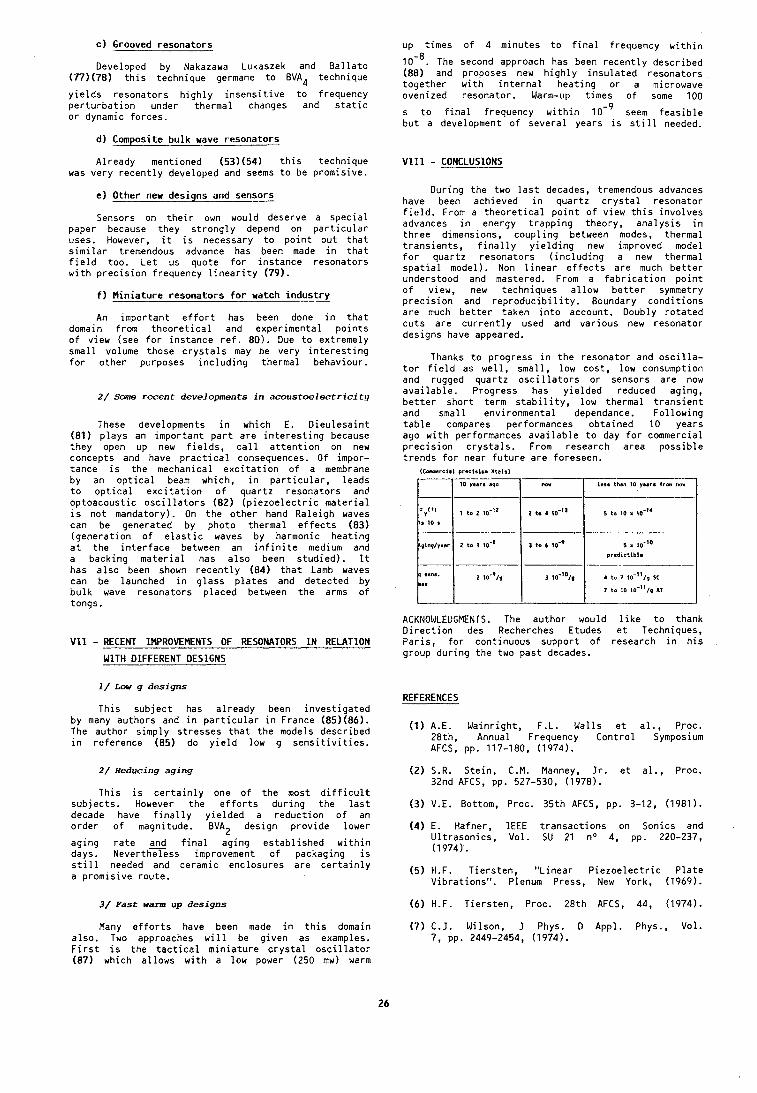
C ) Grooved resona to rs
Developed by Nakazawa Lukaszek and B a l l a t o (77)(78) t h i s technique germane t o EVA4 technique
y i e l d s resona to rs h i g h l y i n s e n s i t i v e t o frequency p e r t u r b a t i o n under the rma l changes and s t a t i c o r dynamic fo rces .
d) Composite b u l k wave resona to rs
Al ready mentioned (53)(54) t h i s technique was very r e c e n t l y developed and seems t o be p romis ive .
e) Other new designs and sensors
Sensors on t h e i r own would deserve a s p e c i a l paper because they s t r o n g l y depend on p a r t i c u l a r uses. However, i t i s necessary t o p o i n t o u t t h a t s i m i l a r tremendous advance has been made i n t h a t f i e l d too. L e t us quote f o r i n s t a n c e resona to rs w i t h p r e c i s i o n frequency l i n e a r i t y (79) .
f ) M i n i a t u r e resona to rs f o r watch i n d u s t r y
An impor tan t e f f o r t has been done i n t h a t domain from t h e o r e t i c a l and exper imenta l p o i n t s o f view (see f o r ins tance r e f . 80) . Due t o ex t reme ly sma l l volume those c r y s t a l s may be very i n t e r e s t i n g f o r o t h e r purposes i n c l u d i n g thermal behaviour .
2 / Same recent developments i n a c o u s t o e l e c t r i c i t y
These developments i n which E. D i e u l e s a i n t (81) p l a y s an impor tan t p a r t a r e i n t e r e s t i n g because they open up new f i e l d s , c a l l a t t e n t i o n on new concepts and have p r a c t i c a l consequences. O f impor- tance i s t h e mechanical e x c i t a t i o n o f a membrane by an o p t i c a l beam which, i n p a r t i c u l a r , l eads t o o p t i c a l e x c i t a t i o n o f quar tz resona to rs and op toacous t i c o s c i l l a t o r s (82) ( p i e z o e l e c t r i c m a t e r i a l i s n o t mandatory). On t h e o t h e r hand Ra le igh waves can be generated by photo thermal e f f e c t s (83) ( g e n e r a t i o n o f e l a s t i c waves by harmonic h e a t i n g a t t h e i n t e r f a c e between an i n f i n i t e medium and a backing m a t e r i a l has a l s o been s t u d i e d ) . It has a l s o been shown r e c e n t l y (84) t h a t Lamb waves can be launched i n g l a s s p l a t e s and de tec ted by b u l k wave resona to rs p laced between t h e arms o f tongs.
V I I - RECENT IMPROVEMENTS OF RESONATORS I N RELATION
WITH DIFFERENT DESIGNS
1 / Low g designs
T h i s s u b j e c t has a l r e a d y been i n v e s t i g a t e d by many au thors and i n p a r t i c u l a r i n France (85)(86) . The author s imp ly s t r e s s e s t h a t t h e models descr ibed i n re fe rence (85) do y i e l d low g s e n s i t i v i t i e s .
2 / Reducing aging
T h i s i s c e r t a i n l y one o f t h e most d i f f i c u l t s u b j e c t s . However t h e e f f o r t s d u r i n g t h e l a s t decade have f i n a l l y y i e l d e d a r e d u c t i o n o f an o r d e r o f magnitude. EVAZ design p r o v i d e lower
ag ing r a t e and f i n a l ag ing e s t a b l i s h e d w i t h i n days. N e v e r t h x e s s improvement o f packaging i s s t i l l needed and ceramic enclosures a r e c e r t a i n l y a p romis ive r o u t e .
3/ ~ a s t w a r n up designs
Many e f f o r t s have been made i n t h i s domain a l s o . Two approaches w i l l be g i v e n as examples. F i r s t i s t h e t a c t i c a l m i n i a t u r e c r y s t a l o s c i l l a t o r (87) which a l l o w s w i t h a low power (250 mw) warm
up _ t imes of 4 minutes t o f i n a l frequency w i t h i n
lo-'. The second approach has been r e c e n t l y descr ibed (88) and proposes new h i g h l y i n s u l a t e d resona to rs t o g e t h e r w i t h i n t e r n a l h e a t i n g o r a microwave ovenized resona to r . Warm-up t imes o f some 100
s t o f i n a l f requency w i t h i n seem f e a s i b l e b u t a development o f severa l years i s s t i l l needed.
V131 - CONCLUSIONS
Dur ing t h e two l a s t decades, tremendous advances have been achieved i n q u a r t z c r y s t a l resona to r f i e l d . From a t h e o r e t i c a l p o i n t o f view t h i s i n v o l v e s advances i n energy t r a p p i n g theory , a n a l y s i s i n t h r e e dimensions, c o u p l i n g between modes, the rma l t r a n s i e n t s , f i n a l l y y i e l d i n g new improved model f o r q u a r t z resona to rs ( i n c l u d i n g a new thermal s p a t i a l model). Non l i n e a r e f f e c t s a r e much b e t t e r understood and mastered. From a f a b r i c a t i o n p o i n t o f view, new techniques a l l o w b e t t e r symmetry p r e c i s i o n and r e p r o d u c i b i l i t y . Boundary c o n d i t i o n s a r e much b e t t e r taken i n t o account. Doubly r o t a t e d c u t s a r e c u r r e n t l y used and v a r i o u s new resona to r designs have appeared.
Thanks t o p rogress i n t h e resona to r and o s c i l l a - t o r f i e l d as w e l l , sma l l , low cos t , low consumption and rugged q u a r t z o s c i l l a t o r s o r sensors a r e now a v a i l a b l e . Progress has y i e l d e d reduced aging, b e t t e r s h o r t te rm s t a b i l i t y , low therma l t r a n s i e n t and sma l l envi ronmental dependance. F o l l o w i n g t a b l e compares performances o b t a i n e d 10 years ago w i t h performances a v a i l a b l e t o day f o r commercial p r e c i s i o n c r y s t a l s . From research area p o s s i b l e t r e n d s f o r near f u t u r e a r e foreseen.
IC0merei.l preclston XtaIsl
ACKNOWLEDGMENTS. The au thor would l i k e t o thank D i r e c t i o n des Recherches Etudes e t Techniques, P a r i s , f o r cont inuous suppor t o f research i n h i s group d u r i n g t h e two p a s t decades.
REFERENCES
less than 10 years from nor 10 p a r s ago
(1) A.E. Wa in r igh t , F.L. Wa l l s e t a l . , Proc. 28th, Annual Frequency C o n t r o l Symposium AFCS, pp. 117-180, (1974).
1-1 1 now
(2) S.R. S te in , C.M. Manney, J r . e t a l . , Proc. 32nd AFCS, pp. 527-530, (1978).
( 3 ) V.E. Bottom, Proc. 35 th AFCS, pp. 3-12, (1981).
(4) E. Hafner, IEEE t r a n s a c t i o n s on Sonics and U l t r a s o n i c s , Vol . SU 21 no 4, pp. 220-237, (1974).
(5) H.F. T i e r s t e n , "L inear P i e z o e l e c t r i c P l a t e V ib ra t ions" . Plenum Press, New York, (1969).
(6) H.F. T i e r s t e n , Proc. 28 th AFCS, 44, (1974).
(7) C.J. Wilson, J Phys. D Appl . Phys.,, Vol . 7 , pp. 2449-2454, (1974).
( 8 ) H . F . T i e r s t e n and R.C. Smythe, Proc. 31s t AFCS, pp. 44-47, (1977).
( 9 ) R.J. Besson, B.M. Dulmet e t a l . , U l t r a s o n i c s Symposium Proceedings, pp. 152-156, (1978).
(10) D.S. Stevens and H.F. T i e r s t e n , Proc. 35 th AFCS, pp. 205-21 2, ( 1 981 ) .
(11) H.F. T i e r s t e n and D.S. Stevens, Proc. 36 th AFCS, pp. 37-45, (1982).
(12) R . Bourquin and D. Nassour, C.R. Acad. Sc. P a r i s , t. 298, SBr ie 11, no 12, pp. 517-520, (1984).
(13) B. Dulmet, Revue de Phys. Appl. 19, pp. 839-849, (1984).
(14) 8. Dulmet and F. F i c h e t , Proc. IEEE, U l t r a s o n i c s Symposium, (1984).
(15) B. Dulmet, R . Bourquin, C.R. Acad. Sc. P a r i s , t. 294 SBr ie 11, pp. 361-364, (1982).
(16) B. Dulmet, R . Bourquin, Revue Phys. Appl. 18, pp. 619-624, (1983).
(17) R . Bourquin, B. Dulmet, Proc. CongrSs l n t e r n a - t i o n a l de Chronomi t r ie Besanqon, pp. 109-113, (1984).
(18) R. Bourquin, B. Dulmet, G. Genes t ie r , Proc. U l t r a s o n i c s Symposium, (1984).
(19) R.F. Milsom, D.T. E l l i o t t e t a l . , Proc. AFCS, pp. 174-186, (1981).
(20) R.D. M i n d l i n , Proc. 36 th AFCS, pp. 3-21, (1982).
(21) Z . Nikodem, P.C.Y. Lee, I n t . J . S o l i d s S t r u c t u r e 10, pp. 177-196, (1974).
(22) P.C.Y. Lee, Y.K. Yong, AFCS, (1984).
(23) A. B a l l a t o , IEEE t r a n s . Sonics U l t r a s o n i c s , Vol . SU 25 no 3, pp. 132-138, (1978).
(24) A. B a l l a t o , IEEE t r a n s Sonics U l t r a s o n i c s , Vol . SU 25 n04, pp. 223-226, (1978).
(25) R.N. Thurston, "Waves i n so l ids " , Handbuch der Physik V1 a/4, Spr inger Ver lag, (1974).
(26) H.F. T i e r s t e n , I n t . J . Eng. Sc. Vol . 9, pp. 587-604 Pergamon, (1971).
(27) J.C. Baumhauer and H.F. T i e r s t e n , J . Ac. Soc. Am, Vol . 54 n", pp. 1017-1034, (1973).
(28 )H.F . T i e r s t e n , J . Acoust. Soc. Am. Vol. 57 no 3, pp. 660-666, (1975).
(29) P.C.Y. Lee, Kuang-Ming Wu, Proc. 30 th AFCS, pp. 1-7, (1976).
(30) P.C.Y. Lee, Kuang-Ming Wu, Proc. 34 th AFCS, pp. 403-411, (1980).
(31) P.C.Y. Lee and Y.K. Yong, Proc. 37 th AFCS, pp. 200-207, (1983).
(32) P.C.Y. Lee, Y.S. Wang e t a l . , J. Acoust. Soc. Am. 57 n O l , pp. 95-105, (1975).
(33) 0.5. Stevens, H.F. T i e r s t e n , Proc. 37 th AFCS, Pp. 208-217, (1983).
(34) B.K. Sinha, H.F. T i e r s t e n , J. App. Phys., Vol . 55 no 9, pp. 3337-3347.
(35) J.P. V a l e n t i n , D o c t o r a l Thesis no 178, Besanqon, (1903).
(36) J.P. V a l e n t i n , G. Thiobald, J .J . Gagnepain, Proc. 38 th AFCS, (1984).
(37) J.P. V a l e n t i n , M.D. D e c a i l l o t , R.J. Besson, Proc. 38 th AFCS, (1984).
(38) R . Hol land, IEEE Trans. SU 21 no 3, p. 171, (1974).
(39) R . Bechmann, A.D. B a l l a t o , T J Lukaszek, Proc. IRE Vol . 50 no 8, (1962).
(40) G. Genes t ie r , D o c t o r a l t h e s i s no 127, ENSMM, Besanqon, (1982).
(41) K. l i j i m a , Y . Tsuzuki e t a l . , Proc. 30 th AFCS, pp. 65-70, (1976).
(42) L. Wimmer, S. H e r t l e t a l . , Rev. Sc i . l ns t rum. 55(4 ) , pp. 605-609, ( A p r i l 1984) .
(43) R.J. Besson, Proc. 3 0 t h AFCS, pp. 78-82, (1976) and Proc. 31s t AFCS, pp. 147-152, (1977).
(44) R.J. Besson, J.M. Groslambert , F.L. Wal ls , F e r r o e l e c t r i c s 1982, Vol. 43, pp. 57-65.
(45) P. M a i t r e , ENSMM, Besanqon, p r i v a t e communica- t i o n .
(46) J.R. Vig, J.W. Lebus e t a l . , Proc. 31s t AFCS, pp. 131-143, (1977).
(47) W.P. Hanson, Proc. 37 th AFCS, pp. 261-264, (1983).
(48) C.R. T e l l i e r and a l . , Proc. 40 th AFCS, (1986).
(49) D.F. C r o x a l l , 1 . R . C h r i s t i e e t a l . , Proc. 3 6 t h AFCS, pp. 62-65, (1982).
(50) J.F. Ba lasc io , A.F. Armington, Proc. 4 0 t h AFCS, (1986).
(51) J . D e t a i n t , H. Poignaut e t a l . , Proc. 34 th AFCS, pp. 93-101, (1980).
(52) C.D.J. Emin, J.F. Werner, Proc. 37 th AFCS, pp. 136-143, (1983).
(53) J.S. Wang, K.M. L a k i n e t a l . , Proc. 3 7 t h AFCS, pp. 144-150, (1983).
(54) T.W. Grudkowski, J.F. B lack e t a l . , Proc. 36 th AFCS, pp. 537-548, (1983).
(55) R.J. Besson, Proc. 2 8 t h AFCS, p. 8, (1974).
(56) J .J . Gagnepain, R.J. Besson, P h y s i c a l Acous t i cs WP Mason Ed. Vol . X I 245, Acad. Press, (1975).
(57) J .J . Gagnepain, Proc. 3 5 t h AFCS, pp. 14-30, (1981).
(58) J.H. B a l b i , J.A. Duf faud, R.J. Besson, Proc. 32nd AFCS, pp. 162-168, (1978).
(59 )J .H . B a l b i , M. Dulmet, A. T h i r a r d , Revue de Physique APp l iqu ie , tome 17 no 1, ( j a n v i e r 1982).
( 6 0 ) R . Bourquin, D. Nassour, D. Hauden, Proc. 3 6 t h AFCS, pp. 200-207, (1982).
(61) 3 . 3 . Gagnepain, M. O l i v i e r , F.L. Wa l l s , Proc. 3 7 t h AFCS, pp. 218-225, (1983).
(62) E.P. Eern isse , Proc. 2 9 t h AFCS, pp. 1-4, (1975).
(63) E.P. Eern isse , Proc. 3 0 t h AFCS, pp. 8-11, (1976) .
(64) A. B a l l a t o , P h y s i c a l Acous t i cs Vol . X l I 1 , pp. 115-181, (1977) .
(65) J. Kus te rs , IEEE Trans Sonics U l t r a s o n i c s SU 23, pp. 273-276, (1976) .
(66) J.J. Gagnepain, J.C. Poncot and C. Pegeot, Proc. 3 1 s t AFCS, pp. 17-22, (1977) .
(67) J.R. V ig, J.W. Lebus e t a l . , Proc. 2 9 t h AFCS, pp. 220-229, (1975) .
(68) P.O. Wi lcox, G.S. Snow e t a l . , Proc. 2 9 t h AFCS, pp. 202-219, (1975) .
(69) R.O. Pe te rs , Proc. 3 0 t h AFCS, pp. 224-231, (1976) .
(70) R.L. F i l l e r , J.M. Fronck e t a l . , Proc. 32nd AFCS, pp. 290-298, (1978) .
(71) R.J. Besson, Proc. 1 0 t h PTTI, pp. 101-130, (1978) .
(72) French p a t e n t s n o 7601035, 7717309, 7802261, 7828728, 791 8553, 81 10006, 827 5351 and c o r r e s - ponding p a t e n t s o r p a t e n t s pending i n o t h e r c o u n t r i e s .
(73) E.P. Graf , U.R. P e i e r , 3 7 t h AFCS, pp. 492-500, (1983).
(74) J.P. Aubry, A. Debais ieux, 3 8 t h AFCS, (1984) .
(75) R.J. Besson, D.A. Emmons, Proc. 1 1 t h PTTI, pp. 457-469.
(76) J.P. V a l e n t i n , 3 4 t h AFCS, pp. 194-201, (1980) .
(77) M. Nakazawa, T. Lukaszek, A. B a l l a t o , Proc 3 6 t h AFCS, pp. 513-516.
(7B)M. Nakazawa, T. Lukaszek, A. B a l l a t o , Proc. 3 5 t h AFCS, pp. 71-91, (1981).
(79) M. Nakazawa, H. I t o e t a l . , Proc. 3 6 t h AFCS, pp. 290-296, (1982).
(80) A.E. Zumsteg, P. Suda, Proc. 3 0 t h AFCS, pp. 196-201, (1976) .
(81) E. D i e u l e s a i n t , D. Royer, The mechanica l behav io r o f e l e c t r o m a g n e t i c s o l i d con t inua , pp. 3-15, G.A. Manguin e d i t o r E l s e v i e r , (1984).
(82) E. D i e u l e s a i n t , 0. Royer, Proc. U l t r a s o n i c s Symposium, pp. 793-795, (1982).
( 8 3 1 0 . Royer, E . D i e u l e s a i n t , J . de Phys. C6 supp l . nOIO, Tome 44, (Oct . 1983).
(84) E. D i e u l e s a i n t , A. B i l l rnann e t a l . , Proc. U l t r a s o n i c s Symposium, (1983).
(85) R.J. Besson, J .J . Gagnepain, 0. Janiaud, M. Va ldo is , 33 rd AFCS, pp. 337-345, (1979) .
(86) 0 . Janiaud, D o c t o r a l Thes is Besan~on , (1978).
(87) H.W. Jackson, Proc. 3 6 t h AFCS, pp. 492-498, (1982) .
(88) J.P. V a l e n t i n , M.D. D e c a i l l o t , R.J. Besson, P roc . AFCS, (1984) and Proc. l r s t European Frequency and Time Forum, (1987).
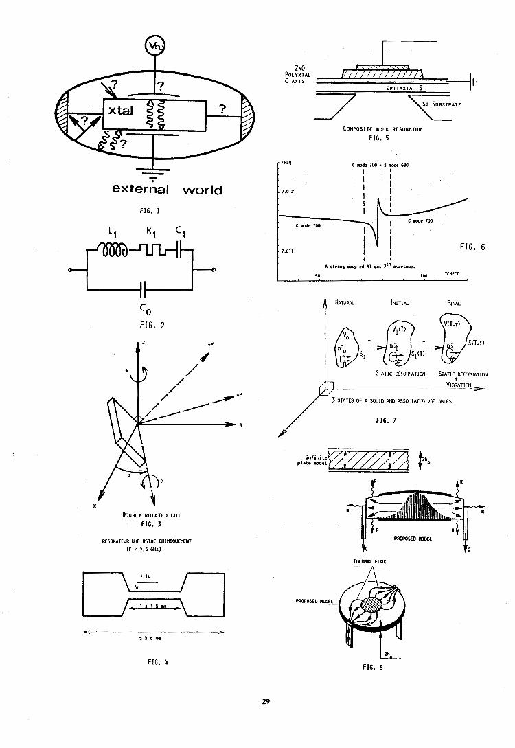
I
exterial world
FIG. 1
0 FIG. 2
DOUBLY R O T A T E D CUT
FIG, 3
RESONATEUR UHF USlNE CHIHIPUEHENT
(F , 1.5 GHz)
E P I T A X I A L S I I ' I 7
COMPOSITE BULK RESONATOR
FIG. 5
I I
I C made IW C mode 7W
I I I I
- 7.011 I
i I
FIG, 6
A strong coupled AT cu t 71h overtoar .
50 1W 1EMP.C
STATIC FOR EM TI ON STATIC D~FORWTION
3 STATES OF A SOLID A I D ASSCCIATtl) V A ? I N I E S
/ FIG. 7
inf in i te .late - l m A P
FIG, 4 [2h0
FIG. 8
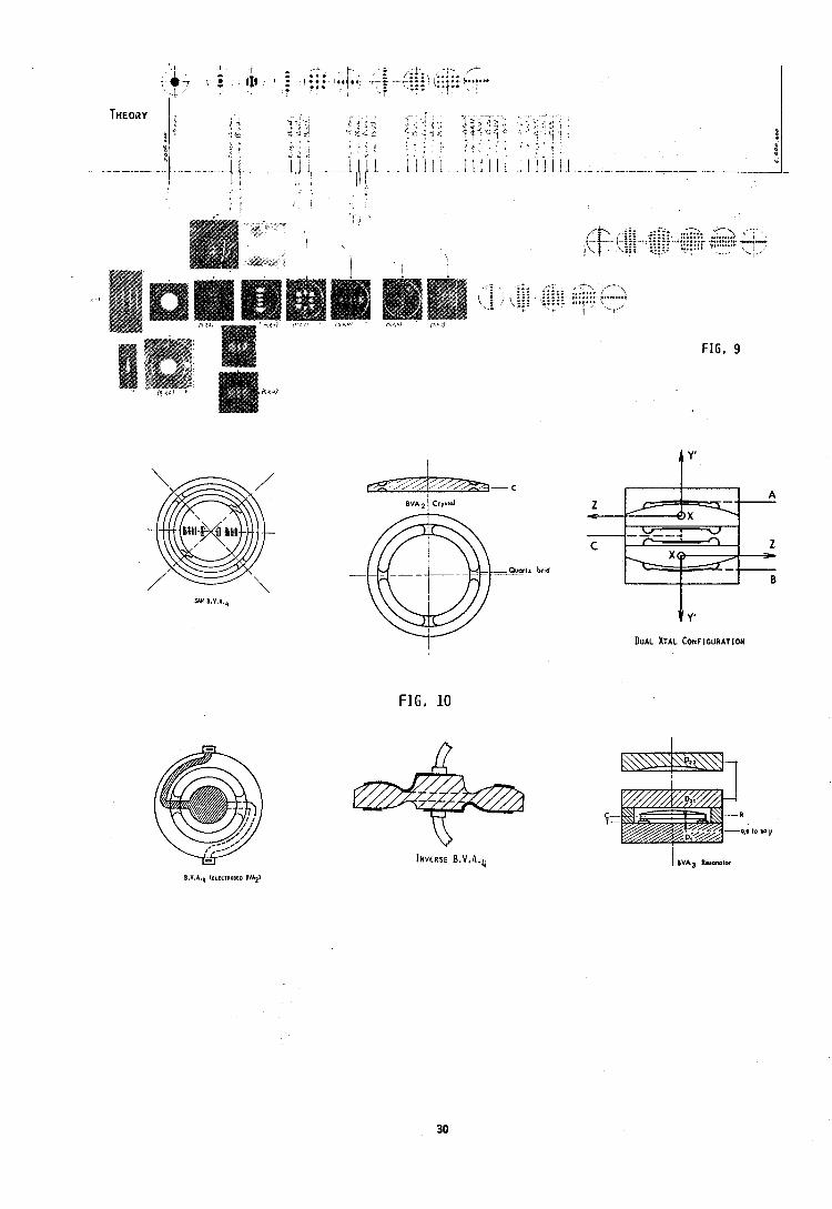
!
.;-:. ,::- ... .... f i- - ;,.+;-,.;, ,,--.., .:, ( i -.;,,:it. Giili. ,.....-,........,
, ::: .... " '1" ' \ - . - ,.* ' L ~ . '
FIG, 9
FIG, 10
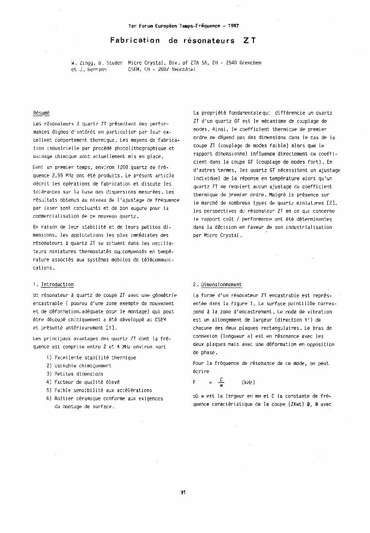
l e r Forum Europ6en Temps-FrBquence - 1987
F a b r i c a t i o n de resonateurs Z T
W. Zlngg, B. Studer Micro Crystal, DIV. of ETA SA, CH - 2540 Grenchen et J . Hermann CSEM, CH - 2007 Neuchatel
Resume
Les resonateurs a quartz Z T presentent des perfor- mances dignes dlinter@t en particulier par leur ex- cellent comportement thermique. Les moyens de fabrica- tion industrielle par procede photolithographique et usinage chimique sont actuellement mis en place.
Dans un premier temps, environ 1200 quartz de fre- quence 2,55 MHz ont kt4 produits. Le present article decrit les o~erations de fabrication et discute les tolerances sur la base des dispersions mesurees. Les resultats obtenus au niveau de I1ajustage de frequence par laser sont concluants et de bon augure pour la commercialisation de ce nouveau quartz.
En raison de leur stabilite et de leurs petites di- mensions, les applications les plus imrngdiates des resonateurs a quartz ZT se situent dans les oscilla- teurs miniatures thermostates ou compenses en temp&- rature associes aux systemes mobiles de telecommuni- cations.
1 . Introduction
Un resonateur a quartz de coupe ZT avec une geometric encastrable ( pourvu dlune zone exempte de mouvement et de deformation,adequate pour le montage) qui peut @tre decoupe chimiquement a et6 developpe au CSEM et present6 anterieurement [ll.
Les principaux avantages des quartz ZT dont la fr6- quence est comprise entre 2 et 4 MHz environ sont
1 ) Excel lente stabi 1 it6 thermique 2) Usinable chimiquement 3) Petites dimensions 4) Facteur de qualit6 eleve 5) Faible sensibil it6 aux accelerations 6) Boitier ceramique conforme aux exigences
du montage de surface.
La propriete fondamentalequi differencie un quartz Z T d'un quartz GT est le mecanisme de couplage de modes. Ainsi, le coefficient thermique de premier ordre ne depend pas des dimensions dans le cas de la coupe ZT (couplage de modes faible) alors que le rapport dimensionnel influence directement ce coeffi- cient dans la coupe GT (couplage de modes fort). En
d'autres termes, les quartz GT necessitent un ajustage individuel de la reponse en temperature alors qu'un quartz Z T ne requiert aucun ajustage du coefficient thermique de premier ordre. Malgre la presence sur le march6 de nombreux types de quartz miniatures [ Z ] ,
les perspectives du resonateur ZT en ce qui concerne le rapport coGt / performance ont ete deterininantes dans la decision en faveur de son industrialisation par Micro Crystal.
2. Dimensionnement
1.a forme d'un resonateur ZT encastrable est repres- entee dans la figure 1 . La surface pointi 1 lee corres- pond a la zone d'encastrement. Le mode de vibration est un a1 longement de largeur (direction Y I ) de chacune des deux plaques rectangulaires. Le bras de connexion (longueur a) est en resonance avec les deux plaques mais avec une deformation en opposition de phase.
Pour la frequence de resonance de ce mode, on peut ecrire
C F I - w (kHz
oii w est la largeur en mm et C la constante de fr6- quence caracteristique de la coupe (ZXwt) 0, 8 avec
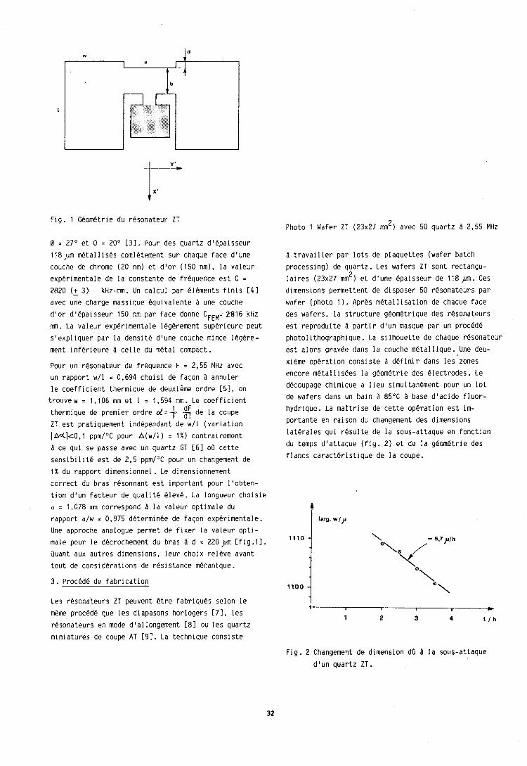
Fig. 1 Geometric du resonateur ZT 2 Photo 1 Wafer ZT (23x27 mm ) avec 50 quartz a 2,55 MHz
0 = 27" et 0 = 20' [31. Pour des quartz d'epaisseur 118 ,urn metal 1 ises comletement sur chaque face d'une couche de chrome (20 nm) et d'or (150 nm), la valeur experimentale de la constante de frequence est C = 2820 (+ 3) kHz.mm. Un calcul par elements finis [41 avec une charge massique equivalente a une couche d'or d'epaisseur 150 nm par face donne CFEM= 2816 kHz mm . La valeur experimentale legerement superieure peut s'expliquer par la densite d'une couche mince legere- ment inferleure a celle du metal compact.
Pour un resonateur de frequence F = 2,55 MHz avec un rapport w/l = 0,694 choisi de facon 3 annuler le coefficient thermique de deuxi6me ordre [51, on trouvew = 1,106 mm et 1 = 1,594 mm. Le coefficient
1 dF thermique de premier ordre d = T 3 de la coupe ZT est pratiquement independant de w/l (variation
I ~ d l t 0 , l ppm/OC pour A(w/l) = 1%) contrairement a ce qui se passe avec un quartz GT [61 oa cette sensibilite est de 2,5 ppmI0C pour un changement de 1% du rapport dimensionnel. Le dimensionnement correct du bras resonnant est important pour l'obten- tion d'un facteur de qualit6 eleve. La longueur choisie a = 1,078 mm correspond a la valeur optimale du rapport a/w = 0,975 determinee de facon experimentale. Une approche analogue permet de fixer la valeur opti- male pour le decrochement du bras a d = 220pm Efig.11. Quant aux autres dimensions, leur choix releve avant tout de considerations de resistance mecanique . 3. Procede de fabrication
Les resonateurs ZT peuvent @tre fabriques selon le m@me procede que les diapasons horlogers [7], les resonateurs en mode d'allongement 181 ou les quartz
miniatures de coupe AT [9]. La technique consiste
a travailler par lots de plaquettes (wafer batch processing) de quartz. Les wafers ZT sont rectangu-
2 laires (23x27 mm ) et d'une epaisseur de 118 ,Dm. Ces dimensions permettent de disposer 50 resonateurs par wafer (photo 1). Apres metallisation de chaque face des wafers, 1 a structure geometrique des resonateurs est reproduite a partir d'un masque par un proc6de photolithographique. La silhouette de chaque resonateur est alors gravee dans la couche metallique. Une deu- xieme operation consiste a definir dans les zones encore metallisees la geometric des electrodes. Le decoupage chimique a lieu simultanement pour un lot de wafers dans un bain a 85OC a base d'acide fluor- hydrique. La maltrise de cette operation est im- portante en raison du changement des dimensions laterales qui resulte de la sous-attaque en fonction du temps d'attaque (fig. 2) et de la geometrie des flancs caracteristique de la coupe.
T larg. w / ?
Fig. 2 Changement de dimension dO 8 la sous-attaque
d'un quartz ZT.
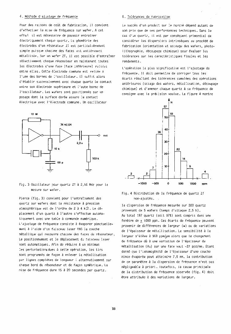
4. Methode d'ajustage de frequence
Pour des raisons de coGt de fabrication, i l convient
d'effectuer la mise de frequence sur wafer. A cet effet i l est necessaire de pouvoir entrainer
electriquement chaque quartz. La geometric des electrodes d'un resonateur ZT est particulierement
simple pui sque chacune des faces est rnt.ierement metallisee. Sur un wafer ZT, i l est possible d'entrainer
selectivement chaque resonateur en maintenant toutes
les electrodes d'une face (face inferieure) relifit?s
entre el les . Cette electrode commune est re1 iee a l'une des bornes de lloscillateur. I1 suffit alors d'etablir successivement avec chaque quartz le contact
entre son electrode superieure et l'aute borne de
1 'osci 1 lateur . Les wafers sont positionnes sur un posage dont la surface doree assure le contact electrique avec l'electrode commune. Un oscillateur
Fig. 3 Oscillateur pour quartz ZT a 2,55 MHz pour la mesure sur wafer.
Pierce (fig. 3) convient pour 1 'entrainement des quartz sur wafers dont la resistance a pression atmospherique est de l'ordre de 2 a 4 k 3 . Le de- placement dlun quartz a l'autre s'effectue automa- tiquement avec une table a commande numerique. L'ajustage de frequence consiste 8 evaporer ponctuelle- ment a l'aide d'un faisceau laser YAG la couche metallique qui recouvre chacune des faces du resonateur.
Le posit ionnement et le deplacement du faisceau laser sont automatiques. Afin de reduire a un minimum les perturbatiomjdues a cette operation, les tirs sont programmes de facon a enlever la metall isation par lignes completes de longueur 1 alternativement sur chaque bord du resonateur et de facon symetrique. La mise de frequence dure 15 a 20 secondes par quartz.
5. Tolerances de fabrication
Le succes d'un produit sur le march6 depend autant de
son prix que de ses performances techniques. Dans le cas d'un quartz, i l est par consequent primordial de
considerer les dispersions intrinseques au procede de fabrication (orientation et usinage des wafers, photo- l i thographie, decoupage chimique) pour @valuer les tolerances sur les caracteristiques finales et les rendernents . L'operation la plus s~gnificative est l'ajustage de
frequence. I 1 doit permettre de corriger tous les @carts resultant des tolerances curnulees des operations
anterieures (sciage des wafers, metal l i sation, decoupage chimique) et d'arnener chaque quartz a sa frequence de consigne avec la prkision voulue. La figure 4 montre
Fig. 4 Distribution de la frequence de quartz ZT non-ajustes.
la dispersion de frequence mesuree sur 203 quartz provenant de 5 wafers (temps d'attaque 2,5 h). Au total 197 quartz (soit 97%) sont compris dans une
fenCtre de + 1000 ppm. Ces kcarts de frequence peuvent provenir de differences de largeur (w) ou de variations de l'epaisseur de metallisation. La sensibilite a la largeur s161Pve a 900 ppml~m alors que le changement de frequence dO 8 une variation de lt6paisseur de
metal lisation (Au) sur une face vaut -27 ppm/nm. Etant
donne que I'inhomogenit6 de l'epaisseur dlune couche
mince evaporee peut atteindre 7,5 nm, la contribution de ce parametre a la dispersion de frequence n'est pas negligeable a priori. Toutefois, la cause principale de la distribution de frequence observee (fig. 4) doit Ctre attribuee a des variations de largeur.
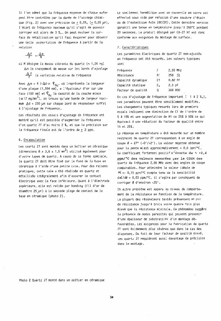
Si l'on admet que la frequence moyenne de chaque wafer
peut &tre contrdl6e par la duree de l'usinage chimi- que (fig. 2) avec une precision de + 0,5%, (+ 0,55 pm), llecart de frequence maximum qulil s'agit de pouvoir
corriger est alors de 3 %, . On peut evaluer la sur- face de metal 1 isation ,qul i 1 faut &vaporer pour obteni r une telle ar~qrnentation de frkquence a partir de la
' relation
oa M designe la masse vibrante du quartz (c 1,24 mg) A m le changement de masse sur les bords d'ajustage
- $F la variation relative de frequence
Avec A m = 4 1.Ad.e yAu, 00 lrepresente la longueur d'une plaque (1,594 mm), e 1 '6paisseur dlor sur une face (150 nm) et TAU la densite de la couche mince
3 (= 17 mglmm ) , on trouve qu'une bande de largeur maxi- mum A d = 230pm sur chaque bord du resonateur suffit a l'ajustage de frequence. Les resultats des essais d'ajustage de frequence ont montre qu'i 1 est possible d'augmenter la frequence d'un quartz ZT dlau moins 2 %, et que la precision sur la frequence finale est de llordre d e + 2 ppm.
6. Encapsulation
Les quartz ZT sont montes dans un boitier en ceramique 3 (dimensions 8 x 3,6 x 1,5 mm ) utilise egalement pour
d'autre types de quartz. A cause de sa forme speciale, le quartz ZT doit @tre fix6 sur le fond de la base en
ceramique a l'aide d'une petite cale. Pour des raisons pratiques, cette cale a ete realishe en quartz et metallisee integralement afin d'assurer le contact
electrique avec la face inferieure . Quant a 1 'electrode superieure, elle est reliee par bonding (fil d'or de
diametre 25,um) a la seconde plage de contact de la base en cerarnique (photo 2).
Le scellement hermetique avec un couvercle en verre est
effect& sous vide par refusion d'une soudure d'etain ou de 1 'eutectique AuSn (80120) . Cette derniere version garantit une tenue en temperature jusqu'a 260°C pendant
20 secondes. Le produit design6 par CX-ZT HT est donc conforme aux exigences du montage de surface.
7. Caracteri stiques
Les parametres electriques de quartz ZT non-ajustes
en frequence ont ete mesures. Les valeurs typiques
sont
Frequence F 2,55 MHz Resistance R1 250 .!! Capacite dynamique C1 0,82 fF
Capacite statique Co 2,3 PF Facteur de qua1 it6 Q 300 000
En cas d'ajustage de frequence important ( 1 a 2 %,),
ces parametres peuvent @tre sensiblement modifies. Les changements typiques mesures lors de premiers
essais indiquent une diminution de C1 de llordre de 5 A 10% et une augmentation de R1 de 25% a 50% ce qui equivaut -3 une reduction du facteur de qualit4 entre
15 et 25%.
La reponse en temperature a ete mesuree sur un nombre
restreint de quartz ZT correspondant a un angle de coupe 0 = 27' (-O'/+Z1). La valeur moyenne obtenue
pour la pente oL est approximativement + 0,6 ppmI0C. Ce coefficient fortement positif s '.kcarte d e % + 0 , 4
ppm/OC aes valeurs mesur6es p a r l e CSEM d e s quartz de frequence 2,56 MHz avec des angles de coupe
comparables . Pour at'teindre la valeur ideale de 0( =- 0,15 ppmI0C compte tenu de la sensibilite
d d l d 0 = 0,03 ppmI0C, i 1 s'agira par consequent de corriger 0 d'environ -25'.
Un autre probleme est apparu au niveau du comporte-
ment de la resistance en fonct'ion de la temperature. La plupart des resonateurs testes presentent un plC de resistance jusqu'a trois voire quatre fois plus
eleve que la resistance minimale. Ce phenomene suggbre la presence de modes parasites qui peuvent provenir
d'une epaisseur de substrats ou d'un montage de- favorables. Les exigences pour la fabrication de quartz ZT sont evidemment plus severes que dans le cas des diapasons. Du fait de leur Facteur de qualit6 eleve, les quartz ZT requierent aussi davantage de precision
dans le montage.
Photo 2 Quartz ZT monte dans un boitier en ceramique
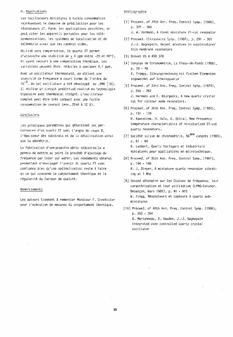
8. Applications
Les oscillateurs miniatures 2 faible consommation representent le domaine de predilection pour les resonateurs ZT. Parmi les applications possibles, on peut citer les appareils portables pour les tele- communications, les systPmes de localisation et de telemetrie ainsi que les cameras video.
Utilise sans compensation, le quartz ZT permet dlatteindre une stabilite de + 4 ppm entre -20 et 80°C. En ayant recours a une compensation thermique, ces variations peuvent Otre reduites a quelques 0,1 ppm.
Avec un oscillateur thermostate, on obtient une stabllite de frequence A court terme de I'ordre de
Un tel oscillateur a ete developpk au LPMO [lo]. I 1 utilise un circuit prediffuse realis6 en technologic bipolaire avec thermostat integre. L1oscillateur complet peut @tre tres compact avec une faible consommation de courant (env. 20mA a 12 V ) .
Conclusions
Les principaux parametres qui determinet les per- formances d'un quartz ZT sont l'angle de coupe @ ,
I'epaisseur des substrats et de la metallisation ainsi que la geometric.
La fabrication d1unepremi6re serie industrielle a permls de mettre au point le procede d'ajustage de frbquence par laser sur wafer. Les rendements obtenus permettent d'envisager l'avenir du quartz ZT avec confiance bien qu'une optimalisation reste A faire en ce qui concerne le comportement thermique et la regularit6 du facteur de qualite.
Remerciements
Les auteurs tiennent ?I remercier Monsieur F. Crevoisier pour 11ex6cution de mesures du comportement thermique.
Bibliographic
E l l Proceed. of 39th Ann. Freq. Control Symp. (1985), p. 375 - 380 J. W. Hermann, A novel miniature ZT-cut resonator
[2] Proceed. Ultrasonics Symp. (19871, p. 291 - 301 J .-J . Gagnepain, Recent advances in subminiature/ thin membrane resonators
[31 Brevet US 4 450 378
[41 Congrps de Chronometric, La Chaux-de-Fonds (1986), p. 39 - 46 K. Trumpy, Storungsrechnung mit finiten Elementen angewendet auf Schwingquarze
[51 Proceed. of 33rd Ann. Freq. Control Symp. (1 979), p. 255 - 262 J. Hermann and C. Bourgeois, A new quartz crystal cut for contour mode resonators.
[61 Proceed. of 34th Ann. Freq. Control Symp. (1980), p. 131 - 139
H. Kawashima, H. Sato, 0. Ochiai, New frequency temperature characteristics of miniaturized GT-cut quartz resonators.
171 Societe suisse de chronometric, 5heme congres (1983), p . 61 - 64 R. Lambert, Quartz horlogers et industriels miniatures pour applications en microtechnique.
[81 Proceed. of 35th Ann. Freq. Control Symp. (1981 ) ,
p. 144 - 148 R . J. Dinger, A miniature quartz resonator vibrat- ing at 1 MHz
[91 Second skminaire sur les Etalons de frkquence, leur caracterisation et leur uti 1 isation (LPMO-Cetehor, Besan~on, mars 1985), p. N1 - N15 W. Zingg, Resonateurs et capteurs a quartz sub- miniatures
[ 101 Proceed. of 40th Ann. Freq . Control Symp. ( 1986), p. 350 - 354 G. Marianneau, D. Hauden, J .- J . Gagnepain Integrated oven controlled quartz crystal oscillator
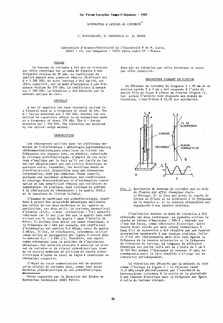
l e r Forum EuropBen Temps-FrBquence - 1987
KESONATEUK A CRISTAL DE COKINDON"
E. DIISULESALNT, D . MAZE:KOLLE e t D . ROYER
L a b o r a t o i r e d ' A c o u s t o 6 l e c t r i c i t 6 d e l ' U n i v e r s i t 6 P e t M . C u r i e , ESCPI - 10, r u e Vauquel in - 75231 P a r i s Cedex 05 - France
KESUME
Un bar reau d e cor indon a k t 6 mis en v i b r a t i o n par e f f e t thermique s u r un mode d e f l e x i o n B une fr6quence v o i s i n e d e 20 kHz. Le c o e f f i c i e n t d e q u a l i t 6 mesurg sous p r e s s i o n r 6 d u i t e ( 0 , O l t o r r ) e z t Q = 2 500 000. Un a u t r e ba r reau a S t 6 e x c i t 6 , pa r e f f e t c a p a c i t i f , s u r un mode d ' e x t e n s i o n B une f r 6 - quence v o i s i n e d e 270 kHz. Le c o e f f i c i e n t Q mesur6 e s t 1 700 000. La v i b r a t i o n a 6 t 6 d 6 t e c t 6 e par l a rn6thode o p t i q u e du c o i n .
ABSTRACT
A bar of s a p p h i r e has been the rmal ly e x c i t e d i n o f l e x u r a l mode a t a f requency of about 20 kllz. Thc Q - f a c t o r measured was 2 500 000. Another ba r was e x c i t e d by c a p a c i t i v e e f f e c t i n a n e x t e n s i o n a l mode a t a f requency of about 270 kHz. The Q - f a c t o r measured was I 700 000. The v i b r a t i o n was d e t e c t e d by t h e o p t i c a l wedge method.
INTRODUCTION
Les r 6 s o n a t e u r s u t i l i s 6 s dans l e s d i f f 6 r e n t s do- maines d e 1 1 6 1 e c t r o n i q u e : m6trologie,instrumentatioq t616comunica t ions ,pour s t a b i l i s e r ou f i l t r e r l e s f r6quences d e s s ignaux s o n t , en gGn6ra1, c o n s t i t u 6 s d e c r i s t a u x p i 6 z o 6 l e c t r i q u e s . L'emploi d e c e s c r i s - t aux s ' e x p l i q u e par l e f a i t q u ' i l e s t f a c i l e d e l e s e x c i t e r m6caniquement p a r une t e n s i o n E l e c t r i q u e d e quelques v o l t s . Cependant, l e s mate r iaux dou6s d e p i 6 z o 6 l e c t r i c i t 6 , d i s p o n i b l e s sous des dimensions r a i s o n n a b l e s , s o n t peu nombreux. Parmi ceux-ci , quelques uns seulement p r 6 s e n t e n t d e s c o e f f i c i e n t s d e couplage 6lectrom6canique e t d 1 a t t 6 n u a t i o n conve- nab les e t une s e n s i b i l i t 6 r 6 d u i t e aux v a r i a t i o n s d e temperature. En p r a t i q u e , deux c r i s t a u x s e p r t t e n t B l a r d a l i s a t i o n d e r e s o n a t e u r s : l e q u a r t z (Si.02) e t l e t a n t a l a t e d e l i t h i u m (LiTa03) .
L'examen d e mats r i aux rcon p i 6 z o E l e c t r i q u e s , poss6- d a n t a p r i o r i des p r o p r i 6 t 6 s m6caniques m e i l l e u r e s que c e l l e s d e c e s deux mat6r iaux e t du q u a r t z en p a r t i c u l i e r , e s t donc u t i l e . Le cor indon- (monocr i s ta l d 'a lumine :A1203, c l a s s e c r i s t a l l i n e : 3 m ) a p p a r a i t s 6 d u i s a n t c a r i l e s t p l u s dur que l e q u a r t z (son coef- f i c i e n t e s t 9 , c e l u i du q u a r t z 7 dans 1 ' 6 c t i e l l e d e Mohr). I1 a t t 6 n u e donc moins l e s ondes 6 l a s t i q u e s . A l a f r6quence d e I GHz p a r exemple, son c o e f f i c i e n t d 1 a t t 6 n u a t i o n e s t env i ron 0 , 3 d ~ l p s , c e l u i du q u a r t z 2 dB/ps. I 1 e s t , en consLquence, couramment u t i l i s 6 comme m i l i e u de p ropaga t ion des l i g n e s a r e t a r d dans l e domaine 0 , s - 5 GHz [ I ] . T o u t e f o i s , son emploi c o m e rgsona teur pose l e problPme de l ' e x c i t a t i o n mccanique. Une s o l u t i o n c o n s i s t e B a s s o c i e r un c r i s - t a l d e cor indon e t un c r i s t a l p iCzo6lec t r ique (com- me on a s s o c i e membrane de s i l i c i u m e t couche pi6zo- 6 l e c t r i q u e d'oxyde d e z i n c ) de f a s o n 3 c o n s t i t u e r un r6sona teur composi te .
S t r e mis en v i b r a t i o n p a r e f f e t thermique e t a u s s i p a r e f f e t c a p a c i t i f .
KESONATEUK VIBRANT E N FLEXION
Un b l t o n n e t d e cor indon d e longueur 1 = 40 m e t d e s e c t i o n c a r r 6 e 3 x 3 mm a 6 t 6 suspendu B l ' a i d e d e q u a t r e f i l s d e f a ~ o n B v i b r e r e n f l e x i o n ( f i g u r e 1 ) . Les p o i n t s d ' a t t a c h e s o n t d i s p o s 6 s aux noeuds d e v i b r a t i o n , c ' e s t - 2 - d i r e B 22,42 des e x t r 6 m i t 6 s .
' FIL DE 'SUSPENSION
DEFORMEE
Fig, 1. Excitation du barreau de corindon sur un mode de f lex ion par e f f e t thermique Joule. a ) Montage. b ) La face qui porte la couche de chronie se d i l a t e e t se contracte d Za fr iquena de Za tension v . c l La tension al ternat ive eat superposge d une tension continue.
L ' e x c i t a t i o n s u i v a n t c e mode d e v i b r a t i o n a 6 t 6 e f f e c t u 6 e par deux techn iques . La p6emiSre u t i l i s e l a couche de chrome d 1 6 p a i s s e u r 1 000 A , d6pos6e s u r l ' u n e des f a c e s , c o m e r 6 s i s t a n c e B l e c t r i q u e . C e t t e couche 6 t a n t r e l i 6 e pa r deux rubans conduc teurs B deux f i l s d e suspens ion a s t 6 chauf f6e par une t e n s i o n a l t e r n a t i v e superpos6e B une t e n s i o n con t inue . Ce l le - c i n ' e s t pas i n d i s p e n s a b l e mais e l l e rend Bgales l a f requence d e l a t e n s i o n a l t e r n a t i v e e t l a f r6quence de v i b r a t i o n du bar reau . La longueur d e d i f f u s i o n thermique e s t p e t i t e ( e l l e e s t de l ' o r d r e d e 7 pm B 20 000 Hz) devant 1 1 6 p a i s s e u r du b a r r e a u (3 mm); en cons6quence,seule l a f a c e chauf f6e s ' a l l o n g e ( e t s e c o n t r a c t e ) ~ B r i o d i q u e m e n t .
L ' o b j e t de c e t t e communication e s t de montrer La v i b r a t i o n e s t d 6 t e c t 6 e p a r l a m6thode du c o i n qu 'un c r i s t a l d e corindon p e u t , c o m e t o u t a u t r e c o m e l ' i n d i q u e l a f i g u r e 2 : l e f a i s c e a u l a s e r matc r iau p i 6 z o 6 l e c t r i q u e ou non p i & z o G l e c t r i q u e , ( 1 , s mW),coup6 psr iodiquement pa r l ' e x t r b m i t 6 du
barreau,donne n a i s s a n c e a l a s o r t i e de l a photodiode ::Etude suppor t6e par l a D i r e c t i o n des Etudes e t 1 une t e n s i o n E l e c t r i q u e don t l a f r s q u e n c e e s t 6 g a l e
Recherches Techniques (DRET P a r i s ) . a c e l l e du b a r r e a u v i b r a n t .
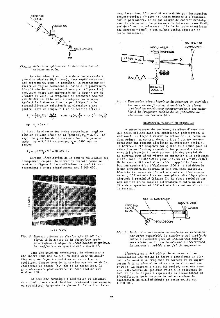
OSCILLOSCOPE
FigL% Ul luc t i on vptique de La v ibrat ion par Za - rr16thode du coin.
Le r 6 s o n a t e u r e t a n t ~ l a c 6 dans une e n c e i n t e a p r e s s i o n r e d u i t e (0.01 t o r r ) . deux exp6r iences o n t i t 6 e f f e c t u 6 e s . ~ a n s l a premizre, l e i ~ s o n a t e u r e s t e x c i t e e n regime permanent a l ' a i d e d ' u n g6nCrateur . L1anipl i tude d e l a t e n s i o n a l t e r n a t i v e ( f i g u r e 1 . c ) app l iqu6e e n t r e l e s e x t r 6 m i t 6 s d e l a couche e s t de l ' o r d r e du V o l t . La f r6quence d e r6sonance mesurge e s t 20 260 Hz. E l l e e s t , a quelques Her tz p r z s , & a l e 3 l a f r&quence f o u r n i e pa r 1 1 6 q u a t i o n de B e r n o u i l l i - E u l e r r e l a t i v e l a v i b r a t i o n d'une p o u t r e l i h r e d e longueur 1 e t de s e c t i o n a 2 [ 2 ] :
f n = ~ ~ / 2 ~ avec tg (un t) = (-1 ) n t h t ~ 2) 1 n 4
V 6 t a n t l a v i t e s s e des ondes a c o u s t i q u e s l o n i t u - b d l n a l e s s u i v a n t l ' a x e d e l a "pou t re" , rg = a / & 1e rayon de g i r a t i o n d e l a s e c t i o n . Pour le premier mode v l = 3,0112 en p renan t V b = 10700 m/s on t r o u v e
Lorsque l ' e x c i t a t i o n de l a couche r s s i s t a n t e e s t brusquement coupde, l a v i b r a t i o n d e c r o i t c o m e l e montre l a f i g u r e 3 . Le c o e f f i c i e n t d e q u a l i t 6 cor - r espondan t B c e t t e dPcro i s sance e s t 2 500 000.
ceau l a s e r d o n t 1 1 i n t e n s i t 6 e s t modulBe p a r i n t e r a c t i o n acous to -op t ique ( f i g u r e 4 ) . C e t t e m6thode a l ' a v a n t a g e , s u r l a p r6c6den te I d e no pas e x i g e r d e c o n t a c t mecanique avec l e r 6 s o n a t e u r . La p u i s s a n c e du f a i s c e a u l a s e r He-Ne e s t d e 40 nlW. La u i s s a n c e u t i l e d e l a t a c h e c h a u f f a n t e kl (de s u r f a c e " I m ) n ' e s t qu 'une p e t i t e f r a c t i o n d e c e t t e pu i ssance .
BARREAU DE
MODULATEUR CORINDON ( fr l
Oscillateur
Pig. 4 Excitation photothermique du batonnet en corindon -- sur un mode do f lex ion. L1ampZitude du signal uppliqucr' au moduZatcur acousto-optiquc e s t modu- lde 6 La frdquence moitid de la frkquence de rdsonance du barreau [31.
RESONATEUR VIBRANT EN EXTENSION
Un a u t r e ba r reau d e cor indon , d e mtmes d imens ions que c e l u i u t i l i s 6 dans l e s exp6r iences prEc6dentes . a 6tC monte d e f a s o n B v i b r a r en e x t e n s i o n . La t e n u e en deux p o i n t s , au c e n t r e , donnant l i e u 1 des mouvements p a r a s i t e s q u i r e n d e n t d i f f i c i l e l a d 6 t e c t i o n o p t i q u e , l e b a r r e a u a 6 t 6 suspendu p a r q u a t r e f i l s comme pour l a v i b r a t i o n e n f l e x i o n , cependant l e s p o i n t s d ' a t t a c h e s o n t i c i dispot i5s 1 une d i s t a n c e 114 d e s e x t r 6 m i t 6 s . Le b a r r e a u peu t a i n s i v i b r e r e n e x t e n s i o n B l a f r6quence f = V / 1 s o i t f = 267 500 Hz pour 1 = 4 0 mm e t V 9 10 700 m/s. Ce b a r r e a u a 6 t 6 e x c i t e pa r e f f e t c a p p i t i f . Dans c e b u t une couche d ' o r d 1 6 p a i s s e u r 1000 A a 6 t 6 d6pos6e a une e x t r 6 m i t 6 du b a r r e a u e t s u r une f a c e l a t 6 r a l e . L 1 e x t r 6 m i t 6 c o n s t i t u e l ' b l e c t r o d e mobile d ' u n conden- s a t e u r , 1 ' 6 l e c t r o d e f i x e e s t une p i z c e m 6 t a l l i q u e p l a n e d i s p o s 6 e a p r o x i m i t e ( f i g u r e 5 ) . La f o r c e p r o d u i t e pa r a p p l i c a t i o n d 'une t e n s i o n a l t e r n a t i v e v e n t r e un d e s f i l s d e s u s p e n s i o n e t 1 1 6 1 e c t r o d e f i x e met e n v i b r a t i o n l e b a r r e a u .
FILS DE SUSPENSION
FAISCE LASER He-Ne
OSCILLOSCOPE
1 ,5 s / d i v . Fig. 5. Excitation du barreau de corindon en extension --
Pig&. Barreau vibrant en f Zexion f f = 20 260 Hal. - par e f f e t capac i t i f . La tension v e s t appliqude Signal d la sor t i e de Za photodiode apras entre LrlLectrode f i xe s t I1dlectrode mobile in terrupt ion brusque de L1ezci tat ion thermique. constitude par Za couche d4posde d Z1extrdmittS Le coe f f i c i en t de qualitd e s t : 2,s ~ 1 0 ~ . du barreau e t r e l i l e d un f i l de suspension.
Dans une deuxisme expgr ience , l e r 6 s o n a t e u r a 6 t 6 i n s 6 r 6 dans une bouc le , e n s E r i e avec un ampli- f i c a t e u r , d e f a s o n ?I c o n s t i t u e r un c i r c u i t au to - o s c i l l a n t . Compte t enu d e l a t e n s i o n aux bornes d e l a r e s i s t a n c e d e charge (5 ,4 kfl) de l a pho tod iode , l e g a i n n e c e s s a i r e pour e n t r e t e n i r l ' o s c i l l a t i o n e s t env i ron 100.
La deuxisme techn ique d ' e x c i t a t i o n du h s t o n n e t d e cor indon c o n s i s t e i c h a u f f e r loca lement ( p a r exemple e n son m i l i e u ) l a couche d e chrome a l ' a i d e d ' u n f a i s -
LVexpi5rience a 6 t d e f f e c t u s e e n a s s o c i a n t au condensa teur une bob ine d e f a s o n 1 c o n s t i t u e r un c i r - c u i t r6sonnan t B l a f r6quence du b a r r e a u e t e n super - posan t i l a t e n s i o n a l t e r n a t i v e une t e n s i o n c o n t i n u e ( -30V) . Le b a r r e a u a a i n s i BtB e x c i t e , avec u n e t e n - s i o n a l t e r n a t i v e d e que lques v o l t s B l a f r s q u a n c e d e 267 175 Hz. La f i g u r e 6 r e p r 6 s e n t e l a d s c r o i s s a n c e d e l ' o s c i l l a t i o n a p r z s coupure de c e t t e t e n s i o n . Le c o e f f i c i e n t d e q u a l i t 6 d 6 d u i t d e c e t t e courbe e s t 1 700 000.
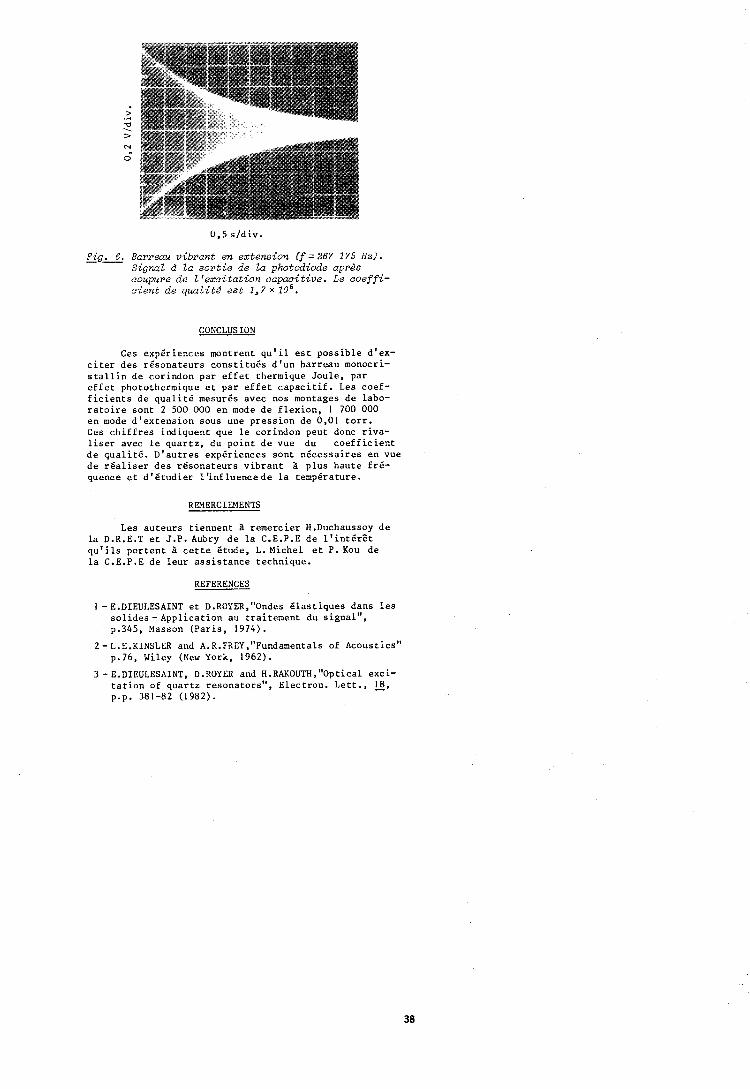
Fig&, Barreau vibrant en extension ( f = 267 175 Hz). - Signal d l a sor t i e de la photodiode aprds coupure de Z'excitation capacitive. Le c o e f f i - cierrt da quaLitc5 e s t 1,7 x l o 6 .
CONCLUSION
Ces expgr iences montrent q u ' i l e s t p o s s i b l e d 'ex- c i t e r d e s r b s o n a t e u r s c o n s t i t u 6 s d ' u n b a r r e a u monocri- s t a l l i n d e cor indon par e f f e t thermique J o u l e , p a r e f f e t photothermique e t p a r e f f e t c a p a c i t i f . Les coef - f i c i e n t s d e q u a l i t 6 mesurBs avec nos montages d e labo- r a t o i r e s o n t 2 500 000 e n mode d e f l e x i o n , 1 700 000 en mode d ' e x t e n s i o n sous une p r e s s i o n d e 0,01 t o r r . Ces c h i f f r e s i n d i q u e n t que l e cor indon peu t donc r i v a - l i s e r avec l e q u a r t z , du p o i n t d e vue du c o e f f i c i e n t d e q u a l i t b . D ' a u t r e s expbr iences s o n t n e c e s s a i r e s e n vue d e r b a l i s e r d e s r b s o n a t e u r s v i b r a n t B p l u s h a u t e f r b - quence e t d ' b t u d i e r l ' i n f l u e n c e d e l a temp6rature.
REMERCIEMENTS
Les a u t e u r s t i e n n e n t a r e m e r c i e r H.Duchaussoy d e l a D.R.E.T e t J .P . Aubry d e l a C.E.P.E d e l ' i n t I r 8 t q u ' i l s p o r t e n t 1 c e t t e I t u d e , L.Miche1 e t P. Kou d e l a C.E.P.E d e l e u r a s s i s t a n c e t echn ique .
REFERENCES
I -E.DIEULESAINT e t D.ROYER,"Ondes B l a s t i q u e s dans l e s s o l i d e s - A p p l i c a t i o n au t r a i t e m e n t du s i g n a l " , p.345, Masson ( P a r i s , 1974).
2-L,E.KINSLER and A.R.FREY,"Fundarnentals of Acous t i cs" p.76, Wiley (New York, 1962).
3 -E.DIEULESAINT, D.ROYER and H.RAKOUTH,"Optical exc i - t a t i o n of q u a r t z r e s o n a t o r s " , E l e c t r o n . L e t t . , 18, p.p. 381-82 (1982).

l e r Forum Europien Temps-Friquence - 1987
INFLUENCE DE LA QUALITE DU MATERIAU SUR LES PERFORMANCES DES RESONATEURS A QUARTZ
CCPC - 44, Avc!ritlr: tle la Clncibrr! - 95105 AIICI-NITUIL CI:OCX SlCN - Rue ilu R;ltl;~r - 74000 ANNCfY TTDl-X
Len technoloqies rBcentes de rdsonnteurs B quartz de type BVA ou QAS ont permis un gain d'un fac- teur 10 sur les perforn~ances de sensibilite B l'envi- ronnernent mecanique ou tlrermique.
Les gains de performance en stabilite (court terme et long terme) ont permis de mettre en evidence dcs limitations dues au matkriau.
[.en ddfauts mis en jeu, lids au mot6riau, snnt princ:ipalemcnt Len i~npllrctOs ioniqclcts n~ol)iles et le taux do clislocal.ion.
CFPf et 51CN on1 entrepris r6cen1111crit. one doclblc action :
- CnractBrisation des n~albriac~x "actucls" en ter~nes de vieillissement et de tenue aux rayonnements ionisants.
- L'Btude et la caracterisation des conditions cle sweeping en fonction des crithres de stabilite des resonateurs sous irradiations.
Cette etude prelirninaire a permis de niettre cn dvidence les enselgnements suivants :
- La contributim &s irnpuretes ioniques mobiles au vieillissement et notamment les ameliorations li6es au sweeping.
- La correlation entre la qualit6 intrinsbque du mat6riau et les conditions de sweeping.
- L'influence des conditions de sweeping sur le comportement frequence-temperature des resonateurs.
Les conditions de traitement optimum pour I'obtention tle rtisonateurs QAS SC de faiblc vieillis- selllent et dc haule resistance k l'irradiation ant pu &tre d6finies.
ABSTRACT
Recent resonator technologies such as BVA or QAS allow an improvement by a ratio of 10 of frequency stability under thermal and mechanical environnemen- tal stresses.
Ageingandshort term stabilityachieved by these resonators show limitations dire to the material pro- perties.
Point and extensed defects sucli as migrating ionic impurities and dislocations are mainly involted.
CEPE and SICN started an experimental work on:
- Determination of the best sweeping condi- tions From frequency stability measurements under irradiations.
- Corrol;~Lion I)rlwcr!n intrinsic rrlntcriol p r o - perties and sweeping conditions.
- Influonce of sweeping conditions on frecluericy-temperature behavior of resonators.
Sweeping conditions have been established to optimise stability of 10 MIiz OAS SC P/3 resonators under spatial telccomn~unication radiation doses.
I - INTRODUCTION
I. ' infltlcnrc du rr~ilttiriao stir Irn proor i6tb:; bleclriques do:; r6soriatctlrs i t qu;~rtz csL recolinue depuis longtelrlps. I.es zonro identi fjnl~les par tqm- graoliie de rayons X (zoncs Z , 3 , + X) d'on I)loc syntt16tiqtrc nc presentcnt pan deo cnr:~c.tbrjr;l.icl~lrn frBqucnce-tc1npbri1t.11rr r iqot~rat~nrr~~cnt ido~lt ic1~li.n.
On sait aussi que la sensil)il i16 nirx rnynn- nements i0nisant.s peut etre trbs diffBrr?nte d'trr~ materiau B l'autre ou entre les zones de crois- sance d'un bloc, cette sensibilite Btant dtroite- ment like B la presence d'inipuretks ioniques [ 1 , 2 ] .
Le "sweeping", ou Blectrodiffusion sous fort champ Blectrique et B haute temp8rnt~lre (l'im- puretbs ioniques mobiles, qcli oe ~ I I I ~ : t 1'61 irsirin- tion de ces impuretes mobiles, conduit B du 1nat6- riau nettement moins sensible aux rayonnenients [ 3 , 61 . Le materiau swept presente par ailleurs des propriet6s mecaniques "d'usinabilit6" legkrement differentes, il est repute plus "cassant" que le quartz synthgtique PQ.
Plus r6cemment, des travaux ont montr6 l'influence du materiau sur les performances de vieillissement, de stabilit6 et de retrace de re- sonateurs B coupe double rotation, phenomhne qui a Bt6 iriterpr6t6 par la presence dtimpuret6s ioniques mobiles dans le maLBrisu [ 9 ] .
Les recuits effectues t~ haute tesp~?rature, sous vide, sur des lames non m6tallis6es, ambnent dgalement une Bvnlution (asymptotique et irrever- sible) de la frequence du resonateur. I1 est pro- bable qu'au dele du simple degazage des surfaces, les relaxations de contraintes internes, grace B la presence de dislocations, sont g6n6r6es par ces recuits.
L'introduction des techniques chimiques, pour usiner les faces laterales [ 7 ] ou lldpaisse~~r de r6sonateurs, a montre Bgalement l'influence du mat6riau. L a presence dtimpuret6s ou de fortes densites de dislocations genbre une forte discon- tinuit6 de l'attaque en surface qui peut conduire, au-delB des formes dues l'anisotropie [ a ] , B des surfaces inutilisables ou B la presence de canaux (etch channels) penetrant profondement dans le vo- lume du materiau.
On peut done classer llinfluence du mate- riau en :
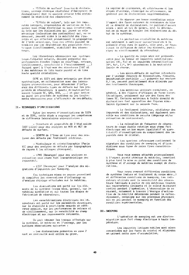
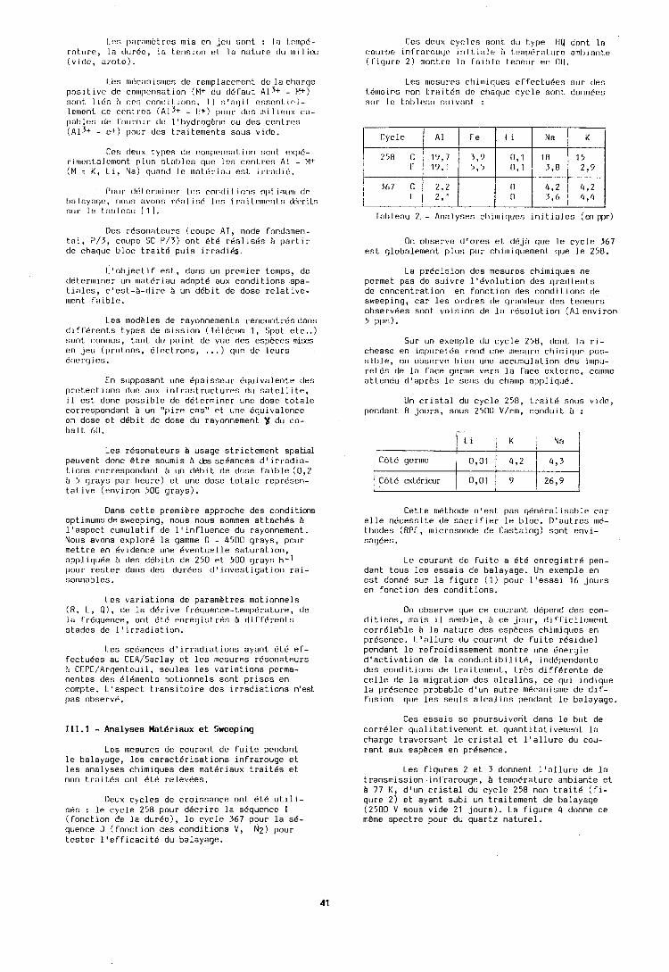
I.c:n parnnlbtres mis en jcu :;ant : I:] t.omp6- r:itt~rc!, In tlurdo, la t.r:noion et lo r~;~lurc tlu mil iou (vide, a~ote).
Les mticanisn~es de reniplacement de la ct>nrqo poollive dc conlper~sation (bl+ du clbfatlt A I ~ + - M+) !;clr~t 1 itin ?I rr::; conlli I ions. I 1 r;'or]i t cr;ncnt.ir.l- lerrlenl dc rent 1.c~ (Alj+ - II+) [>our c1os 111ilir:11x (:(I- pabl(:s de rourriir dc l't>ydrogi?r~c OU des cenlrc+; ( ~ l 3 + - c+) pour des traitenlents sous vide.
Ce:; cleux lypcs de compcris:~tior~ sont expd- rin~c?nLalr:nicnt. plos sL:~l~lcr; q11c ies ccnlrc:; A1 - M+ ( M : K , Li, Na) c1~1:lntl Ic tnt~ttirintl est ii.radi6.
r'1111r 1161 crn~ incr Ivs con11 i I i rlnn c11it. ~ I I I ~ I I I I ctc II:I l:~ynqo, rlcnln :lvrlnn rb:~ l i nc! 11:s I I,:, i I c?lnc.nI c; tkl.ril.s stir le t.:1111c:1~ 1 I 1 ,
Ocs r6sonateurs (coupe AT, mode fondomeri- tnl, P/3, cot~pe SC P/3) ont BtB rdalis6s ;i partir de chaque bloc trait6 puis irradies.
L'objectif est, dans un premier temps, de determiner un mat6riau adapt6 aux conditions spa- tiales, c'est-A-dire B un debit de dose relative- ment faible.
Les rnodkles de rayonnements rencontresdans difft'rents types de mission (TblBcom 1, Spot etc..) sont connus, tant du point de vue des esphces mises en jar (protons, Blcctrons, . . . ) (loo de leurs energies.
En supposant une dpaisseur dquivalente des protections due aox infrastructures dcr satellite, i l est donc possible de determiner une dose totale correspondant b un "pire cas" et une Bquivalcnce en dose et debit de dose du rayonnement Y du co- balt 60.
Les r6sonateurs B usage strictement spatial peuvent donc &tre soumis B cks sceances d'irradia- tions correspondant B un debit de dose faible(0,Z h 5 grays par heure) et une dose totale represen- tative (environ 500 grays).
Oans cette premiere approche des conditias optlmumsdesweeping, nous nous sommes attaches b l'aspect cumulatlf de l'influence du rayonnement. Nous avons explore la gamme 0 - 4500 grays, pour mettre en bvldence une Bventuelle saturation, appliquee A des debits de 250 et 500 grays h-1 pour rester dans des durees d'investigation rai- sonnables.
Les variations de parametres motionnels (R, L, Q), de la derive frgquence-temp6rature, de la frequence, ont dtb enreqlstres 3 diffdrents stades de l'lrradlat~on.
Les scBances d'irradiations ayant Bt6 ef- fectuees au CEA/Saclay et les mesures resonateurs h CTPC/Arqenteuil, sekrles les variations perma- nentes des dldinents ~rlotionnels sont prises en compte. L'aspect transitoire des irradiations n'est pas observe.
111.1 - Analyses Mnteriaux e t Sweeping
Les mesures de courant de fuite pendant le balayage, les caracterisations infrarouge et les analyses ctlimiques des materiaux traites et non trait6s ont 6t6 relevees.
Deux cycles de croissance ont 6th utili- s6s : le cycle 258 pour decrire la sequence I (fonction de la duree), le cycle 367 pour la se- quence J (fonction des conditions V , N2) pour tester ltefficacitB du balayage.
Ce:; daox cycles sont du type 1 i Q dont la courlle inrr;~rou~jr: i ni t in1 r? II tornp6rnluro ;i~nt~i;~nt.c? (firjurc 2) nlontre 1:) foible teneur en 011.
Les nlestlres chi~~liques effectuees slrr des I.d~no ins non t ri~ i tbn clc cliacl~lc cycle sorit donnecs stir I(? ~:IIIII?:III st~iv:lrit :
On observe d'ores et d6jB que le cycle 367 est globalement plus pur ctiim~quement que le 258.
La precision des mesures chimiques ne permet pas de suivre l'bvolution des gradients de concentration en fonction des conditions de sweeping, car les ordres de grandeur des teneurs observdes sont voisins de la resolution (Alenviron 5 ppnl) .
Sur un exe~nple du cycle 258, dont la ri- chesse en impurcl6n rend une rncsoro chirnicluc ~ o s - sihle, on observe 11 ien une acc~lr~lulat ion dcs ~ I I I ~ I L I - retds de la face gernle vers la face externe, cornnle attendu d'aprhs 1s sens du champ nppliqu6.
Un crist.al du cycle 250, trail6 sous vldc, pendant 0 jours, sous 2500 V/rm, condult A :
CBtb germe
CBt6 exterleur 0,Ol 26,9
Cette rn6thode n'est pas g6n6ralisable car elle nbcessite de sacrifier le bloc. D'autres me- thodes (RPE, microsonde de Castaing) sont envi- sag6es.
Le courant de fuite a 6t6 enregistre pen- dant tous les essais de balayage. Un exemple en est donne sur la figure (1) pour l'essai 16 jours en fonction des conditions.
On observe que ce courant depend des con- ditions, rnais il senll)le, b ce .]our, di rricilc~~~ent corr6lable h la nature des espbces chimiques en presence. L'allure du co~lrant de fuite residue1 pendant le refroidissement montre une Bnergie d'activation de la conductibilit6, independante des conditions de traitement, trbs differente de cello de la migration des alcalins, ce qui indique la presence probable d'un a~rtre mecanisme de dif- fusion que les seuls alcalins pendant le balayage.
Ces essals se poursuivent dans le but de corr6lcr qualitativen~orlt el quantitativelr~ent la charge traversant le cristal et l'allure du cou- rant aux esphces en pr6sence.
Les figures 2 et 3 donnent l'allure de la transmission infrarouge, B temperature ambiante et A 77 K, dfun cristal du cycle 258 non trait6 (fi- gure 2) et ayant subi un traitement de balayage (2500 V sous vide 21 jours). La figure 4 donne ce m&me spectre pour du quartz naturel.
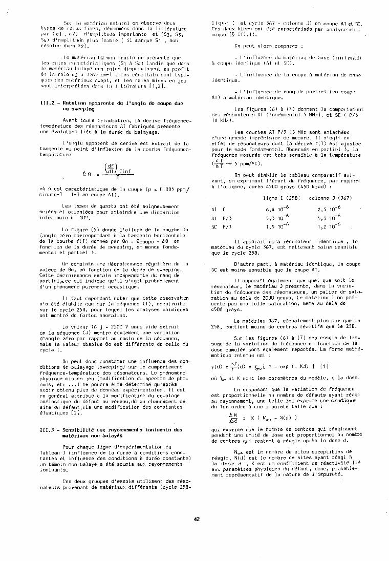
Sur Ir n~nttiriao nsturel on nbscrve dcux t.ypc!s do r:~irr; f irlt:~, ddnolnrt~dos dans la 1 iltdraturc p:lr ( el , 1!2) d':~~l~l)liLudc irtcporLnnto et (52, 53, 5 4 ) d'nlnplitotlt? pltlr; I;~il)le ( i l ttlnnclur 31 , nor1 rtinoluo dans e2).
111.2 - Rotation apparente de l'anqle de coupe due nu swccpinq
Avant toute irradiation, la ddrive Fr6q~tcnce- temperature des resonateurs AT fabriques presente une 6volution lice B la duree du balayaqe.
L'angle apparent de derive est extrait de la tangente au point d'inflexion de la courbe FrBquence- temperature
nt'l p est caracteristique de la coupe (p = 0.085 ppm/ minute-1 T-1 en coupe AT).
Les lames de qt~artz ont Bt6 soigneuselnent sciees et oriontees pour atteindre une dispersion infBrieure b 10".
La figure (5) donne l'allure de la rourbe 00 (angle zero correspondant B la tangente horizontale de la courbe f(T) donnee par 00 = Ocoupe - A 0 en fonction de la durBe de sweeping, en morlde fonda- mental et partiel 3.
On conatate une decroissance regulibre de la valeur de 80, en fonction de la durBe de sweeping. Cette decroissance semble independante du rang de partie1,rcce qui indique qu'il s'agit probablement d'un ph6nombne purement acoustique.
I1 faut cependant noter que rette observaticn n'a et.6 Btablie que sur la sequence (I), construite sur le cycle 258, pour lequel les analyses chimiques ont montrC de fortes anomalies.
La valeur 16 j - 2500 V sous vide extrait de la sequence (J) montre Bgalement une variation d'angle zero par rapport au reste de la s6quence, mais la valeur obaolue 00 est differente de celle du cycle I.
On peut donc constater une influence des con- ditions de balayage (sweeping) sur le comportement frBquence-temperature dea r6sonateurs. Le phBnomene physique mis en jeu (modification du spectre de pho- nons, etc ... ) ne pourra &tre determine qu'aprhs avoir obtenu plus de donnBes exp6rimentales. I1 est en general attribue b la modification du couplage anelastique du defaut au reaeau,dir au changement de site du defaut,via une modification des constantes Blnstiquos [2].
111.3 - Sensibilite aux rayonnements ionisants des matgriaux non balayes
Pour chaque ligne d'exp6rimentation du Tableau 1 (influence de la dur6e B conditions cons- tantes et influence des conditions B durCe constante) un thoin non balay6 a Bt6 soumia aux rayonnements ionisanta.
Ces deux groupes d'essais utilisent des rbso- nateurs provenant de mat6riaux diffBrents (cycle 258-
1 itjrlt! 1 cl cyrlrt 367 - colonrle J) en coupe AT et. T. Cos dr!crx l)lorn onl. dLri raracLBristSs par analynr: chi- n~irluc ( $ 111.1).
Lrs flqtlrcs (6) b (7) dorinent lc colnporLcmt?nL d e ~ r6aoriateurs AT (Tondamental 5 Mliz), et SI: ( P/3 10 MII/).
Les cot~rbes AT P/1 15 MHz sont entachees d'une grande imprecision de mesure. I1 s'ngit en effet de resonateura dont la derive f(T) est ajustee pour le mode fondamental. Observ6s en partlel 3, la frequence mesuree est trbs sensible B la temperature
On petlt dtnblir le tal>leat~ cornparatic sui- vant, en exprimant l'ticart de frequence, par rapport B l'origine, aprbs 4500 grays (450 krnd) :
ligne I (258) colonne J (367)
AT F 6,4 2,5 in-' AT P/3 5,3 1 0 - ~ 5,3 1 r 6
SC P/3 1,5 1,2
I1 apparalt qu'h rbaonatetrr identique , lo materiau du cycle 367, est nettemer~t n~oins sensible que le cycle 258.
D'autre part, B matBriau identique, la coupc SC est moins sensible que la coupe AT.
I1 apparait Bgnlcment que quel que salt le resonateur, le matdriau J presente, dans la varla- tion de Frhquence des resonateurs, un paller de satu- ration au deli de 2000 grays. Le rnaterlau I ne pr6- sente pas une telle saturation, m&me au delb de 4500 grays.
Le materiau 367, globalernent plus pur que le 258, contient moins de centres reactifs que le 258.
Sur les figures (6) b ( 7 ) des essais de lis- sage de la variation de fr6quence en fonction de la dose cumul6e sont Bgalement report6s. La forme mathe- matique retent~e est :
y(d) : g(d) : L[ I - exp ( - ~ d ) I [I] f
oh Y,,et K sont les parametres du modble, d la dose.
En supposant que la variation de frequence est proportionnelle au nombre de defauts ayant reagi au rayonnement, une telle loi exprime une c i n e t i q u e du ler ordre B irne impuretB telle que :
AN : K ( N,, - N(d) ) A d
qui exprime que le nombre de centres qui reagissent pendant une unit6 de dose eat proportionnel au nombre de centres tlui realant B rbagir ;1prb:3 1;i dose d.
N, eat le nombre de sites suceptiblea de rkagir, N(d) est le nombre de sites ayant r6agi B la dose d , K est un coefficient de rBactivitB li6 aux parametres physiques du defaut, donc, probable- ment representatif de la nature de ltirnpuretB.
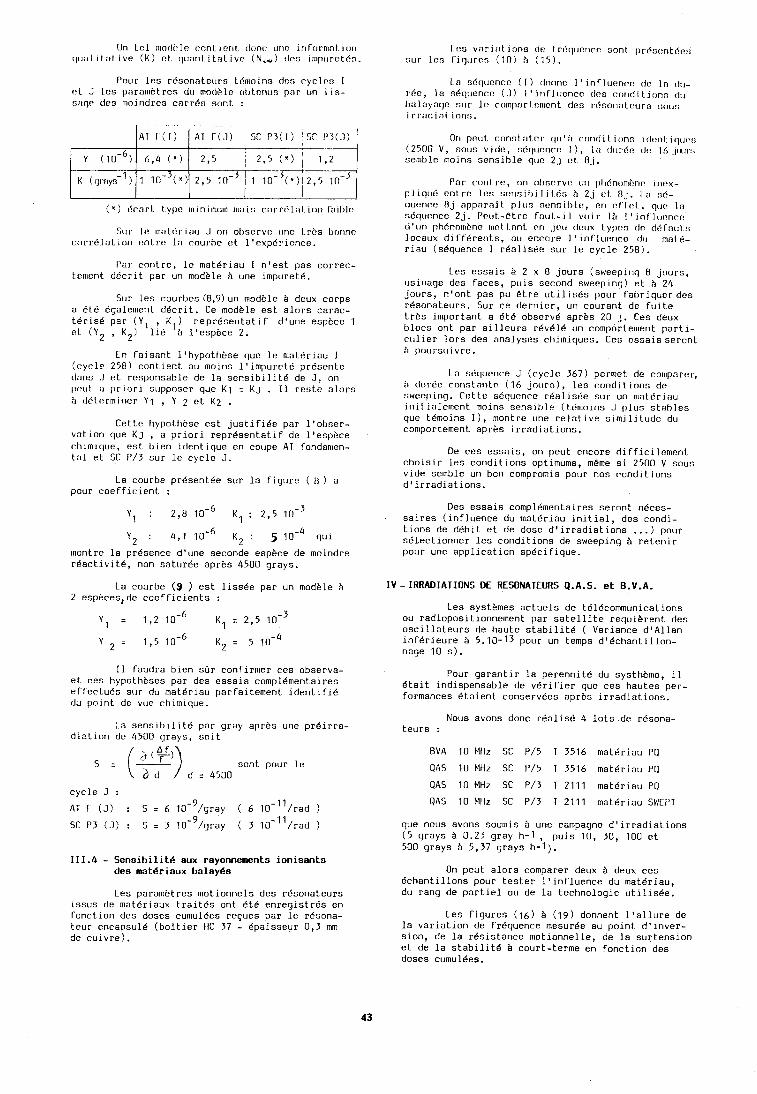
On lel 111ot1i:lr: cnnl i en1 dnnc tlrlo irifcirn~nt iori rl~loli tat ive ( K ) ct cl~cor?l.itnl ivt: (N,) clcs ilnp1iret6n.
Pour Ics rdsonatec~rs 16111oins tier; eyclos I (!I J Lcs parnmbtres d~ rno(li.lc ol,tcr\us pilr tin l is- s:\qe des 111oindrcs carrds sont :
( ' ) c!rarl. t ypt? laini~r~t~lci rn:~is corrtil:~l. ion T:iil~l(!
st11 It! 1rl:ll6rlau .I ori ol~scrvt? uric Lrbs bclrine rt~rr6lat1on cnLre In courbe ct l'expdrience.
Par conlre, le materiau I n'est pas correc- t.rment ddcrit par un modele i une impuret6.
Sur les courbes (8,9)un modele B deux corps a B t C Bgalenient d6crlt. Ce modele est alors carac- t6r1s6 par (Y, , K1) reprbsentatif d'une espece 1 rt (Y2 , K2) 116 B l'espkce 2.
Cn faisant lfhypothi?se quc le rnat.6riau I (cycle 258) contient au n~oins lfimpuret6 presente clans .I et responsable de la sensibilit6 de J, on poul. ti oric~ri supposer que K1 = KJ . 11 rcstc alors h ddlermincr Y1 , Y 2 et K2 .
Cette hypothese est justifiee par l'obser- vation que KJ , a priori representatif do l'espbce chimiquc, est bien identique en coupe AT fondan~en- tal et SC P/3 sur le cycle J.
La courbe pr6sent6e sur la figure ( 0 ) a pour coefficient :
Y2 : 4,l K 2 : 5 1 0 - ~ qui
montre la pr6sence d'une seconde espece de moindre r6activit6, non saturge aprhs 4500 grays.
La courbe ( 9 ) est lissee par un modkle B 2 esphces, de coefficients :
I1 faudra bien sar confirmer ces observa- et ces hypnthksas par des essals compl6mentaires effectu6s sur du mat6rlau parfaitement ldenti fie du polrit de vuc ch~mlque.
La sensibilite par gray apres une pr6irra- diation de 4500 grays, soit
cvcle J :
111.4 - Sensibilit6 atlx rayonnements ionisants des mat6riaux balay6s
Les parametres motionnels des resonateurs issus de lnat6rlaux trait6s ont 6t.4 enregistres en fonction des doses curnulees recues par le r6sona- teur encapsule (boitier tic 37 - Bpaisseur 0,3 mm de culvre).
I ct; v:lri:it ions dc frdqticncn sonl. prdsr:ntc!c::; sur los fiqlcre!; (10) ?I (15).
1 n s6qcicncc ( I ) donnc I ' i nf l uc?ncc de I n d~j- rbe, I a s6qooncc? (-1) 1 ' irlf lticncc des cmrid i tionn d~j l~olilyaqo our 11: cornporl.cnicnt dcs rdsonatc.urs t;ntis i rr;~di:iI it~rir;.
On ~I(~IIL cnnsl :ll.cr qir ' h c'ond i 1 ions i tl(:nl: i clclr:t; (2500 V, SCJ~I~; vide?, !~fi(~ucri(:c 1 ) , 1:i (JIII.I:I? tic? 16 ~INII.!; selclble moins sensible quc 2j rt. Oj.
f'nr cor~trc, rin n1)srrvo (111 ~~li6~10lll~n(~ ir~r:x- pliquti onlrc lor; ~c:risilii l it.61; h 2j c!t O.1. I :I nd- qtient:o 8j appnrt~f 1 pltrn nonnil~l t!, f?n cfl(?l., qrlt: 1:1 s6qtre:nce 2j. I1ctlI.-8t.r~ fritr1.-i l v~iir lii I ' lnl'lutmec! t1'11n 1)li6nocnbric 111cl Inn1 1.n j1:11 dt>llx t.yl~n!; tln dr!f:nlIr; locatix diff6rents, ou encore 1 'influer~co tftr mat 6- riau (sdquence I r6alis6e sur le cycle 258).
Les essais B 2 x 8 jours (sweepirig 8 jours, usinage des faces, puis second sweepinq) et b 24 jours, n'ont pas pu etre utilises pour fabriquerdcs r6sonateurs. Sur ce dernier, un courant de fuite trhs important a 6t6 observe apres 20 j. Ces deux 'locs ont par ailleurs r6v616 un comportement pnrti- culier lors des analyses chimiques. Ces essaisseront k poursuivre.
La sd(lk~enre J (cycle 367) pornlet de cnlclparcr, A durdc? ronstnnt~ (16 jnurs), les conditions dr: sweeping. Cc?t te s6qllenre rbal isde sur un n~altiri nu initinlen~ent moins sonsihle (tdcccoins J plus stables que t61noins I), n~ontrc one relative sirnilittide du con~portement aprhs irradiations.
Oe ces essnis, oci peut encore difficilen~ent choisir les conditions optimums, meme si 2500 V sous vide semble un bon compromis pour nos conditions d'irradiations.
Oes essais compl6mentaires seront n6ces- saires (influence du materiau initial, des condi- tions de debit et de dose d'irradiations ... ) pour s6Zectionner les conditions de sweeping B retenir pour une application specifique.
IV-IRRADIATIONS DE RESONATEURS Q.A.S. et B.V.A.
Les systemes actuels de t616communications ou radiopositionnement par satellite requierent des oscillateurs de haute stabilit6 ( Variance dlAllan inferieure B 5.10-13 pour un temps d16chantillon- nage 10 s).
Pour garantir la perennit6 du systhkrne, il dtait indispensable de verifier que ces hautes per- formances Btaient conserv6es apres irradiations.
Nous avons donc realis6 4 lots de r6sona- teurs :
BVA 10 Mllz SC P/5 T 3516 materiau PQ
QAS 10 Mliz SC P/5 1 3516 materiau PQ
QAS 10 MHz SC P/3 T 2111 mat6riau PQ
QAS 10 Mllz SC P/3 T 2111 mat6riau SWEPT
que nous avons soumls B une calnpagne d'irradiations (5 grays B 0.23 gray h-1 , puis 10, 30, 100 et 500 grays i3 5,37 grays h-I).
On peut alors comparer deux B deux ces 6chantillons pour tester l'influence du materiau, du rang de partiel ou de la technologie utilis6e.
Les figures (16) B (19) donnent l'allure de la variation de frdquence mesurge au point d'inver- sion, de la resistance motionnelle, de la surtension et de la stabilite B court-terme en fonction des doses cumul6es.
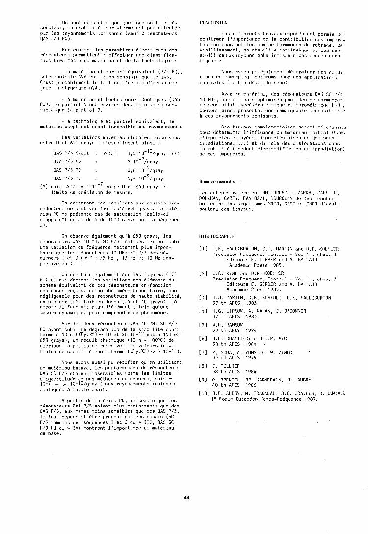
On p c u t c n n s t n t e r qcre q u e l que s o i t l e r e - sona tcu r , l a :> t .nh i l i t t ' cou r t - te rme e s t peu a f f e c t d e p a r Q AS
l e s P/3
i o n i s a n t s
Par c o n t r c , l e s paranlht res B l c c t r i q u e s des r6r;on:rt c!urs pc:r~rrctLorlt r l ' t : f focl.clcr (lrtc c l a o s i fic:l- I i o n t ri:!; nt!l.t.c? (III 111i1t.6r i : ~ u o t (11% . I n t . n c h r ~ r ~ l r ~ q i o :
- h 111:1L6rlilu ct. p n r t i o l t !qtr lvnlont ( r / 5 PO), lo t c c h n n l n q i e l1VA e n t rnoins s e n s i h l o q ~ ~ e l e QAS. C'cst . p r o t ~ n l ) l o n ~ o r ~ t I c f n i I. de 1 ' a c t i n n d16cr:ln quc ,J~I~IC I:] st r t l r t L I ~ C BVA.
- h 11li1l.6r i:lu (!I. Lr!cl l r inloqie i tlonl. i cltrt:n (OAS P O ) , I(: 1~1r . t ic!l 5 t!:;L c:nvi con tlcux f o i s nloirlo son- s i l l l o cltrc? 11: ~ m r t i e l 3 .
- B t e c h n o l o g i c e t p a r t i e l B q u i v a l e n t , l e m a t d r i a u swept e s t q u a s i i n s e n s i b l e a u x rayonnements.
Les v a r i a t i o n s moyennes q l o b a l e s , observecs e n t r e 0 e t 650 g rays , s 1 6 t a b l i s s e n t a i n s i :
PAS P/3 Swept : bf / f 1,5 1 0 - ~ ~ / g r a ~ ( * )
OVA P/5 PQ : 9 2 10- /gray
QAS P/5 PQ : 9 2,6 10- /grey
QAS P/3 PO : 9
5,4 10- /gray
( * ) s n i t A f / f : 1 e n t r e 0 e t 650 g ray : l i n l i t e de p r e c i s i o n de nlesuro.
En con~parant ces r e s u l t a t s aux courbes p r b - reden tes , on peu t v e r i f i e r qulA 650 g rays , l e mate- r i a l ~ PQ ne p r i i sen te pas de s a t u r a t i o n ( c e l l e - c i n ' a p p a r a l t qu 'au d e l e de 1000 g rays s u r l a s6quence -,
On observe Bqalement q u ' h 650 g rays , l e s r i i sona teurs QAS 10 MHz SC P/3 r 6 a l l s e s ICI o n t sub1 une v a r l a t l o n de f requence net tement p l u s Impor- t a n t e que l e s resona teurs 10 MHz SC P/3 des s6- quences I e t J ( h f = 35 Hz , 13 Hz e t 10 Hz res - p e c t ivement ) .
On c o n s t a t e Bgalement s u r l e s f i g u r e s (17 ) 2 ( 1 8 ) q u i donnent l e s v a r i a t i o n s des e lements du schema e q u i v a l e n t de ces resona teurs en f o n c t i o n des doses reques, q u ' u n phenomhne t r a n s i t o i r e , non n e g l i g e a b l e pour des resona teurs de hau te s t a b i l i t 6 , e x i s t e aux t r h s f a i b l e s doses ( 5 e t 10 g rays ) . La encore il f a u d r a i t p l u s d1dl8ments, t e l s qu 'une mesure dynamique, pour comprendre ce ph6nomhne.
Sur l e s deux resona teurs QAS 10 MHz SC P/3 PO ayant s u h i urte d d g r a d a t i o n de l a s t a b i l i t e c o u r t - t e r n ~ e h 10 s ( ry( t " )& 10 e t 20.10-12 e n t r e 150 e t 650 g r a y s ) , un r e c u i t thermique (10 h - 100°C) de guCr ison a pe rmis de r e t r o u v e r l e s v a l e u r s i n i - t i a l e s de s t a b i l i t e cour t - te rme ( T y ( c ) u 3 10-13).
Nous avons a u s s i p u v e r i f i e r qu 'en u t i l i s a n t un m a t e r i a u balay6, l e s per formances de r e s o n a t c u r s QAS SC P/3 e t a i e n t i n s e n s i b l e s (dans l e s l i m i t e s d ' i n c e r t i t u d e de nos m6thodes de mesures, s o i t d 10-7 + 10-lO/gray ) aux rayonnements i o n i s a n t s app l iques f a i b l e d e b i t .
A p a r t i r de m a t e r i a u PQ, il semble qile l e s rCsonateurs BVA P/5 s o i e n t p l u s p e r f o r m a n t s que des QAS P/5, eux-m&mes molns s e n s i b l e s que des QAS P/3. I 1 f a u t cependant & t r e p ruden t c a r ces e s s a i s (SC P/3 temoins des sequences I e t J du $ 111, QAS SC P/3 PQ du § I V ) montrent l ' i m p o r t a n c e du m a t e r i a u de base.
CONCL llS I ON
Lcs d i f f e r c n t s t ravaux expos6s o n t pernris dc c o n f i r n ~ e r l ' i m p n r t a n c e de l a c o n t r i b u t i o n des impure- t 6 s i o n i q u e s m o b i l e s aux per formances de r e t r a c e , de v i e i l l i s s e m e n l , tle s t a b i l i L 6 i n t r i n s h q u e e t des scn- o i l , i I i 1.6s EIIJX r c~yc -~nno~~~r?n l n i o n i s:lnLs dc:s rr inonnl c?llrs ?I q11:1rl7.
Now; :lvonr; IIU O(j:llrrr~onL t ldLorrr~inci. clt?s r11ntl1- t i o n s do "sweco inq" o p t imuwo pour des app l i r n t i o n s npnt ia lc : ; ( f ; ~ i l ) l o t lbl) iL dc clo!;e).
Avt:c cc! 111:lt6r i nu, (ICG r6n(1r1nl.~ur:i OA!i ST 1'/3 10 MIII, O: I~ n i 1 lr>~rrr; op t in1 in6n potlr tlc!!; ( ~c~r I ' r~ r rn ;~nrc~n t l~ : ncnn i l i i li t 6 ; ~ c c d l t ' r o n ~ ~ t . r i c l u e el. I):~rnnlr!l.riq~rc: I I l l ] , po(~vt:nt a i n s i ~ l r d s c r i t c r unc r e n ~ : ~ r t ~ ~ ~ a l ) l o ir~r;t.nr;il~i l i 16 b ces rayonnements i o n i s a n t s .
Des t - r i ~ v a u x cnmpl6menta i res s e r o n t n k c e s s a i r m potrr de te rm iner 1 ' i n f l u e n c e du rna te r iau i n i t i a l (lypcs d ' impl r retbs be1 ny6es, in lpuretes mises en .jet1 sour; i r r a d i a t i o n s , ... ) e t du r % l e dcs d i s l o c a t i o n s dans l a m o b i l i t 6 (pendant B l e c t r o d i f f u s i o n ou i r r a d i a t i o n ) de ces impure tbs .
Rcmerciements -
Les a u t e u r s r e n l r r c l c n t MM. RRCNDTL, IAIiKA, TAPCL I I, DOIJKHAN, GADLY, TANTOZZI , DOURQIIIN (it, l e i r r r o n t r 1 - b u t l o n eL l e s orqan~snres MRES, DRET e t CNES d ' a v o ~ r s o t ~ t e n u ces Lrnvoux.
BIBLIOGRAPHIE
[I] L.E. HALLIBURTON, J.J. MARTIN and D.R. KLILIILCII P r e c i s i o n Frequency C o n t r o l - Vol 1 , chap. 1
E d i t e u r s E. GERBER and A. BALLATO Academic Press 1985.
[ 2 ] J.C. KING and D.R. KOLIILLR Precision Frequency C o n t r o l - Vol 1 , chap. 3
E d i t e u r s E . GERBER and A. BALLATO Academic Press 1985.
[ 3 ] J.J. MARTIN, R . B . BOSIOLI, L.E. HALLIBURTON 37 t h AFCS 1983
[ 4 ] H.G. LIPSON, A. KAHAN, J . O'CONNOR 37 t h AFCS 1983
[ 5 ] W.P. HANSON 30 t h AFCS 1984
[ 6 ] J.G. GUALTIERY and J.R. VIG 38 t h AFCS 1984
[ 7 ] P. SUDA, A. ZUMSTEG, W. ZINGG 33 r d AFCS 1979
[ 8 ] C. TELLIER 38 t h AFCS 1984
[ 9 ] R. ORENDEL, JJ. GACNEPAIN, JP. AUBRY 40 t h AFCS 1986
[ l o ] J.P. AUBRY, M. FRAGNEAU, J.C. CRAVEUR, D.JANlAUD IU Forum Europ6en Temps-FrBquence 1987.
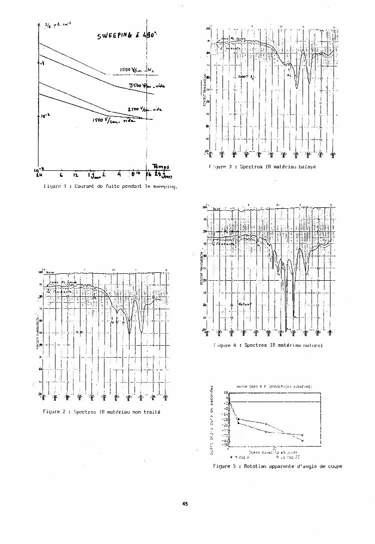
F'oure 3 : Spectres IR rnat6riau balayd
f i r jc~re 1 : Courant de f u i t e pendant l e sweeping.
Figure 4 : Spectres IR rnatgriau nature1
Figure 2 : Spectres IR rnat6riau non t r a i t e
. . :Itjp.si .rk,c.+; :-,q o -;,,.I::
s 5 I::,: i' >b ,.I,: ,::
.gure 5 : Rotation apparente d 'angle d s coupe
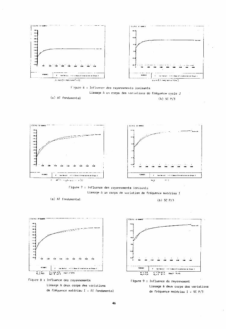
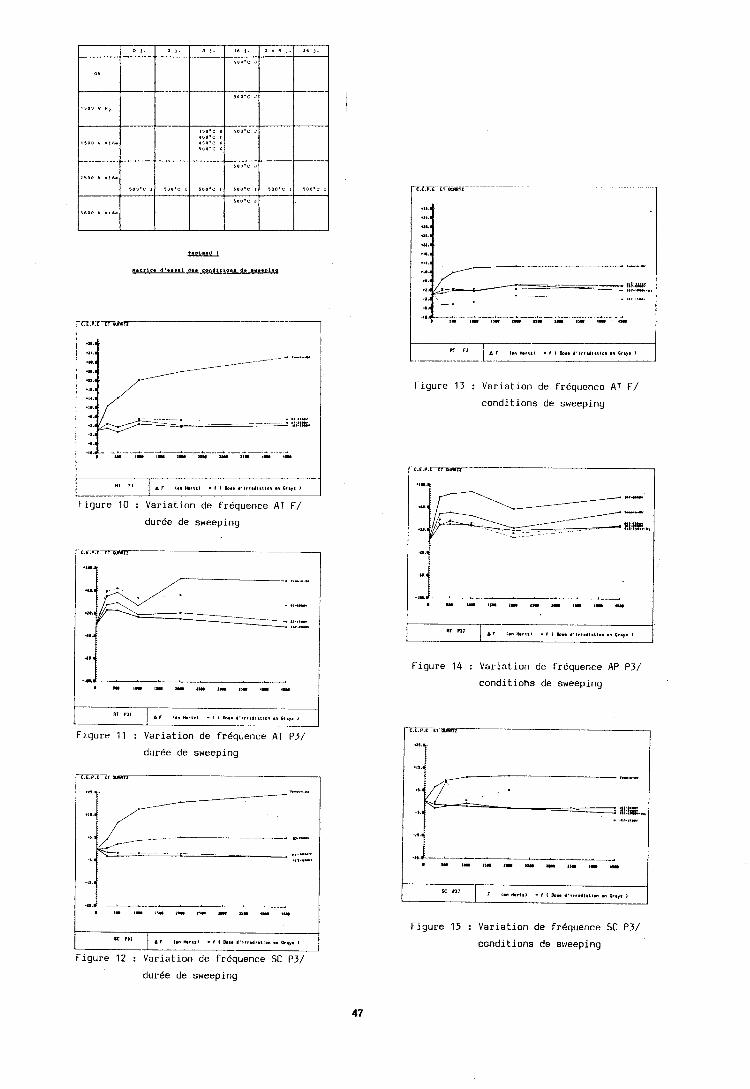
Figure 10 : Variation de frequence AT F/
duree de sweeping
duree de sweeping
n! A r (." r n . t . ~ - r I h.. ,- cllrl I
1-iyure 13 : Variation de frequence AT F/
conditions de sweeping
Figure 1 1 : Variation de frkquence AT P3/
"I
Figure 14 : Variation de frkquence AP P3/
conditions de sweeping
A I Ian rnr1.1 . I I Ibl. d ' l ? . l l a l l a n nn Cq. I
.,.&-L_-L. . . . . , I U I 1 111 1 1 I 11 U I,. <I .,. I
Figure 12 : Variation de frequence SC P3/
Figure 15 : Variation de frkquence SC P3/
conditions de sweeping
durke de sweeping
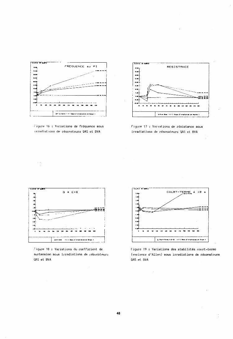
.... .G.. Y.
I.. ,//---- ."" .c .. .". .c ..
Figure 16 : Variations de frequence sous
irradiations de rCsonateurs QAS et BVA
t,P I I.' -, I L.. .*l,,l.l.ll." on W.". I
Figure 18 : Variations du c~fficient de
surtension sous irradiations de r6sonateurs
QAS et BVA
7.m,rm.r--.-- ,I..
RESISTANCE
:: 1 11.1
,..I - 1 ----- .. _ ::::pi
I.. y--..- -""
1,. .n .' .I " --"" .,.1
L. l .l .-
Figure 17 : Variations de resistance sous
irradiations de resonateurs QAS et EVA
I . . 1 ,."k+- - .- . . . , . - - -I .". ---1 .a " .. " ., I..
Figure 19 : Variations des stabilites court-terrne
(variance d1Allan) sous irradiations de resonateurs
QAS et BVA
~13afqtis aqi uodn YJOM
a~nlrij %u!s!mo~d JO uo!1sa881ls aql ~ I ! M dn spua uo!snlnuoo aqi pull palsnls~a aJo olup ~o~uaiu!.tadxa atuos E '3aS u1 ' L U ~ J aqi jo X~!suap sseru 1eaJ-e pampa1 aqi jo uo!13unj u so painlnsje3 a ~ u X31~nnoc uo!lou!~ualap-z aql 01 s a n p ~uatua~nseam aqi jo Xiu!o~~asun pawnsst? uo jo suo!~nqpiuon aq1 p'z '3as u! puo 'painZ!~sa~u! ajo sanlsh ~ualua~nsuatu jo s~!cd iua~ajj!p LUOJJ z anul?pad~u! 3!lsnoos x p a d s aqi JO uo!iw!m~aiap aql JO sai!l!q!ssod sno!JoA aql E'Z 'ass u! !paJap!suo3 ale L~lamoa8 l e a aqi jo samanUu! aql 2.z 'XIS ul ~ i u a ~ ~ i ~ a n ~~?uo!suaiu!p-auo 11:qi m o ~ j 8u!m:1s
.Lla~!lnadsa 'LU~IJ aql pur! 11!1shn ail] JO sanimpadiu! a!lsno3o y!nads :dz 'bz .Xla~!lnadsa~ 'mly aql puo 1nlslCls aql jo sassauynyl :dl 'bl .UO!IVJ~!A Juaqs ssauya!qi 3.a 'a~ninn~is al!sodruon ~cuo!suaiu!p-auo aql jo uo!~c~uasa~daJ a!~umaqng -1':)ld
1
'paq!Jnsap s! lapom ~l!o!~a~oaql aqi uoy3as %u!molloj aqi ul 'L~iatuoaS al!u!ju! aql JO X1!1!q1?~1ddn aql jo si!iu!l aql u!q~!m sno~oS!l s! qn!qm s!sXll:ue JoInuosaJ al!sodmon I? oi /(,'8/ qnwo.'dr! luanaJ o pa~dopl? ahoy am punmap 8u!innxa aJom Xlsno!~qo s!qi ll!j~nj 01 laplo UI
J.1JIIPSIII?JI 1111 50 t~l?lql>ld UO!ln.l.l.lOn I! J3Llll?J 3Al?L[ ?M ' ~ ~ 1 ? ~ 1 1 ~ ~ [ 1 ? ~ ! d ~ 1
s! suo!suaru!p loisdin pill? Lrtl!j Su!u!i\ualap Lnuanba~j ~ ~ U I ! L I O S ~ J
at11 jo o!ln~ aql ~oll!uosa~ n!~lnqaoza!d a~!sodirton ?tll JO u o ! ~ t ? ~ ~ d d ~ ? s!q] u! anu!S ' J ~ X I ? ~ pal!sodap a q ~ j o ~ut!~suon ssaujj!is n!lst?[a a~!lnajja a41 JO u! X~!nolah asoqd n!uost?Jlln at11 'an~wpadiu! ?!isnono n!j!nads aql jo uo!~~!u!ii~~a]ap aql ~ o j oslt? lnq 'ssauyn!tll ii11!1 palo[~i~u~lnn~? arll jo put! ale1 uo!l!sodap ail1 JO ~0~1~03aaq i ~ o j Xluo IOU pt:aq Josuas II!ISXJD z1~otil~ 3\11 asti 01 put!q 11: Jt?au scuaas I! ' s n q ~ '[lam sl: ~unag!u%!s aq XCLU sa!l~adoid lan!ul?qoaiu aql jo Suposuas ~t?uo!l!ppl! ail1 'siul!.l aql jo sa!l~ado~d o!latrSt!iu ~o a!ldo 'n!.rlnalaaql uodn pasnnoj s! ~sa~alu! L~l:iupd aqi sasr:o pauo!luaiu ail1 u! i l l n o q ~ l ~ .ad1?1 oap!A n!1au8om tutu 8 Zu!it~onq~.ioj aql pul? uo!lonpo~d ns!p int:dtuon ~nl!%!p at11 JOJ aoua~odiu! 8u!sl?a~nu! asp! aha!qx sassano~d 8u!i1:0n asaq,L .anb!uqnal Bu!~ailnds pul! uo!~r?~odn~a aql ay![ sassaao~d 8i1!1oon lon!sXqd Xq pannpo~d XI!JI?LU!J~ ~ J I : put? X~~snptt! y d o 3111 so 11" MI! hisnpu! ~o~n~~pvon!tuas at11 JOJ Xllc!mdsa aasu~?l~odt~t!jo all? s~ul!j '1x1s Ss~i~l! j n!nnala!p lo n!lli!iaiu u!i11 ~ a i l ~ l ! ~ j o uo!lnz~~ain~u~?qn [l?o!isltosr! JO Il?o!ul?qoau1 ail] s! ~adcd itlasa~d aql 30 LU!I? X{J,
.anll?A Xlpola~ Su!isa~a~u! aql loj uo!ssa~dxa al!n!ldxa UI! la8 01 ~ a p ~ o u! Xllnjssaonns ssal JO a ~ o w selnuuoj uo!~cm!xo~ddu jo 61a!~o~ I? uaha pa!lddi! ahcq / L ' Y ' s ' ~ / s~oqine amos JannpsuvJi a q ~ puc uam!oads aql 30 suo!suam!p Su!u!wa~ap-Xouanbay aqi JO O!IVJ q3!q e J O ~ 'a1e~no3e Xl1ua!3gjns 'ssalaqua~au 'sem lapow aqi ~ o i n y 8u!ldno31o3!uoqnaiuo~i3ala mol ha^ ~ I ! M Ic!Jaiom nyloalaoza!d JOJ JO wo!suaaw!p-~annpsuc~i llnms puu -uam!oads a8~ol ~ a q i o ~ jo sasco aqi u1 '~t!pai~!rn Jannpsuoa oui~alaoza!d aqi jo iunlsuoa o!lsnla ah!13aga Su!u!uua~ap Xouanbalj anuouosal aqi oi sapo~isala 8u!i!oxa uo!lc~q!~ aql uaamlaq pool lno!~inala aql jo qooqpaaj aql apnlnu! IOU
saop qa!qm lapom lun!ul!qaam Lla~nd c m o ~ j IJI!IS saqnco~ddc asaqi11~ inq~ 131?j aqyl jo aouanbasuoo o s! s ! q ~ 'suo!icnba iuaje~!nba L113apad Xq paq!Josap s! JOII?UOS~J ai!sodmon aqi sy~om pauo!iuam lie u! 'qnniu ha^ ~ajj!p suo!lvla~ aql jo s w o j anutunaddu aql qSnoq11~ '/p/ S ! M ~ pun n7 st! llam sc '/c/ "uaW punJaloa '/Z/ J2jalog put) ~ q l ! ~ Xq suo!laAuap aqi a n umouy X~uommo3 aJom Inq '/I/ asoy Xq apnm sum qnuo~ddo ISJIJ aq1 ~uo!i1?8!]sa~u! lapun 1cuamur-uam!3ads aqssnd aql pul! uad lu!~!~p an!tm o!.~inalaoza!d aql jo Su!is!suoa SJOII?IIOS~J ai!sodmoo st: paioa.11 aq lsnm sald~ul!s aq& 'saaucuosal q~Suala~em-j~aq Lluo-uampads aql jo sa!nuanba~j aql oi puodsauoo IOU op sa!manbaq anuauosaJ l~n!ucqnam pa~nscam L1ll:iuampadxa '~a3npsumi aqi JO aouasa~d aql jo asneoaq 'anb!uq3al3!uosnJlln ahnm Bu!pucis aql jo aso3 aqi u~ .uo!~o]!oxa ahom snonu!]uoo o %u!Lldde Xq aldwos a q ~ jo Lsuanbay aoueuosal aql WOJJ JO as~nd uoqs n jo am!] uo!~oScdo~d aql jo ~uatua~nsoaw aqi mog ~aql!a pau!uualap aq unn uatu!oads aqi it! Xi!nola~ awqd a!uost:~iln aqL ' ~ a o ~ i p w u ~ ~ a~q~!i!ns 1: ~ I ! M ~sa~aiu! jo uatu!oads aqi jo Bu!ldnoo Lq paiu~oj~ad Lllcnsn s! sp!nh!~ JO sp!los u! X~!mja~ asnqd J!lsnonc jo uo~~nu~uua iaa
,sajdiut!s ai!sodiuon I V ~ I J I ? I ~ ~ put! ' ! . jp~~t?~ib ' t i~pi~t!nl) jo Jaqiullu I? 01 pa!lddl? uaaq ss"q lapotu aql pui: par~~diuon uaaq aAt!q anlt:~-z Su!z!~ainn~~?qn I~!.I~II!LU a111 jo Xnn~t~no~! aql 01 s~a~a~ul?~t!d paJnsl!aiu aql jo s?!or?Jnnnc aql jo suo!inq!.~~uon J O J J ~ ai1.L .aldiucs a~!sodmoo I! jo Z U j pu~? IUj sa!nuat i l~~~ anul!uosa~ n!uoiw~:q!s~?~ih OM] JO 'mly aql jo dm Ll!suap ssl?m It?aJc a41 put: ~ o ~ t ? u o s a ~ al!sod[uon aqi jo ( ~ = u 'Iuua~ut:putlj aql 3.9) IJ j
Xnuanba~j anitr!uosa~ auo :~J I : s~!~?d-~aia~i~~ut:d p a ~ ~ a j a ~ d pait!S!~sa~u! aqL .s~aiaiuo~ed putisnau om1 w o ~ j A sa!i!nolaA asaqd aqi JO n siut?lsuoo ssaujj!~s aql .lo z sanul!padiu! o!lsnono nyioads aql ail!lnnlt!n 01 sa!i!l!q!ssod s n o ! ~ n ~ najjo JolcuosaJ a~!sodmon iul!j/zut!nb aql jo s!sLlt!un ~cn!la~oaqi aqL .JolnuosaJ ~l?isBn zl~anb a uo pa~!sodap aq isntu uo!1o8!1sahu! Japun lul!j u!qi aqi 'poqlam s!ql 01 Zu!p~oonv .pannpoJlu! s! siul!j n!Jinala!p jo sa [lam so n!l11?1a~u jo sa!~!nola~ awqd Su!puodsa~~on aql JO slumsuon ssaujj!ls ~nuo!ssa~dmoo put? ~1:aqs n!isl?ia 3111 JO UO!I I?U!ILJ . I~I~~ aql JOJ pot11aiu v
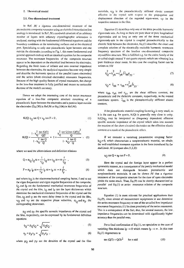
In Ref. /8/ ;I rigorous one-dimensioni~l treittrnent of the piczoclectric composite rcso1i;ttor using an cl~ctrici~l tr;trisriiissiori line nni~logy is introduced. In Ref. /O/ ;I sandwich structure of an arbitrary number of layers with arbitrary cryst:~llogri~pliic oriertti~tiori is nnnlyzcd, starting with tlie fu~id;~ment~~l dil'ferentiol equi~tions and the bountl;~ry conditions ;it the tenninnting surf;~ces and nt the electrical port. Specinlizing to only one piezoelectric Inyer between and one outsitlc the electrodes iiccording to Fig. I, this more fi~ridi~mental i~nd general upproacli ends 111) with ;ui identical equation for the composite resonntor. 'I'he resonance frequencies of the corl~posite structure appear to be dependent on the electrical loi~d between the electrodes. Regarding the limit cases of infinite and zero external impedance between the electrodes, the analyticill ecluittions become very siniple and describe the harmonic spectra of the pari~llel (open electrodes) and the series (short circuited electrodes) resonance frequencies. Becnuse of the high quality factors of crystal resonators, the chiinge to the loss-free treatment is fully justified itnd means no noticeitble decrease of the model's iiccurilcy.
Hence we adopt the interesting case of the series resonilnee equation of a loss-free composite structure consisting of a piezoelectric layer between the electrodes and a passive layer outside the electrodes (Eq.(30) in Ref.lW or Eq.(106) in Kef.F)/):
where we used the abbreviations and definition relations
and where k~ is the electromechanical coupling factor, f and w are the eigen frequencies and eigen angular frequencies of the composite, f~ and fF ;we the fi~ndamentnl mechanical resonilnce frequencies of the crystnl and the film, IQ and IF are the layer thicknesses which determine the mechanical resonance frequencies of the crystal and the film, t~ and IF are the wave delay times in the crystal and the film, VQ and VF are the respective phase velocities, a ilnd aF the corresponding slownesses.
Q
ZQ i~nd ZF, the specific acoustic imped~lnces of the crystal and the film, respectively, can be expressed by its fundamental definition equations
zQ= PQvQ= 6 * ( 5 )
Z F - P F V F ' & 9 (6)
~i~;~tcri:~ls, c~ is tlie pieztnAectric;~lly stil'l'ened eii~stic const;uit efl'cclivc in tlie crystill wit11 resl)cct lo the prol);~g;~tion arid displi~ccment direction of' the regarded eigen-wi~ve, cl; ist the respective const;Int in tlie lil~n.
Iiquntion ( I ) tlcscribcs o~ily one of tl~e three possible Il;utnor~ic eigerimode-sets. As long ;IS there :Ire pure shei~r or pure lor~gitudin;~l eigenmodes and as long os only one of tlie three ~iiechanical eigenmode-sets in [lie crystnl is coupled piezoclectric;~lly to the electric field between the electrodes, Eq.(l) describes the exact ;tnd complete solution of the electrici~lly exciti~ble h;~rnlonic resonance frequency spectrum of the lossfree (>lie-din~e~isioni~l composite crystal/l'il~n-struct~~re. 'I'his is l'ull'illcd e.g. for the elltire f;uiiily of the so called single rotitted Y-cut cluortz crystills which ;Ire vibrating in a pure thickness shear mode. In this ciise the coupling fi~ctor can be written as 1101
2 CQ = z66 = c~~ + e /E
~6 Y Y '
where c ~ , eyy6 and cyy are the sheiu stiffness constant, the piezoelectric and the dielectric constants, respectively, in the rotated coordinate system. th6 is the piezoelectrically stiffened elastic constant.
If the piezcwiectric ~iii~terii~l coupling fitctor k~ is very s~nitll, its i t is the case e.g. for qu;utz, K(Q) is generiilly very close to unity. K(Q)zQ nli~y be interpreted as (frequency dependent) effective specific ncoustic i~nped;~nce of the c~yst;~l which takes into account the re;tction of the short-circuited electrodes on the effective eli~stic
constiint ;IS ;I rest111 of tile piezoelectric cflkct.
If we consrder a vanrshing p~ezoelectnc coupling factor k~ = 0, which characterizes a nonpiezoelectric material, we obtain the well established resonance equation in the form introduced by Lu and Lewis /4/ (compare also /1,2,3/):
Here the crystal and the foreign layer appear in a perfect symmetric manner, as a consequence of the purely mechanical model which does not distinguish between piezoelectric and nonpiezoelectric materials. It can be shown 191 that a rigorous treatment of the composite structure for the case of open electrodes yields the same result. Thus, Eq.(9) can be shortly characterized as parallel and Eq.(l) ns series resonance relation of the composite structure.
Equation (1) is more relevant for practical applications than Eq.(9), since alniost ;ill measurement equipments in use determine the series resonance frequency or one of the so called low impedance resonance frequencies /11/ in close proxinlity of the series resonance. This is a consequence of the fact, that, for several reasons, the low impedance frequencies can be detem~ined with significantly higher accuracy than the parallel ones.
For a final confimlation of Eq.(l), we specialize to the case of
vanishing film thickness IF + 0 which means fF = . In this case
Eq.(I) degenerates to
tan (w2) = ~ / 2 k ~ for n odd (10) where p q and p~ are the densities of the crystal and the film
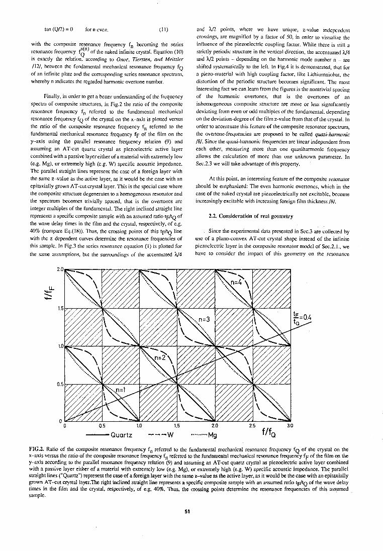
t i ~ n (Ql2) = 0 for 11 eve!]. (1 1)
with the cmnposite reson;tnce frequency fn becoming the series resonance frequency ?(") of the naked infinite crystiil. Equation (10)
Q is ex;~ctly the relotion, ticcording to Onoe, Ticrsren, at~tl Meirzler 1121, between the fi~ndi~nientnl mechntiicnl resonance frequency f~ of ;in infinite p1;ite and the correspondirig series resonance spectrum, whereby n indicxtes the reg:~rded hiirmonic overtone number.
Finally, in order to get ;I better understanding of the frequency spectrii of coniposite structures, in Fig.2 the ratio of the composite resonnnce frecluency fn referred to the fund;lrnental mecli:~nic:!l resoniuice frequency f~ of the crystal on the x-axis is plotted versus the ratio of the composite resonance frequency fn referred to the fundamental meclirinical resonnnce frequency fF of tlie film on the y-axis using the parallel resonance frequency relation (9) and assuming an AT-cut quartz crystal as piezoelectric ;ictive layer combined with a passive layer either of a materinl with extremely low (e.g. Mg), or extremely high (e.g. W) specific acoustic impednnce. The parallel straight lines represent the case of a foreign layer with the sitme z-value as the active layer, as it would be the case with an epitaxinlly grown AT-cut crystal layer. This is the special cnse where the composite structure degenerates to ;I homogeneous resonator nnd the spectrum becomes trivially spaced, thot is the overtones ;ire integer multiples of the fundamental. The right inclined straight line represents o specific cornposite sample with an assunied ratio tF/tQ of the wave del;~y times in the film and the crystal, respectively, of e.g. 40% (~0mp:ue Eq.(18)). 'rhus, the crossing poinls of this t F / t ~ line with the z-dependent curves determine the resonance frequencies of this somple. In Fig.3 the scrics resonnnce eclu;~tion (1) is plotted for
the slime assumptions, but the surroundings of the accentuated U4
and 112 points, where we hnvc uniclue, z-value indeperiderlt crc~ssings, ire magnified by a factor of 50, in order to visualize tile influence of the piezoelectric coupling factor. While there is still a strictly periodic structure in the vertical direction, the accentuated h/4 and h/2 points - depending on the honnonic mode number n - ;we sliil'ted systern:~ticolly to the left. In Fig.4 i t is demonstrated, that fi)r a piezo-ni;~terial with high coupling filclor, like Lithiumniohr, the distortion of the periodic structure becomes significant. The most interesting fiict we can le:trn from the figures is the nontrivinl spacing of the tiamionic overtones, thot is the overtones of an inl~omogeneous composite structure ;Ire more or less significi~ntl~ devinting from even or odd ~nultiples of the fund;~nientnl, depending on the deviation-degree of the film z-vnlue from that of the crystal. In order to accentuate this feitture of the conlposite resonator spectrum, tlie overtone-frequencies are proposed to be called quusi-harmonic 181. Since the quasi-honnonic frequencies are linear independent from each other, measuring more thnn one quasiharmonic frequency allows the ciilculation of more than one unknown pwameter. In Sec.2.3 we will take advantage of this property.
At this point, an interesting feature of the composite resonator should be eniphasized: The even hamionic overtones, which in the cnse of the naked crystol ore piezoelectrically not excitable, become incre;~singly excitable with iricre;~sing foreign film thickness /XI.
Since the experimcritnl datn presented in Sec.3 are collected by use of a plano-convex AT-cut crystal shape instead of the infinite piezoelectric layer in the composite resoniltor model of Sec.2. I., we have to consider the impact of this geonietry on the resonnnce
FI(i.2. Ratio of the composite resonance frequency fn referred to the fundamental mechanical resonance frequency f~ of the crystal on the x-axis versus the ratio of the composite resonance frequency fn referred to the fundiunental n~echnniciil resonimce frequency f~ of the film on the y-:\xis according to the pariillel resonance frequency relation (9) and assuming an AT-cut quartz crystiil as piezoelectric active layer combined with a passive layer either of a material with extremely low (e.g. Mg), or extremely high (e.g. W) specific acoustic impednnce. The parallel straight lines ("Quartz") represent the case of a foreign layer with the same z-value as the active Inyer, as it would be the case with an epitaxinlly grown AT-cut crystitl layer.The right inclined straight line represents a specific composite sample with an assumed ratio IF/IQ of the wave delay times in the film and the crystal, respectively, of e.g. 40%. Thus, the crossing points determine the resonance frequencies of this ahsunled sample.
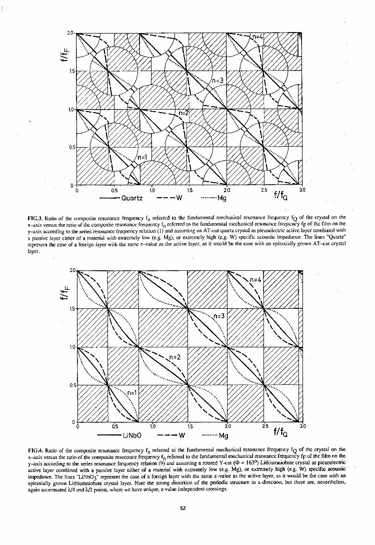
FI(i.3. Ratio of the composite resonance frequency f n referred to the ftlndiimental mechanical resonance frequency f~ of the crystal 011 the x-llxis versus the ratio of the conlpositc reson;lnce frequency fIl referred to the fundnnlent;~l niechi~nic;~l resonance freqclcncy fF of the filnl on the y-axis according to the series reson;lnce frequency relation (1) and :~ssurning an AT-cut qu;ulz cryst;~l ;Is piezoelectric active layer combined with a passive Inyer either of a material with extrenlely low (e.g. Mg), or extremely high (e.g. W) specific acoustic in1ped;mce. The lines "Quartz" represent the case of a foreign l;lyer with the same z-value ns the active layer, as it would be the c;we with an epit:lxinlly grown AT-cut crystal layer.
LiNbO --- W ........a. Mg
FICA. Ratio of the composite resonance frequency fn referred to the fundamental mechanical resonance frequency f~ of the crystal on the x-axis versus the ratio of the composite resonance frequency fn referred to the fundamental mechanical resonance frequency f~ of the film on the y-axis according to the series resonance frequency relation (9) and assuming a rotated Y-cut ((O = 163O) Lithiumniobate crystal as piezoelecvic active layer combined with a passive layer either of a material with extremely low (e.g. Mg), or exaemely high (e.g. W) specific acoustic impedance. The lines "LiNbOgU represent the case of a foreign layer with the same z-value as the active layer, as it would be the case with an epitaxially grown Lithiurnniobate ~rystal layer. Note the strong distortion of the periodic structure in x-direction, but there are, nevertheless, ngain :tccentuated ?J4 and points, where we hove unique, z-value independe~lt crossings.
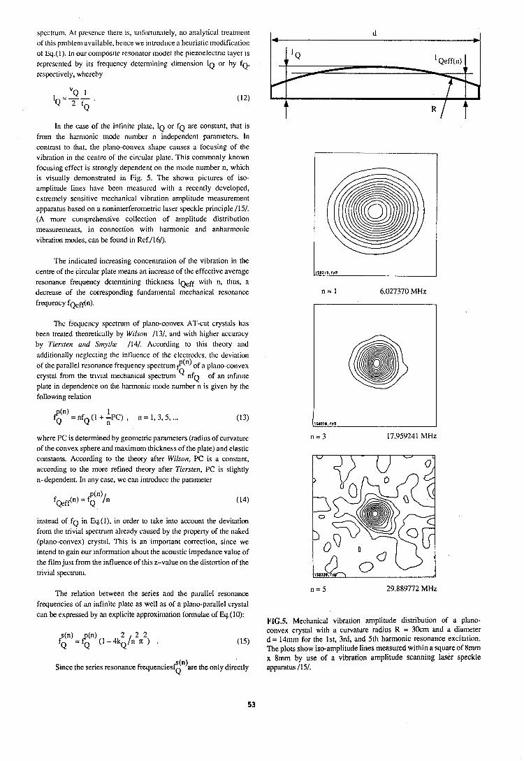
spectrum. At preserice there is, unfon~in;itely, no annlytic:~l trentmeilt ot'this probleni available, hence we i~itroduce a heuristic modificution ot bq.(l). In our composite resonator model the ptezoelectrlc layer IS
represented by its frequency detemlining dinlension IQ or by FQ, respectively, whereby
In the case of the infinite plate, IQ or FQ are constant, that is from the harnlonic mode number n independent parameters. In contrast to that, the plnno-convex slinpe causes ii focusing of tlie vibration in the centre of the circular plate. This commonly known focusing effect is strongly dependent on the mode number n, which is visually demonstrated in Fig. 5. The shown pictures of iso- amplitude lines have been measured with a recently developed, extremely sensitive mechanical vibration aniplitude measurement apparatus based on a noninterferometric laser speckle principle 1151. (A more comprehensive collection of amplitude distribution measurements, in connection with harmonic and anharnmonic vibration modes, can be found in Ref.1164.
The indicated increasing concentration of the vibration in the centre of the circular plate means an increase of the effective average resonance frequency determining thickness 1eff with n, thus, a decrease of the corresponding fundamental mechanical resonance frequency f ~ ~ f k n ) .
The frequency spectrum of plano-convex AT-cut cryslnls h;~s been treated theoretically by Wilson 1131, and with higher acci~racy by Tiersterr und Snryttre 1141. According to this theory and additionally neglecting the influence of the electrodes, tlie deviation of the parallel resonance frequency spectrum@n) of a plano-convex cryslal from the m v t l niechan~cal spectrum nfQ of an ~ n h n ~ t e plate in dependence on the harmonic mode number n is given by the following relation
where PC is determined by geometric parameters (radius of curvature of the convex sphere and maximum thickness of the plate) and elastic constants. According to the theory after Wilson, PC is a constant, according to the more refined theory after Tiersten, PC is slightly n-dependent. In any case, we can introduce the parameter
instend of f~ in Eq.(l), in order to t'ake into account the devitation from the trivial specuurn already caused by the property of the naked (plano-convex) crystal. This is an important correction, since we intend to gain our information about the acoustic impedance value of the film just from the influence of this z-value on the distortion of the trivial spectrum.
The relation between the series and the parallel resonance frequencies of an infinite plate as well as of a plano-parallel crystal can be expressed by an explicite approximation formulae of Eq.(lO):
(n) Since the series resonance frequencies? are the only directly Q
158ZIY,fn7
n = l 6.027370 MHz
isanm.rns
n = 3 17.959241 MHz
n = 5 29.889772 MHz
FIGS. Mechanical vibration amplitude distribution of a plano- convex crystal with a curvature radius R = 30cm and a diameter d = 14n1n1 for the Ist, 3rd, and 5th harmonic resonance excitation. The plots show iso-amplitude lines measured within a square of 8mm x 8mm by use of a vibration amplitude scanning laser speckle apparatus 1151.
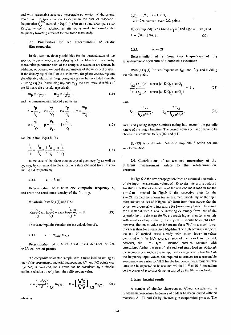
iind with reasonable accuracy measurable parameters of the crystal fn/fF = i n , i = 1 ,2 ,3 ,... layer, we use 11s equatlon to calculate the piirallel resonance
P(ntf ' ' ' .' i odd: h/4-points, i even: U2-points. frequencies f needed In Eq.(14). (For more details cornpiire nlso
Q . Ref./8/, where in addition an attempt is made to consider the If, for simplicity, we assume k~ = 0 and e.g. i = 1, we yield frequency lowering effect of the electrode mass load). z = (2n - I ) n 1 ~ 4 . (22)
2.3. I'ossibililies for the determinalio~i of el:lstic film properties
2.3.3. z - 2f
In this section, three possibilities for the detennination of the Determination of x from two frequencies of the specific acoustic impedance values ZF of the film from two eilsiliy quasi-harmonic spectrunl of a composite r'sollator measuri~ble parimeter pairs of tlie composite resonator ;ire bhown. In addition, of course, we need the parameters of the unloaded crystnl. Writing Eq.(I) for two frequencies fnl iind fn2 and dividing If the density p~ of the film is also known, the phase velocity VF and the relations yields the effective elastic stiffness constant c~ can be concluded directly utilizing Eq.(6). Introducing r n ~ and m ~ , the areal miiss densities of f (n -i)n - arctan [ i l ~ ( Q l ) tan Q1l the film and the clystal, respectively, n2 1 - = 1 , (23)
m~ = pFIF , m Q = pQIQ , (16) 'nl (n2-j)n - arcuu~ [Z"K(Q~) tan Q2]
and the dimensionless reduced parameters with
c~ P F IF c = - , p = - , I = - ,
C~ PQ 'Q
we obtain from Eqs.(3)-(6)
(17) and i and j being integer numbers taking into account the periodic nature of the arctan function. The correct values of i and j hiwe to be chosen in nccordnnce to Eqs.(lO) imd (1 I).
Eq.(23) is n definite, pole-free implicite function for the
(18) z-detennin;ttion.
I n the case of the plano-convex crystal geometry f~ i\S well ns 2.4. Co~~tributions of a11 ass~~n~ecl unccrtai~ity of the IQ, ~ I Q , IQ correspond to the effective values obtained from k].(14) different measurement values to the z-deternlinntion and bq.(J), respectively. accuracy
Determination of z from one composite frequency fn and from the areal mass density of the film mF.
We obtain from Eqs.(l) and (18)
fn m +' z tan (71- --) = 0 . f z (19) Q
This is an implicite function for the calculation of z.
Determination of z from areal mass densities of ?J4 or U2 calibrated probes
I f n composite resonator si~mple with ;I m:tss load according to one of the accentuated, material independent U4 and U2 points (see Figs.2-3) is produced, the z value can be calculated by a simple, explicite relation directly from the calibrated m-value:
In Figs.68 the error propagation from an assumed uncertainty of the input measurement values of 1% to the interesting reduced z-value is plotted as a function of the reduced mass load m for the a - f, m method. In Figs.9-I1 the respective plots for the z -- 2f method are shown for an assumed uncertainty of the input measurement values of 100ppm. We learn from these curves that the errors are progressively increasing for lower mass loads. The errors for ii material with a z-value differing extremely from that of the crystal, like it is the case for W, are much higher than for materials with z-values close to that of the crystal. It should be emphasized, however, that an ni-value of 0.5 means for a W-film a much lower thickness than for a respective Mg-film. The high i\ccuri\cy range of the z --2f method starts already with much lower ni-values compared with the high accuracy range of the z - f, nl method, however, the z - f, m method renuins accurate with unrestricted further increase of the reduced mass load m. Although the accuracy demand on the rn input values is generally less than on the frequency input values, the required toleritnces for a reasonable z-accuracy are easier to fulfill for the frequency measurements. The latter can be expected to be accurate within 10-5 to 10"1 depending on the degree of resonator damping caused by the film mass load.
f n / f ~ f n / f ~ 3. Experimental results
' =LK] hi4 mh/41 z = [ ~ ] y 2 m N 2 9 (21) A number of circulw plano-convex AT-cut ~rystals with a
whereby fundamental resonance frequency of 6 MHz has been loaded with the materials Al, Ti, and Cu by electron gun evaporation process. The
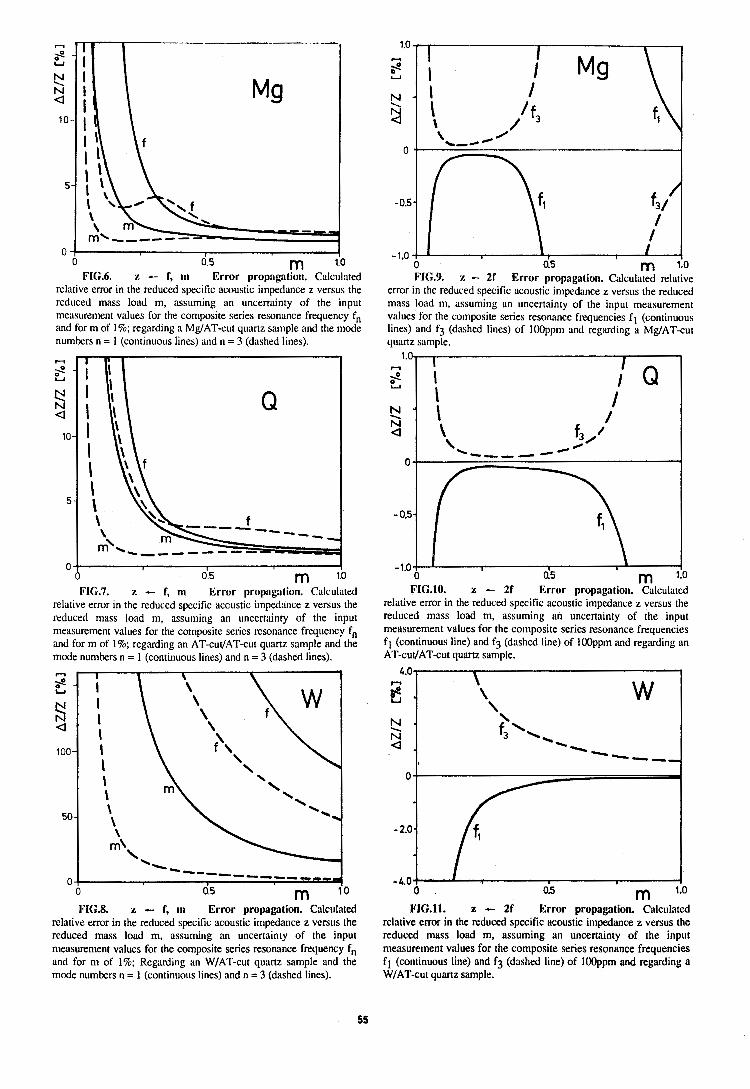
0 I
0 5 m 1.0 FIG.6. z - f, rn Error propagation. Calculated
relative error in the reduced specific ncoustic impedance z versus the reduced mass load m, assuming an uncertainty of the input measurement values for the composite series resonance frequency fn and for m of 1%; regarding a MdAT-cut quartz sample and the mode numbers n = 1 (continuous lines) iind n = 3 (dashed lines).
o 015 m 1.0
FIG.7. z - f, rn Error propagation. Calculated relative error in the reduced specific acoustic imped:uice z versus the reduced mass load m, assuming an uncertainty of the input measurement values for the composite series resonance frequency fn and form of 1%; regarding an AT-cut/AT-cut quartz sample and the mode numbers n = 1 (continuous lines) and n = 3 (dashed lines).
FIC.8. z - f, rn Error propaption. Calculated relative error in the reduced specific acoustic impedance z versus the reduced mass load m, assuming an uncertainty of the input measurement values for the composite series resonance frequency fn and for m of 1%; Regarding an WIAT-cut quiutz sitmple and the mode numbers n = 1 (continuous lines) and n = 3 (dashed lines).
error in the reduced specific acoustic impedance z versus the reduced mass load m, assuming an uncertainty of the input measurement values for the composite series resonance frequencies f l (continuous lines) and f3 (dashed lines) of 100ppnl and regarding a MUAT-cut quartz snmple.
1.0 4
I I I
FIC.10. z - 21 Error propagalion. Calculi~ted relative error in the reduced specific acoustic impedance z versus the reduced mass load m, assuming an uncertainty of the input measurement values for the composite series resonance frequencies fl (continuous line) and f3 (dashed line) of IOOppm and regarding an AT-cut1AT-cut quartz sample.
- s'
s - 0 -.
- 4.0 0 0.5 m 1.0
FI(i.11. z -- 2f Error propagation. Calculated relative error in the reduced specific acoustic impedance z versus the reduced mass load m, assuming an uncertainty of the input measurement values for the composite series resonance frequencies f l (continuous line) and f3 (dashed line) of lOOppm and regarding a WIAT-cut quartz sample.
I I I I \ ,' f3 '+
%--' 4'
-0.5-
/ I
-1.0 . I I
0 0.5 m 1.0 FIG.9. z -- 2f Error propagation. Calculated relative
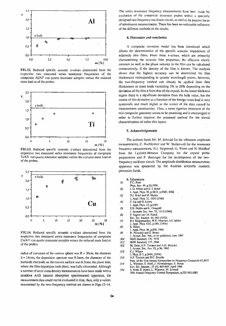
FIG.12. Reduced specific acoustic z-vi~lues determined from the respective two measured series resonance frequencies of the composite AI/AT-cut quartz resonator samples versus the reduced mass load m OF the probes.
PI(;.13. Reduced specific acoustic z-values detemlined from the respective two measured series resonance frequencies of composite Ti/AT-cut quartz resonator samples versus the reduced mass load nl of the
FI(i.14. Reduced specific acoustic z-values determined from the respective two measured series resonance frequencies of conlposite CuIAT-cut qumz resonator san~ples versus the reduced mass loud m of the probes.
radius of curvature of the convex sphere was R = 30cm, the diameter d = 14tnm, the deposition aperture was 8.3mm, the diameter of the backside electrode on the convex surface was 6.3mn1; the plane side, where the filni deposition took place, was fully electroded. Although a number of areill niass density measurements have been made with a sensitive AAS (atomic absorption spectrometer) apparatus, the measurement data could not be evaluated in time, thus, only z-values determined by the two-frequency method are shown in Figs.12-14.
The series resonance frequency nleasurenlenls have bee: m;~de by excitation of the co~iiposite resonator probes within o specially designed two frequency oscillntor circuit, iIS well as by passive locus of admittance measurements. There hns been no noticeable influence of the different methods on the results.
4. 1)iscussion and conclusion
A composite resonator model hns been introd~~ced which allows the determiniition of the specific itcou~tic impedances of relntively thin films. From these z-values, which are prinlarily characterizing the acot~stic film properties, the effective elastic constant ns well ns the phase velocity in the film can be calculated consecutively, if the density of the film is known. The analysis shows that the highest accuracy can be determined for film thicknesses corresponding to qu;irter wavelength points, however, the two-frequency method ciin i1lre;rdy be i~pplied from film thicknesses or mass loads exceeding 3% to 20% depending on the deviation of the film z from that of the crystal. In the lower thickness region there is a significant deviation from the bulk value, but the course of this deviation as a function of the foreign mitss load is very systematic and much higher ;is the scntter of the dntn caused by n1e:lsurement uncertninties. Thi~s, ii more rigorous ueat~nent of the real con~posite geometry seems to be promising and is encouraged in order to further improve the proposed method for the elastic chiuacterization of rather thin liiyers.
The authors thank Mr. M. Schnlid for the vibration ~mplitude measurements, C. Btrchleitrler and W. Stubenvoll for the resonance frequency measurements, H.J. Siegmund, G. Thorn and H. Midhof from the Leybold-Heraeus Corilpnny for the crystal probe preparations and P. Berllnger for the development of the two- frequency oscillator circuit. The amplitude distribution measurement apparatus was sponsored by the Austrian scientific research pron~otion funds.
6. Literature F.C. Rose Phys. Rev. 49, p.50.1936 J. G. Miller and D. I. Bolcf J. Appl. Phys. 39, p.5815, p.4589, 1968 D.I. Bolcf and M. Mcnes J. Appl. Phys. 31, 1010 (1960) C. Lu and 0. Lcwis J. Appl. Phys. 43, p.4385 E.R. Dobbs and L. Fincgold J. Acoustic Soc. Am. 32, 1215 (1960) F. Eggcrs and Th. Funck Rcv. Sci. Inswm. 44, 969 (1973) H.I. Ringcnechcr, W.E. Mocrncr, I.G. Millcr J. Appl. Phys. 45R, p.549, (1974) E. Bcncs J. Appl. Phys. 56, p.608, 1984 H. Nowotny and E. Bcncs I. Acousl. Soc. Am., lo bc published, Junc 1987 IEEE Sundud. 176,1978 IEEE Suntf;ud. 177, 19M M, Onoc, H.F. Ticrslcn and A.H. Mciklcr J. Acousl. Soc. Am. 35, p.36, 1963 C.J. Wilson J. Phys. D 7, p.2449, (1974) H.F. Ticrstcn and R.C. S~nylhc Proc. of thc 31sl Annual Symposium on Frqucncy Contro1,44-47,1977 L. Wimmcr, S. Hcd, J. Hcmclsbcrgcr, E. Bcncs Rcv. Sci. Insuum., 55 (4). 605-609, April 1984 S. Hcnl, E. Bcncs, L. Wimmcr, M. Sch~nid 39th Annual Fqucncy Control Symposium, p.535-543,1985
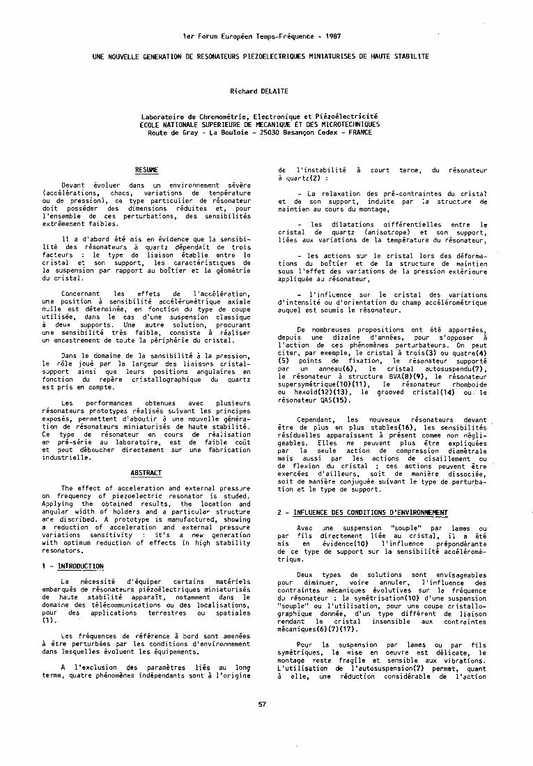
l e r Forum Europien Temps-Friquence - 1987
UNE NOUVELLE GENERATION DE RESONATEURS PIEZOELECTRIQUES MINIATURISES OE HAUTE STABILITE
R ichard DELAITE
L a b o r a t o i r e de Chronomit r ie , E l e c t r o n i q u e e t P i i z o i l e c t r i c i t i ECOLE NATIONALE SUPERIEURE DE MECANIQUE ET DES MICROTECHNIQUES
Route de Gray - La B o u l o i e - 25030 B e s a n ~ o n Cedex - FRANCE
RESUME
Devant i v o l u e r dans un environnement skvhre ( a c c i l i r a t i o n s , chocs, v a r i a t i o n s de temp i ra tu re ou de p ress ion) , ce t ype p a r t i c u l i e r de r i s o n a t e u r d o i t possider des dimensions r i d u i t e s e t , pour l 'ensemble de ces p e r t u r b a t i o n s , des s e n s i b i l i t i s extr imement f a i b l e s .
I 1 a d 'abord i t 6 mis en i v i d e n c e que l a s e n s i b i - l i t 6 des r i s o n a t e u r s 1 quar tz d i p e n d a i t de t r o i s fac teurs : l e type de l i a i s o n i t a b l i e e n t r e l e c r i s t a l e t son support , l e s c a r a c t i r i s t i q u e s de l a suspension par r a p p o r t au b o i t i e r e t l a g i o m i t r i e du c r i s t a l .
de l ' i n s t a b i l i t d 1 c o u r t terme, du r i s o n a t e u r 1 quar tz (2 ) :
- La r e l a x a t i o n des p r i - c o n t r a i n t e s du c r i s t a l e t de son support , i n d u i t e par l a s t r u c t u r e de m a i n t i e n au cours du montage,
- l e s d i l a t a t i o n s d i f f i r e n t i e l l e s e n t r e l e c r i s t a l de quar tz (an iso t rope) e t son support , l i i e s aux v a r i a t i o n s de l a t e m p i r a t u r e du r i s o n a t e u r ,
- l e s a c t i o n s su r l e c r i s t a l l o r s des d i forma- t i o n s du b o i t i e r e t de l a s t r u c t u r e de m a i n t i e n sous l ' e f f e t des v a r i a t i o n s de l a p r e s s i o n e x t i r i e u r e a p p l i q u i e au r i s o n a t e u r ,
Concernant l e s e f f e t s de l ' a c c 6 l i r a t i o n , - l ' i n f l u e n c e sur l e c r i s t a l des v a r i a t i o n s une p o s i t i o n 1 s e n s i b i l i t i a c c i l i r o m i t r i q u e a x i a l e d ' i n t e n s i t d ou d ' o r i e n t a t i o n du champ a c c i l i r o m i t r i q u e n u l l e e s t d i t e r m i n i e , en f o n c t i o n du type de coupe auquel e s t soumis l e r i s o n a t e u r . u t i l i s i e , dans l e cas d'une suspension c lass ique A deux supports . Une a u t r e s o l u t i o n , p rocuran t une s e n s i b i l i t i t r a s f a i b l e , c o n s i s t e A r i a l i s e r un encastrement de t o u t e l a p i r i p h i r i e du c r i s t a l .
Dans l e domaine de l a s e n s i b i l i t i i l a p ress ion , l e r61e j o u i par l a l a r g e u r des l i a i s o n s c r i s t a l - support a ~ n s i qu,e l e u r s p o s i t i o n s angu la i res en f o n c t i o n du repere c r i s t a l l o g r a p h i q u e du quar tz e s t p r i s en compte.
Les performances obtenues avec p l u s i e u r s r i s o n a t e u r s p r o t o t y p e s r i a l i s i s s u i v a n t l e s p r i n c i p e s exposis , permet tent d ' a b o u t i r 1 une n o u v e l l e g i n i r a - t i o n de r i s o n a t e u r s m i n i a t u r i s i s de haute s t a b i l i t i . Ce type de r i s o n a t e u r en cours de r i a l i s a t i o n en p r 6 - s i r l e au l a b o r a t o i r e , e s t de f a i b l e c o t t e t peut diboucher d i rectement su r une f a b r i c a t i o n i n d u s t r i e l l e .
ABSTRACT
The e f f e c t o f a c c e l e r a t i o n and e x t e r n a l pressure on frequency o f p i e z o e l e c t r i c resona to r i s studed. A p p l y i n g t h e ob ta ined r e s u l t s , t h e l o c a t i o n and angular w i d t h o f ho lders and a p a r t i c u l a r s t r u c t u r e a r e d i s c r i b e d . A p r o t o t y p e i s manufactured, showing a r e d u c t i o n o f a c c e l e r a t i o n and e x t e r n a l pressure v a r i a t i o n s s e n s i t i v i t y : i t ' s a new genera t ion w i t h optimum r e d u c t i o n o f e f f e c t s i n h i g h s t a b i l i t y resonators.
1 - INTRODUCTION
La n i c e s s i t i d 'bqu iper c e r t a i n s m a t i r i e l s embarquis de r i s o n a t e u r s p i i z o i l e c t r i q u e s m i n i a t u r i s i s de haute s t a b i l i t i a p p a r a i t , notamment dans l e domaine des t i l dcommun ica t ions ou des l o c a l i s a t i o n s , pour des a p p l i c a t i o n s t e r r e s t r e s ou s p a t i a l e s (1 ) .
Les f r iquences de r i f i r e n c e I bord son t amenies i i t r e p e r t u r b i e s par l e s c o n d i t i o n s d'environnement dans l e s q u e l l e s i v o l u e n t l e s iqu ipements.
A l ' e x c l u s i o n des parami t res l i i s au long terme, qua t re phenomines ind ipendan ts sont 2 l ' o r i g i n e
De nombreuses p r o p o s i t i o n s o n t i t 6 appor t ies , depuis une d i z a i n e d1ann6es, pour s'opposer 1 l ' a c t i o n de ces phinomgnes p e r t u r b a t e u r s . On peut c i t e r , par exemple, l e c r i s t a l 3 t r o i s ( 3 ) ou quatre(4) (5) p o i n t s de f i x a t i o n , l e r i s o n a t e u r support6 par un anneau(6), l e c r i s t a l autosuspendu(7), l e r i s o n a t e u r i s t r u c t u r e BVA(8)(9), l e r i s o n a t e u r supersymitrique(lO)(ll), l e r i s o n a t e u r rhomboide ou hexo id ( l2 ) (13) , l e grooved c r i s t a l ( l 4 ) ou l e r i s o n a t e u r QAS(15).
Cependant, l e s nouveaux r i s o n a t e u r s devant i t r e de p l u s en p l u s s t a b l e s ( l b ) , l e s s e n s i b i l i t i s r i s i d u e l l e s appara issen t I presen t comme non n i g l i - geables. E l l e s ne peuvent p l u s i t r e e x p l i q u i e s pa: l a seule a c t i o n de compression d i a m a t r a l e mals auss i par l e s a c t i o n s de c i s a i l l e m e n t ou de f!exion du c r i s t a l ; ces a c t i o n s peuvent f t r e exercees d ' a i l l e u r s , s o i t de maniare d i s s o c i i e , s o i t de m a n i i r e conjuguee s u i v a n t l e t y p e de per tu rba- t i o n e t l e t ype de support .
2 - INFLUENCE DES CONDITIONS D'ENVIRONNEMENT
Avec une suspension "souple" par lames ou par f i l s d i rectement l i k e au c r i s t a l , il a Btb mls en i v i d e n c e ( l 0 ) l ' i n f l u e n c e p r iponddran te de ce type de support su r l a s e n s i b i l i t i a c c i l i r o m i - t r i q u e .
Deux types de s o l u t i o n s son t envisageables pour d iminuer , v o i r e annuler , l ' i n f l u e n c e des c o n t r a i n t e s micaniques i v o l u t i v e s su r l a f r i q u e n c e du r i s o n a t e u r : l a s y m i t r i s a t i o n ( l 0 ) d'une suspension "souple" ou l ' u t i l i s a t i o n , pour une coupe c r i s t a l l o - graphique donnie, d 'un t ype d i f f i r e n t de l i a i s o n rendant l e c r i s t a l i n s e n s i b l e aux c o n t r a i n t e s micaniques(6) ( 7 ) (17).
Pour l a suspension par lames ou par f i l s symi t r iques , l a mise en oeuvre e s t d i l i c a t e , l e montage r e s t e f r a g i l e e t s e n s i b l e aux v i b r a t i o n s . L ' u t i l i s a t i o n de l ' au tosuspens ion(7 ) permet, quant 2 e l l e , une r d d u c t i o n cons iderab le de l ' a c t i o n
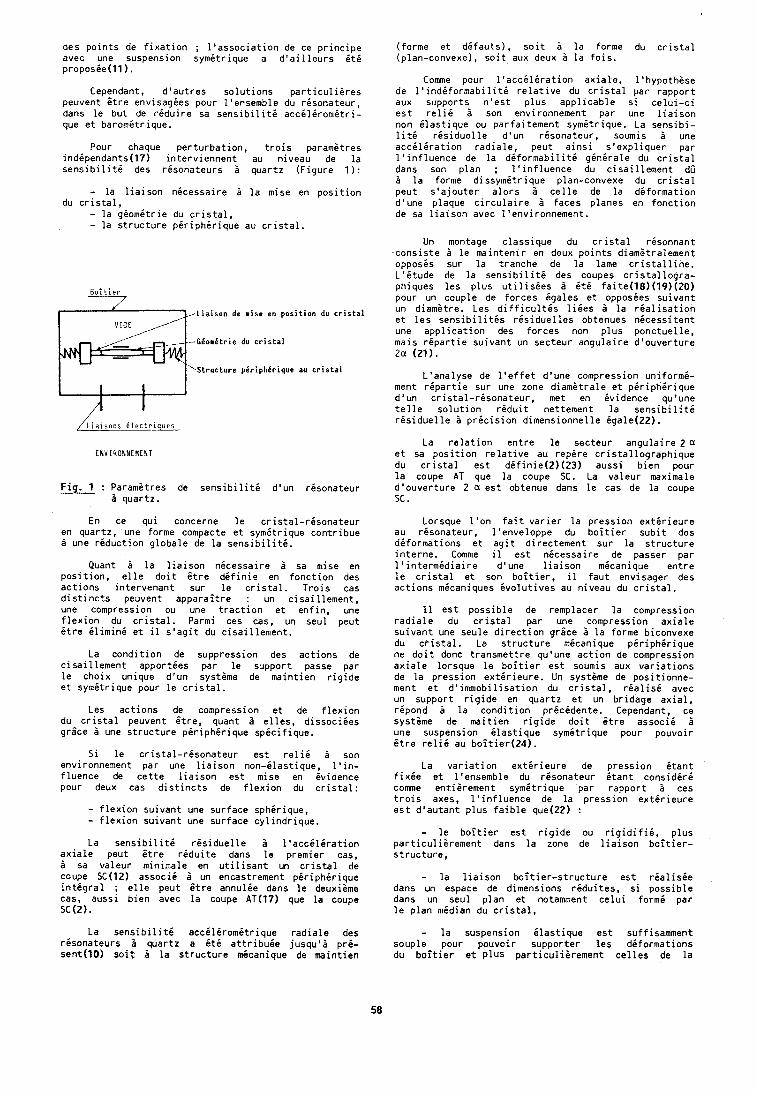
des points de fixation ; l'association de ce principe avec une suspension symitrique a d'ailleurs it6 proposie(l1).
Cependant, d'autres solutions particulieres peuvent 6tre envisagies pour l'ensemble du rGsonateur, dans le but de rgduire sa sensibiliti accilirornitri- que et baromdtr ique.
Pour chaque perturbation, trois parametres indipendants(l7) interviennent au niveau de la sensibiliti des risonateurs 5 quartz (Figure 1):
- la liaison nicessaire B la mise en position du cristal,
- la giomitrie du cristal, - la structure piriphirique au cristal.
Liaison de nise en position du cristal
.,--GComCtrie du cristal
\structure pCriphCrique au cristal
/Liaisons Qlectriques
F i g . : Paramitres de sensibiliti d'un risonateur - B quartz.
En ce qui concerne le cristal-risonateur en quartz, une forme compacte et symitrique contribue i une riduction globale de la sensibilitk.
Quant i la liaison nicessaire 5 sa mise en position, elle doit 6tre difinie en fonction des actions intervenant sur le cristal. Trois cas distincts peuvent apparaitre : un cisaillement, une compression ou une traction et enfin, une flexion du cristal. Parmi ces cas, un seul peut itre ilimini et il s'agit du cisaillement.
La condition de suppression des actions de cisaillement apporties par le support passe par le choix unique d'un systime de maintien rigide et symitrique pour le cristal.
Les actions de compression et de flexion du cristal peuvent Gtre, quant i elles, dissociies grlce 2 une structure piriphkrique spicifique.
Si le cristal-risonateur est relii B son environnement par une liaison non-ilastique, l'in- fluence de cette liaison est mise en evidence pour deux cas distincts de flexion du cristal:
- flexion suivant une surface sphhrique, - flexion suivant une surface cylindrique. La sensibiliti risiduelle 2 l'acciliration
axiale peut 6tre riduite dans le premier cas, i sa valeur minimale en utilisant un cristal de coupe SC(12) associi 2 un encastrement piriphirique intigral ; elle peut 6tre annulie dans le deuxiame cas, aussi bien avec la coupe AT(17) que la coupe SC (2).
La sensibiliti acchl6rom6trique radiale des rgsonateurs B quartz a 6th attribuie jusqu'i pr6- sent(l0) soit i la structure micanique de maintien
(forme et dGfauts), soit ?I la forme du cristal (plan-convexe), soit aux deux B la fois.
Comme pour l'acciliration axiale, l'hypothese de l'indiformabilitd relative du cristal par rapport aux supports- n'est plus applicable si celui-ci est reli6 a son environnement par une liaison non ilastique ou parfaitement symitrique. La sensibi- lit6 risiduelle d'un risonateur, soumis B une acciliration radiale, peut ainsi s'expliquer par l'influence de la diformabiliti ginirale du cristal dans son plan ; l'influence du cisaillement dO B la forrne dissymitrique plan-convexe du cristal peut s'ajouter alors 2 celle de la deformation d'une plaque circulaire 2 faces planes en fonction de sa liaison avec l'environnement.
Un montage classique du cristal risonnant ,consiste 2 le maintenir en deux points diamstralement opposis sur la tranche de la lame cristalline. L'itude de la sensibiliti des coupes cristallogra- phiques les plus utilisees 2 it6 faite(18)(19)(20) pour un couple de forces bgales et opposies suivant un didmetre. Les difficultis likes I la rialisation et les sensibilitis risiduelles obtenues nicessitent une application des forces non plus ponctuelle, mais ripartie suivant un secteur angulaire d'ouverture 2ci (21).
L'analyse de l'effet d'une compression uniformi- ment ripartie sur une zone diamatrale et piriphirique d'un cristal-risonateur, met en ividence qu'une telle solution riduit nettement la sensibiliti risiduelle i pricision dimensionnelle igale(22).
La relation entre le secteur angulaire 2 a et sa position relative au repere cristallographique du cristal est ddfinie(2)(23) aussi bien pour la coupe AT que la coupe SC. La valeur maximale d'ouverture 2 est obtenue dans le cas de la coupe SC .
Lorsque l'on fait varier la pression extirieure au risonateur, l'enveloppe du boitier subit des diformations et agit directement sur la structure interne. Comme il est nicessaire de .passer par l'intermidiaire d'une liaison micanique entre le cristal et son boitier, il faut envisager des actions micaniques ivolutives au niveau du cristal.
I1 est possible de remplacer la compression radiale du cristal par une compression axiale suivant une seule direction grlce i la forme biconvexe du cristal. La structure micanique piriphirique ne doit donc transmettre qu'une action de compression axiale lorsque le boitier est soumis aux variations de la pression extirieure. Un systhrne de positionne- ment et d'immobilisation du cristal, rialis6 avec un support rigide en quartz et un bridage axial, ripond 6 la condition pricidente. Cependant, ce systime de maitien rigide doit 6tre associi 2 une suspension ilastique symitrique pour pouvoir 6tre relii au boitier(24).
La variation extirieure de pression itant fixie et l'ensemble du risonateur itant considiri comme entierement symitrique par rapport ces trois axes, l'influence de la pression extirieure est d'autant plus faible que(22) :
- le boitier est rigide ou rigidifii, plus particulierement dans la zone de liaison boitier- structure,
- la liaison boitier-structure est rialishe dans un espace de dimensions rhduites, si possible dans un seul plan et notamment celui formi par le plan median du cristal,
- la suspension ilastique est suffisamment souple pour pouvoir supporter les diformations du boitier et plus particuliirement celles de la
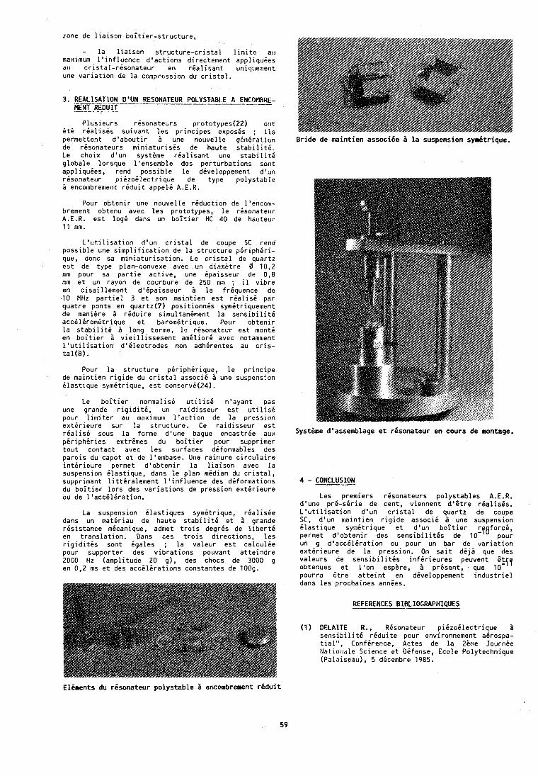
zone de liaison boitier-structure,
- la liaison structure-cristal limite au maximum l'influence d'actions directement appliquies au cristal-risonateur en rialisant uniquement une variation de la compression du cristal.
3. RELL-I?APN D'UN RESONATEUR P0LYSTABL.E A ENCOMBRE- MENT REDUIT
Plusieurs resonateurs prototypes(2J) orit it6 rdallsis suivant les principes exposes ; ils permettent d'aboutir i une nouvelle ganiration de risonateurs miniaturises de haute stabiliti. Le choix d'un syst&me rialisant une stabilite globale lorsque l'ensemble des perturbations sont appliquies, rend possible le diveloppement d'un risonateur piizoilectrique de type polystable i encombrement riduit appeli A.E.R.
Pour obtenir une nouvelle reduction de l'encom- brement obtenu avec les prototypes, le resonateur A.E.R. est log6 dans un boitier HC 40 de hauteur 11 mm.
L'utilisation d'un cristal de coupe SC rend possible une simplification de la structure piriphiri- que, donc sa miniaturisation. Le cristal de quartz est de type plan-convexe avec un diametre 0 10,2 mnt pour sa partie active, une ipaisseur de 0,8 rnm et un rayon de courbure de. 250 mm ; il vibre en cisaillement d'ipaisseur a la frdquence de 10 MHz partiel 3 et son maintien est rialisi par quatre ponts en quartz(7) positionnis symitriquement de manihre 5 riduire sirnultaniment la sensibiliti acciliromEtrique et baro~nitrique. Pour obtenir la stabiliri 5 long terme, le risonateur est monti en boitier 1 vieillissement amiliori avec notamment l'utilisation d'ilectrodes non adh6rentes au cris- tal(8).
Pour la structure piriphirique, le principe de maintien rigide du cristal associ6 5 une suspension ilastique symitrique, est conservi(24).
Le boitier normalisi utilisi n'ayant pas une grande rigiditi, un raidisseur est utillsE pour limiter au maximum l'action de la pression extirieure sur la structure. Ce raidisseur est rialisi sous la forme d'une bague encastrie aux piriphdries extrhes du boitier pour supprimer tout contact avec les surfaces diformables des parois du capot et de l'embase. Une rainure circulaire intirieure permet d'obtenir la liaison avec la suspension ilastique, dans le plan midian du cristal, supprimant littiralement l'influence des diformations du boitier lors des variations de pression extirieure ou de l'acciliration.
La suspension ilastiques symitrique, rialisie dans un matiriau de haute stabiliti et i grande resistance micanique, admet trois degris de liberti en translation. Dans ces trois directions, les rigiditis sont igales ; la valeur est calculie pour supporter des vibrations pouvant atteindre 2000 Hz (amplitude 20 g ) , des chocs de 3000 g en 0,2 ms et des acchlirations constantes de 1009.
Bride de mintien associie 5 la suspension sydtrique.
Systiime d'assemblage et risonateur en cours de montage.
4 - CONCLUSION Les premiers risonateurs polystables A.E.R.
d'une pri-sirie de cent, viennent d'6tre rialisis. L'utilisation d'un cristal de quartz de coupe SC, d'un maintien rigide associi 2 une suspension ilastique symitrique et d'un boitier rpeforci, permet d'obtenir des sensibilitis de 10- pour un .g d'acciliration ou pour un bar de variation exterieure de la pression. On sait dijd que des valeurs de sensibilitis infirieures peuvent Bt?? obtenues et l'on esphre, 1 prisent, que 10- pourra 6tre atteint en diveloppement Industriel
EPiments du risonateur polystable 5 encombrement riduit
59
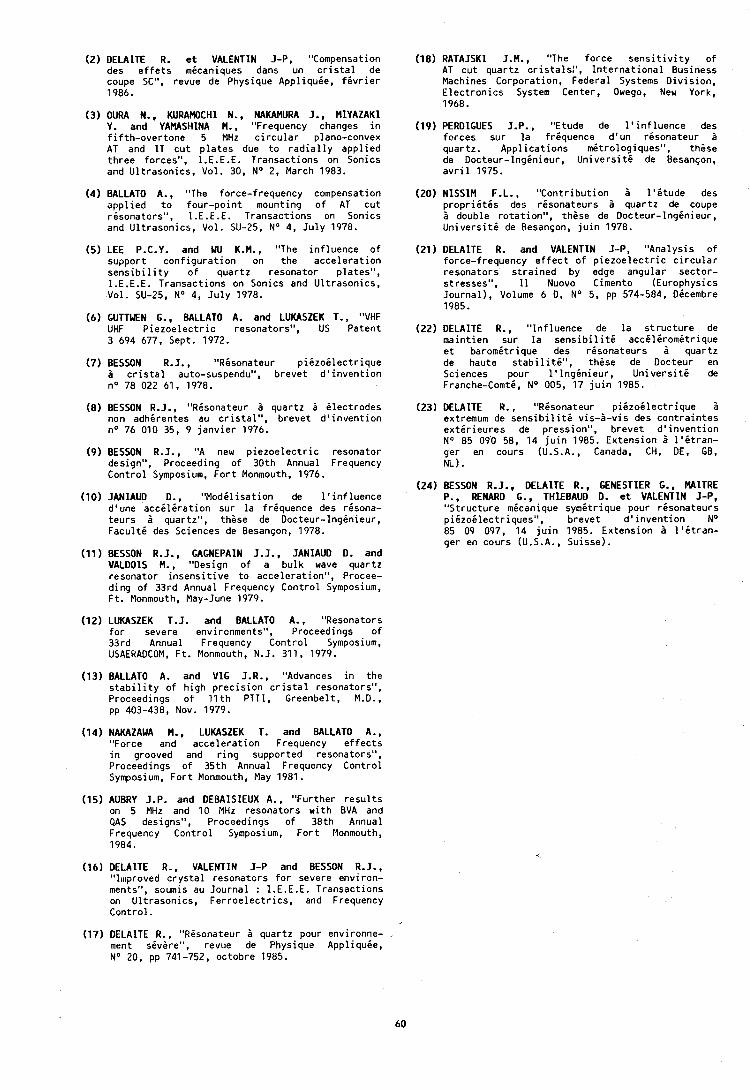
(2) DELAITE R. e t VALENTIN J-P, "Compensation des e f f e t s micaniques dans un c r i s t a l de coupe SC", revue de Physique Appl iquie, f e v r i e r 1986.
(3) OURA N., KURAMOCHI N., NAKAMURA J., MlYAZAKl Y. and YAMASHINA M., "Frequency changes i n f i f t h -ove r tone 5 MHz c i r c u l a r plano-convex AT and 1T cu t p l a t e s due t o r a d i a l l y app l ied three forces", 1 .E.E.E. Transactions on Sonics and Ul t rason ics , Vol. 30, No 2, March 1983.
(4) BALLATO A., "The force-frequency compensation app l ied t o four -po in t mounting o f AT cu t r isonators", I.E.E.E. Transactions on Sonics and Ul t rason ics , Vol. SU-25, No 4, Ju l y 1970.
(5) LEE P.C.Y. and WU K.M., "The in f luence o f support con f i gu ra t i on on the acce lera t ion s e n s i b i l i t y o f quartz resonator plates", I.E.E.E. Transactions on Sonics and Ul t rason ics , Vol. SU-25, No 4, Ju l y 1978.
(6) GUTTWEN G., BALLATO A. and LUKASZEK T., "VHF UHF P iezoe lec t r i c resonators", US Patent 3 694 677, Sept. 1972.
(7) BESSON R J . "Risonateur p i i z o i l e c t r i q u e 2 c r i s t a l auto-suspendu", b revet d ' i nven t i on no 78 022 61, 1978.
(8) BESSON R.J., "Risonateur P quartz B i l ec t rodes non adhirentes au c r i s t a l " , brevet d ' invent ion no 76 010 35, 9 j anv ie r 1976.
(9) BESSON R.J., "A new p iezoe lec t r i c resonator design", Proceeding o f 30th Annual Frequency Cont ro l Symposium, F o r t Monmouth, 1976.
(10) JANIAUD D., "Modi l i sa t ion de l ' i n f l u e n c e d'une a c c i l i r a t i o n sur l a f r iquence des r isona- teurs 6 quartz", these de Docteur-lngbnieur, F a c u l t i des Sciences de Besanson, 1978.
(11) BESSON R.J., GAGNEPAIN J.J., JANIAUD D. and VALDOIS M., "Oesign o f a bulk wave quartz resonator i nsens i t i ve t o accelerat ion", Procee- ding o f 33rd Annual Frequency Control Symposium, F t . Monmouth, May-June 1979.
(12) LUKASZEK T.J. and BALLATO A., "Resonators f o r severe environments", Proceedings o f 33rd Annual Frequency Control Symposium, USAERAOCOM, Ft . Monmouth, N.J. 311, 1979.
(13) BALLATO A. and V1G J.R., "Advances i n the s t a b i l i t y o f h igh p rec i s i on c r i s t a l resonators", Proceedings o f 11 th PTTI, Greenbelt, M.D., pp 403-438, NOV. 1979.
(14) NAKAZAWA M., LUKASZEK T. and BALLATO A., "Force and acce lera t ion Frequency e f f e c t s i n grooved and r i n g supported resonators", Proceedings o f 35th Annual Frequency Control Symposium, F o r t Monmouth, May 1981.
(15) AUBRY J.P. and DEBAISIEUX A,, "Further r e s u l t s on 5 MHz and 10 MHz resonators w i t h BVA and PAS designs", Proceedings o f 38th Annual Frequency Cont ro l Symposium, F o r t Monmouth, 1984.
(16) DELAITE R., VALENTIN J-P and BESSON R. J., "1111proved c r y s t a l resonators f o r severe environ- ments", soumis au Journal : I.E.E.E. Transactions on Ul t rason ics , Fe r roe lec t r i cs , and Frequency Control .
(18) RATAJSKI J.M., "The force s e n s i t i v i t y o f AT cut quartz c r i s ta l s l ' , I n te rna t i ona l Business Machines Corporation, Federal Systems Div is ion , E lec t ron ics System Center, Owego, New York, 1968.
(19) PERDZGUES J.P., "Etude de l ' i n f l u e n c e des forces sur l a f r iquence d'un r isonateur a quartz. App l ica t ions m6trologiques", these de Docteur- lnginieur, U n i v e r s i t i de Besanson, a v r i l 1975.
(20) NISSIM F.L., "Contr ibut ion P l ' e tude des p r o p r i i t i s des r isonateurs i quartz de coupe 2 double ro ta t ion" , t h i se de Docteur-lnginieur , Un ivers i te de Besanson, j u i n 1978.
(21) DELAITE R. and VALENTIN J-P, "Analysis o f force-frequency e f f e c t o f p i ezoe lec t r i c c i r c u l a r resonators s t ra ined by edge angular sector- stresses", 11 Nuovo Cimento (Europhysics Journal) , Volume 6 0, No 5, pp 574-584, Oicembre 1985.
(22) DELAITE R., " Inf luence de l a s t ruc tu re de maint ien sur l a s e n s i b i l i t 6 a c c i l i r o m i t r i q u e e t baromitr ique des r isonateurs a quartz de haute s t a b i l i t i " , these de Docteur en Sciences pour l ' l n g i n i e u r , U n i v e r s i t i de Franche-Comti, No 005, 17 j u i n 1985.
(23) DELAITE R., "Risonateur p i i z o i l e c t r i q u e 5 extremum de s e n s i b i l i t d v is -2-v is des cont ra in tes e x t i r i e u r e s de pression", brevet d ' i nven t i on N o 85 090 58, 14 j u i n 1985. Extension 5 l ' i t r a n - ger en cours (U.S.A., Canada, CH, DE, GB, NL).
(24) BESSON R.J., DELAITE R., GENESTIER G., MAITRE P., RENARD G., THIEBAUD D. e t VALENTIN J-P, "Structure micanique symitr ique pour r isonateurs p i6zo i lec t r iques" , brevet d ' i nven t i on No 85 09 097, 14 j u i n 1985. Extension P l ' i t r a n - ger en cours (U.S.A., Suisse).
(17) DELAITE R:, "Risonateur P quartz pour environne- .- ment sivere", revue de Physique Appl iquie, N o 20, pp 741-752, octobre 1985.
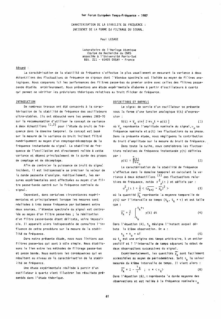
1er Forum European Temps-fr6quence - 1987
CARACTERISATION DE LA STABILfTE DE FREQUENCE :
INCIDENCE DE LA FORME DU FILTRAGE DU SIGNAL.
Paul LESAGE
Laboratoire de 1'Horloge Atomique Equipe de Recherche du CNRS
associee a 1'UniversitP Paris-Sud Bit. 221 - 91405 ORSAY - France
Resume :
La caracterisation de la stabilite de frequence s'effectue le plus usuellement en mesurant la variance a deux
echantillons des fluctuations de frequence de signaux dont I'etendue spectrale est limitee au moyen de filtres ana-
logiques. Nous comparons ici les performances des filtres passe-bas du premier ordre avec celles des filtres passe-
bande etudies anterieurement. Nous presentons une Btude experimentale blaborbe a partir d'oscillateurs b quartz
qui permet de verifier les previsions theoriques relatives au bruit flicker de frequence.
INTRODUCTION
De nombreux travaux ont Bt6 consacres a la carac-
terisation de la stabilite de frequence des oscillateurs
ultra-stables. 11s ont debouch6 vers les annees 1965-70
sur la recommandation d'utiliser le concept de variance
a deux echantillons (1'2) pour l16tude du bruit de fr6-
quence dans le domaine temporel. Ce concept est base
sur la mesure de la variance du bruit incident filtre
numeriquement au moyen d'un comptage-decomptage de la
frequence instantanee du signal. La stabilite de fre-
quence de l'oscillation est directement reliee b cette
variance et depend principalement de la duree des phases
de comptage et de decomptage.
DEFINITIONS ET RAPPELS
Le signal de sortie d'un oscillateur se presente
sous la forme d'une tension analogique V(t) d'expres-
sion :
V(t) = Vo sin[ 2 nvot + $(t) ] (1 ob Vo represente l'amplitude nominale du signal,vo sa
irequence nominale et $(t) les fluctuations de sa phase.
Dans la presente etude, nous negligeons la contribution
du bruit d'amplitude sur la mesure du bruit de frequence.
Dans toute la suite, nous considerons les fluctua-
tions relatives de frequence instantanbe y(t) definies
par : iw ~ ( t ) = znv
Afin de controler la puissance de bruit du signal 0
La caracterisation de la stabilite de frequence incident, il est indispensable de preciser la valeur de s'effectue dans le domaine temporel en calculant la va- la bande passante d'analyse. Habituellement, les me- riance a deux Bchantillons des fluctuations rela- sures experimentales sont effectuees au moyen d'un fil- t i v e s de frequence, notee 0 2 ( T ) et d e f i n i e par : tre passe-bande centre sur la frequence nominale du Y
2 1 - 2 signal. Y ( T ) = z < ( Y ~ + ~ - Y ~ ) > ( 3 )
Cependant, dans certaines circonstances experi-
mentales et principalement lorsque les mesures sont
realisees a tres basse frequence par battement entre
deux sources, l16tendue spectrale du signal est contro-
lee au moyen d'un filtre passe-bas ; la realisation
d'un filtre passe-bande Btant delicate, voire impossi-
ble. I1 apparait alors indispensable de conna'itre l'in-
fluence de cette procedure sur la mesure de la stabi-
lit6 de frbquence.
Dans notre presente Btude, nous nous limitons aux
filtres passe-bas qui sont a pale simple. Nous Btablis-
sons le lien entre les methodes de filtrage passe-bas
et passe bande. Nous montrons les cons6quences qui en
resultent au niveau de la caracterisation de la stabi-
lite de frequence.
Une etude experimentale realisde a partir d'un
osci 1 lateur a quartz vient i 1 lustrer les resu l tats pr6- sentes dans Itetude thiorique.
00 la quantit6 j< reprksente la moyenne temporelle de
y(t) sur l'intervalle de temps (tk, tk + T ) et est telle aue :
'tk
Dans l'equation ( 4 ) , t k dksigne l'instant auquel dC-
bute la kieme observation. On a :
tk = to + kT (5)
oh to est une origine des temps arbitraire, k un entier
positif et T l'intervalle de temps separant le debut de
deux observations successives du signal.
ExpBrimentalement, les quanti tes sont faci lement
accessibles au moyen de periodemetres. Soit T~ la valeur
mesuree du kihme intervalle de temps. il vient alors :
Dans 1 'equation ( 6 ) , T represente la duree moyenne des
observations et est reliee b la frequence nominalevo
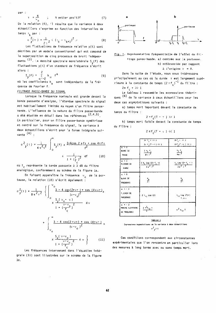
par : T = $ ; N entier positif ( 7 )
0
De la relation (6), i l resulte que la variance A deux
echantillons s'exprime en fonction des intervalles de
temps r k par :
1
2 T ( 8
Les fluctuations de frequence relative y(t) sont
decrites par un modele conventionnel qui est compose de
la superposition de cinq processus de bruit indepen-
dants ( 3 ) . La densite spectrale monolaterale S (f) des Y
fluctuations y(t) d'un standard de frequence s'ecrit
alors : L
Sy(f) = Z h a fa a = - 2
(9)
ob les coefficients ha sont independants de la fr6-
quence de Fourier f.
FILTRAGE PASSE-BANDE DU SIGNAL
Lorsque la frequence nominale est grande devant la
bande passante d'analyse, lletendue spectrale du signal
est habituellement limitee au moyen d'un filtre passe-
bande. L'influence de la nature du filtre passe-bande
a 6t.6 Btudiee en detail dans les references (2'4,5).
En particulier, pour un filtre passe-bande symBtrique
et centre sur la frBquence du signal, la variance a deux ichantil lons slBcrit sour la forme integrale sui-
vante '4) :
( "
ou fc reprBsente la bande passante a 3 dB du filtre
analogique, conformement au schema de la figure la.
En faisant apparaitre la friquence v o de la por-
teuse, la relation (10) s16crit Bgalement :
2 o ( T ) = - 3 - 4 C O S ( ~ ~ ~ V T ) + COS ( ~ V V T jx Y 8 n T (v -v,) 2
0 "
SY( v o - v ) X v - v 2 d v
C
Les frequences intervenant dans llBquation int6-
Fig. 1 . Representation frequenlielle de l'affet de fil-
trage passe-bande. a) centree sur la porteuse.
b) referenciee par rapport
B l'origine v = 0.
Dans la suite de llBtude, nous nous interessons
principalement au cas OD la duree T est largement sup&
rieure h la constante de temps ( 2 nfc)-l du filtre :
2 n fc T >> 1 Le tableau 1 rassemble les expressions thBori-
ques (6) de la varlance i deux Bchantillons pour les
deux cas asymptotiques suivants :
a) temps mort important devant la constante de
temps du fi 1 tre :
2 nfc(T - T ) >> 1 b) temps mort faible devant la constante de temps
du filtre :
2 n f c ( T - T ) << 1
TABLEAU 1
E x p r ~ s s i o n s :symptotiques de la v a r i a n c e i deux 6 c h l n t i l l o n s
0 : 2
BLANC DE
PHASE
a '1
FLICKER DE
PHASE
a ' 0
BLANC OE
fREPUENCE
n = - 1
FLICKER DE
FREPUENCE
a a . 2
MARCHE AL IATOIRE
DE FREPUENCE
Ces conditions correspondent aux circonstances
experimentales que l'on rencontre en particulier lors
des mesures ii long terme avec ou sans temps mort.
grale (11) sont illustries sur le schema de la figure
Ib.
2" fc 7 ,' 1
2 n f ( 1 - i I << 1
3 Bn T
3 hl Log ( Z n f c r )
4 n 2 l2
ho - Z r
2 h-l LO^ ( 2 1
2 n2h-2 T
3
Znfc r >> 1
Znf ( T -T ) >> 1
h2 f c - 4n1
hl Lop ( Z n f c 1 I
2 n 2 1
ho - 2 1
hel Log ( T I T I T )PI
n h.2 T
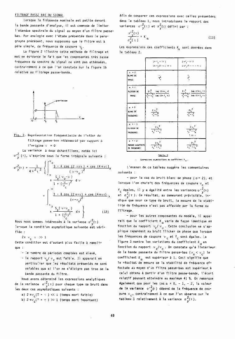
FILTRAGE PASSE BAS DU SIGNAL
Lorsque la frequence nominale est petite devant
la bande passante d'analyse, i I est commode de limiter
l'etendue spectrale du signal au moyen d'un filtre passe
bas. Par analogie avec I'Qtude presentee dans le para-
graphe precedent, nous supposons que le filtre est $
pale simple, de frequence de coupure vc.
La figure 2 illustre cette m6thode de filtrage et
met en evidence le fait que les composantes tres basse
frequence du spectre du signal ne sont pas att6nuees,
contrairement a ce que l'on constate sur la figure lb
relative au filtrage passe-bande.
Fig. 2. ReprBsentation frdquentielle de l'effet de
filtrage passe-bas rdferencie par rapport B
l'origine v = 0
La variance a deux echantillons, notee ici 2 oly (T), s'exprime sous la forme integrale suivante :
I i " ~ 3 - 4 cos ( 2 n v ~ ) + cos ( 4 7 ~ ~ ) ~
2 Nous nous sommes interesses P la variance a1,,(T) I
lorsque la condition asymptotique suivante est viri-
fiee :
2 n v c T >> 1 Cette condition est d'autant plus facile B remplir
que :
- le nombre de periodes comptees est eleve,
- le rapport vO/ v C est faible. I 1 apparait en
particulier que les resultats presentes ne sont
valables que si 1 'on ne s'eloigne pas trop de la
bande passante du filtre.
Nous avons determine les expressions analytiques
de la variance a12( T ) pour chaque type de bruit dans Y
les deux cas asymptotiques suivants :
a) 2 n v c ( T - T ) << 1 (temps mort faible)
b) 2 nvc(T - T ) >> 1 (temps mort important)
Afitl de comparer ces expressions avec celles presentees
dans le tableau 1, nous introduisons le rapport des
variances o"(T) et 02(.r) defini par : Y Y
(Yt2(T) - = K a 2 (13) oy( T )
Les expressions des coefficients Ka sont donnees dans
le tableau 2.
F.ror.8nons arpDrotrerer du coefficient K a
L'examen de ce tableau sugghre les commentaires
suivants :
- pour le cas du bruit blanc de phase ( a = 2), et
lorsque I'on choisit des frequences de coupure v c et
fc Bgales, il y a Bgalite entre les variances a "(T) 2 Y et a ( T ) . Ce resultat, au demeurant previsible, in- Y
dique que pour ce type de bruit, la mesure de la stabi-
lit6 de frequence n'est pas affectee par la forme du
filtrage.
- pour les autres composantes du modele, i l appa-
rait que le coefficient K a v a r i e de facon identique en
fonction du rapport vC/ v 0 . Cette conclusion ne s'ap- plique cependant au bruit flicker de phase que lorsque
les frequences de coupure v c et f c sont 6gales. La
figure 3 montre les variations du coefficient K a e n
fonction du rapport v c / v o . On constate qu'i linterieur de la bande passante du fi ltre passe-bas ( v o < v c ) le coefficient K a est superieur a 1. Ceci signifie que
le resultat de mesure de la stabilite de frequence ef-
fectuee au moyen d'un filtre passe-bas est superieur i
celui obtenu i partir d'un filtre passe-bande, l'ecart
relatif pouvant atteindre au maximum 41 %. On remarque
Bgalement que pour les cas a = 0 , - 1, - 2, la valeur de la variance of2(, ) depend de la frequence de cou-
Y pure v c , contrairement i ce que I'on observe sur le
2 tableau 1 relativement i la variance a (7). Y
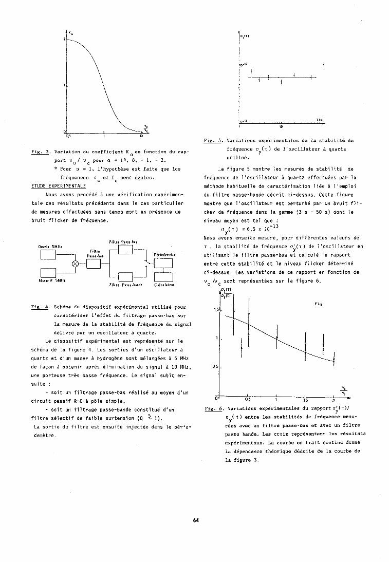
Fig. 5. Variations experimentales de la stabilite de
Fig. 3. Variation du coefficient K en fonction du rap-
port v o / v pour a = l*, 0, - 1, - 2 .
Pour a = 1, llhypoth&se est faite que les
frequences v et fc sont egales.
ETUDE EXPERIMENTALE
Nous avons procede a une verification experimen- tale des resultats precedents dans le cas particulier
de mesures effectuees sans temps mort en presence de
bruit flicker de freouence.
Fig. 4. Schema du dispositif experimental utilise pour
caracteriser lleffet du filtrage passe-bas sur
la mesure de la stabilite de frequence du signal
delivre par un oscillateur B quartz.
Le dispositif experimental est represent6 sur le
schema de la figure 4. Les sorties d'un oscillateur &
quartz et d'un maser a hydrogene sont m6langees a 5 MHz de facon a obtenir aprhs elimination du signal & 10 MHz,
une porteuse tres basse frequence. Le signal subit en- suite :
- soit un filtrage passe-bas realis6 au moyen d'un circuit passif R-C 21 p81e simple,
- soit un filtrage passe-bande constitu6 d'un filtre selectif de faible surtension (Q 2 1). La sortie du filtre est ensuite inject6e dans le perio-
demiitre.
frequence o (T) de l'oscillateur B quartz Y
utilisk.
La figure 5 montre les mesures de stabilite de
frequence de l'oscillateur & quartz effectuees par la
mbthode habituelle de caracterisation liee l'emploi
du filtre passe-bande decrit ci-dessus. Cette figure
montre que l'oscillateur est perturb6 par un bruit fli-
cker de frequence dans la gamme (3 s - 50 s) dont le
niveau moyen est tel que :
o ( T ) a 6 , 5 x 10 -13 Y
Nous avons ensuite mesure, pour diff6rentes valeurs de
T , la stabilite de frequence u;(T) de l'oscillateur en
utilisant le filtre passe-bas ei calcul6 le rapport
entre cette stabilite et le niveau flicker determine
ci-dessus. Les variations de ce rapport en fonction de
v o /Vc sont repr6sentees sur la figure 6.
Variations experimentales du rapportol(~)/ Y
o ( T) entre les stabilites de frequence mesu- Y
rkes avec un filtre passe-bas et avec un filtre
passe bande. Les croix representent les resultats
expcirimentaux. La courbe en trait continu donne
la dkpendance theorique deduite de la courbe de
la figure 3.
Chaque mesure est affectee d'une barre d'erreur
tenant compte de l'incertitude sur la determination du
niveau flicker et de celle due au nombre limit6 de me-
sures permettant le calcul de la stabilite de fr6quence.
La courbe en trait continu represente la dependance
theorique deduite des resultats du tableau 2. La fi-
gure 5 montre que, lorsque le signal traverse un filtre
passe-bas, la valeur de sa stabilite de frequence dB-
pend du rapport v o / v c , en bon accord avec les pr8-
visions theoriques.
CONCLUSION
Nous avons present4 une Btude relative B 1 'effet du filtrage passe-bas d'un signal en vue de la mesure
de son bruit de frequence. Nous avons montrh qu'il
existe des conditions experimentales pour lesquelles la
caracterisation de la stabilite de frequence est enta-
chee d'une erreur systematique non negligeable qui de-
pend essentiellement du rapport entre la frequence de
coupure du filtre et la frequence nominale du signal.
Une Btude experimentale realisee i partir d'un oscil-
lateur B quartz a illustre les pr6visions theoriques
relatives au bruit de frequence en l/f.
BIBLIOGRAPHIE
(1) D.W. ALLAN, "Statistics of Atomic Frequency Stan-
dards". Proc. IEEE Vol. 54, p . 221-230, Fevrier
1966.
(2) J.A. BARNES et a1 , "Characterization of Frequency Stability", IEEE Trans. Trans. Instrum. Meas. Vol.
IM-20, p. 105-120, Mai 1971.
(3) D.A. HOWE, D.W. ALLAN et J.A. BARNES, "Properties
of Signal Sources and Measurement Methods". Proc.
35th Annual Symp. Frequency Control (Philadelphie,
P.A.) p. A1-A47, 1981.
(4) P. LESAGE, C. AUDOIN, "Characterization of Fre-
quency Stability : Uncertainty Due to the Finite
Number of Measurements". IEEE Trans. Instr. Meas.
Vol. IM-22, p. 157-161, Juin 1973 ; Vol. IM-24,
p . 86, Mars 1975 ; Vol. IM-25, p . 270, Sept. 1976.
(5) P. TREMBLAY, "Etude de l'effet de filtrage du si-
gnal sur la caracterisation de la stabilite de fre-
quence". These Ph. D. Universite Laval, Quebec,
Novembre 1985.
(6) P. LESAGE, C. AUDOIN, "Effect of Dead-Time on the
Estimation of the Two Sample Variance". IEEE Vol.
IM-28, p. 6-10, Mars 1979.
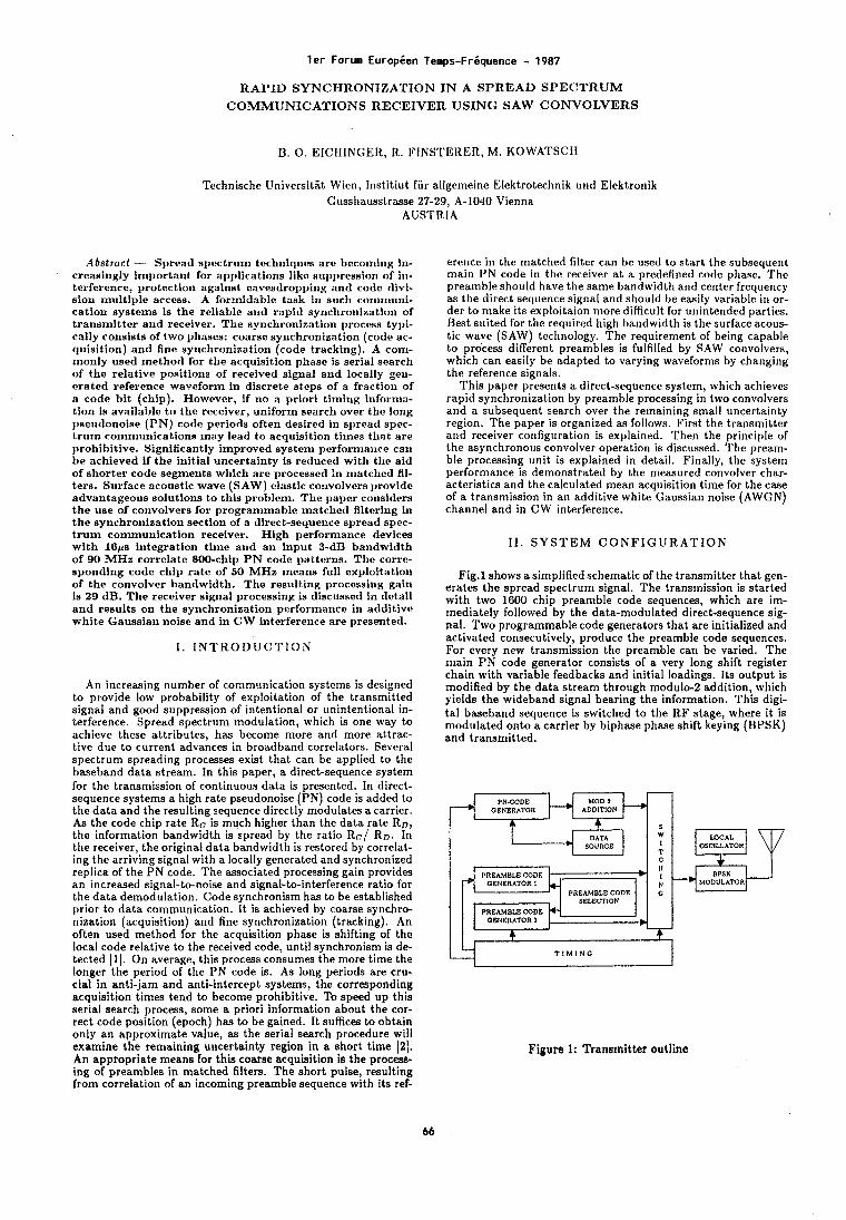
l e r Forum Europien Temps-FrBquence - 1987
RAPID SYNCHRONIZATION IN A SPR.EAD SPECTR.UM COMMUNICATIONS RECEIVER USING SAW CONVOLVERS
B. 0 . EICIIINGEII, R. FINSTERER, M. KOWATSCII
Technische Universitat Wien, Institiut fiir allgemeine Elektrotechnik und Elektronik Gusshausslrasse 27-29, A-1040 Vienna
AUSTRIA
Abstract - Spread spectrum techniqees are becoming in- creasingly important for applications like suppression of ill- terference, protection against eavesdropping and code divi- sion multiple access. A formidable task in sucll cornmuni- cation systems is the reliable and rapid synchronization of transmitter and receiver. The synchronization process typi- cally consists of two phases: coarse synchronization (code ac- quisition) and fine synchronization (code tracking). A com- monly used method for the acquisition phase is serial search of the relative positions of received signal and locally gel!- erated reference waveform in discrete steps of a fraction of n code bit (chip). However, if no a priori timing informa- tion is available to the receiver, uniform search over the long pseudonoise (PN) code periods often desired in spread spec- t r u m cornn~unications may lead to acquisition tilnea tllat are prohibitive. Significantly improved system performance can be achieved if the initial uncertainty is reduced wit11 tllc aid of shorter code segments which are processed in matchetl fil- ters. Surface acoustic wave (SAW) elastic convolvers provide advantageous solutions to this problem. The paper considers the use of convolvers for programmable matched filtering in the synchronization section of a direct-sequence spread spec- t r u m communication receiver. High performance devices with 16ps integration time and an input 3-dB bandwidth of 90 MHz correlate 800-chip PN code patterns. The corre- sponding code chip ra te of 60 MHz means full exploitation of the convolver bandwidth. The resulting processing gain is 29 dB. The receiver signal processing is discussed in detail and results on the synchronization performance in additive white Gaussian noise and in CW interference are presented.
I . I N T R O D U C T I O N
An increasing number of communication systems is designed to provide low probability of exploitation of the transmitted signal and good suppression of intentional or unintentional in- terference. Spread spectrum modulation, which is one way to achieve these attributes, has become more and more attrac- tive due to current advances in broadband correlators. Several spectrum spreading processes exist that can be applied to the baseband data stream. In this paper, a direct-sequence system for the transmission of continuous data is presented. In direct- sequence systems a high rate pseudonoise (PN) code is added to the data and the resulting sequence directly modulates a carrier. As the code chip rate Re is much higher than the data rate RD, the information bandwidth is spread by the ratio Re/ RD. In the receiver, the original data bandwidth is restored by correlat- ing the arriving signal with a locally generated and synchronized replica of the PN code. The associated processing gain provides an increased signal-to-noise and signal-to-interference ratio for the data demodulation. Code synchronism has to be established prior to data communication. It is achieved by coarse synchro- nization (acquisition) and fine synchronization (tracking). An often used method for the acquisition phase is shifting of the local code relative to the received code, until synchronism is de- tected [I]. On average, this process consumes the more time the longer the period of the PN code is. As long periods are cru- cial in anti-jam and anti-intercept systems, the corresponding acquisition times tend to become prohibitive. To speed up this serial search process, some a priori information about the cor- rect code position (epoch) has to be gained. It suffices to obtain only an approximate value, as the serial search procedure will examine the remaining uncertainty region in a short time (21. An appropriate means for this coarse acquisition is the process- ing of preambles in matched filters. The short pulse, resulting from correlation of an incoming preamble sequence with its ref-
erence in the matched Alter can bc: used to start the subsequent main PN code in the receiver at a predefined code phase. The preamble should have the same bandwidth and center freque~~cy as the direct seuuence sianal and should be easilv variable in or- der to make its &ploitaion more difficult for uniitended parties. Best suited for the required high bandwidth is the surface arous- tic wave (SAW) technology. The requirement of being capable to process different preambles is fulfilled by SAW convolvers, which can easily be adapted to varying waveforms by changing the reference signals.
This paper presents a direct-sequence system, which achieves rapid syncl~ronization by preamble processing in two convolvers and a subsequent search over the remaining small uncertainty region. The paper is organized as follows. First the transmitter and receiver co~~figuration is explained. Then the principle of the asynchronous convolver operation is discussed. The pream- ble processing unit is explained in detail. Finally, the system performa~~ce is demonstrated by the measured convolver char- acteristics and the calculated mean acquisition time for the case of a transmission in an additive white Gaussian noise (AWGN) channel and in CW interference.
11. S Y S T E M C O N F I G U R A T I O N
Fig.1 shows a simplified schematic of the transmitter that gen- erates the spread spectrum signal. The transmission is started with two 1600 chip preamble code sequences, which are im- mediately followed by the data-modulated direct-sequence sig- nal. Two programmable code generators that are initialized and activated consecutively, produce the preamble code sequences. For every new transmission the preamble can be varied. The main PN code generator consists of a very long shift register chain with variable feedbacks and initial loadings. Its output is modified by the data stream through modulo-2 addition, which yields the wideband signal bearing the information. This digi- tal baseband sequence is switched to the RF stage, where it is modulated onto a carrier by biphase phase shift keying (BPSK) and transmitted.
MOD 1 ADDITION
t s DATA W
SOURCE I T "
- GENERATOR I N
PREAMBLE CODE G SELECTION
PREAMBLE CODE GENERATOR1
- 4
OSCILLATOR
T I M I N G
Figure 1: Transmitter outline
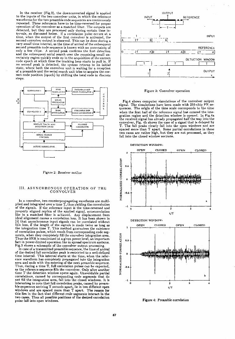
In the receiver (Fig.2), the downconverted signal is applied to the inputs of the two convolver units, in which the reference waveforms for the two preamble code sequences are continuously repeated. These references have to be time-reversed for proper operation of the convolver as a matched filter. The outputs are detected, but they are processed only during certain time in- tervals, as tliscussed below. I f a correlation pulse! occurs at a tir~le, when the output of the first cor~volvcr is activaletl, t l ~ e second convolver output is observed. This can be done during a very small time interval, as the time of arrival of the s~rbseclr~ent second preamble code sequence is known with an uncertainty of only a few chips. A second peak confrnls the first de tect io~~ and the subsequent serial search over the remaining small un- certainty region quickly ends up in the acquisition of the correct code epoch at which time the tracking loop starts to pull in. If no second peak is detected, the syslertt rclr~rrrs to its initial skate, where both the convolver unit is waiting for a reception of a preamble and the serial search unit tries to acquire the cor- rect code position (epoch) by shifting the local code in discrete steps.
OSCILLATOR 4 "?a 0 L
I'IIEAMDLE REF.
I 1-
Y ACTIVE CORRELATOR - Figure 2: Receiver outline
111. A S Y N C H R O N O U S O P E R A T I O N O F T H E C O N V O L V E R
In a convolver, two counterpropagating waveforms are multi- plied and integrated over a time T , thus yielding the convolution of the signals. If the reference input is the time-reversed and properly aligned replica of the applied signal, autocorrelation like in a matched filter is achieved. Any displacement from ideal alignment causes a correlation loss. It has been shown in (31 that asynchronous input signals can be correlated without this loss, if the length of the signals is made twice as long as the integration time T . This method guarantees the existence of correlation pulses, which result from corresponding code seg- ments, when they completely fill the convolver integration area. Thus the SNR is maximized a t a given power level, an important fact in power-limited operation like in spread spectrum systems. Fig.3 shows a schematic of the convolver output processing.
In case of a transmitted preamble sequence, the time of arrival of the desired full correlation peak is restricted to a well-defined time interval. This interval starts at the time, when the refer- ence waveform has completely propagated into the integration area and ends with the entering of the next preamble sequence. Thus, during a time T , full correlation pulses can be expected, as the reference sequence fills the convolver. Only after another time T the detection window opens again. Unavoidable partial correlations, caused by corresponding code segments that do not fill the integration area, fall into the closed windows. It is interesting to note that full correlation peaks, caused by pream- ble sequences arriving T seconds apart, lie in two different open windows and are spaced more than T apart. The reason for this lies in the fact that different code segments interact in the two cases. Thus all possible positions of the desired correlation pulse fall into open windows.
INPUT REFERENCE ?-A?- 1 2 - - - - - INPUT
A 2 T 01 3 REFERENCE
€3 2T A 10 2 T A (6 2 T A
DETECTION WINDOW I T 1 [ T I I T ]
4 OUTPUT 1
T
Figure 3: Convolver operation
Fig.4 shows computer simulations of the convolver output signal. The silr~ulations have been made with 255-chip PN se- quences. The origin of the time scale corresponds to the time when the first half of the reference signal has entered the inte- gration region and the detection window is opened. In Fig.4a the received signal has already propagated half the way into the convolver, Fig. 4b shows the case of a signal that is delayed by T. The full peaks clearly fall into the open windows and are spaced more than T apart. Some partial correlations in these two cases are rather high, but they are not processed, as they fall into the closed window sections.
DETECTION WINDOW:
OPEN CLOSED OPEN CLOSED 1 1 I '
DETECTION WINDOW:
+ OPEN CLOSED ; ,OPEN ; CLOSED ,
Figure 4: Preamble correlation
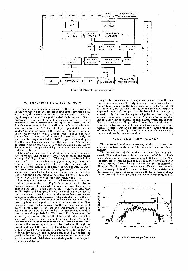
PREAMBLE REF. B P F CONVOLVER 1
1
OSCILLATOR
ENVELOPE DETECTOR GENERATION
I I
LOCAL OSCILLATOR
f .c PREAMBLE REF.
BPF CONVOLVER 2 BPF
Figure 5: Preamble processing unit
I V . P R E A M B L E P R O C E S S I N G U N I T
Because of the counterpropagation of ttie input waveiorrns in the convolver and the corresponding time compression by a factor 2, the correlation outputs are centered at twice the input frequency and the signal bandwidth is doubled. Thus, processing the output of the first convolver during a time T , as discussed before, corresponds to an input time interval of 2T. The time of occurence of a correlation pulse during this interval is measured to within 115 of a code chip (chip period T,), as the analog timing information of the pulse is digitized by sampling in discrete intervals of 0.2T,. This information is used to open the window at the output of the second convolver correctly. As the preamble sequences last for 1600 chips, corresponding to 2T, the second peak is expected after this time. The second detection window can be late up to the measuring uncertainty. To account for this possible delay the window has to be made wider accordingly.
The length of the detection windows is a decisive point in system design. The longer the outputs are activated, the higher is the probability of false alarm. The length of the first window has to be T, in order not to miss any preamble, only the second window can be made smaller. The correlation function, which has to fall completely into the open window, is exactly 'r, wide, but noise broadens the uncertainty region to 2T,. Considering the aforernerltioned widening of the window, due lo discretiza- tion of the t imi~ig information, the overall length of the second time window for the ease of implementation is made 3T,.
The complete convolver unit that achieves coarse acquisition is shown in some detail in Fig.5. In expectation of a trans- n~ission the control unit starts the reference preamble code se- quence generators. Their outputs are BPSK-modulated onto an IF carrier and bandpass filtered before they are applied to the convolvers. In each convolver the respective preamble se- quence is continuously repeated. The output at twice the in- put frequency is bandpass-filtered and envelope-detected. 'I'he resulting baseband signal is compared with a threshold. The output of convolver 1 is activated by the detection window unit every 2T for a time T. In case of a transmitted preamble, a correlation pulse will be detected at the first convolver with a certain detection probability. This probability depends on the actual signal-to-noise ratio and the detection threshold, which is specified by a predefined probability of false alarm. This pulse initiates the counter chain that starts the second window. Any delays in the processing unit have to be considered through the initial loadings of the counters. The detected first pulse itself is delayed by 2T. Coincidence of a second pulse during the 31', wide window and the delayed first pulse is used to confirm the previous decision. The main PN code generator then is started with a predefined initial state, considering additional delays in coincidence detection.
A possible drawback i r ~ the acquisition schernc lies i r ~ the Fact that a false alarrr~ at the output of the first convolver leaves the system blocked for tlie reception of a correct prearnblc? for a time of 2T. During this time the second convolver output is expected and correlation peaks in the first window are not pro- cessed. Only if no confirming second pulse has turned up, an arriving preamble is processed again. A solution to this problem lies in a very low probability of false alarm, which can be spec- ified arbitrarily, according to the Neyrnan Pearson criterion 141. However, a tradeoff has to be made between a very low prob- ability of false alarrn and a correspondingly lower probability of preamble detection. Quantitative results on these ronsidera- tions are shown in the next section.
V . S Y S T E M P E R F O R M A N C E
The presented combined convolver/serial-search acquisition concept has been analyzed and implemented in a breadboard modem.
The performance of the applied convolvers has been mea- sured. The devices have an input bandwidth of 90 MHz. Their integration time is 16 ps, corresponding to 800 code chips. The experimental processing gain of 29 dB is in good agreement with theory. Measured convrlver characteristics are sumniarized ill
Fig.6 [ 5 ] . Graph a shows the convolver eficiency over the out- put frequency. It is -62 dBm a t midband. The peak-to-peak deviation from linear phase is less than 15 degree (gra h b) and the self convolution suppression is 40 dB on average Graph c).
400 600 000 700 800
OUTPUT FREQUENCY IMHE]
Figure 6: Convolver performance
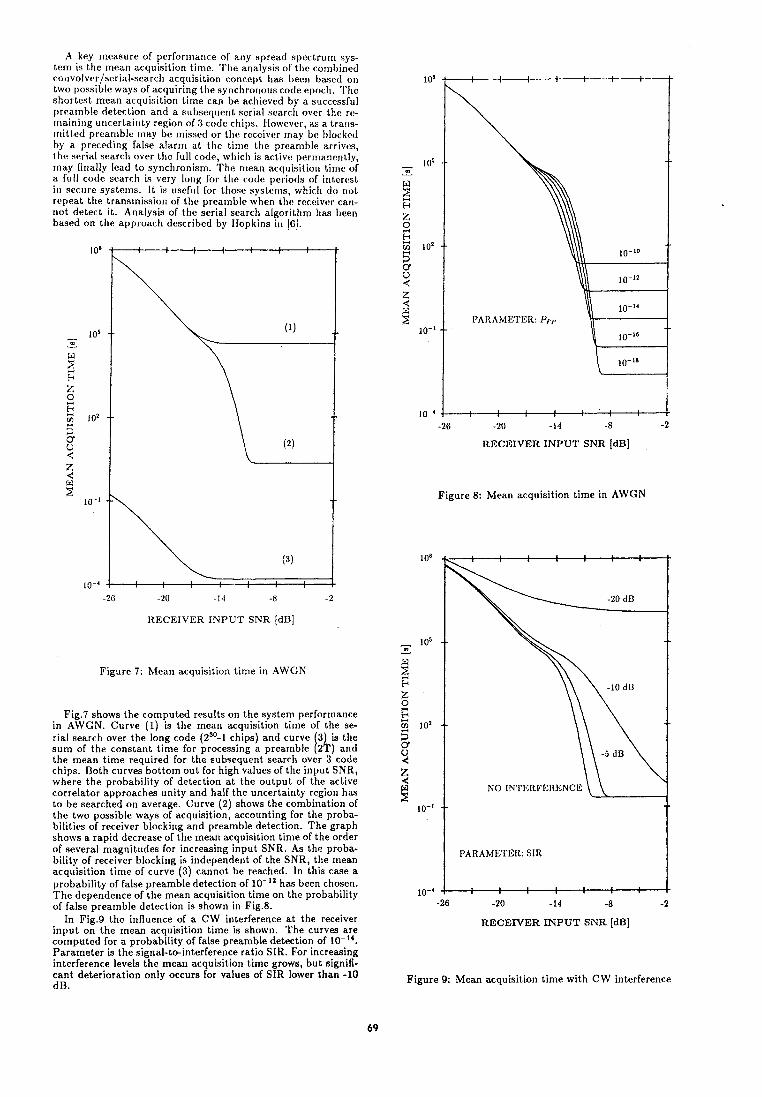
A key measure of perforrrra~lce of any spread spectrurr~ sys- tem is the mean acquisition time. The analysis of the cornbir~ed cor~volver/seriaI-search acqr~isitiori concept has beer1 based on two possible ways of acquiring l l ~ e synchror~ous code epoch. l ' l ~e shortest mean acquisition time can be achieved by a successful preamble detection and a s r ~ b s e q l ~ ~ n t serial search over thc ro- rt~ainir~g ur~certair~ty region of 3 code chips. Ilowevcr, as a Lrar~s- rr~itt,c:d prearr~ble [nay be rnissed or the rcccivor rrlay be I)lockctl by a preceding false alarrr~ at the time tho prcarnble arrivcs, ~ I I ( ? serial searcl~ over the full code, w l~ ic l~ is active perrr~anenl~ly, rnay finally lead to synchronism. The rrlean acquisitioti tirr~e of - m
&
a full code searcl~ is very long for the code periods or int,erc!st in sccurc! systcrrls. It is u sc f~~ l for those systcrns, whir11 do r~o t
W
repeat the transmission ol the preamble when tho reccivcr can- 2 P
not detect it. Analysis of the serial search algorithm IIW been based on the approach described by IIopkins ill 161.
Z 2 E
1 O8 5 0 U 4 z 4
lo5
3 -
Vi - W 2 i;
10 - 4
-26 -20 -14 -8 -2
RECEIVER INPUT SNR [dB]
PARAMETER: f'pr
Figure 8: Mean acquisition time in AWGN
ItECEIVER INPUT SNR [dB]
Figure 7: Mean acquisition time in AWGN
Fig.7 shows the computed results on the system performance in AWGN. Curve (1) is the mean acquisition tirne of the se- rial search over the long code (2'O-1 chips) and curve 3 is the sum of the constant time for processing a preamble [ Z k ) and the mean time required for the subsequent search over 3 code chips. Both curves bottom out for high values of the input SNR, where the probability of detection at the output of the active correlator approaches unity and half the uncertainty region has to be searched on average. Curve (2) shows the combination of the two possible ways of acquisition, accounting for the proba- bilities of receiver blocking and preamble detection. The graph shows a rapid decrease of the mean acquisition time of the order of several magnitudes for increasing input SNR. As the proba- bility of receiver blocking is independent of the SNR, the mean acquisition time of curve (3) cannot be reached. In this case a probability of false preamble detection of lo-'' has been chosen. The dependence of the mean acquisition time on the probability of false preamble detection is shown in Fig.8.
In Fig.9 the influence of a CW interference a t the receiver input on the mean acquisition time is shown. The curves are computed for a probability of false preamble detection of 10-". Parameter is the signal-to-interference ratio SIR. For increasing interference levels the mean acquisition time grows, but signifi- cant deterioration only occurs for values of SIR lower than -10 dB.
NO INTERFERENCE
PARAMETER: SIR
RECEIVER INPUT SNR [dB]
Figure 9: Mean acquisition time with CW interference
V I . C O N C L U S I O N
The mean acquisition time in secure spread spectrum sys- tems, which employ serial search processes for synchronization, often becomes prohibitive, because of the desired long code pe- riods. A direct-sequence spread sj)ectru~rt sysl,ern, tlesigt~ocl for achievipg a low probability of exj)loitation, has bren prescntod. It is rapidly synchronized by a combination of SAW convolvers, acting as matched filters for two prearnble sequences ant1 a sul)- s e q ~ ~ e n t serial search over the rerrlaining small u~lccrtainty re- gion. The application of SAW convolvers to this task c?nsurcs that the prearnble sequences can be chosen differently for each corlsecutive transmission. As a full code serial search unit is active simultaneously with the preamble processit~g unit, acqui- sition can be guaranteed also for the cases, when a transmitted preamble is missed. The combination of these two acquisition processes has been analyzed, sllowing a considerable decrease in the mean acquisition tirne even in strong interference.
ACKNOWLEDGEMENT
The authors are indepted to H.P. Grassl and H.R. Stocker, Siemens Corporate Research Laboratories, Munich, for making available the SAW convolvers, and to Prof. F.J.Seifert for con- tinuous encouragement during the course of this project.
REFERENCES
[ I ] S.S. Rappaport, D.M. Grieco, Spread-Spectrum Signal Acquisition: Methods and Technology, IEEE Communications Magazine, Vo1.22, pp.6- 21,Jun.1984.
121 B.O. Eichinger, R. Finsterer, M. Kowatsch, Convolver-Aided Synchronization in a Direct- Sequence Spread Spectrum Communication Sys- t em, Proc. IEEE 1986 Ultrasonics Sy~nposium, to be published.
131 J.H. Cafarella. Aoolication o f SAW Convolvers to , s
Spread spectr;m' 'Communication, Proc. IEEE 1984 Ultrasonics Symposium, pp.121-126.
141 C.W. Helstrom,Statistical Theory of Signal Detec- tion, p.152. Oxford: Pergamon Press, 1968.
[5] H.P. Grassl, H. Engan, Small Aperture Focusing Chirp Transducers vs. Diflraction-Compensated Beam Compressors in Elastic SAW Convolvers, IEEE Trans. Sonics Ultrason. Vol.SU-32, pp.675- 684, Sept.1985.
16) P.M. Hopkins, A Unified Analysis of Pseudonoise Synchronization by Envelope Correlation, IEEE Trans Commun., Vol. Comm-25, pp. 770-780, Aug.1977.
l e r Forum Europien Temps-FrGquence - 1987
Systemat ic Performance o f t h e Space Clocks i n t h e NAVEX Experiment
Jens Hamesfahr
Deutsche Forschungs- und Versuchsans ta l t f u r L u f t - und Raumfahrt e.V. I n s t i t u t f u r Hochfrequenztechnik 8031 Oberpfaf fenhofen, W-Germany
ABSTRACT
Two atomic c l o c k s were sen t i n t o space f o r a p e r i o d o f seven days on a Spacelab f l i g h t i n t h e end o f 1985.
The t ime standards were p a r t o f t h e spaceborne equipment o f a n a v i g a t i o n exper iment which was c a l l e d NAVEX. Two c l o c k s were used: a cesium and a r u b i d i u m standard. They were housed i n a s p e c i a l f l i g h t c o n t a i n e r . The c l o c k s were c o n t r o l l e d by a ground s t a t i o n i n Germany v i a a two way r a d i o l i n k .
The paper p resen ts t h e r e s u l t s o f c l o c k comparisons between t h e f l i g h t c l o c k s and t h e ground based r e - fe rence c l o c k as w e l l i n t h e space f l i g h t as i n severa l ground measurement p e r i o d s b e f o r e and a f t e r t h e Spacelab miss ion . The c l o c k comparisons were per formed t o g e t i n f o r m a t i o n about t h e c l o c k s ' r a t e . Random e f f e c t s a r e n o t considered. Temperature and r e l a t i v i s t i c e f f e c t s as w e l l as bear ings caused by t h e f l i g h t a t t i t u d e a r e d i s - cussed.
1. Aim o f t h e c l o c k observa t ions
I n 1985, i n l a t e autumn, t h e space l a b o r a t o r y c a l l e d Spacelab has been f l o w n on-board t h e NASA S h u t t l e t h e f i r s t t i m e by German payload c o n t r o l . Tha t m i s s i o n - i t s name was D l - l a s t e d 7 days f rom o c t o b e r 30 t o no- vember 6 and i t s purpose was t o conduct exper iments on b i o l o g i c a l and m a t e r i a l sc iences as w e l l as on naviga- t i o n . The n a v i g a t i o n exper iment on board has been c a l l e d NAVEX. I t was n o t mounted i n s i d e t h e Spacelab b u t on a s p e c i a l s t r u c t u r e behind. No t o n l y t h e f l i g h t s t a t i o n was p a r t o f t h e exper iment equipment b u t a l s o t h r e e ground s t a t i o n s which were s e t up i n Germany. Dur ing t h e t i m e o f d i r e c t v iew f rom t h e S h u t t l e t o t h e ground s t a t i o n s a h i g h f requency l i n k was used. I t has been one o f t h e exper iment aims t o compare a p r e c i s e c l o c k on-board o f t h e S h u t t l e t o a c l o c k i n t h e c o n t r o l s t a t i o n on ground by means o f t h e r a d i o l i n k i n t imes o f c o n t a c t .
The f l i g h t hardware encompassed two atomic f requency standards, a cesium c l o c k c a l l e d CFS and a r u b i d i u m c l o c k RFS. A t i m i n g s i g n a l was e m i t t e d by t h e f l y i n g s t a t i o n and was c o h e r e n t l y d e r i v e d f rom t h e f requency of t h e cesium standard. The r u b i d i u m s tandard was i n - s t a l l e d as a back up c l o c k b u t was n o t used as t i m e re fe rence i n t h e m i s s i o n because no f a i l u r e i n t h e t i m i n g equipment occur red . The rece ived t ime s i g n a l was regenerated i n t h e e l e c t r o n i c s o f t h e c o n t r o l s t a t i o n and sen t back t o t h e f l i g h t s t a t i o n where i t was deco- ded. By t h e use o f t i m e i n t e r v a l measurements i n e i t h e r s t a t i o n s i t has been f e a s i b l e t o work o u t t h e d i f f e r e n - ce between e i t h e r t i m e read ings o f b o t h t h e c l o c k s on every second. Resu l t s o f these measurements a r e shown i n t h e chap te r " r e s u l t s o f t h e f l i g h t p e r i o d " .
F o r i n t e r p r e t i n g o f t h e c l o c k performance i n space i t has been an e s s e n t i a l need t o observe t h e standards on ground based measurements i n o r d e r t o d i s c e r n d i f f e r e n - ces i n t h e performances caused by t h e space f l i g h t . There fo re i n severa l pe r iods t h e standards have been compared t o a r e f e r e n c e c l o c k . T h i s has been o f a p a r t i - c u l a r i n t e r e s t s i n c e t h e space c l o c k s were sw i tched o f f a l o n g t i m e b e f o r e t h e launch and were a c t i v a t e d n o t e a r l i e r than 12 hours a f t e r s t a r t o f t h e D l m i s s i o n and
sw i tched o f f aga in b e f o r e t h e l a n d i n g . I n general t h e r a t e o f a c l o c k d i f f e r s f rom t h e p rev ious r a t e when t h e c l o c k has been d i s a c t i v a t e d i n t h e meantime. That i s why severa l ground measurements were per formed i n o r d e r t o g e t da ta on t h e range o f v a r i a t i o n i n t h e c l o c k r a t e s . The r e s u l t s a r e shown i n t h e chap te r "The ground measurements".
2 . D e f i n i t i o n s and b a s i c s o f da ta e v a l u a t i o n
A l l measurements have been done i n t h e t i m e domain. That means t h e d i f f e r e n c e between t h e read ings o f two c l o c k s i s measured o r computed. The v e r y p r e c i s e t ime s i g n a l o f t h e r e f e r e n c e c l o c k g i v e s t h e s t a r t i n g p o i n t and t h e c l o c k t o be compared g ives t h e c l o s i n g p o i n t o f t h e t i m e i n t e r v a l . Only t h e s i g n a l s which g i v e marks a t a d i s t a n c e o f one second ( 1 pps) a r e used. I t i s assumed t h a t t h e f requenc ies a r e c o n s t a n t i n t h a t i n t e r - v a l . The d i f f e r e n c e i n t h e c l o c k read ings i s c a l l e d r e l a t i v e r e a d i n g (symbol T ) .
I n t h e da ta e v a l u a t i o n many such d i f f e r e n c e s a r e taken and f i t t e d by a s t r a i g h t l i n e u s i n g t h e method o f l e a s t squares. The i n c l i n a t i o n o f t h a t l i n e g ives t h e r e l a - t i v e f requency o f f s e t o r r a t e , c h a r a c t e r i z e d by t h e symbol R (name o f r e f e r e n c e c l o c k - name o f specimen c l o c k ) . The r a t e has been determined o n l y when t h e r e was no s i g n i f i c a n t d r i f t ; excep t ions a r e no ted i n t h e t e x t .
R e l a t i v e read ing , r a t e , and d r i f t o n l y d e s c r i b e t h e sy- s temat i c performance o f t h e standards. The n o i s e i s c h a r a c t e r i z e d by t h e s t a b i l i t y . One has t o compute t h e two-sample o r A l l a n va r iance which shows t h e v a r i a t i o n o f t h e r a t e s i n a d e f i n e d b u t v a r i a b l e t i m e i n t e r v a l when a l l sys temat i c i n f l u e n c e s a r e e x t r a c t e d . The A l l e n va r iance i s an i m p o r t a n t s p e c i f i c a t i o n f o r c l o c k s i n t i m e keeping systems. Bu t i n t h e m i s s i o n t h e spaceborne s tandard c o u l d be compared t o t h e ground based c l o c k o n l y i n s h o r t t i m e i n t e r v a l s when t h e Space S h u t t l e f l e w over Europe. The t imes o f c o n t a c t t h e r e f o r e l a s t e d f rom 5 up t o 9 minutes. The t ime t o t h e n e x t c o n t a c t was 1 1/2 t o 16 hours. To compute t h e A l l a n va r iance i t i s necessary t o have da ta i n e q u i d i s t a n t t i m e i n t e r v a l s . I n t h e NAVEX exper iment t h e computing would have been p o s s i b l e o n l y i n some cases when s u f f i c i e n t da ta p o i n t s were a v a i l a b l e . Moreover t h e c l o c k s were n o t compared d i r e c t l y b u t by u s i n g h i g h f requency l i n k s and e l e c - t r o n i c s i g n a l d e t e c t i o n which caused a d d i t i o n a l no ise . There fo re i t was n o t u s e f u l t o determine t h e A l l a n va r iance on t h e f l i g h t c locks . So i t was n o t determined i n t h e ground measurements, too , because these had t o be compared t o t h e f l i g h t measurements.
3. The ground measurements
There have been 19 s e r i e s o f measurements i n 9 p e r i o d s between 1983 and 1986. A s e r i e s i s d e f i n e d as t h a t t i m e when t h e f l i g h t c l o c k s were a c t i v a t e d . Be fo re t h a t they were sw i tched o f f . The d u r a t i o n o f t h e i n a c t i v a t i o n phases v a r i e d f rom one hour t o severa l months. The c l o c k comparisons were h e l d i n d i f f e r e n t p laces because t h e measurements c o u l d be taken o n l y i n s p e c i f i e d phases on t h e hardware i n t e g r a t i o n and d e i n t e g r a t i o n . According t o t h e v a r y i n g l o c a t i o n s t h e equipment was moved severa l t imes. The most i m p o r t a n t t i m e o f movements was t h e D l m i s s i o n o f course.
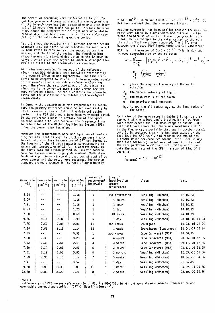
The s e r i e s o f measuring were d i f f e r e n t i n l e n g t h . To g e t homogeneous and comparable r e s u l t s the r a t e o f t h e c l o c ~ s i n each case has been computed over a t i m e i n t e r - v a l o f 12 hours from 8 o ' c l o c k pnl t o 8 o ' c l o c k am l o c a l t ime, s i n c e t h e teniperatures a t n i g h t were more s t a b l e than a t day. That has g i v e n 1 t o 12 i n t e r v a l s f o r com- p u t i n g o f t h e r a t e s depending on the s e r i e s .
Table i shows t h e r e s u l t s on a l l p e r i o d s f o r t h e cesium s tandard CFS. The f i r s t colunln enibodies t h e mean on a l l 12-hour-rates i n each s e r i e s , t h e second colunln t h e minima, and t h e t h i r d t h e maxima. The f o u r t h column shaws the e m p i r i c s tandard d e v i a t i o n i n t h e 12 hour i n - t e r v a l , which g ives t h e degree t o which a s t r a i g h t l i n e c o u l d be f i t t e d t o t h e measured c l o c k readings.
A l l r a t e s a r e computed i n r e s p e c t o f t h e r e f e r e n c e c l o c k named H01 which has been i n s t a l l e d s t a t i o n a r i l y i n a room o f DFVLR i n WeOling/Germany. The t i m e s tan- dards t o be compared t o i t c o u l d n o t been mounted nearby i n a l l events. Then a secondary r e f e r e n c e c l o c k was used. Therefore t h e r a t e worked o u t o f t h e c l o c k rea- d ings has t o be conver ted i n t o a r a t e ve rsus t h e p r i - mary re fe rence c l o c k . The t a b l e c o n t a i n s t h e conver ted r a t e s b u t t h e d e v i a t i o n s a r e r e l a t e d t o t h e o r i g i n a l measurements.
I n Germany t h e comparison o f t h e f requenc ies o f secon- dary and p r imary r e f e r e n c e c o u l d be achieved e a s i l y by c l o c k t r a n s p o r t a t i o n s w h i l s t i n t h e da ta c o l l e c t i o n p e r i o d i n t h e USA t h i s would have been v e r y compl icated. So t h e re fe rence c l o c k s i n Germany and a t t h e Space S h u t t l e launch s i t e were compared v i a f requency l i n k s t o s a t e l l i t e s of t h e Global P o s i t i o n i n g System (GPS) u s i n g t h e common v iew technique.
Moreover t h e temperatures were n o t equal on a l l measu- r i n g p e r i o d s . That i s why t h e c l o c k r a t a s were t r a n s - formed on to a u n i f o r m temperature o f 37 c e n t i g r a d e a t t h e housing of t h e f l i g h t s taadards co r respond ing t o an ambient temperature o f 21 C. To ache ive t h a t , i n t h e f i r s t da ta c o l l e c t i o n p e r i o d i n 1983 t h e tempera- t u r e c o e f f i c i e n t s were r o u g h l y determined. Both s tan- dards were p u t i n an a i r - c o n d i t i o n e d box a t c o n t r o l l e d temperatures and t h e r a t e s were measured. The cesium standard showed a change i n i t s r a t e o f ap rox imate ly
2.43 . 1 0 - l 4 ~ / O C and t h e RFS 5.77 . 1 0 - l 2 3 i 3 r , I r has been assumed t h a t t h e change was l i n e a r .
Another c o r r e c t i o n has been a p p l i e d because t h e measure- ments were taken i n p laces which had d i f f e r e n t a l t i - tudes and were s i t u a t e d i n d i f f e r e n t geographic l a t i - tudes. So t h e changes I n t h e r a t e s caused by t h e r e l a - t i v i s t i c e f f e c t have been computed. The d i f f e r e n c e between t h e p laces (WeBl inglGermany and Cap Canaveral/
USA) I s i n t h e o r d e r o f 0.46 10-12. Th is i s d e r i v e d i n good approx imat ion by t h e r e l a t i o n
o g i v e s t h e a n g u l a r f requency o f t h e e a r t h r o t a t i o n
co t h e vacuum v e l o c i t y o f l i g h t
ro t h e mean r a d i u s o f t h e e a r t h
u t h e g r a v i t a t i o n a l c o n s t a n t
hl, h a r e t h e a l t i t u d e s ; ql, 'p2 t h e l o n g i t u d e s o f tt?e s i t e s .
By a v iew on t h e mean r a t e s i n t a b l e 1 i t can be d i s - cerned t h a t t h e va lues d o n ' t d i s t i n g u i s h a l o t f rom each o t h e r excep t t h e l a s t measurings i n autumn 1986, That d a t a have shown t h a t t h e r e was sometimes a d r i f t i n t h e f requency; e s p e c i a l l y t h a t one i n oc tober s tands o u t . I t I s presumed t h a t t h i s has been caused by t h e f a c t t h a t t h e CFS n e a r l y had reached t h e end o f i t s l i f e t i m e which occur red two months l a t e r . That i s why t h a t l a s t measur ing p e r i o d was n o t used t o i n t e r p r e t t h e r a t e performance o f t h e c l o c k . Taking a l l o t h e r da ta t h e mean r a t e o f t h e CFS i n a span o f t ime o f 3 y e a r s i s
'c t o t a l = 7.91 10-12.
mean r a t e
110-121
8.14
8.09
7.91
8.23
7.50
9.25
7.75
7.85
7.35
7.50
7.42
7.38
7.31
7.60
7.41
9.80
12.20
Tab le 1 12-hour-rates o f CFS versus r e f e r e n ~ e c l o c k H01, R (HO1-CFS), i n v a r i o u s ground measurements. Temperature and geographic c o r r e c t i o n s a p p l i e d . (37 C, Wessl ing/Germany),
max.rate
[10-121
-- -- -- -- -- 9.34
7.86
8.15 - - 7.79
7.57
7.65
7.53
7.76 - -
10.35
15.29
min . ra te
[10-121
- - - - - - -- - - 9.16
7.53
7.56 - - 7.36
7.33
7.14
7.19
7.35 - - 9.08
10.82
d e v i a t i o n
[10-121
1.18
1.18
1.16
1.20
0.69
1.90
0.86
1.14
0.31
0.23
0.43
0.61
0.80
1.17
0.57
1.03
1.24
p l a c e
Wessl ing (Munchen)
Wessl ing (Munchen)
Wessl i n g (Munchen)
Wessl i n g (Munchen)
Wessl i n g (Munchen)
Wessl ing (Munchen)
S t u t t g a r t
Eberdingen ( S t u t t g a r t )
Cape Canaveral (USA)
Cape Canaveral (USA)
Cape Canaveral (USA)
Cape Canaveral (USA)
Wessl i n g (Munchen)
Wessl i n g (Munchen)
Wessl i n g (Munchen)
Wessl i n g (Munchen)
Wessl i n g (Miinchen)
number o f measurement i n t e r v a l s
1
1
1 1
1 6
11 12
1 4 3
6 5
7 1
11 8
d a t e
08.10.83
10.10.83
12.10.83
14.10.83
24.10.83
26.10.-02.11.83
10.03.-01.04.84
28.04.-17.05.84
26.06.85
28.06.-01.07.85
29.11. -01.12.85
03.12. -08.12.85
12.03.-16.03.86
10.04.-16.04.86
21.04.86
04.09.-14.09.86
02.10,-09.10.86
t i m e o f i n a c t i v a t i o n b e f o r e measurement
1 s t a c t i v a t i o n
4 hours
1 hour
1 day
10 hours
1 day
n o t known
1 week
n o t known
4 hours
3 weeks
3 hours
3 months
3 weeks
1 day
1 month
2 weeks
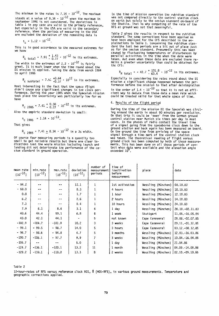
The minimum i n t h e r a t e s i s 7.14 . 10-12. The maximum
stands a t a v a l u e o f 9.34 1 0 - l 2 when t h e maximum i n september 1986 i s n o t considered. The d e v i a t i o n s i n t a b l e 1 i n any case a r e v a l i d t o t h e p r imary re fe rence , b u t e s p e c i a l l y i n t h e US4 a r e v a l i d t o t h e secondary re fe rence . When t h e p e r i o d s o f measuring i n t h e USA a r e excluded t h e d e v i a t i o n o f t h e remain ing da ta i s
sc = 1.12 . 10-12.
T h i s i s i n good accordance t o t h e measured extremes f o r we have
Rc total = 7.91 i::: 1 0 - l Z i n i t s extremes.
The w i d t h i n t h e extremes o f 2.2 10-I ' i s f a i r l y g r e a t . It i s much lower when t h e t i m e round about t h e 0 1 m i s s i o n i s a p p l i e d . Taking t h e da ta f rom march 1984 t o a p r i l 1986
10" i n i t s extremes. Rc s u b t o t a l = 7 '51 -0.37
Most i n t e r e s t i n g i s t h e f a c t t h a t t h e space f l i g h t d i d n ' t cause any s i g n i f i c a n t changes i n t h e c l o c k per- formance. D u r i n g t h e y e a r 1985 when t h e Spacelab m i s s i o n took p l a c e t h e u n c e r t a i n t y was p a r t i c u l a r l y low f o r we have
Rc 1g85 = 7.41 f ::;; . lo-'' i n i t s extremes.
A lso t h e e m p i r i c s tandard d e v i a t i o n i s sma l l :
'c 1985 = 1.14 10-13.
That g i v e s
Rc 1985 = 7.41 2 0.34 1 0 - l 2 i n a 3s w id th .
O f course four measuring p e r i o d s i s a q u a n t i t y t o o smal l t o g e t r e l i a b l e r e s u l t s b u t t h e r e a r e c l e a r i n - d i c a t i o n s t h a t t h e whole m i s s i o n i n c l u d i n g launch and l a n d i n g d i t n o t d e t e r i o r a t e t h e performance o f t h e ce- sium s tandard i n ground opera t ion .
mean r a t e
[1o- l2 ]
Tab le 2
I n t h e t i m e o f m i s s i o n o p e r a t i o n t h e rub id ium s tandard was n o t compared d i r e c t l y t o t h e c o n t r o l s t a t i o n c l o c k on e a r t h b u t s o l e l y t o t h e cesium s tandard on-board o f t h e S h u t t l e . That i s why computing o f t h e r a t e o f t h e RFS a t ground was n o t t h a t meaningfu l .
Table 2 g i v e s t h e r e s u l t s i n r e s p e c t t o t h e rub id ium standard. The same c o r r e c t i o n s have been a p p l i e d as have been employed f o r t h e CFS descr ibed i n t h e ex- p l a i n a t i o n s t o t a b l e 1. Concerning t h e rub id ium s tan- dard t h e l a s t two p e r i o d s a r e a b i t o u t o f p l a c e j u s t as f o r t h e cesium standard. Presumedly t h i s has been caused by f l u c t u a t i n g temperatures o r d is tu rbances by p a r a l l e l a c t i v i t i e s i n t h e t ime when t h e da ta were taken. But even when these d a t e a r e exc luded t h e r e r e - mains a g r e a t e r u n c e r t a i n t y than c o u l d be ob ta ined f o r t h e CFS:
number o f measurement p e r i o d s
1
1
1 1
1
6
6
5
3
5
5
7
1
11
8
I
1 max.rate
110-121
-- - - - - - - - -
8.6
59.1
44.1
-101.8
- 98.7
- 94.8
- 97.7 - -
-120.1
-118.0
R~ t o t a l = - 42.7 f i!!i8 . 10-I ' i n i t s extremes.
d e v i a t i o n
[10-121
12.1
8.3
1.7
2.6
0.4
3 .1
6 .8
10.2
14.0
4.7
9.9
5.0
13.2
13.3
E s p e c i a l l y i n c o n s i d e r i n g t h e r a t e s round about t h e D l m i s s i o n a s i g n i f i c a n t change happened between t h e p e r - formance b e f o r e t h e m i s s i o n t o t h a t a f t e r d e i n t e g r a t i o n
i n t h e o r d e r o f 1.4 . 1 0 - l o so t h a t i t i s n o t an e f f i - c i e n t way t o deduce f rom those d a t a a mean r a t e which c o u l d be t r e a t e d v a l i d f o r t h a t whole space o f t ime.
Dur ing t h e t i m e of t h e m i s s i o n D l t h e Spacelab was c i r c l - i n g around t h e e a r t h i n about 90 minutes p e r r e v o l u t i o n . On t h a t t r i p i t c o u l d be ' seen ' from t h e German ground c o n t r o l s t a t i o n near Munich s i x t imes p e r day i n most cases. I n t h e phases o f r a d i o c o n t a c t t h e t r a v e l t ime o f a s i g n a l go ing f rom t h e spaceborne c l o c k down t o t h e ground s t a t i o n and back aga in has been measured on board. On t h e ground t h e t i m e f rom a r r i v i n g o f t h e space s i g n a l th rough a t ime mark o f t h e c o n t r o l s t a t i o n c l o c k was taken. The t h e o r e t i c a l r e a d i n g o f f l i g h t versus ground c l o c k has been computed by b o t h o f these measure- ments. T h i s has been done on a l l those p e r i o d s o f con- t a c t when dg ta were a v a i l a b l e and t h e e l e v a t i o n ang le exceeded 10 .
t i m e o f i n a c t i v a t i o n b e f o r e measurement
1 s t a c t i v a t i o n
4 hours
1 hour
2 hours
10 hours
1 day
1 week
n o t known
3 weeks
3 hours
3 months
3 weeks
1 day
1 month
2 weeks
p l a c e
Wessl i n g (Munchen)
Wessl i n g (Munchen)
Wessl i n g (Munchen)
Wessl i n g (Munchen)
Wessl i n g (Munchen)
Wessl i n g (Munchen)
S t u t t g a r t
Cape Canaveral
Cape Canaveral
Cape Canaveral
Wessl i n g (Munchen)
Wessl i n g (Munchen)
Wessl i n g (Munchen)
Wessl i n g (Munchen)
Wessl i n g (Munchen)
d a t e
12-hour-rates o f RFS versus r e f e r e n c e c l o c k H01, f! (HO1-RFS), i n v a r i o u s ground measurements. Temperature and geographic c o r r e c t i o n s app l ied .
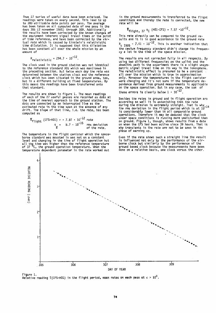
Thus 27 s e r i e s o f u s e f u l da ta have been acheived. The read ings were taken on every second. T h i s l e a d t o up t o 300 u t i l i z a b l e da ta p o i n t s p e r pass. The average has been taken on a l l cumputed da ta o f one pass i n t h e days 306 ( 2 november 1985) th rough 309. A d d i t i o n a l l y t h e r e s u l t s have been c o r r e c t e d by t h e known changes o f t h e equipment i n h e r e n t s i g n a l t r a v e l t imes o r t h e p o i n t o f t ime re fe rence , and have been c o r r e c t e d by t h e v i r - t u a l r a t e which i s caused by E i n s t e i n ' s r e l a t i v i s t i c t ime d i l a t a t i o n . I t i s supposed t h a t t h i s d i l a t a t i o n has been c o n s t a n t a l l over t h e whole m i s s i o n by an amount o f
The c l o c k used i n t h e ground s t a t i o n was n o t i d e n t i c a l t o t h e re fe rence s tandard H01 which was mentioned i n t h e p reced ing s e c t i o n . B u t t w i c e each day t h e r a t e was determined between t h e s t a t i o n c l o c k and t h e r e f e r e n c e c l o c k which has been s i t u a t e d i n t h e ground area, too , b u t i n a d i f f e r e n t b u i l d i n g a t f i x e d temperatures. By t h i s means t h e read ings have been t r a n s f e r r e d o n t o t h a t s tandard.
The r e s u l t s a r e shown i n f i g u r e 1. The mean read ings o f each o f t h e 27 u s e f u l passes a r e recorded as d o t s a t t h e t ime o f neares t approach t o t h e ground s t a t i o n . The d o t s a r e connected by an i n t e r r u p t e d l i n e as t h e es t imated r a t e i n t h e t i m e span a t t h e absence o f any d r i f t . The s lope o f t h a t l i n e , i . e , t h e r a t e , has been computed as
K~~~~~~ (CFS-HOI) = - 7.97 r a t e
s = 8 . 7 . 1 0 - l 5 r m s d e v i a t i o n il o f t h e r a t e .
The temperature i n t h e f l i g h t c a n i s t e r which t h e space- borne s tandard was mounted i n was n o t on a c o n s t a n t l e v e l and changing i n t h e t i m e o f f l i g h t o p e r a t i o n b u t a l l t h g t i m e was h i g h e r t h a n t h e r e f e r e n c e temperature o f 37 C, t h e ground o p e r a t i o n temperature. When t h e temperature dependent parameter i n t h e r a t e worked o u t
i n t h e ground measurements i s t r a n s f e r r e d t o t h e f l i g h t c o n d i t i o n s and thereby t h e r a t e i s c o r r e c t e d , t h e new r a t e w l l l be
T h i s r a t e d i r e c t l y can be compared t o t h e ground r e - s u l t s and i t i s i n good accordance t o t h e ground r a t e
RC Lg85 = 7.41 lo-''. T h i s i s ano ther i n d i c a t i o n t h a t
t h e ceslum f requency s tandard d i d n ' t change i t s f requen- c y a l o t i n t h e t i m e o f t h e space miss ion .
The r e s u l t s a r e n o t c o r r e c t e d f u l l y i n a l l respec ts . By u s i n g two d i f f e r e n t f requenc ies on t h e u p l i n k and t h e downl ink p a t h i n t h e exper iment t h e r e i s a s l i g h t unsym- m e t r i c s i g n a l t r a v e l t ime on i t s way i n t h e ionosphere. The r e l a t i v i s t i c e f f e c t i s presumed t o be a c o n s t a n t a l l over t h e m i s s i o n which i s t r u e i n approx imat ion o n l y . Moreover t h e temperatures i n t h e f l i g h t c a n i s t e r were changin and i t ' s n o t su re i f t h e temperature de- pendence deryved f rom ground measurements i s a p p l i c a b l e on t h e space o p e r a t i o n . B u t i n any case, t h e sum o f
these e r r o r s i s c l e a r l y below 1
Besides t h e r a t e s i n ground and i n f l i g h t o p e r a t i o n a r e accord ing so w e l l i t i s a s t o n i s h i n g t h a t t h e r a t e d u r i n g t h e m i s s i o n i s ex t reme ly s t r a i g h t . That i s why t h e rms d e v i a t i o n i n t h e f l i g h t p e r i o d which i s a t 1 0 - l 4 i s c o n s i d e r a b l y lower than i n a l l comparable ground opera t ions . There fo re i t may be deduced t h a t t h e c l o c k under space c o n d i t i o n s i s r u n n i n g more u n d i s t u r b e d than on ground. F i g u r e 1, though, shows r e s u l t s f rom a da te on when t h e CFS had been a c t i v e s i n c e 39 hours. That i s why t r a n s i e n t s i n t h e r a t e a r e n o t t o be seen i n t h e phase o f warming up.
Even i f t h e r a t e shows such a s t r a i g h t l i n e t h e r e s u l t i s i n f l u e n c e d n o t o n l y by t h e performance o f t h e a i r - borne c l o c k b u t s i m i l a r l y by t h e performance o f t h e ground based c l o c k because t h e measurements have been done on a r e l a t i v e b a s i s , one c l o c k versus t h e o t h e r .
DAY OF YEAR
F i g u r e 1. R e l a t i v e r e a d i n g T(CFS-HO1) i n t h e f l i g h t pe r iod , mean r a t e s on each pass a t E > lo0.
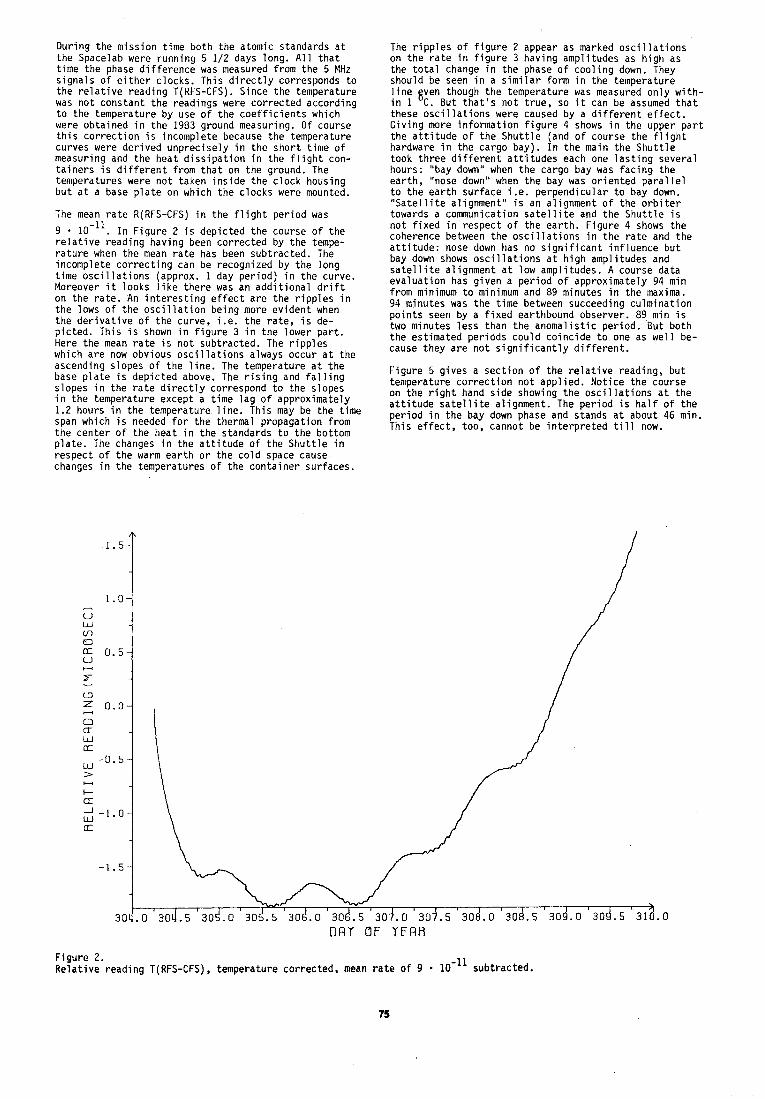
D u r i n g t h e m i s s i o n t ime b o t h t h e atomic standards a t t h e Spacelab were runn ing 5 1/2 days long. A1 1 t h a t t ime t h e phase d i f f e r e n c e was measured f rom t h e 5 MHz s i g n a l s o f e i t h e r c locks . Th is d i r e c t l y corresponds t o t h e r e l a t i v e r e a d i n g T(RFS-CFS) . Since t h e temperature was n o t c o n s t a n t t h e read ings were c o r r e c t e d accord ing t o the temperature b y use o f t h e c o e f f i c i e n t s which were ob ta ined i n t h e 1983 ground measuring. Of course t h i s c o r r e c t i o n i s incomple te because t h e temperature curves were d e r i v e d u n p r e c i s e l y i n t h e s h o r t t i m e o f measur ing and t h e h e a t d i s s i p a t i o n i n t h e f l i g h t con- t a i n e r s i s d i f f e r e n t f rom t h a t on t h e ground. The temperatures were n o t taken i n s i d e t h e c l o c k housing b u t a t a base p l a t e on which t h e c l o c k s were mounted.
The mean r a t e R(RFS-CFS) i n t h e f l i g h t p e r i o d was
9 . 10-ll. I n F i g u r e 2 i s d e p i c t e d t h e course o f t h e r e l a t i v e read ing hav ing been c o r r e c t e d by t h e tempe- r a t u r e when t h e mean r a t e has been sub t rac ted . The incomple te c o r r e c t i n g can be recognized by t h e l o n g t ime o s c i l l a t i o n s (approx. 1 day p e r i o d ) i n t h e curve. Moreover i t l o o k s l i k e t h e r e was an a d d i t i o n a l d r i f t on t h e r a t e . An i n t e r e s t i n g e f f e c t a r e t h e r i p p l e s i n t h e lows o f t h e o s c i l l a t i o n b e i n g more e v i d e n t when t h e d e r i v a t i v e o f t h e curve, i .e . t h e r a t e , i s de- p i c t e d . T h i s i s shown i n f i g u r e 3 i n t h e l o w e r p a r t . Here t h e mean r a t e i s n o t sub t rac ted . The r i p p l e s which a r e now obvious o s c i l l a t i o n s alwavs occur a t t h e
The r i p p l e s of f i g u r e 2 appear as marked o s c i l l a t i o n s on t h e r a t e i n f i g u r e 3 hav ing ampl i tudes as h i g h as t h e t o t a l change i n t h e phase o f c o o l i n g down. They should be seen i n a s i m i l a r fo rm i n t h e temperature l i n e gven though t h e temperature was measured o n l y w i t h - i n 1 C. Bu t t h a t ' s n o t t r u e , so i t can be assumed t h a t these o s c i l l a t i o n s were caused by a d i f f e r e n t e f f e c t . G i v i n g more i n f o r m a t i o n f i g u r e 4 shows i n t h e upper p a r t t h e a t t i t u d e o f t h e S h u t t l e (and o f course t h e f l i g h t hardware i n t h e cargo bay) . I n t h e main t h e S h u t t l e took t h r e e d i f f e r e n t a t t i t u d e s each one l a s t i n g severa l hours: "bay down" when t h e cargo bay was f a c i n g t h e e a r t h , 'nose down" when t h e bay was o r i e n t e d p a r a l l e l t o t h e e a r t h s u r f a c e i . e . p e r p e n d i c u l a r t o bay down. " S a t e l l i t e a l ignment " i s an a l ignment o f t h e o r b i t e r towards a comnunicat ion s a t e l l i t e and t h e S h u t t l e i s n o t f i x e d i n r e s p e c t o f t h e e a r t h . F i g u r e 4 shows t h e coherence between t h e o s c i l l a t i o n s i n t h e r a t e and t h e a t t i t u d e : nose down has no s i g n i f i c a n t i n f l u e n c e b u t bay down shows o s c i l l a t i o n s a t h i g h amp l i tudes and s a t e l l i t e a l ignment a t l ow amp l i tudes . A course da ta e v a l u a t i o n has g i v e n a p e r i o d o f approx imate ly 94 min f rom minimum t o minimum and 89 minutes i n t h e maxima. 94 minu tes was t h e t i m e between succeeding c u l m i n a t i o n p o i n t s seen by a f i x e d ear thbound observer . 89 m in i s two minu tes l e s s t h a n t h e a n o m a l i s t i c p e r i o d . B u t b o t h t h e es t imated p e r i o d s c o u l d c o i n c i d e t o one as w e l l be- cause t h e y a r e n o t s i g n i f i c a n t l y d i f f e r e n t .
ascending s lopes o f t h e l i n e . The temperature a t t h e base p l a t e i s d e p i c t e d above. The r i s i n g and f a l l i n g F i g u r e 5 g i v e s a s e c t i o n o f t h e r e l a t i v e reading, b u t
s lopes i n t h e r a t e d i r e c t l y correspond t o t h e s lopes temperature c o r r e c t i o n n o t a p p l i e d . N o t i c e t h e course
i n t h e temperature except a t i m e l a g o f approx imate ly on t h e r i g h t hand s i d e showing t h e o s c i l l a t i o n s a t t h e a t t i t u d e s a t e l l i t e a l ignment . The p e r i o d i s h a l f o f t h e 1.2 hours i n t h e temperature l i n e . T h i s may be t h e t i m e period in the bay down phase and stands at about 46 min.
span which i s needed f o r t h e thermal p ropaga t ion f rom t h e c e n t e r o f t h e h e a t i n t h e standards t o t h e bo t tom
T h i s e f f e c t , too , cannot be i n t e r p r e t e d t i l l now.
p l a t e . The changes i n t h e a t t i t u d e o f t h e S h u t t l e i n r e s p e c t o f t h e warm e a r t h o r t h e c o l d space cause changes i n t h e temperatures o f t h e c o n t a i n e r su r faces .
D R Y OF Y E A R
F i g u r e 2. R e l a t i v e r e a d i n g T(RFS-CFS) , temperature co r rec ted , mean r a t e o f 9 lo-'' sub t rac ted .
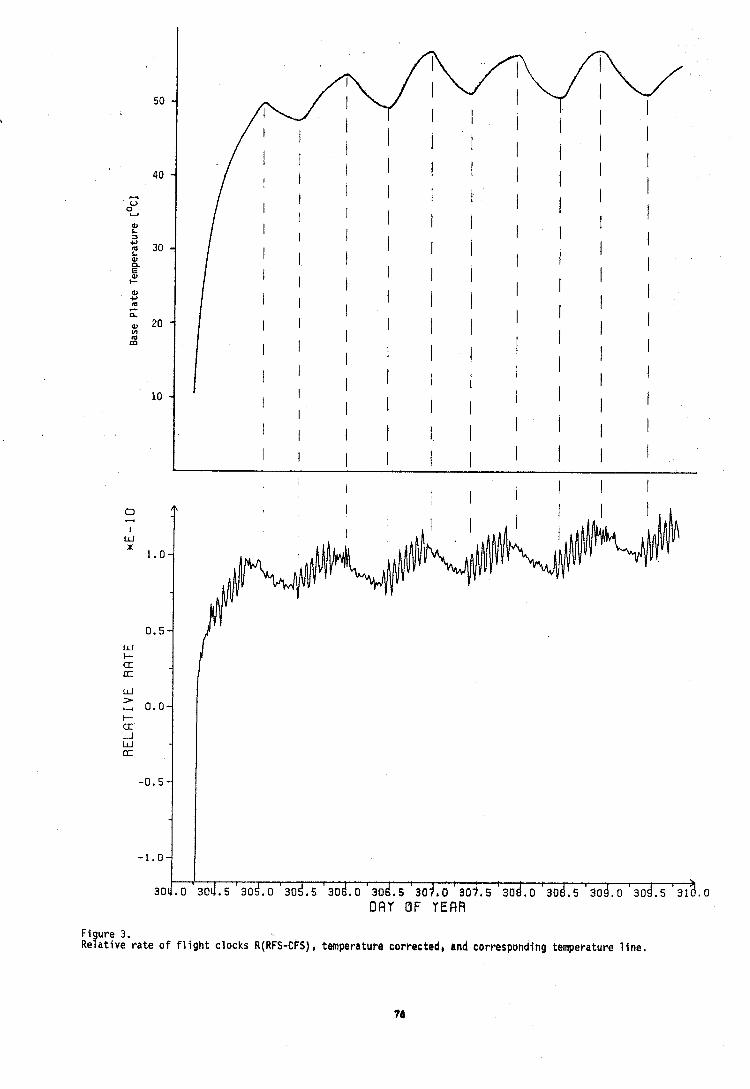
0 w
I W X
1.0
0.5 W C- u Ot
W > M 0.0 k u -1 W ir
-0.5
-1.0
30 .O D A Y OF YERR
Figure 3 . R e l a t i v e r a t e of f l i g h t clocks R(RFS-CFS), temperatube corrected, and corresponding temperature l i n e .
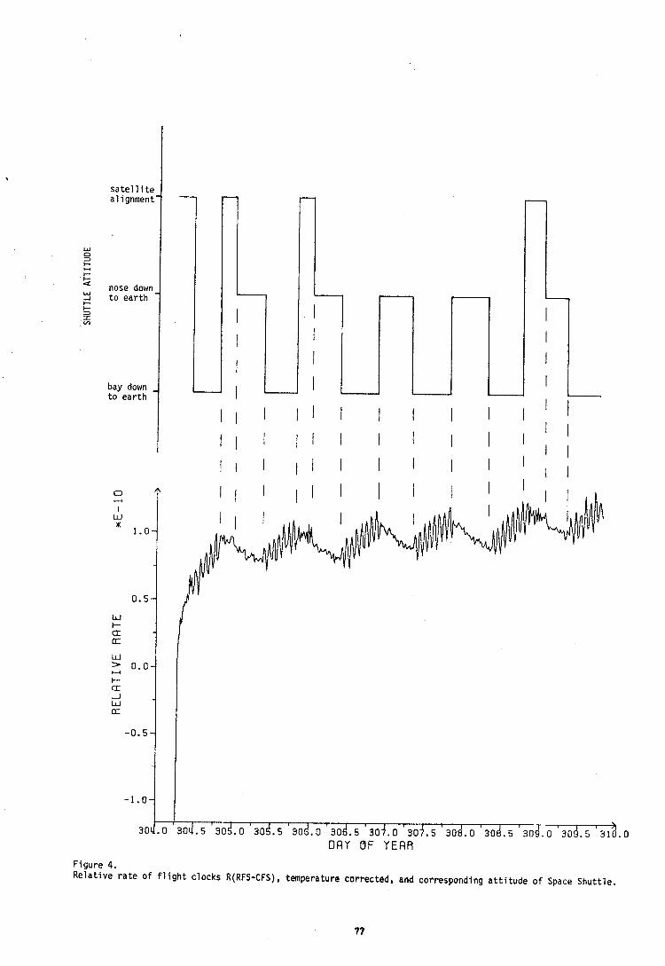
sate1 1 i t e alignment'
nose down t o e a r t h -
bay down - t o ear th
0 - I
W x
1.0-
0.5-
W I- a LT
W =. 0.0- u l- a -I W [r
-0.5-
-1.0-
30c.o
A
30J.5 30i.o 306.5 3od.o 3od.5 3oj.o 30j.5 30d.o 304.5 304. o 30d.5 31 .o
D A Y I1F Y E A R
Figure 4. R e l a t i v e r a t e of f 1 i g h t clocks R(RFS-CFS), temperature corrected, and corresponding a t t i t u d e o f Space Shut t le .
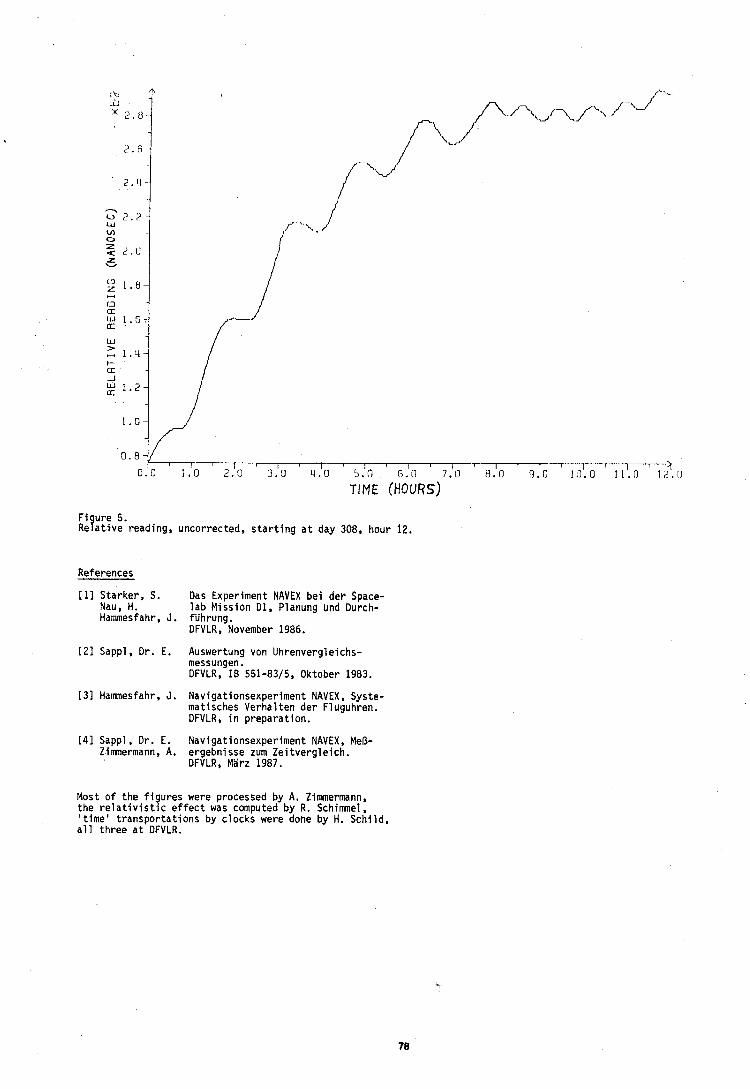
F i ure 5. ~ e ? a t i v e reading, uncorrected, s t a r t i n g a t day 308, hour 12.
cu LIL ;K 2.8..
2 . 6 - 4
2 . 4 - - u ? . % - !-u
References
I"
f i f ~ - v " - J - J' L,' /'
f -"\,"
[ll Starker, S. Das Experiment NAVEX be i der Space- Nau, H. l a b Mission Dl, Planung und Durch- Hanunesfahr, J. fiihrung.
DFVLR, November 1986,
5 z . u
U.J 1 . 6 - e
> 1.11-
I ' 0 . 0 1 .0 2.'11 3.'0 u - ' - ' - T ~ - ~ ~ ? . 5 . 0 0
TIME (HOURS)
[21 Sappl , Dr. E. Auswertung von Uhrenvergleichs- messungen. DFVLR, I B 551-83/5, Oktober 1983.
131 Hanunesfahr, J. Navigationsexperiment NAVEX, Syste- matisches Verhal t en der F l uguhren. DFVLR, i n preparat ion.
[41 Sappl, Dr. E. Navigationsexperiment NAVEX, MeO- Zimnermann, A. ergebnisse zum Ze i tverg le ich .
DFVLR, MIrz 1987.
Most o f the f i gu res were processed by A. fimmermann, The r e l a t i v i s t i c e f f e c t was computed by R. Schimnel,
t ime' t ranspor ta t ions by c locks were done by H. Schi ld, a l l th ree a t DFVLR.
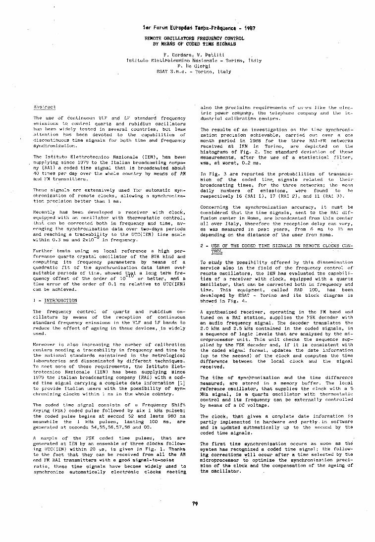
l e r Portia kuraplari Ternbh-Pr6qbencr - i9L7
BEMOTE OSCILLATORS FREQUENCY CONTROL BY MEAk8 bP CdbEb TIME BIG~AL!~
P a Cordara, V , Pettiti T~t.ituto K ~ C ~ ~ F O ~ ~ ? C H ~ C O hdziflhe~t? - l'orihal tt.:tly
P . be C;iut-gi 1;SAT s.n.c. - 'l'orinn, Italy
'Ih? use of continuous V1.F and I.[' standard frequency erlllsslorls to control quartz and rubidium oscil laLorb hds been widely tested in several countries, but Less dttentlon has been devoted to the capabilities of tl~scontinuous time signals for both time and frequency synchronization.
The Istituto Elettrotecnico Nazionale (IEN) , has been supplying since 1979 to the Italian broadcasting compa- ny (RAT) a coded time signal that is broadcastbd about 40 times per day over the whole country by means af AM and F'M transmitters.
'l'hese signals are extensively Used for automatic sy11- ctironization of remote clocks, allowing a synchroniza- tion precision better than 1 ms.
Recently has been developed a receiver with clock, equipped with an oscillator with thermostatic cohtrol, that can be corrected both in frequency and time, av- eraging the synchronization data over two-days periods and reaching a traceabi ity to the UTC(1EN) time scale within 0.3 n u and 2x10-"in frequency.
Further tests using as local reference a high per- formance quartz crystal oscillator of the BVA kind and computing its frequency parameters by means of a quadratic fit of the synchronization data taken oVek suitable periods of time, showed LQ8t a long term fre- quency offset of the order of 10 or better, and a time error of the order of 0.1 ms relative to UTC(1EN) can be achieved.
1 - INTRODUCTION The frequency control of quartz and rubidium os- cillators by means of the reception of continuous standard frequency emissions in the VLF and LF bands to reduce the effect of ageing in these devices, is widely used.
Moreover is also increasing the number of calibration centers needing a traceability in frequency and time to the national standards maintained In the metrological laboratories and disseminated by different techniques, To meet some of these requirements, the Istituto Elet- trotecnico Nazlonale (IEN) has been supplying slnce 1979 the Italian broadcasting company (RAI) with a cod- ed time signal carrying a complete date information [l] to provide Italian users with the possibility of syn- chronizing clocks withln 1 ms in the whole ~~Lintry,
'I'he coded time signal consists of a Frequency Shift Keying (F'SK) coded pulse followed by six 1 kllz pulses; the coded pulse begins at second 52 and lasts 960 ms meanwhile the 1 kHz pulses, lasting 100 me, are generated at seconds 54,55,56,57,58 and 00,
A sample of the FSK coded time pulses, that are generated at IEN by an ensemble of three clocks follow- ing UTC(1EN) within 20 ps, is given in Fig. 1, Thanks to the fact that they can be received from all the AM and FM RAI transmitters with a good signal-to-noise ratio, these time signals have become widely used to synchronize automatically electronic clocks meeting
also the precision requirer~icnts of u:: 'rs like the clec- Lric powur coniprrny L he t,clt?lJtl<ltlc ~ ~ I I I I J J ~ I ~ uno Lt~e in- dustrial calibration centers.
?'he results of an investigation on the tirne synchroni- zation precision achievable, carried out over a one month period in i 9 ~ 6 for the three HAT-ti'M networks received at IEN in Torino, are depicted on the histograms of Fig. 2. The standard deviation of these measurements, after the use of a statistical filter, was, at worst, 0.2 ms.
In Fig. 3 are reported the probabilities of transmis- sion of the coded time. signals related to their broadcasting times, for the three networks; the mean daily humbers of emissions, were found to he respectively 16 (HA1 I ) , 17 (RAI 21, and 11 (IiAI 7 ) .
Concerning the synchronization accuracy, it must be considered that the time signals, sent to the RAI dlf- fusion center in Homa, are broadcasted from this center all ovet- Italy, therefore the reception delay can vary, as was measured in past years, from 6 ms to 15 nls depending on the distance of the user from Homa.
2 - USE OF THC CODED TIME SIGNALS IN REMOTE CLOCKS CON- TROt -
To study the possibility offered by this dissemination eervice also in the field of the frequency control of i-emote oscillators, the fEN has evaluated the capabili- ties of a receiver with clock, equipped with a quartz oscillator, that can be corrected both in frequency and time, This equipment, called HAD 100, has been developed by ESAT - Torino and its block diagram is showed in Fig, 4.
A synthesized receiver, operating in the FM band and tuned on a RAT station, supplies the FSK decoder with an audio frequency signal. The decoder translates the 2.0 kHz and 2.5 kHz contained in the coded signals, in a sequence of logic levels that are analyzed by the mi- croprocessor unit. This unit checks the sequence sup- plied by the FSK decoder and, if it is consistent with the coded signal format, updates the date information (up to the second) of the clock and computes the time difference between the local clock and the signal received,
The time of synchronization and the time difference measured, are stored in a memory buffer. The local Peference oscillator, that supplies the clock with a 5 MHz signal, is a quartz oscillator with thermostatic conti-01 and its frequency can be externally controlled by means of a DC voltage.
The clock, that gives a complete date information is partly implemented in hardware and partly in software and is updated aUtbmatically up to the second by the coded time signals.
The first time synchronization occurs as soon as the system has recognized a coded time signal; the follow- ing corrections will occur after a time selected by the microprocessor to optimize the synchronization preci- sion of the clock and the compensation of the ageing of the ~aciliator~
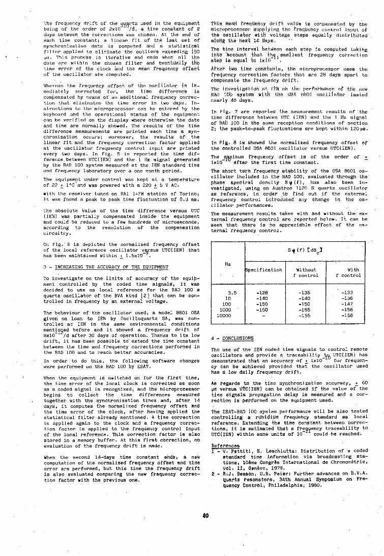
The frequency drift of the qyartz used in the equipheht being of the order of 2x10 /d, a time constant of 2 days between the corrections was chosen. At the end of each bime constant, a linear fit of the last set of synchronization data is computed and a statistical filter applied to eliminate the outliers exceeding 150
1 . ~ s . This II~OCOCIR in iterative i~nd ends when n l i Lllo daLa ure within the chosen filter and cvenhlaiiy tho time errwr of the clock bnd tho mean frequency offset of the oscillator ai-e computed.
Whereas l.he frequency offset of the osciliet,or iS iln- rnatlrately corrt!cLed tor, the time diffcretice is comt~ensated by means of an additional frequency tori-ec- tion that elis~inates the time error in two days. In- st.ructions to the niicroprocessor can be entered by the keyboard and the operdtioncrl status of the equipment can be verified on the display where otherwise the date and time are norn~ally showed. The reslllts of the time difference measurements are printed each time a syn- chronization occurs; moreover, the results of' the linear fit and the frequency correction factor applied at the oscillator frequency control input are printed every two days. In Fig. 5 is reported the time dif- ference between UTC(1EN) and the 1 Hz signal generated by the RAD 100 system measured at the IEN standard time and frequency laboratory over a one month period.
The equipment under control was kept at a temperature of 22 + l0C and was powered with a 220 + 5 V AC. With the receiver tuned on RAI 1-FM station of Torinoi it was found a peak to peak time fluctuatioh of 0.3 ms,
The absolute value of the time difference versus UTC (IEN) was partially compensated inside the equipment and could be reduced to a few hundreds of microseconds, according to the resolution of the compensation circuitry.
On Fig. 6 is depicted the normalized frequency offset of the local reference oscillator v sus UTC(1EN) that -3' has been maintained within + 1.5~10 . 3 - INCREASING THE ACCURACY OF THE EQlJIPMENT
To investigate on the limits of accuracy of the equip- ment controlled by the coded time signals, it Was decided to use as local reference for the RAD 100 a quartz oscillator of the BVA kind [2] that can be con- trolled in frequency by an external voltage,
The behaviour of the oscillator used, a model 6601 OSA given on loan to IEN by Oscilloquartz SA, was con- trolled at IEN in the same environmental conditions mentipged before and it showed a frequency drift of 8x10- /d after 30 days of operation. Thanks to its low drift, it has been possible to extend the time constant between the time and frequency corrections performed in the RAD 100 and to reach better accuracies.
In order to do this, the following software changes were performed oh the RAD 100 by ESAT.
I When the equipment is switched on for the first time, the tlme error of the local clock is correctbd as sooh as a coded signal is recognized, and the microprocessor begins to collect the time differences measbred together with the synchronization times and, after 14 days, it computes the hormalized frequency offset end the time error of the clock, after having applied the statistical filter already mentioned. A time correction is applied again to the clock and a frequency correc- tion factor is applied to the frequency control input of the local reference. This correction factor is also stored in a memory buffer. At this first correction, no evaluation of the frequency drift is made,
When the second 14-days time constant ends, 8 new computation of the normalized frequency offset and time error are performed, but this time the frequency drift is also evaluated comparing the new frequency correc- tion factor with the previous one.
'I'llik! bead frequency drift value is con~pensated by the mici-oprocesnot &L~[)plying tho frecjuchcy control it~;)ui of the oscillator dith voltage steps equally distributed aiodg the kext 14 tiays.
The tlh~e intervdl between each step is computed takihg inta 'hccaunt that t h g , smallest frequency correctiorl step is equei to lxio- Af'tkr MU t ime cbhiltants , tilo lhicropPocessor uses thb fyerjuency cori-ection factoh that are 28 days apart to cumpunsake the kbequeticy drift.
'I'trl! investigatioh at tirN oh Lhe prrioPlndnce oh the rier 1tAll iritl byskein w i t h the USA rlBO1 oscillator iastod nearly 40 days.
In Pig. 7 are reported the measurement result's of the time difference between UTC (IEN) and the 1 Hz signal of R A ~ 100 In the same reception conditions of section 2; the peak-to-peak fluctuations are kept within 120~s.
In Fig' 8 is showed the normalized frequency offset of the controiled OSA 8801 oscillator versus UTC(1EN).
The lvihum frequency offset is of the order of 2 1x10- after tHe first time constant.
The short term Prequerlcy stability of the OSA 8601 os- tillakur included in the RAD 100, evaluated through the phase spectra1 density S (f), has also been in- veetigated, using an Austron 1120 S quartz oscillator as reference, in order to find out if the external frequency control introduced any Change in the os- tillator performances.
The measurement resuits taken with and without the ex- ternal frequency control ai-e reported below. It can be seen that there is no appreciable effect of the ex- ternal freauency control *
4 - CONCLUSIONS
Hz
3.5 10 100 1000 10000
The use of the IEN coded time signals to control remote oscillators and provide a traceability-\$ UTC(1EN) has demonstrated that an accuracy of 2 1x10 for frequen- cy can be achieved provided that the oscillator used has a low daily frequency drift.
Aa regards to the time Synchronization accuracy, 2 60 V B VeFSUS UTc(fEN1 can be obtained if the value of the time sikhals brogagation delay is measured and a cor- kection is performed on the equipment used.
S q (f) t d ~ ~ l
The BSAT-HAD 100 system performance will be also tested controlling a rubidium frequency standard as local reference. Extending the time constant between correc- tions, it is estimated that a frepyency traceability to UTC(1EN) within some units of 10- could be reached.
Specification
-128 -140 -150 -150 -
peferences 1 - V , Pettiti. S, teschiutta: Distribution of a coded
standard time information via broadcasting sta- tians, lOBme Congr&s international de Chronombtrie, Val' ILi den&ve, 1979.
2 - R,J, Besson, U 6 R d Peierr Further advances on b.V.A. 4uartz hesonators, 34th Annual Symposi urn on Fre- QUenCy Control, Philadelphia, 1980.
Without f control
-135 -140 -150 -155 -155
With f control
-133 -136 -147 -156 -156
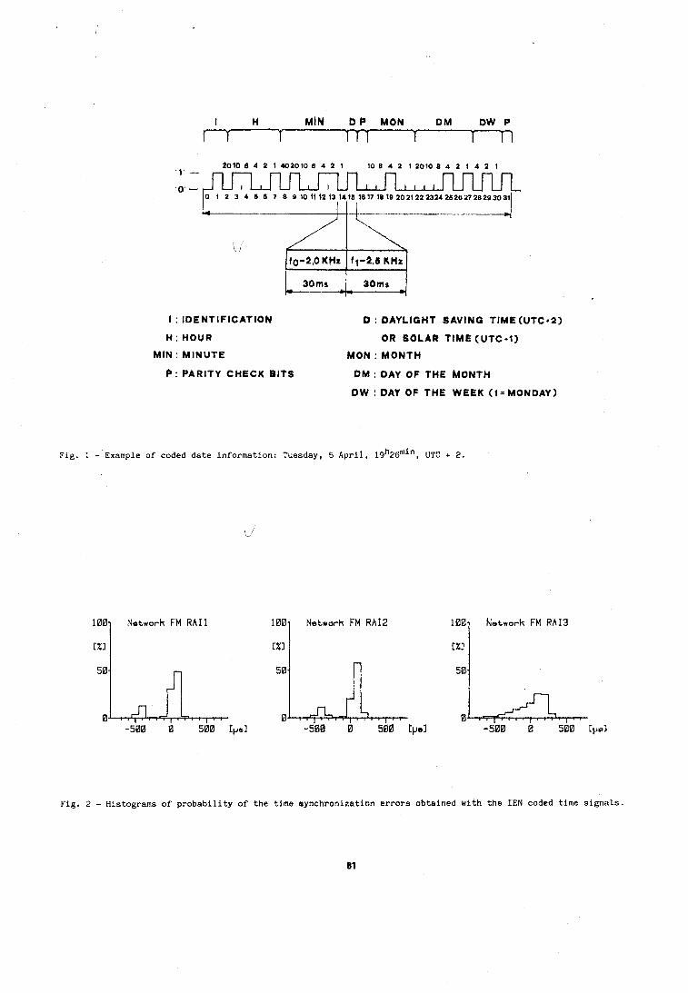
I H MI# b C MON DM OW P
I--
I : IDENTIFICATION D : DAYLIQHT 8AVINQ TIME(UTC*2)
H : HOUR OR SOLAR TIME (UTC+l )
MIN: MINUTE MON : MONTH
P : PARITY CHECK BITS DM : DAY OF THE MONTH
Fig. 1 - Example of coded date information: Tuesday, 5 April, 1 9 ~ 2 6 ~ ~ " , UIC + 2.
Fig. 2 - Histograms of probability of the time synchronization errors obtained with the IEN coded time signals.
81
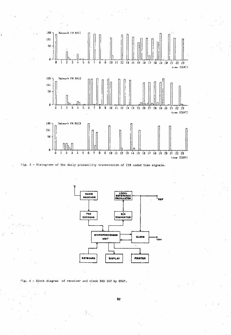
Limo LCtMll
100 7 Network FM RAIB n w
time ICEMTI
Fig. 3 - Histograms of the daily probability transmission of IEN coded time signals.
Fig. 4 - Block diagram of receiver and clock RAD 100 by ESAT,
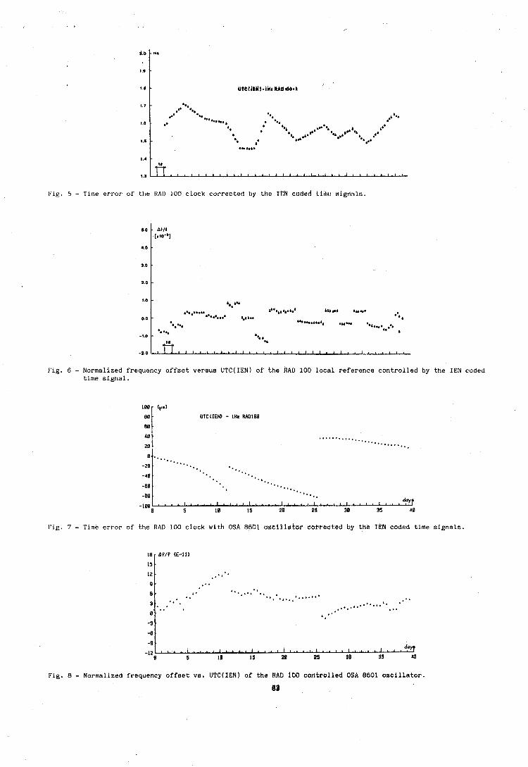
pig. 5 - Time error of the HAI) 100 clock corrected by the Iffk coded time eigrrnlo,
Fig. 6 - Normalized frequency offset versus UTC(fEN) of the RAD 100 local reference controlled by the IEN coded time signal.
Fig. 7 - Time error of the RAD 100 clock with OSA 8601 oseillatbr corrected by the IGN coded time signals.
Fig. 8 - Normalized frequency offset vs, UTC(1EN) of the RAD 100 cantrolled 06A 8601 oscillator.
83
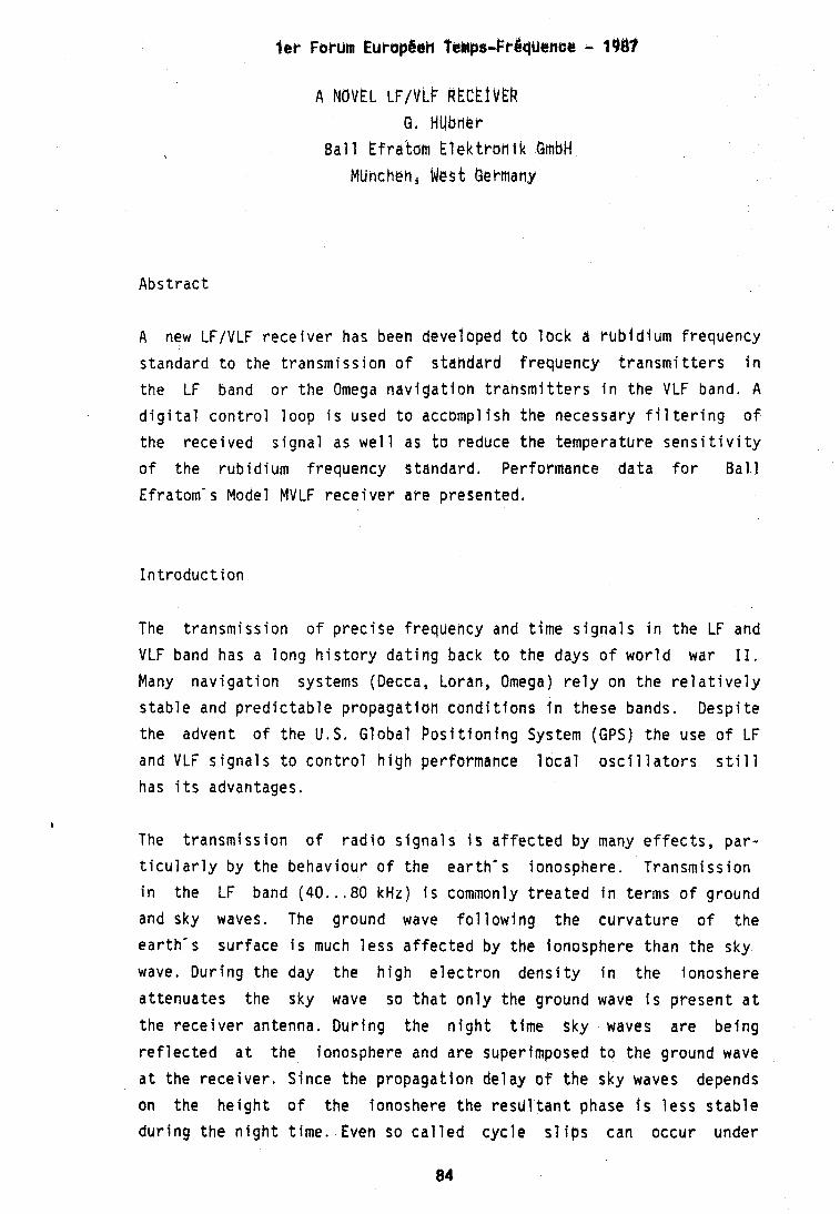
A h0VEL LF/VLF R k C E I V E R a, HUbner
B a l l Efrakam E l e k t r b h i k GmbH MUncheh, Mes t Uermany
Abs t rac t
A new LFIVLF r e c e i v e r has been developed t o l b c k a r h b i d i u m f requency
s tandard t o t he t ransmiss i o n o f s tahdard f requency t r a n s m i t t e r s i n
the LF band o r t h e Omega n a v i g a t i o n t rahsmi t t e r s i n t h e VLF band, A
d i g i t a l c o n t r o l l oop i s used t o accompl ish t he necessary f i l t e r i n g o f
t he r ece i ved s i g n a l as w e l l as t o reduce t h e temperature s e n s i t i v i t y
o f t he r ub id i um f requency s tandard. Performance da ta f o r B a l l
Efratom' s Model MVLF r e c e i v e r a re presented,
I n t r o d u c t i o n
The t ransmiss ion o f p r e c i s e f requency and t ime s i g n a l s i n t h e LF and
VLF band has a l o n g h i s t o r y d a t i n g back t o t h e days o f w o r l d war 11. Many n a v i g a t i o n systems (Decca, Loran, Omega) r e l y on t h e r e l a t i v e l y
s t a b l e and p r e d i c t a b l e p ropaga t ion conditions i n these bands. Desp i t e
t he advent of t h e U,S. Global Posi t f o n l n g System (GPS) t he use o f LF
and VLF s i g n a l s t o c o n t r o l h i g h performance l o c a l o s c i l l a t o r s s t i l l
has i t s advantages.
The t ransmiss ion o f r a d i o s i g n a l s i s a f f e c t e d by many e f f e c t s , p a r -
t i c u l a r l y by the behav iour o f t he e a r t h ' s ionosphere. Transmiss ion
i n the LF band (40 . . . 80 kHz) i s commonly t r e a t e d i n terms o f ground
and sky waves, The ground wave f o l l o w i n g t h e c u r v a t u r e o f t h e
ea r t h ' s su r face i s much l e s s a f f e c t e d by t h e ionosphere than t h e sky
wave. Dur ing the day t he h i g h e l e c t r o n d e n s i t y i n t h e ionoshere
a t tenua tes the sky wave so t h a t o n l y the ground wave i s p resen t a t
the r e c e i v e r antenna, Dur ing t he n i g h t t ime sky waves a re be ing
r e f l e c t e d a t t he Ionosphere and a re superimposed t o t h e ground wave
a t the r e c e i v e r , S lnce t he propagation de lay o f t h e sky waves depends
on t he h e l g h t o f t he ionoshere t h e r e s d l t a n t phase f s l e s s s t a b l e
d u r i n g t h e n i g h t t ime . Even so c a l l e d c y c l e s l i p s can occur under
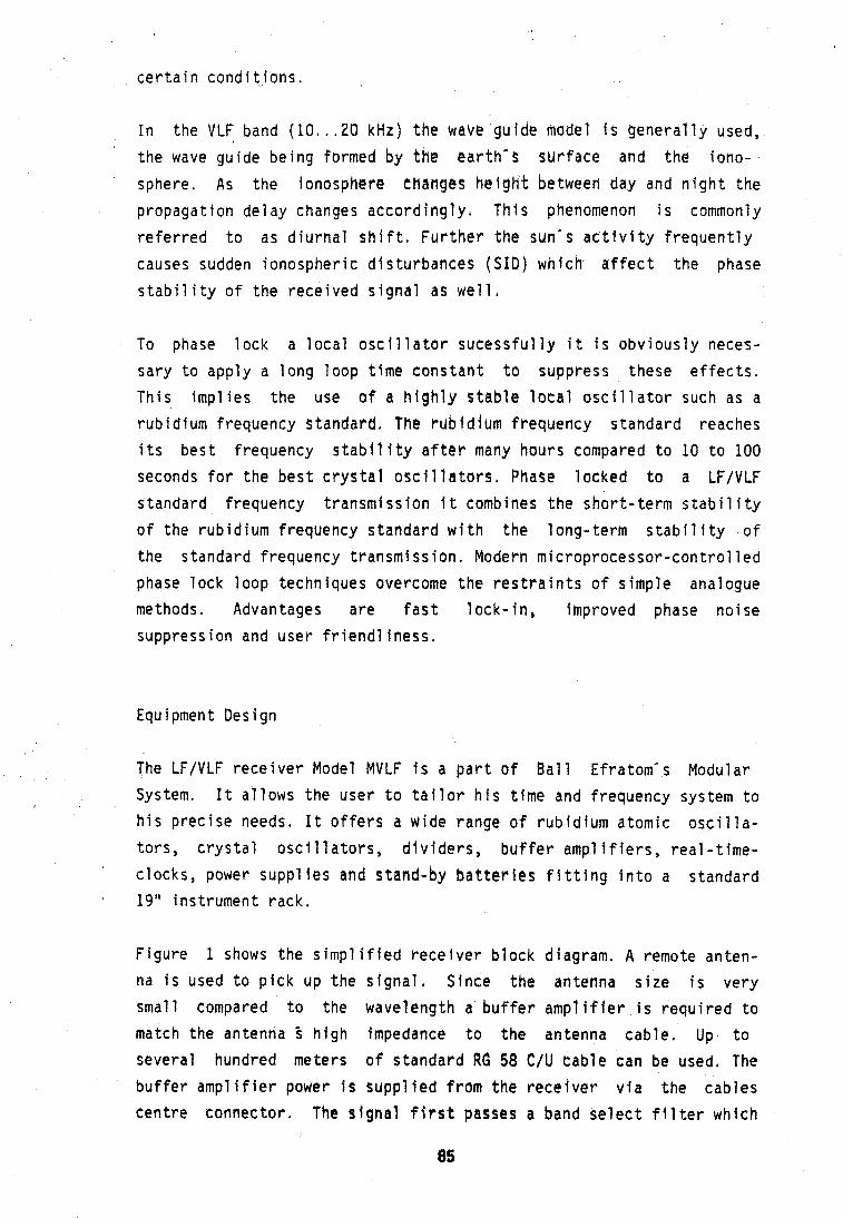
c e r t a i r l c o n d i t i o n s .
I n the VLF band ( 1 0 , . .20 kHz) t h e Nave gu ide model i s g e n e r a l l y used,
t he wave gu ide be ing formed b y the e a r t h ' s sur face and t h e iono-
sphere. As t h e ionosphere changes h e i g h t between day and n i g h t t he
propagat i o n de l ay changes a c c o r d i n g l y , Thf s phenomenon i s commonly
r e f e r r e d t o as d i u r n a l s h i f t , F u r t h e r t he sun's a c t i v i t y f r e q u e n t l y
causes sudden ionospher i c d i s t u rbances (SID) which a f f e c t the phase
s t a b i l i t y o f t he r ece i ved s i g n a l as w e l l .
To phase l o c k a l o c a l o s c i l l a t o r sucessfu l l y i t i s o b v i o u s l y neces-
sary t o app ly a l ong l oop t ime cons tan t t o suppress these e f f e c t s .
Th i s i m p l i e s t he use o f a h i g h l y s t a b l e l o c a l o s c i l l a t o r such as a
rub id ium f requency s tandard, The r u b f d f urn f requency s tandard reaches
i t s b e s t f requency stab11 i t y a f t e r many hours compared t o 10 t o 100
seconds f o r t he b e s t c r y s t a l o s c i l l a t o r s , Phase l ocked t o a LFIVLF
s tandard f requency t r ansm iss i on I t combines t h e s h o r t - t e r m s t a b i l i t y
o f the r ub id i um f requency s tandard w i t h t he l ong - t e rm s t a b i l i t y o f
t he s tandard f requency t r ansm iss i on . Modern m i c r o p r o c e s s o r - c o n t r o l l e d
phase l o c k l o o p techniques overcome t h e r e s t r a i n t s o f s imp le analogue
methods. Advantages a re f a s t l o c k - i n , improved phase no i se
suppress i o n and user f r i e n d 1 iness .
Equ i pmen t Design
The LFIVLF r e c e i v e r Model MVLF i s a p a r t o f B a l l Efratom's Modular
System. I t a l l ows t he user t o t a i l o r h i s t ime and f requency system t o
h i s p r e c i s e needs. I t o f f e r s a wide range o f r ub id i um atomic o s c i l l a -
t o r s , c r y s t a l o s c i 1 l a t o r s , d i v i d e r s , b u f f e r ampl i f i e r s , r e a l - t ime - '
c locks , power suppl f e s and stand-by batteries f l t t i n g i n t o a s tandard 19" ins t rument rack ,
F i gu re 1 shows t h e simp1 i f i e d r e c e i v e r b l ock diagram, A remote anten- na i s used t o p i c k up t h e s i g n a l , S ince t h e antenna s i z e i s ve r y
smal l compared t o the wavelength a b u f f e r ampl i f i e r i s r e q u i r e d t o
match the antenna f h j g h Impedance t o t he antenna cab le . Up t o
severa l hundred meters o f s tandard RG 58 C/U cab le can be used, The
b u f f e r ampl i f i e r power i s suppl f e d f rom the r e c e i v e r v i a t he cab les
cen t re connec to r , The s i g n a l f f ~ s t passe3 a band s e l e c t f i l t e r which
85
i s swi tched t o e i t h e r the LF a r VLF band, A f t e r s b f f i c i e h t amp1 ifi-
c a t i o n the s i gna l i s f e d t o a quadrature phase d e t e c t o r , Reference
s i g n a l s o f t he des i r ed frequency a re gederated by a syn thes i ze r f rom
the e x t e r n a l rub id ium frequency s tandard, The syn thes i ze r a1 so gener-
a tes a 1 pps which can be synchronized by an ~ x t @ P n a l s i g n a l . A phase
s h i f t e r a l l ows the 1 pps t o be s h i f t e d i n iOOns s teps over a range o f
10 seconds.
The phase d e t e c t o r analogue o u t p u t i s low pass f 11 t e r e d and f e d t o an
a n a l o g u e - t o - d i g i t a l - c o n v e r t e r . The measurement r e s u l t s f rom b o t h the
d i r e c t and t he quadrature s i gna l enable t he microprocessor t o ca l cu -
l a t e bo th f i e l d s t r e n g t h and phase ( r e l a t i v e t o t he e x t e r n a l r e f e r -
ence) o f t he rece i ved s i g n a l , Three d i g i t a l - to-analogue conve r te r s
p rov ide reco rde r ou tpu t s f o r bo th f i e l d s t r e n g t h and phase as w e l l as
the c o n t r o l vo l t age t o the rub id i um frequency s tahdard. A 40-charac-
t e r vacuum f l u o r e s c e n t d i s p l a y and a smal l keyboard i n t e r f a c e s t o the
user . The d i s p l a y p rov ides f u l l i n f o r m a t i o n about t he r e c e i v e r and
t he c o n t r o l 1 oop performance such as frequency, f i e l d s t r eng th ,
phase, c o n t r o l vo l tage , t ime and s i z e o f t he l a s t f requency c o r r e c -
t i o n a p p l i e d t o t he e x t e r n a l r ub id i um f requency s tandard.
A re fe rence s i g n a l de r i ved f rom the syn thes i ze r can be i n j e c t e d a t
the antenna i n p u t . Th i s enables t o a u t o m a t i c a l l y compensate f o r any
phase changes o c c u r r i n g i n the f i l t e r s and amp1 i f i e r s under so f tware
c o n t r o l .
W i t h i n a E f ra tom Modular System one o r e more power supp ly modules
de l i v e r DC power t o a l l the assoc ia ted modQles. A DC/DC conve r te r
prov ides a l l t h e necessary vo l t ages f o r t h e r e c e i v e r c i r c u i t r y .
Software Design
The general des ign goal was t o min imize t he r e c e i v e r hardware and t o
have t he microprocessor do ing as much s i g n a l p rocess ing as poss ib l e .
P a r t i c u l a r l y t he VLF band i s cha rac te r i zed by ex t reme ly h i g h no i se
l e v e l s , The wanted s i g n a l i s g e n e r a l l y b u r i e d i n n o i s e and a SNR o f
-20dB i s cons idered acceptable. Averaging and c r o s s - c o r r e l a t i o n tech-
niques a r e consequent ly necessary t o r ecove r the s i g n a l . I n c o n t r a s t
t o a n a v i g a t i o n r e c e i v e r , which must p r e d i c t t he amount o f t he d i u r -
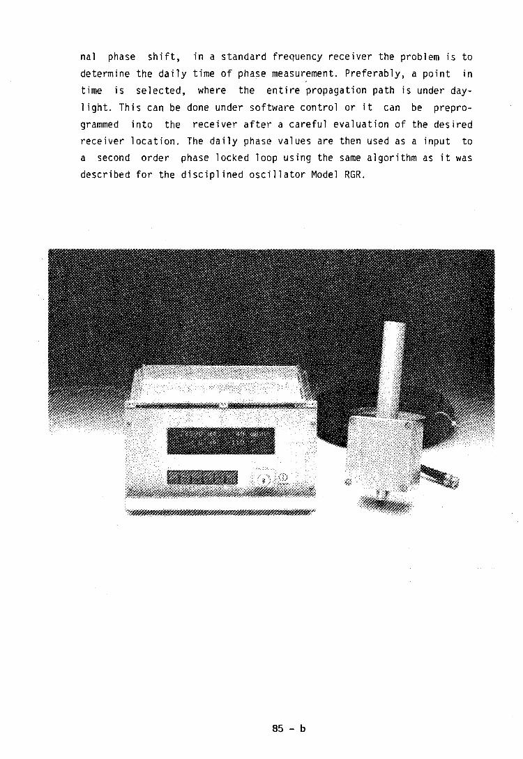
nal phase shift, in a standard frequency receiver the problem is to
determine the daily time of phase measurement. Preferably, a point in
time is selected, where the entire propagation path is under day-
light. This can be done under software control or it can be prepro-
grammed into the receiver after a careful evaluation of the desired
receiver location. The daily phase values are then used as a input to
a second order phase locked loop using the same algorithm as it was
described for the disciplined oscillator Model RGR.
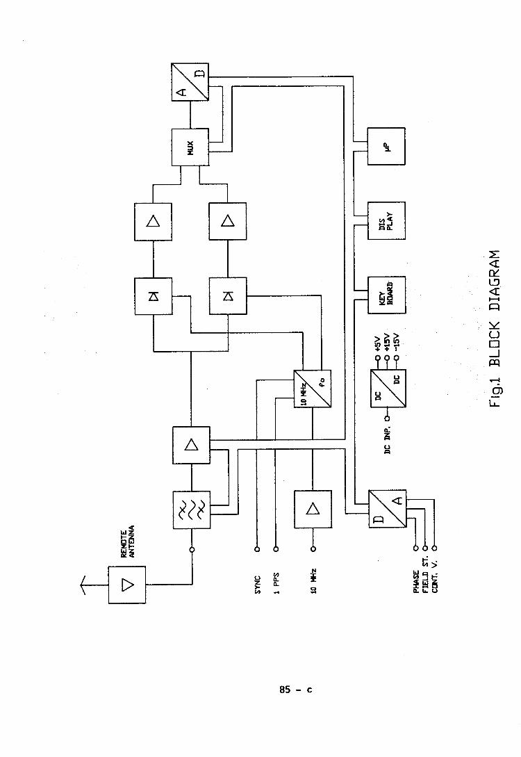
QUARTZ OSCILLATORS, CHARACTERISTICS AND EVOLUTION
E, GRAF
OSA OSCILLOQUARTZ SA - NEUCHATEL
Les spdc i f i ca t ions d ' o s c l I I a t e u r s q u a r t z sont de p l u s en p l u s
in f luenc6es p a r les exigences venant de systkmes comme les systkmes
G.P.S. (Global Pos i t i onn ing System) s t E,R,N, I , S , (R6seau num6r ique avec
in tCgra t i on des serv ices) , AprCs exp l i c a t i on de quel ques termes et
d 6 f i n i t ions u t i I isCes p a r les I nghn ieurs en T6lCcommunications, des
exemples de spdc i f i ca t i ons de VCXO, de s e n s i b i l i t 6 h I tacc616ra t ion
s ta t i que et de d d r i v e de f r6quence seront discuths,

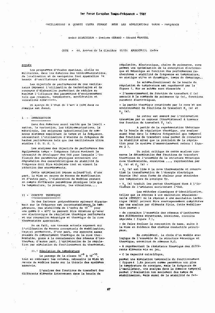
l e r ForUmi EuropBen TeMps-FPlqUanW - 1g87
OSCILLATEURS A QUAI<TZ UL'rRA STABLE PUUR LES A~PLIcAI'IONS TEMPS - I'KEQUENCE
Andre DEBAISIEUX - Evelyne G k k ~ ~ b - Gerard MAROT~L
CEPE - 44, Avenue de la Glaci@re 95105 AIIGENT~uIL cedex
RESUME
Les programmes dV6tudes spatiaux, civils ou militaires, dans les domaines des t~lecanmunications, de localisation et de navigation font apparaftre le besoin d'oscillateurs ultra stable.
Les objectifs de performances de ces oscilla- teurs imposent l'utilisation de technologies et de concepts d'elaboration permettant de reduire au maximum l'influence des parametres dfenvironnement tels que pression, temperature, acceleration et vibrations aleatoires.
Un apercu de l'etat de l'art a CEPE dans ce dmaine est donne.
I - INTRODUCTION
Dans des dmaines aussi varies que la locali - sation, la nav~gation, les tel6canmunications, la mgtrolog~e, les exigences operationnelles de n m - breux systemes exploitant le temps et la frequence, necessitent l'utilisation dlBtalons de frequence de hautes performances tels que les oscillateurs ultra stables ( 0. U. S. ) .
Les analyses des objectifs de performance des equipements temps - frequence futurs montrent la necessite de developper des OUS pour lesquels llin- fluence des parametres physiques entrainant une degradation des caracteristiques de stabilite de frequence doit &tre minimisee tout en visant la reduction des encmbrements.
Cette optimisation impose aujourd'hui, dlune part, la mise en oeuvre de moyens de md4lisation et d'autre part, l'elaboration de modeles prenant en compte different6 parametres physiques tels que la temperature, la pression, les vibrations....
I1 - CONCEPT THERMIQUE
Un des facteurs preponderants agissant directe- ment sur la frequence est inc~ntestablemen$~la tem- perature. Des stabilitds de lfordre de 10 pour une gamme 0 - 40°C ne peuvent &tre obtenues qu'avec une Blectronique de regulation thermique performante et une conception mecanique et thermique de la cuve thermostatee appropriee.
De ce fait, nos travaux actuels reposent sur lfutillsation de moyens conceptuels de mcdBlisationr Ceux-ci permettent, d'une part, une approche assee pouseee du canportemeht thermique de la cuve ther- mostatbe, grace A la connaissance des rBssaux d'iso- thermesi dvautre part, ltoptimisation de la regula- tion par simulation du fonctionnement du thermostat.
11.1 Resulation de tem~erature
Le passage de la classe 10" A 1 0 ~ ' ~ ~ tout en reduisant les volumes, hecessite la mise Cn oeuvre de modeles bases sur la theorie des sysCBtass asservis.
Ltanalyse des fonctions de transfert des different6 elements intervenant dans la boucle de
regulation, Blectronique, chaine de puissance, cuve permet une uptimisation de la conception Blectroni- que et mBcanique en fonction des performances re- cherchees t stabilitd de frequence en temperature, en statique rt/ou en dynamique, temps de demarrage..
Le sch~mavfanctionnel de la boucle de regulation de temperature est represent6 par la figure 1. Sur ce schema sont disscci6s :
- ibasaervissement de fonction de transfert C (6) associe a la eanmande de puissance Gp (s), fonctions purement Blectroniques,
- la partie thermique constituee par la cuve et son environnement de fonctions de transfert K1 (s) et K2 (s).
Le retour est assure par llinformation transmise par un capteur (thermistance) A travers une fonction de transfert TI (6).
A partir de la representation theorique de la boucle de regulation thermique, une analyse aussi bien dans ie dmaine frequentiel que tedlporel des fonctions de transfert nous pemet de connaitre la stabilite dihsi que la precision de la regula- tion pour le systeme dlasservissement retenu ( figu- re 2 1.
Un point critique de cette analyse con- cerne ia determination des fonctions de transfert thermiques de l'ensemble de la structure mecanique cuve thermostatee, enceintes ..., representees par K1 (s) et K2 (6) :
- K (6) est lice a la cuve thermostatee et concr6- ti62 la transformation de lf6nergie Blectrique fournie (Pe) sous forme de chaleur pour atteindre une temperature de consigne Tc.
- K (8) traduit les pertes thermiques dues a l'in- 2 fluence de loambiance environnant 1'OUS.
Les methdes classiques d'identification, telles que la reponse a une excitation impulsion- nelie (Sl'REJC) oU la reponse A une excitation harmo- nique (BODE) peUvent &tre avantageusement ccmpletefs par tine analyse par elements finis. Cette mddlisa- tion permet :
- de connaitre lfensemble des reseaux dlisothermes des differentes structures, enceintes, circuits imprimes ( figure 3 1, - de faire evoluer la conception de base, suite a la mise en evidence des chemins conductifs princi- paux .
En compl6ment, le choix dlun modele ana- logique de l'ensemble de la structure mecanique et thermique, constitub de reseaux R,C,
- R representant la resistance themique des diff6- rents 616ments mis en jeu, - C la capacite calorifique,
permet une simtilrltion temporelle du fonctionnement ( figure4 ).En prenant came parametre non plus la temperature de consigne, mais la frequence de i,osciliateur, line analyse dans le dcmaine temporel permet 116valuation non aeulement des temps de stebilisation, maie ausei de la stsbilite de £re-
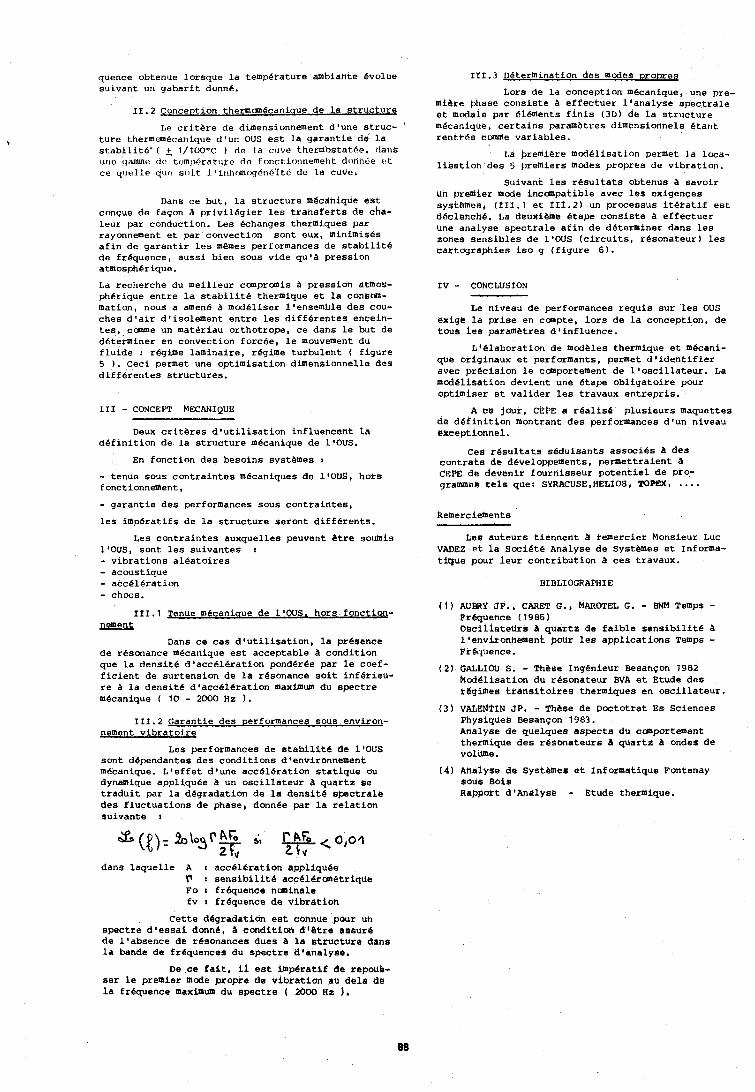
quence obtenue lorsque l a tempkrature ambidhte Bvolue sulvant un gaba r i t donne.
11.2 Conception thermanecaniaue de l a s t r u c t u r e
Le c r i t e r e de dimensionnement d tune s t ruc - t u r e thermmBcanique d1un OUS e s t l a ga ran t i e de l a s t a b i i i t b ' ( + 1/10O0C I dr la cilvt! thermostatfie, datrs utit. 'jamme [ic tcmpfirature dc fonctionnemeht d~lntii.e t s t
ce cl~~t,lLe ~ I A V s111t l 'inhrmcxjdti6~t6 dc? La cuve.
Dans c e but , l a s t r u c t u r e mecdnique e s t conque de faqon a p r i v i l e g i e t l e s t r a n s f e r t a de cha- l eu r par conduction. Les Bchanges thermiques par rayonnement e t par convection sont eux, minimises a f i n de g a r a n t i r l e s memes performances de s t a b i l i t e de frequence, aus s i bien sous vide q u l a press ion atmospherique.
La recherche du mei l leur ccmpraais a press ion atmoS- pherique e n t r e l a s t a b i l i t e thermique e t l a cofisM- mation, nous a amen6 a mod6liser l 'ensemble des cou- ches d ' a i r d ' isolement e n t r e l e s d i f f e r e n t e a encein- t e s , capme un matBriau or thot rope , c e dans l e but de determiner en convection forcee , l e mouvement du f l u i d e : regime laminai re , regime tu rbu len t ( f i gu re 5 ) . Ceci permet une opt imisa t ion dimensionnelle des d i f f e r e n t e s s t ruc tu re s .
111 - CONCEPT MECANIQUE --
Deux c r i t e r e s d 8 u t i l i s a t i o n inf luencent l a d e f i n i t i o n de l a s t r u c t u r e mecanique de 1'OUS.
En fonct ion d e s besoins systhmes :
- tenue sous con t r a in t e s mecaniques de llOUS, hore f onctionnement , - ga ran t i e des performances sous con t r a in t e s ,
l e s impera t i fs de l a s t r u c t u r e seront d i f f e r e n t s .
Les con t r a in t e s auxquelles peuvent Btre souh~is l1OUS, sont l e s su ivantes : - v ib ra t ions a l e a t o i r e s - acoustique - accel4ra t ion - chocs.
111.1 '$'enue m4canioue de ldOUS, hors f o n c t i o p nement
bans c e c a s d 8 u t i l i s a t i o n , l a presence de resonance mecanique e s t acceptable a condi t ion que l a dens i t e d*acc618ration ponderbe par l e coef- f i c i e n t de sur tens ion de l a resonance s o i t i n f e r i eu - r e a l a dens i t6 d8acc616ra t ion maximum du Spectre mecanique ( 10 - 2000 Hz ) .
111.2 2- nement v i b r a t o i r e
Les performances de s t a b i l i t e de l'OUS sont dependantes des condi t ions d'environnement mecanique. L ' e f f e t d 'une acce l e ra t ion s t a t i q u e ou dynamique appliquee a un o s c i l l a t e u r a qua r t z Be t r a d u i t par l a degradation de l a dens i t e Bpectrdle des f l uc tua t ions de phase, donnde par l a r e l a t i o n suivante :
dans l aque l l e A : acc616ration appliquee V r s e n s i b i l i t e accel6run6trique Fo I frdquence nuninale f v : frequence de v ib ra t ion
Ce t t e degradation e s t connue pour uh spec t r e d ' e s s a i donne, A conditioli d 4 B t r e assur4 de l 'absence de resonances dues a l a e t ruc tu re Bans l a bande de frequences du spec t r e d 'hnalyse.
111.3 DBterminetion des modes DroDreg
Lors de l a conception mecanique, une pre- miere phase cons i s t e a e f f ec tue r l t a n a l y s e s p e c t r a l e e t modale par Bl6ments P in i s (3111 de La s t r u c t u r e m6canique, c e r t a i n s pariimbtres dimensionnels Btant r en t r6s cMvrre va r i ab l e s .
Ld bremihre modelisation permet l a loca- l i s a t i o n d r s 5 ~ ~ r e m i e r s m d e s propres de v ib ra t ion .
Suivant l e s r e s u l t a t s obtenus savoir Un prentier mode incompatible avec l e s exigences systemes, (f11.1 e t T I I . 2 ) un proceosus i t e r a t i f e s t d6olehchi. La deuxieme &ape cons i s t e a e f f ec tue r une analyse spec t r a l e a f i n d e determiner dans l e s zones s ens ib l e s de I'OUS ( c i r c u i t s , resonateur l l e s car tographies i s o g ( f i g u r e 6).
I V - CONCLUSION
Le niveau de performances r equ i s su r l e s OUS exigs l a p r i s e en compte, l o r s de l a conception, de t ous i e s parametres do in f luence .
Lle labora t ion de modeles thermique e t m6cani- que originaux e t performants, permet d ' i d e n t i f i e r avec p rec i s ion i e cctnportement de l @ o s c i l l a t e u r . La modelisation devient une &ape ob l iga to i r e pour opt imirer e t va l ide r l e s travaux en t r ep r i s .
A c e jour, CEPE a r e a l i s 6 p lus i eu r s maquettes d& d e f i n i t i o n montrant des performances d 'un niveau exceptionnel.
Ces r e s u l t a t s seduisants a s soc i e s a des c o n t r a t s de devel6ppements, permet t ra ient a CEPE de devenir fournisseur p o t e n t i e l d e pro- grammes t e i s que: SYRACUSE,HELIOS, TOPEX, ....
Les au t eu r s t i ennen t a i-emercier Monsieur Luc VADEZ e t l a SociBt6 Analyse de SystOmes e t Informa- t i que pour l e u r con t r ibu t ion a ce s travaux.
BIBLIOGRAPHIE
( 4 ) AUBkY J P , , CARET G . , ~AROTEL G. - BNM Temps - Prequence ( 1986 ) ~ s c i l i a t e t i r s ti qua r t z de f a i b l e s e n s i b i l i t e a i ' envi ronnei~~ent pour l e s app l i ca t ions Temps - FrBiiUence.
( 2 ) OALLIOU S. - These Ingenieur Besanpon 1982 ku i6 l i s a t io i l du resonateur BVA e t Etude des t eg ihes t r ans i t . o i r e s thermiques en o s c i l l a t e u r .
( 3 ) VALENTIN JP. - These de Doctotrat Es Sciences Physiques Besanpon 1983. Analyse de quelques a spec t s du comportement thermiqtte des r6sonateurs a qua r t z ondes de vollime.
( 4 ) Anaiyee de Systemee e t Informatique Fontenay BOUS B0iB Rapport d ' ~ n a i y s @ - etude thermique.
De c e f a i t , il e s t imp6ratif Be rapoue- s e r l e premier mode propre de v ib ra t ion au de l a da l a frequence maximum du spec t r e ( 2000 Hz ).
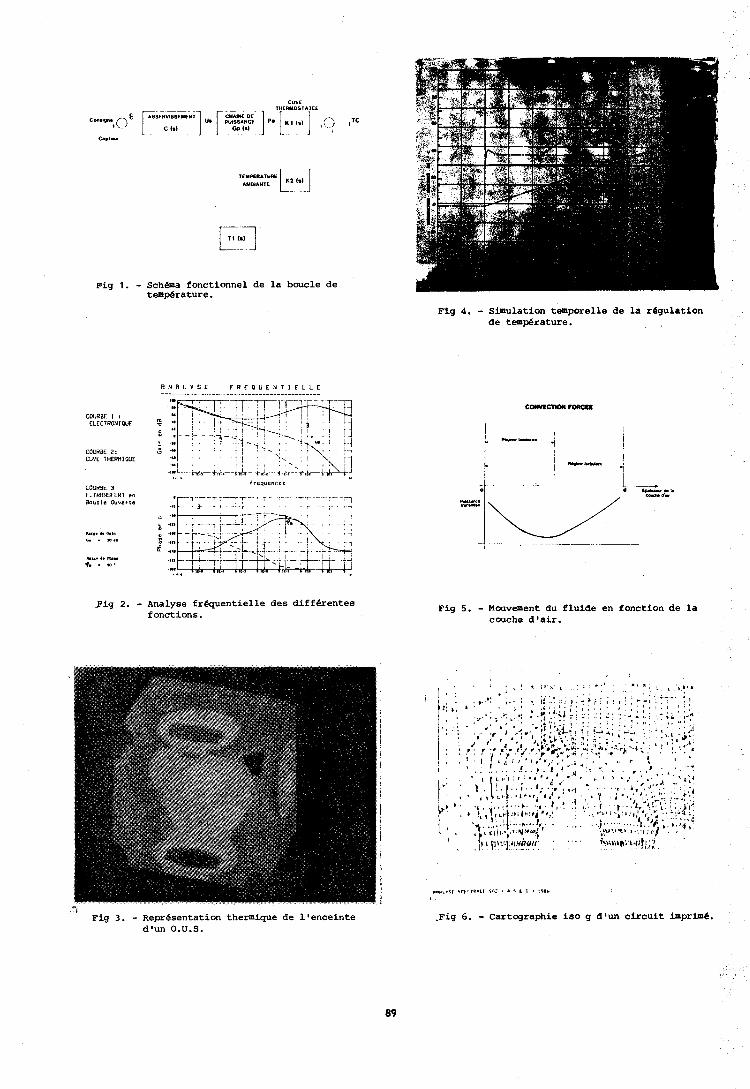
CUVE THERMOSTATTI
", r ~GNE D E ] - [ 1 WISSANCE C 1.1 Go I*)
K 3 l s ) ,() s T c , cap,-
TEMPERATURE I ,,) I AMEIANTE
Pig 1. - Schba fonctionnel de la boucle de temperature.
COURBE 2; CUVE THERUIOUE ."I . . ' , \ *.-
: I ' . , \ . , \ ! : U l . . , , _,.L
,.** COURBE 3
(rcquenccr
F.TRRNSFERT en *,-T-.7-T -- - . , - . ,... . .' -.. -- Boucle Ouvcrto I
I*.'. 4. C.,.
Y . IO,. UI.. 4. n u Q. .
m .- Fig 2. - Analyse frequentielle des differentes
fonctions.
Fig 3. - Representation thermique de l'enceinte d'un O.U.S.
Fig 4. - Simulation temporelle de la regulation de temp6rature.
Fig 5. - Mouvement du fluide en fonction de la couche d'air.
.Fig 6. - Cartographie iso g d'un circuit imprime.
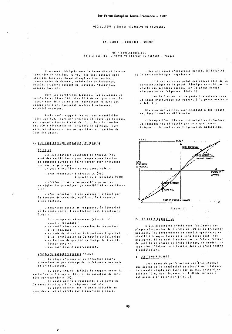
l e r Forum Europben Temps-Friquence - 1987
O S C I L L A T E U R A G R A N D E E X C U R S I O N O f F R E O U E N C E
M H . B I D A R T - G I R A R O E T - W O L C O F F
O K P I E Z O E L E C J R O N I O U E 3 0 B L d C A L L l E N l - 9 2 3 9 2 V I L L E N E U V E L A G A R E N N E - F R A N C E
C o u r a m m e n t d i s i g n i s s o u s l e t e r n e d ' o s c i l l a t e u r s c o m m a n d i s e n t e n s i o n , o u V C O , c e s o s c i l l a t e u r s s o n t u t i l i s i s d a n s d e s c h a m p s d ' a p p l i c a t i o n s v a r i i s : t r a n s m i s s i o n d e d o n n i e s , m o d u l a t i o n d e f r i q u e n c e , b o u c l e s d t a s s e r v i s s e n e n t d e s y s t i a e s , t C I C m h t r i e , m e s u r e s D o p p l e r .
D a n s c e s d i f f i r e n t s d o m a i n e s , l e s e a i g e n c e s d e s e n s i b i l i t i , l i n i a r i t i , s t a b i l i t e d e c e t y p e d ' o s c i l - l d t e u r s o n t d e p l u s e n p l u s i m p o r t a n t e s e t d a n s d e s c o n d i t i o n s J ' e n v i r o n n e m e n t s i v i r e s ( a v i o n i q u e , m a t i r i e l e a b a r q u i .
A p r e s a v o i r r a p p e l 6 l e s n o t i o n s e s s e n t i e l l e s I i e e s a u r V C O , l e u r s p e r f o r m a n c e s e t l e u r s l i m i t a t i o n s , r r t e x p o s e p r i s e n t e I ' C t a t d e I ' a r t d a n s l e d o a a i n e d e s V C O i r i s o n a t e u r e n T a n t a l a t e d e L i t h i u m , l e u r s c d r d c t i r i s t i q u r s e t I e s p e r s p e c t i v e s e n f o n c t i o n d e l a u r C v o l u t i o n .
P r i n c i p e -------- L e s o s c i l l a t e u r s c o n l a n d i s e n t e n s i o n ( V C O )
s o n t d e s o s c i l l a t e u r s p o u r l e s q u e l s u n e t e n s i o n d e c o m n a n d e p e r n e t d e f a i r e v a r i e r l e u r f r i q u e n c e s u r u n e l a r g e p l a g e .
L a b o u c l e o s c i l l a t r i c e e s t c o n s t i t u i e :
- d ' u n r i s o n a t e u r A c i r c u i t L C ( V C O ) h q u a r t z o u B T a n t a l a t e ( V C X 0 )
- d ' i l i a e n t s s i r i e o u p a r a l l e l e p e r n e t t a n t d e r i g l e r l e s p a r a m i t r e s d e s e n s i b i l i t i e t d e l i n e a - r i t i
- d ' u n v a r a c t o r ( d i o d e v a r i c a p ) a t t a q u C p a r l a t e n s i o n d e c o m m a n d e , m o d i f i a n t l a f r i q u e n c e d ' o s c i l l a t i o n .
L ' e x c u r s i o n t o t a l e d e f r i q u e n c e , l a l i n i a r i t i , e t l a s t a b i l i t i d e I ' o s c i l l a t e u r s o n t d i r e c t e n e n t l i i e s :
- i l a n a t u r e d u r i s o n a t e u r ( c i r c u i t L C , q u a r t z , l a n t a l a t e )
- a u c o e f f i c i e n t d e s u r t e n s i o n d u r i s o n a t e u r - i l a f r i q u e n c e - a u m o d e d e v i b r a t i o n ( r i s o n a t e u r s i q u a r t z ) - i l a c o n s t i t u t i o n d e l a b o u c l e o s c i l l a t r i c e - a u f a c t e u r d e q u a l i t i e n c h a r g e d e I ' o s c i l -
l a t e u r c o a p l e t - I U X c o n d i t o n s d ' e n v i r o n n e m e n t .
G r a n d e u r s c a r a c t i r i s t i q u e s ( F i g . 1 ) .......................... - L a p l a g e d ' e x c u r s i o n d e f r C q u e n c e p o u r r a
s l e x p r i a e r e n p o u r c e n t a g e d e l a f r 6 q u e n c e n o m i n a l e d e I ' o s c i l l a t e u r .
- L a p e n t e ( K H z / V ) d C f i n i t l e r a p p o r t e n t r e l a v a r i a t i o n d e f r e q u e n c e ( K H z ) e t l a v a r i a t i o n d e t e n - s i o n c o r r e s p o n d a n t e (U).
L a p e n t e n o n i n a l e r e p r i s e n t e : l a p e n t e d e l a c a r a c t i r i s t i q u e B l a f r C q u e n c e n o m i n a l e .
L a p e n t e n o y e n n e e s t l a p e n t e c a l c u l 6 e a u s e n s d e s m o i n d r e s c a r r i s s u r l l e x c u r s i o n g l o b a l e .
- S u r u n e p l a g e d ' e x c u r s i o n d o n n i e , l a l i n i a r i t i d e l a c a r a c t i r i s t i q u e r e p r f s e n t e :
. l ' i c a r t e n t r e u n p o i n t q u e l c o n q u e r e e l d e l a c a r a c t e r i s t i q u e e t l e p o i n t t h i o r i q u e c a l c u l i p a r l a d r o i t e d e s m o i n d r e s c a r r e s , s u r l a p l a g e d o n n i e d ' e x c u r s i o n d e f r i q u e n c e ( d e f . I )
. o u l a f l u c t u a t i o n d e p e n t e i n s t a n t a n i e d a n s l a p l a g e d ' e x c u r s i o n p a r r a p p o r t b l a p e n t e n o m i n a l e ( d e f . 2 )
C e s d e u x d e f i n i t i o n s c o r r e s p o n d e n t A d e s e x i g e n - c e s f o n c t i o n n e l l e s d i f f i r e n t e s .
- l o r s q u e I ' o s c i l l a t e u r e s t n o d u l C e n F r e q u e n c e l a c o m m a n d e e s t e f f e c t u i e p a r u n s i g n a l b a s s e f r i q u e n c e . O n p a r l e r a d e f r i q u e n c e d e m o d u l a t i o n .
PL A I i D ' IXL I IRS IO I Dt tR.OtKICE
PLAGE M IflSlOl DL CMIUNM
f i g u r e I.
S ' i l s p e r m e t t e n t d ' a t t e i n d r e f a c i l e m e n t d e s p l a g e s d ' e x c u r s i o n d e l ' o r d r e d e 1 0 % d e l a f r e q u e n c e n o m i n a l e , l e s p e r f o r a a n c e s d e d e n s i t 6 t p e c t r a l e , d e s t a b i l i t i A D o y e n t e r n e e t h l o n g t e r m c s o n t t r i s a i d i o c r e s . E l l e s s o n t I i m i t i e s p a r l e f a i b l e f a c t e u r d e q u a l i t 6 e n c h a r g e d e I 1 o s c i l l a t e u r , e t r e n d e n t c e t y p e d ' o s c i l l a t e u r i n u t i l i s a b l e d a n r u n g r a n d n o e b r e d ' a p p l i c a t i o n s .
L e u r g a m m e d e p e r f o r m a n c e s e s t t r i s e t e n d u e a u x d i p e n s d e l a c o m p l e x i t 6 d u c i r c u i t o s c i l l a t e u r . U n e x e n p l e s i m p l e e s t d o n n e p a r u n V C X O i n t C g r 6 e n b o i t i e r T O 8 , d o n t l e v a r a c t o r ( d i o d e v a r i c a p ) e s t p l a c e A 1' e x t e r i e u r ( F i g . 2)
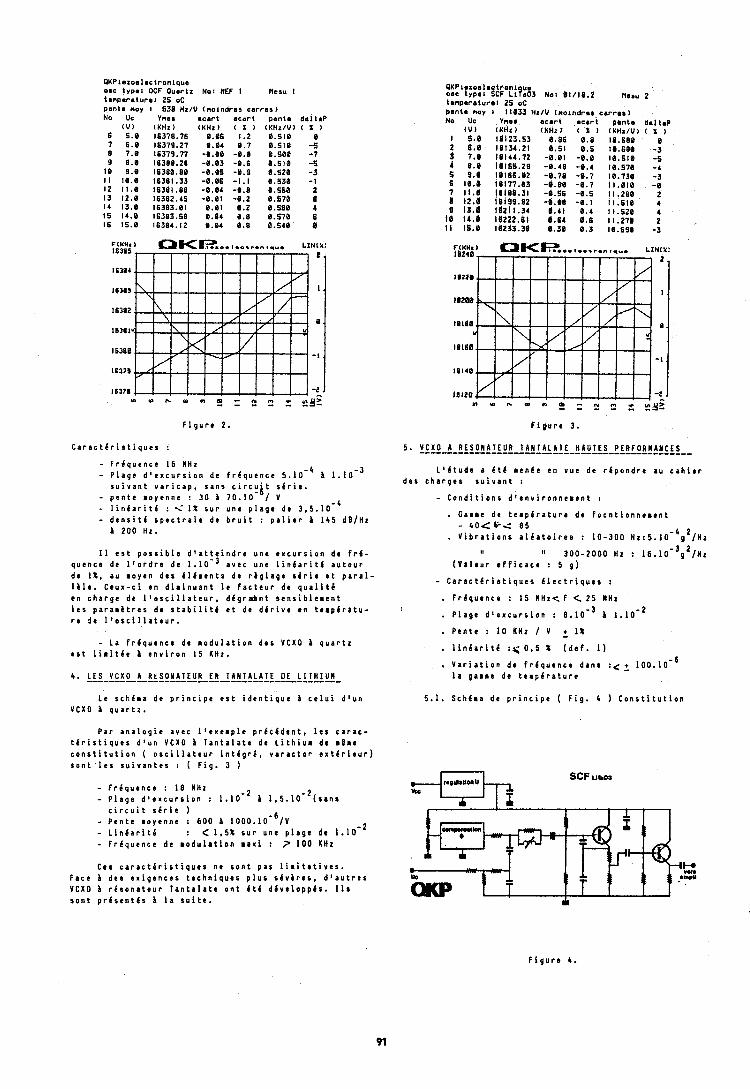
QKPlezoa lac t ron lqua 08c type: OCF Oubr tz NO: REF I tmnparaturat 25 oC Pante noy : 538 Hz/U (no lnd ron c a ~ No Uc Ynor # c a r t a c a r t
( U ) (KHz) (KHz1 ( X I 6 5.0 16378.76 8.06 1.2 7 6.8 16379.27 8.04 0.7 8 7.0 16379.77 -0.00 -0.8 9 8.8 16380.28 -8.83 -0.6 10 9.8 16380.80 -0.05 -0.9 I I 10.8 16381.33 -8.86 -1.1 I2 11.0 16381.88 -0.84 -8.8 13 12.8 16382.45 -0.01 -8.2 14 13.0 16383.81 8.01 0.2 15 14.0 16313.58 0.04 8.8 16 15.8 16384.12 8.04 0.8
F i g u r e 2.
C a r a c t & r i s t i q u e s :
- F r l q u e n c e 16 #Hz - P l a g e d o e x c u r s i o n de f r l q u e n c e 5 .10 - ' b l . l ~ - ~
s u i v a n t v a r i c a p , s a n s c i r c u ' t s l r i e . b - p e n t e m o y e n n e : 3 0 1 7 0 . 1 0 - / V - l i n l a r i t l : i 1 % s u r u n e p l a g e de 3 ,5 .10 '
4
- d e n s i t l s p e c t r a l e de b r u i t : p a l i e r i 1 4 5 d B / H z b 2 0 0 Hz.
I 1 e s t p o s s i b l e d ' a t t e i n d r e u n e e x c u r s i o n de f r l - q u t n c e de l ' o r d r e de 1 . 1 0 - 3 a v e c u n e l i n l a r i t l a u t o u r de It. au m o y e n d e s 4 1 6 m e n t c d e r i g l a g e s l r i e a t p a r a l - l i l e . C e u x - c i e n d i m i n u a n t l e f a c t e u r de q u a l i t 6 e n c h a r g e de l l o s c i l l a t e u r , d l g r a c b n t r e n s i b l e m e n t l e s p a r a m i t r e s d e s t a b i l i t 6 e t de d l r i v e e n t e m p i r a t u - r e d e l ' o ~ c i l l a t e u r .
- L a f r l q u e n c e de m o d u l a t i o n d e s VCXO A q u a r t z e s t l i m i t 6 e b e n v i r o n 1 5 KHz.
Le s c h e m a d e p r i n c i p e e s t i d e n t i q u e i c e l u i d l u n VCXO b q u a r t z .
P a r a n a l o g i e a v e c l ' e x e r p l e p r C c C d e n t , l e a c a r a c - t 6 r i s t i q u e s d ' u n VCXO 1 T a n t a l a t e de L i t h i u m d c r l r e c o n s t i t u t i o n ( o s c i l l a t e u r i n t l g r 4 , v a r a c t o r o x t i t i e u r ) s o n t l e s s u i v a n t e s : ( F i g . 3 )
- F r i q u e n c e : I 8 HHz - ~ l a g e d ' e x c u r s i o n : 1.10.' i 1 , 5 . 1 0 - ~ ( s a n s
c i r c u i t s l r i e ) - P e n t e m o y e n n e : 6 0 0 i 1 0 0 0 . 1 0 - ~ / ~ - L i n i a r i t 6 : C 1 , 5 % s u r u n e p l r g o d c 1 .10 -
2
- F r l q u e n c e d e m o d u l a t i o n m a x i : P 1 0 0 K H z
Ces c a r a c t 6 r i s t i q u e s n e s o n t p a 8 l i r i t a t i v e s . F a c e i d e s e x i g e n c e s t e c h n i q u e s p l u s s 6 v i r e s , d ' a u t r e s VCXO b r l s o n r t e u r l a n t a l a t e o n t 4 t 6 d 6 v e l o p p l s . 1 1 s s o n t p r 6 s e n t l s h l a s u i t e .
~ r n t a nov 8 11833 H Vnes
(KHz I 11123.93 18134.21 18144.72 l(1155.29 18166.82 16177.03 10186.31 ial9e.e~ iuzi 1.34 18222.61 18233.38
x/U ( n o r n d r e r c r r r a s ) e c a r t a c a r t p e n t e Uml t rP l Y H z l ( X ) (KHzIU) ( x I 0.86 8.8 18.688 8 0.51 8.5 10.680 -3 -8.01 -0.0 10.510 -5 -8.48 -0.4 18.570 -4 -0.78 -0.7 10.730 -3 -8.88 -0 .7 11.018 -8 -8.96 -8.5 Il.280 2 -0.80 -0.1 11.518 4 I 0.4 It.520 4 4 8 11.271 2 0.38 0.3 18.690 -3
F i g u r e 3.
5 . VCXO-A-ALSO!Af EUR-LA!l!l.!lLI!!AUIIIIPLRf O!!!!iLS-- L 1 4 t u d e a i t & m c n 6 e e n v u e de r 6 p o n d r e a u c a h i e r
d e s c h a r g e s s u i v a n t :
- C o n d i t i o n s d ' e n v i r o n n e r e n t :
. Garme de t e m p 6 r a t u r e d e f o c n t i o n n e m e n t - 4 0 < 1 i < 8 5 . V i b r a t i o n s a 1 6 a t o i r e s : 1 0 - 3 0 0 ~ z : ~ . 1 0 - ~ ~ ~ / l i z
I: " 3 0 0 - 2 0 0 0 Hz : 1 ~ . 1 0 - ~ g ~ / ~ z
( V l l t u r e f f i c a c e : 5 g )
- C a r a c t 6 r i s t i q u e s 6 I e c t r i q u e s :
. F r i q u e n c e : 1 5 MHz< F < 2 5 MHz
, P l a g e d l e x c u r s i o n : 8 . 1 0 - ~ 1 .10- '
. P c n t e : 1 0 kHz I V r 1 %
. l i n g a r i t l : < 0 , 5 % ( d e f . 1 )
. V a r i a t i o n d e f r e q u e n c e d a n s : < r 1 0 0 . 1 0 - 6 l a g a r m e d e t e m p b r a t u r e
5.1. Sch6ma d e p r i n c i p e ( F i g . 4 ) C o n s t i t u t i o n
SCF urrar
F i g u r e 4 .
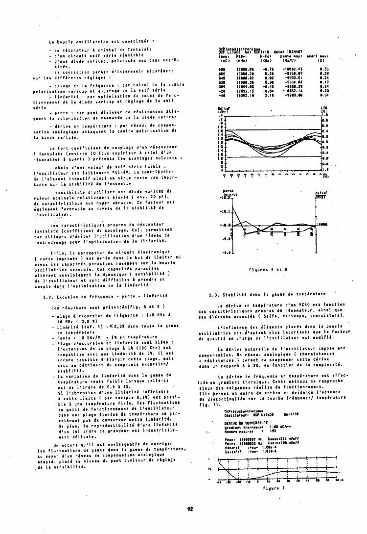
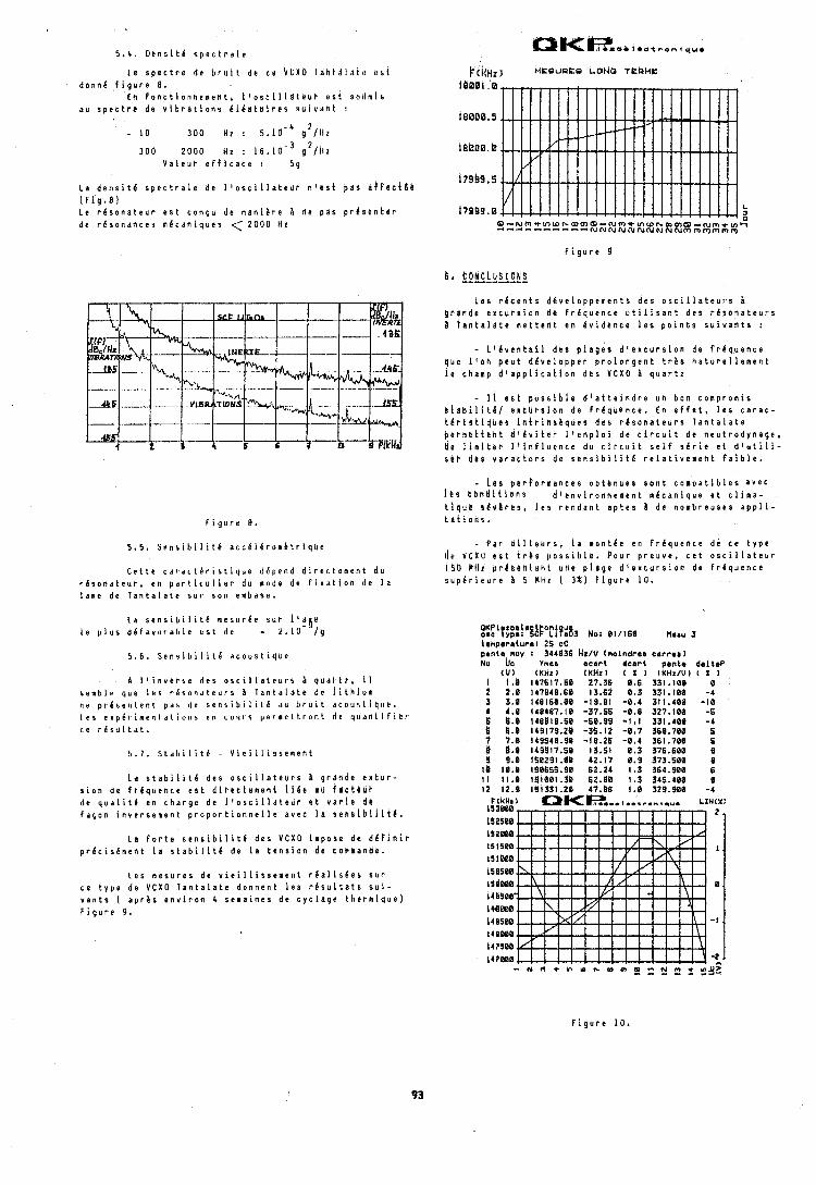
L e s p e c t r e d e b r u i t d e c e V C X b 1 d h t d l 4 t u b s l d o n n e f i g u r e 8.
E n f o n c t i o n n e m e n t , I ' o s c i l l a t c d r e s 4 s u ~ l m i a a u s p e c t r e d e v i b r a t i o n s b l e a t o i r e s s u i v d n t :
3 0 0 2 0 0 0 H z : 1 6 . g 2 / ~ { l V a i e u r e f f i c a c e : 5 g
L a d e n s i t d s p e c t r a l e d e I ~ o s c i ~ l a t e u r n i r s t b a s a h f e e t 8 8 ( f i g * 8 ) L e r e s o n a t e u r e s t c o n Q u d e m a n i a r e & rle p d s p r k s b n t e r d e r i s o n a n c e s n e c a n i q u e s < 2 0 0 0 H z
C e t t e c d r a r t e r i s t i q u e d f p e n d d i r e c t e m e n t d u r h s o n d t e u r , e n p d r t i c u l i e r d u n o d e d e f i x d t i o n d e l a l a n e d e l a n t a l a t e s u r s o n e m b a s e .
L a s e n s i b i l i t C m e s u r e e s u t l o a t e l e p i u s d & f a v o r a b l e r s t d o - 2 . 1 0 - / g
5.6. S e n s i b i l i t e d c o u s t i j u e
A I l ~ n v e r s e d e s o s c i l l a t e u r s B q u d r t t , i l 5 r n b l r q u e I r s t e s o n d t e u r s B T ~ n t d l a t e d c l i t h i u m n r p r h s e n t e n t p n s d r s e n h i b i l i l b d u b r u i t d c o u 5 t i ~ l l e . I r s e x p 6 1 1 n r n l a t i o 1 1 s art c o ~ l r s p c r n c l t r o n l d c r j u r ! i i i f l b r c e r h s u l t d t .
L a s t a b i l i t e d e s o s c i l l a t e u r s g r a n d e e ~ t u r - s i o n d e f r h q u e n c e e s t d i r e c t e m e n t l i k e i d f e t t h b r d e q u a l i t l e n c h a r g e d e i ' o s c i l l a t e u r e t v a r i e d e f a s o n i n v e r s e m e n t p r o p o r t i o n n e l i e a v e c l a s e n s i b i l i t 6 .
L a f o r t e s e n s i b i l i t e d e s V C X O i m p o s e d e d e f i n i r p r l c i s e m e n t l a s t a b i i i t k d e l a t e n s i o n d c c o m a a n d e .
L e s n e s u r e s d e v i e i l l i s s e a e n t r i a l i s e e s s u r c e t y p e d e V C X O T a n t a l a t e d o n n e n t l e s r e s u l t a t s s u i - v a n t s ( a p r a s e n v i r o n 4 s e n a i n e s d e c y c l a g e t h e r m i q u e ) F i g u r e 9 .
F i g u r e IJ
L e o r e c e n t s d 6 v e l o p p e m e n t s d e o o s c i l l a t e u r s B g r d n d e e x c u r s i o n d e f r k q u e n c e u t i l i s a n t d e s r e s o n a t e u r s B t a n t a l a t e m e t t e n t e n e v i d e n c e l e s p o i n t s s u i v a n t s :
- L l k v e n t a i l d e s p i a g e s d l e x c u r o i o n d e f r e q u e n c e q u e l l o h p e u t d k v e l o p p e r p r o l o n g e n t t r 8 s h a t u r e l l e m e n t l e c h a m p d l a p p l i c a t i o n d b s V C X O A q u a r t z
- 1 1 e s t p o s s i b l e d ' a t t e i n d r e u n b o n c o h p r o m i s h t a b i l l t b / e x t U r s i o n d e f r k q u e n c e . E n e f f e t , l e s c a r a c - i d r i r t i q h e r i h t r i h s h q u e s d e s r 6 s o n a t e u r s l a n t a l a t e p e r b e t t e n t d l g v i t e r l l e s p l o i d e c i r c u i t d e n e u t r o d y n a g e , B e l i m i t e r I l i n f l u e n c e d u c i r c u i t s e l f s i r i e e t d ' u t i l i - o r b d s 5 v a r a c t o r s d e s e n s i b i l i t e r e l a t i v e n e n t f a i b l e .
- L e s p e r f o r m a n c e s o b t k n u e s s o n t c o m p a t i b l e s a v e c l b s k a n d i i l o n s d ' e n v i r o n n e m e n t n e c a n i q u e e t c i i m a - t i q u e & 6 v C r r s , l e s r e n d a n t a p t e s b d e n o m b r e u s e s a p p l i - t . S t i o h 5 ,
- P a r d i l l e u r s , l a m o n t k e e n f r i q u e n c e d e c e t y p e tic V C N U e s t t r b s p o s s i b l e . P o u r p r e u v e , c e t o s c i l l a t e u r 1 3 U M H t p r l s e n t s h t u n e p l d g e d t e x c u r s i o n d e f r 6 q u e n c e s b p b r i r u r e B 5 M H z ( 3 % ) F i g u r e 1 0 .
PKPI z o a l r o w type: 8 & ' ~ ! ? ~ 8 3 N o ] 01/160 Haru 3 t e n p e r r i u r e l 25 OC p e n i r moy 1 344636 Hz/U (molndrra c a r r o b ) N o be v n r ~ r c s r t .cart pente d a l t a P
( U t (KHxI (KHz) ( X ) ( K H x / U ) ( % I 1 1.8 147617.58 27,36 0 . 6 331 . l00 0 2 2 . 0 141848.60 13.62 8 . 3 331.100 -4 3 8 . 0 148160.00 -19.81 -0 .4 311.480 -10 4 4 . 0 148487.10 -37.55 -0.8 327.100 -5 fi 8 , 8 148818.50 -68.99 - I , ! 331.400 -4 k 8 . 8 119178.28 -35.12 - 0 . 7 568.700 6 '/ 1 , 0 149840.98 -18.26 -0.4 361.780 5 B U.e 1 4 9 9 1 ? . s e 1 3 . 5 1 8 . 3 376.680 9 g 9 . 8 150291.08 42.17 0 . 8 373.508 8
F i g u r e 1 0 .
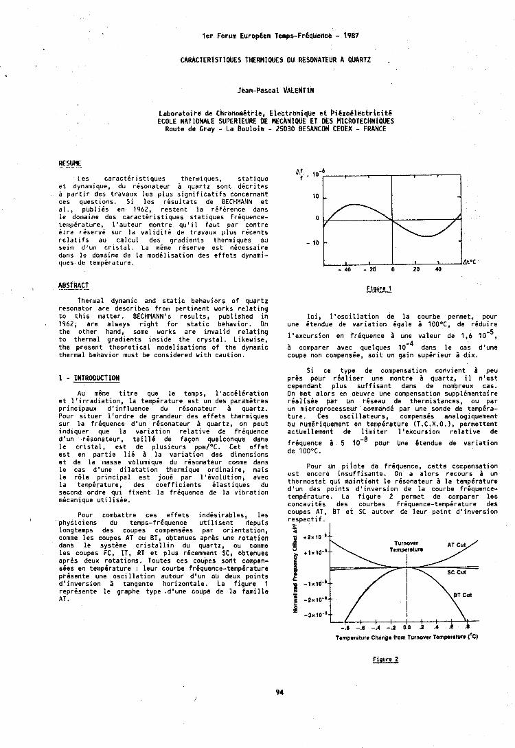
l e t Forum Europ ien Temps-Fr6qbertbe - 1987
CARACTERtSTlQUES THERMIQUES DU RESONATEUR # QUARTZ
L a b o r a t o i r e de ChronomBtrie, E l e c t r o n i q u e c t P i C z o i l e e t r i c i t Q ECOLE NATIONALE SUPERIEURE DE MECANIQUE E l DES MlCROTECHNlPUES
Route de Gray - La B o u l o i e - 25036 BESANCON CEDER - FRANCE
Les c a r a c t b r i s t ~ q u e s ther~n iques , s t a t i q u e e t dynamique, du rbsonateur B quar tz sont d i c r l t e s i p a r t l r des t ravaux l e s p l u s s i g n l f i c a t l f s concernant ces ques t ions . S i l e s r i s u l t a t s de BECtlMANN e t d l . , p u b l i b s en 1962, r e s t e n t l a r i f e r e r i c e dans l e domalne dcs c a r a c t i r i s t ~ q u e s s t a t i q u e s f r iquence- tert ipbrdture, l ' a u t e u r montre q u ' i l f a u t par c o n t r e Ot re r i s e r v i sur l a v a l i d i t i de t ravaux p l u s r i c e n t s r e l a t i f s au c a l c u l des g r a d i e n t s the rm~ques au s e i n d 'un c r i s t d l . La msme rdserve e s t n i c e s s a i r e ddns l e d o p a ~ n e de l a m o d i l i s a t i o n des e f f e t s dynami- ques de t e m p i r a t u r e .
T h e r ~ l ~ a l dynamic and s t a t i c behav io rs o f q u a r t z resona to r a r e descr ibed from p e r t i n e n t works r e l a t i n g t o t h i s mat te r . BECHMANN's r e s u l t s , p u b l i s h e d i n 1962, a r e always r i g h t f o r s t a t i c behavior , On t h e o t h e r hand, some works a r e i n v a l i d r e l a t i n g t o thermal g r a d i e n t s i n s i d e t h e c r y s t a l . L i kew ise , t h e p resen t t h e o r e t i c a l mode l i sa t ions o f t h e dynamic thermal behav io r must be considered w i t h cau t ion .
Au mime t i t r e que. l e temps, I ' a c c d l i r a t i o n e t l o i r r a d i a t i o n , l a temperature e s t un des p a r a m i t r e s p r i n c i p a u x d ' i n f l u e n c e du r i s o n a t e u r B quar tz . Pour s i t u e r l ' o r d r e de grandeur des e f f e t s thermiques sur l a f r i quence d 'un r6sona teur d quar tz , on peu t i n d i q u e r que l a v a r i a t i o n r e l a t i v e de f r i q u e n c e d 'un r i s o n a t e u r , t a i l 1 6 de fapon quelconque dans l e c r i s t a l , e s t de p l u s i e u r s ppm/OC. Cet e f f e t e s t en p a r t i e l i d 1 l a v a r i a t i o n des dimensions e t de l a lnasse volumique du rdsonateur cornme dans l e cas d'une d i l a t a t i o n thermique o r d i n a i r e , mais l e r 6 l e p r i n c i p a l e s t joud par l ' i v o l u t i o n , avec l a tempdrature, des c o e f f i c i e n t s i l a s t i q u e s du second o r d r e q u i f i x e n t l a f r i q u e n c e de l a v i b r a t i o n mbcanique u t i l i s i e .
Pour cornbattre ces e f f e t s i n d b s i r a b l e s , l e s p h y s i c i e n s du temps-f r iquence u t i l i s e n t depuis longtemps des coupes compensdes p a r o r i e n t a t i o n , comme l e s coupes AT ou BT, obtenues apres une r o t a t i o n dans l e syst ime c r i s t a l l i n du quar tz , ou comme l e s coupes FC, IT, RT e t p l u s rdcemment SC, obtenues a p r b deux r o t a t i o n s . Toutes ces coupes son t compen- sees en t e ~ n p i r a t u r e : l e u r courbe frdquence-tempbrature p r i s e n t e une o s c i l l a t i o n au tour d 'un ou deux p o i n t s d ' i n v e r s i o n d tangente h o r i z o n t a l e . La f i g u r e 1 reprdsen te l e graphe t y p e .dlune coupe de l a f a m i l l e AT.
Figure 1
l c i , l ' o s c i l l a t i o n de l a courbe permet, pour une i t e n d u e de v a r i a t i o n i q a l e 1 100°C, de r i d u i r e
l ' e x c u r s i o n en f rbquence ;i une v a l e u r de 1,6
1 comparer avec. quelques l oe4 dans l e cas d'une coupe non compensee, s o i t un g a i n s u p i r i e u r B dim.
S i ce t y p e de compensation c o n v i e n t i peu p r i s pour r i a l i s e r une montre d quar tz , il n ' e s t cependant p l u s s u f f i s a n t dans de nombreux cas. On met a l o r s en oeuvre une compensation s u p p l i m e n t a i r e r i a l i s k e par un r i s e a u de thermistances, ou par un micropt-ocesseur commahdi par une-sonde de temp6ra- t u r e . Ces o s c i l l a t e u r s , compenses analogiquement eu kumit-iquement en temp6rature (T.C.X.O. ) , pe rmet ten t ac tue l lement de l i m i t e r l ' e x c u r s i o n r e l a t i v e de
f rbquence A 5 lo- ' pour Uhe Btendue de v a r i a t i o n de 100°C.
Pour un p i l o t e de f r iquence , c e t t e compensation e s t encore i n s u f f i s a n t b . On a a l o r s recours 1 un thermos ta t q u i m a i n t i e n t l e r i s o n a t e u r 1 l a temperature d ' u n des p o i n t s d ' i n v e r s i o n de l a courbe f r iquence- tempdrature, La f i g u r e 2 permet de comparer l e s concav i tes des courbes f r i q u e n c e - t e m p i r a t u r e des coupes AT, BT a t SC autot l r de l e u r p o i n t d ' i n v e r s i o n r e s p e c t i f . t
\ { : : ! , ! ! : ; ' ; -.I -.6 -.4 -.2 0.0 .2 -4 .6
Tempercllura Change horn turnover Temperature ('c)
Figure 2
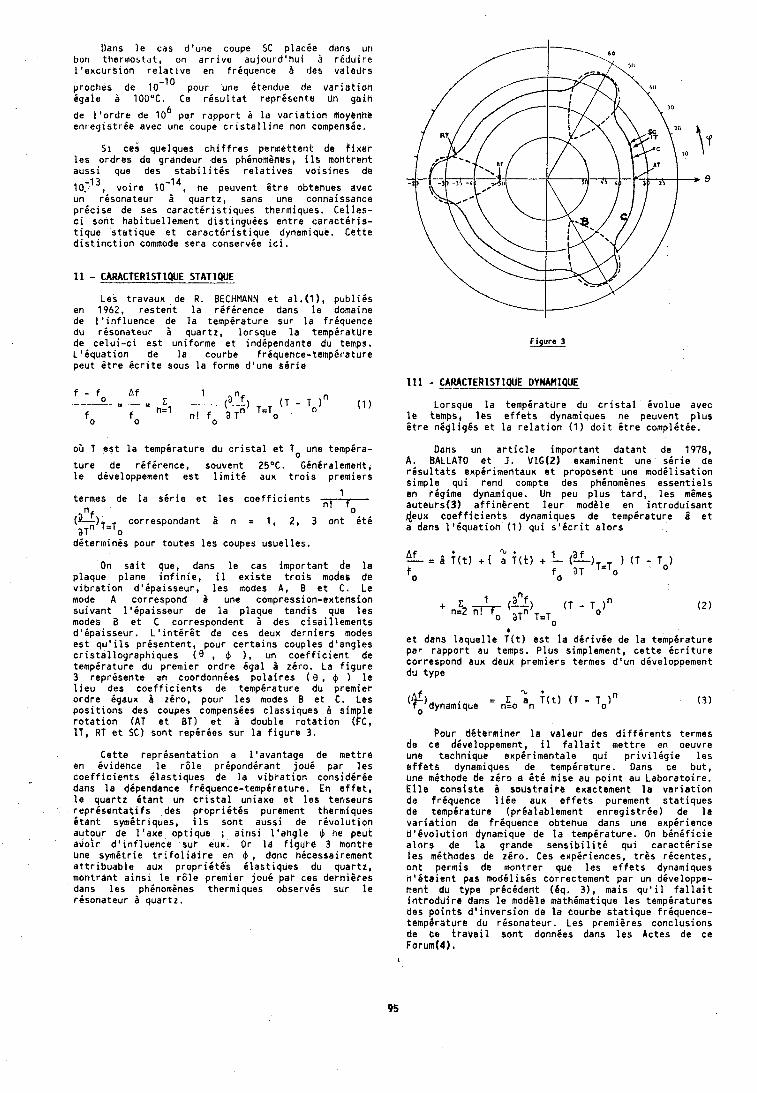
Uans l e cas d'urie coupe SC placire dans un bon t l i e r~nob ta t , on a r r i v e a u j o u r d ' h u i i r i d u i r e l ' d x c u r s i o n r e l a t ~ v e en f r iquence 5 des va leurs
prochas de 10- lo pour une i t e n d u e da v a r i a t i o n i g a l e a 100°C. Ce r i s u l t a t r e p r i s e n t e Un g a i h
6 de l ' o r d r e de 10 par r a p p o r t i l a v a r i a t i o n hoyennb enr e g ~ s t r i e avec une coupe c r i s t a l l i n e non compens6e.
51 ces quelques c h i f f r e s permat ten t de f i n r r l e s o r d r e s de grandeur des phinomenes, i l s montrent auss i sue des s t a b i l i t i s r e l a t i v e s v o i s i n e s de
10.-13, v o i r e ne peuvent 6 t r e obtenues avec un r i s o n a t e u r i quar tz , sans une connaissance p r 6 c i s e de ses c a r a c t i r i s t i q u e s thermiques, Ce l les - c i son t hab i tue l lement d i s t i n g u i e s e n t r e c a r a c t g r i s - t i q u e s t a t i q u e e t c a r a c t 6 r i s t i q u e dynamique, C e t t e d i s t i n c t i o n commode sera conserv ie i c i .
Les t ravaux de R . BECHMANN e t a l . ( l ) , publ!;s en 1962, r e s t e n t l a re fe rence dans l e domaine de l ' i n f l u e n c e de l a temperature su r l a f r i quence du r i s o n a t e u r a quar tz , l o rsque l a t e m p i r a t u r e de c e l u i - c i e s t un i fo rme e t i nd ipendan te du temps, L ' i q u a t i o n de l a courbe f r iquence- tempgrdture peut i t r e i c r i t e sous l a forme d 'une s i r i e
f - f Af 1 -0 - C (a>, (T - T ~ ) "
h = l ( 1 )
f o fo n ! f o a T" T=To
oO T e s t l a t e m p i r a t u r e du c r i s t a l e t To une tempira-
t u r e de r i f i r e n c e , souvent 25". G in i ra lement , l e diveloppement e s t l i m i t 6 aux t r o i s premiers
termes de l a s i r i e e t l e s c o e f f i c i e n t s 1
0 (elf) aTn T=To correspondant 5 n = 1, 2, 3 o n t f ( t i
d i t e r m i n i s pour t o u t e s l e s coupes u s u e l l e s .
On s a i t que, dans l e cas impor tan t de l a p laque p lane i n f i n i e , il e x i s t e t r o i s modes de v i b r a t i o n d ' i p a i s s e u r , l e s modes A, B e t C. Le mode A correspond 2 une compression-extension s u i v a n t l ' i p a i s s e u r de l a p laque t a n d i s que l e s modes a e t C correspondent i des c i s a i l l e m e n t s d ' i p a i s s e u r . L ' i n t i r G t de ces deux d e r n i e r s modes e s t q u ' i l s p r i s e n t e n t , pour c e r t a i n s couples d 'ang les c r i s t a l l o g r a p h i q u e s ( 0 , $ ),, un c o e f f i c i e n t de t e m p i r a t u r e du premier o r d r e ega l i z i r o . La f i g u r e 3 reprgsen te en coordonnies p o l a i r e s ( 0 , $ ) l e l i e u des c o e f f i c i e n t s de tempgrature du premier o r d r e igaux zero, pour l e s modes B e t C . Les p o s i t i o n s des coupes compensies c l a s s i q u e s 2 simple r o t a t i o n (AT e t BT) e t i double r o t a t i o n (KC, IT , RT e t SC) sont r e p i r i e s su r l a f i g u r e 3.
C e t t e r e p r i s e n t a t i o n a l ' a v a n t a g e de m e t t r e en i v i d e n c e l e r 6 l e p r i p o n d i r a n t j o u i par l e s c o e f f i c i e n t s i l a s t i q b e s de l a v i b r a t i o n considerhe dans l a dipendance f r iquence- temp i ra tu re . En e f f e t , l e q u a r t z B t a n t un c r i s t a l uniaxe e t l e s tenseurs r e p r i s e n t a t i f s des p t o p r i i t i s purement thermiques i t a n t symi t r iques , i l s son t auss i de r i v o l u t i o n au tour de l ' a x e o p t i q u e ; a i n s i l ' a n g l e rp he peut i i 9 o i r d ' i n f l u e n c e sur eux, Or l a f i g u r e 3 montre m e s y m i t r ~ e t r i f o l i a i r e en $ , donc h icessai rement a t t r i b u a b l e aur p r o p r i i t 6 ' s i l a s t i q u e s du quar tz , montrant a i n s i l e r S l e premier j o u i pa r ces d e r n i l r e s dans l e s phinombnes thermiques observes sur l e r i s o n a t e u r i quar tz .
Figure 3
I l l - CAR_ACTERISTIQUE DYNAMIQUE
Lorsque l a temperature du c r i s t a l i v o l u e avec l e temps, l e s e f f e t s dynamiques ne peuvent p l u s S t r e n e g l i g e s e t l a r e l a t i o n (1) d o i t 6 t r e c o m p l i t i e .
Dans un a r t i c l e impor tan t d a t a n t de 1978, A. BALLATD e t J . VIG(2) examinent une s i r i e de r i s u l t a t s expi r imentaux e t proposent une m o d i l i s a t i o n s imp le q u i rend compte des phinomines e s s e n t i e l s en r i g i m e dynamique. Un peu p l u s t a r d , l e s mimes au teurs (3 ) a f f i n l r e n t l e u r mod i le en i n t r o d u i s a n t d e w c o e f f i c i e n t s dynamiques de t e m p i r a t u r e i e t a dans 1 8 6 q u a t i o n (1) q u i s ' i c r i t a l o r s
6 e t dans l a q u e l l e T ( t ) e s t l a d d r i v i e de l a t e m p i r a t u r e par r a p p o r t au temps. P l u s simplement, c e t t e i c r i t u r e correspond aux deux p remie rs termes d 'un d i v e l o p ~ e m e n t du type
" u . = an T ( t ) ( T - T ~ ) ~ ()t)dynamique o n-o
Pour d i t e r m i n e r l a v a l e u r des d i f f 6 r e n t s termes de ce diveloppement, il f a l l a i t m e t t r e en oeuvre une technique e x p i r i m e n t a l e q u i p r i v i l i g i e l e s c f f e t s dynemidues de t e m p i r a t u r e . Dans ce b u t , bne mkthode de z i r o e i t 6 mise au p o i n t au L a b o r a t o i r e . E l l e c o n s i s t e 1 s o u s t r a i t e exactement l a v a r i a t i o n da f r i q u e n c e l i i e aux e f f e t s purement s t a t i q u e s de t e m p i r a t u r e (prbalablement e n r e g i s t r h e ) de l a v a r i a t i o n de f r i q u e n c e obtehue dans une e x p i r i e n c e U ' i v o l u t i o n dynamique de l a temp i ra tu re . On b i n i f i c i e a l o r s de l a grande s e n s i b i l i t h q u i c a r a c t e r i s e l e s mithodes de z i r o . Ces e x p i r i e n c e s , t r l s r i c e n t e s , o n t permis de montrer que l e s e f f e t s dynamiques n ' i t a i e n t pas m o d d l i s i s correctement par un d ive loppe- ment du type p r i c i d e n t (6q. 3), mais q u ' i l f a l l a i t i n t r o d u i r e dans l e mod l le math imat ique l e s temp i ra tu res des p o i n t s d ' i n v e r s i o n de l a courbe s t a t i q u e f r iquence- temperature du r6sonateur . Les premieres conc lus ions de ce t r a v a i l son t donndes dans l e s Actes de ce Forum(4)
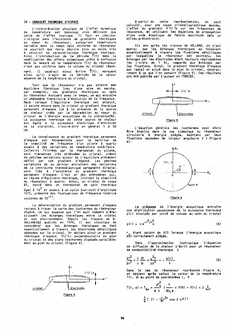
I V - GRADIENT THERHIQUE D'ESPACE
L ' i n t e r p r i t a t i o n pt iys ique de l ' e f f e t dyndmique de t e m p i r a t u r e e s t beaucoup p l u s d 6 l i c a t e que c e l l e de l ' e f f e t s t a t i q u e . 11 f a u t en chercher I ' o r i g i t i e darts l ' e x i s t e n c e de g r a d i e n t s thermiques au coeur du r i s o n a t e u r , puisqu'une temp6rature v a r i d b l e dans l e temps lnais ~ ~ n i f o r m e du r i s o n a t e u r ne p o u r r a i t que f a i r e d i c r i r e p l u s ou moins v i t e i c e l u i - c i sa c a r a c t i r i s t i q u e thermique s t a t i q u e . A i n s i l ' i n t r o d u c t i o n de l a d i r i v i e t ( t ) dans l a m o d i l i s a t i o n des e f f e t s dynamiques p r g t e i con fus ion dans l a mesure 06 l a temperature T ( t ) du r i s o n a t e u r n ' e s t pas uni forn ie dans l e volume du c r i s t a l t i s o n -
nan t . 11 v a u d r a i t mieux i c r i r e S ( t ) , marquant a i n s i q u ' i l s ' a g i t de l a d i r i v i e de l a v a l e u r llloyenne de l a temperature du c r i s t a l .
Tant que l e r i s o n a t e u r n ' a pas a t t e i n t son i q u i l i b r e thermique (cas d 'une mise en marche, p a r exemple), l e s g r a d i e n t s thermiques au s e i n du r i s o n a t e u r i v o l u e n t avec l e temps, ce q u i e n t r a i n e un phinomene t r a n s i t o i r e d 1 6 v o l u t i o n de l a f r i quence . Mais lo rsque l ' i q u i l i b r e thermique e s t a t t e i n t , il e x i s t e encore dans l e c r i s t a l un g r a d i e n t thermique permanent d'espace lii l a presence de l a source de cha leur c r i i e par l a degrada t ion au coeur du c r i s r a l de l ' i n e r g i e acous t ique de l a v i b r a t i o n ( 5 ) . La puissarice thermique de c e t t e source de cha leur e s t i g a l e B l a puissance i l e c t r i q u e d ' e n t r e t i e n de l a v i b r a t i o n , c ' e s t - l - d i r e en g inera1 1 ZI 50 I J W .
La connaissance du g r a d i e n t thermique permanent d'espace e s t fondamentale pour l a m a i t r i s e de l a s t a b i l i t i de f r i q u e n c e d ' u n p i l o t e i q u a r t z soumis i des v a r i a t i o n s de t e m p i r a t u r e e x t i r i e u r e . C e l l e s - c i f i l t r i e s par l e the rmos ta t du p i l o t e , son t t ransmises t r 6 s a t t 6 n u i e s au c r i s t a l , c r i a n t de p e t l t e s v a r i a t i o n s au tour de l ' i q u i l i b r e p r i c i d e n t d i f i n i par son g r a d i e n t d'espace. Les p e t i t e s v a r i a t i o n s de ce d e r n i e r e n t r a i n e n t des v a r i a t i o n s de l a c o n t r a i p t e t h e r m o i l a s t i q u e permanente d i r e c t e - merit l i i e a l ' e x i s t e n c e du g r a d i e n t thermique permanent d'espace, C ' e s t un des phSnom6nes q u i , en r i g i m e d ' i q u i l i b r e thermique, l i t n i t e n t l a s t a b i l i t d du r i s o n a t e u r B quar tz . A i n s i , un c r i s t a l de coupe AT, m o n t i dans un thermos ta t de g a i n thermique
dga l B l o 3 e t soumis i un c y c l e j c u r - n u i t d l a m p l i t u d e 1UuC, p r i s e n t e des f l u c t u a t i o n s de f r i q u e n c e r e l a t i v e
1 1 v o i s i n e s de 10- . La d i t e r m i n a t i o n du g r a d i e n t permanent d'espace
r e v i e n t B t r a c e r l a c a r t e des isothermes du r i s o n a t e u r i t u d ~ i , ce q u i suppose que l ' o n s a i t comment s 1 6 t e - b l i s s e r i t l e s ichanges thermiques e n t r e l e c r i s t a l e t son environnement. Depuis l e s t ravaux de R. HOLLANU(6) p u b l i i s en 1974, il e s t c l a s s i q u e de c o n s i d i r e r que l e s ichanges thertniques se f o n t essen t ie l l ement 2 t r a v e r s l e s i l e c t r o d e s m i t a l l i q u e s d i p o s i e s sur l e c r i s t a l . On o b t i e n t a i n s i un g r a d i e n t thermique d'espace aT/ 3 2 p e r p e n d i c u l a i r e au p lar . du c r i s t a l e t des p l a n s isothermes d i s p o s i s p a r a l l i l e - ment au p l a n du c r i s t a l ( F i g u r e 4 ) .
cristal / \ ilsctrodss Figure 4
A p a r t i r de c e t t e r e p r i s e n t a t i o n , on peu t c a l c u l e r , pour une coupe c r i s t a l l o g r a p h i q u e donnie, l ' e f f e t du g r a d i e n t a T / 32 sur l e s f r i quences de r6sonance, en u t i l i s a n t l e s i q u a t i o n s de p ropaga t ion dlune onde i l a s t i q u e de f a i b l e amp l i tude dans un m i i i e u p r i c o n t r a i n t .
D i x afls a p r i s l e s t ravaux de HOLLAND, on s ' e s t aperGu que l e s ichanges thermiques se f a i s a i e n t essen t ie l l emeht i t r a v e r c l e s f i x a t i o n s m 6 t a l l i q u e s par l e s q u e l l e s l e r i s o n a t e u r e s t maintenu, l e s ichanges par l e s E lec t rodes i t a n t - t o u j o u r s n i g l i g e a b l e s (de l ' o r d r e de 1 %), compares aux ichanges p a r l e s f i x a t i o n s . A i n s i , l e g r a d i e n t thermique d'espace e s t r a d i a l e t s i t u i dans l e p l a n du c r i s t a l , c o n t r a i - rement I ce que l ' o n p e n s a i t ( F i g u r e 5 ) . Ces r 6 s u l t a t s o h t 6 t 6 p u b l i C ~ pat- l ' a u t e u r en 1985(5).
cristal / 1 Clectrodes Figure 5
LILqua t ion g i n i r a l e des isothermes peu t a l o r s & r e 6tabl ie . dens !e cas c l a s s i q u e du r i s o n a t e u r c i r c u l a i r e a energ ie p i i g i e , maintenu par deux f i x a t i o n s opposies de l a r g e u r a n g u l a i r e 2 E ( F i g u r e 6 ) .
rayon R
Le pihgeege de l ' i n e r g i e acous t ique e n t r a i n e Une d i s t r i b u t i o n gaussienne de l a puissance thermique p ( r ) d i s s i p 6 e p a r u n i t 6 de volume au s e i n du c r i s t a l
~ ( r ) = 11e -r2/r: ( 4 )
r i t a n t v o i s i n de R/3 l o r s q u e l 1 6 n e r g i e acous t ique e g t correctement p i 6 g i e .
Dans l ' a p p r o n i m a t i o n i s o t r o p i q u e 1 1 6 q u a t i o n de d i f f u s i o n de l a cha leur s 1 6 c r i t pour un r i s o n a t e u r de c o n d u c t i b i l i t l thermique X
Dans l e cae du rLsona teur repr6sentC F i g u r e 6, on o b t i e n t aprhs c a l c u l l a v a l e u r de l a tempgrature T ( r , 8) au p o i n t de coordonn6es r, 8
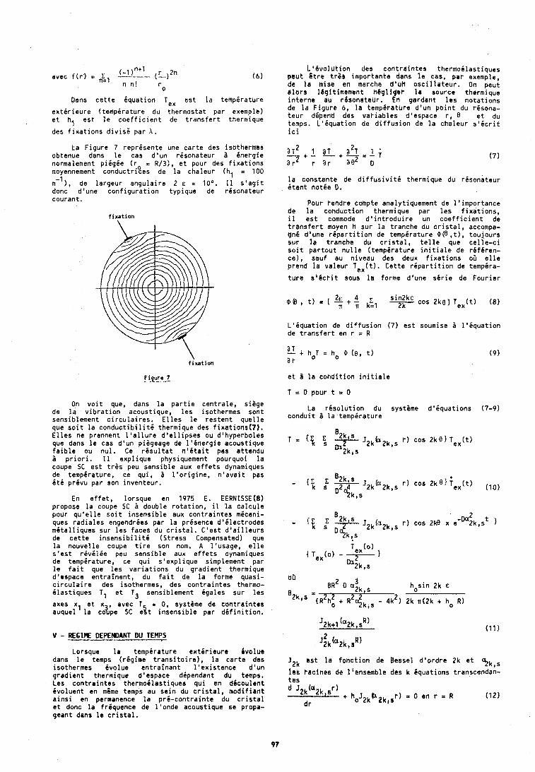
(-1 )? ( ~ ) 2 n avec f ( r ) = - n n !
0
Oans c e t t e 6qua t ion Ten e s t l a temp i ra tu re
e x t i r i e u r e ( t e m p i r a t u r e du thermostat pa r exemple) e t h, e s t l e c o e f f i c i e n t de t r a n s f e r t thermique
des f i x a t i o n s d i v i s k par A .
La F i g u r e 7 r e p r i s e n t e une c a r t e des isothermes obtenue dans l e cas d 'un r i s o n a t e u r B i n e r g i e normalement p i i g i e ( r = R/3), e t pour des f i x a t i o n s moyennement conduc t r iees de l a cha leur (hl = 100
m- I ) , de l a r g e u r a n g u l a i r e 2 E = l o 0 . 11 s l a g i t donc d 'une c o n f i g u r a t i o n t y p i q u e de r i s o n a t e u r couran t .
fixation
fixation
Figure 7
On v o i t que, dans l a p a r t i e c e n t r a l e , s i i g e de l a v i b r a t i o n acous t ique , l e s isothermes son t sensib lement c i r c u l a i r e s . E l l e s l e r e s t e n t q u e l l e que s o i t l a c o n d u c t i b i l i t b thermique des f i x a t i o n s ( 7 ) . E l l e s ne prennent l ' a l l u r e d ' e l l i p s e s ou d 'hyperboles que dans l e cas d 'un piageage de l ' i n e r g i e acoust ique f a i b l e ou n u l . Ce r i s u l t a t n ' i t a i t pas a t tendu i p r i o r i . 11 e x p l i q u e physiquement pourquoi l a coupe SC e s t t r & s peu s e n s i b l e aux e f f e t s dynamiques de t e m p i r a t u r e , ce q u i , i l ' o r i g i n e , n ' a v a i t pas i t 6 p r i v u par son i n v e n t e u r .
En e f f e t , l o rsque en 1975 E. EERNISSE(B) propose l a coupe SC 3 double r o t a t i o n , il l a c a l c u l e pour q u ' e l l e s o i t i n s e n s i b l e aux c o n t r a i n t e s m ican i - ques r a d i a l e s engendr ies par l a p r i sence d ' i l e c t r o d e s m i t a l l i q u e s sur l e s faces du c r i s t a l . C ' e s t d ' a i l l e u r s de c e t t e i n s e n s i b i l i t d (S t ress Compensated) que l a n o u v e l l e coupe t i r e son nom. A l ' usage , e l l e s ' e s t r i v i l d e peu s e n s i b l e aux e f f e t s dynamiques de temp i ra tu re , ce q u i s ' e x p l i q u e simplement par l e f a i t que l e s v a r i a t i o n s du g r a d i e n t thermique d'espace e n t r a i n e n t , du f a i t de l a forme quasi - c i r c u l a i r e des isothermes, des c o n t r a i n t e s thermo- i l a s t i q u e s TI e t T3 sensib lement (gales su r l e s
axes xl e t x a v e c - T = 0, systame de c o n t r a i n t e s auquel l a coTpe SC e 5 t i n s e n s i b l e par d i f i n i t i o n ,
V - R E G I N DEPENDANT DU TEHPS
Lorsque l a t e m p i r a t u r e e x t i r i e u r e i v o l u e dans l e temps ( r i g i m e t r a n s i t o i r e ) , l a c a r t e des isothermes Cvolue e n t r a i n a n t l ' e x i s t e n c e d 'un g r a d i e n t thermique d'espace d ipendant du temps. Les c o n t r a i n t e s t h e r m o i l a s t i q u e s q u i en dCcoulent Cyoluent en mOme temps au s e i n du c r i s t a l , m o d i f i a n t a i n s i en permanence l a p r i - c o n t r a i n t e du c r i s t a l e t donc l a f r i q u e n c e de l ' o n d e acoust ique se propa- geant dans l e c r i s t a l .
L ' B v o l l i t i o n des c o t i t r a i n t e s t h e r m o i l a s t i q u e s p c u t G t r e t t 8 s impor tan te dens l e cas, p a r exemple, d t l a mise en marche d'UH o s c i l l a t e u r . On peut d l o r s 16git imoment n b g l i g r t l a source th r rm ique i n t e r n e au t8sonateur . k r ~ gardant l e s n o t a t i o n s de l a F i g u r e 6, l a tempbrathre d ' u n p o i n t du r i s o n a - t e u r d ipend des v a r i a b l e s d'espace r, 0 e t du temps. L ' i q u a t i o n de d i f f u s i o n de l a c h a l e u r s ' i c r i t i c i
l a cons tan te de d i f f u s i v i t i thermique du r i s o n a t e u r 6 t a n t n o t i e D,
pour tendre coinpte analyt iquement de l ' i m p o r t a n c e de l a t o n d u c t i o n thermique p a r l e s f i x a t i o n s , il e s t commode d ' i n t r o d u i r e un c o e f f i c i e n t de t r a n s f e r t moyen h sur l a t ranche du c r i s t a l , accompa- g n i d'uhe r i p a r t i t i o n de tempgrature @(e , t ) , t o u j o u r s su r l a t ranche du c r i s t a l , t e l l e que c e l l e - c i s o i t p a t t o u t n u l l e ( t e m p i r a t u r e i n i t i a l e de r i f 6 r e n - ce ) , sau f au n i v e a u des deux f i x a t i o n s oG e l l e prend l a v a l e u r T e x ( t ) . C e t t e r i p a r t i t i o n de temp6ra-
t u r e s l € c r i t sous l a forme dlune s i r i e de F o u r i e r
L ' i q u e t i o n de d i f f u s i o n ( 7 ) e s t soumise i l ' i q u a t i o n de t r a t i s f e r t en r = R
e t B l a c o n d i t i o n i n i t i a l e
T = 0 pour t = 0
La r i s o l u t i o n du syst8me d ' b q u a t i o n s (7-9) c o n d u i t B l a t e m p i r a t u r e
B2k s - { E i! s s J 2 k ( ' 2 k , s r ) cos 2 k e ) i x ( t )
- t Bw J2k(a2k,s r ) cos 2@ x e -~ :k ,s ' 1 '?!k!s
J2k o s t l a f o h c t i o n de Bessel d ' o r d r e 2k e t qk,s I e s t a c l n e s de l iensemble des k i q u a t i o n s transcendan- t e s
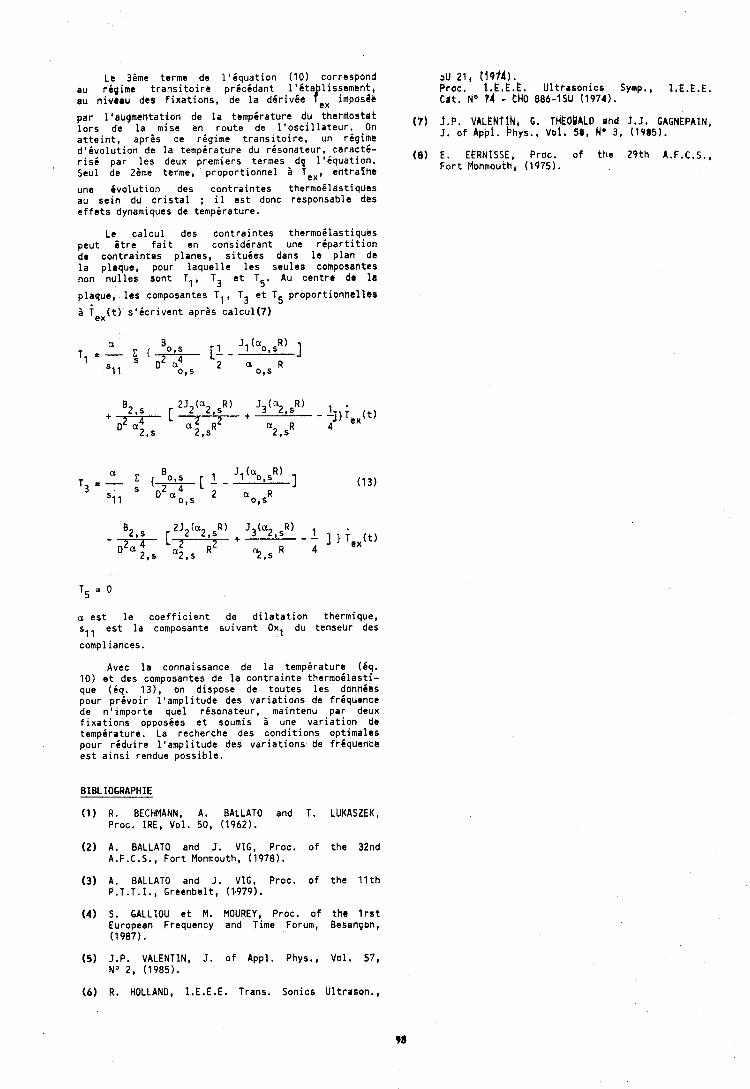
Le 38me terme de l ' i q u a t i o n (10) correspond au r i p i m e t r a n s i t o i r e p r i c i d a n t I ' i t a l issement , au n iveau des f i x a t i o n s , de l a d ( r i v6a tX imposge
p a r l l i i ugmenta t ion de l a t e m p i r a t u r e du t h e r ~ o s t a t l o r s de l a .mise en r o u t e de l ' o s c i l l a t e u r . On a t t e i n t , apres ce r i g i m e t r a n s i t o i r e , un r i g i m e d ' i v o l u t i o n de l a t e m p i r a t u r e du r i s o n a t e u r , c a r a c t i - r i s i pa r l e s deux p remie rs termes d l ' i q u a t i o n . Seul de m e t e r s e , p r o p o r t i o n n e l 2 , e n t r a l n e
au 21, 14914). Proc. l.E,E.E. U l t r a s o n i c s Symp., I.E.E.E. C a t . No 74 - t H O 886-1SU (1974).
une i v o l u t i o n des c o n t r a i n t e s the rmo6 las t iques au s e i n du c r i s t a l ; il e s t donc responsdble des e f f e t s dynamiques de temp6rature.
Le c a l c u l des c o n t r a i n t e s t h e r m o i l a s t i q u e s peu t S t r e f a i t en cons ideran t une r i p a r t i t i o n de c o n t r a i n t e s p lanes, s i t u i e s dans l e p l a n de l a p laque, pour l a q u e l l e l e s seu les composantes non n u l l e s son t T1, T3 e t T5. Au c e n t r e dr l a
p laque, l r s composantes T1, T3 e t T5 p r o p o r t i o n n e l l b s
2 f e x ( t ) s ' i c r i v e n t a p r i s c a l c u l ( 7 )
a e s t l e c o e f f i c i e n t de d i l a t a t i o n thermique, sll e s t l a composante s u i v a n t Oxl du tenseur des
compliances.
Avec l a connaissance de l a temperature (Cq. 10) e t des composantes de l a c o n t r a i n t e t h e r m o i l a s t i - que (iq,. 1 3 ) , on d ispose de t o u t e s l e s donnibs pour p r e v o i r 1 ' amp l i tude des v a r i a t i o n s de frequence de n ' i m p o r t e que l r i s o n a t e u r , maintenu par deux f i x a t i o n s opposies e t soumis i une v a r i a t i o n de temp i ra tu re . La recherche des c o n d i t i o n s op t ima les pour r i d u i r e 1 'amp l i tude des v a r i a t i o n s de ft-8qucflce e s t a i n s i rendue p o s s i b l e .
(1) R . BECHMANN, A. BALLATO and T. LUKASZEK, Proc. IRE, Vol . 50, (1962).
(2) A. BALLATO and I. VIG, Proc. o f t h e 32nd A.F.C.S., F o r t Monmouth, (1978).
(3) A. BALLATO and J. VIG, Proc. o f t h e 1 1 t h P .T .T. I . , Greenbel t , (1.979).
(4) 5. GALLIOU s t M. MOUREY, Proc, o f t h e I r s t European Frequency and Time Forum, Besan~oh, (1987).
(5) J.P. VALENTIN, J . o f Appl. Phys., Vol . 57, No 2, (1985).
(8) E. EERNlSSE, Proc, of t h e 2 9 t h A.F.C.S., F o r t Munmodth, (1975).
(6) R, HOLLAND, I.E.E.E. Trans. Sonics U l t rason . ,
ler Forum EuropQen Tbmps-Friquence - 1987
SENSIBILITE b'UM RESONATEUR A W A R T 2 PLAN-CONVEX€ A L A C O M P R E S S Z ~ ~ b 1 A K T R A L E
, Laboratoire de ChranornQtrie, Eleotronique et CiitoQlecti-icitd ECOLE NATIONALE SUPERtEURE bE &CANlPUE k t DES MICRt)tECHNll/dES
Route de Gray - La Bodlbie - 25030 Besancjen Cadex - FRANtE
RE SUM - Le sensibilit6 aux forces externes des risoka-
teurs vibrant an tisaillement doipaisseur est rigie par les non liniaritis des diformrtions et des lois de comportement ilastique. Cette sensibi- lit6 est donnbe par une intigrale de perturbation qui dipend des diformations statiques et dynamiques en tous points de la plaque. En raison du pidgeagc de l'inrr ir, lr domaine d'intbgration btsit jusqu'l prisent r h i t a u centre de la plaque.
Lerrque celle-ci est circulaire, 10s contraintes et les diformations Statiques cri6es par une comprer- sion diam2trale ne sont pas homog2nes. Comma par ailleurs il est possible de modiliser prbcisdment la distribution de la vibration pour un rdsoneteur plan-convhxe, nous proposons une amilioratibn du calcul de la sensibiliti, en Ctendatit 10 domaine d'intdgration i l'ensemble du disque,
Nous donnons les risultats relatifs I des risonateurs de coupe AT et SC en fonction de l'azimut d e la force appliquie st pour diff6rents modes de vibrations, partiels et anharmoniques (bien que piigis, ces derniers n e prisentent pas un maximum d'amplitkide absolu au centre de la plaque).
The force sensitivity of thickness shear modes iti quartz resonators is an bssehtially non linear rffrct arising from the intrinsic non lineari- ties of the stress versus strain expansion for the actbal moterial, as re11 as from the superposi- tion of the static and dynamic contributiohs fop the final strain, That sensitivity can IccUhPtely br predicted by a first order perturbation integral which depends on both of the static and dynamic fields ih the resonator. In the case of contoured disk resonator&, the vibrating modes of practical interest are trapped at the center of the plate, Thus, the perturbation integral is currently performed over a domain restricted to the center of the plate, ifthough the biasing state is not homogeneous when thr; birsing forces act on a diameter of the d i r k , The hbrr presedted stbdy systsmrtiorlly ent6ndY ttir ihtdqration range to the whole bulk of thr; disk.
the ramJltr prbdieted for AT rnd Sc but8 arr showed, Including the force arnsitivity of some atthrrwonic MOdbSl the maximum amplitude o f which doer not OCGUr #t the plate canter,
statique pri-existant 3 la vibration(5). Les iquations de propagetioh traduisent alors l'iquilibre dynamique d o u n petit 616ment de volume soumis i un accroissement dynamiqut des contraintes par rapport 3 leurs valeurs statiques non nulles. En pratique, o n utilise 16 champ des diplacements particulaires comme variables, prifhrentiellement aux contraintes. On utilise donc, 3 cet effet, les lois de comporte- ment du h a t 6 r i d ~ (kelations efforts - diformations dans la cas purement ilastlque). Ces lois font intervenir des coefficients ilastiques clairement ddfinis, dits matiriels, lorsqu'on diveloppe le tensmut des bffohts tottux en fonction de celui de la diformation totale, En analysant prdcisiment l a superposition d s s o n t r i b u t i o n s statiques et dynamiques i cette dSformation totale, on parvient assez a i s i p n t , lorsque la vibration demeure infinith- simale, a relier lo;lccroissement dynamique du tenseur des efforts aux dirivies partielles du diplacement mOcanique dynamique. Le tenseur de coefficients ilastiques effectifs qui caractirise cette relation s'txprime alors en fonction des coefficients matCrictls du second ordre (les coeffi- cients C,, de la thiorie de l~ilasticiti liniaire)
I J
du troisi2me ordre (les coefficients C ainsi que des d r i v e s partieiles du d i p l a c e m e ~ ~ l t a t i q u e superposd P la vibration. Dans Ie cas purement Elastique (hypothase suffisante pour traiter de nombreux problemes de vibrations dans le quartz, matiriau faiblement piito6lectrique), une formulation variationnelle permet d'obtenir tr2s rapidement les i q ~ a t i o n s locales pour l'effet dcoustoilastique (131, Smct. 1). Larsque I'rffet pi6zoblectrique ne peut 8tre nigligi, les iquations locales peuvent Otre igalement obtenues, au prix d'un effort supplb- mentaire(6).
Par rilleurs, it rst clair que certaines prbcautions doivent ftre prises en ce qui concerne loicriture des conditions aux limites car la surface externe du solide se trouve diplacie aussi bien par sbite de la pridiform_rtion statique que par suite de la vibration ells-meme. 11 est donc extrime- tnent avantageux de rbfirencer toutes les variables de champ (les tenseurs d'efforts, les diformations) B liaida des toordottnies des points matiriels du solide B 116tat nature1 (ni vibration, ni pridifor- mation), Ceci ambne P substitder 3 la notion de contrainte, 14 notion de tenseur de Piola-Kirchoff pour lo trnseur des efforts, en rapportant la force B 1'616ment da surface ivalui dans l'dtat nrtursf(7), L e a lqurtionr de propagation et 10s conditions auk iimitas ainsi abtenues satisfont au principe d'invdriance rotationnelle de 116nergie blastiqw(8).
4
1 - OESCRlPtlON Et hEfHOOOL06lE DE LtE'IUDE Nods traitons ici 16 ces d'un disque en compres- sion diamlthald : les ddformations statiques ne
Dan$ le passi, diverse$ (tudes ant permis Bent alorsi bt trbs Cvidemment, pas homoglnes de modiliser la sensibilitb pux forcer &#t@rnrs sei"u disque* TOutefOis, les nOn liniaritgs des vibrations da cisaillament d1Qpaics&ur(l,t), intrinshues d~ quartz sont asset faibles pour mris aussi d'rutre!, types de vibrati~n(j,4), &*tte qU@# m8ma en a ~ ~ l i q u a n t au rlsonateur des ~ r i c h a r g a s
non R6pligeablks devrnt lr charge i la rupture,
:::::!::::fa ;:s:~EndfiCe l~:f~:t,i:~~~~t~):l~~~~~u~~ I ~ S ~. t i r t i ~ n s del coefficients ilastiques effectits tion d,une mdr an tofiction da 1t6trt di(quiligra fi9utPnt dlns 1Cb 8qUltions locales, ne dipassent
pas quelques en valeur relative. 11 est donc logique de recourir 6 une mithode de perturbation pour ivaluer la variation de friquence qui risulte de la pridiformation(9). La sensibiliti est alors donnie par une intigrale de volume oG interviennent les coefficients ilastiques d'ordre deux et trois, ainsi que les dirivies partielles des diplacements micaniques statiques et dynamiques par rapport aux coordonnies correspondantes des points du solide pris dans l'itat naturel. Dans un milieu anisotrope, de nombreuses variantes euvent ftre envisagees tant pour risoudre le probrime statique que le problime dynamique. Mais, en pratique, on sait tris bien que seules les vibrations dites A inergie piigie permettent d'obtenir pour le risonateur, de trPs bonnes caractiristiques de surtension et de stabiliti temporelle(l0). Eh ce cas, la zone vibrante des modes les plus usitis, dits mitrologiques, se trouve riduite ii la proximiti immidiate du centre de la plaque. Pour cette raison, on a pris l'habitude d'ivaluer la sensibiliti en reportant dans les equations utilisies pour modiliser l'effet acoustoilastique, les valeurs des dirivjes partielles des diplacements statiques et micaniques calculies exactement au centre de la plaque. Comme celle-ci est ginir?lement asset mince pour autoriser le recours a l'hypothase d'une distribution plane des contraintes statiques et comme la diriyie, partielle priponddrante pour le diplacement mecanique est la dirivie suivant l'ipaisseur (l'onde est, au centre de la plaque, assimilie A une onde plane se propageant selon l'ipaisseur), facilement bvaluable, m6me l'intigration suivant l'ipaisseur disparait des modiles ainsi ilaboris qui ivaluent donc la sensibiliti tris directement i partir des iquations locales de I 'effet acoustoilastique.
Dans cette btude, nous calculons la sensibilit6 des vibrations de cisaillement i la compression diamitrale en effectuant une intigration sur le volume du risonateur. Nous nous attachons donc B mettre en ividence la modification des r6sultats par rapport 1 la mhthode de calcul local, plut6t qu'6 Innover, pour la solution des problPmes statiques et dynamiques eux-mimes.
Nous supposons d'abord que la distribution des efforts statiques est quasiment identique i celle qu'on obtient dans un disque isotrope(l1) soumis 1 deux forces diamitrales opposies igalement riparties suivant l'ipaisseur. On sait notamment que pour un problime tris voisin, la prise en compte de l'anisotropie ne modifie guire les risultats en termes de contraintes(l2). Les diformations sont ensuite obtenues B loaide des relations de souplesse, en tenant compte de l'anisotropie. Comme les iquations de compatibiliti pour un milieu isotro e ont 6th utilisies pour obtenir la distribu- ~ % e s contraintes statiques, cette dimarche au demeurant classique, est tris imparfaite car le diplacement statique ne peut alors ftre int6gri B partir des diformations puisqu'il y a disaccord entre les symitries uti lisies pour les coeff icjents ilastiques et celles auxquelles obiissent les conditions de compatibiliti. Cependant, 1 'effet acoustoilastique ne fait intervenir le diplacement statique qu'en terme de ses dirivies partielles. Celles-ci peuvent Gtre isolies dans les diformations en faisani appel i des conditions diterminant la rotation de la plaque. Les risultats obtenus pour la sensibilith finale dependent 16girement du choix de ces conditions. Pour notre part, nous avons choisi de supposer q6e le diplacement micanique parallale au diamitre d'application des forces, est nu1 sur le diamatre perpendiculaire I ce dernier. Ceci est arbitraire : par exemple, nous aurions pu supposer que le diplacement transverse ftt nu1 sur le diamitre d'application des forces. Nous avons pu virifier que la sensibiliti finale aurait alors diffiri au maximum de 1 % p a t rapport aux valeurs que nous produisons ici. Le choin de ces conditions intervient donc pour la comparaison
de nos risul tats avec ceux diautres auteurs(2,13).
Par ailleurs, pour modiliser la vibration, noub avons choisi les risultats ricemment proposis par Stevens et Tiersten(l4), applicables aux risona- teurs plans-convenes avec ufle orientation quelconque de la coupe cristalline. Les inconnubs sont les amplitudes das projections du diplacement micanique sur le tribdre orthonormi des solutions propres pour une plaque plane infinie de mime orientation (ondes planes(l5)). Apris iliminatiorl de la variable ipaisseur, on obtient une iquation de dispersion reliant la fr6quence aun composantes du vecteur dlande dans la elan de la plaque (l'onde est guidie). Cette Bquation est alors giniralisie en iquation aux dirivies partielles par rapport aux directions oituies dans le plan de la plaque. Les dirivies crbis6es ront iliminies par une rotation du repire de travail autour de la normale 3 la plaque. Cette rotation difihit l'orientation des figures modales dans le replre habitue], lii aux axes cristallogra- phiques par deux rotations successives 0 autour de $2, 0 autour de OX'. Dans le repare final, la distribution d'amplitude est donnie par les fonctions d1Hermite, solutions convergentes de l'iquation aux dit-ivies partielles dans laquelle llipaisseur lentement variable est exprimie par un diveloppement parabolique (la surface convexe rielle est sphirique). La troisihme rotation ci-dessus mentionnie est nulle en coupe AT, non nulle et dipendant du type de mode (cisaillement lent ou rapide) et du rang de partiel (nombre de 1/2 longueurs d'ondes suivaht l'hpaisseur) dens le cas giniral, et notamment en coupe SC. Ce modale est assez pricis pour le calcbl des friquences et par ailleurs, l'itude des modes par topographie aux rayons X(16) permer de virifier qu'il conduit 1 des risultats giniralement tras cohirents pour l'identification des modes ; la troisihme rotation est effectivement observable, et conforme aux pridictions dans la limite de quelques degris. Les modes mitrologiques habituellement employis correspondent i une riparti- tion gaussienne dans le plan de la plaque ; les modes correspondant aux autres formes prises par les fonctions d'kermite sont dits anharmoniques. Pour identifier les modes, nous utilisons une nomenclature utilisant le hombre de lignes nodales ~uccessivemeht suivant l'ipaisseur, puis les axes X" et fi du repire de la triple rotation. Par exemple (C,5,0,0) repr6sente le partiel 5 du mode de cisaillement lent C, avec une distribution gaussienne dans les deux directions du plan.
La figure modale reste indipendante de l'azimuth du diametre d'application des f o y e s , dans le cas de vibrations suffisamment piegees dans la rigion centrale. I1 n'y a donc pas de lien entre les symitries pr6sent6es par les champs des diplace- ments statiques et dynamiques. Les termes f igurant dans l'intigrale de perturbation s'integrent aisiment suivant l'ipaisseur mais on doit recourir B une mithode numirique pour les directions du plan de la plaque. Le nombre de points retenus pour le calcul est limit; car nous avons utilisi, 2 cet effet, un microordinateur de capacith moyenne. Le lecteur pourra trouver dans les appendices A, B , C, 0, des pr6cisions supplimentaires sur le ditail des calculs et les iquations retenues.
11 - RESULTATS OBTENUS Les rgsultats que nous prisentons sur les
figures 1 3 6 sont des courbes K f I f(Y ), Y itant l'azimut rfe la force F dans le replre de la double rotation ct K le coefficient de sensibiliti sans dimension, diffni par Ratajski(l), obtenu en multi- pliant la sensibiliti relative de la friquence Af/(fF) par nD/f 05 n est le rang de partiel et D fe diamltre de la plaque. Les courbes en pointillhs reprisentent les risultats obtenus localement au centre de la plaque, les autres
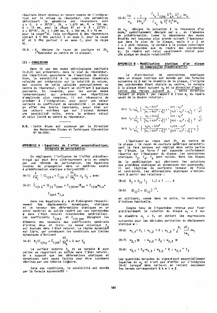
r i s u l t a t s i t a n t obtenus en tenan t compte de l ' i n t i g r a - t i o n su r l e volume du r i s o n a t e u r . Les parametres d i f i n i s s a n t l a g i o m i t r i e des r i s o n a t e u r s s'ont 4 = 0, 0 = 35O25', 2h = 1,679 mm, R c = 150 mm, o = 15 mm, pour l a c8upe A T e t $ = - 22"25' , 8 = 35O15', 2h = 1,089 mm, R = 300 mm, D = 15 Mm pour l a c o u p e O ~ c . Cela corrSspond B des r i s o n a t e u r s v i b r a n t d 5 MHz p a r t i e l 5 en mode C , pour l a coupe AT e t 5 MHz p a r t i e l 3 en mode C, pour l a coupe SC . (N.H. : R d i s i g n e l e rayon de courbute e t 2h0
l P i p a i s s e u r au c e n t r e de l a p laque) .
19.1 - CONCLUSION
Oans l e cas des modes m i t r o l o g i q u e s h a b i t u e l s (n,O,O) q u i p r i s e n t e n t , dans l e p l a n du r i s o n a t e u r , une r i p a r t i t i o n gaussienne de l ' a m p l i t u d e de v i b r a - t i o n , l a s e n s i b i l i t i d l a compression d iamgt ra le c a l c u l i e par i n t i g r a t i o n su r l a t o t a l i t i du volume, e s t v o i s i n e de c e l l e c a l c u l i e ponctuel lement au c e n t r e du r i s o n a t e u r , l ' i c a r t se c h i f f r a n t b quelques pourcents. En revanche, pour l e s a u t r e s modes (anharmoniques) q u i p r i s e n t e n t une r i p a r t i t i o n d 'amp l i tude p l u s complexe, il e s t n i c e s s a i r e de p r o c i d e r i l ' i n t i g r a t i o n , pour a v o i r une v a l e u r c o r r e c t e du c o e f f i c i e n t de s e n s i b i l i t i : on observe en e f f e t des i c a r t s impor tan ts , auss i b i e n su r l e s v a l e u r s ex t r imes que sur l ' a z i m u t dbhhaht une s e n s i b i l i t i n u l l e , e n t r e l e p resen t c a l c u l e t c e l u i l i m i t 6 au c e n t r e du r i s o n a t e u r .
N.B. : C e t t e i t u d e e s t soutenue par l a D i r e c t i o n des Recherches Etudes e t Techniques (Convent ion No 86-058).
APPENDICE A : Equat ions de l ' e f f e t acous tob las t ique ; i n t C g r a l e de p e r t u r b a t i o n .
En n i g l i g e a n t l ' i n f l u e n c e de l ' e f f e t p i E t o 6 l e c - t r i q u e q u i peu t t t r e u l t i r i e u r e m e n t p r i s en compte par une mithode de p e r t u r b a t i o n , l e s i q u a t i o n s l o c a l e s de p ropaga t ion dans un m a t i r i a u soumis i p r i d i f o r m a t i o n s t a t i q u e s 0 i c r j v e n t ( 9 ) :
a a u (A-1) ( (cijk & + Eijk %I= p0 u j , avec
Dans ces i q u a t i o n s O , w e t E d i s i q n e n t r e s p e c t i - vement l e s d ip lacements dynamiques, s t a t i q u e s e t l e tenseur des d i f o r m a t i o n s s t a t i q u e s en Uh p o i n t m a t i r i e l du s o l i d e reper6 par ses coordonnies a dans l ' i t a t n a t u r e l (coordonnies m a t i r i e l l e s ) . Les c o e f f i c i e n t s CijkQ e t Ci jk elnn. d i s i g n e n t l e s
i l i m e n t s des tenseurs des coefficients m a t i r i e l s d 'o rd res deux e t t r o i s . La masse volumique f e s t i v a l u i e dans l ' i t a t n a t u r e l . Le regime dynamiqu? e s t l i b r e , pa r consiquent l e s c o n d i t i o n s aux l i m i t e s dvnamiaues s ' i c r i v e n t
a o (A-3) Ni(CijkL + tijkk) < = 0 sur
La s u r f a c e e x t e r n e S e t sa normale N son t c e l l e s se r a p p o r t a n t au s o f i d e dans 1 ' Q t a t n a t u r e l . On a supposi que l e s d i f o r m a t i o n s s t a t i q u e s e t dynamiques son t assez f a i b l e s pour 6 t r e i s o l i m e n t d i c r i t e s p a r une t h i o r i e l i n t a i r e .
Dans ces c o n d i t i o n s , l a s e n s i b i l i t i e s t donn6e p a r l a formule su ivan te (9 ) :
05 ha dQsigne l a pL i l sa t ion B l a resonance d 'un mode, symbo~iquemcnt d6signC par a , en l 'absence de p r 6 d i f o r m a t i o h . Comme l a dipendance des modes B t u d i k s e s t beaucoup p l u s grande s u i v a n t l ' i p a i s s e u r que dans l e p l a n de l a p laque, seu ls k = 2 e t i = 2 son t retenus, l a normale B l a p laque c o i n c i d a n t avec l e deux i l f i e axe du repgre des coordonnies a , , Ce repare e s t c e l u i usuel lement c h o i s i pour uhe p laque en double r o t a t i o n ( l 7 )
APPENDICE B : M o d C l i s a t i o n s t a t i q u e d'un d isque en compresslon d i a m 6 t r a l e ( l l ) .
La d i s t r i b u t i o n de c o n t r a i n t e s s t a t i q u e s dans un d isque i s o t r o p e e s t donnie par l e s formules su ivan tes 05 D e s t l e d iamgt re de l a plaque, l ' o r i g i n e des coordonnies i t a n t c h o i s i e au cen t re , l a normale B l a p laque i t a n t s u i v a n t a e t l a d i r e c t i o n d ' a li- c a t i o n des f o r c e s s u i v a d a, ; c e t t e dire!:ion f a i s a n t un ang le Y p a r r a p p o r t B l ' a x e a, du r e p i r e usue l de l a double r o t a t i o n .
L'CpaisseuP au repos v a u t 2h au c e n t r e de l a p laque : l e rayon de courbure sph%rique c a r a c t i r i - san t l a face convexe e s t n i g l i g i dans c e t t e p a r t i e de l ' i t u d e . Le f o r c e F e s t supposie un i fo rm iment r i p a r t i e su r l B Q p a i s s e u r du d isque. Les c o n t r a i n t e s s t a t i q u e s T2, T4, T6 son t n u l l e s . Dans l e s i t a p e s
de l a m o d i l i s a t i o n q u i d i c r i v e n t l e s s o l u t i o n s des problkmes s t a t i q u e s e t dynamiques non superposis , il h s t l i g i t i m e de confondre tenseur de P i o l a s t c o n t r a i n t e . Les d i f o r m a t i o n s s t a t i q u e s s ' o b t i e n - nen t 8 p a r t i r des r e l a t i o n s :
en u t i l i s a n t , comme dans l a s u i t e , l a c o n t r a c t i o n d ' i n d i c e s h a b i t u e l l e .
Compte t e n u de l ' hypo thgse re tenue pour f i x e r a r b i t r a i r e m e n t l a r o t a t i o n du d isque wl = 0 su r
l e d iamgtre a, r 0, on o b t i e n t l e s expressions
su ivan tes pour l e s d i r i v i e s p a r t i e l l e s du d ip lacement s t a t i q u e w :
Les q u a n t i t i s marquies du s i g n e & s o n t e s s c n t i e l l o m e n t impa i res en az e t n ' o n t pas d ' e f f e t su r l ' i n t i g r a l e (A-4) l o r s q u e dans c e l l e - c i on r e t i e n t seulement l e s termes correspondant 3 k = i = 2.
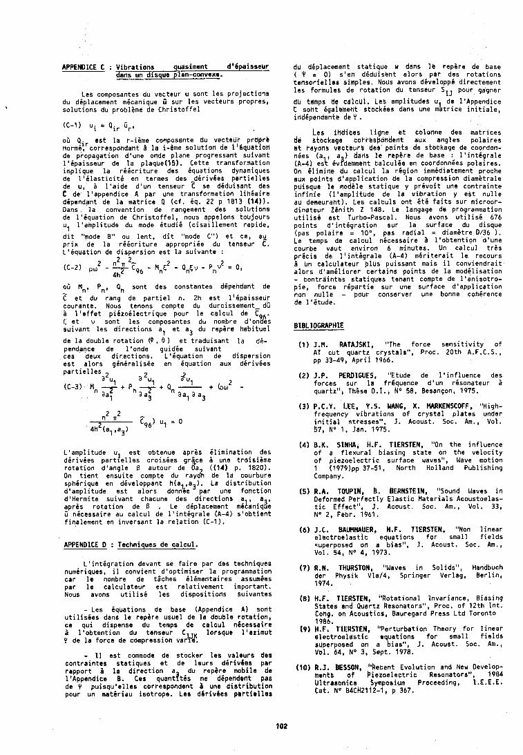
APPENDICE C : V i b r a t i o n s quasiment d 'dpa issebr dans un d i s q u r plan-convexe.
Les composantes du vec teur u son t l e s p r o j e c t i o n s du d ip lacement micanique D sur l e s vec teurs propres, s o l u t i o n s du p rob l ime de C h r i s t o f f e l
05 Q e s t l a r - i i m e conlposahte dU vecteuk p r b p k t normi t rcorrespondant B l a i-&me s o l u t i o n de l l b q u e t i o n de p ropaga t ion d 'une onde p lane p rogressan t s u i v a n t l ' i p a i s s e u r de l a p l a q u e ( l 5 ) . Ce t te t r a n s f o r m a t i o n imp l ique l a r i i c r i t u r e des i q u a t i o n s dynamiques de l ' i l a s t i c i t i en termes des -d i r i vbes p a r t i e l l e s de u, 2 l ' a i d e d ' u n tenseur C se ddduisant des C de l ' append ice A par une tra;sformation l i h i a i r e d ipendant de l a m a t r i c e Q ( c f . eq. 22 p 1813 (14) ) . Dans l a conven t ion ,de rangement des s o l u t i o h s de l ' i q u a t i o n de C h r i s t o f f e l , nous appelons t o u j o u r s u, l ' a m p l i t u d e du mode 6 t u d i i ( c i s a i l l e m e n t rap ide ,
d i t "mode 8" ou l e n t , d i t "mode C") e t ce, a y p r i x de l a r i i c r i t u r e appropr lee du tenseur C. L 'Bqua t ion de d i s p e r s i o n e s t l a s u i v a n t e : -
oh M,, P,, Q, son t des cons tan tes d ipehdant de - .. .. .. C e t du rang de p a r t i e l n. 2h e s t l ' i p a i s s e u r courante. Nous tenons compte du durcissement- dO a l ' e f f e t p i i z o i l e c t r i q u e pour l e c a l c u l de C 5 e t v son t l e s composantes du nombre d'on9die; s u i v a n t l e s d i r e c t i o n s a, e t a3 du r e p i r e h a b i t u e 1
du dgplacement s t a t i q u e w dans l e repZre de base ( Y = 0 ) s 'e t i d i d u i s b h t a l o r s par des r o t a t i o n s t e h s o r i e l l e s s imples. Nous avons d i v e l o p p i d i rec tement l e s formules de r o t a t i o n du tenseur SIJ pour gagner
tiu temps da c a l c u l . L t s amp l i tudes u de l 0 A p p e n d i c e C sod t Bgalement s t o c k i e s dans une m a t r i c e i n i t i a l e , i dd ipendan te de Y .
Les i h d i c e s l i g n e e t co lonne des m a t r i c e s d b btbckage cokrrbpandent aux adgles p o l a i r e s c t rayons vec teurb deb p a i n t s de stockage de coordon- n i e s ( a , a ) dads 1s r e p i r e de base : l ' i n t i g r a l e (A-4) eslt ivademment t a l c u l i e en coordonnies p o l a i r e s , On i l i m i n e du c a l c u l l a r i g i o n immidiatement proche aux p o i n t s d ' a p p l i c a t i o n de l a compression d i a m i t r a l e puisque l e mod i le s t a t i q u e y p r i v o i t une c o n t r a i n t e i n f i n i e ( l ' a m p l i t u d e de l a v i b r a t i o n y e s t n u l l e au demeuraht). Les c a l c u l s o n t i t 6 f a i t s su r m ic roor - d i n a t e u r 2 6 n i t h 2 148. Le langage de programmation u t i l i s i e s t Tbrbo-Pascal . Nous avons u t i l i s i 676 p o i n t s d ' i n t i g r a t i o n su r l a s u r f a c e du d isque (pas p o l a i r e = l o 0 , pas r a d i a l = d i a m i t r e 0136 ) . Le temps de c a l c u l n i c e s s a i r e a l ' o b t e n t i o n d 'une courbe vau t e d v i r o n 6 minutes. Un c a l c u l t r k s p r i c i s de l ' i n t i g r a l e (A-4) m i r i t e r a i t l e recours 5 un c a l c u l a t e u r p l u s p u i s s a n t mais il c o n v i e n d r a i t a l o r s d ' a m i l i o r e r c e r t a i h s p o i n t s de l a m o d i l i s a t i o n - c o n t r d i h t e s s t a t i q u e s tenan t compte de l ' a n i s o t r o - p i e , f o r c e r i p d r t i e s t i r une sur face d ' a p p l i c a t i o n non n u l l e - pour conserver une bonne coh i rence de l ' i t u d e .
de l a double r o t a t i o n 6 , 8 ) e t t r a d u i s a n t l a d i - pendance de l ' o n d e g u i d i e s u i v a n t (1 ) J.M. RATAfSKl, "The f o r c e s e n s i t i v i t y o f
ces deux d i r e c t i o n s . L ' i q u a t i o n de d i s p e r s i o n AT c u t q u a r t z c r y s t a l s " , Proc. 2 0 t h A.F.C.S.,
e s t a l o r s g i n i r a l i s i e en i q u a t i o n aux d i r i v i e s pp 33-49, A p r i l 1966.
p a r t i e l l e s aZul a 2ul (2) J.P. PEROIGUES, "Etude de l o i n f l u e n c e des 2 Zul + (pa - (C-3) Mn -7 + Pn -7 + Qn - f o r c e s sur l a f rgquence d ' u n r i s o n a t e u r 2
aal a a3 aa, a a3 quar tz" , Th ise O. I . , No 58, Besanson, 1975.
L ' a m p l i t u d e ul e s t obtenue a p r i s C l i m i n a t i o n des d i r i v i e s p a r t l e l l e s c r o i s i e s gr-ce 2 une t r o i s i i m e r o t a t i o n d 1 a n g l e B a u f o u r de b ((11) p. 1820). On t i e n t e n s u i t e compte du rayo% de l a courbure s p h i r i q u e en dhveloppant h (a a ). La d i s t r i b u t i o n d 'amp l i tude e s t a l o r s d o n z e par une f o n c t i o n d4Hermi te s u i v a n t chacune des d i r e c t i o n s a a s r o t a t i o n de I? , Le d ip lacement mi~;ni& O n i c e s s a i r e au c a l c u l de l ' i n t i g r a l e (A-4) s ' o b t i e n t f i na lement en i n v e r s a n t l a r e l a t i o n (C- I ) .
APPENDICE 0 : Techniques de c a l c u l .
(3) P.C.Y. LEE, Y.S. WANG, X. MARKENSCOFF, "High- f r e a u e n c ~ v i b r a t i o n s o f c r y s t a l p l a t e s under i n i t i a l ' s t t e s s e s " , J . A C O U S ~ . Soc. Am., Vol . 57, No 1, Jan. 1975.
(4) B.K. SINHA, H.F. TIERSTEN, "On t h e i n f l u e n c e o f a f l e x u r a l b i a s i n g s t a t e on t h e v e l o c i t y o f p i e z o e l e c t r i c s u r f a c e waves", Wave mot ion 1 (1979)pp 37-51, N o r t h H o l l a n d P u b l i s h i n g Company.
(5 ) R.A. TOllPlN, 8. tlERNSTElN, "Sound Waves i n Deformed P e r f e c t l y E l a s t i c M a t e r i a l s Acoustoelas- t i c E f f e c t " , J + Acoust. Soc. Am., Vol. 33, No 2, Febr . 1961.
(6) J.C. BAUkHAUER, H.F. TIERSTEN, "Non l i n e a r e l e c t r o e l a s t i c equa t ions f o r sma l l f i e l d s superposed on a b ias" , J . Acoust. Soc. Am., Vol . 54, No 4, 1973.
L o i n t i g r a t i o n devant se f a i r e par des techniques numir lques, il c o n v i e n t d ' o p t i m i s e r l a programmation (7) R.N. THURSTON, "Waves i n Sol ids" , Handbuch
car I e nombre de t i c h e s i l i m e n t a i r e s sssumies der Phys ik Vla/4, Spr inger Ver lag, B e r l i n ,
Dar l e c a l c u l a t e u r e s t r e l a t i v e m e n t impor tan t . 1974. Nous avons u t i l i s i l e s d i s p o s i t i o n s su ivan tes
(8) H.F. TIERSTEN, " R o t a t i o n a l Invar iance , B i a s i n g
- Les i q u a t i o n s de base (Appendice A) son t S ta tes and Quartz Resonators", Proc. o f 1 2 t h I n t .
u t i l i s i e s dans l e r e p k r e usue l de l a double r o t a t i o n i Cong. on Acous t i cc , Bauregard Press L t d Toron to
ce q u l d ispense du temps de c a l c u l n6cessa i re 1986.
& l ' o b t e n t i o n du tenseur C lo rsque l ' a z i m u t ( 9 ) H.F. TIERSTEN, " P e r t u r b a t i o n Theory f o r l i n e a r
Y de l a f o r c e de compression vary#. r l e c t r o e l d s t i c equa t ions f o r sma l l f i e l d s superposed on a b ias" , 3. Acoust. Soc. Am.,
- 11 e s t commode de s tocker l e s v a l e u r s des Val. 64, No 3, Sept. 1978.
c o n t r a i n t e s s t a t i q u e s e t de l e u r s d k r i v i e s par a la direction a du de (10) R,J, BESSON, "Recent E v o l u t i o n and New Develop- l tAppend ice 8. Ces q u a n t f t i s ne dependant pas menth o f b i e z o e l e c t r i c Resonators", 1984
de Y p u i s q u ' e l l e s correspondent B une d i s t r i b u t i o n U l t r a s o n i c s Sympbsium Proceeding, I.E.E.E.
pour un mdtd r iau i s o t r o p e . Les dbr i vdes p a r t i e l l e s Cat. No 84Ck2112-1, p 367.
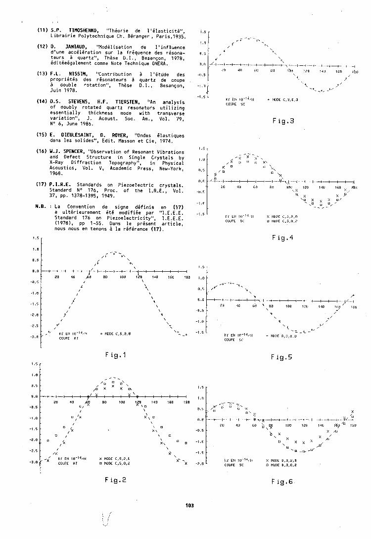
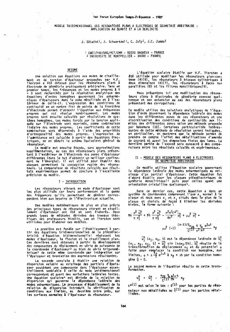
l e r Forum European Temps-Fr€quanea - 1967
MODELE TRlOlMENSIONNEL OES RESONATEURS P L A ~ s A ELECTRODES DE O k ~ b i E t k f k h t l B l T k A f R ~ : APPLICATION AU QUART2 E t h LA ~ E k ~ l d l T k
RESUME
Une s o l u t i o n aux Squat ions aux modes de c i s a i l l e - ment e t de t o r s i o n d 1 6 p a i s s e u r proposhes p a r H.F. T i e r s t e n a 6 t 6 obtenue pour l e s r6sona teurs p lans 1 B l e c t r o d e de geometric p ra t iquement a r b i t r a i r e , Dans un p remie r temps, l e s frequences e t l e s modes p ropres a V = 0 sont recherches par l a r e s o l u t f o n a r la l y t fque des 6qua t ions d'ondes homogenes gouvernant l e s anharmo- n iques d16pa isseurs dans l a zone d t a l l i s 6 e e t 3 l ' e x - t 6 r i e u r de c e l l e - c i . L ' e x p r e s s i o n des c o n d i t i o n s de c o n t i n u i t 6 en un nombre f i n 1 de p o i n t s de l a f r o n t i P r e d ' i l e c t r o d e permet d ' o b t e n i r 1 1 6 q u a t i o n aux frequences p ropres q u i e s t r e s o l u e numPriquement. Les modes p ropres son t e n s u i t e ca lcu lCs p a r r C s o l u t i o n s de sys- tPmes homogenes. Les modes fo rces p a r l a t e n s i o n appl 1 - qu6e s u r 1161ec t rode son t exprimes, comme combinaison l i n b a i r e des modes propres. Les c o e f f i c i e n t s de c e t t e combinaison son t determines i 1 ' a i d e des p r o p r i 6 t P s d 'o r thogona l i t 6 des modes p ropres . L ' e x p r e s s i o n de l ' a d m i t t a n c e e s t c a l c u l 6 e i p a r t i r des equat ions 6 l e c - t r f q u e s , on en d 6 d u i t l e schema Cqu iva len t ghn6ral du resona teur .
Ce modPle e s t e n s u i t e Ptendu, sans approximat fons suppl4mentai res, au cas des resona teurs p lans pr4sen- t a n t a 1 1 e x t 6 r i e u r de 1161ec t rode des zones d16pafsseur d i f f e r e n t e s (dans l e b u t d ' o b t e n i r un m e i l l e u r c o n f i n e - ment de l i 6 n e r g i e ) . I 1 e s t u t i l i s P pour e t a b l i r des abaques permet tan t l a concep t ion r a p i d e des rhsona- t e u r s . La comparaison de r e s u l t a t s c a l c u l 6 s aux r 6 s u l - t a t s exp6rimentaux permet de conc lu re l ' e x c e l l e n t e p r 6 c i s i o n du modele.
1 - INTRODUCTION
Les resona teurs v i b r a n t en mode d i6pa isseur son t l e s p l u s u t i l i s e s c a r l e u r s performances e t l a gamme des frequences q u ' i l s pe rmet ten t de g6n6rer c o r r e s - pondent b i e n aux besoins de 1 ' 6 l e c t r o n i q u e a c t u e l l e .
Des m d P l e s mathPmatiques de p l u s en p l u s p r e c i s des p r i n c i aux types de resonateut-s v i b r a n t en c i s a i l - lement d 4 l p a i s s e u r o n t h t 6 e t son t Q labor6s . Deux grands types de d t h o d c s d6r i v6es des t ravaux thCo- r i q u e s des p ro fesseurs M i n d l i n , Lee e t T i e r s t e n son t u t i l i s6es pour 6 l a b o r e r ces modPles.
La premiere e s t fondCe sur I ' P t a b l i s s e m e n t p a r - t i r des equa t ions t r i d i m e n s i o n n e l l e s de l a p iezo6 lec - t r i c i t 6 d 1 6 q u a t i o n b i d i m e n s i o n n e l l e l r P g i s s a n t l e s modes d 'epa isseur , l a f l e x i o n e t l e c i s a i l l e m e n t p lan , Ces dern iPres son t obtenues i p a r t i r du d6veloppement des composantes du deplacement en s 6 r i e de puissance de l a coordonnPe d16pa isseur2 ou b i e n de s e r i e tr igonom6- t r i q u e 3 de c e t t e $me coordonn6e p a r i n t 6 g r a t i o n s u r 1 '4pa isseur e t t r o n c a t i o n des expressions r 6 s u l t a n t e s 6
La seconde c o n s i s t e d a t a h l i r une r e l a t i o n de d i s p e r s i o n v a l a b l e au vo is ihage des p a r t i e l s d ' b p a i s - seur poss6dant une composante dans t 1 6 p a i s s e u r essen- t i e l l e m e n t semblable Zi c e l l e du made unid lmenslonnel
L 1 & q i a t i a n s c a l a i r b 4 t a b l i e p a r H.F. T i e r s t e n a B t 6 u t i l i s 6 e o u r modBl i se r l e s resona teurs p lan-con- Yexe 1 0 1 5 1 , f e s r6sona teurs i biseaux t y l i n d r l q u e s L deux dimensions ( 6 ) ( 7 ) , l e s r6sona teurs a faces non pard118les (8 ) e t l e s f i l t r e s m o n o l i t h i q u e s ( 9 ) .
Nous CrbsentanS i c f une mod61 i s a t i o n des resona- t e u r s p lans B Clec t rodes de g6om6tr ie convexe que l - conque e t son ex tens ton au cas des resona teurs p lans p r e s e n t a n t des c o r r u g a t i o n s .
Ce modCle u t i l i s e des s o l u t i o n s a n a l y t i ues de l ' equa- t i o n d'onde gouvernant l a dependance l a t i r a l e des modes dans l e s d i f f e r e n t e s zones de ces r6sona teurs e t une d i s c r 6 t i s a t i o n des c o n d i t i o n s de c o n t i n u i t l s aux li- m i t e s des d i f f e r e n t e s zones se lon une d t h o d e propos6e p a r Nakamura ( l o ) , C e r t a i n e s p a r t i c u l a r i t 6 s f n t 6 r e s - santes de c e t t e rn6thode de r e s o l u t i o n s e r o n t ind iquees, en p a r t i c u l i e r , on montrer i l que l a d t h o d e permet de p rendre en compte 1 ' e f f e t des m 5 t a l l i s a t i o n s dtamen6e de c o u r a h t e t auss i l e s dimensions f i n i e s des lames. La d e r n i 8 r e p a r t l e de l o e x p o s e sera consacre I des compa- r a i s o n s e h t r e l c s r 6 s u l t a t s c a l c u l 6 s e t expCrimentaux.
11 - MObELE DES RESOJATEURS PLANS A ELECTRODES ut G-E
Ce modele u t i l i s e 1 ' g q u a t i o n s c a l a i r e gouvernant l a dependance l a t e r a l e des modes anharmoniques au v o i - s inage d 'un p a r t i e l d t & p a i sseur . C e t t e equa t ion f u t d ' a b o r d Q t a b l i e pour l e s p laques p i 6 z o 4 l e c t r i q u e s de sym6t r ie monocl i n i q u e l l p u t s pour c e l l e s ayant une o r i e n t a t i o n c r i s t a l l i n e quelconques,
Dans ce d e r n i e r cas, c e t t e equa t ion a dans un system@ de coordonn6es comprenant l ' a x e x normal i l a p laque e t deux axes xl e t x, s i t u l s dans !e p l a n de l a p laque e t c h o i s i s de f a ~ o n 2 C l i m i n e r l e s d6r i v6es m i x t e s , l a forme s u i v a n t e :
i y (xi, x3, ,t) e s t l a dependace l a t 6 r a l e de 3: (xl, x2, x , t ) a s i n (nnx2 /2h) . 'i"6sulte de l a t r a n s f o r m a $ i o n du d e p l a c e m e n t ul e t du p o t e n t i e l I+ f a f t e pour r e l a c e r l a c o n d i t i o n non homogPne, aux l i m i t e r . + t? ejwt L x2 = t h p a r l a condi t i o n homo- gene $ = 0.
Le second membre de l i 6 q u a t i o n r e s u l t e de c e t t e t r a n s - fo rmat ion ,
correspondant e t ayant des v a r i a t i o n s l a t 6 r a l e s l e n t e s , Une Pqua t ion s c a l a i r e 4 e s t d 6 r i v k e de l a r e l a t i o n de
v d w t U! = 01 - '2
d i s o e r s i o n a u i aouverne l a dhendance l a t e r a l e des modis anhanndniqu;s. Le processus d14 tab l t ssement de l a c*( l ) e r t se lon l e bas : pour ~ e s p a r t f e s du reso- r e l a t i o n de d i s p e r s i o n i n t r o d u l t l a v e r t f t c a t l o n de c o n d i t i o n s aux l i m i t e s , au deuxi8me o r d r e p rss , su r n a t e u r nan M t a l l i s e e s ou pour l e s p a r t i e s meta l - l e s su r faces normales Zi l l B p a i s s e u r du r6sonateur . l i s 6 e s .
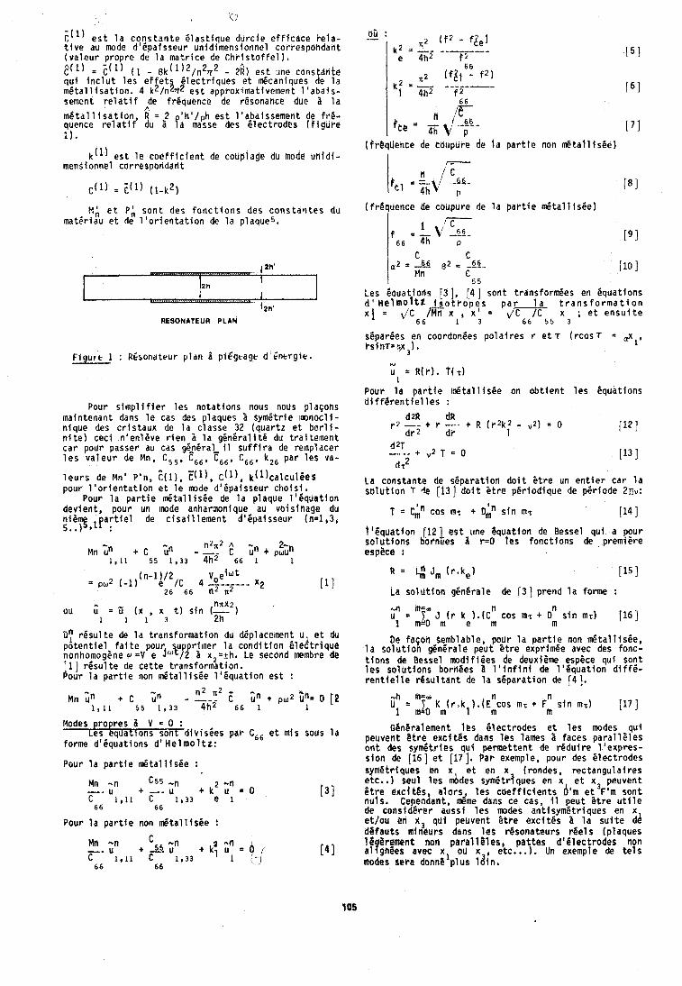
? ( ' ) e s t l a c o n s t a r i t e G l a s t i q u e d u r c i e e f f i c a c e t-ela- t i v e au mode dlCpai sseur unid imensionnel correspohdar i t ( v a l e u r p ropre de l a m a t r i c e de C h r i s t o f f e l ) .
= i ( ' ) ( 1 - 8k(1)2/n27r2 - 23) e s t tine cdns tdn te q u i i n c l u t l e s e f i e t 3 f l e c t r i q u e s e t d c a n i q u e s de l a m G t a l l i s a t i o n . 4 k /n * e s t approximat ivement l ' a b a i s - sement r e l a t i f p e frCquence de r6sonartce due a l a m 6 t a l l i s a t i o n , R = 2 ' h 0 l p h e s t l 'abaissenier i t de f r C - quence r e l a t i f du 1 aa flasse des B tec t rodes ( f i g u r e
k ( l ) e s t l e c o e f f i c i e n t de couplage du mode u r i i d i - mensionnel corresponddr i t
t I { e t P,#, s o n t des f o n c t i o n s des c o n s t a n t e s du matGriau e t de l ' o r i e n t a t i o n de l a plaques.
RESONATEUR PLAN
F i g u r e 1 : RCsondtrur p l a n 1 piEgtagb d ' i n c r g r e .
Pour simp1 i f i e r l e s n o t a t i o n s nous nous pldgons maintenant dans l e cas des plaques 3 symet r ie i m n o c l i - n lque des c r i s t a u x de l a c lasse 32 ( q u a r t z e t b e r l i - n i t e ) c e c i n 'en leve r i e n b l a g e n e r a l i t 6 du t r a i tement c a r pour passer au cas g&6ral 11 s u f f i r a de re~np lacer l e s v a l e u r de Mn, C55, C s 6 , Fs6, C66, k26 par l e s va-
l e u r s de Mn' P'n, t ( ~ ) , ? ( l ) , ~ ( l ) , k ( l ) ~ a l ~ ~ l b e S pour l ' o r i e n t a t i o n e t l e mode d ' t p a i s s e u r c h o i s i .
Pour l a p a r t i e d t a l l i s 6 e de l a p laque l ' i i q u a t i o n dev ien t , pour un m d e anharmonique au vo is tnage du n i t 5 9 , f a r t i e l de c i s a i l l e m e n t d16pa isseur (n=1,3, 5..) :
nnx2) ou 5 3 ( x , x t ) s i n (-
1 1 1 3 2h
D: r e s u l t e de l a t r a n s f o r m a t i o n du deplacement ul e t du p o t e n t i e l f a i t e pour u r i m e r l a c o n d i t i o n B l e c t r i q u e nonhomog5ne r =V e J I P ~ I x 2 = r h . Le second menbre l e
I 11 r g s u l t e de c e t t e t rans fo rmat fon . our l a p a r t i e non d t a l l i s 6 e l t i ? q u a t i o n e s t :
n2 n2 " Mn ;h C Cn - -.. C Gn + U [ I
1,11 5 5 1,33 4h2 6 6 1
Modes r o r e s 3 V = 0 : L:S ! q ~ a t i ~ n s son t d iv i sCes par Cg6 e t mis sous l a
forme dlCquat ions d 1 H e l m o 1 t z :
Pour l a p a r t i e d t a l l i s e e :
Pour l a p a r t i e non 1nPta l l f s6e :
(fr@t(U&nce de coupure de l a p a r t i e non d t a l l i s e e )
( f rBquence de coupure de l a p a r t i e & a l l i sCe)
, ( 4 1 son t t rdnsform6es en equa t ions r o p y s p a r l a t r a n s f o r m a t f o n
x i J C 6 6 m x l , x 3 = d v 5 5 x 3 ; e t e n s u i t e
sBpar6cs en coordonees po l a i r e s r e t T ( r c o s 7 = .x r s i n r = p x 3 ) .
L)
u = R ( r ) . t ( ~ ) 1
Pour l a p a r t i e i n P t a l l i s 8 e on o b t i e n t l e s 6qua t ions d i f f g r e n t i e l l e s :
La cons tan te de separa t ion d o i t P t r e un e n t i e r c a r l a s o l u t i o n f l e [13] d o i t s t r e pPr iod ique de per tode 2nv:
T 3 G n c o s m7 + D$ s i n m~ 114 I i ' C q u a t i o n (12 1 e s t une Bquat ion de Bessel q u i a pour s o l u t i o n s bornees a r=O l e s f o n c t i o n s de premiere espece :
La S o l u t i o n g6nBrale de ( 3 ] prend l a forme :
De fagon semblable, pour l a p a r t i e non d t a l l i s e e , l a s o l u t i o n generale peu t 5 t r e exprimee avec des fonc- t l o n s de Bessel m o d i f l e e s de deuxieme espece q u i son t l e s s o l u t i o n s b ~ r h e e s 1 l ' i n f i n i de l l & q u a t i o n d i f f e - r e n t i e l l e d s u l t a n t de l a separa t ion de f4 ] .
Oeneratement 1es e l e c t r o d e s e t l e s modes q u i peuvent 8 t r e e x c i t e s dans l e s lames 8 faces p a r a l l P l e s o n t des symCtries q u l pe rmet ten t de r e d u t r e l ' e x p r e s - s i o n de [ 1 6 ] e t (171, Par exemple, pour des C lec t rodes symPtriques en x e t en x (rondes, r e c t a n g u l a i r e s etc. , ) seul l e s d d e s sym6tr jques en x e t x 3 peuvent l t r e e x c i t b s , alars, l e s c o e f f i c i e n t s d'm e t F'm s o n t nu ls , Ce endant, meme dans ce cas, il peut P t r e u t i l e de c o n s i 8 e r e r auss i l e r modes an t i symBt r iquer en x e t /ou en x, q u i peuvent S t r e e x c i t e s b l a s u i t e dd d g f a u t s mineurs dans l e s rgsona teurs r e e l s (p laques 16 8 r ment non p a r a l l i l e s , p a t t e s d t € l e c t r o d e s non alsgn8es arec x, ou x , etc.. . I , Un exemple de t e l s modes 8era donne p l u s l d i n ,
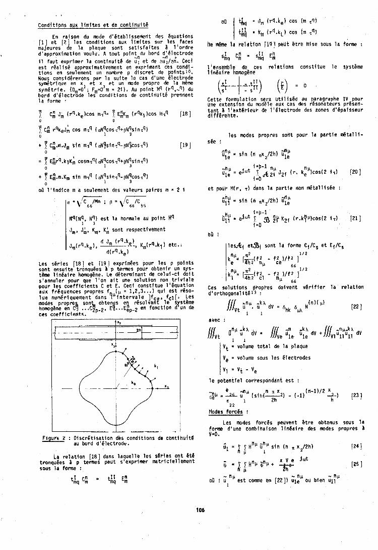
C o n d i t i o n s aux l i m i t e s e t de c o n t i n u i t 6
En r a l b o n du mode d 'e tab l i sse~r ren t des equat ions [ I ] e t [2d 1es c o n d i t i o n s aux l i m i t e s su r l e s Paces majeures e l a p laque son t s a t i s f a i t e s 8 l ' o r d r e d 'approx imat ion voulu. A t o u t p o i n t du hord d161ec t rode
4 + i 1 f a u t expr imer l a c o n t i n u f t e de G: e t de aul/an. Cecj e s t r 6 a l i s e approximat ivement en exprimarlt ces corldl- t i o n s en seulement un nolnbre p d i s c r e t de p o i n t s l o . Nous consid6rerons par l a s u f t e l e cas d'une e l e c t r o d e s y d t r ' i q u e en xl e t x 3 e t un mode p roprc de 111 meme s y m e t r i e . (D,=O ; Fl,,=O m = 21). AU p o i n t 14'1 (rq,-q) du b o r d d161ec t rode l e s c o n d i t i o n s de c o n t i n u i t 6 prednent l a forme
t 7 c;.~.J, s l n mTq (d!sintq-pN!cosrq) 0
[I9 I 7 E;rq.klKh cosmTq( a ~ q c o ~ T q + p ~ q s i n z q ) 0 1 3
t 7 E! .~ .K~ s i n mTq ( a ~ q s l n r q - p ~ q c o ~ zq) 0 1 3
02 l ' i n d i c e m a seulement des va leurs p a l r e s In = 2 i - P
W ( N ~ , N ~ I e s t l a hormale au p o i h t Mq 1 1 3 I J ~ , J;, K ~ . K; son t respect ivement
Les s e r i e s [18] e t [19] exprimees pour l e s p p o i n t s s o n t e n s u l t e t ronquees ?I p t e r m s pour o b t e n l r un sys- t h e l i n l a l r e homog8ne. Le de te rminan t de c e l u i - c i do i t s ' a n n u l e r pour que l ' o n a f t une s o l u t i o n non t r i v l a l e p o u r l e s c o e f f i c i e n t s C e t E. Ceci c o n s t i t u e 1 ' e q u a t i o n aux f r e q u e n c e s p ropres f ( p = 1,2,3..,) q u i e s t reso- l u e numer iquement dans ? " i n t e r v a l e Ifce, fc l [. Les modes p ropre son ob ten s en r e s o l v a n t l e systPme homog&ne en C l ...C\p-2. E(...E:~-~ en f o n c t i o n d 'un de ces c o e f f i c t e n t t .
F i u r c 2 : D i s c r E t i s a t i o n des c o n d i t i o n s de c b n t l t l u i t b - au bord d ' l l e c t r o d e .
La r e l a t l o n 118 ] dans l a q u e l l e l e s s 6 ~ f e s o n t 8 t @ t ronquees i p termes p e u t s ' expr imer m a t r i c i e l lement sous l d forme :
I Cn = ti! E; tmq m
qq = (I,,, ( rq .ke ) cos (m %'l)
ti$ = k, ( r f l . kL ) cos (m ,9)
s C: s y E#
1 'ensenibl8 de ces r e l a t i o n s c o n s t i t u e l e syst8me i hea l r e homogene
- - (t) = " C e t t e f o r m u l a t i o n sera u t i l i s 6 e au paragraphe I V pour une ex tens ion du modP1e aux cas des rPsonateurs presen- t a n t a l ' e x t g r i e u r de l l C l e c t r o d e des tones d 'gpa isseur d l f f 6 r e h t e '
l e s modes p ropres son t pour l a p a r t i e d t a l l l - see :
*till fin' 1 e = s i n ( n .x2/2hl uy
e t pour M( r , r ) dans l a p a r t i e non ~ t a l l i s ~ e :
i;y = s i n i n .x2/2h) i$:
bb :
l l e s f t l e t a { son t l a forme Ci/Ct e t Ef/CS
Ces s o l u t i ~ f l s PPopPes d o i v e n t v e r i f i e r l a r e l a t i o n dl or thogona l 4 t 6 1 3 :
1 1 I Vt = volume t o t a l de l a p laque
I Ve = Valume sous l e s ~ l e c t r o d e s
I VI a V t Ve
l e p o t e n t i e l corresponddnt e s t :
Ftodes f o r c e s :
Les modes f o r c e s pel ivent B t r e obtenus sous l a farme d 'une cornbinaison l l n e a i r e des modes p ropres 1 V=O,
f24 I
" " P oil : GIn' r r t c o m e en [22 ] ) 4:' ou b i e n u l l
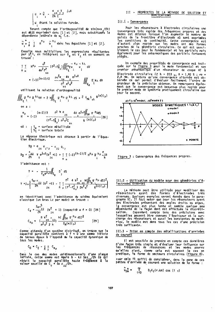
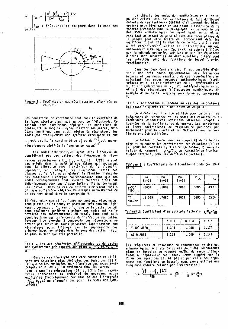
f : f r i q u e n c e de c o u p u r e dans l a zone des p a t t e s .
F i g u r e 4 : ModEl i sa t ion d t s m ~ t a l l ~ s a t l o n s d ' a r r i v E e de c o u r a n t ,
Les c o n d i t i o n s de c o n t i n u i t i son t e n s u i t e exprim6eb de l a f a ~ o n d C c r i t e p l u s hau t au bord de 1 ' P l e c t r o d e . Ce f a i s a n t nous para issons n6gl i g e r l e s condt t i o n s de c o n t i n u i t 8 t e l o n g des rayons l i m i t a n t l e s p a t t e s , mais ( t a n t donne que dans c e t t e r e g i o n du r6sona teur , l e s modes o n t p ra t iquement une symet r ie c i r c u l 2 i r e e t que
au" u1 e s t p e t i t , l a c o n t i n u i t 6 de uT e t de +,est appro-
x imat ivement v e r i f i e e l e l o n g de ce rayon? '' Les modes anharmoniques ayant dans l ' a n a l y s e ne
c o n s i d e r a n t pas ces p a t t e s , des f r iquences de reso- nances s u p 6 r i e u r e s I fcm Ifcm = fce ( 1 + :/2) 1 ne son t pas p i i g i s dans l a zone de ces p a t t e s donc l a v i b r a t i o n vers 1 ' e x t 6 r i e u r de yi ~ ! ~ ~ ~ ! ~ ~ ~ Cependant, en p r a t i q u e , l e s dimensions f i n l e s des p laques e t l e f a i t qu 'en general l a f i x a t i o n n 'absorbe pas to ta lement l ' e n e r g i e correspondante f o n t que l e s modes correspondants son t souvent observes a l o r s que theor iquement pour une p laque i n f i n i e i l s ne d e v r a i e n t pas l l C t r e . Dans ce cas on observe simplement q u ' i l s o n t une s u r t e n s i o n r $ d u i t e , Un exemple exper imenta l de ce cas sera donne dans l e paragraphe V.
I 1 f a u t n o t e r que sf l e s lames ne son t pas r igoureuse- ment p lanes ( e l l e s son t , en p r a t i q u e t r P s souvent 16g6- rement convexes), f , v a r i e l e l o n g de l a p a t t e , ce qu i p e u t Cgalement c o n h i r e 3 p i i g e r des modes q u l ne l e s e r a i e n t pas theoriquement. Au t o t a l , t o u t c e c i d o l t c o n d u i r e I ne pas t e n i r compte de l ' e f f e t de ces p a t t e s l o r s q u e l ' o n cherche a concevo i r des resona teurs ne devant pas a v o i r de modes p a r a s i t e s ( a p p l i c a t i o n s aux resona teurs pour f i l t r e s ) c a r l a suppressfoh des anharmoniques non piPg6s dans l a zone des p a t t e s h ' e s t , l e p l u s souvent que t r e s p a r t i e l l e .
111.4 = Cas des g ~ o m i t r i e s d 4 C l e c t r o d e s e t de p a t t e s non symeVlques p a r TXpplT aux P n s x , = u P t f o 6 0 -
Dens ce cas l b s n a l y s e d o i t B t r e cor tdui te en u t i l i - san t des s o l u t i o n s p l u s generales des Bquat ions 11 ] e t
2 que c e l l e s employees pour 1 'ana lyse des modes symC- I r J q u e s en x, e t x3 . On r e t i e n d r a donc l e s termes vou lus dans l e s expressions (161 e t (17 1. Ces dissym6-
t r i e s e n t r a i n e n t l a p r e s e n c e de nouveaux modes e x c i t a b l e s C lec t r iquement c a r dens ce cas 1 1 t n t 8 g r a l e ifse uledS ne s ' a n n u l e pas p o u r l e s modes non sym6-
t r l q u e s .
La t H & b r i e des modes noti s y m l t r l q u e s en xl e t x pouvant e x i s t e r dans l e s resoha teurs du f a i t de 16 er: dCfauts de r 6 a l l s a t i o n l 6 (de fau t d 'a l l gnement des ~ Q e c - t r o d e s ) peUt C t r e f a i t e eti u t i l i s a n t l ' e x t e n s i o n de l a th&o t - ie prCsentPe dans l e paragraphe I V . De t m e l e cas des m d e s anharmoniques tioh sym6tr iques en x e t x 3 r e s u l tank de defaht de p a r a l l i l i s m e des faces p ianes de l a p laque Qeut Ot re t r a i t @ en l f l t r o d u i s a t i t dans l e s Equat ions [I ] e t 1 2 1 l a dgpendance de h(x l , x,) J c e c i a 6 t i e f f e c t i v e m e n t r e a l i s 6 en u t i l i s a n t une tn6thode en t i8 remeht numlr fque p a r Drrorsky8, ce p o u r r a i t 1 ' C t r e p a r l a m&thode p rbpos ie , c a r dans ce cas l e s i q u a t i o n s dta;ndes son t ¶bles en deux Cduat ions d b A i r y don t l e s s o l u t i o n s $an t des f o n c t i o n s de Bessel d ' o r d r e f k a c t f o n n a i r e ,
Dans ces deux d e r n l e r s cas, il e s t p o s s i b l e d 'ob- t e n t r utie t rOs bonne approx imat i on des frequences p ropres e t des lnodes r e s u l t a n t de ces i m p e r f e c t i o n s en c a l c u l a n t l e s modes p ropres a n t i s y m e t r i q u e s ( s y d - t r i q u e s en x e t an t i symet r iques en x , sym6tr iques en x e t a n t i s y r ) l i t r l q u e s en x , e t , anti?ymi.tr iques en x ~2 x ) des resona teurs a 'C lec t rodes s y m i t r i q ~ e s , uI) exemp!e d 'une t e l l e demarche sera donne au paragraphe V ,
l I I , S - A p p l i c a t i o n dU modele au cas des resona teurs b t i l isantf
Le modSle d e c r i t a 6 t 6 u t i l f s P pour c a l c u l e r l e s f r i q u c n c e s de resonance e t l e s modes des r i s o n a t e u r s a E l e c t r o d e s c i r c u l a i r e s u t i l i sen t d i v e r s e s coupes Y tournCes de l a b e r l i n i t e e t du quar tz . Les cons tan tes s t l e u r s c o e f f i c i e n t s de temperature p u b l i g e s p a r Bechmannl7 pour l e q u a r t z e t pa r B a i l e y 1 8 pour l a ber - 1 i n i t e o n t E t6 u t i l i s C e s .
Le tab leau 1 donne pour l e s coupes AT de l a b e r l i - n i t e e t du q u a r t z l e s c o e f f i c i e n t s des Bquat ions [l] e t
o u r l e s p a r t i e l s 1 3 e t 5. Le t a b l e a u 2 donne l a Ii/e$r du r b p p o r t mgf q u i c a r a c t i r i s e 1 'an iso - t r o p l e l a t e r a l e , pour l e s d l i r e n t s p a r t i e l s .
Tableau 1 : C o e f f i c i e n t s de l ' i q u a t i o n d'onde (en 1011 Nm-L)
l e s freqbences de r l sonance du fondamental e t des ses anharmoniques, o n t e t 6 c a l c u l l e s pour des resona teurs p l a n s en f o n c t i o n du r a p p o r t re/2h, du rayon d ' 6 l e c - t r a d e 1 'Bpaisgeur des lames. Comne sugg6rP p a r l a forme des equations [ 3 ] a t ( 4 1 o t p a r c e l l e des argu- ments des f o n c t i o n s de Bessel, nous avons u t i l i s 6 une f requence r e d u f t e d 6 f i n l e p a r l ' e x p r e s s i o n :
C 6 6
.2177
.2924
I OBI
i Tableau 2: C o e f f i c i g n t d ' a h i s o t r o p i e l a t e r a l e c Mn/C55
5 5
,5086
,6880
Y-30\fi637 A1P04
AT q u a r t z ---
n - 5 *
1.174
1.144
Y-30b AlPO,
AT QUARTZ
Mti ( r l = l )
.1.099
n = 1
1.303
1.263
N = 3
1.068
1.049
Mn (11.31
,5802
,7580
Mn (n=5)
,7016
.go09
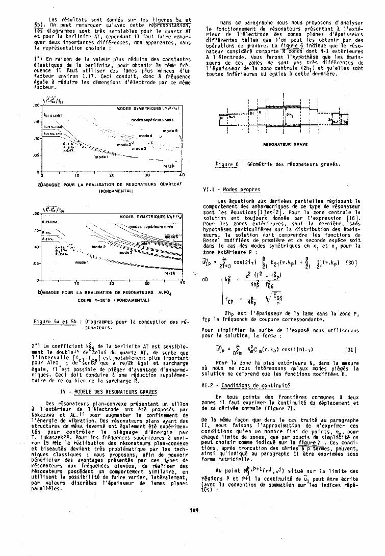
Les r e s u l t a t s sont donnes sur l e s f i g l i r e s 5a e t 5b ) . On peu t remarquer qu'avec c e t t e r @ r e s e n i a t r o n , les diagramnes sont t rPs semblables pour l e quar tz AT e t pour l a b e r l i n i t e AT, cependant 11 faUt f a i r e remar- quer deux impor tan tes d i f ferences, non apparentes, dans l a r e p r 6 s e n t d t i o n c h o i s i e :
1') En r a i s o n de l a v a l e u r p l u s r i i d u i t e des codstantes i i l a s t i q u e s de l a b e r l i n i t e , pour o b t e r i i r l a d m e f r 8 - quence I 1 f a u t u t i l i s e r des lames p l u s minces d lun f a c t e u r e n v i r o n 1.17. Ceci c o n d u i t , donc 2 frequence Pgale r e d u f r e l e s dimensions d o e l e c t r o d e par ce d l n e fac teur . 7
\I=. 1 2 * / f @ ~
h.1 &LIMIT
.15 m d e s superieuts om's
.-. .- mode4 - .- mode2" ' '
mode 3
mode 5 i t ' I
-- --- _ - .
--
~ ) A B A Q U E POUR LA REALISATION DE RESONATEURS OUARTZAT
(FONDAMENTAL)
7-r \f,-fc*/!w
'201 MODES SYMETRIOUES l a d l
.1oj r i . 1% mode( w-:.. 1-
h.$%. * . - + +
mode 1
reah 0 ,
1'0 do do I 4 0
O)ABAQUE POUR L A REALISATION DE RESONATEURS A L P O ~
COUPE Y-30'6' ( FONDAMENTAL)
F i g u r e 5d e t 5b : Diagramnes pour l a concept ion des rg- sonateurs.
2') Le c o e f f i c i e n t kg6 de l a b e r l i n i t e AT e s t sens ib le - ment l e double14 de c e l u i du q u a r t z AT, de s o r t e que 1 ' i n t e r v a l l e I f - f ] e s t notablement p l u s i m p o r t a n t pour AlPO, ; d e c 8 0 r f 8 que re/2h egal e t surcharge Egale, il 'est p o s s i b l e de p i e g e r d 'avantage d'anharmo- n iques. Ceci d o i t condu i re 2 une r e d u c t i o n suppl6men- t a i r e de r e ou b i e n de l a surcharge #.
f V - HOOELE DES RESONATEURS GRAVES
Des resonateurs p l an-convexe p resen tan t un s i l 1 on 5 l l e x t P r i e u r de l ' e l e c t r o d e o n t 6tP proposes p a r NakazavJa e t AL.19 pour augmenter l e conf inement de 1 ' B n e r g i e de v i b r a t i o n . Des resona teurs p lans ayant des s t r u c t u r e s de &sa i n v e r s e o n t Bgalement CtQ exp6rimen- t 8 s p o u r c o n t r c l e r l e p i e g e a g e d 8 6 n e r g i e p a r T. Lukaszek20. Pour l e s frequences super ieu res a e n v i - r o n 15 MHz l a r 6 a l i s a t i o n des resonateurs plan-convexe e t b i seau tBs d e v i e n t t r P s p rob l6mat ique p a r l e s tech- n iques c l a s s i q u e s . nous proposons, a f f n de p o u v o i r b 6 n i i f l c l e r des ava;tages present6s p a r ces types de resona teurs aux frequences glevees, de r e a l i ser des r6sona teurs possedant un comportement s i m l l d l r e , en u t i l 1 s a n t l a p o S s l b i l i t 8 de f a l r e v a r l e r , l a t8 ra lement , p e r v a l e u r s d i s c r 2 t e s 116pa lsseur de lamed p lanes para1 l P l e s .
Dans ce paragraphe nous nous proposons d l a n a l y s e r l e forict lonhemerit de r$sond teurs p resen tan t 2 I 4 e x t C - r i e u r de l i 8 1 e c t r b d e des zones p lanes d ' i i pa isseurs d i f f 8 r t n t e s t e l l e s que l ' o n peu t l e s o b t e n i r pa r des opCrat ion5 de gravure. La fi u r e 6 i n d i q u e que l e r6so- n a t e u r cons ider6 c o m p o r t e h dont N-1 e x t i i r i e u r e s 3 1 ' 6 l e c t r o d e . Nous fk rons l ' h y p o t h 6 s e que l e s epa is - seurs de ces zones he sor l t pas t r e s d i f f e r e n t e s de 1 i B p a i s s e u r de l a tone c e n t r a l e (2hI) e t q u ' e l l e s sont t o u t e s I n f C r l e u r e s ou Egales 1 c e t t e dern i2 re .
RESONATEUR QRAVE
VI.1 - Modes p ropres
Les Bquatforls abx der i vees p a r t i e l l e s r 6 g i s s a n t l c comporternent des anharmoniaues de ce type de resonateur s o n t l e s B q u a t i o n s [ l ] e t [ Z ] . Pour l a zone c e n t r a l e l a s o l u t i o n e s t t o u j o u r s donnee par l ' e x p r e s s l o n [16] . Pour l e s zones e x t e r i e u r e s , sauf l a d e r n i s r e , sans hypothOses p a r t l c u l i P r e s su r l a d i s t r i b u t i o n des Opals- seurs, l a s o l u t i o n d o i t comprendre l e s f o n c t i o n s de Bessel m o d l f l 6 e s de p r e m i h e e t de seconde espgce s o f t dans l e cas des modes s y m l t r i q u e s en xl e t x 3 pour l a fohe ~ x t 6 e i e u r e P :
2hp e s t 1 ' e p a i s s e u r de l a lame dans l a zone P, f c p l a f reqdence de coupure correspondante.
Pour s i m p l i f i e r l a s u i t e de 11expos6 nous u t i l f s e r o n s pour l a s o l u t i o n , l a forme :
Pour l a zone l a p l u s e x t 6 r i e u r e N, dans l a mesure oii nous ne nous In t6 ressons qu'aux modes p i6ges l a s o l u t i o n ne comprend que l e s fonc t ions mod i f iees K.
VI.2 - Cond i t ions de c o n t i n u i t 6
En tous p o i n t s des f r o n t i e r e s communes deux zones il f a u t expr imer l a c o n t i n u i t 6 du deplacement e t de sa d8rfvCe normale ( f i g u r e 7).
De l a J m e facon que dans l e cas t r a i t s au paragraphe I I, nous fa isons 1 'approx imat ion de n 'expr imer ces c o n d l t i o n s q u ' e n un nombre f i n i de p o i n t s , n , pour chaque l i m i t e de zones, que p a r souc is de s i m p l i g i t 6 on p e u t c h o i s i r comme i n d i q u e r u r l a f i u r e 7 . Ces cond i - t l o n r , aprer t r o n c a t i o n des s B r i e s ~ e s , peuvent, a i n s f qu l lnd lqu& au paragraphe I1 Otre exprimees sous forme h a t r l c i e l l e .
Au p o i n t ~ i * ~ + ~ t r J , ~ j ) s f t u g s u r l a l i m i t e des r e g i o n s P k t P + I l a c o n t i n u i t 6 de p e u t a t r e P c r i t e (avec l a caf lvent ion de sonmation sur l e s i n d i c e s r6p6- tCs) :
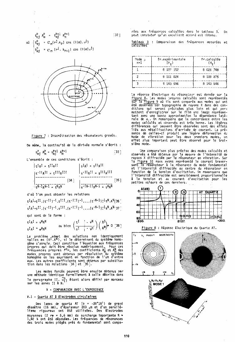
tP+l A P + ~ %j A! = j 1, [ 32 1
oir I ( j = e m ( r j . k p ) cos ( i ( m ) . T j )
Itij = e m ( r j . k,+l) cos i i i m ~ d l
F i g u r e 7 : D i s c r C t l s a t i o n des resondteurs gravEs.
De &me, l a c o n t i n u i t 6 de l a d 6 r i v 6 e normale s 1 8 c r I t :
dloB l ' o n p e u t o b t e n i r l e s r e l a t i o n s
L'ensemble de ces c o n d i t i o n s s 1 6 c r i t :
q u i son t de l a forme :
tI~I = ~IIAII
tlIIAII = tIIIAIII ----------------- ----------------- 134 I %N-lAN- l = tNAN
tI~I =
sIAI = w N ~ N ou b i e n (x.;) ( f 3- 0 [38 ]
,IAI = S I I ~ I f
slIIAII = sIIIAIII ----------*------a
-- --- -----.----a 135 I s~f~-l~A~-l , ,NAN
Le problOme adm t des s o l u t i o n s non iden t iquement n u l l e s en ( A I . A f ) , s i l e de te rm inan t du systeme homo- ggne s 'annule. Ceci c o n s t i t u e 1 1 6 q u a t i o n aux frequences p ropres q u i d o i t E t r e r 6 s o l u e numeriquement. Pou ces L f r e q u e n c e s p r o p r e s f n ~ , l e s c o e f f i c i e n t s qf, e t Am des modes p ropres son t obtenus p a r r e s o l u t i o n du syst ime homoghe en l e s expr iman t en f o n c t i o n de l ' u n d ' e n t r e eux. Les a u t r e s c o e f f i c i e n t s son t obtenus p a r s u b s t i t u - t i o n dans l e s r e l a t i o n s [ 3 4 ] e t [35].
Les modes f o r c e s peuvent E t r e e n s u i t e obtenus p a r une d t h o d e i d e n t i q u e fo rme l lement i c e l l e d g c r i t e dans
w
l e p a r a g r a p h e 11. uf l & t a n t a l o r s d 6 f l n i p a r morceau s u r l e s zones I 1 N.
V - COMPARAISON AVEC LIEXPERIENCE
V.1 - Q u a r t z AT B 61 ec t rodes c i r c u l a i r e s
Des lames de q u a r t z AT ( e = -35"15' ) de grand d iamgtre (16 mn), d lOpaisseur 203. ~m e t d 'un p a r a l l l - l i s m e r i g o u r e u x o n t e t g u t i l i s e e s . Des g l e c t r o d e s
r6es ailx f r i quer i ces ca lcu lPes dans l e tab leau 3. r)n p e u t cons ta t i? r qu'un e x c e l l e n t accord e s t ,~l)tenu.
Tableau 3 : Cumparaison del; frgquences lnesurees e t c a l T
La reponse 6 l e c t r i q u e du r e s o n a t e l ~ r e s t donnee sur l a f i u r e 8. Les modes propres c a l c u l 6 s son t rep resen tes h i g ! r e 9 oii i l s son t cwnpar6s aux modes qui o n t b t 6 observes pa r topograph ie de rayons X dans des con- d i t i o n s qu i s e r o n t p r6c isges p l u s l o i n e t qu i pe r - m e t t e n t d ' e n r e g i s t r e r su r l e f i l m une image represen- t a n t avec une bonne approx imat ion l a dependance l a t e - r a l e de d l . On reinarquera que l a concordance e n t r e l e s modes c a l c u l g s e t observes e s t t rOs bonne. Les l6gSres d i f f e r e n c e s qui peuvent e t r e observees son t des e f f e t s 116s aux m 6 t a l l i s a t i o n s d 1 a r r i v 6 e de couran t . La pr6- sence de c e l l e s - c i p r o d u i t une l e g e r e d6 fo rmat ion du mode de v i b r a t i o n pour l e s deux p remie rs modes, un e f f e t p l u s i l l p o r t a n t peu t t t r e observe pour l e t r o i - si8me mode.
Une cornparaison p l u s p r e c i s e des nodes c a l c u l 6 s e t observes a 6 t 6 obtenue par l a mesure de 1 1 i n t e n s i t 6 de rayons X d i f f r a c t i e p a r l e resona teur en v i b r a t i o n . Sur l a f i u r e 10 nous avons rep r6sen t6 l e couran t t r a v e r - s a n b n a t e u r i l a resonance du mode fondamental e t l ' i n t e n s i t e d i f f r a c t e e au c e n t r e du resona teur en f o n c t i o n de l a t e n s i o n d ' e x c i t a t i o n . On remarquera que 1 ' i n t e n s i t 6 d i f f r a c t e e e s t sensib lement p r o p o r t i o n n e l l e 1 l a t e n s i o n e t au c o u r a n t d ' e x c i t a t i o n pour l e s p e t i t e s v a l e u r s de ces d e r n i e r s .
F i g u r e 8 : REponse E l t c t r i q u e du Quar tz AT.
moyennes ( 2 r e = 5,6 mm) de surcharge impor tan te R = 1,92 % o n t b t 6 dfposges. Les frgquences de rdsonances des t r o i s modes p ieggs p rgs du fondamental son t compa-
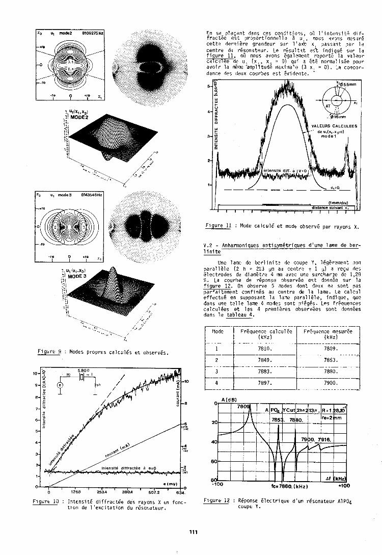
F i g u r e 9 : Modes propres c a l c u l e s e t observCs.
0 , e (mv) 1 I I I I I I 1 0
0 1268 253.4 380.4 ' 507.2 834.
F i g u r t 10 : I n t e n s i t 6 d i f f r a c t & des rayons X en fonc - ti on de 1 ' e x c i t a t i o n du r6sondteur .
En se- p l a c a n t daris css col i l l i tlofls, 9; 1 ' i n t e r l s i t; d i F: f r a c t e e esF- p r o p o r t l o r i n e l l , ? a iJ , nolts . ~ I W I S Imes.rre c e t t a d e r n l e r e grandeur silr 1 ' a k x passarit p a r It? c e n t r e du r6sona teur . Le r e s u l t s t e s i i nd iqu f ! s i l r l d f i g u r e 11, oC nous avons Egalamerit r e p o r t s 1.3 v a l e u r ca C ~ J ee de u ( x , x = 01 qu i ,3 e t e normal ~ s P e pour a v i i r l l a i r t ~ e l a n p l i t u n E rnaxi:aale (r xl = 01. ~a col icor- dance des rleux courbes e s t & v i d ? n t e .
F i g u r e 11 : Mode c a l c u l e e t modt observP par rayons X .
V . 2 - Anharmoniques a n t i s y m e t r i q u e s d 'une lame de b e r - l i n i t e
Une lame de b e r l i n i t e de coupe Y, l e g t r e m e n t i o n p a r a l l d l e ( 2 h = 213 fl au cer i t ra t i K) a requ des e l e c t r o d e s de d i a n P t r e 4 Im avec une surcharge dc 1,28 $. La courbe de reponse observPe e s t dorin8c sirr l a f i g u r e 12. On observe 5 ~nodcs dont deux ns son t pas p a r f a i tement c o n f i n e s au c e n t r e de l a lame. Le c a l c u l e f f e c t & en supposant l a l a w p a r a l l e l e , i nd ique , que dans trne t e l l e lame 4 nodes son t pi6g6s. l e s frequences calc1116es e t l e s 4 premisres observees son t IonnPes dans 11: tab leau 4.
F l g u r t 12 : RGponse e l e c t r i q u e d ' u n resona teur Alp04 coupe Y.
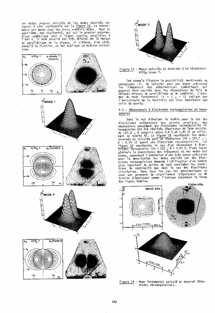
1 - P S III>~I?S p ropres ;al~:~rlPs e t l a s :nodes 6)bserv6s par rayorls '( soti t rep rssen t fs rtlr l a f i g u r e 13. La concor- dance? e s t bonnc \)our l e s t r o i s p r e ~ n i e r s 'nodes. Pour It! qLlat-i;~ne, non reprQsent0, qu i e s t l e premier aniiarno- ti1 g .1~ symf t r i q u e ~ i v c c 2 1 i g r ~ e s nodal i s para1 1 P les ;i l ' a x c x l e nod12 obse*vG e s t t rPs dPForn6 par l e manque l e para]l161isiqe do l d plaque, i l s16 tend , d 'un ccitP, j u s q ~ i ' l l a f i x a t i o n , ce q u i expl i que 5.1 i ~ o d e s t o s t l r ten - s i o n .
x, AIPOd Y u,rnode 1 7809 k H z
0 -re
-re 0 +re 1 XI
F i g u r e 13 : Modts c a l c u l e s e t observPs d ' u n r6sona teur ~ 1 ~ 0 ~ coupe Y.
Ce t exefnple i l l u s t r e l a p o s s i b i l i t 6 , metit ionti0~? au paragraphe 111, de c a l c u l e r avec une bonne p r e c i s i o n l e s frequences des a n h a r n o n i q ~ e s s y v 6 t r i q u e s q u i peuvent D t r e e x c i t & s dans l e s resona teurs du f a i t l e d e f a u t s ~ninelrr-s de para: 151 isme ou de s:~m6trie. L ' e x a - men du node fondatnental ( n = 1 iL = I ) i n d i q u e :lue 1 'anisotropic de l a her1 i n i t e e s t p l u s i lnpor tdr i te quc! c e l l e du qt lar tz .
V.3 - Resonateurs a e l e c t r o d e s r e c t a n g u l a i r e s e t hexa- gonal es
Dans l e b u t 1 1 6 v a l u e r l e tnodsle pour l e cas des P l e c t r o d e s resenta ant des u o i n t s a n q u l e ~ x . des r6sonate:rrs possedant des 6 l e c t r o d e s r e c t a n g u l a i r e s e t qexagonales o n t GtP r e a l i s e s (epa i sseirr de lame vo i s i n e de 153,5 11 R c o t n p r i s e n t r e 0,9 % e t 1,20 8 ) en u t i l i - s a n t dtu q u a r t z AT. La f i g u r e 14 represen te l e s mode, observes e t c d l c u l P s pour un resonatour ( 2 h = l53,7 p ; R = 0.95 %) a y a n t une 5 l e c t r o d e r e c t a n g u l a i r e . L a f i g u r e 15 represen te l e cas d 'un resona teur a 51ec- t r 3 d e s hexagonales (2h = 153 R = 0.93 X. D'une f a ~ o n gen6ra le l a concorddtlce des fr6quences c t des m d e s e s t bonne, cependant l ' o b t e n t i o n d 'une t r e s bonne p r 6 c i s i a 1 pour l a d e s c r i p t i o n des !?odes e x c i tPs par des e l e c - t r o d e s r e c t a n g u l a i r e s demande 1 ' u t i l i s a t i o n d ' u n nombre p l u s i m p o r t a n t de p o i n t s oG sont exprimees l e s cond i - t i o n s de c o n t i n u i t s que dans l e cas des e l e c t r o d e s c i r c u l a i r e s . Dans tous l e s cas l e s anharmoniques ne s o n t pas purement de c i s a i l l e m e n t d lPpaisseur ou fie t o r s i o n d S 6 p a i s s e u r colnme l ' i n d i q u e notatnment l a forme des l i q n e s nodales.
F i u r t 14 : Mode fondamental c a l c u l e e t observe ( e l e c - t r o d t s r r c t a n g u l a l r r r ) .
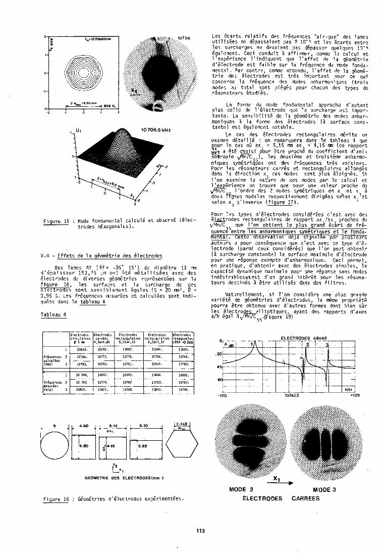
F i g u r e 15 : Mode fondamental c a l c u l e e r observC ( e l e c - t rodes hgxagonalks 1.
V.4 - E f f e t s de l a g6om6tr ie des e l e c t r o d e s
Des lames ,AT ( @ = -35' 15') de t l i a n s t r e 13 mn d 8 B p a i j s e u r 153,75 pn o r i t ? t 6 m 6 t a l l i s C e s avec des G lec t rades de d i verses ygomi. t r i e s ropr6sentPes sur l a F igure 16, l e s s ~ l r f a c e s e t l d s. lrci iarge de es e l e c t r o d e s s o n t s e n s i h l e m e n t 6gales IS = 20 mn2, 8 = 0,95 5. Les Frequences :wsur6es e t c a l c 1 ~ 1 6 e s son t i n d i - qu61:s dans l e tab leau 4
2
2
:l l- 2 - 2
Tableau 4
lrc=10709533HZ X
i
@ 2 ab,=6.60mm
r 7 axe xl I
.1 0 1
c1
GEOMETRIE DES ELECTRODES(mm.)
F l gure 16 : GomEt r ies d 'C lec t rodes expEr i mentges.
Les Pcar ts r e l a t i f s des Frequences " a i r - y d p " des lames i u t i l i s 6 e s ne depassaient pas 2 1 0 - 4 e t l e s P c a r t s e n t r e l e s ru rcharges ne deva ien t pas d6passer que l lups 10-4 6galef lent . Ceci c o n d u i t B a f f i r m e l - , comlne 1. ca11:ul 1.t
1 1 e x p 5 r i e n c e l ' i n d i q u e i t que l ' e f f e t de 1s gGomPtrie d161ec t rode c s t F a i h l e su r l a f r C q u ~ n c e du mode fondd- 'nerital . Dar con t re , coteme n t tendu , 1 ' e f f e t de l a g6om6- t r i e des 6 lec t rode ; e s t t r P s impor td i i t ,pour ce q u i concpnie l a f r6qupnce des 8?odes anhdrnon i lqu~s ( t r o i s 3aodes t ~ t a l son t p i6g6s pour chacun des types de r6sona ta i t r s 6 tud i6s .
La forire dlu node f~oddrnenta l approcite d ' a u t a n t p l u s c e l l e de l l C l e c t r o d e clue l a surc i iarge e s t i n p o r - t a n t e . La s e n s i b i l i t g de l a g601n6trie des nodes anhar- m o t i i q ~ ~ e s A l a forme des P l e c t r o d e s ( 3 sur face c o r ~ s - t a n t e ) e s t ggalement no tab le .
Le cas des G lec t rodes r e c t a n g u l a i r a s 16ri t e un examen d6 ta i116 : on rernarquera dans l e tab leau 4 que gout- l u cas ou axl = 5,15 mn ax = 4,15 mn (ce r a p p o r t & a 6 t 6 c h o i s i pour Ot re prochs du c o e f f i c i e n t d ' a n i - so l l rop ie mc 5 5 ) , l e s deuxieme e t t ro i s iPme anharrno- n iques symetr iques o n t des fr6quences t @ s v o i s i n e s . Pour l e s r6sona teurs c a r r e s e t r e c t a n g u l a l r s s a1 long& dans l a d i r e c t i o n xl ces modes s o n t p l u s 5 l o i g ~ l s . S i l ' o n exaaine l a nat,rre lie ces .nodes p a r l e c a l c u l c t 1 ' ex Pr ience on t rouve que pour une v a l e u r proche de & l ' o r d r e des Z n o l e s syn6 t r iques en x e t r 3 S de~rx f ' fgors nodales respec t i vement d i r i g 6 e s s d o n xl e t se lon x 3 5 ' i n v e r s e ( f i g u r e 1 7 ) .
cons i dPrCes c ' e s t avec des r a p p o r t dx /ax proches de p l u s grand &art de frb
quence e n t r e l e s anharmoniques sym6tr iques e t l e fonda- menta l . c e t t e o b s e r v a t ~ o n de ja s igna lee p a r ) l u s i e u r s au teurs d pour consPquerice que c ' e s t avec ce type 8 ' 6 - l e c t r o d e (parmi ceux cons id6r6s ) que 1 ' o n peu t o b t a n i r (1 surcharge cons tan te ) l a su r face maxiinall? d161ec t rode pour une r6ponse exernpte dlanharnoniq?re. Ceci permet, en p r a t i q u e , d ' o b t e n i r avec des e l e c t r o d e s s imples, l a capaci t 6 dynariique maximal e pour une reponse sans 17odes i n d e s i r s b l e s e t e s t d ' u n grand i n t E r 6 t pour l e s resona- t e u r s dus t in6s 5 6 t r e u t i l i s 6 s dans des fi l t r e s .
Ya t i i re l lemen t, s i 1 ' on considPre une p l u s grande v a r i e t e de g6omPtries d161ectrodes, l a m6me p r o p r i d t 6 p o u r r a S t r e obtenue avec d ' a u t r e s formes don t b i e n s7r l e s -6lect:o e l 1 i p t i s u e s ayant des r a p p o r t s d 'axes a i b egal a&;5.rigure i9)
MODE 2 MODE 3
ELECTRODES CARREES
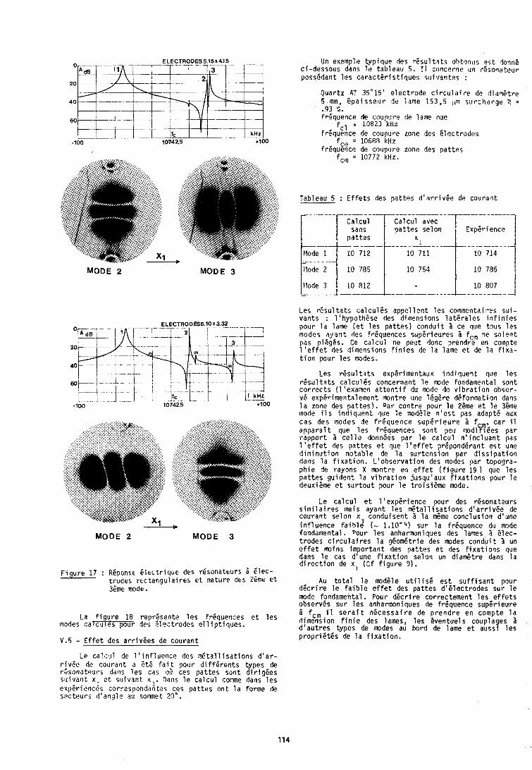
MODE 2 MODE 3
MODE 2 MODE 3
F i g u r e 17 : REponst G l e c t r i q u e des resonateurs 2 E l e c - t rodes r e c t a n g u l a i r e s e t na tu re des 26me e t 3Pme mode.
La f i g u r e 18 represen te l e s frequences e t l e s modes calc81 I es pour des S lec t rodes e l 1 i p t i q u e s .
V.5 - E f f e t des a r r i v e e s de c o u r a n t
Le c a l c u l de 1 ' i n f l u e n c e des l t a l l i s a t i o n s d ' a r - r i v e e dc c o ~ r r a n t a 5t.G f a i t pour d i F f 6 r e n t s types de r i s o n a t e u r s da~ is l e s cas 03 ces p a t t e s son t d i r i g e e s s i l i va r l t x e t s ~ l i v a n t x 3 . Datis l e c a l c u l comme dans l e s
1 exper iences correspondantes ces p a t t e s o n t l a forme de s e c t e u r s d ' a n g l e au sommet 27" .
Un exemple t y p i q u e des r b s u l t a t s o R t e n ~ ~ s o s t donne c i -dessous dans l e tab leau 5 . I1 concerne un r6;onateur possddant l e s c a r a c t e r i s t i q u e s s ~ ~ i v a t i t e s :
Q u a r t z AT 35-15' e l e c t r o d e c i r c u l a i r e dc d i a n 6 t r e 5 mm, E p a i s s e u r de lame 153,5 pm s u r c h d r g e ? = .93 %.
B uence de couor~re de lame nuc? qL, = 10823 HZ
~ r 6 ~ u ; h c e de coupure zone des e l e c t r o d e s f,,, = 10688 kliz
frequ%e de coupure zone des p a t t e s f,;, = 10772 kHz.
Tableau 5 : E f f e t s des p a t t o s d ' a r r i v e e de couran t
i a l c u l Ca lcu l avec sans p a t t e s se lon ExpBrience
p a t t e s - ---- - ----
10 711 I0 714
Les r e s u l t a t s c a l c u l 6 s appel l e n t l e s commentaires s u i - van ts : 11hypo th6se des dimensions l a t e r a l e s i n f i n i e s pour l a lame ( e t l e s p a t t e s ) c o n d u i t 5 ce que tous l e s modes a y a n t des fr6quences super ieu res 3 fc,, ne s o i e n t pas pieggs. Ce c a l c u l ne peu t donc prendre en co~spte 1 ' e f f e t des dimensions f i n i e s de l a lame e t de l a f i x a - t i o n pour l e s modes.
Les r e s u l t a t 5 experimentaux i n d i q u e n t que l e s r e s u l t a t s c a l c u l e s concernant l e mode fondamental son t c o r r e c t s ( 1 'examen a t t e n t i f du mode de v i b r a t i o n obser- ve expdrimentalelnent m n t r e une 16g6re de fo rmat ion dans l a zone des p a t t e s ) . pa r c o n t r e pour l e 26me e t l e 36me mode i l s i n d i q u e n t que l e modele n ' e s t pas adapt6 aux c a s des modes de f r e q u e n c e s u p e r i e u r e f , c a r il a p p a r a i t que l e s frequences son t peu modiW6es p a r r a p p o r t c e l l e donnees par l e c a l c u l n ' i n c l u a n t pas 1 ' e f f e t des p a t t e s e t l u e l ' e f f e t preponderant e s t une d i m i n u t i o n n o t a b l e de l a s u r t e n s i o n par d i s s i p a t i o n dans l a f i x a t i o n . L ' o b s e r v a t i o n des modes ;jar topogra- p h i e de rayons X montre en e f f e t ( f i g u r e 19 que l e s p a t t e s gu iden t l a v i b r a t i o n jusqu 'aux f i x a t i o n s pour l e deuxieme e t s u r t o u t pour l e t r o i s i e m e mode.
Le c a l c u l e t l ' e x p e r i e n c e pour des resona teurs s i m i l a i r e s tnais ayant l e s d t a l l i s a t i o n s d ' a r r i v e e de c o u r a n t se lon x 3 condu isen t l a &me conc lus fon d 'une i n f l u e n c e f a i b l e (- 1.10-4) su r l a f requence du mode fondamental. Pour l e s anharmoniques des lames 5 b l e c - t r o d e s c i r c u l a i r e s l a geometric des modes c o n d u i t 1 un e f f e t moins i m p o r t a n t des p a t t e s e t des f i x a t i o n s que dans l e cas d'une f i x a t i o n se lon un diamPtre dans l a d i r e c t i o n de xl ( C f f i g u r e 9).
Au t o t a l l e mod6le u t i l i s e e s t s u f f i s a n t pour d e c r i r e l e f a i b l e e f f e t des p a t t e s d o e l e c t r o d e s sur l e mode fondamental. pour d 6 c r i r e correctement l e s e f f e t s observes sur l e s anharmoniques de f requence super ieu re 5 f,, il s e r a i t n e c e s s a i r e de p r e n d r e en compte l a d imension f i n i e des lames, l e s even tue ls coupla es 3 d ' a u t r e s types de modes au bord de lame e t auss? l e s p r o p r i e t e s de l a f i x a t i o n .
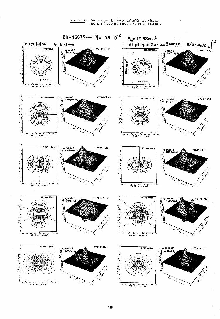
F i g u r e 18 : Comparaison des modcs c a l c u l E s d ~ s rEsona- t e u r s ii e l e c t r o d e c i r c u l a i r ~ e t e l l i p t i q u e .
2 2h=.15375mm 6. .95 10- ~,=19,63,,,~2 112 circulaire re=5.0 mm ell ipt ique 2a = 5.62mm/x1 alb=b,,/C55]
2 0 I 5 - 10 4 1 0 0 D I I D I S 2 0 RXE XI l i o r m u n ~ r l
RXE XI I rn rm,uniLI
-2.J -l.5 -1.0 -0.5 0.0 0.5 1.0 1.5 2.0 RXEXI I ~ r , m u n i i l RXEXI l i n m v n c t l
'1.0 .I.I -1.0 -0,s 0.0 0.5 1.0 1.1 2.0 RXE XI Icn r. unrt l RXE XI l ~ n m ~ n ~ t l
. . .. r * ' 6
n C X ? " B q
0 RXE XI l i n m uobL1 RXE XI 1.n r m u n ~ i l
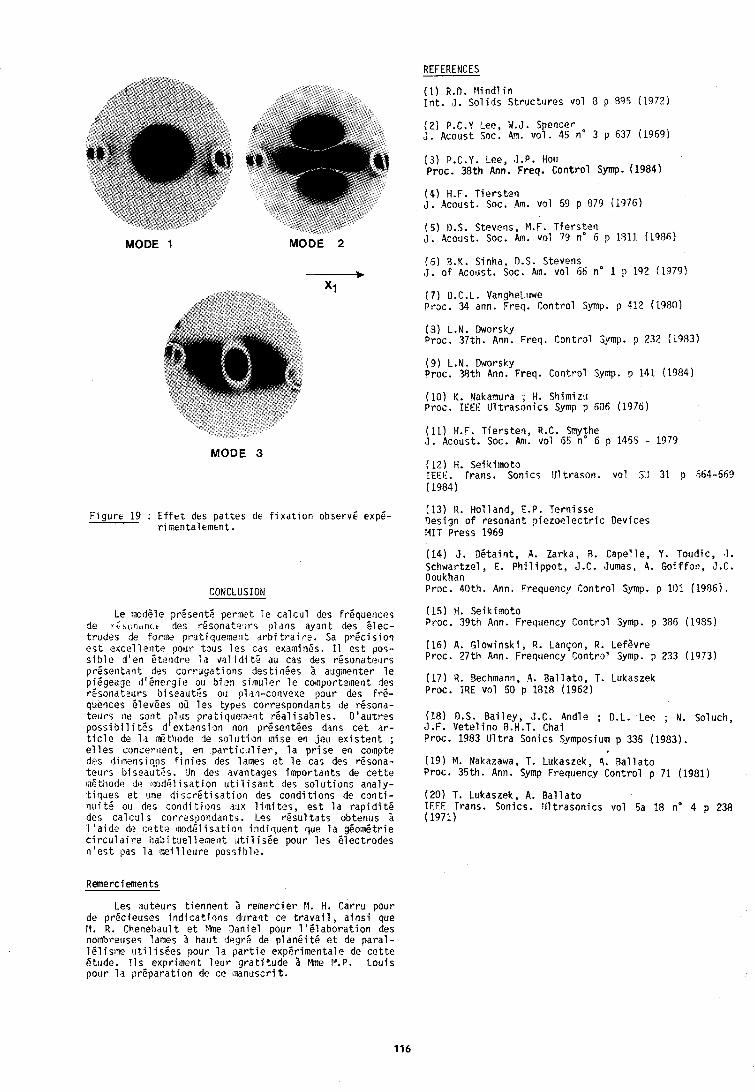
REFERENCES
( 1 ) R.D. r l i n d l i n I n t . , I , S o l i d s Struct,. ires vol 8 p 8% (1972)
MODE 1 MODE 2
MODE 3
F i g u r t 19 : E f f e t des p a t t e s de f i x a t i o n observe expE- r i mentalement .
CONCLUSION
Le modEle pr6senttjl p e r w t l o c a l c u l des frequences de l i 5 b l i d l ~ t des r e s o n a t e l ~ r s p lans ayai i t des e l e c - t rodes de for~ne prat iquernent d r b i t r a i re . Sa p r P c i s i o n e s t 2 x c e l l e n t e pour tous 1% cas examin8s. I 1 e s t pos- s i b l e d 'en Bterldrz l a val i d i t e au cas des r6sonatet l rs preser l tdr i t des c o r r u g a t i o n s des t inees I auginenter l e piegeage d 1 6 n e r 3 i e ou h i e n s i ~ n u l e r l e conporteinent des rCsondt?urs b i s e a u t k ou plan-convexe pour des f r e - quences 5 levees oir l e s types correspondants de r6sona- t e ~ i r s fit> son t ,)lus p ra t i querne i t r e a l i s a b l e s . D ' a u t r e s p o s s i b i l i t S s d ' e x t a n s i s n non present6es dans c e t a r - t i c l e de l a d t h o d e de s o l u t i o n mise en j e u e x i s t e n t ; e l l e s concernen t, en p a r t i c r i l i e r , l a p r i s e en co~npte des dilnensi?!ls f i n i e s des lames e t l e cas des resona- telurs bi;eautBs. IJn des avantages impor tan ts de c e t t e m6tiiotle de c m d 6 l i s a t i o n u t i l i s a r i t des s o l u t i o n s ana ly - t iclues e t urie d i s ~ r 6 t i s a t i o n des c o n d i t i o n s de c o n t i - n u i t 5 ou des c o n d i t i o n s aux l i m i t e s , e s t l a r a p i d i t e des a l c u l j corresponddnts. Les r e s u l t s t s obtenus % 1 ' a i d e dc c e t t z lnodel i s a t i o n indi lquer i t que l a gBom6trie c i r c u l a i r e habi t ~ e l l e m e r l t , r t i l i s 6 e pour l e s e l e c t r o d e s n ' e s t pas l a m e i l l e u r e possi h l e .
Remerciements
( 2 ) P.C.Y Lee, W.J. S encer J . Acolist Soc. Am. vo!. 45 no 3 p 637 (1960)
( 3 ) P.C.Y. Lee, J . P . Hou Proc. 38th Ann. Freq. C o n t r o l Symp. (19841
( 4 ) H.F. T i e r s t e n J. Aco~ust. Soc. 4m. v o l 59 p 879 (1976)
( 5 ) D.S. Steveqs, M.F. T i e r s t e n J. A c o ~ ~ s t . Soc. Am. vol 79 no 6 p 1813. (1986)
(6) R.K. Sinha, D.S. Stevens ,I. o f Acoust. Soc. Am. vo l 156 no 1 p 192 (1979)
( 7 ) D.C.L. VangheLuwe P r x . 34 ann. Freq. Con t ro l Symp. p 4:? (2980)
(3) L.N. Dworsky Proc. 37th. Ann. Freq. Con t ro l Qmp. p 232 (1983)
( 9 ) L.N. Dworsky Proc. 38 th Ann. Freq. Con t ro l Symp. p 141 (1984)
( 1 0 ) K. Nakamura ; H. S h i m i t u Proc. I E E E I J l t r a s o n i c s Symp p 606 (1976)
(11) H.F. T i e r s t e n , R.C. Smythe J . Acoust. Soc. Am. vo l 65 no 6 p 1455 - 1979
(12) H. Seik imoto IEEE. Trans. Sonics Ill t rason . vo l SU 31 p 564-569 ( 1984)
(13) R. Hol land, E.P. Tern isse Design of resonant p i e z o e l e c t r i c Devices MIT Press 1969
(14) J . D e t a i n t , A. Zarka, R. Capel le , Y. T o ~ i d i c , ' 1 . Schwartzel , E. P h i l i p p o t , J.C. Jumas, A. G o i f f o n , J.C. Doukhan Proc. 40th. Ann. Frequency Cont ro l Symp. p 101 (1986).
( 1 5 ) H. Seik imoto Proc. 39th Ann. Frequency Cont ro l Symp. p 385 (1985)
( 1 6 ) A. Glowinsk i , R. Lanqon, R. LefSvre Proc. 27th Ann. Frequency Cont ro l Symp. p 233 (1973)
(17) R. Bechmann, 4. B a l l a t o , T. Lukaszek Proc. IRE v o l 50 p 1818 (1962)
(18) D.S. B a i l e y , J.C. Andle ; D.L. Lee ; N. Soluch, J.F. V e t e l i n o R.H.T. Chai Proc. 1983 U l t r a Sonics Symposium p 335 (1983).
(19 ) M. Nakatawa, T. Lukaszek, 4. B a l l a t o Proc. 35th. Ann. Symp Frequency Cont ro l p 71 (1981)
( 2 0 ) T. Lukaszek, A. B a l l a t o IEEE rrans. Sonics. I J l t r a s o n i c s v o l 5a 18 no 4 p 238 ( 1971)
Les au teurs t i e n n e n t r e ~ n e r c i e r 14. H. Carru pour de prec ieuses i n d i c a t i o n s duran t ce t r a v a i l , a i n s f que PI. R. Chenebault e t Mne Dan ie l pour 1 1 6 1 a b o r a t i o n des nomhreuses lames I haut degr6 de p l a n e i t 6 e t de p a r a l - l e l isme t i t i l i s 6 e s pour l a p a r t i e exper imenta le de c e t t e etude. I l r exprimerit l s u r g r a t i t u d e Mme F7.P. L o u i s porur l a p r e p a r a t i o n de ce tnanuscri t.
l b r Forum EoropBkn temps-Fr6~uefice - 1987
CALCUL D1 PER'IVRBATION AVEC ELEMgWS FINIS APPUQUh: AUX faBSOh'AmURS A QUARTZ
K. TrUmpy
L a b o r a t o i r e de mic ro techn ique ETA SA, CH-2540 Orenchen Suisse.
RESUME - La m6thode des 616ments f i n i s a p p l f q u i e au c a l c u l de r i s o n a t e u r s 1 q u a r t z s ' e s t a v i r i e labor ieuse , A 1 ' a t d e
du c a l c u l de p e r t u r b a t i o n il e s t p o s s i b l e de r i d u i r e
l ' e n v e r g u r e des c a l c u l s dans l e cas 02 de f a i b l e s 6 c a r t s de f r i q u e n c e r Q s u l t e n t de l a v a r i a t t o n d iun pa-
r a n 6 t r e e x t i r i e u r . Le c a l c u l de p e r t u r b a t i o n d ' o r d r e sup6r ieu r e s t a p p l i -
que au c a l c u l du comportement de l a f r i q u e n c e en fonc-
t t o n de l a t e m p i r a t u r e pour l e s t r o t s r i s o n a t e u r s sU i -
vants: diapason de t o r s i o n , r i s o n a t e u r v i b r a n t en mode de c i s a i l l e m e n t d ' i p a i s s e u r , resona teur v i b r a n t en
mode de contour ,
La mi thode a Q t i a p p l i q u i e iga lement au c a l c u l de l a
p e r t u r b a t i o n de f requence sous l ' i n f l u e n c e de f o r c e s
s ta t iques .Par exemple on a ca lcu l i5 l a r i p o n s e f r6quen-
c e - f o r c e d 'un r i s o n a t e u r en forme de double-diapason.
INTRODUCTION
La mi thode des i l i m e n t s f i n i s a i t 6 u t i l i s i e pour l a
mod61 i s a t i o n m a t h h a t i que de d i f f 6 r e n t s r6sona teurs i quartz , A c d t d de l ' i n d i c a t i o n de l a f r i q u e n c e de r i - sonance e t du mouvement de l a zone de f i x a t i o n ( f a c - t e u r de q u a l i t i ) on s ' i n t i r e s s e au comportement de l a
f r i q u e n c e en f o n c t i o n de l a temp i ra tu re , L 1 l t l e r g i e do
systPme p i i z o i l e c t r i q u e se man i fes te s u r t o u t en i n e r -
g i e d ' o s c i l l a t i o n micanique, ce q u i nous permet de
c a l c u l e r l a courbe f r6quence-tempirature avec une bonne p rCc is ion , en t e n a n t compte seulement de paraml- t r e s micaniques en ce q u i concene l a d t l a t a t i o n t h e r -
mique du m a t e r i e l e t l a v a r i a t i o n des c o e f f i c i e n t s i l a s t i q u e s sous 1 ' e f f e t de l a temp i ra tu re . La mi thode numir ique des i l i m e n t s f i n i s permet de
prendre en c o n s i d 6 r a t i o n l a g i o m i t r i e exac te du rho- nateur e t t o u s l e s e f f e t s d ' a n i s o t r o p i e du quar tz ,
Compari des methodes a n a l y t i q u e s l e c a l c u l numi r ique
demande une impor tan te u t i l i s a t i o n de c a l c u l a t r i c e .
S u r t o u t pour l e s modes sup6r ieu rs l a d l t e r m i n a t f o n des
v a l e u r s e t des vec teurs p ropres d e v i e n t une teche l a -
bor ieuse. A I ' a f d e du c a l c u l de p e r t u r b a t l o n il e s t
p o s s i b l e de r 6 d u i r e consid i i rablement l e volume de c a l - c u l p o u r l a d i t e n i n a t i o n des v a l e u r s p ropres p e r t u r -
b6es.
PbUr deux types de r i s o n a t e u r s , l e s r i s u l t a t s obtenus
avec c e t t e mi thode s e r o n t compar is B ceux r i s u l t a n t
d 'un c a l c u l exac t : un d iapason de t o r s i o n u t i l i s 6
comme cap teur de t e m p i r a t u r e e t un r i s o n a t e u r v i b r a n t
en mode de c o n t o u r ( q u a r t z ZT) q u i se d i s t i n g u e p a r
une s t a b i l i t 6 thermique e x c e p t i o n e l l e . Pour l e r6sona- t e u r v i b r a n t en mode de c i s a i l l e m e n t d 1 6 p a i s s e u r
( q u a r t z AT), l a mi5thode du c a l c u l de p e r t u r b a t i o n
d ' o r d r e s u p i r i e u r n ' e s t pas a p p l i q u a b l e B cause de l a
d 6 g 6 n i r a t i o n des v a l e u r s propres. Cela s i g n i f i e que
t h i o r i q u e m e n t 11 y a Un nombre i n f i n f de vec teurs p r o -
p res d i f f i r e n t s avec l a mime v a l e u r p r o p r e ( f r i -
quence), Ce t y p e de r i s o n a t e u r e x i g e qu 'on c a l c u l e avec 18 mi thode " e x a c t e ' ( i t 6 r a t i o n v e c t o r i e l l e s imu l -
tange l , c e q u i ne c o n s t i t u e pas un d6savantage dans c e
cas parce q u ' i l s ' a g i t de l a p remis re v a l e u r propre.
Ces c a l c u l s s o n t r i a l i s i s avec des c o e f f i c i e n t t h e r -
miques du q u a r t z p rovenan t de deux au teurs d i f f i r e n t s .
Les r g s u l t a t s d ipenden t la rgement des c o e f f i c i e n t s
u t i l isbs. I 1 s s o n t compares aux v a l e u r s e x p i r i m e n t a l es.
Un a u t r e example de c a l c u l de p e r t u r b a t i o n concerne l a P a r t a t i o n de frPquence sous 1 ' i n f l u e n c e de f o r c e s s t a t i q u e s , Des c a l c u l s de p e r t u r b a t l o n du p remie r o r -
d r e s o n t p r i s e n t i s pour un double diapason q u i s u s c i t e
a c t u e l l e m e n t un grand S n t i r E t c o m e c a p t e u r de f o r c e . Ce c a l c u l e x i g e comme o p 6 r a t i o n s l e s p l u s longues deux
ahalyses s t a t i q u e s d'i5liment.s f i n i s . On o b t i e n t des
r iponses f r fquence- fo rce t r l s proches des v a l e u r s
e x p i r i m e n t a l es.
Avec l e p r o g r a m e d i v e l o p p i B ETA, i t e s t p o s s i b l e d '
e f f e c t u e r des c a l c u l s s t a t i q u e s e t de modes p ropres ,
e t des analyses modales pour l e s p rob l imes b i -d imen-
s i o n e l s s u i v a n t s :
Les cas de c o n t r a t n t e s e t de d i f o r m a t i o n s p lanes e t
c e l u i 3 s y m i t r i e a x i d l e ; l e s p laques minces e t i p a i s -
ses; l e s coqueb p lanes H n c e s e t i p a i s s e s ; l e cas de
l a t o r s i o n ST'Venant (seulement s t a t i q u e ) . On p e u t t r a i t e r auss i l e s cas du m a t e r i e l i s o t r o p e ou a n i s o -
t rope ,
Le programne B c r i t eh langage FORTRAN e s t i n s t a l l 6 s u r
Une c a l c u l a t r i c e HP 1000 F. Les c a l c u l s s o n t e f f e c -
tugs en double p r i c i s i o n . Les m a t r i c e s sym6tr iques de
r i g i d i t i e t de masse son t s t r u c t u r i e s en forme d l eti- veloppe, c ' e s t 1 d i r e que chaque l i g n e e s t h6mor ts ie
depuis 1 ' i l 6 m e n t d iagonal j u s q u ' au d e r n l e r B l i m e n t
non rtul. Compari B l a m6mor isat ion en forme de bande 11 en r i s u l t e souvent une r i d u c t i o n d'espace de mimoi-
r e de p l u s de 50%. Pour l a d i t e r m l n a t i o n des v a l e I l r s
e t vec teurs p ropres on u t i l i s e l ' a l g o r i t h m e des i t i r e - t i o n s v e c t o r i e l l es s imul t a n i e s (subspace i t e r a t i o n ) ,
Le nombre de c o n d i t i o n de l a m a t r i c e de r i g i d i t 8 e s t a d l i o r i en m u l t i p l i a n t l e s m a t r i c e s de gauche e t de
d r o i t e avec une m a t r i c e d iagonale, de t e l l e s o r t e qUI
tous l e s C l iments diagonaux de l a m a t r i c e de r i g i d i t 6
a i e n t l a v a l e u r 7 ( l a m a t r i c e de masse e s t soUMise d l a meme t r a n s f o r m a t i o n ) . Le programme s 'emp lo ie s o i t en mode i n t e r a c t i f s o i t en
mode "batch". La deuxi ime p o s s i b i l i t i permet de c a l c u - l e r p l u s i e u r s courbes f requence- temp i ra tu re a rec un
"lancement", p a r exemple pendant une n u l t .
n a i e ~ m t d , j fl u ~ t i ~ l tb,,1. 81 t, r irk, yk, a) represen t8 1 Cs ctrorddnhies du hoeud k i l a temp6rdture t a , ce hbeud aura l e r too rdonn ies ik i i a temp6rdtUre t : CI, + a:, , en U p p a s a n t nu1 l e 1 a
eompasahte s e l o n 1 'axe des 2 , LL( c l s a i l l e m @ n t d ' i p a i s - seur de i a p laqbe, b r b v u q b l pab l e d i l ~ t a t i o n an iso -
t rdpe , d a l t C t r e h i i g l i p i en U t i l l s a n t un mod8le b i - d i -
metislone1 , kn f u n c t i o n de l a temp l rd t l r re on o b t l e n t l e s expres-
s tat is su ivan tes :
kasse v o l uml qbe : ~ ~ l ~ / ( ( l + d , ~ l ( l +d,,)(l+d,,))
Masse s u r f a c l q u e des
B l ec t rodes m l nces : C L ' - C L ( ~ - b , l - b l a )
S i on t i e n t cbmpte de 1 d comopasante s e l o n 1 'axe des z des coardonn6es 4 , an t r o u v e dr.- b,,rl + b,,ry . Pour
des toordonn8es en d l r e c t i o n t - (bas.-b,,, 0 ) on a drt- 0 ,
FORMULATION DU CALCUL OE LA COURBE FREQUENCE-TEMPE- t e s t done 1 'axe a u t o u r duquel 11 f a u t f a i r e t o u r n e r
RATURE ~ U U S t e s naeuds U'un ang le dy.0n t r o u v e c e t ang le en
appl l q u a h t 1 ' o p i r a t i o n tl s u r 1 e v e c t e u r fi - (b,,.b,,, o)
La mesure e x p i r i m e n t a l e de l a v a r i a t i o n des c o e f f l c l - ( ~ 4 e s t i ~ f - m l m e o r thogona l au v e c t e u r t :
e n t s i l a s t i q u e s en f o n c t i o n de l a temperature e s t un dn,- (bf,+ b:,) -i i d y l =dn,/lAl - a probl6me d i f f i c i l e 1 cause de l e u r p e t l t e s s e , 11 y
des i c a r t s p e r c e p t i b l e s e n t r e l e s v a l e u r s i n d i q u i e s Avec c e t t e va leup t r o u v e : p a r d i f f i r e n t s auteurs. Dans nos c a l c u l s on u t i l i s e he*-h'coe d y 2 h b ( l - d y 2 / 2 ) - h'(1-(b:,+bi,)/2)
l e s v a l e u r s de [I] e t de [2]. Les v a l e u r s de [ 2 ] o n t i t 6 obtenues s u r l a base des v a l e u r s de [l] e t [31
rendues c o h i r e n t e s 2 l ' a i d e d'une d t h o d e f t i r a t i v e , c ' e s t i d i r e que l a s y m i t r i e t r i g o n a l e e s t auss l v a l a -
b l e pour 1 ' i n v e r s e de l a m a t r i c e de r a i d e u r du q u a r t z ( m a t r i c e de f l e x i b i l i t i ) I t o u t e s temp i ra tu res .
Le c a l c u l des c o e f f i c i e n t s d ' b l a s t i c i t i c,, en fon t r t i 0 t I
de l a t e m p i r a t u r e s ' i c r i t de l a f a ~ o n s u i v a n t e t
3 c,,(T) - c,,(Ta) ( 1 +;,TC~:' ( T - TO)^ )
avec 1 es c o e f f i c i e n t s de temperature fcl7)d'ordre k. La t e m p i r a t u r e de r i f i r e n c e To e s t 25 O C .
La t r a n s f o r m a t i o n du tenseur des modules d ' i l a s t i c i t i
correspondant B l ' o r i e n t a t i o n des p laques de q u a r t z
p a r r a p p o r t au rep6re c r i s t a l l o g r a p h i q u e e t l a conver-
y i = y ; ( I + bi3/2)
C e t t e t o r r e c t i o n du deuxl tme a r d r e i n f l u e n c e seulement
i m p e r c e p t i b l ement 1 es r i i s u l t a t s des coupes pour 1 es-
que l i r r s I ' b r d r e de grahdeur des b,, e s t comparable i ~ e l u t des bb ( p a r exemple l e q u a r t z ZT). b a r t a n t de ces paramgtres p e r t u r b & on c a l c u l e l a ma-
t r 4 c e de r i g l d i t 6 e t l a m a t r i c e de masse sans aucune e r r e u r ~ Ces deux Mat t iCes d i f i h i s s e n t exactement
' l q u a t i o f l qUi d8termi t te lks v a l e u r s e t vec teurs p r o -
p r e s per tu rb i i s dans n o t r e thodtle. Comne deuxi tme i t a p e
11 s ' a g l t ma in tenan t de de te rminer l e s v a l e u r s p e r -
t t i r b l e s .
s i o n des modules i l a s t i q u e s conforme au champ des con-
t r a i n t e s ( c o n t r a i n t e p lane, d i f o r m a t i o n plane, con- CALCUL OES VALEURS PROPRES PERTURBEES DU PREMIER OR- t r a i n t e de c i s a i l l e m e n t d ' i p a i s s e u r ) a & t i expose dans ORE ET D'ORDRE SUPERttUR
[41. P a r a l l i l e m e n t au c a l c u l des modules d ' i l a s t l c i t ~ , l e s L e i Vdleurs Cropres A,, e t l e s vec teurs p ropres On dB-
c o e f f i c i e n t s p r i n c i p a u x de d i l a t a t i o n en f o n c t t o n de f l n t s p a r 1 '6qUat ion s u i v a n t e d 'un p r o b l h e 2 N-dimen-
l a t e m p i r a t u r e s' i c r i v e n t de l a maniPre s u i t v a n t e ! S ~ O ~ S :
Avec l a m a t r i c e A , d i c r l v a n t une t r a n s f o r m a t i o n de s o n t d i t e r m i n i s p a r l a m6thode des i t e r a t i o n s vec to -
coordonnies e n t r e l e s axes c r i s t a l l og raph iques e t 1 e r i e l l e s s f mu1 tenge (subspace I t e r a t i o n ) [51. Les va- repere u t t l i s i dans l e c a l c u l , on a p p l i q u e une t r a n s - l e u r s p ropres non digBnar6es s o n t c l a s s i e s p a r o r d r e
f o r m a t i o n de congruence s u r l a m a t r i c e d iago- croissant : hn>h, pour n > I , e t l e s vec teurs 5, v 6 r i -
f i e n t l a r e l a t i o r i ( d n l - i pour n# l e t z l b o d l l t rkhteht) :
c ' e s t '8 d i r e q u ' i l s s o n t orthonorm8s dans Uh serls gE-
n f r a l { s f . Lorsque l ' o r d r e n des v a l e u r s p ropres augmente, l e
c a l c u l e x a c t des v a l e u r s p ropres per tu rbees avec l a mgthode des i t f r a t i o n s v e c t o r i e l l e s , en p r e n a n t l e s
vec teurs e t v a l e u r s p ropres non p e r t u r b & comme va-
l e u r s i n i t i a l e s , d e v i e n t e x t r h e m e n t f a s t i d i e u x . La
m6thode de c a l c u l de p e r t u r b a t i o n permet de t r o u v e r
l e s v a l e u r s p ropres per tu rbees beaucoup p l u s r a p i d e -
ment e t avec une e x a c t i t u d e i n t f r e s s a n t e . Le c a l c u l de p e r t u r b a t i o n au p remie r o r d r e l f v r e des
r 6 s u l t a t s exac ts seulement au vo is i t l age d i r e c t he l a
v a l e u r p r o p r e non p e r t u r b 6 e e t s ' e f f e c t u e se lon l a me- thode connue [6]:
La norme du vec teur p r o p r e p e r t u r b 5 t i e s t i n d l t e r m i -
nee e t l e s 5, du probleme 8 N-dimensions forment une
base complete, donc : N
ii = ii + a GI ( a l << 1 ) ISn
L'Bq. ( 1 en forme p e r t u r b e e s ' f c r i t c o m e s u i t :
neP ja p e r l u r b a t l o h d ' a r d r e 9Ubgr ieur .
En pdsant A X % rrr~dd an t r a b v e cor respondan t 8 1 ' fq. (6)
I d v a l e u r A r u d ' u n o r d r e s b p t r i e u r en p a r t a n t de 1'6q. (1 J @ t i forme p e r t u r b e e e t en mu1 t l p l i a n t s c a l a i r e m e n t
t$tt8 Qquat ibn avec 3; :
La l n a t r i c e de hlasse M ' h e change p ra t iquement pas dans
l e cas d lune d i l a t a t i b n thebmique parce que l e p r o d u i t
du volume p a r l a masse volUrnique r e s t e cons tan t ,
On a t r o u v e q u ' l l e s t p o s s i b l e de c a l c u l e r A W d i r e c t e -
ment p a r l a mf thode i t e r a t i v e des g r a d i e n t s conjugu6s. C e t t e methode permet l a d f t e r m i n a t i o n du minimum de l a
f o n c t i o n e l l e quadra t ique F ( k ) - ( 2 , A s ) . Comne 11 sera UErmohtrl p l u s l o i n , l e p o i n t 2; ne c o r -
respohd pas du minimum mais au p o i n t s t a t l o n n a i r e de
l a f a n c t i o n e l l e ~ ( 2 1 - ( f , ( l t ' - A n h t S ) i i ) . On p e u t t r o u v e r c e t t e v a l e u r s t a t i o n n a i r e en t e r m i n a n t
1 ' i t l r a t i o n l o r s q l l ' e l l e d 6 c r o i t apres un comportement
s t a t i a n n a i r e de l a f o n c t i o n e l l e , En posant d - S t + s, 3; , on t r o u v e :
F *r [:Li;+q,d;,(f I- AaM1) (d;+ q,ii;))
~ ~ ; + ~ , i j i l ~ ~ ~ - ~ n ~ b ) ~ ~ ; + q p ; ~ ) + ~ ~ n ( ~ n + q l ~ l n ~ ( ~ ; + q l q ) ) K'3; = A:,M'O; (An + A A ~ ) M ~ ~ ;
Par l e s 6q. ( 1 e t ( 2 ) en forme p e r t u r b 6 e a i n s i qu 'en Avec K a 3 K + b f l e t M ' P M + A M on t r o u v e l ' l q u a t i o n : t e n a n t compte de l a sym6t r ie des m a t r i c e s e t en u t i l i -
K ' ~ ~ ~ + C ~ , K G , + C a , ~ ~ i i , - AnM1iin + A A ~ M ~ ~ , +AA,AMG, s a n t en forme p e r t ~ r b e e l a r e l a t i o n : (K-A,U)ii, - (K-h,M)i l ,- 8 - (f t -AnM)l i l - (K-AIM) i i l - (AI-An)Y31.
+ ~ ~ C a ~ ~ i i ~ + h n C a l A M 6 , + a h n C a l M 6 i i , 0) brl o b t l e n t :
En n e g l i g e a n t l e s termes d ' o r d r e s ~ l p l r i e u r 8 un, on
t r o u v e :
K ' Gm+ C 0:') K iil = AnM ' tn + hnC a;') M ii, + A A!') M 0, (4)
La mu1 t i p l i c a t i o n s c a l a i r e de 1 ' f q . ( 4 ) avec 0, donne,
en tenan t compte des Cq. ( 1 ) e t ( 2 ) :
(G,IC1ijn) = A,(G,M'tn) + AX(:) (5 )
Pour l e premier ~ r d r e on t rouve , avec A + A A -
w ~ + 2 w ~ w + ~ w ' ~ w ~ + 2 w ~ w , une p e r t u r b a t i o n de l a
v i t e s s e a n g u l a i r e :
En t e n a n t compte des equa t ions ( 1 e t ( 2 ) e t en m u l t j -
p l i a n t scala i rernent 1 '6q. ( 4 ) avec ii, ( I z n ) on t rouve :
( GI, K On) + a;')hl = An( Gll M ' On) + hnaiO
Pour l e p remie r o r d r e on o b t i e n t l a r e l a t i o n :
= ( G t , ( K ' - A d l m I An- A1 (7)
En s u b s t i t u a n t l e s a?) s e l o n 1 '6q.(7) dans ( 3 ) e t en nhgl i g e a n t l e s termes d ' o r d r e s u p 6 r i e u r i deux, 11 e s t
p o s s i b l e de de te rminer l a p e r t u r b a t i o n de l a v a l e u r
p r o p r e du deuxieme o rd re . C e t t e methode e x i g e que 1 'on connaisse l e s N v a l e u r s e t vec teurs p ropres du p r o b l i -
me 3 El dimensions, c e q u i n ' e s t p ra t iquement jama is l e cas. On a donc chercht! urn a u t r e methode pour de te rmi -
F-4: (G~l(K'-A~M')G;)+AAn((G;lMIG;)+q~ (G;lMoG;))
- ~ : ( x ; - ~ ; ) + A A , ( I + ~ ~ )
F~*(A;-A,)~;+AA, (9 )
tln c o n s t a t e que pour 1dhJ < IX;-A;I 11 r f s u l t e un
d6cro issement de l a f o n c t i o n e l l e en d i r e c t i o n ij; avec I c n , uh accroissemerlt pour I>n e t que ij; correspond t une v a l e u r s t a t i o n n a i r e AXn ( v a l e u r m in ima le pour n-1).
Une c o n d i t i o n ngcessa i re 5 l ' a p p l i c a t i o n de l a mfthode
des g r a d i e n t s c o n j u g u i s e s t n a t u r e l l e m e n t que l a v a l -
eu r de l a f o n c t i o h e l l e se t r o u v e au dessus de l a va-
l e u r s t a t i o n n a i r e au debu t de l ' i t b r a t i o n . A c 6 t 6 du Vecteur p r o p r e tlon p e r t u r b 6 on dfspose s e l o n 1 'Bq, ( 7 ) d'une m e i l l e u r e approx imat ion du vec teur i n i t i a l :
Pour l a f o n c t i o n e l l e on o b t i e n t :
r(8) (an+Ca$, , (~ ' -A~Y') ( i i ,+Ca, i i , ) )
r (fin ,(K'-knY')d,) + 2Cat(iil , (K ' -A~U ' )O~) +
(Cel i j t ,(scl-hnYo)Co1ij,)
Le p remie r terme correspond d 'apres 1 '6q. ( 5 ) 8 ~ ~ f ) e t l e del lx i lme d 'aprgs 116q. ( 7 ) 1 2~a: (hn-A , ) . Le t r 0 i -
slame terme p e d t l t r e t r a n s f o r m l en :
( ~ d l i ~ , ~ ( ~ - h , ) l ) ~ a t ~ , ) + ( ~ a l ~ , , ( ~ ~ - h , ~ ~ ) ~ a , d , ) - t C o $ , , C ( h , - ~ , ) ~ a , 3 $ + o(')*CO~(X,-X,) + 0(')
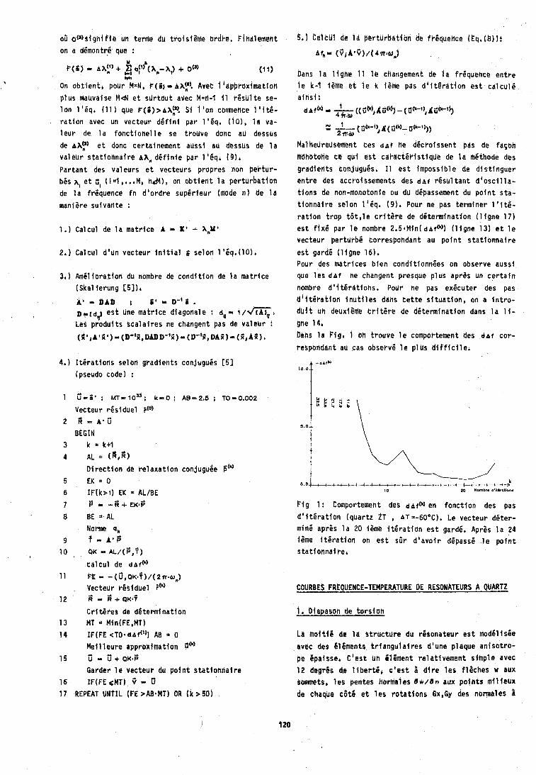
05 o o s i g n i f i e un term@ du trois ietne ordke. Finalement CalcU1 de I d bor turbat fon de Or6quence ( h . (b) 1: on a d6montrj que : Af,- (31A*V)/14*luli)
Y i P(6) 9 A A t ) + a?) (A,- XI) + OIJ) (1 1)
1w On obt ien t , pour M=N, ~ ( l ) AI','! Avet 1 'apbrtrximation ptus mauvaise M d e t s t i r tou t avec k=ti-f i 1 r6shl t e se- I o n l l i q . (11 ) qhe P(~),AA?\ S i 1 'on comnence 1 ' { t i - r a t i o n avec un vecteur d e f i n i par l 8 6 q , (101, l a va- l e u r de l a f onc t i one l l e se t rouve donc ad desshs de AX:^ e t donc certainement aussi au dessus de l a valeur s ta t f onna i re AA" d 6 f l n l e t]dr 1 I 5 q ~ (9)'
Par tant des Valeurs e t vecteurs propres non per tura b6s A, e t dl II=l ,,.,Ma n&), on o b t i e n t l a per turbat ion de l a frequence f n d lordre superteur (mode n ) de l a mantsre suivante :
1.) Calcul de l a mat r ice A - It' - X,Y'
2,) Celcul d'un vecteur i n i t i a l selon l ' i q . ( l O ) ,
3 . ) Amklforatton du nombre de cond i t i on de l a mat r ice (Skal ierung [51),
A * bAlD t i1 .I U-'i . pl(d4 e 9 t une mat r ice diagonale : d, l/m, tes prodt i i t s sca la l res ne changent pas de va leur :
(j;rj~1k1)~(D"kiDbDD"ii)-(D"3iDAji)~(k~lLd)~
4. ) I t e r a t i o n s sel on gradients conjugu6s C51 (pseudo code) :
Dans l a 1 tgne 11 l e changement de l a frequence en t re l e k - I fsme e t l e k i8me pas d ' i t l r a t i o n es t ca lc l r le a ins t t
1 d ~ f t k i 9 ((~b)~,@j- (d*-l),d@-ij) 4 w.a,
u ., - 1 ( 8tn-4) 4 ~ ( k ) - 0th-4))) 2 m& r
Malhetlrellsenlent ces d ~ f he d6croissent pas de fa$Oh mdnotone ce gu i e s t c a k d c t ~ r i s t i q u e de l a mgthode des gradients conjugu6s. I 1 e s t impossible de dt s t lnguer ent re des accroissements des d ~ f rQsu l tan t d ' o s c i l l a - t i ons de non-monotonie ou dll dgpassement du p o i n t s ta- t i onna i re selan 1 'Sq. (91. Pour ne pas terminer 1 'itti- r a t i o n t r o p t 6 t , l e c r i t e r e de determinat ion ( 1 igne 17) e s t f i x 6 par l e nombre 2 , 5 4 M i n ( d ~ f ( ~ ) ( l i g n e 131 e t l e vecteur per turb5 correspondant au p o i n t s ta t l onna i re
es t garde ( l t g n e 16). Pour des matr ices b ien condtttonnees on observe dussi qde l e s d ~ f ne changent presque p lus aprss un c e r t a i n nombre d ' i t l r d t i o n s . Pour ne pas ex6cuter des pas d 1 i t 6 r a t i o n i n u t i l e s dens t e t t e s i t u a t i o n , on a i n t r o - d u i t uh deuxt8me c r i t e r e de determinat ion dans l a 1 i - gne 14, bans l a Fig, 1 on trouve l e comportement des d a r cor-
respondent au cas observe l e p lus d i f f i c i l e c
1 t - E ' ; MT- loU: k - 0 : AB-2.5 ; TO-0.602 E I e r t \ Vecteur residue1
2 a - ~ ~ i i BEGIN
3 k = k + l A1 * (e,fi) D i r e c t i o n de re laxa t i on conjugube iitk) EK = 0 IF (k> l ) EK = AL/BE F - - k + EK+$
BE = AL Norme 4,
? - A * B QK = AL/($,?)
ca lcu l de d ~ f ( ~ )
FB * - ( 6 , 0 ~ * ? ) / ( 2 ~ o , ) Vecteur ~ S s l d u e l i(k) W - 6 + QK.?
Cr t t s res de determt na t i on MT = Min(FE,Mf) IF(FE c t o b d ~ f ~ ' ) ) AB * 0
F f g 1: Comportement des dbftk) en fonct ion des pas
d ' t t e r a t i o n (quartz ZT , AT=-60°C). Le vecteur d6ter - mine aprgs l a 20 r ime i t C r a t i o n e s t gard6. AprOs l a 24 i8me I t s r a t i o n oh e s t s l i r d l avo i r ddpass6 l e p o i n t s ta t tonna i re,
1, Diapason de t o r s i o n
La mol t i 6 de l a St ruc ture du rhsonateur e s t modClis6e
Met1 l eu re apprbl imat ion 0"3 avec des hlgments i r i d n g u l a i r e s d'une plaque an iso t ro- 15 u ' - u ^ + a ~ ~ i ; pe Bpaisse, C1est un Element re la t ivement s imple avec
Garder l e vecteur du p o t n t s ta t i onne i re 12 degrhs de 1 i b e r t e r c i e s t i d l r e l e s f laches w aux 16 IF(FE <MT) 3 - somnets, l e s pentes narmales dw/8n aux po in t s m l l ieux 17 REPEAT UNTIL 1FE 2ABbMT) OR ( k > SO) de chaqUe cat6 e t l e s r o t a t i o n s Bx,Gy des normales g
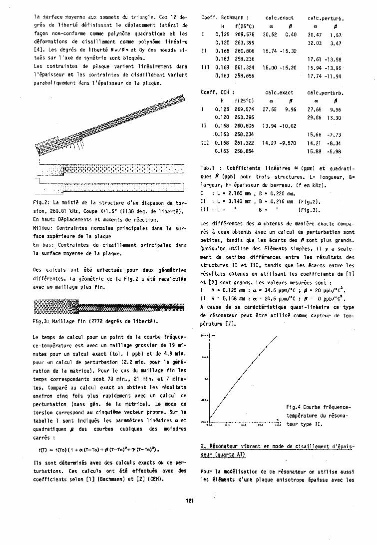
l a s u r f a c e aoyenne aux somnets du t r ! a ~ g l e . Ces 1 2 de- g r i s de l i b e r t 6 d b f l n i s s e n t l e d6placement l a t e r a l de
fason non-conforme c o m e polyn6me quadra t ique e t l e s d6 fo rmat ions de c i s a i l l e m e n t c o m e polynBme I i n i a i r e
[ 4 ] . Les degr6s de l i b e r t i e w l a n e t Gy des noeuds s f - t u i s s u r l ' a x e de sym6t r ie son t b l o q u i s .
Les c o n t r a l n t e s de p laque v a r i e n t l i n i a f r e m e n t dans
l t 6 p a i s s e u r @t l e s c o n t r a i n t e s de c i s a i l l e m e n t v a r i e h t
parabol iquement dans 1 ' i p a i s s e u r de l a plaque,
Fig.2: La m o i t i i de l a s t r u c t u r e d 'un diapason de t o r -
s ion, 260.81 kHz, Coupe Xt1.5' (1138 deg. de l i b e r t i ) .
En haut : Dip lacements e t moments de r 6 a c t i o n .
M i l i e u : C o n t r a i n t e s normales p r i n c i p a l e s dans l a su r -
f a c e s u p i r i e u r e de l a p laque
En bas: C o n t r a i n t e s de c i s a i l l e m e n t p r l n c i p a l e s dans
l a s u r f a c e moyenne de l a plaque.
Coe f f , Bethmann :
H f(2S°C) 1 0.1 25 269.578
0.120 263.399
I 1 0,168 260.808 0.1 63 258.236
I 1 1 0.168 261,324
0.1 63 258.856
Coef f . CEH : h f (25"C)
I 0.125 269.574 0.1 20 263,396
11 0.168 260,806
0.163 258.234
111 0.168 261,322 0,163 258.654
T a b d l : C o e f f i c i e n t s l i n 6 a i r e s a (ppm) e t q u a d r a t i -
ques B (ppb) pobr t r o i s s t r u c t u r e s . L= longueur, B=
l a r g e u r , H= 6pa isseur du barreau. ( f en kHz).
: L e 2.160mn, B = 0 . 2 2 0 m n . 11 : L 3,140 IIIII B a 0,216 ~III (Fig.2) . 111 : L = I' B = 'I (F lg.3) .
Les d i f f e r e n c e s des a obtenus de mani8re e x a c t e compa-
r 6 s I ceux obtenus avec un c a l c u l de p e r t u r b a t i o n s o n t p e t i t e s , tandf s que l e s b c a r t s des P son t p l u s grands.
Quoiqulon u t i l l s e des b lgments s imples, I 1 y a seu le -
ment de p e t i t e s d l f f 6 r e n c e s e n t r e l e s r e s u l t a t s des s t r u c t u r e s 11 e t 111, t a n d i s que l e s ( c a r t s e n t r e l e s
Des c a l c u l s o n t i t 6 e f f e c t u b s pour deux g6ometr les r e s u l t a t s obtenus en u t i l i s a n t l e s c o e f f i c i e n t s de [I]
d i f f 6 r e n t e s . La g 6 o m i t r i e de l a Fig.2 a 6 t 6 r e c a l c u l 6 e et t21 grandre Les valeurs msur6es sent :
avec un m a i l l a g e p l u s f i n , 1 H = 0,125 mm : a = 34.6 ppm/'C ; P = 20 ppb/O~' .
11 H = 0.168 inn : a = 20.6 ppm/'C ; p = 0 ppb/O~' . A cause de sa c a r a c t € r i s t i q u e q u a s i - l i n 6 a i r e ce t y p e
de rgsona teur p e u t B t r e u t i l i s i c o m e c a p t e u r de tem- Fig.3: M a i l l a g e f i n (2772 degr6s de l i b e r t i ) . p e r a t u r e t71.
Le temps de c a l c u l pour un p o l n t de l a courbe frbquen-
ce- temperature e s t avec un m a i l l a g e g r o s s i e r de 19 m i -
nutes pour un c a l c u l e x a c t ( t o l . l ppb) e t de 4.9 min.
pour un c a l c u l de p e r t u r b a t i o n (2.2 min. pour l a g ihb-
r a t i o n de l a m a t r i c e ) . Pour l e cas du m a i l l a g e f i n l e s
temps correspondants s o n t 70 min., 21 min, e t 7 minu-
tes. Comparb au c a l c u l e x a c t on o b t i e n t l e s r b s u l t a t s e n v i r o n c i n q f o i s p l u s rapidement avec un c a l c u l de
p e r t u r b a t i o n (sans g6n. de l a m a t r i c e ) . Le mode de
t o r s i o n correspond au c inqui8me v e c t e u r propre, Sur l a t a b e l l e 1 son t I n d i q u i s l e s paramgtres l l n i a f r e s a e t
quadra t iques f l des courbes cubiques des moindres
c a r r i s :
11s s o n t dbtermin6s avec des c a l c u l s exac ts ou de per - t u r b a t l o n s . Ces c a l c u l s o n t s t 6 e f f e c t u e s avec dcs c o e f f i c i e n t s s e l o n [I] (Bechmann) e t [ 2 1 (CEH).
.*ha 8
Fig.4 Courbe f r6quence-
tempgrature du r6sona- 1s.1 . n. ,.it t e u r t y p e 1 1 . . . . . . . . . . : . '
2. Resonateur v i b r a n t en mode de c i s a i l l e m e n t d 1 6 p a l s -
seur ( q u a r t z AT)
Pour l a m o d b l i s a t l o n de c e resona teur on u t i l i s e a u s s i l e s i l i m e n t s d'une p laque a n i s o t r o p e 6pa lsse avec l e s
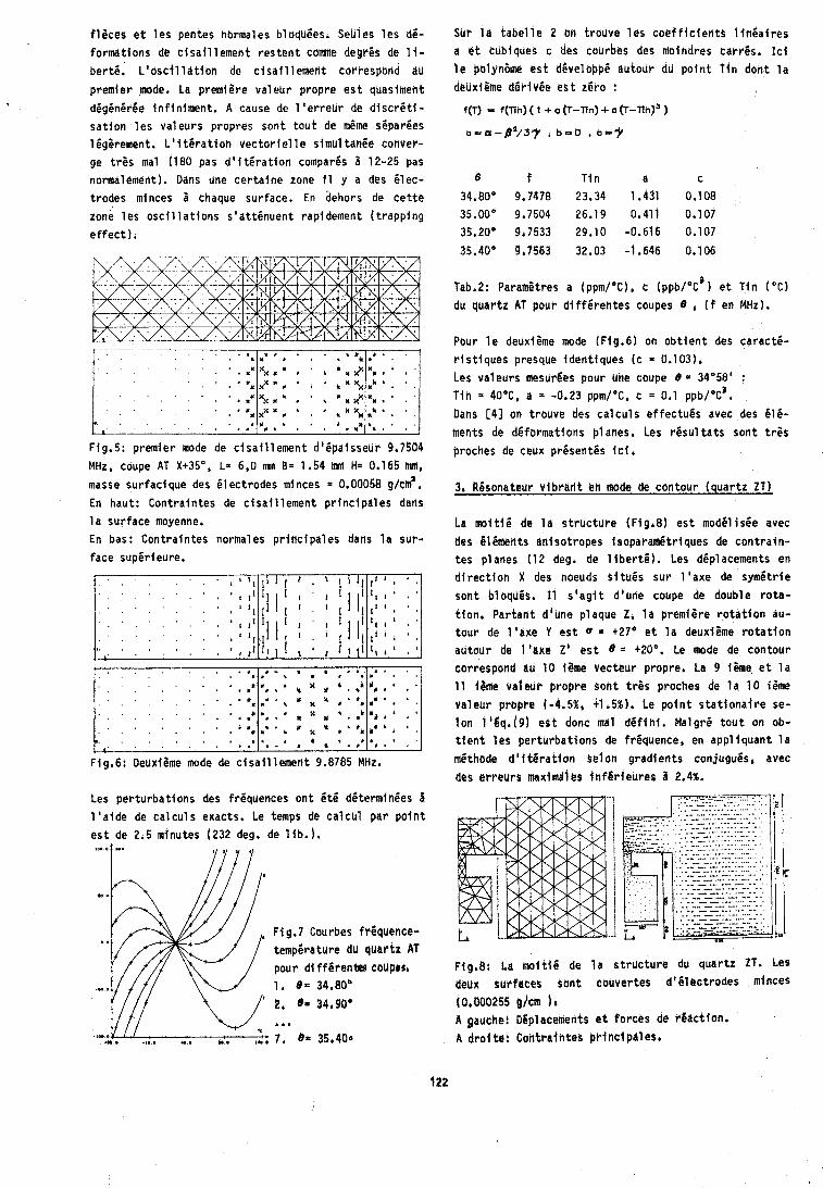
f l i c e s e t l e s pentes normales bloquies, Sebles l e s d i - formations de c i s a i l l ement res ten t come degr is de 1 i- bert6. L ' b S ~ ~ l l d t i ~ n de c i sa i l l emen t correspond i iu premier mode. La premiCre valeur propre e s t quaslment digin6r6e in f in iment . A cause de 1 ' e r reu r de d t sc r6 t t - sa t lon l e s valeurs prapres sont t o u t de m6me s6paries l ig i rement . L ' i t 6 r a t i o n vec to r i e l l e simul t an ie coriver- ge t r 2 s ma1 (180 pas d 1 t t 6 r a t i o n compar6s 1 12-25 pas normalement). Dans une cer ta tne zone 11 y a des i l e c -
SUr l a t a b e l l e 2 on trouve 16s c o e f f i c i e n t s l t r i i a i r e s a e t cublques c des coclrbes des moindres carres, I c i l e palyn6me e s t dEvelopp6 dutour du p o i n t t i n dant l a deuxiPme dCbiv6e e s t r 6 r o :
f(T) - f(Tln) ( I + a (T-Tln) + c (~-f lh) ' )
a - a - ~ v ~ y , b m o , b-y
B f T i n a c 34.80" 9.7478 23.34 1.451 0.108 35.00' 9,7504 26.19 0.411 0.107 35-20' 9,7533 29.10 -0.616 0,107
trodes minces 5 chaque surface. En dehors de c e t t e zone l e s o s c i l l a t t o n s s4at t6nuent rapidement ( t r app ing e f f e c t ) .
fab.2: Paramitres a Ippm/'C), c Ippb/'c3) e t T in (OC)
du quartz AT pour d i f f6 rentes coupes 0 4 ( f en MHz).
Fig.5: premier mode de c l sa t l l emen t d' ipaisseui. 9,7504 MHz, coupe AT X+35', L= 6,O mn B= 1.54 H= 0,165 MI
masse surfacique des i l e c t r o d e s minces = 0.00058 g/ci#. En haut: Contraintes de c i sa l l l emen t p r i nc ipa les dans l a surface moyenne. En bas: Contralntes normales p r i nc ipa les dahs l a sur- face supir ieure,
. . . . . . .
. . . . . . . . . : . , , , . , ,
. . . . . ." * I , 8 .. . . . . I . , X * , ' * # * " ' .
. . . . , I ) . , , . . r . ,: $, X o 4 . . I . I . . a ,
1 . . . , . , . .I . * X * b " b . ' ' ' . + . . , . . , . . . , .: # * . ' . , " d . ' :
Fig.6: ~ e u x i i m e mode de c i sa t l l emen t 9.8785 MHz,
Les per turbat ions des fr6quences ont 6 th d i t e rm ln ies 2 1 'a ide de ca l cu l s exacts. Le temps de ca l cu l par p o i n t e s t de 2.5 mtnutes (232 deg. de l i b . ) .
I I I I
F i g.7 Courbes frCquence- tempirature du quartz AT pour d i ff6rente6 cauptr, 1, 8 . 34.80'
2. 34,90b ... 7. 85 35,400
Pour l e deuxtQme mode (Ffg.6) on o b t i e n t des c a r a c t i - r t s t t q u e s presque identtques (c = 0.103). Les valeurs mesurCes pour une Coupe 8 = 34'58' : T in = 40°C, a = -0.23 ppm/"C, c = 0.1 p p b / 0 ~ 3 . Dans [41 on trouve des ca l cu l s e f fec tu6s avec des 616- ments de d6fbrmations planes. Les r 6 s u l t a t s sont t r i s prochas de cetlx pr6sent is f c i r
3, RBsonateur v lb rar i t en mode de COhtOUr (quar tz ZT)
La m o i t i 6 de l a s t r i rc ture (FIg.8) e s t modi l i s6e avec des I l6ments antsotropes i r o p a r a d t r i q u e s de cont ra in- tes planes (12 deg, de 1 l b e r t 6 ) . Les d6placements en d i r e c t i o n X des noeuds e i tu6s sur l ' a x e de symgtrte sont bloqUis, I 1 s ' a g t t d'une coupe de double ro ta - t ion , Partar i t dlune plaque Z, l a prem i i re r o t a t i o n au- t ou r de l ' a x e Y e s t 0 = +27" e t l a deuxlime r o t a t l o n autour de 1 'axe 2' e s t 8 +20°. Le mode de contour correspond au 10 i2me vecteur propre. La 9 t ime e t l a 11 l ime vathur propre sont t r 2 s proches de l a 10 i ime valeur propre (-4.58, +I ,5%). Le po tn t s t a t i o n a i r e se- l o n 116q.(9) e s t donc ma1 d 6 f i n i . M a l g r i t o u t on ob- t i e n t l e s per turbat ions de friquence, en appl iquant l a methode d ' i t i r a t i o n gelon gradients conjugu6sb avec des e r reu r r maximdl 8s i n f6 r i eu reo 1 2.4%.
flg,Q: La n o i t i B de l a structure! dU quartz ZT. Les deux surfaces sbnt couvertes d '6 lec t rodes minces (0,000255 ~ / c m 1' A gauche: Diplacements e t forces de r6act lon. A d r o i tr! Gontrafntes pr inc tpa les .
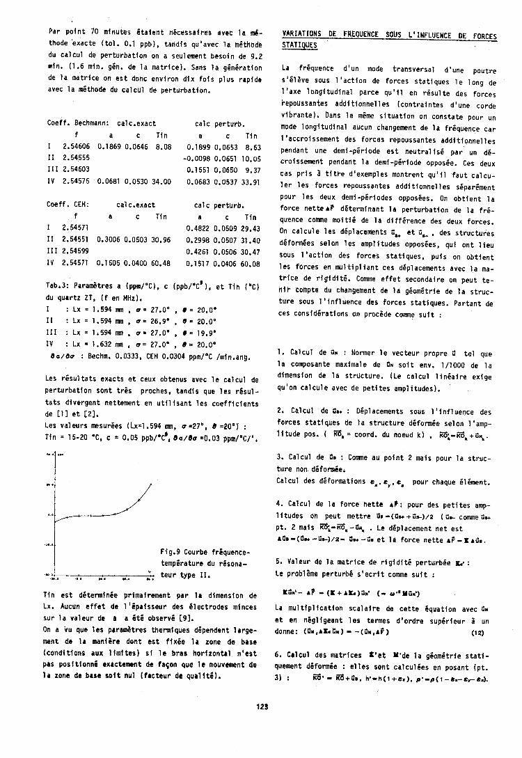

7. D6termination de l a pe r tu rba t i on de l a fr6cjUeh-
ce ~ f - r f r + a f . : avec l e s tq, ( 4 ) e t (12) on o b t i e n t :
> L '6quat ion (6 ) donne :
La m6thode a 6 t6 appliqu6e au calcUl de l a reponse
fr6quence-force d 'un double diapason C8j. Fig.10 mon-
t r e un quar t dU double diapason. La s t ruc tu re a 6 t 6
mod61 is6e avec des t l tments ani sotropes isoparam6tr i - ques de cont ra tn tes planes, Sur l e s deux axes de sym6- t r i e il r 6 s u l t e des forces de react ion.
du r6sonateur e t de tous l e s e f f e t s d ian i so t rop ie du quartz.
La haute p r6c i s l on a t t e i n t e avec l a fi6thode de$ 616-
ments f i n i s a 6 t6 dBmontr6e aussl dans I 'exemple du
ca lcu i de l a per turbat ion de Oriquence de s t ruc tu res
soumlses 1 des forces stat lqhes. Je t l e n s b rerflercier ma bel le-soeur F, frumpy pour l a
co r rec t i on ghn6rale du t e x t e frangats, M. l e Prof. M. Ojanguren pour ses eonsel ls concernant l e s expressions
techniques de l a premi2re p a r t t e e t h. W. Ztngg du d i -
partement quartz de ETA pour l a mise b d i s p o s i t i o n des
val curs exp6rimental es.
[I]: R. Bechmanh, A. Ba l l a to , T.J. Lukaszek, Higher Order Temperature Coeff, o f the E l a s t i c S t i f f n e s s Com-
p l iances o f puartz, Proc, I.R.E. 1962 p. 1812-1821.
[2]: C, Bourgeois, Rapp. Tec. 205 CEH, Neuchftel.
Fig.10: Le quar t d 'un double diapason, coupe Xi1 .So, L31: C.A& Adams, G.M, Enslow, J.A. Kusters, R.W. Ward,
L/2 = 2.60 mn, B = 0.245 mn, H = 0.175 mn, f s 46.729 Selected Toplcs i n Quar tz Crys ta l Research, Proc. 24th
kHz (mode fonddmental 1. Ann. Symp. on Freq. Control 1970 p. 55-63.
On a obtenu l e s valeurs suivantes pour une fo rce de 1 N C41: K 1 Tritmpy, Stlirungsrechnung m f t F i n i t e n Elementen
(0.5 N par bras) : angewendet auf Schwingquarze, Actes du 60e Congrgs de
Afr = 490.5.H~~ = -10.9 Hz, A? = 479.6 Hz. l a SSC La Chaux-de-Fonds 1986 p, 39-46.
La valeur exp6rfmentale e s t r r = 486 Hz/N.
Une formule ana ly t ique [ l o ] bas6e sur l e mod21e d'une t 5 5 : H.R. Schwarz, Methode der F l n i t e n Elemente, Teub-
poutre mince donne (E = 78300 N/mn ) 464.0 Hz/N, Notre her-ver lag S t u t t g a r t 1984,
modele donne une va leur p lus pr6c lse parce q u ' e l l e
t i e n t compte des dt format ions de c i sa i l l emen t e t des
e f f e t s d ' i n e r t i e de ro ta t i on .
A l a place de l a m6thode dtvelopp6e i c i on peut aussi
d6terminer l a pe r tu rba t i on de l a matr tce de r i g t d i - t 6 AX^ exp l ic i tement en mod6lisant l a fo rce AP par
des appuis e las t iques des noeuds (mat r ice diagonal) . Dans ce cas on peut e f f ec tue r des ca l cu l s de perturba-
t i o n d 'o rdre sup6rieur.
t61: H, Baumgtrtel, Endltchdimensionale Analyt ische
St8rUngstheorle, Akademte-Verl ag Ber l f n-Ost 1972.
t71: W. Zlngg, C.E. Leuenberger, Senseur de Tempira-
t u r e a Quar tz Rtsonnant, Conf. sur l e s Appl. des Sen-
seurs eh Microtechnique, Uni. Neuchftel l n s t . de Mi- crotechnique 1984 p. 5-9.
t81: M. Christen, Senseurs resonnants b quartz, Actes du 59e Congr8s de l a SSC In te r l aken 1985 p. 31-36.
CONCLUSION t91: U. Ztngg, LI. Studer, J, Hermann, Fab r i ca t i on de
On a vu q u l i l es t poss lb le de d6terminer l e s perturbam ResOn"eurs 2Tf, Prerehte dans ce CongrPs*
t l o n s de fr iquence d 'o rd re sup6rieur par l a m6thode des gradients avec une pr(cfs(on sup(rfeur 8 flOl: w*cb Albert, Quartz Crys ta l Beam
1% en ragle ginsrale, Compar6 a l a mGthode exacte, lerometer, P ~ o c * 28th l n t b I ns t r . SY~P. Las 1982
pour l e mode n, l e temps de ca l cu l e s t d ' envfron ii P' 33-441
l / n . Cette p o s s ~ b i l i t 6 permet l e ca lcu l de courbes friquence-temperature par 1 a m6thode des 61 C e n t s f l - n is . La m6thode g6n6rale e s t appl iquable aux formes de
rgsonateurs le, p lus d i f fe rentes . Par rappo r t dux c a l - c u l s analyt tques on ob t ten t des valehrs p lus pr6clses parce qu'on peut t e n i r compte de l a g iomkt r fe euacte
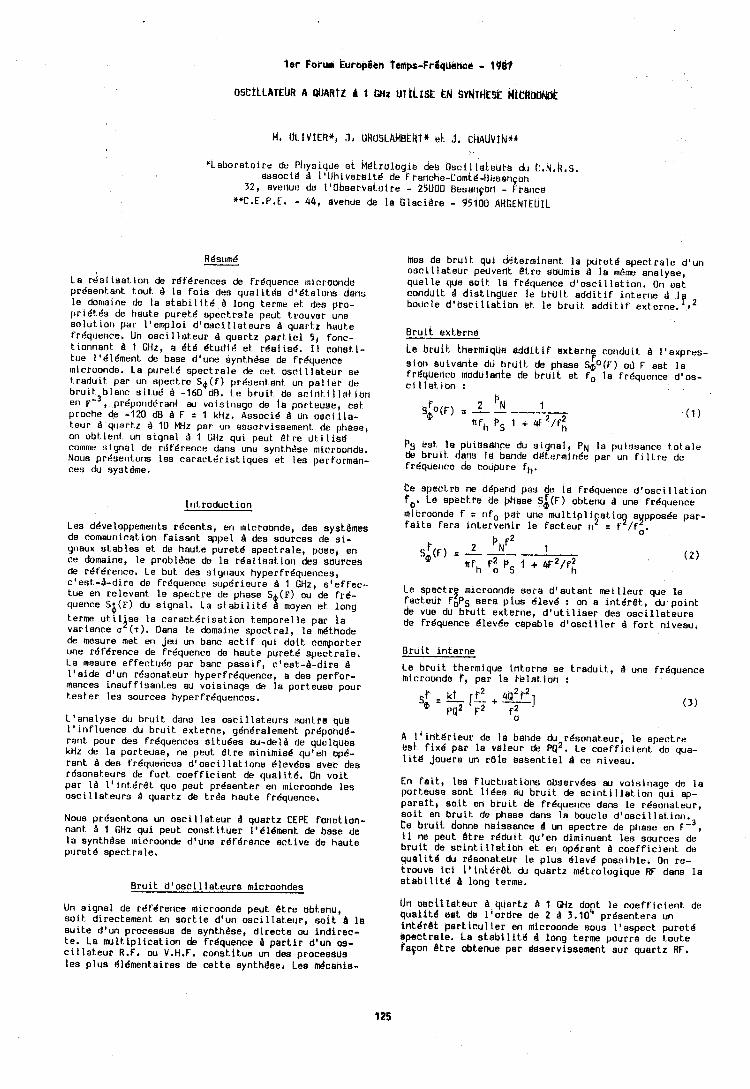
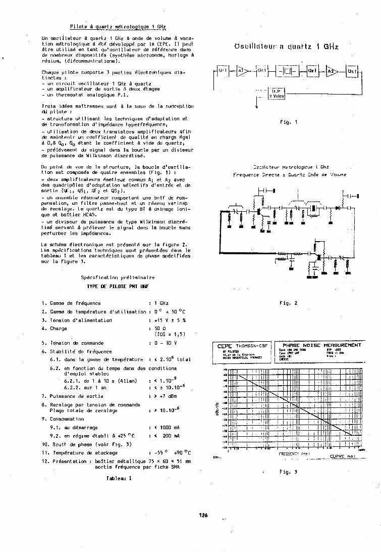
P i l o t e A quartz mdtrolbgiQue 4 GHZ - Un osc i l l a t eu r A quartz 1 Gtit A unde de voldfhe Q vbta- Lion m6trologique d Bt6 dBvelopp6 par la CEPE. I1 peut Btre u t i l i s 6 en tant qu 'o sc i l l a t eu r de reference delis de no~nbreux d i s p o s i t i f s (syntht3se microonde, horloge $ rdslum, tBlBco~nmuri~ratioris).
Cheque p l l o t e cumpotte 3 p s r t ~ e s Blecttotiiques d is - t i n c t e s : - un c i r c u l t o sc i l l a t eu r 1 GHz A quartz - uri amplificateur du s o r t ~ e A deux ktayes - un thermostat analogique P.I.
Trois idees maftresses sont 9 l a base de l a conrept.itin du pi1ot.e : - s t r u r t u r e u t ~ l i s a n t l e s terhniquea d 'adspts l ion bt. de t ransformat. ion d ' 1mp6danre hyperfrBquenrer - util isat . ion de deux t r a n s i s t o r s amplificateuPs a f i n de maintetiir un roeff ic ient de qua l i t 6 err rharge 6gal d 0,8 Po, Qo Btant l e c o e f f ~ c i e n t A vide du quar tz , - prdl6vement du signal daris l a boucle par un d iv iseur de puissanre de Wilkinson discr6t i sB.
Du point de vue de la s t ruc tu re , la boucle d ' oac i l l a - t i on est. composOe de quatre ensembles (Fig. 1 ) : - deux amplificateurs Bmetteur comun A 1 e t A2 avec des quadr~pd le s d 'adaptation s e l e c t i f s d4en t rQe e t de s o r t i e ( W l , PSI, QE2 e t 452 1. - un urisembte rdsor~ateur c:omport.snt urie s e l f de coin- perisat.ion, un f i l t r e passe-tiaut e t un r6ut:eu varirdp de recalage. Le quartz e s t du type 01 9 us i t~age ioni- que st. bo t t i e r HC45. - un div iseur de puissanre de type Wilkiriao~t discrd- t.isk servant. B prdlever le s igna l dans l a baut le sans perturber l e s i~npddances,
Le sch6ma Blectronique e s t present6 aur l a f igure 2. Les sp6cl f ica t ions techniques sont presentees dans l e tableau I e t lea carsr t .6r ia t iques de phase sp6cifidea sur l a f i gu re 3.
Sp6cif ica t ion pre l iminai re
TYPE DE PILOTE WT UiF
1. Game de frequence t 1 G H t
2. Gamme do t.empbrature d 'ut i l i s s t i o n : 0 O + 50 O C
3 , Tension d ' s l imenta t ion ! + 1 5 V t 5 %
4 , Charge t 50 P (TO5 = 1 , 5 )
5, Tension dt? commande : O - f b V
6. S t s b i l i t d de frkquence
6.1. dans la gsmme de temperature : < 2 . 1 0 ~ t o t a l
6.2. en fonction du temps datls des condit.ions d'emploi s t ab l e s 6.2.1. de 1 d 10 s (Allan) : < I . I O - ~ 6.2.2. sur 1 an r < t 10 ,10 '~
7, Puissance de s o r t i e 1 > +7 dBm
8. Recalage per tension de co~nmande Plage t o t a l e de recalage : 3 10 .10 -~
9 , Consommat ion
9.1, au ddaarrage : < 1000 mA 9.2. en regime k t ab l i A +25 O C : C 200 in4
10. Bruit de phase (voi r f i g . 3 )
11. Temp6t.ature de atockage : - 5 4 ' +90°C
12, Prdsentation : bo t t i e r metalt ique 75 x 60 x 51 inn s o r t i e frequence par f iche SMA
Fig. 'I
Zs:~( lc teur Metrclogrcue 1 G h t
Yrequencz Dlrec;e o Cucrtz Cnde oe Vclune
Fig. 2
4
.u
.u
.?I
4 8
41
,, .I*
2 :::: .I11
.It4
.iU
.I11
.ill
.ill
uia.,. CURVE no: . . . . -
Tableau I
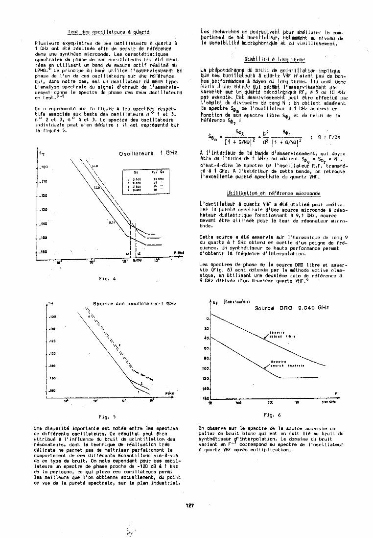
Test des o s t i l l a t e u r s B quartz
P lus leurs exemplairea de res o s c i l t a t e d t s A quartz A 1 CHz ant 6 t6 r6a l i s6s a f i t i do serv ic da rgt'krenea dans une synth6se microonde, Les carac tdr is t iqdes speckralea de phase de ces osri l lat,euPs 0ht i t $ maau- r6es &n u t i l i s a h t un banc de menure ect i P r i e l i s 8 dii LPMO. Le p r i nc ipe du bat~c u t i l i s e l'Elds&tvinskrtleHt Utl phase de l l u n de cue a s r i t t a t e u r s sub dtie rdt'Ytehce q u ~ , dans not re cas, est un ose i t l a teu r dU memd kypb, L'analyse spe r t ra l c du signet dierreui. de I 1 a s ~ l ; l t v i s - sement. donne l e spectre de phase des deux asci 1 lek.eui'8 en test . 3 m 5
On a wpr6sen t i sur l a f i gu re 4 les spectbks rkspec- t i f s aasocida aux t,esks des o s e i l la tebra n 1 et 3 , n o 2 e t 3 , n o 4 et 3. Le spectre d e ~ Osci l la teurs ind iv idue la peut e'en ddduire 1 11 est beptdsentd BLIP l a f i gu re 5.
Spectre des osci l lateuts OH2 '\
Fig. 5
Une d i s p a r i t e importante est notee ent re tes epectree de d i f f e r e n t 8 osc i l l e teu rs . Ce t d s u l t a t peut b t r e att.r ibu6 tl l ' i n f l u e n c s du b r u i t de s c i n t i l l a t i o n dee rdsonateurs, dont l a technique de r i e l i s a t i o n t r ee dd l t ca te ne permet pas de met t r ieer parfaitement l e comportement. de ces d i f f i r e n t s dchant i I lona v ie-&v ia da ce type de b t 'u i t , On m t e cependant pout eea o e c l l - la teurs un spectre de phaae proche de -120 dEl d I kHz de l a porteuee, ce qu i p lace ces o s c i l l a t e u r s parmi. lea mei l leure que l ' m obtienne ectuellement, du p o i n t de vue de l a p u r e t i apectrale, sur l e p lan i n d u s t r i e l ,
Las kechirrthke se padrsdlvahh pour am6llbrer l e corn- bnrti?metlL de id. u e r i t l a t ~ t . ~ nui~mment au nivt?au de La d i ? ~ s i b t l l t a ! 1111tkupharil~Lie @t d~ v ie i l i i s semen t .
9 t l r b i i i t 6 d idng, tarms
l d bf$pohdib$hc dU bhUi i de e c l n t i l l a t i u r i tmplique t$& bks arritir!eute 8 .liidtf z YHF h4s ie t i t pas de bon- hbe p8kPd~1hdh~ks d Mbykn uJ tong herhe, t l b eodt donc k r ~ r ~ i 8 d l u n ~ ilnti.de 4 ~ 1 ptrt.nteI. t ~ e t l s e ~ v i g s e ~ e i r t par v ~ b ~ b t u t . 1JP L]n qutli-ti mitrulu tque k ~ , d 5 cru Ib kliz p a l dxettiplk, ck t &st!ivlildkhieh! peUL etke effecLu6 par t i ehp tu l ds d i v i e e u ~ s de tahg td : on obkient aisdment 1s spacthe kL1 de l ' d s c i l l ~ l t e u r 8 1 CHz asservi en
A 1' l h t 8 b i ~ U b da 1 Y bar~de dieaservissement, qu i de r a I @ti% de i ' b r d r e db 1 kHti ari oh t i en t ka = SQir x N , h l$s t -d-d l te 1.5 spectre & t l b s c i l l a t e u r R.F. t ranef6- tc! 4 1 GH2. A l l ~ x t d r i i ? u ~ de c e t t e bande, on retrouve t ' k ~ c k l leh te puret8 spectkale du q u w t z VHF,
~ k j l i a a t i d n @h rdplrence microonde
L ' b b c l l i a t e u r quartz VHk e d t i u k i l i s d pour am0l1o- bet. l e butokc! spect.rale dlUne source microonds B rdso- heteur di .4 lectr iqbe fohct,idnhant A 9 , l CHz, source devant d t re u t l l i s d e pdur le t.est de r6sonat.eur ~ a i c r o - bhde ,
Cet.1.e source a 6kd ssaervie sJr llharmoniquc de rang 9 du quartz 8 1 GIiz obtend en s o r t i e d 'un peigne de f r 6 - quence, Uh synthdt tsedr de haute performance permet d lab ten i r Id frdqdence d ' i n t e r p o l at ion.
Lee spectres de bhase de l a source DHO l i b r e et asser- v i e (Fig. 6) sont obtends par l a J t h o d e ac t i ve c las- sique, en U t t l i s a n t Urle dedxi8me r a i e de r6f6rerice A 9 kHz ck t ivge diun deilxtime quartz V H F ' . ~
sy / b d l r i r r d P / ~ i l
Bource DRO 9,040 GHz
Fig . 6
20
Y O .
100.
bn observe sur is spectre de l a source asservie un p a l t e r dl? b r u i t blanc qu i est en f a i t l i d au bruit. du ~ y n t h d t i e e u r interpolation. Le domaine du b r u i t var ian t en F' cotrespond cw spectre de l ' o s c i l l a t e u r A quartz VHF c p r b n u l t i p l i c a t i o n .
1 n i i t t a I l b f a
:\\ I * u t e * *nabI.&.
Conclusion
L 1 u t l l t s a t i o n de quartz VHF B 1 [;Hz permet d 'ob ter l i r , dans l e bas de l a yarnrne des ~nlcroonde.s, une rdfdrence de frdquence de haute puret6 spe r t ra lu q u ~ peut ensul- t e & t r e u t ~ l l s j e dans un processus dr synlh6sc pour obt e n l r une source ~nlcruonde du haute qua1 118. Ltis per for~na~i res sont certa~nc?rnent encore pe r fec t t b l es eL sont l t des au progrds de l a technotogle, notemment au rilveau de I 'd ldbora t on des r6sonal eurs.
Rdf6rences
W.A. Edson, "Noise i n osc i l l a to rs " , Proc. IRE, 48, n o 8 (1966). E. Hefncr, "The offec1.s o f noise or1 c r ys ta l o s c i l l a - t.ors9', IEEE Nasa Symp. on short term frequency s ta - b i l i t y " , Goddard Space F l i g h Cent.er, Greenbelt., Marylar~d (1964). L. Cut le r and C. Searle, "Some aspect.^ o f t.he theory and measurement o f frequency f l uc tua t i ons i n f r e - quency standards", Proc. IEEE, 54, n o 2 (1966). R. Orendel, "Bru i t in terne des o s c i l l a t e u r s A quartz", These Docteur-Ingdnieur, n O 63, LPMD, Resenyon, France (1975). F.L. Walls, S.R. Stein, J.E. Grey and D.J. Glaze, "Design considerat ion i n ' s t a t e o f the a r t ' s i gna l processing and phase noise measurement systems", 30th Ann. Freq. Cont. Symp., Fort. Monrnout.h, N.J. (1976). J. Hcrrdin, M. O l i v i e r , "MBtrologie du t.ernps et des frdquences deu osci l lat .eurs microorldes et. m i l l imd- t r iques", Cor~grBs In te rna t i ona l de Chronom6trie, Besangon (1904).
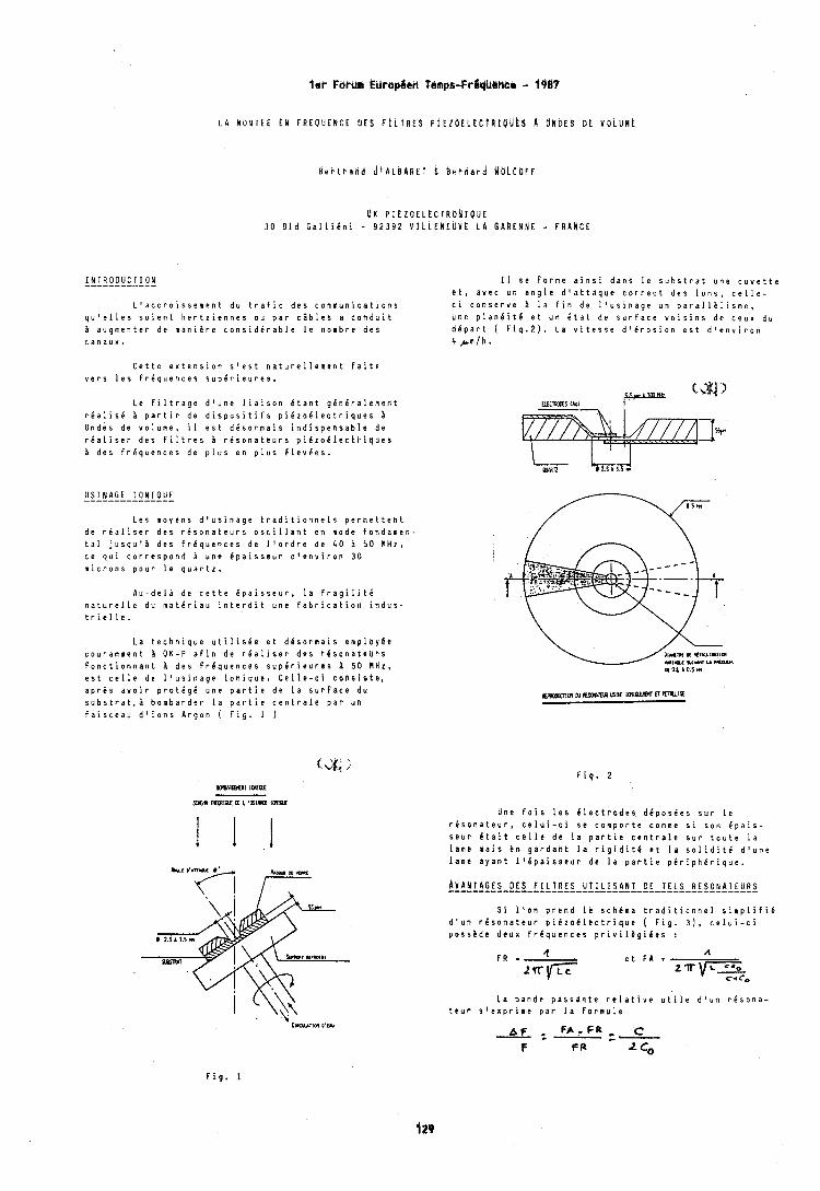
lei- Fbrum EUrbpCek Temps-FrSt#Mic@ - 1987
L A MONTEE EN FREUUENCE UES F f L T R E S P l ~ Z b E L E C t b I P b E S A ONDES DE V O L U k t
B e r t r d n d ~ I A L ~ A R E T E B e r n a r d b l U L C M l F
U K PIEZOELECTRUNIOUE 3 0 B l d G a l l i e n i - 9 2 3 9 2 V f L L E N E U V k L A GARENNE - FRANCE
I N T R O D U C T I O N ------------ L ' a c c r o i s s e m e n t d u t r a f i c d e s c o m m u n i c a t i o n s
q u ' e l l e s s o i e n t h e r t z i e n n e s o u p a r c a b l e s a c o n d u i t i a u g m e n t e r d e m a n i i r e c o n s i d C r a b l e l e n o m b r e d e s c a n a u x .
C e t t e e x t e n s i o n s ' e s t n a t u r e l l e m e n t f a i t e v e r s l e s f r e q u e n c e s s u p C r i e u r e s .
L e f i l t r a g e d ' u n e l i a i s o n C t a n t g e h e r a l e m e n t r e a l i s 6 i p a r t i r d e d i s p o s i t i f s p i C z o C l e c t r i q u e s b O n d e s d e v o l u m e , il e s t d d s o r m a i s i n d i s p e n s a b l e d e r i a l i s e r d e s f i l t r e s r i s o n a t e u r s p i C z o C l e c t r l q u e s i d e s F r C q u e n c e s d e p l u s e n p l u s C l e v C e s .
U S I N A G E 1 O N I O U E --------------- L e s m o y e n s d ' u s i n a g e t r a d i t i o n n e l s p e r m e t t e n t
d e r C a l i s e r d e s r C s o n a t e u r s o s c i l l a n t e n m o d e f o n d a m o n - t a l j u s q u ' i d e s f r e q u e n c e s d e l ' o r d r e d e 4 0 i 5 0 M H z , c e q u i c o r r e s p o n d i u n e C p a i s s e u r d ' e n v i r o n 3 0 m i c r o n s p o u r l e q u a r t z .
A u - d e l i d e c e t t e C p a i s s e u r , l a F r a g i l i t C n a t u r e l l e d u m a t e r i a u i n t e r d i t u n e f a b r i c a t i o n i n d u s - t r i e l l e .
L a t e c h n i q u e u t i l i s i e e t d l s o r m a i s e m p l o y e e c o u r a m n e n t A O K - P a f i n d e r C a l i s e r d e s r 6 s o n a t e u b s f o n c t i o n n a n t B d e s f r e q u e n c e s s u p C r i e u r c s 5 0 M H z , e s t c e l l e d e l ' u s i n a g e i o n i q u e . C e l l e - c i c o h s i s t e , a p r e s a v o i r p r o t C g C u n e p a r t i e d e l a s u r f a c e d u s u b s t r a t , i b o m b a r d e r l a p a r t i e c e n t r a l e p a r u n f a i s c e a u d ' i o n s A r g o n ( F i g . 1 )
I 1 s e f o r m e a i n s i d a n s l e s u b s t r a t u n e c u v e t t e e t , a v e c u n a n g l e d ' a t t a q u e c o r r e c t d e s i o n s , c e l l e - c i c o n s e r v e B l a f i n d e l ' u s i n a g e u n p a r a l l i l i s m e , u n e p l a n e i t 6 e t u n B t a t d e s u r f a c e v o i s i n s d e c e u x d u d e p a r t ( F i g . 2 ) . L a v i t e s s e d ' i r o s i o n e s t d ' e n v i r o n 4 ,&m/h.
F i g . 2
U n e f o i s l e s C l e c t r o d e s d C p o s C e s s u r l e r l s o n a t e u r , c e l u i - c i s e c o m p o r t e c o m m e s i s o n C p a i s - s e u r l t a i t c e l l * d e l a p a r t i e c e n t r a l e s u r t o u t e l a l a m e m a i s e n g a r d a h t l a r i g i d i t e e t l a s o l i d i t 6 d ' u n e l a m e a y a n t l l C p a i s s e u r d e l a p a r t i e p e r i p h l r i q u e .
S i l ' o d p r e n d I! s c h C m a t r a d i t i a n n e l s i m p l i f i C d ' u n r e s o n a t e u r p i 6 z o d l c c t r i q u e ( F i g . 3 1 , c e l u i - c i p o s s i d e d e u x F r C q u e n c e s p r i v i l 8 g i C e s :
L a b a n d e p a s s a n t e r e l a t i v e u t i l e d ' u n r C s o n a - t e u r s l e x p r i m e p a r l a f o r n u l e
F A - F R _ C a:- c-
F F R ' 6
F i g . 1
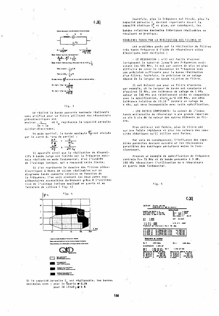
Poll I.6 am,, ! A- 0.. to-
Poll u ll?&, : I-% to-
bnr rur1a.M trt olvlu ru u wn w n u . a ,rtla :
F i g . 3
E n r e a l i t 6 l a b a n d e p a s s a n t e m a x i m a l e r e a l i s a b l e s a n s a r t i f i c e p o u r ~ n F i l t r e u t i l i s a n t d e s r C s o n a t e u r s p i C z o C l e c t r i q u e s e s t e n v i r o n 1 0 5 C r e p r 6 s e n t e l a c a p a c i t e p a r a s i t e
c o t C p b o i t i e r - e l e c t r o d e s .
En m o d e p a r t i e l , l a b a n d e m a x i m a l e q e s t d l v i s e e p a r l e c a r r C d u r a n g d e p a r t i e l :
I 1 a p p a r a t t a i n s i q u e l a r i a l i s a t i o n d e d l s p o s i - t i f s b a n d e l a r g e e s t l i m i t e e p a r l a f r e q u e n c e m a x i - m a l e r d a l i s e e e n m o d e f o n d a m e n t a l , d ' o i l l i n t g r e t d e l ' u s i n a g e i o n i q u e , q u i a r e p o u s s 6 c e t t e l i m i t e .
S i l ' o n r e p r e s e n t e l e d o m a i n e d e s f i l t r e s p i i z o - e l e c t r i q u e s i O n d e s d e v o l u m e r C a l i s a b l e s s u r u n d i a g r a m m e b a n d e p a r s a n t e r e l a t i v e e n f a n c t i o n d e l a f r e q u e n c e , l l o n v o i t a i s e m e n t l e s d e u x z o n e s s u p - p l i m e n t a i r e s a c c e s s i b l e $ d o r e n a v a n t g r s c e I l ' d t i l i s a - t i o n d e l ' u s i n a g e i o n i q u e a p p l i q u e a u q u a r t z e t a u T a n t a l a t e d e L i t h i u m ( F i g . 4 )
t o u t e f o i p , p l u s l a f r e q b e n c e e s t & l e v e e , p l u s l a t a p a t i t 6 p a r a s i t e C d e v l e n t i m p o r t a n t e d e v a n t la t e p a c i t e b t d t i q u b t! a t p l u s , p a r c o n s e q u e n t , l e s
b a n d e s relatives m a x l n r i e ~ t h h o r i q u e s r e a l i s a b l e s s e b g d u i s e n t e n b b a t i q u e .
P A b B L E H t S P O S E S C b k L A R E A L I S A T I O N D E S F l L t R t S H F ................................................. L b b p r b b i k m e s p o s e s p a r l a r e a l i s a t i o n d e f l l t r e s
t r b s h a u t e f r e q u c n c e 3 l f a l d e d e r k s o n a t e u r s p i i z o - d l e c t r i q u e s s o n t m u l t i p l e s :
- L E R E S O N A T E U R : s a i l e s t f a c i l e d l u s i n e r l a n i q u e m e n t i e s u b s t r a t j u s q u ' 8 d e s f r e q u e n c e s a v o i - s i n a n t l e s 500 k H z , i l e s t p a r c o n t r e d e p l u s e n p l u s d l f f i c i l e d e c a l e r l e r e s o n a t e u r e n f r e q u e n c e a v e c u n c p r e c i r i b h s u f f i s a n t e p o u r l a b o n n e r 6 a l i s a t i o n d l u n l i l t b e . l o u t a f o i s , l a p r e c i s i o n d e c e c a l a g e d e p e n d d e l a l a r g e u r d e b a n d e r e l a t i v e d u f l l t r e .
1 1 b s t i ~ i d e n t q u e p o u r u n f l l t r e d ' a n t e n n e p a r e x e m p l e , a b l a l b r g e u r d e b a n d e e s t c o n s t a n t e e t d l e n u i r o n 1 5 K H z , u n e t o l e r a n c e d e c s l r g e d e 1 k H z a u t o u p d t 1 0 0 H k z e s t r e l a t i v e m e n t a i s e e e t c o m p a t i b l e a v e t l a s p i t i f i c a t i o n , a l o r f q u ' i 4 0 0 M H z , u n e m e m e t o l e r a n c e r e l a t i v e d e 1 0 . 1 0 d o n n e r a u n c a l a g e d e 4 K H z , q u i s e r a i n c o m p a t i b l e a v e c c e t t e s p k c i f i c a t i o n .
- L E S A U T R E S C O N P O S A N T S : l a v a l e u r d e l ' i n d u c - t a n c e m o t i o n n e l l e d u r e s o n a t e u r a u n e g r a n d e i m p o r t a n - c e v i s b v i s d r l a v a l e u r d e s a u t r e s C l e k e n t s d u f i l - t r e .
P l u s c e l l e - c i e s t f a i b l e , p l u s l e f i l t r e e s t s b r u n e f a i b l e i d p i d a n c e e t p l u s l e s v a l e u r s d e s c a p a - c i t e s t h k o r i q u e s q u l l l d t i i i s e s o n t f o r t e s .
P a r v a l e d e c o n s 6 q u e n c e s , l ' i n f l u e n c e d e s c a p a - t 1 t C s p a r a s i t e s d e v i e n t m o i n d r e e t l e s r e s i s t a n c e s p a r a l l a l e s d e s b o b i n a g e s p e r t u r b e n t n o i n s l e f o n c - t i o n n e m e n t .
P r e n o n s u n e x e m p l c d e s p e c i f i c a t i o n d e f r C q u e n c e c e f i t r a l k F o - 7 5 W H z e t d k b a n d e p a s s a n t e B 3 d B , 1 0 0 K H Z n e c e s s i t a n t l ' u t i l i s a t i o n d e 4 r e s q n a t e u r s e n q u a r t z n o d e f o n d a m e n t r l .
F i g . 5
S i l a c a p a c i t d p a r a s i t e C e s t n e g l i g e a b l e , k e s b a n d 0 8 n a x i ~ a l e s s o n t : p o u r l e & u a t t z w 0 . 3 %
p o u r 1 6 L i t a U 3 # 5 %
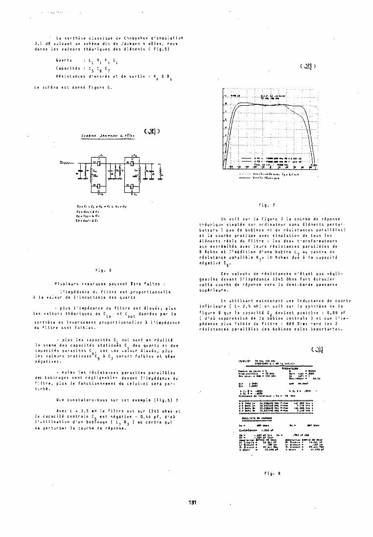
L a s y n t h k s e c l a s s i q u e d e C h e b y s h e v d l o n d u l a t i u t l O , I d B s u i v a n t u n s c h e m a d i t d e J s u m a n n 4 p 6 l e s , n o u s d o n n e 1 0 s v a l e u r s t h e o r i q u e s d e s 6 1 6 n e n t s ( F i g . 5 )
Q u a r t z : L i Ri F i Ci
C a p a c i t C s : C C6 C 5 7
R d s i s t a n c e s d ' e n t r d e e t d e s o r t i e : R e E tis
L e s c h e m a e s t d o n n e f i g u r e 6.
F i g . 6
P l u s i e u r s r e m a r q u e s p e u v e n t B t r e f a i t e s :
- l ' i m p 6 d a n c e d u f i l t r e e s t p r o p o r t i o n n e l l e & l a v a l e u r d e i ' i n d u c t a n c e d e s q u a r t z
- p l u s l ' i m p i d a n c e d u f i l t r e e s t d i e v 6 e l p l u s l e s v a l e u r s t h e o r i q u e s d e C e t Gout d o n n l e s p a r l a
s y n t h e s e e t i n v e r s e m e n t p r o p o r t i o n n e l l e s h l ' i m p i d a n c e d u f i l t r e s o n t f a i b l e s .
- p l u s l e s c a p a c i t e s C, q u i s o n t t n r l a i i t l l a somme d e s c a p a c i t d s s t a t i q u i s C d e s q u a r t z e t d e s c a p a c i t i s p a r a s i t e s C , o n t u n e v a y e u r C l e v i e , p l u s l e s v a i e u r s p r a t i g u e s P c 5 b C s e r o n t f a l b l e s e t mame n l g a t i v e s . 7
- m a i m s l e s r e s i s t a n c e s p a r a s i t e s p a r a l l i l e s des b o b i n a g e s s o n t n e g l i g e a b l e s d e v a n t l ' i m p l d a n c e d u
f i l t r e , p l u s l e f o n c t i o ~ n e n e n t d e c e l u i - c i s e t a p e p - t u r b l .
O u e c o n s t a t o n s - n o u s s u r c e t e x e m p l C ( F i g . 5 ) ?
A v e c 1 - 3 , s A H l e f l l t r e e s t S U P 1 2 4 5 o h m s e t l a c a p a c i t l c e n t r a l e C e s t n e g a t i v e - 0 , 4 4 p F , d l o b l ' u t i l i s a t i o n d l u n b o b f n a g e ( L, R, ) a u c e n t r e q u i
I I v a p e r t u r b e r l a c o u r b e d e r 4 p o n s e .
.... .......... t...L.v.;L L,. %r,* - C.".b. k1.i ,,,,,
F i g . 7
On v o i t s u r l a F i g u t e 7 l a c o u r b e d e r C p o n s e t h e o r i q u e s i m u l d e s u r o r d i n a t e u r s a n s i l 6 m e n t s p e r t u r - b a t e u r n ( p a s d e b o b i n e s n i d e r i s i s t a n c e s p a r a l i & l e s ) e t l a c o u r b e p r a t i q u e a v e c s i m u l a t i o n d e t o u s l e s C i C m e n t s r l e l s d u f i l t r e : l e s d e u x t r a n s f o r m a t e u r s a u x e x t r l m i t C s a v e c l e u r s r i s i s t a n c e s p a r a l l i l e s d e 6 K b h m s e i I l s d d l t i o n d t u n e b o b i n e L 7 a u c e n t r e d e r d s i s t a n c e p a r a i l k l e R,= 1 0 K o h m s d u e B l a c a p a c i t C n d g a t i v e C6.
C e s v a i e u r s d e r e s i s t a n c e s n ' i t a n t p a s n 6 g l i - g b s b l t s d e v a n t l l i m p C d a n c e 1 2 4 5 Ohms f o n t l c r o u l e r c a t t e c o u r b c d t P 6 p o h s e v e r r l a d e m i - b a n d e p a s s a n t e s u p 6 r i a u r e .
E n u t i l i s a n t m a i n t e n a n t u n e i n d u c t a n c e d e q u a r t z i h f 6 r i e u r e ( L - 2 , s mH) o n v o i t s u r l a s y n t h k s e d e l a
f i g u r e 8 q u e l a c a p a c i t d C 6 d e v i e n t p o s i t i v e : 0 , 9 8 p F ( d ' o t s u p p r e s s i o n d e l a b o b i n e c e n t r a l e 1 e t q u e i l i m - p d d a n c e p l u s f a i b l e d u f i l t r e : 8 8 9 Ohms r e n d l e s 2 r e s i s t a n c e s p a r a l i 8 l e s d e s b a b l n e s m o i n s i m p o r t a n t e s .
IY#I,I~ n rut too x m eurmyrw 0.3 .r c l MI~I)
k b r l ....I.... I I I D * T t U R *
, ' t * . a M, t.,' ,.*r : ::::O 111. )AS*. A ads. 100 KM. Cr Ir Ir - 1
I...,h.> ...... .................................................. . I 1.r. . 7I.*II44I I,** ?-I- -4I.Ilo I*. . 6 I C I h 1. 7I.0071~S HI I-IL 7,141 <Hz . 4 I WIb 74.TNIbS Wt -*I .n¶ XU. I p r ? h a 71.00710 w1 I - P r ?.la IYI . ..................................................
IIULCT1T I H - .................... he. Ht oms I.. U v ~ k .
C, . ( * l ta .CC I . M a ,I
c wunt . 14.n1a *I c u v n t . lr.a?a #I
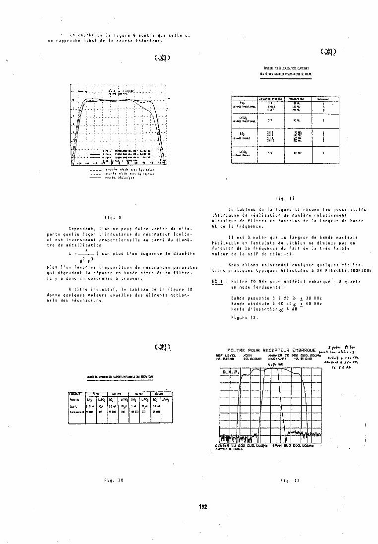
' L a c o u r b e d e l a f i g u r e 9 m o n t r e q u e c e l l e - c i s e r a p p r o c h e a i n s i d e l a c o u r b e t h i o r i q u e .
F i g . 9
C e p e n d a n t , l 1 o n n e p e u t f a i r e v a r i e r d e n l i m - p o r t e q u e l l e f a g o n l ' i n d u c t a n c e d u r b s o n a t e u P ( c e i l e - c i e s t i n v e r s e m e n t p r o p o r t i o n n e l l e a u c a r r i d u d i a m b - t r e d e m i t a l l i s a t i o n
K L =- ) c a r p l u s l ' o n a u g m e n t e l e d i a r n b t r e
6' F 3 p l u s l ' o n f a v o r i s e l ' a p p a r i t i o n d e r e s o n a n c e s p a r a s i t e s q u i d i g r a d e n t l a r i p o n s e e n b a n d e a t t C n u C e d u f i l t ~ e . 1 L y a d o n c u n c o m p r o m i s 2 t r o u v e r .
A t i t r e i n d i c a t i f , l e t a b l e a u d e l a f i g u r e 1 0 d o n n e q u e l q u e s v a l e u r s u s u e l l e s d e s B l 6 m e n t s m o t i o n - n e i s d e s r e s o n a t e u r s .
L e t a b l e a u d e l a f i g u r e 1 1 r e s u m e l e s p o s s i b i l i t C s t h f o r i q u e s d e r i a l i s a t i o n d e m a n i a r e r e l a t i v c m e n t t l a s s i q d a d e f i l t r e s e n f o n c t i o n d e l a l a r g e u r d e b a n d e e t d e l a f r h q u e n c e .
f l e s t 1 h o t e t q u e l a l a r g e u r d e b a n d e s a r i m a l e P i a l i s a b l e e n T a n t a l a t e d e L i t h i u m n e d i m i n u e p a s e n f o n c l i o n d b l a f r C q u e n c e d u f a i t d e l a t r h s f a i b l e v a l e u r d e l a s e l f d e c e l u i - c i .
N o u s a l l o n s m a i n t e n a n t a n a l y s e r q u e l q u e s r e a l i s a - t i o h r p r a t i q u e s t y p i q u e s e f f e c t u e e s A O K P l E Z O E L E C T R O N l O U E
& X 1 : F i l t t e 7 0 M H z p o u r m a t e r i e l e n b a r q u e - 8 q u a r t z ---- e n m o d e f a n d a m e n t a l .
B a n d c p a s s a n t b a 3 d B 2- + 30 K H z B a n d e a t t e h u g e B 6 0 d B 6 2 6 0 K H z e e r t e d l i n s e P t i b n < 4 d B
I, p1*1 Filter FILTRE POUR RECEPTEUR EMBRROUE ,,,,a ,,,
R E F L E V E L / b f V MARUEA 7 0 0 0 0 0 0 0 . 0 0 0 H t 4. a 4 S d B iO . OOOda MA0 (A/R3, -2, O l O d B * w j J i J J. dNL
h.p 4 # r rcrU4 6 tI. dIIt
r~ 1 4 JB
CIiNtkR 70 6 0 0 0 0 0 . O O O H ~ LIPAN S O 0 O O O i 6 W H i AHPTO h 0 d k m
F i g . 1 0 F i g . 1 2
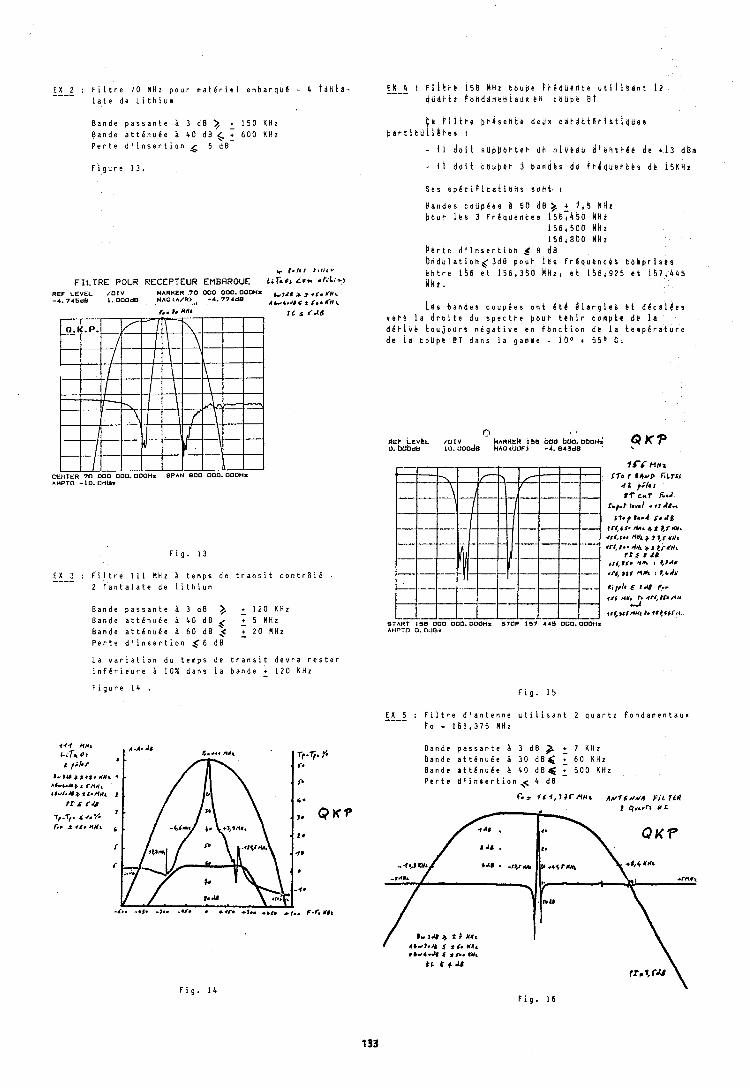
E X 2 : F i l t r e 7 0 MHz p o u r m a t e r i e l e m b a r q u e - 4 t d t i k d - ---- l a t e d e L i t h i u m
B a n d e p a s s a n t e h 3 d B )/ + 1 5 0 KHz B a n d e a t t e n u i e 4 0 d B < + 6 0 0 KHz P e r t e d ' i n s e r t i o n g 6 d B
F i g u r e 1 3 .
+ r.kr r6 r r rv
FILTRE POUR RECEPTEUR EMBRROUE Lirror LU*. *LL-->
R E F L E V E L / D I V MARKER 7 0 0 0 0 0 0 0 . OOOHI ,,,A,, , ,,-. CY, - 4 . 7 4 5 d B I . OOOdB MAG<A/R>, , -4 . 7 7 4 6 8 I ,r ,,,, '., <"\
F i g u r e 1 4 .
S e s s p e t l f l c e t i d n s s o h t I
B a n d e s c b U p i e s b S O d B ) + f , $ kNt
b a u r l e s 3 f k d q u e d t e s 1 5 6 7 4 5 0 RHt 1 5 6 1 8 0 0 H H z 1 5 6 1 8 0 0 h k z
p b r t e d l l n s e r t i o H $ 8 d B b n d b i a t i o n g 3 d B p o u t i e s f r 6 q u e n c h r t o h p r l $ e s L n t r e 1 5 6 e t 156,35&l M H Z , e t 1 5 6 1 9 1 b k t 1 5 7 1 4 4 5 i H l .
i h s b a n d e s c o u p i e s o n t 6 t h k l a r g i e s t i d & c a l & e s vk i -B l e d ~ b i t e d u s p e c t p e p o u b t e h i r c o m p t t d e l a d g r l v e t d u j o ~ r 9 n e g a t i v e e d f o n c t i o n d e l a t e m p g r a t u r e d @ l a c o u p e B T d a n s l a g a n n e - 1 0 ° + 5 5 O C .
F i g . 1 3
E X 3 : F i l t r e 1 1 1 MHz h t e m p s d e t r a n s i t c o n t r t i e - ---- 2 l ' a n t a l a t e d e l i t h i u m
B a n d e p a s s a n t e a 3 d B )/ + 1 2 0 KHz B a n d e a t t i n u b e h 4 0 d B \( + 5 MHz B a n d e a t t e n u e e i 6 0 d B ,< + 2 0 MHz P e r t e d ' i n s e r t i o n < 6 d B
L a v a r i a t i o n d u t e m p s d e t r a n s i t d e v r a r e s t e r i n f e r i e u r e 1 0 % d a n s l a b a n d e + 1 2 0 KHz
rr6 A#, h <rl,#r# dl1 .d
+ ~ c # t r d u t t. *rt++r,a START 1 5 8 0 0 0 0 0 0 . ODOHs STOPT; 4 4 5 0 0 0 . OOObir AMPTO 0 . OdUm
F i g . 1 5
E X 5 : F i l t r e d ' a n t e n n e u t l l i s a n t 2 q u a r t z f o n d a m e n t a u x ---- l o - 1 6 1 , 3 7 5 MHz
B a n d e p a s s a n t e h 3 d B + 7 K H z B a n d e a t t 6 n u 6 e 3 0 d B ( + 6 0 K H z B a n d e a t t & n u & e h 4 0 d B 6 + 5 0 0 KHz P t r t e d ' i n s e r t i o n , ~ 4 d B
I q<.~n M L
QKP
F i g . 1 4 F i g . 1 6
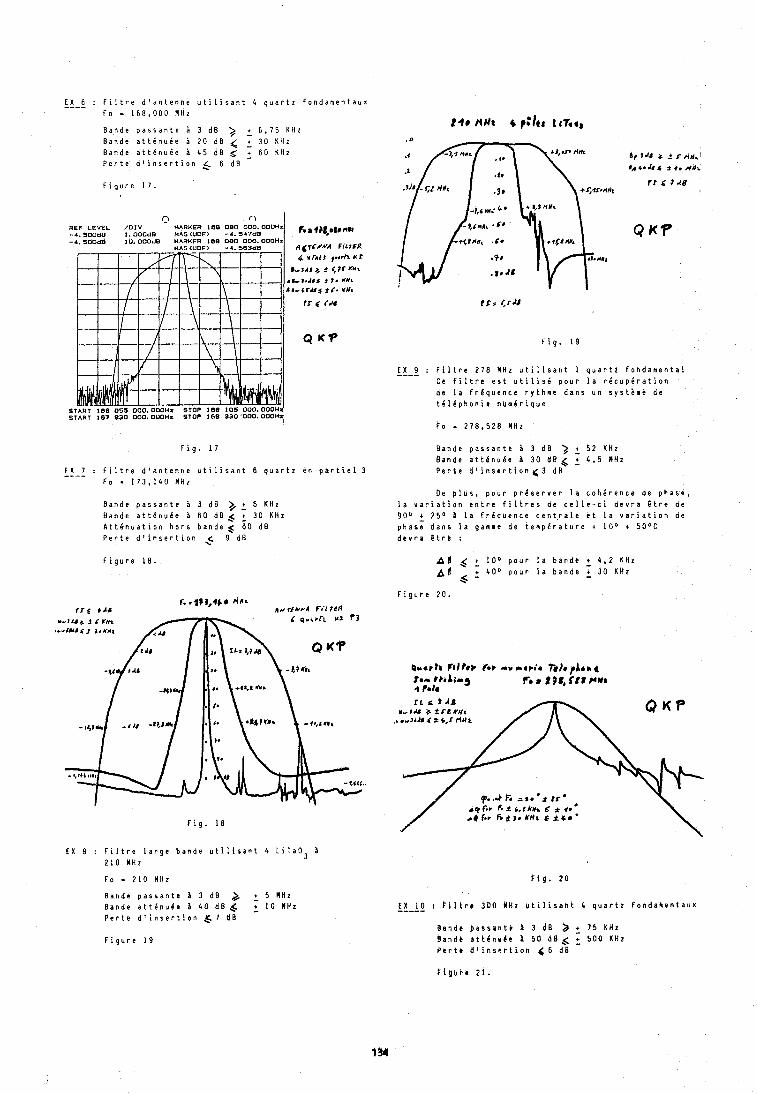
E X 6 : F i l t r e d ' a n t e n n e u t i l i s a n t 4 q u a r t z f o n d a m e n t a u x ---- F o - 1 6 8 , 0 8 0 M H z
B a n d e p a s s a n t e B 3 d B 3 + 6 , 7 5 K H z B a n d e a t t 6 n u i e B 20 d B 4 , 3 0 K H z B a n d e att6nul.e A 4 5 d B $ + 6 0 K h z P e r t e d ' i n s e r t i o n _C 6 d B
F i g u r e 1 7 .
F i g . 1 7
n o REF LEVEL /OIV MARKER 188 080 000. 000Hz -4.300d0 I. OOOd8 M&G(UOF> - 4 . 547d8 -4.300d6 10.000d8 MARKER 188 080 000. DOOH*
MAG (UOF) -4.56348
E X 7 : F i l t r e d ' a n t e n n e u t i l i s a n t 6 q u a r t 2 e n p a r t i e l 3 ---- F o = 1 7 3 , 1 4 0 M H z
,.8q#g,m8,,,",
,q (t TCZA'A Fir r fR
B a n d e p a s s a n t e B 3 d B )/ + 6 K H z B a n d e a t t i n u l c B 6 0 d B s + 3 0 K H z A t t e n u a t i o n h o r s b a n d e 1 6 0 d B P e r t e d l i n s e r t i o n $ 9 d B
4 x r4t t ,..en r ~ 3 4 1 + 9 ( 7 r x ~ t
r I- 1.Y4 t 1 . W e
44-4r.Ud t l . YUI
rr 5 fN
Q U P
STAHT 168 0'35 000.000HX STOP 118 105 000.000H START 167 830 000. OUOH. STOP IS6 a30 000. OOOH
F i g u r e 1 8 .
f i g . 1 8
E X 8 : F i l t r e l a r g e b a n d e u t i l i r a n t 4 L i T a 0 3 8 2 1 0 M H z
F o - 2 1 0 M H z
B a n d c p a s s a n t e 3 d B ) + 5 M H z B a n d e a t t e n u l e ji 4 0 d B ,< + 10 M H z P e r t e d ' i n s e r t i o n Q 7 d B
F i g . 1 9
E X 9 : F i l t r e 2 7 8 M H z u t i l i s a n t I q u a r t z f o n d a m e n t a l ---- C e f i l t r e e s t u t i l i s i p o u r l a r 6 c u p k r a t i o n d e l a f r C q u e n c e r y t h m e d a n s u n s y s t i m e d e t C l 6 p h o n i e n u m C r i q u e
1 0 - 2 7 8 , 5 2 8 M H z
B a n d e p a s s a n t t B 3 d B 3 + 5 2 K H z B a n d e a t t C n u 6 e B 3 0 d B 4 r 4 , 5 M H z P e r t e d 1 i n s e r t i o n < 3 d B
b e p l u s , p o u r p r e s e r v e r l a c o h e r e n c e d e p h a s e , l a v a r i a t i o n e n t r e f i l t r e s d e c c l l e - c i d e v r a B t r e d e 900 + 2 5 " b l a F r C q u e n c e c e n t r a l e e t l a v a r i a t i o n d e p h a s e d a n s l a g a m m e d e t e m p e r a t u r e + 1 0 ° t 5 0 ° C d c r r a E t r e :
6 + l o o p o u r l a b a n d e + 4 4 2 K H z + 4 0 0 p o u r l a b a n d e + 30 K H z
A * 6 - F i g u r e 20.
F i g . 2 0
E X 1 0 : t i l t r e 3 0 0 M H z u t i l i s a n t 4 q u a r t z f b n d a b e n t a u x ----- ~ a n d e p a s s d n t e B 3 d B ) i 7 5 K H z B a n d b a t t e n u b e 5 0 d B $ 2 5 0 0 K H z P e r t a d l i n s e r t i o n 66 d B
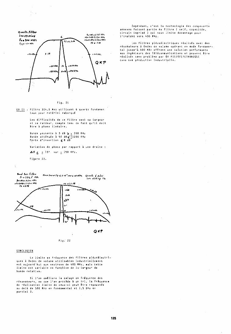
F i g . 2 1
E X 1 1 : F i l t r e 3 2 4 , 5 M H z u t i l i s a n t 6 q u a r t z f o n d a m e h - ----- t a u ~ p o u r m a t e r i e l e m b a r q u C
L e s d i f f i c u l t e s d e c e f i l t r e s o n t s a l a r g e u r e t s a r a i d e u r , c o n p t e t e n u d u f a i t q u ' i l d o i t t t r e B p h a s e l i n i a i r e .
B a n d e p a s s a n t e A 3 d B a + 2 0 0 K H z B a n d e a t t d n u 6 e i 5 0 dB(+1200 K H z P e r t e d ' i n s e r t i o n 6 8 d 8
V a r i a t i o n d e p h a s e p a r r a p p o r t A u n e d r o i t e :
A6 $ + 1 5 " s u r + 1 5 0 K H z .
F i g u r e 22.
C O N C L U S I O N ---------- L a l i m i t e e n F r C q u e n c e d e s P i l t P B s p i 6 z o l l e c t r i -
q u e s & O n d e s d e v o l u m e u t i l i s a b l t s i n d u s t r i e l l e k e n t e s t a u j o u r d ' h u i a u x e n v i r o n s d e 4 0 0 M H z , l a i s c e t t e l i n i t e e s t v a r i a b l e e n f o n t t i o n d e l a I l ~ g e u r d e b a n d e r e l a t i v e .
t e p e n d a n t , c ' e s t l a t e c h n o l o g i a d e s c o m p o s a n t s a n n e x e s f s i s a d t p a r t i e d u f i l t r e ( s e l f , c a p a c i t e s , c i r c u i t i m p r i m e ) q u i n o u s l i m i t e d a v a n t a g e p o u r i l i n s t i n t v e r s 4 0 0 M h z .
L e s f l l i ~ e s p i e z o e i e c t t i q u e s r i a l ~ s k s a v e c d e s r d s o n a t e u r s O n d e s d e v o l u ~ e o p e r a n t e n m o d e f o n d a m e n - t a l j u s d U 1 8 4 0 0 H H z o f f r e n t u n e s o l u t i d n p e r f o r m a n t e a u x i n g e n i e u r s d e s T d l d c o m m u n i c a t i o n s e t p e u v e n t t t r e t a a l i s k s s a n s p r o b l D m e p a r O K P I E Z O I L E C T R O N I O U E d a n s u n h p ~ o d u c t i o h i n d u s t r i e l l e .
S i l ' o n a m 4 l i o r e 1 e c a l a g e e n f r e q u e n t e d e s r d s o n a t e u r s , o u q u a l ' o n p r o c h d e 3 u n t r i , l a f ~ 4 q u e n c e d e r e a l i s a t i o n l i m i t e d e c e u x - c i p e u t 8 t r e r e p o u s s 6 ~ a u - d e l i d e 5 0 0 M H z e n f o n d a ~ e n t a l e t 1 , 5 C H I e n p a r t i e l 3.
l e r Forum EuropBen Temps-FrBquence - 1987
AUTOMATIC TEMPERATURE TEST SYSTEM FOR BVA RESONATORS BASED ON IEC 444
U. R. Peler
Oscilloquartz SA, Neuchhtel, Switzerland
A b s t r a c t That fact made clear that the bottle neck in the pro- duction was (and still is) in the final mounting procedure
The handicap that we cannot use plating in the final fie- due to long measuring times. It was evident that the mea-
quency ajustment process for BVA resonators, and the small suring time for final ajustment and for finding the frequen-
frequency tolerance of only f 0.3 ppm caused us to develop cy - time curve was iong'
an equipment that allows us to measure open BVA resona- tors and closed units as well under clean vacuum at their turnover temperature. An IEC 444 based automatic system is discribed that permits to measure the frequency tempe- rature curve and the parameters at their individual turnover temperatures for four quartz simultaneously. The system runs on a HP 85A computer and software is kept universally. Each of the four independent channels can perform a different task:
- temperature runs to determine turnover and parameters at turnover
- parameters at specified temperature(s) - golno go testing due to high resistance - single measurement at ambient temperature
There are some reasons for that: The operation has to be done in a glove box under dry nitrogen atmosphere (c 40 ppm of humidity), for measuring the quartz itself has to be under vacuum and it must be operated at its turn-over point. On the other hand the BVA resonator being a electrodeless crystal cannot be ajusted by plating, the only feasible method is chemical etch, and this operation cannot be carried out in the glove- box. The next difficulty comes from the fact that frequency is strongly dependent on the con- densor plates which are carring the electrodes, mainly on the gap size which is in the order of 6 p for the plano-plan0 condensor and 10 p for the plano-concave condensor. So each resonator has to be measured with its own pair of conden- sors when the final frequency ajustment needs to be within
The settability of the ovens is better than O.l°C f 1.5 Hz what corresponds to 0.3 ppm at 5 MHz.
(absolute) and temperature stability is estimated between 0.001 and 0.0l0C. The system has to measure the following quantities:
Statistical data about the 1986 BVA production are given as an example.
frequency resistance turn-over point quartz parameters.
Keywords To do that there are several options: Oscillator, Testset, Transmission method follwoing IEC 444, network analyzer.
Quartz, Resonator, BVA, electrodeless quartz, elec- trodeless resonator, Transmission Method, Pi network The oscillator methods disqualifies itself by the fact
that on that way only the frequency but no parameters can be determined.
I n t r o d u c t i o n
The BVA resonator is an electrodeless Crystal with very low ageing (10-l l lday guarantied) some 10- l2 are mea- su red typically. Its Design has been discribed in earlier papers'a2. Photograph Fig. 1 shows an open resonator. In the center is the "sandwich" consisting of the plano-concave condensor, the resonator in the middle and the plano-plano condensor. The quartz pieces are hold together with four clips and suspended with springs in an rigid cage.
The increasing demand for BVA resonators pushed us tO review seriously our production means for this resonator. A first look at the manufacturing times showed the following distribution:
- machining 30 % measuring 70 %
The Testset would be capable to parameter measure- ment also but it has the disadvantage that all settings are manual and by this way become operatordependent. But the most serious doubt we had was whether the testset would operate properly in a dry nitrogen atmosphere or not (we had some bad experiances with an LC-bridge, that refused to work under these conditions).
The network analyzer is an expensive equipment and mainly designed for the 30 MHz and higher frequency range. It would really be an overkill to use it for 5 MHz resonators. On the other side it is a four port device and it makes quite a difference if you have to get 8 or 16 coaxial cables into a glove box. So we omitted this solution.
For these reasons only the transmission method is left. The method is in use in our laboratory for ten years and therefor well known (including its difficulties). It has the advantage that only the wnetwork has to be brought into the glovebox and all other equipment can Stay outside. Thit
is possible because the x-network transforms the measuring head into a SO n system. On the other hand it must be said that it is really not the most convenient method to implement in a computer controlled system.
System descript ion
Part 1 : Oven
The condition for the oven was that it has to be settable by computer. Then we need the same stability that we have in our OSA 8601 Oscillators. So it was near to choose the same oven circuit that is used in that oscillator. Also the ovendesign itself is quite similar to the 8601 oven. Fig. 2 gives the mechanical design. The oven itself is made of a round aluminium block with the heater wrapped around. The oven cylinder is fixed by screws to a foam support. The tube in the center is used to evacuate the system. The BVA resonator is put into the lodging. The crystal in connected via piston contacts to the x network that is located in the cover. As in the original 8601 oven the Testoven is thermally insulated by a dewar flask (not shown).
The 8601 uses a NTC resistance as temperature sensor. So it is necessary to deal with the nonlinearity of this device. In early stage of the project we intended to set the oventemperature manually by the means of digiswitches, later the computer version was implemented, The schematic diagram is given in Fig. 3.
The temperature vs. resistance data of the thermistor used is given by the manufacturer In form of a table, not a handy form to deal with a computer. So we made a least squares fit approximation:
thus
R25 o~ being the resistance at 25DC. Applying (1) as a
model to the thermistor table gives the coefficients
The above mentioned values apply for the temperature range between 30°C and 100 O C .
The required temperature range is 30°C S T s 100°C with a minimum interval of 0.5OC. That means that there are 141 possible temperature settings. So a 8 bit value is sufficient.
The idea of this digital oven is to use 8 bits coming from the computer or from the digiswitch as an adress to read a read only memory that is programmed to give a 12 bit value which is fed to digital to analog converter.
The oven circuit in Fig. 3 tends to have the same voltage on the + and the - entry of the amplifier. So the required voltage is that of the voltage divider
Using (4) and (5) U(T) can be calculated. The values are then rounded to the 12 bit DIA converter resolution. Verification of rouhded values shows that the temperature error due to the rounding is less than f 0.08"C what is more than sufficient for the application.
The PROMS were burnt after transferring the values calculated in a HP 858 computer via RS-232 to the PROM programmer.
The next problem was putting the oven circuit on the IEEE 488 bus. Fortunately the HP Switch Box 3488A we use for the signal switching in the system can be equipped with a digital 110 drawer (bidirectional). So we use 8 bits for the temperature setting and another 2 bits for the, oven#. The control signals are used to extract the clock signal.
The oven device has three different temperature sen- sors:
1. Thermistor for temperature control 2. LM335 silicon sensor for temperature
measurement and faiisafe # I 3. temperature fuse (125OC), failsafe #2.
The circuit is checked out with a HP Quartz Thermo- meter and turned out to be accurat within f O.l°C (absolut). The result is correlated with the above mentionned rounding error.
Part 2: Quartz Measuring System
The system setup is given in Fig. 4. The transmission method following IEC 444 Is based on
x network synthesizer vector voltmeter power splitter.
The classical x-network in coaxial form (Fig. 5) turned out to be too large to fit in a oven and the experiance showed that it does not like at ail temperature cycling. This fact is due to the bonding of the disc resistors to the body. The difference in the thermal expansion coefficients will create stress and normally the disc resistor breaks.
For that reason we tried a different approach: instead of a coaxial we used a stripline design. Fig. 5 gives the details. In principal the x network could be realized with only one thickfilm resistor with three tappings. In this case there remains the problem of ajusting the n sections. Since the accuracy must be better than f 1% for each element one should not look for difficulties in ajusting. That was the reason we constructed our n network of 5 resistors that can be individually measured and trimmed. The hybrid circuits are built into the cover of the ovens (Fig. 6). Of course it no longer is a IEC 444 x network but it behaves like one. By comparison this fact could be proven.
Having four ovens there must be some commutation cir- cuitry for switching from one oven to the next one (Fig. 7). This is done by the HP 3488A Switch box in its VHF relay drawer. This unit is a double 4 channel coaxial multiplexer with good phase catacteristics (the propagation times bet- ween the different channel are matched < 90 psec = 0.16O).
The measuring system is shown in Fig. 4. On top we have the high frequency switching and below the instruments,
For the vector voltmeter we had two options: Rhode & Schwarz 2PU Rhode & Schwarz ZPV
The ZPU beelng the analog and the ZPV beelng the dlg'ltal version. In a computerized systeM it would be normel tu choose the digital version but It turned out that the PPV (when connected to a IEEE 488 bus) is able to make oriiy Uh& measurement per second. So you get a slow system, t he 2PLi must of course be backed up with a analog tb f$gitll converter. But this one can be fast& than the TPV and It is needed anyway to read the temperetun. We have ct i~bbbn the ZPU even when its remote programming optlan Isn't very handy to use.
in every transmission method you have to lack on zero phase to get the reading following IEC 444. Before yoll can lock you must have some sweep capability to find the zero phase condrtion. The first idea Is uslng the computer and the synthesizer to sweep the frequency to find zero phase. Un- fortunately that is a very slow method: When used to mea- sure crystals before final ajustment you know the frequency only with an accuracy of 500 Hz and the temperature influence gives you another 200 Hz. So you have to search a 700 Hz range. Taking a BVA resonator with a Q value of more than 2.2 . l o 6 at 5 MHz what makes a bandwlth of 2.2 Hz. If you scan the range in steps of 2 Hz at a rate of 2 measurements per second (the rate of the A/D converter, the iEEE 488 bus and the computer decision) then a full scan will take 175 Seconds!
A better approach is to use the built-in sweep capatrllity of the 3325A Synthesizer and to add to the analog ampiltude output of the ZPU a comparator that stops the sweeping in the moment it detects the response of the quartz. By this methods we get scan times down to 20 seconds,
The approximate frequency once determined, the com- puter can take over and lock at zero phase via the A f vs phase relationship
Af tan (p).f 12/Qeff (6)
At room temperature the Q value is measured a flfst time to have a more precise departure point during the temperature cycle. Subsequent the measured, ihdlvldual Qeff is used.
Part 3: Software
The HP 85A computer is programmed In BASIC, it takes about 24k. With exception of the initialization bf the Mba- surement the program is made for unattended operation. This is needed because we want to have also m~aSUremglltS made during night time. Taking in consideration that at Neuchatel we have frequent power failures or power glitches the program needs tb have an autostelrt Option that allows to resume measurement after a black out.
It Is designed for twa niaih applieetians:
1. measuring of parameters at a known tUrnUvtlr temperatule
2. making a temperature run to determine the turnover temperatllrrs and 16 meaarurcr thc parameters at that tempertiture.
The same two programs U e Used for "nakbdl' dnd to en- closured crystals. The 'nakbdWsonatbfs can be tested In standard condensors or with their awrf ean$ensBYs. Irl !hi$ case the ovens have to bt9 put bnder vacukim. If We dad1 with an enclosumd BVA then We db not need any plrmpitlg because it is already vacuums~al~d.
In thki Cdke tlt type i nleasutertlent the bperator types I H thlr crystdl nuttibet and the turnover temperature at whlch the test should be done. t h e oven Is {hen H&dted to the indlcabd temDeIattirb end lh 9 mlhutes ltitetvrrllr the twqtibncy Is checked. When It Is stable ehough tho Med- [rurewlttni Is takdH $rid the oven shut dawn, To decreasb the 0uul dbwh time: the dewar tlask is llftud.
Since we have ahly I b Wdttb ahd a cansldercrble Mass td h a t the temperaturb slbpe Is ahly b.70lsec. Cool down time 1st epprdxlmately 45 mihut&. So WI) bet a cycle time of 2 haurr LO ttilttUtes. First we cowsidered the fact not to havg any water in the glbre box as an advantage (in earlier time we had an accident that filled the glove box with water!) but now It is the slow cool down that limits our ptoductldn. Also the poor power for heating turns out to be a disadvantage though it was intended to prevent thermal shocks. At that tlme the target was to manufacture 8 BVAs per week, so we could afford the Slow process. Today that SitUtltiOh has changed.
Beside the poor heating and cooling capabilities the long cycle time Is determined by the thermal time con- stant of the BVA resonator itself: it is In the order of 45 binutes! t h e reason is simple: The heat transfer has to be tione via the springs and the clips (see Fig. I ) , both are made of stainless steel and the contact is made only by the spring force. In operation it Is a advantage because tempe- rature fltlctUatlons of the oven are not directly transferred to to crystal but for quick measuring It Is definitively not.
in the type 2 run measurements are taken at 80, 85 and 90° C and a least squares fit Is used to determine the turn- over temperature. The temperature is then lowered to that point and after stablllsation of the frequency the mea- surement is taken. Of course that cycle time Is even longer: 4 hours. this fact has to a lesser degree an influence be- cause only some few samples have to be measured this way (turnover temperature is very constant over one serle) and when flnlshed BVAs are concerned the cycle takes place during hight tlme and there is plenty of time.
All data it stored for statistical use on a floppy disc and far safety reasons once a week the new data are also transferred to a tape.
Part 4: Performance
t h l dbsolut oven ternperature has been checked against a quartzthermometer. The reached temperatures stay well withln k O,l°C. The stability of the temperature was not measured because for our application it is not relevant. Anyway csome test have been made by recording the frequency of a special BVA made in -AT-Cut ("wrong AT"). Such a design has the normal thermal time constant of a BVA resonator and eliminates thereford the thermal fiUctuations so that the reading becomes meaningless. Clawever we estimate the stability somewhere between CI,oQI $lid 61.UI80.
t h e athlsr errors are easier to be estimated. The foilawlnfj v81~61b ,have been evaluated by using methods discrlbd kr 1kC Pual, 444 3and its annexes.
kttrrrt (warst case)!
- ff '~lqb&h~y '1 o ' ~ resistance 5 %o dytlamlc parameters 4 % a YJ~rllt4i ti KO
n rt&tio cafracitdnc?e 10 %
The relativly high error for the Co measurement comes
from the fact that we have to measure an impedance of about - j 11 kR with a 25 R system. With these high impedances cross talk in the n network becomes an important factor: With an impedance of 11 kR you get an attenuation of 53 db whereas cross talk is specified at 60 db. Cross talk is in the same order of magnitude. Even if you increase the output voltage of the synthesizer to the maximum, the voltage at the output of the n network still stays small and you have to measure a noisy signal. Applying some digital filtering is a must and helps appreciably but you have also to do some range switching on the vector voltmeter. Doing this together with voltage switching of the synthesizer will increase considerably the inaccuracy.
Part 5: Statistical data of 1986 BVA Production
All parameter data are stored for statistical purposes. We use two different forms:
histograms moving means.
Both are used for production control, especially the moving mean is a very sensitif tool to show slow changes in manufacturing parameters. Normally the trend can be realized long time before the limits are reached.
Fig. 8 gives the histogram of the frequency error at the turnover temperature. Remember: The limits are f 1.5 Hz only. The black histogram is the 1986 production, the gray one is the same as published in an earlier paper.2 The newer data has more gaussian shape, it is the effect of a more regular production in larger series.
Fig. 9 is the histogram for the resistance R1. Fig. 10
the one for the dynamic capacitance C1, Here we find a
small shift when compared with the older values. This is due to the change in measuring method: The old values hold for room temperature whereas the new ones hold at turn- over temperature.
Also the 0 value (Fig. 11) is a little different, this is due to a change in raw material which brought a decrease of about 10%. In more detail it can be seen in the moving mean diagram (Fig. 16).
The turnover temperature became also more regular as we had more experience (Fig. 12).
venience of the raw material becomes evident. Serle # 18 was natural quartz and shows by far the highest Q values.
The turnover temperature (Fig. 17) shows also a clear learning effect. The allowance for all series has been f15 sec of arc.
Fig. 18 is a plot of the frequency shift during bake out. Normally the values are quite small, Series #26 and #39 being the exceptions (both series were made of the same batch of raw material of the same manufacturer).
Another important parameter is the short term stabili- ty. Though it cannot be measured on the discribed equipment some data are given in Fig. 19. The strange representation of data need some explanations: For each quartz the short term stability has been recorded for Tau - 0.1, 0.2, 1 and 10 seconds. Then mean and standard devi- ation have been calculated for each series. In the tri- dimensional plot you have on the X-Axis Tau (in sec), on the Y-Axis the serial number and on the 2-Axis the short term stability (in 10- I 3).
In Fig. 20 we have the production quantities of BVA re- sonators in the years 1981 to 1986 including a forcast for 1987. The test phase finished 1982; 1983 to 1985 pro- duction was constant at 4 BVA per week. 1986 we doubled to 8 per week and in spring 1987 we hope to be at 20 per week. This number will still not be sufficient to cover the demand, there are plans for further increase. Then watercooling and an increased power in the measuring equipment will be a must.
Conclus ion
The present paper shows a possible solution for accu- rate measuring equipment for high precision BVA resona- tors at their turnover temperature, under vacuum and in a dry nitrogen filled glove box.
The equipment turns now for a year, day by day, without any deficiancy. So it is highly reliable and pro- vides quality assurance data automatically.
Aknowledgments
The author likes to thank to Mr. Droz and Mr. Bolorney of the quality assurance departement of Oscilloquartz for providing the short term stability data.
The last histogram (Fig. 13) shows the frequency Referencies change during final bake out. The value is not predictable but normally small. The extremes shown in Fig. 13 are due 1. R. J. Besson, U. R. Peier, 'Further Advances on BVA to samples with strong initial ageing (probabely caused by Quartz Resonators", 34th AFCS (1980) strong stress in the raw material). These resonators of course are rejects. 2. E. P. Graf, U. R. Peier, "BVA Quartz Crystal Resonator and
Oscillator Production - A statistical Review', 37th In the following Fig. 14 to 18 we have the moving AFCS (1983)
means for the series #8 to #40 what corresponds to the years 1981 to 1986. These plots show the mean values of 3, IEC Publications 444 , 444-1, 444-2, 444-3 the series (0) and a straight line for the plus and minus one sigma values.. The dashed lines are the mean sigma values over the series #8 to 40, the centerline is the mean value for the series. On the ordinate we have the series#. The missing series (14, 21 and 31) were intentionally omitted because they were special series with different parameters.
Fig. 14 gives the final frequency after bake out. In the moving mean the learning effect appears clearly: the early series were less precise than the newer ones. Series #39 being an exception could be traced to high stress material.
Fig. 15 (R,) and Fig. 16 (Q value) are correlated be-
cause the dynamic values are quite constant. The pro- 139 - .
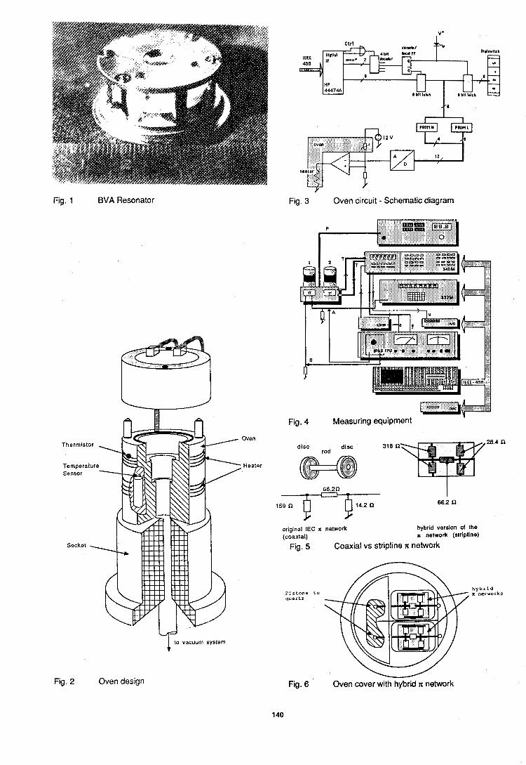
Fig. 1 BVA Resonator Fig. 3 Oven circuit - Schematic diagram
to vacuum system T
Fig. 4 Measuring equipment L Z a @
disc disc rod
original IEC n network (coaxial)
hybrid version of the u network (stripline)
Fig. 5 Coaxial vs stripline n network
h y b r i d P i s t o n s t o n networks quartz
Fig. 2 Oven design v
Fig. 6 Oven cover with hybrid x network
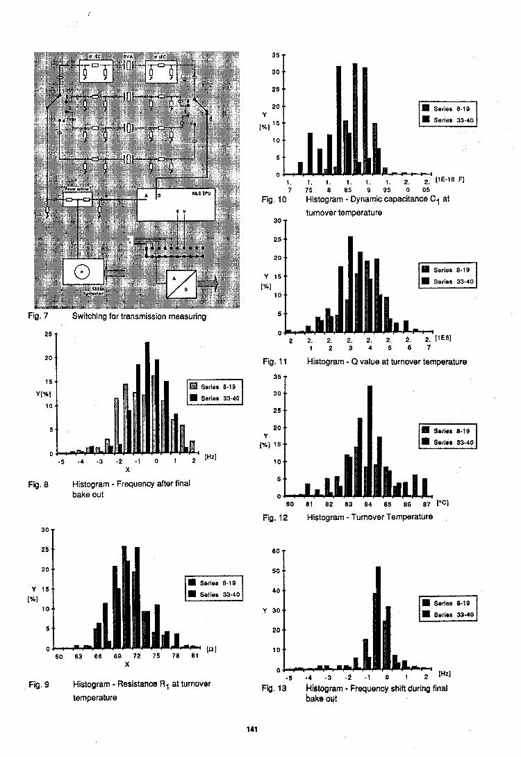
Fig. 7 Switching for transmission measuring
25 T
Fig. 8 Histogram Frequency after final bake out
7 75 8 85 9 95 0 05
Fig. 10 Histogram - Dynamic capacitance C1 at
turnover temperature
Fig. 11 Histogram - Q value at turnover temperature
Series 33-40 m 60 81 82 83 84 85 86 871°Cl
Fig. 12 Histogram - Turnover Temperature
25 (10
20 50
Y 15 4 0
[%I 10 Y 30
5 20
0 tn I 10
x 0
-5 a 4 -3 -2 - 1 0 1 2 lHtl Fig. 9 Histogram - Resistance R1 tit turnover Fid. 13 Miltogram - F requenc), shift during final
temperature bake out
141
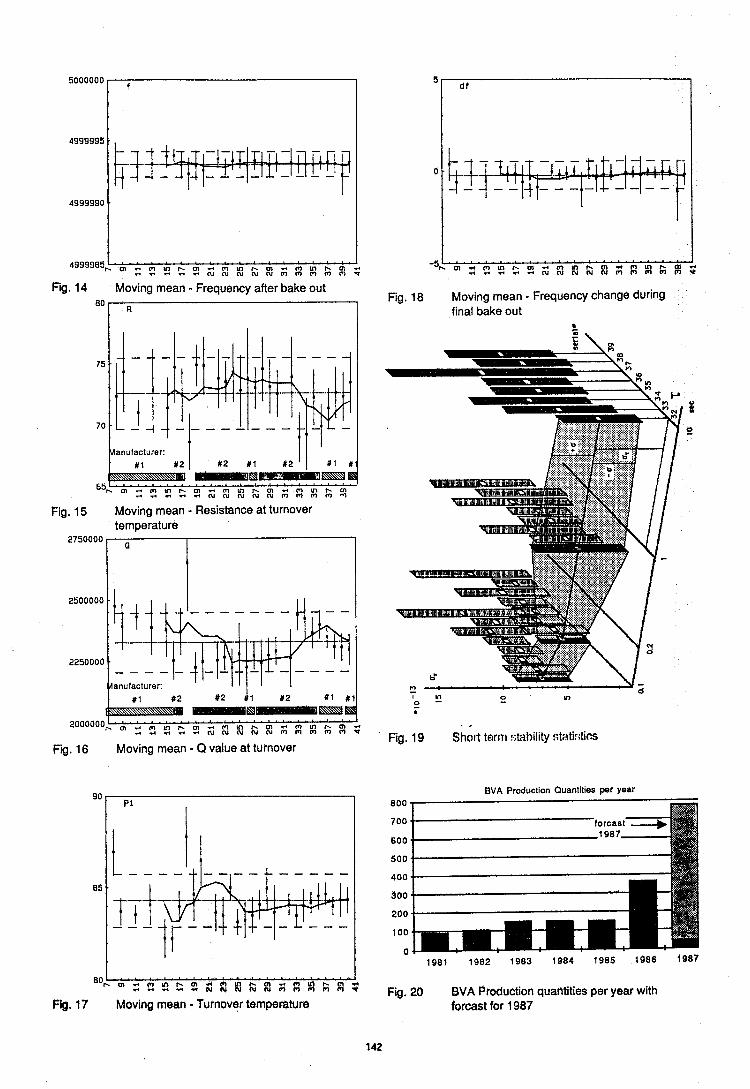
Fig. 14 Moving mean - Frequency after bake out Fig. 18 Moving mean - Frequency change during
final bake out
anufacturer:
Fig. 15 Moving mean - Resistance at turnover temperature
2750000
2000000
Fig. 16 Moving mean - Q value at turnover
.. . Fig. 19 Sh01-t tern1 !;tibility :;tirti!iti~s
BVA Production Quantities per year 800 >
700
BOO
500
400
300
200
100
n
'oL i 4 4 ' ' h ~ i k h ' d k i ' Flg. 17 Moving mean - Tutnover temperature
Fig. 20 BVA Production quantities per year with forcast for 1987
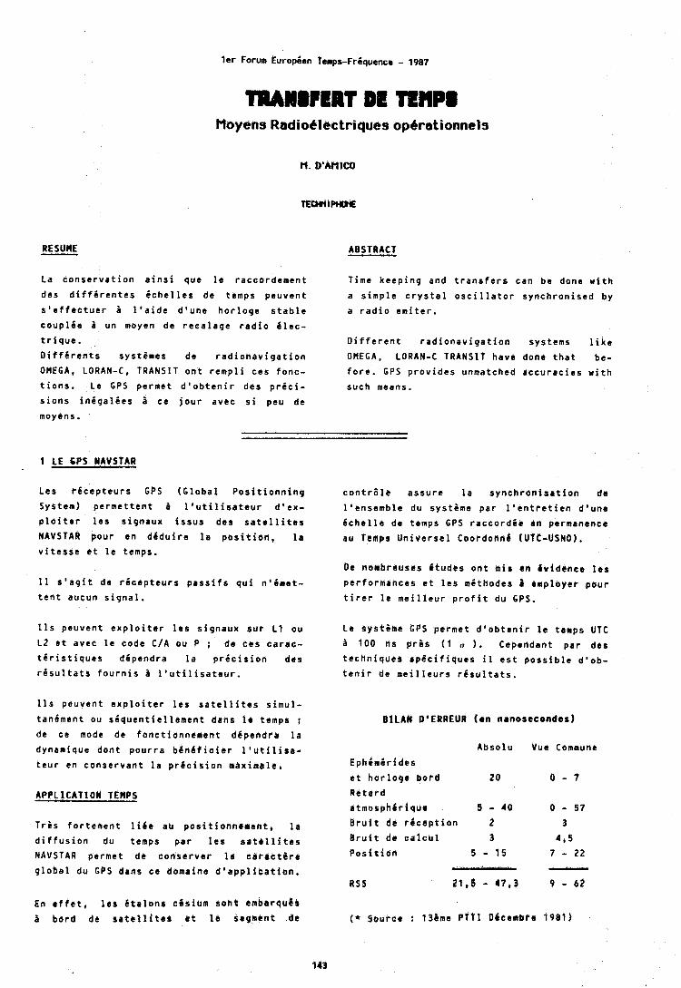
l e r Forum EuropSen Temps-Friquence - 1987
TRAH8RRT DC TRtlPl Moyehs Radiobloctriques opbrationnels
ABSTRACT
La c o n s e r v a t i o n a i n s i que l e r a c c o r d e m e n t
des d i f f i r e n t e s i c h e l l e s de temps p e u v e n t
s ' e f f e c t u e r i l ' a i d e d ' u n e h o r l o g e s t a b l e
c o u p l i e u n moyen de r e c a l a g e r a d i o i l e c -
t r i q u e .
D i f f C r e n t s sys t&mes de r a d i o n a v i g a t i o n
OMEGA, LORAN-C, TRANSIT o n t r e m p l i c e s f o n c -
t i o n s . Le GPS p e r m e t d ' o b t e n i r des p r i c i -
s i o n s i n i g a l i e s ce j o u r avec s i peu de
Time k e e p i n g and t r a n s f e r s can b e done w i t h
a s i m p l e c r y s t a l o s c i l l a t o r s y n c h r o n i s e d by
a r a d i o e m i t e r .
D i f f e r e n t r a d i o n a v i g a t i o n sys tems l i k e
OMEGA, LORAN-C TRANSIT have done t h a t be-
f o r e . GPS p r o v i d e s unmatched a c c u r a c i e s w i t h
such means.
moyens.
1 LE 6PS NAVSTAR
Les r d c e p t e u r s GPS ( G l o b a l P o s i t i o n n i n g
System) p e r m e t t e n t A l ' u t i l i s a t e u r d ' e x -
p l o i t e r 16s s i g n a u x i s s u s des s a t e l l i t e s
NAVSTAR p o u r en d d d u i r e l a p o s i t i b n , l a
v i t e s s e e t l e temps.
I 1 s ' a g f t de r i c e p t e u r s p a s s f f s q u i n ' l i m e t -
t e n t aucun s i g n a l .
11s p e u v e n t e x p l o i t e r l e s s i g n a u x s u r L1 o u
LZ e t avec l a code C/A o u P ; de c e s c a r r u -
t 6 r i s t i q u e s d i p e n d r a l a p r i c i s i o n des
r i s u l t a t s f o u r n i s a l ' u t i l i s a t e u r .
11s p e u v e n t e x p l o i t e r 16s s a t e l l i t e s s i m u l -
t andmen t ou s i q u e n t i t l l e m e n t dans l r temps ;
d t C e mode de f o n c t i o n n e m e n t d i p e n d r r l a
dynamique d o n t p o u r r a b e n 4 t i c i e r l ' u t i l i r a -
t e u r en c o n s e r v r n t l a p r d c i s i o n a d x i i i t a l r .
T r b s f o r t e m e n t l i l i e aU p o s i t i e n n b h e n t , l a
d i f f u s i o n du temps p a r l e 9 s L t S l l i t C s
NAVSTAR pe rme t de c o n s e r v e r l e c a r r c t & r r
g l o b a l du GPS dans c e domafne d ' a p p l i c a t i o n .
En e f f e t , l e s i t a l b n r c l i s i o m s o n t embarqu$a
i b b r d de s a t e l l i t e $ r t I b segment de
c o n t r 6 l e a s s u r e l a s y n c h r o n i s a t i o n de
l ' e n s e m b l e d u sys t6me p a r I ' e n t r e t i e n d ' u n e
6 c h e l l e de temps GPS r a c c o r d i e Cn permanence
a u Tbmpr U n i v e r s e 1 c o o r d o n n d t u f t - U S N O ) .
De nombreusss ( t u d e s o n t m i s en ( v fdCnce 16s p e r f o r m a h c e s a t l e s m i t h b d e s 4 emp loye r p o u r
t i r e r l e m e i l l e u r p r o f i t d u GPS.
Le sys t6me GPS p e r m e t d ' o b t e n i r l a temps UTC
3 100 ns p r b s ( 1 r , 1. Ceper ldant p a r des
t e c h n i q u e 9 s p 6 c i f i q u e s il e s t p o s s i b l e d 1 o b -
t e n i r de m e i i l e u r s r 6 s u l t a t s .
BLLAM DIERREUR (en nrnasecondes)
A b s o l u
EphCmdr ides
e t h o r l o g e b o r d 20 R e t a r d
a t m o s p h / r i q u r 8 - 40
B r u i t de r 6 c e p t i o n 2 B r u i t d6 ~ ~ 1 0 t 1 1 3 p o s i t i o n S - 15
P
R S S a i , ~ - 4 7 , 3
Vue Commune
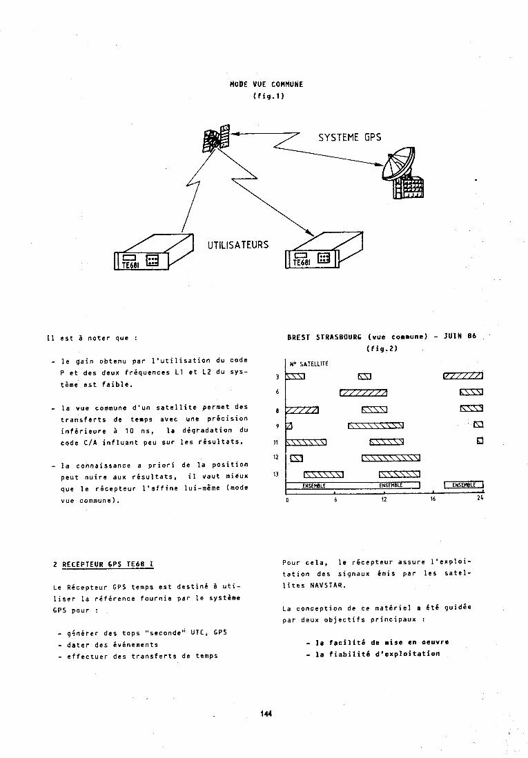
HODE VUE COMMUNE
( f i g . 1 )
SYSTEME GPS
1 1 e s t I n o t e r que :
- l e g a i n o b t e n u p a r l ' u t i l i s a t i o n du code
P e t des deux f r i q u e n c e s L1 e t L2 du s y s -
tame e s t f a i b l e .
- l a vue commune d ' u n s a t e l l i t e pe rme t des
t r a n s f e r t s de temps avec une p r i c i s i o n
i n f i r i e u r e i 10 ns , l a d i g r a d a t i o n du
code C/A i n f l u a n t peu s u r l e s r i s u l t a t s .
- l a c o n n a i s s a n c e a p r i o r i de l a p o s i t i o n
p e u t n u i r e aux r i s u l t a t s , il v a u t mieux
que l e r i c e p t e u r l ' a f f i n e l u i - m i m e (mode
vue commune).
2 RECEPTEUR 6 P S T E 6 8 1
Le R i c e p t e u r GPS temps e s t d e s t i n i I u t i -
l i s e r l a r i f i r e n c e f o u r n i e p a r l e sys t sme
GPS p o u r :
- q 5 n i r e r des t o p s "seconde" UTC, GPS
- d a t e r des 6 v i n e m e n t s
- e f f e c t u e r des t r a n s f e r t s de temps
EREST STRASBOURS ( v u e commune) - I U l N 8 6
( f i g . 2 )
No SATELLITE
hZ3
ENSEMBLE ENSEMBLE 1 LEHsEneLEI "l
0 6 12 16 2 1
Pour c e l a , l e r i c e p t e u r a s s u r e I ' e x p l o i -
t a t i o n des s i g n a u x Cmis p a r l e s s a t e l -
l i t e s NAVSTAR,
La c o n c e p t i o n de ce m a t e r i e l s i t 6 g u i d i e
p a r deux o b j e c t i f s p r i n c i p a u x :
- l a f a c i l i t i d e m i t e e n o e u v r e
- l a f i a b i l i t d d ' e x p l o i t a t i o n
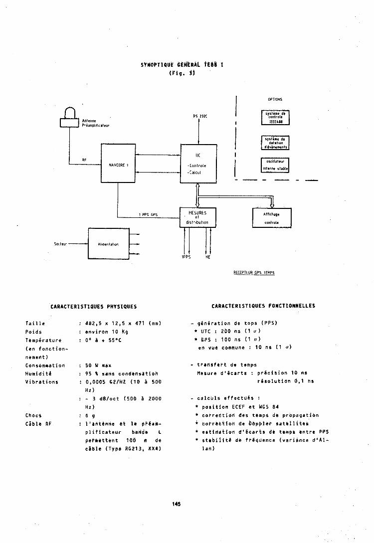
s r k o C T l a u E t ~ d k ~ k L fe l l t (F ig . 1)
I OPTIONS
CARACOEAISTIQUES PHYSIQUES
P o i d s : e n v i r o n 1 0 Kg
( e n f o n c t i o n -
nemen t )
Consommation : 5 6 Ld max
H u m i d i t i : 95 b sans c o n d e n s a t i o n
V i b r a t i o n s : 8,0005 G2 IH t ( 1 0 P 500
Hz : - 3 ~ E V O C ~ ( 5 8 0 a 2000
H i
Chocs : b g
C t b l e R F : l ' b d t l n d e c t l a pP6am-
p l i f f c a t e u i Ddnda L
$ e P m c t t e n r 166 m de
c a b l e (Type RG213, KXJ)
RECEPTEUR GPS TEMPS
CARACTERISTIQUES FOHtTIONNELLES
- g i n i r a t i o n de t o p s (PPS)
* UTC t 200 n s ( 1 u )
* S P S : 100 n s ( 1 a )
e n vue commune : 1 0 n s I 1 n )
- t r a n s f e i t de temps
l4esure d 1 6 c a r t s : p r d c i s i o n 1 0 ns
r i s o l u t i o n 6 , l n s
- c a l c u l s e f f e c t u a s :
* p d s i t i o n ECEF b t WGS 84
* c o r r e c t i o n d t s temps de p r o p a g a t i o n
* c o r r a t t i o n de O a p p l e r s a t e l l i t e s
4 e s t i M l t i o r l d t 6 c a r t s dc temps e n t r e PP9
* stabifit6 de f r g q u e n c e ( v a r i b n c e d ' A l -
lak)
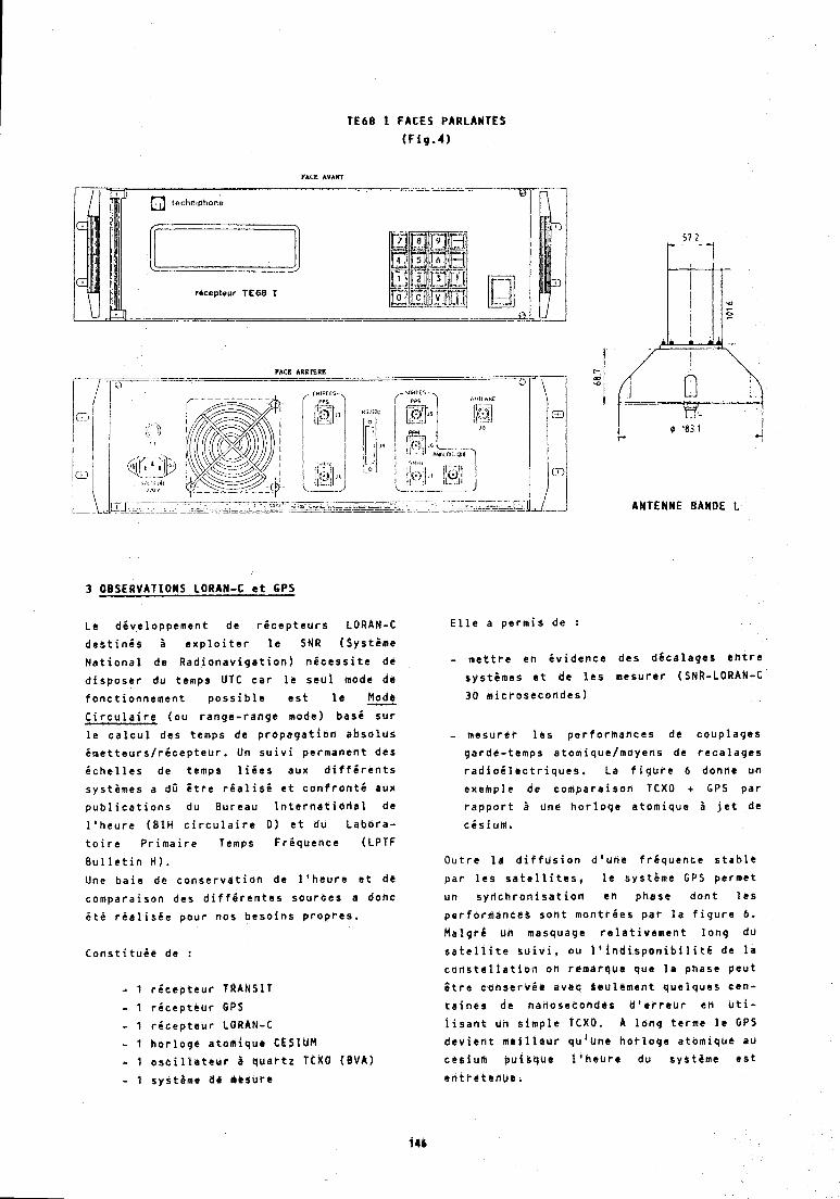
TE68 1 F A C E S P A R L A N ~ E S
(Fig.4)
FACE *WART
ricepteur TEBB I
FACE ARRfeRE --
@ 183 1
i . 0 "
A N T E N N E BAND6 L
3 O B S E R V A T I O N S LORAN-C e t 6 P S
Le dhve loppeman t de r 6 c e p t e u r s LORAN-C E l l e a p e r m i s de :
d e s t i n 6 s B e x p l o i t e r l e SNR ( S y s t i m e
N a t i o n a l de R a d i o n a v i g a t i o n ) n d c e s s i t e de - m e t t r e en i v i d e n c e des d i c a l a g e s e n t r e
d i s p o s e r du temps UTC c a r l e s e u l mode de s y s t i m e s a t de l e s m e s u r e r (SNR-LORAN-C
f o n c t i o n n e m e n t p o s s i b l e e s t l e % 30 m i c r o s s c o n d e s )
C i r c u l a i r e ( o u r a n g e - r a n g e mode) bas6 s u r
l a c a l c u l des temps de p r o p a g a t i o n a b s o l u s - mesu re r l e s p e r f o r m a n c e s dc c o u p l a g e s
i m e t t e u r s / r i c e p t e u r . Un s u i v i pe rmdnen t des ga rde - temps a tom ique /moyens de r e c a l a g e s
i c h e l l e s de temps l i i e s aux d i f f i r e n t s r a d i o E l e c t r i q u e s , La f i g i c r e 6 donne u n
s y s t i m e s a dS E t r e r i a l i s 6 e t c o n f r o n t 6 pun exbmple de c o m p a r a i s o n TCXO + GPS p a r
p u b l i c a t i o n s du B u r e a u I n t e r n a t i o d e l de r a p p o r t i une h o r l o q e a t o m i q u e i j e t de
l ' h e u r e ( B 1 H c i r c u l a i r e D ) e t du L a b o r a -
t o i r e P r i m a i r e Temps FrCquence (LPTF
B u l l e t i n H I .
Une b a i e de c o n s e r v a t i o n de l ' h e u r e a t de
c o m p a r a i s o n des d i f f i r e n t e s s o u r a e s a dodc
6 t i r i a l i s h e p o u r nos b c s o i n s p r o p r e s .
- 1 r i c e p t e u r TRANSIT
- 1 r i c e p t c u r GPS
- 1 r i c e p t e u r LORAN-C
- 1 h o r l o q e a t o m i q u e CESIUM
- 1 o s c i l l e t e u r i q u a r t z TCXO (BVA)
- 1 sys temc d ~ n r s u r c
O u t r e l r d i f f u s i o n d l u h e f r i q u c n c e s t a b l e
p a r l e s s a t e l l i t e s , l e s y s t i m e GPS pe rme t
u n s y r l c h r o n i s a t i o r i r n phase d o n t l e s
p e r f o r m a n c e s s o n t m o n t r i e s p a r l a f i g u r e 6.
H a l g r d un masquage r e l r t i v e m e n t l o n g du
s a t e l l i t e g d i v i , ou I ' i n d i s p o n i b i l i t S de l a
t o r ! s . t e l l a t i a i i on remarque que l a phase p e u t
Z t r e d iYh8ervdt avbe & e u l & m e n t q u t l q u e s cen -
t a i n e s dc nanoseeondes d ' e r r e u r e n C t i -
i i s a n t un s i m p l e I'CXO, A l o n g t e r m e l e GPS
d e v i e n t m t i i l o d r q J 1 u h s H o t l o g e a t a m i q u e aJ
c e s i u m p u i a q u e f ' h e b r e du eySt8me e s t
e n t r 6 t e n u b .
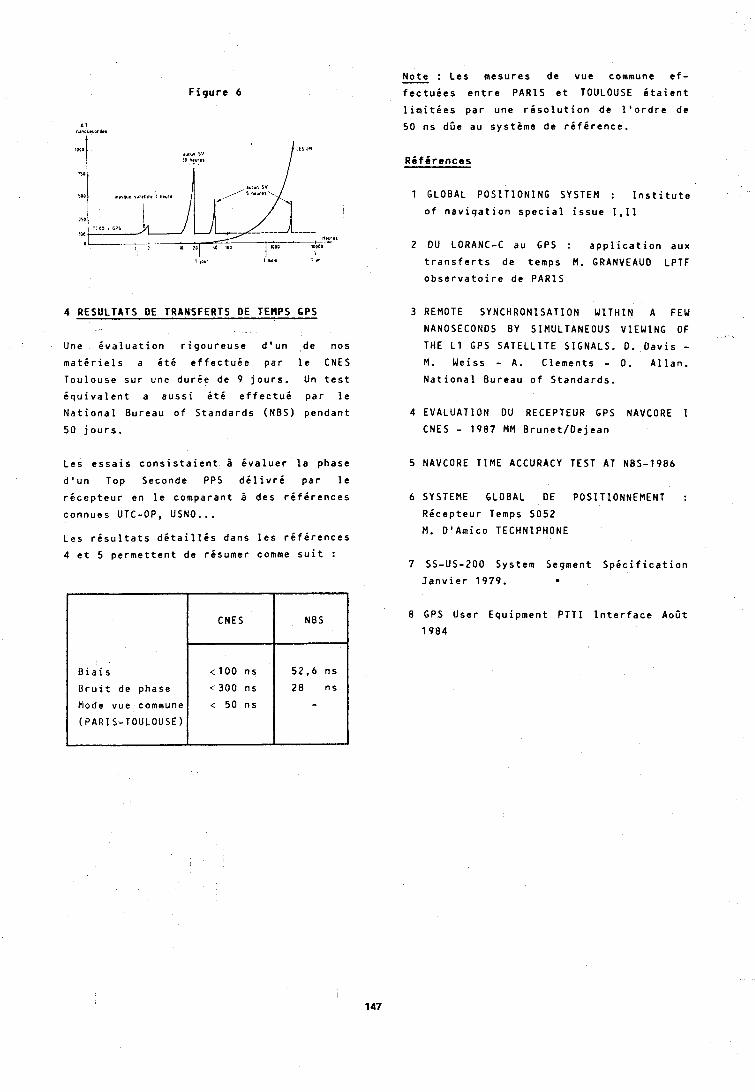
F i g u r e 6
4 RESULTATS DE TRANSFERTS DE TEMPS 6PS
Une e v a l u a t i o n r i g o u r e u s e d ' u n de nos
m a t i r i e l s a i t 6 e f f e c t u i e p a r l e CNES
T o u l o u s e s u r une d u r i e de 9 j o u r s . Un t e s t
i q u i v a l e n t a a u s s i i t 6 e f f e c t u i p a r l e
N a t i o n a l Bu reau o f S t a n d a r d s (NBS) p e n d a n t
50 j o u r s .
L e s e s s a i s c o n s i s t a i e n t B i v a l u e r l a phase
d ' u n Top Seconde PPS d i l i v r i p a r l e
r i c e p t e u r en l e comparan t i des r i f i r e n c e s
connues UTC-OP, USNO...
Les r i s u l t a t s d i t a i l l i s dans l e s r i f i r e n c e s
4 e t 5 p e r m e t t e n t de resumer comme s u i t :
N o t e : L e s mesu res de vue commune e f - 7
f e c t u i e s e n t r e PARIS e t TOULOUSE i t a i e n t
l i m i t i e s p a r une r i s o l u t i o n de l ' o r d r e de
50 n s dDe au sys teme de r i f i r e n c e .
B i a i s
Bruit de phase
Mode vue commune
(PARIS-TOULOUSE)
1 GLOBAL POSITIONING SYSTEM : I n s t i t u t e
o f n a v i q a t i o n s p e c i a l i s s u e 1 ,11
2 DU LORANC-C au GPS : a p p l i c a t i o n aux
t r a n s f e r t s de temps M. GRANVEAUO LPTF
o b s e r v a t o i r e de PARIS
CNES
t 1 0 0 n s
( 3 0 0 n s
< 50 n s
3 REMOTE SYNCHRONISATION WlTHIN A FEW
NANOSECONDS BY SIMULTANEOUS VIEWING OF
THE L1 GPS SATELLITE SIGNALS. D. D a v i s - M. Weiss - A. C lemen ts - D. A l l a n .
N a t i o n a l Bu reau o f S t a n d a r d s .
NBS
52,6 ns
28 ns -
4 EVALUATION DU RECEPTEUR GPS NAVCORE 1
CNES - 1987 MM B r u n e t / D e j e a n
5 NAVCORE TIME ACCURACY TEST AT NBS-1986
6 SYSTEME GLOBAL DE POSITIONNEMENT :
R e c e p t e u r Temps SO52
M. D 'Amico TECHNIPHONE
7 SS-US-200 System Segment S p i c i f i c a t i o n
J a n v i e r 1979. . 8 GPS Use r Equ ipmen t PTT I I n t e r f a c e AoDt
1984
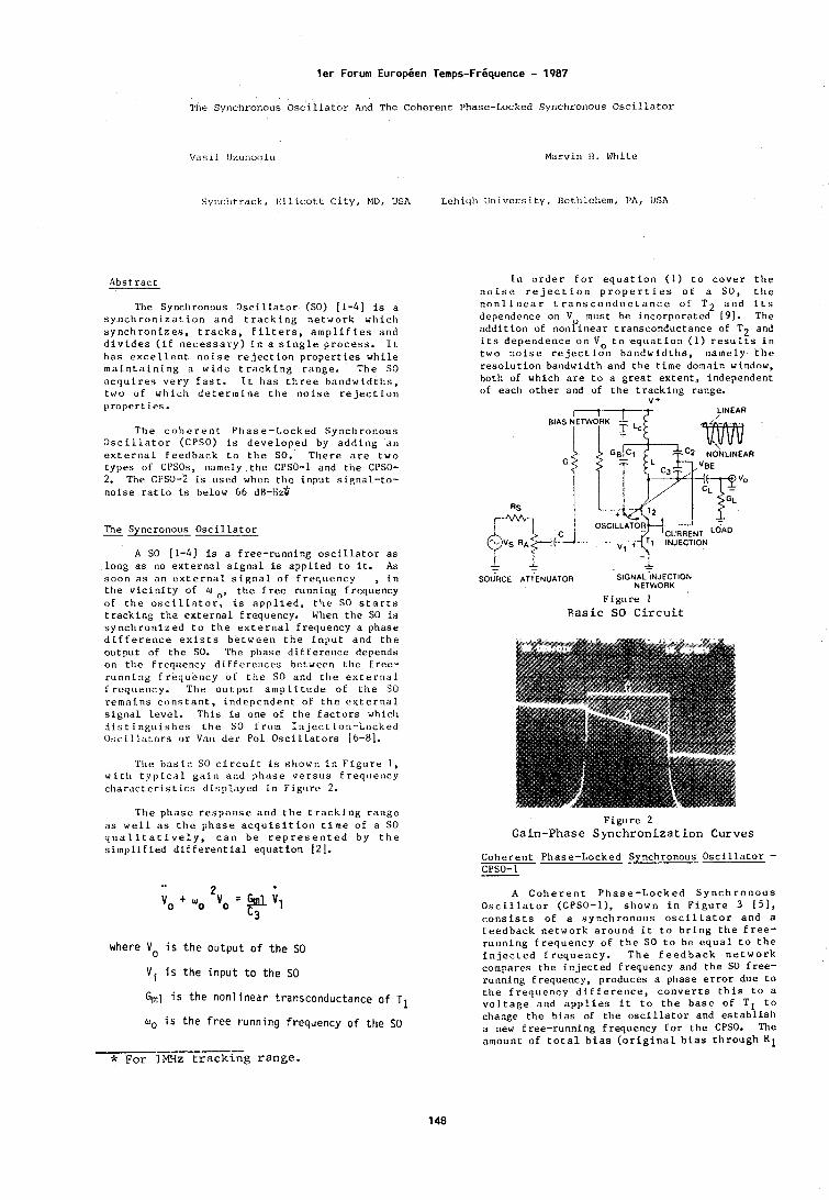
ler Forum EuropCen Temps-FrCquence - 1987
The Synchronous O s c i l l a t o r And The C o h e r e n t Phase-Locked Synchronous O s c i l l a t o r
V a s i l l izunoqlu Marvin I ! . White
S y ~ l c l ~ t r a c k , E1lic:ot.t C i t y , M D , USA Lehiqli l i n i v e r s i t y , 13ctlilchem, PA, lJSA
The Synchronous O s c i l l a t o r (SO) 11-41 is a s y n c h r o n i z a t i o n a n d t r a c k i n g n e t w o r k w h i c h s y n c h r o n i z e s , t r a c k s , f i l t e r s , a m p l i f i e s a n d d i v i d e s ( i f n e c e s s a r y ) i n a s i n g l e p r o c e s s . I t h a s e x c e l l e n t n o i s e r e j e c t i o n p r o p e r t i e s w h i l e m a i n t a i n i n g a w i d e t r a c k i n g r a n g e . T h e SO n c q u i r e s v e r y f a s t . I t h a s t h r e e h n n d w t d t h s , t w o o f w h i c h d e t e r m i n e t h e n o i s e r e j e c t i o n p r o p e r t i c s .
I n o r d e r f o r e q u a t i o n ( 1 ) t o c o v e r t h e n o i s e r e j e c t i o n p r o p e r t i e s o f a SO, t h e n o n l i n e a r t r a n s c o n d u c t a n c e o f T 2 a n d i t s dependence on V must be i n c o r p o r a t e d (91. The a d d i t i o n of n o n f i n e a r t r a n s c o n d u c t a n c e of T2 and i t s d e p e n d e n c e o n V o t o e q u a t i o n ( 1 ) r e s u l t s i n t w o n o i s e r e j e c t i o n b a n d w i d t h s , n a m e l y t h e r e s o l u t i o n bandwid th and t h e t i m e domain window, both of which a r e t o a g r e a t e x t e n t , i ndependen t of each o t h e r and of t h e t r a c k i n g range.
v + I-t LINEAR
T h e c o h e r e n t P h a s e - L o c k e d S y n c h r o n o t ~ s O s c i l l a t o r (CPSO) i s d e v e l o p e d by a d d i n g a n e x t e r n a l f e e d b a c k t o t h e SO. T h e r e a r e t w o t y p e s of CPSOs, namely t h e CPSO-1 and t h e CPSO- 2. The CPSO-2 i s used when t h e i n p u t s i g n a l - t o - n o i s e r a t i o is below 66 ~ H - H Z *
The Syncronous O s c i l l a t o r - A SO 11-41 is a f r ee - runn ing oscillator a s
l o n g a s no e x t e r n a l s i g n a l i s a p p l i e d t o it. As s o o n a s n n e x t e r n a l s i g n a l o f f r e q u e n c y , i n t h e v i c i n i t y of U t h e f r e e runn ing f r equency of t h e o s c i l l a t o r , i s a p p l i e d , t h e SO s t a r t s t r a c k i n g t h e e x t e r n a l f r equency . When t i le SO is s y n c h r o n i z e d t o t h e e x t e r n a l f r e q u e n c y a phase d i f f e r e n c e e x i s t s b e t w e e n t h e i n p u t a n d t h e o u t p u t of t h e SO. 'Che phase d i f f e r e n c e depends on t h e f r e q u e n c y d i f f e r e l l c e s be tween t h e f r e e - r u n n i n g f r e q u e n c y o f t h e SO and t h e e x t e r n a l I r e q u e n c y . T h e o u t p u t a m p l i t u d e o f L l ~ e SO r e m a i n s c o n s t a n t , i n d e p e n d e n t o f t h e e x t e r n a l s i g n a l l e v e l . T h i s i s one of t h e f a c t o r s which d i s t i n g u i s h e s t h e SO f r o m I n j e c t i o n - L o c k e d O s c i l l a t o r s o r Van d e r Po l O s c i l l a t o r s 16-61.
The b a s i c SO c i r c u i t i s s h o w n i n F i g u r e 1 , w i t h t y p i c a l g a i n a n d p h a s e v e r s u s E r e q ~ l e ~ i c y c h a r a c t e r i s t i c s d i s p l a y e d i n F i g u r e 2.
T h e p h a s e r e s p o n s e a n d t h e t r a c k i n g r a n g e a s w e l l a s t h e p h a s e a c q u i s i t i o n t i m e o f a SO q u a l i t a t i v e l y , c a n b e r e p r e s e n t e d b y t h e s i m p l i f i e d d i E E e r e n t i a 1 e q u a t i o n [Z].
where Vo i s t h e o u t p u t o f t h e SO
Vi i s t h e i n p u t t o t h e SO
G,1 i s t h e n o n l i n e a r t ransconductance o f TI
uO i s t h e f r e e r u n n i n g f requency o f t h e SO
--- * For lMHz t r a c k i n g range .
BIAS A E T W ~ R K 1
CURRENT ''AD
SOURCE ATTENUATOR S ~ G N A L ~ N J E C T ~ O N NETWORK
F i g u r e 1 B a s i c SO C i r c u i t
F i g u r e 2 Gain-Phase S y n c h r o n i z a t i o n Curves
C o h e r e n t P h a s e - L o c k e d Synchronous O s c i l l a t o r - CPSO-1
A C o h e r e n t P h a s e - L o c k e d S y n c h r o n o u s O s c i l l a t o r (CPSO-I), s h o w n i n F i g u r e 3 [51, c o n s i s t s o f a s y n c h r o n o u s o s c i l l a t o r a n d a f e e d b a c k n e t w o r k a r o u n d i t t o b r i n g t h e f r e e - r u n n i n g f r e q u e n c y of t h e SO t o b e e q u a l t o t h e i n j e c t e d f r e q u e n c y . T h e f e e d b a c k n e t w o r k compares t h e i n j e c t e d f r e q u e n c y and t h e SO f r e e - runn ing f r equency , p roduces a phase e r r o r d u e t o t h e f r e q u e n c y d i f f e r e n c e , c o n v e r t s t h i s t o a v o l t a g e a n d a p p l i e s i t t o t h e b a s e o f T t o change t h e b i a s of t h e o s c i l l a t o r and e s t a b l l i s h a new f r e e - r u n n i n g f r e q u e n c y f o r t h e CPSO. The amoun t o f t o t a l b i a s ( o r i g i n a l b i a s t h r o u g h R 1

Figure 3 CPSO-1
p l u s f e e d b a c k b i a s ) must b r i n g t h e n a t u r a l f r e q u e n c y o f t h e CPSO t o be e q u a l t o t h e i n j e c t e d frequency. The f e e d b a c k n e t w o r k d o e s no t a s s i s t t h e s y n c h r o n i z a t i o n p r o c e s s i n any way; i t merely f o r c e s t h e f ree-running f r eq t~ency of t h e SO t o be e q u a l t o t h e i n j e c t e d f r e q u e n c y a n d e s t a b l i s h e s a b s o l u t e c o h e r e n c y . T h e s y n c h r o n i z a t i o n o c c u r s w i t h i n t h e SO by t h e i n j e c t e d f r e q u e n c y and d o e s n o t i n v o l v e t h e f e e d b a c k l o o p . T h e r e f o r e , t h e o p t i m a l n o i s e r e j e c t i o n p r o p e r t i e s , t h e a c q u i s i t i o n t i m e and o t h e r v i r t u e s of t h e SO remain und is tu rbed . The c o h e r e n c y p r o c e s s p r o d u c e s s i x i m p o r t a n t f u n c t i o n a l p r o p e r t i e s :
( i ) I t makes t h e CPSO c o h a r e n t t h r o u g h o u t t h e t r a c k i n g range ( z e r o phase e r r o r ) .
( i i ) I t makes t h e r e s o l u t i o n b a n d w i d t h ( n o i s e b a n d w i d t h ) f u l l y i n d e p e n d e n t of i t s t r k c k i n g range.
( i i i ) The CPSO o p e r a t e s a t i t s maximum n o i s e r e j e c t i o n l e v e l ( m i n i m a l n o i s e b a n d w i d t h ) throughout t h e t r a c k i n g range.
( i v ) The t r a c k i n g r a n g e a f a CPSO is l i m i t e d o n l y by t h e b i a s i n g r a n g e of t h e o s c i l l a t o r t r a n s i s t o r .
( v ) The s e n s i t i v i t y i s c o n s t a n t t h r o u g h o u t t h e t r a c k i n g range.
( v i ) I t i s f r e q u e n c y - s t a b i i z e d f o r t e m p e t a t u r e v a r i a t i o n s .
The CPSO i s a new network ( o r f i l t e r ) whose n o i s e bandwidth ( r e s o l u t i o n bandwidth) 18 f u l l y i n d e p e n d e n t of i t s t r a c k i n g r a n g e and h a s a b s o l u t e c o h e r e n c y . A l t h o u g h c o h e r e n c y i s de te rmined by t h e feedback loop, f rkquedcy add phase a c q u i s i t i o n a r e independent of it.
O p e r a t i o n of x: F o r e a c h SO c e n t r e frequency (f r e e - r b n n i ng f r e d u e n c y ) i n F i g u r e L . - t h e t r a c k i n g r a n g e i s i d e n t i f i e d a s w . Minor d i f f e r e n c e s i n AW may e x i s t f o r e a c h c e n t r e frequency and they a r e u s u a l l y l e s s than a few percen t . The n o i s e bandwidth of t h e SO a t
each c e n t r e frequency is m i n i ~ n a l (inaximt~m Q) a s e x p e c t e d , a s t h e t a n k c i r c u i t o p e r a t e s a t i t s peak Q. The n o i s e b a n d w i d t h i n c r e a s e s a s t h e frequency moves away from t h e c e n t r e frequency. As t h e Crso always o p e r a t e s a t i ts f ree - runn ing EreqUehby, where t h e i n j e c t e d frequency is equa l t o t h e f t e e - r u n n i n g f r e q u e n c y , i t a l w a y s h a s maximum n o i s e r e j e c t i o n . When t h e f ree - runn ing frequency of t h e CPSO is changed by vary ing t h e b t a s of TI, a new t r a c k i n g c u r v e is e s t a b l i s h e d . There lo re , t h e CPSO t r a c k i n g range i s formed by a n I n f i n i t e number of b i a s l e v e l s , e a c h o n e h a v i n g a t r a c k i n g r a n g e AO . l n d i v i d u a l t r a c k i n g ranges do not have any s i g n i f i c a n c e i h t h e o p e r a t i o n of t h e CPSO, a s t h e CPSO a l w a y s o p e r a t e s a t i t s f r e e - r u n n i n g f r e q u e n c y . F o r c o n v e n i e n c e we w i l l d e f i n e t h e t o t a l t r a c k i n g range of t h e CPSO a s N A o , knowing t h a t under e a c h t r a c k i n g c u r v e Acd t h e r e a r e a n i n f i n i t e number of o p e r a t i n g p o i n t s , e a c h c o r r e s p o n d i n g t o t h e f ree-running f requency of t h e CPSO.
I n F i g u r e 3, t h e o - c o r r e c t i o n n e t w o r k should e s t a b l i s h a b i a s f o r t r a n s i s t o r T1, which w i l l c h a n g e t h e f r e e - r u n n i n g f r e q u e n c y of t h e CPSO t o c o r r e s p o n d t o t h e i n j e c t e d f r e q u e n c y . The g e n e r a t i o n of s u c h a b i a s l o c u s by t h e o- c o r r e c t i o n n e t w o r k is n o t n s t r a i g h t f o r w a r d p r o c e d u r e b u t r e q u i r e s a s k i l l f u l mapping i f a b s o l u t e coherency is t o be achieved.
C a l i b r a t i o n o f t h e p h a s e c o r r e c t i o n network: The p - c o r r e c t i o n network, i n F i g u r e 3, - i s d i s c o n n e c t e d f r o m t h e b a s e of t r a n s i s t o r
feedback net&'
F i g u r e 5 Bias and Phase Error in CPSO
TI and t e r m i n a t e d i n %, which is approx imate ly equa l t o t h e i n p u t r e s i s t a n c e of t r a n s i s t o r TI, a t p o i n t D, a s s h o w n i n F i g u r e 5. A new r e s i r t o r RB i s c o n n e c t e d t b t h e b a s e of T1 and is a p p l i e d t o a v a r i a b l e v o l t a g e s o u r c e VE. We i d e n t i f y t h e f r e q u e n c y r a n g e a t w h i c h t h e CPSO s h o u l d o p e r a t e , s a y W - G) 2, a n d d e t e r - mine t h e c h a n g e i n V E w i i c h moves t h e f r e e - r u n n i n g f r e q u e n c y of t h e CPSO f rom W 1 t o 0 2, T h i e p t o c e d u r e e n a b l e s u s t o d r a w t h e b i a o / f r e q u e n c y c u r v e shown i n F i g u r e 6 , The
I
-, *llEOULNOY
F i g u t e 6
B i a s and Phase Error Curves
J.2 b-9 I 02 1 L j + 2 F i ~ u r e 4
Tracking of a CPSO
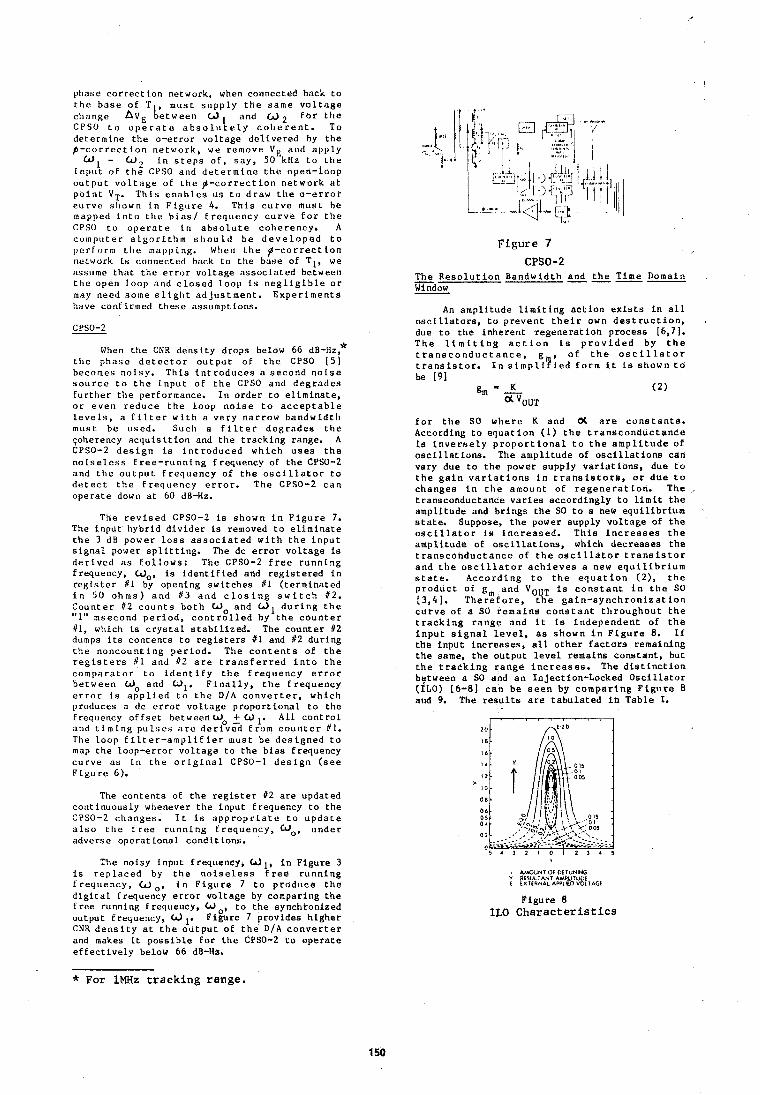
phase c o r r e c t ion network, when connected back t o t h e b a s e of T1, must s u p p l y t h e s a m e v o l t a g e c h a n g e hvE b e t w e e n W and u 2 f o r t h e CPSO t o o p e r a t e a b s o l ~ ~ t e l y c o l ~ e r e n t . To de te rmine t h e o - e r r o r v o l t a g e d e l i v e r e d by t h e p - c o r r e c t i o n n e t w o r k , we remove V e and a p p l y
W , - W 2 i n s t e p s O F , s a y , 50 kHz t o t h e i n p u t of t h e CPSO and d e t e r m i n e t h e open- loop o u t p u t v o l t a g e of t h e $ - c o r r e c t i o n n e t w o r k a t p o i n t VT. T h i s e n a b l e s u s t o d raw t h e o - e r r o r c u r v e sllown i n F i g u r e 4. T h i s c u r v e mus t be mapped i n t o t i l e b i a s / f r e q u e n c y c u r v e f o r t h e CPSO t o o p e r a t e i n a b s o l u t e c o h e r e n c y . A co ln l )u te r a l g o r i t h m s h o u l d b e d e v e l o p e d t o p e r f o r m t h e napp ping. When t h e $ - c o r r e c t i o n network Is connected back t o t h e b m e of TI , we assume t h a t t h e e r r o r v o l t a g e a s s o c i a t e d between t h e open l o o p a n d c l o s e d l o o p i s n e g l i g i b l e o r may need some s l i g h t a d j u s t m e n t . E x p e r i m e n t s hdve confirmed t h e s e assumptions.
When t h e CNR d e n s i t y d rops below 66 ~ B - H Z ? t h e p h a s e d e t e c t o r o u t p u t of t h e CPSO 1 5 ) becomes n o i s y . T h i s i n t r o d u c e s a s e c o n d n o i s e s o u r c e t o t h e i n p u t of t h e CPSO and d e g r a d e s f u r t h e r t h e performance. I n o r d e r t o e l i m i n a t e , o r e v e n r e d u c e t h e l o o p n o i s e t o a c c e p t a b l e l e v e l s , a f i l t e r wit11 a v e r y n a r r o w b a n d w i d t h mus t be used. Such a f i l t e r d e g r a d e s t h e qoherency a c q u i s i t i o n and t h e t r a c k i n g range. A CPSO-2 d e s i g n i s i n t r o d u c e d w h i c h u s e s t h e n o i s e l e s s f r e e - r u n n i n g f requency of t h e CPSO-2 a n d t h e o u t p u t f r e q u e n c y of t h e o s c i l l a t o r t o d e t e c t t h e F r e q u e n c y e r r o r . The CPSO-2 c a n o p e r a t e down a t 60 dB-Hz.
The r e v i s e d CPSO-2 is shown i n F i g u r e 7. The i n p u t h y b r i d d i v i d e r i s removed t o e l i m i n a t e t h e 3 dB power l o s s a s s o c i a t e d w i t h t h e i n p u t s i g n a l power s p l i t t i n g . The dc e r r o r v o l t a g e i s d e r i v e d a s f o l l o w s : The CPSO-2 f r e e r u n n i n g f requency , Wo, is i d e n t i f i e d and r e g i s t e r e d i n r e g i s t e r 111 by opening s w i t c h e s t l ( t e r m i n a t e d i n 5 0 o h m s ) a n d # 3 a n d c l o s i n g s w i t c h 12. C o u n t e r 112 c o u n t s b o t h W o a n d U1 d u r i n g t h e "1" msecond p e r i o d , c o n t r o l l e d by t h e c o u n t e r 111, which i s c r y s t a l s t a b i l i z e d . The c o u n t e r 12 dumps i t s c o n t e n t s t o r e g i s t e r s #I and 1 2 dur ing t h e n o n c o u n t i n g p e r i o d . The c o n t e n t s of t h e r e g i s t e r s % I and 1 2 a r e t r a n s f e r r e d i n t o t h e c o m p a r a t o r t o i d e n t i f y t h e f r e q u e n c y e r r o r b e t w e e n Wo and W1. F i n a l l y , t h e f r e q u e n c y e r r o r i s a p p l i e d t o t h e D / A c o n v e r t e r , w h i c h produces a dc e r r o r v o l t a g e p r o p o r t i o n a l t o t h e Frequency o f f s e t betweenWo + W A l l c o n t r o l and t i m i n g p u l s e s a r e d e r i v z f r o m c o u n t e r # I . The l o o p f i l t e r - a m p l i f i e r must be d e s i g n e d t o map t h e loop-e r ro r v o l t a g e t o t h e b i a s frequency c u r v e a s i n t h e o r i g i n a l CPSO-1 d e s i g n ( s e e F l g u r e 6).
The c o n t e n t s of t h e r e g i s t e r #2 a r e updated con t inuous ly whenever t h e i n p u t f requency t o t h e CPSO-2 c h a n g e s . I t i s a p p r o p r i a t e t o u p d a t e a l s o t h e f r e e r u n n i n g f r e q u e n c y , a,, u n d e r adverse o p e r a t i o n a l c o n d i t i o n s .
The noisy i n p u t frequency, W 1, i n F i g u r e 3 i s r e p l a c e d by t h e n o i s e l e s s f r e e r u n n i n g f r e q u e n c y , W o , i n F i g u r e 7 t o p r o d u c e t h e d i g i t a l Frequency e r r o r v o l t a g e by compariflg t h e f r e e running f requeacy , W , t o t h e synch ton ized ou tpu t Frequency, dl. ~ i i u r e 7 prov ides h i g h e r CNR d e n s i t y a t t h e o u t p u t of t h e D / A c o n v e r t e r and makes it p o s s i b l e f o r t h e CPSO-2 t o o p e r a t e e f f e c t i v e l y below 66 dB-Ha.
Figure 7 CPBO-2
The R e s o l u t i o n B a n d w i d t h and t h e T ime Domain - W i nrlnw
An a m p l i t u d e l i m i t i n g a c t i o n e x i s t s i n a l l o s c i l l a t o r s , t u p r e v e n t t h e i r own d e s t r u c t i o n , due t o t h e i n h e r e n t r e g e n e r a t i o n p rocess [6,71, T h e l i m i t i n g a c t i o n i s p r o v i d e d by t h e t r a n s c o n d u c t a n c e , g , o f t h e o s c i l l a t o r t r a n s i s t o r , I n s i r n p l i y i e d f o r m i t i s shown t o be [ g l
K gm - - ( 2 )
a 'OUT
f o r t h e SO w h e r e K and (X a r e c o n s t a n t s . According t o e q u a t i o n (1) t h e t r a n s c o n d u c t a n c e is i n v e r s e l y p r o p o r t i o n a l t o t h e a m p l i t u d e of o s c i l l a t i o n s . The a m p l i t u d e of o s c i l l a t i o n s can vary due t o t h e power supp ly v a r i a t i o n s , due t o t h e g a i n v a r i a t i o n s i n t r a n s i s t o r e , o r d u e t o c h a n g e s i n t h e amount of r e g e n e r a t i o n . The t ransconduc tance v a r i e s a c c o r d i n g l y t o l i m i t t h e ampl i tude and b r i n g s t h e SO t o a new e q u i l i b r i u m s t a t e . Suppose, t h e power supp ly v o l t a g e oE t h e o s c i l l a t o r is i n c r e a s e d . T h i s i n c r e a s e s t h e a m p l i t u d e of o s c i l l a t i o n s , which d e c r e a s e s t h e t r a n s c o h d u c t a n c e of t h e o s c i l l a t o r t r a n s i s t o r a n d t h e o s e l l l a t o r a c h i e v e s a new e q u i l i b r i u m s t a t e . A c c o r d i n g t o t h e e q u a t i o n ( 2 ) , t h e p r o d u c t of g m and VOUT i s c o n s t a n t i n t h e SO ( 3 , 4 ] . T h e r e f o r e , t h e g a i n - s y n c h r o n i z a t i o n c u t v e of a SO r e m a i n s c o n s t a n t t h r o u g h o u t t h e t r a c k i n g r a n g e and i t is i n d e p e n d e n t of t h e i n p u t s i g n a l l e v e l , a s s h o w n i n F i g u r e 8. I f t h e i n p u t i n c r e a s e s , a l l o t h e t f a c t o r s remain ing t h e same, t h e o u t p u t l e v e l r emains c o n s t a n t , bu t t h e t r a c k i n g r a n g e i n c r e a s e s . The d i s t i n c t i o n bptween a SO and a n In jec t ion-Locked O s c i l l a t o r (ILO) [6-81 c a n be s e e n by c o m p a r i n g F i g u r e 8 and 9. The r e s u l t s a r e t a b u l a t e d i n T a b l e I.
! AMOUNT Of DITUNING v ISULTANT AMPLITLIOI I PXTERNAL APPLIED VOLTAGI
F i g u r e 8 ILO Characteris t ics
* For lMHz tracking range.
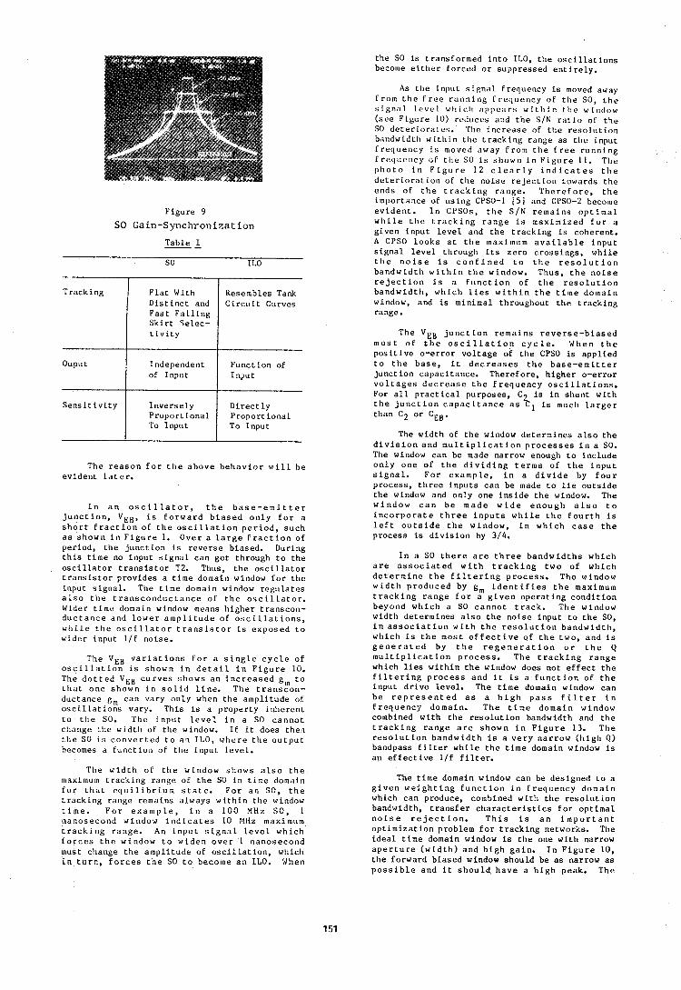
t h e SO is t r a n s f o r m e d i n t o ILO, t h e o s c i l l a t i o n s become e i t h e r f o r c e d o r s u p p r e s s e d e n t i r e l y .
F i g u r e 9
SO Gain-Synchroniza t i o n
T a b l e
SO ILO
The r e a s o n f o r t h e a b o v e b e h a v i o r w i l l h e e v i d e n t l a t e r .
T r a c k i n g
Ouput
S e n s i t i v i t y
I n a n o s c i l l a t o r , t h e b a s e - e m i t t e r j u n c t i o n , V E B , i s f o r w a r d b i a s e d o n l y f o r a s h o r t f r a c t i o n o f t h e o s c i l l a t i o n p e r i o d , s u c h a s s h o w n i n F i g u r e I. O v e r a l a r g e f t a c t i o n o f p e r i o d , t h e j u n c t i o n is r e v e r s e b i a s e d . During t h i s t i m e no i n p u t s i g n a l c a n g e t t h rough t o t h e o s c i l l a t o r t r a n s i s t o r T2. Thus , t h e o s c i l l a t o r t r a n s i s t o r p r o v i d e s a t i m e domain window f o r t h e i n p u t s i g n a l . The t i m e domain window reg111,ates a l s o t l i e t r a n s c o n d u c t a n c e o f t h e o n c i l l a t o r . Wider t i m e domain window means h i g h e r t r a n s c o n - d u c t a n c e a n d l o w e r a m p l i t u d e o f o s c i l l a t i o n s , w h i l e t h e o s c i l l a t o r t r a n s i s t o r i s e x p o s e d t o w l d e r i n p u t 111 n o i s e .
The V E H v a r i a t i o n s f o r a s i n g l e c y c l e o f o s c i l l a t i o n is s h o w n i n d e t a i l i n F i g u r e 10. The d o t t e d V E B c u r v e s s h o w s a n i n c r e a s e d g m t o t h a t o n e s h o w n i n s o l i d l i n e . T h e t r a n s c o n - d u c t a n c e gm c a n v a r y o n l y when t h e a m p l i t u d e of o s c i l l a t i o n s vary. T h i s is a p r o p e r t y i n h e r e n t t o t h e SO. The i n p u t l e v e l i n a SO c a n n o t change t h e w i d t h of t h e wiridow. I f i t does t h e n t h e SO i s c o n v e r t e d t o a n ILO, w h e r e t h e o u t p u t becomes a f u n c t i o n of t h e i n p u t l e v e l .
F l a t With D i s t i n c t and F a s t F a l l i n g S k i r t S e l e c - t i v i t y
Independen t of I n p u t
I n v e r s e l y P r o p o r t i o n a l To I n p u t
The w i d t h o f t h e w i n d o w s h o w s a l s o t h e maximum t r a c k i n g r ange of t h e SO i n t i m e domain f o r t h a t e q u i l i b r i u m s t a t e . F o r a n SO, t l i e t r a c k i n g r ange r ema ins a l w a y s w i t h i n t h e window t i m e . F o r e x a m p l e , i n a 1 0 0 MHz SO, 1 n a n o s e c o n d window i n d i c a t e s 10 Mltz maximum t r a c k i n g r a n g e . An i n p u t s i g n a l l e v e l w h i c h f o r c e s t h e window t o w i d e n o v e r 1 n a n o s e c o n d must change t h e a m p l i t u d e of o s c i l l a t i o n , which i n t u r n , f o r c e s t h e SO t o become a n ILO. When
Resembles Tank C i r c u i t Curves
F u n c t i o n of I n p u t
D i r e c t l y P r o p o r t i o n a l To I n p u t
As t l ie i n p u t s i g n a l f r e q u e n c y i s moved away f r o m t h e F r e e r u n n i n g f r e q c l e n c y o f t l i e SO, t h e s i g n : ~ l l e v e l w l ~ i c l ~ ; Ippe ; t r s w l t l i i n t l i e wln<lnw ( s e e F i g u r e 10) r educes ilnd t h e SIN r a t i o of t h e SO d e t e r l o r ; i t e r . The i n c r e a s e of t h e r e s o l u t i o n bandwid th w i t h i n t h e t r a c k i n g r ange a s t h e i n p u t E r e q c ~ e n c y i s moved ilway f r o n l t h e f r e e r u n n i n g F r e q u e n c y o r t l i c SO is s h o w n i n E ' l g u r e 1 1 . T h e p h o t o i n F i g u r e 1 2 c l e a r l y i n d i c a t e s t h e d e t e r i o r a t i o n of t h e n o i s e r e j e c t i o n t o w a r d s t h e e n d s o f t h e t r a c k i n g r n n g e . T h e r e f o r e , t h e i m l ~ o r t a n c e of c ~ s i n g CPSO-1 ( 5 ) and CPSO-2 become e v i d e n t . I n CPSOs, t h e S IN r e m a i n s o p t i m a l w h i l e t h e t r a c k i n g r a n g e is m a x i m i z e d f o r a g i v e n i n p u t l e v e l and t l ie t r a c k i n g is cohe ren t . A CPSO l o o k s a t t h e maximum a v a i l a b l e i n p u t s i g n a l l e v e l t h r o u g h i t s z e r o c r o s s i n g s , w h i l e t h e n o i s e i s c o n f i n e d t o t h e r e s o l u t i o n b a n d w i d t h w i t h i n t h e window. T h u s , t h e n o i s e r e j e c t i o n i s a f u n c t i o n o f t h e r e s o l u t i o n b a n d w i d t h , w h i c h l i e s w i t h i n t h e t i m e d o m a i n window, and i s m i n i m a l t h r o u g h o u t t h e t r a c k i n g range.
The V E R j u n c t i o n r e m a i n s r e v e r s e - b i a s e d m o s t o f t h e o s c i l l a t i o n c y c l e . When t h e p o s i t i v e o - e r r o r v o l t a g e of t h e CPSO is a p p l i e d t o t l i e b a s e , i t d e c r e a s e s t h e b a s e - e m i t t e r j u n c t i o n c a p a c i t a n c e . T h e r e f o r e , h i g h e r o - e r r o r v o l t a g e s d e c r e a s e t h e f r e q u e n c y o s c i l l a t i o n s . For a l l p r a c t i c a l p u r p o s e s , C2 i s i n s h u n t w i t h t h e j u n c t i o n c a p a c i t a n c e a s C1 i s mucli l a r g e r t h a n C2 o r CEB.
The w i d t h of t h e window d e t e r m i n e s a l s o t h e d i v i s i o n a n d m u l t i p l i c a t i o n p r o c e s s e s i n a SO. The window c a n b e made na r row enough t o i n c l u d e o n l y o n e o f t h e d i v i d i n g t e r m s o f t h e i n p u t s i g n a l . F o r e x a m p l e , i n a d i v i d e by f o u r p r o c e s s , t h r e e i n p u t s c a n b e made t o l i e o u t s i d e t h e window and o n l y o n e i n s i d e t h e window. The w i n d o w c a n b e m a d e w i d e e n o u g h a l s o t o i n c o r p o r a t e t h r e e i n p u t s w h i l e t h e f o u r t h i s l e f t o u t s i d e t h e w i n d o w , i n w h i c h c a s e t h e p r o c e s s is d i v i s i o n by 3 / 4 .
I n a SO t h e r e a r e t h r e e b a n d w i d t h s w h i c h a r e a s s o c i a t e d w i t h t r a c k i n g t w o o f w h i c h d e t e r m i n e t h e f i l t e r i n g p r o c e s s . T h e window w i d t h p r o d u c e d by g m i d e n t i f i e s t h e maximum t r a c k i n g r n n g e f o r a g i v e n o p e r a t i n g c o n d i t i o n b e y o n d w h i c h a SO c a n n o t t r a c k . T h e window w i d t h d e t e r m i n e s a l s o t h e n o i s e i n p u t t o t h e SO, i n a s s o c i a t i o n w i t h t h e r e s o l u t i o n b a n d w i d t h , w h i c h i s t h e m o s t e f f e c t i v e o f t h e t w o , a n d i s g e n e r a t e d by t h e r e g e n e r a t i o n o r t h e Q m u l t i p l i c a t i o n p r o c e s s . The t r a c k i n g r a n g e which l i e s w i t h i n t h e window does n o t e f f e c t t h e f i l t e r i n g p r o c e s s a n d i t is a f u n c t i o n o f t h e i n p u t d r i v e l e v e l . The t i m e domain window c a n b e r e p r e s e n t e d a s a h i g h p a s s f i l t e r i n f r e q u e n c y d o m a i n . T h e t i m e d o m a i n window combined w i t h t h e r e s o l u t i o n bandwid th and t h e t r a c k i n g r a n g e a r e s h o w n i n F i g u r e 13. T h e r e s o l u t i o n b a n d w i d t h is a v e r y n a r r o w ( h i g h Q) bandpass f i l t e r w h i l e t h e t i m e domain window is a n e f f e c t i v e l / f f i l t e r .
The t i m e domain window c a n be d e s i g n e d t o a g i v e n w e i g h t i n g f u n c t i o n i n f r e q u e n c y d o m a i n which c a n produce, combined w i t h t h e r e s o l u t i o n bandwid th , t r a n s f e r c h a r a c t e r i s t i c s f o r o p t i m a l n o i s e r e j e c t i o n . T h i s i s a n i m p o r t a n t o p t i m i z a t i o n p rob lem f o r t r a c k i n g networks . The i d e a l t i m e domain window i s t h e one w i t h na r row a p e r t u r e ( w i d t h ) a n d h i g h g a i n . I n F i g u r e 10 , t h e f o r w a r d b i a s e d window s h o u l d b e a s na r row a s p o s s i b l e a n d i t s h o u l d . h a v e a h i g h peak . The
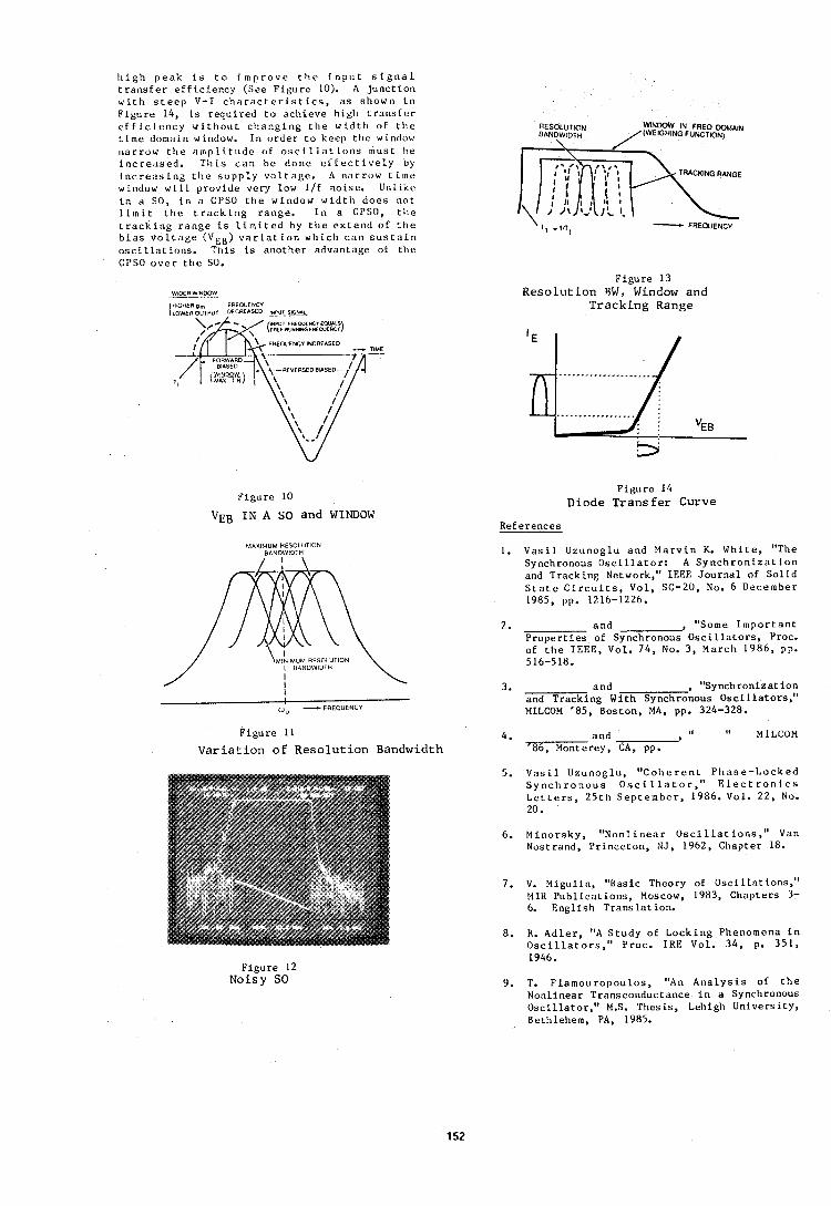
h i g h p e a k i s t o i m p r o v e t h e i n p u t s i g n a l t r a n s f e r e f f i c i e n c y (See F i g u r e 10). A j u n c t i o n w i t h s t e e p V-I c h a r a c t e r i s t i c q , a s shown i n F i g u r e 14, i s requ i red t o a c h i e v e h igh t r a n s f e r e f f i c i e n c y w i t h o l ~ t c h a n g i n g t h e wid t l l o f t h e t i m e dnmain window. Irl o r d e r t o keep t l ~ e window n a r r o w t h e . t r n p l i t u d e ( I F o s c i l l a t i o n b mus t be i n c r e . ~ b e d . T h i s c a n be d o n e e f f e c t i v e l y by i n ~ r e ~ ~ s l n g t h e s u p p l y v o l t a g e . A n a r r o w t i m e window w i l l p rov ide very low l / f noise. Unlike i n SO, i n a CPSO t h e window w i d t h d o e s no t limit t h e t r a c k i n g range . I n a CPSO, t h e t r a c k i n g r a n g e i s l i m i t e d by t h e e x t e n d O F t h e b i a s v o l t a g e ( ' IEB) v a r i a t i o n w h i c h c a n s u s t a i n o s c i l l a t i o n s . Th is i s a n o t h e r advantdge of t h e CPSO o v e r t h e SO.
WIDER WINKIW
HtGUER pm FREQUENCY lLOWEROuTPuT DECREASED Em!!&
Figure 10
V E ~ I N A SO and WINDOW
MAXIMUM RESOLUTION BANDWIDTH
/ I \
F i g u r e 11
V a r i a t i o n o f R e s o l u t i o n Bandwidth
F igure 12 Noisy SO
AESOLUTION WINDOW IN FREQ WAIN BANDWIDTH /(WEIGHING FUNCTION)
\
' I , .in, - FREQUENCY
Figure 13 R e s o l u t i o n SW, Window and
T r a c k i n g Range
F i g u r e 14 Diode T r a n s f e r Curve
References
1. V a s i l Uzunoglu and M a r v i n K. W h i t e , "The Synchronous O s c i l l a t o r : A S y n c h r o n i z a t i o n and Track ing Network," IEEE J o u r n a l of S o l i d S t a t e C i r c u i t s , Vol , SC-20, No. 6 December 1985, pp. 1216-1226.
2. and , "Some I m p o r t a n t P r o p e r t i e s of Synchronous O s c i l l a t o r s , Proc. of t h e IEEE, Vol. 74, No. 3, March 1986 , pp. 516-518.
3. and , "Synchronizat ion and Track ing With Synchronous O s c i l l a t o r s , " MILCOM '85, ~ o s t o n , MA, pp. 324-328.
4. and I, . I ' MILCOM f86, Monterey, CA, pp.
5. V a s i l l l z u n o g l u , " C o h e r e n t P h a s e - L o c k e d S y n c l i r o n o u s O s c i l l a t o r , " E l e c t r o n i c s L e t t e r s , 2 5 t h S e p t e m b e r , 1986. Vol. 22, No. 20.
6. M i n o r s k y , " N o n l i n e a r O s c i l l a t i o n s , " Van N o s t r a ~ i d , P r i n c e t o n , NJ, 1962, Chapter 18.
7. V. Migillin, "Basic Theory of O s c i l l n t ions," MIR P u b l i c a t i o n s , Moscow, 1983, Chap te r s 3- 6. Engl i sh T r a n s l a t i o n .
8. R. A d l e r , "A S t u d y of L o c k i n g Phenomena i n O s c i l l a t o r s , " P roc . IRE Vol. 34, p. 351, 1946.
9. T. F l a m o u r o p o u l o s , "An A ~ i a l y s i s of t h e Nonlinear Transconductance i n a Sy~ichronous O s c i l l a t o r , ' ' M.S. Thes i s , Lehigh U n i v e r s i t y , Bethlehem, PA, 1985.
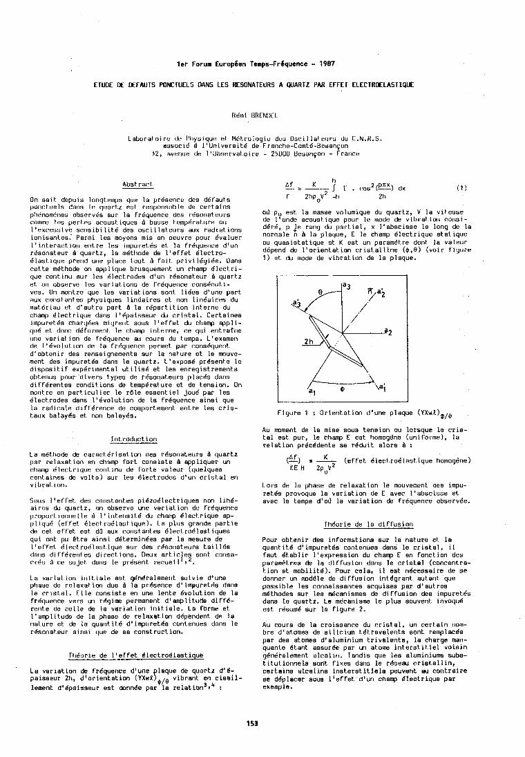
ler Forum Europien Temps-Frbquence - 1987
ETUDE DE DEFAUTS WNCTUELS DAMS LES AESONATEURS A WART2 PAR EFFEl ELECTRDELASTIQUE
Laborat.oire du Pltyaique ot MBt.rologil? duo Osci l lal.t!~ll.s clu C.N.11.S. associd B 1'Universit.B de Frondie-Comtd-Resahycln
32, avenue de l '0bs1?rvat,oire - 25000 Uesanqon - France
On sait . depuis lorigtr~nps que la presence dcs d6faut.s ~,orlctuels dans l e quart.2 e s t rasponsable de certairis phBnom6nes observtis sur la frOquence des resonateurs comc l e s pert.t?s acoust. iques B basse t.emperat,ure ou l ' excess ive s e n s i b i l i t e des oscil lat .eurs aux radia t ions ionisantes. Parmi l e s moyens m i s en oeuvre pour Bvaluer l ' interact. ion ent re l e s irnpuretBs e t l a fr6quence d'un rOsonateur B quar tz , l a m6ttiode de l ' e f f e t Blectro- dlast.ique prend une place tout Q fait. privilr igi6e. Dans cet.t.e m6thode on applique brusquemerit. un charrp Blect-ri- que cant inu sur les Blectrodes d'url ~ B s o n a t e t ~ r Q quar1.z et. or1 observe les var i at. ions de frBquence cons6cut i - ves. On m n t r e que l e s var ia t ions sont l i6es d'une par t aux constant.es physiques l inBaires e t non l in6ai res du rnatBriau e t dlaut.re part Q la rr ipart i t ion int.erne du charrp dlect,rique dans 1 '6paisseur du c r i s t a l , Cer ta ines itnpuret6s chargees migrent sous I ' e f f e t du champ eppli- qu6 et. dooc driforment l e champ in terne , ce qui ent.rafrie clne variat.ion de frequence au cours du temps. L'examen de 1'6volut.ion de la frdquence perrnet par cons6quent. d 'obteni r des renseignements sur l a nature e t le mouve- ment des impucet6s dans l e quartz. L'exposd prdsente lo disposit- if expBrirnenta1 u t i l i s 6 et Les enregiatrements obtenus pour d ivers types de rksonateurs places dana d i f fg ren te s conditions de tempdrature e t de tension. On morit.re en part-icul ie r l e rBle e s sen t i e l jou4 per l e s 6lect.rodes dans I'Cvolution de l a fr6quence a i n s i que la r ad i r a l e d i f ference de comportement en t r e l e s c r i s - taux balayes et non balayBs.
Introduction
La mBthode de ca rac t6 r i s a t ion des r6sonateurs B quar tz par relaxat.ion en champ f o r t cons is te B appllquer un champ Blectrlque contknu de f o r t e valeur (quelques centaines de v o l t s ) sur les Blectrodes d'un c r i s t a l en vibration.
Sous l ' e f fet. des constantea piBzodlectriques non l ing- a i r e s du quar tz , on observe une var ia t ion de frdquence proportionnelle d l l i n t , ens i td du champ 6lect.rique ap- p l iqu6 (ef f e t 6 lec t ro6last ique). La plus grande p a r t i e ck cet e f f e t e s t dO aux constantes Blectrodlast.iquea qui ont pu & r e a in s i dBtermin6es par l a mesura de l ' e f f e t BlectroOlastique sur des rdsonat,eurs t a i l 168 dans di f fdrentes di rec t ions. Deux art. i c l e s sont corisa- crBs B ce sujet. dans l e present recueil1 9'.
La var ia t ion i n i t i a l e e s t gBn8ralement su iv i e d'une phase de relaxation due B l a pri5aence d'impuretds dens l e c r i s t a l . E l l e consis te en une lente Bvolution de la frequence vers tm regime permanent d'amplit.ude d i f f 6 - rente de c e l l e de l a var ia t ion i n i t i a l e , La forme e t 1'amplit.ude de la phase de relaxation dependent de l a nature e t de la quarit.it.6 d'impuretBs contenues dans l e rCsonat.eur a in s i que de ss construction.
ThBorie de l ' e f f e t BlectroBlastique
La v a r i a t ~ o n de frdquence d'una laque de quartz d 'b- paisaeur 2h, d ' o r i en t a t ion (YxwP!,,, v ibrant en c i a a i l - lement d'Bpaiaseur e s t cbnnde p a r y i i :
03 po e s t l a masse volumique du quar tz , V l a v i t e s se de I'onde acoust.ique pour l e mode de vibrat-ion consi- dBrB, p Je rang du p a r t i e l , x l ' absc i s se l e long de l a normale n Q la plaque, E l e champ Blectrique s t a t i q u e ou quas is ta t ique e t K e s t un parametre dont l a valeur depend de l ' o r i en t a t ion c r i s t a l l i n e ( $ , e l (voir f igure 1 ) e t du mode de v ibra t ion de l a plaque.
Figure 1 : 0rient.at ion d'une plaque ( Y X W L ) ~ , ~
Au moment de la mise sous tension ou lorsque l e c r i s - t a l e s t pur, l e champ E eat homogdne (uniforme), l a r e l a t i on pr6cddente s e rdduit a lo r s A :
K (f) z - ( e f f e t Blec t ro6las t ique homogdne) EE t i 2p,v2
Lors de la phase de re laxat ion l e ~nouvement des impu- retBs provoque l a var ia t ion de E avec l ' absc i s se e t rvec le temps dl03 la var ia t ion de frBquenre observBe.
ThBorie de l a d i f fu s ion
Pour obteni r des informctions sur l a nature e t l a quarit i t6 d'impuretds contenuea dens l e c r i s t a l , i l faut Btabl i r l 'expression du champ E en fonction des parametres de l a d i f fus ion dans l e c r i e t e l (concentra- t i on e t mobili t6). Pour ce l a , i l es t ndcessaire de s e donner un mdPle de d i f fus ion intggrant autant que possiblo lea connaissances arquises par d ' au t r e s d t h o d e s sur l e s dcanismes de d i f fus ion des impuretda dans l e quartz. Le mBcanisme l e plus souvent invoqud e s t rBsumt? sur l a f igure 2.
Au coura de l a cro issanre du c r i s t a l , un ce r t a in nom- bre d'at,omas de s i l i c i m td t r ava l en t s sont remplac6s par des a t o m s d'aluminium t r i v a l e n t s , l a charge men- quante Btant assurge par un atome i n t e r s t i t i e l vois in gBn6ralement a l ca l ln . Tandis que l e s aluminiums subs- t i t u t i o n n e l s sont f i xes dans l e rgseau c r i s t a l l i n , ce r t a ina e l ca l in s i n s t , e r s t i t i e l a peuvent au con t r a i r e st d6placer soua l ' e f f e t d'un champ dlec t r ique par exemple'
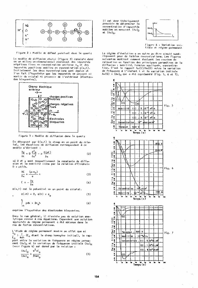
Figure 2 : Modlile ck dBfaut. ponclucl dons l e quar1.z
Lc rnodele de d i f f u s i o n cho i s i ( f i y u r e 3 ) rons is l r? done cn un mi 1 ieu uni rlirnerisionnul cont enanl. des ilnpilret 6s n11rjat ivcs t'i xlta t:ri corlceril rat. ion un i forlrv: no ol des iapuretda pos i t i ves rnobi las en coricenl ra t ion p ( x , t ) . In i t ia lcmer l t les dcux concentrations son1 Bgalos et. l ' o n f a i t I 'hypoth&st? que leu impuretks ne peuvent n i s o r t i r du c r i s t a l n i provenir de l ' e x t d r i e u r (6 lec t ro - des 11 l oquarites ) .
Champ blectrique exthrieur
o--
harges negatives
Figure 3 : Mod6le de d i f f u s i o n dens l e quartz
En dtkignant par E(x , t ) l e champ en un po in t du c r i s - t a l , les Bquations de d i f f u s i o n correspondant B ce rnodsle s 'dcr ivent :
oS D et p sont respect ivement l a constante de d i f f u - s i on et l a m o b i l l t 6 l ldes par l a reIat.ion d o E i n s t e i n 0 = pkT/e.
0 ( x , t ) est l e po ten t i o l en un point. du c r i s t a l .
h pdx = 2noh (6 )
-h
exprime l 'hypothsse des Blectrodes bloquantes.
Dens Ie cas gendral, 11 n ' e x i s t e pas de so lu t i on ana- l y t ~ q u e ronnue d res equations. Cependant une solut. ion approcli6e du r6g1me permanent a BtB obtenue dens l e ras de fo r tes roncent ra t ions.
L'Btude de rdgime permanent rnontre en e f f e t que si > .,- (Eo Btant l e chomp homoy6ne i n i t . i a l ) , l e rap-
E, 4eh U
por t en t re l a v a r i a t i o n & frBquence en rdgirne perma- nent (AwlD et l a v a r i a t ~ o n de frdquerice i n i t . i a l e (AwlH ( v o i r f i y u r e 4) est donne par l a r e l a t i o n :
I 1 cst door I h8or ~querncrit p o s s l l ~ l e de ddl.erminer l a concent r a t lot i d' lmpuretea mob L les en m~?sclrsnt ( A w ) ~ et
Flgurt: 4 : Variet .~on I n i - t i a le et regime permanent.
Le rdyime d'15volut1011 a eri out rt? pu 6 t r e s ~ m u l d r1urn6- r ~qut~lnent pour dt* t a ~ b l e s roriccnt ra t loris. I-ea f ~ y u r e s s u ~ v a r ~ t t?s ~nont rent romnient Bvoluent lou rourbtis dc relaxet ion en forirt lor1 d12s pr ln r i paux paramGI reu de l a d l t fu:31011 : lnobi I I t6 , t cnslort oppl lcluBe, rorlrenl ra - t iori. C'es t l e rapport Au(t )/AIJ(O) ont r e l a v a r ~ a l Ion de fr4querire 4 I ' l ns ta r i t t et l a v a r ~ a t l o n l h i t i a l e Aw(0) = (AIJJ)~ q u ~ a dt6 represent6 (Fig. 5, 6 e t 7).
r!
a a
-t. o = - -! 2 a - 0 8 c * Fig. 7 = f - - a
0
2 n , d
z C 6
E o I ~ N I ~ U ~ ~ ~ D Y I ~
Temps ( 6 1
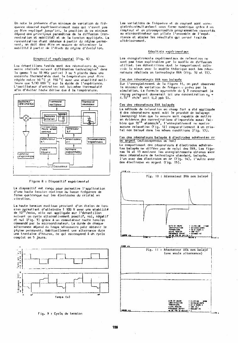
On note la prdsence d'un mInlmum de v a r i a t i o n de t rd- qclenre observt! exptir~mentalemerit rnals qul n 'avar t pas (IU e t re expl iqu6 j usqu ' l c l , l a posl t .~on de cSe Intnllnum d6pend des p r i n r i psux paramdtrus do l a diffusion (con- centrat ion e t m b i l l t 8 ) et de le kenslon t r l~p l iqu le . La rotirentrat. lon dtant tlbtenue I p a r t i r du r 6 g i m perma- rit:rit, on dol t dorir e t r e cn Immure dc dLiterminer tn 1nobilit.6 A part l r de I 'd tude du r8yrnx! d ' 6 v t 1 l ~ t l o n .
W o s l t l f ' exp6rimental (Fig. f l )
Lee c:ctianl r l Ions t est 4s sont &s rt!sotial ours du rotn- Inacre rda l ISI!~ sutvant d i f f d r e n t es te rhno log i rs5 dans l e yommt: 5 ou 10 MIir part I e l 3 ou 5 places daris une t~r i ra l r i te tht.rmostatt!u don1 l a temptiraturr: peut i.11.t. rdql6e ent re 50 O C et 150 "C aver une s tab11 l tB m e ~ l - l c c~ re que 5/10 000 'C sur l a durde de l 'expdr ienre. I . ' os r i l l a teu r d ' en t re t ren est IUL-meme thermostat6 a f rn d ' dv l t e r tou te d d r ~ v e due B l a tempgrature.
Figure 8 : D i a p o s i t i f expBrimerrta1
Le d l s p o s i t i f est ronqu pour permettre l ' a p p l i c a t i o n d'une 1iaut.e t e n s ~ o n cont.lhue w basse frdquence de forrne quelconque sur les Blectrodes du c r i s t a l en vtbrat ton.
La haute tension continue prov ient d'un d ta lan de ten- s lon pfrmetteht d ' a t t e i f l d re 1 100 V avec une s t a b i l l t d de 10' /mois, e l l e est eppliqui?e sur 1 ' 8chan t i l l on suivant un cyc le alternetivembflt p o s i t i f , nul , n d g a t i f e t nu1 (Fig. 9 ) grace I un commutateur haute tension r o ~ a h d d per l e ~nicroordihakeur. La durde de cheque alt-ernance ck5pend du temps ridcessal r e pour obten i r l e rdg~me permaneht, Heb~tuel lement une alternsrrce dure une t ren ta ine d'heures, ce qui Corrttspond B Un cyc le rohp le t en 5 jours.
F ig , 9 1 Cyctt: de tension
Les va r i a t i ons de fr6quelire at de courant sont enre- g i s t rde i simul t ahciment sous f o r r n ~ num6rique gr9re d ur1 rompteur et url piroarnpttrern6tre proyrammables cbnnertda HU ~n ic roord inateur qui pi lut,e I 'enscmblr, de I 'expd- Pienre et atocke lt?e r4su l t s ta qul st?rorit t r a i l d s u l t.6r ieclrement.
RBsul Lat s expBrlment.au5 --- Les rrirey i s t remcrlt s expdrrtnerit aux cia relaxal t o r ~ ria sorit pds tous expl i r a l ~ l ~ s par l e modL'lt: de d l t f u s l u n ut i l i s d . Les drtistit I I Ions dorit l a romportemerit coln- cidt? Ir! tnieux aver l e moddle thBor~qut: sorit. l es rt(so- nateurs r d a l ~ s r ' . ~ en ter l i r lo loyle U V A ( f l y . 1U a t 11).
Cas des rdeonateurs B V A non balayes Sur l 'enreyistrement de l a f rgure 11, on peut observer l e rnlnlmurrt de v a r ~ a t ton de f r6qut r l c prdvu par l a ~ ~ m u l a t t o n . La fo rmt~ la approrhde du $ 3 roncernant l e rdgr f~g permyr~ent dor~nerar t 1r1 une roncentrat ron no * 6.10 ch/nr ao t t 0,2 ppb SI.
Cas dea rksonateurs E V A balayds
1.a mdthode de relaxat ion en champ f o r t a dtc! appliquge B des rdsonateurs aysnt subi l e procddd de balayage (sweeping) bren que l a mesure so r t rapable de mettre en Bvidence des ronrent rat ions d' rmpuret6s aussl fa ] - b l r a que 1016 atomes/m3, I 'enregistrement ne montrc aurune re laxa t i on (Fig. 12) cornparat ivement B un c r l u - t a l non balayc! dans l es mm&mes roridit- ions (Fig. 13).
Cas des rCaonateura balayds B Blectrodes adhdrentas o r ou argent (autosuspendus ou non) Le compoctament des r0sonateurs B Blectrodes adhBren- t es balayks tie d i f f s r e pas de r e l u i des D V A . Les f igu- res 14 u t 15 moritrent. l es enregisttements obtenus avec deux r6sor.ateuro de ter l ino log ie standard, ba layc !~ , l ' u n avec des Blectrodes en or (Fig. 141, l ' a u t r e avec des dlectrodes on argent (Fig. 15).
Fig. 10 : RBsonateur BVA non balay6 -1
OAT€ Cf M U E - 14-CEV-00 I7H.O 1DENf I~ IEATIW . I V A 3 4 l S C i # * l TIVIRA~UE • *a. a DCCRL c HAUfE ICNSIU4 . IL v d t P R E W OKPARI - I O d O U 4 *2
L . R PI in. W MlUt ,-, 4 i
lllOf r Z 7 U • 11l11 4
2Bb#d M.
Fig. I I I Rdsonateur BVA non balayi. (une s e d e al ternance)
I
I I
C I
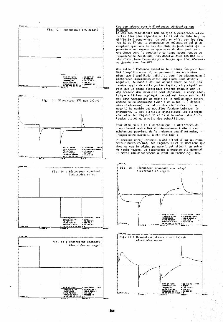
I I O E N l l f l C A I l W BVIS82IU2 I E R E R A I W € . LIP. 8 DECRC C HAUIE TEhSlOH - 300 YDLI
zasss 4.
Fig. 13 : REsonateur BVA non balay6 I
C e s des rBson_ateurs B Blectrodes adhgrentes non balayks Le cas des rBsonaleurs nor! balayks B Blect.rodes adhB- rentes ( l es p lus repandus en f a i t ) est de l a i n l e p l u s d i f f i c i l e B compreridre. (In voit. en e f r e t sur tes f l gu - res 16 e t 17 que l e processus de re laxa t i on eat p lus cornplexe q.1~1 dans l e r ss dcu BVA, on pcut rloter quL' l e procussua se rompo!;~? en appcrrerlce de deux p a r t i e s : uhc phase dorit l a rorlst arlte de temps ssser rspide se rapprorhe do c e l l e qcle l ' o n observe avec l e s EVA s u l - v i e d'une phase beauco~lp p lus longcle que I ' o n n fobser - ve jamais ever I r a BVA.
Une autre d ~ f f L ' r e n r e essent i e l l e : a lo rs que pour l e s I j V A I ' amp1 I tudr? t v rQylrne permanent res te du rdrr~e slgnt? que I ' a rnp l~ lude ~ n i t ~ a l e , pour les rdsonateurs B B l u r t codes adhr5renl t?s r e t t e amp1 i tude cut deveni r nBgat~ive, l e rnoddle u t I l l s 6 act.uel lement ne peut pas reridre rompte de r e t t e part 1rular1t6, e l l e s l g n i f l e - r a ~ t que I t ? champ B lec t r i que in terne produ i t par l e dt5plarement dea lmpuret 6s peut d6pssoer l e rliamp B ler - t r l q u e extBr ieur appliqud, r e qu i est ~ n a d m ~ s s l b l e . I 1 est donr nBcessaire de modt f le r l e mod6le pour rendre rompte de r e phBnomdne ( v o w 8 r e s u j e t le 5 dis rus- s l on ci-dessous). La nature des Blectrodes (or ou argent) ne semble pas modi f ie r fondamentalement l e phBnorn6ne. I 1 est d l f f i r ~ l e d ' a t t r i b u e r l es d ~ f f B r e n - res ent re l es f i yu res 16 e t 17 B l a nature des Blec- t rodes p l u t 8 t qu'd r e l l e des Bchant i l lons.
Pour e t r e tout. B f a i t c e r t a l n que l a d t f fd renr t? de colnportement ent re BVA e t rdsonateurs B dleclrodeu adhBrentes prov ient de l a presence dea Olectrodes, I 'expBrience suivante a dt.8 r k a l i s d e :
Uri premler enreyistrerner~t a 6 td e f f ec tud sur un rBso- nat,eur rnontd en RVA, les f igures 10 e t 11 montrent quc dar~v ce ras l e rdgilne permarlent est. a t t e i n t en rnoins de t r o i s tieures. Le rdsonateur a ensui te BtB ddmontB e t d t a l l i s B directement suivant l a technologie QAS.
2BWW - H z - - ---+--- - -- Fig. 14 : RCsonateur standard
Electrodes en or
j F i g . 15 : REsonateur standard
1 6 lectrodes en argent
I tWCRATll lC
F R C M K T JFPhRT - $&3 HZ I - 2 O W +* , n 0 O E IPS,LX WRLE
\~fn. . I l 2 7 l b 4
I Fig. 16 : REsonateur standard non ba ayE 1 I E lectrodes en argent !
I d m I T *WE - 21-IUIN-O8 W l l IDENTIPICAI1CU . ACN9350SCIWP3 IEWERATWIE !@I. 2 OECRE C , HAUTE fCY61ml . M V X I
-,:raw .n. , PRLMYCE DEPART - 9922220 HI ~~~; ,y~~=,rn M~LL:
2 - % R K 2 % - - --
I -
Fig. 17 : RBsonateur standard non balay6 Blectrbdes en or
-1 I i
OATS I T aUc 2 0 - w I - e l OW¶
'I*U?K fZNS1ON . $ 9 1 (OLl I R I W K E 0SPAI.I 7l .PaD HZ - I
b l d l ~ h
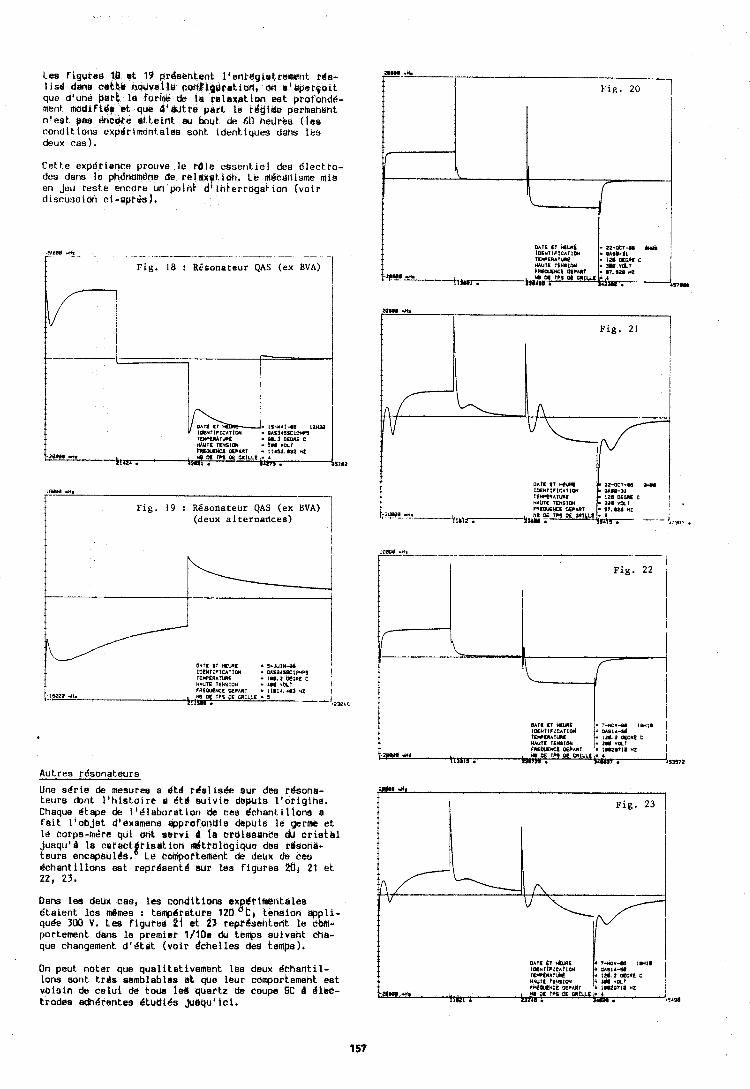
Lea f igures 18 e t 19 prdsehtent l 'enrdgietretwtlt rde- l isd den@ cekbb hoidvel t~ f i b r i k f $ ~ r s t i & ~ , oh u l tdpe l~o i t que dlune pork la t'crrmt de la relsxeti t ih erst profond6- ment. madifi6c et que d ' w t r e pe r t i e i-%dirtre permanent n ' e s t gas e n c e e lr t teint ei, bout de 6u heurba ( I e s conditions expdrlment.ald8 sont identiqubs dens lea deux r a s ) .
Cet,te exp6tienre prouve Ie rb le essent i e l dee i?lectro- des dam l e phdtiom6ne de r e l a#s t ion . Le mlcal~isme mis en jeu rb5t.e enrare im point. dl l h t e r r o g d ion (vbir dlsrussiort el-aprds),
zeauu .I. - -- - . - - - -- - - -- -- - - Fig, 18 : RGsonateur QAS (ex EVA)
. , , i . IS-#At-#I l2H3D I ~ ~ H T I P I E A T I O N . D A ~ ~ ~ I I C I O I U Y l E V U A t U C . W. 9 DCCRC c HAUIS r~rnlix - YI v h r
-2BRPs .If. I R W S U OTPhRT I I4YI. 632 MZ H M r Oe GRILLE - r
0 1 2
1em r*.
Fig. 19 : Rgsonateur QAS (ex BVA) (deux alternarices) 1
o*rc rr MYIE - I-JUIN-H I I L I E N ~ I P ~ C A ~ I W . OLSIIISCIPUPI 1 rc*PtRArunt . LO#. 2 oeGuc c ururs r f n s ~ o u re# vhr I P R E W N C S OCPARt . 11#14.1#3 *Z 1 , .,la q rrs OE ~ I L L L - Y - -- 111SU .
I F i g . 20
2D##. Ih
1 Fig, 21
Autres r6sonateurs
Une ad r i e de mesuree a dtd rda l i sde aur dea rdsons- awr .n. teurs dont I th is t ,o l re o dtd su iv i e depuis l ' o l i g lne . Fig. 23 Chaque dtspe de L1dlaboration dz ces l chsn t i l l ons s f a i t I 'obje t d'cxamens tipprofandis dspuis l e germe e t l e corps-mdre qui ant aervf P in erateaance dir c r i s k e l j u squ ' l l a c a r e c t ~ t i e u t i o n bdtrologique dbe rdsone- 1 teura encapsull?l). Le comortement de deirx de ces 1 I d c h ~ n t i l l o n s e s t r ep r6sekd wr l e s f igures $fl, 21 e t 22, 23,
Dam lea deux cas, Ics conditions ex drimalntales A' dta lent l e s dines : tempdrsture 120 C b tension appl i - quBe 300 V. Les figured 21 rt 23 repr&sentent l e btrm- por temnt dens la premier l/lOe du temps suivant cha- que changement d 1 8 t a t (vo i t dchel les dee temps).
I On peut noter que quali tat ivement l e s deux Bchentil- lons sont t rda seniblables ek que leur comportement ea t voisin de ce lu l & t o m l b d quartz de coupe SC d 8 1 ~ - t rodes edhdrentes dtudi6s Juaqu l i c i , ~ 3 ~ . m . 'I1R .
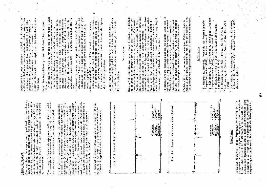
w 3 " , O . - ~ m -- w m 3 E - F m--. m C L 3 m c 0 - m o o
L + m -? o f4
3 m - o m .+ no a, 0 L Y k m w ** a> u %2 2
w w 3 m m - 3 0 3 -0
CL L Y
: .!? G o o c aL .u m 0 -- 0 a "Z r " L' - .- rn 4
m L O L. 0 - u 3 E m m 2
.5 L - 0 c w E -4
u i m w T m 3 -
3 UE m d o n a m . r F : . m % z 3 - 3 O Y O a l U > L
2.53 : 2z :%2 u c u - 0 N ~ C 3 3 m ~ . ~ m a,
n 3 E Y C c ul 3 w
3 m r m E m r u m m o w m s ~ c r n 4 4 C - - w m c T J l a l 3 s 912+2O- .-. c o m m a g m u c m
0 4 m m m u m m w c rn 3 4 0 0 L I 3 0.0 .-.3 0 - m w u 0.u m u l l m n 3 4 4 E m V O X 4 X ?
- m u 3 m a , r r , m a l L X a c 5.u O O E . ~ ~ u o c-8 C " L i m . u O 4 m u
o m u m m m - I a m 3 a l - r 0 - m - m 0 c ~ a l m m c m o - m L m E T n f > L
m o .+ - l --. -4 3 w - E L 4 m u
3 . o m
I al - a l w r4 > w r aLi m x m m u r n YU 0 Y € L o c m 3 4 al Y o W Y C - D O c r
c w L id (c.
m l c l c n m .-
-a a l m m m m m u w m u n w 0 m
m m - a ) - Y r n 'OD m O E m E O C C 0 m n 0 0 m
C 0,
$ E L m m
c Y O f r -'3u u - w m w E L m O m L o- m m m a - L)
w c m - m m -I€-
8 r m al w
m a 4 n o m O L C C 1 3 0 3 W C W
E I.
3 . 2 . " = ;z , " zg L a l 0
3 1 , 3 w I40 a l u u a l m r a l 4 - 6 ~ m
3 r 3alua l a U U G >
m --. m m m m c m c ~ c z
. u r n u r n U U U V - " .. '...a ..- A- .u r 41. w m sr, urn- W- n o m )r--m v m c - + - 0. 0- - m- L. m o G m 8 "
22 U T C r c - = I - 0 z m * m Lb
3 0 3 rc -r m v - m m m r w m n
Y r - r L v m E L - ~ L C;D I C 1 m 1 G m -.m I f " " " " l * I - 5
UI- w c nu
let Forum E u r a p Q e ~ P ~ i i ~ p b ~ P e d q u b H ~ t ~ - 1PLl9
SlMULATlON NUMERIQUE DES PROFILS OE S U # A ~ ~ of! 4UAkti tlltkNU9 PAR U$1NAtE cHIMQUE
Laboratoire de Chronomitrie, E1eetronigd~ B t Piizo81ectricit6 Route d e Gray - L a Bouloie - L5030 Besahc6n Cedex - F R A W
RESUME - Nous proposons un modale mathimatique simple
de l'usinage chimique, inspire du modale de Frank, dans lequel on admet que la vitesse de dissolution ne dipend que de l'orientation, a , de l'iliment d'un profil de surface. Des iquations ginirales caractirisent la direction dans laquelle un iliment de profil de pente, p(a), se propage i l'intirieur du cristal au cours de l'attaque chimique. Ce modile appliqui i un profil initial de forme triangu- laire ou aliatoire autorise, i chaque instant t, d'usinage, une simulation graphique du profil usind. Les risultats concernant certaines lois symitrisies de vitesse de dissolution sont en accord avec les pridictions qualitatives d'lrving mais seules des lois 2 caractire non symitrique permettent d'obtenir des profils usin6s 2 forme alternie. Nous comparons les risultats obtenus par simulation numirique 2 ceux obtenus expdrimentale- ment par usinage chimique de coupes i simple rotation avec 8 = - 26O5, - 31°5, 37O5 et - 41°5. Les coupes avec 6 = - 26O5 et 37O5 prisentent des profils paraboliques parfaitement simulis par des lois symitrisies de vitesse de dissolution. Mais les lois de dissolution non symitriques font apparaitre des profils de forme mi-concave, ml-convexe, compara- b l e ~ aux profils 2' usinis des coupes avec 8 = - 31°5 et - 41°5. Ainsi, il apparait que le modale de simulation numirique proposi rend parfaitement compte des profils obtenus par usinage chimique du quartz.
ABSTRACT -- A two - dimensional mathematical model of the
dissolution directly derived from the Frank model is carried out under the assumption that the dissolu- tion velocity depends only on the local orientation, a , of the surface profile element. General analytical equations which characterize in terms of orientation the direction in which an element of the surface profile with slope p(a ) progresses into the bulk crystal are proposed. This model is applied to surface profiles with initial randomized or triangular shape in order to achieve at any etching time, t, a graphical simulation of the moving surface profile. Some typical results related to symmetrical etching laws are found to be in agreement with previous qualitative predictions made by Irving. However etching profiles uith a mixed shape are obtained by using only more complicated etching laws. Experimental results oh singly rotated quartz plates with 6 = 37O5, - 26O5, - 31°5 and - 41°5 are compared with the predictions of this graphical model. The concave and convex profilometry 2 ' traces of plates with respectively 8 = 37O5 and 6 s - 26O5 show a close adequacy with the theoretical etched surface profiles resulting from simple etching laws containing only even terms. The theoreti- cal etched profiles derived from dissymmetrical etch rate orientation relationships which give rise t o alternatively convex and concave shaped profiles agree well with the Z' surface profiles
produced on plates with 8 = - 31°5 and 8 = - 41°5 by repeated etchings. Hence this graphical simulation provides very satisfactory explanation and prediction for the dissolution of quartz in fluoride solutions.
Lorsque des risonateurs haute friquence sont obtenus par des procidis mhcaniques, rodage et polissage, des contraintes se diveloppent au cours du polissage qui crient une couche superficielle 0 5 le riseau cristallin est fortement perturbitl-4). Cette couche superficielle nuit aux performances du risonateur et son effet peut devenir pripondirant pour des plaques tris minces. Or, l'amincissement d'un cristal de quartz est igalement possible par usinage chimique. Cette mithode, non traumatisante pour le cristal, voit igalement son champ d'applica- tions slitendre i la rialisation de dispositifs microminiatures, risonateurs ou capteurs(5-7).
Oes travaux antdrieurs i 1981, sur des coupes AT(4-8) et SC(8) ont montri qu'il 6tait possible apras des attaques chimiques successives du quartz dans des solutions de bifluorured'ammonium, d'obtenir des cristaux presentant un itat de surface satisfai- sant. Mais l'obtention de surfaces polies pour des profondeurs d'attaque approchant 1 0 um nicessite l'emploi de sUrfactants(9). De plus, des 6tudes systhmatiques ricentes concernant l'usinage chimique, dans une solution concentric de bifluorure d'ammonium, de coupes cristallographiques simples X, Y ou 2(10,11), de coupes ?I simple rotation(l1-14) ou ii double rotation(ll,l5,16) ont permis de mettre en ividence une dipendence tres marquie de l'itat final de surface avec l'angle de coupe. Au deli d'une profondeur critique dNattaque(ll-16) associie 2 lt6paisseur de la couche superficielle disordonnie qui se d6veloppe a u cours du rodage micanique, la topographie de surface est caractiristique de 1 'orientation du cristal. Pour certaines coupes(l1- 13,15-171 l'orientation et l'aspect gdomitrique des figures stables de dissolution ne dipend plus de llBtat de surface initial(l7). Seule la densiti des figures de dissolution reste partiellement affectie par les conditions de l'usinage micanique initial.
Pour la production de composants miniatures, il s'avare indispensable de disposer d'un modale permettaht de prkvoir lleffet d'anisotrobie d'usinage et de simuler l'ivol~tion dea profils de surface au cours de l'usinage. Ainsi a it6 entreprise cette 6tude relative 2 la modilisation de l'attaque chimiqub. Un modale mathimatique simple de la dissolution, inspiri du modele de Frank(l8) a it6 divelopp6 afin de rialiser une 6tude profilomitri- que des surfaces que prisentent, au cours de l'usinage chimique, des coupes ?I simple rotation.
LE MOOELE MATHEWTIQUE
Les Bquations g6n6rales
*~ctuellement avec C.E.P.E. - Argenteuil - France
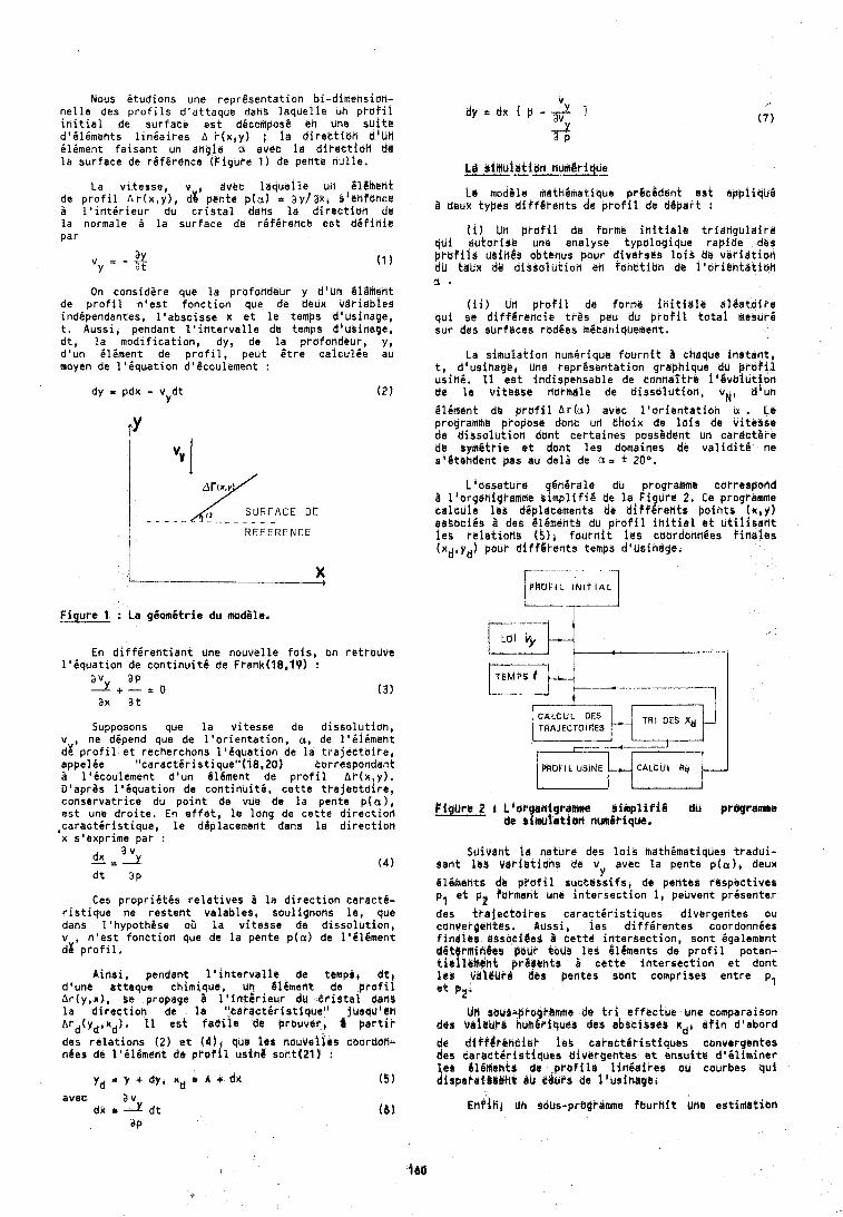
Mous itudions une repr8sentation bi-dimensioh- nelle des profils d'attaque dahs laqhelle Uh prdfil initial de surface est dicomposb en une shitC d'iliments liniaires A r(x,y) ; la direhtian d f u n ilBment faisant un angle a avet la directien de la surface de rgfirence (Figure 1) de pente nulle.
La vitesse, v , avec ldquelle un LtlbttIb~t de profil Ar(x,y), d% pehte p(a) = aylak, sianfohce i l'intirieur du cristal ddns la directioh de la normale i la surface de ref8rence est difidie par
On considere que la profondeur y d 8 U h 816Metit de profil n'est fonction que de deux vdriabies independantes, l'abscisse x et le temps d'usinage, t. Aussi, pendant l'intervalle de temps diubinerge, dt, la modification, dy, de la profondaur, y, d'un iliment de profil, peut Btre caiculie au moyen de 18Bquation d'8coulement :
dy = pdx - v dt Y
( 2 )
I R E F E R E N C E
Figure 1 : La giomitrie d u mod8le.
En differentiant une nouvelle fois, on retrouve l'iquation de continuiti de Frahk(l8,iP) !
a v a p A + - i o ( 3 ) ax at
Supposons que la vitesse de dissolutiant v , ne depend que de l'orientation, a, de l'iliment dg profil et recherchons 1'Bquation de la trajectoire, appelge "caractiristique"(l8,20) correspondant
l'icoulement d'un Blbment de profil &r(x,y). D'apras l'iquation de continuiti, cette trajectoire, conservatrice du point de vue de 15 pente p(u), est une droite. En effet, le long de cette direction ,caractgristique, le deplacement dahs la direction x s'exprime par :
a v x = r ( 4 ) dt ap
Ces propriitis relatives 2 la direction caract6- r istique ne restent. valables, soulignons le, que dans l'hypothhse ou la vitesse de dissolution, v n'est fonttioh que de la pente p(a) de 1'516ment dz'profil,
Ainsi, pendant l'intarvalle de temp&# df, d'une attaque chimique, un 8limeht de prof11 hr(y,x!, se propage i l'intirieur du dridtal dad$ la dlrectioh de la "taractiristiqueti jusqu8 tn hrd(ydixd), I1 est f a d i h de b r w v e r , b partir
des relations ( 2 ) et Iiljl qU@ I ~ s nouveiies c60rdM- nbes de lfi16ment da pt'afil using sont(21) f
yd x Y + dy, n d h x + d~ avec a v
dk r -2 dt ap
La modB1e mathdmat ique prdcgdant eat appl iqbd B deuk typds differents de pl-ofil de dgpart r
(i) Uh p ~ o f i l de furme initiale tridnguleira qdi dutarise une analyse typalogique r a p i ~ e das prbfils bsinds ubtenus pour diversas lais da vari&tioh d~ tdUx dB d.issol~tiarl en funbtitrn dl l'ol-ibntdtiah a 4
(ii) Wfl prafil de farme initial8 algatoire qui se diff6rencie tr8s peu du profil total mesuri sur des surfaces rbd6as m8eaniqbement.
La simuldtion numirique fournit i cheque instant, t, dsusinage, Uhe reprbsentation graphique du p r b f i l usini, 11 est ihdispehsable de cohnlitr~l i86voiuti6n de la vitbese darmale de dissulutiari, v ~ , d i u n
6lE.ment d6 prufil Atla) avec l'orientatioh u . Le programme proposo donc uri choix de lois de vitesse de di6soIution dant certaines poss8dedt un cardctbre de s g m 6 t ~ i e st dunt fes dumafnes de validit6 ne s1&t4ndent pas au deli de a = + Zoo.
Liossature 6nirale du programRe carreapand 8 ll~rgdhlgl-amrtie d m p l i f i e de la H ure 2. Ce pragH1mme c a l d l e 16s d6placetnents do lifffqrehts points (x,yl associis a des tit6mdhts du prafil initial et utili~aflt ies relations ( 5 ) , faurnit las cabrdonn&es finales (xd,yd) bout diff6rents temps d'usindge.
-- - .- - P ~ U F I L Ihlt I A L r I
CALCUL DAS TRAJECTOIRES
Suivdtit la nature des lois hathimdtiques tradui- bant leg variltiuhs de v,, avec la pente p(u), deux
8lBmahts db prafil sdatdsifs, de pentes rtispectives p, & pPB farmstit une intersection 1, peuvent prisenter - des trajectoires caracteristiques divergentes o u con3erpetite~. Aussi, les dif f irentes coordonnies finales rssoci@ss 8 tette intersection, sont igalement dPk rmirtdvrs pbbt kaUS leg ljldments de profil poten- t i e f l l l h t pr8l@nts h oette intersection et dont l r $ V&lbbr$ dcs pentes sont comprises entre p, et PZ'
bn sou$-prayramme de tri sf feciue bne comparaison dds vli@Likb h ~ h 6 ~ i q u e k deb abscisses rids afin d'abord
de dfff$rehci@~ lee oaractiristiques canvergentes dss caract6rirtiqu~s divergentes at ensuite d'iliminer leb Blimetitr de hprof$ls liniaires a u courbes quf dispakaiOYYha e b rrurs de l'usinapdl
EnPift~ tin $bbs-prbgl'amme fuurhit Wh@ estimation
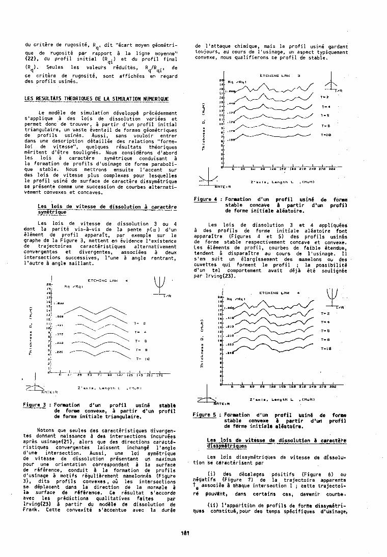
du critire de rugositi, R dit "icart moyen giomitri- 4'
que de rugositi par rapport i la ligne moyenne" (221, du profil initial (Rqi) et du profil final
(Rq). Seules les valeurs riduites, Rq/Rqi, de
ce critgre de rugositi, sont affichies en regard des profils usinis.
LES RESULTATS THEORIPUES DE LA SIMULATION NUMEjI?
Le modile de simulation diveloppi pricidemment s'applique i des lois de dissolution variies et permet donc de trouver, i partir d'un profil initial triangulaire, un vaste 6ventail de formes giomitriques de profils usinis. Aussi, sans vouloir entrer dans une description ditaillde des relations "forme- loi de vitesse", quelques risultats thioriques miritent dt8tre soulignis. Nous considirons d'abord les lois B caractire symitrique conduisant a la formation de profils d'usinage se forme paraboli- que stable. Nous metrrons ensuite l'accent sur des lois de vitesse plus complexes pour lesquelles le profil usini de surface de caractire dissymdtrique se prisente comme une succession de courbes alternati- vement convexes et concaves.
Les lois de vitesse de dissolution i caractare symitrique
Les lois de vitesse de dissolution 3 ou 4 dont la pariti vis-a-vis de la pente p(a ) d'un iliment de profil apparait, par exemple sur le graphe de la Figure 3, mettent en evidence l'existence de trajectoires caractiristiques alternativement convergentes et divergentes, associies a deux intersections successives, l'une 3 angle rentrant, l'autre L angle saillant.
Figure 3 : Formation d'un profil ubin6 stablt de forme convexe, 5 partir d'un profil de forme initiale triangulairt.
"- 19-
18-
17 . 15-
Notons que seules des caractiristiqueb divergen- tes donnent naissance 5 des intersections incurvees apris usinage(21), alors que des directibne caracti- ristiques convergentes laissent inchange l'angle d'une intersection. Aussi, une loi symitrique de vitesse de dissolution prdsentant un maximum pour une orientation ccrrespohdant B la surface de rbfirence, conduit 1 la formation de ptofils d'usinage B motifs rigulilrement mamelonnh~ (Figure 31, dits profils convexes, ou les intersections se ddplacent dans la direction de la normale B la surface de r4ferencc. Ce rlsultat s'accorde avec les pr6diction5 qualitatives feites par Irving(23) a partir du inod6le de dissolution de Frank. Cette convexitd s'accentue avec la dur6e
E T C H I N G L R W 4
Rq ~ R q l
1 . eae
de l'attaque chimique, mais le profil usini gardant toujours, au cours de l'usinage, un aspect typiquement convexe, nous qualifierons ce profil de stable.
I ETCHING L R W 3 I
Z'axlr. L e n g t h L , ( M U M )
Figure 4 : Formation d'un profil usinl de forme stable concave i partir d'un profil de forme initiale al6atoire.
Les lois de dissolution 3 et 4 appliquhes des profils de forme initiale al6atoire font
apparaitre (Figures 4 et 5 ) des profils usinis de forme stable respectivement concave et convexe. Les iliments de profil, courbes de faible itendue, tendent 2 disparaitre au cours de l'usinage. 11 s'en suit un ilargissement des mamelons ou des cuvettes qui forment le profil ; la possibilitg d'un tel comportemrnt avait d6 ja it6 soul ign6e par lrving(23).
I E T C H I N O LRW 4 \ ' I /
Figure 5 : Formation d'lm profil using de farme stabla cbnvaxe B partir d'un profil da fsrmt initiate el&etoirel
Leo ldis de vitcssa de dissolutio,n a caract@Pb aissfi6triques
Les lois dissym6triqUes de vitesse de dissolu- tion se cdraot6risent par
(il des dicalages Cositifs (Figure 6) ou n6gatifs (Figure 7 ) de la trajectoire apparente 7, associee i chaque intersection 1 1 cette trajectoi-
rl pOUdd!it, dahl certaifis cas, de~enir caurbel
(ii) liapp8rition de profilr de forme disrymltri- ques constituC, pour des tamps Sp6cif i g ~ e ~ dlusihage,
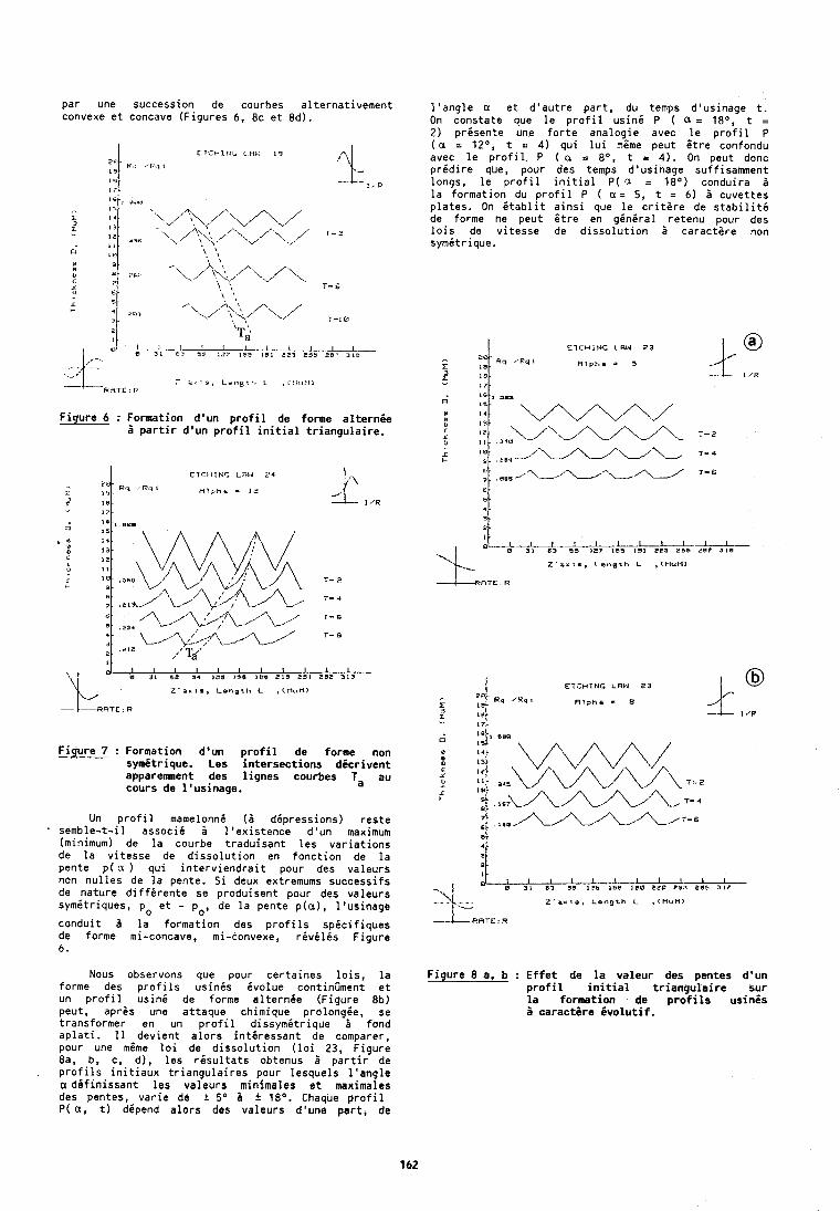
par une succession de courbes al ternat ivement convexe e t concave (Figures 6, 8c e t Ed).
ti \ , Ti
,.--. - + - i ' i - - F ~ ~ 2 * * -
: a t s , L e n y r l t L , C l l ~ r P I l R R T E ' P
F igure 6 : Formation d'un p r o f i l de forme a l t e r n i e p a r t i r d 'un p r o f i l i n i t i a l t r i angu la i re .
ETCHING L R I J 2 4
Pq ~ R q l R l y h a 3 12
Figure 7 : Formation d'un p r o f i l de forme non symitrique. Les i n te rsec t i ons d i c r i v e n t apparemment des l i gnes courbes Ta au cours de I 'usinage.
Un p r o f i l mamelonni ( 2 dipressions) res te semble-t- i l assoc i i i l ' e x i s tence d'un maximum (minimum) de l a courbe t radu isant l e s va r i a t i ons de l a v i tesse de d i sso lu t i on en fonct ion de l a pente p ( a ) qu i i n t e r v i e n d r a i t pour des valeurs non nu l l es de l a pente. S i deux extremums successi fs de nature d i f f i r e n t e se produisent pour des valeurs sym6triques, po e t - po, de l a pente p ( a ) , l 'us inage
condui t 2 l a format ion des p r o f i l s sp i c i f i ques de forme mi-concave, mi-convexe, r i v d l i s Figure 6.
l ' a n g l e a e t d ' au t re pa r t , du temps d'usinage t . On constate que l e p r o f i l usin6 P ( a = lEO, t = 2) pr isente une f o r t e analogie avec l e p r o f i l P ( a = 12O, t = 4) qu i l u i mOme peut Otre confondu avec l e p r o f i l P ( a = 8O, t = 4 ) . On peut donc p r i d i r e que, pour des temps d'usinage suffisamment longs, l e p r o f i l i n i t i a l P( a = l a 0 ) conduira i l a formation du p r o f i l P ( a = 5, t = 6) 2 cuvettes p la tes . On i t a b l i t a i n s i que l e c r i t e r e de s t a b i l i t i de forme ne peut i t r e en g6n i ra l retenu pour des l o i s de v i tesse de d i s s o l u t i o n 2 caractere non symitr ique.
ETCHING L R W Z3
R l p h a - W
I l l I 1 I I I I l t 0 31 63 J¶ 1Zb 15s 1.A EZC C¶l En5 > I ?
Z ' a r j s , L e n g t h L , [ M U M )
NOUS observons que pour cer ta ines l o i s , l a F igure 8 a, b : E f f e t de l a va leur des pentes d'un forme des p r o f i l s u s i n i s i v o l u e contintment e t p r o f i l i n i t i a l t r i a r t gu la i re sur un p r o f i l u s i n i de forme a l te rnde (Figure 8b) l a format ion de p r o f i l s usines peut, apres une attaque chimique prolongie, se 5 carac tare i v o l u t i f . transformer en un p r o f i l d issymi t r ique i fond a p l a t i . 11 -devient a l o r s in t6ressant de comparer, pour une meme l o i de d i sso lu t i on ( l o i 23, Figure 8a, b, c, d) , l e s r i s u l t a t s obtenus B p a r t i r de p r o f i l s i n i t i a u x t r i angu la i res pour lesquels l ' a n g l e a ddf in issant l e s valeurs minimales e t maximales des pentes, var ie de + 5O a * 18O. Chaque p r o f i l P ( a , t ) dipend a l o r s des valeurs d'une pa r t , de
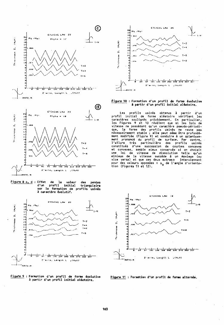
E T C H I N G LRW 2 3
R l p h e - I b
1
A A A g11 I L 1;s 1;s E L d b A¶ 3;b
Z ' a u t t , L a n g t h L ,Cl-iuU>
ATE R
Figure 8 c, d : Ef fe t de l a valeur des pentes d'un p r o f i l i n i t i a l t r i d n g u l a i r e sur l a format ion de p r o f i l s usinds B caractare d v o l u t i f .
E T C H I N G L R W 2 3
1 /R
T- 2
,Z-.-.+~-.~'U 7.4
L I I I I I I I I L I 0 3 3 6- I W I 136 1s. roe 830 ri.0 313s
.- : ' a i l s . L a n a r k L , ( M U M )
f i g u r e 9 : Formation d'url p r o f i l de farme i v o l u t i v e B p a r t i r d 'un p r o f i l i n i t i a l a lga to i re .
F igure 10 : Formation d'un p r o f i l de forme dvo lu t i ve B p a r t i r d 'un p r o f i l i n i t i a l a lga to i re .
Les p r o f i l s u s i n i s obtenus 5 p a r t i r d'un p r o f i l i n i t i a l de forme a l i a t o i r e v 6 r i f i e n t l e s ca rac t i r es sou l i gn i s prbcidemment. En p a r t i c u l i e r , l e s Figures 9 e t 10 r i v i l e n t que s i l e s l o i s de v i tesse ne possident qu'un c a r a c t i r e pseudo-pir iodi- que, l a forme des p r o f i l s usinEs ne res te pas nicessairement s tab le ; e l l e peut mame f t r e profond6- ment niodi f ike (Figure 9) e t conduire a un aplanisse- ment prononci du p r o f i l de surface. Par contre, l ' a l l u r e t r i s p a r t i c u l i i r e des p r o f i l s u s i n i s const i tuds d'une successiofl de courbes concaves e t convenes, semble mieux conservie s i on c h o i s i t une l o i de v i tesse de d i s s o l u t i o n t e l l e quoun minimum de l a v i tesse succGde h un maximum (ou v i ce versa) e t que ces deux extrema in terv iennent pour des valeurs opposies + a, de l ' a n g l e d 'o r ien ta- t i o n (Figures 11 e t 12).
E T C H I N G LRW 18
1 J ; A A I;) 1;s ,;a &A* r i e 2;- k-
Z ' a . c l i , Lonuth L , ( M U M ) RRTE! R
F igu re 11 : Fbrnriltibn d'bn p r o f i l de forme el terngo.
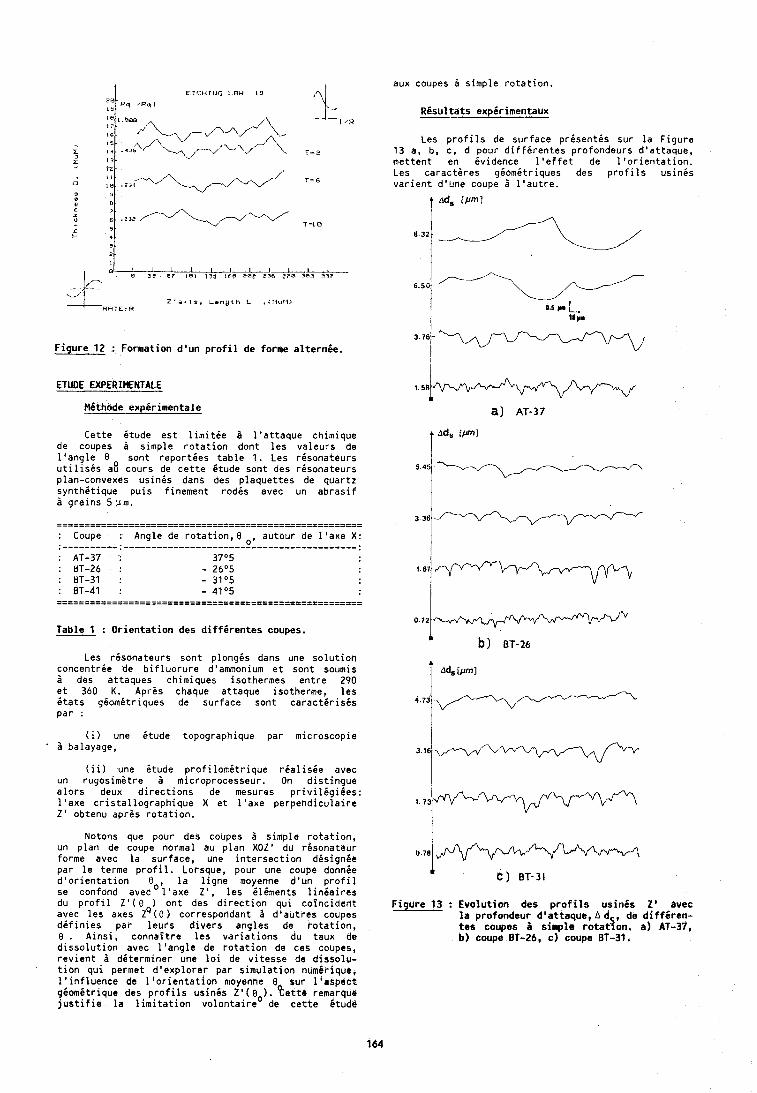
aux coupes 5 s imp le r o t a t i o n .
RCsu l ta ts exp i r imentaux
Les p r o f i l s de su r face p r e s e n t i s su r l a F i g u r e 13 a, b, c, d pour d i f f i r e n t e s p ro fondeurs d ' a t t a q u e , met ten t en i v i d e n c e l ' e f f e t de l ' o r i e n t a t i o n . Les c a r a c t c r e s gbomi t r iques des p r o f i l s u s i n i s v a r i e n t d 'une coupe 5 l ' a u t r e .
1 bcf, [PI
F i g u r e 12 : Format ion d 'un p r o f i l de forme a l t e r n i e .
1 I I I I I I I - A 3 3 8 7 1 8 1 135 Irn raz a x 2 7 8 1r?3 337
0 5 0
Z ' a ~ l r , L e n g t h L , l t l n E l ) R H T E ' R
ETUDE EXPERlHENTALE
Mi thode e x p i r i m e n t a l e
0.5 #. L 18 y.
C e t t e i t u d e e s t l i m i t i e 5 l ' a t t a q u e chimique de coupes B s imp le r o t a t i o n dont l e s v a l e u r s de l ' a n g l e 8 son t r e p o r t i e s t a b l e 1. Les r6sona teurs u t i l i s i s a8 cours de c e t t e i t u d e son t des rbsona teurs plan-convexes u s i n i s dans des p l a q u e t t e s de quar tz s y n t h i t i q u e p u i s f inement r o d i s avec un a b r a s i f a g r a i n s 511111.
--=---------------------------------------------------- -- -------------------------------..-------------------- : Coupe : Angle de r o t a t i o n , O _ , au tour de l ' a x e X :
Tab le 1 : O r i e n t a t i o n des d i f f i r e n t e s coupes. - Les r i s o n a t e u r s son t p l o n g i s dans une s o l u t i o n
concentric de b i f l u o r u r e d'ammonium e t sont soumis 5 des a t taques chimiques isothermes e n t r e 2 9 0 e t 360 K . Apres chaque a t taque isotherme, l e s i t a t s g i o m i t r i q u e s de sur face sent c a r a c t i r i s i s par :
( i ) une i t u d e topographique par microscopic 5 balayage,
( i i ) une i t u d e p r o f i l o m 6 t r i q u e r i a l i s i e avec un rugos im6t re a microprocesseur. On d i s t i n g u e a l o r s deux d i r e c t i o n s de mesures p r i v i l i g i 6 e s : l ' a x e c r i s t a l l o g r a p h i q u e X e t l ' a x e p e r p e n d i c u l a i r e 2 ' obtenu aprBs r o t a t i o n .
Notons que pour des coupes 5 s imp le r o t a t i o n , un p l a n de coupe normal au p l a n X O Z ' du r i s o n a t e u r forme avec l a su r face , une i n t e r s e c t i o n ddsign6e p a r l e terme p r o f i l . Lorsque, pour une coupe donnie d ' o r i e n t a t i o n 8 , l a l i g n e moyenne d ' u n p r o f i l se confond avecO l ' a x e Z', l e s i l d m e n t s l i n d a i r c s du p r o f i l Z ' ( 8 o n t des d i r e c t i o n q u i c o i n c i d e t i t avec l e s axes ~ ' ( 8 ) correspondant 5 d ' a u t r e s coupes d d f i n i e s par l e u r s d i v e r s angles de r b t a t i o n , 8 . A i n s i , c o n n a i t r e l e s v a r i a t i o n s du taux de d i s s o l u t i o n avec l ' a n g l e de r o t a t i o n de ces coupes, r e v i e n t 5 ddterminer une l o i de v i t e s s e de d i s s o l u - t i o n q u i permet d l e x p l o r e r par s i m u l a t i o n numir ique, l ' i n f l u e n c e de l ' o r i e n t a t i o n moyenne 0 su r l ' d s p b c t g i o m i t r i q u e des p r o f i l s u s i n i s Z' ( 8 1. P e t t r remarque j u s t i f i e l a l i m i t a t i o n v o i o n t a i r e O de c e t t e 6tude
F i g u r e 13 : E v o l u t i o n des p r o f i l s us inCs 2 ' avec l a p ro fondeur d 'at taque, A d , de d i f f g r e n - t e s coupes i s imp le r o t a d o n . a ) AT-37, b) coupe BT-26, c ) coupe BT-39.
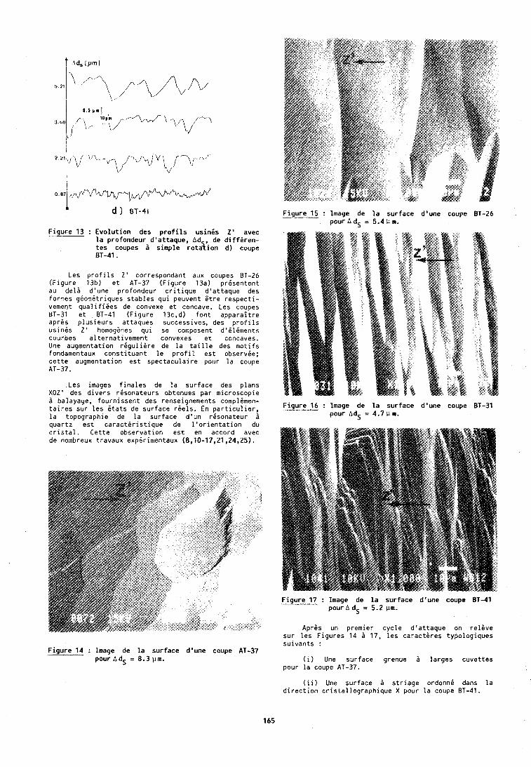
F i g u r e 13 : E v o l u t i o n des p r o f i l s u s i n i s 2 ' avec l a p ro fondeur d 'a t taque , Ad de d i f f i r e n - t e s coupes 5 s imp le r o t d y i o n d) coupe 81-41.
Les p r o f i l s Z ' correspondant aux coupes BT-26 ( F i g u r e 13b) e t AT-37 (F igure 13a) p r i s e n t e n t au d e l d d 'une p ro fondeur c r i t i q u e d ' a t t a q u e des formes g i o m i t r i q u e s s t a b l e s q u i peuvent i t r e r e s p e c t i - vement q u a l i f i i e s de convexe e t concave. Les coupes BT-31 e t BT-41 ( F i g u r e 13c,d) f o n t a p p a r a i t r e aprgs p l u s i e u r s a t taques successives, des p r o f i l s u s i n i s Z' homoggnes q u i se composent d ' i l i m e n t s courbes a l t e r n a t i v e m e n t convexes e t concaves. Une augmentation r i g u l i i r e de l a t a i l l e des m o t i f s fondamentaux c o n s t i t u a n t l e p r o f i l e s t observ ie ; c e t t e augmentation e s t s p e c t a c u l a i r e pour l a coupe AT-37.
Les images f i n a l e s de l a su r face des p lans XOZ' des d i v e r s r i s o n a t e u r s obtenues par microscopic ?I balayage, f o u r n i s s e n t des renseignements complimen- t a i r e s su r l e s i t a t s de s u r f a c e r i e l s . En p a r t i c u l i e r , l a topographie de l a su r face d ' u n r i s o n a t e u r d q u a r t z e s t c a r a c t i r i s t i q u e de l ' o r i e n t a t i o n du c r i s t a l . C e t t e o b s e r v a t i o n e s t en accord avec de nombreux t ravaux expi r imentaux (8.10-17,21,24,25).
F i g u r e 14 : lmage de l a s u r f a c e d 'une coupe AT-37 pour AdS = 8.3 pin.
F i g u r e 15 : Image de l a s u r f a c e d'une coupe 81-26 --- pourAd, = 5.4Um.
F i g u r e 16 : lmage de l a s u r f a c e d 'une coupe pour AdS = 4.7pm.
F i g u r e 17 : Image de l a s u r f a c e d 'une coupe BT-41 pour A = 5.2 um.
Aprgs un premier c y c l e d ' a t t a q u e on r e l i v e su r l e s F i g u r e s 14 d 17, l e s c a r a c t g r e s t ypo log iques s u i v a n t s :
( i ) Une s u r f a c e grenue 3 l a r g e s c u v e t t e s pour l a coupe AT-37.
( i i ) Une sur face B s t r i a g e o rdonn i dans l a d i r e c t i o n c r i s t a l l o g r a p h i q u e X pour l a coupe BT-41.
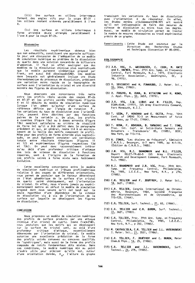
(iii) Une surface en sillons interrompus formant des angles vifs pour la coupe BT-31 ; les sillons restant ordonnis parallilement 2 l'axe X.
(iv) Une surface en sillons interrompus 6 forme arrondie douce arrangis parallilement i l'axe X pour la coupe BT-26.
Oiscussion
Les risultats explrimentaux obtenus bien que non exhaustifs, constituent une approche suffisin- te pour une discussion de l'adlquation de ce modile de simulation numirique au problgme de la dissolution du quartz dans une solution concentrie de bifluorure d'ammonium. 11 faut en effet souligner que des modiles de la dissolution chimique plus sophistiquis que le modile purement cinimatique proposi par Frank, ont aussi it6 dbveloppis(20). Ces modiles dans lesquels est giniralement incluse une itude thermodynamique du processus de dissolution, pridisent une variation moins rapide de la topographie de surface avec l'orientation du cristal et une diversiti moindre des flgures de dissolution.
Nous observons une concordance tres nette entre les profils riels usinis des coupes BT-26 et AT-37 et les profils usinis thioriques (Figures 4 et 5) diduits du modile de simulation numirique lorsque l'on admet qu'autour d'une surface de rifirence dlfinie par l'angle de rotation 8 , les variations du taux de dissolution avec llorient8- tlon, peuvent 6tre dicrites par des fonctions paires de la variable p. Ue plus, les profils a cuvettes (Figure 13a) ou 2 domes arrondis (Figure 13b) semblent satisfaire au critire de stabiliti de forme tel qu'il a it6 difini dans le paragraphe pricident et qui, en giniral, reste lii 2 un accrois- sement de la taille des motifs composant le profil. M6me pour des profils de forme alternie plus sophisti- quie, on peut igalement constater une corrilation totale entre risultats thioriques (Figures 11 et 12) et expirimentaux (Figures respective5 13d et 13c). On peut donc raisonnablement infirer qu'au deli d'une profondeur critique d'attaque des lois de vitesse de dissolution B fonctions ~mpaires, sont a l'origine de la formation de ces profils usinis 2 forme mixte mais faiblement ivolutive.
Cette excellente concordance entre le modile de simulation numirique et l'itude profilomitrique relative B des coupes de diffirentes orientations, nous permet de postuler que le facteur diterminant de l'itat g i o m i t ~ i q u e de la surface d'un cristal de quartz uslne chimiquement, est l'orientation du cristal. En effet, nous n'avons jamais pu expiri- mentalement mettre en difaut le modile de simulation propose dont nous savons qu'il est bas6 sur la seule hypothise d'une dependence de la vitesse de dissolution vis 2 vis de l'orientation de la surface sur laquelle se diveloppent les figures de dissolution.
CONCLUSION
traduisant les variations du taux de dissolution avec l'orientation 8 du rdsonateur. En effet, les itudes menies pricidemment(l0-17) ont montri qu'il est indispensable de faire des mesures de vitesse de dissolution au moins tous les degris. Aussi, ce modile de simulation permet de limiter le nombre de mesures nicessaires au traci expirimental pricis de ce graphe.
Remerciements : Cette itude est soutenue par la Direction des Recherches Etudes et Techniques (Convention No 85-099).
(1) J.R. VlG, H. WASSHAUSER, C. COOK, M. KATZ and E. HAFNER, Proc. 27th Ann. Symp. on Frequency Control, Fort Monmouth, N.J., 1973, Electronic Industrie Association, Washington, DC, p 98, (1973).
(2 ) Y. SEKlGUCHl and H. FUNAKUBO, J. Mater. Sci., 15, 3066, (1980). -
( 3 ) H. FUKUYO, N. OURA. N. KITAJIMA and H. KONO, 1. Appl. Phys., 50, 3653, (1979).
(4) J.R. VIG, J.W. LEBUS and R. FILLER, Rep. ECOM-4548, (1977), (US Army Electronics Command, Fort Monmouth, N.J.).
(5) T. UEDA, F. KOHSAKA and E. OGITA, Proc. 10th Cont. of IMEKO TC-3 on Measurement of force and Mass, pp 17-22, (1984).
(6) T. UEDA, F. KOHSAKA, D. YAMAZAKI and T. 11N0, Proc. lnt. Conf. on Solid-State Sensors and Actuators - Transducers' 85, (19851, IEEE, New York, pp 113-116.
(7) W. ZINGG, "Les &talons de friquence", Siminaire C.N.R.S., B e s a n ~ o n , 6-7 mars 1985, pp N-1-15, (Edition du C.N.R.S., 1985).
(8) J.R. VIG, R.J. BRANDMAYR and R.L. FILLER, Report DELET-TR-80-5 (US Army Electronic Research and Development Command, Fort Monmouth, N.J. 1980).
( 9 ) R.J. BRANDNAYR and J.R. VIG, Proc. 39th Ann. Symp. on Frequency Control, Philadelphia, Pa, 1985, I.E.E.E., New York, N.Y., p 276, (1985).
(10) C.R. TELLIER and F. JOUFFROY, J. Mater Sci., 18, 3621, (1983). -
(11) C.R. TELLIER, Congris International de Chrono- mitrie, B e s a y o n , 1984, Sociiti F r a n ~ a i s e des Microtechniques et de Chronomitrie, pp 115-120, (1984).
(129 C.R. TELLIER, Surf. Technol., 2, 83, (1984). (13) C.R. TELLIER and C.B. BURON, Surf. Technol.,
22, 3621, (1983). - Nous proposons un modile de simulation numirique
des profils de surface produits par une attaque (14) C - R - TELLIER, Proc. 39th ~ n n . Symp. on Frequency chimique d'un cristal de quartz. Comme Frank(lB), Control, Philadelphia, Pa, 1985, I.E.E.E., nous postulons que les motifs qui se dlveloppent New York, N.Y., p 282, (1985). sur la surface du cristal sont, au deli d'une profondeur critique doattaque, essentiellement (15) M. CASTAGLIOLA, C.R. T E L L E R and J.L. VATERKOWSKI dbterminls par l'orientation du cristal. Ce modile J. Mater. Sci., 2, 3551, (1986). autorise une excellente pridiction de la forme des profils usinls convexes ou concaves (16) C.R. TELLIER, F. JOUFFROY and C. BURON, Mater
de "symltrlques", mais aussi de la forme des profils Chem.& Phys., 14, 25, (1986).
composis de motifs fondamentaux dits mixtes. Dans ces conditions, le modele num6rique m i s au point (17) C.R. TELLIER and J.L. VATERKOWSKI, Surf. s'avire utile our ~ r i c i s e r au'elle est. autour Technol., 26, 275, (1985). d'une orientatidn donnie, Oo, 'l'allure d; graphe
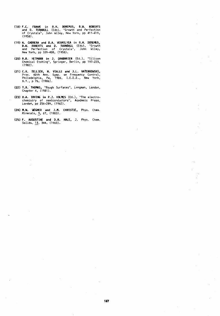
(18)F.C. FRANK i n R.H. DOREMUS, B.W. ROBERTS and 0. TURNBULL (Eds), "Gror th and P e r f e c t i o n o f Crys ta ls " , John Wiley, New York, pp 411-419, (1958).
(19) N. CABRERA and D.A. MRMlLYEA i n R.H. DOREMUS, B.W. ROBERTS and D. TURNBULL (Eds), "Growth and P e r f e c t i o n o f Crys ta ls " , John Wi ley, New York, pp 339-408, (1958).
(20) R.B. HEZMANN i n J. GRABMAIER (Ed.), " S i l i c o n Chemical Etching" , Spr inger , B e r l i n , pp 197-223, (1982).
(21) C.R. TELLIER, N, VIALLE end J.L. VATERROWSKt, Proc, 4 0 t h Ann. Symp. on Frequency C o n t r o l , P h i l a d e l p h i a , Pa, 1986, I . E . E . E . , Nek York, N.Y., p 76, (1986).
(22) T.R. T H W S , "Rough Surfaces", Longman, London, Chapter 4, (1981).
(23) B.A. IRVING i n P.J. HOLES (Ed.), "The e l e c t r o - chemis t ry o f semiconductors", Academic Press, Londoh, pp 256-289, (1962).
(24) M.W. WEGNER and J.M. CHRISTIE, Phys. Chem. M inera ls , 9, 67, (1983).
(25) F. AUGUStlNE and D.R. HALE, J. Phys. Chem. So l ids , 13, 344, (1960).
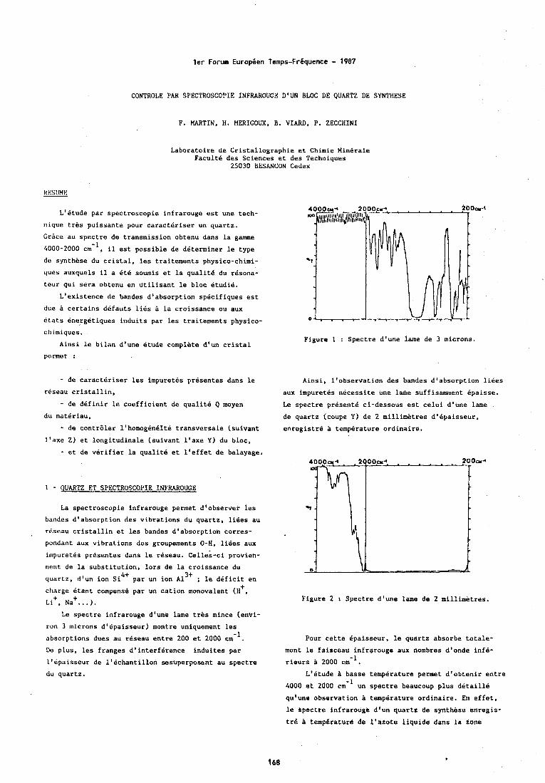
ler Forum Europien Temps-Friquence - 1987
CONTROLE PAR SPECTROSCOPIE INFRAROUGE D'UN BLOC DE QUARTZ DE SYNTHESE
F. MARTIN, H. MERICOUX. 6 . VIARD, P. ZECCIIINI
Laboratoire de Cristallographie et Chimie Minerale Pacult6 des Sciences et des Techniques
25030 BESANCON Cedex
HESUME
L'etude par spectroscopie infrarouge est une tech-
nique tres puissante pour caracteriser un quartz.
Grsce au spectre de transmission obtenu dans la game
4000-2000 cm-l, il est possible de determiner le type
do synthese du cristal, les traitements physico-chimi-
ques auxquels il a ete sownis et la qualit6 du resona-
tour qui sera obtenu en utilisant le bloc etudie.
L'existence de bandes d'absorption specifiques est
due a certains defauts lies a la croissance ou aux
dtats energetiques induits par les traitements physico-
ch imiques.
Ainsi le bilan d'une etude complete d'un cristal
permet :
- de caracteriser les impuretes presentes dans le reseau cristallin,
- de definir le coefficient de qualite Q moyen du materiau,
- de contraler l'homog8n6ite transversale (suivant l'axo Z) et longitudinale (suivant l'axe Y ) du bloc,
- et de verifier la qualite et l'effet de balayage.
1 - QUARTZ ET SPECTROSCOPIE INFRAROUGE La spectroscopie infrarouge permet d'observer les
bandes d'absorption des vibrations du quartz, liees au
rescau cristallin et les bandes d'absorption corres-
pondant aux vibrations des groupements 0-H, liees aux
i~npuretes presentes dans le reseau. Celles-ci provien-
nent de la substitution, lors de la croissance du
quartz, d'un ion si4+ par un ion ~1~~ ; le deficit en t
charge etant cornpens4 par un cation monovalent (H , ~ i + , ~ a + ... ).
Le spectre infrarouge d'une lame tres mince (envi-
run 3 microns d'epaisseur) montre uniquement les
absorptions dues au rOseau entre 200 e t 2000 cm-l
Do plus, les franges d'interference induites par
l'ipaisseur de l'echantillon sesuperposent au spectre
du quartz,
Figure 1 : Spectre d'une lane de 3 microns.
Ainsi, l'observation des bandes d'absorption liees
aux impuretes necessite une laple suffisamment epaisse.
Le spectre presente ci-dessous est celui d'une lame
de quartz (coupe Y) de 2 millimetres d'epaisseur,
enregistre temperature ordinaire.
Figure 2 1 Spectre d'une lame de 2 millimetres.
Pour cette epaissour, le quartz absorbe totale-
ment le faisceau infrarouge aux nombres d'onde infe-
rieurs & 2000 cm-l.
L'etude P basse temperature permet d'obtenir entre
4000 et 2000 cm-l un spectre beaucoup plus detail14
qu'une observation a temperature ordinaire. Erl effet,
le spectre infrarouge d'un quartz de synthese enregis-
trB tempdrature de l'azotc liquide dans la zone
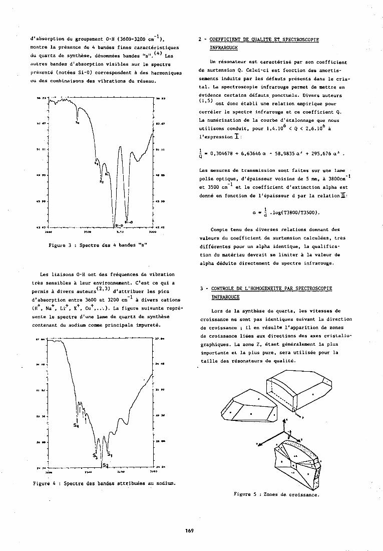
d'absorption du groupement 0-H (3600-3200 cm-') , montre la presence de 4 bandes fines caracteristiques
du quartz de synthese, dCnommees bandes "s".'~) Les
nutres bandes d'absorption visibles sur le spectre
present8 (notees Si-0) correspondent a des harmoniques
ou des combinaisons des vibrations du rcseau.
I@- 3%- 3.3,~ 1aoo
Figure 3 : Spectre des 4 bandes "st'
Les liaisons 0-H ont des frequences de vibration
tres sensibles a leur environnement. C'est ce qui a
permis a divers auteurs (213) d'attribuer les pics
d'absorption entre 3600 et 3200 cm-I divers cations +
(H+, Na , ~i+, K', CU',.:.). La figure suivante repre-
sente le spectre d'une lame de quartz de synthese
contenant du sodium cormne principale impurete.
Figure 4 : Spectre deo bandes attribuees au sodium.
2 - COEFFICIENT DE QUALITE ET SPECTROSCOPIE INFRAROUCE
Un resonateur est caracterise par son coefficient
de surtension Q. Celui-ci est fonction des amortis-
sements induits par les defauts presents dans le cris-
tal. La spectroscopie infrarouge permet de mettre en
evidence certains defauts ponctuels. Divers auteurs
( 1 ' 5 ) ont donc etabli une relation empirique pour
correler le spectre infrarouge et ce coefficient Q.
La numerisation de la courbe d'etalonnage que nous 6 6 utilisons conduit, pour 1,4.10 C Q < 2,6.10 a
l'expression I :
Les mesures de transmission sont faites sur une lame
polie optique, d'epaisseur voisine de 5 mm. 3800cm-~
et 3500 em-' et le coefficient d'extinction alpha est
donne en fonction de l'ipaisseur d par la relationx:
Compte tenu des diverses relations donnant des
valeurs du coefficient de surtension calculees, tres
differentes pour un alpha identique, la qualifica-
tion du materiau devrait se limiter a la valeur de
alpha deduite directement du spectre infrarouge.
3 - CONTROLE DE L'HOMOCENEITE PAR SPECTROSCOPIE INFRAROUCE
Lors de la synthese du quartz, les vitesses de
croissance ne sont pas identiques suivant la direction
de croissance ; il en result* l'apparition de zones
de croissance liees aux directions des axes cristallo-
graphiques. La zone Z, etant generalenent la plus
importante et la plus pure, sera utilisee pour la
taille des resonateurs de qualite.
Figure 5 : Zones de croissance.
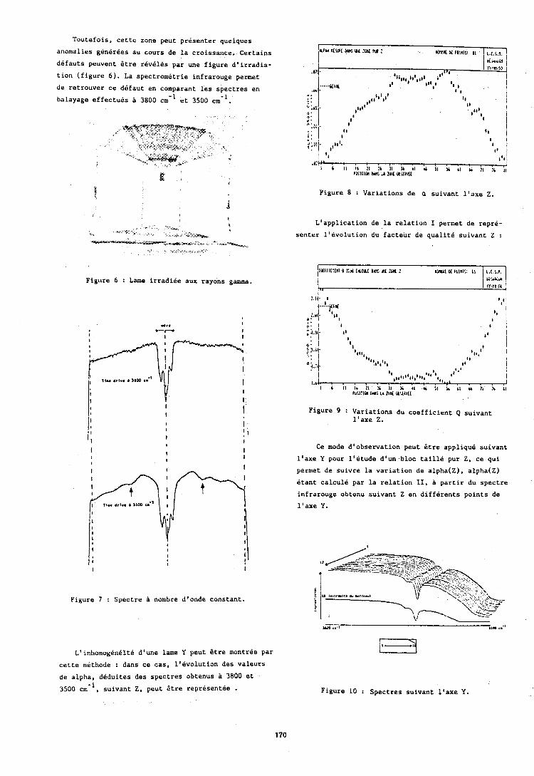
Toutefois, cette zone peut presenter quelques
anomalies generees au cours de la croissance. Certains
defauts peuvent Btre reveles par une figure d1irradia-
tion (figure 6 ) . La spectrometrie infrarouge permet
de retrouver ce defaut en comparant les spectres en
balayage effectues P 3800 cm-I et 3500 cm-l.
Figure 6 : Lame irradiee aux rayons gamma.
MWL M UL :W N :
Figure 8 : Variations de a suivant l'axe 2.
L1application de la relation I permet de repre-
senter llevolution du facteur de qualite suivant Z :
Figure 9 : Variations du coefficient Q suivant l1axe 2.
Ce mode dlobservation peut Btre applique suivant
l'axe Y pour l'etude dlun bloc taille pur Z, ce qui
permet de suivre la variation de alpha(Z), alpha(Z)
etant calcule par la relation 11, a partir du spectre
infrarouge obtenu suivant Z en differents points de
l1axe Y.
Figure 7 : Spectre a nombre dlonde constant.
L'inhomogeneite d'une lame Y peut Btre montree par
cette methode : dans ce cas, llevolution des valeurs
de alpha, deduites des spectres obtenus 3800 et
3500 cm-l, suivant Z, peut Btre representee . Figure 10 : Spectres suivant llaxe Y.
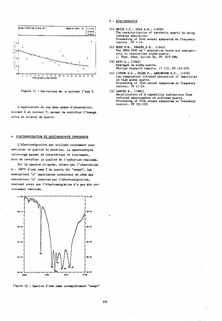
Figure 11 : Variations de a suivant l'axe Y,
L'application de ces deux modes d'observation,
suivant Z et suivant Y, permet de contraler lthomoge neite du cristal de quartz.
4- ELECTROMICRATION ET SPECTROSCOPIE INFRAROUGE
L'alectromigration est utilisee coutarmhent pour
arneliorer la qualiti du materiau. La spectroscopic
infrarouge permet de caracteriser ce traitement,
donc de contr6ler la qualit6 de l'op6ration rialisbe.
Sur le spectre ci-apriis, obtenu par Itobservation
a - 180°C d'une lame Y du quartz dit "swept", les
absorptibns "s" importantes subsistent all cat6 des
absorptions "e" induites par l'electromigratibh,
rnonttant ainsi que l'electromigration n'a pas it6 cor-
rectement realisee.
5 - BIBLIOGRAPHIE (1) BRICE J.C., COLE A.M., (1978)
The caracterization of synthetic quartz by using infrared absotption. Proceuding of 32nd annual symposiunl on frequency cohttol. e p 1-10,
(2) DObD D.M., FHASER D.B.. (1965) The 3000-3900 cm-1 absotption bands and anelasti- city in crystalline alpha-quartz. 3. Phys. Cham. Solids 26, PP. 673-6d6.
( 3 ) KATY A . , (1962) Hydrogen in Plpha-quartz. Philip* research reports, 17 (3). PP 133-279.
(4) LIPSON H.O., EULER F., ARHINCTON A.F., (1978) Lou temperature infrared absorption of impurities in high grade quartz. Proceeding of 32nd annual symposium on frequerlcy control. PP 11-23.
(5) SAWYER B., (1983) Recalibration of Q capability indications from infrared measurements on cultured quartz. Proceeding of 37th annual symposium on frequency control, PP 151-152.
Figure 12 : Spectre d'une lame incompl&tement "swept"
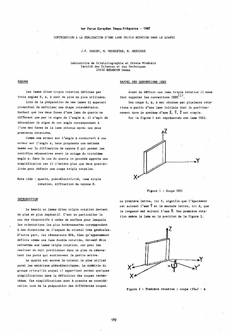
ler Forum EuropBen Tempe-Fraq~ence - 1987 CONTRIBUTION A LA REALISATION D'UNE LAME TRIPLE ROTATION DANS LE QUARTZ
J.F. DARCES, M. MOUSSETAD, H. MERIOOUX
Laboratoire de Cristallographie et Chimie Minerale Facultd des Sciences et des Techniques
25030 BESANCON Cedex
RESIME RAPPEL DES CONVENTIONS IEEE
Les lames dites triple rotation definies par
trois angles 8, I$, $ sont de plus en plus utilisees.
Lors de la preparation de ces lames il dpparait
primordial de maitriser une &ape intermediaire.
Sachant que les deux faces d'une lame de quartz ne
diffirent que par le signe de l'angle 9, il s'agit de
determiner le signe de cet angle correspondant a
l'une des faces de la lame obtenue apres les deux
premieres rotations.
Come une erreur sur l'angle @ conduirait a tlne
erreur sur l'angle $, nous proposons une methode
basee sur la diffraction de rayons X qui permet les
contrales necessaires avant le sciage du troisieme
angle $. Dans le cas du quartz ce procddd appotte une
simplification car il n'existe plus que deux possibi-
lites pour definir une coupe triple rotatiott.
Avant de dZfinir une lame triple rotation il nous (1) faut rappeler leu conventions IEEE .
Une coupe B , 4 , $ est obtenue par plusieurs rota-
tions a partir d'une lame initiale dont le position-
nement dans le systhme d'axe d , ?, ? est simple. Sur la figure 1 est representie une lame (YX).
Mots cles r quartz, piezo6lectricft8, lame triple
rotation, diffraction de rayons X.
Figure 1 : Coupe CfX)
INTRODUCTfON
Le besoin en lames dites triple rotation deviant
de plus en plus imperatif. C'est en partictllier le
cas des dispositifs ondes de surface pour lesquels
les orientations les plus interessantes corre$pondent
a des directions de l'espace du cristal ttes ghbrales.
D'autre part, les r4sonateurs BVA, bien qu'apparemerit
ddfinis come une lame double rotation, doivent Qtre
rattaehes aux lames triple rotation, car pour les
realiser on doit positionner dans le plan du r8sona-
teur les ponts qui soutiennent la partie active.
Le quartz est encore le cristal le p1u.d utilise
parmi les materiaux pi8zoelectriques. La symiltrie du
groupe cristallin auquel il appartient permet quelques
simplifications dans la definition des coupes recher-
chees. Ces simplifications sont B prendre en consid6-
ration lors de la preparation des diffekehted coupes.
La premiere lettre, ici 'f, sighifie que l'ipaisseur
est suivant i'ake ? et la seconde lettre, ici X, qud
1d longueur est suivant l'exe d . Une premiere rota- tion amane l& lame en 18 position de la figure 2.
Figure 2 1 PremiPre totarion I coupe (YXw) - Q
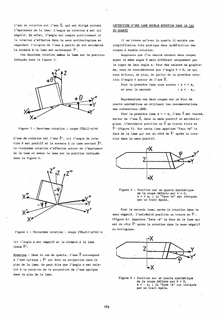
L'axe de rotation est l'axe 2, qui est dirige suivant l'epaisseur de la lame. L'angle de rotation $ est ici
negatif. En effet, I'angle est compte positivement si
la rotation s'effectue dans le sens antihorlogique en
regardant l'origine de l'axe L partir de son extrdmite.
La normale a la lame est maintenant if'. Une deuxihme rotation amene la lame sur la position
indiquee dans la figure 3.
Figure 3 : Deuxieme rotation : coupe (YXw1)-$It0
L'axe de rotation est l'axe 2 ' ' ici l'angle de rota- -+
tion 0 est positif et la normale P la lame devient Y".
La troisieme rotation s'effectue autour de llBpaisseur
de la lame et amene la lame sur la position indiquee
dans la figure 4.
Figure 4 : Troisieme rotation : coupe (YXwlt)-$/+@I-$
Ici l'angle + est negatif et la normale a la lame reste if".
Flpmarqug : Dans le cas du quartz, l'axe 2 correspond L l'axe optique ; 2" est donc sa projection dans le plan de la lame. On peut dire que l'angle $ est rela-
tif $ la rotation de la projection de l'axe optique
dans le plan de la lame.
DEFINITION D'UNE LAME DOUBLE ROTATION DANS LE CAS - DU QUARTZ
11 se trouve qu'avec le quartz il existe une
simplification trhs pratique dans ladefinition des
coupes a double rotation.
Supposons que l'on desire obtenir deux coupes
ayant le mdme angle 0 mais differant uniquement par
le signe de leur angle 6 . Pour des raisons de graphis-
me, nous ne considererons que l'angle 8 = 0, ce qui
nous evitera, de plus, de parler de la premiere rota- -*
tion d'angle 8 autour de l'axe X.
Pour la premiere lame nous aurons : $ = + $,
et pour la seconde : $ = - $,.
Representons ces deux coupes sur un bloc de
quartz synthtitique en utilisant les recommandations
des conventions IEEE.
Pour la premiere lame $ = + 9, l'axe if est tourn6, autour de l'axe 2, dans le sens positif ou antihorlo- gique. LtextrBmite positive de 9 se trouve alors en if' (Figure 5). Sur cette lame appelons "face +$" la
face de la lame qui est du cdti de if' apres la rota-
tioh dans le sens positif.
Figure 5 : Position sur un quartz synthetique de la coupe definie par 8 = 0 , 9 = + Oo ; la "face +$" est indiquee par un trait epais.
Pour la seconde lame4 apres la rotation dans le
sens hegatif, 11extr6nlit6 positive se trouve en ?'. (Figure 6). Appeldns "face -4" la face de la lame qui est du c6t6 if' apres la rotation dans le sens negatif
ou horlogique.
Figure 6 : Position sur un quartz synthetique de la coupe definie par 8 = 0, 9 = - Oo ; la "face -$I' kst indipdee par un trait Cpais.
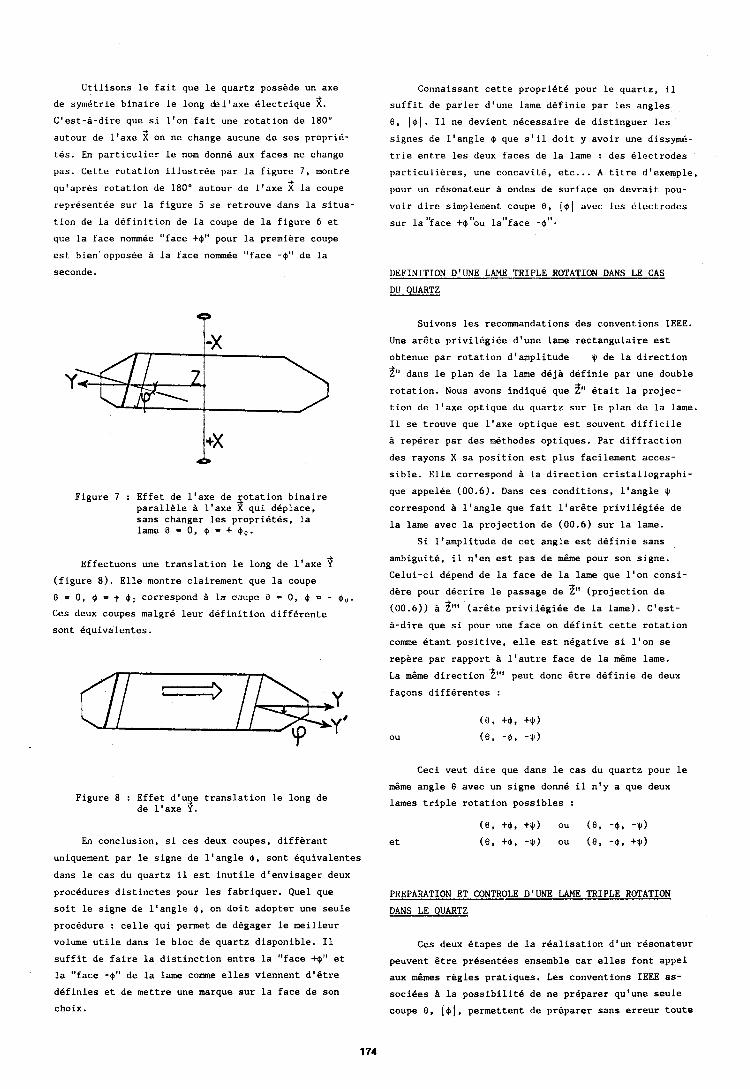
Utilisons le fait que le quartz possede un axe
de symetrie binaire le long Ql'axe dlectrique 2. C'est-A-dire que si l'on fait une rotation de 180"
autour de l'axe 2 on ne change aucune de ses proprie- tes. En particulier le nom donne aux faces ne change
pas. Cette rotation illustree par la figure 7, montre
qu'apres rotation de 180" autour de l'axe 3 la coupe representee sur la figure 5 se retrouve dans la situa
tion de la definition de la coupe de la figure 6 et
que la face nommee "face + $ I 1 pour la premiere coupe
est bien opposee la face nommee "face -$" de la
seconde.
Figure 7 : Effet de l'axe de rotation binaire parallele l'axe 3 qui deplace, sans changer les proprietes, la lame 0 = 0, $ = + 6,.
Effectuons une translation le long de l'axe 3 (figure 8). Elle montre clairement que la coupe
0 = 0, $ = $ $ U correspond P la ouupe 8 = 0, @ = - $,.
Ces deux coupes malgre leur definition differente
sont equivalentes.
Figure 8 : Effet d'une translation le long de de l1axe 3 .
En conclusion, si ces deux coupes, differant
uniquement par le signe de l'angle 0, sont equivalentes
dans le cas du quartz il est inutile d'envisager deux
procedures distinctes pour les fabriquer. Quel que
soit le signe de l'angle $, on doit adopter une seule
procedure : celle qui permet de degager le meilleur
volume utile dans le bloc de quartz disponible. I1
suffit de faire la distinction entre la "face +$'I et
' la "face -$" de la lame comme elles viennent d'Btre
ddfinies et de mettre une marque sur la face de son
choix.
Cor~naissant cette propriet6 pour le quartz, il
suffit de parler d'une lame definie par les angles
8, ( $ 1 . I1 ne devient necessaire de distinguer les
signes de l'angle $ que s'il doit y avoir une dissyme-
trie entre les deux faces de la lame : des electrodes
particulieres, une concavite, etc... A titre d'exemple,
pour un resonateur a ortdes de surface on devrait pou-
voir dire simpler~lent coupe 8 , ( $ 1 avec les cilectrodes
sur la'kace +$"ou lal'face -9".
DEFINITION D'UNE LAME TRIPLE ROTATION DANS LE CAS
DU QUARTZ
Suivor~s les recommandations des conventions IEEE.
Une arBte privilegiee d'une lame rectangulaire est
obtenue par rotation d'amplitude $I de la direction
2" dans le plan de la lame deja definie par une double rotation. Nous avons indique que 2" Btait la projec- tion de l'axe optique du quartz sur le plan de la lame.
I1 se trouve que l'axe optique est souvent difficile
B reperer par des methodes optiques. Par diffraction
des rayons X sa position est plus facilement acces-
sible. Elle correspond a la direction cristallographi-
que appelee (00.6). Dans ces conditions, l'angle + correspond B l'angle que fait l'arBte privilegiee de
la lame avec la projection de (00.6) sur la lame.
Si l'amplitude de cet angle est definie sans
ambiguite, il n'en est pas de m6me pour son signe.
Celui-ci depend de la face de la lame que l'on consi-
dere pour decrire le passage de 2" (projection de
(00.6)) h 2"' (ar8te privilegiee de la lame). C'est-
a-dire que si pour une face on definit cette rotation
come etant positive, elle est negative si l'on se
repere par rapport B l'autre face de la mBme lame.
La m6me direction 3"' peut donc Btre difinie de deux fa~ons differentes :
Ceci veut dire que dans le cas du quartz pour le
m6me angle 0 avec un signe donne il n'y a que deux
lames triple rotation possibles :
(0, +$. +*) ou ( 0 , -@. -*)
et ( 0 + - ou (0, - $ B +$)
PREPARATION ET CONTROLE D'UNE LAME TRIPLE ROTATION
DANS LE QUARTZ
Ces deux etapes de la realisation d'un resonateur
peuvent Btre presentees ensemble car elles font appel
aux mBmes rhgles pratiques. Les conventions IEEE as-
sociees 21 la possibilitk de ne priparer qu'une seule
coupe 0. ( $ 1 , permettent de preparer sans erreur toute
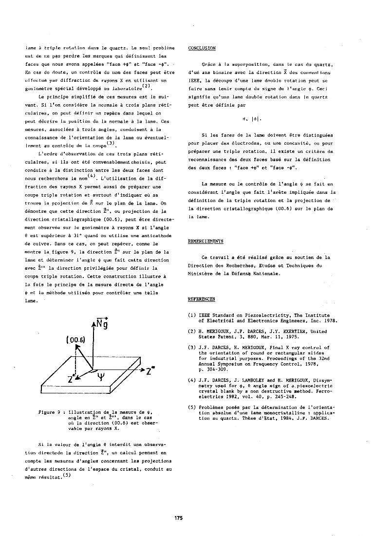
lame a triple rotation dans le quartz. Le seul problGn~e
est de ne pas perdre les marques qui definissent les
faces que nous avons appelees "face +$" et "face -$",
En cas de doute, un contrale du rlom des faces peut Btre
etfectue par diffraction de rayons X en utilisant un ( 2 ) goniometre special developpe au laboratoire .
Le principe si~nplifie de ces mosures est le sui-
vant. Si l'on considere la normale a trois plans reti-
culaires, on peut definir un repere dans lequel on
peut ddcrire la position de la normale a la lame. Ces
mesures, associees a trois angles, conduisent a La
connaissance de l'orientation de la lame ou eventuel- (3) lement au contrdle de la coupe .
L'ordre d'observation de ces trois plans reti-
culaires, si ils ont 6tB convenablementchoisis, peut
conduire a la distinction entre les deux faces dont
nous recherchons le n~rn'~). L'utilisation de la dif-
fraction des rayons X permet aussi de preparer une
coupe triple rotation et surtout d'indiquer oh se
trouve la projection de 2 sur le plan de la lame. On ddmontre que cette direction 9, ou projection de la direction cristallographique (00.6), peut Btre directe-
ment observee sur le goniometre B rayons X si l'angle 8 est supdrieur a 31' quand on utilise une anticathode
de cuivre. Dans ce cas, on peut rep8rer, come le
montre la figure 9, la direction 2" sur le plan de la lame et determiner l'angle $I que fait cette direction
avec 2"' la direction privilegiee pour dkfinir la coupe triple rotation. Cette construction illustre B
la fois le principe de la mesure directe de l'angle
$ et la methode utilisee pour contrdler une telle
lame.
Figure 9 : Illustrat on de la mesure de 9 , angle en 4'' et 2"', dans le cas oh la direction (00.6) est obser- vable par rayons X .
Grice a la superposition, dans le cas du quartz,
d'uri axe binaire avec la direction 2 dcs conventions IEEE, la d6coupe d'une lame double rotation pout se
faire sans tenLr compte du signe de l'angle $I. Ceci
signifie qu'une lame double rotation dans le quartz
peut Btre definie par
Si les faces de la lame doivent Etre distinguees
pour placer des electrodes, ou une concavite, ou pour
preparer une triple rotation, il existe un critere de
reconnaissance des deux faces base sur la definition
des deux faces : "face +$" et "face -a".
La mesure ou le contrdle de l'angle 9 se fait en
considerant l'angle que fait l'arBte impliquee dans la
definition de la triple rotation et la projection de
la direction cristallographique (00.6) sur le plan de
la lame.
Ce travail a dte realis6 grgce au soutien de la
Direction des Recherches, Etudes et Techniques du
Ministere de la Dlfens(! Nationale.
REFERENCES
(1) IEEE Standard on Piezoelectricity. The Institute of Electricdl and Electronics Engineers, Inc. 1978.
(2) H. MERIGOUX, J.F. DARCES, J.Y. EXERTIER, United States Patent, 3, 880, Mar. 11, 1975.
(3) J.F. DARCES, H. MERIGOUX, Final X ray control of the orientation of round or rectangular slides for industrial purposes. Proceedings of the 32nd Annual Symposium on Frequency Control, 1978, p. 304-309.
(4) J.F. DARCES, J. LAMBOLEY and H. MERIGOUX, Dissym- metry used for 0, 8 angle sign of a piezoelectric crystal blank by a non destructive method. Ferro- electrics 1982, vol. 40, p. 245-248.
(5) Probl%n~es poses par la determination de l'orienta- tion absolue d'une lame monocristalline : applica- tion au quartz. These dlEtat, 1984, J.F. DARCES.
Si la valeur de l'angle 8 interdit une observa-
tion directede la direction 2'1, un calcul prenant en compte les mesures d'angles concernant les projections
d'autres directions de l'espace du cristal, conduit au
m6me res~ltat.(~)
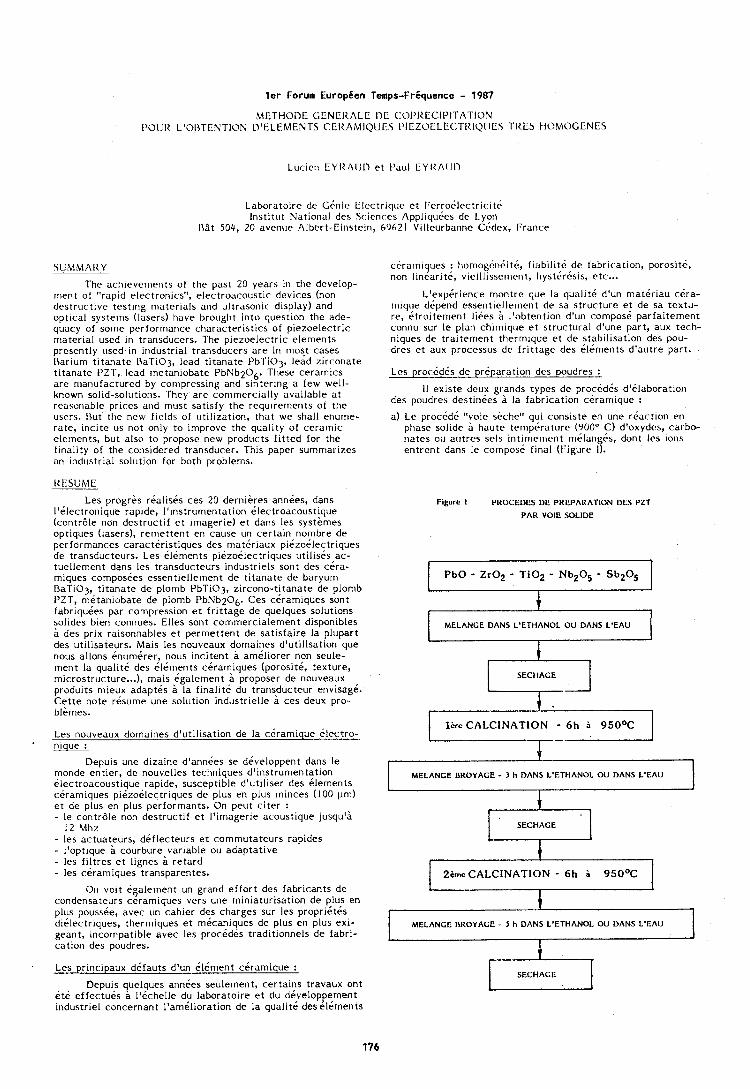
l e r Forum EuropBen Temps-Friquence - 1987
METHOL>E GENEItALE I>E C:OI'IIECIPITATION I'OUll L'OI5TENTION D'ELEMENTS CEI<AIMIQUES PIEZOELE(:TItIQ,)IIeS TlIES HOMOGENES
Lucicn CYltt\lJD et I'aul EYItA[JI)
Laboratoirc de Ghnic Elcctriqcle et Fcrro6lrctr ic i tc Institut National des Sc:it>nces Appliqucks de Lyori
1\9t 504, 20 avenue Albert-Cirlstcin, 69621 Vlllcurbiinne Cbdex, France
SUMMAllY -- The achievements of the past 20 years in the develop-
~nen t of "rapid electronics", electroacoustic devices (non destructive testing ri~aterials and ultrasonic display) and optical systerns (lasers) have brought into question the ade- quacy of some performance characteristics of piezoelectric material used in transducers. The piezoelectric elements presently used in industrial transducers are in most cases I\ariurn t i tanate RaTiO3, lead titanate PbTi03, lead zirconate t i tanate PZT, lead rnetaniobate PbNb206. These ceramics are nianufactured by cornpressing and sinterlng a few well- known solid-solutions. They are conlrnercially available a t rcasorlable prices arld nlilst satisfy the requirements of the users. but the new fields of utilization, that we shall enurne- rate, incite us not only to improve the quality of cerarrlic elerrlents, but also to propose new prodt~cts f i t t cd for the finality of the corisidered transducer. This paper surnrnarizes an industrial solution for both problems.
IIESUME
Les progres realises ces 20 dernieres annees, dans I'electronique rapide, I'instrurnentation electroacoustique (contrale non destructif e t irnagerie) et dans les systirnes optiques (lasers), rernettent en cause un certain nornbre de performances caracteristiques des mattiriaux piezoilectriques de transducteurs. Les ilernents piizo6Iectriques utilises ac- tuellernent dans les transducteurs industriels sont des cera- rniques cornposees essentiellernent de titanate de baryum DaTiOj, t i tanate de plornb PbTi03, zircono-titanate de plornb PZT, rnetaniobate de plornb PbNb206. Ces cerarniques sont fabriqu&es par compression et f r i t tage de quelques solutions solides bien connues. Elles sont cornrnercialen~ent disponibles a des prix raisonnables et perrnettent de satisfaire la plupart des utilisateurs. Mais les nouveaux dornaines d'utilisation que nous allons CnumCrer, nous incitent a arnil iorer non seule- rnent la qualite des elements ceramiques (porosite, texture, microstructure...), rnais egalement a proposer de nouveaux produits mieux adapt6s h l a f inalite du transducteur envisage. Cette note resume une solution industrielle a ces deux pro- blernes.
Les nouveaux dornalnes d'utillsation de la cerarn~que klectro- ~ I O I I P !
ce ra~n i~ues : tiornog6n&it6, fiabilit&,de fabrication, porosite, non l~near i tk, vicillisserncnt, hysteresis, etc...
L'expirience rnontrc que la qualite d'un rnateriau chra- rnique dCpend essentiellement de sa structure et de sa textu- re, htroitenlent liees a I'obtention d'un cornpose parfaiternent connu sur l e plan chimique e t structural d'une part, aux tech- niques de traiternent thermique et de stabilisation des pou- dres et aux processus de fr i t tage des elenlents d'autre part.
Les procedes de preparation des p o u d r e s ~
11 existe deux grands types de procedbs d'klaborat~on des poudres destinies i la fabr icat~on cerarnique :
a) Le proced6 "voie st?chett qui consiste en une reaction erl phase solide h haute t e ~ n ~ i r a t t ~ r e (900" C) d'oxydcs, carbo- nates ou autres sels i r l t i r ~ i c ~ ~ ~ c n t ~r~&langes, dont I rs ions entrent darls le corrlpos& final (I'igure 1).
Pigum 1 PItOCEDCS DE PKEPAIIATION 1)ES PZT
PAR VOlE SOLlDE
PbO - Zr02 - T i 0 2 - N b 2 0 5 - SbZOS
I t
MELANGE DANS L'ETHANOL OU DANS L'EAU
SECHAGE G hrc CALCINATION 1 1 - 6 h i 950°C
I -. ... -- .
Depuis une dizaine d'anndes se developpent dans le t rnonde entier, de nouvelles techniques d'instrurnentation MELANGE BROYAGE - 3 h DANS L'ETHANOL OU DANS L'EAU 1 electroacoust~que rapide, suscept~ble d'utlliser des elements cerarnlaues ~ ~ ~ z o e l e c t r i a u e s de plus en plus minces (100 yrn) et de pius en plus perfo;rnants. 'On peu i citer : t - le contrale non destructif et I'irnagerie acoustique jusqu'a
12 Mhz - les actuateurs, deflecteurs et cornrnutateurs rapides - I'optique h courbure variable ou adaptative - les f i l t res e t lignes i retard - les cerarniques transparentes.
011 voit 64alernent un grand e f fo r t des fabricants dc condensateurs cerarniques vers une miniaturisation de plus en plus poussCe, avec un cahier des charges sur les propri i tes dielectriques, therrniques et rnecaniques de plus en plus exi- MELANGE I)ROYACE - 5 h DANS L'ETHANOL ou DANS L'EAU geant, incompatible avec les procedes traditionnels de fabri- cation des poudres.
Les prlnclpaux defauts d'un element cerarn~que :
Depuls quelques annees seulernent, certalns travaux ont ete effectues a 1'Cchelle du laborato~re et du d6veloppement lndustrlel concernant l 'arneltorat~on de la quallte des elements
SECHACE u
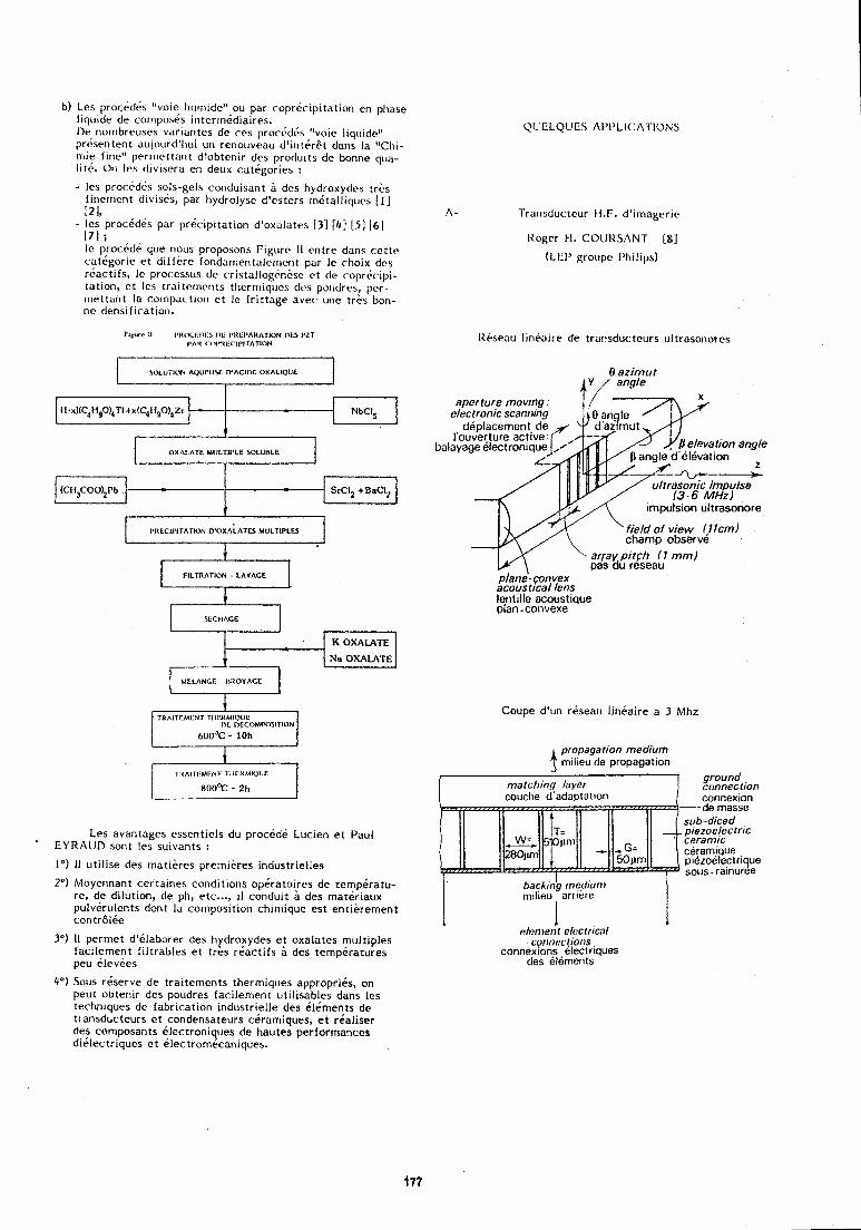
b) Les procedds "VOIC hurn~de" ou par copreclpltation en phase l~qurde de cornpo\es tnterrrl&d~a~rcs. I)e norrlbreuses varldntes de ces prochdbs "vole I~qu~de" pr65entent aujourd'hu~ un reriouveau d'lriteret dans la "Chr- rrile f~ne " perrnettant d'obtcnlr dcs produ~ts de bonne qua- 11th. Ori les d ~ v ~ s e r a en deux catCgorles :
- les procfdbs sols-gels corlduisarit b dcs hydroxydes trbs firierr~ent divisds, pat hydrolyse d'cstcrs rn6talliqucs ( 1 1 121. .- ,? - les procdd&s par prdc~pi tat ion d'oxalates 131 141 [ 5 ] 161 171 : - . , Ic procdde que rious proposons Figure 11 eritre dans cettc catdgorie e t d i f fkre fondarricntalcrrlent par Ic choix dcs rGactifs, Ie processus dc cristalloghnhsc et de copr6c.ipi- tntion, et lcs trnitcrncr~ts t l icrrr~iqi~cs des poudres, per- rnettant lo cornpactiori et Ic I r i t tage nvec uric tr&s bon- nc densification.
I OXALATE MIJLTII'LE SOLUBLE
I
PIIECIPITATION O'OXALATES MULTIPLES G FILTRATION - LAVAGE
I
MCLANGE - 1)IlOYACE L-4
TllAITI!MI:NI TIII'IlMIVIJC
R O O F - 211
Les avantages essentiels du procede Lucien e t Paul EYRAUD sont les su~vants :
1") I1 utilise des rnatieres prerniires industrielles
2") Moyennant certaines conditions operatoires de tempiratu- re, de dilution, de ph, etc ..., il conduit a des mat i r iaux pulvirulents dont la composition chirnique est entierement contrBlCe
3") 11 perrnet d' i laborer des hydroxydes e t oxalates multiples facilernent filtrables et tres reactifs des tempiratures peu ClevCes
4') Sous reserve de tra~tements therm~ques appropritis, on peut obten~r des poudres facllement u t~ l~sab les dans les techniques de fabrtcat~on industr~elle des 61ements de transducteurs e t condensateurs cbram~ques, e t real~ser des composants ilectroniques de hautes performances d16lectrlques et eLectrornecaniques.
A - Transducteur H.F. d'imagerie
Roger H. COUIISANT I8j
(LEI' groupc f'hilips)
Iteseau lineaire de trarisducteurs ultrasonorcs
0 azimur A Y / angle
balayage electronlqu
plane'- convex acousttcal lens lentille acoustique plan -convexe
Coupe d'un reseau lineaire a 3 Mhz
4 propagation medium rnllleu de propagation
ground connection cotinexion
--de masse sub-diced piezoelecfric ceramtc
ceramique piezoelectrique SOUS. ralnuree
I ' backin$ rneciium milieu arrlere
I I I I
elt!!met)t eh?crncal I
connec!iotls connexioris electr~ques
des elements
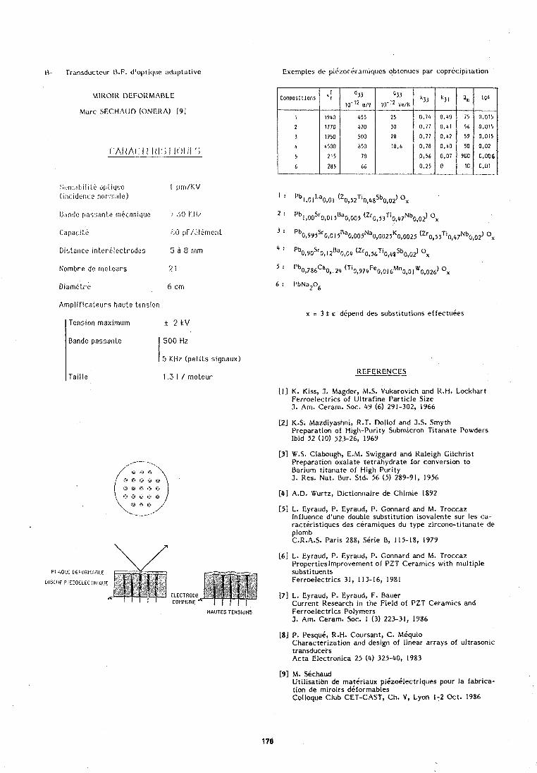
I - Transducteur LLF. d'optique adaptative Exernples de piCzocdrarr~i~ucs obtcnues par copr6cipitation
MIIlOiK DEFOItMADLE
Marc SECHAUI) (ONERA) 191
x z 3 + E d6pend des substitutions effectuees
: ; t :~~:, i l ) i l i l .~ qjl. i~,j l~(: I ) I I ~ I / K V iinc.idcnc.c nor,~r~alr:)
Ihndc [jarisarite rni'canique > 50 I'll?
Cspaci ti. FjO ~ : ~ F / ~ ~ l 6 m ~ c n L
Distance inter6lectrodt.s 5 a 0 mm
Nombre de rnoteurs 2 1
DiamG t r e 6 cm
Amplif icateurs haute tension
Tension maximum + 2 k V
REFEIZENCES
Bande passanle
[ I ] K. Kiss, J. Magder, M.S. Vukarovich and H.H. Lockhart Ferroelectrics of Ul t raf ine Particle Size 3. Am. Ceram. Soc. 49 (6) 29 1-302, 1966
500 Hz
5 KI-lz (pet i ls signaux)
[2] K.S. Mazdiyashni, R.T. Dollof and J.S. Smyth Preparation of High-Purity Submicron Titanate Powders lbid 52 (10) 523-26, 1969
Taille 1.3 l / molcur
[3] W.S. Clabough, E.M. Swiggard and Raleigh Cilchrist Preparation oxalate tetrahydrate for conversion to Barium titanate of High Purity 3. Res. Nat. Bur. Std. 56 ( 5 ) 289-91, 1956
[4] A.D. Wurtz, Dictionnaire de Chimie 1892
[I] L. Eyraud, P. Eyraud, P. Connard and M. Troccaz Influence d'une double substitution isovaiente sur les ca- racteristiques des ceramiques du type zircono-titanate de plomb C.R.A.S. Paris 288, Serie 8, 115-18, 1979
[6 ] L. Eyraud, P. Eyraud, P. Connard and M. Troccaz Propertieslrnprovement of PZT Ceramics wi th multiple substituents Ferroelectrics 31, 113-16, 1981
171 L. Eyraud, P. Eyraud, F. Bauer Current Research in the Field of PZT Ceramics and Ferroelectrlcs Polymers J. Am. Cerarn' Soc. 1 (3) 223-31, 1986
[8] P. Pesque, R.H' Coursant, C. Miquio Characterization and design of linear arrays of ultrasonic transducers Acta Electronica 25 (4) 325-40, 1983
[9 ] MA Sechaud Uti l isatlon de rnateriaux piizo6lectriques pour la fabrica- t ion de rniroirs diformables Colloque Club CET-CAST, Ch. V, Lyon 1-2 Oct. 1986
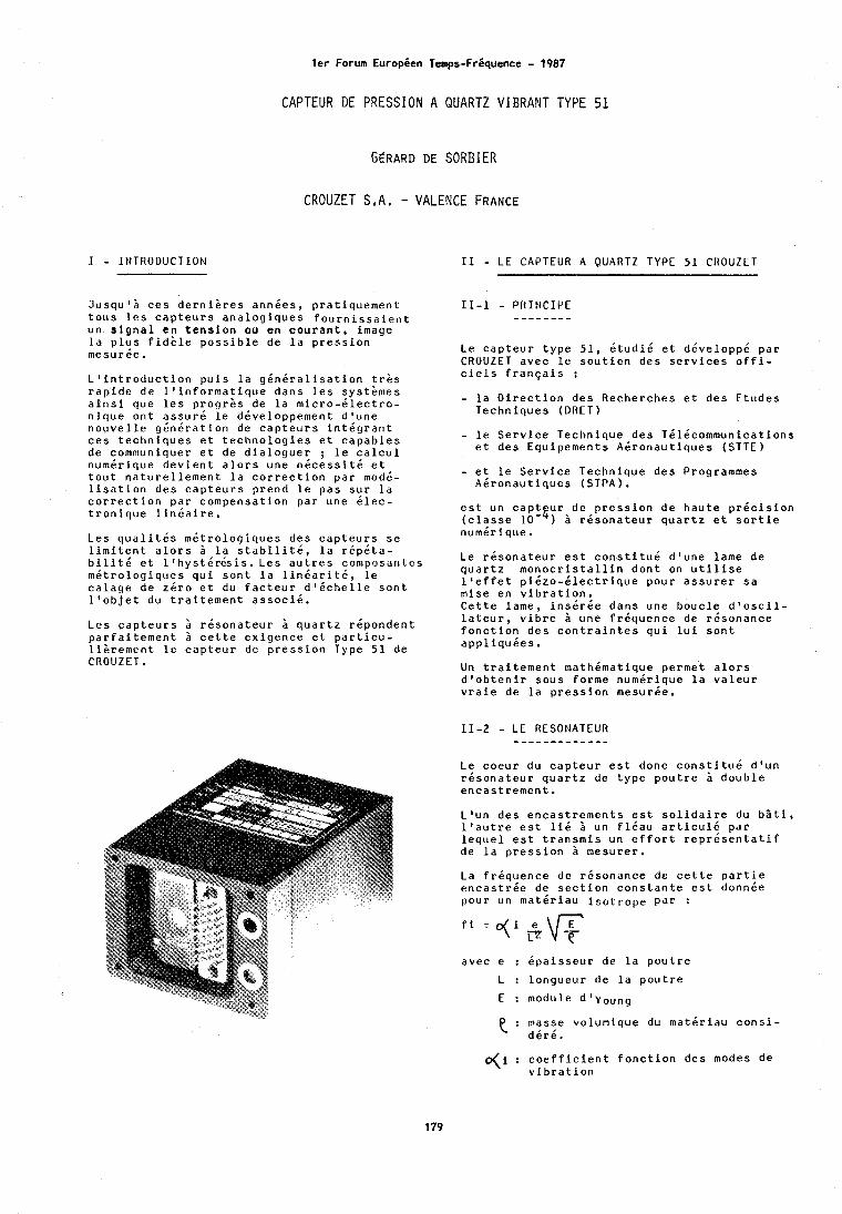
I - INTRODUCTION
l e r Forum EuropCen Temps-Fr6quence - 1987
CAPTEUR DE PRESSION A QUARTZ VIBRANT TYPE 51
G ~ R A R D DE SORBIER
CROUZET S ,A, - VALENCE FRANCE
3 u s q u q i c e s d e r n i k r e s a n n d e s , p ra t iquement t o u s l e s c a p t e u r s a n a l o g i q u e s f o u r n i s s a i e n t un s i g n a l en t e n s i o n ou en c o u r a n t , image l a p l u s f i d b l e p o s s i b l e de l a p r e s s i o n mesuree.
L ' i n t r o d u c t i o n p u i s l a g d n d r a l i s a t i o n t r k s r a p i d e de l q i n f o r m a t i q u e dans l e s systkmes a i n s i que l e s p r o g r k s de l a m i c r o - d l e c t r o - n i q u e on t a s s u r d l e ddveloppement d ' u n e n o u v e l l e g d n d r a t i o n de c a p t e u r s i n t d g r a n t c e s t e c h n i q u e s e t t e c h n o l o g i e s e t c a p a b l e s de communiquer e t de d i a l o g u e r ; l e c a l c u l numdrique d e v i e n t a l o r s une n d c e s s i t d e t t o u t n a t u r e l l e m e n t l a c o r r e c t i o n par modd- l i s a t i o n d e s c a p t e u r s prend l e pas s u r l a c o r r e c t i o n par compensat ion par une Clec- t r o n i q u e l i n d a i r e .
Les q u a l i t C s m d t r o l o g i q u e s d e s c a p t e u r s s e l i m i t e n t a l o r s i l a s t a b i l i t d , l a r d p k t a - b i l i t d e t 1 8 h y s t d r & s i s . Les a u t r e s coniposar\tes m d t r o l o g i q u e s q u i s o n t l a l i n d a r i t k , l e c a l a g e de 261-0 e t du f a c t e u r d ' d c h e l l e s o n t l ' o b j e t du t r a i t e m e n t a s s o c i k .
Les c a p t e u r s h r d s o n a t e u r h q u a r t z rdpondent p a r f a i t e m e n t i c e t t e e x i g e n c e e t p a r t i c u - l i k r e m e n t l e c a p t e u r de p r e s s i o n Type 51 de C R O U Z E T .
I1 - L E C A P T E U R A Q U A R T Z TYPE 51 C R O U Z E T
1 1 - 1 - PRINCIPE - - - - - - - - Le c a p t e u r t y p e 51 , d t u d i d e t ddveloppd par C R O U Z E T avec l e s o u t i e n d e s s e r v i c e s o f f i - c i e l s f r a n g a i s :
- l a D i r e c t i o n d e s Recherches e t d e s E tudes Techniques ( D R E T )
- l e S e r v i c e Technique d e s Tdldcommunicat ions e t d e s Equipements Adronaut iques (STTE)
- e t l e S e r v i c e Technique d e s Programmes Akronaut iques (STPA).
e s t un cap! u r de p r e s s i o n de h a u t e p r d c i s i o n ( c l a s s e 10 $ 1 A r 6 s o n a t e u r q u a r t z e t s o r t i e numdrique.
Le r d s o n a t e u r e s t c o n s t i t u k d lune lame de q u a r t z m o n o c r i s t a l l i n dont on u t i l i s e l ' e f f e t p i b z o - d l e c t r i q u e pour a s s u r e r s a mise en v i b r a t i o n . C e t t e lame, i n s d r d e d a n s une bouc le d ' o s c i l - l a t e u r , v i b r e i une f r d q u e n c e de rdsonance f o n c t i o n d e s c o n t r a i n t e s q u i l u i s o n t a p p l i q u d e s .
Un t r a i t e m e n t mathdmatique permet a l o r s d ' o b t e n i r s o u s forme numdrique l a v a l e u r v r a i e de l a p r e s s i o n mesurde.
11-2 - L E RESONATEUR - - - - - - - - - - - - - Le coeur du c a p t e u r e s t d o n ~ c o n s t i t u d d 'un r d s o n a t e u r q u a r t z de t y p e p o u t r e h d o u b l e e n c a s t r e m e n t .
L'un d e s e n c a s t r e m e n t s e s t s o l i d a i r e du b z t i , l t a u t r e e s t l i d i un f l d a u a r t i c u l d par l e q u e l e s t t r a n s m i s un e f f o r t r e p r d s e n t a t i f de l a p r e s s i o n 5 mesurer .
La f rdquence de rdsonance de c e t t e p a r t i e e n c a s t r d e de s e c t i o n c o n s t a n t e e s t donnde pour un matdr iau i s o t r o p e p a r :
avec e : k ~ a i s s e u r de l a p o u t r e
L : longueur de l a p o u t r e
E : module d1young
masse volumique du matdr iau c o n s i - e : d d r d .
O(i : c o e f f i c i e n t f o n c t i o n d e s modes de v i b r a t i o n
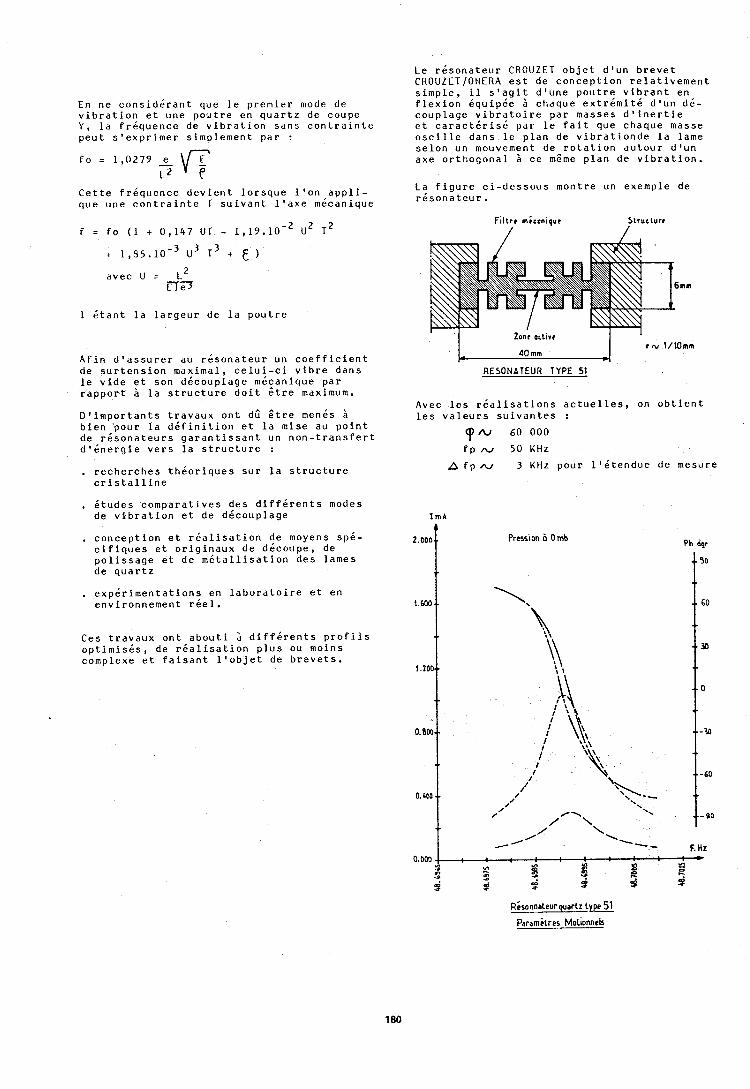
En ne c o n s i d d r a n t que l e p remier mode de v i b r a t i o n e t une powtre en q u a r t z de coupe Y , l a f r d q u e n c c de v i b r a t i o n s a n s c o n t r a i n t e peu t s l e x p r i m e r s implement pdr : - C e t t e f r d q u e n c e d e v i e n t l o r s q u e l o o n a p p l i - que une c o n t r a i n t e T s u i v a n t l ' a x e mdcanique
avec u = L * n-3
1 C t a n t l a l a r g e u r de l a p o u t r e
Afin d ' a s s u r e r au r d s o n a t e u r un c o e f f i c i e n t de s u r t e n s i o n maximal, c e l u i - c i v i b r e dans l e v i d e e t son ddcouplage mCcanique par r a p p o r t i l a s t r u c t u r e d o i t 6 t r e maximum.
D ' i m p o r t a n t s t r a v a u x o n t dG S t r e mends b bien pour l a d d f i n i t i o n e t l a mise au p o i n t de r d s o n a t e u r s g a r a n t i s s a n t un n o n - t r a n s f e r t d ' k n e r g i e v e r s l a s t r u c t u r e :
, r e c h e r c h e s t h d o r i q u e s s u r l a s t r u c t u r e c r i s t a l l i n e
, d t u d e s c o m p a r a t i v e s d e s d i f f d r e n t s modes de v i b r a t i o n e t de ddcouplage
, c o n c e p t i o n e t r d a l i s a t i o n de moyens spk- c i f i q u e s e t o r i g i n a u x de ddcoupe, de p o l i s s a g e e t de m d t a l l i s a t i o n d e s lames de q u a r t z
Le r d s o n a t e u r C R O U Z E T o b j e t d l u n b r e v e t CROUZET/ONERA e s t de c o n c e p t i o n r e l a t i v e m e n t s i m p l e , i l s 1 a g i t d l u n e p o u t r e v i b r a n t en f l e x i o n dquipde 2 chaque e x t r d m i t d d l u n dd- couplage v i b r a t o i r e par masses d ' i n e r t i e e t c a r a c t d r i s 6 par l e f a i t que chaque masse o s c i l l e dans l e p lan de v i b r a t i o n d e l a lame s e l o n un mouvement de r o t a t i o n a u t o u r d l u n axe o r t h o g o n a l i c e m6me plan de v i b r a t i o n .
La f i g u r e c i - d e s s o u s montre un exemple de r d s o n a t e u r .
Zone otlivr ' L d i m m J I
P N l / l O m m
RESONATEUR TYPE 51
Avec l e s r d a l i s a t i o n s a c t u e l l e s , on o b t i e n t l e s v a l e u r s s u i v a n t e s :
N 60 000
f p N 50 KHz
A f p w 3 KHz pour l l d t e n d u e de mesure
I mA
2.000 f Press~on h 0 mb Ph dqr
, e x p d r i m e n t a t i o n s en l a b o r a t o i r e e t en environnement r d e l .
Ces t r a v a u x on t a b o u t i i d i f f d r e n t s p r o f i l s o p t i m i s d s , de r d a l i s a t i o n p l u s ou moins complexe e t f a i s a n t l ' o b j e t de b r e v e t s .
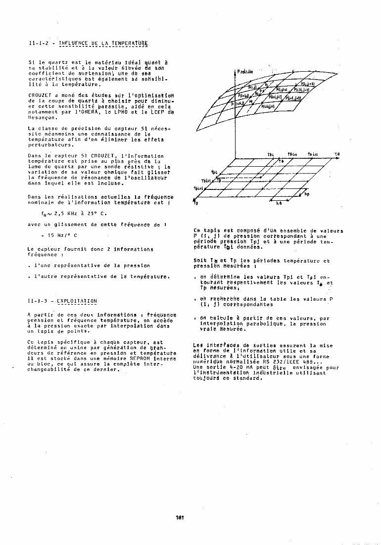
11-1-2 - INFLUENCE DE LA ~ E ~ ~ P E R A ~ U I ~ ~ - - - - - - - - - - - - - - - - - - - - - - - - - * .
S i l e q u a r t z e s t l e m a t e r i a u i d $ a i Udat 3 :a s t a b l l i t d e t i l a v a l e d t 61bvke %d b B H c o e f f i c i e n t de s ~ r t e n s i b f l ~ une dc sbb c a r a c t d r i s t i q u e s e s t kqdlemenk s d s k h s i b l - l i t 6 i l a t empkrakdre ,
C R O U Z E T a men6 d e s d t u d e s bd t i i a p t i i n i $ d t i a H de l a coupe de q u a r t z b c h b i j i r pour dlminu- e r c e t t e s e n s i b i l i t d p a r d b i t e , a i d k en c a i a notamment p a r l i O t 4 E R A , I @ LPMO e t l e LCEP d8 Iiesanpon.
La c l a s s e de p r d c i s i o n d u c a p t e u r 51 n 6 c e s - s i t e ndanmoins une c o n n a i s s a h c e de l a t empdra turc a f i n d t e n k l i m i n e r l e s e f f e t s p e r t u r b a t e u r s ,
Dans l e c a p t e u r 5 1 C R O U Z C T , l f i n f o r m a t i o n t e m p 6 r a t u r e e s t p r i s e au p l u s p r h s de l a lame de q u a r t z par une sonde r k s i s t i c e ; l a v a r i a t i o n de s a v a l e u r ohmique f a i t l i s s e t l a f rdquence de r e s o n a n c e de i tbBci l !a teu t dans l e q u e l e l l e e s t i n c l u s e .
Dans l e s r d a l i s a t i o n s a c t u e l l e s l a fkQqtlence nominale de l ' i n f o r m a t i o n t e M p Q r a t u r e e s t
avec un g l i s s e m e n t de c e t t e f rkquence de 3
Le c a p t e u r f o u r n i t donc 2 i n f o r m a t i o n s f r d q u e n c e :
. l ' u n e r e p r k s e n t a t i v e de l a p r e s s i o n
l t a u t r e r e p r d s e n t a t i v e de Id t e m p h r a t u r e ,
A p a r t i r de c e s deux i n f o r m a t i o n s r Prkquetika p r e s s i o n e t f r d q u e n c e t e m p g t a t b r e , oh accbde
l a p r e s s i o n e x a c t e par i h t e t p o l d t i b n ddiis un t a p i s de p o i n t s .
Ce t a p i s s p d c i f i q u e i chaqhe c a p t e u r , e s t ddtermind en u s i n e par g d n k r d t i o n de o r a h - d e u r s de r k f d r e n c e en p r e s s i d n e t temp6ratuPe i l e s t s t o c k 4 dans une m6moire REPROM i n t e r i i e au b l o c , c e q u i a s s u r e l a comple te i n t e r - c h a n g e a b i l i t 6 de c e d e r n i e r ,
Ce tapis e s t cbmposk diUn ensemble de v a l e u r s b ( i l jl da pWs3iUh CdPibspdndant i une p d r i a d e ptklasibh T p j e t a Uhe p i r i o d k tem- p d r a t u r e to1 danndes.
Suit T & e t t p l e s p k r i u d b s t e m p k r a t u r e e t p rcss lb f l MesUr&ea :
bh d e t e r h i h e l e s r a l e u r s Tpi e t ~ g i e n - t a u r a n t rbspec t ive lnen t i e s v a l e u r s Ts e t f p MesUrkesr
4 bh C ~ c h e r b h ~ ddtis l a t a b l e l e s v a l e u r s P t i 1 j) r o t r e s p b n d a n t e k
bn c a i c u l a $ p a r t i t de k e s v a l e u r s , pa r i n t e r p a l a t i o n p a r a b o l i q u e , l a p r e s s i o n v r a i e he8urCe A
L e s i n t & r Q d e e s de s o k t i e s a s s u r e n t l a mise en torme de i i i n f o r m a t i o n u t i l e e t s a d k l i v r d h c e a i t u t i l i s a t s b r s o u s une forme nunikridUk t idt tnai iske RS 232lIEEE 488... Une s o r t i e 4-20 hA p a t B i t e e n v i s a g k e pour l i i h s t r u m e h t 8 t i u h i n d U s t r i e i i e u t i l i s a n t t o u j U J r 4 c e S tahdard 6
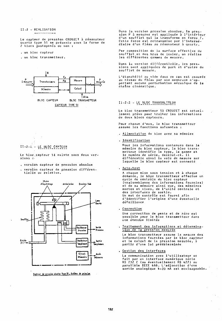
1 1 - 2 - RCALISATION - - - - - - - - - - - Le c a p t e u r de p r e s s i o n C R O U Z E T a r i s o n a t c u r q u a r t z t y p e 51 s e p r k s e n t e sous l a forme de 2 b l o c s , jus taposds ou non :
, u n b loc c a p t e u r
, un b loc t r a n s m e t t e u r .
I Alim BLOC C A P T E U R BLOC TRANSMETTEUR
C A P T E U R TYPE 51
11-2-1 - L E B L O C CAPTEUR - - - - - - - - - - - - - - - Le b l o c c a p t e u r 51 e x i s t e sous deux v e r - s i o n s :
, v e r s i o n c a p t e u r de p r e s s i o n a b s o l u e
.. v e r s i o n c a p t e u r de p r e s s i o n d i f f d r e n - t i e l l e ou r e l a t i v e .
Dans l a v e r s i o n p r e s s i o n a b s o l u e , l a p r e s - s i o n P i mesurer e s t a p p l i q u k e 5 l ' i n t d r i e u r d ' u n s o u f f l e t q u i l a t r a n s f o r m e en f o r c e f . C e t t e f o r c e e s t r e t r a n s m i s e par l ' i n t e r m i - d i a i r e d o u n f l d a u du r d s o n a t e u r q u a r t z .
Par c o n ~ p o s i t i o n de 14 s u r f a c e e f f e c t i v e du s o u r f l e t e t d e s b r a s de l e v i e r , on r d a l i s e l e s d i f f d r e n t e s gammes de mesure.
Dans l a v e r s i o n d i f f 6 r e n t i c l l e , l e s p r e s - s i o n s s o n t a p p l i q u k e s de p a r t e t d ' a u t r e du s o u f f i e t de mcsure.
L 1 & t d n c h 6 i t 6 au v i d e dans ce c a s e s t ~ s s u r 6 c au n iveau du f l d a u par une membrane n ' a p - p o r t a n t ducune p e r t u r b a t i o n mdcanique de l a c h a i n e c i n k m a t i q u e .
1 1 - 2 - 2 - L E B L O C TRANSMETTEUR . . . . . . . . . . . . . . . . . . . . Le b l o c t r a n s m e t t e u r 51 C R O U Z E T e s t a c t u e l - lement prkvu pour t r a i t e r l e s i n f o r m a t i o n s de deux b l o c s c a p t e u r s .
Pour chacun d l e u x , l e b l o c t r a n s m e t t e u r assume l e s f o n c t i o n s s u i v a n t e s :
. A l i m e n t a t i o n du b l o c avec s a mdmoire
. I d e n t i f i c a t i o n
Pour l e s i n f o r m a t i o n s c o n t e n u e s dans l a mkmoire du b l o c c a p t e u r , l e b l o c t r a n s - m e t t e u r i d e n t i f i e l e t y p e , l a gamme e t l e numiro de s i r i e , d e c e l u i - c i . I1 d i f f d r e n t i e a i n s i l a v o i e de mesure s u r l a q u e l l e l e b l o c c a p t e u r e s t c o n n e c t 6
A chaque mise s o u s t e n s i o n e t i chaque demande, l e b l o c t r a n s m e t t e u r e f f e c t u e un c y c l e de c o n t r 6 l e du b l o c c a p t e u r ( v r a i s e m b l a n c e d e s i n f o r m a t i o n s f o u r n i e s ) e t de s a mimoire a i n s i q u e , d e s mdmoires mor tes e t v i v e s , de l ' u n i t i c e n t r a l e e t d e s i n t e r f a c e s de s o r t i e . Un mot de c o n t r 6 l e e s t f o u r n i a f i n d 9 i d e n t i f i e r l ' o r i g i n e d ' u n e i v e n t u e l l e d i f a i l l a n c e
, C o r r e c t i o n
Une c o r r e c t i o n de pen te e t de z i r o e s t p o s s i b l e pour l e b l o c t r a n s m e t t e u r dans une ktendue l i m i t d e
, T r a i t e m e n t d e s i n f o r m a t i o n s e t d d t e r m i n a - t i o n de l a p r e s s i o n mesuree
Le b l o c t r a n s m e t t e u r assume l a mesure d e s i n f o r m a t i o n s f o u r n i e s par l e b l o c capFeur e t l e c a l c u l de l a p r e s s i o n mesurde, a p a r t i r d ' u n e l o i prddkterrnin6e
. C e s t i o n d e s i n t e r f a c e s
La communication avec l ' u t i l i s a t e u r s e f a i t pa r un i n t e r f a c e numir ique s k r i e RS 2 3 2 C (ou d v e n t u e l l e m e n t R S 422) ou p a r a l l e l e I E E E 488. L ' a d j o n c t i o n d f u n e s o r t i e a n a l o g i q u e 4-20 m A e s t e n v i s a g e a b l e ,
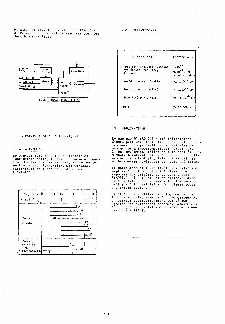
De plus, le bloc transmetteur rdalise les diffkrences des pressions mesurkes pour les deux blocs capteurs
dlim. ) lacs
BLOC TRANSMETTEUR TYPE 51
111 - CARACTERISTIQUES TECHNIQUES
Le capteur type 51 est actuellement en fabrication skrie, la gainme de mesure, fonc- tion des besoins des marchds, est actuelle- ment en cours d'extension. Les versions disponibles sont d'ores et dkjh les suivantes :
111-2 - PERFORMANCES
IV - APPLICATIONS
Paramktres
. Pricision incluant justesse, hystdrdsis, mobilitd, linbari td
, Rdsidus de moddlisation
. Rksolution - Mobilitk
. Stabilitd sur 6 mois , MTBF
Le capteur 51 CROUZET a 6td initialement dtudid pour une utilisation adronautique dans les nouvelles gknkrations de centrales de navigation andmobaromdtriques numkriques. I1 est Cgalement utilisd pour le contrcle des moteurs d'adronefs ainsi que pour des appli- cations en mitrologie, tels que manom&tres et baromktres num6riques de haute prdcision.
Performances
1 j
8,10-~. EM selon version
< l.10-~ t1.1
< 1.10-~ EM
~yp. l . l ~ - ~ EM
> 80 000 h
La conception et l'architecture modulaire du capteur 51 lui permettent kgalement de rdpondre aux crit&res du concept actuel de "CAPTEUR INTELLIGENT" et de dialoguer avec le calculateur de process soit directement, soit par l'intermddiaire d o u n rkseau local dtinstrumentation.
De plus, les qualitds mktrologiques et la tenue auk environnements font du capteur 51, un capteur particu1i;rement adapt6 aux besoins des diffdrents secteurs industriels o& une grande pricision doit s'allier 2 une grande stabilitk.
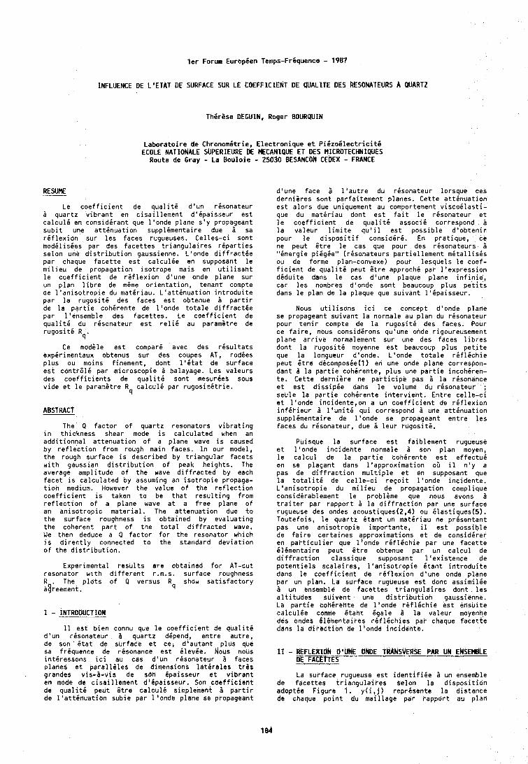
l e r Forum Europ ien Temps-Friquence - 1987
INFLUENCE DE L'ETAT DE SURFACE SUR LE COEFFIClENT DE QUALITE DES RESONATEURS A QUARTZ
T h i r i s e DEGUIN. Roger BOURQUIN
L a b o r a t o i r e de Chronomit r ie , E l e c t r o n i q u e e t P i 6 z o i l e c t r i c i t i ECOLE NATIONALE SUPERIEURE bE MECANIQUE ET bES MICROTECHNIQUES
Route de Gray - La B o u l o i e - 25030 BESANCOM C E ~ E X - FRANCE
RESUME
Le c o e f f i c i e n t de q u a l i t i d ' u n r i s o n a t e u r H q u a r t z v i b r a n t en c i s a i l l e m e n t d ' i p a i s s e u r e s t c a l c u l i en c o n s i d i r a n t que l ' o n d e p lane s ' y propayeant s u b l t une a t t i n u a t i o n supp l imenta i re due a sa r i f l e x i o n sur l e s faces rugueuses. C e l l e s - c i son t m o d i l i s i e s par des f a c e t t e s t r i a n g u l a i r e s r i p a r t i e s s e l o n une d i s t r i b u t i o n gaussienne. L 'onde d i f f r a c t i e par chaque f a c e t t e e s t c a l c u l i e en supposant l e m l l i e u de p ropaga t ion i s o t r o p e mals en u t i l i s a n t l e c o e f f i c i e n t de r i f l e x i o n d 'une onde p lane sur un p l a n l i b r e de mime o r i e n t a t i o n , tenan t compte de l ' a n i s o t r o p i e du m a t i r i a u . L ' a t t i n u a t i o n i n t r o d u i t e par l a r u g o s i t i des faces e s t obtenue B p a r t i r de l a p a r t i e c o h i r e n t e de l ' o n d e t o t a l e d i f f r a c t i e p a r l 'ensemble des f a c e t t e s . Le c o e f f i c i e n t de q u a l i t 6 du r i s o n a t e u r e s t r e l i i au parami t re de r u g o s i t i R
q ' Ce modele e s t compar i avec des r i s u l t a t s
expi r i rnentaux obtenus sur des coupes AT, r o d i e s p l u s ou moins f inement , dont l ' i t a t de s u r f a c e e s t c o n t r 6 l i pa r microscopic H balayage. Les v a l e u r s des c o e f f i c i e n t s de q u a l i t 6 son t mesuries sobs v i d e e t l e parametre R c a l c u l i par r u g o s i m i t r i e .
q
ABSTRACT
The Q f a c t o r o f q u a r t z resona to rs v i b r a t i n g i n th i ckness shear mode i s c a l c u l a t e d when an a d d i t i o n n a l a t t e n u a t i o n o f a p lane wave i s caused by r e f l e c t i o n from rough main faces. I n our model, t h e rough s u r f a c e i s descr ibed by t r i a n g u l a r f a c e t s w i t h gaussian d i s t r i b u t i o n o f peak h e i g h t s . The average ampl i tude o f t h e wave d i f f r a c t e d by each f a c e t i s c a l c u l a t e d oy assuming an i s o t r o p i e propaga- t i o n medium. However t h e va lue o f t h e r e f l e c t i o n c o e f f i c i e n t i s taken t o be t h a t r e s u l t i n g from r e f l e c t i o n o f a p lane wave a t a f r e e p lane o f an a n i s o t r o p i c m a t e r i a l . The a t t e n u a t i o n due t o t h e su r face roughness i s ob ta ined by e v a l u a t i n g t h e coherent p a r t o f t h e t o t a l d i f f r a c t e d wave. We then deduce a Q f a c t o r f o r t h e resona to r which i s d i r e c t l y connected t o t h e s tandard d e v i a t i o n o f t h e d i s t r i b u t i o n .
Exper imenta l r e s u l t s a r e ob ta ined f o r AT-cut resona to r w l t h d i f f e r e n t r.m.s. s u r f a c e roughness R . The p l o t s o f Q versus R show s a t i s f a c t o r y agreement. 4
I - INTRODUCTION
I 1 e s t b i e n connu que l e c o e f f i c i e n t de q u a l i t i d ' u n r i s o n a t e u r a q u a r t z dipend, e n t r e a u t r e , de s o n ' B t a t de su r face e t ce, d ' a u t a n t p l u s que sa f r i q u e n c e de r isonance e s t BlevBe, Nous nous i n t i r e s s o n s i c i au cas d ' u n r i s o n a t e u r B faces p lanes e t p a y a l l i l e s de dimensions l a t 6 r a l e s t r i s grandes v is -a -v is de son Bpaisseur e t v i b r a n t en mode de c i s a i l l e m e f l t d ' i p a i s s e u r . Son c o e f f i c i e n t de q u a l i t i peu t i t r e c a l c u l i simplement 5 p a r t i r de l o a t t i n u a t i o n sub ie par l ' o n d e p lane se propageant
d'une face H l ' a u t r e du r i s o n a t e u r l o r s q u e ces d e r n i k r e s sont p a r f a i t e m e n t p lanes. C e t t e a t t i n u a t i o n e s t a l o r s due uniquement au comportement v i s c o i l a s t i - que du m a t i r i a u dont e s t f a i t l e r i s o n a t e u r e t l e c o e f f i c i e n t de q u a l i t i a s s o c i i correspond H l a v a l e u r l i r n i t e q u ' i l e s t p o s s i b l e d ' o b t e n i r pour l e d i s p o s i t i f c o n s i d i r b . En p r a t i q u e , ce ne peu t Gt re l e cas que pour des r i s o n a t e u r s B " i n e r g i e p i igEe" ( r i s o n a t e u r s p a r t i e l l e m e n t m i t a l l i s i s ou de forme plan-convene) pour l e s q u e l s l e coef- f i c i e n t de q u a l i t i peut Gt re approch i pa r l ' e x p r e s s i o n d i d u i t e dans l e cas d 'une p laque p lane i n f i n i e , c a r l e s nombres d 'onde son t beaucoup p l u s p e t i t s dans l e p l a n de l a p laque que s u i v a n t l ' i p a i s s e u r .
Nous u t i l i s o n s i c i ce concept d 'onde p lane se propageant s u i v a n t l a normale au p l a n du r i s o n a t e u r pour t e n i r compte de l a r u g o s i t i des faces. Pour ce f a i r e , nous c o n s i d i r o n s qu'une onde r igoureusement p lane a r r i v e normalement su r une des faces l i b r e s don t l a r u g o s i t i moyenne e s t beaucoup p l u s p e t i t e que l a longueur d'onde. L'onde t o t a l e r i f l i t h i e peu t i t r e dicomposie(1) en une onde p lane correspon- dan t B l a p a r t i e c o h i r e n t e , p l u s une p a r t i e i n c o h i r e n - t e . C e t t e d e r n i s r e ne p a r t i c i p e pas H l a r i sonance e t e s t d i s s i p i e dans l e volume du r i s o n a t e u r ; seu le l a p a r t i e c o h i r e n t e i n t e r v i e n t . E n t r e c e l l e - c i e t l ' o n d e i n c i d e n t e , o n a un c o e f f i c i e n t de r i f l e x i o n i n f 6 r i e u r B l ' u n i t i q u i correspond B une a t t i n u a t i o n supp l imenta i re de l ' o n d e se propageant e n t r e l e s faces du r i s o n a t e u r , due B l e u r r u g o s i t i .
Puisque l a s u r f a c e e s t fa ib lement rugueuse e t l ' o n d e i n c i d e n t e normale H son p l a n moyen, l e c a l c u l de l a p a r t i e c o h i r e n t e e s t e f f e c t u i en se p l a ~ a n t dans l ' a p p r o x i m a t i o n oil il n ' y a pas de d i f f r a c t i o n m u l t i p l e e t en supposant que l a t o t a l i t i de c e l l e - c i r e ~ o i t l ' o n d e i n c i d e n t e . L ' a n i s o t r o p i e du m i l i e u de p ropaga t ion complique cons id i rab lement l e probleme que nous avons B t r a i t e r pa r r a p p o r t 3 l a d i f f r a c t i o n par une sur face rugueuse des ondes acoustiques(2,4) ou E las t iques(5 ) . T o u t e f o i s , l e q u a r t z i t a n t un m a t i r i a u ne p r i s e n t a n t pas une anisotropic impor tan te , il e s t p o s s i b l e de f a i r e c e r t a i n e s approx imat ions e t de c o n s i d i r e r en p a r t i c u l i e r que l ' onde r i f l i c h i e par une f a c e t t e i l i m e n t a i r e peu t i t r e obtenue par un c a l c u l de d i f f r a c t i o n c l a s s i q u e supposant l ' e x i s t e n c e de p o t e n t i e l s s c a l a i r e s , l ' a n i s o t r o p i e B t a n t i n t r o d u i t e dans l e c o e f f i c i e n t de r i f l e x i o n d'une onde p lane par un p lan . La sur face rugueuse e s t donc a s s i m i l i e B un ensemble de f a c e t t e s t r i a n g u l a i r e s don t l e s a l t i t u d e s s u i v e n t une d i s t r i b u t i o n gaussienne. La p a r t i e c o h i r k n t e de l ' o r lde . rB f lEch ie e s t e n s u i t e c a l c u l B e comme i t a n t k g a l e a l a v a l e u r moyenne des ondes B lkmenta i res r i f l i c h i e s par chaque f a c e t t e dans l a d i r e c t i o n de l ' o n d e i n c i d e n t e .
11 - d t F ~ ~ x t d s S O 'UK ONDE T##kS\iER$E PAR LIN ENSEMBLE bE FACETTES
La sur face rugueuse e s t i d e n t i f i i e i un ensemble de f a c e t t e s t r i a n g u l a i r e s s e l o n l a d i s p o s i t i o n a d o p t i e F i g u r e 1. y ( i !j) r e p r i s e n t e l a d i s t a n c e de chaque p o i n t du m a i l l a g e par r a p p o r t au p l a n
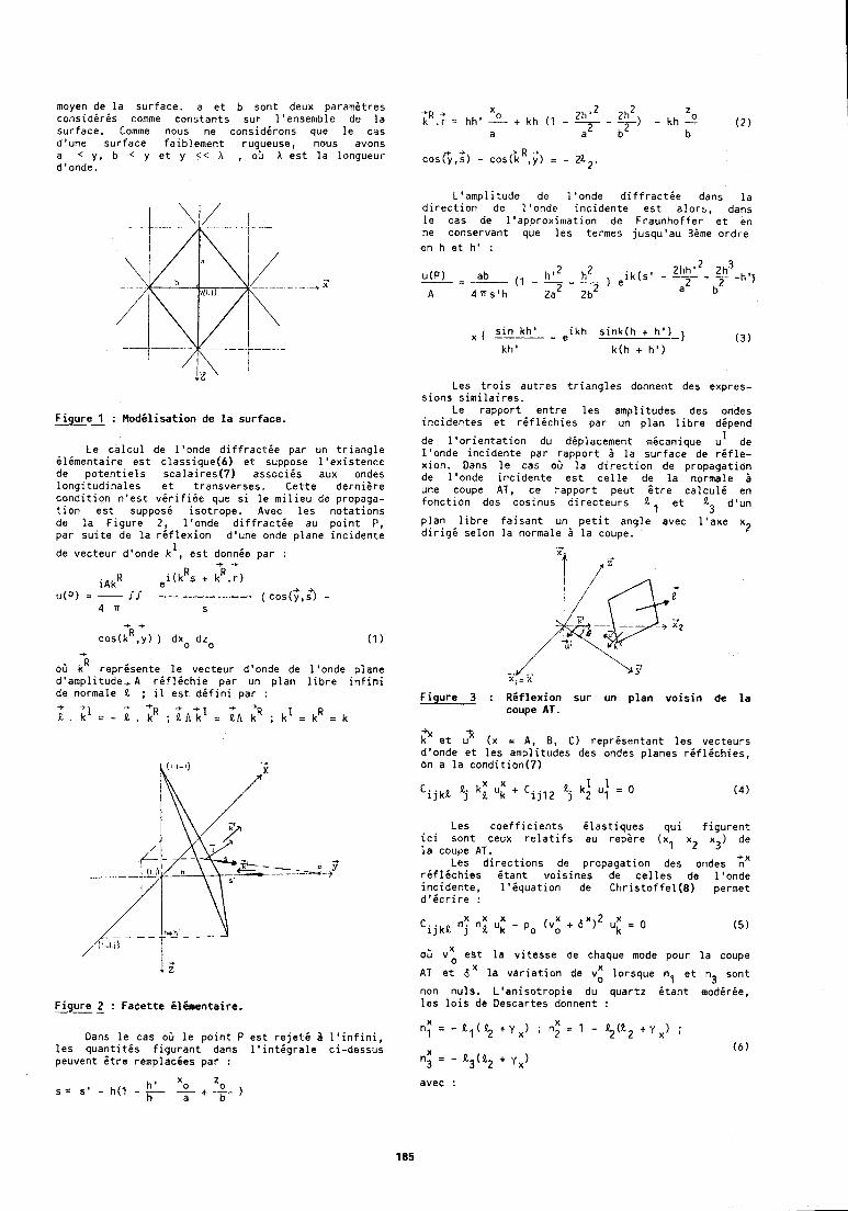
moyen de la surface. a et b sont deux paramitres considiris comme constants sur l'ensemble de la surface. Comme nous ne considirons que le cas d'une surface faiblement rugueuse, nous avons a < y, b < y et y < < X , oL X est la longueur d'onde.
Fiqure 1 : Modilisation d e la surface. ---
Le calcul de l'onde diffracthe par un triangle ilimentaire est classique(6) et suppose l'existencc de potentiels scalaires(7) assocles aux ondes longitudinales et transverses. Cette derniire condition n'est virifiie que si le milieu de propaga- tion est suppose isotrope. Avec les notations de la Figure 2, l'onde diffractie au point P, par suite de la riflexion d'une onde plane incidente
de vecteur d'onde k L , est donnie par : + +
R R i ~ k ~ e i(k s + k .r)
I / + +
u(P) = - (cos(y,s) - 4 a s
+ + R
cos(k , y) ) dxo dzo (1) +
air kR reprisente le vecteur d'onde de I'onde plane d'amplitude, A riflichie par un plan libre infini de normale It ; il est ddfini par :
+ + + + ;t . ;1 = - I t . kH ; Rn;l = It, ;R ; k1 = kR 3 k
Fiqure 2 : Facette Climentaire. ---
Dans le cas oG le point P est rejeti A l'infini, les quantitis figurant dans l'intigrale ci-dessus peuvent $tre remplacees par :
L'amplitude de l'onde diffractie dans la direction de l'onde incidente est alors, dans le cas de l'approximation de Fraunhoffer et en ne conservant que les termes jusqu'au 3ime ordre en h et h' :
sin kh' ikh sink(h + h')-) X I - - e ( 3 ) kh' k(h + h')
Les trois autres triangles donnent des expres- sions similaires.
Le rapport entre les amplitudes des ondes incidentes et rifldchies par un plan libre dipend
de l'orientation du ddplacement mdcanique u' de l'onde incidente par rapport A la surface de rifle- xion. Dans le cas oG la direction de propagation de l'onde incidente est celle de la normale A une coupe AT, ce rapport peut Stre calculi en fonction des cosinus directeurs .el et It3 d'un
plan libre faisant un petit angle avec l'axe x2 dirigd selon la normale A la coupe.
Figure 3 : Riflexion sur un plan voisin de la coupe AT.
+x k et uk (X = A, 8, C) reprisentant les vecteurs d'onde et les amplitudes des ondes planes riflichies, on a la condition(7)
Les coefficients ilastiques qui figurent ici sont ceux relatifs au repire (xl x2 x3) de la coupe AT.
Les directions de propagation des ondes %X riflichies itant voisines de celles de I'onde incidente, l'iquation de Christoffel(8) permet d'icrire :
oir v t est la vitesse de chaque mode pour la coupe ., A T et 6'' la variation de vz lorsque n, et n, sont
" non nuls. L'anisotropie du quartz &ant modirie, les lois de Descartes donnent :
avec :
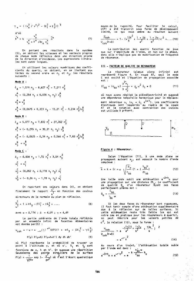
En p o r t a n t ces r i s u l t a t s dans l e systsme ( 5 ) , on o b t i e n t l e s v i t e s s e s e t l e s vec teurs p ropres de chaque mode r i f l i c h i s dans une d i r e c t i o n proche de l a d i r e c t i o n d o i n c i d e n c e . Les expressions l i t t i r a - l e s sont assez longues.
En u t i l i s a n t l e s v a l e u r s numir iques des c o e f f i - c i e n t s du quar tz , on o b t i e n t , en se l i m i t a n t aux termes du second o r d r e en nl e t n3, l e s r i s u l t a t s s u i v a n t s :
Rode A : ---
moyen de l a r u g o s i t i . Pour f a c i l i t e r l e c a l c u l , U(P) a i t 6 t r a n s c r i t sous forme de diveloppement l i m i t i , ce q u i nous amine au r i s u l t a t s u i v a n t
Mode B : .- 2 2 6 8 = 5,077 n3 + 7,832 nl + 27,352 n3
En r e p o r t a n t ces va teurs dans (41, on o b t i e n t
f i na lement l e r a p p o r t en f o n c t i o n des cosinus U
d i r e c t e u r s de l a normale au p l a n de r i f l e x i o n .
avec a = 0,114 ; B = 4,09 ; y = 4949
La p a r t i e cohhrente de l ' o n d e t o t a l e r i f l i c h i e p a r un ensemble i n f i n i de f a c e t t e s i l i m e n t a i r e s e s t donnie par (1 ) :
oil P(y) r e p r i s e n t e l a p r o b a b i l i t i de t rouvel - un p o i n t A l ' a l t i t u d e y, e t ob s ' , tl e t 5 son t
f o n c t i o n s de y, h e t h ' . On suppose une r i p a r t i t i o n Gaussienne des p o i n t s s i n g u l i a r s de l a s u r f a c e
exp (L 4) & J e s t 1 1 6 c a r t quadra t ique P(y) = - mu 20
La c o n t r i b u t i o n des q u a t r e f a c e t t e s ne joue que sur l ' a m p l i t u d e de l ' o n d e , e t noh sur l a phase, donc e l l e n ' i m p l i q u e pas de m o d i f i c a t i o n de f r i q u e n c e de r isonance.
111 - Y T E U R DE PUALITE DU RESONATEUR
Le r i s o n a t e u r (p laque p lane i n f i n i e ) e s t r e p r i s e n t i F i g u r e 4. En coupe AT, s e u l l e mode C e s t e x c i t e e t l ' i q u a t i o n de p ropaga t ion a s s o c i i e e s t : 9-
ob nous avons n d g l i g i l a p i i z o i l e c t r i c i t i e t supposi une dipendance tempore l le harmonique pour l e d i p l a c e -
ment micanique ul (u, = eiw t, .. Les c o e f f i c i e n t s i l a s t i q u e s son t rapporti:' au repere ds l a coupe AT e t l a n o t a t i o n avec c o n t r a c t i o n des i n d i c e s e s t u t i l i s i e A p r i s e n t .
F i g u r e 4 : RBsonateur.
Selon l ' i q u a t i o n ( l l ) , 5 une onde p lane se propageant s u i v a n t x2, e s t a s s o c i i l e nombre d fonde complexe :
Une t e l l e onde s u b i t une a t t e n u a t i o n emZrho pour uhe p ropaga t ion su r une d i s t a n c e 2h . Le c o e f f i c i e n t de q u a l i t i Q d ' u n r i s o n a t e u r gyan t ses faces p a r f a i t e m e n t pl%nes e s t :
S i l e s deux faces du r i s o n a t e u r son t rugueuses, il f a u t t e n i r compte d 'une a t t e n u a t i o n suppldmentai re due B l a r g f l e x i o n s u r de t e l l e s su r faces . S i c e t t e a t t i n u a t i o n r e s t e t r i s f a i b l e (ce q u i e s t n o t r e cas en p r a t i q u e pour l e s r i s o n a t e u r s a quar tz ) , on peu t r i i c r i r e pour l e s v a l e u r s p e t i t e s de
02, l a r e l a t i o n ( l o ) , sous l a forme :
Au cours d 'un t r a j e t , l ' d t t i n u a t i o n t 0 t d l e sub ie p a r l ' o n d e e s t donc :
' i 6 - k r h o ,-2rho ,-r'u
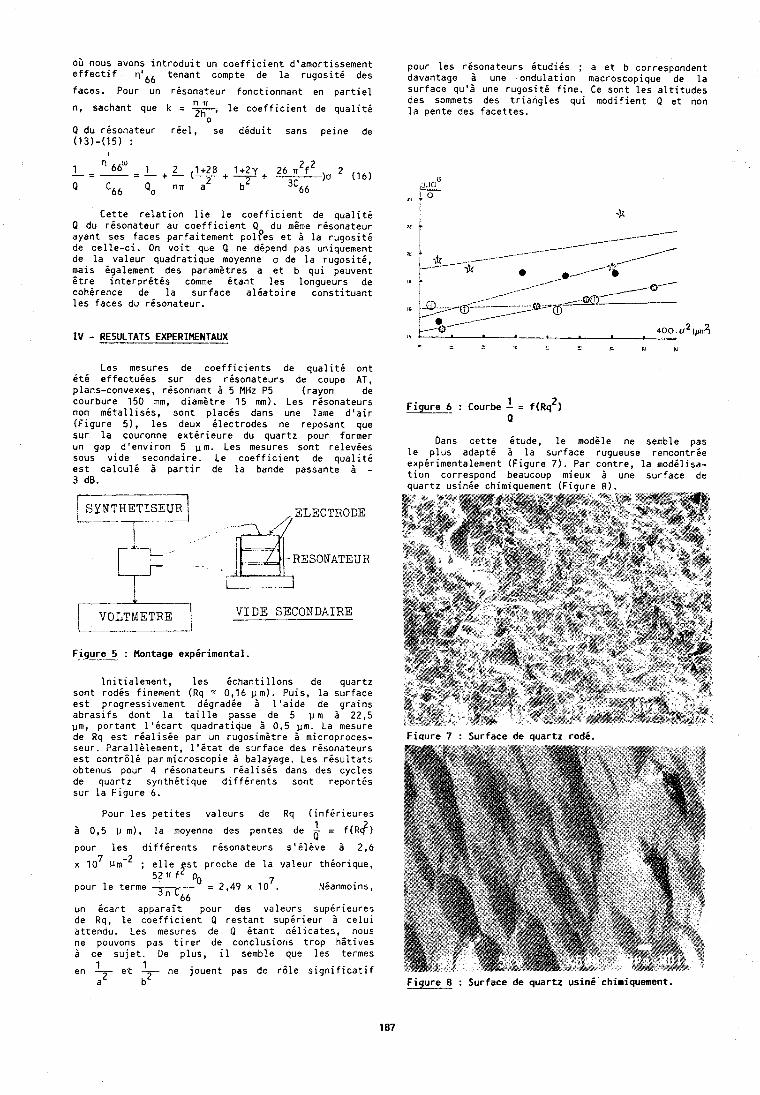
03 nous avons introduit un coefficient d'amortissement pour les r6:onateurs itudiis ; a et b correspondent effectif '1'66 tenant compte de la rugositi des davantage a une ondulation macroscopique de la faces. pour un risonateur fonctionnant en partiel surface qu'8 une rugositi fine. Ce sont les altitudes
n R des sommets des triangles qui modifient Q et non n, sachant que k = 2ho' le coefficient de qualiti la pente des facettes.
Q du risonateur riel, se diduit sans peine de (13)-(15) :
Les mesures de coefficients de qualiti ont it6 effectuies sur des risonateurs de coupe AT, plans-convexes, risonr~ant B 5 MHz P5 (rayon de courbure 150 mm, didmatre 15 mm). Les resonateurs non m8tallisis, sont placis dans une lame d'air (Figure 5), les deux ilectrodes ne reposant que sur la couronne extirieure du quartz pour former un gap d'environ 5 p m . Les mesures sont relevies sous vide secondaire. Le coefficient de qualiti est calculi i partir de la bande passante i - 3 dB.
Cette relatlon lie le coefficient de qualitd Q du rdsonateur au coefficient Q du mime risonateur a
ayant ses faces parfaitement polfes et 1 la rugositi de celle-ci. On voit que Q ne dipend pas uniquement a de la valeur quadratique moyenne a de la rugositi, mais igalement des parametres a et b qui peuvent
1s itre interpretis comme itant les longueurs de cohirence de la surface al6atoire constituant les faces du risonateur. ,,
1 Figure 6 : Courbe - = f ( ~ ~ * ) a
-3 . .IC--
, -&-.---. ---.------- -. /-
/ =& 0 . ,.a'
/4&'
,/-. -<-----
<_-A-
,/o--- _-_@---------A -/.-@-=a &
Dans cette ktude, le modkle ne semble pas le plus adapt6 i la surface rugueuse rencontrie expirimentalement (Figure 7). Par contre, la modilisa- tion correspond beaucoup mieux 6 une surface de
, IV - RESULTATS EXPERIMENTAUX Y I 400 i ~ * ( ~ r n Z )
' 2 C h I 4 IU
auartz usinie chimiauement [Fiaure 8 ) .
/
RESONATEUR
J. r V O L T M E T R E I VIDE SBCONDAIRE
Fjigxe_5. : Montage expirimental.
lnitialement, les ichantillons de quartz sont rodis finement (Rq 2 0,16 urn). Puis, la surface est progressivement digradie B l'aide de grains abrasifs dont la taille passe de 5 p m 2 22,5 urn, portant l'icart quadratique 2 0,5 p m . La mesure de Rq est rialisie par un rugosim&tre 2 microproces- seur. ParallGlement, l'itat de surface des risonateurs est contr6lk par microscopie 2 balayage. Les risultats obtenus pour 4 risonateurs rialisis dans des cycles de quartz synthitique diffirents sont report& sur la Figure 6.
Pour les petites valeurs de Rq (infirieures
i 0,5 p m), la moyenne das pentes de = f (R$)
pour les diffirents risonateurs s'El&ve 2 2,6
x lo7 ; elle fst proche de la valeur thkorique, 5 2 R f p0
pour le terme 7 Tic,, = 2 , 4 9 x 1 0 . Nianmoins,
- - un icart apparait pour des valeurs supirieures de Rq, le coefficient Q restant supirieur b celui attendu. Les mesures de Q itant dilicates, nous ne pouvons pas tirer de conclusions trop hstives 2 ce sujet. De plus, il semble que les termes
1 1 en e.t -2- ne jouent pas de r6le significatif a b
Fiqure 7 : Surface d e quartz rods.
Figure 8 : Surface de quartz using chimiquement.
MIBLIOGRAPHIE
(1) P. BECKMAN, A . SPIZZICHINO, "The s c a t t e r i n g o f e lec t romagne t i c waves f rom rough su r faces . Mac M i l l an , (New York] 1963.
( 2 ) L. FORTUIN, "Survey o f L i t t e r a t u r e on r e f l e c t i o n and s c a t t e r i n g o f sound waves a t t h e sea su r face , Journ. Acous. Soc. Am., 2, 5, p 1209-1228, 1970.
( 3 ) C.W. HORTON, "A rev iew o f r e v e r b e r a t i o n , s c a t t e r i n g and e c h o - s t r u c t u r e , Journ. Acous. Soc. Am., 47, p 290-298, 1970.
( 4 ) P.J. WELTON, "The p o t e n t i a l method f o r m u l a t i o n o f a c o u s t i c wave s c a t t e r i n g by rough sur faces" , Journ . Acous. Soc. Am., 2, p 66-73, 1973.
(5) M. de B I L L Y , G. QUENTIN, "Backsca t te r ing o f a c o u s t i c waves by randomly rough s u r f a c e s o f e l a s t i c s o l i d immerged i n water" , Journ . Acous. Soc. A m . , 2, 2, p 591-601, 1982.
(6 ) M. BORN, E . WOLF, " P r i n c i p l e s o f o p t i c s " , Pergamon, (New-York) , 1980.
(7) P.M. MORSE, H. FESHBACK, "Methods o f T h e o r e t i c a l Physics" , Mc Graw-H i l l , (New-York), 1953.
(8 ) E . DIEULESAINT, 0 . ROYER, "Ondes i l a s t i q u e s dans l e s s o l i d e s " , Masson, ( P a r i s ) , 1974.
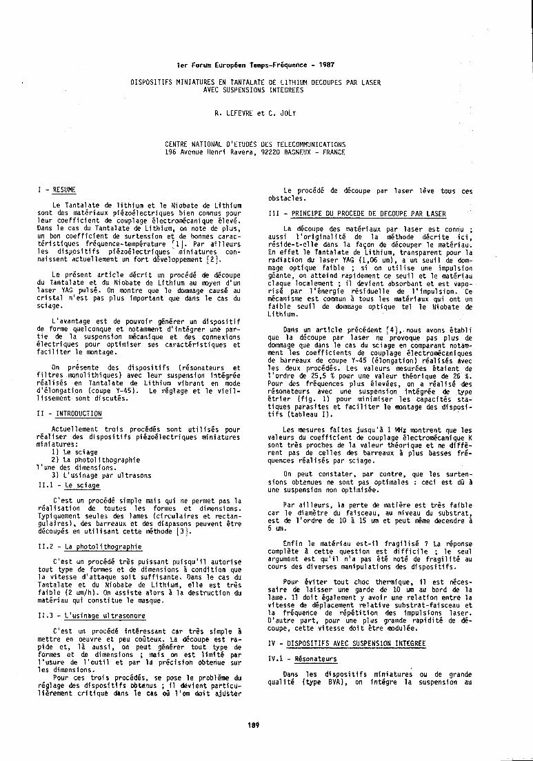
l e r Forum Europhen Temps-FrBquence - 1987
DISPOSITIFS MINIATURES EN TANTALATE OE LITHIUM DECOUPES PAR LASER AVEC SUSPENSIONS INTEGREES
R. LEFEVKE e t C, JOLY
CENTRE NATIONAL D'ETUDES DES TELECOMMUNICATIONS 196 Avenue Henr i Ravera, 92220 DAGNEUX - FRANCE
RESUME I -- Le T a n t a l a t e de l i t h i u m e t l e Niobate de L i t h i u m
son t des mate r i dux p i e z o d l e c t r i ques b i e n connus pour l e u r c o e f f i c i e n t de couplage e lect ro1n6canique 6 lev6 . Dans l e cas du T a n t a l a t e de L i th ium, on no te de p l u s , un bon c o e f f i c i e n t de su r tens ion e t de honnes carac- t e r i s t i q u e s fr6quence-temp6rature [I]. Par a i l l e u r s l e s d i s p o s i t i f s p i B z o 6 l e c t r i q u e s m i n i a t u r e s con- na i ssent a c t u e l lement un f o r t d6veloppement 121.
Le p resen t a r t i c l e d 6 c r i t un procede de d6coupe du T a n t a l a t e e t du Niobate de L i t h i u m au m y e n d 'un l a s e r YAG puls6. On I m n t r e que l e do~mnage cause au c r i s t a l n ' e s t pas p l u s impor tan t que dans l e cas du sciage.
L 'avantage e s t de pouvo i r g6n6rer un d i s p o s i t i f de forme quelconque e t nota~nment d 1 i n t 6 g r e r une par - t i e de l a suspension d c a n i q u e e t des connexions B l e c t r i q u e s pour o p t i ~ n i s e r ses c a r a c t 6 r i s t i q u e s e t f a c i l i t e r l e montage.
On p resen te des d i s p o s i t i f s ( r6sona teurs e t f i l t r e s ~ m n o l i t h i q u e s ) avec l e u r suspension in t6grCe r e a l i s e s en T a n t a l a t e de L i t h i u m v i b r a n t en mode d 1 8 l o n g a t i o n (coupe Y-45). Le r6g lage e t l e v i e i l - 1 issement sont d iscu tes .
I 1 - INTRODUCTION
Ac tue l lement t r o i s procbd6s sont u t i l i s 6 s pour r e a l i s e r des d i s p o s i t i f s p i 6 z o 6 l e c t r i q u e s m i n i a t u r e s m i n i a t u r e s :
1) Le sc iage 2 ) La p h o t o l i thograph ie
1 'une des dimensions. 3 ) L 'us inage par u l t r a s o n s
11.1 - Le sc iage
C ' e s t un proc6d6 s imple mais qu i ne permet pas l a r e a l i s a t i o n de t o u t e s l e s formes e t dimensions. Typiquement seules des lames ( c i r c u l a i r e s e t rec tan- gu l a i r e s 1, des barreaux e t des diapasons peuvent E t r e dPcoup6s en u t i l i s a n t c e t t e l d t h o d e [ 3 ] .
11.2 - La pho to l i t h o g r a p h i e
C ' e s t un proc6d6 t r e s p u i s s a n t p u i s q u ' i l a u t o r i s e t o u t type de formes e t de dimensions i c o n d i t i o n que l a v i t e s s e d ' a t t a q u e s o i t s u f f i s a n t e . Dans l e cas du T a n t a l a t e e t du Niobate de L i th ium, e l l e e s t t r g s f a i b l e ( 2 um/h). On a s s i s t e a l o r s 1 l a d e s t r u c t i o n du matPr iau qu i c o n s t i t u e l e masque.
11.3 - L 'us inage u l t r a s o n o r e
C ' e s t un procdd6 i n t e r e s s a n t c a r t r l s s imple 'a m e t t r e en oeuvre e t peu coirteux. La &coupe e s t ra - p i d e e t , l a auss i , on peu t gPn6rer t o u t t ype de fo r~nes e t de dimensions ; mais on e s t l i m i t 6 par l ' u s u r e de l ' o u t i l e t pa r l a p r 4 c i s i a n abtenue sur l e s dimensions.
Pour ces t r o i s procedgs, se pose l e problPme du r6g lage des d i s p o s i t f f s obtenus ; il d e v i e n t p a r t i c u - l i s r e m e n t c r i t i q u e dans l e cab 03 l ' o n d o i t a j u s t e r
Le procPdP de decoupe par l a s e r l 6 v e tous ces obs tac les .
111 - PRINCIPE DU PROCEDE DE DECOUPE PAR LASER
La d6coupe des mat6 r iaux par l a s e r e s t connu ; auss i 1 ' o r i g i n a l i t 6 de l a d t h o d e d B c r i t e i c i , r 6 s i d e - t - e l l e dans l a f a ~ o n de d6couper l e mater iau. En e f f e t l e T a n t a l a t e de L i t h i u m , t r a n s p a r e n t pour l a r a d i a t i o n du l a s e r YAG (1,06 um), a un s e u i l de dom- mage o p t i q u e f a i b l e ; s i on u t i l i s e une impu ls ion ggante, on a t t e i n d rapidement ce s e u i l e t l e mate r iau c laque localement ; il d e v i e n t absorbant e t e s t vapo- r i s e p a r l 1 6 n e r g i e r 6 s i d u e l l e de l ' i m p u l s i o n . Ce d c a n i s m e e s t commun Z tous l e s mat6 r iaux q u i o n t un f a i b l e s e u i l de dommage o p t i q u e t e l l e N ioba te de L i t h i u m .
Dans un a r t i c l e pr6c6dent [ 4 ] , nous avons e t a h l i que l a decoupe par l a s e r ne provoque pas p l u s de dorn~nage que dans l e cas du sc iage en comparant notam- ment l e s c o e f f i c i e n t s de couplage 6 lect rom6caniques de barreaux de coupe Y-45 ( B l o n g a t i o n ) r 6 a l i s 6 s avec l e s deux proc6d6s. Les v a l e u r s mesur6es e t a i e n t de l ' o r d r e de 25,5 % pour une v a l e u r t h e o r i q u e de 26 X . Pour des frequences p l u s 6lev6es, on a r 6 a l i s 6 des r6sona teurs avec une suspension i n t 6 g r 6 e de type 6 t r i e r ( f i g . 1) pour m in im iser l e s c a p a c i t 6 s s ta - t i q u e s p a r a s i t e s e t f a c i l i t e r l e montage des d i s p o s i - t i f s ( t a b l e a u I ) ,
Les mesures f a i t e s j u s q u ' 8 1 MHz m n t r e n t que l e s va l eu rs du c o e f f i c i e n t de coup1 age Clectrom6canique K son t t r 6 s p ro thes de l a v a l e u r t h 6 o r i q u e e t ne d i f f P - r e n t pas de c e l l e s des barreaux 1 p l u s basses f r 6 - quences r e a l i s6s par sc iage.
On peut cons ta te r , pa r con t re , que l e s su r ten- s ions obtenues ne sont pas op t ima les : c e c i e s t dir 3 une suspenston non opt i ln is6e.
Par a i l l e u r s , l a p e r t e de mat ie re e s t t r 6 s f a i b l e c a r l e d iamgtre du fa isceau , au n iveau du s u b s t r a t , e s t de l ' o r d r e de 10 i 15 um e t peu t $me decendre 8 5 um.
E n f i n l e mat6 r iau e s t - i l f r a g f l i s g ? La r6ponse complete 3 c e t t e ques t ion e s t d i f f i c i l e ; l e seul argument e s t q u ' i l n ' a pas 6 t 6 n o t 6 de f r a g i l i t 6 au cours des d ive rses man ipu la t ions des d i s p o s i t i f s .
Pour 6 v i t e r t o u t choc thermique, il e s t neces- s a i r e de l a i s s e r une garde de 10 um au bord de l a lame. I 1 d o i t 6galement y a v o i r une r e l a t i o n e n t r e l a v i t e s s e de dgplace~nent r e l a t i v e s u b s t r a t - f a i s c e a u e t l a f rgquence de r g p e t i t i o n des impu ls ions l a s e r . D ' a u t r e p a r t , pour une p l u s grande r a p i d i t 6 de d6- coupe, c e t t e v i t e s s e d o i t E t r e tnodul6e.
I V - DISPOSITIFS AVEC SUSPENSION INTEGREE
Dans l e s d i s p o s i t i f s min iature; ou de grande q u a l i t 5 ( t y p e EVA), on i n t 6 g r e l a suspension au
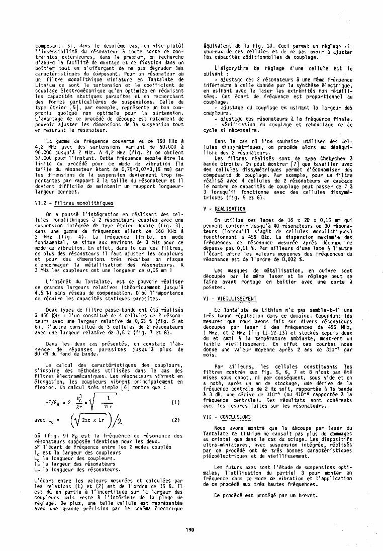
composant. S i , dans l e deuxieme cas, on v l s e p l ~ t a t l 1 i n s e n s i b i l i t 6 du resonateur i t o u t e s o r t e de con- t r a i n t e s e x t d r i e u r e s , dans l e premier , on recherc l ie d 'abord l a f a c i l i t e de imntage e t de f i x a t i o h dans uh b o i t i e r t o u t en s ' e f f o r s a n t de ne pas degrader l e s c a r a c t e r i s t i q u e s du composant. Pour un resonateur ocr un f i l t r e rnono l i th ique m i n i a t u r e en T a n t a l a t e de L i t h i u m ce sont l a s u r t e n s i o n e t l e c o e f f i c i e n t de couplage 6lectro1nPcanique qu'on o p t i m i z e en r e d u i s a n t l e s capac i tes s t a t i q u e s p a r a s i t e s e t en recherchant des formes p a r t i c u l i P r e s de suspensions. C e l l e du type E t r i e r 151, par exemple, rep resen te un bon c o w promis quoiquc non op t ima le pour l a su r tens ion . L 'avantage de ce procede de decoupe e s t nota~nment de pouvo i r a j u s t e r l e s dimensions de l a suspension t o u t en mest~rant l e rgsonateur .
La gamine de frequence couver te va de 160 KHz i 4,2 MHz avec des sur tens ions v a r i a n t de 50.000 5 90.000 j u s q u ' i 2 MHz. A 4,2 MHz ( f i g . 2) on o b t i e n t 37.000 pour l ' i n s t a n t . Ce t te frequence semble & t r e l a l i m i t e du procede pour ce mode de v i b r a t i o n ( l a t a i l l e du resona teur B t a n t de 0,75*0,07*0,15 mn) c a r l e s dimensions de l a suspension deviennent t r o p im- p o r t a n t e s par r a p p o r t 'a l a t a i l l e du resonateur e t i 1 d e v i e n t d i f f i c i l e de m i n t e n i r un rapppor t longueur- 1 argeur c o r r e c t .
V I .2 - F i l t r e s monol i t h i q u e s
On a pousse 1 1 i n t 6 g r a t i o n en r e a l i s a n t des c e l - l u l e s mono l i th iques i 2 resonateurs coupl6s avec une suspension i n t d g r P e de type B t r i e r double ( f i g . 31, dans une gamme de frt iquences a l l a n t de 160 KHz 'a 2 MHz ( F i g . 4 ) . La f requence l i m i t e , en mode fondalnental, se s i t u e aux env i rons de 3 MHz pour ce mode de v i b r a t i o n . En e f f e t , dans l e cas des f i l t r e s , en p l u s des resonateurs il f a u t a j u s t e r l e s coup leurs e t pour des dimensions t r e s r e d u i t e s on r i s q u e d'endommager l a & t a l l i s a t i o n des resonatetit-s. A 3 MHz l e s coupleurs o n t une longueur de 0,05 mn !
L 1 i n t 6 r 6 t du Tan ta la te , e s t de pouvo i r r e a l i s e r de grandes l a r g e u r s r e l a t i v e s ( theor iquement j u s q u ' i 4,5 %) sans reseau de compensation. D'o: l ' i m p o r t a n c e de r e d u i r e l e s capac i tes s t a t i q u e s p a r a s i t e s .
Deux types de f i l t r e passe-bande on t 6 te r e a l i s e s i 455 k l lz : l ' u n c o n s t i t u e de 4 c e l l u l e s de 2 r6sona- t e u r s avec une la rge t r r r e l a t i v e de 0.63 % ( f i g . 5 e t 6 ) , l ' a u t r e c o n s t i t u g de 3 c e l l u l e s de 2 r6sona teurs avec une l a r g e u r r e l a t i v e de 3,5 % ( f i g . 7 e t 8).
Dans l e s deux cas pr6sent6s, on cons ta te l ' a b - sence de r e p o n s e s p a r a s i t e s j u s q u ' i p l u s de 80 dB du fond de bande.
Le c a l c u l des carac t e r i s t i q u e s des coupleurs, s ' i n s p i r e des methodes u t i l i s e e s dans l e cas des f i l t r e s Blectrom6caniques. Les resonateurs v i b r e n t en e longa t ion , l e s coupleurs v i b r e n t p r i n c i p a l e m e n t en f l e x i o n . Un c a l c u l t rCs s imple [ 6 ] montre que :
"3 r-7
avec LC = (1/GZ7)/2 0 3 ( f i g . 9 ) FR e s t l a f r e q u e n c e de resonance des rPsonateurs supposee i d e n t i q u e pour l e s deux. AF l ' e c a r t de frequence e n t r e l e s 2 modes coupl6s 1, e s t l a l a r g e u r des coupleurs LC l a longueur des coupleurs. 1, l a l a r g e u r des resonateurs Lr l a longueur des resonateurs.
L ' e c a r t e n t r e l e s va leurs m s u r d e s e t ca lcu lees par l e s r e l a t i o n s ( I 1 e t ( 2 ) e s t de l ' o r d r e de 15 %. I 1 e s t d i en p a r t i e 'a l ' i n c e r t i t u d e sur l a l a r g e u r des coupleurs ~ n a i s r e s t e 1 1 1 i n t 6 r i e u r de l a p lage de reglage. De p lus, une t e l l e ce l l u l e e s t representee avec une grande p r e c i s i o n par l e schema 6 l e c t r i q u e
I q u l v a l e n t de l a f i g . 10. Ceci permet un reg lage r i - oureux de ces e l l u l e s e t de ne pas a v o i r 1 a j u s t e r
yes oapaci t e s a h t i o n n e l l e s de couplage.
L1algorythnie de r6g lage d'crne c e l l u l c e s t l e s u i v a n t : - a jus tage des 2 resdha teurs 1 ufle &the frequence i n f e r l e u r e B c e l l e donr16e a r l a synth89e C l e c t r i q u e , en u s i h a n t avec l e l a s e r f e s ex t r&mi t 8 s tioh n @ t & l l t - sees. Get B c a r t de f requence e s t p r o p o r t i o n n e l au coup1 age. - a jus tage du couplage eh u s i n a n t l a l a r g e u r des coupleurs. - a j u s t a g r des resona teurs 'a l a f requence f i n a l e .
- v 6 r i f l c a t i o n du couplage e t rebouclage de ce c y c l e s f n6cessdi r e .
Dans l e cas oil I' on souha i te u t i l i s e r des c e l - l u l e s d issym6tr iques, on procede a l o r s au des8qui- l i b r e des 2 r l s o n a t e u r s .
Les f i l t r e s r e a l i s l s son t de type Chebychev 'a bande 6 t r o i t e . On peu t mont re r 171 que t a v a i l l e r avec des c e l l u l e s d l ssym5tr iques permet d16conomiser des compbsants de couplage. Par exemple, pour un f i l t r e r e a l i s 6 avec 4 c e l l u l e s de 2 resona teurs en cascade l e nombre de capac i tes de couplage peu t passer de 7 i 3 l o r s q u ' i l f o n c t i o n n e avec des c e l l u l e s dissyme- t r i q u e s ( f i g . 5 e t 6).
V - REALISATION
On u t i l i s e des lames de 16 x 20 x 0,15 mn qu i peuvent c o n t e n i r j usc lu ' i 40 resona teurs ou 30 resona- t e u r s ( l o r s q u ' i l s ' a g i t de c e l l u l e s monol i t h i q u e s ) f o n c t l o n n a n t 3 455 KHz. La d i s p e r s i o n maximale des frequences de resonance mesurge apres decoupe ne depasse pas 0.11 X. Par a i l l e u r s d'une lame 'a l ' a u t r e l ' e c a r t e n t r e l e s va leurs Imyennes des frequences de resonance e s t de l ' o r d r e de 0,032 %.
Les masques de J t a l l t s a t i o n , en c u i v r e son t decoupes par l e 6 m e l a s e r e t l e r6g lage peu t se f a i r e avant lrlontage en b o i t i e r avec une c a r t e 3 po i n tes .
V I - VIEILLISSEMENT
Le T a n t a l a t e de L i t h i u m n ' a pas s e m b l e - t - i l une t r e s bonne r e p u t a t i o n dans ce domaine. Cependant l e s m s u r e s que nous avons f a i t su r d i v e r s resona teurs decoupes p a r l a s e r i des frequences de 455 MHz, 1 MHz, e t 2 MHz ( f i g 11-12-13) c t s tockes depuis deux du e t demi 'a l a temperature ambiante, mont ren t un f a i b l e v i e i l l issement. En e f f e t ces courbes nous donne une v a l e u r moyenne apres 2 ans de 310-7 p a r mois.
Par a i l l e u r s , l e s c e l l u l e s c o n s t i t u a n t s l e s f i l t r e s ~non t res aux f i g . 5, 6, 7 e t 8 n ' o n t pas St6 mises sous capot, n i par consequent, sous v i d e e t on a note, aprPs un an de stockage, une d e r i v e de l a f requence c e n t r a l e de 2 Hz s o i t , rappor tee 'a l a bande B 3 dB, une d e r i v e de 310-4 (ou 410-6 r a p p o r t e e B l a f requence c e n t r a l e ) . Ces r e s u l t a t s son t coherents avec l e s mesures f a i t e s su r l e s resonateurs.
V I I - CONCLUSIONS
NOUS avons montre que l a decoupe par l a s e r du T a n t a l a t e de L i t h i u m ne c a u s a i t pas p l u s de dormnages au c r i s t a l que dans l e cas du sc iage. Les d i s p o s i t i f s u l t r a - m i n i a t u r e s , avec suspension in tegree , 6 a l i s 6 s p a r ce procede o n t de t r e s bonnes c a r a c t e r i s t i q u e s p i d z o 6 l e c t r i q u e s e t de v i e i l l i s s e m e n t .
Les f u t u r s axes son t l ' e t u d e de suspensions o p t i - males, l ' u t i l i s a t i o n du p a r t i e l 3 pour monter en f requence dans ce mode de v i b r a t i o n e t l ' a p p l i c a t i o r l de ce procede aux t r e s hautes f r l quences .
Ce procOd6 e s t p ro tege par un b reve t .
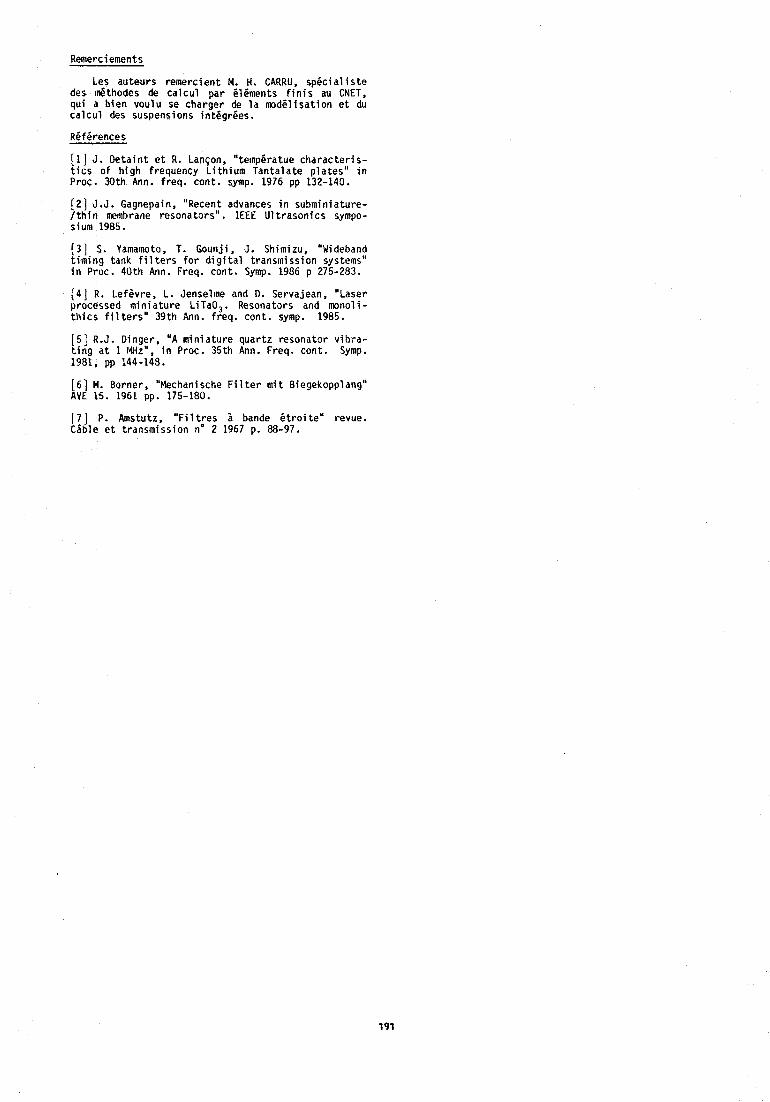
Remerci ements
Les au teurs remerc ien t M. H. CARRU, s p e c i a l i s t e des J t h o d e s de c a l c u l p a r Blements f i n i s au CNET, q u i a b i e n v o u l u se charger de l a m o d ~ l i s a t i o n e t du c a l c u l des suspensions in tdgrees .
References
E l ] J . D e t a i n t e t R. L a n ~ o n , "tempBratue c h a r a c t e r i s - t i c s o f h i g h frequency L i t h i u m T a n t a l a t e p l a t e s " i n Proc. 30 th Ann. f req . cont . symp. 1976 pp 132-140.
[ 2 ] J.J. Gagnepain, "Recent advances i n s u b a i n i a t u r e - / t h i n mernlwane resona to rs " . IEEE U l t r a s o n i c s sympo- sium 1985.
[ 3 ] , S. Yamamoto, T. Goun j i , J . Sh i~n izu , "Wideband timing tank f i l t e r s f o r d i g i t a l t rans in iss ion systems" i n Proc. 40 th Ann. Freq. con t . Symp. 1986 p 275-283.
[ 4 ] R. Le fsv re , L. Jensel~ne and D. Servajean, "Laser processed m i n i a t u r e LITaO, , Resonators and mono1 i - t h i c s f i l t e r s " 39 th Ann. f req . con t . symp. 1985.
[ 5 1 R.J. Ding:r, 'A m i n i a t u r e q u a r t z resona to r v i h r a - t i n g a t 1 MHz , i n Proc. 35 th Ann. Freq. con t . Symp. 1981, pp 144-148.
[ 6 ] M. Borner, "Mechanische F i l t e r m i t Biegekopplang" AVE 15. 1961 pp. 175-180.
[7] P. Amstutz, " F i l t r e s 1 bande 6 t r o i t e " revue. C i b l e e t t ransmiss ion no 2 1967 p. 88-97.
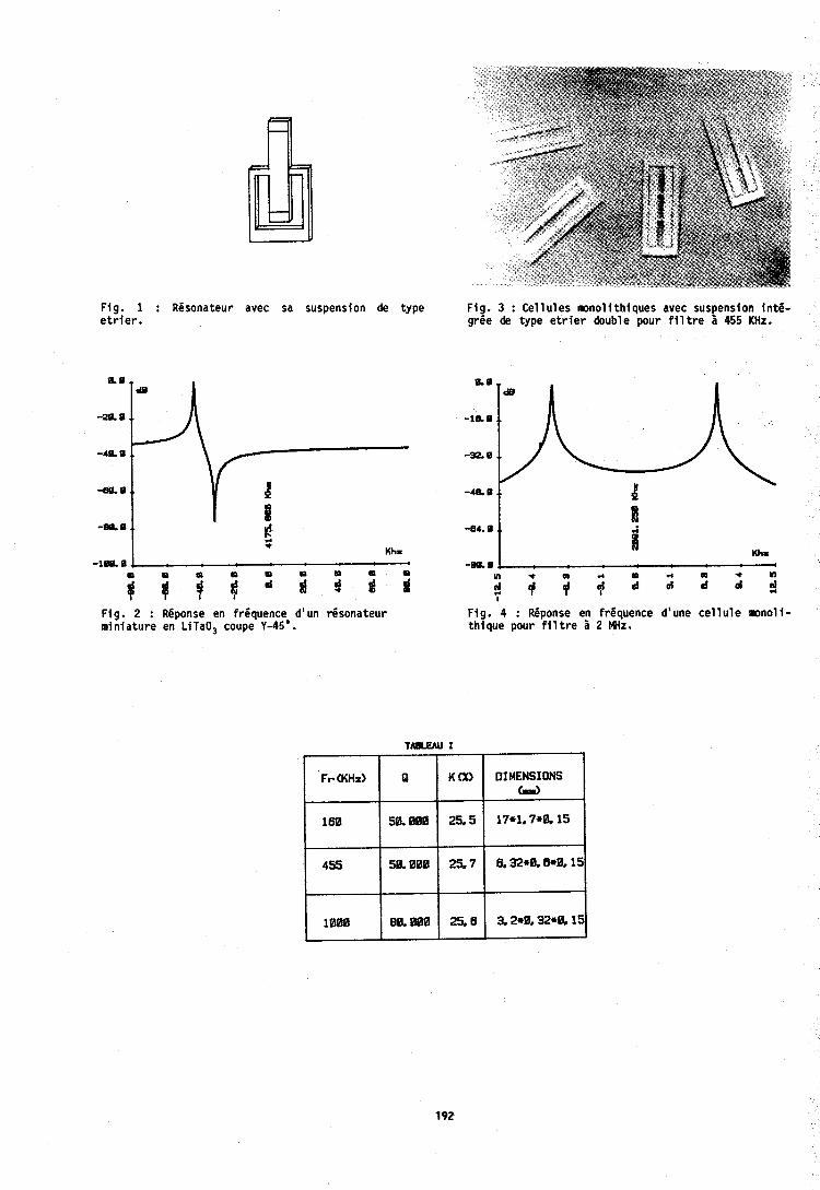
Fig . 1 : Resonateur avec sa suspension de type F ig . 3 : Cellules monolithiques avec suspension in t6 - e t r i e r . gr6e de type e t r i e r double pour f i l t r e a 455 KHz.
-20.0 .. -10.0 ..
-40.0 ..
-60.0 .. l -4% 0 .. 4 -89.0 .. 1
-84.0 .. 1 $ *
Kh. 1 Kh8 "lea 0, I -ma. -I
t m " i ; j : ; 3 d ? d
Fig . 2 : Reponse en frequence* d'un Gsonateur F ig . 4 : Reponse en frequence d'une c e l l u l e m n o l i - miniature en LITaO3 coupe Y-45 . thique pour f i l t r e 2 MHz.
Fr(KHz) Q K ( X ) DIMENSIONS Grim)
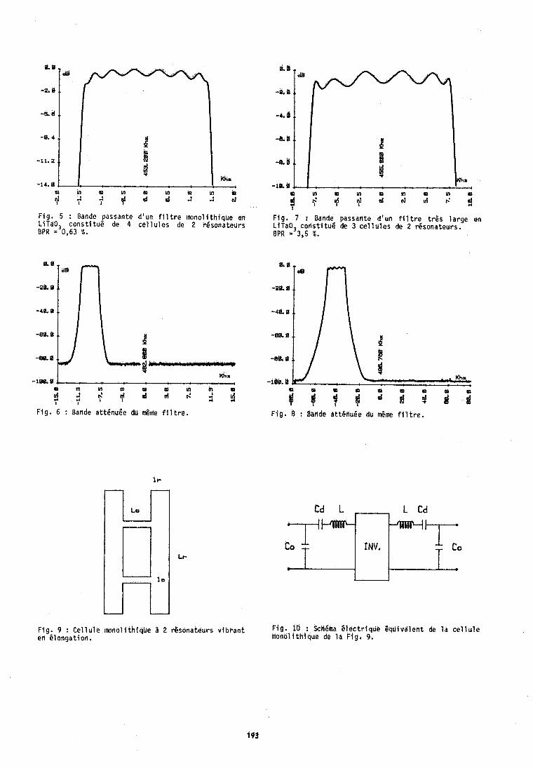
il. s
-2.6
-6. d
-e. 4
-11.2
-14.0
F ig . 5 : Bande passante d 'un f l l t r e ~ w n o l i t h i q u e en LiTaO, cot1st l tu6 de 4 c e l l u l e s de 2 resona teurs BPR = 0,63 X.
F ig . 6 : Bande at t6nuBe dli J m e f i l t r e .
F i . 7 : Bande passante d 'un f l l t r e t r P s l a r g e en L i?a03 c o n s t i f u 6 de 3 c e l l u l e s de 2 r6sona teur r . BPR = 3,5 %.
F l g . 8 : Barlde a t tghu6e du &me f l l t r e .
F i g . 9 : C e l l u l e m n o l l t h i q u e 2 2 resona teurs v i b r a n t F ig . 10 : Schema E l e c t r l q u e E q u i v a l e n t de l a c e l l u l e en B longa t ion . n ionol i tHfque de l a ~ i g . 9,
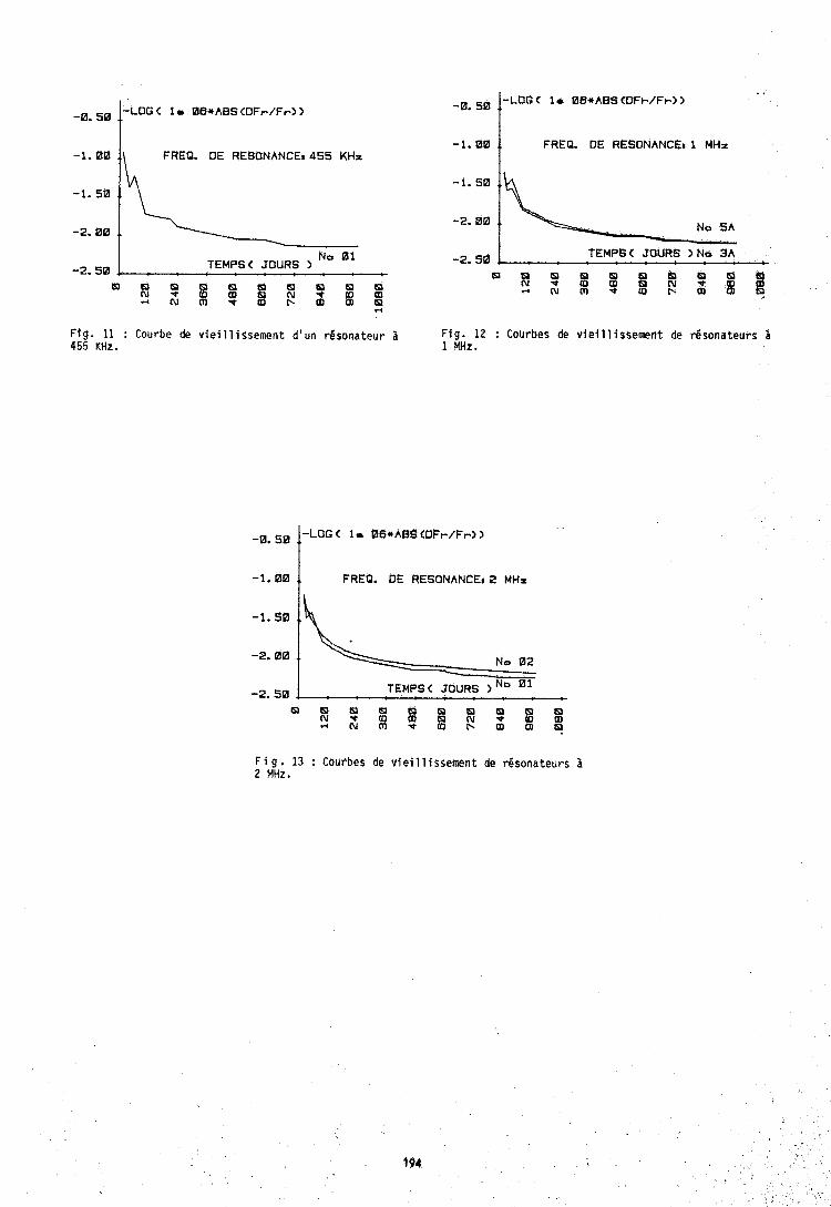
-1.00 I\ FREQ. DE RESONANCE* 455 KHz
-2.00
-2.50 TEMPS< JOURS )
C W 8 B 8 8 8 8
-1.00 t FREQ. DE RESONANCE: I MHz
Ftg. 11 : Courbe de vieillissement d'un resonateur 2 Fig. 12 : Courbes de vieillissement de dsonateurs 455 K H t . 1 MHz.
-1.00 1 FREQ. OE RESONANCE, 2 MHz
-'* 1 \: : N;
-2.50 TEMPS < JOURS ) 01
F i g . 13 : Courbes de viei 11 i ssement de rgsonateurs 2 2 MHz.
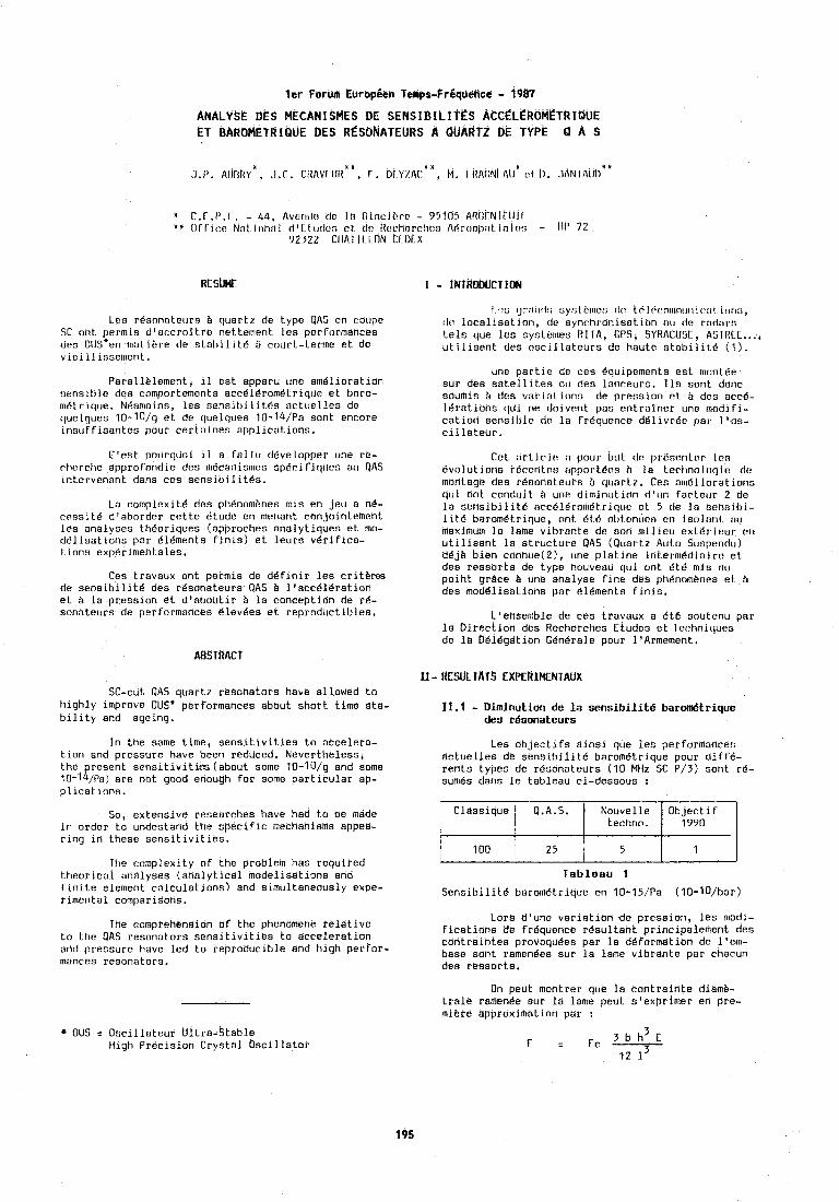
l e r Forulh EurbpSBn Temps-Fr6qtieflcii - 1487
ANALYSE DES MECANI SMES DE SENS IBILITZS ACCCLEROMETR IQUE ET BAROMETRIQUE DES RCSONATELJRS A QUARTZ bk TYPE Q A S
X r,f .ly.r. - 44, Avcritic. tlr In (ilnc3~E>rc? - 95105 AR~;I-NII Ill1 * # f l f l 1c.r Nal lon;r l (1 '1 t crdrn rt dc. Ilt?chorchr!j At;rosllirl ~:llr~s - bf' 7 2
92322 CIIATII LON CFOEX
Leo rdsnnatet~rs B quartz de type OAS en coupe SC ont permis d'accroltre nettement les perforn~ances des O U S * ~ ~ matibre de stahlllt6 B court-ternlc et de vlellllssen~ent.
Parallblement, 11 est apparu une am6lloratlon sensthle des comportemcnts accdldromdtrlque et bnro- tndtrlque. NBan~olns, les sensibllltds sctuelles de quelques 10-1O/g et do quelques 10-14/Pa son1 encore ~nsufflsantes pour certillnes applications.
C1cst pourquoi il e fallu developper une rc- rt~erche appro fondle des mticanisr~~es sp6ci f iqlrcs otr OAS lntervenant dans ces senslbilltds.
La colnplexit6 dcs ptidnom8nes mis en jeu a n6- rrssltd d'aborder cette Btude en menant con~ointemeht les analyses theorlques (approches anolytlques et mo- dBllsatlons par Bldments finls) et leurs vBriflca- tlons expBrlmentales.
Ces travaux ont permls de d6flnlr les critkres de sensiblllte des rdsohateurs QAS Q 11acc816rst~on et B la pression et dlaboutlr B la conception de re- sonateurs de performances dlev6es et reproductlbles.
ABSTRACT
SC-cut QAS quartz resohators have allowed to hlghly improve OUSX performances about short time sta- blllty and ageing.
In the same time, senaitlvlties to accelera- tlon and pressure have been reduced. Nevertheless, the resent sensltivlties (about some 10-10/g and some I: 10-1 /Pa) are not good enough for some particular ap- pl~catlons,
So, extensive researches have had to be made in order to undeatafld the speciflc mechanisms apped- ring In these sensitlvlties.
The cornplexlty of the problem has requlred theor~cal analyses (analytical modellsatlons and flnlte element calculatl~hs) and simultaneously expe- rimental comparisons.
The comprehension of the phenomene teldtive to the QAS resonators sensitivities to acceleration add pressure have led to reproducible and high perfor- mances resonators.
1 ,,s ij1':11~l~i sy?ti.rnc.j t l r tr'l lit,nr~u~~t!cll c (11 \otlC,, t l ~ . locallsat~on, tlc synchronlsatlon otr d r rndats tels que les syntbrncs kll A, GPS, SYRACllrJE, ASTRCL ..., ut~llsent des osclllateurs de haute stabll~te (1).
une part~e de ces dqulpements est mnntde sur des satell~tes ou des lanceurs. 11s sont donc sourhis B dcs varlatlonn de presslon et b dcs acc6- 16rations clcil ne dolvent pas entrafner une modlfi- catlor1 sensihle de la frdquence ddlivrBc pa1 loos- cillateur.
Cet arl~rlo n poor btlt tlr pr8ncvitrr Ico 6volut1o1in rdccntrs i~pporl ~ C R h la Lcrtinolt~q~e d~ mdritagc des rbsonateurs b qc~ortz. Ces aln6lloratlons qul ant condult b une d~mlnutlon d'un fartecrr 2 de la sensib1 lit6 nrc61dro111Etrlque et 5 tle la senr;lbl- 1 lti? boromEtrlquc, ont 61 6 ol)tcntrrs rn ~soli~ril ;111 maximum lo lame vlhrante de son nlll~ct~ e x t ~ r l e ~ r rr1 utllisant la structure GAS (Quartz Auto Suspendu) d6jb bien connue(2), une platlne inLernlBdlalre et des pessorts de type nouveau qui ant Btb mls ail polht grhce B une analyse fine des phdnombnes et B des moddllsatiohs por elements flnis.
Loensemble de ces travaux a 6td soutenu par la Direction dks Recherchea Etudes et lechn~rlues de la Ddldgation Gdn8rale pour llArmement.
XI - RESULTATS EXPERIMENTAUX
Les Objectifs ainsi que les performances actuelles de sensibilite baromdtrique pour diff6- rents types de resonateurs (10 MHz SC P/3) sont re- sumes dans le tableau ci-dessous :
T a b l e a l l 1
Sensibilitd barometrique en 10-15/Pa (10-10/bar)
Lore dlunc variation de pression, les modl- ficatiohs de frequence resultant principalement des contraintes provoqudes par la d6formstion de loem- base sont ramenecs sur la lame vibrante par chacun des ressorts.
On peut montrer que la contralhte diamb- trale ramen8e aur la lame peut s'exprimer en pre- miere approximation par !
* OUS = Oscillateur Ultra-Stable Hlgh Precision Crystal Oscillator
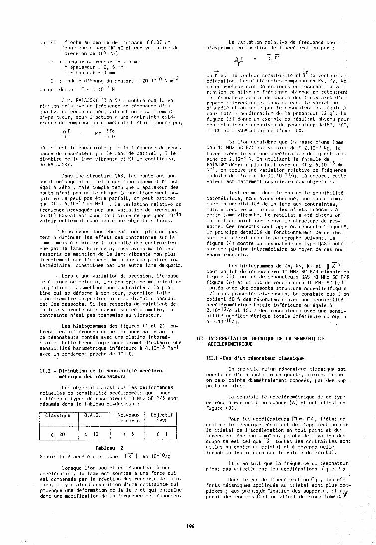
ob f C flbchc atr centre de l'enlbnse ( 0,07 um 1111krr unr o~nl~nse llr 40 pL unc viir~at Ion do prcsvlon dc 105 P n )
t~ : larqeur du ressort = 2,5 rrrrri ti Bpaisseur : 0,15 ltlln I = houtrtrr = 3 nlm
J.M. RATAJSKY ( 3 fi 5) a nrorolr6 quo lil vo- ri:ll ion rnl;lt.ivc? rlr fritq~lcrirc? do r6r;onnnc:c tl't~ro rl(riirt.c, (It: c,olrpt: elr~r~riitc, vil~riorlt cri cisaj Ilc~t~r!nL tl'bl):~inr;c:trr, soun I 'action rl'une rnnt.rsintr! exLO- riourc dc rcllrll)rc!;!iion eliorrobl.rnlc I' dlait donnito 11ar:
- c Co A f = K f - f r1 D
oh F est la contrainte ; fo la frdquence dc rdso- nance 00 rksonoteur ; n le ranq de partiel ; I) le d~anli.Lre dt? la lame vibrante et KC le coefficient de RAIAJSKY.
Dans une structure QAS, les ponts on1 une position angulaire telle que th6orlquement Kf est &gal B zero , mais compte tenu que l16pals:jeur des ponts n'est pas nulle et que le pos~tionnement an- qula~re ne peut pas @tre parfait, on p ~ u t estinler quc Kf c 5.10-15 ms N-1 . La variation relative de frdquence provoquCe par une varlatlon de presslon (It. 105 Pascal eat donc de l'ordr~ dr qurlqkres 10-14 valpur nrttement s~rpdrirurc ailx flbjertlfs fix&o.
Nous avons donc cherch6, non plus unique- ment b diminuer les effets des contraintes sur la lame, nlais fi diminuer ltintensit6 des contraintes vue par la lame. Pour cela, nous avons monte les ressorts de maintien de la lame vibrante noti plirs directement sur l'embase, mais sur une platine in- termedlaire constltuee par une autre lame de qartz.
Lors d'une variation de pression, l'embase metalllque se deforme. Les ressorts de ma~ntient de la platine transmettent une contrainte tI la pla- tine qui se deforme tI son tour, exception faite d'un dlamhtre perper~diculaire au diamhtre passant par les ressorts. Si les ressorts de malntlent de la lame vibrante se trouvent sur ce diamhtre, la contrainte n'est pas transmise au vibrateur.
Les hlstogrammes des flgures (1 et 2) mon- trent les differences de performance entre un lot de rgsonateurs montes avec une platlne 1nterm6- dialre. Cette tecnnologie nous permet d'obtenlr une senslbillte barometrique inferleure tI 4.10-15 pa-1 avec un rendement proche de 100 b.
11.2 - Diminution de la sensibilit6 acc816ro- dtrique des r6sonateurs
Les objectifs ainsi que les performances actuelles de sensibilit6 accel6rometrique pour diffkrents types de resonateurs 10 MHz SC P/3 sont. resumes dans le tnbleau ci-dessous :
Tableau 2
Lorsque l'on soumet un resonateur tI une acc616ratlon, la lame est soumise tI une foi'ce qul est cornpensee par la reaction des ressorts de maln- tien, I1 y a alors apparition d'une contralnte q u ~ provoque une deformation de la lame et qui entralne donc une modiflcatlon de la frequence de resonance.
Objectif 1990
4 1
Classique
,< 20
1.a var iat. ion rt!lal ive de Cr6qunnre peal. s'exprilncr r:rl f'o~orl. i c l r ~ dr: l 'acc~llbr:~t ion par :
-, + 3 r = K . f T
-f 4
olr K c,nl 11: voe.I1'111. nr?nsil~ililc'. nl r I ? vnrt~~trr ;I"- c616r;lt ion. I c?n [li f f'6rc:nt on co~~ll~c~s:lr~l.us Kx, Ky, K7 tlr cc vort c~rr sorrl tl6t orinin6c:n c?n n~c~ntrrant lo vil- rint ion rol nl ivc: tlc! (rdn~rc~ncr: ol~l c.nuc? en rrtol~rn:tot
Q.A.S. ' Nouveaux
lc rOsonatc?ur riul.nur de rlii~rtrn dc,:; t.rr~ir; ;lxoo d ' un rephrr tri -t.c!c.t nnt] In. D:lnn c.r3 pa:;, 1:1 vnr i:~l. ion [I 1 ;1e~~516r:rI iorr :;trI)ic! 11i1r I 1, r6:;011ol c:irr I!:;I (:[jir 11: ti tlct~x Coio I ':lcc.eil6ral. ior~ (I(% 1 i 1 ~rr!:;ilrol.lv~~, (2 (1). I ;I figlrrc (3) donnc? cln cxt:r~~plc 1113 rd:;trl t.:lL olltencr pour clcs roLirLio~~:; :;UC[:[!:;LIIVC:; [ I ~ I rf!:;e~t~irLoor ~l~!lflO. 3611.
.( 10
51 l'on rnns~clbre qoe 1i1 mosse d'clne lome PAS 10 MHz SC P/3 st voislne de 0,2.10-3 kg, la force cr6dc lprs d'uno acc616ration de lg vnl- sine de 2.10--I N. En utllisant lo formule de I1AIA.lSKY dkcrlte plus haut avec un KC t= 5.10-l5 Ins N-1, on trouve une variation relatlve de frequence ~nduite de l'ordre de 30.10-10/g. LB encore, ceLte valeur est nettement superleure aux ob,jectifs.
ressorts
4 5
Tout comme dans le cas de la sens~bil~t& t~arom6trique, nous avons cht'rclib, non pas B dlmi- nuer la ser~slt~llltk de la lame aux conti'ainLes, rt~ais b rbdulre au maxlmum les efrets trarlsmis b cette lame vlbrantc. Ce rksultat a 6th nl~tc~iu en n~cttarit all polnt clne nouvellc elructure dc rcs- sorts. Ces ressorts sont appeles ressorts "muguet". Le prlnclpe detail16 de fonctionnement de ce res- sort est decrit dans le paragraphe suivant. La flgure (4) montre un r6sonaLeor de type QAS moht6 sur une platine lntermedlaire au moyen de ces nou- veaux ressorts.
Les hlstogrammes de Kx, Ky, Kz et 11 Tll pour un lot de resonateurs 10 MHz SC P/3 classiques flgure (5), un lot de r6sonateurs QAS 10 MHz SC P/3 flgure (6) et un lot de resonateurs 10 MHz SC P/3 montes avec des ressorts structure nouvelle(fiqur~* 7) sont prCsent6s cl-dessous. On constate que loon
obtient 50 ?L des resonateurs avec une sensibilite acc616rom6trlque totale Inferleure ou Bgale B 2.10-1~/g et 100 % des resonateurs avec une sensi- bilitd acc616rom6trlque totale inferieure ou dgale tI 5.10-10/~,
111-INTERPRETATION THEORIQUE DE LA SENSIBILITE ACCELEROMETRIQUE
111.1 -Cas dlun r6sonateur classique
On rnlil~c~l lr. qtr'ktn rdsonntptlr rlas!iirl~rr est constitue d'une pastille de quartz, pleine, tenue en deux points dlametralement oppos6s, par des sup- ports souples.
La sensibilit6 acc616rom6trique de ce type de resonateur est bien connue [6] et est jllustr6e figure (8).
Pour les acc6lBrntei1rs rl et r2 , 1'BLat dr contrainte m6canlque resultant de l'appllcatlon sur le crlstal de l'acce16ration en tout point et des forces de reoctlon - c a u x polnts de flxation des supports est tel que 2 toutes les contralntes sont nullea ad centre du cristal et B moyenne nulle lorsqu'on les 1nLhgre sur le volume du cristal,
I1 s'en suit que la frdquence du resanateur n'est pas affectee par les accClerations r1 et r 2
Oans le cas de l'acc616ration r 3 , les ef- forts mecaniques appliques ou cristal sont plus com- plexes ; aux pointsde fixation des supports,
l1 paralt des couples 5! et un effort de cisalllement
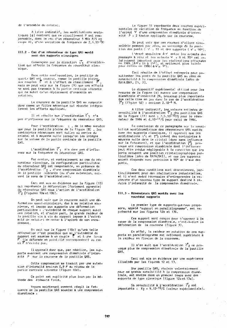
A Lltrc ~ndlcatlf, Ics rnoddllsatlohs analy- t~qtrcs [ h ] lnnntrrnt quc ce clsaillrrnent P ost rcs- ponsnl,lr, tlnnn I P rn? d'un rCnonntour 5 MIiz P/5 cn rotlpc, A T , d'tchv var tnt ]on dc frdrftrrricc do 2 , ~ . l0-9k
111.2 - Css d'un rBsonnteur dc Lypc dAS monte ovcc clcs st~pports clossiqtlcs
ronlrllrntpns pnr la dlrrcllon T2 d1acc61Cril- t 1r1n qu I nff~rtr 1:) rrdrlurtice dtr 1.6nonatBur clnn- 31q11r.
Drln~i rcttt? cnnriq~rrabion, la postille de 1111iirt.7 QA5 (?rrl !inollli!ir!, 1:0111111e In parit il lo olcinr' atrx cotrples Zf ct 11 Ifef.fort de cisaillcmcnt ?, 111ais on pcut voir sur In figure (9) que ces erforto ne sonL pas transmis A lo partie centrale vibran1.e qui ne suhit qu'un d6placenlent dlenseml,le en rotation.
La couronne de la pastille QAS se comport,e donc comme un filtre m6canique qui absorbe 1nt6gra- lement l e ~ efforts appliquks.
I1 en r6sulte que ltacc816ratirn r 3 n l a pas d'lnfluence sur la fr6quence du resonatour UAS.
Pour l'acc6ldratio1~ 1 , de la m@me manihro clue pour la pastllle pleine de la figure ( 8 ) , lea contralntes n~dcanlques sont nulles au centre du crlstal et B moyenne nulle lorsqu'on les intbgre sur le volume de la partie centrale de la pastllle QAS.
L'acc61dfatlon Fl n i a donc pas dlinflu- ence sur la fr6quence du r6soriat.eur QAS.
Par contre, et contrairement au cas du rd- sonateur classique, la configurstlon particullbte du resonateur QAS est responsable, en presence de l'acc616ration F2 , d'une compression diambtrale de la pastille vlbrante (ou dtune extension, sui- vaht le sens de 11acc616ratlon).
Cecl est mis en evidence sur la figure (10) qul reprCsente la deformation (fortement agrandie) du r6sonateur QAS sous ltactlon de l'accd1Cration F2 (figures 10a et 1Db).
On peut voir que la couronne sdblt uhe d6- formation quasi-clrculalre, due i sa relatlve sou- plesse, et Impose aux supports une dkformatlon partlcullbre : l'extr6mlt6 de chaque support subit une rotation, et d'autre part, la grahde raideur de la pastllle vls 81 vls du suppobt impose B ltextr6- mlt6 de celui-rl de rrr:ter b l'aplomb de son encn- drement .
On volt sur la figure ( 1 0 ~ ) qu'une telle dkformatlon n'est posslble que si 11extr6tnit6 du support est soumlse B un couple ? et i une folre ? la d6formee en po1ntillC cnrrespondralt au cos 6 oh nler ~ a L e pas.
Ilopl~nraitdonc que, par rkaction, les sup- pdrts exercent une compression diam6trale d'inten- sit6 P sur la couronne de la pastille QAS.
Cette compressioh se tradult pdi- une exten- sion d'intehsitd enviroh 0,9 P au niveau de la pilrt~c centrnle villrnnte (Figure 10d).
Ce point est explicit6 plus loin par Ia md- thode des Blements finis,
Voyons maintenant comment r6agit la frk- quence de la pastille QA5 soumise une compression dlam6trals :
ILn figure 11 represer~te deux co~jrl~es experl- hlentnios de variilt Inn de fi-6qtrenrc en fonrtinn cle l'ozlmut q' d'unc compresolon diamdtrnle d'lnten- sit6 P : 2 Newton app11qlrOe sur la cournnne.
Or1 (~rtrt vni 1. qc~c c-cn collrbrs d'nl lorr ain~r- nni'tlnlr pnnnprlt IIIII 761.13, 1111 vo lnlnoge dr, 1 :I posi- I Ion rlcn pnnl n ( I' : 0 ) r ~ t tlrn sirpl~ol l !: ( u' = On0).
I ItSrnrt nntl~ll:~lre 6" ehtre lcs n71rntdts dc:s passatjrs k 161 o P I 10.; H / 1111111 s Y = I1 ~t 90" vst I c- lilt I vr.lllent illlpnrl pnl OU(~I let, rBnl I nil1 loris P I f rrlthq 011 19Ub ( A ~ Y 111 a 1 5 " ) , cl rlrLlo111c~111 plus lallrlr I I ~ I I I ~ ( $ 1 I(-!, t l ~ Ic)f16 ( P W 2 3" ) .
LC d~sposltif exp6ri1i1enLol trtllls6 pour lee tnesures de la fiqtlrc ( 4 ) exef.ce une coinpression d~olndtralc d'intenslt6 2N, beauroup plus ln~portante q p celle mlse en jeu dans le cas de l'acc616ratlon r 2 (figlire 10) : envlron 2.10-4 N.
A titre ~ndlcatlf, lesnvnleurs eatln~des de senalbilit6 B l'accC16rat1on T 2 des past~lles QAS de la figure (11) sont : 2,5.10-I~/C pour Ie reno- natedr de 1984 et 6.10-11/~ Dour celui de 1406.
En concluo~on dc ce paragraphe strr In sensl- bill t6 acr018rom6tr I qoe des resonateurs OAS ~l~ontds avec des supports rlassiques, il opparalt que leo accdl6ratlons \'I et p3 crdent des contraintes B moyenrie nullc dans le crlstal (donc sans Influence scrr la FrdclcrDnre), et que llnrcdlhrat~on fi pro- voquc Lml? rohlpressifln d~amOtrnle dont 1 ' ~nfitrt~ncr! peut @tre rchdue n6qligeablc i la condition qt~c lrs bonts occupent une positlon cfistallograph~qt~e par- ticuliere (z6ro de RATAJSKf), et qtre les supports soieht dispos6s avec pr6clsldn B 90° de l'axe des punts.
Ccs deux conditions sont draconiennes, por- ticuli6remenk pour des realisations industrielles, et 11 s'est avkrd hecessaire d'entteprendre la re- cherche d'un nouveau type de support destln6 B rB- duire lilhtbnsit6 de la compressibn diam6trale.
111.3 - RBsonateurs OAS montes svec les ~OtIVkdux supports
Le premier type de supportaquenous propo- sons, sppeld "support en paral1610gramme1', est re- present6 sur les figurea 12b ek 13b.
Ces support sont concus pour stopposer B la cause de la conlpression diametrale, c'cst4-dlre la deformation de la couronne (figure 3).
En effet, la raideur en rotatibn de ces sup- ports en par~ll6logrsmrne est nettement superieure B la raideur en flexion de la couronne.
.-b I1 e'en suit que l'acc616ratlon f 2 ne pro-
voqbe plus de compressioh dihmdtrale de la pastille GAS.
Ceci est mis en Bvidence par une experience illUstrbk par les figures 12 et 13,
Une pastille QAS, chnieir volontairemcnt pour sd grandc schsibilite ti la compression diam6- trsley est montee dens uh premler temps avec des supports de type classique (figure 12aetl3a).
SA sensibilit6 B ltacc616ration ?)2 est importante : K 2 = 9.10-~O/G (valeur exp6rimentale).
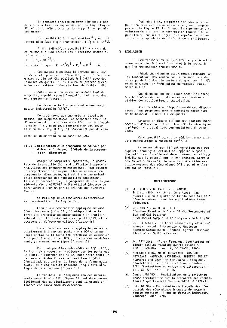
Or1 cocr~l~lbtc ensui te ce tnelne disposi ti t' par deux notrr?r, lamel les rnpport8es par col laqo ( fiqurc 121) ot IJl)), :cf'in d'ot~tcnir Ion strpports crl 11nrnl- I6 I r~(]r:llritclr: .
t
La scr~ail~ilitb )I l'ncc6ldr:tlion f 2 cot nrl- l rn~cnt pllrr, f;~ i l l lo cltlo (1rdr6doc11111rnL : K2 = 1. 111-ftVc
A l i(r.r: ~rxlic:nt if, In scnsil~i 1 i lt! III:IX~III:I~C dr c:o rr5!;on:ltf:t1r [lour t.oules les cli rcct ions d'accb 16- V - rrltion o!;t :
Ce!; stcl~pnr t.9 or1 I>:II,:I l 16 l I I ~ ~ . ~ ~ I I I I I I ! nnnt clonr int6rcno:lntn pr~tlr lour c?fficacit.d, cc~ais il faut si- gnaler qu'ils ont BLB r6alisBs b llONERA avec des lan~t?l les en quartz, et qu'ils ne se pretent gukre ?I des realisations industrielles de faible coirt.
Aussi, nous proposons un second type de supports, appel6 support "Muguet", dont le schema eat represent6 figure 14.
La photo de la flgure 4 montre une reall- satlon industrielle (CEPE).
Contraircment aux supports en parall6lo- rjrnnlrne, lea supports Muguet nc s'oposcnt pas B la cl6formatlo? dc la rouronne SOLIS l'actlon dc l'acc6- leratlon r 2 , mals leur conformation est telle (flcjure 14 = h, tl ) quill n'apparatt pas de com-
S pression dlametrale de la pastllle QAS.
111.4 -. Utilisation dqun progrrime de calculs par Bl&inerits finis pour 1'6tu& de la compres- s ion diametrale
Malgr6 sa simpllcit6 apparente, la g6bm6- trle de la pastllle aAS rend difflcile l'approche analytlque des ph6nomhnes m6canlques. Pour Btudler le compottement de ces pastilles soumlses b une compresslon dlam6trale, qul est l'une des prlncl- pales composantes des senslbilites acc616rom6- trique et barometrlque, le programme de calculs par elements finls ASTRONEF a BtC utilis& (Analyse de Structures 8 I'ONERA par la methode des Elements flnls).
Le maillage bi-dimensionneldu r6sonateur est represent6 sur la figure 15 .
Lors d'une compresslon appliquee suivant l'axe des ponts ( I' = Do), lcint6~ralit6 de la force est transmise en compression B la pastille vlbrante par ltlnterm6dlaire des ponts (99:;) et la couronne so deforme en ellipse (figure 16).
Lors d'une compression appllquee perpendl- culalrement B l'axe des ponts ( V s 90°), la ma- jeure partle de la force est transmise en extension B la pastllle vlbrante (89%), la couronne se defer- mant, 18 encore, en elllpse (figure 17).
Pour une position intercnedlalre ('t' = 45O), la force de compresslon oppllquee par les ponts sur la pastllle vlbrante est nulle, mals cette pastille est soumlse B des forces de cisaillement (dont l'amplltude est environ le tiers de la force appli- quke), 'kt des couples assurant 1'8qullibre ska- tlque de la structure (figure 10).
La varlstion de frequence rnesuree exp6ri- rnentalement B Y = 4S0 (flgure 11) est don? essen- tlellen~ent due au clsalllement dont la grande in- fluence est alnsl mise en Bvldence.
Ccs r6stllt~ts, compl6tds par ceux ol,tehus potlr dlnut,ros vnleurs ~nqtrlni res q' , gotit rrqroil- pds sclr In rir)tl~,t! 17. I:] Viqure 19a rcpr8sonl.r: 1 ' 6 - volt~t ion c11: I 'rf'rorl cle rnmpc.cssion trannn~in b I:] 11t1r;t i 1 lo villrilnt o ; ]:I fiqt~ru 1711 rcprdsente 1 '6vo- lul, inn rorrc:s[~r~ntl~cnt.e clc I l~frl't~rt dc cisai I lerl~knl .
I I?!; rci:;onnl.c!t~rs tlc I.ypr: QAti !uxlt lxlr rrrrq~l ictl 111oinn scnr;ill lco i~ 1 'accbl~:.r:ll ir111 tft B lo prr,:;!; i rill luc? Ic!; rr5t;onntctcrn t.rntlit. innnol n.
I '6ltwlo t.t~rioriquc ct expbri~~~ontalr: ul'lix!ltrbc :acr lea r6r;onnLct1rs OAS nlontre que leurs serisil1ilit8n correspondent b des ttispersions dc luelqucd 10-10/[; et de quelqcres l(l-I4/~a autour de valeurs nocni- nales riullt?~.
Ces dispersions sont liees essentiellert~ent aux tol6rances de fabrication qui sont indisso- ciables des r6alisations industrielles.
Afln de reduire l'lmportance de ces dlaper- slons, nous proposons deux dlsposlt~fs m6canlques de malnt~en de In pasLlllr de cluart7.
l e prrllclct c l ~ s p o s ~ t ~ f est one platlnc ~nter- m6dlalrc destinbe A flltrer les erforts rn6ran1qoea appl1qu6s nu cristnl lora des varlat~ons do prcs- slon.
Ce disposit if pcrmct do rbtfuire In serisil~i- 1 i t.6 barocndtr iq~lc h quelqt~er; 10-15/~n.
Le second dlspositlf est constitue par des supports dtun type partlculler, appeles supports "Muguet", dont le r81e est de mlnlmlser les efforts indults sur le cristal par l'a?c618ration. Grgce B ces nouveaux supports, la senslbllit6 acc616rom6- Lrlque moyenne des r6sonateurS QAS a pu &tre dlvl- see par un fncteur 2.
BIBLIOGRAPHIE
[I I JP. AUBRY - G. CARET - G. MARDTEL Bulletin BNM, No 63-64, Janv-Avril 1986 'lOscillateurs t~ quartz de faible sensrbilit6 B llenvironnement pour les applications temps- FrBquence.
[ 2 ] JP. AUBRY - A. DEBAISIEUX "Further Results on 5 and 10 MHz Resonators of BVA and QAS Designs" 38th Annual Symposium on Frequency Cmtml, p24U
[ 3 ] JM. RATAJSKI - The force sensltlvity of AT cuL quartz crystal - International Business Machins Corporation - Federal System Divis~on Electronics Systems Center
[43 JM. RATAJSKI - "Force-Frequency Coefficient of singly rotated vlbatlng quartz crystals". IDM J. Res Dev , vol 12, pp 92-99, 1968,
[ 5 ] NOBUNDRI OURA, NAIMU KURAMOCHI, YRSUSHI NIYAZAKI, MASAKAZU YAMASHIMA, SHIGEAKI SUZUKY "Cenerallzed Equation for Force - Frequency Characterlstlcs of Circular Quartz Plates" ICEE Ttansactlons an sonics and ultrasonics Val. 5U 32 - No 6 - 11-06
[6] Denis JANIAUD - Modelisatlon de ltinfluehce d'une acceleration sur la fr6quence des r&san$~ teurs B quartz - Note techniw dNERA no 1978-5,
[7] F.L, NISSlM - Contributidn B l16tude des pro- pri$tes das resonateura b quartz de coupe B clauble rotation - These de Docteur-Inglnieur, Besangon, Juin 1978.
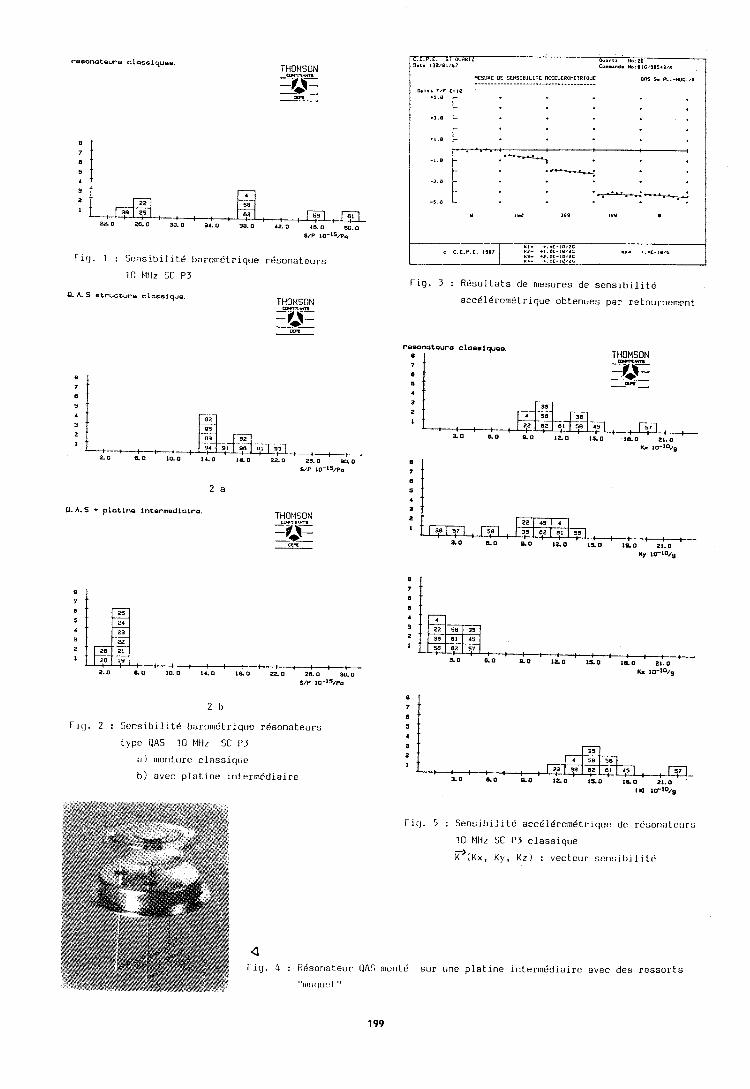
F l c j . 1 : S e n s i b l l l t d barometr lqcle r b s o n a t e u r s
I 0 Mtlz SC P3
0. A. S etructure classiquo.
2 b
F ic]. 2 : S c n s i b i l i t e barorndtricloe r 6 s o n a t e u r s
t y p e I IAS 10 M t l z SC P3
: I ) ~ r ~ c ~ r ~ t . u r e c l n s s i r ~ ~ ~ e
h ) avec p l a t i n e i n t e r m d d i a i r e
C.E .P .E . 51 OURRIZ 0.I. 138101197
O u & r < ~ t40.26 Co.*.nd. N ~ : O I C I ~ $ I ~ I I K
f l q . 3 : R e s u l t a t s cle mesures d e s e n s l l ~ l l l t d
a c c C l d r o m 6 t r l q u e o b t e n u e s p a r r e tou rnemen t
c C.E.P.E. 1987
1 - i r j . 5 : S e n s i b i l i t b acc616romdt r ique do r d s o r i ; ~ t c u r s
10 ClIiz SC P3 c l a s s i q u e
~ ' { K X , K y , K z ) : v e c t c u r sorl:;il,il i t 6
M I - . . . C - I E I I C "2- .,.oc.,e,2c " 3 - +2.OC-IO,1C
I". ... C - I B I C
K 4 - ..IF-$E/2C
a f i g . 4 : ilBsoriatour OAS ~ r ~ u n t d
t'llllil~~l!?l "
s u r une p l a t i n e i n t e r r n d d i a i r e avec d e s r e s s o r t s
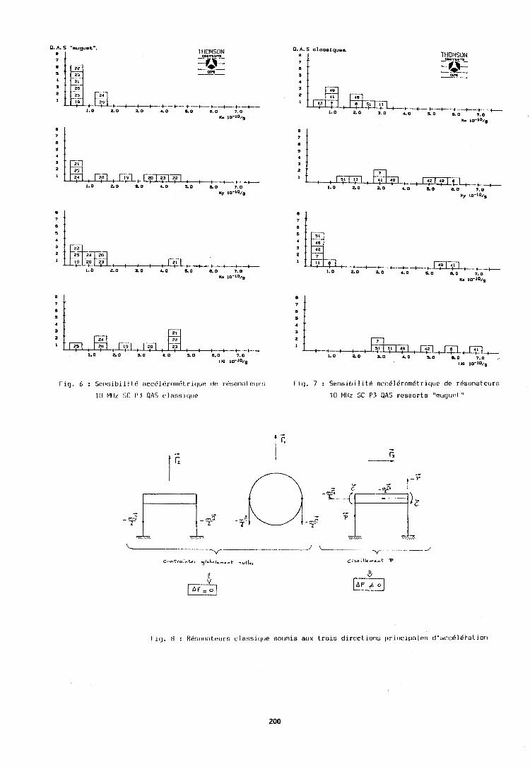
0. A. S "musuet".
: I
Fiq. 6 : SensibilltC acc61Brom6trique de r6soni1trurs
0. A. S cloeslquoe
4
Fig. 7 : Sensibilit6 occ61Bron16tricjue de r6son;~tcur:;
l(1 Mliz SC P3 PAS ressorts "rnugor,l "
Fig. 0 : RBsonateurs classiclue sournis aux trois directions principales d'scc616rnLior1
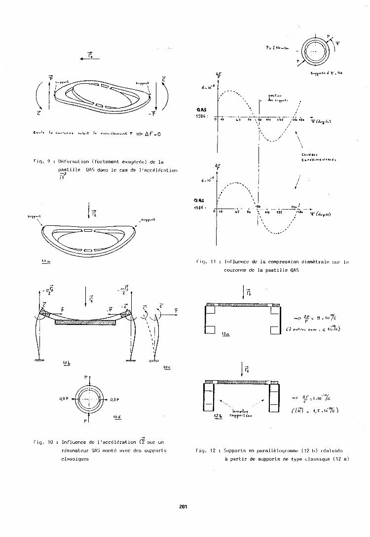
r i g . 9 : Deforrl~aLion ( f 'or ternent e x a g b r b e ) d e l a
p a s t i l l e O A S d a n s l e c a s d e l ' a c c b l d r a t i o n
EJ
F i g . 11 : I n f l u e n c e d c l a c o n ~ p r e s s i o r ~ diarnbLralo s u r l a
cou ronne d e l a p a s t i l l e Q A S
4
I - i c j . 10 : I n f l u e n c e de l ' a c c b l d r a t i o n s u r un
r6s t ina t cu r Q A S rr~ontr', a v e c d e s s u p p o r t s
c l a s s i q u e s
f ~ q . 12 : 5upport r ; e n p a r a l l b l o c ~ r n t ~ ~ r n c ( 1 2 I)) r6nl1sd:;
B p a r t l r d e s u p p o r t s de t y p e c l a s s l q u e (12 a )
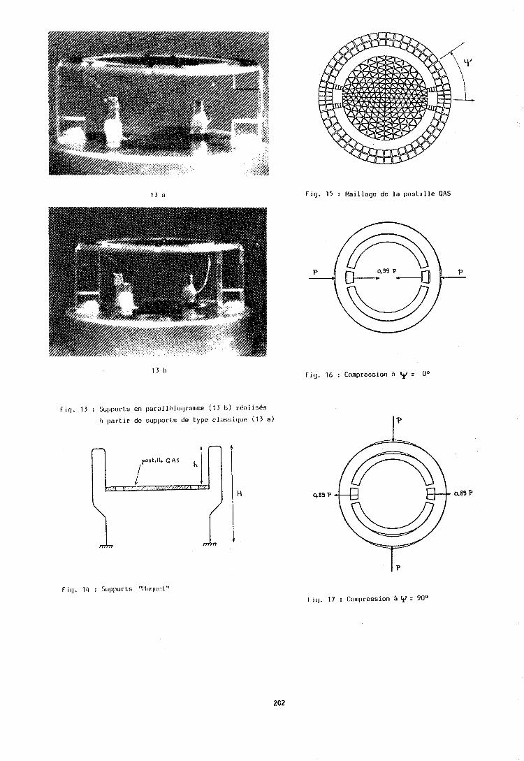
Fig. 15 : Maillage de la pastille UAS
Fi!]. 16 : Compression ?I (il = [lo
Fig. 13 : Supports cn 11arall8logran1me (13 b ) rbalises
b partir de supports de type clansiquc ( 1 3 a)
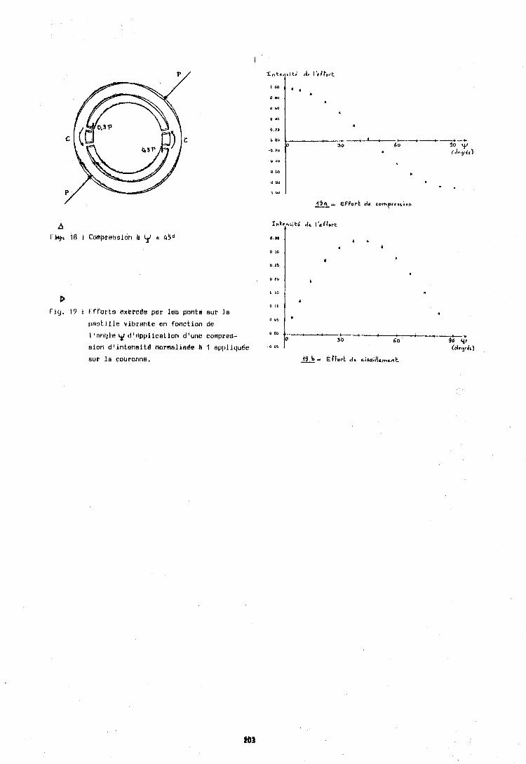
l ' n h g l e ~ didpplicatioh d i u n e comprert- - 1 : e- : 30 60 . so 4
oion d'ihtehsitd normaliade A 1 appliquge . o * % (dtajp&)
SUT la courbnne. a- €( for t dr ~isejul;I(emrnt
0 (1 15
0 I0 Pig. 19 t Errarts exkrcde par les pants eur la
0 LY pastille vibratlte en fonctian de
II
*
l e r Forum Europgen Temps-Friquence - 1987
of Bs l i n i t e Grown at Mgh Tempera-
B.H.T. Chai and J.P. Hou Electronic Materials and Devices Laboratory
Allled-Signal, Inc., P.O.Box 1 02 1 R, Morr istow n, NJ 07960, USA Tel: (20 11-455-41 85 and (20 1 1-455-3439
Berlinite has attracted a lot of attention during the past years because of the potential applications in both BAW and SAW devices. Growth of berlinite at moderately low temperatures (<200eC) has been wel l established both at our and several other laboratories. However, one major problem which has caused dlsappointrnent for device application I s the rather high acoustic loss due to the high water content of these crystals grown a t low temperatures.
A major breakthrough was achieved by Detaint and his associates at CNET in France who demonstrated that by growing the berl inite crystals at progressively higher temperatures, the water content was drastically reduced and the Q value greatly increased, Tn some cases approaching the Q value of quartz crystals.
We have conducted similar experiments in our laboratory. The low water content of berlinite grown at around 300'C was confirmed and the Q of our crystals was comparable to those of CNET. The water content has reduced from typically 500 ppm for low temperature grown berl ini te to around 20-50 ppm for high temperature grown berl ini te. Since berl in i te has to be grown in highly corrosive concentrated acid solutions, the design of the growth vessel and the growth procedure also had to be changed to accommodate the higher temperature and pressure conditions. We w i l l discuss our efforts to achieve the high temperature growth of berl inite. The results of the evaluation of these high temperature berl inite in both bulk wave resonators as we1 1 as SAW devices w i 11 also be presented.
It is our be1 ief that w i th this new development, berl ini te has finally achieved i t s expectation to become a vlable material for piezoelectric device app 1 i ca t i ons.
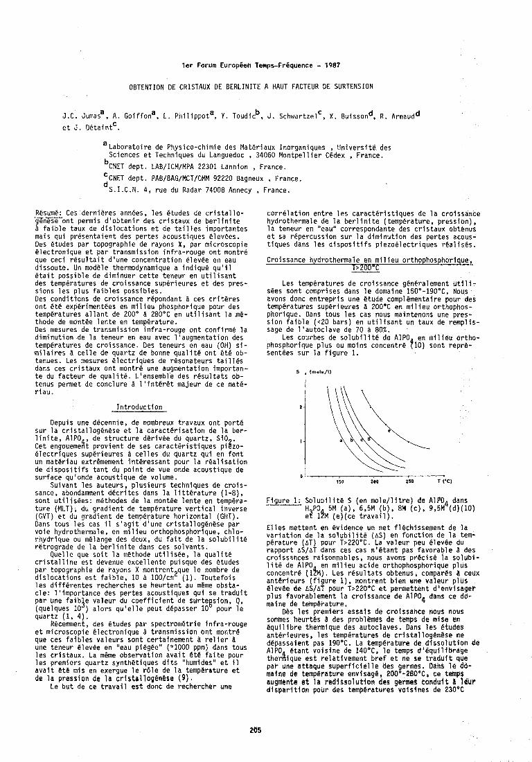
l e r Forum Europ ien Temps-Frgquence - 1987
OBTENTION DE CRISTAUX DE BERLINITE A HAUT FACTEUR DE SURTENSION
J.C. ~ u m a s ~ , A. ~ o i f f o n ~ , C. p h i l i p p o t a , Y . Toudicb, J . schwartzelc , X . ~ u i s s o n ~ , R . ~ r n a u d ~
e t J. O@ta in tc .
a ~ a b o r a t o i r e de Physico-chimie des Mate r laux Inorganiques , U n i v e r s i t e des Sciences e t Techniques du Languedoc , 34060 M o n t p e l l i e r Cedex , France.
b~~~~ dept . LAB/ICM/MPA 22301 Lannion , France.
'CNET dep t . PAB/BAG/MCT/CMM 92220 Bagneux , France.
d ~ . ~ . ~ . ~ . 4, r u e du Radar 74008 Annecy , France.
Resume: Ces d e r n i e r e s annees, l e s etudes de c r i s t a l l o - genese o n t permis d ' o b t e n i r des c r i s t a u x de b e r l i n i t e 2 f a i b l e taux de d i s l o c a t i o n s e t de t a i l l e s impor tan tes mais q u i p r e s e n t a i e n t des p e r t e s acoust iques e levees. Des etudes p a r topographie de rayons X, p a r m ic roscop ie e l e c t r o n i q u e e t p a r t ransmiss ion i n f r a - r o u g e o n t montre que c e c i r e s u l t a i t d 'une c o n c e n t r a t i o n @levee en eau d i s s o u t e . Un n~ode le thermodynamique a i n d i q u e q u ' i l e t a i t p o s s i b l e de d im inuer c e t t e teneur en u t i l i s a n t des temperatures de c ro issance super ieu res e t des p res - s ions l e s p l u s f a i b l e s p o s s i b l e s . Des c o n d i t i o n s de c ro issance repondant d ces c r i t e r e s o n t e t e experimentees en m i l i e u phosphorique pour des temperatures a l l a n t de 200' d 280°C en u t i l i s a n t l a me- thode de montee l e n t e en temperature. Des nlesures de t ransmiss ion i n f r a - r o u g e o n t con f i rme l a d i m i n u t i o n de l a teneur en eau avec l ' augmenta t ion des temperatures de c ro issance . Des teneurs en eau (OH) s i - m i l a i r e s c e l l e de q u a r t z de bonne q u a l i t & o n t e t e ob- tenues. Les mesures e l e c t r i q u e s de resona teurs t a i 1 l e s dans ces c r i s t a u x o n t montre une augmentation importan- t e du f a c t e u r de q u a l i t e . L'ensembl'e des r e s u l t a t s ob- tenus permet de c o n c l u r e d l ' i n t e r e t majeur de ce mate- r i a u .
I n t r o d u c t i o n
Depuis une decennie, de nombreux t ravaux o n t p o r t e su r l a c r i s t a l l o g e n e s e e t l a c a r a c t e r i s a t i o n de l a ber - l i n i t e , A lp0 , de s t r u c t u r e d e r i v e e du quar tz , SiO . Cet engoueme%t p r o v i e n t de ses c a r a c t e r i s t i q u e s p igzo- e l e c t r i q u e s super ieu res B c e l l e s du q u a r t z q u i en f o n t un mate r lau extrhmement i n t e r e s s a n t pour l a r e a l i s a t i o n de d i s p o s i t i f s t a n t du p o i n t de vue onde acous t ique de s u r f a c e qu 'onde acous t ique de volume.
Su ivan t l e s au teurs , p l u s i e u r s techniques de c r o i s - sance, abondamment d e c r i t e s dans l a l i t t e r a t u r e (1-a) , son t u t i l i s e e s : methodes de l a montee l e n t e en tempera- t u r e (MLT), du g r a d i e n t de temperature v e r t i c a l i n v e r s e (GVT) e t du g r a d i e n t de temperature h o r i z o n t a l (GHT). Dans tous l e s cas il s ' a g i t d 'une c r i s t a l l o g e n e s e par v o i e hydrothermale, en m i l i e u or thophosphor ique, c h l o - r h y d r i q u e ou melange des deux, du f a i t de l a s o l u b i l i t e r g t r o g r a d e de l a b e r l i n i t e dans ces so lvan ts .
Q u e l l e que s o i t l a methode u t i l i s e e , l a q u a l i t e c r i s t a l l i n e e s t devenue e x c e l l e n t e puisque des etudes par topograph ie de rayons X mont ren t que l e nombre de d i s l o c a t i o n s e s t f a i b l e , 10 a 100/cm2 (1). T o u t e f o i s l e s d i f f e r e n t e s recherches se h e u r t e n t au meme obs ta - c l e : l ' i m p o r t a n c e des p e r t e s acoust iques q u i se t r a d u i t p a r une f a i b$e v a l e u r du c o e f f i c i e n t de su r tegs ion , Q, (quelques 10 ) a l o r s q u ' e l l e peu t depasser 10 pour l e q u a r t z (1 , 4 ) .
Recemment, des etudes p a r spectrometric i n f r a - r o u g e e t m ic roscop ie e l e c t r o n i q u e d t ransmiss ion o n t montre que ces f a i b l e s v a l e u r s son t ce r ta inement d r e l i e r B une teneur @levee en "eau p iegee" (clOOO ppm) dans tous l e s c r i s t a u x . La meme o b s e r v a t i o n a v a i t B t e f a i t e pour l e s premiers q u a r t z syn the t iques d i t s "humides" e t il a v a i t BtB mis en exergue l e r61e de l a tempCrature e t de l a p r e s s i o n de l a c r l s t a l l o g ~ n @ s e ( 9 ) .
Le b u t de ce t r a v a l l e s t donc de rechercher une
c o r r e l a t i o n e n t r e l e s c a r a c t e r i s t l q u e s de l a c ro issance hydrothermale de l a b e r l i n i t e ( tempera tu re , p r e s s i o n ) , l a teneur en "eau" correspondante des c r i s t a u x obtenus e t sa repercuss ion sur l a d i m i n u t i o n des p e r t e s acous- t i q u e s dans l e s d i s p o s i t i f s p i e z o e l e c t r i q u e s r e a l i s & .
Croissance hydrothermale en m i l i e u or thophosphor ique, T>200°C
Les temperatures de c ro issance generalement u t i l i - sees son t comprises dans l e domaine 150'-190°C. Nous avons donc e n t r e p r i s une e tude complementaire pour des temperatures super ieu res d 200°C en m i l i e u Orthophos- phor ique. Dans tous l e s cas nous maintenons une p res - s i o n f a i b l e (<20 bars ) en u t i l i s a h t un taux de r e m p l i s - sage de l ' a u t o c l a v e de 70 A 80%.
Les courbes de s o l u b i l i t B de AlPO en m i l i e u o r t h o - phosphorique p l u s ou moins concen t re ? l o ) son t r e p r 8 - sentees s u r l a f i g u r e 1.
F i g u r e 1: S o l u b i l i t e S (en m o l e / l i t r e ) de A1P04 dans H PO 5M ( a ) , 6,5M (b ) , 8# ( c ) , 9,5M (d ) (10) e3 I!!M (e) ( ce t r a v a i 1 ) .
E l l e s m e t t e n t en ev idence un n e t f l ech issement de l a v a r i a t i o n de l a s o l u b i l i t e (AS) en f o n c t i o n de l a tem- p e r a t u r e (AT) pour T>220°C. La v a l e u r peu e levee du r a p p o r t AS/AT dans ces cas n ' e t a n t pas f a v o r a b l e B des c r o i ssances r a i sonnabl es , nous avons p r e c i s e 1 a s o l u b l - l i t e de AlPO en m i l i e u a c i d e or thophosphor ique p l u s concen t re ( 1 9 ~ ) . Les r e s u l t a t s obtenus, compares B ceux a n t e r i e u r s ( f i g u r e l ) , mont ren t b i e n une v a l e u r p l u s e levee de ASJAT pour T>220aC e t permet ten t d 'env isager p l u s favorablement l a c ro issance de A1P04 dans ce do- malne de temperature.
Des l e s p remie rs e s s a i s de c ro issance nous nous sommes heur tes B des problemes de temps de mise en e q u i l i b r e thermique des au toc laves . Dans l e s etudes a n t e r i e u r e s , l e s temperatures de c r i s t a l logenese ne depassaient pas 190°C. La temperature de d i s s o l u t i o n de Alp0 e t a n t v o i s i n e de 140eC, l e temps d ' e q u i l i b r a g e t h e r 4 i q u e e s t r e l a t i v e m e n t b r e f e t ne se t r a d u i t que pap une a t t a q u e s u p e r f i c i e l l e des germes. Darls 1e do- mai he de tenip8rdture envisage, 200'-280°C, ce temps augmente e t l a r e d i s s o l u t i o n des germes c o n d u l t il leur d i s p a r i t i o n pour des temperatures v o i s i n e s de 230QC
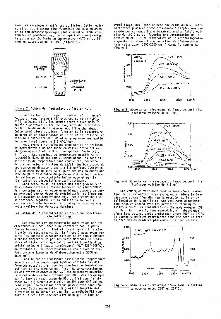
avec l e s ence in tes chau f fan tes u t i l i s e e s . C e t t e r e d i s - rempl issage, 80%, s o i t l e meme que c e l u i du GHT. C e t t e s o l u t i o n e s t d ' a u t a n t p l u s f a v o r i s e e que nous operons d i f f k r e n c e p r o v i e n t d 'une c ro issance temperature va- en m i l i e u or thophosphor ique p l u s concentre. Pour con- r i a b l e q u i commence a une temperature p l u s f a i b l e v o i - t o u r n e r ce probleme, nous avons opere dans un p remie r s i n e de 160°C ce q u i f a v o r i s e une augmentat ion de l a temps p a r mont6e l e n t e en t ~ m p e r a t u r e (MLT) en u t i l i - teneur en eau. S i l a temperature de l a c r i s t a l l o g e n e s e san t un au toc lave de 100 cm ( f i g u r e 2 ) . augmente, il s ' e n s u i t une r e d u f t i o n de 1 'absorbance
dans c e t t e zone (3600-2600 cm ) comme l e montre l a f i g u r e 4.
bouchon PTFE
germes
solution
a u t o c l a v e ac ler
c h e m i s e PTFE
' I AlPO, ,- G V T 175'C I
h32.1 / MLT 160-la*
F i g u r e 2: Schema de 1 ' a u t o c l a v e u t i l i s 6 en MLT. -- Pour e v i t e r t o u t r i s q u e de r e d i s s o l u t i o n , on e f -
fec tue un remp l i ssage a 70% avec une s o l u t i o n H PO / AlPO adequate ( l l ) , l e s germes &an t s i t u e s d a k f a p a r t f e super ieu re de 1 'au toc lave , hors de l a s o l u t i o n , pendant l a duree de l a mise en e q u i l i b r e thermique. Ce t te temperature a t t e i n t e , f o n c t i o n de l a temperature de debut de c r i s t a l l i s a t i o n de l a s o l u t i o n u t i l i s e e , on bascule 1 'au toc lave de 180" e t on programme une niontee l e n t e en temp@rature de 1 8 4*C/ jou r .
Nous avons a i n s i e f f e c t u e deux s e r i e s de c r o i s s a n - ce hydrothermale de b e r l i n i t e en m i l i e u a c i d e o r t h o - phosphorique 9.5 e t 12 M s u r des germes d ' o r i e n t a t i o n X, Y e t r . Les domaines de temperature e t u d i e s son t rassembles dans l e tab leau I. E t a n t donne l e s f a i b l e s v a r i a t i o n s de temperature dans chaque cas, correspon- dan t a des va leurs l i m i t e e s de AS/AT, l e s epaisseurs de c ro issance ne depassent pas 1 a 1.5 mm/face. Tou te fo is il a pu e t r e i s o l e dans l a p l u p a r t des cas au moins une lame de p a r t e t d ' a u t r e du germe en vue de l e u r carac- t 6 r i s a t i o n par s p e c t r o m e t r i e i n f r a - r o u g e e t p a r l a r e a l i s a t i o n de d i s p o s i t i f s p i e z o e l e c t r i q u e s .
Dans c e t t e etude l e s germes t i t i l i s e s p rov iennen t de c r i s t a u x obtenus a "basse temp@raturel ' (160'-180°C). Dans c e r t a i n s cas, on observe un b lanchissement du ger- me provoque par un debut de p r e c i p i t a t i o n de 1 'eau dGe a l ' e l e v a t i o n de temperature ( 9 ) . Ceci n ' e n t r a i n e aucu- ne inc idence n e g a t i v e su r l a j u a l i t e de l a p a r t i e c ro issance "haute temperature , pu isqu 'on observe une n e t t e a m e l i o r a t i o n de c e t t e d e r n i e r e .
E v a l u a t i o n de l a c o n c e n t r a t i o n en "eau" par spectrome- t r i e i n f r a - r o u g e
Les mesures par s p e c t r o m e t r i e i n f r a - r o u g e o n t 6 t 6 ef fectuees sur des lames Y ne contenant pas l e germe "basse temperature" i n i t i a l e t devant s e r v i r a l a rea- l i s a t i o n de r6sona teurs . Sur l a f i g u r e 3 nous avons r e - p o r t e l e s spec t res c a r a c t e r i s t i q u e s de c r i s t a u x obtenus a "basse temperature" p a r l e s t r o i s methodes de c r o i s - sance u t i l i s e e s a i n s i que c e l u i r e a l i s 6 8 p a r t i r d ' u n c r i s t a l p repare a "haute temperature" (MLT 225'-245°C). On c o n s t a t e qu'une c o n c e n t r a t i o n en eau e levee se t r a - d u i t parlune l a r g e bande d ' a b s o r p t i o n e n t r e 3600 e t 2600 cm- .
Dans l e cas de c ro issance d i t e s "basse temperature ' ' en m i l i e u or thophosphor ique 6,5M on c o n s t a t e des d i f - ferences no tab les b i e n que l e s domaines de temperature u t i l i s e s s o i e n t comparables. A i n s i l a c o n c e n t r a t i o n en OH des c r i s t a u x obtenus p a r GVT e s t net tement super ieu - r e a c e l l e de c r i s t a u x obtenus p a r GHT. Cela s ' e x p l i q u e p a r l e taux de rempl issage de 92% u t i l i s e pour l a me- thode GVT (1 ) super ieu r a c e l u i de 80% pour GHT q u i se t r a d u i t p a r une p r e s s i o n i n t e r n e p l u s e levee dans l ' a u - t o c l a v e . C e t t e augmentation de p r e s s i o n f a v o r i s e une e l e v a t i o n de l a teneur en eau (9 ) . La m6thode MLT corl- d u i t a un r e s u l t a t i n t e r m e d i a i r e b i e n que l e taux de
F i g u r e 3: Absorbance i n f r a - r o u g e de lames de b e r l i n i t e (epa isseur v o i s i n e de 0.2 mm)
F i g u r e 4: Absorbance i n f r a - r o u g e de lames de b e r l i n i t e (epa isseur v o i s i n e de 0,2 mm)
Ces remarques v o n t donc dans l e sens d 'une d iminu- t i o n de l a c o n c e n t r a t i o n en eau quand on e l e v e l a tem- p e r a t u r e e t que l ' o n d iminue l a p r e s s i o n de l a c r i s - t a l l o g e n e s e de l a b e r l i n i t e . Ces r e s u l t a t s experimen- taux son t en accord avec l e s p r e v i s i o n s theor iques f a i t e s a p a r t i r de c o n s i d e r a t i o n s thermodynamiques ( 9 ) .
Dans l a f i g u r e 5, nous reprodu isons 1 'absorbance d 'une lame obtenue apres c ro issance e n t r e 250" e t 277°C. La courbe super ieu re represen tee dans une e c h e l l e t r e s d i l a t e e met en evidence p l u s i e u r s p i c s b i e n d e f i n i s .
400b 3500 3000 2500 (cm-1)
F i g u r e 5: Absorbance i n f r a - r o u g e d 'une 1 ame de b e r l i n i - t e obtenue e n t r e 250' e t 277OC.
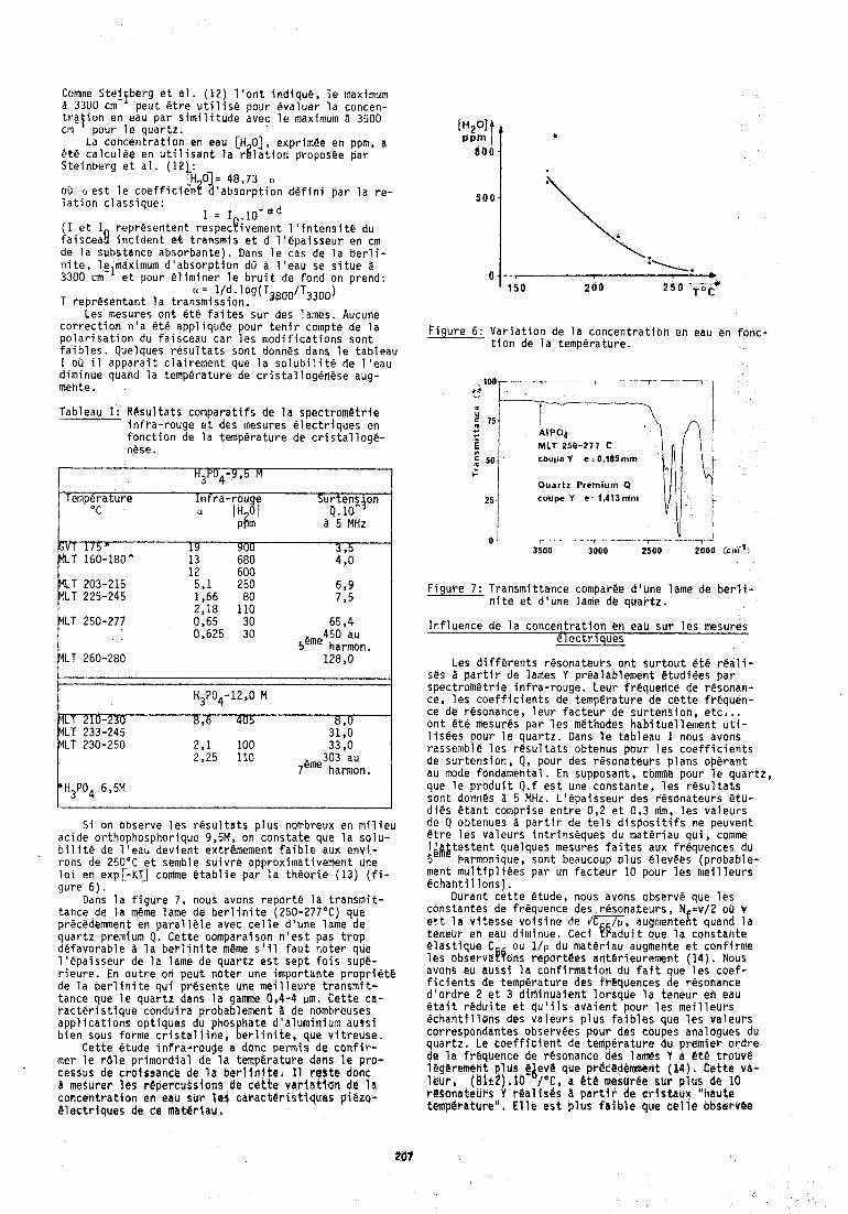
Come Ste! be r e t a l . (12) 1 ' o n t i n d i q u e , l e maximum a 3300 cm p e z t e t r e u t i l i s e pour eva luer l a concen- t r a t i o n en eau p a r s i m i l i t u d e avec l e maximum 2, 3500 cni pour l e q u a r t z .
La c o n c e n t r a t i o n en eau [H 01, exprimge en ppm, a 6t@ c a l c u l e e en u t i l i s a n t l a r g l a t i o n proposee p a r S te inbera e t a l . (121: - -
[H 01- 48,73 a oSr a e s t l e c o e f f i c i e n t d 'absorpt ion d e f i n i p a r l a r e - l a t i o n c l a s s i q u e :
I = 1 , . 1 0 - ~ ~ (I e t I represen ten t respecyivement 1 ' i n t e n s i t e du f a i s c e a f l i n c i d e n t et t ransmis e t d l ' e p a i s s e u r en cm de l a substance absorbante) . Dans l e cas de l a b e r l i - n i t e , lelmaximum d ' a b s o r p t i o n dO 2, l ' e a u se s i t u e a 3300 cm e t pour e l i m i n e r l e b r u i t de fond on refi id:
' lid' 0g(T3800/T3300) T r e p r e s e h t a n t l a t ransmiss ioh .
Les mesures o n t B t e f a i t e s s u r des lames. Aucune c o r r e c t i o n n ' a e t e app l iquee pour t e n i r compte de l a p o l a r i s a t i o n du fa isceau c a r l e s m o d i f i c a t i o n s s o n t f a i b l e s . Quelques r e s u l t a t s son t donnes dans l e tab leau I oO il a p p a r a i t c l a i r e m e n t que l a s o l u b i l i t e de l ' e a u d iminue quand l a temperature de c r i s t a l l o g e n e s e aug- mente.
Tableau I t R e s u l t a t s compara t i f s de l a s p e c t r o m e t r i e i n f r a - r o u g e e t des mesures e l e c t r i q u e s en f o n c t i o n de 1 a temperature de c r i s t a l l oge- n@se.
Temperature I h f r a - r o u g e Sur tens jon C a IH-01 0. 10' . ,
~ f i m 8 '5 MHz I
65 $ 4 450 au
5eme harmon.
230 8,6 405 YLT 233-245 ilLT 230-250 2 , l 100 33.0
2;25 110 3 0 3 . a ~ 7 h a r m o n 1
S i on observe l e s r e s u l t a t s p l u s nombreux en m i l i e u ac ide or thophosphor ique 9,5M, on c o n s t a t e que l a so lu - b i l i t e de l ' e a u d e v i e n t extremement f a i b l e aux e n v i - rons de 250°C e t senible s u i v r e approximat ivement Une l o i en exp[-KT] comme @ t a b l i e p a r l a t h e o r i e (13) ( f i - gure 6 ) .
Dans l a f i g u r e 7, nous avons r e p o r t 6 l a t r a n s m i t - tahce de l a meme lame de b e r l i n i t e (250-277'C) que p recedement en p a r a l l e l e avec c e l l e d 'une lame de q u a r t z premfum Q. C e t t e comparalson n ' e s t pas t r o p de favorab le a l a b e r l i n i t e m@me s l i l f a u t n o t e r que l ' e p a i s s e u r de l a lame de q u a r t z e s t sep t f o i s supe- r i e u r e . En o u t r e on peu t n o t e r une impor tan te p r o riete de l a b e r l i n i t e q u i p resen te une m a i l l e u l e transmit- tance que l e q u a r t z dans l a g a m e 0,4-4 urn. C e t t e ca- r a c t e r i s t i q u e condu i rd probablement 3 de nombreuses a p p l i c a t i o n s op t iques du phosphate d 'a lumin ium auss i b i e n sous forme c r i s t a l l i n e , b e r l i n i t e , que v i t r e u s e .
Ce t te etude i n f r a - r o u g e a donc permis de c o n f i r - mer l e r b l e p r i m o r d i a l de l a temperature dans l a p r o - cessus de c ro lssance de l a b e r l l n i t e . I 1 r e s t e done B mesurer les repercuss ions de c c t t e v a r i a t t o n de l a c o n c e n t r a t i o n en ebU sur la4 c a r a c t e r i s t i q u e s p iezo- 8 l e c t r i q u e s de c e mat i i r l au ,
F i g u r e 6: V a r i a t i o n de l a c o n c e n t r a t i b n en eau en fonc- t i o n de l a temperature.
I RIP04 MLT 250-277 C coupe Y e : 0,185 mm
Quartz Premium Q coupe Y e - 1,413mm
Flguee 7: Transmit tance comparee d 'une lame de b e r l i - n i t e e t d 'une la f ie de q u a r t z .
I n f l u e n c e de l a c o n c e n t r a t i o n en eau s u r l e s mesures e l e c t r i q u e s
Les d i f f d r e n t s resona teurs o n t s u r t o u t e t e r e a l i - ses a p a r t i r de lames Y prealablement e tud iees p a r s p e c t r o m e t r i e i n f r a - r o u g e . Leur f requencd de resonan- ce, l e s c o e f f i c i e n t s de temperature de t e t t e f requen- ce de r&sonance, l e u r f a c t e u r de s u r t e n k i o n , e t c , . . o n t e t e mesures par l e s methodes h a b i t u e l l e m e n t u t i - l i s e e s pour l e q u a r t z . Dans l e t a b l e a u I nous avons rassemble l e s r d s u l t a t s obtenus pour l e s c o e f f i c i e n t s de sur tens ion , Q, pour des resona teurs p lans operan t au mode fondamental. En supposatit, comme pour l e q u a r t z , que l e p r o d u i t Q.f e s t une cons tan te , l e s r e s u l t a t s son t donnes a 5 MHz. L ' e p a i s s e u r des resona teurs e t u - d i e s e t a n t comprise e n t r e 0,2 e t 0,3 ntm, l e s v a l e u r s de Q obtenues a p a r t i r de t e l s d i s p o s i t i f s ne peuvent e t r e l e s va leurs i n t r i n s e q u e s du m a t e r i a u q u i , comme l $ , & t e s t e n t quelques mesures f a i t e s aux f requences du 5 harmonique, son t beaucoup p l u s @levees (p robab le - ment m u l t l p l l e e s p a r un f a c t e u r 10 pour l e s m e i l l e u r s 6 c h a n t i l l o n s ) .
Durant c e t t e Ctude, nous avons observe que l e s constantes de frkquence des resona teurs , N =v /2 oO v e T t l a v i t e s s e v o i r i n e de i n , nugmentefit quand l a teneur en eau d iminue. Ceci eeadui t que l a cons tan te C l a s t i q u e C ou l / p du mate r iau augmente e t con f i rme l e s observaf!fons repor tees an te r ieu rement (14) . Nous aVOhS eu auss i l a c o n f i r m a t i o n du f a i t que l e s c o e f - f i c i e n t s de temperature des f r tquences de resonance d ' o r d r e 2 e t 3 d i m i n u a i e n t l o r b q u e l a teneur en eau e t a i t r e d u i t e e t q u ' i l s d v a i e n t pour l e s m e i l l e u r s e c h a n t i l l a n s des v a l e u r s p l u s f a i b l e s que l e s v a l e u r s corresponddntes observees pour des coupes analogues du q u a r t z . Le c o e f f i c i e n t de temperature du p remie r o r d r e de l a f rgquence de resonance des lacs Y a e t e t rouv t l
que pr@cBdemmarrt (14 ) . C e t t e va- a B t e mesurge s u r p l u s de lo a p a r t l r de c r l s t a u x ' 'haute
tempcratut-e". E l l e e s t p l u s f a i b l e que c e l l e obre rvee
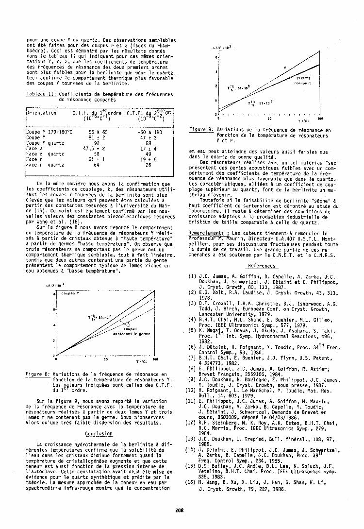
pour une coupe Y du q u a r t z . Oes observa t ions semblables o n t e t e f a i t e s pour des coupes r e t z ( faces du rhom- boedre) . Ceci e s t demontre p a r l e s r e s u l t a t s donnes dans l e t a b l e a u I 1 q u i i n d i q u e n t pour ces memes o r i e n - t d t i o n s Y, r, z , que l e s c o e f f i c i e n t s de temperature des frequences de resonance des deux premiers o r d r e s son t p l u s f a i b l e s pour l a b e r l i n i t e que pour l e q u a r t z . Ceci con f i rme l e comportement thermique p l u s f a v o r a b l e des coupes Y tournees de l a b e r l i n i t e . tcoujle I)
Tableau I 1 : C o e f f i c i e n t s de temperature des frequences de resonance compares
r i e n t a t i o n C.T.F. d t l e i o r d r e p o c - )
Coupe Y 1 7 0 - 1 8 0 " ~ 55 a 65 -60 a 180 Coupe Y 8 1 t 2 47 + 3 Coupe Y q l a r t z 9 2 58 Face z 47,5 + 2 17 + 4 Face z q u a r t z 58 49 Face r 6 1 t l 19 i. 5 Face r q u a r t z 64 2 6
De l a m&me maniere nous avons l a c o n f i r m a t i o n que l e s c o e f f i c i e n t s de couplage, k , des resona teurs u t i l i - s a n t l e s coupes Y tournees de l a b e r l i n i t e son t p l u s e leves que l e s v a l e u r s q u i peuvent & t r e c a l c u l e e s ?I p a r t i r des constantes mesurees a l ' u n i v e r s i t e du Mai- ne ( 1 5 ) . Ce p o i n t e s t egalement con f i rm6 par l e s nou- v e l l e s v a l e u r s des cons tan tes p i e z o e l e c t r i q u e s mesurees p a r Wang e t a1 . (16) .
Sur l a f i g u r e 8 nous avons r e p o r t e l e comportement en temperature de l a frequence de resona teurs Y r e a l i - ses d p a r t i r de c r i s t a u x obtenus d "haute temperature" a p a r t i r de germes "basse tempera tu re" . On observe que t r o i s resona teurs ne comportant pas l e germe o n t un comportement thermique semblable, t o u t ?I f a i t 1 i n e a i r e , t a n d i s que deux a u t r e s con tenan t une p a r t i e du germe p resen ten t l e comportement t y p i q u e de lames r i c h e s en eau obtenues d "basse temperature" ,
F i g u r e 8: V a r i a t i o n s de l a f requence de resonance en - f o n c t i o n de l a temperature de resona teurs Y . Les gp leurs ind iquees son t c e l l e s des C.T.F. du 1 o r d r e .
Sur l a f i g u r e 9, nous avons r e p o r t e l a v a r i a t i o n de l a f requence de resonance avec l a temperature de resona teurs r e a l i s e s a p a r t i r de deux lames Y e t t r o i s lames r ne contenant pas l e germe. Nous n 'observons a l o r s qu'une t r e s f a i b l e d i s p e r s i o n des r e s u l t a t s .
Conclus ion
La c ro issance hydrothermale de l a b e r l i n i t e a d i f - fe ren tes temperatures con f i rme que l a s o l u b i l i t e de l ' e a u dans l e s c r i s t a u x d iminue fo r tement quand l a temperature de c r i s t a l l o g e n e s e augmente e t que c e t t e teneur e s t auss i f o n c t i o n de l a p r e s s i o n i n t e r n e de l ' a u t o c l a v e . C e t t e c o n s t a t a t i o n a v a i t d e j a 6t.e mise en ev idence pour l e q u a r t z s y n t h e t l q u e e t p r e d i t e par l a t h e o r i e . La mesure approchee de l a teneur en eau p a r spectrometric i n f r a - r o u g e montre que l a c o n c e n t r a t i o n
F i g u r e 9 : V a r i a t i o n s de l a frequence de resonance en f o n c t i o n de l a temperature de resona teurs Y e t r.
en eau peu t a t t e i n d r e des v a l e u r s auss i f a i b l e s que dans l e q u a r t z de bonne q u a l i t & .
Des resona teurs r e a l i s e s avec un t e l mate r iau "sec" p resen ten t des p e r t e s acoust iques f a i b l e s avec un com- por tement des c o e f f i c i e n t s de temperature de l a fre- quence de resonance p l u s f a v o r a b l e que dans l e q u a r t z . Ces c a r a c t e r i s t i q u e s , a l l i e e s a un c o e f f i c i e n t de cou- p lage s u p d r i e u r au q u a r t z , f o n t de l a b e r l i n i t e un ma- t e r i a u d ' a v e n i r .
T o u t e f o i s s i l a f a i s a b i l i t e de b e r l i n i t e "sPcheU a h a u t c o e f f i c i e n t de s u r t e n s i o n e s t demontre au stade du l a b o r a t o i r e , il r e s t e a de te rminer des c o n d i t i o n s de c ro issance adaptges ti l a p r o d u c t i o n i n d u s t r i e l l e de c r i s t a u x de t a i l l e comparable a c e l l e du q u a r t z .
Remerciements : Les au teurs t i e n n e n t a r e m e r c i e r l e Pro fesseur M. Maur in, D i r e c t e u r U.A.407 U.S.T.L. Mont- p e l 1 i e r , pour ses d i s c u s s i o n s f ruc tueuses pendant t o u t e l a duree de ce t r a v a i l . Une grande p a r t i e de ces r e - c h e r c h e ~ a e t 6 soutenue p a r l e C.N.E.T. e t l e C.N.R.S.
References
(1 ) J.C. Jumas, A. G o i f f o n , B. Capel le , A . Zarka, J.C. Doukhan, J. Schwartzel , J . D C t a i n t e t E. P h i l i p p o t , J . C r y s t . Growth, 80, 133, 1987.
(2 ) E.D. Kolb, R.A. Laudise, J . C r y s t . Growth, 43, 313, 1978.
(3 ) D.F. C r o x a l l , T.R.A. C h r i s t i e , B.J. Isherwood, A.G. Todd, J . B i r c h , European Conf. on C r y s t . Growth, Lancaster U n i v e r s i t y , 1979.
(4 ) B.H.T. Chai, M.L. Shand, E. Bueh le r , M.L. G i l l e o , Proc. IEEE U l t r a s o n i c s Symp., 577, 1979.
( 5 ) K. Nagalt T. Ogawa, J . Okuda, J . Asahara, S. Tak i , Proc. 1 I n t . Symp. Hydrothermal React ions, 496, 1982.
(6) 3 . D e t a i n t , H. Poignant , Y. Toudic, Proc. 34th Freq. C o n t r o l Symp., 93, 1980.
(7) B.H.T. Chai, E. Buehler , J .J . F lynn , U.S. Pa ten t , 4 324773, 1982.
(8 ) E. P h i l i p p o t , J.C. Jumas, A. G o i f f o n , R. A s t i e r , B reve t F r a n ~ a i s , 2559166, 1984.
( 9 ) J.C. Doukhan, B. Bovlogne, E . P h i l i p p o t , J.C. Jumas, Y . Toudic, J . C r y s t . Growth, sous presse, 1987.
(10) H, Poignant , L . Le Marechal, Y . Toudic, Mat. Res. B u l l . , 14, 603, 1979.
(11) E. P h i l i p p o t , J.C. Jumas, A. G o i f f o n , M. Maur in, J.C. Doukhan, A. Zarka, B. Capc l le , Y . Toudic, J. DBta in t , J. Schwartzel , Demande de B r e v e t en cours, 8603009, depose l e 04/03/1986.
(12) R.F. S te inberg , M. K. Roy, A.K. Estes, B.H.T. Chai, R.C. M o r r i s , Proc. IEEE U l t r a s o n i c s Symp., 279, 1984.
(13) J.C. Doukhan, L . T rep ied , B u l l . M inera l . , 108, 97, 1985.
(14) J . D e t a l n t , E. P h i l i p p o t , J.C. Jumas, J . S c h ~ ~ r t z e l , A. Zarka, B. Capel le , J.C. Doukhan, Proc, 39 Freq. Con t ro l Symp., 234, 1985.
(15) D.S. B a i l e y , J.C. Andle, D.L. Lee, N. Soluch, J.F. V e t e l i n o , B.H.T. Chai , Proc. IEEE U l t r a s o n i c s Symp. 335, 1983.
(16) H. Wang, B. Xu, X . L i u , J . Han, S. Shan, H. L i , J . Crys t . Growth, 79, 227, 1986.
l a r brum European temps-fr&qiieriee - 1987
DEFECT6 IN S Y ~ T H E T I C M BEALtNITE : LATTICE DEFECT9 AND WATER INTAKE: b b b I ~ A A l 5 ~ I 4 WltH QLlARTZ
0. BOULOQNE. P. CtlRt31ER and J.C. DLIUKHAN
Leboretoire d e Structure e t Propr1dt6s d e I'Etat Solide [associated to CNRS 2341 Universit6 d e L ~ l i e Fiandres Artois, 59855 Villeneuve d'Ascq Cedex FRANCE
AUS'CKACT
a b e r l i n i t e A%P04 i s i s o s t r u c t u r a l with q u a r t z and i s s y n t h e t i z e d by hydrothermal growth. 'She r e s u l - t i n g c r y s t a l s c o n t a i n water which can be d e t e c t e d by i n f r a r c d spec t roscopy . T h i s wa te r o c c u r s a t a time un- d e r the form of very t i n y f l u i d i n c l u s i o n s and p o i n t d e f e c t s . Near i n f r a r e d spec t roscopy a l l o w s bo th forms of i n c o r p o r a t i o n t o be d i s t i n g u i s h e d . The second one ( d i s s o l v e d wate r ) cor responds t o a ttiermodynamical e q u i l i b r i u m c o n c e n t r a t i o n which depends only on t h e s t a t i c g r o w t t ~ c o n d i t i o n s (T, P , c o n c e n t r a t i o n of t h e n u t r i e n t ) . The f i r s t form bf Water ( f l u i d i n c l u s i o n s ) i s o u t of equ i l ib r iu rd ahd i s probably due t o a too high growth r a t e .
L a t t i c e d e f d c t s l i k e d i s l o c a t i o n s and twins a r e very s i m i l a r i n q u a r t z and b e r l i n i t e . However t h e A%-0 bonds i n b e r l i n i t e a r e markedly weaker than Si-0 bonds o r even L'-O ones. T h i s favours g l i d e systems such t h a t only t h e s e weak bonds a r e broken by t h e mobile d i s l o - c a t i o n s . These g l i d e s a r e p b a s a l - g l i d e (0001) 1/3 <1120>, & rhombohedra1 g l i d e s {I01 1}1/3<11?0> cjnd st& g l i d e s i n rhombohedra1 { 101 11 o r pyramiddl { 11221 p lanes .
Like f o r q u a r t z wa te r i n b e r l i n i t e l e a d s t o hydro- l y t i c weakening i . e . t o edhanced d i s l o c a t i o n m o b i l i t y under a g iven a p p l i e d s t r e s s . Th i s weakening becomes e f f i c i e n t a t t empera tu res T 5 250°C m e n t h e wate r as - s o c i a t e d p o i n t d e f e c t s became mobile. I t i s sugges ted t h a t t h e wasex d e f e c t s migra tu towards t h e d i s l o c a t i o n c o r e s and us a s s i s t t h e d u r W t i o U and t h e propaga- t i o n of double k i n k s on t h e d i s l o c a t i o n s . Such a pro- c e s s shou ld r e s t r i c t t h e s t a b i l i t y add t h e performances of p i e z o e l e c t r i c d e v i c e s .
INTRODUCTION
There is a lmos t no n a t u r a l b e r l i n i t e c r y s t a l s a l - though t h i s minera l has been d i scovered i n Sweden by N.J .Ber l in (1 ) and c o m e r c i a 1 b e r l i n i t e i s no t y e t a v a i l a b l e . The s tudy p r e s e n t e d h e r e h a s t h u s been per- formed on s y n t h e t i c c r y s t a l s grown i n f o u r d i s t i n c t l a b o r a t o r i e s i n d i f f e r e n t c o n d i t i o n s n o t a lways comple- t e l y known by t h e a u t h o r s of t h i s a r t i c l e . However most of t h e c r y s t a l s have been hydl 'othermally grown i n con- c e n t r a t e d s o l u t i o n s of H3P04 o r HC% ( o r bo th) a t tempe- r a t u r e s ranging from 160 t o 230°C and p r e s s u r e s < 100 b a r s (2 t o 6 ) . Like f o r a q u a r t z grown by a ve ry s imi- l a r t echn ique y e a r s ago tltis hydrothermal p r o c e s s l e a d e t o wet c r y s t a l s . In q u a r t z water i s c u r r e n t l y d e t e c t e d by i n f r a r e d spec t roscopy (IRS) i n t h e range 3500-2500 cm-1 ( s e e a review i n 7 ) and i t h a s long been ttiought t h a t t h i s wa te r e n t e r e d i n t o t h e q u a r t 8 l a t t i c e a s p o i n t d e f e c t s ( e i t h e r s u b s t i t u t i o n a l o r i n t e r s t i t i a l ones) wi th a super s a t u r a t e d c o n c e n t r a t i o n due t o a t o o h igh growth r a t e . However i t h a s been shown r e c e n t l y (8 t o 10) time t h i s water can occur e i t h e r under t h e form of t i n y f l u i d i n c l u s i o n s b t of t r u l y d i s s o l v e d wate r , t h e f i r s t one be ing t h e hlost f r e q u e n t . Both forms of wa te r can be d i s t i n g u i s h e d by n e a r i n f r a r e d spec t roscopy (NfRS) i n t h e range 7000-4000 cm'l and s u b s t i t u t i o n a l wa te r p o i n t d e f e c t s denoted (4H)si have been c h a r a c t e r i z e d by e l e c t r o n s p i n resonance (ESR) exper iments (11.12). S u b s t i t u t i o n a l wa te r p o i n t d e f e c t s have a l s o been found by ESR i n b e r l i n i t e ( 1 3 ) . It i s t h u s i n t e r e s t i n g t o u s e s i m i l a r i n f r a r e d t echn iques wi th a view t o c h a r a c t e r i z e wa te r i n b e r l i n i t e .
Another i n t e r e s t i n g problem d e a l s wi th t h e e f f e c t of water on d i s l o c a t i o n m o b i l i t y , t h e s o c a l l e d hydro- l y t i c weakening phenomenon d i scovered i n q u a r t z by Gr iggs and Ulac ic (14 t o 16) . I n t h i s c a s e a g a i n i t i s i n t e r e s t i n g t o i n v e s t i g a t e t h e p o s s i b l e occur rence of such an e f f e c t i n b e r l i n i t e . T h i s r e q u i r e s a systema- t i c i n v e s t i g a t i o n of l a t t i c e d e f e c t s ( d i s l o c a t i o n s , w t i n s ) i n as-grown b e r l i n i t e and i n b e r l i n i t e p l a s t i - c a l l y deformed a t v a r i o u s t empera tu res .
I n t h e f i r s t s e c t i o n one r e p o r t s t h e exper imenta l c h a r a c t e r i z a t i o n of l a t L i c e d e f e c t s i n a b e r l i n i t e . The water d e f e c t s a r e i n d i r e c t l y c h a r a c t e r i z e d by IRS and d i r e c t l y irnaged by t r a n s m i s s i o n e l e c t r o n microscopy (TCM) f o r t h e f l u i d i n c l u s i o n s . D i s l o c a t i o n s and twins a r e a l s o c h a r a c t e r i z e d by TEM. The second s e c t i o n d e a l s wi th p l d s t i c de format ion and TEM i n v e s t i g a t i o n of t h e r e s u l t i n g d i s l o c a t i o n s t r u c t u r e .
I1 - LATTICE DEFliCTS
One d i s t i n g u i s h e s h e r e two k i n d s of l a t t i c e de- f e c t s i) t h e ones a s s o c i a t e d t o w a t e r which can be e i t h e r t i n y f l u i d i n c l u s i o n s o r t r u e p o i n t d e f e c t s and i i ) extended d e f e c t s l i k e d i s l o c a t i o n s , twins ...
2-1 : Defec t s a s s o c i a t e d t o wa te r
As mentioned above wate r i s c u r r e n t l y d e t e c t e d i n m i n e r a l s by IKS i n t h e wave number range 3500-2500 cm-1 which cor responds t o a n a b s o r p t i o n by s t r e t c h i n g of t h e 0-H bonds. I n a v a r i e t y of m i n e r a l s , molecu la r wa te r i n f l u i d i n c l u s i o n s g i v e s r i s e t o a broad a b s o r p t i o n band whi le OH hydroxyls wi th e x a c t a l l o c a t i o n s i n t h e c r y s - t a l s t r u c t u r e r a t h e r l e a d t o p o l a r i s e d s h a r p a b s o r p t i o n peaks (17 t o 19) . T h i s t y p i c a l l y t h e c a s e of t h e charge compensat ing H a s s o c i a t e d t o i m p u r i t i e s l i k e A% i n q u a r t z (21,211. Q u a n t i t a t i v e e s t i m a t e s of t h e atomic r a t i o H/Si i n q u a r t z have been proposed by v a r i o u s au- t h o r s . M i n e r a l o g i s t s u s e t o compare t h e a b s o r p t i o n spectrum of t h e wet q u a r t z s t u d i e d t o t h e one of a dry s t a n d a r d and t h e l I /Si r a t i o i s assumed t o be p r o p o r t i o - n a l o r s imply r e l a t e d t o t h e a r e a bound by t h e two s p e c t r a ( 7 ) . I t i s thus i m p l i c i t e l y assumed t h a t t h e OH s t r e t c h i n g v i b r a t i o n s occur a t any wave number com- p r i s e d between 3500 and 2500 cm-1 wi th a s i m i l a r we igh t . C r y s t a l growers who produce s y n t h e t i c q u a r t z f o r piezo- e l e c t z i c a p p l i c a t i o n s r a t h e r deduce a q u a l i t y f a c t o r Q from t h e a b s o r p t i o n r a t i o a t two wave numbers on t h e same spectrum (3300 cm-1 where t h e OH a r e a c t i v e and 3800 cm-I where they do n o t absorb i n f r a r e d l i g h t ) .
I n t h e c a s e of b e r l i n i t e t h i s second method can be e a s i l y t r ansposed and a weight r a t i o H20/AkP04 can be e s t i m a t e d . An e m p i r i c a l formula h a s been r e c e n t l y pro- posed (21)
c = - 50 T3800 (weight i n ppm) = - t l o g -
T3300
where T i s t h e i n t e n s i t y of t h e t r a n s m i t t e d l i g h t a t t h e c o n i i d e r e d wave number x and t i s t h e sample th ick- n e s s i n cm. The method of m i n e r a l o g i s t s i s l e s s e a s i l y t r ansposed because t h e r e i s no a v a i l a b l e s t a n d a r d of dry b e r l i n i t e , however t h e whole spectrum i n t h e range 4000 - 2500 cm-1 c o n t a i n s more in format ion t h a t on ly t h e a b s o r p t i o n r a t i o a t two wave numbers, e s p e c i a l l y t h e peaks a ~ s o c i a t e d t o chemical i m p u r i t i e s cou ld even- t u a l l y be d e t e c t e d . We have assumed t h a t dry b e r l i n i t e
would be conipletcly t r ' lnsparent i n t h e r.lngc, 4000-2500 cm-I and t l i , ~ t wa te r , whatever i t p r e c i s e incorpora l ion mode i n b c r l i n i t e e x h i b i t s t h e some c f f i c i r n c 5 y a s i r i
q u ~ t r t z . Th i s , 1 1 1 0 ~ s an amount of 011 i n wet b e r l i n i t e t o bc deduced from an , ~ b s o r p t i o n spectrum i n u s i n g t h e
I formu1.l f o r q u a r t z bas,il samples ( 7 )
2500 Ll C = - Ae+l ' (a tomic (2 )
4000
whcre t i s tllc. s,l~npLr t l l i c k ~ i c s s i l l cm and T(v) and I ( v ) t t ~ c t r , lnsni i t tcd and i n c i d e n t i n t e n s i t i e s r e s p e c t i - ve ly a t t h e wave number V . 'l'his l a t e r a tomic conccn t ra - t i o n can be ( o n v e r t c d i n t o a weight c o n c e n t r a t i o n t120/AQ1'04 i n m u l t i p l y i n g i t by 7.38 x Both mc- thods can t h u s be compared and g i v e q u a l i t a t i v e l y t h e same r e s u l t s wi th v a l u e s which can be Lwice l a r g e r wi th t h e second method f o r some samples which probably i m p u r i t i e s producing sharp a b s o r p t i o n peaks c o n t r i b u - t i n g t o c . F igure 1 shows t h e IRS's of two samples with comparable wa te r c o n t e n t s b u t one e x h i b i t s sllarp peaks a t t r i b u t e d t o i m p u r i t i e s . I f one t e n t a t i v e l y a t t r i b u t e s t h e a r e a enc losed by t h e peaks t o H compen- s a t e d i m p u r i t i e s , t h e i r a tomic c o n c e n t r a t i o n would be 2 300 a t ppm.
I 'revious IKS s t u d i e s (22,23) have shown t h a t i n gcnc~r.11 b e r l i n i t e c r y s t a l s a r e wet, t h e d r y e s t ones being one o r two o r d e r s of magnitude w e t t e r than a c t u - '11 h igh g rade q u a r t z . t h e wa te r c o n t e n t c l e a r l y decrea - s e s a s t h e growth t empera tu re i n c r e a s e s and t h e pieao- e l e c t r i c performances s p e c t a c u l a r l y i n c r e a s e a s t h e water c o n t e n t d e c r e a s e s . However i t i s n o t known i f t h i s w a t r r i n t a k e occurs under t h e form of t i n y inc lu - s i o n s o r of t r u l y d i s s o l v e d wate r we have t h u s inves- t i g a t e d some b e r l i n i t e c r y s t a l s by NIKS. T h i s t echn i - que r e q u i r e s r a t h e r t h i c k c r y s t a l s ( 2 mm t o 1 cm) because of t h e low absorbance c o e f f i c i e n t i n t h e cor - responding wave number range. There fore i n a number of c a s e s t h e samples t e s t e d c o n t a i n e d t h e seeds . F i g u r e 2 shows t h e N I R spectrum of a c r y s t a l c o n t a i n i n g i t s seed . One c l e a r l y observes two a b s o r p t i o n s peaks. One i n t h e v i c i n i t y of 1930 nm (5200 cm-l) i s a t t r i b u t e d t o a combinat ion of s t r e t c h i n g and t w i s t i n g modes of t h e wa te r molecules i . e . t o f l u i d i n c l u s i o n s i n q u a r t z (8 ,17) . The o t h e r peak n e a r 2300 nm (: 4300 t o 4400 cm-1) i s a t t r i b u t e d i n t h e c a s e of q u a r t z t o OH p o i n t d e f e c t s . Th i s peak which i s p r e s e n t l y s l i g h t l y dedou- b l e d i n b e r l i n i t e super imposes on t h e i n t r i n s i c ab- s o r p t i o n of t h e b e r l i n i t e l a t t i c e and we can a t t r i b u t e i t t o p o i n t d e f e c t s cor responding t o t r u l y d i s s o l v e d wate r . The f a c t t h a t t h i s peak i s dedoubled i n b e r l i - n i t e b u t n o t i n q u a r t z cou ld cor respond t o t h e occuren- c e of two s i m i l a r b u t d i s t i n c t p o i n t d e f e c t s f o r ins - t a n c e i n t e r s t i t i a l H20 molecules i n t o two d i s t i n c t s i - t e s i n t h e c r y s t a l s t r u c t u r e o r two d i f f e r e n t s u b s t i t u - t i o n a l d e f e c t s l i k e (4H)kQ and (4H)' wi th equa l con- c e n t r a t i o n s f o r t h e e l e c t r i c a l e q u i f i b r i u m . The i n f l u - ence of t h e c r y s t a l t o g r a p h i c o r i e n t a t i o n of t h e sample and of t h e t empera tu re on N I R absorbance s p e c t r a a r e shown on F i g u r e s 3 and 4 . One n o t e s t h a t t h e c r y s t a l l o - g raph ic o r i e n t a t i o n most ly a f f e c t s t h e i n t r i n s i c ab- s o r p t i o n of t h e b c r l i n i t e s t r u c t u r e b u t t h e peaks due t o molecular wa te r o r t o p o i n t d e f e c t s a r e n o t nnrked- l y a f f e c t e d . In t h e same way t h e s p e c t r a recorded a t room tempera tu re (300 K) o r a t low tempera tu re (30 K) on a b a s a l sample a r e e s s e n t i a l l y i d e n t i c a l , one j u s t obsc rvcs n s l i g h t d e c r e a s e of t h e i n t r i n s i c a b s o r p t i o ~ i a t low tempera tu re . I n c o n t r a s t a f t e r an a n n e a l i n g of 3 hours a t 300°C, one c l e a r l y observes a d e c r e a s e of t h e peak a t t r i b u t e d t o wa te r p o i n t d e f e c t s and an in- c r e a s e of t h e one a t t r i b u t e d t o i n c l u s i o n s i . e . t h i s experiment shows t h a t some i n i t i a l l y d i s s o l v e d wate r has p r e c i p i t a t e d dur ing t h e a n n e a l i n g t r e a t m e n t . T h i s experiment a l s o conf i rms t h a t t h e a b s o r p t i o n peaks a t : 1930 and 2300 nm a r e e f f e c t i v e l y r e l a t e d t o molecu- l a r wa te r ( i n c l u s i o n s o r bubbles ) and d i s s o l v e d wate r under t h e form of p o i n t d e f e c t s r e s p e c t i v e l y . These a r e t h e r e f o r e two k i n d s of wa te r i n wet b e r l i n i t e c r y s - t a l s . The d i s s o l v e d wate r cannot probably be complete l y e l i m i n a t e d because i t cor responds t o a s o l u b i l i t y which i s a f u n c t i o n of t h e thermodynamic paramete rs of
growth ( t e n i p c r : l t ~ ~ r c , p r e s s u r e , c o n c c n t r a t i o ~ ~ of t h e 1 1 u t r i e n t ) h u t t h e o t h e r kind of wa te r i s c l e a r l y rcala- Led Lo phenomena o u t of tt~c~rmodyn'lmic e q u i l i b r i u m l i k e .I t oo 1ii):li growti1 r.lte and i t cou ld i n p r i n c i p l e be avoided o r n t Ic.lst minimized. The growth r a t e est ima- t c d by t h c c r y s t a l growers i s in f a c t a nlc,in v a l l ~ c (s<ti~lple t l l i ckness ( l ividcd by t h e growth t i m e ) . I'hc g rowt l~ r a t e cou ld vzrry d u r i n g t h e growtll pr0cr .ss . I t cou ld be l a r g e a t t h e beg inn ing , t h u s l e a d i n g t o a l a r g e wntcr i n t a k e and then d e c r e a s e t o ve ry low va- l u e s . We llave t h u s Lr icd t o cst im.l te a wa te r concen l ra - t i o n p r o t i l e i l l '1 s.1111pIc w11ic~I1 11.1s 1)eoti c u t in t h i n s l a b s p , ~ r , i l l e l Lo Ll~c seed with .I very t l ~ i n diamond saw. Convelltional II< s p c c t r ~ r hCrvc hcen recorded f o r each sl.lh and Ll~e cor responding concen t r , l t ion p r o f i l e (cst im,i ted wi th fornit11,l ( 1 ) ) i s sl~own on F i g u r e 5 . I t i s synuiletric,il and c l e a r l y sllows t h a t on bo th s i d e s of '1 r a t h e r dry seed a l.irge mount of wa te r e n t e r s i n tile c r y s t a l a t t h e beg inn ing of t h e growth p r o c e s s then t h e c o n c e n t r a t i o n d e c r e a s e s a g a i n down t o v a l u e s a s low a s 60 weight ppm ( o r H/(A!L+P) : 800 a t ppm) As sugges ted above t h e l a r g e wate r int.xke a t t h e heg in- n i n g of growth cou ld be due t o a too h igh growth r a t e b u t t h e r e i s a n a l t e r n a t i v e e x p l a n a t i o n . The seed c o n t a i n s as-grown d i s l o c a t i o n s and i t i s w e l l known i n t h e c a s e of q u a r t z growth t h a t t h e n u t r i e n t produces a t t h e very beg inn ing of t h e growth p r o c e s s e t c h chan- n e l s a l o n g t h e d i s l o c a t i o n s i n t h e seed. Such c h a n n e l s c o u l d a l s o form i n t h e b e r l i n i t e s e e d s and tliey c o u l d be p ro longa ted over some l e n g t h i n t h e m a t e r i a l dcpo- s i t e d on t h e sced . 'Illis would l ead t o he te rogeneous ly d i s t r i b u t e d e l o n g a t e d f l u i d i n c l u s i o n s . To c o n t r o l t h i s h y p o t h e s i s we have observed i n TEM a number of t h i n saniples c u t i n s l a b s wi th d i f f e r e n t wa te r con- t e n t s . I n t h e w e t t e s t ones ( n o t f ' lr from t h e sced) one c l e a r l y obscrvcs .i l 'lrgc d e n s i t y (up t o " 1015 cni-3) of very t i n y s p h e r i c a l f l u i d i n c l u s i o n s ( F i g u r e 6 ) . The s m a l l e s t ones wt ich can be d e t e c t e d by TEM have a r a d i u s of 30 t o 40 A b u t t h e r e i s no d i s l o c a t i o n i n t h e i r v i c i n i L y and they a r e homogeneously d i s t r i b u t e d a t l e a s t a t t h e s c a l e of t h e o b s e r v a t i o n s i n TEM (minimum m a g n i f i c a t i o n 2 10 ,000) . No such i n c l u s i o n s a r e seen i n d r y e r samples. T h e r e f o r e t h i s k i n d of wa te r i n t a k e which i s o u t of e q u i l i b r i u m cou ld be avo i - ded even wi th d i s l o c a t e d seeds i n d e c r e a s i n g t h e i n i - t i a l growth r a t e , The a n n e a l i n g experiment shown on F i g u r e 4 a l s o s u g g e s t s t h e f o l l o w i n g comment. A p a r t of t h e wa te r i n i t i a l l y d i s s o l v e d (growth c o n d i t i o n s T 210°C, P : 20 b a r s ) p r e c i p i t a t e s d u r i n g a n n e a l i n g a t 300°C, 1 b a r . T h i s t e n d s t o i n d i c a t e t h a t wa te r s o l u b i l i t y i n b e r l i n i t e d e c r e a s e s a s T i n c r e a s e s , a t l e a s t up t o 300-350°C. T h i s i s i n complete agreement wi th p r e v i o u s r e s u l t s which have l e d t o grow b e r l i n i t e a t h i g h e r t empera tu re (6 ,23 ,24) . Sys temat ic s t u d i e s by IRS o r NIRS (on t h i c k c r y s t a l s i n t h i s l a t e r c a s e ) c o u l d p rov ide a good t o o l f o r t h e measurement of wa te r s o l u b i l i t y i n b e r l i n i t e a s a f u n c t i o n of t h e growth c o n d i t i o n s and t h i s would h e l p i n de te rmin ing t h e b e s t c o n d i t i o n s f o r o b t a i n i n g c r y s t a l s a s d ry a s p o s s i - b l e .
F i n a l l y i t can be s a i d t h a t wa te r g e n e r a l l y e n t e r s i n b e r l i n i t e under a t l e a s t two d i s t i n c t forms. One ( f l u i d i n c l u s i o n s ) i s c o r r e c t l y c h a r a c t e r i z e d and can probably be avo ided . The o t h e r one ( s o l u b i l i t y ) i s n o t completely c h a r a c t e r i z e d , t h e n a t u r e of t h e a s s o c i a - t e d p o i n t d e f e c t s be ing n o t e l u c i d a t e d , i t is t h e r e f o - r e imposs ib le a t t h e moment t o s u g g e s t any p rocedure t o e l i m i n a t e o r a t l e a s t minimize t h i s second k ind of wa te r . However i t a p p e a r s t l ~ n ~ t h e p i e z o e l e c t r i c per- formances of b e r l i n i t e c r y s t a l s wi thou t f l u i d inc lu - s i o n s a r e a l r e a d y s a t i s f a c t o r y (22) .
2-2 : D i s l o c a t i o n s and g l i d e systems
The c r y s t a l s t r u c t u r e of ct b e r l i n i t e (25) i s t h e same a s t h e one of a q u a r t z wi th ve ry s i m i l a r l a t t i c e pa ramete rs excep t t h a t c i s twice l a r g e r because of t h e sequence At-P-AL a l o n g t h i s d i r e c t i o n . One t h e r e - gore e x p e c t s d i s l o c a t i o n s wi th Burgers v e c t o r & (4.94 A). Other Burgers v e c t o r s which have been c h a r a c t e r i - zed i n q u a r t z & a n d +a (26 t o 281 a r e a p r e c i a b l y l a r g e r i n b e r l i n i t e = 10.95 A ; ~ c + a T = 12.01 A ) . Furthermore t h e r e i s a n o t h e r d i f f e r e n c e between
quclrtz and b e r l i n i t e a l though bo th can be cons idered cis <:ovaletit c r y s t a l s . In q u a r t z a l l ttie Si-0 bonds Iiavr a s i m i l a r s t r e n g t h while i n b e r l i n t e t h e Ak-0 bonds a r e weaker than t h e 1'-0 ones ( 2 9 ) . Easy g l i d e i s thus expected t o occur in p lanes such t h a t on ly Ak-O bonds a r e broken by t h e mobile d i s l o c a t i o n s and t h e r e s u l t i n g f low s t r e s s i s expected t o be a p p l e e i a b l y lower than i n q u a r t z . A d e t a i l l e d i n v e s t i g a t i o n of t h e c r y s t a l s t r u c t u r e shows t h a t two p o s s i b l e g l i d e sys - tems f u l f i l l - t h e above r e q i ~ i r e n i r n t s , t h e b a s a l a_ g l i d e (0001) 1/3<2110> and rhombohedra1 g l i d e s {01 1 1 1 1 / 3 <2110> (30) .
2-3 : P l a n a r d e f e c t s : twins and A=
Dauphine twins , B r a z i l twins and an t i -phase boun- < l .~ r ic~s (AFB) have a l r e a d y bccn observed i n a b e r l i n i t c ( L 3 , ) l ) . AI'U's cor respond t o a mismatch of t h e A t and I' c . t t ions , t h e oxygen s u b l a t t i c e be ing u n a f f e c t e d . Hraz i l twins a r e found i r i {I0121 p lanes . They seem t o occur p re fe rc !n t i a l ly i n c r y s t a l s c o n t a i n i n g i m p u r i t i e s ( d e t e c t e d by IRS). A s i m i l a r a s s o c i a t i o n occurs i n q u a r t z (amethyst i s known t o c o n t a i n numerous B r a z i l t w i n s ) . These i m p u r i t i e s probably f i n d p r e f e r e n t i a l s i - t e s i n t h e twin boundar ies and f a v o u r t h e i r growth. P lanar d e f e c t s ( twins and APB's) a r e extremely r a r e i n good q u a l i t y c r y s t a l s and w i l l n o t be i n v e s t i g a t e d f a r - t h e r .
LlI - PLASTIC DEFOKMATION
The fo l lowing cx[>eriments have been performed wi th a view t o c h a r ; ~ c t c r i z e t h e g l i d e systems of b c r l i n i t e and thcsir y i i ? ld s t r e s s e s . T h i s i n f o r n ? t i o n con be use- f u l f o r unders tand ing which d e f e c t s a r e n u c l e a t e d du- r i n g mechanical g r i n d i n g and t o which depth they cx- tend. Again one time i t i s u s e f u l t o comparc with the c:asc! of qtiilrtz W I I ~ C I I i s b e t t e r known. 111 q u a r t z it
small amount of water d i s p e r s e d i n t h e c r y s t a l induces a d ramat ic decre;ise of t h e y i e l d s t r e s s above a tempe- r a t u r e of t h e o r d e r of 400°C which i s t h e t empera tu re a t which the wa te r po in t d e f e c t s become mobile . A s i - m i l a r behaviour cou ld o r c u r in b e r l i n i t e . To t e s t t h i s I ~ y p o t l i e s i s we have performed two t y p e s of de for rm~t ion t e s t s i ) deformcition a t room tempera tu re under a con- l i n i n g p rcss t l r e t o p reven t f r a c t u r c s ; i n t h e s e condi- t i o n s i t i s expected t h a t wa te r h a s no e f f e c t on t h e mechanical p r o p e r t i e s of b e r l i n i c e and i i ) deformation wi thou t c o n f i n i n g p r e s s u r e i n a t empera tu re range ex- t end ing up t o t h e a + 6 t r a n s i t i o r l . Tw6 ~ 0 m p r e s S i o n o r i e n t a t i o n s have been t e s t e d . The f i r s t one c o r r e s - ponds t o t h e so c a l l e d "0'" o r i e n t a t i o n of q u a r t z (26, 28,32) it i s a t 45" t o t h e and & d i r e c t i o n s and promotes a b a s a l g l i d e wi th a maximum Schmid f a c t o r 4 = 112. The o t h e r o r i e n t a t i o n sometimes c a l l e d "m" i s a t 45" t o a1 and 9 - % 3 . I t cor responds t o 4 = 0 f o r J. b a s a l glidedwtiich should n o t be a c t i v a t e d . d i s l a r - 'V ge ( ~ ~ 4 2 ) f o r tw_o rhombohpdral 2 g l i d e s , namely (1701) 1/31 1120/ and (1101)1 /3~11201 .
3-1 : Rooni t empera tu re de format ion
We have used a Griggs-type deformation m a ~ l ~ i n e with a v i s c o u s s y n t h e t i c rubber a s c o n f i n i n g medium. This ~ l l o w s homogeneous c o n f i n i n g p r e s s u r e s of 600 t o 1000 MPa t o be ob ta ined wi thou t p a r a s i t i c d e v i a t o r i c s t r e s s e s . One has r e p o r t e d on F igure 7 t h e recorded deformat ion c u r v e s f o r c o n s t a n t s t r a i n r a t e t e s t s . For comparison the curve ob ta ined i n t h e same c o n d i t i o n s witti 4 q u J r t z sample i s a l s o r e p o r t e d . These c u r v e s r e p r e s e n t t h e d e v i a t o r i c s t r e s s 0 = F/S v e r s u s Aklk wticre S and 9. a r e t h e s e c t i o n and t h e l eng th of t h e c r y s t a l t e s t e d , A!? i t s s h o r t e n i n g under t h e compressi- ve Eorce F. As can be seen q u a r t z e x h i b i t s a s t r i c t l y e l a s t i c behaviour up t o u l t i m a t e d e v i a t o r i c s t r e s s - 7000 MPa a t which i t b reaks e x p l o s i v e l y . I n c o n t r a s t b e r l i n i t e e x h i b i t s a d u c t i l e behaviour a t moderate f low s t r e s s e s of t h e o r d e r of 1000 MPa f o r t h e 0' sam- p l e ( t h i s i s t h e o r d e r of magnitude of an u s u a l harde- ned s t e e l ) and of " 3000 MPa f o r t h e m sample. In t h i s l a t e r c a s e small c r a c k s a r e observed i n o p t i c a l m i - croscopy a f t e r de format ion . These exper iments prove t h a t b e r l i n i t e i s c o n s i d e r a b l y weaker than q u a r t z and i t can be i r r e v e r s i b l y damaged dur ing machining.
More q u a n t i t a t i v e in format ion can be deduced f r o m t h e i n v e s t i g a t i o n by TKM of t h e d e f e c t s l i f t by p l a s - t i c de format ion . I n t h e 0' sample, a f t e r 1 ,5% p l a s t ' c s t r a i n one observes a homogeneous d e n s i t y ( 1 2 x 10 4 cm-2) of 2 d i s l o c a t i o n s l y i n g i n t h e b a s a l p lane . They have marked p r e f e r r e d o r i e n t a t i o n s p a r a l l e l t o t h e a d i r e c t i o n s (F igure 8 ) however no screw d i s l o c a t i o n & i s observed i . e . t h e d i s l o c a t i o n s have a i 60' c h a r a c t e r . Tliis s i t u a t i o n i s very s i m i l a r t o t h e one a l r e a d y ob- se rved in q u a r t z (28,32) and i n t e t r a h e d r a l semicon- d u c t o r s ( s e e f o r i n s t a n c e a r e c e n t review i n 33) . Dis- l o c a t i o n s with an a r b i t r a r y o r i c n t a t i o n i n t h e s e cova- l e n t s t r u c t u r e s have d a n g l i n g bonds which i n c r e a s e t h e i r c o r e e n e r g i e s . For c e r t a i n o r i e n t a t i o n s which cor respond t o s imple c r y s t a l l o g r a p h i c o r i e n t a t i o n s the- s e dang l ing bonds in t h e c o r e s can r e c o n s t r u c t . The cor responding d i s l o c a t i o n i s more s t a b l e ( l e s s ener - gy) b u t i t s m o b i l i t y i s decreased and p l a s t i c deforma- t i o n i s govcrlled a t low tempera tu re ( P e i e r l s regime, s e e f o r i n s t a n c e 34) by t h e n u c l e a t i o n and t h e propa-
g a t i o n of double k i n k s a l o n g t h e s e d i s l o c a t i o n s . The h y d r o l y t i c weakening phenomenon t h u s s imply c o n s i s t s i n an e a s i e r n u c l e a t i o n of t h e s e double k i n k s because i t i s a s s i s t e d by wate r p o i n t d e f e c t s . Such an i n t e r - a c t i o n between a low d e n s i t y of p o i n t d e f e c t s and d i s - l o c a t i o n s can be e f f i c i e n t on ly i f t h e p o i n t d e f e c t s a r e mobile and d i f f u s e towards ttie d i s l o c a t i o n l i n e s i . e . i f t h e t empera tu re i s h igh enough.
I n salnple m one observes i n TI!M a he te rogeneous d i s l o c a t i o n d e n s i t y i n t h e rhombohedra1 p l a n e s . In some a r e a s i t i s ve ry low w h i l e i n o t h e r s i t i s s o h i g h t h a t i n d i v i d u a l c o n t r a s t s of d i s l o c a t i o n s cclllnot be s e p a r a t e d . Furthermore t h e r e a r e c l e a r l y c r o s s s l i p s i n t h e b a s a l p lane (F igure 9) probably caused by t h e i n t e r n ; ~ l s t r e s s ( t h e Schmid f a c t o r f o r t h e b a s a l p lane c a n c e l s f o r t h i s o r i e n t a t i o n ) . One a g a i n observes t h a t t h e 3 d i s l o c . l t i o n s having c r o s s - s l i p e d i n (0001) have a p r e f e r r e d f 60" c h a r a c t e r . The smal l c r a c k s observed o p t i c a l l y have probably occur red a f t e r deform:ition, d u r i n g decompression, under t h e a c t i o n of t h e i n t e r n a l s t r e s s because one observes i n TEM t h a t i n m:lny casc>s d i s l o c a t i o n s a r e con t inuous on both s i d c s of t h e c r a c k s .
These deformat ion exper iments a t room tenipcrntti- r e f i n a l l y show t h a t under n o t too h igh s t r e s s e s a l a r g e d e n s i t y of d i s l o c a t i o n s can be in t roduced . As mechanical g r i n d i n g i s a somewhat s i m i l a r p rocess indu- c i n g l o c a l i z e d h igh d e v i a t o r i c s t r e s s e s and c o n f i n i n g p r e s s u r e , a l a r g e d i s l o c a t i o n d e n s i t y and microcracks can r e s u l t s . From t h i s p o i n t of view b e r l i n i t e and q u a r t z have a d i f f e r e n t behav iour and t h i s should be k e p t i n mind.
3-2 : I n f l u e n c e of t empera tu re
Deformation t e s t s a t t empera tu re above TR have been performed wi thou t c o n f i n i n g p r e s s u r e . The c o r r e s - ponding samples have been c u t i n t h e b i g g e s t c r y s t a l s t o avo id t h e seeds . U n f o r t u n a t e l y i t happenned t h a t t h e s e b i g g e s t c r y s t a l s a r e a l s o t h e w e t t e s t ones. Below % 250°C, no p l a s t i c s t r a i n can be o b t a i n e d ; b r i t t l e f r a c t u r e s occur a t s t r e s s e s of t h e o r d e r of 200 t o 300 MPa even wi th t h e lowes t s t r a i n r a t e s ob- t a i n a b l e wi th a low speed i n s t r o n machine (2 2 um min-1 i . e . 2 s - ' ) . Above 250°C, wa te r d e f e c t s begin t o be mobile and some wate r p r e c i p i t a t i o n b e g i n s t o occur . Th is i s c l e a r l y seen i n TEM. The s t r e s s - s t r a i n c u r v e s o b t a i n e d f o r c o n s t a n t s t r a i n r a t e t e s t s ( b = s - ' ) a r e r e p o r t e d on F igure 10. They i n d i c a - t e a s e v e r e d e c r e a s e of t h e f low s t r e s s a s t h e t e s t tenlperature i s i n c r e a s e d . Furthermore above 300°C y i e l d i n g i s fol lowed by a s t a g e wi th a ha rden ing r a t e d a / d ~ which i n c r e a s e s a s T i n c r e a s e s . Like f o r wet q u a r t z t h i s phenomenon i s t o be r e l a t e d wi th wa te r p r e c i p i t a t i o n which accompanies p l a s t i c de format ion and which occurs more and more r a p i d l y a s T i n c r e a s e s . An apparen t a c t i v a t i o n volume V h a s been measured by t h e s t r e s s r e l a x a t i o n t echn ique (35) a l l a long t h e de- fo rmat ion c u r v e a t 400°C. I t shows a r a p i d d e c r e a s e then s t a b i l i s e s a t a v a l u e a s low as 1 a2c. A l l t h e s e f a c t s a r e c o n s i s t e n t wi th a the rmal ly a c t i v a t e d defor - mation p rocess . However t h e r e s u l t i n g d i s l o c a t i o n s t r u c t u r e s a s observed i n TEM a r e n o t t h e ones expec ted
f o r such a p rocess . They on ly c a s t in fo rmat ion about wa te r p r e c i p i t a t i o n ; one observes numerous bubbles wi th v a r i o u s s i z e s , o f t e n connected t o d i s l o c a t i o n seg- ments. These l a t e r ones a r e most o f t e n i n cl imb c o n f i r g u r a t i o n and form a number of j u n c t i o n s ( F i g u r e 11) . We b e l i e v e t h a t t h i s d i s l o c a t i o n c o n f i g u r a t i o n r e s u l t s from t h e con t inuous m o d i f i c a t i o n caused by wate r pre- c i p i t a t i o n of t h e i n i t i a l d i s l o c a t i o n s t r u c t u r e r e l a - t e d t o the rmal ly a c t i v a t e d g l i d e . I n n o t s o wet samples one shou ld observe s t r a i g h t d i s l o c a t i o n s conf ined i n t o t h e i r g l i d e p lanes . Dryer b i g c r y s t a l s be ing n o t y e t a v a i l a b l e i t has n o t been p o s s i b l e t o unambiguously demons t ra te t h a t t h e r e i s a h y d r o l y t i c weakening i n b e r l i n i t e ; however t h e f a c t t h a t a ha rden ing i s obse r - ved when wate r p r e c i p i t a t e s a t h igh t empera tu re ( i . e . when l e s s wa te r d e f e c t s a r e a v a i l a b l e f o r k ink nuc lea - t i o n ) s t r o n g l y s u g g c s t s t h a t such a weakening does occur .
I V - CONCLUSION
From t h e p o i n t of view of l a t t i c e d e f e c t s t h e r e a r e many s i m i l a r i t i e s and some marked d i f f e r e n c e s be t - ween b e r l i n i t e and q u a r t z . Both c r y s t a l s have t h e same s t r u c t u r e and bo th can c o n t a i n some wate r which d ra - m a t i c a l l y a f f e c t s a number of t h e i r p h y s i c a l proper- t i e s , e s p e c i a l l y t h e i r mechanical p r o p e r t i e s and t h e performances of t h e p i e z o e l e c t r i c d e v i c e s . Among t h e d i f f e r e n c e s one n o t i c e s t h e l e n g t h of t h e c parameter which i s twice l a r g e r i n b e r l i n i t e and t h e s t r e n g t h of t h e At-0 bonds which i s markedly lower than t h e one of Si-0 bonds. As a r e s u l t g l i d e i n p r i s m a t i c p lanes which i s an easy g l i d e system i n wet q u a r t z seems t o be p r o h i b i t e d i n b e r l i n i t e . Other d i f f e r e n c e s a r e n o t s t r u c t u r a l and r a t h e r seem t o be r e l a t e d t o t h e s t a t e of t h e a r t i n growing processes . Pren~ium h igh g rade q u a l i t y q u a r t z a r e commercial ly a v a i l a b l e now ; they c o n t a i n a ve ry smal l amount of i m p u r i t i e s and wate r ( H/Si + AL/Si probably l e s s than 20 a t ppm) s i m i l a r b e r l i n i t e c r y s t a l s a r e n o t y e t a v a i l a b l e . Ac- t u a l c r y s t a l s c o n t a i n wa te r a s t h e main impur i ty and t h i s wa te r e n t e r s under two forms t i n y f l u i d i n c l u - s i o n s which a r e probably g e n e r a t e d by a t o o h igh growth r a t e and d i s s o l v e d wate r . Because i t h a s been p o s s i b l e t o c o r r e c t l y a n a l y s e t h i s f i r s t k i n d of wa- t e r , i t shou ld r a p i d l y d i s a p p e a r i n a d j u s t i n g conve- n i e n t l y t h e g rowthcondi t ions . It a p p e a r s t o be more d i f f i c u l t t o e l i m i n a t e t h e second k ind of wa te r becau- s e i t s c o n c e n t r a t i o n cor responds t o a thermodynamical e q u i l i b r i u m . S h i f t i n g t h i s e q u i l i b r i u m towards t h e d e s i r e d d i r e c t i o n ( l e s s d i s s o l v e d w a t e r ) r e q u i r e s a good knowledge of t h e n a t u r e of t h e p o i n t d e f e c t s a s s o c i a t e d t o t h i s d i s s o l v e d wate r (peaks a t % 2300 nm i n NIRS). ESR exper iments c o u l d perhaps be a power- f u l t o o l t o s o l v e t h i s problem. A thermodynamic ana ly - s i s of t h e i r e q u i l i b r i u m c o n c e n t r a t i o n would t h u s a l l o w d i f f e r e n t growth c o n d i t i o n s t o be t e s t e . A l t e r - n a t i v e l y a more e m p i r i c a l method would s imply c o n s i s t i n measuring by NIRS t h e amount of d i s s o l v e d wate r f o r a few s e t of growth c o n d i t i o n s , t o deduce t r e n d s and t o adop t a good compromise between exper imenta l f e a - s a b i l i t y ( n o t too h igh T and P, n o t t o o low growth r a t e f o r i n s t a n c e ) and i d e a l c o n d i t i o n s .
F i n a l l y i t i s a l s o t o be mentioned t h a t t h e me- c h a n i c a l p r o p e r t i e s of q u a r t z and b e r l i n i t e a r e marked- l y d i f f e r e n t . Quartz i s remarkably s t r o n g a t room tem- p e r a t u r e and even a t t empera tu re a s h igh a s T = 1300°C (under c o n f i n i n g p r e s s u r e t o p reven t i t s t ransforma- t i o n i n t o c r i s t o b a l i t e ) . D i s l o c a t i o n s in t roduced by mechanical g r i n d i n g t h u s p ropaga te over ve ry smal l d i s t a n c e from t h e machined s u r f a c e ( o r d e r of 1 um o r l e s s ) . I n c o n t r a s t b e r l i n i t e i s much weaker. I t s easy g l i d e system (0001)1/3<1120> y i e l d s a t a s t r e s s compa- r a b l e t o t h e one of an u s u a l carbon s t e e l . Disloca- t i o n s can thus be s e v e r e l y m u l t i p l i e d i n a l a y e r wi th an a p p r e c i a b l e t h i c k n e s s under t h e machined s u r f a c e . D i s l o c a t i o n m u l t i p l i c a t i o n can a l s o g e n e r a t e micro- c r a c k s and a l l t h e s e f e a t u r e s n e c e s s a r i l y l i m i t t h e p i e z o e l e c t r i c p ~ r f o r m a n c e s . However, a t t h e moment, t h e d e f e c t s l i m i t i n g t h e s e performances s t i l l seems t o be t h e l a r g e wate r c o n c e n t r a t i o n s .
ACKNOWLEDGMENTS
The a u t h o r s g r a t e f u l l y thank t h e c r y s t a l growers who kind19 gave them t h e i r c r y s t a l s : Dr P h i l i p p o t from t h e U n i v e r s i t y of M o n t p e l l i e r , Dr Todd from t h e GEC H i r s t c e n t e r , Dr CHAI from A l l i e d Chemicals , Dr D e t a i n t from CNET. The a u t h o r s a l s o thank DAII, CNET f o r f i n a n c i a l suppor t .
REFERENCES
(1) PALACHE C. , BElWAN H . and FRONDEL C. ,The Dana's system of mineralogy, Vol.11 (1970) J .Wiley
(2) STANLEY J.M., Ind.Eng.Chem., 1954, 46, 1684.
(3) KOLB E.D. and LAUDISE R.A., J .Cryst .Growth 1978, 43, 313. - (4) KOLB E.D., BARNS R.L.. LAUDISE R.A., and GRENIER J . C . , 1980, Mat.Res.Bull. , 14, 603.
(5) KOLB E.D., GRENIER J.C. and LAUDISE R.A. (1981), J .Cryst .Growth, 2, 178.
(6) JUMAS J.C. , GOIFFON A., CAPELLE B., ZARKA A . , DOUKHAN J .C . , SCHWARTZEL J . , DETAINT J. and PHILIPPOT E. , J .Cryst .Growth 1987, 80, 133.
(7) PATERSON M.S., Bull .Minera1 1982, 105, 20.
(8 ) AINES R.D., KIRBY S.H. and ROSSMAN G.R., Phys. Chem.Minerals 1984, lJ, 204.
(9) kRONENBERG A . K . , KIRBY S.H.. AINES R . D . and ROSSMAN G.K., J.Geophys.Res. 1986, 91, 12723
(10) CORDIER P.. BOULOGNE B. and DOUKHAN J.C. , B u l l . Minera l . 1987, i n p r e s s .
(11) NUTALL K.H.D. and WEIL J.A., S o l i d S t a t e Com. 1980, 33, 99.
(12) WEIL J .A. , Phys.Chem.Minerals 1984, 10, 149
(13) HALLIBURTON L.E., KAI'PENS L.A., AIWINGTON A.F. and LARKIN J . , J.Appl.I'hys. 1980, 2, 2193.
(14) GRIGGS D.T. and BLACIC J .N. , S c i e n c e 1965, J l , 292.
(15) GRIGGS D.T., Geophys.J.R.Astron. 1967, 5, 19.
(16) GRIGGS D.T., J.Geophys.Res. 1974, 2, 1653
(17) AINES R.O. and ROSSMAN G.R., J.Geophys.Res. 1984, 84, 4059. - (18) BERAN A., Phys.Chem.Minerals 1984, 13, 306
(19) FREUND F. and OBERHEUSER G . , J.Geophys.Res. 1986, 91, 745. - (20) KATS A., Ph i lys .Res .Repor t s 1962, 2, 133
(21) LIPSON H.G. and KAHANE A, , J.Appl.Phys. 1985, 5 8 ( 2 ) , 963.
(22) DETAINT J. , PHILIPPOT E., JUMAS J . C . , SCHWARTZEL J . , ZARKA A., CAPELLE B. and DOUKHAN J.C. 3gth Ann. Freq. C o n t r o l . Symp. (1985).
(23) DOUKHAN J . C . , BOULOGNE B., CORDIER P., PHILIPPOT E., JUMAS J.C. and TOUDIC Y . , J .Cryst .Growth 1987, i n p r e s s .
(24) JUMAS J.C. , GOIFFON A, , PHILIPPOT E . , TOUDIC Y . , SCHWARZEL J . and DBTAINT J . , t h i s p roceed ing
(25) SCHWARZENBACM D., Z . K r i s t a l l o g r . 1966, 123, 161
(26) KIRBY S.H. and Mc COKMICK J.W.. Bul l?Minera l . 1979, 102, 124
(27) TREPIED L. and DOUKHAN J .C . , Bull .Minera1. 1982, 105, 176 -- (28) DOUKHAN J.C. and t r e p i e d L., Bull .Minera1. 1985, 108, 97. - (29) DE BRETTEVILLE A. and BRILL R., Acta C r y s t a l l o g r . 1955, 5, 567
(30) BOULOGNE B., FRANCOIS P., CORDIER P., DOUKHAN J.C. PHILIPPOT E. and JUMAS J . C . Philos.Mag. 1987, i n p r e s s
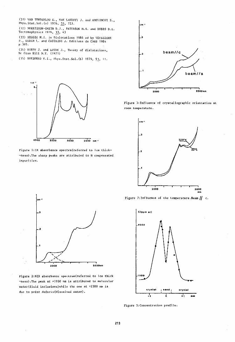
(3 1) VAN TENDERLOO G., VAN LANDUYT J. and AMELINCKX S. , Phys.Stat.Sol.(a) 1976, 2, 723. (32) MORRISSON-SMITH D.J., PATERSON M.S. and HOBBS B.E. Tectonophysics 1976, 2, 43 (33) HEGGIE M.I. in Dislocations 1984 ed by VEYSSIERE l ' . , KUUIN L. and CASTAING J. Editions du CNRS 1984 p.305.
( 3 4 ) HIRTH J. and LOTHE J., Theory of dislocations, Mc Craw Hill N.Y. (1971)
(35) DO'I'SICNKO V.I., Phys.Stat.So1. (b) 1979, 2, l I .
Figure 3:Influence of crystallographic orientation at
room temperature.
Figure 1:IR absorbance spectra(referred to Icm thick-
-ness).The sharp peaks are attributed to H compensated
impurities.
Figure 2:NIR absorbance spectrum(referred to Icm thick
-ness).The peak at 21930 nm is attributed to molecular
water(f1uid inc1usions)while the one at =2300 nm is
due to point defects(disso1ved water).
nm
Figure 7: Influence of the temperature-Beam // c.
f r ~ * t a l I 8a.d 1 c r y s t a l I
I I
I I - 1 0 + I mrn
Figure 5:Concentration profile.
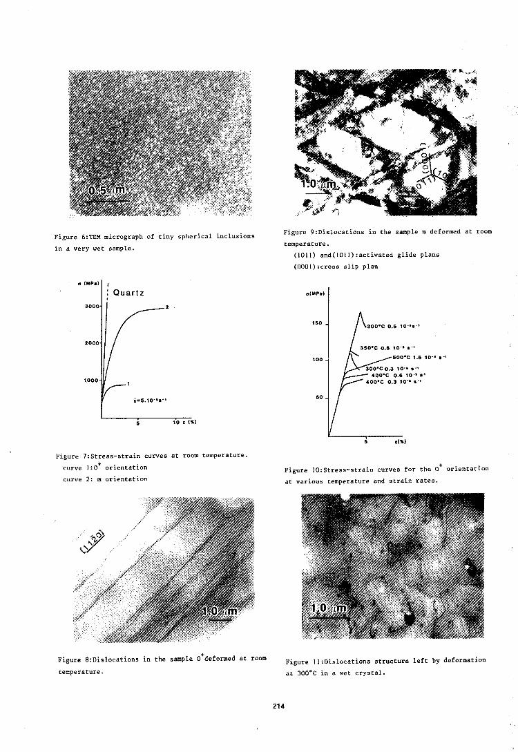
Figure 6:TEM micrograph of tiny spherical inclusions
in a very wet sample.
: Q u a r t z I
Figure 7:Stress-strain curves at room temperature.
curve 1:0+ orientation
curve 2: m orientation
Figure 9:Dislocations in the sample m deformed at room
temperature.
(1011) and(l0ll):activated glide plans
(0001):cross slip plan
Figure I0:Stress-strain curves for the 0' orientation
at various temperature and strain rates.
Figure 8:Dislocations in the sample deformed at room Figure I1:Dislocations structure left by deformation temperature. at 300'6 in a wet crystal.
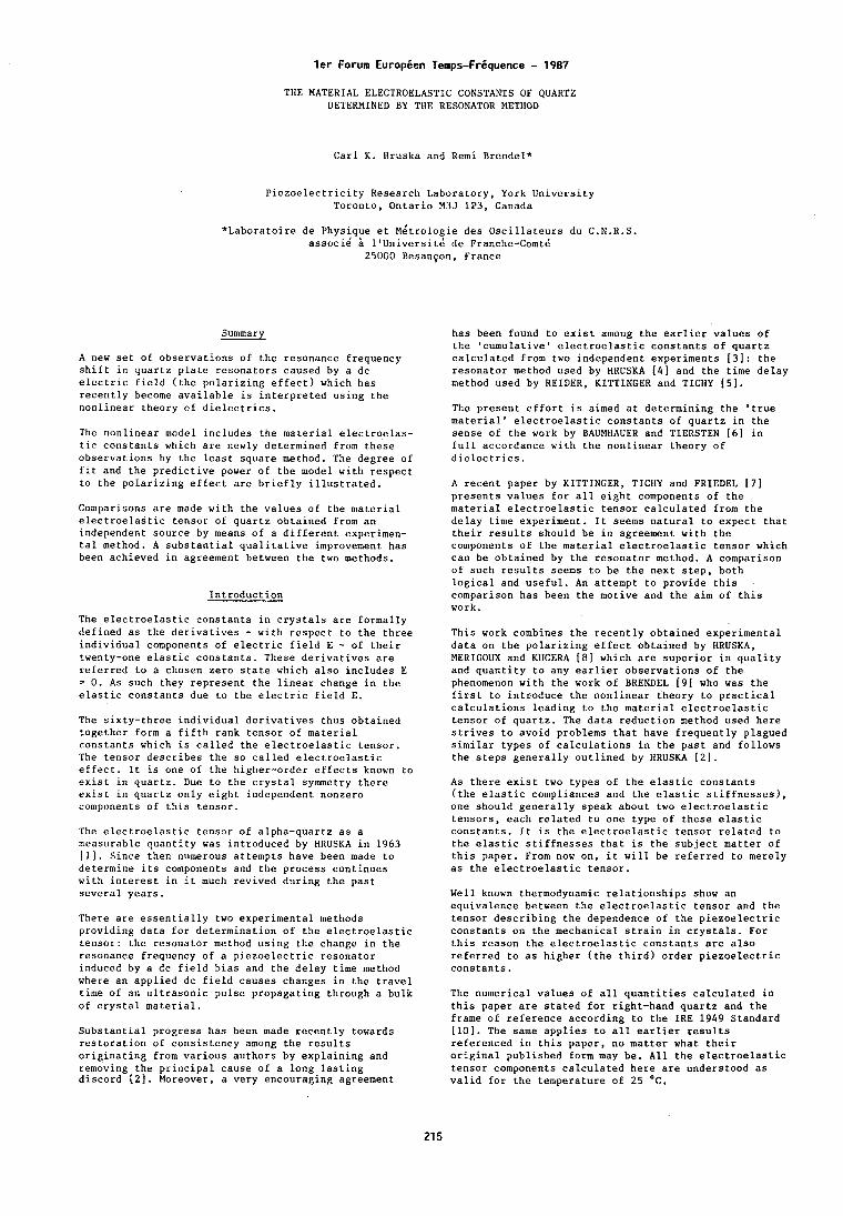
l e r Forum Europien Temps-Friquence - 1987
THE MATERIAL ELECTROELASTIC CONSTANTS OF QUARTZ DETERMINED BY THE RESONATOR METHOD
Carl K. Hruska and Remi Brer~del*
Piezoelectricity Research Laboratory, York University Toronto, Ontario M3J 1P3, Canada
*Laboratoire de Physique et ~ 4 t r o l o ~ i e des Oscillateurs du C.N.R.S. associd lluniversit& de Franche-Comt&
25000 Besan~on, France
Summary
A new set of observations of the resonance frequency shift in quartz plate resonators caused by a dc electric field (the polarizing effect) which has recently become available is interpreted using the nonlinear theory of dielectrics.
The nonlinear model includes the material electroelas- tic constants which are newly determined from these observations by the least square method. The degree of fit and the predictive power of the model with respect to the polarizing effect are briefly illustrated.
Comparisons are made with the values of the material electroelastic tensor of quartz obtained from an independent source by means of a different experimen- tal method. A substantial qualitative improvement has been achieved in agreement between the two methods.
Introduction
The electroelastic constants in crystals are formally defined as the derivatives - with respect to the three individual components of electric field E - of their twenty-one elastic constants. These derivatives are referred to a chosen zero state which also includes E 3 0 , As such they represent the linear change in the elastic constants due to the electric field E.
The sixty-three individual derivatives thus obtained together form a fifth rank tensor of material constants which is called the electroelastic tensor. The tensor describes the so called electroelastic effect. It is one of the higher-order effects known to exist in quartz. Due to the crystal symmetry there exist in quartz only eight independent nonzero components of this tensor.
The electroelastic tensor of alpha-quartz as a measurable quantity was introduced by HRUSKA in 1963 [I]. Since then numerous attempts have been made to determine its components and the process continues with interest in it much revived during the past several years.
There are essentially two experimental methods providing data for determination of the electroelastic tensor: the resonator method using the change in the resonance frequency of a piezoelectric resonator induced by a dc field bias and the delay time method where an applied dc field causes changes in the travel time of an ultrasonic pulse propagating through a bulk of crystal material.
Substantial progress has been made recently towards restoration of consistency among the results originating from various authors by explaining and removing the principal cause of a long lasting discord (21. Moreover, a very encouraging agreement
has been found to exist among the earlier values of the 'cumulative' electroelastic constants of quartz calculated from two independent experiments [3]: the resonator method used by HRUSKA (41 and the time delay method used by REIDER, KITTINGER and TlCHY [5].
The present effort is aimed at determining the 'true material' electroelastic constants of quartz in the sense of the work by BAUMHAUER and TIERSTEN 16) in full accordance with the nonlinear theory of dielectrics.
A recent paper by KITTINGER, TICHY and FRIEDEL 171 presents values for all eight components of the material electroelastic tensor calculated from the delay time experiment. It seems natural to expect that their results should be in agreement with the components of the material electroelastic tensor which can be obtained by the resonator method. A comparison of such results seems to be the next step, both logical and useful. An attempt to provide this comparison has been the motive and the aim of this work.
This work combines the recently obtained experimental data on the polarizing effect obtained by HRUSKA, MERIGOUX and KUCERA [ 8 1 which are superior in quality and quantity to any earlier observations of the phenomenon with the work of BRENDEL 191 who was the first to introduce the nonlinear theory to practical calculations leading to the material electroelastic tensor of quartz. The data reduction method used here strives to avoid problems that have frequently plagued similar types of calculations in the past and follows the steps generally outlined by HRUSKA [2].
As there exist two types of the elastic constants (the elastic compliances and the elastic stiffnesses), one should generally speak about two electroelastic tensors, each related to one type of these elastic constants. It is the electroelastic tensor related to the elastic stiffnesses that is the subject matter of this paper. From now on, it will be referred to merely as the electroelastic tensor.
Well known thermodynamic relationships show an equivalence between the electroelastic tensor and the tensor describing the dependence of the piezoelectric constants on the mechanical strain in crystals. For this reason the electroelastic constants are also referred to as higher (the third) order piezoelectric constants.
The numerical values of all quantities calculated in this paper are stated for right-hand quartz and the frame of reference according to the IRE 1949 Standard [lo]. The same applies to all earlier results referenced in this paper, no matter what their original published form may be. All the electroelastic tensor components calculated here are understood as valid for the temperature of 25 OC.
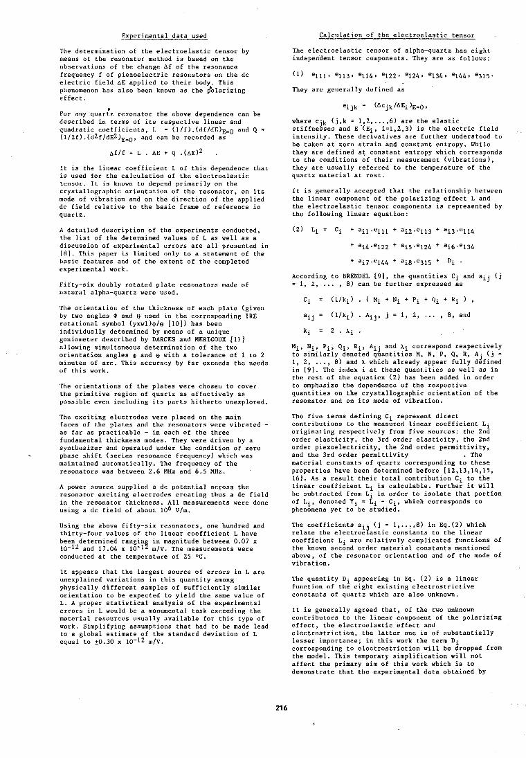
Experimental data used
The determination of the electroelastic tensor by means of the resonator method is based on the observations of the change Af of the resonance frequency f of piezoelectric resonators on the dc electric field AE applied to their body. This phenomenon has also been known as the $olarizing effect.
a For any quartz resonator the above dependence can be described in terms of its respective linear and quadratic coefficients, L = (l/E).(df/dE)E,O and Q = (1/2f). ( d 2 f / d ~ 2 ) ~ = ~ , arid can be recorded as
It is the linear coefficient L of this dependence that is used for the calculation of the electroelastic tensor. It is known to depend primarily on the crystallographic orientation of the resonator, on its mode of vibration and on the direction of the applied dc field relative to the basic frame of reference in quartz.
A detailed description of the experiments conducted, the list of the determined values of L as well as a discussion of experimental errors are all presented in [El. This paper is limited only to a statement of the basic features and of the extent of the completed experimental work.
Fifty-six doubly rotated plate resonators made of natural alpha-quartz were used.
The orientation of the thickness of each plate (given by two angles 8 and e used in the corresponding IRE rotational symbol (yxwl)8/e [lo]) has been individually determined by means of a unique goniometer described by DARCES and MERIGOUX [I11 allowing siniultaneous determination of the two orientation angles 8 and e with a tolerance of 1 to 2 minutes of arc. This accuracy by far exceeds the needs of this work.
The orientations of the plates were choser~ to cover the primitive region of quartz as effectively as possible even including its parts hitherto unexplored.
The exciting electrodes were placed on the main faces of the plates and the resonators were vibrated - as far as practicable - in each of the three fundamental thickness modes. They were driven by a synthesizer and operated under the condition of zero phase shift (series resonance frequency) which was maintained automatically. The frequency of the resonators was between 2.6 MHz and 6.5 MHz.
A power source supplied a dc potential across the resonator exciting electrodes creating thus a dc field in the resonator thickness. All measurements were done using a dc field of about lo6 V/m.
Using the above fifty-six resonators, one hundred and thirty-four values of the linear coefficient L have been determined rangin in magnitude between 0.07 x 10-l2 and 17.04 x 10-I! m/V. The measurements were conducted at the temperature of 25 OC.
It appears that the largest source of errors in L are unexplained variations in this quantity among physically different samples of sufficiently similar orientation to be expected to yield the same value of L. A proper statistical analysis of the experimental errors in L would be a monumental task exceeding the material resources usually available for this type of work. Simplifying assumptions that had to be made lead to a global estimate of the standard deviation of L equal to t0.30 x 10-12 m/V.
Calculation of the electroelastic tensor
The electroelastic tensor of alpha-quartz has eight independent tensor components. They are as follows:
They are generally defined as
where cjk (j,k = 1,2, ..., 6) are the elastic stiffnesses and E'(E~, i=1,2,3) is the electric field intensity. These derivatives are further understood to be taken at zero strain and constant entropy. While they are defined at constant entropy which corresponds to the conditions of their measurement (vibrations), they are usually referred to the temperature of the quartz material at rest.
It is generally accepted that the relationship between the linear component of the polarizing effect L and the electroelastic tensor components is represented by the following linear equation:
According to BRENDEL [ 9 1 , the quantities Ci and aij (j = 1, 2, ... , 8) can be further expressed as
aij = (l/ki) . Aij, j = 1, 2, ... , 8, and
Mi, Nip Pi, Qi, Ri, A. . and Xi correspond respectively 1 J
to similarly denoted quantities M, N, P, Q, R, Aj (j = 1, 2, ..., 8) and A which already appear fully defined in [ 9 ] . The index i at these quantities as well as in the rest of the equation (2) has been added in order to emphasize the dependence of the respective quantities on the crystallographic orientation of the resonator and on its mode of vibration.
The five terms defining Ci represent direct contributions to the measured linear coefficient Li originating respectively from five sources: the 2nd order elasticity, the 3rd order elasticity, the 2nd order piezoelectricity, the 2nd order permittivity, and the 3rd order permittivity . The material constants of quartz corresponding to these properties have been determined before [12,13,14,15, 161. As a result their total contribution Ci to the linear coefficient Li is calculable. Further it will be subtracted from Li in order to isolate that portion of Li, denoted Yi = Li - Ci, which corresponds to phenomena yet to be studied.
The coefficients a i ( j = 1,...,8) in Eq.(2) which relate the electroelastic constants to the linear coefficient Li are relatively complicated functions of the known second order material constants mentioned above, of the resonator orientation and of the mode of vibration.
The quantity Di appearing in Eq. (2) is a linear function of the eight existing electrostrictive constants of quartz which are also unknown.
It is generally agreed that, of the two unknown contributors to the linear component of the polarizing effect, the electroelastic effect and electrostriction, the latter one is of substantially lesser importance; in this work the term Di corresponding to electrostriction will be dropped from the model. This temporary simplification will not affect the primary aim of this work which is to demonstrate that the experimental data obtained by
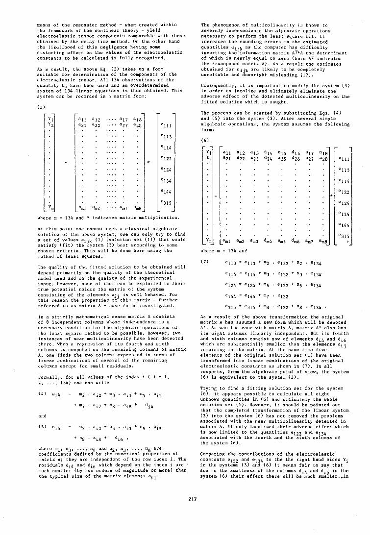
mearis of the resonator method - when treated within the framework of the nonlinear theory - yield electroelastic tensor components comparable with those obtained by the delay time method. On the other hand the likelihood of this negligence having some distorting effect on the values of the electroelastic constants to be calculated is fully recognized.
As a result, the above Eq. (2) takes on a form suitable for determination of the components of the electroelastic tensor. All 134 observations of the quantity Li have heen used and an overdetermined system of 134 linear equations is thus obtained. This system can be recorded in a matrix form:
where m = 134 and * indicates matrix multiplication.
At this poirit one cannot seek a classical algebraic solution of the above system; one can only try to find a set of values eijk (1) (solution set (1)) that would satisfy (fit) the system (3) best according to some chosen criteria. This will be done here using the method of least squares.
The quality of the fitted solution to be obtained will depend primarily on the quality of the theoretical model used and on the quality of the experimental input. However, none of them can be exploited to their true potential unless the matrix of the system consisting of the elements aij is well behaved. For this reason the properties of this matrix - further referred to as matrix A - have to be investigated.
In a strictly mathematical sense matrix A consists of 8 independent columns whose independence is a necessary condition for the algebraic operations of the least square method to be possible. However, two instances of near multicolinearity have been detected there. Wheri a regression of its fourth and sixth columns is computed on the remaining columns of matrix A, one finds the two columns expressed in terms of linear combinations of several of the remaining columns except for small residuals.
Formally, for all values of the index i ( i = 1, . . . . 2, 134) one can write
and
where m2, in3, .... m8 and n2, n3,, .... n8 are coefficients defined by the numerical properties of matrix A; they are independent of the row index i. The residuals di4 and di6 which depend on the index i are much smaller (by two orders of magnitude or more) than the typical size of the matrix elements aij.
The phenomenon of multicolinearity is known to severely inconvenience the a1l:ehraic operations necessary to perform the least square fit. It increases the rounding errors in the estimated quantities eijk as the computer has difficulty inverting the information matrix AT*A thc determinant of which is nearly equal to zero (here AT indicates the transposed matrix A). As a result the estimates obtained for ei.k are likely to be completely unreliable and downright misleading (171.
Consequently, it is important to modify the system (3) in order to localize and ultimately eliminate the adverse effect of the detected multicolinearity on the fitted solution which is sought.
The process can be started by substituting Eqs. (4) and (5) into the system (3). After several simple algebraic operations, the system assumes the following form:
where m = 130 and
As a result of the above transformation the original matrix A has assumed a new form which will be denoted A ' . As was the case with matrix A, matrix A' also has its eight columns linearly independent. But its fourth and sixth columns consist now of elements di4 and di6 which are substantially smaller than the elements aij remaining in the matrix. At the same time five elements of the original solution set (1) have been transformed into linear combinations of the original electroelastic constants as shown in ( 7 ) . In all respects, from the algebraic point of view, the system (6) is equivalent to the system (3).
Trying to find a fitting solution set for the system (61, it appears possible to calculate all eight unknown quantities in (6) and ultimately the whole solution set ( 1 ) . However, it should be pointed out that the conlpleted transformation of the linear system (3) into the system (6) has not removed the problems associated with the near multicolinearity detected in matrix A. It only localized their adverse effect which is now limited to the quantities el22 and e134 associated with the fourth and the sixth columns of the system (6).
Comparing the contributions of the electroelastic constants elZZ and e134 to the the right hand sides Yi in the systems (3) and (6) it seems fair to say that due to the smallness of the columns di4 and di6 in the system (6) their effect there will be much smaller.,In
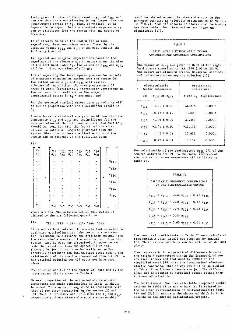
fact, given the size of the elements di4 and di6, one small and do not exceed the standard errors in the car1 say that their contribution is not larger than the measured quantity Li (globally estimated to be f0.30 x experimental errors in Yi. Then, conversely, it is 10-l2 m/V). Also the associated statistical indicators impossible to expect that the constants el22 and e134 are favourable: the t test values are large and can be calculated from the system with any degree of significant 1171. accuracy.
If an attempt to solve the system (6) is made regardless, these suspicions are confirmed by the computed values el22 and el34 which will exhibit the following features:
(a) against our original expectations based on the magnitude of the elements ai. in matrix A and the size of the left hand sides Yi, tie values of el22 and el34 will be disproportionately large;
(b) if repeating the least square process for subsets of equations selected at random from the system ( 6 ) the fitted values el22 and el34 will exhibit substantial instability; the same phenomenon will occur if small (ar~ificially introduced) variations in the values of Yi - well within the scope of experimental errors in Li - are made; and
(c) the computed standard errors in elz2 and el34 will be out of proportion with the experimental errors in
A more formal statistical analysis would show that the coniponents el22 and e134 are insignificant for the interpretation of the left hand sides Yi and that they should be, together with the fourth and the sixth columns in matrix A' completely dropped from the system. When this is done the final edition of the system car1 be recorded in the followit~g form:
where m = 134. The solution set of this system is limited to the six following quantities
It is not without interest to mention that in order to deal with multicolinearity, the texts on statistics [I71 recommend to eliminate the afflicted columns (and the associated elements of the solution set) from the system. This is what has effectively happened as we made the transition from the system (3) to (8). However, by just doing it mechanically and without carefully describing the intermediate steps taken, the relationship of the new transformed solution set (9) to the original solution set (1) would not have been clear.
The solution set (9) of the system (8) obtained by the least square fit is shown in Table I.
Several properties of the estimated electroelastic components and their combinations in Table I1 should be noted. Their order of magnitude is consistent with that of the other quantities in the system (3) and (8). This is 10-12 m / ~ and 10-12 m 2 / ~ for Yi and aij, ' respectively. Their standard errors are reasonably
The relationship of the combinations cijk (7) of the reduced solution set (9) to the basic independent electroelastic tensor components (1) is listed in Table 11.
I
TABLE I
CALCULATED ELECTROELASTIC TENSOR COMPONENT AND COMPONENT COMBINATIONS
The values of eijk are given in N/(V.m) for right hand quartz according to IRE 1949 1101 at 25 OC. The errors are standard errors. Classical statisti- cal indicators accompany the solution 1171.
TABLE I1
electroelastic tensor components
ijk eijk or cijk
ell1 -2.86 i 0.06
~ 1 1 3 -0.42 i 0.11
~ 1 1 4 -1.99 2 0.09
c124 -2.41 i 0.10
c144 1.02 i 0.04
~ 3 1 5 0.72 t 0.09
CALCULABLE COMPONENT COMBINATIONS OF THE ELECTROELASTIC TENSOR
statistical indicators
t for Ho significance
-46.976 0.0001
-3.803 0.0002
-23.364 0.0001
-23.192 0.0001
27.618 0.0001
8.152 0.0001
The numerical coefficients in Table I1 were calculated from matrix A which itself was computed by BRENDEL [91. Their values have been rounded off to two decimal places.
There appears to be no practical difference between the matrix A constructed within the framework of the nonlinear theory and that used by HRUSKA in the simplified model I181 with the 'cumulative' electro- elastic constants. This is why Table I1 is so similar to Table IV published a decade ago [4]. The differ- ences are attributed to numerical causes rather than to those of principle.
The definition of the five calculable component combi- nations in Table I1 is not unique. It is related to the selected representation of multicolinearity (Eqs. (4) and (5)) in matrix A the choice of which in turn depends on the adopted optimization process.
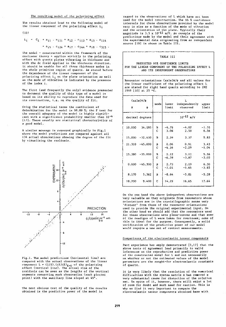
The resulting model of the polarizing effect
The results obtained lead to the following model of the linear component of the polarizing effect Li
The model - constructed within the framework of the nonlinear theory - applies strictly to the polarizing effect with quartz plates vibrating in thickness and with the dc field applied in the thickness direction. It should be usable for all three thickness modes in the whole primitive region of quartz. As stated before the dependence of the linear component of the polarizing effect Li on the plate orientation as well as the mode of vibration is indicated by the presence of the index i.
The first (and frequently the only) evidence presented to document the quality of this type of a model is based on its ability to reproduce the data used for its construction, i.e. on the quality of fit.
Using the statistical terms the coefficient of determination for the model is 98.89 %; the F test for the overall adequacy of the model is highly signifi- cant with a significance probability smaller than 10-4 1171. These usually are statistical characteristics of a good model.
A similar message is conveyed graphically in Fig.1 where the model predictions are compared against all 134 actual observations showing the degree of the fit by visualizillg the residuals.
Fig.1. Tile model predictions (horizontal line) are compared with the actual observations of the linear component L = (l/f).(df/dE)E=O of the polarizing effect (vertical line). The actual size of the residuals can be seen as the lengths of the vertical segments connecting each observation (each plotted point) with the auxiliary line sloped at 45O.
The next obvious test of the quality of the results obtained is the predictive power of the model in
regard to the observations of L which have not been used for the model construction. The 95 % confidence intervals for these observations provided by the model vary in size as a function of the mode of vibration and the orientation of the plate. Typically their magnitude is 3.5 x 10⁻¹² m/V. An example of the predictions made by the model and their agreement with the experimental data originating from an independent source 1191 is shown in Table 111.
On the one hand the above independent observations are very valuable as they originate from resonators whose orientations are in the crystallographic sense very 'distant' from those of the resonator orientations used to provide the original experimental input. On the other hand we should add that the resonators used for these observations were plano-convex and that some of the readigns of L were taken for overtones; none of this is ideal for the purpose. Consequently, a solid verification of the predictive power of our model would require a new set of control measurements.
TABLE I11
PREDICTED 95% CONFIDENCE LIMITS FOR THE LINEAR COMPONENT OF THE POLARIZING EFFECT L
AND ITS INDEPENDENT OBSERVATIONS
Resonator orientations (xzlw)~/@ and all values for the linear coefficient of the polarizing effect L are stated for right hand quartz according to IRE 1949 [lo] at 25 OC.
Comparisons of the electroelastic tensor components
Past experience has amply demonstrated [2,171 that the above tests of agreement lead primarily to valid inferences on the reproductive and predictive power of the constructed model for L and not necessarily on whether or not the estimated values of the model parameters are the sought-for electroelastic constants of quartz.
L lower independently upper limit observed limit
10-l2 m / ~
-4.79 -4.07 -1.35 3.06 2.50 6.56
2.39 3.37 5.83
0.06 0.91 3.43 -4.36 -2.29 -1.04
2.12 3.12 5.56 -6.39 -3.87 -3.03
2.73 2.19 6.30 -7.01 -5.65 -3.45
-8.64 -5.81 -5.28
14.29 16.65 17.64
(xz~w)Y/~
1 b
decimal degrees
10.000 34.185
15.000 -32.430
21.310 -45.000
15.380 -35.000
0.000 -45.300
8.170 5.362
18.700 9.400
It is very likely that the resolution of the numerical difficulties with the system matrix A has removed a very substantial cause for distortion of the solution set. In spite of it, however, there still exist a lot of room for doubt and much need for caution. This is why we find it very important to compare the electroelastic tensor components obtained here with
mode
B C
B
B C
B C
B C
B
C
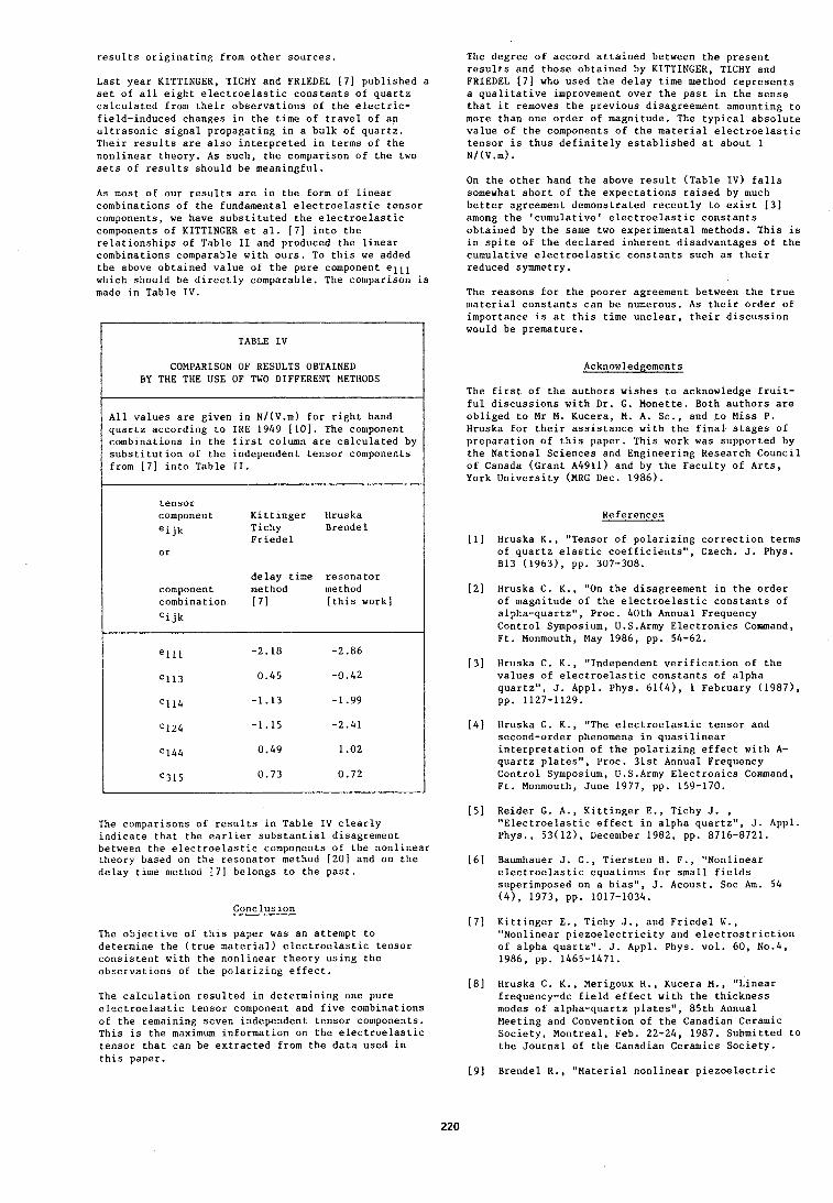
results originating from other sources.
Last year KITTINGER, TICHY and FRIEDEL [7] published a set of all eight electroelastic constants of quartz calculated from their observations of the electric- field-induced changes in the time of travel of an ultrasonic signal propagating in a bulk of quartz. Their results are also interpreted in terms of the nonlinear theory. As such, the comparison of the two sets of results should be meaningful.
As most of our results are in the form of linear combinations of the fundamental electroelastic tensor components, we have substituted the electroelastic components of KITTINGER et al. [7] into the relationships of Table I1 and produced the linear combinations comparable with ours. To this we added the above obtained value of the pure component ell1 which should be directly comparable. The comparison is made in Table IV.
TABLE IV I COMPARISON OF RESULTS OBTAINED 1 BY THE THE USE OF TWO DIFFERENT METHODS
The degree of accord attained between the present results and those obtained by KITTINGER, TICHY and FRIEDEL [7] who used the delay time method represents a qualitative improvement over the past in the sense that it removes the previous disagreement amounting to more than one order of magnitude. The typical absolute value of the components of the material electroelastic tensor is thus definitely established at about 1 N/(V.m).
On the other hand the above result (Table IV) falls somewhat short of the expectations raised by much better agreement demonstrated recently to exist 131 among the 'cumulative' electroelastic constants obtained by the same two experimental methods. This is in spite of the declared inherent disadvantages of the cumulative electroelastic constants such as their reduced symmetry.
The reasons for the poorer agreement between the true illaterial constants can be numerous. As their order of importance is at this time unclear, their discussion would be premature.
Acknowledgements
The first of the authors wishes to acknowledge fruit- ful discussions with Dr. G. Monette. Both authors are
All values are given in N/(V.m) for right hand obliged to Mr M. Kucera, M. A. Sc., and to Miss P. quartz according to IRE 1949 [lo]. The component Hruska for their assistance with the final stages of combinations in the first column are calculated by preparation of this paper. This work was supported by substitution of the independent tensor components the National Sciences and Engineering Research Council from [7] into Table 11. of Canada (Grant A4911) and by the Faculty of Arts,
York University (MRG Dec. 1986).
tensor component Kittinger Hruska ei jk Tichy Brendel
Friedel 0 r
delay time resonator component method method
[this work] I combination [71 Cijk
References
[l] Hruska K., "Tensor of polarizing correction terms of quartz elastic coefficients", Czech. J. Phys. B13 (1963), pp. 307-308.
[2] Hruska C. K., "On the disagreement in the order of magnitude of the electroelastic constants of alpha-quartz", Proc. 40th Annual Frequency Control Symposium, U.S.Army Electronics Command, Ft. Monmouth, May 1986, pp. 54-62.
[3] Hruska C. K., "Independent verification of the values of electroelastic constants of alpha quartz", J. Appl. Phys. 61(4), 1 February (1987), pp. 1127-1129.
-1.15 -2.41
1: 0.49 1.02 1 [4] Hruska C. K., "The electroelastic tensor and second-order phenomena in quasilinear interpretation of the polarizing effect with A- quartz plates", Proc. 31st Annual Frequency
C315 0.73 0.72 Control Symposium, U.S.Army Electronics Command, Ft. Monmouth, June 1977, pp. 159-170.
[5] Reider G. A . , Kittinger E., Tichy J. , The comparisons of results in Table IV clearly "Electroelastic effect in alpha quartz", J. Appl. indicate that the earlier substantial disagrement Phys., 53(12), December 1982, pp. 8716-8721. between the electroelastic components of the nonlinear theory based on the resonator method I201 and on the [61 Baumhauer J. C., Tiersten H. F., "Nonlinear delay time method [7] belongs to the past. electroelastic equations for small fields
superimposed on a bias", J. Acoust. Soc Am. 54 (4), 1973, pp. 1017-1034.
Conclusion
The objective of this paper was an attempt to determine the (true material) electroelastic tensor consistent with the nonlinear theory using the observations of the polarizing effect.
The calculation resulted in determining one pure electroelastic tensor component and five coinbinations of the remaining seven independent tensor components. This is the maximum information on the electroelastic tensor that can be extracted from the data used in this paper.
[7] Kittinger E., Tichy J., and Friedel W., "Nonlinear piezoelectricity and electrostriction of alpha quartz". J. Appl. Phys. vol. 60, No.4, 1986, pp. 1465-1471.
[8] Hruska C. K., Merigoux H., Kucera M., "Linear frequency-dc field effect with the thickness modes of alpha-quartz plates", 85th Annual Meeting and Convention of the Canadian Ceramic Society, Montreal, Feb. 22-24, 1987. Submitted to the Journal of the Canadian Ceramics Society.
[91 Brendel R., "Material nonlinear piezoelectric
coefficients for quartz", J.Appl.Phys. 54(9), September 1983, pp. 5339-5346.
1101 I R E Standards on Piezoelectric Crystals, I E E E Standard 176; see also Proc. IRE, vol. 37, Dec. 1949, pp. 1378-1395.
[Ill Darces J. F. and Merigoux H., "Final x-ray control of the orientation of round and rectangular slides for industrial purposes", Proc. AFCS, May-June 1978, pp. 304-309.
(121 Bechmann R . , Ballato A. D. and Lukaszek T. J., "Higher order temperature coefficients of the elastic stiffnesses and compliances of alpha- quartz", Proc. I R E , vol. 50, 1962, pp. 1812-1822.
[13] Thurston R.N., McSkimmin H.J. and Andreatch, "Third-order elastic coefficients of quartz", J Appl. Phys., vol. 37(1) , 1966, pp. 267-275.
(141 Cady W. G., "Piezoelectricity", vol. 1, Dover Publ., New York 1964, sec. 156, p. 219.
(151 Bechmann R., "Elastic and piezoelectric constants of alpha-quartz", Phys. Rev., vol. 110, 1958, pp. 1060-1061.
[16] Besson R. and Gagnepain J.-J., "Determination des coefficientes non lineaires de polarisation electrique du quartz", C. R . Acad. Sci. Paris, vol. B 274, 1972, pp. 835-838.
(171 Mendenhall W. and Sincich T., " A second course in business statistics: Regression analysis", Dellen Publishing Company, San Francisco, Collier Mac~nillan Publishers, London, 2nd edition, 1986, p. 168, pp. 222-223, p. 228, pp. 234-235.
( 181 Hruska K., "Polarizing effect with piezoelectric plates and second-order effects," I E E E Trans. Sonics Ultrason., vol. SU-18, Jan. 1971, pp. 1-7.
(191 Kusters J., private communication.
(201 Brendel R . , "Erratum: Material nonlinear piezoelectric coefficients for quartz", J.Appl.Phys., vo1.55, No.2, Jan. 1984, p. 608.
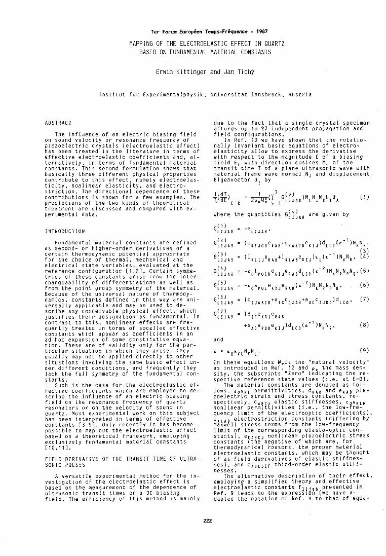
l e r Forum Europien Temps-Fr6quence - 1987
MAPPING OF THE ELECTROELASTIC EFFECT I N QUARTZ BASED ON FUNDAMENTAL MATERIAL CONSTANTS
E r w i n K i t t i n g e r and J a n T i c h 9
lnstitut fur Experimentalphysik, Universitat Innsbruck, Austria
ABSTRACT
The influence of an electric biasing field on sound velocity o r resonance frequency of piezoelectric crystals (electroelastic effect) has been treated in the literature in terms of effective electroelastic coefficients and, al- ternatively, in terms o f fundamental material constants. This second formulation shows that basically three different physical properties contribute to this effect, namely electroelas- ticity, nonlinear elasticity, and electro- striction. The directional dependence of these contributions is shown for a few examples. The predictions of the two kinds of theoretical treatment are discussed and compared with ex- perimental data.
Fundamental material constants are defined as second- o r higher-order derivatives of a certain thermodynamic potential appropriate for the choice of thermal, mechanical and electrical state variables, evaluated at the reference configuration [ 1 , 2 ] . Certain symme- tries of these constants arise from the inter- changeability of differentiations as well as from the point group symmetry of the material. Because of the universal nature of thermody- namics, constants defined in this way are uni- versally applicable and may be used to de- scribe any conceivable physical effect, which justifies their designation as fundamental. In contrast to this, nonlinear effects are fre- quently treated in terms of socalled effective constants which appear as coefficients in an ad hoc expansion of some constitutive equa- tion. These are o f validity only for the par- ticular situation in which they arise. They usually may not be applied directly to other situations involving the same basic effect u n - der different conditions, and frequently they lack the full symmetry of the fundamental con- stants.
Such is the case for the electroelastic ef- fective coefficients which are employed to de- scribe the influence of an electric biasing field on the resonance frequency of quartz resonators o r on the velocity o f sound in quartz. Most experimental work on this subject has been interpreted in terms of effective constants [3-91. Only recently it has become possible to map out the electroelastic effect based on a theoretical framework, employing exclusively fundamental material constants [ 10 ,111 .
FIELD DERIVATIVE OF THE TRANSIT TIME OF ULTRA- SONIC PULSES
A versatile experimental method for the in- vestigation of the electroelastic effect is based on the measurement o f the dependence of ultrasonic transit times on a DC biasing field. The efficiency o f this method is mainly
due t o the fact that a single crystal specimen affords up t o 2 7 independent propagation and field configurations.
In Ref. 1 0 w e have shown that the rotatio- nally invariant basic equations o f electro- elasticity allow t o express the derivative with respect t o the magnitude E of a biasing field E L with direction cosines M L , o f the transit tlme T of a plane ultrasonic wave with material frame wave normal NJ and displacement Eigenvector U I by
where the quantities G[;jAB are given by
G(l) L I J A B -e L I J A B '
G ( 3 ) ( 3 ) L I J A B ' ('KLI J e R A B t l R L A B e K I J ) e O ( c - l ) ~ K N R ' ( 4 )
G( 7 ) LIJAB ' ( 6 1 ~ e K ~ J e R ~ B
t 6 ~ c e ~ ~ ~ e ~ I J)~LcD('-' )N K N R ( 8
and
In these equations W,is the "natural velocity" as introduced in Ref. 1 2 and the mass den- sity, the subscripts "Zero" indicating the re- spective reference state values (i.e. at E=O).
The material constants are denoted as fol- lows: E o n K ~ permittivities, d K A B and e K A B pie- zoelectric strain and stress constants, re- spectively, ~ ~ ~ ~ ~ , e l a j t i c stiffnesses, € x K I N nonlinear perm, lvltles (i.e., the low-!re- quency limit of the electrooptic coefficients), l K L A B electrostriction constants (differing by Maxwell stress terms from the low-frequency limit of the corresponding elasto-optic con- stants), e nonlinear piezoelectric stress constants [the negative o f which are, f o r thermodynamical bcasons, the proper material electroelastic constants, which may be thought of as field derivatives of elastic stiffnes- ses), and C A B C D E F third-order elastic stiff- nesses.
The alternative description of their effect, employing a simplified theory and effective electroelastic constants f l i . , b presented in Ref. 9 leads to the expressldn (we have a- dapted the notation of Ref. 9 t o that o f equa-
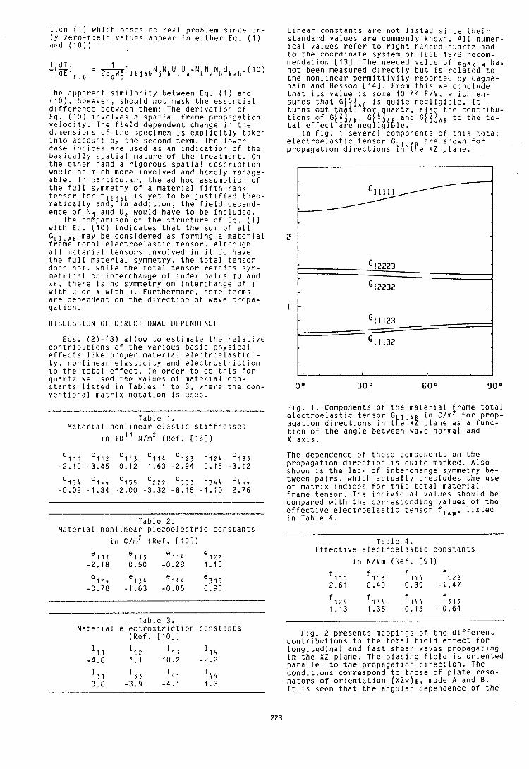
tion (1) which poses no real problem since on- ly zero-field values appear in either Eq. ( 1 ) and (10))
The apparent similarity between Eq. ( 1 ) and (lo), however, should not mask the essential difference between them: The derivation of Eq. (10) involves a spatial frame propagation velocity. The field dependent change in the dimensions o f the specimen is explicitly taken into account by the second term. The lower case indices are used as an indication o f the basically spatial nature of the treatment. On the other hand a rigorous spatial description would be much more involved and hardly manage- able. In particular, the ad hoc assumption of the full symmetry o f a material fifth-rank tensor for f l i j a b is yet to be justified theo- retically and, in addition, the field depend- ence of N and U, would have to be included.
The codparison of the structure of Eq. ( 1 ) with Eq. (10) indicates that the sum of all G L I J A B may be considered as forming a material frame total electroelastic tensor. Although all material tensors involved in it do have the full material symmetry, the total tensor does not. While the total tensor remains sym- metrical on interchange of index pairs I J and A s , there is no symmetry on interchange of I with J o r A with 6 . Furthermore, some terms are dependent on the direction o f wave propa- gation.
DISCUSSION OF DIRECTIONAL DEPENDENCE
Eqs. (2)-(8) allow to estimate the relative contributions of the various basic physical effects like proper material electroelastici- t y , nonlinear elasticity and electrostriction to the total effect. In order t o do this for quartz we used the values of material con- stants listed in Tables 1 to 3 , where the con- ventional matrix notation is used.
Linear constants are not listed since their standard values are commonly known. All numer- ical values refer to right-handed quartz and to the coordinate system o f IEEE 1978 recom- mendation [131. The needed value o f E o n K has not been measured directly but is relatea to the nonlinear permittivity reported by Gagne- pain and Besson [14]. From this we conclude that its value is some F/V, which en- sures that G[ jA is quite negligible. It t u r n s o u t !.,!or ats? the contribu- tions of G ~ ~ ~ A B , ~ ( ~ 7 1 ~ ~ : i 6 G i l J A l to the to- tal effect are neg\lgl%le.
In Fig. 1 several components of this total electroelastic tensor G are shown f o r propagation directions !/iJ!!e X Z plane.
Fig. 1. Components o f the material frame total Table 1 . electroelastic tensor G I J A B in c/m2 f o r prop-
Material nonlinear elastic stiffnesses agation directions in the X Z plane as a func- tion of the angle between wave normal and
in 10" ~ / m ' (Ref. [161) X axis.
Table 2. Material nonlinear piezoelectric constants
in c/m2 (Ref. [lo])
e l l l el13 e114 e122 -2.18 0.50 -0.28 1.10
e 1 2 4 134 e 1 4 4 315 -0.78 -1.63 -0.05 0.90
Table 3. Material electrostriction constants
(Ref. [lo])
The dependence of these components on the propagation direction is quite marked. Also shown is the lack o f interchange symmetry be- tween pairs, which actually precludes the use of matrix indices f o r this total material frame tensor. The individual values should be compared with the corresponding values o f the effective electroelastic tensor fix,,, listed in Table 4.
Table 4. Effective electroelastic constants
in N/Vm (Ref. [91)
Fig. 2 presents mappings o f the different contributions t o the total field effect f o r longitudinal and fast shear waves propagating in the X Z plane. The biasing field is oriented parallel to the propagation direction. The conditions correspond t o those of plate reso- nators of orientation ( X Z w ) @ , mode A and 9. It is seen that the angular dependence o f the
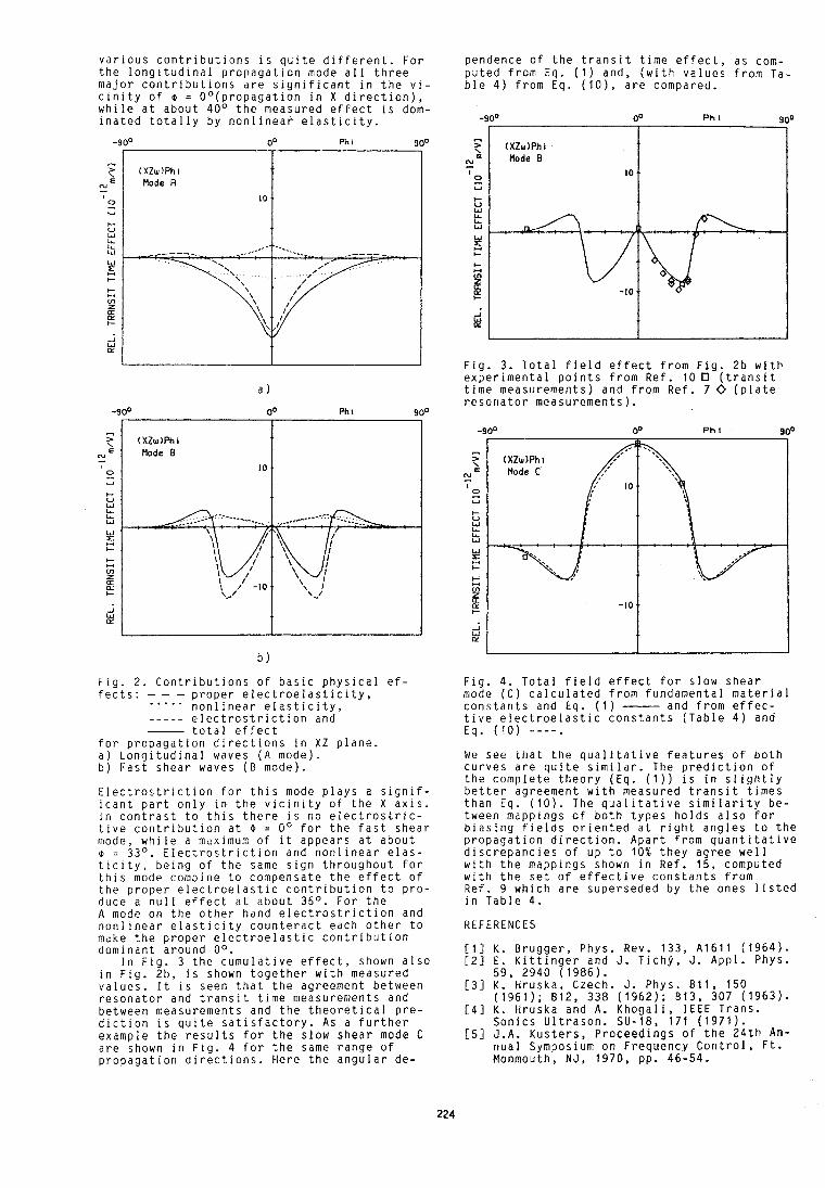
various contributions is quite different. For the longitudinal propagation mode all three major contributions are significant in the vi- cinity of o = Oo(propagation in X direction), while at about 40° the measured effect is dom- inated totally by nonlinear elasticity.
-90' Phi 90°
-90"
N, Mode B
Fig. 2. Contributions of basic physical ef- fects: - - - ..... proper electroelasticity, nonlinear elasticity, - - - - - electrostriction and
total effect for propagation directions in XZ plane. a) Longitudinal waves (A mode). b) Fast shear waves (B mode).
Electrostriction for this mode plays a signif- icant part only in the vicinity of the X axis. In contrast to this there is no electrostric- tive contribution at 0 = O0 for the fast shear mode, while a maximum of it appears at about 0 = 33'. Electrostriction and nonlinear elas- ticity, being of the same sign throughout for this mode combine to compensate the effect of the proper electroelastic contribution to pro- duce a null effect at about 35O. For the A mode on the other hand electrostriction and nonlinear elasticity counteract each other to make the proper electroelastic contribution dominant around OO.
In Fig. 3 the cumulative effect, shown also in Fig. 2b, is shown together with measured values. It is seen that the agreement between resonator and transit time measurements and between measurements and the theoretical pre- diction is quite satisfactory. As a further example the results f o r the slow shear mode C are shown in Fig. 4 f o r the same range of propagation directions. Here the angular de-
pendence of the transit time effect, as com- puted from Eq. ( 1 ) and, (with values from Ta- ble 4) from Eq. (lo), are compared.
" t (XZw)Phl
N, Mode B
0 U
Fig. 3. Total field effect from Fig. 2 b with experimental points from Ref. 10 (transit time measurements) and from Ref. 7 0 (plate resonator measurements).
Fig. 4. Total field effect f o r slow shear mode (C) calculated from fundamental material constants and Eq. ( 1 ) - and from effec- tive electroelastic constants (Table 4) and Eq. (10) ----. We see tltat the qualitative features o f both curves are quite similar. The prediction o f the complete theory (Eq. (1)) is in slightly better agreement with measured transit times than Eq. (10). The qualitative similarity be- tween mappings of both types holds also for biasing fields oriented at right angles t o the propagation direction. Apart from quantitative discrepancies of up to 10% they agree well with the mappings shown in Ref. 15, computed with the set o f effective constants from Ref. 9 which are superseded by the ones listed in Table 4.
REFERENCES
[I] K. Brugger, Phys. Rev. 133, A1611 (1964). [2] E. Kittinger and J. Tichj, J. Appl. Phys.
59. 2940 (1986). [31 ~ . . ~ r u s k a ; ~ z e c h . J. Phys. B11, 150
i1961); 812, 3 3 8 (1962); B13, 307 (1963). [4] K. ~ r u s k a and A. Khogali, IEEE Trans.
Sonics Ultrason. SU-18, 171 (1971). [51 J.A. Kusters, Proceedings of the 24th An-
nual Symposium on Frequency Control, Ft. Monmouth, N J , 1970, pp. 46-54.
K. Hruska, IEEE Trans. Sonics Ultrason. SU-18, 1 (1971). K. Hruska, Proceedings of the 31st Annual Symposium on Frequency Control, Ft. Mon- mouth, NJ, 1977, pp 159-170. C.K. Hruska, IEEE Trans. Sonics Ultrason. SU-25, 198 (1978); SU-25, 390 (1978). G.A. Reider, E. Kittinger, and J. Tichj, J. Appl. Phys. 53, 8716 (1982). E. Kittinger, J. Tichj, and W. Friedel, J. ADD^. P ~ v s . 60. 1465 (1986). R. bende el,. J. ~ p p l . P ~ Y S . 54; 5339 (1983); 55, 608 (1984). R.N. Thurston and K. Brugger, Phys. Rev. 133, A1604 (1964). IEEE Standard on Piezoelectricitv (ANSI/IEEE Std. 176-1978) ( I E E E , - ~ e w York, 1978). J.J. Gagnepain and R. Besson, in Physical Acoustics, edited by W.P. Mason and R.N. Thurston (Academic, New York, 19761, Vol. X I , p. 263.
[I51 E. Kittinger, G.A. Reider, and J. Tichj, J. Acoust. Soc. Am. 73, 1995 (1983).
[I61 R.N. Thurston, H.J. McSkimin, and P. Andreatch. J. ADD^. Phvs. 37, 267
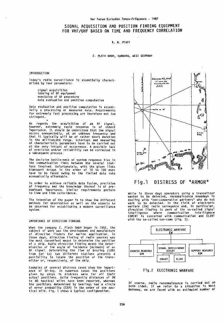
l e r Forum Europ ien Temps-FrLquence - 1987
SIGNAL A C Q U I S I T I O N AND P O S I T I O N F I N D I N G EQUIPMENT FOR VHF/UHF BASED ON T IME AND FREQUENCY CORRELATION
K . G. PFAFF
C, PLATH GMBH, HAMBURG, WEST GERMANY
INTRODUCTION
l o d a y ' s r a d l o s u r v e i l l a n c e i s e s s e n t i a l l y c h a r a c t - e r i z e d by f o u r parameters:
s i g n a l a c q u l s i t l o n t a s k i n g o f DF equipment e x e c t u i o n o f OF p rocedure d a t a e v a l u a t i o n and p o s i t i o n computa t ion
Data e v a l u a t i o n and p o s i t i o n computa t ion i s essen t - i a l l y a p rocess ing o f measured da ta . Requirements f o r e x t r e m e l y f a s t p r o c e s s i n g a r e t h e r e f o r e n o t t o o s t r i n g e n t .
(L
As regards t h e a c q u i s i t i o n o f an RF s i g n a l , however, e x t r e m e l y r a p i d response I s o f u tmost Impor tance. I t shou ld be understood t h a t t h e s i g n a l occurs unexpectedly , a t an unknown f requency and t h a t It t y p i c a l l y w i l l be o f r a t h e r s h o r t d u r a t i o n i n t h e m i l l i s e c o n d range. I n t e r c e p t and measur ing o f c h a r a c t e r i s t i c parameters have t o be c a r r i e d o u t a t t h e v e r y i n s t a n t o f occurrence. A p o s s i b l e l a c k o f p r e c i s i o n and/or r e l i a b i l i t y can be c o r r e c t e d i n a subsequent process.
The d e c i s i v e b o t t l e - n e c k o f system response l i e s i n t h e communication l i n k s between t h e s e v e r a l s t a t . - i o n s i n v o l v e d . U n f o r t u n a t e l y , w i t h t h e g i v e n I i n k s t r a n s p o r t de lays i n t h e o r d e r o f 10 t o 100 msec have t o be faced owing t o t h e l i m i t e d d a t a r a t e economica l l y a f f o r d a b l e .
I n o r d e r t o ach ieve r e l i a b l e d a t a f u s i o n , p r e c i s i o n o f f requency and t h e knowledge t h e r e o f i s o f p r e - dominant impor tance. S i m i l a r requ i rements p e r t a i n t o t i m e and t i m e co inc idence .
The i n t e n t i o n o f t h e paper i s t o show t h e d i f f e r e n t methods f o r o b s e r v a t i o n as w e l l as t h e aspec ts t o be observed f o r e s t a b l i s h i n g a modern s u r v e i l l a n c e system.
IMPORTANCE OF DIRECllON FINDING
When t h e company C . P l a t h GmbH began i n 1952, t h e s u b j e c t o r work was t h e development and manufacture o f d i r e c t i o n f i n d e r s f o r mar ine a p p l i c a t i o n . I n those days, d i r e c t i o n f i n d i n g o f r a d i o sources was t h e most conven ien t means t o de te rm ine t h e p o s i t i o n o f a s h i p . Radio d i r e c t i o n f i n d i n g means t h e d e t e r - m i n a t i o n o f t h e a n g l e o f i n c i d e n c e (az imuth ) o f an RF s i g n a l . De te rm in ing t h e l i n e o f b e a r i n g (LOB) f r o m ( o r t o ) two d i f f e r e n t s t a t i o n s p r e s e n t s a p o s s i b i l i t y t o l o c a t e t h e p o s i t i o n o f t h e t r a n s - m i t t e r o r , r e s p e c t i v e l y , o f t h e s h i p .
Examples o f severa l d i s t r e s s cases show t h e i m p o r t - ance o f OF-ing. I n numerous cases t h e p o s i t i o n s g i v e n by s h i p s i n d i s t r e s s were f a r o f f t h e i r a c t u a l ~ o s i t i o n s . O u i t e f r e a u e n t l v d i s t a n c e s o f 30
F i g . 1 DISTRESS OF "ARMOR"
Whi le i n those days o p e r a t o r s u s i n g a t r a n s m i t t e r wanted t o be de tec ted , reconnaissance nowadays i s d e a l i n g w l t h "non-coopera t i ve p a r t n e r s n who do n o t want t o be de tec ted . I n t h e f i e l d o f e l e c t r o n i c w a r f a r e (EW) r a d l o surveyance and, i n p a r t i c u l a r , d i r e c t i o n f i n d i n g I s p a r t o f t h e s o - c a l l e d s i g n a l I n t e l l i g e n c e where communication i n t e l l i g e n c e COMINT i s concerned w i t h communication and ELINT w i t h t h e s o - c a l l e d non-coms ( F i g . 2 ) .
COUNTER MEASURES SUPPORT MEASURES
I COMINT 1 [ ELINT (
F i g . 2 ELECTRONIC WARFARE
t o 80 n a u t i c a l m i l e s have 'been - repor ted, whereas t h e p o s i t i o n s determined by b e a r l n g s had a c i r c l e Of course, r a d i o reconna' issance I s c a r r i e d o u t on o f e r r o r p r o b a b l i t y (CEP) i n t h e o r d e r o f one nau- b o t h s ides . I f we r e f e r t o a s i t u a t i o n i n West
t i c a l m i l e . F i g . 1 shows a t y p i c a l c o n f i g u r a t i o n . Germany. we a r e faced w i t h an e s t i m a t e d number o f
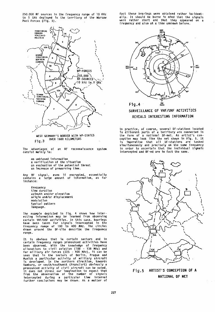
250.000 RF sources i n t h e f requency range o f 10 KHz t o 1 GHz deployed i n t h e t e r r i t o r y o f t h e Warsaw Pac t Forces ( F i g . 3) .
WEST GERMANY'S BORDER WITH WP-STATES
F i g . 3 OVER 1600 KILOMETERS
The advantages o f an RF reconnaissance system c o n s i s t m a i n l y i n :
an unblased i n f o r m a t i o n a v e r i f i c a t i o n o f t h e s i t u a t i o n an e v a l u a t i o n o f t h e p o t e n t i a l t h r e a t an i n c r e a s e o f p rewarn ing t ime .
Any RF s i g n a l , even i f enc ryp ted , e s s e n t i a l l y c o n t a i n s a l a r g e amount o f i n f o r m a t i o n . as f o r i n s t a n c e :
f requency t i m e d u r a t i o n az imuth and/or e l e v a t i o n o r i g i n and/or d i sp lacement m o d u l a t i o n t y p i c a l p a t t e r n language.
The example d e p i c t e d i n F i g . 4 shows how i n t e r - e s t i n g i n f o r m a t i o n may be lea rned f r o m o b s e r v i n g c e r t a l n VHF/UHF a c t i v i t i e s . I n t h i s case, b e a r i n g s have been taken f o r s i g n a l s I n t e r c e p t e d i n t h e f requency range o f 100 t o 400 MHz. The c i r c l e s drawn around t h e OF-s i te d e s c r i b e t h e f requency range.
I t I s obv ious t h a t i n c e r t a i n s e c t o r s and I n c e r t a i n f requency ranges pronounced a c t i v i t i e s have been observed. W i t h t h e knowledge o f f requency a l l o c a t i o n s t o c i v i l a v i a t i o n (108 - 138 MHz) and f o r m i l i t a r y a i r f o r c e s (225 - 400 MHz), i t can be seen t h a t i n t h e s e c t o r s o f B e r l i n , Prague and Munich a p a r t i c u l a r a c t i v i t y o f m i l i t a r y a i r c r a f t i s developed. I n t h e n o r t h e r n d i r e c t i o n , towards Hamburg, o r south/southwest (Franc f o r t ) o b v i o u s l y a pronounced a c t i v i t y o f c i v i l a i r c r a f t can be noted. I t does n o t s t r e s s o u r i m a g i n a t i o n t o expec t t h a t f r o m t h e o b s e r v a t i o n o f t h e number o f s i g n a l s i n t e r c e p t e d d u r i n g a p a r t i c u l a r t i m e i n t e r v a l f u r t h e r conc lus ions may be drawn. As a m a t t e r o f
f a c t these b e a r i n g s were o b t a i n e d r a t h e r I n c i d e n t - a l l y . It shou ld be borne i n mind t h a t t h e s i g n a l s were r a t h e r s h o r t and t h a t t h e y appeared on a f requency and a l s o a t a t i m e unknown b e f o r e .
F i g . 4 SW foul*
SURVEILLANCE OF VHFIUHF ACTIVITIES
REVEALS I N T E R E S T I N G INFORMATION
I n p r a c t i c e , o f course, s e v e r a l OF-s ta t ions l o c a t e d i n d i f f e r e n t p a r t s o f a t e r r i t o r y a r e connected i n t h e fo rm o f a n a t i o n a l OF-net. An a r t i s t ' s con- c e p t i o n may l o o k l i k e t h e n e t shown i n F i g . 5. It i s I m p e r a t i v e t h a t a l l DF-s ta t ions a r e tasked s i m u l t a n e o u s l y and p r e c i s e l y on t h e same f requency i n o r d e r t o a s c e r t a i n t h a t t h e i n d i v i d u a l s i g n a l s i n t e r c e p t e d and DF-ed a r e I n f a c t t h e same.
F i g . 5 A R T I S T ' S CONCEPTION OF A
NATIONAL DF N E T
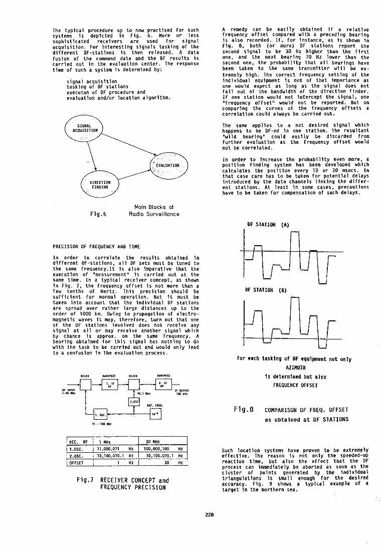
The t y p i c a l procedure up t o now p r a c t i s e d f o r such systems i s d e p t c t e d I n F tg . 6. More o r l e s s s o p h i s t i c a t e d r e c e i v e r s a r e used f o r s i g n a l a c q u i s i t i o n . For i n t e r e s t i n g s i g n a l s t a s k l n g o f t h e d i f f e r e n t DF-s ta t lons i s then re leased . A da ta f u s i o n o f t h e command da ta and t h e DF r e s u l t s i s c a r r i e d o u t i n t h e e v a l u a t i o n c e n t e r . The response t i m e o f such a system i s determined by:
s i g n a l a c q u i s i t i o n t a s k i n g o f DF s t a t i o n s executon o f DF procedure and e v a l u a t i o n and/or l o c a t i o n a l g o r i t h m .
A remedy can be e a s i l y o b t a i n e d i f a r e l a t i v e f requency o f f s e t compared w i t h a p reced ing b e a r i n g i s a l s o recorded. I f , f o r i ns tance , as i s shown i n F i g . 8, b o t h ( o r more) DF s t a t i o n s r e p o r t t h e second s i g n a l t o be 30 Hz h i g h e r than t h e f i r s t one, and t h e n e x t b e a r i n g 70 Hz lower than t h e second one, t h e p r o b a b i l i t y t h a t a l l bear ings have been taken t o t h e same t r a n s m i t t e r w i l l be ex- t r e m e l y h i g h . l h e c o r r e c t f requency s e t t i n g o f t h e i n d i v i d u a l equipment I s n o t o f t h a t importance as one would expect as l o n g as t h e s i g n a l does n o t f a l l o u t o f t h e bandwidth o f t h e d i r e c t i o n f i n d e r . I f one s t a t i o n would n o t i n t e r c e p t t h e s i g n a l , one Vrequency o f f s e t n would n o t be r e p o r t e d . Bu t on comparing t h e cu rves o f t h e f requency o f F s e t s a c o r r e l a t i o n c o u l d always be c a r r i e d ou t .
The same a p p l i e s t o a n o t d e s i r e d s i g n a l which happens t o be DF-ed I n one s t a t i o n . The r e s u l t a n t lqwi l d bear ing" c o u l d e a s i l y be d iscarded f rom f u r t h e r e v a l u a t i o n as t h e f requency o f f s e t would n o t be c o r r e l a t e d .
I n o r d e r t o i n c r e a s e t h e p r o b a b i l i t y even more, a p o s i t i o n f i n d i n g system has been developed which c a l c u l a t e s t h e p o s i t i o n every 1 0 o r 20 msecs. I n t h a t case c a r e has t o be taken f o r p o t e n t i a l de lays i n t r o d u c e d by t h e da ta channels l i n k f n g t h e d i f f e r - e n t s t a t i o n s . A t l e a s t I n some cases, p r e c a u t i o n s have t o be taken f o r compensation o f such de lays .
Main Blocks of F1g.6 Radio Surveillance
OF STATION (A)
PRECISION OF FREQUENCY AND TIME
I n o r d e r t o c o r r e l a t e t h e r e s u l t s ob ta ined i n d i f f e r e n t DF-stat ions, a l l DF s e t s must be tuned t o t h e same f r e q u e n c y . I t i s a l s o i m p e r a t i v e t h a t t h e execu t ion o f "measurement" I s c a r r i e d o u t a t t h e same t ime. I n a t y p i c a l r e c e i v e r concept, as shown i n F i g . 7, t h e f requency o f f s e t i s n o t more t h a n a few t e n t h s o f Her tz . Th is p r e c i s i o n should be s u f f i c i e n t f o r normal opera t ion . But i t must be taken i n t o account t h a t t h e i n d i v i d u a l DF s t a t i o n s a r e spread over r a t h e r l a r g e d i s t a n c e s up t o t h e o r d e r o f 1000 km. Owing t o p ropaga t ion o f e l e c t r o - magnetic waves I t may, t h e r e f o r e , t u r n o u t t h a t one o f t h e DF s t a t i o n s fnvo lved does n o t r e c e i v e any s i g n a l a t a l l o r may r e c e i v e ano ther s i g n a l which by chance i s approx. on t h e same f requency. A b e a r i n g ob ta ined f o r t h i s s i g n a l has n o t h i n g t o do w i t h t h e t a s k t o be c a r r i e d o u t and would o n l y lead t o a c o n f u s i o n i n t h e e v a l u a t i o n process.
F l g . 7 R E C E I V E R CONCEPT and FREQUENCY P R E C I S I O N
REC. RF
1.OSC. 2.OSC.
OFFSET
U
OF STATION (0)
f o r each t a s k i n g o f DF equipment n o t o n l y
AZlMUTll
I s determlned b u t a l s o
FREQUENCY OFFSET
1 MHz
71,000,071 HZ
70,100,070.1 HZ
1 Hz
F i g . 8 COMPARISON OF FREQ. O F F S E T
as obtained a t DF S T A T I O N S
30 MHz
100,000,100 Hz
10,100,070.1 HZ
30 Hz -
Such l o c a t i o n systems have p roven t o be ex t reme ly e f f e c t i v e . The reason i s n o t o n l y t h e speeded-up r e a c t i o n t ime, b u t a l s o t h e e f f e c t t h a t t h e DF process can Immediate ly be abor ted as soon as t h e C l u s t e r o f p o i n t s generated b y t h e i n d i v i d u a l t r i a n g u l a t i o n s I s sma l l enough f o r t h e d e s i r e d accuracy, F i g . 9 shows a t y p l c a l example o f a t a r g e t i n t h e n o r t h e r n sea.
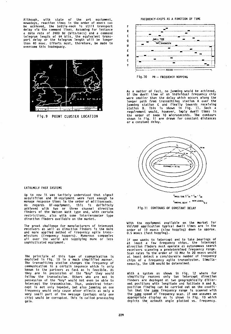
Al though, w i t h s t a t e o f t h e a r t equipment, nowadays, r e a c t i o n t imes i n t h e o r d e r o f msecs can be achieved, t h e b o t t l e - n e c k i s s t i l l t r a n s p o r t d e l a y v i a t h e comnand l i n e s . Assuming f o r i n s t a n c e a d a t a r a t e o f 2400 Bd ( b i t s / s e c s ) and a command t e l e g r a m l e n g t h o f 64 b i t s , t h e e q u i v a l e n t t r a n s - p o r t d e l a y o r t h e t e l e g r a m l e n g t h w i l l be l o n g e r t h a n 40 msec. E f f o r t s must, t h e r e f o r e , be made t o overcome t h i s Inadequacy.
F i g . 9 POINT CLUS1 ER LOCAI'IUN
EXTREMELY FAST SYSTEMS
Up t o now i t was t a c i t e l y understood t h a t s i g n a l a c q u l s i t i o n and OF-equipment were f a s t enough t o manage response t imes i n t h e o r d e r o f m i l l i s e c o n d s . As regards OF-equipment, t h i s i s d e f i n i t e l y ach ieved w i t h two o r t h r e e channel d l r e c t i o n f i n d e r s o f t h e Watson Watt t y p e and, w l t h c e r t a i n r e s t r i c t i o n s , a l s o w l t h some i n t e r f e r o m e t e r t y p e d i r e c t i o n f i n d e r s a v a i l a b l e on t h e market .
The g r e a t cha t lenge f o r manu fac tu re rs o f i n t e r c e p t r e c e i v e r s as w e l l as d i r e c t i o n f l n d e r s i s t h e more and more a p p l i e d method o f Frequency a g i l e t r a n s - m i s s i o n s ( f r e q u e n c y hoppers) . Numerous companies a l l ove r t h e w o r l d a r e s u p p l y i n g more o r l e s s s o p h i s t i c a t e d equipment.
l h e p r i n c i p l e o f t h i s t y p e o f communication i s d e p i c t e d I n F i g . 10 i n a much s i m p l i f i e d manner. The t r a n s m i t t i n g s t a t i o n changes t h e f requency o f communication i n a c e r t a i n sequence wh ich i s o n l y known t o t h e p a r t n e r s as f a s t as i s f e a s i b l e . As t h e y a r e I n possess ion o f t h e "key' t h e y would f o l l o w t h e t r a n s m i s s i o n . Others who a r e n o t i n possess ion o f t h e "key" would n o t even be a b l e t o i n t e r c e p t t h e t r a n s m i s s i o n . Thus, undes i red i n t e r - c e p t i s n o t o n l y impeded, b u t a l s o jamming on one f requency would o n l y cause m i n o r e f f e c t s as o n l y a v e r y s m a l l p a r t o f t h e message (perhaps o n l y one c h i p ) would be c o r r u p t e d . T h l s i s c a l l e d p r o c e s s i n g g a i n .
FREQUENCY-CHIPS AS A FUNCTION OF TIME
F i g . 10 PR ,- FREQUENCY HOPPING
As a m a t t e r o f f a c t , no jamming would be achieved, i f t h e d w e l l t i m e o f an i n d i v i d u a l f requency c h i p were s m a l l e r t h a n t h e d e l a y wh ich occurs a l o n g t h e l o n g e r p a t h f r o m t r a n s m i t t i n g s t a t i o n A o v e r t h e j a n i n g s t a t i o n C and f i n a l l y towards r e c e i v i n g s t a t i o n 0 . l h i s i s shown i n F i g . 11. Such a requ i rement would, however. i m p l y d w e l l t i m e s i n t h e o r d e r o f some 1 0 microseconds. l h e c o n t o u r s shown i n F l g . 11 a r e drawn f o r c o n s t a n t d i s t a n c e s o r a c o n s t a n t d e l a y .
T w r ~ ~ rllu : ' rc + T~~ - T~~
T ~ l ~ l ~ ~ ~ PIUV . PATU LLYSTH '0.1
Fig.11 CONTOURS OF CONSTANT DELAY
W i t h t h e equipment a v a i l a b l e on t h e marke t f o r VtIF/UHF a p p l i c a t i o n t y p i c a l d w e l l t i m e s a r e i n t h e o r d e r o f 10 msecs ( s l o w hopping) down t o approx. 0.5 msecs ( f a s t hopp ing ) .
I f one wants t o i n t e r c e p t and t o t a k e b e a r i n g s o f a t l e a s t a few f requency c h i p s , t h e i n t e r c e p t d i r e c t i o n f i n d e r s must o p e r a t e as autonomous search r e c e i v e r s scanning a p rede te rm ined f requency range. Scan r a t e s i n t h e o r d e r o f 10 MHz i n 20 msecs would a t l e a s t d e t e c t a c o n s i d e r a b l e number o f f requency c h i p s o f a f requency a g i l e t r a n s m i s s i o n . S i m u l t a - neous ly , t h e LOB would be determined.
W i t h a system as shown i n F i g . 1 2 where f o r s i m p l i c i t y reasons o n l y two i n t e r c e p t d i r e c t i o n f i n d e r s a r e deployed a t two g e o g r a p h i c a l l y d i f f e r - e n t p o s i t i o n s w l t h l o n g i t u d e and l a t i t u d e A and 8 , p o s i t i o n f i n d i n g can be c a r r i e d o u t on t h e c o n d i t - i o n t h a t t h e same f requency range i s scanned w l t h t h e lame speed o f f requency scan. I f one assumes an a p p r o p r i a t e d l s p l a y as i s shown i n F i g . 13 wh ich d e p i c t s t h e az imuth a n g l e p l o t t e d vs. f requency .
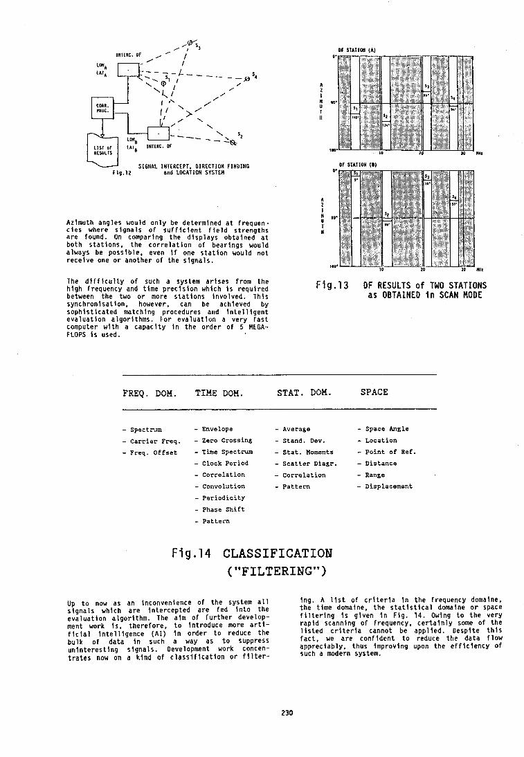
DF STATION ( A )
u SIGNAL INTERCEPT, D IRECTION FlNUlNO T l g . 1 2 and LOCATION SYSTEM
Azimuth ang les would o n l y be de te rm ined a t f r e q u e n - c i e s where s i g n a l s o f s u f f i c i e n t f i e l d s t r e n g t h s a r e found. On compar ing t h e d i s p l a y s o b t a i n e d a t b o t h s t a t i o n s , t h e c o r r e l a t i o n o f b e a r i n g s would a lways be p o s s i b l e , even I f one s t a t i o n would n o t r e c e i v e one o r a n o t h e r o f t h e s i g n a l s .
The d i f f i c u l t y o f such a system a r i s e s f rom t h e h i g h f requency and t i m e p r e c i s i o n wh ich I s r e q u i r e d between t h e two o r more s t a t i o n s I n v o l v e d . T h i s s y n c h r o n l s a t i o n , however, can be ach ieved by s o p h i s t i c a t e d match ing procedures and i n t e l l i g e n t e v a l u a t i o n a l g o r i t h m s . F o r e v a l u a t i o n a v e r y f a s t computer w i t h a c a p a c i t y i n t h e o r d e r o f 5 MEGA- FLOPS i s used.
F i g . 13 DF RESULTS o f TWO STATIONS as OBTAINED i n SCAN MODE
FREQ. DOM. TIME DOH. S T A T . DOH. S P A C E
- Spectrum - Envelope - Average - Space Angle - Carrier Freq. - Zero Crossing - Stand. Dev. - Location - Freq. Offset - Time Spectrum - Stat. Moments - Point of Ref.
- Clock Period - Scatter Diagr. - Distance - Correlation - Correlation - Range - Convolution - Pattern - Displacement - Periodicity - Phase Shift - Pattern
("FILTERING")
Up t o now as an inconven ience o f t h e system a l l s i g n a l s which a r e i n t e r c e p t e d a r e f e d I n t o t h e e v a l u a t i o n a l g o r i t h m . The a i m o f f u r t h e r deve lop - ment work I s , t h e r e f o r e , t o i n t r o d u c e more a r t i - f i c i a l I n t e l l i g e n c e ( A I ) i n o r d e r t o reduce t h e b u l k o f d a t a i n such a way as t o suppress u n i n t e r e s t i n g s i g n a l s . Development work concen- t r a t e s now on a k i n d o f classification o r f i l t e r -
i n g . A l i s t o f c r i t e r i a i n t h e f requency domaine, t h e t i m e domaine, t h e s t a t i s t i c a l domaine o r space f i l t e r i n g i s g i v e n I n F i g . 14. Owing t o t h e v e r y r a p i d scanning o f f requency, c e r t a i n l y some o f t h e l i s t e d c r i t e r i a cannot be a p p l i e d . D e s p i t e t h i s f a c t , we a r e c o n f i d e n t t o reduce t h e d a t a f l o w a p p r e c i a b l y . t h u s i m p r o v i n g upon t h e e f F i c i e n c y o f such a modern system.
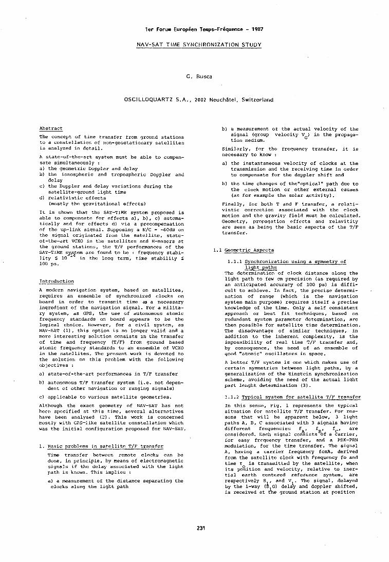
l e r Forum Europien Temps-Friquence - 1987
NAV-SAT TIME SYNCt IRONIZATION STUDY
G. Busca
OSCILLOQUARTZ S.A., 2002 Neuch l te l , Swi tzer land
Abstract
The concept of time transfer from ground stations to a constellation of r~on-geostationary satellites is analyzed in detail.
A state-of-the-art system must be able to compen- sate simultaneously : a) the geometric Doppler and delay b) the iorlospheric and tropospheric Doppler and
delay C) the Doppler and delay variations during the
satellite-ground light time d) relativistic effects
(mostly the gravitational effects)
It is shown that the SAT-TIME system proposed is able to compensate for effects a), b) , c) automa- tically and for effects d) via a precompensation of the up-link signal. Supposing a N/C = -60dB on the signal originated from the satellite, state- of-the-art VCXO in the satellites and H-masers at the ground stations, the T/F performances of the SAT-TIME s&sfem are found to be : frequency stabi- lity 5 10 in the long term, t.ime stability 5 100 ps.
Introduction
A modern navigation system, based on satellites, requires an ensenlble of synchronized clocks on board in order to transmit time d( a necessary ingredient of the navigation signal. For a milita- ry system, as GPS, the use of autonomous atomic frequency standards on board appears to be the logical choice. However, for a civil system, as NAV-SAT (11, this option is no longer valid and a more interesting solution consists in the transfer of time and frequency (T/F) from ground based atomic frequency standards to an ensemble of VCXO in the satellites. The present work is devoted to the solutiorl on this problem with the following objectives :
a) state-of-the-art performances in T/F transfer
b) autonomous T/F transfer system (i.e. not depen- dent of other navigation or ranging signals)
C) applicable to various satellite geometries.
Although the exact geometry of NAV-SAT has not been specified at this time, several alternatives have been analysed (2). This work is concerned mostly with GPS-like satellite constellation which was the initial configuration proposed for NAV-SAT.
1. Hasic problems in satellite T/F transfer
Time transfer between remote clocks can be done, in principle, by means of electromagnetic signals if the delay associated with the light path is known. This implies :
a) a measurement of the distance separating the clocks along the light path
b) a measurement of the actual velocity of the signal (group velocity VG) in the propaga- tion medium.
Similarly, for the frequency transfer, it is necessary to know :
a) the instantaneous velocity of clocks at the transmission and the receiving time in order to compensate for the doppler shift and
b) the time changes of the"optica1" path due to the clock motion or other external causes (as for example the solar activity).
Finally, for both T and F transfer, a relati- vistic correction associated with the clock motion and the gravity field must be calculated. Geometry, propagation effects and relavitity are seen as being the basic aspects of the T/F transfer.
1.1 Geometric Aspects
1.1.1 Synchronization using a symmetry of light paths
The determination of clock distance alona the light path to few cm precision (as required by an anticipated accuracy of 100 ps) is diffi- cult to achieve. In fact, the precise determi- . nation of range (which is the navigation system main purpose) requires itself a precise knowledge of the time. Only a self consistent approach or best fit techniques, based on redundant system parameter determination, are then possible for satellite time determination. The disadvantage of similar techniques, in addition to the inherent complexity, is the impossibility of real time T/F transfer and, by consequence, the need of an ensemble of good "atomic" oscillators in space.
A better T/F system is one which makes use of certain symmetries between light paths, by a generalization of the Einstein synchronization scheme, avoiding the need of the actual light part lenght determination (3).
1.1.2 Typical system for satellite T/F transfer
In this sense, Fig. 1 represents the typical situation for satellite T/F transfer. For rea- sons that will be apparent below, 3 light paths A, B, C associated with 3 signals having different frequencies fAt fge fC, are considered. Each signal consists Of a carrier, for easy frequency transfer, and a PSK-PRN modulation, for the time transfer. The signal A, having a carrier frequency foxA, derived from the satellite clock with frequency fo and time T is transmitted by the satellite, when its and velocity, relative to iner- tial earth centered reference system, are respectively S , and V1. The signal, delayed by the l-way (A G) delay and doppler shifted, is received at t%e ground station at position
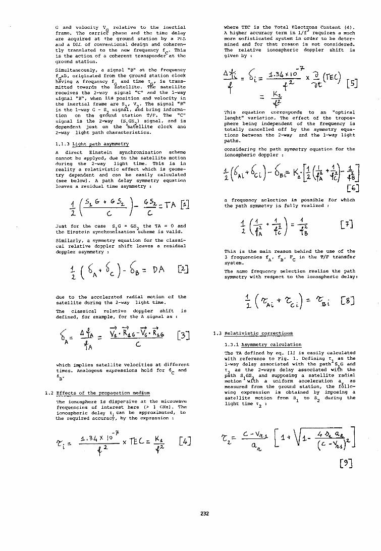
G and velocity V relative to the inertial frame. The carrieg phase and the time delay are acquired at the ground station by a PLL and a DLL of conventional design and coheren- tly translated to the new frequency fC. This is the action of a coherent transponder at the ground station.
Simultaneously, a signal "B" at the frequency f xB, originated from the ground station clock G having a frequency fG and time T , is trans- mitted towards the satellite. ~!?e satellite receives the 2-way signal "C" and the 1-way signal "B", when its position and velocity in the inertlal frame are S V2. The signal "B" is the 1-way G - S signa?lr, and bring informa-
2 tion on the ground station T/F. The "C" signal is the 2-way (S1GS2) signal, and is dependent just on the satellite clock and 2-way light path characteristics.
1.1.3 Light path asymmetry
A direct Einstein synchronization scheme cannot be applyed, due to the satellite motion during the 2-way light time. This is in reality a relativistic effect which is geome- try dependent and can be easily calculated (see below). A path delay symmetry equation leaves a residual time asymmetry :
Just for the case S G = GS2 the TA = 0 and the Einstein synchronization scheme is valid. Similarly, a symmetry equation for the classi- cal relative doppler shift leaves a residual doppler ssymmetry :
due to the accelerated radial motion of the satellite during the 2-way light time.
The classical relative doppler shift is defined, for example, for the A signal as :
which implies satellite velocities at different times. Analogous expressions hold for dC and
6 ~ '
1.2 Effects of the propagation medium
The ionosphere is dispersive at the microwave frequencies of interest here ( > 1 GHz). The ionospheric delay rican be approximated, to the required accuracy, by the expression t
where TEC is the Total Electsons Content ( 4 ) . A higher accuracy term in l/f requires a much more sofisticated system in order to be deter- mined and for that reason is not considered. The relative ionospheric doppler shift is given by :
This equation corresponds to an "optical lenght" variation. The effect of the tropos- phere being independent of the frequency is totally cancelled off by the symmetry equa- tions between the 2-way and the l-way light paths.
considering the path symmetry equation for the ionospheric doppler :
a frequency selection is possible for which the path symmetry is fully realized :
This is the main reason behind the use of the 3 frequencies fA, fg, F in the T/F transfer system.
C
The same frequency selection realize the path symmetry with respect to the ionospheric delay:
1.3 ~elativistic corrections
1.3.1 Asymmetry calculation
The TA defined by eq. [I1 is easily calculated with reference to Fig. 1. Defining Tl as the 1-way delay associated with the path S G and T~ as the 2-ways delay associated wi& the path S GS and supposing a satellite radial motion w&h a uniform acceleration a as measured from the ground station, the fgllo- wing expression is obtained by imposing a satellite motion from S1 to S2 during the light time r2 :
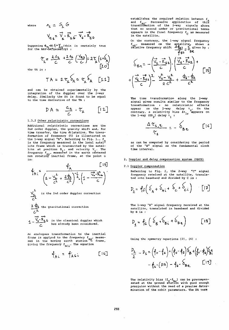
where DL = sL 6
Supposing a&<- C'V (this is certainly true for the ~A~-sA~geo&+ry) :
C k
the TA is :
and can be obtained experimentally by the integration of the doppler over the 2-way delay. Similarly the DA is found to be equal to the time derivative of the TA :
1.3.2 Other relativistic corrections
Additional relativistic corrections are the 2nd order doppler, the gravity shift and, for time transfer, the time dilatation. The trans- formation of frequency (5) is illustrated on the l-way signal "A". Referring to Fig. I., fA is the frequency measured in the local satel- lite frame which is transmitted by the satel- lite at position S1, and velocity V1. The frequency f measured in the earth centered non rotatinv'inertial frame, at the point G is:
L is the 2nd order doppler correction
-. c '-
the gravitational correction
cZ 4 ->
* R ~ , G is the classical doppler which I-" has already been considered.
An analogous transformation to the inertial frame is applyed to the frequency f , measu- red in the moving earth stationA% frame, giving the frequency fAGi. The equation
establishes the required relation between f and fAG. Successive application of thi; transformation of the 2-way signals shows that no second order or gravitational terms appears in the final frequency fC as measured in the satellite.
On the contrary, the l-way signal frequency f , measured on the sa ellite shows a rifative frequency shift ~ t ~ ) = $ given by :
The time transformation along the 2-way signal gives results similar to the frequency transformation : no relativistic effects appear on the 2-way delay 7 . On the contrary, a relativity bias AT^^ 'appears on the l-way (GS2) delay 7 1 '
as can be computed by considering the period of the "B" signal as the fundamental clock time interval.
2. Doppler and delay compensation system (DDCS)
2.1 Doppler compensation
Referring to Fig. 2, the 2-way "C" signal frequency received at the satellite, transla- ted into baseband and divided by C is :
The l-way "B" signal frequency received at the satellite, translated in baseband and divided by B is :
Using the symmetry equations [21, [61 :
The relativity bias (f * ~ 5 ~ ~ ) can be precompen- sated at the ground station with good enough precision without the need of a precise deter- mination of the orbit parameters. The DA term
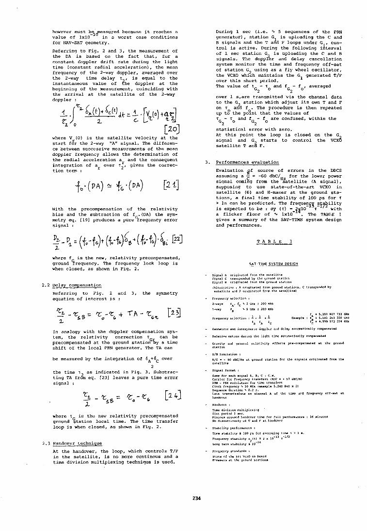
however must b-yfleasured because it reaches a value of 1x10 in a worst case conditions for NAV-SAT geometry.
Referring to Fig. 2 and 3, the measurement of the DA is based on the fact that, for a constant doppler drift rate during the light time (constant radial acceleration), the mean frequency of the 2-way doppler, averaged over the 2-way time delay T , is equal to the instni~taneous value of zhe doppler at the beginning of the measurement, coinciding with the arrival at the satellite of the 2-way doppler :
L /
where V (0) is the satellite velocity at the start f:r the 2-way "A" signal. The differen- ce between successive measurements of the mean doppler frequency allows the determination of the radial acceleration ar and the consequent integration of a over r2, gives the correc- tion term :
With the precompensation of the relativity bias and the subtraction of fG.(DA) the sym- metry eq. [191 produces a pure frequency error signal :
where f is the new, relativity precompensated, ground (irequency. The frequency lock loop is when closed, as shown in Fig. 2.
2.2 Delay compensation
Referring to Fig. 2 and 3, the symmetry equation of interest is :
In analogy with the doppler compensation sys- tem, the relativity correction T can be precompensated at the ground stationG'by a time shift of the local PRN generator. The TA can
be measured by the integration of 6A+6C over
2 the time T~ as indicated in Fig. 3. Substrac- ting TA from eq. [231 leaves a pure time error signal :
where T is the new relativity precompensated ground %tation local time. The time transfer loop is when closed, as shown in Fiy. 2.
2.3 Handover technique
At the handover, the loop, which controls T/F in the satellite, is no more continous and a time division multiplexing technique is used.
During 1 sec (i.e. 5 sequences of the PRN generator), station GI is uploading the C and B signals and the T and F loops under GI, con- trol is active. During the following interval of 1 sec station G2 is uploading the C and B signals. The doppler and delay cancellation system monitor the time and frequency off-set of station G using as a fly wheel oscillator,
2 the VCXO which maintains the Gl generated T/F over this short period. The value of 7 - T and fG - fo, averaged
G2 O 2 over 1 s,are transmitted via the channel data to the G station which adjust its own T and F on r an2d f . The procedure is then repeated up t: the po?nt that the values of T - T and fG - f are confused, within the G2 O 2 O
statistical error with zero. At this point the loop is closed on the G signal and G starts to control the V C X ~ satellite T ani F.
3. Performances evaluation
Evaluation flf source of errors in the DDCS assuming a - = -60 dbC/HZ for the lower power
C signal coming from the satellite (A signal), supposing to use state-of-the-art VCXO in satellite (6) and H-maser at the ground sta- tions, a final time stability of 100 ps for r > Is can be predicted. The frequenfr es$9ility is expected to be : oy (T) =-ja10 T with a flicker floor of % 1x10 . The TABLE 1 gives a summary of the SAT-TIME system design and performances.
T A B L E 1
SAT-T IME SYSTEM DESIGN - - Signal A originated from the rbtellite
signal c tranrpundrd by tho qround station signal 8 ozlginated fzcm the ground statlon
1hlterr.ative i A originated from grourid stations, C transponded by satellite and 8 originated from the satellite)
- Frequency $election I
2-ways f A , fC 2. 5 GHz f 200 MHz
1-way fa 5 5 GHz 2 200 HHI
f E 5.207 887 733 CHI frequency selection : - ?- + 1 Example I ? r 5 101 283 320 GHZ
f~ f~
f: s 4:999 572 224 GHz
- Geometric and ionospheric dopplar and delay automatically compensated
- Eelative motion during the light time automatisally compensated
- Gravity and general relativity effects pre-conpnsatcd at the ground station
- S/N Imitation :
N/C - - 60 d X / H z st ground station for the signals originated from the 611tellite
- signal format :
Sam for each signal A, 0 . C : C.W. Carrier for frequency transfert iN/C - - 57 dSC/N) PRN - PSK modulation for time transfert Clock frequency z 10 MHz lexamplc 5.242 840 x 21 Sequence duration z 0.2 s. Data tranrmiseions en channel A of the time and frequency off-set at
- Handover :
Tlme dlvirion multiplexing Slat period 1 6%. ninimurn assumed handover time far full performances : 16 mlnutes NO d~ec~ntlnuity of T and P at handover
- Stability performances i
~ i m e stability s 100 ps for averaging tame r > 1 1.
Frequency rtabrlity 0 ( 7 ) : 2 x 10-l3 ,-'I2 y -14
Long term mtrbllity S 10
- Frequency standards :
State of the art VCXO on board H-MaeerS at the ground stations
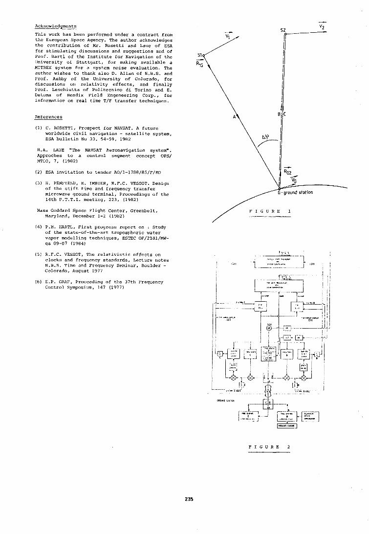
Acknowledgments - This work has been performed under a contract from the European Space Agency. The author acknowledges the contribution of Mr. Rosetti and Laue of ESA for stimulating discussions and suggestions and of Prof. Hart1 of the Institute for Navigation of the University of Stuttgart, for making available a MITREX system for a system noise evaluation. The author wishes to thank also D. Allan of N.B.S. and Prof. Ashby of the University of Colorado, for discussions on relativity effects, and finally Prof. Leschiutta of Politecnico di Torino and E. Detoma of Bendix Field Engeneering Corp., for information on real time T/F transfer techniques.
References -- 4 (1) C. ROSETTI, Prospect for NAVSAT. A future
worldwide civil navigation - satellite system, ESA bulletin No 30, 54-59, 1982
H.A. LAUE "The NAVSAT Aeronavigation system". Approches to a control segment concept OPS/ MTCO, 7, (1902)
( 2 ) ESA invitation to tender A0/1-1788/85/F/~~
( 3 ) H. PENFIELD, E. IMBIER, R.F.C. VESSOT. Deslgri of the stift time and frequency transfer microwave ground terminal, Proceedings of the 14th P.T.T.I. meeting, 223, (1982)
Nasa Goddard Space Flight Center, Greenbelt, Maryland, December 1-2 (1962)
( 4 ) P.H. HARTL, First progress report on : Study of the state-of-the-art tropospheric water vapor modelling techniques, ESTEC OF/2181/MW- gs 09-07 (1964)
(5) R.F.C. VESSOT, The relativistic effects on clocks and frequency standards, Lecture notes N.B.S. Time and Frequency Seminar, Boulder - Colorado, August 1977
(GI E.P. GRAF, Proceeding of the 37th Frequency Control Symposium, 147 (1977)
F I G U R E 1 / -
F I G U R E 2
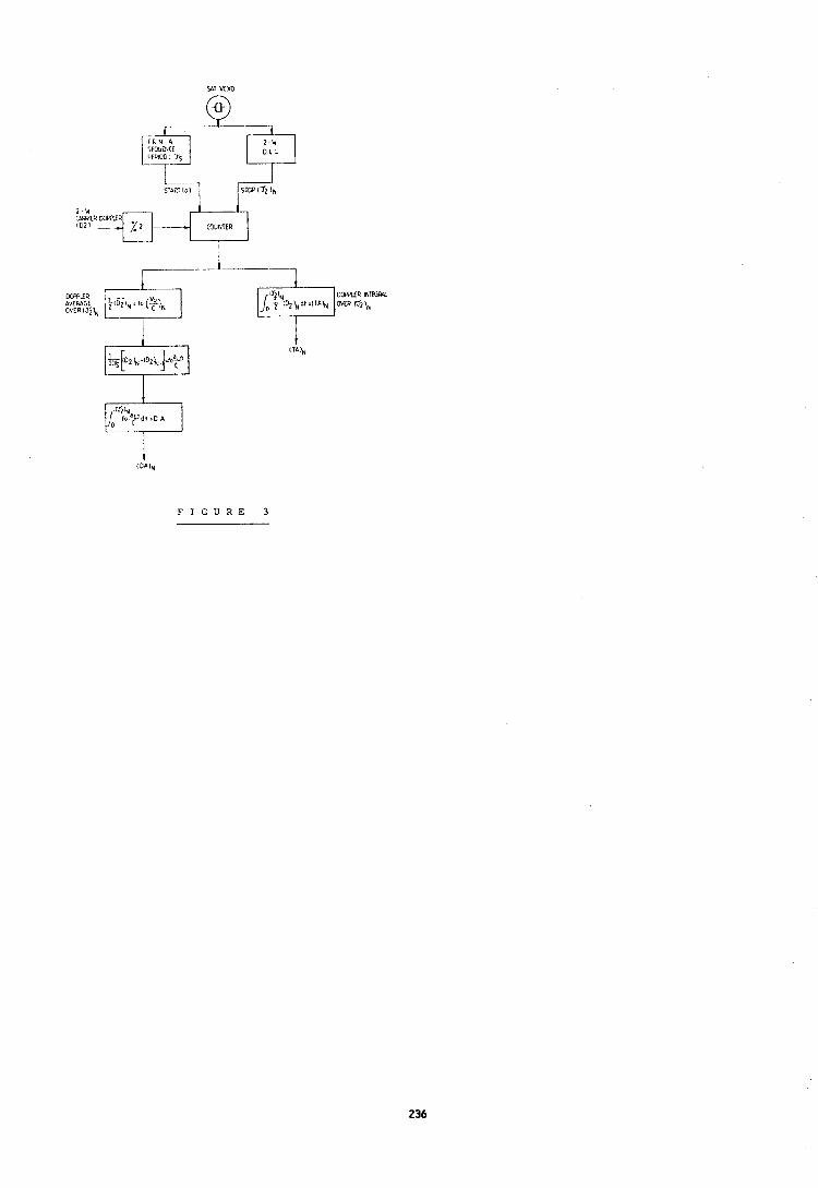
F I G U R E 3
l e r Forum Europien Temps-Friquence - 1987
UTILISATION DES SIGNAUX DU G.P.S. EN MODE DIFFERENTIEL INSTANTANE I'OUR LES API'LICATIONS TEMPS-FREQUENCE DE I1AUTE I'RECISION
G. NARD - J. KABIAN - R. COUNON
SERCEL S .A. B.1'. 64 - 44471 CARQ1JEI:OU FRANCE
RESUME I.cs marqucs de temps des signaux codes ct la phasc de la porteuse des satellites G.P.S. ont 6td utilisEes lors de rEcentes experiences, particulierement en mettant en oeuvre les tech- niques differentielles instantanees entre les observations de 2 ou plusieurs recepteurs G.P.S. sdpards par des distances atteignant 1000 kilo- ntbtres ou plus. I1 a pu Etre ddmontrE que les exactitudes de comparaison dc temps provenant de plusieurs satcllites sont cohdrentcs au nivcau de 1 :i quclqucs nanosccondes, et des incertitudes de quclqucs dizaines dc picosccondes, de jour comnle de nuit, et avec des configurations gdo- mdtriques trhs varides des satellites, pour une distance entrc rEceptcurs de plus de TO00 kilo- 1112 t rcs. I,a naturc des signaux ct lcs nldthodcs de trai- tcslcnt utilisdes sont ddcritcs. Les facteurs intervenant sur l'exactitude et les moyens de Ics maitriser sont analys6sI notalJIlnent la carac- tdrisation des exactitudes des recepteurs et dcs antennes C.P.S., les effets des trajets ~nultiples, les r6sidus d'erreurs de propagation ou de parametres orbitaux des satellites ... etc, ainsi quc Ics moycns mdtrologiqucs ut,iles 5 cc type de mesures.
1 - LE GPS NAVSTAR ET SES MARQUES DE TEMPS. Le Global Positioning System NAVSTAR sera
constitud, Jans sa phase finale, de 21 satel- litcs places sur 3 plans orbitaux inclines de 55' sur l'dquateur, B une altitude de 20000 kilombtres (periode orbitale circulaire de 12 heures). Chaque satellite est equip6 d'horloges de grande stabilitd dont l'6tat et la marche pcuvcnt Etre observ6s depuis le sol avec d'ex- trE~nes exactitude et precision. De meme, la position instantanee relativement au sol de chaque satellite peut Gtre determinee et prevue avec une precision cxtrEmc. Chaque satellite radiodiffuse un message numerique qui permet aux rdcepteurs exploitant ces messages de cal- culer de facon precise la position instantande de ce satellite et 116tat instantane de son horloge. Chaque satellite transmet Bgalement des marques de tcmps de grande prdcision et stabilitd qui pcrnlcttcnt de determiner lc tcmps de parcours dcs signaux entrc le satcllita ct les rdccptcurs. Ce sont : - les signaux temporcls codes (dits C/A et P) - la phasc de la porteuse de ces signaux
(1575 Mllz). Dans Ies applications de transfert du temps,
rnEme dc trEs haute prGcision, on s'int6resse cssentiellement aux marques de temps du code C/A et B la phasc de la porteuse de la fr6- qucnce dite L1 du systhmc. I1 a en effct 6td d6montrd que l'emploi supplementaire des mar- ques de temps du code "P" du systbme et de la porteuse de la fr6quence "1.2" n'apporte et n'apportera pas d'amdlioration significative b l'exactitude des mesures de tern s, surtout lorsqutelles s'appliquent des otservateurs
dont la position est fixe, ce qui est le cas le plus g6n6ral. L'usage de ces signaux compld- mcntaires ne presente de lfintCr8t que lorsque les observateurs sont B bord de mobiles subis- sant des nlouvements dynamiques violents et des brouillages radio6lectriques volontaires de forte intensite. Leur usage et leur int6rgt sont donc essenticllement militaires et ils seront de toutes nlanikres liinites et r6serves. Cette limitation ne reduira en rien les perfor- mances de la connaissance du temps qui int6res- sent le plus souvent la conlmunautd civile. Afin de pouvoir lncsurcr Ie temps, un rdcep-
tcur usager du systbi~ic doit Etrc capablc dc ddterminer h chaque instant dc Inesurc la dis- tance qui le sdpare du satellite afin de deter- ~nincr le tcmps dc parcours dcs signaux marques dc tcnlps. Pour ccla, il disposc de la position du satcl litc (grace nu nlessagc transmi<), mais il est Cvidcnt qu'il doit aussi connaitre la sienne, et avec une pr6cision qui est directe- ment en relation avec l'exactitude du tcmps qui est recherch6e.
I1 existe dvidemment des relations prdcises entre la ddtermination de la position des dif- f6rents satellites, la position dc l'usager, l'btat de l'horloge de chaque satellite rcla- tivement B une origine commune de telnps, et enfin l'indication precise du temps aulun usa- ger peut esperer obtenir dlun reckptiur. La reference commune de temps du systEme est dite "temps GPS", sa relation avec le temps UTC est 6tablie et contral6e par Lcs grands labora- toires militaires et civils des U.S.A. (UTC USNO MASTER CLOCK et CPS master control station) Cette relation doit &tre connue, au moins a posteriori, par l'usager qui desire rdfCrer les mesures absolues de temps auxquelles il procede au temps UTC riJ .
Le problkme le plus frequent qui interesse la majorit6 des usagers est, dans une mtme communaut@, d'ttre assure de pouvoir disposer d'une r6f6rence de temps commune. Chacun des usagers s' intdressera donc essentiel lelnent aux errcurs de mesure qu'il est susceptible de faire relativement aux mesures faites par le reste de sa communaut6. I1 en resultera donc le plus souvent la capacit6 d'observation dif- fdricntielle des donnees du GPS qui conduit 5 la ~ossibilit6 de rdduire ou dlEliminer la majEure partic des erreurs de mesure possibles et d'obtenir des exactitudes remarquables et inegaldes par d'autres moyens. DEs l'avbncn~ent de la phase operationnelle
de navigation 2D du systeme GPS (mi-1990), une degradation volontaire des valeurs des para- mbtres des messages permettant de determiner l'etat des horloges et la position instantanee des satellites est envisagee. Cette degradation potentielle inquibte les usagers possibles. En fait, si la description complkte des degra- dations envisagees reste Bvidemment inconnue, les statistiques les concernant ont 15tB pu- bli6es et ont conduit l'dtablissement de modkles. [2]
Lcur a n a l y s e montrc clue l e u r i n f l u e n c e s u r I ' c x a c t i t u d c d c l a mcsure du temps d e v r a i t E t r e l i m i t d c , pour l e s u t i l i s a t c u r s f i x c s , h q u c l - yucs d i z a l n c s de nanosccondes pour l 1 o b s e r v a - t i o n a b s o l u e du temps c t de l ' o r d r e d ' u n e nano- s e c o n d ~ pour l e s o b s e r v a t i o n s e n vue commune, d c s t i n d c 3 l ' d t a b l i s s c r n c n t d 'un tcmps r c l a t i f .
Rien quc nc d i s p o s a n t cn 1987 quc dc 6 s a t c l - l i t c s p r o t o t y p e s u t i l i s a b l c s , l e GI's permct dEs 3 p r d s c n t unc o b s e r v a t i o n du tcmps e n v i r o n 14 h e u r c s p a r j o u r .
2 - I,ES 'I'EMI'S E'T MODES D'UTILISATION DU GPS EN TKANSFERT DE TEMPS.
Les u s a g c r s p o t c n t i e l s du t r a n s f e r t d c tcmps ou dc s y n c h r o n i s a t i o n p a r l e CPS peuvent S t r e c l a s s e s en d i f f d r c n t e s c a t e g o r i e s :
2 . 1 . Les o b s c r v a t e u r s f i x e s B l a s u r f a c e dc l a t e r r e , e t parmi eux 2 g roupes :
- Ceux q u i ne s e d d p l a c c n t peu ou jamais e t q u i o n t donc l a p o s s i b i l i t 6 de c o n n a i t r e ou de dd tc rn l incr p r 6 a l a b l c m c n t l e u r p o s i t i o n p r e c i s e en t r o i s d imens ions . La p r e c i s i o n a v e c l a q u e l l e c c t t e p o s i t i o n d o i t & t r e connue e s t e n r e l a t i o n d i r c c t e avcc l a p r d c i s i o n r e c h e r c h e e pour l a dd tc r ln ina t i o n du tcmps . L ' e x p e r i e n c e montre c l u l i l c s t i ~ n p o r t a n t de r e f e ' r e r l a p o s i t i o n cn coordonndcs CPS (WGS 8 4 ) . Lorsquc l a p o s i t i o n c s t rdputdc connuc avec l a p r e c i s i o n r c q u i s c , i l c s t p o s z i b l c d ' c x t r a i r c l c tcmps cn o b s c r - v a n t U N SCUL SATLI,l,I'IE.
- Ccux q u i f o n t I c s o b s e r v a t i o n s B p o i n t f i x c , mais q u i nc c o n n a i s s c n t p a s h I ' o r i g i n e l c u r p o s i t i o n : c ' c s t dans l a r e ' a l i t d l c c a s I c p l u s c o u r a n t . Unc c r r c u r dc 130 mbt res s u r l a p o s i - t i o n p c u t c o n d u i r c , en moyenne e t du f a i t d e s a n g l e s sous l e s q u c l s l c s s a t e l l i t e s s o n t o b s e r - v a b l e ~ , B unc e r r e u r de d e t e r m i n a t i o n du temps de 100 nanosccondcs . I 1 f a u d r a donc p r 6 a l a b l c - nlcnt d i t c r m i n c r l a p o s i t i o n e t de p r e f e r e n c e c n s c r d f d r a n t au CPS lui-mznie. Pour c e l a , i l f a u d r a d t a b l i r d e s s o l u t i o n s dc p o s i t i o n u t i - l i s a n t au moins q u a t r e s a t e l l i t e s . En f o n c t i o n de l a p r e c i s i o n r e c h e r c h e e , c e t t e o p e ' r a t i o n i n i t i a l e p e u t p r c n d r e un temps p l u s ou moins long : de l ' o r d r e de q u e l q u e s m i n u t e s , pour a t t e i n d r c d e s e x a c t i t u d e s de 30 B 100 nano- s e c o n d e s , e t j u s q u ' 8 p l u s i e u r s j o u r s , e t s e u l e - ment s i l a q u a l i t 6 d e s r 6 c e p t c u r s l e p e r m e t , pour a t t e i n d r e q u e l q u e s nanosecondes . Une f o i s l a p o s i t i o n connue, on s e r a ramen6 au c a s p r 6 - c d d c n t e t l l o b s e r v a t i o n d l u n s e u l s a t e l l i t e s u f f i r a pour d e t e r m i n e r l e temps.
I1 f a u t a u s s i c o n s i d e ' r c r l c mode i n t e r e s s a n t l ' u s a g e r : s ' i l a p p a r t i e n t B une communaut6 c t q u ' i l s 1 i n t 6 r c s s e :I une rnesure de temps RELA- 'TIVE A CELLES FAI'I'ES PAR CETTE COMMUNAUTE, i l d c v r a p r d a lab lcincnt d d t e r m i n c r s a p o s i t i o n , c n rcpErc CPS WGS 8 4 , mais dont l a q u a l i t 6 p e u t n f E t r e quc RELATIVE A LA POSITION DES AUTRES ODSERVATEURS DE LA MEME COMMUNAUTE. Dans c e c a s l a d d t c r m i n a t i o n r c l a t i v c de p o s i t i o n , meme pour s a t i s f a i r c dc bonnes e x a c t i t u d e s ne n e c c s - s i t c iluc cluclclues h e u r e s D'OBSERVATION DIFFE- 11LNl'IBLLE dc p o s i t i o n , d c p r d f d r e n c c provcnant d ' u n maxilnunl dc s a t c l l i t e s ( a u moins 5 pour e t r c c n mcsurc dc q u a l i f i e r l c s mesurcs f a i t c s ) .
2 . 2 . Cas d c s o b s e r v a t e u r s p l a c e s s u r d e s mobi les cn mouvcment.
I 1 c s t a u s s i p o s s i b l c de mcsurer I c tcmps dans c c s c o n d i t i o n s , avcc cependant d c s d i f f i - c u l t e s s u p p l d m c n t a i r c s d c d i f f e r e n t c s o r i g i n c s . . Par d e f i n i t i o n , un mobi le q u i s e d d p l a c e d o i t s imultan6ment C t a b l i r s a p o s i t i o n t r i - d i m e n s i o n n e l l e c t e x t r a i r e l e temps, donc rd- soudrc 4 inconnues : X , Y , Z e t T. I 1 l u i f a u t donc u t i l i s c r l e s donn6cs c n provenance d ' a u moins 4 s a t e l l i t e s . De t o u t e e v i d e n c e , au
c o u r s de mesures i n s t a n t a n e e s , l a q u a n t i t e d ' i n f o r m a t i o n u t i l e h l a d e t e r m i n a t i o n de l a p o s i t i o n n ' e s t p l u s d i s p o n i b l c pour e ' t a b l i r l a mesure du temps. (Cec i e s t couramment ex- prime' e n t e r m e s de g e o ~ n e t r i e d ' o b s e r v a t i o n d e s s a t c l l i t c s : c r e s t l a d i f f e r e n c e e n t r e l e "TDOP" cn modes "T" d ' u n c p a r t , c t "31) + T" d ' a u t r c p a r t . P r a t i q u e l n c n t , c c r a p p o r t p e u t d v o l u c r c n t r c 2 c t 5 . . I 1 e s t d e l i c a t d 1 6 t a b l i r une moyenne d e s o b s e r v a t i o n s dc temps s u c c c s s i v e s h b o r d d ' u n m o b i l e , l e s c o n d i t i o n s d l o b s c r v a t i o n E t a n t i n s t a b l e s , du f a i t notamnlcnt d c s r i s q u c s d ' o c - c u l t a t i o n t e l n p o r a i r c s d c s s a t c l l i t c s . De l a m&me f a c o n que pour l e s o b s c r v a t i o n s au s o l , une m&mc communautd nlobi le d l o b s c r v a t c u r s p c u t C t a b l i r un temps r e l a t i f dans une s o l u t i o n d i f f e r e n t i e l l e compl6 te p o s i t i o n - t e m p s , avec d c s a v a n t a g e s c o n ~ p a r a b l e s h ceux d e j h 6voque's. Cependant dans t o u s l e s c a s , l a p r e c i s i o n moyenne de l l e x t r a c t i o n du temps 5 bord d l u n mobi le p e u t & t r e c o n s i d e r e e commc 2 B 5 f o i s moins bonne q u ' 8 p o i n t f i x e .
3 - LES APPLICATIONS DU TRANSFERT DE TEMI'S m E GPS.
Pouvoi r 6 t a b l i r ou t r a n s f e r e r l e temps a v e c une e x a c t i t u d e de q u c l q u e s nanosecondcs prd- s c n t e un i n t 6 r e t q u i c r o 3 t rap idement au f i l d c s a n n e c s .
I 1 c x i s t c t o u t d ' a b o r d d c s a p p l i c a t i o n s s c i c n t i f i q u c s , colnlllc l ' d t a b l i s s e n ~ c n t du tc111ps n a t i o n a l ou i n t e r n a t i o n a l p a r I c s g r a n d s labo- r a t o i r e s ou o b s c r v a t o i r c s , ou l a d i s s e m i n a t i o n ou l e regroupclnent du temps e n t r e l a b o r a t o i r e s p r i m a i r c s c t s c c o n d n i r c s .
Les p r d c i s i o n s r c c h c r c h d c s s o n t c x t r s m c s : q u c l q u e s nanosecondes .
- La s y n c h r o n i s a t i o n de I ' o b s e r v a t i o n dc c c r t a i n s phe'nowbncs p h y s i q u e s , g6nera lement a s s o c i e s 5 l ' e s p a c c : . Synchronisme d e s p rd lbvements d a n s l e s s t a t i o n s d c r a d i o a s t r o n o m i e ou d 1 i n t e r f E r o m 6 - t r i c 5 b a s c longuc (V.L.B.1) ( q u e l q u e s nano- s e c o n d e s ) . . S y n c h r o n i s a t i o n d e s o b s e r v a t i o n s s p a t i a l e s h l l a i d e de l a s e r s (1 nanoseconde) . . D e f i n i t i o n d ' u n e b a s e commune de temps pour l e s s t a t i o n s d l o r b i t o g r a p h i e s p a t i a l e ( q u e l q u e s nanosecondes) .
- La s y n c h r o n i s a t i o n d e s sys tkmes de n a v i - g a t i o n a y a n t l e u r s e m e t t e u r s b a s e s 5 t e r r e mais s e p a r e s p a r de g r a n d e s d i s t a n c e s : . OMEGA (100 B 300 nanosecondes)
, LORANC (30 B 100 nanosecondes) . GEOLOC ( 2 S 6 nanosecondes) . P l u s recemmcnt e s t a p p a r u l e b e s o i n d 1 a s s u -
r e r une s y n c h r o n i s a t i o n e n t r e e l e m e n t s de s y s - tbmes de communicat ion, pour l e s q u e l s d c s p r e c i s i o n s dc 10 5 300 nanosecondes s o n t r e - chcrchBes e t q u i peuvent c o n s t i t u e r dans un proche a v e n i r une d c s demandes l e s p l u s impor- t a n t e s e n non~bre .
c e r t a i n s sys tbmes d ' a n t i c o l l i s i o n pcuvent a u s s i t r o u v e r un grand i n t e r e t B une s o l u t i o n commune p o s i t i o n - t e l n p s .
4 - LES SOURCES D'EIIREUR DANS LA DETEI1MINATION DU TEMPS PAR LE GPS, METHODES ET MOYENS P P
I 1 y a c s s c n t i e l l c m c n t 3 o r i g i n c s aux c r r c u r s : - C c l l e s p r o v c n a n t du systbme GPS e t d e s s a - t e l l i t e s , e r r e u r s v o l o n t a i r e s ou non. - Lcs e r r e u r s a s s o c i e c s au m i l i e u dc propaga- t i o n e t 8 l ' c n v i r o n n e m e n t du r e ' c e p t c u r . - Les e r r e u r s p r o v e n a n t du r e c e p t e u r u t i l i s e ou de s a mise en o e u v r e .
4 . 1 . E r r c u r s a s s o c i e e s au systkme GPS l u i - mEme : -
T r o i s t y p e s d ' e r r e u r :
. Retard ct horloges des satellites.
. Pr6visions des 6phdm6rides des satcllites. . Ddgradations volontaires. Ccrtaines de ces crreurs ont des effcts forte- mcnt corrbl@s : c'est le cas lorsque plusieurs utilisateurs obscrvent simultanement et eta- blissent cntrc cux un temps rclatif. Dans ce cas ccs crrcurs sont bliminees ou fortement attdnudcs.
4.1.1. Temps satellite : Lcs stations au sol du systka~c GPS 6tablissent 1'6tat ct la derive dcs horlogcs de tous les satellites ct plusieurs fois par jour "chargent" les m6moires du satel- lite avec dcs cocfficients qui sont ensuite radiodiffus6s ct reGus par les utilisateurs. 1,c conlportc~rlcnt dcs horloges n'cst pas exactc- mcnt cclui prBvu par ces coefficients et il en r6sulte dcs crreurs. Ccs erreurs affectent directemcnt l'usager qui vcut determiner son tcmps local par rapport ail temps GPS. Par con- tre les erreurs obscrv6cs sont les mB~ncs pour tous les observateurs du mdnlc satellitc au 1nEn1e instant. Pour lcs satellites prototypes (groupe 1 cxistant en 1987), l'erreur d'horloge peut Etre de l'ordre de 0- = 10 nanosecondes 2 h 4 11cures aprbs le chargemcnt et atteindrc 60 narioseconclcs aprEs 24 hcurcs sans chargement (cxccpt ionnc I ) .
pour lcs satcllitcs opfrationnels definitifs, ccttc crrcur cst sp6cifi6c 3 (T= 20 nanosccon- dcs. Ccs crrcurs sont totalcmcnt rcsscntics en lnodc tcnlps absolu mais sont annuldcs cn obser- vation dc tcnlps diffdrcnticl, en vue commune.
4.1.2. Ephdrl~Er idcs dcs satel litcs : 1,cs lois dc mouvca~ent de chaquc satellite sont Cgalcmcnt suivics ct analysees par ~ C S stations a tcrrc qui dtablisscnt les parambtrcs orbi- taux associes b chaque satellite, ct qui sont aussi "chargds" pfriodiqucnlcnt dans la ~ndmoirc des satellites.
Entre les positions du satellite calculCes par le rdceptcur utilisateur h l'aide de ces paramktrcs ct scs positions r6clles, il existe des crrcurs associecs aux variations du champ de pcsanteur, aux ph6noniEnes de trainees, de pression de radiation etc...
S1agissant de mesures de temps uniquement, en principe opbr@es lorsque le satellite est proche de sa culmination au lieu d1obscrva- tion, les erreurs radiales ont un effet prb- ponderant. Elles sont estim6cs 5 T= 10 ns, cn mode temps direct, et sont rdduites, dans le rapport k = D/20000 environ en observation diff6rentielle(ob D cst la distance separant Ics points d'observation, en Km). 4.1.3. D6gradation volontaire de la prEci-
sion (S.A.). Selon lcs docunlcnts publids par lcs DOD/DOT,
ces ddgradations affccteraient l'enscmblc dcs 6phEmCrides : lcs coefficients de ddtcrrnina- tion de 116tat d'horloge et lcs paramktres orbitaux, avcc unc r6partition dquilibrdc dcs cffcts. Unc part dc l'erreur corrcspondrait 3 un biais constant pour la durdc dc la vali- ditd d'un chargemcnt, et une part 3 une quan- tit6 aldatoirc.
I.cs cffcts globaux de cette degradation doivent conduirc b dcs erreurs dc position horizontales de 100 mbtres, 2 DRMS, pour un IIDOP nloyen dc 1,6 en modc 3 D + T.
Ccttc definition conduit 5 un U.E.R.ERMS (User Equivalcnt Range Error) Cgal 3
DKMS 100 UERIiRMS = - = , 6 = 31 mbtres,
ce qui sc traddit, dans le domaine du temps par :
31 = 100 nanosecondes. T~~~ ' 3,10
Cette valeur est confirm6e par les exemples de courbes de r6partition des erreurs pr6vi- sibles qui ont Ct6 publiees [2] , reproduites
sur les FIGURES 1 ct 2. La FIGURE 2 suggbre un dT (i- = 0,4 nanoseconde par secondc. dt
Dans la mesure oh les contributions des biais et de la part aleatoire de l'erreur sont equi- librCes, le rayon de correlation temporel des erreurs serait donc dc l'ordrc de :
t "- l o o = 176 secondes, soit un peu x 0,4
moins de 3 minutes. Donc il s'agit d'un bruit additionnel "filtrCU ct lcntement Cvolutif. En fait, il est suppose que la valeur TmS
de 100 ns puisse dtre repartie entre les erreurs d'horloge TRMS = 70 ns ct les para- rnhtrcs orbitaux T 6su IlMS = 70 ns Egalenlcnt. Chacunc dc ces crrcurs au niveau de chaque satellite serait repartie entre un biais cons- tant pour la dur6e de validit6 du charge~nent de l'ordre de 50 ns, et une quantitC purement aleatoire de 50 ns Cpalement.
La FIGURE N03 montre cornrrlent Cvoluent les effets de ces erreurs pour les modes temps absolu, et temps differentiel en vue commune.
La mesure du temps est 6tablie gCn6ralement sur la moyennc de 15 minutes d'observations encadrant Ic point de culmination du satellite utilisb. Cette moyenne doit conduire h une reduction dans un rapport lcs effcts aldatoircs mais nc change pas ccux des biais.
Lorsqu'on ftablit lc temps absolu, Ics IIIC- surcs rcstcnt arfectfes d'une inccrtitude RMS de 76 nanosccondcs cnviron pour une nlcsurc in- dividucllc sur un scul satellite. Les biais 6tant supposds quclconqucs pour chaque satcl- litc, on pcut cspbrcr, en escomptant unc nloyenne dc 6 obscrvations dc qualit6 par jour, obtenir unc crrcur IZMS rdsiducllc dc 30 nnno- sccondcs. Par contre, dans lc cas ob on analysc les
crreurs ultimes cn mode temps relatif en vue commune, les effets des biais d'horloge dispa- raisscnt totalement et les biais ct parts al6atoircs associes aux coefficients orbitaux se reduisent approximativement dans un rapport 6gal B la distance s6parant les 2 recepteurs d'observation sur la distance au satellite :
k = 2: !70 . Par exemple k = 0,05 pour
D = 1000 km. Pour une telle distance, les erreurs diff6-
renticlles r6siduelles sont de l'ordre de 3 nanosecondes pour l'observation de 1 satellite et de 1 nanoseconde pour une moyenne quoti- dienne Btablie sur l'observation de 6 satelli- tes.
4.2. Erreurs associ6cs au milicu de pro- pagation :
Ccs erreurs conccrncnt essentiellenlent les retards de propagation associes h la traver- see de l'ionosphkre et de la troposphhre. Sont aussi B prcndre en consideration des effets de trajcts multiples h proximitd dc l'antcnnc de reception dc l'utilisatcur qui constituent un ph6norn5nc associd 5 la propagation rnais dont les effets peuvent Btre grandement rCduits par dcs dispositions convcnablcs du traiterncnt dans les recepteurs et par une mise en station convenable des antennes. C'cst pourquoi ce sujet est trait6 au chapitre concernant les recepteurs.
4.2.1. Erreurs de propagation troposphb- rique,.
Les effets de ce retard sont moins 5 redou- ter pour la mesure du temps que pour la dbter- mination de la position par le GPS. En effet on s'efforce, pour les mesures du temps, dteffectuer des mesures pour des angles d'Cl6- vation des satellites dlau moins 30 40' au- dessus de l'horizon. Le retard troposph6rique
accurnuld h l a v c r t i c a l c d ' u n p o i n t c s t dc l ' o r - d r c dc 3 B 5 nanosccondcs en moycnnc, e t dc 5 :I 1 0 nanosccondcs pour unc d l e v a t i o n de 3 0 " . 1 , ' i n d i c e dc r d f r a c t i o n dvolue dans l c temps e t en f o n c t i o n de l ' a l t i t u d e . Sur l e cumul, l a v a l c u r du c o i n d i c c M c s t dc 3 0 . 1 0 - 5 avcc uric dc 5 . 1 0 - 5 ( s o i t 1 6 % ) .
1 , ' i n c c r t i t u d c dc r c t a r d , pour El > 3 0 " c s t donc r J 2 n a n o s c c o n d e s . E l l e c s t p a r c o n t r c d i l f i c i l c h rnoddl i sc r , c t i l n ' c s t p r a t i q u c m c n t pas possible d ' d t a b l i r de c o r r 6 l a t i o n pour d c s p o i n t s d ' o b s c r v a t i o n s d i s t a n t s dc p l u s dc 300 k i l o r ~ i b t r e s .
4 . 2 . 2 . E r r c u r s dc p r o p a g a t i o n i o n o s p h e r i q u e .
1.c r c t a r d i o n o s p h 6 r i q u c , pour unc o b s c r v a - t ion r~lonofrBqucncc du GI ' s , c s t d i r c c t e r n c n t f o n c t i o n dc I ' d l d v a t i o n , dc l 1 a c t i v i t C s o l a i r e , dc i ' d c l a i r c n l c n t s o l a i r c du l i e u c t donc d c l a s a i s o n , dc l ' h c u r c c t dc l a p o s i t i o n gdographi - que . Cc r e t a r d c s t moddlisd dans l c s r e c e p t c u r s , c t l ' c r r c u r c o r r e s p o n d 3 l a d i f f d r e n c c c n t r c l e r c t a r d r e e l e t c e l u i du modkle. On admet gene- r a l c n ~ e n t que l c modkle compense 5 0 % d c s e r - r c u r s .
I,a FIGURE 4 n ~ o n t r c un exemplc de l a v a r i a t i o n c t dc l a d i s p e r s i o n du r e t a r d i o n o s p h 6 r i q u e a unc 6poquc dc maximum d ' a c t i v i t i s o l a i r e .
Dc n u i t ou l o r s d c s f a i b l c s a c t i v i t d s so- I a i r c s , l c r c t a r d c s t compr i s c n t r e 8 e t 2 0 nanosccondcs , c t 1 ' 6 c a r t - t y p e nloycn dc l l c r r c u r c s t dc 3 ;I 6 nanosccondcs , cn moycnnc 5 nano- sccondcs .
Dc j o u r c t p a r f o r t e a c t i v i t e , L C r c t a r d p c u t v a r i c r c n t r c 20 c t 6 0 nanosccondes c t l ' d c a r t - t y p e v a r i c dc 5 :I 1 5 nanosccondcs ( p o u r d c s a n g l c s d ' d l d v n t i o n s u p d r i c u r s 5 3 0 " ) .
C c t t c c r r c u r s ' a p p l i q u e t o t a l c m c n t pour d c s observations d i r c c t c s dc temps : e i l c c s t a t t 6 - nubc l o r s dc mcsurcs d i f f 6 r e n t i e l l c s en vue colnmunc. Un inodEle s i m p l e de l ' e r r e u r d i f f d r c n - t i c i l c r d s i d u c l l c , cn f o n c t i o n dc l a d i s t a n c r s E p a r a n t 2 r 6 c e p t c u r s , e s t ind iqud c ' . ;SOLIS :
Q~ iono ( D ) = 0,25 t i o n o I - e - ~ ? i d S @ o i l 3 ion0 e s t l c r e t a r d c a l c u l 6 p a r l e mod&le, ..
c t D l a d i s t a n c c en k i l o r n b t r e s 2 6 p a r a n t l e s dcux r d c e p t e u r s .
C e r t a i n e s m o d d l i s a t i o n j t e n t e n t d ' e t a b l i r l e r e t a r d i o n o s p h d r i q u c en a n a l y s a n t e t f i l t r a n t l a v a r i a t i o n e n f o n c t i o n du temps de 1 1 6 c a r t c n t r c l e r c t a r d de phase e t l e r e t a r d de groupe d c s s i g n a u x GPS.
4 . 3 . E r r e u r s r o v e n a n t d c s rCce t e u r s de ! e u r misz en o e u v r e , e t dupmode %-- Fonct ionncrnent .
- Les c r r c u r s s u i v a n t e s c o n c e r n e n t l e s rdcep- t c u r b : , l a r d g u l a r i t b du r c t a r d de I 1 a n t e n n e en f o n c -
t i o n dc l a d i r e c t i o n d ' a r r i v d c d e s s i g n a u x . . l a s t a b i l i t e du r e t a r d du r e c e p t c u r d e p u i s l ' a n t e n n e jusctu 'au c o r r d l a t e u r , e t de l ' e n - t r d c dc IrEvEncmcnt dc temps 3 mcsurer j u s - q u ' a u c o r r d l a t c u r . . l e n i v c a u dc b r u i t a s s o c i d 5 chacluc mesure du r d c c p t c u r .
. l a q u a n t i f i c a t i o n d c s mcsurcs .
. l a p r o t c c t l o n dc l l a n t c l l n c c t d c s t c c h n i q u c s dc t r a i t c n t c n t c o n t r e l c s t r a j c t s m u l t i p l e s .
- c t l a misc cn oeuvre d e s r 6 c c p t e u r s : . l a c a l i b r a t i o n du r e t a r d d c s r d c c p t e u r s . . I ' c x a c t i t u d c dc l a p o s i t i o n dc r b f b r c n c c d c l ' a n t c n n c . . l e bon ddgagcn~cnt dc l ' a n t e n n e c t l a p r o t c c - t i o n c o n t r e l c s r B f l c c t c u r s c n v i r o n n a n t s .
- Lcs c r r c u r s d o i v c n t e t r e a u s s i a n a l y s d e s s e l o n l e s modes de f o n c t i o n n e m c n t .
4 . 3 . 1 . L C r e c e p t e u r e t l ' a n t e n n e .
Des m a t d r i c l s dc q u a l i t 6 e t de per formances t r E s d i f f ' b r e n t e s e x i s t e n t e t peu de c o n s t r u c -
t c u r s p u b l i c n t l c s s p d c i f i c a t i o n s dc r c t a r d de l e u r s r e c c p t e u r s e t l e u r i n s e n s i b i l i t e h d i f f 6 - r e n t s f a c t e u r s .
- L 1 a n t e n n e : Des 1nod6les d ' a n t c n n e t r k s d i f f 6 r e n t s e x i s t e n t : d o u b l e s d o u b l e t s c r o i s e s , m i c r o s t r i p , h e l i c e s , s p i r a l c s , c t c . . . E l l c s d o i v c n t p r d s c n t c r un r c t a r d dc groupc inddpendant dc l a d i r c c t i o n d l a r r i v d c e t dc I ' d l E v a t i o n . Dcs a n t c n n c s q u a d r i h e l i c e s dc q u a l i t d p r d s c n t c n t dc? v a r i a t i o n s dc r e t a r d ~$e groupc i n f d r i c u r e s 5 - 2 nnnosccondcs c t dc - 2 0 p i c o s e c o n d e s pour l c r e t a r d de phase pour unc d i r e c t i o n d ' a r r i v b e a u e l c o n a u e dans l a demi- s p h s r e s u p d r i e u r c c a r a c t b r i i a n t l c u r diagramrne. D ' a u t r e s modelcs , p a r t i c u l i E r c r n c n t l e s a n t c n n e s p l a n c s ou e n s p i r a l c , p r d s c n t c n t d c s v a r i a t i o n s 1 0 f o i s p l u s i m p o r t a n t e s , c t c c r t a i n e s n ' o n t p robablemcnt jarnais f a i t l ' o b j e t d ' u n r c l c v e de c a r a c t d r i s t i q u e s d a n s une chambre an6choidc appropr ie ' e .
Lcs a n t e n n e s GPS d e s t i n d e s 3 l a mcsure du temps, conime pour l e s mesures g 6 o d 6 s i q u e s , d o i - v e n t c o n s e r v e r l e u r p r o p r i e ' t 6 de p o l a r i s a t i o n c i r c u l a i r e a u s s i b i e n que p o s s i b l e dans t o u t e s l e s d i r e c t i o n s e t p a r t i c u l i E r c m e n t pour l c s f a i b l e s 6 l i v a t i o n s , c c q u i e s t t o u t 5 f a i t i u l - p o s s i b l e pour d c s a n t c n n e s p l a n e s . Cec i c s t c s s c n t i c l pour a t t d n u e r l e s c f f c t s d c s n l u l t i p l c s t r a j c t s p r o v e n a n t d 1 6 v e n t u c l s r 6 f l e c t e u r s e n v i - r o n n a n t s .
G n f i n , pour I c s mcsurcs dc g r a n d c e x a c t i t u d e , l c s a n t c n n c s d o i v c n t E t r c munics d ' u n Bcran d c protection c t d l u n p l a n a b s o r b a n t I c s ondcs r 6 - f l d c h i c s p a r l c s s u r f a c c s p l a c d c s s o u s l ' a n t e n - nc . (ModElcs cornparablcs :I ceux cmployds cn g e o d e s i c ) .
- La s t a b i l i t d du r c t a r d du r d c c p t c u r : Sclon l e u r ~ n o r p h o l o g i c , l e s a n l p l i f i c a t e u r s 5 h a u t c f r e q u c n c c c t h f r d q u c n c c i n t e r m d d i a i r c d c s r e c e p t e u r s peuvcnt p r e s e n t e r d e s r e t a r d s de groupc de q u e l q u e s c c n t a i n c s 3 q u e l q u e s m i l i i e r s de nanosecondes . I 1 e s t e s s c n t i e l que c e r e t a r d s o i t connu avec p r e c i s i o n e t q u ' i l r e s t e i n s c n - s i b l e 3 d i f f e r c n t s f a c t e u r s t e l s que : . l e n i v e a u de s i g n a l r e c u d e s s a t e l l i t e s . l a t c m p d r a t u r e de fonc t ionnement . l a t e n s i o n d l a l i n i e n t a t i o n . l e v i c i l l i s s c r n c n t . I 1 d o i t c n E t r c de meme pour l e r e t a r d d e s c i r - c u i t s de l r i n t e r v a l l o m & t r e de p r e c i s i o n i n c o r - porE q u i permet de cornparer un BvEnement e x t 6 - r + e u r ( 1 p . p . s . p a r exemple) a v e c l e temps d 1 a r - r i v 5 e d e s s i g n a u x GPS.
La FIGURE NO5 mont re un exemple de v e ' r i f i c a - t i o n de s t a b i l i t 6 de c a l i b r a t i o n e n f o n c t i o n du n i v e a u : i c i de l l o r d r e de 1 nanoseconde pour l e r e t a r d de groupc e t de 1 0 p i c o s e c o n d e s p o u r l c r e t a r d de phase [3] . Le r e t a r d d e s r 6 c e p t e u r s de p r i c i s i o n p e u t & t r e B t a l o n n e e t specific' a v e c une e x a c t i t u d e de 2 3 1 0 nanosecondes s e l o n l e s nlod&les. De nornbreux r e ' c e p t e u r s a c t u e l l e ~ n e n t e n s e r v i c e ne s o n t p a s s p e c i f i i s .
- Le n i v e a u de b r u i t d e s mesures : C e r t a i n s r e c c p t e u r s o p e r e n t d e s mcsures t o u t e s l e s 6 sccondcs avec un B c a r t - t y p e de l l o r d r e dc 1 0 nanosccondes , 1 1 6 c a r t - t y p e de l a moyenne d t a b l i c s u r 1 3 ou 1 5 m i n u t e s e s t donc de 1 nano- scconde .
Dcs r d c e p t c u r s comme l e NRTl p r e s e n t 6 FIGURE n o 1 1 p r e s e n t e n t s u r une moyenne de 1 5 m i n u t e s un b r u i t de rnesure de l ' o r d r e dc 1 5 0 p i c o s c c o n - d e s . Pour l c s mesures d e f r i q u e n c e , l e b r u i t d c mesurc dc v a r i a t i o n r e l a t i v e de tenips du r e c e p - t e u r N R T l a t t e i n t 1 0 p i c o s e c o n d e s p a r seconde ( 1 0 - 1 1 ) pour d e s o b s e r v a t i o n s e s p a c e e s de 0 ,6 scconde, e t s e m a i n t i e n t pour d e s temps p l u s l o n g s , uniquement l i m i t e s p a r l a s t a b i l i t 6 de l a s o u r c e du s a t e l l i t e .
- La q u a n t i f i c a t i o n d e s mesures : Le b r u i t i n d u i t e s t e n g 6 n b r a l n e ' g l i g e a b l e e t i n f d r i e u r h 1 nanoseconde ( c 1 0 p i c o s e c o n d e s pour l e NRTl pour une moyenne de 1 5 m i n u t e s ) .
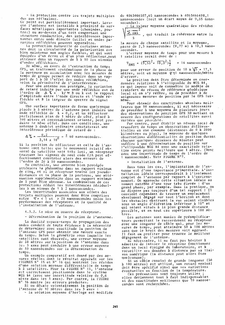
- La p r o t e c t i o n c o n t r e l e s t r a j e t s m u l t i p l e s dus aux r d f l e x i o n s . Cc p o i n t e s t p a r t i c u l i b r e ~ n e n t i m p o r t a n t . Lors- quc l ' a n t e n n e e s t i n s t a l l e e B p r o x i m i t e de s u r - f a c e s m d t a l l i q u c s i m p o r t a n t e s (chemin6es, pou- t r c s ) ou a u - d e s s u s d ' u n t o i t coniportant unc s t r u c t u r c c o n d u c t r i c e , d e s interferences impor- t a n t e s c n t r c ondc d i r e c t e ( u t i l e ) c t ondes pa- r a s i t c s r d f l 6 c h i c s pcuvcnt a p p a r a i t r c .
Ida protection n a t u r c l l c dc c c r t a i n e s a n t c n - n c s dont l a c i r c u l a r i t 6 de l a p o l a r i s a t i o n e s t b i c n maintcnuc aux a n g l c s f a i b l e s , c t q u i s o n t dquipdcs d ' u n d c r a n c t d ' u n p l a n r d f l e c t c u r , p e u t a t t b n u c r dans un r a p p o r t de 5 5 10 l e s n i v c a u x d ' o n d c s r b f l f c h i c s .
Dc mEmc, au c o u r s dc l l c x t r a c t i o n du temps CPS, un t r a i t c e l c n t s y s t d m a t i q u c d c l a phasc de l a p o r t e u s e cn a s s o c i a t i o n avec I c s mcsurcs de tcmps dc groupc pcrnlct dc r d d u i r c dans un r a p - p o r t de 5 5 30 l ' e f f e t d c s ondes r d f l d c h i e s , s c l o n l a p d r i o d i c i t d de l l i n t e r f d r e n c e .
Pour une a n t e n n c non p r o t d g b e , l a v a r i a t i o n dc r e t a r d i n d u i t e p a r une ondc r e f l e c h i e e s t de l ' o r d r e de A 2 = k/ n B ou k e s t l e r a p p o r t d ' a m p l i t u d e e n t r e l ' o n d e d i r e c t e e t l ' o n d e r d - f l d c h i c c t B l a l a r g c u r du s p c c t r c du s i g n a l GI's.
Unc s u r f a c c i m p o r t a n t e dc formo que lconquc p l a c d c 5 5 mht res de l ' a n t e n n e p e u t i n d u i r e une ondc r d f l d c h i c dc k = 0 , 2 , e t un r e f l c c t e u r p a r f a i t c n ~ c n t p l a n d c 1 mEtrc dc c b t d , p l a c d B 100 i ~ ~ b t r c s c t c o r ~ v c n a b l c ~ n c n t o r i c n t d , p c u t p r o - d u i r c Ic IIIEIIIC c f f c t . Dans c c s c o n d i t i o n s , unc a n t c n n c 5 d o u b l c t o r d i n a i r e c o n s t a t c r a i t unc i n t c r f ' d r c n c c p d r i o d i q u c de r c t a r d de :
nx = 0,2
= 2 60 nanosccondcs . 3 ,14 x lo6
S i l a p o s i t i o n du r 6 f l e c t c u r e t c e l l c de l ' a n - tcnric s o n t t c l l c s cluc I e Inouvcincnt r c l a t i f ob- sc rvd du s a t c l l i t c s o i t t r E s l c n t , un r d c c p t e u r t r a i t a n t l e s s i g n a u x du s e u l code C / A p c u t e f - f c c t i v e m c n t c o n s t a t e r a l o r s d e s e r r e u r s dc l ' o r d r e d c 20 B 50 nanosecondes .
Au c o n t r a i r c , unc a n t c n n c b i c n p r o t b g d e a t t b n u c r a l e phdnomknc dans un r a p p o r t minin~um dc c i n q , c t s i l e r d c e p t c u r t r a i t c l c s pscudo- d i s t a n c e s c t l a phasc dc l a p o r t c u s c , une a t t @ - n u a t i o n supp 16mcnta i rc dans un r a p p o r t nlinimunl de 5 p c u t s t r e o b t e n u e . La c o n ~ b i n a i s o n de c e s p r o t e c t i o n s r e d u i t l e s i n t e r f e r e n c e s r 6 s i d u e l - l e s 5 un n i v e a u de 1 & 2 nanosecondcs .
Lcs i n c e r t i t u d e s a s s o c i C e s aux e f f e t s d e s t r a j e t s m u l t i p l e s pcuvent donc S t r e c o m p r i s e s c n t r e T = < 1 e t > 20 nanosecondes s e l o n l e s per formances d e s r d c e p t e u r s e t l a q u a l i t d d c I ' i n s t a l l a t i o n de l ' a n t e n n c .
4 .3 .2 . La misc c n o c u v r c du r d c c p t e u r .
- Ddterrninat ion de l a p o s i t i o n de l ' a n t e n n e .
La d u a l i t @ cspace- temps dc p r o p a g a t i o n d e s ondes c o n d u i t dc t o u t e e v i d e n c e 5 l a n d c e s s i t b dc d e t e r m i n e r avcc e x a c t i t u d e l a p o s i t i o n de l ' a n t e n n e GPS pour o b t e n i r une mesure c x a c t e du temps. Se lon l a geomdtr ic sous l a q u e l l c l c s s n t c l l i t c s s o n t o b s c r v b s , une c r r c u r nloycnne dc 50 ~ n E t r c s s u r l a p o s i t i o n dc l ' a n t c n n c dans l c s 3 a x c s p e u t c o n d u i r e B une c r r e u r moyenne dc 50 nanosecondcs s u r l a d d t c r m i n a t i o n du tclnps.
Un exernple c o m p a r a t i f e s t donne p a r d e s me- s u r c s r d e l l c s dont l c r e s u l t a t a p p a r a i t s u r l c s h I G U R E S N o 15 c t N o 16 q u i mont ren t l c s r E s i d u s d ' u n c s o l u t i o n moycnnc d i f f d r c n t i e l l c de temps B 5 s a t e l l i t e s . Pour l a FIGURE N o 1 5 , l ' a n t e n n e c s t c o r r c c t c m c n t p o s i t ionndc dans l c s y s t b ~ n e WGS 54 (avec une i n c e r t i t u d e r e l a t i v e dc 0 , 6 mbtrc dans l e s 3 a x c s ) . P a r c o n t r e , l a FIGURE N o 16 montre l e s e r r e u r s p r o d u i t e s .
S i on d d c a l c v o l o n t a i r e m e n t l a p o s i t i o n de l ' a n t c n n e de 10 mbt res dans l e s 3 a x e s : - l a s o l u t i o n nioyenne d ' h o r l o g e e s t m o d i f i e e
de 4063466507,65 nanosecondes B 4063466498,l nanosecondes ( s o i t un k a r t moyen de 9 , 5 5 nano- s e c o n d e s ) .
- La v a l e u r moyenne q u a d r a t i q u e d e s r e s i d u s vFl q u i t r a d u i t l a c o h d r e n c e e n t r e l a
l a mcsure d c chaque s a t e l l i t e c t l a moyenne, p a s s e de 2 ' 3 nanosccondes ( 0 , 7 7 m) 5 1 0 , 3 nano- secondes .
L a e r r c u r moycnnc d c temps pour une mesurc 5 1 s a t c l l i t e s e r a i t donc de :
- - 2 1 TaMS - ( 9 , 5 s 2 + 1 0 , 3 )r = 14 nanosecondes
pour une c r r e u r de p o s i t i o n de 10 x = 1 7 , 3 m b t r e s , s o i t en moycnne ~ 2 1 nanoseconde/mGtre d ' e r r e u r .
La p o s i t i o n d o i t d t r e de te rn i in6e e n c o o r - donnbcs r c l a t i v e s 5 l ' e l l i p s o i d e du WGS 84 , c e q u i inlpose s o i t de c o n n a i t r e l e modele de t r a n s f e r t du r e s e a u de r e f e r e n c e gdodes ique l o c a l s i on s t y r e f e r e , ou de p r o c e d e r B de s o i g n e u s e s mesures de p o s i t i o n p a r l e GPS l u i - meme.
Pour o b t e n i r d c s c x a c t i t u d c s a b s o l u e s m e i l - l c u r e s que 10 n a n o s e c o n d e s , i l e s t n e c e s s a i r e dc p r o c e d e r 5 une moyenne do p l u s i e u r s j o u r s d c s o b s e r v a t i o n s de p o s i t i o n GPS 3D l n e t t a n t en o c u v r c d c s c o n f i g u r a t i o n s dc satellites a u s s i v a r i d c s quc p o s s i b l c .
Par c o n t r c , pour d t a b l i r un rEscau l o c a l dc t r a n s f c r t d c tcnlps e n o b s e r v a t i o n s d i f f d r c n - t i c l l e s cn vuc conimunc (distances d c 0 B 2000 k i l o n l E t r c s ou p l u s ) , l a moycnnc dc q u c l q u c s observations d i f f d r c n t i c l l c s dc p o s i t i o n d u r a n t chacunc q u c l q u c s d i z a i n c s de m i n u t e s p e u t s u f f i r c B unc d d t c r ~ l ~ i n a t i o n de p o s i t i o n s u r I ' c l l i p s o i d c WGS 84 a v c c unc e x a c t i t u d e r c l a - t i v c c n t r c p o i n t s n l c i l l c u r c quc 1 n k t r e . (Donc avec une i n c e r t i t u d e de temps de l ' o r d r e de 1 nanoseconde) . V o i r FIGURE N07.
- I n s t a l l a t i o n de l l a n t e n n e .
Dans t o u s l c s c a s , l ' i n ~ p l a n t a t i o n de I ' a n - t e n n e e s t d ' u n e impor tance p r i m o r d i a l e . L ' i n s - t a l l a t i o n i d d a l c c o r r e s p o n d r a i t B I ' i s o l e m c n t comple t de l l a n t c n n e p a r r a p p o r t B l ' e n v i r o n - nement. On approche c e t t e s i t u a t i o n i d e a l e au solnmet extrdnlc d ' u n e t o u r t r b s Blevde : d l u n grand p h a r e , p a r exemple. Dans l a p r a t i q u e , on ne d i s p o s e p a s t o u j o u r s d ' u n t e l s u p p o r t 1 I 1 c o n v i e n t c e p e n d a n t de t r o u v e r un emplacement abso lument degage s u r t o u t l ' h o r i z o n e t dont l e s o b s t a c l e s o b s t r u a n t l a vue s o i e n t v i s i b l e s sous un a n g l e d 1 B l 6 v a t i o n i n f e r i e u r 10' e t q u i s o i e n t s i t u d s B l a p l u s g rande d i s t a n c e p o s s i b l e , e t e n t o u t c a s s u p 6 r i e u r e 5 100 m E - t r e s .
Lcs a n t e n n e s s o n t munics d e p r e a m p l i f i c a - t e u r s p e r m e t t a n t l c raccordenlent a u r e c e p t e u r avec une longueur de c l b l e q u i , pour l c s nlc- s u r e s de temps, p e u t a t t e i n d r e 50 B 100 mEtres s a n s que l e b r u i t d c s mesures s o i t aggravd . I 1 f a u t en p r o f i t c r pour t r o u v e r l e m e i l l e u r ddgagement dc I ' a n t e n n e .
S i n d c c s s a i r c , i l ne f a u t p a s h d s i t c r 5 a d ~ n c t t r e dc l a i s s c r l e r d c e p t c u r f o n c t i o n n e r dans un l o c a l d l o i g n b du l a b o r a t o i r e , e t 5 r e c u c i l l i r s c s donnees 5 d i s t a n c e p a r s a l i a i - son numdriquc ( l a d i s t a n c c p e u t a l o r s e t r e q u e l c o n q u e ) .
S i un c l b l e c o a x i a l d c g rande longueur (50 5 100 mEtres) e s t u t i l i s 6 , son r e t a r d nominal d o i t S t r e s p d c i f i d a i n s i que s c s v a r i a t i o n s d v e n t u e l l e s en f o n c t i o n de l a t c m p b r a t u r e .
Ces p r d c a u t i o n s s o n t t o u j o u r s u t i l e s ; e l l e s d e v i e n n c n t t o u t B f a i t i n d i s p e n s a b l e s s i d e s e x a c t i t u d e s n l e i l l e u r e s que 10 nanose- condes s o n t r e c h e r c h e e s .
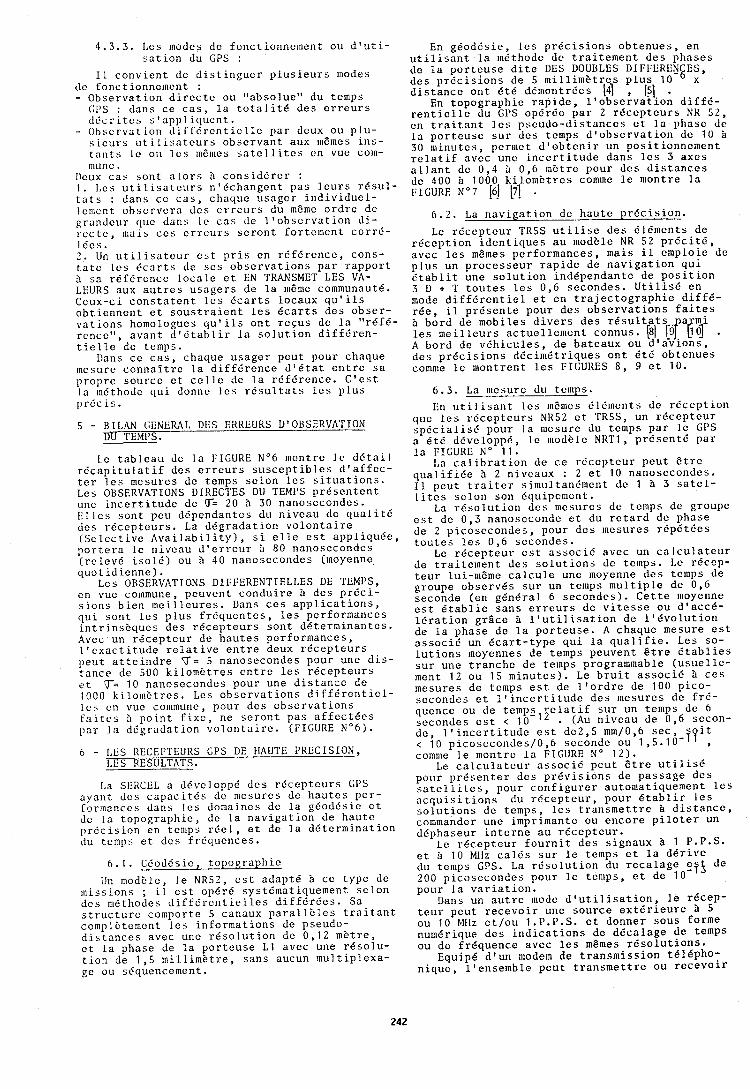
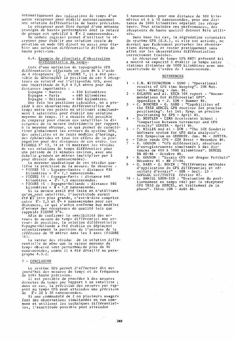
a u t o m a t i q u e n ~ e n t d c s i n d i c a t i o n s de temps d ' u n a u t r c r d c e p t c u r pour d t a b l i r a u t o ~ n a t i q u e m e n t unc s o l u t i o n d i f f e r c n t i e l l e de h a u t e p r 6 c i s i o n .
L C r d c c p t c u r p e u t B t r e equ ip6 d l u n e a n t e n n c pro tdgde dc h a u t c s per formances dont l e r e t a r d dc groupe e s t s p e c i f i d 3 6< 2 nanosecondes .
1111 rr~odulc l o g i c i c 1 pcrrnct d ' u t i l i s e r l e r 6 - c c p t c u r pour d t a b l i r une s o l u t i o n l o c a l e de 1'0s i t ion cn rnodc d i r e c t ou a u s s i pour 6 t a - b l i r une s o l u t i o n d i f f E r e n t i c l l e d i f f d r E e de h a u t c p r e c i s i o n .
6 . 4 . Excrnple de r d s u l t a t s d ' o b s c r v a t i o n d i f f d r e n t i c l l e du tcrnps.
Lors d ' u n e o p e r a t i o n dc t o p o g r a p h i c GPS d i f f d r e n t i c l l e c f i e c t u d e en j u i n 86 b l l a i d e dc 4 r d c c p t c u r s [7] , FIGURE 7 , i l a d t d pos- s i b l c dc d d t c r n ~ i n e r l a ~ o s i t i o n dc c e s 4 r d c e o - t c u r s cn r e l a t i f s u r l ' e l l i p s o i d e GPS, avec
*
unc i n c e r t i t u d e de 0 ,4 i 0 , 6 m e t r e pour d e s d i s t a n c e s i n l p o r t a n t e s :
Espagne - Nantes = 430 k i l o m k t r e s Espagne - P a r i s = 680 k i l o m e t r e s Espagne - Hol lande = 980 k i l o m k t r e s . Une f o i s l e s p o s i t i o n s c a l c u l 6 e s , on a p r o -
cddd 5 d c s o b s e r v a t i o n s d i f f e r e n t i e l l c s de temps e n t r e c e s p o i n t s e n u t i l i s a n t s i m u l t a n 6 - mcnt 5 s a t e l l i t e s pour 6 t a b l i r une s o l u t i o n moycnnc de temps. I1 a c n s u i t c E t E p o s s i b l c dc conlparcr pour chacun d c s s a t c l l i t c s l a d i - vcrgcncc dc s a nlcsurc i n d i v i d u c l l c p a r r a p p o r t b l a rnoycnnc o b t c n u c , c c q u i pcrrrlct de c a r n c t d - r i s c r g loba le r r~cn t l c s e r r e u r s du systitrnc GPS, d c s s a t e l l i t e s c t dc l e u r s moditles d ' h o r l o g e , d c s dphdnldridcs c t t o u s l c s c f f c t s d c l a p r o - p a g a t i o n pour d c s distances dc c c t o r d r c . Lcs l:I(;URES N o 13 , 14 c t 15 nlontrcnt l c s r d s i d u s dc c c s s o l u t i o n s de temps d i f f e r e n t i e l pour unc p d r i o d c de 25 m i n u t e s e n v i r o n , avcc une d c h c l l e g radude en mEtres ( m u l t i p l i c r p a r 3 pour o b t c n i r d c s nanosecondes) .
La moyenne q u a d r a t i q u e de c e s r 6 s i d u s qua- l i f i e l a p r d c i s i o n de l a mesure. On o b s e r v e : - FIGURE 13 : Espagne-Nantes : d i s t a n c e 430
k i l o m b t r c s = G= 1 , l nanoscconde. - FIGURE 14 : Espagne-Par i s : d i s t a n c e 680
k i l o m 8 t r e s = G= 1 , 3 nanosecondes . - FIGURE 15 : Es agne- t lo l lande : d i s t a n c e 980
k i l o n l k t r c s = 8= 1.8 nanoseconde. S i l a mesure a v a i t 6 t 6 f a i t e e n n ' u t i l i s a n t
q u l u n s e u l s a t e l l i t e , l ' i n c e r t i t u d e a u r a i t d t 6 f o i s p l u s g r a n d e , c ' e s t - 3 - d i r e compr i se c n t r e G= 2 , s e t F= 4 nanosecondes pour c e s d i s t a n c e s , c e q u i s ' a v b r e conforme aux modkles d l e r r e u r d e s r e c e p t e u r s de q u a l i t 6 t e l s que r a p p e l e s FIGURE N06.
A f i n de conf i r rner l a s e n s i b i l i t d d e s c r - r c u r s dc nicsure de temps d i f f d r c n t i c l aux c r - r c u r s dc p o s i t i o n , l a s o l u t i o n d i f f d r c n t i c l l e Bspagnc-l lol landc a d t 6 d t a b l i e en d d p l a c a n t v o l o n t a i r c m e n t l a p o s i t i o n d c l ' a n t e n n c de l a r d f d r c n c c de 10 rnbtres dans l e s 3 a x e s (FIGURE 1 6 ) .
La v a l e u r d e s r d s i d u s de l a s o l u t i o n d i f f 6 - r c n t i c 1 l e de n1Ea1e que l a v a l e u r moyennc du t c n ~ p s obscrvd s o n t p e r t u r b d e s d e p l u s de 10 nanosccondcs , comlnc i l a d t e d e t a i l 1 6 au p a r a - g r a p h ~ 4 .3 .2 .
7 - CONCLUSION
Lc systit~rlc GI's permct d l c f f c c t u c r dEs au- j o u r d ' h u i d e s nlcsures dc ternps e t dc f rEqucnce dc t r b s h a u t c p r d c i s i o n .
I 1 e s t p o s s i b l e de p r o c d d e r 3 d e s mesures d i r c c t c s du temps p a r r a p p o r t 3 un s a t e l l i t e ; dans c e c a s , l a p r d c i s i o n d e s nlcsurcs p a r r a p - p o r t a u temps GPS p e u t a t t e i n d r e une p r e c i s i o n dc LT= 20 3 30 nanosecondes .
S i une communaut6 de 2 ou p l u s i e u r s u s a g c r s f o n t d e s o b s e r v a t i o n s s i n l u l t a n e e s en vue con1- mune e t u t i l i s e n t l e s t e c h n i q u e s d i f f g r e n t i e l - l e s , l l e x a c t i t u d e p o s s i b l e p e u t a t t e i n d r e
5 nanosecondes pour une d i s t a n c e dc 500 k i l o - rnittres c t 6 i 10 nanosecondes , pour unc d i s - t a n c e de 2000 k i l o ~ n i t t r e s s 6 p a r a n t l e s r 6 c e p - t e u r s . Pour a t t c i n d r e c e s p e r f o r m a n c e s , d c s r d c e p t e u r s de h a u t c q u a l i t d d o i v e n t 6 t r e u t i l i - s d s .
Dans t o u s I c s c a s , l a d d g r a d a t i o n v o l o n t n i r c du s y s t b ~ n e GI's ( S . A . ) , s i e l l e e s t a c t i v d c , ne d c v r a i t quc f a i b l c l n c n t p c r t u r b c r l e s o b s c r v a - t i o n s d i r e c t e s , e t r e s t e r p r a t i q u c m e n t s a n s c f f e t s u r l c s o b s e r v a t i o n s d i f f d r c n t i e l l e s c o r r e c t c ~ n e r ~ t t r a i t d c s .
Lc r d c e p t e u r d c temps GPS NRT1 p r d s c n t d i c i a montrd s a c a p a c i t d 3 d t a b l i r l e tcmps c n t r e s t a t i o n s d i s t a n t e s d c 1000 k i l o m k t r e s a v e c unc i n c e r t i t u d e d c l ' o r d r e d c 1 nanobccondc.
REFERENCES
F.N. WITHINGTIION - USNO : " O p e r a t i o n a l r e s u l t s o f GI's t i m e keep ing" . ION Nat. t e c h . Meeting - J a n . 86. KALAFUS and a l . RTCM 104 r e p o r t : "Recom- menda t ions f o r d i f f e r e n t i a l GPSol. Appendice b - J. ION - Summer 86. C . BOUCHER - G. NARD : " C a p a b i l i t i e s o f t h e TR5S SERCEL GPS r e c e i v e r f o r p r e c i s e p o s i t i o n i n g " . 1 s t I n t . Symp. on p r e c i s e p o s i t i o n i n g by GPS - A p r i l 85. G . BEUTLER - CERN A c c e l e r a t o r School : "Co~nparison bctwcen t c r r a n ~ c t c r and (;PS r e s u l t s " GENEVA - A p r i l 86. 1). WILLIS and a 1 - IGN : "The IGN G c o d c t i c S o f t w a r e systcln f o r GPS d a t a a n a l y s i s " . 4 t h Symposium on GEODESY. J a n . 86 - AUSTIN. Table rondc GI's - COB B r c s t - Novc~r~brc 8 6 . R . GOUNON : "GI'S d i i f 6 r c n t i c 1 , r d s u l t o t s d ' e n r c g i s t r e ~ ~ l c n t s s i m u l t a n 6 s i d e s d i s - t a n c e s de 400 3 1000 k i lomi? t rcs" . SERCCL RN 80-86 - O c t o b r e 86. R. GOUNON : " E s s a i s GI's s u r d r a g u e I ' c r thu is" DBcembrc 85 - RN 27-86. G. NARD - G . BONIN : " D i f f B r c n t e s mCthodes d l a p p l i c a t i o n du GPS d i f f e r e n t i e l e t r b - s u l t a t s d ' e s s a i s " - SEE - S e c t . 23 - SUPELEC GIF/YVETTE F E v r i e r 87. L . DANIEL StIOM-IGN : " E v a l u a t i o n du p o s i - t ionnement en temps r e e l p a r l e r e c e p t e u r CPS TR5S de SERCEL, e t t r a i t e m e n t de l a phase1'. These IGN - AoOt 86.
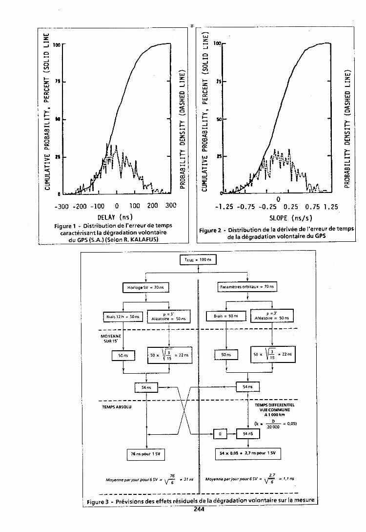
DELAY (ns) Figure 1 - Distribution de I'erreur de temps
caracterisant la degradation volontaire
W
n W
z A
n W x ln u n V
i= - ln r W n
i= Y A U m 9m 0 p: n.
0 -1.25 -0 .75 -0.25 0.25 0 .75 1 - 2 5
SLOPE (ns/s)
Figure 2 - Distribution de la derivee de I'erreur de temps de la degradation volontaire du GPS
Horloge SV = 70 ns 11 Parametres orbitaux = 70 ns It
MOYENNE I
TEMPS ABSOLU
Moyenne parlourpour 6SV = 6 =31ns
Aleatoire = 50 ns
TEMPS DIFFERENTIEL VUE COMMUNE
A 1 000 krn
1 54 x 0,OS = 2.7 ns pour I SV
Moyenne parjourpour 6SV = 8 = 1,Ins
Figure 3 - Previsions des effets residuels de la degradation volontaire sur la mesure I 244 -
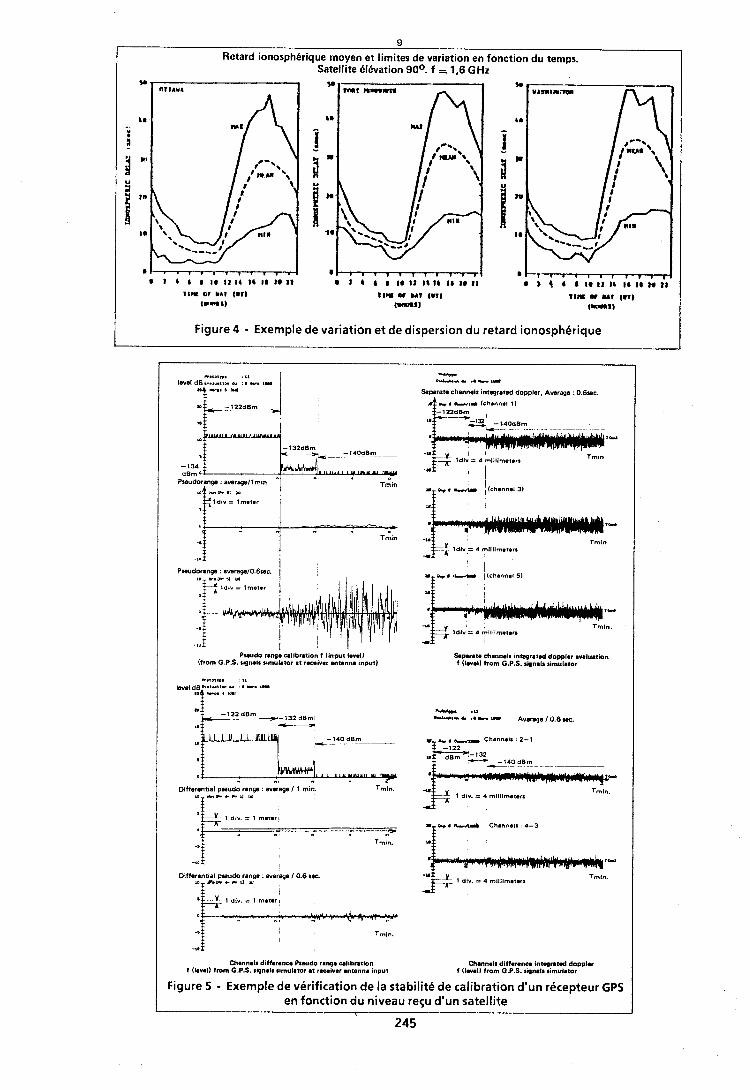
9
Retard ionosphdrique moyen et limites de variation en fonction du temps. Satellite Bldvation 90°. f =. 1,6 GHz
I Figure 4 - Exemple de variation et de dispersion du retard ionospherique
C I I D l l S . : 8 ,
level dB r..xu.un w : 8 r. 8 -
.-O' '
"rr t- r I.- I"
Saperale channel1 integrated doppler, Awrage : O.6re. R e r -- (chann.~ 1 I
Pawdo rawm u l ibnt ion f [input Irvell lfrom G.P.S. sqwls simulator at rmivar antenna input)
Differentla1 pseudo range : average / 1 min. Trnln. 1 0 1 - ~ a c r v w
z I+& 1 ~ I V . = I met.rl
I 2
- 0 ; Tmin.
t -a*$ I
Differential pseudo range : werage 10.6 w. 1 O 5 " U C ~ ' 1 W
1 dl", = 1 meUri
Channel1 diffarense Pswdo rang. callbratian f Ilavall from G.P.S. signal1 rimulator at recaiver antenna input
,,.., P",.l i . , . . ., - 71,',..1.
Tmln
Tmln
Soperate channels tnt.prated doppler avaluatwn f Ilevalb from G.P.S. rqnals r8mulator
I + # MI Channels: 4-3
I
-"g* 1 dl". = 4 mlt~imrer. Tmln.
*
Chmnall diffmranm intqratad dopplat f I lna l l from G.P.S. sipwlc simulator
Figure 5 - Exemple de verification de la stabilite de calibration d'un recepteur GPS en fonction du niveau regu d'un satellite
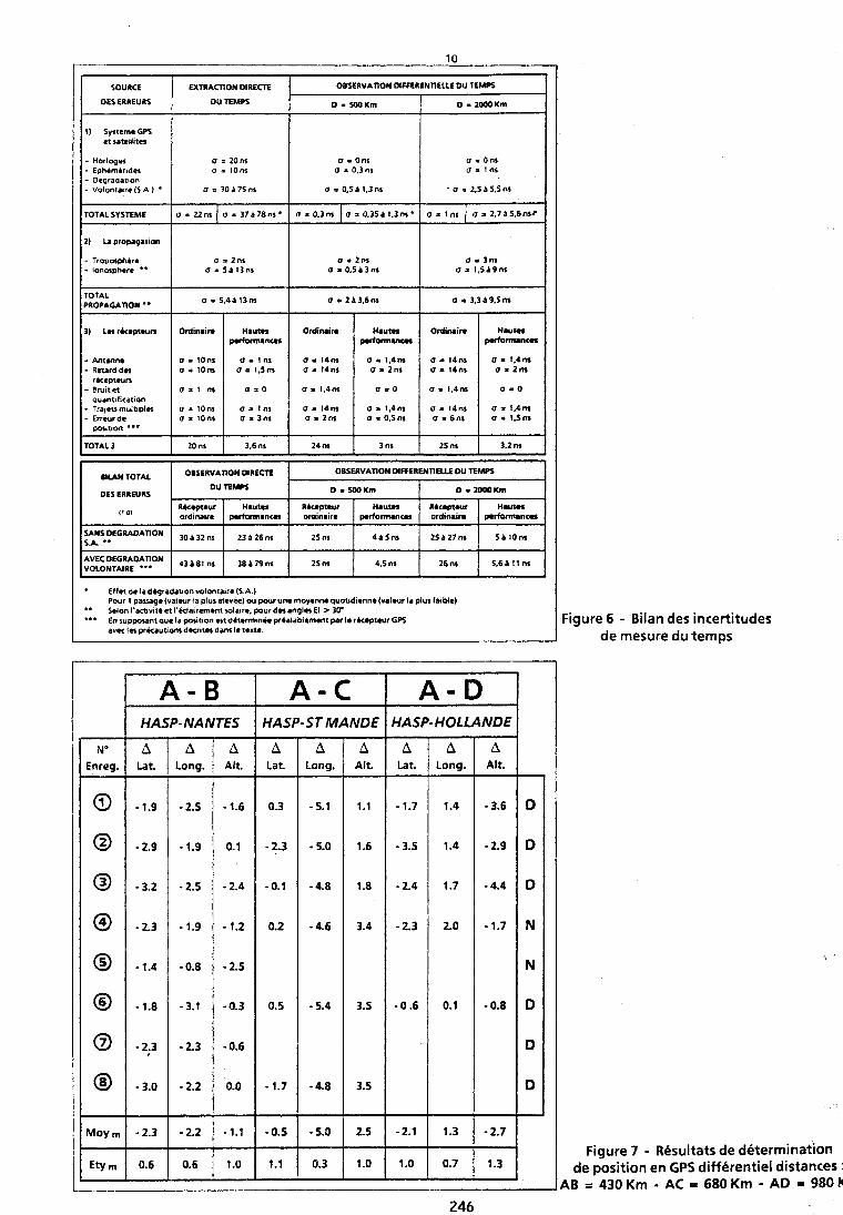
1) SystimeGPS et satellites
SOURCE EXTRACTION OlRECE
OES ERREURS OU TEMPS
o = Ons o i 0.3 ns
a a 0.51 l,3ns
OBSERVATION DIFFERENTIELLE DU TEMPS
0.500Km
TOTALSYSTEME
2) l a propagation
I - Antenna - Retard d n 1
0.2MX)Km
TOTAL PROPAGATION **
r k e p t w n - B m ~ t e t o r 1 m a .0 a r 1,411s 0.0 o r 1 . 4 ~ O r 0 quanufieation
1-Traj.tsmuIt~pln - Enrur d r 1 ::I:: 1 ~JJ;:: 1 ::.: I a = l , 4 n s a 0.5 ns 1 1 Q r 1 , 4 1 ~ a r 1,Snr I
U i 2 2 n s
o r 5.4A 13ns
I
o = 3 7 1 7 8 n s '
IUN TOTAL
DES ERREURS
a r 2a3.6ns
I
SANS OEGRADAnON S.A. **
DEGRADAnON VOLONTAIRE ***
Figure 7 - Resultats de determination de position en GPS differentiel distances :
AB r 430 Km - AC = 680 Krn - AD = 980 KIT
a r 0 . 3 n s
a = 3.3 A 9.5 ns
I
OBSERVATION MRECTE
OU TEMPS
Effet d r lad6gradation voionca~re(S A Pour 1 pasaga (valwr ha plus elevre) w p w r un* moyenno quot~d imne(va iwr la plus fa~bl*)
" Sdon i 'ac t~v~td et I'(tlairemenc sola~r*, pour dnang1.r El > 30' ..* En suppount qu. I. portion ~t d6trrmlnro prtalablemmt par I* rh*pt*urGPS
avec I n prkaut tom d k n t n danr I. t rx t r . -
30 132 ns
A3 A 81 ns
Figure 6 - Bilan des incertitudes de mesure du temps
a80.35P1.3os*
OBSERVATION OlFFERENTlELLE OU TEMPS
o i l n s
0. W K r n
23 P 26 ns
38 4 79 ns
0 lWOKrn
25 m
25 m
4a5ns
4,s ns
2 5 6 2 7 m
26 nr
J
5a10ns
5.6 1 I 1 m A
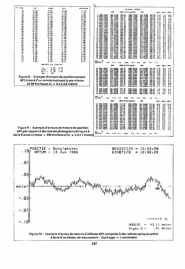
P? Yep. La1 Lenp A l l Disrane.
.vs2. IVb7N 4-2. IV79N mar. IWVU
Figure 8 - Exernple d'erreurs de positionnernent GPS a bord d'un carnion Bvoluant une vitesse
de 80 Krnlheure (a = 0,3 0,6 metre)
BEGINTIJD = 12:33:00 EINDTIJD = 12:38:29
.-
(vI4
----- > n tIOOG'I'E = 4 3 . 1 1 mat c I- Sigma t l :; ..B1 mc tc l -
Figure 10 - Exernple d'erreur de rnesure d'altitude GPS cornparee des releves optiques precis 3 bord dSun bateau en rnouvernent - Ecart type = I centirnktre
Figure 9 . Exempie deerreurs de mesure de position GPS par rapport a des releves photograrnrnetriques 4
bord d'avion (vitesse = 300 Krniheure) (a = 0,4 a 1 metre)_
49 4U1.957WI 22S.SU3C 718 .W 49SSeT5Ull 22l .SObU 7 l l . 7 6 -1.8 1.8 -1.9 11 a9Sz.97lw 2 2 I . a I T U 71b.b. 4CIl.9711*' 121.31711 7 I7 . tP -2.. 1.2 -8.S 01 4 m . w ~ ~ m . m z n e 724 .m ~TSZ.VVOIM ZZI.OO*QE 7m.a* -1.0 1.6 1.2 sz 4 ~ 3 . 1 8 7 ~ ZZI.L.~VC 7 a 1 . o ~ 4*aa.aaaa* ZII.LLLU 7 1 1 . 1 ~ -1.3 1.1 0 .0 S l 4VS3.0lV7ll 221.1lS7C 74S.46 4TSZ.8213U. 221.1134R 744.41 -1.1 1.B 1.1 a4 4 T S l . # l l l ~ 2I?.w7LC 749.1b 4TSl.@llOM al9.WS4C 7a7.01 -1.3 2.b 1 . 5 SS4*$1.041% 219.bST71 7Sl .04 4VS3.1444M ClT.bS7SC 7S1.Sl -1.7 2.b 1 . 1 PL4VS3.DS41N PIV.12sZC 7S1.29 4.53.1SSIM ZIT. lZb3C 749.96 -1.9 2.3 1 .3 S7 49S1.0071N '218.9.49C 7S7 .? lb 4TS1.1S79N 2 [email protected] l1 %.?I -1.7 2.Z 1.2 SO ~ * S S . ~ Z Z ~ M 21m.basac' 741.41 a m . 1 ~ 4 9 1 1 2 1 a . b ~ ~ 748.11 -1.9 2.4 1 .3 59 49Zl.OSllN 2I8.2PlLL 72Y.1b IT¶l .OSIIM 2I8.2m4C 727.b. ,-1.7 2.6 1.3 61 a t a a . 1 4 ~ 1 ~ a 1 7 . w ~ ~ r a o . 9 ~ w a r . s r 7 p a 1 7 . v n n 737.78 -1.9 2 . r 1 .1 b I 49I1.0434W 217.704bC 7S3.11 4T¶T.D442M 217.702DC 701.04 -1.7 5.5 1.1 62 .~SJ.O~I I I I 217 abb41 7~1.79 a n 3 . 8 u o ~ r t r . s b 4 u 784.43 -1.7 a . 1 I .a 63 4*Sa.#lVY 2Ib.VPIlE 749.bV 4TSl.1404Y 1Lb.9VbY 74I.3u -1.7 2.0 I .4 bb l*Sl.8lS*N 2Ib.bZbbE 7 *3 .b I 49O1.1170M ZIb.bZ4X 742.31 -2.1 1.1 1.3 bS "S3.#33W 21b.24DZE 7S3.00 443.0140M 511.PlOlC 7:2.31 -1.9 5.4 1.1 bb I IS1 .8Z lm 2 I S . l 4 Y I i 73M.ZS 4901.1108M 21S.04411 7lb.20 ed.1 a.6 2.0
, I , , L.nq , , A,, ,.7
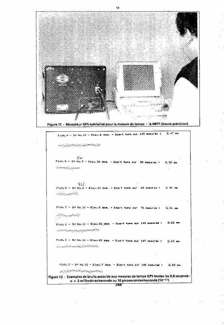
Figure 11 - Rbcepteur GPS spbcialisb pour la mesure du temps : le NRTl (haute prbcision)
cc4 F i c h . 3 - SU 1.10. 3 - Eleu. 38 der. - Ec8t-t twrr sur EI8 aesures : 2. 38 mn,
."'. . ,. ..<:.- ;.,.,+ ?': .: ,..-..; .......
r.d F i c h . S - SU 140. 6. - Eleu. 14 der. - Ecart twpe sur 69 assures : 2. 96 m s
. . .. ,,,.:; ...:..:..: .':. . .
F i c h . 7 - SV 140. 11 - Eleu. E: der. - Ecart tvpe sur 76 arsurer 1 5. 31 mu,
F i c h . 1 - SV No. 11 - Eleu.32,dcr. - Ecart twro sur 149 mcsures 8 2.62 m n ~
. . . . . ......... ;,;.. .. ,.:-,,.-, ;y..;; -4.. :.:.::*i-.:.~'-.\.-.. .. . . . . . . . . . . . . . .
I F i c h . 2 - $11 140. 12 - Elru. 7 drr. - Ecort t v ~ e rur 146 aesuraz 3 2.93 mn, I ......:; ',..;~,;-~;:,;..-:.:;:,~.:.~ ..-., .:.. .... .-.... :'.. . . ....... . . . . . ..* ,.., . .".',.
Figure 12 - Exemples de bruits associ6s aux mesures de temps GPS toutes les 0,6 seconde : a = 3 millim&treslseconde ou 10 picosecondeslseconde (10-11)
L48
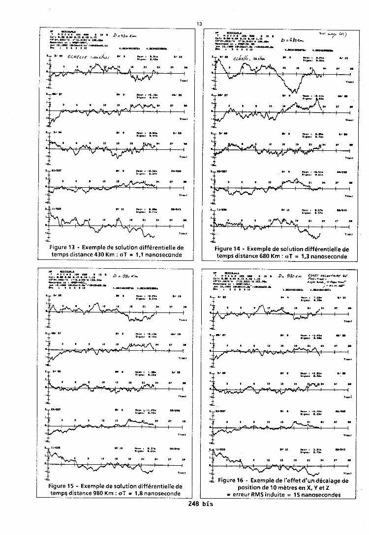

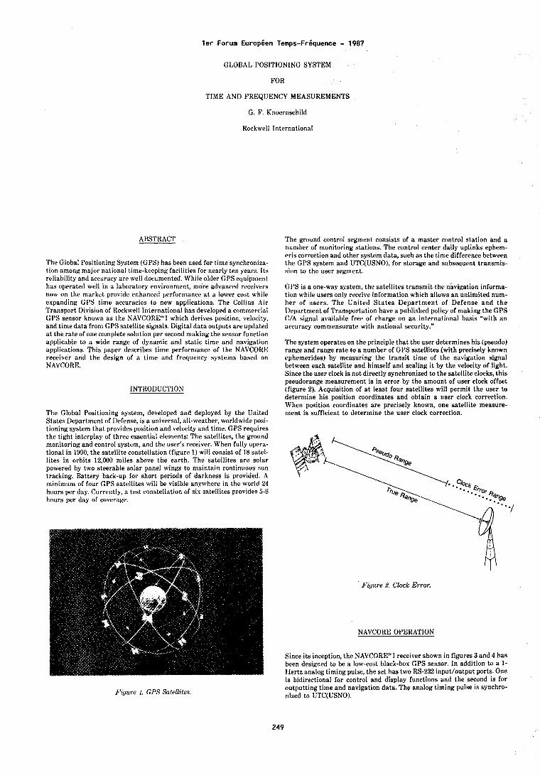
l e r Forum Europien Temps-Friquence - 1987
GLOBAL POSITIONING SYSTEM
FOR
TIME AND FREQUENCY MEASUREMENTS
G. F. Knoernschild
Rockwell International
ABSTRACT
The Global Positioning System (GPS) has been used for time synchroniza- tion among major n;~tional time-kccping facilities for nearly ten years. Its reliability and accuracy are well tlocumented. While older GPS equipment has operated well in a laboratory environment, more advanced receivers now on the market provide enhanceti performance a t a lower cost while expanding G1'S time accuracies to new applications. The Collins Air Transport Division of Rockwell International has developed a commercial GPS Yensor known as the NAVCORCUI which derives position, velocity, and time data from GPS satellite signals. Digital dataoutputs are updated a t the rate of one complete solution per second making the sensor function applicable to a wide range of dynamic and static time and navigation applications. This paper describes time performance of the NAVCORE receiver and the design of a time and frequency systems based on NAVCORE.
INTRODUCTION
The Global Positioning system, developed and deployed by the United States Department of Defense, is a universal, all-weather, worldwide posi- tioning system that provides position and velocity and time. GPS requires the tight interplay of three essential elements: The satellites, the ground monitoring and control system, and the user's receiver. When fully opera- tional in 1990, the satellite constellation (figure 1) will consist of 18 satel- lites in orbits 12,000 miles above the earth. The satellites are solar powered by two steerable solar panel wings to maintain continuous sun tracking. Battery back-up for short periods of darkness is provided. A minimum of four GPS satellites will be visible anywhere in the world 24 hours per day. Currently, a test constellation of six satellites provides 5-8 hours per day of coverage.
Filjuve I . GPS Satellites.
The ground control segment consists of a master control station and a number of monitoring stations. The control center daily uplinks ephem- eris correction and other system data, such a s the time difference between the GPS system and UTC(USNO), for storage and subseouent transmis- sion to the user segment.
GPS is a one-way system, the satellites trensniit the navigation infornia- tion while users only receive information which allows an unlinlited num- ber of users. The United S t a t e s Depar tment of Defense and the Department of Transportation have a puhlished policy of making the GPS C/A signal available free of charge on an international basis "with an accuracy commensurate with national security."
The system operates on the principle that the user determines his (pseudo) range and range rate to a number of GPS satellites (with precisely known ephemerides) by measuring the transit t ime of the navigation signal between each satellite and himself and scaling i t by the velocity of light. Since the user clock is not directly synchronized to the satellite clocks, this pseudorange measurement is in error by the amount of user clock offset (figure 2). Acquisition of a t least four satellites will permit the user to determine his position coordinates and obtain a user clock correction. When position coordinates are precisely known, one satellite measure- ment is sufficient to determine the user clock correction.
F iy t~ re 2. Clock E ~ ~ r o r .
NAVCORE OPERATION
Since its inception, the NAVCORE" I receiver shown in figures 3 and 4 has been designed to be a low-cost black-box GPS sensor. In addition to a 1- Hertz analog timing pulse, the set has two RS-232 input/output ports. One is bidirectional for control and display functions and the second is for outputting time and navigation data. The analog timing pulse is synchro- nized to lJTC(USN0).
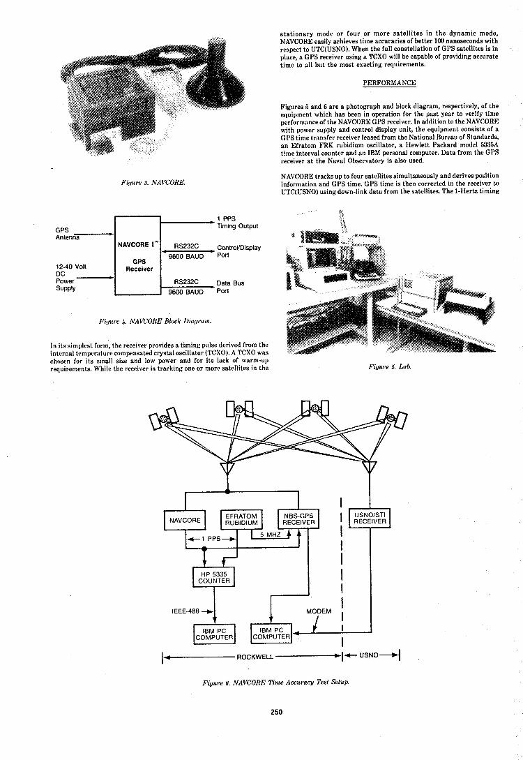
Filjzwe 8. NAVCORE.
1 PPS Timing Output
Control/Display Port
Data Bus port
Fi!ju I-(, 4 NAVCORE Block 1)ircuvrc I!/.
In its simplest form, the receiver provides a timing pulse derived from the internal temperature compensated crystal oscillator (TCXO). A TCXO was chosen for its snlall size and low power and for its lack of warm-up requirements. While the receiver is tracking one or more satellites in the
s ta t ionary mode o r four o r more sa te l l i tes in t he dynamic mode, NAVCORE easily achieves time accuracies of better 100 nanoseconds with respect to UTC(USN0). When the full constellation of GPS satellites is in place, a GPS receiver using a TCXO will be capable of providing accurate time to all but the most exacting requirements.
PERFORMANCE
Figures 5 and 6 are a photograph and block diagram, respectively, of the equipment which has been in operation for the past year to verify time performance of the NAVCORE GPS receiver. In addition to the NAVCORE with power supply and control display unit, the equipment consists of a GPS time transfer receiver leased from the National Bureau of Standards, an Efratom FRK rubidium oscillator, a Hewlett Packard model 5335A time interval counter and an IBM personal computer. Data from the GPS receiver a t the Naval Observatory is also used.
NAVCORE tracks up to four satellites simultaneously and derives position information and GPS time. GPS time is then corrected in the receiver lo UTC(USN0) using down-link data from the satellites. The 1-Hertz timing
Fifjure 5. Lab.
IEEE-488 -+
ROCKWELL -----If USNO-~
Figure 6. NAVCORE Time Accuracy Test Setup.
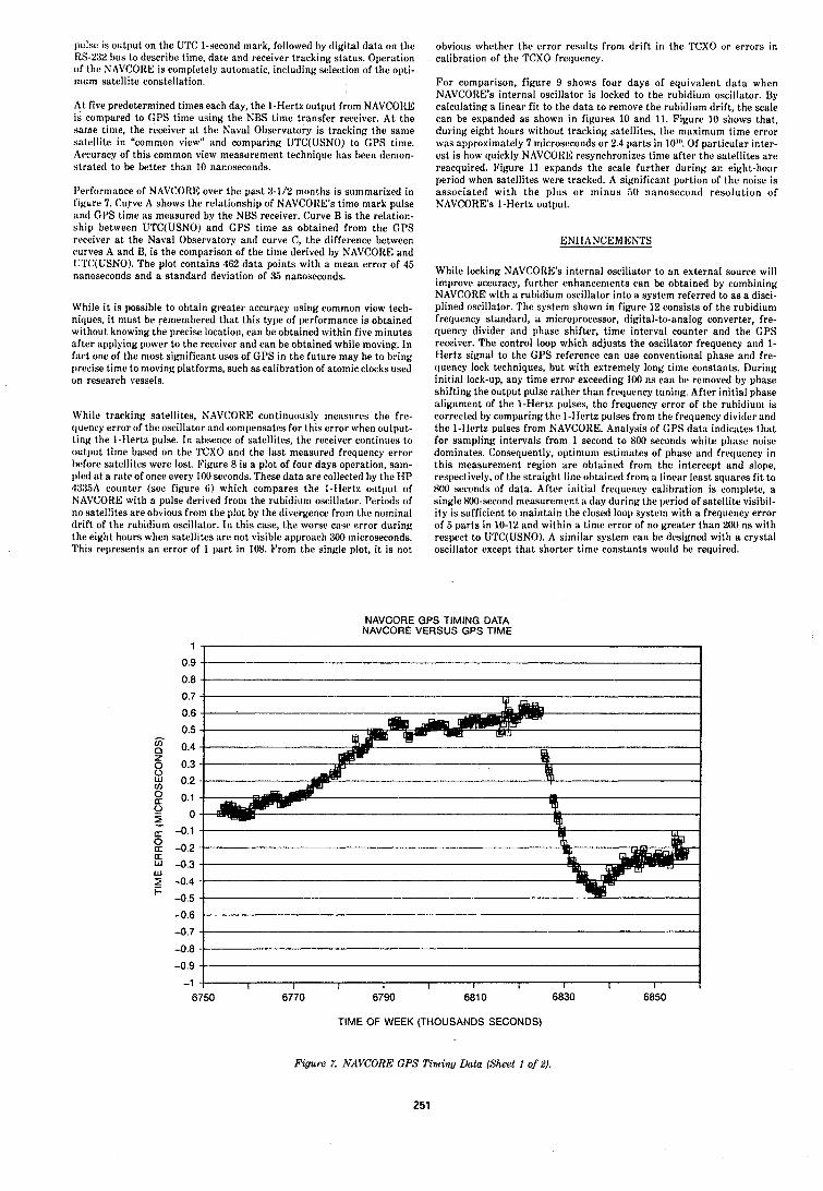
~ ~ ~ l s e is output on the UTC 1-second mark, followed by digital data on the RS-232 bus to describe tirne, date and receiver tracking status, Operation of the NAVCORE is completely automatic, including selection of the opti- mum satellite constellation.
At five predetermined times each day, the 1-Hertz output from NAVCORE is compared to GPS time using the NBS time transfer receiver. At the sarne time, the receiver a t the Naval Observatory is tracking the same satellite in "common view" and comparing UTC(USN0) to GPS time. Ac~curacy of this common view measurement technique has heen denion- stratetl to be better than 10 nanoseconds.
I'erformance of NAVCORE over the past 3-1N months is summarized in S~gure 7. Curve A shows the relationship of NAVCORE's time mark pulse ant1 GPS time as measured by the NBS receiver. Curve B is the relation- ship between UTC(USN0) and CPS time a s obtained from the GPS receiver a t the Naval Observatory and curve C, the difference between curves A and B, is the comparison of the time derived by NAVCORE and II'PC(USN0). The plot contains 462 data points with a mean error of 45 nanoseconds and a standard deviation of 35 nanoseconds.
While it is possible to obtain greater accuracy using common view terh- niques, i t must be remembered that this type of performance is ohtained without knowing the precise location, can be obtained within five minutes after applying power to the receiver and can be obtained while moving. In fact one of the most significant uses of GPS in the future may be to bring precise time to moving platforms, such a s calibration of atomic clocks used on research vessels.
While tracking satellites, NAVCORE continuously measures the fre- clutAncy error of the oscillator and compensates for this error when output- ting the I-Ilertz pulse. In absence of satellites, the receiver continues to output time based on the TCXO and the last measured frequency error br!fore satellites were lost. Figure 8 is a plot of four days operation, sam- pled a t a rate of once every 100 seconds. These data are collected by the H P .15:IRA counter (see figure 6) which compares the I-Ilertz output of NAVCOKE with a pulse derived from the rubidium oscillator. Periods of no satellites are obvious from the plot by the divergence from the nominal drift of the rubidium oscillator. In this case, the worse case error during the eight hours when satellites are not visible approach 300 microseconds. This represents an error of 1 part in 108. From the single plot, it is not
obvious whether the error results from drift in the TCXO or errors in calibration of the TCXO frequency.
For comparison, figure 9 shows four days of equivalent da t a when NAVCORE's internal oscillator is locked to the rubidium oscillator. By calculating a linear fit to the data to remove the rubidium drift, the scale can be expanded a s shown in figures 10 and 11. Figure 10 shows that, during eight hours without tracking satellites, the maximum time error was approximately 7 n~icroseconds or 2.4 parts in 10"'. Of particular inter- est is how quickly NAVCORE resynchronizes time after the satc.llites are reacquired. Figure 11 expands the scale further during an eight-hour period when satellites were tracked. A significant porlion of the noise is associated with the plus o r minus 50 nanosecond resolution of NAVCORE's 1-Hertz output.
ENHANCEMENTS
While locking NAVCORE's internal oscillator lo an external source will improve accuracy, further enhancements can be obtained by combining NAVCORE with a rubidium oscillator into a svstem referred to a s a disci- plined oscillator. The system shown in figureVl2 consists of the rubidium frequency standard, a microprocessor, digital-to-analog converter, fre- quency divider and phase shifter, time interval counter and the CPS receiver. The control loop which adjusts the oscillator frequency and 1- Hertz signal to the GPS reference can use conventional phase and fre- quency lock techniques, but with extremely long time constants. During initial lock-up, any time error exceeding 100 ns can be removed by phase shifting the output pulse rather than frequency tuning. After initial phase alignment of the 1-Hertz pulses, the frequency error of the rubitlium is corrected by comparing the 1-Hertz pulses from the frequency divider and the 1-Hertz pulses from NAVCORE. Analysis of GPS datil indicates that for sampling intervals from 1 second to 800 seconds white phase noise dominates. Consequently, optimum estimates of phase and frequenry in this measurement region are obtained from the intercept and slope, respectively, of the straight linr obtained from a linear least sc1uarc.s fit to 800 seconds of data. After initial frecluency calibration is coniplc.te, a single 800-second measurement a day during the period of satellite visibil- ity is sufficient to maintain the closed loop system with a frequency error of 5 parts in 10-12 and within a time error of no greater than 200 ns with respect to UTC(USN0). A similar system can be designed with a crystal oscillator except that shorter time constants would be required.
NAVCORE GPS TIMING DATA NAVCORE VERSUS GPS TlME
TlME OF WEEK (THOUSANDS SECONDS)
Figure 7. NAVCORE GPS Timing Data (Sheet I of 2).
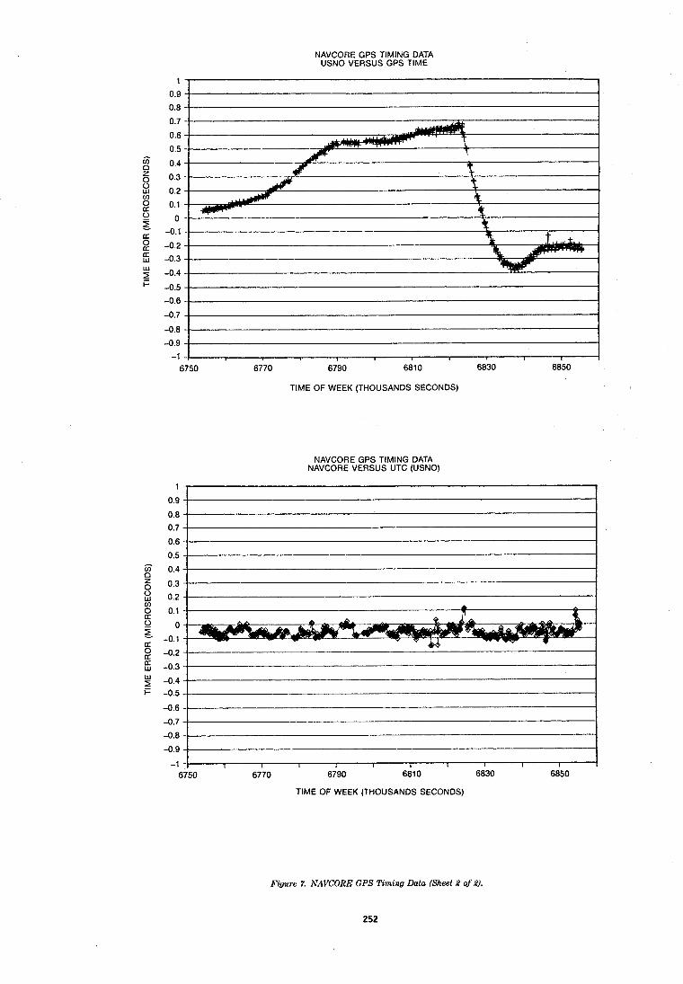
NAVCORE GPS TIMING DATA USNO VERSUS GPS TlME
TlME OF WEEK (THOUSANDS SECONDS)
NAVCORE GPS TIMING DATA NAVCORE VERSUS UTC (USNO)
TlME OF WEEK (THOUSANDS SECONDS)
Figure 7. NAVCORE GPS Timing Data (Sheet 2 qf 2).
252
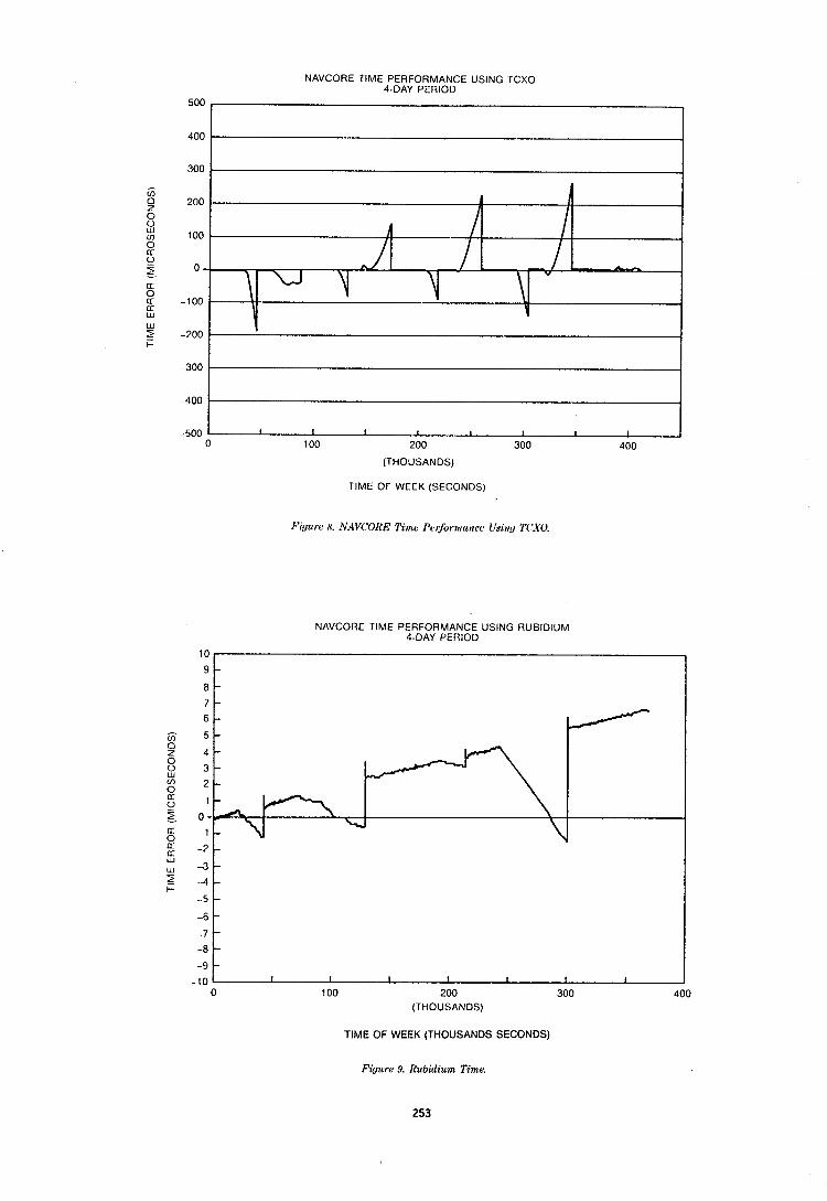
NAVCORE TlME PERFORMANCE USING TCXO 4-DAY PERIOD
-500 1 I I I I I I
0 100 200 300 1
400
(THOUSANDS)
TlME OF WEEK (SECONDS)
I'iu?~rc 8. NAVCOItE Timc 1'o~'ormtrncc Uyi~tv T('X0
NAVCORE TlME PERFORMANCE USING RUBIDIUM 4-DAY PERIOD
-10 1 I I I t I I I I 0 100 200 300 400
(THOUSANDS)
TlME OF WEEK (THOUSANDS SECONDS)
Figure 9. Rubidium Time.
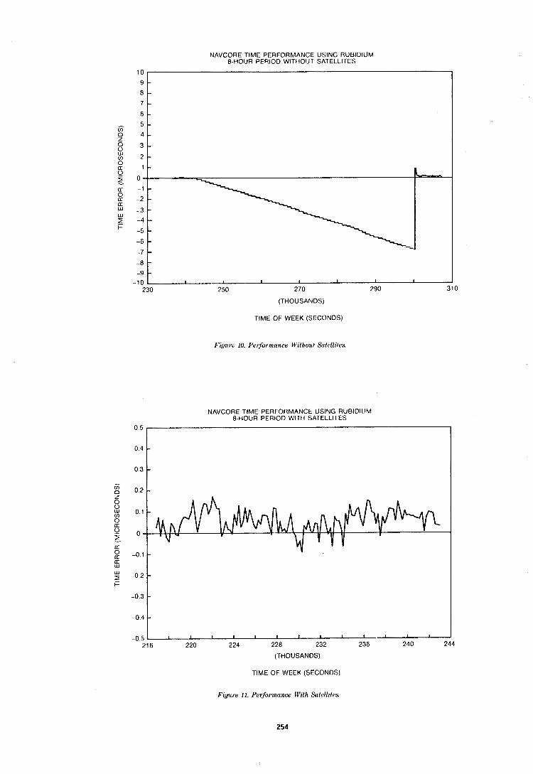
NAVCORE TlME PERFORMANCE USING RUBIDIUM 8-HOUR PERIOD WITHOUT SATELLITES
TlME OF WEEK (SECONDS)
10
9 8
7
6
5 4
3
2
-8 -9
-10
Pi~ul'e 10. P ~ ' ~ f o r m ~ n c i , Without S(ilc1lilcs.
- - - - - - - -
- -
I I I 1 I I I
NAVCORE TlME PERFORMANCE USING RUBIDII!M 8-HOUR PERIOD WITI-I SATELLITES
230 250 270 290 310
(THOUSANDS)
-0.4, , , I -0 5 216 220 224 228 232 236 240 244
(THOUSANDS)
TlME OF WEEK (SECONDS)
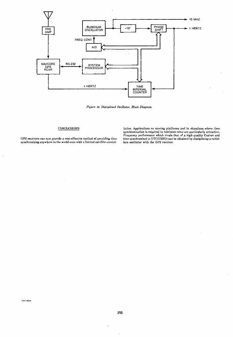
10 MHz
1 HERTZ
7
Figure 12. Disciplined Oscillato~; Block Diauram.
CONCLUSlONS lation. Applications on moving platforms and in situations where time synchronization is required in minimum time are particularly attractive. Frequency performance which rivals that of a high quality Cesium and
(;PS receivers can now provide a cost-effective method of providing timc time synchronized to UTC(USN0) can he obtained by disciplining a rubitl- synchronizing anywhere in the world even with a limited satellite constel- ium oscillator with the CPS receiver.
C I
NAVCORE GPS
RCVR - v
1 HERTZ TIME . + INTERVAL *
RS-232 - SYSTEM PROCESSOR
C
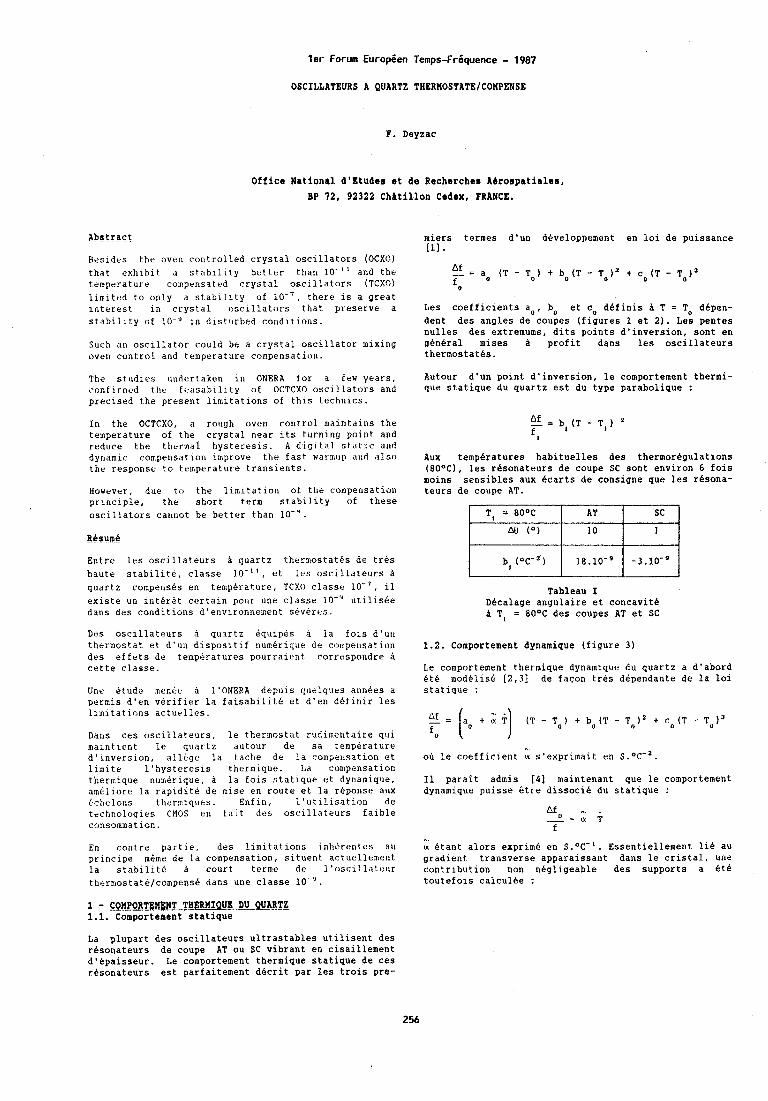
ler Forum Europeen Temps-Friquence - 1987
OSCILLATEURS A QUARTZ THERMOSTATE/COUPENSE
F. Deyzac
Office National d'dtuder et de Recherche8 k6rorpatialer, BP 72, 92322 Chatillon Cedex, FRANCE.
Abstract miers termes d'un developpement en lo1 de puissance r , 3 L A 1 .
Besides the oven controlled crystal oscillators (OCXO) that exhibit d stability better than lo-'' and the a f = a. (T - To) + bo(T - TOl2 + cO(T - temperatur? compensated crystal oscillators (TCXO) o limited to only a stability of lo-', there is a great interest in crystal oscillators that preserve a Les coefficients a,, bo et cO definis A T = To dhpen- stability of lo-'' rt~ disturbed conditions. dent des angles de coupes (figures 1 et 2 ) . Les pentes
nulles des extremums, dits points d'inversion, sont en Such an oscillator could be a crystal oscillator mixing general mises a profit dans les oscillateurs oven control and trtmperature compensation. thermostaths.
'phe studies undertaken in ONERA for a few years, Autour d'un point d'inversion, le comportement thermi- conf irincd t h e fizasabil~ ty of OCTCXO oscillators and que statique du quartz est du type parabolique : precised the present limitations of this technics.
In the OCTCXO, a rough oven control n~alntdlns the af = b,(T - TI) temperature of the crystal near its turning point and reduce the thermal hysteresis. A dlgltal static and
f t
dynamic compensation improve the East watrnup and also Aux temperatures habituelles des thermor6gulations the response to temperature transients. (80°C), les r6sonateurs de coupe SC sont environ 6 fols
moins sensibles aux ecarts de consigne que les rbsona- However, due to the limitation of the compensation teurs de coupe AT. principle, the short term stability of these oscillators cannot be better than lo"'.
Resume Entre les oscillateurs h quartz thermostatbs de trcis haute stabilite, classe lo-'', et lrs oscillate~~rs h quartz compensbs en temperature, TCXO classe lo-', il existe un inter6t certain pour une classe lo-" utilisee dans drs conditions d'en7ironnement stveres.
Des oscillateurs quartz equipes a la fois d'un thermostat et d'un dispositif numerique de compensation des effets de temperatures pourraient correspondre h cette classe.
Unr dtude menbe h 1'ONERA depuls ~(uelques annBes a permis d'en verifier la faisabilite et d'en definir les llmitdtlons acturlles.
Dans ces oscillateurs, le thermostat rudimentaire qui maintient le quartz autour de sa temperature d'inversion, allege la tache de la compeilsation et limite l'hysteresis thermique. La compensation thermique numerique, h la fois statique et dynamique, ameliore la rapidite de mise en route et la reponse aux tchelons thzrmiques. Enfln, l'utilisation de technologies CMOS en fait des oscillateurs faible consommation.
Tableau I Dhcalage angulaire et concavitb A T, = 80°C des coupes AT et SC
1.2. Comportement dynamique (figure 3 )
Le comportement thermique dynamique du quartz a d'abord Bt& modelis6 r2 .31 de faqon tres dependante de la loi statique :
oh le coefficient a s'exprimait en S."C-'.
I1 parait admis [41 maintenant que le comportement dynamique puisse 6tre dissocib du statique :
En contre partie, des limitations inhtrentes au u Btant alors exprime en s.OC-'. Essentiellement lie au principe m6me de la compensation, situent actuellement gradient transverse apparaissant dans le cristal, une la stabilitb a court terme de l'oscillateur contribution non negligeable des supports a 6th thermostate/compense dans une classe lo-'. toutefois calculee :
1 - CQnPoRTEM&TTTHLwISE..DUQUARTZ 1.1. Comportement statique
La plupart des oscillateurs ultrastables utilisent des resonateurs de coupe AT ou SC vibrant en cisaillement d'bpaisseur. Le comportement thermique statique de ces rbsonateurs est parfaitement dhcrit par les trois pre-
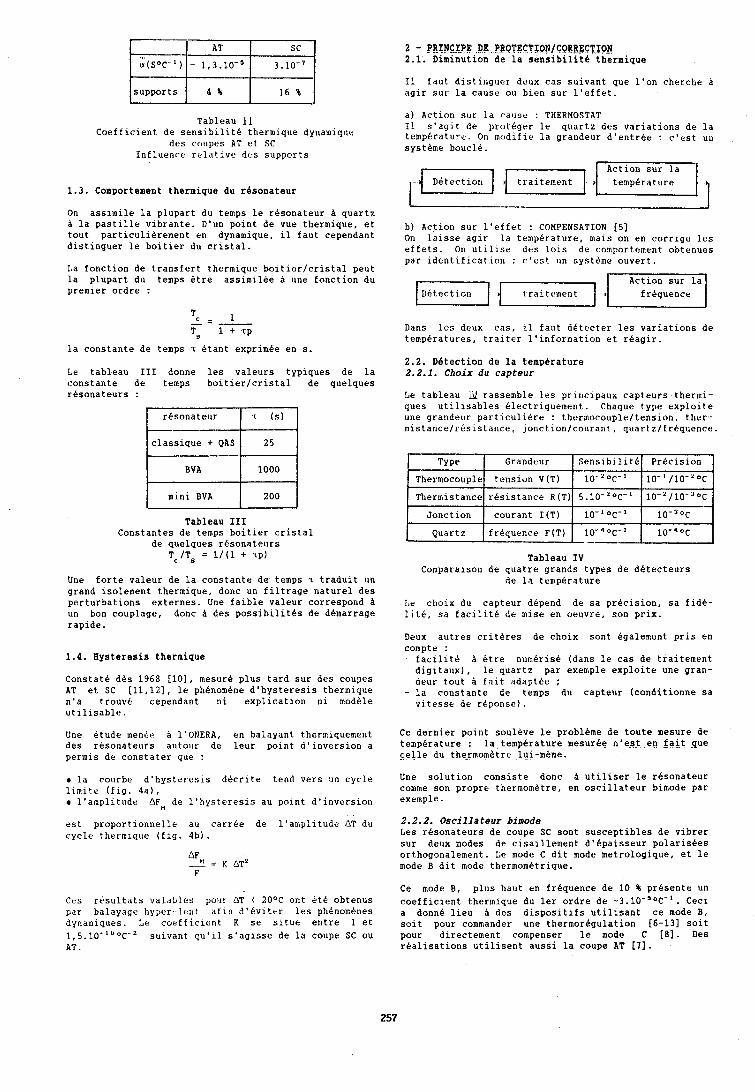
I I
supports 4 % 16 % I Tableau 11
Coefficient de sensibilite thermique dynamique des collpes AT et SC
Influenre relative its supports
2 - PRINCIPE DF PROTECTION/CORPECT~ 2 . 1 . Diminution de la senslbilite thermique
I1 faut distinguer doux cas suivant que l'on cherchr a agir sur la cause ou bien sur l'effet.
a) Action sur I d cause : THERMOSTAT I1 s'ag~t de piotbger le quartz des variations de la temperature. On mudifie la grandeur d'entrbe : c'rst un systbme boucle.
1.3. Comportement thermique du resonateur
On assimile la plupart du temps le resonateur h quartz h la pastille vibrante. D'un point de vue tbermique, et tout particulierement en dynamique, il faut cependant distinguer le boitier du cristal.
La fonction de transfert thermique boitierlcristal peut la plupart du temps Ctre assirnilbe A une fonction du premier ordre :
la constante de temps 7 &ant exprimbe en s.
Le tableau I11 donne les valeurs typiques de la constante de temps boitierlcristal de quelques resonateurs :
resonateur
classique + QAS
I BVA 1 1 0 0 0 1
Tableau I11 Constantes de temps boitier cristal
de quelques resonateurs Tc/TB = 1/(1 + '~p)
I mini BVA
Une forte valeur de la constante de temps T traduit un grand isolement thermique, donc un filtrage nature1 des perturbations externes. Une faible valeur correspond h un bon couplage, donc A des possibilites de dhnarrage rapide.
200
1 . 4 . Hysteresis therlnique
Constate dbs 1968 [lo], mesurb plus tard sur des coupes AT et SC [11,12], le phbnombne d'hysteresis thermique n'a trouve cependant ni explication ni modble utilisable.
Une etude menbe a l'ONERA, en balayant thermiquement des resonateurs autour de leur point d'inversion a permis de constater que :
la courbe d'hysteresls decrite tend vers un cycle limite (fig. 4a), r l'amplitude AF de l'hysteresis au point d'inversion
est proportionnelle au carrGe de l'amplltude AT du cycle thermique (fig. 4b).
Ces resultats valables pour AT ( 20°C ont btC obtenus par balayage hyper-leut afin d'bviter les phbnomcnes dynamiques. Le coefficient K se situe entre 1 et 1,5.10-100~-2 suivant qu'il s'agisse de la coupe SC ou AT.
b) Action sur l'effet : COMPENSATION [5] On leisse agir la temperature, mais on en corrige les effets. On utilise des lois de comportement obtenues par identification : c'est un systeme ouvert.
Dans les deux cas, il faut detecter les variations de temperatures, traiter l'information et rbagir.
2 . 2 . Detection de la temperature 2.2.1. Choix du capteur
Le tableau U rassemble les prir~cipaux capteurs tbermi- ques utilisables tlectriquement. Chaque type exploite une grandeur particulierr : thermocouple/tension, ther- mistancelrbsistance, jonctionlcourant, quartzlfrbquence.
Tableau IV Comparaison de quatre grands types de detecteurs
de la tempbrature
Type
Thermocouple
Thermistance
Jonction
Quartz
Le choix du capteur depend de sa precision, sa fide- lit&, sa facilitb de mise en oeuvre, son prix.
Deux autres criteres de choix sont egalement pris en compte : - facilitb a Ctre numCris6 (dans le cas de traitement digitaux), le quartz par exemple exploite une gran- deur tout a fait adaptbe ;
- la constante de temps du capteur (conditionne sa vitesse de reponse).
Grandeur
tension V(T)
resistance R (T)
courant I (T)
frbquence F(T)
Ce dernier point souleve le probleme de toute mesure de temperature : la temperature mesur6e n'est en fajt que celle du the.rmom&tre lgi-m6rne.
Une solution consiste donc a utiliser le resonateur comme son propre thermombtre, en oscillateur birnode par exemple.
Sensib~lltb 10-'°C-'
5.10-'O~-'
lo-' OC-I
10-h~'l --
2 .2 .2 . Oscillateur birnode Les resonateurs de coupe SC sont susceptibles de vibrer sur deux modes de cisaillement d'bpaisseur polarlsees orthogonalement. Le mode C dlt mode metrologique, et le mode B dit mode thermometrique.
PrGcision
lo-' 110-'OC
10-'/lO-JOC
~O-"C
10-40C
Ce mode 0 , plus haut en frbquence de 10 % presente un coefficient thermique du ler ordre de -3.10-30~-1 . Ceci a donne lieu h des dispositifs utilisant ce mode 0 , soit pour commander une thermor6gulation [6-131 soit pour directement compenser le mode C [81 . Des realisations utilisent aussi la coupe AT [ 7 ] .
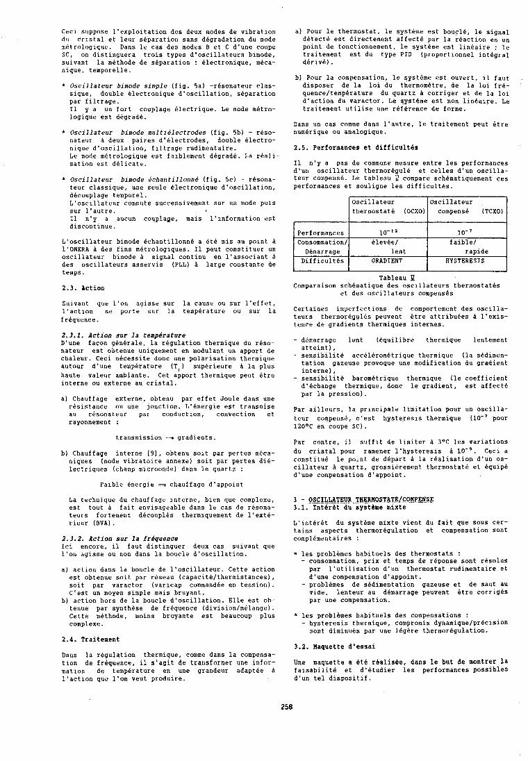
Ceci suppose l'exploitation des deux modes de vibration du cristal et leur separation sans degradation du mode n~etrologique. Dans le cas des modes B et C d'une coupe S t , on distinguera trois types d'oscillateurs bimode, suivant la methode de separation : electronique, meca- nique, temporelle.
Oscillateur bimode simple (fig. 5a) -resonateur clas- sique, double electronique d'oscillation, separation par filtrage. 11 y a un fort couplage electrique. Le mode metro- logique est degrade.
* Oscillate~rr bimode mrrl tielectrodes (fig. 5b) - reso- nateur d deux paires d'blectrodes, double Alectro- nique d'oscillation, filtrage rudimentaire. La mode metrologique est faiblement degrade. La reali- sation est delicate.
* Oscillateur birnode echantillo~lne (fig. 5c) - rbsona- teur classique, une seule Blectronique d'oscillation, decouplage temporel. L'oscillateur commute successivement sur un mode puis sur l'autre. I1 n'y a aucun couplage, mais l'information est discontinue.
a) Pour le thermostat, 1e systeme est boucle, le signal detect4 est directement affect6 par la rbactlon en un point de fonctlonnement, le systdme est llnkalre ; le traitement est du type PID (proportionnel integral derive).
b) Pour la compensation, le systdme est ouvert, 11 faut disposer de la lo1 du thermombtre, de la lo1 fre- quence/temperature du quartz h corriger et de la lo1 d'action du varactor. Le =sthe est non llneaire. Le traltement utillse une reference de forme.
Dans un cas comme dans l'autre, le traitement peut etre numerique ou analogique.
2.5 . Performances et difficultbs
I1 n'y a pas de commune mesure entre les performances d'un oscillateur thermoregulb et celles d'un oscllla- teur compense. Le tableau U compare schbmatiquement ces performances et souligne les difficult6s.
L'oscillateur bimode CchantillonnB a BtB mis au point h 1'ONERA h des fins metrologiques. I1 peut constituer un oscillateur bimode h signal continu en l'associant A des oscillateurs asservis (PLL) d large constante de temps.
Tableau 2 . 3 . Action Comparalson schematique des osclllateurs thermostates
et des oscillateurs compenses Sulvant que l'on aglsse sur la cause ou sur l'effat, lsactlon se porte sur la tempetaturr ou sur la Certalnes ln~yerfectlons de comportement des oscilla-
frequence. teurs thermorkgul6s peuvent etre attrlbuees A l'exls- tance de gradlents thermlques internes.
Oscillateur cornpens6 (TCXO)
lo-' faible/
rapide HYSTERESIS
J
Performances Consommation/
Demarrage Difficultes
2.3.1. Action sur la temperature DQune la regulation thermique du reso.. - dbmarrage lent (equilibre thermique lentement nateur est obtenue uniquement en modulant un apport de atteint), chaleur. Ceci ,,beessite done une polarisation thermiq,le - sensibilite acc614rom6trique thermique (la sedimen- autour d'une temperature (TI) supBrieure d la plus tation gazeuse provoque une modification du gradient
interne), haute valeur ambiante. Cet apport thermique peut btre - sensibilite barometrique thermique (le coefficient interne ou externe au cristal. d'echange thermique, donc le gradient, est affect6
Oscillateur thermostat6 (OCXO)
Blev&e/ lent
GRADIENT
par la pression) a) Chauffage externe, obtenu par effet Joule dans une
resistance ou une ~onctlon. L'energle est transmlse par ailleurs, la prlnclpale llmitatlon pour un oscilla- au resonateur par conduction, convection et rayonnement : teur compense, c'est hysteresis thermique (lo-' pour
120°C en coupe SC).
transmrssion -* gradients. Par contre, il suffit de limiter h 3OC les variations
b) Chauffage interne [9], obtenu soit par pertes meca- d~ cristal pour ramener l'hysteresis h lo-'. ~ e c i a niques (mode vibratoire annexe) soit par pertes die- constitue le point de depart la realisation d'un 0s- lectriques (champ microonde) dans le quartz : cillateur h quartz, grossihrement thermostat6 et equip6
d'une compensation d'appoint. Faible Bnergie --, chauffage d'appoint
La technique du chauffaga interne, bien que complexe, est tout d fait envisageable dans le cas de resona- teurs fortement dbcouplBs thermiquement de l'exte- rieur (BVA).
2.3.2. Action sur la frdquence Ici encore, il faut distinguer deux cas suivant que 1'011 agisse ou non dans la boucle d'oscillation.
a) action dans la boucle de l'oscillateur. Cette action est obtenue soit par reseau (capacite/thermistances), soit par varactor (varlcap commandbe en tension). C'est un moyen simple mais bruyant.
b) actlon hors de la boucle d'oscillation. Elle est ob- tenue par synthdse de frequence (divisionImBlange). Cette methode, moins bruyante est beaucoup plus complexe .
2.4. Traitement
Dans la regulation thermique, comme dans la compensa- tion de frbquence, il s'agit de transformer une infor- mation de temperature en une grandeur adaptbe h l'actlon que l'on veut produire.
3 - OSCILLATE~_R.THERMOSTATE/COMPENSE 3 . 1 . Intbrht du systeme mixte
L'intBr6t du systbme mixte vient du fait que sous cer- tains aspects thermoregulation et compensation sont complementaires :
* les problemes habituels des thermostats : - consommation, prix et temps de reponse sont resolus par l'utilisation d'un thermostat rudimentaire et d'une compensation d'appoint.
- problbmes de sedimentation gazeuse et de saut au vide, lenteur au demarrage peuvent btre corriges par une compensation.
* les problbmes habituels des compensations : - hysteresis thermique, cornpromis dynamiquelpr6cision
sont diminues par une legdre thermoregulation.
3.2. Maquette d'essai
Une maquette a Btb realisbe, dans le but de montrer la faisabilite et d'etudier les performances possibles d'un tel dispositif.
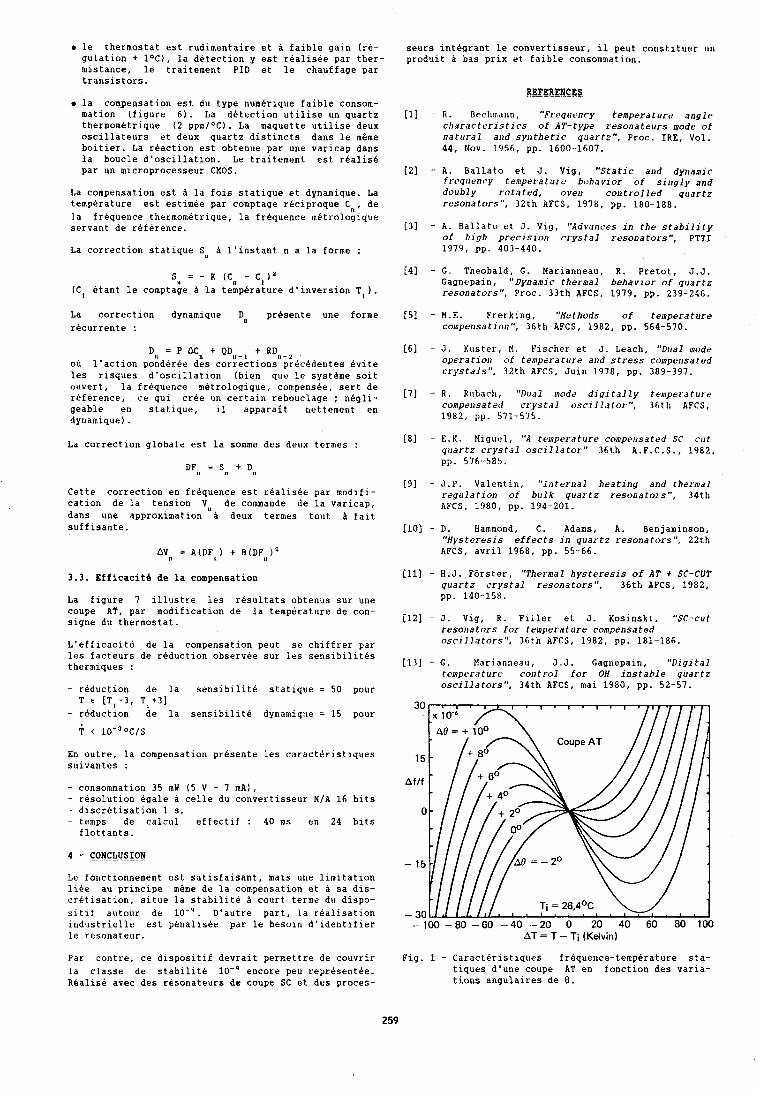
le thermostat est rudlmentaire et A faible galn (re- gulation + 1°C), la detection y est reallsbe par ther- mistance, le traltement PID et le chauffage par translstors.
la compensation est du type numerique faible consom- mation (figure 6). La detection utilise un quartz thermometrique (2 ppm/OC). La maquette utilise deux oscillateurs et deux quartz distincts dans le meme boitier. La reaction est obtenue par une varicap dans la boucle d'oscillation. Le traitement est realis6 par un microprocesseur CMOS.
La compensation est a la fois statique et dynamique. La temperature est estimee par comptage reciproque C,), de la frequence thermometrique, la frequence metrologique servant de reference.
La correction statique S,, a l'instant n a la forme :
SLI = - K (Cn - C1 ) Y
(C, &ant le comptage A la temperature d'inversion T,).
La correction dynamique Dn presente une forme recurrente :
Dl, = P A c , , + Q D , , - I +RD,-z ou l'action ponderee des corrections precedentes evite les risques d'oscillation (bien que le systkme soit ouvert, la frequence rnetrologique, compens6e, sert de reference, ce qui cree un certain rebouclage ; negli- geable en statique, il apparait nettement en dynamique) .
La correction globala est la somme des deux termes :
Cette correction en frequence est realisbe par modlfi- cation de la tension VU de commande de la varicap, dans une approximation a deux termes tout A fait suffisante.
3.3. Etficacite ds la compensation
La figure 7 illustre les resultats obtenus sur une coupe AT, par modification de la temperature de con- signe du thermostat.
L'efficacite de la compensation peut se chiffrer par les facteurs de reduction observee sur les sensibilites thermiques :
- reduction de la sensibilite statique = 50 pour T t [Ti -3, T , t3]
- reduction de la sensibilite dynamique = 15 pour
En outre, la compensation presente les caracteristiques suivantes :
- consommation 35 mW (5 V - 7 mA), - resolution &gale a celle du convertisseur N/A 16 bits - discretisation 1 s, - temps de calcul effectif : 40 ms en 24 bits
flottants.
Le fonctionnement est satisfaisant, mais une limitation libe au principe meme de la compensation et A sa dis- cretisation, situe la stabilite A court terme du dispo- sitlf autour de lo-'. D'autre part, la realisation industrielle est penallsee par le besoin d'identifier le resonataur.
Par contre, ce dispositif devrait permettre de couvrir la classe de stabilite lo-' encore peu representee. Realise avec des resonateurs de coupe SC et des proces-
seurs intkgrant le convertisseur, il peut constituer un produit a bas prix et faible consommation.
REFERENCES . . - -- . - - - - 111 - R. Brchmann, "Preqtrency temperature angle
characteristics of AT-type resonateurs niode of natural and synthetic quartz", Proc. IRE, Vol. 44, Nov. 1956, pp. 1600-1607.
[2] - A. Ballato et J. Vig, "Static and dynalnic frrqc~ency telirperaturs behavior of singly and dorlbly rotated, ovell controlled quartz resonators", 32th AFCS. 1978, pp. 180-188.
[?I - A. Ballato et J. Vlg, "Advances in the stability of high precision crystal resonators", PTTI 1979, pp. 403-440.
[4] - G. Theobald, G. Marianneau, R. Pretot, J.J. Gagnepain, "Dynamic thermal behavior of quartz resonators", Proc. 33th AFCS, 1979, pp. 239-246.
[5] - M.E. Frerking, "Methods of temperature colnpmsatioa", 36th AFCS, 1982, pp. 564-570.
[6] - J. Kuster, M. Pischer et J. Leach, "Dual mode operation of temperature and stress compensated crystdls", 32th AFCS, Juin 1978, pp. 389-397.
[7] - R. Rubach, "Dual ~nodr dlgi tally traiperature compensated crystal oscillator", 36th AFCS, 1982, pp. 571-575.
I81 - E.K. Mlguel, "A temperature co~nprnsated SC ccrt quartz crystal oscillator" 36th A.F.C.S., 1982, pp. 576-585.
[Y] - J .P. Valentin, "Internal heating and thermal regulation of bulk quartz resonators", 34th AFCS, 1980, pp. 194-201.
[lo] - D. Hammond, C. Adams, A. Benjaminson, "Hysteresis effects in quartz resonators", 22th AFCS, avril 1968, pp. 55-66.
[Ill - H.J. Forster, "Thermal hysteresis of AT + SC-CUT quartz crystal resonators", 36th AFCS, 1982, pp. 140-158.
[I21 - J. Vig, R. Flller et J. Kosinski, "SC-cut resonators for temperature compensa fed oscillators", 36th AFCS, 1982, pp. 181-186.
[l3] - G. Marianneau, J. J. Gagnepain, "Digital temperature control for OH instable quartz oscillators", 34th AFCS, mai 1980, pp. 52-57.
AT = T -- Ti (Kelvin)
Fig. 1 - Caracteristiques frbquence-temperature sta- tiques d'unr coupe AT en fonction des varia- tions angulaires de 8.
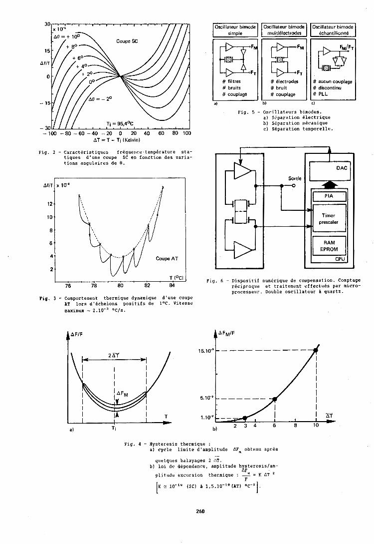
30
15
Af l f
0
- 15
- 30 -100 - 8 0 - 6 0 - 4 0 - 2 0 0 20 40 60 80 100
AT = T - Ti (Kelvin)
Fig. 2 - Caracteristiques frequence-temperature sta- tiques d'une coupe SC en fonction des varia- tions angulaires de 0.
Pig. 3 - Comportemer~t thermique dynamique d'une coupe AT lors d'bchelons positifs de 1°C. Vitesse maximum 2.lO-= OCIs.
# bruits # bruit # discontinu # couplage # couplaye # PLL
a) DI CI
Fig. 5 - Oscillateurs bimodes. a) Separation Blectrique b) Separation mecanlque c) Separation temporelle.
I
- D AC
Sortie
b- e
w
Dm Timer
Flg. 6 - Dlsposltlf numerlque de compensation. Comptage reclproque et traitement effectuBs par mlcro- processeur. Double osclllateur h quartz.
Fig. 4 - Hysteresis thermique : a) cycle limite d'amplitude AF, obtenu aprPs
.... quelques balayages 2 AT.
b) loi de dependance, amplitude h steresislam- XF . - plitudr excursion thermique : = K AT '
F
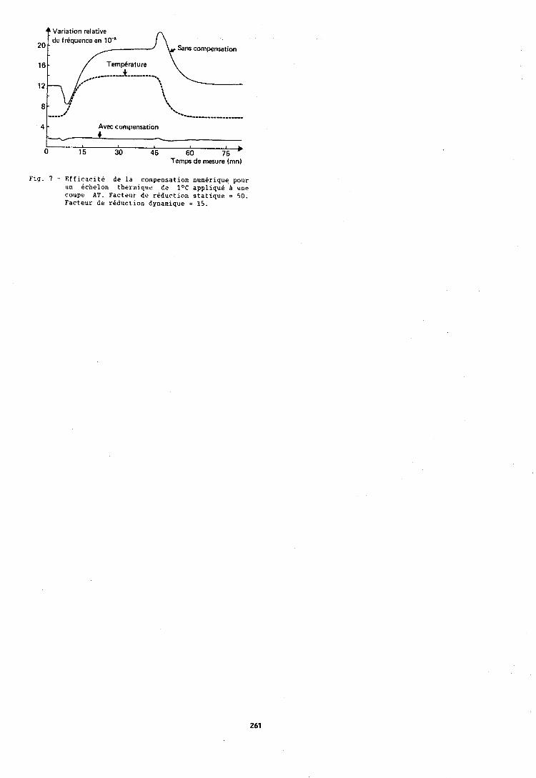
Variation relative de f rbquence en 10"
201 /-4 sans compensation
Fig. 7 - Efflcacite de la compensation numerlque pour un echelon thermlqur de lac applique A une coupe AT. Facteur de redurtion statlque = 50. Facteur de reduction dynamlque = 15.
-. '. 'r
;L '. *.
------l-ll----l.)-___-
4 - Avec compensation
---V .) -
0 15 30 45 60 75 Temps de mesure (mnl
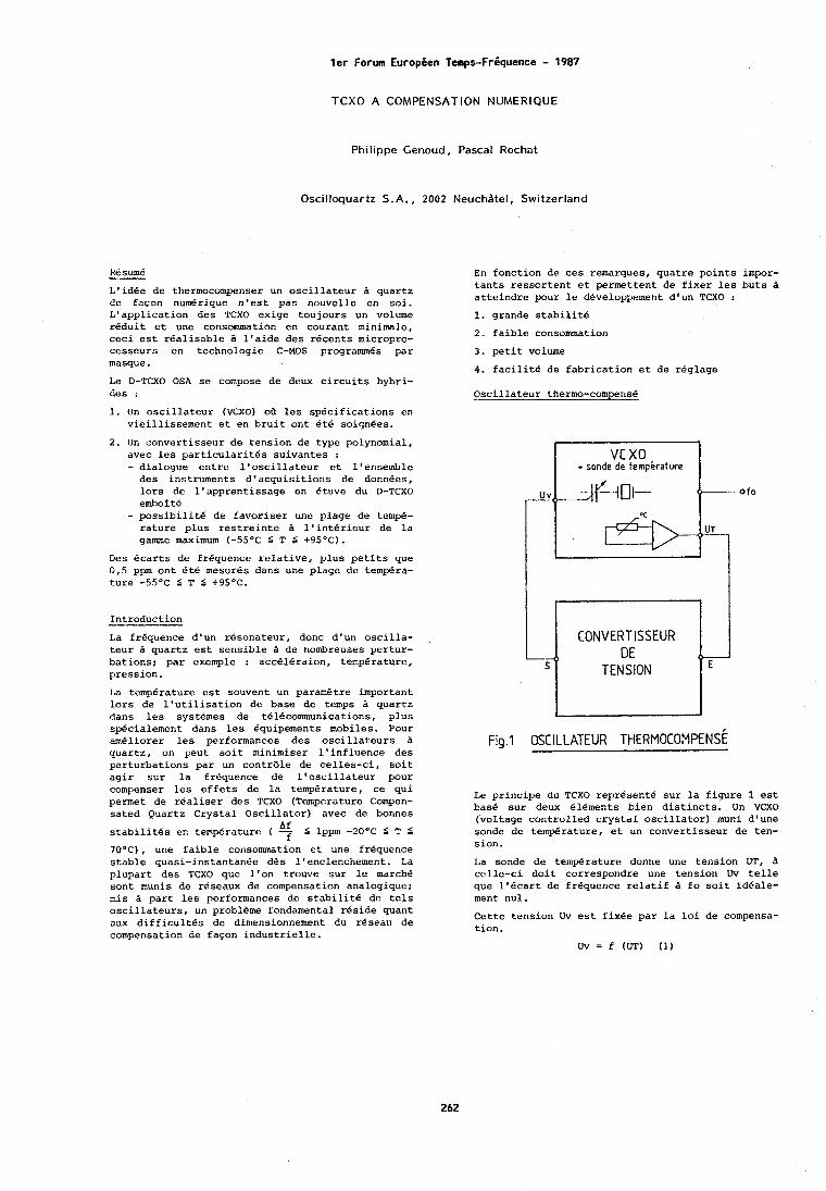
ler Forum Europien Temps-Friquence - 1987
TCXO A COMPENSATION NUMERIQUE
Philippe Genoud, Pascal Rochat
Oscilloquartz S.A., 2002 Neuchdtel, Switzerland
Re sum6 -- L'idde de thermocompenser un oscillateur B quartz de facon nudrique n'est pas nouvelle en soi. L'application des TCXO exige toujours un volume reduit et une consomation en courant minimale, ceci est realisable a l'aide des recents micropro- cesseurs en technologie C-MOS programmes par masque.
Le D-TCXO OSA se compose de deux circuits hybri- des :
1. Un oscillateur (VCXO) ot~ les specifications en vicillissement et en bruit ont BtB soignees.
2. IJn convertisseur de tension de type polynomial, avec lcs particularites suivantes : - dialogue entre l'oscillateur et l'ensemble des instruments d'acquisitions de donnees, lors de l'apprentissage en etuve du D-TCXO emboi te
- possibilite de favoriser une plage de tom+- rature plus restreinte B l'interieur de la game maximum (-55°C 5 T 6 +9S°C).
Des ecarts de frequence relative, plus petits que 0,5 ppm ont Ete mesures dans une plage de tempera- t.ure -5S°C 5 T 6 t95'C.
Introduction
La frdquence d'un r&sonateur, donc d'un oscilla- teur B quartz est sensible B de nombreuses pertur- bations; par exemple : accelCiraion, temperature, pression.
I,a temperature est souvent un paramatre important lors de l'utilisation de base de temps B quartz dans les systemes de t~16communications, plus spdcialemcrlt dans leu equipements mobiles. Pour ameliorer les performances des oscil1at:eurs B quartz, on peut soit minimiser l'influence des perturbations par un contrdle de celles-ci, soit agir sur la frequence de l'oscillateur pour compenser les effets de la temperature, ce qui permet de rdaliser des TCXO (Temperature Compen- sated Quartz Crystal Oscillator) avec de bonnes
Af stabilitks en temperature ( 2 5 lppm -20°C 5 T 5
70°C), une faible consommation et une frequence stable quasi-instantanee d6s l'enclenchement. La plupart des TCXO que l'on trouve sur le marche sont munis de reseaux de compensation analogique; mis B part les performances de stabilite de tels oscillateurs, un probleme fondamental reside quant aux difficultes de dimensionnement du reseau de compensation de fapon industrielle.
En fonction de ces remarques, quatre points impor- tants ressortent et permettent de fixer les buts B atteindre pour le developpement d'un TCXO :
1. grande stabllite
2. faible consommation
3. petit volume
4. facilite de fabrication et de reglage
Oscillateur thermo-cornpens6
+ sonde de temperature
Le principe du TCXO represente sur la figure 1 est base sur deux elements bien distincts. Un VCXO (voltage controlled crystal oscillator) muni d'une sonde dc tem$rature, et un convertisseur de ten- sion.
I,a sonde de temperature donne une tension UT, B cellc-ci doit correspondre une tension Uv telle que l'dcart de frequence relatif B fo soit id6ale- ment nul.
- ( E
-)
S
Cette tension Uv est fixee par la loi de compensa- tion.
- CONVERTISSEUR
DE TENS ION
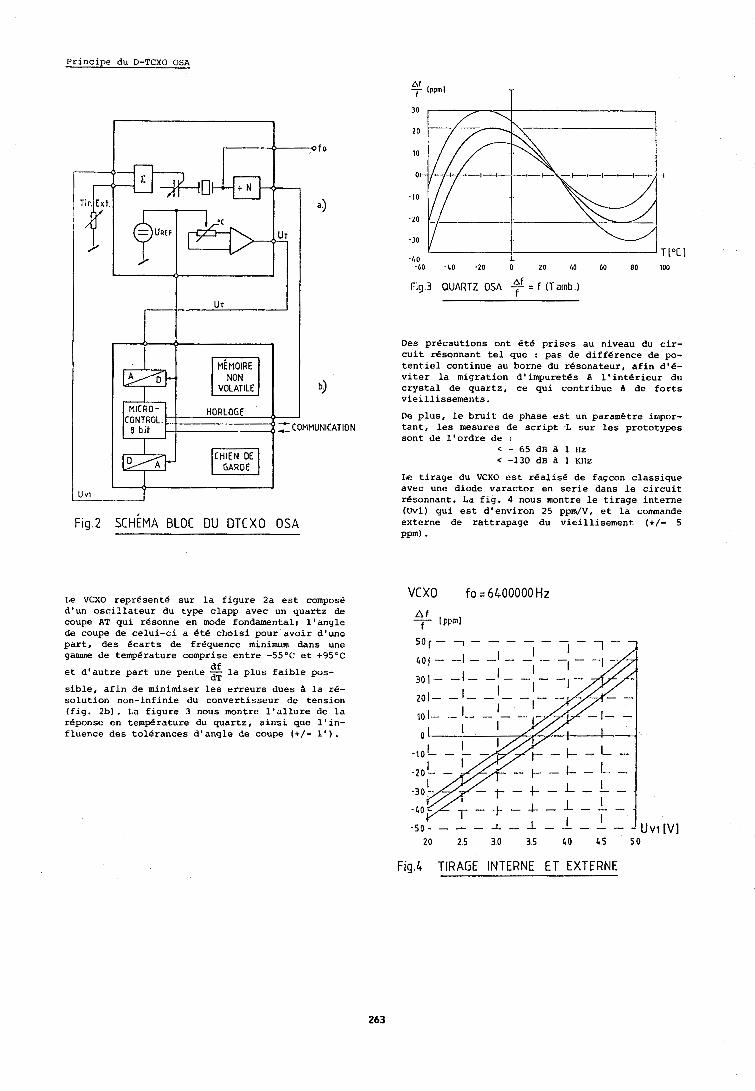
Principe du D-TCXO OSA
VOLATILE
Fig.3 QUARTZ OSA $i = f (Tamb.1
Des precautions ont Bt& prises au niveau du cir- cuit rOsonnant tel que : pas de difference de po- tentiel continue au borne du resonateur, afin d'&- viter la migration d'impuretgs A l'interieur du
3 crystal de quartz, ce qui contribue A de forts vieillissements.
CONTROL. De plus, le bruit de phase est un parametre intpor- f COMMUNICATION tant, les mesures de script ,L sur les prototypes
sont de l'ordre de : < - 65 dB a 1 Irz < -130 dB A 1 Kllz
IIF! tirage du VCXO est rBalis6 de fa~con classique avec unc diode varactor en serie dans le circuit rdsonnant. La fig. 4 nous montre le tirage interne (Uvl) qui est d'environ 25 ppm/V, et la commande
Fig 2 S C H ~ M A BLOC DU DTCXO OSA externe de rattrapage du vieillisernent (+/- 5 PP~) .
Le VCXO reprdsente sur la figure 2a est compose d'un oscillateur du type clapp avec un quartz de coupe AT qui resonne en mode fondamentali l'angle do coupe de celui-ci a bt.5 choisi pour avoir d'une part, des Bcarts de frequence minimum dans une gamme de temperature comprise entre -55OC et t95OC
df et d'autre part une pente la plus faible pos-
-.
sible, afin de minimiser les erreurs dues a la re- solution non-infinie du convertisseur de tension (fig. 2b). La figure 3 nous montre l'allure de la reponse en temperature du quartz, aimi que l'in- fluence des tolerances d'angle de coupe (+/- 1').
VCXO fo = 6 4 0 0 0 0 0 H z
Fig.4 TlRAGE INTERNE E T EXTERNE
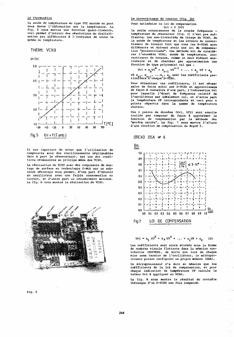
Le t h e m m e t r e
La sonde de temp4rature du type PTC montfe en pont nous donne l'infonnation sur la temperature. La fig. 5 nous montre une fonction quasi-linedire, ceci pennet d'obtenir des resolutions de digitali- sation peu differentes A l'interieur de toute la qammc dc temperature.
THERM. VCXO
Fig .5 Ur = f (Tamb.)
I1 est important de noter que l'utilisation de composants avec des vieillirsements negligeables (mis a part le rcisonnateur), est une des condi- tions necessaires au principe meme des TCXO.
La realisation du VCXO avec des composants de mon- tage de surface en technologic C-MOS sur un sub- strat ceramique nous permet, d'une part d'obtenir un oscillateur avec une faible consomation en courant, et d'autre part un encombrcment minimum. La fig. 6 nous montre lo realisation du VCXO.
Le convertisseur de tension (fig. 2b)
Pour satisfaire la loi de compensation Uvl = f (UT)
la seule connaissance de la courbe frequence - temgrature du resonateur (fig. 3 ) n'est pas suf- fisantei les non-linfarites de tirage du VCXO, de la sonde de temp4rature et les erreurs du conver- tisseur de tension font que tous lcs D-TCXO sont differents et doivent avoir une loi de compensa- tion "pcrsonnnlie6e". Une methode est de consid6- rer l'ensemble VCXO, sonde de temNrature, con- vertisseur de tension, c o m e un seul element non- linfaire et de chercher par approximation une fonction de type polynomial tel que :
UVI = a U T ~ t all-l UT"-' t . . . + a UT t a 1 0
oB a , an ... a , a sont les coefficients par- ticufters : chaquelo-T~XO. Pour determiner ces coefficients, il est neces- saire de faire subir dux D-TCXO un apprentissage de fagon I connaltre d'une part, l'information Uvl pour laquelle l'ecart de frequence relatif de l'oscillateur est idealement nul, ct d'autre part la temp6rature UT correspondante et ceci pour n points repartis dans la g a m e de temperature choisie.
Ces n paires de donn6es (Uvi, UTi) sont ensuite traitfs par computer de facon I approximer la fonction de compensation par la m6thode des "widre carrds". La fig. 7 nous montre l'allure d'une fonction de compcnsation de dcgre 5.
DTCXO OSA # 6
Fig.7 LO1 DE COMPENSATION
5 Uvl = a5 UT t 8 4 U T ~ t .. . t alUT t a. (21
Les coefficients sont alors stockes sou6 la forme dc nombres virgule flottante dans la &moire non- volatile (EEPROM), de sorte que lors de chaque mise sous tension de l'oscillateur, lo micropro- cesseur puisse configurer sa propre memore (RAM).
1.e microprocesseur n'a donc en &moire que les coefficients de la loi de compensation, et pour chaque indication de temperature UT calcule la valeur Uvl B appliquer au VCXO.
La fig. 8 nous montre le resultat du contrdle thermique d'un D-TCXO une fois compense.
Fig. 6
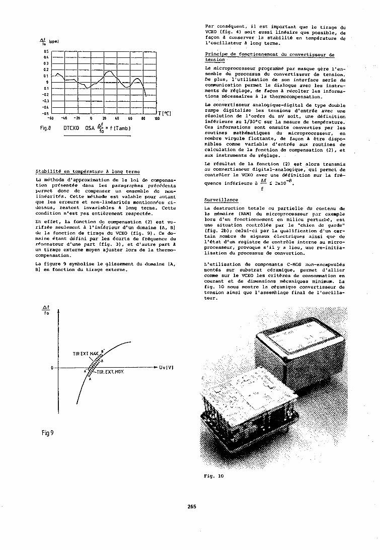
Fig.8 OTCXO OSA $ = f (Tatnb.1
stzbilite en temperature A long terme
La mdthode d'approximation de la loi de compensa- tion 1~resent6e dans les paragruphes prOcEclents pcrmct donc dc compenser un ensemble dc non- liriearitbs. Cette dthode est valable pour ,Iiltant que les erreurs et non-linearitds mentionnEcs ci- dcssus, restcnt invariables a long tcrme. Cetta condition n'est pas entierement respectee.
En effet, la fonction de compensation ( 2 ) est vd- rifiee seulemc~~t A l'in&rieur d'un domaine [A, B] dl! la fonction de tirage du VCXO (fig. 9). Ce do- maine Ctant defini par les ecarts da frCquence du r6nonateur d'une part (fig. 3 ) , ot d'autre part d un tirage externe moyen ajuster lors de la thermo- compensation.
Par cons8quent, il eSt important que le tirage du VCXO (fig. 4 ) soit aussi linedire que possible, de facon B conserver la stabilite en temperature de l'oscillateur long terme.
Principo dr fonctionnement du convertisseur de tenbinn
Le microprocesseur program6 par masque gPre l'en- scmble du processus du convertisseur de tension. De plus, l'utilisation de son interface serio de communication permet le dialogue avec les instru- ments de reglage, de facon a recolter lcs informa- tions necessaires B la thermocompensation.
Le convertisseur analogique-digital de type double rampe digitalisc les tensions dlentr€e avec une rbsolution dc l'ordre du mV soit, une definition inferieure au l/lO°C sur la mesure de temperature. Ces informations sont cnsuite converties par les routines mathCn~atiques du microprocesseur, en nonhre virgule flottante, de facon A &re dispo- nibles c o m e variable d1entr8e aux routines de calculation de la fonction de compensation (2). et aux instruments do r6glage.
Ia resultat de la fonction (21 est alors transmis au convertisreur digital-analogique, qui permet de contrblcr le VCXO avec une definition sur la frC-
A f quence inferieure B - L ?x10-~. f
Surveillance
La destruction totalc ou partiellc du contenu do la memoire (RAM) du microprocesseur par cxemple lors d'un fonction~iement ell milicu perturb&, cst une situation c01itr6lde par le "chicn dc garde" (fig. 2b)j celui-ci par la qualification d'un cer- tain n o d r e de signaux blcctriques ainsi quc dc 1'Btat d'un registre de contrale interne au micro- processeur, provoque s'il y a lieu, uric re-initia- lisation du processus de convertion.
La figure 9 symbolise le glissement du domaine [A, L'utilisation de composants C-MGS non-encapsules 81 en fonction du tirage externe. montes sur substrat ceramique, permrt d'alliar
c o m e sur le VCXO les critPrcs de consomniation en courant et de dimensions mecaniques minimum. La fig. 10 nous montre la ceramique convertisseur de tension ainsi quc l'assemblage final de l'oscilla- teur.
Fig 9
Fig. 10
Conclusions -- L'utilisation des nouvelles technologies nous a permis de realiser un D-TCXO avec un encombrement normalis6, A un type de boitier couramment utilis6 pour la fabrication des TCXO analogiques. De plus, la m6thode de dialogue entre les D-TCXO et l'en- semble des instruments d'acquisition de donn6es, permct de thermocompenser lcs oscillateurs encap- aiul8s sous atmosphere neutre; donc dt61iminer toutes interventions physiques sur les oscilla- teurs pendant et aprBs leur apprentissage en dtuve; ceci permet d'une part d'Bviter toute per- turbation due au systemes de mesure, et d'autre part a diminuer les coats de fabrication.
Bihliographie
(1) G. Marianneau "METHODES NUMERIQUES DE COMPEN- SATION ET DE CONTROLE" CNRS - FORMATION Etalon de Fr6quence leur caracterisation et leur uti- lisation 6 et 7 mars 1985
( 2 ) J. S. Wilsen "AN IMPROVED METHOD OF TEMPERATURE COMPENSATION OF CRYSTAL OSCILLATORS" 37th symp. freq. control 1983
( 3 ) Rapport interne OSA
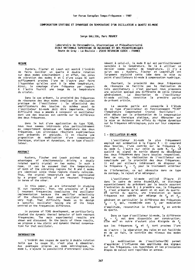
ler Forum Europien Temps-FrGquence - 1987
COMPENSATION STATIQUE ET DYNAMIQUE EN TEMPERATURE D'UN OSCILLATEUR A QUARTZ BI-MODE
Serge GALLIOU, Marc MOUREY
Laboratoire d e Chronomitrie, Electronique et Piizoilectriciti ECOLE NATIONALE SUPERZEURE DE MECANlQUE ET DES MICROTECHNZQUES
Route de Gray - La Bouloie - 25030 BESANCON CEOEX - FRANCE
RESUME
Kusters, Fischer et Leach ont montri l'intirlt de faire osciller un quartz a double rotation sur deux modes simultaniment ; en effet, les zones de vibration des modes B et C d'une coupe SC sont suffisamment proches l'une de l'autre pour faire l'hypothese qu'elles sont i la mlme tempirature. Ainsi, le comptage d'une friquence par rapport 2 l'autre fournit une image de la tempirature du cristal.
Dans le cas prisent, la proximiti des friquences de resonance des deux modes complique la rialisation pratique de l'oscillateur : la silectiviti des amplificateurs des boucles du schema usuel de l'oscillateur bi-mode doit Otre importante. Cette difficult6 nous a amenis i concevoir un oscillateur dont une des boucles est centrie sur la diffirence des deux friquences.
Uans le but d'une application du type TCXO, nous nous sommes intiressis plus particuliBrement a u comportement dynamique en tempirature des deux friquences. Les principaux risultats expirimentaux sont prisentis et analysis. 11 en risulte une proposition de modilisation d'une compensation thermique, statique et dynamique, de ce type d'oscil- lateur.
ABSTRACT
Kusters, Fischer and Leach pointed out the advantages of simultaneously driving a doubly rotated quartz crystal on two modes. In such a case, it can be assumed that the temperatures of botn of the vibrating regions for B and C modes are identical since those regions closely coincide. Thus, the crystal temperature can be appreciated by a proper counting of one resonant frequency in terms of the other.
In this paper, we are interested in studying SC cut resonators. Then, the proximity of B and C resonant frequencies complicates the oscillator implementation because the amplifier selectivity of the classical dual mode oscillator must be very high. That difficulty leads us t o design a specific oscillator having one of its loops centred on the frequencies difference.
in purpose of TCXO development, we particurlarly studied the dynamic thermal behavior of both resonant frequencies. The main experimental results are shown and discussed. On the basis of these results, we propose a new static and dynamic thermal compensa- tion for that oscillator.
niment 3 celui-ci, le mode B qui est particuliarement sensible B la tempirature. D e 12 b utiliser ce dernier comme capteur de tempirature, il n'y a qu'un pas ; Kusters, Fischer et Leach(l.2) ont largement exploit; cette idie dans la mise au point d'oscillateurs bi-mode i compensation numirique.
Pourtant, la proximiti des deux friquences de risonance ne facilite pas la rialisation de tels oscillateurs ; c'est pourquoi nous proposons une solution quelque peu diffirente de celle retenue giniralement. La description de !:oscillateur bi-mode utilisi, constitue la premiere partie du present article.
La seconde partie est consacrie A l'itude de c e type d'oscillateur en fonctionnement "TCXO" (TempBrature Compensated Crystal Oscillator) : elle dibute par la prisentation de la compensation en regime thermique statique, pour diboucher sur la mise en Cvidence des effets du regime dynamique sur la friquence mitrologique, puis sur leur compensa- tion.
I - OSCILLATEUR BI-MODE L'oscillateur bi-mode le plus friquemment
employ6 est schimatisi i la Figure 1 : il comprend deux boucles, l'une centrie sur la friquence du mode C, L'autre sur celle du mode , f . :S qualiti du signal de sortie depend du d6c015)plage des deux friquences dans leurs boucles respectives. Dans ce cas, la rialisation de l'oscillateur est compliquie par la proximiti des deux friquences. 11 est par ailleurs intiressant de disposer de la friquence fg - fC pour le traitement ultirieur
de l'information, ce qui nicessite dans c e type de montage, le rajout d'un milangeur.
L'oscillateur bi-mode utilisi (Figure 2 ) dans le cadre de cette itude(3.4). se distinaue essentiellement du pricident par ia 'boucle assurant l'entretien du mode B ; B premiire vue, la friquence f n'est prisente qu'en amont et en aval du quartz. ER sortie du quartz, une translation en basse friquence est operee par milange de fB et fc' ginirant en particulier la diffirence des friquences fB - fC qui, recombinie avec fC par modulation
d'amplitude, reconstitue la frequence fB en entrie du quartz.
Dans ce type d'oscillateur bi-mode, la diffirence f - fC est donc disponible par construction. ~ f l e est en outre d'autant plus iloignie de fC
que les friquences fg et fC sont proches l'une
de l'autre : la siparation des raies en est facilitie et de ce fait, le contrdle des niveaux des modes B et C.
L'intirlt des coupes de quartz i double rotation La modilisation de l'oscillateur(5) permet telle que la coupe SC, n'est plus i dimontrer. d'appricier l'influence des amplitudes des signaux Aux avantages propres au mode mbtrologique, le sur les friquences. Les hypotheses et les principales mode C, s'ajoute la possibiliti d'entretenir simulta- itapes de calcul sont reporties en annexe.
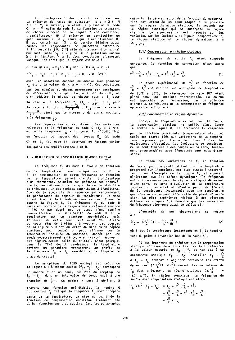
Le diveloppement des c a l c u l s e s t bas6 sur l a p r i s e n c e de r a i e s de p u l s a t i o n w + n D ( - N < n < N, n e n t i e r ) , w i t a n t l a p u l s a t i o n du mode C, w + fi c e l l e du mode 8. La f o n c t i o n de t r a n s f e r t de chaque i l i m e n t de l a F i g u r e 3 e s t m o d i l i s i e ; 1 ' a n i p l i f i c a t e u r HF A p r i s e n t e en p a r t i c u l i e r un g a i n maximum B w , a l o r s que l ' a m p l i f i c a t e u r BF B e s t c e n t r d su r fi . Ce d e r n i e r i l i m i n e auss i t o u t e s l e s composantes de p u l s a t i o n e x t i r i e u r e a I ' i n t e r v a l l e 1 0 , 2 Sll a f i n de d isposer d ' u n s i g n a l modulant ( n o t i S : F i g u r e 3) b p u l s a t i o n unique n . En l i m i t a n t % b 1, deux c o n d i t i o n s s ' imposent l o r s q u e l ' o n i c r i t que l e sys t ime e s t bouc le :
H, s i n ( B c a. + 8 = H-l s i n ( - 0 + a. + 8 -,)
avec l e s n o t a t i o n s donnies en annexe (une grandeur xn i t a n t l a va leur de x B w + n 0 ) . Ces c o n d i t i o n s
s u r l e s modules e t phases permet ten t par consiquent de d i t e r m i n e r l e couple ( w , 0 ) s a t i s f a i s a n t , e t d ' e n d i d u i r e l e n iveau de chaque r a i e : Eo pour
w l a r a i e b l a f r h u e n c e fh i fC = ; E, pour
l a r a i e 1 f . ( f B = g_-+--$ ; E-l pour l a r a i e B w - 2 a
', a i n s i que l e n i v e a u U du s i g n a l modulant n
b l a f r i q u e n c e - 2 n'
Les f i g u r e s 4-a e t 4-b donnent l e s v a r i a t i o n s r e l a t i v e s de l a f r i q u e n c e du mode C ( f C = 5 MHz) e t de l a f r i q u e n c e fg - fC (avec fB = 5,470 MHz)
en f o n c t i o n du r a p p o r t des n iveaux Eo (du mode
C) e t El (du mode 8 ) , obtenues en f a i s a n t v a r i e r
l e s g a i n s des a m p l i f i c a t i o n s A e t B.
11 - UTlLlSATION DE L'OSCILLATEUR BI-MODE EN TCXO
La f r i q u e n c e fC du mode C i v o l u e en f o n c t i o n
de l a t e m p i r a t u r e comme i n d i q u i su r l a F i g u r e 5. La compensation de c e t t e f r i q u e n c e en f o n c t i o n de l a temperature permet d ' i v i t e r l ' u t i l i s a t i o n d ' u n thermostat , s o l u t i o n q u i p r i s e n t e ses i n c o n v i - n i e n t s , au d e t r i m e n t de l a q u a l i t i de l a s t a b i l i t i de f r i quence . Un des remides c o n t r i b u a n t b l ' a m i l i o r a - t i o n de l a s t a b i l i t d de f r i q u e n c e e s t ce r ta inement l a performance du cap teur de t e m p i r a t u r e . Le mode B e s t t o u t B f a i t i n d i q u i dans ce cas. Comme l e montre l a F i g u r e 5, l a f r i quence f du mode B v a r i e en f o n c t i o n de l a t e m p i r a t u r e b raeson d ' e n v i r o n - 150 Hz par d e g r i e t , de p l u s , d 'une manigre q u a s i - l i n i a i r e . La s e n s i b i l i t i du mode B 2 l a t e m p i r a t u r e e s t un avantage a p p r i c i a b l e , mais 1 ' i n t i r C t de c e t t e sonde e s t avant t o u t d 1 6 t r e au coeur mtme de l ' i l i m e n t B mesurer. Les courbes de l a F i g u r e 5 n ' o n t en e f f e t de sens qu'en regime s t a t i q u e , pour l e q u e l on peu t a f f i r m e r que l a t e m p i r a t u r e i n d i q u i e en abscisse, donnde p a r une sonde n icessai rement e x t i r i e u r e au c r i s t a l r i sonnan t , e s t r igoureusement c e l l e du c r i s t a l . C ' e s t pourquoi dans l e TCXO d i c r i t ci-dessous, l a t e m p i r a t u r e d e v i e n t un parami t re t r a n s p a r e n t au p r o f i t de l a frhquence fB - fC s e n s i b l e b l a t e m p i r a t u r e
v r a i e du c r i s t a l .
Le synopt ique du TCXO employ6 e s t c e l u i de l a F i g u r e 6 : b chaque coup le ( fC , fB - f C ) correspond
un nombre N e t un seu l , r i s u l t a t du comptage de fg - fC, dans un i n t e r v a l l e de temps i g a l & une
f r a c t i o n de 1. Ce nombre N s e r t 2 g i n i r e r , B fr
t r a v e r s une f o n c t i o n p r i - i t a b l i e , l e nombre Q q u i c o r r i g e fC t e l que l a f r i q u e n c e fS s o i t i nd ipen-
dante de l a temp6rature. La mise au p o i n t de l a f o n c t i o n de compensation c o n s t i t u e l ' i l i m e n t c16 du bon fonct ionnement du syst ime. Dans l e s paragraphes
su ivan ts , l a d k t e r m i n a t i o n de l a f o n c t i o n de compensa- t i o n e s t e f f e c t u i e en deux i t a p e s : l a premiere su r l e r i g i m e thermique s t a t i q u e , l a seconde sur l e r i g i m e dynamique q u i se superpose au r i g i m e s t a t i q u e . La s u p e r p o s i t i o n e s t t r a d u i t e s u r l e s v a r i a b l e s par l e s i n d i c e s S e t D pour , respect ivement , l e r i g i m e s t a t i q u e e t l e r i g i m e dynamique ( f = fS + f O ) .
2.1/ Compensation en r i g i m e s t a t i q u e
La f r iquence de s o r t i e fS i t a n t supposie
constante, l a f o n c t i o n de c o r r e c t i o n n ' e s t a u t r e que :
S Le t r a c i e x p i r i m e n t a l de f, en f o n c t i o n de 5 f i - f e s t r i a l i s i su r une g a k e de temp6rature C
de 20°C b 80°C, l e r i s o n a t e u r de t y p e EVA i t a n t p l a c e dans une e n c e i n t e thermostatic. La courbe e s t approchie, p a r r i g r e s s i o n , par un polyn6me d ' o r d r e 3. Le r i s u l t a t de l a compensation de f rhquence a p p a r a i t b l a F i g u r e 7.
2.2/ Compensation en r i g i m e dynamique
Lorsque l a temperature i v o l u e dans l e temps, l a compensation s t a t i q u e ne s u f f i t p l u s . Comme l e montre l a F i g u r e 8, l a f r i q u e n c e fC compensie
p a r l a f o n c t i o n p r i c k d e n t e (compensation s t a t i q u e ) s u b i t des i c a r t s l i e s aux v a r i a t i o n s de l a tempira- t u r e imposees p a r l ' e n c e i n t e . Dans t o u t e s l e s exper iences e f fec tuees , l e s i v o l u t i o n s de temp i ra tu - r e se son t l i m i t i e s B des rampes ou p a l i e r s , f a c i l e - ment programmables avec l ' e n c e i n t e don t nous d ispo- s i o n s .
Le t r a c i des v a r i a t i o n s de fC en f o n c t i o n
du temps, pour un p r o f i l d ' i v o l u t i o n de tempdrature programmi su r l ' e n c e i n t e , e s t p l u s s imp le b i n t e r p r i - t e r : sur l ' exemple de l a F i g u r e 9 , il a p p a r a i t c l a i r e m e n t que l e s e f f e t s dynarniques ( l a f r6quence e s t i c i cornpensie pour l e r i g i m e s t a t i q u e ) dependent d'une p a r t , du sens d ' i v o l u t i o n de l a t e m p i r a t u r e (mont ie ou descente) e t d ' a u t r e p a r t , de l ' i c a r t de l a t e m p i r a t u r e i n s t a n t a n i e avec une temperature que nous avons suppos i l t r e c e l l e du p o i n t d ' i n v e r - s ion . La m6me e x p i r i e n c e r i p i t i e & des v i t e s s e s d i f f i r e n t e s ( F i g u r e 10) d imontre que l e s v a r i a t i o n s de f r i q u e n c e dependent a u s s i de c e l l e s - c i .
L'ensemble de ces observa t ions se r isume B :
oir T e s t l a t e m p i r a t u r e i n s t a n t a n i e e t T - l a tempira-
t u r e du p o i n t d ' i n v e r s i o n bas de l a coupe SC.
I 1 e s t i m p o r t a n t de p r i c i s e r que l a compensation s t a t i q u e u t i l i s i e dans tous l e s cas f a i t r i f i r e n c e 2 l a v a l e u r mesur ie de f fC e t non pas b sa
composante s t a t i q u e f i -'f:. ~ s s i m i i e r f i - f: 5 fB - fC r e v i e n t b n i g l i g e r notamment l e s e f f e t s
D D dynamiques ( A fC e t A f B ) devant l e s v a r i a t i o n s de
f dues uniquement au regime s t a t i q u e ( Af; = - B 150 A T I . En regime dynamique, l a f r i q u e n c e de s o r t i e avec compensation s t a t i q u e e s t a l o r s :
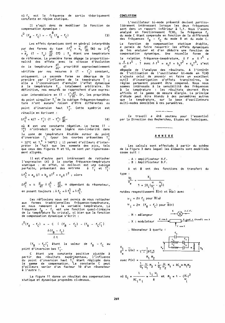
0 5 f est la friquence de sortie thioriquement cons2ante en rigime statique.
11 s'agit donc de modiliser la fonction de compensation dynamique :
ED (fg - fC) = - D fc (fB - fC) (3)
Les effets dynarniques sont en giniral interpritis nJ dT D par des formes du type ~f: = a, at (6) ou A f C
?r dT = a 2 (T - To) ( 7 ) ; To itant une te~npirature
de rifirence. La premiere forme digage la proporttion- naliti des effets avec la vitesse d'ivolution
dT de la tempirature =, proprigti approximativement
virifide par nos mesures B (T - T-) constant,
uniquement. La seconde forme se dimarque de la premiere par l'influence de la tempirature T ; elle a l'lnconvinient d'annuler l'effet dynamique a la tempirature T , totalement arbitraire. En difinitive, nos mesur8s se rapprochent d 8 u n e expres- - dT sion interm6diaire en ( T - Ti)dT. Or, les propriitis
du point singulier ~ ~ - d e la cubique friquence-tempira- ture n'ont aucune raison d'Btre diffirentes a u
point d'inversion haut T:. Cette symitrie est
rdtablie en icrivant :
~ f ; = K(T - TT) (T - T:) dT dt
0 3 K est une constante nigative. Le terme (T - Tf) n' introduit qu'une ligere non-liniariti dans
la zone de Lempirature itudiie autour du point d'inversion Ti (pour les courbes prisenties Tf
= 32°C et T.' > 140°C) ; il permet d'ailleurs d'inter- priter le 'fait que les sommets des pics, tels que ceux des figures 9 et 10, ne sont par rigoureuse- ment alignis.
11 est d'autre part intiressant de rattacher I'expression ( 4 ) B la courbe friquence-tempirature statique : en effet, si celle-ci est une cubique parfaite, prisentant des extrema B Tf et ~ f :
2 ~ f z = a. A T + bo A T + c O A T~ ; alors
u d Af = a - A f: . g, a dependant du risonateur, C dT 5 D en posant toujours : A f - A fC + A fC. C -
Ces riflexions nous ont permis de nous rattacher aux formes tradittonnelles friquence-tempirature, en nous ramenant a la variable tempirature. La friquence f - f est une fonction quasi-liniaire de la tempipature Cdu cristal, si bien que la fonction de compensation dynamique s'icrit :
(fB - fC); itant la valeur de fB - fC au
point d'inversion bas Tf.
C itant une constante positive ajustie B partir des risultats expirJmentaux, l'influence du point d'inversion haut T . 6tant nigligie dans la gamme de compensation. 'la constante C peut d'ailleurs varier d'un facteur 1 0 d'un risonateur 2 l'autre ! .
La figure 11 donne un risultat des compensations statique et dynamique proposies ci-dessus.
CONCLUSION
L'oscillateur bi-mode present6 devient particu- lierement intiressant lorsque les deux friquences sont dans un rapport infirieur B 1 ,l. Nous l'avons analysi en fonctionnement TCXO, la friquence f du mode C Ltant compensie en fonction de la diffirencL des friquences fg - fC du mode B et du mode C.
La fonction de compensation statique Gtablie, a permis de faire ressortir les effets dynamiques de las analyser et d'en diduire une fonction de compensation dynamique. Une nouvelle forme de
la relation frisuence-tempirature. A f = A fS + 2 3 ~ A A fs . ; avec A fs = aoT + boT + coT , s v e s t
dT digagie de l'analyse des risultats. A l'intirit de l'utilisation de l'oscillateur bi-mode en TCXD s'ajoute celui de pouvoir en faire un excellent outil d'investigation d'effets transitoires, le rigime permanent pouvant itre compensi. Nous nous sommes intiressis B la sensibiliti des friquences B la tempirature : les risultats devront Btre affinis et la gamme de mesure ilargie. Le principe d'itude peut Btre itendu B des parametres autres que la tempirature, sur la base d'oscillateurs multi-modes sensibles B ces parametres.
Ce travail a it6 soutenu pour l'essentiel par la Direction des Recherches, Etudes et Techniques.
A N N E X E
Les calculs sont effectuis B partir du schema de la Figure 3 dans lequel les iliments sont modilisis comme suit :
. A : amplificateur H.F.
. B : Amplificateur B.F.
A et B ont des fonctions de transfert du
type :
"s - 5 i
"e 1 + jQi(q-F) w wi
noties respectivemen: K(w) et i(w) avec
w = 2n fC pour A( a) -
W = 2n (fB - fC) pour B(w) i
. M : milangeur X cor d w.
X ~ $ 9 t (Ycos i ) cor d . X : modulateur t 1 Y ... m
. Rdsonateur B quartz :
"s - 1 = '(U) = 1 - jp(u)
avec P(u) = M1 M2
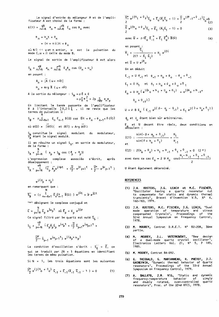
Le s i g n a l d ' e n t r i e du mi langeur M e t de l ' a m p l i - f i c a t e u r A e s t c h o i s i de l a forme :
E ( t ) = ngN en = nzf: En cos on avec
06 NR < < w e t n e n t i e r , w e s t l a p u l s a t i o n du mode C,w + R c e l l e du mode B.
Le s i g n a l de s o r t i e de l ' a m p l i f i c a t e u r A e s t a l o r s
SA = n$N an = nz! EllAn cos (@n + a n )
en posant : -
An = / A ( w + nQ)I
an = Arg 'A ( o,+ nR)
A l a s o r t i e du mi langeur : SM = p E x E 2
= PC, , + 2P n$p enep
En l i m i t a n t l a bande passante de l ' a m p l i f i c a t e u r B B l ' i n t e r v a l l e ] 0,2 R L , il ne r e s t e que l e s termes de p u l s a t i o n R :
N
St) c o n s t i t u e l e s i g n a l modulant du modulateur , SA i t a n t l e s i g n a l modulk.
11 en r i s u l t e un s i g n a l SX, en s o r t i e du modulateur , de l a forme :
N
S X = p=-N C { a p + S B c o s ( @ + a ) ) P P
L ' e x p r e s s i o n complexe a s s o c i i e s ' i c r i t , aprEs divel0DDement :
j ( @ + ap) e P
en remarquant que : N - - ~ ( ~ 1 ) ejQl: = ejQt
'LI = (' n=-N+l n n-1
"*" d i s i g n a n t l e complexe c o n j u g u i e t
N .E = z T ,hpt .g = e j @ ~
p=-N p P P
Ce s i g n a l f i l t r i par l e q u a r t z e s t n o t i TG :
- La c o n d i t i o n d ' o s c i l l a t i o n s ' i c r i t : ST = E , ce
q u i se t r a d u i t pa r 2N + 1 i q u a t i o n s en i d e n t i f i a n t l e s termes de mime p u l s a t i o n .
S i N = 1 , l e s t r o i s i q u a t i o n s son t l e s su ivan tes
avec 'ij = P lEo .E - * 1 + El F:) B(R) ( 4 )
$o e t @u k t a n t b i e n sirr a r b i t r a i r e s .
E e t U devant 6 t r e r i e l s , deux c o n d i t i o n s en dgcou len t :
(C2) : 2(ao + Go) + al + a-l + el + 0-1 = 0 (2 a )
a - a avec dans ce cas E = 2 U Ho cos( 1 -1 + O 1
2
U k t a n t iga lement dk te rmink .
REFERENCES .--
1 A . KUSTERS, J.G. LEACH e t M.C. FISCHER, " O s c i l l a t o r hav ing a q u a r t z resona to r c u t t o compensate f o r s t a t i c and dynamic thermal t r a n s i e n t s " , B reve t d ' i n v e n t i o n V.5, No 4, 160-183, 1979.
(2) J.A. KUSTERS, M.C. FISCHER, J.G. LEACH, "Dual mode o p e r a t i o n o f temperature and s t r e s s compensated C r y s t a l s " , Proceedings o f t h e 32nd Annual Symposium on Frequency C o n t r o l , 1978.
(3) M. MOUREY, C o n t r a t D.R.E.T. No 82-208, 36me p a r t i e .
( 4 ) M. MOUREY, J . L . VATERKOWSKI, "New design o f a dual-mode q u a r t z c r y s t a l o s c i l l a t o r " , E l e c t r o n i c s L e t t e r s Vol . 21, No 5, P 185, 1985.
(5 ) M. MOUREY, C o n t r a t 84-092.
( 6 ) G. THEOBALD, G. MARIANNEAU, R. PRETOT, J.J. GAGNEPAIN, "Dynamic thermal behav io r o f Quartz resonators" , Proceedings of t h e 33rd Annual Symposium on Frequency C o n t r o l , 1979.
(7) A. BALLATO, J.R. V I G , " S t a t i c and dynamic f requency- temperature behav io r o f s i n g l y and doubly r o t a t e d , oven-con t ro l led quar tz resonators" , Proc. o f t h e 32nd AFCS, 1979.
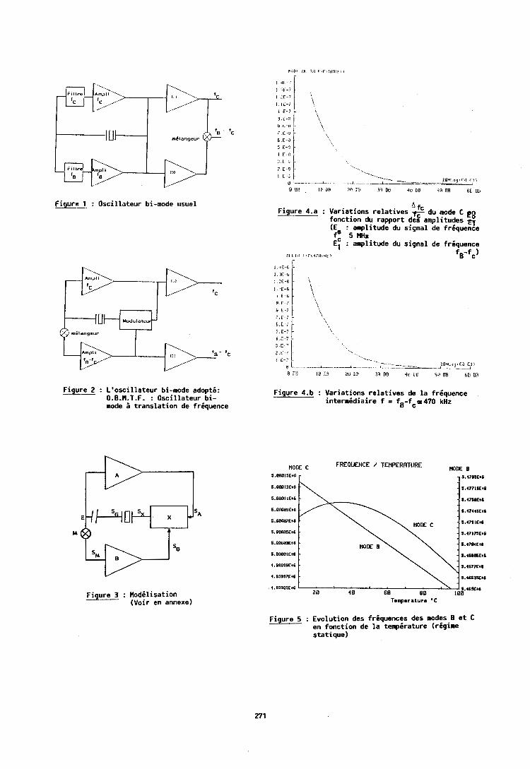
Figure 1 : Oscillateur bi-mode trsuel
Figure 2 : L'oscillateur bi-mode adopti: O.B.M.T.F. : Oscillateur bi- mode 5 translation de frgquence
Figure 3 : Mod6lisation (Voir en annexe)
A fc Figure 4.a : Variations relatives du mode C e n fonction du rapport des amplitudes -& (E : amplitude du signal de friquence fa 5 MHz E: : amplitude du signal de friquence
Llt L I H F,F1 47111li: '8 fB-fc)
I . lC -6
i E-t.
3 . 1 : - I B E-7
6 . E - 7 5 . E - 7
1. E-7
?l I . ; l .~~~?iL~l E l I i
D n E l a r m E011fi 31111~ 4 i l i l n 5I.08 ~ E I I J R
1 4 1 : - '
I ir-? I X . 7
l L l L - : -
I E - l
9 , L -!'
Figure 4.b : Variations relatives de la friquence intermidiaire f = fB-fco470 kHz
.
' \ \,
- - ', ',
none c FREQUENCE / TEMPERRTuRE MODE B S.BOB15Et0 - - S . ~ ~ I S E ~ I
- S.477ISCtE
5.88811Et6 - - S.47SIEtB
5 .00MSEt6 - - S . 4 7 I I S E t I
S.OODB3Etf . - S . 4 7 B i F t I
5.BBBBIEtS -
Tamparature * C
B E-H i-
; E-.j L t, E-, } 5 . F - , / !, :-1 i 1 C-: L - ~ I .-.. .._. ..- --__ -- " ' L d
PO-l o g , F l l F l i i
B UP 1 0 IIR zo nu XI rle ii1 ns se nB sr; or1
Figure 5 : Evolution des friquences des modes B et C en fonction de la tempdrature (rigime statique)
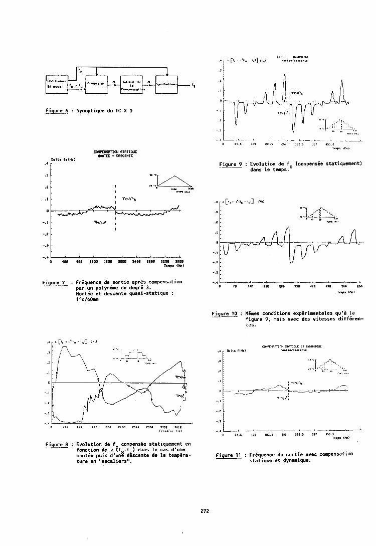
COWENSATION STATIOM HONTEE - DESCENTE
D e l t a fslHz) m 4 r
(c 1
F i ~ u r e --- 7 : Frdquence de s o r t i e apres compensation par un polyntme de degr i 3. Montde e t descente quasi-statique : 1 Oc/60mm
0wIl lal.ur
Bl-mode fg - lC __+
F i e : Evolut ion de f compensie statiquement en - fonction de A f f -f ) dans l e cas d'uhe montie puis d'ung dgscente de l a tempira- ture en "ercaliers".
C-pla=e
. I .
Figure 9 : Evolut ion de fc (compensie statiquement) dans l e temps.
Figure 6 : Synoptique du TC X 0 - . I .
- . Z - I" . L
- . 3 . ICt8"S ,m,
Figure 10 : Mimes conditions expirimentales q u ' i l a f igure 9, mais avec des vitesses d i f f i r e n - 'i\?S.
Figure 11 : Friquence de s o r t i e avec compensation stat ique e t dynamique.
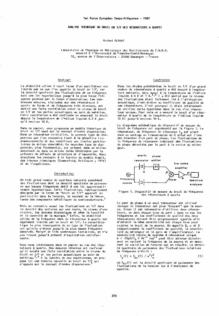
l e r Forum Europeen Temps-Friquence - 1987
ANALYSE THEORIQUE W BRUIT EN l / f DES ESONATEURS A QUARTZ
Michel PLANAT
Laborat .oire de Physique e t M6t.rologie des O s c i l l a t e u r s du C.N.R.S. a s s o e l 6 a l ' U n i v e r s i t 6 de Franche-Comtd-Besangon
32, avenue de I ' O b s e r v a t o i r e - 25000 Besan9or.l - France
A b s t r a c t
La s t . a b i l i t 6 ult.ime d c o u r t terme d 'un o s c i l l a t e u r e s t l i m i t Q e par c e que I ' o n a p p e l l e l e bruit. en l / f , c a r l a d e n s i t 6 s p e c t r a l e des f luctuat . ions de s a fr6quence s u i t une l o i hyperbo l ique jusqu 'd l a p l u s basse f r d - quence permise p a r I s temps d ' o b s e r v a t i o n . Les nom- b reuses mesures, r d a l i s 6 e s s u r des r d s o n a t e u r s d q u a r t z de forme e t de f r6quences t r 6 s d i v e r s e s , on t montrk une f0rt.e cor r6 la t . ion e n t r e l e niveau de brui t . en l / f e t l e s p e r t e s a c o u s t i q u e s au s e i n du mat.6riau. Cet.te cor r6 la t . ion a d t 6 confirmde en mesurant l e b r u i t d e p u i s l a temp6rat.ure de 11h61ium l i q u i d e 4.2 K jus - qu 'd env i ron 50 K.
Dans ce p a p i e r , nous proposons un moddle t .hdorique du brui t . en l / f bas6 s u r l e concept d 'ondes d i s p e r s i v e s . Dans un rfisonat.eur c r i s t . a l l i n , l e premier type de d i s - p e r s i o n que I ' o n r e n c o n t r e t i e n t Q l a geornkt,rie t r i - dimensionnel l e e t aux condit. ions aux 1 i m i t . c ~ part. i cu - l i 8 r e s du m i l i e u consid6rd. Le &uxieme t y p e de d i s - p e r s i o n , p l u s fondamental , e s t present. dans un m i l i e u absorban t ou dans un mi l i e u rendu hBt6rogGne p a r l a p r6sence de d 6 f a u t s de st.ruct.ure e t d ' impure t6s . Nous discut.ons l e s concep ts I l a lurnidre du rnodBle B t a b l i , des t-ravaux c l a s s i q u e s (Sommerfeld, B r i l l o u i n ; 1914) e t de l o e x p 6 r i e n c e .
I n t r o d u c t i o n
Un t r d s grand nombre de systGmes n a t u r e l s posseden t des f l u c t u a t i o n s dont l a d e n s i t 6 s p e c t r a l e de pu i ssan- ce aux basses fr6quences o b 6 i t d une l o i approx imat i - vsment hyperbol ique. C e t t e f l u c t u a t i o n , habit.uellement des ignee par l e terme de "bru i t en l / f " a p p a r a f t en p a r t i c u l i e r dans l a t-ension, l e couran t ou l a r 6 s i s - t a n c e des composants m d t a l l i q u e s ou s e m i c o n d ~ c t e u r s . ~
Mais on r e n c o n t r e a u s s i l e s f luc t .ua t ions en l / f dans l a d e n s i t e des v o i t u r e s s u r une r o u t e , l e niveau d 'une r i v i s r e , l e s donn6es Bconomiques e t mb~ne l a t ,onal i t 6 e t l a s o n o r i t 6 de l a mrsique.* E n f i n , l a s t a b i l i t 6 u l t ime de l a frequence dans un r6sonaLeur d q u a r t z e s t Qgalement l i m i t 6 e p a r un bruit. en l / f . La ca rac t .6 r i s - t ique l a p l u s remarquable de c e type de f luc t .ua t ion e s t q u ' e l l e s ' 6 t e n d jusqu18 l a p l u s b a s s e fr6quence observ6e. Malgr6 de t r 6 s nombreuses t e n t a t i v e s , on n ' a pas t.rouv6 jusqu 'd prBsent d ' e x p l i c a t i o n s a t i s f a i - t iante .
Nous nous i n t 6 r e s s o n s dans c e p a p i e r alJ c a s des rbso- nat.eurs q u a r t z . Des mesures r6cen tes on t confirm6 q u ' i l e x i s t e une f o r t e c o r r 6 l a t i o n e n t r e l e niveau du bruit. en l / f e t l e s p e r t e s a c o u s t i q u e s au s e i n du m a t 6 r 1 a u . ~ , ~ A l a lumisre de c e s expBriences, on pro- pose i c i une t h 6 o r i e nouve l le du b r u i t en l / f q u i s t appuie s u r l e concept. d ' ondes d i s p e r s i v e s .
Exper ience
Dans l e s Btudes p rdc6den tes l e b r u i t en l / f d 'un grand nombre de r6sonat.eurs I q u a r t z a 6 t 6 mesurci d t.emp6ra- t.ure ambiante, mais a s i l a t empera tu re de I ' h6 l ium l i q u i d e 3 4 K e t 1 K.',' I a ~ t e m n t r d que l e niveau des f l u c t u a t i o n s 6 t a i t for tement l i d d l t a t t 6 n u a t ion a c o u s t i q u e , c ' e s t - 6 - d i r e au c o e f f i c i e n t de qua l i t .6 d e c e s r6sonat,eurs. C 'est . pourquoi i l 6 t a i t i n t 6 r e s s a n t de v e r i f i e r c e t t e hypot.hdse dans l e c a s d ' u n r8sona- t e u r unique. Pour c e l a on a mesur6 l e b r u i t d 'un r6so- n a t e u r Q quart.2 de l a t emp6ra tu re de I ' h6 l ium l i q u i d e (4 K ) jusqu 'd env i ron 50 K.
Le diagramme sch6mat. ique du d i s p o s i t i f de mesure du b r u i t de fr6quence e s t r e p r e s e n t 6 s u r l a f i g u r e 1. Le r6sona teur , de fr6quence de rdsonance f o e s t p l a r 6 dans un mont.age en t r a n s m i s s i o n en Il s i t.u6 s u r l ' u n e des branches d 'un pont de phase. Les f luc tua l . ions d e l a fr6quence de r6sonance i n d u i s e n t des f l u c t uat. i o n s de phase d 6 t e c t 6 e s p a r l e pont Q l a s o r l i e du m6lan- geur .
q u a r t z phase reeonator rhl l ter
l o w nolao
ernpllller
F i g u r e 1. D i s p o s i t i f de mesure du b r u i t de fr6quence des r 6 s o n a t e u r s Q q u a r t z
Le pont de phase d un s e u l r6sona teur est. u t i l i s 6 lo r sque l e rdsona teur e s t p l u s "bruyant" que l a sour - ce . Sinon i l e s t n 6 c e s s a i r e d ' u t i l i s e r deux rdsona- t.eurs, un dans chaque b r a s du pont ; dans c e c a s l e s fr6quences e t l e s c 0 e f f i c i e n t . s de q u a l i t 6 des deux r 6 s o n a t e u r s doivent. B t r e soigneusement a j u s k 6 s a f i n d l o h t , e n i r l a mbme s e n s i b i l i t 6 s u r chaque b r a s pour r e j e t . e r l e b r u i t de l a source . On a p p e l l e Q , 1 e t G r e spec t ivement l e coef f i c ien t . d e q u a l i t d , l a s e n s i b i - l i t 6 du m6langeur e t l e g a i n de l ' a m p l i f i c a t e u r . La s e n s i b i l i t 6 t o t a l e b s y t h e 1 r6sona teur un ique a = -2Q@G/fo V HZ-' lad-' p e u t Bt re obtenue d i r e c t e - ment en v a r i a n t l a f r6quence de l a s o u r c e e t en mesu- r a n t l a v a r i a t i o n de t-ension qu i en r 6 s u l t e . La d e n s i - t 6 o p e c t r a l e de pu i ssance des f luc tua l . i o n s r e l a t i v e s de fr6quence s o d c r i t :
2 2 S y ( f ) = S A v ( f ) / a fo (1
oil S A v ( f ) e s t l a de r i s i t6 s p e c t r a l e de p u i s s a n c e des f l u c t u a t i o n s de l a t e n s i o n l u e Q l ' a n a l y s e u r de s p e c t r e .
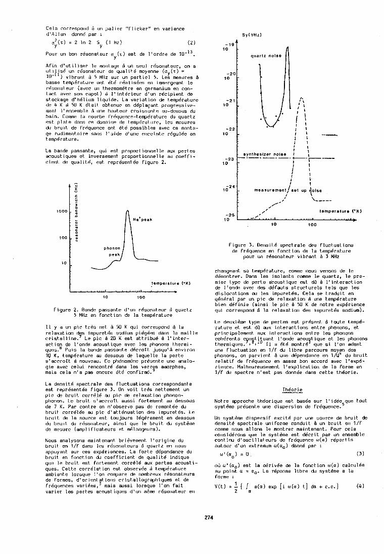
Cela correspond Fi un p a l i e r "f l l cker" en var iance d ' A l l a n donne par : S y ( l H z )
a 2 ( z ) = 2 In 2 S ( I Hz) Y Y ( 2 )
Pour un bon rdsonat.eur a ( z ) e s t de l ' o r d r e de 1 0 - l ~ . Y quartz noise
Afin d ' u t i l i s e r l e monkage un s e u l r d s o n a t e u r , on a u t i l i s 8 un rdsonat.eur de qua l i t .6 moyenne ( a y ( r ) = IU-") vibrant . d 5 Mtlz s u r un p a r t i e l 5. Les mesures d basse t.emp6rature ont d t d r6a l i sGes en immergeant. l e r8sona teur (avec un thermomdtre en germanium en con- t.act avec son c a p o t ) B I ' i n t b r i e u r d 'un r 6 c i p i e n t do s t o c k a g s dth61ium l i q u i d e . La v a r i a t i o n de t.emp6ral:ure de 4 K B 50 K Q t a i t obtenue en ddplaqant p r o g r e s s i v e - monl I 'ensemble A une ha t~ t . eur c r o i s s a n t t ? au-dessus du ha in . Comme l a courbe frequence-temp6rat.ure du q u a r t z <!st. p l a t e dans ce dotnaine de t.emp6rat.ure, l e s mesures du b r u i t de frequence ont 6 t 6 p o s s i b l e s avec ce monta- ge rud imenta i re s a n s l ' a i d e d 'une e n c e i n t e rdgu lde en t empdrat.ure.
La bande p a s s a n t e , q u i e s t p r o p o r t i o n n e l l e aux p e r t e s r ', acous t iques e t inversemerit p r o p o r t i o n n e l l e au coef f I -
synlheslzer noise I -23 .-.---.f---'---
c i e n t de q u a l i t 6 , e s t r e p r e s e n t e e f i g u r e 2. 1 0 t I ' I I
temperature ( *K )
F i g u r e 2. Bande p a s s a n t e d 'un rdsona teur B q u a r t z S MHz en f o n c t i o n & l a t empera tu re
t l y a un p i c t r d s ne t $I 50 K qui correspond A l a r e l a x a t ion des ~ m p u r e t d s sodium p16gdes dans l a m a t l l e c r t s t a l l i n e . ' Le p i c d 20 K e s t a t t r i b u C A l ' i n t e r - act on de l ' o n d e a c o u s t i q u e avec l e s phonons the rml - q u ~ y . e P u t s l a bande p a s s a n t e d d c r o t t jusqu 'd env l ron 10 K , tempdraturo au dessous de l a q u e l l e l a p e r t e s ' a c r r o t t B nouveau. Ce ph6nom6ne p r d s e n t e une analo- g t e avec c e l u i r encon t r6 dans l e s v e r r e s amorphes, mals c e l a n ' a pas encore Bt6 c 0 n f i r m 6 . ~
La d e n s i t 6 spec t , r a le des f l u c t u a t i o n s cor respondan te e s t repr8sent.de f i g u r e 3. On v o i t t r d s nett.ement un p i c de b r u i t c o r r d l d au p i c & relaxat . ion phonon- phonon. Le b r u i t s ' a c c r o t l . a u s s i fort.ement au dessous d e 7 K. P a r cont.re on n ' o b s e r v e p a s de remontde du b r u i t c o r r d l 6 e au p i c d ' a t t d n u a t i o n des impuretds. Le b r u i t de l a source a s t t.oujours leg6rement en dessous du b r u i t du rdsonat.eur, a i n s i que l e b r u i t du syst61ne de mesure (amp1 i f i c a t e u r s e t d l a n g e u r s ) .
Nous ana lysons maintenant bridvement. I ' o r i g i n e du b r u i t en l / f dans l e s r6sonat .eurs d q u a r t z en nous appuyant s u r ces exp6r iences . La f0rt.e d4pendance du bruit. en foncLion du coef f i c ien t . de q u a l i t 6 ind ique qun 11: b r u i t e s t for lement cor r618 aux p e r t e s a c o u s t i - ques. C e t t e c o r r C l a t i o n e s t observde B t.emp6rat.ure ambiante lo r sque I ' on compare de nombreux r6sonakeurs de formes, d l o r i e n t . a t i o n s c r i s t . a l1ograph iques e t de f requences v a r i 6 e s , rnais a u s s i lo r sque I ' on f a i t v a r i e r l c s p e r t e s acous t iques d ' u n mbme r e s o n a t e u r en
\,,,,..
t e m p e r a t u r e ( ' K )
F i g u r e 3. Dens i td s p e c t r a l e des fluct.uaLions de f rdqc~ence en f o n c t i o n de l a temp6rat.ure
pour un rdsona teur v i b r a n t A 3 MHz
changeant s a tempCrature, comme nous venons de l e dbmontrer. Dans l e s i s o l a n t s comme l e q u a r t z , l e p r c - mier type de p e r t e a c o u s t i q u e e s t &I d l ' i n t e r a c t , i o n de I ' onde avec des d 6 f a u t s s t r u c t u r e l s t e l s que l e s d i s loca t . ions w l e s impuret6s. Ce la s e t r a d u i t en ydnera l par un p i c de rs laxat . ion d une t.emp6rature b i e n d6Pin ie ( a i n s i l e p i c d 50 K de n o t r e experience q u i cor respond B l a r e l a x a t i o n des impuret6s sodium).
Le deuxidme type de p e r t e s e s t p r e s e n t t o u t e temp6- r a t u r e e t e s t dd aux i n t e r a c t i o n s e n t r e phonons, e t p r inc ipa lement aux i n t e r a c t i o n s e n t r e l e s phonons c o h e r e n t s c n s t i t u a n t l ' o n d e acou t i ue e t l e s phonons 3 . q . thermiques.9,8;10 I 1 a 6 t 6 rnontrb que sl l ' o n admet une f luc t .ua t ion en l / f du l i b r e pa rcours moyen des phonotis, on parv ien t d une ddpendarlce en l/u4 du b r u i t r e l a t i f de frdquenco en assez bon accord avec l ' expd- r i e n c e . Malheureusement l ' e x p l i c a t i o n de l a forme en l / f du s p e c t r e n ' e s t pas donnde dans c e t t e t h d o r i e .
Not.re approche t-h6orique e s t basde s u r l ' i d d e que tout. syst$me pr6sent.e une d i s p e r s i o n de frgquence.=
Un systdme d i s p e r s i f e x c i t e p a r une s o u r c e de b r u t t de densit.6 s p e c t r a l e uniforme conduit. B un b r u i t en l / f c o m e rious a l l o n s l e montrer maintenant . Pour c e l a cons iddrons que l c systdme e s t d d c r i t p a r un ensemble r o n t i n u d ' o s c i l l a t e u r s de f rdquence w(a) r 6 p a r t i s a u t o u r d 'un extremum w(ao) donne p a r :
w Q ( a 0 ) = 0 ( 3 )
0 3 w ' (aO) e s t l a & r i d e de l a f o n c t i o n w(a) c a l c u l e e au p o i n t a = ao . La reponse l i b r e du systeme a l a forme :
1 V ( t ) = - ( ( a ( a ) exp [ i w ( a ) t ] da + c.c.)
2 a ( 4
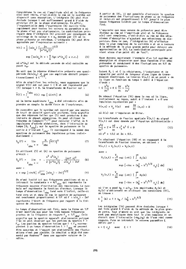
Considdrons le cas ob l 'amplitude a ( a ) e t l a frCquence w(a) sont r ee l s , c 'est-A-dire l e cas ob l e systdme est. d i spe r s i f sans absorpt~ion. L1int6gra le (4) peut & r e BvaluCe lorsque t e s t suffisamment grand 8 l ' a i d e du pr inc ipe d i t de la phase s t a t i onna i r e . En e f f e t , l 'exponentielle dans I 'expression (4) o s c i l l e t r d s rapidemont pour toutes les valeurs du paramdtre a oh l a phase n ' e s t pas s t a t i onna i r e . La contr ibut ion pr in- c ipa l e dans l ' i n t k g r a l e (4) provient par consequent du voisinage de la valeur a = a, donnee par ( 3 ) ob l a phase pr6sent.e un extr6mum. L1int6gra le (4) peut Btre approchee par I ' expression suivante :
exp [ iw(ao ) t + i Sgn ut ' (ao)] + c.c.1 (5) 4
03 wM(ao) e s t l a d6riv6e seconde de w(a) calcul6e au point ao.
On voit que la reponse 616mentaire pr6sent.e une quasi- pCriode 2n/w(ao) et ue son smplit.ude de'croit propor-
I 19 tionnellement & t- . Afin de simp1 i f i e r l e s ca lculs , nous supposons que l e s ignal V(t) e s t nu1 pour t. < 0 e t e s t represent6 par ( 5 ) lorsque t > 0, Sa transformde de Fourier e s t :
- Tabs V(f) = V(t) exp [ -2 in f t ] dt
0
od l a borne supdrieure Tobs a 6t6 i n t rodu i t e a f i n de prendre en compte la d u d e f i n i e de 11exp6rience.
On considdre que l e systdme e s t exc i t e par une source de b ru i t de densi t6 spec t r a l e uniforme. Cela s i g n i f i e que des r6ponses t e l l e s que ( 5 ) sont produites A des i n s t an t s de depart a l f a iq i r e s . On peut u t i l i s e r l e thtiordrne de Compbell t pour ca lculer l ' e f f e t de N impulsions d 'ent rge a l&a to i r e s , dens l ' i n t e r v a l l e de temps [0, Tabs[, sur l e spect re de puissance de l a s o r t i e 1 ll inst .ant Tabs. I1 correspond la somme des spec t r e s de puissance des impulsions p r i s e s indivi - duellement :
En u t i l i s a n t (5) e t ( 6 ) ce spect re de puissance s 1 6 c r i t : - m
n L a L ( a o ) i e r f V j 2 S V ( f ) = l i m v .
2 Iwu(ao)l ' w(aO) - 2xf (8 )
Tabs +
avec :
v = exp [ - i d 4 1 [w(ao) - 2nf] 1 /2
On s ' e s t l1mit6 i c i aux frequences posit-ives e t on a in t rodui t l a constante v = N / T o b s qui represente l a frdquence moyenne dlexcit .at ion des impulsions. Le sym- bole e r f repr6sente la fonct. ion d ' e r r eu r . Lorsque le temps d'observation Tabs tend vers l ' i n f i n i , c e l l e - c l tend vers un e t dans ce cas l e spect re de puissance e s t exact-ement proport.ionne1 A 1/F ob F = w(ao) - 2nf represente 1 '6car t de frequence par rapport B l a fr6- quence de r6uonance.
Le temps d'observation e s t f i n i , mais l a forme en 1/F n ' e s t m d i f i6e que pour les t rd s basses fr6quences proches de l a frequence de coupure Fo = l / T o b s . Cela s i g n i f i e que l e spect re apparaft s t a t i onna i r e puisque l o o n ne peut observer que les p a r t i e s du spect.re F > Fo. Les pa r t i e s du spec t r e t .e l les que F < Fo corres- pondant B un temps d'observat,ion t > T O R S ne peuvent. Btre mesurdes et l ' aspect non s t a t i onna l r e des f l uc tu - at.ions n ' e s t pas y js ib le . Ce r e s u l t a t a d6jA 6th com- mente par Keshner dans une approche voisine de l a n6tre.
A p a r t i r de (81, i l e s t poss ib le d ' e x t r a i r e le spec t r e de puissance des f l uc tua t ions de phase ou de fr6quence e t ce lu i - c i e s t proportionnel B l / f jusqu'8 l a p lus basse frequence to l6rde par l e t.emps d 'observat ion f i n i .
L'approche que nous venons de presenter peut & t r e Ctendue au cas 03 1'amplit.ude a ( a ) e t l a frdquence w(a) sont complexes, c 'es t -8-di re au cas 03 des d c a - nismes d 'absorption s ' a jou ten t aux mdcanismes de dio- persion. Oans ce cas, I ' i n t6g ra t ion (4) sleffect .ue dans l e plan complexe de l a var iable a e t on a recours B l a d t h o d e de l a plus grande pente pour obteni r une approximation de (4) . La contr ibut ion p r inc ipa l e pro- vient a lo r s d'un point d i t de "col".
Nous donnons maintenant l'exemple d'un t e l systdme 4 absorption e' dispersion sont deux f ace t t e s d'un mBme ph6nomdne e t conduisent 8 des f luc tuat ions en l / f du spect re de puissance.
Soient H, L e t C l a rGsistance, l ' inductance e t l a capaci te par uni t6 de longueur d'une l igne de t rans- mission Blectrique. La tension V(x,t) en un point x de l a ligne en fonction du temps t ob6it B l 'dquation d'onde :
a2v av a2v L C - + R C - = - a t 2 a t ax2
On resoud 116quation (10) dans l e cas ob l a l igne, inikialelnent au repos, sub i t 1 I ' inst-ant t = 0 une impulsion representee par :
a v V ( X , O ) = Vo 6 ( x ) and - ( x , ~ ) = 0 a t.
od 6 (x ) e s t I 'impulsion de Dirac.
La transForm6e de Fourier spat i a l e T ( k , t ) du signal V(x, t ) e s t donc donnee par 1'6quat ion d i f f e r e n t i e l l e :
En r6solvant 1'6quat.ion (10) e t en repassant 8 l a transformCe de Fourier inverse, M obt ient :
V(x,t) = Vl(x, t ) + V2(x, t ) (13)
avec : v -P
v l ( x , t ) = 2 exp ( -a t ) .f Ai(k) 4x -m
exp [-ikx + ( k i - k2) ' /* c o t ] dk]
(14) 9
v2 x , = e x t A2(*) 4n -OD
exp [-ikx + (k i - k2)112 co t ] dk)
od l 'on a pose kg = a/co. Les amplitudes Al(k) e t A2(k) s 'obtiennent en u t i l i s a n t l e s conditions (11 ), on lrouve :
Les in tdgra les (14) peuvent Btre 6valu6es lorsque t e s t t r d s grand B l ' a i de de l a d t h o d e de l a p lus gran- de pente. Tout. d'abord on voit que l e s in t6grants ne sont pas analytiques dans tout l e plan complexe e t on c h o ~ s i t donc l ' i n t e r v a l l e (-kg,kg) de I 'axe r ee l comme coupure. Puis on in t rodui t l e nouveau paramstre t; dCfini par :
x = 5 co t avec 5 < 1 (16)
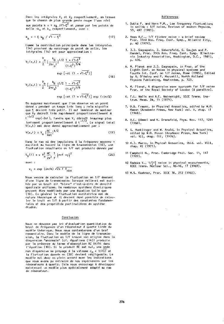
Uans l es in tegra les V1 e t V2 respectivement., on trouve quo l e chemin de p lus grande pente coupe I ' axe rCel - aux p0int.s k = + ka //I-c2 et. passe par les po in t s de s e l l e -ks et ks respect ivement, avec :
Comme l a contribut.ion p r ~ n c i p a l e dam les i n tdg ra les (14) provient du vo i s~nage du po in t de se l l e , l es in tdgra les (14) ont pour approximat.ion :
- exp [ - a t (1 - JI-~*) ]
exp [ - a t (1 + 41-c2)] exp ( - in /2)
On suppose maintenant que l ' o n observe en un po in t donnrf x pendant un temps trGs long ; ce la s i g n i f i e que F, devient t r b s p e t i t . I 1 est immddiat. de montrer que V 2 ddcro f t t r 6s rapidement proportionnellement d
t.-5/2 exp(-2at ), tandis que V 1 dBcrof t beaucoup p lus lantement proport ionnelloment. 6 t.-'j2. Le s igr la l tot.al V(x, t ) est dorlc donne approximativemer~l par :
Dans l e cas od des impulsions B l a frequence moyenne v exc i t en t au hasard l a l i gne de trarismission (101, une f luctuat, i on rdsu l tan te en l / f est produit-e dolinde par
avec : -7
v1 = exp ( in /4) J2n f Tabs
Nous venom de ca lcu ler l a f luct .uat ion en l / f Bmanant d'une l i gne de transmission lorsque c e l l e - c i est exc i - tde par un brui t . d i t "blanc" c ' es t -d -d i re de densi t6 spect ra le uniforme. De nombreux syst6mes B lec t r iques peuvent d t re moddlisds par une equation t e l l e que (10). En gdnbral l a f luc tuat - ion e ~ c i t a t ~ r i c e est de nature thermique et il devient. done possible de calcu- I s r l e bruit. en l / f B par t ir des constantes fondamen- t a l es et dcs propr i6 tes part-icu1iSres du syst6me tit.udiB.
Conclusion
Nous ne donnons pas i c i d'dvaluat ion quant i tat , ive du bruit. de frdquence d'un rBsonateur d quartz t i r d e du lnoddle thkorique. Nous nous contenterons d 'un b re f comment.aire. Dans l e moddle de l a l i gne de transmis- s ion , l a Fluct.uat.ion en 1 / f trouve son o r i g i ne dans l a dispersion "anormale" ( c f . dquat,ions (14)) produit,e par l a presence du terrne d 'absorpt ion RC aV/at dans l ' dqua t i on (10). Si l e p rodu i t RC est nul, une z d e non d ispers ive se propage d l a v i tesse co = 1/JLC et l a f luct,uation donnee en (20) devient nBgligeable. Le modble est donc en p l e i n accord avec les i nd i ca t i ons que rious avons p t ~ ext.raire de nos experiences sur l e s r6sonat.eur.s d quartz. Cela nous encourage .4 ddvelopper maintenant un modble p lus sp6cialement adapt6 au cas du r8sonat eur.
1. Dut ta P. and Horn P.M., Low frequency f l uc tua t i ons i n s o l i d s : l / f noise, Reviews o f modern Physics, 53, 497 (1981).
2. Voss R.F., 1 / f F l i cke r noise : a b r i e f review Proc. 33rd Ann. Freq. Cont. Symp., At.1ant.i~ C i t y , p. 40 (1979).
3. 3.5. Gagnepain, J. Uebersfeld, G. Goujon and P. Handel, Proc. 35th Ann. Freq. Conk. Symp. (E lec t ro- n i c Indust-ry Association, Washington, D.C., 1981 ), p. 476.
4. M. Planat and J.J. Gagnepain, i n Proc. o f t he E igh th Conf. on Noise i n physical systems and Fourth Int*. Conf. on l / F noise, Rome (1985), Ed i t ed by A. D'Amico and P. Mazzett i , North Hol land Physics Publ ishing, Amsterdam, p. 323.
5. M. Planat., A d ispers ive wave approach fo r l / F no ise Proc, o f the Royal Society o f London (A para f t re ) .
6. F.L. Walls and A.E. Wainwright, IEEE Trans. Ins- trum. Meas. 24, 15 (1975).
7. U.B. Fraser, i n Physical Acoustics, ed i t ed by W.D. Mason (Academic Press, New York) vol. V, chap. I 1 (1968).
11. H.E. Uommel and K. Dransfeld, Phys. Rev. 117, 1245 (1960).
9. S. Hunklinger and W. Arald, i n Physical Acoustics, edil.ed by W.D. Mason (Academic Press, New York) vol . X I I , chap. 111, (1976).
10 H.J. Maris, i n Phyical Acoustics, i b i d . vol. V I I I , chap. V I (1971 ).
11 Campbell N., Proc. Cambridge P h i l . Soc. 15, 117 (1909).
12 Radeka V., I/\ f ( noise i n phys ica l measurements, IEEE Trans. Nuc ear Sci., NS-16, 17 (1969).
13 M.S. Keshner, Proc. IEEE 70, 212 (1982).
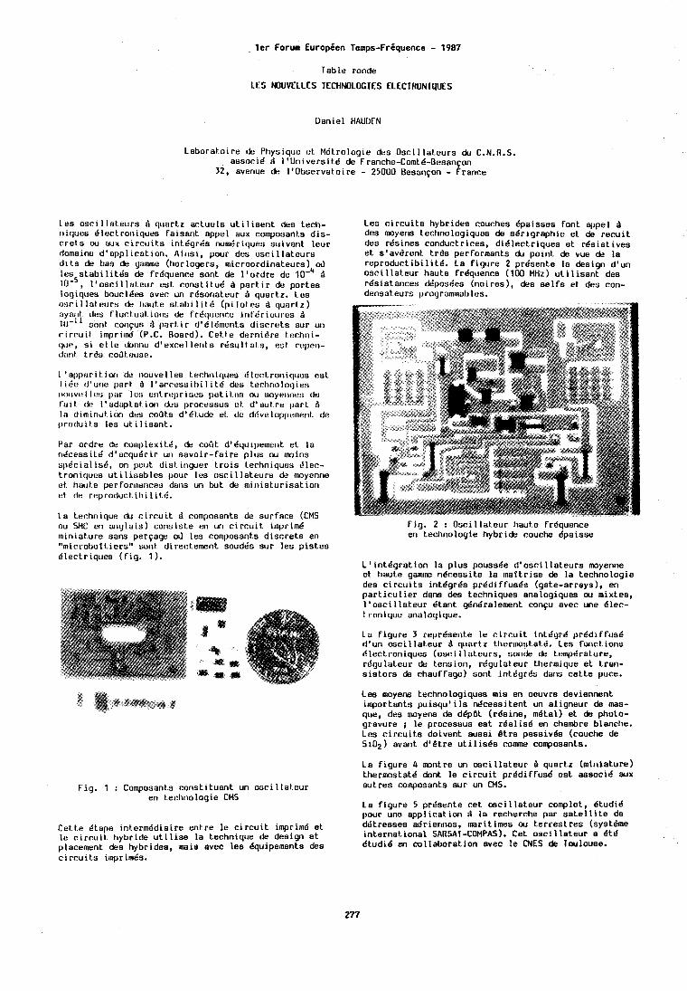
1er Forum Europien Temps-Friquence - 1987
Table ronde
LES MUVELLES TECHNOLOGIES ELECTRONIQUES
Daniel HAUDEN
Laborato i re dc Physique ot M6trologie des Osc i l l a teu rs du C.N.R.S. assor16 d 1 'Un ivers i td de Franche-ComtB-Bosan on
32, avenue de l tObse rva to~ re - 25OUU Uesanfon - Prance
Leu osci 1 la teurs A quartz ac tue ls u t i 1 isent dao tech- i ~ i ques d lec t ro~ i i ques fa isant appcl aux composant.~ d i s - c re t s ou etlx c i r c c ~ i t s int.dgrda numdriques s t ~ i v a ~ i t leur domaine d 'opp l ica t ion . A ins i , pour des o s c i l l a t e u r s d i t s de bas de game (horlogers, microordinateurs) 03 les s t a b i l i t t ' s de frdquence sont de I ' o rd re de B
I ' o s c i l l a t e u r est const i tud A p a r t i r de portes loqiques boucl6es avec un rBsonateur B quartz. Les 11m-i I ln t IttJrs h. 11at1t.e sl.abi 1 i t 6 ( p i 1o t .e~ A quar tz ) clyarll tlcs f 1ucl.uat. iorls de f r t 'que~~ce inV6r ict~rt .s Q 10-'I oni~ t coi~qus A part . i r d'6ldment.s d i sc rs t s sur un c i r c u i t i m p r i d (P.C. Board). Cet.te dernidre tochni- 11c1f!, s i e l l c cfonrio d'excal lent s rdsul t at.s, eat. ct:l~er,- rl;lr~t t,r&s co0t.ouse.
1 ' n l ~ l ) t ~ r i t . i w ~ de nouvel les t.echniques dlectroniqlrus osL 1 i 612 t l 'ur~c part A 1 'srcesui l ) i 1 i t@ des t.ectinologies i1tnlvo l l c:; 11;1r lcr; el\\. rt: l~r i uus pat. i t.t?r; nu 1noynilnt::j (la fa1 t. &! I' aduptat iorl &LI ~ I C O C ~ S S U S t?t d' aut r e pa r t A 1:s diminut. ion dt!s coats d'dt.udc et. clc ddvaloppumer~l. dc produit.s les u t i 1 isant.
Par ordre de complexit@, de coat d 'dq i~ ipe~ncr~t e t l a ndcessiLB d1acqu6r i r un savo i r - f a i r e p lus w moins sp6c ia l is6 , on 11etjt dist.inyuer t r o i s tecl~niques Jlec- t roniquos u t i l i o a b l e s pour lus o s c i l l a t e u r s & moyenne e t t1cn~t.e perfor~nancss dulls un but da m in ia tu r i sa t i o r i t:t de reproduct.ibi l i t .@.
La technique du c i r c u i t FI composants de surface (CMS ou SMC cn ang ln is ) corisiste en un c i rcu i t . imprimd miniature sans pervage oJ les compoaants d iscre te en "microbot t ie rs" soot directement soudds sur lea p i s tes B lec t r iques ( f i g . 1 ).
Les c i r c u i t s lrybrides couches Bpaisses font +pel P des moyens technologiquus de sdr ig raph ie et de r e c u i t des rdsines conduct r ices, d i d l e c t r iques e t rda i s t i ves e t s 'av6rent t r 6 s performants du point. de vue de l a r e p r o d u c t i b i l i t d . La f i gu re 2 prdsente l o design d'un o s c i l l a t e u r haute frdquence (100 MHz) u t i l i s a n t des rdsist.ances d6posdes (noires), des s e l f s et des con- densateurs ~~rogrammables.
F ig . 2 : Osc i l l a teu r haut.e frdqueiice en tectinologie hybr ide couche dpaiase
L ' i n t d g r a t i o n l a p lus poussde d ' o s c i l l a t e u r s moyenne et haute gamin? ndcessi te l a mat t r ise & l a technologie des c i r c u i t s intdgrde p rdd i ffusBs (gate-arrays), en p a r t i c u l i e r dans des techniques analogiques w mixtes, l ' osc i l l a ' eu r dtank $ndralement confu avec une Olec- t roniquc unalogique.
La f i gu re 3 repr8sent.e l e c i r c u i t inLdgrB p rdd i f f usd d'un o s c i l l a t e u r A qunrtz t l ier~nostatd. Les fonct ions Blectroniques (osc i l l a teu rs , sonde de tempdrature, rdgulatuur dt, tension, rdgulateur thermique e t t ran- s i s t o r s de chauffage) sont in tdyrds da~w ce t te puce.
Les moyens technologiques mis en oeuvre deviennent importants p u i s q u ' i l s d c e s s i t e n t un a l igneur de mas- que, des moyens de ddp6t (rgsine, mdtal) e t & photo- gravure ; l e procesaus est r d a l i s d en chambre blanche. Lea c i rcu i t .s doivent aussi &tee passivds (couctie de Si02 ) avant d t & t r e u t i l i sds comme conposants.
La f i gu re 4 m n t r e un m c i l l a t e u r A quartz (miniature) thermostat6 dont l e c i r c u i t p red i f f usd est associr! aux
Fig. 1 : Composants const i tuant un o s c i l l a t e u r autres composants sur un CMS. en techno l og ie CMS
La f i gu re 5 prt'sente cet mc i l l a t . eu r coolplat, d tud id pour une app l ica t ion B l a recherche par sa t . e l l i t e de
Cett.e Btape int.erm@diaire ent re l o c i r c u i t impri~nd e t d6tresses adr ie r~~ ies , marit imes w t e r res t res (systlme
l a c ~ r r u i t hybr ide u t i l i s e l a technique & des ig i e t i n te rna t i ona l SARSAT-COMPAS). Cet o s c i l l a t e u r a d td placement des hybridee, mais avcc les dquipements des d tud id sn co l l abo ra t i on avec l e CNES de Twlouse.
c i r c u i t s imprimds.
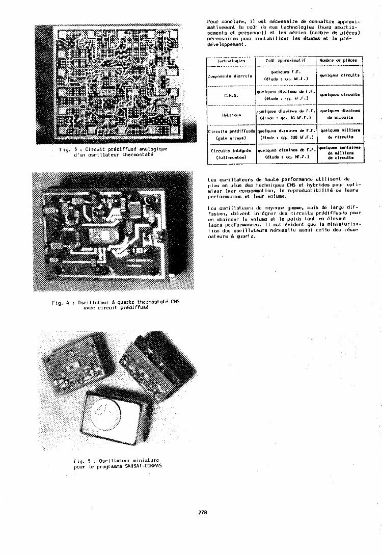
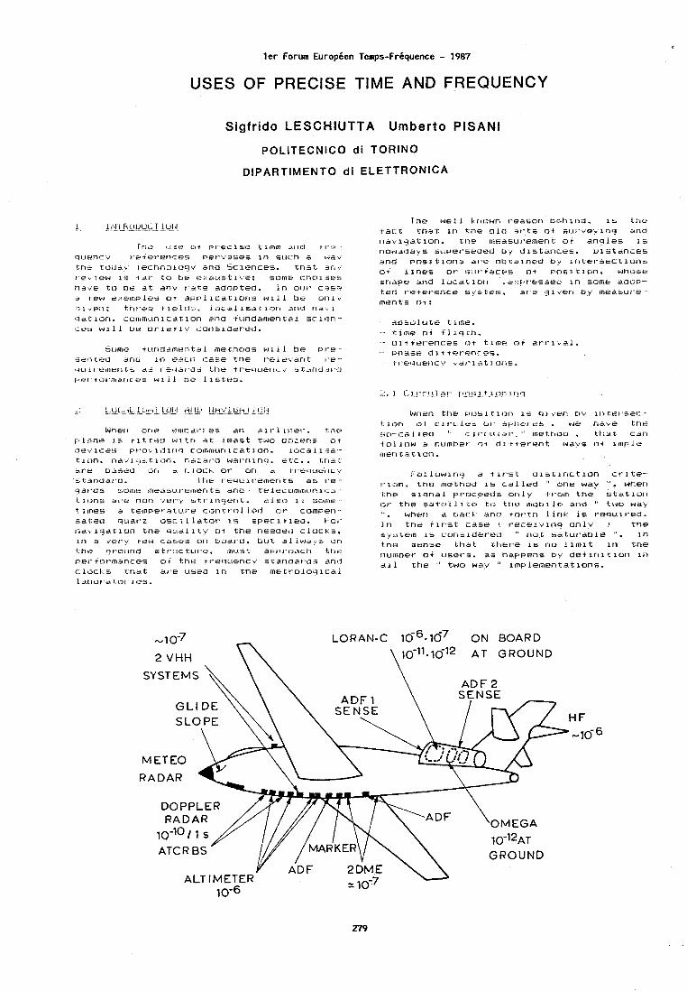
l e r Forum Europeen Temps-FrCquence - 1987
USES OF PRECISE TIME AND FREQUENCY
Sigfrido LESCHIUTTA Umberto PlSANl
POLlTECNlCO d i TORINO
DIPARTIMENTO d i ELETTRONICA
ir is c.l:se r s i I.yl,eclse t'line AIIU ?I-*-.
qLtenc:y t,eiet-erices per-vases i n ~ L I C ~ a dav ?tit: tocia\ I echnoloqv and Sciences. tna t en, t . e ~ ~ e w 1% (dl.' t u t ~ e r : . :aust i \e: some cr tn lses t ieve t o ne a t any r a t e Odnptrd. i n oc..tt- case? s few r ; .em~) ies o t a p n l l c a t i o n s w l l l be o n l y I ' t l -~r-ee t1oIdc. .~oca l i sa . t i a r ' i 3.110 na . ,~ . . ~ . ~ d t LOTI. i ;u~i~mc.~n~cdt i o n hnu .t i.indaflien t a i sc 113n cr.e5 will bt? br' let .ly c:orl5lilet'ed.
5e~mtd l ~ t r ~ d ~ ~ r ~ a n t d . L metnuas w l . L I br-. P I ~
":id~ttt.-d drid 1r.l V:~.:?ILII eaEe t t ie ~ i : r I.e-.. IIC~ I t'e~lit?rI L L a9 I e>'Iat-il:, t r ~ e tt.'uc,ctertc..~., s tarru.:rt'.cl r.zet,tc.rl-maiici3B WI 11 C)C l i ~ i t c ? ~ ~ .
Wlieri one cttnl~di'l. c + 8 ar7 311"l inel'. 'thy o l i i ne 1% ti t ,retd i.rlcrt e t l e a s t twu rdolert= ot Cievic~:, p ~ . o , l j l r t i ' l c o ~ n t ~ i ~ ~ r t l c a t i o n . L L - I L : ~ ~ is*-,,
t i on . r ia 'd~~i :~t . r~>n. r;.~:~it-d wal-rirr>cl. e t c . . c t ~ r t AI'U D~SPCI 01') : : i c : I on rt~eile.leilc',~ st'driclat'd. I tie rer~~e1i.rtaen t s as t-e-. rqat-Us sonic ineajt-rr~e~nen t s all0 telecol~imctnica.~ I; lc.,n:; t i r , ~ nun ~ e i - . ~ btt-ln(:jeri t. BIYO 1 1 s0i11t t irne!s a tempet.al:.~.~~ e c a n r r o l i e d ol- cornper?.. Sa.l;Sd qctat-z 05: l a i spec 1.1 leu. t.:o~'. nav l r ja t i o n the ctieai I t,,. o i t he rteec1ei:l c1ocl.s. :in a vet-v tew ca$%t:.s on t:!oal'~d. bii't a l i w a ~ + *>I-i
the q t 'o~ .~r~d s t t - i ~ c ~ L I I . ~ . mctsr; arr>t.mach tr ie pe~.'tc~t-inances cr.i the tt*ei.lc.Iencv sl;arinar'cls anlj c iocl . .s t n a t at'e useu l r ) the 1nc.tr.olnrl1ca.i l,st.,ot~a t.ot 11s.
I he we1 1 l:rrt:~wn ~ ~ e a s u r i Dehil'ld. 1s t h e .+act t h a t i n Lne olcl a 1 - t ~ o t su l ' ve \ inq and r iav iqa t lo r i . the measui'ement o 1 anq les I s i~owarlay s sc.tpet~seuetl by d l stcinces. L l s t a n c e s r:md p o s i t i ons at-e obtalnec) o,v in te l -see t lone,
o i Alnes o r se.tt,tacks o t p o s ~ t i o n . wh~jsi. snape and l o c a t l r m .c:.:r)t-essed I n some aoov-. Led t-etet-ence sgsteln. a r e .rllvsn f i y 1nea6ui-e. 1ne17ts 01:
aoso lu te t ime. c l i ~ ~ e o t i1 iq l .h .
.. o i t iel-enc:es or t lme a t a r - I - i i a l .
... rjhc+se d I t i el-enc oc,, ~ I - c ' ? L ( ~ I ? c v dt - I d t l.oiis.
G4ner1 t t ie F I ~ . > ~ I Cl(71-i 15 "en D'., 11ilet"se(-. tlon of c i r c i e u (21'. i ) l l . te~.es . we r ihrc kt?*? i i~- .chA iecl " 1:. 1 ~vc . . r . r r -1.'. " tnetrlod . t;tiat: C . ~ I - I
lo11c?w a number a t d l t tet-errt wave a t ~ n t p i e . iner? t A c i o n .
I - u i l o w i l ~ i ? a t 11.,st c l l s t l n c t l o t ~ ct-l,ce.-. ri,:>n. t ne me.thod 1s ca.11ed " nne w a y ", when i;he a i q n a l pt-oceeds on l v it-om the s t a t l o l . i or- tr ie s a t e l 1 i t + ti:) t t ie iliot>l l c and " two way . when a oac:t an0 rot- rn iirbt.: 1s t-equit-eU. I n t n e t i l . * s t case i 13ece lv lng o n l v I t h e %y;>tern r s consldet-ed " r iot sa tu t -ab le ". Ira t n s sense t h a t ttietqe 1s no l i m i t I n t he r i ~~ i~ ioe t - 01. ~ ( s e l - ~ j . as nappens o y o e t l r t t t i o n i r ' i
ail t he -' two wa:y .' lmple~nentavlone.
M ETEO
RADAR
DOPPLER RADAR
LORAN-C 10-~.16' O N BOARD
HF
-10-6
2$ME \ GROUND - 10-7 10-0
ALTIMETER Y ADF -
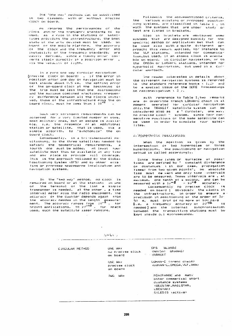
I tie "or?r wav" ~ltekktoas can be suodi; icied ~n t w o c lasses. w i t t i or- w l t t i o ~ t t P I . . M C ~ ~ C
(..ic)cl. c~n boatd.
HS r-esat'ds 'the pet.? ormances w t t he c loh s arid, o t the .tt-equenc.r standa~'ds tci ot? c.~sr.?a. ae a t - L I I ~ i r i the s t a t l o n e a ~ t - satc?l.. I I t e s p t - o v t d i r ~ q the i n tt'as t~-uc tu t -e . t he bes t j t e t e ot t t ie & I - te de,~lceFj must be used. Dri i-~o~+r-d o t t he mob1 l e p l a t 1.i3t-m. ,the accuracy 1:3t the c loch. and t l ie f t'eq~cericy e t and ~ n s t a o i 1 L t s o t t he tt-eqc.~ency standar-as. a re t.?ds 1 IV clef-iveu. since a t; lmirtq et-r~'or' curl... det't5 i t s e l t a l r - . ~ ? c t l y i n e pos iu io r i e l - ro r , $14 Chr ve.Locltv t i t I i q t h .
I n a p11t.e one way cit .culat- n a ~ i q a t i o n (pt-ecise c l o c t t i r ~ boat-d) . 1 1 the et-rot- I n [ ' o s l t i t in a t t r t - one ddv 01 nav lqa t i o r i must be I e p t r r ~ s i d e about (-1.2 l m . t he s e t t i n i l et-t-or i-J+ tt ie on--boat d clock a t t h e beq i r in lnq ot the t r i p must be l e s s than one micr-oseconij ~ i n t j t ne md.. i i r t c c m como ined t r a c t i n n a l tt-equen-- cv d i t f e r e n c e between a l l t ne c l o c k s i n d o l - ved. those a t t he i n f ras t t . uc tu re p l u s the ori tioat-d c l o c t . must be l e s s tnan 1 ICP-'' .
P U C ~ ~ e t - v 5 t t iricient requit 'ements can tie dccer>cud l o t J drt-v l i m i i e d number- o t usrh . inobt t n i l i t s ~ v ones, b u t art escape i s a v d i l a - tile. I .e. t t ~ e Presence o t arl add1 t l o n a l s t a t i o n o r s a t e l l i t e . t n a t i s used, v ~ a a s i inp le 1 t i t o "sdnctton1;:e" t he ort bod1 d c l n c t .
L o n s e q ~ ~ e r l t l v . l n a t t - i - d imens iona l P O -
a i t i o n l n q . to t he ttit-ee s a t e l l i t e = r ierdra t o s a t $ a t v the nleometl-ical t'equiremerits. A
t o u r t h one rnclst be added. A t l e d s t idu t i a t e l l i t r must t t ius be a v a i l a b l e a t d r i ~ tlmta 'rncl ariv p l a c e t o (at-ovide 1~111 ~ u ~ e t atre. l h l s i s t ne af~pt-oach to l l owed b~ the Globa l I - o s i t i o n i n g bystem rGtS) and b * othet- e x i s - t i r iq ot- pt3or>osca spacebot'nr l o c a l i = a t i o n and ~ ~ a ~ i y a t l o r t svsteflis.
I n the "two wav" method, no c l o c t i s I-equrt-ed on oodrd t i t - a t t he S ta t i on : i n one o t t t ie t e t - m i n ~ i l o f t he l i n k a s im(?le traspondet- i s needed, a t t h e o t h e r . a t ime ~ n t e t - b a l meter p l u s t t ie r a d i o equipment. Ine dcc:ut-acv o+ the coun te r depends aga in rt-om the accur-acv needed i n t h e l e n q t h measur-e- n~ertt. Ihe a c c ~ t t - a c ~ I-anqes from 1 . tot- c~round a p ~ l i c a t i o n s . t o l 1 . 1 - ' ~ , f o r space ccses. such the s a t e l 11 t e taset' r'anqlnq.
F o l l o w i n q the aoovernentioneil c t . l tet - la. t ne v a r i o u s e.: ist lr i i4 ot- pt.oPosed p o s i t i o - 111i-19 svstems. at-e c lass11 l e d i n l d b l e 1 . i n w icn t h e svsterns t h a t at-e undet- r t u d v 01- t e s t al-e l i s t e d i r i b l -ackets.
irl so t n bt-acl e t 5 al'e merit ioneu some sv5tems t t ~ a t a r e deslgned b a s i c 1 y tot one spec] t i c method ot- a p p l i c a t i o n b u t t h a t can be used a l s o w i t h s q u i t e d i+ te t *en t ap- pt-oach: t h i s t-emdt-t app l i es , tot- i ns tance t o t h e VLF s t a t i o n s . i r i tended tot' commurtlca- t i un .ou t used. ii an atornlc c l ock 1s a ~ a i l d b l e on boat-d. i n c l l -cu ia t - nav iqa t ron . ot- t o t h e 011E0(4 01- LOh~td-L s t a t ions . ln tenaed tot- hgpe l -oo l ic n a b i g a t i o n . oc.~t used i n a c l t ' - r:ulat- apf7t'oat:h.
I t ie reader i n t e r e s t e d i n d e t a i l s about t h e c l i t te t -en t n a v i q a t l o n svstwms i s t7e+et r e d .to t he s tandara t-etet-ence books t 1.;) and t o a spec la1 issue o f the IEEE kt.oceedirig5 on r a d i o n a v i q a t i o n t ; r .
N i t h t-etet-ence t o Table I . two t-ernal-I s a r e o t ordet- : the t rench LOfiAI4-C c h a l n 1s a t moment opera ted fol. c i t - cu ia t * ndv i g a t i o n o n l y . t h e TkANsll s a t u l l i t e s ~ s t e m can be cons idered a l s o as a " c l t - c u l a r , one w a b , no PI-eclse c l u c l " svstem. s i n c e tour con s e c u t i v e ~ o s l t i o ~ i s o t t h e same s a t e l l i t e car) be used i n ot-det- t o b lmu ld te iuu l - s a t e l - - 11tes.
When t h e p o s i t i o n 1s giber? uy t h h tntetmeec t l n n o t two hvpet.bolae or tht7ee hypet-bolo ids. t h e p o s i t i o n i n q ot' n a v l g a t lor1 method i s c a l l e d accot-d lnglv.
b i n c e these l i n e s ot sut-taces o t ~ 0 5 1 - t i o n s at-e d e t i n e d by " cons tan t d l + fet-ence o t d i s tances ( i n our case. p ropaqa t l on t imes) tt-om two q ~ ~ e n po i r i t s " , no abso lu te t ime must he kept and o n l v t ime i n t e t - k a l s at-e t o be meashred. lhese i n t e t - ~ a l s at'e . a t rsa;:ifllum. one t e n t h o t a secona. anu can be measured w i t h a l u - 5 - lcl-6 accut-acy.
Consequently no p r e c i s e c l o c k i s needed on boat-d : o b d ~ o u s l ~ the c l o c k s i n t h e i r i t r -astruccut 'e, i n ot-det- t o ensure a p r v c i s i o n ~n p o s i t i o n l n q ot t h e o r d e r o t Z v - 5r.j m. must d r i t o t no more o t 11.11.1 ns / d (1 .e. a +I-equencv accut-acy o t 1 . 1s needed ) and the ~ r i t e t - n a l r ' ynchron isa t lor) between t h z t r a n s n ~ i t t i n f r s t a t i o n s must be Kept i r i s tde o. 1 tnict-oseconas.
CINL W C I Y LOF&I~l--i r t I-enc c t ia in J
p t-ec i se c l o c k (LlJhclPJ-.L. O l l t ~ A , 'v'LF . A l . l k ~ on board
M I l d I T t A N O E an0 man" o t h e r commer-cia1 s h o r t d l s t a n c e systems (OEO5IAFi. hAlLS1 AH. LUCS I AK > S U L E ~ I S r a c t i v e )
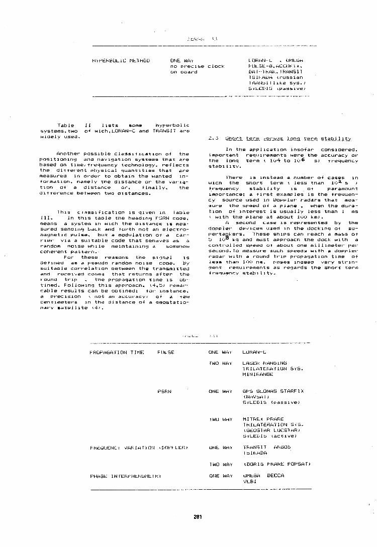
t i r t ' E h B u L IL Plk. l biUV Ohlk W C l r ~ u h k l d - L . C ~ l l t b ~ n o p r e c i s e c l o c k b i J ~ . > t -e. h i .~ IJ l - I A .
u n b o a r d DA I - I txkl . I HbilUbl l 1511 AUM c t - u s s i a r i IKAI4tll l l i k e s y s . ) brL.EL,lt, t p d s r i v e ~
l a b l e 1 1 l ists some h k p e t - c o l i c s y s t e m s . t w o o t wich,LOFtAN-C a n d ih6\l\(bIT a r e w l a e l ? u s e d .
HnQthe t - p o s s i b l e ~ L a s s i t l c a t i o n o t t n e p o s i t i o n i n y a n d n a v i g a t i o n s y s t e m s t h a t a re b a s e d o n t i t n e / + t T e q u e n c y t e c h n n r o q y . r e t l e c t s t n e d l * t e t * e n t b 3 t 1 v s i c a l q u a n t i t i e s t h a t a re rrteasut-ea i n o t - d e r t o o b t a i n t h e w a n t e d i n - - t o r m a t i o n . n a m e l y t h e d i s t a n c e o r t h e var ia- t i o n o t A d i s t a n c e of-. i i n a l l ~ . t h e o i t t e r e n r e b e t w e e n two d i s t a n c e s .
l h i s c l a s s i t i c a t i o n is q i v e n i n l a b i e 1 1 1 . I n t h i s t a o l e t h e h e a d i n g FSHIJ c o d e , m e a n s a s v s t e r r ~ i n w i c h t h e d i s t a n c e is nbea s u t - e d s e n o i n r l b a c k a n d t o r t h n o t arb elect1.0- n b d y n e t i c p u l s e , b u t a m o d u l a t i o n ot a c a r - - t - l e t - v i d a s u i t a b l e c o d e t h a t n e n a 9 e s a s a r-andom n o i s e w h i l e n ~ e i n t a i n i n q a somenow c o h e r - e n t p a t t e r n .
For- t h e s e t - e a s o n s t h e s i q n a l is d e f i n e u a s a P s e u d o t-anaom n o i s e c o d e . b{ s u i t a n l e c o r t - e l a t i o n n e t w e e n t h e t r - a n s m i t t e d dnO t - u c e i * e d C O U ~ ~ t h a t t - e t u t - n s a f t e r t h e t o u n d t t - i p , t h e p r - o p a g a t i o n time is ob- t i n e d . F-01 l o w i n q t h i s a p p r o a c h . (4.51 t - e m a r - c a b l e t - e s c r l t s c a n b e o b t i n e d : tor- i n s t a n c e . d p r e c i s i o n ( n o t a n a c c u t - a c v j ot a few c e n r i m e t e t - s i n t h e o i s t a n c e o t a q e o s t a t i o - n a r y s d t e l l i t e r 4 ) .
I n t h e a p ~ l i c a t i o n i n s o i at- c o n s i d e r e d . l a p o r r a n t t - e q u i t -enbents w e r e t h e a c c u t - a c y ot- t n e l o n g t e r m ( 104 t o 11.16 s ) t r - e q u e n c v s t a b 1 l i t y .
1 - h e r e is i n s t e a d a n u m n e r o i cases i n w i c n t h e s h o r t t e r m ( less t h a n 11:12 s , t r e q u e r l c y s t a b l l i t ~ is ot p a r a m o u n t i m p o t - c a n c e : a t it-st e : c a a p l e s I S t h e t t - e q u e n - - c..+ s o u r c e u s e d i n Uopcrlet- t -ada t - s t h a t mea- s u t 3 e t h e s p e e d o r a p l a n e , when t h e du l -a - L i o n o t i n t e r e s t is u s u a l l v less t h a n I m s ( w i t h t h e p l a n e a t a b o u t 1 0 0 k m ) .
A s e c o n u c a s e is r e p t 3 e + e n t e d b y t h e i i n p p l e t - d e v i ~ e s t t s e d i n t h e clock i n q 0 4 s u - p e t - t a i h e t - s . I h e s e s h i p s c a n t e a c h a m a s s o t :I lcrs C q arid m u s t a p p t . o a c n t h e docL w i t h a t orbtt-.oL l e d s p e e u o t a o o u t o n e mi 1 1 l m e t e l ' pe t - s e c o n d . l o m e a s u r e s u c h s p e e a j w i t h a ~ O P P Let-
t-adat- w i t r i a t ourbd t t - i p p t - o ~ a q a t i o n t i m e of less t h a n 1l.rl.b n s . p o s e s i n a e e a vet-y s L t - i n - r l e n t t - e q u i t 7 e m e n L s a s t eqat-dm t h e s h o t t re , - I I I t t w s u e n c v s t a b i 1 i t V .
t: R U F ' A ~ A I‘ I ON T I ~ I E F ULSE ONE WAY LUFtAId--L
ONE W k Y GPS GLONAS S T A H F I X ( N n V h n 7 ) S I L E D I S ( p a s s i v e )
I rl0 WAY tDOFi1S F'hAHE F'DF'SI.IT)
UlJE WAY LIMEDA UECCA 'JLG I
n i p e c i a i c a s e is r e p r e s e n t e d b v t h e 1,-equenc.,, t t - a s l a t i o n c h a i n s 1.1sed :in t h o 11, LC:~.E)WI,*C r-ad l o I 1r.1,. e . i n w i c n t n e a a s r n a r c d d ~ \ ~ l l o c ~ l a r ~ n e i 1,t.1<.'--!.4l.'t.l 112) 1s t l ' e e tet.t"Ei:l 111 0 - a 31,er;e to a c r n t l m u t t ' l c c a t ' l * l e t - < 5 ! .,
I ~ t e ~ r a t i l I T ~ - e ~ ~ ~ t l a t l o r i s t ~ e q u i t ' o c r . ~ a n 111 d t . i c t i ~ t i o ~ t s l i n t ot 291Jk.~ L m . t h o t o t a k t I - o r ~ u o r ~ c y et-t'or' i r l t h e b a s e bar10 s h o u l d t e m a i n l e s s t h a n 2 b l r . l ' n l s l i m i t t-es~t1r.es t h a t . i n t h e c n a l n at a-e i )uar - tZ o s c 1 1 la tor-s r i r e d e d tot- t h e a b o i e m e n -, t i o n e d i r e q u o r i c y tt-anslat ion. t h e a c c u t - a c ies I - a r ~ g e tt-om ,iv-6 t o t - t h e i . i r q s t s t e p t o 1 l - 7 ~ , tol- t h e l a s t s t e p s .
L l u i t e d l t t e r e n t 1s t h e s i r ; - r a t l o n ~ n t h e d i c q i t a l I - o m m u n i c a t l o r t s . w h e r e t r ~ e p o s i t i o n i n t i m e l e e d h to t t ~ r tneaninr ) ot t h e s k n ~ o u l ~
The L L I 1 l h e r l ~ . t l a t i o n s a d m i t t -ectm roaridat lor15 L5 kil l - b u - - 3 ~ h a r c o d i n q e r ror e v e r y 1 5 o d ~ s : ttie r e l a t i o n g i v i n g t h e t o t a l ~ n c e - - rct-ace0 et-t*ors 1 I E ( t h e p h a s e a c c u m ~ ~ l a t e d t j e twoer , t h e two I n t e t e s t e d c l o c i s1 is
&*net-r s ( l ( . r 2 I, 1 . 1 i s t h e d u t - a t i o n ; n o d r c o d i n s et ' t ,ot i s adnri t t e o .
F o r 5 = 8 . c 4 11 .1~ s ( t e n a a ; ~ r . i t is I1E :. 1111c-) n + .
L ~ I - t i t h r = k7rlaar t . o t a t i o n 11-r
t t'dct l c ~ n a l t t eri\enc:y e t t -or ' n e t w e e l > t h e twt:, c i o c , . . ~ , cme t i r ~ u s b$/?* 1 . 2 ~ ILI-'' .
T h i s t i g ~ i l ' e c a l l s tot . t h e u s e o t ate- i r ~ i c r t t . equencyl s t a n d a t - a s p l u s a "et-,v coir tple. : i i v r ~ c n t - ~ n i s a t i o r ~ r iee \+ot - t ' s i r l s l n e a r I i e t . a ~ * i : h ~ CJ t t t - e q u e n c v s c a r I o a t . d s l o c a t e o i n t h e c e i e - . c ~ i n m ~ ~ ~ ~ i c a t i o n c e r r t e t ' s o t a n a t i o n a l n e t u o l - c : .
T h r n tos t a p p t * o p t % l a t ; e b a l a n c e Oetweer i a t o m i c c i o c l s ( h i y h e t c o s t , lower- a t - i r t s . s i n t p l e r s y n c n o n i s a t i o n pr 'ocedur-es , tecget d e c o d i n q e t - t - 0 t . s ) v e t - s u s a n e t w o r k tor-med m a s t l g o t o t q ~ l a t - t z s t a n d a t - 0 s ( l o w e t - c o s t . P. t e r t d e a a n d pt o \ e n r e l i a b i I i t $ , h i q t ~ e t d r r t t s . c o m p l e ~ ~ n c t r o n i s a t i o n p t - o c e d ~ t c - e s , t r l ~ r n e t - et t-or t - a t e 1 1s a m a t t e r o t d e b a t e .
B c ~ t i t c a n n e s a t e l v aSn.tflted t h a t t n e F ' I -oo lem 1 l e e i n t h e n e t w o r k e t t i c l e r 8 c v a n d c d p a ~ l t f ; i t t n e e t - t - a t - t - a r e i s ~ - i c i n i ? i c a n t . . t h e c o m P u t e t 7 s s u t - v e , i n q ttie t t -a t I l c t l o w d s t L h d t a s p e c i f i c f l l eesaqe is t - e p e a t e o b d c t dncl i o t t t ~ t . tntr1 s a t i ~ t a c t o t - i l k ~ e s l t i c s d t - r ?
00 t i n e d . I h i s P I o i - e a u r e . i t t o n ).t e i l u e n t . IL.
w e t - s i n a e e d t h e e t t l c i e n t u s e o t t h e c n d r i - n e l . I t h a s b e e n e a : t l m a t e d t h a t A I ,. ~ r i c t - r a s e i n t h e w h o l o c o s t o t a r letwol l . dike
Lo L e t t e r - c l o c C ~ F ' L L I ~ a a a i t r o n a l ( S ~ I C L ! ~ ~ Z ~
car1 i r lc t e a l e oi a b o ~ , r I v 7. t n e c a p a c i t y ilt
t h e n e t w o t ~ l . .
I t o n e w e r e t - e o u i l - e d to 1 1 5 t t h e m a s t r m p o t - t a n t or u t - q e n t p t - o b l e m s or- n e e d s t o b e s o l * e d tot- t h e c j e v e l o p m e n t o t d i q l t a l c o m - m u n i c a t i o n a . a t l e a s t lrom t h e p o i n t o t view
o r 1 i m e t F t - e q ~ ~ r n c v i n e t r o l o q ~ , p 0 s s l D i y t h h f o l l o w i n q l i s t c o u l d D e d l - a t t r d :
- ~ m p t o v e t h e t - e l l a b i l l t ~ o t a t o m i c t t erquen c + s t a n d a t u s . w i t h a q o a l ot a b o u t 1f.15 t,at.tr-s.
- pt 'oouce a s f l ~ a l l i n e . c P e n s i ~ e i t a n d a t - a w i t h a 1 ~ ' ~ a c c u l a c v t o t - 1 1 t e . t o b e u s e d I n s m a l l a ~ l t o n o i n u ~ c s s v s t e m s . s u c h t h e rni 1 i t a r v or~es,
- lmpt 'o ie t n e a v u c t t a 1 ~ ~ u l ' l t b o i t h e t l - e q u r n c r s t a n d s t U s : h i q h e t - D l t rat6?s a t e a p ~ t - o d c h 1 n s ,
- impt -ove t h e t . t n a e r s t d l i d i n q b e t w e e n p t - o d u - c e c ' s a n d u s e t ' s oi t t - e q u e n c v s t a n d a t a s i n t e l e c o m m u n i c n t i o n s ; d i i t r t a e n t L e t - m s . s p e c 1 t i c - t i o n = . s y l n b o l s a l - e u s e d .
C l o c t s a n d t l 'ecluencv s t a n d a t - a s a r e ~ ~ a v i o u s l v t h e b a s i c t o o l s o t lime M e t t - o l o q v ; a s u i l , a b l o c o m a i n a t i o n ( b o t a b o u t o n e h ~ l r l d t ' ~ ) ~ atomic clock s s c a t t e t - e d I n t w e n t y or. LO I ' l e t t - o l ~ - ~ r l i c a l L a b o l ' a t o ~ ' i e s , f o t . m s . to t - r n s t a n c e . t h e l n t e r n a t i o n a i 1 l m e S c a l e iiil. a t u n d a l n e n t a l t ' e s e a t - c h t o o l tot- t - e s e a t - c h a n d t , e r h ~ t o l o q y .
0.1 n o lesser i m m o t - t a n c e a t - e t h e d i t - e c t 01% i n d i l - e c t u s e s of. c l o c l s i n o t h e r . Plett-010- (qies or. i n b a s i c s c i e n c e s ; s o m e o t t h e s e u s e s arse bet-e I i s t e t l . c j i v i n q tot- e a c h c a s e t h c ~ t - i n c i p l e o n l y o t t h e m e a s u r e m e n t a n d t h e t i m e / t r e s u e n c v a c c u r a c y n e e a e d .
Some t - e t e t - e n c e e atme s u q q e s t et i 7 , 1 to t - ttie r e a d e r - i n t e r e s t e d i n t h e
d e t a i l s o t ttie m e a s u r e m e n t s or- a p p l i c a t i o n s .
4 1 new aa i r n i t i n n o t t h e m e t e r 117 1Yt3:~. t h e L o n i e r e n c e 1 n t e t . n a t i o -
n a l e d e s F o r s e t Iiei~. tr-es. h a s a d o p t e d t h e i o l l o w i n q ( t r a s l a t e d tt-om t h e d r e n c h ) d e t i - r l i t i o n t o t - t h e m e t e t - : " t h e meter- is t h e l e n q t h e q a 1 t o t h e d i s t a n c e t r a k e l l e d i n a tlnte i n t e t - v a l o t 1/3"79.!4S8 ot a s e c o n d b q a lane e l e c t r o m a g n e t i c w a d e i n v a c u u m " .
The u n i t o t l e r l g t h is c o n s e q u e n t l y now l i n k e d t o t h e d e t i n i t l o n of t h e s e c o n d a n d s i n c e i o t - c a n " e . : a c t U v a l u e w a s a d o p t e d , t h e a c c u t - a c y a v a i l a b l e Cot- t h e u n i t o i t l m e ( 1 ' 1 c a r ) now. i n p t - i n c i p l e . b e t t - a n s t e t - r e ~ j t o t h o u n i t o t l e n q t h .
4 .2 q, q t - a v i t v a c c r l e t - a t i o r i I h e v a l u e or s is o o t i n e o i n t h e l a b o t - a -
t o l - v a n d i n t h e i i e l d . b v a t r e e t a l l o t a b o d v . The a o d v is a s q u a t - e c u b e co t -ne t - t'et-- l e c t o r - : h i s t t . a ~ e c t o r q c a n b e f o l l o w e d b y Jaset- i n t e t - ? e l - o m e t t ' v , s i n c e t h e t a l l i n q t - e t t - o r - e t l e c t o t - t o t - m s t h e v a t - i a h l t . at-m o t a I l i c n e l s o n i n t e t - r u t o rne te t . I h e laser c a n b e s t a b 1 1 i z e d w i t t ~ t - e t e t - e n c e t o a t t - r q u e n c v s t a r l a a t - d , a ~ > d Lhe t i m e t a q q i n g o t t h e t a l l i s ~ e t ' t o t - m e d v i a a n a t o m i c s t a n d a t - a .
I l o c a l v a l u e o i y c a n b e o b t i n e d w l t h a n acc! . t racy o t l v - 9 . b u t t h e t i m e i n t e t - v a l r n e a s ~ c t - e m e n t s m ~ t s t D e pet- tot 'mea ~ t s i n g a n a t o m i c i t - e q i t e n c y s t a n a a t - d .
4. L. WI. 6ra,di ta t - iona l constant: t imes t d t - t h Ill a 5 n .
I n sate111 t e c r t~b i t c a l c r r l a t l o n s t h e cruant i tv c?t i n t e l - e s t i s t he pl.'oanct 0Iv1 and riot the i n d i v i d u a l v a l ~ ~ e tot' t t le st-avita,.... i.iori,al coni;t;ar.~t . 6. tin atrcctrate va lue o f CiPl i n ob t l r led .v ia the t h i t - d I . .e~ler- law. t h a t c-drr oe w t - i tt;et"t as: a3 G ( M ~ + M ~ ) = G M ~ Z 4 r - p " whet-e 1:' i d t ne o r -b i t clerlod. a i s t he ot 'b i t uerniaxis arid 1'11. and M;: at-e r c s ~ e c t i v e l v t he 6-alrttl anu eace l 1 i t e ilkasses, r e s p e c t i v e l y .
l lass 112 call be o b v i o u s l v Oistseqat'cjed , nemia:,i.j a can oe flluasut-ed q i a lanet- t-an-- 1 , w l t h ? ~ n acc:ur.acy o t about 1 . i ~ ' ~ , ,the c.)et,iod 1'. CIS ~ i . t c t LJO~IJ' let- (21- laset- o t . b ~ tc19t-a-. t , atotnir cIc.)cl..; cir~d I k l can 1')o t't?cl::orlecl w1t.h an accuc.ac,d o t atbout l l . r ' 9 . the va lue o t t he pt-odi.rct lil'l car1 be conserquen t 1 d ob- i w i t k i an acc:k.kt-ecv O F aboLtt ~ u - 6 i , t socne incet -es t the .+ac t that: booth G and m at-s s e ~ a l . - a t e l " t:riown w i t h 1 ~ ' ~ r t - r o r s .
4.4 J o s e ~ h s o n r i t u c t l h e Josephson e b t e c t l i n k s d i r r c t y d
It-equencv to a qol taqe. v i a tne r a t l o between e. e l e c t r o n cnarge, ani-1 h . l l a n i ~ o n e t d r l t a .
Th i J ct'doqeen i c wnerlotnrlion, I r~t-esuen theot-et i c a i I \ i n 9 . I turbdamental ~ \ i e-tldncjecf t he e l e c t t ~ i c d l f n e t ~ - o l o g ~ ; a yo1 tass Iran be measut-ed w i t h an accctt-dcv o f about lc,-8 - 14.1-9 , ~ [ s i r l q a t t -eq~ter~cr C O L I I I ~ ~ I - . Lon-- vet se l v . i t a 401 tdqe i s adequatelv I nown w i t h t -es~)ec t t o t t ~ r tundamental b l u n i t s . t h e I - a t l o e / n . can be det'ivea w i t h unpt-ece- t lel l ted acc~tt-acy.
The Joser~hson vo l t dqes a v a i l a b l e a t the rnofr~ent at-e sofllrnaw incor lvenient t o t he tr~eas~et~ement. be inq the va lues vat'\ sfl1a.11 (dl-ound 1 -10 m V ) . b u t wot5h i s i n praqt-rss . a iming t o more comtot- table v a l ~ t e s o t u. 1 - 1 I"' .
4.3 the q e o p o t e n t i a l Ihe v a l c ~ e and the d i s t r i b u t i o n o t t h e
r ~ a o p o t e n t i a l around t h e t a r t h . r e i l e c t s t he ma55 d i s t t - i b c ~ t i o n i n s i d e the E a r t h ~ t s e l t .
These q u a n t i t i e s a r e now \ nown bv o o o e ~ - ~ a t i c ~ r i o t trbr anomalies i n the 0 1 - b i t s o f some s p e c i a l s a t e l l i t e s , i n s e r t e d i n w e l l de t l ned c:~t-rulal. o r -n i t s . I t i s t d n t a - rleous POS i t tons o t these s a t e l 1 i t e s d r e n~e~su t -ed v i a l a s e r ranq i n q 01% bopplet. mea- sut einent. l. e. pt-eciss t ime in te l .va l or- t1.e Lquencv vdt. iat ions.
I t la r e a l stlapu o t t he geotd i s ttlus d i d i l s b i e : a vet-y powet'ful i fnp le f l~enta t ion i n some qeodet ic s a t e l l i ~ e s i s t h e pt-ssence o t i on-boat-d t'addt. a1 t i rnetet , 9 1 ~ l n q t t le smal 1 = t a l e tocaoqt-aphv o t c o n t i n e n t s and sear?. bv s u i t a b l e t t -edtrr~rn t o t the radar- echoes, a n~linbet- 0 t i n t or-mat i ons can be dt?t'iv&d. such - 5 wirid stt-enclth, wdve h e i g t t ~ s , i :ur- te i~t= Fboi,itione. e t c .
4. h 'JEhY LritlGt H A b t Ili I E,hFLf\lll'lE 1 k \ Y tVLkt1 J
dnd UUiibl -VLb$I The s c i e n t r t i c a p p l i c a t i o n t-squit inr l
t he utmost ~ e t - t or-mdnces tt-om a f t e s u e n c ~ s tandard i s t he Jet. lat-rje base i n t e r i e ~ ' o m e - tt'v , i n wich, i n tw t~ t-emote s t a t i o n s the ' t i m e o t a t - t - ~ ~ a l " oi d p ~ t l s e comirlq trom a
t a(4 l o stdt- i s m e a ~ ~ ~ t - e d and subseqoent l v ComPdred . d l a c o r r e l a t i o n .
1r1 i n i s d ~ v l i c a t l o n the c l o c k s t o be I I S C ? ~ must ttave a t t-equency s tab1 1 i t y o i t he 'Jrqoer" n t l 4 .to t - t he dl.kr-atlor) o f a n~rasut~ement. t l i 7 i c a I l y tt-om It . ) minutes t o few hours. I h i s t'eqult-emerir; tot -ces t o t he use ot t4yaroyen maser, t h e un ique n e r i c e s t o have tserAched a tt'equency s t a b i l i t v o t about 1c.1-14 - 1e.r-'5 dut- inq one hour.
VLLiI da ta at-e ins t t -umenta l i n o b t a i n i n q t,he can t i n e r ~ t a l d l - i f t , t t ie p o s i t i o n dnd 3haPe o t e : : t r aga lac t i c r a d i o sout.ces . w i t h an accut acy o l I v narlot-adiants. t h e wande r i n g o f t h e Fo le , t he sma l l s c a l e ba t - i a t i ons i n t t ie t - o t a t l o n a l speed o t t h e Eat-th, and c) t l iet' rstv'onornir'al and seophvs ica l data.
14 sin11 la t - t e c r ~ n i q ~ ~ e . c a l l e d Oudsi -VLL<l, uses. i n s t e d d or a na tu t -a l t -adlo source, a6 a t -adio s t a r , t he cotiet-ent s i g n a l s coming ft-om an d l - t i t i c i a 1 s a t e l l a t e . [ h i s l a t t e r technic~ue i s u s e t u l 1 beoars\ dnd sut-key inq.
REFERENCES
1 G.J.Sonnenbet-g: Radar and E l e c t r o n i c Nav igat ion , Newnes-BLI~ tet"wot*ths, London, 1Y70
3 IEEE Proceedings, October 1983, Vo1.71: G loba l Nav iga t i on Systems
4 S.Leschllrt,ta,V.Pettlti,U.Pisani,Sony . l in An; P tse l ilninat-y t 'esul ts o t a s a t e l 1 i t e l o c a l i s a t z o n and syncht*on isa t ion e:<perrment based on pseudo-t-andom no1 se techniques,
Accademia d e l l e Scienze d l Tot'ino, L)ec. iL?86
3 B.D~rbuis: 'Temps- Ft-equences dans l e s te lecomm~tn ica t ions f ranca iees , Bu1 l e t i n Bureau N a t i o n a l de NBt ro log ie , N.63-64, Pat-is, 1986
6 M. tit 'arivea~~d; Echel l e s de 'Temps Atomique, Chiron, P a r i s , 1986
7 S.SatStot-i ( ed. ) : Le misure n e l l a sc ienza, t e c n i c a e s o c i e t d , Paravia,T'orir lo, 1979
R f4.Fet-t-o, F'.Giacomo,S. L e s c h i u t t a ( e d i - tot -+) : Mctt-nlogy and Fundamental Constants, Not-th-Hol land, Cltnstet-dam, 198CI
9 P. Cut let., A.Lucas ( e d i t o r s ) :Quantum Met ro logy and Fundamental P h y s i c a l Con- s t a n t s , ,F'len~im,New Yorl:, 1989
10 B.W.Petley: The Fundamental P h y s i c a l Const;ants and the F r o n t i e r o f Measurements, H i lghet., B t q i s t o l , 1985
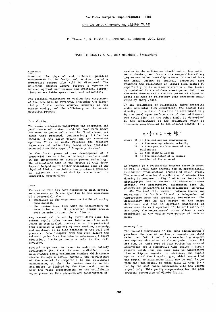
l e r Forum Europeen Temps-Friquence - 1987
DESIGN OF A COMMERCIAL CESIUM TUBE
P. Thomann, C. Busca, H. Schwcda, L . Johnson, J . C . Sapin
OSCILLOQUARTZ S . A . , 2002 NeuchBtel, Switzerland
Abstract
Some of the physical and technical problems encountered in the design and construction of a commercial cesium tube will be discussed. The solutions adopted always reflect a comprumise between optimal performance and practical limita- tions as available space, cost, and reliability.
The critical parameters of various key components of the tube will be reviewed, including the direc- tivity of the cesium source, symmetry of the Ramsey cavity, and the efficiency of the atomic detection process.
Tntroduction
The basic principles underlying the operation and performance of cesium standards I~ave been known for over 30 years and since the first commercial tubes were produced, comparatively little has chat~ged in the basic design and the technical options, This, in part, reflects the relative importance of reliability among other qualities expected from this type of frequency standard.
In the first phase of our development of a commercial cesium tube, no attempt has been made at any improvement on already proven technology. The evaluations made in the course of this deve- lopment helped us to better understand some of the physical limitations behind the practical problems of life-time and reliability encountered in commercial cesium tubes.
Oven - The cesium oven has been designed to meet several requirements which are specific to the operation of a commercial tube : a) operation of the oven must be inhibited during
tube bakeout b) the cesium beam flux must be independent of
tube orientation. No condensed cesium should ever be able to reach the collimator.
Requirement (a) is met by first distilling the cesium supply under vacuum into a metallic cell which is then sealed. The cesium is thus protected from exposure to air during oven loading, assembly, and mounting. It is also confined to the cell and prevented from escaping from the oven during the bakeout cycle. Once the tube is outgassed, a short electrical discharge burns a hole in the cell envelope.
Several steps must be taken in order to satisfy requirement (b). First the oven is divided into a main chamber and a collimator chamber which commu- nicate through a narrow channel. The conductance of the channel IS comparable to the collimator conductance, so that the cesium density in the collimator is limited by the flow conditions to half the value corresponding to the equilibrium vapor pressure. This prevents any condensation of
cesium in the collimator itself and in the colli- mator chamber, and favours the evaporation of any liquid cesium accidentally present in the collima- tor area. Cesium is actively prevented from reaching the collimator in liquid form either by capillarity or by surface migration : the liquid is contained in a stainless steel gauze that lines the main chamber walls and the potential migration paths are made of relatively long stretches sepa- rated by sharp edges.
In any collimator of cylindrical shape operatlng under molecular flow conditions, the atomic flux density in the axial direction is determined only by the total open surface area of the collimator. The total flux, on the other hand, is determined by the conductance of the collimator which is i~~versely proportional to the channel length I l l :
where Q is the collinlator conductance v is the average atomic velocity S is the open surface area of the
collimator L is the channel length 11 is the perimeter of a normal
section of the channel
An example of a cylindrical channel array is shown in Fig. 1 where each channel has an approximately triangular cross-section ("crinkled foil" type). The measured angular distribution of atomic flux density is compared in Fig. 2 with the theoretical distribution for a channel of circular cross- section. The directivity, calculated from the geometrical parameters of the collimator, is equal to 48. The best fit, however, between theory and experiment, is for D = 31 and is independent of temperature near the operating temperature. The discrepancy may be due partly to the shape difference and also to spurious scattering of atoms near the exit aperture of the collimator. In any case, the experimental curve allows a safe prediction of the cesium consumption of such an oven.
Beam optics 3
The overall dimensions of the tube (32Ox76x76mm ) preclude the use of multipole magnets as state selectors. Both A and B state-selecting magnets are dipoles with circular shaped pole pieces ( 1 2 1 and Fig. 2). This type of beam optics has several advantages for a commercial tube design : dipole magnets weigh less and cost less to manufacture than multipole magnets. Jn addition, the dipole optics is of the flop-in type, which means that the signal to background ratio may be much larger than one; the signal to noise ratio is thus limi- ted by the shot noise associated with the useful signal only. This partly compensates for the poor focusing properties of dipole fields.
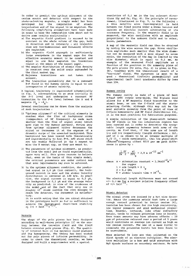
In order to predict the optimum alignment of the cesium source and detector with respect to the state-selecting magnets, a simple model has been developed for the computation of atomic trajectories and of the signal to be expected. The following simplifying assumptions have been made in order to keep the computation time short and to derive some results analytically : a) The magnetic field gradient is assumed to be
constant in the whole volume of the gap, both in direction and in intensity : all trajecto- ries are two-dimensional and focussing effects are neglected.
b) The magnetic field strength is sufficiently large everywhere in the magnet gaps for the effective magnetic moment to be constant and equal to one Bohr magneton (no transition region at the edges of the magnet gaps).
c) The angular distribution of atomic flux density is constant over the solid angle subtended by the first magnet gap.
d) Majorana transitions are not taken into account.
e) The transition probability due to a resonant R-F field in the Ramsey cavity is equal to one irrespective of atomic velocity.
A typical trajectory is represented schematically in Fig. 3, corresponding to an atom initially in the F=3 level and undergoing a resonant RE transition to the F=4 level between the A and B magnets ( 0 - - -eA). Several conclusions can be drawn from the analysis of such trajectories :
1) "Optimum alignment" of the critical elements is reached when the flux of background atoms (independent of RF frequency) is made much smaller than the flux of signal atoms (which give rise to the Ramsey pattern). Moving away from optimum alignment either decreases the signal or increases it at the expense of a dramatic surge of the unwanted background. This background has been traced both theoretically and experimentally to fast F=4, m#O atoms which are too weakly deflected in the A magnet to miss the B magn,et gap, as they are meant to.
2) The parameters of optimum alignment, as predic- ted from the model and as found experimentally, agree very well. This gives reasons to believe that, even on the basis of this simple model, the critical parameters are under control and that some improvements may even be achieved.
3) In the optimum alignment condition, the predic- ted signal is 1,4 pA (ion current), the back- ground current is zero and the atomic velocity distribution is centered at 130 m/s. In prac- tice, the signal current is equal to 0,3 ph, the background is 0,l pA and the average velo- city as predicted. In view of the crudeness of the model of the fact that only one in roughly 10 atoms leaving the oven manages to reach the detector, the agreement is satisfac- tory. It is worth noting that the ion signal obtained in the Drototvpes built so far is sufficient to - - achieve the -jpy.~nipoal short-term stability oy (T) = 3x10
Magnets
The shape of the pole pieces has been designed according to well-known principles [21 on the ana- logy between the two-wire field and the field between circular pole pieces (Fig. 4). The quanti- ty of interest here is the magnetic field gradient and its homogeneity. The theory has been worked out for pole pieces of infinite permeability. In order to check the theoretical results, we have designed and built a magnetometer with a spatial
resolution of 0,l mm in the two relevant direc- tions (Oy and Oz, Fig. 4). The principle of measu- rement, illustrated in Fig. 5, is the following : a thin metallic wire (non-magnetic) is held between two fixed points under a known tension and carries an electric current alternating at ~ t s resonance frequency. In the magnetic field to be measured, the wire oscillates with an amplitude proportional to the unknown field and to other, known, parameters.
A map of the maqnetic field can thus he obtained by moving the wire across the gap. Since oscilla- tion amplitudes much smaller than the wire diame- ter can be measured with a good signal to noise ratio, the resolution of the map is limited by the wire diameter, which is equal to 0,l mm. An example of the measured field amplitude as a function of the position in the symmetry plane of the pole pieces (Oz axis, Fig. 2) is given in Fig. (6), together with the theoretical result of a "two-wire" field. The agreement is seen to be good : theoretical (infinite permeability) and experimental (soft iron) gradients differ by less than 15%.
Ramsey cavity
The Ramsey cavity is made of a piece of bent X-band OEHC copper wave-guide. The E-plane bend allows for a RF magnetic field transverse to the atomic beam, as are the C-field and the state- selecting fields. Although this may not be the most suitable geometry from the point of view of C-field homogeneity and RF field distribution 131, it is the most practical for fabricdtion purposes.
A simple calculation of the phase-shift between the RF fields in the two interaction regions has been carried out in order to determine the accep- table length asymmetry between both arms of the cavity. We find that, if the arms are of length 1-x and l+x respectively (length difference : 2x), and if 1 is chosen to be an integer multiple of X /2 (A = guide wavelength), then the phase-shift i#ducedgfrequency offset 6f/f per nun path diffe- rence is given by :
where a = attenuation constant = 1 , 3 4 ~ 1 0 - ~ m - ~ for copper
1 = arm length = 2 X f = 9,2 GHz 9
T = atomic transit time = 10-~s. The electrical length difference must not exceed +/- 0.3 mm a maximum relative frequency offset of +/- 1x10 .
Atomic detector
The signal atoms are ionized by a hot wire detec- tor. Among the numerous metals that have a large eriough contact potential to ionize cesium 141, tantalum has been chosen for its high resistivity, low vapour pressure and good mechanical proper- ties. However, tantalum, like other refractory metals, tends to release potassium ions in bursts. Even trace amounts may have adverse effects : 10 ppm of potassium released over a period of 5 years would contribute on average ion current as high as the cesium current. The use of a mass filter to eliminate the potassium bursts has been found to be unavoidable.
Mass selected Cs ions are then collected on the first dynode of an electron multiplier. The elec- tron multiplier is a box and grid structure with MgO dynode surfaces as secondary emitters. We have
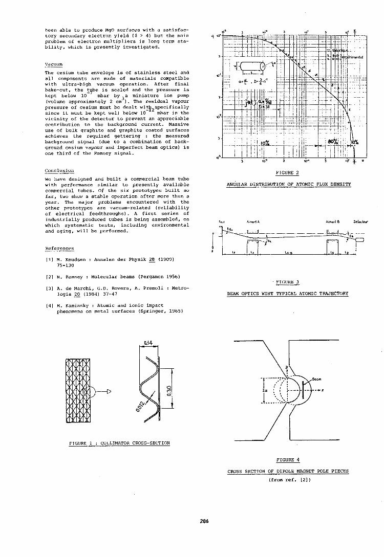
been able to produce MgO surfaces with a satisfac- tory secondary electron yield (6 > 4) but the nuin problem of electron multip1.iers is long term sta- bility, which is presently investigated.
VdCUUm
The cesium tube envelope is of stainless steel and all components are made of materials compatible with ultra-high vacuum operation. After final bake-out, the t be is sealed and the pressure is kept below a by 3a miniature ion pump (volume approximately 2 cm ) . The residual vapour pressure of cesium must be dealt witP2specifically since it must be kept well below 10 mbar in the vicinity of the detector to prevent an appreciable contribution to the background current. Massive use of bulk graphlte and graphite coated surfaces achieves the required gettering : the measured background signal (due to a combination of back- ground cesium vapour and imperfect beam optics) is one third of the Ramsey signal.
Conclusion
We have designed and built a commercial beam tube with performance similar to presently available commercial tubes. Of the six prototypes built so far, two show a stable operation after more than a year. The major problenls encountered with the other prototypes are vacuum-related (reliability of electrical feedthroughs). A first series of industrially produced tubes is being assembled, on which systematic tests, including environmental and aging, will be performed.
References
[I] M. Knudsen : Annalen der Physik 2 (1909) 75-130
[2] N. Ramsey : Molecular beams (Pergamon 1956)
(31 A. de Marchi, G.D. Rovera, A. Premoli : Metro- logia 20 (1984) 37-47
[ 4 ] M. Kaminsky : Atomic and ionic impact phenomena on metal surfaces (Springer, 1965)
FIGURE 2
AN~ULAR DISTRIBUTION OF ATOMIC FLUX DENSITY
FIGURE 3
BEAM OPTICS WIHT TYPICAL ATOMIC TRAJECTORY
FIGURE 1 : COLLIMATOR CROSS-SECTION
FIGURE 4
CROSS SECTION OF DIPOLE MAGNET POLE PIECES
(from ref. [21)
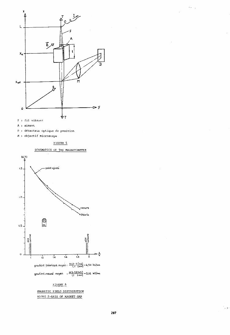
D : ddtecteur optique de position
M : objectif microscope
FIGURE 5
SCHEMATICS OF ?'HE MAGNETOMETER
FIGURE 6
MAGNETIC FIELD DISTRIBUTION
ALONG Z-AXIS OF MAGNET GAP
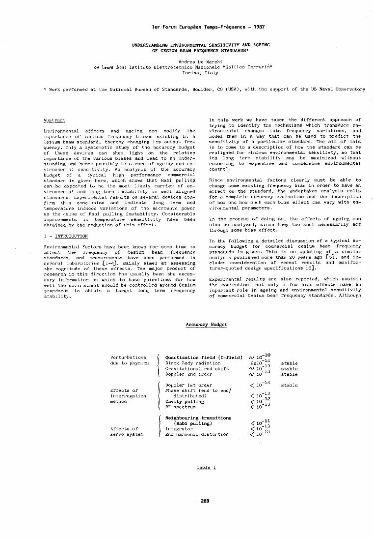
ler Forum Europsen Temps-Frsquence - 1987
UNDERSTANDING ENVIRONMENTAL SENSITIVITY AND AGEING OF CESIUM BEAM FREQUENCY STANDARDSf
Andrea De Marchi on leofe from: Istituto Elettrotecnico Nazionale "Galileo Ferraris"
Torino, Italy
4t Work performed at the National Bureau of Standards, Boulder, CO (USA), with the support of the US Naval Observatory
Abstract -- Environrnent,al effects and ageing can modify the importance of various frequency biases existing in a Cesium beam standard, thereby changing its output fre- quency. Only a systematic study of the accuracy budget of these devices can shed light on the relative importance of the various biases and lead to an under- standing and hence possibly to a cure of ageing and en- vironmental sensitivity. An analysis of' the accuracy budget of a typical high performance commercial standard is given here, which shows that Habi pulling can be expected to be the most likely carrier of en- vironmental and long term instability in well aligned st:andards. Experin~ental results on several devices con- firm this conclusion and indicate long term and temperature induced variations of the microwave power as the cause of Rabi pulling instability. Considerable improvements in temperature sensitivit.~ have been obt.ained by the reduction of this effect.
1 - INTRODUCTION Environmental factors have been known for some time to affect the frequency of Cesium beam frequency standards, and measurements have been performed in several laboratories [l-43, mainly aimed at assessing the magnitude of these effects. The major product of research in this direction has usually been the neces- sary lnfor~nation on which to base guidelines for how well the environment should be controlled around Cesium standards to obtain a target long term frequency stability.
In this work we have taken the different approach of trying to identify the mechanisms which transduce en- vironmental changes into frequency variations, and model them in a way that can be used to predict the sensitivity of a particular standard. The aim of this is to come to a descriptiorl of how the standard can be realigned for minimum environmental sensitivty, so that its long term stability may be maximized without resorting to expensive and cumbersome environmental control.
Since environmental factors clearly must be able to change some existing frequency bias in order to have an effect on the standard, the undertaken analysis calls for a complete accuracy evaluation and the description of how and how much each bias effect can vary with en- vironmental parameters.
In the process of doing so, the effects of ageing can also be analyzed, since they too must necessarily act tt~rough some bias effect.
In the following a detailed discussion of a typical ac- curacy budget for commercial cesium beam frequency standards is given. This is an updating of a similar analysis published more than 20 years ago [5], and in- cludes consideration of recent results and manifac- turer-quoted design specifications [ 61.
Experimental results are also reported, which sustain the contention that only a few bias effects have an important role in ageing and environmental sensitivity of commercial Cesium beam frequency standards. Although
Accuracy Budget
Perturbations Quantization field (C-field) due to physics Black Body radiation stable
Gravitational red shift stable Doppler 2nd order stable
I Doppler 1st order < lo-14 stable Effects of Phase shift (end to end] interrogation distributed) method Cavity pulling
RF spectrum
I Neighbouring transitions (Rabi pulling) ( 10‘ll
Effects of Integrator < lo-'3 servo system 2nd harmonic distortion < 10-l3
Table 1
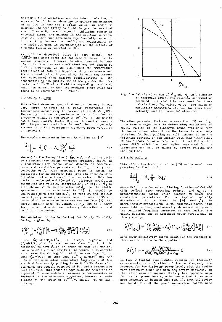
Whether C-fleld varlatlons are absolute or relative, it 1 appears that it 1s an advantage to operate the standard at as low as possible a field value, in order to decrease ~ t s sensitivity to field changes. Factors that can Influence B are changes in shielding factor or external fleld,cand clianges in the exciting current. Only the latter ones have been experimentally tested in thls work by temperature coefflclent measurements on Lt~e whole standard. An lnvestlgatron on the effects of external fields is reported in 131. 0
As will be described below in more detail, the @'i"p%'rature coefficient did not seem to depend on the Zeeman frequency. It seems therefore correct to con- clude that the observed coefficient was not caused by C-ficld variation. On the other hand the temperature coefficient of both the Copper winding resistance and the electronic circuit generating the exciting current (as calculated from maximum specifications of the components) pg not justify variations greater than few parts in 10 /OC at a field corresponding to f Y 40 kHz. This is smaller than the measured limit whiczh was found to be independent of C-field.
2 . 2 Cavity pullinn
This effect deserves special attention because it was very early indicated as a major responsible for temperature sensitivity in commercial standards [12]. l'hc cavity's thermal expansion accou ts in fact for its F: f'requcncy change of the order of 10- /OC. If the cavity has a tligh quality factor Q , as it usually does, a 10°C temperature variation fs sufficient to grossly n11 s tune it, with a consequellt microwave power var-iation of several dm.
The complete expression for cavity pulling is 1 9 3
where Q is the Ramsey line Q, $3, = - 0 is the cavi- ty mistuning from Cesium resonan%e frequency and Ae is a proportionality factor which depends on microwave power and modulation parameters. In fig. 1 a typical behaviour of A, with microwave power is shown, as calculated for an existing tube from its velocity dis- tribution and actual n~odulation parameters. This be- haviour can be quite different for different modulation parameters and velocity distribution. In fig. 1 A,, is also shown, which is the value of A, in the static approximation, as calculated in [5]. It should be underlined here that while A H is zero at the optimum power P , Ac usually crosses zero at some different power l,S/el. As a consequence one can see from (3) that cavity pulling does not vanish at Po, but at a power level which depends on velocity distribution and modulation parameters.
The variation of cavity pulling due solely to cavity tuning is given by
Since 53, . ~ ( P / P ~ ) / ~ Y . is always negative and d~l,/a(~/~ )N, -1 as one can see from fig. 1, it is necessaryOto have A r < o in order to make (4) vanish. For a carefully tuned cavity it is desirable to operate at a power for which A,N 0. At P we see f r y fig. 1 that A,No.I; in this case fo2 Q S. 5x10 and Qc
7 2.5~10 the calculated temperature c%f$ficient of the standard from cavity pulling is 4x10 /OC. Commercial standards are usually operated at P , and a temperature coefficient of this order of magnit8de can therefore be expected. In some models a temperature compensation is included in the microwave ficient of the order of prising.
Fig. 1 - Calculated values of I\,, and A as a function of microwave power. The velocity distribution measured in a real tube was used for these calculations. The values of A are based on modulation parameters not too Ear from those actually used in commercial standards.
The other parameter that can be seen from (3) and flg. 1 to have a major role in determining variations of cavity pulling is the microwave power available from the harmonic generator. Since the latter is also very important for Rabi pulling we will discuss i L in t.tre following section, in conjunction with this other bias. It can already be seen from tables 1 and 2 that the power shift which has been often mentioned in the literature can only be caused by Cavity pulling and Rabi pulling.
2.3 Rabi pulling
This effect has been studied in [13] and a useful ex- pression for the bias is
where R(f ) is a damped oscillating function of C-field with sev5ral zero crossing points, and At is a proportionality factor which depends on power and modulation parameters. For a typical velocity distribution it is shown in [9] that A R is approximately proportional to the microwave power. This makes Rabi pulling quadratically dependent on power. The combined frequency variation of Rabi pulling and cavity pulling, due to microwave power variations, is then given by:
Zero power sensitivity points exist for the standard if there are solutions to the equation
In fig. 2 typical experimental results for frequency measurements as a function of Zeeman frequency are reported for two different power levels with the cavity very carefully tuned and with the cavity mistuned. In the latter case it appears thatAe has opposite sign for the two power levels, which means that it crosses zero somewhere in between (see fig. 1). When the cavity was tuned (C = 0) the power insensitive points were
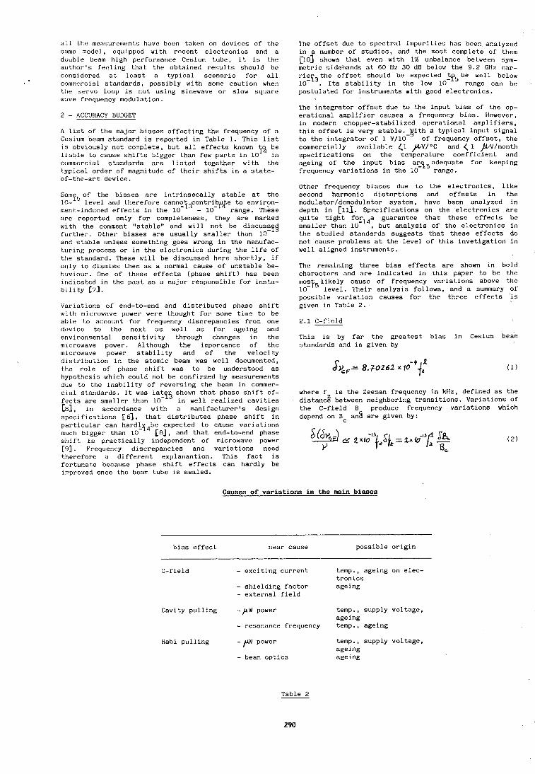
all the measurements have been taken on devices of the same model, equipped with recent electronics and a double beam high performance Cesium tube, it is the author's feeling that the obtained results should be considered at least a typical scenario for all commercial standards, possibly with some caution when the servo loop is not using sinewave or slow square wave frequency modulation.
2 - ACCURACY BUDGET
A list of the major biases affecting the frequency of a Cesium beam standard is reported in Table 1. This list is obviously not complete, but all effects known 13 ;; liable to cause shifts bigger than few parts in 10 comnlerciol standards are listed together with the typical order of magnitude of their shifts in a state- of-the-art device.
Somf50f the biases are intrinsecally stable at the 10- level and therefore cann~tj~contribu e to envirpn- ment-induced effects in the 10 - lo-'' range. These are reported only for completeness, they are marked with the comment "stable" and will not be discusyEf further. Other biases are usually smaller than 10 and stable unless something goes wrong in the manufac- turing process or in the electronics during the life of the standard. These will be discussed here shortly, if ortly to dismiss them as a normal cause of unstable be- huviour. One of these effects (phase shift) has been indicated in the past as a major responsible for insta- bility L7J.
Variations of end-to-end and distributed phase shift with microwave power were thought for some time to be able to account for frequency discrepancies from one device to the next as well as for ageing and environmental sensitivity through changes in the microwave power. Although the importance of the microwave power stability and of the velocity distribution in the atomic beam was well documented, the role of phase shift was to be understood as hypothesis which could not be confirmed by measurements due to the inability of reversing the beam in commer- cial standards. It was lat shown that phase shift ef- fects are smaller than l0-l5 in well realized cavities [$I, in accordance with a manifacturerqs design specifications [ 6 ' J , that distributed phase shift in particular can hard3 be expected to cause variations
4 much bigger than 10 [8j, and that end-to-end phase shift is practically independent of microwave power [ g ] . Frequency discrepancies and variations need therefore a different explanantion. This fact is fortunate because phase shift effects can hardly be improved once the beam tube is sealed.
The offset due to spectral impurities has been analyzed in a number of studies, and the most complete of them ~ 0 3 shows that even with 1% unbalance between sym- metric sidebands at 60 fiz 30 dB below the 9.2 GHz car- riergthe offset should be expected _tf5 be well below 10- . Its stability in the low 10 range can be postulated for instruments with good electronics.
The integrator offset due to the input bias of the op- erational amplifier causes a frequency bias. However, in modern chopper-stabilized operational amplifiers, this offset is very stable. bith d typical input signal to the integrator of 1 ~/10- of frequency offset, the commercially available (1 JA/V/OC and ( 1 ,bV/rnonth specifications on the temperature coefficient and ageing of the input bias ar_e15adequate for keeping frequency variations in the 10 range.
Other frequency biases due to the electronics, like second harmonic distortions and offsets in the modulator/demodulator system, have been analyzed in depth in [111. Specifications on the electronics are quite tight fo_r14a guarantee that these effects be smaller than 10 , but analysis of the electronics in the studied standards suggests that these effects do not cause problems at the level of this invetigation in well aligned instruments.
The remaining three bias effects are shown in bold characters and are indicated in this paper to be the mosi51ikely cause of frequency variations above the 10 level. Their analysis follows, and a surtlmary of possible variation causes for the three effects is given in Table 2.
This is by far the greatest bias in Cesium beam standards and is given by
where f is the Zeeman frequency in kHz, defined as the distanc: between neighboring transitions. Variations of the C-field B produce frequency variations which depend on Bc an2 are given by:
Causes of var iat ions i n the main b i a s e s
bias effect near cause possible origin
-- -
C-field - exciting current - shielding factor - external field
Cavity pulling - ,UW power
- resonance frequency Rabi pulling - PW power
- beam optics
temp., ageing on elec- tronics ageing
temp., supply voltage, ageing temp., ageing
temp., supply voltage, ageing ageing
Table 2
290
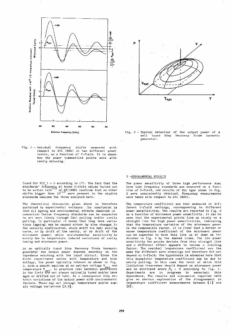
Cig. 3 - Typical behaviour of the output power of a well t,uned Step Recovery Diode harmonic genera tor.
Fig. 2 - Residual frequency shifts measured with respect to AT1 (NBS) at two different power levels, as a function of C-field. It is shown how the power insensitive points move with cavity detuning.
3 -EXPERIMENTAL RESULTS
found for R(f ) = 0 according to (7). The fact that the standards' frgquenEy at those C-field values turned out to be within 1x10 ofl$T1(NBS) confirms that no other shifts bigger than 10 were present in the studied standards besides the three analyzed here.
The theoretical discussion given above is therefore sustained by experimental evidence. The conclusion is that all ageing and environmental effects observed in conirnercial Cesium frequency standards can be suspected to act most likely through Rabi pulling and/or cavity pulling. In particular it seems that long term varia- tions (ageing) may be caused either by slow changes in the velocity distribution, which shift the Rabi pulling curve, or by drift of the cavity, or by drift of the microwave power; while environmental sensitivity is mainly due to temperature induced variations of cavity tuning and microwave power.
In an optimally tuned Step Recovery Diode harmonic generator the output power depends smoothly on the impedance matching with the input circuit. Since the diode capacitance varies with temperature and bias voltage, the power typically behaves as shown in fig. 3, with a smooth maximum at an optimum voltage V and temperature To t. In practice real harmonic gengpitors in the field age not always optimally tuned and/or have aged or drifted out of tune. As a consequence they ex- hibit variations of the output power with environn~ental factors. These may act through temperature and/or sup- ply voltage variations [2,4].
The power sensitivity of three high performance dual beam tube frequency standards was measured as a func- tion of C-field, and results of the type shown in fig. 2 were consistently obtained. Frequency measurements were taken with respect to AT1 (NBS).
The temperature coefficient was then measured at dif- ferent C-field settings, corresponding to different power sensitivities. The results are reported in fig. 4 as a function of microwave power sensitivity. It can be seen that the experimental points line up nicely on a straight line for high power sensitivities, indicating that the temperature variation of the microwave power is the responsible factor. It is clear that a better or worse temperature coefficient of the microwave power can be expected to move this line up or down as in- dicated in fig. 4 by the dashed lines. For low power sensitivity the points deviate from this straight line and a different effect appears to become a limiting factor. The residual temperature coefficient was the same for different zero crossings and therefore did not depend on C-field. The hypothesis is advanced here that this asymptotic temperature coefficient may be due to cavity pulling. In this case the level at which this limitation intervenes should depend on microwave power and be minimized where = 0 according to fig. 1. Experiments are in progress to ascertain this dependence. The results and discussion reported here give an obvious explanation of the disagreement in temperature coefficient measurements between (11 and 121.
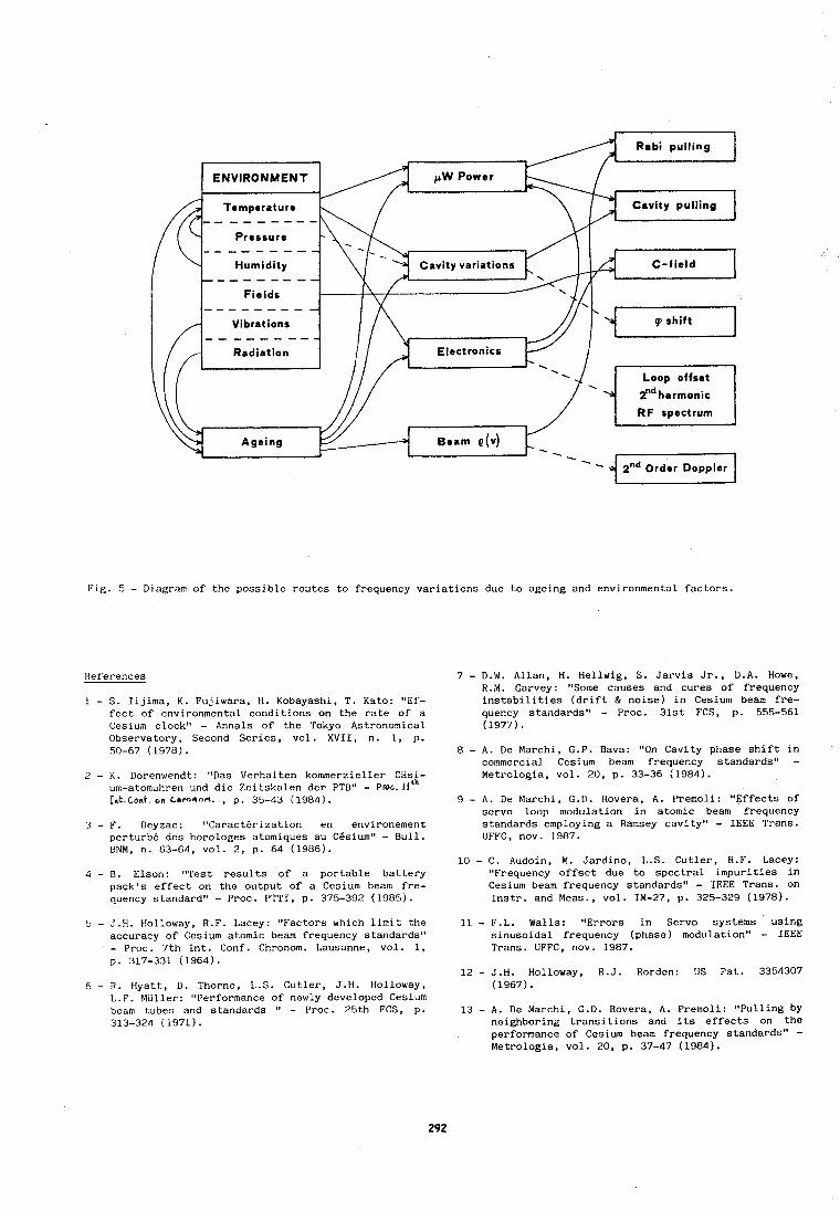
ENVlRONMENT
Cavity pulling
Cavity variations - - - - - - - - -
- - - - - - - - -
Fig. 5 - Diagram of the possible routes to frequency variations due to ageing and environment~l factors.
References
1 - S. Iijima, K. Fujiwara, H. Kobayashi, T. Ksto: "Ef- fect of environmental conditions on the rate of a Cesium clock" - Annals of the Tokyo Astronomical Observatory, Second Series, vol. XVII, n. 1, p. 50-67 (1978).
2 - K. Dorenwendt: "Das Verhalten kommerzieller Casi- urn-atornuhren und die Zeitskalen der PTB" - Proc. 1 1 ' ~ Ink.Conk on 6hronnl.c. , p. 35-43 (1984).
3 - F. Deyzac : "Caract6rization en environement perturb6 des horologes atomiques au CBsium" - Bull. BNM, n. 63-64, vol. 2, p. 64 (1986).
4 - B. Elson: "Test results of a portable battery pack's effect on the output of a Cesium beam fre- quency standard" - Proc. PTTI, p. 375-392 (1985).
5 - J.H. Holloway, R.F. Lacey: "Factors which limit the accuracy of Cesium atomic beam frequency standards" - Proc. 7th Int. Conf. Chronom. Lausanne, vol. 1, p. 317-331 (1964).
6 - R. Hyatt, D. Thorne, L.S. Cutler, J.H. tloll~~ay, L.F. Muller: "Performance of newly developed Cesium beam tubes and standards " - Proc. 25t,h FCS, p. 313-324 (1971).
7 - D.W. Allan, H. Hellwig, S. Jarvis Jr., D.A. Howe, R.M. Garvey: "Some causes and cures of frequency instabilities (drift & noise) in Cesium beam fre- quency standards" - Proc. 31st FCS, p. 555-561 (1977).
8 - A. De Marchi, G.P. Bava: "On Cavity phase shift in commercial Cesium beam frequency standards" - Metrologia, vol. 20, p. 33-36 (1984).
9 - A. De Marchi, G.D. Rovera, A. Premoli: "Effects of servo loop modulation in atomic beam frequency standards employing a Ramsey cavity" - IEEE Trans. UFFC, nov. 1987.
10 - C. Audoin, M. Jardino, L.S. Cutler, R.F. Lacey: "Frequency offset due to spectral impurities in Cesium beam frequency standards" - IEEE Trans. on Instr. and Meas., vol. IM-27, p. 325-329 (1978).
11 - F.L. Walls: "Errors in Servo systems using sinusoidal frequency (phase) modulation" - IEEE Trans. UFFC, nov. 1987.
12 - J.H. Holloway, R.J. Rorden: US Pat. 3354307 (1967).
13 - A. De Marchi, G.D. Rovera, A. Premoli: "Pulling by neighboring transitions and its effects on the performance of Cesium beam frequency standards" - Metrologia, vol. 20, p. 37-47 (1984).
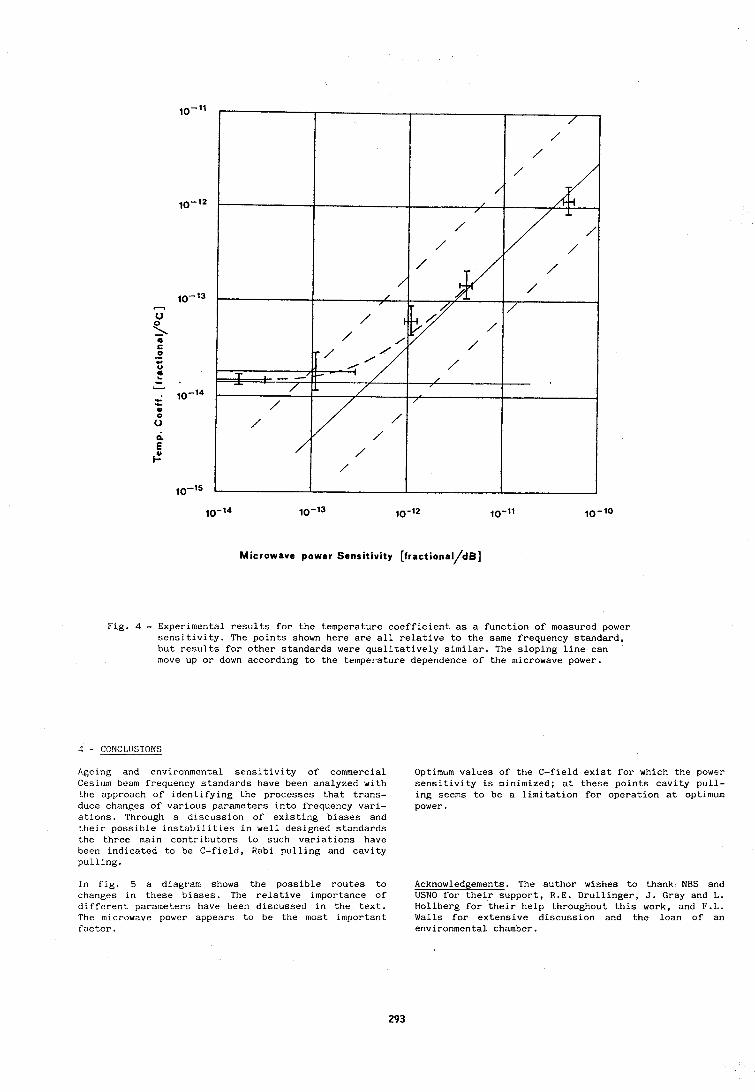
10-l4 10-l3 10-12 IO-l1 lo-lo
Microwave power Sensitivity [ f r a c t i o n a l / d ~ ]
Fig. 4 - Experimental results for the temperature coefficient as a function of measured power sensitivity. The points shown here are all relative to the same frequency standard, but results for other standards were qualitatively similar. The sloping line can move up or down according to the temperature dependence of the microwave power.
4 - CONCLIISIONS
Ageing and environmental sensitivity of commercial Optimum values of the C-field exist for which the power Cesium beam frequency standards have been analyzed with sensitivity is minimized; at these points cavity pull- the approach of identifying the processes that trans- ing seems to be a limitation for operation at optimum duce changes of various parameters into frequency vari- power. ations. Through a discussion of existing biases and their possible instabilities in well designed standards the three main contributors to such variations have been indicated to be C-field, Rabi pulling and cavity pulling.
In fig. 5 a diagram shows the possible routes to Acknowledgen~ents. The author wishes to thank NBS and changes in these biases. The relative importance of USNO for their support, R.E. Drullinger, J. Gray and L. different parameters have been discussed in the text. Hollberg for their help throughout this work, and F.L. The microwave power appears to be the most important Walls for extensive discussion and the loan of an factor. environmental chamber.
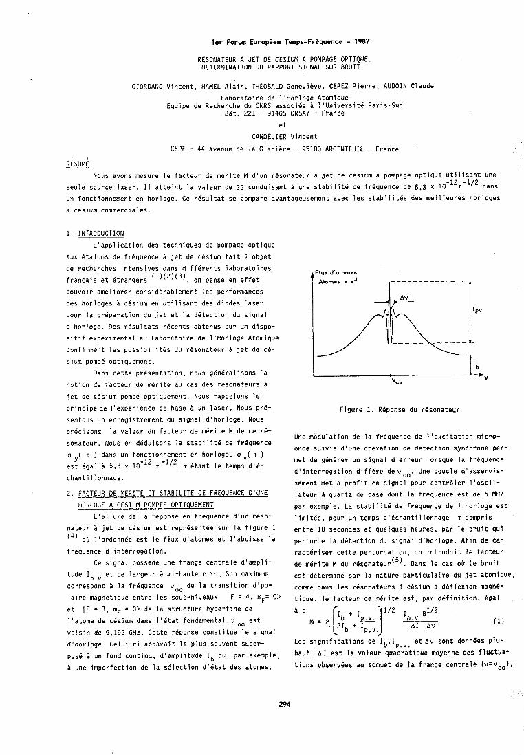
ler Forum Europien Temps-Friquence - 1987 RESONATEUR A JET OE CESIUM A POMPAGE OPTIQUE. DETERMINATION DU RAPPORT SIGNAL SUR BRUIT.
GIORDANO Vincent, HAMEL Alain, THEOBALD Genevieve, CEREZ Pierre, AUDOIN Claude
Laboratoi re de 1 'Horloge Atomique Equipe de Recherche du CNRS associke ti 1'Universite Paris-Sud
Bat. 221 - 91405 ORSAY - France et
CANDELIER Vincent
CEPE - 4 4 avenue de la Glaciere - 95100 ARGENTEUIL - France R ~ S U M ~
Nous avons mesure le facteur de merite M d'un rdsonateur a jet de cesium a pompage optique utilisant une
seule source laser. 11 atteint la valeur de 29 conduisant a une stabilite do frequence de 5,3 x 1 0 -12T -1/2 dans
un fonctionnement en horloge. Ce resultat se compare avantageusement avec les stabilitis des meilleures horloges
a cesium commerciales.
1. INTRODUCTION
L'application des techniques de pompage optique
aux etalons de frequence a jet de cesium fait I'objet
de recherches intensives dans differents laboratoires
f r a n ~ a i s et etrangers (1)(2)(3). on pense en effet
pouvoir ameliorer considerablement les performances
des horloges a cesium en utilisant des diodes laser
pour la preparation du jet et la detection du signal
d'horloge. Des rdsultats recents obtenus sur un dispo-
sitif experimental au Laboratoire de I'Horloge Atomique
confirment les possibilites du resonateur a jet de ce- sium pomp6 optiquement.
Oans cette presentation, nous gineralisons la
notion de facteur de merite au cas des resonateurs a
jet de cBsium pompe optiquement. Nous rappelons le
principede l'expkrience de base A un laser. Nous pr6-
sentons un enregistrement du signal d'horloge. Nous Figure 1. RBponse du resonateur
pricisons la valeur du facteur de mirite M de ce re- Une modulation de la frequence de l'excitation micro-
sonateur. Nous en deduisons la stabilite de frequence onde suivie d'une operation de detection synchrone per-
a ( T ) dans un fonctionnement en horloge. o y ( T ) Y met de generer un signal d'erreur lorsque la frequence
est egal a 5,3 x T -'", T etant le temps d'6- d'interrogation differe d e w o o . Une boucle d'asservis-
chantillonnage. sement met a profit ce signal pour contrtiler l'oscil-
2. FACTEUR DE MERITE ET STABILITE OE FREQUENCE D I U N E
HORLOGE A CESIUM POMPEE OPTIQUEMENT
L'allure de la reponse en frequence d'un reso-
nateur a jet de cesium est representee sur la figure 1 ( 4 ) oh 1 'ordonnee est le flux d'atomes et 1 'abcisse la
frdquence d'interrogation.
Ce signal possede une frange centrale d'ampli-
tude I et de largeur a mi-hauteur A V . Son maximum P.V
correspond a la friquence vo0 de la transition dipo-
laire magnetique entre les sous-niveaux IF = 4, m = 0> F et ( F = 3, inF = O> de la structure hyperfine de
l'atome de cesium dans 1'Btat fondamenta1.v oo est
voisin de 9,192 GHz. Cette reponse constitue le signal
d'horloge. Celui-ci apparait le plus souvent super-
pose a un fond continu, d'amplitude I b dC, par exemple, a une imperfection de la selection d'etat des atomes.
lateur a quartz de base dont la frequence est de 5 MHz par exemple. La stabilite de frequence de l'horloge est
limithe, pour un temps d'echantillonnage T compris
entre 1 0 secondes et quelques heures, par le bruit qui
perturbe la detection du signal d'horloge. Afin de ca-
racteriser cette perturbation, on introduit le facteur
de merite M du r6~onateur'~). Oans le cas oh le bruit
est determine par la nature particulaire du jet atomique,
comme dans les resonateurs B cBsium a deflexion magne-
tique, le facteur de merite est, par definition, egal
Les significations de Ib,Ip,v. et A v sont donnBes PIUS
haut. A I est la valeur quadratique moyenne des fluctua-
tions observees au sommet de la frange centrale (v=voo),
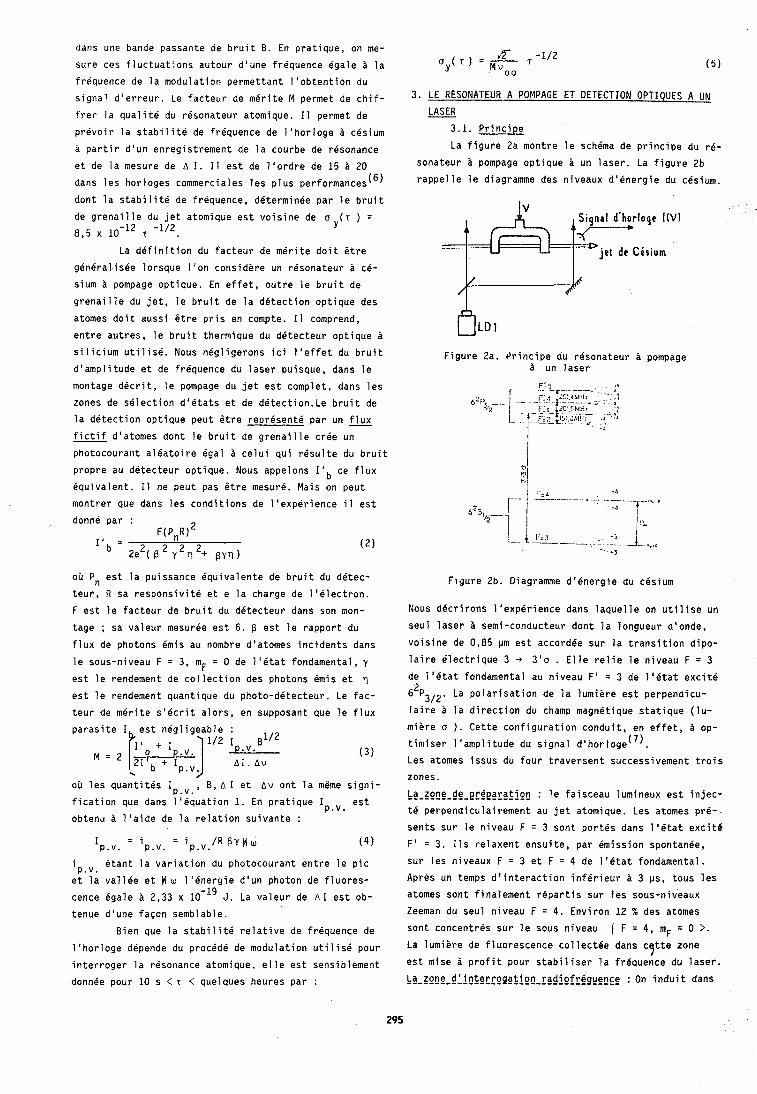
dans une bande passante de bruit 8. En pratique, on me-
sure ces fluctuations autour d'une frequence Bgale A la
frequence de la modulation permettant l'obtention du
signal d'erreur. Le facteur de merite M permet de chif-
frer la qualite du resonateur atomique. I 1 permet de
prevoir la stabilite de frequence de l'horloge cesium
a partir d'un enregistrement de la courbe de resonance
et de la mesure de A I. I1 est de l'ordre de 15 20
dans les hor loges commerciales les plus performances(6)
dont la stabilite de frequence, determinee par le bruit
de grenaille du jet atomique est voisine de a ( T ) = 8,5 x 10-l2 T 'll2.
Y
La definition du facteur de merite doit Otre
generalisee lorsque I'on considere un resonateur c6-
sium a pompage optique. En effet, outre le bruit de
grenaille du jet, le bruit de la detection optique des
atomes doit aussi Ctre pris en compte. I1 comprend,
entre autres, le bruit thermique du detecteur optique ti
silicium utilise. Nous negligerons ici l'effet du bruit
d'amplitude et de frequence du laser puisque, dans le
montage decrit, le pompage du jet est complet, dans les
zones de selection d'itats et de d6tection.Le bruit de
la detection optique peut etre represent6 par un flux fictif d'atomes dont le bruit de grenaille cree un
photocourant aleatoire egal a celui qui resulte du bruit
propre au detecteur optique. Nous appelons l o b ce flux
equivalent. I1 ne peut pas &re mesure. Mais on peut
montrer que dans les conditions de l'experience i l est
donne par : F(P,R)'
I' - 2 2 2 - 2e2( B Y rl + ~Yrl)
OD Pn est la puissance dquivalente de bruit du detec-
teur, R sa responsivite et e la charge de 1161ectron.
F est le facteur de bruit du detecteur dans son mon-
tage ; sa valeur mesurge est 6, p est le rapport du
flux de photons Bmis au nombre d'atomes incidents dans
le sous-niveau F = 3, mF = 0 de l'htat fondamental, y
est le rendement de collection des photons Bmis et
est le rendement quantique du photo-detecteur. Le fac-
teur de merite s'ecrit alors, en supposant que le flux
oir les quantites I , 8 , A I et Av ont la meme signi- P.V. fication que dans l'equation 1. En pratique I est P.V. obtenu a l'aide de la relation suivante :
= i : i Ip.v. p.v. p.v. /R B Y M U ( 4 )
i etant la variation du photocourant entre le pic p.v. et la vallee et H w l'energie d'un photon de fluores-
cence 4gale a 2,33 x 10-l9 J. La valeur de A 1 est ob-
tenue d'une facon semblable.
Bien que la stabilite relative de frequence de
l'horloge depende du procede de modulation utilise pour
interroger la resonance atomique. elle est sensiblement
donnee pour 10 s < T < quelques heures par :
3 . LE RESONATEUR A POMPAGE ET DETECTION OPTIQUES A UN
LASER - 3.1. Principe
La figure 2a montre le schema de principe du re-
sonateur & pompage optique a un laser. La figure 2b
rappelle le diagramme des niveaux d'energie du cesium.
j e t de Cksiurn
Figure 2a. Principe du resonateur a pompage a un laser
Figure 2b. Diagramme d16nergie du cesium
Nous decrirons l'experience dans laquelle on utilise un
seul laser 2 semi-conducteur dont la longueur d'onde,
voisine de 0,85 pm est accordee sur la transition dipo-
laire electrique 3 -+ 3 ' 0 . Elle relie le niveau F = 3 de l'btat fondamenta! au niveau F' = 3 de 1'Btat excite
6 ' ~ ~ ~ ~ . La polarisation de la lumiere est perpendicu-
laire a la direction du champ magnetique statique (lu-
miere a ) . Cette configuration conduit, en effet, a op-
timiser I 'amplitude du signal dlhorloge('). Les atomes issus du four traversent successivement trois
zones.
La_zppp-de-ergeaya;Ioy : le faisceau lumineux est injec-
te perpendiculairement au jet atomique. Les atomes pr6-
sents sur le niveau F = 3 sont portes dans 1'Btat excite
F' = 3 . 11s relaxent ensuite, par emission spontanee,
sur les niveaux F : 3 et F = 4 de l16tat fondamental. Apres un temps d'interaction inferieur a 3 ps, tous les
atomes sont finalement repartis sur les sous-niveaux
Zeeman du seul niveau F = 4. Environ 12 % des atomes
sont concentres sur le sous niveau ( F = 4, mF = 0 >. La lumiere de fluorescence collectee dans c tte zone 7 est mise B profit pour stabiliser la frequence du laser.
C a - z g n g - d ~ j a f e r r g g a f j g ~ - r a d i g f ~ g g g p ~ ~ g : On induit dans
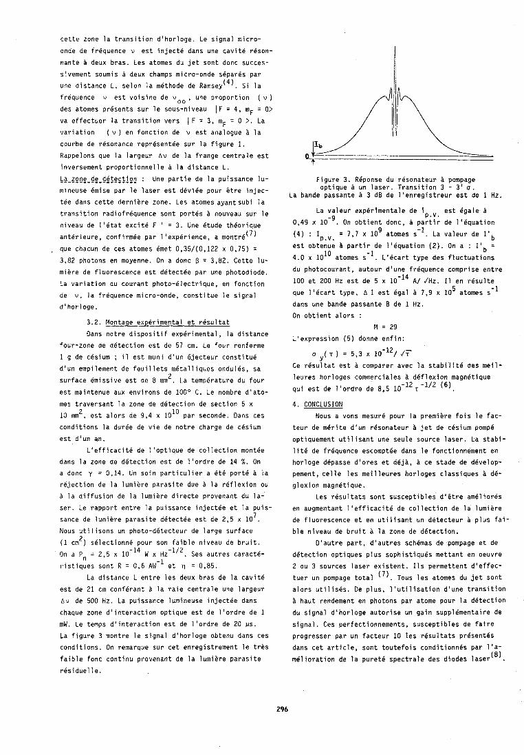
cette zone la transition d'horloge. Le signal micro-
onde de frequence v est inject6 dans une cavite reson-
nante a deux bras. Les atomes du jet sont donc succes-
sivement soumis 3 deux champs micro-onde separes par
une distance L, selon la methode de ~ a m s e y ( ~ ) . Si la
trequence v est voisine de w o o , une proportion ( u )
des atomes presents sur le sous-niveau ( F = 4, m F = 0> va effectuer la transition vers ( F = 3, mF = 0 >. La
variation ( v ) en fonction de v est analogue la
courbe de resonance representee sur la figure 1.
Kappelons que la largeur A u de la frange centrale est
inversement proportionnelle a la distance L.
La-<pnp-dp-de$pc.jpc : Une partie de la puissance lu-
mineuse emise par le laser est deviee pour stre injec-
tee dans cette derniere zone. Les atomes ayantsubi la
transition radiofrequence sont portes nouveau sur le
niveau de 1'4tat excite F ' = 3. Une etude theorique anterieure, conf irmee par 1 'experience, a m0ntr6(~)
, que chacun de ces atomes 6met 0,35/(0,122 x 0,75) =
3,82 photons en moyenne. On a donc f3 = 3,82. Cette lu- miere de fluorescence est detectee par une photodiode.
La variation du courant photo-electrique, en fonction
de v, la frequence micro-onde, constitue le signal
d'horloge.
3.2. Montage experimental et resultat
Dans notre dispositif experimental, la distance
four-zone de detection est de 57 cm. Le four renferme
1 g de cesium ; i l est muni d'un ejecteur constitue
d'un empilement de feuillets metalliques ondules, sa 2 surface emissive est de 8 mm . La temperature du four
est maintenue aux environs de 100° C. Le nombre d'ato-
Figure 3. RBponse du resonateur a pompage optique un laser. Transition 3 - 3' 5.
La bande passante 3 dB de 1 'enregistreur est de 1 Hz.
La valeur experimentale de i est egale a P.!.
0,49 x lo-'. On obtient donc, partir de 1 'equation 9 (4) : Ip.v. = 7,7 x 10 atomes s-I. La valeur de I a b
est obtenue b partir de 116quation (2). On a : I'b = 4.0 x 101° atomes s-I. L'ecart type des fluctuations
du photocourant, autour d'une frequence comprise entre
100 et 200 Hz est de 5 x 10-l4 A/ /Hz. I1 en resulte 5 que liecart type, A I est Cgal a 7,9 x 10 atomes s-'
dans une bande passante B de 1 Hz.
On obtient alors :
M = 29 L'expression (5) donne enfin:
a ( T ) = 5,3 x 10⁻¹²//i- Y
Ce resultat est a comparer avec la stabilite des meil-
leures horloges cornmerciales dPflexion magnetique
qui est de l'ordre de 8,5 10-l2 T -'I2 (6).
mes traversant la zone de detection de section 5 x 4. CONCLUSION 2 10 mm . est alors de 9,4 x 10" par seconde. Dans ces Nous a vons mesure pour la premiere fois le fac-
conditions la duree de vie de notre charge de cesium teur de merite d'un resonateur a jet de cesium pomp6 est d'un an.
L1efficacit6 de l'optique de collection montee
dans la zone de detection est de l'ordre de 14 %. On
a donc y = 0,14. Un soin particulier a 6th port6 a la
rejection de la lumiere parasite due a la reflexion ou
a la diffusion de la lumiere directe provenant du la-
ser. Le rapport entre la puissance injectee et la puis- 7 sance de lumiere parasite d6tectPe est de 2,5 x 10 .
Nous utilisons un photo-detecteur de large surface 2 (1 cm ) selectionne pour son faible niveau de bruit.
On a Pn = 2.5 x 10-'a W x HZ'~'~. Ses autres caracte-
ristiques sont R = 0,6 AW-I et q = 0,85.
optiquement utilisant une seule source laser. La stabi-
lit6 de frequence escomptee dans le fonctionnement en
horloge depasse d'ores et deji, ce stade de develop-
pement, celle les meilleures horloges classiques dB-
glexion magnetique.
Les resultats sont susceptibles d i 6 t r e amClior6s
en augmentant 11efficacit6 de collection de la lumiere
de fluorescence et en utilisant un detecteur a plus fai- ble niveau de bruit la zone de detection.
D'autre part, d'autres schdmas de pompage et de
detection optiques plus sophistiques mettant en oeuvre
2 ou 3 sources laser existent. 11s permettent d'effec- ,-. La distance L entre les deux bras de la cavite tuer un pompage total ( ' j . Tous les atomes du jet sont
est de 21 cm conferant a la raie centrale une largeur alors uti 1 is&. Oe plus, 1 'util isation d'une transition
A v de 500 Hz. La puissance lumineuse injectee dans haut rendement en photons par atome pour la detection
chaque zone d'interaction optique est de l'ordre de 1 du signal d'horloge autorise un gain suppl6mentaire de
mW. Le temps d'interaction est de l'ordre de 2 0 MS. signal. Ces perfectionnements, susceptibles de faire
La figure 3 montre le signal d'horloge obtenu dans ces progresser par un facteur 10 les resultats prhsentes
conditions. On remarque sur cet enregistrement le trhs dans cet article, sont toutefois conditionnes par 1 'a-
faible fonc continu provenant de la lumiere parasite melioration de la puret6 spectrale des diodes laser (8).
residuelle.
Remerciements
Les a u t e u r s r e m e r c i e n t P. PETIT, D. GUITARD e t
J . DUPONT pour l e u r a i d e techn ique e f f i c a c e .
REFERENCES
( 1 ) G . AVILA, E. de CLERCQ, M. de LABACHELERIE. P.
CEREZ. "Microwave Ramsey Resonances f rom a Laser
Diodes O p t i c a l l y Pumped Cesium Beam Resonator" .
IEEE Trans. on I n s t r , and Meas. Vo l . IM-34, no 2,
June 1985.
( 2 ) WU X in -X in , YAO Shu-Tong, SHANG Song-Quon, XUE
J ian -We i , XIE Lin-Zhen, "Exper imen ta l R e s u l t s on a
GaAlAs Laser Diode O p t i c a l l y Pumped Cesium Beam".
Chinese Phys. L e t t . Vo l . 2, no 1, 1985.
( 3 ) R.E. DRULLINGER, "Frequency Standards Based on
O p t i c a l l y Pumped Cesium". Proceedings o f IEEE, Vol . 74, no 1, January 1986.
( 4 ) N. F. RAMSEY, "Mo lecu la r Beams", Ox fo rd . Clarendon
Press, 1956.
( 5 ) R.F. LACEY, A.L. HELGESSON e t J.H. HOLLOWAY, Pro-
ceedings o f t h e IEEE, V o l . 54, February 1966, pp.
170-178.
( 6 ) R. HYATT, D. THRONE, L.S. CUTLER, J.H. HOLLOWAY e t
L.F. MUELLER, Proceedings o f t h e 25th Annual Sympo-
s ium on Frequency C o n t r o l , 1971, pp. 314-324.
( 7 ) G . AVILA, V . GIORDANO, V. CANDELIER, E. de CLERCQ,
G. THEOBALD e t P. CEREZ, " S t a t e S e l e c t i o n i n a Ce-
s ium Beam by Laser Diode O p t i c a l Pumping. A pa-
r a i t r e .
( 8 ) M. de LABACHELERIE, P. CEREZ, "A 850 nm Semi- 0
Conductor Laser Tunable over a 300 A Range".
O p t i c s Com. Vo l . 55, n o 3, 1985, pp. 174-178.
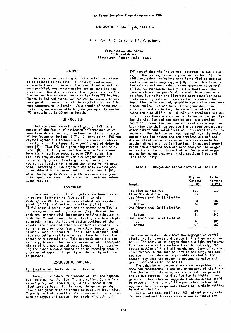
l e r Forum Europien Temps-Friquence - 1987
THE GROWTH OF LONG TI3VS4 CRYSTALS
2 . K. Kun, W. E. Gaida, and R. W. Weinert
Westinghouse R&D Center 1310 Beulah Road
P i t tsburgh, Pennsylvania 15235
ABSTRACT
Weak spots and crack ing i n TVS c r y s t a l s a re shown t o be r e l a t e d t o non-metal l ic impur i ty inc lus ions. To e l im ina te these inclusions, t he cons t i t uen t ma te r i a l s were p u r i f i e d , and contamination dur ing handl ing was minimized. Residual s t ress i n t he c r y s t a l was i d e n t i - f i e d as another cause o f c rack ing f o r long TVS boules. Thermally induced s t ress was reduced by us ing a three- zone growth furnace i n which the c r y s t a l could cool t o room temperature un i fo rmly . As a r e s u l t o f these modi- f i c a t i o n s , we a re now ab le t o grow good-qual i ty seeded TVS c r y s t a l s up t o 20 cm i n length.
INTRODUCTION
Thal l ium vanadium s u l f i d e (TI3VS4 or TVS) i s a member o f t he f am i l y o f chalcogentde compounds which have favorab le acoust ic p rope r t i es f o r t he f a b r i c a t i o n o f low-frequency devices [I-71. I n p a r t i c u l a r , TVS has c rys ta l l og raph i c d i r e c t i o n s w i t h low acoust ic ve loc i - t i e s f o r which the temperature c o e f f i c i e n t o f delay i s zero [5]. Thus TVS i s a promising mater ia l f o r delay l i n e s [8]. To f u l l y e x p l o i t the ma te r i a l ' s i n t r i n s i c b e n e f i t s i n surface acoust ic wave (SAW) delay l ine app l ica t ions , c r y s t a l s o f var ious lengths must be reproducibly grown. Cracking dur ing growth o r i n device f a b r i c a t i o n has l i m i t e d the length o f TVS crys- t a l s . Cracking o f TVS c r y s t a l s was thus invest iga ted i n an at tempt t o increase usefu l c r y s t a l length [9]. As a r e s u l t , up t o 20 cm long TVS c r y s t a l s were grown. Th is paper discusses i n d e t a i l our approach and subse- quent r e s u l t s .
BACKGROUND
The i nves t i ga t i on o f TVS c r y s t a l s has been pursued i n several labora tor ies [3,6,10,11]. A t t he Westinghouse R&D Center we have s tud ied both c r y s t a l growth [6,12], and device p rope r t i es [1,5,8] . Our TI-V-S phase diagram inves t i ga t i on showed t h a t TVS i s an incongruent ly me l t i ng compound [12]. One o f t he problems inherent w i t h incongruent me l t i ng behavior i s t h a t t he TVS me l t cannot be p u r i f i e d by s imple m u l t i p l e re-growth, where the top and bottom sect ions o f t he c r y s t a l a re discarded a f t e r subsequent re-growths. N S can only be grown once from a non-stoichiometr ic me l t s l i g h t l y poor i n vanadium. For m u l t i p l e growths, t h a l - l ium and s u l f u r must be added each t ime t o ob ta in t he proper me l t composit ion. Th is approach opens the pos- s i b i l i t y , however, f o r new contamination and inadequate mix ing o f t he newly added const i tuents . Thus, p u r i f y - i ng t he cons t i t uen t elements p r i o r t o reac t i ng them i s a p re fe r red approach t o p u r i f y i n g the TVS by m u l t i p l e re-growths.
WPERIMENTAL PROCEDURE
P u r i f i c a t i o n o f t he Const i tuent Elements
Among the cons t i t uen t elements o f TVS, t h e h ighest ava i l ab le p u r i t y t ha l l i um, T I , and s u l f u r , S, a re " s i x ninesn pure, bu t vanadium, V, i s only "three nines f ive-ure a t best . Furthermore, the quoted p u r i t y l eve l s are given w i t h reference t o m e t a l l i c impur i t ies . There i s no l i m i t spec i f i ed f o r non-metal l ic impu r i t i es such as oxygen and carbon. Our study o f c rack ing i n
TVS showed t h a t t he inc lus ions, detected i n t h e v i c i n - i t y o f t h e cracks, f r equen t l y con ta in carbon [9] . I n add i t ion , o ther inc lus ions were i d e n t i f i e d as gaseous inc lus ions conta in ing oxygen [13]. Since t h a l l i u m i s t he main cons t i t uen t (about three-quarters by weight) o f TVS, we s t a r t e d by p u r i f y i n g t he tha l l i um. The obvious choice f o r p u r i f i c a t i o n would have been zone melt ing, bu t molten t h a l l i u m wets most conta iner mate- r i a l s except graph i te . Since carbon i s one o f t h e impur i t i es t o be removed, g raph i t e would a l s o have been a poor choice. I n add i t i on , s ince g raph i t e i s an exce l l en t heat conductor, t h e separat ion o f molten zones would be d i f f i c u l t . M u l t i p l e d i r e c t i o n a l s o l i d i - f i c a t i o n was the re fo re chosen as t he method f o r p u r i f y - i ng t he t h a l l i u m and was c a r r i e d ou t i n a v e r t i c a l p o s i t i o n i n evacuated and sealed fused s i l i c a ampoules. Each t ime t h e t h a l l i u m was coo l i ng t o room temperature a f t e r d i r e c t i o n a l s o l i d i f i c a t i o n , it cracked the s i l i c a ampoule. The t h a l l i u m bar was removed from t h e broken ampoule and i t s bottom and top sect ions c u t o f f and discarded before being re turned t o a new ampoule f o r another d i r e c t i o n a l s o l i d i f i c a t i o n . I n several exper i - ments t he discarded sect ions were analyzed f o r oxygen and carbon content. Table 1 shows the t y p i c a l oxygen and carbon concentrat ions i n t h e sec t ions f i r s t and l a s t t o s o l i d i f y .
Table 1 - Oxygen and Carbon Content o f Tha l l ium
Sample
Oxygen Carbon Content Content
(PPM) (PPM)
Tha l l ium as received A f t e r Standard Cleaning 1 s t D i rec t i ona l S o l i d i f i c a t i o n
TOP Bottom
2nd D i rec t i ona l S o l i d i f i c a t i o n TOP Bottom
3 rd D i rec t i ona l S o l i d i f i c a t i o n TOP Bottom
The data i n Table 1 show t h a t t he segregat ion c o e f f i - c i en t s , K , f o r oxygen and carbon i n t h a l l i u m a re c l ose t o 1. The behavior o f oxygen shows a s l i g h t preference t o concentrate i n t he sec t i on f i r s t t o s o l i d i f y , t he bottom sec t i on o f t he t h a l l i u m charge. Some o f it a l so concentrates i n t he sec t i on l a s t t o s o l i d i f y , t h e t op sect ion . Th i s behavior i s probably r e l a t e d t o t he p o s s i b i l i t y t h a t t h e oxygen i s present as ox ide and gas, d isso lved i n t h e molten T I .
The behavior o f carbon shows a random pa t te rn : it does not concentrate i n any p re fe r red p a r t o f t h e t h a l - l ium charge. Furthermore, as determined from para1 l e i a n a l y t i c a l samples, i t s d i s t r i b u t i o n i s h i g h l y inhomo- geneous. Th i s behavior suggests t h a t t h e carbon could be present i n t h e form o f f i n e p a r t i c l e s t h a t would agglomerate o r be dispersed, depending on t h e i r we t t i ng by molten tha l l i um.
Su l f u r was a l so p u r i f i e d . n S i x - n i n e s " p u r i t y s u l - f u r was used and the main concern was t o remove the
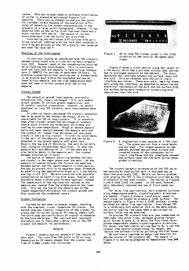
carbon. This was accomplished by m u l t i p l e d i s t i l l a t i o n o f s u l f u r i n evacuated and sealed fused s i l i c a ampoules. There was no at tempt t o analyze the s u l f u r f o r res idua l carbon because o f the ana l y t i ca l d i f f i - c u l t y of de tec t ing low carbon concentrat ions i n the presence o f a large s u l f u r background. However, i t was observed t h a t as t he s u l f u r d i s t i l l e d over there was a black residue l e f t behind. The amount o f residue diminished each time the s u l f u r was d i s t i l l e d .
Considering thu well-known d ~ f f i c u l t i e s w i t h p u r i - f y i n g vanadium, combined w i t h the f a c t t h a t vanadium i s only 6 weight percent o f the TVS c rys ta l s , the vanadium was used "as received."
Reactinq o f t he Const i tuents
I n previous s tud ies we determined t h a t N S c r y s t a l s became contaminated w i t h s i l i c o n dur ing t h e i r prepara- t i o n [12]. However, most o f t he contamination occurred wh i l e reac t i ng the const i tuents . Th is i s cons is tent w i t h the f a c t t h a t t he ampoule i s he ld a t h igh tempera- t u r e (- 1000'C) f o r per iods o f more than 10 hours. To minimize contamination t he react ing now i s accomplished i n an alumina boat w i t h i n the evacuated and sealed fused s i l i ca ampoule, and the high-temperature me1 t does no t come i n d i r e c t contac t w i t h t he s i l i c a ampoule.
Crys ta l Growth
The essent ia l growth requirements, p rev ious ly determined (121, remain unchanged: 1) a very s tab le growth system, 2) co r rec t growth composition, and 3) ca re fu l reac tant preparat ion. However, t o ob ta in good-quality long TVS c rys ta l s , more requirements were added.
I n order t o ob ta in uncracked TVS c r y s t a l s a t t e n t i o n had t o be pa id t o t he thermal shrinkage, which i s appreciable f o r 20 cm long c r y s t a l s . I t i s essent ia l t h a t a f t e r c r y s t a l growth t h e shrinkage o f c r y s t a l s should occur w i thout any hinderance whi le they are coo l i ng t o room temperature. Rough or dented ampoule wa l l s and vapor depos i t between the ampoule wa l l and the c r y s t a l a l l impede f r e e shrinkage and can cause cracks i n t he coo l i ng cryst,al. I n order t o avoid dents i n t he wa l l o f t he ampoule, t he seed end has t o be at tached t o t he growth ampoule w i t h g rea t care. Usual ly t h e t op end o f the boule, the p a r t t o s o l i d i f y l as t , contains concentrated impur i t ies . I t wets t he ampoule wa l l and adheres t o i t . I f the seed end i s a l so he ld by dents i n the ampoule wa l l , the c r y s t a l becomes s t ra ined as it cools.
The source o f depos i t occur r ing between the wal l and c r y s t a l i s t h e vapor phase over the mel t . As the ampoule i s lowered through the furnace i t s seed end becomes coo ler and the vapors deposi t i n t h a t sec t ion . One way t o prevent t h i s i s t o suppress vapor format ion by b a c k f i l l i n g t he ampoule w i t h argon a t < 1 atm before sea l i ng i t o f f [Ill. We were concerned w i t h poss ib le contamination by b a c k f i l l i n g w i t h argon, however, and there fore chose a three-zone furnace approach instead. The temperature o f the top zone was reduced as t he ampoule was lowered from the middle zone t o t he lower zone. Th is way the top o f the ampoule was a t the lowest temperature throughout t he c r y s t a l growth and thus contained the condensed vapors.
Crys ta l Evaluat ion
Evaluat ion was done i n several stages, s t a r t i n g w i t h t he s implest , v isua l inspect ion f o r cracks. The second step was i n te rna l inspect ion o f t he c r y s t a l f o r cracks and inc lus ions using an IR imaging camera 1141. The t h i r d step was v e r i f i c a t i o n o f c r y s t a l o r i e n t a t i o n by t he Laue technique. The l a s t and most important eva luat ion was t o f a b r i c a t e a delay l i n e on the TVS c r y s t a l and measure i t s performance.
RESULTS
F igure 1 shows a t yp i ca l example o f the r e s u l t s o f t h i s work. The crack- f ree TVS boule i s 20 cm long. Inspect ion by IR camera showed t h a t the c r y s t a l was f r e e o f hidden cracks and inc lus ions.
Figure 1. 20 cm long TVS c r y s t a l grown i n the (110) d j r e c t i o n by the v e r t i c a l Bridgman tech- nlque.
F igure 2 shows a cross sec t ion along the length o f a N S boule, which had a po l ished surface t h a t s ta ined due t o prolonged exposure t o the ambient. The s t a i n decorated the i n te r face between the surface layer and t h e bu l k . I t a lso revealed t h a t t he s o l i d - l i q u i d i n te r face was convex. There was r a d i a l impur i ty t rans- p o r t along the in ter face, as detected by measuring the e l e c t r i c a l res is tance o f the bulk and the surface [13], t he surface being more conductive (containing more impur i t ies) than the bu lk .
Figure 2. A long i tud ina l cross sec t ion o f a TVS crys- t a l . The piece was c u t from a round boule and pol ished. Pro-longed exposure t o t he ambient s ta ined the pol ished surface and revealed t races o f t he subsequent so l i d - l i q u i d in ter faces and the in ter faces between the surface layer and the bu lk (arrow shows growth d i rec t i on ) .
The c rys ta l l og raph i c o r i e n t a t i o n o f t he N S boule was assured by seeding the me l t i n t he same way as described prev ious ly [12]. We d i d no t have a problem w i th growing the TVS i n any o r i e n t a t i o n provided by the o r i e n t a t i o n o f t he seed c r y s t a l . The boules i n Figures 1 and 4 used (110) c u t seeds. I n t he past, however, t h i s laboratory repor ted the use o f Z-cut seeds too [121.
For delay l i n e app l ica t ions , well-prepared surfaces along temperature-stable, c r ys ta l l og raph i c d i rec t i ons a re needed. F igure 3 shows a round boule, sawed i n h a l f along i t s length t o produce a (110) surface. The second sample i n F igure 3 has a (110) surface, already pol ished f o r delay l ine appl i ca t i on . Even though TVS i s a r e l a t i v e l y s o f t ma te r i a l (3-4 on t h e Mohs scale), the m i r ro r q u a l i t y ind ica tes t h a t a dev ice-qua l i ty surface f i n i s h can be obtained.
To prov ide TVS c r y s t a l s t h a t a re less cumbersome t o f a b r i c a t e i n t o delay l ines , we began growing rectan- gu lar boules (Figure 4) i n which the f l a t faces incor- porate temperature s tab le c r ys ta l l og raph i c d i r e c t i o n s . For delay l i n e f a b r i c a t i o n a l l one has t o do i s c u t t he c r y s t a l i n t o several p ieces along i t s length, and improve t h e surface f i n i s h by po l i sh ing the f l a t faces.
We prev ious ly repor ted on delay l i n e behavior f o r shor ter pieces o f TVS c r y s t a l s [a]. The sample i n F igure 3 i s now being prepared t o demonstrate long SAW delay.
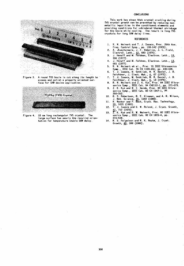
CONCLUSIONS
Figure 3. A round N S boule i s c u t along i t s length t o access and p o l i s h a properly or iented sur- face f o r SAW device app l ica t ion.
F igure 4. 15 cm long rectangular TVS c r y s t a l . The large surface has nearly t he required or ien- t a t i o n f o r temperature s tab le SAW delay.
This work has shown t h a t c rys ta l cracking dur ing TVS c rys ta l growth can be prevented by reducing non- m e t a l l i c impur i t i es i n the const i tuent elements and prov id ing cond i t ions f o r unhindered thermal shrinkage f o r the boule whi le coo l ing. The r e s u l t i s long TVS c r y s t a l s f o r long SAW delay l ines.
REFERENCES
1. R. W. Weinert and T. J. Isaacs, Proc. 29th Ann. Freq. Control Symp., pp. 139-142 (1975).
2. A . Jhunjhunwala, J. F. Vetelino, J. C. F ie ld , Electron. L e t t . , l2, 683 (1976).
3. J. Henaff and M . Feldman, Electron. Le t t . , l3, 300 (1977).
4. J. Henaff and M. Feldman, Electron. Le t t . , 3, 661 (1977). R. W. Weinert e t a l . , Proc. 76 IEEE Ul t rason ics
'
Symp., IEEE Cat. 76 CH 1120-5SU, pp. 532-535. T. J. Isaacs, M. Got t l ieb , M. R. Daniel, J. D. Feichtner, J. E lec t . Mat., 4, 67 (1975). T. J. Isaacs, M. Got t l ieb , M. R. Daniel, J. D. Feichtner, J. E lec t . Mat., 5 , 13 (1976). R. W . Weinert and Z . K. Kun, Proc. 84 IEEE U l t r a - sonics Symp., IEEE Cat. 84 CH2112-1, pp. 271-273. Z. K. Kun and W. E. Caida, Proc. 83 IEEE U l t r a - sonics Svm~.. IEEE Cat. 83 CH 1947-1, PP. . . , 350-352.
10. 0. S. Robertson, 8. E. Kinsman, and A. R. Wilson, J. Mat. Science, 15, 1592 (1986).
11. K. Wacker and P. E c k , Cryst. Res. Technology, 20, 1025 (1985).
12. J. Isaacs and C. W. Roland, J. Cryst. Growth, 47, 712 (1979). -
13. Z. K. Kun and R. W. Weinert, Proc. 82 IEEE U l t r a - sonics Symp., IEEE Cat. 82 CH 1823-4, pp. 515-518.
14. R. S. Feigelson and R. K. Route, J. Cryst. Growth, 40, 399 (1980).
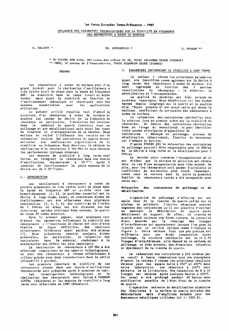
ler Forum Europien Temps-Fr6quence - 1987 INFLUENCE DES PARAMEES TECHNOI.OGIQUES SIJR LA STABILITE EN FIlEQUENCE
DES HESONATEUHS A ONllES BE SURFACE
S. CALISTI PH. 1)EFHANOIJLD U . HAUDEN * '
TfI SINTRA ASM DTAS, 3911 route des cr&tes UP 38, 06561 VALHONNI< CEDEX (FRANCE) '+ CNRS, 32 avenue de llObservatoire, 25000 DESANCON CEDEX (FRANCE)
RESUME 2.- PARAMETRES 1NF'L.UENCANT LA STABILITE A LONG TEHME
Le tableau 1 resume les prirlcipaux parametres ayant dte identifies comme agissant sur la derive a
Les resonateurs a ondes de surface sont d'un grand interdt pour la realisation dioscillateurs a tres faible bruit de phase dans la bande de frequence UHF. La stabilite dans le temps (court et nloyen terme) mais aussi la stabilite en fonction de l'environnement (rndcanique et thermique) sont des donnees essentielles pour les applications militaires.
Le present article rappelle tout drabord la structure d'un resonateur ondes de surface et analyse les causes de derive de la frequence de resonance en particulier, lf~volution des tensions dans le substrat de quartz (tensions dues au polissage et aux metallisations) rnais aussi les types de fixation et d'encapsulation de ce dernier. Nous mettons en relief l'influence des recuits sur la relaxation interne des contraintes du quartz devant entrainer une amelioration significative de la stabilite en frequence. Nous dCcrivons la methode de reallsation d'un resonateur a 320 MHz et nous donnons les performances typiques obtenues.
Les mesures de stabilite a long terme sont faites en integrant le resonateur dans une boucle d'oscillations therrnostatee a Apres 6 semaines de fonctionnement la pente moyenne de la derive est de 3.10-9/jour.
1.- INTRODUCTION
Les oscillateurs a resonateurs a ondes de surtace presentent un tres faible bruit de phase dans la bande de frequence UHF et au-dela vers les hyperfrequences [I, 21. Le probleme essentiel est la derive 6 long terme. Ainsi, de nombreuses etudes de vieillissement ont ete effectuees dans plusieurs laboratoires 13, 4, 5, 61. Des stabilites de llordre de 1 PPM/an ou mieux ont ete obtenues sur des structures variees utilisant bien entendu, le quartz de coupe ST comme substrat.
Dans le present papier, nous analysons tout d'abord les parametres influencant la stabilite des resonateurs ; l'importance de chacun est loin d'ftre etablie de faqon definitive, des resultats relativement differents ayant parfois 6th obtenus 171. Nous presentons ensuite quelques etudes prealables, en particulier, la relaxation des contraintes dans le substrat, conduisant la minimisation des effets les plus importants.
La realisation de resonateurs 320 MHz a Cte effectuee compte-tenu de ces apports technologiques. Ce sont des resonateurs a reseau reflechissant sillons graves avec deux transducteurs dans la cavite (dispositif 2 portes).
Les premiers resultats de stabilite de ces resonateurs places dans une boucle dloscillations thermostatee sont pr6sentCs apres 6 semaines de test,
Les investigations technologiques et la realisation des resonateurs sont faites & THOMSON SINTRA (Valbonne) et les mesures de stabilitC a long terme sont effectuees au LPMO (Besancon).
long terme des rdsonateurs a ondes de surface. 11s sont regroupes en fonction des 3 parties constitutives du resonateur : le substrat, la metallisation et l'encapsulation.
La qualit6 du materlau est bien entendu de premiire importance. Nous beneficions ici des etudes menees depuis longtemps sur le quartz et la qualite dite "Super premium 0" est aussi celle qui donne le meilleur coefficient de surtension des resonateurs a ondes de surface.
La relaxation des contraintes residuelles dans le substrat joue au premier ordre sur la stabilite du resonateur. En dehors des contraintes residuelles dues au tirage du monocristal on peut identifier trois causes principales dlapparition de contraintes t decoupe et polissage, process de metallisation (electrodes), fixation du resonateur sur llembase du boitier.
D1apres STOKES [8] la relaxation des contraintes de polissage pourrait Btre responsable pour 10 PPM/an de la derive B long terme et la mktallisation pour 3 PPM/an.
Le dernier point concerne l'encapsulation ou il est evident que le minimum de pollution est obteriu dans le cas dlune encapsulation sous vide pousse. De plus, pour les resonateurs ceci permet d'atteindre un coefficient de surtension plus eleve. Cependant, comme nous le verrons dans la suite la premiere famille de rCsonateurs testes a ete encapsulee sous azote sec.
Relaxation des contraintes de polissage et de n4tallisation
L1opBration de polissage s'effectue sur une seule face de la tranche de quartz collee sur le plateau du polissoir. L'action n~ecanique exercee engendre des contraintes qu'il est possible d'estimer en mesurant la deformation du quartz apres decollement du support. En effet, la tranche de quartz prend toujours une forme concave, la concavite etant mesur6e par le comptage des franges dlinterferences qui apparaissent lorsque l'on pose la tranche sur un calibre optique comme llindique la figure 1, Cette methode bien que peu precise est suff isante pour une etude comparative. Apres polissage, la courbure residuelle est de 10 d 20 franges dVinterf&rences, elle depend de la methode de polissage et bian entendu, des dimensions (diamhtre et Bpaisseur) de la tranche de quartz.
La relaxation des contraintes a ete obtenue par un recuit A haute temperature sous une atmosphere dlazote, Le tableau 2 resume les principaux resultats obtenus pour des essais faits a 250° et 450°C dans hotre laboratoire. Les resultats a 10O0C sont extraits de la litterature. Une relaxation de 8 a 10 franges est obtenue apres quelques heures 450°C. Cet essai a 6th prolong6 pendant 60 heures sans modification sensible de llBtat final de la tranche de quartz.
L1opBration suivante de mCtallisation aluminium des ilectrodes B la surface du quartz entraine des deformations mais dlamplitude moindre pour les dpaisseurs m6talllques utilisdes ici ( - 1000 A).
La relaxation des contraintes ainsi engendree est obtenue par un recuit sous atmosphere legerement reductrice (N, + H, 10 X). Cependant, nous avons dO limiter la temperature a 400°C pour eviter la deterioration des electrodes dfaluminium 19, 101.
L'aluminium des electrodes es t yerlerale~nent utilise avec 2 a 4 X de cuivre qui a pour but de bloquer la migration de l'aluminiun~ a l'interface lorsque une forte puissance electrique est appliquee au transducteur. Ceci a 6t6 de~nontre de facon relativement precise [ll] ; pour notre part, nous avons adopte un alliage A1-Cu 2 %.
L1accrochage de la couche d'aluminium est tr&s sensiblement anleliore par le depBt prealable d'une couche de chrome. Ce materiau est connu pour diffuser dans l'aluminium avec comme effet negatif d'augmenter la resistivite des electrodes. Cependant, lleffet de cette couche de chrome sur la stabilite long terme n'a pas &ti clairement dtabli puisque des resultats similaires de l'ordre de quelques PPM/an de derive ont Cte obtenus avec et sans Cr [7]. Les essais que nous avons fait ont confirm4 la det4rioration extrCmenlent rapide de la resistivite lorsque l'on effectue des traitements thermiques a 425°C. La figure 2 montre des resultats conlparatifs obtenus dans les mCmes conditions sur des couches avec et sans chrome. Ainsi, il apparait exclu d'effectuer des recuits a haute temperature sur une structure comprenant une sous-couche Cr. Compte-tenu de ces resultats, nous avons developpe une technologic 8 couche A1-Cu 2 % qui permet de faire n'importe quel etuvage ou recuit en particulier la relaxation des contraintes du substrat comme il a ete question precedemment. L'accrochage direct de l'alun~iniun~ sur le quartz a ete resolu par la ~nise au point dfune operation de nettoyage prealable par plasma reactif.
3.- STRUCTURE DES RESONATEURS
Le resonateur retenu pour tester les ameliorations technologiques precddentes est le dispositif frequence fondamentale de 319,820 MHz a structure 2 portes crest-8-dire i 2 transducteurs (entree et sortie) d'ouverture 100 A. Les reseaux rCflecteurs sont composes de 700 sillons graves de 2,5 pm de largeur. Le substrat est du quartz ST 36" dont le point d'inversion de temperature est de 55°C. Les transducteurs sont en A1-Cu 2 % dlepaisseur 700 A rCalises en lift-off.
Les sillons sont realises par gravure ionique reactive, leur profondeur est drenviron 1000 A.
Un recuit d'ulie heure 1 400°C sous atmosphere reductrice est fait sur la tranche de quartz comprenant 20 motifs elementaires. Les resonateurs sont ensuite decoupes et montes dans un boitier metallique du type DIL 18. Ce boitier dont une version est prevue pour llencapsulation sous vide a ete ferme sous azote sec (taux d'humidite inferieur a 10 PPM) par soudure A la molette electrique.
4.- RESULTATS EXPERIMENTAUX
4.1.- Caracteristiques du resonateur
Fonction de transfert
La figure 3 montre la reponse typique drun resonateur en fonction de la frequence. Sur la mCme figure, nous avons les reponses en amplitude, phase et temps de groupe mesures a 25°C. La frequence de resonance est de x 319,730 MHz est la perte d'insertion 6 dB. Le facteur de surtension en charge est de 7680.
a s'exprime en g-I
La figure 4a montre un bloc de diagramme du montage de mesure qui est essentiellement un discriminateur de phase avec un bras de reference et un bras de mesure dans lequel est insere le resonateur. Ce dernier est monte sur un pot vibrant (figure 4b) permettant d'examiner la sensibilite accClerometrique en vibration sinusoldale dans la plage 10 A lo4 hertz. L'accelBration maximum possible avec cet appareil est de 50 g pour une masse de 30 grammes. Elle est nlesuree par un accelerometre monte directement sur le pot vibrant. Le signal de l'accelero~netre est connect4 sur la deuxieme entree de l'analyseur de reseau BF dont la premiere recoit le signal du discriminateur de phase. Le rapport des deux signaux donne directement la sensibilite accel4rometrique. Le tableau 3 donne les resultats mesures en comparaison de quelques resultats extraits de publications recentes. Les valeurs trouvees sont entre l.lW9 et 6.10-9 suivant la direction de lfacceleration appliquee et le type de fixation. Les valeurs dites "intrinseques" ont ete obtenues en collant directement le resonateur sur la tGte du pot vibrant.
4.2.- Stabilite a long terE
Les mesures de stabilite a long terme ont ete effectuees en integrant le resonateur, dans une boucle dloscillateur. Ce dernier represent6 schematiquemerlt sur la figure 5 est constitue, outre le resonateur a ondes de surface (ROS) d'un amplificateur large bande (A), d'un circuit passif d'adaptation en phase et en amplitude des impedances (C.P) et dlun coupleur directif (C.D), permettant de sortir le signal de la boucle d'oscillations avec une bonne isolation. La puissance appliquee sur le resonateur est de 0,3 mu. L'amplificateur de sortie (A.S) permet dfobtenir un signal sur 50 R avec une isolation entre l'entree et la sortie de 40 dB. L'oscillateur est monte dans un thermostat dont la temperature est contr81Ce h 10-40C. Pour atteindre ce resultat l'ensemble est place dans une salle a temperature rCgulee. La temperature de regulation est de 54,5" correspondant la temperature du point d'inversion mesuree sur les resonateurs.
La figure 6 represente la derive en frequence pendant les 36 premiers jours de fonctionnement. L'oscillateur a ete mis en route le 6 fevrier 1987 ; au cours des premiers jours la derive a ete de 2.10-7/jour. Apres 20 jours de fonctionnement, la derive se stabilise B 3.10-g/jour. L1arr6t et la remise en route de l'oscillateur provoque un saut de frequence de l'ordre de 10-6. Apres quelques jours, la derive a repris une pente moyenne de 6,10-9/jour.
5.- CONCLUSION
Les premiers resultats e~lregistres ici sont trop jeunes et trop fragmentaires pour pretendre valider la filiCre technologique choisie. 11s sont cependant encourageants puisque la pente moyenne de 3.10-9/jour correspond a l'objectif de 1 PPM/an que l'on s'est fixb. Les essais de vieillissement vont etre poursuivis pendant un an sur un banc a 40 postes thermostaths en construction au LPMO. A llissue de ces essais, nous pourrons conclure valablement sur la filiere technologique mise en place pour realiser des oscillateurs B resonateurs a ondes de surface.
La sensibilite accClCrometrique "a" est definie par le glissement de frequence au premier ordre provoque par l'application d'une acceleration y soit :
BIBLIOGRAPHIE
[I] W.J. TANSKI, R.A. ST. CYR, P.G DRAGONETTI and E.G. KOSCO". A Radar System Application of an 840 MHz SAW Resonato stabilised Oscillator. IEEE Transaction on sonics and ultrasonics Vol. SU28 no 3 May 81 pp. 146, 150.
! 2 1 W. J. TANSKI, "UHF Saw Resor~ators and applications". Proc. of 34 th. Frequency control Symposium May 80.
131 T.E. PARKER, "Analysis of aging data on Saw oscillators" Proc. of Ann. Freq. Control. Symposium date pp. 292, 301.
141 T.E. PARKER "Random and systematc contributions to long term Frequency Stability in Saw oscillators" Proc. of the 1983 Ultrasonic Symposium, pp 257, 262.
15) W.R. SHREVES "Active aging of Saw Resonators" Proc. of the 1980 Ultrasonic Symposium.
161 W.R. SHREVES, J.A. KUSTERS, C.A. ADAMS "Fabrication of Saw Resonators for improved long term agingq1 Proc. of the 1978. Ultrasonic Symposium pp, 573, 579.
17) W.J. TANSKI "The influence of a chrome fi1111 bonding layer on Saw Resonator performances" Proc. of the 1985 Ultrasonic Symposium pp. 252, 257.
[8] R.B. STOKES and M.J. DELANEY "Aging mechanisms in Saw Oscillators" Proc, of the 1983 Ultrasonic Symposium.
[9] A.K. SINHA and T.T. SHENG "The temperature dependance of stresses in aluminium films on oxydized silicon substrate Thin solid films 1978 pp. 117, 126.
[lo] M. HERSHKOVITZ, I.A. BLECH and Y. KOMEN "Stress relaxation in thin aluminium films". Thin Solid film 1985 pp. 155, 162.
[Ill W.R. SHREVES, R.C. BRAY, S. ELLIOT and YG. CHU "Power dependence of aging in Saw Resonators" Proc. of the 1981 Ultrasonic Symposium pp. 94, 99.
[12] M.F. THIERSTEN and D.S. STEVENS "Acceleration sensitivity of surface acoustic wave resonators. Appl. Phys. Lett. January 1986 pp. 97, 99.
[13] T.E. PARKER AND J. CALLERAME "Sensitivity of Saw delay lines and Resonators to vibrationn. 1981 IEEE Ultrasonics Symposium Proceedings Vol. 1 pp. 129, 1344.
1141 W.L. SMITH and W.J. SPENCER, "Precision Crystal Frequency standards" Proceedings, 15th Annual Symposium on Frequency Control, US Army Electronics Command, Fort Mommouth, NJ, pp. 139, 155, (1961), National Technical Information Service Accession Nr AD 265 455.
1151 Raymond L. FILLER and John R. VIG., "The acceleration and warm up characterictics of four point mounted SC and AT-Cut resonators, Proc. 35 th Ann. Freq. Control Symposium, USAERADCOM, Fort Mommouth, NJ 07703 May 1981, pp. 110, 116.
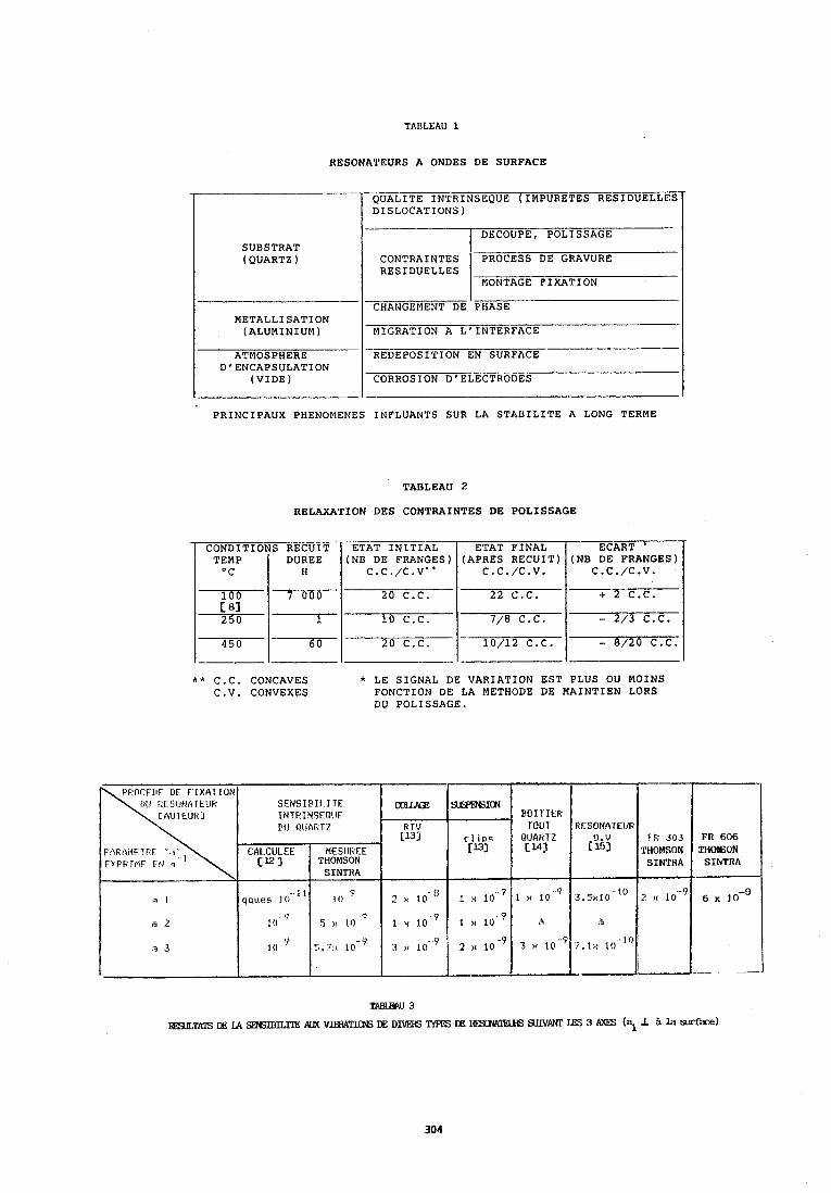
TABLEAU 1
RESONATEURS A ONDES DE SURFACE
PRINCIPAUX PHENOMENES INFLUANTS SUR LA STABILITE A LONG TERME
SUBSTRAT (QUARTZ )
METALLISATION (ALUMINIUM)
ATMOSPHERE D'ENCAPSULATION
(VIDE)
TABLEAU 2
RELAXATION DES CONTRAINTES DE POLISSAGE
QUALITE IN'PRINSEQUE (IMPURETES RESIDUELL'P? DISLOCATIONS)
DECOUPE, POLISSAGE
RESIDUELLES MONTAGE FIXATION
CHANGEMENT DE PHASE
MIGRATION A L'INTERFACE --- - - REDEPOSITION EN SURFACE - CORROSION D' EL~F~RoEs
* * C.C. CONCAVES * LE SIGNAL DE VARIATION EST PLUS OU MOINS C.V. CONVEXES FONCTION DE LA METHODE DE MAINTIEN LORS
DU POLISSAGE.
CONDITIONS RECUIT DUREE
450 6 0
TABLEW 3
=TATS IIE LA S3SIBlLl"E WX VEWil"l'W tE D m lYPES DE IEXlW- WIVM LES 3 AXES (al la Ed&-)
ETAT FINAL (APRES RECUIT)
c.c./c.v.
22 C.C.
7/8 C.C.
10/12 C.C.
ETAT INITIAL (NB DE FRANGES)
c.c./c.vn*
20 C.C.
10 C.C.
20 C.C.
ECART ' (NB DE FRANGES)
c.c./c.v.
+ 2 C.C.
- 2/3 C.C.
- 8/20 C.C.
c E i u a
K TV L13J
2 x 10 "
F'F'DLE LIE LIE F IYAl I?)N rill I tF SIJEIR IE l lF SENSIPII-I I E
INTF INSERUE D(J O U ~ C T Z
FR 606 T W O , SIhTRA
6 x
sisRx3ICN
c l I P S [133
1 x 1 0 "
1 ~ 1 0 . ~ i H i O
-.
MESlJhEE THOMSON SINTRA
0
CAI CULEE CK 3
HOITIER TOUT
QUARTZ cuj
I x 10.'
"J! L O
- 7 5,1>! 1 0
a I
a 2
9 3
qques I 0 L1
1 0 ( )
10
LESONA IEUR
('1
J,;xiO
r f i 303 THOMSON SINTRA
2 >c t 0 - O
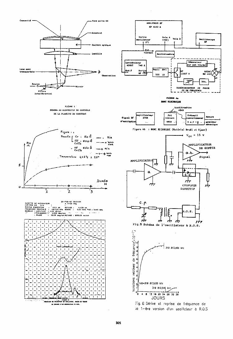
LM. se.1 t r a ~ p w 8 n t n
Observation
FIGUFS 1
SCHEMA DU DISPOSITII DE CONTROLE
06 LA PLANEITB DU SUBSTRAT
RECETTE OE RESONATEUR 25-FEE-87 09:57;54
( u p r o s s EW o $0 I A T I 2 5 0.g
PERTES ~ I N S E R ~ ~ O ~ : ' 6.03 dB RETARD : 4.428 u l FREOUENCE CENTRALE : 310.730 M H z BANDI I 0.50 MHz PAS ; 0.001 MHa E F I L L E : AYPLIrUOE : 4.00 a'o/om
:PFREOUENCE '?' 0:026 YHz/om "' ' ' C. -' . : PHASE : 20.00 a.p/ornRIrARO : 1000.00 n./em
I u u I I DISCRININATEUR OE PIUSI I L - - _OUDBTRBP!F- - - - - - A
?I- 4 s
= -ws
F i g u r e 4b : BANC I E C A W I O U E ( M a t e r i e l B r u C l e t K j a e r )
DE SORTIE - cr.h. Signal
AMPLIFICATEUI
. .
COUPLEUR DIRECTIF
Pig. 5 Schema de 1
I li4=j7 ~'oscillateur & R.O.S.
JOURS Fig. 6 Derive e t reprise de frequence de la I--ere vcrsion d'un oscilloteur b R.0.S
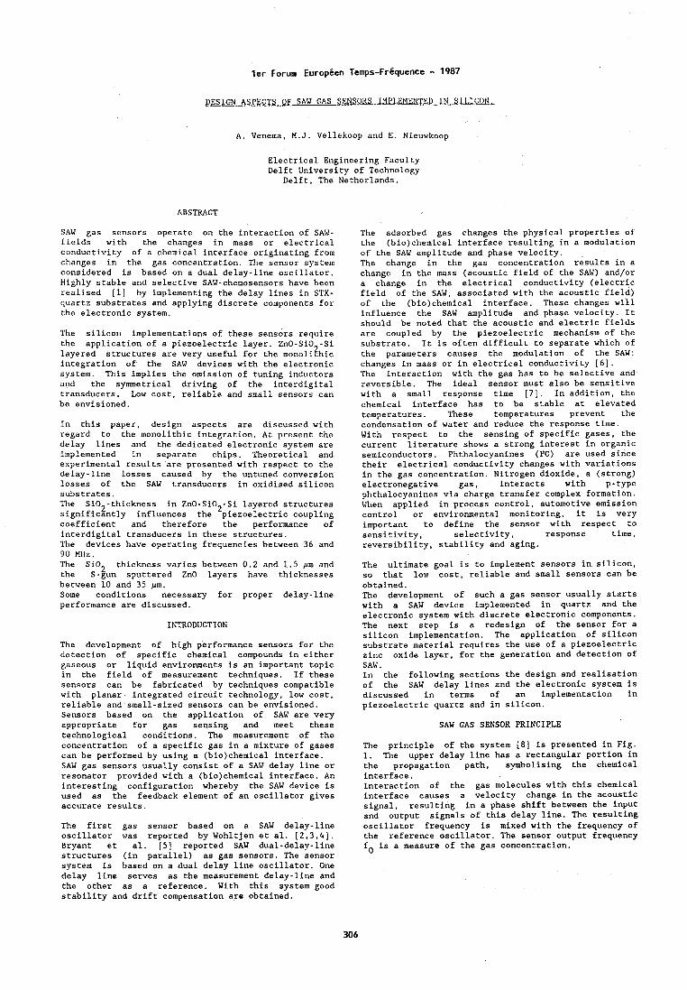
l e r Forum Europien Temps-FrBquence - 1987
DESIGN ASPECTS OF SAW GAS SENSORS 1MPI.T.MEWTED IN SII.ICON.
A. Venelna, M.J. Vellekoop and E. Nieuwkoop
Electrical Engineering Faculty Delft University of Technology
Delft, The Netherlands.
ABSTRACT
SAW gas sensors operate on the interaction of SAW- fields with the changes in mass or electrical conductivity of a chemical interface originating from changes in the gas concentration. The sensor system considered is based on a dual delay-line oscillator. Highly stable and selective SAW-chemosensors have been realised [I] by implementing the delay lines in STX- quartz substrates and applying discrete components for the electronic system.
The silicorl implementations of these sensors require the application of a piezoelectric layer. ZnO-SiO -Si layered structures are very useful for the monoli?hic integration of the SAW devices with the electronic system. This implies the omission of tuning inductors and the symmetrical driving of the interdigital transducers. Low cost, reliable and small sensors can be envisioned.
In this paper, design aspects are discussed with regard to the monolithic integration. At present the delay lines and the dedicated electronic system are implemented in separate chips. Theoretical and experimental results are presented with respect to the delay-line losses caused by the untuned conversion losses of the SAW transducers in oxidised silicon substrates. The Si02-thickness in ZnO-SiO -Si layered structures 2 significantly influences the piezoelectric coupling coefficient and therefore the performance of interdigital transducers in these structures. The devices have operating frequencies between 36 and 90 MHz. The Si02 thickness varies between 0.2 and 1.5 pm and the S-gun sputtered ZnO layers have thicknesses between 10 and 35 pm. Some conditions necessary for proper delay-line performance are discussed.
INTRODUCTION
The development of high performance sensors for the detection of specific chemical compounds in either gaseous or liquid environments is an important topic in the field of measurement techniques. If these sensors can be fabricated by techniques conlpatible with planar integrated circuit technology, low cost, reliable and small-sized sensors can be envisioned. Sensors based on the application of SAW are very appropriate for gas sensing and meet these technological conditions. The measurement of the concentration of a specific gas in a mixture of gases can be performed by using a (bio)chemical interface. SAW gas sensors usually consist of a SAW delay line or resonator provided with a (bio)chemical interface. An interesting configuration whereby the SAW device is used as the feedback element of an oscillator gives accurate results.
The first gas sensor based on a SAW delay-line oscillator was reported by Wohltjen et al. [2,3,4]. Bryant et al. [5] reported SAW dual-delay-line structures (in parallel) as gas sensors. The sensor system is based on a dual delay line oscillator. One delay line serves as the measurement delay-line and the other as a reference. With this system good stability and drift compensation are obtained.
The adsorbed gas changes the physical properties ot the (bro)chemical interface resulting in a modulation of the SAW amplitude and phase velocity. The change in the gas concentration results in a change in the mass (acoustic field of the SAW) and/or a change in the electrical conductivity (electric field of the SAW, associated with the acoustic field) of the (bio)chemical interface. These changes will influence the SAW amplitude and phase velocity. It should be noted that the acoustic and electric fields are col~pled by the piezoelectric mechanism of the substrate. It is often difficult to separate which of the parameters causes the modulation of the SAW: changes in mass or in electrical conductivity (6). The interaction with the gas has to be selective and reversible. The ideal sensor must also be sensitive with a small response time [7]. In addition, the chemical interface has to be stable at elevated temperatures. These temperatures prevent the condensation of water and reduce the response time. With respect to the sensing of specific gases, the current literature shows a strong interest in organic semiconductors. Phthalocyanines (PC) are used since their electrical conductivity changes with variations in the gas concentration. Nitrogen dioxide, a (strong) electronegative gas, interacts with p-type phthalocyanines via charge transfer complex formation. When applied in process control, automotive emission control or environmental monitoring, it is very important to define the sensor with respect to sensitivity, selectivity, response time, reversibility, stability and aging.
The ultimate goal is to implement sensors in silicon, so that low cost, reliable and small sensors can be obtained. The development of such a gas sensor usually starts with a SAW device implemented in quartz and the electronic system with discrete electronic components. The next step is a redesign of the sensor for a silicon implementation. The application of silicon substrate material requires the use of a piezoelectric zinc oxide layer, for the generation and detection of SAW. In the following sections the design and realisation of the SAW delay lines and the electronic system is discussed in terms of an implementation in piezoelectric quartz and in silicon.
SAW GAS SENSOR PRINCIPLE
The principle of the system (81 is presented in Fig. 1. The upper delay line has a rectangular portion in the propagation path, symbolising the chemical interface. Interaction of the gas molecules with this chemical interface causes a velocity change in the acoustic signal, resulting in a phase shift between the input and output signals of this delay line. The resulting oscillator frequency is mixed with the frequency of the reference oscillator. The sensor output frequency fo is a measure of the gas concentration.
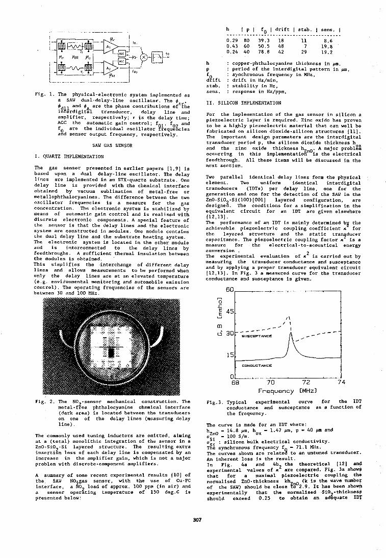
h I p I fo I drift I stab. I sens. I . . . . . . . . . . . . . . . . . . . . . . . . . . . . . . . . . . . . . . . . 0.29 80 39.3 18 11 8.6 0.43 60 50.5 48 7 19.8 0.24 40 78.8 42 29 19.2
Fig. 1. The physical-electronic system implemented as a SAW dual-delay-line oscillator. The 4 , 4 and 4 are the phase contributions oftEhe i$tQrdigith transducer, delay line and amplifier, respectively; r is the delay time; AGC the automatic gain control; fo are the individual oscil1atorfi!&;q&c;:: and sensor output frequency, respectively.
SAW GAS SENSOR
I. QUARTZ IMPLEMENTATION
The gas sensor presented in earlier papers [1,9] is based upon a dual delay-line oscillator. The delay lines are implemented in an STX-quartz substrate. One delay line is provided with the chemical interface obtained by vacuum sublimation of metal-free or metallophthalocyanines. The difference between the two oscillator frequencies is a measure for the gas concentration. The electronic system is stabilized by means of automatic gain control and is realised with discrete electronic components. A special feature of the sensor is that the delay lines and the electronic system are constructed in modules. One module contains the dual delay line and the substrate heating system. The electronic system is located in the other module and is interconnected to the delay lines by feedthroughs. A sufficient thermal insulation between the modules is obtained. This simplifies the interchange of different delay lines and allows measurements to be performed when only the delay lines are at an elevated temperature (e.g. environmental monitoring and automobile emission control). The operating frequencies of the sensors are between 30 and 100 MHz.
Fig, 2. The NO2-sensor mechanical construction. The metal-free phthalocyanine chemical interface (dark area) is located between the transducers on one of the delay lines (measuring delay line).
The commonly used tuning inductors are omitted, aiming at a (total) monolithic integration of the sensor in a ZnO-Si02-Si layered structure. The resulting extra insertion loss of each delay line is compensated by an increase in the amplifier gain, which is not a major problem with discrete-component amplifiers.
A summary of some recent experimental results [lo] of the SAW NO-gas sensor, with the use of CU-PC interface, a fjo2 load of approx. 100 ppm (in air) and a sensor operating temperature of 150 deg.C is presented below:
h : copper-phthalocyanine thickness in pm, P : period of the interdigital pattern in pm,
fo : synchronous frequency in MHz, drift : drift in Hz/min, stab. : stability in Hz, sens. : response in Hz/ppm,
11. SILICON IMPLEMENTATION
For the implementation of the gas sensor in silicon a piezoelectric layer is required. Zinc oxide has proven to be a highly piezoelectric material that can well be fabricated on silicon dioxide-silicon structures [Ill. The important design parameters are the interdigital transducer period p, the silicon dioxide thickness hox and the zinc oxide thickness hznO, A major problem occurring in this implementation is the electrical feedthrough. All these items will be discussed in the next section.
Two parallel identical delay lines form the physical element. Two uniform identical interdigital transducers (IDTs) per delay line, one for the generation and one for the detection of the SAW in the ZnO-SiO -Si(100)[001] layered configuration, are designe8. The conditions for a simplification in the equivalent circuit for an IDT are given elsewhere 112,131. The performance of an IDT is mainly determined by the achievable piezoelectric coupling coefficient n for the layered structure and the static tran ducer capacitance. The piezoelectric coupling factor n' is a measure for the electrical-to-acoustical energy conversion . The experimental evaluation of n2 is carried out by measuring the transducer conductance and susceptance and by applying a proper transducer equivalent circuit [12,13]. In Fig. 3 a measured curve for the transducer conductance and susceptance is given.
CONDUCTANCE
l 5 'i Frequency [MHz]
Fig.3. Typical experimental curve for the IDT conductance and susceptance as a function of the frequency.
The curve is made for an IDT where: hZnO - 14.8 pm, hox - 1.47 pm, p - 40 pm and o - 100 S/m. Si o : silicon bulk electrical conductivity. ~ a e synchronous frequency f - 71.1 MHz. The curves shown are relates to an untuned transducer. An inherent loss is the result. In Fig. 4a and 4b the theoretical (121 and experimental values of c2 are compared. Fig. 3a shows that for a maximal piezoelectric coupling the normalised ZnO-thickness kh (k is the wave number of the SAW) should be close fg02.9, It has been shown experimentally that the normalised Si02-thicknesg should exceed 0.25 t o obtain an adequate IDT
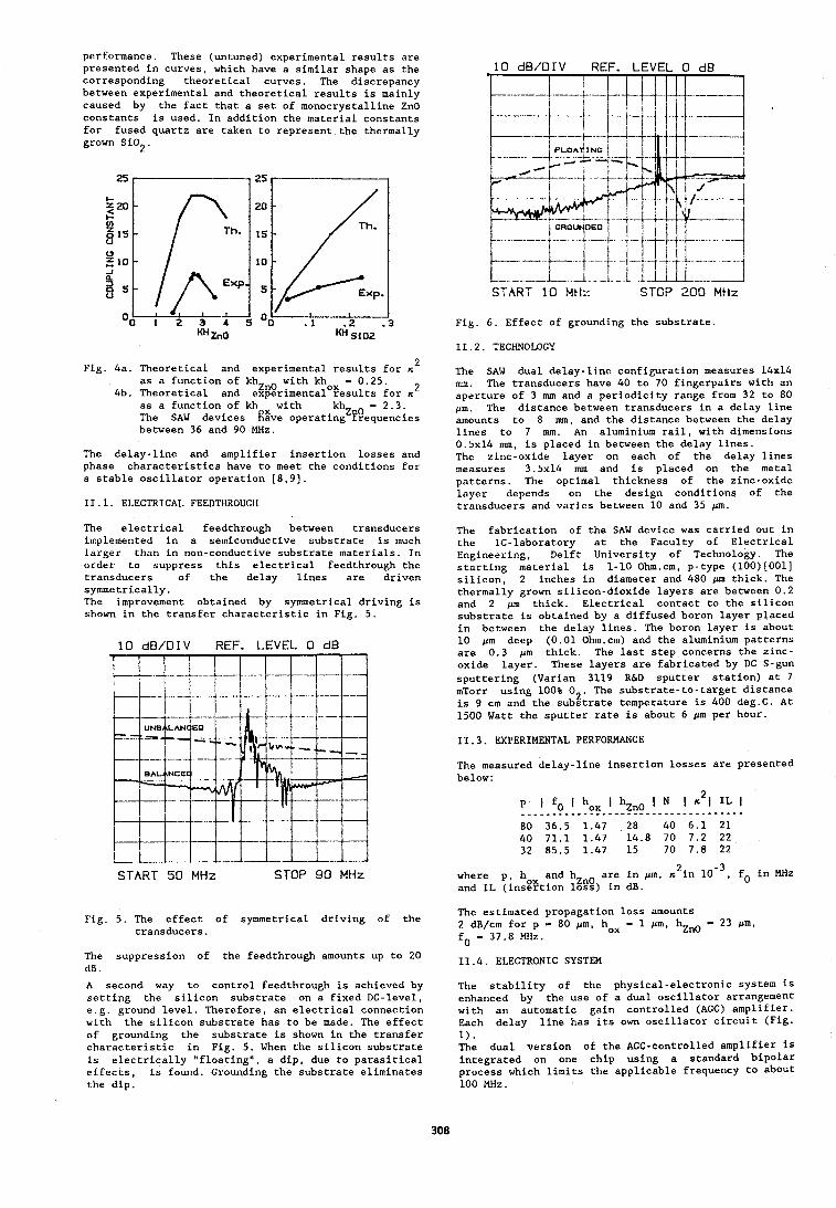
performance. These (untuned) experimental results are presented in curves, which have a similar shape as the corresponding theoretical curves. The discrepancy between experimental and theoretical results is mainly caused by the fact that a set of monocrystalline ZnO constants is used. In addition the material constants for fused quartz are taken to represent the thermally grown SiO 2'
Fig. 4a. Theoretical and experimental results for n 2
as a function of kh with khox - 0.25. 4b. Theoretical and e@rimental results for K
as a function of kh with kh - 2.3. The SAW devices @ve operatingZ?Bequencies between 36 and 90 MHz.
The delay-line and amplifier insertion losses and phase characteristics have to meet the conditions for a stable oscillator operation [8,9].
11.1. ELECTRICAL FEEDTHROUGW
The electrical feedthrough between transducers implemented in a semiconductive substrate is much larger than in non-conductive substrate materials. In order to suppress this electrical feedthrough the transducers of the delay lines are driven symmetrically. The improvement obtained by symmetrical driving is shown in the transfer characteristic in Fig. 5.
10 dB/DIV REF. LEVEL 0 dB
START 50 MHz STOP 90 MHz
10 dB/DIV REF. LEVEL 0 dB
START 1 0 Mti:: STOP 200 MHz
Fig. 6. Effect of grounding the substrate.
11.2. TECHNOLOGY
The SAW dual delay-line configuration measures 14x14 nun. The transducers have 40 to 70 fingerpairs with an aperture of 3 mm and a periodicity range from 32 to 80 pm. The distance between transducers in a delay line amounts to 8 nun, and the distance between the delay lines to 7 mm. An aluminium rail, with dimensions 0.5~14 mm, is placed in between the delay lines. The zinc-oxide layer on each of the delay lines measures 3.5~14 nun and is placed on the metal patterns. The optimal thickness of the zinc-oxide layer depends on the design conditions of the transducers and varies between 10 and 35 pm.
The fabrication of the SAW device was carried out in the IC-laboratory at the Faculty of Electrical Engineering, Delft University of Technology. The starting material is 1-10 Ohm.cm, p-type (100)[001] silicon, 2 inches in diameter and 480 pm thick. The thermally grown silicon-dioxide layers are between 0.2 and 2 pm thick. Electrical contact to the silicon substrate is obtained by a diffused boron layer placed in between the delay lines. The boron layer is about 10 pm deep (0.01 0hm.cm) and the aluminium patterns are 0.3 pm thick. The last step concerns the zinc- oxide layer. These layers are fabricated by DC S-gun sputtering (Varian 3119 R&D sputter station) at 7 mTorr using 100% 02. The substrate-to-target distance is 9 cm and the substrate temperature is 400 deg.C. At 1500 Watt the sputter rate is about 6 pm per hour.
11.3. EXPERIMENTAL PERFORMANCE
The measured delay-line insertion losses are presented below:
P I fo I box I N IcLlILI
80 36.5 1.47 28 40 6.1 21 40 71.1 1.47 14.8 70 7.2 22 32 85.5 1.47 15 70 7.8 22
where p, hox and hzno are in pm. s2in to in MHz and IL (insertion loss) in dB.
The estimated propagation loss amounts Fig. 5. The effect of symmetrical driving of the
transducers. 2 dB/cm for p - 80 pm, hox - 1 pm, hZnO - 23 pm, fo - 37.8 MHz.
The suppression of the feedthrough amounts up to 20 11.4. ELECTRONIC SYSTEM dB.
A second way to control feedthrough is achieved by setting the silicon substrate on a fixed DC-level, e.g. ground level. Therefore, an electrical connection with the silicon substrate has to be made. The effect of grounding the substrate is shown in the transfer characteristic in Fig. 5. When the silicon substrate is electrically "floating", a dip, due to parasitical effects, is found. Grounding the substrate eliminates the dip.
The stability of the physical-electronic system is enhanced by the use of a dual oscillator arrangement with an automatic gain controlled (AGC) amplifier. Each delav line has its own oscillator circuit (Fig. 1). The dual version of the AGC-controlled amplifier is integrated on one chip using a standard bipolar process which limits the applicable frequency to about 100 MHz.
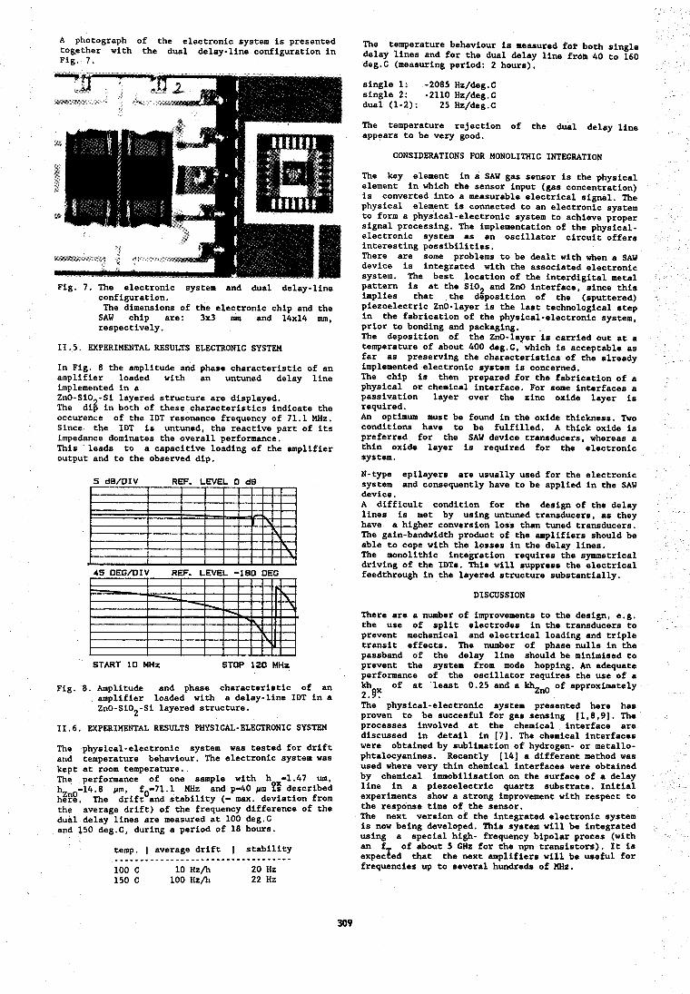
A photograph of the electronic system is presented together with the dual delay-line configuration in Fig. 7.
Fig. 7. The electronic system and dual delay-line configuration. The dimensions of the electronic chip and the SAW chip are: 3x3 mm and 14x14 mm, respectively.
11.5. EXPERIMENTAL RESULTS ELECTRONIC SYSTEM
In Fig. 8 the amplitude and phase characteristic of an amplifier loaded with an untuned delay line implemented in a Zn0-S10 -Si layered structure are displayed. The dis in both of these characteristics indicate the occurence of the IDT resonance frequency of 71.1 MHz. Since the IDT is untuned, the reactive part of its impedance dominates the overall performance. This leads to a capacitive loading of the amplifier output and to the observed dip.
5 d B / D I V REF. L E V E L 0 dB I I
-
45 OEG/OIV REF. L E V E L -180 DEG
START 10 MHZ S ~ O P 120 MHZ
Fig. 8. Amplitude and phase characteristic of an amplifier loaded with a delay-line IDT in a ZnO-SiO -Si layered structure. 2
11.6. EXPERIMENTAL RESULTS PHYSICAL-ELECTRONIC SYSTEM
The physical-electronic system was tested for drift and temperature behaviour. The electronic system was kept at room temperature. The performance of one sample with h -1.47 um, hZnO-14.8 pm, fO-71. 1 MHz and p-40 pm ?g described here, The drift and stability (- max. deviation from the average drift) of the frequency difference of the dual delay lines are measured at 100 deg.C and 150 deg.C, during a period of 18 hours.
temp. I average drift I stability ______.-..____--...-.--..-.------.- 100 C 10 H Z / ~ 20 Hz 150 C 100 Hz/h 22 Hz
The temperature behaviour is measured for both single delay lines and for the dual delay line frob 40 to 160 deg.C (measuring period: 2 hours).
single 1: -2085 Hz/deg.C single 2: -2110 Hz/deg.C dual (1-2): 25 Hz/deg.C
The temperature rejection of the dual delay line appears to be very good.
CONSIDERATIONS FOR MONOLITHIC INTEGRATION
The key element in a SAW gas sensor is the physical element in which the sensor input (gas concentration) is converted into a measurable electrical signal. The physical element is connected to an electronic system to form a physical-electronic system to achieve proper signal processing. The implementation of the physical- electronic system as an oscillator circuit offers interesting possibilities. There are some problems to be dealt with when a SAW device is integrated with the associated electronic system. The best location of the interdigital metal pattern is at the Si02 and ZnO interface, since this implies that the deposition of the (sputtered) piezoelectric ZnO-layer is the last technological step in the fabrication of the physical-electronic system, prior to bonding and packaging. The deposition of the ZnO-layer is carried out at a temperature of about 400 deg.C, which is acceptable as far as preserving the characteristics of the already implemented electronic system is concerned. The chip is then prepared for the fabrication of a physical or chemical interface. For some interfaces a passivation layer over the zinc oxide layer is required. An optimum must be found in the oxide thickness. Two conditions have to be fulfilled, A thick oxide is preferred for the SAW device transducers, whereas a thin oxide layer is required for the electronic system.
N-type epilayers are usually used for the electronic system and consequently have to be applied in the SAW device. A difficult condition for the design of the delay lines is met by using untuned transducers, as they have a higher conversion loss than tuned transducers. The gain-bandwidth product of the amplifiers should be able to cope with the lcsses in the delay lines. The monolithic integration requires the symmetrical driving of the IDTs. This will suppress the electrical feedthrough in the layered structure substantially.
DISCUSSION
There are a number of improvements to the design, e.g. the use of split electrodes in the transducers to prevent mechanical and electrical loading and triple transit effects. The number of phase nulls in the passband of the delay line should be minimised to prevent the system from mode hopping. An adequate performance of the oscillator requires the use of a kh of at least 0.25 and a khZnO of approximately 2.9: The physical-electronic system presented here has proven to be succesful for gas sensing [1,8,9]. The processes involved at the chemical interface are discussed in detail in [ 7 ] . The chemical interfaces were obtained by sublimation of hydrogen- or metallo- phtalocyanines. Recently (141 a different method was used where very thin chemical interfaces were obtained by chemical immobilisation on the surface of a delay line in a piezoelectric quartz substrate. Initial experiments show a strong improvement with respect to the response time of the sensor. The next version of the integrated electronic system is now being developed. This system will be integrated using a special high- frequency bipolar proces (with an f of about 5 GHz for the npn transistors). It is expecTed that the next amplifiers will be useful for frequencies up to several hundreds of MHz.
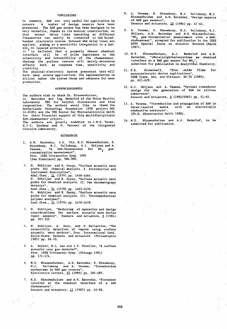
CONCLUSIONS
In summary, SAW are very useful for application in sensors. A number of design aspects have been presented. The SAW gas sensor has been designed to be very versatile, thanks to its modular construction, so that sensor delay lines operating at different frequencies can easily be connected to the broad- banded electronic system. Untuned SAW delay lines are applied, aiming at a monolithic integration in a ZnO- SiO -Si layered structure. It is believed that a properly chosen chemical interface will be of prime importance to the selectivity and reversibility of the chemosensor, whereas the surface texture will mainly determine effects such as response time, sensitivity and stability. The physical-electronic system presented here will have many sensor applications. The implementation in silicon makes the system cheap and adequate for mass production.
ACKNOWLEDGEMENTS
The authors wish to thank Dr. Nieuwenhuizen, Ir. Barendsz and Ing. Nederlof of the Prins Maurits Laboratory TNO for helpful discussions and kind cooperation. The authors would like to thank the Netherlands Technology Foundation (STW project DEL 22.0185) and the TNO Center for Microelectronics Delft for their financial support of this multidisciplinary SAW-chemosensor project. The authors are greatly indebted to J.M.G. Teven, E.J.G. Goudena and W. Verveer of the Integrated Circuits Laboratory.
REFERENCES
1. A.W. Barendsz, J.C. Vis, M.S. Nieuwenhuizen, E. Nieuwkoop, M.J. Vellekoop, W.J. Ghijsen and A. Venema, "A SAW-Chemosensor for NO2 gas- concentration measurement", Proc. IEEE Ultrasonics Symp. 1985 (San Francisco) pp. 586-590.
2. H. Wohltjen and R. Dessy, "Surface acoustic wave probe for chemical analysis. I. Introduction and instrument description", Anal.Chem., 51 (1979) pp. 1458-1464. H. Wohltjen and R. Dessy, "Surface acoustic wave probe for chemical analysis. 11. Gas chromatograpy detector", Anal.Chem., fi (1979) pp. 1465-1470. H. Wohltjen and R. Dessy, "Surface acoustic wave probe for chemical analysis. 111. Thermomechanical polymer analyzer", Anal.Chem., (1979) pp. 1470-1478.
3. H. Wohltjen, "Mechanism of operation and design considerations for surface acoustic wave device vapor sensors", Sensors and Actuators, 2 (1984) pp. 307-325.
4. H. Wohltjen, A. Snow, and D. Ballantine, "The selectivity detection of vapors using surface acoustic wave devices", Proc. International Conf. Solid-State Sensors and Actuators (Philadelphia 1985) pp. 66-70.
5. A. Bryant, D.L. Lee and J.F. Vetelino, "A surface acoustic wave gas detector", Proc. IEEE Ultrasonic Symp. (Chicago 1981) pp. 171-174.
6. M,S. Nieuwenhuizen, A.W. Barendsz, E. Nieuwkoop, M,J. Vellekoop and A. Venema, "Transduction mechanisms in SAW gas sensors", Electronics Letters, (1986) pp. 184-185.
8. A. Venema, E. Nieuwkoop, M.J. Vellekoop, M.S. Nieuwenhuizen and A.W. Barendsz, "Design aspects of SAW gas sensors", Sensors and Actuators, (1986) pp. 47-64.
9. A. Venema, E. Nieuwkoop, M.J. Vellekoop, W.J. Ghijsen, A.W. Barendsz and M.S. Nieuwenhuizen, '*NO2 gas-concentration measurement with a SAW- chemosensor", accepted for publication in the IEEE UFFC Special Issue on Acoustic Sensors (March 1987).
10. M.S. Nieuwenhuizen, A.J. Nederlof and A.W. Barendsz, "(Meta1lo)phthalocyanines as chemical interface on a SAW gas sensor for NO2", submitted for publication in Analytical Chemistry.
11. F.S. Hickernell, "Zinc oxide films for acoustoelectric device applications", IEEE Trans. Son. and Ultrason. SU-32 (1985), pp. 621-629.
12. W.J. Chijsen and A. Venema, "Optimal transducer design for the generation of SAW in silicon substrates", Sensors and Actuators, 2 (1982/1983) pp. 51-62.
13. A. Venema, "Transduction and propagation of SAW in three-layered media with an electrically conductive substrate". (Ph.D. dissertation Delft 1980).
14. M.S. Nieuwenhuizen and A.J. Nederlof, to be submitted for publication.
7. M.S. Nieuwenhuizen and A.W. Barendsz, "Processes involved at the chemical interface of a SAW chemosensor", Sensors and Actuators, (1987) pp. 45-62.
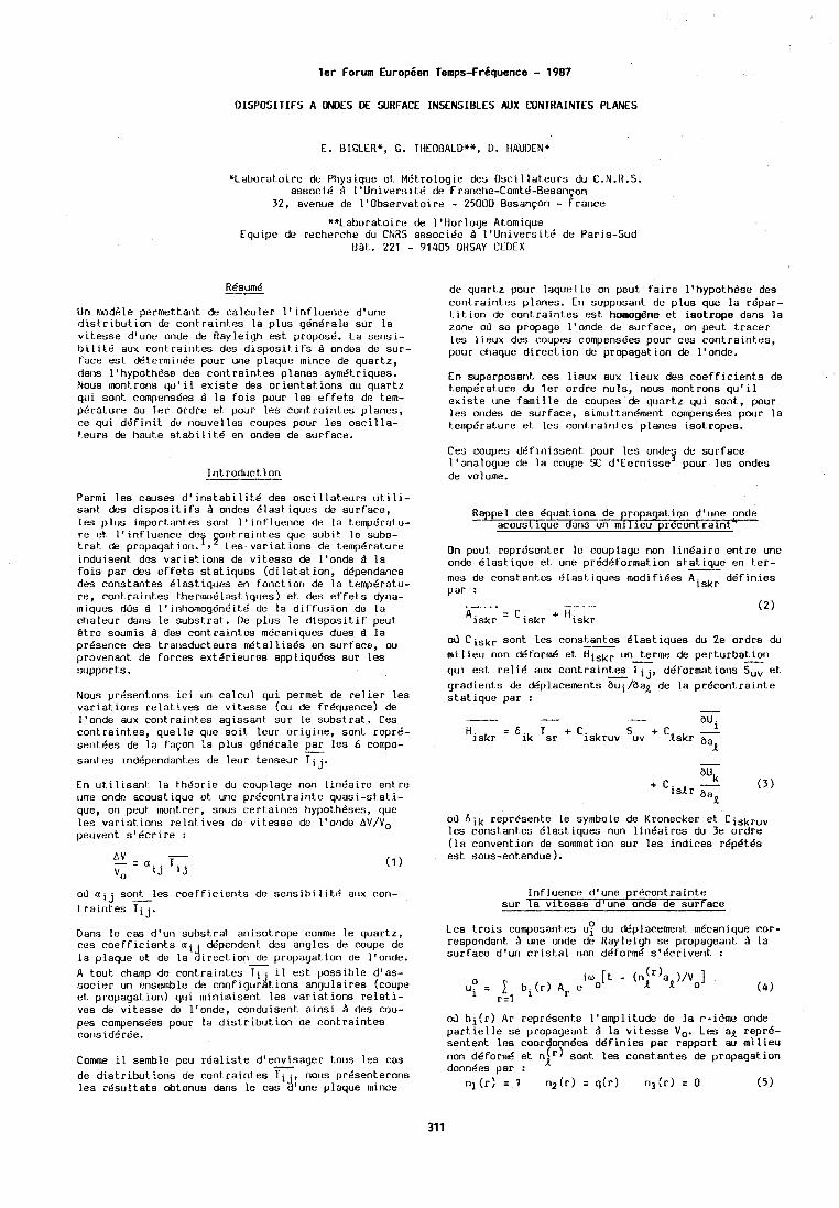
l e r Forum Europien Temps-Fr6quence - 1987
DISPOSITIFS A WOES DE SURFACE INSENSIBLES AUX CONTRAINTES PLANES
E. BIGLCR*, G. TliEflt3ALD**, D. HAUDEN*
*Labomto i re de Physique et MBtrologie des Osc i l l a teu rs du C.N.R.S. associe B l ' U n i v e r s i t 6 de Franche-Comtd-Resanpn
32, avenue de I 'Observato l re - 25UUO Besanyon - France
**Laboratoire do 1'Horloge Atomiquo Equipe de rectierche du CNRS associ6c Q 1 'Un ivers i tB de Paris-Sud
B&t. 221 - 91405 ORSAY OEDEX
Un m d d l e permettant de ca lcu lec 1' inf luer ice d'une d i s t r i b u t i o n de cont ra in tes l a p lus gdn6ralo sur l a v i tesse d'une oode de Rayleigh est proposd. La sensi- b i l i t d aux cont ra in tes des d i s p o s i t i f s d ondes de sur - face est d6terrnint5e pour une plaque mince de quartz, dans 1' hypoth6se des cor1traint.e~ planes sym6t.r iques. Nous rront.roris qu' i l ex is te des or ientat. ions du quart.2 qu i sont cornpensees Q l a f o i s pour l e s e f f e t s de t.em- p6ra ture au l e r ordre e t pour les cont ra in tes planes, ce qui d g f i n i t de riouvelles coupes pour les o s c i l l a - teurs de haute s tab i l i t . 6 en ondes de surface.
I n t roduc t i on
Parrni l e s causes d' i n s t a b i l i t b des osc i 1lat.eurs u t i li- sank des d i s p o s i t i f s Q ondes Blast iques de surface, les p lus import antes sont 1 ' in f lue i lce de l a t empdratu- r e et I ' i n f l u e n c e de on t ra in tes que sub i t l e subs- 7, S t r a t de propayat ion. Les. va r i a t i ons de l.emptirature induisent des variat.ior>s de v i tesse de l 'onde r ) l a f o i s par des e f f e t s s ta t iques ( d i l a t a t i o n , d6pendance des constantes d las t iques en fonct ion de l a temperatu- re, cant-raintes thermo6last.iques) e t des e f f e t s dyna- miques dOs d l ' inhomog6n6it6 de l a d i f f u s i o n de l a chaleur dariv l e substrat . De p lus l e d i s p o s i t i f peut B t re soumis B des cont.raintes mBcaniques dues d l a presence des t r a ~ ~ s d u c t e u r s r d t a l l i s e s en surface, ou provenant de forces ex t6r ieures appliquBes sur l es supports.
Nous prbsentons i c i un c a l c u l qu i permet de r e l i e r les variat.ions r e l a t i v e s de v i tesse (ou de frequence) de l 'onde aux cont ra in tes agissant sur l e substrat . Ces cont ra in tes , quel l e que s o i t leur or ig ine , sont repre- sent6es de l a fayon l a p lus y6ndrale par l es 6 compo- - santes indbpendarites de leur tenseur T i j.
En u t i lisanl: l a theor ie ~ I J couplage non l i n 6 a i r e en t re one onde acoustique et. une pr6cont ra in te quas i - s ta t i - que, on peut moi~trei-, sous cer ta ines hypoth*ses, que l es var ia t io r ls relat. ives de v i tesse de l 'onde A V / V o peuvent s ' b c r i r e :
A V - - = a . . T . V o 1J L J
oir a i j sont les c o e f f i c i e n t s de s e n s i b ~ l i t l i aux con- - t r a i n t e s Tij.
Dans l e cas d'url substrat anisotrope comme l e quartz, ces c o e f f i c i e n t s a i . ddpendent. des angles de coupe de l a plaque e t de l a d i rec t i o r i - de propagation de l 'onde. A tout. champ de cont ra in tes T i j 11 est poss ib le d'as- soc ier un ensemble de c o n f i g u r a t ~ o n s angulaires (coupe et propagat-ion) qu i minimisent l es variat. ions r e l a t i - ves de vi tesse de l 'onde, conduisent a i n s i Q des cou- pes compens6es pour l a d is t r ibu t , ion de cont,raintes corisid6rBe.
Comme il semble peu r d a l i s t e d'envisager t.ous l es cas de d i s t r i b u t i o n s de cont ra in tes Tij: nous pr6senteron.s l e s r6su l t a t s obtenus dans l e cas d une plaque mince
de quart.2 pour l aque l l e on peut f a l r e IQhypot.h6ae des cont ra in tes planes. En supposant de p lus que lo r6par- t.it i on de cont ra in tes est homogene e t i so t rope dans l a zone oil se propage l 'onde de surface, on peut t r ace r les l ieux des coupes compens6es pour ces contralnt.es, pour chaque d i r e c t i o n de propagat ion de l 'onde.
En superposant ces 11~ux aux l i eux des coefficients de tempgrature du l e r ordre nuls, nous montrons qu'11 e x i s t e une f a m i l l e de coupes de quartz qu i sont, pour l es orides de surfare, s ~ m u l t andment rompens6es pour l a tenip6rature e t l es ront r a ~ n t e s planes isot ropes.
Ces coupes dBts~n issent pour l es ondef de surface l 'analogue de l a coupe SC dlEernisse pour l es ondes de volume.
Rappel des Bquations de propagat ion d'une onde - acoust~que dans un m l l l e u pr6cont ra ln t1
On peut representer l e couplage non l i n t i a ~ r e ent re une onde Blast ique et. une prBddformat.ion stat-ique en t e r -
7.-
mes de constantes 6last.iques modif16cs Aiskr d6 f1n ies par :
-- -- A h k c = i s k r + Hiskc
oil Ciskr sont les corlsLa+s Blast iques du 2e ordre du m i l i e u non dBforrnB e t Hiskr un terme de pe r tu rba t i on - - q u i est r e l i e aux cont ra in tes T i j , dBformations Suv e t gradients de d6placements G / 8 a l de l a precont ra in te s ta t i que par : - - - -- aui
+ C H isk r ' 'ik Tsr + ' iskruv 'UV Lskr a,
L
oJ S i k repr6sente l e symbole de Kronerker e t Ciskruv les constantes Blast iques non l i nda i res du 3e ordre ( l a convention de sommation sur l es ind ices r6pBtBs est sous-ent.endue ).
In f luence d'une prgcont ra in te sur l a v i tesse d'une onde de surface
Les t r o i s composantes up du &placement. mBcanique r o r - respondant Q une onde de Rayleigh se propageant A l a surface d 'un c r i s t a l non d4form6 s'tScrivent :
013 bi(r) A r reprBsente l 'ampl i tude de l a r - i 6 m onde pa r t - i e l l e se propagesnt. d l a v i tesse Vo. LRS ax repr6- sentent les coordorin6es dCf in ies par rapport au m i l i e u non d B f o r d et n l r ) sont. l es constantes de p r 0 p a g a t . i ~ donndes par :
n l ( r ) = l n p ( r ) = q ( r ) n g ( r ) = O ( 5 )
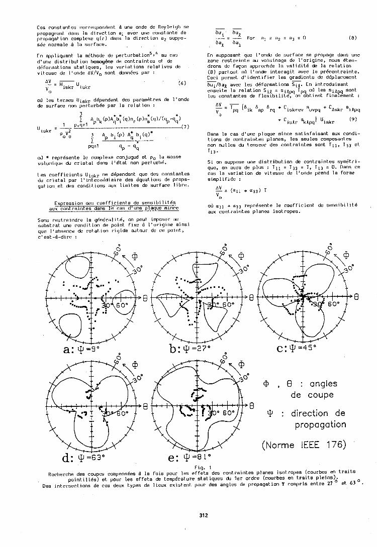
Ces c o n s t a n t e s correspondent d une onde de Rayleigh s e propagearit dans l a d l r e c t Ion a1 aver une c o n s t a n t e d e p ropaga t ion complexe q ( r ) dans l a d i r e c l l u n a 2 suppo- sBe normale d l a s u r f a c e .
En app l iquan t l a nSthode de p e r t u r b a t i ~ n ~ , ~ au c a s d 'une dis t . r ibut , ior i homogene de c o n t r a i n t e s ut de ddformat ions s t a t . iques , l e s va r ia t . ions r e l a t i v e s de v i t e s s e de l ' onde A V / V o sorlt donn6es pa r :
od l e s t ,er~nes Uiskr d6pendent. des pa ramet res de l ' o n d e de s u r f a c e non pert.urb6e par l a r e l a t i o n :
oir * r e p r d s e n t e l e cornplexe conjugu6 e t po l a manse v ~ ~ l u ~ e i q u e du c r l s t a l dans 1 ' 6 t a t non p e r t urb6.
Leu c o e f f i c i e n t s U i s k r ne d6pendent que des c o n s t a n t e s du c r i v t a l par l ' i n t . e rm8dia i re des 6quatio11s de propa- g a t i o n e t deu c o n d i t i o n s aux 1 i 1 n i t . e ~ de s u r f a c e l i b r e .
Express ton des c o e f f l c l e n t s d e s e n s t b l l l t 6 s aux c o n t r a i n t e s dans l e pas d ' u n e p laque rntnce
- - a u i au, - = - f o r a l = a2 = a3 = O ( 8 ) aal a a i
En supposant que I ' o n d e de s u r f a c e s e propage dans une zone r e s t r e i n t e au vo i s inage de l ' o r i g i n e , nous Bten- d rons de fayon approch6e l a v a l i d i t 6 de l a r e l a t i o n (8 ) part-out oir l ' o n d e i n t e r a g i t avec l a pr6contraint .e . Ceci oermet d ' i d e n t i f i e r l e s q r a d i e n t s de d6ulacement 7 - aui /aal avec l e s d6format ions S i l . En i n t r o d u i s a n t e n s u i t e l a rc la t - ion Sill = silpq T p q O? l e s s i l l s o n t l e s c o n s t a n t e a de f l e x i b i l i t 6 , on o b t l e n t fina8ement :
Dans l e c a s d 'une p laque mince s a t i s f a i s a n t aux condi- t. i o n s de c o n t r a i n t e s p l a n e s , l e s s e u l e s co~nposontes non n u i l e s du t.enseur des c o n t r a i n t e s s o n t T11, T 3 3 et. 113.
S i on suppose une d i s t r i b u t i o n de c o n t r a i n t e s sym6t r i - que, on aura de p l u s : T l l = T S 3 = T , T 1 3 = 0. Dans c e c a s l a v a r i a t i o n de v i t e s s e de l ' o n d e prend l a forme s i m p l i f i 6 e :
oir a l l + a33 r e l u 6 s e n t e l e r o e f f l c ~ e n t de s e n s l b 1 l l t 8 aux conLra1nI.e~ p l a n e s ~ s o l r o p e s .
Sans r e s t . r e i n d r e l a y4n6ral it .6, on peut imposer au suhs t . r a t une coridit.ion de point. f i x e A l ' o r i g i n e a i n s i que I ' absence de r o t a t i o n r i y i d e aut.our de ce p o i n t , c ' e s t - A - d i r e :
, 8 : angles de coupe
: direction de propagation
(Norme IEEE 176)
Fig. 1 Recherche des coupes compens6es B l a f o i s pour l e s e f f e t s des c 0 n t r a i n t . e ~ p l a n e s isot . ropes (courbes en t r a i t s
p o i n t , i l l d s ) e t pour l e s e f f e t , s de t.ernp6rat.ure s t a t i q u e s du l e r o r d r e (courbes en t r a i t s p l e i n s ) . Des i n t e r s e c t i o n s de c e s deux t y p e s d e l i e u x exis t .ent pour dos a n g l e s de p ropaga t ion Y compris e n t r e 27 O et. 63 O
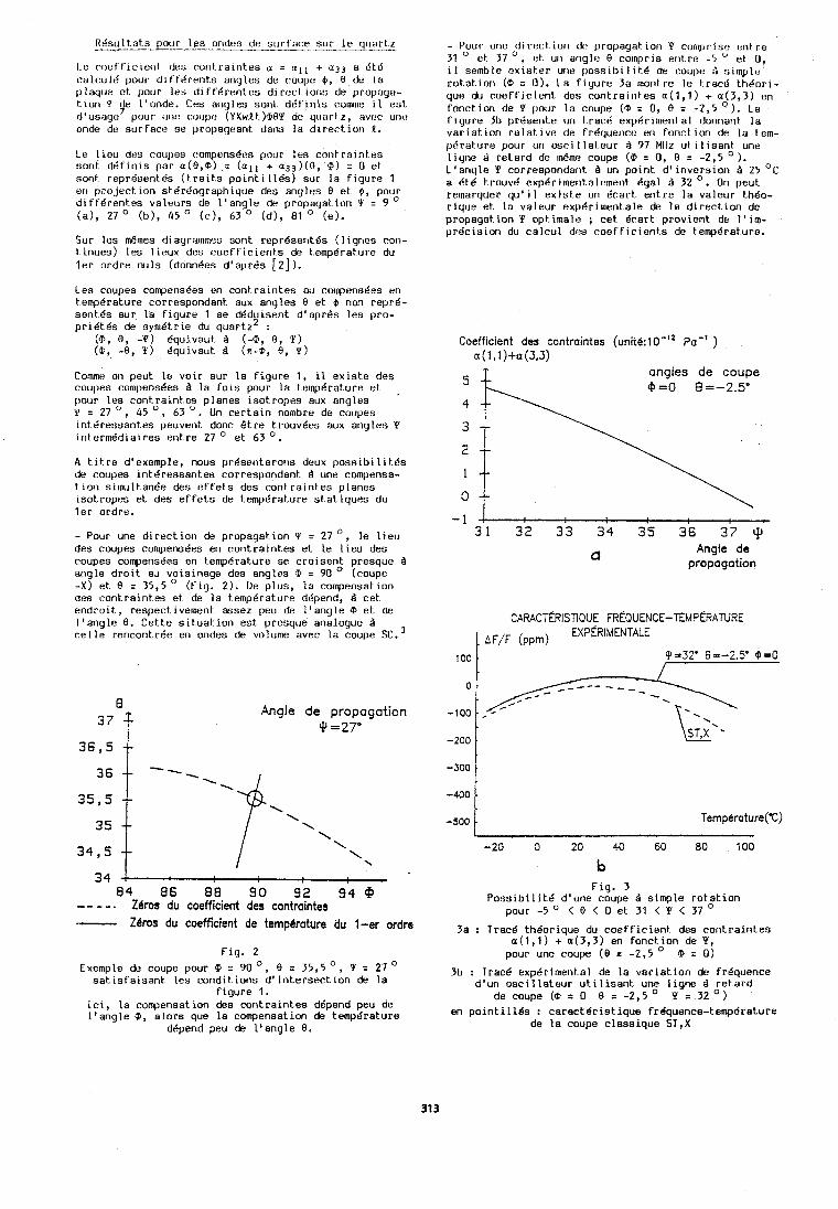
R6sultat.s pour les ondes de su r fa re sur l e quartz -- ---- Le t:oef'f~cierit ties cont ra in tes u 2 a l l + a33 a bt,6 c:alculd pour d ~ f t d r e n t s anyles do coupt? 6, 8 du l a p l a q l ~ e o t pour les d i f f d ren tes direct.~orlt; de propaga- t ion Y tie l'ortde. Ceu anyles sod. d6t i n i s comlne il ent d 'usiqe7 pour uric coupe? (YXwLt.)@BY de quart.^, avr:c unc! onde de surface se prol~agearit dans l a direct. ion 1.
Le l i e u deti coupes t~ornpens6es pour leu ron t ra ln tes sont d d f ~ n l s par a ( 8 , ~ ) = (all + a33)(0, 0) = 0 et sont reprdsent6s ( t r a t t s p o l n t ~ 116s) sur l a f igure 1 ell p r o ~ e r t lor1 stdrbograph~que des ariylos 8 et $, pouor d l f fg rentes valeurs de l ' ang le de propayat lon Y = 9 (a), 27 O (b), 45 O ( c ) , 63 O (d) , 81 O (e).
Sur les &mes diagralnmes sont reprdaerlt6s ( l igneo ron- t inues) les l i ~ u x des c o e f f i c i e n t s de tempdrature du l e r ordre nu ls (donl~des d'aprds [2 ] ) .
Les coupes rompens6es en cont ra ln tes ou ro~npunsties eri tempdrature correspondant aux angles 8 et 6 nor1 repr6- sent& sur l a f tgure 1 se d6d lsent d ' a p r d ~ les pro- Y p r i d tds de symd t r~e du quartz :
(CJ, 8, -Y) dquivaut B (4, 0, Y) (0, -8, Y) dqu~vau t B (n -@, 8, Y )
Comme on peut l o vo i r sur l a f i gu re 1, il exls te des coupes rornpens6es l a Pots pour l a tornpdralure et ,
pour l es r o n t r a ~ n t e s planes tsotropes aux angles Y = 27 O , 45 O , 63 '. Un rer t -a tn nombre de ruvpes lnt t i resssntes peuverlt done & t r e ti'ouv6es aux angles Y tn termdd~al res ent re 27 O et 63 O .
A t i t r e d'exemple, nous pr&ser~teror is deux posstb i l i t .& de coupes intBressantes corresporldant 4 une compensa- t l o n simultanBe des t? f f e t s dea cont ra ln tes planes isotropes et des e f f e t s de t.emp6rature stat.iques du l e r ordre.
- Pour une d i r e c t iori de propagat i on Y = 27 ', l e l i e u des coupes compensdes en cont ra in tes et l e l i e u dea coupes compensdes en tempdrature se c ro isent presque Q angle d r o i t au voisinage des angles @ s 90 O (coupe - X ) et 8 = 35,5 (Fig. 2). De p lus , l a compensat ion des cont ra in tes et de l a t.emp6rat.ure ddpend, B cet, endro i t , respectivement assez peu de l ' ang le Q e t de l ' ang le 8. Cet,t.e sit.uat.ion est presque analogue Q c e l l e rerlcontrde en ondes de volume avec l a coupe SC.
- Pour unu direct. iori do propagation Y cornprise en! r e 31 et 37 ', el. UII angle 9 colnpris er,t.rr! -5 O e t U, i l semblo ~?xiut .er une ))ossibi l i t .6 de coupe B sirnplo r o t a t i o n (Q! = 0) . La f i y u r e 3a 1non1.r~ l e tract! t hdo r i - qun du coef f ic ienL de:s cont ra in tes a (1 , l ) + u(3,3) en fonct ion de Y pour l a coupe (@ = 0, 8 = -2,5 O). La f i gu re 311 p r d s e ~ ~ t e on l.rac:t! expd r i~ne~ l ta l tlorlrla~lt l a v a r i a t i o n re la t , i ve de fr6quencc eri fonct ior l de l a tem- pt5ral u re pour un osci I lat.eur A 97 Mllz ut i l isarit une l i gne d re ta rd de 1n6me coupe ( Q = 0, 8 = -2,5 O). 1 'angle Y coryespondat~t B un po in t d' invers ion Q 25 O C
a Otd t 1.ouv6 exp6r imerit alcmrnt 6gal Q 32 . Or1 peut. rernarquer qu' il exist.e un &car t entre l a valeur t.h6o- r ique et. l a valeur expdrirnentale & l a direct. ion dc propagnt,ion Y optimale ; cet dcart provient de I ' i m - pr t ic lu ion du ca l cu l des coef ' f ic ienLs de t.emp6rature.
Coefficient des contraintes (unitb: 1 0-l2 pa-' ) a(l,l)+a(3,3) ..
5 -- angles de coupe 910 6=-2.5'
2 -- 1 -- 0 --
- 1 8
3 1 32 33 34 3 5 36 37 9
Q Angle de
propagation
34 ! 84 86 8 8 9 0 92 9 4 @ - - - - . Zeros du coefficient des contraintes - Zeros du coefficient de temperature du 1-er ordrs
Fig. 2
Exernple dt, coupe pour 9 = 90° , 8 = 35,5O, Y = 27' sat* i s fa isant les cond i t ions d' i n te rsec t i on de l a
f i gu re 1. I c t , l a compensation des cont ra in tes d6pend peu de l ' a n g l e 9, a l o r s que l a compensation de tempdrature
ddpend peu de l ' ang le 8.
F i g . 3 Poss ib i l i t c ! d'une coupe $ simple r o t at-ion
pour - 5 O < 8 < 0 et 31 < Y < 37 O
3a : Tracd thdorique du c o e f f i c i e n t dea cont ra in tes a ( 1 , l ) + a(3,3) en fonct ion de Y,
pour une coupe ( 8 E -2,5 9 = 0)
3b : Tracd expdrimerital de l a v a r i a t i o n de frdquence d'un o s c i l l a t e u r u t i l i s a n t une l i gne d r e t a r d
de coupe (0 = 0 8 n -2,5O Y = 32') en p o i n t i l l 6 s : ca rac t6 r i s t i qua frhquence-temp6rature
de l a coupe classique ST,X
La rompensatlon slrnultande des e f f e t s de te~npdrat+ure stat . lques du l e r o r d r e e t des e f f e t s des cont . ra in tes p l a n e s iso1,ropes e s t donc p o s s t b l e en ondes de s u r - f a r e .
P l u s ~ e u r s coupes s o r ~ t apparues l o r s de cet,te 6 tude t,h6orique :
- P o s s i b i l i t c ! d 'une coupe A s imple rot at ion Q = 0 dans l a zone -5 O < 0 < 0, 31 O < Y < 37 O . Au voistnage de e e s angles de coupe, l ' a n g l e du f lux d ' d n e r g i e e s t de l ' o r d r e de 3 O , e t l e r o e f f i c i e n t de coc~plage k2 de l ' o r d r e de 0 , l L.'
- P l u s i e c ~ r s COUI)UB d double r o t a t i o n sont. A d t u d i e r en d6t a i l dans l a zone 27 < Y < 45 O .
U'aut r e s coc~pes existerl t pour des angles de propaga- t i o n Y p l u s BlevBs, mais on s a i t e que, p l u s I ' a n g l a Y e s t Blevd, p l u s 11. coef f ic ien t : de couplage e s t f a i b l e . I 1 semble donc ra i sonnable de s e l i m i t e r aux angles Y i e s p l u s f a i b l e s . Parmi c e s coupes, l e s d i f f e r e n t s f a c t e u r s d op t i tn i se r son t : - 1s coefficient . de couplage Blectro-mbcanique
- I ' a n g l e du f l u x d ' d n e r g i e - l e s t.ol6rances a n g u l a i r e s de f a b r i c a t i o n - l ' e f t ' e t de t.emp6rature du 2e ordre .
IJnu 6t.uda ~:xptir i~nentala devra b ~ e n entcndu ronflrmer r u s premiers r 6 s u l t at s.
Remerciernents
Nous relnerclons MM. R. Coquerel e t C . Honjour pour l a r 6 a l 1 s a t i o n des l ~ q n e s 4 r e t a r d u t i l l s r?es pour e e t t e Btude.
H.F. T l e r s t e n and B.K. Slnha, "Temperature d e r i v a l l - ves of t h e fundamental e l a s t i c ronst .ants of q u a r t z " , Proc. 32nd Ann. Freq. Cont. Symp., A t l a n t i c - C l t y , N.J., 150-154 (1970).
D. Hauden, M. Michel and J . J . Gagnepain, "lilyher order temperature coefflc1ent .s of q u a r t z SAW o a c t l - l a t o r s " , Pror. 32nd Ann. Freq. Cont. Symp., At lan t ic -Ct ty , N.J. (1978).
C .P. Eernisse , "Cttlculat ions on t h e s t reso-compen- s a t e d (sC-cut) q u a r t z resonator", Proc. 30th Ann. Freq. Colrt. Symp., Fort. Monlnouth, 8 (1976).
H . F . T i e r s t e n , J.C. Baunhauer, "Nonlinear e l e r t r o - e l a s t i c equat.ions for small f i e l d s superposed on a b ias" , J. Acoust. Soc. A m . , 54, 1017 (1973).
H.F. T i e r s t e n , B.K. Sinha, "A p e r t u r b a t i o n a n a l y s l s of t h e a t t e n u a t i o n and d i s p e r s i o n of s u r f a c e waves", 3 . Appl. Phys., 49, 87 (1978).
0. Hauden, M. Planat. and 2.3. Gagnepain, "Nonlinear proper t i e s of s u r f a c e acoust.ic waves : appl icak i 011s
t o osc i 1 l a t o r s and sensors" , IEEE Trans. Sonics Ult,rason., SU-18, n O 5 (1981 ).
ILEE St-andard on P i e z o e l e c t r i c i t y , IEEC Trans. Sonics Ul t rason . , SU-31, n o 2 (1984).
M. FtLDMANN el J. HENAFF, "Propayat ion des ondes 6last . lques de s u r f a c e ; A t l a s des r o n f l g u r a t l a n r a l - r u l d e s pour Le q u a r t z , l e t a n t a l a t e de l i thlurn e t l e vanado-sulfure de t ha1 1 i urn en ce qul conrerne l e s coef f l c i e n t s de t emp6rat u r e el le couplage p16zo- Ls lec t r~que" , Revue de Physique AppliquBe, 12, 1775 (1977).
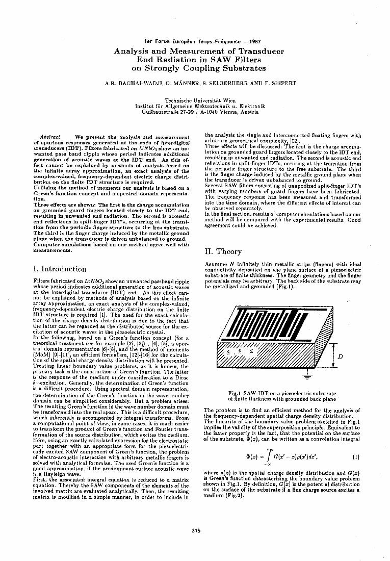
l e r Forum Europeen Temps-Fr6quence - 1987
Analysis and Measurement of Transducer End Radiation in SAW Filters
on Strongly Coupling Substrates
A.R. HAGHAI-WADJI, 0. M A N N E R , S. SELBEIlHERR AN11 F. SGJFERT
lkchnische UniversitBt Wien Institut fur Aligemeine Elektrotechnik u. Elektronik
Gufihausstrafie 27-29 / A-10.10 Vienna, Austria
Abstract -- We presei~t the annlysis and rnensurernent of spurious responses generated a t the ends of interdigital transducers (IDT). Filters fabricated on L 1 N b 0 3 s l~ow an un- wanted pass band ripple whose period indicates additional gexieration of acoustic waves a t the IDT end. As tliis ef- fect cannot be explained by methods of analysis basrd on the infinite array approximation, an exact s~lalysis of the complex-valued, frequency-dependent electric c l~arge distri- bution on the finite IDT structure is required. IJtilizing the metliod of inorrients our analysis is based on a Green's function concept and a spectral don~aiii rel~reseiita- tion. Three effects are shown: The first is tile charge accumulation on grounded guard fingers loratetl closely to tlio IDT elid, res~ilt ing in unwaiitecl end radiation. The second is aco~istic t ~ n d reflections in split-flnger IDT1s, occiirriiig a t the transi- tion from the periodic finger structure to the free substrate. The tflird is the finger charge induced by the mc~tallic ground plane when the transducer is driven unbalanced to grouud. C:ornputer simulations based on our mrthod agree well with measurements.
I. Introduction Filters fabricated on LzNbOs show an unwanted passband ripple whose period indicates additional generation of acoustic waves a t the interdigital transducer (IDT) end. As this effect can- not be explained by methods of analysis based on the infinite array approximation, an exact analysis of the complex-valued, frequency-dependent electric charge distribution on the finite I D T structure is required 111. The need for the exact calcula- tion of the charge density distribution is due to the fact that the latter can be regarded as the distributed source for the ex- citation of acoustic waves in the piezociectric crystal. In the following, based on a Green's function concept (for a theortical treatment see for example (21, (31) , (41, 151, a spec- tral domain representation 161-(81, and the method of ~nornents (MOM 91-(111, an efficient formalism, (121-(161 for the calcula- tion o j t !3 e spatial charge density distribut~on will be presented. Treating linear boundary value problems, as it is known, the primary task is the ronstrurtion of Green's function. The latter is the response of the medium under consideration to a Dirac 6-excitation. Generally, the determination of Green's function is a difficult procedure. Using spectral dornain representation, the determination of the Green's function in the wave number domain can be simplified considerably. But a problem arises: The resulting Green's function in the wave number domain must be transformed into the real space. This is a difficult procedure, which inherently is accompanied by integral transforms. Frorn a computational point of view, in some cases, it is much easier to transform the product of Green's function and Fourier trans- formation of the source distribution, which excites the medium. Here, using an exactly calculated expression for the electrostatic part together with an appropriate form for the piezoeiectri- cally excited SAW component of Green's function, the problem of electro-acoustic interaction with arbitrary metallic fingers is solved with analytical formulae. The used Green's function is a good approximation, if the predominant surface acoustic wave is a Rayleigh wave. First, the associated integral equation is reduced to a matrix equation. Thereby the SAW components of the elements of the involved matrix are evaluated analytically. Then, the resulting matrix is modified in a simple manner, in order to include in
the analysis the single and interconnected floating fingers with arbitrary geometrical complexity, (12 . Three eRects will be discussed: The A rst is the charge arcumu- lation on grounded guard fingers located closely to the IDT end, resulting in unwanted end radiation. The second is acoustic end reflections in split-finger IDTs, occuring a t the transition from the periodic finger structure to the free substrate. The third is the finger charge induced by the metallic ground plane when the transducer is driven unbalanced to ground. Several SAW filters consisting of unapodized split-finger IIIT's with varying numbers of guard fingers have been fabricated. The frequency response has bee11 measured and transforincd into the time domain, where the different effects of iriteresb can he observed separately. In the final section, results of compr~ter sin~ulations based or1 our method will be compared with the expcsri~rlental results. Good agreement could be achieved.
11. Theory
Asumme N infinitely thin metallic strips (fingers) with ideal conductivity deposited on the plane surface of a piezoelectric substrate of finite thickness. The finger geometry and the finger potentials may be arbitrary. The back side of the substrate may be metallized and grounded (Fig.1).
Fig.1 SAW-IDT on a piezoelectric substrate of finite thickness with grounded back plane
The problem is to find an efficient method for the analysis of the frequency-dependent spatial charge density distribution. The linearity of the boundary value problerr~ sketched ill Fig.1 implies the validity of the superposition principle. Equivalent to the latter property is the fact, that the potential on the surface of the substrate, @(x), can be written as a convolution integral
where p(,x) is the spatial charge density distribution and G(z) is Greens function characterizing the boundary value problem shown in Fig.1. By definition, G x) is the potential distribution 011 the surface of the substrate i a line charge source excites a medium (Fig.2).
I
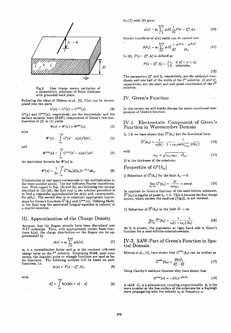
Eq,(7) with (8) gives
Fig.2 Line charge source excitarion of a piezoelectric substrate of finite thickness with grounded back plane
Following the ideas of Milsom et.al. 141, G(x) can be decom- posed into two parts
GC(x) and GbaW(x), respectively, are the electrostatic and the surface acouctic wave (SAW) cornponenls of Green's function. Insertion of (2) in (1) yields
with to3
me(,) - / cC(,' Z ) ~ ( X ~ ) ~ Z ~ , ( 4 ) - m
and t m
@aaw(z) = / C"lu(d - z)p(r')dx1. (5) -m
An equivalent formula for W(x) is
(Convolution in real space corresponds to the multiplication in the wave number space). The bar indicates Fourier transforma- tion. With regard to Eqs. (5) and ( 6 ) , and following the concept discribed in 1121- 161, the first step in the solution procedure is to find a reasona I, e approximation for p(x), and, consequently, for p(k,). The second step is to construct appropriate expres- sions for Green's functions ca(k,) and GmW(z). Utilizing MOM, in the final step the associated integral equation is reduced to a matrix equation.
111. Approxirnation of the Charge Density Asumme that the fingers already have been discretized into NST substrips. Then, with appropriately chosen basis func- tions bl(z), the charge distribution on the fingers can be ap- proximated by
N ST 4 x 1 = PO C P I ~ I ( Z ) .
I = 1 (7)
po is a normalization factor and pl is the constant unknown charge value on the l t h substrip. Employing MOM, most com- monly, the impulse, pulse or triangle functions are used as ba- sic functioris. The following analysis will be based on puls- functions, i.e.
bl(2) = P ( x - €;",6~), (8)
with
A! = r b 1 ( ~ ) d x = z: - x;* (9)
Fourier trar~sform of p(z) easily can be carried out:
In (a), P ( x - E,f", 4) is deflned as
P(x - F , 61) = { 1, i f x p < z < z ; ; 0, otherwise.
(12) The parameters (T and 61, respectively, are the midpoint coor- dinate and one half of the width of the l t h substrip. xp and xi, respectively, are the start and end point coordinates of the l t h substrip.
IV. Green's Function
In this sectiori we will briefly discuss the above mentioned com- ponents of Green's function.
IV-1. Electrostatic Component of Green's Function in Wavenumber Dolnairi In 11.11 we have shown that cC(k, ) has the functional forrrr
with cP,r = \/=a (14)
D is the thickness of the substrate.
Properties of Ge(k,)
i) Behaviour of ~ ' ( k , ) for the limit k, -+ 0:
U - const. l i n ~ cC(kz ) = - - k, -0 r0633,r (15)
In contrast to Green's function of the semi-infinite substrate, - Ge(kZ) is regular a t point k. = 0. This is because the line charge source, which excites the medium (Fig.2), is not isolated.
ii) Behaviour of GTk,) in the limit D -+ oo:
1 1 lim ?(kc) = -------
D-+m ~ o ( 1 t CP,?) lkzl ' (16)
As it is known, the expression a t right hand side is Green's furlction for a semi-infinite substrshowedate.
I V-2. SAW-Part of Green's Function in Spa- tial Domain Milsom et.al., 141, have shown that r w ( k , ) can be written as
-aaw 2koG, G (k,) = -
k2 - k! '
Using Cauchy's residuue theorem they have shown that
is valid. G, is a piezoelectric coupling proportionality. ko is the wave number a t the free surface of the substrate for a Rayleigh wave propagating with the velocity uo a t frequency w .
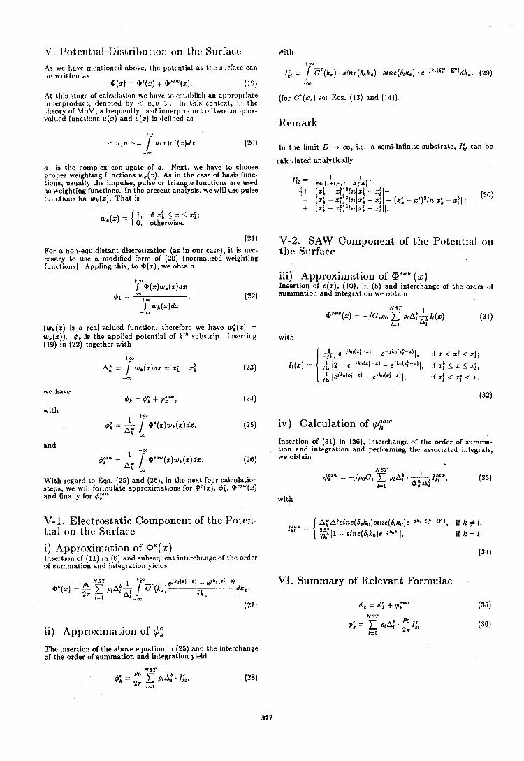
V. Potential Distribution on tlic Su1.facc. with
As we have nientioncd above, tlle potential a1 the surface can be written as = ( k ) ~ ( 6 ~ k ) i n ( k ) e I f d k (29)
@(x) -- GC(x) -t (PaIZW(x). (19) m
A t this stage of calc~llation we have to estzrblish ari appropriate (for cc(k , ) set: E ~ ~ , (13) (14 ) ) . irlr~erproduct, denoted by i u,v >. 111 this coritoxt, in the theory of MOM, a frequently used innerproduct of t,wo compltrx- valued functions u(x) arid v(x) is definetl as Re~nark
< u,v >= rY(x)Y'( l )dJ . (20) In the lilriit D -+ m, i.e. a semi-infinite substrate, Ill can be - a3
calculated analytically a' is the cornplex conjugate of a. Next, we have to choose proper weighting functions wk(x). As in the rase of basis func- I == - 1 - 1 tions, usually the impulse, pulse or triangle functions are used *~IV(I+CP,) ' TAT' as weighting functions. In the present analysis, we will use pulse . I+ (x i - x ~ ) * l n 1 x ~ - x,bl- functions for wk(x). That is - (x i - ~ i ) ' l t & l ~ : - xi1 - (x i - ~ f ) ~ l n l x ~ - x:l+ (30)
+ (x i - ~ 1 ) ~ l n l x t - xi( ) . 1, i f x b , < x < x ~ ; 0, otherwise.
For a non-equidistant discretization (as in our case), it is nec- essary to use a modified form of (20) (normalized weighting functions). Appling this, to @(x), we obtain
(wk(x) is a real-valued function, therefore we have w;(x), = wk x)). 4k is the applied potential of kth substrip. Inserting ( 1 4 in (22) together with
we have 4 k = 4; +4;LIw,
and
With regard to Eqs. (25) and (26), in tlie next four calculation steps, we will forrnulate approximations for @'(x), &, @"*(x) and finally for 4yW
V- 1. Electrostatic Component of the Poten- tial on the Surface
i) Approximation of Q e ( x ) Insertion of (11) in (6) and subsequent interchange of the order of sunimation and integration yields
/,ONST e ~ k , ( ~ i -2 ) - e~ks(z : -z)
a e ( x ) = P I A : ~ 1 Ee(kz) dk,. 1=1 A1 -m jkz
(27)
ii) Approximation of 4; The insertion of the above equation in (25) and the interchange of the order of summation and integration yield
V-2. SAM' Componerit of the Potential on the Surface
iii) Approximation of Waw (x) Insertion of p(x), ( lo) , in (5) and interchange of the order of aunlmation and integration we obtain
NST 1 aaaW (x) r - jc "PO C PIA!
1=1 A1 (31)
with
iv) Calculation of 4pW Insertion of (31) in (26), interchange of the order of summa- tion and integration and performing tlie associated integrals, we obtain
NST 1 *a, sl"" = -.ipoG, C PA: - z w z I k l ,
l=i k 1 (33)
with
VI. Summary of Relevant Formulae
NST
I=1
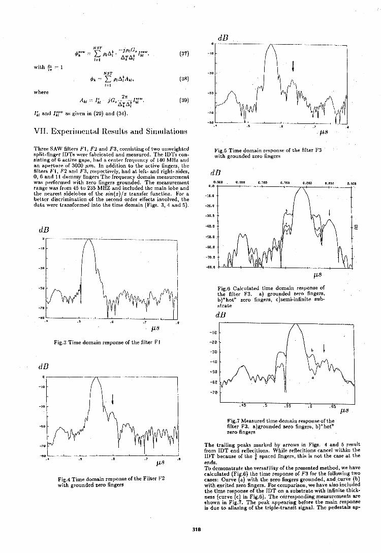
N S T --JPOG row 6rW = 1 PAP + AwAb lkl 1=1 k 1
where 2= ,,w
Akl = I ; I - J G , ~ I ~ I . k 1
(39)
I& and I;?" as given in (29) and (34).
VII. E x p e r i n ~ e ~ ~ t a l Results and Si~liulatio~ls
Three SAW filters F1, F 2 and F3, consisting of two ur~wcighted split-finger IDTs were fabricated and measured. The IDTs con- sisting of 6 active gaps, had a center frequency of 140 MHz and an aperture of 3000 pm. In addition to the active fingers, the filters F1 , F 2 and F3, respectively, had a t left- and right- sides, 0, 6 and 11 durnmy fingers The frequency domain nieasurernent was performed with zero fingers grounded. T l ~ e measureme~~t range was from 45 to 235 the main lobe arid the nearest sidelobes of better discrimination of data were transformed into the time domain (Figs. 3, 4 and 5).
Fig.5 Time domain response of the filter F3 with grounded zero fingers
Fig.6 Calculated time domain response of the filter F3, a) grounded zero fingers, b)"hot" zero fingers, c)semi-infinite sub- strate
dB
Fig.3 Time domain response of the filter F1
Fig.4 Time domain response of the Filter F2 with grounded zero fingers
Fig.7 Measured time domain response of the filter F3. a)grounded zero fingers, b)"hotn zero fingers
The trailing peaks marked by arrows in Figs. 4 and 5 result from IDT end reflecitions. While reflecitions cancel within tlie IDT because of the $ spaced fingers, this is not the case a t the ends. To demonstrate the versatility of the presented method, we have calculated (Fig.6) the time response of F 3 for the followitig two cases: Curve (a) with tlie zero fingers grounded, and curve (b) with excited zero fingers. For comparison, we have also included the time response of the IDT on a substrate with infinite thick- ness (curve (c in Fig.6). The corresponding n~easuremer~ts are 4 shown in Fig. . The peak appearing before the main response is due to aliasing of the triple-transit signal. The pedestals ap-
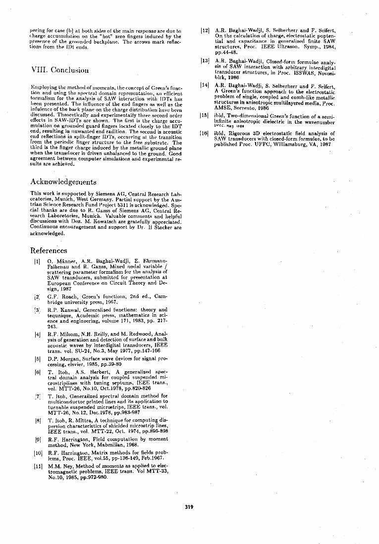
pering for case (b) at both sitlrs of the rnair~ response are due to charge accurnulatio~~ on tI1e "hot" zero fingers ind~lcctl by the presence of the groundtd backplane. 'rllc arrows m ~ r k reflec- tions from the Illt ends.
VIII. Co~iclusior~
En~ploying the neth hod of rnorrlei~ts, the c otlrcpt of Green's func- tion and l~sirtg thc spectral domain rcy)rescr~tatiot~, an eflicicwt forn~alisrn for the analysts of SAW intt,ra~tion wit11 I1)Ts has Ireen presented. The influence of Ihe end Ot~grrs as well as the ir~fuler~ce of the back plane on the charge distril)utiol~ llave betm discussed. Tt~roretically and ~xprrirnentally three second order enects in SAW-IDTs are shown. TIie first is the charge acctl- rr~ulation on grounded guard fingers located ciosely to the Ill'r end, resulting in unwanted end radition. The second is acoustic end reflections in split-finger IDTs, occurt ing a t the transitiot~ from the periodic finger structr~re to tire free substrate. The third is the finger charge induced by the rnetailic ground plane when the transducer is driven unbalanced to the ground. Good agreement between cornputer simulations and experimental re- sults are achieved.
This work is supported by Siemens AG, Central Research Lab- oratories, Munich, West Germany. Partial support by the Aus- t r i a ~ ~ Science Researcl~ Fund Project 5311 is acknowledged. Spe- cial thanks are due to R. Ganss of Siemens AG, Central Re- search Laboretories, Munich. Valuable comrnents artd helpful discussions with Doz. M. Kowatsch are gratefully appreciated. Contir~uous encouragement and support by Dr. 11 Stocker are acknowledged.
References
[ I ) 0. Manner, A.R. Baghai-Wadji, E. Ehrmann- Falkenau and R. Ganss, Mixed nodal variable / scattering parameter formalism for the analysis of SAW transducers, submitted for presentation at European Conference on Circuit Theory and De- sign, 1987
12) G.F. Roach, Green's functions, 2nd ed., Carn- bridge university press, 1967.
13) R.P. Kanwal, Generalized functions: theory and tequnique, Academic press, mathematics in sci- ence and engineering, volume 171, 1983, pp. 217- 243.
14) R.F. Milsom, N.H. Reilly, and M. Redwood, Anal- ysis of generation and detection of surface and bulk acoustic waves by interdigital transducers, lEEE trans. vol. SU-24, No.3, May 1977, pp.147-166
15) D.P. Morgan, Surface wave devices for signal pro- cessing, elsvier, 1985, pp.39-80
[6] T. Itoh, A.S. Herbert, A generalized spec- tral domain analysis for coupled suspended mi- crostriplines with tuning septums, IEEE trans., vol. MTT-26, No.10, Oct.1978, pp.820-826
171 T . Itoh, Generalized spectral domain method for rr~ulticonductor printed lines and its application to turnable suspended microstrips, IEEE trans., vol. MTT-26, No.12, Dec.1978, pp.983-987
18) T. Itoh, R. Mittra, A technique for computing dis- persion characteristics of shielded microstrip lines, IEEE trans., vol. MTT-22, Oct. 1974, pp.896-898
191 R.F. Harrington, Field computation by moment method, New York, Mabmillan, 1968.
(101 R.F. Harrington, Matrix methods for fields prob- lems, Proc. IEEE, voi.55, pp-136-149, Feb.1967.
ill] M.M. Ney, Method of moments as applied to elec- tromagnetic problems, IEEE trans. Vol MTT-33, No.10, 1985, pp.972-980.
112) A.R. Llaghai-Wntlji, 6 . Selberlterr and F. Seifert, On the calculation of charge, electrostatic popten- tial and capacitance in generalized finite SAW structures, Proc. IEEII: (Jltrason. Syrnp., 1984, yp.44-48.
(131 A.H. Uaghai-Wadji, Closed-form formulae analy- sis of SAW interaction with arbitrary iittercligital transducer strllctures, in I'roc. ISSWAS, Novosi- birk, 1988
(14) A.R. Daghai-Wadji, S. Selberherr and F. Seifert, A Green'e fu t~ct io l~ approacl~ to the electrostatic prohlen~ of single, roul)led and comb-like metallic slructures in anisotropic multilayered media, Proc. AMSE, Sorrento, 1986
115) %id, Two-dimctlsional Green's function of a s e ~ r ~ i - Itifini1.e anisotropic dielectric in the wavenurnber V c c C , Hay ISOB
1161 ibid, Rigorous 3D electrostatic field analysis of SAW transducers wit11 closed-forn~ formulae, to be published Proc. UIq'FC, Williamsburg, VA, 1987
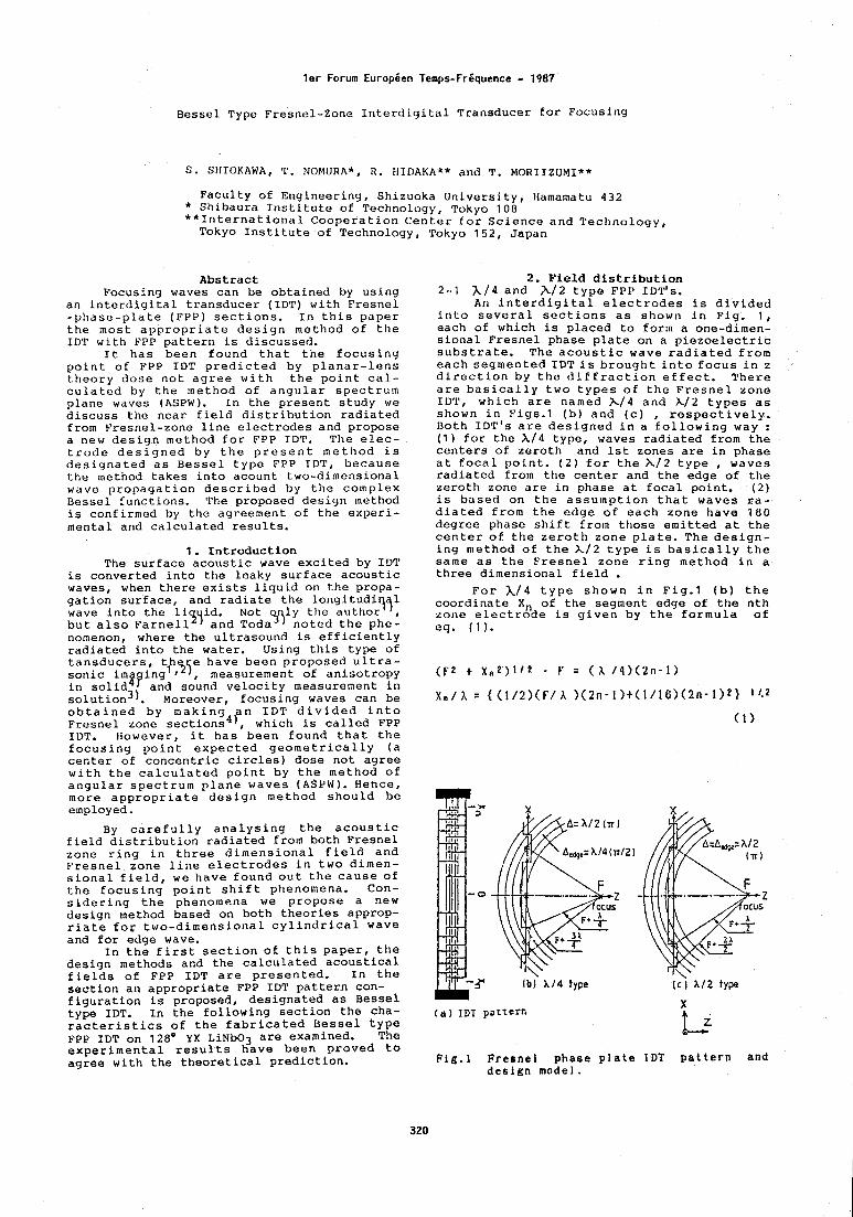
ler Forum EuropCen Temps-Friquence - 1987 Bessel Type Fresnel-Zone Interdigital Transducer for Focusing
S. SHIOKAWA, 'r. NOMURA*, R. IIIDAKA** and T. MORIIZUMI*"
Faculty of Engineering, Shizuoka University, Hamamatu 432 * Shibaura Institute of Technology, Tokyo 100 **International Cooperation Center for Science and Technology, Tokyo Institute of Technology, Tokyo 152, Japan
Abstract Focusing waves can be obtained by using
an interdigital transducer (IDT) with Fresnel -phase-pla te (FPP) sections. In this paper the most appropriate design mettlod of the IDT with FPP pattern is discussed.
It has been found that the focusing point of FPP IDT predicted by planar-lens theory dose not agree with the point cal- culated by the method of angular spectrum plane waves (ASPW). In the present study we discuss the near field distribution radiated from Fresnel-zone line electrodes and propose a new design method for FPP IDT. The elec- trode designed by the present method is designated as Bessel type FPP IDT, because the method takes into acount two-dimensional wave propagation described by the complex Dessel functions. The proposed design method is confirmed by the agreement of the experi- mental and calculated results.
1. Introduction The surface acoustic wave excited by IDT
is converted into the leaky surface acoustic waves, when there exists liquid on the propa- gation surface, and radiate the longitudi wave into the liqyid. Not q~jly the but also Farnell and Toda noted the phe- nomenon, where the ultrasound is efficiently radiated into the water. Using this type of tansducers, t/~,yj; have been proposed ultra- sonic imtging measurement of anisotropy in solid and sound velocity measurement in solution3). Moreover, focusing waves can be obtained by making an IDT divided into Fresnel zone sections4), which is called FPP IDT. However, it has been found that the focusing point expected geometrically (a center of concentric circles) dose not agree with the calculated point by the method of angular spectrum plane waves (ASPW). Hehce, more appropriate design method should be employed.
By carefully analysing the acoustic field distribution radiated from both Fresnel zone ring in three dimensional field and Fresnel zone line electrodes in two dimen- sional field, we have found out the cause of the focusing point shift phenomena. Con- sidering the phenomena we propose a new design method based on both theories approp- riate fog two-dimensional cylindrical wave and for edge wave.
In the first section of this paper, the design methods and the calculated acoustical fields of FPP IDT are presented. In the section an appropriate FPP IDT pattern con- figuration is proposed, designated as Bessel type IDT. In the following section the cha- racteristics of the fabricated Bessel type FPP IDT on 128O Y X L ~ N ~ O ~ are examined. The experimental results have been proved to agree with the theoretical prediction.
2. Field distribution 2-1 A / 4 and A12 type FPP IDT's.
An interdigital electrodes is divided into several sections as shown in Fig. 1 , each of which is placed to form a one-dimen- sional Fresnel phase plate on a piezoelectric substrate. The acoustic wave radiated from each segmented IDTis broughtinto focus in z direction by the diffraction effect. There are basically two types of the Fresnel zone ID'P, which are named X I 4 and A12 types as shown in Figs.1 (b) and (c) , respectively. Both IDT's are designed in a following way : (1) for the X/4 type, waves radiated from the centers of zeroth and 1st zones are in phase at focal point. (2) for the X / 2 type , waves radiated from the center and the edge of the zeroth zone are in phase at focal point. (2) is based on the assumption that waves ra- diated from the edge of each zone have 180 degree phase shift from those emitted at the center of the zeroth zone plate. The design- ing method of the X/2 type is basically the same as the Fresnel zone ring method in a three dimensional field .
For h/4 type shown in Fig.1 (b) the coordinate Xn of the segment edge of the nth zone electrode is given by the formula of eq. ( 1 ) .
( a ) IDT pattern
Ib ) A14 type ( c j A I ~ type "
Flg.1 Fresnel phase plate IDT pattern and design model.
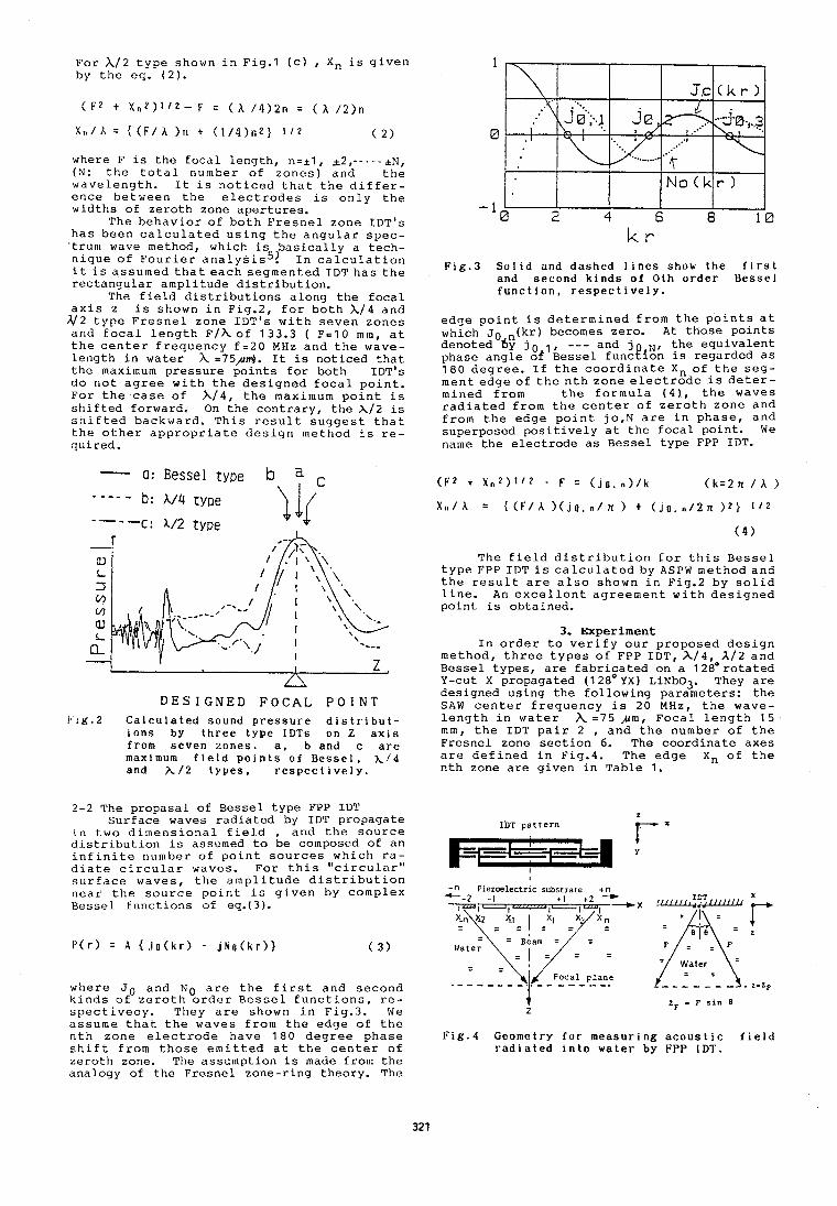
F o r A/2 t y p e shown i n Fig.1 ( c ) , X n i s g i v e n by t h e e q . ( 2 ) .
where F i s t h e f o c a l l e n g t h , n = i l , + 2 , - - - - - i t ? , (N: t h e t o t a l number o f z o n e s ) a n d t h e w a v e l e n g t h . I t i s n o t i c e d t h a t t h e d i f f e r - e n c e b e t w e e n t h e e l e c t r o d e s i s o n l y t h e w i d t h s of z e r o t h zone a p e r t u r e s .
The b e h a v i o r o f b o t h F r e s n e l z o n e IDT's h a s b e e n c a l c u l a t e d u s i n g t h e a n g u l a r s p e c - ' t rum wave method, which i s b a s i c a l l y a t e c h - n i q u e o f F o u r i e r a n a l y s i s 5 ! I n c a l c u l a t i o n i t i s a s s u m e d t h a t e a c h s e g m e n t e d I D T h a s t h e r e c t a n g u l a r a m p l i t u d e d i s t r i b u t i o n .
The f i e l d d i s t r i b u t i o n s a l o n g t h e f o c a l a x i s z i s shown i n F ig .2 , f o r b o t h X/4 a n d
A12 t y p e F r e s n e l z o n e IDT's w i t h s e v e n z o n e s a n d f o c a l l e n g t h ~ / h o f 133.3 ( F=lO m m , a t t h e c e n t e r f r e q u e n c y f = 2 0 MHz a n d t h e wave- l e n g t h i n w a t e r A =75,um). I t i s n o t i c e d t h a t t h e maximum p r e s s u r e p o i n t s f o r b o t h IDT's d o n o t a g r e e w i t h t h e d e s i g n e d f o c a l p o i n t . F o r t h e c a s e o f X / 4 , t h e maximum p o i n t i s s h i f t e d forward . On t h e c o n t r a r y , t h e X/2 i s s h i f t e d b a c k w a r d . T h i s r e s u l t s u g g e s t t h a t t h e o t h e r a p p r o p r i a t e d e s i g n m e t h o d i s r e - q u i r e d .
- a: Bessel t ype b a c . - - - d b: A/4 type
----c: A/2 type
D E S I G N E D F O C A L P O I N T f 1 g . 2 C a l c u l a t e d sound p r e s s u r e d i s t r i b u t -
i o n s by t h r e e type I D T s on Z a x i s from seven zones . a , b and c a r e maximum f i e l d p o i n t s of B e s s e l , ~ / 4 and A / 2 t y p e s , r e s p e c t i v e l y .
2-2 The p r o p a s a l o f B e s s e l t y p e FPP IDT S u r f a c e waves r a d i a t e d by IDT p r o p a g a t e
i n t w o d i m e n s i o n a l f i e l d , a n d t h e s o u r c e d i s t r i b u t i o n i s assumed t o b e composed of a n i n f i n i t e number o f p o i n t s o u r c e s w h i c h r a - d i a t e c i r c u l a r waves. F o r t h i s " c i r c u l a r " s u r f a c e w a v e s , t h e a m p l i t u d e d i s t r i b u t i o n n e a r t h e s o u r c e p o i n t i s g i v e n by c o m p l e x R e s s e l f u n c t i o n s of eq.( 3 ).
w h e r e JO a n d N o a r e t h e f i r s t a n d s e c o n d k i n d s o f z e r o t h o r d e r B e s s e l f u n c t i o n s , r e - s p e c t i v e ~ ~ . They a r e shown i n F ig .3 . We a s s u m e t h a t t h e w a v e s f r o m t h e e d g e o f t h e n t h z o n e e l e c t r o d e h a v e 1 8 0 d e g r e e p h a s e s h i f t f r o m t h o s e e m i t t e d a t t h e c e n t e r o f z e r o t h zone. The a s s u m p t i o n i s made from t h e a n a l o g y of t h e F r e s n e l z o n e - r i n g t h e o r y . The
F i g . 3 Sol id and dashed 1 i n e s show t h e f i r s t and second k i n d s of 0 t h o r d e r Besse l f u n c t i o n , r e s p e c t i v e l y .
e d g e p o i n t i s d e t e r m i n e d f r o m t h e p o i n t s a t which Jo . (kr) becomes zero . A t t h o s e p o i n t s d e n o t e d by j o I , --- and j N , t h e e q u i v a l e n t phase a n g l e o f B e s s e l f u n c t i o n i s r e g a r d e d a s 1 8 0 d e g r e e . I f t h e c o o r d i n a t e X n o f t h e s e g - m e n t e d g e o f t h e n t h z o n e e l e c t r o d e i s d e t e r - m i n e d f r o m t h e f o r m u l a ( 4 ) , t h e w a v e s r a d i a t e d f r o m t h e c e n t e r o f z e r o t h z o n e a n d f r o m t h e e d g e p o i n t jo ,N a r e i n p h a s e , a n d s u p e r p o s e d p o s i t i v e l y a t t h e f o c a l p o i n t . We name t h e e l e c t r o d e a s B e s s e l t y p e FPP IDT.
The f i e l d d i s t r i b u t i o n f o r t h i s B e s s e l t y p e FPP I D T i s c a l c u l a t e d by ASPW m e t h o d a n d t h e r e s u l t a r e a l s o shown i n F ig .2 by s o l i d l i n e . An e x c e l l e n t a g r e e m e n t w i t h d e s i g n e d p o i n t is o b t a i n e d .
3. Experiment I n o r d e r t o v e r i f y o u r p r o p o s e d d e s i g n
m e t h o d , t h r e e t y p e s o f FPP IDT, h / 4 , A/2 a n d B e s s e l t y p e s , a r e f a b r i c a t e d on a 1 2 E 0 r o t a t e d Y-cut X p r o p a g a t e d (12E0YX) LiNb03. They a r e d e s i g n e d u s i n g t h e f o l l o w i n g p a r a m e t e r s : t h e SAW c e n t e r f r e q u e n c y i s 20 MHz, t h e wave- l e n g t h i n w a t e r A = 7 5 ,urn, F o c a l l e n g t h 1 5 m m , t h e IDT p a i r 2 , a n d t h e number o f t h e F r e s n e l zone s e c t i o n 6. The c o o r d i n a t e a x e s a r e d e f i n e d i n Fig.4. The e d g e X n o f t h e n t h zone a r e g i v e n i n T a b l e 1.
z l i ) ~ pattern Fx
-n Piezoelectric substrate t n - -2 - 1 + I t 2 -_CX
5 = i :
zF - F s i n 0 z
F i g . 4 Geometry f o r measur ing a c o u s t i c f i e l d r a d i a t e d i n t o wate r by FPP IDT.
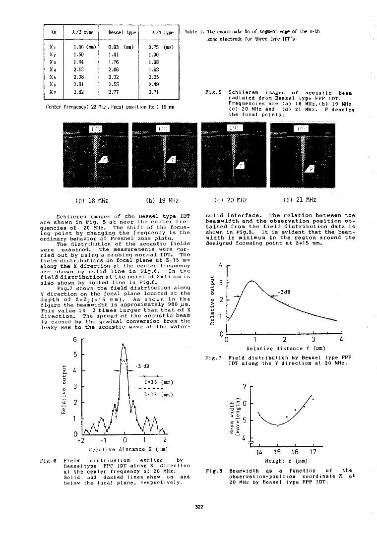
Center frequency : 20 MHr , Focal posi t lon Fz : 15 mm
Table I. The coordinate Xn of segment edge of the n-th zone electrode for three type IDT's.
Fig.5 Schlieren images of acoustic beam radiated from Bessel type FPP IDT. Frequencies are (a) 18 MHz, (b) 10 MHz (c) 20 MHz and ( d l 21 MHz. F denotes the focal points.
( a ) 18 Ml i z (tj) 19 MHz ( c ) 20 Etlz ( d l 2 1 MHz
Schlieren images of the Bessel type IDT are shown in Fig. 5 at near the center fre- quencies of 20 MHz. The shift of the focus- ing point by changing the frequency is the ordinary behavior of Fresnel zone plate.
The distribution of the acoustic fields were examined. The measurements were car- ried out by using a probing normal IDT. The field distributions on focal plane at Z=15 mm along the X direction at the center frequency are shown by solid line in Fig.6. In the field distribution at the point of Z=17 mm is also shown by dotted line in Fig.6.
Fig.7 shows the field distribution along Y direction on the focal plane located at the depth of Z=ZF(t15 mm). As shown in the figure the beamwldth is approximately 980 pm. This value is 2 times larger than that of X direction. The spread of the acoustic beam is caused by the gradual conversion from the leaky SAW to the acoustic wave at the water-
5 - 4 -
-.c.-)-
3 - Z=15 (mm) - - - - - - 2.17 (mm)
2 -
1
0 -2 -1 0 1 2
Relative distance X (mm)
solid interface. The relation between the beamwidth and the observation position ob- tained from the field distribution data is shown in Fig.8. It is evident that the beam- width is minimum in the region around the designed focusing point at 2 = 1 5 mm.
Relative distance Y (VJI)
Fig.7 Field distribution by Bessel type FPP IDT along the Y direction at 20 MHz.
Fig.6 Field distribution excited by Height z (nm) Besseltype FPP IDT along X direction a t the center frequency of 20 MHz. Fig.8 Beamwidth as a function of t h e Solid and dashed lines show on and observation-position coordinate 2 at below the focal plane, respectively. 20 Mllz by Bessel type FPP IDT.
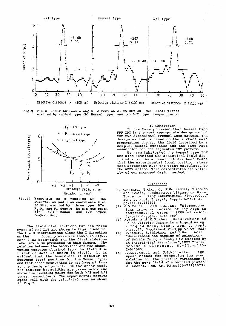
Bessel type X / 2 type
Relative distance X ( ~ 1 0 0 urn) Relative distance X ( ~ 1 0 0 urn) Relative distance X (x100 IJR)
Fig.9 Field distributions along X direction at 20 MHz on the focal planes excited by (a)h/4 type,(b) Bessel type, and tc) k / 2 type, respectively.
-.-F2 : A / Z type 4. Conclusion It has been proposed that Bessel type
O F B : Bessel type FPP IDT is the most appropriate design method for two-dimensional Fresnel Zone pattern. The
*--C F4 : )L/4 type 1 design method is based on the surface wave propagation theory, the field described by a
/ ' complex Bessel function and the edge wave assumption for the segmented IDT pattern.
We have fabricated the Bessel type IDT and also examined the acoustical field dis- tributions. As a result it has been found that the experimental focal position shows good agreement with the point calculated by the ASPW method. This demonstrates the valid-
F2 FB F4 ity of our proposed design method. 0) PI
0 t 3 + 2 + 1 0 -1 -2
D E S I G N E D F O C A L P O I N T Height z (mm)
Fig.10 Beamwldth as a function of the observation-position coordinate 2 al 20 MHz, excited by three type IDTs. F ,FB and F2 denote the minlmum point f%r 4 Bessel and A/2 types, respective 1 y.
The field distributions for the three types of FPP IDT are shown in Figs. 9 and 10. The field distributions along the X direction on the focal planes are shown in Fig.9. Both 3-dB beamwidth and the first sidelobe level are also presented in this figure. The relation between the beamwidth and the obser- vation position obtained from the field dis- tribution data is shown in Fig.10. It is evident that the beamwidth is minimum at designed focal position for the Bessel type, and that other beamwidths do not have minimum at the designed points. On the other hand, the minimum beamwidths are taken below and above the focusing point for both h/2 and h/4 types, respectively. The experimental results agree well with the calculated ones as shown in Fig.2.
Heferences (1) T.Nomura, T.\i,kuchi, T.Moriizumi, T.Yasuda
and K.Toda, Underwater Ultrasonic Waven Transducer Using Interdigital Electrodes, Jpn. J. Appl. ~ h ~ s , 2 1 , supplement21 -3, pp.138-140(1982)
1 2 ) G.W.Farnell and C.K.Jen: ll~icroscope . - . lens using conversion of Rayleigh to compressional waves, "IEEE ultrason. Symp.Proc.,pp673-676(1?:0)
(3) K.Toda and H.Urabe: Measurement of Sound Velocity Change Sin a Liquid using a Liquid Delay Line , Jpn. J. Appl. phys.,21, Supplement 21-3,pp.57-59(1982)
(4) T.Nomura, S.Shiokawa and T.Moriizumi: "Measurement and Mapping of Anisotropy of Solids Using a Leaky SAW Excited by an Interdigital Transducerl',IEEE.Trans. Sonics & Ultrason., SU-32,pp235- 240(1985).
(5) J.C.Lookwood and J.G.Willette: "High- speed method for computing the exact solution for the pressure variations in for the near field of a baffled piston" J. Acoust. Soc. Am.,53,pp735-741(1973).
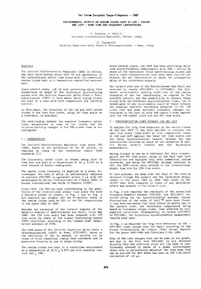
ler Forum Europeen Temps-Frbquence - 1987 ENVIRONMENTAL EFFECTS ON CESIUM CLOCKS KEPT AT IEN - TORINO
AND ISPT - HOMA TIME AND FREQUENCY LADOHATOHIES
V. Cordara, V. Pettiti Tstituto Eiettrotecnico Nazlonale, Torino, Italy
C. Tignanelli Istituto S~lperiore dellc Poste e 'I'elecomunict~zioni - Roma, Italy
Abstract
The Istituto Elettrotecnlco Nazionale (IEN) in Torino, has been contributing since 1972 to the generation of the international atomic time scale with its commercial cesium clocks kept in a temperature controlled environ- men t . Since several years, INN is also performing daily time comparisons by means of the television synchronizing pulses with the Istituto Superiore delle Poste e Tele- cvmunicazioni (ISPT) in Roma where three cesium clocks are kept in a room with both temperature and humidity control . In this paper, the behaviour of the IEN and ISPT cesium clocks in the last four years, using UTC time scale as a reference, is analyzed.
l'he relationship between the seasonal frequency varin- tions encountered in some of the clocks and the relative humidity changes in the IEN clocks room is in- vestigated.
1 - INTRODUCTION The Istituto Elettrotecnico Nazionale time scale UTC (IEN), based on the definition of the SI second, is realized by means of six commercial cesium beam standards [l 1 .
The laboratory master clock is chosen among five of them that are kept at a temperature of 24 + 0.5OC in a room located 12 meters underground.
The master clock frequency is supplied to a phase mi- crostepper the rate of which is periodically adjusted to maintain UTC(1EN) in agreement within 5 ps with UTC established by Bureau International de 1'Heure (BIH) of Bureau International des Poids et Mesures (BIPM).
Since 1972, the IEN has been contributing to the gene- ration of the international atomic time scale TAI with a variable number of clocks; in Fig. 1 and in Fig. 2 are reported the weights and the bi-monthly rates of the cesium clocks used by BIH in the TAI computations in the years 1983 to 1986.
Besides the reception of the Loran-C signals of the Estartit station of Mediterranean Sea Chain, since May 1985, the IEN time scale has been compared with UTC time scale by means of the Global Positioning System (GPS) satellites, according to the "common view" measu- rement schedule of BIPM.
The time scale of the Istituto Superiore delle Poste e Telecomunicazioni (ISPT) in Roma, UTC(ISPT), based on the definition of the SI second, is carried out by means of three commercial cesium beam standards and is generated directly by one of these clocks.
The cesium clocks are kept in a controlled environment at a temperature of 21.5 2 0.5OC and with humidity con- trol (60 + 10%).
Since several years, the ISPT has been performing daily time synchronizatiori measurements with IEN - Torino by means of the television field synchronizing pulses and yearly clock transportation have also been carried out between the two laboratories to check the propagation delay of the television signals.
Two Loran-C stations of 'he Mediterranean Sea Chain arc received to relate U'I'C(1SPT) to UTC(USN0). The dif- ferent environmental working conditions of the cesium standards of the two laboratories, as regards to the humidity control, and the possibility to compare these clocks with two different synchronization links, led to investigate if any relationship could be found between the seasonal humitlity variations measured in the IEN clock room and some periodic frequency changes en- countered in the past on some IEN cesium clocks against both the IEN master clock and the UTC time scale.
To analyze the long term behaviour of the cesium clocks of IEN and ISPT it has been decided to cons~der the last four years (1983-1986) of time comparisons taken at IEN and ISPT against the local UTC tlme scales and the dally synchronlzation results between the two laboratories obtained by means of the reception of Sel- Lia Marina Loran-C station and the television measurements.
Having choosed to use as a reference for this investi- gation the UTC time scale, owing to the fact that both laboratories are equipped only with commercial cesium standards, and being the UTC(1EN) already referred to UTC, the ISPT clocks were related to the international atomic time via the IEN time scale.
At this purpose, the mean over ten days of the results obtained through the Loran-C and the television measu- rement in the years 1983 to 1986 (MJD 45335 to MJD 46795) have been compared to check if any periodical effect was present in the Loran-C link.
In Fig. 3 are reported the residuals of the normalized frequency departure between UTC( IEN) and UTC( ISPT) ob- tained using the two synchronization systems. Annual fluctuations of the order of 3x10-'3 have been found; it has been estimated that this effect is mainly due to the Loran-C link, the television comparisons being based on microwave relays links, less affected by pro- pagation variations. Consequently, to relate UTC( ISPT) to IJTC(IEN), the television synchronization measurement results were used.
In Fig. 4 is depicted the long term behaviour of UTC - UTC(1EN) (mean values over ten days) according to the Bureau International de 1'Heure (BIH) Annual Reports for the years 1983-1985 and Circulars D for 1986.
Some of the rate changes that can be seen on the graph, are due to the fact that UTC(1EN) is not obtained directly from the reference clock but its rate is con- tinuously steered by means of a phase microstepper whose rate is periodically adjusted. The time step that can be noticed for MJD 46564 has been an IEN time scale correction of -19 ps.
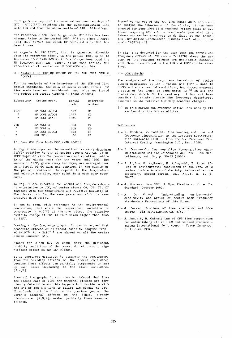
In Fig. 5 are reported the mean values over ten days of UTC - UTC(LSPT) obtained via the synchronizatior~ lirik with IEN and from the above mentioned BIH publications.
The reference clock used to generate UTC(1EN) has been changed twice in the period 1983-1984 but since 1 March 1!JH4 (MJD 45760) the clock HP 5061/000 s.n. 893 tlas been in use.
As regards to UTC(ISPT), that is generated directly frorn its reference clock, in the period 1983 up to 14 September 1986 (MJD 46687) it has always been used the HP 5061/004 s.n. 1237 clock. After that period, the reference clock has become HP 5061/004 s.n. 597.
:3 - ANALYSIS 01' TIlE BEliAVIOIIR 01' IEN AND ISPT CESlIIM -. An.,-
For the analysis of the behaviour of the 1EN and ISPT cesium standards, the data of seven clocks versus UTC time scale have been considered. llere below are listr?d the models and serial numbers of these clocks:
Laboratory Cesium model Serial Reference number number
ISPT HP 5061 A/004 597 C1 HP 5061 A/004 1237 C2 HP 5061 A(") 1815 C3
I EN tip 5061 A 303 C4 IIP 5OCl A 609 C5 IIP 5061 A/004 893 C6 OSA 3200 84 C 7
( ' ) opz. 004 from 18-2-1986 (MJD 464'79)
In Flg. 6 are reported the normalized frequency departwes ( Af/f) relative to UTC of cesium clocks C1, C2, C3 of ISPT together with the temperature and relative humidi- ty of the clocks room for the years 1983-1986. The values of ~ f / f , given every ten days, are averaged over an interval of 60 days and centered in the middle of the period considered. As regards to the temperature and relative humidity, each point is a mean over seven days . In Fig. 7 are reported the normalized frequen~yde~r- tures,relative to UTC, of cesium clocks C4, C5, C6, C7 together with the temperature and relative humidity of the clocks room for the same years and with the same criteria used before.
It can be seen, with reference to the environmental conditions, that while the temperature variation is comparable (+ 0.5"C) at the two sites, the relative humidity change at IEN is four times higher than that at ISPT.
Looking at the frequency graphs, it can be argued that seasonals effects of different quantity ranging from +0.5x10-l3 to + 3x10-l3 are showed on all the cesium - clocks examined [ 2 1 .
Except for clock C7, it seems that the different humidity conditions of the rooms, do not cause a sig- nificant effect on the IEN clocks.
It is therefore difficult to separate the temperature from the humidity effects on the clocks considered because these effects can partially compensate or sum up each other depending on the clock considered 13,4,51.
From all the graphs it can also be deduced that from the second half of 1985 the seasonal effects are more clearly detectable and this happens in coincidence with the use of the GPS link to relate IEN clocks to UTC. This leads to think that in the previous years, the ]Loran-C seasonal effects on the links, already dimonstrated [ 2,6,7 1 , masked partially these seasonal effects.
Regarding the use of the U'I'C time scale as a reference to analyze the behaviours of the clocks, it has been checked for year 1986 if a seasonal effect could be ev- inced comparing UTC with a time scale generated by n laboralory cesium standard; lo do this, it was chosen the Physikalisch-Technische Bundesanst.alt atomic time scale 'I'A(PfI'B) ( * I .
Tn Fig. 8 1s depicted for the year 1986 the normalized frequency offset of UTC versus TA (PTB) where the am- ount of the seasonal effects are negligible compared with those encountered on the IFN and ISPT clocks exam- lr~ed.
The analysis of the long term behaviour of cesium clocks maintained at IEN - Torino and ISPT - Roma in different environmental conditions, has showed seasonal effects of the order of some units 10-l3 on all the clocks considered. On the contrary, it has not been possible to relate closely the frequency departures, observed to the relative humidity seasonal. changes.
( " ) In this period the synchronization link used by PTB was based on the GPS satellites.
References
1 - F. Cordara, V. Pettiti: 'Time keeping and time and frequency dissemiriation at the Istituto Elettrotec- nico Nazionale ([EN) - 18th Precise Time and 'I'lme Interval Meeting, Washington I).C., Dec. 10R(1.
2 - K. Dorenwendt: Ilas verhalten kommerzieller cgsi- urn-atomuhreri und die Zeitskalen der P'I'B - PTB Mit- teilungen, vol. 94, p. 35-43 (1984).
3 - S. Iijima, K. Fujiwara, H. Kobayashi, T. Kato: Ef- fect of environmental conditions on the rate of a cesium clock - Annals of the Tokyo Astronomical Ob- servatory, Second Series, vol. XVIII, n. 1, p. 50-67.
4 - J. Kusters: New 5061 A Specificatior~s, HP - The Standard, October 1983.
5 - A. De Marchi: Understanding environmental sensitivity and ageing of cesium beam frequency standards - Proceedings of this Forum.
6 - G. Becker: Problems of time standards and time scales - PTB Mitteilungen 92, 3/82.
7 - J. Azoubib, D. Guinot: Use of GPS time comparisons for establishing TAI in 1983 and related problems - Bureau international de 1'Heure - Notes Internes, n. 1, June 1984.
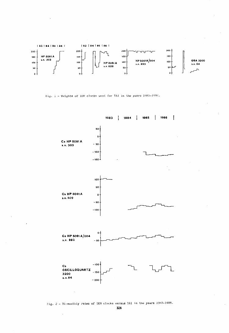
[' ' ig. 1 - Weights of 1EN c locks usc?rl f o r TAI in ttie years I ' l t 3 3 - 1 ~ ) 8 ( j .
1 83 1 8 4 1 85 186 1 183 1 8 4 1 85 186 I
200 0 - s p n 8 303 { o u u u 1
F i g . 2 - Bi-monthly r a t e s of I E N c locks versus TA1 i n t h e y e a r s 1'383-1986. 326
loo
50
0
HP 5 0 6 1 ~ / 0 0 4 OSA 3200 -. HP 5061 A s n 893 s n. 8 4
s n 608 -. / T
Fig. 3 - Residuals of the norn~alized frequency departure of IN"( JSIJ'I') vs IITC( [EN) .
5 ItJ.1
I UTC - UTC(1EN)
2
- 2 5 ~ ' " ' " 1 " " " ~ ~ ~ 1 ~ ~ ~ ~ ~ ~ ~ ~ ~ ~ c t a I 8 . . MJD 45400 45600 45800 46000 46200 46400 46600
Fig. 4 - UTC(1EN) vs UTC from BIH Annual Reports and Circulars D.
58 t l ~ a l UTC - UTC(1SPT)
40 "1 1983 I 1984 I 1985 I 1986 I
Fig. 5 - UTC(1SPT) vs UTC from the television link with IEN and BIH Annual Reports and Circulars D.
327
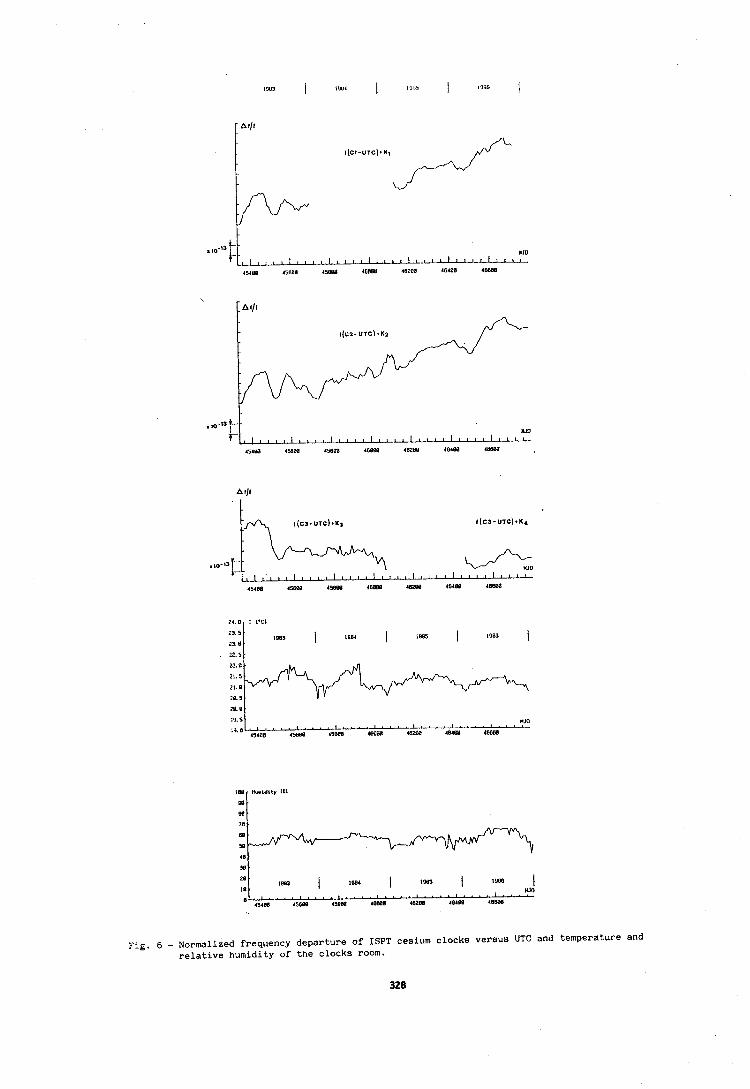
.to-13 #, , , , , , , , , YJU
. . . , ~ ~ ~ L L ~ ~
45180 45608 45888 4 0 W 46200 48488 46888
19.5 YJU
1% 8 w- 45400 45680 45888 4WBB 462LW 48404 4MIBB
1983 1 1904 ( 1- I I@* ( I . . . . YJO
4,488 45588 4 m I W 4DZOB 40488 48588
Fig. 6 - Normalized frequency departure of ISPT cesium clocks versus UTC and temperature and relative humidity of the clocks room.
328
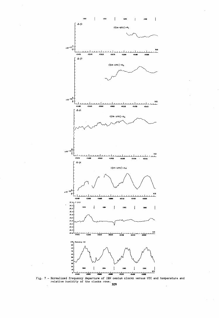
YJO U I I I I I I I I L 1 l l c I t I I I , I I I , I I ,
Fig. 7 - Normalized frequency departure of ZEN cesium clocks versus UTC and temperature and relative humidity of the clocks room.
329
a 10
1083 1 lDB4 I IE63 I 10M) I O " ' ' ' ~ l ' ' c " ~ ' ' ~ l ' ' ~ ~ ' ' ' ~ ~ ' ~ ~ ~ ~ ' ~ ~ ~ ~
YJO
45400 45800 45300 40000 4628B 40480 488W
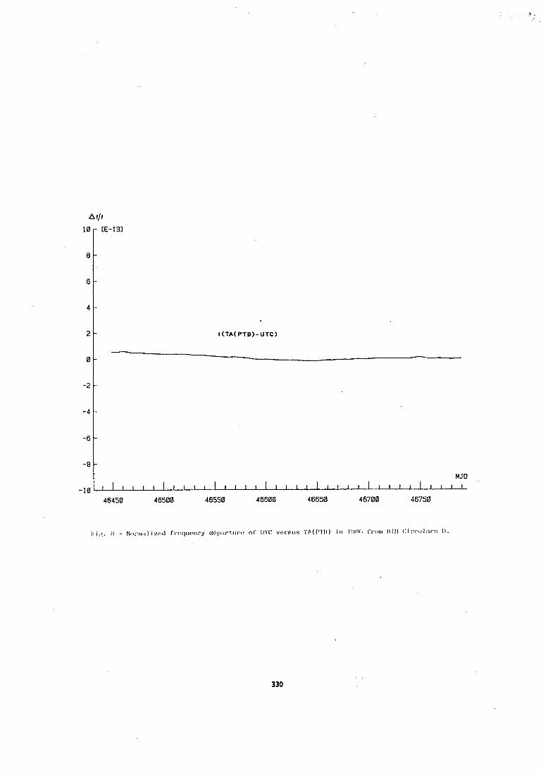
MJD -8t_,...uA -10 46450 46500 46550 46600 46650 46700 46750
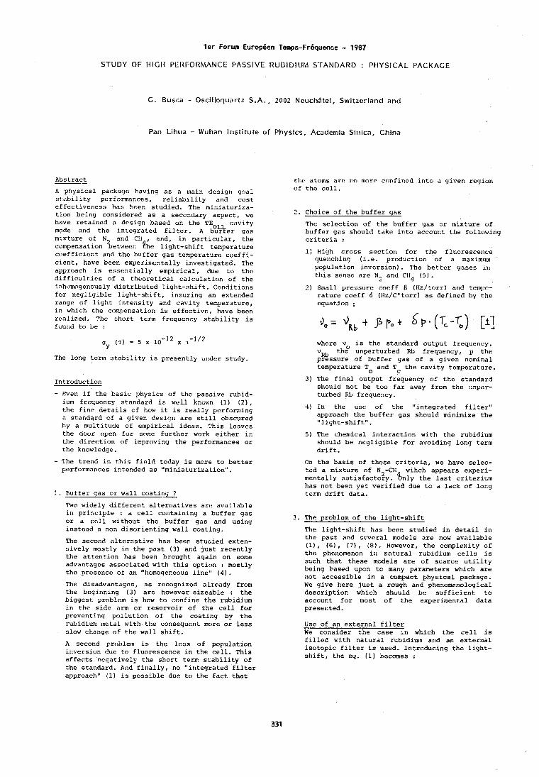
ler Forum Eurapgen Temps-Frgquence - 1987 STUDY OF t{ IGIi PERFORMANCE PASSIVE RUBIDIUM STANDARD : PHYSICAL PACKAGE
G. Busca - Oscillocluartz S . A . , 2002 Ncuchbtel, Switzerland ancl
Pan Lihua - Wuhan l r~st i tute of Physics, Acaderr~ia Sinica, China
Abstract -- A physical package having as a main design yoal stai~ility performances, reliability and cost effectiveness has been studied. The miniaturiza- tion being considered as a secondary aspect, we have retained a design based on the TE cavity mode and the integrated filter. A &%er gas mixture of N and CH , and, in particular, the compensation between ?he light-shift temperature coefficient and the buffer gas temperature coeffi- cient, have been experimentally investigated. The approach is essentially empirical, due to the difficulties of a theoretical calculation of the inhvmogenously distributed light-shift. Conditions for negligible liyht-shift, insuring an extended range of light intensity and cavity temperature, in which the compensation is effective, have been realized. Thc short term frequency stability is found to be :
The long term stability is presently under study.
Introduction
- Even if the basic physics of the passive rubid- ium frequency standard is well known (1) ( 2 ) , the fine details of how it is really performing a standard of a given design are still obscured by a multitude of empirical ideas. This leaves the door open for some further work either in the direction of improving the performances or the knowledge.
- The trend in this field today is more to better performances intended as "miniaturization".
1. Buffer gas or wall coatlnq 7
Two widely different alternatives are available in principle : a cell containing a buffer gas or a cell without the buffer gas and using instead a non disorienting wall coating.
The second alternative has been studied exten- sively mostly in the past ( 3 ) and just recently the attention has been brought again on some advantages associated with this option : mostly the presence of an "homoqeneous line" (4).
The disadvantages, as recognized alxcady from the beginning (3) arc however sizeable : the biggest problem is how to confine the rubidium in the side arm or reservoir of the cell for preventing pollution of the coating by the rubidium metal with,the consequent more or less slow change of the wall shift.
A second problem is the loss of population inversiun due to fluorescence in the cell. This affects negatively the short term stability of the standard. And finally, no "integrated filter approach" (1) is possible due to the fact that
the atoms are no more confirled into a given region of the cell.
2. Choice of the buffer yas - The selectiori of the buffer gas or mixture of buffer gas should take into account the following criteria :
1) High cross section for the fluorescence quenching (i.e. production of a maximum population inversron) . The better gases In this sense arc N, and CiI4 (5).
2) Small pressure coeff 0 (Hz/torr) and tempt- rature coeff 6 (Hz/Cotorr) as defined by the equation :
where v is the standard output frequency, vKb the? unperturbed Kb frequency, p the pressure of buffer gas of a given nominal temperature T and T the cavity temperature.
31 The final output frequency of the standard should not be too far away from the unper- turbed RL frequency.
4) In the use of the "~ntegrated filter" approach the buffer gas should minimize the "light-shift".
5) The chemical interaction with the rubidium should be negligible for avoiding long term drift.
On the basis of these criteria, we have selec- ted a mixture of N -CH wihch appears experi-
2 mentally satisfactory. 8n1y the last criteriurn has not been yet verified due to a lack of long term drift data.
3. The problem of the light-shift
The light-shift has been studied in detail in the past and several models are now available (11, (61, ( 7 1 , ( 8 ) . However, the complexity of the phenomenon irl natural rubidium cells is such that these models are of scarce utility being based upon to many parameters which are not accessible in a campact physical package. We give here just a rough and phenomenological description which should be sufficient to account for most of the experimental data presented.
Use of an external filter We consider the case in which the cell is filled with natural rubidium and an external isotopic filter is used. Introducing the light- shift, the eq. [I] becomes :
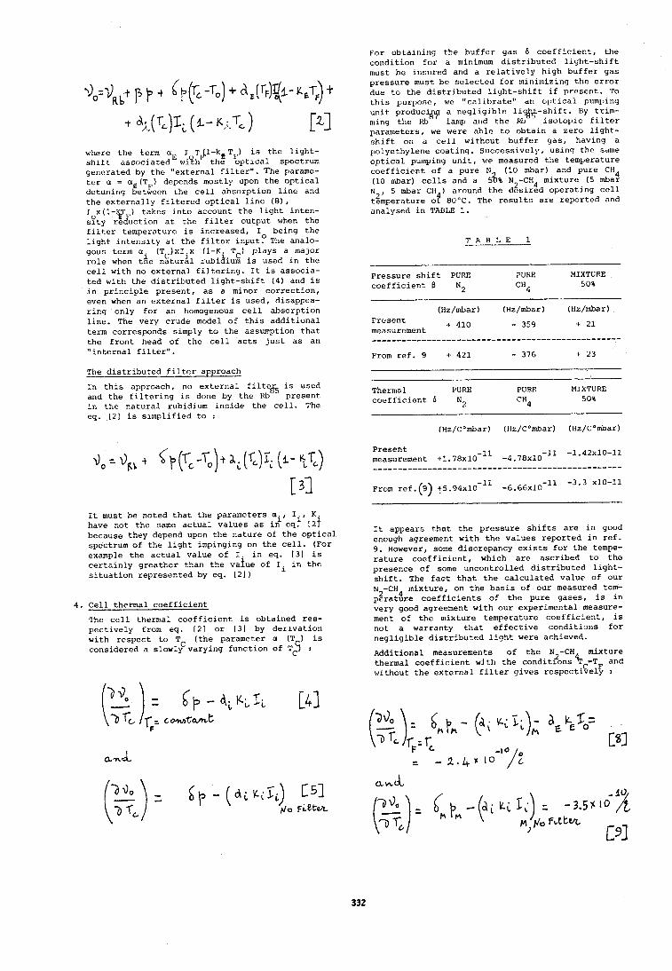
where t h e term aC 1 T /I-kC TF) i s t h e l i g h t - s h i f t a s s o c i a t e d ' w1?1? t h e o p t i c a l spectrum genera ted by t h e " e x t e r n a l f i l t e r " . The parame- t e r a = a E ( T F ) dt?pends mostly upon t h e o p t i c a l detunirig betwcon t h e c e l l absorp t ion l i n e and t h e e x t e r n a l l y f i l t e r e d o p t i c a l l i n e (81, I x(1-$T ) t a k e s i n t o account t h e l i g h t i n t e n - soty r e J u c t i o n a t t h e f i l t e r o u t p u t when t h e f i l t e r temperature i s increased , I being t h e l i g h t i n t e n s i t y a t t h e f i l t e r i n p u t ? The analo- gous term a . (T ) x I . x ( 1 - K . TC) p lays a major
C r o l e when tiie n s t u r h rubiaium is used i n t h e c e l l wi th no e x t e r n a l f i l t e r i n g . I t i s assoc ia - t e d wi th t h e d i s t r i b u t e d l i g h t - s h i f t (4 ) and i s i n p r i n c i p l e p r e s e n t , a s a minor c o r r e c t i o n , even when on e x t e r n a l f i l t e r is used, disappea- r i n g on ly f o r an homogenous c e l l absorp t ion l i n e . The very crude model of t h i s a d d i t i o n a l term corresponds simply t o t h e assumption t h a t t h e f r o n t head of t h e c e l l a c t s j u s t a s an " i n t e r n a l f i l t e r " .
The d i s t r i b u t e d f i l t e r approach
I n t h i s approach, no e x t e r n a l f i l t v 5 is used and t h e f i l t e r i n g is done by t h e Rb present. i n t h e n a t u r a l rubidium i n s i d e t h e c e l l . The eq. [2] i s s i m p l i f i e d t o :
I t must be noted t h a t t h e parameters a i , I . , K have not t h e same a c t u a l v a l u e s a s i n e q t 1 2 f because they depend upon t h e n a t u r e of t h e o p t i c a l spectrum of t h e l i g h t impinging on t h e c e l l . (For example t h e a c t u a l va lue of I , i n eq. [ 3 1 i s c e r t a i n l y g r e a t h e r than t h e v a l u e of Ii i n t h e situation represen ted by eq. [21)
4. C e l l thermal c o e f f i c i e n t
The c e l l , thermal c o e f f i c i e n t i s obta ined r e s - p e c t i v e l y from eq. [ 2 ] o r (31 by d e r i v a t i o n wi th r e s p e c t t o TC ( t h e parameter a (T ) is considered a slowly vary ing f u n c t i o n of TCC] :
For ob ta in ing t h e b u f f e r gas 6 c o e f f i c i e n t , t h e c o n d i t i o n f o r a minimum din t . r ibu ted l i g h t - s h i f t must be insured and a r e l a t i v e l y high b u f f e r gas p r e s s u r e must be s e l e c t e d f o r minimizing t h e e r r o r due t o t h e d i s t r i b u t e d l i g h t - s h i f t i f p r e s e n t . To t h i s purllofir?, wc "cilli1,rate" dn o l , t i c a l pumping u n i t produc a n e g l i g i b l e l i i$ \S-sh i f t . By t r i m - ming t h e *% lamp and t h e M i s o t o p i c f i l t e r parameters , we were a h l e t o o b t a i n a z e r o l i g h t - s h i f t on a c e l l wi thout b u f f e r g a s , having a pc>lyethylene c o a t i n g . Success ive ly , using t h c same o p t i c a l pulnping u n i t , we measured t h e temperature c o e f f i c i e n t of a pure N (10 mbar) and pure CH4 ( l o mbar) c e l l s and a 5%% N -CH mixture ( 5 mbar
2 . 4 N 2 , 5 mbar Cii ) around t h e d e s l r e d o p e r a t i n g c e l l temperature o t 80°C. The r e s u l t s a r e repor ted and onalysed i n TABLE 1.
T A B L E 1
Pressure s h i f t PURE PURE MIXTU'E
c o e f f i c i e n t 6 N 2 CH4 50%
Present t 410
measurement
From r e f . 9 t 421 - 376 t 23
-
Thernial PURE PURE MIXTURE c o e f f i c i e n t 6 N 2 CH4
50%
Present measurement +1.78x10-l1 -4 .78~10- l1 -1'42x10-11
From r e f . (9) + 1 . 9 4 ~ 1 0 - ~ ~ - 6 . 6 6 ~ 1 0 - ' ~ -3.3 x10⁻¹³
I t appears t h a t t h e p r e s s u r e s h i f t s a r e i n good enough agreement w i t h t h e v a l u e s r e p o r t e d i n r e f . 9. However, some d iscrepancy e x i s t s f o r t h e tempe- r a t u r e c o e f f i c i e n t , which a r e a s c r i b e d t o t h e presence of some u n c o n t r o l l e d d i s t r i b u t e d l i g h t - s h i f t , The f a c t t h a t t h e c a l c u l a t e d v a l u e of o u r N -CH4 mixture , on t h e b a s i s of o u r measured tem-
2 p e r a t u r e c o e f f i c i e n t s of t h e pure gases , i s i n very good agreement w i t h o u r experimental measure- ment o f t h e mix ture temperature c o e i f i c l e n t , i s not a warranty t h a t e f f e c t i v e c o n d i t i o n s f o r n e g l i g i b l e d i s t r i b u t e d l i g h t were achieved.
Addi t iona l measurements of t h e N -CH mixture thermal c o e f f i c i e n t wj th t h e condit?ons % C = ~ F and without t h e e x t e r n a l f i l t e r g i v e s r e s p e c t i v e l y :
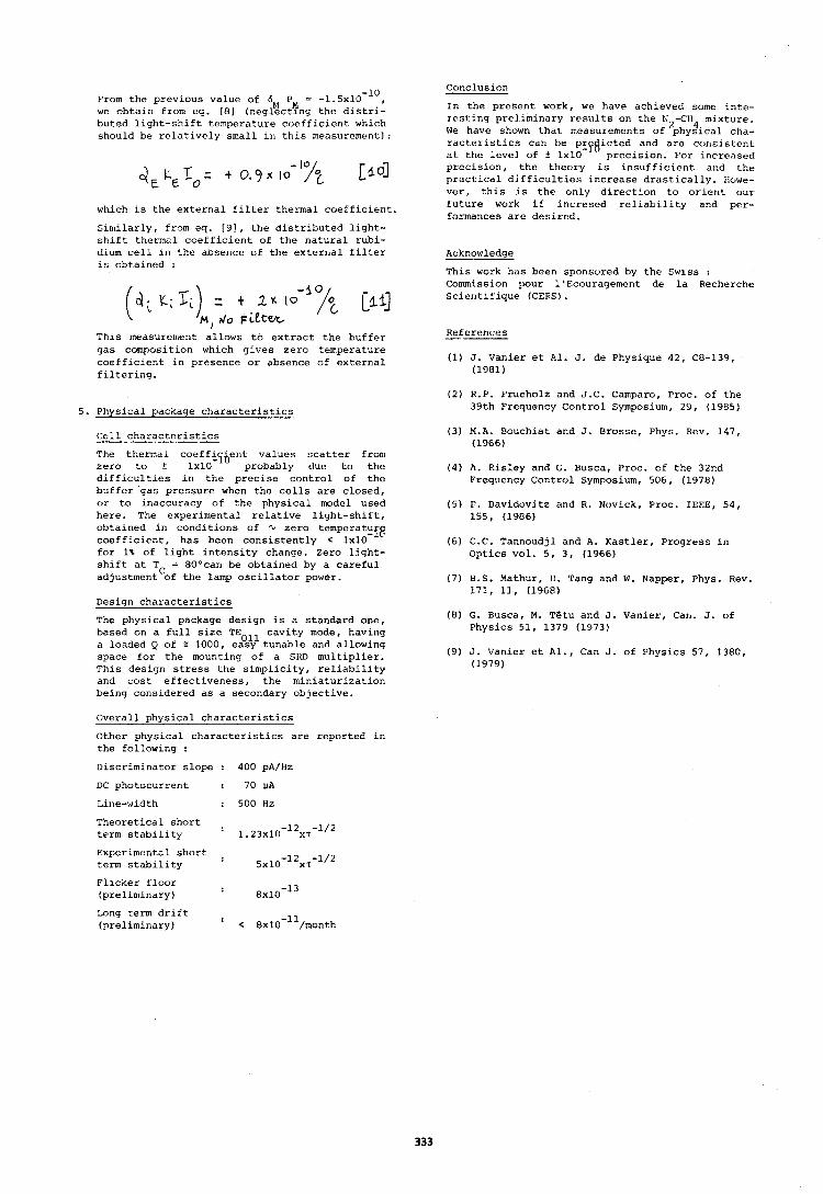
From the previous value of 6M PN = - 1 . 5 ~ 1 0 - ~ ~ , we obtain from eq. [8] (neglecting the distri- buted llght-shift temperature coefficient which should be relatively small I n this measurement):
which is the external filter thermal coefficient.
Similarly, from eq. 191, the distributed light- shift thermal coefficient of the natural rubi- dium cell in the absence of the external filter is obtained :
This measurement allows to extract the buffer gas composition which gives zero temperature coefficient in presence or absence of external filtering.
5. Physical package characteristics
Cell charact.eristics
The thermcll coeffiyprit values scatter from zero to t 1x10 probably clue to the difficulties iri the precise control of the buffer gas pressure when the cells are closed, or to inaccuracy of the physical model used here. The experimental relative light-shift, obtained in conditions of Q zero temperatu coefficient, has been consistently < 1x10 - i8 for 1% of light intensity change. Zero light- shift at TC = 80°can be obtained by a careful adjustment of the lamp oscillator power.
Design characteristics
The physical package design is a standard one, based on a full size TEOll cavity mode, having a loaded Q of : 1000, easy tunable and allowing space for the mounting of a SKD multiplier. This design stress the simplicity, reliability and cost effectiveness, the miniaturization being considered as a secondary objective.
Overall physical characteristics
Other physical characteristics are reported in the following :
Discriminator slope : 400 pA/Hz
DC photocurrent : 70 UA
Theoretical short . term stability 1 . 2 3 ~ 1 0 - ~ ~ x r - ~ / ~
Experimental short . term stability . 5x10-12xT-1/2
Conclusion
In the present work, we have achieved some inte- resting preliminary results on the N2-CH mixture. We have shown that measurements of phy2ical cha- racteristics can be pr icted and are cor~sjstent -%I at the level of f 1x10 precision. For increased precision, the theory is insufficient and the practical difficulties increase drastically. tiowe- ver, this is the only direction to orient our future work if incresed reliability and per- formances are desired.
Acknowledge -- This work has been sponsvred by the Swiss : Commission pour 1'Ecouragement de la Recherche Scientifique (CERS) .
References -- (1) J. Vanier et Al. J. de Physique 42, C8-139,
(1981)
(2) R.P. Frueholz and J.C. Camparo, Proc, of the 39th Frequency Control Symposium, 29, (1985)
(3) M.A. Bouchiat and J. Brosse, Phys. Rev. 147, (1966)
(4) A. Risley and G. Busca, Proc. of the 32nd Frequency Control Symposium, 506, (1978)
( 5 ) P. Davidvvitz and R. Novick, Proc. IEEE, 54, 155, (1986)
(6) C.C. Tannoudjl and A. Kastler, Progress in Optics vol. 5, 3, (1966)
(7) B.S. Mathur, 11. Tang and W. Napper, Phys. Rev. 171, 11, (1968)
( 5 ) G. Busca, M. TBtu and J. Vanier, Can. J. of Physics 51, 1379 (1973)
(9) J. Vanier et Al., Can J. of Physics 57, 1380, (1979)
Flicker floor (preliminary) : aX10-l3
Long term drift . (preliminary ) < 8x10-''/month
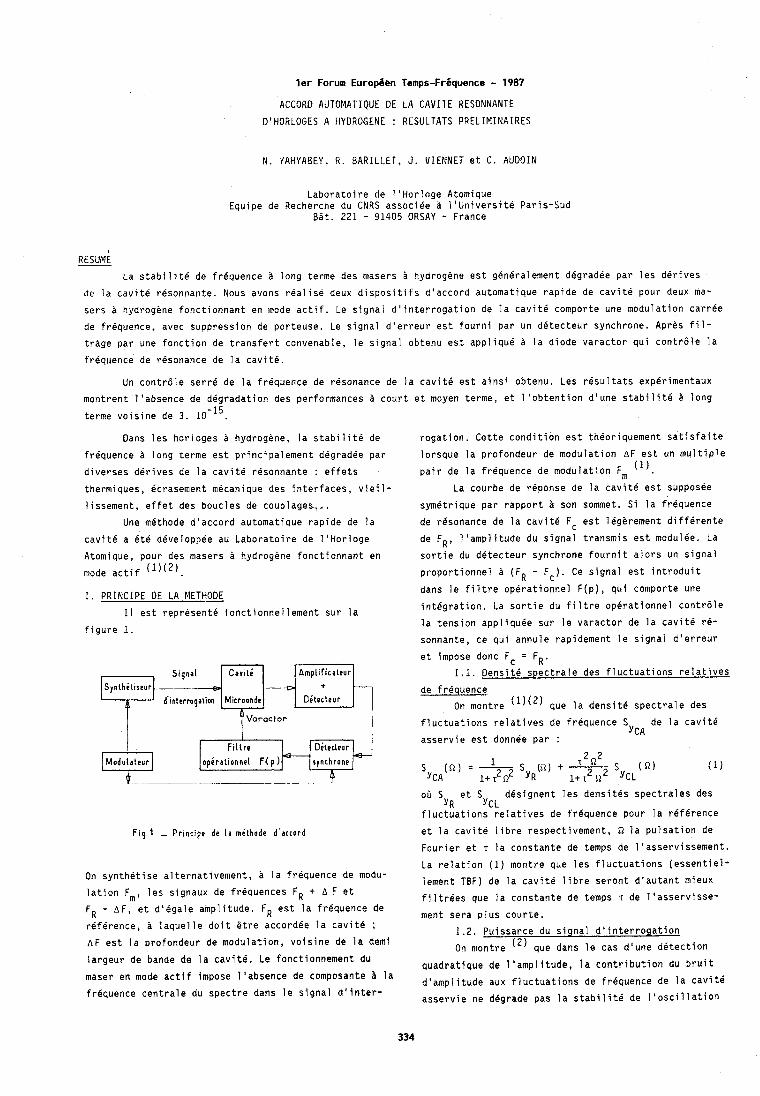
l e r Forum Europ6en Temps-Friquence - 1987
ACCORD AUTOMATIQUE DE LA CAVITE HESONNANTE
D'HORLOGES A HYDROGENE : RESULTATS PRELIMINAIRES
N. YAHYABEY, R. BARILLET, J . VIENNET et C. AUDOIN
Laboratoire de 1'Horloge Atomique Equipe de Recherche du CNRS associee I'Utiiversite Paris-Sud
BBt. 221 - 91405 ORSAY - France
RESUME
La stabilite de frequence long terme des masers B hydrogene est generalement degradee par les derives
de la cavite resonnante. Nous avons realise deux dispositifs d'accord automatique rapide de cavite pour deux ma-
sers a hydrogene fonctionnant en mode actif. Le signal d'interrogation de la cavite comporte une modulation carree
de frequence, avec suppression de porteuse. Le signal d'erreur est fourni par un detecteur synchrone. Apres fil-
trhge par une fonction de transfert convenable, le signal obtenu est applique la diode varactor qui contr6le la
frequence de resonance de la cavit6.
Un contrdle serre de la frequence de resonance de la cavite est ainsi obtenu. Les resultats experimentaux
montrent l'absence de degradation des performances a court et moyen terme, et l'obtention d'une stabilite R long
terme voisine de 3. 10-15.
Dans les horloges hydrogene, la stabilite de rogation, Cette condition est theoriquement satisfaite
frequence long terme est principalement degradee par lorsque la profondeur de modulation AF est un multiple
diverses derives de la cavite resonnante : effets (1) pair de la frequence de modulation Fm . thermiques, dcrasement mecanique des interfaces, vieil- La courbe de reponse de la cavite est supposee
lissement, effet des boucles de couplages,,. symetrique par rapport son sommet. Si la friquence
Une methode d'accord automatique rapide de la
cavite a ete developpee au Laboratoire de 1'Horloge
Atomique, pour des masers a hydrogene fonctionnant en mode actif (1)(2'.
I. PRINCIPE DE LA METHODE
I 1 est represent4 fonctionnellement sur la figure 1.
Amplif icaleur ~ 1 q n a 1 4Tl-4-$ S n t h i l ~ s e u r
d ' l n t e r r ~ ~ a l i o n Mitroonde Oe'tecteur
Voroctor
Fig.1 - P r i n c i p c de l a mdlhode d'accord
On synthetise alternativement, a la frequence de modu-
lation Fm, les signaux de frequences FR + A F et
FR - AF, et d'egale amplitude. FR est la frequence de
reference, laquelle doit btre accordee la cavite ;
A F est la profondeur de modulation, voisine de la demi
largeur de bande de la cavit6. Le fonctionnement du
maser en mode actif impose l'absence de composante la
frequence centrale du spectre dans le signal d'inter-
de resonance de la cavite Fc est legerement differente
de FR, l'amplitude du signal transmis est modulee. La
sortie du detecteur synchrone fournit alors un signal
proportionnel (FR - F c ) Ce signal est introduit
dans le filtre operationnel F(p), qui comporte une
integration. La sortie du fil tre operationnel contrdle
la tension appliquee sur le varactor de la cavit4 re-
sonnante, ce qui annule rapidement le signai d'erreur
et impose donc Fc = FR. 1.1. Densite spectrale des fluctuations relatives
de frequence
On montre (')(') que la densite spectrale des
fluctuations relatives de frequence S de la cavite
asservie est donnee par : YCA
oil S et S designent les densites spectrales des YR YCL
fluctuations relatives de frequence pour la reference
et la cavitb libre respectivement, Q la pulsation de
Fourier et T la constante de temps de l'asservissement.
La relation (1) montre que les fluctuations (essentiel-
iement TBF) de la cavit6 libre seront d'autant mieux
filtrCes que la constante de temps T de l'asservisse-
ment sera plus courte.
1.2. Puissance du signal d'interrogation
On montre (2) que dans le cas d'une detection
quadratique de 1 'amplitude, la contribution du bruit
d'amplitude aux fluctuations de frequence de la cavit6
asservie ne degrade pas la stabilite de I'oscillation
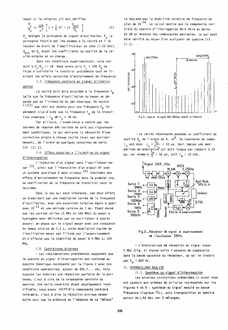
maser si la relation (2) est verifiee
PC designe la puissance du signal d'excitation, Po la
puissance fournie par les atomes a la cavite et F le
facteur d e bruit de l'amplificateur d e tete (1 ,42 GHz),
Qext et Qc etant les coefficients de qualite de la ca-
vite externe et en charge.
Dans nos conditions experimentales, cela con-
duit PciPo :?:' 18. Nous avons pris P = 100 Po d e
facon a satisfaire la condition precedente tout en l i -
mitant les effets parasites dlentrainement de frequence.
1.3. Frequence centrale ~ I J signal d'interro-
gation
La cavite doit Otre accordee ?I la frequence FR
telle que la frequence d'osci llation du maser ne dB-
pende pas de l'lntensite du jet atomique. On montre
( 1 ) ( 2 ) que ceci est obtenu pour une frequence FR 16-
gerement plus elevee que la frequence fo de la transi-
tion atomique : FR # fo + 3 0 Hz
Par ailleurs, l'experience a montre que les
courbes de reponse des cavites ne sont pas rigoureuse-
ment symetriques, ce qui entraine la necessite d'une
correction propre A chaque cavite (avec son environ-
nement), de l'ordre d e quelques centaines de Hertz
(cf. 111.1).
1.4. Effets associes a l'injection du signal
d'interrogation
L'injection d'un signal dans l'oscillateur ma-
ser (3), ainsi que 1 'interaction d'un signal RF avec
un systeme quantique a deux niveaux (4) induisent des
effets d'entrainement d e frequence dans le premier cas,
de modification de la frequence d e transition dans le
deux i eme . Dans le cas qui nous interesse, ces deux effets
se traduisent par une modulation carree de la frequence
d'oscillation, avec une excursion relative egale a quel-
ques 10-l3 et une periode voisine de l ms. Etant donne
que les sorties utiles (5 M H z et 100 MHz) du maser a
hydrogene sont delivrees par un oscillateur A quartz
asservi en phase sur le signal maser avec une constante
de temps voisine de 0,3 s , cette modulation rapide de
I'oscillation maser est filtree par I'asservissement
et n'affecte pas la stabilite du maser a 5 MHz ou 100 MHz.
1.5. Contraintes diverses
- Les considerations precedentes supposent que
le spectre du signal d'interrogation est conforme au
spectre theorique represent6 sur la figure 2 avec nos
conditions operatoires. autour de 405,7 . . . kHz. Cela suppose (en thborie) une rejection parfaite de la por-
teuse, c'est a dire d e la composante centrale du
spectre. Une telle condition &ant physiquement inve-
rifiable, nous avons chiffre la composante centrale
tolerable, c'est dire la rejection minimum neces-
saire pour que la presence ou l'absence d e ce "defaut"
ne degrade pas la stabilite relative d e frequence d e
plus de 10-16. Le calcul montre que la composante cen-
trale du spectre d'interrogation doit &tre au moins
62 dB en dessous des composantes maximales, c e qui peut
Gtre verifie au moyen d'un analyseur d e spectre (cf.
Fip.2, Sperlre d u clgnal 405,782kHi m o d u l i en frigutncr
- La cavite resonnante possede un coetficient d e
qualit6 Qc d e 1 'ordre de 4 . lo4. Sa constante de temps Q
T~ est donc T~ = --L - 1 0 ps. Ceci impose une demi ?lv
periode de m o d u l a t i o 8 q u i soit longue par rapport a 1 0 T m
ys, par exemple 7 > 50 us, soit Fm < 1 0 kHz.
Fig.3 ,Ricepleur de signal el asservisrernenl d e I'oscilla~eur 5MHz
- L'Blectronique d e reception du signa; maser
5 MHz (Fig. 3 ) impose enfin l'absence d e composante
dans la bande passante du recepteur, ce qui se traduit
par F, > 6 0 0 Hz.
11. APPAREILLAGE REALISE
11.1. Synthese du signal d'interrogation
Les diverses coritraintes presentees ci avant nous
ont conduit aux schemas de principe represent& sur les
figures 4 et 5 : synthese du signal module en basse
frequence (logique TTL), puis transposition du spectre
autour d e 1 , 4 2 G H z par 2 melanges.
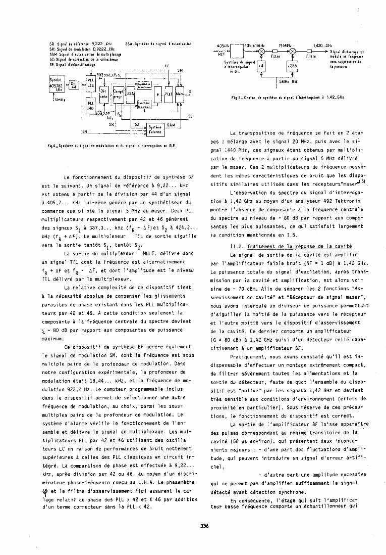
SR S ~ g n a l dt r i l i r e n c t 9 . 2 2 2 ..LHI S S A ; Slnthese du r i g n a l d 'autor i rat ion S M : S ~ g n a l de madulalion 0 , 9 2 2 2 ... kHz S A M . S i g n a l d 'autor i rat ion dr m u l l i p l e ~ a g e SC: Stqnal d t correrlion dr IJ corbcidencr SE: Signal d'ichantillonnage
- . . . . . . . . . . . - . .. . . . SC
I SM
4 0 5 t l O k H z 19.6MHi 1 ,420 ... C H I S ~ g n a l d'~nlerrogation m o d u l i m Iriquencr aver rupprer$lon dt
la porttusr
i 'MI Ly~d- ld sR.---- La transposition de frequence se fait en 2 eta-
Fip,4,S1nthirt du r ignal de modulation # \ du r ignal d'1n1erroyation en B.F.
Le fonctionnement du dispositif de syntnese UF
est le suivant. Un signal de reference h 9,22.. . kHz est o b t e n ~ a partir de la division par 4 4 d'un signal
405,7 . . . kHz lui-meme genere par un synthetiseur du commerce que pilote le signai 5 MHz du maser. Deux PLL
multiplicateurs respectivement par 4 2 et 4 6 generent
des signaux S1 387,3 . . . kHz ( f R - AF)et S2 i 424,2 . . . kHz ( f Q t A F ) . Lemultiplexeur T T L d e sortieaiguille
vers la sortie tant6t S1, tantat S2.
La sortie du multiplexeur MULT. delivre donc
un signal TTL dont la frhquence est alternativement
fR t A F et f R - A F , et dont Itamplitude est le niveau
TTL delivre par le multiplexeur.
La relative complexit6 de ce dispositif tietlt
h la necessite absolue de compenser les gl issements
parasites de phase existant dans les PLL multiplica-
teurs par 4 2 et 46. A cette condition seulement la
composante i la frequence centrale du spectre devient
2 - 8 0 dB par rapport aux composantes de puissance maximum.
Ce dispositif de synthese BF genere Bgalement
le signal de modulation SM, dont la frequence est sous
multiple paire de la profondeur de modulation. Dans
notre configuration experimentale, la profondeur de
modulation 6tai t 18,44.. . kHz, et la frequence de mo-
dulation 922,2 Hz. Le compteur programmable inclus
dans le dispositif permet de selectionner une autre
frequence de modulation, au choix, parmi les sous-
multiples pairs de la profondeur de modulation. Le
systeme d'alarme verifie le fonctionnement de l'en-
semble et delivre le signal de multiplexage. Les mul-
tiplicateurs PLL par 4 2 et 46 utilisent des oacilla-
teurs LC en raison de performances de bruit nettement
superieures h celles des PLL classiques en circuit in- t6gr-6. La comparaison de phase est effectude a 9,22 . . .
pes : melange avec le signal 20 MHz, puis avec le si-
gnal 1440 MHz, ces signaux etant obtenus par multipli-
cation de frequence a partir du signal 5 MHz delivre
par le maser. Ces 2 multiplicateurs de frequence posse-
dent les m6mes caractbristiques de bruit que les dispo- sitifs similaires utiiises dans les recepteursl'masef I( 5)
L'observation du spectre du signal d'interroga-
tion h 1,42 GHz au moyen d'un analyseur 492 Tektronix
montre l'absence de composante i la frequence centrale
du spectre au niveau de - 8 0 dB par rapport aux compo- santes les plus puissantes, ce qui satisfait largement
la condition mentionnee en 1.5.
11.2. Traitement de la reponse de la cavite
Le signal de sortie de la cavite est amplifie
par l'amplificateur faible bruit (NF = 1 dB) a 1,42 GHz.
La puissance totale du signal d'excitation, apres trans-
mission par la cavit6 et amplification, est alors voi-
sine de - 70 dBm. Afin de separer les 2 fonctions "As-
servissement de caviteN et "Rbcepteur de signal maserw,
nous avons intercale un diviseur de puissance permettant
d'aiguiller la moiti6 de la puissance vers le recepteur
et l'autre moitle vers le dispositif d'asservissement
de la cavite. Ce dernier comporte un amplificateur
(G = 60 dB) A 1,42 GHz suivi d'un detecteur relie capa-
citivement h un amplificateur BF.
Pratiquement, nous avons constate qu'il est in-
dispensable d'effectuer un montage extremement compact,
de filtrer severement toutes les alimentations et la
sortie du detecteur, faute de quoi l'ensemble du dispo-
sitif est "pollue'' par les signaux 1,42 GHz et devient
tres sensible aux conditions d'environnement (effets de
proximite en particulier). Sous reserve de ces pr6cau-
tions, le fonctionnement du dispositif est correct.
La sortie de l'amplificateur BF laisse apparaitre
des pulses correspondant au regime transitoire de la
cavit6 (50 ps environ), qui presentent deux inconvd-
nients majeurs : - d'une part des fluctuations d'ampli-
tude, qui peuvent introduire un signal d'erreur artifi-
ciel, kHz, apres division par 4 2 ou 46, au moyen d'un discri- - d'autre part une amplitude excessive mfnateur phase-fr6quence congu au L.H.A. Le phasemitre qui ne permet pas d'ampljfier suffisamment le signal
et ie filtre d'asservissement F(p) assurent le ca- detect4 avant detection synchrone. lage relatif de phase des PLL x 4 2 et X 46 par addition En cons6quence, 1'Btage qui suit l1amplifica- d'un terme correcteur dans la PLL x 42. teur basse frdquence comporte un Bchantillonneur qui
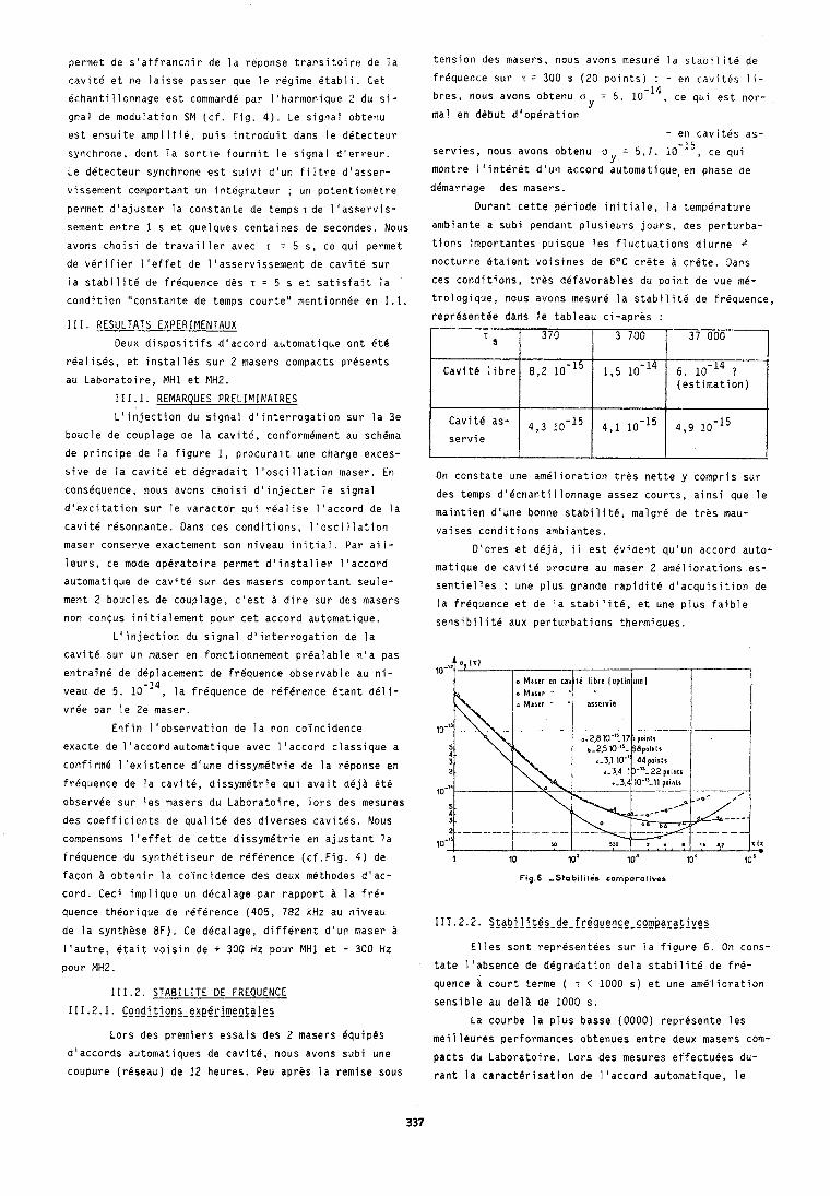
permet de s'affranchir de la reponse transitoire de la
cavite et ne laisse passer que le regime etabli. Get
echantillonnage est command6 par I'harmonique 2 du si-
gnal de modulation SM (cf. Fig. 4). Le signal obtenu
est ensuite amplifie, puis introduit dans le detecteur
synchrone, dont la sortie fournit le signal d'erreur.
Le detecteur synchrone est suivi d'un filtre d'asser-
vissement comportant un intdgrateur ; un potentiometre
permet d'ajuster la constante de t e m p s ~ d e l'asservis-
sement entre 1 s et quelques centaines de secondes. Nous
avons choisi de travailler avec r = 5 s, ce qui permet de verifier l'effet de l'asservissement de cavite sur
la stabilite de frequence dhs T = 5 s et satisfait la
condition "constante de temps courte" mentionnee en 1.1.
111. RESULTATS EXPERIMENTAUX
Deux disposi tifs dlaccord automatique ont et6
realises, et installes sur 2 masers compacts presents
au Laboratoire, MH1 et MHz.
111.1. REMARQUES PRELIMINAIRES
L'injection du signal d'interroyation sur la 3e
boucle de couplage de la cavit6, conformement au schema
de principe de la figure 1, procurait une charge exces-
sive de la cavite et degradait l'oscillation maser. En
consequence, nous avons choisi d'injecter le signal
d'excitation sur le varactor qui realise l'accord de la
cavite resonnante. Dans ces conditions, l'oscillation
maser conserve exactement son niveau initial. Par ail-
leurs, ce mode operatoire permet d'installer l'accord
automatique de cavite sur des masers comportant seule-
ment 2 boucles de couplage, c'est a dire sur des masers
non contus initialement pour cet accord automatique.
L'injection du signal d'interrogation de la
tension des masers, nous avons mesure la stab1 iite de
frequence sur T = 300 s (20 p o ~ n t s ) : - en c a v ~ t e s 1 1 -
breo, nous avons obtenu o = 5. 10-14, ce qui est nor- Y
ma1 en debut d10p6ration
- en cavites as- s e r v ~ e s , nous avons obtenu o = 5,7. 10-15, ce qui
Y montre I'interet d'uri accord automatique, en phase de
demarrage des masers.
Durant cette periode initiale, la temperature
ambiante a subi pendant plusieurs jours, des perturba-
tions importantes puisque les fluctuations diurne 4
nocturne etaient volsires de 6OC crgte a crete. Dans
ces conditions, tres defavorables du point de vue me-
trologique, nous avons mesure la stabilite de frequence,
representee dans le tableau ci-apres :
On constate une amelioration tres nette y compris sur
des temps d'echantillonnage assez courts, ainsi que le
maintien d'une bonne stabilite, malgre de tres mau-
vaises conditions ambiantes.
D'ores et deja, i l est evident qu'un accord auto-
matique de cavite procure au maser 2 ameliorations es-
sentielles : une plus grande rapidit6 d'acquisition de la frequence et de la stabilite, et une plus faible
sensibilite aux perturbations thermiques.
s
Cavite libre
Cavite as-
servie
cavite sur un maser en fonctionnement prealable n'a pas
entrain6 de deplacement de frequence observable au ni-
veau de 5. 10-14, la frequence de reference Btant deli-
vree par le 2e maser.
Enfin l'observation de la non co7ncidence
exacte de l'accordautomatique avec l'accord classique a
confirme l'existence dlune dissymetrie de la reponse en
frequence de la cavite, dissymetrie qui avait deja ete
observee sur les masers du Laboratoire, lors des mesures
des coefficients de qualit6 des diverses cavites. Nous
compensons l'effet de cette dissymetrie en ajustant la
frequence du synthetiseur de reference (cf.Fig. 4) de 1 10 lo2 10' lo' 10'
facon A obtenir la coyncidence des deux methodes d'ac- cord. Ceci implique un decalage par rapport a la fr6-
370
8,2
4 , 3 1D-15
Fig.8 -S tab i l~ tes comparatives
quence theorique de reference (405, 782 kHz au niveau 111.2.2. S $ g b i l i $ ~ ~ - d g - f r $ g g g n ~ g - ~ o m p $ C g f j y e s
de la synthese BF). Ce decalage, different d'un maser a
3 700
1,5
4,1 10-15
l'autre, etait voisin de + 300 Hz pour MH1 et - 300 Hz Elles sont representees sur la figure 6. On cons-
pour MH2. tate l'absence de degradation dela stabilite de fr6-
37 000
6. lo-14 ? (estimation)
4,9 10-15
quence i court terme ( T < 1000 s) et une amelioration 111.2. STABILITE DE FREQUENCE
sensible au deli de 1000 s. 111.2.1. c g n d j t j o n s - e a e ~ r i ~ e n t a ~ g s
La courbe la plus basse (0000) represente les Lors des premiers essais des 2 masers equipes meiileures performances obtenues entre deux masers com-
d'accords automatiques de cavite, nous avons subi une pacts du Laboratoire. Lors des mesures effectuees du- coupure (rbseau) de 12 heures. Peu apres la remise sous rant la caracterisation de l'accord automatique, le
maser MH2 p r e s e n t a i t des problemes d ' o r d r e magnet ique. ( 6 ) R.F.C. Vessot e t a l . P roc . 4 0 t h Ann. Symp. on Cela e n t r a i n a i t deux i n c o n v e n i e n t s : d ' u n e p a r t une Frequ. Con t ro . P h i l a d e l p h i a , 28-30 may 1986, r e l a t i v e f a i b l e s s e du n iveau d ' o s c i l l a t i o n , d ' a u t r e pp 413-418.
p a r t l a n e c e s s i t e d ' u t i l i s e r un champ magnetique s t a t i -
que p l u s i n t e n s e ( 6 mG au l i e u de 1 mG genera lement) .
Le p remie r p o i n t de favorab le ( n i v e a u f a i b l e ) e x p l i q u e
pourquoi nous n 'avons pas r e t r o u v e , en c o u r t terrne e t
en c a v i t e s l i b r e s , une s t a b i l i t e de f requence optimum.
Ma lg re c e l a , l e s deux masers en c a v i t e s a s s e r v i e s mon-
t r e n t une s t a b i l i t e de f requence q u i r e j o i n t l e compor-
tement optimum a n t e r i e u r aux a l e n t o u r s de T = 10 000s,
e t q u i se r e v e l e m e i l l e u r e au d e l a , semblant mon t re r un
p a l i e r aux a l e n t o u r s de 3.10-15. Ce p a l i e r apparen t
rep resen te t r e s probablement I ' e f f e t p e r t u r o a t e u r du
b r u i t magnetique ambiant , e f f e t q u i e s t notablement
acc ru p a r l e fonct ionnetnent en champ f o r t du maser MH2.
En tous cas. ce p a l i e r n ' e s t absolument pas l a l i m i t e
u l t i m e due a I ' a s s e r v i s s e m e n t de c a v i t e proprement d i t ,
1 i m l t e que l e c a l c u l s i t u e aux a l e n t o u r s de 10 -18 ( 2 )
en ce q u i concerne I ' e f f e t du b r u i t de l ' e l e c t r o n i q u e ,
p l u s probablement e n t r e 1 0 - l 6 e t en r a i s o n des
f l u c t u a t i o n s d ' a m p l i t u d e du s i g n a l d ' i n t e r r o g a t i o n .
Les r e s u l t a t s p receden ts , obtenus dans des
c o n d i t i o n s de fonc t ionnement peu f a v o r a b l e s , mon t ren t
l a v a l i d i t 6 de l a methode d ' a c c o r d u t i l i s e e , l ' a b s e n c e
de degrada t ion due au systeme d ' a c c o r d automat ique, e t
p a r consequent l a p o s s i b i l i t e d ' o b t e n i r une s t a b i l i t e
de f requence a long terme v o i s i n e de 10-15, v o i r e
mieux puisque c e l a e s t dCj& obtenu en masers i c a v i t e s
l i b r e s ( 6 ) .
CONCLUSION
Les r e s u l t a t s p r e l i m i n a i r e s concernant l ' a c -
c o r d automat ique r a p i d e de c a v i t e resonnante mon t ren t
une a m e l i o r a t i o n s e n s i b l e des per formances A moyen
terme, sans degrada t ion mesurable de l a s t a b i l i t e de
f requence. De p l u s , c e t accord automat ique appor te une
r e d u c t i o n n o t a b l e d e l a s e n s i b i l i t e thermique, du temps
de mise en oeuvre des masers, e t il peut 6 t r e i n s t a l l 6
su r des masers non concus i n i t i a l e m e n t c e t e f f e t . Un
t e l d i s p o s i t i f , en v e r s i o n compacte i n t 6 g r e e au maser,
p e u t B t r e t r e s i n t e r e s s a n t en vue de l ' u t i l i s a t i o n de
masers 2 hydrogene dans l e s 6 c h e l l e s de temps.
BIBLIOGRAPHIE
( 1 ) C. AUDOIN, "Fas t C a v i t y Auto-Tuning Systems f o r
Hydrogen Masers", Rev. Phys. Appl . 16 (1981) pp.
125-130 e t 17 (1982) p . 273 .
( 2 ) N. YAHYABEY, These "Accord automat ique r a p i d e de
l a c a v i t e resonnante dans une h o r l o g e atomique a hydrogene", Orsay, 2 1 Octobre 1986.
( 3 ) J. VIENNET, These de D o c t o r a t d ' E t a t , Orsay (1977) .
( 4 ) RAMSEY N.F. , Phys. Rev. 100 (1955) 1191.
( 5 ) R. BARILLET, P. PETIT, J. VIENNET e t C. AUDOIN,
"Masers i hydrogene a c t i f s e t compacts", b u l l e t i n
du BNM, Spec ia l Temps Frbquence, j a n v i e r - a v r i l
1986, volume 2 , pp 54-59.
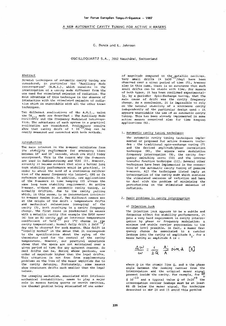
l e r Forum Europien Temps-Friiquence - 1987
A NEW AUTOMATIC CAVITY TUNING FOR ACT IVE H MASERS
G. Busca and 1.. Jol~nson
OSCILLOQUAETZ S . A . , 2002 Neuchitel , Switzerland
Abstract
Several techniques of automatic cavity tuning are considcred, in particular the "Auxiliary Mode Interroqation" (A.M. I.) , which consists in the interrogation of a cavity mode different from the one used for stimulated emission of radiation. The main advantage of this technique is the absence of interaction with the stimulated emission of radia- tion which is unavoidable with all the other known techniques.
Two different realizations of the A.M.I., using the TE1 , mode are described : The Auxiliary Mode ~scillaior and the t'rec~uency Modulated Intcrroga- tion. The advantages of each systeni in a practical rc!olization are considered. Prelllrpjyary results show that cavity drift of C 10 /day can be
of magnitude compared to the-lyetallic cavities. Very small drifts ( r 1x10 /day) have been observed over a given period of time ( 5 ) , however also in this case, there is no assurance that such small drifts can be stable with time. For masers of both types, it has been confirmed experimental- ly, by a periodic Spin-Exchange tuning, that the main cause of drift was the cavity frequency change. As a conclusion, it is impossible to rely on the natural stability of a microwave cavity independently of the particular design used : it appears unavoidable the use of an automatic cavity tuning. This has been already implemented in some active masers conceived also for t h e keel~irlg applications (6).
rosily measured and corrected with both methods. 1. Automatic cavity tuning techniques
Introduction
The main interest in the H-maser originates from its stabi ity pe~formance for averaging times 1' between 10 and 10 seconds, which are still today unsurpassed. This is the reason why the ti-masers are used in Radioastronomy and VLBI (1). However, rcrently it became evidclnt that also a better long term stability performance would be practical, in order to avoid the need of a continuous calibra- tion of the maser frequency via Loran-C, CPS or Cs reference standards. In addition, new applications of the H-masers in time keeping (2) stress the same long term stability requirement. An active H-maser, without an automatic cavity tuning, is normally drifting, due to the cavity pulling which, in this sense, is an inconvenient intrinsic to H-maser design itself. Two different causes are at the origin of the drift : temperature drifts and mechanical relaxations (creeping) of the cavity ( 3 ) , both resulting in a cavity frequency change. The first cause is predominant in masers with a metallic cavity (for example the EFOS maser ( 4 ) has an A1 cavity-y~d an intrinsic temperature coefficient of 5x10 per 1°C change in -iB; cavity temperature). Normal daily drift 5 2x10 day can be ubserved for such masers. This drift is "legally normal" in the sense that it corresponds to the specifications about the aging of the thermistor used for the control of the cavity temperature. However, our practical experience shows that the specs are not maintained over a given period of time for any apparent reasons. So real drifts can be, during whose perdiods, one order of magnitude higher than the legal drifts. This situation is not free from supplementary problems as the loss of the maser amplitude due to the cavity detuning. Fortunately, some masers show consistent drifts much smaller than the legal values.
The creeping mechanism, associated with intrinsic ~l~cchanical instabilities, seems to play a major role in masers having quartz or cervit cavities, the thermal problem being attenuated of one order
The automatic cavity tuning techniques imple- mented or proposed for active H-masers inclu- des : the traditional spin-exchange tuning (7) and the derived amplitude/phase correlation technique (a), the square wave modulation frequency interrogation (91, the cavity fre- quency switching servo (10) and the inverse transfer function technique (11). Several other techn~ques have been implemented in the connec- tion of the automatic cavity tuning of passive H-masers. All the techniques listed imply an interrogation of the cavity mode which sustains the stimulated emission of radiation and have to deal with the problem of minimizing the perturbations on the stimulated emission of radiation.
2. =problems in cavity interrogation
a) Injection lock
The injection lock appears to be a subtle and dangerous effect for stability performances, it puts a very hard requirement in cavity interro- gation by phase or frequency modulation: a minimum and stable carrier suppression to the maximum level possible. In fact, a maser fre- quency change Aw associated to a carrier leakage into the cavity of amplitude Ai, for a maser having an amplitude A is :
where Q is the atomic line Q, and a the phase angle between the leaking carrier from the interrogation and the original maser signgh present inside' the cavity. For example, for - 5 10-l3 and a typical value Q of 2x10'~ thz interrogation carrier leakage must be at least 68 dB below the maser signal. The technique described in REF 10 and 11 avoid this problem
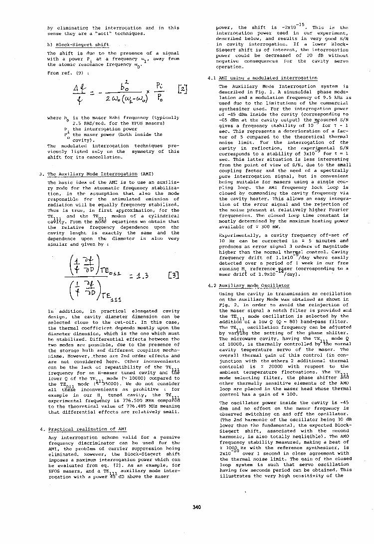
by eliminating the interrogation and in this sense they are a "soft" t-echniques.
L) Block-Siegert shift
The shift is due to the presence of a signal with a power P . at a frequency lol, away from the atomic resokance frequency w 0' From ref. (9) :
where ho is the maser Hahi frequency (typically 2.5 RAD/std. for the EFOS masers)
P , the interro51ation power P' the maser power (both inside the O cavity).
The modulated interrogation techniques pre- viously listed rely on the symnetry of this shift. for its cancellation.
3. &Auxiliary Mode Interrogation (AMI)
The basic idea of thc AM1 is to use an auxilia- ry mode for the atuonlatic frequency stabiliza- tion, in the assumption that also the mode responsible for the stimulated emission of radiation will be equally frequency stabilized. ~ h u s is true, in first approximation, for the
and the TE modes of a cylindrical ::$I$. From the m%! equations we obtain that the relative frequency dependence upon the cavity ler~ght is exactly the same and the dependence upon the diameter is also very similar and given by :
In addition, in practical elongated cavity design, the cavity diameter dimension can be selected close to the cut-off. In this case, the thermal coefficient depends mostly upon the diameter dimension, which is the one which must be stabilized. Differential effects between the two modes are possible, due to the presence of the storage bulb and different coupling mecha- nisme. However,.these are 2nd order effects and are not considered here. Other inconvenients can be the lack of repeatibility of thc TE frequency for an H-maser tuned cavity and #16 lower Q of the TE mode (QJ 10000) compared to the TEOll mode (k155000). We do not consider a11 these inconvenients as prohitive : for example in our Ell tuned cavity, the TE experimental frequency is 776.500 MHz cornpat&& to the theoretical value of 776.485 MHz meaning that differential effects are relatively small.
4. Practical realization of RMI
Any interrogation scheme valid for a passive frequency discriminator can be used for the AMI, the problem of carrier suppression being eliminated. However, the Block-Siegert shift imposes a maximum interrogation power which can be evaluated from eq. [Z]. As an example, for EFOS masers, and a TE auxiliary mode inter- rogation with a power # dn above the maser
power, the shift is -2~10-15. This is the interrogation power used in our experiment, described below, and results in very good S/N in cavity interrogation. If a lower Block- Siegert. shift is of interest, the interrogation power could be decreased of 20 dB without negative consequences for the cavity servo operation.
4.1 AM1 using a modulated interrogation
The Auxiliary Mode Interrogation system is described in Fig. 1. A sinusoidal phase modu- lation and a modulation frequency of 9.5 kHz is used due to the limitations of the conunercial synthesizer used. For the interrogation power of -45 dBn1 inside the cavity (corresponding to -65 dBm at the cavity output) the-yasured S/N gives a frequency stability of 10 for T = 1 sec. This represents a deterioration of a fac- tor of 5 compared to the theoretical thermal noise limit. For the interrogation of the cavity in reflection, the experJpenta1 S/N corresponds to a stability of 3x10 for T = 1 sec. This latter situation is less interesting from the point of view of S/N, due to the small coupling factor and the need of a spectrally pure interrogation signal, but is convenient being suitable for masers using a single cou- pling loop. The AM1 frequency lock loop is closed by commanding the cavity frequency via the cavity heater. This allows an easy inteyra- tion of the error signal and the rejection of the noise present at relatively higher Fourier frequencies. The closcd loop time constant is mostly determined by the maximum heating power available of s 300 mW.
Experimentally, a cavity frequency off-set of 10 Hz can be corrected in = 5 minutes and produces an error signal 3 orders of magnitude higher than the normal thec~al control. Cavity frequency drift of 1.1~10 /day where easily detected over a period of 1 week in our free running H reference-~tser (corresponding to a mser drif* of 1.9~10 /day).
4.2 Auxiliary mode Oscillator
Using the cavity in transmission an oscillation on the Auxiliary Mode was obtained as shown in Fig. 2. In order to avoid the reinjection of the maser signal a notch filter is provided and the TElll mode oscillation is selected by the addition of a low Q (Q = 80) band-pass filter. The TE oscillation frequency can be adjusted by var$%g the setting of the phase shifter. The microwave cavity, having the TE mode Q of 10000, is thermally controlled byl\he normal cavity temperature servo of the maser. The overall thermal gain of this control (in con- junction with the others 2 additional thermal controls) is E 20000 with respect to the ambient termperature fluctuations. The TE mode selecting filter, the phase shifter 41% other thermally sensitive elements of the AM0 loop are placed in the maser head whose thermal control has a gain of 100.
The oscillator power inside the cavity is -45 dBm and no effect on the maser frequency is observed switching on and off the oscillator. (The 2nd harmonic of the oscillator being 30 dB lower than t.he fundamental, the expected Block- siegert shift, associated with the second harmonic, is also totally negligible). The AM0 frequency stability measured, making a beat of s lO_OPOHz with the reference synthesizer, is 2x10 over 1 second in close agreement with the thermal noise limit. The gain of the closed loop system is such that servo oscillation having few seconds period can be obtained. This illustrates the very high sensitivity of the
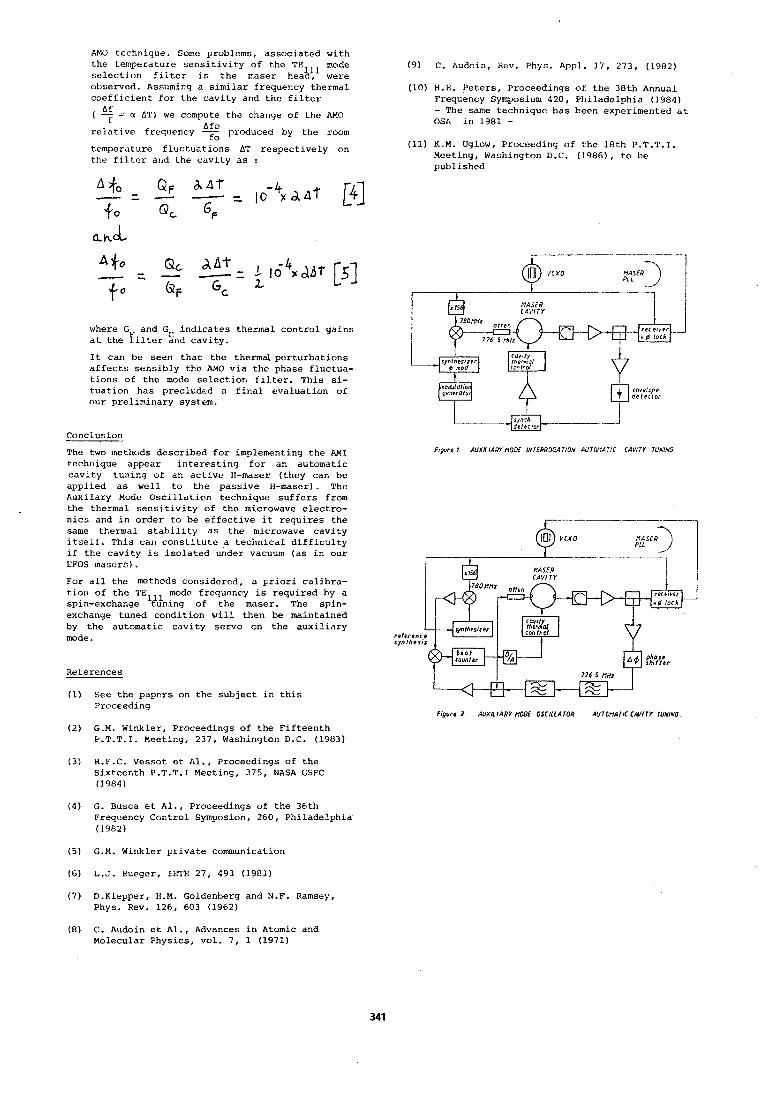
AM0 technique. Sorne problems, associated with the temperature sensit~vlty of the TE mode selection fllter in the maser hea?ljl were observed. Assuming a similar frequency thermal coefficient foz the cavity and the fllter Af
( 7 = u A'l') we compute the change of the AM0
relative frequency - AfO produced by the room fo
temperature fluctuations AT respectively on the filter and the cavity as :
where G and G indicates thermal control gains at the Filter End cavity.
It can be seen that the thermal perturbations affects sensibly the AM0 via the phase fluctua- tions of the mode selection filter. This si- tuation has precluded a final evaluation of our preliminary system.
Conclusion
The two methods described for implementing the M I technique appear interesting for an automatic cavi.ty tuning of an active H-maser (they can be applied as well to the passive H-maser). The Auxilary Mode Oscillntinn technique suffers from the thermal sensitivity of the microwave electro- nics and in order to be effective it requires the same thermal stability as the microwave cavity itself. This can constitute a technical difficulty if the cavity is isolated under vacuum (as in our EFOS masers).
For all the methods considered, a priori calibra- tion of the TE mode frequency is required by a spin-exchange '#ning of the maser. The spin- exchange tuned condition will then be maintained by the automatic cavity servo on the auxiliary mode.
References
(1) See the papers on the subject in this Proceeding
(2) G.M. Winkler, Proceedings of the Fifteenth P.T.T.I. Meeting, 237, Washington D.C. (1983)
(3) R.F.C. Vessot et Al., Proceedings of the Sixteenth P.T.T.1 Meeting, 375, NASA GSFC (1984)
(4) G. Busca et Al., Proceedings of the 36th Frequency Control Symposion, 260, Philadelphia (1982)
(5) G.M. Winkler private communication
(6) L.J. Rueger, IETE 27, 493 (1981)
(7) D.Klepper, H.M. Goldenberg and N.F. Ramsey, Phys. Rev. 126, 603 (1962)
(9) C. Audoin, Rev. Phys. Appl. 17, 273, (1982)
(10) H.E. Peters, Proceedings of the 38th Annual Frequency Symposium 420, Philadelphia (1984) - The same technique has been experimented at OSA in 1981 -
(11) K.M. Uglow, Proceeding of the 18th P.T.T.I. Meeting, Washington D.C. (1986), to be published
figure 1 AUXILIARY NODE INIERROGA TlON AUTONA TIC (AVI TY TUKING
, $ v m o PLt M A s i R ) 1 --
MASER CAY1 1 Y
F igure 1. AUXILIARY PIODE OSCILLATOR AUTONATIC CAVITY TUNING
(8) C. Audoin et Al., Advances in Atomic and Molecular Physics, vol. 7, 1 (1971)

ler Forum Europeen Temps-FrBquence - 1987 Experiences with H-Maser EFOS 1 and EFOS 3
at the Fundamental Statlon Wettzell
Wolfgang Schluter
Institut fur Angewandte Geodasie Fundamentalstation Wettzell der
Forschungsgruppe Satellitengeodasie 0 - 8 4 9 3 K o t z t i n g
Fed. Rep. Germany
(Mitteilung aus dem Institut fur Angewandte Geodasie)
Summary - Deutsches Geodatisches Forschungsinsti- tut, Abt. I , Munchen,
Two H-Masers EFOS 1 and EFOS 3 are emoloved at the Fundamentalstation Wettzell -a' reie- rence station for Geodesy and Geodynamics- to provide hlghly stable reference-frequencies for Very Long Baseline Interferometry meas- urer11ent.s which are carried out with the 20 m Radiotelescope. The clocks driven by the H- Masers are compared with the timescale UTC (Wettzell). This comparison allows to analyse the frequency-drifts of the H-Masers. Empha- sis has been placed on the long term behavior of EFOS 1.
Introduction
Research in geodynamics and plate tectonics employs Laserranging-, VLBI- and some Micro- wave-Systems which allow very precise deter- mination of satellite-orbits, station-coordi- nates, baselines, polar motion and earth-ro- tation.
The Fundamentalstation Wettzell (FS-Wettzell) 1s a reference station for Geodesy and Geo- dynamics situated in the Bavarian Forest. FS-Wettzell provides data for the
- Geodatisches Institut, Universitat Bonn.
The concentration on relevant observation- techniques like laser-ranging, VLBI and others on a few global distributed fundamen- tal stations allow the combination of diffe- rent techniques to realize a uniform, global reference frame within the cm-domain and to check out systematic errors in the different techniques. FS-Wettzell is equipped with
- Laser-ranging facilities (a stationary 3rd generation Laser-ranglng system and a mobile system (MTLRS 1) employed in the W E G E N E R - M E D L A S - C a m p a i g n ,
- Radiotelescope for VLBI (Mark 111-data acquisition device),
- Doppler receiver (TRANET 11) which is part of the TRANSIT-Network and
- Timing-system to provide time and fre- quency as required.
- realization and maintenance of a global Further activities have been started to set Reference System, UP a
- determination of kinematic and geodyna- - new laser ranging system capable for mlc phenomenas, Satellite- and Lunar-tracking and
- determination of the earth gravity field.
The activities are carried out within inter- national projects like the NASA-Crustal Dyna- rnlcs Project (COP), the joint COATES-Project, the WEGENER-MEDLAS-project and the ongoing MERIT-Project (IRIS, INTENSIV, TEMPO) [NASA, 19851, [Reinhart et.al., 19851. The FS-Wett- zell is operated by the Institut fur Ange- wandte Geodasie (IfAG) and the Forschungs- einrichtung Satellitengeodasie on behalf of the Forschungsgruppe Satellitengeodasie (FGS), a cooperative effort of the
- Institut fur Astronomische und Physika- lische Geodasie and Forschungseinrichtung Satellitengeodasie of the Technische Uni- versitat Munchen,
- Instltut fur Angewandte Geodasie, (IfAG/ OGFI, Abt. II), Frankfurt am Main,
- GPS tracking device for geodetic appli- cations.
Timing System of FS-Wettzell
The demand in time and frequency differs from the various applications (figure 1). To meet all requirements the timing system con- sists of (figure 2)
- 4 Cesium clocks which orovide UTC (Wett- zell) within about 1 microsec of UTC (USNO),
- 2 H-Maser which provide frequencies for VLBI ( O (loo . . . 1000 S) < 2.10-15),
- several Rubidium clocks and EVA-crystals adjusted to UTC (Wettzell) as working standards for laser ranging and others.
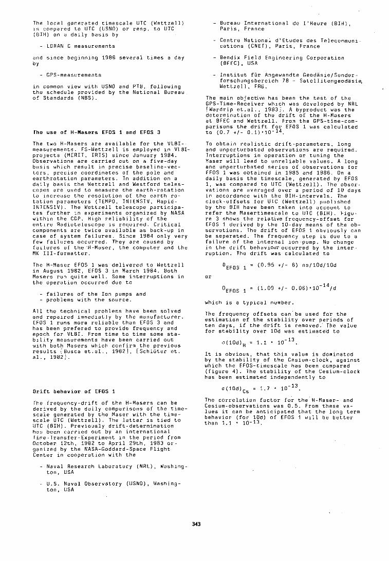
The l o c a l g e n e r a t e d t i m e s c a l e UTC ( W e t t z e l l ) i s compared t o UTC (USNO) o r r e s p . t o UTC ( B I H ) on a d a i l y b a s i s by
- LORAN C measurements
and s i n c e b e g i n n i n g 1986 s e v e r a l t i m e s a day b Y
- GPS-measurements
i n common v i e w w i t h USNO and PTB, f o l l o w i n g t h e s c h e d u l e p r o v i d e d by t h e N a t i o n a l Bu reau o f S t a n d a r d s (NBS).
The u s e of H-Masers EFOS 1 and EFOS 3
The t w o H-Mase rs a r e a v a i l a b l e f o r t h e VLB I - measu remen ts . F S - W e t t z e l l i s emp loyed i n VLBI- p r o j e c t s (MERIT, I R I S ) s i n c e J a n u a r y 1 9 8 4 . O b s e r v a t i o n s a r e c a r r i e d o u t on a f i v e - d a y b a s i s w h i c h r e s u l t i n p r e c i s e b a s e l i n e - v e c - t o r s , p r e c i s e c o o r d i n a t e s o f t h e p o l e and e a r t h r o t a t i o n p a r a m e t e r s . I n a d d i t i o n on a d a i l y b a s i s t h e W e t t z e l l and W e s t f o r d t e l o s - copes a r e used t o measure t h e e a r t h - r o t a t i o n t o i n c r e a s e t h e r e s o l u t i o n o f t h e e a r t h - r o - t s t i o n p a r a m e t e r s (TEMPO, INTENSIV, R a p i d - INTENSIV) . The W e t t z e l l t e l e s c o p e p a r t i c i p a - t e s f u r t h e r i n e x p e r i m e n t s o r g a n i z e d by NASA w i t h i n t h e CDP. H i g h r e l i a b i l i t y o f t h e e n t i r e R a d i o t e l e s c o p e i s r e q u i r e d . C r i t i c a l components a r e t w i c e a v a i l a b l e as b a c k - u p i n c a s e o f s y s t e m f a i l u r e s . S i n c e 1984 o n l y v e r y few f a i l u r e s o c c u r r e d . They a r e caused by f a i l u r e s o f t h e H -Mase r , t h e c o m p u t e r and t h e MK 1 1 1 - f o r m a t t e r .
The H-Maser EFOS 1 was d e l i v e r e d t o W e t t z e l l i n August 1 9 8 2 , EFOS 3 i n March 1984 . B o t h Mase rs r u n q u i t e w e l l . Some i n t e r r u p t i o n s i n t h e o p e r a t i o n o c c u r r e d due t o
- f a i l u r e s o f t h e I o n pumps and - p r o b l e m s w i t h t h e s o u r c e .
A l l t h e t e c h n i c a l p r o b l e m s h a v e been s o l v e d and r e p a i r e d i m m e d i a t l y by t h e m a n u f a c t u r e r . EFOS 1 r u n s more r e l i a b l e t h a n EFOS 3 and has been p r e f e r e d t o p r o v i d e f r e q u e n c y and epoch f o r VLB I . From t i m e t o t i m e some s t a - b i l i t y measurements have been c a r r i e d o u t w i t h b o t h Mase rs w h i c h c o n f i r m t h e p r e v i o u s r e s u l t s [ B u s c a e t . a l . , 19821 , [ S c h l u t e r e t . a l . , 19821.
D r i f t b e h a v i o r o f EFOS 1
The f r e q u e n c y - d r i f t o f t h e H-Masers can be d e r i v e d by t h e d a i l y c o m p a r i s o n s o f t h e t i m e - s c a l e g e n e r a t e d by t h e Maser w i t h t h e t i m e - s c a l e UTC ( W e t t z e l l ) . The l a t t e r i s t i e d t o UTC ( B I H ) . P r e v i o u s l y d r i f t - d e t e r m i n a t i o n has been c a r r i e d o u t by an i n t e r n a t i o n a l T i m e - T r a n s f e r - E x p e r i m e n t i n t h e p e r i o d f r o m O c t o b e r 1 2 t h , 1982 t o A p r i l 2 9 t h , 1983 o r - g a n i z e d by t h e NASA-Goddard-Space F l i g h t C e n t e r i n c o o p e r a t i o n w i t h t h e
- Bu reau I n t e r n a t i o n a l de 1 ' H e u r e ( B I H ) , P a r i s , F r a n c e
- C e n t r e N a t i o n a l d ' E t u d e s des Te lecommun i - c a t i o n s (CNET), P a r i s , F r a n c e
- B e n d i x F i e l d E n g i n e e r i n g C o r p o r a t i o n (BFEC), USA
- I n s t i t u t f u r Angewandte G e o d a s i e / S o n d e r - f o r s c h u n g s b e r e i c h 78 - S a t e l l i t e n g e o d a s i e , W e t t z e l l , FRG.
The ma in o b j e c t i v e has been t h e t e s t o f t h e GPS-T ime-Rece i ve r w h i c h was d e v e l o p e d by NRL [ W a r d r i p e t . a l . , 19831 . A b y p r o d u c t was t h e d e t e r m i n a t i o n o f t h e d r i f t o f t h e H-Masers a t BFEC and W e t t z e l l . From t h e GPS- t ime-com- p a r i s o n s t h e d r i f t f o r EFOS 1 was c a l c u l a t e d t o ( 0 . 7 + / - 0 . 1 ) . 1 0 - ~ ~ .
To o b t a i n r e a l i s t i c d r i f t - p a r a m e t e r s , l o n g and u n p e r t u r b a t e d o b s e r v a t i o n s a r e r e q u i r e d . I n t e r r u p t i o n s i n o p e r a t i o n o r t u n i n g t h e Maser w i l l l e a d t o u n r e l i a b l e v a l u e s . A l o n g and u n p e r t u r b a t e d s e r i e s o f o b s e r v a t i o n s f o r EFOS 1 was o b t a i n e d i n 1985 and 1986 . On a d a i l y b a s i s t h e t i m e s c a l e , g e n e r a t e d by EFOS 1, was compared t o UTC ( W e t t z e l l ) . The o b s e r - v a t i o n s a r e a v e r a g e d o v e r a p e r i o d o f 1 0 days i n a c c o r d a n c e w i t h t h e B I H - i n t e r v a l s . The c l o c k - o f f s e t s f o r UTC ( W e t t z e l l ) p u b l i s h e d by t h e BIH h a v e been t a k e n i n t o a c c o u n t t o r e f e r t h e M a s e r t i m e s c a l e t o UTC ( B I H ) . F i g u - r e 3 shows t h e r e l a t i v e f r e q u e n c y - o f f s e t f o r EFOS 1 d e r i v e d by t h e 10 -day means o f t h e o b - s e r v a t i o n s . The d r i f t o f EFOS 1 o b v i o u s l y can be s e p e r a t e d . The f r e q u e n c y s t e p i s due t o a f a i l u r e o f t h e i n t e r n a l i o n - p u m p . No change i n t h e d r i f t b e h a v i o u r o c c u r r e d by t h e i n t e r - r u p t i o n . The d r i f t was c a l c u l a t e d t o
w h i c h i s a t y p i c a l number .
The f r e q u e n c y o f f s e t s can be used f o r t h e e s t i m a t i o n o f t h e s t a b i l i t y o v e r p e r i o d s o f t e n days , ~f t h e d r i f t i s r emoved . The v a l u e f o r s t a b i l i t y o v e r 10d was e s t i m a t e d t o
I t i s o b v i o u s , t h a t t h i s v a l u e i s d o m i n a t e d by t h e s t a b i l i t y o f t h e C e s i u m - c l o c k , a g a i n s t w h i c h t h e E F O S - t i m e s c a l e has been compared ( f i g u r e 4 ) . The s t a b i l i t y o f t h e C e s i u m - c l o c k has been e s t i m a t e d i n d e p e n d e n t l y t o
The c o r r e l a t i o n f a c t o r f o r t h e H -Mase r - and C e s i u m - o b s e r v a t i o n s was 0 .5 . From t h e s e va - l u e s i t can be a n t i c i p a t e d t h a t t h e l o n g t e r m b e h a v i o r ( f o r 1 0 d ) o f EFOS 1 w i l l be b e t t e r t h a n 1.1 1 0 - 1 3 .
- N a v a l Resea rch L a b o r a t o r y (NRL) , Wash ing- t o n , USA
- U.S. N a v a l O b s e r v a t o r y (USNO), Wash ing- t o n , USA
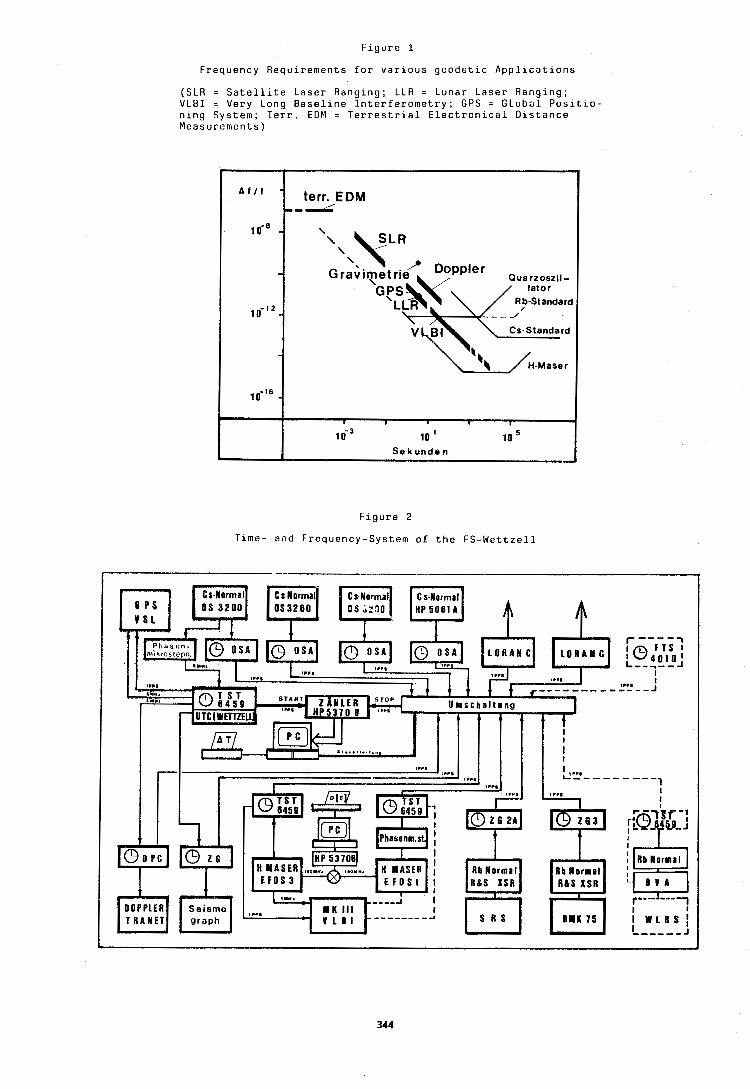
Figure 1
Frequency R e q u i r e m e n t s for v a r i o u s geodetic Applications
(SLR = Satellite Laser R a n g i n g ; LLR = Lunar Laser R a n g i n g ; VLBI = Very Long Baseline I n t e r f e r o m e t r y ; G P S = G L o b a l P o s l t l o - ning S y s t e m ; Terr. EDM = T e r r e s t r i a l Electronlcal D i s t a n c e M e a s u r e m e n t s )
Figure 2
Time- a n d Frequency-System o f t h e FS-Wettzell
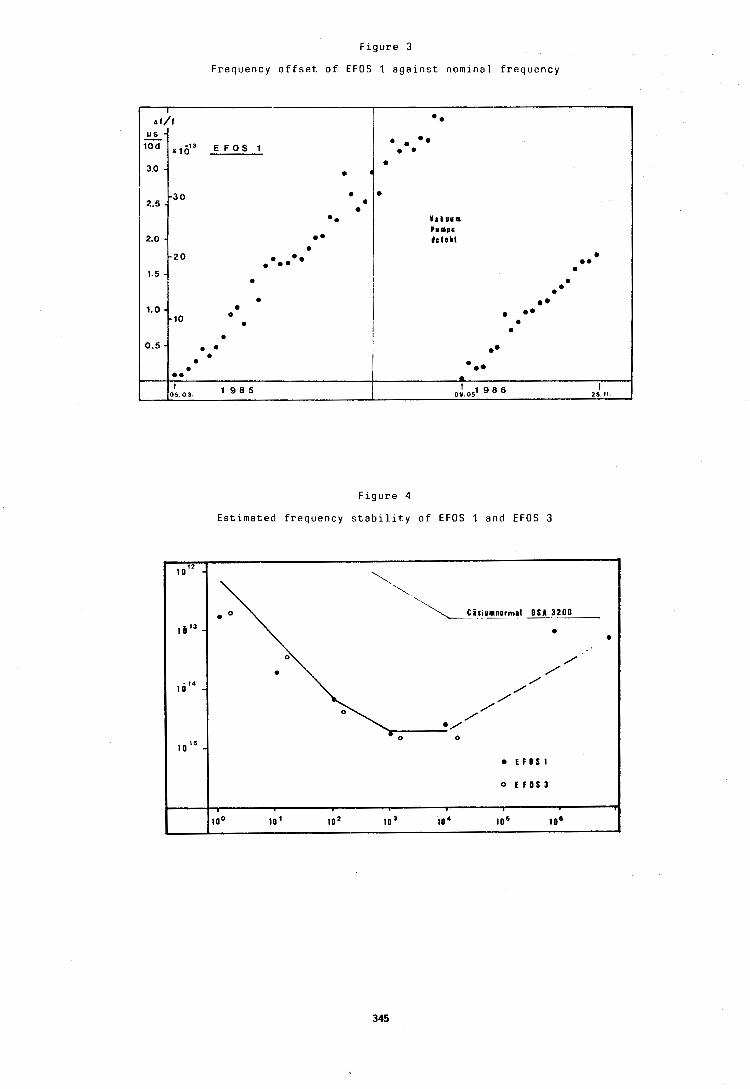
F r e q u e n c y o f f s e t o f EFOS 1 a g a i n s t n o m i n a l f r e q u e n c y
F i g u r e 4
E s t i m a t e d f r e q u e n c y s t a b i l i t y o f EFOS 1 and EFOS 3
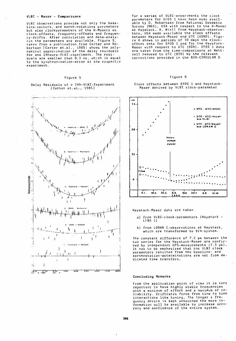
VLBI - Maser - Comparisons
VLBI observations provide not only the base- line-vectors, and earth-rotations parameters but also clockparameters of the H-Masers as clock-offsets, frequency-offsets and frequen- cy-drifts. After correlation and data-analy- sls the parameters are available. Figure 5 , taken from a publication from Carter and Ro- bertson [Carter et.al., 19851 shows the poly- nominal approximation of the delay residuals for one 24hours-VLBI-experiment. The resi- duals are smaller than 0.3 ns, which is equal to the synchronization-error of the respectiv ex~eriment.
Figure 5
Delay Residuals of a 24h-VLBI-Experiment [Carter et.al., 19851
For a series of VLBI-experiments the clock parameters for EFOS 1 have been made avail- able by D . Robertson from National Geodetic Survey (NGS), USA with respect to the H-Maser at Haystack. A. Niell from Haystack-observa- tory, USA made available the clock offsets between Haystack-Maser and UTC (USNO). Figu- re 6 shows in periods of 10 days the clock- offset data for EFOS 1 and for the Haystack- Maser with respect to UTC (BIH). EFOS 1 data are taken from the time-comparisons at Wett- zell reduced to UTC (BIH) by the relevant corrections provided in the BIH-CIRCULAR D.
Figure 6
Clock offsets between EFOS 1 and Haystack- Maser derived by VLBI clock-parameter
Haystack-Maser data are taken
a) from VLBI-clock-parameters (Haystack - EFOS 1)
b) from LORAN C-observations at Haystack, which are transformed to BIH-system.
The constant difference of 7.2 ps between the two series for the Haystack-Maser are confir- med by independant GPS-measurements (7.3 ps). It has to be emphasized that the VLBI clock parameters resulted from the baseline- and earthrotation-determinations are not from de- dicated time transfers.
Concluding Remarks
From the application point of view it is very important to have highly stable frequencies with a minimum of effort and a maximum of re- liability. Driftrates force from time to time interactions like tuning. The longer a fre- quency device is kept untouched the more in- formation will be available to increase accu- racy and confidence of the entire system.
R e f e r e n c e s
NASA Space S c i e n c e and A p p l i - c a t i o n N o t i c e , C r u s t a l Dynamics R e s e a r c h , Wa- s h i n g t o n , USA, 1985
R e i n h a r t E. e t . a l . : The WEGENER M e d i t e r r a n e a n L a s e r T r a c k i n g P r o j e c t WEGNER-MEOLAS, CSTG - B u l l e t i n , 1985
Busca G . e t . a l . : P r e l i m i n a r y Measurements on EFOS 1 H-Mase r , P r o c . o f t h e 3 6 t h a n n u a l Sympo- s i u m on F r e o u e n c v Con- t r o l , ~ h i l a d e l ~ h i a , USA, 1982
S c h l u t e r W . e t . a l . : F i r s t E x p e r i e n c e s w i t h t h e H-Maser EFOS 1, P r o c . o f t h e 1 4 t h a n n u a l P r e - c i s e Time and T i m e i n t e r - v a l ( P T T I ) A p p l i c a t i o n s and P l a n n i n g M e e t i n g , G r e e n b e l t , USA, 1982
W a r d r i p C . e t . a l . : An I n t e r n a t i o n a l Time T r a n s f e r E x p e r i m e n t v i a t h e G l o b a l P o s i t i o n i n g System, P r o c . o f t h e 3 7 t h A n n u a l Symposium on F r e - quency C o n t r o l , P h i l a - d e l p h i a , USA, 1983
C a r t e r W.E. e t . a l . : G e o d e t i c R a d i o I n t e r f e r o - m e t r i c S u r v e y i n g : A p p l i - c a t i o n s and R e s u l t s , J o u r n a l o f G e o p h y s i c a l R e s e a r c h , V o l . 9 0 , No.B6, 1985
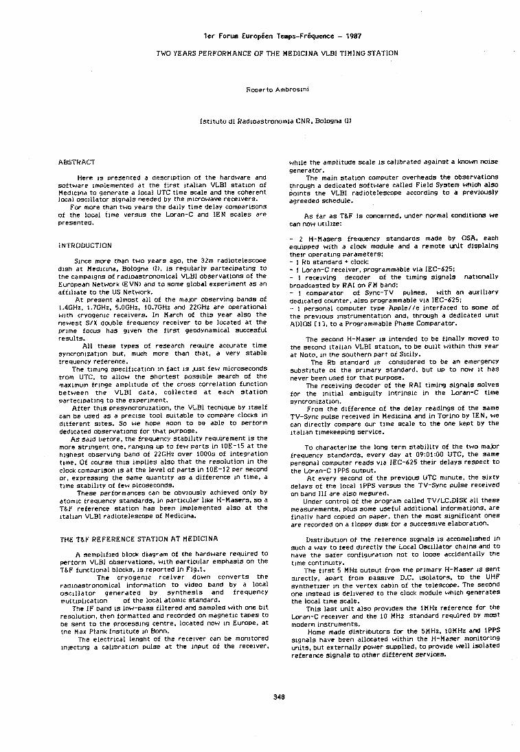
l e r Forum Europien Temps-Frgquence - 1987
TWO YEARS PERFORMANCE OF THE MEDlCINA VLBI TIMING STATION
Roberto Ambroslnl
Here 1.3 presented a descrlptlon of the hardware and sottware lm~lemented a t the f ~ r s t talla an VLBI stat lon of Medrclna t o generate a local UTC tlme scale and the coherent local osc~ l la tor slgnals needed by the microwave recelvers.
For more than two years the dally tlme delay comparisons
ot the local time versus the Loran-C and IEN scales are presented.
1 NTRODUCTION
Slnce more than two years ago, the 32m radlotelescope dlsh at Medicma, Bologna (I), IS regularly parteclpatlng t o the campalgns of rad~oastronomlcal VLBI observatlons o f the European Network (EVN) and t o some global experiment as an a t t l l la te to the US Network.
A t present almost a l l o f the maJor observing bands of 1.4GHz, 1.7GHz, 5.0GHz. 10.7GHz and 22GHz are operational w ~ t h cryogenlc receivers. I n March of th ls year also the newest S/X double frequency recelver t o be located a t the prlme tocus has g ~ v e n the f l r s t geodynamlcal succesful results.
A l l these types o f research requlre accurate tlme syncronlzatlon but, much more than that, a very stable trequency reference.
The tlmlnq spec~ f l ca t~on I n fact 1s &st few microseconds trom UTC, t o allow the shortest posslble search o f the maxlmum f r ~ n g e ampl~tude of the cross correlation functlon between the VLBI data, col lected a t each s t a t i o n Parteclpatlng to the experlment.
A f te r th ls presyncronlzatlon, the VLBI tecnlque by I t se l f can be used as a preclse tool sultable t o compare clocks I n d ~ t t e r e n t sltes. So we hope soon t o be able t o pertorm dedlcated obse rva t~ons to r tha t purpose.
AS said betore, the frequency s tab l l l t y requirement 1s the more stringent one. ranglng up t o few parts I n 1OE-15 a t the hlghest observlng band of 22GHz over 1000s of Integration time. Of course th ls ~ m p l ~ e s also tha t the resolution I n the clock comparison IS a t the level o f parts I n IOE-12 per second or, expressing the same quantity as a d~fference I n tlme, a tlme s tab l l l t y o t few p~coseconds.
These performances can be obviously achteved only by atomlc frequency standards, I n particular l ~ k e H-Masers, so a TBF reference stat lon has been Implemented also at the ~ t a l ~ a n VLBI radlotelescope of Medlclna.
THE TBF REFERENCE STATION AT MEDICINA
A sempllfled block diagram of the hardware requlred t o pertorm VLBI observations, w ~ t h particular emphasls on the I'BF funct~onal blocks, I s reported In F1g.1.
The cryogenlc rce iver down converts the raa~oastronom~cal lntormatlon t o v~deo band by a local o s c ~ l l a t o r generated by synthes is and frequency mu l t~p l~ca t l on o f the local atomlc standard.
The I F band IS low-pass f ~ l t e r e d and sampled wl th one b l t resolut~on, then formatted and recorded on magnetlc tapes t o be sent t o the processing centre, located now In Europe, a t the Max Plank lns t l tu te I n Bonn.
The electrical lenght of the recelver can be mon~tored lnjectlng a callbratlon pulse a t the input of the recelver.
,onomid CNR, Bologna (1)
whlle the amplitude scale 1s ca l~bra ted against a known noise generator.
The main stat lon computer overheads the observations through a ded~cated software called F ~ e l d System which also points the VLBI radiotelescope according t o a previously agreeded schedule.
As far as TLF i s concerned, under normal conditions we can now utl l lze:
- 2 H-Masers frequency standards made by OSA, each equipped w ~ t h a clock module and a remote un i t d~sp la lng thelr operating parameters: - 1 Rb standard + clock; - 1 Loran-C recelver, programmable vla IEC-625; - 1 recelvlng decoder of the timlng slgnals nationally broadcasted by RAI on FM band: - 1 comparator of Sync-TV pulses, w ~ t h an auxll lary dedlcated counter, also programmable via IEC-625: - 1 personal computer type Apple//e Interfaced t o some of the prevlous lnstrumentatlon and, through a dedicated Unlt ADIOS C13, t o a Programmable Phase Comparator.
The second H-Maser IS Intended t o be t lnal ly moved t o the second I ta l lan VLBl statlon, t o be bu l l t w ~ t h i n t h l s year a t Noto, I n the southern part o t Slclly.
The Rb standard IS considered t o be an emergency substltute of the prlmary standard, but up t o now l t has never been used for that purpose.
The recelvlng decoder o f the RAI tlmlng s~gna l s solves for the l n l t l a l amblgu~ty lntr lnslc I n the Loran-C time syncronlzatlon.
From the dlfference o f the delay readings of the same TV-Sync pulse recelved I n Medicina and I n Torlno by IEN, we can dlrectly compare our time scale t o the one kept by the ~ t a l ~ a n tlmekeeplng servlce.
To characterize the long term s tab l l l t y o f the two major trequency standards, every day a t 09:01:00 UTC, the same personal computer reads via IEC-625 thelr delays respect t o the Loran-C lPPS output.
A t every second of the previous UTC minute, the sixty delays of the local lPPS versus the TV-Sync pulse rece~ved on band I11 are also mesured.
Under control o f the program called TV/LC.DISK a l l these measurements, plus some useful addltlonal lnformatlons, are f lnailv hard copled on paper, then the most slgnlf lcant ones are recorded on a floppy dlsk fo r a successive elaboration.
Dlstr lbut lon of the reference s~gna l s IS accompl~shed I n such a way t o teed dlrectly the Local Oscillator chalns and t o have the sater conf~gurat lon not t o loose accidentallv the tlme continultv.
The t l r s t 5 MHz output from the prlmary H-Maser 1s sent dlrectly, apart from passlve D.C. so la tors, t o the UHF synthetlzer I n the vertex cabln of the telescope. The second one Instead IS delivered t o the clock module whlch generates the local tlme scale.
Thls las t un i t also provldes the 1 MHz reference for the Loran-C recelver and the 10 MHz standard required by most modern Instruments.
Home made distr ibutors fo r the 5MHz. lOMHz and 1PPS slgnals have been allocated w ~ t h i n the H-Maser monltorlng units, but externally power supplied, t o provlde wel l Isolated reference s~gna ls t o other d ~ f f e r e n t services.
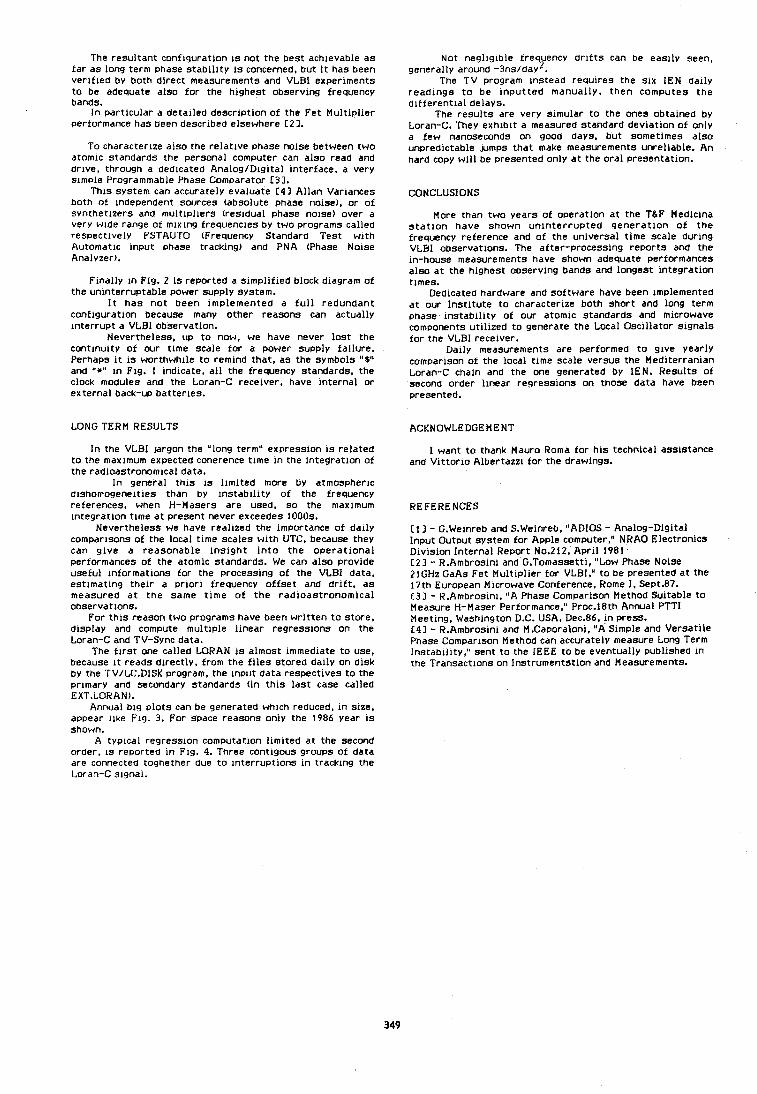
The resultant configuration 1s not the best ach~evable as fa r as long term phase s tab l l l t y IS concerned, but i t has been ver l f led by both direct measurements and VLBI experiments t o be adequate also fo r the highest observing frequency bands.
I n particular a detalled description of the Fet Mult lp l ier pertormance has been described elsewhere C21.
To characterlze also the relat ive phase nolse between two atomlc standards the personal computer can also read and drlve, through a dedicated Ana log /D~g~ ta l interface, a very s l m ~ l e Programmable Phase Comparator C33.
T h ~ s system can accurately evaluate C41 Allan Variances both o t Independent sources (absolute phase nolse), or o f svnthetlzers and m u l t l ~ l l e r s (residual phase nolse) over a very wlde range of mlxlng frequencies by two programs called respectively FSTAUTU (Frequency Standard Test w ~ t h Automat~c Input phase tracking) and PNA (Phase No~se Analyzer).
F ~ n a l l y I n Fig. 2 1s reported a s~mp l i f i ed block diagram of the unlnterruptable power supply system.
I t has no t been ~mplemented a f u l l redundant conf lgurat~on because many other reasons can actually interrupt a VLBI observation.
Nevertheless, up to now, we have never los t the continuity of our time scale fo r a power supply failure. Perhaps i t 1s worthwhile t o remind that, as the symbols "S" and "*" I n Fig. 1 Indicate, a l l the frequency standards, the clock modules and the Loran-C recelver, have internal or external back-up batteries.
LONG TERM RESULTS
I n the VLBI jargon the "long term" expression 1s related t o the maxlmum expected coherence time I n the Integration o f the radloastronomlcal data.
I n general th ls IS l l rn~ted more by atmospheric d~shomogeneltles than by l n s t a b i l ~ t ~ of the frequency references, when H-Masers are used, so the maxlmum lntegratlon time a t present never exceedes 1000s.
Nevertheless we have reallzed the importance o f dally comparisons of the local tlme scales w i th UTC, because they can give a reasonable l ns lgh t i n t o the o p e r a t ~ o n a l performances o f the atomlc standards. We can also provide useful lnformat~ons for the processing o f the VLBI data, estlmatlng thew a pr lo r l frequency o f fse t and d r i f t , as measured a t the same t lme o f t he radloastronomlcal observations.
For t h l s reason two programs have been wr l t ten t o store, dlsplay and compute mul t~p le h e a r regresslons on the Loran-C and TV-Sync data.
The f l r s t one called LORAN i s almost ~mmedlate t o use, because ~t reads directly, from the f i l es stored dally on disk by the TV/LC.DISK program, the Input data respectives t o the primary and secondary standards (in t h l s las t case called EXT.LORAN).
Annual b ls p lo ts can be generated whlch reduced, i n slze. appear Ilke Fig. 3. For space reasons only the 1986 year 1s Shown.
A typlcal regression computation l lml ted a t the second order. IS reported I n Fig. 4. Three contlgous groups o f data are connected toghether due t o lnterruptlons I n tracklng the Loran-C s~gnal .
Not negllglble trequency drifts can be e a s ~ l y seen. generally around -3ns/day2.
The TV program Instead requires the SIX IEN dally readlngs t o be Input ted manually, then computes the dl f ferent la l delays.
The resul ts are very simular t o the ones obtalned by Loran-C. They exhlbl t a measured standard deviation o f only a few nanoseconds on good days, but sometimes also unpredictable Jumps that make measurements unreliable. An hard copy w ~ l l be presented only a t the oral presentation.
CONCLUSIONS
More than two years o f operation a t the TLF Mediclna s t a t l o n have shown uninterrupted genera t ion o f the frequency reference and o f the universal time scale durlng VLBI oDservatlons. The after-processing reports and the in-house measurements have shown adequate performances also at the hlghest observing bands and longest lntegratlon tlmes.
Dedicated hardware and software have been Implemented a t our lns t l tu te t o characterlze both short and long term phase lnstabl l l ty of our atomlc standards and microwave components u t ~ l ~ z e d t o generate the Local Oscil lator slgnals fo r the VLBI recelver.
Dally measurements are pertormed t o give yearly comparison o t the local tlme scale versus the Med~terranlan Loran-C cham and the one generated by IEN. Results o f second order h e a r regressions on those data have been presented.
ACKNOWLEDGEMENT
1 want t o thank Mauro Roma for h ~ s technical asslstance and Vl t tor to Albertazz~ for the drawings.
REFERENCES
C13 - G.Welnreb and S.Weinreb, "ADIOS - Analog-Digital Input Output system for Apple computer," NRAO Electronics D ~ v i s ~ o n Internal Report No.212, Apr i l 1981 C23 - R.Ambroslni and G.Tomassett1, "Low Phase No~se 21GHz GaAs Fet Mult lp l ier for VLBI," t o be presented a t the 17th European M~crowave Conference, Rome I, Sept.87. C31 - R.Ambrosln1, "A Phase Comparison Method Suitable t o Measure H-Maser Performance," Proc.18th Annual PTTl Meetlng. Washington D.C. USA, Dec.86, i n press. C43 - R.Ambroslni and M.Caporalon~, "A Slmple and Versatl le Phase Compar~son Method can accurately measure Long Term ins tab~ l l ty , " sent t o the IEEE t o be eventually publ~shed I n the Transact~ons on Ins t ruments t~on and Measurements.
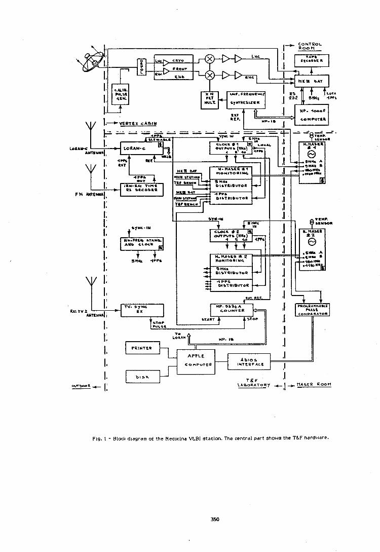
VERTEX C A B I N
TO I: LORAY MP. ID
I I
PPINTEP 11 I 2
APPLE A b l e r ,I
It C o n P u r E P I u T t u F A c E ,I I* D I S K T&F '
,I --a C I:
Fig. 1 - Block d~agram of the Medicina VLBI station. The central part shows the T&F hardware.
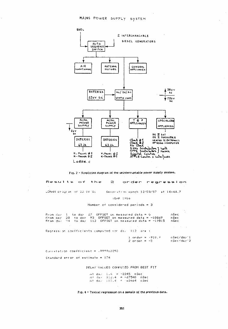
r
GENERAL A P P L I A N C E S
A I f? Cc~DITlcnluG
L-
Fig. 2 - Simplltied diagram of the unlnterruptable power supply System.
R c s u 1 t s u-f t h e 2 o r d e r r e g r e s s i on
~9Fnl.I pr our 9rr1 ( 3 t , 2 11.1 t : G e n ~ r i t I 0or1 epoch 12./03,':?7 a t 1 4 : 4 4 . 7
ANTENNA NOTOPS
Number o f c o n s ~ d e r e d p e r i o d s = 3
Fr on1 d . i , I t o d a y 27 OFFSET or1 m e a ~ l ~ r e d d a t a = Cl nSec From d3.y 28 t o da,,, 7 3 OFFSET on rneas.ur.ed d a t a = -10869 nSec Fr.cm da.,, ' 4 t o d a v 11 2 OFFSET on rnea.s.ured d . a t a = -1'f'F;l 5 nSec
Lor r v l a t i or, toe f f i c I en t = .9P'?9&2253
: S t a n d a r d e r r o r o f e s t ~ r ~ a t e = 174
PELk'r" t.ALI-IES COMPLITED FROPI ElEST F I T
Fig. 4 - Typical regression on a sample of the previous data.
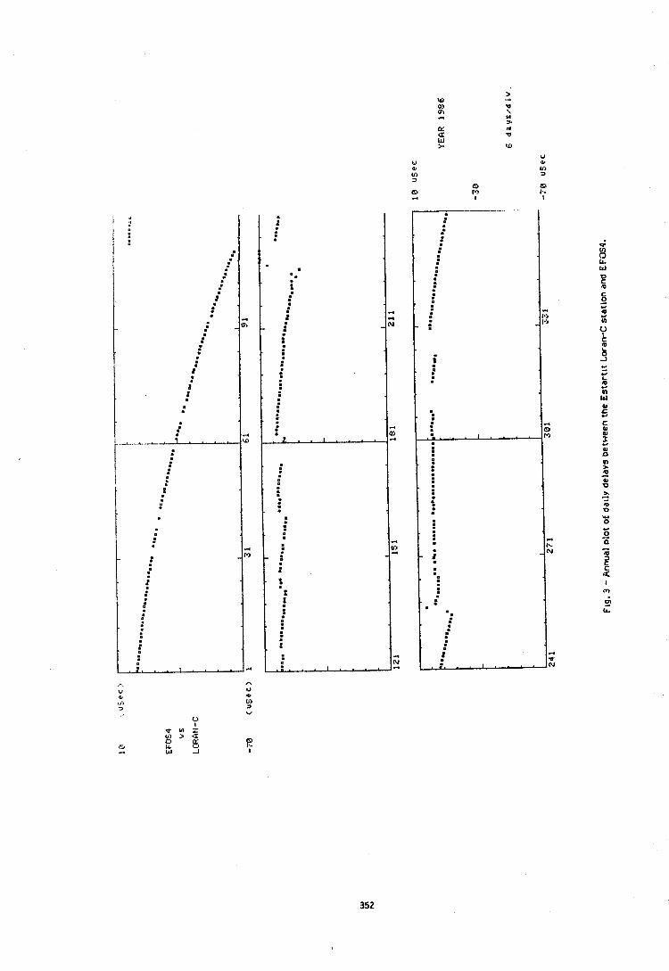
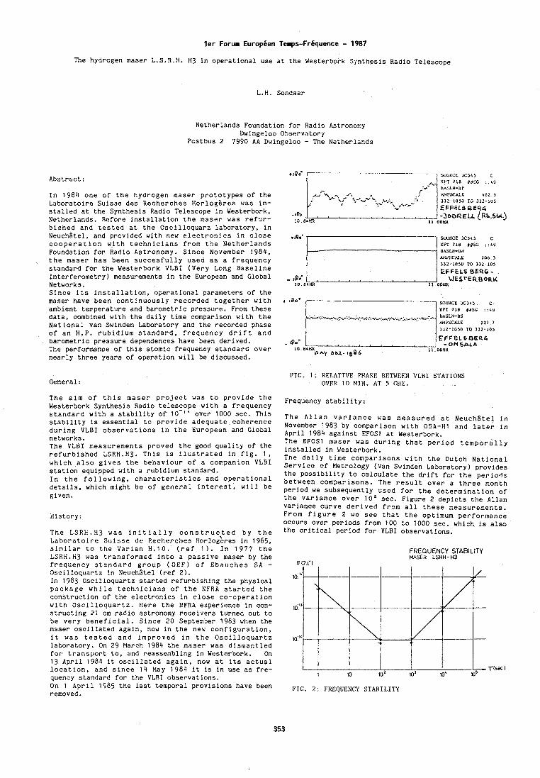
l e r Forum Europben Temps-Frbquence - 1987
The hydrogen maser L.S.R.H. H3 in operational use at the Westerbork Synthesis Radio Telescope
L.H. Sondaar
Netherlands Foundation for Radio Astronomy Dwingeloo Observatory
Postbus 2 7990 AA Dwingeloo - The Netherlands
Abstract:
In 1984 one of the hydrogen maser prototypes of the Laboratoire Suisse des Recherches Horloghres was in- stalled at the Synthesis Radio Telescope in Westerbork, Netherlands. Before installation the maser was refur- bished and tested at the Oscilloquarz laboratory, in Neuchgtel, and provlded with new electronics in close cooperation with technicians from the Netherlands Foundation for Radio Astronomy. Since November 1984, the maser has been succesfully used as a frequency standard for the Westerbork VLBI (Very Long Baseline Interferometry) measurements in the European and Global Networks. Since its installation, operational parameters of the maser have been continuously recorded together with ambient temperature and barometric pressure. From these data, combined with the daily time comparison with the National van Swinden Laboratory and the recorded phase of an H.P. rubidium standard, frequency drift and barometric pressure dependences have been derived. The performance of this atomic frequency standard over nearly three years of operation will be discussed.
General :
+loo' SOUaCE 3C34, C XPT 718 dDSC .:L9 UASLN-UW hn1'SChl.E ?OD 3 332 -1050 TO 332 -10 )
PIG. 1 : RELATIVE PIIASE BETWEEN VI,HI STATIONS OVER 10 M I N . AT 5 CIIZ.
The aim of this maser project was to provide the Frequency stability: Westerbork Synthesis Radio telescope with a frequency standard with a stability of 1 0 - l ~ over 1000 sec. This stability is essential to provide adequate coherence during VLBI observations in the European and Global networks. The VLBI measurements proved the good quality of the refurbished LSRH.H3. This Is ilustrated tn fig. 1, which also gives the behaviour of a companion VLBI station equipped with a rubidium standard. In the following, characteristics and operational details, which might be of general interest, will be given.
History:
The LSRH.H3 was initially constructed by the Laboratoire Suisse de Recherches ~orloeeres in 1965, similar to the Varian H.10. (ref 1 ) . In 1977 the LSRH.H3 was transformed into a passive maser by the frequency standard group (CEF) of Ebauches SA - Oscilloquartz in Neuchltel (ref 2). In 1383 Oscilloquartz started refurbishing the physical package while technicians of the NFRA started the construction of the electronics in close co-operation with Oscilloquartz. Here the NFRA experience in con- structing 21 cm radio astronomy receivers turned out to be very beneficial. Since 20 September 1983 when the maser oscillated again, now in the new configuration, it was tested and improved in the Oscilloquartz laboratory. On 29 March 1984 the maser was dismantled for transport to, and reassembling in Westerbork. On 13 April 1984 it oscillated again, now at its actual location, and since 14 May 1984 it is in use as fre- quency standard for the VLBI observations. On 1 April 1485 the last temporal provisions have been removed.
The Allan varlance was measured at NeuchStel in November 1983 by comparison with OSA-HI and later in April 1984 against EFOSl at Westerbork. The EFOSl maser was during that period temporally installed in Westerbork. The daily time comparisons with the Dutch National Service of Metrology (Van Swinden Laboratory) provides the possibility to calculate the drift for the periods between comparisons. The result over a three month period we subsequently used for the determination of the variance over lo5 sec. Figure 2 depicts the Allan variance curve derived from all these measurements. From figure 2 we see that the optimum performance occurs over periods from 100 to 1000 sec. which is also the critical pcriod for VLBI observations.
FREQUENCY STABILITY MASER LSRH - H3
FIG. 2 : FREQUENCY STARIL-ITY
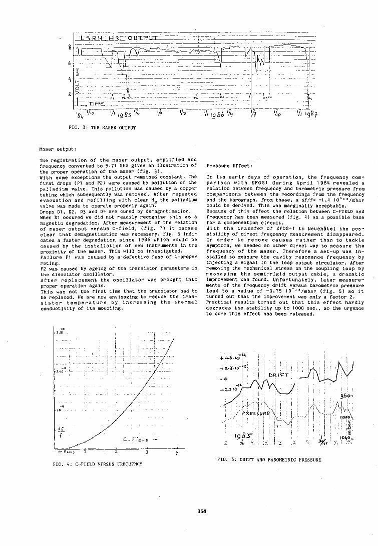
F I G . 3 : THE MASER OUTI'UT
Maser output:
The registration of the maser output, amplified and frequency converted to 5.71 K H z gives an ilustration of the proper operation of the maser (fig. 3). With some exceptions the output remained constant. The first drops (PI and P2) were caused by pollution of the palladium valve. This pollution was caused by a copper tubing which subsequently was removed. After repeated evacuation and refilling with clean H2 the palladium valve was made to operate properly again. Drops Dl, D2, D3 and D4 are cured by demagnetisation. When Dl occured we did not readily recognize this as a magnetic degradation. After measurement of the relation of maser output versus C-field, (fig. 7) it became clear that demagnetisation was necessary. Fig. 3 indi- cates a faster degradation since 1986 which could be caused by the installation of new instruments in the proximity of the maser. This will be investigated. Failure F1 was caused by a defective fuse of improper rating. F2 was caused by ageing of the transistor parameters in the disociator oscillator. After replacement the oscillator was brought into proper operation again. This was not the first time that the transistor had to be replaced. We are now envisaging to reduce the tran- sistor temperature by increasing the thermal conductivity of its mounting.
FIG. 4 : C - F I E L D VERSUS FRESUENCY
Pressure Effect:
In its early days of operation, the frequency com- parison with EFOSl during April 1984 revealed a relation between frequency and barometric pressure from comparisons between the recordings from the frequency and the barograph. From these, a Af/f= -1.4 10-I '/mbar could be derived. This was marginally acceptable. Because of this effect the relation between C-FIELD and frequency has been measured (fig. 4) as a possible base for a compensation circuit. With the transfer of EFOS-1 to NeuchStel the pos- sibility of direct frequency measurement disappeared. In order to remove causes rather than to tackle symptoms, we needed an other direct way to measure the frequency of the maser. Therefore a set-up was in- stalled to measure the cavity resonance frequency by injecting a signal in the loop output circulator. After removing the mechanical stress on the coupling loop by reshaping the semi-rigid output cable, a dramatic improvement was found. Unfortunately, later measure- ments of the frequency drift versus barometric pressure lead to a value of -0,75 10-13/mbar (fig. 5) so it turned out that the improvement was only a factor 2. Practical results turned out that this effect hardly degrades the stability up to 1000 sec., so the urgence to cure this effect has been released.
FIG. 5: D R T F T AND R A R O P E T R I C FRESSLIRE
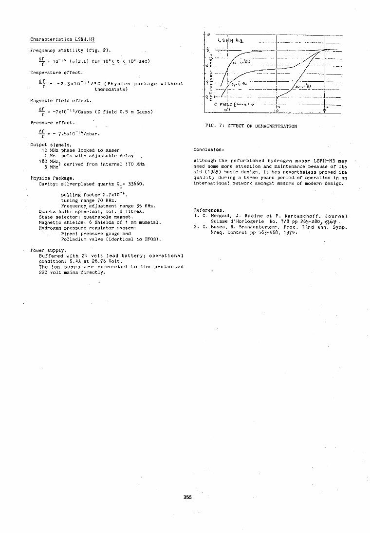
Characteristics LSRH.H3
Frequency stability (fig. 2).
% 1 0 - I * (o(2,t) for 10'1 t ( 10' sec)
Temperature effect.
A f - - - 2 . 3 ~ 1 0 - ' ~ / ~ ~ (Physics package without f thermostats)
Eagnetic field effect
f = -7xl0-"/Gauss (C field 0.5 m Gauss) f
Pressure effect.
bf - - 7.5~10-l4/mbar. f
Output signals. 10 MHz phase locked to maser 1 Hz puls with adjustable delay
l8; 1;:) derived from internal 170 MHz
Physics Package. Cavity: silverplated quartz Q1- 33660.
pulling factor 2.7~10-'. tuning range 70 KHz. Frequency adjustment range 35 KHz.
Quartz bulb: spherical, vol. 2 litres. State selector: quadrapole magnet. Magnetic shields: 6 Shields of 1 mm mumetal. Hydrogen pressure regulator system:
Pirani pressure gauge and Polladium valve (identical to EFOS).
Conclusion:
Although the refurbished hydrogen maser LSRH-H3 may need some more attention and maintenance because of its old (1965) basic design, it has nevertheless proved its quality during a three years period of operation in an international network amongst masers of modern design.
References. 1. C. Menoud, J. Racine et P. Kartdschoff, Journal
Suisse dlHorlogerie No. 7/8 pp 265-280,19bY 2. G. Busca, H. Brandenberger, Proc. 33rd Ann. Symp.
Freq. Control pp 563-568, 1979,
Power supply. Buffered with 24 volt lead battery; operational condition: 5.4A at 26.76 Volt. The ion pumps are connected to the protected 220 volt mains directly.
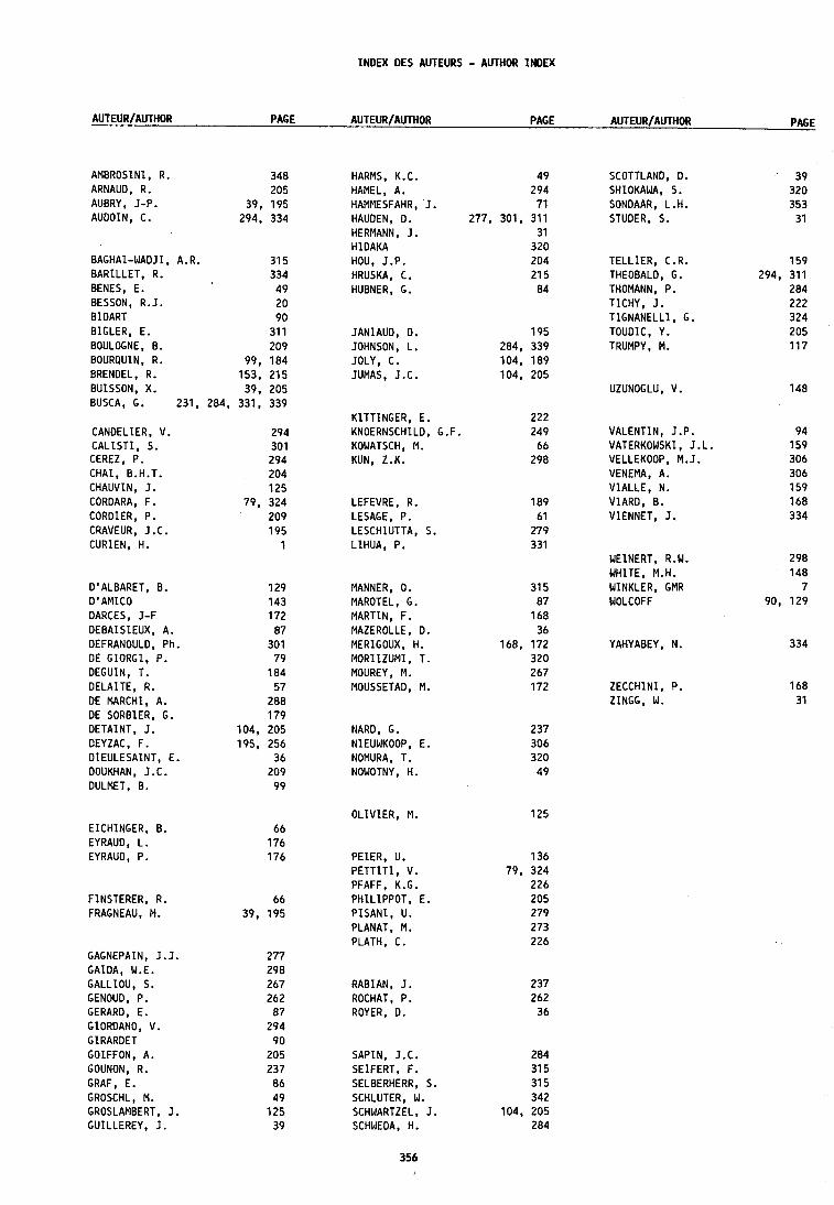
INDEX DES AUTEURS - AUTHOR lNDEX
AUTEUR/AUTHOR PAGE AUTEUR/AUTHOR PAGE AUTEUR/AUTHOR PAGE
AMBROSINI , R. 3 4 8 ARNAUD, R. 2 0 5 AUBRY, J-P. 39, 1 9 5 AUDOIN, C. 294, 3 3 4
HARMS, K.C. 4 9 HAMEL, A. 2 9 4 HAMMESFAHR, J. 7 1 HAUDEN, D. 277, 301, 3 1 1 HERMANN, J. 3 1 HIDAKA 3 2 0 HOU, J.P. 2 0 4 HRUSKA, C. 2 1 5 HUBNER, G. 8 4
SCOTTLAND, D. SHIOKAWA, S. SONDAAR, L.H. STUDER, S.
BAGHAI-WADJI, BARILLET, R. BENES, E. BESSON, R.J. BIDART BIGLER, E. BOULOGNE, 8. BOURQUIN, R. BRENDEL, R. BUISSON, X. BUSCA, G.
A.R. 3 1 5 3 3 4
4 9 2 0 9 0
3 1 1 2 0 9
99 , 1 8 4 1 5 3 , 2 1 5
39, 2 0 5 231, 284, 331 , 3 3 9
TELLIER, C.R. THEOBALD, G. THOMANN, P. TICHY, J. TIGNANELLI , G. TOUDIC, Y. TRUMPY, M.
JANIAUD, D. 1 9 5 JOHNSON, L . 284, 3 3 9 JOLY, C. 104 , 1 8 9 JUMAS, J.C. 104 , 2 0 5
UZUNOGLU, V.
KZTTINGER, E. 2 2 2 KNOERNSCHILD, G .F. 2 4 9 KOWATSCH, M. 6 6 KUN, Z.K. 2 9 8
CANDELIER, V. C A L I S T I , S. CEREZ, P. CHAI, B.H.T. CHAUVIN, J. CORDARA, F . CORDIER, P. CRAVEUR, J.C. CURIEN, H.
VALENTIN, J.P. VATERKOWSKI, J.L. VELLEKOOP, M. J. VENEMA, A. VIALLE, N. VIARD, B. VIENNET, J.
LEFEVRE, R. LESAGE, P. LESCHIUTTA, S. LIHUA, P.
WEINERT, R.W. WHITE, M.H. WINKLER, GMR WOLCOFF
D ' ALBARET, B. D ' AMICO OARCES, J-F DEBAISIEUX, A. DEFRANOULD, Ph. DE GIORGI, P. DEGUIN, T. DELAITE, R. DE MARCHI, A. DE SORBZER, G. DETAINT, J. DEYZAC, F. DIEULESAINT, E. DOUKHAN, J.C. DULMET, 8 .
MANNER, 0. MAROTEL, G. MARTIN, F. MAZEROLLE, D. MERIGOUX, H. MORIIZUMI, T. MOUREY, M. MOUSSETAD, M.
YAHYABEY, N.
ZECCHINI, P. ZINGG, W.
NARD, G. NIEUWKOOP, E. NOMURA, T. NOWOTNY, H.
DLIVIER, M. 1 2 5 EICHINGER, B. EYRAUD, L . EYRAUD, P. PEIER, U. 1 3 6
P E T T I T I , V. 79 , 3 2 4 PFAFF, K.G. 2 2 6 PHILIPPOT, E. 2 0 5 P I S A N I , U. 2 7 9 PLANAT, M. 2 7 3 PLATH, C. 2 2 6
FINSTERER, R. 6 6 FRAGNEAU, M. 39, 1 9 5
GAGNEPAIN, J.J. GAIDA, W.E. GALLIOU, S. GENOUD, P. GERARD, E. GIORDANO, V. GIRARDET GOIFFON, A. GOUNON, R. GRAF, E. GROSCHL, M. GROSLAMBERT, J . GUILLEREY, J .
RABIAN, J. ROCHAT, P . ROYER. D.
SAPIN, J.C. 2 8 4 SEIFERT, F . 3 1 5 SELBERHERR, S. 3 1 5 SCHLUTER, W. 3 4 2 SCHWARTZEL, J. 104, 2 0 5 SCHWEDA, H. 2 8 4
Imprim6 en France
par l l lmprimerie du Conseil G6niral du DOUBS
HGtel du D6partement Avenue de l a Gare d'Eau 25031 - BESANCON CEDEX
Pr inted i n France
by the Pr in t ing Of f ice o f Conseil Gin6ral du DOUBS
HGtel du D6partement Avenue de l a Gare dlEau 25031 - BESANCON CEDEX