
Proceedings - Universität Paderborn
86
Holger Giese, Albert Zündorf (Eds.) Days 2005 15th -18th September 2005 Paderborn, Germany Proceedings
-
Upload
khangminh22 -
Category
Documents
-
view
0 -
download
0
Transcript of Proceedings - Universität Paderborn

Holger Giese, Albert Zündorf (Eds.)
Days 2005
15th -18th September 2005 Paderborn, Germany
Proceedings


Volume Editors Jun.-Prof. Dr. Holger Giese University of Paderborn Department of Computer Science Warburger Straße 100, 33098 Paderborn, Germany [email protected] Prof. Dr. Albert Zündorf University of Kassel Department of Computer Science and Electrical Engineering Wilhelmshöher Allee 73, 34121 Kassel, Germany [email protected]
Program Committee Program Committee Chairs
Holger Giese (University of Paderborn, Germany) Albert Zündorf (University of Kassel, Germany)
Program Commitee Members
Gregor Engels (University of Paderborn, Germany) Pieter van Gorp (University of Antwerp, Belgium) Sabine Glesner (University of Karlsruhe, Germany) Luuk Groenewegen (Leiden University, Netherlands) Reiko Heckel (University of Leicester, UK) Jens Jahnke (University of Victoria, Canada) Mark Minas (University of the Federal Armed Forces, Germany) Manfred Nagl (RWTH Aachen, Germany) Jörg Niere (University of Siegen, Germany) Bernhard Rumpe (TU Braunschweig, Germany) Andy Schürr (TU Darmstadt, Germany) Wilhelm Schäfer (University of Paderborn, Germany) Dániel Varró (Budapest University of Technology and Economics, Hungary) Bernhard Westfechtel (University of Bayreuth, Germany)


Editors’ preface Fujaba is an Open Source UML CASE tool project started at the software engineering group of Paderborn University in 1997. It initially combined features of commercial “Executable UML” CASE tools with rule-based visual programming concepts adopted from its ancestor, the graph transformation tool PROGRES. In 2002, Fujaba has been redesigned and became the Fujaba Tool Suite with a plug-in architecture allowing developers to add functionality easily while retaining full control over their contributions. Fujaba followed the model-driven development philosophy right from its beginning in 1997. At the early days, Fujaba had a special focus on code generation from UML diagrams resulting in a visual programming language with a special emphasis on object structure manipulating rules. Today, at least six rather independent tool versions are under development in Paderborn, Kassel, Darmstadt, and Siegen for supporting (1) reengineering, (2) embedded real-time systems, (3) education, (4) specification of distributed control systems, (5) integration with the ECLIPSE platform, and (6) MOF-based integration of system (re-)engineering tools. Quite a number of research groups have also chosen Fujaba as a platform for UML and MDA related research activities. In addition, quite a number of Fujaba users send us requests for more functionality and extensions. This 3rd International Fujaba Days aims at bringing together Fujaba developers and Fujaba users from all over the world to present their ideas and projects and to discuss them with each other and with the Fujaba core development team. Thanks to the EU research project SEGRAVIS we were able to invite Jean Bezivin to give a keynote talk on ModelWare for the Fujaba Days. Within the technical program of the main workshop, we will have 10 papers addressing meta-modeling, reverse engineering, formal methods, and code generation and real-time systems. An additional demo session and two panel sessions will complete the program. The abstracts of the invited talk plus an overview paper about the development efforts at the main Fujaba locations Paderborn, Kassel, Darmstadt, Siegen, and Bayreuth, 5 position papers presenting innovative ways of using or extending Fujaba of about 8 pages, and 4 reports of new features or projects extending Fujaba of about 4 pages are compiled in the form of a technical report. The structure of the report reflects the organization of the related presentations in sessions at the workshop. There will be one session on model-driven development, one session on reverse engineering, one session on formal methods, one session on code generation as well as one session dealing with real-time systems. We hope that this compilation of the keynote abstract, the overview paper, the position papers, and the reports of the Fujaba workshop presentations provides a useful insight into the ongoing activities in the Fujaba project and provides the needed background information and motivation for joining the Fujaba development team. The Fujaba Developer Days after the main workshop further enable active Fujaba developers to meet each other and to spend two days together to share their experiences, to work on Fujaba extensions, etc. Within the Fujaba Developer Days, a number of tutorials about Fujaba 4 Eclipse, the new code generation mechanism, changes due to the upcoming Fujaba 5.0 release, and the Support for different meta-models will be held. Holger Giese & Albert Zündorf Program Committee Chairs

Table of Contents The Fujaba Tool Suite 2005: An Overview About the Development Efforts in Paderborn, Kassel, Darmstadt, Siegen and Bayreuth..............................................................................1
Keynote Talk Model Driven Development..................................................................................................15
Jean Bezivin (Université de Nantes)
Model-Driven Development SPin – A Fujaba Plugin for Architecture Stratification.................................................. 17
Felix Klar, Thomas Kühne, Martin Girschick (TU Darmstadt) Graph Transformations with MOF 2.0 .................................................................. 25
Carsten Amelunxen, Tobias Rötschke, Andy Schürr. (TU Darmstadt)
Reverse Engineering Detection of Incomplete Patterns Using FUJABA Principles ........................................ 33
Sven Wenzel (Tampere University of Technology, University of Dortmund) Calculation and Visualization of Software Product Metrics .......................................... 41
Matthias Meyer (University of Paderborn), Jörg Niere (University of Siegen)
Formal Methods A Plugin for Checking Inductive Invariants when Modeling with Class Diagrams and Story Patterns .................................................................................................. 45
Basil Becker, Holger Giese, Daniela Schilling (University of Paderborn) Formal Verification of Java Code Generation from UML Models .................................. 49
Jan Olaf Blech, Sabine Glesner, Johannes Leitner (University of Karlsruhe)
Code Generation Generation of Type Safe Association Implementations ............................................... 57
Dietrich Travkin, Matthias Meyer (University of Paderborn) Template- and modelbased code generation for MDA-Tools ....................................... 63
Leif Geiger, Christian Schneider, Carsten Reckord (University of Kassel)
Real-Time Systems The SceBaSy PlugIn for the Scenario-Based Synthesis of Real-Time Coordination Patterns for Mechatronic UML .................................................................................. 67
Holger Giese, Sergej Tissen (University of Paderborn) Worst-Case Execution Times Optimization of Story Patterns for Hard Real-Time Systems ................................................................................................................. 71
Sven Burmester, Holger Giese, Andreas Seibel, Matthias Tichy (University of Paderborn)

The Fujaba Tool Suite 2005:An Overview About the Development Efforts in
Paderborn, Kassel, Darmstadt, Siegen, and Bayreuth
The Fujaba Developer Teams fromPaderborn, Kassel, Darmstadt, Siegen, and Bayreuth
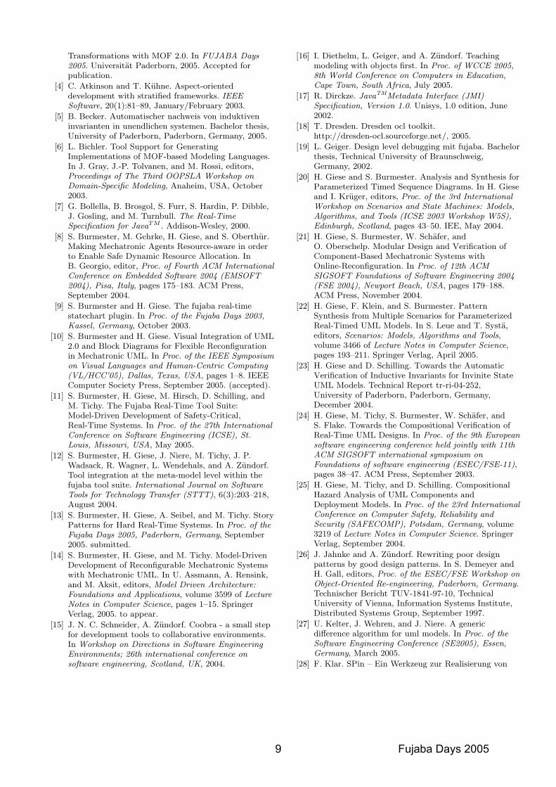
ABSTRACTThis paper provides an overview about the Fujaba ToolSuite and its independent tool versions developed and main-tained in Paderborn, Kassel, Darmstadt, and Siegen includ-ing future plans for tool development in Bayreuth. Start-ing with the architecture and roadmap for the Fujaba core,we report about the different directions of development(e.g. meta-modeling, realtime systems, and re-engineering)and also provide an outlook on planned future work for eachdirection. In addition, references which provide more de-tailed information for the different directions are providedand a comprehensive list of the plug-ins which are avail-able or currently under development by Paderborn, Kassel,Darmstadt, or Siegen is included.
KeywordsFujaba, UML, MOF, JMI, Reverse Engineering, Design Pat-tern, Anti Pattern, Metrics, Model-Driven Development,Code Generation, Story Pattern, Graph Transformations,Triple Graph Grammars, Tool Integration, Versioning, Real-Time, Mechatronic, Modelchecking, Scenarios, Teaching,Eclipse, Metamodeling
1. INTRODUCTIONFujaba is an Open Source UML CASE tool project started
by the software engineering group of Paderborn Universityin 19971. In 2002, Fujaba has been redesigned and becamethe Fujaba Tool Suite with a plug-in architecture allowingdevelopers to add functionality easily while retaining fullcontrol over their contributions.
Fujaba followed the model driven development philosophyright from its beginning in 1997. At the early days, Fujabahad a special focus on code generation from UML diagramsresulting in a visual programming language with a specialemphasis on object structure manipulating rules.
Today, at least six rather independent tool suites areunder development in Paderborn, Kassel, Darmstadt, andSiegen for supporting (1) re-engineering, (2) real-timeand mechatronic systems, (3) education, (4) specificationof distributed control systems, (5) integration with theECLIPSE platform, and (6) MOF-based integration of sys-tem (re)engineering tools.
The paper is organized as follows. In the next section,we report about architectural improvements concerning the
1Fujaba is a successor of the not UML-compatible CASEtool PROGRES whose development has been started around1986.
Fujaba kernel and about the Eclipse integration efforts aswell as approaches concerning model versioning. In Sec-tion 3, we present our approaches concerning model-drivendevelopment. This includes work on support for MOF 2.0meta-models as well as various applications of triple graphgrammars for e.g. tool integration and (meta-)model trans-formations. We show in Section 4 ongoing research concern-ing reverse engineering of software systems, in particulardesign pattern and anti pattern recognition. Section 5 con-tains a presentation of the various approaches concerningmodel driven development of dependable, embedded, real-time systems. In Section 6, we present work on teachingobject-oriented concepts using Fujaba as well as work on aFujaba supported software development process. We con-clude the paper with an overview about possible new re-search areas for Fujaba. [hg,mtt]
2. MODEL MANAGEMENT - ARCHITEC-TURE AND ALGORITHMS
In this section, we report about the current state of the Fu-jaba kernel as well as the current state of the Fujaba Eclipseintegration efforts. This section includes reports about ver-sioning in Fujaba and work on computing differences be-tween models.
2.1 KernelThe Fujaba Tool Suite has been well proven in various
projects in the last eight years since its beginning. Espe-cially, the changeover from Fujaba 3 to the Fujaba ToolSuite 4 with its ability to add plug-ins had opened ourproject to a wider developer community beyond the Univer-sity of Paderborn. However, the Fujaba Tool Suite hasstill limitations that impede further development.
Fujaba can only handle one project at a time. Thisprevents the possibility to define dependencies betweenprojects. Projects must always be consistent in itself. Fu-ture versions of the Fujaba Tool Suite will be able tohandle more than one project with project dependencies.
Fujaba is particularly well known for its Story DrivenModeling (SDM). However, SDM is restricted to the UMLclass meta model. There are new approaches using the Meta-Object Facility (MOF) for class models. To support suchapproaches, an interface for class meta models and SDM isintroduced so that the meta models can be changed [46].Further enhancements of the meta model and the user in-terface are under work.
All these enhancements will result in the Fujaba ToolSuite 5 which are in turn only a preparation for the most
1 Fujaba Days 2005
important enhancement. The Fujaba Tool Suite will bemigrated to the widely used IDE Eclipse. [lw,tr]
2.2 Fujaba4EclipseIn 2004, we received an IBM Eclipse Innovation Grant for
porting a core part of the Fujaba Tool Suite to an Eclipseplug-in [35]. Today, the third release of Fujaba for Eclipseis available for download at the Fujaba web site. So far,the plug-in supports modeling of class and story diagrams,from which Java code can be generated.
The Fujaba4Eclipse plug-in reuses major parts of Fujaba.The display and editing of diagrams has been reimplementedusing the well-documented Eclipse and GEF frameworks.First tests show that especially the display of large classdiagrams is much faster than in Fujaba.
Fujaba4Eclipse already provides several extension pointswhich enable the contribution of new diagrams or diagramelements as well as loading and saving of model elementsprovided by other Eclipse plug-ins. More extension pointswill follow. Several Fujaba reverse engineering plug-inshave already been ported successfully to Eclipse. The ex-perience shows that the effort required is not too high sincemany parts of Fujaba4Eclipse, e.g. figures for displayingUML elements, can easily be reused. The MyPlugin exam-ple plug-in for Eclipse will soon be available as well, so startcontributing! [mm,lw]
2.3 Persistency [KS]The old storing mechanism of Fujaba (FPR) accompa-
nied the Tool right from the first development stages. Butas Fujaba evolved, more and larger projects were started,using Fujaba. Thus a single-user environment is not suitedfor these projects any more. Previous attempts to add aversioning facility to Fujaba [45] did not succeed.
CoObRA is a framework, developed at the University ofKassel, that offers undo/redo, persistency and version con-trol techniques [15]. It records changes to the object struc-ture of an application to facilitate all these features. Themajor advantage is that it provides an easy-to-use mech-anism requiring very low integration costs. CoObRA wassuccessfully integrated into the model of the Fujaba ToolSuite.
This results in a major feature for Fujaba: Projects can bestored in local files and in server side repositories to sharethem among developers, both with the same API. Addi-tionally full undo and redo support was added to Fujaba.For applications developed with Fujaba the CoObRA plug-in also extends the Fujaba code generation facilities to offerCoObRAs features to applications generated with Fujaba.
CoObRA2, which is integrated into Fujaba5, already pro-vides all the features from CoObRA and was optimizedconcerning design and processing speed. Planned featuresinclude hierarchical and cascaded repositories to supportworking in groups at different development sites. Also, itis future work to use CoObRA2 with CVS servers, to con-currently work on e.g. Fujaba project files and additionalresources like documentation and images within the sameCVS repository.
To continue the work on Fujaba’s scalability for largeprojects, we want to introduce a generic loading on demandstrategy. Models could be partially loaded when requiredand unloaded to free memory without harming proper op-eration. This would tackle the memory problems with large
Fujaba specifications, which are quite some obstacle at thistime. [cs]
2.4 Differences of ModelsIn general, software should be developed in teams. In or-
der to support cooperative team work a version managementsystem which supports UML models is absolutely necessary.It is not always possible to record changes to a model asdone in the CoObRA approach, depicted above. Thus theessential part of such systems is the ability to calculate dif-ferences, present them to the developer and to provide mergeoperations to come to a consistent model. In our approachwe use unified diagrams with difference information to bepresented to the developer.
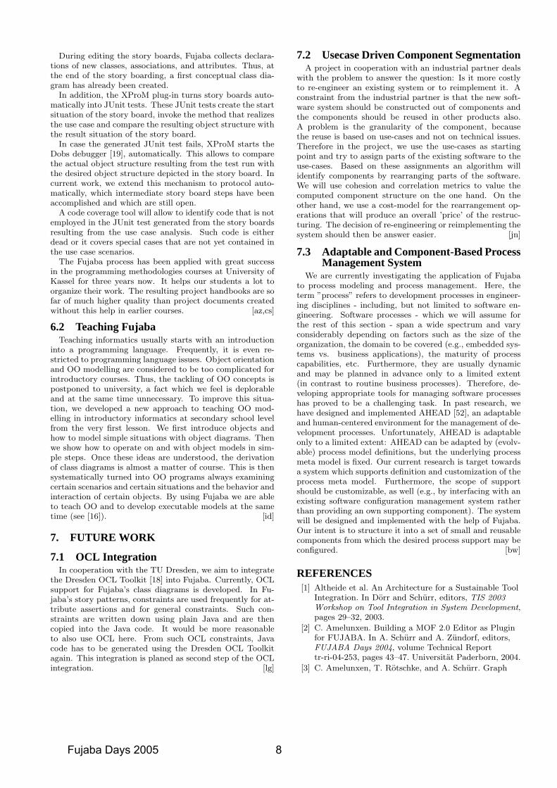
The current algorithm calculates differences of two mod-els given as XMI files. The output is also an XMI file; itcontains the unified model of the two original models withadditional difference information added by the XMI exten-sion mechanism. The difference algorithm does not rely onpersistent unique identifiers and the calculation itself is con-figurable to capture the semantics of an actual model or partof the model in the algorithm. The algorithm is designed tosupport flat diagrams, where a recursive nesting of diagramelements is forbidden, e.g. UML class diagrams or sequencediagrams. The configuration of the algorithm for UML classdiagrams works well and is part of the plug-in distribution.Currently the algorithm is enhanced to support hierarchicaldiagrams such as UML package diagrams, state-charts orMatlab/Simulink models. For more details see [27].
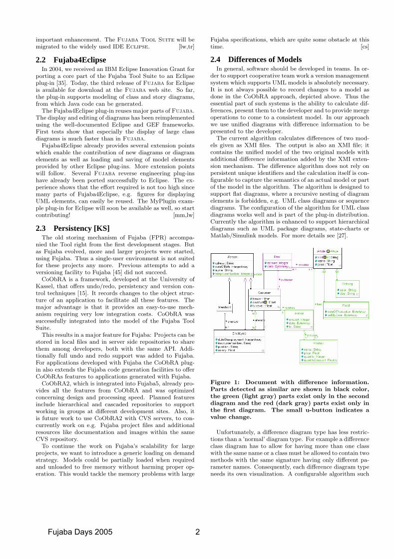
Figure 1: Document with difference information.Parts detected as similar are shown in black color,the green (light gray) parts exist only in the seconddiagram and the red (dark gray) parts exist only inthe first diagram. The small u-button indicates avalue change.
Unfortunately, a difference diagram type has less restric-tions than a ’normal’ diagram type. For example a differenceclass diagram has to allow for having more than one classwith the same name or a class must be allowed to contain twomethods with the same signature having only different pa-rameter names. Consequently, each difference diagram typeneeds its own visualization. A configurable algorithm such
Fujaba Days 2005 2
as the calculation algorithm is not feasible. We have devel-oped a cook book which describes how a diagram type im-plementation can be transformed in an implementation forthe corresponding difference diagram type step by step. Fu-jaba currently supports the visualization of difference classdiagrams only, cf. Figure 1. For more details see [37, 41].[jn]
3. MODEL- AND META-MODEL-DRIVENSOFTWARE DEVELOPMENT
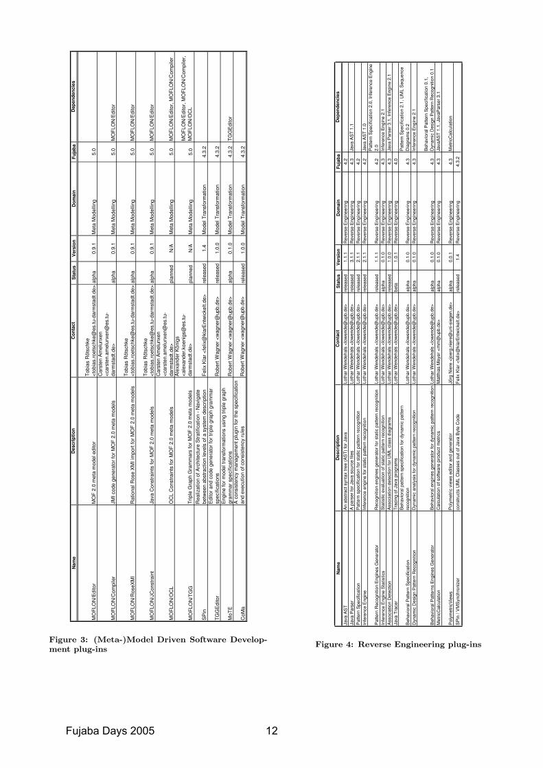
Originally, Fujaba has been developed to support model-driven software development activities by offering its usersan executable subset of UML 1.x with a precise semanticsdefinition based on graph transformations. Despite of thefact that Fujaba has been used from the very beginning formeta modeling and bootstrapping activities, the tool’s mainfocus was and still is the rule-based development of ordi-nary Java applications with complex data structures. OMG-compliant meta modeling activities and the definition ofmodel-to-model transformations were out-of-scope. Nowa-days this situation is rapidly changing with the developmentof a number meta modeling and model-transformation plug-ins, which are the main topic of this section.
These plug-ins support meta modeling activities based onMOF 2.0, rule-based definition of ”local” model transfor-mations (working on a single model on the same abstractionlevel) as well as the specification of step-wise model refine-ment processes and the translation between models belong-ing to different meta models. These plug-ins developed atdifferent Universities, are described in the following subsec-tions. [as]
3.1 Meta Modeling with MOF 2.0Meta -modeling languages are used to describe other mod-
eling languages. The Object Management Group (OMG)adopted MOF 2.0 [40] as standard meta modeling language.It provides valuable new features for modularization, refine-ment, and reuse of meta models compared to UML 1.x classdiagrams which are currently supported by the Fujaba ker-nel.
Therefore, we developed a meta modeling frameworkcalled MOFLON (www.moflon.org). The framework isbased on MOF 2.0 and realized as a new Fujaba plug-in[2] (replacing the Fujaba UML 1.4 compatible class diagrameditor). MOF 2.0 simplifies modularization and reuse ofmeta models by offering a sophisticated package concept aswell as powerful means for refinement of attribute types andassociations. Packages act as namespaces and can be refinedand reused using package merges. This concept is more so-phisticated than Fujaba’s current package concept.
Further major features of MOF 2.0 compared to FujabaUML class diagrams are the relations between associationends. In MOF 2.0 association ends can be redefinitions,subsets or unions of other association ends. Those relationssimplify the challenging task to structure, reuse, and refinehuge meta models. Beside the new features, the editor offersan XMI import which permits the exchange of models withRational Rose and other XMI-standard-compliant commer-cial UML CASE tools. [ca,tr]
3.2 Meta Model Transformation with StoryDiagrams
Choosing MOF 2.0 as modeling (graph schema definition)language has some implications for Fujaba graph transfor-mations as discussed in [3]. Model/graph transformationsdefined by means of story diagrams, are no longer manipu-lating simple directed, node- and edge-labeled graphs withattributed nodes, but have to be adapted to the much morecomplicated data model imposed by MOF 2.0. This adap-tion involves some modifications of different parts of Fujaba.On the one hand, packages offer now much more sophisti-cated means to structure, reuse, and refine model fragmentsand to define namespaces for classes and other model el-ements; they are intended to replace Fujaba’s simple viewdiagram concept. On the other hand some effort has be doneto integrate the improved association concept that is intro-duced by MOF 2.0 as well as UML 2.0 into Fujaba graphtransformations, i.e. to modify its underlying class of graphsappropriately.
In MOF 2.0, set-valued association ends are not neces-sarily unique. As already indicated in [53], the introduc-tion of non-unique association ends requires modificationsof the graph model, because story diagrams have to dealwith multiple links of the same type between identical ob-jects. Besides, relationships between association ends can bedefined that result in automatic link-creation (subsets) or re-strict possible end types for given associations(redefinition).While automated link-creation is transparently performedby the MOFLON plug-ins [2], some modifications are neces-sary in the Fujaba core to support the remaining new MOF2.0 concepts: Unions of association ends make associationsvirtually abstract, so links of that type may be queried, butnot created, modified or deleted by story diagrams. Theserestrictions should be checked statical during the creation ofstory diagrams. Other new features like redefinition of asso-ciation ends demand additional runtime analysis activities.[ca,tr]
3.3 MDD and Stratified Graph Transforma-tions
Complex software systems call for ways to obtain sim-plified views onto them, otherwise important architecturalstructures will be buried in overwhelming details. However,resolving certain issues often requires the manipulation ofmore detailed architecture without destroying the consis-tency between these more detailed models and their abstrac-tions. Architecture Stratification [4] addresses the need toprovide a multitude of views on models ranging from veryconcrete to very abstract so that a large number of stake-holders may view the system (model) with a level of abstrac-tion that is best for their particular interests and require-ments. In contrast to a layer, as in the ISO/OSI networkmodel, each level fully describes the whole system, albeitusing varying conciseness.
The SPin plug-in [28] extends Fujaba with facilities to an-notate very abstract models so that they can be successivelytransformed into more concrete versions in accordance withOMG’s MDA approach. SPin comes with a dynamically ex-tendable library of refinement transformations. Thus, SPinprovides basic support for architecture stratification. Cur-rently, refinement transformations are realized as straight-forward Fujaba graph transformations. Future work willinvestigate the use of triple graph grammars (TGGs) forthe same and more advanced purposes including round-tripengineering. [fk,tk]
3 Fujaba Days 2005
3.4 Model Transformation using TGGsThe advent of OMG’s new silver-bullet of the model-
driven architecture (MDA) [42] has put model transforma-tions into focus. A practicable model transformation tech-nique should allow a visual specification of the transforma-tion with an underlying formal foundation and is expectedboth to be applicable in different stages of the developmentprocess and in both directions. The transformation processitself should be executable in a batch-oriented and incre-mental way. Additionally, the technology should allow syn-chronizing models that belong to different meta models andkeeping them consistent.
Due to these requirements, we are using the visual, formal,and bidirectional transformation technique of triple graphgrammars (TGGs) [48]. A triple graph grammar specifica-tion is a declarative definition of a bidirectional model trans-formation. The mapping between two models is achieved byan additional correspondence model. It enables a clear dis-tinction between the source and the target and holds addi-tional traceability information [12]. This extra informationis needed to preserve the consistency between both models.
A recently developed Fujaba plug-in offers the requiredtool support for model transformations with triple graphgrammars. Its main component is an editor for the declar-ative specification of triple graph grammar rules. Fromthis specification we derive implementations of executableconsistency-checking or establishing rules automatically.The rules are executed using the standard Fujaba modeltransformation engine. This engine is currently extendedtowards incremental model transformations. Additionally,we have developed a concept which allows us to transformFujaba incompliant models. Based on this concept, we havedeveloped a code generator with round-trip engineering ca-pabilities. The generator transforms class diagrams repre-sented in Fujaba to Eclipse’s Java abstract syntax tree andvice versa. This case study is a first step towards modelround-trip engineering and code generation realizing the vi-sion of MDA. [rw]
3.5 Tool Integration with TGGsAs mentioned in the previous subsection, triple graph
grammars provide powerful means to integrate models be-longing to different meta models. In contrast to the activi-ties discussed above, where Java tools with open interfacesare integrated for round-trip engineering purposes, the mainfocus of the work described here is laid on consistency check-ing and update propagation between models manipulated bycommercial-off-the-shelf modeling tools. These tools are nei-ther written in Java nor do they usually offer appropriateinterfaces for model manipulation purposes. Furthermore,automatic round-trip engineering is usually unfeasible andthe main emphasis has to be laid on consistency checkingand traceability link creation activities. In addition, adher-ence to standards is a must which are or will hopefully bein the future supported by the regarded CASE tools.
Therefore, we are developing a variant of TGGs whichfinally generates Java code for MOF/JMI-compliant toolinterfaces. Furthermore, we take OMG’s MOF 2.0 Query/ Views / Transformations Request for Proposals (QVT)[43] and the most promising submission from the QVT-partners [44] into account. Our solution is based on thetool integration framework Toolnet from Daimler Chrysler[1]. This framework offers interfaces for uniformly access-
ing tools’ data by means of so called tool adapters basedon Java Metadata Interfaces (JMI) [36]. Finally, the frame-work provides the infrastructure for inter-tool communica-tion. We are currently busy to extend Toolnet by (semi-)automatic tool integration mechanisms (e.g. consistencychecking, attribute change propagation, model transforma-tion). In this scenario, Fujaba is used to draw declarativetriple graph grammars, (semi-)automatically derive opera-tional graph rewriting rules for the different tool integra-tion use cases, and generate JMI-compliant Java code fromthem. In the future, we plan to extend the formalism oftriple graph grammars to multi graph grammars. Withmulti graph grammars, we will be able to cope with an ar-bitrary number of to be integrated tools instead of pairs oftools only [32]. [ak,as]
3.6 Incremental Model Synchronization usingTGGs
One common problem application programmers in gen-eral and CASE tool developers in particular have to solveis to keep some internal object model and its representationon screen consistent, i. e. have the graphical user interfacealways display what the internal object model looks like.
Although this is not a “hard” problem and everybodyknows how to implement such a synchronization, it is at leastannoying and error prone work that keeps you away fromthe “real” work. Usually observers are registered on bothmodels. They are activated when something changes in onemodel and then update the other model. So for each changeoperation an observer reaction has to be implemented.
In our experience, when implementing observers you usu-ally think in terms of “what happens if attribute x changesits value” or “what happens if object y gets another childobject of type Z”. This is a rather low level operational kindof abstraction close to the implementation of observers. Ahigher level of abstraction is to think in terms of “what-corresponds-to-what-rules” and leave the actual operationsnecessary to perform the synchronization to a tool that doesthe right thing.
We think that triple graph grammars are a good match forthat higher level of abstraction. We think that those rulescan be written down using triple graph grammars, maybewith some extensions added. We plan that this is done insuch a way that either the observer code can be automati-cally generated or that an interpreter executes those rules.This will result in two major improvements compared tomanual implementation. First, you will not have to imple-ment the observers manually any longer. Second, designingand maintaining the synchronization can be done on thehigher level of abstraction described above.
That scheme is not limited to the special problem de-scribed here which represents a part of our motivation. Be-cause we use triple graph grammars it is straightforward toapply that scheme to any two object models. [tm]
3.7 CodeGen2The old code generation concept of Fujaba added an ab-
straction layer that should ease the adaption to new pro-graming languages. But that also makes the maintenance ofthe code generation very complex. In fact, to generate fewline of code one has to write dozens of lines in the code gen-eration. This makes small adaption of the code generationimpossible especially for Fujaba users. The CodeGen2 plug-
Fujaba Days 2005 4
in now replaces the old code generation by a new template-based one. Using templates, it should be possible (even forthe user) to adapt the generated code to ones wishes andto write own templates for new languages or new languageelements.
Additionally, CodeGen2 introduces a layer of so calledtokens on which the templates are applied. On this layeroptimizations can easily be preformed. Several optimiza-tions have already been implemented which results in fasterexecution time of the generated code.
CodeGen2 was completely specified using Fujaba (exceptfor the templates, of course). This way CodeGen2 is thefirst step towards bootstrapping of Fujaba. [cs,lg,cr]
3.8 JMI Code Generation for MOF 2.0One part of the MOFLON framework as described in 3.1 is
a code generator plug-in based on the MOMoC compiler [6]for the generation of MOF 2.0 compliant meta models. Tobe able to work with meta modeled languages, tool providersneed to map meta models on source code. For that purpose,SUN provides the Java Metadata Interface (JMI) [17] whichis a standardized mapping of MOF compliant meta modelsonto Java. As the Java representation of MOF, JMI speci-fies the generation of tailored interfaces for the creation andaccess of meta data as well as a set of reflective interfacesfor a unified discovery of meta data. The standardized in-terfaces facilitate an easy exchange and integration of metamodels which make JMI a very useful standard.
Thus, the MOFLON code generator adheres to the JMIstandard and generates compliant meta model implementa-tions. The XML-based code generation process consists ofthree steps. First of all a modularized preprocessing phaseperforms several kinds of transformations on the meta model(e.g. unfolding of refinement relationships between pack-ages). Afterwards in the second step, the meta model istransformed into a proprietary XML representation whichacts as input for several XSL stylesheets transforming theXML representation during the third and last step into Javacode. The generated meta model implements all JMI in-terfaces and supports the new features of MOF 2.0. Fur-thermore, all changes concerning the instances of the metamodel are propagated by an event mechanism to enable aclean and easy integration. This event mechanism is basedon the event mechanism provided by the NetBeans Meta-data Repository (MDR) [33], a JMI repository which is usedby several tools, to achieve compatibility between MDR andmeta models generated by MOFLON. Future versions of thecode generator will be integrated with an OCL compiler andthe graph transformation of Fujaba (cf. Section 3.2). There-fore, the MOMoC/XSLT-based three-phase code generationapproach has to be integrated with the template-based codegeneration mechanism of CodeGen2 described in the previ-ous subsection. [ca]
4. RE-ENGINEERINGToday, software is seldom developed from scratch. In fact,
developers spend most of their time with the maintenance ofexisting systems, e.g. to meet new requirements or to inte-grate them with other software components. Unfortunately,(design) documentation for such systems or components isoften not available or has become obsolete over time. Thus,before changes can be made, an understanding of the systemhas to be gathered from the available artifacts such as e.g.
the source code.The work presented in the following sections aims to sup-
port this task. The first approach reverse engineers class di-agrams from the byte code of Java class libraries in order tomake them amenable for model based development. The fol-lowing approaches are concerned with the analysis of sourcecode in order to detect or improve design and anti patternimplementations as well as to perform coarse-grained analy-ses to get a first impression of a system. Finally, an approachfor analyzing the evolution of domain-specific software ar-chitectures is presented.
4.1 Java Byte-codeFujaba’s Story Driven Modeling (SDM) is very helpful
for creating method implementations. Especially pattern-matching is well supported by SDM, because of the graphi-cal specification approach. However, to be able to use SDM,a class diagram containing the metamodel of the elementsto be used in SDM must be present in the current Fujabaproject.
If a developer just wants to use his own model elementswhich are defined in his project, this does not represent aproblem. Yet, often developers use elements of other devel-opers. For those elements typically no class diagram exists,but corresponding source code or byte code only. To geta class diagram from these representations one can reverseengineer “by hand” or use a parser in combination with agenerator that produces a class diagram automatically. Aplugin that is able to automate this process for Java sourcecode is the JavaParser plug-in which is part of the FujabaRE Tool Suite.
An alternative way to obtain the desired class diagrams isthe Java Virtual Machine synchronizer (VM-synchronizer)introduced in [28]. It is part of the “SPin” plug-in andsupports synchronization of UML classes with their Javacounterpart by creating class diagrams from Java byte code.[fk]
4.2 Design Pattern RecognitionIn recent years, we have developed a semiautomatic de-
sign pattern recognition on the source code of existing sys-tems [38]. The approach uses a static analysis of the ab-stract syntax graph (ASG) representation of the source code.Patterns are described graphically based on graph grammarrules with respect to the ASG. It is a highly scalable processwhich can be applied to large real world applications withmore than 100.000 LOC. The found design pattern instancesare rated by accuracy values [39].
The static analysis focuses on the structural aspects of apattern. Behavioral aspects of patterns can only be ana-lyzed rudimentary by static analysis. Thus, we are workingon a dynamic analysis that confirms or weakens the pat-tern instances from static analysis [51]. Behavioral patternsbased on sequence diagrams describe the interaction withinpatterns. The dynamic analysis executes the system to beanalyzed and records traces of method calls. These traceswill be compared to the behavioral patterns. [lw]
4.3 Anti Pattern Recognition and Transfor-mation
In contrast to design patterns, anti patterns represent baddesign solutions especially with respect to maintainability.Examples include data classes consisting only of fields and
5 Fujaba Days 2005
almost no behavior, god classes assuming too much respon-sibilities in a (sub-)system, or huge conditionals for handlingrequests or representing different states of an object. Thepresence of anti pattern instances in a system may compli-cate certain maintenance tasks significantly. Thus, we usethe pattern recognition approach introduced in the previ-ous section in combination with software product metrics torecognize anti pattern instances.
An anti pattern can usually be transformed into a bet-ter solution, sometimes based on design patterns. Startingfrom the ideas presented in [26], we are currently workingon support for the improvement of recognized anti patterninstances. We want to provide anti pattern specific refactor-ings of the ASG, which improve the structure of the softwarewhile preserving its behavior. Since not necessarily all foundanti pattern instances need to be improved, the re-engineerdetermines those to be transformed. The transformation it-self, however, we plan to automate as far as possible. [mm]
4.4 MetricsSoftware product metrics are one opportunity to perform
coarse-grained analysis. Metrics such as lines of code, num-ber of attributes or methods of a class, lack of cohesion, ordepth of inheritance hierarchies allow for producing quanti-tative analysis results of a software system. A combinationof different metrics allows to draw conclusions such as prob-lematic or high influencing system parts. To overcome theflood of numbers produced by the metrics, Lanza proposes agraphical representation of metric combinations. So-calledpolymetric views are an ideal means to get a first impressionof a system.
Polymetric views are two-dimensional graphs containingnodes and sometimes edges, which are arranged in a certainlayout. Nodes represent entities of the analyzed softwaresystem and edges represent relationships between the enti-ties. Each node is a rectangle and can carry up to 5 metricvalues depending on the certain layout, whereas edges do notcarry any metric information. A reverse engineer can easilyidentify runaways by looking at the produced pictures andperform further analysis.
Fujaba needs two plug-ins to support the metrics calcu-lation and polymetric views. The first plug-in offers thecalculation of several object-oriented software product met-rics. The second plug-in allows for viewing the metric resultscalculated by the first plug-in as polymetric views. Bothplug-ins allow for extending and modifying the set of met-rics and polymetric views, respectively. For more details see[34]. [mm,jn]
4.5 Trend Analysis of Domain-Specific Soft-ware Architectures
The aim of this research activity is to define a methodi-cal approach to monitor the progress of evolving a domain-specific software architecture from an initial to a desiredsituation. Therefore, both relevant metrics and consistencyrules are taken into account. Rather than gathering archi-tectural information only once to assess the quality, we re-peat the measurements over an extended period of time andanalyze the trends that can be observed. A case study ofthis approach has been described in [47].
Fujaba is used as meta modeling tool to define the analysispart of the related tool chain. First, the domain-specificmeta model is defined using the MOFLON/Editor plug-in
described in section 3.1. Consistency rules and metrics arethen defined using Fujaba graph transformations that havebeen adapted to MOF 2.0 as described in section 3.2, andtriple graph grammars (cf. section 3.5). Using the JMI-compliant MOFLON/Compiler plug-in described in section3.8, Java code for analysis rules is generated, which canbe checked and visualized by a partially hand-written toolframework. [tr]
5. REAL-TIME AND MECHATRONICSYSTEMS
A new field of research concerns the software develop-ment for reconfigurable mechatronic systems. Mechatronicsystems combine technologies from mechanical and electri-cal engineering as well as from computer science. They arereal-time systems because reactions to the environment usu-ally have to be completed within a specific, predictable timeand they are hybrid systems because they usually consist ofdiscrete control modes as well as implementations of contin-uous feedback controllers. Due to their application domain,the behavior, which is largely controlled by software, hasto meet safety-critical requirements. Thus, modeling ap-proaches for mechatronic systems must include formal ver-ification in order to guarantee safety-critical requirements.In the following sections, we describe our ongoing efforts formodeling and formal verification of mechatronic systems.[mtt]
5.1 ModelingIn order to support specifying the architecture of embed-
ded real-time systems which are usually distributed systems,Fujaba has been extended by UML 2.0 component diagramsin the Fujaba Real-Time Tool Suite [11]. The behavior ofsingle components is specified by real-time statecharts [9].Real-time statecharts introduce clocks and allow the specifi-cation of worst-case execution times (WCETs) for activitiesand deadlines for transitions. The abandonment of the zero-execution time semantics for transitions enables code gener-ation for hard real-time systems. We introduced coordina-tion patterns [24] as a notion to capture the local real-timecoordination behavior of different roles as real-time state-charts. Those patterns are subject to formal verification inorder to guarantee safety-critical properties. Component be-havior is then derived by composing and refining a numberof pattern role behaviors. In addition, story diagrams havebeen enhanced to automatically derive worst-case executiontimes [13]. Code generation exists for Real-Time Java [7]and for C++. [sb]
5.2 ModelcheckingMechatronic components, which beside their local con-
trol are also interconnected with each other, result in acomplex distributed embedded real-time system. As suchmechatronic systems often contain real-time and safety-critical requirements, a proper approach for the real-timeand safety analysis is mandatory. One aim of the FujabaReal-Time Tool Suite is to provide a tool support for veri-fication. Therefore, a number of plug-ins were developed.The main plug-in provides compositional model checkingtechniques and a background model checking engine. Aninterface permits to attach different model checker backendplug-ins, e.g. Uppaal and Raven, realizing a transformation
Fujaba Days 2005 6
from the UML model to the model checker specific inputlanguage [24]. [mh]
5.3 Invariant CheckingIn addition to the modelchecking of the interaction be-
tween components, the Fujaba Real-Time Tool Suite offersa plug-in which is capable of checking story patterns. Prop-erties to be checked are structural ones given as so calledforbidden graph patterns. Each forbidden graph patterndescribes a critical situation and must never be part of aconcrete object diagram produced by the application of agiven set of story patterns. The developed plug-in auto-matically checks for a given set of forbidden graph patternswhether a set of given story patterns can ever produce one ofthem. If this is possible the plug-in outputs a counter exam-ple showing the faulty story pattern and how it can producean object diagram containing a forbidden graph pattern. Incontrast to most other tools on checking graph transforma-tion systems our approach is also feasible for infinite statesystems (cf. [23] and [5]). [ds]
5.4 Hybrid SystemsMechatronic systems, which combine techniques from me-
chanical and electrical engineering and from computer sci-ence, require the integration of components from these dif-ferent domains. This has been achieved by enhancing theReal-Time Tool Suite with hybrid components [21]. Hy-brid components integrate for example feedback-controllercomponents from the control engineering domain with hy-brid reconfiguration charts2 which are extensions of real-timestatecharts (see Section 5.1).
Hybrid components and hybrid reconfiguration charts donot just provide the required integration of the different do-mains, they further reduce complexity of the models whenspecifying dynamic reconfiguration and simplify analyses[21]. We integrated the real-time modelchecking with thedesign of hybrid systems [14] and support code generationfor C++.
Currently, we extend hybrid reconfiguration charts tomodel reconfiguration by graph-based reconfiguration rules[10] and to support flexible resource management [8]. [sb]
5.5 Multi-Agent SystemsMechatronic components can be viewed as autonomous
agents, which leads to the notion of mechatronic systems asmulti-agent systems. A suite of plug-ins that is currentlyunder development aims to enable the prototyping and veri-fication of such systems by extending existing modeling andcode generation tools.
The first area of interest is the prototyping of simulatedversions of the agents’ physical environment. The environ-ment model and the agents’ capabilities for perceiving andmanipulating it are specified and generated based on UMLclass diagrams and story patterns [29].
Building on this model of the observable environment, thesocial structure of the system is modeled. A decompositioninto communities of agents provides a separation of concernsand enables an intuitive specification of the agents’ interac-tions and social dependencies using story patterns [31].
Finally, critical aspects of the system model will be modelchecked, while non-critical aspects are optimized using em-pirical evaluation [30]. The revised behavioral specification
2Formerly known as hybrid statecharts.
will then be implemented by individual agents, which weultimately plan to derive automatically. [fl]
5.6 Scenario-Based SynthesisThe scenario-based synthesis approach for parameterized
real-time behavior presented in [22, 20] extends our ap-proach for the compositional formal verification of UML-RTmodels described by components and patterns [24]. Thescenario-based synthesis techniques facilitates the designand verification steps by automatically deriving the requiredpattern behavior. Starting from a set of timed scenarios, thepresented procedure generates a set of Statecharts with ad-ditional real-time annotations that realize these scenarios.As parameterized timed scenarios are supported, differentsystem configurations can be specified as required by ad-justing the behavior using the specific timing constraints.
In the future work we plan to improve the approach bysupporting parameters in an even more general manner. Inaddition, we want to look into hybrid behavior and oppor-tunities to also do synthesis for parameterized real-time be-havior with restricted continuous behavior. [hg]
5.7 Dependable SystemsBased on the above presented support for real-time and
hybrid systems, support for modeling of dependable systemsis added to the Fujaba Real-Time Suite. Fault TolerancePatterns [50] capture the structure of standard fault tol-erance techniques like distributed recovery blocks or triplemodular redundancy setups. In addition, deployment re-strictions and degradation rules are specified for these pat-terns. The patterns are easily applicable to component-based real-time systems and are used to satisfy required haz-ard likelihoods in combination with a compositional hazardanalysis approach [25]. Based on the aforementioned de-ployment restrictions, viable deployments are automaticallycomputed prior to the systems systems as well as online forrepair. If a full repair of the system is not possible, degra-dation rules [49] are used to degrade the systems functionalor non-functional properties in order to keep its operating.
Currently, we address the behavior synthesis of genericcomponents in fault tolerance patterns like voter compo-nents. [mtt]
6. METHODOLOGY
6.1 The Fujaba ProcessIn order to facilitate the use and the teaching of Fujaba
and story driven modeling, the Fujaba group at Universityof Kassel has developed tool support for the so-called FujabaProcess. The Fujaba Process is of course iterative, use-casedriven and test-centered as a modern process should be. TheXProM plug-in developed at University of Kassel providesdedicated tool support for this process. The process is or-ganized in the following steps:
First, the developer organizes his functional requirementsinto use cases.
Second, each use-case is elaborated by a textual scenariodescriptions using a predefined format.
Third, these textual use case scenarios are elaborated intoso-called story boards. A story board is a simple activitydiagram where the activities contain collaboration diagramsmodeling the corresponding step in detail.
7 Fujaba Days 2005
During editing the story boards, Fujaba collects declara-tions of new classes, associations, and attributes. Thus, atthe end of the story boarding, a first conceptual class dia-gram has already been created.
In addition, the XProM plug-in turns story boards auto-matically into JUnit tests. These JUnit tests create the startsituation of the story board, invoke the method that realizesthe use case and compare the resulting object structure withthe result situation of the story board.
In case the generated JUnit test fails, XProM starts theDobs debugger [19], automatically. This allows to comparethe actual object structure resulting from the test run withthe desired object structure depicted in the story board. Incurrent work, we extend this mechanism to protocol auto-matically, which intermediate story board steps have beenaccomplished and which are still open.
A code coverage tool will allow to identify code that is notemployed in the JUnit test generated from the story boardsresulting from the use case analysis. Such code is eitherdead or it covers special cases that are not yet contained inthe use case scenarios.
The Fujaba process has been applied with great successin the programming methodologies courses at University ofKassel for three years now. It helps our students a lot toorganize their work. The resulting project handbooks are sofar of much higher quality than project documents createdwithout this help in earlier courses. [az,cs]
6.2 Teaching FujabaTeaching informatics usually starts with an introduction
into a programming language. Frequently, it is even re-stricted to programming language issues. Object orientationand OO modelling are considered to be too complicated forintroductory courses. Thus, the tackling of OO concepts ispostponed to university, a fact which we feel is deplorableand at the same time unnecessary. To improve this situa-tion, we developed a new approach to teaching OO mod-elling in introductory informatics at secondary school levelfrom the very first lesson. We first introduce objects andhow to model simple situations with object diagrams. Thenwe show how to operate on and with object models in sim-ple steps. Once these ideas are understood, the derivationof class diagrams is almost a matter of course. This is thensystematically turned into OO programs always examiningcertain scenarios and certain situations and the behavior andinteraction of certain objects. By using Fujaba we are ableto teach OO and to develop executable models at the sametime (see [16]). [id]
7. FUTURE WORK
7.1 OCL IntegrationIn cooperation with the TU Dresden, we aim to integrate
the Dresden OCL Toolkit [18] into Fujaba. Currently, OCLsupport for Fujaba’s class diagrams is developed. In Fu-jaba’s story patterns, constraints are used frequently for at-tribute assertions and for general constraints. Such con-straints are written down using plain Java and are thencopied into the Java code. It would be more reasonableto also use OCL here. From such OCL constraints, Javacode has to be generated using the Dresden OCL Toolkitagain. This integration is planed as second step of the OCLintegration. [lg]
7.2 Usecase Driven Component SegmentationA project in cooperation with an industrial partner deals
with the problem to answer the question: Is it more costlyto re-engineer an existing system or to reimplement it. Aconstraint from the industrial partner is that the new soft-ware system should be constructed out of components andthe components should be reused in other products also.A problem is the granularity of the component, becausethe reuse is based on use-cases and not on technical issues.Therefore in the project, we use the use-cases as startingpoint and try to assign parts of the existing software to theuse-cases. Based on these assignments an algorithm willidentify components by rearranging parts of the software.We will use cohesion and correlation metrics to value thecomputed component structure on the one hand. On theother hand, we use a cost-model for the rearrangement op-erations that will produce an overall ’price’ of the restruc-turing. The decision of re-engineering or reimplementing thesystem should then be answer easier. [jn]
7.3 Adaptable and Component-Based ProcessManagement System
We are currently investigating the application of Fujabato process modeling and process management. Here, theterm ”process” refers to development processes in engineer-ing disciplines - including, but not limited to software en-gineering. Software processes - which we will assume forthe rest of this section - span a wide spectrum and varyconsiderably depending on factors such as the size of theorganization, the domain to be covered (e.g., embedded sys-tems vs. business applications), the maturity of processcapabilities, etc. Furthermore, they are usually dynamicand may be planned in advance only to a limited extent(in contrast to routine business processes). Therefore, de-veloping appropriate tools for managing software processeshas proved to be a challenging task. In past research, wehave designed and implemented AHEAD [52], an adaptableand human-centered environment for the management of de-velopment processes. Unfortunately, AHEAD is adaptableonly to a limited extent: AHEAD can be adapted by (evolv-able) process model definitions, but the underlying processmeta model is fixed. Our current research is target towardsa system which supports definition and customization of theprocess meta model. Furthermore, the scope of supportshould be customizable, as well (e.g., by interfacing with anexisting software configuration management system ratherthan providing an own supporting component). The systemwill be designed and implemented with the help of Fujaba.Our intent is to structure it into a set of small and reusablecomponents from which the desired process support may beconfigured. [bw]
REFERENCES[1] Altheide et al. An Architecture for a Sustainable Tool
Integration. In Dorr and Schurr, editors, TIS 2003Workshop on Tool Integration in System Development,pages 29–32, 2003.
[2] C. Amelunxen. Building a MOF 2.0 Editor as Pluginfor FUJABA. In A. Schurr and A. Zundorf, editors,FUJABA Days 2004, volume Technical Reporttr-ri-04-253, pages 43–47. Universitat Paderborn, 2004.
[3] C. Amelunxen, T. Rotschke, and A. Schurr. Graph
Fujaba Days 2005 8
Transformations with MOF 2.0. In FUJABA Days2005. Universitat Paderborn, 2005. Accepted forpublication.
[4] C. Atkinson and T. Kuhne. Aspect-orienteddevelopment with stratified frameworks. IEEESoftware, 20(1):81–89, January/February 2003.
[5] B. Becker. Automatischer nachweis von induktiveninvarianten in unendlichen systemen. Bachelor thesis,University of Paderborn, Paderborn, Germany, 2005.
[6] L. Bichler. Tool Support for GeneratingImplementations of MOF-based Modeling Languages.In J. Gray, J.-P. Tolvanen, and M. Rossi, editors,Proceedings of The Third OOPSLA Workshop onDomain-Specific Modeling, Anaheim, USA, October2003.
[7] G. Bollella, B. Brosgol, S. Furr, S. Hardin, P. Dibble,J. Gosling, and M. Turnbull. The Real-TimeSpecification for JavaTM . Addison-Wesley, 2000.
[8] S. Burmester, M. Gehrke, H. Giese, and S. Oberthur.Making Mechatronic Agents Resource-aware in orderto Enable Safe Dynamic Resource Allocation. InB. Georgio, editor, Proc. of Fourth ACM InternationalConference on Embedded Software 2004 (EMSOFT2004), Pisa, Italy, pages 175–183. ACM Press,September 2004.
[9] S. Burmester and H. Giese. The fujaba real-timestatechart plugin. In Proc. of the Fujaba Days 2003,Kassel, Germany, October 2003.
[10] S. Burmester and H. Giese. Visual Integration of UML2.0 and Block Diagrams for Flexible Reconfigurationin Mechatronic UML. In Proc. of the IEEE Symposiumon Visual Languages and Human-Centric Computing(VL/HCC’05), Dallas, Texas, USA, pages 1–8. IEEEComputer Society Press, September 2005. (accepted).
[11] S. Burmester, H. Giese, M. Hirsch, D. Schilling, andM. Tichy. The Fujaba Real-Time Tool Suite:Model-Driven Development of Safety-Critical,Real-Time Systems. In Proc. of the 27th InternationalConference on Software Engineering (ICSE), St.Louis, Missouri, USA, May 2005.
[12] S. Burmester, H. Giese, J. Niere, M. Tichy, J. P.Wadsack, R. Wagner, L. Wendehals, and A. Zundorf.Tool integration at the meta-model level within thefujaba tool suite. International Journal on SoftwareTools for Technology Transfer (STTT), 6(3):203–218,August 2004.
[13] S. Burmester, H. Giese, A. Seibel, and M. Tichy. StoryPatterns for Hard Real-Time Systems. In Proc. of theFujaba Days 2005, Paderborn, Germany, September2005. submitted.
[14] S. Burmester, H. Giese, and M. Tichy. Model-DrivenDevelopment of Reconfigurable Mechatronic Systemswith Mechatronic UML. In U. Assmann, A. Rensink,and M. Aksit, editors, Model Driven Architecture:Foundations and Applications, volume 3599 of LectureNotes in Computer Science, pages 1–15. SpringerVerlag, 2005. to appear.
[15] J. N. C. Schneider, A. Zundorf. Coobra - a small stepfor development tools to collaborative environments.In Workshop on Directions in Software EngineeringEnvironments; 26th international conference onsoftware engineering, Scotland, UK, 2004.
[16] I. Diethelm, L. Geiger, and A. Zundorf. Teachingmodeling with objects first. In Proc. of WCCE 2005,8th World Conference on Computers in Education,Cape Town, South Africa, July 2005.
[17] R. Dirckze. JavaTMMetadata Interface (JMI)Specification, Version 1.0. Unisys, 1.0 edition, June2002.
[18] T. Dresden. Dresden ocl toolkit.http://dresden-ocl.sourceforge.net/, 2005.
[19] L. Geiger. Design level debugging mit fujaba. Bachelorthesis, Technical University of Braunschweig,Germany, 2002.
[20] H. Giese and S. Burmester. Analysis and Synthesis forParameterized Timed Sequence Diagrams. In H. Gieseand I. Kruger, editors, Proc. of the 3rd InternationalWorkshop on Scenarios and State Machines: Models,Algorithms, and Tools (ICSE 2003 Workshop W5S),Edinburgh, Scotland, pages 43–50. IEE, May 2004.
[21] H. Giese, S. Burmester, W. Schafer, andO. Oberschelp. Modular Design and Verification ofComponent-Based Mechatronic Systems withOnline-Reconfiguration. In Proc. of 12th ACMSIGSOFT Foundations of Software Engineering 2004(FSE 2004), Newport Beach, USA, pages 179–188.ACM Press, November 2004.
[22] H. Giese, F. Klein, and S. Burmester. PatternSynthesis from Multiple Scenarios for ParameterizedReal-Timed UML Models. In S. Leue and T. Systa,editors, Scenarios: Models, Algorithms and Tools,volume 3466 of Lecture Notes in Computer Science,pages 193–211. Springer Verlag, April 2005.
[23] H. Giese and D. Schilling. Towards the AutomaticVerification of Inductive Invariants for Invinite StateUML Models. Technical Report tr-ri-04-252,University of Paderborn, Paderborn, Germany,December 2004.
[24] H. Giese, M. Tichy, S. Burmester, W. Schafer, andS. Flake. Towards the Compositional Verification ofReal-Time UML Designs. In Proc. of the 9th Europeansoftware engineering conference held jointly with 11thACM SIGSOFT international symposium onFoundations of software engineering (ESEC/FSE-11),pages 38–47. ACM Press, September 2003.
[25] H. Giese, M. Tichy, and D. Schilling. CompositionalHazard Analysis of UML Components andDeployment Models. In Proc. of the 23rd InternationalConference on Computer Safety, Reliability andSecurity (SAFECOMP), Potsdam, Germany, volume3219 of Lecture Notes in Computer Science. SpringerVerlag, September 2004.
[26] J. Jahnke and A. Zundorf. Rewriting poor designpatterns by good design patterns. In S. Demeyer andH. Gall, editors, Proc. of the ESEC/FSE Workshop onObject-Oriented Re-engineering, Paderborn, Germany.Technischer Bericht TUV-1841-97-10, TechnicalUniversity of Vienna, Information Systems Institute,Distributed Systems Group, September 1997.
[27] U. Kelter, J. Wehren, and J. Niere. A genericdifference algorithm for uml models. In Proc. of theSoftware Engineering Conference (SE2005), Essen,Germany, March 2005.
[28] F. Klar. SPin – Ein Werkzeug zur Realisierung von
9 Fujaba Days 2005
Architektur-Stratifikation. Diplomarbeit, April 2005.
[29] F. Klein and H. Giese. Ontologiebasiertes RapidPrototyping fur kognitive Multiagentensysteme. InModellierung 2004 - Praktischer Einsatz vonModellen, Workshop W4: Ontologien in der und furdie Softwaretechnik, Marburg, 2004, pages 33–42.Conradin Verlag, Marburg, March 2004.
[30] F. Klein and H. Giese. Analysis and Design ofPhysical and Social Contexts in MultiAgent Systemsusing UML. In R. C. et al., editor, Proc. of the 4thWorkshop on Software Engineering for Large-ScaleMulti-Agent Systems (in Conjunction with theInternational Conference on Software Engineering),St. Louis, MO, USA, pages 1–7. IEEE, May 2005.accepted.
[31] F. Klein and H. Giese. Separation of concerns formechatronic multi-agent systems through dynamiccommunities. In R. Choren, A. Garcia, C. Lucena, andA. Romanovsky, editors, Software Engineering forMulti-Agent Systems III: Research Issues andPractical Applications, volume 3390 of Lecture Notesin Computer Science, pages 272–289. Springer Verlag,February 2005.
[32] Konigs and Schurr. MDI - a Rule-BasedMulti-Document and Tool Integration Approach.Special Section on Model-based Tool Integration inJournal of Software&System Modeling, 2005.submitted for publication.
[33] M. Matula. NetBeans Metadata Repository. SUNMicrosystems, Marz 2003.
[34] M. Meyer and J. Niere. Calculation and visualizationof software product metrics. In Proc. of the 3ndFujaba Days, Paderborn, Germany, September 2005.
[35] M. Meyer and L. Wendehals. Teaching object-orientedconcepts with eclipse. In Proc. of the EclipseTechnology eXchange Workshop (ETX), SatelliteEvent of the 19th Conference on Object-OrientedProgramming, Systems, Languages, and Applications(OOPSLA), Vancouver, Canada, pages 1–5. ACMPress, October 2004.
[36] Mosher. A New Specification for Managing Metadata.Sun Microsystems, 2002.
[37] J. Niere. Visualizing differences of uml diagrams withfujaba. In Proc. of the 2nd Fujaba Days, Darmstadt,Germany, October 2004.
[38] J. Niere, W. Schafer, J. P. Wadsack, L. Wendehals,and J. Welsh. Towards Pattern-Based DesignRecovery. In Proc. of the 24th InternationalConference on Software Engineering (ICSE), Orlando,Florida, USA, pages 338–348. ACM Press, May 2002.
[39] J. Niere, J. P. Wadsack, and L. Wendehals. HandlingLarge Search Space in Pattern-Based ReverseEngineering. In Proc. of the 11th InternationalWorkshop on Program Comprehension (IWPC),Portland, USA, pages 274–279. IEEE ComputerSociety Press, May 2003.
[40] Object Management Group. Meta Object Facility(MOF) 2.0 Core Specification, March 2003.ptc/03-10-04.
[41] D. Ohst, M. Welle, and U. Kelter. Difference Tools forAnalysis and Design Documents. In Proceedings of theIEEE International Conference on Software
Maintenance 2003 (ICSM2003), Amsterdam, pages13–22, September 2003.
[42] OMG. Model Driven Architecture.http://www.omg.org/mda/.
[43] OMG. Request for Proposal: MOF 2.0Query/Views/Transformations RFP, 2002.http://www.omg.org/cgi-bin/doc?ad/2002-04-10.
[44] QVT-partners. QVT-partners revised submission toQVT, 2003.http://qvtp.org/downloads/1.1/qvtpartners1.1.pdf.
[45] I. Rockel. Versionierungs- und mischkonzepte fur umldiagramme. Master’s thesis, University of Paderborn,Germany, 2000.
[46] T. Rotschke. Adding Pluggable Meta Models toFUJABA. In A. Schurr and A. Zundorf, editors,FUJABA Days 2004, volume Technical Reporttr-ri-04-253, pages 57–62. Universitat Paderborn, 2004.
[47] T. Rotschke. Re-engineering a Medical ImagingSystem Using Graph Transformations. In J. L. Pfaltz,M. Nagl, and B. Bohlen, editors, Applications ofGraph Transformations with Industrial Relevance(AGTIVE 2003), volume 3062 of Lecture Notes inComputer Science, pages 185–201. Springer, 2004.
[48] A. Schurr. Specification of graph translators withtriple graph grammars. In E. W. Mayr, G. Schmidt,and G. Tinhofer, editors, Graph-Theoretic Concepts inComputer Science, 20th International Workshop, WG’94, volume 903 of LNCS, pages 151–163, Herrsching,Germany, June 1994.
[49] M. Tichy and H. Giese. Extending Fault TolerancePatterns by Visual Degradation Rules. In Proc. of theWorkshop on Visual Modeling for Software IntensiveSystems (VMSIS) at the the IEEE Symposium onVisual Languages and Human-Centric Computing(VL/HCC’05), Dallas, Texas, USA, September 2005.(accepted).
[50] M. Tichy, H. Giese, D. Schilling, and W. Pauls.Computing Optimal Self-Repair Actions: DamageMinimization versus Repair Time. In R. de Lemos andA. Romanovsky, editors, Proc. of the ICSE 2005Workshop on Architecting Dependable Systems, St.Louis, Missouri, USA. ACM Press, May 2005.
[51] L. Wendehals. Improving Design Pattern InstanceRecognition by Dynamic Analysis. In Proc. of theICSE 2003 Workshop on Dynamic Analysis (WODA),Portland, USA, May 2003.
[52] B. Westfechtel. Ein graphbasiertes Managementsystemfur dynamische Entwicklungsprozesse. InformatikForschung und Entwicklung, 16:125–144, 2001.
[53] A. Zundorf. Rigorous Object Oriented SoftwareDevelopment. University of Paderborn, 2001.Habilitation Thesis.
APPENDIX
A. AUTHORS
ak: Alexander Konigs, Real-Time Systems Lab, Darmstadt Uni-versity of Technology, Germany,[email protected]
as: Andy Schurr, Real-Time Systems Lab, Darmstadt Universityof Technology, Germany,[email protected]
Fujaba Days 2005 10
az: Albert Zundorf, Software Engineering Research Group, Uni-versity of Kassel, Germany,[email protected]
bw: Bernhard Westfechtel, Applied Computer Science 1, Univer-sity of Bayreuth, Germany,[email protected]
ca: Carsten Amelunxen, Real-Time Systems Lab, DarmstadtUniversity of Technology, Germany,[email protected]
cr: Carsten Reckord, Software Engineering Research Group, Uni-versity of Kassel, Germany,[email protected]
cs: Christian Schneider, Software Engineering Research Group,University of Kassel, Germany,[email protected]
ds: Daniela Schilling, Software Engineering Group, University ofPaderborn, Germany,[email protected]
fk: Felix Klar, Darmstadt University of Technology, Germany,[email protected]
fl: Florian Klein, Software Engineering Group, University ofPaderborn, Germany,[email protected]
hg: Holger Giese, Software Engineering Group, University ofPaderborn, Germany,[email protected]
id: Ira Diethelm, Software Engineering Research Group, Univer-sity of Kassel, Germany,[email protected]
jn: Jorg Niere, Software Engineering Group, University ofSiegen, Germany,[email protected]
lg: Leif Geiger, Software Engineering Research Group, Univer-sity of Kassel, Germany,[email protected]
lw: Lothar Wendehals, Software Engineering Group, Universityof Paderborn, Germany,[email protected]
mg: Martin Girschick, Darmstadt University of Technology, Ger-many,[email protected]
mh: Martin Hirsch, Software Engineering Group, University ofPaderborn, Germany,[email protected]
mm: Matthias Meyer, Software Engineering Group, Universityof Paderborn, Germany,[email protected]
mtt: Matthias Tichy, Software Engineering Group, University ofPaderborn, Germany,[email protected]
rw: Robert Wagner, Software Engineering Group, University ofPaderborn, Germany,[email protected]
sb: Sven Burmster, Software Engineering Group, University ofPaderborn, Germany,[email protected]
tk: Thomas Kuhne, FG Metamodeling, Darmstadt University ofTechnology, Germany,[email protected]
tm: Thomas Maier, Software Engineering Research Group, Uni-versity of Kassel, Germany,[email protected]
tr: Tobias Rotschke, Real-Time Systems Lab, Darmstadt Uni-versity of Technology, Germany,[email protected]
B. PLUG-IN OVERVIEW
Nam
eD
escr
iptio
nC
onta
c tS
tatu
sV
ersi
onD
omai
nFu
jaba
Dep
ende
ncie
s
Diff
eren
ceA
lgor
ithm
Plu
gin
Diff
eren
ce a
lgor
ithm
con
figur
ed fo
r cla
ss d
iagr
ams
Jörg
Nie
re <
joer
g.ni
ere@
uni-s
iege
n.de
>re
leas
ed1.
1.0
Diff
eren
ce S
uppo
rt4.
x
Diff
eren
ceV
iew
erP
lugi
nD
iffer
ence
cla
ss d
iagr
am v
isua
lizat
ion
Jörg
Nie
re <
joer
g.ni
ere@
uni-s
iege
n.de
>re
leas
ed1.
1.0
Diff
eren
ce S
uppo
rt4.
3D
iffer
ence
Cal
cula
torP
lugi
n
Diff
eren
ceIn
tegr
ator
Plu
gin
Com
forta
ble
hand
ling
diffe
renc
es o
f cla
ss d
iagr
ams
Jörg
Nie
re <
joer
g.ni
ere@
uni-s
iege
n.de
>re
leas
ed1.
1.0
Diff
eren
ce S
uppo
rt4.
3D
iffer
ence
Cal
cula
torP
lugi
n,D
iffer
ence
Vie
wer
Plu
gin
Figure 2: Diagram difference plug-ins
11 Fujaba Days 2005
Nam
eD
escri
pti
on
Co
nta
ct
Sta
tus
Vers
ion
Do
main
Fu
jab
aD
ep
en
den
cie
s
MO
FLO
N/E
dito
rM
OF
2.0
met
a m
odel
edi
tor
Tobi
as R
ötsc
hke
<tob
ias.
roet
schk
e@es
.tu-d
arm
stad
t.de>
alph
a0.
9.1
Met
a M
odel
ling
5.0
MO
FLO
N/C
ompi
ler
JMI c
ode
gene
rato
r for
MO
F 2.
0 m
eta
mod
els
Car
sten
Am
elun
xen
<car
sten
.am
elun
xen@
es.tu
-da
rmst
adt.d
e>al
pha
0.9.
1M
eta
Mod
ellin
g5.
0M
OFL
ON
/Edi
tor
MO
FLO
N/R
oseX
MI
Rat
iona
l Ros
e X
MI i
mpo
rt fo
r MO
F 2.
0 m
eta
mod
els
Tobi
as R
ötsc
hke
<tob
ias.
roet
schk
e@es
.tu-d
arm
stad
t.de>
alph
a0.
9.1
Met
a M
odel
ling
5.0
MO
FLO
N/E
dito
r
MO
FLO
N/J
Con
stra
int
Java
Con
stra
ints
for M
OF
2.0
met
a m
odel
sTo
bias
Röt
schk
e <t
obia
s.ro
etsc
hke@
es.tu
-dar
mst
adt.d
e>al
pha
0.9.
1M
eta
Mod
ellin
g5.
0M
OFL
ON
/Edi
tor
MO
FLO
N/O
CL
OC
L C
onst
rain
ts fo
r MO
F 2.
0 m
eta
mod
els
Car
sten
Am
elun
xen
<car
sten
.am
elun
xen@
es.tu
-da
rmst
adt.d
e>pl
anne
dN
/AM
eta
Mod
ellin
g5.
0M
OFL
ON
/Edi
tor,
MO
FLO
N/C
ompi
ler
MO
FLO
N/T
GG
Trip
le G
raph
Gra
mm
ars
for M
OF
2.0
met
a m
odel
s
Ale
xand
er K
önig
s <a
lexa
nder
.koe
nigs
@es
.tu-
darm
stad
t.de>
plan
ned
N/A
Met
a M
odel
ling
5.0
MO
FLO
N/E
dito
r, M
OFL
ON
/Com
pile
r, M
OFL
ON
/OC
L
SP
inR
ealiz
atio
n of
Arc
hite
ctur
e S
tratif
icat
ion
- Nav
igat
e be
twee
n ab
stra
ctio
n le
vels
of a
sys
tem
des
crip
tion
Felix
Kla
r <fe
lix@
klar
Ent
wic
kelt.
de>
rele
ased
1.4
Mod
el T
rans
form
atio
n4.
3.2
TGG
Edi
tor
Edi
tor a
nd c
ode
gene
rato
r for
trip
le g
raph
gra
mm
ar
spec
ifica
tions
Rob
ert W
agne
r <w
agne
r@up
b.de
>re
leas
ed1.
0.0
Mod
el T
rans
form
atio
n4.
3.2
MoT
EE
ngin
e fo
r mod
el tr
ansf
orm
atio
ns u
sing
trip
le g
raph
gr
amm
ar s
peci
ficat
ions
Rob
ert W
agne
r <w
agne
r@up
b.de
>al
pha
0.1.
0M
odel
Tra
nsfo
rmat
ion
4.3.
2TG
GE
dito
r
CoM
aA
con
sist
ency
man
agem
ent p
lugi
n fo
r the
spe
cific
atio
n an
d ex
ecut
ion
of c
onsi
sten
cy ru
les
Rob
ert W
agne
r <w
agne
r@up
b.de
>re
leas
ed1.
0.0
Mod
el T
rans
form
atio
n4.
3.2
Figure 3: (Meta-)Model Driven Software Develop-ment plug-ins
Nam
eD
escr
iptio
nC
onta
c tS
tatu
sV
ersi
onD
omai
nFu
jaba
Dep
ende
ncie
s
Java
AS
TA
n ab
stra
ct s
ynta
x tre
e (A
ST)
for J
ava
Loth
ar W
ende
hals
<lo
wen
de@
upb.
de>
rele
ased
1.1.
1R
ever
se E
ngin
eerin
g4.
2Ja
va P
arse
rA
par
ser f
or J
ava
sour
ce fi
les
Loth
ar W
ende
hals
<lo
wen
de@
upb.
de>
rele
ased
3.1.
1R
ever
se E
ngin
eerin
g4.
3Ja
va A
ST
1.1
Pat
tern
Spe
cific
atio
nP
atte
rn s
peci
ficat
ion
for s
tatic
pat
tern
reco
gniti
onLo
thar
Wen
deha
ls <
low
ende
@up
b.de
>re
leas
ed2.
1.1
Rev
erse
Eng
inee
ring
4.2
Infe
renc
e E
ngin
eIn
fere
nce
engi
ne fo
r sta
tic p
atte
rn re
cogn
ition
Loth
ar W
ende
hals
<lo
wen
de@
upb.
de>
rele
ased
2.1.
1R
ever
se E
ngin
eerin
g4.
2Ja
va A
ST
1.0
Pat
tern
Rec
ogni
tion
Eng
ines
Gen
erat
orR
ecog
nitio
n en
gine
s ge
nera
tor f
or s
tatic
pat
tern
reco
gniti
onLo
thar
Wen
deha
ls <
low
ende
@up
b.de
>re
leas
ed1.
1.1
Rev
erse
Eng
inee
ring
4.2
Pat
tern
Spe
cific
atio
n 2.
0, In
fere
nce
Eng
ine
2.0
Infe
renc
e E
ngin
e S
tatis
tics
Sta
tistic
eva
luat
ion
of s
tatic
pat
tern
reco
gniti
onLo
thar
Wen
deha
ls <
low
ende
@up
b.de
>al
pha
0.1.
0R
ever
se E
ngin
eerin
g4.
3In
fere
nce
Eng
ine
2.1
Ass
ocia
tion
Det
ectio
nA
ssoc
iatio
n de
tect
ion
for U
ML
clas
s di
agra
ms
Loth
ar W
ende
hals
<lo
wen
de@
upb.
de>
rele
ased
1.0.
0R
ever
se E
ngin
eerin
g4.
3Ja
va P
arse
r 3.1
, Inf
eren
ce E
ngin
e 2.
1Ja
va T
race
rTr
acin
g of
Jav
a pr
ogra
ms
Loth
ar W
ende
hals
<lo
wen
de@
upb.
de>
beta
1.0.
1R
ever
se E
ngin
eerin
g4.
0
Beh
avio
ral P
atte
rn S
peci
ficat
ion
Beh
avio
ral p
atte
rn s
peci
ficat
ion
for d
ynam
ic p
atte
rn
reco
gniti
onLo
thar
Wen
deha
ls <
low
ende
@up
b.de
>al
pha
0.1.
0R
ever
se E
ngin
eerin
g4.
3P
atte
rn S
peci
ficat
ion
2.1,
UM
L S
eque
nce
Dia
gram
s 0.
2D
ynam
ic D
esig
n P
atte
rn R
ecog
nitio
nD
ynam
ic a
naly
sis
for d
ynam
ic p
atte
rn re
cogn
ition
Loth
ar W
ende
hals
<lo
wen
de@
upb.
de>
alph
a0.
1.0
Rev
erse
Eng
inee
ring
4.3
Infe
renc
e E
ngin
e 2.
1
Beh
avio
ral P
atte
rns
Eng
ines
Gen
erat
orB
ehav
iora
l eng
ines
gen
erat
or fo
r dyn
amic
pat
tern
reco
gniti
onLo
thar
Wen
deha
ls <
low
ende
@up
b.de
>al
pha
0.1.
0R
ever
se E
ngin
eerin
g4.
3B
ehav
iora
l Pat
tern
Spe
cific
atio
n 0.
1,
Dyn
amic
Des
ign
Pat
tern
Rec
ogni
tion
0.1
Met
ricC
alcu
latio
nC
alcu
latio
n of
sof
twar
e pr
oduc
t met
rics
Mat
thia
s M
eyer
<m
m@
upb.
de>
alph
a0.
1.0
Rev
erse
Eng
inee
ring
4.3
Java
AS
T 1.
1, J
avaP
arse
r 3.1
Pol
ymet
ricV
iew
sP
olym
etric
vie
ws
edito
r and
gen
erat
orJö
rg N
iere
<jo
erg.
nier
e@un
i-sie
gen.
de>
alph
a0.
0.1
Rev
erse
Eng
inee
ring
4.3
Met
ricC
alcu
latio
n
SP
in /
VM
Syn
chro
nize
rco
nstru
cts
UM
L C
lass
es o
ut o
f Jav
a B
yte
Cod
eFe
lix K
lar <
felix
@kl
arE
ntw
icke
lt.de
>re
leas
ed1.
4R
ever
se E
ngin
eerin
g4.
3.2
Figure 4: Reverse Engineering plug-ins
Fujaba Days 2005 12
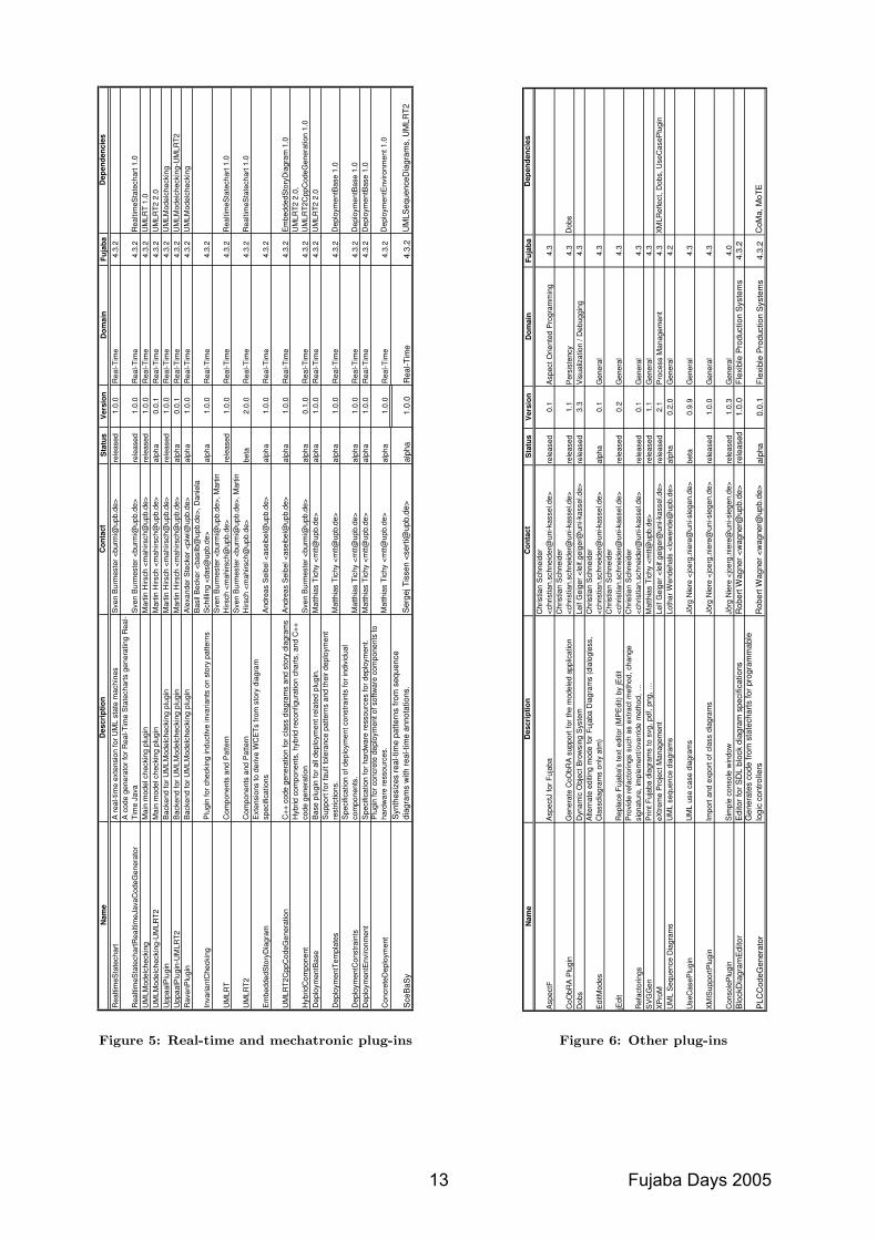
Nam
eD
escr
iptio
nC
onta
c tS
tatu
sV
ersi
onD
omai
nFu
jaba
Dep
ende
ncie
s
Rea
ltim
eSta
tech
art
A re
al-ti
me
exte
nsio
n fo
r UM
L st
ate
mac
hine
sS
ven
Bur
mes
ter <
burm
i@up
b.de
>re
leas
ed1.
0.0
Rea
l-Tim
e4.
3.2
Rea
ltim
eSta
tech
artR
ealti
meJ
avaC
odeG
ener
ator
A c
ode
gene
rato
r for
Rea
l-Tim
e S
tate
char
ts g
ener
atin
g R
eal-
Tim
e Ja
vaS
ven
Bur
mes
ter <
burm
i@up
b.de
>re
leas
ed1.
0.0
Rea
l-Tim
e4.
3.2
Rea
ltim
eSta
tech
art 1
.0U
MLM
odel
chec
king
Mai
n m
odel
che
ckin
g pl
ugin
Mar
tin H
irsch
<m
ahirs
ch@
upb.
de>
rele
ased
1.0.
0R
eal-T
ime
4.3.
2U
MLR
T 1.
0U
MLM
odel
chec
king
-UM
LRT2
Mai
n m
odel
che
ckin
g pl
ugin
Mar
tin H
irsch
<m
ahirs
ch@
upb.
de>
alph
a0.
0.1
Rea
l-Tim
e4.
3.2
UM
LRT2
2.0
Upp
aalP
lugi
nB
acke
nd fo
r UM
LMod
elch
ecki
ng p
lugi
nM
artin
Hirs
ch <
mah
irsch
@up
b.de
>re
leas
ed1.
0.0
Rea
l-Tim
e4.
3.2
UM
LMod
elch
ecki
ngU
ppaa
lPlu
gin-
UM
LRT2
Bac
kend
for U
MLM
odel
chec
king
plu
gin
Mar
tin H
irsch
<m
ahirs
ch@
upb.
de>
alph
a0.
0.1
Rea
l-Tim
e4.
3.2
UM
LMod
elch
ecki
ng-U
MLR
T2R
aven
Plu
gin
Bac
kend
for U
MLM
odel
chec
king
plu
gin
Ale
xand
er S
teck
er <
piw
i@up
b.de
>al
pha
1.0.
0R
eal-T
ime
4.3.
2U
MLM
odel
chec
king
Inva
riant
Che
ckin
gP
lugi
n fo
r che
ckin
g in
duct
ive
inva
riant
s on
sto
ry p
atte
rns
Bas
il B
ecke
r <ba
silb
@up
b.de
>, D
anie
la
Sch
illin
g <d
as@
upb.
de>
alph
a1.
0.0
Rea
l-Tim
e4.
3.2
UM
LRT
Com
pone
nts
and
Pat
tern
S
ven
Bur
mes
ter <
burm
i@up
b.de
>, M
artin
H
irsch
<m
ahirs
ch@
upb.
de>
rele
ased
1.0.
0R
eal-T
ime
4.3.
2R
ealti
meS
tate
char
t 1.0
UM
LRT2
Com
pone
nts
and
Pat
tern
S
ven
Bur
mes
ter <
burm
i@up
b.de
>, M
artin
H
irsch
<m
ahirs
ch@
upb.
de>
beta
2.0.
0R
eal-T
ime
4.3.
2R
ealti
meS
tate
char
t 1.0
Em
bedd
edS
tory
Dia
gram
Ext
ensi
ons
to d
eriv
e W
CE
Ts fr
om s
tory
dia
gram
sp
ecifi
catio
nsA
ndre
as S
eibe
l <as
eibe
l@up
b.de
>al
pha
1.0.
0R
eal-T
ime
4.3.
2
UM
LRT2
Cpp
Cod
eGen
erat
ion
C++
cod
e ge
nera
tion
for c
lass
dia
gram
s an
d st
ory
diag
ram
sA
ndre
as S
eibe
l <as
eibe
l@up
b.de
>al
pha
1.0.
0R
eal-T
ime
4.3.
2E
mbe
dded
Sto
ryD
iagr
am 1
.0
Hyb
ridC
ompo
nent
Hyb
rid c
ompo
nent
s, h
ybrid
reco
nfig
urat
ion
char
ts, a
nd C
++
code
gen
erat
ion
Sve
n B
urm
este
r <bu
rmi@
upb.
de>
alph
a0.
1.0
Rea
l-Tim
e4.
3.2
UM
LRT2
2.0
, U
MLR
T2C
ppC
odeG
ener
atio
n 1.
0D
eplo
ymen
tBas
eB
ase
plug
in fo
r all
depl
oym
ent r
elat
ed p
lugi
n.
Mat
thia
s Ti
chy
<mtt@
upb.
de>
alph
a1.
0.0
Rea
l-Tim
e4.
3.2
UM
LRT2
2.0
Dep
loym
entT
empl
ates
Sup
port
for f
ault
tole
ranc
e pa
ttern
s an
d th
eir d
eplo
ymen
t re
stric
tions
.M
atth
ias
Tich
y <m
tt@up
b.de
>al
pha
1.0.
0R
eal-T
ime
4.3.
2D
eplo
ymen
tBas
e 1.
0
Dep
loym
entC
onst
rain
tsS
peci
ficat
ion
of d
eplo
ymen
t con
stra
ints
for i
ndiv
idua
l co
mpo
nent
s.M
atth
ias
Tich
y <m
tt@up
b.de
>al
pha
1.0.
0R
eal-T
ime
4.3.
2D
eplo
ymen
tBas
e 1.
0D
eplo
ymen
tEnv
ironm
ent
Spe
cific
atio
n fo
r har
dwar
e re
ssou
rces
for d
eplo
ymen
t.M
atth
ias
Tich
y <m
tt@up
b.de
>al
pha
1.0.
0R
eal-T
ime
4.3.
2D
eplo
ymen
tBas
e 1.
0
Con
cret
eDep
loym
ent
Plu
gin
for c
oncr
ete
depl
oym
ent o
f sof
twar
e co
mpo
nent
s to
ha
rdw
are
ress
ourc
es.
Mat
thia
s Ti
chy
<mtt@
upb.
de>
alph
a1.
0.0
Rea
l-Tim
e4.
3.2
Dep
loym
entE
nviro
nmen
t 1.0
Sce
BaS
yS
ynth
esiz
es re
al-ti
me
patte
rns
from
seq
uenc
e di
agra
ms
with
real
-tim
e an
nota
tions
.S
erge
j Tis
sen
<ser
ti@up
b.de
>al
pha
1.0.
0R
eal-T
ime
4.3.
2U
MLS
eque
nceD
iagr
ams,
UM
LRT2
Figure 5: Real-time and mechatronic plug-ins
Nam
eD
escri
pti
on
Co
nta
ct
Sta
tus
Vers
ion
Do
main
Fu
jab
aD
ep
en
den
cie
s
Asp
ectF
Asp
ectJ
for F
ujab
aC
hris
tian
Sch
neid
er
<chr
istia
n.sc
hnei
der@
uni-k
asse
l.de>
rele
ased
0.1
Asp
ect O
rient
ed P
rogr
amm
ing
4.3
CoO
bRA
Plu
gin
Gen
erat
e C
oObR
A s
uppo
rt fo
r the
mod
eled
app
licat
ion
Chr
istia
n S
chne
ider
<c
hris
tian.
schn
eide
r@un
i-kas
sel.d
e>re
leas
ed1.
1P
ersi
sten
cy4.
3D
obs
Dob
sD
ynam
ic O
bjec
t Bro
wsi
ng S
yste
mLe
if G
eige
r <le
if.ge
iger
@un
i-kas
sel.d
e>re
leas
ed3.
3V
isua
lizat
ion
/ Deb
uggi
ng4.
3
Edi
tMod
esA
ltern
ate
editi
ng m
ode
for F
ujab
a D
iagr
ams
(dia
logl
ess,
C
lass
diag
ram
s on
ly a
tm)
Chr
istia
n S
chne
ider
<c
hris
tian.
schn
eide
r@un
i-kas
sel.d
e>al
pha
0.1
Gen
eral
4.3
jEdi
tR
epla
ce F
ujab
a's
text
edi
tor (
MP
Edi
t) by
jEdi
tC
hris
tian
Sch
neid
er
<chr
istia
n.sc
hnei
der@
uni-k
asse
l.de>
rele
ased
0.2
Gen
eral
4.3
Ref
acto
rings
Pro
vide
refa
ctor
ings
suc
h as
ext
ract
met
hod,
cha
nge
sign
atur
e, im
plem
ent/o
verr
ide
met
hod,
…C
hris
tian
Sch
neid
er
<chr
istia
n.sc
hnei
der@
uni-k
asse
l.de>
rele
ased
0.1
Gen
eral
4.3
SV
GG
enP
rint F
ujab
a di
agra
ms
to s
vg, p
df, p
ng, …
Mat
thia
s Ti
chy
<mtt@
upb.
de>
rele
ased
1.1
Gen
eral
4.3
XP
roM
eXtre
me
Pro
ject
Man
agem
ent
Leif
Gei
ger <
leif.
geig
er@
uni-k
asse
l.de>
rele
ased
2.1
Pro
cess
Man
agem
ent
4.3
XM
LRef
lect
, Dob
s, U
seC
aseP
lugi
nU
ML
Seq
uenc
e D
iagr
ams
UM
L se
quen
ce d
iagr
ams
Loth
ar W
ende
hals
<lo
wen
de@
upb.
de>
alph
a0.
2.0
Gen
eral
4.2
Use
Cas
ePlu
gin
UM
L us
e ca
se d
iagr
ams
Jörg
Nie
re <
joer
g.ni
ere@
uni-s
iege
n.de
>be
ta0.
9.9
Gen
eral
4.3
XM
ISup
portP
lugi
nIm
port
and
expo
rt of
cla
ss d
iagr
ams
Jörg
Nie
re <
joer
g.ni
ere@
uni-s
iege
n.de
>re
leas
ed1.
0.0
Gen
eral
4.3
Con
sole
Plu
gin
Sim
ple
cons
ole
win
dow
Jörg
Nie
re <
joer
g.ni
ere@
uni-s
iege
n.de
>re
leas
ed1.
0.3
Gen
eral
4.0
Blo
ckD
iagr
amE
dito
rE
dito
r for
SD
L bl
ock
diag
ram
spe
cific
atio
nsR
ober
t Wag
ner <
wag
ner@
upb.
de>
rele
ased
1.0.
0Fl
exib
le P
rodu
ctio
n S
yste
ms
4.3.
2
PLC
Cod
eGen
erat
orG
ener
ates
cod
e fro
m s
tate
char
ts fo
r pro
gram
mab
le
logi
c co
ntro
llers
Rob
ert W
agne
r <w
agne
r@up
b.de
>al
pha
0.0.
1Fl
exib
le P
rodu
ctio
n S
yste
ms
4.3.
2C
oMa,
MoT
E
Figure 6: Other plug-ins
13 Fujaba Days 2005

Fujaba Days 2005 14

Keynote Talk: Recent Trends in MDE: Principles, Standards,
Platforms and Applications
Jean Bézivin ATLAS Group (INRIA & LINA)
University of Nantes 2, rue de la Houssinière 44322 Nantes cedex 3
France
ABSTRACT Several initiatives like the European ModelWare Integrated Project are currently investigating the applicability of Model Driven Engineering (MDE) to change the current practices of software development and maintenance. As an emerging area, MDE is still very much in evolution. The industrial demand is quite high while the research answer for a sound set of foundation principles is still far from being stabilized. Since the MDA™ initial proposal by OMG five years ago, MDE has much changed and gained in consideration but still has to prove that it is really leading to a major long-term technological evolution. To this end, what is much needed is a precise definition of the MDE goals and non-goals and a stable statement of the set of principles from which MDE foundations could be assessed. One important question is how MDE relates to other contemporary technologies (Object Technology, XML, etc.). Another way to provide a characterization of MDE is by listing the various operations like transformations that could be performed on basic models. The talk will discuss the historical contributions of MDE, its present state and potential future evolutions as well as related open research issues.
15 Fujaba Days 2005

Fujaba Days 2005 16
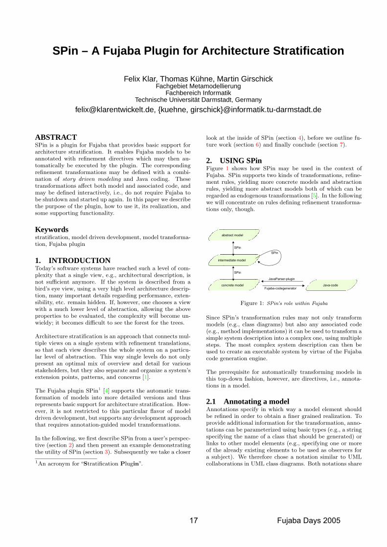
SPin – A Fujaba Plugin for Architecture Stratification
Felix Klar, Thomas Kühne, Martin GirschickFachgebiet Metamodellierung
Fachbereich InformatikTechnische Universität Darmstadt, Germany
[email protected], {kuehne, girschick}@informatik.tu-darmstadt.de
ABSTRACTSPin is a plugin for Fujaba that provides basic support forarchitecture stratification. It enables Fujaba models to beannotated with refinement directives which may then au-tomatically be executed by the plugin. The correspondingrefinement transformations may be defined with a combi-nation of story driven modeling and Java coding. Thesetransformations affect both model and associated code, andmay be defined interactively, i.e., do not require Fujaba tobe shutdown and started up again. In this paper we describethe purpose of the plugin, how to use it, its realization, andsome supporting functionality.
Keywordsstratification, model driven development, model transforma-tion, Fujaba plugin
1. INTRODUCTIONToday’s software systems have reached such a level of com-plexity that a single view, e.g., architectural description, isnot sufficient anymore. If the system is described from abird’s eye view, using a very high level architecture descrip-tion, many important details regarding performance, exten-sibility, etc. remain hidden. If, however, one chooses a viewwith a much lower level of abstraction, allowing the aboveproperties to be evaluated, the complexity will become un-wieldy; it becomes difficult to see the forest for the trees.
Architecture stratification is an approach that connects mul-tiple views on a single system with refinement translations,so that each view describes the whole system on a particu-lar level of abstraction. This way single levels do not onlypresent an optimal mix of overview and detail for variousstakeholders, but they also separate and organize a system’sextension points, patterns, and concerns [1].
The Fujaba plugin SPin1 [4] supports the automatic trans-formation of models into more detailed versions and thusrepresents basic support for architecture stratification. How-ever, it is not restricted to this particular flavor of modeldriven development, but supports any development approachthat requires annotation-guided model transformations.
In the following, we first describe SPin from a user’s perspec-tive (section 2) and then present an example demonstratingthe utility of SPin (section 3). Subsequently we take a closer
1An acronym for “Stratification Plugin”.
look at the inside of SPin (section 4), before we outline fu-ture work (section 6) and finally conclude (section 7).
2. USING SPinFigure 1 shows how SPin may be used in the context ofFujaba. SPin supports two kinds of transformations, refine-ment rules, yielding more concrete models and abstractionrules, yielding more abstract models both of which can beregarded as endogenous transformations [5]. In the followingwe will concentrate on rules defining refinement transforma-tions only, though.
Figure 1: SPin’s role within Fujaba
Since SPin’s transformation rules may not only transformmodels (e.g., class diagrams) but also any associated code(e.g., method implementations) it can be used to transform asimple system description into a complex one, using multiplesteps. The most complex system description can then beused to create an executable system by virtue of the Fujabacode generation engine.
The prerequisite for automatically transforming models inthis top-down fashion, however, are directives, i.e., annota-tions in a model.
2.1 Annotating a modelAnnotations specify in which way a model element shouldbe refined in order to obtain a finer grained realization. Toprovide additional information for the transformation, anno-tations can be parameterized using basic types (e.g., a stringspecifying the name of a class that should be generated) orlinks to other model elements (e.g., specifying one or moreof the already existing elements to be used as observers fora subject). We therefore chose a notation similar to UMLcollaborations in UML class diagrams. Both notations share
17 Fujaba Days 2005
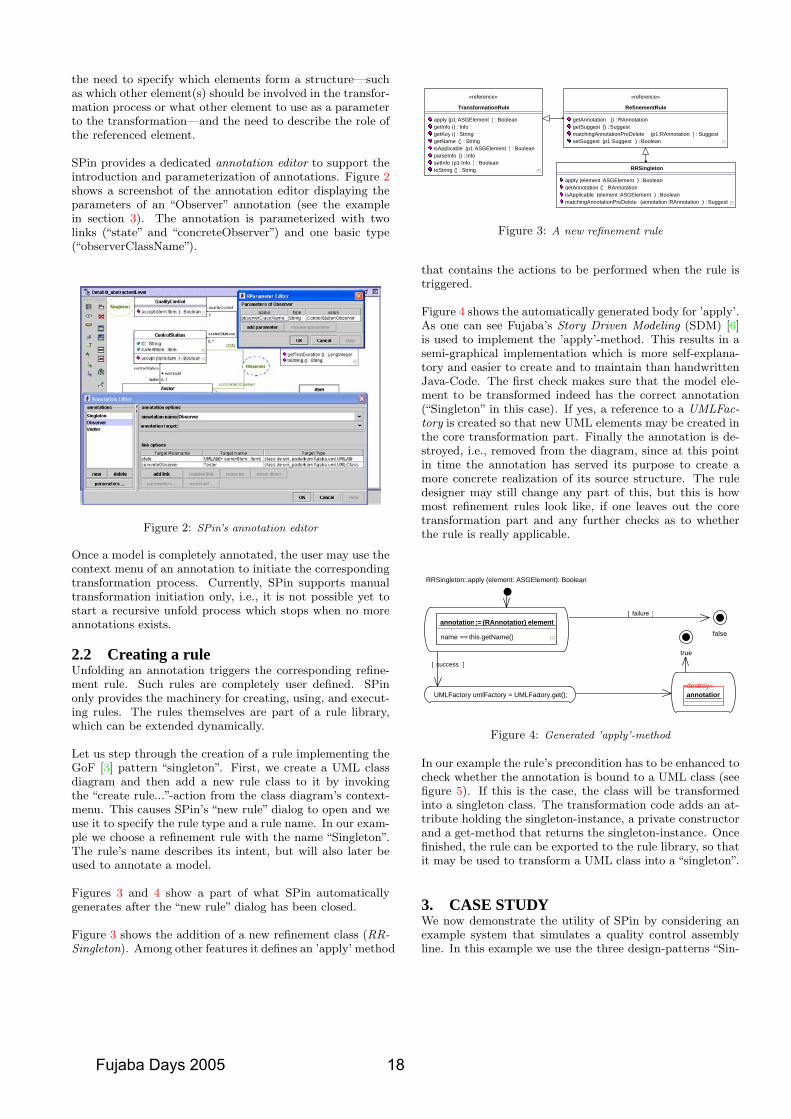
the need to specify which elements form a structure—suchas which other element(s) should be involved in the transfor-mation process or what other element to use as a parameterto the transformation—and the need to describe the role ofthe referenced element.
SPin provides a dedicated annotation editor to support theintroduction and parameterization of annotations. Figure 2shows a screenshot of the annotation editor displaying theparameters of an “Observer” annotation (see the examplein section 3). The annotation is parameterized with twolinks (“state” and “concreteObserver”) and one basic type(“observerClassName”).
Figure 2: SPin’s annotation editor
Once a model is completely annotated, the user may use thecontext menu of an annotation to initiate the correspondingtransformation process. Currently, SPin supports manualtransformation initiation only, i.e., it is not possible yet tostart a recursive unfold process which stops when no moreannotations exists.
2.2 Creating a ruleUnfolding an annotation triggers the corresponding refine-ment rule. Such rules are completely user defined. SPinonly provides the machinery for creating, using, and execut-ing rules. The rules themselves are part of a rule library,which can be extended dynamically.
Let us step through the creation of a rule implementing theGoF [3] pattern “singleton”. First, we create a UML classdiagram and then add a new rule class to it by invokingthe “create rule...”-action from the class diagram’s context-menu. This causes SPin’s “new rule” dialog to open and weuse it to specify the rule type and a rule name. In our exam-ple we choose a refinement rule with the name “Singleton”.The rule’s name describes its intent, but will also later beused to annotate a model.
Figures 3 and 4 show a part of what SPin automaticallygenerates after the “new rule” dialog has been closed.
Figure 3 shows the addition of a new refinement class (RR-Singleton). Among other features it defines an ’apply’ method
String : ) (toStringBoolean : )Info:p1 (setInfo
Info : ) (parseInfoBoolean : )ASGElement:p1 (isApplicable
String : ) (getNameString : ) (getKeyInfo : ) (getInfo
Boolean : )ASGElement:p1 (apply
TransformationRule
«reference»
Boolean : )Suggest:p1 (setSuggestSuggest : )RAnnotation:p1 (matchingAnnotationPreDelete
Suggest : ) (getSuggestRAnnotation : ) (getAnnotation
RefinementRule
«reference»
Suggest : )RAnnotation:annotation (matchingAnnotationPreDeleteBoolean : )ASGElement:element (isApplicable
RAnnotation : ) (getAnnotationBoolean : )ASGElement:element (apply
RRSingleton
Figure 3: A new refinement rule
that contains the actions to be performed when the rule istriggered.
Figure 4 shows the automatically generated body for ’apply’.As one can see Fujaba’s Story Driven Modeling (SDM) [6]is used to implement the ’apply’-method. This results in asemi-graphical implementation which is more self-explana-tory and easier to create and to maintain than handwrittenJava-Code. The first check makes sure that the model ele-ment to be transformed indeed has the correct annotation(“Singleton” in this case). If yes, a reference to a UMLFac-tory is created so that new UML elements may be created inthe core transformation part. Finally the annotation is de-stroyed, i.e., removed from the diagram, since at this pointin time the annotation has served its purpose to create amore concrete realization of its source structure. The ruledesigner may still change any part of this, but this is howmost refinement rules look like, if one leaves out the coretransformation part and any further checks as to whetherthe rule is really applicable.
]success[
]failure[
this.getName()==name
element) RAnnotation(:= annotation
RRSingleton::apply (element: ASGElement): Boolean
false
true
UMLFactory umlFactory = UMLFactory.get();«destroy»annotation
Figure 4: Generated ’apply’-method
In our example the rule’s precondition has to be enhanced tocheck whether the annotation is bound to a UML class (seefigure 5). If this is the case, the class will be transformedinto a singleton class. The transformation code adds an at-tribute holding the singleton-instance, a private constructorand a get-method that returns the singleton-instance. Oncefinished, the rule can be exported to the rule library, so thatit may be used to transform a UML class into a “singleton”.
3. CASE STUDYWe now demonstrate the utility of SPin by considering anexample system that simulates a quality control assemblyline. In this example we use the three design-patterns “Sin-
Fujaba Days 2005 18
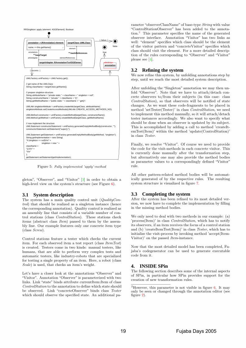
]success[
]failure[
false
true
«destroy»annotation
RRSingleton::apply (element: ASGElement): Boolean
elementReferences
UMLClass:targetClass
element
hasInReferences
RAnnotationToASGElement:targetAdapter
aSGAdapter
this.getName()==name
element) RAnnotation(:= annotation
annotations
haveTarget
UMLFactory umlFactory = UMLFactory.get();
// get name of the UMLClassString className = targetClass.getName();
// prepare singleton-structureString attributeName = "private static " + className + " singleton = null";String constructorName = "private " + className + "()";String getMethodName = "public static " + className + " get()";
UMLAttr singletonAttribute = umlFactory.createAttr(targetClass, attributeName);singletonAttribute.setCreateAccessMethods(UMLAttr.CREATE_ACCESS_METHODS_NO);
UMLMethod constructor = umlFactory.createMethod(targetClass, constructorName);UMLMethod getMethod = umlFactory.createMethod(targetClass, getMethodName);
// now implement the structureUMLStatement constructorStatement = umlFactory.generateEmptyMethodBody(constructor, "");constructorStatement.setStatement("super();");
UMLStatement getStatement = umlFactory.generateEmptyMethodBody(getMethod, "singleton");String getImplementation = new String("if (singleton == null)\r\n" +" singleton = new " +className +"();\r\n" +"\r\n");getStatement.setStatement(getImplementation);
Figure 5: Fully implemented ’apply’-method
gleton”, “Observer”, and “Visitor” [3] in order to obtain ahigh-level view on the system’s structure (see Figure 6).
3.1 System descriptionThe system has a main quality control unit (QualityCon-trol) that should be realized as a singleton instance (hencethe corresponding annotation). Quality control is realized asan assembly line that consists of a variable number of con-trol stations (class ControlStation). These stations checkitems (abstract class Item) passed to them by the assem-bly line. Our example features only one concrete item type(class Screw).
Control stations feature a tester which checks the currentitem. For each observed item a test report (class ItemTest)is created. Testers come in two kinds: manual testers, likehumans, that are able to perform very complex tests andautomatic testers, like industry-robots that are specializedfor testing a single property of an item. Here, a robot (classScale) is used, that checks an item’s weight.
Let’s have a closer look at the annotations “Observer” and“Visitor”. Annotation “Observer” is parameterized with twolinks. Link “state” binds attribute currentItem:Item of classControlStation to the annotation to define which state shouldbe observed. Link “concreteObserver” binds class Testerwhich should observe the specified state. An additional pa-
rameter “observerClassName”of base-type String with value“ControlStationObserver” has been added to the annota-tion.2 This parameter specifies the name of the generatedobserver interface. Annotation “Visitor” has two links aswell: “element” specifies which class should be the elementof the visitor pattern and “concreteVisitor” specifies whichclass should visit the element. For a more detailed descrip-tion of the rules corresponding to “Observer” and “Visitor”please see [4].
3.2 Refining the systemWe now refine this system, by unfolding annotations step bystep, until we reach the most detailed system description.
After unfolding the “Singleton” annotation we may then un-fold “Observer”. Note that we have to attach/detach con-crete observers to/from their subjects (in this case: classControlStation), so that observers will be notified of statechanges. As we want these code-fragments to be placed inmethod ’setTester(Tester)’ in class ControlStation, we needto implement this method manually, so it will attach/detachtester instances accordingly. We also want to specify whatshould be done when an observer is updated by its subject.This is accomplished by adding a call to method ’createIt-emTest(Item)’ within the method ’update(ControlStation)’in class Tester.
Finally, we resolve “Visitor”. Of course we need to providethe code for the visit-methods in each concrete visitor. Thisis currently done manually after the transformation step,but alternatively one may also provide the method bodiesas parameter values to a correspondingly defined “Visitor”rule.
All other pattern-related method bodies will be automat-ically generated of by the respective rules. The resultingsystem structure is visualized in figure 7.
3.3 Completing the systemAfter the system has been refined to its most detailed ver-sion, we now have to complete the implementation by fillingin the missing method bodies.
We only need to deal with two methods in our example: (a)’process(Item)’ in class ControlStation, which has to notifyits observers, if an item receives the focus of a control stationand (b) ’createItemTest(Item)’ in class Tester, which has toinitialize the visit-process by invoking method ’accept(Item-Visitor)’ on the passed Item-instance.
Now that the most detailed model has been completed, Fu-jaba’s codegenerator can be used to generate executablecode from it.
4. INSIDE SPinThe following section describes some of the internal aspectsof SPin, in particular how SPin provides support for thecreation of new transformation rules.
2However, this parameter is not visible in figure 6. It mayonly be seen or changed through the annotation editor (seefigure 2).
19 Fujaba Days 2005
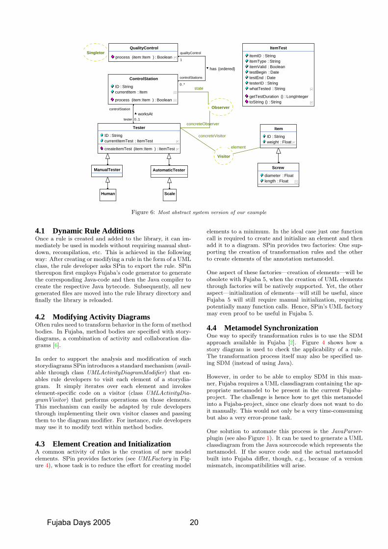
Scale
Float : lengthFloat : diameter
ScrewManualTester
String : ) (toStringLongInteger : ) (getTestDuration
String : whatTestedString : testerIDDate : testEnd
Date : testBeginBoolean : itemValidString : itemType
String : itemID
ItemTest
controlStation
0..1testerworksAt
Human
AutomaticTester
ItemTest : )Item:item (createItemTest
ItemTest : currentItemTestString : ID
TesterconcreteObserver
Observer
state0..*
controlStations
1
qualityControlSingletonBoolean : )Item:item (process
QualityControl
Boolean : )Item:item (process
Item : currentItemString : ID
ControlStation
{ordered}has
concreteVisitorFloat : weight
String : ID
Item
element
Visitor
Figure 6: Most abstract system version of our example
4.1 Dynamic Rule AdditionsOnce a rule is created and added to the library, it can im-mediately be used in models without requiring manual shut-down, recompilation, etc. This is achieved in the followingway: After creating or modifying a rule in the form of a UMLclass, the rule developer asks SPin to export the rule. SPinthereupon first employs Fujaba’s code generator to generatethe corresponding Java-code and then the Java compiler tocreate the respective Java bytecode. Subsequently, all newgenerated files are moved into the rule library directory andfinally the library is reloaded.
4.2 Modifying Activity DiagramsOften rules need to transform behavior in the form of methodbodies. In Fujaba, method bodies are specified with story-diagrams, a combination of activity and collaboration dia-grams [6].
In order to support the analysis and modification of suchstorydiagrams SPin introduces a standard mechanism (avail-able through class UMLActivityDiagramModifier) that en-ables rule developers to visit each element of a storydia-gram. It simply iterates over each element and invokeselement-specific code on a visitor (class UMLActivityDia-gramVisitor) that performs operations on those elements.This mechanism can easily be adapted by rule developersthrough implementing their own visitor classes and passingthem to the diagram modifier. For instance, rule developersmay use it to modify text within method bodies.
4.3 Element Creation and InitializationA common activity of rules is the creation of new modelelements. SPin provides factories (see UMLFactory in Fig-ure 4), whose task is to reduce the effort for creating model
elements to a minimum. In the ideal case just one functioncall is required to create and initialize an element and thenadd it to a diagram. SPin provides two factories: One sup-porting the creation of transformation rules and the otherto create elements of the annotation metamodel.
One aspect of these factories—creation of elements—will beobsolete with Fujaba 5, when the creation of UML elementsthrough factories will be natively supported. Yet, the otheraspect—initialization of elements—will still be useful, sinceFujaba 5 will still require manual initialization, requiringpotentially many function calls. Hence, SPin’s UML factorymay even proof to be useful in Fujaba 5.
4.4 Metamodel SynchronizationOne way to specify transformation rules is to use the SDMapproach available in Fujaba [2]. Figure 4 shows how astory diagram is used to check the applicability of a rule.The transformation process itself may also be specified us-ing SDM (instead of using Java).
However, in order to be able to employ SDM in this man-ner, Fujaba requires a UML classdiagram containing the ap-propriate metamodel to be present in the current Fujaba-project. The challenge is hence how to get this metamodelinto a Fujaba-project, since one clearly does not want to doit manually. This would not only be a very time-comsumingbut also a very error-prone task.
One solution to automate this process is the JavaParser-plugin (see also Figure 1). It can be used to generate a UMLclassdiagram from the Java sourcecode which represents themetamodel. If the source code and the actual metamodelbuilt into Fujaba differ, though, e.g., because of a versionmismatch, incompatibilities will arise.
Fujaba Days 2005 20
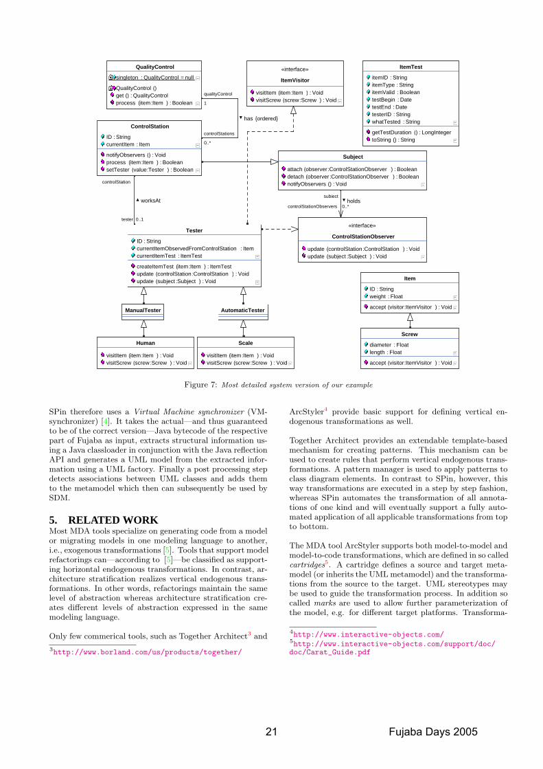
0..*controlStationObservers
subjectholds
Void : )Subject:subject (updateVoid : )ControlStation:controlStation (update
ControlStationObserver
«interface»
Void : ) (notifyObserversBoolean : )ControlStationObserver:observer (detach
Boolean : )ControlStationObserver:observer (attach
Subject
Void : )Screw:screw (visitScrewVoid : )Item:item (visitItem
Scale
ManualTester
controlStation
0..1tester
worksAt
Void : )Screw:screw (visitScrewVoid : )Item:item (visitItem
Human
AutomaticTester
0..*
controlStations
1
qualityControl
{ordered}has
String : ) (toStringLongInteger : ) (getTestDuration
String : whatTestedString : testerIDDate : testEnd
Date : testBeginBoolean : itemValidString : itemType
String : itemID
ItemTest
Void : )ItemVisitor:visitor (accept
Float : weightString : ID
Item
Void : )ItemVisitor:visitor (accept
Float : lengthFloat : diameter
Screw
Void : )Subject:subject (updateVoid : )ControlStation:controlStation (update
ItemTest : )Item:item (createItemTest
ItemTest : currentItemTestItem : currentItemObservedFromControlStation
String : ID
Tester
Void : )Screw:screw (visitScrewVoid : )Item:item (visitItem
ItemVisitor
«interface»
Boolean : )Item:item (processQualityControl : ) (get
) (QualityControl
null = QualityControl : singleton
QualityControl
Boolean : )Item:item (processBoolean : )Tester:value (setTester
Void : ) (notifyObservers
Item : currentItemString : ID
ControlStation
Figure 7: Most detailed system version of our example
SPin therefore uses a Virtual Machine synchronizer (VM-synchronizer) [4]. It takes the actual—and thus guaranteedto be of the correct version—Java bytecode of the respectivepart of Fujaba as input, extracts structural information us-ing a Java classloader in conjunction with the Java reflectionAPI and generates a UML model from the extracted infor-mation using a UML factory. Finally a post processing stepdetects associations between UML classes and adds themto the metamodel which then can subsequently be used bySDM.
5. RELATED WORKMost MDA tools specialize on generating code from a modelor migrating models in one modeling language to another,i.e., exogenous transformations [5]. Tools that support modelrefactorings can—according to [5]—be classified as support-ing horizontal endogenous transformations. In contrast, ar-chitecture stratification realizes vertical endogenous trans-formations. In other words, refactorings maintain the samelevel of abstraction whereas architecture stratification cre-ates different levels of abstraction expressed in the samemodeling language.
Only few commerical tools, such as Together Architect3 and
3http://www.borland.com/us/products/together/
ArcStyler4 provide basic support for defining vertical en-dogenous transformations as well.
Together Architect provides an extendable template-basedmechanism for creating patterns. This mechanism can beused to create rules that perform vertical endogenous trans-formations. A pattern manager is used to apply patterns toclass diagram elements. In contrast to SPin, however, thisway transformations are executed in a step by step fashion,whereas SPin automates the transformation of all annota-tions of one kind and will eventually support a fully auto-mated application of all applicable transformations from topto bottom.
The MDA tool ArcStyler supports both model-to-model andmodel-to-code transformations, which are defined in so calledcartridges5. A cartridge defines a source and target meta-model (or inherits the UML metamodel) and the transforma-tions from the source to the target. UML stereotypes maybe used to guide the transformation process. In addition socalled marks are used to allow further parameterization ofthe model, e.g. for different target platforms. Transforma-
4http://www.interactive-objects.com/5http://www.interactive-objects.com/support/doc/doc/Carat_Guide.pdf
21 Fujaba Days 2005
tions are described using the script language JPython. Thisis supplemented by the concept of blueprints which are simi-lar to model templates. ArcStyler follows the MDA approachwhere a platform independent model (PIM) is completelyparameterized and then transformed to a new platform spe-cific model (PSM). If this approach is used in a staged, in-cremental manner, it very much resembles the abstractionlevel stratification approach of SPin.
Neither Together Architect nor ArcStyler support Fujaba’sStory Driven Modeling, which is very useful for the semi-graphical specification of transformation rules as used inSPin.
6. FUTURE WORKThe current version of SPin offers a limited set of transfor-mation rules. Although these are user extensible, the utilityof SPin would be increased if it came with a rich set ofready-to-use rules. By applying the stratification processto big and complex software systems it will be possible toextract useful rules which can then be added to SPin.
Employing stratification in its intended form with SPin iscurrently hindered by the fact that only manual, stepwiseinitiations of transformations are supported. In order tofully automate the generation of a complex system from agiven simple and abstract view, it is necessary to automatethe process of unfolding annotations. This includes the spec-ification of the order in which annotations are to be unfolded.However, this ordering is neither difficult to work out, norshould it be part of an automated process. Annotations ex-hibit natural dependencies and lend themselves to generatelevels of system concerns [1]. It is therefore the task of thesystem architect to select which of the annotations are ad-dressed at each specific abstraction level. As a result, futureversions of SPin should provide a configuration system thatallows users to specify and store their annotation processingorders.
SPin will significantly benefit from the new features of Fu-jaba 5. For instance, the then available support for multipleprojects will enable developers to create rules in one projectand immediately apply them in another. Moreover, usersthen might be able to easily navigate back and forth be-tween different levels of abstraction.
Moving up in the hierarchy of abstraction levels is alreadypossible as long as the more detailed versions were generatedby SPin. This is accomplished by using Fujaba’s built in“undo” mechanism.
In the current release of SPin the transformation rules areexpressed using arbitrary Java code. This implies that thereis no way to execute them “backwards” or to automaticallygenerate inverse rules. The “reverse application” of forwarddirected generation rules is, however, an attractive facilityfor reverse engineering systems. This way, one may startfrom a complex system and simplify the system by eithercreating and applying “abstraction rules” or by using refine-ment rules in the“reverse”direction. This, however, requiresrules that can either be transformed into their inverse orrules that work bi-directionally. Hence, we are planning toinvestigate replacing Java for specifying transformation rules
with an approach that supports bi-directional rule applica-tion from the start, e.g., Triple Graph Grammars [7].
7. CONCLUSIONSPin is the result of a diploma thesis conducted at the meta-modeling department of the Darmstadt University of Tech-nology [4]. Although it currently provides only basic supportfor architecture stratification, it represents a starting pointthat can be extended into full stratification support.
Even the current SPin version, however, already demon-strates the feasibility of transforming both model elementsand associated code in sync with each other, in order toobtain a fully specified complex system from a simple sys-tem, after a number of transformation steps. Current ruledefinitions sometimes require manual edits to the generatedmodels—for user code, such as implementations of “visit”methods for the visitor pattern—however, this is no prin-ciple limitation of the approach. More sophisticated rulesand corresponding annotation dialogs will allow the contin-uous and fully automated generation of models from top tobottom.
Transformation rules are user-definable, typically using aconvenient mix of SDM (for pattern matching) and Java(for an unconstrained definition of transformations). SinceSPin is able to dynamically integrate new rules, the devel-opment of the main system model and corresponding rules,can proceed in an interleaved and very interactive manner.
The creation of new rules in SPin is heavily assisted by anumber of convenient utilities, such as support for modifyingmethod bodies, element creation, and the synchronization ofthe UML metamodel.
In addition, the work on SPin resulted in a pattern-like no-tation for refinement annotations that enable transforma-tion parameters to be specified both graphically (throughlabeled links) and non-graphically (through primitive pa-rameter types entered into a corresponding dialog). Thisway one achieves fine grained control of the transformationprocess, using a concise notation.
We believe that SPin already represents an interesting start-ing point for supporting architecture stratification, but as wehave outlined in the previous section on future work, we areconvinced that it has an even higher potential for furtherdevelopment.
8. REFERENCES[1] C. Atkinson and T. Kuhne. Aspect-Oriented
Development with Stratified Frameworks. IEEESoftware, 20(1):81–89, 2003.
[2] T. Fischer, J. Niere, L. Torunski, and A. Zundorf. StoryDiagrams: A new Graph Rewrite Language based onthe Unified Modeling Language and Java. Technicalreport, AG-Softwaretechnik, Fachbereich 17,Universitat Paderborn, 1999.
[3] E. Gamma, R. Helm, R. Johnson, and J. Vlissides.Entwurfsmuster. Addison-Wesley, 1996.
Fujaba Days 2005 22

[4] F. Klar. SPin – Ein Werkzeug zur Realisierung vonArchitektur-Stratifikation. Diplomarbeit, TechnischeUniversitat Darmstadt, April 2005,http://www.klarentwickelt.de/doc/science/
diplomarbeit_klar.pdf.
[5] T. Mens, K. Czarnecki, and P. V. Gorp. A taxonomy ofmodel transformations. In J. Bezivin and R. Heckel,editors, Language Engineering for Model-DrivenSoftware Development, number 04101 in DagstuhlSeminar Proceedings. Internationales Begegnungs- undForschungszentrum (IBFI), Schloss Dagstuhl, Germany,2005.
[6] U. Nickel, J. Niere, and A. Zundorf. The FUJABAEnvironment. Technical report, Computer ScienceDepartment, University of Paderborn, 2000.
[7] A. Schurr. Specification of graph translators with triplegraph grammars. Germany, June 1994. Herrschin,Springer Verlag. Proceedings of the 20th InternationalWorkshop on Graph-Theoretic Concepts in ComputerScience.
23 Fujaba Days 2005

Fujaba Days 2005 24
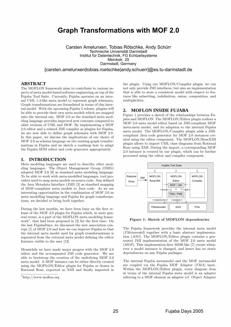
Graph Transformations with MOF 2.0
Carsten Amelunxen, Tobias Rötschke, Andy SchürrTechnische Universität Darmstadt
Institut für Datentechnik, FG EchtzeitsystemeMerckstr. 25
Darmstadt, Germany[carsten.amelunxen|tobias.roetschke|andy.schuerr]@es.tu-darmstadt.de
ABSTRACTThe MOFLON framework aims to contribute to various as-pects of meta model-based software engineering on top of theFujaba Tool Suite. Currently, Fujaba operates on an inter-nal UML 1.4-like meta model to represent graph schemata.Graph transformations are formulated in terms of this inter-nal model. With the upcoming Fujaba 5 release, plugins willbe able to provide their own meta models which are mappedonto the internal one. MOF 2.0 as the standard meta mod-eling language provides improved new concepts compared toolder versions of UML and MOF. By implementing a MOF2.0 editor and a related JMI compiler as plugins for Fujaba,we are now able to define graph schemata with MOF 2.0.In this paper, we discuss the implications of our choice ofMOF 2.0 as schema language on the existing graph transfor-mations in Fujaba and we sketch a roadmap how to adaptthe Fujaba SDM editor and code generator appropriately.
1. INTRODUCTIONMeta modeling languages are used to describe other mod-eling languages. The Object Management Group (OMG)adopted MOF 2.0 [9] as standard meta modeling language.To be able to work with meta-modelled languages, tool pro-viders need to map meta models on source code. Sun definedthe Java Metadata Interface (JMI) [3] as standard mappingof MOF-compliant meta models to Java code. As we seeinteresting opportunities in the combination of MOF 2.0 asmeta modelling language and Fujaba for graph transforma-tions, we decided to bring both together.
During the last months, we have been busy on the first re-lease of the MOF 2.0 plugin for Fujaba which, in more gen-eral terms, is a part of the MOFLON meta modeling frame-work1, that had been proposed in [2] for the first time. Onthe last FujabaDays, we discussed the new association con-cept [1] of MOF 2.0 and how we can improve Fujaba so thatthe internal meta model used for graph transformations isseparated from the external meta model defining the editorfeatures visible to the user [12].
Meanwhile we have made major progres with the MOF 2.0editor and the accompanied JMI code generator. We areable to bootstrap the creation of the underlying MOF 2.0meta model. A MOF instance can be either directly createdusing the MOFLON/Editor plugin for Fujaba or drawn inRational Rose, exported as XMI and finally imported in
1http://www.moflon.org
the plugin. Using our MOFLON/Compiler plugin, we cannot only provide JMI interfaces, but also an implementationthat is able to store a consistent model with respect to fea-tures like subsetting, redefinition, union, composition, andmultiplicities.
2. MOFLON INSIDE FUJABAFigure 1 provides a sketch of the relationships between Fu-jaba and MOFLON. The MOFLON/Editor plugin realizes aMOF 2.0 meta model editor based on JMI-compliant MOFmeta-meta model, and its adaption to the internal Fujabameta model. The MOFLON/Compiler plugin adds a JMI-compliant Java code generator for MOF 2.0 instances cre-ated using the editor component. The MOFLON/RoseXMIplugin allows to import UML class diagrams from RationalRose using XMI. During the import, a corresponding MOF2.0 instance is created by our plugin, which can be furtherprocessed using the editor and compiler component.
MOFLON
Compiler
MOFLON
RoseXMI
FMA / FME
<<event>> <<call>>
MOFLON
Editor
MOF / JMI
Rational
Rose
<<extends>><<implements>>
XMI
Fujaba Tool Suite
FMetamodel ASG FSA
Figure 1: Sketch of MOFLON dependencies
The Fujaba framework provides the internal meta model(FMetamodel) together with a basic abstract implementa-tion (ASG). The MOFLON/Editor plugin contains a gen-erated JMI implementation of the MOF 2.0 meta model(MOF). This implemention fires MDR-like [7] events when-ever a model instance is changed, and hence has no staticdependencies on any Fujaba packages.
The internal Fujaba metamodel and the MOF metamodelare coupled via the Fujaba MOF Adapter (FMA) layer.Within the MOFLON/Editor plugin, every diagram itemin terms of the internal Fujaba meta model is an adapterreferring to a MOF element as adaptee (cf. Object Adapter
25 Fujaba Days 2005
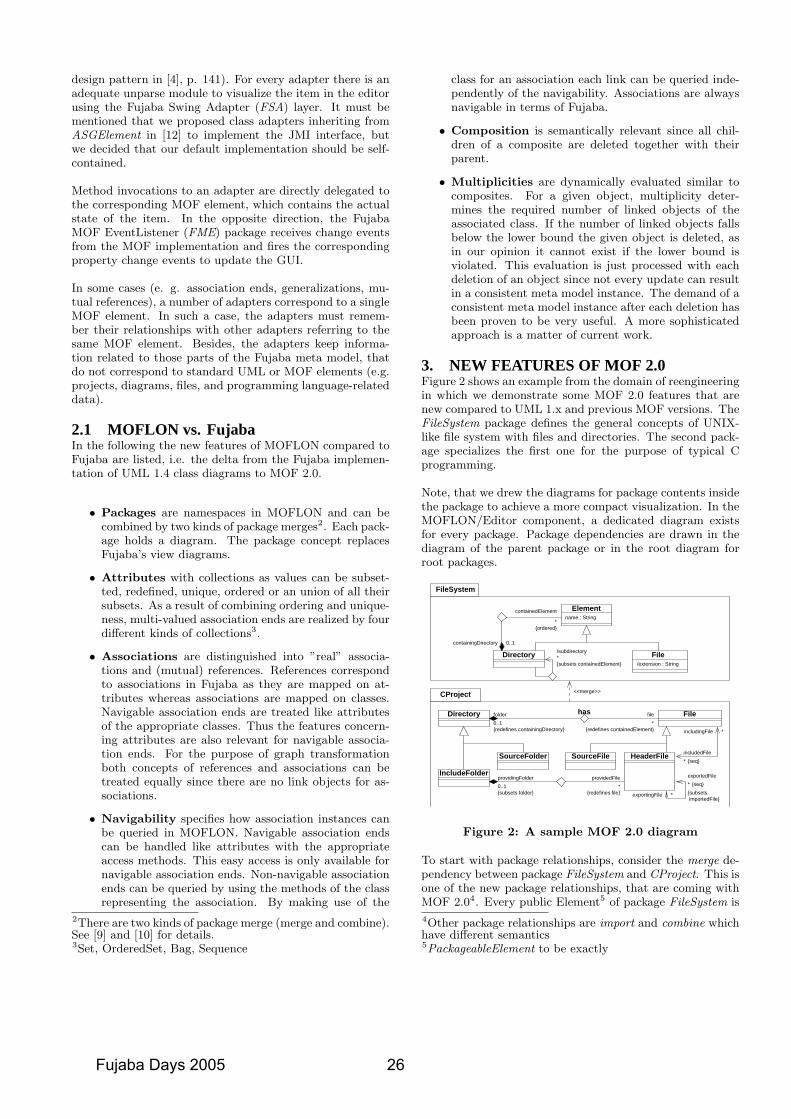
design pattern in [4], p. 141). For every adapter there is anadequate unparse module to visualize the item in the editorusing the Fujaba Swing Adapter (FSA) layer. It must bementioned that we proposed class adapters inheriting fromASGElement in [12] to implement the JMI interface, butwe decided that our default implementation should be self-contained.
Method invocations to an adapter are directly delegated tothe corresponding MOF element, which contains the actualstate of the item. In the opposite direction, the FujabaMOF EventListener (FME) package receives change eventsfrom the MOF implementation and fires the correspondingproperty change events to update the GUI.
In some cases (e. g. association ends, generalizations, mu-tual references), a number of adapters correspond to a singleMOF element. In such a case, the adapters must remem-ber their relationships with other adapters referring to thesame MOF element. Besides, the adapters keep informa-tion related to those parts of the Fujaba meta model, thatdo not correspond to standard UML or MOF elements (e.g.projects, diagrams, files, and programming language-relateddata).
2.1 MOFLON vs. FujabaIn the following the new features of MOFLON compared toFujaba are listed, i.e. the delta from the Fujaba implemen-tation of UML 1.4 class diagrams to MOF 2.0.
• Packages are namespaces in MOFLON and can becombined by two kinds of package merges2. Each pack-age holds a diagram. The package concept replacesFujaba’s view diagrams.
• Attributes with collections as values can be subset-ted, redefined, unique, ordered or an union of all theirsubsets. As a result of combining ordering and unique-ness, multi-valued association ends are realized by fourdifferent kinds of collections3.
• Associations are distinguished into ”real” associa-tions and (mutual) references. References correspondto associations in Fujaba as they are mapped on at-tributes whereas associations are mapped on classes.Navigable association ends are treated like attributesof the appropriate classes. Thus the features concern-ing attributes are also relevant for navigable associa-tion ends. For the purpose of graph transformationboth concepts of references and associations can betreated equally since there are no link objects for as-sociations.
• Navigability specifies how association instances canbe queried in MOFLON. Navigable association endscan be handled like attributes with the appropriateaccess methods. This easy access is only available fornavigable association ends. Non-navigable associationends can be queried by using the methods of the classrepresenting the association. By making use of the
2There are two kinds of package merge (merge and combine).See [9] and [10] for details.3Set, OrderedSet, Bag, Sequence
class for an association each link can be queried inde-pendently of the navigability. Associations are alwaysnavigable in terms of Fujaba.
• Composition is semantically relevant since all chil-dren of a composite are deleted together with theirparent.
• Multiplicities are dynamically evaluated similar tocomposites. For a given object, multiplicity deter-mines the required number of linked objects of theassociated class. If the number of linked objects fallsbelow the lower bound the given object is deleted, asin our opinion it cannot exist if the lower bound isviolated. This evaluation is just processed with eachdeletion of an object since not every update can resultin a consistent meta model instance. The demand of aconsistent meta model instance after each deletion hasbeen proven to be very useful. A more sophisticatedapproach is a matter of current work.
3. NEW FEATURES OF MOF 2.0Figure 2 shows an example from the domain of reengineeringin which we demonstrate some MOF 2.0 features that arenew compared to UML 1.x and previous MOF versions. TheFileSystem package defines the general concepts of UNIX-like file system with files and directories. The second pack-age specializes the first one for the purpose of typical Cprogramming.
Note, that we drew the diagrams for package contents insidethe package to achieve a more compact visualization. In theMOFLON/Editor component, a dedicated diagram existsfor every package. Package dependencies are drawn in thediagram of the parent package or in the root diagram forroot packages.
Directory
SourceFolder SourceFile HeaderFile
has
IncludeFolder
File
FileSystem
CProject
{ordered}*
containedElement
0..1containingDirectory
Directory File{subsets containedElement}
/subdirectory*
/extension : String
Elementname : String
<<merge>>
file*
{redefines containedElement} includingFile *
includedFile*
exportedFile{seq}
{seq}
{subsets importedFile}
*exportingFile
*{redefines file}
providedFile
{subsets folder}
providingFolder0..1 *
folder0..1{redefines containingDirectory}
Figure 2: A sample MOF 2.0 diagram
To start with package relationships, consider the merge de-pendency between package FileSystem and CProject. This isone of the new package relationships, that are coming withMOF 2.04. Every public Element5 of package FileSystem is
4Other package relationships are import and combine whichhave different semantics5PackageableElement to be exactly
Fujaba Days 2005 26
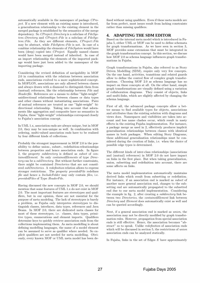
automatically available in the namespace of package CPro-ject. If a new element with an existing name is introduced,a generalization relationship to the existing element in themerged package is established by the semantics of the mergedependency. So CProject::Directory is a subclass of FileSys-tem::Directory and CProject::File is a subclass of FileSys-tem::File. As they are different elements, CProject::Filemay be abstract, while FileSytem::File is not. In case of acombine relationship the elements of FileSystem would havebeen (deep) copied into CProject. Equally named classeswould have been merged instead of inherited. In case ofan import relationship the elements of the imported pack-age would have just been added to the namespace of theimporting package.
Considering the revised definition of navigability in MOF2.0 in combination with the relations between associationends, associations evolved to a more sophisticated concept.In MOFLON, associations are only allowed between classesand always drawn with a diamond to distinguish them from(mutual) references, like the relationship between File andHeaderfile. References are a means to define ”light-weight”unidirectional relationships between classes or data typesand other classes without instantiating associations. Pairsof mutual references are treated as one ”light-weight” bi-directional relationship. Taking into account that adorn-ments like aggregation and composite have no semantics inFujaba, these ”light-weight” relationships correspond closelyto Fujaba’s association concept.
In UML 1.x, association ends are always unique, but in MOF2.0, they may be non-unique as well. In combination withordering, multi-valued association ends have to be realizedby four different kinds of collections.
Probably the strongest improvement in MOF 2.0 is the pos-sibility to define union-, subset-, redefinition-releationshipsbetween properties and hence association ends. In figure2, the property subdirectory is defined as subset of con-tainedElement. So only containedElements of type Direc-tory can be a subDirectory. But without further constraints,there might be contained Directories that are not consid-ered subDirectories. A redefinition relation allows to expressstronger restrictions. The property providedFile redefinesfile and hence a IncludeFolder may only contain files, i.e.providedFiles of Type HeaderFile.
Having discussed the new concepts in MOF 2.0, we shouldmention that some features of UML 1.x do not exist in MOF2.0. The most important features are stereotypes and qual-ifiers, but in our opinion, these are not essential for thepurpose of meta modeling. The lack of stereotypes is barelya problem, as Fujaba only interpretes stereotypes to dis-tinguish classes, interfaces, data types, references and JavaBeans. In MOF 2.0, there are dedicated meta classes formost of these stereotypes, i.e. classes, data types, primi-tive types, enumerations and element imports. Qualifiersdetermine keys to quickly retrieve association ends from thecollections implementing them. As meta modelling is aboutdefining modelling languages, the name of a model elementcan be assumed to serve as qualifier where needed. So ex-plicit qualifiers are not needed for meta modelling. Obvi-ously, every known MOF or UML meta model has been de-
fined without using qualifiers. Even if these meta models arefar from perfect, most issues result from lacking constraintsrather than missing qualifiers.
4. ADAPTING THE SDM EDITORBased on the internal meta model which is introduced in Fu-jaba 5, either UML or MOF can be used to define schematafor graph transformations. As we have seen in section 3,MOF provides some extensions that must be integrated inthe graph transformation concept. In this section, we discusshow MOF 2.0 as schema language influences graph transfor-mations in Fujaba.
Graph transformations in Fujaba, also referred to as StoryDriven Modelling (SDM), require only very few concepts.On the one hand, activities, transitions and related guardsallow to define the control flow of complex graph transfor-mations. Choosing MOF 2.0 as schema language has noimpact on these concepts at all. On the other hand, simplegraph transformations are visually defined using a variationof collaboration diagrams. They consist of objects, linksand multi-links, which are slightly affected by changing theschema language.
First of all, the advanced package concepts allow a bet-ter means to find available types for objects, associationsand attributes than the existing solution with diagrams andviews does. Namespaces and visibilities are taken into ac-count and less name clashes occur, which result in nastyeffects in the existing Fujaba implementation. For instance,a package merge as used in 2, effectively produces implicitgeneralization relationships between classes with identicalnames in both packages. When editing Story Diagrams,these additional generalization relationships must be con-sidered during the creation of links, i.e. when the choice ofpossible edge types is determined.
The different kinds of inter-class relationships (associationsand (mutual) references) in MOF 2.0 do not have impacton links in the first place. But when taking generalization,union, subsetting and redefinition into account, there aresome affects on links.
The meta model implementation automatically maintainsderived links which result from subsetting or redefintion.For instance, if an association end is marked as subset ofanother more general association end, changes to the sub-setting end are automatically propagated to the subsettedend due to our meta model implementation. Consideringthe example in fig. 2, after creating a subdirectory link be-tween two Directories, the containedElement link betweenDirectory and Element does automatically exist as well andcan be queried accordingly.
Next, if a general association end is marked as union, theassociation may not be directly modified by graph transfor-mation rules. However, propagation from special associationends is still effective. Hence, the association becomes ”ab-stract” so to speak. Unlike redefinition of association endswhich will be discussed in section 5, the restrictions of unionassociation ends can be analyzed statically.
In Fujaba, links in the set of Edges E have approximately
27 Fujaba Days 2005
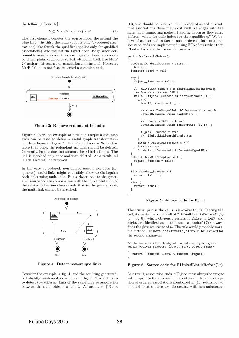
the following form [13]:
E ⊂ N × EL× I ×Q×N (1)
The first element denotes the source node, the second theedge label, the third the index (applies only for ordered asso-ciations), the fourth the qualifier (applies only for qualifiedassociations), and the last the target node. Edge labels cor-resond to associations in the class diagram. Associations canbe either plain, ordered or sorted, although UML like MOF2.0 assigns this feature to association ends instead. However,MOF 2.0, does not feature sorted association ends.
Figure 3: Remove redundant includes
Figure 3 shows an example of how non-unique associationends can be used to define a useful graph transformationfor the schema in figure 2. If a File includes a HeaderFilemore than once, the redundant includes should be deleted.Currently, Fujuba does not support these kinds of rules. Thelink is matched only once and then deleted. As a result, allinlude links will be removed.
In the case of ordered, non-unique association ends (se-quences), multi-links might ostensibly allow to distinguishboth links using multilinks. But a closer look to the gener-ated source code in combination with the implementation ofthe related collection class reveils that in the general case,the multi-link cannot be matched.
]success[ ]failure[
A::isUnique (): Boolean
b
a
thisa
b
B:bab
ab
{...}
truefalse
Figure 4: Detect non-unique links
Consider the example in fig. 4, and the resulting generated,but slightly condensed source code in fig. 5. The rule triesto detect two different links of the same ordered associationbetween the same objects a and b. According to [13], p.
103, this should be possible: ”..., in case of sorted or qual-ified associations there may exist multiple edges with thesame label connecting nodes n1 and n2 as log as they carrydifferent values for their index i or their qualifier q.” We be-lieve, that ”sorted” in fact means ”ordered”, has sorted as-sociation ends are implemented using FTreeSets rather thanFLinkedLists and hence no indices exist.
public boolean isUnique(){
boolean fujaba__Success = false ;B b = null ;Iterator iterB = null ;
try {fujaba__Success = false ;
// multilink bind b : B iMultiLinkSearchNormTopiterB = this.iteratorOfB() ;while (!fujaba__Success && iterB.hasNext()) {
try {b = (B) iterB.next () ;
// check To-Many-Link ’b’ between this and bJavaSDM.ensure (this.hasInB(b)) ;
// check multilink b to bJavaSDM.ensure (this.isBeforeOfB (b, b)) ;
fujaba__Success = true ;// iMultiLinkSearchNormBottom
}catch ( JavaSDMException e ) {} // try catch
} // while OOVariable[B,OOVariableType[12],]}catch ( JavaSDMException e ) {
fujaba__Success = false ;}
if ( fujaba__Success ) {return (false) ;
}else {
return (true) ;}
}
Figure 5: Source code for fig. 4
The crucial part is the call A.isBeforeB(b,b). Tracing thecall, it results in another call of FLinkedList.isBefore(b,b)(cf. fig 6), which obviously results in false, if left andright are identical as in this case, as indexOf(b) alwaysfinds the first occurence of b. The rule would probably work,if a method like nextIndexAfter(b,b) would be invoked forthe second argument.
//returns true if left object is before right objectpublic boolean isBefore (Object left, Object right){
return (indexOf (left) < indexOf (right));}
Figure 6: Source code for FLinkedList.isBefore(l,r)
As a result, association ends in Fujaba must always be uniquewith respect to the current implementation. Even the excep-tion of ordered associations mentioned in [13] seems not tobe implemented correctly. So dealing with non-uniqueness
Fujaba Days 2005 28
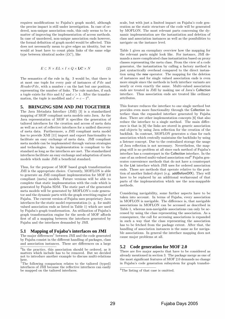
requires modifications to Fujaba’s graph model, althoughthe precise impact is still under investigation. In case of or-dered, non-unique association ends, this only seems to be amatter of improving the implementation of access methods.In case of unordered, non-unique association ends however,the formal definition of graph model would be affected. Thisdoes not necessarily mean to give edges an identity, but wewould at least have to count plain links of the same edgetype between identical nodes (LC), like
E ⊂ N × EL× I ×Q× LC×N (2)
The semantics of the rule in fig. 3 would be, that there isat most one tuple for every pair of instances of File andHeaderF ile, with a number c on the last but one position,representing the number of links. The rule matches, if sucha tuple exists for this and hf and c > 1. After the transfor-mation, the tuple is modified and c′ = c− 16.
5. BRINGING SDM AND JMI TOGETHERThe Java Metadata Interface (JMI) [3] is a standardizedmapping of MOF compliant meta models onto Java. As theJava representation of MOF it specifies the generation oftailored interfaces for the creation and access of meta dataas well as a set of reflective interfaces for a unified discoveryof meta data. Furthermore, a JMI compliant meta modelhas to provide XMI [11] import and export functionality tofacilitate an easy exchange of meta data. JMI compliantmeta models can be implemented through various strategiesand technologies. An implementation is compliant to thestandard as long as the interfaces are met. The standardizedinterfaces facilitate an easy exchange and adaptation of metamodels which make JMI a beneficial standard.
Thus, for the purpose of MOF based graph transformationJMI is the appropriate choice. Currently, MOFLON is ableto generate an JMI compliant implementation for MOF 2.0compliant (meta) models. Future versions will be able tocomplete that static implementation with the code which isgenerated by Fujaba SDM. The static part of the generatedmeta models will be generated by MOFLON’s code genera-tor and the dynamic parts with the graph rewriting engine ofFujaba. The current version of Fujaba uses proprietary Javainterfaces for the static model representation (e. g. for multivalued association ends as listed in Table 1) which are usedby Fujaba’s graph tranformation. An utilization of Fujaba’sgraph transformation engine for the needs of MOF affordsfirst of all a mapping between the interfaces generated byFujaba and the interfaces demanded by JMI.
5.1 Mapping of Fujaba’s interfaces on JMIThe major differences7 between JMI and the code generatedby Fujaba consist in the different handling of packages, classand association instances. These are differences on a large
6In the practice, this association should be ordered, as itmatters which include has to be removed. But we decidednot to introduce another example to discuss multi-relationshere.7The following comparison relates to the tailored (typed)interfaces of JMI because the reflective interfaces can easilybe mapped on the tailored interfaces.
scale, but with just a limited impact on Fujaba’s code gen-eration as the static structure of the code will be generatedby MOFLON. The most relevant parts concerning the dy-namic implementation are the instantiation and deletion ofclass and association instances as well as the possibilities tonavigate on the instance level.
Table 1 gives an exemplary overview how the mapping forthe relevant parts might look like. For instance, JMI de-mands a more complicated class instantiation based on proxyclasses representing the meta class. From the view of a codegenerator, the instantiation by calling a factory method isjust syntactically overhead compared to the direct instan-tion using the new operator. The mapping for the deletionof instances and for single valued association ends is evenmore simple since the methods in both interface variants arenearly or even exactly the same. Multi-valued associationends are treated in JMI by making use of Java’s Collectioninterface. Thus association ends are treated like ordinaryattributes.
This feature reduces the interface to one single method butprovides even more functionality through the Collection in-terface than the expanded interface generated by Fujabadoes. There are other implementation concepts [6] that alsoreduce the interface to a single method. The main differ-ence is that in [6] the links are stored in generic associationend objects by using Java reflection for the creation of thebacklink. In contrast, MOFLON generates a class for eachassociation which centrally maintains the backlinks by usinga listener concept. Due to the centralized storage the usageof Java reflection is not necessary. Nevertheless, the map-ping still is no problem at all since each method of Fujaba’sinterface has a counterpart in the Collection interface. In thecase of an ordered multi-valued association end8 Fujaba gen-erates convenience methods that do not have a counterpartin the List interface which JMI uses for ordered associationends. Those are methods that operate relative to the posi-tion of another linked object (e.g. addBeforeOfX). They willhave to be replaced by an additional workaround of thatparts of the implementation which use the non-mappablemethods.
Considering navigability, some further aspects have to betaken into account. In terms of Fujaba, every associationin MOFLON is navigable. The difference is, that navigableassociations in MOFLON can be accessed as described inTable 1, whereas non-navigable associations can only be ac-cessed by using the class representing the association. As aconsequence, the call for accessing associations is expandedin such a way that the class representing the associationhas to be fetched from the package extent. After that, thehandling of association instances is the same as for naviga-ble associations. In general the interface mapping does notcause major problems at all.
5.2 Code generation for MOF 2.0There are five major aspects that have to be considered asalready mentioned in section 3. The package merge as one ofthe most significant features of MOF 2.0 demands no changein Fujaba’s code generation subsystem for graph transfor-
8The listing of that case is omitted.
29 Fujaba Days 2005
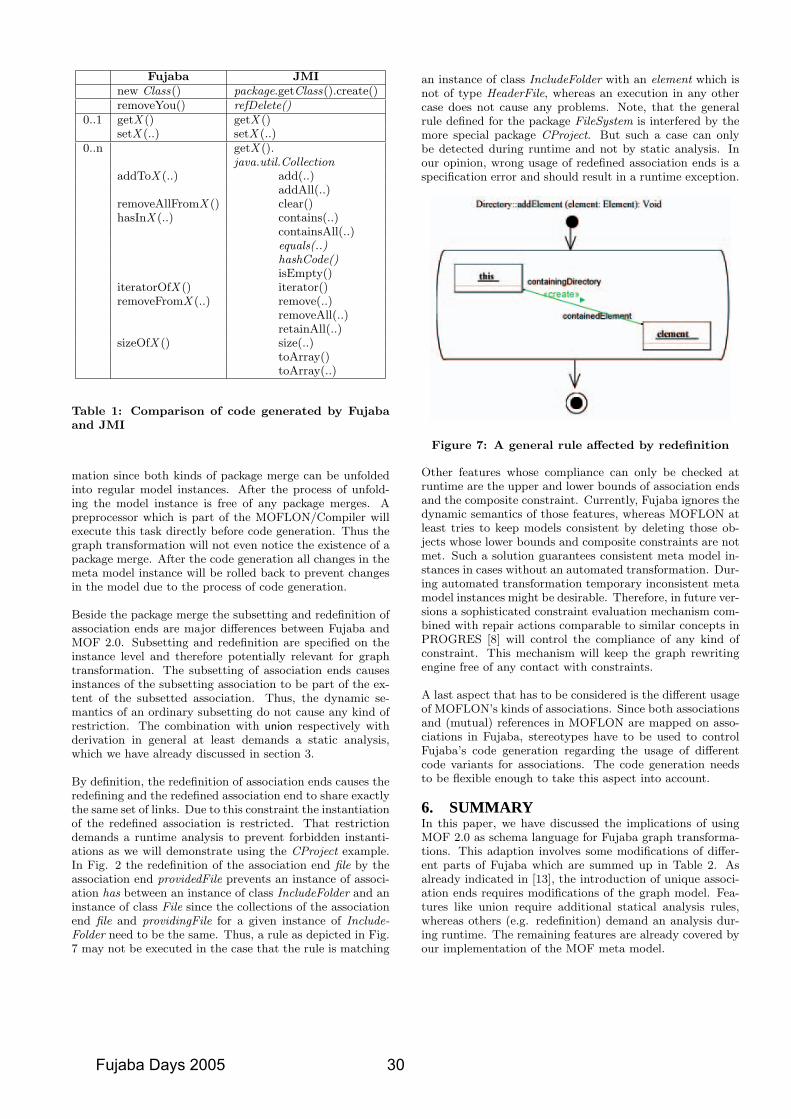
Fujaba JMInew Class() package.getClass().create()removeYou() refDelete()
0..1 getX () getX ()setX (..) setX (..)
0..n getX ().java.util.Collection
addToX (..) add(..)addAll(..)
removeAllFromX () clear()hasInX (..) contains(..)
containsAll(..)equals(..)hashCode()isEmpty()
iteratorOfX () iterator()removeFromX (..) remove(..)
removeAll(..)retainAll(..)
sizeOfX () size(..)toArray()toArray(..)
Table 1: Comparison of code generated by Fujabaand JMI
mation since both kinds of package merge can be unfoldedinto regular model instances. After the process of unfold-ing the model instance is free of any package merges. Apreprocessor which is part of the MOFLON/Compiler willexecute this task directly before code generation. Thus thegraph transformation will not even notice the existence of apackage merge. After the code generation all changes in themeta model instance will be rolled back to prevent changesin the model due to the process of code generation.
Beside the package merge the subsetting and redefinition ofassociation ends are major differences between Fujaba andMOF 2.0. Subsetting and redefinition are specified on theinstance level and therefore potentially relevant for graphtransformation. The subsetting of association ends causesinstances of the subsetting association to be part of the ex-tent of the subsetted association. Thus, the dynamic se-mantics of an ordinary subsetting do not cause any kind ofrestriction. The combination with union respectively withderivation in general at least demands a static analysis,which we have already discussed in section 3.
By definition, the redefinition of association ends causes theredefining and the redefined association end to share exactlythe same set of links. Due to this constraint the instantiationof the redefined association is restricted. That restrictiondemands a runtime analysis to prevent forbidden instanti-ations as we will demonstrate using the CProject example.In Fig. 2 the redefinition of the association end file by theassociation end providedFile prevents an instance of associ-ation has between an instance of class IncludeFolder and aninstance of class File since the collections of the associationend file and providingFile for a given instance of Include-Folder need to be the same. Thus, a rule as depicted in Fig.7 may not be executed in the case that the rule is matching
an instance of class IncludeFolder with an element which isnot of type HeaderFile, whereas an execution in any othercase does not cause any problems. Note, that the generalrule defined for the package FileSystem is interfered by themore special package CProject. But such a case can onlybe detected during runtime and not by static analysis. Inour opinion, wrong usage of redefined association ends is aspecification error and should result in a runtime exception.
Figure 7: A general rule affected by redefinition
Other features whose compliance can only be checked atruntime are the upper and lower bounds of association endsand the composite constraint. Currently, Fujaba ignores thedynamic semantics of those features, whereas MOFLON atleast tries to keep models consistent by deleting those ob-jects whose lower bounds and composite constraints are notmet. Such a solution guarantees consistent meta model in-stances in cases without an automated transformation. Dur-ing automated transformation temporary inconsistent metamodel instances might be desirable. Therefore, in future ver-sions a sophisticated constraint evaluation mechanism com-bined with repair actions comparable to similar concepts inPROGRES [8] will control the compliance of any kind ofconstraint. This mechanism will keep the graph rewritingengine free of any contact with constraints.
A last aspect that has to be considered is the different usageof MOFLON’s kinds of associations. Since both associationsand (mutual) references in MOFLON are mapped on asso-ciations in Fujaba, stereotypes have to be used to controlFujaba’s code generation regarding the usage of differentcode variants for associations. The code generation needsto be flexible enough to take this aspect into account.
6. SUMMARYIn this paper, we have discussed the implications of usingMOF 2.0 as schema language for Fujaba graph transforma-tions. This adaption involves some modifications of differ-ent parts of Fujaba which are summed up in Table 2. Asalready indicated in [13], the introduction of unique associ-ation ends requires modifications of the graph model. Fea-tures like union require additional statical analysis rules,whereas others (e.g. redefinition) demand an analysis dur-ing runtime. The remaining features are already covered byour implementation of the MOF meta model.
Fujaba Days 2005 30
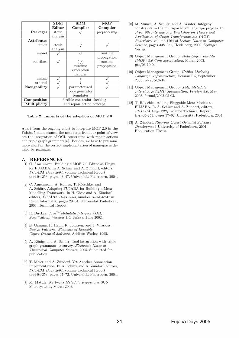
SDM SDM MOFEditor Compiler Compiler
Packages static√
preprocesinganalysis
Attributesunion static
√ √
analysissubset
√ √runtime
propagationredefines
√(√
) runtimeruntime propagation
execeptionhandler
unique√
?√
ordered√
?√
Navigability√
parameterized√
code generatortemplates
Composition flexible constraint checkingMultiplicity and repair action concept
Table 2: Impacts of the adaption of MOF 2.0
Apart from the ongoing effort to integrate MOF 2.0 in theFujaba 5 main branch, the next steps from our point of vieware the integration of OCL constraints with repair actionsand triple graph grammars [5]. Besides, we have to put somemore effort in the correct implementation of namespaces de-fined by packages.
7. REFERENCES[1] C. Amelunxen. Building a MOF 2.0 Editor as Plugin
for FUJABA. In A. Schurr and A. Zundorf, editors,FUJABA Days 2004, volume Technical Reporttr-ri-04-253, pages 43–47. Universitat Paderborn, 2004.
[2] C. Amelunxen, A. Konigs, T. Rotschke, andA. Schurr. Adapting FUJABA for Building a MetaModelling Framework. In H. Giese and A. Zundorf,editors, FUJABA Days 2003, number tr-ri-04-247 inReihe Informatik, pages 29–34. Universitat Paderborn,2003. Technical Report.
[3] R. Dirckze. JavaTMMetadata Interface (JMI)Specification, Version 1.0. Unisys, June 2002.
[4] E. Gamma, R. Helm, R. Johnson, and J. Vlissides.Design Patterns: Elements of ReusableObject-Oriented Software. Addison-Wesley, 1995.
[5] A. Konigs and A. Schurr. Tool integration with triplegraph grammars - a survey. Electronic Notes inTheoretical Computer Science, 2005. Submitted forpublication.
[6] T. Maier and A. Zundorf. Yet Another AssociationImplementation. In A. Schurr and A. Zundorf, editors,FUJABA Days 2004, volume Technical Reporttr-ri-04-253, pages 67–72. Universitat Paderborn, 2004.
[7] M. Matula. NetBeans Metadata Repository. SUNMicrosystems, March 2003.
[8] M. Munch, A. Schurr, and A. Winter. Integrityconstraints in the multi-paradigm language progres. InProc. 6th International Workshop on Theory andApplication of Graph Transformations TAGT,Paderborn, volume 1764 of Lecture Notes in ComputerScience, pages 338–351, Heidelberg, 2000. SpringerVerlag.
[9] Object Management Group. Meta Object Facility(MOF) 2.0 Core Specification, March 2003.ptc/03-10-04.
[10] Object Management Group. Unified ModelingLanguage: Infrastructure, Version 2.0, September2003. ptc/03-09-15.
[11] Object Management Group. XML MetadataInterchange (XMI) Specification, Version 2.0, May2003. formal/2003-05-03.
[12] T. Rotschke. Adding Pluggable Meta Models toFUJABA. In A. Schurr and A. Zundorf, editors,FUJABA Days 2004, volume Technical Reporttr-ri-04-253, pages 57–62. Universitat Paderborn, 2004.
[13] A. Zundorf. Rigorous Object Oriented SoftwareDevelopment. University of Paderborn, 2001.Habilitation Thesis.
31 Fujaba Days 2005

Fujaba Days 2005 32
Detection of Incomplete Patterns Using FUJABA Principles
Sven WenzelTampere University of Technology, Finland
University of Dortmund, [email protected]
ABSTRACTAn approach for the detection of structural patterns in UMLclass diagrams is presented. It picks up some principles ofthe reverse engineering component of Fujaba, such as ahierarchical pattern definition and an alternating bottom-up/top-down analysis. Furthermore it uses a fuzzy-like eval-uation mechanism so that it is able to recognize not onlyentire patterns but also incomplete instances.The knowledge about incomplete instances, which obviouslyoccur rather often during the developing process, assists de-velopers not only while maintaining or reverse engineeringexisting software but already while designing and imple-menting new software.
1. INTRODUCTIONSince software systems become larger and more complex,the task of understanding while developing and especiallywhile maintaining software becomes more and more diffi-cult. Therefore the use of patterns has become a helpfulmethodology to develop software in a more structured andunderstandable way.
In general, a pattern is a scheme that consists of three mainparts: a context, a problem, and a solution. They discussa particular recurring problem which arises in a particularsituation – the context. Furthermore they offer a provensolution to this problem.
Several pattern families focus on different aspects of soft-ware development and take place in the different stages ofthe development process. The main interest within the de-sign and implementation phases is directed towards thosepatterns that focus on problems of software design. Theseare behavioral patterns that focus on the run-time behaviorof software elements and structural patterns that concen-trate on the structural arrangements of software elements.Both types can be separated into more abstract and moreconcrete problems.
Design patterns [1] are more abstract and focus on prob-lems in object-oriented software in general. For example,the Composite pattern describes how to compose several ob-jects into a part-whole hierarchy with a uniform interface.Specialization patterns [2] do not discuss general project-independent problems, but focus on more specific topicsof concrete projects. They describe, for example, how toextend a particular framework and support users in thisprocess.
It is well-known that the knowledge about patterns used ina software helps the developer to get a better understandingof it. Therefore, Fujaba [3] and other tools (see Section 7,Related Work) offer mechanisms to detect pattern instancesin given software. Especially in maintenance and reverseengineering the occurrence of the solution parts of particu-lar patterns help the developer to understand the originalproblems.
But the knowledge about used patterns – especially with re-gard to structural patterns in general – assists the developeralready while designing or implementing new software. Asin maintenance and reverse engineering, the reason is a bet-ter understanding, but the circumstances are quite different.Since the software is currently in development, the likelihoodof partly instantiated patterns is rather high. However, theknowledge about those incomplete patterns helps the devel-oper and should not be neglected.
An example is the use of specialization patterns guiding adeveloper while extending a framework. The patterns de-fine the classes that have to be created, the interfaces thathave to be implemented, or the operations that have to beoverwritten, etc. Furthermore, architectural rules may bedefined as a pattern to enforce structural properties of thedeveloped software. The developer would like to check ifher design satisfies these architectural rules during develop-ment and she also wants to have information about the workprogress, in other words, the tasks that have to be done.
Consequently, an approach for the detection of structuralpatterns should be able to recognize these incomplete in-stances as well as entire ones. A possible realization of thedetection of incomplete patterns based on the Unified Mod-eling Language (UML) [4] is generally presented in [5] andis also discussed on the next pages. It picks up some funda-mental ideas of the Fujaba approach, such as a hierarchicalpattern definition and an alternating bottom-up/top-downanalysis. Furthermore it uses a fuzzy-like evaluation mech-anism so that the introduced approach is able to recognizenot only entire patterns, but also incomplete instances.
Due to its parallels to Fujaba, this paper focuses on thedifferences between this approach and the one underlyingFujaba. The following Section 2 introduces the Fujabaapproach itself, while Section 3 discusses the characteristicsof incomplete pattern instances and the limits of Fujaba.Sections 4 and 5 present an improved model for pattern
33 Fujaba Days 2005
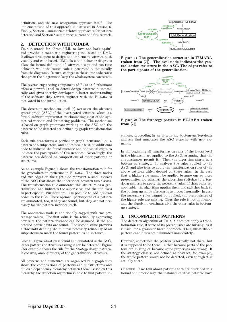
definitions and the new recognition approach itself. Theimplementation of this approach is discussed in Section 6.Finally, Section 7 summarizes related approaches for patterndetection and Section 8 summarizes current and future work.
2. DETECTION WITH FUJABAFujaba stands for “From UML to Java and back again”and provides a round-trip engineering tool based on UML.It allows developers to design and implement software bothvisually and code-based. UML class and behavior diagramsallow the formal definition of software design and run-timebehavior, while the source code is generated automaticallyfrom the diagrams. In turn, changes in the source code causechanges in the diagrams to keep the whole system consistent.
The reverse engineering component of Fujaba furthermoreoffers a powerful tool to detect design patterns automati-cally and gives thereby developers a better understandingof the software they reverse-engineer with the Fujaba asmotivated in the introduction.
The detection mechanism itself [6] works on the abstractsyntax graph (ASG) of the investigated software, which is aformal software representation eliminating most of the syn-tactical variants and formatting problems. The mechanismis based on graph grammars working on the ASG and thepatterns to be detected are defined by graph transformationrules.
Each rule transforms a particular graph structure, i.e. apattern or a subpattern, and annotates it with an additionalnode to indicate the found instance and additional edges toindicate the participants of this instance. Accordingly, thepatterns are defined as compositions of other patterns orstructures.
As an example Figure 1 shows the transformation rule forthe generalization structure in Fujaba. The three nodesand two edges on the right side represent a small extractof the ASG that shows the inheritance between two classes.The transformation rule annotates this structure as a gen-eralization and indicates the super class and the sub classas participants. Furthermore, it is possible to add optionalnodes to the rule. These optional participants of a patternare annotated, too, if they are found, but they are not nec-essary for the pattern instance itself.
The annotation node is additionally tagged with two per-centage values. The first value is the reliability expressinghow sure the pattern instance can be assumed, if the an-notated participants are found. The second value providesa threshold defining the minimal necessary reliability of allsubpatterns to mark the found pattern as an instance.
Once this generalization is found and annotated in the ASG,larger patterns or structures using it can be detected. Figure2 for example shows the rule for the Strategy design pattern.It consists, among others, of the generalization structure.
All patterns and structures are organized in a graph thatshows the compositions of patterns and substructures andbuilds a dependency hierarchy between them. Based on thishierarchy the detection algorithm is able to find pattern in-
Figure 1: The generalization structure in FUJABA(taken from [7]). The oval node indicates the gen-eralization structure in the ASG. The edges refer tothe participants of the generalization.
Figure 2: The Strategy pattern in FUJABA (takenfrom [7]).
stances, proceeding in an alternating bottom-up/top-downanalysis that annotates the ASG stepwise with new ele-ments.
In the beginning all transformation rules of the lowest levelin the hierarchy are applied to the ASG, assuming that thecircumstances permit it. Then the algorithm starts in abottom-up strategy. It analyzes the rules applied to theASG, and also tries to apply the transformation rules of theabove patterns which depend on these rules. In the casethat a higher rule cannot be applied because one or moreprerequisites are missing, the algorithm switches to a top-down analysis to apply the necessary rules. If these rules areapplicable, the algorithm applies them and switches back tothe bottom-up mode afterwards to proceed normally. In casethe necessary rules cannot be applied, the prerequisites ofthe higher rule are missing. Thus the rule is not applicableand the algorithm continues with the other rules in bottom-up strategy.
3. INCOMPLETE PATTERNSThe detection algorithm of Fujaba does not apply a trans-formation rule, if some of its prerequisites are missing, as itis usual for a grammar-based approach. Thus, unsatisfiablepattern candidates are eliminated immediately.
However, sometimes the pattern is formally not there, butit is supposed to be there – either because parts of the pat-tern are missing or because some properties are wrong. Ifthe strategy class is not defined as abstract, for example,the whole pattern would not be detected, even though it isactually there.
Of course, if we talk about patterns that are described in aformal and precise way, the instances of those patterns have
Fujaba Days 2005 34
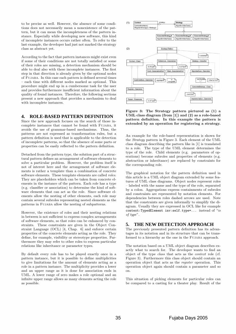
to be precise as well. However, the absence of some condi-tions does not necessarily mean a nonexistence of the pat-tern, but it can mean the incompleteness of the pattern in-stance. Especially while developing new software, this kindof incomplete instances occurs rather often. To refer to thelast example, the developer had just not marked the strategyclass as abstract yet.
According to the fact that pattern instances might exist evenif some of their conditions are not totally satisfied or someof their roles are missing, a detection mechanism should beable to deal also with these incomplete instances. The firststep in that direction is already given by the optional nodesof Fujaba. In this case each pattern is defined several times– each time with different nodes marked as optional. Thisprocedure might end up in a cumbersome task for the userand provides furthermore insufficient information about thequality of found instances. Therefore, the following sectionspresent a new approach that provides a mechanism to dealwith incomplete instances.
4. ROLE-BASED PATTERN DEFINITIONSince the new approach focuses on the search of those in-complete instances that cannot be found with Fujaba, itavoids the use of grammar-based mechanisms. Thus, thepatterns are not expressed as transformation rules, but apattern definition is used that is applicable to the detectionof incomplete patterns, so that the absence of some parts orproperties can be easily reflected to the pattern definition.
Detached from the pattern type, the solution part of a struc-tural pattern defines an arrangement of software elements tosolve a particular problem. However, the problem itself isnot of interest here and the arrangement of software ele-ments is rather a template than a combination of concretesoftware elements. These template elements are called roles.They are placeholders which can be taken from concrete el-ements in the instance of the pattern. Each role has a type(e.g. classifier or association) to determine the kind of soft-ware elements that can act as the role. Since software el-ements allow the nesting of other elements, each role maycontain several subroles representing nested elements as thepatterns in Fujaba allow the nesting of subpatterns.
However, the existence of roles and their nesting relationsin between is not sufficient to express complex arrangementsof software elements, so that roles can be enhanced by con-straints. These constraints are given in the Object Con-straint Language (OCL) [4, Chap. 6] and enforce certainproperties of the concrete elements acting as the role. Theydefine, for example, visibility or stereotype properties. Fur-thermore they may refer to other roles to express particularrelations like inheritance or parameter types.
By default every role has to be played exactly once in apattern instance, but it is possible to define multiplicitiesto give limitations for the amount of elements acting as arole in a pattern instance. The multiplicity provides a lowerand an upper range as it is done for association ends inUML. A lower range of zero makes a role optional and aninfinite upper range allows as many elements acting the roleas possible.
Figure 3: The Strategy pattern pictured as (1) aUML class diagram (from [1]) and (2) as a role-basedpattern definition. In this example the pattern isextended by an operation for registering a strategy.
An example for the role-based representation is shown forthe Strategy pattern in Figure 3. Each element of the UMLclass diagram describing the pattern like in [1] is translatedto a role. The type of the UML element determines thetype of the role. Child elements (e.g. parameters of op-erations) become subroles and properties of elements (e.g.abstraction or inheritance) are replaced by constraints forthe corresponding role.
The graphical notation for the pattern definition used inthis article is a UML object diagram extended by some fea-tures of UML class diagrams. Object nodes represent roles– labeled with the name and the type of the role, separatedby a colon. Aggregations express containments of subrolesand constraints are represented by notation elements. Fordependencies between roles dashed arrows are used. Notethat the constraints are given informally to simplify the di-agram. Usually they are expressed in OCL like for examplecontext:TypedElement inv:self.type=... instead of “isof type”.
5. THE NEW DETECTION APPROACHThe previously presented pattern definition has its advan-tages in its notation and in its structure that can be trans-formed to a hierarchy as the one in the Fujaba approach.
The notation based on a UML object diagram describes ex-actly what to search for. The developer wants to find anobject of the type class that acts as the context role (cf.Figure 3). Furthermore this class object should contain anoperation object that acts as the register operation. Thisoperation object again should contain a parameter and soon.
This situation of picking elements for particular roles canbe compared to a casting for a theater play. Result of the
35 Fujaba Days 2005
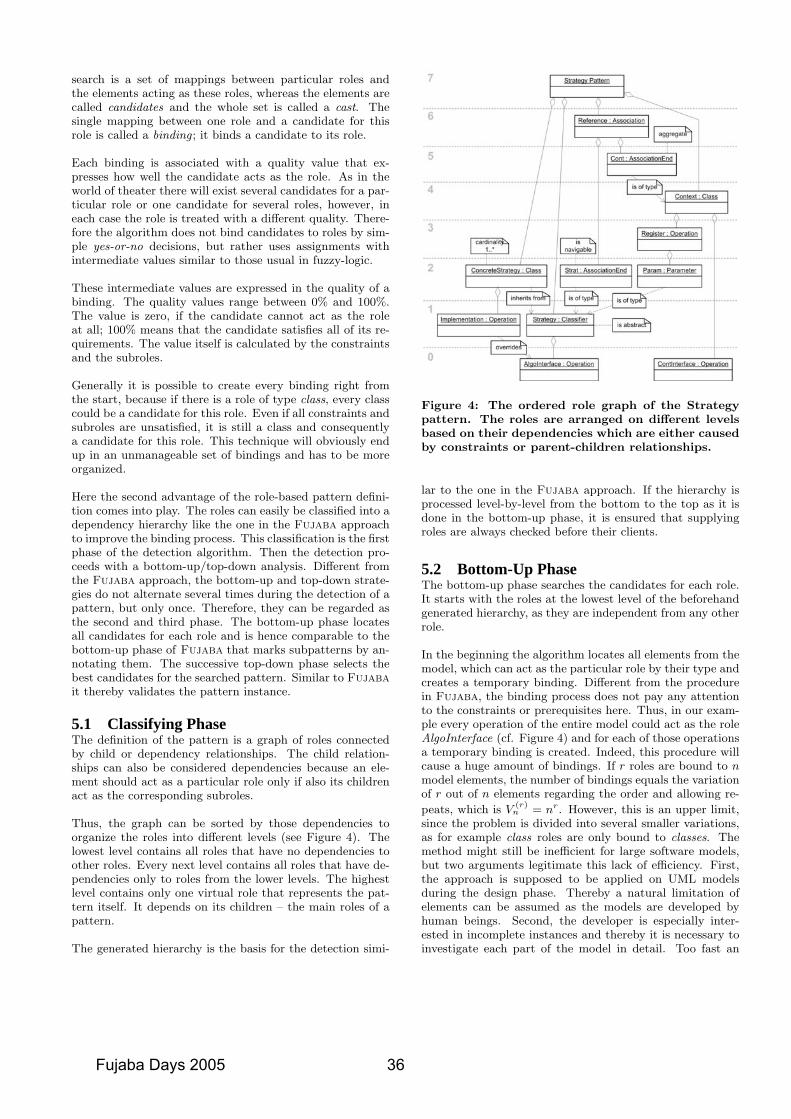
search is a set of mappings between particular roles andthe elements acting as these roles, whereas the elements arecalled candidates and the whole set is called a cast. Thesingle mapping between one role and a candidate for thisrole is called a binding ; it binds a candidate to its role.
Each binding is associated with a quality value that ex-presses how well the candidate acts as the role. As in theworld of theater there will exist several candidates for a par-ticular role or one candidate for several roles, however, ineach case the role is treated with a different quality. There-fore the algorithm does not bind candidates to roles by sim-ple yes-or-no decisions, but rather uses assignments withintermediate values similar to those usual in fuzzy-logic.
These intermediate values are expressed in the quality of abinding. The quality values range between 0% and 100%.The value is zero, if the candidate cannot act as the roleat all; 100% means that the candidate satisfies all of its re-quirements. The value itself is calculated by the constraintsand the subroles.
Generally it is possible to create every binding right fromthe start, because if there is a role of type class, every classcould be a candidate for this role. Even if all constraints andsubroles are unsatisfied, it is still a class and consequentlya candidate for this role. This technique will obviously endup in an unmanageable set of bindings and has to be moreorganized.
Here the second advantage of the role-based pattern defini-tion comes into play. The roles can easily be classified into adependency hierarchy like the one in the Fujaba approachto improve the binding process. This classification is the firstphase of the detection algorithm. Then the detection pro-ceeds with a bottom-up/top-down analysis. Different fromthe Fujaba approach, the bottom-up and top-down strate-gies do not alternate several times during the detection of apattern, but only once. Therefore, they can be regarded asthe second and third phase. The bottom-up phase locatesall candidates for each role and is hence comparable to thebottom-up phase of Fujaba that marks subpatterns by an-notating them. The successive top-down phase selects thebest candidates for the searched pattern. Similar to Fujabait thereby validates the pattern instance.
5.1 Classifying PhaseThe definition of the pattern is a graph of roles connectedby child or dependency relationships. The child relation-ships can also be considered dependencies because an ele-ment should act as a particular role only if also its childrenact as the corresponding subroles.
Thus, the graph can be sorted by those dependencies toorganize the roles into different levels (see Figure 4). Thelowest level contains all roles that have no dependencies toother roles. Every next level contains all roles that have de-pendencies only to roles from the lower levels. The highestlevel contains only one virtual role that represents the pat-tern itself. It depends on its children – the main roles of apattern.
The generated hierarchy is the basis for the detection simi-
Figure 4: The ordered role graph of the Strategypattern. The roles are arranged on different levelsbased on their dependencies which are either causedby constraints or parent-children relationships.
lar to the one in the Fujaba approach. If the hierarchy isprocessed level-by-level from the bottom to the top as it isdone in the bottom-up phase, it is ensured that supplyingroles are always checked before their clients.
5.2 Bottom-Up PhaseThe bottom-up phase searches the candidates for each role.It starts with the roles at the lowest level of the beforehandgenerated hierarchy, as they are independent from any otherrole.
In the beginning the algorithm locates all elements from themodel, which can act as the particular role by their type andcreates a temporary binding. Different from the procedurein Fujaba, the binding process does not pay any attentionto the constraints or prerequisites here. Thus, in our exam-ple every operation of the entire model could act as the roleAlgoInterface (cf. Figure 4) and for each of those operationsa temporary binding is created. Indeed, this procedure willcause a huge amount of bindings. If r roles are bound to nmodel elements, the number of bindings equals the variationof r out of n elements regarding the order and allowing re-
peats, which is V(r)
n = nr. However, this is an upper limit,since the problem is divided into several smaller variations,as for example class roles are only bound to classes. Themethod might still be inefficient for large software models,but two arguments legitimate this lack of efficiency. First,the approach is supposed to be applied on UML modelsduring the design phase. Thereby a natural limitation ofelements can be assumed as the models are developed byhuman beings. Second, the developer is especially inter-ested in incomplete instances and thereby it is necessary toinvestigate each part of the model in detail. Too fast an
Fujaba Days 2005 36
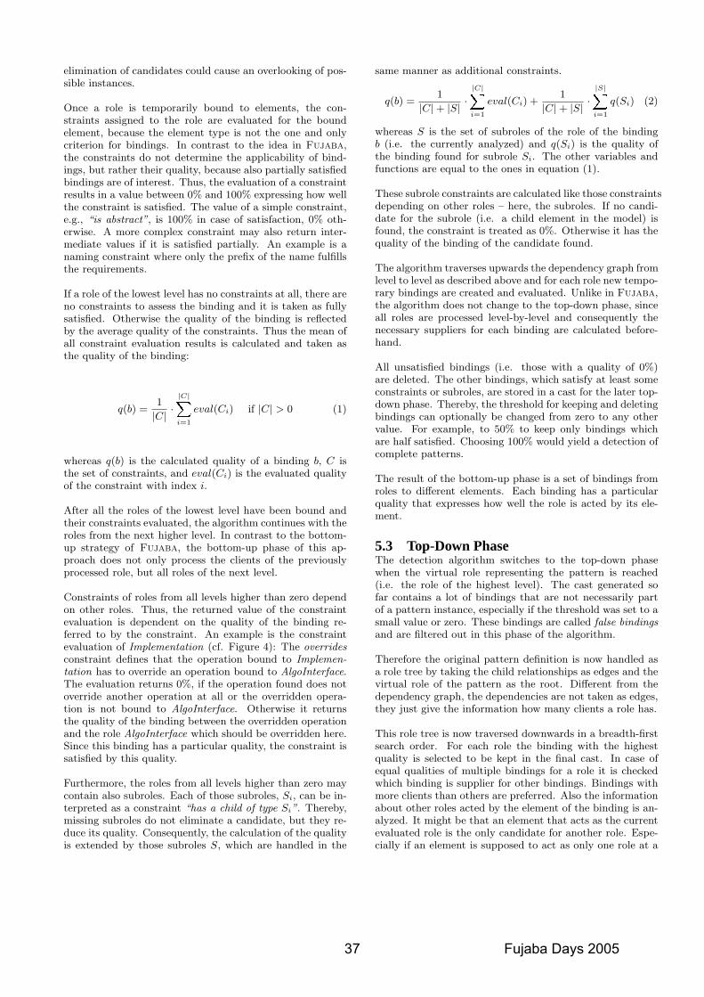
elimination of candidates could cause an overlooking of pos-sible instances.
Once a role is temporarily bound to elements, the con-straints assigned to the role are evaluated for the boundelement, because the element type is not the one and onlycriterion for bindings. In contrast to the idea in Fujaba,the constraints do not determine the applicability of bind-ings, but rather their quality, because also partially satisfiedbindings are of interest. Thus, the evaluation of a constraintresults in a value between 0% and 100% expressing how wellthe constraint is satisfied. The value of a simple constraint,e.g., “is abstract”, is 100% in case of satisfaction, 0% oth-erwise. A more complex constraint may also return inter-mediate values if it is satisfied partially. An example is anaming constraint where only the prefix of the name fulfillsthe requirements.
If a role of the lowest level has no constraints at all, there areno constraints to assess the binding and it is taken as fullysatisfied. Otherwise the quality of the binding is reflectedby the average quality of the constraints. Thus the mean ofall constraint evaluation results is calculated and taken asthe quality of the binding:
q(b) =1
|C| ·|C|X
i=1
eval(Ci) if |C| > 0 (1)
whereas q(b) is the calculated quality of a binding b, C isthe set of constraints, and eval(Ci) is the evaluated qualityof the constraint with index i.
After all the roles of the lowest level have been bound andtheir constraints evaluated, the algorithm continues with theroles from the next higher level. In contrast to the bottom-up strategy of Fujaba, the bottom-up phase of this ap-proach does not only process the clients of the previouslyprocessed role, but all roles of the next level.
Constraints of roles from all levels higher than zero dependon other roles. Thus, the returned value of the constraintevaluation is dependent on the quality of the binding re-ferred to by the constraint. An example is the constraintevaluation of Implementation (cf. Figure 4): The overridesconstraint defines that the operation bound to Implemen-tation has to override an operation bound to AlgoInterface.The evaluation returns 0%, if the operation found does notoverride another operation at all or the overridden opera-tion is not bound to AlgoInterface. Otherwise it returnsthe quality of the binding between the overridden operationand the role AlgoInterface which should be overridden here.Since this binding has a particular quality, the constraint issatisfied by this quality.
Furthermore, the roles from all levels higher than zero maycontain also subroles. Each of those subroles, Si, can be in-terpreted as a constraint “has a child of type Si”. Thereby,missing subroles do not eliminate a candidate, but they re-duce its quality. Consequently, the calculation of the qualityis extended by those subroles S, which are handled in the
same manner as additional constraints.
q(b) =1
|C| + |S| ·|C|X
i=1
eval(Ci) +1
|C| + |S| ·|S|X
i=1
q(Si) (2)
whereas S is the set of subroles of the role of the bindingb (i.e. the currently analyzed) and q(Si) is the quality ofthe binding found for subrole Si. The other variables andfunctions are equal to the ones in equation (1).
These subrole constraints are calculated like those constraintsdepending on other roles – here, the subroles. If no candi-date for the subrole (i.e. a child element in the model) isfound, the constraint is treated as 0%. Otherwise it has thequality of the binding of the candidate found.
The algorithm traverses upwards the dependency graph fromlevel to level as described above and for each role new tempo-rary bindings are created and evaluated. Unlike in Fujaba,the algorithm does not change to the top-down phase, sinceall roles are processed level-by-level and consequently thenecessary suppliers for each binding are calculated before-hand.
All unsatisfied bindings (i.e. those with a quality of 0%)are deleted. The other bindings, which satisfy at least someconstraints or subroles, are stored in a cast for the later top-down phase. Thereby, the threshold for keeping and deletingbindings can optionally be changed from zero to any othervalue. For example, to 50% to keep only bindings whichare half satisfied. Choosing 100% would yield a detection ofcomplete patterns.
The result of the bottom-up phase is a set of bindings fromroles to different elements. Each binding has a particularquality that expresses how well the role is acted by its ele-ment.
5.3 Top-Down PhaseThe detection algorithm switches to the top-down phasewhen the virtual role representing the pattern is reached(i.e. the role of the highest level). The cast generated sofar contains a lot of bindings that are not necessarily partof a pattern instance, especially if the threshold was set to asmall value or zero. These bindings are called false bindingsand are filtered out in this phase of the algorithm.
Therefore the original pattern definition is now handled asa role tree by taking the child relationships as edges and thevirtual role of the pattern as the root. Different from thedependency graph, the dependencies are not taken as edges,they just give the information how many clients a role has.
This role tree is now traversed downwards in a breadth-firstsearch order. For each role the binding with the highestquality is selected to be kept in the final cast. In case ofequal qualities of multiple bindings for a role it is checkedwhich binding is supplier for other bindings. Bindings withmore clients than others are preferred. Also the informationabout other roles acted by the element of the binding is an-alyzed. It might be that an element that acts as the currentevaluated role is the only candidate for another role. Espe-cially if an element is supposed to act as only one role at a
37 Fujaba Days 2005
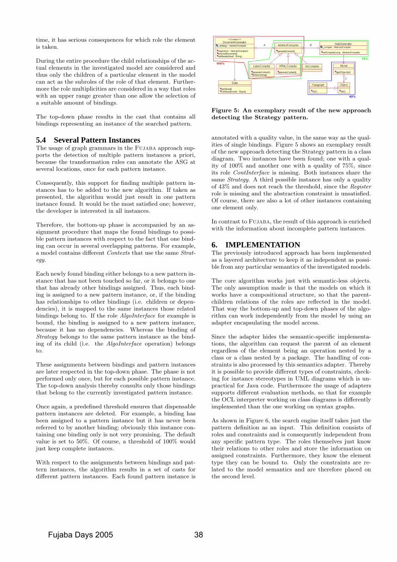
time, it has serious consequences for which role the elementis taken.
During the entire procedure the child relationships of the ac-tual elements in the investigated model are considered andthus only the children of a particular element in the modelcan act as the subroles of the role of that element. Further-more the role multiplicities are considered in a way that roleswith an upper range greater than one allow the selection ofa suitable amount of bindings.
The top-down phase results in the cast that contains allbindings representing an instance of the searched pattern.
5.4 Several Pattern InstancesThe usage of graph grammars in the Fujaba approach sup-ports the detection of multiple pattern instances a priori,because the transformation rules can annotate the ASG atseveral locations, once for each pattern instance.
Consequently, this support for finding multiple pattern in-stances has to be added to the new algorithm. If taken aspresented, the algorithm would just result in one patterninstance found. It would be the most satisfied one; however,the developer is interested in all instances.
Therefore, the bottom-up phase is accompanied by an as-signment procedure that maps the found bindings to possi-ble pattern instances with respect to the fact that one bind-ing can occur in several overlapping patterns. For example,a model contains different Contexts that use the same Strat-egy.
Each newly found binding either belongs to a new pattern in-stance that has not been touched so far, or it belongs to onethat has already other bindings assigned. Thus, each bind-ing is assigned to a new pattern instance, or, if the bindinghas relationships to other bindings (i.e. children or depen-dencies), it is mapped to the same instances those relatedbindings belong to. If the role AlgoInterface for example isbound, the binding is assigned to a new pattern instance,because it has no dependencies. Whereas the binding ofStrategy belongs to the same pattern instance as the bind-ing of its child (i.e. the AlgoInterface operation) belongsto.
These assignments between bindings and pattern instancesare later respected in the top-down phase. The phase is notperformed only once, but for each possible pattern instance.The top-down analysis thereby consults only those bindingsthat belong to the currently investigated pattern instance.
Once again, a predefined threshold ensures that dispensablepattern instances are deleted. For example, a binding hasbeen assigned to a pattern instance but it has never beenreferred to by another binding; obviously this instance con-taining one binding only is not very promising. The defaultvalue is set to 50%. Of course, a threshold of 100% wouldjust keep complete instances.
With respect to the assignments between bindings and pat-tern instances, the algorithm results in a set of casts fordifferent pattern instances. Each found pattern instance is
Figure 5: An exemplary result of the new approachdetecting the Strategy pattern.
annotated with a quality value, in the same way as the qual-ities of single bindings. Figure 5 shows an exemplary resultof the new approach detecting the Strategy pattern in a classdiagram. Two instances have been found; one with a qual-ity of 100% and another one with a quality of 75%, sinceits role ContInterface is missing. Both instances share thesame Strategy. A third possible instance has only a qualityof 43% and does not reach the threshold, since the Registerrole is missing and the abstraction constraint is unsatisfied.Of course, there are also a lot of other instances containingone element only.
In contrast to Fujaba, the result of this approach is enrichedwith the information about incomplete pattern instances.
6. IMPLEMENTATIONThe previously introduced approach has been implementedas a layered architecture to keep it as independent as possi-ble from any particular semantics of the investigated models.
The core algorithm works just with semantic-less objects.The only assumption made is that the models on which itworks have a compositional structure, so that the parent-children relations of the roles are reflected in the model.That way the bottom-up and top-down phases of the algo-rithm can work independently from the model by using anadapter encapsulating the model access.
Since the adapter hides the semantic-specific implementa-tions, the algorithm can request the parent of an elementregardless of the element being an operation nested by aclass or a class nested by a package. The handling of con-straints is also processed by this semantics adapter. Therebyit is possible to provide different types of constraints, check-ing for instance stereotypes in UML diagrams which is un-practical for Java code. Furthermore the usage of adapterssupports different evaluation methods, so that for examplethe OCL interpreter working on class diagrams is differentlyimplemented than the one working on syntax graphs.
As shown in Figure 6, the search engine itself takes just thepattern definition as an input. This definition consists ofroles and constraints and is consequently independent fromany specific pattern type. The roles themselves just knowtheir relations to other roles and store the information onassigned constraints. Furthermore, they know the elementtype they can be bound to. Only the constraints are re-lated to the model semantics and are therefore placed onthe second level.
Fujaba Days 2005 38
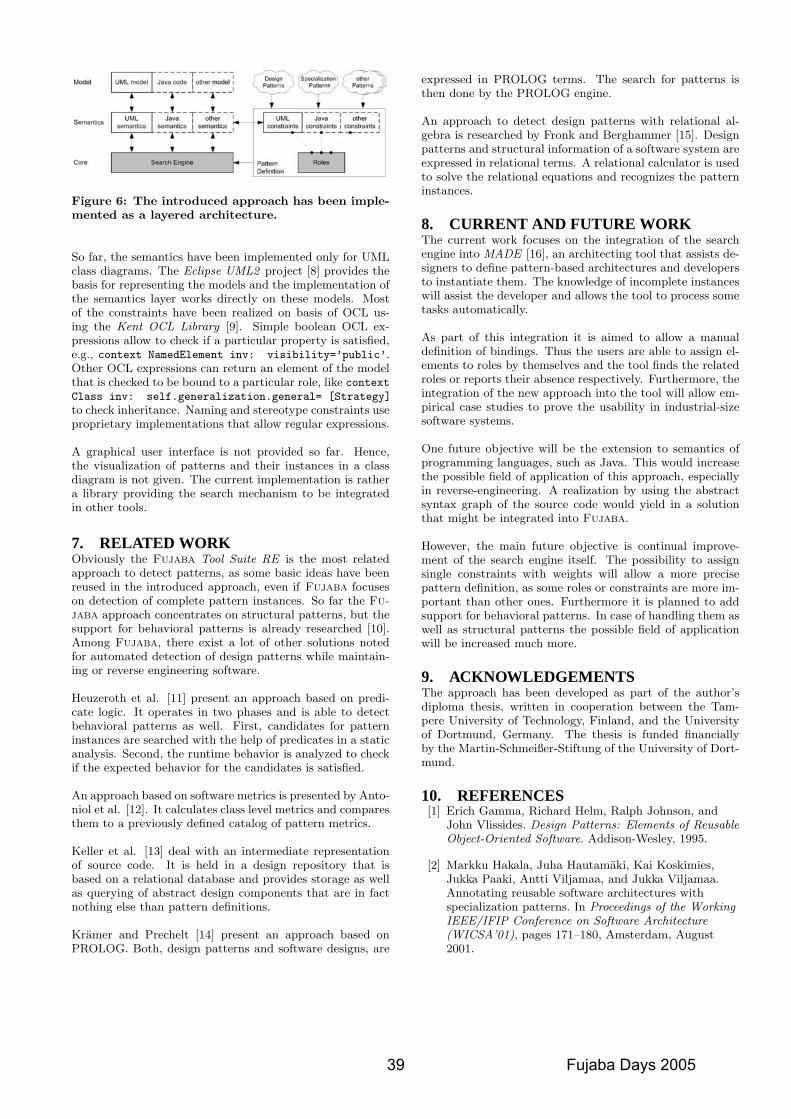
Figure 6: The introduced approach has been imple-mented as a layered architecture.
So far, the semantics have been implemented only for UMLclass diagrams. The Eclipse UML2 project [8] provides thebasis for representing the models and the implementation ofthe semantics layer works directly on these models. Mostof the constraints have been realized on basis of OCL us-ing the Kent OCL Library [9]. Simple boolean OCL ex-pressions allow to check if a particular property is satisfied,e.g., context NamedElement inv: visibility=’public’.Other OCL expressions can return an element of the modelthat is checked to be bound to a particular role, like contextClass inv: self.generalization.general= [Strategy]
to check inheritance. Naming and stereotype constraints useproprietary implementations that allow regular expressions.
A graphical user interface is not provided so far. Hence,the visualization of patterns and their instances in a classdiagram is not given. The current implementation is rathera library providing the search mechanism to be integratedin other tools.
7. RELATED WORKObviously the Fujaba Tool Suite RE is the most relatedapproach to detect patterns, as some basic ideas have beenreused in the introduced approach, even if Fujaba focuseson detection of complete pattern instances. So far the Fu-jaba approach concentrates on structural patterns, but thesupport for behavioral patterns is already researched [10].Among Fujaba, there exist a lot of other solutions notedfor automated detection of design patterns while maintain-ing or reverse engineering software.
Heuzeroth et al. [11] present an approach based on predi-cate logic. It operates in two phases and is able to detectbehavioral patterns as well. First, candidates for patterninstances are searched with the help of predicates in a staticanalysis. Second, the runtime behavior is analyzed to checkif the expected behavior for the candidates is satisfied.
An approach based on software metrics is presented by Anto-niol et al. [12]. It calculates class level metrics and comparesthem to a previously defined catalog of pattern metrics.
Keller et al. [13] deal with an intermediate representationof source code. It is held in a design repository that isbased on a relational database and provides storage as wellas querying of abstract design components that are in factnothing else than pattern definitions.
Kramer and Prechelt [14] present an approach based onPROLOG. Both, design patterns and software designs, are
expressed in PROLOG terms. The search for patterns isthen done by the PROLOG engine.
An approach to detect design patterns with relational al-gebra is researched by Fronk and Berghammer [15]. Designpatterns and structural information of a software system areexpressed in relational terms. A relational calculator is usedto solve the relational equations and recognizes the patterninstances.
8. CURRENT AND FUTURE WORKThe current work focuses on the integration of the searchengine into MADE [16], an architecting tool that assists de-signers to define pattern-based architectures and developersto instantiate them. The knowledge of incomplete instanceswill assist the developer and allows the tool to process sometasks automatically.
As part of this integration it is aimed to allow a manualdefinition of bindings. Thus the users are able to assign el-ements to roles by themselves and the tool finds the relatedroles or reports their absence respectively. Furthermore, theintegration of the new approach into the tool will allow em-pirical case studies to prove the usability in industrial-sizesoftware systems.
One future objective will be the extension to semantics ofprogramming languages, such as Java. This would increasethe possible field of application of this approach, especiallyin reverse-engineering. A realization by using the abstractsyntax graph of the source code would yield in a solutionthat might be integrated into Fujaba.
However, the main future objective is continual improve-ment of the search engine itself. The possibility to assignsingle constraints with weights will allow a more precisepattern definition, as some roles or constraints are more im-portant than other ones. Furthermore it is planned to addsupport for behavioral patterns. In case of handling them aswell as structural patterns the possible field of applicationwill be increased much more.
9. ACKNOWLEDGEMENTSThe approach has been developed as part of the author’sdiploma thesis, written in cooperation between the Tam-pere University of Technology, Finland, and the Universityof Dortmund, Germany. The thesis is funded financiallyby the Martin-Schmeißer-Stiftung of the University of Dort-mund.
10. REFERENCES[1] Erich Gamma, Richard Helm, Ralph Johnson, and
John Vlissides. Design Patterns: Elements of ReusableObject-Oriented Software. Addison-Wesley, 1995.
[2] Markku Hakala, Juha Hautamaki, Kai Koskimies,Jukka Paaki, Antti Viljamaa, and Jukka Viljamaa.Annotating reusable software architectures withspecialization patterns. In Proceedings of the WorkingIEEE/IFIP Conference on Software Architecture(WICSA’01), pages 171–180, Amsterdam, August2001.
39 Fujaba Days 2005
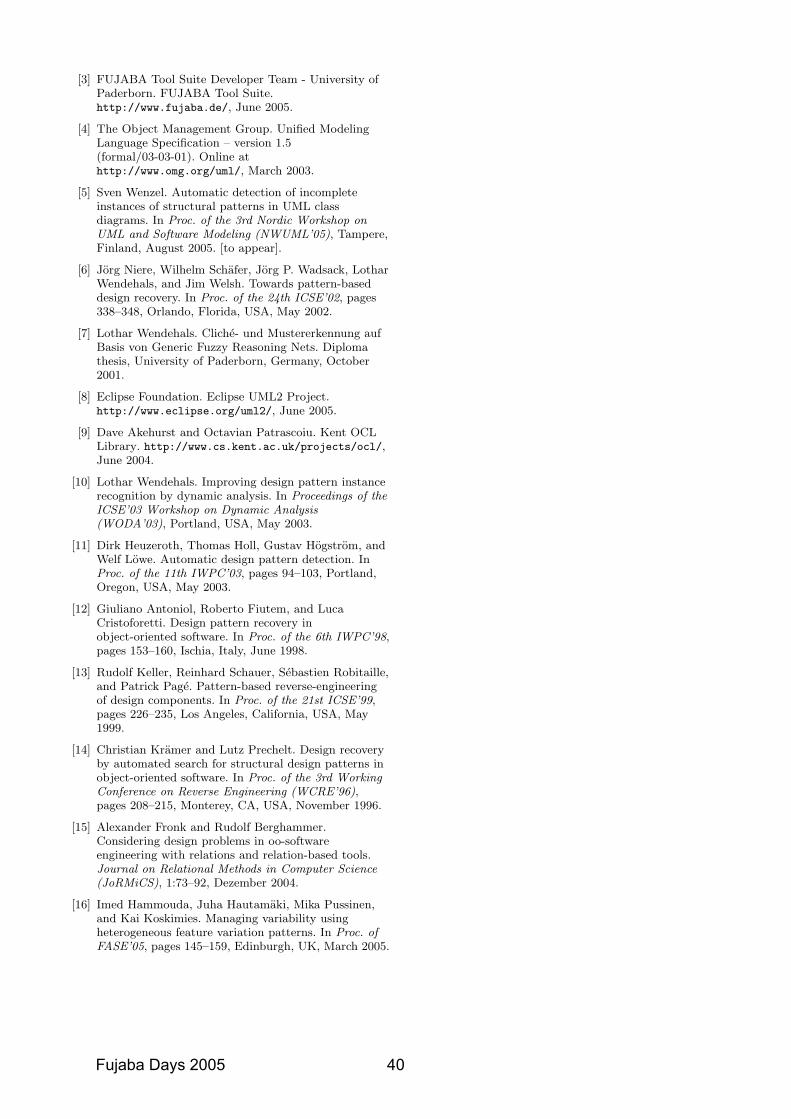
[3] FUJABA Tool Suite Developer Team - University ofPaderborn. FUJABA Tool Suite.http://www.fujaba.de/, June 2005.
[4] The Object Management Group. Unified ModelingLanguage Specification – version 1.5(formal/03-03-01). Online athttp://www.omg.org/uml/, March 2003.
[5] Sven Wenzel. Automatic detection of incompleteinstances of structural patterns in UML classdiagrams. In Proc. of the 3rd Nordic Workshop onUML and Software Modeling (NWUML’05), Tampere,Finland, August 2005. [to appear].
[6] Jorg Niere, Wilhelm Schafer, Jorg P. Wadsack, LotharWendehals, and Jim Welsh. Towards pattern-baseddesign recovery. In Proc. of the 24th ICSE’02, pages338–348, Orlando, Florida, USA, May 2002.
[7] Lothar Wendehals. Cliche- und Mustererkennung aufBasis von Generic Fuzzy Reasoning Nets. Diplomathesis, University of Paderborn, Germany, October2001.
[8] Eclipse Foundation. Eclipse UML2 Project.http://www.eclipse.org/uml2/, June 2005.
[9] Dave Akehurst and Octavian Patrascoiu. Kent OCLLibrary. http://www.cs.kent.ac.uk/projects/ocl/,June 2004.
[10] Lothar Wendehals. Improving design pattern instancerecognition by dynamic analysis. In Proceedings of theICSE’03 Workshop on Dynamic Analysis(WODA’03), Portland, USA, May 2003.
[11] Dirk Heuzeroth, Thomas Holl, Gustav Hogstrom, andWelf Lowe. Automatic design pattern detection. InProc. of the 11th IWPC’03, pages 94–103, Portland,Oregon, USA, May 2003.
[12] Giuliano Antoniol, Roberto Fiutem, and LucaCristoforetti. Design pattern recovery inobject-oriented software. In Proc. of the 6th IWPC’98,pages 153–160, Ischia, Italy, June 1998.
[13] Rudolf Keller, Reinhard Schauer, Sebastien Robitaille,and Patrick Page. Pattern-based reverse-engineeringof design components. In Proc. of the 21st ICSE’99,pages 226–235, Los Angeles, California, USA, May1999.
[14] Christian Kramer and Lutz Prechelt. Design recoveryby automated search for structural design patterns inobject-oriented software. In Proc. of the 3rd WorkingConference on Reverse Engineering (WCRE’96),pages 208–215, Monterey, CA, USA, November 1996.
[15] Alexander Fronk and Rudolf Berghammer.Considering design problems in oo-softwareengineering with relations and relation-based tools.Journal on Relational Methods in Computer Science(JoRMiCS), 1:73–92, Dezember 2004.
[16] Imed Hammouda, Juha Hautamaki, Mika Pussinen,and Kai Koskimies. Managing variability usingheterogeneous feature variation patterns. In Proc. ofFASE’05, pages 145–159, Edinburgh, UK, March 2005.
Fujaba Days 2005 40
Calculation and Visualization of Software Product Metrics
Matthias Meyer∗Software Engineering Group
Department of Computer ScienceUniversity of PaderbornWarburger Straße 100
33098 Paderborn, Germany
Jorg NiereSoftware Engineering Group
Department of Computer ScienceUniversity of Siegen
Holderlinstr. 357068 Siegen, Germany
ABSTRACTThe paper presents a further step of the Fujaba Tool Sui-te RE to support coarse-grained analyses based on metricsand especially polymetric views. Polymetric views are gra-phical representations of certain metric combinations. Fol-lowing an interactive reverse engineering approach, polyme-tric views can be created on demand. The reverse engineer isable to define new polymetric view descriptions and createnew views afterwards.
1. INTRODUCTIONSoftware product metrics are one opportunity to perform
coarse-grained analyses. Metrics such as lines of code, num-ber of attributes or methods of a class, lack of cohesion ordepth of inheritance hierarchies ([3, 4, 5, 7]) allow for pro-ducing quantitative analysis results of a software system.A combination of different metrics allows to draw conclu-sions such as problematic or high influencing system parts.To overcome the flood of numbers produced by the metrics,Lanza proposes in [6] a graphical representation of the me-tric combinations. So-called polymetric views are an idealmeans to get a first impression of a system.
The Fujaba Tool Suite RE is a collection of reverse engi-neering tools based on the Fujaba Tool Suite [10] and severalFujaba plug-ins. The Fujaba Tool Suite RE allows for par-sing Java source code into an Abstract Syntax Graph (ASG)representation, which serves as central repository to all fur-ther analyses. Currently the Tool Suite RE consists of staticand dynamic analysis techniques to recognize implementa-tions of patterns [8], such as design patterns or antipatterns[1]. The techniques allow for performing a fine-grained ana-lysis of a system. Coarse-grained analyses are also possible,but produce too many uncertain results.
In order to support also fast and reliable coarse-grainedanalyses, we extended the Fujaba Tool Suite RE with twoplug-ins. The first plug-in, called MetricsCalculation and de-scribed in Section 2, offers the calculation of several object-oriented software product metrics. The second plug-in Po-lymetricViews, described in Section 3, allows for viewing themetric results calculated by the first plug-in in polymetricviews as introduced by Lanza. The paper closes with somefuture work issues.
∗This work is part of the Finite project funded by the Ger-man Research Foundation (DFG), prj-no. SCHA 745/2-2.
2. METRICS CALCULATIONBefore the MetricsCalculation plug-in is able to calculate
software product metrics for certain model elements, the sy-stem to be analyzed has to be parsed into the Abstract Syn-tax Graph (ASG) representation. Therefore the MetricsCal-culation plug-in uses the JavaAST plug-in and the JavaParserplug-in. The ASG comprises UML elements such as classes,attributes and methods as well as elements corresponding toclassical syntax trees such as literals or assignments. Where-as the UML elements are used to represent declaration parts,the other elements are used to represent method bodies. Inthe following we call the whole representation the model ofthe source code.
Each metric has a unique acronym, e.g. LOC which standsfor Lines Of Code or NOC, Number Of Children, which isthe number of direct sub classes of a class. The user mayselect the metrics to be calculated from the list of all sup-ported metrics (cf. Table 1). Each metric value together withits acronym is stored in a separate result object that is linkedto the corresponding model element via Meta-Model Inte-gration (MMI) pattern [2]. The plug-in offers to present allresults in a table.
2.1 Contributing a new metricFar more metrics exist than currently are supported by
the plug-in. Therefore, the plug-in was designed to be easilyextended by new metrics. Each metric can be calculated fora particular type of model element. LOC, for example, iscalculated for a method, the metric WLOC computes thelines of code for a whole class, and the number of children(NOC) is calculated on classes as well. For each metric, acalculator class exists which takes a model element of theappropriate type as input and calculates its metric value.All calculator classes implement a common interface. Thedata about available metrics is stored in an XML file. Thefile contains an XML element for each metric, which besidesthe unique acronym contains a name, a description, and thefully qualified name of the calculator class. Thus, in order tocontribute a new metric, a calculator class that implementsthe common interface must be developed and an elementdescribing the metric has to be added to the XML file.
2.2 Metric thresholdsFor each metric, the user may additionally configure a
threshold. If the metric value of a model element exceedsthis threshold, an annotation is created which connects themodel element and the result object (again via MMI pat-tern). Currently, the annotations are only visible in class
1
41 Fujaba Days 2005
mtt
Rectangle
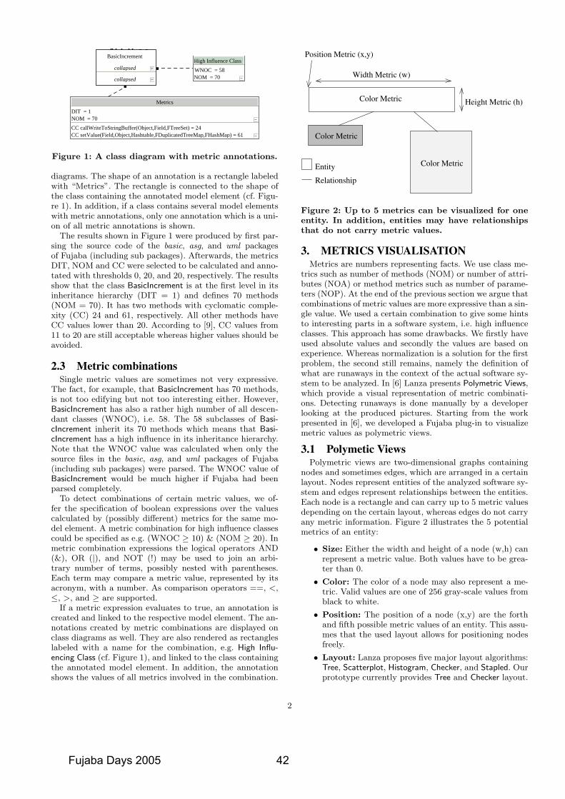
DIT = 1Metrics
DIT = 2Metrics
NOM = 24DIT = 1
Metrics
DIT = 1Metrics
DIT = 1Metrics
DIT = 2Metrics
DIT = 1Metrics
DIT = 1Metrics
DIT = 1Metrics
DIT = 1Metrics
DIT = 1Metrics
DIT = 1Metrics
DIT = 1Metrics
DIT = 2Metrics
DIT = 2Metrics
DIT = 1Metrics
DIT = 1Metrics
DIT = 2Metrics
hjljh
Integer : ) (sizeOfTemplatesVoid : )TemplateManager:manager (set
Void : ) (resetTemplatesBoolean : )String:key (removeKeyFromTemplates
Boolean : )TemplateFile:obj (removeFromTemplatesVoid : ) (removeAllFromTemplates
Iterator : ) (keysOfTemplatesIterator : ) (iteratorOfTemplates
Boolean : )String:key (hasKeyInTemplatesBoolean : )TemplateFile:obj (hasInTemplates
TemplateFile : )String:filename (getTemplateTemplateFile : )String:key (getFromTemplates
TemplateManager : ) (getIterator : ) (entriesOfTemplates
Boolean : )TemplateFile:obj (addToTemplates
FHashMap : templatesTemplateManager : manager
TemplateManager
Boolean : )String:name, File:dir (accept)String:start (NameFilter
String : start
NameFilter
Void : )String:line (parseLineVector : ) (getFileVector
File[] : ) (getFileArrayInteger : ) (getErrorState
String : ) (getCommandLineString : )String:selection, String:line (createPathListSelection
)Integer:type, String:selection, String:line (CommandLineParser)String:line (CommandLineParser
0 = Integer : mode NO_ERROR = Integer : errorType
"" = String : commandLine new Vector() = Vector : allFiles
1 = Integer : WRONG_EXPRESSION 8 = Integer : PATH_NOT_EXISTS
2 = Integer : PATH_LIST 0 = Integer : NO_ERROR
2 = Integer : NO_COMMAND 4 = Integer : EMPTY_COMMANDLINE
1 = Integer : COMMAND_LINE
CommandLineParser
Integer : )Object:o2, Object:o1 (compare
TreeNodeComparator
String : )String:strg (upFirstCharString : )Integer:width, String:text (textToWidth
String : )String:string (quoteString : )String:s (nullIfEmpty
Boolean : )String:s (isNullOrEmptyString : )String:strg (downStart
String : )String:strg (downFirstChar
Utility
Void : )FIncrement:increment (objectSelected
FujabaObjectSelectListener
«interface»
Entry
«interface»
«reference»
String : ) (toStringObject : )Object:value (setValue
Object : ) (getValueObject : ) (getKey
)Object:value, String:key (KeyValuePair)BasicIncrement:value, BasicIncrement:key (KeyValuePair
Object : valueObject : key
KeyValuePair
ListIterator
«interface»
«reference»
Integer : ) (size
Void : ) (resetInteger : ) (previousIndex
Object : ) (previousInteger : ) (nextIndex
Object : ) (nextBoolean : ) (hasPrevious
Boolean : ) (hasNextObject : )Integer:index (get
Integer : ) (currentIndex)Integer:start (AbstractListIterator
) (AbstractListIterator
Integer : startInteger : pos
true = Boolean : first
AbstractListIterator
String : )Object:obj (toStringString : )FType:type (toString
String : )FParam:incr (toStringString : )FMethod:incr (toString
String : )FClass:incr (toStringString : )FBaseTypes:incr (toString
String : )BasicIncrement:incr (toStringVoid : )Boolean:value (setRemoveYouPrinted
Void : )String:out (printlnVoid : )Object:out (println
Void : )String:out (printVoid : )Object:out (print
Boolean : ) (isRemoveYouPrintedBoolean : )String:debugValue (isOnBoolean : )Integer:debugValue (isOn
Boolean : ) (isOn
false = Boolean : removeYouPrinted false = Boolean : DEF_DEFAULT_PLUGIN_DEBUG
FD
Void : ) (initClass : )String:name (getClass
ClassMap : ) (getClass : )String:name (forName
) (ClassMap
null = ClassMap : theInstance new Hashtable (128) = Hashtable : map
ClassMap
Void : )String:s (setCommentString : ) (getComment
Boolean : )ClassLoader:classLoader, String:fileName (doFileBoolean : )String:fileName (doFile
Void : )String:currentLine (doCurrentLine
Logger.getLogger (FileStringReader.class) = Logger : log null = String : comment
FileStringReader
Void : )FTypeList:types (setTypesVoid : )String:fpackage (setFpackage
Void : )FHashMap:classes (setClassesVoid : )FClassDiagram:classDiag (setClassDiag
FTypeList : ) (getTypesString : ) (getFpackage
FHashMap : ) (getClassesFClassDiagram : ) (getClassDiag
Void : )String:currentLine (doCurrentLineFClassDiagram : )String:name (createClassDiagram
FClass : )Boolean:interf, String:packageName, FClass:genClass, FDiagram:diag, String:className (createClassFAttr : )FClass:clazz, FType:type, String:name (createAttr
FAssoc : )Integer:sel, String:rightCard, String:rightName, String:leftCard, String:leftName, FClass:right, FClass:left, String:name (createAssoc)ClassLoader:loader, String:path, String:name (ClassDiagTemplateLoader
)ClassLoader:loader, String:name (ClassDiagTemplateLoader
null = FTypeList : types null = String : fpackage
new FHashMap() = FHashMap : classes null = FClassDiagram : classDiag
ClassDiagTemplateLoader
Void : )String:str (append)JScrollPane:scrollPane (AutoScrollTextArea
JScrollPane : scrollPane
AutoScrollTextArea
Void : ) (stopVoid : ) (run
)JTextArea:out, InputStream:in (StreamPoller
false = Boolean : stopped null = JTextArea : out
null = InputStreamReader : in
StreamPoller
Void : )Integer:exitValue, String:output (outputFinishedVoid : ) (outputCleared
Void : )String:newLine (outputAppended
OutputListener
«interface»
Thread
«reference»
Void : ) (run)JInternalFrame:aframe (MyThread
JInternalFrame : frame
MyThread
JInternalFrame
«reference»
Void : ) (switchProcessStateVoid : ) (stopThreadsVoid : ) (startThreads
Void : )MouseListener:mouseListener (setMouseListenerVoid : )ActionListener:act (setExitAction
Void : )String:commandLine (setCommandLineVoid : ) (resetProcessState
Void : )OutputListener:listener (removeOutputListenerVoid : ) (recompileButtonPressed
Void : )String:commandLine (quietExecuteCommandVoid : )ProcessEvent:event (notifyAllProcessListeners
Void : )String[]:argv (mainBoolean : ) (isRunning
Boolean : ) (isAutoContinueEnabledMap : ) (getenv
String : ) (getOutputActionListener : ) (getExitAction
Map : ) (getEnvironmentString : ) (getCommandLine
Void : ) (exitButtonPressedVoid : )String:title, String:commandLine (executeCommand
Void : )String:commandLine (executeCommandVoid : ) (executeButtonPressed
String[] : )Map:properties (convertEnvironmentBoolean : )String:cmdLine (compileAndWaitForResult
Void : )ProcessListener:newListener (addProcessListenerVoid : )OutputListener:listener (addOutputListener
)Boolean:show, Boolean:calledByCompileAction (ProcessOutputViewer) (ProcessOutputViewer
{"waiting...", "starting...", "running...", "finished"} = String[] : states new JButton ("Again") = JButton : recompile
new JLabel ("State: " + states[0]) = JLabel : processStateLabel new FTreeSet() = FTreeSet : processListeners
new JLabel ("Command: ") = JLabel : processCommandLabel null = Process : process
null = StreamPoller : normalOutputPoller new JTextArea() = JTextArea : normalOutput
4 = Integer : maxProcessStates Logger.getLogger (ProcessOutputViewer.class) = Logger : log
Collection : listeners "Exit" = String : exitText
null = ActionListener : exitAction new JButton (exitText) = JButton : exit
new JButton ("Execute") = JButton : execute null = StreamPoller : errorOutputPoller
getenv() = Map : environment 0 = Integer : curProcessState
new JComboBox() = JComboBox : commandLineBox new JButton ("Clear History") = JButton : clearHistory new JButton ("Clear Display") = JButton : clearDisplayBoolean : calledByCompileAction
JPanel : advancedPanel
ProcessOutputViewer
Void : ) (startVoid : ) (interrupt
Object : ) (getVoid : ) (finished
Object : ) (construct
) (SwingWorker
Object : valueThread : thread
SwingWorker
String : ) (toStringInteger : ) (sizeOfCodeBlocks
Void : )LongInteger:tag (setModifiedTagBoolean : )TemplateManager:obj (setManager
Void : )String:filename (setFilenameString : )String:line (retrieveCodeBlockName
Boolean : )String:key (removeKeyFromCodeBlocksBoolean : )TemplateCodeBlock:obj (removeFromCodeBlocks
Void : ) (removeAllFromCodeBlocksVoid : )BufferedReader:in, String:line (processLine
Void : ) (parseBufferedReader : ) (open
Iterator : ) (keysOfCodeBlocksIterator : ) (iteratorOfCodeBlocks
Boolean : ) (isModifiedBoolean : )String:key (hasKeyInCodeBlocks
Boolean : )TemplateCodeBlock:obj (hasInCodeBlocksLongInteger : ) (getModifiedTag
TemplateManager : ) (getManagerTemplateCodeBlock : )String:key (getFromCodeBlocks
String : ) (getFilenameIterator : ) (entriesOfCodeBlocks
Boolean : )TemplateCodeBlock:obj (addToCodeBlocks)String:filename (TemplateFile
0 = LongInteger : modifiedTagTemplateManager : manager
Logger.getLogger (TemplateFile.class) = Logger : log "" = String : filename
FHashMap : codeBlocks
TemplateFile
Void : )FLinkedList:lastSelected (setLastSelectedVoid : )String:incrID (selectIncrByID
Void : ) (removeLastSelectedVoid : )ASGElement:element (gotoElement
FLinkedList : ) (getLastSelectedIncrSelector : ) (get
) (IncrSelector
new IncrSelector() = IncrSelector : selector Logger.getLogger (IncrSelector.class) = Logger : log
null = FLinkedList : lastSelected
IncrSelector
Class : )Boolean:resolve, String:name (loadClassClassLoader : ) (get
URL : )String:name (findResource) (UnifiedClassLoader
ClassLoader : instance
UnifiedClassLoader
String : ) (getDescriptionVoid : )String:ext (addExtension
Boolean : )String:name, File:f (acceptBoolean : )File:f (accept
)String:description, String:ext (SchemaFilter
new LinkedList() = LinkedList : extensionsString : description
SchemaFilter
Integer : ) (sizeOfTokensBoolean : )TemplateFile:obj (setTemplate
Void : )String:name (setNameBoolean : )TemplateToken:obj (removeFromTokens
Void : ) (removeAllFromTokensVoid : )BufferedReader:in, String:line (processLine
Void : )BufferedReader:in (parseIterator : ) (iteratorOfTokens
Boolean : )TemplateToken:obj (hasInTokensTemplateFile : ) (getTemplate
Iterator : )FHashMap:parameter (getSourceCodeLinesString : )FHashMap:parameter (getSourceCode
String : ) (getNameBoolean : )TemplateToken:obj (addToTokens
Void : )String:placeholder (addPlaceholderTokenVoid : )String:code (addCodeToken
)String:name (TemplateCodeBlock
FLinkedList : tokensTemplateFile : template
"" = String : name Logger.getLogger (TemplateCodeBlock.class) = Logger : log
TemplateCodeBlock
Integer : ) (getReturnCode)Integer:rc (ProcessEvent
Integer : returnCode
ProcessEvent
Initializer{}Comparator : ) (getPackageComparator
Comparator : ) (getLessTypeComparator : ) (getLessString
Comparator : ) (getLessClassNameComparator : ) (getLessBasicIncrComparator : ) (createLessString
Logger.getLogger (FujabaComparator.class) = Logger : loggerComparator : lessString
FujabaComparator
Void : )String:out (printlnVoid : )Object:out (println
Void : )String:out, Integer:debugValue (printlnVoid : )Object:out, Integer:debugValue (println
Void : )Integer:debugValue (printlnVoid : ) (println
Void : )Integer:end, Integer:begin (printStackTraceVoid : )Integer:depth (printStackTrace
Void : ) (printStackTraceVoid : ) (printRemoveYouStack
Void : )String:out (printVoid : )Object:out (print
Void : )String:out, Integer:debugValue (printVoid : )Object:out, Integer:debugValue (print
Void : )Integer:debugValue (printVoid : ) (print
String : )Integer:end, Integer:begin, Throwable:throwable (getStackTraceString : )Integer:end, Integer:begin (getStackTrace
Void : )Object:out (_printlnVoid : )Object:out (_print
DebugPreferences.get() = DebugPreferences : options true = Boolean : SETATTRSTONULL
FujabaDebug
StringBuffer : )String:strg (upFirstCharVoid : )String:newStrg (setIndentString
String : )Boolean:aggregation, Boolean:isUsingAttr, Boolean:isPartnerQualified, Boolean:isQualified, Boolean:toOne, String:type, String:roleName (removeYouBody
StringBuffer : ) (newLineStringBuffer : )Character:c, Integer:n (itChar
Void : ) (incIndentString : ) (getIndentString
String : )Integer:type, String:fieldTypeName, String:name (getFullAccessMethodName
String : )Boolean:selfQualified, Boolean:qualifier, Integer:upperBound, String:name, Integer:type (getAssocAccessMethodLine
String : )Boolean:selfQualified, Integer:upperBound, String:name, Integer:type (getAssocAccessMethodLine
String : )Integer:type, String:name (getAccessMethodNameVoid : ) (decIndent
String : )sIsAggr, Boolean:fIsAggr, Boolean:sIsRef, Boolean:fIsRef, String:sQualifierName, String:fQualifierName, String:sCard, String:sRoleName, String:sClassName, String:constraint, String:assocName, String:fCard, String:fRoleName, String:fClassName (assocCommentary
" " = String : indentString 0 = Integer : indent
REMOVE_YOU_METHOD + 1 = Integer : SIZE_OF_METHOD IS_METHOD + 1 = Integer : SET_METHOD
ADD_AFTER_OF_METHOD + 1 = Integer : SET_IN_METHOD GET_FROM_METHOD + 1 = Integer : REMOVE_YOU_METHOD
REMOVE_KEY_FROM_METHOD + 1 = Integer : REMOVE_VALUE_FROM_METHOD ADD_METHOD + 1 = Integer : REMOVE_METHOD
KEYS_OF_METHOD + 1 = Integer : REMOVE_KEY_FROM_METHOD REMOVE_VALUE_FROM_METHOD + 1 = Integer : REMOVE_ENTRY_FROM_METHOD
SIZE_OF_METHOD + 1 = Integer : REMOVE_ALL_FROM_METHOD INDEX_OF_METHOD + 1 = Integer : LAST_INDEX_OF_METHOD
GET_KEY_FOR_METHOD + 1 = Integer : KEY_CHANGED_IN_METHOD HAS_ENTRY_IN_METHOD + 1 = Integer : KEYS_OF_METHOD
HAS_IN_METHOD + 1 = Integer : ITERATOR_OF_METHOD GET_METHOD + 1 = Integer : IS_METHOD
LAST_INDEX_OF_METHOD + 1 = Integer : IS_BEFORE_OF_METHOD IS_BEFORE_OF_METHOD + 1 = Integer : IS_AFTER_OF_METHOD
GET_AT_METHOD + 1 = Integer : INDEX_OF_METHOD GET_KEY_FROM_METHOD + 1 = Integer : HAS_VALUE_IN_METHOD
HAS_VALUE_IN_METHOD + 1 = Integer : HAS_KEY_IN_METHOD SET_METHOD + 1 = Integer : HAS_IN_METHOD
HAS_KEY_IN_METHOD + 1 = Integer : HAS_ENTRY_IN_METHOD REMOVE_ALL_FROM_METHOD + 1 = Integer : GET_VALUE_FROM_METHOD GET_NEXT_INDEX_OF_METHOD + 1 = Integer : GET_PREVIOUS_OF_METHOD
GET_PREVIOUS_OF_METHOD + 1 = Integer : GET_PREVIOUS_INDEX_OF_METHOD GET_LAST_OF_METHOD + 1 = Integer : GET_NEXT_OF_METHOD
GET_NEXT_OF_METHOD + 1 = Integer : GET_NEXT_INDEX_OF_METHOD REMOVE_METHOD + 1 = Integer : GET_METHOD
GET_FIRST_OF_METHOD + 1 = Integer : GET_LAST_OF_METHOD GET_VALUE_FROM_METHOD + 1 = Integer : GET_KEY_FROM_METHOD
SET_IN_METHOD + 1 = Integer : GET_KEY_FOR_METHOD ITERATOR_OF_METHOD + 1 = Integer : GET_FROM_METHOD
IS_AFTER_OF_METHOD + 1 = Integer : GET_FIRST_OF_METHOD ENTRIES_OF_METHOD + 1 = Integer : GET_AT_METHOD
REMOVE_ENTRY_FROM_METHOD + 1 = Integer : ENTRIES_OF_METHOD 0 = Integer : ADD_METHOD
GET_PREVIOUS_INDEX_OF_METHOD + 1 = Integer : ADD_BEFORE_OF_METHOD ADD_BEFORE_OF_METHOD + 1 = Integer : ADD_AFTER_OF_METHOD
SourceCodeFactory
String : )Boolean:aggregation, Boolean:isInternalQualified, Boolean:isPartnerQualified, Boolean:isQualified, Boolean:toOne, String:type, String:roleName (removeYouBodyString : )Boolean:selfQualified, Boolean:qualifier, Integer:upperBound, String:name, Integer:type (getAssocAccessMethodLine
String : )Boolean:sIsAggr, Boolean:fIsAggr, Boolean:sIsRef, Boolean:fIsRef, String:sQualifierName, String:fQualifierName, String:sCard, String:sRoleName, String:sClassName, String:constraint, String:assocName, String:fCard, String:fRoleName, String:fClassName (assocCommentary
JavaFactory
Void : )Integer:newScale (setScaleInteger : ) (getScale
Font : ) (getJavaSourceFontFont : )Integer:size, Integer:style, Integer:type (getFont
Font : )Integer:size, Integer:type (getFontFont : )Integer:type (getFont
Font : ) (getDefaultFont
0 = Integer : scale new FHashMap() = FHashMap : fonts
1 = Integer : JAVA_SOURCE_FONT 12 = Integer : DEFAULT_FONT_SIZE
0 = Integer : DEFAULT_FONT
FontContainer
«final»
Void : )ProcessEvent:event (processFinished
ProcessListener
«interface»
Integer : )Object:o2, Object:o1 (compare
ObjectComparator
PropertyChangeSupport
«reference»
TestRunner
«reference»
Void : )String[]:args (mainTestSuiteLoader : ) (getLoader
FujabaTestRunner
Iterator
«interface»
«reference»RuntimeException
«reference»
FElement : ) (getContext
)FElement:context, Throwable:cause (RuntimeExceptionWithContext
)FElement:context, Throwable:cause, String:message (RuntimeExceptionWithContext)FElement:context, String:message (RuntimeExceptionWithContext
)FElement:context (RuntimeExceptionWithContext
FElement : context
RuntimeExceptionWithContext
Integer : )Object:o2, Object:o1 (compare) (IncrementComparator
IncrementComparator
Integer : )String:propertyName (sizeOfListenersInteger : ) (sizeOfListeners
Integer : ) (sizeOfChildrenInteger : ) (sizeOfAllListeners
Boolean : )Object:source (setSourceVoid : ) (removeYou
Void : )PropertyChangeListener:listener, String:propertyName (removePropertyChangeListenerVoid : )PropertyChangeListener:listener (removePropertyChangeListener
Boolean : )PropertyChangeListener:listener, String:propertyName (removeFromListenersBoolean : )PropertyChangeListener:listener (removeFromListeners
Iterator : ) (keysOfChildrenIterator : )String:propertyName (iteratorOfListeners
Iterator : ) (iteratorOfListenersIterator : ) (iteratorOfChildren
Iterator : ) (iteratorOfAllListenersBoolean : )String:propertyName (hasListeners
Boolean : )PropertyChangeListener:listener, String:propertyName (hasInListenersBoolean : )PropertyChangeListener:listener (hasInListeners
Boolean : )PropertyChangeListener:listener (hasInAllListenersObject : ) (getSource
FujabaPropertyChangeSupport : )String:propertyName (getFromChildrenVoid : )Object:newValue, Object:oldValue, String:propertyName (firePropertyChange
Void : )PropertyChangeEvent:evt (firePropertyChangeIterator : ) (entriesOfChildren
Boolean : )PropertyChangeListener:listener, String:propertyName (addToListenersBoolean : )PropertyChangeListener:listener (addToListeners
Void : )PropertyChangeListener:listener, String:propertyName (addPropertyChangeListenerVoid : )PropertyChangeListener:listener (addPropertyChangeListener
)Object:sourceBean (FujabaPropertyChangeSupport
Object : source 7162625831330845068L = LongInteger : serialVersionUID
Vector : listenersHashtable : children
FujabaPropertyChangeSupport
Boolean : )String:name, File:dir (accept)String:ext (ExtFilter
String : ext
ExtFilter
Void : ) (removeObject : ) (next
Boolean : ) (hasNext)Iterator:second, Iterator:first (CombinedIterator
null = Iterator : second false = Boolean : firstDone
null = Iterator : first
CombinedIterator
Class : )Class:aClass (reloadClass : )String:suiteClassName (load
FujabaTestSuiteLoader
CC getFullAccessMethodName(String,String,Integer) = 22CC getAccessMethodName(String,Integer) = 44DIT = 1
Metrics
String : )String:code (setCodeString : )FHashMap:parameter (getSourceCode
String : ) (getCode)String:code (SourceCodeToken
"" = String : code
SourceCodeToken
String : )String:token (setTokenString : ) (getToken
String : )FHashMap:parameter (getSourceCode)String:placeholder (PlaceHolderToken
"" = String : token
PlaceHolderToken
Void : ) (updateActionsVoid : ) (saveHistoryToProperties
Void : ) (removeNotExistingFilesVoid : ) (loadHistoryFromProperties
Boolean : )File:file (isInHistoryFileHistory : ) (get
File : ) (firstOfHistoryBoolean : )File:file (addToHistory
) (FileHistory
FileHistory : singleton Logger.getLogger (FileHistory.class) = Logger : log
Vector : fileVector "core/FileHistory.properties" = String : FILE_HISTORY_KEY
"FileHistory" = String : FILE_HISTORY
FileHistory
String : ) (toStringVoid : )Integer:y (setYVoid : )Integer:x (setX
Void : )Point:value (setPointVoid : ) (removeYou
Void : )String:property, ASGElement:parent, ASGElement:asgElement (notifyUponChangePoint : ) (getPoint
)Point:value (PointIncrement) (PointIncrement
Integer.MAX_VALUE = Integer : y Integer.MAX_VALUE = Integer : x
String : notifyUponChangePropertyASGElement : notifyUponChangeParent
ASGElement : notifyUponChange
PointIncrement
collapsed
collapsed
BasicIncrement
Comparable
«interface»
«reference»
String : ) (getID
UniqueIdentifier
«interface»
Boolean : )TemplateCodeBlock:obj (setCodeBlockString : )FHashMap:parameter (getSourceCode
TemplateCodeBlock : ) (getCodeBlock
TemplateCodeBlock : codeBlock
TemplateToken
NewClassA
NOM = 70WNOC = 58High Influence Class
CC setValue(Field,Object,Hashtable,FDuplicatedTreeMap,FHashMap) = 61CC callWriteToStringBuffer(Object,Field,FTreeSet) = 24NOM = 70DIT = 1
Metrics
Figure 1: A class diagram with metric annotations.
diagrams. The shape of an annotation is a rectangle labeledwith “Metrics”. The rectangle is connected to the shape ofthe class containing the annotated model element (cf. Figu-re 1). In addition, if a class contains several model elementswith metric annotations, only one annotation which is a uni-on of all metric annotations is shown.
The results shown in Figure 1 were produced by first par-sing the source code of the basic, asg, and uml packagesof Fujaba (including sub packages). Afterwards, the metricsDIT, NOM and CC were selected to be calculated and anno-tated with thresholds 0, 20, and 20, respectively. The resultsshow that the class BasicIncrement is at the first level in itsinheritance hierarchy (DIT = 1) and defines 70 methods(NOM = 70). It has two methods with cyclomatic comple-xity (CC) 24 and 61, respectively. All other methods haveCC values lower than 20. According to [9], CC values from11 to 20 are still acceptable whereas higher values should beavoided.
2.3 Metric combinationsSingle metric values are sometimes not very expressive.
The fact, for example, that BasicIncrement has 70 methods,is not too edifying but not too interesting either. However,BasicIncrement has also a rather high number of all descen-dant classes (WNOC), i.e. 58. The 58 subclasses of Basi-cIncrement inherit its 70 methods which means that Basi-cIncrement has a high influence in its inheritance hierarchy.Note that the WNOC value was calculated when only thesource files in the basic, asg, and uml packages of Fujaba(including sub packages) were parsed. The WNOC value ofBasicIncrement would be much higher if Fujaba had beenparsed completely.
To detect combinations of certain metric values, we of-fer the specification of boolean expressions over the valuescalculated by (possibly different) metrics for the same mo-del element. A metric combination for high influence classescould be specified as e.g. (WNOC ≥ 10) & (NOM ≥ 20). Inmetric combination expressions the logical operators AND(&), OR (|), and NOT (!) may be used to join an arbi-trary number of terms, possibly nested with parentheses.Each term may compare a metric value, represented by itsacronym, with a number. As comparison operators ==, <,≤, >, and ≥ are supported.
If a metric expression evaluates to true, an annotation iscreated and linked to the respective model element. The an-notations created by metric combinations are displayed onclass diagrams as well. They are also rendered as rectangleslabeled with a name for the combination, e.g. High Influ-encing Class (cf. Figure 1), and linked to the class containingthe annotated model element. In addition, the annotationshows the values of all metrics involved in the combination.
Width Metric (w)
Relationship
Entity
Color Metric
Position Metric (x,y)
Height Metric (h)
Color Metric
Color Metric
Figure 2: Up to 5 metrics can be visualized for oneentity. In addition, entities may have relationshipsthat do not carry metric values.
3. METRICS VISUALISATIONMetrics are numbers representing facts. We use class me-
trics such as number of methods (NOM) or number of attri-butes (NOA) or method metrics such as number of parame-ters (NOP). At the end of the previous section we argue thatcombinations of metric values are more expressive than a sin-gle value. We used a certain combination to give some hintsto interesting parts in a software system, i.e. high influenceclasses. This approach has some drawbacks. We firstly haveused absolute values and secondly the values are based onexperience. Whereas normalization is a solution for the firstproblem, the second still remains, namely the definition ofwhat are runaways in the context of the actual software sy-stem to be analyzed. In [6] Lanza presents Polymetric Views,which provide a visual representation of metric combinati-ons. Detecting runaways is done manually by a developerlooking at the produced pictures. Starting from the workpresented in [6], we developed a Fujaba plug-in to visualizemetric values as polymetric views.
3.1 Polymetic ViewsPolymetric views are two-dimensional graphs containing
nodes and sometimes edges, which are arranged in a certainlayout. Nodes represent entities of the analyzed software sy-stem and edges represent relationships between the entities.Each node is a rectangle and can carry up to 5 metric valuesdepending on the certain layout, whereas edges do not carryany metric information. Figure 2 illustrates the 5 potentialmetrics of an entity:
• Size: Either the width and height of a node (w,h) canrepresent a metric value. Both values have to be grea-ter than 0.
• Color: The color of a node may also represent a me-tric. Valid values are one of 256 gray-scale values fromblack to white.
• Position: The position of a node (x,y) are the forthand fifth possible metric values of an entity. This assu-mes that the used layout allows for positioning nodesfreely.
• Layout: Lanza proposes five major layout algorithms:Tree, Scatterplot, Histogram, Checker, and Stapled. Ourprototype currently provides Tree and Checker layout.
2
Fujaba Days 2005 42
mtt
Rectangle
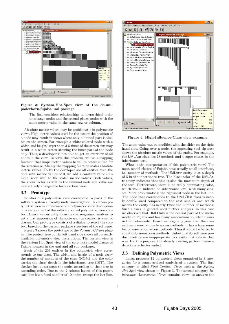
Figure 3: System-Hot-Spot view of the de.uni-paderborn.fujaba.uml package.
The first considers relationships as hierarchical orderto arrange nodes and the second places nodes with thesame metric value in the same row or column.
Absolute metric values may be problematic in polymetricviews. High metric values used for the size or the position ofa node may result in views where only a limited part is visi-ble on the screen. For example a white colored node with awidth and height larger than 3-5 times of the screen size mayresult in a white screen showing the inner part of the nodeonly. Thus, a developer is not able to get an overview of allnodes in the view. To solve this problem, we use a mappingfunction that maps metric values to values better suited forthe screen-size. Mainly the mapping function scales absolutemetric values. To let the developer see all entities even theones with metric values of 0, we add a constant value (mi-nimal node size) to the scaled metric values. Both values,the zoom factor as well as the minimal node size value areinteractively changeable for a certain view.
3.2 PrototypeEntities of a polymetric view correspond to parts of the
software system currently under investigation. A certain po-lymetric view is an instance of a polymetric view descriptionon a certain part of the software, called polymetric view con-text. Hence we currently focus on coarse-grained analysis toget a first impression of the software, the context is a set ofclasses. Our prototype consists of a dialog to select the con-text based on the current package structure of the software.
Figure 3 shows the prototype of the PolymetricViews plug-in. The project tree on the left hand side shows all currentlyavailable polymetric view descriptions. The current view isthe System-Hot-Spot view of the core meta-model classes ofFujaba located in the uml and all sub packages.
Each of the 203 entities in the polymetric view corre-sponds to one class. The width and height of a node carrythe number of methods of the class (NOM) and the colorcarries the class’ depth in the inheritance tree (DIT). Thechecker layout arranges the nodes according to their size inascending order. Due to the 2-column layout of this paper,each line has a fixed number of 10 nodes, except the last line.
Figure 4: High-Influence-Class view example.
The zoom value can be modified with the slider on the righthand side. Going over a node, the appearing tool tip noteshows the absolute metric values of the entity. For example,the UMLAttr class has 78 methods and 4 super classes in theinheritance tree.
What is the interpretation of this polymetric view? Themeta-model classes of Fujaba have usually small interfaces,i.e. number of methods. The UMLAttr entity is at a depthof 5 in the inheritance tree. The black color of the UMLAt-tr entity indicates that this is also the maximum depth ofthe tree. Furthermore, there is no really dominating color,which would indicate an inheritance level with many clas-ses. More problematic is the rightmost node in the last line.The node that corresponds to the UMLClass class is near-ly double sized compared to the next smaller one, whichmeans the entity has nearly twice the number of methods.Such classes in general need further analysis. In this casewe observed that UMLClass is the central part of the meta-model of Fujaba and has many associations to other classesin the meta-model. Hence we originally generated the classand map associations to access methods, it has a huge num-ber of association access methods. Thus it would be better tocount only non-access methods. Unfortunately software pro-duct metrics are inappropriate to classify methods in thatway. For this purpose, the already existing pattern instancedetection is better suited.
3.3 Defining Polymetric ViewsLanza proposes 12 polymetric views organized in 3 cate-
gories for a coarse-grained analysis of a system. The firstcategory is titled First Contact Views such as the SystemHot Spot view shown in Figure 3. The second category In-heritance Assessment Views contains views to analyze the
3
43 Fujaba Days 2005
mtt
Rectangle
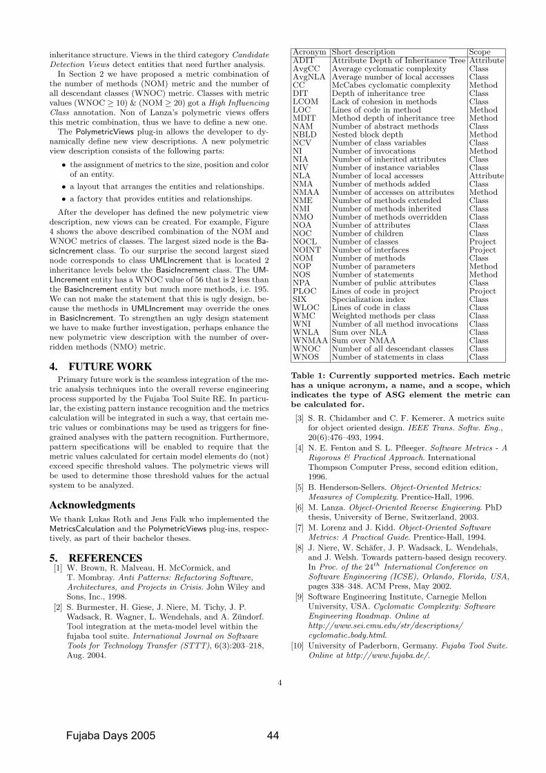
inheritance structure. Views in the third category CandidateDetection Views detect entities that need further analysis.
In Section 2 we have proposed a metric combination ofthe number of methods (NOM) metric and the number ofall descendant classes (WNOC) metric. Classes with metricvalues (WNOC ≥ 10) & (NOM ≥ 20) got a High InfluencingClass annotation. Non of Lanza’s polymetric views offersthis metric combination, thus we have to define a new one.
The PolymetricViews plug-in allows the developer to dy-namically define new view descriptions. A new polymetricview description consists of the following parts:
• the assignment of metrics to the size, position and colorof an entity.
• a layout that arranges the entities and relationships.
• a factory that provides entities and relationships.
After the developer has defined the new polymetric viewdescription, new views can be created. For example, Figure4 shows the above described combination of the NOM andWNOC metrics of classes. The largest sized node is the Ba-sicIncrement class. To our surprise the second largest sizednode corresponds to class UMLIncrement that is located 2inheritance levels below the BasicIncrement class. The UM-LIncrement entity has a WNOC value of 56 that is 2 less thanthe BasicIncrement entity but much more methods, i.e. 195.We can not make the statement that this is ugly design, be-cause the methods in UMLIncrement may override the onesin BasicIncrement. To strengthen an ugly design statementwe have to make further investigation, perhaps enhance thenew polymetric view description with the number of over-ridden methods (NMO) metric.
4. FUTURE WORKPrimary future work is the seamless integration of the me-
tric analysis techniques into the overall reverse engineeringprocess supported by the Fujaba Tool Suite RE. In particu-lar, the existing pattern instance recognition and the metricscalculation will be integrated in such a way, that certain me-tric values or combinations may be used as triggers for fine-grained analyses with the pattern recognition. Furthermore,pattern specifications will be enabled to require that themetric values calculated for certain model elements do (not)exceed specific threshold values. The polymetric views willbe used to determine those threshold values for the actualsystem to be analyzed.
AcknowledgmentsWe thank Lukas Roth and Jens Falk who implemented theMetricsCalculation and the PolymetricViews plug-ins, respec-tively, as part of their bachelor theses.
5. REFERENCES[1] W. Brown, R. Malveau, H. McCormick, and
T. Mombray. Anti Patterns: Refactoring Software,Architectures, and Projects in Crisis. John Wiley andSons, Inc., 1998.
[2] S. Burmester, H. Giese, J. Niere, M. Tichy, J. P.Wadsack, R. Wagner, L. Wendehals, and A. Zundorf.Tool integration at the meta-model level within thefujaba tool suite. International Journal on SoftwareTools for Technology Transfer (STTT), 6(3):203–218,Aug. 2004.
Acronym Short description ScopeADIT Attribute Depth of Inheritance Tree AttributeAvgCC Average cyclomatic complexity ClassAvgNLA Average number of local accesses ClassCC McCabes cyclomatic complexity MethodDIT Depth of inheritance tree ClassLCOM Lack of cohesion in methods ClassLOC Lines of code in method MethodMDIT Method depth of inheritance tree MethodNAM Number of abstract methods ClassNBLD Nested block depth MethodNCV Number of class variables ClassNI Number of invocations MethodNIA Number of inherited attributes ClassNIV Number of instance variables ClassNLA Number of local accesses AttributeNMA Number of methods added ClassNMAA Number of accesses on attributes MethodNME Number of methods extended ClassNMI Number of methods inherited ClassNMO Number of methods overridden ClassNOA Number of attributes ClassNOC Number of children ClassNOCL Number of classes ProjectNOINT Number of interfaces ProjectNOM Number of methods ClassNOP Number of parameters MethodNOS Number of statements MethodNPA Number of public attributes ClassPLOC Lines of code in project ProjectSIX Specialization index ClassWLOC Lines of code in class ClassWMC Weighted methods per class ClassWNI Number of all method invocations ClassWNLA Sum over NLA ClassWNMAA Sum over NMAA ClassWNOC Number of all descendant classes ClassWNOS Number of statements in class Class
Table 1: Currently supported metrics. Each metrichas a unique acronym, a name, and a scope, whichindicates the type of ASG element the metric canbe calculated for.
[3] S. R. Chidamber and C. F. Kemerer. A metrics suitefor object oriented design. IEEE Trans. Softw. Eng.,20(6):476–493, 1994.
[4] N. E. Fenton and S. L. Pfleeger. Software Metrics - ARigorous & Practical Approach. InternationalThompson Computer Press, second edition edition,1996.
[5] B. Henderson-Sellers. Object-Oriented Metrics:Measures of Complexity. Prentice-Hall, 1996.
[6] M. Lanza. Object-Oriented Reverse Engieering. PhDthesis, University of Berne, Switzerland, 2003.
[7] M. Lorenz and J. Kidd. Object-Oriented SoftwareMetrics: A Practical Guide. Prentice-Hall, 1994.
[8] J. Niere, W. Schafer, J. P. Wadsack, L. Wendehals,and J. Welsh. Towards pattern-based design recovery.In Proc. of the 24th International Conference onSoftware Engineering (ICSE), Orlando, Florida, USA,pages 338–348. ACM Press, May 2002.
[9] Software Engineering Institute, Carnegie MellonUniversity, USA. Cyclomatic Complexity: SoftwareEngineering Roadmap. Online athttp://www.sei.cmu.edu/str/descriptions/cyclomatic body.html.
[10] University of Paderborn, Germany. Fujaba Tool Suite.Online at http://www.fujaba.de/.
4
Fujaba Days 2005 44
mtt
Rectangle
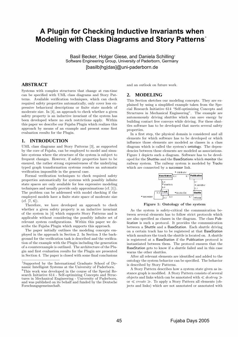
A Plugin for Checking Inductive Invariants whenModeling with Class Diagrams and Story Patterns∗
Basil Becker, Holger Giese, and Daniela Schilling†
Software Engineering Group, University of Paderborn, Germany[basilb|hg|das]@uni-paderborn.de
ABSTRACTSystems with complex structures that change at run-timecan be specified with UML class diagrams and Story Pat-terns. Available verification techniques, which can checkrequired safety properties automatically, only cover less ex-pressive behavioral descriptions or finite state models ofmoderate size. In [4], an approach to check whether a givensafety property is an inductive invariant of the system hasbeen developed where no such restrictions apply. Withinthis paper we describe our Fujaba Plugin which realizes thisapproach by means of an example and present some firstevaluation results for the Plugin.
1. INTRODUCTIONUML class diagrams and Story Patterns [3], as supportedby the core of Fujaba, can be employed to model and simu-late systems where the structure of the system is subject tofrequent changes. However, if safety properties have to beensured, the rather strong expressiveness of the underlyingtyped graph transformation systems renders an automaticverification impossible in the general case.
Formal verification techniques to check required safetyproperties automatically for systems with possibly infinitestate spaces are only available for less expressive modelingtechniques and usually provide only approximations (cf. [1]).The problem can be addressed with model checking if theemployed models have a finite state space of moderate size(cf. [7, 6]).
Therefore, we have developed an approach to checkwhether a given safety property is an inductive invariantof the system in [4] which supports Story Patterns and isapplicable without considering the possibly infinite set ofrelevant system configurations. Within this paper we de-scribe the Fujaba Plugin which supports this approach.
The paper initially outlines the modeling concepts em-ployed in the approach in Section 2. In Section 3 the back-ground for the verification task is described and the verifica-tion of the example with the Plugin including the generationof a counterexample is outlined. The architecture of the Plu-gin and first evaluation results for the Plugin are presentedin Section 4. The paper is closed with some final conclusions
†Supported by the International Graduate School of Dy-namic Intelligent Systems at the University of Paderborn.∗This work was developed in the course of the Special Re-search Initiative 614 - Self-optimizing Concepts and Struc-tures in Mechanical Engineering - University of Paderborn,and was published on its behalf and funded by the DeutscheForschungsgemeinschaft.
and an outlook on future work.
2. MODELINGThis Section sketches our modeling concepts. They are ex-plained by using a simplified example taken from the Spe-cial Research Initiative 614 “Self-optimizing Concepts andStructures in Mechanical Engineering”. The example areautonomously driving shuttles which can save energy bybuilding contact free convoys while driving. For these shut-tles software has to be developed that meets several safetyproperties.
In a first step, the physical domain is considered and allelements for which software has to be developed or whichinfluence those elements are modeled as classes in a classdiagram which is called the system’s ontology. The depen-dencies between these elements are modeled as associations.Figure 1 depicts such a diagram. Software has to be devel-oped for the Shuttles and the BaseStations which monitor therailway system. The railway system is modeled by Trackswhich are connected by a successor link.
Figure 1: Ontology of the system
As the system is safety-critical the communication be-tween several elements has to follow strict protocols whichare also specified as classes in the diagram. The class Pub-lication is such a protocol. It provides the communicationbetween a Shuttle and a BaseStation. Each shuttle drivingon a certain track has to be registered at that BaseStationwhich monitors the track the shuttle is located on. A shuttleis registered at a BaseStation if the Publication protocol isinstantiated between them. The protocol ensures that theBaseStation gets to know if a shuttle failed and in this casewarns the other shuttles.
After all relevant elements are identified and added to theontology the system behavior can be specified. The behavioris described by Story Patterns.
A Story Pattern describes how a system state given as in-stance graph is modified. A Story Pattern consists of severalobjects and links which can be annotated with� destroy �or � create �. To apply a Story Pattern all elements (ob-jects and links) which are not annotated or annotated with
45 Fujaba Days 2005
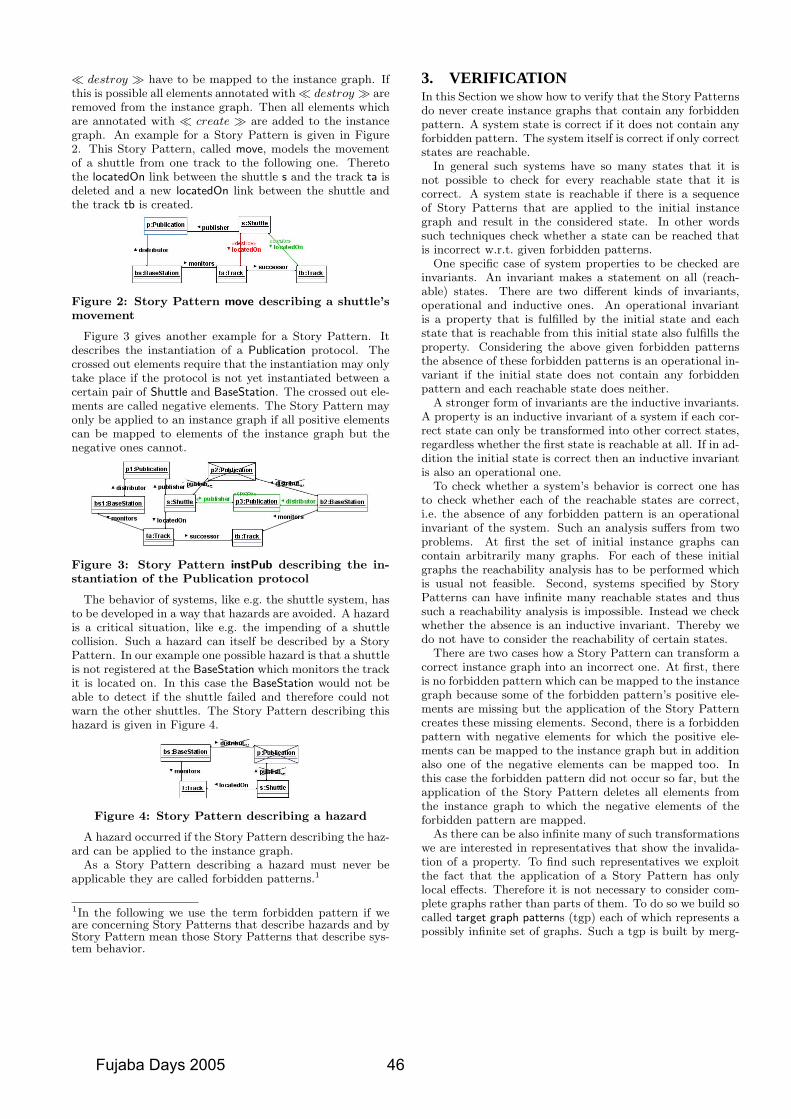
� destroy � have to be mapped to the instance graph. Ifthis is possible all elements annotated with� destroy � areremoved from the instance graph. Then all elements whichare annotated with � create � are added to the instancegraph. An example for a Story Pattern is given in Figure2. This Story Pattern, called move, models the movementof a shuttle from one track to the following one. Theretothe locatedOn link between the shuttle s and the track ta isdeleted and a new locatedOn link between the shuttle andthe track tb is created.
Figure 2: Story Pattern move describing a shuttle’smovement
Figure 3 gives another example for a Story Pattern. Itdescribes the instantiation of a Publication protocol. Thecrossed out elements require that the instantiation may onlytake place if the protocol is not yet instantiated between acertain pair of Shuttle and BaseStation. The crossed out ele-ments are called negative elements. The Story Pattern mayonly be applied to an instance graph if all positive elementscan be mapped to elements of the instance graph but thenegative ones cannot.
Figure 3: Story Pattern instPub describing the in-stantiation of the Publication protocol
The behavior of systems, like e.g. the shuttle system, hasto be developed in a way that hazards are avoided. A hazardis a critical situation, like e.g. the impending of a shuttlecollision. Such a hazard can itself be described by a StoryPattern. In our example one possible hazard is that a shuttleis not registered at the BaseStation which monitors the trackit is located on. In this case the BaseStation would not beable to detect if the shuttle failed and therefore could notwarn the other shuttles. The Story Pattern describing thishazard is given in Figure 4.
Figure 4: Story Pattern describing a hazard
A hazard occurred if the Story Pattern describing the haz-ard can be applied to the instance graph.
As a Story Pattern describing a hazard must never beapplicable they are called forbidden patterns.1
1In the following we use the term forbidden pattern if weare concerning Story Patterns that describe hazards and byStory Pattern mean those Story Patterns that describe sys-tem behavior.
3. VERIFICATIONIn this Section we show how to verify that the Story Patternsdo never create instance graphs that contain any forbiddenpattern. A system state is correct if it does not contain anyforbidden pattern. The system itself is correct if only correctstates are reachable.
In general such systems have so many states that it isnot possible to check for every reachable state that it iscorrect. A system state is reachable if there is a sequenceof Story Patterns that are applied to the initial instancegraph and result in the considered state. In other wordssuch techniques check whether a state can be reached thatis incorrect w.r.t. given forbidden patterns.
One specific case of system properties to be checked areinvariants. An invariant makes a statement on all (reach-able) states. There are two different kinds of invariants,operational and inductive ones. An operational invariantis a property that is fulfilled by the initial state and eachstate that is reachable from this initial state also fulfills theproperty. Considering the above given forbidden patternsthe absence of these forbidden patterns is an operational in-variant if the initial state does not contain any forbiddenpattern and each reachable state does neither.
A stronger form of invariants are the inductive invariants.A property is an inductive invariant of a system if each cor-rect state can only be transformed into other correct states,regardless whether the first state is reachable at all. If in ad-dition the initial state is correct then an inductive invariantis also an operational one.
To check whether a system’s behavior is correct one hasto check whether each of the reachable states are correct,i.e. the absence of any forbidden pattern is an operationalinvariant of the system. Such an analysis suffers from twoproblems. At first the set of initial instance graphs cancontain arbitrarily many graphs. For each of these initialgraphs the reachability analysis has to be performed whichis usual not feasible. Second, systems specified by StoryPatterns can have infinite many reachable states and thussuch a reachability analysis is impossible. Instead we checkwhether the absence is an inductive invariant. Thereby wedo not have to consider the reachability of certain states.
There are two cases how a Story Pattern can transform acorrect instance graph into an incorrect one. At first, thereis no forbidden pattern which can be mapped to the instancegraph because some of the forbidden pattern’s positive ele-ments are missing but the application of the Story Patterncreates these missing elements. Second, there is a forbiddenpattern with negative elements for which the positive ele-ments can be mapped to the instance graph but in additionalso one of the negative elements can be mapped too. Inthis case the forbidden pattern did not occur so far, but theapplication of the Story Pattern deletes all elements fromthe instance graph to which the negative elements of theforbidden pattern are mapped.
As there can be also infinite many of such transformationswe are interested in representatives that show the invalida-tion of a property. To find such representatives we exploitthe fact that the application of a Story Pattern has onlylocal effects. Therefore it is not necessary to consider com-plete graphs rather than parts of them. To do so we build socalled target graph patterns (tgp) each of which represents apossibly infinite set of graphs. Such a tgp is built by merg-
Fujaba Days 2005 46
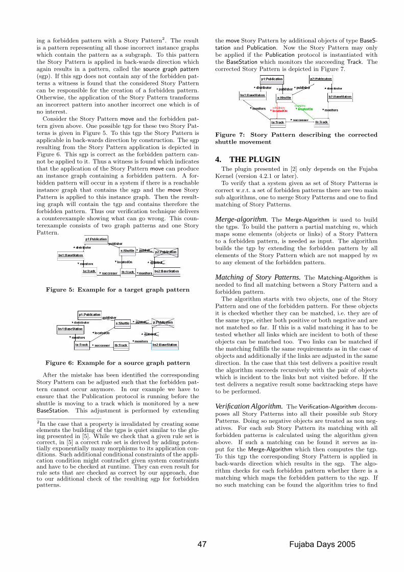
ing a forbidden pattern with a Story Pattern2. The resultis a pattern representing all those incorrect instance graphswhich contain the pattern as a subgraph. To this patternthe Story Pattern is applied in back-wards direction whichagain results in a pattern, called the source graph pattern(sgp). If this sgp does not contain any of the forbidden pat-terns a witness is found that the considered Story Patterncan be responsible for the creation of a forbidden pattern.Otherwise, the application of the Story Pattern transformsan incorrect pattern into another incorrect one which is ofno interest.
Consider the Story Pattern move and the forbidden pat-tern given above. One possible tgp for these two Story Pat-terns is given in Figure 5. To this tgp the Story Pattern isapplicable in back-wards direction by construction. The sgpresulting from the Story Pattern application is depicted inFigure 6. This sgp is correct as the forbidden pattern can-not be applied to it. Thus a witness is found which indicatesthat the application of the Story Pattern move can producean instance graph containing a forbidden pattern. A for-bidden pattern will occur in a system if there is a reachableinstance graph that contains the sgp and the move StoryPattern is applied to this instance graph. Then the result-ing graph will contain the tgp and contains therefore theforbidden pattern. Thus our verification technique deliversa counterexample showing what can go wrong. This coun-terexample consists of two graph patterns and one StoryPattern.
Figure 5: Example for a target graph pattern
Figure 6: Example for a source graph pattern
After the mistake has been identified the correspondingStory Pattern can be adjusted such that the forbidden pat-tern cannot occur anymore. In our example we have toensure that the Publication protocol is running before theshuttle is moving to a track which is monitored by a newBaseStation. This adjustment is performed by extending
2In the case that a property is invalidated by creating someelements the building of the tgps is quiet similar to the glu-ing presented in [5]. While we check that a given rule set iscorrect, in [5] a correct rule set is derived by adding poten-tially exponentially many morphisms to its application con-ditions. Such additional conditional constraints of the appli-cation condition might contradict given system constraintsand have to be checked at runtime. They can even result forrule sets that are checked as correct by our approach, dueto our additional check of the resulting sgp for forbiddenpatterns.
the move Story Pattern by additional objects of type BaseS-tation and Publication. Now the Story Pattern may onlybe applied if the Publication protocol is instantiated withthe BaseStation which monitors the succeeding Track. Thecorrected Story Pattern is depicted in Figure 7.
Figure 7: Story Pattern describing the correctedshuttle movement
4. THE PLUGINThe plugin presented in [2] only depends on the Fujaba
Kernel (version 4.2.1 or later).To verify that a system given as set of Story Patterns is
correct w.r.t. a set of forbidden patterns there are two mainsub algorithms, one to merge Story Patterns and one to findmatching of Story Patterns.
Merge-algorithm.The Merge-Algorithm is used to buildthe tgps. To build the pattern a partial matching m, whichmaps some elements (objects or links) of a Story Patternto a forbidden pattern, is needed as input. The algorithmbuilds the tgp by extending the forbidden pattern by allelements of the Story Pattern which are not mapped by mto any element of the forbidden pattern.
Matching of Story Patterns.The Matching-Algorithm isneeded to find all matching between a Story Pattern and aforbidden pattern.
The algorithm starts with two objects, one of the StoryPattern and one of the forbidden pattern. For these objectsit is checked whether they can be matched, i.e. they are ofthe same type, either both positive or both negative and arenot matched so far. If this is a valid matching it has to betested whether all links which are incident to both of theseobjects can be matched too. Two links can be matched ifthe matching fulfills the same requirements as in the case ofobjects and additionally if the links are adjusted in the samedirection. In the case that this test delivers a positive resultthe algorithm succeeds recursively with the pair of objectswhich is incident to the links but not visited before. If thetest delivers a negative result some backtracking steps haveto be performed.
Verification Algorithm.The Verification-Algorithm decom-poses all Story Patterns into all their possible sub StoryPatterns. Doing so negative objects are treated as non neg-atives. For each sub Story Pattern its matching with allforbidden patterns is calculated using the algorithm givenabove. If such a matching can be found it serves as in-put for the Merge-Algorithm which then computes the tgp.To this tgp the corresponding Story Pattern is applied inback-wards direction which results in the sgp. The algo-rithm checks for each forbidden pattern whether there is amatching which maps the forbidden pattern to the sgp. Ifno such matching can be found the algorithm tries to find
47 Fujaba Days 2005
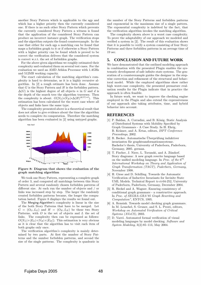
another Story Pattern which is applicable to the sgp andwhich has a higher priority then the currently consideredone. If there is no such other Story Pattern which preventsthe currently considered Story Pattern a witness is foundthat the application of the considered Story Pattern canproduce an incorrect instance graph. The verification stopsand the algorithm outputs the found counterexample. In thecase that either for each sgp a matching can be found thatmaps a forbidden graph to it or if otherwise a Story Patternwith a higher priority can be found which is proved to becorrect the verification delivers that the considered systemis correct w.r.t. the set of forbidden graphs.
For the above given algorithms we roughly estimated theircomplexity and evaluated them on several test cases. For theevaluation we used an AMD Athlon Processor with 1.4GHzand 512MB working capacity.
The exact calculation of the matching algorithm’s com-plexity is hard to determine, as it is a highly recursive al-gorithm. In [2] a rough estimate has been done. Assumethat G is the Story Pattern and H is the forbidden pattern.∆(G) is the highest degree of all objects n in G and d isthe depth of the search tree the algorithm traverses. Thenthe complexity is about: O(|VG|∗|VH |∗∆(H)∆(G)∗d). Thisestimation has been calculated for the worst case where allobjects and links have the same type.
The complexity presented above is a theoretical result thatdoes not allow to give evidence about the time the algorithmneeds to complete its computation. Therefore the matchingalgorithm has been evaluated in [2] using untyped graphs.
Figure 8: Diagram that shows the evaluation of thegraph matching algorithm
We took one Story Pattern, representing a complete graphof order 3, and computed all matchings between this StoryPattern and several randomly chosen forbidden patterns ofdifferent size. At each run the number of objects and / orlinks was increased step by step. The larger the randomlycreated forbidden patterns became, the longer the compu-tation lasted. Figure 8 displays the results we found out.
The Merging-Algorithm’s complexity is linear in the sizeof the both Story Patterns that have to be merged. LetG = (OG, LG) and H = (OH , LH) be these two StoryPatterns, with O is the set of objects and L the set oflinks. The complexity then can be expressed as follows:O(|VG|+|EG|+|VH |+|EH |). This estimation is very obviousas it is clear that the algorithm has to visit each item ofboth graphs only once.
The verification algorithm’s complexity is mainly deter-mined by two parts. At first the number of Story Pat-terns and the number forbidden patterns, and second thesize of the single patterns. The complexity is quadratic in
the number of the Story Patterns and forbidden patternsand exponential in the maximum size of a single pattern.The exponential complexity is indebted by the fact, thatthe verification algorithm invokes the matching algorithm.
The complexity shown above is a worst case complexity.To prove the adaptability of our approach we modeled andverified a system in [2]. The result of this evaluation showsthat it is possible to verify a system consisting of four StoryPatterns and three forbidden patterns in an average time of19 sec.
5. CONCLUSION AND FUTURE WORKWe have demonstrated that the outlined modeling approachin combination with the presented Plugin enables the sys-tematic development of safe infinite state systems. The gen-eration of a counterexample guides the designer in the step-wise correction and refinement of the structural and behav-ioral model. While the employed algorithms show ratherhigh worst-case complexity, the presented premature eval-uation results for the Plugin indicate that in practice theapproach is often feasible.
In future work, we want to improve the checking engineemployed in the Plugin and also extend the expressivenessof our approach also taking attributes, time, and hybridbehavior into account.
REFERENCES[1] P. Baldan, A. Corradini, and B. Konig. Static Analysis
of Distributed Systems with Mobility Specified byGraph Grammars - A Case Study. In H. Ehrig,B. Kramer, and A. Ertas, editors, ISPT ConferenceProceedings, 2002.
[2] B. Becker. Automatische Uberprufung induktiverinvarianten fur graphtransformationssysteme.Bachelor’s thesis, University of Paderborn, Paderborn,Germany, 2005. german.
[3] T. Fischer, J. Niere, L. Torunski, and A. Zundorf.Story diagrams: A new graph rewrite language basedon the unified modeling language. In Proc. of the 6th
International Workshop on Theory and Application ofGraph Transformation (TAGT), Paderborn, Germany,November 1998.
[4] H. Giese and D. Schilling. Towards the AutomaticVerification of Inductive Invariants for Invinite StateUML Models. Technical Report tr-ri-04-252, Universityof Paderborn, Paderborn, Germany, December 2004.
[5] R. Heckel and A. Wagner. Ensuring consistency ofconditional graph grammars - a constructive approach.In Proc. of SEGRA-GRA’95 Graph Rewriting andComputation”, ENTCS, 1995.
[6] A. Rensink. Towards model checking graph grammars.In M. Leuschel, S. Gruner, and S. L. Presti, editors,Workshop on Automated Verification of CriticalSystems (AVoCS), 2003.
[7] D. Varro. Automated formal verification of visualmodeling languages by model checking. Software andSystem Modeling, 3(2):85–113, May 2004.
Fujaba Days 2005 48
Formal Verification of Java Code Generationfrom UML Models
Jan Olaf Blech Sabine Glesner Johannes Leitner
Institute for Program Structures and Data OrganizationUniversity of Karlsruhe, 76128 Karlsruhe, Germany
ABSTRACTUML specifications offer the advantage to describe softwaresystems while the actual task of implementing code for themis passed to code generators that automatically producee.g. Java code. For safety reasons, it is necessary that thegenerated code is semantically equivalent to the originalUML specification. In this paper, we present our approachto formally verify within the Isabelle/HOL theorem proverthat a certain algorithm for Java code generation from UMLspecifications is semantically correct. This proof is part ofmore extensive ongoing work aiming to verify UML transfor-mations and code generation within the Fujaba tool suite.
KeywordsStatecharts, Fujaba, Isabelle/HOL, verification, semantics,transformations, code generation.
1. INTRODUCTIONThe generation of code from specification languages likeUML is an important aspect of the Model Driven Archi-tecture (MDA). State-of-the-art Computer Aided SoftwareEngineering (CASE) tools like the Fujaba tool suite comewith such code generation mechanisms. To ensure correctsoftware and system behavior, it is a necessary prerequisitethat the semantics of the original UML systems is preservedduring code generation.
To ensure that such transformations are correct, formal ver-ification is necessary. In this paper, we consider an algo-rithm that transforms simplified Statecharts into a Java-like language. We verify that this transformation algorithmis correct. Therefore we formalize the semantics of State-charts and the targeted Java subset as well as the trans-formation algorithm within Isabelle/HOL. Furthermore, weprove, also within Isabelle/HOL, this code generation algo-rithm correct by showing that each Statechart specificationand the corresponding program code are bisimilar. The useof bisimulation as equivalence criterion between Statechartsand the Java-like programming language ensures an ade-quate semantics formalism even for non-terminating systemsand programs. In order to obtain machine-checked proofs aswell as reusability of proofs, our proofs and formalizationsare conducted within Isabelle/HOL.
This paper describes ongoing work that is part of a largerproject aiming to verify real life transformations from UMLspecifications of CASE tools to Java code. Apart from ouralready finished formalization and proof work, we give a de-
tailed plan for our future work concerning verification ofMDA transformations. We believe that verification of Fu-jaba transformations can be a major and highly interestingresearch area in the future.
In Section 2, we discuss various approaches for the formal-ization of Statecharts. After that, we explain basic founda-tions for behavioural equivalence proofs in Isabelle/HOL inSection 3. Our formalization of the Java-like programminglanguage as well as our Statechart formalization togetherwith the actual correctness proof is discussed in Section 4.We discuss related work in Section 5. In Section 6, we con-clude and present our future workplan.
2. SEMANTICS OF STATECHARTSStatecharts are an extension of finite state machines whichare implemented in many tools and widely used in practice.Nevertheless, the definintion of their semantics poses subtledifficulties due to inherent ambiguities. In this section, wefirst introduce Statecharts in Subsection 2.1. Afterwards, inSubsection 2.2, we summarize how executable code, e.g. Javacode, can be generated from them automatically. In Subsec-tion 2.3, we explain the difficulties when formally definingthe semantics of Statecharts. Finally, in Subsection 2.4, wediscuss methods to prove equivalence of Statecharts.
2.1 The Statechart LanguageStatecharts [12] are a visual language which enhance fi-nite state machines by hierarchical and parallel composi-tion of states (and broadcast communication between par-allel transtitions). They have found wide-spread use in themodelling of complex dynamic behaviour and are part of theUML standard [20] with advanced features such as historymechanisms and extended transition trigger conditions. InUML Statecharts, transitions as well as states can be deco-rated with actions, i.e. statements in some imperative lan-guage, thereby significantly increasing the expressive powerof statecharts.
2.2 Code Generation From StatechartsThere are numerous tools providing code generation fromStatecharts. Most of these employ one of the following threestrategies of code generation which are almost directly de-rived from code generation strategies for finite automata.
• (Hierarchical) Switch/Case Loop This most simple ap-proach creates a nested switch/case statement that
49 Fujaba Days 2005
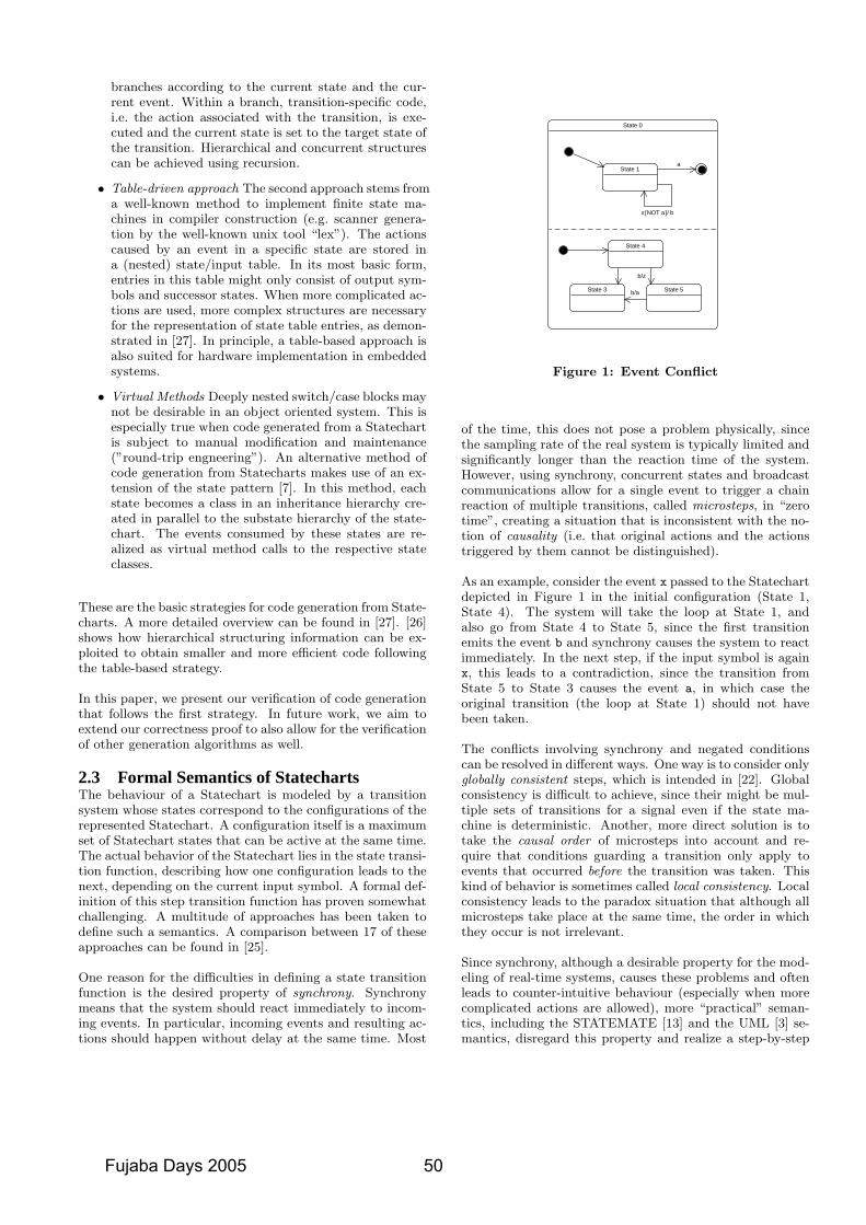
branches according to the current state and the cur-rent event. Within a branch, transition-specific code,i.e. the action associated with the transition, is exe-cuted and the current state is set to the target state ofthe transition. Hierarchical and concurrent structurescan be achieved using recursion.
• Table-driven approach The second approach stems froma well-known method to implement finite state ma-chines in compiler construction (e.g. scanner genera-tion by the well-known unix tool “lex”). The actionscaused by an event in a specific state are stored ina (nested) state/input table. In its most basic form,entries in this table might only consist of output sym-bols and successor states. When more complicated ac-tions are used, more complex structures are necessaryfor the representation of state table entries, as demon-strated in [27]. In principle, a table-based approach isalso suited for hardware implementation in embeddedsystems.
• Virtual Methods Deeply nested switch/case blocks maynot be desirable in an object oriented system. This isespecially true when code generated from a Statechartis subject to manual modification and maintenance(”round-trip engneering”). An alternative method ofcode generation from Statecharts makes use of an ex-tension of the state pattern [7]. In this method, eachstate becomes a class in an inheritance hierarchy cre-ated in parallel to the substate hierarchy of the state-chart. The events consumed by these states are re-alized as virtual method calls to the respective stateclasses.
These are the basic strategies for code generation from State-charts. A more detailed overview can be found in [27]. [26]shows how hierarchical structuring information can be ex-ploited to obtain smaller and more efficient code followingthe table-based strategy.
In this paper, we present our verification of code generationthat follows the first strategy. In future work, we aim toextend our correctness proof to also allow for the verificationof other generation algorithms as well.
2.3 Formal Semantics of StatechartsThe behaviour of a Statechart is modeled by a transitionsystem whose states correspond to the configurations of therepresented Statechart. A configuration itself is a maximumset of Statechart states that can be active at the same time.The actual behavior of the Statechart lies in the state transi-tion function, describing how one configuration leads to thenext, depending on the current input symbol. A formal def-inition of this step transition function has proven somewhatchallenging. A multitude of approaches has been taken todefine such a semantics. A comparison between 17 of theseapproaches can be found in [25].
One reason for the difficulties in defining a state transitionfunction is the desired property of synchrony. Synchronymeans that the system should react immediately to incom-ing events. In particular, incoming events and resulting ac-tions should happen without delay at the same time. Most
State 0
State 1
x[NOT a]/ b
a
State 4
State 5State 3
b/a
b/z
Figure 1: Event Conflict
of the time, this does not pose a problem physically, sincethe sampling rate of the real system is typically limited andsignificantly longer than the reaction time of the system.However, using synchrony, concurrent states and broadcastcommunications allow for a single event to trigger a chainreaction of multiple transitions, called microsteps, in “zerotime”, creating a situation that is inconsistent with the no-tion of causality (i.e. that original actions and the actionstriggered by them cannot be distinguished).
As an example, consider the event x passed to the Statechartdepicted in Figure 1 in the initial configuration (State 1,State 4). The system will take the loop at State 1, andalso go from State 4 to State 5, since the first transitionemits the event b and synchrony causes the system to reactimmediately. In the next step, if the input symbol is againx, this leads to a contradiction, since the transition fromState 5 to State 3 causes the event a, in which case theoriginal transition (the loop at State 1) should not havebeen taken.
The conflicts involving synchrony and negated conditionscan be resolved in different ways. One way is to consider onlyglobally consistent steps, which is intended in [22]. Globalconsistency is difficult to achieve, since their might be mul-tiple sets of transitions for a signal even if the state ma-chine is deterministic. Another, more direct solution is totake the causal order of microsteps into account and re-quire that conditions guarding a transition only apply toevents that occurred before the transition was taken. Thiskind of behavior is sometimes called local consistency. Localconsistency leads to the paradox situation that although allmicrosteps take place at the same time, the order in whichthey occur is not irrelevant.
Since synchrony, although a desirable property for the mod-eling of real-time systems, causes these problems and oftenleads to counter-intuitive behaviour (especially when morecomplicated actions are allowed), more “practical” seman-tics, including the STATEMATE [13] and the UML [3] se-mantics, disregard this property and realize a step-by-step
Fujaba Days 2005 50
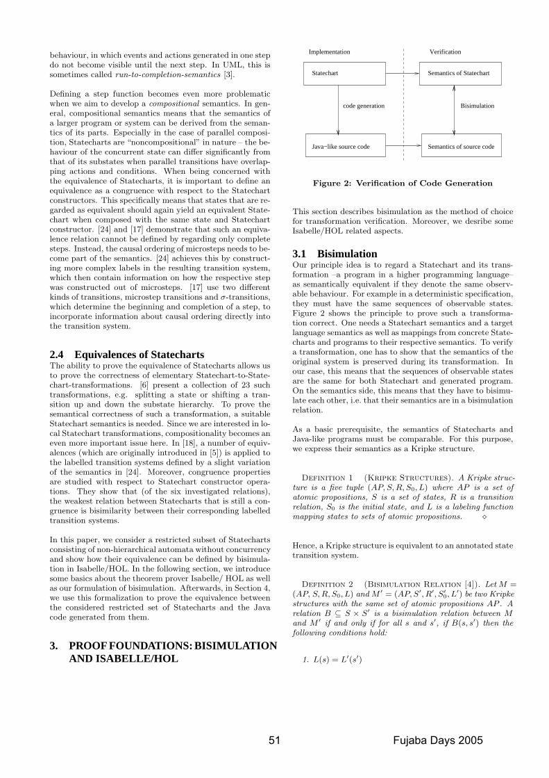
behaviour, in which events and actions generated in one stepdo not become visible until the next step. In UML, this issometimes called run-to-completion-semantics [3].
Defining a step function becomes even more problematicwhen we aim to develop a compositional semantics. In gen-eral, compositional semantics means that the semantics ofa larger program or system can be derived from the seman-tics of its parts. Especially in the case of parallel composi-tion, Statecharts are “noncompositional” in nature – the be-haviour of the concurrent state can differ significantly fromthat of its substates when parallel transitions have overlap-ping actions and conditions. When being concerned withthe equivalence of Statecharts, it is important to define anequivalence as a congruence with respect to the Statechartconstructors. This specifically means that states that are re-garded as equivalent should again yield an equivalent State-chart when composed with the same state and Statechartconstructor. [24] and [17] demonstrate that such an equiva-lence relation cannot be defined by regarding only completesteps. Instead, the causal ordering of microsteps needs to be-come part of the semantics. [24] achieves this by construct-ing more complex labels in the resulting transition system,which then contain information on how the respective stepwas constructed out of microsteps. [17] use two differentkinds of transitions, microstep transitions and σ-transitions,which determine the beginning and completion of a step, toincorporate information about causal ordering directly intothe transition system.
2.4 Equivalences of StatechartsThe ability to prove the equivalence of Statecharts allows usto prove the correctness of elementary Statechart-to-State-chart-transformations. [6] present a collection of 23 suchtransformations, e.g. splitting a state or shifting a tran-sition up and down the substate hierarchy. To prove thesemantical correctness of such a transformation, a suitableStatechart semantics is needed. Since we are interested in lo-cal Statechart transformations, compositionality becomes aneven more important issue here. In [18], a number of equiv-alences (which are originally introduced in [5]) is applied tothe labelled transition systems defined by a slight variationof the semantics in [24]. Moreover, congruence propertiesare studied with respect to Statechart constructor opera-tions. They show that (of the six investigated relations),the weakest relation between Statecharts that is still a con-gruence is bisimilarity between their corresponding labelledtransition systems.
In this paper, we consider a restricted subset of Statechartsconsisting of non-hierarchical automata without concurrencyand show how their equivalence can be defined by bisimula-tion in Isabelle/HOL. In the following section, we introducesome basics about the theorem prover Isabelle/ HOL as wellas our formulation of bisimulation. Afterwards, in Section 4,we use this formalization to prove the equivalence betweenthe considered restricted set of Statecharts and the Javacode generated from them.
3. PROOF FOUNDATIONS: BISIMULATIONAND ISABELLE/HOL
Java−like source code
Implementation Verification
Statechart
code generation
Semantics of Statechart
Semantics of source code
Bisimulation
Figure 2: Verification of Code Generation
This section describes bisimulation as the method of choicefor transformation verification. Moreover, we desribe someIsabelle/HOL related aspects.
3.1 BisimulationOur principle idea is to regard a Statechart and its trans-formation –a program in a higher programming language–as semantically equivalent if they denote the same observ-able behaviour. For example in a deterministic specification,they must have the same sequences of observable states.Figure 2 shows the principle to prove such a transforma-tion correct. One needs a Statechart semantics and a targetlanguage semantics as well as mappings from concrete State-charts and programs to their respective semantics. To verifya transformation, one has to show that the semantics of theoriginal system is preserved during its transformation. Inour case, this means that the sequences of observable statesare the same for both Statechart and generated program.On the semantics side, this means that they have to bisimu-late each other, i.e. that their semantics are in a bisimulationrelation.
As a basic prerequisite, the semantics of Statecharts andJava-like programs must be comparable. For this purpose,we express their semantics as a Kripke structure.
Definition 1 (Kripke Structures). A Kripke struc-ture is a five tuple (AP, S, R, S0, L) where AP is a set ofatomic propositions, S is a set of states, R is a transitionrelation, S0 is the initial state, and L is a labeling functionmapping states to sets of atomic propositions. �
Hence, a Kripke structure is equivalent to an annotated statetransition system.
Definition 2 (Bisimulation Relation [4]). Let M =(AP, S, R, S0, L) and M ′ = (AP, S′, R′, S′
0, L′) be two Kripke
structures with the same set of atomic propositions AP . Arelation B ⊆ S × S′ is a bisimulation relation between Mand M ′ if and only if for all s and s′, if B(s, s′) then thefollowing conditions hold:
1. L(s) = L′(s′)
51 Fujaba Days 2005
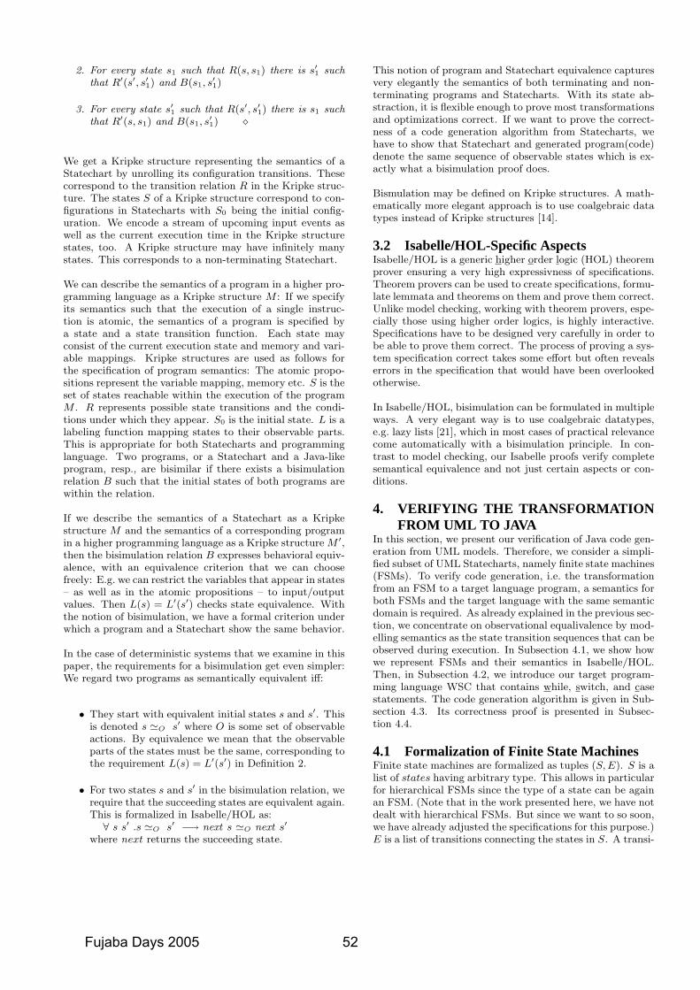
2. For every state s1 such that R(s, s1) there is s′1 such
that R′(s′, s′1) and B(s1, s
′1)
3. For every state s′1 such that R(s′, s′
1) there is s1 suchthat R′(s, s1) and B(s1, s
′1) �
We get a Kripke structure representing the semantics of aStatechart by unrolling its configuration transitions. Thesecorrespond to the transition relation R in the Kripke struc-ture. The states S of a Kripke structure correspond to con-figurations in Statecharts with S0 being the initial config-uration. We encode a stream of upcoming input events aswell as the current execution time in the Kripke structurestates, too. A Kripke structure may have infinitely manystates. This corresponds to a non-terminating Statechart.
We can describe the semantics of a program in a higher pro-gramming language as a Kripke structure M : If we specifyits semantics such that the execution of a single instruc-tion is atomic, the semantics of a program is specified bya state and a state transition function. Each state mayconsist of the current execution state and memory and vari-able mappings. Kripke structures are used as follows forthe specification of program semantics: The atomic propo-sitions represent the variable mapping, memory etc. S is theset of states reachable within the execution of the programM . R represents possible state transitions and the condi-tions under which they appear. S0 is the initial state. L is alabeling function mapping states to their observable parts.This is appropriate for both Statecharts and programminglanguage. Two programs, or a Statechart and a Java-likeprogram, resp., are bisimilar if there exists a bisimulationrelation B such that the initial states of both programs arewithin the relation.
If we describe the semantics of a Statechart as a Kripkestructure M and the semantics of a corresponding programin a higher programming language as a Kripke structure M ′,then the bisimulation relation B expresses behavioral equiv-alence, with an equivalence criterion that we can choosefreely: E.g. we can restrict the variables that appear in states– as well as in the atomic propositions – to input/outputvalues. Then L(s) = L′(s′) checks state equivalence. Withthe notion of bisimulation, we have a formal criterion underwhich a program and a Statechart show the same behavior.
In the case of deterministic systems that we examine in thispaper, the requirements for a bisimulation get even simpler:We regard two programs as semantically equivalent iff:
• They start with equivalent initial states s and s′. Thisis denoted s 'O s′ where O is some set of observableactions. By equivalence we mean that the observableparts of the states must be the same, corresponding tothe requirement L(s) = L′(s′) in Definition 2.
• For two states s and s′ in the bisimulation relation, werequire that the succeeding states are equivalent again.This is formalized in Isabelle/HOL as:∀ s s′ .s 'O s′ −→ next s 'O next s′
where next returns the succeeding state.
This notion of program and Statechart equivalence capturesvery elegantly the semantics of both terminating and non-terminating programs and Statecharts. With its state ab-straction, it is flexible enough to prove most transformationsand optimizations correct. If we want to prove the correct-ness of a code generation algorithm from Statecharts, wehave to show that Statechart and generated program(code)denote the same sequence of observable states which is ex-actly what a bisimulation proof does.
Bismulation may be defined on Kripke structures. A math-ematically more elegant approach is to use coalgebraic datatypes instead of Kripke structures [14].
3.2 Isabelle/HOL-Specific AspectsIsabelle/HOL is a generic higher order logic (HOL) theoremprover ensuring a very high expressivness of specifications.Theorem provers can be used to create specifications, formu-late lemmata and theorems on them and prove them correct.Unlike model checking, working with theorem provers, espe-cially those using higher order logics, is highly interactive.Specifications have to be designed very carefully in order tobe able to prove them correct. The process of proving a sys-tem specification correct takes some effort but often revealserrors in the specification that would have been overlookedotherwise.
In Isabelle/HOL, bisimulation can be formulated in multipleways. A very elegant way is to use coalgebraic datatypes,e.g. lazy lists [21], which in most cases of practical relevancecome automatically with a bisimulation principle. In con-trast to model checking, our Isabelle proofs verify completesemantical equivalence and not just certain aspects or con-ditions.
4. VERIFYING THE TRANSFORMATIONFROM UML TO JAVA
In this section, we present our verification of Java code gen-eration from UML models. Therefore, we consider a simpli-fied subset of UML Statecharts, namely finite state machines(FSMs). To verify code generation, i.e. the transformationfrom an FSM to a target language program, a semantics forboth FSMs and the target language with the same semanticdomain is required. As already explained in the previous sec-tion, we concentrate on observational equalivalence by mod-elling semantics as the state transition sequences that can beobserved during execution. In Subsection 4.1, we show howwe represent FSMs and their semantics in Isabelle/HOL.Then, in Subsection 4.2, we introduce our target program-ming language WSC that contains while, switch, and casestatements. The code generation algorithm is given in Sub-section 4.3. Its correctness proof is presented in Subsec-tion 4.4.
4.1 Formalization of Finite State MachinesFinite state machines are formalized as tuples (S, E). S is alist of states having arbitrary type. This allows in particularfor hierarchical FSMs since the type of a state can be againan FSM. (Note that in the work presented here, we have notdealt with hierarchical FSMs. But since we want to so soon,we have already adjusted the specifications for this purpose.)E is a list of transitions connecting the states in S. A transi-
Fujaba Days 2005 52
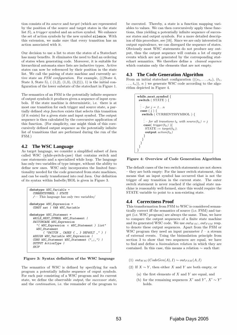
tion consists of its source and target (which are representedby the position of the source and target states in the statelist S), a trigger symbol and an action symbol. We enhancethe set of action symbols by the new symbol silence. Withthis extension, we make sure that every transition has anaction associated with it.
Our decision to use a list to store the states of a Statecharthas many benefits. It eliminates the need to find an orderingof states when generating code. Moreover, it is suitable forhierarchical automata since lists are inductive types. Activestates can now be referenced by their position in the statelist. We call the pairing of state machine and currently ac-tive state an FSM configuration. For example, (((State 4,State 3, State 5), ( (1,2), (1,3), (3,2))), 1) is the initial con-figuration of the lower substate of the statechart in Figure 1.
The semantics of an FSM is the potentially infinite sequenceof output symbols it produces given a sequence of input sym-bols. If the state machine is deterministic, i.e. there is atmost one transition for each trigger and source state, a par-tially defined step function exists that selects this transition(if it exists) for a given state and input symbol. The outputsequence is then calculated by the corecursive application ofthis function. (For simplicity, one might think of this core-cursively defined output sequence as the potentially infinitelist of transitions that are performed during the run of theFSM.)
4.2 The WSC LanguageAs target language, we consider a simplified subset of Javacalled WSC (while-switch-case) that contains switch andcase statements and a specialized while loop. The languagehas only two variables of type integer, without the ability todefine new ones. WSC only incorporates the limited func-tionality needed for the code generated from state machines,and can be easily transformed into real Java. Our definitionof its syntax within Isabelle/HOL is given in Figure 3.
datatype WSC_Variable =CURRENTSYMBOL | STATE/— This language has only two variables/
datatype WSC_Expression =CONST nat | VAR WSC_Variable
datatype WSC_Statement =WHILE_NEXT_SYMBOL WSC_Statement |SWITCHCASE WSC_Expression"( WSC_Expression × WSC_Statement ) list"WSC_Statement
( "SWITCH _ CASES { _ } DEFAULT _" ) |ASSIGN WSC_Variable WSC_Expression |CONS WSC_Statement WSC_Statement ("_;_") |OUTPUT ActionType |SKIP
Figure 3: Syntax definition of the WSC language
The semantics of WSC is defined by specifying for eachprogram a potentially infinite sequence of ouput symbols.For each pair consisting of a WSC program and its currentstate, we define the observable output, the successor state,and the continuation, i.e. the remainder of the program to
be executed. Thereby, a state is a function mapping vari-ables to values. We can then corecursively apply these func-tions, thus yielding a potentially infinite sequence of succes-sor states and output symbols. For a more detailed descrip-ion of this procedure, see [16]. Since we are only interested inoutput equivalence, we can disregard the sequence of states.Obviously most WSC statements do not produce any out-put, thus the output sequence will contain a lot of emptyevents which are not generated by the corresponding stat-echart semantics. We therefore define a cleaned sequencewhich contains only the elements that are not empty.
4.3 The Code Generation AlgorithmFrom an initial statechart configuration (((s1, . . . , sn), (t1,. . ., tn)), n ) we generate WSC code according to the algo-rithm depicted in Figure 4.
while next symbol {switch ( STATE ) {... – for j = 1. . .ncase ( j ) {switch ( CURRENTSSYMBOL ) {... – for all transtions tk with source(tk) = jcase( trigger(tk) ){STATE := target(tk);output action(tk)}}}}}
Figure 4: Overview of Code Generation Algorithm
The default cases of the two switch statements are not shown– they are both empty: For the inner switch statement, thismeans that an input symbol has occurred that is not thetrigger of any transition in the current state. The outerswitch statement is never reached if the original state ma-chine is reasonably well-formed, since this would require theSTATE variable to point to a non-existing state.
4.4 Correctness ProofThis transformation from FSM to WSC is considered seman-tically correct iff the semantics of source (i.e. FSM) and tar-get (i.e. WSC program) are always the same. Thus, we haveto compare the output sequences of a finite state machineand its generated WSC code. We use outWSC , outFSM resp.to denote these output sequences. Apart from the FSM orWSC program they need an input parameter I – a streamof external events. Using the bisimulation principle fromsection 3 to show that two sequences are equal, we haveto find and define a bisimulation relation in which they arecontained. In this case, this means a relation ∼ such that:
(1) outWSC(CodeGen(A), I) ∼ outFSM (A, I)
(2) If X ∼ Y , then either X and Y are both empty, or
(a) the first elements of X and Y are equal, and
(b) for the remaining sequences X ′ and Y ′, X ′ ∼ Y ′
holds.
53 Fujaba Days 2005
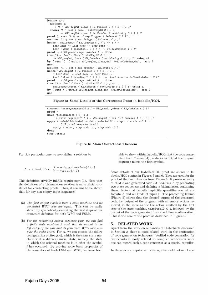
lemma c2 :assumes a1
: "X = WSC_seqOut_clean ( FA_CodeGen C ) ( i ; I )"shows "X = Leaf ( Some ( takeStepIO C i ) )
; WSC_seqOut_clean ( FA_CodeGen ( nextConfig C i ) ) I"proof ( cases "i ∈ set ( map Trigger ( Relevant C ) )" )assume "i /∈ set ( map Trigger ( Relevant C ) )"hence " WSC_seqOut ( FA_CodeGen C ) ( i ; I ) =
Leaf None ; Leaf None ; Leaf None ;
Leaf ( Some ( takeStepIO C i ) ) ; FollowCodeGen i C I"proof ...( 29 proof steps omitted ) ...donethus "X = Leaf ( Some ( takeStepIO C i ) )
; WSC_seqOut_clean ( FA_CodeGen ( nextConfig C i ) ) I" using a1by ( simp ) ( unfold WSC_seqOut_clean_def FollowCodeGen_def , auto )nextassume "i ∈ set ( map Trigger ( Relevant C ) )"hence "WSC_seqOut ( FA_CodeGen C ) ( i ; I )
= Leaf None ; Leaf None ; Leaf None ;
Leaf ( Some ( takeStepIO C i ) ) ; Leaf None ; FollowCodeGen i C I"proof ...( 38 proof steps omitted ) ...donethus "X = Leaf ( Some ( takeStepIO C i ) ) ;
WSC_seqOut_clean ( FA_CodeGen ( nextConfig C i ) ) I" using a1by ( simp ) ( unfold WSC_seqOut_clean_def FollowCodeGen_def , auto )qed
Figure 5: Some Details of the Correctness Proof in Isabelle/HOL
theorem "state_sequenceIO A I = WSC_seqOut_clean ( FA_CodeGen A ) I"proof -have "bisimulation (
⋃I A .
{ ( state_sequenceIO A I , WSC_seqOut_clean ( FA_CodeGen A ) I ) } )"apply ( unfold bisimulation_def , rule ballI , simp , ( erule exE )+ )
...( 17 proof steps omitted ) ...apply ( auto , simp add: c1 , simp add: c2 )
donethus ?thesis
Figure 6: Main Correctness Theorem
For this particular case we now define a relation by
X ∼ Y :⇐⇒ ∃A I.X = outWSC(CodeGen(A), I)Y = outFSM (A, I)
This definition trivially fullfills requirement (1). Note thatthe definition of a bisimulation relation is an artificial con-struct for conducting proofs. Thus, it remains to be shownthat for any non-empty input sequence:
(a) The first output symbols from a state machine and itsgenerated WSC code are equal. This can be easilyshown by symbolically executing the first steps of oursemantics definiton for both WSC and FSMs.
(b) For the remaining output sequence pair, we can finda finite state machine A such that its output is theleft entry of the pair and its generated WSC code out-puts the right entry. For A, we can choose the followconfiguration Followi(A), which is the same state ma-chine with a different initial state, namely the statein which the original machine is in after the symboli has occurred. By proving some basic properties ofthe semantics of both FSM and WSC, we have been
able to show within Isabelle/HOL that the code gener-ated from Followi(A) produces as output the originalsequence minus the first symbol.
Some details of our Isabelle/HOL proof are shown in Is-abelle/HOL syntax in Figures 5 and 6. They are used for theproof of the final theorem from Figure 6. It proves equalityof FSM A and generated code FA CodeGen A by generatingtwo state sequences and defining a bisimulation containingthem. Note that Isabelle implicitly quantifies over all au-tomata A and all kinds of input I. The preceeding lemma(Figure 5) shows that the cleaned output of the generatedcode, i.e. output of the program with all empty actions re-moved, is the same as the the action emitted by the firststep of the state machine, takeStepIO C i, followed by theoutput of the code generated from the follow configuration.This is the core of the proof as described in Figure 6.
5. RELATED WORKApart from the work on semantics of Statecharts discussedin Section 2, there is more related work on the verificationof code generation techniques. Verified code generation forStatecharts is closly related to compiler verification sinceone can regard such a code generator as a special compiler.
In the area of compiler verification, a two-fold notion of cor-
Fujaba Days 2005 54
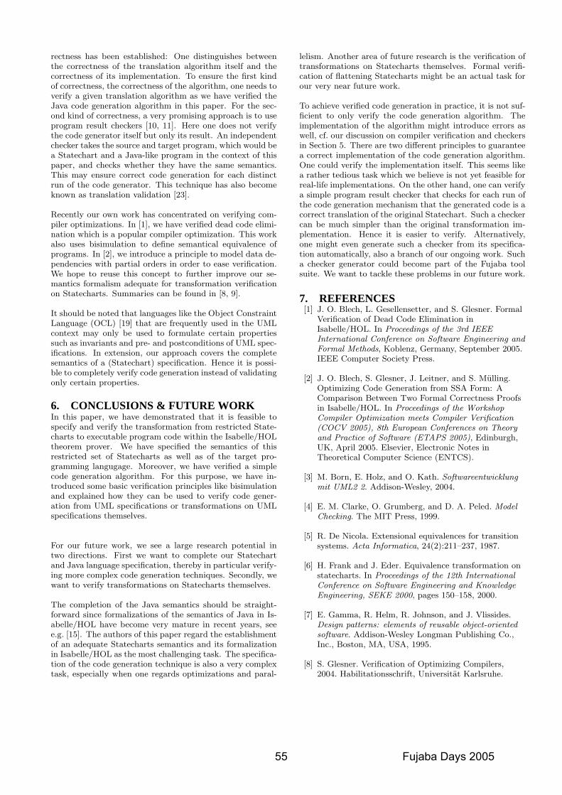
rectness has been established: One distinguishes betweenthe correctness of the translation algorithm itself and thecorrectness of its implementation. To ensure the first kindof correctness, the correctness of the algorithm, one needs toverify a given translation algorithm as we have verified theJava code generation algorithm in this paper. For the sec-ond kind of correctness, a very promising approach is to useprogram result checkers [10, 11]. Here one does not verifythe code generator itself but only its result. An independentchecker takes the source and target program, which would bea Statechart and a Java-like program in the context of thispaper, and checks whether they have the same semantics.This may ensure correct code generation for each distinctrun of the code generator. This technique has also becomeknown as translation validation [23].
Recently our own work has concentrated on verifying com-piler optimizations. In [1], we have verified dead code elimi-nation which is a popular compiler optimization. This workalso uses bisimulation to define semantical equivalence ofprograms. In [2], we introduce a principle to model data de-pendencies with partial orders in order to ease verification.We hope to reuse this concept to further improve our se-mantics formalism adequate for transformation verificationon Statecharts. Summaries can be found in [8, 9].
It should be noted that languages like the Object ConstraintLanguage (OCL) [19] that are frequently used in the UMLcontext may only be used to formulate certain propertiessuch as invariants and pre- and postconditions of UML spec-ifications. In extension, our approach covers the completesemantics of a (Statechart) specification. Hence it is possi-ble to completely verify code generation instead of validatingonly certain properties.
6. CONCLUSIONS & FUTURE WORKIn this paper, we have demonstrated that it is feasible tospecify and verify the transformation from restricted State-charts to executable program code within the Isabelle/HOLtheorem prover. We have specified the semantics of thisrestricted set of Statecharts as well as of the target pro-gramming langugage. Moreover, we have verified a simplecode generation algorithm. For this purpose, we have in-troduced some basic verification principles like bisimulationand explained how they can be used to verify code gener-ation from UML specifications or transformations on UMLspecifications themselves.
For our future work, we see a large research potential intwo directions. First we want to complete our Statechartand Java language specification, thereby in particular verify-ing more complex code generation techniques. Secondly, wewant to verify transformations on Statecharts themselves.
The completion of the Java semantics should be straight-forward since formalizations of the semantics of Java in Is-abelle/HOL have become very mature in recent years, seee.g. [15]. The authors of this paper regard the establishmentof an adequate Statecharts semantics and its formalizationin Isabelle/HOL as the most challenging task. The specifica-tion of the code generation technique is also a very complextask, especially when one regards optimizations and paral-
lelism. Another area of future research is the verification oftransformations on Statecharts themselves. Formal verifi-cation of flattening Statecharts might be an actual task forour very near future work.
To achieve verified code generation in practice, it is not suf-ficient to only verify the code generation algorithm. Theimplementation of the algorithm might introduce errors aswell, cf. our discussion on compiler verification and checkersin Section 5. There are two different principles to guaranteea correct implementation of the code generation algorithm.One could verify the implementation itself. This seems likea rather tedious task which we believe is not yet feasible forreal-life implementations. On the other hand, one can verifya simple program result checker that checks for each run ofthe code generation mechanism that the generated code is acorrect translation of the original Statechart. Such a checkercan be much simpler than the original transformation im-plementation. Hence it is easier to verify. Alternatively,one might even generate such a checker from its specifica-tion automatically, also a branch of our ongoing work. Sucha checker generator could become part of the Fujaba toolsuite. We want to tackle these problems in our future work.
7. REFERENCES[1] J. O. Blech, L. Gesellensetter, and S. Glesner. Formal
Verification of Dead Code Elimination inIsabelle/HOL. In Proceedings of the 3rd IEEEInternational Conference on Software Engineering andFormal Methods, Koblenz, Germany, September 2005.IEEE Computer Society Press.
[2] J. O. Blech, S. Glesner, J. Leitner, and S. Mulling.Optimizing Code Generation from SSA Form: AComparison Between Two Formal Correctness Proofsin Isabelle/HOL. In Proceedings of the WorkshopCompiler Optimization meets Compiler Verification(COCV 2005), 8th European Conferences on Theoryand Practice of Software (ETAPS 2005), Edinburgh,UK, April 2005. Elsevier, Electronic Notes inTheoretical Computer Science (ENTCS).
[3] M. Born, E. Holz, and O. Kath. Softwareentwicklungmit UML2 2. Addison-Wesley, 2004.
[4] E. M. Clarke, O. Grumberg, and D. A. Peled. ModelChecking. The MIT Press, 1999.
[5] R. De Nicola. Extensional equivalences for transitionsystems. Acta Informatica, 24(2):211–237, 1987.
[6] H. Frank and J. Eder. Equivalence transformation onstatecharts. In Proceedings of the 12th InternationalConference on Software Engineering and KnowledgeEngineering, SEKE 2000, pages 150–158, 2000.
[7] E. Gamma, R. Helm, R. Johnson, and J. Vlissides.Design patterns: elements of reusable object-orientedsoftware. Addison-Wesley Longman Publishing Co.,Inc., Boston, MA, USA, 1995.
[8] S. Glesner. Verification of Optimizing Compilers,2004. Habilitationsschrift, Universitat Karlsruhe.
55 Fujaba Days 2005
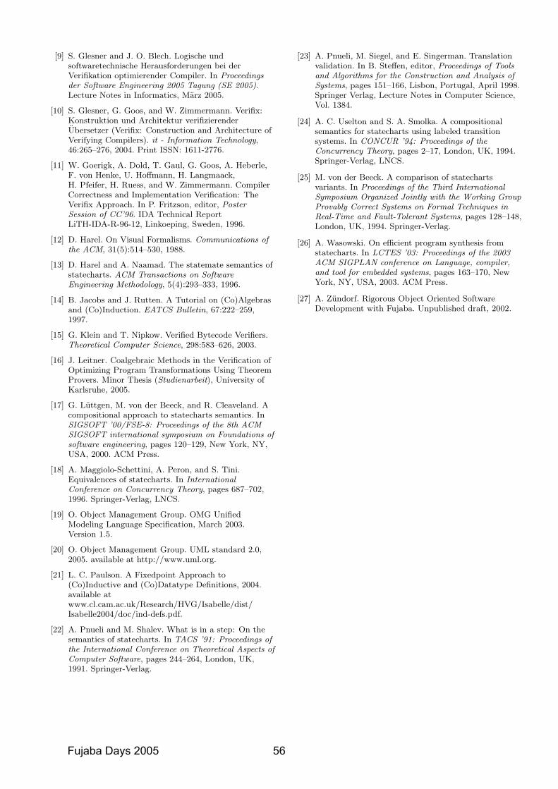
[9] S. Glesner and J. O. Blech. Logische undsoftwaretechnische Herausforderungen bei derVerifikation optimierender Compiler. In Proceedingsder Software Engineering 2005 Tagung (SE 2005).Lecture Notes in Informatics, Marz 2005.
[10] S. Glesner, G. Goos, and W. Zimmermann. Verifix:Konstruktion und Architektur verifizierenderUbersetzer (Verifix: Construction and Architecture ofVerifying Compilers). it - Information Technology,46:265–276, 2004. Print ISSN: 1611-2776.
[11] W. Goerigk, A. Dold, T. Gaul, G. Goos, A. Heberle,F. von Henke, U. Hoffmann, H. Langmaack,H. Pfeifer, H. Ruess, and W. Zimmermann. CompilerCorrectness and Implementation Verification: TheVerifix Approach. In P. Fritzson, editor, PosterSession of CC’96. IDA Technical ReportLiTH-IDA-R-96-12, Linkoeping, Sweden, 1996.
[12] D. Harel. On Visual Formalisms. Communications ofthe ACM, 31(5):514–530, 1988.
[13] D. Harel and A. Naamad. The statemate semantics ofstatecharts. ACM Transactions on SoftwareEngineering Methodology, 5(4):293–333, 1996.
[14] B. Jacobs and J. Rutten. A Tutorial on (Co)Algebrasand (Co)Induction. EATCS Bulletin, 67:222–259,1997.
[15] G. Klein and T. Nipkow. Verified Bytecode Verifiers.Theoretical Computer Science, 298:583–626, 2003.
[16] J. Leitner. Coalgebraic Methods in the Verification ofOptimizing Program Transformations Using TheoremProvers. Minor Thesis (Studienarbeit), University ofKarlsruhe, 2005.
[17] G. Luttgen, M. von der Beeck, and R. Cleaveland. Acompositional approach to statecharts semantics. InSIGSOFT ’00/FSE-8: Proceedings of the 8th ACMSIGSOFT international symposium on Foundations ofsoftware engineering, pages 120–129, New York, NY,USA, 2000. ACM Press.
[18] A. Maggiolo-Schettini, A. Peron, and S. Tini.Equivalences of statecharts. In InternationalConference on Concurrency Theory, pages 687–702,1996. Springer-Verlag, LNCS.
[19] O. Object Management Group. OMG UnifiedModeling Language Specification, March 2003.Version 1.5.
[20] O. Object Management Group. UML standard 2.0,2005. available at http://www.uml.org.
[21] L. C. Paulson. A Fixedpoint Approach to(Co)Inductive and (Co)Datatype Definitions, 2004.available atwww.cl.cam.ac.uk/Research/HVG/Isabelle/dist/Isabelle2004/doc/ind-defs.pdf.
[22] A. Pnueli and M. Shalev. What is in a step: On thesemantics of statecharts. In TACS ’91: Proceedings ofthe International Conference on Theoretical Aspects ofComputer Software, pages 244–264, London, UK,1991. Springer-Verlag.
[23] A. Pnueli, M. Siegel, and E. Singerman. Translationvalidation. In B. Steffen, editor, Proceedings of Toolsand Algorithms for the Construction and Analysis ofSystems, pages 151–166, Lisbon, Portugal, April 1998.Springer Verlag, Lecture Notes in Computer Science,Vol. 1384.
[24] A. C. Uselton and S. A. Smolka. A compositionalsemantics for statecharts using labeled transitionsystems. In CONCUR ’94: Proceedings of theConcurrency Theory, pages 2–17, London, UK, 1994.Springer-Verlag, LNCS.
[25] M. von der Beeck. A comparison of statechartsvariants. In Proceedings of the Third InternationalSymposium Organized Jointly with the Working GroupProvably Correct Systems on Formal Techniques inReal-Time and Fault-Tolerant Systems, pages 128–148,London, UK, 1994. Springer-Verlag.
[26] A. Wasowski. On efficient program synthesis fromstatecharts. In LCTES ’03: Proceedings of the 2003ACM SIGPLAN conference on Language, compiler,and tool for embedded systems, pages 163–170, NewYork, NY, USA, 2003. ACM Press.
[27] A. Zundorf. Rigorous Object Oriented SoftwareDevelopment with Fujaba. Unpublished draft, 2002.
Fujaba Days 2005 56
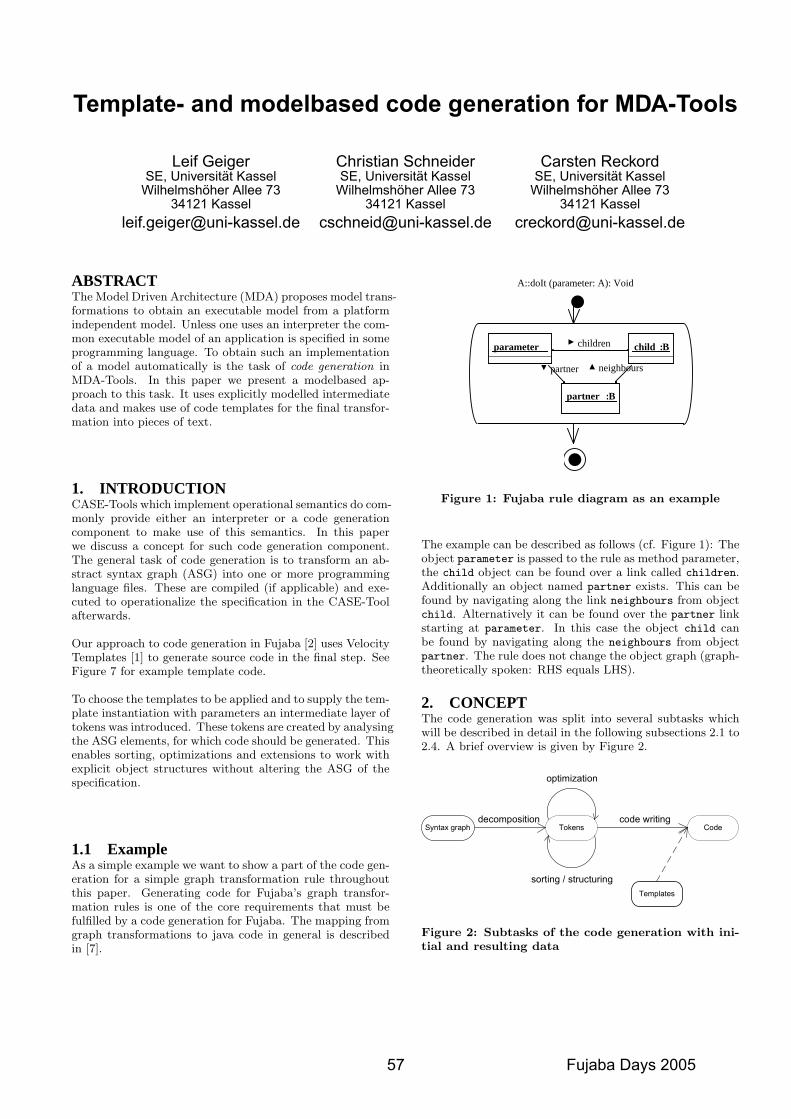
Template- and modelbased code generation for MDA-Tools
Leif GeigerSE, Universitat Kassel
Wilhelmshoher Allee 7334121 Kassel
Christian SchneiderSE, Universitat Kassel
Wilhelmshoher Allee 7334121 Kassel
Carsten ReckordSE, Universitat Kassel
Wilhelmshoher Allee 7334121 Kassel
ABSTRACTThe Model Driven Architecture (MDA) proposes model trans-formations to obtain an executable model from a platformindependent model. Unless one uses an interpreter the com-mon executable model of an application is specified in someprogramming language. To obtain such an implementationof a model automatically is the task of code generation inMDA-Tools. In this paper we present a modelbased ap-proach to this task. It uses explicitly modelled intermediatedata and makes use of code templates for the final transfor-mation into pieces of text.
1. INTRODUCTIONCASE-Tools which implement operational semantics do com-monly provide either an interpreter or a code generationcomponent to make use of this semantics. In this paperwe discuss a concept for such code generation component.The general task of code generation is to transform an ab-stract syntax graph (ASG) into one or more programminglanguage files. These are compiled (if applicable) and exe-cuted to operationalize the specification in the CASE-Toolafterwards.
Our approach to code generation in Fujaba [2] uses VelocityTemplates [1] to generate source code in the final step. SeeFigure 7 for example template code.
To choose the templates to be applied and to supply the tem-plate instantiation with parameters an intermediate layer oftokens was introduced. These tokens are created by analysingthe ASG elements, for which code should be generated. Thisenables sorting, optimizations and extensions to work withexplicit object structures without altering the ASG of thespecification.
1.1 ExampleAs a simple example we want to show a part of the code gen-eration for a simple graph transformation rule throughoutthis paper. Generating code for Fujaba’s graph transfor-mation rules is one of the core requirements that must befulfilled by a code generation for Fujaba. The mapping fromgraph transformations to java code in general is describedin [7].
neighbours partner
children parameter B:child
B:partner
A::doIt (parameter: A): Void
Figure 1: Fujaba rule diagram as an example
The example can be described as follows (cf. Figure 1): Theobject parameter is passed to the rule as method parameter,the child object can be found over a link called children.Additionally an object named partner exists. This can befound by navigating along the link neighbours from objectchild. Alternatively it can be found over the partner linkstarting at parameter. In this case the object child canbe found by navigating along the neighbours from objectpartner. The rule does not change the object graph (graph-theoretically spoken: RHS equals LHS).
2. CONCEPTThe code generation was split into several subtasks whichwill be described in detail in the following subsections 2.1 to2.4. A brief overview is given by Figure 2.
Syntax graph Tokens Code
optimization
sorting / structuring
decomposition code writing
Templates
Figure 2: Subtasks of the code generation with ini-tial and resulting data
57 Fujaba Days 2005
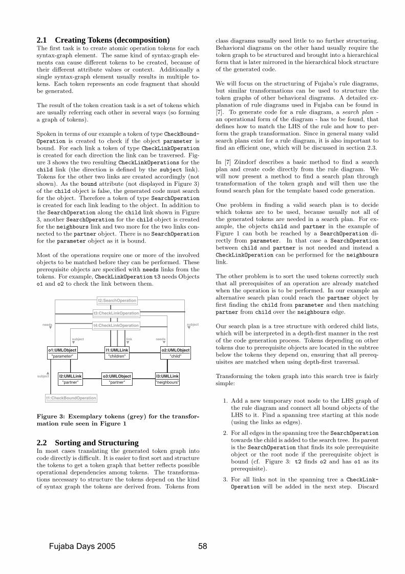
2.1 Creating Tokens (decomposition)The first task is to create atomic operation tokens for eachsyntax-graph element. The same kind of syntax-graph ele-ments can cause different tokens to be created, because oftheir different attribute values or context. Additionally asingle syntax-graph element usually results in multiple to-kens. Each token represents an code fragment that shouldbe generated.
The result of the token creation task is a set of tokens whichare usually referring each other in several ways (so forminga graph of tokens).
Spoken in terms of our example a token of type CheckBound-Operation is created to check if the object parameter isbound. For each link a token of type CheckLinkOperation
is created for each direction the link can be traversed. Fig-ure 3 shows the two resulting CheckLinkOperations for thechild link (the direction is defined by the subject link).Tokens for the other two links are created accordingly (notshown). As the bound attribute (not displayed in Figure 3)of the child object is false, the generated code must searchfor the object. Therefore a token of type SearchOperation
is created for each link leading to the object. In addition tothe SearchOperation along the child link shown in Figure3, another SearchOperation for the child object is createdfor the neighbours link and two more for the two links con-nected to the partner object. There is no SearchOperation
for the parameter object as it is bound.
Most of the operations require one or more of the involvedobjects to be matched before they can be performed. Theseprerequisite objects are specified with needs links from thetokens. For example, CheckLinkOperation t3 needs Objectso1 and o2 to check the link between them.
l2:UMLLink"partner"
t1:CheckBoundOperation
o3:UMLObject"partner"
l3:UMLLink"neighbours"
o1:UMLObject"parameter"
l1:UMLLink"children"
o2:UMLObject"child"
t4:CheckLinkOperation
t3:CheckLinkOperation
t2:SearchOperation
needs
subject link needs
subject
subject
Figure 3: Exemplary tokens (grey) for the transfor-mation rule seen in Figure 1
2.2 Sorting and StructuringIn most cases translating the generated token graph intocode directly is difficult. It is easier to first sort and structurethe tokens to get a token graph that better reflects possibleoperational dependencies among tokens. The transforma-tions necessary to structure the tokens depend on the kindof syntax graph the tokens are derived from. Tokens from
class diagrams usually need little to no further structuring.Behavioral diagrams on the other hand usually require thetoken graph to be structured and brought into a hierarchicalform that is later mirrored in the hierarchical block structureof the generated code.
We will focus on the structuring of Fujaba’s rule diagrams,but similar transformations can be used to structure thetoken graphs of other behavioral diagrams. A detailed ex-planation of rule diagrams used in Fujaba can be found in[7]. To generate code for a rule diagram, a search plan -an operational form of the diagram - has to be found, thatdefines how to match the LHS of the rule and how to per-form the graph transformation. Since in general many validsearch plans exist for a rule diagram, it is also important tofind an efficient one, which will be discussed in section 2.3.
In [7] Zundorf describes a basic method to find a searchplan and create code directly from the rule diagram. Wewill now present a method to find a search plan throughtransformation of the token graph and will then use thefound search plan for the template based code generation.
One problem in finding a valid search plan is to decidewhich tokens are to be used, because usually not all ofthe generated tokens are needed in a search plan. For ex-ample, the objects child and partner in the example ofFigure 1 can both be reached by a SearchOperation di-rectly from parameter. In that case a SearchOperation
between child and partner is not needed and instead aCheckLinkOperation can be performed for the neighbours
link.
The other problem is to sort the used tokens correctly suchthat all prerequisites of an operation are already matchedwhen the operation is to be performed. In our example analternative search plan could reach the partner object byfirst finding the child from parameter and then matchingpartner from child over the neighbours edge.
Our search plan is a tree structure with ordered child lists,which will be interpreted in a depth-first manner in the restof the code generation process. Tokens depending on othertokens due to prerequisite objects are located in the subtreebelow the tokens they depend on, ensuring that all prereq-uisites are matched when using depth-first traversal.
Transforming the token graph into this search tree is fairlysimple:
1. Add a new temporary root node to the LHS graph ofthe rule diagram and connect all bound objects of theLHS to it. Find a spanning tree starting at this node(using the links as edges).
2. For all edges in the spanning tree the SearchOperationtowards the child is added to the search tree. Its parentis the SearchOperation that finds its sole prerequisiteobject or the root node if the prerequisite object isbound (cf. Figure 3: t2 finds o2 and has o1 as itsprerequisite).
3. For all links not in the spanning tree a CheckLink-
Operation will be added in the next step. Discard
Fujaba Days 2005 58
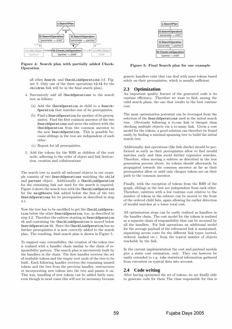
s:SearchPlan
children
childrensubject subject
needs needst6:CheckLinkOperation"partner -> child"
t2:SearchOperation"parameter -> child"
t5:SearchOperation"parameter -> partner"
o3:UMLObject"partner"
o2:UMLObject"child"
Figure 4: Search plan with partially added Check-Operation
all other Search- and CheckLinkOperations (cf. Fig-ure 3: Only one of the three operations t2-t4 for thechildren link will be in the final search plan).
4. Successively add all CheckOperations to the searchtree as follows:
(a) Add the CheckOperation as child to a Search-
Operation that matches one of its prerequisites
(b) Find a SearchOperation for another of its prereq-uisites. Find the first common ancestor of the twoSearchOperations and move the subtree with theCheckOperation from the common ancestor tothe new SearchOperation. This is possible be-cause siblings in the tree are independent of eachother.
(c) Repeat for all prerequisites.
5. Add the tokens for the RHS as children of the rootnode, adhering to the order of object and link destruc-tion, creation and collaborations
The search tree to match all unbound objects in our exam-ple consists of two SearchOperations matching the child
and partner object. Additionally a CheckLinkOperation
for the remaining link not used for the search is required.Figure 4 shows the search tree with the CheckLinkOperationfor the neighbours link added below the first of the twoSearchOperations for its prerequisites as described in step4.1.
Now the tree has to be modified to get the CheckLinkOpera-tion below the other SearchOperation, too, as described instep 4.2. Therefore the subtree starting at SearchOperationt5 and containing the CheckLinkOperation is moved belowSearchOperation t5. Since the CheckLinkOperation has nofurther prerequisites it is now correctly added to the searchplan. The resulting, final search plan is shown in Figure 5.
To support easy extensibility, the creation of the token treeis realized with a handler chain similar to the chain of re-sponsibility pattern. The search plan is successively built bythe handlers in the chain. The first handler receives the setof available tokens and the empty root node of the tree to bebuilt. Each following handler receives the remaining unusedtokens and the tree from the previous handler, restructuresor incorporating new tokens into the tree and passes it on.This way, handling of new tokens can be added fairly easy,even though in most cases this will not be necessary because
s:SearchPlan
t6:CheckLinkOperation"partner -> child"
t2:SearchOperation"parameter -> child"
t5:SearchOperation"parameter -> partner"
Figure 5: Final Search plan for our example
generic handlers exist that can deal with most tokens basedsolely on their prerequisites, which is usually sufficient.
2.3 OptimizationAn important quality feature of the generated code is itsruntime efficiency. Therefore we want to find, among thevalid search plans, the one that results in the best runtimecost.
The most optimization potential can be leveraged from theselection of the SearchOperations used in the initial searchtree. Obviously following a to-one link is cheaper thanchecking multiple objects via a to-many link. Given a costmodel for the tokens, a good solution can therefore be foundeasily by finding a minimal spanning tree to build the initialsearch tree.
Additionally, fast operations (like link checks) should be per-formed as early as their prerequisites allow to find invalidmatches early and thus avoid further expensive searches.Therefore, when moving a subtree as described in the treegeneration process above, its tokens should afterwards bepropagated towards the common ancestor as far as theirprerequisites allow or until only cheaper tokens are on theirpath to the common ancestor.
Finally, with the exception of tokens from the RHS of thegraph, siblings in the tree are independent from each other.Therefore, subtrees with a low runtime cost relative to thenumber of tokens in the subtree can be moved to the frontof the ordered child lists, again allowing for earlier detectionof invalid matches at a lower total cost.
All optimization steps can be easily realized as handlers inthe handler chain. The cost model for the tokens is realizedas a separate chain of responsibility that can be accessed byall the handlers. For link operations an additional modelfor the average payload of the referenced link is maintained,separating access costs for the different link types (sorted,ordered, hashed etc.) from the typical number of objectsreachable by the link.
In the current implementation the cost and payload modelsgive a static cost estimation, only. They can however beeasily extended to e.g. take statistical information gatheredfrom execution on typical data into account.
2.4 Code writingAfter having optimized the set of tokens, we are finally ableto generate code for them The class responsible for this is
59 Fujaba Days 2005
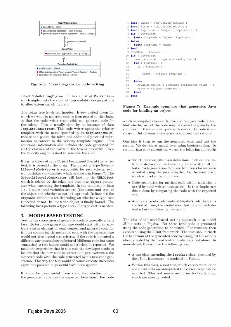
0..n
0..1
{ordered}generators
String : )Token:operation (generateCodeForChildrenString : )Token:operation (generateCode
String : targetName
CodeWritingEngine
String : )Token:operation (generateCode
CodeWriter
String : )Token:operation (generateCodeBoolean : )VelocityContext:context, Token:operation (fillContext
String : templateName
TemplateCodeWriter
Figure 6: Class diagram for code writing
called CodeWritingEngine. It has a list of CodeWriterswhich implements the chain of responsibility design patternto allow extension, cf. figure 6.
The token tree is visited inorder. Every visited token forwhich we want to generate code is then passed to the chain,so that the code writer responsible can generate code forthe token. This is usually done by an instance of classTemplateCodeWriter. This code writer opens the velocitytemplate with the name specified by its templateName at-tribute and passes the token and additionally needed infor-mation as context to the velocity template engine. Thisadditional information also includes the code generated forall the children of the token in the tokens hierarchy. Thenthe velocity engine is used to generate the code.
If e.g. a token of type ObjectAssignmentOperation is vis-ited, it is passed to the chain. The object of type Object-
LifecycleCodeWriter is responsible for such tokens, so itwill initialize the template which is shown in Figure 7. TheObjectLifecycleCodeWriter will look up the UMLObject
which is refered by the token and pass it as object param-eter when executing the template. In the template in lines1 to 3 some local variables are set (the name and type ofthe object and whether or not it is optional. In lines 4-6 the$tmpName variable is set depending on whether a type castis needed or not. In line 9 the object is finally bound. Thefollowing lines preform a type check if a type cast is needed.
3. MODELBASED TESTINGTesting the correctness of generated code is generally a hardtask. To test code generation, one would start with an arbi-trary syntax element in some context and generate code forit. Just comparing the generated code with the expected onewould not give a good test criteria: if the code is indented adifferent way or somehow refactored (different code but samesemantics), a test failure would nonetheless be reported. Wemade the experience that in this case the developer tends tobelieve that the new code is correct and just overwrites theexpected code with the code generated by his new code gen-eration. This way the test would of course execute successfulagain but possible bugs would have been ignored.
It would be more useful if one could test whether or notthe generated code has the expected behaviour. For code
Figure 7: Example template that generates Javacode for binding an object
which is compiled afterwards, like e.g. our java code, a firsthint whether or not the code may be correct is given by thecompiler. If the compiler quits with errors, the code is notcorrect. But obviously this is not a sufficent test criteria.
Our idea is then to run the generated code and test theresults. We do this at model level using bootstrapping. Totest our java code generation, we use the following approach:
• Structural code, like class definitions, method and at-tribute declaration, is tested by hand written JUnittests. Code generation for class definitions for instanceis tested using the java compiler, for the most part,which is invoked by a unit test.
• Code generation for method calls within activities istested by hand written tests as well. In this simple casethis is done by comparing the code with the expectedone.
• Additional syntax elements of Fujaba’s rule diagramsare tested using the modelbased testing approach de-scribed in the following paragraph.
The idea of the modelbased testing approach is to modelJUnit tests in Fujaba. For these tests code is generatedusing the code generation to be tested. The tests are thenexecuted using the JUnit framework. The tests should checkthe behaviour of the generated code by using just the axiomsalready tested by the hand written tests described above. Inmore detail, this is done the following way:
• A test class extending the TestCase class, provided bythe JUnit framework, is modeled in Fujaba.
• Within this class, a unit test, which checks whether ornot constraints are interpreted the correct way, can bemodeled. This test makes use of method calls, only,which are already tested.
Fujaba Days 2005 60
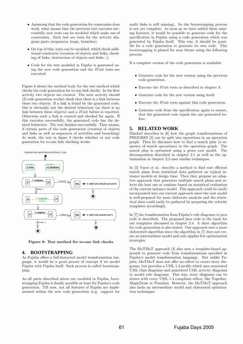
• Assuming that the code generation for constraints doeswork, what means that the previous test executes suc-cessfully, new tests can be modeled which make use ofconstraints. Such test are tests for the activity dia-gram parts (sequences, loops, branches).
• On top of this, tests can be modeled, which check addi-tional constructs (creation of objects and links, check-ing of links, destruction of objects and links...).
• Code for the test modeled in Fujaba is generated us-ing the new code generation and the JUnit tests areexecuted.
Figure 8 shows the method body for the test method whichchecks the code generation for to-one link checks. In the firstactivity two objects are created. The next activity should(if code generation works) check that there is a link betweenthese two objects. If a link is found by the generated code,this is obviously not the desired behaviour (as there is nolink between these objects) and a JUnit failure is reported.Otherwise such a link is created and checked for again. Ifthis executes successfully, the generated code has the de-sired behaviour. The test finishes successfully. That means,if certain parts of the code generation (creation of objectsand links as well as sequences of activities and branching)do work, the test in figure 8 checks whether or not codegeneration for to-one link checking works.
]success[
]failure[
]failure[
]success[
CodeGenTest::test5CheckLinkToOne (): Void
«create»Item:i1
«create»Neighbor:n1
neighbor n1i1 1: fail("Link should exist")this
1: fail("Link should not exist")thisneighbor
i1 n1
«create»neighbor i1 n1
Figure 8: Test method for to-one link checks
4. BOOTSTRAPPINGAs Fujaba offers a full-featuered model transforamtion lan-guage, it would be a good proove of concept if we modelFujaba with Fujaba itself. Such process is called bootstrap-ping.
As all parts described above are modeled in Fujaba, boot-strapping Fujaba is finally possible at least for Fujaba’s codegeneration. Till now, not all features of Fujaba are imple-mented within the new code generation (e.g. support for
multi links is still missing). So the bootstrapping processis not yet complete. As soon as we have added these miss-ing features, it would be possible to generate code for thespecification in Fujaba using a code generation which wasgenerated by Fujaba itself. This way, it should be possi-ble for a code generation to generate its own code. Thisbootstrapping is planed for near future using the followingprocess:
If a complete version of the code generation is available:
• Generate code for the new version using the previouscode generation.
• Execute the JUnit tests as described in chapter 3.
• Generate code for the new version using itself.
• Execute the JUnit tests against this code generation.
• Generate code from the specification again to ensure,that the generated code equals the one generated be-fore.
5. RELATED WORKZundorf describes in [6] how the graph transformations ofPROGRES [3] can be split into operations in an operationgraph. Then he discusses how to find a search plan (a se-quence of search operations) in the operation graph. Thesearch plan is optimized using a given cost model. Thedecomposition described in chapter 2.1 as well as the op-timization in chapter 2.3 uses similar techniques.
In [5] Varro et al. describe a method to find cost efficientsearch plans from statistical data gathered on typical in-stance models at design time. Then they propose an adap-tive approach that generates multiple search plans and se-lects the best one at runtime based on statistical evaluationof the current instance model. This approach could be easilyincorporated into our current approach since the cost modelis well-prepared for more elaborate analysis and the statis-tical data could easily be gathered by preparing the velocitytemplates accordingly.
In [7] the transformation from Fujaba’s rule diagrams to javacode is described. The proposed java code is the basis forour templates discussed in chapter 2.4. A short algorithmfor code generation is also stated. Our approach uses a moreelaborated algorithm since the algorithm in [7] does not cre-ate an intermediate model and only applies few optimizationstrategies.
The MoTMoT approach [4] also uses a template-based ap-proach to generate code from transformations specified inFujaba’s model transformation language. But unlike Fu-jaba, MoTMoT does not offer an editor to create story dia-grams, but provides a UML 1.4 profile which uses annotatedUML class diagrams and annotated UML activity diagramsto model rule diagrams. This way, story diagrams can bedrawn with every UML 1.4 compliant editor, like Together,MagicDraw or Poseidon. However, the MoTMoT approachalso lacks an intermediate model and elaborated optimiza-tion techniques.
61 Fujaba Days 2005
6. CONCLUSIONS AND FUTURE WORKThe model-based approach to code generation described inthis paper has shown to be very flexible, easy to implementand simple to use. We managed to avoid dependencies tothe target textual language in the generator model. All tar-get language elements are expressed in the templates. Onlythe basic language paradigm (imperative) and some struc-tural information (class, method, declaration hierarchy) isimplicitly contained in the implementation.
We expect, introducing new imperative output languageswill be possible very quickly. However, this causes creationof multiple similar template files. This tends to increasemaintenance cost as behavioral changes in a template mustbe reflected for all generated langauges. In opposition tothat the amount of template code is very low for a singlelanguage, compared to the code that was neccessary in theprevious Fujaba code generation (more than factor 3).
As the complete code generation model (without templates)is modelled with Fujaba itself this approach paves the wayto bootstrapping Fujaba - generating Fujaba with Fujaba.But as well as completing the code generation to supportall syntax elements of Fujaba, bootstrapping is still futurework.
From the optimizations described in section 2.3, only theminimal spanning tree approach is currently in use. Theother methods remain to be implemented. Another area offuture work is the optimization based on statistical execu-tion data.
We expect, that the currently implemented transformations,that are used to generate and alter the intermediate data,can be inverted quite easily (except for omitted tokens).This makes us confident that reverse engineering of the gen-erated code to obtain the original model again should beachieved with low cost. Singly the inversion of templatesstill requires some research work.
7. REFERENCES[1] Velocity Homepage.
http://jakarta.apache.org/velocity/, 1999.
[2] Fujaba Group. The Fujaba Toolsuite.http://www.fujaba.de/, 1999.
[3] Progres Group. PROGRES: Programmed GraphRewriting System. http://www-i3.informatik.rwth-aachen.de/research/projects/progres/,2004.
[4] H. Schippers, P. V. Gorp, and D. Janssens. LeveragingUML Profiles to generate Plugins from Visual ModelTransformations. In Software Evolution throughTransformations 2003 (SETra03). ICGT, Rome (Italy),October 2004.
[5] G. Varro, K. Friedl, and D. Varro. Adaptive graphpattern matching for model transformations usingmodel-sensitive search plans. In International Workshopon Graph and Model Transformation (GraMoT).GPCE 2005, Tallin (Estonia), September 2005.
[6] A. Zundorf. Eine Entwicklungsumgebung furPROgrammierte GRaphErsetzungsSysteme -Spezifikation, Implementierung und Verwendung, PhDThesis (in German), 1995.
[7] A. Zundorf. Rigorous Object Oriented SoftwareDevelopment, Habilitation Thesis, 2001.
Fujaba Days 2005 62
Generation of Type Safe Association Implementations
Dietrich Travkin, Matthias MeyerSoftware Engineering Group
Department of Computer ScienceUniversity of PaderbornWarburger Straße 100
33098 Paderborn, Germany[travkin|mm]@uni-paderborn.de
ABSTRACTModel driven development facilitates the specification ofsoftware models from which code can be generated auto-matically. In practice, a software system can often not bemodelled completely. Developers still have to implementparts of it manually and thus have to work with the gener-ated code. Therefore, the usability of the code is important.
The Fujaba Tool Suite is a UML case tool which allows tomodel the structure and behaviour of a system with UMLdiagrams and to generate Java code for the specifications.However, the code currently generated for associations isnot type safe. Furthermore, a lot of code is added to theimplementation of the model classes which decreases theirusability. In this paper, we present an approach to gen-erate type safe association implementations in Java whichalso improves the readability and usability of the generatedcode.
1. INTRODUCTIONModel driven development helps to cope with the contin-
uously increasing complexity of the software systems beingdeveloped today. Instead of implementing a whole system byhand in some programming language, models are designedin modelling languages, e.g. UML. Then, code can be gen-erated automatically from these models. Today, typicallynot the whole system can be modelled and generated, sothat developers still have to work with the generated codemanually.
When modelling a system with UML, its structure is de-fined with class diagrams. Class diagrams allow specifyingvarious kinds of associations between classes. However, to-day’s programming languages have no support for associa-tions. Thus, when generating code for class diagrams, asso-ciations have to be expressed using the language constructsavailable in the particular programming language.
The Fujaba Tool Suite [3] is a UML case tool that offersUML class diagrams to model the structure and extendedUML activity diagrams, called story diagrams, to model thebehaviour of a software system. Fujaba’s class diagramssupport most binary association types defined by the UML(qualified, sorted or ordered, 1-to-1, 1-to-n, n-to-m, bi- andunidirectional).
Furthermore, Fujaba is able to generate Java code for itsmodels. Classes modelled in class diagrams are translated toJava classes. To implement the associations, the classes par-ticipating in an association get additional private attributesto store associated objects and public access methods to
link, unlink, or iterate through associated objects. The ac-cess methods also ensure consistency for bidirectional asso-ciations by mutually calling each other.
Depending on the type of association, up to 18 accessmethods per association are generated into a model class.Thus, a class participating in several associations becomesbadly readable. Furthermore, the generated code is nottype safe. Thomas Maier and Albert Zundorf [5, 4] recog-nised these problems and propose a different solution. Theygreatly improve the readability and usability of the gener-ated code by extracting the association methods into sep-arate classes representing association ends, so called roleclasses. However, their approach can not guarantee typesafety as well and the support for associations which arequalified on both sides remains unclear.
In this paper, we present an approach that adopts the ideapresented in [5]. We also implement associations using gen-eral role classes which contain all necessary access methods.However, our hierarchy of role classes is organised differ-ently to explicitly support associations which are qualifiedon both sides. Furthermore, by generating specialisations ofrole classes for each concrete association end, we are able tooffer a type safe implementation. The role class hierarchyis available as a separate class library which can be usedindependently of Fujaba. In addition, a Fujaba plug-in hasbeen developed which adapts the code generation of Fujabafor non-qualified associations to use the new approach.
In the following section we present requirements for anassociation implementation and point out the limitations ofthe existing approaches in more detail. Section 3 describesour approach for implementing associations and Section 4describes a Fujaba plug-in which generates code accordingto it. Section 5 concludes the paper and indicates futurework.
2. REQUIREMENTSThere are many ways to implement associations. In all
cases the implementations have to manage the referencesbetween the objects connected by an association dependingon its kind (e.g. qualified 1-to-n) and its constraints (e.g.ordered). In [6] we identified several requirements whichshould be fulfilled by an association implementation. Thefour most important of them which we address in this paperare:
1. Association typesAssociations may be uni- or bidirectional with multi-plicities 1-to-1, 1-to-n or n-to-m. In case of to-n as-
63 Fujaba Days 2005
sociations, the associated objects may be ordered orsorted. Furthermore, associations may be qualified onone or both sides. All combinations have to be sup-ported.
2. ConsistencyIn case of bidirectional associations, consistency has tobe ensured: if there is a reference from object a to ob-ject b then there also has to be a reference from objectb to object a. Thus, when object a is linked/unlinkedto b, the reverse link from b to a has to be estab-lished/removed automatically.
3. Type safetyThe generated code has to be type safe, i.e. all typeerrors have to be detected at compile time.
4. ReadabilityThe generated code has to be human readable andshould add as little code as possible to model classes.
The current Fujaba version fulfills the first two require-ments. For each association, private attributes with severalpublic access methods are generated into the code for themodel classes. The access methods allow to link or unlinkinstances of model classes according to the association. Incase of bidirectional associations, these access methods au-tomatically ensure consistency by calling each other. Whenan access method is called on object a to connect it to objectb, the method calls the corresponding access method on bto link it to a. The same holds for the access methods tounlink objects. Thus, to establish or remove a link, a callof the appropriate access method on one of the objects issufficient.
For the implementation of to-n associations, special con-tainer classes are used to store an arbitrary amount of as-sociated objects. These containers allow storing objects ofthe most general type (Object in Java) and the generatedcode contains type casts. Thus, the code is not type safeand requirement 3 is not fulfilled. A developer is able to(accidently) insert code into a model class that adds objectsof the wrong type to a container managing the connectedobjects of an association. Since this can not be checked bythe compiler, type errors occur at runtime.
Depending on the type of association, up to 18 publicaccess methods per association are generated into the im-plementation of a model class. This heavily decreases thereadability and usability of the generated code and the pub-lic interface of the model classes becomes very bloated. Re-quirement 4 is not fulfilled.
The approach presented in [5] greatly improves the read-ability of the generated code by providing the functionalityto manage the associated model elements in separate roleclasses and thus keeping the code added to the model classesat a minimum. The role classes are implemented using JavaGenerics. Generics [1, 2] are new with Java 1.5 and enablegeneric type definitions in Java. However, in spite of usingGenerics, the resulting association implementations are nottype safe. In order to ensure consistency for bidirectionalassociations, inside the role classes Java’s reflection mech-anism is used to call methods on the opposite end of theassociation. The reflection mechanism requires type castsand thus type safety is lost (cf. [6] for details). In addition,it is unclear how associations which are qualified on both
sides are supported. Thus, requirement 4 is additionallyfulfilled but requirement 3 is not.
3. TYPE SAFE ASSOCIATIONSIn the following, we present an approach which fulfills all
the requirements stated above.
3.1 Implementations based on Role ClassesWe adopt the idea proposed in [5] to separate the associ-
ation implementation and the model implementation fromeach other. Instead of generating all the code to managereferences of associated objects into the model classes, thefunctionality is provided by separate role classes. The roleclasses contain all the functionality to link or unlink twomodel elements and to iterate through the connected ele-ments.
For each kind of association end, a special role class ex-ists implementing the required association methods. In caseof a 1-to-1 association, each model class must be able toreference one instance of the other model class at runtime.Thus, a to-1 role class is required which is able to manageone reference. In case of a 1-to-n association, one class mustbe able to manage an arbitrary number of references to in-stances of the other class, requiring a to-n role class. N -to-massociations can be realised with the help of two instancesof a to-n role class. Association constraints and qualifiedassociations require additional role classes.
Figure 1: A qualified bidirectional 1-to-n association
class Person{
private Tenant_Home_Role home = null;public final Tenant_Home_Role home(){
if (this.home == null){
this.home = new Tenant_Home_Role (this);}return this.home;
}}
Figure 2: An implementation of a model class
Figure 3: Realisation of the association in Figure 1
An association is realised by two instances of role classes,one for each association end. Instead of the association
Fujaba Days 2005 64
Figure 4: A decision tree describing the role class hierarchy
methods the model classes only get one attribute and onemethod for each association they are involved in. The at-tribute saves the role object and the method creates andreturns it. Thus, the association methods are implementedonly once in a role class and do not have to be generated foreach association anymore, which avoids code redundancy.As an example, Figure 2 illustrates the implementation ofa model class involved in the association shown in figure 1.Figure 3 shows an object structure in which a House objectis connected with two Person objects via the same associ-ation using role objects. Note that the figures already usespecialised role classes which will be explained in Section3.3.
3.2 Role Class HierarchyEach of the role classes implements a link and an unlink
method. In bidirectional associations, these methods haveto call each other on either side of an association to main-tain consistency. Qualified associations require a key to linktwo model elements. Since the methods call each other onboth sides of an association, they require this key, regard-less whether they are called on an object representing a rolethat is qualified or not (cf. Figure 5). If both sides arequalified even two keys are needed. Therefore the numberof parameters in the link and unlink methods are differentdepending on whether the role is used in an association thatis not qualified, qualified on one side or qualified on bothsides. Thus, a common abstraction for all role classes wouldonly be possible, if all link and unlink methods had threeparameters (one for the object to be linked or unlinked andtwo for possible keys). In many cases, however, the addi-tional parameters would be useless. Therefore, we proposea hierarchy of role classes which is divided into three ratherindependent sub hierarchies for associations which are notqualified, qualified on one side, or qualified on both sides, re-spectively. Inside these hierarchies, the number of requiredparameters is equal and a common abstraction exists.
Figure 5: A call of the link method in the qualifiedassociation shown in Figure 1
Figure 4 shows a decision tree which describes the wholerole class hierarchy and helps to determine the role classesneeded to realise a particular association. Each node in thetree corresponds to a role class. An edge is labelled accord-ing to the purpose of the child role class and indicates thatthe child role class refines its parent. At the first level, thetree is divided into the three sub hierarchies. The left hi-erarchy shows the role classes for non-qualified associations.It is subdivided into a class for the to-1 side and one forthe to-n side which again has two children, one for an or-dered and one for a sorted to-n side. The hierarchy in themiddle contains the role classes for associations qualified onone side. It is subdivided in roles for the non-qualified sideand those for the qualified side which in turn are organisedaccording to the type (to-1 or to-n side) as well as to possi-ble constraints (ordered and sorted). The hierarchy on theright shows the roles for associations qualified on both sidesand is organised according to the same criteria as the otherhierarchies.
Although the number of different role classes is ratherhigh, it is easy to choose the right role classes for a par-ticular association. The decision tree in Figure 4 describeshow to do that (dark nodes indicate possible decisions). Theassociation between House and Person (cf. Figure 1), for ex-ample, is qualified on one side. Thus, role classes from thehierarchy in the middle have to be used. A House objectmust be able to manage an arbitrary number of Person ob-jects for each key. Therefore it requires a qualified to-n role.A Person object must be able to store one House object.Since the opposite side is qualified and this side does notuse a key, a non-qualified to-1 role class from the hierarchyin the middle has to be chosen.
The role classes are generic. They use type parametersfor the type of the elements to be referenced by the roles,the type of the role owner and – in qualified associations –the key types. The generic type definitions are necessaryfor a type safe implementation but not sufficient. This isdescribed more precisely in the following section.
3.3 Type SafetyTo keep bidirectional associations consistent, methods for
linking and unlinking two objects are called on both sidesof an association (link on one side of an association calls linkon the other side of the association, cf. Figure 5). The linkand unlink methods are implemented within the general roleclasses, where the types of the elements referenced by therole classes are only represented by type parameters. Theconcrete types used in a concrete association are not known
65 Fujaba Days 2005
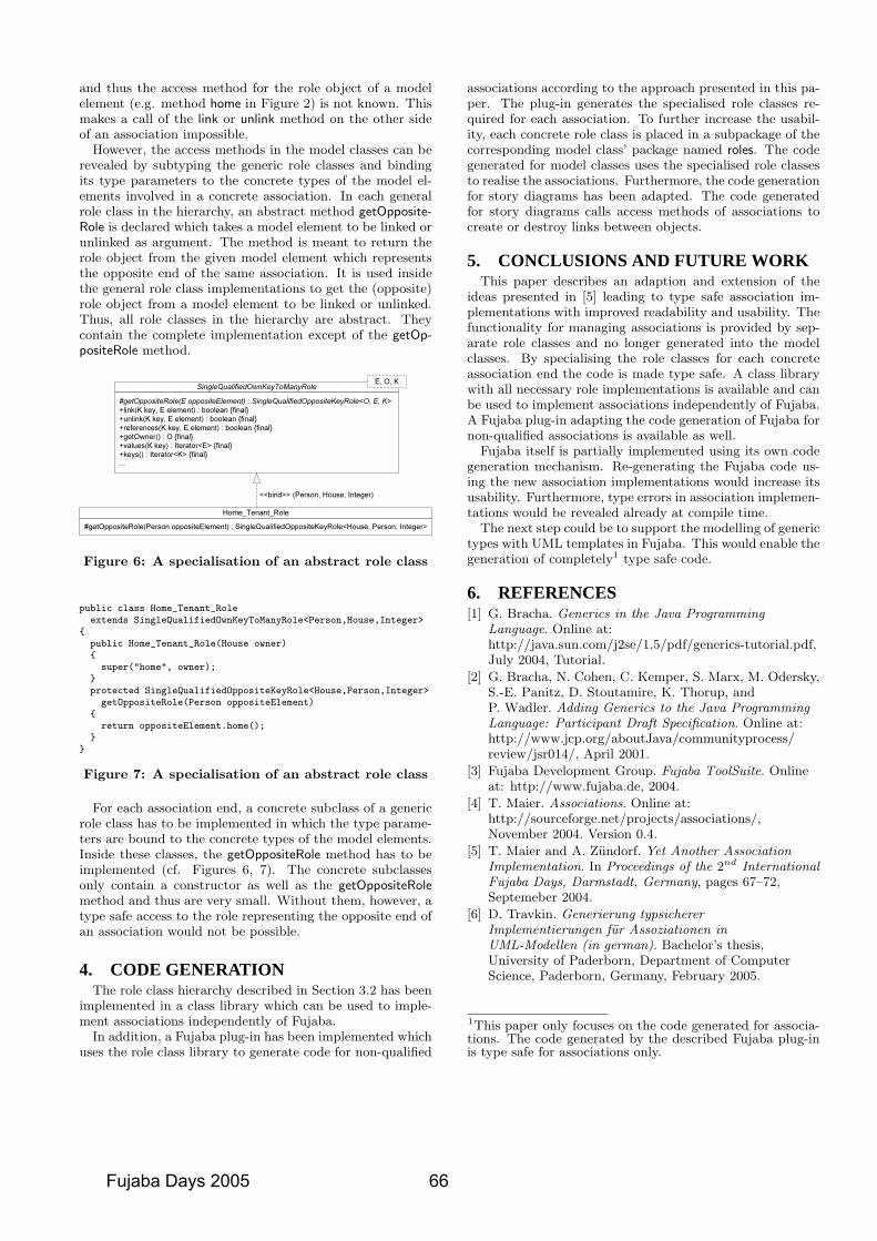
and thus the access method for the role object of a modelelement (e.g. method home in Figure 2) is not known. Thismakes a call of the link or unlink method on the other sideof an association impossible.
However, the access methods in the model classes can berevealed by subtyping the generic role classes and bindingits type parameters to the concrete types of the model el-ements involved in a concrete association. In each generalrole class in the hierarchy, an abstract method getOpposite-Role is declared which takes a model element to be linked orunlinked as argument. The method is meant to return therole object from the given model element which representsthe opposite end of the same association. It is used insidethe general role class implementations to get the (opposite)role object from a model element to be linked or unlinked.Thus, all role classes in the hierarchy are abstract. Theycontain the complete implementation except of the getOp-positeRole method.
Figure 6: A specialisation of an abstract role class
public class Home_Tenant_Roleextends SingleQualifiedOwnKeyToManyRole<Person,House,Integer>
{public Home_Tenant_Role(House owner){
super("home", owner);}protected SingleQualifiedOppositeKeyRole<House,Person,Integer>
getOppositeRole(Person oppositeElement){
return oppositeElement.home();}
}
Figure 7: A specialisation of an abstract role class
For each association end, a concrete subclass of a genericrole class has to be implemented in which the type parame-ters are bound to the concrete types of the model elements.Inside these classes, the getOppositeRole method has to beimplemented (cf. Figures 6, 7). The concrete subclassesonly contain a constructor as well as the getOppositeRolemethod and thus are very small. Without them, however, atype safe access to the role representing the opposite end ofan association would not be possible.
4. CODE GENERATIONThe role class hierarchy described in Section 3.2 has been
implemented in a class library which can be used to imple-ment associations independently of Fujaba.
In addition, a Fujaba plug-in has been implemented whichuses the role class library to generate code for non-qualified
associations according to the approach presented in this pa-per. The plug-in generates the specialised role classes re-quired for each association. To further increase the usabil-ity, each concrete role class is placed in a subpackage of thecorresponding model class’ package named roles. The codegenerated for model classes uses the specialised role classesto realise the associations. Furthermore, the code generationfor story diagrams has been adapted. The code generatedfor story diagrams calls access methods of associations tocreate or destroy links between objects.
5. CONCLUSIONS AND FUTURE WORKThis paper describes an adaption and extension of the
ideas presented in [5] leading to type safe association im-plementations with improved readability and usability. Thefunctionality for managing associations is provided by sep-arate role classes and no longer generated into the modelclasses. By specialising the role classes for each concreteassociation end the code is made type safe. A class librarywith all necessary role implementations is available and canbe used to implement associations independently of Fujaba.A Fujaba plug-in adapting the code generation of Fujaba fornon-qualified associations is available as well.
Fujaba itself is partially implemented using its own codegeneration mechanism. Re-generating the Fujaba code us-ing the new association implementations would increase itsusability. Furthermore, type errors in association implemen-tations would be revealed already at compile time.
The next step could be to support the modelling of generictypes with UML templates in Fujaba. This would enable thegeneration of completely1 type safe code.
6. REFERENCES[1] G. Bracha. Generics in the Java Programming
Language. Online at:http://java.sun.com/j2se/1.5/pdf/generics-tutorial.pdf,July 2004, Tutorial.
[2] G. Bracha, N. Cohen, C. Kemper, S. Marx, M. Odersky,S.-E. Panitz, D. Stoutamire, K. Thorup, andP. Wadler. Adding Generics to the Java ProgrammingLanguage: Participant Draft Specification. Online at:http://www.jcp.org/aboutJava/communityprocess/review/jsr014/, April 2001.
[3] Fujaba Development Group. Fujaba ToolSuite. Onlineat: http://www.fujaba.de, 2004.
[4] T. Maier. Associations. Online at:http://sourceforge.net/projects/associations/,November 2004. Version 0.4.
[5] T. Maier and A. Zundorf. Yet Another AssociationImplementation. In Proceedings of the 2nd InternationalFujaba Days, Darmstadt, Germany, pages 67–72,Septemeber 2004.
[6] D. Travkin. Generierung typsichererImplementierungen fur Assoziationen inUML-Modellen (in german). Bachelor’s thesis,University of Paderborn, Department of ComputerScience, Paderborn, Germany, February 2005.
1This paper only focuses on the code generated for associa-tions. The code generated by the described Fujaba plug-inis type safe for associations only.
Fujaba Days 2005 66
The SceBaSy PlugIn for the Scenario-Based Synthesisof Real-Time Coordination Patterns for Mechatronic UML∗
Holger Giese and Sergej TissenSoftware Engineering Group, University of Paderborn,
Warburger Str. 100, Paderborn, Germany
[hg|serti]@uni-paderborn.de
ABSTRACTThe future generation of networked, technical applicationsdemands support for the development of high quality soft-ware for the proper real-time coordination of safety-criticalsystems. In this paper, we present the SceBaSy pluginfor the Fujaba Real-Time Tool Suite which supports thescenario-based synthesis of the real-time coordination pat-terns. Extending our approach for the compositional for-mal verification of Mechatronic UML models describedby components and patterns [5], the plugin enables the de-signer to specify the required real-time coordination usingmultiple parameterized scenarios described by a subset ofthe UML 2.0 sequence diagram notation. In addition tothe synthesis, comfortable analysis capabilities have beenrealized to guide the designer when conflicts between thedifferent scenarios exist.
1. INTRODUCTIONIn the development of safety-critical systems, the design andverification of the real-time coordination of the system is ofcrucial importance. The increasing complexity of these sys-tems and their interconnection by networks which can be of-ten observed today, makes their production an even greaterchallenge. Therefore, the current practice could benefit frommore automated support for the design of correct and safereal-time coordination.
Today, a number of scenarios are usually developed inthe earlier phases to outline and specify possible or requiredinteraction behavior. Later, an operational model of thisinteraction is then derived manually. The underlying ideaof scenario-based synthesis is simply to automate this step(cf. [7, 8, 12, 13]).
However, in our specific case of real-time systems, besidesthe causal relation between the different events also the tim-ing constraints are essential. Available approaches cf. [10, 9,6] only provide a global behavior for fixed timing constraints.We employ here our approach [4] for the synthesis of distrib-uted operational behavior from parameterized scenarios, asit is in practice often difficult to specify all timing informa-tion such as worst-case execution times (wcet), deadlines, ortimeouts in advance.
In this paper, the support for the scenario-based synthesisof real-time coordination pattern provided by the SceBaSy
∗This work was developed in the course of the Special Re-search Initiative 614 – Self-optimizing Concepts and Struc-tures in Mechanical Engineering – University of Paderborn,and was published on its behalf and funded by the DeutscheForschungsgemeinschaft.
plugin is presented. It complements our Mechatronic UMLapproach for the compositional formal verification [5] whichsupports to build a correct and safe real-time coordinationof a whole system composed of components and patterns.
The plugin supports the automatic derivation of the pa-rameterized role behavior in form of Real-Time Statecharts(RTSC) [2] for patterns from a given set of parameterizedscenarios. Therefore, it enables the designer to automatethis otherwise costly development step and guarantees cor-rectness by construction. In addition to the synthesis, com-fortable analysis capabilities have been realized to guide thedesigner when conflicts between the different scenarios exist.
The paper is organized as follows: In Section 2, the real-time modeling with scenarios as supported by the SceBaSyplugin is sketched introducing a simple example pattern.Then, the support of the plugin for the analysis of a set ofscenarios in case of conflicts is outlined in Section 3. For aconflict free set of scenarios, the handling and output of thesynthesis step are then described in Section 4. Finally, wesketch the architecture of the plugin and its dependenciesw.r.t. other Mechatronic UML plugins in Section 5 andsum up the paper with a short conclusion.
2. REAL-TIME MODELINGAs a running example, we consider the Monitor-ActuatorPattern [3]. This pattern specifies a controller which moni-tors and controls another system. Therefore, the controllersends advices to the system via an actuator and monitorstheir realization. The actuator calculates the actions whichhave to be done to realize the system-state and sends themto the system. The monitor waits for the system status anddecides then whether the advice is fulfilled or not. Further-more the monitor and actuator check their presence by send-ing periodically a life tick message to each other (cf. heartbeat).
To describe the variable behaviors of the roles within thepattern, we model the different scenarios by UML sequencediagrams where besides constant timing constraints also pa-rameterized timing constraints for upper bounds are sup-ported. The sequence diagrams are modeled with the Fujabaplugin UMLSequenceDiagrams. Additionally, our plugin ex-tends the sequence diagram plugin by time observations andtime restrictions to be able to specify real-time behaviorwithin sequence diagrams. Time observations assign the ac-tual time to a clock and time constraints can refer to theseclocks and make restrictions. Two sequence diagrams whichdescribe two scenarios of the Monitor-Actuator Pattern areshown in Figure 1 and 2
67 Fujaba Days 2005
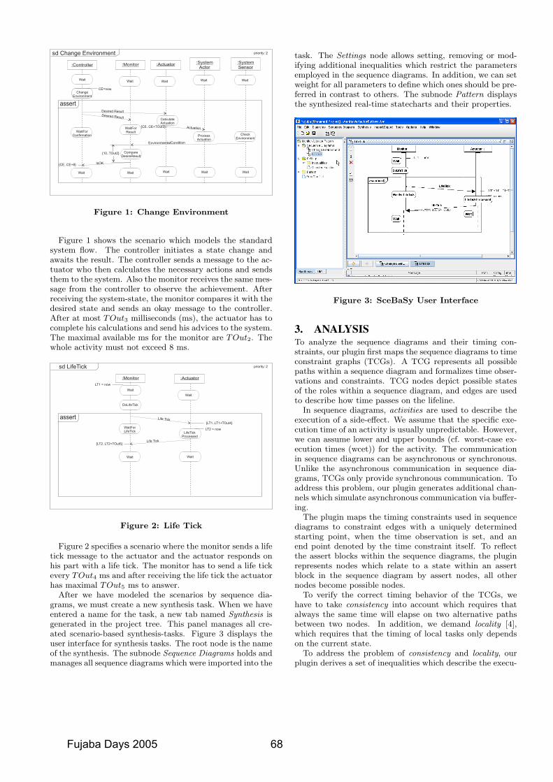
sd Change Environment priority: 2
:Controller :Monitor
ChangeEnvironment
assert
:Actuator
Desired Result
Desired Result
WaitForResult
Actuation
EnvironmentalCondtiion
CompareDesireResult
IsOK
ProcessActuation
CalculateActuation
Wait
ChangeEnvironment
WaitWaitWait
Wait Wait Wait Wait
CE=now
{10..TOut2}
{CE..CE+8}
{CE..CE+TOut3}
WaitForConfirmation
:SystemActor
CheckEnvironment
Wait
Wait
:SystemSensor
Figure 1: Change Environment
Figure 1 shows the scenario which models the standardsystem flow. The controller initiates a state change andawaits the result. The controller sends a message to the ac-tuator who then calculates the necessary actions and sendsthem to the system. Also the monitor receives the same mes-sage from the controller to observe the achievement. Afterreceiving the system-state, the monitor compares it with thedesired state and sends an okay message to the controller.After at most TOut3 milliseconds (ms), the actuator has tocomplete his calculations and send his advices to the system.The maximal available ms for the monitor are TOut2. Thewhole activity must not exceed 8 ms.
sd LifeTick priority: 2
:Monitor
assert
:Actuator
Wait
Wait
DoLifeTick
Life Tick
Wait
Life Tick
Wait
LT1 = now
{LT1..LT1+TOut4}
LT2 = now
{LT2..LT2+TOut5}
LifeTickProcessed
WaitForLifeTick
Figure 2: Life Tick
Figure 2 specifies a scenario where the monitor sends a lifetick message to the actuator and the actuator responds onhis part with a life tick. The monitor has to send a life tickevery TOut4 ms and after receiving the life tick the actuatorhas maximal TOut5 ms to answer.
After we have modeled the scenarios by sequence dia-grams, we must create a new synthesis task. When we haveentered a name for the task, a new tab named Synthesis isgenerated in the project tree. This panel manages all cre-ated scenario-based synthesis-tasks. Figure 3 displays theuser interface for synthesis tasks. The root node is the nameof the synthesis. The subnode Sequence Diagrams holds andmanages all sequence diagrams which were imported into the
task. The Settings node allows setting, removing or mod-ifying additional inequalities which restrict the parametersemployed in the sequence diagrams. In addition, we can setweight for all parameters to define which ones should be pre-ferred in contrast to others. The subnode Pattern displaysthe synthesized real-time statecharts and their properties.
Figure 3: SceBaSy User Interface
3. ANALYSISTo analyze the sequence diagrams and their timing con-straints, our plugin first maps the sequence diagrams to timeconstraint graphs (TCGs). A TCG represents all possiblepaths within a sequence diagram and formalizes time obser-vations and constraints. TCG nodes depict possible statesof the roles within a sequence diagram, and edges are usedto describe how time passes on the lifeline.
In sequence diagrams, activities are used to describe theexecution of a side-effect. We assume that the specific exe-cution time of an activity is usually unpredictable. However,we can assume lower and upper bounds (cf. worst-case ex-ecution times (wcet)) for the activity. The communicationin sequence diagrams can be asynchronous or synchronous.Unlike the asynchronous communication in sequence dia-grams, TCGs only provide synchronous communication. Toaddress this problem, our plugin generates additional chan-nels which simulate asynchronous communication via buffer-ing.
The plugin maps the timing constraints used in sequencediagrams to constraint edges with a uniquely determinedstarting point, when the time observation is set, and anend point denoted by the time constraint itself. To reflectthe assert blocks within the sequence diagrams, the pluginrepresents nodes which relate to a state within an assertblock in the sequence diagram by assert nodes, all othernodes become possible nodes.
To verify the correct timing behavior of the TCGs, wehave to take consistency into account which requires thatalways the same time will elapse on two alternative pathsbetween two nodes. In addition, we demand locality [4],which requires that the timing of local tasks only dependson the current state.
To address the problem of consistency and locality, ourplugin derives a set of inequalities which describe the execu-
Fujaba Days 2005 68
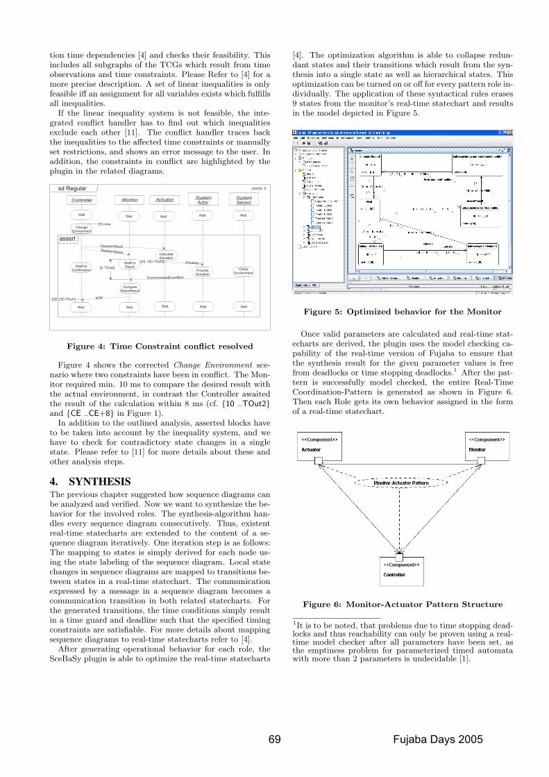
tion time dependencies [4] and checks their feasibility. Thisincludes all subgraphs of the TCGs which result from timeobservations and time constraints. Please Refer to [4] for amore precise description. A set of linear inequalities is onlyfeasible iff an assignment for all variables exists which fulfillsall inequalities.
If the linear inequality system is not feasible, the inte-grated conflict handler has to find out which inequalitiesexclude each other [11]. The conflict handler traces backthe inequalities to the affected time constraints or manuallyset restrictions, and shows an error message to the user. Inaddition, the constraints in conflict are highlighted by theplugin in the related diagrams.
sd Regular priority: 2
:Controller :Monitor
ChangeEnvironment
assert
:Actuator
Desired Result
Desired Result
WaitForResult
Actuation
EnvironmentalCondtiion
CompareDesireResult
IsOK
ProcessActuation
CalculateActuation
Wait
ChangeEnvironment
WaitWaitWait
Wait Wait Wait Wait
CE=now
{0..TOut2}
{CE..CE+TOut1}
{CE..CE+TOut3}
WaitForConfirmation
:SystemActor
CheckEnvironment
Wait
Wait
:SystemSensor
Figure 4: Time Constraint conflict resolved
Figure 4 shows the corrected Change Environment sce-nario where two constraints have been in conflict. The Mon-itor required min. 10 ms to compare the desired result withthe actual environment, in contrast the Controller awaitedthe result of the calculation within 8 ms (cf. {10 ..TOut2}and {CE ..CE+8} in Figure 1).
In addition to the outlined analysis, asserted blocks haveto be taken into account by the inequality system, and wehave to check for contradictory state changes in a singlestate. Please refer to [11] for more details about these andother analysis steps.
4. SYNTHESISThe previous chapter suggested how sequence diagrams canbe analyzed and verified. Now we want to synthesize the be-havior for the involved roles. The synthesis-algorithm han-dles every sequence diagram consecutively. Thus, existentreal-time statecharts are extended to the content of a se-quence diagram iteratively. One iteration step is as follows:The mapping to states is simply derived for each node us-ing the state labeling of the sequence diagram. Local statechanges in sequence diagrams are mapped to transitions be-tween states in a real-time statechart. The communicationexpressed by a message in a sequence diagram becomes acommunication transition in both related statecharts. Forthe generated transitions, the time conditions simply resultin a time guard and deadline such that the specified timingconstraints are satisfiable. For more details about mappingsequence diagrams to real-time statecharts refer to [4].
After generating operational behavior for each role, theSceBaSy plugin is able to optimize the real-time statecharts
[4]. The optimization algorithm is able to collapse redun-dant states and their transitions which result from the syn-thesis into a single state as well as hierarchical states. Thisoptimization can be turned on or off for every pattern role in-dividually. The application of these syntactical rules erases9 states from the monitor’s real-time statechart and resultsin the model depicted in Figure 5.
Figure 5: Optimized behavior for the Monitor
Once valid parameters are calculated and real-time stat-echarts are derived, the plugin uses the model checking ca-pability of the real-time version of Fujaba to ensure thatthe synthesis result for the given parameter values is freefrom deadlocks or time stopping deadlocks.1 After the pat-tern is successfully model checked, the entire Real-TimeCoordination-Pattern is generated as shown in Figure 6.Then each Role gets its own behavior assigned in the formof a real-time statechart.
Figure 6: Monitor-Actuator Pattern Structure
1It is to be noted, that problems due to time stopping dead-locks and thus reachability can only be proven using a real-time model checker after all parameters have been set, asthe emptiness problem for parameterized timed automatawith more than 2 parameters is undecidable [1].
69 Fujaba Days 2005
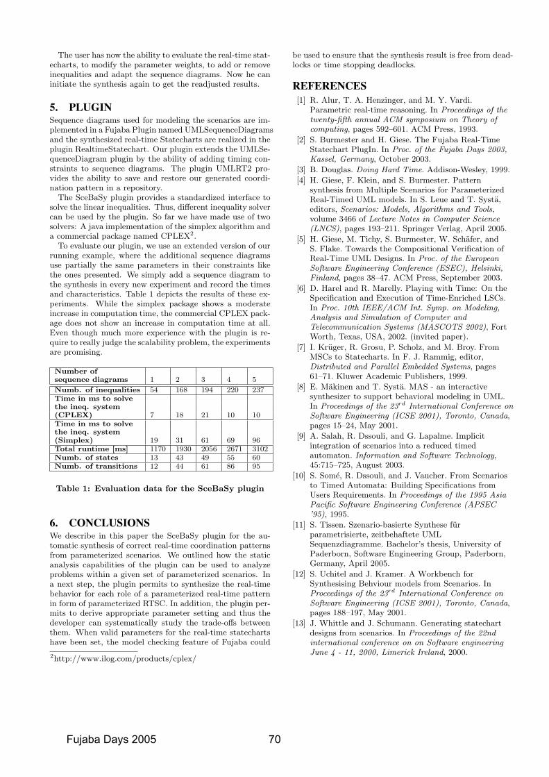
The user has now the ability to evaluate the real-time stat-echarts, to modify the parameter weights, to add or removeinequalities and adapt the sequence diagrams. Now he caninitiate the synthesis again to get the readjusted results.
5. PLUGINSequence diagrams used for modeling the scenarios are im-plemented in a Fujaba Plugin named UMLSequenceDiagramsand the synthesized real-time Statecharts are realized in theplugin RealtimeStatechart. Our plugin extends the UMLSe-quenceDiagram plugin by the ability of adding timing con-straints to sequence diagrams. The plugin UMLRT2 pro-vides the ability to save and restore our generated coordi-nation pattern in a repository.
The SceBaSy plugin provides a standardized interface tosolve the linear inequalities. Thus, different inequality solvercan be used by the plugin. So far we have made use of twosolvers: A java implementation of the simplex algorithm anda commercial package named CPLEX2.
To evaluate our plugin, we use an extended version of ourrunning example, where the additional sequence diagramsuse partially the same parameters in their constraints likethe ones presented. We simply add a sequence diagram tothe synthesis in every new experiment and record the timesand characteristics. Table 1 depicts the results of these ex-periments. While the simplex package shows a moderateincrease in computation time, the commercial CPLEX pack-age does not show an increase in computation time at all.Even though much more experience with the plugin is re-quire to really judge the scalability problem, the experimentsare promising.
Number ofsequence diagrams 1 2 3 4 5
Numb. of inequalities 54 168 194 220 237Time in ms to solvethe ineq. system(CPLEX) 7 18 21 10 10Time in ms to solvethe ineq. system(Simplex) 19 31 61 69 96Total runtime [ms] 1170 1930 2056 2671 3102Numb. of states 13 43 49 55 60Numb. of transitions 12 44 61 86 95
Table 1: Evaluation data for the SceBaSy plugin
6. CONCLUSIONSWe describe in this paper the SceBaSy plugin for the au-tomatic synthesis of correct real-time coordination patternsfrom parameterized scenarios. We outlined how the staticanalysis capabilities of the plugin can be used to analyzeproblems within a given set of parameterized scenarios. Ina next step, the plugin permits to synthesize the real-timebehavior for each role of a parameterized real-time patternin form of parameterized RTSC. In addition, the plugin per-mits to derive appropriate parameter setting and thus thedeveloper can systematically study the trade-offs betweenthem. When valid parameters for the real-time statechartshave been set, the model checking feature of Fujaba could
2http://www.ilog.com/products/cplex/
be used to ensure that the synthesis result is free from dead-locks or time stopping deadlocks.
REFERENCES[1] R. Alur, T. A. Henzinger, and M. Y. Vardi.
Parametric real-time reasoning. In Proceedings of thetwenty-fifth annual ACM symposium on Theory ofcomputing, pages 592–601. ACM Press, 1993.
[2] S. Burmester and H. Giese. The Fujaba Real-TimeStatechart PlugIn. In Proc. of the Fujaba Days 2003,Kassel, Germany, October 2003.
[3] B. Douglas. Doing Hard Time. Addison-Wesley, 1999.
[4] H. Giese, F. Klein, and S. Burmester. Patternsynthesis from Multiple Scenarios for ParameterizedReal-Timed UML models. In S. Leue and T. Systa,editors, Scenarios: Models, Algorithms and Tools,volume 3466 of Lecture Notes in Computer Science(LNCS), pages 193–211. Springer Verlag, April 2005.
[5] H. Giese, M. Tichy, S. Burmester, W. Schafer, andS. Flake. Towards the Compositional Verification ofReal-Time UML Designs. In Proc. of the EuropeanSoftware Engineering Conference (ESEC), Helsinki,Finland, pages 38–47. ACM Press, September 2003.
[6] D. Harel and R. Marelly. Playing with Time: On theSpecification and Execution of Time-Enriched LSCs.In Proc. 10th IEEE/ACM Int. Symp. on Modeling,Analysis and Simulation of Computer andTelecommunication Systems (MASCOTS 2002), FortWorth, Texas, USA, 2002. (invited paper).
[7] I. Kruger, R. Grosu, P. Scholz, and M. Broy. FromMSCs to Statecharts. In F. J. Rammig, editor,Distributed and Parallel Embedded Systems, pages61–71. Kluwer Academic Publishers, 1999.
[8] E. Makinen and T. Systa. MAS - an interactivesynthesizer to support behavioral modeling in UML.In Proceedings of the 23rd International Conference onSoftware Engineering (ICSE 2001), Toronto, Canada,pages 15–24, May 2001.
[9] A. Salah, R. Dssouli, and G. Lapalme. Implicitintegration of scenarios into a reduced timedautomaton. Information and Software Technology,45:715–725, August 2003.
[10] S. Some, R. Dssouli, and J. Vaucher. From Scenariosto Timed Automata: Building Specifications fromUsers Requirements. In Proceedings of the 1995 AsiaPacific Software Engineering Conference (APSEC’95), 1995.
[11] S. Tissen. Szenario-basierte Synthese furparametrisierte, zeitbehaftete UMLSequenzdiagramme. Bachelor’s thesis, University ofPaderborn, Software Engineering Group, Paderborn,Germany, April 2005.
[12] S. Uchitel and J. Kramer. A Workbench forSynthesising Behviour models from Scenarios. InProceedings of the 23rd International Conference onSoftware Engineering (ICSE 2001), Toronto, Canada,pages 188–197, May 2001.
[13] J. Whittle and J. Schumann. Generating statechartdesigns from scenarios. In Proceedings of the 22ndinternational conference on on Software engineeringJune 4 - 11, 2000, Limerick Ireland, 2000.
Fujaba Days 2005 70
Worst-Case Execution Time Optimization of Story Patternsfor Hard Real-Time Systems ∗
Sven Burmester†, Holger Giese, Andreas Seibel, and Matthias TichySoftware Engineering Group, University of Paderborn, Warburger Str. 100, Paderborn, Germany
[burmi|hg|aseibel|mtt]@uni-paderborn.de
ABSTRACTIn the future, technical systems are expected to operatemore intelligent than today by taking their local contextexplored by means of sensors and network communicationinto account. To realize this vision, the systems must beable to represent and query as well as interact with a largenumber of possible situations not known a priori. There-fore, flexible means to store, query, and manipulate suchcontext information are required. Known flexible and pow-erful representations are class diagrams or other graph-likenotations. However, such dynamic data structures whichare sources for unpredictable run-time timing behavior aretraditionally not recommended for the development of hardreal-time systems. In this paper, we describe our efforts toemploy story patterns, which are used for the specificationof query and update operations on dynamic data structures,in hard real-time systems.
KeywordsReal-Time, Story-Pattern, Worst-Case Execution Time Op-timization
1. INTRODUCTIONAdvanced technical systems of the future such as self-adap-tive [18, 13, 14] or self-optimizing [3] technical systems willoperate smarter than today’s systems by adjusting their op-eration to the experienced context. Besides the informationprovided by sensors, the communication with other entitiesnear by via wireless networks will increase the available in-formation and its complexity.
The software of these systems must thus be able to repre-sent and query a large number of possible not a priori knowncontext situations. The means to store, query and manipu-late such context situations must support model-based de-velopment and should not be restricted to fixed-sized arrays.UML and in particular class diagrams became the standardto describe the structure of the complex information. Storydiagrams [19, 12] are an advanced technique to manipulatethis information. However, class diagrams describe proper-ties of dynamic data structures which result in unpredictable
†Supported by the International Graduate School of Dy-namic Intelligent Systems. University of Paderborn.∗This work was developed in the course of the Special Re-search Initiative 614 – Self-optimizing Concepts and Struc-tures in Mechanical Engineering – University of Paderborn,and was published on its behalf and funded by the DeutscheForschungsgemeinschaft.
run-time timing behavior and are thus traditionally not con-sidered as an option for the development of hard real-timesystems.
In real-time systems, the provision of a service (e.g. reac-tion to an incoming message, a computation, . . . ) is associ-ated with a certain deadline. If the deadline expires beforethe service is provided, the results in embedded systems aretypically catastrophic due to damages to humans in case ofautomotive or railway systems. Those systems are namedhard real-time systems.
In order to guarantee to meet the required deadlines, theworst-case execution times (WCETs) of methods or other im-plementation artifacts must be known. In addition, worst-case execution times are required for a schedulability anal-ysis [5] which is used to check whether concurrent processesare executable on a given processor meeting the requireddeadlines.
Standard dynamic data structures are unbounded, i.e. theyhave no predetermined maximal amount of stored elements.Thus, no worst-case execution time can be given for oper-ations on these data structures, since the execution timetypically is dependant on the contained number of storedelements. Therefore, in order to determine a worst-case ex-ecution time, the maximal number of elements in those datastructures must be fixed beforehand. Then, the worst-caseexecution time can be determined.
Additionally, algorithms in standard applications are op-timized for the average case (e.g. the quicksort algorithm).Since the average case is only of low relevance in hard real-time systems, algorithms on those dynamic data structuresshould have an optimal (read: minimal) worst-case execu-tion time. Therefore, we require (1) a model that allows thedetermination of WCETs of the generated code and (2) weshould generate code so that the WCETs are optimized.
Current WCET analysis techniques are restricted to im-perative programming languages. Dynamic, object-orientedprogramming languages are not addressed at all. Buttazzoeven demands to avoid dynamic data structures in real-timesystems [5].
The standard approach in WCET analysis is to analyzethe longest executable path, to map each instruction of thispath to elementary operations, and to determine the WCETsof these elementary operations. The elementary operationscan be for example assembler instructions as in the [6] orJava Byte Code instructions as in [1].
In [6], the WCET of a fragment of generated C code isdetermined by summing up the number of processor cy-cles each C instruction’s corresponding assembler instruc-
71 Fujaba Days 2005
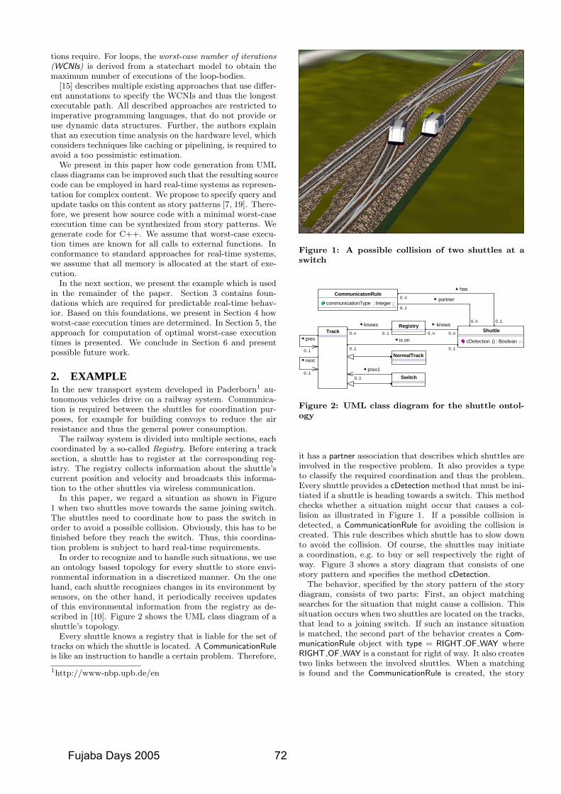
tions require. For loops, the worst-case number of iterations(WCNIs) is derived from a statechart model to obtain themaximum number of executions of the loop-bodies.
[15] describes multiple existing approaches that use differ-ent annotations to specify the WCNIs and thus the longestexecutable path. All described approaches are restricted toimperative programming languages, that do not provide oruse dynamic data structures. Further, the authors explainthat an execution time analysis on the hardware level, whichconsiders techniques like caching or pipelining, is required toavoid a too pessimistic estimation.
We present in this paper how code generation from UMLclass diagrams can be improved such that the resulting sourcecode can be employed in hard real-time systems as represen-tation for complex content. We propose to specify query andupdate tasks on this content as story patterns [7, 19]. There-fore, we present how source code with a minimal worst-caseexecution time can be synthesized from story patterns. Wegenerate code for C++. We assume that worst-case execu-tion times are known for all calls to external functions. Inconformance to standard approaches for real-time systems,we assume that all memory is allocated at the start of exe-cution.
In the next section, we present the example which is usedin the remainder of the paper. Section 3 contains foun-dations which are required for predictable real-time behav-ior. Based on this foundations, we present in Section 4 howworst-case execution times are determined. In Section 5, theapproach for computation of optimal worst-case executiontimes is presented. We conclude in Section 6 and presentpossible future work.
2. EXAMPLEIn the new transport system developed in Paderborn1 au-tonomous vehicles drive on a railway system. Communica-tion is required between the shuttles for coordination pur-poses, for example for building convoys to reduce the airresistance and thus the general power consumption.
The railway system is divided into multiple sections, eachcoordinated by a so-called Registry. Before entering a tracksection, a shuttle has to register at the corresponding reg-istry. The registry collects information about the shuttle’scurrent position and velocity and broadcasts this informa-tion to the other shuttles via wireless communication.
In this paper, we regard a situation as shown in Figure1 when two shuttles move towards the same joining switch.The shuttles need to coordinate how to pass the switch inorder to avoid a possible collision. Obviously, this has to befinished before they reach the switch. Thus, this coordina-tion problem is subject to hard real-time requirements.
In order to recognize and to handle such situations, we usean ontology based topology for every shuttle to store envi-ronmental information in a discretized manner. On the onehand, each shuttle recognizes changes in its environment bysensors, on the other hand, it periodically receives updatesof this environmental information from the registry as de-scribed in [10]. Figure 2 shows the UML class diagram of ashuttle’s topology.
Every shuttle knows a registry that is liable for the set oftracks on which the shuttle is located. A CommunicationRuleis like an instruction to handle a certain problem. Therefore,
1http://www-nbp.upb.de/en
Figure 1: A possible collision of two shuttles at aswitch
0..n
0..1
0..n0..n
knows
0..1 0..1
is on 0..n 0..1
knows
0..1
0..10..1
prev1
Switch
0..n
0..1
Track
prev
NormalTrack
Boolean : ) (cDetection
Shuttle
partner
has
next
Integer : communicationType
CommunicatonRule
Registry
Figure 2: UML class diagram for the shuttle ontol-ogy
it has a partner association that describes which shuttles areinvolved in the respective problem. It also provides a typeto classify the required coordination and thus the problem.Every shuttle provides a cDetection method that must be ini-tiated if a shuttle is heading towards a switch. This methodchecks whether a situation might occur that causes a col-lision as illustrated in Figure 1. If a possible collision isdetected, a CommunicationRule for avoiding the collision iscreated. This rule describes which shuttle has to slow downto avoid the collision. Of course, the shuttles may initiatea coordination, e.g. to buy or sell respectively the right ofway. Figure 3 shows a story diagram that consists of onestory pattern and specifies the method cDetection.
The behavior, specified by the story pattern of the storydiagram, consists of two parts: First, an object matchingsearches for the situation that might cause a collision. Thissituation occurs when two shuttles are located on the tracks,that lead to a joining switch. If such an instance situationis matched, the second part of the behavior creates a Com-municationRule object with type = RIGHT OF WAY whereRIGHT OF WAY is a constant for right of way. It also createstwo links between the involved shuttles. When a matchingis found and the CommunicationRule is created, the story
Fujaba Days 2005 72
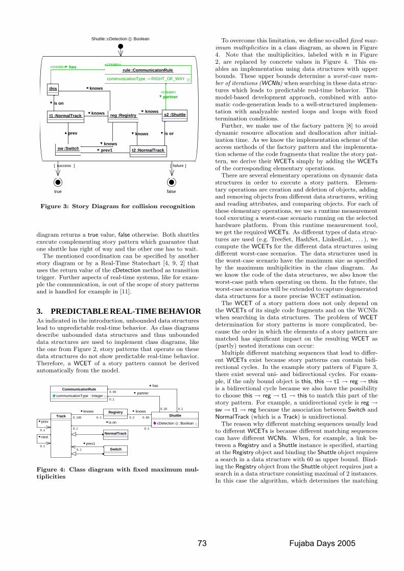
]failure[]success[
falsetrue
knows
knows
prev1
prev is on
«create»partner
is on
knows NormalTrack:t1 Registry:reg
NormalTrack:t2
knows Switch:sw
Shuttle:s2
knows
«create»
RIGHT_OF_WAY:=communicationType
CommunicatonRule:rule
this
«create» has
Shuttle::cDetection (): Boolean
Figure 3: Story Diagram for collision recognition
diagram returns a true value, false otherwise. Both shuttlesexecute complementing story pattern which guarantee thatone shuttle has right of way and the other one has to wait.
The mentioned coordination can be specified by anotherstory diagram or by a Real-Time Statechart [4, 9, 2] thatuses the return value of the cDetection method as transitiontrigger. Further aspects of real-time systems, like for exam-ple the communication, is out of the scope of story patternsand is handled for example in [11].
3. PREDICTABLE REAL-TIME BEHAVIORAs indicated in the introduction, unbounded data structureslead to unpredictable real-time behavior. As class diagramsdescribe unbounded data structures and thus unboundeddata structures are used to implement class diagrams, likethe one from Figure 2, story patterns that operate on thesedata structures do not show predictable real-time behavior.Therefore, a WCET of a story pattern cannot be derivedautomatically from the model.
0..20
0..1
0..600..2
knows
0..1 0..1
is on 0..100 0..1
knows
0..1
0..10..1
prev1
Switch
0..50
0..1
Track
prev
NormalTrack
Boolean : ) (cDetection
Shuttle
partner
has
next
Integer : communicationType
CommunicatonRule
Registry
Figure 4: Class diagram with fixed maximum mul-tiplicities
To overcome this limitation, we define so-called fixed max-imum multiplicities in a class diagram, as shown in Figure4. Note that the multiplicities, labeled with n in Figure2, are replaced by concrete values in Figure 4. This en-ables an implementation using data structures with upperbounds. These upper bounds determine a worst-case num-ber of iterations (WCNIs) when searching in these data struc-tures which leads to predictable real-time behavior. Thismodel-based development approach, combined with auto-matic code-generation leads to a well-structured implemen-tation with analyzable nested loops and loops with fixedtermination conditions.
Further, we make use of the factory pattern [8] to avoiddynamic resource allocation and deallocation after initial-ization time. As we know the implementation scheme of theaccess methods of the factory pattern and the implementa-tion scheme of the code fragments that realize the story pat-tern, we derive their WCETs simply by adding the WCETsof the corresponding elementary operations.
There are several elementary operations on dynamic datastructures in order to execute a story pattern. Elemen-tary operations are creation and deletion of objects, addingand removing objects from different data structures, writingand reading attributes, and comparing objects. For each ofthese elementary operations, we use a runtime measurementtool executing a worst-case scenario running on the selectedhardware platform. From this runtime measurement tool,we get the required WCETs. As different types of data struc-tures are used (e.g. TreeSet, HashSet, LinkedList, . . . ), wecompute the WCETs for the different data structures usingdifferent worst-case scenarios. The data structures used inthe worst-case scenario have the maximum size as specifiedby the maximum multiplicities in the class diagram. Aswe know the code of the data structures, we also know theworst-case path when operating on them. In the future, theworst-case scenarios will be extended to capture degenerateddata structures for a more precise WCET estimation.
The WCET of a story pattern does not only depend onthe WCETs of its single code fragments and on the WCNIswhen searching in data structures. The problem of WCETdetermination for story patterns is more complicated, be-cause the order in which the elements of a story pattern arematched has significant impact on the resulting WCET as(partly) nested iterations can occur:
Multiple different matching sequences that lead to differ-ent WCETs exist because story patterns can contain bidi-rectional cycles. In the example story pattern of Figure 3,there exist several uni- and bidirectional cycles. For exam-ple, if the only bound object is this, this → t1 → reg → thisis a bidirectional cycle because we also have the possibilityto choose this → reg → t1 → this to match this part of thestory pattern. For example, a unidirectional cycle is reg →sw → t1 → reg because the association between Switch andNormalTrack (which is a Track) is unidirectional.
The reason why different matching sequences usually leadto different WCETs is because different matching sequencescan have different WCNIs. When, for example, a link be-tween a Registry and a Shuttle instance is specified, startingat the Registry object and binding the Shuttle object requiresa search in a data structure with 60 as upper bound. Bind-ing the Registry object from the Shuttle object requires just asearch in a data structure consisting maximal of 2 instances.In this case the algorithm, which determines the matching
73 Fujaba Days 2005
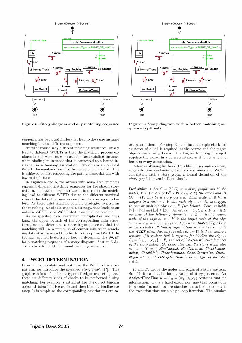
]failure[]success[
falsetrue
knows
knows
prev1
prev is on
«create»partner
is on
knows NormalTrack:t1 Registry:reg
NormalTrack:t2knows
Switch:sw
Shuttle:s2
knows
«create»
RIGHT_OF_WAY:=communicationType
CommunicatonRule:rule
this
«create» has
Shuttle::cDetection (): Boolean
13
2 4
567
8
9
Figure 5: Story diagram and any matching sequence
sequence, has two possibilities that lead to the same instancematching but use different sequences.
Another reason why different matching sequences usuallylead to different WCETs is that the matching process ex-plores in the worst-case a path for each existing instancewhen binding an instance that is connected to a bound in-stance via a to-many association. To obtain an optimalWCET, the number of such paths has to be minimized. Thisis achieved by first respecting the path via associations withlow multiplicities.
In Figures 5 and 6, the arrows with associated numbersrepresent different matching sequences for the shown storypattern. The two different strategies to perform the match-ing lead to different WCETs due to the different maximalsizes of the data structures as described two paragraphs be-fore. As there exist multiple possible strategies to performthe matching, we should choose a strategy, that leads to anoptimal WCET, i.e. a WCET that is as small as possible.
As we specified fixed maximum multiplicities and thusknow the upper bounds of the corresponding data struc-tures, we can determine a matching sequence so that thematching will use a minimum of comparisons when search-ing data structures and thus leads to the optimal WCET. Inthe next section is described how to determine the WCETfor a matching sequence of a story diagram. Section 5 de-scribes how to find the optimal matching sequence.
4. WCET DETERMINATIONIn order to calculate and optimize the WCET of a storypattern, we introduce the so-called story graph [17]. Thisgraph consists of different types of edges respecting thatthere are different kinds of checks to be performed duringmatching: For example, starting at the this object bindingobject t1 (step 1 in Figure 6) and then binding binding reg(step 2) is simple as the corresponding associations are to-
]failure[]success[
falsetrue
knows
knows
prev1
prev is on
«create»partner
is on
knows NormalTrack:t1 Registry:reg
NormalTrack:t2knows
Switch:sw
Shuttle:s2
knows
«create»
RIGHT_OF_WAY:=communicationType
CommunicatonRule:rule
this
«create» has
Shuttle::cDetection (): Boolean
13
2 8
794
6
5
Figure 6: Story diagram with a better matching se-quence (optimal)
one associations. For step 3, it is just a simple check forexistence of a link is required, as the source and the targetobjects are already bound. Binding sw from reg in step 4requires the search in a data structure, as it is not a to-onebut a to-many association.
Before explaining further details like story graph creation,edge selection mechanism, timing constraints and WCETcalculation with a story graph, a formal definition of thestory graph is given in Definition 1.
Definition 1 Let G = (V, E) be a story graph with V thenodes, E ⊆ (V × V × IN3 × IN × Es × T ) the edges and letGs = (Vs, Es) be a story pattern. Each node vs ∈ Vs ismapped to a node v ∈ V and each edge es ∈ Es is mappedto one or multiple edges e ∈ E (see below). Thus, it holds|V | = |Vs| and |E| ≥ |Es|. An edge e = (s, t, w, c, Le, te) ∈ Econsists of the following elements: s ∈ V is the sourcenode of the edge e. t ∈ V is the target node of the edgee. w = Att = (wf , wd, ca) is defined as AnalysedTypeTimewhich includes all timing information required to computethe WCET when choosing the edge e. c ∈ IN is the maximumnumber of iterations that is required for binding the edge e.Le = {es1, ..., esn} ⊆ Es is a set of Link/MultiLink-referencesof the story pattern Gs associated with the story graph edgee. te ∈ T = { BindNormal, BindOptional, CheckIsomor-phism, CheckLink, CheckAttribute, CheckConstraint, Check-NegativeLink, CheckNegativeNode } is the type of the edgee ∈ E.
Vs and Es define the nodes and edges of a story pattern.See [19] for a detailed formalization of story patterns. AnAnalysedTypeTime w = Att = (wf , wd, ca) contains runtimeinformation. wf is a fixed execution time that occurs dueto a code fragment before starting a possible loop. wd isthe execution time for a single loop iteration. The number
Fujaba Days 2005 74
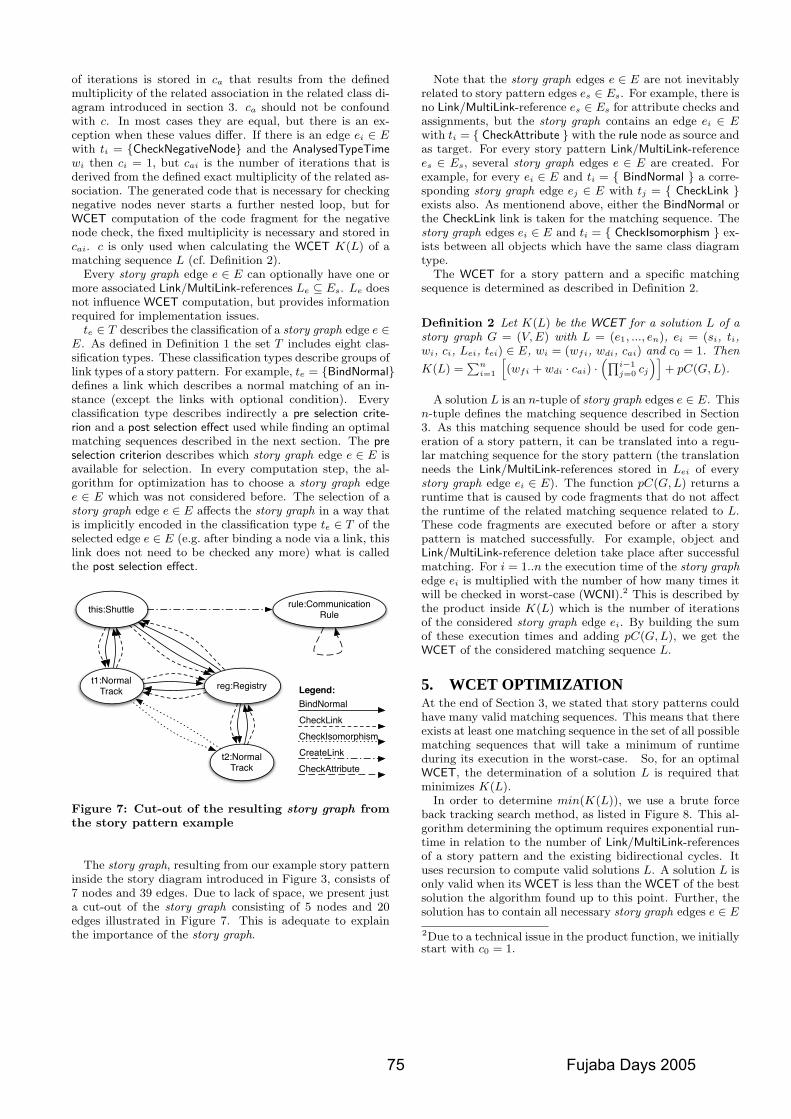
of iterations is stored in ca that results from the definedmultiplicity of the related association in the related class di-agram introduced in section 3. ca should not be confoundwith c. In most cases they are equal, but there is an ex-ception when these values differ. If there is an edge ei ∈ Ewith ti = {CheckNegativeNode} and the AnalysedTypeTimewi then ci = 1, but cai is the number of iterations that isderived from the defined exact multiplicity of the related as-sociation. The generated code that is necessary for checkingnegative nodes never starts a further nested loop, but forWCET computation of the code fragment for the negativenode check, the fixed multiplicity is necessary and stored incai. c is only used when calculating the WCET K(L) of amatching sequence L (cf. Definition 2).
Every story graph edge e ∈ E can optionally have one ormore associated Link/MultiLink-references Le ⊆ Es. Le doesnot influence WCET computation, but provides informationrequired for implementation issues.
te ∈ T describes the classification of a story graph edge e ∈E. As defined in Definition 1 the set T includes eight clas-sification types. These classification types describe groups oflink types of a story pattern. For example, te = {BindNormal}defines a link which describes a normal matching of an in-stance (except the links with optional condition). Everyclassification type describes indirectly a pre selection crite-rion and a post selection effect used while finding an optimalmatching sequences described in the next section. The preselection criterion describes which story graph edge e ∈ E isavailable for selection. In every computation step, the al-gorithm for optimization has to choose a story graph edgee ∈ E which was not considered before. The selection of astory graph edge e ∈ E affects the story graph in a way thatis implicitly encoded in the classification type te ∈ T of theselected edge e ∈ E (e.g. after binding a node via a link, thislink does not need to be checked any more) what is calledthe post selection effect.
this:Shuttle rule:CommunicationRule
t1:NormalTrack reg:Registry
t2:NormalTrack
Legend:
CheckIsomorphismCheckLinkBindNormal
CreateLinkCheckAttribute
Figure 7: Cut-out of the resulting story graph fromthe story pattern example
The story graph, resulting from our example story patterninside the story diagram introduced in Figure 3, consists of7 nodes and 39 edges. Due to lack of space, we present justa cut-out of the story graph consisting of 5 nodes and 20edges illustrated in Figure 7. This is adequate to explainthe importance of the story graph.
Note that the story graph edges e ∈ E are not inevitablyrelated to story pattern edges es ∈ Es. For example, there isno Link/MultiLink-reference es ∈ Es for attribute checks andassignments, but the story graph contains an edge ei ∈ Ewith ti = { CheckAttribute } with the rule node as source andas target. For every story pattern Link/MultiLink-referencees ∈ Es, several story graph edges e ∈ E are created. Forexample, for every ei ∈ E and ti = { BindNormal } a corre-sponding story graph edge ej ∈ E with tj = { CheckLink }exists also. As mentionend above, either the BindNormal orthe CheckLink link is taken for the matching sequence. Thestory graph edges ei ∈ E and ti = { CheckIsomorphism } ex-ists between all objects which have the same class diagramtype.
The WCET for a story pattern and a specific matchingsequence is determined as described in Definition 2.
Definition 2 Let K(L) be the WCET for a solution L of astory graph G = (V, E) with L = (e1, ..., en), ei = (si, ti,wi, ci, Lei, tei) ∈ E, wi = (wfi, wdi, cai) and c0 = 1. Then
K(L) =∑n
i=1
[(wfi + wdi · cai) ·
(∏i−1j=0 cj
)]+ pC(G, L).
A solution L is an n-tuple of story graph edges e ∈ E. Thisn-tuple defines the matching sequence described in Section3. As this matching sequence should be used for code gen-eration of a story pattern, it can be translated into a regu-lar matching sequence for the story pattern (the translationneeds the Link/MultiLink-references stored in Lei of everystory graph edge ei ∈ E). The function pC(G, L) returns aruntime that is caused by code fragments that do not affectthe runtime of the related matching sequence related to L.These code fragments are executed before or after a storypattern is matched successfully. For example, object andLink/MultiLink-reference deletion take place after successfulmatching. For i = 1..n the execution time of the story graphedge ei is multiplied with the number of how many times itwill be checked in worst-case (WCNI).2 This is described bythe product inside K(L) which is the number of iterationsof the considered story graph edge ei. By building the sumof these execution times and adding pC(G, L), we get theWCET of the considered matching sequence L.
5. WCET OPTIMIZATIONAt the end of Section 3, we stated that story patterns couldhave many valid matching sequences. This means that thereexists at least one matching sequence in the set of all possiblematching sequences that will take a minimum of runtimeduring its execution in the worst-case. So, for an optimalWCET, the determination of a solution L is required thatminimizes K(L).
In order to determine min(K(L)), we use a brute forceback tracking search method, as listed in Figure 8. This al-gorithm determining the optimum requires exponential run-time in relation to the number of Link/MultiLink-referencesof a story pattern and the existing bidirectional cycles. Ituses recursion to compute valid solutions L. A solution L isonly valid when its WCET is less than the WCET of the bestsolution the algorithm found up to this point. Further, thesolution has to contain all necessary story graph edges e ∈ E
2Due to a technical issue in the product function, we initiallystart with c0 = 1.
75 Fujaba Days 2005
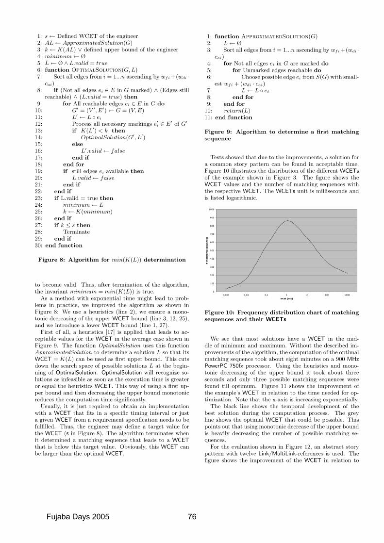
1: s← Defined WCET of the engineer2: AL← ApproximatedSolution(G)3: k ← K(AL) ∨ defined upper bound of the engineer4: minimum← Ø5: L← Ø ∧ L.valid = true6: function OptimalSolution(G, L)7: Sort all edges from i = 1...n ascending by wfi +(wdi ·
cai)8: if (Not all edges ei ∈ E in G marked) ∧ (Edges still
reachable) ∧ (L.valid = true) then9: for All reachable edges ei ∈ E in G do
10: G′ = (V ′, E′)← G = (V, E)11: L′ ← L ◦ ei
12: Process all necessary markings e′i ∈ E′ of G′
13: if K(L′) < k then14: OptimalSolution(G′, L′)15: else16: L′.valid← false17: end if18: end for19: if still edges ei available then20: L.valid← false21: end if22: end if23: if L.valid = true then24: minimum← L25: k ← K(minimum)26: end if27: if k ≤ s then28: Terminate29: end if30: end function
Figure 8: Algorithm for min(K(L)) determination
to become valid. Thus, after termination of the algorithm,the invariant minimum = min(K(L)) is true.
As a method with exponential time might lead to prob-lems in practice, we improved the algorithm as shown inFigure 8: We use a heuristics (line 2), we ensure a mono-tonic decreasing of the upper WCET bound (line 3, 13, 25),and we introduce a lower WCET bound (line 1, 27).
First of all, a heuristics [17] is applied that leads to ac-ceptable values for the WCET in the average case shown inFigure 9. The function OptimalSolution uses this functionApproximatedSolution to determine a solution L so that itsWCET = K(L) can be used as first upper bound. This cutsdown the search space of possible solutions L at the begin-ning of OptimalSolution. OptimalSolution will recognize so-lutions as infeasible as soon as the execution time is greateror equal the heuristics WCET. This way of using a first up-per bound and then decreasing the upper bound monotonicreduces the computation time significantly.
Usually, it is just required to obtain an implementationwith a WCET that fits in a specific timing interval or justa given WCET from a requirement specification needs to befulfilled. Thus, the engineer may define a target value forthe WCET (s in Figure 8). The algorithm terminates whenit determined a matching sequence that leads to a WCETthat is below this target value. Obviously, this WCET canbe larger than the optimal WCET.
1: function ApproximatedSolution(G)2: L← Ø3: Sort all edges from i = 1...n ascending by wfi +(wdi ·
cai)4: for Not all edges ei in G are marked do5: for Unmarked edges reachable do6: Choose possible edge ei from S(G) with small-
est wfi + (wdi · cai)7: L← L ◦ ei
8: end for9: end for
10: return(L)11: end function
Figure 9: Algorithm to determine a first matchingsequence
Tests showed that due to the improvements, a solution fora common story pattern can be found in acceptable time.Figure 10 illustrates the distribution of the different WCETsof the example shown in Figure 3. The figure shows theWCET values and the number of matching sequences withthe respective WCET. The WCETs unit is milliseconds andis listed logarithmic.
0
100
200
300
400
500
600
700
800
900
1000
0,001 0,01 0,1 1 10 100 1000
wcet (ms)
# m
atc
hin
g s
eq
uen
ces
Figure 10: Frequency distribution chart of matchingsequences and their WCETs
We see that most solutions have a WCET in the mid-dle of minimum and maximum. Without the described im-provements of the algorithm, the computation of the optimalmatching sequence took about eight minutes on a 900 MHzPowerPC 750fx processor. Using the heuristics and mono-tonic decreasing of the upper bound it took about threeseconds and only three possible matching sequences werefound till optimum. Figure 11 shows the improvement ofthe example’s WCET in relation to the time needed for op-timization. Note that the x-axis is increasing exponentially.
The black line shows the temporal development of thebest solution during the computation process. The greyline shows the optimal WCET that could be possible. Thispoints out that using monotonic decrease of the upper boundis heavily decreasing the number of possible matching se-quences.
For the evaluation shown in Figure 12, an abstract storypattern with twelve Link/MultiLink-references is used. Thefigure shows the improvement of the WCET in relation to
Fujaba Days 2005 76
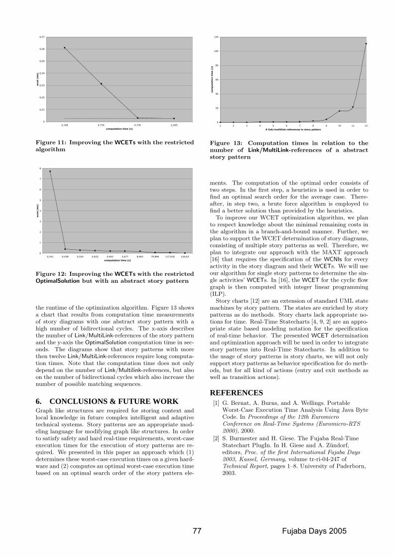
0
0,01
0,02
0,03
0,04
0,05
0,06
0,07
0,168 0,734 0,736 2,265
computation time (s)
wcet
(m
s)
Figure 11: Improving the WCETs with the restrictedalgorithm
0
1
2
3
4
5
6
7
8
0,341 0,438 0,524 0,632 0,643 3,677 8,663 79,866 117,816 126,63
computation time (s)
wcet
(m
s)
Figure 12: Improving the WCETs with the restrictedOptimalSolution but with an abstract story pattern
the runtime of the optimization algorithm. Figure 13 showsa chart that results from computation time measurementsof story diagrams with one abstract story pattern with ahigh number of bidirectional cycles. The x-axis describesthe number of Link/MultiLink-references of the story patternand the y-axis the OptimalSolution computation time in sec-onds. The diagrams show that story patterns with morethen twelve Link/MultiLink-references require long computa-tion times. Note that the computation time does not onlydepend on the number of Link/Multilink-references, but alsoon the number of bidirectional cycles which also increase thenumber of possible matching sequences.
6. CONCLUSIONS & FUTURE WORKGraph like structures are required for storing context andlocal knowledge in future complex intelligent and adaptivetechnical systems. Story patterns are an appropriate mod-eling language for modifying graph like structures. In orderto satisfy safety and hard real-time requirements, worst-caseexecution times for the execution of story patterns are re-quired. We presented in this paper an approach which (1)determines these worst-case execution times on a given hard-ware and (2) computes an optimal worst-case execution timebased on an optimal search order of the story pattern ele-
0
20
40
60
80
100
120
1 2 3 4 5 6 7 8 9 10 11 12
# link/multilink-references in story pattern
co
mp
uta
tio
n t
ime (
s)
Figure 13: Computation times in relation to thenumber of Link/MultiLink-references of a abstractstory pattern
ments. The computation of the optimal order consists oftwo steps. In the first step, a heuristics is used in order tofind an optimal search order for the average case. There-after, in step two, a brute force algorithm is employed tofind a better solution than provided by the heuristics.
To improve our WCET optimization algorithm, we planto respect knowledge about the minimal remaining costs inthe algorithm in a branch-and-bound manner. Further, weplan to support the WCET determination of story diagrams,consisting of multiple story patterns as well. Therefore, weplan to integrate our approach with the MAXT approach[16] that requires the specification of the WCNIs for everyactivity in the story diagram and their WCETs. We will useour algorithm for single story patterns to determine the sin-gle activities’ WCETs. In [16], the WCET for the cyclic flowgraph is then computed with integer linear programming(ILP).
Story charts [12] are an extension of standard UML statemachines by story pattern. The states are enriched by storypatterns as do methods. Story charts lack appropriate no-tions for time. Real-Time Statecharts [4, 9, 2] are an appro-priate state based modeling notation for the specificationof real-time behavior. The presented WCET determinationand optimization approach will be used in order to integratestory patterns into Real-Time Statecharts. In addition tothe usage of story patterns in story charts, we will not onlysupport story patterns as behavior specification for do meth-ods, but for all kind of actions (entry and exit methods aswell as transition actions).
REFERENCES[1] G. Bernat, A. Burns, and A. Wellings. Portable
Worst-Case Execution Time Analysis Using Java ByteCode. In Proceedings of the 12th EuromicroConference on Real-Time Systems (Euromicro-RTS2000), 2000.
[2] S. Burmester and H. Giese. The Fujaba Real-TimeStatechart PlugIn. In H. Giese and A. Zundorf,editors, Proc. of the first International Fujaba Days2003, Kassel, Germany, volume tr-ri-04-247 ofTechnical Report, pages 1–8. University of Paderborn,2003.
77 Fujaba Days 2005
[3] S. Burmester, H. Giese, and O. Oberschelp. HybridUML Components for the Design of ComplexSelf-optimizing Mechatronic Systems. In Informaticsin Control, Automation and Robotics. KluwerAcademic Publishers, 2005. to appear.
[4] S. Burmester, H. Giese, and W. Schafer. Model-drivenarchitecture for hard real-time systems: Fromplatform independent models to code. In Proc. of theEuropean Conference on Model Driven Architecture -Foundations and Applications (ECMDA-FA’05),Nurnberg, Germany, pages 1–15, November 2005.
[5] G. C. Buttazzo. Hard Real Time Computing Systems:Predictable Scheduling Algorithms and Applications.Kluwer international series in engineering andcomputer science : Real-time systems. 1997.
[6] E. Erpenbach. Compilation, Worst-Case ExecutionTimes and Scheduability Analysis of StatechartModels. Ph.D.-thesis, University of Paderborn,Department of Mathematics and Computer Science,2000.
[7] T. Fischer, J. Niere, L. Torunski, and A. Zundorf.Story Diagrams: A new Graph Rewrite Languagebased on the Unified Modeling Language. LNCS 1764,pages 296–309, November 1998.
[8] E. Gamma, R. Helm, R. Johnson, and J. Vlissides.Design Patterns: Elements of Reusable ObjectOriented Software. Reading, MA, 1995.
[9] H. Giese and S. Burmester. Real-Time StatechartSemantics. Technical report, 2003.
[10] H. Giese, S. Burmester, F. Klein, D. Schilling, andM. Tichy. Multi-Agent System Design forSafety-Critical Self-Optimizing Mechatronic Systemswith UML. In B. Henderson-Sellers and J. Debenham,editors, OOPSLA 2003 - Second InternationalWorkshop on Agent-Oriented Methodologies, pages21–32, Anaheim, CA, USA, Center for ObjectTechnology Applications and Research (COTAR),University of Technology, Sydney, Australia, Oct.2003.
[11] H. Giese, M. Tichy, S. Burmester, W. Schafer, andS. Flake. Towards the compositional verification ofreal-time uml designs. In Proc. of the EuropeanSoftware Engineering Conference (ESEC), Helsinki,Finland, pages 38–47. ACM Press, September 2003.
[12] H. J. Kohler, U. A. Nickel, J. Niere, and A. Zundorf.Integrating UML Diagrams for Production ControlSystems. pages 241–251. ACM Press, 2000.
[13] D. J. Musliner, R. P. Goldman, M. J. Pelican, andK. D. Krebsbach. Self-Adaptive Software for HardReal-Time Environments. IEEE Inteligent Systems,14(4), July/Aug. 1999.
[14] P. Oreizy, M. M. Gorlick, R. N. Taylor, D. Heimbigner,G. Johnson, N. Medvidovic, A. Quilici, D. S.Rosenblum, and A. L. Wolf. An Architecture-BasedApproach to Self-Adaptive Software. IEEE IntelligentSystems, 14(3):54–62, May/June 1999.
[15] P. P. Puschner and A. Burns. Guest Editorial: AReview of Worst-Case Execution-Time Analysis.Real-Time Systems, 18(2/3):115–128, May 2000.
[16] P. P. Puschner and A. V. Schedl. ComputingMaximum Task Execution Times - A Graph-BasedApproach. In Real Time Systems, 13, TechnicalReport, pages 67–91. Springer Link, Kluwer AcademicPublishers, July 1997.
[17] A. Seibel. Story Diagramme fur EingebetteteEchtzeitsysteme. Bachelor Thesis at University ofPaderborn, Department of Computer Science,Paderborn, Germany, February 2005.
[18] J. Sztipanovits, G. Karsai, and T. Bapty. Self-adaptivesoftware for signal processing. Commun. ACM,41(5):66–73, 1998.
[19] A. Zundorf. Rigorous Object Oriented SoftwareDevelopment. Habilitation Thesis at University ofPaderborn, Department of Computer Science,Paderborn, Germany, 2001.
Fujaba Days 2005 78