PROCEEDINGS - Unisinos
214
VI Brazilian Symposium on Computer Games and Digital Entertainment November, 7-9, 2007 São Leopoldo – RS - BRAZIL PROCEEDINGS Published by Sociedade Brasileira de Computação - SBC Edited by Marcelo Walter Luiz Gonzaga da Silveira Jr Computing Track Chairs Marcelo Walter Bruno Feijó Jorge Barbosa Organized by Soraia Raupp Musse Fernando Santos Osório João Ricardo Bittencourt Luiz Gonzaga da Silveira Jr Christian Hofsetz Universidade do Vale do Rio dos Sinos - UNISINOS Pontifícia Universidade Católica do Rio Grande do Sul - PUCRS Sponsored by Sociedade Brasileira de Computação
-
Upload
khangminh22 -
Category
Documents
-
view
3 -
download
0
Transcript of PROCEEDINGS - Unisinos
VI Brazilian Symposium on Computer Games and Digital Entertainment
November, 7-9, 2007 São Leopoldo – RS - BRAZIL
PROCEEDINGS
Published by
Sociedade Brasileira de Computação - SBC
Edited by
Marcelo Walter
Luiz Gonzaga da Silveira Jr
Computing Track Chairs Marcelo Walter Bruno Feijó Jorge Barbosa
Organized by
Soraia Raupp Musse Fernando Santos Osório João Ricardo Bittencourt
Luiz Gonzaga da Silveira Jr Christian Hofsetz
Universidade do Vale do Rio dos Sinos - UNISINOS
Pontifícia Universidade Católica do Rio Grande do Sul - PUCRS
Sponsored by
Sociedade Brasileira de Computação
Table of Contents
SBGames 2007
Preface v Program Committe vi Reviewers vii Technical Papers Creating a Director for an Interactive Storytelling System Vinicius da Costa de Azevedo Cesar Tadeu Pozzer.........................................1-9 Towards Consistency in Interactive Storytelling:Tension Arcs and Dead Ends Leandro Motta Barros Soraia Raupp Musse.......................................10-16 Virtual Dungeon Master:Um Narrador Inteligente de Quests para Role Playing Games Felipe Pedroso João Ricardo Bittencourt.................................17-26 Simulação Visual de Ondas Oceânicas em Tempo Real Usando a GPU Alex Salgado Aura Conci Esteban Clua.............................................27-36 The GPU Used as a Math Co-Processor in Real Time Applications Marcelo Zamith Esteban Clua Paulo Pagliosa Aura Conci Anselmo Montenegro Luis Valente.............................................37-43 Algoritmos Evolutivos para a produção de NPCs com Comportamentos Adaptativos Marcio K. Crocomo Mauro Miazaki Eduardo do Valle Simões..................................44-53 Implementacao de Suporte a Modelos de Personagem Nao Jogador em Dispositivos Móveis na Mobile 3D Game Engine Paulo C. Rodacki Gomes Cláudio José Estácio Vitor Fernando Pamplona..................................54-62
A Point-and-Shoot Technique for Immersive 3D Virtual Environments Rafael P. Torchelsen Marcos Slomp André Spritzer Luciana P. Nedel.........................................63-70 FURGBOL-PV: Um Ambiente para Realidade Mista Usando Futebol, Battle e Pac-Man Silvia da Costa Botelho Eder Mateus Nunes Gonçalves Gisele Moraes Simas Rafael Gonçalves Colares Renan Rosado de Almeida Renan de Queiroz Maffei Rodrigo Ruas Oliveira....................................71-76 Robot ARena: an Augmented Reality Platform for Game Development Daniel Calife João Luiz Bernardes Jr. Romero Tori..............................................77-86 Integrating the Wii controller with enJine: 3D interfaces extending the frontiers of a didactic game engine João Bernardes Ricardo Nakamura Daniel Calife Daniel Tokunaga Romero Tori.............................................88-96 Um Framework OpenSource para a Construção de Sistemas Multiatores Allan Lima Patrícia Tedesco Geber Ramalho...........................................97-106 Um Framework para o Desenvolvimento de Agentes Cognitivos em Jogos de Primeira Pessoa Ivan Monteiro Débora Abdalla.........................................107-115 Interperceptive games Julio César Melo Rummenigge R. Dantas Luiz Marcos G. Gonçalves Claudio A. Schneider Josivan Xavier Samuel Azevedo Aquiles Burlamaqui.....................................116-122 Análise da plataforma J2ME através de um estudo de caso na área de jogos multiplayer Fernando Bevilacqua Andrea Schwertner Charão Cesar T. Pozzer........................................123-132
Implementation of a Service Platform for Crossmedia Games Fernando Trinta Davi Pedrosa Carlos André Guimarães Ferraz Geber Ramalho..........................................133-139 moBIO Threat: A mobile game based on the integration of wireless technologies Wilian Segatto Eduardo Herzer Cristiano L. Mazzotti João R. Bittencourt Jorge Barbosa..........................................140-147 What Went Wrong? A Survey of Problems in Game Development Fábio Petrillo Marcelo Pimenta Francisco Trindade Carlos Dietrich........................................148-157 RTSAI: a game tool for IA research André M.C. Campos......................................158-162 RTSCup Project: Challenges and Benchmarks Vicente Filho Clauirton A. Siebra José C. Moura Renan T. Weber Geber L. Ramalho.......................................163-169 Utilizando Rapidly-Exploring Random Trees (RRTs) para o Planejamento de Caminhos em Jogos Samir Souza Luiz Chaimowicz........................................170-177 Reflex - A Flash Game Engine Rodrigo M.A.Silva Laércio Ferracioli.....................................178-186 Avaliando a Usabilidade de um Jogo através de sua Jogabilidade, Interface e Mecânica Carlos Teixeira Karen Daldon Omar Buede Milene Silveira........................................187-196 Providing Expressive Gaze to Virtual Animated Characters in Interactive Applications Rossana Baptista Queiroz Leandro M. Barros Sor
aia Musse...........................................197-206

PREFACE
Welcome to SBGames 2007, the VI edition of the Brazilian Symposium on Computer Games and Digital Entertainment. SBGames is the yearly symposium of the Special Interest Group on Games and Digital Entertainment of the Brazilian Computer Society (SBC). This volume contains the 24 full papers accepted for the computing track, out of 55 submitted, an acceptance ratio of 44%. Out of the 24 accepted papers, 13 are in English (54%). We hope this trend will continue, increasing the visibility of the research work being developed in Brazil by the gaming community. For the first time the selection process was double blind, and each paper was reviewed by at least 3 experts, improving the quality of the reviewing process. Also, a selection of the best papers will be selected for publication in a special edition of IJCGT - International Journal of Computer Games Technology. Papers accepted for the art & design, game & culture tracks, short papers accepted for all tracks and screenshot of games selected to the game festival have been included as addition material. We would like to thank all authors, whose work and dedication made possible to put together an exciting program. Next, we would like to thank all members of the technical program committee and reviewers, for their time helping us maintain the overall quality of the program. We would like to wish all attendees an exciting symposium!
São Leopoldo, November 2007
Marcelo Walter Bruno Feijó
Jorge Barbosa
Chairs of the program committee Computing track
v

Program Committee
Adelailson Peixoto Universidade Federal de Alagoas Alexandre Sztajnberg Universidade do Estado do Rio de Janeiro
André Campos Universidade Federal do Rio Grande do Norte Bruno Feijó Pontifícia Universidade Católica do Rio de Janeiro Cesar Pozzer Universidade Federal de Santa Maria
Christian Hofsetz Universidade do Vale do Rio dos Sinos Clauirton Siebra Universidade Federal de Pernambuco
Drew Davidson Carnegie Mellon University Edmond Prakash Manchester Metropolitan University Edson Cáceres Universidade Federal do Mato Grosso do Sul Esteban Clua Universidade Federal Fluminense
Fernando Osório Universidade do Vale do Rio dos Sinos Fernando Trinta Universidade Federal de Pernambuco
Flávio S. C. da Silva Universidade de São Paulo Geber Ramalho Universidade Federal de Pernambuco
Jacques Brancher Universidade Regional Integrada - Campus de Erechim Jim Terkeurst University of Teesside
João Comba Universidade Federal do Rio Grande do Sul John Buchanan Carnegie Mellon University Jorge Barbosa Universidade do Vale do Rio dos Sinos
José Saito Universidade Federal de São Carlos Judith Kelner Universidade Federal de Pernambuco
Laércio Ferracioli Universidade Federal do Espírito Santo Luiz Chaimowicz Universidade Federal de Minas Gerais
Manuel M. Oliveira Neto Universidade Federal do Rio Grande do Sul Marcelo Dreux Pontifícia Universidade Católica do Rio de Janeiro Marcelo Walter Universidade Federal de Pernambuco
Maria Andréia Rodrigues Universidade de Fortaleza Martin Hanneghan Liverpool John Moores University
Michael Youngblood The University of North Carolina at Charlotte Patrícia Tedesco Universidade Federal de Pernambuco Paulo Pagliosa Universidade Federal de Mato Grosso do Sul
Paulo Rodacki Gomes FURB - Universidade Regional de Blumenau Romero Tori SENAC-SP / Universidade de Sao Paulo
Sérgio Scheer Universidade Federal do Paraná Soraia Musse Pontifícia Universidade Católica do Rio Grande do Sul
Waldemar Celes Pontifícia Universidade Católica do Rio de Janeiro Wu Shin-Ting Universidade Estadual de Campinas
vi

Reviewers
Adelailson Peixoto Fernando Trebien Marcelo Dreux Alex Gomes Fernando Trinta Marcelo Walter
Alexandre Sztajnberg Flávio S. C. da Silva Marcos Slomp André Campos Geber Ramalho Maria A. Rodrigues Bruno Feijó Harlen Batagelo Marinho Barcellos
Carlos Dietrich Jacques Brancher Martin Hanneghan Cesar Pozzer Jim Terkeurst Mauro Steigleder
Christian Hofsetz Joao Bittencourt Michael Youngblood Christian Pagot João Bernardes Patrícia Tedesco Clauirton Siebra John Buchanan Paulo Pagliosa
Danielle Rousy Silva Jorge Barbosa Paulo Rodacki Gomes Denison Tavares José Saito Rafael Torchelsen Drew Davidson Judith Kelner Ricardo Nakamura Edmond Prakash Laércio Ferracioli Romero Tori Edson Cáceres Leandro Fernandes Samir Souza
Eduardo Jacober Leonardo Schmitz Sérgio Scheer Eleri Cardozo Luiz Chaimowicz Soraia Musse Esteban Clua Luiz H. de Figueiredo Waldemar Celes
Fernando Osório Marcelo de P. Guimarães Wu Shin-Ting
vii

Technical Papers
Creating a Director for an Interactive Storytelling System
Vinicius da Costa de Azevedo Cesar Tadeu Pozzer
Universidade Federal de Santa Maria – UFSM Departamento de Eletrônica e Computação – DELC
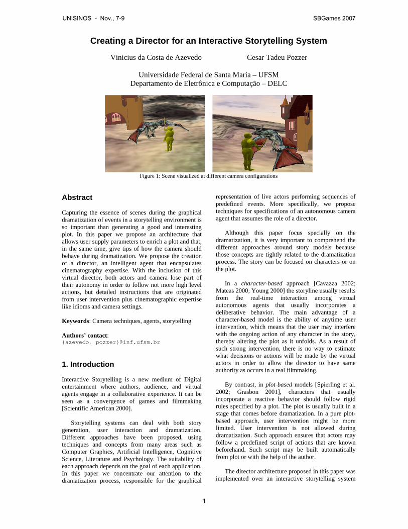
Figure 1: Scene visualized at different camera configurations
Abstract Capturing the essence of scenes during the graphical dramatization of events in a storytelling environment is so important than generating a good and interesting plot. In this paper we propose an architecture that allows user supply parameters to enrich a plot and that, in the same time, give tips of how the camera should behave during dramatization. We propose the creation of a director, an intelligent agent that encapsulates cinematography expertise. With the inclusion of this virtual director, both actors and camera lose part of their autonomy in order to follow not more high level actions, but detailed instructions that are originated from user intervention plus cinematographic expertise like idioms and camera settings. Keywords: Camera techniques, agents, storytelling Authors’ contact: {azevedo, pozzer}@inf.ufsm.br 1. Introduction Interactive Storytelling is a new medium of Digital entertainment where authors, audience, and virtual agents engage in a collaborative experience. It can be seen as a convergence of games and filmmaking [Scientific American 2000].
Storytelling systems can deal with both story generation, user interaction and dramatization. Different approaches have been proposed, using techniques and concepts from many areas such as Computer Graphics, Artificial Intelligence, Cognitive Science, Literature and Psychology. The suitability of each approach depends on the goal of each application. In this paper we concentrate our attention to the dramatization process, responsible for the graphical
representation of live actors performing sequences of predefined events. More specifically, we propose techniques for specifications of an autonomous camera agent that assumes the role of a director.
Although this paper focus specially on the
dramatization, it is very important to comprehend the different approaches around story models because those concepts are tightly related to the dramatization process. The story can be focused on characters or on the plot.
In a character-based approach [Cavazza 2002;
Mateas 2000; Young 2000] the storyline usually results from the real-time interaction among virtual autonomous agents that usually incorporates a deliberative behavior. The main advantage of a character-based model is the ability of anytime user intervention, which means that the user may interfere with the ongoing action of any character in the story, thereby altering the plot as it unfolds. As a result of such strong intervention, there is no way to estimate what decisions or actions will be made by the virtual actors in order to allow the director to have same authority as occurs in a real filmmaking.
By contrast, in plot-based models [Spierling et al.
2002; Grasbon 2001], characters that usually incorporate a reactive behavior should follow rigid rules specified by a plot. The plot is usually built in a stage that comes before dramatization. In a pure plot-based approach, user intervention might be more limited. User intervention is not allowed during dramatization. Such approach ensures that actors may follow a predefined script of actions that are known beforehand. Such script may be built automatically from plot or with the help of the author.
The director architecture proposed in this paper was
implemented over an interactive storytelling system
UNISINOS - Nov., 7-9 SBGames 2007
1
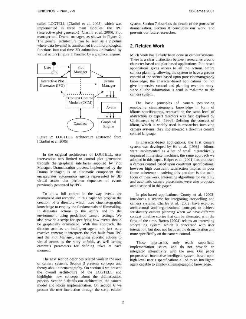
called LOGTELL [Ciarlini et al. 2005], which was implemented in three main modules: the IPG (Interactive plot generator) [Ciarlini et al. 2000], Plot manager and Drama manager, as shown in Figure 2. The general architecture can be seen as a pipeline where data (events) is transformed from morphological functions into real-time 3D animations dramatized by virtual actors (Figure 1) handled by a graphical engine. Figure 2: LOGTELL architecture (extracted from [Ciarlini et al. 2005]
In the original architecture of LOGTELL, user
intervention was limited to control plot generation through the graphical interfaces supplied by Plot Manager. Dramatization process, implemented by the Drama Manager, is an automatic component that encapsulates autonomous agents represented by 3D virtual actors that perform sequences of events previously generated by IPG.
To allow full control in the way events are
dramatized and recorded, in this paper we propose the creation of a director, which uses cinematographic knowledge to employ the fundamentals of filmmaking. It delegates actions to the actors and to the environment, using predefined camera settings. We also provide a script for specifying how events should be graphically dramatized. With this approach, the director acts as an intelligent agent, not just as a reactive camera; it interprets the plot built from IPG and the Plot Manager, assigning specific actions to virtual actors as the story unfolds, as well setting camera’s parameters for defining takes at each moment.
The next section describes related work in the area
of camera systems. Section 3 presents concepts and theory about cinematography. On section 4 we present the overall architecture of the LOGTELL and highlights new concepts about the dramatization process. Section 5 details our architecture, the camera model and idiom implementation. On section 6 we present the user interaction through the script edition
system. Section 7 describes the details of the process of dramatization. Section 8 concludes our work, and presents our future researches.
2. Related Work Much work has already been done in camera systems. There is a clear distinction between researches around character-based and plot-based applications. Plot-based applications gives access to all the actions before camera planning, allowing the system to have a greater control of the scenes based upon pure cinematography knowledge; the character-based applications do not give immersive control and planning over the story, since all the information is send in real-time to the camera system.
The basic principles of camera positioning employing cinematography knowledge in form of idioms specifications, representing the same level of abstraction as expert directors was first explored by Christianson et Al. [1996]. Defining the concept of idiom, which is widely used in researches involving camera systems, they implemented a directive camera control language.
In character-based applications, the first camera
system was developed by He at al. [1996] – idioms were implemented as a set of small hierarchically organized finite state machines, the same approach we adopted in this paper. Halper et al. [2001] has proposed a camera control based upon constraint specifications; however high constraint satisfaction implies in poor frame coherence – solving this problem is the main focus of their work. Interesting algorithms for visibility and automatic camera placements were also proposed and discussed in this paper.
In plot-based applications, Courty et al. [2003]
introduces a scheme for integrating storytelling and camera systems. Charles et al. [2002] have explored architectural and organizational concepts to achieve satisfactory camera planning when we have different context timeline stories that can be alternated with the flow of the time. Barros [2004] relates an interesting storytelling system, which is concerned with user interaction, but does not focus on the dramatization and more specifically on the camera control.
These approaches only reach superficial
implementation issues, and do not provide an integrated interactivity with the user. Our paper proposes an interactive intelligent system, based upon high level user’s specifications allied to an intelligent agent capable to employ cinematographic knowledge.
Database
Plot Manager
Interactive Plot Generator (IPG)
Context Control Module (CCM)
Drama Manager
Graphical Engine
User
Avatar
UNISINOS - Nov., 7-9 SBGames 2007
2
3. Cinematography Concepts
The American Society of Cinematographers defines cinematography as:
“a creative and interpretive process that culminates in the authorship of an original work of art rather than the simple recording of a physical event.”
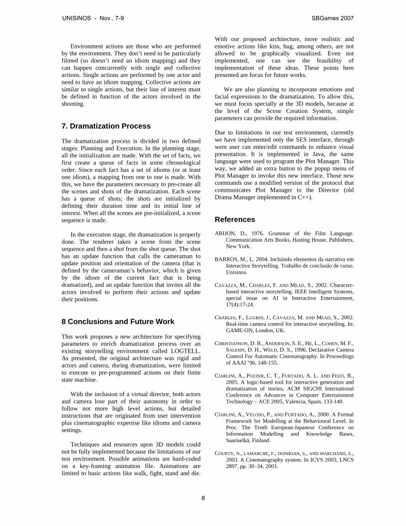
This means that cinematography is a far complex process, and since we don’t have the technology to develop creative and intelligent directors that approaches the human interpretation of reality, we based our work upon human specifications and some heuristics [Arijon 1976] defined by cinematographers: • Create a line of interest: Is the line that connects
the major two points in one scene (mostly of the times, the two actors that interact in the scene).
• Parallel editing: Scenes should alternate between different contexts, locations and times.
• Only show peak moments of the story: Repetitive movements should be eliminated.
• Don’t cross the line: Once a scene is taken by a side of the interest line, the camera must maintain in that side, to not make confused movement shots. The camera can switch sides, but only upon an establishing shot, that shows that transition.
• Let the actor lead: The actor should initiate all movement, and the camera should come to rest a little before the actor.
• Break movement: A scene illustrating some movement must be broke into at least two shots.
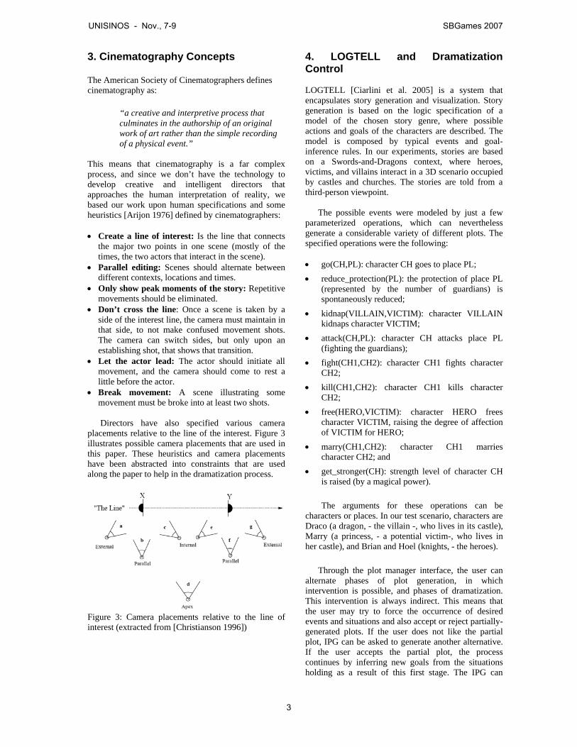
Directors have also specified various camera
placements relative to the line of the interest. Figure 3 illustrates possible camera placements that are used in this paper. These heuristics and camera placements have been abstracted into constraints that are used along the paper to help in the dramatization process.
Figure 3: Camera placements relative to the line of interest (extracted from [Christianson 1996])
4. LOGTELL and Dramatization Control LOGTELL [Ciarlini et al. 2005] is a system that encapsulates story generation and visualization. Story generation is based on the logic specification of a model of the chosen story genre, where possible actions and goals of the characters are described. The model is composed by typical events and goal-inference rules. In our experiments, stories are based on a Swords-and-Dragons context, where heroes, victims, and villains interact in a 3D scenario occupied by castles and churches. The stories are told from a third-person viewpoint.
The possible events were modeled by just a few
parameterized operations, which can nevertheless generate a considerable variety of different plots. The specified operations were the following: • go(CH,PL): character CH goes to place PL; • reduce_protection(PL): the protection of place PL
(represented by the number of guardians) is spontaneously reduced;
• kidnap(VILLAIN,VICTIM): character VILLAIN kidnaps character VICTIM;
• attack(CH,PL): character CH attacks place PL (fighting the guardians);
• fight(CH1,CH2): character CH1 fights character CH2;
• kill(CH1,CH2): character CH1 kills character CH2;
• free(HERO,VICTIM): character HERO frees character VICTIM, raising the degree of affection of VICTIM for HERO;
• marry(CH1,CH2): character CH1 marries character CH2; and
• get_stronger(CH): strength level of character CH is raised (by a magical power).
The arguments for these operations can be
characters or places. In our test scenario, characters are Draco (a dragon, - the villain -, who lives in its castle), Marry (a princess, - a potential victim-, who lives in her castle), and Brian and Hoel (knights, - the heroes).
Through the plot manager interface, the user can
alternate phases of plot generation, in which intervention is possible, and phases of dramatization. This intervention is always indirect. This means that the user may try to force the occurrence of desired events and situations and also accept or reject partially-generated plots. If the user does not like the partial plot, IPG can be asked to generate another alternative. If the user accepts the partial plot, the process continues by inferring new goals from the situations holding as a result of this first stage. The IPG can
UNISINOS - Nov., 7-9 SBGames 2007
3
generate a number of possibilities of chained events for each phase to fulfill story goals.
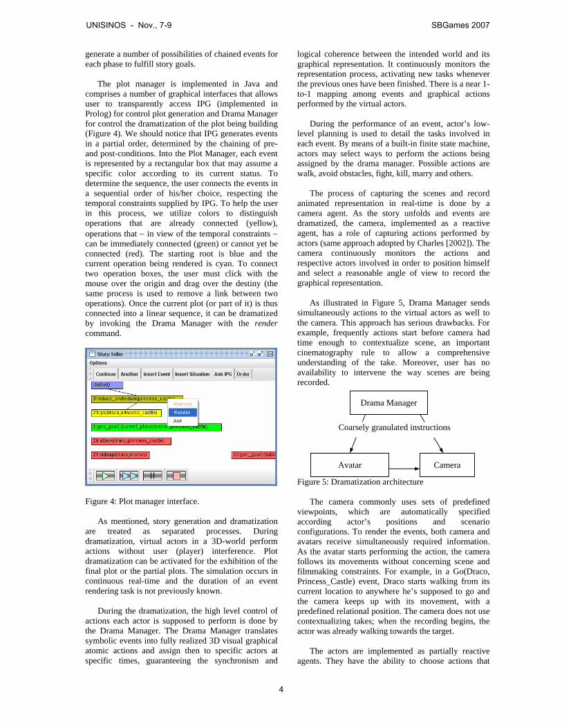
The plot manager is implemented in Java and comprises a number of graphical interfaces that allows user to transparently access IPG (implemented in Prolog) for control plot generation and Drama Manager for control the dramatization of the plot being building (Figure 4). We should notice that IPG generates events in a partial order, determined by the chaining of pre- and post-conditions. Into the Plot Manager, each event is represented by a rectangular box that may assume a specific color according to its current status. To determine the sequence, the user connects the events in a sequential order of his/her choice, respecting the temporal constraints supplied by IPG. To help the user in this process, we utilize colors to distinguish operations that are already connected (yellow), operations that − in view of the temporal constraints − can be immediately connected (green) or cannot yet be connected (red). The starting root is blue and the current operation being rendered is cyan. To connect two operation boxes, the user must click with the mouse over the origin and drag over the destiny (the same process is used to remove a link between two operations). Once the current plot (or part of it) is thus connected into a linear sequence, it can be dramatized by invoking the Drama Manager with the render command.
Figure 4: Plot manager interface.
As mentioned, story generation and dramatization
are treated as separated processes. During dramatization, virtual actors in a 3D-world perform actions without user (player) interference. Plot dramatization can be activated for the exhibition of the final plot or the partial plots. The simulation occurs in continuous real-time and the duration of an event rendering task is not previously known.
During the dramatization, the high level control of actions each actor is supposed to perform is done by the Drama Manager. The Drama Manager translates symbolic events into fully realized 3D visual graphical atomic actions and assign then to specific actors at specific times, guaranteeing the synchronism and
logical coherence between the intended world and its graphical representation. It continuously monitors the representation process, activating new tasks whenever the previous ones have been finished. There is a near 1-to-1 mapping among events and graphical actions performed by the virtual actors.
During the performance of an event, actor’s low-level planning is used to detail the tasks involved in each event. By means of a built-in finite state machine, actors may select ways to perform the actions being assigned by the drama manager. Possible actions are walk, avoid obstacles, fight, kill, marry and others.
The process of capturing the scenes and record animated representation in real-time is done by a camera agent. As the story unfolds and events are dramatized, the camera, implemented as a reactive agent, has a role of capturing actions performed by actors (same approach adopted by Charles [2002]). The camera continuously monitors the actions and respective actors involved in order to position himself and select a reasonable angle of view to record the graphical representation.
As illustrated in Figure 5, Drama Manager sends simultaneously actions to the virtual actors as well to the camera. This approach has serious drawbacks. For example, frequently actions start before camera had time enough to contextualize scene, an important cinematography rule to allow a comprehensive understanding of the take. Moreover, user has no availability to intervene the way scenes are being recorded. Figure 5: Dramatization architecture
The camera commonly uses sets of predefined viewpoints, which are automatically specified according actor’s positions and scenario configurations. To render the events, both camera and avatars receive simultaneously required information. As the avatar starts performing the action, the camera follows its movements without concerning scene and filmmaking constraints. For example, in a Go(Draco, Princess_Castle) event, Draco starts walking from its current location to anywhere he’s supposed to go and the camera keeps up with its movement, with a predefined relational position. The camera does not use contextualizing takes; when the recording begins, the actor was already walking towards the target.
The actors are implemented as partially reactive
agents. They have the ability to choose actions that
Drama Manager
Camera Avatar
Coarsely granulated instructions
UNISINOS - Nov., 7-9 SBGames 2007
4
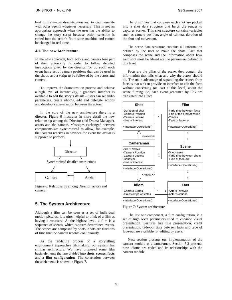
best fulfils events dramatization and to communicate with other agents whenever necessary. This is not an appropriate approach when the user has the ability to change the story script because action selection is coded into the actor’s finite state machine and cannot be changed in real-time.
4.1. The new Architecture In the new approach, both actors and camera lose part of their autonomy in order to follow detailed instructions given by the director. To do such, each event has a set of camera positions that can be used in the shoot, and a script to be followed by the actors and camera.
To improve the dramatization process and achieve a high level of interactivity, a graphical interface is available to edit the story’s details - users can set audio parameters, create idioms, edit and delegate actions and develop a conversation between the actors.
In the core of the new architecture there is a
director. Figure 6 illustrates in more detail the new relationship among the Director (old Drama Manager), actors and the camera. Messages exchanged between components are synchronized to allow, for example, that camera receives in advance the event the avatar is supposed to perform.
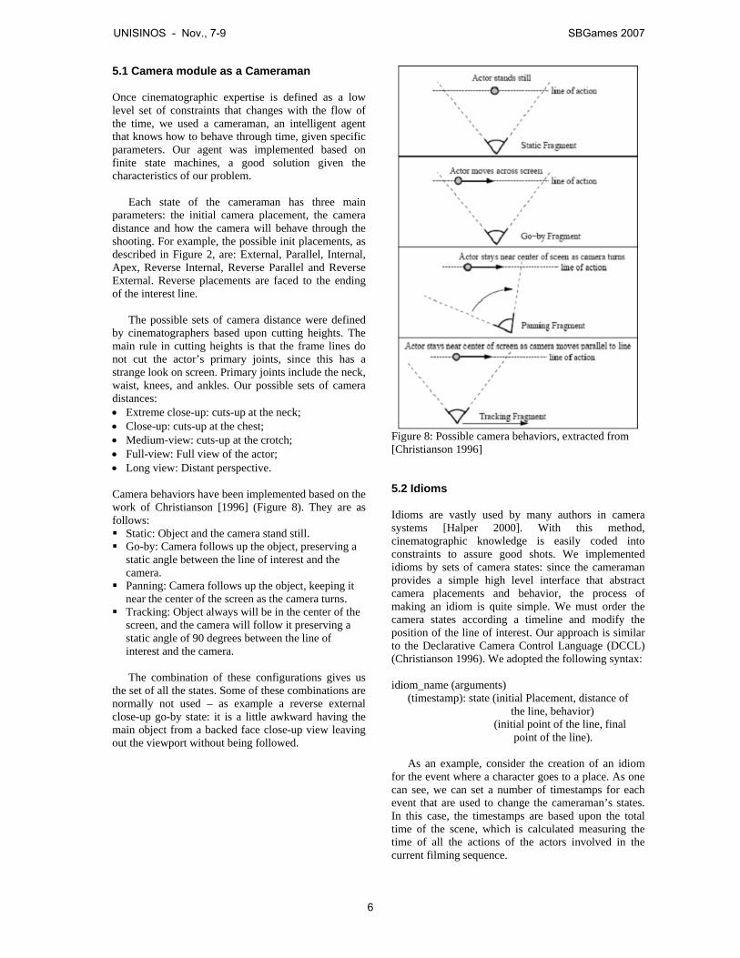
Figure 6: Relationship among Director, actors and camera. 5. The System Architecture Although a film can be seen as a set of individual motion pictures, it is often helpful to think of a film as having a structure. At the highest level, a film is a sequence of scenes, which captures determined events. The scenes are composed by shots. Shots are fractions of time that the camera records continuously.
As the rendering process of a storytelling environment approaches filmmaking, our system has similar architecture. We have proposed some film basic elements that are divided into shots, scenes, facts and a film configuration. The correlation between these elements is shown in Figure 7.
The primitives that compose each shot are packed into a shot data structure that helps the render to captures scenes. This shot structure contains variables such as camera position, angle of camera, duration of the shot and movement.
The scene data structure contains all information defined by the user to make the shots. Fact that composes the scene and the information about how each shot must be filmed are the parameters defined in this level. Facts are the pillar of the scene: they contain the information that tells what and why the actors should do. The main advantage of separating the scenes from facts is that we can provide an interface to edit the facts without concerning (at least at this level) about the scene filming. So, each event generated by IPG are translated into a fact
Figure 7: System architecture
The last one component, a film configuration, is a set of high level parameters used to enhance visual presentation. Features like title presentation, credit presentation, fade-out time between facts and type of fade-out are available for editing by users.
Next section presents our implementation of the
camera module as a cameraman. Section 5.2 presents how idioms are coded and its relationships with the camera module.
Camera Avatar
Director
Synchronized detailed instructions
Shot -Duration of shot -Camera Position -Camera LookAt -Line of interest
+Interface Operations()
Film -Fade time between facts -Title of the dramatization -Credits -Type of fade out
+Interface Operations()
Cameraman -Set of States -Camera Position -Camera LookAt -Behavior -Line of interest
+Interface Operations()
Scene -Shot queue -Fade time between shots -Type of fade out
+Interface Operations()
Fact -Actors Involved -Actor’s actions
+Interface Operations()
<<uses>>
<<uses>>
1 *
1 1
1
*
* 1
Idiom -Camera States -Timestamps of states
+Interface Operations()
UNISINOS - Nov., 7-9 SBGames 2007
5
5.1 Camera module as a Cameraman Once cinematographic expertise is defined as a low level set of constraints that changes with the flow of the time, we used a cameraman, an intelligent agent that knows how to behave through time, given specific parameters. Our agent was implemented based on finite state machines, a good solution given the characteristics of our problem.
Each state of the cameraman has three main
parameters: the initial camera placement, the camera distance and how the camera will behave through the shooting. For example, the possible init placements, as described in Figure 2, are: External, Parallel, Internal, Apex, Reverse Internal, Reverse Parallel and Reverse External. Reverse placements are faced to the ending of the interest line.
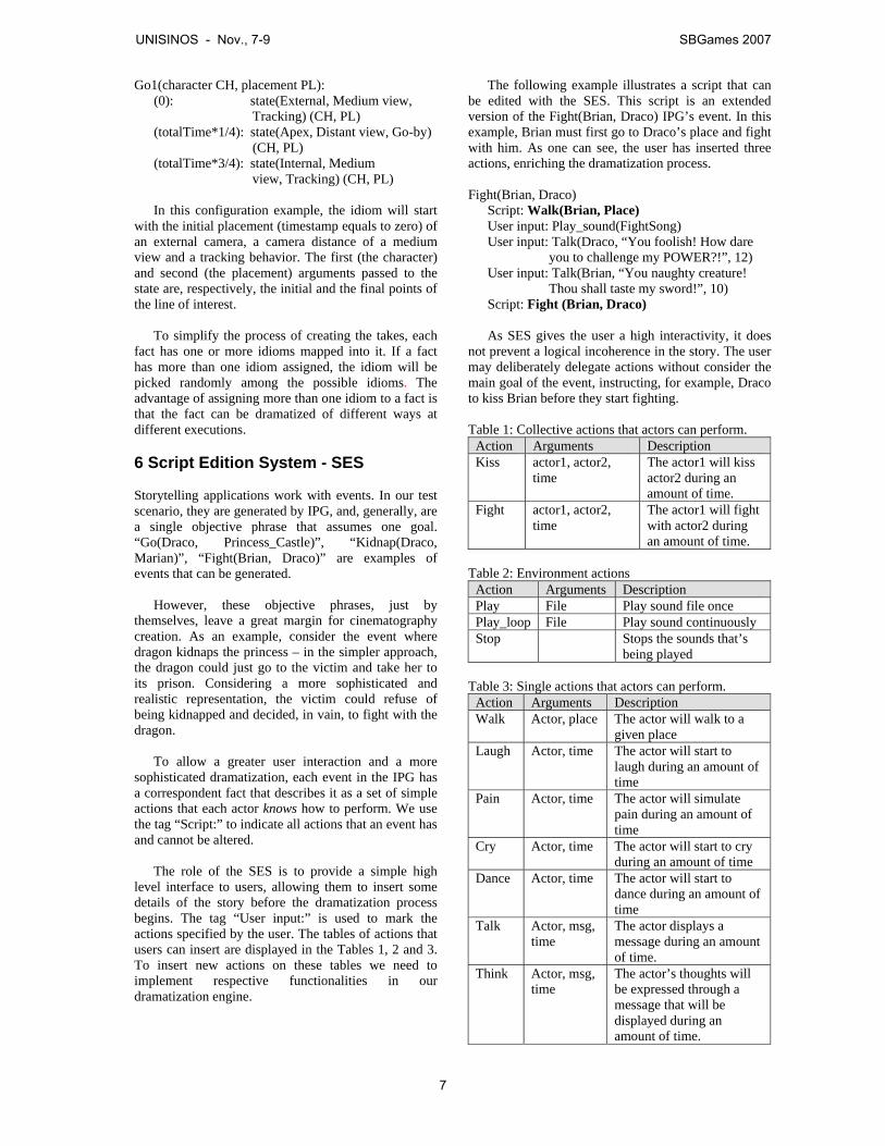
The possible sets of camera distance were defined by cinematographers based upon cutting heights. The main rule in cutting heights is that the frame lines do not cut the actor’s primary joints, since this has a strange look on screen. Primary joints include the neck, waist, knees, and ankles. Our possible sets of camera distances: • Extreme close-up: cuts-up at the neck; • Close-up: cuts-up at the chest; • Medium-view: cuts-up at the crotch; • Full-view: Full view of the actor; • Long view: Distant perspective. Camera behaviors have been implemented based on the work of Christianson [1996] (Figure 8). They are as follows: Static: Object and the camera stand still. Go-by: Camera follows up the object, preserving a
static angle between the line of interest and the camera.
Panning: Camera follows up the object, keeping it near the center of the screen as the camera turns.
Tracking: Object always will be in the center of the screen, and the camera will follow it preserving a static angle of 90 degrees between the line of interest and the camera.
The combination of these configurations gives us
the set of all the states. Some of these combinations are normally not used – as example a reverse external close-up go-by state: it is a little awkward having the main object from a backed face close-up view leaving out the viewport without being followed.
Figure 8: Possible camera behaviors, extracted from [Christianson 1996]
5.2 Idioms Idioms are vastly used by many authors in camera systems [Halper 2000]. With this method, cinematographic knowledge is easily coded into constraints to assure good shots. We implemented idioms by sets of camera states: since the cameraman provides a simple high level interface that abstract camera placements and behavior, the process of making an idiom is quite simple. We must order the camera states according a timeline and modify the position of the line of interest. Our approach is similar to the Declarative Camera Control Language (DCCL) (Christianson 1996). We adopted the following syntax: idiom_name (arguments) (timestamp): state (initial Placement, distance of the line, behavior) (initial point of the line, final point of the line).
As an example, consider the creation of an idiom for the event where a character goes to a place. As one can see, we can set a number of timestamps for each event that are used to change the cameraman’s states. In this case, the timestamps are based upon the total time of the scene, which is calculated measuring the time of all the actions of the actors involved in the current filming sequence.
UNISINOS - Nov., 7-9 SBGames 2007
6
Go1(character CH, placement PL): (0): state(External, Medium view, Tracking) (CH, PL) (totalTime*1/4): state(Apex, Distant view, Go-by) (CH, PL) (totalTime*3/4): state(Internal, Medium view, Tracking) (CH, PL)
In this configuration example, the idiom will start
with the initial placement (timestamp equals to zero) of an external camera, a camera distance of a medium view and a tracking behavior. The first (the character) and second (the placement) arguments passed to the state are, respectively, the initial and the final points of the line of interest.
To simplify the process of creating the takes, each
fact has one or more idioms mapped into it. If a fact has more than one idiom assigned, the idiom will be picked randomly among the possible idioms. The advantage of assigning more than one idiom to a fact is that the fact can be dramatized of different ways at different executions. 6 Script Edition System - SES Storytelling applications work with events. In our test scenario, they are generated by IPG, and, generally, are a single objective phrase that assumes one goal. “Go(Draco, Princess_Castle)”, “Kidnap(Draco, Marian)”, “Fight(Brian, Draco)” are examples of events that can be generated.
However, these objective phrases, just by themselves, leave a great margin for cinematography creation. As an example, consider the event where dragon kidnaps the princess – in the simpler approach, the dragon could just go to the victim and take her to its prison. Considering a more sophisticated and realistic representation, the victim could refuse of being kidnapped and decided, in vain, to fight with the dragon.
To allow a greater user interaction and a more
sophisticated dramatization, each event in the IPG has a correspondent fact that describes it as a set of simple actions that each actor knows how to perform. We use the tag “Script:” to indicate all actions that an event has and cannot be altered.
The role of the SES is to provide a simple high
level interface to users, allowing them to insert some details of the story before the dramatization process begins. The tag “User input:” is used to mark the actions specified by the user. The tables of actions that users can insert are displayed in the Tables 1, 2 and 3. To insert new actions on these tables we need to implement respective functionalities in our dramatization engine.
The following example illustrates a script that can be edited with the SES. This script is an extended version of the Fight(Brian, Draco) IPG’s event. In this example, Brian must first go to Draco’s place and fight with him. As one can see, the user has inserted three actions, enriching the dramatization process.
Fight(Brian, Draco) Script: Walk(Brian, Place) User input: Play_sound(FightSong) User input: Talk(Draco, “You foolish! How dare
you to challenge my POWER?!”, 12) User input: Talk(Brian, “You naughty creature!
Thou shall taste my sword!”, 10) Script: Fight (Brian, Draco) As SES gives the user a high interactivity, it does
not prevent a logical incoherence in the story. The user may deliberately delegate actions without consider the main goal of the event, instructing, for example, Draco to kiss Brian before they start fighting.
Table 1: Collective actions that actors can perform.
Action Arguments Description Kiss actor1, actor2,
time The actor1 will kiss actor2 during an amount of time.
Fight actor1, actor2, time
The actor1 will fight with actor2 during an amount of time.
Table 2: Environment actions
Action Arguments Description Play File Play sound file once Play_loop File Play sound continuously Stop Stops the sounds that’s
being played Table 3: Single actions that actors can perform.
Action Arguments Description Walk Actor, place The actor will walk to a
given place Laugh Actor, time The actor will start to
laugh during an amount of time
Pain Actor, time The actor will simulate pain during an amount of time
Cry Actor, time The actor will start to cry during an amount of time
Dance Actor, time The actor will start to dance during an amount of time
Talk Actor, msg, time
The actor displays a message during an amount of time.
Think Actor, msg, time
The actor’s thoughts will be expressed through a message that will be displayed during an amount of time.
UNISINOS - Nov., 7-9 SBGames 2007
7
Environment actions are those who are performed
by the environment. They don’t need to be particularly filmed (so doesn’t need an idiom mapping) and they can happen concurrently with single and collective actions. Single actions are performed by one actor and need to have an idiom mapping. Collective actions are similar to single actions, but their line of interest must be defined in function of the actors involved in the shooting.
7. Dramatization Process
The dramatization process is divided in two defined stages: Planning and Execution. In the planning stage, all the initialization are made. With the set of facts, we first create a queue of facts in some chronological order. Since each fact has a set of idioms (or at least one idiom), a mapping from one to one is made. With this, we have the parameters necessary to pre-create all the scenes and shots of the dramatization. Each scene has a queue of shots; the shots are initialized by defining their duration time and its initial line of interest. When all the scenes are pre-initialized, a scene sequence is made.
In the execution stage, the dramatization is properly
done. The renderer takes a scene from the scene sequence and then a shot from the shot queue. The shot has an update function that calls the cameraman to update position and orientation of the camera (that is defined by the cameraman’s behavior, which is given by the idiom of the current fact that is being dramatized), and an update function that invites all the actors involved to perform their actions and update their positions.
8 Conclusions and Future Work This work proposes a new architecture for specifying parameters to enrich dramatization process over an existing storytelling environment called LOGTELL. As presented, the original architecture was rigid and actors and camera, during dramatization, were limited to execute to pre-programmed actions on their finite state machine.
With the inclusion of a virtual director, both actors
and camera lose part of their autonomy in order to follow not more high level actions, but detailed instructions that are originated from user intervention plus cinematographic expertise like idioms and camera settings.
Techniques and resources upon 3D models could not be fully implemented because the limitations of our test environment. Possible animations are hard-coded on a key-framing animation file. Animations are limited to basic actions like walk, fight, stand and die.
With our proposed architecture, more realistic and emotive actions like kiss, hug, among others, are not allowed to be graphically visualized. Even not implemented, one can see the feasibility of implementation of these ideas. These points here presented are focus for future works.
We are also planning to incorporate emotions and
facial expressions to the dramatization. To allow this, we must focus specially at the 3D models, because at the level of the Scene Creation System, simple parameters can provide the required information.
Due to limitations in our test environment, currently we have implemented only the SES interface, through were user can enter/edit commands to enhance visual presentation. It is implemented in Java, the same language were used to program the Plot Manager. This way, we added an extra button to the popup menu of Plot Manager to invoke this new interface. Those new commands use a modified version of the protocol that communicates Plot Manager to the Director (old Drama Manager implemented in C++). References ARIJON, D., 1976. Grammar of the Film Language.
Communication Arts Books, Hasting House, Publishers, New York.
BARROS, M., L. 2004. Incluindo elementos da narrativa em
Interactive Storytelling. Trabalho de conclusão de curso. Unisinos.
CAVAZZA, M., CHARLES, F. AND MEAD, S., 2002. Character-
based interactive storytelling. IEEE Intelligent Systems, special issue on AI in Interactive Entertainment, 17(4):17-24.
CHARLES, F., LUGRIN, J., CAVAZZA, M. AND MEAD, S., 2002.
Real-time camera control for interactive storytelling. In: GAME-ON, London, UK.
CHRISTIANSON, D. B., ANDERSON, S. E., HE, L., COHEN, M. F.,
SALESIN, D. H., WELD, D. S., 1996. Declarative Camera Control For Automatic Cinematography. In Proceedings of AAAI ’96, 148-155.
CIARLINI, A., POZZER, C. T., FURTADO, A. L. AND FEIJÓ, B.,
2005. A logic-based tool for interactive generation and dramatization of stories, ACM SIGCHI International Conference on Advances in Computer Entertainment Technology – ACE 2005, Valencia, Spain, 133-140.
CIARLINI, A., VELOSO, P., AND FURTADO, A., 2000. A Formal
Framework for Modelling at the Behavioural Level. In Proc. The Tenth European-Japanese Conference on Information Modelling and Knowledge Bases, Saariselkä, Finland.
COURTY, N., LAMARCHE, F., DONIKIAN, S., AND MARCHAND, E.,
2003. A Cinematography system. In ICVS 2003, LNCS 2897, pp. 30–34, 2003.
UNISINOS - Nov., 7-9 SBGames 2007
8

HALPER, N., HELBING, R., STROTHOTTE, T., 2001. A camera trade-off between constraint satisfaction and frame coherence. in Eurographics, volume 20.
HALPER, N. AND OLIVER, P., 2000. CAMPLAN: A Camera
Planning Agent. In Smart Graphics”. Papers from the 2000 AAAI Spring Symposium (Stanford, March 20–22), Menlo Park, AAAI Press, pages 92–100.
HE, L., COHEN, M., AND SALESIN, D. 1996. The virtual
cinematographer: A paradigm for automatic real-time camera control and directing. In Proceedings of the ACM SIGGRAPH '96, 217-224.
GRASBON, D. AND BRAUN, N., 2001. A morphological
approach to interactive storytelling. In: Fleischmann, M.; Strauss, W., editors, Proceedings: CAST01, Living in Mixed Realities, Sankt Augustin, Germany, p. 337-340.
MATEAS, M. AND STERN, A., 2000. Towards integrating plot
and character for interactive drama. In: Dautenhahn, K., editor, Socially Intelligent Agents: The Human in the Loop, AAAI Fall Symposium, Technical Report, p. 113-118.
SCIENTIFIC AMERICAN, 2000. Special issue on digital
entertainment, 283 (5), November. SPIERLING, U., BRAUN, N., IURGEL, I. AND GRASBON, D.,
2002. Setting the scene: playing digital director in interactive storytelling and creation. Computer and Graphics 26, 31-44.
YOUNG, R., 2000. Creating interactive narrative structures:
The potential for AI approaches. In: AAAI Spring Symposium in Artificial Intelligence and Interactive Entertainment, Palo Alto, California. AAAI Press.
UNISINOS - Nov., 7-9 SBGames 2007
9

Towards Consistency in Interactive Storytelling:Tension Arcs and Dead Ends
Leandro Motta BarrosUniversidade do Vale do Rio dos Sinos
Sao Leopoldo, RS, Brazil
Soraia Raupp MussePontifıcia Universidade Catolica do Rio Grande do Sul
Programa de Pos-Graduacao em Ciencia da ComputacaoPorto Alegre, RS, Brazil
Abstract
Interactive Storytelling (IS) systems are an emerging class of in-teractive entertainment applications with emphasis in narrative as-pects. One of the approaches used to develop IS applications isbased on planning algorithms. This paper describes two mecha-nisms that can be introduced to planning-based IS in order to solvetwo problems that are inherent to this approach. The first is a tech-nique to control the pace of story evolution, so that the generatedstories follow a specified tension arc. The second is a method thatcan avoid story dead ends by intervening in the story in a way thatis justified with previous story events. These mechanisms help toproduce a more enjoyable user experience, since their use tendsto result in stories with higher narrative consistency. Results fromexperiments with users suggest that the proposed mechanisms im-prove both of the aspects being addressed by this work.
Keywords:: Interactive Storytelling, narratives, planning, riddles,tension arcs, story dead ends
Author’s Contact:
[email protected]@pucrs.br
1 Introduction
The fabulous commercial success attained by several technicallyadvanced computer games has stimulated the further developmentand adoption of new technologies applied for the interactive digi-tal entertainment. Perhaps this is more clearly visible in the areaof Computer Graphics, but there are also evident advancements inareas like Artificial Intelligence (AI) and Computer Networks. Onthe other hand, a less technical and more conceptual analysis of thegames developed in the past decades, reveals that most of them aredesigned around the same concepts: hand-eye coordination, puzzle-solving and resource management [Crawford 2004].
Several researchers believe that it is possible to go beyond this, andthat the exploration of aspects neglected by today’s games can orig-inate new forms of interactive digital entertainment. Among theseresearchers, Janet Murray [Murray 1997], Andrew Glassner [Glass-ner 2004] and Chris Crawford [Crawford 2004] believe that narra-tive and interactive aspects can be combined in order to generatea new media for storytellers and a new form of artistic expression.Transforming this vision into something concrete requires us to dealwith a new set of challenges. The field that deals with the challengesrequired to create interactive applications capable to generate con-sistent narratives is called Interactive Storytelling (IS).
An IS system can be seen as an agent that tell stories, and that adaptthe stories as it interacts with the player. One of the most impor-tant challenges in the field of IS is how to model this storytelleragent such that it achieves a good balance between interactivity andnarrative consistency. In other words, it is desired that the systemactually takes the player actions into account, but still generates in-teresting stories, capable to please the player.
Researchers on the field of IS are exploring different approaches inorder to achieve this goal. One of these approaches is based on theuse of planning algorithms to generate the sequence of events thatcompose the story. Planning-based IS has some interesting char-acteristics, but it has one fundamental drawback: general purposeplanning algorithms are created in the context of AI, without any
consideration of narrative aspects. Consequently, planning algo-rithms per se will not be able to generate consistent stories: wehave to explicitly introduce mechanisms to enforce this.
In this paper, we present two of such mechanisms. First, we de-scribe in detail a method that can be used to make the generatedstories follow a tension arc specified by the author.1 This method isdesigned for stories following the Riddle master plot [Tobias 1993].Second, we introduce a way to subtly intervene in the stories in or-der to avoid some story dead ends.
The next session presents some work related to ours. Section 3 pro-vides an overview of Fabulator, our Interactive Storytelling proto-type, in which the ideas presented in this paper were implemented.The main contributions of this paper are in sections 4 and 5, whichdescribe the two mechanisms mentioned in the previous paragraph.This is followed by the presentation of results (Section 6) and, con-cluding the paper, some final remarks.
2 Related Work
The similarities between plans and stories have been explored sincethe early systems for non-interactive story generation, like UNI-VERSE [Lebowitz 1985]. In this work, plot outlines resemblingsoap operas are generated by using planing algorithms and librariesof characters and plot fragments.
Our work is based on the use of one particular type of planning sys-tems, namely, STRIPS-like planning systems. This approach was in-troduced in a work by Charles et al. [Charles et al. 2003], in whichplanning was used to create sequences of actions allowing the storycharacters to pursuit their goals. In a previous work [Barros andMusse 2005], we built on these ideas, concentrating on methodsthat could improve the narrative consistency of the IS model de-scribed by Charles.
The work by Young and collaborators [Riedl et al. 2003], which isalso based on planning, observed that the player is able to performactions that are totally incompatible with the plot created by theplanning algorithm. For example, the player may try to kill a char-acter that is expected to play a fundamental role in the upcomingstory events. Young calls these cases “exceptions”, and proposesintervention mechanisms that can avoid them. In extreme cases, theidea of intervention consists in making the player action fail (e.g.,making the gun misfire). Exceptions are closely related to the no-tion of “dead ends” that we deal with in this paper. Indeed, theintervention mechanisms proposed by Young can be used to dealwith dead ends, but we believe that the approach we introduce inthis paper is more subtle, thus less damaging to the narrative con-sistency.
The architecture described by Magerko [Magerko 2005] includes aprobabilistic player model, used to predict the player behavior, sothat the system can anticipate his or her actions. Our own workcurrently does not uses a player model, but as we discuss later, amodel like the one described by Magerko could help to improve theperformance of the method we propose for foreseeing story deadends.
Finally, Mateas and Stern [Mateas and Stern 2003] have taken a lotof care to generate highly consistent stories in the interactive dramaFacade. In particular, they try to ensure that the generated stories
1A poster with a short description of this specific point has been pub-lished previously [Barros and Musse 2007]. Here, we provide additionaldetails about it and present more results.
UNISINOS - Nov., 7-9 SBGames 2007
10
follow a certain tension arc. Our work also presents a mechanismthat aims to make the generated stories follow an author-definedtension arc, but our work (which is in the context of planning-basedIS) is considerably different.
3 Architecture Overview
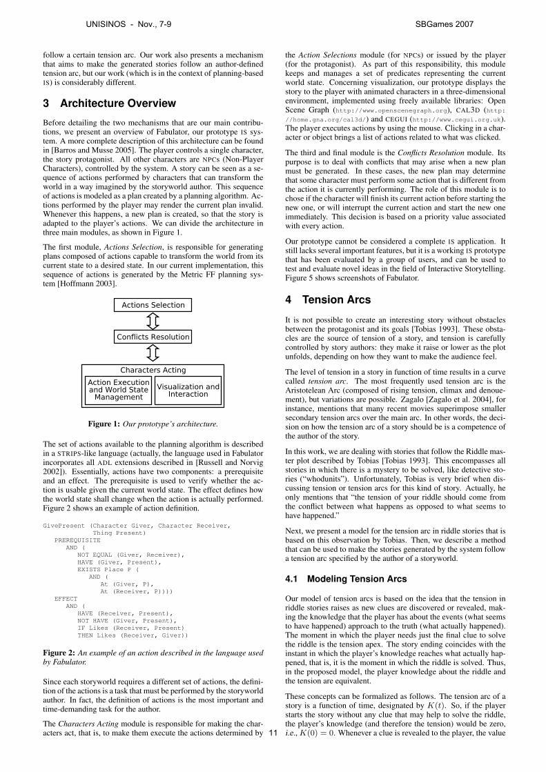
Before detailing the two mechanisms that are our main contribu-tions, we present an overview of Fabulator, our prototype IS sys-tem. A more complete description of this architecture can be foundin [Barros and Musse 2005]. The player controls a single character,the story protagonist. All other characters are NPCs (Non-PlayerCharacters), controlled by the system. A story can be seen as a se-quence of actions performed by characters that can transform theworld in a way imagined by the storyworld author. This sequenceof actions is modeled as a plan created by a planning algorithm. Ac-tions performed by the player may render the current plan invalid.Whenever this happens, a new plan is created, so that the story isadapted to the player’s actions. We can divide the architecture inthree main modules, as shown in Figure 1.
The first module, Actions Selection, is responsible for generatingplans composed of actions capable to transform the world from itscurrent state to a desired state. In our current implementation, thissequence of actions is generated by the Metric FF planning sys-tem [Hoffmann 2003].
Figure 1: Our prototype’s architecture.
The set of actions available to the planning algorithm is describedin a STRIPS-like language (actually, the language used in Fabulatorincorporates all ADL extensions described in [Russell and Norvig2002]). Essentially, actions have two components: a prerequisiteand an effect. The prerequisite is used to verify whether the ac-tion is usable given the current world state. The effect defines howthe world state shall change when the action is actually performed.Figure 2 shows an example of action definition.
GivePresent (Character Giver, Character Receiver,Thing Present)
PREREQUISITEAND (
NOT EQUAL (Giver, Receiver),HAVE (Giver, Present),EXISTS Place P (
AND (At (Giver, P),At (Receiver, P))))
EFFECTAND (
HAVE (Receiver, Present),NOT HAVE (Giver, Present),IF Likes (Receiver, Present)THEN Likes (Receiver, Giver))
Figure 2: An example of an action described in the language usedby Fabulator.
Since each storyworld requires a different set of actions, the defini-tion of the actions is a task that must be performed by the storyworldauthor. In fact, the definition of actions is the most important andtime-demanding task for the author.
The Characters Acting module is responsible for making the char-acters act, that is, to make them execute the actions determined by
the Action Selections module (for NPCs) or issued by the player(for the protagonist). As part of this responsibility, this modulekeeps and manages a set of predicates representing the currentworld state. Concerning visualization, our prototype displays thestory to the player with animated characters in a three-dimensionalenvironment, implemented using freely available libraries: OpenScene Graph (http://www.openscenegraph.org), CAL3D (http://home.gna.org/cal3d/) and CEGUI (http://www.cegui.org.uk).The player executes actions by using the mouse. Clicking in a char-acter or object brings a list of actions related to what was clicked.
The third and final module is the Conflicts Resolution module. Itspurpose is to deal with conflicts that may arise when a new planmust be generated. In these cases, the new plan may determinethat some character must perform some action that is different fromthe action it is currently performing. The role of this module is tochose if the character will finish its current action before starting thenew one, or will interrupt the current action and start the new oneimmediately. This decision is based on a priority value associatedwith every action.
Our prototype cannot be considered a complete IS application. Itstill lacks several important features, but it is a working IS prototypethat has been evaluated by a group of users, and can be used totest and evaluate novel ideas in the field of Interactive Storytelling.Figure 5 shows screenshots of Fabulator.
4 Tension Arcs
It is not possible to create an interesting story without obstaclesbetween the protagonist and its goals [Tobias 1993]. These obsta-cles are the source of tension of a story, and tension is carefullycontrolled by story authors: they make it raise or lower as the plotunfolds, depending on how they want to make the audience feel.
The level of tension in a story in function of time results in a curvecalled tension arc. The most frequently used tension arc is theAristotelean Arc (composed of rising tension, climax and denoue-ment), but variations are possible. Zagalo [Zagalo et al. 2004], forinstance, mentions that many recent movies superimpose smallersecondary tension arcs over the main arc. In other words, the deci-sion on how the tension arc of a story should be is a competence ofthe author of the story.
In this work, we are dealing with stories that follow the Riddle mas-ter plot described by Tobias [Tobias 1993]. This encompasses allstories in which there is a mystery to be solved, like detective sto-ries (“whodunits”). Unfortunately, Tobias is very brief when dis-cussing tension or tension arcs for this kind of story. Actually, heonly mentions that “the tension of your riddle should come fromthe conflict between what happens as opposed to what seems tohave happened.”
Next, we present a model for the tension arc in riddle stories that isbased on this observation by Tobias. Then, we describe a methodthat can be used to make the stories generated by the system followa tension arc specified by the author of a storyworld.
4.1 Modeling Tension Arcs
Our model of tension arcs is based on the idea that the tension inriddle stories raises as new clues are discovered or revealed, mak-ing the knowledge that the player has about the events (what seemsto have happened) approach to the truth (what actually happened).The moment in which the player needs just the final clue to solvethe riddle is the tension apex. The story ending coincides with theinstant in which the player’s knowledge reaches what actually hap-pened, that is, it is the moment in which the riddle is solved. Thus,in the proposed model, the player knowledge about the riddle andthe tension are equivalent.
These concepts can be formalized as follows. The tension arc of astory is a function of time, designated by K(t). So, if the playerstarts the story without any clue that may help to solve the riddle,the player’s knowledge (and therefore the tension) would be zero,i.e., K(0) = 0. Whenever a clue is revealed to the player, the value
UNISINOS - Nov., 7-9 SBGames 2007
11
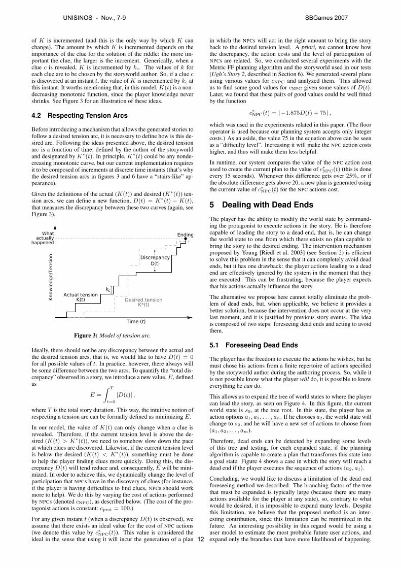
of K is incremented (and this is the only way by which K canchange). The amount by which K is incremented depends on theimportance of the clue for the solution of the riddle: the more im-portant the clue, the larger is the increment. Generically, when aclue c is revealed, K is incremented by kc. The values of k foreach clue are to be chosen by the storyworld author. So, if a clue cis discovered at an instant t, the value of K is incremented by kc atthis instant. It worths mentioning that, in this model, K(t) is a non-decreasing monotonic function, since the player knowledge nevershrinks. See Figure 3 for an illustration of these ideas.
4.2 Respecting Tension Arcs
Before introducing a mechanism that allows the generated stories tofollow a desired tension arc, it is necessary to define how is this de-sired arc. Following the ideas presented above, the desired tensionarc is a function of time, defined by the author of the storyworldand designated by K∗(t). In principle, K∗(t) could be any nonde-creasing monotonic curve, but our current implementation requiresit to be composed of increments at discrete time instants (that’s whythe desired tension arcs in figures 3 and 6 have a “stairs-like” ap-pearance).
Given the definitions of the actual (K(t)) and desired (K∗(t)) ten-sion arcs, we can define a new function, D(t) = K∗(t) − K(t),that measures the discrepancy between these two curves (again, seeFigure 3).
Figure 3: Model of tension arc.
Ideally, there should not be any discrepancy between the actual andthe desired tension arcs, that is, we would like to have D(t) = 0for all possible values of t. In practice, however, there always willbe some difference between the two arcs. To quantify the “total dis-crepancy” observed in a story, we introduce a new value, E, definedas
E =
∫ T
t=0
|D(t)| ,
where T is the total story duration. This way, the intuitive notion ofrespecting a tension arc can be formally defined as minimizing E.
In our model, the value of K(t) can only change when a clue isrevealed. Therefore, if the current tension level is above the de-sired (K(t) > K∗(t)), we need to somehow slow down the paceat which clues are discovered. Likewise, if the current tension levelis below the desired (K(t) < K∗(t)), something must be doneto help the player finding clues more quickly. Doing this, the dis-crepancy D(t) will tend reduce and, consequently, E will be mini-mized. In order to achieve this, we dynamically change the level ofparticipation that NPCs have in the discovery of clues (for instance,if the player is having difficulties to find clues, NPCs should workmore to help). We do this by varying the cost of actions performedby NPCs (denoted cNPC), as described below. (The cost of the pro-tagonist actions is constant: cprot = 100.)
For any given instant t (when a discrepancy D(t) is observed), weassume that there exists an ideal value for the cost of NPC actions(we denote this value by c∗NPC(t)). This value is considered theideal in the sense that using it will incur the generation of a plan
in which the NPCs will act in the right amount to bring the storyback to the desired tension level. A priori, we cannot know howthe discrepancy, the action costs and the level of participation ofNPCs are related. So, we conducted several experiments with theMetric FF planning algorithm and the storyworld used in our tests(Ugh’s Story 2, described in Section 6). We generated several plansusing various values for cNPC and analyzed them. This allowedus to find some good values for cNPC given some values of D(t).Later, we found that these pairs of good values could be well fittedby the function
c∗NPC(t) = b−1.875D(t) + 75c ,
which was used in the experiments related in this paper. (The flooroperator is used because our planning system accepts only integercosts.) As an aside, the value 75 in the equation above can be seenas a “difficulty level”. Increasing it will make the NPC action costshigher, and thus will make them less helpful.
In runtime, our system compares the value of the NPC action costused to create the current plan to the value of c∗NPC(t) (this is doneevery 15 seconds). Whenever this difference gets over 25%, or ifthe absolute difference gets above 20, a new plan is generated usingthe current value of c∗NPC(t) for the NPC actions cost.
5 Dealing with Dead Ends
The player has the ability to modify the world state by command-ing the protagonist to execute actions in the story. He is thereforecapable of leading the story to a dead end, that is, he can changethe world state to one from which there exists no plan capable tobring the story to the desired ending. The intervention mechanismproposed by Young [Riedl et al. 2003] (see Section 2) is efficientto solve this problem in the sense that it can completely avoid deadends, but it has one drawback: the player actions leading to a deadend are effectively ignored by the system in the moment that theyare executed. This can be frustrating, because the player expectsthat his actions actually influence the story.
The alternative we propose here cannot totally eliminate the prob-lem of dead ends, but, when applicable, we believe it provides abetter solution, because the intervention does not occur at the verylast moment, and it is justified by previous story events. The ideais composed of two steps: foreseeing dead ends and acting to avoidthem.
5.1 Foreseeing Dead Ends
The player has the freedom to execute the actions he wishes, but hemust chose his actions from a finite repertoire of actions specifiedby the storyworld author during the authoring process. So, while itis not possible know what the player will do, it is possible to knoweverything he can do.
This allows us to expand the tree of world states to where the playercan lead the story, as seen on Figure 4. In this figure, the currentworld state is s0, at the tree root. In this state, the player has asaction options a1, a2, . . . , an. If he chooses a2, the world state willchange to s2, and he will have a new set of actions to choose from(a1, a2, . . . , am).
Therefore, dead ends can be detected by expanding some levelsof this tree and testing, for each expanded state, if the planningalgorithm is capable to create a plan that transforms this state intoa goal state. Figure 4 shows a case in which the story will reach adead end if the player executes the sequence of actions 〈a2, a1〉.
Concluding, we would like to discuss a limitation of the dead endforeseeing method we described. The branching factor of the treethat must be expanded is typically large (because there are manyactions available for the player at any state), so, contrary to whatwould be desired, it is impossible to expand many levels. Despitethis limitation, we believe that the proposed method is an inter-esting contribution, since this limitation can be minimized in thefuture. An interesting possibility in this regard would be using auser model to estimate the most probable future user actions, andexpand only the branches that have more likelihood of happening.
UNISINOS - Nov., 7-9 SBGames 2007
12
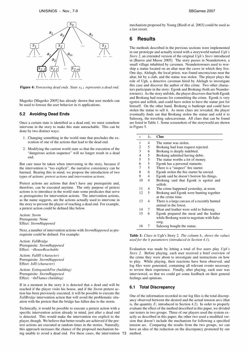
Figure 4: Foreseeing dead ends. State s2.1 represents a dead end.
Magerko [Magerko 2005] has already shown that user models canbe used to foresee the user behavior in IS applications.
5.2 Avoiding Dead Ends
Once a certain state is identified as a dead end, we must somehowintervene in the story to make this state unreachable. This can bedone by two distinct ways:
1. Changing something in the world state that precludes the ex-ecution of one of the actions that lead to the dead end.
2. Modifying the current world state so that the execution of the“dangerous action sequence” will no longer result in a deadend.
But care must be taken when intervening in the story, because ifthe intervention is “too explicit”, the narrative consistency can beharmed. Bearing this in mind, we propose the introduction of twotypes of actions: pretext actions and intervention actions.
Pretext actions are actions that don’t have any prerequisite and,therefore, can be executed anytime. The only purpose of pretextactions is to introduce in the world state some predicates that serveas prerequisites for intervention actions. The intervention actions,as the name suggests, are the actions actually used to intervene inthe story to prevent the player of reaching a dead end. For example,a pretext action could be defined like below.
Action: StormPrerequisite: NoneEffect: StormHappened
Next, a number of intervention actions with StormHappened as pre-requisite could be defined. For example:
Action: FallBridgePrerequisite: StormHappenedEffect: ¬HouseReachable
Action: FallIll (character)Prerequisite: StormHappenedEffect: IsIll (character)
Action: ExtingsuishFire (building)Prerequisite: StormHappenedEffect: ¬InFlames (building)
If in a moment in the story it is detected that a dead end will bereached if the player visits his house, and if the Storm pretext ac-tion has been previously executed, it will be possible to execute theFallBridge intervention action that will avoid the problematic situ-ation with the pretext that the bridge has fallen due to the storm.
Technically, it would be possible to execute a pretext action with aspecific intervention action already in mind, just after a dead endis detected. This would make the intervention too explicit to theplayer, though. We believe that better results are achieved if the pre-text actions are executed at random times in the stories. Naturally,this approach increases the chance of the proposed mechanism be-ing unable to avoid a dead end. For these cases, the intervention
mechanism proposed by Young [Riedl et al. 2003] could be used asa last resort.
6 Results
The methods described in the previous sections were implementedin our prototype and actually tested with a storyworld named Ugh’sStory 2, an extended version of the original Ugh’s Story introducedin [Barros and Musse 2005]. The story passes in Neandertown, asmall village inhabited by cavemen. Neandertowners used to wor-ship a statue located on an altar near the caves in which they live.One day, Alelugh, the local priest, was found unconscious near thealtar, hit by a club, and the statue was stolen. The player plays therole of Ugh, a detective caveman hired by Alelugh to investigatethis case and discover the author of this crime. Two other charac-ters participate in the story: Egonk and Brokung (both are Neander-towners). As the story unfolds, the player discovers that both Egonkand Brokung had reasons for committing the crime. Egonk is veryegotist and selfish, and could have stolen to have the statue just forhimself. On the other hand, Brokung is bankrupt and could havestolen the statue to sell it. As more clues are revealed, the playereventually finds out that Brokung stolen the statue and sold it toSalesorg, the traveling salescaveman. All clues that can be foundare listed in Table 1. Some screenshots of the storyworld are shownin Figure 5.
c kc Clue
1 4 The statue was stolen.2 5 Brokung had loan request rejected.3 6 Brokung is deeply indebted.4 5 Brokung admitted having debts.5 5 The statue worths a lot of money.6 5 Egonk has a personal statuette.7 5 There is a “suspect” fire starter.8 6 Egonk stolen the fire starter he envied.9 4 Egonk said he doesn’t borrow his things.10 4 Brokung said that Egonk is egotist and
selfish.11 4 The crime happened yesterday, at noon.12 5 Brokung and Egonk were hunting together
at the crime time.13 4 There is a large carcass of a recently hunted
animal in the forest.14 7 Meat and leather were sold to Salesorg.15 6 Egonk prepared the meat and the leather
while Brokung went to negotiate with Sale-sorg.
16 7 Salesorg bought the statue.
Table 1: Clues in Ugh’s Story 2. The column kc shows the valuesused for the k parameters (introduced in Section 4.1).
Evaluation was made by letting a total of five users play Ugh’sStory 2. Before playing, each user received a brief overview ofthe crime they were about to investigate and instructions on howto play. While playing, their reactions have been observed, andlog files were generated, containing all relevant events necessaryto review their experience. Finally, after playing, each user wasinterviewed, so that we could get some feedback on their generalfeelings and opinions.
6.1 Total Discrepancy
One of the information recorded in our log files is the total discrep-ancy observed between the desired and the actual tension arcs (thatis, the quantity E, introduced in Section 4.2). In order to properlyevaluate the effect of the method described in this paper, we dividedour testers in two groups. Three of our players used the system ex-actly as described in this paper; the other two used a modified ver-sion that doesn’t include the mechanism for following a specifiedtension arc. Comparing the results from the two groups, we canhave an idea of the reduction on the discrepancy promoted by ourmethod.
UNISINOS - Nov., 7-9 SBGames 2007
13
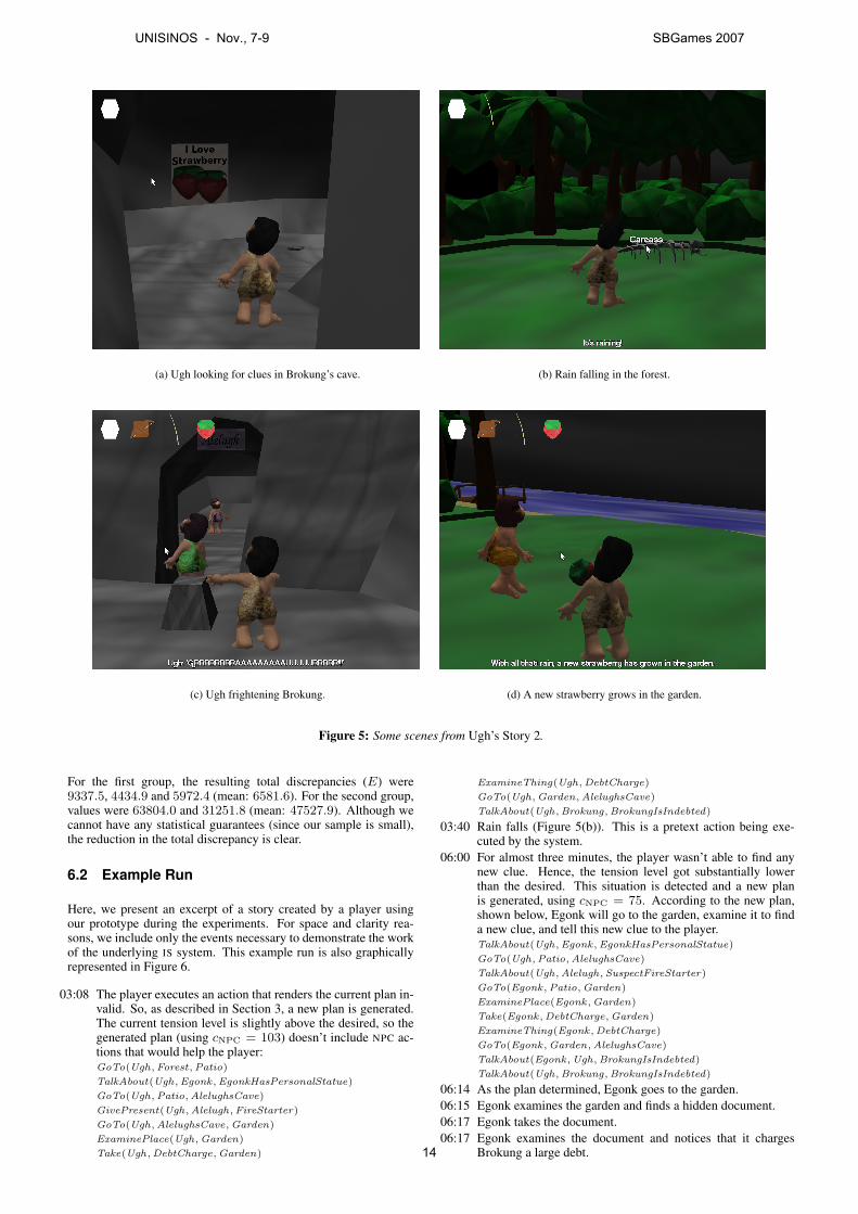
(a) Ugh looking for clues in Brokung’s cave. (b) Rain falling in the forest.
(c) Ugh frightening Brokung. (d) A new strawberry grows in the garden.
Figure 5: Some scenes from Ugh’s Story 2.
For the first group, the resulting total discrepancies (E) were9337.5, 4434.9 and 5972.4 (mean: 6581.6). For the second group,values were 63804.0 and 31251.8 (mean: 47527.9). Although wecannot have any statistical guarantees (since our sample is small),the reduction in the total discrepancy is clear.
6.2 Example Run
Here, we present an excerpt of a story created by a player usingour prototype during the experiments. For space and clarity rea-sons, we include only the events necessary to demonstrate the workof the underlying IS system. This example run is also graphicallyrepresented in Figure 6.
03:08 The player executes an action that renders the current plan in-valid. So, as described in Section 3, a new plan is generated.The current tension level is slightly above the desired, so thegenerated plan (using cNPC = 103) doesn’t include NPC ac-tions that would help the player:GoTo(Ugh, Forest, Patio)
TalkAbout(Ugh, Egonk , EgonkHasPersonalStatue)
GoTo(Ugh, Patio, AlelughsCave)
GivePresent(Ugh, Alelugh, FireStarter)
GoTo(Ugh, AlelughsCave, Garden)
ExaminePlace(Ugh, Garden)
Take(Ugh, DebtCharge, Garden)
ExamineThing(Ugh, DebtCharge)
GoTo(Ugh, Garden, AlelughsCave)
TalkAbout(Ugh, Brokung, BrokungIsIndebted)
03:40 Rain falls (Figure 5(b)). This is a pretext action being exe-cuted by the system.
06:00 For almost three minutes, the player wasn’t able to find anynew clue. Hence, the tension level got substantially lowerthan the desired. This situation is detected and a new planis generated, using cNPC = 75. According to the new plan,shown below, Egonk will go to the garden, examine it to finda new clue, and tell this new clue to the player.TalkAbout(Ugh, Egonk , EgonkHasPersonalStatue)
GoTo(Ugh, Patio, AlelughsCave)
TalkAbout(Ugh, Alelugh, SuspectFireStarter)
GoTo(Egonk , Patio, Garden)
ExaminePlace(Egonk , Garden)
Take(Egonk , DebtCharge, Garden)
ExamineThing(Egonk , DebtCharge)
GoTo(Egonk , Garden, AlelughsCave)
TalkAbout(Egonk , Ugh, BrokungIsIndebted)
TalkAbout(Ugh, Brokung, BrokungIsIndebted)
06:14 As the plan determined, Egonk goes to the garden.06:15 Egonk examines the garden and finds a hidden document.06:17 Egonk takes the document.06:17 Egonk examines the document and notices that it charges
Brokung a large debt.
UNISINOS - Nov., 7-9 SBGames 2007
14
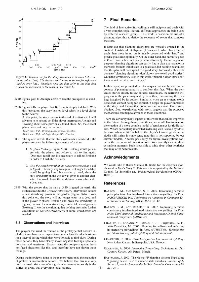
Figure 6: Tension arc for the story discussed in Section 6.2 (con-tinuous black line). The desired tension arc is shown for reference(dashed gray line). Numbers near the dots refer to the clue thatcaused the increment in the tension (see Table 1).
06:40 Egonk goes to Alelugh’s cave, where the protagonist is stand-ing.
07:00 Egonk tells the player that Brokung is deeply indebted. Withthis revelation, the story tension level raises to a level closerto the desired.At this point, the story is close to the end of its first act. It willadvance to its second act if the player interrogates Alelugh andBrokung about some previously found clues. So, the currentplan consists of only two actions:TalkAbout(Ugh, Brokung, BrokungIsIndebted)
TalkAbout(Ugh, Alelugh, SuspectFireStarter)
08:21 The system detects that the story will reach a dead end if theplayer executes the following sequence of actions:
1. Frighten Brokung (Figure 5(c)). Brokung would get an-gry with the player, and refuse to talk to him again.(One must recall that it is necessary to talk to Brokungin order to finish the first act).
2. Give the strawberry (that the player possesses) as a giftto Egonk. The only way to regain Brokung’s friendshipwould be giving him this strawberry. And, since theonly strawberry in the world was given to another char-acter, this would leave the world in an unsolvable state:a dead end.
08:48 With the pretext that the rain at 3:40 irrigated the earth, thesystem executes the GrowNewStrawberry intervention action:a new strawberry grows in the garden (Figure 5(d)). Fromthis point on, the story will no longer enter in a dead endif the player frightens Brokung and gives the strawberry toEgonk, because the new strawberry can be taken and given toBrokung. It worths mentioning that nothing precludes furtherexecutions of GrowNewStrawberry if more strawberries areneeded.
6.3 Observations and Interviews
The players that used the version of the prototype that doesn’t in-clude the mechanism to respect tension arcs have faced at least onelong interval during which they were not able to find clues. Duringthese periods, they have clearly shown negative feelings, speciallyboredom and angriness. Players using the complete system havenot faced situations like this, and therefore have not shown thesefeelings.
During the interviews, none of the players mentioned the executionof pretext or intervention actions. We believe that this is a verypositive result, since one of our goals was intervening subtly in thestories, in a way that everything looks natural.
7 Final Remarks
The field of Interactive Storytelling is still incipient and deals witha very complex topic. Several different approaches are being usedby different research groups. This work is based on the use of aplanning algorithm to define the sequence of events that composethe story.
It turns out that planning algorithms are typically created in thecontext of Artificial Intelligence (AI) research, which has differentgoals than those in IS. AI is mostly concerned with “hard” andprecise goals like optimality. On the other hand, the narrative goalsin IS are more subtle, not easily defined formally. Hence, a generalpurpose planning algorithm can easily find a plan that transformsthe world from its initial state to a goal state, but nothing guaranteesthat this plan will correspond to a good story. Informally, this boilsdown to “planning algorithms don’t know how to tell good stories.”Or, in the terminology used in this work, “planning algorithms don’tknow about narrative consistency.”
In this paper, we presented two techniques that can be used in thecontext of planning-based IS to confront this fact. When the gen-erated stories closely follow an ideal tension arc, the narrative willprogress in the pace imagined by its author, transmitting the feel-ings imagined by its author. Similarly, when an IS system avoidsdead ends without being too explicit, it keeps the player immersedin the story, and feeling that his actions are relevant. Our results,obtained from experiments with users, suggest that the proposedmechanisms can help to advance in these directions.
There are certainly many aspects of this work that can be improvedin the future. Among these possibilities, we would like to mentionthe creation of a more complex model of tension arcs for riddle sto-ries. We are particularly interested in dealing with lies told by NPCs,because, when an NPC is belied, the player’s knowledge about theriddle will shrink in some sense (and this is not supported by ourcurrent model). Another possibility for future investigations con-cerns the execution of pretext actions. We currently execute themat random moments, but it is possible to think about other heuristicsthat may offer better results.
Acknowledgments
We would like to thank Marcelo H. Borba for the cavemen mod-els used in Ugh’s Story 2. This work is supported by the NationalCouncil for Scientific and Technological Development (CNPq –Brazil).
References
BARROS, L. M., AND MUSSE, S. R. 2005. Introducing narrativeprinciples into planning-based interactive storytelling. In Proc.of ACM SIGCHI Intl. Conference on Advances in Computer En-tertainment Technology (ACE 2005), 35–42.
BARROS, L. M., AND MUSSE, S. R. 2007. Improving narrativeconsistency in planning-based interactive storytelling. In Proc.of the Third Artificial Intelligence and Interactive Digital Enter-tainment Conference (AIIDE 07).
CHARLES, F., LOZANO, M., MEAD, S. J., BISQUERRA, A. F.,AND CAVAZZA, M. 2003. Planning formalisms and authoringin interactive storytelling. In Proc. of TIDSE’03: Technologiesfor Interactive Digital Storytelling and Entertainment.
CRAWFORD, C. 2004. Chris Crawford on Interactive Storytelling.New Riders Games, Indianapolis, USA, October.
GLASSNER, A. 2004. Interactive Storytelling: Techniques for 21stCentury Fiction. AK Peters, March.
HOFFMANN, J. 2003. The Metric-FF planning system: Translating“ignoring delete lists” to numeric state variables. Journal of AIResearch, special issue on the 3rd Intl. Planning Competition 20,291–341.
UNISINOS - Nov., 7-9 SBGames 2007
15

LEBOWITZ, M. 1985. Story-telling as planning and learning. Po-etics 14, 483–502.
MAGERKO, B. 2005. Mediating the tension between plot and in-teraction. In Imagina 2005.
MATEAS, M., AND STERN, A. 2003. Facade: An experiment inbuilding a fully-realized interactive drama. In Game DevelopersConference, Game Design track.
MURRAY, J. H. 1997. Hamlet on the Holodeck: The Future ofNarrative in Cyberspace. Free Press, New York, USA.
RIEDL, M. O., SARETTO, C. J., AND YOUNG, R. M. 2003. Man-aging interaction between users and agents in a multi-agent sto-rytelling environment. In Proc. of AAMAS ’03: the 2nd Intl.Conference on Autonomous Agents and Multi-Agent Systems.
RUSSELL, S., AND NORVIG, P. 2002. Artificial Intelligence: AModern Approach, second ed. Prentice Hall, Englewood Cliffs,USA, December.
TOBIAS, R. B. 1993. 20 Master Plots: and how to build them.Writer’s Digest Books, Cincinnati, USA.
ZAGALO, N., BARKER, A., AND BRANCO, V. 2004. Story reac-tion structures to emotion detection. In Proc. of the SRMC’04,ACM Multimedia 2004 — Workshop on Story Representation,Mechanisam, Context, 33–38.
UNISINOS - Nov., 7-9 SBGames 2007
16
Virtual Dungeon Master: Um Narrador Inteligente de Quests
para Role Playing Games
Felipe S. Pedroso João R. Bittencourt
Universidade do Vale do Rio dos Sinos (UNISINOS), Grad.Tec. Jogos Digitais, Brasil
{[email protected]; [email protected]}
Resumo Este trabalho propõe a criação de um agente inteligente que utiliza técnicas de Inteligência Artificial (Lógica Difusa), capaz de desenvolver e gerenciar quests de Role Playing Game (RPG), incluindo personagens coadjuvantes, monstros e eventos gerais. Será utilizado como base do comportamento do agente o Sistema de Aventuras Instantâneas (SAI), que gera através de jogadas aleatórias, os eventos principais de uma aventura de método RPG (quest). Com este método simplificado é possível criar o lugar onde vai começar a aventura, o inimigo principal, o fornecedor das pistas, além de outras características de uma aventura. Para evitar a criação de uma história totalmente inconsistente, devido à aleatoriedade, é adotada uma ontologia que descreve o mundo do jogo e uma base de conhecimentos, modelada com Lógica Difusa que possibilitam ao agente ajustar a narrativa de forma a deixá-la mais imersiva e atrativa em conformidade com o conceito de ficção interativa.
Abstract This work presents the construction of a intelligent agent that uses Artificial Intelligence (Fuzzy Logic) and is capable to create and manage quests for a Role Playing Game, including non playable characters, monsters and generic events. For the base behavior of the agent it’s used the Sistema de Aventuras Instantâneas (SAI), which creates through a random system the main events of an Role Playing Game (RPG) campaign. With this simple system is possible to create the place were the adventure begins, the main villain, who gives clues about the plot, besides other features about the adventure. To avoid a incompatible story due the random system, it’s created a ontology that describes the world of the game and a knowledge base with Fuzzy Logic rules, that helps the agent to adjust the story to make it more immersive and attractive. Palavras-Chave: Inteligência Artificial, Role Playing Game, Storytelling.
1. Introdução Os jogos de Role Playing Game (RPG) sempre se destacaram no mercado para computadores e vídeo games. Muitos deles, derivados do sistema papel e caneta, possuindo mecânicas e enredos parecidos com estes. O RPG tem como base as inúmeras quests que podem ser criadas, não apresentando limitações quanto às possibilidades de explorar a narrativa. Entende-se por quests, missões que necessitam serem cumpridas no decorrer do jogo, tendo em vista o aprimoramento do personagem, seja através da aquisição de novos itens ou da evolução pelo ganho de pontos de experiência. Entretanto, atualmente o enredo segue de forma linear, não deixando espaço para uma maior exploração da narrativa e dos elementos do jogo. No mercado, existem alguns jogos que possibilitam
ao jogador criar suas próprias aventuras. Neverwinter
Nights [Bioware 2002] é um deles e destaca-se por ter uma solução denominada Aurora Toolset, que facilita a criação e edição de quests, itens, monstros e Non-
Player Characters (NPC), utilizando o sistema Dungeons & Dragons [Wizards 2000]. Este editor oferece um bom conjunto de possibilidades para montar o mapa de aventura, mas não oferece um meio de criar NPCs de forma automática, pois falas, lugares e aparência precisam ser editados manualmente, o que para muitos RPGistas é um trabalho não muito agradável. Também oferece um editor de quests, mas compete ao usuário criar toda a trama. Murray [Murray 2003] cita a importância da
comunicação e interatividade através de narrativas em ambientes informatizados, como por exemplo, jogos e textos digitais. Propõe um novo conceito de narrador, o Cyberbardo, que seria um contador de histórias, um típico Dungeon Master (papel de um jogador que controla e cria as situações narrativas em uma típica partida de RPG com lápis e papel) podendo alterar a narrativa conforme a mesma se desenrolar. Há possibilidade de criar novas situações e elementos dramáticos, desenvolvendo uma história personalizada e única para o jogador. Na comunidade científica já existem iniciativas
referentes aos algoritmos de storytelling, por exemplo, as pesquisas de Cavazza [Cavazza et. al. 2003], onde
UNISINOS - Nov., 7-9 SBGames 2007
17
foram pesquisados e abordados temas como Inteligência Artificial, usados em sistemas de narrativas, como também o comportamento de cada personagem por meio de árvores de decisões hierárquicas [Cavazz et. al. 2005]. Com estes dados, pretende-se criar uma forma
diferenciada de jogar RPGs Computadorizados (CRPG
– Computer Role Playing Game). A proposta do presente trabalho é desenvolver um protótipo de um agente inteligente autônomo denominado Virtual
Dungeon Master (VDM) que irá criar quests personalizadas ao personagem do jogador. Desta forma, espera-se proporcionar uma melhor experiência ao jogar, adicionando um tempo extra de replay ao título no mercado. Este artigo está organizado em seis seções. Na
seção 2 são apresentados os trabalhos relacionados ao tema. Na seção 3 são abordadas questões importantes quanto ao gênero RPG e a ficção interativa. Posteriormente na seção 4 os principais conceitos teóricos utilizados para fundamentar o modelo proposto na seção 5. Na seção 6 são retomados alguns aspectos referentes ao protótipo implementado. Por último, na seção 7 são feitas as considerações finais
2. Trabalhos Relacionados Cavazza [Cavazza et. al. 2005] propõe um protótipo de storytelling interativo. O sistema é focado nos personagens e não no enredo em si. É mostrada uma história e, no seu desenrolar, é possível intervir a qualquer momento, enviando comandos para os atores realizarem. A história é adaptada conforme os atores interagem, essas interações são implementadas a partir de Hierarchical Task Network (HTN), um algoritmo que permite a busca através de uma hierarquia de valores definidos.Em outro artigo utilizado como base, Cavazza [Cavazza et. al. 2003] descrevem um sistema chamado OPIATE – Open-ended Proppian Interactive
Adaptive Tale Engine, que simula o papel do Mestre de Jogo, utilizando técnicas de IA. O sistema controla toda a história apresentada em um jogo de aventura, onde o jogador controla um herói e o sistema reage a cada ação do jogador.
Algoritmos como Hierarchical Task Network
(HTN) ou Heuristic Searching Method (HSM) são usados para resolver este desafio. Fairclough [Fairclough et. al. 2003] apresentam Fuzzy Cognitive
Goal Net como a ferramenta de criação de enredos, combinando a capacidade de planejamento da Goal Net e a habilidade de conclusão da Fuzzy Cognitive Maps.
Charles [Charles et. al. 2004] propõem a utilização
de Realidade Misturada (Mixed Reality) para uma nova maneira de apresentar narrativas interativas. O usuário, além de interagir, irá fazer parte da história como um personagem virtual, desempenhando um papel durante a narrativa. São capturadas, em tempo real, seqüências
de gestos que o usuário executa e sobrepõe no mundo virtual, povoado por agentes autônomos que poderão atuar com o usuário.
Liu [Liu et. al. 2006] descrevem o conceito de um
banco de histórias visuais interativo (Visual
Storytteling Warehouse ou VSW) que utiliza eXtensible Markup Language (XML) para gerar histórias no estilo cartoon, conforme essas foram descritas em uma estrutura , ou interação do usuário. Dada uma estrutura de enredo, o sistema é capaz de produzir múltiplas versões de uma mesma história a partir de personagens, background (plano de fundo) e diálogos da história. Estes são extraídos do banco de dados a partir das especificações do usuário.
3. RPG e Ficção Interativa
RPG é a sigla de Role Playing Game, ou seja, um jogo de atuação e interpretação de papéis. Foi criado por Gary Gygax e Dave Arneson, em 1974, juntamente com o lançamento do jogo Dungeon & Dragons. Durante uma partida de RPG, os jogadores
assumem o papel de um personagem que se aventura em cenários diversos como, por exemplo, fantasia medieval. Ao contrário de um jogo de vídeogame, em uma partida de RPG não há um final pré-estabelecido, os jogadores decidem quando irão finalizar a aventura. Geralmente, é jogado com um pequeno grupo de pessoas, dentre eles, um é selecionado para ser Mestre de Jogo, o narrador, aquele que ditará o andamento e os acontecimentos, ao mesmo tempo controlando Non
Playable Characters1 (NPCs) e monstros. Também age
como juiz, caso algum empecilho ocorra durante a partida. Apesar do RPG ser um jogo, não há vencedores ou
perdedores, pois o mesmo caracteriza-se por ser cooperativo. Todos ajudam a cumprir os desafios. É prezada a diversão e, conseqüentemente, a criação, a interpretação, o raciocínio, entre outras habilidades sociais. Jogos de Computer Role Playing Games (CRPG),
os primeiros a serem feitos para computador, como por exemplo, Ultima2 [Ultima 80], apesar dos poucos recursos gráficos e de máquinas disponíveis, já apresentavam um princípio de narrativa. Estes foram uma primeira tentativa de transpor o RPG de mesa para um mundo virtual. Tais jogos foram até então muito bem recebidos pelo público. Com a evolução dos computadores foi possível melhorar os CRPGs,
1 Non Playble Characters, no português, Personagens não jogadores. No RPG de mesa são personagens controlados pelo mestre e são interpretados pelo mesmo. Nos CRPGs são controlados por Inteligência Artificial ou lógica do jogo. São personagens com quem o jogador pode interagir, sendo geralmente o ferreiro, o dono da taverna, o guarda local, etc. 2 Conhecido também como Akalabeth.
UNISINOS - Nov., 7-9 SBGames 2007
18
utilizando-se de recursos de hardware mais sofisticados, possibilitando a seus criadores um melhor foco na história a ser desenvolvida. O gênero CRPG é um dos mais jogados desde o
inicio da era de jogos via computador, mas ainda não há uma evolução na parte da narrativa de suas histórias. A linearidade é algo que prevalece até hoje. Não importa o tamanho do mundo que se tem no jogo, pois não é possível explorá-lo livremente e realizar quests sem que elas tenham relações dependentes entre si. Isto impede o jogador de avançar livremente, pois só poderá realizar uma determinada quest que esteja encadeada linearmente, não havendo possibilidade de avançar sem cumprir a anterior. Tychsen [Tychsen et. al. 2005] descrevem o papel
do DM existente em quatro tipos de plataformas diferentes. A função do DM varia em cada ambiente, no Pen and Paper Role Playing Game (PnPRPG) é responsável por todo o desenrolar da história, que em alguns CRPGs não foram substituídos completamente por uma narrativa pré-determinada. Em MMORPGs o conceito é diferente, sendo o GM apenas um observador com poder limitado, não podendo interferir diretamente no ambiente de jogo ou nas regras. Por último DMs em Live Action Role Playing Games (LARPs) são forçados a deixar que o jogo tome um rumo aleatório, não tendo controle direto no desenrolar da narrativa. A narrativa conhecida atualmente vem sendo
desenvolvida ao longo do tempo. Os primeiros estudos das estruturas da narrativa foram realizados pelo filósofo grego Aristóteles, através da análise de poemas e epopéias. Ao longo dos anos, alguns autores desenvolveram a fundo a teoria da narrativa, como Quintiliano (escritor e retórico da Roma antiga). Para a teorização na área dos jogos foi escolhida a de Vladimir Propp, que em 1928 publicou Morphology of
the Folktale [Propp 1983], na qual trata dos elementos narrativos básicos. O desenvolvimento da metodologia e da teoria deu-se através de sua pesquisa com contos folclóricos russos. Propp identificou sete classes de personagens ou agentes, seis estágios de evolução da narrativa e trinta e uma funções narrativas das situações dramáticas. Vladimir Propp trata das esferas de ação dos contos
folclóricos com sete grandes personagens: 1. o Agressor (aquele que faz o mal), 2. o Doador (aquele que entrega o objeto mágico ao Herói), 3. o Auxiliar ou coadjuvante (que ajuda o Herói durante o percurso), 4. a Princesa (ou personagem procurada) e seu Pai, 5. o Mandatário (o que envia o herói em missão), 6. o Herói e 7. o Anti-Herói ou Falso-Herói. A morfologia que Propp sugeriu (esquematizada
abaixo) pode ser aplicada em filmes como Star Wars™ ou Star Trek™, provando como sua teoria é amplamente usada até os nossos dias.
Nota-se que os jogos digitais em geral, têm sua linha de narrativa inferior ao proposto por Propp, ou seja, apesar de apresentarem o andamento da história de uma forma básica, com alguma possibilidade de interação do jogador, o jogo em si não se adapta ao jogador. Os jogos geralmente seguem uma linha contínua que não pode ser desviada com um único começo e um único final. Alguns trabalham com formas ramificadas de narrativa, mas mesmo com alguns nós de narrativa, não teríamos como tratar todos os finais possíveis. Seriam muito difíceis de programar, pois quanto mais bifurcações, mais complexo torna-se o jogo. Mudar a narrativa conforme a interação do jogador
com o mundo é um dos grandes desafios da programação em jogos, uma vez que quests, e a própria história, deveriam adaptar-se conforme o personagem. Ter-se-ia um modelo que renderia um maior replay, aumentando a diversão e a capacidade de gerar um mundo novo a cada início de partida. Logo, o processo de contar estórias é essencial nos
jogos de RPG. Entretanto a arte narrativa requer a existência de um narrador apto capaz de criar eventos e adaptar o fluxo narrativo conforme as ações dos demais jogadores. É um senso comum dos jogadores típicos de RPG afirmarem que um “RPG de mesa” (modalidade não computadorizado) proporciona uma experiência muito mais enriquecedora do que as modalidades tecnológicas. O principal diferencia destes dois modos de jogo é a existência de um narrador humano, capaz de julgar e adaptar os eventos para o grupo. No agente inteligente que está sendo proposto neste trabalho espera-se dotá-lo com esta capacitação de adaptação, desta forma criando narrativas mais diversificadas ao invés de utilizar um sistema linear pré-determinado.
Na próxima seção serão abordados alguns conceitos
teóricos que permitiram modelar uma heurística de desenvolvimento de estórias.
4. Embasamento Teórico 4.1 Sistemas de Aventuras Instantâneas Analisando uma partida de RPG, podem-se notar padrões específicos, tanto criados por mestres quanto aleatórios. Baseado nos fatos citados, foi criado o Sistema de Aventuras Instantâneas (SAI) [Filho e Cobbi]. O sistema reúne uma série de opções que podem ser usadas em uma aventura, podendo gerar, se o mestre assim desejar, uma aventura (quest) ou campanha completa (seqüências de aventuras). A proposta de arquitetura que será detalhada na
próxima sessão utilizou o SAI, porque esse oferece uma estrutura básica para se criar quests. Apesar da sua aleatoriedade, é possível determinar cada aspecto de uma partida de RPG. Foi levada em conta a
UNISINOS - Nov., 7-9 SBGames 2007
19
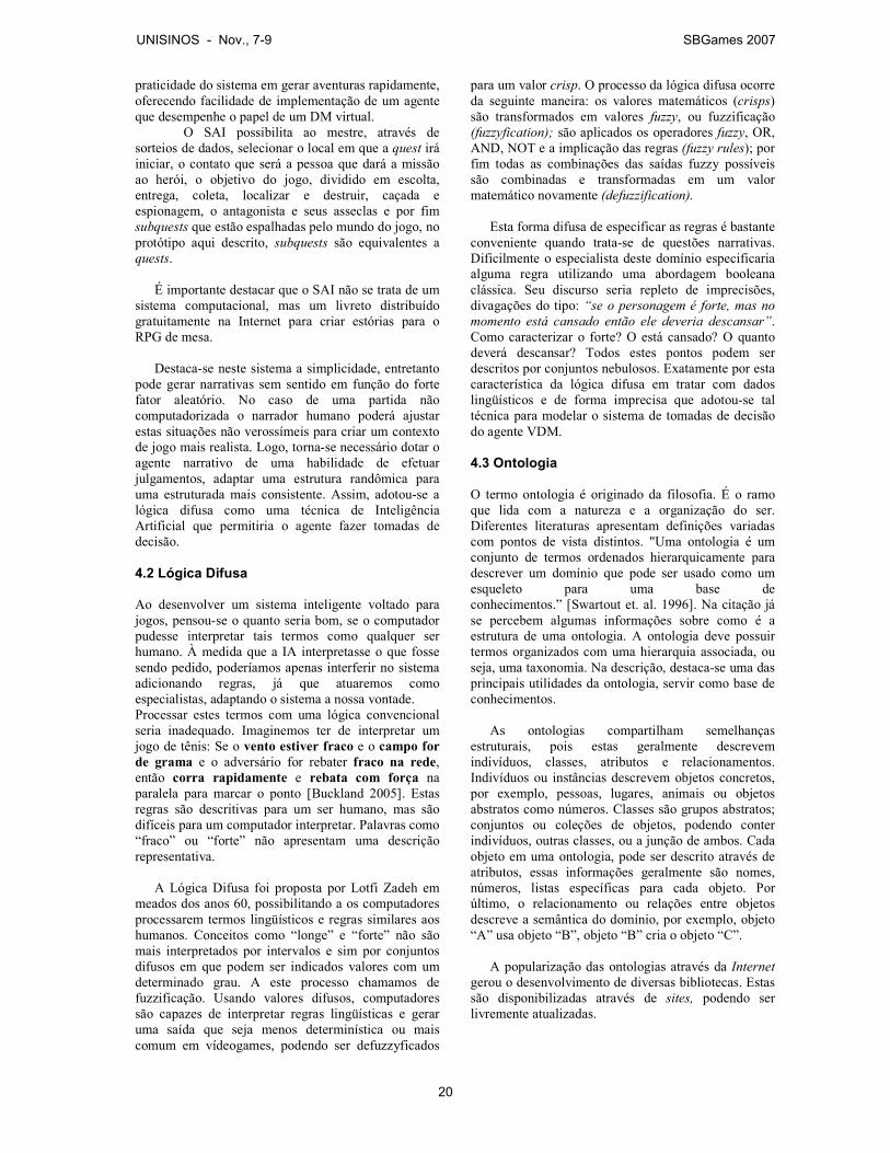
praticidade do sistema em gerar aventuras rapidamente, oferecendo facilidade de implementação de um agente que desempenhe o papel de um DM virtual.
O SAI possibilita ao mestre, através de sorteios de dados, selecionar o local em que a quest irá iniciar, o contato que será a pessoa que dará a missão ao herói, o objetivo do jogo, dividido em escolta, entrega, coleta, localizar e destruir, caçada e espionagem, o antagonista e seus asseclas e por fim subquests que estão espalhadas pelo mundo do jogo, no protótipo aqui descrito, subquests são equivalentes a quests. É importante destacar que o SAI não se trata de um
sistema computacional, mas um livreto distribuído gratuitamente na Internet para criar estórias para o RPG de mesa. Destaca-se neste sistema a simplicidade, entretanto
pode gerar narrativas sem sentido em função do forte fator aleatório. No caso de uma partida não computadorizada o narrador humano poderá ajustar estas situações não verossímeis para criar um contexto de jogo mais realista. Logo, torna-se necessário dotar o agente narrativo de uma habilidade de efetuar julgamentos, adaptar uma estrutura randômica para uma estruturada mais consistente. Assim, adotou-se a lógica difusa como uma técnica de Inteligência Artificial que permitiria o agente fazer tomadas de decisão. 4.2 Lógica Difusa Ao desenvolver um sistema inteligente voltado para jogos, pensou-se o quanto seria bom, se o computador pudesse interpretar tais termos como qualquer ser humano. À medida que a IA interpretasse o que fosse sendo pedido, poderíamos apenas interferir no sistema adicionando regras, já que atuaremos como especialistas, adaptando o sistema a nossa vontade. Processar estes termos com uma lógica convencional seria inadequado. Imaginemos ter de interpretar um jogo de tênis: Se o vento estiver fraco e o campo for de grama e o adversário for rebater fraco na rede, então corra rapidamente e rebata com força na paralela para marcar o ponto [Buckland 2005]. Estas regras são descritivas para um ser humano, mas são difíceis para um computador interpretar. Palavras como “fraco” ou “forte” não apresentam uma descrição representativa. A Lógica Difusa foi proposta por Lotfi Zadeh em
meados dos anos 60, possibilitando a os computadores processarem termos lingüísticos e regras similares aos humanos. Conceitos como “longe” e “forte” não são mais interpretados por intervalos e sim por conjuntos difusos em que podem ser indicados valores com um determinado grau. A este processo chamamos de fuzzificação. Usando valores difusos, computadores são capazes de interpretar regras lingüísticas e gerar uma saída que seja menos determinística ou mais comum em vídeogames, podendo ser defuzzyficados
para um valor crisp. O processo da lógica difusa ocorre da seguinte maneira: os valores matemáticos (crisps) são transformados em valores fuzzy, ou fuzzificação (fuzzyfication); são aplicados os operadores fuzzy, OR, AND, NOT e a implicação das regras (fuzzy rules); por fim todas as combinações das saídas fuzzy possíveis são combinadas e transformadas em um valor matemático novamente (defuzzification). Esta forma difusa de especificar as regras é bastante
conveniente quando trata-se de questões narrativas. Dificilmente o especialista deste domínio especificaria alguma regra utilizando uma abordagem booleana clássica. Seu discurso seria repleto de imprecisões, divagações do tipo: “se o personagem é forte, mas no
momento está cansado então ele deveria descansar”. Como caracterizar o forte? O está cansado? O quanto deverá descansar? Todos estes pontos podem ser descritos por conjuntos nebulosos. Exatamente por esta característica da lógica difusa em tratar com dados lingüísticos e de forma imprecisa que adotou-se tal técnica para modelar o sistema de tomadas de decisão do agente VDM. 4.3 Ontologia O termo ontologia é originado da filosofia. É o ramo que lida com a natureza e a organização do ser. Diferentes literaturas apresentam definições variadas com pontos de vista distintos. "Uma ontologia é um conjunto de termos ordenados hierarquicamente para descrever um domínio que pode ser usado como um esqueleto para uma base de conhecimentos.” [Swartout et. al. 1996]. Na citação já se percebem algumas informações sobre como é a estrutura de uma ontologia. A ontologia deve possuir termos organizados com uma hierarquia associada, ou seja, uma taxonomia. Na descrição, destaca-se uma das principais utilidades da ontologia, servir como base de conhecimentos. As ontologias compartilham semelhanças
estruturais, pois estas geralmente descrevem indivíduos, classes, atributos e relacionamentos. Indivíduos ou instâncias descrevem objetos concretos, por exemplo, pessoas, lugares, animais ou objetos abstratos como números. Classes são grupos abstratos; conjuntos ou coleções de objetos, podendo conter indivíduos, outras classes, ou a junção de ambos. Cada objeto em uma ontologia, pode ser descrito através de atributos, essas informações geralmente são nomes, números, listas específicas para cada objeto. Por último, o relacionamento ou relações entre objetos descreve a semântica do domínio, por exemplo, objeto “A” usa objeto “B”, objeto “B” cria o objeto “C”. A popularização das ontologias através da Internet
gerou o desenvolvimento de diversas bibliotecas. Estas são disponibilizadas através de sites, podendo ser livremente atualizadas.
UNISINOS - Nov., 7-9 SBGames 2007
20
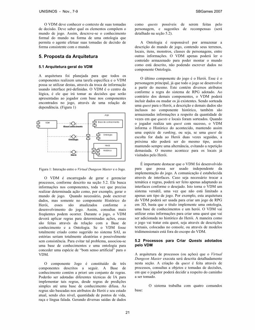
O VDM deve conhecer o contexto de suas tomadas de decisão. Deve saber qual os elementos compõem o mundo de jogo. Assim, descreve-se o conhecimento formal do mundo na forma de uma ontologia que permita o agente efetuar suas tomadas de decisão de forma consistente com o mundo.
5. Proposta da Arquitetura 5.1 Arquitetura geral do VDM A arquitetura foi planejada para que todos os componentes realizem uma tarefa específica e o VDM possa se utilizar destas, através da troca de informação usando interface pré-definidas. O VDM é o centro da lógica, é ele que irá tomar as decisões que serão apresentadas ao jogador com base nos componentes encontrados no jogo, através de uma relação de dependência. (Figura 1)
Figura 1: Interação entre o Virtual Dungeon Master e o Jogo. O VDM é encarregado de gerar e gerenciar
processos, conforme descrito na seção 5.2. Ele busca informações nos componentes, toda vez que precisa realizar determinada ação como, por exemplo, gerar o mundo de jogo. Quando necessário, pode escrever dados, mas somente no componente Histórico do Herói, esses são atualizados conforme o desenvolvimento do jogo. Assim, consultas mais freqüentes podem ocorrer. Durante o jogo, o VDM deverá aplicar regras para determinadas ações, essas são feitas através da relação com a Base de conhecimento e a Ontologia. Se o VDM fosse totalmente criado como sugerido no sistema SAI, as estórias seriam totalmente aleatórias e possivelmente sem consistência. Para evitar tal problema, associou-se uma base de conhecimentos e uma ontologia para conceder uma espécie de “bom senso artificial” para o VDM. O componente Jogo é constituído de três
componentes descritos a seguir. A Base de conhecimento contém a priori um conjunto de regras. Poderão ser adotadas diferentes técnicas de IA para implementar tais regras, desde regras de predições simples até uma base de conhecimento difusa. As regras são baseadas nos atributos do Herói e seu estado atual, sendo eles nível, quantidade de pontos de vida, raça e língua falada. Gerando diversas saídas de dados
como quests possíveis de serem feitas pelo personagem, e sugestões de recompensas (será detalhado na seção 5.2). A Ontologia é responsável por armazenar a
descrição do mundo de jogo, contendo seus terrenos, locais, itens, monstros, classes de personagens, entre outras informações. O VDM apenas poderá ler o conteúdo armazenado para poder montar o mundo como está descrito, não podendo escrever dados no componente Ontologia. O último componente do jogo é o Herói. Esse é o
personagem principal, já que todo o jogo se desenvolve a partir do mesmo. Este contém diversos atributos conforme a regra do sistema de RPG adotado. Ao contrário dos demais componentes, o VDM poderá incluir dados ou mudar os já existentes. Sendo sorteada uma quest para o Herói, a descrição e demais dados são inclusos no componente histórico, também são armazenadas informações a respeito da quantidade de vezes em que quests e locais foram sorteados. Quando o jogador realiza um quest com sucesso, o VDM informa o Histórico do acontecido, mantendo assim uma espécie de ranking, ou seja, se uma quest de escolta for dada ao Herói duas vezes seguidas, a próxima não poderá ser do mesmo tipo, assim mantendo sempre uma alternância, evitando a repetição demasiada. O mesmo acontece para os locais já visitados pelo Herói. É importante destacar que o VDM foi desenvolvido
para que possa ser usado independente da implementação do jogo. A comunicação é estabelecida através de interfaces. Caso seja necessário trocar a temática e regras, poderá ser feito apenas adaptando as interfaces conforme o desejado. Isto torna o VDM um sistema versátil, uma vez que não está limitado a apenas um tipo de jogo. Por exemplo, esta arquitetura do VDM poderá ser usada para criar um jogo de RPG em 3D, basta que o título implemente uma ontologia, uma base de conhecimentos e um herói. O VDM vai utilizar estas informações para criar uma quest que vai ser adicionada no histórico do Herói. A maneira como o jogo vai tratar esta quest, seja através de descrições textuais, colocadas no console, ou através de modelos tridimensionais está fora do escopo do VDM. 5.2 Processos para Criar Quests adotados pelo VDM A arquitetura de processos (ou ações) que o Virtual
Dungeon Master executa será descrita detalhadamente nesta seção. A criação da quest é feita através de processos, consultas a objetos e tomadas de decisões, em que o jogador poderá decidir a respeito do caminho a ser tomado.
O sistema trabalha com quatro comandos
base:
UNISINOS - Nov., 7-9 SBGames 2007
21

a) Inicializar: este processo ocorre quando o jogo é carregado pela primeira vez, com isto são carregadas as informações necessárias no decorrer da execução do programa. Esta ação é executada somente no início para carregar o mundo e o herói;
b) Sortear: processo usado quando for necessária uma ação aleatória por parte do VDM. Estas ações aleatórias são baseadas nas tabelas do SAI;
c) Escolher: quando for necessária uma interação do jogador, este processo é ativado. A partir da escolha, é possível mudar o curso do jogo;
d) Definir: a partir da escolha do jogador, o VDM pode definir determinadas ações, geralmente dependentes dos objetos a serem consultados. Estas definições são feitas, utilizando uma base de conhecimento. O primeiro passo a ser executado é inicializar o
mundo de jogo. Este está descrito na Ontologia de cada jogo. O jogo existente é composto de um mundo povoado por NPCs, monstros, localidades e itens. Esses são lidos e armazenados pelo VDM para serem usados na medida em que se tornarem necessários. Na seqüência, é necessário inicializar o herói que
representará o jogador. Este é escolhido pelo jogador dentre as diversas possibilidades apresentadas no jogo. O objeto herói é inicializado contendo seus atributos. É criado um histórico vazio. A primeira tomada de decisão ocorre após a
inicialização do herói (diamante A, Figura 2 - Anexo). Na primeira vez em que o jogo for inicializado, é sorteado um terreno dentre todos os possíveis descritos no mundo. Esta ação foi planejada para que a cada vez que se começa um novo jogo, este não ocorra sempre na mesma localidade, possibilitando ao jogador uma nova experiência a cada partida. Se não for a primeira vez, cabe ao jogador escolher para qual terreno mover o herói. Estando em um terreno, é possível escolher entrar em seu agrupamento ou movimentar-se para outro. Estando no agrupamento, duas novas opções são oferecidas (diamante B, Figura 3), pode-se voltar para o terreno inicial ou avançar para os locais que pertencem ao agrupamento. Cada agrupamento contém um número pré-determinado de locais, dependendo da cidade que o jogador escolher. Esta poderá ter ou não certas construções, como por exemplo, um templo ou castelo. Escolhido o local (diamante C, Figura 3), o VDM consulta a base de conhecimentos e o atributo pontos de vida do herói para verificar se o local desejado contém ou não, uma quest. Caso não seja constatada uma regra válida para a geração do local, este estará vazio, não apresentando interação, obrigando o jogador a voltar e re-selecioná-lo. Como o local depende dos pontos de vida do herói, há possibilidade de que locais previamente visitados possam estar povoados. Estando o local de acordo com as regras, este então
receberá um Mandatário [Propp 83]. As regras da base de conhecimento são verificadas para escolher qual
melhor NPC. Por exemplo, podem existir regras na base de conhecimentos que são baseadas na raça e na língua falada pelo herói. Sempre será gerado um Mandatário, mas com raças e comportamentos diferentes. Um humano terá grandes chances de que seu mandatário seja da mesma raça, mas se este falar élfico, poderá ser apresentado um elfo ou meio-elfo. Este procedimento foi adotado para novamente diversificar o jogo. O Mandatário dará ao jogador uma missão a ser
cumprida. A formação da missão considera regras existentes e o atributo nível do herói. Seis tipos de missões são possíveis, somente uma poderá ser sorteada, ou seja, o mandatário poderá requerer uma quest de escolta, mas nunca uma escolta e entrega ao mesmo tempo. Cada classe tem prioridades em suas missões, um mago realizará entregas e coletas mais freqüentes e um guerreiro, caçadas e escoltas. Determinado o tipo de quest que será atribuída ao
herói, algumas definições adicionais são feitas. As descrições de cada tipo serão exemplificadas a seguir:
a) Escolta: o VDM define o local em que será
concluída a quest final e um NPC (chamado de Popular na Ontologia). Para cumprir a missão será necessário levar este NPC para o local determinado.
b) Espionagem: a cidade que deverá ser espionada é definida dentre qualquer uma existente no mundo (menos a cidade em que foi adquirida a missão). Para cumpri-la, é preciso entrar no agrupamento definido.
c) Entrega: definido um item qualquer, será preciso entregá-lo a um determinado local (templo, taverna, guilda,...), em uma determinada cidade.
d) Coleta: o objetivo dessa missão é coletar um determinado item e entregar para o mandatário que o pediu.
e) Procura e destrói: definido um anti-herói de acordo com as regras necessárias, o objetivo é derrotar este inimigo.
f) Caçada: parecido com a quest anterior, mas é definido um monstro errante qualquer que pertença ao terreno atual em que o herói se encontra.
Dada a quest, esta é armazenada no histórico. O
histórico mantém o VDM atualizado sobre as missões completas e pendentes que o herói possui. Ao mesmo tempo, o histórico monitora a quantidade de vezes que determinado tipo de quest foi dada ao herói, o local em que o herói recebeu e o tipo de item dado na recompensa. Quanto mais for sorteado um elemento, menos chance este tem de ser escolhido novamente. Assim, existirá uma grande variação dos tipos de quests, locais e itens. Durante a transição de um terreno para o outro, é
sorteado um monstro de acordo com o nível atual do herói. Caso o personagem morra, (diamante D, Figura 3) o jogo é terminado e será necessário reiniciá-lo.
UNISINOS - Nov., 7-9 SBGames 2007
22
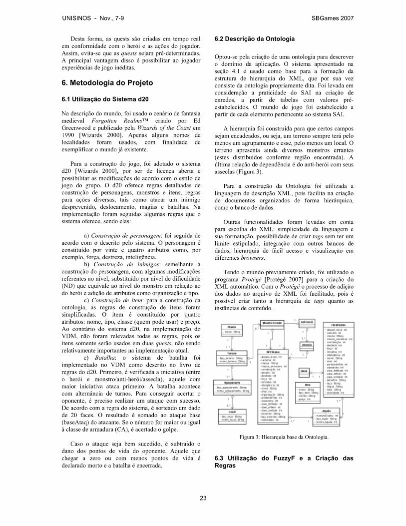
Desta forma, as quests são criadas em tempo real em conformidade com o herói e as ações do jogador. Assim, evita-se que as quests sejam pré-determinadas. A principal vantagem disso é possibilitar ao jogador experiências de jogo inéditas.
6. Metodologia do Projeto 6.1 Utilização do Sistema d20
Na descrição do mundo, foi usado o cenário de fantasia medieval Forgotten Realms™ criado por Ed Greenwood e publicado pela Wizards of the Coast em 1990 [Wizards 2000]. Apenas alguns nomes de localidades foram usados, com finalidade de exemplificar o mundo já existente. Para a construção do jogo, foi adotado o sistema
d20 [Wizards 2000], por ser de licença aberta e possibilitar as modificações de acordo com o estilo de jogo do grupo. O d20 oferece regras detalhadas de construção de personagens, monstros e itens, regras para ações diversas, tais como atacar um inimigo desprevenido, deslocamento, magias e batalhas. Na implementação foram seguidas algumas regras que o sistema oferece, sendo elas:
a) Construção de personagem: foi seguida de
acordo com o descrito pelo sistema. O personagem é constituído por vinte e quatro atributos como, por exemplo, força, destreza, inteligência.
b) Construção de inimigos: semelhante à construção do personagem, com algumas modificações referentes ao nível, substituído por nível de dificuldade (ND) que equivale ao nível do monstro em relação ao do herói e adição de atributos como organização e tipo.
c) Construção de item: para a construção da ontologia, as regras de construção de itens foram simplificadas. O item é constituído por quatro atributos: nome, tipo, classe (quem pode usar) e preço. Ao contrário do sistema d20, na implementação do VDM, não foram relevadas todas as regras, pois os itens somente serão usados em duas quests, não sendo relativamente importantes na implementação atual.
c) Batalha: o sistema de batalha foi implementado no VDM como descrito no livro de regras do d20. Primeiro, é verificada a iniciativa (entre o herói e monstro/anti-herói/assecla), aquele com maior iniciativa ataca primeiro. A batalha acontece com alternância de turnos. Para conseguir acertar o oponente, é preciso realizar um ataque com sucesso. De acordo com a regra do sistema, é sorteado um dado de 20 faces. O resultado é somado ao ataque base (baseAtaq) do atacante. Se o número for maior ou igual à classe de armadura (CA), é acertado o golpe.
Caso o ataque seja bem sucedido, é subtraído o
dano dos pontos de vida do oponente. Aquele que chegar a zero ou com menos pontos de vida é declarado morto e a batalha é encerrada.
6.2 Descrição da Ontologia
Optou-se pela criação de uma ontologia para descrever o domínio da aplicação. O sistema apresentado na seção 4.1 é usado como base para a formação da estrutura de hierarquia do XML, que por sua vez consiste da ontologia propriamente dita. Foi levada em consideração a praticidade do SAI na criação de enredos, a partir de tabelas com valores pré-estabelecidos. O mundo de jogo foi estabelecido a partir de cada elemento pertencente ao sistema SAI. A hierarquia foi construída para que certos campos
sejam encadeados, ou seja, um terreno sempre terá pelo menos um agrupamento e esse, pelo menos um local. O terreno apresenta ainda diversos monstros errantes (estes distribuídos conforme região encontrada). A última relação de dependência é do anti-herói com seus asseclas (Figura 3). Para a construção da Ontologia foi utilizada a
linguagem de descrição XML, pois facilita na criação de documentos organizados de forma hierárquica, como o banco de dados. Outras funcionalidades foram levadas em conta
para escolha do XML: simplicidade da linguagem e sua formatação, possibilidade de criar tags sem ter um limite estipulado, integração com outros bancos de dados, hierarquia de fácil acesso e visualização em diferentes browsers. Tendo o mundo previamente criado, foi utilizado o
programa Protégé [Protégé 2007] para a criação do XML automático. Com o Protégé o processo de adição dos dados no arquivo de XML foi facilitado, pois é possível criar tanto a hierarquia de tags quanto as instâncias de conteúdo.
Figura 3: Hierarquia base da Ontologia. 6.3 Utilização do FuzzyF e a Criação das Regras
UNISINOS - Nov., 7-9 SBGames 2007
23
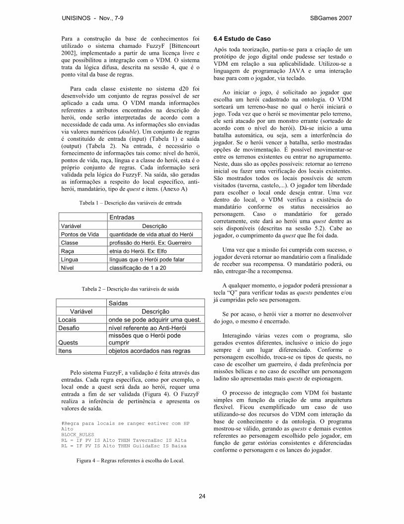
Para a construção da base de conhecimentos foi utilizado o sistema chamado FuzzyF [Bittencourt 2002], implementado a partir de uma licença livre e que possibilitou a integração com o VDM. O sistema trata da lógica difusa, descrita na sessão 4, que é o ponto vital da base de regras. Para cada classe existente no sistema d20 foi
desenvolvido um conjunto de regras possível de ser aplicado a cada uma. O VDM manda informações referentes a atributos encontrados na descrição do herói, onde serão interpretadas de acordo com a necessidade de cada uma. As informações são enviadas via valores numéricos (double). Um conjunto de regras é constituído de entrada (input) (Tabela 1) e saída (output) (Tabela 2). Na entrada, é necessário o fornecimento de informações tais como: nível do herói, pontos de vida, raça, língua e a classe do herói, esta é o próprio conjunto de regras. Cada informação será validada pela lógica do FuzzyF. Na saída, são geradas as informações a respeito do local específico, anti-herói, mandatário, tipo de quest e itens. (Anexo A)
Tabela 1 – Descrição das variáveis de entrada
Entradas
Variável Descrição
Pontos de Vida quantidade de vida atual do Herói
Classe profissão do Herói. Ex: Guerreiro
Raça etnia do Herói. Ex: Elfo
Língua línguas que o Herói pode falar
Nível classificação de 1 a 20
Tabela 2 – Descrição das variáveis de saída
Saídas
Variável Descrição
Locais onde se pode adquirir uma quest.
Desafio nível referente ao Anti-Herói
Quests missões que o Herói pode cumprir
Itens objetos acordados nas regras
Pelo sistema FuzzyF, a validação é feita através das
entradas. Cada regra específica, como por exemplo, o local onde a quest será dada ao herói, requer uma entrada a fim de ser validada (Figura 4). O FuzzyF realiza a inferência de pertinência e apresenta os valores de saída. #Regra para locais se ranger estiver com HP Alto BLOCK_RULES RL = IF PV IS Alto THEN TavernaEsc IS Alta RL = IF PV IS Alto THEN GuildaEsc IS Baixa
Figura 4 – Regras referentes à escolha do Local.
6.4 Estudo de Caso
Após toda teorização, partiu-se para a criação de um protótipo de jogo digital onde pudesse ser testado o VDM em relação a sua aplicabilidade. Utilizou-se a linguagem de programação JAVA e uma interação base para com o jogador, via teclado. Ao iniciar o jogo, é solicitado ao jogador que
escolha um herói cadastrado na ontologia. O VDM sorteará um terreno-base no qual o herói iniciará o jogo. Toda vez que o herói se movimentar pelo terreno, ele será atacado por um monstro errante (sorteado de acordo com o nível do herói). Dá-se início a uma batalha automática, ou seja, sem a interferência do jogador. Se o herói vencer a batalha, serão mostradas opções de movimentação. É possível movimentar-se entre os terrenos existentes ou entrar no agrupamento. Neste, duas são as opções possíveis: retornar ao terreno inicial ou fazer uma verificação dos locais existentes. São mostrados todos os locais possíveis de serem visitados (taverna, castelo,...). O jogador tem liberdade para escolher o local onde deseja entrar. Uma vez dentro do local, o VDM verifica a existência do mandatário conforme os status necessários ao personagem. Caso o mandatário for gerado corretamente, este dará ao herói uma quest dentre as seis disponíveis (descritas na sessão 5.2). Cabe ao jogador, o cumprimento da quest que lhe foi dada. Uma vez que a missão foi cumprida com sucesso, o
jogador deverá retornar ao mandatário com a finalidade de receber sua recompensa. O mandatário poderá, ou não, entregar-lhe a recompensa. A qualquer momento, o jogador poderá pressionar a
tecla “Q” para verificar todas as quests pendentes e/ou já cumpridas pelo seu personagem. Se por acaso, o herói vier a morrer no desenvolver
do jogo, o mesmo é encerrado. Interagindo várias vezes com o programa, são
gerados eventos diferentes, inclusive o início do jogo sempre é um lugar diferenciado. Conforme o personagem escolhido, troca-se os tipos de quests, no caso de escolher um guerreiro, é dada preferência por missões bélicas e no caso de escolher um personagem ladino são apresentadas mais quests de espionagem. O processo de integração com VDM foi bastante
simples em função da criação de uma arquitetura flexível. Ficou exemplificado um caso de uso utilizando-se dos recursos do VDM com interação da base de conhecimento e da ontologia. O programa mostrou-se válido, gerando as quests e demais eventos referentes ao personagem escolhido pelo jogador, em função de gerar estórias consistentes e diferenciadas conforme o personagem e os lances do jogador.
UNISINOS - Nov., 7-9 SBGames 2007
24
7. Conclusão Este trabalho foi desenvolvido a partir da idéia de criar um sistema que construísse estórias automáticas de maneira inteligente. Seu principal objetivo foi implementar um sistema que utilizasse técnicas de Inteligência Artificial, capaz de gerar um comportamento consistente quanto à criação de estórias. No desenvolvimento do trabalho, foi proposto o VDM, buscando criar um ambiente controlado, que possibilite ao jogador ter um mundo com variadas alternativas de quest, visando com isto a aumentar o interesse, a expectativa e o replay dos envolvidos, ao mesmo tempo em que possa dar uma longevidade à vida útil dos jogos, tornando-os mais arrojados e atrativos. Foi apresentada uma teorização da IA direcionada aos jogos digitais. Descreveu-se amplamente a teoria da narrativa como suporte na construção do modelo aplicado. A criação deste novo modelo teve como base o
Sistema de Aventuras Instantâneas que, apesar de aleatório, forneceu subsídios para a criação do modelo, dando-lhe maior nível de controle. Espera-se com este trabalho ter contribuído para a
aplicação do VDM possibilitando adaptar-se à diversidade de jogos digitais no gênero RPG encontrados no mercado, pois independente da temática dos jogos e suas regras, o VDM é de possível aplicabilidade. Apesar de no trabalho estar sendo utilizada a lógica difusa, é possível trocar por qualquer outra técnica de IA, pois o VDM tem a flexibilidade de ser implementado conforme as regras definidas pelo desenvolvedor da base do jogo. O modelo do VDM foi proposto para ser independente de especificidades de implementações. A versão inicial implementada do VDM ainda
carece de um maior tempo de estudo e aprofundamento, pois sua complexidade exige uma adequação à indústria de jogos, visando a sua larga aplicação no mercado. Uma nova fase do trabalho deverá estar focada no
desenvolvimento do motor, incluindo maior número de regras conforme o sistema adotado. Além destas, destaca-se a necessidade de um visualizador do ambiente gerado pelo VDM bem como a melhoria da interface com o jogador. Um maior tempo dedicado à construção de uma
narrativa, incluindo um perfil de cada usuário, sendo possível uma adaptação da história conforme o próprio perfil e ações tomadas no decorrer do jogo. Também é necessária uma maior adaptação do sistema d20 como distribuição de pontos de experiência a cada monstro derrotado e quests cumpridas, o que implicaria na evolução do personagem. Magias e ataques especiais
bem como suas regras específicas deverão ser implementadas, para melhor caracterizar o sistema. Com relação à ontologia e à utilização do XML,
deve-se procurar uma generalização das regras e suas variáveis, fazendo com que estas sejam de fácil adaptação, conforme forem necessárias em outros sistemas e modos de jogo. Através do estudo das diferentes temáticas foi
ampliada a base de conhecimentos teóricos, bem como a oportunidade de melhoria da conceituação e validação das teorias que deram suporte técnico ao desenvolvimento do presente trabalho. Pretendeu-se de maneira prática, buscar uma maior
atratividade para o mercado de jogos, visando a atender aos interesses de seus jogadores, proporcionando-lhes múltiplas alternativas de fidelização do cliente e conseqüentemente maior rentabilidade do desenvolvedor.
Referências BIOWARE CORP. 2002. Disponível em: www.nwn.bioware.com . [Acesso em 20 jun. 2007]. CD-ROM, Windows.
BITTENCOURT, J. R.; OSÓRIO, F. S. FuzzyF - Fuzzy Logic Framework: Uma Solução Software Livre para o Desenvolvimento, Ensino e Pesquisa de Aplicações de Inteligência Artificial Multiplataforma. In: III Workshop
sobre Software Livre, Porto Alegre: Sociedade Brasileira de Computação, 2002. 58-61.
BUCKLAND, M. Programing Game AI by Example. Wordware
Publishing Inc: Texas, 2005. 495p. CAVAZZA, M; CHARLES, F.; MEAD, S. J. Interactive
Storytelling: From AI experiment to new media. In: Proceedings of the second international conference on Entertainment computing, May 08 - 10, 2003 , Pittsburgh, Pennsylvania.
CAVAZZA, M; CHARLES, F.; MEAD, S. J. Interacting
with Virtual Characters in Interactive Storytelling. In:
Proc. AAMAS’02, July 15-19, 2005, pages 318-325, Bologna, Italy.
CHARLES, F; CAVAZZA, M.; MEAD, S. J.; MARTIN, O.; NANDI, A.; MARICHAL, X. Compelling Experiences in Mixed Reality Interactive Storytelling. In: Proc. ACE’04, June 3-5, 2004, pages 32-41, Singapure.
FILHO, V.; COBBI, B. SAI - Sistema de Aventuras
Instantâneas. Royal Hunter. 2002. Disponível em: www.rederpg.com.br/portal/modules/news/article.php?storyid=573. [Acesso em 22 jan. 2007].
FAIRCLOUGH, C. R.; CUNNINGHAN, P. AI Structuralist
Storytellingin Computer Games.
LIU, Y.; AKLEMAN, E.; CHEN, J. Visual Storytelling
Warehouse. 2006.
UNISINOS - Nov., 7-9 SBGames 2007
25
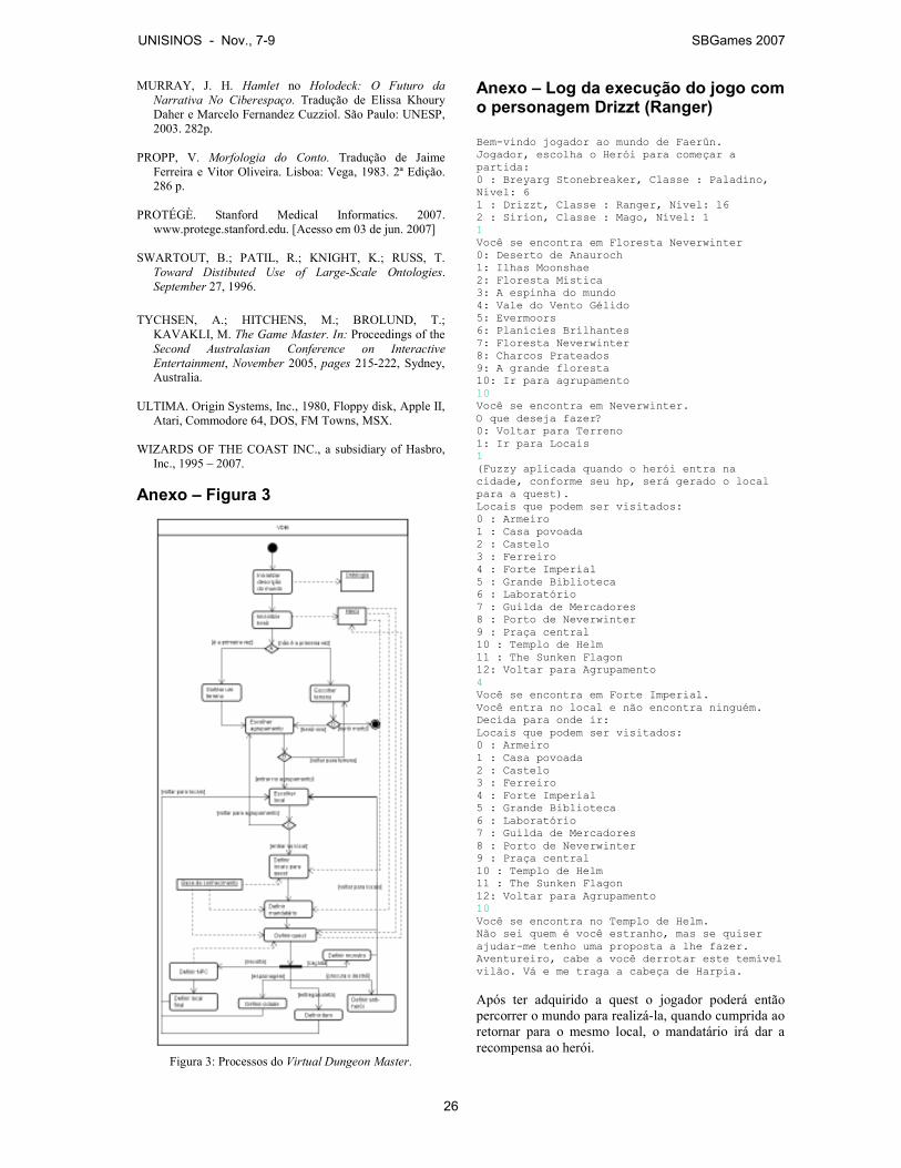
MURRAY, J. H. Hamlet no Holodeck: O Futuro da
Narrativa No Ciberespaço. Tradução de Elissa Khoury Daher e Marcelo Fernandez Cuzziol. São Paulo: UNESP, 2003. 282p.
PROPP, V. Morfologia do Conto. Tradução de Jaime Ferreira e Vitor Oliveira. Lisboa: Vega, 1983. 2ª Edição. 286 p.
PROTÉGÈ. Stanford Medical Informatics. 2007. www.protege.stanford.edu. [Acesso em 03 de jun. 2007]
SWARTOUT, B.; PATIL, R.; KNIGHT, K.; RUSS, T.
Toward Distibuted Use of Large-Scale Ontologies. September 27, 1996.
TYCHSEN, A.; HITCHENS, M.; BROLUND, T.; KAVAKLI, M. The Game Master. In: Proceedings of the Second Australasian Conference on Interactive
Entertainment, November 2005, pages 215-222, Sydney, Australia.
ULTIMA. Origin Systems, Inc., 1980, Floppy disk, Apple II, Atari, Commodore 64, DOS, FM Towns, MSX.
WIZARDS OF THE COAST INC., a subsidiary of Hasbro, Inc., 1995 – 2007.
Anexo – Figura 3
Figura 3: Processos do Virtual Dungeon Master.
Anexo – Log da execução do jogo com o personagem Drizzt (Ranger) Bem-vindo jogador ao mundo de Faerûn. Jogador, escolha o Herói para começar a partida: 0 : Breyarg Stonebreaker, Classe : Paladino, Nível: 6 1 : Drizzt, Classe : Ranger, Nível: 16 2 : Sirion, Classe : Mago, Nível: 1 1 Você se encontra em Floresta Neverwinter 0: Deserto de Anauroch 1: Ilhas Moonshae 2: Floresta Mística 3: A espinha do mundo 4: Vale do Vento Gélido 5: Evermoors 6: Planícies Brilhantes 7: Floresta Neverwinter 8: Charcos Prateados 9: A grande floresta 10: Ir para agrupamento 10 Você se encontra em Neverwinter. O que deseja fazer? 0: Voltar para Terreno 1: Ir para Locais 1 (Fuzzy aplicada quando o herói entra na cidade, conforme seu hp, será gerado o local para a quest). Locais que podem ser visitados: 0 : Armeiro 1 : Casa povoada 2 : Castelo 3 : Ferreiro 4 : Forte Imperial 5 : Grande Biblioteca 6 : Laboratório 7 : Guilda de Mercadores 8 : Porto de Neverwinter 9 : Praça central 10 : Templo de Helm 11 : The Sunken Flagon 12: Voltar para Agrupamento 4 Você se encontra em Forte Imperial. Você entra no local e não encontra ninguém. Decida para onde ir: Locais que podem ser visitados: 0 : Armeiro 1 : Casa povoada 2 : Castelo 3 : Ferreiro 4 : Forte Imperial 5 : Grande Biblioteca 6 : Laboratório 7 : Guilda de Mercadores 8 : Porto de Neverwinter 9 : Praça central 10 : Templo de Helm 11 : The Sunken Flagon 12: Voltar para Agrupamento 10 Você se encontra no Templo de Helm. Não sei quem é você estranho, mas se quiser ajudar-me tenho uma proposta a lhe fazer. Aventureiro, cabe a você derrotar este temível vilão. Vá e me traga a cabeça de Harpia.
Após ter adquirido a quest o jogador poderá então percorrer o mundo para realizá-la, quando cumprida ao retornar para o mesmo local, o mandatário irá dar a recompensa ao herói.
UNISINOS - Nov., 7-9 SBGames 2007
26
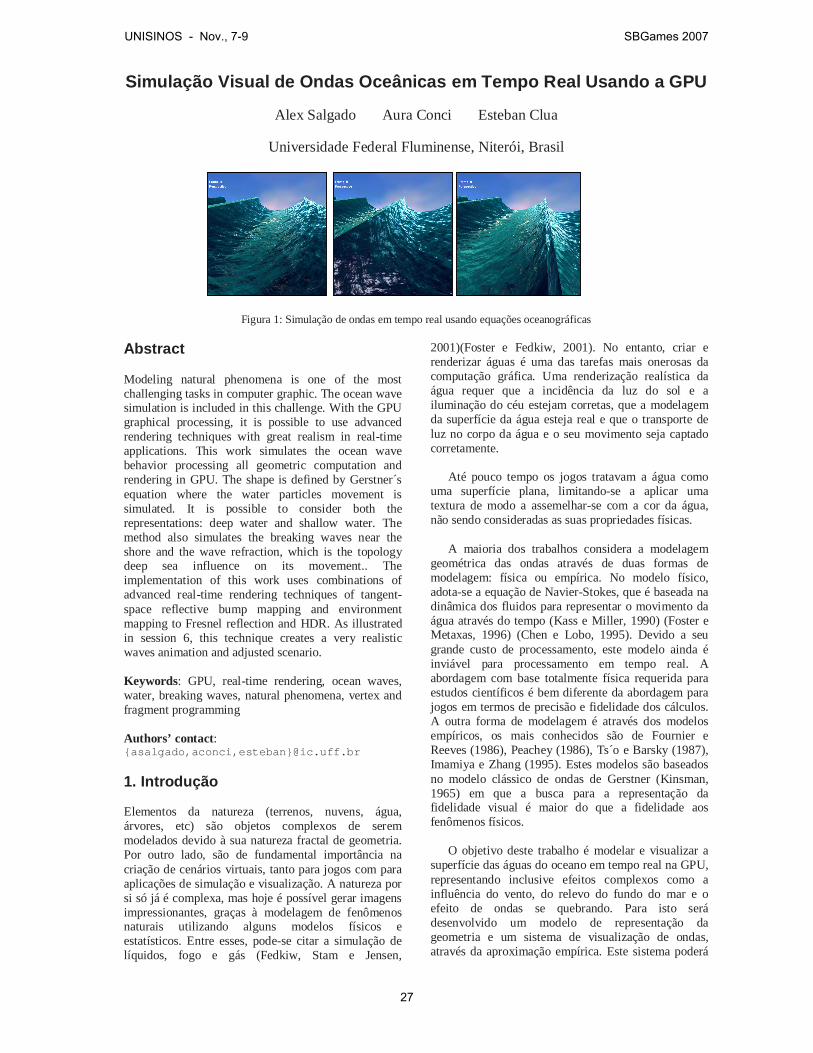
Simulação Visual de Ondas Oceânicas em Tempo Real U sando a GPU
Alex Salgado Aura Conci Esteban Clua
Universidade Federal Fluminense, Niterói, Brasil
Figura 1: Simulação de ondas em tempo real usando equações oceanográficas Abstract Modeling natural phenomena is one of the most challenging tasks in computer graphic. The ocean wave simulation is included in this challenge. With the GPU graphical processing, it is possible to use advanced rendering techniques with great realism in real-time applications. This work simulates the ocean wave behavior processing all geometric computation and rendering in GPU. The shape is defined by Gerstner´s equation where the water particles movement is simulated. It is possible to consider both the representations: deep water and shallow water. The method also simulates the breaking waves near the shore and the wave refraction, which is the topology deep sea influence on its movement.. The implementation of this work uses combinations of advanced real-time rendering techniques of tangent-space reflective bump mapping and environment mapping to Fresnel reflection and HDR. As illustrated in session 6, this technique creates a very realistic waves animation and adjusted scenario. Keywords: GPU, real-time rendering, ocean waves, water, breaking waves, natural phenomena, vertex and fragment programming Authors’ contact: {asalgado,aconci,esteban}@ic.uff.br 1. Introdução Elementos da natureza (terrenos, nuvens, água, árvores, etc) são objetos complexos de serem modelados devido à sua natureza fractal de geometria. Por outro lado, são de fundamental importância na criação de cenários virtuais, tanto para jogos com para aplicações de simulação e visualização. A natureza por si só já é complexa, mas hoje é possível gerar imagens impressionantes, graças à modelagem de fenômenos naturais utilizando alguns modelos físicos e estatísticos. Entre esses, pode-se citar a simulação de líquidos, fogo e gás (Fedkiw, Stam e Jensen,
2001)(Foster e Fedkiw, 2001). No entanto, criar e renderizar águas é uma das tarefas mais onerosas da computação gráfica. Uma renderização realística da água requer que a incidência da luz do sol e a iluminação do céu estejam corretas, que a modelagem da superfície da água esteja real e que o transporte de luz no corpo da água e o seu movimento seja captado corretamente. Até pouco tempo os jogos tratavam a água como uma superfície plana, limitando-se a aplicar uma textura de modo a assemelhar-se com a cor da água, não sendo consideradas as suas propriedades físicas. A maioria dos trabalhos considera a modelagem geométrica das ondas através de duas formas de modelagem: física ou empírica. No modelo físico, adota-se a equação de Navier-Stokes, que é baseada na dinâmica dos fluidos para representar o movimento da água através do tempo (Kass e Miller, 1990) (Foster e Metaxas, 1996) (Chen e Lobo, 1995). Devido a seu grande custo de processamento, este modelo ainda é inviável para processamento em tempo real. A abordagem com base totalmente física requerida para estudos científicos é bem diferente da abordagem para jogos em termos de precisão e fidelidade dos cálculos. A outra forma de modelagem é através dos modelos empíricos, os mais conhecidos são de Fournier e Reeves (1986), Peachey (1986), Ts´o e Barsky (1987), Imamiya e Zhang (1995). Estes modelos são baseados no modelo clássico de ondas de Gerstner (Kinsman, 1965) em que a busca para a representação da fidelidade visual é maior do que a fidelidade aos fenômenos físicos. O objetivo deste trabalho é modelar e visualizar a superfície das águas do oceano em tempo real na GPU, representando inclusive efeitos complexos como a influência do vento, do relevo do fundo do mar e o efeito de ondas se quebrando. Para isto será desenvolvido um modelo de representação da geometria e um sistema de visualização de ondas, através da aproximação empírica. Este sistema poderá
UNISINOS - Nov., 7-9 SBGames 2007
27
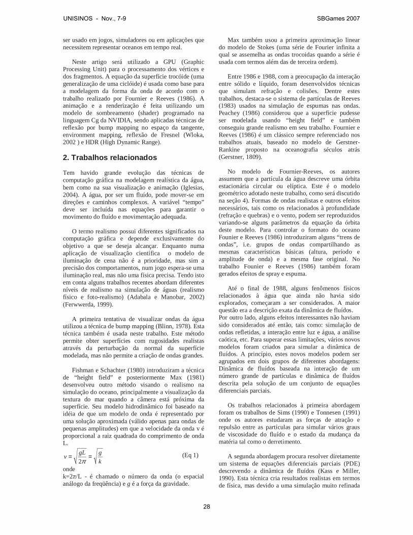
ser usado em jogos, simuladores ou em aplicações que necessitem representar oceanos em tempo real. Neste artigo será utilizado a GPU (Graphic Processing Unit) para o processamento dos vértices e dos fragmentos. A equação da superfície trocóide (uma generalização de uma ciclóide) é usada como base para a modelagem da forma da onda de acordo com o trabalho realizado por Fournier e Reeves (1986). A animação e a renderização é feita utilizando um modelo de sombreamento (shader) programado na linguagem Cg da NVIDIA, sendo aplicadas técnicas de reflexão por bump mapping no espaço da tangente, environment mapping, reflexão de Fresnel (Wloka, 2002 ) e HDR (High Dynamic Range). 2. Trabalhos relacionados Tem havido grande evolução das técnicas de computação gráfica na modelagem realística da água, bem como na sua visualização e animação (Iglesias, 2004). A água, por ser um fluído, pode mover-se em direções e caminhos complexos. A variável “tempo” deve ser incluída nas equações para garantir o movimento do fluído e movimentação adequada. O termo realismo possui diferentes significados na computação gráfica e depende exclusivamente do objetivo a que se deseja alcançar. Enquanto numa aplicação de visualização científica o modelo de iluminação de cena não é a prioridade, mas sim a precisão dos comportamentos, num jogo espera-se uma iluminação real, mas não uma física precisa. Tendo isto em conta alguns trabalhos recentes abordam diferentes níveis de realismo na simulação de águas (realismo físico e foto-realismo) (Adabala e Manobar, 2002) (Ferwwerda, 1999). A primeira tentativa de visualizar ondas da água utilizou a técnica de bump mapping (Blinn, 1978). Esta técnica também é usada neste trabalho. Este método permite obter superfícies com rugosidades realistas através da perturbação da normal da superfície modelada, mas não permite a criação de ondas grandes. Fishman e Schachter (1980) introduziram a técnica de “height field” e posteriormente Max (1981) desenvolveu outro método visando o realismo na simulação do oceano, principalmente a visualização da textura do mar quando a câmera está próxima da superfície. Seu modelo hidrodinâmico foi baseado na idéia de que um modelo de onda é representado por uma solução aproximada (válido apenas para ondas de pequenas amplitudes) em que a velocidade da onda v é proporcional a raiz quadrada do comprimento de onda L.
k
ggLv ==
π2 (Eq 1)
onde k=2�/L - é chamado o número da onda (o espacial análogo da freqüência) e g é a força da gravidade.
Max também usou a primeira aproximação linear do modelo de Stokes (uma série de Fourier infinita a qual se assemelha as ondas trocoidas quando a série é usada com termos além das de terceira ordem). Entre 1986 e 1988, com a preocupação da interação entre sólido e líquido, foram desenvolvidos técnicas que simulam refração e colisões. Dentre estes trabalhos, destaca-se o sistema de partículas de Reeves (1983) usados na simulação de espumas nas ondas. Peachey (1986) considerou que a superfície pudesse ser modelada usando “height field” e também conseguiu grande realismo em seu trabalho. Fournier e Reeves (1986) é um clássico sempre referenciado nos trabalhos atuais, baseado no modelo de Gerstner-Rankine proposto na oceanografia séculos atrás (Gerstner, 1809). No modelo de Fournier-Reeves, os autores assumem que a partícula da água descreve uma órbita estacionária circular ou elíptica. Este é o modelo geométrico adotado neste trabalho, como será discutido na seção 4). Formas de ondas realistas e outros efeitos necessários, tais como os relacionados à profundidade (refração e quebras) e o vento, podem ser reproduzidos variando-se alguns parâmetros da equação da órbita deste modelo. Para controlar o formato do oceano Founier e Reeves (1986) introduziram alguns “trens de ondas”, i.e. grupos de ondas compartilhando as mesmas características básicas (altura, período e amplitude de onda) e a mesma fase original. No trabalho Founier e Reeves (1986) também foram gerados efeitos de spray e espuma. Até o final de 1988, alguns fenômenos físicos relacionados à água que ainda não havia sido explorados, começaram a ser considerados. A maior questão era a descrição exata da dinâmica de fluídos. Por outro lado, alguns efeitos interessantes não haviam sido considerados até então, tais como: simulação de ondas refletidas, a interação entre luz e água, a análise caótica, etc. Para superar essas limitações, vários novos modelos foram criados para simular a dinâmica de fluídos. A princípio, estes novos modelos podem ser agrupados em dois grupos de diferentes abordagens: Dinâmica de fluídos baseada na interação de um número grande de partículas e dinâmica de fluídos descrita pela solução de um conjunto de equações diferenciais parciais.
Os trabalhos relacionados à primeira abordagem foram os trabalhos de Sims (1990) e Tonnesen (1991) onde os autores estudaram as forças de atração e repulsão entre as partículas para simular vários graus de viscosidade do fluído e o estado da mudança da matéria tal como o derretimento. A segunda abordagem procura resolver diretamente um sistema de equações diferenciais parciais (PDE) descrevendo a dinâmica de fluídos (Kass e Miller, 1990). Esta técnica cria resultados realistas em termos de física, mas devido a uma simulação muito refinada
UNISINOS - Nov., 7-9 SBGames 2007
28
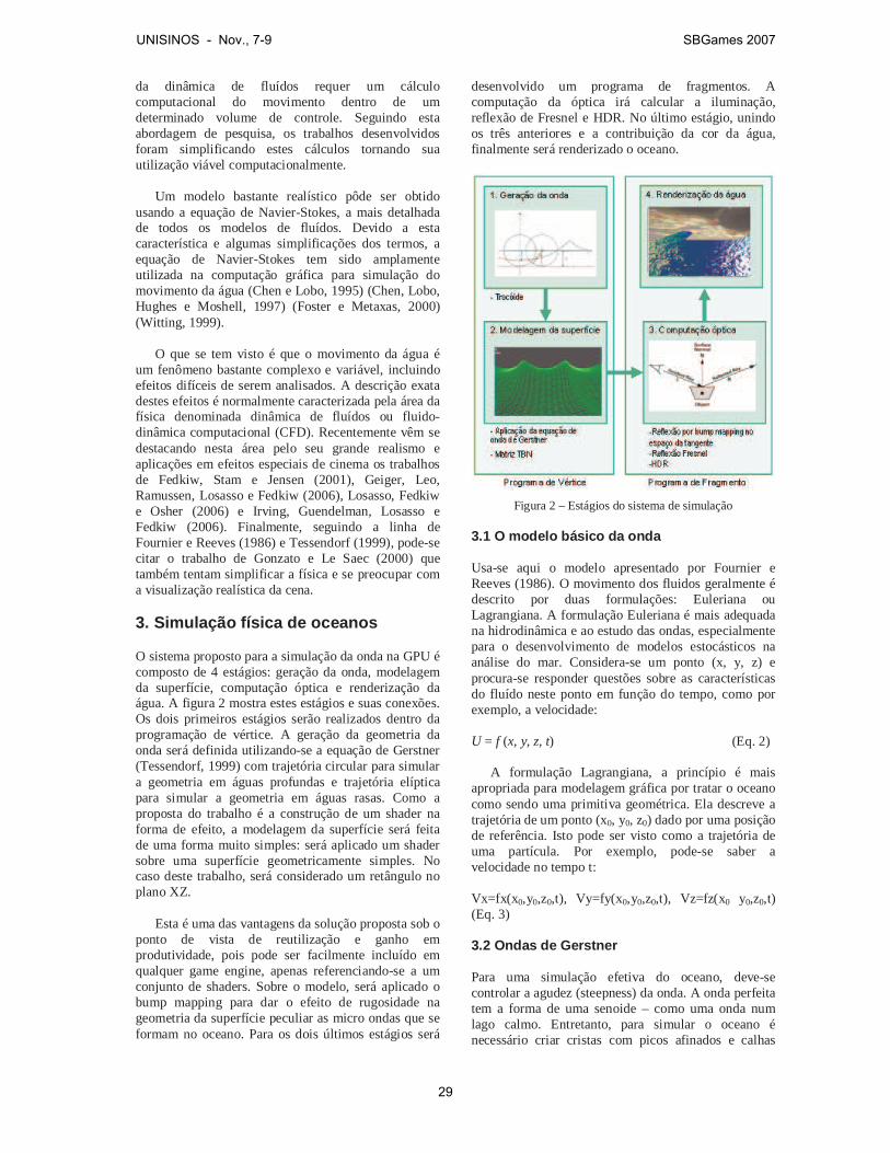
da dinâmica de fluídos requer um cálculo computacional do movimento dentro de um determinado volume de controle. Seguindo esta abordagem de pesquisa, os trabalhos desenvolvidos foram simplificando estes cálculos tornando sua utilização viável computacionalmente. Um modelo bastante realístico pôde ser obtido usando a equação de Navier-Stokes, a mais detalhada de todos os modelos de fluídos. Devido a esta característica e algumas simplificações dos termos, a equação de Navier-Stokes tem sido amplamente utilizada na computação gráfica para simulação do movimento da água (Chen e Lobo, 1995) (Chen, Lobo, Hughes e Moshell, 1997) (Foster e Metaxas, 2000) (Witting, 1999). O que se tem visto é que o movimento da água é um fenômeno bastante complexo e variável, incluindo efeitos difíceis de serem analisados. A descrição exata destes efeitos é normalmente caracterizada pela área da física denominada dinâmica de fluídos ou fluido-dinâmica computacional (CFD). Recentemente vêm se destacando nesta área pelo seu grande realismo e aplicações em efeitos especiais de cinema os trabalhos de Fedkiw, Stam e Jensen (2001), Geiger, Leo, Ramussen, Losasso e Fedkiw (2006), Losasso, Fedkiw e Osher (2006) e Irving, Guendelman, Losasso e Fedkiw (2006). Finalmente, seguindo a linha de Fournier e Reeves (1986) e Tessendorf (1999), pode-se citar o trabalho de Gonzato e Le Saec (2000) que também tentam simplificar a física e se preocupar com a visualização realística da cena. 3. Simulação física de oceanos O sistema proposto para a simulação da onda na GPU é composto de 4 estágios: geração da onda, modelagem da superfície, computação óptica e renderização da água. A figura 2 mostra estes estágios e suas conexões. Os dois primeiros estágios serão realizados dentro da programação de vértice. A geração da geometria da onda será definida utilizando-se a equação de Gerstner (Tessendorf, 1999) com trajetória circular para simular a geometria em águas profundas e trajetória elíptica para simular a geometria em águas rasas. Como a proposta do trabalho é a construção de um shader na forma de efeito, a modelagem da superfície será feita de uma forma muito simples: será aplicado um shader sobre uma superfície geometricamente simples. No caso deste trabalho, será considerado um retângulo no plano XZ. Esta é uma das vantagens da solução proposta sob o ponto de vista de reutilização e ganho em produtividade, pois pode ser facilmente incluído em qualquer game engine, apenas referenciando-se a um conjunto de shaders. Sobre o modelo, será aplicado o bump mapping para dar o efeito de rugosidade na geometria da superfície peculiar as micro ondas que se formam no oceano. Para os dois últimos estágios será
desenvolvido um programa de fragmentos. A computação da óptica irá calcular a iluminação, reflexão de Fresnel e HDR. No último estágio, unindo os três anteriores e a contribuição da cor da água, finalmente será renderizado o oceano.
Figura 2 – Estágios do sistema de simulação
3.1 O modelo básico da onda Usa-se aqui o modelo apresentado por Fournier e Reeves (1986). O movimento dos fluidos geralmente é descrito por duas formulações: Euleriana ou Lagrangiana. A formulação Euleriana é mais adequada na hidrodinâmica e ao estudo das ondas, especialmente para o desenvolvimento de modelos estocásticos na análise do mar. Considera-se um ponto (x, y, z) e procura-se responder questões sobre as características do fluído neste ponto em função do tempo, como por exemplo, a velocidade: U = f (x, y, z, t) (Eq. 2) A formulação Lagrangiana, a princípio é mais apropriada para modelagem gráfica por tratar o oceano como sendo uma primitiva geométrica. Ela descreve a trajetória de um ponto (x0, y0, z0) dado por uma posição de referência. Isto pode ser visto como a trajetória de uma partícula. Por exemplo, pode-se saber a velocidade no tempo t: Vx=fx(x0,y0,z0,t), Vy=fy(x0,y0,z0,t), Vz=fz(x0 y0,z0,t) (Eq. 3) 3.2 Ondas de Gerstner Para uma simulação efetiva do oceano, deve-se controlar a agudez (steepness) da onda. A onda perfeita tem a forma de uma senoide – como uma onda num lago calmo. Entretanto, para simular o oceano é necessário criar cristas com picos afinados e calhas
UNISINOS - Nov., 7-9 SBGames 2007
29
arredondadas. Para representar esta onda com mais realismo será utilizado o modelo de onda de Gerstner. O modelo físico descreve a superfície em termos de movimentos de pontos individuais na superfície. Será considerado que uma partícula descreve um movimento circular a partir de sua posição de repouso. O plano XZ é o plano do mar em repouso e Y representa a coordenada de altura ao plano da superfície do mar. Considerando o movimento no plano XY, a equação de Gerstner simplificada será o sistema:
)cos(
)sin(
00
00
tkxryy
tkxrxx
ωω
−−=−+=
( Eq. 4) Onde: H = 2r é a altura da onda; k = 2�/L é o número de onda; L = 2�/k = gT2/2� é o comprimento de onda; T = 2�/� é o período; c = L/T = �/k é a celeridade da onda (velocidade da fase) ou seja, a velocidade de viagem da crista. Observando-se a equação 4 como uma equação paramétrica percebe-se que se trata de uma trocóide, uma generalização da ciclóide. Esta equação representa a curva descrita por um ponto P que tem distância r do centro de um círculo de raio 1/k que se move circularmente sobre uma linha de distância 1/k sob o eixo X (figura 3). Portanto, amplitude A= r, x0 e y0 são as coordenadas iniciais do mar em repouso, � é a frequência, t o tempo e k o número da onda.
Figura 3 – Movimento de uma partícula na trocóide
Assumindo
� = kx0- �t como sendo a fase da
onda, pode-se reescrever a equação como:
)cos(
)sin(
0
0
Φ−=Φ+=
ryy
rxx
(Eq. 5) Com este modelo básico é possível chegar as formas desejadas para uma cena realista. Por exemplo, alterando-se kr, obtem-se várias formas de onda como se pode ver na figura 4.
Figura 4 – Formas de onda variando o parâmetro kr.
3.3. Consideração dos estágios do sistema A partir deste modelo básico, será definida a forma da onda bem como seu sombreamento. Desta forma, foi criado um um programa de vértice e um programa de fragmento. O programa de vértice definido implementa a equação de onda de Gerstner com variações dos atributos para simular a influência do fundo na formação da onda como a refração, influência do vento e quebra. O programa de vértice também calcula a matriz para o cálculo da iluminação. O programa de fragmento utiliza as informações recebidas do programa de vértice para calcular a iluminação e definição das cores finais. 4. Implementando a equação de Gerstner na GPU Este trabalho utiliza a programação em GPU para implementar a simulação de onda. Esta sessão descreve cada passo necessário para obter a forma de onda final desejada. Como o movimento de cada partícula da água é definido por um traçado circular (figura 5), com o emprego do shader é possível aplicar a equação 4 em cada vértice da figura que define a superfície do mar.
Figura 5 – Posição de uma partícula de água com o
movimento da onda
UNISINOS - Nov., 7-9 SBGames 2007
30
Utilizando a linguagem Cg, este cálculo será efetuado no programa de vértice, que executará os seguintes passos:
1. Receber como entrada um polígono retangular representando a superfície do oceano no plano XZ;
2. Transformar os vértices do polígono utilizando a equação 4;
3. Transformar as coordenadas atuais do espaço do objeto projetado;
4. Enviar dados do vértice transformado para o processador de fragmentos.
4.1. Acrescentando a influência do vento Uma vez definido a forma básica da onda serão acrescentados alguns efeitos especiais. Um deles é o efeito do vento sobre as ondas, fazendo com que elas sofram uma inclinação na parte superior da onda na mesma direção do vento. Para acrescentar tal efeito, será adicionado mais um controle no ângulo de fase da equação de Gerstner:
tytkx ∆∆−−=Φ λω0 (Eq. 6) Onde: � é uma constante de proporcionalidade do vento Pela expressão é possível constatar que a partícula será mais acelerada no topo e mais desacelerada na base da onda gerando uma projeção na forma da onda em direção à frente de onda. 4.2. Refração e influência do fundo do mar sobre as ondas Quando as ondas se propagam de águas profundas para águas rasas (ao se aproximar da costa, por exemplo), as características da onda mudam assim que ela começa a sofrer a influência do solo, mantendo-se constante apenas o período. A velocidade da onda diminui com a diminuição da profundidade. Assim que as ondas passam a sentir o fundo, um fenômeno chamado refração pode ocorrer. Quando as ondas entram na zona de transição (profunda para rasa), a parte da onda em águas profundas move-se mais rapidamente que a onda em águas rasas. Como mostrado na figura 6, essa diminuição na velocidade da fase da onda pode ser percebido numa visão aérea do mar. A medida que a onda sente o fundo do mar e sua velocidade e seu comprimento de onda diminui, a crista da onda tende a se alinhar com a costa marítima. De acordo com a equação:
cTL = (Eq. 7) Onde L é o comprimento de onda; c a celeridade da onda; T o período. Na zona de transição entre águas profundas e águas rasas, a celeridade (c) da onda (m/s) é calculada pela equação:
( )khk
gc tanh2 = (Eq. 8)
Onde k = 2�/L é o número de onda; g é a aceleração da gravidade e h a profundidade da água.
Figura 6 – Refração da onda ao se aproximar da costa (águas
rasas). Em águas profundas, onde a profundidade da água é maior que a metade do comprimento de onda, k.h é um valor grande de modo que tanh(k.h) é aproximadamente igual a 1. Portando, a celeridade em m/s pode ser escrito como:
π22 gL
k
gc == (Eq. 9)
ou com um produto de celeridades,
π2*
gLcc =
e substituindo c = L/T, tem-se:
π2*
gL
T
Lc =
simplificando L,
π2
gTc =
ou seja, supondo g = 9,8 m/s2,
56,1*Tc = é a celeridade da onda em águas profundas. Em águas rasas, onde a profundidade da água (h) é menor que 1/20 do comprimento de onda, t.h é um valor pequeno, logo tanh(t.h) é aproximadamente igual a t.h. Substituindo tanh(t.h) por t.h na equação 8 e simplificando k, tem-se:
( ) ghkhk
gc ==2
(Eq. 10) Extraindo a raiz quadrada, obtém-se:
ghc = , como sendo a celeridade da onda em águas rasas. A figura 7 mostra a variação das ondas representada nas equações 9 e 10.
UNISINOS - Nov., 7-9 SBGames 2007
31
Figura 7 – Transição e variação das ondas
4.3. O comprimento de onda de acordo com a profundidade A diminuição da profundidade da água também altera o comprimento de onda, sendo que o período permanece constante (Kinsman, 1965). Se chamarmos de k∞ o número de onda em uma profundidade infinita, uma boa aproximação para o número de onda k na profundidade h é dada por:
( ) ∞= kkhk tanh (Eq. 11) Quando x � 0, então tanh(x) � x. Logo, em águas rasas, onde a profundidade é pequena, a relação fica:
∞= khk 2
ou h
kk ∞=
Quando x � �, então tanh(x) � 1, logo k � k∞. Uma vez que k.h = 2�h/L, com uma relação h/L de 1/2 obtém-se um argumento de � para a tangente hiperbólica o que é praticamente igual a 1. Por esta razão, a “profundidade” tem relacionamento com o comprimento de onda e significa a relação h/L ser maior que 1/2 como citado anteriormente na figura 7. Assim, uma boa aproximação para a equação 11 é:
)tanh( hk
kk
∞
∞= (Eq. 12)
4.4. A celeridade em relação à profundidade Uma vez afetado o comprimento de onda, a celeridade da onda também é afetada como mostrado no item anterior, o que significa: c/c� = k�/k e a onda é refratada assim como a velocidade sofre diminuição. De fato, pode-se aplicar a lei de Snell Descartes (USP-Educar, 2006) para calcular o ângulo que a frente de onda faz ao partir de uma profundidade infinita e entrar numa profundidade h.
∞∞
=c
chh
)sin(
)sin(
θθ
(Eq. 13) A figura 8 mostra que quando a onda emitida por A' se desloca até B em um intervalo de tempo t, a onda emitida por A, neste mesmo intervalo de tempo, sofre
um deslocamento menor até B', considerando que v2 < v1. Sendo:A'B = v1.t e AB' = v2.t Obtem-se:
2
1
´
´
v
v
AB
BA =
Da geometria da figura 7, tem-se:
AB
BA´sin 1 =θ
AB
AB´sin 2 =θ
(Eq. 14) Dividindo as duas equações, obtém-se:
2
1
2
1
´
´
sin
sin
v
v
AB
BA ==θθ
Como n1 = vc / v1 e n2 = vc / v2, substituindo na equação anterior, obtem-se a expressão da lei de Snell Descartes:
1
2
2
1
)sin(
)sin(
n
n=
θθ
O efeito de profundidade não pode ser calculado considerando-se apenas informações locais, o atraso da fase que é introduzido é acumulativo. Sendo k é uma função de profundidade, que por sua vez é função de x0. Assumindo
� = 0 para x0 = 0, e que a constante de
proporcionalidade � = 0, a equação da fase agora será:
( )∫+−=Φ0
0
x
dxxktω (Eq. 15)
onde
( )( ))(tanh xhk
kxk
∞
∞=
Desta forma será possível simular o efeito de refração da onda ao aproximar-se da costa e receber influência do fundo do mar.
Figura 8 – Frente de onda na refração de acordo com a lei de
Snell. 4.5. Quebra da onda na costa As teorias clássicas dizem que a medida que a onda se aproxima da costa, sua trajetória passa a ser elíptica ao invés da circular em águas profundas. Biesel (1952) propôs um modelo em que o eixo maior da elipse se
UNISINOS - Nov., 7-9 SBGames 2007
32
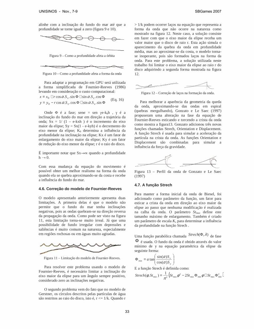
alinhe com a inclinação do fundo do mar até que a profundidade se torne igual a zero (figura 9 e 10).
Figura 9 – Como a profundidade afeta a órbita
Figura 10 – Como a profundidade afeta a forma da onda
Para adaptar a programação em GPU será utilizada a forma simplificada de Fournier-Reeves (1986) levando em consideração o custo computacional:
Φ+Φ−=Φ+Φ+=
sin..sincos..cos
cos..sinsin..cos
0
0
xz
zx
SSryy
SSrxx
αααα
(Eq. 16)
Onde
� é a fase; sen� = sen �e-k0h , � é a
inclinação do fundo do mar em direção a trajetória da onda; Sx = 1/ (1 – e-kxh ) é o incremento do eixo maior da elipse; Sy = Sx(1 - e-kyh) é o decremento do eixo menor da elipse; K0 determina a influência da profundidade na inclinação na elipse; Kx é um fator de enlargamento do eixo maior da elipse; Ky é um fator de redução do eixo menor da elipse; r é o raio do disco. É importante notar que Sx�� quando a profundidade h � 0. Com essa mudança da equação do movimento é possível obter um melhor realismo na forma da onda quando ela se quebra aproximando-se da costa e recebe a influência do fundo do mar. 4.6. Correção do modelo de Fournier-Reeves O modelo apresentado anteriormente apresenta duas limitações. A primeira delas é que o modelo não permite que o fundo do mar tenha inclinações negativas, pois as ondas quebram-se na direção reversa da propagação da onda. Como pode ser visto na figura 11, esta limitação torna-se muito irreal. Já que uma possibilidade de fundo irregular com depressões e saliências é muito comum na natureza, especialmente em regiões rochosas ou em águas muito agitadas.
Figura 11 – Limitação do modelo de Fournier-Reeves.
Para resolver este problema usando o modelo de Fournier-Reeves, é necessário limitar a inclinação do eixo maior da elipse para um ângulo sempre positivo, considerado zero as inclinações negativas. O segundo problema vem do fato que no modelo de Gerstner, os círculos descritos pelas partículas de água são restritos ao raio do disco, isto é, r <= 1/k. Quando r
> 1/k podem ocorrer laços na equação que representa a forma da onda que não ocorre na natureza como mostrado na figura 12. Neste caso, a solução consiste em fazer com que o eixo maior da elipse receba um valor maior que o disco de raio r. Esta ação simula o aparecimento da quebra da onda em profundidade média, mas ao aproximar-se da costa, o modelo torna-se inoperante, pois são formados laços na forma da onda. Para este problema, a solução utilizada neste trabalho foi limitar o eixo maior da elipse ao raio r do disco adquirindo a segunda forma mostrada na figura 12.
Figura 12 – Correção de laços na formação da onda.
Para melhorar a aparência da geometria da queda da onda, aproximando-se das ondas em espiral (quebras mergulhando), Gonzato e Le Saec (1997) propuseram uma alteração na fase da equação de Fournier-Reeves esticando e torcendo a crista da onda como mostra a figura13. Gonzato adicionou três novas funções chamadas Strech, Orientation e Displacement. A função Strech é usada para simular a aceleração da partícula na crista da onda. As funções Orientation e Displacement são combinadas para simular a influência da força da gravidade.
Figura 13 – Perfil da onda de Gonzato e Le Saec (1997) 4.7. A função Strech Para manter a forma inicial da onda de Biesel, foi adicionado como parâmetro da função, um fator para esticar a crista da onda em direção ao eixo maior da elipse ao passo que nenhuma modificação é realizada na calha da onda. O parâmetro Stmax define este tamanho máximo de enlargamento. Também é criado um parâmetro de escala Ks para determinar a influência da profundidade na função Strech .
Uma função parabólica chamada ),( λΦStrech de fase Φ é usada. O fundo da onda é obtido através do valor mínimo de y na equação paramétrica da elipse da seguinte forma:
=Φ
y
x
S
Sa
)cos(
)sin(tanmin α
α
E a função Strech é definida como:
( )2minmaxminmax
2max2max 2
1),( Φ+Φ−= StStStStStrech φφ
πφ
UNISINOS - Nov., 7-9 SBGames 2007
33
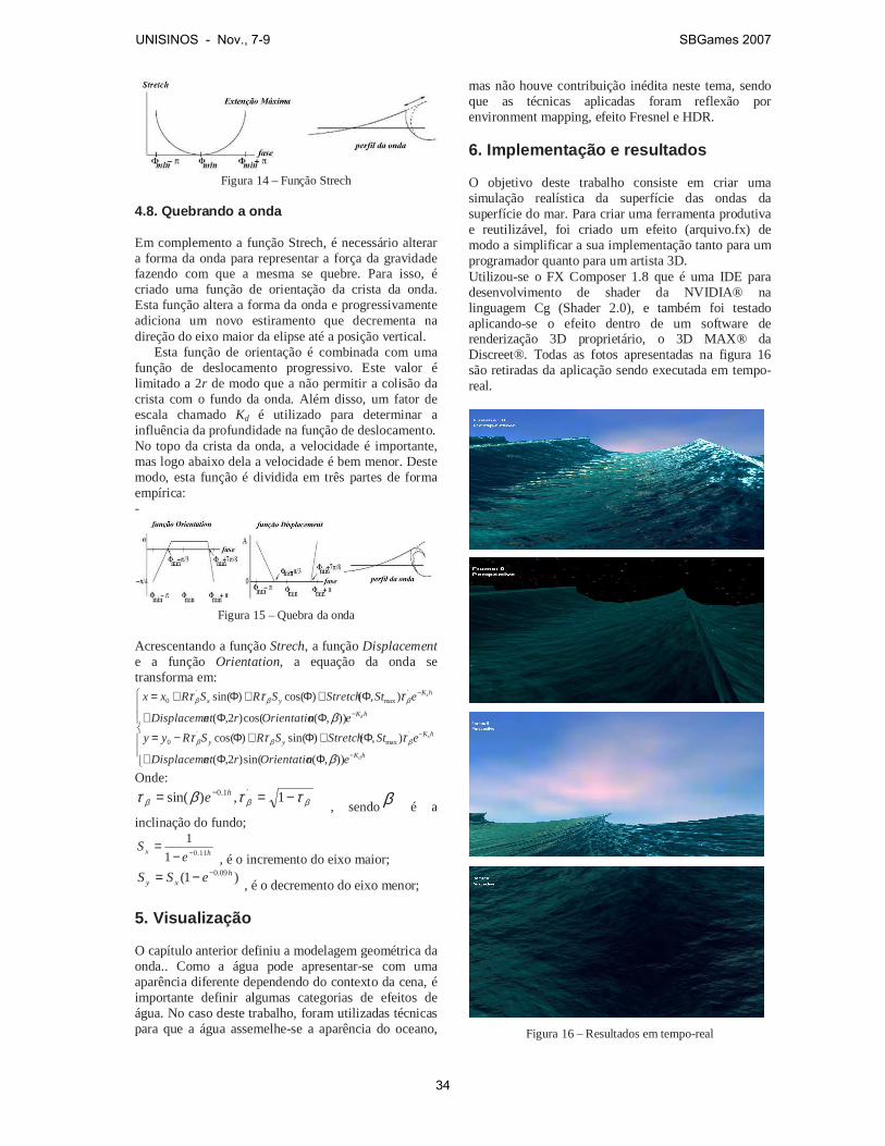
Figura 14 – Função Strech
4.8. Quebrando a onda Em complemento a função Strech, é necessário alterar a forma da onda para representar a força da gravidade fazendo com que a mesma se quebre. Para isso, é criado uma função de orientação da crista da onda. Esta função altera a forma da onda e progressivamente adiciona um novo estiramento que decrementa na direção do eixo maior da elipse até a posição vertical. Esta função de orientação é combinada com uma função de deslocamento progressivo. Este valor é limitado a 2r de modo que a não permitir a colisão da crista com o fundo da onda. Além disso, um fator de escala chamado Kd é utilizado para determinar a influência da profundidade na função de deslocamento. No topo da crista da onda, a velocidade é importante, mas logo abaixo dela a velocidade é bem menor. Deste modo, esta função é dividida em três partes de forma empírica: -
Figura 15 – Quebra da onda
Acrescentando a função Strech, a função Displacement e a função Orientation, a equação da onda se transforma em:
ΦΦ+
Φ+Φ+Φ−=
ΦΦ+
Φ+Φ+Φ+=
−
−
−
−
hK
hKyy
hK
hKyx
d
s
d
s
enOrientatiorntDisplaceme
eStStretchSRSRyy
enOrientatiorntDisplaceme
eStStretchSRSRxx
)),(sin()2,(
),()sin()cos(
)),(cos()2,(
),()cos()sin(
´max
´0
´max
´0
β
τττβ
τττ
βββ
βββ
Onde:
βββ ττβτ −== − 1,)sin( ´1.0 he , sendoβ é a
inclinação do fundo;
hxe
S11.01
1−−
= , é o incremento do eixo maior;
)1( 09.0 hxy eSS −−=
, é o decremento do eixo menor; 5. Visualização O capítulo anterior definiu a modelagem geométrica da onda.. Como a água pode apresentar-se com uma aparência diferente dependendo do contexto da cena, é importante definir algumas categorias de efeitos de água. No caso deste trabalho, foram utilizadas técnicas para que a água assemelhe-se a aparência do oceano,
mas não houve contribuição inédita neste tema, sendo que as técnicas aplicadas foram reflexão por environment mapping, efeito Fresnel e HDR. 6. Implementação e resultados O objetivo deste trabalho consiste em criar uma simulação realística da superfície das ondas da superfície do mar. Para criar uma ferramenta produtiva e reutilizável, foi criado um efeito (arquivo.fx) de modo a simplificar a sua implementação tanto para um programador quanto para um artista 3D. Utilizou-se o FX Composer 1.8 que é uma IDE para desenvolvimento de shader da NVIDIA® na linguagem Cg (Shader 2.0), e também foi testado aplicando-se o efeito dentro de um software de renderização 3D proprietário, o 3D MAX® da Discreet®. Todas as fotos apresentadas na figura 16 são retiradas da aplicação sendo executada em tempo-real.
Figura 16 – Resultados em tempo-real
UNISINOS - Nov., 7-9 SBGames 2007
34

Para visualizar a cena, foi utilizado um computador AMD Athlon XP 1800 com 512 RAM com uma placa de vídeo NVIDIA FX 5200 Shader 2.0. O shader foi programado de forma que alguns parâmetros pudessem ser configurados pelo usuário. Estes parâmetros definem o comportamento visual e físico da onda do mar. De forma empírica e visual foram configurados valores para estes parâmetros de forma a atingir o objetivo final de uma cena realista. Manipulando-se essas propriedades, é possível alterar a granularidade das ondas capilares; alterar a velocidade da partícula da água, alterar a contribuição da reflexão de Fresnel e HDR no cálculo da iluminação; criar ambientes noturnos, diurnos, sol, estrelas através do cubemap; alterar o período, a freqüência e raio da onda e controlar a contribuição do vento. 7. Conclusão Foi proposto um sistema de visualização tempo real para simulação de ondas oceânicas. Para alcançar um nível de simulação que caracterizasse uma aplicação em tempo real, todo o processamento e programação deste trabalho foi direcionado para a arquitetura e o hardware gráfico da GPU. Foi abordado o comportamento das ondas em águas profundas, águas rasas com a influência do fundo do mar sobre a forma destas ondas. Foi possível simular a modelagem geométrica baseada nas leis físicas e algumas configurações empíricas com atenção para as ondas se quebrando na costa oceânica. Simulou-se também a refração das ondas quando esta sente o fundo do mar e perde velocidade de fase de acordo com a lei de Snell Descartes, alterando as propriedades da onda tais como o comprimento de onda e velocidade, a medida que se aproxima da costa. Os resultados obtidos foram satisfatórios e convincentes quanto a visualização da superfície de um oceano com formação de ondas. Para aumentar o desempenho da renderização, pode-se acrescentar algoritmos de níveis de detalhe (LOD) para que os polígonos distantes da visão possam ser renderizados com menos detalhes (Bustamante e Celes, 2002). Para representar a topologia do fundo do mar que foi utilizado nas equações da onda, podería-se utilizar um mapa de altura que armazenasse estas informações. Assim o programa de vértice poderia ler este mapa e interpretar os valores tornando mais refinado a visualização. Entretanto, este recurso só é possível com o perfil do Shader 3.0 (Gerasimov, Fernando e Green, 2004) utilizando o recurso de Vertex Texture. Neste trabalho não foi gerado o efeito de espuma e bolhas na superfície das ondas. O que pode ser gerado utilizando a física de sistema de partículas e autômatos celulares. Pode-se também gerar o fenômeno de caustics que ocorre na superfície da água (Fernando, 2004).
A crista da onda ficou com uma aparência relativamente regular e reta que não existe na natureza da onda. Seria interessante criar irregularidades e ruídos na formação dessas cristas gerando padrões aleatórios utilizando a função noise. 8. Bibliografia (Adabala e Manobar, 2002) N. Adabala, S. Manohar, Techniques for realistic visualization of fluids: a survey, Comput. Graph. Forum volume 21 (1), pp. 65-81, 2002. (Biesel, 1952) F. Biesel, Study of wave propagation in water of gradually varying Depth, Gravity Waves, pp. 243-253, U.S. National Bureau of Standards Circular 521, 1952. (Blinn, 1978) J.F. Blinn, Simulation of wrinkled surfaces, Proceedings of SIGGRAPH’78, Comput. Graph, volume 12 (3), pp. 286–292. 1978. (Chen e Lobo, 1995) J. Chen, N. Lobo, Toward interactive-rate simulation of fluids with moving obstacles using navier-stokes equations, Graphical models and Image Processing, pp.107-116, (março 1995). (Chen, Lobo, Hughes e Moshell, 1997) J.X. Chen, N.V. Lobo, C.E. Hughes, J.M. Moshell, Real-time fluid simulation in a dynamic virtual environment, IEEE Comput.Graph. Appl., pp.52–61, (maio-junho 1997). (Fedkiw, Stam e Jensen, 2001) R .Fedkiw, J. Stam., H. W. Jensen. Visual Simulation of Smoke, Proceedings of SIGGRAPH 2001, pp. 15-22, 2001. (Ferwwerda, 1999) J.A. Ferwerda, Three varieties of realism in computer graphics, Cornell Workshop on Rendering, Perception and Measurement, 1999. (Fernando, 2004) R. Fernando. GPU Gems: Programming Techniques, Tips, and Tricks for Real-Time Graphics, Addison-Wesley Pub, 2004. (Fishman e Schachter, 1980) B. Fishman, B. Schachter, Computer display of height fields, Comput. Graph. 5 pp. 53–60, 1980. (Fournier e Reeves, 1986) A. Fournier, W. T. Reeves, A simple model of ocean waves, SIGGRAPH´86, volume 20, pp. 75-84, 1986. (Foster e Metaxas, 2000) N. Foster, D. Metaxas, Modeling water for computer animation, Commun. ACM volume 43 (7), pp. 60–67, 2000. (Foster e Fedkiw, 2001) N. Foster, R. Fedkiw, Practical Animation of Liquids, Proceedings of SIGGRAPH 2001, pp. 23-30, 2001.
UNISINOS - Nov., 7-9 SBGames 2007
35

(Geiger, Leo, Ramussen, Losasso e Fedkiw, 2006) Geiger, W., Leo, M., Rasmussen, N., Losasso, F. and Fedkiw, R., So Real It'll Make You Wet, SIGGRAPH 2006 Sketches and Applications, 2006. (Gerasimov, Fernando e Green, 2004) P. Gerasimov, R. Fernando, S. Green, Shader Model 3.0: Using Vertex Texture, NVidia Corporation, 2004. (Gerstner, 1809) F.J. Gerstner, Theorie der wellen, Ann. der Physik 32, pp. 412-440, 1809. (Gonzato, Le Saec, 2000) J.C. Gonzato, B. Le Saec, On Modeling and Rendering Ocean Scenes, Journal of Visualisation and Computer Simulation, 11, pp. 27-37, 2000. (Irving, Guendelman, Losasso e Fedkiw, 2006) Irving, G., Guendelman, E., Losasso, F. and Fedkiw, R., Efficient Simulation of Large Bodies of Water by Coupling Two and Three Dimensional Techniques, SIGGRAPH 2006, ACM TOG 25, pp. 805-811, 2006. (Imamiya e Zhang, 1995) A. Imamiya, D. Zhang, Modelling breaking ocean waves, influence of floor and refraction, Pacific Graphics 95, 1995. (Iglesias, 2004) A. Iglesias, Computer graphics for water modeling and rendering: a survey, Future Generation Computer System, volume 20 (8), pp. 1355-1374, (novembro 2004). (Kass e Miller, 1990) M. Kass, G. Miller, Rapid, stable fluid dynamics for computer graphics, ACM Press, New York, NY, USA, 1990. (Kinsman, 1965) B. Kinsman, Wind Waves: Their Generation and Propagation on the Ocean Surface, Prentice Hall, 1965. (Peachey, 1986) D. R. Peachey, Modeling waves and surf, SIGGRAPH´86, volume 20, pp. 65-70, 1986. (Reeves, 1983) W.T. Reeves, Particle systems—a technique for modeling a class of fuzzy objects,: Proceedings of SIGGRAPH’83, Comput. Graph. Volume 17 (3) pp. 359–376, 1983. (Sims, 1990) K. Sims, Particle animation and rendering using data parallel computation, Proceedings of SIGGRAPH’90, Comput.Graph. volume 24 (4), pp. 405–413, 1990. (Ts´o e Barsky, 1987) P. Y. Ts’o, B. A. Barsky, Modeling and rendering waves: Wave-tracing using beta-splines and reflective and refractive texture mapping,. ACM Transactions on Graphics, volume 6 pp. 191-214, (Julho 1987). (Tonnesen, 1991) D. Tonnesen, Modeling liquids and solids using thermal particles,: Proceedings of Graphics Interface’91, pp. 255–262, 1991.
(Tessendorf, 1999) J. Tessendorf, Simulating ocean water, SIGGRAPH’99 Course Notes, 1999. (Witting, 1999) P. Witting, Computational fluid dynamics in a traditional animation environment, in: Proceedings of SIGGRAPH’99, pp. 129–136, 1999. (Wloka, 2002) M. Wloka, Technical report: Fresnel Reflexion, NVIDIA Corporation, (Junho 2002).
UNISINOS - Nov., 7-9 SBGames 2007
36
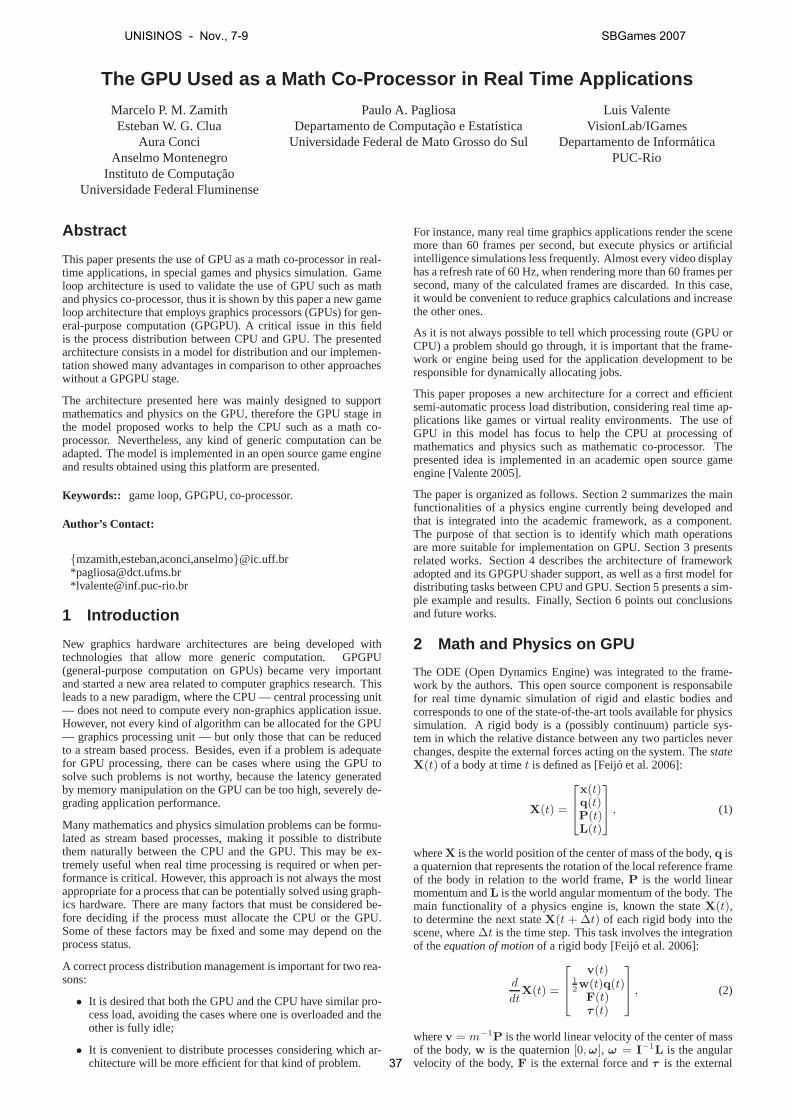
The GPU Used as a Math Co-Processor in Real Time Applications
Marcelo P. M. ZamithEsteban W. G. Clua
Aura ConciAnselmo Montenegro
Instituto de ComputacaoUniversidade Federal Fluminense
Paulo A. PagliosaDepartamento de Computacao e Estatıstica
Universidade Federal de Mato Grosso do Sul
Luis ValenteVisionLab/IGames
Departamento de InformaticaPUC-Rio
Abstract
This paper presents the use of GPU as a math co-processor in real-time applications, in special games and physics simulation. Gameloop architecture is used to validate the use of GPU such as mathand physics co-processor, thus it is shown by this paper a newgameloop architecture that employs graphics processors (GPUs)for gen-eral-purpose computation (GPGPU). A critical issue in thisfieldis the process distribution between CPU and GPU. The presentedarchitecture consists in a model for distribution and our implemen-tation showed many advantages in comparison to other approacheswithout a GPGPU stage.
The architecture presented here was mainly designed to supportmathematics and physics on the GPU, therefore the GPU stage inthe model proposed works to help the CPU such as a math co-processor. Nevertheless, any kind of generic computation can beadapted. The model is implemented in an open source game engineand results obtained using this platform are presented.
Keywords:: game loop, GPGPU, co-processor.
Author’s Contact:
{mzamith,esteban,aconci,anselmo}@ic.uff.br*[email protected]*[email protected]
1 Introduction
New graphics hardware architectures are being developed withtechnologies that allow more generic computation. GPGPU(general-purpose computation on GPUs) became very importantand started a new area related to computer graphics research. Thisleads to a new paradigm, where the CPU — central processing unit— does not need to compute every non-graphics application issue.However, not every kind of algorithm can be allocated for theGPU— graphics processing unit — but only those that can be reducedto a stream based process. Besides, even if a problem is adequatefor GPU processing, there can be cases where using the GPU tosolve such problems is not worthy, because the latency generatedby memory manipulation on the GPU can be too high, severely de-grading application performance.
Many mathematics and physics simulation problems can be formu-lated as stream based processes, making it possible to distributethem naturally between the CPU and the GPU. This may be ex-tremely useful when real time processing is required or whenper-formance is critical. However, this approach is not always the mostappropriate for a process that can be potentially solved using graph-ics hardware. There are many factors that must be consideredbe-fore deciding if the process must allocate the CPU or the GPU.Some of these factors may be fixed and some may depend on theprocess status.
A correct process distribution management is important fortwo rea-sons:
• It is desired that both the GPU and the CPU have similar pro-cess load, avoiding the cases where one is overloaded and theother is fully idle;
• It is convenient to distribute processes considering whichar-chitecture will be more efficient for that kind of problem.
For instance, many real time graphics applications render the scenemore than 60 frames per second, but execute physics or artificialintelligence simulations less frequently. Almost every video displayhas a refresh rate of 60 Hz, when rendering more than 60 framespersecond, many of the calculated frames are discarded. In thiscase,it would be convenient to reduce graphics calculations and increasethe other ones.
As it is not always possible to tell which processing route (GPU orCPU) a problem should go through, it is important that the frame-work or engine being used for the application development toberesponsible for dynamically allocating jobs.
This paper proposes a new architecture for a correct and efficientsemi-automatic process load distribution, considering real time ap-plications like games or virtual reality environments. Theuse ofGPU in this model has focus to help the CPU at processing ofmathematics and physics such as mathematic co-processor. Thepresented idea is implemented in an academic open source gameengine [Valente 2005].
The paper is organized as follows. Section 2 summarizes the mainfunctionalities of a physics engine currently being developed andthat is integrated into the academic framework, as a component.The purpose of that section is to identify which math operationsare more suitable for implementation on GPU. Section 3 presentsrelated works. Section 4 describes the architecture of frameworkadopted and its GPGPU shader support, as well as a first model fordistributing tasks between CPU and GPU. Section 5 presents asim-ple example and results. Finally, Section 6 points out conclusionsand future works.
2 Math and Physics on GPU
The ODE (Open Dynamics Engine) was integrated to the frame-work by the authors. This open source component is responsabilefor real time dynamic simulation of rigid and elastic bodiesandcorresponds to one of the state-of-the-art tools availablefor physicssimulation. A rigid body is a (possibly continuum) particlesys-tem in which the relative distance between any two particlesneverchanges, despite the external forces acting on the system. ThestateX(t) of a body at timet is defined as [Feijo et al. 2006]:
X(t) =
x(t)q(t)P(t)L(t)
, (1)
whereX is the world position of the center of mass of the body,q isa quaternion that represents the rotation of the local reference frameof the body in relation to the world frame,P is the world linearmomentum andL is the world angular momentum of the body. Themain functionality of a physics engine is, known the stateX(t),to determine the next stateX(t + ∆t) of each rigid body into thescene, where∆t is the time step. This task involves the integrationof theequation of motionof a rigid body [Feijo et al. 2006]:
d
dtX(t) =
v(t)1
2w(t)q(t)F(t)τ (t)
, (2)
wherev = m−1P is the world linear velocity of the center of massof the body,w is the quaternion[0, ω], ω = I−1L is the angularvelocity of the body,F is the external force andτ is the external
UNISINOS - Nov., 7-9 SBGames 2007
37
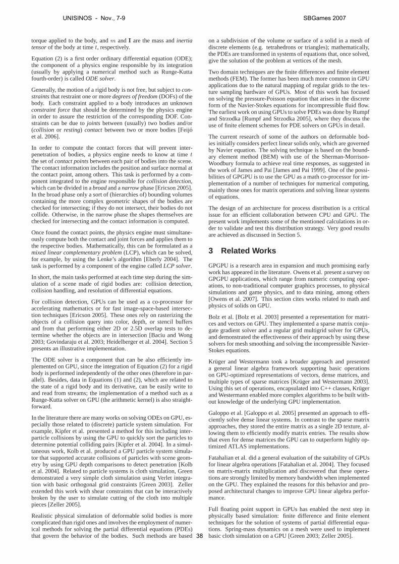
torque applied to the body, andm andI are the mass andinertiatensorof the body at timet, respectively.
Equation (2) is a first order ordinary differential equation(ODE);the component of a physics engine responsible by its integration(usually by applying a numerical method such as Runge-Kuttafourth-order) is calledODE solver.
Generally, the motion of a rigid body is not free, but subjectto con-straintsthat restraint one or moredegrees of freedom(DOFs) of thebody. Each constraint applied to a body introduces an unknownconstraint forcethat should be determined by the physics enginein order to assure the restriction of the corresponding DOF.Con-straints can be due tojoints between (usually) two bodies and/or(collision or resting) contactbetween two or more bodies [Feijoet al. 2006].
In order to compute the contact forces that will prevent inter-penetration of bodies, a physics engine needs to know at timetthe set ofcontact pointsbetween each pair of bodies into the scene.The contact information includes the position and surface normal atthe contact point, among others. This task is performed by a com-ponent integrated to the engine responsible forcollision detection,which can be divided in abroadand anarrowphase [Ericson 2005].In the broad phase only a sort of (hierarchies of) bounding volumescontaining the more complex geometric shapes of the bodies arechecked for intersecting; if they do not intersect, their bodies do notcollide. Otherwise, in the narrow phase the shapes themselves arechecked for intersecting and the contact information is computed.
Once found the contact points, the physics engine must simultane-ously compute both the contact and joint forces and applies them tothe respective bodies. Mathematically, this can be formulated as amixed linear complementary problem(LCP), which can be solved,for example, by using the Lenke’s algorithm [Eberly 2004]. Thetask is performed by a component of the engine calledLCP solver.
In short, the main tasks performed at each time step during the sim-ulation of a scene made of rigid bodies are: collision detection,collision handling, and resolution of differential equations.
For collision detection, GPUs can be used as a co-processor foraccelerating mathematics or for fast image-space-based intersec-tion techniques [Ericson 2005]. These ones rely on rasterizing theobjects of a collision query into color, depth, or stencil buffersand from that performing either 2D or 2.5D overlap tests to de-termine whether the objects are in intersection [Baciu and Wong2003; Govindaraju et al. 2003; Heidelberger et al. 2004]. Section 5presents an illustrative implementation.
The ODE solver is a component that can be also efficiently im-plemented on GPU, since the integration of Equation (2) for arigidbody is performed independently of the other ones (therefore in par-allel). Besides, data in Equations (1) and (2), which are related tothe state of a rigid body and its derivative, can be easily write toand read from streams; the implementation of a method such asaRunge-Kutta solver on GPU (the arithmetic kernel) is also straight-forward.
In the literature there are many works on solving ODEs on GPU,es-pecially those related to (discrete) particle system simulation. Forexample, Kipfer et al. presented a method for this includinginter-particle collisions by using the GPU to quickly sort the particles todetermine potential colliding pairs [Kipfer et al. 2004]. In a simul-taneous work, Kolb et al. produced a GPU particle system simula-tor that supported accurate collisions of particles with scene geom-etry by using GPU depth comparisons to detect penetration [Kolbet al. 2004]. Related to particle systems is cloth simulation, Greendemonstrated a very simple cloth simulation using Verlet integra-tion with basic orthogonal grid constraints [Green 2003]. Zellerextended this work with shear constraints that can be interactivelybroken by the user to simulate cutting of the cloth into multiplepieces [Zeller 2005].
Realistic physical simulation of deformable solid bodies is morecomplicated than rigid ones and involves the employment of numer-ical methods for solving the partial differential equations (PDEs)that govern the behavior of the bodies. Such methods are based
on a subdivision of the volume or surface of a solid in a mesh ofdiscrete elements (e.g. tetrahedrons or triangles); mathematically,the PDEs are transformed in systems of equations that, once solved,give the solution of the problem at vertices of the mesh.
Two domain techniques are the finite differences and finite elementmethods (FEM). The former has been much more common in GPUapplications due to the natural mapping of regular grids to the tex-ture sampling hardware of GPUs. Most of this work has focusedon solving the pressure-Poisson equation that arises in thediscreteform of the Navier-Stokes equations for incompressible fluid flow.The earliest work on using GPUs to solve PDEs was done by Rumpfand Strzodka [Rumpf and Strzodka 2005], where they discuss theuse of finite element schemes for PDE solvers on GPUs in detail.
The current research of some of the authors on deformable bod-ies initially considers perfect linear solids only, which are governedby Navier equation. The solving technique is based on the bound-ary element method (BEM) with use of the Sherman-Morrison-Woodbury formula to achieve real time responses, as suggested inthe work of James and Pai [James and Pai 1999]. One of the possi-bilities of GPGPU is to use the GPU as a math co-processor for im-plementation of a number of techniques for numerical computing,mainly those ones for matrix operations and solving linear systemsof equations.
The design of an architecture for process distribution is a criticalissue for an efficient collaboration between CPU and GPU. Thepresent work implements some of the mentioned calculationsin or-der to validate and test this distribution strategy. Very good resultsare achieved as discussed in Section 5.
3 Related Works
GPGPU is a research area in expansion and much promising earlywork has appeared in the literature. Owens et al. present a survey onGPGPU applications, which range from numeric computing oper-ations, to non-traditional computer graphics processes, to physicalsimulations and game physics, and to data mining, among others[Owens et al. 2007]. This section cites works related to mathandphysics of solids on GPU.
Bolz et al. [Bolz et al. 2003] presented a representation formatri-ces and vectors on GPU. They implemented a sparse matrix conju-gate gradient solver and a regular grid multigrid solver forGPUs,and demonstrated the effectiveness of their approach by using thesesolvers for mesh smoothing and solving the incompressible Navier-Stokes equations.
Kruger and Westermann took a broader approach and presenteda general linear algebra framework supporting basic operationson GPU-optimized representations of vectors, dense matrices, andmultiple types of sparse matrices [Kruger and Westermann 2003].Using this set of operations, encapsulated into C++ classes, Krugerand Westermann enabled more complex algorithms to be built with-out knowledge of the underlying GPU implementation.
Galoppo et al. [Galoppo et al. 2005] presented an approach toeffi-ciently solve dense linear systems. In contrast to the sparse matrixapproaches, they stored the entire matrix as a single 2D texture, al-lowing them to efficiently modify matrix entries. The results showthat even for dense matrices the GPU can to outperform highlyop-timized ATLAS implementations.
Fatahalian et al. did a general evaluation of the suitability of GPUsfor linear algebra operations [Fatahalian et al. 2004]. They focusedon matrix-matrix multiplication and discovered that theseopera-tions are strongly limited by memory bandwidth when implementedon the GPU. They explained the reasons for this behavior and pro-posed architectural changes to improve GPU linear algebra perfor-mance.
Full floating point support in GPUs has enabled the next step inphysically based simulation: finite difference and finite elementtechniques for the solution of systems of partial differential equa-tions. Spring-mass dynamics on a mesh were used to implementbasic cloth simulation on a GPU [Green 2003; Zeller 2005].
UNISINOS - Nov., 7-9 SBGames 2007
38
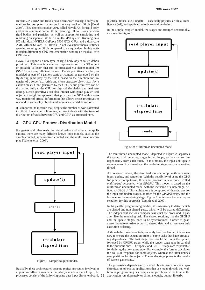
Recently, NVIDIA and Havok have been shown that rigid body sim-ulations for computer games perform very well on GPUs [Bond2006]. They demonstrated an API, called Havok FX, for rigid bodyand particle simulation on GPUs, featuring full collisionsbetweenrigid bodies and particles, as well as support for simulating andrendering on separate GPUs in a multi-GPU system. Running onaPC with dual NVIDIA GeForce 7900 GTX GPUs and a dual-coreAMD Athlon 64 X2 CPU, Havok FX achieves more than a 10 timesspeedup running on GPUs compared to an equivalent, highly opti-mized multithreaded CPU implementation running on the dual-coreCPU alone.
Havok FX supports a new type of rigid body object called debrisprimitive. This one is a compact representation of a 3D objecton possible collision that can be processed via shader model3.0(SM3.0) in a very efficient manner. Debris primitives can be pre-modeled as part of a game’s static art content or generated onthefly during game play by the CPU, based on the direction and in-tensity of a force (e.g. brick and stone structure blown apart by acannon blast). Once generated by the CPU, debris primitivescan bedispatched fully to the GPU for physical simulation and finalren-dering. Debris primitives can also interact with game-playcriticalobjects, through an approach that provides the GPU with a one-way transfer of critical information that allows debris primitives torespond to game-play objects and large-scale world definitions.
It is important to mention that, despite the number of works devotedto GPGPU available in literature, no work deals with the issue ofdistribution of tasks between CPU and GPU, as proposed here.
4 GPU-CPU Process Distribution Model
For games and other real-time visualization and simulationappli-cations, there are many different known loop models, such asthesimple coupled, synchronized coupled and the multithread uncou-pled [Valente et al. 2005].
r e a d p l a y e r i n p u t
u p d a t e ( t )
t = c a l u l a t e e l a p s e d t i m e
r e n d e r
Figure 1: Simple coupled model.
Basically, these architectures arrange typical processesinvolved ina game in different manners, but always inside a main loop. Theprocesses consist of the following ones: data input (from keyboard,
joystick, mouse, etc.), update — especially physics, artificial intel-ligence (AI), and application logic — and rendering.
In the simple coupled model, the stages are arranged sequentially,as shown in Figure 1.
r e a d p l a y e r i n p u t
u p d a t e ( t )
t = c a l u l a t e e l a p s e d t i m e
r e n d e r
Figure 2: Multithread uncoupled model.
The multithread uncoupled model, depicted in Figure 2, separatesthe update and rendering stages in two loops, so they can run in-dependently from each other. In this model, the input and updatestages can run in a thread, and the rendering stage can run in anotherthread.
As presented before, the described models comprise three stages:input, update, and rendering. With the possibility of usingthe GPUfor generic computation, this paper proposes a new model, calledmultithread uncoupled with GPGPU. This model is based on themultithread uncoupled model with the inclusion of a new stage, de-fined as GPGPU. This architecture is composed of threads, oneforthe input and update stages, another for the GPGPU stage, andthelast one for the rendering stage. Figure 3 depicts a schematic repre-sentation for this approach [Zamith et al. 2007].
In the parallel programming models, it is necessary to detect whichare shared and non-shared parts, which will be treated differently.The independent sections compose tasks that are processed in par-allel, like the rendering task. The shared sections, like the GPGPUand the update stages, need to be synchronized in order to guar-antee mutual-exclusive access to shared data and to preserve taskexecution ordering.
Although the threads run independently from each other, it is neces-sary to ensure the execution order of some tasks that have process-ing dependence. The first stage that should be run is the update,followed by GPGPU stage, while the render stage runs in parallelto the previous ones. The update and GPGPU stages are responsiblefor defining the new game state. For example, the former calculatesthe collision response for some objects, whereas the latterdefinesnew positions for the objects. The render stage presents theresultsof current game state.
The processing dependence of shared objects needs to use a syn-chronization object, as applications that use many threadsdo. Mul-tithread programming is a complex subject, because the tasks in theapplication run alternately or simultaneously, but not linearly.
UNISINOS - Nov., 7-9 SBGames 2007
39
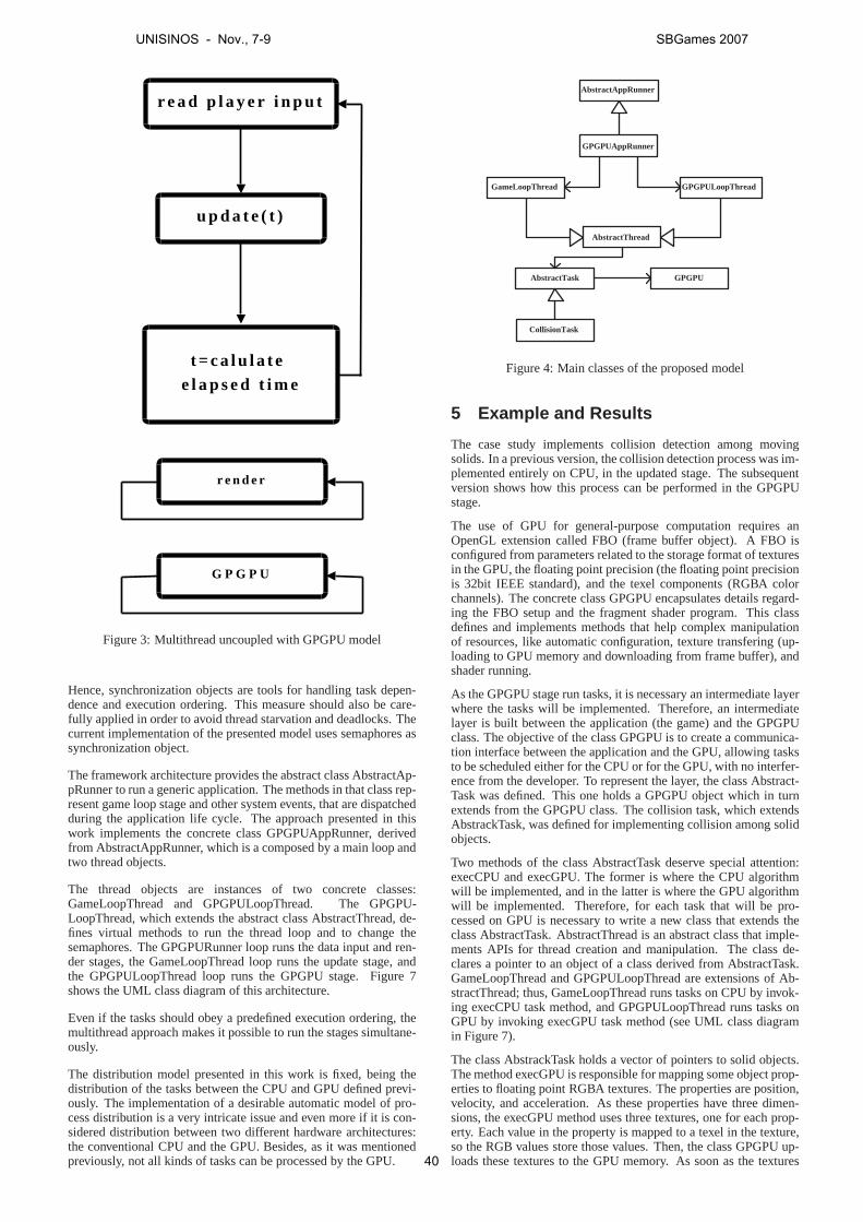
r e a d p l a y e r i n p u t
u p d a t e ( t )
t = c a l u l a t e e l a p s e d t i m e
r e n d e r
G P G P U
Figure 3: Multithread uncoupled with GPGPU model
Hence, synchronization objects are tools for handling taskdepen-dence and execution ordering. This measure should also be care-fully applied in order to avoid thread starvation and deadlocks. Thecurrent implementation of the presented model uses semaphores assynchronization object.
The framework architecture provides the abstract class AbstractAp-pRunner to run a generic application. The methods in that class rep-resent game loop stage and other system events, that are dispatchedduring the application life cycle. The approach presented in thiswork implements the concrete class GPGPUAppRunner, derivedfrom AbstractAppRunner, which is a composed by a main loop andtwo thread objects.
The thread objects are instances of two concrete classes:GameLoopThread and GPGPULoopThread. The GPGPU-LoopThread, which extends the abstract class AbstractThread, de-fines virtual methods to run the thread loop and to change thesemaphores. The GPGPURunner loop runs the data input and ren-der stages, the GameLoopThread loop runs the update stage, andthe GPGPULoopThread loop runs the GPGPU stage. Figure 7shows the UML class diagram of this architecture.
Even if the tasks should obey a predefined execution ordering, themultithread approach makes it possible to run the stages simultane-ously.
The distribution model presented in this work is fixed, beingthedistribution of the tasks between the CPU and GPU defined previ-ously. The implementation of a desirable automatic model ofpro-cess distribution is a very intricate issue and even more if it is con-sidered distribution between two different hardware architectures:the conventional CPU and the GPU. Besides, as it was mentionedpreviously, not all kinds of tasks can be processed by the GPU.
GPGPUAppRunner
AbstractAppRunner
GameLoopThread GPGPULoopThread
AbstractThread
GPGPU AbstractTask
CollisionTask
Figure 4: Main classes of the proposed model
5 Example and Results
The case study implements collision detection among movingsolids. In a previous version, the collision detection process was im-plemented entirely on CPU, in the updated stage. The subsequentversion shows how this process can be performed in the GPGPUstage.
The use of GPU for general-purpose computation requires anOpenGL extension called FBO (frame buffer object). A FBO isconfigured from parameters related to the storage format of texturesin the GPU, the floating point precision (the floating point precisionis 32bit IEEE standard), and the texel components (RGBA colorchannels). The concrete class GPGPU encapsulates details regard-ing the FBO setup and the fragment shader program. This classdefines and implements methods that help complex manipulationof resources, like automatic configuration, texture transfering (up-loading to GPU memory and downloading from frame buffer), andshader running.
As the GPGPU stage run tasks, it is necessary an intermediatelayerwhere the tasks will be implemented. Therefore, an intermediatelayer is built between the application (the game) and the GPGPUclass. The objective of the class GPGPU is to create a communica-tion interface between the application and the GPU, allowing tasksto be scheduled either for the CPU or for the GPU, with no interfer-ence from the developer. To represent the layer, the class Abstract-Task was defined. This one holds a GPGPU object which in turnextends from the GPGPU class. The collision task, which extendsAbstrackTask, was defined for implementing collision amongsolidobjects.
Two methods of the class AbstractTask deserve special attention:execCPU and execGPU. The former is where the CPU algorithmwill be implemented, and in the latter is where the GPU algorithmwill be implemented. Therefore, for each task that will be pro-cessed on GPU is necessary to write a new class that extends theclass AbstractTask. AbstractThread is an abstract class that imple-ments APIs for thread creation and manipulation. The class de-clares a pointer to an object of a class derived from AbstractTask.GameLoopThread and GPGPULoopThread are extensions of Ab-stractThread; thus, GameLoopThread runs tasks on CPU by invok-ing execCPU task method, and GPGPULoopThread runs tasks onGPU by invoking execGPU task method (see UML class diagramin Figure 7).
The class AbstrackTask holds a vector of pointers to solid objects.The method execGPU is responsible for mapping some object prop-erties to floating point RGBA textures. The properties are position,velocity, and acceleration. As these properties have threedimen-sions, the execGPU method uses three textures, one for each prop-erty. Each value in the property is mapped to a texel in the texture,so the RGB values store those values. Then, the class GPGPU up-loads these textures to the GPU memory. As soon as the textures
UNISINOS - Nov., 7-9 SBGames 2007
40
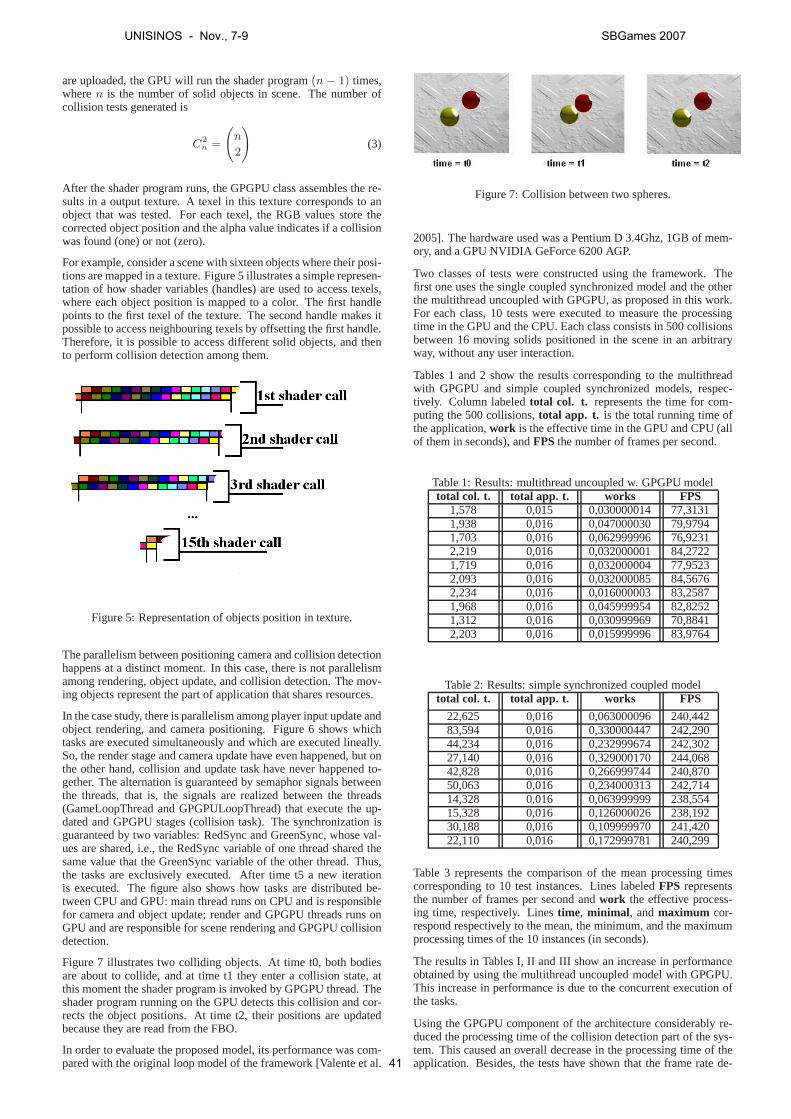
are uploaded, the GPU will run the shader program(n − 1) times,wheren is the number of solid objects in scene. The number ofcollision tests generated is
C2
n=
(
n
2
)
(3)
After the shader program runs, the GPGPU class assembles there-sults in a output texture. A texel in this texture corresponds to anobject that was tested. For each texel, the RGB values store thecorrected object position and the alpha value indicates if acollisionwas found (one) or not (zero).
For example, consider a scene with sixteen objects where their posi-tions are mapped in a texture. Figure 5 illustrates a simple represen-tation of how shader variables (handles) are used to access texels,where each object position is mapped to a color. The first handlepoints to the first texel of the texture. The second handle makes itpossible to access neighbouring texels by offsetting the first handle.Therefore, it is possible to access different solid objects, and thento perform collision detection among them.
Figure 5: Representation of objects position in texture.
The parallelism between positioning camera and collision detectionhappens at a distinct moment. In this case, there is not parallelismamong rendering, object update, and collision detection. The mov-ing objects represent the part of application that shares resources.
In the case study, there is parallelism among player input update andobject rendering, and camera positioning. Figure 6 shows whichtasks are executed simultaneously and which are executed lineally.So, the render stage and camera update have even happened, but onthe other hand, collision and update task have never happened to-gether. The alternation is guaranteed by semaphor signals betweenthe threads, that is, the signals are realized between the threads(GameLoopThread and GPGPULoopThread) that execute the up-dated and GPGPU stages (collision task). The synchronization isguaranteed by two variables: RedSync and GreenSync, whose val-ues are shared, i.e., the RedSync variable of one thread shared thesame value that the GreenSync variable of the other thread. Thus,the tasks are exclusively executed. After time t5 a new iterationis executed. The figure also shows how tasks are distributed be-tween CPU and GPU: main thread runs on CPU and is responsiblefor camera and object update; render and GPGPU threads runs onGPU and are responsible for scene rendering and GPGPU collisiondetection.
Figure 7 illustrates two colliding objects. At time t0, bothbodiesare about to collide, and at time t1 they enter a collision state, atthis moment the shader program is invoked by GPGPU thread. Theshader program running on the GPU detects this collision andcor-rects the object positions. At time t2, their positions are updatedbecause they are read from the FBO.
In order to evaluate the proposed model, its performance wascom-pared with the original loop model of the framework [Valenteet al.
Figure 7: Collision between two spheres.
2005]. The hardware used was a Pentium D 3.4Ghz, 1GB of mem-ory, and a GPU NVIDIA GeForce 6200 AGP.
Two classes of tests were constructed using the framework. Thefirst one uses the single coupled synchronized model and the otherthe multithread uncoupled with GPGPU, as proposed in this work.For each class, 10 tests were executed to measure the processingtime in the GPU and the CPU. Each class consists in 500 collisionsbetween 16 moving solids positioned in the scene in an arbitraryway, without any user interaction.
Tables 1 and 2 show the results corresponding to the multithreadwith GPGPU and simple coupled synchronized models, respec-tively. Column labeledtotal col. t. represents the time for com-puting the 500 collisions,total app. t. is the total running time ofthe application,work is the effective time in the GPU and CPU (allof them in seconds), andFPS the number of frames per second.
Table 1: Results: multithread uncoupled w. GPGPU modeltotal col. t. total app. t. works FPS
1,578 0,015 0,030000014 77,31311,938 0,016 0,047000030 79,97941,703 0,016 0,062999996 76,92312,219 0,016 0,032000001 84,27221,719 0,016 0,032000004 77,95232,093 0,016 0,032000085 84,56762,234 0,016 0,016000003 83,25871,968 0,016 0,045999954 82,82521,312 0,016 0,030999969 70,88412,203 0,016 0,015999996 83,9764
Table 2: Results: simple synchronized coupled modeltotal col. t. total app. t. works FPS
22,625 0,016 0,063000096 240,44283,594 0,016 0,330000447 242,29044,234 0,016 0,232999674 242,30227,140 0,016 0,329000170 244,06842,828 0,016 0,266999744 240,87050,063 0,016 0,234000313 242,71414,328 0,016 0,063999999 238,55415,328 0,016 0,126000026 238,19230,188 0,016 0,109999970 241,42022,110 0,016 0,172999781 240,299
Table 3 represents the comparison of the mean processing timescorresponding to 10 test instances. Lines labeledFPS representsthe number of frames per second andwork the effective process-ing time, respectively. Linestime, minimal, andmaximum cor-respond respectively to the mean, the minimum, and the maximumprocessing times of the 10 instances (in seconds).
The results in Tables I, II and III show an increase in performanceobtained by using the multithread uncoupled model with GPGPU.This increase in performance is due to the concurrent execution ofthe tasks.
Using the GPGPU component of the architecture considerablyre-duced the processing time of the collision detection part ofthe sys-tem. This caused an overall decrease in the processing time of theapplication. Besides, the tests have shown that the frame rate de-
UNISINOS - Nov., 7-9 SBGames 2007
41

time main thread Render thread GPGPU thread
t0
t1
t2
t3
t4
t5
t6
Start application GameThreadLoop.RedSync = GPGPUThreadLoop.GreenSync GameThreadLoop.GreenSync = GPGPUThreadLoop.RedSync
render
render
render
render
render
render
update.camera()
If (GPGPUThreadLoop.Red) testCollision() signal(GPGPUThreadLoop.GreenSync) end If
If (GPGPUThreadLoop.Red) testCollision() signal(GPGPUThreadLoop.GreenSync) end If
If (GameThreadLoop.Red) update.objects() signal(GameThreadLoop.GreenSync) end If
If (GameThreadLoop.Red) update.objects() signal(GameThreadLoop.GreenSync) end If
update.camera()
update.camera()
update.camera()
Figure 6: Task parallelism representation
Table 3: GPU and CPU comparativesGPU CPU
FPS 80,1952100 241,1151000works 0,0345000 0,1929000time 1,8967000 35,2438000
minimal 0,0160000 0,0630001maximum 0,0630000 0,3300004
crease, to enable GPGPU processing, did not affect the quality ofthe animation, which was preserved.
6 Conclusions and Future Work
Balancing the load between CPU and GPU is an interesting ap-proach for achieving a better use of the computational resources ina game or virtual and augmented reality applications. By doing thisit is possible to dedicate the additional free computational power toother tasks as AI and complex physics, which could not be doneinmore rigid or sequential architectures.
This work has demonstrated this possibility by introducinga newstage in a multithread uncoupled game engine architecture,which isresponsible for general-purpose processing on the GPU. As it wasexemplified by a solution for the collision detection problem, it ispossible to use this same approach for other problems and tasks asAI and those listed in Section 2, which can be also processed inthis component of the architecture by the GPU. In order to do thisit suffices to do the correct mapping of the objects to the appro-priate textures and design the corresponding shader responsible forimplementing the algorithm associated to the solution.
The results tabled in Section 5 demonstrate that the use of GPUfor general-purpose computation is a promising way to increase theperformance in game engines, virtual and augmented realitysys-tems, and other similar simulation applications.
In the most recent graphics processors, as the GeForce 8 series, it ispossible to use one of its GPUs for running a thread responsible formanaging the load balancing between CPU and GPU. The authorsintend to pursue this direction in a future work. Another point to
be investigated is how to detect in a more automatic way whichprocesses are appropriate for CPU or GPU allocation.
References
BACIU , G., AND WONG, W. S. K. 2003. Image-based techniquesin a hybrid collision detector.IEEE Transactions on Visualiza-tion and Computer Graphics 9, 2, 254–271.
BOLZ, J., FARMER, I., GRISPUN, E., AND SCHRODER, P. 2003.Sparse matrix solvers on the GPU: conjugate gradients andmultigrid. ACM Transactions on Graphics 22, 3, 917–924.
BOND, A. 2006. Havok FX: GPU-accelerated physics for PCgames. InProceedings of Game Developers Conference 2006.Available atwww.havok.com/content/view/187/77/.
EBERLY, D. H. 2004.Game Physics. Morgan Kaufmann.
ERICSON, C. 2005.Real-Time Collision Detection. Morgan Kauf-mann.
FATAHALIAN , K., SUGERMAN, J., AND HANRAHAN , P. 2004.Understanding the efficiency of GPU algorithms for matrix-matrix multiplication. InGraphics Hardware 2004, 133–138.
FEIJO, B., PAGLIOSA, P. A., AND CLUA , E. W. G. 2006.Visualizacao, simulacao e games. InAtualizacoes em In-formatica, K. Breitman and R. Anido, Eds. Editora PUC-Rio,127–185. (In Portuguese).
GALOPPO, N., GOVINDARAJU, N. K., HENSON, M., ANDMANOCHA, D. 2005. LU-GPU: efficient algorithms for solvingdense linear systems on graphics hardware. InProceedings ofthe ACM/IEEE Conference on Supercomputing, 3–14.
GOVINDARAJU, N. K., REDON, S., LIN , M. C., ANDMANOCHA, D. 2003. CULLIDE: interactive collision detectionbetween complex models in large environments using graphicshardware. InGraphics Hardware 2003, 25–32.
GREEN, S., 2003. NVIDIA cloth sample. Available atdownload.developer.nvidia.com/developer/
UNISINOS - Nov., 7-9 SBGames 2007
42

SDK/ Individual Samples/ samples.html#glsl physics.
HEIDELBERGER, B., TESCHNER, M., AND GROSS, M. 2004. De-tection of collisions and self-collisions using image-space tech-niques.Journal of WSCG 12, 3, 145–152.
JAMES, D. L., AND PAI , D. K. 1999. Accurate real time de-formable objects. InProceedings of ACM SIGGRAPH 99, 65–72.
K IPFER, P., SEGAL, M., AND WESTERMANN, R. 2004. Uber-Flow: a GPU-based particle engine. InGraphics Hardware2004, 115–122.
KOLB, A., LATTA , L., AND RESK-SALAMA , C. 2004. Hardware-based simulation and collision detection for large particle sys-tems. InGraphics Hardware 2004, 123–132.
KRUGER, J., AND WESTERMANN, R. 2003. Linear algebra op-erators for GPU implementation of numerical algorithms.ACMTransactions on Graphics 22, 3, 908–916.
OWENS, J. D., LEUBKE, D., GOVINDARAJU, N., HARRIS, M.,KRUGER, J., LEFOHN, A. E., AND PURCELL, T. J. 2007. Asurvey of general-purpose computation on graphics hardware.Computer Graphics Forum 26. To appear.
RUMPF, M., AND STRZODKA, R. 2005. Graphics processor units:New prospects for parallel computing. InNumerical Solutionof Partial Differential Equations on Parallel Computers, vol. 51of Lecture Notes in Computational Science and Engineering.Springer-Verlag, 89–134.
VALENTE, L., CONCI, A., AND FEIJO, B. 2005. Real time gameloop models for single-player computer games. InProceedingsof the IV Brazilian Symposium on Computer Games and DigitalEntertainment, 89–99.
VALENTE, L. 2005. Guff: um framework para desenvolvimentode jogos. Master’s thesis, Universidade Federal Fluminense. (InPortuguese).
ZAMITH , M. P. M., CLUA , E. W. G., CONCI, A., MOTENEGRO,A., PAGLIOSA, P. A., AND VALENTE, L. 2007. Parallel pro-cessing between gpu and cpu: Concepts in a game architecture.IEEE Computer Society, 115–120. ISBN: 0-7695-2928-3.
ZELLER, C. 2005. Cloth simulation on the GPU. InACM SIG-GRAPH 05: ACM SIGGRAPH 2005 Sketches.
UNISINOS - Nov., 7-9 SBGames 2007
43
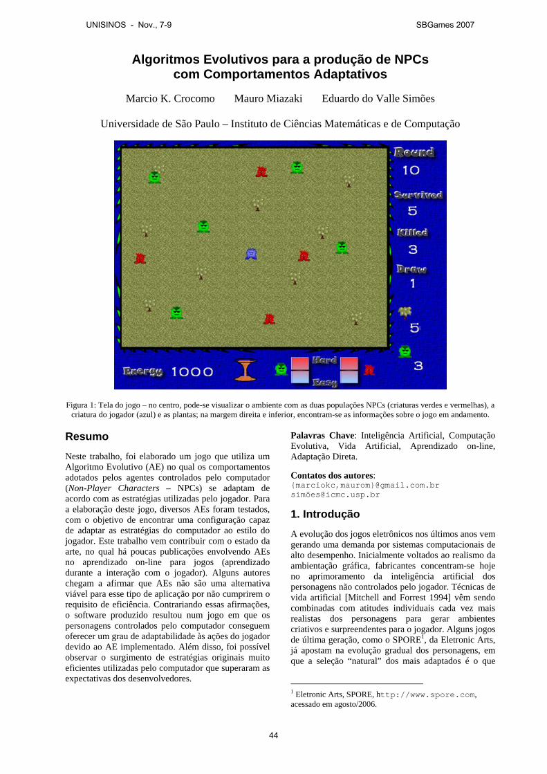
Algoritmos Evolutivos para a produção de NPCs com Comportamentos Adaptativos
Marcio K. Crocomo Mauro Miazaki Eduardo do Valle Simões
Universidade de São Paulo – Instituto de Ciências Matemáticas e de Computação
Figura 1: Tela do jogo – no centro, pode-se visualizar o ambiente com as duas populações NPCs (criaturas verdes e vermelhas), a
criatura do jogador (azul) e as plantas; na margem direita e inferior, encontram-se as informações sobre o jogo em andamento. Resumo
Neste trabalho, foi elaborado um jogo que utiliza um Algoritmo Evolutivo (AE) no qual os comportamentos adotados pelos agentes controlados pelo computador (Non-Player Characters – NPCs) se adaptam de acordo com as estratégias utilizadas pelo jogador. Para a elaboração deste jogo, diversos AEs foram testados, com o objetivo de encontrar uma configuração capaz de adaptar as estratégias do computador ao estilo do jogador. Este trabalho vem contribuir com o estado da arte, no qual há poucas publicações envolvendo AEs no aprendizado on-line para jogos (aprendizado durante a interação com o jogador). Alguns autores chegam a afirmar que AEs não são uma alternativa viável para esse tipo de aplicação por não cumprirem o requisito de eficiência. Contrariando essas afirmações, o software produzido resultou num jogo em que os personagens controlados pelo computador conseguem oferecer um grau de adaptabilidade às ações do jogador devido ao AE implementado. Além disso, foi possível observar o surgimento de estratégias originais muito eficientes utilizadas pelo computador que superaram as expectativas dos desenvolvedores.
Palavras Chave: Inteligência Artificial, Computação Evolutiva, Vida Artificial, Aprendizado on-line, Adaptação Direta.
Contatos dos autores: {marciokc,maurom}@gmail.com.br simõ[email protected]
1. Introdução
A evolução dos jogos eletrônicos nos últimos anos vem gerando uma demanda por sistemas computacionais de alto desempenho. Inicialmente voltados ao realismo da ambientação gráfica, fabricantes concentram-se hoje no aprimoramento da inteligência artificial dos personagens não controlados pelo jogador. Técnicas de vida artificial [Mitchell and Forrest 1994] vêm sendo combinadas com atitudes individuais cada vez mais realistas dos personagens para gerar ambientes criativos e surpreendentes para o jogador. Alguns jogos de última geração, como o SPORE1, da Eletronic Arts, já apostam na evolução gradual dos personagens, em que a seleção “natural” dos mais adaptados é o que
1 Eletronic Arts, SPORE, http://www.spore.com, acessado em agosto/2006.
UNISINOS - Nov., 7-9 SBGames 2007
44
define o sucesso das populações controladas pelos jogadores.
Até o momento, os desenvolvedores de jogos têm concentrado maiores esforços na área de computação gráfica. No entanto, vários jogos têm se destacado pela qualidade de sua Inteligência Artificial, como o Black & White 2 e o The Sims. Sweetser [2002] afirma que o próximo foco a ser desvendado no mercado de jogos será com personagens que se comportam de forma realista e podem aprender e se adaptar, ao invés de personagens com maiores resoluções e jogos com mais quadros por segundo.
Este trabalho traz contribuições para o campo de Inteligência Artificial aplicada a jogos ao elaborar um jogo que utiliza um Algoritmo Evolutivo (AE) e propor mecanismos evolutivos para o desenvolvimento e otimização de estratégias de ações para personagens não controlados pelo jogador. No meio acadêmico, AEs vêm sendo explorados com grande freqüência, sendo que novas técnicas são constantemente elaboradas. Já na aplicação em jogos comerciais, AEs encontram certa resistência devido ao fato de pesquisadores apontarem a técnica como lenta e capaz de permitir a obtenção de desempenhos ruins [Sweetser 2002; Spronck 2004]. Este trabalho procura verificar tais afirmações e demonstrar que diversas técnicas relacionadas a AE desenvolvidas no meio científico podem ser aplicadas em jogos na prática.
2. Inteligência Artificial em Jogos
Existem muitas técnicas de Inteligência Artificial utilizadas nos jogos eletrônicos atuais. Sweetser [2002], em seu trabalho, cita algumas dessas técnicas, explicando como as mesmas se encontram inseridas no cenário de produção de jogos.
Atualmente, para programar as estratégias utilizadas pelo computador, Máquinas de Estados Finitos [Piccione and Rubinstein 1993] são utilizadas em jogos com uma freqüência maior do que outras técnicas de Inteligência Artificial [Sweetser 2002]. Embora sejam de fácil implementação e geralmente suficientes para o propósito do jogo, essa técnica torna bastante previsível a estratégia utilizada pelo computador [Ponsem 2004]. Exemplos de jogos comerciais que utilizam essa técnica são: Age of Empires, Enemy Nations, Half-Life, Doom e Quake.
Scriptings [Prechelt 2003] são linguagens de programação criadas para simplificar a programação de tarefas complexas para um programa particular. São utilizadas em jogos para permitir que os jogadores possam programar o comportamento dos personagens controlados pelo computador, como no jogo Baldur’s Gate, por exemplo. O jogo Neverwinter Nights é outro exemplo de jogo que utiliza scripting.
O papel da Lógica Fuzzy [Elkan 2001] nos jogos atuais geralmente não ultrapassa complexos comandos condicionais (comandos do tipo se-então-senão).
Segundo Sweetser, isto se deve à complexidade de se criar sistemas de Lógica Fuzzy. Esta técnica se mostra útil em tomadas de decisão e seleção de comportamentos em sistemas de jogos. Pode-se, por exemplo, utilizá-la para determinar o quão “assustado” um personagem está em relação ao jogador. Os jogos BattleCruiser: 3000AD, Platoon Leader e SWAT 2 são exemplos de jogos comerciais que utilizam Lógica Fuzzy.
A técnica de Flocking [Reynolds 1987] possui como objetivo simular comportamentos naturais de grupos de entidades, como, por exemplo, um rebanho de ovelhas. Essa técnica foi utilizada com sucesso em uma variedade de jogos comerciais criando ambientes realistas para o jogador explorar. Exemplos de jogos que utilizaram essa técnica são: Half-Life, Unreal, e Enemy Nations.
Redes Neurais Artificiais (RNA) [Haykin 2001] podem ser utilizadas para ensinar o computador a imitar o comportamento do jogador. Embora Sweetser diga que Redes Neurais Artificiais terão um grande papel a desempenhar nos jogos comerciais em um futuro próximo, os desenvolvedores de jogos têm sido relutantes em aceitar o uso dessa técnica, devido ao fato de permitirem gerar comportamentos “inadequados” para os personagens controlados pelo computador. Essa deficiência é também apontada em outros algoritmos de aprendizado, como, por exemplo, os Algoritmos Evolutivos. No entanto, os jogos que empregaram RNAs não a utilizaram no aprendizado durante o jogo (aprendizado on-line), mas sim no treinamento dos agentes do jogo durante o desenvolvimento do mesmo (aprendizado off-line). Exemplos de jogos que utilizam Redes Neurais: Black & White, Creatures, Dirt Track Racing e Heavy Gear.
A Inteligência Artificial em jogos utiliza técnicas de aprendizado de máquina que podem ser utilizadas on-line ou off-line [Yannakakis 2005]:
• No aprendizado off-line, as modificações se dão durante a produção do jogo, quando as estratégias utilizadas se adaptam jogando contra outras técnicas programadas; ou seja, sem a intervenção de um jogador humano.
• No aprendizado on-line, a adaptação do jogo ocorre durante a interação com o usuário, ou seja, depois que o jogo já foi produzido. Para que o aprendizado on-line funcione na prática, precisa-se que seja rápido, efetivo, robusto e eficiente [Spronck 2004].
Em relação a como o aprendizado é realizado, Manslow [2002] explica a diferença entre duas abordagens distintas:
• Adaptação Indireta: Ocorre quando alterações são feitas a certos aspectos do comportamento, baseadas nas estatísticas do jogo. A escolha de quais estatísticas são extraídas, e suas interpretações na forma de mudanças no comportamento dos agentes do jogo, são feitas pelo programador. O papel desse mecanismo de
UNISINOS - Nov., 7-9 SBGames 2007
45
aprendizado se restringe a extrair informação do jogo e não age diretamente na mudança do comportamento dos agentes. Um exemplo de adaptação indireta é a mudança dinâmica do nível de dificuldade: as informações extraídas do jogo são baseadas no nível das habilidades do jogador; em resposta a isso, é atribuído ao jogo um nível de dificuldade compatível às habilidades do usuário.
• Adaptação Direta: utiliza algoritmos de otimização e de aprendizado por reforço para alterar diretamente o comportamento da IA nas bases que afetam seu desempenho. O algoritmo de aprendizado procura por parâmetros que oferecem o melhor desempenho, isto é, o melhor comportamento para os agentes controlados pelo jogo. A Adaptação Direta geralmente é ineficiente e difícil de controlar. Além disso, é difícil encontrar uma medida adequada de desempenho. No entanto, a adaptação direta apresenta a vantagem de não limitar os comportamentos dos agentes do jogo e requer pouco conhecimento prévio do programador sobre bons comportamentos.
3. Algoritmos Evolutivos em Jogos
Inspirados na Teoria da Evolução de Darwin [Darwin 1998], os Algoritmos Evolutivos (AEs) [Holland 1962] abstraem mecanismos da biologia, tais como o crossover e a mutação, e os aplicam em problemas computacionais com o objetivo de encontrar uma solução adequada [Tomassini 1995]. É possível explicar um AE como sendo um procedimento iterativo. Inicialmente, é gerada de forma aleatória uma população de indivíduos, em que cada um representa uma possível solução para o problema em questão. Cada solução é avaliada por uma função de pontuação, recebendo uma “nota” (fitness score) que indica o quão eficaz é a solução [Tomassini 1995]. Baseando-se nessa pontuação, é selecionado um grupo de indivíduos. Existem vários métodos para essa seleção, como o da Roleta e o Elitismo [Bramlette 1991]. Em seguida, aplicando os operadores de crossover e mutação, uma nova geração é criada (um novo conjunto de soluções). Após isso, é reiniciado o processo a partir da fase de avaliação. Geração após geração, existe uma tendência a se obter resultados cada vez melhores [Mitchell and Forrest 1994]. Caso o problema seja modificado durante a execução do AE, é esperado que este comece a buscar dinamicamente uma nova solução, gerando soluções adaptativas [Watson et al. 2002].
Além das funções de mutação e crossover, outros operadores evolutivos podem ser utilizados, como Funções de Genocídio [Simões 1999], por exemplo. Nesse passo, algumas técnicas especiais foram introduzidas por pesquisadores, conseguindo aumentar o desempenho do AE. Entre elas, a de Hereditariedade [Simões 2000] e Funções de Predação [Crocomo et al. 2004] merecem destaque. Na técnica de Hereditariedade [Simões 2000], ao invés da pontuação de cada indivíduo na geração corrente, o valor utilizado
para a seleção do indivíduo mais adaptado, que irá cruzar com todos os outros da população, é o valor médio da pontuação do indivíduo nas últimas cinco gerações. Foram propostos em [Crocomo et al. 2004] e [Simões and Barone 2003] dois tipos de predação: Aleatória e Síntese. Na Predação Aleatória, a cada vinte gerações, o cromossomo do pior indivíduo é selecionado e substituído por um cromossomo aleatório. Na Predação por Síntese, o cromossomo do pior indivíduo é substituído por um cromossomo que tem cada um de seus genes substituído pelo valor mais comum encontrado na população em cada lócus.
Os AEs têm sido bastante utilizados para evoluir estratégias de jogos desde os anos 80. Pode-se citar como exemplo o jogo “Iterated Prisioner’s Dilemma” [Yao and Darwen 2000], de grande importância para economistas, cientistas sociais e cientistas da computação. Esse jogo utiliza aprendizado off-line.
Jogos são um bom ambiente de testes para Algoritmos Evolutivos, pois apresentam problemas de co-evolução e evolução multiobjetivo [Koza 1992]. Existem jogos que são criados com o propósito de ser um ambiente de testes para AEs, como é o caso, por exemplo, do jogo “Cellz” [Lucas 2004]. Esses jogos envolvem interação entre os personagens controlados pelos jogadores e os diversos caracteres autônomos, que necessitam de percepção, cognição e determinado grau de adaptabilidade às reações dos jogadores e às variações do ambiente de jogo.
Embora Algoritmos Evolutivos tenham sido explorados intensivamente no meio acadêmico, ainda não foram bem aceitos no desenvolvimento de jogos. Essa resistência vem do fato de alguns pesquisadores apontarem essa técnica como sendo lenta e não eficaz, no sentido de permitir que desempenhos ruins sejam gerados [Sweetser 2002; Spronck 2004]. No entanto, Sweetser reconhece que AEs oferecem oportunidades para desenvolver estratégias em áreas nas quais técnicas tradicionais de IA para jogos apresentam deficiências.
Exemplos de jogos de computador que utilizam Algoritmos Evolutivos são: Creatures; Cloack, Dagger and DNA; e Return to Fire II.
4. Trabalhos Relacionados
Em [Ponsem 2004], Ponsen utiliza Algoritmos Evolutivos para auxiliar na criação de estratégias a serem utilizadas pelo computador. No trabalho realizado por Ponsen, foi utilizado um Algoritmo Evolutivo no aprendizado off-line de jogos para desenvolver bons scripts a serem utilizados em um jogo de estratégia em tempo real. Para tanto, foi utilizado o jogo Wargus2, um clone do famoso jogo de estratégia Warcraft II. Ponsen utilizou AEs no
2 Wargus, http://wargus.sourceforge.net, acessado em agosto/2006.
UNISINOS - Nov., 7-9 SBGames 2007
46
aprendizado off-line do jogo, deixando o aprendizado on-line a cargo da técnica Dynamic Scripting, desenvolvida por Spronck [2004].
Spronck afirma em [Spronck 2004] que Algoritmos Evolutivos não são candidatos a serem utilizados no aprendizado on-line em jogos, pois não satisfazem dois dos quatro requisitos apresentados pelo autor: rápido, efetivo, robusto e eficiente. Spronck explica estes requisitos da seguinte forma:
• Rápido: como o aprendizado on-line ocorre durante a execução do jogo, o algoritmo de aprendizado deve ser computacionalmente rápido, para que não atrapalhe o andamento do jogo.
• Efetivo: os scripts adaptados devem ser pelo menos tão desafiadores quanto aqueles programados explicitamente. Conseqüentemente, o mecanismo de aprendizado precisa garantir a geração de uma IA mais eficiente. Esse requisito, aponta Spronck, exclui métodos de aprendizado aleatório, como os Algoritmos Evolutivos, pois podem produzir estratégias muito ruins para serem testadas pelo jogador, prejudicando a jogabilidade.
• Robusto: o mecanismo de aprendizado precisa ser capaz de lidar com uma quantidade de aleatoriedade significante, inerente à maioria dos mecanismos usados em jogos comerciais.
• Eficiente: o processo de aprendizado deve ser eficiente, funcionando com apenas um pequeno conjunto de testes. Spronck acredita que este requisito exclui técnicas de aprendizado lento, como Redes Neurais, Algoritmos Evolutivos e Aprendizado por Reforço, que tomariam muito tempo de jogadores humanos a fim de otimizar suas estratégias.
A técnica Dynamic Scripting desenvolvida por Spronck foi testada utilizando um simulador muito semelhante ao jogo de RPG Baldur’s Gate, em que um grupo de personagens controlados pelo computador confronta outro grupo controlado pelo jogador. No trabalho desenvolvido por Yannakakis [2005], um jogo utilizando o modelo predador-presa foi desenvolvido aplicando um AE no aprendizado on-line de agentes controlados pelo computador através de uma Rede Neural. Segundo Yannakakis, os desafios encontrados ao se projetar um mecanismo de aprendizado para oponentes em tempo real são:
• Desempenho em tempo real: o aprendizado deve ter um bom desempenho em tempo real, sendo que geralmente uma única CPU é disponibilizada para a maioria dos jogos. O autor lembra também que a maioria dos jogos comerciais utiliza acima de 90% de sua CPU apenas para engines gráficas.
• Realismo: Yannakakis diz que evolução neural apresenta o potencial para a geração de oponentes adaptativos, mas também pode gerar comportamentos não realistas. Na maioria dos jogos de computador, o jogador interage com um pequeno número de
oponentes. Dessa forma, um comportamento não realista é facilmente notado e pode levar a um baixo entretenimento do jogador.
• Adaptação Rápida: um bom aprendizado on-line deve se adaptar rapidamente às mudanças de estratégia feitas pelo jogador. De outra forma, o jogo se tornaria entediante. Este é um grande desafio para o desenvolvedor do mecanismo responsável pelo aprendizado on-line dado os recursos computacionais disponíveis, o comportamento realista e o pequeno número de oponentes que interagem com o jogador.
Yannakakis desenvolveu um conjunto de métricas de entretenimento para medir o interesse dos jogadores em jogos do estilo predador-presa. Nessas métricas, o autor procura medir o desafio do jogo (nível de dificuldade), diversidade de comportamento nos oponentes e se o comportamento dos oponentes predadores é agressivo. O último item é explicado pelo autor como a capacidade dos oponentes predadores se movimentarem e cobrirem uniformemente o cenário. Isso dá a impressão ao jogador que uma estratégia inteligente foi adotada pelo computador.
Sweetser [2002] realizou uma revisão de IA em jogos, comparando várias técnicas como Algoritmos Evolutivos, Árvores de Decisão, Redes Neurais, Máquinas de Estados Finitos, Scripting, Lógica Fuzzy, e Flocking. Ele levantou para cada um desses métodos suas vantagens, desvantagens e aplicações, além de citar jogos que utilizaram essas técnicas. Segundo Sweetser, embora as possíveis aplicações de AEs sejam imensas, eles ainda não foram totalmente aceitos no desenvolvimento de jogos.
5. Análise Crítica
Ponsen utiliza um Algoritmo Evolutivo no aprendizado off-line em jogos, deixando o aprendizado on-line do jogo a cargo da técnica Dynamic Scripting desenvolvida por Spronck e seu grupo. Em seu trabalho, Spronck diz que o aprendizado on-line precisa ser eficiente (aprendendo em um pequeno número de tentativas) e, portanto, técnicas como Redes Neurais Artificiais, Algoritmos Evolutivos e Aprendizado por Reforço [Sutton and Barto 1998] não são opções viáveis.
Embora vários trabalhos envolvendo o uso de Algoritmos Evolutivos no desenvolvimento de jogos tenham sido desenvolvidos, pouco material é encontrado sobre sua utilização em jogos com aprendizado on-line. Spronck afirma que AEs não são uma alternativa viável a ser utilizada no aprendizado on-line em jogos comerciais e explica os motivos que o levam a afirmar isso. No entanto, suas afirmações ainda não foram de fato demonstradas.
Diferente do trabalho de Ponsen [2004], que utilizou um AE no aprendizado off-line, e contrariando as afirmações de Spronck, o jogo desenvolvido neste trabalho utiliza um AE no aprendizado on-line. Como
UNISINOS - Nov., 7-9 SBGames 2007
47

em pouco tempo de jogo é possível notar uma adaptação dos agentes controlados pelo computador (aprendendo a fugir do jogador e a ir em direção às plantas para se alimentar, por exemplo), a afirmação feita por Spronck sobre a viabilidade de se utilizar AE, por não serem eficientes, é colocada em dúvida.
No requisito “Eficiência”, descrito por Spronck, os scripts adaptados um jogo pode ser o de selecionar o script mais adequado contra a estratégia adotada pelo jogador, dentre um conjunto de scripts previamente programados. Isso mostra que AEs também podem ser utilizados no aprendizado on-line. No entanto, as qualidades (rápido, efetivo, robusto e eficiente) apontadas por Spronck para um algoritmo de aprendizado on-line, são importantes critérios de avaliação para esses algoritmos, já que foram aceitos pela comunidade científica como métricas de qualidade para aprendizado on-line.
O trabalho de Yannakakis, que também coloca em dúvida as afirmações de Spronck, utiliza um AE no aprendizado on-line de um jogo no modelo predador presa. Yannakakis diz que um problema enfrentado pelo seu trabalho é o realismo apresentado pelo jogo, pois AEs podem gerar comportamentos vistos pelos jogadores como sendo não realistas. Esse problema pode ser resolvido fazendo uso da idéia proposta por Spronck, de utilizar um conjunto de scripts previamente programados, contendo, cada um, comportamentos realistas. Ao se utilizar um AE para selecionar o script mais adequado para enfrentar a estratégia do jogador, é garantido que os comportamentos adotados pelos personagens irão apresentar o realismo desejado.
6. Software Desenvolvido
O Ecossistema Artificial desenvolvido e suas funções evolutivas foram implementados em linguagem C++. Nesse ambiente, os seres virtuais devem se adaptar e “sobreviver” na forma de criaturas carnívoras, herbívoras ou onívoras. O ambiente inclui funções que permitam que os indivíduos selecionem parceiros de acordo com seu desempenho no ambiente para se reproduzir e renovar a população. O funcionamento dos mesmos encontra-se explicado a seguir.
6.1 O Jogo Desenvolvido
O jogo criado consiste de um Ecossistema Artificial contendo plantas e três tipos de criaturas: azuis, verdes e vermelhas. A interface do jogo pode ser vista na Figura 1. Cada criatura possui os seguintes parâmetros:
• “Energia”: inicia em 1000 e, com o passar do tempo, vai sendo incrementado. A “Velocidade” também influencia na “Energia”. Quanto mais rápida a “Velocidade”, mais rápido é o decremento deste parâmetro, pois maior é o gasto de energia. A comida também influencia, mas de forma inversa, aumentando o nível de “Energia”. Quando o valor atinge 0, o
indivíduo morre. Este parâmetro não é controlado pelo AE.
• “Herbcarn”: o valor deste parâmetro varia no intervalo [0,6] e indica se a “criatura” é carnívora (“Herbcarn” = 0), herbívora (“Herbcarn” = 6) ou onívora (valor entre 0 e 6). Este parâmetro também define o nível de eficácia de cada tipo de alimento (planta ou carne) em aumentar a “Energia”, de acordo com as equações:
Energia =Energia+Herbcarn*100 (para plantas) Energia =Energia+(6–Herbcarn)*150 (para carne)
Assim, quando “Herbcarn”=0, o indivíduo só come carne e a cada vez que ele se alimenta a sua “Energia” aumenta 900 (6*150) pontos. Quando “Herbcarn”=6, de forma semelhante, o indivíduo só come plantas e a cada vez que ele se alimenta a sua “Energia” aumenta 600 (6*100) pontos. No caso dos valores intermediários, de 1 a 5, o indivíduo é onívoro, ou seja, come tanto carne quanto planta e o valor somado da “Energia” na ingestão de cada um dos dois tipos de alimentos é calculado pelas equações apresentadas acima. Uma outra influência do parâmetro “Herbcarn” nos indivíduos é que criaturas com “Herbcarn” menor podem se alimentar de criaturas com “Herbcarn” maior. Criaturas com “Herbcarn” de valores iguais ou criaturas de uma mesma população não podem se alimentar umas das outras.
• “Velocidade”: varia no intervalo [1,5] e representa o quão rápido é um indivíduo. Em uma perseguição, o mais veloz ganha. Quanto maior o atributo “Velocidade”, mais ativo é o indivíduo e, portanto, mais rápido o atributo “Energia” é decrementado a cada turno (ou ação tomada). A equação abaixo regula este fator.
Energia = Energia–Velocidade (ao andar) Energia = Energia– (Velocidade*2) (ao correr)
• “Navegador”: a ação a ser tomada é indicada por uma tabela de controle de movimentação. A Tabela 1 apresenta um exemplo.
As entradas do “Navegador” são informações sobre o que se encontra perto do indivíduo, dadas pelas quatro primeiras colunas da Tabela I. Se houver uma planta por perto (dentro de um raio de 60 pixels, em um ambiente de 640x480 pixels), a entrada “Planta” se encontra no estado 1, senão, o estado é 0. O mesmo ocorre quando um membro da população 1 ou das outras populações se encontram por perto.
Tabela I: Exemplo de “Navegador” com 16 situações e possíveis saídas para cada situação.
Planta Pop1 Pop2 Pop3 Saída 0 0 0 0 0 0 0 0 1 9
… 1 1 1 0 5 1 1 1 1 8
UNISINOS - Nov., 7-9 SBGames 2007
48
Para cada situação, o “Navegador” possui 10 saídas possíveis, descritas a seguir:
• 0: Andar aleatoriamente para uma direção.
• 1: Correr aleatoriamente para uma direção.
• 2: Correr para o local em que se encontra a planta mais próxima (perseguir).
• 3: Correr para a direção oposta de onde se encontra a planta mais próxima (fugir).
• 4: Correr para o local em que se encontra o membro da população 1 mais próximo (perseguir).
• 5: Correr para a direção oposta de onde se encontra o membro da população 1 mais próximo (fugir).
• 6: Correr para o local em que se encontra o membro da população 2 mais próximo (perseguir).
• 7: Correr para a direção oposta de onde se encontra o membro da população 2 mais próximo (fugir).
• 8: Correr para o local em que se encontra o membro da população 3 mais próximo (perseguir).
• 9: Correr para a direção oposta de onde se encontra o membro da população 3 mais próximo (fugir).
A cada ação de andar tomada pelo indivíduo, este se move 1 unidade do cenário na direção desejada e sua “Energia” diminui no valor de seu parâmetro “Velocidade”. Quando o indivíduo corre, sua “Energia” diminui em 2 x “Velocidade” e ele se move na direção desejada em “Velocidade” unidades.
A tela do jogo é do tamanho 800x600 pixels e nela podem ser identificados os seguintes componentes importantes:
• Mundo: É a área da tela onde o jogo se passa. O retângulo maior, no canto superior esquerdo da tela, possui as dimensões de 640x480 pixels e é o Ecossistema Artificial no qual as criaturas (personagem do jogador e agentes controlados pelo computador) habitam. Cada indivíduo possui resolução de 32x32 pixels. As pequenas árvores espalhadas pelo cenário representam a vegetação, ou seja, o alimento para as criaturas onívoras e herbívoras.
• Criatura azul: É o Personagem controlado pelo jogador.
• Round: o número abaixo da palavra Round (canto superior direito) indica quantas gerações as criaturas controladas pelo computador tiveram para evoluir. Se Round=1, todas as criaturas contêm controladores inicializados aleatoriamente. Conforme Round aumenta, as criaturas tiveram mais gerações para evoluir e, portanto, a dificuldade do jogo tende a aumentar.
• Survived: é o número de vitórias obtidas pelo jogador até o Round atual; o jogador obtém uma vitória quando é a única criatura sobrevivente.
• Killed: é o número de derrotas obtidas. O jogador é derrotado quando é morto antes que a areia do tempo, representado na imagem da ampulheta, termine. Isso pode ocorrer quando a “Energia” do jogador termina (morrendo de fome) ou quando ele é predado por uma criatura carnívora.
• Draw: é o número de empates até o presente momento. Caso a areia da ampulheta termine e, além do jogador, algum personagem do computador ainda se encontre vivo, o resultado da partida é considerado um empate e Draw aumenta em uma unidade.
• Arbustos Consumidos: representado pelo número que se encontra no canto inferior direito da tela, ao lado do arbusto. Apresenta o número de plantas consumidas pelo jogador desde o início do jogo.
• Criaturas Consumidas: abaixo do número anterior, marca o número de criaturas consumidas pelo jogador desde o início do jogo.
• Energy: dado pelo número no canto inferior esquerdo da tela. Representa o total de “Energia” do personagem controlado pelo jogador, iniciada com o valor 1000. Caso o número chegue a 0, o jogador perde o Round.
• Ampulheta: ao lado de Energy, representa quanto tempo falta para acabar o Round atual. Caso o tempo termine, se ainda existam criaturas da população verde (controladas pelo computador) vivas, o Round é considerado empatado.
• Nível de Dificuldade: no canto inferior da tela, ao lado da ampulheta, baseado no fitness dos três melhores indivíduos de cada população, apresenta um valor que estima a dificuldade oferecida atualmente ao jogador. Existe um medidor de dificuldade para cada população controlada pelo computador: verde (medidor da esquerda) e vermelha (medidor da direita).
O jogo pode ser jogado de dois modos, descritos a seguir:
• Modo1: No primeiro modo, o jogador controla uma criatura onívora e possui como objetivo sobreviver até que todas as criaturas herbívoras (população de criaturas verdes) controladas pelo computador morram. Os herbívoros podem morrer predados pelo jogador ou sem energia (falta de alimento).
• Modo2: No segundo modo, além das criaturas herbívoras controladas pelo computador, existem também as carnívoras (população de criaturas vermelhas). O jogador se encontra no papel de um onívoro que deve sobreviver se alimentando e fugindo dos predadores até o próximo Round. A única maneira de uma criatura carnívora morrer é por falta de energia.
Nos dois modos de jogo, o objetivo do jogador (que controla a criatura azul) é o de ser a última criatura sobrevivente. Caso isso ocorra, o jogador obtém uma vitória, isto é, o valor do campo Survived é aumentado em uma unidade. Quando o jogador morre antes que o tempo da partida acabe, ele é derrotado naquele Round
UNISINOS - Nov., 7-9 SBGames 2007
49
(o campo Killed é aumentado em um). No caso do tempo acabar com o jogador vivo e alguma criatura controlada pelo computador também viva, o Round é considerado empatado (o campo Draw é incremetado).
6.2 As Funções Evolutivas Implementadas
O AE utilizado tem como papel adaptar o “Navegador” de cada população. No jogo implementado, o parâmetro “Velocidade” é fixado em 3 para qualquer personagem e os valores de “Herbcarn” são:
• Personagem do jogador (azul): 2
• Criaturas Verdes: 6
• Criaturas Vermelhas: 0
O cromossomo a ser evoluído pelo AE é a saída do navegador (coluna mais a direita da Tabela I), codificado como um vetor de inteiros. Essas saídas definem os comportamentos apresentados pelas criaturas no ambiente.
É selecionado oIndivíduo maisbem adaptado
População étestada noambiente
A população égerada
aleatoriamente
CrossoverMutação
Figura 2: Fluxograma do Algoritmo Evolutivo
A Figura 2 ilustra os passos seguidos pelo AE. Inicialmente, os parâmetros dos cromossomos são gerados aleatoriamente. As populações são testadas no ambiente junto com o personagem do jogador até que a partida termine. Para cada população controlada pelo computador, o membro que sobrevive por mais tempo (medido em turnos ou ações tomadas) é selecionado para se tornar o “pai” da próxima geração. Caso mais de um indivíduo sobreviva pelo mesmo tempo, o atributo “Energia” serve como critério de desempate, sendo selecionado o indivíduo com maior “Energia”. Aplicam-se, em seguida, as funções de crossover e mutação para se gerar a próxima geração.
Na etapa de Crossover, os cromossomos de todos os outros membros restantes da população, com exceção do “pai”, possuem 50% de chance de ter cada um dos seus parâmetros substituídos pelos do “pai”. Na Mutação, cada parâmetro do cromossomo apresenta 2% de chance de ser substituído por um valor aleatório dentro do intervalo apropriado.
O AE tem como objetivo, a cada partida, adaptar as estratégias tomadas pelas populações controladas pelo computador em relação às estratégias adotadas pelo jogador durante o jogo. Para tornar o AE mais eficiente, além da configuração tradicional que utiliza apenas os operadores de mutação e crossover, foram aplicados outros operadores evolutivos:
1) Hereditariedade [Simões 2000]: utiliza a média nas últimas cinco gerações do fitness de cada indivíduo para seleção do cromossomo “pai”.
2) Predação Randômica [Simões and Barone 2003]: substitui a cada 20 gerações o cromossomo de menor pontuação por um novo cromossomo aleatório, visando inserir diversidade na população.
3) Predação por Síntese [Crocomo et al. 2004]: substitui a cada geração o cromossomo de menor pontuação (que não seja o último a sofrer predação por síntese) por um novo cromossomo, sendo cada parâmetro substituído pela moda (o valor mais encontrado entre os membros da população) daquele parâmetro nos outros cromossomos da população.
7. Experimentos Realizados
O jogo foi utilizado como uma plataforma de testes para encontrar o AE mais eficiente, fazendo com que duas populações de criaturas disputassem entre si o domínio do ambiente. Cada uma dessas populações foi evoluída por uma instância diferente do AE, independentes entre si. Dessa forma, o AE controlando a população que dominou o ambiente na maioria das gerações foi considerado o mais eficiente.
No primeiro experimento realizado, considerou-se para determinar qual população dominou a outra em uma determinada geração, o critério: qual população possui o indivíduo com o maior fitness. Dizemos que a população A dominou o ambiente na geração i se nesta geração o melhor fitness da população A foi superior ao melhor fitness da população B. Assim, a taxa de dominação do ambiente é:
NGXfXtxdom )()( =
onde:
X População A ou B
txdom(X) Taxa de dominação do ambiente
f (X) Número de gerações em que a população X dominou o ambiente
NG Número de gerações transcorridas
Com isso, para determinar se a população A dominou a B ou o inverso, pode-se calcular:
)()(),( BtxdomAtxdomBAdom −=
Dessa forma, podem-se obter três casos:
1. Se dom(A,B) < 0, então a População B dominou o ambiente na maioria das gerações.
2. Se dom(A,B) = 0, então houve empate.
3. Se dom(A,B) > 0, então a População A dominou o ambiente na maioria das gerações.
Como o ambiente proposto é dinamicamente mutável e, portanto, um ambiente com muito ruído, foi necessário adotar um rigoroso critério estatístico para poder afirmar a superioridade de um AE em relação ao
UNISINOS - Nov., 7-9 SBGames 2007
50

outro. Por exemplo, como saber se a diferença de 4% de dominação do ambiente é suficiente para afirmar a superioridade do AE da população A em relação ao AE da população B? Portanto, para tornar confiáveis os dados colhidos, foi utilizado o cálculo do erro máximo de estimação, com um nível de confiança de 95% [Francisco 1993]. O seu cálculo é realizado a partir dos valores amostrados até a iteração corrente e é definido pela equação:
NCserro
2
=
onde:
erro Erro máximo de estimação
s2 Variância amostral
NC Nº de competições realizadas (amostras)
A Figura 3 exibe o algoritmo implementado, já incorporando erro e f(X) (internamente, na função dom(A,B)) para solucionar os problemas anteriormente citados. A cada iteração do laço, é realizada uma competição. NC registra o número de competições realizadas. A competição realizada no passo 4 é igual ao realizado no experimento anterior. Em cada competição realizada, os cromossomos, gerados de forma aleatória, são iguais para as duas populações, A e B, mas diferem de uma competição para a outra. No passo 5, é calculado qual população, A ou B, dominou o jogo ou se houve empate, em cada geração. O cálculo do erro, realizado no passo 6, considera os resultados das competições realizadas até a competição atual NC como suas amostras. As iterações continuam até que: o número máximo de competições permitido (200) seja alcançado; ou a condição de erro máximo de estimação (5%) mais o número mínimo de competições permitido (30) seja atingido.
Os dados coletados dessa forma permitem verificar a superioridade de um AE sobre o outro, levando em consideração o erro máximo obtido. Foram então realizados experimentos comparando AEs utilizando as técnicas apresentadas na seção 6.2 (Hereditariedade e Predações) com um AE tradicional (que utiliza apenas crossover e mutação).
Figura 3: Algoritmo utilizado para a coleta dos dados
Após a realização desses experimentos, foi possível selecionar um AE para evoluir o comportamento do computador no jogo elaborado. O experimento
realizado permitiu observar os comportamentos que emergiram na população controlada pelo computador, em meio a jogos contra um jogador humano.
8. Resultados Obtidos
Os dados coletados pelo experimento para comparação dos AEs podem ser observados na Tabela 2. A população A utiliza sempre um AE tradicional e a população B utiliza um AE com as funções da primeira coluna. O valor entre parênteses representa o erro amostral.
Tabela 2: Comparação dos diferentes AEs AE da população B txdom(A) Empate txdom(B)
Hereditariedade, Predação Randômica e Síntese
0,42749 (0,02094)
0,10863 (0,01792)
0,46387 (0.02016)
Predação Síntese 0,41276 (0,02031)
0,1169 (0,01760)
0,47033 (0,02232)
Predação Randômica 0,42651 (0,02126)
0,09234 (0,01936)
0,48115 (0,02096)
Predação Randômica e Síntese
0,43253 (0,01917)
0,07385 (0,01203)
0,49362 (0,01948)
Hereditariedade 0,38007 (0,01727)
0,10060 (0,01699)
0,51934 (0,02021)
A Tabela 2 possibilita identificar que todos os AEs implementados se mostraram mais aptos a adaptar as populações do que um AE tradicional (contendo apenas crossover e mutação). Seguindo os resultados encontrados, o AE que conseguiu dominar com mais facilidade a população controlada pelo AE tradicional foi aquele contendo apenas a função evolutiva “Hereditariedade”, pois apresentou os melhores resultados em simulação (Taxa de dominação de aproximadamente 52% com 2% de erro amostral). A vantagem desse algoritmo é que o mesmo é mais resistente à queda de pontuação da população evoluída. No entanto, a função hereditariedade faz com que uma boa solução encontrada por um indivíduo demore mais para ser difundida na população. A adaptação apresentada nesse algoritmo foi mais lenta e mais difícil de notar do que nos outros algoritmos utilizados.
O algoritmo que apresentou uma adaptação mais fácil de ser percebida e que, portanto, foi o escolhido para ser o algoritmo utilizado no jogo, foi o que utiliza as técnicas de Predação por Síntese e Randômica. Uma curiosidade que ocorreu ao se utilizar esta técnica foi que as criaturas verdes (herbívoras) começaram a “predar” a criatura do jogador. Tal fato ocorreu porque ouve um erro de projeto na primeira versão do jogo, em que o autor esqueceu de reprogramar a função Predação Randômica para que não modificasse o atributo “Herbcarn” das criaturas. Tal erro já foi reparado, mas, no entanto, ilustra bem a capacidade do AE de explorar as oportunidades oferecidas (incluindo erros no código) para gerar melhores soluções, tentando vencer a qualquer custo o jogador.
O objetivo do trabalho era criar maneiras pelas quais as criaturas controladas pelo computador desenvolvessem estratégias de jogo que se tornassem desafiadoras e interessantes ao jogador. Alguns
1 NC = 0; 2 Repita
3 NC = NC + 1; 4 Realize uma competição de até 1000 gerações;
5 Calcule txdom(B); 6 Calcule o erro;
7 Até que (NC > 200) ou ((NC > 30) e (erro < 0.05 * txdommédia(B)))
UNISINOS - Nov., 7-9 SBGames 2007
51
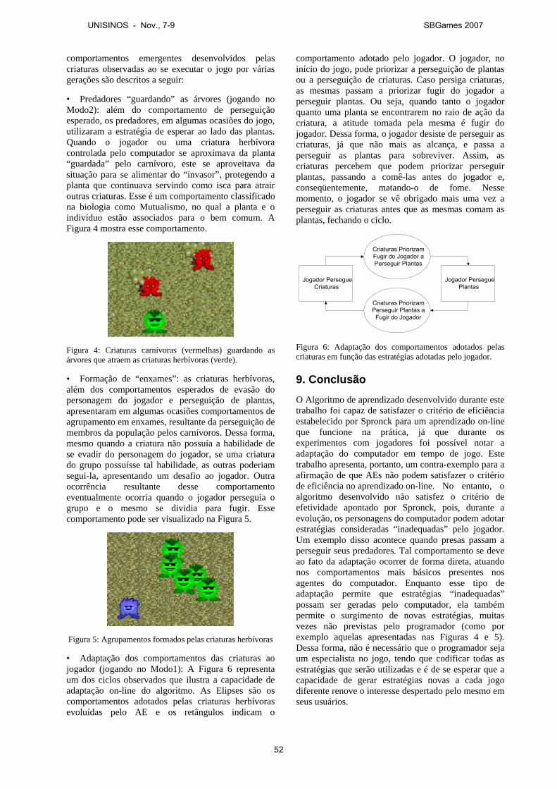
comportamentos emergentes desenvolvidos pelas criaturas observadas ao se executar o jogo por várias gerações são descritos a seguir:
• Predadores “guardando” as árvores (jogando no Modo2): além do comportamento de perseguição esperado, os predadores, em algumas ocasiões do jogo, utilizaram a estratégia de esperar ao lado das plantas. Quando o jogador ou uma criatura herbívora controlada pelo computador se aproximava da planta “guardada” pelo carnívoro, este se aproveitava da situação para se alimentar do “invasor”, protegendo a planta que continuava servindo como isca para atrair outras criaturas. Esse é um comportamento classificado na biologia como Mutualismo, no qual a planta e o indivíduo estão associados para o bem comum. A Figura 4 mostra esse comportamento.
Figura 4: Criaturas carnívoras (vermelhas) guardando as árvores que atraem as criaturas herbívoras (verde).
• Formação de “enxames”: as criaturas herbívoras, além dos comportamentos esperados de evasão do personagem do jogador e perseguição de plantas, apresentaram em algumas ocasiões comportamentos de agrupamento em enxames, resultante da perseguição de membros da população pelos carnívoros. Dessa forma, mesmo quando a criatura não possuía a habilidade de se evadir do personagem do jogador, se uma criatura do grupo possuísse tal habilidade, as outras poderiam segui-la, apresentando um desafio ao jogador. Outra ocorrência resultante desse comportamento eventualmente ocorria quando o jogador perseguia o grupo e o mesmo se dividia para fugir. Esse comportamento pode ser visualizado na Figura 5.
Figura 5: Agrupamentos formados pelas criaturas herbívoras
• Adaptação dos comportamentos das criaturas ao jogador (jogando no Modo1): A Figura 6 representa um dos ciclos observados que ilustra a capacidade de adaptação on-line do algoritmo. As Elipses são os comportamentos adotados pelas criaturas herbívoras evoluídas pelo AE e os retângulos indicam o
comportamento adotado pelo jogador. O jogador, no início do jogo, pode priorizar a perseguição de plantas ou a perseguição de criaturas. Caso persiga criaturas, as mesmas passam a priorizar fugir do jogador a perseguir plantas. Ou seja, quando tanto o jogador quanto uma planta se encontrarem no raio de ação da criatura, a atitude tomada pela mesma é fugir do jogador. Dessa forma, o jogador desiste de perseguir as criaturas, já que não mais as alcança, e passa a perseguir as plantas para sobreviver. Assim, as criaturas percebem que podem priorizar perseguir plantas, passando a comê-las antes do jogador e, conseqüentemente, matando-o de fome. Nesse momento, o jogador se vê obrigado mais uma vez a perseguir as criaturas antes que as mesmas comam as plantas, fechando o ciclo.
Jogador PersegueCriaturas
Criaturas PriorizamFugir do Jogador aPerseguir Plantas
Jogador PerseguePlantas
Criaturas PriorizamPerseguir Plantas a
Fugir do Jogador
Figura 6: Adaptação dos comportamentos adotados pelas criaturas em função das estratégias adotadas pelo jogador.
9. Conclusão
O Algoritmo de aprendizado desenvolvido durante este trabalho foi capaz de satisfazer o critério de eficiência estabelecido por Spronck para um aprendizado on-line que funcione na prática, já que durante os experimentos com jogadores foi possível notar a adaptação do computador em tempo de jogo. Este trabalho apresenta, portanto, um contra-exemplo para a afirmação de que AEs não podem satisfazer o critério de eficiência no aprendizado on-line. No entanto, o algoritmo desenvolvido não satisfez o critério de efetividade apontado por Spronck, pois, durante a evolução, os personagens do computador podem adotar estratégias consideradas “inadequadas” pelo jogador. Um exemplo disso acontece quando presas passam a perseguir seus predadores. Tal comportamento se deve ao fato da adaptação ocorrer de forma direta, atuando nos comportamentos mais básicos presentes nos agentes do computador. Enquanto esse tipo de adaptação permite que estratégias “inadequadas” possam ser geradas pelo computador, ela também permite o surgimento de novas estratégias, muitas vezes não previstas pelo programador (como por exemplo aquelas apresentadas nas Figuras 4 e 5). Dessa forma, não é necessário que o programador seja um especialista no jogo, tendo que codificar todas as estratégias que serão utilizadas e é de se esperar que a capacidade de gerar estratégias novas a cada jogo diferente renove o interesse despertado pelo mesmo em seus usuários.
UNISINOS - Nov., 7-9 SBGames 2007
52
O resultado final deste trabalho culminou também no início de um novo projeto, no qual um novo jogo será construído, assim como um novo AE responsável por seu aprendizado, que terá como meta satisfazer também o requisito de efetividade apontado por Spronck. Em suma, o objetivo desse novo projeto será o de responder a pergunta: é possível construir um AE para o aprendizado on-line de jogos que possa ser utilizado na prática, por satisfazer os requisitos de rapidez, efetividade, robustez e eficiência?
Agradecimentos O presente trabalho foi realizado com apoio do CNPq, Conselho Nacional de Desenvolvimento Científico e Tecnológico – Brasil.
Os autores gostariam de agradecer a Francisco Krug pela música produzida para o jogo.
Referências BRAMLETTE, M., 1991. Initialization, mutation and selection
methods in genetic algorithms for function optimization. In: Proceedings of the Fourth International Conference on Genetic Algorithms. San Mateo, CA, USA, 100–107.
CROCOMO, M., SIMÕES, E.V. AND DELBEM, A.C.B., 2004. Otimização automática de parâmetros de sistemas evolucionários de acordo com a aplicação. In: Anais do I Encontro de Robótica Inteligente do XXIV Congresso da Sociedade Brasileira de Computação. Salvador, BA.
DARWIN, C., 1998. The origin of species by means of natural selection. Reading, UK: Cox & Wyman (reprint from the sixth edition), 458 p., ISBN 185958070.
ELKAN, C., 2001. Paradoxes of fuzzy logic, revisited. In: International Journal of Approximate Reasoning, 26(2), 153–155.
FRANCISCO, W., 1993. Estatística: síntese de teoria, exercícios propostos e resolvidos. Piracicaba:Unimep, 219 p.
HAYKIN, S., 2001. Redes neurais: princípios e prática. Bookman, 900 p., ISBN 8573077182.
HOLLAND, J., 1962. Outline for a logical theory of adaptive systems. In: Journal of the Association for Computing Machinery, 3, 297–314.
KOZA, J., 1992. Genetic evolution and co-evolution of game strategies. In: International Conference on Game Theory and Its Applications, New York, USA.
LUCAS, S., 2004. Cellz: a simple dynamic game for testing evolutionary algorithms. In: Proceedings of the 2004 IEEE Congress on Evolutionary Computation, IEEE Press, 1007–1014.
MANSLOW, J., 2002. Learning and adaptation (book chapter). AI game programming wisdom, Charles River Media, 557–566.
MITCHELL, M. AND FORREST., S., 1994. Genetic algorithms and artificial life. In: Artificial Life, 1(3), 267–289.
PICCIONE, M. AND RUBINSTEIN, A. 1993. Finite automata play a repeated extensive game. In: Journal of Economic Theory, 61, 160–168.
PONSEM, M., 2004. Improving adaptive game AI with evolutionary learning. MSc thesis, Faculty of Media & Knowledge Engineering, Delft University of Technology, Netherlands.
PRECHELT, L., 2003. Are scripting languages any good? A validation of Perl, Python, Rexx, and Tcl against C, C++, and Java. In: Advances in Computers, 57, 207–271, ISSN 0065-2458.
REYNOLDS, W. C., 1987. Flocks, Herds, and Schools: A Distributed Behavioral Model. In: Proceedings of SIGGRAPH. Anaheim, CA, USA, 25–34.
SIMÕES, E.V., 2000. Development of an embedded evolutionary controller to enable collision-free navigation of a population of autonomous mobile robots. PhD thesis, University of Kent at Canterbury, UK.
SIMÕES, E.V. AND BARONE, D.A.C., 2003. Predation: an approach to improving the evolution of real robots with a distributed evolutionary controller. In: Proceedings of International Conference on Robot Automation. New York: IEEE Press, 664–669.
SIMÕES, E.V. AND DIMOND, K., 1999. An evolutionary controller for autonomous multi-robot systems. In: Proceedings of the IEEE International Conference on Systems, Man and Cybernetics, Tokyo, Japan, 596–601.
SPRONCK, P., YEE, N., SHPRINKHUIZEN-KUYPER, I. AND POSTMA, E., 2004. Online adaptation of game opponent AI in theory and practice. In: Proceedings of the 4th International Conference on Intelligent Games and Simulation, London, UK, 45–53.
SUTTON, R. AND BARTO, A., 1998. Reinforcement learning: an introduction. MIT Press, 432 p.
SWEETSER P., 2002. Current AI in games: a review. Technical report, School of ITEE, University of Queensland, Australia.
TOMASSINI, M., 1995. Survey of genetic algorithms. In: Annual Reviews of Computational Physics, World Scientific, 3, 87–118.
WATSON, R., FICICI, S. AND POLLACK, J., 2002. Embodied evolution: distributing an evolutionary algorithm in a population of robots. In: Robotics and Autonomous Systems, 39, 1–18.
YANNAKAKIS, G.N., 2005. AI in computer games: generating interesting interactive opponents by the use of evolutionary computation. PhD thesis, University of Edinburgh, UK.
YAO, X. AND DARWEN, P., 2000. Genetic algorithms and evolutionary games. In: Commerce, Complexity and Evolution, Cambridge: University Press, 1(16), 313-333.
UNISINOS - Nov., 7-9 SBGames 2007
53
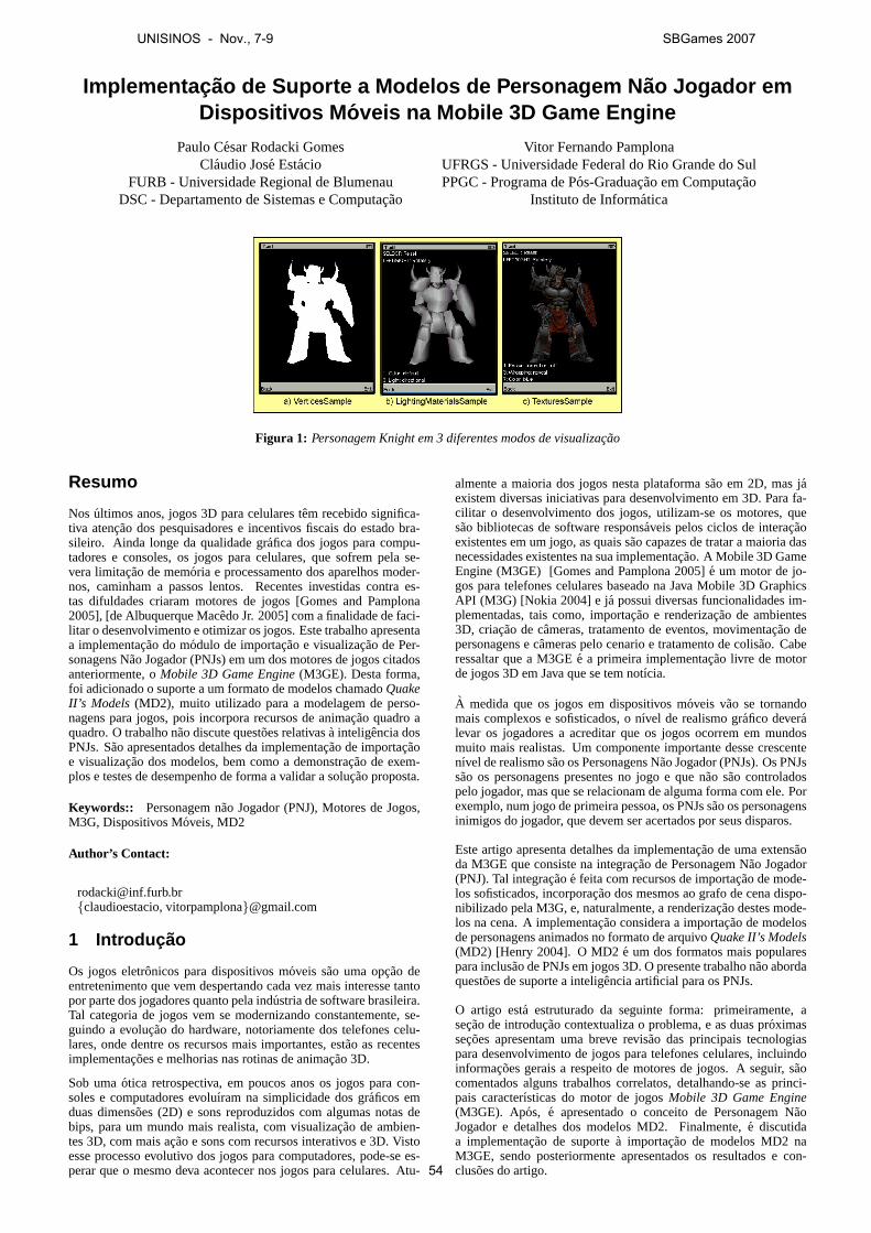
Implementac ao de Suporte a Modelos de Personagem N ao Jogador emDispositivos M oveis na Mobile 3D Game Engine
Paulo Cesar Rodacki GomesClaudio Jose Estacio
FURB - Universidade Regional de BlumenauDSC - Departamento de Sistemas e Computacao
Vitor Fernando PamplonaUFRGS - Universidade Federal do Rio Grande do SulPPGC - Programa de Pos-Graduacao em Computacao
Instituto de Informatica
Figura 1: Personagem Knight em 3 diferentes modos de visualizacao
Resumo
Nos ultimos anos, jogos 3D para celulares tem recebido significa-tiva atencao dos pesquisadores e incentivos fiscais do estado bra-sileiro. Ainda longe da qualidade grafica dos jogos para compu-tadores e consoles, os jogos para celulares, que sofrem pela se-vera limitacao de memoria e processamento dos aparelhos moder-nos, caminham a passos lentos. Recentes investidas contra es-tas difuldades criaram motores de jogos [Gomes and Pamplona2005], [de Albuquerque Macedo Jr. 2005] com a finalidade de faci-litar o desenvolvimento e otimizar os jogos. Este trabalho apresentaa implementacao do modulo de importacao e visualizacao de Per-sonagens Nao Jogador (PNJs) em um dos motores de jogos citadosanteriormente, oMobile 3D Game Engine(M3GE). Desta forma,foi adicionado o suporte a um formato de modelos chamadoQuakeII’s Models (MD2), muito utilizado para a modelagem de perso-nagens para jogos, pois incorpora recursos de animacao quadro aquadro. O trabalho nao discute questoes relativasa inteligencia dosPNJs. Sao apresentados detalhes da implementacao de importacaoe visualizacao dos modelos, bem como a demonstracao de exem-plos e testes de desempenho de forma a validar a solucao proposta.
Keywords:: Personagem nao Jogador (PNJ), Motores de Jogos,M3G, Dispositivos Moveis, MD2
Author’s Contact:
[email protected]{claudioestacio, vitorpamplona}@gmail.com
1 Introduc ao
Os jogos eletronicos para dispositivos moveis sao uma opcao deentretenimento que vem despertando cada vez mais interesse tantopor parte dos jogadores quanto pela industria de software brasileira.Tal categoria de jogos vem se modernizando constantemente, se-guindo a evolucao do hardware, notoriamente dos telefones celu-lares, onde dentre os recursos mais importantes, estao as recentesimplementacoes e melhorias nas rotinas de animacao 3D.
Sob umaotica retrospectiva, em poucos anos os jogos para con-soles e computadores evoluıram na simplicidade dos graficos emduas dimensoes (2D) e sons reproduzidos com algumas notas debips, para um mundo mais realista, com visualizacao de ambien-tes 3D, com mais acao e sons com recursos interativos e 3D. Vistoesse processo evolutivo dos jogos para computadores, pode-se es-perar que o mesmo deva acontecer nos jogos para celulares. Atu-
almente a maioria dos jogos nesta plataforma sao em 2D, mas jaexistem diversas iniciativas para desenvolvimento em 3D. Para fa-cilitar o desenvolvimento dos jogos, utilizam-se os motores, quesao bibliotecas de software responsaveis pelos ciclos de interacaoexistentes em um jogo, as quais sao capazes de tratar a maioria dasnecessidades existentes na sua implementacao. A Mobile 3D GameEngine (M3GE) [Gomes and Pamplona 2005]e um motor de jo-gos para telefones celulares baseado na Java Mobile 3D GraphicsAPI (M3G) [Nokia 2004] e ja possui diversas funcionalidades im-plementadas, tais como, importacao e renderizacao de ambientes3D, criacao de cameras, tratamento de eventos, movimentacao depersonagens e cameras pelo cenario e tratamento de colisao. Caberessaltar que a M3GEe a primeira implementacao livre de motorde jogos 3D em Java que se tem notıcia.
A medida que os jogos em dispositivos moveis vao se tornandomais complexos e sofisticados, o nıvel de realismo grafico deveralevar os jogadores a acreditar que os jogos ocorrem em mundosmuito mais realistas. Um componente importante desse crescentenıvel de realismo sao os Personagens Nao Jogador (PNJs). Os PNJssao os personagens presentes no jogo e que nao sao controladospelo jogador, mas que se relacionam de alguma forma com ele. Porexemplo, num jogo de primeira pessoa, os PNJs sao os personagensinimigos do jogador, que devem ser acertados por seus disparos.
Este artigo apresenta detalhes da implementacao de uma extensaoda M3GE que consiste na integracao de Personagem Nao Jogador(PNJ). Tal integracaoe feita com recursos de importacao de mode-los sofisticados, incorporacao dos mesmos ao grafo de cena dispo-nibilizado pela M3G, e, naturalmente, a renderizacao destes mode-los na cena. A implementacao considera a importacao de modelosde personagens animados no formato de arquivoQuake II’s Models(MD2) [Henry 2004]. O MD2e um dos formatos mais popularespara inclusao de PNJs em jogos 3D. O presente trabalho nao abordaquestoes de suporte a inteligencia artificial para os PNJs.
O artigo esta estruturado da seguinte forma: primeiramente, asecao de introducao contextualiza o problema, e as duas proximassecoes apresentam uma breve revisao das principais tecnologiaspara desenvolvimento de jogos para telefones celulares, incluindoinformacoes gerais a respeito de motores de jogos. A seguir, saocomentados alguns trabalhos correlatos, detalhando-se as princi-pais caracterısticas do motor de jogosMobile 3D Game Engine(M3GE). Apos, e apresentado o conceito de Personagem NaoJogador e detalhes dos modelos MD2. Finalmente,e discutidaa implementacao de suportea importacao de modelos MD2 naM3GE, sendo posteriormente apresentados os resultados e con-clusoes do artigo.
UNISINOS - Nov., 7-9 SBGames 2007
54
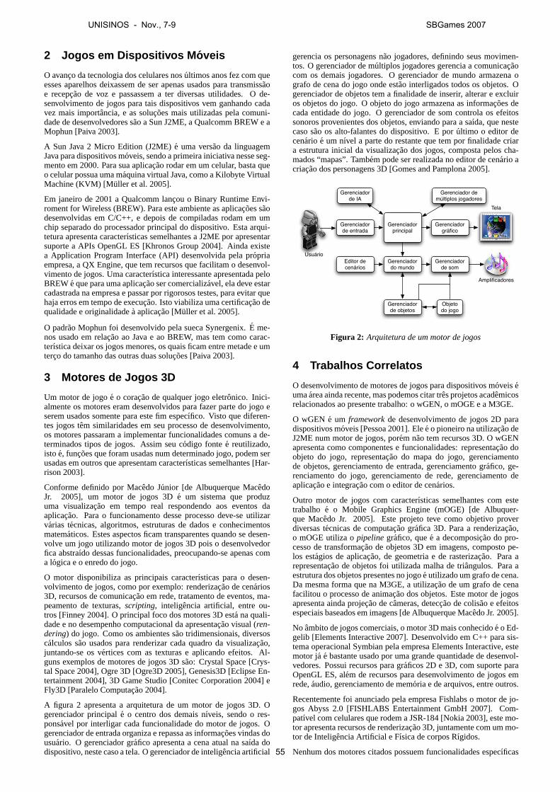
2 Jogos em Dispositivos M oveis
O avanco da tecnologia dos celulares nosultimos anos fez com queesses aparelhos deixassem de ser apenas usados para transmissaoe recepcao de voz e passassem a ter diversas utilidades. O de-senvolvimento de jogos para tais dispositivos vem ganhando cadavez mais importancia, e as solucoes mais utilizadas pela comuni-dade de desenvolvedores sao a Sun J2ME, a Qualcomm BREW e aMophun [Paiva 2003].
A Sun Java 2 Micro Edition (J2ME)e uma versao da linguagemJava para dispositivos moveis, sendo a primeira iniciativa nesse seg-mento em 2000. Para sua aplicacao rodar em um celular, basta queo celular possua uma maquina virtual Java, como a Kilobyte VirtualMachine (KVM) [Muller et al. 2005].
Em janeiro de 2001 a Qualcomm lancou o Binary Runtime Envi-roment for Wireless (BREW). Para este ambiente as aplicacoes saodesenvolvidas em C/C++, e depois de compiladas rodam em umchip separado do processador principal do dispositivo. Esta arqui-tetura apresenta caracterısticas semelhantes a J2ME por apresentarsuporte a APIs OpenGL ES [Khronos Group 2004]. Ainda existea Application Program Interface (API) desenvolvida pela propriaempresa, a QX Engine, que tem recursos que facilitam o desenvol-vimento de jogos. Uma caracterıstica interessante apresentada peloBREWe que para uma aplicacao ser comercializavel, ela deve estarcadastrada na empresa e passar por rigorosos testes, para evitar quehaja erros em tempo de execucao. Isto viabiliza uma certificacao dequalidade e originalidadea aplicacao [Muller et al. 2005].
O padrao Mophun foi desenvolvido pela sueca Synergenix.E me-nos usado em relacao ao Java e ao BREW, mas tem como carac-terıstica deixar os jogos menores, os quais ficam entre metade e umterco do tamanho das outras duas solucoes [Paiva 2003].
3 Motores de Jogos 3D
Um motor de jogoe o coracao de qualquer jogo eletronico. Inici-almente os motores eram desenvolvidos para fazer parte do jogo eserem usados somente para este fim especıfico. Visto que diferen-tes jogos tem similaridades em seu processo de desenvolvimento,os motores passaram a implementar funcionalidades comuns a de-terminados tipos de jogos. Assim seu codigo fontee reutilizado,isto e, funcoes que foram usadas num determinado jogo, podem serusadas em outros que apresentam caracterısticas semelhantes [Har-rison 2003].
Conforme definido por Macedo Junior [de Albuquerque MacedoJr. 2005], um motor de jogos 3De um sistema que produzuma visualizacao em tempo real respondendo aos eventos daaplicacao. Para o funcionamento desse processo deve-se utilizarvarias tecnicas, algoritmos, estruturas de dados e conhecimentosmatematicos. Estes aspectos ficam transparentes quando se desen-volve um jogo utilizando motor de jogos 3D pois o desenvolvedorfica abstraıdo dessas funcionalidades, preocupando-se apenas coma logica e o enredo do jogo.
O motor disponibiliza as principais caracterısticas para o desen-volvimento de jogos, como por exemplo: renderizacao de cenarios3D, recursos de comunicacao em rede, tratamento de eventos, ma-peamento de texturas,scripting, inteligencia artificial, entre ou-tros [Finney 2004]. O principal foco dos motores 3D esta na quali-dade e no desempenho computacional da apresentacao visual (ren-dering) do jogo. Como os ambientes sao tridimensionais, diversoscalculos sao usados para renderizar cada quadro da visualizacao,juntando-se os vertices com as texturas e aplicando efeitos. Al-guns exemplos de motores de jogos 3D sao: Crystal Space [Crys-tal Space 2004], Ogre 3D [Ogre3D 2005], Genesis3D [Eclipse En-tertainment 2004], 3D Game Studio [Conitec Corporation 2004] eFly3D [Paralelo Computacao 2004].
A figura 2 apresenta a arquitetura de um motor de jogos 3D. Ogerenciador principale o centro dos demais nıveis, sendo o res-ponsavel por interligar cada funcionalidade do motor de jogos. Ogerenciador de entrada organiza e repassa as informacoes vindas dousuario. O gerenciador grafico apresenta a cena atual na saıda dodispositivo, neste caso a tela. O gerenciador de inteligencia artificial
gerencia os personagens nao jogadores, definindo seus movimen-tos. O gerenciador de multiplos jogadores gerencia a comunicacaocom os demais jogadores. O gerenciador de mundo armazena ografo de cena do jogo onde estao interligados todos os objetos. Ogerenciador de objetos tem a finalidade de inserir, alterar e excluiros objetos do jogo. O objeto do jogo armazena as informacoes decada entidade do jogo. O gerenciador de som controla os efeitossonoros provenientes dos objetos, enviando para a saıda, que nestecaso sao os alto-falantes do dispositivo. E porultimo o editor decenario e um nıvel a parte do restante que tem por finalidade criara estrutura inicial da visualizacao dos jogos, composta pelos cha-mados “mapas”. Tambem pode ser realizada no editor de cenario acriacao dos personagens 3D [Gomes and Pamplona 2005].
Usuário
Gerenciador de entrada
Gerenciador principal
Gerenciador de IA
Gerenciador de múltiplos jogadores
Gerenciador gráfico
Tela
Editor de cenários
Gerenciador do mundo
Gerenciador de som
Gerenciador de objetos
Amplificadores
Objeto do jogo
Figura 2: Arquitetura de um motor de jogos
4 Trabalhos Correlatos
O desenvolvimento de motores de jogos para dispositivos moveiseumaarea ainda recente, mas podemos citar tres projetos academicosrelacionados ao presente trabalho: o wGEN, o mOGE e a M3GE.
O wGEN e um frameworkde desenvolvimento de jogos 2D paradispositivos moveis [Pessoa 2001]. Elee o pioneiro na utilizacao deJ2ME num motor de jogos, porem nao tem recursos 3D. O wGENapresenta como componentes e funcionalidades: representacao doobjeto do jogo, representacao do mapa do jogo, gerenciamentode objetos, gerenciamento de entrada, gerenciamento grafico, ge-renciamento do jogo, gerenciamento de rede, gerenciamento deaplicacao e integracao com o editor de cenarios.
Outro motor de jogos com caracterısticas semelhantes com estetrabalho e o Mobile Graphics Engine (mOGE) [de Albuquer-que Macedo Jr. 2005]. Este projeto teve como objetivo proverdiversas tecnicas de computacao grafica 3D. Para a renderizacao,o mOGE utiliza opipelinegrafico, quee a decomposicao do pro-cesso de transformacao de objetos 3D em imagens, composto pe-los estagios de aplicacao, de geometria e de rasterizacao. Para arepresentacao de objetos foi utilizada malha de triangulos. Para aestrutura dos objetos presentes no jogoe utilizado um grafo de cena.Da mesma forma que na M3GE, a utilizacao de um grafo de cenafacilitou o processo de animacao dos objetos. Este motor de jogosapresenta ainda projecao de cameras, deteccao de colisao e efeitosespeciais baseados em imagens [de Albuquerque Macedo Jr. 2005].
No ambito de jogos comerciais, o motor 3D mais conhecidoe o Ed-gelib [Elements Interactive 2007]. Desenvolvido em C++ para sis-tema operacional Symbian pela empresa Elements Interactive, estemotor ja e bastante usado por uma grande quantidade de desenvol-vedores. Possui recursos para graficos 2D e 3D, com suporte paraOpenGL ES, alem de recursos para desenvolvimento de jogos emrede,audio, gerenciamento de memoria e de arquivos, entre outros.
Recentemente foi anunciado pela empresa Fishlabs o motor de jo-gos Abyss 2.0 [FISHLABS Entertainment GmbH 2007]. Com-patıvel com celulares que rodem a JSR-184 [Nokia 2003], este mo-tor apresenta recursos de renderizacao 3D, juntamente com um mo-tor de Inteligencia Artificial e Fısica de corpos Rıgidos.
Nenhum dos motores citados possuem funcionalidades especıficas
UNISINOS - Nov., 7-9 SBGames 2007
55
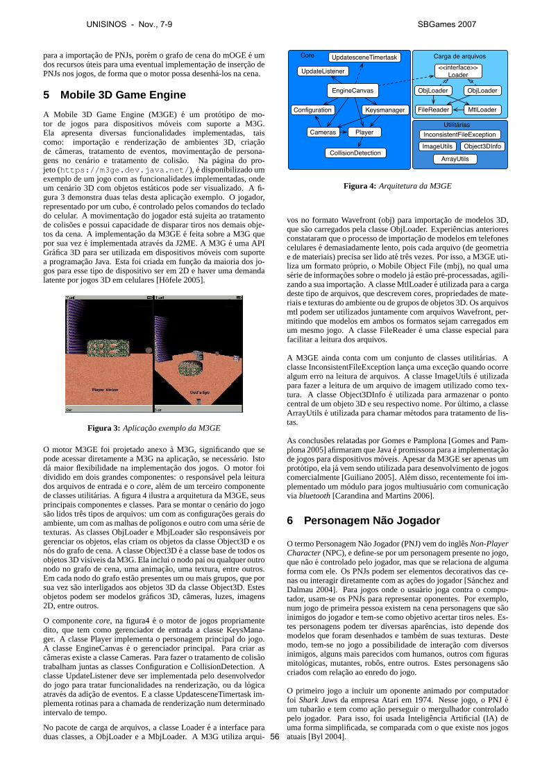
para a importacao de PNJs, porem o grafo de cena do mOGEe umdos recursosuteis para uma eventual implementacao de insercao dePNJs nos jogos, de forma que o motor possa desenha-los na cena.
5 Mobile 3D Game Engine
A Mobile 3D Game Engine (M3GE)e um prototipo de mo-tor de jogos para dispositivos moveis com suporte a M3G.Ela apresenta diversas funcionalidades implementadas, taiscomo: importacao e renderizacao de ambientes 3D, criacaode cameras, tratamento de eventos, movimentacao de persona-gens no cenario e tratamento de colisao. Na pagina do pro-jeto (https://m3ge.dev.java.net/ ), e disponibilizado umexemplo de um jogo com as funcionalidades implementadas, ondeum cenario 3D com objetos estaticos pode ser visualizado. A fi-gura 3 demonstra duas telas desta aplicacao exemplo. O jogador,representado por um cubo,e controlado pelos comandos do tecladodo celular. A movimentacao do jogador esta sujeita ao tratamentode colisoes e possui capacidade de disparar tiros nos demais obje-tos da cena. A implementacao da M3GEe feita sobre a M3G quepor sua veze implementada atraves da J2ME. A M3Ge uma APIGrafica 3D para ser utilizada em dispositivos moveis com suportea programacao Java. Esta foi criada em funcao da maioria dos jo-gos para esse tipo de dispositivo ser em 2D e haver uma demandalatente por jogos 3D em celulares [Hofele 2005].
Figura 3: Aplicacao exemplo da M3GE
O motor M3GE foi projetado anexoa M3G, significando que sepode acessar diretamente a M3G na aplicacao, se necessario. Istoda maior flexibilidade na implementacao dos jogos. O motor foidividido em dois grandes componentes: o responsavel pela leiturados arquivos de entrada e ocore, alem de um terceiro componentede classes utilitarias. A figura 4 ilustra a arquitetura da M3GE, seusprincipais componentes e classes. Para se montar o cenario do jogosao lidos tres tipos de arquivos: um com as configuracoes gerais doambiente, um com as malhas de polıgonos e outro com uma serie detexturas. As classes ObjLoader e MbjLoader sao responsaveis porgerenciar os objetos, elas criam os objetos da classe Object3D e osnos do grafo de cena. A classe Object3De a classe base de todos osobjetos 3D visıveis da M3G. Ela inclui o nodo pai ou qualquer outronodo no grafo de cena, uma animacao, uma textura, entre outros.Em cada nodo do grafo estao presentes um ou mais grupos, que porsua vez sao interligados aos objetos 3D da classe Object3D. Estesobjetos podem ser modelos graficos 3D, cameras, luzes, imagens2D, entre outros.
O componentecore, na figura4e o motor de jogos propriamentedito, que tem como gerenciador de entrada a classe KeysMana-ger. A classe Player implementa o personagem principal do jogo.A classe EngineCanvase o gerenciador principal. Para criar ascameras existe a classe Cameras. Para fazer o tratamento de colisaotrabalham juntas as classes Configuration e CollisionDetection. Aclasse UpdateListener deve ser implementada pelo desenvolvedordo jogo para tratar funcionalidades na renderizacao, ou da logicaatraves da adicao de eventos. E a classe UpdatesceneTimertask im-plementa rotinas para a chamada de renderizacao num determinadointervalo de tempo.
No pacote de carga de arquivos, a classe Loadere a interface paraduas classes, a ObjLoader e a MbjLoader. A M3G utiliza arqui-
UpdateListener
UpdatesceneTimertask
EngineCanvas
KeysmanagerConfiguration
CollisionDetection
PlayerCameras
<<interface>>Loader
ObjLoader ObjLoader
FileReader MtlLoader
Core Carga de arquivos
InconsistentFileException
ArrayUtils
ImageUtils Object3DInfo
Utilitárias
Figura 4: Arquitetura da M3GE
vos no formato Wavefront (obj) para importacao de modelos 3D,que sao carregados pela classe ObjLoader. Experiencias anterioresconstataram que o processo de importacao de modelos em telefonescelularese demasiadamente lento, pois cada arquivo (de geometriae de materiais) precisa ser lido ate tres vezes. Por isso, a M3GE uti-liza um formato proprio, o Mobile Object File (mbj), no qual umaserie de informacoes sobre o modelo ja estao pre-processadas, agili-zando a sua importacao. A classe MtlLoadere utilizada para a cargadeste tipo de arquivos, que descrevem cores, propriedades de mate-riais e texturas do ambiente ou de grupos de objetos 3D. Os arquivosmtl podem ser utilizados juntamente com arquivos Wavefront, per-mitindo que modelos em ambos os formatos sejam carregados emum mesmo jogo. A classe FileReadere uma classe especial parafacilitar a leitura dos arquivos.
A M3GE ainda conta com um conjunto de classes utilitarias. Aclasse InconsistentFileException lanca uma excecao quando ocorrealgum erro na leitura de arquivos. A classe ImageUtilse utilizadapara fazer a leitura de um arquivo de imagem utilizado como tex-tura. A classe Object3DInfoe utilizada para armazenar o pontocentral de um objeto 3D e seu respectivo nome. Porultimo, a classeArrayUtils e utilizada para chamar metodos para tratamento de lis-tas.
As conclusoes relatadas por Gomes e Pamplona [Gomes and Pam-plona 2005] afirmaram que Javae promissora para a implementacaode jogos para dispositivos moveis. Apesar da M3GE ser apenas umprototipo, ela ja vem sendo utilizada para desenvolvimento de jogoscomercialmente [Guiliano 2005]. Alem disso, recentemente foi im-plementado um modulo para jogos multiusuario com comunicacaovia bluetooth[Carandina and Martins 2006].
6 Personagem N ao Jogador
O termo Personagem Nao Jogador (PNJ) vem do inglesNon-PlayerCharacter(NPC), e define-se por um personagem presente no jogo,que naoe controlado pelo jogador, mas que se relaciona de algumaforma com ele. Os PNJs podem ser elementos decorativos das ce-nas ou interagir diretamente com as acoes do jogador [Sanchez andDalmau 2004]. Para jogos onde o usuario joga contra o compu-tador, usam-se os PNJs para representar oponentes. Por exemplo,num jogo de primeira pessoa existem na cena personagens que saoinimigos do jogador e tem-se como objetivo acertar tiros neles. Es-tes personagens podem ter diversas aparencias, isto depende dosmodelos que foram desenhados e tambem de suas texturas. Destemodo, tem-se no jogo a possibilidade de interacao com diversosinimigos, alguns mais parecidos com humanos, outros com figurasmitologicas, mutantes, robos, entre outros. Estes personagens saocriados com relacao ao enredo do jogo.
O primeiro jogo a incluir um oponente animado por computadorfoi Shark Jawsda empresa Atari em 1974. Nesse jogo, o PNJeum tubarao e tem como acao perseguir o mergulhador controladopelo jogador. Para isso, foi usada Inteligencia Artificial (IA) deuma forma simplificada, se comparada com o que existe nos jogosatuais [Byl 2004].
UNISINOS - Nov., 7-9 SBGames 2007
56

7 Modelo Animado MD2
O formato de arquivo de modelo MD2e um dos formatos maispopulares para inclusao de PNJs em jogos 3D [Henry 2004]. Sur-giu em novembro de 1997 para ser utilizado no jogoQuake IIpro-duzido pela ID Software. Suas principais caracterısticas sao: serum modelo geometrico formado por triangulos, utilizar animacaoquadro a quadro, istoe, cada quadro representa uma pose do per-sonagem, e quando as poses sao exibidas em sequencia da-se avisualizacao do movimento. Um outra caracterıstica importantee que sua estrutura de dados ja foi concebida contendo primitivasgraficas do OpenGL para desenho do modelo, onde os vertices jaestao organizados para facilitar a chamada de desenho de primiti-vas do tipo GlTRIANGLE FAN e Gl TRIANGLE STRIP. Estasprimitivas tem utilizacao opcional, pois alem da lista de vertices, oarquivo possui uma lista dos triangulos utilizados na modelagem dopersonagem.
Este formatoe uma variacao dos arquivos MDL que sao usados emjogos comoHalf Life e noCounter Strike, que utilizam uma versaoderivada do motorQuake II [Santee 2005]. A extensao do arquivodo modeloe MD2 e ele esta em formato binario dividido em duaspartes: cabecalho e dados, comentadas a seguir.
7.1 Cabecalho
Conforme descrito por Santee [Santee 2005],e no cabecalho doarquivo MD2 que estao definidos os numeros de vertices, faces,quadros chave e tudo mais que esta dentro do arquivo. Pelo fato deser um arquivo binario, o cabecalho torna-se muito importante paraa localizacao do restante dos dados. Cada informacao presente nocabecalhoe armazenada em quatrobytesrepresentados por um tipode dado inteiro.
Antes de apresentar o conteudo do cabecalhoe preciso rever algunsconceitos:
• Quadro-chave: a animacao do modeloe representada por umasequencia de quadros-chave, e cada um representando umaposicao do personagem, devendo ser realizada interpolacaoentre os quadros-have. Para armazenar um quadro-chave, omodelo guarda uma lista de vertices, o nome do quadro, umvetor de escala e um vetor de translacao. Este doisultimossao usados para a descompactacao dos vertices, multiplicandocada coordenada do vertice pelo vetor de escala e somando aovetor de translacao. Istoe feito para transformar os verticesde ponto fixo para ponto flutuante;
• Coordenadas de Textura: as coordenadas de textura sao utili-zadas para mapear a textura no modelo 3D. Istoe feito atravesdas coordenadass e t. Cada vertice do modelo 3D recebe umpar de coordenadas de texturas e t;
• Skin: sao texturas que dao representacao visual externa ao mo-delo. Atraves dosskinspodem-se distinguir partes do corpo,roupa, tecido, materiais anexados, entre outros. Essesskinssao mapeados para o modelo atraves das coordenadas de tex-tura. No cabecalho encontram-se o tamanho e a quantidadedeskinsque podem ser utilizados no modelo;
• Comando OpenGl: os comandos OpenGl presentes noarquivo sao usados para a renderizacao atraves das pri-mitivas GL TRIANGLE FAN e GL TRIANGLE STRIP. Oarquivo MD2 apresenta uma lista de numeros inteiros,que estao na seguinte estrutura: o primeiro valore onumero de vertices a ser renderizado com a primitivaGL TRIANGLE FAN caso seja positivo ou renderizado coma primitiva GL TRIANGLE STRIP caso seja negativo. Osseguintes numeros vem na sequencia divididos em grupos detres, onde os dois primeiros representam as coordenadas detexturas e t, e o terceiro oındice para o vertice. Repete-se aestrutura acima ate que o numero de vertices a desenhar sejazero significando o fim da renderizacao do modelo;
• Triangulos: sao os que definem as faces do modelo. Eles saouma lista deındices da lista de vertices. Cada conjunto de tresındices representa um triangulo;
• Vertices: sao os pontos no mundo cartesiano que desenham omodelo 3D. Sao representados pelas coordenadas:x, y ez;
• Vetor Normal: e um vetor que esta contido na estrutura dosvertices, utilizado para calcular a iluminacao do modelo.
A estrutura completa do cabecalho pode ser vista na tabela 1. Estaestrutura representa a mesma sequencia presente dentro do arquivoMD2.
Tabela 1: Cabecalho dos arquivos MD2
Conteudo Descricaomagic ID do formato (deve ser igual
a 844121161)version Versao do arquivo (para
Quake2 precisa ser igual a 8)skinWidth Largura do skin do modelo (pixels)skinHeight Altura do skin (empixels)frameSize Tamanho das informacoes dos
frames (embytes)numSkins Numero de skins avaliados
numVertices Numero de verticesnumTexCoords Numero de coord. de textura
numTriangles Numero de triangulosnumGlCommands Numero de comandos OpenGL
numFrames Numero de quadros para animacaooffsetSkins Posicao dos skins
offsetTexCoords Posicao das coordenadas detextura nobuffer
offsetTriangles Posicao dos triangulos nobufferoffsetFrames Posicao dos quadros
offsetGlCommands Posicao dos comandos OpenGLoffsetEnd Posicao para o final do modelo
7.2 Dados
As informacoes de cada vertice do modelo sao armazenadas empoucosbytes. O resultado dissoe um arquivo pequeno, mas comperdas na exatidao da geometria do modelo [MD2 2005]. Dispo-sitivos moveis tem espaco de memoria restrita e a resolucao dosdisplaysnesses dispositivose bem menor do que em um monitorde um computador do tipo PC ou de uma tela de aparelho de TV.Por isso a perda de qualidade na visualizacao dos modelos nao etao perceptıvel quanto seria em um computadordesktop. Os tiposde dados sao apresentados da seguinte forma:
• Vetor: composto por tres coordenadas do tipofloat;
• Informacao Textura: lista de nomes de texturas associadas aomodelo;
• Coordenadas da Textura: sao armazenadas na estrutura comoshort integers;
• Triangulos: cada triangulo possui uma lista com osındicesdos vertices e uma lista com osındices das coordenadas datextura;
• Vertices: sao compostos de coordenadas 3D, onde sao arma-zenados em umbytecada coordenada e umındice do vetornormal;
• Quadros: tem informacoes especıficas da lista de vertice doquadro;
• Comandos OpenGL: sao armazenados em uma lista deinte-gers.
7.3 Texturas
As texturas utilizadas nos modelos MD2 sao localizadas em arqui-vos separados. Todos os vertices do modelo devem ser mapeadospara essa mesma textura. Por este motivo a textura deve ter dife-rentes regioes para representar cada parte do personagem, desde ospes ate a cabeca, chamados assim deskins[Misfit Code 2005]. Na
UNISINOS - Nov., 7-9 SBGames 2007
57
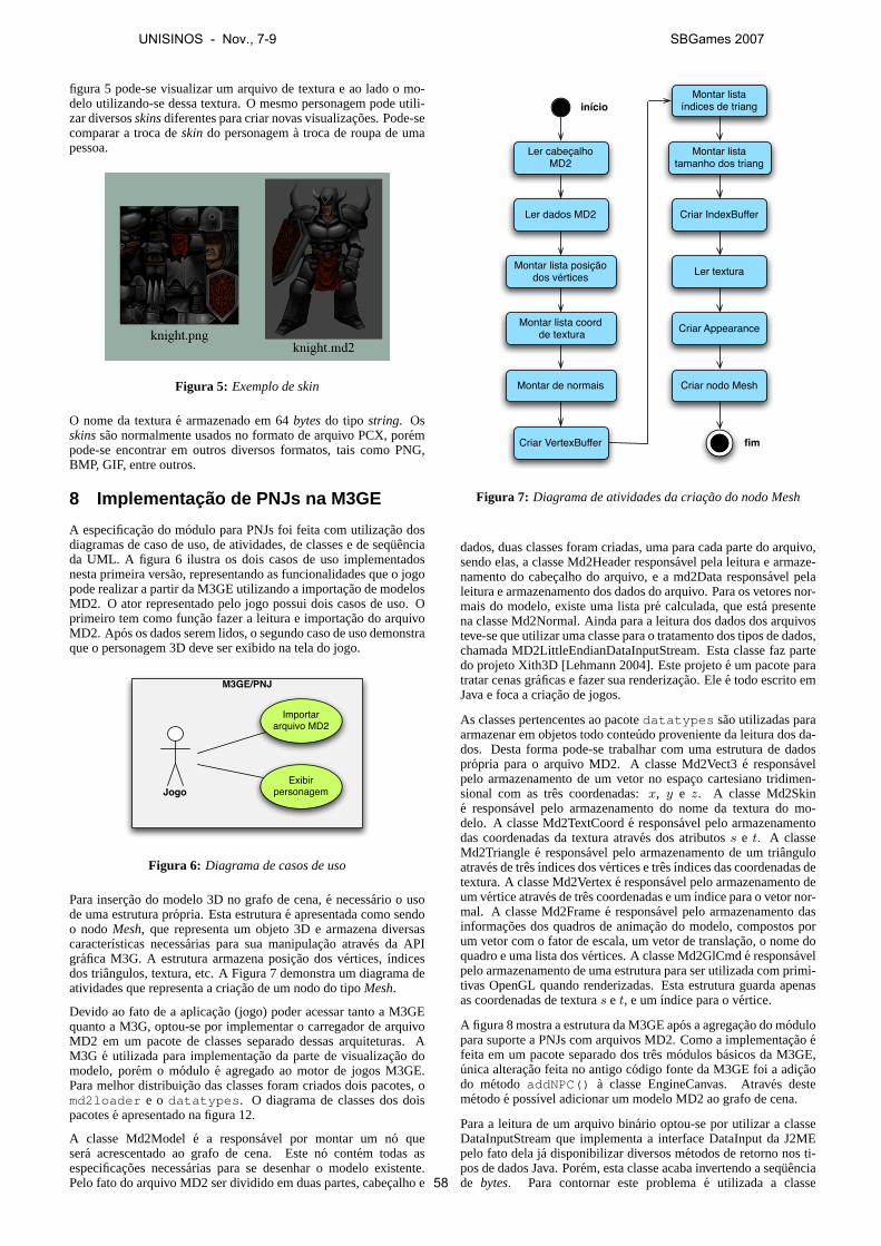
figura 5 pode-se visualizar um arquivo de textura e ao lado o mo-delo utilizando-se dessa textura. O mesmo personagem pode utili-zar diversosskinsdiferentes para criar novas visualizacoes. Pode-secomparar a troca deskin do personagema troca de roupa de umapessoa.
Figura 5: Exemplo de skin
O nome da texturae armazenado em 64bytesdo tipo string. Osskinssao normalmente usados no formato de arquivo PCX, porempode-se encontrar em outros diversos formatos, tais como PNG,BMP, GIF, entre outros.
8 Implementac ao de PNJs na M3GE
A especificacao do modulo para PNJs foi feita com utilizacao dosdiagramas de caso de uso, de atividades, de classes e de sequenciada UML. A figura 6 ilustra os dois casos de uso implementadosnesta primeira versao, representando as funcionalidades que o jogopode realizar a partir da M3GE utilizando a importacao de modelosMD2. O ator representado pelo jogo possui dois casos de uso. Oprimeiro tem como funcao fazer a leitura e importacao do arquivoMD2. Apos os dados serem lidos, o segundo caso de uso demonstraque o personagem 3D deve ser exibido na tela do jogo.
M3GE/PNJ
Jogo
Importar arquivo MD2
Exibir personagem
Figura 6: Diagrama de casos de uso
Para insercao do modelo 3D no grafo de cena,e necessario o usode uma estrutura propria. Esta estruturae apresentada como sendoo nodoMesh, que representa um objeto 3D e armazena diversascaracterısticas necessarias para sua manipulacao atraves da APIgrafica M3G. A estrutura armazena posicao dos vertices,ındicesdos triangulos, textura, etc. A Figura 7 demonstra um diagrama deatividades que representa a criacao de um nodo do tipoMesh.
Devido ao fato de a aplicacao (jogo) poder acessar tanto a M3GEquanto a M3G, optou-se por implementar o carregador de arquivoMD2 em um pacote de classes separado dessas arquiteturas. AM3G e utilizada para implementacao da parte de visualizacao domodelo, porem o modulo e agregado ao motor de jogos M3GE.Para melhor distribuicao das classes foram criados dois pacotes, omd2loader e o datatypes . O diagrama de classes dos doispacotese apresentado na figura 12.
A classe Md2Modele a responsavel por montar um no quesera acrescentado ao grafo de cena. Este no contem todas asespecificacoes necessarias para se desenhar o modelo existente.Pelo fato do arquivo MD2 ser dividido em duas partes, cabecalho e
início
Ler cabeçalho MD2
Ler dados MD2
Criar nodo Mesh
Criar Appearance
Ler textura
Montar lista índices de triang
Criar VertexBuffer
Montar lista posição dos vértices
Montar lista coord de textura
Montar de normais
Montar lista tamanho dos triang
Criar IndexBuffer
fim
Figura 7: Diagrama de atividades da criacao do nodo Mesh
dados, duas classes foram criadas, uma para cada parte do arquivo,sendo elas, a classe Md2Header responsavel pela leitura e armaze-namento do cabecalho do arquivo, e a md2Data responsavel pelaleitura e armazenamento dos dados do arquivo. Para os vetores nor-mais do modelo, existe uma lista pre calculada, que esta presentena classe Md2Normal. Ainda para a leitura dos dados dos arquivosteve-se que utilizar uma classe para o tratamento dos tipos de dados,chamada MD2LittleEndianDataInputStream. Esta classe faz partedo projeto Xith3D [Lehmann 2004]. Este projetoe um pacote paratratar cenas graficas e fazer sua renderizacao. Elee todo escrito emJava e foca a criacao de jogos.
As classes pertencentes ao pacotedatatypes sao utilizadas paraarmazenar em objetos todo conteudo proveniente da leitura dos da-dos. Desta forma pode-se trabalhar com uma estrutura de dadospropria para o arquivo MD2. A classe Md2Vect3e responsavelpelo armazenamento de um vetor no espaco cartesiano tridimen-sional com as tres coordenadas:x, y e z. A classe Md2Skine responsavel pelo armazenamento do nome da textura do mo-delo. A classe Md2TextCoorde responsavel pelo armazenamentodas coordenadas da textura atraves dos atributoss e t. A classeMd2Trianglee responsavel pelo armazenamento de um trianguloatraves de tresındices dos vertices e tresındices das coordenadas detextura. A classe Md2Vertexe responsavel pelo armazenamento deum vertice atraves de tres coordenadas e umındice para o vetor nor-mal. A classe Md2Framee responsavel pelo armazenamento dasinformacoes dos quadros de animacao do modelo, compostos porum vetor com o fator de escala, um vetor de translacao, o nome doquadro e uma lista dos vertices. A classe Md2GlCmde responsavelpelo armazenamento de uma estrutura para ser utilizada com primi-tivas OpenGL quando renderizadas. Esta estrutura guarda apenasas coordenadas de texturas e t, e umındice para o vertice.
A figura 8 mostra a estrutura da M3GE apos a agregacao do modulopara suporte a PNJs com arquivos MD2. Como a implementacaoefeita em um pacote separado dos tres modulos basicos da M3GE,unica alteracao feita no antigo codigo fonte da M3GE foi a adicaodo metodo addNPC() a classe EngineCanvas. Atraves destemetodoe possıvel adicionar um modelo MD2 ao grafo de cena.
Para a leitura de um arquivo binario optou-se por utilizar a classeDataInputStream que implementa a interface DataInput da J2MEpelo fato dela ja disponibilizar diversos metodos de retorno nos ti-pos de dados Java. Porem, esta classe acaba invertendo a sequenciade bytes. Para contornar este problemae utilizada a classe
UNISINOS - Nov., 7-9 SBGames 2007
58

UpdateListener
UpdatesceneTimertask
EngineCanvas
KeysmanagerConfiguration
CollisionDetection
PlayerCameras
<<interface>>Loader
ObjLoader ObjLoader
FileReader MtlLoader
Core Carga de arquivos
InconsistentFileException
ArrayUtils
ImageUtils Object3DInfo
Utilitárias
Md2LittleEndianDataInputStream
Md2DataMd2Header
Md2Model
Md2Normal
Md2VertexMd2Vect3
Md2Frame
MdSkin
Md2TextCoord
Md2GlCmdMd2Triangle
Carregador Md2 (md2loader)
Tipos de dados MD2 (datatypes)
Figura 8: Carregador MD2 inserido na M3GE
MD2LittleEndianDataInputStream que sobrescreve os metodos daclasse DataInputStream fazendo a mudanca na sequencia dosbytesquando ha dois ou maisbytespara serem lidos. Um exemplo destaconversao pode ser analisado no codigo abaixo, ondee feita a lei-tura de quatrobytes. Apos isso, sua sequenciae invertida e retorna-se o valor no tipo de dado primitivo de Java, o int, que representaum numero inteiro.
public int readInt() throws IOException {int[] res=new int[4];for(int i=3;i>=0;i--)
res[i]=din.read();return ((res[0] & 0xff) << 24) |
((res[1] & 0xff) << 16) |((res[2] & 0xff) << 8) |(res[3] & 0xff);
}
O gerenciador grafico da M3GE ja implementa funcoes capazes dedesenhar os objetos em cena. Entao para o PNJ ser desenhado, bastaanexa-lo ao grafo de cena. Porem, para isto ocorrer o modelo deveter uma estrutura compatıvel o nodoMeshpertencentea bibliotecaM3G. Este nodo define um objeto 3D atraves de seus triangulosjuntamente com suas caracterısticas conforme demonstrado na fi-gura 9.
Mesh
VertexBuffer
IndexBuffer IndexBuffer
Appearance Appearance
Armazena informações sobre coord. de
vértices, normais, etc.
Define um sub-mesh (lista de triângulos)
A lista de Appearance permite que um único mesh tenha mais de
uma cor ou textura. Há um Appearance por sub-mesh
Armazena informações sobre as propriedades da superfície
de cada sub-mesh
Figura 9: Estrutura do nodo Mesh
O nodoMeshtem em sua estrutura o VertexBuffer que armazenainformacoes relativas a posicao dos vetores, a lista de normais, alista de cores e as coordenadas da textura. Ainda possui uma listade IndexBuffer que define os triangulos. Outra parte presente na es-truturae a lista de Appearance quee composta pelas informacoes deluzes, pelo modo de desenho do polıgono, o modo de composicaodospixels, o modo de visualizacao baseado na distancia da camerae porultimo uma lista de texturas.
A classe Md2Model tem como funcao fazer as chamadas de lei-tura do arquivo MD2 e, a partir dos dados recebidos, montar umaestrutura completa de um nodo Mesh capaz de ser desenhado pelaM3GE. Isto ocorre a partir do construtor da propria classe que re-cebe como parametros o local e nome do arquivo MD2, o locale nome do arquivo de textura e oındice do quadro a ser visuali-zado. Os metodos de leitura de arquivo MD2 desta classe conver-tem e preparam os dados de acordo com a estrutura do nodoMesh,que e entao armazenado no atributo model do objeto instanciadopela classe Md2Model. Em seguida elee adicionado ao grafo decena atraves do metodoaddNPC() da classe EngineCanvas. Estemetodo foi projetado para receber quatro parametros: local e nomedo arquivo MD2, local e nome do arquivo de textura, numero doquadro a ser visualizado e o nome do modelo. O primeiro passodeste metodoe criar um nodo Mesh atraves da criacao de um ob-jeto da classe Md2Model responsavel pela leitura e estruturacaodo modelo. Em seguidae utilizada a classe Object3DInfo, que jaestava implementada na M3GE, para inserir um nome ao modelo.Este nome tera utilidade para o dispositivo de tiros implementadona M3GE, podendo assim distinguir qual objeto foi atingido. Aposisso, basta inserir o nodoMesha um grupo e depois incluı-lo aonodo especialWorld que armazena todo o grafo de cena do jogo. OnodoWorld e um atributo da classe EngineCanvas.
9 Resultados
Para desenvolvimento de todo o projeto, incluindo os exemplos, foiutilizada a IDE Eclipse, com J2ME, Sun Java Wireless Toolkit, asAPIs M3GE e M3G, e o Eclipse ME. Durante a implementacao,varios testes foram realizados, inclusive avaliando resultados emdiversos tipos de visualizacao. A figura 1, por exemplo, ilustra avisualizacao apenas com coordenadas de vertices e triangulos, comvetores normais, e com texturas, respectivamente. Nesta terceiravisualizacao pode-se ver melhor os detalhes do personagem atravesdoskinescolhido para ser utilizado como textura, cujo arquivo estano formato PNG.
Figura 10: Jogo exemplo com importacao de PNJs
Para finalizar os testes e verificar a viabilidade do projeto foi im-plementado um prototipo de jogo, ilustrado na figura 10. Esteprototipo e baseado no antigo jogo exemplo da M3GE, poremnesta versao foram adicionados tres personagens a cena: o Knight
UNISINOS - Nov., 7-9 SBGames 2007
59
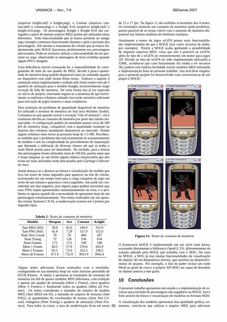
(arquivos knight.md2 e knight.png), o Centaur (arquivos cen-taur.md2 e centaur.png) e o Knight Evil (arquivos knight.md2 eknight evil.png). Os personagens Knight e Knight Evil sao car-regados a partir do mesmo arquivo MD2 porem sao utilizados skinsdiferentes. Toda funcionalidade que ja estava presente no antigojogo exemplo continuou funcionando durante e apos a inclusao dospersonagens. Ate mesmo o tratamento de colisao que ja estava im-plementado pela M3GE funcionou perfeitamente nos personagensadicionados. Pode-se inclusive utilizar a funcionalidade de tiro pre-sente no jogo, observando as mensagens de texto exibidas quandoalgum PNJe atingido.
Uma deficiencia inicial constatada foi a impossibilidade de carre-gamento de mais de um quadro do MD2, devidoa pouca quanti-dade de memoriaheappadrao disponıvel tanto no emulador quantono dispositivo real onde foram feitos testes. Embora o suporteaanimacao esteja implementado e tenham sido feitos testes com ate 5quadros de animacao para o modelo Knight, invariavelmente surgeexcecao de falta de memoria. De certa forma isto ja era esperadono inıcio do projeto, entretanto seguiu-se a premissa de que breve-mente os telefones celulares rodando Java terao memoria suficientepara execucao de jogos maiores e mais complexos.
Para avaliacao do problema de quantidade disponıvel de memoriafoi utilizado o monitor de memoria do Sun Java Wireless Toolkit.Constatou-se que quando ocorre a excecao “Out of memory”, elaerealmente devida ao consumo de memoria por parte das classes ins-tanciadas. A configuracao padrao do emulador possui cerca de 500Kb de memoria heap, compatıvel com a quantidade existente namaioria dos celulares atualmente disponıveis no mercado. Poremalguns celulares mais novos ja possuemheapde 1.5 Mb. Percebeu-se tambem que o problema nao esta exatamente no armazenamentodo modelo e sim na complexidade do procedimento de importacaoque demanda a utilizacao de diversas classes ate que se tenha onodo Mesh pronto para ser desenhado. Na verdade, para a leiturados personagens foram utilizados mais de 500 Kb, porem antes queo heapchegasse ao seu limite alguns objetos instanciados que naoiriam ser mais utilizados eram descartados peloGarbage Collectordo Java.
Ainda destaca-se a demora na leitura e visualizacao do modelo queleva em torno de trinta segundos para aparecer na tela do celular,acarretando em um tempo total para a carga completa do jogo emtorno de um minuto e quarenta e cinco segundos. Isto pode ser con-siderado um fato negativo, pois alguns jogos podem necessitar queseus PNJs sejam apresentados instantaneamente na cena, e o pro-blema se agrava quando ha a necessidade de apresentar mais de umpersonagem simultaneamente. Nos testes realizados em um apare-lho celular Siemens CX 65, a renderizacao ocorreu em 5framesporsegundo (fps).
Tabela 2: Testes de consumo de memoria
Modelo Weapon Axe Centaur Knight
Tam MD2 (Kb) 38.0 62.0 240.0 312.0Tam PNG (Kb) 42.8 7.29 157.0 132.0
Num Text Coord 70 78 469 307Num Triang 72 126 536 634Num Frames 173 173 199 198Mem 1 Frame 84.5 57.0 276.0 263.9Mem 5 Frames 93.5 72.6 322.2 338.5Mem all Frames 471.9 732.8 3053.9 3942.4
Alguns testes adicionais foram realizados com o emulador,configurando-se sua memoria heapno valor maximo permitido de65536 Kbytes. A tabela 2 apresenta os resultados de consumo dememoria em Kb de quatro modelos MD2 diferentes, com exibicaoe apenas um quadro de animacao (Mem 1 Frame), cinco quadros(Mem 5 Frames) e finalmente todos os quadros (Mem all Fra-mes). Os testes consideram o tamanho do arquivo de modeloMD2 (Tam MD2) em Kb, o tamanho do arquivo de texturas (TamPNG), as quantidades de coordenadas de textura (Num Text Co-ord), triangulos (Num Triang) e quadros de animacao (Num Fra-mes). Para todos os casos, a taxa de renderizacao ficou em torno
de 15 a 17 fps. Na figura 11 sao exibidosscreenshotsdos 4 testes.Os resultados mostram um consumo de memoria ainda proibitivo,porem passıvel de se tornar viavel com o aumento de memoria dis-ponıvel nos futuros modelos de telefones celulares.
Atualmente a motor de jogos wGEN possui mais funcionalida-des implementadas do que a M3GE (tais como recursos deaudio,por exemplo). Porem a M3GE acaba ganhando a possibilidadede importar arquivos MD2, coisa que nao e possıvel na wGEN,alem do fato de a wGEN ser eminentemente um motor para jogos2D. Devido ao fato da wGEN ter sido implementada utilizando aJ2ME, acredita-se que caso futuramente ela venha a ter recursos3D, podera com relativa facilidade incluir modelos MD2 utilizandoa implementacao feita no presente trabalho. Isto sera bem simples,pois o presente projeto foi desenvolvido com caracterısticas de umplugin a M3GE.
Figura 11: Testes de consumo de memoria
O frameworkmOGE e implementado em um nıvel mais baixo,acessando diretamente a biblioteca OpenGL ES, diferentemente dasolucao adotada pela M3GE que trabalha com o M3G. No casoda M3GE, a M3G ja traz muitas funcionalidades de visualizacaode objetos 3D em dispositivos moveis, que auxiliou no desenvolvi-mento do projeto. Por exemplo, o fato de poder incluir um nodoMesh ao grafo de cena e a propria API M3G ser capaz de desenharos objetos anexos a este grafo.
10 Conclus oes
O presente trabalho apresentou um estudo e a implementacao de re-cursos para inclusao de personagens nao-jogadores na M3GE. Istoefeito atraves da leitura e visualizacao de modelos no formato M2D.
A visualizacao dos modelos apresentou boa qualidade grafica, en-tretanto, conclui-se que utilizar o arquivo MD2 para adicionar
UNISINOS - Nov., 7-9 SBGames 2007
60
PNJ aos jogose atualmente inviavel no desenvolvimento de jogoscomerciais perante a ainda pequena quantidade de memoria dis-ponıvel ea demora em renderizar os personagens nos atuais apare-lhos de telefonia celular disponıveis no mercado brasileiro. Porem,acredita-se que este problema podera ser contornado de duas for-mas. A primeira consiste na tendencia de melhoria nos recursosde hardware dos futuros dispositivos moveis. A segunda consisteem utilizar tecnicas de reducao de nıvel de detalhe das malhasde polıgonos dos modelos, diminuindo assim a carga de processa-mento grafico exigida para sua renderizacao. Acredita-se que istopode trazer bons resultados, e justifica-se devidoa baixa resolucaografica dos visores dos atuais aparelhos celulares.
Para testes e validacao dos resultados, foi implementado umprototipo de jogo com mais de um PNJ em cena, entretanto, devidoa limitacoes de memoria dos dispositivos reais, nao foi possıvel vi-sualizar de forma satisfatoria as animacoes dos modelos MD2. Foipossıvel a visualizacao de todos os quadros de animacao nos mode-los MD2 testados em emuladores, desde que estes fossem configu-rados para permitir o uso maximo de memoria permitido.
Os resultados obtidos neste trabalho demonstram quee possıvelutilizar o arquivo MD2 para a manipulacao de personagens emmotores de jogos para dispositivos moveis, apesar da demora naimportacao dos modelos. Desta forma, abre-se a possibilidadede desenvolvimento de estudos que possibilitem novas descober-tas para viabilizar a utilizacao de MD2 em telefones celulares, es-pecialmente considerando as animacoes dos modelos como um re-quisito altamente desejavel para o desenvolvimento de jogos comPNJs. Com esta primeira experiencia, os autores sugerem tambemestudos para a integracao de recursos de Inteligencia Artificial aosPNJs, de forma a melhorar a qualidade dos jogos 3D para disposi-tivos moveis.
Refer encias
BYL , P. B. 2004.Programming believable characters for computergames. Charles River Media, Massachusetts.
CARANDINA , R., AND MARTINS, T. 2006. Suporte a jogos multi-usuario em engine 3d para dispositivos moveis. Tech. rep., Cen-tro Universitario Senac, Sao Paulo, Junho.
CONITEC CORPORATION, 2004. 3d gamestudio / a6.http://conitec.net/a4info.htm , Acesso em: 17 abr. 2006.
CRYSTAL SPACE, 2004. Crystal space 3d.http://crystal.sourceforge.net , Acesso em: 17 abr. 2006.
DE ALBUQUERQUE MACEDO JR., I. J. 2005. moge – mobilegraphics engine: o projeto de um motor grafico 3d para a criacaode jogos em dispositivos moveis. Tech. rep., UFPE.
ECLIPSE ENTERTAINMENT, 2004. Welcome to the home of gene-sis3d.http://www.genesis3d.com/ , Acesso em: 17 abr.2006.
ELEMENTS INTERACTIVE, 2007. Edgelib mobile game engine.http://www.edgelib.com/ , Acesso em: 25 ago. 2007.
FINNEY, K. C. 2004.3D game programming, all in one. ThomsonCourse Technology, Boston.
FISHLABS ENTERTAINMENT GMBH, 2007. Fishlabs 3d mobilejava games.http://www.fishlabs.net/en/engine/index.php , Acesso em: 25 ago. 2007.
GOMES, P. C. R.,AND PAMPLONA , V. F. 2005. M3ge: um motorde jogos 3d para dispositivos moveis com suporte a mobile 3dgraphics api. InSBGames2005 - Simposio Brasileiro de Jogospara Computador e entretenimento Digital, Anais do WJOGOS2005, SBC, 55–65.
GUILIANO , S., 2005. Autonomous productions.http://www.autonomousproductions.com/ , Acesso em: 14set. 2005.
HARRISON, L. T. 2003. Introduction to 3D game engine designusing directx 9 and C#. Springer-Verlag, New York.
HENRY, D., 2004. Md2 file format (quake 2’s model).http://tfc.duke.free.fr/coding/md2-specs-en.html ,Acesso em: 24 mar. 2006.
HOFELE, C., 2005. 3d graphics for java mobile devices,part 1: M3g’s immediate mode. http://www-128.ibm.com/developerworks/wireless/library/wi-mobile1/ , Acesso em: 17 mar. 2006.
KHRONOS GROUP, 2004. Opengl es: overview.http://www.opengles.org/opengles/index.html , Acesso em: 17abr. 2006.
LEHMANN , J., 2004. Xith3d: contents.http://xith.org/tutes/GettingStarted/html/contents.html ,Acesso em: 25 out. 2006.
MD2, 2005. Md2 - gpwiki. http://gpwiki.org/index.php/MD2 , Acesso em: 24 mar. 2006.
M ISFIT CODE, 2005. Misfit model 3d. http://www.misfitcode.com/misfitmodel3d/olh_quakemd2.html , Acesso em: 24 mar. 2006.
M ULLER, L. F., FRANTZ, G. J.,AND SCHREIBER, J. N. C. 2005.Qualcomm brew x sun j2me: um comparativo entre solucoespara desenvolvimento de jogos em dispositivos moveis. InSUL-COMP - Congresso Sul Catarinense de Computacao, vol. 1, Sul-comp, 1–8.
NOKIA . 2003. Jsr-184 mobile 3d api for j2me. Tech. rep.,[P.O.Box].
NOKIA , 2004. Ri binary for jsr-184 3d graphics api for j2me.http://www.forum.nokia.com/main/ , Acesso em 19abr. 2006.
OGRE3D, 2005. Ogre 3d: open source graphics engine.http://www.ogre3d.org , Acesso em: 15 jul. 2007.
PAIVA , F., 2003. O jogo das operadoras. http://www.teletime.com.br/revista/55/capa.htm ,Acesso em: 05 abr. 2006.
PARALELO COMPUTACAO, 2004. Fly3d.com.br.http://www.fly3d.com.br , Acesso em: 17 abr. 2006.
PESSOA, C. A. C. 2001.wGEM. Master’s thesis, UFPE, Recife.
SANCHEZ, D., AND DALMAU , C. 2004. Core techniques andalgorithms in game programming. New Riders, Indianapolis.
SANTEE, A. 2005. Programacao de jogos com C++ e DirectX.Novatec Editora, Sao Paulo.
UNISINOS - Nov., 7-9 SBGames 2007
61
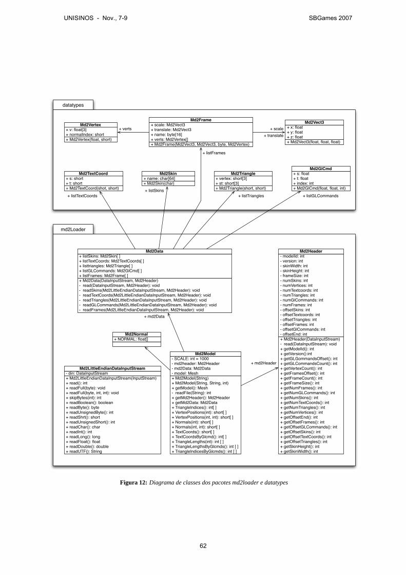
md2Loader
+ Md2Model(String)+ Md2Model(String, String, int)+ getModel(): Mesh- readFile(String): int+ getMd2Header(): Md2Header+ getMd2Data: Md2Data+ TriangleIndices(): int[ ]+ VertexPositions(int): short[ ]+ VertexPositions(int, int): short[ ]+ Normals(int): short[ ]+ Normals(int, int): short[ ]+ TextCoords(): short[ ]+ TextCoordsByGlcmd(): int[ ]+ TriangleLengths(int): int [ ]+ TriangleLengthsByGlcmds(): int [ ]+ TriangleIndicesByGlcmds(): int [ ]
- SCALE: int = 1000- md2header: Md2Header- md2Data: Md2Data- model: Mesh
Md2Model
+ Md2LittleEndianDataInputStream(InputStream)+ read(): int+ readFull(byte): void+ readFull(byte, int, int): void+ skipBytes(int): int+ readBoolean(): boolean+ readByte(): byte+ readUnsignedByte(): int+ readShrt(): short+ readUnsignedShort(): int+ readChar(): char+ readInt(): int+ readLong(): long+ readFloat(): float+ readDouble(): double+ readUTF(): String
- din: DataInputStreamMd2LittleEndianDataInputStream
+ Md2Header(DataInputStream)- read(DataInputStream): void+ getModelId(): int+ getVersion():int+ getGLGommandsOffset(): int+ getGLCommandsCount(): int+ getVertexCount(): int+ getFramesOffset(): int+ getFrameCount(): int+ getFrameSize(): int+ getNumFrames(): int+ getNumGLCommands(): int+ getNumSkins(): int+ getNumTextCoords(): int+ getNumTriangles(): int+ getNumVertices(): int+ getOffsetEnd(): int+ getOffsetFrames(): int+ getOffsetGLCommands(): int+ getOffsetSkins(): int+ getOffsetTextCoords(): int+ getOffsetTriangles(): int+ getSkinHeight(): int+ getSkinWidth(): int
- modelId: int- version: int- skinWidth: int- skinHeight: int- frameSize: int- numSkins: int- numVertices: int- numTextcoords: int- numTriangles: int- numGlCommands: int- numFrames: int- offsetSkins: int- offsetTextcoords: int- offsetTriangles: int- offsetFrames: int- offsetGlCommands: int- offsetEnd: int
Md2Header
+ Md2Data(DataInputStream, Md2Header)- read(DataInputStream, Md2Header): void- readSkins(Md2LittleEndianDataInputStream, Md2Header): void- readTextCoords(Md2LittleEndianDataInputStream, Md2Header): void- readTriangles(Md2LittleEndianDataInputStream, Md2Header): void- readGLCommands(Md2LittleEndianDataInputStream, Md2Header): void- readFrames(Md2LittleEndianDataInputStream, Md2Header): void
+ listSkins: Md2Skin[ ]+ listTextCoords: Md2TextCoords[ ]+ listtriangles: Md2Triangle[ ]+ listGLCommands: Md2GlCmd[ ]+ listFrames: Md2Frame[ ]
Md2Data
datatypes
+ Md2Vertex(float, short)
+ v: float[3]+ normalIndex: short
Md2Vertex
+ Md2TextCoord(shot, short)
+ s: short+ t: short
Md2TextCoord
+ Md2Skin(char)+ name: char[64]
Md2Skin
+ Md2Frame(Md2Vect3, Md2Vect3, byte, Md2Vertex)
+ scale: Md2Vect3+ translate: Md2Vect3+ name: byte[16]+ verts: Md2Vertex[]
Md2Frame
+ Md2GlCmd(float, float, int)
+ s: float+ t: float+ index: int
Md2GlCmd
+ Md2Triangle(short, short)
+ vertex: short[3]+ st: short[3]
Md2Triangle
+ Md2Vect3(float, float, float)
+ x: float+ y: float+ z: float
Md2Vect3+ scale
+ translate+ verts
+ listFrames
+ listTextCoords+ listSkins
+ listGLCommands
+ md2Header
+ md2Data
+ listTriangles
+ NORMAL: float[]
Md2Normal
Figura 12: Diagrama de classes dos pacotes md2loader e datatypes
UNISINOS - Nov., 7-9 SBGames 2007
62
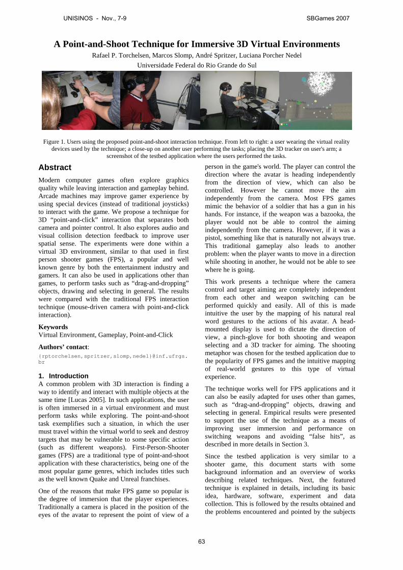
A Point-and-Shoot Technique for Immersive 3D Virtual Environments Rafael P. Torchelsen, Marcos Slomp, André Spritzer, Luciana Porcher Nedel
Universidade Federal do Rio Grande do Sul
Abstract Modern computer games often explore graphics quality while leaving interaction and gameplay behind. Arcade machines may improve gamer experience by using special devices (instead of traditional joysticks) to interact with the game. We propose a technique for 3D “point-and-click” interaction that separates both camera and pointer control. It also explores audio and visual collision detection feedback to improve user spatial sense. The experiments were done within a virtual 3D environment, similar to that used in first person shooter games (FPS), a popular and well known genre by both the entertainment industry and gamers. It can also be used in applications other than games, to perform tasks such as “drag-and-dropping” objects, drawing and selecting in general. The results were compared with the traditional FPS interaction technique (mouse-driven camera with point-and-click interaction).
Keywords Virtual Environment, Gameplay, Point-and-Click
Authors’ contact: {rptorchelsen,spritzer,slomp,nedel}@inf.ufrgs.br
1. Introduction A common problem with 3D interaction is finding a way to identify and interact with multiple objects at the same time [Lucas 2005]. In such applications, the user is often immersed in a virtual environment and must perform tasks while exploring. The point-and-shoot task exemplifies such a situation, in which the user must travel within the virtual world to seek and destroy targets that may be vulnerable to some specific action (such as different weapons). First-Person-Shooter games (FPS) are a traditional type of point-and-shoot application with these characteristics, being one of the most popular game genres, which includes titles such as the well known Quake and Unreal franchises.
One of the reasons that make FPS game so popular is the degree of immersion that the player experiences. Traditionally a camera is placed in the position of the eyes of the avatar to represent the point of view of a
person in the game's world. The player can control the direction where the avatar is heading independently from the direction of view, which can also be controlled. However he cannot move the aim independently from the camera. Most FPS games mimic the behavior of a soldier that has a gun in his hands. For instance, if the weapon was a bazooka, the player would not be able to control the aiming independently from the camera. However, if it was a pistol, something like that is naturally not always true. This traditional gameplay also leads to another problem: when the player wants to move in a direction while shooting in another, he would not be able to see where he is going.
This work presents a technique where the camera control and target aiming are completely independent from each other and weapon switching can be performed quickly and easily. All of this is made intuitive the user by the mapping of his natural real word gestures to the actions of his avatar. A head-mounted display is used to dictate the direction of view, a pinch-glove for both shooting and weapon selecting and a 3D tracker for aiming. The shooting metaphor was chosen for the testbed application due to the popularity of FPS games and the intuitive mapping of real-world gestures to this type of virtual experience.
The technique works well for FPS applications and it can also be easily adapted for uses other than games, such as “drag-and-dropping” objects, drawing and selecting in general. Empirical results were presented to support the use of the technique as a means of improving user immersion and performance on switching weapons and avoiding “false hits”, as described in more details in Section 3.
Since the testbed application is very similar to a shooter game, this document starts with some background information and an overview of works describing related techniques. Next, the featured technique is explained in details, including its basic idea, hardware, software, experiment and data collection. This is followed by the results obtained and the problems encountered and pointed by the subjects
Figure 1. Users using the proposed point-and-shoot interaction technique. From left to right: a user wearing the virtual reality devices used by the technique; a close-up on another user performing the tasks; placing the 3D tracker on user's arm; a
screenshot of the testbed application where the users performed the tasks.
UNISINOS - Nov., 7-9 SBGames 2007
63
of the experiment. Finally, conclusions are summarized and a set of improvements, future works and research opportunities are listed.
2. Related Work Despite the lack of publications from the game industry and developers, it is interesting to examine how shooter games emerged and evolved. After this briefing, some relevant related works will be discussed.
Arcade games were a very popular entertainment choice during the 80's. Missile Command [Web 1], a game from Atari, was launch in mid 1980 to become on of the greatest classic video games ever. The gameplay was very simple: move a cursor on the screen and press a button to shoot missiles at enemy missiles in order to keep them from hitting cities that were located below the screen. All interaction was done using a trackball and three buttons correspondent to three onscreen cannons that could be used by the player to accomplish his in-game mission. Within a level, the cursor moves always at the same speed, which is increased as the player advances in the game. The view was static, which means that the player was not free to explore the world. Years later, the same game was ported to Atari 2600, which introduced an axis-based joystick with a single button, but its gameplay barely changed.
Another relevant game appeared in 1984, when Duck Hunt [Web 2] was launched by Nintendo in Japan for its Nintendo Entertainment System (NES). The same idea from Missile Command was present here, but the player was able to interact with a more realistic metaphor: a pistol, which was used by pointing it at the screen and pressing its trigger. The screen was also static. Variants of the same game allows the player to interact using the default joystick from NES, which consists of a digital pad with four directions (DPad).
Many other games emerged from Missile Command and Duck Hunt, but, in 1992, Konami launched for the arcade the game Lethal Enforcers [Web 3], which uses the pistol metaphor and also allows limited weapon switching and camera movement. During gameplay, an icon of a weapon appears on the screen and if the user shoots at it, the current weapon becomes the one represented by the icon and it will be active until it runs out of bullets, in which case it will switch back to the initial gun. The camera moves horizontally (scrolling) after the player eliminates all enemies in an area (screen). VirtualCop [5], an arcade game by SEGA released in 1994, allowed the player to move in a 3D virtual environment, but the camera still moved without any interaction from the player. From this day on, no relevant modifications were made on the gameplay of this type of shooting game.
Two years later from VirtuaCop a new game style was born: Wolfenstein 3D [Web 4] was launched by id Software for the PC (DOS). The player was able to freely move within the virtual environments of the game, moving forward and
backward and looking right or left. Looking up or down was not possible. A virtual gun was placed (drawn) on the bottom of the screen, centered, thus locking the aiming to the camera movement. Basically, all interaction was done with the traditional keyboard, including weapon switching. It was the beginning of the First-Person Shooter era, and many games derived from Wolfenstein 3D, including the well known Doom [Web 5] and Quake [Web 6] franchises, also from id Software.
The most significant advance in gameplay from Wolfenstein 3D to modern FPS gaming is the possibility of looking freely by using the mouse to control the camera. But again, aim and camera control are bound together. Some games, such as Freelancer [Web 7], from Microsoft, allowed aiming to be done independently from the camera, but since navigation and aiming were done using mouse, they tended to mutually interfere. There were also FPS games that used virtual reality devices (head-mounted displays) to improve the gamer experience. In these cases, looking and aiming were again bound together and shooting and weapon switching was accomplished in non-intuitive ways, using special joysticks which were held by the player. But outside of the game industry most of the work in techniques of 3D point-and-click [Ughini 2006] [Hugg 2006] [Jacob 1990] [Kyriakakis 2001] are related to direct selecting objects not predicting its trajectory. Predicting the trajectory of objects is a common task to us and most of the time prediction of movement is mapped to the mouse [Huff 2006]. But we are used to track moving objects with the eyes, to take advantage of this work has being done to use both hands and eyes to select objects [Jacob 1990] [Yamato 2000] [Ware 2000]. Another important aspect in predicting movement is the sound produced in most of objects in movement, the sound can help locating objects and predict speed [Kyriakakis 2001]. Following the cited characteristics and work we present a technique to map the prediction of movements and selection of objects in a 3D immersive environment and compare it to a traditional mouse selection technique.
3. Method Within this section, all implementation details will be discussed. First, an overview of the basic concept of the proposed technique is provided. The hardware available for the implementation of the concept is then presented, followed by the software used and implemented. The experiment is then discussed in details, including the hypothesis, dependent and independent variables, and what data was collected from the testbed application and from the questionnaire applied to each participant.
3.1 Concept The technique works very well for point-and-shoot applications, since its goal is to skirt problems and limitations found in existing interaction techniques, the following items should be considered: • user should be able to look freely;
UNISINOS - Nov., 7-9 SBGames 2007
64
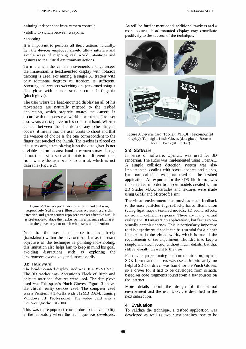
• aiming independent from camera control; • ability to switch between weapons; • shooting. It is important to perform all these actions naturally, i.e., the devices employed should allow intuitive and simple ways of mapping real world intentions and gestures to the virtual environment actions. To implement the camera movements and garantees the immersion, a headmounted display with rotation tracking is used. For aiming, a single 3D tracker with only rotational degrees of freedom is sufficient. Shooting and weapon switching are performed using a data glove with contact sensors on each fingertip (pinch glove). The user wears the head-mounted display an all of his movements are naturally mapped to the testbed application, which properly rotates the camera in accord with the user's real world movements. The user also wears a data glove on his dominant hand. When a contact between the thumb and any other fingers occurs, it means that the user wants to shoot and that the weapon of choice is the one correspondent to the finger that touched the thumb. The tracker is placed on the user's arm, since placing it on the data glove is not a viable option because hand movements may change its rotational state so that it points to a different place from where the user wants to aim at, which is not desirable (Figure 2).
Note that the user is not able to move freely (translation) within the environment, but as the main objective of the technique is pointing-and-shooting, this limitation also helps him to keep in mind his goal, avoiding distractions such as exploring the environment excessively and unnecessarily.
3.2 Hardware The head-mounted display used was IISVR's VFX3D. The 3D tracker was Ascention's Flock of Birds and only its rotational features were used. The data glove used was Fakespace's Pinch Gloves. Figure 3 shows the virtual reality devices used. The computer used was a Pentium 4 1.4GHz with 512MB RAM, running Windows XP Professional. The video card was a GeForce Quadro FX2000. This was the equipment chosen due to its availability at the laboratory where the technique was developed.
As will be further mentioned, additional trackers and a more accurate head-mounted display may contribute positively to the success of the technique.
3.3 Software In terms of software, OpenGL was used for 3D rendering. The audio was implemented using OpenAL. A simple collision detection system was also implemented, dealing with boxes, spheres and planes, but box collision was not used in the testbed application. An exporter for the 3DS file format was implemented in order to import models created within 3D Studio MAX. Particles and textures were made using GIMP and Microsoft Paint. The virtual environment thus provides much feedback to the user: particles, fog, radiosity-based illumination (using light maps), textured models, 3D sound effects, music and collision response. There are many virtual reality and 3D interaction applications, but few explore visually complex scenes. This is particularly important to this experiment since it can be essential for a higher immersion in the virtual world, which is one of the requirements of the experiment. The idea is to keep a simple and clean scene, without much details, but that still is visually pleasant to the user. For device programming and communication, support SDK from manufacturers was used. Unfortunately, no helpful SDK or driver was found for the Pinch Gloves, so a driver for it had to be developed from scratch, based on code fragments found from a few sources on the Internet. More details about the design of the virtual environment and the user tasks are described in the next subsection.
4. Evaluation To validate the technique, a testbed application was developed as well as two questionnaires, one to be
Figure 2. Tracker positioned on user's hand and arm, respectively (red circles). Blue arrows represent user's aim
intention and green arrows represent tracker effective aim. It is preferable to place the tracker on his arm, since placing it
on the glove may not match with user's aim intention.
Figure 3. Devices used. Top-left: VFX3D (head-mounted display). Top-right: Pinch Gloves (data glove). Bottom:
Flock of Birds (3D tracker).
UNISINOS - Nov., 7-9 SBGames 2007
65
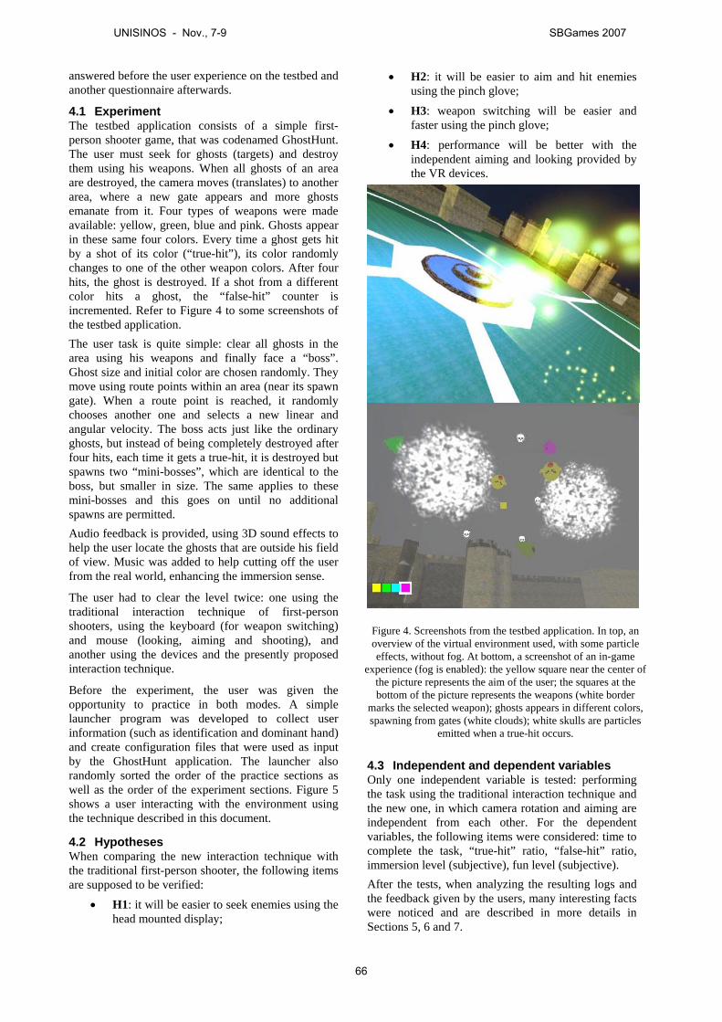
answered before the user experience on the testbed and another questionnaire afterwards.
4.1 Experiment The testbed application consists of a simple first-person shooter game, that was codenamed GhostHunt. The user must seek for ghosts (targets) and destroy them using his weapons. When all ghosts of an area are destroyed, the camera moves (translates) to another area, where a new gate appears and more ghosts emanate from it. Four types of weapons were made available: yellow, green, blue and pink. Ghosts appear in these same four colors. Every time a ghost gets hit by a shot of its color (“true-hit”), its color randomly changes to one of the other weapon colors. After four hits, the ghost is destroyed. If a shot from a different color hits a ghost, the “false-hit” counter is incremented. Refer to Figure 4 to some screenshots of the testbed application. The user task is quite simple: clear all ghosts in the area using his weapons and finally face a “boss”. Ghost size and initial color are chosen randomly. They move using route points within an area (near its spawn gate). When a route point is reached, it randomly chooses another one and selects a new linear and angular velocity. The boss acts just like the ordinary ghosts, but instead of being completely destroyed after four hits, each time it gets a true-hit, it is destroyed but spawns two “mini-bosses”, which are identical to the boss, but smaller in size. The same applies to these mini-bosses and this goes on until no additional spawns are permitted. Audio feedback is provided, using 3D sound effects to help the user locate the ghosts that are outside his field of view. Music was added to help cutting off the user from the real world, enhancing the immersion sense.
The user had to clear the level twice: one using the traditional interaction technique of first-person shooters, using the keyboard (for weapon switching) and mouse (looking, aiming and shooting), and another using the devices and the presently proposed interaction technique.
Before the experiment, the user was given the opportunity to practice in both modes. A simple launcher program was developed to collect user information (such as identification and dominant hand) and create configuration files that were used as input by the GhostHunt application. The launcher also randomly sorted the order of the practice sections as well as the order of the experiment sections. Figure 5 shows a user interacting with the environment using the technique described in this document.
4.2 Hypotheses When comparing the new interaction technique with the traditional first-person shooter, the following items are supposed to be verified:
• H1: it will be easier to seek enemies using the head mounted display;
• H2: it will be easier to aim and hit enemies using the pinch glove;
• H3: weapon switching will be easier and faster using the pinch glove;
• H4: performance will be better with the independent aiming and looking provided by the VR devices.
4.3 Independent and dependent variables Only one independent variable is tested: performing the task using the traditional interaction technique and the new one, in which camera rotation and aiming are independent from each other. For the dependent variables, the following items were considered: time to complete the task, “true-hit” ratio, “false-hit” ratio, immersion level (subjective), fun level (subjective). After the tests, when analyzing the resulting logs and the feedback given by the users, many interesting facts were noticed and are described in more details in Sections 5, 6 and 7.
Figure 4. Screenshots from the testbed application. In top, an overview of the virtual environment used, with some particle effects, without fog. At bottom, a screenshot of an in-game
experience (fog is enabled): the yellow square near the center of the picture represents the aim of the user; the squares at the bottom of the picture represents the weapons (white border
marks the selected weapon); ghosts appears in different colors, spawning from gates (white clouds); white skulls are particles
emitted when a true-hit occurs.
UNISINOS - Nov., 7-9 SBGames 2007
66
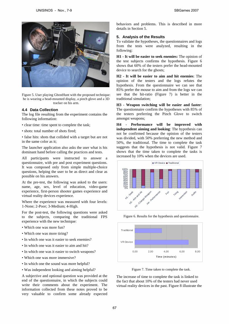
4.4 Data Collection The log file resulting from the experiment contains the following information: • clear time: time spent to complete the task; • shots: total number of shots fired; • false hits: shots that collided with a target but are not in the same color as it; The launcher application also asks the user what is his dominant hand before calling the practices and tests. All participants were instructed to answer a questionnaire, with pre and post experiment questions. It was composed only from simple multiple-choice questions, helping the user to be as direct and clear as possible on his answers. At the pre-test, the following was asked to the users: name, age, sex, level of education, video-game experience, first-person shooter games experience and virtual reality devices experience. Where the experience was measured with four levels: 1-None; 2-Poor; 3-Medium; 4-High. For the post-test, the following questions were asked to the subjects, comparing the traditional FPS experience with the new technique: • Which one was more fun? • Which one was more tiring? • In which one was it easier to seek enemies? • In which one was it easier to aim and hit? • In which one was it easier to switch weapons? • Which one was more immersive? • In which one the sound was more helpful? • Was independent looking and aiming helpful? A subjective and optional question was provided at the end of the questionnaire, in which the subjects could write their comments about the experiment. The information collected from these notes proved to be very valuable to confirm some already expected
behaviors and problems. This is described in more details in Section 5.
5. Analysis of the Results To validate the hypotheses, the questionnaires and logs from the tests were analyzed, resulting in the following: H1 - It will be easier to seek enemies: The opinion of the test subjects confirms the hypothesis. Figure 6 shows that 60% of the testers prefer the head-mounted device to search for the ghosts; H2 - It will be easier to aim and hit enemies: The opinion of the testers and the logs refutes the hypothesis. From the questionnaire we can see that 85% prefer the mouse to aim and from the logs we can see that the hit-ratio (Figure 7) is better in the traditional simulation; H3 - Weapon switching will be easier and faster: The questionnaire confirm the hypotheses with 85% of the testers preferring the Pinch Glove to switch amongst weapons; H4 - Performance will be improved with independent aiming and looking: The hypothesis can not be confirmed because the opinion of the testers was divided, with 50% preferring the new method and 50%, the traditional. The time to complete the task suggests that the hypothesis is not valid. Figure 7 shows that the time taken to complete the tasks is increased by 10% when the devices are used.
0%10%20%30%40%50%60%70%80%90%
100%
H1 - See
k
H2 - Aim
and H
it
H3 - Cha
nge W
eapo
n
H4 - Perf
ormanc
eFun
Tiring
Immersi
onAud
io
VR Device Traditional
0,00 2,00 4,00 6,00 8,00
VR Device
Traditional
Time (minutes)
The increase of time to complete the task is linked to the fact that about 10% of the testers had never used virtual reality devices in the past. Figure 8 illustrate the
Figure 5. User playing GhostHunt with the proposed technique: he is wearing a head-mounted display, a pinch glove and a 3D
tracker on his arm.
Figure 6. Results for the hypothesis and questionnaire.
Figure 7. Time taken to complete the task.
UNISINOS - Nov., 7-9 SBGames 2007
67
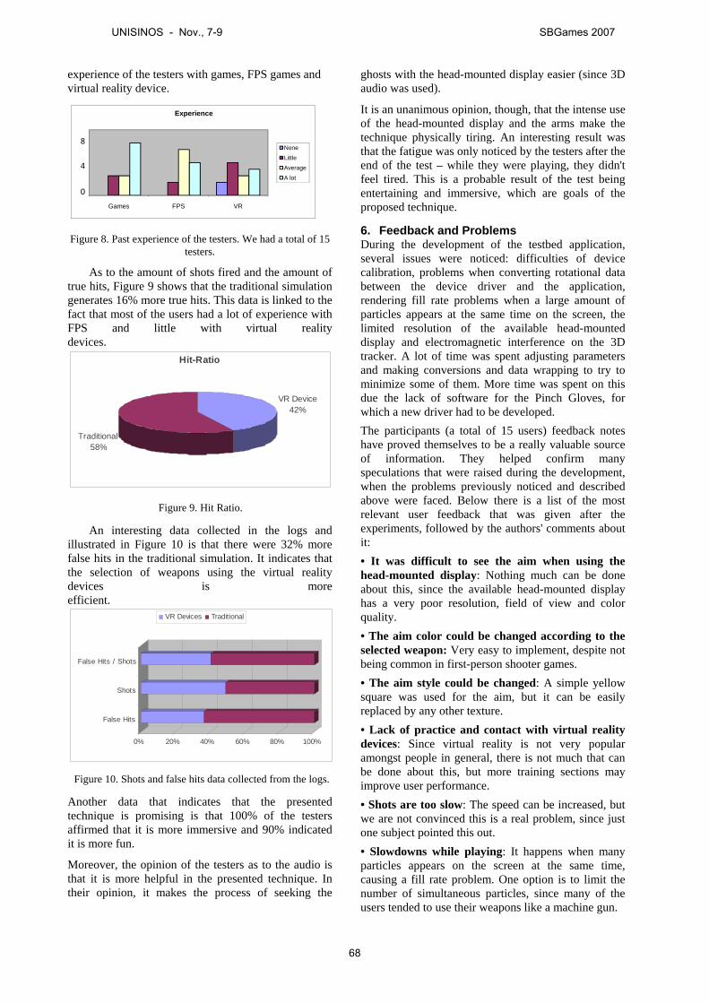
experience of the testers with games, FPS games and virtual reality device.
Games FPS VR
Experience
None
Little
Average
A lot
8
4
0
Figure 8. Past experience of the testers. We had a total of 15 testers.
As to the amount of shots fired and the amount of true hits, Figure 9 shows that the traditional simulation generates 16% more true hits. This data is linked to the fact that most of the users had a lot of experience with FPS and little with virtual reality devices.
Hit-Ratio
VR Device42%
Traditional58%
An interesting data collected in the logs and illustrated in Figure 10 is that there were 32% more false hits in the traditional simulation. It indicates that the selection of weapons using the virtual reality devices is more efficient.
0% 20% 40% 60% 80% 100%
False Hits
Shots
False Hits / Shots
VR Devices Traditional
Another data that indicates that the presented technique is promising is that 100% of the testers affirmed that it is more immersive and 90% indicated it is more fun.
Moreover, the opinion of the testers as to the audio is that it is more helpful in the presented technique. In their opinion, it makes the process of seeking the
ghosts with the head-mounted display easier (since 3D audio was used).
It is an unanimous opinion, though, that the intense use of the head-mounted display and the arms make the technique physically tiring. An interesting result was that the fatigue was only noticed by the testers after the end of the test – while they were playing, they didn't feel tired. This is a probable result of the test being entertaining and immersive, which are goals of the proposed technique.
6. Feedback and Problems During the development of the testbed application, several issues were noticed: difficulties of device calibration, problems when converting rotational data between the device driver and the application, rendering fill rate problems when a large amount of particles appears at the same time on the screen, the limited resolution of the available head-mounted display and electromagnetic interference on the 3D tracker. A lot of time was spent adjusting parameters and making conversions and data wrapping to try to minimize some of them. More time was spent on this due the lack of software for the Pinch Gloves, for which a new driver had to be developed. The participants (a total of 15 users) feedback notes have proved themselves to be a really valuable source of information. They helped confirm many speculations that were raised during the development, when the problems previously noticed and described above were faced. Below there is a list of the most relevant user feedback that was given after the experiments, followed by the authors' comments about it: • It was difficult to see the aim when using the head-mounted display: Nothing much can be done about this, since the available head-mounted display has a very poor resolution, field of view and color quality. • The aim color could be changed according to the selected weapon: Very easy to implement, despite not being common in first-person shooter games. • The aim style could be changed: A simple yellow square was used for the aim, but it can be easily replaced by any other texture. • Lack of practice and contact with virtual reality devices: Since virtual reality is not very popular amongst people in general, there is not much that can be done about this, but more training sections may improve user performance. • Shots are too slow: The speed can be increased, but we are not convinced this is a real problem, since just one subject pointed this out. • Slowdowns while playing: It happens when many particles appears on the screen at the same time, causing a fill rate problem. One option is to limit the number of simultaneous particles, since many of the users tended to use their weapons like a machine gun.
Figure 9. Hit Ratio.
Figure 10. Shots and false hits data collected from the logs.
UNISINOS - Nov., 7-9 SBGames 2007
68
• The Pinch Gloves failed to respond sometimes: It was noticed before that the Pinch Gloves do not fit very well in all hand sizes, which can cause difficulties in detecting the contact between the fingers – mainly when trying to touch the thumb with the little finger. • Aiming problems when the hand is too far away from the body: The data retrieved from the tracker presents an increasing and significant error as the tracker is moved away from its magnetic base. This error is accentuated by the presence of nearby metal objects, which may cause a magnetic interference. With more appropriate devices and more calibration and training, the authors believe it is possible to highly increase user performance and validate the second hypothesis. Despite all these problems, all users preferred the new technique, considering it more fun and immersive. Another interesting fact is that the weight of the head-mounted display was barely noticed when doing the tests of the new technique, and the authors believe that the immersion level provided by the devices and the feedback given by the testbed application helped the user to ignore its weight.
7. Conclusions and Future Works Since it has been some time that first-person shooters use the same type of interaction, the proposed technique comes to revigorate the genre. To that goal the proposed point-and-shooting technique presents positive results and feedback. The results showed that weapon switching was more entertaining and efficient with the proposed technique. It was also noticed that users tended to perform less false-hits using the new method. It received mostly positive feedback from testers, especially in regards to the entertainment level and the mapping of real-life movements. Such mapping can be used not only in FPS games, but also in any application that requires fast switching of tools, selecting, point-and-clicking, etc. From the results obtained with the experiment, it can be said that the presented technique allows for a more immersive and entertaining interaction with a 3D environment, to a point that the fatigue felt by the users due to the head-mounted display and the arm movements necessary to control the aiming passed unnoticed by the subjects until after the tests were over. With the feedback given by the participants and due to problems encountered during the development stage, a series of improvements can be made to improve user performance and then, possibly, validate the second hypothesis. Most of the request was related to graphics, devices and task: Graphics: Improve the graphics engine to avoid slowdowns and include extra scenes were the most requested improvements. Devices: A common request was for a rotatory chair to decrease the fadigue; add haptic and wind feedback;
command the experiments in a room isolated from any metal that can interfere with the 3D tracker; use more than one tracker to estimate the user's aim; develop a “bracelet” to comfortably integrate the tracker and pinch gloves. Task: Training some users for some time using the new technique and confront them with users using the traditional interaction; develop tasks that need the use of both hands; study the possibility of adding translational degrees of freedom to allow the user to move and interact with the virtual environment; add offensive actions for ghosts to study user's reactions.
8. Acknowledgements The authors would like to thank the CNPq for the support and all the volunteers who participated in the experiment.
9. References LUCAS, J.F., BOWMAN, D.A., CHEN, J., and WINGRAVE, C.A., 2005. "Design and Evaluation of 3D Multiple Object Selection Techniques," Proc. of the ACM I3D, March 2005. DELIGIANNIDIS, L. and JACOB, R.J.K. 2006. "The VR Scooter: Wind and Tactile Feedback Improve User Performance". IEEE Symposium on 3D User Interfaces 2006 (3DUI 2006). March 2006. pages: 143-150. UGHINI, CLEBER S.; BLANCO, FAUSTO R.; PINTO, FRANCISCO M.; FREITAS, CARLA M.D.S.; NEDEL, LUCIANA P. 2006. “EyeScope: A 3D Interaction Technique for Accurate Object Selection in Immersive Environments”, In: SVR 2006 - SBC Symposium on Virtual Reality, 2006, Belém: CESUPA, 2006. v. 1, p. 77-88. HUFF, RAFAEL; SILVA ISABEL C.S.; FREITAS, CARLA M.D.S.; NEDEL, LUCIANA P. 2006. “Seleção de Objetos em Ambientes Virtuais com Mouse 3D”, In: SVR 2006 - SBC Symposium on Virtual Reality, 2006, Belém: CESUPA, 2006. v. 1, p. 349-360. BOWMAN, D., KRUIJFF, E., LAVIOLA, J., and POUPYREV, I. 2005. 3D User Interfaces -Theory and Practice. Addison Wesley. JACOB, R. J. K. 1990. What you look at is what you get: eye movement-based interaction techniques. In CHI ’90: Proceedings of the SIGCHI conference on Human factors in computing systems, pages 11–18, New York, NY, USA. ACM Press. KYRIAKAKIS, C. 2001. Fundamental and technological limitations of immersive audio systems. In Jeffay, K. and Zhang, H., editors, Readings in multimedia computing and networking, page 0. Morgan Kaufmann Publishers Inc., San Francisco, CA, USA. NEDEL, L. P., FREITAS, C. M. D. S., JACOB, L. J., AND PIMENTA., M. 2003. Testing the use of egocentric interactive techniques in immersive virtual environments. In Interact 2003, pages 471–478. IFIP. YAMATO, M., INOUE, K., MONDEN, A., TORII, K., AND ICHI MATSUMOTO, K. 2000. Button selection for general guis using eye and hand together. In AVI ’00: Proceedings of the working conference on Advanced visual interfaces, pages 270–273, New York, NY, USA. ACM Press.
UNISINOS - Nov., 7-9 SBGames 2007
69

WARE, C. 1990. Using hand position for virtual object placement. The Visual Computer, 6(5):245–253. Web 1 http://en.wikipedia.org/wiki/Missile_Command (Visited on 14/12/2006) Web 2 http://en.wikipedia.org/wiki/Duck_Hunt (Visited on 14/12/2006) Web 3 http://en.wikipedia.org/wiki/Lethal_Enforcers (Visited on 14/12/2006) Web 4 http://en.wikipedia.org/wiki/Wolfenstein_3D (Visited on 14/12/2006) Web 5 http://en.wikipedia.org/wiki/Doom (Visited on 14/12/2006) Web 6 http://en.wikipedia.org/wiki/Quake (Visited on 14/12/2006) Web 7 http://en.wikipedia.org/wiki/Freelancer_%28computer_game%29 (Visited on 14/12/2006)
UNISINOS - Nov., 7-9 SBGames 2007
70
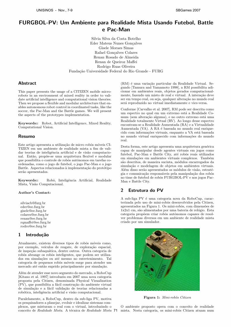
FURGBOL-PV: Um Ambiente para Realidade Mista Usando Futebol, Battlee Pac-Man
Silvia Silva da Costa BotelhoEder Mateus Nunes Goncalves
Gisele Moraes SimasRafael Goncalves ColaresRenan Rosado de AlmeidaRenan de Queiroz Maffei
Rodrigo Ruas OliveiraFundacao Universidade Federal do Rio Grande - FURG
Abstract
This paper presents the usage of a CITIZEN mobile micro-robots in an environment of mixed reality in order to vali-date artificial intelligence and computational vision theories.Then we propose a flexible and modular architecture that en-ables autonomous robot control in coordinated tasks, like thesoccer, the Pac-Man and the Battle games. We will presentthe aspects of the prototypes implementation.
Keywords:: Robot, Artificial Intelligence, Mixed Reality,Computational Vision.
Resumo
Este artigo apresenta a utilizacao de micro robos moveis CI-TIZEN em um ambiente de realidade mista a fim de vali-dar teorias de inteligencia artificial e de visao computacio-nal. Entao, propoe-se uma arquitetura flexıvel e modularque possibilita o controle de robos autonomos em tarefas co-ordenadas, como o jogo de futebol, o jogo Pac-Man e o jogoBattle. Aspectos relacionados a implementacao do prototiposerao apresentados.
Keywords:: Robo, Inteligencia Artificial, RealidadeMista, Visao Computacional.
Author’s Contact:
[email protected]@[email protected]@[email protected]@[email protected]
1 Introducao
Atualmente, existem diversos tipos de robos moveis como,por exemplo, veıculos de resgate, de exploracao espacial,de inspecao subaquatica, dentre outros. Outra categoria derobos abrange os robos inteligentes, que podem ser utiliza-dos em simulacoes ou ate mesmo no entretenimento. Talcategoria de pequenos robos moveis surge para atender ummercado ate entao suprido principalmente por simulacao.
Alem de atender esse novo segmento do mercado, a RoboCup[Kitano et al. 1997] introduziu em 2007 uma nova categoriaproposta pela Citizen, denominada Physical Visualization(PV), que possibilita a facil construcao do ambiente virtualde simulacao e a facil validacao de teorias relacionadas arobotica, inteligencia artificial e visao computacional.
Paralelamente, a RoboCup, dentro da sub-liga PV, motivaos pesquisadores a planejar, evoluir e idealizar sistemas com-plexos, que misturam o real com o virtual, introduzindo oconceito de Realidade Mista. A tecnica de Realidade Mista
(RM) e uma variacao particular da Realidade Virtual. Se-gundo [Tamura and Yamamoto 1998], a RM possibilita adi-cionar em ambientes reais, objetos gerados computacional-mente, fazendo um misto de real e virtual. A interacao deveser em tempo real, ou seja, qualquer alteracao no mundo realsera reproduzido no virtual imediatamente e vice-versa.
Conforme [Carvalho et al. 2007], RM pode ser descrita comoum espectro no qual em um extremo esta a Realidade Co-mum (sem alteracao alguma), e no outro extremo esta umaRealidade totalmente Virtual (RV). Ao longo desse espectroencontram-se a Realidade Aumentada (RA) e a VirtualidadeAumentada (VA). A RA e baseada no mundo real enrique-cido com informacoes virtuais, enquanto a VA esta baseadano mundo virtual enriquecido com informacoes do mundoreal.
Desta forma, este artigo apresenta uma arquitetura genericacapaz de manipular desde agentes virtuais em jogos comofutebol, Pac-Man e Battle City, ate robos reais utilizadosem simulacoes em ambientes virtuais complexos. Tambemsao descritos, de maneira sucinta, modulos encarregados dasimulacao e modelagem de objetos em ambientes virtuais.Alem disso serao apresentados os modulos de visao, estrate-gia e comunicacao responsaveis pela manipulacao dos robosno time de futebol de robos FURGBOL-PV e nos jogos Pac-Man e Battle City.
2 Estrutura do PV
A sub-liga PV e uma categoria nova da RoboCup, carac-terizada pelo uso de mini-robos desenvolvidos pela Citizen,apresentados na Figura 1. Os mini-robos, com dimensoes de1x2x1 cm, sao alimentados por uma bateria de relogio. Estacategoria propoem criar robos autonomos capazes de resol-ver problemas diversos em um ambiente de realidade mistacriado por um simulador.
Figura 1: Mini-robos Citizen
O ambiente proposto opera com o conceito de realidademista. Nesta categoria, os mini-robos Citizen atuam num
UNISINOS - Nov., 7-9 SBGames 2007
71
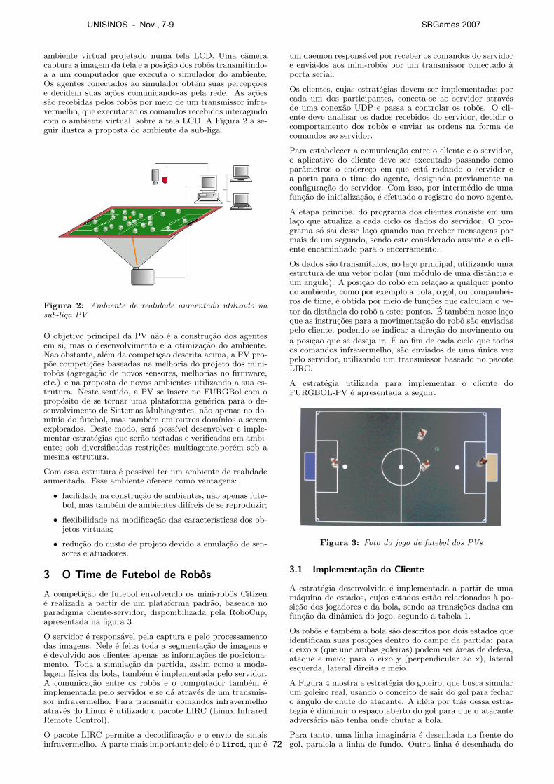
ambiente virtual projetado numa tela LCD. Uma cameracaptura a imagem da tela e a posicao dos robos transmitindo-a a um computador que executa o simulador do ambiente.Os agentes conectados ao simulador obtem suas percepcoese decidem suas acoes comunicando-as pela rede. As acoessao recebidas pelos robos por meio de um transmissor infra-vermelho, que executarao os comandos recebidos interagindocom o ambiente virtual, sobre a tela LCD. A Figura 2 a se-guir ilustra a proposta do ambiente da sub-liga.
Figura 2: Ambiente de realidade aumentada utilizado nasub-liga PV
O objetivo principal da PV nao e a construcao dos agentesem si, mas o desenvolvimento e a otimizacao do ambiente.Nao obstante, alem da competicao descrita acima, a PV pro-poe competicoes baseadas na melhoria do projeto dos mini-robos (agregacao de novos sensores, melhorias no firmware,etc.) e na proposta de novos ambientes utilizando a sua es-trutura. Neste sentido, a PV se insere no FURGBol com oproposito de se tornar uma plataforma generica para o de-senvolvimento de Sistemas Multiagentes, nao apenas no do-mınio do futebol, mas tambem em outros domınios a seremexplorados. Deste modo, sera possıvel desenvolver e imple-mentar estrategias que serao testadas e verificadas em ambi-entes sob diversificadas restricoes multiagente,porem sob amesma estrutura.
Com essa estrutura e possıvel ter um ambiente de realidadeaumentada. Esse ambiente oferece como vantagens:
• facilidade na construcao de ambientes, nao apenas fute-bol, mas tambem de ambientes difıceis de se reproduzir;
• flexibilidade na modificacao das caracterısticas dos ob-jetos virtuais;
• reducao do custo de projeto devido a emulacao de sen-sores e atuadores.
3 O Time de Futebol de Robos
A competicao de futebol envolvendo os mini-robos Citizene realizada a partir de um plataforma padrao, baseada noparadigma cliente-servidor, disponibilizada pela RoboCup,apresentada na figura 3.
O servidor e responsavel pela captura e pelo processamentodas imagens. Nele e feita toda a segmentacao de imagens ee devolvido aos clientes apenas as informacoes de posiciona-mento. Toda a simulacao da partida, assim como a mode-lagem fısica da bola, tambem e implementada pelo servidor.A comunicacao entre os robos e o computador tambem eimplementada pelo servidor e se da atraves de um transmis-sor infravermelho. Para transmitir comandos infravermelhoatraves do Linux e utilizado o pacote LIRC (Linux InfraredRemote Control).
O pacote LIRC permite a decodificacao e o envio de sinaisinfravermelho. A parte mais importante dele e o lircd, que e
um daemon responsavel por receber os comandos do servidore envia-los aos mini-robos por um transmissor conectado aporta serial.
Os clientes, cujas estrategias devem ser implementadas porcada um dos participantes, conecta-se ao servidor atravesde uma conexao UDP e passa a controlar os robos. O cli-ente deve analisar os dados recebidos do servidor, decidir ocomportamento dos robos e enviar as ordens na forma decomandos ao servidor.
Para estabelecer a comunicacao entre o cliente e o servidor,o aplicativo do cliente deve ser executado passando comoparametros o endereco em que esta rodando o servidor ea porta para o time do agente, designada previamente naconfiguracao do servidor. Com isso, por intermedio de umafuncao de inicializacao, e efetuado o registro do novo agente.
A etapa principal do programa dos clientes consiste em umlaco que atualiza a cada ciclo os dados do servidor. O pro-grama so sai desse laco quando nao receber mensagens pormais de um segundo, sendo este considerado ausente e o cli-ente encaminhado para o encerramento.
Os dados sao transmitidos, no laco principal, utilizando umaestrutura de um vetor polar (um modulo de uma distancia eum angulo). A posicao do robo em relacao a qualquer pontodo ambiente, como por exemplo a bola, o gol, ou companhei-ros de time, e obtida por meio de funcoes que calculam o ve-
tor da distancia do robo a estes pontos. E tambem nesse lacoque as instrucoes para a movimentacao do robo sao enviadaspelo cliente, podendo-se indicar a direcao do movimento ou
a posicao que se deseja ir. E ao fim de cada ciclo que todosos comandos infravermelho, sao enviados de uma unica vezpelo servidor, utilizando um transmissor baseado no pacoteLIRC.
A estrategia utilizada para implementar o cliente doFURGBOL-PV e apresentada a seguir.
Figura 3: Foto do jogo de futebol dos PVs
3.1 Implementacao do Cliente
A estrategia desenvolvida e implementada a partir de umamaquina de estados, cujos estados estao relacionados a po-sicao dos jogadores e da bola, sendo as transicoes dadas emfuncao da dinamica do jogo, segundo a tabela 1.
Os robos e tambem a bola sao descritos por dois estados queidentificam suas posicoes dentro do campo da partida: parao eixo x (que une ambas goleiras) podem ser areas de defesa,ataque e meio; para o eixo y (perpendicular ao x), lateralesquerda, lateral direita e meio.
A Figura 4 mostra a estrategia do goleiro, que busca simularum goleiro real, usando o conceito de sair do gol para fecharo angulo de chute do atacante. A ideia por tras dessa estra-tegia e diminuir o espaco aberto do gol para que o atacanteadversario nao tenha onde chutar a bola.
Para tanto, uma linha imaginaria e desenhada na frente dogol, paralela a linha de fundo. Outra linha e desenhada do
UNISINOS - Nov., 7-9 SBGames 2007
72
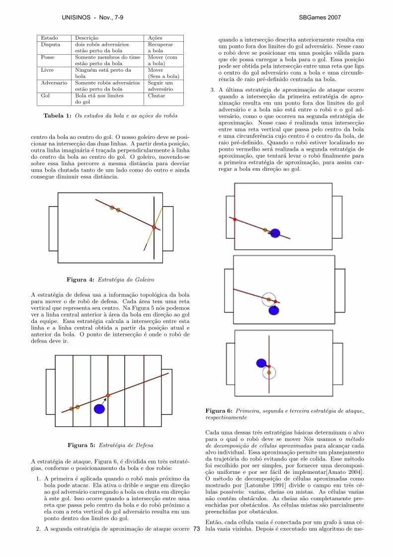
Estado Descricao AcoesDisputa dois robos adversarios Recuperar
estao perto da bola a bolaPosse Somente membros do time Mover (com
estao perto da bola a bola)Livre Ninguem esta perto da Mover
bola (Sem a bola)Adversario Somente robos adversarios Seguir um
estao perto da bola adversarioGol Bola eta nos limites Chutar
do gol
Tabela 1: Os estados da bola e as acoes do robos
centro da bola ao centro do gol. O nosso goleiro deve se posi-cionar na interseccao das duas linhas. A partir desta posicao,outra linha imaginaria e tracada perpendicularmente a linhado centro da bola ao centro do gol. O goleiro, movendo-sesobre essa linha percorre a mesma distancia para desviaruma bola chutada tanto de um lado como do outro e aindaconsegue diminuir essa distancia.
Figura 4: Estrategia do Goleiro
A estrategia de defesa usa a informacao topologica da bolapara mover o de robo de defesa. Cada area tem uma retavertical que representa seu centro. Na Figura 5 nos podemosver a linha central anterior a area da bola em direcao ao golda equipe. Essa estrategia calcula a interseccao entre estalinha e a linha central obtida a partir da posicao atual eanterior da bola. O ponto de interseccao e onde o robo dedefesa deve ir.
Figura 5: Estrategia de Defesa
A estrategia de ataque, Figura 6, e dividida em tres estrate-gias, conforme o posicionamento da bola e dos robos:
1. A primeira e aplicada quando o robo mais proximo dabola pode atacar. Ela ativa o drible e segue em direcaoao gol adversario carregando a bola ou chuta em direcaoa este gol. Isso ocorre quando a interseccao entre umareta que passa pelo centro da bola e do robo proximo aela com a reta vertical do gol adversario resulta em umponto dentro dos limites do gol.
2. A segunda estrategia de aproximacao de ataque ocorre
quando a interseccao descrita anteriormente resulta emum ponto fora dos limites do gol adversario. Nesse casoo robo deve se posicionar em uma posicao valida paraque ele possa carregar a bola para o gol. Essa posicaopode ser obtida pela interseccao entre uma reta que ligao centro do gol adversario com a bola e uma circunfe-rencia de raio pre-definido centrada na bola.
3. A ultima estrategia de aproximacao de ataque ocorrequando a interseccao da primeira estrategia de apro-ximacao resulta em um ponto fora dos limites do goladversario e a bola nao esta entre o robo e o gol ad-versario, como o que ocorreu na segunda estrategia deaproximacao. Nesse caso e realizada uma interseccaoentre uma reta vertical que passa pelo centro da bolae uma circunferencia cujo centro e o centro da bola, deraio pre-definido. Quando o robo estiver localizado noponto vermelho sera realizada a segunda estrategia deaproximacao, que tentara levar o robo finalmente paraa primeira estrategia de aproximacao, para assim car-regar a bola em direcao ao gol.
Figura 6: Primeira, segunda e terceira estrategia de ataque,respectivamente
Cada uma dessas tres estrategias basicas determinam o alvopara o qual o robo deve se mover Nos usamos o metodode decomposicao de celulas aproximadas para alcancar cadaalvo individual. Essa aproximacao permite um planejamentoda trajetoria do robo evitando que ele colida. Esse metodofoi escolhido por ser simples, por fornecer uma decomposi-cao uniforme e por ser facil de implementar[Amato 2004].O metodo de decomposicao de celulas aproximadas comomostrado por [Latombe 1991] divide o campo em tres ce-lulas possıveis: vazias, cheias ou mistas. As celulas vaziasnao contem obstaculos. As cheias sao completamente pre-enchidas por obstaculos. As celulas mistas sao parcialmentepreenchidas por obstaculos.
Entao, cada celula vazia e conectada por um grafo a uma ce-lula vazia vizinha. Depois e executado um algoritmo de me-
UNISINOS - Nov., 7-9 SBGames 2007
73
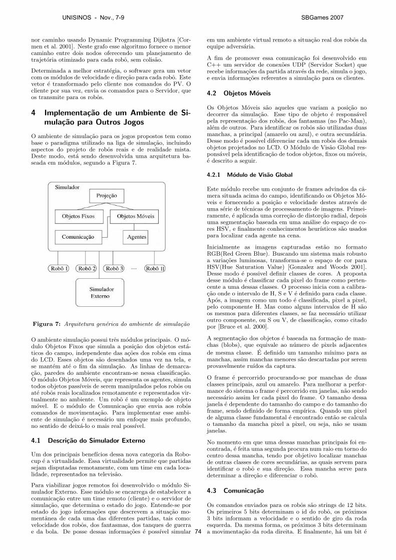
nor caminho usando Dynamic Programming Dijkstra [Cor-men et al. 2001]. Neste grafo esse algoritmo fornece o menorcaminho entre dois nodos oferecendo um planejamento detrajetoria otimizado para cada robo, sem colisao.
Determinada a melhor estrategia, o software gera um vetorcom os modulos de velocidade e direcao para cada robo. Estevetor e transformado pelo cliente nos comandos do PV. Ocliente por sua vez, envia os comandos para o Servidor, queos transmite para os robos.
4 Implementacao de um Ambiente de Si-mulacao para Outros Jogos
O ambiente de simulacao para os jogos propostos tem comobase o paradigma utilizado na liga de simulacao, incluindoaspectos do projeto de robos reais e de realidade mista.Deste modo, esta sendo desenvolvida uma arquitetura ba-seada em modulos, segundo a Figura 7.
Figura 7: Arquitetura generica do ambiente de simulacao
O ambiente simulacao possui tres modulos principais. O mo-dulo Objetos Fixos que simula a posicao dos objetos esta-ticos do campo, independente das acoes dos robos em cimado LCD. Esses objetos sao desenhados uma vez na tela, ese mantem ate o fim da simulacao. As linhas de demarca-cao, paredes do ambiente encontram-se nessa classificacao.O modulo Objetos Moveis, que representa os agentes, simulatodos objetos passıveis de serem manipulados pelos robos ouate robos reais localizados remotamente e representados vir-tualmente no ambiente. Um robo e um exemplo de objetomovel. E o modulo de Comunicacao que envia aos roboscomandos de movimentacao. Para implementar esse ambi-ente de simulacao e necessario um enfoque mais profundo,no sentido de deixa-lo o mais real possıvel.
4.1 Descricao do Simulador Externo
Um dos principais benefıcios dessa nova categoria da Robo-cup e a virtualidade. Essa virtualidade permite que partidassejam disputadas remotamente, com um time em cada loca-lidade, representados na televisao.
Para viabilizar jogos remotos foi desenvolvido o modulo Si-mulador Externo. Esse modulo se encarrega de estabelecer acomunicacao entre um time remoto (cliente) e o servidor desimulacao, que determina o estado do jogo. Entende-se porestado do jogo informacoes que descrevem a situacao mo-mentanea de cada uma das diferentes partidas, tais como:velocidade dos robos, dos fantasmas, dos tanques de guerrae da bola. De posse dessas informacoes e possıvel simular
em um ambiente virtual remoto a situacao real dos robos daequipe adversaria.
A fim de promover essa comunicacao foi desenvolvido emC++ um servidor de conexoes UDP (Servidor Socket) querecebe informacoes da partida atraves da rede, simula o jogo,e envia informacoes referentes a simulacao para os clientes.
4.2 Objetos Moveis
Os Objetos Moveis sao aqueles que variam a posicao nodecorrer da simulacao. Esse tipo de objeto e responsavelpela representacao dos robos, dos fantasmas (no Pac-Man),alem de outros. Para identificar os robos sao utilizadas duasmanchas, a principal (amarelo ou azul), e outra secundaria.Desse modo e possıvel diferenciar cada um robos dos demaisobjetos projetados no LCD. O Modulo de Visao Global res-ponsavel pela identificacao de todos objetos, fixos ou moveis,e descrito a seguir.
4.2.1 Modulo de Visao Global
Este modulo recebe um conjunto de frames advindos da ca-mera situada acima do campo, identificando os Objetos Mo-veis e fornecendo a posicao e velocidade destes atraves deuma serie de tecnicas de processamento de imagens. Primei-ramente, e aplicada uma correcao de distorcao radial, depoisuma segmentacao baseada em uma analise do espaco de co-res HSV, e finalmente conhecimentos heurısticos sao usadospara localizar cada agente na cena.
Inicialmente as imagens capturadas estao no formatoRGB(Red Green Blue). Buscando um sistema mais robustoa variacoes luminosas, transforma-se o espaco de cor paraHSV(Hue Saturation Value) [Gonzalez and Woods 2001].Desse modo e possivel definir classes de cores. A propostadesse modulo e classificar cada pixel do frame como perten-cente a uma dessas classes. O processo inicia com a calibra-cao onde o intervalo de H, S e V e definido para cada classe.Apos, a imagem como um todo e classificada, pixel a pixel,pelo componente H. Mas como alguns intervalos de H saoos mesmos para diferentes classes, se faz necessario utilizaroutro componente, ou S ou V, de classificacao, como citadopor [Bruce et al. 2000].
A segmentacao dos objetos e baseada na formacao de man-chas (blobs), que equivale ao numero de pixels adjacentes
de mesma classe. E definido um tamanho mınimo para asmanchas, assim manchas menores sao descartadas por seremprovavelmente ruıdos da captura.
O frame e percorrido procurando-se por manchas de duasclasses principais, azul ou amarelo. Para melhorar a perfor-mance do sistema o frame e percorrido em janelas, nao sendonecessario assim ler cada pixel do frame. O tamanho dessajanela e dependente do tamanho do campo e do tamanho doframe, sendo definido de forma empırica. Quando um pixelde alguma classe fundamental e encontrado entao se calculao tamanho da mancha pixel a pixel, ou seja, nao se usamjanelas.
No momento em que uma dessas manchas principais foi en-contrada, e feita uma segunda procura num raio em torno docentro dessa mancha, tendo por objetivo localizar manchasde outras classes de cores secundarias, as quais servem paraidentificar o robo e sua direcao. Essa mancha serve paradeterminar a direcao e diferenciar o robo.
4.3 Comunicacao
Os comandos enviados para os robos sao strings de 12 bits.Os primeiros 5 bits determinam o id do robo, os proximos3 bits informam a velocidade e o sentido de giro da rodaesquerda. Da mesma forma, os proximos 3 bits determinama movimentacao da roda direita. E finalmente, ha um bit e
UNISINOS - Nov., 7-9 SBGames 2007
74
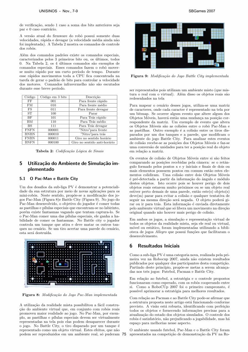
de verificacao, sendo 1 caso a soma dos bits anteriores sejapar e 0 caso contrario.
A versao atual do firmware do robo possui somente duasvelocidades, rapida e devagar (a velocidade media ainda naofoi implentada). A Tabela 2 mostra os comandos de controledos robos.
Alem dos comandos padroes existe os comandos especiais,caracterizados pelos 3 primeiros bits ou, os ultimos, todos0. Na Tabela 2, os 4 ultimos comandos sao exemplos decomandos especiais. Esses comandos fazem o robo mover-se muito rapido por um curto perıodo de tempo. Duranteesse rapidos movimentos toda a CPU fica concentrada natarefa de gerar o padrao de bits para controlar a velocidadedos motores. Comandos infravermelho nao sao escutadosdurante esse breve perıodo.
Codigo Codigo em 3 bits DescricaoFF 001 Para frente rapidoFM 010 Para frente medioFS 011 Para frente devagarST 100 PararBF 101 Para Tras rapidoBM 110 Para Tras medioBS 111 Para Tras devagar
FNFN 000001 ”Nitro”para frenteBNBN 000010 ”Nitro”para trasFNBN 000011 Giro no sentido horarioBNFN 000100 Giro no sentido anti-horario
Tabela 2: Codificacao Logica de Sinais
5 Utilizacao do Ambiente de Simulacao im-plementado
5.1 O Pac-Man e Battle City
Um dos desafios da sub-liga PV e demonstrar a potenciali-dade da sua estrutura por meio de novas aplicacoes para osmini-robos. Neste sentido, propoe-se a modificacao dos jo-gos Pac-Man (Figura 8)e Battle City (Figura 9). No jogo doPac-Man desenvolvido, o objetivo do jogador e comer todasas pastilhas e pılulas especiais que encontram-se no labirinto,porem existe fantasmas vagando que tentam captura-lo. Seo Pac-Man comer uma das pılulas especiais, ele ganha a ha-bilidade de comer os fantasmas. No Battle city o jogadorcontrola um tanque que atira e deve matar os outros tan-ques no cenario. Se um tiro acertar uma parede do cenario,esta sera destruıda.
Figura 8: Modificacao do Jogo Pac-Man implementada
A utilizacao da realidade mista possibilitou a facil constru-cao do ambiente virtual que, em conjunto com robos reaispromoveu maior realidade ao jogo. No Pac-Man, por exem-plo, as pastilhas e pılulas especiais devem ser virtualmenterepresentadas na tela pois elas podem desaparecer duranteo jogo. No Battle City, o tiro disparado por um tanque erepresentado como um objeto virtual. Estes efeitos, que naopodem ser reproduzidos em um ambiente real, so puderam
Figura 9: Modificacao do Jogo Battle City implementada
ser representados pois utilizam um ambiente misto (que mis-tura o real com o virtual). Alem disso os objetos reais saoredesenhados na tela
Para mapear o cenario desses jogos, utiliza-se uma matrizde caracteres, onde cada caracter e representado na tela porum bitmap. Se ocorrer algum evento que altere algum dosObjetos Moveis, havera entao uma mudanca na posicao cor-respondente da matriz. Um exemplo de evento que alteraos Objetos Moveis sao as colisoes entre o robo Pac-Man eas pastilhas. Outro exemplo e a colisao entre os tiros dis-parados por um dos tanques e a parede, que modificam oambiente do jogo Battle City. Para analisar estes eventosde colisao recebe-se as posicoes dos Objetos Moveis e faz-seuma conversao de unidades para ter a posicao real do objetoem relacao a matriz.
Os eventos de colisao de Objetos Moveis entre si sao feitoscomparando as posicoes recebidas pela camera: se o retan-gulo formado pelos pontos x e y iniciais e finais de dois oumais elementos possuem pontos em comum entao estes ele-mentos colidiram. Uma colisao entre dois Objetos Moveise pre-detectada a partir da informacao do angulo e modulodestes objetos. Isto ocorre pois se houver perigo de doisobjetos reais estarem muito proximos ou se um objeto realestiver perto demais de uma parede, entao este(s) objeto(s)deve(m) parar para evitar a colisao e qualquer tentativa deseguir na mesma direcao sera negada. O objeto podera gi-rar ou ir para tras. Esta informacao e enviada diretamentepelo ambiente virtual que so libera um movimento na direcaooriginal quando nao houver mais perigo de colisao.
Em ambos os jogos, a simulacao e representacao virtual detodos os objetos da realidade mista, seja ele real ou virtual,movel ou estatico, foram implementadas utilizando a bibli-oteca de jogos Allegro que possui funcoes que facilitaram odesenvolvimento.
6 Resultados Iniciais
Como a sub-liga PV e uma categoria nova, realizada pela pri-meira vez na Robocup 2007, ainda nao existem resultadospublicados por qualquer dos participantes desta competicao.Partindo deste princıpio, propoe-se metas a serem alcanca-das nos tres jogos: Futebol, Pacman e Battle City.
Em relacao ao futebol, a estrategia e o controle propostosfuncionaram como esperado, com os robos cooperando entresi. Como a RoboCUp 2007 foi o primeiro campeonato, epossıvel aprimorar a estrategia para melhores resultados.
Com relacao ao Pacman e ao Battle City pode-se afirmar quea estrutura proposta neste artigo esta funcionando conformeprevisto. A visao esta robusta, identificando com perfeicaotodos os objetos e fornecendo informacoes precisas para aatualizacao do estado dos objetos simulados. O controle dosrobos e satisfatorio, nao prejudicando a jogabilidade, mas haespaco para melhorias nesse aspecto.
O ambiente usando futebol, Pac-Man e o Battle City foramapresentados na competicao de demonstracao da PV na Ro-
UNISINOS - Nov., 7-9 SBGames 2007
75

bocup 2007, em Atlanta, quando obteve o quinto lugar naclassificacao final.
7 Conclusoes e Trabalhos Futuros
Neste artigo, primeiramente foi apresentada a arquiteturacliente-servidor da sub-liga PV da RoboCup, utilizada nofutebol de robos. Depois foi mostrado um resumo da arquite-tura generica desenvolvida para a sub-liga PV, que propoema criacao de aplicacoes originais para os mini-robos. Estaarquitetura pode ser decomposta basicamente nos modulosde: Objetos Fixos, Objetos Moveis e Comunicacao. Tam-bem foram ressaltadas as principais caracterısticas da visao,planejamento e comunicacao. E finalmente foram apresen-tadas adaptacoes dessa arquitetura para os jogos Pac-Man eBattle City.
Enfase foi dada para a visao e o planejamento, demonstrandocomo foram implementados e as tecnicas utilizadas. Na visaomostrou-se o uso do espaco de cores HSV para representaros pixels, como foi feita a classificacao dos mesmos a partirde um conjunto de classes pre-definidos para o futebol derobos e como os objetos foram localizados, a partir da iden-tificacao de manchas de classes de cores. O modulo de pla-nejamento implementado para o futebol de robos tambemfoi demonstrado, ressaltando a maquina de estados criadapara a equipe, os estados de cada agente, identificados porum estagio de percepcao, e as tecnicas de controle utiliza-das. O Metodo de Decomposicao de Celulas Aproximadajuntamente com o Algoritmo de Dijkstra foram usados paraa geracao das trajetorias otimas dos robos no campo.
Existem varios planos de incrementar o Pac-man e BattleCity, visando torna-los mais atrativos. Dentre as modifica-coes desejadas, esta a modificacao do Battle City para pos-sibilitar o jogo entre duas equipes remotas, a agregacao denovos objetivos e tambem criacao uma inteligencia artificialpara os agentes (tanques). Para o jogo Pac-Man pretende-secriar uma IA para possibilitar a cooperacao entre os fantas-mas explorando assim o controle dos robos.
Referencias
Amato, N. 2004. Randomized motion planning. Tech. rep.,University of Padova.
Bruce, J., Balch, T., and Veloso, M. 2000. Fast andinexpensive color image segmentation for interactive ro-bots.
Carvalho, F. G., Raposo, A. B., and Gattass, M. 2007.Uma interface hıbrida para desktop integrando realidadevirtual, realidade aumentada e 2d wimp. IX Simposiumon Virtual and Augmented Reality (SVR) 2007,Petropolis,RJ, Brasil , 152–161.
Cormen, T., Leiserson, C., Rivest, R., and Stein, C.2001. Introduction to Algorithms. McGraw Hill/MITPress.
Gonzalez, R., and Woods, R. 2001. Image Processing.Addison Wesley Pub.
Kitano, H., Asada, M., Kuniyoshi, Y., Noda, I., andOsawa, E. 1997. Robocup: The robot world cup initi-ave. In The First International Conference on Autono-mous Agent (Agents-97).
Latombe, J. 1991. Robot Motion Planning. Kluwer Acade-mic Publishers.
Tamura, H., and Yamamoto, H. 1998. Vision andgraphics in producing mixed reality worlds. Computer Vi-sion for Virtual Reality Based Human Communications,1998. Proceedings., 1998 IEEE and ATR Workshop on,78 – 85.
UNISINOS - Nov., 7-9 SBGames 2007
76
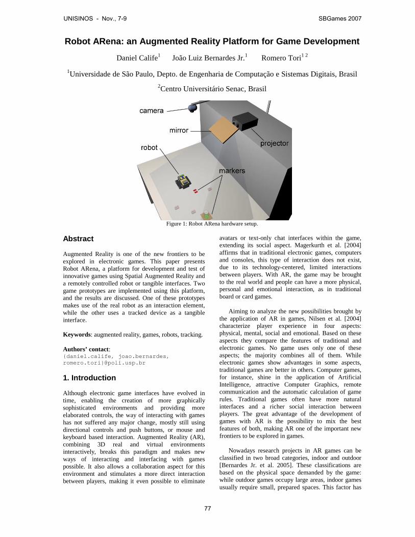
Robot ARena: an Augmented Reality Platform for Game Development
Daniel Calife1 João Luiz Bernardes Jr.1 Romero Tori1 2
1Universidade de São Paulo, Depto. de Engenharia de Computação e Sistemas Digitais, Brasil
2Centro Universitário Senac, Brasil
Figure 1: Robot ARena hardware setup.
Abstract Augmented Reality is one of the new frontiers to be explored in electronic games. This paper presents Robot ARena, a platform for development and test of innovative games using Spatial Augmented Reality and a remotely controlled robot or tangible interfaces. Two game prototypes are implemented using this platform, and the results are discussed. One of these prototypes makes use of the real robot as an interaction element, while the other uses a tracked device as a tangible interface. Keywords: augmented reality, games, robots, tracking. Authors’ contact: {daniel.calife, joao.bernardes, romero.tori}@poli.usp.br 1. Introduction Although electronic game interfaces have evolved in time, enabling the creation of more graphically sophisticated environments and providing more elaborated controls, the way of interacting with games has not suffered any major change, mostly still using directional controls and push buttons, or mouse and keyboard based interaction. Augmented Reality (AR), combining 3D real and virtual environments interactively, breaks this paradigm and makes new ways of interacting and interfacing with games possible. It also allows a collaboration aspect for this environment and stimulates a more direct interaction between players, making it even possible to eliminate
avatars or text-only chat interfaces within the game, extending its social aspect. Magerkurth et al. [2004] affirms that in traditional electronic games, computers and consoles, this type of interaction does not exist, due to its technology-centered, limited interactions between players. With AR, the game may be brought to the real world and people can have a more physical, personal and emotional interaction, as in traditional board or card games.
Aiming to analyze the new possibilities brought by the application of AR in games, Nilsen et al. [2004] characterize player experience in four aspects: physical, mental, social and emotional. Based on these aspects they compare the features of traditional and electronic games. No game uses only one of these aspects; the majority combines all of them. While electronic games show advantages in some aspects, traditional games are better in others. Computer games, for instance, shine in the application of Artificial Intelligence, attractive Computer Graphics, remote communication and the automatic calculation of game rules. Traditional games often have more natural interfaces and a richer social interaction between players. The great advantage of the development of games with AR is the possibility to mix the best features of both, making AR one of the important new frontiers to be explored in games.
Nowadays research projects in AR games can be
classified in two broad categories, indoor and outdoor [Bernardes Jr. et al. 2005]. These classifications are based on the physical space demanded by the game: while outdoor games occupy large areas, indoor games usually require small, prepared spaces. This factor has
UNISINOS - Nov., 7-9 SBGames 2007
77
a great impact on the technologies and implementation of the games, especially for registration and interaction. Outdoor games mostly use physical metaphors of interaction, such as colliding with virtual objects to collect them, touching other players, running or walking in some ample physical space to move within the game. Indoor games also use the physical metaphor, but to a lesser extent, often in the form of Tangible User Interfaces (TUI) [Ishii and Ullmer 1997] and combining it with other interaction metaphors, such as player gesture or voice recognition.
This work presents an infrastructure, called “Robot
ARena”, which can be used as a platform for development of innovative indoor AR games based on Spatial Augmented Reality (SAR) [Bimber and Raskar 2005] (which brings the visualization of the augmented content directly into the physical space) and a wireless controlled robot or tangible interfaces. The main goal of the Robot ARena project was to develop and test that infrastructure, exploring new ways of combining low-cost tracking, robot controlling and spatially AR techniques.
One of the main concerns during this research was
to provide a basis to develop games that further explore the interaction between real and virtual environments, not only with real elements influencing virtual ones, but also the with the opposite happening, i.e. virtual elements affecting the real world. A wireless controlled robot is therefore adequate as a real "character" in the game, since it can both influence and be influenced by these virtual elements.
This infrastructure has as base the enJine, described
in section 3.1, a game engine that provides a framework for the creation of virtual worlds and the necessary mechanics for the development of a game. 2. Related Work Since the end of the last decade, several applications using AR as an interface have been described in the literature. More recently several projects combining AR and games have also been presented. In the field of robotics, in particular, computer vision and augmented reality have been used and combined even more numerously. This brief review will be limited to more recent projects, and those that are more closely related to the work described in this paper. The discussion begins with another extension of enJine's capabilities into the AR realm using JARToolKit and goes on about the DWARF framework for AR, the Augmented Coliseum where robots interact with virtual elements using a different control scheme and Kobito, which shares characteristics with the Robot ARena, such as the virtual elements affecting real objects.
2.1 EnJine + JARToolKit Tsuda et al. [2007] present an integration of JARToolKit [Geiger et al. 2002] and enJine whose objective is the simplification of the development of low cost AR games, increasing the potential of enJine as a didactic tool and a testbed for new game technologies.
This integration with JARToolkit gives enJine the capacity to recognize commands given with the use of fiducial markers and a video camera. Besides reproducing the video stream obtained from the camera and tracking these markers. These characteristics, combined with enJine, facilitate the development of monitor-based AR games without the need for complex (and expensive) systems for tracking or stereoscopic visualization.
2.2 DWARF
DWARF (Distributed Wearable Augmented Reality Framework) [MacWilliams et al. 2003] is a framework based on distributed services (position tracking, three-dimensional rendering, input and output and task modeling) for Augmented Reality applications. Each service is a piece of software that can run on separated hardware components, with its own processor, memory, i/o devices and network access. The different services are dynamically connected with other services communicating their needs and abilities through the network. Distributed middleware is responsible for controlling the communications between these services.
This framework is used to develop complete Augmented Reality applications, projected to be flexible and guarantee to users a high degree of freedom. These characteristics are attained because the framework's services can be distributed over independent machines, that can be added or removed from the environment without causing a great impact on the whole system.
2.3 Augmented Coliseum
Augmented Coliseum [Kojima et al. 2006] is an application similar to the game prototype described here. It is a game in which Augmented Reality is used to enrich a competition between real robots with effects such as rays and explosions in a virtual environment. Robots can also collide with obstacles in the virtual environment that can block their movement. Unlike the work described in this paper, however, there is no need for visual tracking. The position of the robots is always known because they actively follow a certain pattern projected on them along with the virtual environment they are in. Each robot has 5 light sensors in known positions that detect variations in this light pattern and can identify where it is moving to and then follow it.
UNISINOS - Nov., 7-9 SBGames 2007
78
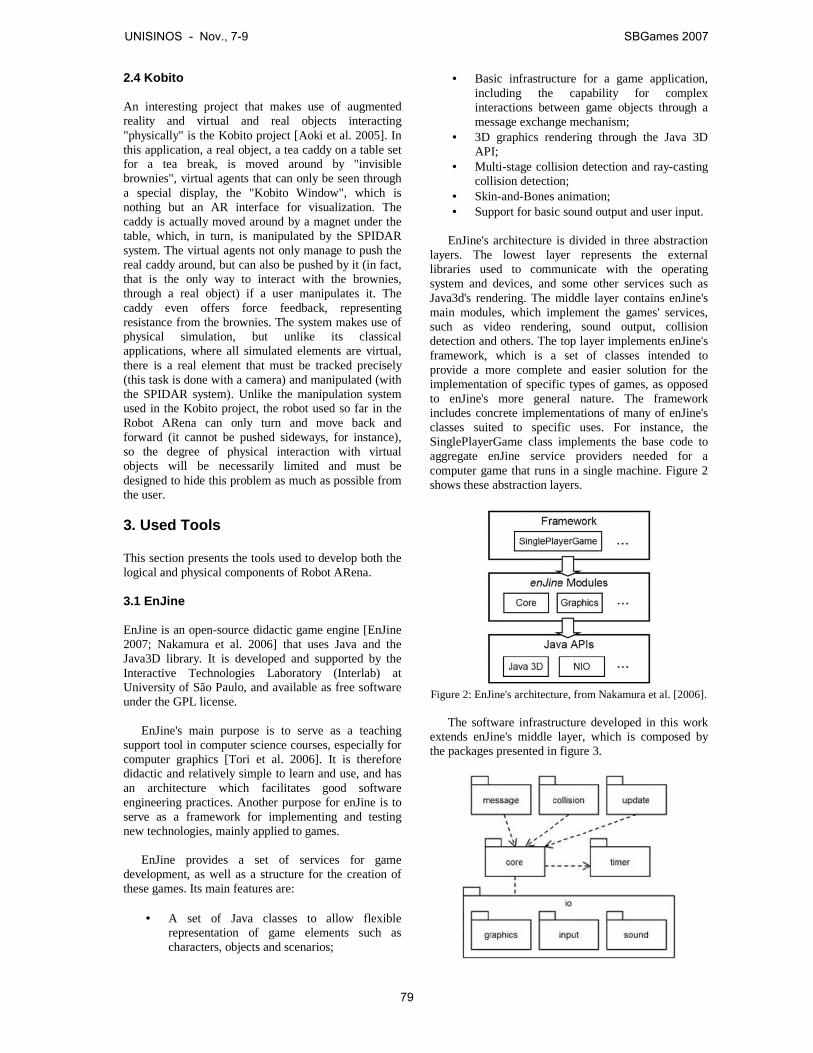
2.4 Kobito
An interesting project that makes use of augmented reality and virtual and real objects interacting "physically" is the Kobito project [Aoki et al. 2005]. In this application, a real object, a tea caddy on a table set for a tea break, is moved around by "invisible brownies", virtual agents that can only be seen through a special display, the "Kobito Window", which is nothing but an AR interface for visualization. The caddy is actually moved around by a magnet under the table, which, in turn, is manipulated by the SPIDAR system. The virtual agents not only manage to push the real caddy around, but can also be pushed by it (in fact, that is the only way to interact with the brownies, through a real object) if a user manipulates it. The caddy even offers force feedback, representing resistance from the brownies. The system makes use of physical simulation, but unlike its classical applications, where all simulated elements are virtual, there is a real element that must be tracked precisely (this task is done with a camera) and manipulated (with the SPIDAR system). Unlike the manipulation system used in the Kobito project, the robot used so far in the Robot ARena can only turn and move back and forward (it cannot be pushed sideways, for instance), so the degree of physical interaction with virtual objects will be necessarily limited and must be designed to hide this problem as much as possible from the user. 3. Used Tools This section presents the tools used to develop both the logical and physical components of Robot ARena. 3.1 EnJine
EnJine is an open-source didactic game engine [EnJine 2007; Nakamura et al. 2006] that uses Java and the Java3D library. It is developed and supported by the Interactive Technologies Laboratory (Interlab) at University of São Paulo, and available as free software under the GPL license.
EnJine's main purpose is to serve as a teaching support tool in computer science courses, especially for computer graphics [Tori et al. 2006]. It is therefore didactic and relatively simple to learn and use, and has an architecture which facilitates good software engineering practices. Another purpose for enJine is to serve as a framework for implementing and testing new technologies, mainly applied to games.
EnJine provides a set of services for game
development, as well as a structure for the creation of these games. Its main features are:
• A set of Java classes to allow flexible
representation of game elements such as characters, objects and scenarios;
• Basic infrastructure for a game application, including the capability for complex interactions between game objects through a message exchange mechanism;
• 3D graphics rendering through the Java 3D API;
• Multi-stage collision detection and ray-casting collision detection;
• Skin-and-Bones animation; • Support for basic sound output and user input.
EnJine's architecture is divided in three abstraction
layers. The lowest layer represents the external libraries used to communicate with the operating system and devices, and some other services such as Java3d's rendering. The middle layer contains enJine's main modules, which implement the games' services, such as video rendering, sound output, collision detection and others. The top layer implements enJine's framework, which is a set of classes intended to provide a more complete and easier solution for the implementation of specific types of games, as opposed to enJine's more general nature. The framework includes concrete implementations of many of enJine's classes suited to specific uses. For instance, the SinglePlayerGame class implements the base code to aggregate enJine service providers needed for a computer game that runs in a single machine. Figure 2 shows these abstraction layers.
Figure 2: EnJine's architecture, from Nakamura et al. [2006].
The software infrastructure developed in this work
extends enJine's middle layer, which is composed by the packages presented in figure 3.
UNISINOS - Nov., 7-9 SBGames 2007
79

Figure 3: EnJine's main packages, from Nakamura et al. [2006].
3.2 OpenCV
OpenCV [2007] (Open Source Computer Vision Library) is a free library of C/C++ functions mostly for computer vision and image processing, with a focus on real-time applications, which makes it interesting for Augmented Reality.
As two of the main concerns of Augmented Reality are registration and tracking, and one approach to obtain them is through computer vision, OpenCV is a robust and flexible tool to be used in such applications.
3.3 Lego Mindstorms
Lego Mindstorms [2007], or Lego Robotics Invention System (RIS), is a set of blocks, motors, sensors and other components, such as gears and axles, created and marketed by the Lego group. It can be used to build many types of robots and other automated or interactive systems.
The main component of Lego Mindstorms, which controls input (sensors) and output (motors), is called the RCX block. The RCX has a Renesas H8/300 microcontroller that interprets the programs loaded in its RAM through an interface that uses infrared to send and to receive data.
3.4 JavaComm
The Java Communications API [2007] (JavaComm) is a Java library that aids the development of platform-independent applications for communication. This library provides application access to RS-232 and IEEE-1284 hardware. 4. Robot ARena Robot ARena is a software and hardware platform for the development of AR games. It has a robot as its main interaction element, but is not limited to using only that. The wireless controlled robot was chosen because of its capability not only to affect but also to be affected by virtual elements. It can collect some virtual element passing over it, for instance, or collide with and be hindered by virtual barriers or be pushed by virtual characters.
For the visualization of the augmented
environment, Robot ARena uses the concept of projection-based spatial displays, presented in [Bimber and Raskar 2005], freeing users from uncomfortable devices, such as Head-Mounted displays and, at the same time, enabling the visualization of the virtual content directly on the real world.
Robot ARena is implemented in a game structure
as an abstraction layer above enJine, creating new
possibilities for visualization and game code. Figure 4 shows a common structure of a game.
Figure 4: Robot ARena in Game Structure, adapted from
[Lewis et al. 2002].
Although the main interaction element of the platform is a robot, it is not necessary that all games, or applications developed, use it. The platform provides two tracked devices, described in section 5.1.2, which can be attached to any desired object, or be used by themselves as tangible elements of interaction, as shown in section 6.2.
The platform enables the insertion of real elements,
aside from the main tracked object, that can also influence virtual elements. These additional real elements, however, are not tracked and therefore must be static and have their position determined during the system's initialization, using color markers positioned in the arena.
4.1 Hardware
Robot ARena's hardware is composed of a table, a camera, a projector, a mirror, a robot and two tracked devices, all of them connected through a computer, except for the tracked devices (detected through computer vision), in the setup shown in figure 1.
4.2 Software Architecture
Robot ARena's software is divided in three subsystems, some of which directly access its hardware (treated as a black box) sending and receiving signals. These subsystems, and their relationship with each other, are shown in figure 5, and discussed in the next sections.
UNISINOS - Nov., 7-9 SBGames 2007
80
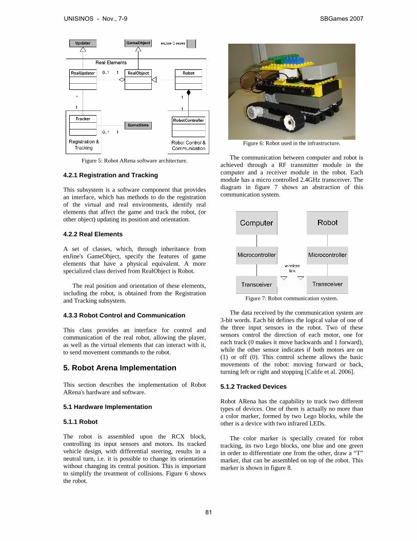
Figure 5: Robot ARena software architecture.
4.2.1 Registration and Tracking
This subsystem is a software component that provides an interface, which has methods to do the registration of the virtual and real environments, identify real elements that affect the game and track the robot, (or other object) updating its position and orientation.
4.2.2 Real Elements
A set of classes, which, through inheritance from enJine's GameObject, specify the features of game elements that have a physical equivalent. A more specialized class derived from RealObject is Robot.
The real position and orientation of these elements, including the robot, is obtained from the Registration and Tracking subsystem.
4.3.3 Robot Control and Communication
This class provides an interface for control and communication of the real robot, allowing the player, as well as the virtual elements that can interact with it, to send movement commands to the robot. 5. Robot Arena Implementation This section describes the implementation of Robot ARena's hardware and software. 5.1 Hardware Implementation 5.1.1 Robot
The robot is assembled upon the RCX block, controlling its input sensors and motors. Its tracked vehicle design, with differential steering, results in a neutral turn, i.e. it is possible to change its orientation without changing its central position. This is important to simplify the treatment of collisions. Figure 6 shows the robot.
Figure 6: Robot used in the infrastructure.
The communication between computer and robot is
achieved through a RF transmitter module in the computer and a receiver module in the robot. Each module has a micro controlled 2.4GHz transceiver. The diagram in figure 7 shows an abstraction of this communication system.
Figure 7: Robot communication system.
The data received by the communication system are
3-bit words. Each bit defines the logical value of one of the three input sensors in the robot. Two of these sensors control the direction of each motor, one for each track (0 makes it move backwards and 1 forward), while the other sensor indicates if both motors are on (1) or off (0). This control scheme allows the basic movements of the robot: moving forward or back, turning left or right and stopping [Calife et al. 2006].
5.1.2 Tracked Devices
Robot ARena has the capability to track two different types of devices. One of them is actually no more than a color marker, formed by two Lego blocks, while the other is a device with two infrared LEDs.
The color marker is specially created for robot
tracking, its two Lego blocks, one blue and one green in order to differentiate one from the other, draw a “T” marker, that can be assembled on top of the robot. This marker is shown in figure 8.
UNISINOS - Nov., 7-9 SBGames 2007
81
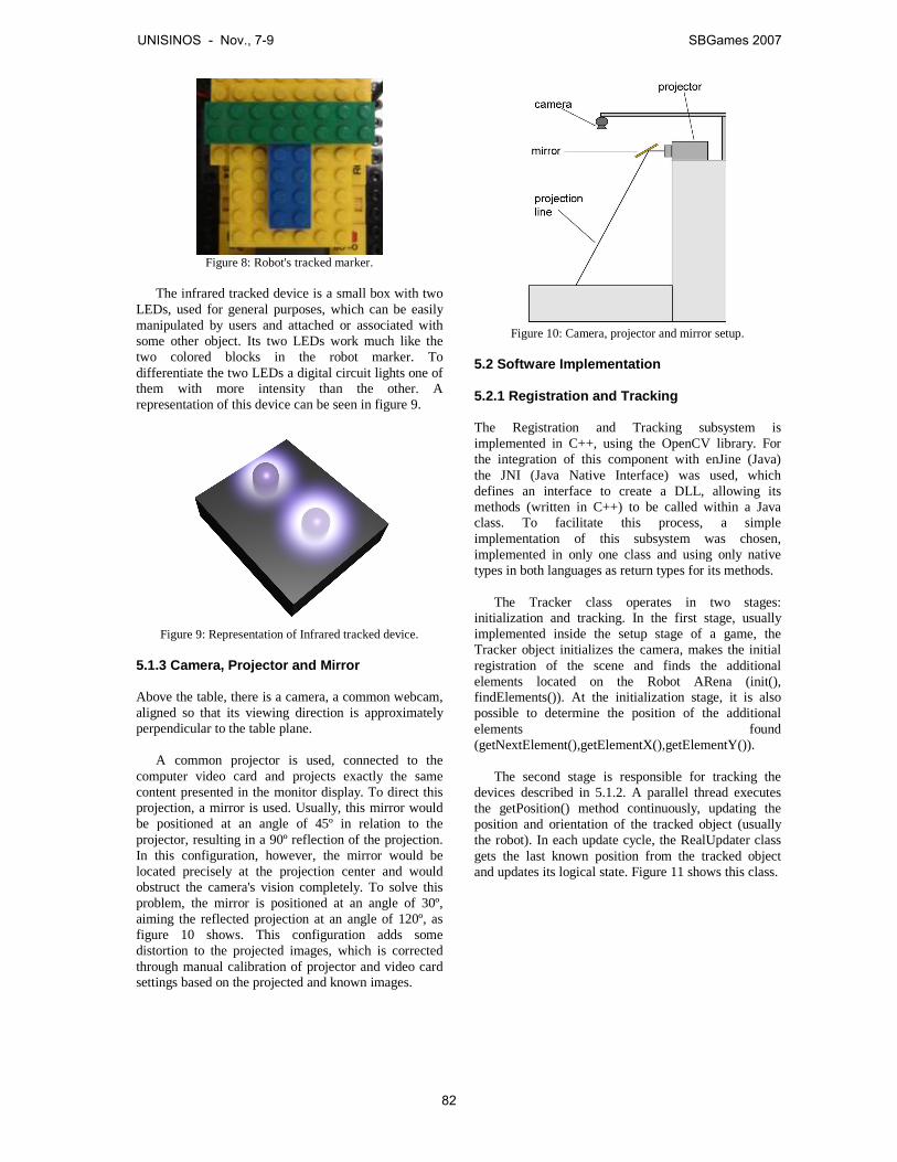
Figure 8: Robot's tracked marker.
The infrared tracked device is a small box with two
LEDs, used for general purposes, which can be easily manipulated by users and attached or associated with some other object. Its two LEDs work much like the two colored blocks in the robot marker. To differentiate the two LEDs a digital circuit lights one of them with more intensity than the other. A representation of this device can be seen in figure 9.
Figure 9: Representation of Infrared tracked device.
5.1.3 Camera, Projector and Mirror
Above the table, there is a camera, a common webcam, aligned so that its viewing direction is approximately perpendicular to the table plane.
A common projector is used, connected to the
computer video card and projects exactly the same content presented in the monitor display. To direct this projection, a mirror is used. Usually, this mirror would be positioned at an angle of 45º in relation to the projector, resulting in a 90º reflection of the projection. In this configuration, however, the mirror would be located precisely at the projection center and would obstruct the camera's vision completely. To solve this problem, the mirror is positioned at an angle of 30º, aiming the reflected projection at an angle of 120º, as figure 10 shows. This configuration adds some distortion to the projected images, which is corrected through manual calibration of projector and video card settings based on the projected and known images.
Figure 10: Camera, projector and mirror setup.
5.2 Software Implementation
5.2.1 Registration and Tracking
The Registration and Tracking subsystem is implemented in C++, using the OpenCV library. For the integration of this component with enJine (Java) the JNI (Java Native Interface) was used, which defines an interface to create a DLL, allowing its methods (written in C++) to be called within a Java class. To facilitate this process, a simple implementation of this subsystem was chosen, implemented in only one class and using only native types in both languages as return types for its methods.
The Tracker class operates in two stages:
initialization and tracking. In the first stage, usually implemented inside the setup stage of a game, the Tracker object initializes the camera, makes the initial registration of the scene and finds the additional elements located on the Robot ARena (init(), findElements()). At the initialization stage, it is also possible to determine the position of the additional elements found (getNextElement(),getElementX(),getElementY()).
The second stage is responsible for tracking the
devices described in 5.1.2. A parallel thread executes the getPosition() method continuously, updating the position and orientation of the tracked object (usually the robot). In each update cycle, the RealUpdater class gets the last known position from the tracked object and updates its logical state. Figure 11 shows this class.
UNISINOS - Nov., 7-9 SBGames 2007
82
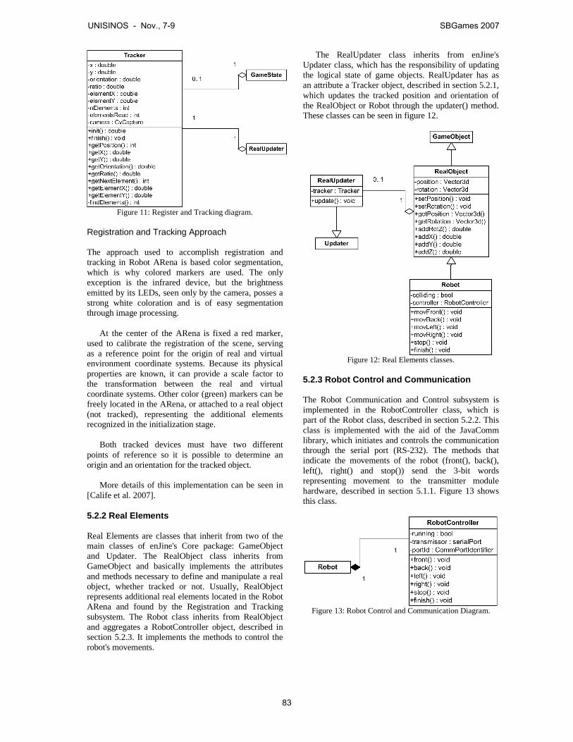
Figure 11: Register and Tracking diagram.
Registration and Tracking Approach
The approach used to accomplish registration and tracking in Robot ARena is based color segmentation, which is why colored markers are used. The only exception is the infrared device, but the brightness emitted by its LEDs, seen only by the camera, posses a strong white coloration and is of easy segmentation through image processing.
At the center of the ARena is fixed a red marker, used to calibrate the registration of the scene, serving as a reference point for the origin of real and virtual environment coordinate systems. Because its physical properties are known, it can provide a scale factor to the transformation between the real and virtual coordinate systems. Other color (green) markers can be freely located in the ARena, or attached to a real object (not tracked), representing the additional elements recognized in the initialization stage.
Both tracked devices must have two different
points of reference so it is possible to determine an origin and an orientation for the tracked object.
More details of this implementation can be seen in
[Calife et al. 2007].
5.2.2 Real Elements
Real Elements are classes that inherit from two of the main classes of enJine's Core package: GameObject and Updater. The RealObject class inherits from GameObject and basically implements the attributes and methods necessary to define and manipulate a real object, whether tracked or not. Usually, RealObject represents additional real elements located in the Robot ARena and found by the Registration and Tracking subsystem. The Robot class inherits from RealObject and aggregates a RobotController object, described in section 5.2.3. It implements the methods to control the robot's movements.
The RealUpdater class inherits from enJine's Updater class, which has the responsibility of updating the logical state of game objects. RealUpdater has as an attribute a Tracker object, described in section 5.2.1, which updates the tracked position and orientation of the RealObject or Robot through the updater() method. These classes can be seen in figure 12.
Figure 12: Real Elements classes.
5.2.3 Robot Control and Communication
The Robot Communication and Control subsystem is implemented in the RobotController class, which is part of the Robot class, described in section 5.2.2. This class is implemented with the aid of the JavaComm library, which initiates and controls the communication through the serial port (RS-232). The methods that indicate the movements of the robot (front(), back(), left(), right() and stop()) send the 3-bit words representing movement to the transmitter module hardware, described in section 5.1.1. Figure 13 shows this class.
Figure 13: Robot Control and Communication Diagram.
UNISINOS - Nov., 7-9 SBGames 2007
83
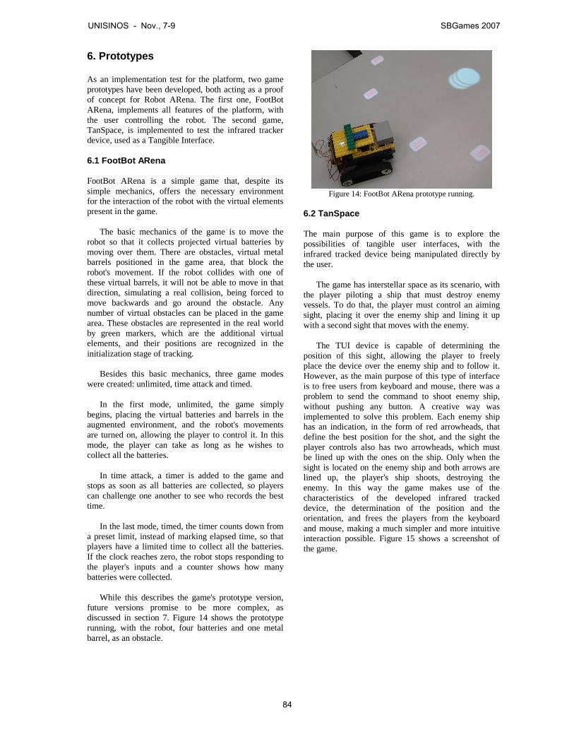
6. Prototypes As an implementation test for the platform, two game prototypes have been developed, both acting as a proof of concept for Robot ARena. The first one, FootBot ARena, implements all features of the platform, with the user controlling the robot. The second game, TanSpace, is implemented to test the infrared tracker device, used as a Tangible Interface.
6.1 FootBot ARena
FootBot ARena is a simple game that, despite its simple mechanics, offers the necessary environment for the interaction of the robot with the virtual elements present in the game.
The basic mechanics of the game is to move the robot so that it collects projected virtual batteries by moving over them. There are obstacles, virtual metal barrels positioned in the game area, that block the robot's movement. If the robot collides with one of these virtual barrels, it will not be able to move in that direction, simulating a real collision, being forced to move backwards and go around the obstacle. Any number of virtual obstacles can be placed in the game area. These obstacles are represented in the real world by green markers, which are the additional virtual elements, and their positions are recognized in the initialization stage of tracking.
Besides this basic mechanics, three game modes
were created: unlimited, time attack and timed. In the first mode, unlimited, the game simply
begins, placing the virtual batteries and barrels in the augmented environment, and the robot's movements are turned on, allowing the player to control it. In this mode, the player can take as long as he wishes to collect all the batteries.
In time attack, a timer is added to the game and
stops as soon as all batteries are collected, so players can challenge one another to see who records the best time.
In the last mode, timed, the timer counts down from
a preset limit, instead of marking elapsed time, so that players have a limited time to collect all the batteries. If the clock reaches zero, the robot stops responding to the player's inputs and a counter shows how many batteries were collected.
While this describes the game's prototype version,
future versions promise to be more complex, as discussed in section 7. Figure 14 shows the prototype running, with the robot, four batteries and one metal barrel, as an obstacle.
Figure 14: FootBot ARena prototype running.
6.2 TanSpace
The main purpose of this game is to explore the possibilities of tangible user interfaces, with the infrared tracked device being manipulated directly by the user.
The game has interstellar space as its scenario, with
the player piloting a ship that must destroy enemy vessels. To do that, the player must control an aiming sight, placing it over the enemy ship and lining it up with a second sight that moves with the enemy.
The TUI device is capable of determining the
position of this sight, allowing the player to freely place the device over the enemy ship and to follow it. However, as the main purpose of this type of interface is to free users from keyboard and mouse, there was a problem to send the command to shoot enemy ship, without pushing any button. A creative way was implemented to solve this problem. Each enemy ship has an indication, in the form of red arrowheads, that define the best position for the shot, and the sight the player controls also has two arrowheads, which must be lined up with the ones on the ship. Only when the sight is located on the enemy ship and both arrows are lined up, the player's ship shoots, destroying the enemy. In this way the game makes use of the characteristics of the developed infrared tracked device, the determination of the position and the orientation, and frees the players from the keyboard and mouse, making a much simpler and more intuitive interaction possible. Figure 15 shows a screenshot of the game.
UNISINOS - Nov., 7-9 SBGames 2007
84
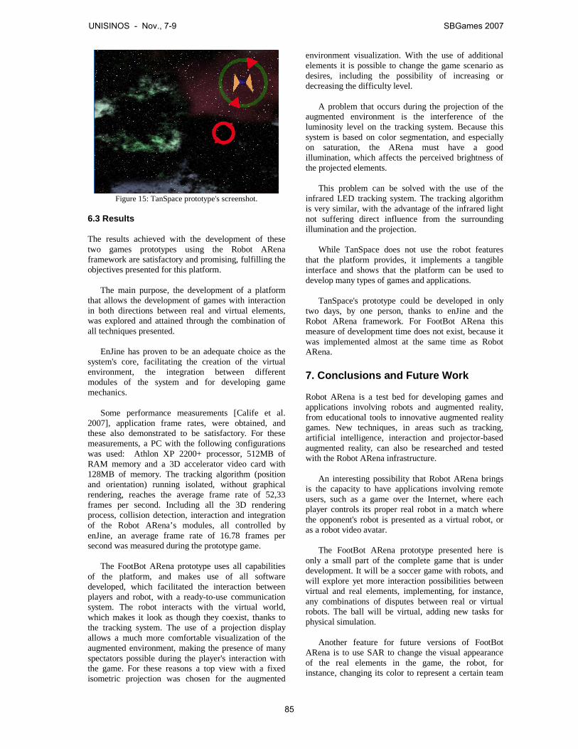
Figure 15: TanSpace prototype's screenshot.
6.3 Results
The results achieved with the development of these two games prototypes using the Robot ARena framework are satisfactory and promising, fulfilling the objectives presented for this platform.
The main purpose, the development of a platform
that allows the development of games with interaction in both directions between real and virtual elements, was explored and attained through the combination of all techniques presented.
EnJine has proven to be an adequate choice as the
system's core, facilitating the creation of the virtual environment, the integration between different modules of the system and for developing game mechanics.
Some performance measurements [Calife et al.
2007], application frame rates, were obtained, and these also demonstrated to be satisfactory. For these measurements, a PC with the following configurations was used: Athlon XP 2200+ processor, 512MB of RAM memory and a 3D accelerator video card with 128MB of memory. The tracking algorithm (position and orientation) running isolated, without graphical rendering, reaches the average frame rate of 52,33 frames per second. Including all the 3D rendering process, collision detection, interaction and integration of the Robot ARena’s modules, all controlled by enJine, an average frame rate of 16.78 frames per second was measured during the prototype game.
The FootBot ARena prototype uses all capabilities
of the platform, and makes use of all software developed, which facilitated the interaction between players and robot, with a ready-to-use communication system. The robot interacts with the virtual world, which makes it look as though they coexist, thanks to the tracking system. The use of a projection display allows a much more comfortable visualization of the augmented environment, making the presence of many spectators possible during the player's interaction with the game. For these reasons a top view with a fixed isometric projection was chosen for the augmented
environment visualization. With the use of additional elements it is possible to change the game scenario as desires, including the possibility of increasing or decreasing the difficulty level.
A problem that occurs during the projection of the
augmented environment is the interference of the luminosity level on the tracking system. Because this system is based on color segmentation, and especially on saturation, the ARena must have a good illumination, which affects the perceived brightness of the projected elements.
This problem can be solved with the use of the
infrared LED tracking system. The tracking algorithm is very similar, with the advantage of the infrared light not suffering direct influence from the surrounding illumination and the projection.
While TanSpace does not use the robot features
that the platform provides, it implements a tangible interface and shows that the platform can be used to develop many types of games and applications.
TanSpace's prototype could be developed in only
two days, by one person, thanks to enJine and the Robot ARena framework. For FootBot ARena this measure of development time does not exist, because it was implemented almost at the same time as Robot ARena. 7. Conclusions and Future Work Robot ARena is a test bed for developing games and applications involving robots and augmented reality, from educational tools to innovative augmented reality games. New techniques, in areas such as tracking, artificial intelligence, interaction and projector-based augmented reality, can also be researched and tested with the Robot ARena infrastructure.
An interesting possibility that Robot ARena brings is the capacity to have applications involving remote users, such as a game over the Internet, where each player controls its proper real robot in a match where the opponent's robot is presented as a virtual robot, or as a robot video avatar.
The FootBot ARena prototype presented here is
only a small part of the complete game that is under development. It will be a soccer game with robots, and will explore yet more interaction possibilities between virtual and real elements, implementing, for instance, any combinations of disputes between real or virtual robots. The ball will be virtual, adding new tasks for physical simulation.
Another feature for future versions of FootBot
ARena is to use SAR to change the visual appearance of the real elements in the game, the robot, for instance, changing its color to represent a certain team
UNISINOS - Nov., 7-9 SBGames 2007
85
of which the player is part, or adding some special effects, such as blinking in red when it is close to exploding.
It is possible to provide a better representation of
the augmented environment with more depth cues, projecting its content according to the player's viewpoint, instead of using an isometric projection, but this approach reduces the player's freedom of movement, unless his head position is also somehow tracked. This view-dependant projection would also reduce the possibility of a comfortable view for spectators (they could only stand close to the player for the best view).
Assuming that the player's viewpoint is tracked, it
is possible to use stereoscopic projections, providing more realism to the augmented environment, a feature that is currently being researched. Acknowledgements The authors would like to thank all Interlab students, researchers and professors. And, also, thank CNPq and ItauCultural´s Rumos Arte Cibernética for Daniel Calife's master research financial support. References AOKI, T., ICHIKAWA , H., ASANO, K., MITAKE , H., IIO, Y.,
AYUKAWA , R., KURIYAMA , T., KAWA, T., MATSUMURA, I., MATSUSHITA, T., TOYAMA , T., HASEGAWA, S. AND
SATO, M. 2005. KOBITO - VIRTUAL BROWNIE - VIRTUAL
CREATURES INTERACT WITH REAL OBJECTS AND REAL
PEOPLE. SIGGRAPH'2005 EMERGING TECHNOLOGIES. BERNARDES JR., J.L., DIAS, J.S. AND TORI, R. 2005.
EXPLORING MIXED REALITY USER INTERFACES FOR
ELECTRONIC GAMES. IN: ANAIS DO IV WORKSHOP
BRASILEIRO DE JOGOS E ENTRETENIMENTO DIGITAL
(WJOGOS'2005), SÃO PAULO, P. 353-358. BIMBER, O. AND RASKAR, R. 2005. SPATIAL AUGMENTED
REALITY: MERGING REAL AND VIRTUAL WORLDS. WELLESLEY: A K PETERS.
CALIFE, D., TOMOYOSE, A., SPINOLA, D., BERNARDES JR.,
J.L. AND TORI, R. 2007. ROBOT ARENA: INFRAESTRUCTURE FOR APPLICATIONS INVOLVING
SPATIAL AUGMENTED REALITY AND ROBOTS. IN: PROCEEDINGS OF THE IX SYMPOSIUM ON VIRTUAL AND
AUGMENTED REALITY (SVR'2007), PETRÓPOLIS. CALIFE, D., TOMOYOSE, A., SPINOLA, D. AND TORI, R. 2006.
CONTROLE E RASTREAMENTO DE UM ROBÔ REAL PARA UM
AMBIENTE DE REALIDADE MISTURADA. IN: ANAIS DO II WORKSHOP DE APLICAÇÕES DE REALIDADE VIRTUAL
(WARV'2006), RECIFE. ENJINE: ENGINE FOR GAMES IN JAVA HOMEPAGE.
HTTPS://ENJINE.DEV.JAVA.NET// [ACCESSED 12 OCTOBER
2007]. GEIGER, C., REIMANN , C., STICKLEIN , J. AND PAELKEE, V.
2002. JARTOOLKIT – A JAVA BINDING FOR
ARTOOLKIT. IN: PROCEEDINGS OF THE FIRST IEEE INTERNATIONAL WORKSHOP ON AUGMENTED REALITY
TOOLKIT. ISHII, H. AND ULLMER, B. 1997. TANGIBLE BITS: TOWARDS
SEAMLESS INTERFACES BETWEEN PEOPLE, BITS AND ATOMS. IN: PROCEEDINGS OF THE SIGCHI CONFERENCE ON HUMAN
FACTORS IN COMPUTING SYSTEMS, ATLANTA , P. 234-241. JAVA COMMUNICATIONS API HOMEPAGE.
HTTP://JAVA.SUN.COM/PRODUCTS/JAVACOMM/ [ACCESSED
20 AUGUST 2007]. KOJIMA, M., SUGIMOTO, M., NAKAMURA , A., TOMITA, M.,
NII, H. AND INAMI , M. 2006. AUGMENTED COLISEUM: AN
AUGMENTED GAME ENVIRONMENT WITH SMALL VEHICLES. IN: FIRST IEEE INTERNATIONAL WORKSHOP ON HORIZONTAL
INTERACTIVE HUMAN-COMPUTER SYSTEMS. LEGO MINDSTORMS HOMEPAGE.
HTTP://MINDSTORMS.LEGO.COM/ [ACCESSED 20 AUGUST
2007]. LEWIS, M. AND JACOBSON, F. 2002. GAME ENGINES IN
SCIENTIFIC RESEARCH. COMMUNICATIONS OF THE ACM, V.45, 1, P. 27-31, JAN.
MACWILLIAMS , A., SANDOR, C., WAGNER, M., BAUER, M.,
KLINKER, G. AND BRUEGGE, B. 2003. HERDING
SHEEP: LIVE SYSTEM DEVELOPMENT FOR DISTRIBUTED
AUGMENTED REALITY . IN: PROCEEDINGS OF THE SECOND
IEEE AND ACM INTERNATIONAL SYMPOSIUM ON MIXED AND
AUGMENTED REALITY (ISMAR'2003), TOKYO, P. 123-132. MAGERKUTH, C., ENGELKE, T. AND MEMISOGLU, M. 2004.
AUGMENTING THE VIRTUAL DOMAIN WITH PHYSICAL AND
SOCIAL ELEMENTS: TOWARDS A PARADIGM SHIFT IN
COMPUTER ENTERTAINMENT TECHNOLOGY. IN: PROCEEDINGS OF THE 2004 ACM SIGCHI INTERNATIONAL
CONFERENCE ON ADVANCES IN COMPUTER ENTERTAINMENT
TECHNOLOGY, SINGAPORE, P. 163-172. NAKAMURA , R., BERNARDES JR., J.L. AND TORI, R. 2006.
USING A DIDACTIC GAME ENGINE TO TEACH COMPUTER
SCIENCE. IN: DIGITAL PROCEEDINGS OF THE V BRAZILIAN
SYMPOSIUM ON COMPUTER GAMES AND DIGITAL
ENTERTAINMENT, SBGAMES'2006 TUTORIALS, RECIFE. NILSEN, T., LINTON, S. AND LOOSER, J. 2004. MOTIVATIONS
FOR AUGMENTED REALITY GAMING . IN: PROCEEDINGS OF
THE NEW ZEALAND GAME DEVELOPERS CONFERENCE
(FUSE'04), DUNEDIN, P. 86-93. OPEN SOURCE COMPUTER VISION L IBRARY HOMEPAGE.
HTTP://WWW.INTEL.COM/TECHNOLOGY/COMPUTING/OPENC
V/ [ACCESSED 20 AUGUST 2007]. TORI, R., BERNARDES JR., J.L. AND NAKAMURA , R. 2006.
TEACHING INTRODUCTORY COMPUTER GRAPHICS USING
JAVA 3D, GAMES AND CUSTOMIZED SOFTWARE: A
BRAZILIAN EXPERIENCE. INTERNATIONAL CONFERENCE ON
COMPUTER GRAPHICS AND INTERACTIVE TECHNIQUES, ACM SIGGRAPH'2006 EDUCATORS PROGRAM, BOSTON.
TSUDA, F., HOKAMA , P.M., RODRIGUES, T.M. AND
BERNARDES JR., J.L. 2007. INTEGRATION OF JARTOOLKIT
AND ENJINE: EXTENDING WITH AR THE POTENTIAL USE OF
A DIDACTIC GAME ENGINE. IN: PROCEEDINGS OF THE IX SYMPOSIUM ON VIRTUAL AND AUGMENTED REALITY
(SVR'2007), PETRÓPOLIS.
UNISINOS - Nov., 7-9 SBGames 2007
86
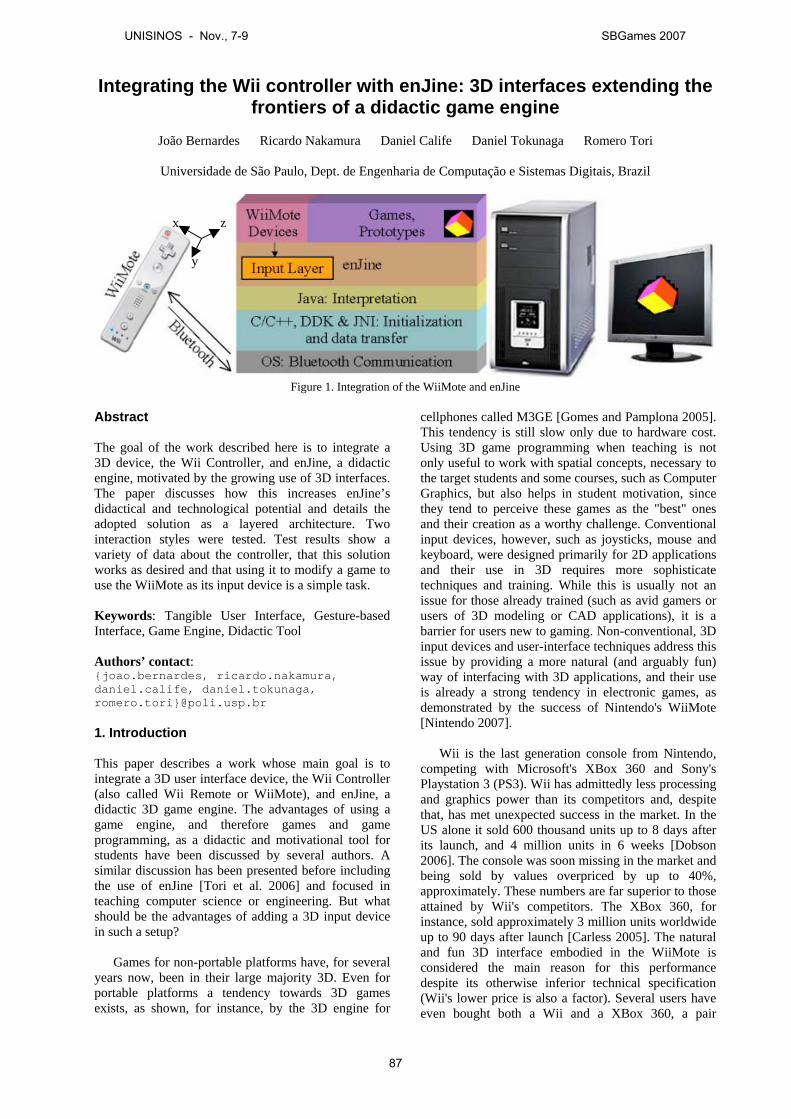
Integrating the Wii controller with enJine: 3D interfaces extending thefrontiers of a didactic game engine
João Bernardes Ricardo Nakamura Daniel Calife Daniel Tokunaga Romero Tori
Universidade de São Paulo, Dept. de Engenharia de Computação e Sistemas Digitais, Brazil
Figure 1. Integration of the WiiMote and enJine
Abstract
The goal of the work described here is to integrate a3D device, the Wii Controller, and enJine, a didacticengine, motivated by the growing use of 3D interfaces.The paper discusses how this increases enJine’sdidactical and technological potential and details theadopted solution as a layered architecture. Twointeraction styles were tested. Test results show avariety of data about the controller, that this solutionworks as desired and that using it to modify a game touse the WiiMote as its input device is a simple task.
Keywords: Tangible User Interface, Gesture-basedInterface, Game Engine, Didactic Tool
Authors’ contact:{joao.bernardes, ricardo.nakamura,daniel.calife, daniel.tokunaga,romero.tori}@poli.usp.br
1. Introduction
This paper describes a work whose main goal is tointegrate a 3D user interface device, the Wii Controller(also called Wii Remote or WiiMote), and enJine, adidactic 3D game engine. The advantages of using agame engine, and therefore games and gameprogramming, as a didactic and motivational tool forstudents have been discussed by several authors. Asimilar discussion has been presented before includingthe use of enJine [Tori et al. 2006] and focused inteaching computer science or engineering. But whatshould be the advantages of adding a 3D input devicein such a setup?
Games for non-portable platforms have, for severalyears now, been in their large majority 3D. Even forportable platforms a tendency towards 3D gamesexists, as shown, for instance, by the 3D engine for
cellphones called M3GE [Gomes and Pamplona 2005].This tendency is still slow only due to hardware cost.Using 3D game programming when teaching is notonly useful to work with spatial concepts, necessary tothe target students and some courses, such as ComputerGraphics, but also helps in student motivation, sincethey tend to perceive these games as the "best" onesand their creation as a worthy challenge. Conventionalinput devices, however, such as joysticks, mouse andkeyboard, were designed primarily for 2D applicationsand their use in 3D requires more sophisticatetechniques and training. While this is usually not anissue for those already trained (such as avid gamers orusers of 3D modeling or CAD applications), it is abarrier for users new to gaming. Non-conventional, 3Dinput devices and user-interface techniques address thisissue by providing a more natural (and arguably fun)way of interfacing with 3D applications, and their useis already a strong tendency in electronic games, asdemonstrated by the success of Nintendo's WiiMote[Nintendo 2007].
Wii is the last generation console from Nintendo,competing with Microsoft's XBox 360 and Sony'sPlaystation 3 (PS3). Wii has admittedly less processingand graphics power than its competitors and, despitethat, has met unexpected success in the market. In theUS alone it sold 600 thousand units up to 8 days afterits launch, and 4 million units in 6 weeks [Dobson2006]. The console was soon missing in the market andbeing sold by values overpriced by up to 40%,approximately. These numbers are far superior to thoseattained by Wii's competitors. The XBox 360, forinstance, sold approximately 3 million units worldwideup to 90 days after launch [Carless 2005]. The naturaland fun 3D interface embodied in the WiiMote isconsidered the main reason for this performancedespite its otherwise inferior technical specification(Wii's lower price is also a factor). Several users haveeven bought both a Wii and a XBox 360, a pair
x
y
z
UNISINOS - Nov., 7-9 SBGames 2007
87

nicknamed "Wii60", to have both the 3D interactionand high-end graphics to play with. It is interesting tonotice that Interlab had already been researching andpublishing about new 3D interfaces for games inenJine for a while before the excitement over WiiMote.Soon after its appearance, Sony also announcedmotion-sensing capabilities for PS3's controller hadbeen in research for over 2 years and would be presentat launch. All this indicates that 3D and more naturalinterfaces are indeed a strong tendency in games (andhopefully in other applications as well).
This tendency is one of the reasons to integrate theWiiMote and enJine (as well as for other enJineextensions discussed in section 3). As a didactic toolfor several computer science or engineering and evengame programming courses, enJine must always striveto be up-to-date with the evolution of interface andgame technologies. This not only influences studentmotivation, but also offers a broader range of optionsfor each course. User Interface courses at bothundergraduate and graduate levels, for instance, areoften limited to 2D devices and techniques, but withthe use of enJine and the WiiMote they could coversome 3D techniques as well, such as tangibleinterfaces. At a lower level of abstraction, even signalprocessing (to treat the raw data obtained from theWiiMote) could be explored didactically.
Another motivator for this integration is the factthat enJine's simplicity (one of the main requirementsfor its goal as a didactic tool) and flexibility, especiallyin its abstract input layer, reduce the complexity ofsuch work. Finally, enJine has secondary goal. Whileits main objective is to be an effective teaching tool, itssimplicity and flexibility have lead to a new goal: toserve as a test bed for new technologies in games.Lately it has been used primarily to exploreAugmented Reality (AR) - a form of interface thatcombines real images, seen directly or captured invideo, and virtual elements in a scene interactively andin real time with 3D registration between real andvirtual elements [Azuma 1997] - and other newinterfaces in games.
While several other 3D devices, such as 3D mice(magnetic or gyroscopic), could have been chosen asan input device for enJine, the choice of the WiiMotewas not merely driven by "fashion". The main factorsfor this choice were the low cost and especially theavailability of this controller, which, unlike other 3Ddevices, is widely accessible to the general public.Before a more detailed discussion of WiiMote, it isimportant to notice now that, aside from its use as aregular wireless game controller, it provides tracker-like data (what it actually measures is accelerations in3 axes; it can also be used as a pointing device thanksto an infrared system), which can be used to implementboth tangible and simple gesture-based interfaces.
Tangible User Interfaces (TUI) are defined asComputer-Human Interfaces that use interactions with
the physical world as metaphors for informationmanipulation in the virtual world [Ishii and Ulmer1997]. In these interfaces, a physical and a virtualobject are associated so that changes in one (usuallymanipulation of the physical object) should affect theother. This association of the WiiMote with virtualobjects in games is quite clear in several cases, such aswhen using the controller to represent pointing a gun,swinging a bat, a tennis racket or a sword. There areeven kits of simple plastic devices that can be securelyattached to the Wii to make it look like these objects.Often, however, there is not such a directcorrespondence between the manipulation of theWiiMote and the in-game object and the gestures madeby the user are what actually serve as a game input.
Considering that, for gestures, the WiiMote isnothing but a hand tracking device (both hands can betracked if using the Nunchuk, an accessory that can beattached to the WiiMote), it only allows the use ofpointing gestures or gestures composed of differenthand trajectories or relative positions between hands,as in the case of the system proposed for Cabral et al.for use in Virtual CAVE Environments [Cabral et al.2005] (actually, Cabral's system uses 2D trajectories,while Wii can track in 3D, but the limitation totrajectories or relative positions is the same).Differences in hand pose cannot be accounted in suchsystems (recognition of gestures combining trajectoriesand pose usually require either complex computervision algorithms or the use of datagloves consideredawkward by many users), limiting the space of possiblegestures. With the WiiMote, associating trajectory-based gestures and button inputs may reduce thislimitation, but not overcome it.
Regardless of this limitation, the WiiMote, as a 3Ddevice either for tangible or gesture-based interfaces,can be useful to enJine, to explore 3D interfaces duringcertain courses, to keep enJine up-to-date with gametechnologies, for student motivation or simply toexplore the limits of these new interfaces within gamesor Augmented Reality.
The next section discusses related work, beforesection 3 discusses enJine (specially its input layer)and 4, the WiiMote. Section 5 explains in detail thesolution adopted to integrate them (illustrated in Figure1). Finally, section 6 presents the results of tests andprototypes based on this solution and the final sectionshows conclusions derived from this work.
2. Related Work
Nintendo's Wii and its controller have been available tothe public for a relatively short time, therefore there isnot much published work to be found about its use.Before presenting this work, however, this sectiondiscusses some underlying questions, such as tangibleand gesture-based interfaces (particularly the problemof gesture recognition with the WiiMote) and gamesthat use them. Architectures with flexible input layers,
UNISINOS - Nov., 7-9 SBGames 2007
88
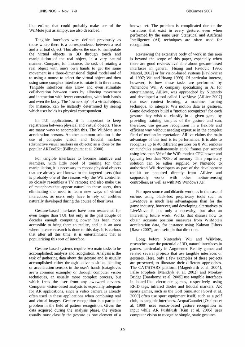
like enJine, that could probably make use of theWiiMote just as simply, are also described.
Tangible Interfaces were defined previously asthose where there is a correspondence between a realand a virtual object. This allows the user to manipulatethe virtual objects in 3D through touch andmanipulation of the real object, in a very naturalmanner. Compare, for instance, the task of rotating areal object with one's own hands to get the samemovement in a three-dimensional digital model and ofto using a mouse to select the virtual object and thenusing some complex interface to rotate it in three axes.Tangible interfaces also allow and even stimulatecollaboration between users by allowing movementand interaction with fewer constraints, with both handsand even the body. The "ownership" of a virtual object,for instance, can be instantly determined by seeingwhich user holds its physical correspondent.
In TUI applications, it is important to keepregistration between physical and virtual objects. Thereare many ways to accomplish this. The WiiMote usesacceleration sensors. Another common solution is theuse of computer vision and fiducial markers(distinctive visual markers on objects) as is done by thepopular ARToolKit [Billinghurst et al. 2000].
For tangible interfaces to become intuitive andseamless, with little need of training for theirmanipulation, it is necessary to choose physical objectsthat are already well-known to the targeted users (thatis probably one of the reasons why the Wii controllerso closely resembles a TV remote) and also make useof metaphors that appear natural to these users, thuseliminating the need to learn new ways of virtualinteraction, as users only have to rely on abilitiesnaturally developed during the course of their lives.
Gesture-based interfaces have been researched foreven longer than TUI, but only in the past couple ofdecades enough computing power has been moreaccessible to bring them to reality, and it is an areawhere intense research is done to this day. It is curiousthat after all this time, it is entertainment that ispopularizing this sort of interface.
Gesture-based systems require two main tasks to beaccomplished: analysis and recognition. Analysis is thetask of gathering data about the gesture and is usuallyaccomplished either through active position, bendingor acceleration sensors in the user's hands (dataglovesare a common example) or through computer visiontechniques, an usually more complex process, butwhich frees the user from any awkward devices.Computer vision-based analysis is especially adequatefor AR applications, since a video camera is alreadyoften used in these applications when combining realand virtual images. Gesture recognition is a particularproblem in the field of pattern recognition. Given thedata acquired during the analysis phase, the systemusually must classify the gesture as one element of a
known set. The problem is complicated due to thevariations that exist in every gesture, even whenperformed by the same user. Statistical and ArtificialIntelligence (AI) techniques are often used forrecognition.
Reviewing the extensive body of work in this areais beyond the scope of this paper, especially whenthere are good reviews available about gesture-basedinterfaces in general [Huang and Pavlovic 1995;Marcel, 2002] or for vision-based systems [Pavlovic etal. 1997; Wu and Huang 1999]. Of particular interest,however, is how these tasks are performed byNintendo's Wii. A company specializing in AI forentertainment, AiLive, was approached by Nintendoand developed a tool called LiveMove [AiLive 2007]that uses context learning, a machine learningtechnique, to interpret Wii motion data as gestures.Game developers build a "motion recognizer" for eachgesture they wish to classify in a given game byproviding training samples of the gesture and can,therefore, use gesture recognition in a flexible andefficient way without needing expertise in the complexfield of motion interpretation. AiLive claims the mainadvantage of this tool is its performance. It is able torecognize up to 40 different gestures on 8 Wii remotesor nunchuks simultaneously at 60 frames per secondusing less than 5% of the Wii's modest CPU power andtypically less than 700kb of memory. This proprietarysolution can be either supplied by Nintendo toauthorized Wii developers as part of the developmenttoolkit or acquired directly from AiLive andsupposedly works with other motion-sensingcontrollers, as well as with MS Windows XP.
For open-source and didactic work, as in the case ofenJine, using black-box proprietary tools such asLiveMove is much less advantageous than for thegame industry, however, and developing alternatives toLiveMove is not only a necessity, but also aninteresting future work. Works that discuss how toobtain accurate position measures from WiiMote'sacceleration data, for instance using Kalman Filters[Rasco 2007], are useful in that direction.
Long before Nintendo's Wii and WiiMote,researches saw the potential of 3D, natural interfaces ingames, particularly in Augmented Reality games andrelated several projects that use tangible interfaces orgestures. Here, only a few examples of these projectsare presented, to illustrate their different approaches.The CAT/STARS platform [Magerkurth et al. 2004],False Prophets [Mandryk et al. 2002] and MonkeyBridge [Barakonyi et al. 2005] use tangible interfacesin board-like electronic games, respectively usingRFID tags, infrared diodes and fiducial markers. ARsports games, such as the Golf Simulator [Govil et al.2000] often use sport equipment itself, such as a golfclub, as tangible interfaces. AcquaGauntlet [Oshima etal. 1999] uses sensor-based gesture recognition asinput while AR PushPush [Kim et al. 2005] usescomputer vision to recognize simple, static gestures.
UNISINOS - Nov., 7-9 SBGames 2007
89
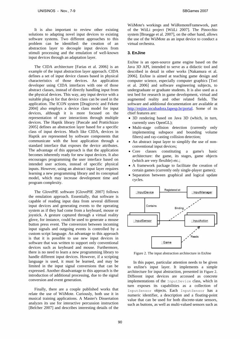
It is also important to review other existingsolutions to adapting novel input devices to existingsoftware systems. Two different approaches to thisproblem can be identified: the creation of anabstraction layer to decouple input devices fromstimuli processing and the emulation of well-knowninput devices through an adaptation layer.
The CIDA architecture [Farias et al. 2006] is anexample of the input abstraction layer approach. CIDAdefines a set of input device classes based in physicalcharacteristics of those devices. An applicationdeveloper using CIDA interfaces with one of thoseabstract classes, instead of directly handling input fromthe physical devices. This way, any input device with asuitable plug-in for that device class can be used in theapplication. The ICON system [Dragicevic and Fekete2004] also employs a device class model for inputdevices, although it is more focused on therepresentation of user interactions through multipledevices. The Haptik library [Pascale and Prattichizzo2005] defines an abstraction layer based for a specificclass of input devices. Much like CIDA, devices inHaptik are represented by software components thatcommunicate with the host application through astandard interface that exposes the device attributes.The advantage of this approach is that the applicationbecomes inherently ready for new input devices. It alsoencourages programming the user interface based onintended user actions, instead of specific physicalinputs. However, using an abstract input layer requireslearning a new programming library and its conceptualmodel, which may increase development time andprogram complexity.
The GlovePIE software [GlovePIE 2007] followsthe emulation approach. Essentially, that software iscapable of reading input data from several differentinput devices and generating events to the operatingsystem as if they had come from a keyboard, mouse orjoystick. A gesture captured through a virtual realityglove, for instance, could be used to generate a mousebutton press event. The conversion between incominginput signals and outgoing events is controlled by acustom script language. An advantage to this approachis that it is possible to use new input devices insoftware that was written to support only conventionaldevices such as keyboard and mouse. Furthermore,there is no need to learn a new programming library tohandle different input devices. However, if a scriptinglanguage is used, it must be learned, and may belimited in the input signal conversions that can beexpressed. Another disadvantage to this approach is theintroduction of additional processing, due to the signalconversion and event generation.
Finally, there are a couple published works thatrelate the use of WiiMote. Curiously, both use it inmusical training applications. A Master's Dissertationanalyzes its use for interactive percussion instruction[Belcher 2007] and describes interesting details of the
WiiMote's workings and WiiRemoteFramework, partof the WiiLi project [WiiLi 2007]. The Pinocchiosystem [Bruegge et al. 2007], on the other hand, allowsthe use of the WiiMote as an input device to conduct avirtual orchestra.
3. EnJine
EnJine is an open-source game engine based on theJava 3D API, intended to serve as a didactic tool anddescribed in detail in other works [Nakamura et al.2006]. EnJine is aimed at teaching game design andcomputer science, especially computer graphics [Toriet al. 2006] and software engineering subjects, toundergraduate or graduate students. It is also used as atest bed for research in game development, virtual andaugmented reality and other related fields. Thesoftware and additional documentation are available athttp://enjine.incubadora.fapesp.br/portal. Some of itschief features are:• 3D rendering based on Java 3D (which, in turn,
currently uses OpenGL);• Multi-stage collision detection (currently only
implementing subspace and bounding volumefilters) and ray-casting collision detection;
• An abstract input layer to simplify the use of non-conventional input devices;
• Core classes constituting a game's basicarchitecture: the game, its stages, game objects(which are very flexible) etc.;
• A framework package to facilitate the creation ofcertain games (currently only single-player games);
• Separation between graphical and logical updatecycles.
Figure 2. The input abstraction architecture in EnJine
In this paper, particular attention needs to be givento enJine's input layer. It implements a simplearchitecture for input abstraction, presented in Figure 2.Different input devices are accessed as concreteimplementations of the InputDevice class, which inturn exposes its capabilities as a collection ofInputSensor objects. Each InputSensor has anumeric identifier, a description and a floating-pointvalue that can be used for both discrete-state sensors,such as buttons, as well as multi-valued sensors such as
UNISINOS - Nov., 7-9 SBGames 2007
90

position trackers. Each InputDevice implementationis responsible for updating the state of its sensors.
The InputManager class maintains a registry ofInputDevices and can be queried by the userapplication. It also maintains a collection of “bindings”that relate each InputSensor to an InputAction.InputActions are objects that represent usercommands with a specific intent within the application.For instance, there might be “jump” and “run”InputActions. Periodically, the InputManagerupdates the state of the InputActions according tothe state of the InputSensors. The state of theInputActions may be accessed by other gamecomponents to execute desired user commands.
This simple yet flexible input layer was created atfirst merely to simplify the configuration of game inputoptions in conventional devices and to accommodatethese devices but has proven particularly adequate tointerfacing with non-conventional devices, such ascameras tracking fiducial markers, color-markedobjects or gestures. Currently, 3 projects extend enJinein this direction: integrating enJine and jARToolKit,Robot Arena and integrating enJine and HandVu.
The first project using non-conventional interfacesand enJine was to integrate it with jARToolKit (a portof ARToolKit to Java) and creating several gameprototypes, including a somewhat complex dance gamenamed "We AR Dancin'", to test the possibilities ofusing fiducial markers and computer vision as inputdevices for AR games [Tsuda et al. 2007]. These testsrevealed several possibilities, limitations andparticularities of this sort of interaction, such as theimportance of visual feedback to the user. Whileduring these tests the fiducial markers were mostlyused for registration purposes in simple gesture-basedinterfaces, the resulting system can just as easily beused with markers on tangible interfaces. Aside fromenabling enJine to aid when teaching 3D interfaces andAR concepts (such as its definition and the concept ofregistration), at a lower level of abstraction this workallows the exploration of image processing concepts(for instance, to remove video background).
Robot ARena [Calife et al. 2007] is aninfrastructure that can be used as a platform fordevelopment of innovative indoor Augmented Realitygames based on tangible interfaces or a wirelesscontrolled robot and Spatial Augmented Reality(SAR), which brings the visualization of theaugmented content directly into the physical space[Bimber and Raskar 2005]. The main goal of thisproject was to develop and test that infrastructure,exploring new ways of combining several techniquesof low-cost tracking (such as by color, infrared orultrasound), robot control and SAR. All these subjectscan be explored didactically by this extension ofenJine.
Finally, a work currently in progress aims tointegrate enJine and HandVu [Kolsch and Turk 2005],a real time gesture recognition library able to handleboth hand tracking (for trajectory-based gestures) andto recognize 6 different hand poses. The main didacticpurpose of this work is to study the potential andlimitations of gesture-based interfaces, especially whenit is possible to recognize not only movement but alsodifferent hand poses.
4. WiiMote Specifications
Nintendo aimed to match the familiarity of a remotecontrol and motion-sensing technology to makegaming accessible to a broader audience and the resultwas the WiiMote, considered the most importantreason for Wii's success. The remote also includes aspeaker, a rumble feature and 4 blue LED's forfeedback as well as an expansion port for additionalinput devices, such as the Nunchuk, which are used inconjunction with the controller. The Nunchuk containsthe same motion-sensing technology enabled in the WiiRemote but also includes an analog stick to assist incharacter movement. Using Bluetooth technology,WiiMote sends user actions to the console from as faras 10 meters away. As a pointing device, it can send asignal from as far as 5 meters away. Up to 4 WiiRemotes (plus 4 accessories such as the Nunchuk) canbe connected at once and the controller and accessoriescan be used ambidextrously [Nintendo 2007].
According to the WiiLi Project [WiiLi 2007], anunofficial but rather complete source of informationabout the WiiMote, it follows the Bluetooth HumanInterface Device (HID) standard and sends reports tothe host with a maximum frequency of 100Hz. Thecontroller does not require any of the authentication orencryption features of the Bluetooth standard. In orderto interface with it, one must first put the controllerinto discoverable mode by either pressing specificbuttons. There are 12 buttons on the WiiMote. Four ofthem are arranged into a directional pad, and the restare spread over the controller. When a button ispressed or released, a packet is sent to the host via aspecific HID input report containing the current stateof all the buttons. This state is also included in all otherinput reports. The motion of the remote is sensed by a3-axis linear accelerometer capable of measuringaccelerations over a range of ±3g with 10% sensitivity.The sensor uses a right-handed coordinate system withthe positive X-axis to the left, and the positive Z-axispointing upward, when the remote is held horizontally,as show in Figure 1. Inputs on each axis are digitized to8 bit unsigned integers. WiiMote's motion sensors arenot accurate enough to use the remote to control an on-screen cursor. To correct this, Nintendo augmented thecontroller with an infrared image sensor on the front,designed to locate two IR beacons within thecontroller's field of view. The beacons are housedwithin the "Sensor Bar". WiiLi also documents thecomplete list of report types and the correspondingdata transmitted in each report. Currently, the sound
UNISINOS - Nov., 7-9 SBGames 2007
91
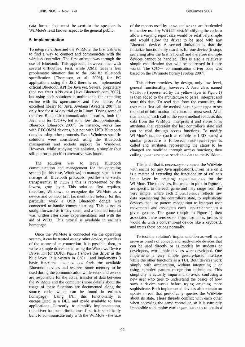
data format that must be sent to the speakers isWiiMote's least known aspect to the general public.
5. Implementation
To integrate enJine and the WiiMote, the first task wasto find a way to connect and communicate with thewireless controller. The first attempt was through theuse of Bluetooth. This approach, however, met withseveral difficulties. First, while J2ME faces a lessproblematic situation due to the JSR 82 Bluetoothspecification [Thompson et al. 2006], for PCapplications using the JSE there is no implementedofficial Bluetooth API for Java yet. Several proprietary(and not free) APIs exist [Java Bluetooth.com 2007],but using such solutions is unthinkable for extendingenJine with its open-source and free nature. Anexcellent library for Java, Avetana [Avetana 2007], isonly free for a 14 day trial or in Linux. Trying some ofthe free Bluetooth communication libraries, both forJava and for C/C++, led to a few disappointments.Bluesock [Bluesock 2007], for instance, works finewith RFCOMM devices, but not with USB Bluetoothdongles using other protocols. Even Windows-specificsolutions were considered, using the Bluetoothmanagement and sockets support for Windows.However, while studying this solution, a simpler (butstill platform specific) alternative was found.
The solution was to leave Bluetoothcommunication and management for the operatingsystem (in this case, Windows) to manage, since it canmanage all Bluetooth protocols, profiles and stackstransparently. In Figure 1 this is represented by thelowest, gray layer. This solution first requires,therefore, Windows to recognize the WiiMote as adevice and connect to it (as mentioned before, for thisparticular work a USB Bluetooth dongle wasconnected to handle communication). This is not asstraightforward as it may seem, and a detailed tutorialwas written after some experimentation and with theaid of WiiLi. This tutorial is available in enJine'shomepage.
Once the WiiMote is connected via the operatingsystem, it can be treated as any other device, regardlessof the nature of its connection. It is possible, then, towrite a simple driver for it, using the Windows DeviceDriver Kit (or DDK). Figure 1 shows this driver as theblue layer. It is written in C/C++ and implements 3basic functions: initialize finds the availableBluetooth devices and reserves some memory to beused during the communication while read and writeare responsible for the actual transfer of data betweenthe WiiMote and the computer (more details about theusage of these functions are documented along thesource code, which can be found in enJine'shomepage). Using JNI, this functionality isencapsulated in a DLL and made available to Javaapplications. Currently, to simplify implementation,this driver has some limitations: first, it is specificallybuilt to communicate only with the WiiMote - the size
of the reports used by read and write are hardcodedto the size used by Wii (22 bits). Modifying the code toallow a varying report size would be relatively simpleand would allow the driver to be used with anyBluetooth device. A second limitation is that theinitialize function only searches for one device (it stopssearching after the first is found) and therefore multipledevices cannot be handled. This is also a relativelysimple modification that will be addressed in futureworks. The C/C++ communication driver code wasbased on the cWiimote library [Forbes 2007].
This driver provides, by design, only low level,general functionality, however. A Java class namedWiiMote (represented by the yellow layer in Figure 1)is then added to the architecture to parse, interpret andstore this data. To read data from the controller, theuser must first call the method setReportType to setthe kind of information the controller must send. Afterthat is done, each call to the read method requests thisdata from the WiiMote, interprets it and stores it asattributes that represent the last controller's state andcan be read through access functions. To modifyWiiMote's outputs (such as rumble or LED states) asimilar procedure is followed: setReportType iscalled and attributes representing the states to bechanged are modified through access functions, thencalling updateOutput sends this data to the WiiMote.
This is all that is necessary to connect the WiiMotewith enJine (or any Java application). From here on itis a matter of extending the functionality of enJine'sinput layer by creating InputDevices for theWiiMote. These devices, illustrated in pink in Figure 1,are specific to the each game and may range from thevery simple, where each InputSensor reflects rawdata representing the controller's state, to sophisticatedevices that use pattern recognition to interpret usermovements and associates each InputSensor to agiven gesture. The game (purple in Figure 1) thenassociates these sensors to InputActions, just as itwould do with a conventional device like a keyboard,and treats these actions normally.
To test the solution's implementation as well as toserve as proofs of concept and ready-made devices thatcan be used directly or as models by students ordevelopers, two simple devices were developed. Oneimplements a very simple gesture-based interfacewhile the other functions as a TUI. Both devices worksimply with acceleration, without integrating it orusing complex pattern recognition techniques. Thissimplicity is actually important, to avoid confusing anew user who tires to understand the basics of howsuch a device works before trying anything moresophisticate. Both implemented devices also contain anupdate thread that periodically queries the WiiMoteabout its state. These threads conflict with each otherwhen accessing the same controller, so it is currentlyimpossible to combine two InputDevices to obtain a
UNISINOS - Nov., 7-9 SBGames 2007
92
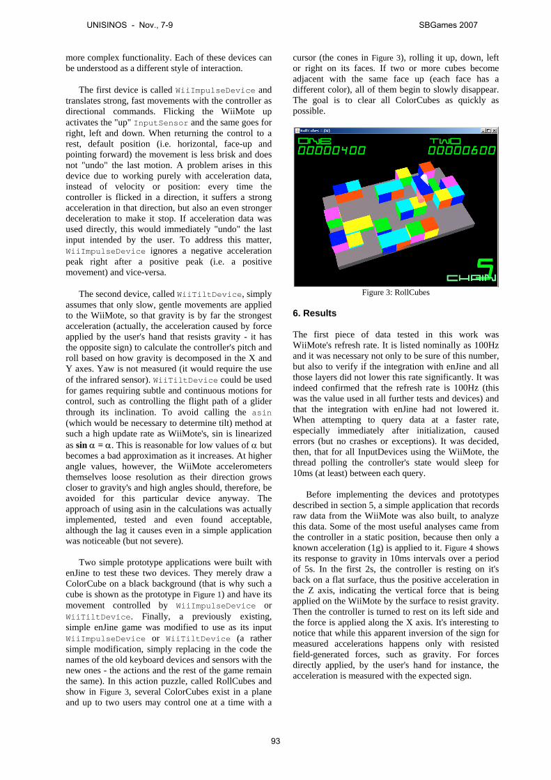
more complex functionality. Each of these devices canbe understood as a different style of interaction.
The first device is called WiiImpulseDevice andtranslates strong, fast movements with the controller asdirectional commands. Flicking the WiiMote upactivates the "up" InputSensor and the same goes forright, left and down. When returning the control to arest, default position (i.e. horizontal, face-up andpointing forward) the movement is less brisk and doesnot "undo" the last motion. A problem arises in thisdevice due to working purely with acceleration data,instead of velocity or position: every time thecontroller is flicked in a direction, it suffers a strongacceleration in that direction, but also an even strongerdeceleration to make it stop. If acceleration data wasused directly, this would immediately "undo" the lastinput intended by the user. To address this matter,WiiImpulseDevice ignores a negative accelerationpeak right after a positive peak (i.e. a positivemovement) and vice-versa.
The second device, called WiiTiltDevice, simplyassumes that only slow, gentle movements are appliedto the WiiMote, so that gravity is by far the strongestacceleration (actually, the acceleration caused by forceapplied by the user's hand that resists gravity - it hasthe opposite sign) to calculate the controller's pitch androll based on how gravity is decomposed in the X andY axes. Yaw is not measured (it would require the useof the infrared sensor). WiiTiltDevice could be usedfor games requiring subtle and continuous motions forcontrol, such as controlling the flight path of a gliderthrough its inclination. To avoid calling the asin(which would be necessary to determine tilt) method atsuch a high update rate as WiiMote's, sin is linearizedas sin α = α. This is reasonable for low values of α butbecomes a bad approximation as it increases. At higherangle values, however, the WiiMote accelerometersthemselves loose resolution as their direction growscloser to gravity's and high angles should, therefore, beavoided for this particular device anyway. Theapproach of using asin in the calculations was actuallyimplemented, tested and even found acceptable,although the lag it causes even in a simple applicationwas noticeable (but not severe).
Two simple prototype applications were built withenJine to test these two devices. They merely draw aColorCube on a black background (that is why such acube is shown as the prototype in Figure 1) and have itsmovement controlled by WiiImpulseDevice orWiiTiltDevice. Finally, a previously existing,simple enJine game was modified to use as its inputWiiImpulseDevice or WiiTiltDevice (a rathersimple modification, simply replacing in the code thenames of the old keyboard devices and sensors with thenew ones - the actions and the rest of the game remainthe same). In this action puzzle, called RollCubes andshow in Figure 3, several ColorCubes exist in a planeand up to two users may control one at a time with a
cursor (the cones in Figure 3), rolling it up, down, leftor right on its faces. If two or more cubes becomeadjacent with the same face up (each face has adifferent color), all of them begin to slowly disappear.The goal is to clear all ColorCubes as quickly aspossible.
Figure 3: RollCubes
6. Results
The first piece of data tested in this work wasWiiMote's refresh rate. It is listed nominally as 100Hzand it was necessary not only to be sure of this number,but also to verify if the integration with enJine and allthose layers did not lower this rate significantly. It wasindeed confirmed that the refresh rate is 100Hz (thiswas the value used in all further tests and devices) andthat the integration with enJine had not lowered it.When attempting to query data at a faster rate,especially immediately after initialization, causederrors (but no crashes or exceptions). It was decided,then, that for all InputDevices using the WiiMote, thethread polling the controller's state would sleep for10ms (at least) between each query.
Before implementing the devices and prototypesdescribed in section 5, a simple application that recordsraw data from the WiiMote was also built, to analyzethis data. Some of the most useful analyses came fromthe controller in a static position, because then only aknown acceleration (1g) is applied to it. Figure 4 showsits response to gravity in 10ms intervals over a periodof 5s. In the first 2s, the controller is resting on it'sback on a flat surface, thus the positive acceleration inthe Z axis, indicating the vertical force that is beingapplied on the WiiMote by the surface to resist gravity.Then the controller is turned to rest on its left side andthe force is applied along the X axis. It's interesting tonotice that while this apparent inversion of the sign formeasured accelerations happens only with resistedfield-generated forces, such as gravity. For forcesdirectly applied, by the user's hand for instance, theacceleration is measured with the expected sign.
UNISINOS - Nov., 7-9 SBGames 2007
93
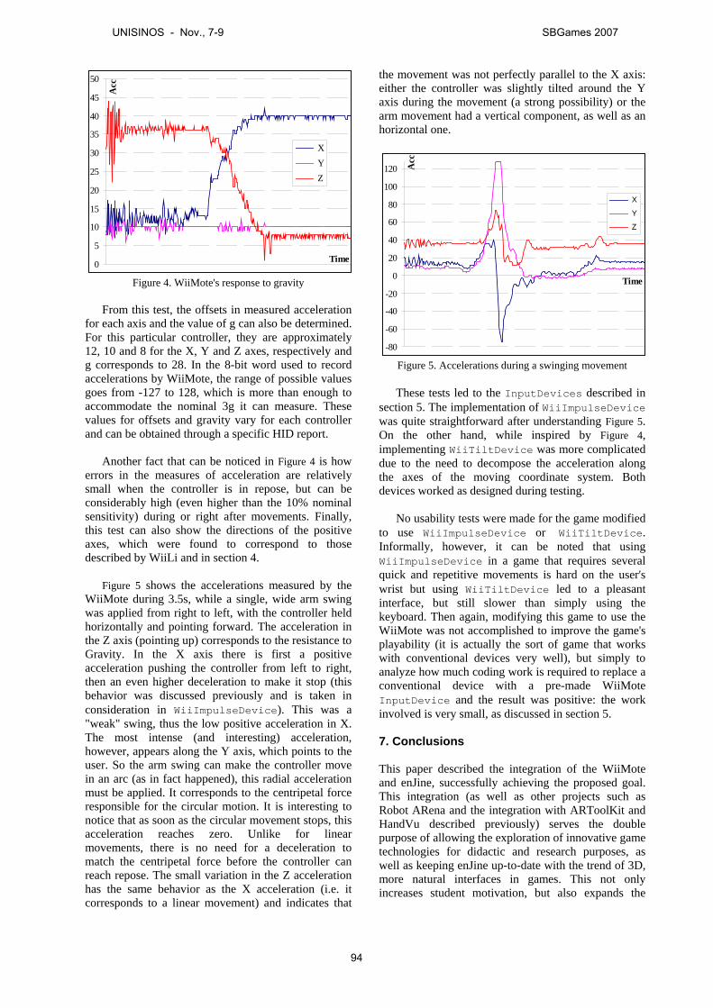
0
5
10
15
20
25
30
35
40
45
50
Time
Acc
X Y Z
Figure 4. WiiMote's response to gravity
From this test, the offsets in measured accelerationfor each axis and the value of g can also be determined.For this particular controller, they are approximately12, 10 and 8 for the X, Y and Z axes, respectively andg corresponds to 28. In the 8-bit word used to recordaccelerations by WiiMote, the range of possible valuesgoes from -127 to 128, which is more than enough toaccommodate the nominal 3g it can measure. Thesevalues for offsets and gravity vary for each controllerand can be obtained through a specific HID report.
Another fact that can be noticed in Figure 4 is howerrors in the measures of acceleration are relativelysmall when the controller is in repose, but can beconsiderably high (even higher than the 10% nominalsensitivity) during or right after movements. Finally,this test can also show the directions of the positiveaxes, which were found to correspond to thosedescribed by WiiLi and in section 4.
Figure 5 shows the accelerations measured by theWiiMote during 3.5s, while a single, wide arm swingwas applied from right to left, with the controller heldhorizontally and pointing forward. The acceleration inthe Z axis (pointing up) corresponds to the resistance toGravity. In the X axis there is first a positiveacceleration pushing the controller from left to right,then an even higher deceleration to make it stop (thisbehavior was discussed previously and is taken inconsideration in WiiImpulseDevice). This was a"weak" swing, thus the low positive acceleration in X.The most intense (and interesting) acceleration,however, appears along the Y axis, which points to theuser. So the arm swing can make the controller movein an arc (as in fact happened), this radial accelerationmust be applied. It corresponds to the centripetal forceresponsible for the circular motion. It is interesting tonotice that as soon as the circular movement stops, thisacceleration reaches zero. Unlike for linearmovements, there is no need for a deceleration tomatch the centripetal force before the controller canreach repose. The small variation in the Z accelerationhas the same behavior as the X acceleration (i.e. itcorresponds to a linear movement) and indicates that
the movement was not perfectly parallel to the X axis:either the controller was slightly tilted around the Yaxis during the movement (a strong possibility) or thearm movement had a vertical component, as well as anhorizontal one.
-80
-60
-40
-20
0
20
40
60
80
100
120
Time
Acc
X
Y
Z
Figure 5. Accelerations during a swinging movement
These tests led to the InputDevices described insection 5. The implementation of WiiImpulseDevicewas quite straightforward after understanding Figure 5.On the other hand, while inspired by Figure 4,implementing WiiTiltDevice was more complicateddue to the need to decompose the acceleration alongthe axes of the moving coordinate system. Bothdevices worked as designed during testing.
No usability tests were made for the game modifiedto use WiiImpulseDevice or WiiTiltDevice.Informally, however, it can be noted that usingWiiImpulseDevice in a game that requires severalquick and repetitive movements is hard on the user'swrist but using WiiTiltDevice led to a pleasantinterface, but still slower than simply using thekeyboard. Then again, modifying this game to use theWiiMote was not accomplished to improve the game'splayability (it is actually the sort of game that workswith conventional devices very well), but simply toanalyze how much coding work is required to replace aconventional device with a pre-made WiiMoteInputDevice and the result was positive: the workinvolved is very small, as discussed in section 5.
7. Conclusions
This paper described the integration of the WiiMoteand enJine, successfully achieving the proposed goal.This integration (as well as other projects such asRobot ARena and the integration with ARToolKit andHandVu described previously) serves the doublepurpose of allowing the exploration of innovative gametechnologies for didactic and research purposes, aswell as keeping enJine up-to-date with the trend of 3D,more natural interfaces in games. This not onlyincreases student motivation, but also expands the
UNISINOS - Nov., 7-9 SBGames 2007
94

possibilities to use enJine in teaching, particularly forcourses involving AR, user interfaces or games.
The integration solution chosen has multiple layersand, at the lowest level, makes use of the operatingsystem’s handling of Bluetooth communication, sincefinding a comprehensive and free library for thisfunction was problematic. A more efficient solutionwas to write a simple device driver to the WiiMoteusing the Windows DDK and allowing Java to access itusing JNI. This driver comprises the second layer ofthe architecture. The third layer, already in Java, is aclass that interprets WiiMote’s raw data, stores its stateas attributes and provides a simple interface to sendoutputs to the controller. With this functionality, usingthe WiiMote becomes just as simple as using any otherdevice. Two sample InputDevices where createdand an existing game was modified to use them.
Testing helped ascertain the unofficial data aboutthe WiiMote, such as its refresh rate and coordinatesystem, as well as showed that the implementedarchitecture did not impair this refresh ratesignificantly. It was found that, while in repose orunder low accelerations, errors in accelerationmeasures by the controller were relatively small, butunder higher accelerations they were significant (evensurpassing the 10% nominal sensor sensitivity).Testing was also important to understand and visualizeWiiMote’s response to user movements to implementWiiImpulseDevice and WiiTiltDevice.
While the project’s goal was satisfactorily reached,the implementation still has a few limitations. Perhapsthe most important is the dependence of the Windowsoperating system. Because Bluetooth communicationwas isolated in the lowers layers of the proposedarchitecture, however, once a suitable and free JavaAPI for this task is found (or, in a worst case scenario,developed internally), it should be relatively simple touse it to make the system platform-independent. Untilthen, however, the Windows system will be prioritizedover other solutions because, in the particular case ofthis work’s authors, it is used much more commonly inclasses and by the students.
Other limitation that can also be addressed in futureworks is to decouple the device driver from theWiiMote, allowing it to serve as a low-levelcommunication interface for any Bluetooth device.Perhaps even more important is to modify the systemto work with more than one controller at a time.Adding the possibility of combining more than oneInputDevice, to allow the creation of complexinterfaces built with simpler modules, is also aninteresting future work. Another possibility to study isextending this work to include other motion sensingcontrollers, such as Sony's Sixaxis wireless controller.
Perhaps the most interesting possible future workswith this system are using it to explore pattern
recognition to build more complex gesture-basedinterfaces and putting the system to practical use, bothusing the system in classrooms and building gameswith innovative 3D interfaces (particularly gesture-based and TUIs). To this end, a game is currently beingdeveloped combining enJine, the WiiMote and RobotARena. While enJine is more of an educational tool initself, instead of a tool for making educational games,using the WiiMote makes the concepts of accelerationsand forces very tangible and building an application toteach those concepts is another interesting future work.
Finally, this work was more concerned with thenecessary infrastructure for integrating WiiMote andenJine than with studying the controller’s use, butformally studying usability aspects of games usingWiiMote is an interesting and necessary future work.
References
TORI, R.; BERNARDES, J. AND NAKAMURA, R., 2006.Teaching Introductory Computer Graphics Using Java3D, Games and Customized Software: a BrazilianExperience. In: Digital proceedings of the 34thInternational Conference and Exhibition on ComputerGraphics and Interactive Techniques, EducatorsProgram. ACM SIGGRAPH.
GOMES, P. AND PAMPLONA, V., 2005. M3GE: um motor dejogos 3D para dispositivos móveis com suporte a Mobile3D Graphics API. In: Proceedings of the BrazilianSymposium on Computer Games and ElectronicEntertainment 2005. SBC, 55-65.
NINTENDO Wii Remote. http://wii.nintendo.com/controller.jsp [accessed 20 August 2007].
DOBSON, J., 2006. Nintendo: 600,000 Wii, 454,000 ZeldaSold In First Eight Days. Available on:http://www.gamasutra.com/php-bin/news_index.php?story=11864 [accessed 20 August 2007].
CARLESS, S., 2005. Xbox CFO Estimates Initial Xbox 360Sales. Available on: http://www.gamasutra.com/php-bin/news_index.php?story=7109%3C/link%3E [accessed 20August 2007].
AZUMA, R., 1997. A Survey of Augmented Reality. Presence:Teleoperators and Virtual Environments, n. 6, 355-385.
ISHII, H. AND ULLMER, B., 1997. Tangible Bits: TowardsSeamless Interfaces Between People, Bits And Atoms.In: Proceedings of The SIGCHI Conference on HumanFactors In Computing Systems, 234-241.
CABRAL, M.; MORIMOTO, C. AND ZUFFO, M., 2005. On theusability of gesture interfaces in virtual realityenvironments. In: Proceedings of the 2005 LatinAmerican conference on Human-computer interaction.ACM, 100-108.
BILLINGHURST, M.; KATO, H. AND POUPYREV, I., 2000.Artoolkit: A computer vision based augmented realitytoolkit. In: Proceedings of the IEEE Virtual Reality 2000Conference. IEEE.
UNISINOS - Nov., 7-9 SBGames 2007
95
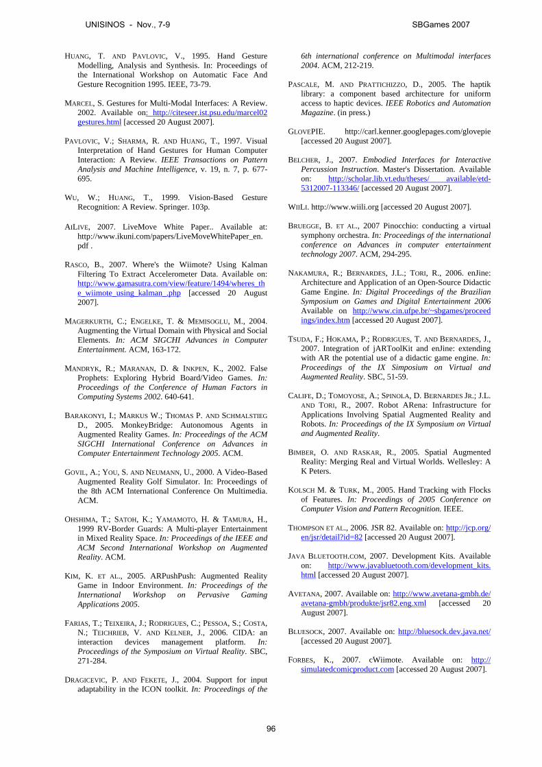
HUANG, T. AND PAVLOVIC, V., 1995. Hand GestureModelling, Analysis and Synthesis. In: Proceedings ofthe International Workshop on Automatic Face AndGesture Recognition 1995. IEEE, 73-79.
MARCEL, S. Gestures for Multi-Modal Interfaces: A Review.2002. Available on: http://citeseer.ist.psu.edu/marcel02gestures.html [accessed 20 August 2007].
PAVLOVIC, V.; SHARMA, R. AND HUANG, T., 1997. VisualInterpretation of Hand Gestures for Human ComputerInteraction: A Review. IEEE Transactions on PatternAnalysis and Machine Intelligence, v. 19, n. 7, p. 677-695.
WU, W.; HUANG, T., 1999. Vision-Based GestureRecognition: A Review. Springer. 103p.
AILIVE, 2007. LiveMove White Paper.. Available at:http://www.ikuni.com/papers/LiveMoveWhitePaper_en.pdf .
RASCO, B., 2007. Where's the Wiimote? Using KalmanFiltering To Extract Accelerometer Data. Available on:http://www.gamasutra.com/view/feature/1494/wheres_the_wiimote_using_kalman_.php [accessed 20 August2007].
MAGERKURTH, C.; ENGELKE, T. & MEMISOGLU, M., 2004.Augmenting the Virtual Domain with Physical and SocialElements. In: ACM SIGCHI Advances in ComputerEntertainment. ACM, 163-172.
MANDRYK, R.; MARANAN, D. & INKPEN, K., 2002. FalseProphets: Exploring Hybrid Board/Video Games. In:Proceedings of the Conference of Human Factors inComputing Systems 2002. 640-641.
BARAKONYI, I.; MARKUS W.; THOMAS P. AND SCHMALSTIEGD., 2005. MonkeyBridge: Autonomous Agents inAugmented Reality Games. In: Proceedings of the ACMSIGCHI International Conference on Advances inComputer Entertainment Technology 2005. ACM.
GOVIL, A.; YOU, S. AND NEUMANN, U., 2000. A Video-BasedAugmented Reality Golf Simulator. In: Proceedings ofthe 8th ACM International Conference On Multimedia.ACM.
OHSHIMA, T.; SATOH, K.; YAMAMOTO, H. & TAMURA, H.,1999 RV-Border Guards: A Multi-player Entertainmentin Mixed Reality Space. In: Proceedings of the IEEE andACM Second International Workshop on AugmentedReality. ACM.
KIM, K. ET AL., 2005. ARPushPush: Augmented RealityGame in Indoor Environment. In: Proceedings of theInternational Workshop on Pervasive GamingApplications 2005.
FARIAS, T.; TEIXEIRA, J.; RODRIGUES, C.; PESSOA, S.; COSTA,N.; TEICHRIEB, V. AND KELNER, J., 2006. CIDA: aninteraction devices management platform. In:Proceedings of the Symposium on Virtual Reality. SBC,271-284.
DRAGICEVIC, P. AND FEKETE, J., 2004. Support for inputadaptability in the ICON toolkit. In: Proceedings of the
6th international conference on Multimodal interfaces2004. ACM, 212-219.
PASCALE, M. AND PRATTICHIZZO, D., 2005. The haptiklibrary: a component based architecture for uniformaccess to haptic devices. IEEE Robotics and AutomationMagazine. (in press.)
GLOVEPIE. http://carl.kenner.googlepages.com/glovepie[accessed 20 August 2007].
BELCHER, J., 2007. Embodied Interfaces for InteractivePercussion Instruction. Master's Dissertation. Availableon: http://scholar.lib.vt.edu/theses/ available/etd-5312007-113346/ [accessed 20 August 2007].
WIILI. http://www.wiili.org [accessed 20 August 2007].
BRUEGGE, B. ET AL., 2007 Pinocchio: conducting a virtualsymphony orchestra. In: Proceedings of the internationalconference on Advances in computer entertainmenttechnology 2007. ACM, 294-295.
NAKAMURA, R.; BERNARDES, J.L.; TORI, R., 2006. enJine:Architecture and Application of an Open-Source DidacticGame Engine. In: Digital Proceedings of the BrazilianSymposium on Games and Digital Entertainment 2006Available on http://www.cin.ufpe.br/~sbgames/proceedings/index.htm [accessed 20 August 2007].
TSUDA, F.; HOKAMA, P.; RODRIGUES, T. AND BERNARDES, J.,2007. Integration of jARToolKit and enJine: extendingwith AR the potential use of a didactic game engine. In:Proceedings of the IX Simposium on Virtual andAugmented Reality. SBC, 51-59.
CALIFE, D.; TOMOYOSE, A.; SPINOLA, D. BERNARDES JR.; J.L.AND TORI, R., 2007. Robot ARena: Infrastructure forApplications Involving Spatial Augmented Reality andRobots. In: Proceedings of the IX Symposium on Virtualand Augmented Reality.
BIMBER, O. AND RASKAR, R., 2005. Spatial AugmentedReality: Merging Real and Virtual Worlds. Wellesley: AK Peters.
KOLSCH M. & TURK, M., 2005. Hand Tracking with Flocksof Features. In: Proceedings of 2005 Conference onComputer Vision and Pattern Recognition. IEEE.
THOMPSON ET AL., 2006. JSR 82. Available on: http://jcp.org/en/jsr/detail?id=82 [accessed 20 August 2007].
JAVA BLUETOOTH.COM, 2007. Development Kits. Availableon: http://www.javabluetooth.com/development_kits.html [accessed 20 August 2007].
AVETANA, 2007. Available on: http://www.avetana-gmbh.de/avetana-gmbh/produkte/jsr82.eng.xml [accessed 20August 2007].
BLUESOCK, 2007. Available on: http://bluesock.dev.java.net/[accessed 20 August 2007].
FORBES, K., 2007. cWiimote. Available on: http://simulatedcomicproduct.com [accessed 20 August 2007].
UNISINOS - Nov., 7-9 SBGames 2007
96
Um Framework Opensource para a Construção de Sistemas Multiatores
Allan D. S. Lima Patricia R. Tedesco Geber L. Ramalho
Universidade Federal de Pernambuco, Centro de Informática, Brasil
Palavras-chave: Atores Sintéticos, Sistemas Multiagentes, Simuladores, Sistemas Multiatores. Contado dos Autores: {adsl, pcart, glr}@cin.ufpe.br
Resumo Com a popularização dos sistemas multiagentes surgiram diversos frameworks para dar suporte ao seu desenvolvimento, reduzindo o custo e tempo de desenvolvimento desses sistemas. Além disto, também há vários projetos, dentre até jogos, que utilizam múltiplos atores sintéticos, um tipo específico de agente inteligente que possui personalidade, atua em ambientes multimídias ou virtuais e são representados graficamente por avatares. Entretanto, os projetos que fazem uso de múltiplos atores sintéticos não costumam utilizar os frameworks existentes durante a sua implementação. Isto se deve ao fato de que esses frameworks não costumam se aplicar tão bem a sistemas multiatores pois não dão suporte as características diferenciais destes sistemas. Assim, este trabalho apresenta o FAct (Framework for Actors), um projeto criado especificamente para auxiliar na construção sistemas multiatores, visando reduzir o custo e tempo de desenvolvimento para os projetos baseados nesta tecnologia. 1. Introdução Aplicados à resolução de problemas em diversas áreas, como Educação a Distância [Torreão et al. 2005], Comércio Eletrônico [Guttman et al. 1998] e Jogos [Barreteau et al. 2001], agentes inteligentes são entidades computacionais com duas importantes características: autonomia e sociabilidade. Estas propriedades permitem a construção de Sistemas Multiagentes (SMAs) que apresentam comportamento flexível e dinâmico. No entanto, como SMAs são sistemas complexos, comumente seu desenvolvimento é baseado em frameworks. Estes agrupam as funcionalidades básicas necessárias a SMAs, como controle do ciclo de vida dos agentes e transporte de mensagens, permitindo ao desenvolvedor se preocupar apenas com a modelagem comportamental dos agentes, o que reduz significativamente o custo de desenvolvimento dos projetos.
No entanto, com a utilização cada vez maior de agentes inteligentes em sistemas que necessitam engajar o usuário na sua interação, vem-se destacando
a modelagem de um tipo especial de agente, denominado ator sintético (também chamados de personagens virtuais). Estes são agentes inteligentes credíveis, que apresentam personalidades em um estilo particular de interação, percepção, raciocínio e ação [Silva et al. 2000].
Este tipo diferenciado de agente vem sendo utilizado no desenvolvimento de diversos projetos de pesquisa (e.g. [Bates et al. 1994; Rousseau e Hayes-Roth 1997] )e também aplicados na construção de jogos [Silva et al. 2000; SmartSim 2007] visando enriquecer a credibilidade dos agentes e melhorar a qualidade da interação com o usuário. No entanto, estes personagens tendem a ser cada vez mais complexos, o que torna o custo e tempo de desenvolvimento destes projetos bastante expressivos.
Em contrapartida, os frameworks para a construção
de SMAs atuam justamente no suporte aos SMAs reduzindo o custo e o tempo de desenvolvimento deles. Entretanto, projetos que aplicam atores sintéticos não fazem uso de qualquer tipo de framework para SMAs. Isto se deve ao fato que de que tais bibliotecas não dão suporte às características particulares dos atores, como por exemplo, o suporte a modelos de personalidade. Isto inviabiliza a aplicação dos mesmos para a construção de projetos baseados em atores.
Neste contexto, este artigo apresenta o FAct (Framework for Actors), que oferece um framework open source para construção SMAct. Ele possui uma biblioteca para ajudar no desenvolvimento da simualção e um conjunto ferramentas gráficas de suporte ao desenvolviment, que podem ser utilizados e estendidos pelo desenvolvedor, que se encarregará apenas da implementação do comportamento dos atores e das demais entidades presentes na simulação, aumentando assim a sua produtividade e, conseqüentemente, reduzindo o custo e o tempo de desenvolvimento dos SMAct.
O presente artigo está organizado em cinco seções. A segunda apresenta um estudo comparativo entre projetos que utilizam o conceito de atores sintéticos; a terceira faz uma análise crítica dos frameworks para a construção de SMAs; a quarta apresenta o conceito de Sistemas Multiatores (SMAct), discutindo algumas diferenças importantes entre SMAs e SMAct; a quinta descreve o FAct abordando seus requisitos, seus módulos, sua arquitetura e a aplicação exemplo desenvolvida sobre ele; a sexta, por fim, relata as
UNISINOS - Nov., 7-9 SBGames 2007
97
conclusões do projeto e mostra os próximos passos no desenvolvimento do projeto. 2. Atores Sintéticos Atores sintéticos, ou agentes credíveis, são entidades computacionais que possuem como objetivo principal transmitir “ilusão de vida” aos usuários de suas aplicações. Para que isto seja possível, eles contam com atributos que possuem uma semântica diferenciada que podem representar os estado emocional do agente, a sua personalidade além de avatar para o mesmo[Silva et al. 2000], além das demais características que um agente autônomo possui, como, por exemplo, os serviços que ele provê, seu estado interno e um mecanismo de comunicação. No decorrer dos últimos anos, a utilização de atores sintéticos vem se popularizando. Sendo estes aplicados para simulação do comportamento de indivíduos em diversos projetos. Além disto, sua utilização nestes projetos quase sempre envolve a aplicação de mais do que um ator em uma única simulação, compondo sistemas com múltiplos atores. Como exemplos, podemos citar os projetos Oz [Bates et al. 1994], Teatro Virtual [Rosseau e Hayes-Roth. 1997], além do projetos Enigmas no Campus [Silva et al. 2000], VICTEC [Paiva et al. 2004] e SmartSim [SmartSim 2007]. Os dois primeiros são analisados pelo pioneirismo na aplicação de modelos de personalidade baseados em psicologia aliados a agentes autônomos. Já os dois últimos são analisados, pois tiveram como resultado a o desenvolvimento de jogos baseados em atores sintéticos.
A seguir, cada um destes projetos é abordado com mais detalhes sob o ponto de vista dos seus objetivos, suas aplicações e seus modelos de personalidade e
emoção. O projeto OZ O projeto Oz [Bates et al. 1994] foi um dos primeiros na utilização de atores sintéticos, tendo sido idealizado para simulação de ambientes artisticamente interessantes. Uma das aplicações desenvolvidas no projeto o OZ foi o Lyotard que é uma ambiente de texto para simulação do comportamento de um gato em seu ambiente cotidiano. Outra aplicação criada a partir deste projeto simula o comportamento de três crianças em um playground. Em ambas, utilizou-se um modelo de personalidade que tem como base (1) a curiosidade, (2) o contentamento, (3) a capacidade de ignorar, (4) a agressividade, (5) a amigabilidade e (6) a arrogância/orgulho. Este modelo é utilizado para determinar o comportamento dos atores com o auxílio de um modelo de emoções baseado no modelo OCC [Orthony et al. 1990].
Teatro Virtual O projeto Teatro Virtural [Rousseau 1997] foi criado para desenvolver atores sintéticos que podem improvisar seus comportamentos em ambientes interativos sem planejamento detalhado. O objetivo do projeto é a construção de atores que interagem entre si e com os humanos para criar novas histórias cada vez que são utilizados. Dentre as aplicações desenvolvidas durante o projeto, podemos ressaltar o Cybercafe, que simula a interação entre os clientes, controlados por humanos, e um garçom que é um ator sintético, e o simulador multiator Animated Puppets, um mundo gráfico habitado por criaturas que dialogam e brincam umas com as outras. Estas criaturas têm seus comportamentos baseados na Teoria dos Traços [Allport 1966] e na Teoria do Aprendizado Social [Bandura 1977]. A primeira assume que o perfil de uma personalidade individual pode ser descrito em termos de um conjunto de traços psicológicos constantes que influenciam o comportamento. Entretanto, na segunda teoria, a personalidade é modificada a cada situação que é vista como uma experiência de aprendizado por reforço. Enigmas no Campus O Projeto Enigmas no Campus [Silva et al. 2000] é um jogo multiagentes de aventura em que o jogador deve solucionar enigmas a fim de restituir o conhecimento do Universo destruído por criaturas maldosas e alienígenas. Ele foi criado para testar, não só um modelo psicossocial desenvolvido por pesquisadores da UFPE, mas também para avaliar a aplicação uma arquitetura para atores sintéticos e outros agentes em jogos de aventura criada igualmente na UFPE. Seu modelo de personalidade é baseado na teoria The Big
Five [Howard e Howard 1995] que classifica a personalidade em cinco tipos distintos: extrovertido, aprazível, consciente, neurótico e “aberto à experiência”. SmartSim O projeto SmartSim [SmartSim 2007], criado na UFPE, tem como objetivo principal o desenvolvimento de um framework de código aberto para a construção de jogos de negócios [Faria e Nulsen 1996] que utilizem atores sintéticos. Como primeira aplicação do framework foi desenvolvido o protótipo de um jogo sério chamado Virtual Team, que tem como objetivo apoiar a capacitação de gerentes de projeto de software com base nos conceitos do PMBOK® [PMBOK 2004]. O comportamento dos personagens neste projeto é baseado no Symlog [Bales e Cohen 1979] que classifica a personalidade do indivíduo em três dimensões Dominância(U)/Submissividade(D), Amigável(P)/Não Amigável(N) e Aceitação(A)/Não aceitação de autoridade e orientação à tarefa (B) [Silva et al. 2006].
UNISINOS - Nov., 7-9 SBGames 2007
98
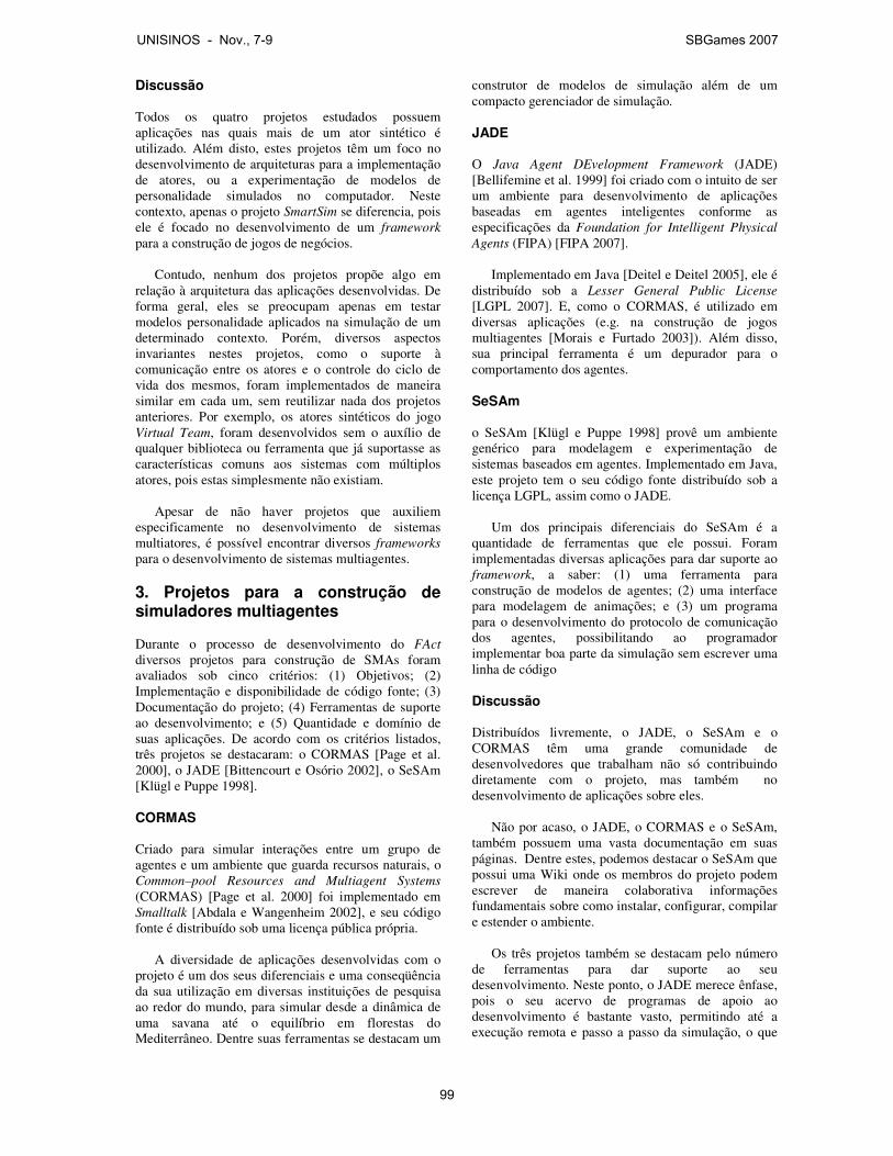
Discussão Todos os quatro projetos estudados possuem aplicações nas quais mais de um ator sintético é utilizado. Além disto, estes projetos têm um foco no desenvolvimento de arquiteturas para a implementação de atores, ou a experimentação de modelos de personalidade simulados no computador. Neste contexto, apenas o projeto SmartSim se diferencia, pois ele é focado no desenvolvimento de um framework para a construção de jogos de negócios.
Contudo, nenhum dos projetos propõe algo em relação à arquitetura das aplicações desenvolvidas. De forma geral, eles se preocupam apenas em testar modelos personalidade aplicados na simulação de um determinado contexto. Porém, diversos aspectos invariantes nestes projetos, como o suporte à comunicação entre os atores e o controle do ciclo de vida dos mesmos, foram implementados de maneira similar em cada um, sem reutilizar nada dos projetos anteriores. Por exemplo, os atores sintéticos do jogo Virtual Team, foram desenvolvidos sem o auxílio de qualquer biblioteca ou ferramenta que já suportasse as características comuns aos sistemas com múltiplos atores, pois estas simplesmente não existiam.
Apesar de não haver projetos que auxiliem especificamente no desenvolvimento de sistemas multiatores, é possível encontrar diversos frameworks para o desenvolvimento de sistemas multiagentes. 3. Projetos para a construção de simuladores multiagentes Durante o processo de desenvolvimento do FAct diversos projetos para construção de SMAs foram avaliados sob cinco critérios: (1) Objetivos; (2) Implementação e disponibilidade de código fonte; (3) Documentação do projeto; (4) Ferramentas de suporte ao desenvolvimento; e (5) Quantidade e domínio de suas aplicações. De acordo com os critérios listados, três projetos se destacaram: o CORMAS [Page et al. 2000], o JADE [Bittencourt e Osório 2002], o SeSAm [Klügl e Puppe 1998]. CORMAS Criado para simular interações entre um grupo de agentes e um ambiente que guarda recursos naturais, o Common–pool Resources and Multiagent Systems (CORMAS) [Page et al. 2000] foi implementado em Smalltalk [Abdala e Wangenheim 2002], e seu código fonte é distribuído sob uma licença pública própria.
A diversidade de aplicações desenvolvidas com o projeto é um dos seus diferenciais e uma conseqüência da sua utilização em diversas instituições de pesquisa ao redor do mundo, para simular desde a dinâmica de uma savana até o equilíbrio em florestas do Mediterrâneo. Dentre suas ferramentas se destacam um
construtor de modelos de simulação além de um compacto gerenciador de simulação. JADE O Java Agent DEvelopment Framework (JADE) [Bellifemine et al. 1999] foi criado com o intuito de ser um ambiente para desenvolvimento de aplicações baseadas em agentes inteligentes conforme as especificações da Foundation for Intelligent Physical
Agents (FIPA) [FIPA 2007].
Implementado em Java [Deitel e Deitel 2005], ele é distribuído sob a Lesser General Public License [LGPL 2007]. E, como o CORMAS, é utilizado em diversas aplicações (e.g. na construção de jogos multiagentes [Morais e Furtado 2003]). Além disso, sua principal ferramenta é um depurador para o comportamento dos agentes. SeSAm o SeSAm [Klügl e Puppe 1998] provê um ambiente genérico para modelagem e experimentação de sistemas baseados em agentes. Implementado em Java, este projeto tem o seu código fonte distribuído sob a licença LGPL, assim como o JADE.
Um dos principais diferenciais do SeSAm é a quantidade de ferramentas que ele possui. Foram implementadas diversas aplicações para dar suporte ao framework, a saber: (1) uma ferramenta para construção de modelos de agentes; (2) uma interface para modelagem de animações; e (3) um programa para o desenvolvimento do protocolo de comunicação dos agentes, possibilitando ao programador implementar boa parte da simulação sem escrever uma linha de código Discussão Distribuídos livremente, o JADE, o SeSAm e o CORMAS têm uma grande comunidade de desenvolvedores que trabalham não só contribuindo diretamente com o projeto, mas também no desenvolvimento de aplicações sobre eles.
Não por acaso, o JADE, o CORMAS e o SeSAm, também possuem uma vasta documentação em suas páginas. Dentre estes, podemos destacar o SeSAm que possui uma Wiki onde os membros do projeto podem escrever de maneira colaborativa informações fundamentais sobre como instalar, configurar, compilar e estender o ambiente.
Os três projetos também se destacam pelo número de ferramentas para dar suporte ao seu desenvolvimento. Neste ponto, o JADE merece ênfase, pois o seu acervo de programas de apoio ao desenvolvimento é bastante vasto, permitindo até a execução remota e passo a passo da simulação, o que
UNISINOS - Nov., 7-9 SBGames 2007
99
facilita consideravelmente o processo de testes das aplicações.
Quanto à tecnologia de implementação destes projetos, o JADE e o SeSAm usam Java, enquanto que o CORMAS foi implementado em Smaltalk. Nos três casos a tecnologia de implementação adotada acaba por dificultar a aplicação dos mesmos na construção de jogos, já que C++ [Stroustrup 1997] é a linguagem de programação mais utilizada nestes tipos de aplicações [Rolling e Morris 2004].
Outra característica interessante é que o JADE possui uma preocupação, em sua arquitetura, com os padrões da FIPA, o que pode facilitar consideravelmente a interoperabilidade entre sistemas multiagentes distintos. 4. Sistemas Multiatores (SMact) A análise realizada na seção dois mostrou que todos os projetos estudados possuem aplicações onde mais de um ator sintético está presente. O Projeto Oz simula diversas crianças em um playground, o Projeto Teatro Virtual utiliza diversos atores no Cibercafe, o Enigmas no Campus também faz uso de múltiplos atores em seu ambiente, e o SmartSim os utiliza na simulação do comportamento de desenvolvedores de software.
Isso se justifica, pois o emprego de múltiplos atores pode ser muito útil, incrementando a interatividade da aplicação através da simulação do comportamento dos atores baseados em diversos tipos de personalidade e emoções.
Por exemplo, no jogo Virtual Team o usuário tem que escolher os desenvolvedores que irão compor uma equipe de desenvolvimento de software. O desempenho da equipe selecionada depende, entre outros fatores, das personalidades de seus membros. Outra conseqüência da utilização de múltiplos atores é o estabelecimento de um nível de relacionamento entre os agentes. Isto também pode ser verificado no Virtual
Team, como uma das variáveis relevantes para o desempenho da equipe na simulação. Através da interface do jogo é possível acompanhar todo o processo de simulação, inclusive estado emocional dos atores nos seus avatares. 4.1 Uma definição para Sistemas Multiatores Tendo como fundamento a deliberação para sistemas multiagentes proposta por Ferber (1999) e as características de um ator sintético, é possível definir o termo ‘sistema multiatores’ como aplicável a um sistema com os seguintes elementos:
1. Um ambiente, E, representando um espaço que geralmente tem um volume;
2. Um conjunto de objetos, O. Estes objetos são geograficamente situados, e em qualquer dado momento é possível associar qualquer objeto com uma posição em E. Estes objetos podem ser percebidos, criados, destruídos e modificados pelos atores;
3. Um conjunto de atores sintéticos, A, que são
objetos específicos (A está contido em O), representando as entidades ativas do sistema;
4. Um conjunto de representações gráficas, RG,
para os atores A, tal que cada ator possua pelo menos uma representação;
5. Um conjunto de relações R, que liga objetos
(e seus agentes) entre si;
6. Um conjunto de operações, Op, tornando possível para os agentes de A perceber, produzir, consumir, transformar e manipular objetos de O;
7. Operadores com a tarefa de representar as
reações do ambiente a Op.
Os pontos 3 e 4 desta definição representam as principais modificações que foram realizadas na definição original para SMAs. O ponto 3 indica a existência de um conjunto de atores sintéticos, o que requer a concepção de uma coleção de agentes com todas as características que ator sintético possui, emoções, personalidade, etc. Já o ponto 4 ressalta a necessidade de um conjunto de representações gráficas para os atores. Elas fazem parte da interface gráfica do projeto, e representam o estado atual do agente para o usuário da aplicação. 5. O FAct: Framework for Actors Como vimos anteriormente, a análise dos projetos para a construção de sistemas multiagentes mostrou que a maioria deles não restringe os tipos de agentes aos quais pretendem apoiar, visando desta forma, auxiliar no desenvolvimento de praticamente qualquer tipo de agente inteligente, sem, entretanto, suportar características de tipos específicos de agentes, como os atores sintéticos. Em decorrência, desta generalidade, projetos como o Enigma no Campus [Silva et at. 2000] e o SmartSim [SmartSim 2007] optaram por realizar toda implementação dos seus ambientes de simulação sem o auxílio de qualquer tipo de framework multiagente. Isto se deve ao fato de que os frameworks atuais para multiagentes não dão suporte as características peculiares aos atores sintéticos, como por exemplo, o suporte a modelos de personalidade.
Visando preencher esta lacuna, o FAct (Framework for Actors), um framework para construção de Sistemas Multiatores foi elaborado. O FAct tem como principal objetisavo apoiar o desenvolvimento de
UNISINOS - Nov., 7-9 SBGames 2007
100

SMAct em projetos que, assim como o Enigma no Campus e o SmartSim, teriam que implementar os seus agentes sem o suporte de ferramenta alguma. 5.1 Requisitos Elicitados Como forma de definir o escopo de um framework para a construção de sistemas multiatores, um processo de elicitação de requisitos foi iniciado. Este processo teve como base a análise dos projetos que utilizam atores sintéticos nos seus ambientes de simulação, as ferramentas para a construção de sistemas multiagentes e a definição criada para sistemas multiatores. Ao final deste processo, seis requisitos fundamentais foram identificados. A seguir, cada um destes requisitos é descrito em detalhes. [RQ01] Fornecer um modelo genérico e extensível tanto para atores sintéticos quanto para suas representações gráficas Normalmente, os projetos para simuladores multiagentes provêem um modelo genérico para construção de agentes. Este modelo também deve estar presente em um framework para implementação de sistemas multiatores. Entretanto, existem características particulares dos atores como a sua personalidade, que também devem ser levadas em consideração em sua construção. Visando atender outra característica particular de um ator sintético, a sua representação gráfica, um framework para construção de SMAct também deve fornecer um modelo genérico para tais representações. Além disto, estes modelos, de ator e de representação, devem possibilitar que o desenvolvedor possa estendê-los de acordo com as necessidades da aplicação que está desenvolvendo. [RQ02] Controlar o ciclo de vida dos atores e o de
suas representações De maneira similar aos frameworks para implementação de SMAs, também se faz necessária a criação, o gerenciamento e a posterior destruição dos atores em um framework para construção de SMAct, porém este suporte também deve ser estendido para as representações gráficas dos atores. Desta forma, o desenvolvedor precisa apenas se preocupar em definir o seu modelo de ator além do seu comportamento enquanto que o framework se encarrega de controlar o ciclo de vida destes. [RQ03] Prover mecanismos genéricos e extensíveis para a comunicação entre os atores Como forma de possibilitar a interação entre os atores durante a simulação, se faz necessária a construção de um modelo genérico e extensível de comunicação. Este modelo deve possuir definições para as mensagens trocadas, mecanismos que possibilitem a troca destas mensagens além de meios para divulgação e busca dos serviços que cada ator provê [Burg et al. 2004].
[RQ04] Fornecer mecanismos para análise da simulação Importantes para o controle, a avaliação e a compreensão do processo de simulação, estes mecanismos permitem não só a depuração desta por parte do desenvolvedor, mas também um maior entendimento da simulação por parte do usuário que a executa. Neste contexto, é fundamental a implementação de uma ferramenta capaz de interpretar os arquivos de log gerando gráficos e de tabelas a partir destes. [RQ05] Ser distribuído sob uma licença open source Um dos fatores que influenciam na criação de uma comunidade de desenvolvedores que contribuem em projeto é a sua licença de distribuição. Sendo assim, este requisito indica que um framework para construção de SMAct deve preferencialmente ser open
source além de ser distribuído sobre uma licença difundida na comunidade. [RQ06] Ser implementado em C++ Segundo Bittencourt (2002), Java é a tecnologia favorita para a construção de SMAs, pois, 66.04% deles são implementados nesta linguagem. Entretanto, isto acaba por reduzir a aplicabilidade destes projetos em áreas como o desenvolvimento de jogos, onde C++ é predominante [Rolling e Morris 2004]. Por isto, a implementação do framework para construção de SMAct em C++ pode vir a aumentar o campo de aplicação destes sistemas. Esta restrição se aplica a todo o framework, exceto às ferramentas de suporte a simulação, pois estas devem ser independentes da biblioteca de componentes que é utilizada na implementação do código fonte da simulação. 5.2 Módulos do FAct Visando contemplar os requisitos do framework, um conjunto de componentes, foi eliciado para compor o FAct. Basicamente o projeto se divide entre o Framework de Simulação e as Ferramentas de suporte, como mostrado na Figura 1. O primeiro é composto por um conjunto de componentes que podem ser reutilizados na implementação do código-fonte da aplicação. O segundo é um conjunto de aplicações para auxílio no desenvolvimento e depuração da simulação.
UNISINOS - Nov., 7-9 SBGames 2007
101

Figura 1 - Visão geral do FAct
Framework de Simulação Responsável pela base da simulação este módulo é subdivido em três componentes, a saber: Simulação, (2) Simulador e (3) Gerador de Logs. A seguir cada um destes é apresentado detalhadamente.
Classes de Simulação: Compõem uma bde classes com o objetivo de dar suporte à implementação da simulação. As classes de simulação compreendem o modelo de ator sintético além do modelo de mensagem que é utilizado na comunicação dos agentes. Estas classes são as entidades básicas necessárias para a construção de simuladores e devem permitir facilmente modificações e extensões. Este módulo atende aos requisitos RQ01 e RQ03.
Simulador: Implementando os requisitos RQ02 e RQ03, este módulo é composto por um conjuntoclasses responsável por gerenciar e executar a simulação além de conter os mecanismos de comunicação.
Gerador de Logs: Visando arquivar um histórico das mensagens e eventos gerados pela simulação, este módulo pode ser utilizado tanto para a análise posterior da simulação, como por outras ferramentas. módulo atende o requisito RQ04.
Controlador/Visualizador: Tem como principal objetivo permitir ao usuário executar, pausar, ajustar a velocidade e visualizar os eventos da simulação. A implementação deste módulo depende do domínio cada aplicação desenvolvido sobre o relacionada ao requisito RQ05. Ferramentas de Suporte Composto por um conjunto de aplicações para no processo de desenvolvimento, depuração e análise da simulação, este módulo possui três ferramentas, a saber: (1) editor para os atributos do atores;
FAct
Responsável pela base da simulação este módulo é subdivido em três componentes, a saber: (1) Classes de
Gerador de Logs. A detalhadamente.
ompõem uma biblioteca de classes com o objetivo de dar suporte à implementação da simulação. As classes de simulação compreendem o modelo de ator sintético além do
utilizado na comunicação dos agentes. Estas classes são as entidades básicas
cessárias para a construção de simuladores e devem facilmente modificações e extensões. Este
requisitos RQ01 e RQ03.
Implementando os requisitos RQ02 e RQ03, este módulo é composto por um conjunto de
responsável por gerenciar e executar a simulação além de conter os mecanismos de
Visando arquivar um histórico das mensagens e eventos gerados pela simulação, este módulo pode ser utilizado tanto para a análise posterior
imulação, como por outras ferramentas. Este
Tem como principal objetivo permitir ao usuário executar, pausar, ajustar a velocidade e visualizar os eventos da simulação. A
depende do domínio de desenvolvido sobre o FAct e está
por um conjunto de aplicações para auxiliar no processo de desenvolvimento, depuração e análise
três ferramentas, a ditor para os atributos do atores; (2) editor
para as regras de simulação; (3) análise dos logs gerados durante a simulação.
Editor de Atores: Ferramenta responsável por permitir ao usuário do simulador a configuração dos atributos dos atores, tais como personalidade e emoções, que estarão presentes no ambiente de simulação. Este editor atua como uma interface gráfica para facilitar o processo de modelagem dos atores contribuindo para a implementação do requisito RQ01.
Editor de Regras: Interface gráfica composta por um editor de regras e fórmulas para aambiente. Esta ferramenta facilita a modelagem do mundo onde a simulação ocorrerá implementação do RQ01.
Analisador de Logs: Fazendo parte da implementação do RQ05, este módulo é composto por uma aplicação capaz de interpretar os arquivos de log da simulação para a geração de tabelas e gráficos permitindo o acompanhamento do comportamento atores durante a simulação. 5.3 Implementação Composta por 5 pacotes (Figura 2FAct foi projetada e implementada para atender aos requisitos identificados na seção 4arquitetura já contempla os módulos Classes de Simulação, Simulador, e Gerador de restando o Controlador/Visualizador desenvolvido de acordo com cada aplicação a criada sobre o framework. Além disto, o módulo de edição de atores foi desenvolvido como uma aplicação independente das demais partes do projeto e já se encontra plenamente funcional. Por fimlogs tem a sua finalização prevista para o fim do ano corrente.
Figura 2: Pacotes do framework e suas dependências. O pacote Actor
regras de simulação; (3) uma ferramenta de gerados durante a simulação.
Ferramenta responsável por permitir ao usuário do simulador a configuração dos atributos dos atores, tais como personalidade e emoções, que estarão presentes no ambiente de
como uma interface gráfica para facilitar o processo de modelagem dos atores
do para a implementação do requisito RQ01.
Interface gráfica composta por para a simulação do
a ferramenta facilita a modelagem do simulação ocorrerá e contribui para a
Fazendo parte da implementação do RQ05, este módulo é composto por
capaz de interpretar os arquivos de log da simulação para a geração de tabelas e gráficos
do comportamento dos
2), a arquitetura do foi projetada e implementada para atender aos
na seção 4. Atualmente a já contempla os módulos Classes de
Gerador de Log. Fica então, o Controlador/Visualizador que deve ser
desenvolvido de acordo com cada aplicação a ser . Além disto, o módulo de
desenvolvido como uma aplicação independente das demais partes do projeto e já se encontra plenamente funcional. Por fim, analisador de
tem a sua finalização prevista para o fim do ano
e suas dependências.
UNISINOS - Nov., 7-9 SBGames 2007
102
Contendo o modelo genérico de ator sintético bem como o modelo genérico de mensagem para a comunicação dos atores, o pacote Actor atende aos RQ01 e RQ04 do projeto compondo assim, a implementação das classes de simulação. O modelo ator desenvolvido dá suporte à criação de atributos para a representação das características presentes no ator. Eles podem conter, por exemplo, o modelo de personalidade adotado para a simulação. A implementação deste modelo genérico se dá através de uma árvore que guarda as informações referentes ao atributo, como o seu nome, seu valor, e a sua descrição.
Além disso, este pacote possui um gerenciador de comunicação que permite o envio de mensagens entre os atores, compondo assim as Classes de Simulação e implementando o RQ04 do framework.
Este pacote contém ainda classes que possuem as funções de controlar o ciclo de vida dos atores, gerenciar os serviços que cada ator possui e gerenciar o processo de simulação. O que também o torna parte da implementação do segundo e do terceiro requisitos, além de compor o módulo Simulador. O pacote Representation
Como atores sintéticos devem ser representados graficamente por avatares, este pacote foi criado especificamente para isto. Ele faz parte das Classes de Simulação e da implementação do RQ03. Além de possuir uma classe genérica e extensível para representar o avatar de um ator, ele também é responsável pelo controle do ciclo de vida destes avatares. A dependência do pacote Actor se deve ao fato que as representações estão diretamente associadas ao atores. O pacote Log O gerador de logs do FAct foi implementado neste pacote. Ele possui classes responsáveis por controlar e representar as mensagens de log geradas durante todo o processo de simulação.
É possível criar diversos arquivos de log; além disso, a habilitação/desabilitação do sistema de log
pode ser realizada a qualquer momento. O pacote FAct Servindo como uma fronteira entre a aplicação e o framework, este pacote contém uma classe que implementa o padrão de projeto Facade [Gamma et al. 1998]. Os métodos dessa classe retornam objetos encapsulados por interfaces que possuem a implementação dos serviços que o FAct provê. Daí o fato destes pacote depender de todos os demais. Por fim, o isolamento dos módulos que se dá através de
interfaces é um ponto fundamental para permitir a manutenção do framework, além da sua própria forma de desenvolvimento incremental. O pacote DesignPattern Auxiliando aos demais, este pacote possui a implementação genérica de alguns padrões de projeto, a saber: (1) Iterator, Singlenton e AbstractFactory [Gamma et al. 1998].
O padrão Iterator é utilizado pelas classes que possuem coleções de objetos dentro do FAct. A utilização deste padrão permite que as coleções sejam percorridas de forma seqüencial, um objeto a cada interação. Já o padrão Singleton é utilizado na implementação das classes do projeto que devem possuir apenas um objeto instanciado durante a execução da simulação. As classes que possuem tal propriedade devem herdar da implementação de genérica, presente no framework, evitando a redundância de código. Finalmente, o padrão AbstractFactory é utilizado pela classe fachada do FAct para construir os objetos que representam o serviços do FAct, tal classe é feita.
Da mesma forma que este pacote foi utilizado pelo próprio framework, ele também é passível de utilização pelos desenvolvedores quando eles estiverem construindo suas aplicações. A Ferramenta de Edição de Atores(?) Criada para atender a demanda identificada de modelar um ator através de uma interface gráfica, esta ferramenta (Figura 3) permite ao desenvolvedor descrever cada atributo das instâncias dos atores que compõem a sua simulação.
A criação de atores pode ser realizada de três maneiras distintas. O novo ator pode ser baseado em um ator vazio (sem atributos), em outro ator previamente modelado ou em um modelo de personalidade. Atualmente a ferramenta dá suporte aos modelos MBTI [Myers et al. 1998], Symlog [Bales e Cohen 1979], The Big Five [Howard e Howard 1995] e Eysenck [Eysenck 2005].
Figura 3: Interface da ferramenta de modelagem de atores.
Através desta ferramenta, atributos são definidos
em uma árvore onde cada nó representa um atributo
UNISINOS - Nov., 7-9 SBGames 2007
103
como mostrado na Figura 4. Cada atributo possui um nome, um tipo, um valor e uma descrição. Os modelos criados podem ser salvos em arquivos no formato XML [Hunter et al. 2007] e posteriormente carregados em tempo de execução pelo FAct ou por qualquer outra aplicação seja capaz de ler o modelo.
Figura 4: Exemplo de um arvore com os atributos de um ator. 5.4 MD-Simulation: uma aplicação desenvolvida sobre o FAct Como forma de testar a aplicabilidade do FAct na construção sistemas multiatores foi desenvolvido M-D
Simulation, um simulador multiatores criado a partir do FAct. O M-D Simulation trata de interações entre um gerente de projeto e um desenvolvedor de software, conforme mostrado na Figura 5.
Figura 5: interface do M-D Simulation.
Assim como nos projeto SmartSim, o modelo de
personalidade implementado nos atores foi baseado na teoria Symlog [Bales e Cohen 1979]. Com base neste modelo dois atores foram implementados, o Developer
Actor e o Manager Actor. O primeiro simula o comportamento de um desenvolvedor de software. O Quadro 1 mostra os atributos que ele possui. Compondo a simulação do comportamento deste ator, quatro ações foram modeladas para ele. São elas: (1) pedir descanso, (2) pedir ajuda para realizar uma tarefa, (3) trabalhar em uma tarefa e (4) reportar a conclusão de uma tarefa.
Quadro 1: Propriedades do Developer Actor. Atributo Descrição
Skills Habilidades técnicas do ator
Analysis Capacidade de Elicitação/Análise de Requisitos
Architecture Aptidão para o projeto de Arquitetura de um software
Programming Competência para implementação (codificação)
Personality Modelo de personalidade baseado no Symlog
Power Dominância(U)/Submissividade(D) Socialization Amigável(P)/Não Amigável(N) Task Aceitação(A)/Não aceitação de
autoridade(B) Others
Energy Energia do ator, mede o quanto ele esta cansado
Motivation Força que impulsiona as ações ator Name Nome do ator Age Idade do ator
Modelado como versão simplificada do Developer
Actor, o Manager Actor é responsável pela simulação do comportamento de um gerente de um projeto. Ele possui a maioria dos atributos presentes no Developer
Actor exceto pelas habilidades técnicas (Skills), motivação (Motivation) e energia (Energy). Entretanto, seu comportamento é completamente distinto. Suas ações são (1) delegar uma tarefa, (2) mandar o desenvolvedor descansar, (3) ajudar o desenvolvedor em uma tarefa, (3) dar opinião sobre uma tarefa realizada, (4) demitir o desenvolvedor.
Com relação ao emprego do FAct no
desenvolvimento desta aplicação, suas classes foram úteis em diversos pontos. Primeiramente, as classes que representam os atores da simulação herdam do modelo genérico presente no framework. Desta forma, as propriedades que ambos possuem são armazenadas na árvore de atributos citada anteriormente.
Outra funcionalidade utilizada no FActé o suporte a
páginas brancas e amarelas. Assim, quando um ator é criado no MD-Simluation, ele guarda os serviços que oferece, uma funcionalidade suportada pelo framework, além de registrá-los no gerenciador de serviços que também já está presente no FAct. Isto facilita consideravelmente, por exemplo, a implementação da interação “pedir ajuda”, pois o ator que necessita de ajuda solicita ao gerenciador de serviços um ator capaz de fornecer tal serviço e, em seguida, só precisa iniciar o processo comunicação com o mesmo.
A comunicação entre os atores também é realizada
através do FAct. Inicialmente, todas as mensagens trocas entre os atores são instâncias da classe criada no framework para representar mensagens. Em seguida, elas também são enviadas através do gerenciador de comunicação desenvolvido no FAct.
UNISINOS - Nov., 7-9 SBGames 2007
104
Na interface gráfica da simulação, as
representações gráficas dos atores estendem o modelo proposto pelo FAct e são guardadas no gerenciador de representações do framework, o que facilita consideravelmente o processo de re-pintura das representações a cada ciclo da simulação.
O gerenciador de logs foi utilizado para imprimir
no console todas as mensagens trocadas durante simulação. O design pattern Singleton foi utilizado no desenvolvimento da classe responsável por criar os objetos da simulação.
Finalmente, a construção desta aplicação permitiu a criação de um ambiente de simulação onde foi possível verificar a aplicabilidade do Symlog na simulação de atores em um ambiente de desenvolvimento de software. Além disto, também foi possível avaliar a aplicabilidade do FAct para a construção de sistemas multiatores. Isto foi feito verificando de fato quais dos seus módulos são utilizados mais freqüentemente e se o funcionamento dos mesmos está de acordo com o esperado. 6. Conclusões e Trabalhos Futuros A análise dos projetos que utilizam o conceito de ator sintético mostrou que eles têm como foco o exame de complexos modelos de personalidade aplicados em contextos de simulação, o que os torna bastante custosos. Além disto, também foi possível verificar que diversos aspectos que pouco se alteram nestes projetos, como por exemplo, o controle da comunicação entre os atores, foram reimplementados em cada um deles.
Em contra partida, esta preocupação na redução dos custos e do tempo de desenvolvimento está presente nos vários frameworks para a construção de Sistemas Multiagentes. Contudo, estas ferramentas não costumam ser utilizadas no desenvolvimento de simulações com atores sintéticos, pois não possuem suporte às características particulares deles, como por exemplo, modelos de personalidade.
Com o objetivo de suprir esta deficiência foi elaborado o FAct (Framework for Actors) que atualmente fornece um framework open source para a construção de sistemas multiatores. Ele é composto por dois módulos. O primeiro, Framework Simulação, se encontra completamente implementado e é composto provê a infra-estrutura necessária ao desenvolvimento do código da simulação. O segundo, as Ferramentas de Suporte, já possui uma ferramenta de modelagem de atores desenvolvida enquanto que as demais já estão em processo de análise de requisitos.
No atual estado de desenvolvimento do FAct, já é possível construir de aplicações multiatores com ele. O primeiro ambiente desenvolvido foi o MD-Simulation,
que simula um conjunto de interações entre um gerente e um desenvolvedor de software.
Por fim, com o intuito de realizar um esforço na consolidação do FAct, se faz necessária a finalização da implementação das demais ferramentas de suporte à simulação. Além disso, para estudar a aplicabilidade do Framework é preciso implementar mais aplicações, desenvolvidas inicialmente sem o framework e posteriormente com utilização do FAct, permitindo assim, uma comparação entre as diferentes versões com relação ao esforço de desenvolvimento e as métricas do código. Outra atividade importante para a consolidação do framework é o estudo e posterior adição ao framework dos modelos de emoções mais utilizados nos projetos que fazem uso de atores sintéticos. Referências ATBDALA, D. D. E WANGENHEIM, VON A., 2002. Conhecendo
o SmallTalk, Sexta edição, Visual Books. ALLPORT, G. W., 1966. Traits Revisited. American
Psychologist 21: 1-10. BANDURA, A., 1977. Social Learning Theory. Englewood
Cliffs, Prentice-Hall. BALES, R. F. E COHEN, 1979. Symlog, A System for the
Multiple Level Observation of Groups, first edition. Free Press.
BATES, J., LOYALL E A. REILLY, W., 1994. AN ARCHITECTURE
FOR ACTION, EMOTION, AND SOCIAL BEHAVIOR. SCHOOL OF
COMPUTER SCIENCE, CARNEGIE MELLON UNIVERSITY. PITTSBURGH, PA, USA.
BARRETEAU O., BOUSQUET, F., ATTONATY J-M., 2001. Role-
playing games for opening the black box of multi-agent
systems: method and lessons of this applications to
Senegal River Valley irrgated systems. Journal of Artificial Societes and Social Simulation vol. 4, no 2.
BELLIFEMINE, F., POGGI, A. E RIMASSA, G., 1999. CSELT
internal technical report. JADE – A FIPA-compliant agent
framework. London, April. BITTENCOURT, J. R. E OSÓRIO F. S., 2002. Ambiente para
Simulação de Múltiplos Agentes Autônomos, Cooperativos
e Competitivos. Monografia de Conclusão de Curso. UNISINOS, São Leopoldo.
DEITEL, H. E DEITEL, P., 2005. Java Como Programar. Sexta
edição, Prentice Hall. EYSENCK, M., 2005. Congnitive Psychology: A Student’s
Handbook, 5th edition, Psychology Press. FARIA, A. J. E NULSEN, R., 1996. Developments In Business
Simulation & Experiential Exercises, volume 23.
University of Windsor e Xavier University. FERBER, J., 1999. Multi-agent Systems: Introduction to
Distributed Artificial Intelligence, first edition, Addison-Wesley Professional.
UNISINOS - Nov., 7-9 SBGames 2007
105

FIPA, 2007. Welcome to the Foundation for Intelligent
Physical Agents [online] http://www.fipa.org [Acessado 19 de Agosto de 2007].
GAMMA, E., HELM, R., JOHNSON, R. E VILISSIDES J., 1995.
Design patterns: elements of reusable object-oriented
software, first edition. Addison-Wesley Professional. GUTTMAN, R. H., MOUKAS, A. G. E MAES, P., 1998. Agents as
Mediators in Electronic Commerce. International Journal
of Electronic Markets, volume 8, number 1. Massachusetts Institute of Technology, MIT Media Laboratory, Cambridge, MA, USA.
HOWARD, P. J. E HOWARD, J. M., 1995. The Big Five Quick
Start: An Introduction to Five-Factor Model of Personalaty for Human Resource Professionals. Center of Applied Cognitive Studies, Chalotte, NC, USA.
HUNTER, D., RAFTER, J., FAWCETT, J., VLIST E. VAN DER,
AYERS, D., DUCKETT, J., WATT, A., MCKINNON L., 2007. Beginning XML, 4th Edition, Wrox.
KLÜGL, F. E PUPPE, F., 1998. The Multi-Agent Simulation
Environment SeSAm. Dep. for Artificial Intelligence, University of Würzburg.
LGPL, 2007. Lesser General Public Licence [online]
Disponível em: http://www.gnu.org/licenses/lgpl.html [Acessado 19 de Agosto de 2007].
MORAIS, L. A. S. E FURTADO, J. J. V., 2003. Estudo e
Desenvolvimento de Sistemas Multiagentes usando JADE:
Java Agent Development framework. Monografia de conclusão de curso. UFCE, Fortaleza.
MYERS, I. B., MCCAULLEY, M. H., QUENK, N. L., MAMMER,
A. L., 1998. MBTI Manual (A guide to the development and use of the Myers Briggs type indicator), Third edition, Consulting Psychologistis Press.
The C++ Programming Language, Third edition, Addison-
Wesley Professional. ORTHONY, A., CLORE, G., L. E COLLINS, A., 1990. The
Cognitive Structure of Emotions, reprint edition. Cambridge University Press.
PAGE, L. C., BOUSQUET, F., BAKAM, I., BAH, A. E BARON C.,
2000. CORMAS : A multiagent simulation toolkit to model
natural and social dynamics at multiplescales.
PAIVA, A., SOBREPEREZ, P., WOODS, S., ZOLL, C., 2004.
Caring for Agents and Agents that Care: Building
Empathic Relations with Synthetic Agents.
PETER S., 2005. Practical Common Lisp (Hardcover), first
edition, Apress. ROUSSEAU, D. E HAYES-ROTH, B., 1997. Improvisational
Synthetic Actors with Flexible Personalities. Knowledge Systems Laboratory, Department of Computer Science, Stanford University, Stanford, California, USA.
ROLLING A. E MORRIS A., 2004. Game Architecture and
Design: A New Edition. New Riders Publishing.
SILVA, D. R. D. RAMALHO, G. L. E TEDESCO P. C. A. R.2000. Atores Sintéticos em Jogos de Aventura Interativos: O
Projeto Enigmas no Campus. Dissertação – Mestrado em Ciências da Computação. CIn-UFPE.
SILVA, D. R. D. S., RAMALHO, G. L., E TEDESCO, P. 2006.
Atores Sintéticos em Jogos Sérios: Uma Abordagem
Baseada em Psicologia Organizacional. Proposta de doutoramento apresentada à Universidade Federal de Pernambuco, como parte do programa de pós-graduação em Ciências da Computação, área de concentração Computação Inteligente.
SMARTSIM, 2006. Projeto SmartSim – Simulação em
gerência de projetos com atores sintéticos. [online] Disponível em: http://cin.ufpe.br/~smartsim [Acessado 19 de Agosto de 2007].
TORREÃO, P. G. B. C., TEDESCO, P. C. A. R., MOURA, H. P.
2005. Project Management Knowledge Learning
Environment: Ambiente Inteligente de Aprendizado para
Educação em Gerenciamento de Projetos. Mestrado em Ciências da Computação. CIn-UFPE.
STROUSTRUP, B., 1997. The C++ Programming Language,
Third edition, Addison-Wesley Professional. WOOLDRIDGE, M., 2002. An Introduction to Multiagent
Systems, first edition. Liverpool: John Wiley & Sons, Ltd.
UNISINOS - Nov., 7-9 SBGames 2007
106
Um Framework para o Desenvolvimento de Agentes Cognitivos em Jogosde Primeira Pessoa
Ivan M. MonteiroUniversidade Federal do Rio Grande do Sul
Debora A. SantosUniversidade Federal da Bahia
Resumo
Em jogos eletronicos e frequente a necessidade da existencia deagentes capazes de emular o comportamento humano. Tais agentessao denominados BOTs. Neste trabalho e apresentada uma arqui-tetura hıbrida para agentes cognitivos no contexto de jogos, jun-tamente com um framework que da suporte ao desenvolvimentodesses agentes. Essa arquitetura visa simplificar o processo demodelagem dos BOTs. Ja o framework fornece a estrutura paraimplementacao e reutilizacao das partes desses agentes.
Keywords:: Inteligencia Artificial, Agentes, Arquitetura de Agen-tes, Framework.
Author’s Contact:
[email protected]@ufba.br
1 Introducao
Os jogos eletronicos possuem um importante papel nos camposrelacionados a inteligencia artificial, podendo ser utilizados comolaboratorios para testar tanto teorias sobre o raciocınio humanoquanto metodos de resolucao de problemas[van Waveren 2001]. Odesenvolvimento de BOTs1 caracteriza bem este papel, pois nos jo-gos, os BOTs devem atuar como jogadores virtuais dotados de inte-ligencia artificial tentando emular2 sequencias de comportamentosdos jogadores humanos.
Com o avanco tecnologico, tem-se aumentado a necessidade e re-alismo dos jogos atuais, o que torna o desenvolvimento dos BOTsmuito mais complexos. Nao basta o BOT cumprir sua funcao basicano jogo, que e interagir com os outros jogadores dentro da logica dojogo, ele tambem precisa apresentar comportamentos naturais dosjogadores humanos, como ter conhecimento do ambiente em queesta inserido, guardar sua historia pessoal, exibir emocao e perso-nalidade como se ele tivesse vida propria, sendo confundido comum jogador humano. Os jogadores humanos tem-se mostrado maissatisfeitos com o jogo se eles acreditam que o personagem comquem ele interage e um jogador humano ao inves de controlado porcomputador.
Em jogos, os personagens podem ser controlados tanto por hu-manos como por computador. O primeiro e visto como mais in-teligente, flexıvel, imprevisıvel, com habilidade de adaptar suasestrategias ao estado dos jogos, possibilidade de raciocinar sobresuas acoes e tambem capaz de utilizar diferentes estrategias paracada momento do jogo. Ja os controlados por computador cos-tumam ser lembrados como personagens previsıveis e com acoespre-definidas, o que torna entediante jogar com eles[de Byl 2004].
Para atingir o nıvel de satisfacao desejado com os BOTs, diver-sas tecnicas em computacao sao utilizadas, como maquina de esta-dos finitos e scripting, mas e em inteligencia artificial que se con-centram as principais tecnicas para se desenvolver um personagemconvincente, tais como: buscas heurısticas, sistemas baseados emconhecimento, logica fuzzy, redes neurais. Entretanto, as tecnicasde forma isolada sao insuficientes para resolver o problema. E
1A palavra BOT surgiu da simplificacao da palavra ROBOT. Este termoficou bastante conhecido na area de jogos referindo-se a personagens quenao sao controlados por jogadores humanos.
2Frequentemente o termo emular e confundido com simular. Umadistincao breve seria que enquanto emular refere-se a o que e feito, simularesta relacionado a como foi feito.
a combinacao adequada das tecnicas que traz um resultado satis-fatorio. Neste contexto, a modelagem de um BOT como um agente,entidade que percebe e atua sobre o ambiente, e muito importante.Primeiro, porque o BOT esta captando percepcoes do ambiente eexecutando acoes como um agente. Segundo, porque a modelagemem agentes facilita a integracao das diversas tecnicas da inteligenciaartificial.
Uma metodologia para o desenvolvimento de BOTs baseado emagentes, alem de util, e bastante importante. Util porque encurtao tempo do seu desenvolvimento atacando diretamente o problemacom um modelo de sua solucao. Importante porque permite o es-tudo e a avaliacao da forma de desenvolver e das tecnicas possıveisde serem utilizadas.
A forma de uma arquitetura de agentes esta intimamente ligada a ta-refa que o agente ira executar no ambiente[Nilsson 1998]. Por isso,a escolha correta da arquitetura para implementar um BOT facilitabastante o seu desenvolvimento. Alem disso, esta escolha tambempropicia o estabelecimento de uma metodologia para o desenvolvi-mento desses agentes.
A utilizacao de uma estrutura definida, aliada a uma arquiteturade agente, servindo de suporte para a organizacao e o desenvol-vimento de BOTs, simplifica bastante a criacao desses jogadoresvirtuais. Esta estrutura desejada e fornecida neste trabalho atravesde um framework para a criacao de agentes em jogos de primeirapessoa. A intencao desse framework, nomeado de IAF , e facili-tar o desenvolvimento do software, que neste caso e o programa doagente. Esta estrutura se baseia na arquitetura hıbrida para agentescognitivos proposta em [Monteiro 2005] e traz funcionalidades ecomponentes de reuso para o desenvolvimento desses agentes.
Com isto, este trabalho simplifica o uso de jogos eletronicos comolaboratorio para pesquisas e estudos voltados a computacao etambem amplia as possibilidades de desenvolvimento de jogado-res virtuais. A area de Inteligencia Artificial e bastante beneficiadacom esta aproximacao, uma vez que muitas tecnicas presentes nestaarea podem ser diretamente aplicadas ao contexto de jogos. Outroimportante ponto e que o conhecimento utilizado neste contexto dejogos tem relacionamento estreito com as simulacoes da robotica, oque permite que os programas de agentes possam ser testados antesde serem embarcados.
A sessao 2 apresenta alguns trabalhos relacionados, a sessao 3expoe a arquitetura[Monteiro 2005] que e utilizada como base dodesenvolvimento do IAF . Na sessao 4 o framework e descrito, naquinta, sao feitos alguns testes e avaliacoes do framework e do de-senvolvimento de BOTs e na sessao 6 sao feitas as consideracoesfinais.
2 Trabalhos Relacionados
O projeto GameBots[Andrew Scholer 2000][Kaminka et al. 2002]busca levar o jogo Unreal Tournament ao domınio de pesquisaem inteligencia artificial. Associado a ele existe o projeto Java-Bots[Adobbati et al. 2001], que fornece uma API para o desen-volvimento de agentes para o jogo Unreal Tournament. Essa APItem como principal objetivo permitir que desenvolvedores consi-gam criar BOTs sem se preocuparem em lidar com aspectos es-pecıficos do protocolo do GameBots.
Apesar de tambem utilizar o GameBots como base, este trabalhovai alem de uma abstracao da comunicacao com o jogo, comoe visto no JavaBot. O framework aqui introduzido, fornece umaimplementacao estrutural da arquitetura de agente apresentada em[Monteiro 2005], aplicada ao jogo Unreal Tournament. Assim, estetrabalho pretende estreitar ainda mais as distancias entre o domınio
UNISINOS - Nov., 7-9 SBGames 2007
107

Figura 1: A arquitetura.
de pesquisa em inteligencia artificial e sistemas multiagentes como domınio de jogos eletronicos.
3 A Arquitetura de Agente
Nesta sessao, e apresentada uma arquitetura modular para o desen-volvimento de agentes cognitivos em jogos de primeira e terceirapessoas[Monteiro 2005]. Essa, visa suprir uma lacuna existente naarea de agentes inteligentes em jogos eletronicos, que e a falta dearquiteturas de agente hıbrido especializado ao contexto de jogos.A seguir sao descritos os modulos presentes na arquitetura, junta-mente com suas interacoes.
A arquitetura de agente cognitivo apresentada aqui e composta porsete modulos:
• Perception - Modulo de eventos responsavel pela filtragemdos sensores do agente.
• Location - Centraliza informacoes sobre o modelo do ambi-ente para o agente.
• Long-Term Decision - Responsavel pelo planejamento.
• Short-Term Decision - Responsavel pela execucao do planoatual.
• Motion - Manipula aspectos de roteamento, colisao e desviosde obstaculos.
• Animation - Modulo responsavel por determinar a animacaoa ser exibida.
• Behavior - Modulo responsavel pela atuacao sobre o ambi-ente de forma reativa.
Dos sete modulos apresentados, cinco sao responsaveis pelo pro-cesso de decisoes do agente, sao eles: Long-Term Decision, Short-Term Decision, Motion, Animation, Behavior. Os modulos de de-cisao estao agrupados em 3 camadas:
• Camada Deliberativa - Responsavel por gerar solucoes glo-bais para tarefas complexas, composta pelo modulo Long-Term Decision.
• Camada Executiva - Responsavel pelo sequenciamento doplano passado pela camada deliberativa, composta pelosmodulos Short-Term Decision e Motion.
• Camada Reativa - Responsavel por responder as percepcoesdo ambiente, composta pelos modulos Animation e Behavior.
O fluxo de informacoes atraves dos modulos e indicado na Figura1. Os dados captados do ambiente seguem para o modulo Percep-tion que os filtra e os envia para os modulos responsaveis. Per-ception, apos a filtragem, envia informacoes para Location, Beha-vior, Animation, Short-Term Decision e Long-Term Decision. Coma informacao recebida de Perception, Location atualiza o modelo de
ambiente do agente e disponibiliza, de forma sıncrona com Percep-tion, consultas a este modelo de ambiente para os modulos: Long-Term Decision, Short-Term Decision e Motion. Baseado no modeloatualizado do ambiente e nas percepcoes, Long-Term Decision uti-liza sua representacao interna de conhecimento para gerar planosque atendam aos objetivos do agente. Estes planos sao passadospara o Short-Term Decision que fica responsavel pela execucao dosmesmos. Para isto, Short-Term Decision utiliza as percepcoes eo modelo atualizado do ambiente juntamente com o modulo Mo-tion, para decidir como executar cada tarefa de um dado plano. Aexecucao das tarefas e feita trocando o comportamento reativo atualdo modulo Behavior. Assim, Behavior atua sobre o ambiente ba-seado em suas percepcoes e o comportamento ativo atual. Anima-tion e Motion sao sub-modulos especializados de Behavior e Short-Term Decision, respectivamente. Animation comunica-se com oBehavior para decidir qual animacao exibir e pode tambem rece-ber percepcoes para gerar novas animacoes. Ja o Motion e usadopara decidir sobre a navegacao do agente no ambiente.
3.1 Modulo Perception
Todos os dados captados por sensores do agente sao tratados comopercepcoes. Estes sensores podem ser dos mais variados tipos, imi-tando alguns dos sentidos humanos, sensores de visao, audicao,tato e olfato. Cada percepcao recebida deve ser repassada paraos modulos apropriados. Assim, Perception centraliza o recebi-mento de percepcoes, cria um modelo de representacao interna des-sas percepcoes e filtra o envio dessas para cada modulo. Essa fil-tragem e importante para fazer que se chegue nos modulos apenasinformacoes relevantes. Por exemplo, o som ambiente de que estaventando muito gera uma percepcao auditiva que apesar de nao sermuito util para Behavior, pode ser interessante para Long-Term De-cision concluir que vem chegando uma tempestade.
3.2 Modulo Location
O modulo Location possui uma representacao do ambiente de modoa facilitar questoes como determinacao de rotas, navegacao, desviode obstaculos e localizacao de objetos no ambiente. Em jogos, ecomum gerar essa representacao de maneira pre-processada, dimi-nuindo assim, o processamento em tempo de execucao. Com isto,para o agente, Location atua como um grande oraculo sobre o am-biente, sendo atualizado diretamente por conjuntos de percepcoes.
3.3 Modulo Long-Term Decision
Ganhar o jogo e o mais importante objetivo para um BOT. Atingiresse objetivo significa tomar uma serie de decisoes que conduzao jogo ao estado de vitoria para este BOT. Long-Term Decisione o modulo responsavel pelas decisoes de mais alto nıvel para oagente. Este modulo utiliza modelos de tomada de decisao para ge-rar solucoes globais para tarefas complexas. A principal atribuicaopara este nıvel e o planejamento. Assim, Long-Term Decision ficaresponsavel por decidir qual a meta atual e o melhor plano paraatingir esta meta. Este plano e enviado para Short-Term Decision,que fica encarregado de executa-lo. Com isto, Long-Term Deci-sion concentra-se em tipos de solucoes estrategicas, delegando aexecucao dos planos para a camada inferior.
3.4 Modulo Short-Term Decision
Short-Term Decision atua como integrador das decisoes tomadaspelo Long-Term Decision e as acoes executadas pelo Behavior.Dado um plano passado para Short-Term Decision, este modulofica responsavel por decidir como executar o plano recebido. Estemodulo tambem possui a liberdade de acrescentar ao plano, tarefasque otimizem o estado do agente e nao desvie do objetivo do plano.A execucao de tarefa dentro de um plano e feita selecionando oscomportamentos dentro de Behavior. Dada uma sequencia de tare-fas a ser executada, Short-Term Decision decide qual o comporta-mento ativar para a execucao de cada uma destas tarefas. Uma ta-refa pode conter um ou mais comportamentos sequenciados. Dessaforma, Short-Term Decision atua sobre Behavior como um seletordo comportamento atual.
UNISINOS - Nov., 7-9 SBGames 2007
108
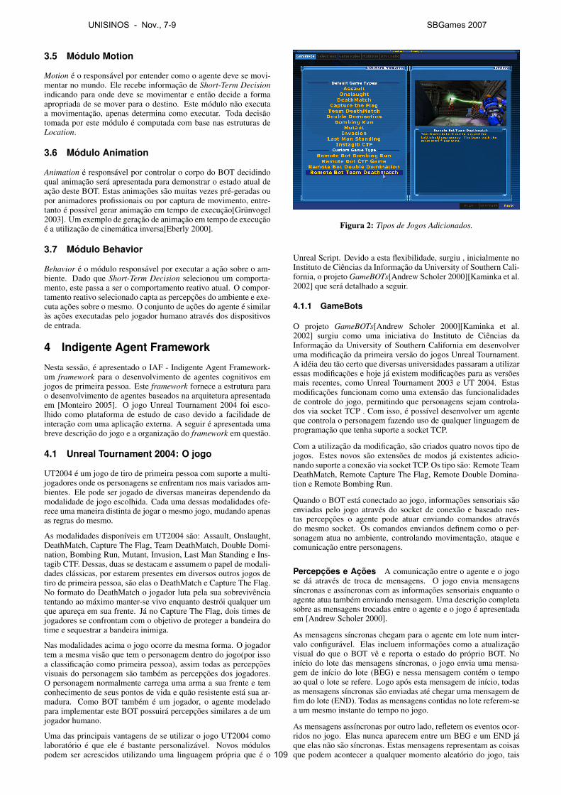
3.5 Modulo Motion
Motion e o responsavel por entender como o agente deve se movi-mentar no mundo. Ele recebe informacao de Short-Term Decisionindicando para onde deve se movimentar e entao decide a formaapropriada de se mover para o destino. Este modulo nao executaa movimentacao, apenas determina como executar. Toda decisaotomada por este modulo e computada com base nas estruturas deLocation.
3.6 Modulo Animation
Animation e responsavel por controlar o corpo do BOT decidindoqual animacao sera apresentada para demonstrar o estado atual deacao deste BOT. Estas animacoes sao muitas vezes pre-geradas oupor animadores profissionais ou por captura de movimento, entre-tanto e possıvel gerar animacao em tempo de execucao[Grunvogel2003]. Um exemplo de geracao de animacao em tempo de execucaoe a utilizacao de cinematica inversa[Eberly 2000].
3.7 Modulo Behavior
Behavior e o modulo responsavel por executar a acao sobre o am-biente. Dado que Short-Term Decision selecionou um comporta-mento, este passa a ser o comportamento reativo atual. O compor-tamento reativo selecionado capta as percepcoes do ambiente e exe-cuta acoes sobre o mesmo. O conjunto de acoes do agente e similaras acoes executadas pelo jogador humano atraves dos dispositivosde entrada.
4 Indigente Agent Framework
Nesta sessao, e apresentado o IAF - Indigente Agent Framework-um framework para o desenvolvimento de agentes cognitivos emjogos de primeira pessoa. Este framework fornece a estrutura parao desenvolvimento de agentes baseados na arquitetura apresentadaem [Monteiro 2005]. O jogo Unreal Tournament 2004 foi esco-lhido como plataforma de estudo de caso devido a facilidade deinteracao com uma aplicacao externa. A seguir e apresentada umabreve descricao do jogo e a organizacao do framework em questao.
4.1 Unreal Tournament 2004: O jogo
UT2004 e um jogo de tiro de primeira pessoa com suporte a multi-jogadores onde os personagens se enfrentam nos mais variados am-bientes. Ele pode ser jogado de diversas maneiras dependendo damodalidade de jogo escolhida. Cada uma dessas modalidades ofe-rece uma maneira distinta de jogar o mesmo jogo, mudando apenasas regras do mesmo.
As modalidades disponıveis em UT2004 sao: Assault, Onslaught,DeathMatch, Capture The Flag, Team DeathMatch, Double Domi-nation, Bombing Run, Mutant, Invasion, Last Man Standing e Ins-tagib CTF. Dessas, duas se destacam e assumem o papel de modali-dades classicas, por estarem presentes em diversos outros jogos detiro de primeira pessoa, sao elas o DeathMatch e Capture The Flag.No formato do DeathMatch o jogador luta pela sua sobrevivenciatentando ao maximo manter-se vivo enquanto destroi qualquer umque apareca em sua frente. Ja no Capture The Flag, dois times dejogadores se confrontam com o objetivo de proteger a bandeira dotime e sequestrar a bandeira inimiga.
Nas modalidades acima o jogo ocorre da mesma forma. O jogadortem a mesma visao que tem o personagem dentro do jogo(por issoa classificacao como primeira pessoa), assim todas as percepcoesvisuais do personagem sao tambem as percepcoes dos jogadores.O personagem normalmente carrega uma arma a sua frente e temconhecimento de seus pontos de vida e quao resistente esta sua ar-madura. Como BOT tambem e um jogador, o agente modeladopara implementar este BOT possuira percepcoes similares a de umjogador humano.
Uma das principais vantagens de se utilizar o jogo UT2004 comolaboratorio e que ele e bastante personalizavel. Novos modulospodem ser acrescidos utilizando uma linguagem propria que e o
Figura 2: Tipos de Jogos Adicionados.
Unreal Script. Devido a esta flexibilidade, surgiu , inicialmente noInstituto de Ciencias da Informacao da University of Southern Cali-fornia, o projeto GameBOTs[Andrew Scholer 2000][Kaminka et al.2002] que sera detalhado a seguir.
4.1.1 GameBots
O projeto GameBOTs[Andrew Scholer 2000][Kaminka et al.2002] surgiu como uma iniciativa do Instituto de Ciencias daInformacao da University of Southern California em desenvolveruma modificacao da primeira versao do jogos Unreal Tournament.A ideia deu tao certo que diversas universidades passaram a utilizaressas modificacoes e hoje ja existem modificacoes para as versoesmais recentes, como Unreal Tournament 2003 e UT 2004. Estasmodificacoes funcionam como uma extensao das funcionalidadesde controle do jogo, permitindo que personagens sejam controla-dos via socket TCP . Com isso, e possıvel desenvolver um agenteque controla o personagem fazendo uso de qualquer linguagem deprogramacao que tenha suporte a socket TCP.
Com a utilizacao da modificacao, sao criados quatro novos tipo dejogos. Estes novos sao extensoes de modos ja existentes adicio-nando suporte a conexao via socket TCP. Os tipo sao: Remote TeamDeathMatch, Remote Capture The Flag, Remote Double Domina-tion e Remote Bombing Run.
Quando o BOT esta conectado ao jogo, informacoes sensoriais saoenviadas pelo jogo atraves do socket de conexao e baseado nes-tas percepcoes o agente pode atuar enviando comandos atravesdo mesmo socket. Os comandos enviandos definem como o per-sonagem atua no ambiente, controlando movimentacao, ataque ecomunicacao entre personagens.
Percepcoes e Acoes A comunicacao entre o agente e o jogose da atraves de troca de mensagens. O jogo envia mensagenssıncronas e assıncronas com as informacoes sensoriais enquanto oagente atua tambem enviando mensagem. Uma descricao completasobre as mensagens trocadas entre o agente e o jogo e apresentadaem [Andrew Scholer 2000].
As mensagens sıncronas chegam para o agente em lote num inter-valo configuravel. Elas incluem informacoes como a atualizacaovisual do que o BOT ve e reporta o estado do proprio BOT. Noinıcio do lote das mensagens sıncronas, o jogo envia uma mensa-gem de inıcio do lote (BEG) e nessa mensagem contem o tempoao qual o lote se refere. Logo apos esta mensagem de inıcio, todasas mensagens sıncronas sao enviadas ate chegar uma mensagem defim do lote (END). Todas as mensagens contidas no lote referem-sea um mesmo instante do tempo no jogo.
As mensagens assıncronas por outro lado, refletem os eventos ocor-ridos no jogo. Elas nunca aparecem entre um BEG e um END jaque elas nao sao sıncronas. Estas mensagens representam as coisasque podem acontecer a qualquer momento aleatorio do jogo, tais
UNISINOS - Nov., 7-9 SBGames 2007
109
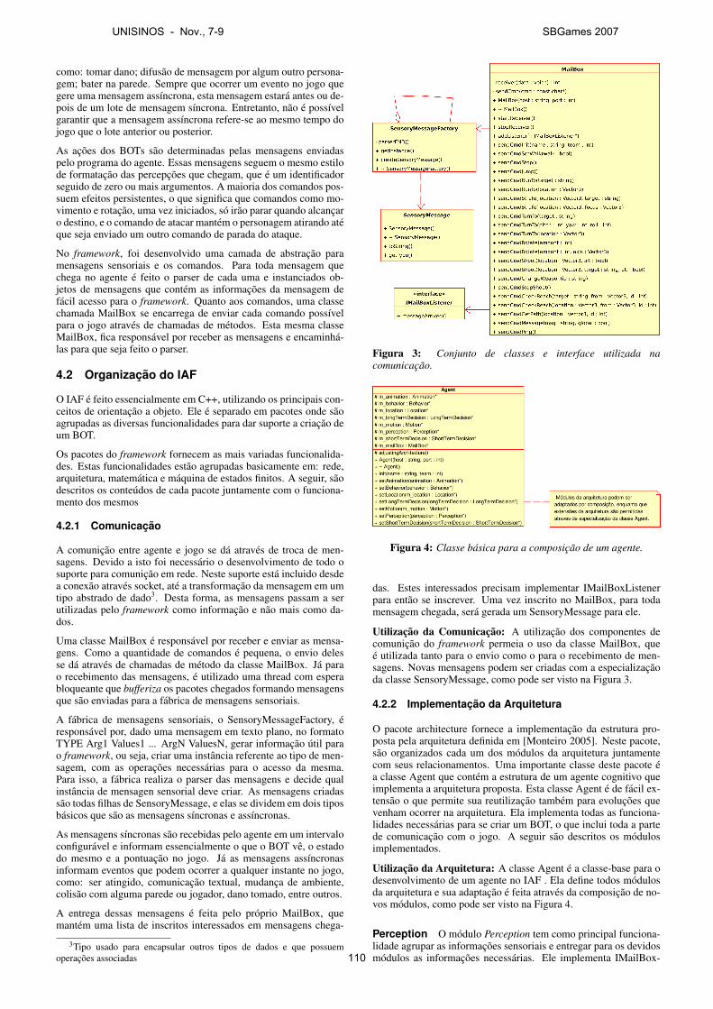
como: tomar dano; difusao de mensagem por algum outro persona-gem; bater na parede. Sempre que ocorrer um evento no jogo quegere uma mensagem assıncrona, esta mensagem estara antes ou de-pois de um lote de mensagem sıncrona. Entretanto, nao e possıvelgarantir que a mensagem assıncrona refere-se ao mesmo tempo dojogo que o lote anterior ou posterior.
As acoes dos BOTs sao determinadas pelas mensagens enviadaspelo programa do agente. Essas mensagens seguem o mesmo estilode formatacao das percepcoes que chegam, que e um identificadorseguido de zero ou mais argumentos. A maioria dos comandos pos-suem efeitos persistentes, o que significa que comandos como mo-vimento e rotacao, uma vez iniciados, so irao parar quando alcancaro destino, e o comando de atacar mantem o personagem atirando ateque seja enviado um outro comando de parada do ataque.
No framework, foi desenvolvido uma camada de abstracao paramensagens sensoriais e os comandos. Para toda mensagem quechega no agente e feito o parser de cada uma e instanciados ob-jetos de mensagens que contem as informacoes da mensagem defacil acesso para o framework. Quanto aos comandos, uma classechamada MailBox se encarrega de enviar cada comando possıvelpara o jogo atraves de chamadas de metodos. Esta mesma classeMailBox, fica responsavel por receber as mensagens e encaminha-las para que seja feito o parser.
4.2 Organizacao do IAF
O IAF e feito essencialmente em C++, utilizando os principais con-ceitos de orientacao a objeto. Ele e separado em pacotes onde saoagrupadas as diversas funcionalidades para dar suporte a criacao deum BOT.
Os pacotes do framework fornecem as mais variadas funcionalida-des. Estas funcionalidades estao agrupadas basicamente em: rede,arquitetura, matematica e maquina de estados finitos. A seguir, saodescritos os conteudos de cada pacote juntamente com o funciona-mento dos mesmos
4.2.1 Comunicacao
A comunicao entre agente e jogo se da atraves de troca de men-sagens. Devido a isto foi necessario o desenvolvimento de todo osuporte para comunicao em rede. Neste suporte esta incluido desdea conexao atraves socket, ate a transformacao da mensagem em umtipo abstrado de dado3. Desta forma, as mensagens passam a serutilizadas pelo framework como informacao e nao mais como da-dos.
Uma classe MailBox e responsavel por receber e enviar as mensa-gens. Como a quantidade de comandos e pequena, o envio delesse da atraves de chamadas de metodo da classe MailBox. Ja parao recebimento das mensagens, e utilizado uma thread com esperabloqueante que bufferiza os pacotes chegados formando mensagensque sao enviadas para a fabrica de mensagens sensoriais.
A fabrica de mensagens sensoriais, o SensoryMessageFactory, eresponsavel por, dado uma mensagem em texto plano, no formatoTYPE Arg1 Values1 ... ArgN ValuesN, gerar informacao util parao framework, ou seja, criar uma instancia referente ao tipo de men-sagem, com as operacoes necessarias para o acesso da mesma.Para isso, a fabrica realiza o parser das mensagens e decide qualinstancia de mensagen sensorial deve criar. As mensagens criadassao todas filhas de SensoryMessage, e elas se dividem em dois tiposbasicos que sao as mensagens sıncronas e assıncronas.
As mensagens sıncronas sao recebidas pelo agente em um intervaloconfiguravel e informam essencialmente o que o BOT ve, o estadodo mesmo e a pontuacao no jogo. Ja as mensagens assıncronasinformam eventos que podem ocorrer a qualquer instante no jogo,como: ser atingido, comunicacao textual, mudanca de ambiente,colisao com alguma parede ou jogador, dano tomado, entre outros.
A entrega dessas mensagens e feita pelo proprio MailBox, quemantem uma lista de inscritos interessados em mensagens chega-
3Tipo usado para encapsular outros tipos de dados e que possuemoperacoes associadas
Figura 3: Conjunto de classes e interface utilizada nacomunicacao.
Figura 4: Classe basica para a composicao de um agente.
das. Estes interessados precisam implementar IMailBoxListenerpara entao se inscrever. Uma vez inscrito no MailBox, para todamensagem chegada, sera gerada um SensoryMessage para ele.
Utilizacao da Comunicacao: A utilizacao dos componentes decomunicao do framework permeia o uso da classe MailBox, quee utilizada tanto para o envio como o para o recebimento de men-sagens. Novas mensagens podem ser criadas com a especializacaoda classe SensoryMessage, como pode ser visto na Figura 3.
4.2.2 Implementacao da Arquitetura
O pacote architecture fornece a implementacao da estrutura pro-posta pela arquitetura definida em [Monteiro 2005]. Neste pacote,sao organizados cada um dos modulos da arquitetura juntamentecom seus relacionamentos. Uma importante classe deste pacote ea classe Agent que contem a estrutura de um agente cognitivo queimplementa a arquitetura proposta. Esta classe Agent e de facil ex-tensao o que permite sua reutilizacao tambem para evolucoes quevenham ocorrer na arquitetura. Ela implementa todas as funciona-lidades necessarias para se criar um BOT, o que inclui toda a partede comunicacao com o jogo. A seguir sao descritos os modulosimplementados.
Utilizacao da Arquitetura: A classe Agent e a classe-base para odesenvolvimento de um agente no IAF . Ela define todos modulosda arquitetura e sua adaptacao e feita atraves da composicao de no-vos modulos, como pode ser visto na Figura 4.
Perception O modulo Perception tem como principal funciona-lidade agrupar as informacoes sensoriais e entregar para os devidosmodulos as informacoes necessarias. Ele implementa IMailBox-
UNISINOS - Nov., 7-9 SBGames 2007
110
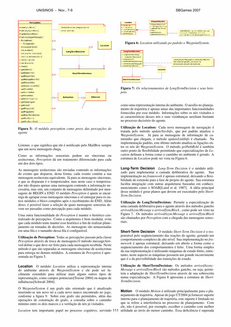
Figura 5: O modulo perception como proxy das percepcoes doagente
Listener, o que significa que ele e notificado pelo MailBox sempreque um nova mensagem chega.
Como as informacoes sensoriais podem ser sıncronas ouassıncronas, Perception da um tratamento diferenciado para cadaum dos dois tipos.
As mensagens assıncronas sao enviadas contendo as informacoesdo evento que disparou, desta forma, cada evento contem a suamensagem assıncrona equivalente. Ja para as mensagens sıncronas,o que as disparam e o temporizador, mas neste caso o temporiza-dor nao dispara apenas uma mensagem contendo a informacao ne-cessaria, mas sim, um conjunto de mensagens delimitado por men-sagens de BEGIN e END. O modulo Perception e quem se encar-rega de agrupar essas mensagens sıncronas e so entregar para os ou-tros modulos o bloco completo apos o recebimento do END. Alemdisso, e possıvel fazer a selecao de quais mensagens sensorias de-vem ser passadas como percepcao para cada modulo.
Uma outra funcionalidade do Perception e manter o historico cen-tralizado de percepcoes. Como a arquitetura e bem modular, evitaque cada modulo tente manter esse historico a fim de realizar plane-jamento ou tomadas de decisoes. As mensagens sao armazenadasem uma fila e o tamanho dessa fila e configuravel.
Utilizacao de Perception: Todas as percepcoes passam pela classePerception atraves de troca de mensagens.O metodo messageArri-ved define o que deve ser feito para cada mensagem recebida. Nestemetodo e que sao separadas as mensagens sıncronas de assıncronaspara entrega no demais modulos. A estrutura de Perception e apre-sentada na Figura 5.
Location O modulo Location utiliza a representacao internado ambiente atraves de WaypointSystem e ele pode ser fa-cilmente extendido para utilizar mais alguns outros tipos derepresentacao, como campos potenciais[Tozour 2004] ou mapas deinfluencias[Schwab 2004].
O WaypointSystem e um grafo nao orientado que e atualizadoinserindo-se um novo no a cada novo marco encontrado no jogo,conforme a figura 9. Sobre este grafo sao permitidos, alem dasoperacoes de construcao do grafo, a consulta sobre o caminhomınimo entre os dois marcos e a verifacao de nos ja visitados.
Location tem importante papel no processo cognitivo, servindo
Figura 6: Location utilizando po padrao o WaypointSystem.
Figura 7: Os relacionamentos de LongTermDecision e seus hots-pots.
como uma representacao interna do ambiente. O auxılio no planeja-mento de trajetoria e apenas umas das importantes funcionalidadesfornecidas por esse modulo. Informacoes sobre os nos visitados eas caracterısticas desses nos e suas vizinhancas auxiliam bastanteno processo decisorio do agente.
Utilizacao de Location: Cada nova mensagem de navegacao etratada pelo metodo updateNavInfo, que por padrao atualiza oWaypointSystem. Ja para as mensagens de informacao de ca-mimnho que chegam, o metodo updateLinkInfo e chamado. Naimplementacao padrao, este ultimo metodo atualiza as ligacoes en-tre os nos do WaypointSystem. O metodo getPathById e tambemoutro ponto de flexibilidade permitindo que especializacoes de Lo-cation definam a forma como o caminho no ambiente e gerado. Aestrutura de Location pode ser vista na Figura 6.
Long-Term Decision Long-Term Decision e o modulo utili-zado para implementar a camada deliberativa do agente. Suaimplementacao no framework e apenas estrutural, deixando a flexi-bilidade de extensao para a fase de projeto do agente. Sua estruturafacilita integracao com outras arquiteturas baseadas em conheci-mencimento como o SOAR[Laird et al. 1987]. A ideia principaldesse modulo e gerar planos que devem ser executados pelo Short-Term Decision.
Utilizacao de LongTermDecision: Permite a especializacao deuma camada deliberativa para o agente atraves dos metodos ganchoarrivedAsyncMessage e arrivedSyncBlock , como pode ser visto naFigura 7. Os metodos arrivedAsyncMessage e arrivedSyncBlocksao chamados por Perception com a chegada das mensagens senso-riais.
Short-Term Decision O modulo Short-Term Decision e o res-ponsavel pelo sequenciamento das reacoes do agente, gerando umcomportamento complexo de alto nıvel. Sua implementacao no fra-mework e apenas estrutural, deixando em aberto a forma como osequenciamento dos comportamentos e feito. Uma forma simplesda sua implementacao e utilizando maquinas de estado finito, entre-tanto, neste aspecto as maquinas possuem um grande inconvinienteque e o da previsibilidade das transicoes de estado.
Utilizacao de ShortTermDecision: Os metodos arrivedAsync-Message e arrivedSyncBlock sao metodos gancho, ou seja, permi-tem a adaptacao de ShortTermDecision atraves de sua sobrescritanuma especializacao. A Figura 8 apresenta a estrutura de Short-TermDecision.
Motion O modulo Motion e utilizado principalmente para o pla-nejamento de trajetoria. Apesar do jogo UT2004 ja fornecer suporteinterno para o planejamento de trajetoria, este suporte e limitado noque se refere a interferencia no processo de planejamento. Comele, nao e possıvel, por exemplo, escolher o caminho com melhorutilidade ao inves do menor caminho. Essa deficiencia e superada
UNISINOS - Nov., 7-9 SBGames 2007
111
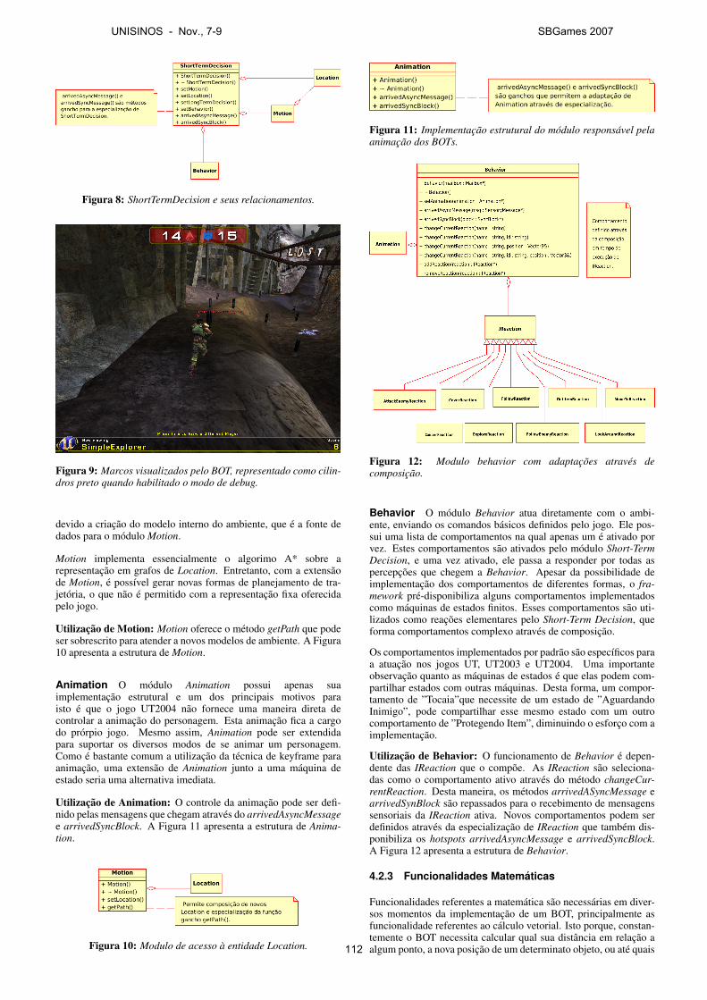
Figura 8: ShortTermDecision e seus relacionamentos.
Figura 9: Marcos visualizados pelo BOT, representado como cilin-dros preto quando habilitado o modo de debug.
devido a criacao do modelo interno do ambiente, que e a fonte dedados para o modulo Motion.
Motion implementa essencialmente o algorimo A* sobre arepresentacao em grafos de Location. Entretanto, com a extensaode Motion, e possıvel gerar novas formas de planejamento de tra-jetoria, o que nao e permitido com a representacao fixa oferecidapelo jogo.
Utilizacao de Motion: Motion oferece o metodo getPath que podeser sobrescrito para atender a novos modelos de ambiente. A Figura10 apresenta a estrutura de Motion.
Animation O modulo Animation possui apenas suaimplementacao estrutural e um dos principais motivos paraisto e que o jogo UT2004 nao fornece uma maneira direta decontrolar a animacao do personagem. Esta animacao fica a cargodo prorpio jogo. Mesmo assim, Animation pode ser extendidapara suportar os diversos modos de se animar um personagem.Como e bastante comum a utilizacao da tecnica de keyframe paraanimacao, uma extensao de Animation junto a uma maquina deestado seria uma alternativa imediata.
Utilizacao de Animation: O controle da animacao pode ser defi-nido pelas mensagens que chegam atraves do arrivedAsyncMessagee arrivedSyncBlock. A Figura 11 apresenta a estrutura de Anima-tion.
Figura 10: Modulo de acesso a entidade Location.
Figura 11: Implementacao estrutural do modulo responsavel pelaanimacao dos BOTs.
Figura 12: Modulo behavior com adaptacoes atraves decomposicao.
Behavior O modulo Behavior atua diretamente com o ambi-ente, enviando os comandos basicos definidos pelo jogo. Ele pos-sui uma lista de comportamentos na qual apenas um e ativado porvez. Estes comportamentos sao ativados pelo modulo Short-TermDecision, e uma vez ativado, ele passa a responder por todas aspercepcoes que chegem a Behavior. Apesar da possibilidade deimplementacao dos comportamentos de diferentes formas, o fra-mework pre-disponibiliza alguns comportamentos implementadoscomo maquinas de estados finitos. Esses comportamentos sao uti-lizados como reacoes elementares pelo Short-Term Decision, queforma comportamentos complexo atraves de composicao.
Os comportamentos implementados por padrao sao especıficos paraa atuacao nos jogos UT, UT2003 e UT2004. Uma importanteobservacao quanto as maquinas de estados e que elas podem com-partilhar estados com outras maquinas. Desta forma, um compor-tamento de ”Tocaia”que necessite de um estado de ”AguardandoInimigo”, pode compartilhar esse mesmo estado com um outrocomportamento de ”Protegendo Item”, diminuindo o esforco com aimplementacao.
Utilizacao de Behavior: O funcionamento de Behavior e depen-dente das IReaction que o compoe. As IReaction sao seleciona-das como o comportamento ativo atraves do metodo changeCur-rentReaction. Desta maneira, os metodos arrivedASyncMessage earrivedSynBlock sao repassados para o recebimento de mensagenssensoriais da IReaction ativa. Novos comportamentos podem serdefinidos atraves da especializacao de IReaction que tambem dis-ponibiliza os hotspots arrivedAsyncMessage e arrivedSyncBlock.A Figura 12 apresenta a estrutura de Behavior.
4.2.3 Funcionalidades Matematicas
Funcionalidades referentes a matematica sao necessarias em diver-sos momentos da implementacao de um BOT, principalmente asfuncionalidade referentes ao calculo vetorial. Isto porque, constan-temente o BOT necessita calcular qual sua distancia em relacao aalgum ponto, a nova posicao de um determinato objeto, ou ate quais
UNISINOS - Nov., 7-9 SBGames 2007
112
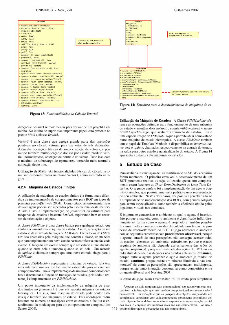
Figura 13: Funcionalidades do Calculo Vetorial.
direcoes e possıvel se movimentar para desviar de um projetil a ca-minho. No intuito de suprir esse importante papel, esta presente nopacote Math a classe Vector3.
Vector3 e uma classe que agrega grande parte das operacoespossıveis no calculo vetorial para um vetor de tres dimensoes.Alem das operacoes basicas de soma e adicao de vetores, e per-mitido tambem multiplicacao e divisao por escalar, produto veto-rial, normalizacao, obtencao da norma e do versor. Tudo isso como maximo de sobrecarga de operadores, tornando mais natural autilizacao desse tipo.
Utilizacao de Math: As funcionalidades basicas do calculo veto-rial sao disponibilizadas na classe Vector3, como mostrado na fi-gura 13.
4.2.4 Maquina de Estados Finitos
A utilizacao de maquinas de estados finitos e a forma mais difun-dida de implementacao de comportamentos para BOT em jogos deprimeira pessoa[Schwab 2004]. Como citado anteriormente, suasdesvantagens podem ser superadas pelo uso racional deste recurso.Aliado a isto, a implementencao no framework da estrutura paramaquinas de estados e bastante flexıvel, explorando bem os recur-sos de orientacao a objetos.
A classe FSMState e uma classe basica para qualquer estado quevenha ser inserido na maquina de estado. Assim, a criacao de umestado se da atraves da heranca de FSMState. Os metodos de FSMS-tate sao chamados pela maquina que contem a classe, de maneiraque para implementar um novo estado basta codificar o que faz cadaevento. E lancado um evento sempre que um estado e inicializado,quando se entra nele e tambem quando se sai dele. Um metodode update e chamado sempre que uma nova entrada chega para oFSMState.
A classe FSMMachine representa a maquina de estado. Ela temuma interface simples e e facilmente extendida para se criar umcomportamento. Para a implementacao de um novo comportamentobasta determinar a funcao de transicao de estados, pois todo o res-tante ja e implementado em FSMMachine.
Um ponto importante da implementacao de maquina de esta-dos finitos no framework e que ela suporta maquina de estadoshierarquica. Ou seja, uma maquina de estado pode conter esta-dos que tambem sao maquinas de estado. Esta abordagem reduzbastante no numero de transicoes entre os estados e facilita o en-tendimento da modelagem para um comportamento complexo[dosSantos 2004].
Figura 14: Estrutura para o desenvolvimento de maquinas de es-tado.
Utilizacao da Maquina de Estados: A Classe FSMMachine ofe-rence as operacoes definidas para funcionamento de uma maquinade estado e mantem dois hotspots, updateWithSyncBlock e upda-teWithAsyncMessage, que avaliam a transicao de estados. Ela euma especializacao de FSMState, o que a permite atuar como estadonuma maquina de estado hierarquica. A classe FSMState tambemtem o papel de Template Methods e disponibiliza os hotspots, en-ter, exit e update, chamados respectivamente na entrada do estado,na saıda para outro estado e na atualizacao do estado. A Figura 14apresenta a estrutura das maquinas de estados.
5 Estudo de Caso
Para avaliar a instanciacao de BOTs utilizando o IAF , dois cenariosforam montados. O primeiro envolveu o desenvolvimento de umBOT puramente reativo, ou seja, utilizando apenas um comporta-mento e sem fazer uso do Short-Term Decision e do Long-Term De-cision. O segundo cenario foi a implementacao de um agente cog-nitivo simples, que possuia uma meta padrao e uma representacaodo seu ambiente. Nestes dois casos, foi possıvel perceber nao soa simplicidade de implementacao dos BOTs, com poucos hotspotspara serem especializados, como tambem a eficiencia obtida pelosjogadores virtuais nos combates.
E importante caracterizar o ambiente no qual o agente e inserido.Isto porque a maneira como o ambiente e classificado influi dire-tamente na forma como o agente e projetado e tambem possibi-lita uma melhor compreensao das dificuldade envolvidas no pro-cesso de desenvolvimento do BOT. O jogo apresenta o ambientecom as seguintes caracterısticas: parcialmente observavel, porqueo agente, atraves de suas percepcoes, nao consegue acessar todosos estados relevantes ao ambiente; estocastico, porque o estadoseguinte do ambiente nao depende exclusivamente das acoes doagente; sequencial, porque a qualidade das acoes do BOT no es-tado atual depende das decisoes nos estados anteriores; dinamico,porque entre o agente perceber e agir o ambiente ja mudou deestado; contınuo, porque existe um numero ilimitado e nao enu-meravel4 de como as percepcoes sao apresentadas; multiagente,porque existe tanto interacao cooperativa como competitiva entreos agentes[Russel and Norving 2004].
O estilo de jogo Team DeathMatch foi utilizado para simplificar
4Apesar de toda representacao computacional ser recursivamente enu-meravel, a informacao que este modelo computacional respresenta nao eenumeravel. Um exemplo e que as posicoes dos objetos sao passadas emcoordenadas cartesianas com cada componente pertencente ao conjunto dosreais. Apesar do modelo computacional suportar uma representacao parcialdos reais, o conjunto dos numeros reais sao nao enumeraveis. Por isso epossıvel dizer que as percepcoes sao nao enumeraveis.
UNISINOS - Nov., 7-9 SBGames 2007
113
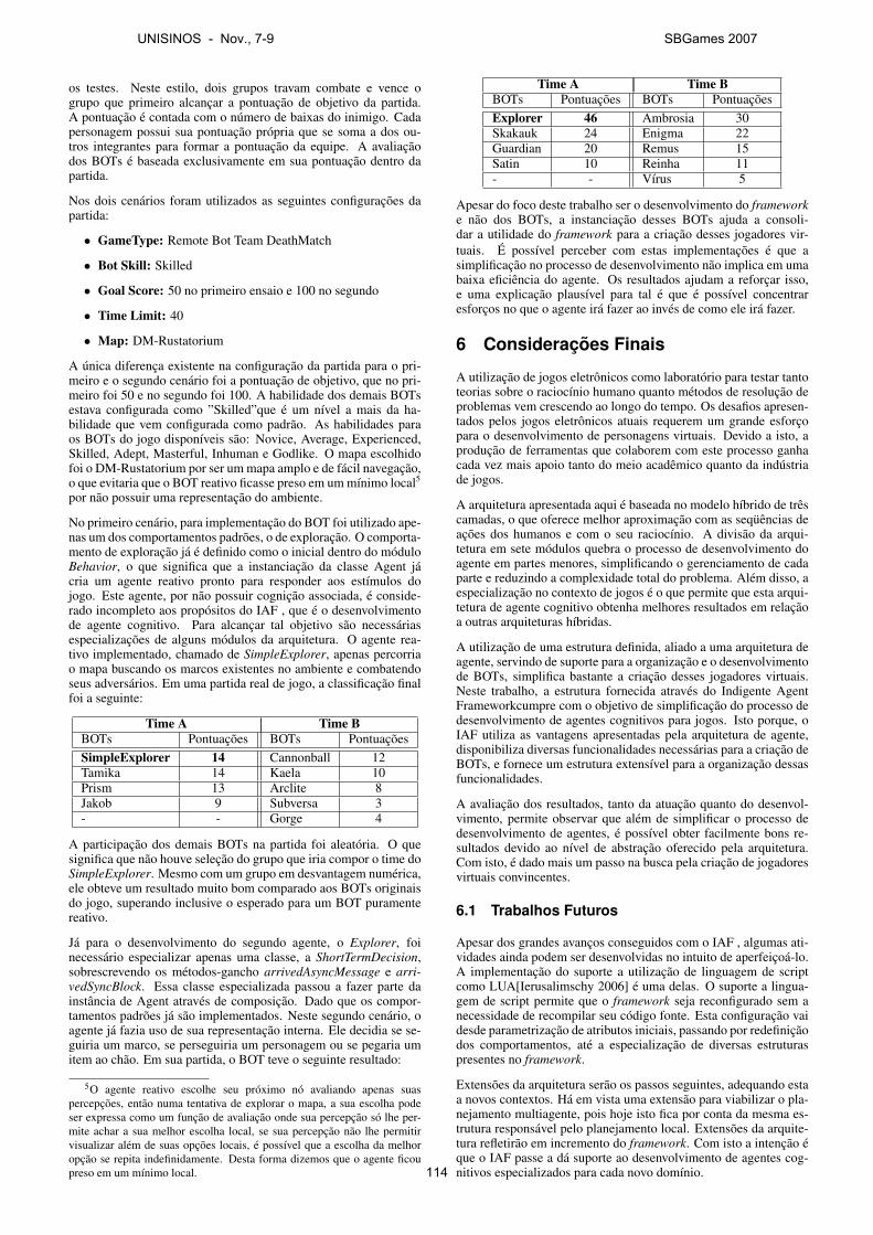
os testes. Neste estilo, dois grupos travam combate e vence ogrupo que primeiro alcancar a pontuacao de objetivo da partida.A pontuacao e contada com o numero de baixas do inimigo. Cadapersonagem possui sua pontuacao propria que se soma a dos ou-tros integrantes para formar a pontuacao da equipe. A avaliacaodos BOTs e baseada exclusivamente em sua pontuacao dentro dapartida.
Nos dois cenarios foram utilizados as seguintes configuracoes dapartida:
• GameType: Remote Bot Team DeathMatch
• Bot Skill: Skilled
• Goal Score: 50 no primeiro ensaio e 100 no segundo
• Time Limit: 40
• Map: DM-Rustatorium
A unica diferenca existente na configuracao da partida para o pri-meiro e o segundo cenario foi a pontuacao de objetivo, que no pri-meiro foi 50 e no segundo foi 100. A habilidade dos demais BOTsestava configurada como ”Skilled”que e um nıvel a mais da ha-bilidade que vem configurada como padrao. As habilidades paraos BOTs do jogo disponıveis sao: Novice, Average, Experienced,Skilled, Adept, Masterful, Inhuman e Godlike. O mapa escolhidofoi o DM-Rustatorium por ser um mapa amplo e de facil navegacao,o que evitaria que o BOT reativo ficasse preso em um mınimo local5
por nao possuir uma representacao do ambiente.
No primeiro cenario, para implementacao do BOT foi utilizado ape-nas um dos comportamentos padroes, o de exploracao. O comporta-mento de exploracao ja e definido como o inicial dentro do moduloBehavior, o que significa que a instanciacao da classe Agent jacria um agente reativo pronto para responder aos estımulos dojogo. Este agente, por nao possuir cognicao associada, e conside-rado incompleto aos propositos do IAF , que e o desenvolvimentode agente cognitivo. Para alcancar tal objetivo sao necessariasespecializacoes de alguns modulos da arquitetura. O agente rea-tivo implementado, chamado de SimpleExplorer, apenas percorriao mapa buscando os marcos existentes no ambiente e combatendoseus adversarios. Em uma partida real de jogo, a classificacao finalfoi a seguinte:
Time A Time BBOTs Pontuacoes BOTs PontuacoesSimpleExplorer 14 Cannonball 12Tamika 14 Kaela 10Prism 13 Arclite 8Jakob 9 Subversa 3- - Gorge 4
A participacao dos demais BOTs na partida foi aleatoria. O quesignifica que nao houve selecao do grupo que iria compor o time doSimpleExplorer. Mesmo com um grupo em desvantagem numerica,ele obteve um resultado muito bom comparado aos BOTs originaisdo jogo, superando inclusive o esperado para um BOT puramentereativo.
Ja para o desenvolvimento do segundo agente, o Explorer, foinecessario especializar apenas uma classe, a ShortTermDecision,sobrescrevendo os metodos-gancho arrivedAsyncMessage e arri-vedSyncBlock. Essa classe especializada passou a fazer parte dainstancia de Agent atraves de composicao. Dado que os compor-tamentos padroes ja sao implementados. Neste segundo cenario, oagente ja fazia uso de sua representacao interna. Ele decidia se se-guiria um marco, se perseguiria um personagem ou se pegaria umitem ao chao. Em sua partida, o BOT teve o seguinte resultado:
5O agente reativo escolhe seu proximo no avaliando apenas suaspercepcoes, entao numa tentativa de explorar o mapa, a sua escolha podeser expressa como um funcao de avaliacao onde sua percepcao so lhe per-mite achar a sua melhor escolha local, se sua percepcao nao lhe permitirvisualizar alem de suas opcoes locais, e possıvel que a escolha da melhoropcao se repita indefinidamente. Desta forma dizemos que o agente ficoupreso em um mınimo local.
Time A Time BBOTs Pontuacoes BOTs PontuacoesExplorer 46 Ambrosia 30Skakauk 24 Enigma 22Guardian 20 Remus 15Satin 10 Reinha 11- - Vırus 5
Apesar do foco deste trabalho ser o desenvolvimento do frameworke nao dos BOTs, a instanciacao desses BOTs ajuda a consoli-dar a utilidade do framework para a criacao desses jogadores vir-tuais. E possıvel perceber com estas implementacoes e que asimplificacao no processo de desenvolvimento nao implica em umabaixa eficiencia do agente. Os resultados ajudam a reforcar isso,e uma explicacao plausıvel para tal e que e possıvel concentraresforcos no que o agente ira fazer ao inves de como ele ira fazer.
6 Consideracoes Finais
A utilizacao de jogos eletronicos como laboratorio para testar tantoteorias sobre o raciocınio humano quanto metodos de resolucao deproblemas vem crescendo ao longo do tempo. Os desafios apresen-tados pelos jogos eletronicos atuais requerem um grande esforcopara o desenvolvimento de personagens virtuais. Devido a isto, aproducao de ferramentas que colaborem com este processo ganhacada vez mais apoio tanto do meio academico quanto da industriade jogos.
A arquitetura apresentada aqui e baseada no modelo hıbrido de trescamadas, o que oferece melhor aproximacao com as sequencias deacoes dos humanos e com o seu raciocınio. A divisao da arqui-tetura em sete modulos quebra o processo de desenvolvimento doagente em partes menores, simplificando o gerenciamento de cadaparte e reduzindo a complexidade total do problema. Alem disso, aespecializacao no contexto de jogos e o que permite que esta arqui-tetura de agente cognitivo obtenha melhores resultados em relacaoa outras arquiteturas hıbridas.
A utilizacao de uma estrutura definida, aliado a uma arquitetura deagente, servindo de suporte para a organizacao e o desenvolvimentode BOTs, simplifica bastante a criacao desses jogadores virtuais.Neste trabalho, a estrutura fornecida atraves do Indigente AgentFrameworkcumpre com o objetivo de simplificacao do processo dedesenvolvimento de agentes cognitivos para jogos. Isto porque, oIAF utiliza as vantagens apresentadas pela arquitetura de agente,disponibiliza diversas funcionalidades necessarias para a criacao deBOTs, e fornece um estrutura extensıvel para a organizacao dessasfuncionalidades.
A avaliacao dos resultados, tanto da atuacao quanto do desenvol-vimento, permite observar que alem de simplificar o processo dedesenvolvimento de agentes, e possıvel obter facilmente bons re-sultados devido ao nıvel de abstracao oferecido pela arquitetura.Com isto, e dado mais um passo na busca pela criacao de jogadoresvirtuais convincentes.
6.1 Trabalhos Futuros
Apesar dos grandes avancos conseguidos com o IAF , algumas ati-vidades ainda podem ser desenvolvidas no intuito de aperfeicoa-lo.A implementacao do suporte a utilizacao de linguagem de scriptcomo LUA[Ierusalimschy 2006] e uma delas. O suporte a lingua-gem de script permite que o framework seja reconfigurado sem anecessidade de recompilar seu codigo fonte. Esta configuracao vaidesde parametrizacao de atributos iniciais, passando por redefinicaodos comportamentos, ate a especializacao de diversas estruturaspresentes no framework.
Extensoes da arquitetura serao os passos seguintes, adequando estaa novos contextos. Ha em vista uma extensao para viabilizar o pla-nejamento multiagente, pois hoje isto fica por conta da mesma es-trutura responsavel pelo planejamento local. Extensoes da arquite-tura refletirao em incremento do framework. Com isto a intencao eque o IAF passe a da suporte ao desenvolvimento de agentes cog-nitivos especializados para cada novo domınio.
UNISINOS - Nov., 7-9 SBGames 2007
114
Referencias
ADOBBATI, R., MARSHALL, A. N., SCHOLER, A., TEJADA, S.,KAMINKA, G. A., SCHAFFER, S., AND SOLLITTO, C. 2001.Gamebots: a 3d virtual world test-bed for multi-agent research.Proceedings of 2nd International Workshop on Infrastructure,MAS and MAS Scalability.
ANDREW SCHOLER, G. K., 2000. Gamebots. Ultimo acesso em01 de dezembro de 2006.
DE BYL, P. B. 2004. Programming Believable Characters forComputer Games. Charles River Media.
DOS SANTOS, G. L. 2004. Maquinas de Estados Hierarquicasem Jogos Eletronicos. Master’s thesis, Pontifıcia UniversidadeCatolica do Rio de Janeiro, Rio de Janeiro.
EBERLY, D. H. 2000. 3D Game Engine Design. Morgan Kauf-mann.
GRUNVOGEL, S. M. 2003. Dynamic character animation. Interna-tional Journal of Intelligent Games and Simulation. 2, 1, 11–19.
IERUSALIMSCHY, R. 2006. Programming in Lua. Lua.Org; 2ndedition.
KAMINKA, G. A., VELOSO, M. M., SCHAFFER, S., SOLLITTO,C., ADOBBATI, R., MARSHALL, A. N., SCHOLER, A., ANDTEJADA, S. 2002. Gamebots: a flexible test bed for multiagentteam research. Commun. ACM 45, 1, 43–45.
LAIRD, J. E., NEWELL, A., AND ROSENBLOOM, P. S. 1987.Soar: an architecture for general intelligence. Artif. Intell. 33, 1,1–64.
MONTEIRO, I. M. 2005. Uma arquitetura modular para o desen-volvimento de agentes cognitivos em jogos de primeira e terceirapessoa. In Anais do IV Workshop Brasileiro de Jogos e Entrete-nimento Digital, 219–229.
NILSSON, N. J. 1998. Artificial Intelligence - A New Synthesis.Morgan Kaufmann.
RUSSEL, S., AND NORVING, P. 2004. Inteligencia Artificial -Traducao da segunda edicao. Editora Campus.
SCHWAB, B. 2004. AI Game Engine Programming. Charles RiverMedia.
TOZOUR, P. 2004. Search space representations. In AI GameProgramming Wisdom 2, Charles River Media, 85–102.
VAN WAVEREN, J. M. P. 2001. The Quake III Arena Bot. Master’sthesis, Delft University of Technology, Delft, Netherlands.
UNISINOS - Nov., 7-9 SBGames 2007
115
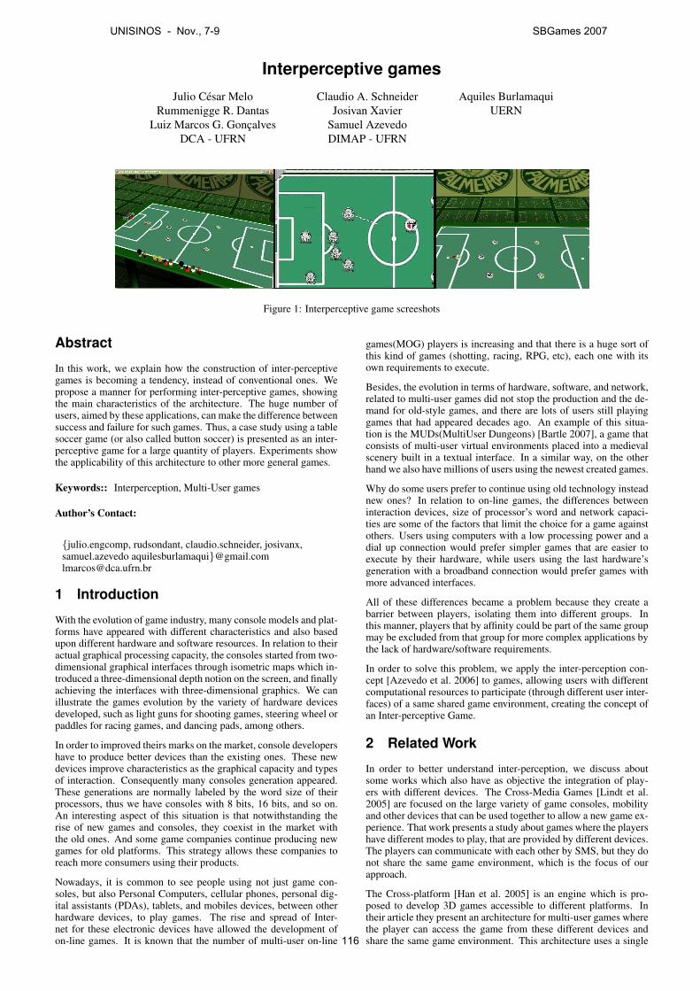
Interperceptive gamesJulio Cesar Melo
Rummenigge R. DantasLuiz Marcos G. Goncalves
DCA - UFRN
Claudio A. SchneiderJosivan Xavier
Samuel AzevedoDIMAP - UFRN
Aquiles BurlamaquiUERN
Figure 1: Interperceptive game screeshots
Abstract
In this work, we explain how the construction of inter-perceptivegames is becoming a tendency, instead of conventional ones. Wepropose a manner for performing inter-perceptive games, showingthe main characteristics of the architecture. The huge number ofusers, aimed by these applications, can make the difference betweensuccess and failure for such games. Thus, a case study using a tablesoccer game (or also called button soccer) is presented as an inter-perceptive game for a large quantity of players. Experiments showthe applicability of this architecture to other more general games.
Keywords:: Interperception, Multi-User games
Author’s Contact:
{julio.engcomp, rudsondant, claudio.schneider, josivanx,samuel.azevedo aquilesburlamaqui}@[email protected]
1 Introduction
With the evolution of game industry, many console models and plat-forms have appeared with different characteristics and also basedupon different hardware and software resources. In relation to theiractual graphical processing capacity, the consoles started from two-dimensional graphical interfaces through isometric maps which in-troduced a three-dimensional depth notion on the screen, and finallyachieving the interfaces with three-dimensional graphics. We canillustrate the games evolution by the variety of hardware devicesdeveloped, such as light guns for shooting games, steering wheel orpaddles for racing games, and dancing pads, among others.
In order to improved theirs marks on the market, console developershave to produce better devices than the existing ones. These newdevices improve characteristics as the graphical capacity and typesof interaction. Consequently many consoles generation appeared.These generations are normally labeled by the word size of theirprocessors, thus we have consoles with 8 bits, 16 bits, and so on.An interesting aspect of this situation is that notwithstanding therise of new games and consoles, they coexist in the market withthe old ones. And some game companies continue producing newgames for old platforms. This strategy allows these companies toreach more consumers using their products.
Nowadays, it is common to see people using not just game con-soles, but also Personal Computers, cellular phones, personal dig-ital assistants (PDAs), tablets, and mobiles devices, between otherhardware devices, to play games. The rise and spread of Inter-net for these electronic devices have allowed the development ofon-line games. It is known that the number of multi-user on-line
games(MOG) players is increasing and that there is a huge sort ofthis kind of games (shotting, racing, RPG, etc), each one with itsown requirements to execute.
Besides, the evolution in terms of hardware, software, and network,related to multi-user games did not stop the production and the de-mand for old-style games, and there are lots of users still playinggames that had appeared decades ago. An example of this situa-tion is the MUDs(MultiUser Dungeons) [Bartle 2007], a game thatconsists of multi-user virtual environments placed into a medievalscenery built in a textual interface. In a similar way, on the otherhand we also have millions of users using the newest created games.
Why do some users prefer to continue using old technology insteadnew ones? In relation to on-line games, the differences betweeninteraction devices, size of processor’s word and network capaci-ties are some of the factors that limit the choice for a game againstothers. Users using computers with a low processing power and adial up connection would prefer simpler games that are easier toexecute by their hardware, while users using the last hardware’sgeneration with a broadband connection would prefer games withmore advanced interfaces.
All of these differences became a problem because they create abarrier between players, isolating them into different groups. Inthis manner, players that by affinity could be part of the same groupmay be excluded from that group for more complex applications bythe lack of hardware/software requirements.
In order to solve this problem, we apply the inter-perception con-cept [Azevedo et al. 2006] to games, allowing users with differentcomputational resources to participate (through different user inter-faces) of a same shared game environment, creating the concept ofan Inter-perceptive Game.
2 Related Work
In order to better understand inter-perception, we discuss aboutsome works which also have as objective the integration of play-ers with different devices. The Cross-Media Games [Lindt et al.2005] are focused on the large variety of game consoles, mobilityand other devices that can be used together to allow a new game ex-perience. That work presents a study about games where the playershave different modes to play, that are provided by different devices.The players can communicate with each other by SMS, but they donot share the same game environment, which is the focus of ourapproach.
The Cross-platform [Han et al. 2005] is an engine which is pro-posed to develop 3D games accessible to different platforms. Intheir article they present an architecture for multi-user games wherethe player can access the game from these different devices andshare the same game environment. This architecture uses a single
UNISINOS - Nov., 7-9 SBGames 2007
116
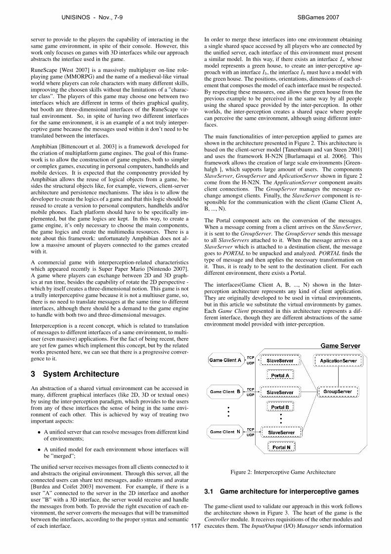
server to provide to the players the capability of interacting in thesame game environment, in spite of their console. However, thiswork only focuses on games with 3D interfaces while our approachabstracts the interface used in the game.
RuneScape [West 2007] is a massively multiplayer on-line role-playing game (MMORPG) and the name of a medieval-like virtualworld where players can role characters with many different skills,improoving the choosen skills without the limitations of a ”charac-ter class”. The players of this game may choose one between twointerfaces which are different in terms of theirs graphical quality,but booth are three-dimensional interfaces of the RuneScape vir-tual environment. So, in spite of having two different interfacesfor the same environment, it is an example of a not truly interper-ceptive game because the messages used within it don’t need to betranslated between the interfaces.
Amphibian [Bittencourt et al. 2003] is a framework developed forthe criation of multiplatform game engines. The goal of this frame-work is to allow the construction of game engines, both to simpleror complex games, executing in personal computers, handhelds andmobile devices. It is expected that the componentry provided byAmphibian allows the reuse of logical objects from a game, be-sides the structural objects like, for example, viewers, client-serverarchitecture and persistence mechanisms. The idea is to allow thedeveloper to create the logics of a game and that this logic should bereused to create a version to personal computers, handhelds and/ormobile phones. Each platform should have to be specifically im-plemented, but the game logics are kept. In this way, to create agame engine, it’s only necessary to choose the main components,the game logics and create the multimedia resources. There is anote about this framework: unfortunately Amphibian does not al-low a massive amount of players connected to the games createdwith it.
A commercial game with interperception-related characteristicswhich appeared recently is Super Paper Mario [Nintendo 2007].A game where players can exchange between 2D and 3D graph-ics at run time, besides the capability of rotate the 2D perspective -which by itself creates a three-dimensional notion. This game is nota trully interperceptive game because it is not a multiuser game, so,there is no need to translate messages at the same time to differentinterfaces, although there should be a demand to the game engineto handle with both two and three-dimensional messages.
Interperception is a recent concept, which is related to translationof messages to different interfaces of a same environment, to multi-user (even massive) applications. For the fact of being recent, thereare yet few games which implement this concept, but by the relatedworks presented here, we can see that there is a progressive conver-gence to it.
3 System Architecture
An abstraction of a shared virtual environment can be accessed inmany, different graphical interfaces (like 2D, 3D or textual ones)by using the inter-perception paradigm, which provides to the usersfrom any of these interfaces the sense of being in the same envi-ronment of each other. This is achieved by way of treating twoimportant aspects:
• A unified server that can resolve messages from different kindof environments;
• A unified model for each environment whose interfaces willbe ”merged”;
The unified server receives messages from all clients connected to itand abstracts the original environment. Through this server, all theconnected users can share text messages, audio streams and avatar[Burdea and Coifet 2003] movement. For example, if there is auser ”A” connected to the server in the 2D interface and anotheruser ”B” with a 3D interface, the server would receive and handlethe messages from both. To provide the right execution of each en-vironment, the server converts the messages that will be transmittedbetween the interfaces, according to the proper syntax and semanticof each interface.
In order to merge these interfaces into one environment obtaininga single shared space accessed by all players who are connected bythe unified server, each interface of this environment must presenta similar model. In this way, if there exists an interface Ia whosemodel represents a green house, to create an inter-perceptive ap-proach with an interface Ib, the interface Ib must have a model withthe green house. The positions, orientations, dimensions of each el-ement that composes the model of each interface must be respected.By respecting these measures, one allows the green house from theprevious example to be perceived in the same way by all peopleusing the shared space provided by the inter-perception. In otherworlds, the inter-perception creates a shared space where peoplecan perceive the same environment, although using different inter-faces.
The main functionalities of inter-perception applied to games areshown in the architecture presented in Figure 2. This architecture isbased on the client-server model [Tanenbaum and van Steen 2001]and uses the framework H-N2N [Burlamaqui et al. 2006]. Thisframework allows the creation of large scale environments [Green-halgh ], which supports large amount of users. The componentsSlaveServer, GroupServer and AplicationServer shown in figure 2come from the H-N2N. The ApplicationServer component awaitsclient connections. The GroupServer manages the message ex-change amongst clients. Finally, the SlaveServer component is re-sponsible for the communication with the client (Game Client A,B, ..., N).
The Portal component acts on the conversion of the messages.When a message coming from a client arrives on the SlaveServer,it is sent to the GroupServer. The GroupServer sends this messageto all SlaveServers attached to it. When the message arrives on aSlaveServer which is attached to a destination client, the messagegoes to PORTAL to be unpacked and analyzed. PORTAL finds thetype of message and then applies the necessary transformation onit. Thus, it is ready to be sent to the destination client. For eachdifferent environment, there exists a Portal.
The interfaces(Game Client A, B, ..., N) shown in the Inter-perception architecture represents any kind of client application.They are originally developed to be used in virtual environments,but in this article we substitute the virtual environments by games.Each Game Client presented in this architecture represents a dif-ferent interface, though they are different abstractions of the sameenvironment model provided with inter-perception.
Figure 2: Interperceptive Game Architecture
3.1 Game architecture for interperceptive games
The game-client used to validate our approach in this work followsthe architecture shown in Figure 3. The heart of the game is theController module. It receives requisitions of the other modules andexecutes them. The Input/Output (I/O) Manager sends information
UNISINOS - Nov., 7-9 SBGames 2007
117
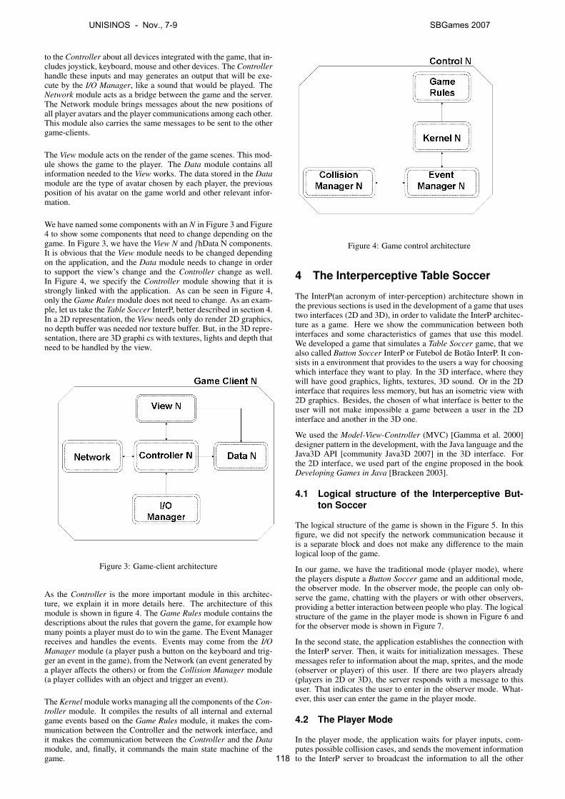
to the Controller about all devices integrated with the game, that in-cludes joystick, keyboard, mouse and other devices. The Controllerhandle these inputs and may generates an output that will be exe-cute by the I/O Manager, like a sound that would be played. TheNetwork module acts as a bridge between the game and the server.The Network module brings messages about the new positions ofall player avatars and the player communications among each other.This module also carries the same messages to be sent to the othergame-clients.
The View module acts on the render of the game scenes. This mod-ule shows the game to the player. The Data module contains allinformation needed to the View works. The data stored in the Datamodule are the type of avatar chosen by each player, the previousposition of his avatar on the game world and other relevant infor-mation.
We have named some components with an N in Figure 3 and Figure4 to show some components that need to change depending on thegame. In Figure 3, we have the View N and [hData N components.It is obvious that the View module needs to be changed dependingon the application, and the Data module needs to change in orderto support the view’s change and the Controller change as well.In Figure 4, we specify the Controller module showing that it isstrongly linked with the application. As can be seen in Figure 4,only the Game Rules module does not need to change. As an exam-ple, let us take the Table Soccer InterP, better described in section 4.In a 2D representation, the View needs only do render 2D graphics,no depth buffer was needed nor texture buffer. But, in the 3D repre-sentation, there are 3D graphi cs with textures, lights and depth thatneed to be handled by the view.
Figure 3: Game-client architecture
As the Controller is the more important module in this architec-ture, we explain it in more details here. The architecture of thismodule is shown in figure 4. The Game Rules module contains thedescriptions about the rules that govern the game, for example howmany points a player must do to win the game. The Event Managerreceives and handles the events. Events may come from the I/OManager module (a player push a button on the keyboard and trig-ger an event in the game), from the Network (an event generated bya player affects the others) or from the Collision Manager module(a player collides with an object and trigger an event).
The Kernel module works managing all the components of the Con-troller module. It compiles the results of all internal and externalgame events based on the Game Rules module, it makes the com-munication between the Controller and the network interface, andit makes the communication between the Controller and the Datamodule, and, finally, it commands the main state machine of thegame.
Figure 4: Game control architecture
4 The Interperceptive Table Soccer
The InterP(an acronym of inter-perception) architecture shown inthe previous sections is used in the development of a game that usestwo interfaces (2D and 3D), in order to validate the InterP architec-ture as a game. Here we show the communication between bothinterfaces and some characteristics of games that use this model.We developed a game that simulates a Table Soccer game, that wealso called Button Soccer InterP or Futebol de Botao InterP. It con-sists in a environment that provides to the users a way for choosingwhich interface they want to play. In the 3D interface, where theywill have good graphics, lights, textures, 3D sound. Or in the 2Dinterface that requires less memory, but has an isometric view with2D graphics. Besides, the chosen of what interface is better to theuser will not make impossible a game between a user in the 2Dinterface and another in the 3D one.
We used the Model-View-Controller (MVC) [Gamma et al. 2000]designer pattern in the development, with the Java language and theJava3D API [community Java3D 2007] in the 3D interface. Forthe 2D interface, we used part of the engine proposed in the bookDeveloping Games in Java [Brackeen 2003].
4.1 Logical structure of the Interperceptive But-ton Soccer
The logical structure of the game is shown in the Figure 5. In thisfigure, we did not specify the network communication because itis a separate block and does not make any difference to the mainlogical loop of the game.
In our game, we have the traditional mode (player mode), wherethe players dispute a Button Soccer game and an additional mode,the observer mode. In the observer mode, the people can only ob-serve the game, chatting with the players or with other observers,providing a better interaction between people who play. The logicalstructure of the game in the player mode is shown in Figure 6 andfor the observer mode is shown in Figure 7.
In the second state, the application establishes the connection withthe InterP server. Then, it waits for initialization messages. Thesemessages refer to information about the map, sprites, and the mode(observer or player) of this user. If there are two players already(players in 2D or 3D), the server responds with a message to thisuser. That indicates the user to enter in the observer mode. What-ever, this user can enter the game in the player mode.
4.2 The Player Mode
In the player mode, the application waits for player inputs, com-putes possible collision cases, and sends the movement informationto the InterP server to broadcast the information to all the other
UNISINOS - Nov., 7-9 SBGames 2007
118
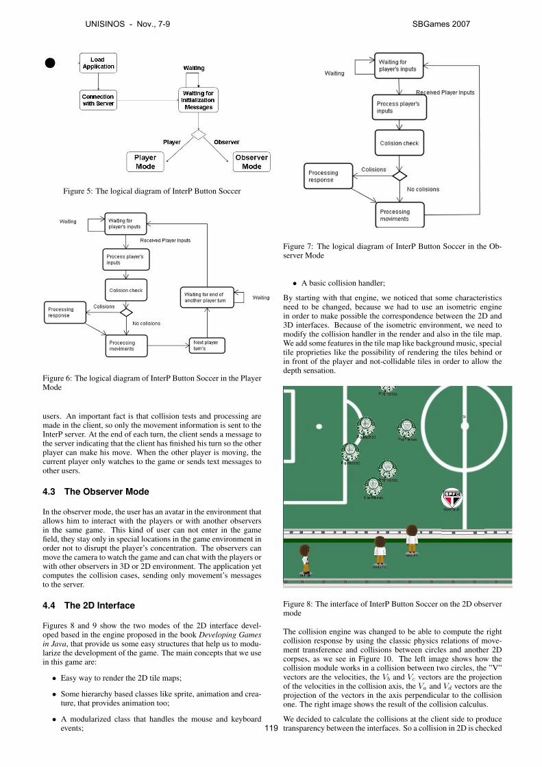
Figure 5: The logical diagram of InterP Button Soccer
Figure 6: The logical diagram of InterP Button Soccer in the PlayerMode
users. An important fact is that collision tests and processing aremade in the client, so only the movement information is sent to theInterP server. At the end of each turn, the client sends a message tothe server indicating that the client has finished his turn so the otherplayer can make his move. When the other player is moving, thecurrent player only watches to the game or sends text messages toother users.
4.3 The Observer Mode
In the observer mode, the user has an avatar in the environment thatallows him to interact with the players or with another observersin the same game. This kind of user can not enter in the gamefield, they stay only in special locations in the game environment inorder not to disrupt the player’s concentration. The observers canmove the camera to watch the game and can chat with the players orwith other observers in 3D or 2D environment. The application yetcomputes the collision cases, sending only movement’s messagesto the server.
4.4 The 2D Interface
Figures 8 and 9 show the two modes of the 2D interface devel-oped based in the engine proposed in the book Developing Gamesin Java, that provide us some easy structures that help us to modu-larize the development of the game. The main concepts that we usein this game are:
• Easy way to render the 2D tile maps;
• Some hierarchy based classes like sprite, animation and crea-ture, that provides animation too;
• A modularized class that handles the mouse and keyboardevents;
Figure 7: The logical diagram of InterP Button Soccer in the Ob-server Mode
• A basic collision handler;
By starting with that engine, we noticed that some characteristicsneed to be changed, because we had to use an isometric enginein order to make possible the correspondence between the 2D and3D interfaces. Because of the isometric environment, we need tomodify the collision handler in the render and also in the tile map.We add some features in the tile map like background music, specialtile proprieties like the possibility of rendering the tiles behind orin front of the player and not-collidable tiles in order to allow thedepth sensation.
Figure 8: The interface of InterP Button Soccer on the 2D observermode
The collision engine was changed to be able to compute the rightcollision response by using the classic physics relations of move-ment transference and collisions between circles and another 2Dcorpses, as we see in Figure 10. The left image shows how thecollision module works in a collision between two circles, the ”V”vectors are the velocities, the Vb and Vc vectors are the projectionof the velocities in the collision axis, the Va and Vd vectors are theprojection of the vectors in the axis perpendicular to the collisionone. The right image shows the result of the collision calculus.
We decided to calculate the collisions at the client side to producetransparency between the interfaces. So a collision in 2D is checked
UNISINOS - Nov., 7-9 SBGames 2007
119
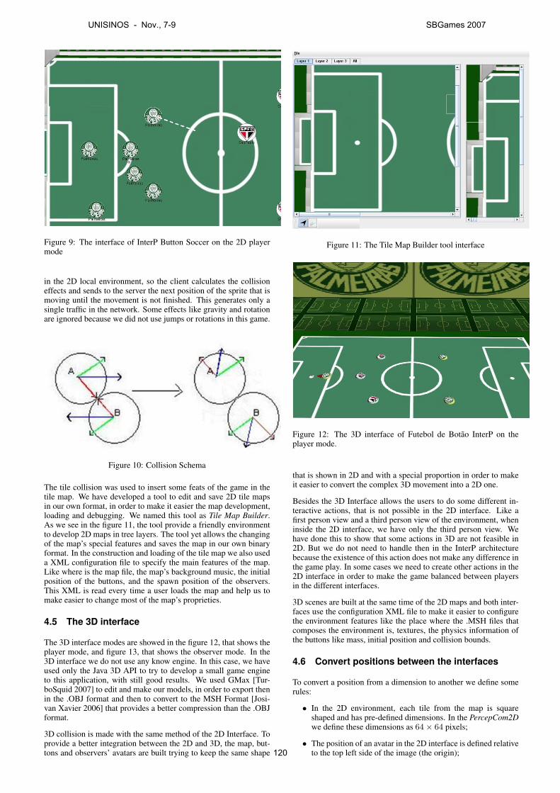
Figure 9: The interface of InterP Button Soccer on the 2D playermode
in the 2D local environment, so the client calculates the collisioneffects and sends to the server the next position of the sprite that ismoving until the movement is not finished. This generates only asingle traffic in the network. Some effects like gravity and rotationare ignored because we did not use jumps or rotations in this game.
Figure 10: Collision Schema
The tile collision was used to insert some feats of the game in thetile map. We have developed a tool to edit and save 2D tile mapsin our own format, in order to make it easier the map development,loading and debugging. We named this tool as Tile Map Builder.As we see in the figure 11, the tool provide a friendly environmentto develop 2D maps in tree layers. The tool yet allows the changingof the map’s special features and saves the map in our own binaryformat. In the construction and loading of the tile map we also useda XML configuration file to specify the main features of the map.Like where is the map file, the map’s background music, the initialposition of the buttons, and the spawn position of the observers.This XML is read every time a user loads the map and help us tomake easier to change most of the map’s proprieties.
4.5 The 3D interface
The 3D interface modes are showed in the figure 12, that shows theplayer mode, and figure 13, that shows the observer mode. In the3D interface we do not use any know engine. In this case, we haveused only the Java 3D API to try to develop a small game engineto this application, with still good results. We used GMax [Tur-boSquid 2007] to edit and make our models, in order to export thenin the .OBJ format and then to convert to the MSH Format [Josi-van Xavier 2006] that provides a better compression than the .OBJformat.
3D collision is made with the same method of the 2D Interface. Toprovide a better integration between the 2D and 3D, the map, but-tons and observers’ avatars are built trying to keep the same shape
Figure 11: The Tile Map Builder tool interface
Figure 12: The 3D interface of Futebol de Botao InterP on theplayer mode.
that is shown in 2D and with a special proportion in order to makeit easier to convert the complex 3D movement into a 2D one.
Besides the 3D Interface allows the users to do some different in-teractive actions, that is not possible in the 2D interface. Like afirst person view and a third person view of the environment, wheninside the 2D interface, we have only the third person view. Wehave done this to show that some actions in 3D are not feasible in2D. But we do not need to handle then in the InterP architecturebecause the existence of this action does not make any difference inthe game play. In some cases we need to create other actions in the2D interface in order to make the game balanced between playersin the different interfaces.
3D scenes are built at the same time of the 2D maps and both inter-faces use the configuration XML file to make it easier to configurethe environment features like the place where the .MSH files thatcomposes the environment is, textures, the physics information ofthe buttons like mass, initial position and collision bounds.
4.6 Convert positions between the interfaces
To convert a position from a dimension to another we define somerules:
• In the 2D environment, each tile from the map is squareshaped and has pre-defined dimensions. In the PercepCom2Dwe define these dimensions as 64× 64 pixels;
• The position of an avatar in the 2D interface is defined relativeto the top left side of the image (the origin);
UNISINOS - Nov., 7-9 SBGames 2007
120
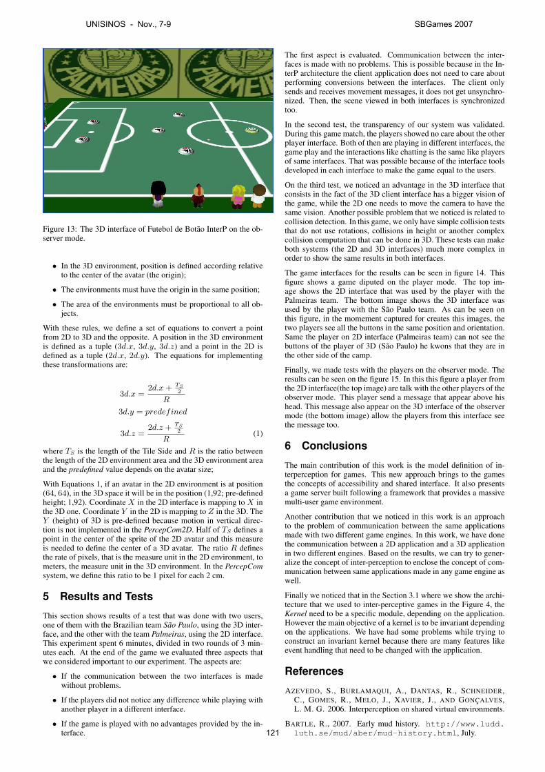
Figure 13: The 3D interface of Futebol de Botao InterP on the ob-server mode.
• In the 3D environment, position is defined according relativeto the center of the avatar (the origin);
• The environments must have the origin in the same position;
• The area of the environments must be proportional to all ob-jects.
With these rules, we define a set of equations to convert a pointfrom 2D to 3D and the opposite. A position in the 3D environmentis defined as a tuple (3d.x, 3d.y, 3d.z) and a point in the 2D isdefined as a tuple (2d.x, 2d.y). The equations for implementingthese transformations are:
3d.x =2d.x + TS
2
R
3d.y = predefined
3d.z =2d.z + TS
2
R(1)
where TS is the length of the Tile Side and R is the ratio betweenthe length of the 2D environment area and the 3D environment areaand the predefined value depends on the avatar size;
With Equations 1, if an avatar in the 2D environment is at position(64, 64), in the 3D space it will be in the position (1,92; pre-definedheight; 1,92). Coordinate X in the 2D interface is mapping to X inthe 3D one. Coordinate Y in the 2D is mapping to Z in the 3D. TheY (height) of 3D is pre-defined because motion in vertical direc-tion is not implemented in the PercepCom2D. Half of TS defines apoint in the center of the sprite of the 2D avatar and this measureis needed to define the center of a 3D avatar. The ratio R definesthe rate of pixels, that is the measure unit in the 2D environment, tometers, the measure unit in the 3D environment. In the PercepComsystem, we define this ratio to be 1 pixel for each 2 cm.
5 Results and Tests
This section shows results of a test that was done with two users,one of them with the Brazilian team Sao Paulo, using the 3D inter-face, and the other with the team Palmeiras, using the 2D interface.This experiment spent 6 minutes, divided in two rounds of 3 min-utes each. At the end of the game we evaluated three aspects thatwe considered important to our experiment. The aspects are:
• If the communication between the two interfaces is madewithout problems.
• If the players did not notice any difference while playing withanother player in a different interface.
• If the game is played with no advantages provided by the in-terface.
The first aspect is evaluated. Communication between the inter-faces is made with no problems. This is possible because in the In-terP architecture the client application does not need to care aboutperforming conversions between the interfaces. The client onlysends and receives movement messages, it does not get unsynchro-nized. Then, the scene viewed in both interfaces is synchronizedtoo.
In the second test, the transparency of our system was validated.During this game match, the players showed no care about the otherplayer interface. Both of then are playing in different interfaces, thegame play and the interactions like chatting is the same like playersof same interfaces. That was possible because of the interface toolsdeveloped in each interface to make the game equal to the users.
On the third test, we noticed an advantage in the 3D interface thatconsists in the fact of the 3D client interface has a bigger vision ofthe game, while the 2D one needs to move the camera to have thesame vision. Another possible problem that we noticed is related tocollision detection. In this game, we only have simple collision teststhat do not use rotations, collisions in height or another complexcollision computation that can be done in 3D. These tests can makeboth systems (the 2D and 3D interfaces) much more complex inorder to show the same results in both interfaces.
The game interfaces for the results can be seen in figure 14. Thisfigure shows a game diputed on the player mode. The top im-age shows the 2D interface that was used by the player with thePalmeiras team. The bottom image shows the 3D interface wasused by the player with the Sao Paulo team. As can be seen onthis figure, in the momement captured for creates this images, thetwo players see all the buttons in the same position and orientation.Same the player on 2D interface (Palmeiras team) can not see thebuttons of the player of 3D (Sao Paulo) he kwons that they are inthe other side of the camp.
Finally, we made tests with the players on the observer mode. Theresults can be seen on the figure 15. In this this figure a player fromthe 2D interface(the top image) are talk with the other players of theobserver mode. This player send a message that appear above hishead. This message also appear on the 3D interface of the observermode (the bottom image) allow the players from this interface seethe message too.
6 Conclusions
The main contribution of this work is the model definition of in-terperception for games. This new approach brings to the gamesthe concepts of accessibility and shared interface. It also presentsa game server built following a framework that provides a massivemulti-user game environment.
Another contribution that we noticed in this work is an approachto the problem of communication between the same applicationsmade with two different game engines. In this work, we have donethe communication between a 2D application and a 3D applicationin two different engines. Based on the results, we can try to gener-alize the concept of inter-perception to enclose the concept of com-munication between same applications made in any game engine aswell.
Finally we noticed that in the Section 3.1 where we show the archi-tecture that we used to inter-perceptive games in the Figure 4, theKernel need to be a specific module, depending on the application.However the main objective of a kernel is to be invariant dependingon the applications. We have had some problems while trying toconstruct an invariant kernel because there are many features likeevent handling that need to be changed with the application.
References
AZEVEDO, S., BURLAMAQUI, A., DANTAS, R., SCHNEIDER,C., GOMES, R., MELO, J., XAVIER, J., AND GONCALVES,L. M. G. 2006. Interperception on shared virtual environments.
BARTLE, R., 2007. Early mud history. http://www.ludd.luth.se/mud/aber/mud-history.html, July.
UNISINOS - Nov., 7-9 SBGames 2007
121
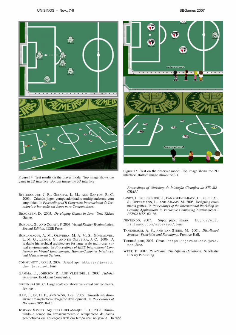
Figure 14: Test results on the player mode. Top image shows thegame in 2D interface. Bottom image the 3D interface
BITTENCOURT, J. R., GIRAFFA, L. M., AND SANTOS, R. C.2003. Criando jogos computadorizados multiplataforma comamphibian. In Proceedings of II Congresso Internacional de Tec-nologia e Inovacao em Jogos para Computadores.
BRACKEEN, D. 2003. Developing Games in Java. New RidersGames.
BURDEA, G., AND COIFET, P. 2003. Virtual Reality Techinologies,Second Edition. IEEE Press.
BURLAMAQUI, A. M., OLIVEIRA, M. A. M. S., GONCALVES,L. M. G., LEMOS, G., AND DE OLIVEIRA, J. C. 2006. Ascalable hierarchical architecture for large scale multi-user vir-tual environments. In Proceedings of IEEE International Con-ference on Virtual Environments, Human-Computer Interfaces,and Measurement Systems.
COMMUNITY JAVA3D, 2007. Java3d api. https://java3d.dev.java.net, June.
GAMMA, E., JOHNSON, R., AND VLISSIDES, J. 2000. Padroesde projeto. Bookman Companhia.
GREENHALGH, C. Large scale collaborative virtual environments.Springer.
HAN, J., IN, H. P., AND WOO, J.-S. 2005. Towards situation-aware cross-platform ubi-game development. In Proceedings ofPervasive2005, 8–13.
JOSIVAN XAVIER, AQUILES BURLAMAQUI, L. G. 2006. Dimin-uindo o tempo no armazenamento e recuperacao de dadosgeometricos em aplicacoes web em tempo real no java3d. In
Figure 15: Test on the observer mode. Top image shows the 2Dinterface. Bottom image shows the 3D
Proceedings of Workshop de Iniciacao Cientıfica do XIX SIB-GRAPI.
LINDT, I., OHLENBURG, J., PANKOKE-BABATZ, U., GHELLAL,S., OPPERMANN, L., AND ADAMS, M. 2005. Designing crossmedia games. In Proceedings of the International Workshop onGaming Applications in Pervasive Computing Environments -PERGAMES, 62–66.
NINTENDO, 2007. Super paper mario. http://wii.nintendo.com/site/spm/, June.
TANENBAUM, A. S., AND VAN STEEN, M. 2001. DistributedSystems: Principles and Paradigms. Prentice-Hall.
TURBOSQUID, 2007. Gmax. https://java3d.dev.java.net, June.
WEST, T. 2007. RuneScape: The Official Handbook. ScholasticLibrary Publishing.
UNISINOS - Nov., 7-9 SBGames 2007
122
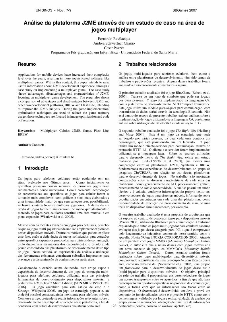
Análise da plataforma J2ME através de um estudo de caso na área dejogos multiplayer
Fernando BevilacquaAndrea Schwertner Charão
Cesar PozzerPrograma de Pós-graduação em Informática - Universidade Federal de Santa Maria
Resumo
Applications for mobile devices have increased their complexitylevel over the years, resulting in more sophisticated software, likemultiplayer games. Within this context, this paper intends to raiseuseful information about J2ME development experience, through acase study on implementing a multiplayer game. The case studyshows advantages, disadvantages and characteristics of J2ME,focusing on multiplayer game development. The paper also showsa comparison of advantages and disadvantages between J2ME andother two development platforms, BREW and Flash Lite, intendingto improve the J2ME analysis. During the game implementation,optimization techniques are used to reduce the game memoryusage; those techniques are focused in image optimization and codeobfuscation.
Keywords:: Multiplayer, Celular, J2ME, Game, Flash Lite,BREW
Author’s Contact:
{fernando,andrea,pozzer}@inf.ufsm.br
1 Introdução
Os jogos para telefones celulares estão evoluindo em umritmo acelerado nos últimos anos. Como inicialmente osaparelhos possuíam poucos recursos, os primeiros jogos eramrudimentares e pouco numerosos. Com a crescente incorporaçãode características aos aparelhos, os jogos para celular foram setornando mais complexos, com gráficos e sons mais elaborados euma interatividade maior do que seus antecessores, possibilitandoinclusive a interação entre múltiplos jogadores. A demanda e aoferta de jogos também aumentaram, de modo que atualmente omercado de jogos para celulares constitui uma área rentável e emplena expansão [Wisniewski et al. 2005].
Mesmo com os recentes avanços em jogos para celulares, percebe-se que os jogos multi-jogador ainda não são amplamente exploradosnestes dispositivos móveis. Dentre os motivos que podem explicaresse fato, estão a deficiência de meios sofisticados para conexõesentre aparelhos (apenas os protocolos mais básicos de comunicaçãoestão disponíveis na maioria dos dispositivos) e o estado aindapouco consolidado das plataformas de desenvolvimento deste tipode jogo. Neste sentido, as experiências de análise e utilizaçãodas ferramentas existentes constituem subsídios importantes parao avanço e a disseminação de conhecimentos nesta área.
Considerando o cenário acima delineado, este artigo expõe aexperiência de desenvolvimento de um jogo de estratégia multi-jogador para telefones celulares, utilizando uma das principaisferramentas de desenvolvimento para dispositivos móveis: aplataforma J2ME (Java 2 Micro Edition) [SUN MICROSYSTEMS2006]. O jogo escolhido para este estudo de caso é oStratego [Wikipedia 2006], um jogo de estratégia popular e, atéonde foi possível constatar, ainda inexistente para telefones móveis.Com esse artigo, pretende-se reunir informações relevantes sobre odesenvolvimento desse tipo de aplicação nessa plataforma, a fim decontribuir com outros desenvolvedores que atuam nesta área.
2 Trabalhos relacionados
Os jogos multi-jogador para telefones celulares, bem como aanálise entre plataformas de desenvolvimento, têm sido temas detrabalhos e publicações recentes. Alguns desses trabalhos foramanalisados e são brevemente comentados a seguir.
O primeiro trabalho analisado foi o jogo BlueGame [Rabelo et al.2005]. Trata-se de um jogo de combate que pode ser jogadopor duas pessoas. O jogo foi implementado na linguagem C#,com a plataforma de desenvolvimento .NET Compact Framework.Este jogo utiliza um modelo peer-to-peer para comunicação, comtransmissão de dados serial através da tecnologia Bluetooth. Nãoestá dentro do escopo do presente trabalho realizar análises sobre aimplementação de jogos utilizando-se a linguagem C#, porém umaanálise sobre utilização de Bluetooth é citada na seção 3.3.2.
O segundo trabalho analisado foi o jogo The Right Way [Hedlungand Maxe 2004]. Este é um jogo de estratégia que podeser jogado por várias pessoas, na qual cada uma controla umpersonagem, que está posicionado em um labirinto. O jogoutiliza um modelo cliente-servidor para comunicação, através doprotocolo HTTP 1.1. O cliente e o servidor foram implementadosutilizando-se a linguagem Java. Sobre os recursos utilizadospara o desenvolvimento de The Right Way, existe um estudorealizado por [KARLSSON et al. 2003], que mostra umacomparação entre as plataformas J2ME, Symbiam e BREW,fundamentada nas experiências de desenvolvimento do grupo depesquisas CIn/CESAR, em relação ao uso dessas plataformaspara o desenvolvimento de jogos. No trabalho, são mostradascomparações entre as diversas características de cada uma dasplataforma, como gerenciamento de I/O, processamento gráfico,processamento de som e conectividade. A análise possui um cunhotécnico e é voltada, conforme informações do próprio texto, aosdesenvolvedores de jogos para sistemas móveis, informando sobrepeculiaridades encontradas em cada uma das plataformas, comodisponibilidade de execução do pressionamento de mais de umatecla do dispositivo simultaneamente, por exemplo.
O terceiro trabalho analisado é uma proposta de arquitetura quedá suporte ao cenário de pequenos jogos para dispositivos móveis[Pereira 2006], utilizando Bluetooth para comunicação. Conformeexplanado pelo autor, os jogos multi-jogador para celulares são umaevolução dos jogos dessa categoria para PC, o que é comprovadopelo lançamento de iniciativas comerciais nesse sentido, como oaparelho Nokia NGage [NOKIA CORPORATION 2006]. Atravésde um paralelo com jogos MMOG (Massively Multiplayer OnlineGame), o autor cita que a união desses com jogos móveis criaum novo conceito de jogo, os MMMOGs (Massively MobileMultiplayer Online Games). Outros estudos também foramrealizados sobre jogos multi-jogador para dispositivos móveis,comprovando a existência da uma preocupação com tópicos dessaárea, como no trabalho de [Sacramento et al. 2005], que propõeum framework para o desenvolvimento de jogos desse estilo(multi-jogador para dispositivos móveis). O objetivo principaldo referido trabalho é proporcionar aos desenvolvedores de jogosum acesso transparente entre os aparelhos, a fim de que não hajapreocupação em questões específicas no processo de comunicação,como a forma com que as informações são trocas entre osdispositivos. O framework é desenvolvido em Java e provê umconjunto de funcionalidades sobre o protocolo HTTP, como enviode mensagens, validação por login e senha, validação de usuário porgrupo, envio de requisições, obtenção de uma lista de informaçõespertinentes (pontos, posição no ranking, apelido, etc).
UNISINOS - Nov., 7-9 SBGames 2007
123
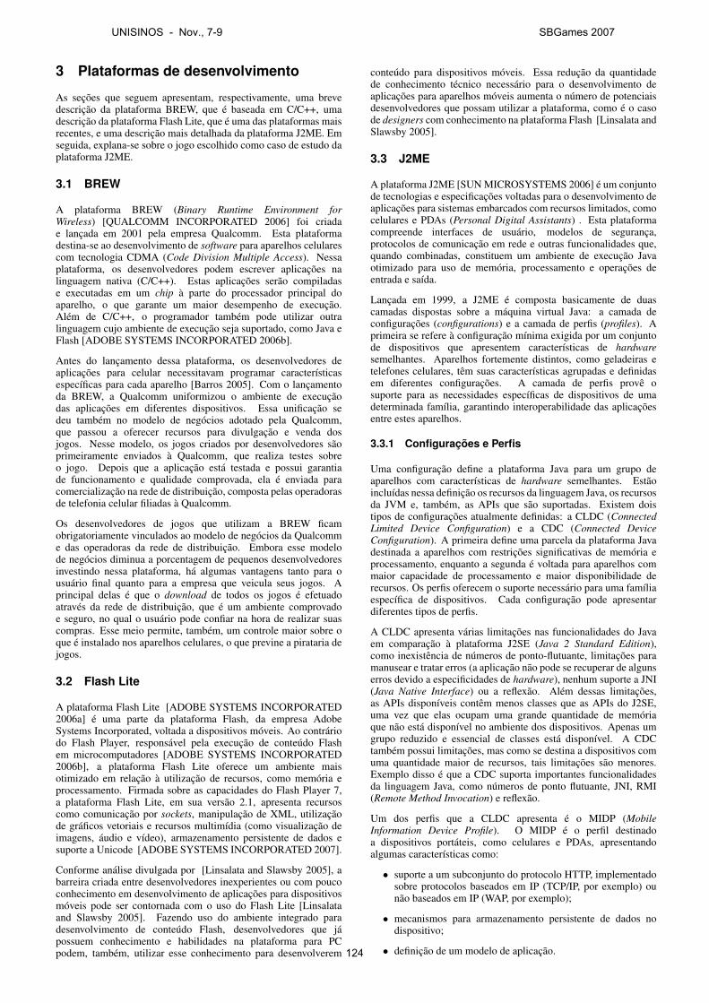
3 Plataformas de desenvolvimento
As seções que seguem apresentam, respectivamente, uma brevedescrição da plataforma BREW, que é baseada em C/C++, umadescrição da plataforma Flash Lite, que é uma das plataformas maisrecentes, e uma descrição mais detalhada da plataforma J2ME. Emseguida, explana-se sobre o jogo escolhido como caso de estudo daplataforma J2ME.
3.1 BREW
A plataforma BREW (Binary Runtime Environment forWireless) [QUALCOMM INCORPORATED 2006] foi criadae lançada em 2001 pela empresa Qualcomm. Esta plataformadestina-se ao desenvolvimento de software para aparelhos celularescom tecnologia CDMA (Code Division Multiple Access). Nessaplataforma, os desenvolvedores podem escrever aplicações nalinguagem nativa (C/C++). Estas aplicações serão compiladase executadas em um chip à parte do processador principal doaparelho, o que garante um maior desempenho de execução.Além de C/C++, o programador também pode utilizar outralinguagem cujo ambiente de execução seja suportado, como Java eFlash [ADOBE SYSTEMS INCORPORATED 2006b].
Antes do lançamento dessa plataforma, os desenvolvedores deaplicações para celular necessitavam programar característicasespecíficas para cada aparelho [Barros 2005]. Com o lançamentoda BREW, a Qualcomm uniformizou o ambiente de execuçãodas aplicações em diferentes dispositivos. Essa unificação sedeu também no modelo de negócios adotado pela Qualcomm,que passou a oferecer recursos para divulgação e venda dosjogos. Nesse modelo, os jogos criados por desenvolvedores sãoprimeiramente enviados à Qualcomm, que realiza testes sobreo jogo. Depois que a aplicação está testada e possui garantiade funcionamento e qualidade comprovada, ela é enviada paracomercialização na rede de distribuição, composta pelas operadorasde telefonia celular filiadas à Qualcomm.
Os desenvolvedores de jogos que utilizam a BREW ficamobrigatoriamente vinculados ao modelo de negócios da Qualcomme das operadoras da rede de distribuição. Embora esse modelode negócios diminua a porcentagem de pequenos desenvolvedoresinvestindo nessa plataforma, há algumas vantagens tanto para ousuário final quanto para a empresa que veicula seus jogos. Aprincipal delas é que o download de todos os jogos é efetuadoatravés da rede de distribuição, que é um ambiente comprovadoe seguro, no qual o usuário pode confiar na hora de realizar suascompras. Esse meio permite, também, um controle maior sobre oque é instalado nos aparelhos celulares, o que previne a pirataria dejogos.
3.2 Flash Lite
A plataforma Flash Lite [ADOBE SYSTEMS INCORPORATED2006a] é uma parte da plataforma Flash, da empresa AdobeSystems Incorporated, voltada a dispositivos móveis. Ao contráriodo Flash Player, responsável pela execução de conteúdo Flashem microcomputadores [ADOBE SYSTEMS INCORPORATED2006b], a plataforma Flash Lite oferece um ambiente maisotimizado em relação à utilização de recursos, como memória eprocessamento. Firmada sobre as capacidades do Flash Player 7,a plataforma Flash Lite, em sua versão 2.1, apresenta recursoscomo comunicação por sockets, manipulação de XML, utilizaçãode gráficos vetoriais e recursos multimídia (como visualização deimagens, áudio e vídeo), armazenamento persistente de dados esuporte a Unicode [ADOBE SYSTEMS INCORPORATED 2007].
Conforme análise divulgada por [Linsalata and Slawsby 2005], abarreira criada entre desenvolvedores inexperientes ou com poucoconhecimento em desenvolvimento de aplicações para dispositivosmóveis pode ser contornada com o uso do Flash Lite [Linsalataand Slawsby 2005]. Fazendo uso do ambiente integrado paradesenvolvimento de conteúdo Flash, desenvolvedores que jápossuem conhecimento e habilidades na plataforma para PCpodem, também, utilizar esse conhecimento para desenvolverem
conteúdo para dispositivos móveis. Essa redução da quantidadede conhecimento técnico necessário para o desenvolvimento deaplicações para aparelhos móveis aumenta o número de potenciaisdesenvolvedores que possam utilizar a plataforma, como é o casode designers com conhecimento na plataforma Flash [Linsalata andSlawsby 2005].
3.3 J2ME
A plataforma J2ME [SUN MICROSYSTEMS 2006] é um conjuntode tecnologias e especificações voltadas para o desenvolvimento deaplicações para sistemas embarcados com recursos limitados, comocelulares e PDAs (Personal Digital Assistants) . Esta plataformacompreende interfaces de usuário, modelos de segurança,protocolos de comunicação em rede e outras funcionalidades que,quando combinadas, constituem um ambiente de execução Javaotimizado para uso de memória, processamento e operações deentrada e saída.
Lançada em 1999, a J2ME é composta basicamente de duascamadas dispostas sobre a máquina virtual Java: a camada deconfigurações (configurations) e a camada de perfis (profiles). Aprimeira se refere à configuração mínima exigida por um conjuntode dispositivos que apresentem características de hardwaresemelhantes. Aparelhos fortemente distintos, como geladeiras etelefones celulares, têm suas características agrupadas e definidasem diferentes configurações. A camada de perfis provê osuporte para as necessidades específicas de dispositivos de umadeterminada família, garantindo interoperabilidade das aplicaçõesentre estes aparelhos.
3.3.1 Configurações e Perfis
Uma configuração define a plataforma Java para um grupo deaparelhos com características de hardware semelhantes. Estãoincluídas nessa definição os recursos da linguagem Java, os recursosda JVM e, também, as APIs que são suportadas. Existem doistipos de configurações atualmente definidas: a CLDC (ConnectedLimited Device Configuration) e a CDC (Connected DeviceConfiguration). A primeira define uma parcela da plataforma Javadestinada a aparelhos com restrições significativas de memória eprocessamento, enquanto a segunda é voltada para aparelhos commaior capacidade de processamento e maior disponibilidade derecursos. Os perfis oferecem o suporte necessário para uma famíliaespecífica de dispositivos. Cada configuração pode apresentardiferentes tipos de perfis.
A CLDC apresenta várias limitações nas funcionalidades do Javaem comparação à plataforma J2SE (Java 2 Standard Edition),como inexistência de números de ponto-flutuante, limitações paramanusear e tratar erros (a aplicação não pode se recuperar de algunserros devido a especificidades de hardware), nenhum suporte a JNI(Java Native Interface) ou a reflexão. Além dessas limitações,as APIs disponíveis contêm menos classes que as APIs do J2SE,uma vez que elas ocupam uma grande quantidade de memóriaque não está disponível no ambiente dos dispositivos. Apenas umgrupo reduzido e essencial de classes está disponível. A CDCtambém possui limitações, mas como se destina a dispositivos comuma quantidade maior de recursos, tais limitações são menores.Exemplo disso é que a CDC suporta importantes funcionalidadesda linguagem Java, como números de ponto flutuante, JNI, RMI(Remote Method Invocation) e reflexão.
Um dos perfis que a CLDC apresenta é o MIDP (MobileInformation Device Profile). O MIDP é o perfil destinadoa dispositivos portáteis, como celulares e PDAs, apresentandoalgumas características como:
• suporte a um subconjunto do protocolo HTTP, implementadosobre protocolos baseados em IP (TCP/IP, por exemplo) ounão baseados em IP (WAP, por exemplo);
• mecanismos para armazenamento persistente de dados nodispositivo;
• definição de um modelo de aplicação.
UNISINOS - Nov., 7-9 SBGames 2007
124
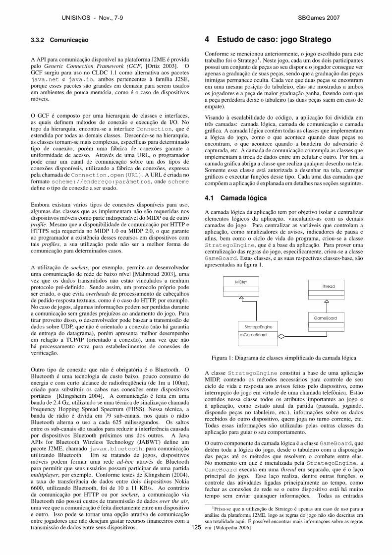
3.3.2 Comunicação
A API para comunicação disponível na plataforma J2ME é providapelo Generic Connection Framework (GCF) [Ortiz 2003]. OGCF surgiu para uso no CLDC 1.1 como alternativa aos pacotesjava.net e java.io, ambos pertencentes à família J2SE,porque esses pacotes são grandes em demasia para serem usadosem ambientes de pouca memória, como é o caso de dispositivosmóveis.
O GCF é composto por uma hierarquia de classes e interfaces,as quais definem métodos de conexão e execução de I/O. Notopo da hierarquia, encontra-se a interface Connection, que éestendida por todas as demais classes. Descendo-se na hierarquia,as classes tornam-se mais complexas, específicas para determinadotipo de conexão, porém uma fábrica de conexões garante auniformidade de acesso. Através de uma URL, o programadorpode criar um canal de comunicação sobre um dos tipos deconexões disponíveis, utilizando a fábrica de conexões, expressapela chamada de Connection.open(URL). A URL é criada noformato scheme://endereço:parâmetros, onde schemedefine o tipo de conexão a ser usado.
Embora existam vários tipos de conexões disponíveis para uso,algumas das classes que as implementam não são requeridas nosdispositivos móveis como parte indispensável do MIDP ou de outroprofile. Mesmo que a disponibilidade de comunicação por HTTP eHTTPS seja requerida no MIDP 1.0 ou MIDP 2.0, o que garanteao programador a existência desses recursos em dispositivos comtais profiles, a sua utilização pode não ser a melhor forma decomunicação para determinados casos.
A utilização de sockets, por exemplo, permite ao desenvolvedoruma comunicação de rede de baixo nível [Mahmoud 2003], umavez que os dados transmitidos não estão vinculados a nenhumprotocolo pré-definido. Sendo assim, um protocolo próprio podeser criado, o que evita overheads de processamento de cabeçalhosde pedido-resposta textuais, como é o caso do HTTP, por exemplo.No caso de jogos, algumas informações podem ser perdidas durantea comunicação sem grandes prejuízos ao andamento do jogo. Paratirar proveito disso, o desenvolvedor pode basear a transmissão dedados sobre UDP, que não é orientado a conexão (não há garantiade entrega do datagrama), porém apresenta melhor desempenhoem relação a TCP/IP (orientado a conexão), uma vez que nãohá processamento extra para estabelecimentos de conexões deverificação.
Outro tipo de conexão que não é obrigatória é o Bluetooth. OBluetooth é uma tecnologia de custo baixo, pouco consumo deenergia e com curto alcance de radiofreqüência (de 1m a 100m),criado para substituir os cabos nas conexões entre dispositivosportáteis [Klingsheim 2004]. A comunicação é feita em umabanda de 2.4 Gz, utilizando-se uma técnica de sinalização chamadaFrequency Hopping Spread Spectrum (FHSS). Nessa técnica, abanda de rádio é divida em 79 sub-canais, nos quais o rádioBluetooth alterna o uso a cada 625 milissegundos. Os saltosentre os sub-canais são usados para reduzir a interferência causadapor dispositivos Bluetooth próximos uns dos outros. A JavaAPIs for Bluetooth Wireless Technology (JABWT) define umpacote J2ME, chamado javax.bluetooth, para comunicaçãoutilizando Bluetooth. Em se tratando de jogos, dispositivosmóveis podem formar uma rede ad-hoc através de Bluetoothpara permitir que seus usuários possam participar de uma partidamultiplayer, por exemplo. Conforme testes de Klingshein (2004),a taxa de transferência de dados entre dois dispositivos Nokia6600, utilizando Bluetooth, foi de 10 a 11 KB/s. Ao contrárioda comunicação por HTTP ou por sockets, a comunicação viaBluetooth não possui custos de transmissão de dados over the air,uma vez que a comunicação é feita diretamente entre um dispositivoe outro. Isso pode se tornar uma opção atrativa de comunicaçãoentre jogadores que não desejam gastar recursos financeiros com atransmissão de dados entre seus dispositivos.
4 Estudo de caso: jogo Stratego
Conforme se mencionou anteriormente, o jogo escolhido para estetrabalho foi o Stratego1. Neste jogo, cada um dos dois participantespossui um conjunto de peças ao seu dispor e o jogador consegue verapenas a graduação de suas peças, sendo que a graduação das peçasinimigas permanece oculta. Cada vez que duas peças se encontramem uma mesma posição do tabuleiro, elas são mostradas a ambosos jogadores e a peça de maior graduação ganha, fazendo com quea peça perdedora deixe o tabuleiro (as duas peças saem em caso deempate).
Visando à escalabilidade do código, a aplicação foi dividida emtrês camadas: camada lógica, camada de comunicação e camadagráfica. A camada lógica contém todas as classes que implementama lógica do jogo, como o que acontece quando duas peças seencontram, o que acontece quando a bandeira do adversário écapturada, etc. A camada de comunicação contempla as classes queimplementam a troca de dados entre um celular e outro. Por fim, acamada gráfica abriga a classe que realiza qualquer desenho na tela.Somente essa classe está autorizada a desenhar na tela, carregargráficos e executar funções desse tipo. Cada uma das camadas quecompõem a aplicação é explanada em detalhes nas seções seguintes.
4.1 Camada lógica
A camada lógica da aplicação tem por objetivo isolar e centralizarelementos lógicos da aplicação, vinculando-as com as demaiscamadas do jogo. Para centralizar as variáveis que controlam aaplicação, como sinalizadores de avisos, indicadores de pausa eafins, bem como o ciclo de vida do programa, criou-se a classeStrategoEngine, que é a base da aplicação. Para prover umacentralização das regras do jogo, especificamente, criou-se a classeGameBoard. Estas classes, e as suas respectivas classes-base, sãoapresentadas na figura 1.
MIDlet
StrategoEngine
GameBoard
Thread
mGameBoard
Figura 1: Diagrama de classes simplificado da camada lógica
A classe StrategoEngine constitui a base de uma aplicaçãoMIDP, contendo os métodos necessários para controle de seuciclo de vida e resposta aos avisos feitos pelo dispositivo, comointerrupção do jogo em virtude de uma chamada telefônica. Estãocontidos nessa classe todos os atributos importantes ao jogo eà aplicação, como estado atual da partida (pausada, jogando,dispondo peças no tabuleiro, etc.), informações sobre os dadosrecebidos do outro dispositivo, quem joga no turno corrente, etc.Todas essas informações são utilizadas pelas outras classes daaplicação para guiar o seu comportamento.
O outro componente da camada lógica é a classe GameBoard, quedetém toda a lógica do jogo, desde o tabuleiro com a disposiçãodas peças até os métodos que resolvem o combate entre elas.No momento em que é inicializada pela StrategoEngine, aGameBoard executa em uma thread em separado, que é o laçoprincipal do jogo. Esse laço realiza, dentre outras funções, ocontrole das atividades ligadas principalmente ao tempo, comofechar as conexões de rede se o outro dispositivo está há muitotempo sem enviar quaisquer informações. Todas as entradas
1Frisa-se que a utilização de Stratego é apenas um caso de uso para aanálise da plataforma J2ME, logo as regras do jogo não são descritas emsua totalidade aqui. É possível encontrar mais informações sobre as regrasem [Wikipedia 2006]
UNISINOS - Nov., 7-9 SBGames 2007
125
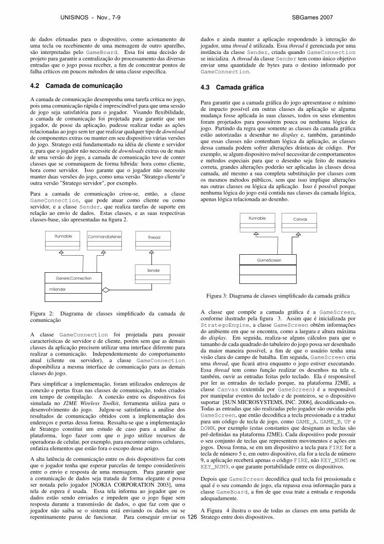
de dados efetuadas para o dispositivo, como acionamento deuma tecla ou recebimento de uma mensagem de outro aparelho,são interpretadas pelo GameBoard. Essa foi uma decisão deprojeto para garantir a centralização do processamento das diversasentradas que o jogo possa receber, a fim de concentrar pontos defalha críticos em poucos métodos de uma classe específica.
4.2 Camada de comunicação
A camada de comunicação desempenha uma tarefa crítica no jogo,pois uma comunicação rápida é imprescindível para que uma sessãode jogo seja satisfatória para o jogador. Visando flexibilidade,a camada de comunicação foi projetada para garantir que umjogador, de posse da aplicação, pudesse realizar todas as açõesrelacionadas ao jogo sem ter que realizar qualquer tipo de downloadde componentes extras ou manter em seu dispositivo várias versõesdo jogo. Stratego está fundamentado na idéia de cliente e servidore, para que o jogador não necessite de downloads extras ou de maisde uma versão do jogo, a camada de comunicação teve de conterclasses que se comuniquem de forma híbrida: hora como cliente,hora como servidor. Isso garante que o jogador não necessitemanter duas versões do jogo, como uma versão "Stratego cliente"eoutra versão "Stratego servidor", por exemplo.
Para a camada de comunicação criou-se, então, a classeGameConnection, que pode atuar como cliente ou comoservidor, e a classe Sender, que realiza tarefas de suporte emrelação ao envio de dados. Estas classes, e as suas respectivasclasses-base, são apresentadas na figura 2.
Runnable
GenericConnection
Sender
ThreadCommandListener
mSender
Figura 2: Diagrama de classes simplificado da camada decomunicação
A classe GameConnection foi projetada para possuircaracterísticas de servidor e de cliente, porém sem que as demaisclasses da aplicação precisem utilizar uma interface diferente pararealizar a comunicação. Independentemente do comportamentoatual (cliente ou servidor), a classe GameConnectiondisponibiliza a mesma interface de comunicação para as demaisclasses do jogo.
Para simplificar a implementação, foram utilizados endereços deconexão e portas fixas nas classes de comunicação, todos criadosem tempo de compilação. A conexão entre os dispositivos foisimulada no J2ME Wireless Toolkit, ferramenta utiliza para odesenvolvimento do jogo. Julgou-se satisfatória a análise dosresultados de comunicação obtidos com a implementação dosendereços e portas dessa forma. Ressalta-se que a implementaçãode Stratego constitui um estudo de caso para a análise daplataforma, logo fazer com que o jogo utilize recursos deoperadoras de celular, por exemplo, para encontrar outros celulares,enfatiza elementos que estão fora o escopo desse artigo.
A alta latência de comunicação entre os dois dispositivos faz comque o jogador tenha que esperar parcelas de tempo consideráveisentre o envio e resposta de uma mensagem. Para garantir quea comunicação de dados seja tratada de forma elegante e possaser notada pelo jogador [NOKIA CORPORATION 2003], umatela de espera é usada. Essa tela informa ao jogador que osdados estão sendo enviados e impedem que o jogo fique semresposta durante a transmissão de dados, o que faz com que ojogador não saiba se o sistema está enviando os dados ou serepentinamente parou de funcionar. Para conseguir enviar os
dados e ainda manter a aplicação respondendo à interação dojogador, uma thread é utilizada. Essa thread é gerenciada por umainstância da classe Sender, criada quando GameConnectionse inicializa. A thread da classe Sender tem como único objetivoenviar uma quantidade de bytes para o destino informado porGameConnection.
4.3 Camada gráfica
Para garantir que a camada gráfica do jogo apresentasse o mínimode impacto possível em outras classes da aplicação se algumamudança fosse aplicada às suas classes, todos os seus elementosforam projetados para possuírem pouca ou nenhuma lógica dejogo. Partindo da regra que somente as classes da camada gráficaestão autorizadas a desenhar no display e, também, garantindoque essas classes não contenham lógica da aplicação, as classesdessa camada podem sofrer alterações drásticas de código. Porexemplo, se algum dispositivo móvel necessitar de comportamentose métodos especiais para que o desenho seja feito de maneiracorreta, grandes alterações poderão ser aplicadas às classes dessacamada, até mesmo a sua completa substituição por classes comos mesmos métodos públicos, sem que isso implique alteraçõesnas outras classes ou lógica da aplicação. Isso é possível porquenenhuma lógica do jogo está contida nas classes da camada lógica,apenas lógica relacionada ao desenho.
Runnable
GameScreen
Canvas
Figura 3: Diagrama de classes simplificado da camada gráfica
A classe que compõe a camada gráfica é a GameScreen,conforme ilustrado pela figura 3. Assim que é inicializada porStrategoEngine, a classe GameScreen obtém informaçõesdo ambiente em que se encontra, como a largura e altura máximado display. Em seguida, realiza-se alguns cálculos para que otamanho de cada quadrado do tabuleiro do jogo possa ser desenhadoda maior maneira possível, a fim de que o usuário tenha umavisão clara do campo de batalha. Em seguida, GameScreen criauma thread, que ficará ativa enquanto o jogo estiver executando.Essa thread tem como função realizar os desenhos na tela e,também, ouvir as entradas feitas pelo teclado. Ela é responsávelpor ler as entradas do teclado porque, na plataforma J2ME, aclasse Canvas (extentida por GameScreen) é a responsávelpor manipular eventos do teclado e de ponteiros, se o dispositivosuportar [SUN MICROSYSTEMS, INC. 2006], decodificando-os.Todas as entradas que são realizadas pelo jogador são ouvidas pelaGameScreen, que então decodifica a tecla pressionada e a traduzpara um código de tecla de jogo, como GAME_A, GAME_B, UP eDOWN, por exemplo (estas constantes que designam as teclas sãopré-definidas na plataforma J2ME). Cada dispositivo pode possuiro seu conjunto de teclas que representem movimentos e ações emjogos. Dessa forma, se em um dispositivo a tecla para FIRE for atecla de número 5 e, em outro dispositivo, ela for a tecla de número9, a aplicação receberá apenas o código FIRE, não KEY_NUM5 ouKEY_NUM9, o que garante portabilidade entre os dispositivos.
Depois que GameScreen decodifica qual tecla foi pressionada equal é o seu comando de jogo, ela repassa essa informação para aclasse GameBoard, a fim de que essa trate a entrada e respondaadequadamente.
A Figura 4 ilustra o uso de todas as classes em uma partida deStratego entre dois dispositivos.
UNISINOS - Nov., 7-9 SBGames 2007
126
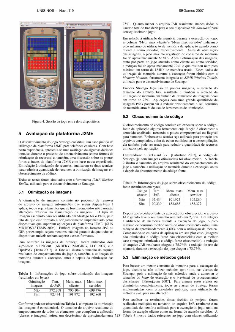
Figura 4: Sessão de jogo entre dois dispositivos
5 Avaliação da plataforma J2ME
O desenvolvimento do jogo Stratego constituiu um caso prático deutilização da plataforma J2ME para telefones celulares. Com basenesta experiência, apresenta-se uma avaliação de algumas decisõestomadas durante o processo de desenvolvimento (como formas deotimização de recursos) e, também, uma discussão sobre os pontosfortes e fracos da plataforma J2ME com base nessa experiência.Em relação à otimização de recursos, analisaram-se duas técnicaspara reduzir a quantidade de recursos: a otimização de imagens e oobscurecimento de código.
Todos os testes foram simulados com a ferramenta J2ME WirelessToolkit, utilizado para o desenvolvimento de Stratego.
5.1 Otimização de imagens
A otimização de imagens consiste no processo de removerdo arquivo de imagem informações que sejam dispensáveis àaplicação, ou seja, elementos que se forem removidos não causarãoalterações drásticas na visualização da imagem. O tipo deimagem escolhido para ser utilizado em Stratego foi o PNG, pelofato de que esse formato é obrigatoriamente implementado pelosdispositivos que suportam aplicações da plataforma J2ME [SUNMICROSYSTEMS 2006]. Embora imagens no formato JPG ouGIF, por exemplo, sejam menores, não há garantia de que todos osdispositivos móveis tenham suporte a esses formatos.
Para otimizar as imagens de Stratego, foram utilizados doissoftwares: o PNGout [ARDFRY IMAGING, LLC 2007] e oOptiPNG [Truta 2007]. A Tabela 1 ilustra o tamanho do arquivoresultante do empacotamento do jogo e, também, a utilização dememória durante a execução, antes e depois da otimização dasimagens.
Tabela 1: Informações do jogo sobre otimização das imagens(resultados em bytes)
Otimização Tam. Mem. max. Mem. max.imagens do JAR cliente servidor
Não 372.308 700.104 699.476Sim 92.434 191.972 192.860
Conforme pode ser observado na Tabela 1, o impacto da otimizaçãodas imagens é considerável. O tamanho do arquivo resultante doempacotamento de todos os elementos que compõem a aplicação(classes e imagens) sofreu um decréscimo de aproximadamente
75%. Quanto menor o arquivo JAR resultante, menos dados ousuário terá de transferir para o seu dispositivo via download paraconseguir obter o jogo.
Em relação à utilização de memória durante a execução do jogo,as colunas "Mem. max. cliente"e "Mem. max. servidor" indicam opico máximo de utilização de memória da aplicação agindo comocliente e como servidor, respectivamente. Antes da otimizaçãodas imagens, o pico máximo registrado de consumo de memóriafoi de aproximadamente 683Kb. Após a otimização das imagens,tanto por parte do jogo atuando como cliente ou como servidor,a redução foi de aproximadamente 72%, o que resultou num picomáximo em torno de 184Kb de memória usada. Esses dados deutilização de memória durante a execução foram obtidos com oMemory Monitor, ferramenta integrada ao J2ME Wireless Toolkit,utilizado para o desenvolvimento de Stratego.
Embora Stratego faça uso de poucas imagens, a redução dotamanho do arquivo JAR resultante e também a redução dautilização de memória em virtude da otimização de imagens ficouem torno de 73%. Aplicações com uma grande quantidade deimagens PNG podem vir a reduzir drasticamente o seu consumode memória através do uso de ferramentas de otimização.
5.2 Obscurecimento de código
O obscurecimento de código consiste em executar sobre o código-fonte da aplicação alguma ferramenta cuja função é obscurecer oconteúdo analisado, tornando-o pouco compreensível ou ilegívelpara humanos. Embora essa técnica seja utilizada para proteção dosarquivos compilados, a fim de evitar ou dificultar a descompilação,ela também pode ser usada para reduzir a quantidade de recursosutilizados pela aplicação.
Utilizando-se o ProGuard 3.7 [Lafortune 2007], o código deStratego (já com imagens otimizadas) foi obscurecido. A Tabela2 ilustra o tamanho do arquivo resultante do empacotamento dojogo e, também, a utilização de memória durante a execução, antese depois do obscurecimento do código-fonte.
Tabela 2: Informações do jogo sobre obscurecimento do código-fonte (resultados em bytes)
Código Tam. Mem. max. Mem. max.obscur JAR cliente servidor
Não 92.434 191.972 192.860Sim 90.230 183.688 183.372
Depois que o código-fonte da aplicação foi obscurecido, o arquivoJAR gerado teve o seu tamanho reduzido em 2,78%. Em relaçãoà utilização de memória durante a execução do jogo, o picomáximo de consumo medido antes do obscurecimento sofreu umaredução de aproximadamente 4,60% com a utilização da técnica.Comparando-se os dados da aplicação em seu pior caso (imagensnão otimizadas e código-fonte não obscurecido) com o melhorcaso (imagens otimizadas e código-fonte obscurecido), a reduçãodo arquivo JAR resultante chegou a 75,76%; a redução do uso dememória durante a execução do jogo chegou a 73,77%.
5.3 Eliminação de métodos get/set
Para buscar um menor consumo de memória para a execução dojogo, decidiu-se não utilizar métodos get/set nas classes deStratego, pois a utilização de tais métodos tende a aumentar otamanho do heap de execução e o overhead de processamentodas classes [Fasterj.com 2007]. Para atenuar esses efeitos oueliminá-los completamente, todas as classes de Stratego foramimplementadas com propriedades públicas, sem utilização demétodos set para sua alteração.
Para analisar os resultados dessa decisão de projeto, foramrealizadas medições no tamanho do arquivo JAR resultante e naquantidade de memória utilizada para a execução do jogo, tanto naforma de atuação cliente como na forma de atuação servidor. ATabela 3 mostra dados referentes ao jogo com classes utilizando
UNISINOS - Nov., 7-9 SBGames 2007
127
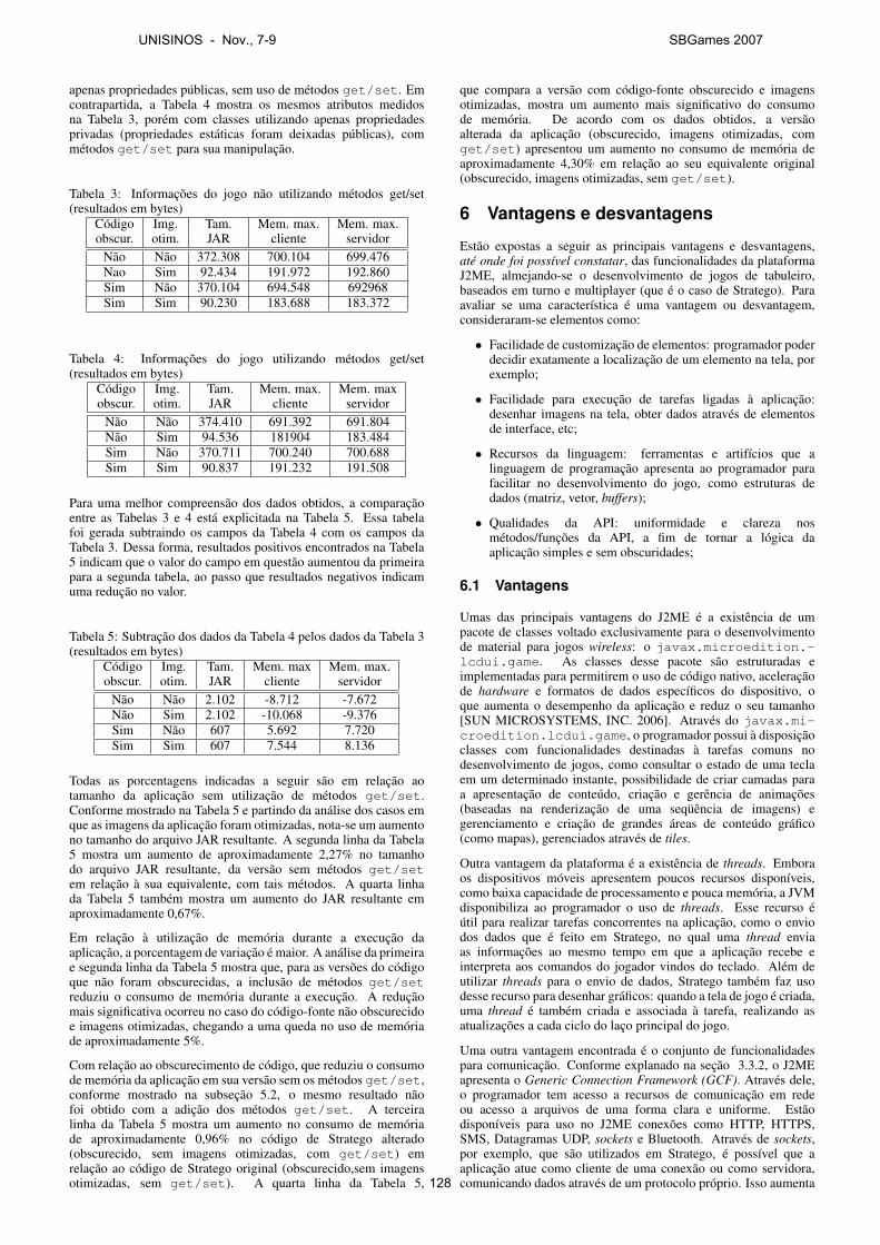
apenas propriedades públicas, sem uso de métodos get/set. Emcontrapartida, a Tabela 4 mostra os mesmos atributos medidosna Tabela 3, porém com classes utilizando apenas propriedadesprivadas (propriedades estáticas foram deixadas públicas), commétodos get/set para sua manipulação.
Tabela 3: Informações do jogo não utilizando métodos get/set(resultados em bytes)
Código Img. Tam. Mem. max. Mem. max.obscur. otim. JAR cliente servidor
Não Não 372.308 700.104 699.476Nao Sim 92.434 191.972 192.860Sim Não 370.104 694.548 692968Sim Sim 90.230 183.688 183.372
Tabela 4: Informações do jogo utilizando métodos get/set(resultados em bytes)
Código Img. Tam. Mem. max. Mem. maxobscur. otim. JAR cliente servidor
Não Não 374.410 691.392 691.804Não Sim 94.536 181904 183.484Sim Não 370.711 700.240 700.688Sim Sim 90.837 191.232 191.508
Para uma melhor compreensão dos dados obtidos, a comparaçãoentre as Tabelas 3 e 4 está explicitada na Tabela 5. Essa tabelafoi gerada subtraindo os campos da Tabela 4 com os campos daTabela 3. Dessa forma, resultados positivos encontrados na Tabela5 indicam que o valor do campo em questão aumentou da primeirapara a segunda tabela, ao passo que resultados negativos indicamuma redução no valor.
Tabela 5: Subtração dos dados da Tabela 4 pelos dados da Tabela 3(resultados em bytes)
Código Img. Tam. Mem. max Mem. max.obscur. otim. JAR cliente servidor
Não Não 2.102 -8.712 -7.672Não Sim 2.102 -10.068 -9.376Sim Não 607 5.692 7.720Sim Sim 607 7.544 8.136
Todas as porcentagens indicadas a seguir são em relação aotamanho da aplicação sem utilização de métodos get/set.Conforme mostrado na Tabela 5 e partindo da análise dos casos emque as imagens da aplicação foram otimizadas, nota-se um aumentono tamanho do arquivo JAR resultante. A segunda linha da Tabela5 mostra um aumento de aproximadamente 2,27% no tamanhodo arquivo JAR resultante, da versão sem métodos get/setem relação à sua equivalente, com tais métodos. A quarta linhada Tabela 5 também mostra um aumento do JAR resultante emaproximadamente 0,67%.
Em relação à utilização de memória durante a execução daaplicação, a porcentagem de variação é maior. A análise da primeirae segunda linha da Tabela 5 mostra que, para as versões do códigoque não foram obscurecidas, a inclusão de métodos get/setreduziu o consumo de memória durante a execução. A reduçãomais significativa ocorreu no caso do código-fonte não obscurecidoe imagens otimizadas, chegando a uma queda no uso de memóriade aproximadamente 5%.
Com relação ao obscurecimento de código, que reduziu o consumode memória da aplicação em sua versão sem os métodos get/set,conforme mostrado na subseção 5.2, o mesmo resultado nãofoi obtido com a adição dos métodos get/set. A terceiralinha da Tabela 5 mostra um aumento no consumo de memóriade aproximadamente 0,96% no código de Stratego alterado(obscurecido, sem imagens otimizadas, com get/set) emrelação ao código de Stratego original (obscurecido,sem imagensotimizadas, sem get/set). A quarta linha da Tabela 5,
que compara a versão com código-fonte obscurecido e imagensotimizadas, mostra um aumento mais significativo do consumode memória. De acordo com os dados obtidos, a versãoalterada da aplicação (obscurecido, imagens otimizadas, comget/set) apresentou um aumento no consumo de memória deaproximadamente 4,30% em relação ao seu equivalente original(obscurecido, imagens otimizadas, sem get/set).
6 Vantagens e desvantagens
Estão expostas a seguir as principais vantagens e desvantagens,até onde foi possível constatar, das funcionalidades da plataformaJ2ME, almejando-se o desenvolvimento de jogos de tabuleiro,baseados em turno e multiplayer (que é o caso de Stratego). Paraavaliar se uma característica é uma vantagem ou desvantagem,consideraram-se elementos como:
• Facilidade de customização de elementos: programador poderdecidir exatamente a localização de um elemento na tela, porexemplo;
• Facilidade para execução de tarefas ligadas à aplicação:desenhar imagens na tela, obter dados através de elementosde interface, etc;
• Recursos da linguagem: ferramentas e artifícios que alinguagem de programação apresenta ao programador parafacilitar no desenvolvimento do jogo, como estruturas dedados (matriz, vetor, buffers);
• Qualidades da API: uniformidade e clareza nosmétodos/funções da API, a fim de tornar a lógica daaplicação simples e sem obscuridades;
6.1 Vantagens
Umas das principais vantagens do J2ME é a existência de umpacote de classes voltado exclusivamente para o desenvolvimentode material para jogos wireless: o javax.microedition.-lcdui.game. As classes desse pacote são estruturadas eimplementadas para permitirem o uso de código nativo, aceleraçãode hardware e formatos de dados específicos do dispositivo, oque aumenta o desempenho da aplicação e reduz o seu tamanho[SUN MICROSYSTEMS, INC. 2006]. Através do javax.mi-croedition.lcdui.game, o programador possui à disposiçãoclasses com funcionalidades destinadas à tarefas comuns nodesenvolvimento de jogos, como consultar o estado de uma teclaem um determinado instante, possibilidade de criar camadas paraa apresentação de conteúdo, criação e gerência de animações(baseadas na renderização de uma seqüência de imagens) egerenciamento e criação de grandes áreas de conteúdo gráfico(como mapas), gerenciados através de tiles.
Outra vantagem da plataforma é a existência de threads. Emboraos dispositivos móveis apresentem poucos recursos disponíveis,como baixa capacidade de processamento e pouca memória, a JVMdisponibiliza ao programador o uso de threads. Esse recurso éútil para realizar tarefas concorrentes na aplicação, como o enviodos dados que é feito em Stratego, no qual uma thread enviaas informações ao mesmo tempo em que a aplicação recebe einterpreta aos comandos do jogador vindos do teclado. Além deutilizar threads para o envio de dados, Stratego também faz usodesse recurso para desenhar gráficos: quando a tela de jogo é criada,uma thread é também criada e associada à tarefa, realizando asatualizações a cada ciclo do laço principal do jogo.
Uma outra vantagem encontrada é o conjunto de funcionalidadespara comunicação. Conforme explanado na seção 3.3.2, o J2MEapresenta o Generic Connection Framework (GCF). Através dele,o programador tem acesso a recursos de comunicação em redeou acesso a arquivos de uma forma clara e uniforme. Estãodisponíveis para uso no J2ME conexões como HTTP, HTTPS,SMS, Datagramas UDP, sockets e Bluetooth. Através de sockets,por exemplo, que são utilizados em Stratego, é possível que aaplicação atue como cliente de uma conexão ou como servidora,comunicando dados através de um protocolo próprio. Isso aumenta
UNISINOS - Nov., 7-9 SBGames 2007
128
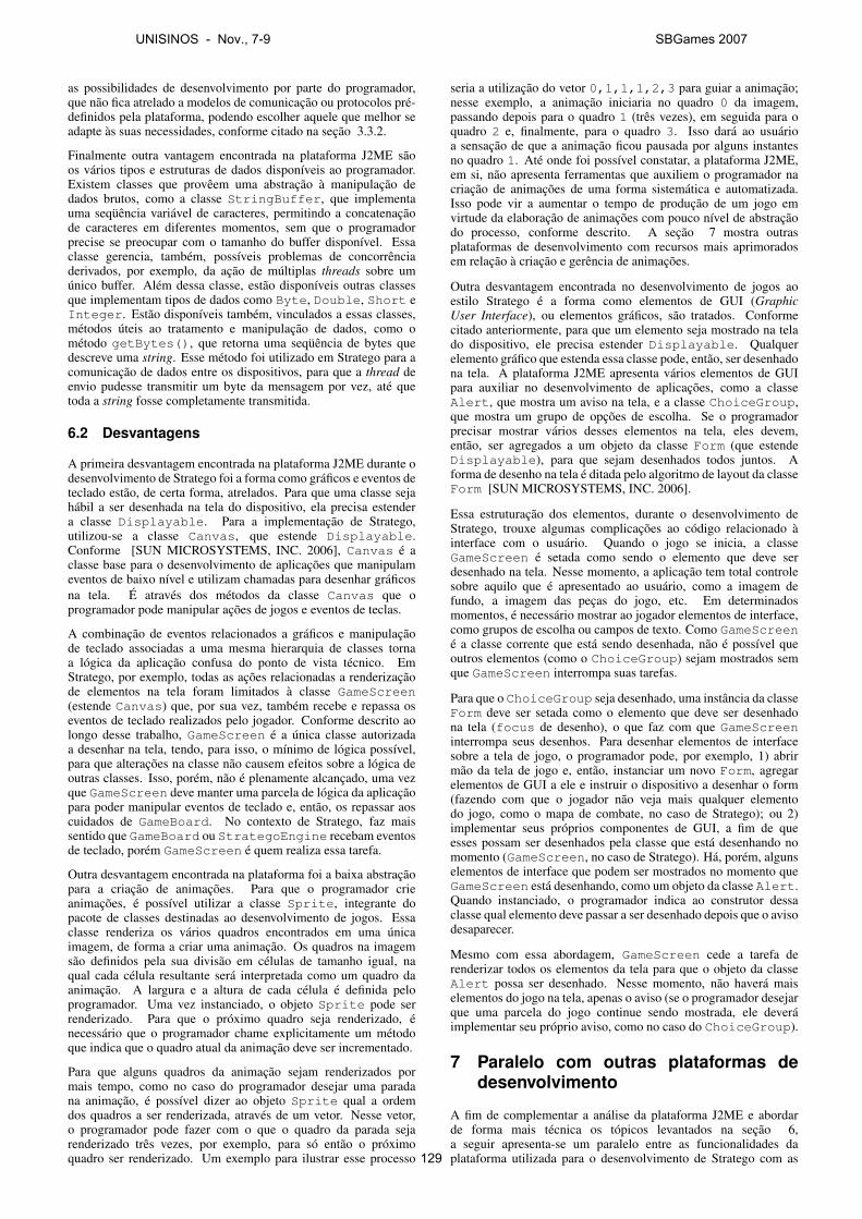
as possibilidades de desenvolvimento por parte do programador,que não fica atrelado a modelos de comunicação ou protocolos pré-definidos pela plataforma, podendo escolher aquele que melhor seadapte às suas necessidades, conforme citado na seção 3.3.2.
Finalmente outra vantagem encontrada na plataforma J2ME sãoos vários tipos e estruturas de dados disponíveis ao programador.Existem classes que provêem uma abstração à manipulação dedados brutos, como a classe StringBuffer, que implementauma seqüência variável de caracteres, permitindo a concatenaçãode caracteres em diferentes momentos, sem que o programadorprecise se preocupar com o tamanho do buffer disponível. Essaclasse gerencia, também, possíveis problemas de concorrênciaderivados, por exemplo, da ação de múltiplas threads sobre umúnico buffer. Além dessa classe, estão disponíveis outras classesque implementam tipos de dados como Byte, Double, Short eInteger. Estão disponíveis também, vinculados a essas classes,métodos úteis ao tratamento e manipulação de dados, como ométodo getBytes(), que retorna uma seqüência de bytes quedescreve uma string. Esse método foi utilizado em Stratego para acomunicação de dados entre os dispositivos, para que a thread deenvio pudesse transmitir um byte da mensagem por vez, até quetoda a string fosse completamente transmitida.
6.2 Desvantagens
A primeira desvantagem encontrada na plataforma J2ME durante odesenvolvimento de Stratego foi a forma como gráficos e eventos deteclado estão, de certa forma, atrelados. Para que uma classe sejahábil a ser desenhada na tela do dispositivo, ela precisa estendera classe Displayable. Para a implementação de Stratego,utilizou-se a classe Canvas, que estende Displayable.Conforme [SUN MICROSYSTEMS, INC. 2006], Canvas é aclasse base para o desenvolvimento de aplicações que manipulameventos de baixo nível e utilizam chamadas para desenhar gráficosna tela. É através dos métodos da classe Canvas que oprogramador pode manipular ações de jogos e eventos de teclas.
A combinação de eventos relacionados a gráficos e manipulaçãode teclado associadas a uma mesma hierarquia de classes tornaa lógica da aplicação confusa do ponto de vista técnico. EmStratego, por exemplo, todas as ações relacionadas a renderizaçãode elementos na tela foram limitados à classe GameScreen(estende Canvas) que, por sua vez, também recebe e repassa oseventos de teclado realizados pelo jogador. Conforme descrito aolongo desse trabalho, GameScreen é a única classe autorizadaa desenhar na tela, tendo, para isso, o mínimo de lógica possível,para que alterações na classe não causem efeitos sobre a lógica deoutras classes. Isso, porém, não é plenamente alcançado, uma vezque GameScreen deve manter uma parcela de lógica da aplicaçãopara poder manipular eventos de teclado e, então, os repassar aoscuidados de GameBoard. No contexto de Stratego, faz maissentido que GameBoard ou StrategoEngine recebam eventosde teclado, porém GameScreen é quem realiza essa tarefa.
Outra desvantagem encontrada na plataforma foi a baixa abstraçãopara a criação de animações. Para que o programador crieanimações, é possível utilizar a classe Sprite, integrante dopacote de classes destinadas ao desenvolvimento de jogos. Essaclasse renderiza os vários quadros encontrados em uma únicaimagem, de forma a criar uma animação. Os quadros na imagemsão definidos pela sua divisão em células de tamanho igual, naqual cada célula resultante será interpretada como um quadro daanimação. A largura e a altura de cada célula é definida peloprogramador. Uma vez instanciado, o objeto Sprite pode serrenderizado. Para que o próximo quadro seja renderizado, énecessário que o programador chame explicitamente um métodoque indica que o quadro atual da animação deve ser incrementado.
Para que alguns quadros da animação sejam renderizados pormais tempo, como no caso do programador desejar uma paradana animação, é possível dizer ao objeto Sprite qual a ordemdos quadros a ser renderizada, através de um vetor. Nesse vetor,o programador pode fazer com o que o quadro da parada sejarenderizado três vezes, por exemplo, para só então o próximoquadro ser renderizado. Um exemplo para ilustrar esse processo
seria a utilização do vetor 0,1,1,1,2,3 para guiar a animação;nesse exemplo, a animação iniciaria no quadro 0 da imagem,passando depois para o quadro 1 (três vezes), em seguida para oquadro 2 e, finalmente, para o quadro 3. Isso dará ao usuárioa sensação de que a animação ficou pausada por alguns instantesno quadro 1. Até onde foi possível constatar, a plataforma J2ME,em si, não apresenta ferramentas que auxiliem o programador nacriação de animações de uma forma sistemática e automatizada.Isso pode vir a aumentar o tempo de produção de um jogo emvirtude da elaboração de animações com pouco nível de abstraçãodo processo, conforme descrito. A seção 7 mostra outrasplataformas de desenvolvimento com recursos mais aprimoradosem relação à criação e gerência de animações.
Outra desvantagem encontrada no desenvolvimento de jogos aoestilo Stratego é a forma como elementos de GUI (GraphicUser Interface), ou elementos gráficos, são tratados. Conformecitado anteriormente, para que um elemento seja mostrado na telado dispositivo, ele precisa estender Displayable. Qualquerelemento gráfico que estenda essa classe pode, então, ser desenhadona tela. A plataforma J2ME apresenta vários elementos de GUIpara auxiliar no desenvolvimento de aplicações, como a classeAlert, que mostra um aviso na tela, e a classe ChoiceGroup,que mostra um grupo de opções de escolha. Se o programadorprecisar mostrar vários desses elementos na tela, eles devem,então, ser agregados a um objeto da classe Form (que estendeDisplayable), para que sejam desenhados todos juntos. Aforma de desenho na tela é ditada pelo algoritmo de layout da classeForm [SUN MICROSYSTEMS, INC. 2006].
Essa estruturação dos elementos, durante o desenvolvimento deStratego, trouxe algumas complicações ao código relacionado àinterface com o usuário. Quando o jogo se inicia, a classeGameScreen é setada como sendo o elemento que deve serdesenhado na tela. Nesse momento, a aplicação tem total controlesobre aquilo que é apresentado ao usuário, como a imagem defundo, a imagem das peças do jogo, etc. Em determinadosmomentos, é necessário mostrar ao jogador elementos de interface,como grupos de escolha ou campos de texto. Como GameScreené a classe corrente que está sendo desenhada, não é possível queoutros elementos (como o ChoiceGroup) sejam mostrados semque GameScreen interrompa suas tarefas.
Para que o ChoiceGroup seja desenhado, uma instância da classeForm deve ser setada como o elemento que deve ser desenhadona tela (focus de desenho), o que faz com que GameScreeninterrompa seus desenhos. Para desenhar elementos de interfacesobre a tela de jogo, o programador pode, por exemplo, 1) abrirmão da tela de jogo e, então, instanciar um novo Form, agregarelementos de GUI a ele e instruir o dispositivo a desenhar o form(fazendo com que o jogador não veja mais qualquer elementodo jogo, como o mapa de combate, no caso de Stratego); ou 2)implementar seus próprios componentes de GUI, a fim de queesses possam ser desenhados pela classe que está desenhando nomomento (GameScreen, no caso de Stratego). Há, porém, algunselementos de interface que podem ser mostrados no momento queGameScreen está desenhando, como um objeto da classe Alert.Quando instanciado, o programador indica ao construtor dessaclasse qual elemento deve passar a ser desenhado depois que o avisodesaparecer.
Mesmo com essa abordagem, GameScreen cede a tarefa derenderizar todos os elementos da tela para que o objeto da classeAlert possa ser desenhado. Nesse momento, não haverá maiselementos do jogo na tela, apenas o aviso (se o programador desejarque uma parcela do jogo continue sendo mostrada, ele deveráimplementar seu próprio aviso, como no caso do ChoiceGroup).
7 Paralelo com outras plataformas dedesenvolvimento
A fim de complementar a análise da plataforma J2ME e abordarde forma mais técnica os tópicos levantados na seção 6,a seguir apresenta-se um paralelo entre as funcionalidades daplataforma utilizada para o desenvolvimento de Stratego com as
UNISINOS - Nov., 7-9 SBGames 2007
129

funcionalidades semelhantes encontradas em outras plataformas.Não é o objetivo dessa seção prover uma análise profunda dasplataformas citadas, mas sim enriquecer a análise das vantagens edesvantagens do J2ME, citadas anteriormente.
7.1 Paralelo entre as vantagens
Uma das vantagens citadas da plataforma J2ME é a existênciade um pacote destinado exclusivamente ao desenvolvimento dejogos. Comparando-se com a plataforma Flash Lite, em sua versão2.0, até onde foi possível constatar, não existe um pacote declasses explicitamente declarado para o desenvolvimento de jogos.Embora a plataforma Flash Lite apresente vários recursos gráficosaprimorados, que serão citados à frente, não há a centralizaçãodesses em um pacote explícito como aquele visto no J2ME.Conforme já descrito, o pacote javax.microedition.-lcdui.game utiliza classes que são implementadas e desenhadaspara tirarem vantagem do hardware do dispositivo, aumentando odesempenho dos processos relacionados.
Outra vantagem citada anteriormente foi a existência de threadsem J2ME, que aumentam a capacidade da aplicação em executartarefas de forma concorrente. Até onde foi possível constatar,na plataforma Flash Lite não está disponível ao programadora criação e utilização de threads. É possível, porém, simulara execução concorrente de operações através do uso da funçãosetInterval(), no qual o programador define um método deuma classe para ser executado repetidamente, com um intervalocustomizável entre as chamadas. Através das propriedades daclasse, é possível manter estados do processo, simulando apreservação de contexto de threads. Essa abordagem, porém, élimitada, uma vez que programador não detém um fluxo exclusivode execução, como aquele proporcionado pelas threads doJ2ME. Conforme testes realizados, métodos que sejam chamadospor setInterval() não podem conter laços infinitos, comoum while(true), uma vez que eles priorizam a execuçãosomente desse método, pois ele não retorna, fazendo com quesetInterval() aguarde sua finalização indeterminadamente,o que faz com que a aplicação não responda mais (resultandoem um crash). Em relação à plataforma BREW, a partirdo SDK 3.0, está disponível ao programador recursos como aIThread, que implementam a execução de tarefas de formaparalela [QUALCOMM INCORPORATED 2006].
Uma vantagem da plataforma J2ME também citada é o grandeconjunto de recursos para comunicação em rede. Em um paralelocom a plataforma Flash Lite, constatou-se que essa apresentameios para troca de informações em rede limitados a protocolospré-definidos, em sua grande maioria. A plataforma possibilitaao programador o carregamento de arquivos externos (comodocumentos de texto ou arquivos XML) através do protocoloHTTP (se o arquivo for remoto), utilização de SMS e envio deum conjunto de informações (como campos de um formulário)para um servidor, utilizando HTTP para a comunicação [ADOBESYSTEMS INCORPORATED 2006a]. No conjunto de meios decomunicação com protocolos mais flexíveis (com característicasdefinidas pelo próprio programador, por exemplo), está disponível aclasse XMLSocket, que permite ao programador abrir um canal dedados com algum servidor e, através de XML, trocar informações.Há várias restrições a serem consideradas nesse processo, comoa porta na qual o socket é aberto, que deve ser, obrigatoriamente,maior que 1024; e que cada mensagem enviada é um documentoXML terminado por um byte zero (o servidor que receber amensagem deve entender essa convenção). Em comparação com asfuncionalidades do Generic Connection Framework do J2ME, queapresenta uma API uniforme e clara para comunicação em rede,através de vários protocolos e formas de transmissão de dados, aspossibilidades de comunicação da plataforma Flash Lite são maislimitadas.
Em um paralelo com a plataforma BREW, é possível encontraralgumas semelhanças em termos de funcionalidades decomunicação. BREW disponibiliza bibliotecas como ITAPI,que possibilitam acesso a serviços de voz e SMS, ISocket quepermite a manipulação de conexões tanto TCP quanto UDP, IWebque facilita a condução de transações web sobre vários protocolos
Tabela 6: Resumo da comparação das vantagens entre asplataformas J2ME, BREW e Flash Lite
Elemento J2ME BREW Flash Liteanalisado
Existência depacote com Sim Não Não
classes voltadasao
desenvolvimento.de jogos
Existência de Sim Sim, a partir do Nãothreads SDK 3.0
Meios de Grande Conjunto Conjuntocomunicação conjunto considerável: HTTP, reduzido:
em rede através do GCF: socket, HTTPS, HTTP, SMS eHTTP, Bluetooth, SMS, comunicação XMLSocketHTTPS, socket, serial. (socket comUPDDatagram, diversas
SMS limitações).e comunicação
serialLinguagem deprogramação Sim Sim Nãofortemente
tipadaGrande conjunto, Os mesmos tipos Inexistentes.como int, byte, de dados nativos A plataforma
Tipos nativos de char e short. da linguagem C, utiliza apenasdados como int, classes para
float, char, representarlong e short. dados.
Grande conjunto Conjuntode classes úteis já considerável deimplementadas, classes, como
Classes como (Não analisado) String,e estruturas StringBuffer Array,
de dados String, Float, Boolean eVector e Number.Hashtable
e IPort que disponibiliza uma comunicação genérica com váriasinterfaces.
Outra vantagem citada sobre o J2ME são os vários tipos e estruturasde dados disponíveis ao programador. Conforme já explanado,J2ME apresenta um grande conjunto de tipos nativos de dados,como int, char e byte, além de classes que implementamestruturas de dados úteis à programação, como StringBuffer.Em um paralelo com a plataforma BREW, um grande conjunto detipos de dados também é fornecido, assim como aqueles que sãoencontrados na linguagem de programação C++ [QUALCOMMINCORPORATED 2006]. Em ambas as plataformas, a linguagemde programação apresenta tipagem forte, o que evita que umavariável tenha seu tipo alterado ao longo do tempo.
Na plataforma Flash Lite, até onde foi possível constatar, existemtambém estruturas de dados já implementadas úteis à programação,como Array, String e Boolean, porém a linguagem deprogramação é fracamente tipada e não apresenta distinção entrecertos tipos nativos de dados. Em relação à tipagem, conformetestes realizados, é facultativa a definição do tipo de uma variável,o que permite que uma variável tenha o seu tipo alterado ao longodo tempo. Se o programador explicitamente especificar o tipo deuma variável, forçando uma tipagem forte, o compilador acusa errode incompatibilidade de tipos se houver a tentativa de utilização dealgum tipo não compatível. Em relação à distinção de tipos nativosde dados, não existe distinção entre números inteiros (com sinal ousem sinal) e números de ponto flutuante. Se o programador desejatipar uma variável como sendo numérica, ele possui à disposiçãoapenas o tipo Number, que engloba todos os tipos de dadosnuméricos existentes na plataforma.
A tabela 6 apresenta um resumo da comparação das vantagens daplataforma J2ME com as outras plataformas.
7.2 Paralelo entre as desvantagens
Em relação às desvantagens encontradas na plataforma J2ME,a primeira delas é a forma como a manipulação de eventos deteclado e a geração de gráficos são tratados de forma atrelada,conforme citado anteriormente. Em um paralelo com plataformaBREW, até onde foi possível constatar, a manipulação de eventosdo teclado e geração de gráficos são elementos distintos tratados porinterfaces diferentes. Para tratar eventos do teclado, a aplicação daplataforma BREW deve implementar o método nomeClasse_-HandleEvent(), onde nomeClasse é o nome da classe quedescreve a aplicação. Para desenhar na tela, a aplicação deve
UNISINOS - Nov., 7-9 SBGames 2007
130
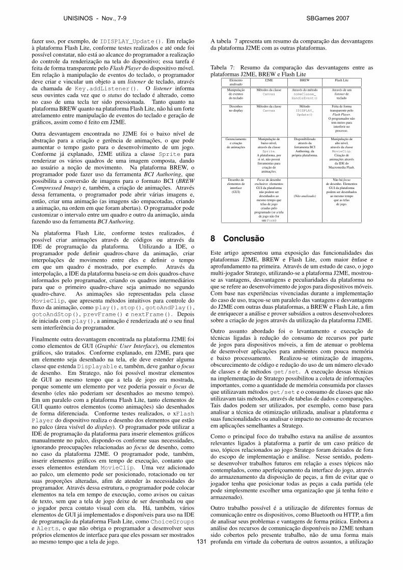
fazer uso, por exemplo, de IDISPLAY_Update(). Em relaçãoà plataforma Flash Lite, conforme testes realizados e até onde foipossível constatar, não está ao alcance do programador a realizaçãodo controle da renderização na tela do dispositivo; essa tarefa éfeita de forma transparente pelo Flash Player do dispositivo móvel.Em relação à manipulação de eventos do teclado, o programadordeve criar e vincular um objeto a um listener de teclado, atravésda chamada de Key.addListener(). O listener informaseus ouvintes cada vez que o status do teclado é alterado, comono caso de uma tecla ter sido pressionada. Tanto quanto naplataforma BREW quanto na plataforma Flash Lite, não há um forteatrelamento entre manipulação de eventos do teclado e geração degráficos, assim como é feito em J2ME.
Outra desvantagem encontrada no J2ME foi o baixo nível deabstração para a criação e gerência de animações, o que podeaumentar o tempo gasto para o desenvolvimento de um jogo.Conforme já explanado, J2ME utiliza a classe Sprite pararenderizar os vários quadros de uma imagem composta, dandoao usuário a noção de movimento. Na plataforma BREW, oprogramador pode fazer uso da ferramenta BCI Authoring, quepossibilita a conversão de imagens para o formato BCI (BREWCompressed Image) e, também, a criação de animações. Atravésdessa ferramenta, o programador pode abrir várias imagens e,então, criar uma animação (as imagens são empacotadas, criandoa animação, na ordem em que foram abertas). O programador podecustomizar o intervalo entre um quadro e outro da animação, aindafazendo uso da ferramenta BCI Authoring.
Na plataforma Flash Lite, conforme testes realizados, épossível criar animações através de códigos ou através daIDE de programação da plataforma. Utilizando a IDE, oprogramador pode definir quadros-chave da animação, criarinterpolações de movimento entre eles e definir o tempoem que um quadro é mostrado, por exemplo. Através dainterpolação, a IDE da plataforma baseia-se em dois quadros-chaveinformados pelo programador, criando os quadros intermediáriospara que o primeiro quadro-chave seja animado no segundoquadro-chave. As animações são representadas pela classeMovieClip, que apresenta métodos intuitivos para controle dofluxo da animação, como play(), stop(), gotoAndPlay(),gotoAndStop(), prevFrame() e nextFrame(). Depoisde iniciada com play(), a animação é renderizada até o seu finalsem interferência do programador.
Finalmente outra desvantagem encontrada na plataforma J2ME foicomo elementos de GUI (Graphic User Interface), ou elementosgráficos, são tratados. Conforme explanado, em J2ME, para queum elemento seja desenhado na tela, ele deve estender algumaclasse que estenda Displayable e, também, deve ganhar o focusde desenho. Em Stratego, não foi possível mostrar elementosde GUI ao mesmo tempo que a tela de jogo era mostrada,porque somente um elemento por vez poderia possuir o focus dedesenho (eles não poderiam ser desenhados ao mesmo tempo).Em um paralelo com a plataforma Flash Lite, tanto elementos deGUI quanto outros elementos (como animações) são desenhadosde forma diferenciada. Conforme testes realizados, o xFlashPlayer do dispositivo realiza o desenho dos elementos que estãono palco (área visível do display). O programador pode utilizar aIDE de programação da plataforma para inserir elementos gráficosmanualmente no palco, dispondo-os conforme suas necessidades,ignorando preocupações relacionadas ao focus de desenho, comono caso da plataforma J2ME. O programador pode, também,inserir elementos gráficos em tempo de execução, contanto queesses elementos estendam MovieClip. Uma vez adicionadoao palco, um elemento pode ser posicionado, rotacionado ou tersuas proporções alteradas, afim de atender às necessidades doprogramador. Através dessa estrutura, o programador pode colocarelementos na tela em tempo de execução, como avisos ou caixasde texto, sem que a tela de jogo deixe de ser desenhada ou queo jogador perca contato visual com ela. Há, também, várioselementos de GUI já implementados e disponíveis para uso na IDEde programação da plataforma Flash Lite, como ChoiceGroupse Alerts, o que não obriga o programador a desenvolver seuspróprios elementos de interface para que eles possam ser mostradosao mesmo tempo que a tela de jogo.
A tabela 7 apresenta um resumo da comparação das desvantagensda plataforma J2ME com as outras plataformas.
Tabela 7: Resumo da comparação das desvantagens entre asplataformas J2ME, BREW e Flash Lite
Elemento J2ME BREW Flash Liteanalisado
Manipulação Métodos da classe Através do método Através de umde eventos Canvas nomeClasse_ listener dedo teclado HandleEvent() teclado
Desenhos Métodos da classe Método Feita de formano display Canvas IDISPLAY_ transparente pelo
Update() Flash Player.O programador não
tem meios parainterferir no
processo.
Gerenciamento Manipulação de Disponibilizado Manipulação dee criação baixo nível, através da alto nível,
de animações através da classe ferramenta BCI através da classeSprite. Authoring, da MovieClip.
A plataforma, por própria plataforma. Criação desi só, não possui animações atravésferramentas para da IDE do
criação de Macromedia Flash.animações.
Desenho de Focus de desenho Não há focuselementos de exclusivo: elementos de desenho. Elementos
interface GUI da plataforma GUI da plataforma(GUI) não podem ser podem ser desenhados
desenhados ao (Não analisado) ao mesmo tempomesmo tempo que que as telas
telas de jogo de jogo.criadas pelo
programado (se a telade jogo não for
um Form)
8 Conclusão
Este artigo apresentou uma exposição das funcionalidades dasplataformas J2ME, BREW e Flash Lite, com maior ênfase eaprofundamento na primeira. Através de um estudo de caso, o jogomulti-jogador Stratego, utilizando-se a plataforma J2ME, mostrou-se as vantagens, desvantagens e peculiaridades da plataforma noque se refere ao desenvolvimento de jogos para dispositivos móveis.Com base nas experiências vivenciadas durante a implementaçãodo caso de uso, traçou-se um paralelo das vantagens e desvantagensdo J2ME com outras duas plataformas, a BREW e Flash Lite, a fimde enriquecer a análise e prover subsídios a outros desenvolvedoressobre a criação de jogos através da utilização da plataforma J2ME.
Outro assunto abordado foi o levantamento e execução detécnicas ligadas à redução do consumo de recursos por partede jogos para dispositivos móveis, a fim de atenuar o problemade desenvolver aplicações para ambientes com pouca memóriae baixo processamento. Realizou-se otimização de imagens,obscurecimento de código e redução do uso de um número elevadode classes e de métodos get/set. A execução dessas técnicasna implementação de Stratego possibilitou a coleta de informaçõesimportantes, como a quantidade de memória consumida por classesque utilizavam métodos get/set e o consumo de classes que nãoutilizavam tais métodos, através de tabelas de dados e comparações.Tais dados podem ser utilizados, por exemplo, como base paraanalisar a técnica de otimização utilizada, analisar a plataforma esuas funcionalidades ou analisar o impacto no consumo de recursosem aplicações semelhantes a Stratego.
Como o principal foco do trabalho estava na análise de assuntosrelevantes ligados à plataforma a partir de um caso prático deuso, tópicos relacionados ao jogo Stratego foram deixados de forado escopo de implementação e análise. Nesse sentido, podem-se desenvolver trabalhos futuros em relação a esses tópicos nãocontemplados, como aperfeiçoamento da interface do jogo, atravésdo armazenamento da disposição de peças, a fim de evitar que ojogador tenha que posicionar todas as peças a cada partida (elepode simplesmente escolher uma organização que já tenha feito earmazenado).
Outro trabalho possível é a utilização de diferentes formas decomunicação entre os dispositivos, como Bluetooth ou HTTP, a fimde analisar seus problemas e vantagens de forma prática. Embora aanálise dos recursos de comunicação disponíveis no J2ME tenhamsido cobertos pelo presente trabalho, não de uma forma maisprofunda em virtude da cobertura de outros assuntos, a utilização
UNISINOS - Nov., 7-9 SBGames 2007
131

de outros meios de comunicação poderá disponibilizar informaçõesúteis sobre esse tópico crítico no desenvolvimento de jogos, que éa comunicação entre os dispositivos.
Outra possibilidade seria a implementação do jogo Stratego em umadas outras duas plataformas de desenvolvimento citadas, BREW eFlash Lite. Através dessa implementação, a análise das vantagens edesvantagens da plataforma J2ME seria maximizada e aumentariaos subsídios informacionais gerados, o que poderia contribuir comestudos e análises futuras entre as plataformas abordadas.
Referências
ADOBE SYSTEMS INCORPORATED, 2006. Adobe flash lite.Disponível em: <http://www.adobe.com/products/flashlite/>.
ADOBE SYSTEMS INCORPORATED,2006. Adobe flash player. Disponível em:<http://www.adobe.com/products/flashplayer/>.
ADOBE SYSTEMS INCORPORATED, 2007.Adobe flash lite 2.1 datasheet. Disponível em:<http://www.adobe.com/products/flashlite/productinfo/-overview/datasheet.pdf>.
ARDFRY IMAGING, LLC, 2007. Pngout. Disponível em:<http://www.ardfry.com/pngoutwin/>.
BARROS, A. R. 2005. Estudo sobre a utilização da tecnologiawireless no desenvolvimento de aplicações distribuídas multi-usuário. Tech. rep., Universidade Federal de Lavras, Lavras.
FASTERJ.COM, 2007. Java performance tuning.
HEDLUNG, M., AND MAXE, R. 2004. Multiplayer Gamesin Mobile Terminals. Master’s thesis, Lulea University ofTechnology, Sweden.
KARLSSON, B. F. F., NASCIMENTO, I. F., BARROS,T. G. F., SANTOS, A. L. M., AND RAMALHO, G. L.2003. Análise de tecnologias de desenvolvimento de jogospara dispositivos móveis. In Workshop Brasileiro de Jogos eEntretenimento Digital (WJOGOS), SBC.
KLINGSHEIM, A. N. 2004. J2ME Bluetooth Programming.Master’s thesis, University of Bergen, Norway.
LAFORTUNE, E., 2007. Proguard. Disponível em:<http://proguard.sourceforge.net/>.
LINSALATA, D., AND SLAWSBY, A., 2005. Addressinggrowing handset complexity with software solutions.Disponível em: <http://www.adobe.com/mobile/news_reviews/-articles/2005/idc_whitepaper.pdf>.
MAHMOUD, Q. H., 2003. J2me low-level networkprogramming with midp 2.0, April. Disponível em:<http://developers.sun.com/techtopics/mobility/midp/-articles/midp2network/>.
NOKIA CORPORATION. 2003. Developer Platform 1.0 forSeries 40 and Series 60: Known Issues. Version 1.1, Jun.
NOKIA CORPORATION, 2006. Ngage.com. Disponível em:<http://www.ngage.com>.
ORTIZ, C. E., 2003. The genericconnection framework, Aug. Disponível em:<http://developers.sun.com/techtopics/mobility/midp/-articles/genericframework/>.
PEREIRA, D. A. 2006. Jogos ubíquos com bluetooth. Tech. rep.,Universidade Federal de Pernambuco, Recife.
QUALCOMM INCORPORATED. 2006. QualcommBrew Developer Home. Disponível em:<http://brew.qualcomm.com/brew/en/developer/overview.html>.
RABELO, S., HAHN, R. M., AND BARBOSA, J. 2005. Bluegame:Um jogo móvel multijogador baseado em comunicação
bluetooth. In Workshop Brasileiro de Jogos e EntretenimentoDigital (WJOGOS), no. 4, SBC.
SACRAMENTO, D. A. A., ROCHA, G., AND ESMIN, A. A. A.2005. Proposta de um framework para construção de jogosmulti-usuários para telefones celulares. In Workshop Brasileirode Jogos e Entretenimento Digital (WJOGOS), SBC.
SUN MICROSYSTEMS, INC. 2006. OverView (MID Profile),Nov.
SUN MICROSYSTEMS. 2006. The Java ME Platform.Disponível em: <http://java.sun.com/j2me/>.
TRUTA, C., 2007. Optipng. Disponível em:<http://optipng.sourceforge.net/>.
WIKIPEDIA, 2006. Stratego. Disponível em:<http://en.wikipedia.org/wiki/Stratego>.
WISNIEWSKI, D., ET AL. 2005. 2005 Mobile Games WhitePaper. In Game Developers Conference. Disponível em:<http://www.igda.org/online/>.
UNISINOS - Nov., 7-9 SBGames 2007
132
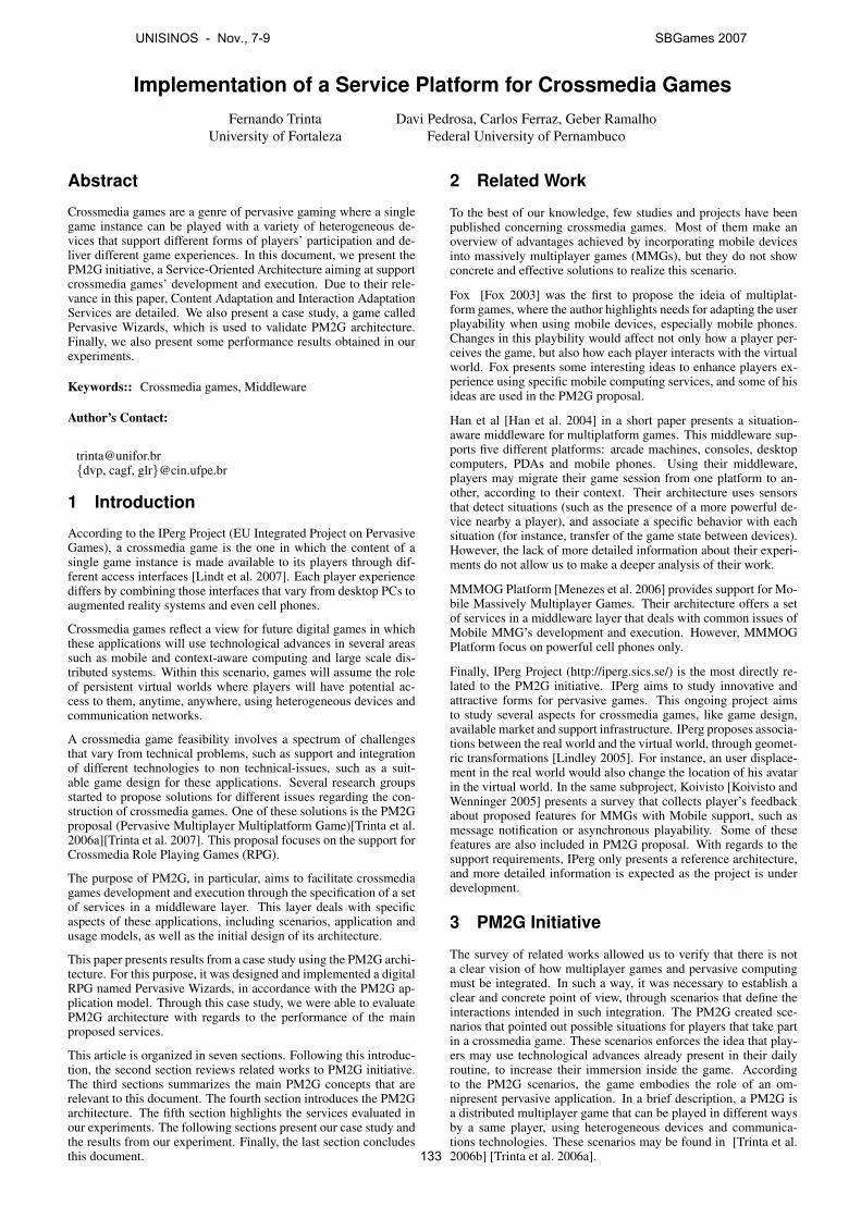
Implementation of a Service Platform for Crossmedia GamesFernando Trinta
University of FortalezaDavi Pedrosa, Carlos Ferraz, Geber Ramalho
Federal University of Pernambuco
Abstract
Crossmedia games are a genre of pervasive gaming where a singlegame instance can be played with a variety of heterogeneous de-vices that support different forms of players’ participation and de-liver different game experiences. In this document, we present thePM2G initiative, a Service-Oriented Architecture aiming at supportcrossmedia games’ development and execution. Due to their rele-vance in this paper, Content Adaptation and Interaction AdaptationServices are detailed. We also present a case study, a game calledPervasive Wizards, which is used to validate PM2G architecture.Finally, we also present some performance results obtained in ourexperiments.
Keywords:: Crossmedia games, Middleware
Author’s Contact:
[email protected]{dvp, cagf, glr}@cin.ufpe.br
1 Introduction
According to the IPerg Project (EU Integrated Project on PervasiveGames), a crossmedia game is the one in which the content of asingle game instance is made available to its players through dif-ferent access interfaces [Lindt et al. 2007]. Each player experiencediffers by combining those interfaces that vary from desktop PCs toaugmented reality systems and even cell phones.
Crossmedia games reflect a view for future digital games in whichthese applications will use technological advances in several areassuch as mobile and context-aware computing and large scale dis-tributed systems. Within this scenario, games will assume the roleof persistent virtual worlds where players will have potential ac-cess to them, anytime, anywhere, using heterogeneous devices andcommunication networks.
A crossmedia game feasibility involves a spectrum of challengesthat vary from technical problems, such as support and integrationof different technologies to non technical-issues, such as a suit-able game design for these applications. Several research groupsstarted to propose solutions for different issues regarding the con-struction of crossmedia games. One of these solutions is the PM2Gproposal (Pervasive Multiplayer Multiplatform Game)[Trinta et al.2006a][Trinta et al. 2007]. This proposal focuses on the support forCrossmedia Role Playing Games (RPG).
The purpose of PM2G, in particular, aims to facilitate crossmediagames development and execution through the specification of a setof services in a middleware layer. This layer deals with specificaspects of these applications, including scenarios, application andusage models, as well as the initial design of its architecture.
This paper presents results from a case study using the PM2G archi-tecture. For this purpose, it was designed and implemented a digitalRPG named Pervasive Wizards, in accordance with the PM2G ap-plication model. Through this case study, we were able to evaluatePM2G architecture with regards to the performance of the mainproposed services.
This article is organized in seven sections. Following this introduc-tion, the second section reviews related works to PM2G initiative.The third sections summarizes the main PM2G concepts that arerelevant to this document. The fourth section introduces the PM2Garchitecture. The fifth section highlights the services evaluated inour experiments. The following sections present our case study andthe results from our experiment. Finally, the last section concludesthis document.
2 Related Work
To the best of our knowledge, few studies and projects have beenpublished concerning crossmedia games. Most of them make anoverview of advantages achieved by incorporating mobile devicesinto massively multiplayer games (MMGs), but they do not showconcrete and effective solutions to realize this scenario.
Fox [Fox 2003] was the first to propose the ideia of multiplat-form games, where the author highlights needs for adapting the userplayability when using mobile devices, especially mobile phones.Changes in this playbility would affect not only how a player per-ceives the game, but also how each player interacts with the virtualworld. Fox presents some interesting ideas to enhance players ex-perience using specific mobile computing services, and some of hisideas are used in the PM2G proposal.
Han et al [Han et al. 2004] in a short paper presents a situation-aware middleware for multiplatform games. This middleware sup-ports five different platforms: arcade machines, consoles, desktopcomputers, PDAs and mobile phones. Using their middleware,players may migrate their game session from one platform to an-other, according to their context. Their architecture uses sensorsthat detect situations (such as the presence of a more powerful de-vice nearby a player), and associate a specific behavior with eachsituation (for instance, transfer of the game state between devices).However, the lack of more detailed information about their experi-ments do not allow us to make a deeper analysis of their work.
MMMOG Platform [Menezes et al. 2006] provides support for Mo-bile Massively Multiplayer Games. Their architecture offers a setof services in a middleware layer that deals with common issues ofMobile MMG’s development and execution. However, MMMOGPlatform focus on powerful cell phones only.
Finally, IPerg Project (http://iperg.sics.se/) is the most directly re-lated to the PM2G initiative. IPerg aims to study innovative andattractive forms for pervasive games. This ongoing project aimsto study several aspects for crossmedia games, like game design,available market and support infrastructure. IPerg proposes associa-tions between the real world and the virtual world, through geomet-ric transformations [Lindley 2005]. For instance, an user displace-ment in the real world would also change the location of his avatarin the virtual world. In the same subproject, Koivisto [Koivisto andWenninger 2005] presents a survey that collects player’s feedbackabout proposed features for MMGs with Mobile support, such asmessage notification or asynchronous playability. Some of thesefeatures are also included in PM2G proposal. With regards to thesupport requirements, IPerg only presents a reference architecture,and more detailed information is expected as the project is underdevelopment.
3 PM2G Initiative
The survey of related works allowed us to verify that there is nota clear vision of how multiplayer games and pervasive computingmust be integrated. In such a way, it was necessary to establish aclear and concrete point of view, through scenarios that define theinteractions intended in such integration. The PM2G created sce-narios that pointed out possible situations for players that take partin a crossmedia game. These scenarios enforces the idea that play-ers may use technological advances already present in their dailyroutine, to increase their immersion inside the game. Accordingto the PM2G scenarios, the game embodies the role of an om-nipresent pervasive application. In a brief description, a PM2G isa distributed multiplayer game that can be played in different waysby a same player, using heterogeneous devices and communica-tions technologies. These scenarios may be found in [Trinta et al.2006b] [Trinta et al. 2006a].
UNISINOS - Nov., 7-9 SBGames 2007
133
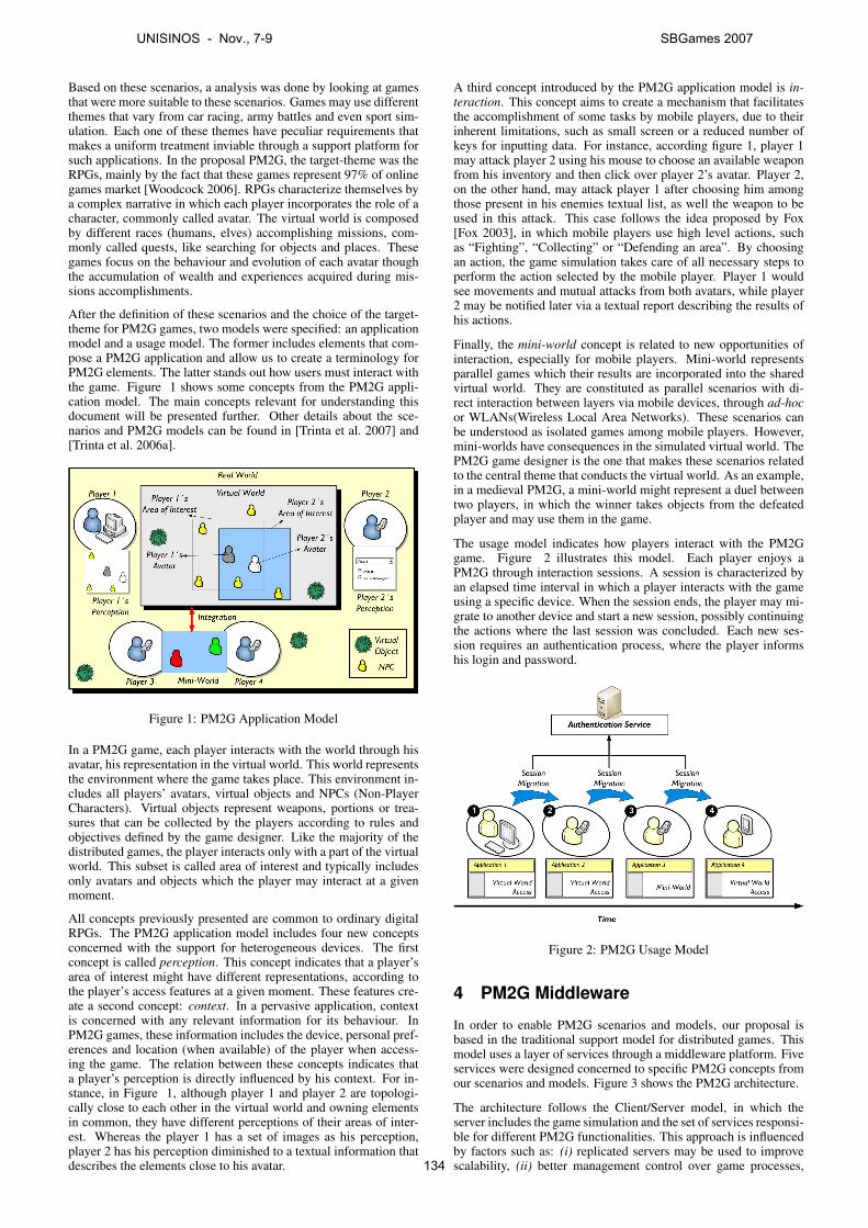
Based on these scenarios, a analysis was done by looking at gamesthat were more suitable to these scenarios. Games may use differentthemes that vary from car racing, army battles and even sport sim-ulation. Each one of these themes have peculiar requirements thatmakes a uniform treatment inviable through a support platform forsuch applications. In the proposal PM2G, the target-theme was theRPGs, mainly by the fact that these games represent 97% of onlinegames market [Woodcock 2006]. RPGs characterize themselves bya complex narrative in which each player incorporates the role of acharacter, commonly called avatar. The virtual world is composedby different races (humans, elves) accomplishing missions, com-monly called quests, like searching for objects and places. Thesegames focus on the behaviour and evolution of each avatar thoughthe accumulation of wealth and experiences acquired during mis-sions accomplishments.
After the definition of these scenarios and the choice of the target-theme for PM2G games, two models were specified: an applicationmodel and a usage model. The former includes elements that com-pose a PM2G application and allow us to create a terminology forPM2G elements. The latter stands out how users must interact withthe game. Figure 1 shows some concepts from the PM2G appli-cation model. The main concepts relevant for understanding thisdocument will be presented further. Other details about the sce-narios and PM2G models can be found in [Trinta et al. 2007] and[Trinta et al. 2006a].
Figure 1: PM2G Application Model
In a PM2G game, each player interacts with the world through hisavatar, his representation in the virtual world. This world representsthe environment where the game takes place. This environment in-cludes all players’ avatars, virtual objects and NPCs (Non-PlayerCharacters). Virtual objects represent weapons, portions or trea-sures that can be collected by the players according to rules andobjectives defined by the game designer. Like the majority of thedistributed games, the player interacts only with a part of the virtualworld. This subset is called area of interest and typically includesonly avatars and objects which the player may interact at a givenmoment.
All concepts previously presented are common to ordinary digitalRPGs. The PM2G application model includes four new conceptsconcerned with the support for heterogeneous devices. The firstconcept is called perception. This concept indicates that a player’sarea of interest might have different representations, according tothe player’s access features at a given moment. These features cre-ate a second concept: context. In a pervasive application, contextis concerned with any relevant information for its behaviour. InPM2G games, these information includes the device, personal pref-erences and location (when available) of the player when access-ing the game. The relation between these concepts indicates thata player’s perception is directly influenced by his context. For in-stance, in Figure 1, although player 1 and player 2 are topologi-cally close to each other in the virtual world and owning elementsin common, they have different perceptions of their areas of inter-est. Whereas the player 1 has a set of images as his perception,player 2 has his perception diminished to a textual information thatdescribes the elements close to his avatar.
A third concept introduced by the PM2G application model is in-teraction. This concept aims to create a mechanism that facilitatesthe accomplishment of some tasks by mobile players, due to theirinherent limitations, such as small screen or a reduced number ofkeys for inputting data. For instance, according figure 1, player 1may attack player 2 using his mouse to choose an available weaponfrom his inventory and then click over player 2’s avatar. Player 2,on the other hand, may attack player 1 after choosing him amongthose present in his enemies textual list, as well the weapon to beused in this attack. This case follows the idea proposed by Fox[Fox 2003], in which mobile players use high level actions, suchas “Fighting”, “Collecting” or “Defending an area”. By choosingan action, the game simulation takes care of all necessary steps toperform the action selected by the mobile player. Player 1 wouldsee movements and mutual attacks from both avatars, while player2 may be notified later via a textual report describing the results ofhis actions.
Finally, the mini-world concept is related to new opportunities ofinteraction, especially for mobile players. Mini-world representsparallel games which their results are incorporated into the sharedvirtual world. They are constituted as parallel scenarios with di-rect interaction between layers via mobile devices, through ad-hocor WLANs(Wireless Local Area Networks). These scenarios canbe understood as isolated games among mobile players. However,mini-worlds have consequences in the simulated virtual world. ThePM2G game designer is the one that makes these scenarios relatedto the central theme that conducts the virtual world. As an example,in a medieval PM2G, a mini-world might represent a duel betweentwo players, in which the winner takes objects from the defeatedplayer and may use them in the game.
The usage model indicates how players interact with the PM2Ggame. Figure 2 illustrates this model. Each player enjoys aPM2G through interaction sessions. A session is characterized byan elapsed time interval in which a player interacts with the gameusing a specific device. When the session ends, the player may mi-grate to another device and start a new session, possibly continuingthe actions where the last session was concluded. Each new ses-sion requires an authentication process, where the player informshis login and password.
Figure 2: PM2G Usage Model
4 PM2G Middleware
In order to enable PM2G scenarios and models, our proposal isbased in the traditional support model for distributed games. Thismodel uses a layer of services through a middleware platform. Fiveservices were designed concerned to specific PM2G concepts fromour scenarios and models. Figure 3 shows the PM2G architecture.
The architecture follows the Client/Server model, in which theserver includes the game simulation and the set of services responsi-ble for different PM2G functionalities. This approach is influencedby factors such as: (i) replicated servers may be used to improvescalability, (ii) better management control over game processes,
UNISINOS - Nov., 7-9 SBGames 2007
134

Figure 3: PM2G Architecture
(iii) higher cheating tolerance and (iv) easiness of implementation.
The PM2G architecture is divided in three main layers. The lowerlayer is referenced as the PM2G server and includes two frame-works: one responsible for the game simulation and another fordealing with the communication between players’ clients and thegame simulation. All the communication between players and thesimulated virtual world is done via events that are received by thecommunication framework and sent to the simulation framework.On the other hand, the simulation framework offers to clients andservices the current game state at a given moment. This state repre-sents the set of information about each player avatar and other gameelements (NPCs or objects). This set of information is then sent tothe player applications which update their graphichal interface inorder to visualize the game state.
The second layer presents the five PM2G services. The first oneis the Context Management Service that holds contextual informa-tion about players. This contextual information includes (i) thedevice being used, (ii) personal preferences and possibly (iii) thegeographic location of each player. This service has a central rolein PM2G solution by the fact that contextual information guides theinternal behavior of others components. Any interested service mayinquires the Context Management Service about any player context,when necessary.
This is the case of the Content Adaptation Service which is respon-sible for sending the current player game state, in accordance withhis current context. According to the application model, each playerinteracts only with his area of interest in the virtual world. The ser-vice adapts information about this area of interest in a more suitableformat to current player’s context. The results from these transfor-mations follow the concept of perception from the PM2G applica-tion model.
A third service is the Interaction Adaptation which aims to facilitatethe execution of tasks by mobile players. To achieve this objective,the service retrieves the available user’s actions based on the currentgame state and player’s context. These actions represent the high-level commands previously cited in the PM2G application model(Section 3). These commands are sent to the player that chooseswhich of them he wants to perform. In a reverse process, the servicereceives the action and transforms it in one or more conventionalcommands, which are sent to the communication framework, andlately to simulation framework for its execution in the virtual world.
Another PM2G service is the Messages Notification. This serviceaims to monitor the game simulation, searching for events that arerelevant to each player. When these events occur, the service usesplayer context information to send messages about these events.These messages utilize different communication technologies suchas SMS or e-mail, according player’s current context.
The last service is the Mini-worlds Integration. This service aims tosupport the mini-world concept from the PM2G application model.It has as main functions: (i) to allow the exchange of profile infor-mation between the virtual world and mini-worlds, such as weaponsou strength level; (ii) to allow that results from these mini-worldsto be integrated later and used in the virtual world.
Following the middleware approach, all PM2G services are placedabove existing layer services, related either with middleware plat-forms for pervasive computing as well as multiplayer games. Thisapproach indicates that the PM2G architecture aims to reuse theseservices, such as a Physical Positioning Service.
Finally, the last layer presents the PM2G client’s application. Thisapplication receives and sends information, either to the servicesas to the game as well, through an API (Application ProgrammingInterface).
Among all services described in the last section, two of them aredirectly related to this work. They are: the Content Adaptation Ser-vice and the Interaction Adaptation Service. These services guideplayer’s playability, the way each user plays the game. Given itsimportance in this work, the following subsections summarize theirfunctionalities. The reader may find more information about themin [Pedrosa et al. 2006].
4.1 Content Adaptation Service
In this service, the content adaptation process defines the concept ofadaptation strategy. A adaptation strategy is associated to each sup-ported device and determines possible transformations that must beperformed before any game information reachs the client applica-tion. Transformations procedures done by the Content AdaptationService are classified in two processing types: logical proceduresand presentation procedures. The former includes procedures thatmodify the contents of an area of interest, such as the amount ofobjects or their positions in the virtual world. The latter preparesthe data to be sent to the client application. Adaptation strategiesaims to avoid that mobile devices be responsible for any processingprocedure concerned with adapting data from the game server sim-ulation. Figure 4 presents the adaptation strategy concept using theUML (Unified Modelling Language) notation.
Figure 4: Class Diagram - Adaptation Strategy
According its definition, each LogicModule receives the player’sAreaOfInterest and Context. Based on this arguments, the Logic-Module creates a new AreaOfInterest with modified information,using the processAOI operation. Examples of logical proceduresare:
• Information Filtering: based on the device and on the pri-ority of each element of the area of interest, elements mightbe discharged and not sent to the player. This implies two ad-vantages: (i) reduction of network traffic, which might be im-portant for the players using some type of connection whichthe charge is done based on the amount of bytes tranfered; (ii)a smaller processing load and memory demanded from thedevice, considering that less objects will be processed by theclient application;
• Bi-dimensional Scale: it adjusts the objects’ positions in anarea of interest (bi-dimensional) based on the resolution of atarget device. By delegating this this to the service, the pro-cessing load in the device is decreased;
• Tiling: it adapts the objects’ positions of an area of inter-est (bi-dimensional) in order to be presented like tiles-based
UNISINOS - Nov., 7-9 SBGames 2007
135
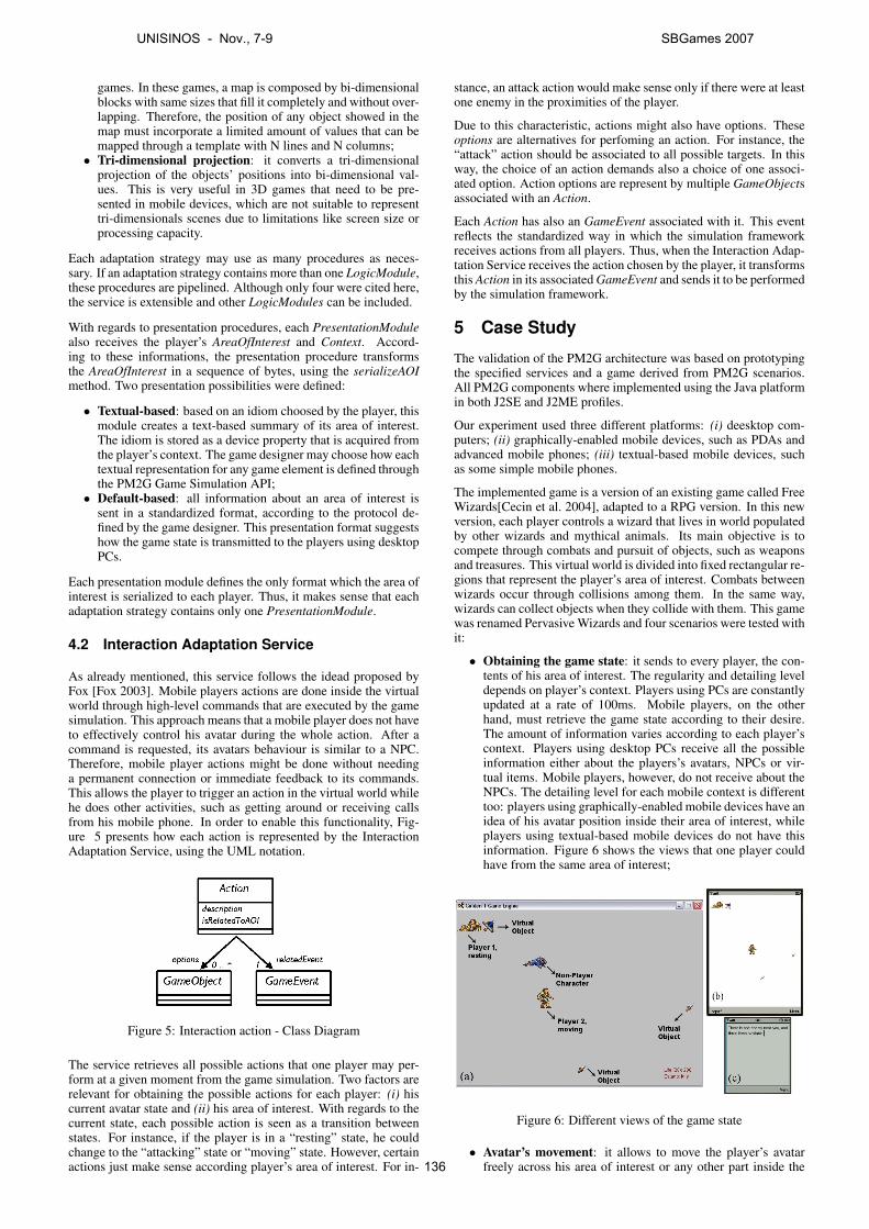
games. In these games, a map is composed by bi-dimensionalblocks with same sizes that fill it completely and without over-lapping. Therefore, the position of any object showed in themap must incorporate a limited amount of values that can bemapped through a template with N lines and N columns;
• Tri-dimensional projection: it converts a tri-dimensionalprojection of the objects’ positions into bi-dimensional val-ues. This is very useful in 3D games that need to be pre-sented in mobile devices, which are not suitable to representtri-dimensionals scenes due to limitations like screen size orprocessing capacity.
Each adaptation strategy may use as many procedures as neces-sary. If an adaptation strategy contains more than one LogicModule,these procedures are pipelined. Although only four were cited here,the service is extensible and other LogicModules can be included.
With regards to presentation procedures, each PresentationModulealso receives the player’s AreaOfInterest and Context. Accord-ing to these informations, the presentation procedure transformsthe AreaOfInterest in a sequence of bytes, using the serializeAOImethod. Two presentation possibilities were defined:
• Textual-based: based on an idiom choosed by the player, thismodule creates a text-based summary of its area of interest.The idiom is stored as a device property that is acquired fromthe player’s context. The game designer may choose how eachtextual representation for any game element is defined throughthe PM2G Game Simulation API;
• Default-based: all information about an area of interest issent in a standardized format, according to the protocol de-fined by the game designer. This presentation format suggestshow the game state is transmitted to the players using desktopPCs.
Each presentation module defines the only format which the area ofinterest is serialized to each player. Thus, it makes sense that eachadaptation strategy contains only one PresentationModule.
4.2 Interaction Adaptation Service
As already mentioned, this service follows the idead proposed byFox [Fox 2003]. Mobile players actions are done inside the virtualworld through high-level commands that are executed by the gamesimulation. This approach means that a mobile player does not haveto effectively control his avatar during the whole action. After acommand is requested, its avatars behaviour is similar to a NPC.Therefore, mobile player actions might be done without needinga permanent connection or immediate feedback to its commands.This allows the player to trigger an action in the virtual world whilehe does other activities, such as getting around or receiving callsfrom his mobile phone. In order to enable this functionality, Fig-ure 5 presents how each action is represented by the InteractionAdaptation Service, using the UML notation.
Figure 5: Interaction action - Class Diagram
The service retrieves all possible actions that one player may per-form at a given moment from the game simulation. Two factors arerelevant for obtaining the possible actions for each player: (i) hiscurrent avatar state and (ii) his area of interest. With regards to thecurrent state, each possible action is seen as a transition betweenstates. For instance, if the player is in a “resting” state, he couldchange to the “attacking” state or “moving” state. However, certainactions just make sense according player’s area of interest. For in-
stance, an attack action would make sense only if there were at leastone enemy in the proximities of the player.
Due to this characteristic, actions might also have options. Theseoptions are alternatives for perfoming an action. For instance, the“attack” action should be associated to all possible targets. In thisway, the choice of an action demands also a choice of one associ-ated option. Action options are represent by multiple GameObjectsassociated with an Action.
Each Action has also an GameEvent associated with it. This eventreflects the standardized way in which the simulation frameworkreceives actions from all players. Thus, when the Interaction Adap-tation Service receives the action chosen by the player, it transformsthis Action in its associated GameEvent and sends it to be performedby the simulation framework.
5 Case Study
The validation of the PM2G architecture was based on prototypingthe specified services and a game derived from PM2G scenarios.All PM2G components where implemented using the Java platformin both J2SE and J2ME profiles.
Our experiment used three different platforms: (i) deesktop com-puters; (ii) graphically-enabled mobile devices, such as PDAs andadvanced mobile phones; (iii) textual-based mobile devices, suchas some simple mobile phones.
The implemented game is a version of an existing game called FreeWizards[Cecin et al. 2004], adapted to a RPG version. In this newversion, each player controls a wizard that lives in world populatedby other wizards and mythical animals. Its main objective is tocompete through combats and pursuit of objects, such as weaponsand treasures. This virtual world is divided into fixed rectangular re-gions that represent the player’s area of interest. Combats betweenwizards occur through collisions among them. In the same way,wizards can collect objects when they collide with them. This gamewas renamed Pervasive Wizards and four scenarios were tested withit:
• Obtaining the game state: it sends to every player, the con-tents of his area of interest. The regularity and detailing leveldepends on player’s context. Players using PCs are constantlyupdated at a rate of 100ms. Mobile players, on the otherhand, must retrieve the game state according to their desire.The amount of information varies according to each player’scontext. Players using desktop PCs receive all the possibleinformation either about the players’s avatars, NPCs or vir-tual items. Mobile players, however, do not receive about theNPCs. The detailing level for each mobile context is differenttoo: players using graphically-enabled mobile devices have anidea of his avatar position inside their area of interest, whileplayers using textual-based mobile devices do not have thisinformation. Figure 6 shows the views that one player couldhave from the same area of interest;
Figure 6: Different views of the game state
• Avatar’s movement: it allows to move the player’s avatarfreely across his area of interest or any other part inside the
UNISINOS - Nov., 7-9 SBGames 2007
136
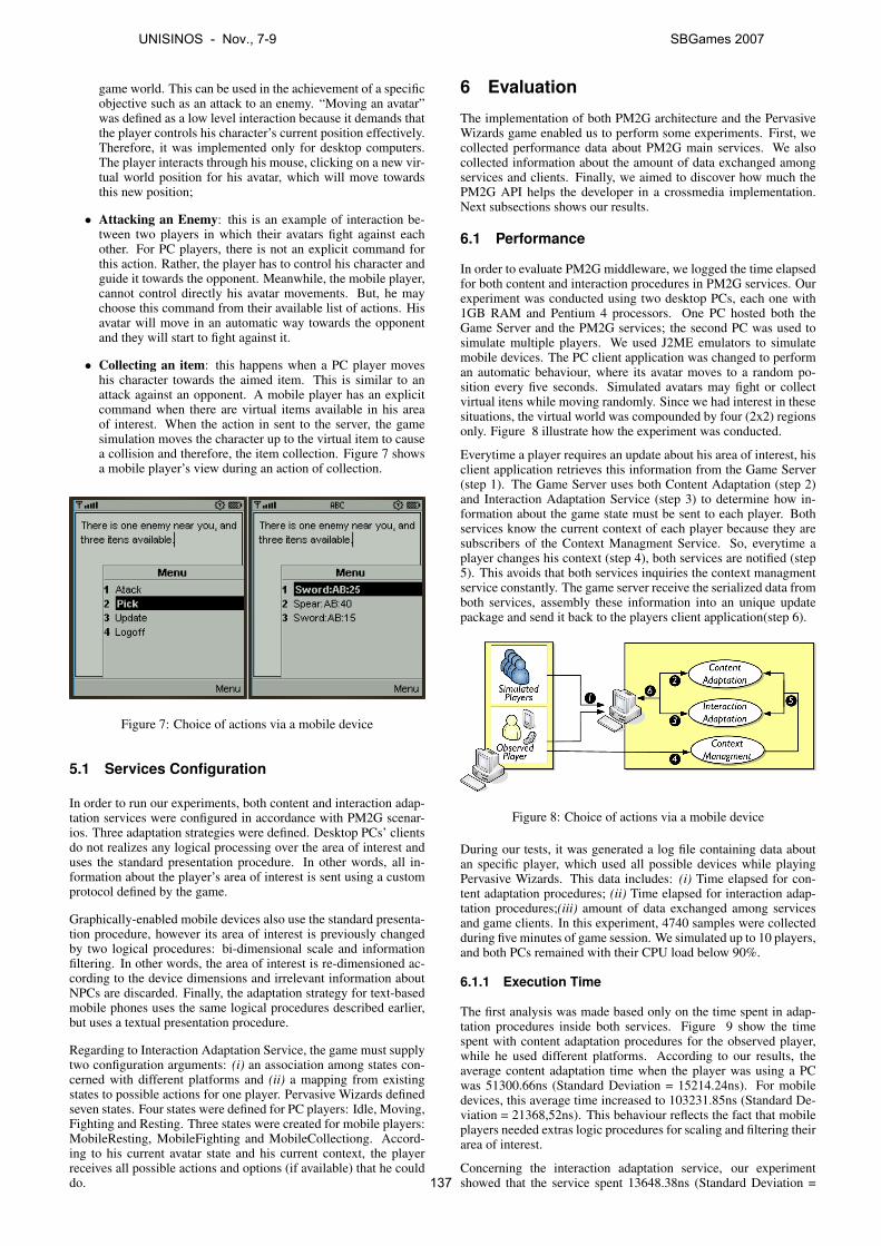
game world. This can be used in the achievement of a specificobjective such as an attack to an enemy. “Moving an avatar”was defined as a low level interaction because it demands thatthe player controls his character’s current position effectively.Therefore, it was implemented only for desktop computers.The player interacts through his mouse, clicking on a new vir-tual world position for his avatar, which will move towardsthis new position;
• Attacking an Enemy: this is an example of interaction be-tween two players in which their avatars fight against eachother. For PC players, there is not an explicit command forthis action. Rather, the player has to control his character andguide it towards the opponent. Meanwhile, the mobile player,cannot control directly his avatar movements. But, he maychoose this command from their available list of actions. Hisavatar will move in an automatic way towards the opponentand they will start to fight against it.
• Collecting an item: this happens when a PC player moveshis character towards the aimed item. This is similar to anattack against an opponent. A mobile player has an explicitcommand when there are virtual items available in his areaof interest. When the action in sent to the server, the gamesimulation moves the character up to the virtual item to causea collision and therefore, the item collection. Figure 7 showsa mobile player’s view during an action of collection.
Figure 7: Choice of actions via a mobile device
5.1 Services Configuration
In order to run our experiments, both content and interaction adap-tation services were configured in accordance with PM2G scenar-ios. Three adaptation strategies were defined. Desktop PCs’ clientsdo not realizes any logical processing over the area of interest anduses the standard presentation procedure. In other words, all in-formation about the player’s area of interest is sent using a customprotocol defined by the game.
Graphically-enabled mobile devices also use the standard presenta-tion procedure, however its area of interest is previously changedby two logical procedures: bi-dimensional scale and informationfiltering. In other words, the area of interest is re-dimensioned ac-cording to the device dimensions and irrelevant information aboutNPCs are discarded. Finally, the adaptation strategy for text-basedmobile phones uses the same logical procedures described earlier,but uses a textual presentation procedure.
Regarding to Interaction Adaptation Service, the game must supplytwo configuration arguments: (i) an association among states con-cerned with different platforms and (ii) a mapping from existingstates to possible actions for one player. Pervasive Wizards definedseven states. Four states were defined for PC players: Idle, Moving,Fighting and Resting. Three states were created for mobile players:MobileResting, MobileFighting and MobileCollectiong. Accord-ing to his current avatar state and his current context, the playerreceives all possible actions and options (if available) that he coulddo.
6 Evaluation
The implementation of both PM2G architecture and the PervasiveWizards game enabled us to perform some experiments. First, wecollected performance data about PM2G main services. We alsocollected information about the amount of data exchanged amongservices and clients. Finally, we aimed to discover how much thePM2G API helps the developer in a crossmedia implementation.Next subsections shows our results.
6.1 Performance
In order to evaluate PM2G middleware, we logged the time elapsedfor both content and interaction procedures in PM2G services. Ourexperiment was conducted using two desktop PCs, each one with1GB RAM and Pentium 4 processors. One PC hosted both theGame Server and the PM2G services; the second PC was used tosimulate multiple players. We used J2ME emulators to simulatemobile devices. The PC client application was changed to performan automatic behaviour, where its avatar moves to a random po-sition every five seconds. Simulated avatars may fight or collectvirtual itens while moving randomly. Since we had interest in thesesituations, the virtual world was compounded by four (2x2) regionsonly. Figure 8 illustrate how the experiment was conducted.
Everytime a player requires an update about his area of interest, hisclient application retrieves this information from the Game Server(step 1). The Game Server uses both Content Adaptation (step 2)and Interaction Adaptation Service (step 3) to determine how in-formation about the game state must be sent to each player. Bothservices know the current context of each player because they aresubscribers of the Context Managment Service. So, everytime aplayer changes his context (step 4), both services are notified (step5). This avoids that both services inquiries the context managmentservice constantly. The game server receive the serialized data fromboth services, assembly these information into an unique updatepackage and send it back to the players client application(step 6).
Figure 8: Choice of actions via a mobile device
During our tests, it was generated a log file containing data aboutan specific player, which used all possible devices while playingPervasive Wizards. This data includes: (i) Time elapsed for con-tent adaptation procedures; (ii) Time elapsed for interaction adap-tation procedures;(iii) amount of data exchanged among servicesand game clients. In this experiment, 4740 samples were collectedduring five minutes of game session. We simulated up to 10 players,and both PCs remained with their CPU load below 90%.
6.1.1 Execution Time
The first analysis was made based only on the time spent in adap-tation procedures inside both services. Figure 9 show the timespent with content adaptation procedures for the observed player,while he used different platforms. According to our results, theaverage content adaptation time when the player was using a PCwas 51300.66ns (Standard Deviation = 15214.24ns). For mobiledevices, this average time increased to 103231.85ns (Standard De-viation = 21368,52ns). This behaviour reflects the fact that mobileplayers needed extras logic procedures for scaling and filtering theirarea of interest.
Concerning the interaction adaptation service, our experimentshowed that the service spent 13648.38ns (Standard Deviation =
UNISINOS - Nov., 7-9 SBGames 2007
137
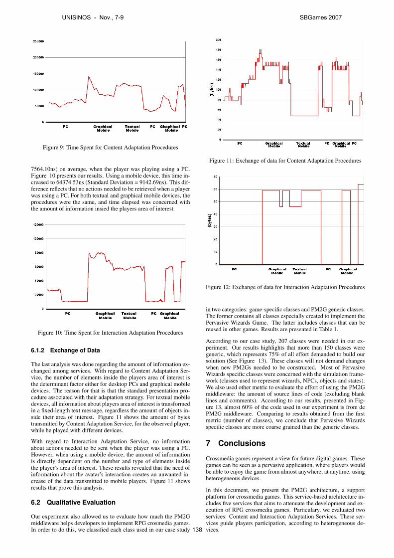
Figure 9: Time Spent for Content Adaptation Procedures
7564.10ns) on average, when the player was playing using a PC.Figure 10 presents our results. Using a mobile device, this time in-creased to 64374.53ns (Standard Deviation = 9142.69ns). This dif-ference reflects that no actions needed to be retrieved when a playerwas using a PC. For both textual and graphical mobile devices, theprocedures were the same, and time elapsed was concerned withthe amount of information insied the players area of interest.
Figure 10: Time Spent for Interaction Adaptation Procedures
6.1.2 Exchange of Data
The last analysis was done regarding the amount of information ex-changed among services. With regard to Content Adaptation Ser-vice, the number of elements inside the players area of interest isthe determinant factor either for desktop PCs and graphical mobiledevices. The reason for that is that the standard presentation pro-cedure associated with their adaptation strategy. For textual mobiledevices, all information about players area of interest is transformedin a fixed-length text message, regardless the amount of objects in-side their area of interest. Figure 11 shows the amount of bytestransmitted by Content Adaptation Service, for the observed player,while he played with different devices.
With regard to Interaction Adaptation Service, no informationabout actions needed to be sent when the player was using a PC.However, when using a mobile device, the amount of informationis directly dependent on the number and type of elements insidethe player’s area of interest. These results revealed that the need ofinformation about the avatar’s interaction creates an unwanted in-crease of the data transmitted to mobile players. Figure 11 showsresults that prove this analysis.
6.2 Qualitative Evaluation
Our experiment also allowed us to evaluate how much the PM2Gmiddleware helps developers to implement RPG crosmedia games.In order to do this, we classified each class used in our case study
Figure 11: Exchange of data for Content Adaptation Procedures
Figure 12: Exchange of data for Interaction Adaptation Procedures
in two categories: game-specific classes and PM2G generic classes.The former contains all classes especially created to implement thePervasive Wizards Game. The latter includes classes that can bereused in other games. Results are presented in Table 1.
According to our case study, 207 classes were needed in our ex-periment. Our results highlights that more than 150 classes weregeneric, which represents 75% of all effort demanded to build oursolution (See Figure 13). These classes will not demand changeswhen new PM2Gs needed to be constructed. Most of PervasiveWizards specific classes were concerned with the simulation frame-work (classes used to represent wizards, NPCs, objects and states).We also used other metric to evaluate the effort of using the PM2Gmiddleware: the amount of source lines of code (excluding blanklines and comments). According to our results, presented in Fig-ure 13, almost 60% of the code used in our experiment is from dePM2G middleware. Comparing to results obtained from the firstmetric (number of classes), we conclude that Pervasive Wizardsspecific classes are more coarse grained than the generic classes.
7 Conclusions
Crossmedia games represent a view for future digital games. Thesegames can be seen as a pervasive application, where players wouldbe able to enjoy the game from almost anywhere, at anytime, usingheterogeneous devices.
In this document, we present the PM2G architecture, a supportplatform for crossmedia games. This service-based architecture in-cludes five services that aims to attenuate the development and ex-ecution of RPG crossmedia games. Particulary, we evaluated twoservices: Content and Interaction Adaptation Services. These ser-vices guide players participation, according to heterogeneous de-vices.
UNISINOS - Nov., 7-9 SBGames 2007
138
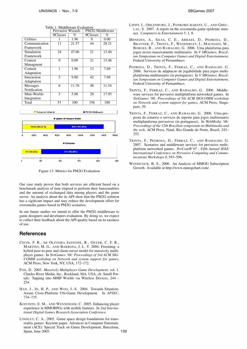
Table 1: Middleware EvaluationPervasive Wizards PM2G Middleware#Classes % #Classes %
Utilities 1 1.96 0 0.00CommunicationFramework
11 21.57 44 28.21
SimulationFramework
24 47.06 21 13.46
ContextManagment
0 0.00 21 13.46
ContentAdaptation
1 1.96 12 7.69
InteractionAdaptation
5 9.80 42 7.69
MessagesNotification
6 11.76 48 11.54
Mini-WorldsIntegration
3 5.88 28 17.95
Total 51 100 156 100
Figure 13: Metrics for PM2G Evaluation
Our case study proves that both services are efficient based on abenchmark analysis of time elapsed to perform their funcionalitiesand the amount of exchanged data among players and the gameserver. An analysis about the its API show that the PM2G solutionhas a sigificant impact and may reduce the development effort forcrossmedia games based in PM2G scenarios.
In our future studies we intend to offer the PM2G middleware togame designers and developers evaluation. By doing so, we expectto collect their feedback about the API quality based on its easinessof use.
References
CECIN, F. R., DE OLIVEIRA JANNONE, R., GEYER, C. F. R.,MARTINS, M. G., AND BARBOSA, J. L. V. 2004. Freemmg: ahybrid peer-to-peer and client-server model for massively multi-player games. In NetGames ’04: Proceedings of 3rd ACM SIG-COMM workshop on Network and system support for games,ACM Press, New York, NY, USA, 172–172.
FOX, D. 2003. Massively Multiplayer Game Development, vol. 1.Charles River Media, Inc., Rockland, MA, USA, ch. Small Por-tals: Tapping into MMP Worlds via Wireless Devices, 244 –254.
HAN, J., IN, H. P., AND WOO, J.-S. 2004. Towards Situation-Aware Cross-Platform Ubi-Game Development. In APSEC,734–735.
KOIVISTO, E. M., AND WENNINGER, C. 2005. Enhancing playerexperience in MMORPGs with mobile features. In 2nd Interna-tional Digital Games Research Association Conference.
LINDLEY, C. A., 2005. Game space design foundations for trans-reality games: Keynote paper. Advances in Computer Entertain-ment (ACE): Special Track on Game Development, Barcelona,Spain, June 2005.
LINDT, I., OHLENBURG, J., PANKOKE-BABATZ, U., AND GHEL-LAL, S. 2007. A report on the crossmedia game epidemic men-ace. Computers in Entertainment 5, 1, 8.
MENEZES, A., SILVA, C. E., ARRAES, D., PEDROSA, D.,BRAYNER, F., TRINTA, F., WANDERLEY, I., MACHADO, M.,BORGES, R., AND RAMALHO, G. 2006. Uma plataforma parajogos mveis massivamente multiusurio. In V SBGames, Brazil-ian Symposium on Computer Games and Digital Entertainment,Federal University of Pernambuco.
PEDROSA, D., TRINTA, F., FERRAZ, C., AND RAMALHO, G.2006. Servicos de adaptacao de jogabilidade para jogos multi-plataforma multiusuario (in portuguese). In V SBGames, Brazil-ian Symposium on Computer Games and Digital Entertainment,Federal University of Pernambuco.
TRINTA, F., FERRAZ, C., AND RAMALHO, G. 2006. Middle-ware services for pervasive multiplatform networked games. InNetGames ’06: Proceedings of 5th ACM SIGCOMM workshopon Network and system support for games, ACM Press, Singa-pore, 39.
TRINTA, F., FERRAZ, C., AND RAMALHO, G. 2006. Uma pro-posta de cenarios e servicos de suporte para jogos multiusuariomultiplataforma pervasivos (in portuguese). In WebMedia ’06:Proceedings of the 12th Brazilian symposium on Multimedia andthe web, ACM Press, Natal, Rio Grande do Norte, Brazil, 243–252.
TRINTA, F., PEDROSA, D., FERRAZ, C., AND RAMALHO, G.2007. Scenarios and middleware services for pervasive multi-platform networked games. PerComW’07 - Fifth Annual IEEEInternational Conference on Pervasive Computing and Commu-nications Workshops 0, 593–596.
WOODCOCK, B. S., 2006. An Analysis of MMOG SubscriptionGrowth. Available at http://www.mmogchart.com/.
UNISINOS - Nov., 7-9 SBGames 2007
139
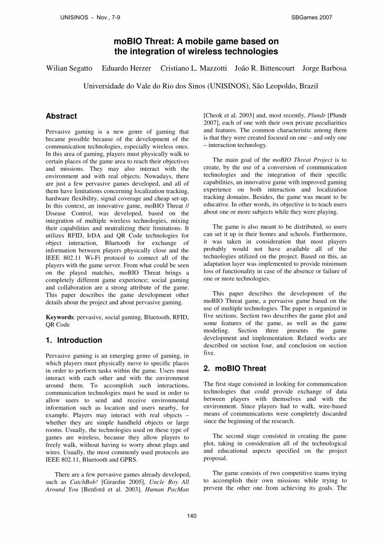
moBIO Threat: A mobile game based on the integration of wireless technologies
Wilian Segatto Eduardo Herzer Cristiano L. Mazzotti João R. Bittencourt Jorge Barbosa
Universidade do Vale do Rio dos Sinos (UNISINOS), São Leopoldo, Brazil
Abstract Pervasive gaming is a new genre of gaming that became possible because of the development of the communication technologies, especially wireless ones. In this area of gaming, players must physically walk to certain places of the game area to reach their objectives and missions. They may also interact with the environment and with real objects. Nowadays, there are just a few pervasive games developed, and all of them have limitations concerning localization tracking, hardware flexibility, signal coverage and cheap set-up. In this context, an innovative game, moBIO Threat // Disease Control, was developed, based on the integration of multiple wireless technologies, mixing their capabilities and neutralizing their limitations. It utilizes RFID, IrDA and QR Code technologies for object interaction, Bluetooth for exchange of information between players physically close and the IEEE 802.11 Wi-Fi protocol to connect all of the players with the game server. From what could be seen on the played matches, moBIO Threat brings a completely different game experience; social gaming and collaboration are a strong attribute of the game. This paper describes the game development other details about the project and about pervasive gaming. Keywords: pervasive, social gaming, Bluetooth, RFID, QR Code 1. Introduction
Pervasive gaming is an emerging genre of gaming, in which players must physically move to specific places in order to perform tasks within the game. Users must interact with each other and with the environment around them. To accomplish such interactions, communication technologies must be used in order to allow users to send and receive environmental information such as location and users nearby, for example. Players may interact with real objects – whether they are simple handheld objects or large rooms. Usually, the technologies used on these type of games are wireless, because they allow players to freely walk, without having to worry about plugs and wires. Usually, the most commonly used protocols are IEEE 802.11, Bluetooth and GPRS.
There are a few pervasive games already developed,
such as CatchBob! [Girardin 2005], Uncle Roy All
Around You [Benford et al. 2003], Human PacMan
[Cheok et al. 2003] and, most recently, Plundr [Plundr 2007], each of one with their own private peculiarities and features. The common characteristic among them is that they were created focused on one – and only one – interaction technology.
The main goal of the moBIO Threat Project is to
create, by the use of a conversion of communication technologies and the integration of their specific capabilities, an innovative game with improved gaming experience on both interaction and localization tracking domains. Besides, the game was meant to be educative. In other words, its objective is to teach users about one or more subjects while they were playing.
The game is also meant to be distributed, so users
can set it up in their homes and schools. Furthermore, it was taken in consideration that most players probably would not have available all of the technologies utilized on the project. Based on this, an adaptation layer was implemented to provide minimum loss of functionality in case of the absence or failure of one or more technologies.
This paper describes the development of the
moBIO Threat game, a pervasive game based on the use of multiple technologies. The paper is organized in five sections. Section two describes the game plot and some features of the game, as well as the game modeling. Section three presents the game development and implementation. Related works are described on section four, and conclusion on section five.
2. moBIO Threat The first stage consisted in looking for communication technologies that could provide exchange of data between players with themselves and with the environment. Since players had to walk, wire-based means of communications were completely discarded since the beginning of the research.
The second stage consisted in creating the game
plot, taking in consideration all of the technological and educational aspects specified on the project proposal.
The game consists of two competitive teams trying
to accomplish their own missions while trying to prevent the other one from achieving its goals. The
UNISINOS - Nov., 7-9 SBGames 2007
140
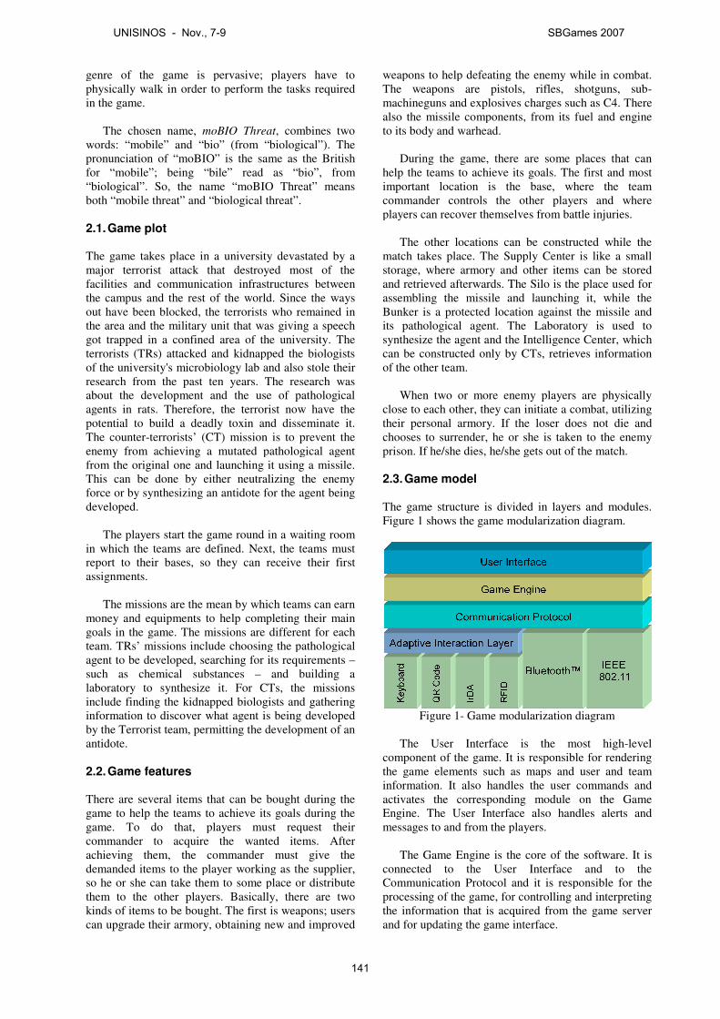
genre of the game is pervasive; players have to physically walk in order to perform the tasks required in the game.
The chosen name, moBIO Threat
words: “mobile” and “bio” (from “biological”). The pronunciation of “moBIO” is the same as the British for “mobile”; being “bile” read as “bio”, from “biological”. So, the name “moBIO Threat” means both “mobile threat” and “biological threat”.
2.1. Game plot The game takes place in a university devastated by a major terrorist attack that destroyed most of the facilities and communication infrastructures the campus and the rest of the world. Since the ways out have been blocked, the terrorists the area and the military unit that was giving a speech got trapped in a confined area of the university.terrorists (TRs) attacked and kidnapped the biologists of the university's microbiology lab research from the past ten years. about the development and the use of pathological agents in rats. Therefore, the terrorist now have the potential to build a deadly toxin and disseminateThe counter-terrorists’ (CT) mission is to prevent the enemy from achieving a mutated pathological agent from the original one and launching it using a missile. This can be done by either neutralizing the enemy force or by synthesizing an antidote for the agent being developed.
The players start the game round in a wai
in which the teams are defined. Nextreport to their bases, so they can receive assignments.
The missions are the mean by which teams can earn
money and equipments to help completing their main goals in the game. The missions are different for each team. TRs’ missions include choosing the pathological agent to be developed, searching for its requisuch as chemical substances –laboratory to synthesize it. For CTs, theinclude finding the kidnapped biologists and gathering information to discover what agent is being developed by the Terrorist team, permitting the devantidote.
2.2. Game features There are several items that can be bought during the game to help the teams to achieve its goals game. To do that, players must request their commander to acquire the wanted items. After achieving them, the commander demanded items to the player working as so he or she can take them to some place or distribute them to the other players. Basically, there are two kinds of items to be bought. The first is weapons; users can upgrade their armory, obtaining new and
genre of the game is pervasive; players have to physically walk in order to perform the tasks required
moBIO Threat, combines two words: “mobile” and “bio” (from “biological”). The pronunciation of “moBIO” is the same as the British for “mobile”; being “bile” read as “bio”, from “biological”. So, the name “moBIO Threat” means both “mobile threat” and “biological threat”.
in a university devastated by a major terrorist attack that destroyed most of the facilities and communication infrastructures between
st of the world. Since the ways blocked, the terrorists who remained in
the area and the military unit that was giving a speech got trapped in a confined area of the university. The
attacked and kidnapped the biologists and also stole their The research was
about the development and the use of pathological agents in rats. Therefore, the terrorist now have the potential to build a deadly toxin and disseminate it.
mission is to prevent the mutated pathological agent
and launching it using a missile. This can be done by either neutralizing the enemy force or by synthesizing an antidote for the agent being
The players start the game round in a waiting room s are defined. Next, the teams must
y can receive their first
The missions are the mean by which teams can earn money and equipments to help completing their main goals in the game. The missions are different for each team. TRs’ missions include choosing the pathological agent to be developed, searching for its requirements –
– and building a For CTs, the missions
include finding the kidnapped biologists and gathering information to discover what agent is being developed
the development of an
There are several items that can be bought during the its goals during the
players must request their wanted items. After
the commander must give the to the player working as the supplier,
can take them to some place or distribute Basically, there are two
kinds of items to be bought. The first is weapons; users , obtaining new and improved
weapons to help defeating the enemy The weapons are pistols, rifles, shotguns, submachineguns and explosives charges such as C4.also the missile componentsto its body and warhead.
During the game, there are some places that can
help the teams to achieve its goals. The first and most important location is the base, where the team commander controls the other players and where players can recover themselves from
The other locations can be constructed while the
match takes place. The Supply Center is like a small storage, where armory and other items can be stored and retrieved afterwards. The Silo is the place used for assembling the missile and Bunker is a protected location against the missile and its pathological agent. The Laboratory is used to synthesize the agent and the Intelligence Center, can be constructed only by CTs, retrieves information of the other team.
When two or more enemy players are physically
close to each other, they can their personal armory. If the lchooses to surrender, he or she is taken to the enemy prison. If he/she dies, he/she gets out
2.3. Game model
The game structure is divided in layers and modules. Figure 1 shows the game modularization diagram.
Figure 1- Game modularization diagram The User Interface is the most high
component of the game. It is responsible for rendering the game elements such as maps and user and team information. It also handles the user commands and activates the corresponding module on the Game Engine. The User Interface also handles alerts and messages to and from the players.
The Game Engine is the core of the software. It
connected to the User Interface and Communication Protocol and it is responsible for the processing of the game, for controlling and interpreting the information that is acquired from the game server and for updating the game interface.
weapons to help defeating the enemy while in combat. The weapons are pistols, rifles, shotguns, sub-machineguns and explosives charges such as C4. There also the missile components, from its fuel and engine
During the game, there are some places that can help the teams to achieve its goals. The first and most important location is the base, where the team commander controls the other players and where players can recover themselves from battle injuries.
The other locations can be constructed while the . The Supply Center is like a small
storage, where armory and other items can be stored and retrieved afterwards. The Silo is the place used for assembling the missile and launching it, while the Bunker is a protected location against the missile and its pathological agent. The Laboratory is used to synthesize the agent and the Intelligence Center, which
constructed only by CTs, retrieves information
When two or more enemy players are physically initiate a combat, utilizing
their personal armory. If the loser does not die and chooses to surrender, he or she is taken to the enemy
she gets out of the match.
is divided in layers and modules. shows the game modularization diagram.
Game modularization diagram
The User Interface is the most high-level s responsible for rendering
the game elements such as maps and user and team information. It also handles the user commands and activates the corresponding module on the Game Engine. The User Interface also handles alerts and
he players.
is the core of the software. It is he User Interface and to the
Communication Protocol and it is responsible for the controlling and interpreting
the information that is acquired from the game server updating the game interface.
UNISINOS - Nov., 7-9 SBGames 2007
141
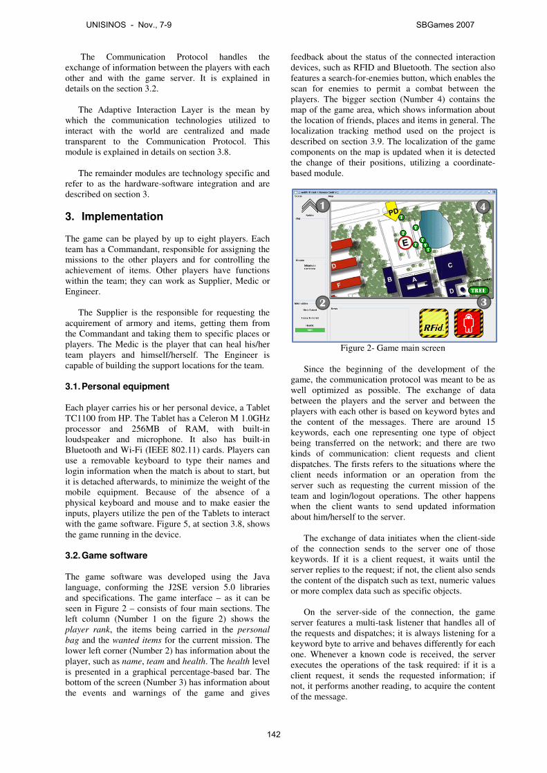
The Communication Protocol handles the exchange of information between the players with each other and with the game server. It is explained in details on the section 3.2.
The Adaptive Interaction Layer is the mean by
which the communication technologies utilized to interact with the world are centralized and made transparent to the Communication Protocol. This module is explained in details on section 3.8.
The remainder modules are technology specific and
refer to as the hardware-software integration and are described on section 3.
3. Implementation The game can be played by up to eight players. Each team has a Commandant, responsible for assigning the missions to the other players and for controlling the achievement of items. Other players have functions within the team; they can work as Supplier, Medic or Engineer.
The Supplier is the responsible for requesting the
acquirement of armory and items, getting them from the Commandant and taking them to specific places or players. The Medic is the player that can heal his/her team players and himself/herself. The Engineer is capable of building the support locations for the team.
3.1. Personal equipment Each player carries his or her personal device, a Tablet TC1100 from HP. The Tablet has a Celeron M 1.0GHz processor and 256MB of RAM, with built-in loudspeaker and microphone. It also has built-in Bluetooth and Wi-Fi (IEEE 802.11) cards. Players can use a removable keyboard to type their names and login information when the match is about to start, but it is detached afterwards, to minimize the weight of the mobile equipment. Because of the absence of a physical keyboard and mouse and to make easier the inputs, players utilize the pen of the Tablets to interact with the game software. Figure 5, at section 3.8, shows the game running in the device. 3.2. Game software The game software was developed using the Java language, conforming the J2SE version 5.0 libraries and specifications. The game interface – as it can be seen in Figure 2 – consists of four main sections. The left column (Number 1 on the figure 2) shows the player rank, the items being carried in the personal
bag and the wanted items for the current mission. The lower left corner (Number 2) has information about the player, such as name, team and health. The health level is presented in a graphical percentage-based bar. The bottom of the screen (Number 3) has information about the events and warnings of the game and gives
feedback about the status of the connected interaction devices, such as RFID and Bluetooth. The section also features a search-for-enemies button, which enables the scan for enemies to permit a combat between the players. The bigger section (Number 4) contains the map of the game area, which shows information about the location of friends, places and items in general. The localization tracking method used on the project is described on section 3.9. The localization of the game components on the map is updated when it is detected the change of their positions, utilizing a coordinate-based module.
Figure 2- Game main screen
Since the beginning of the development of the
game, the communication protocol was meant to be as well optimized as possible. The exchange of data between the players and the server and between the players with each other is based on keyword bytes and the content of the messages. There are around 15 keywords, each one representing one type of object being transferred on the network; and there are two kinds of communication: client requests and client dispatches. The firsts refers to the situations where the client needs information or an operation from the server such as requesting the current mission of the team and login/logout operations. The other happens when the client wants to send updated information about him/herself to the server.
The exchange of data initiates when the client-side
of the connection sends to the server one of those keywords. If it is a client request, it waits until the server replies to the request; if not, the client also sends the content of the dispatch such as text, numeric values or more complex data such as specific objects.
On the server-side of the connection, the game
server features a multi-task listener that handles all of the requests and dispatches; it is always listening for a keyword byte to arrive and behaves differently for each one. Whenever a known code is received, the server executes the operations of the task required: if it is a client request, it sends the requested information; if not, it performs another reading, to acquire the content of the message.
UNISINOS - Nov., 7-9 SBGames 2007
142
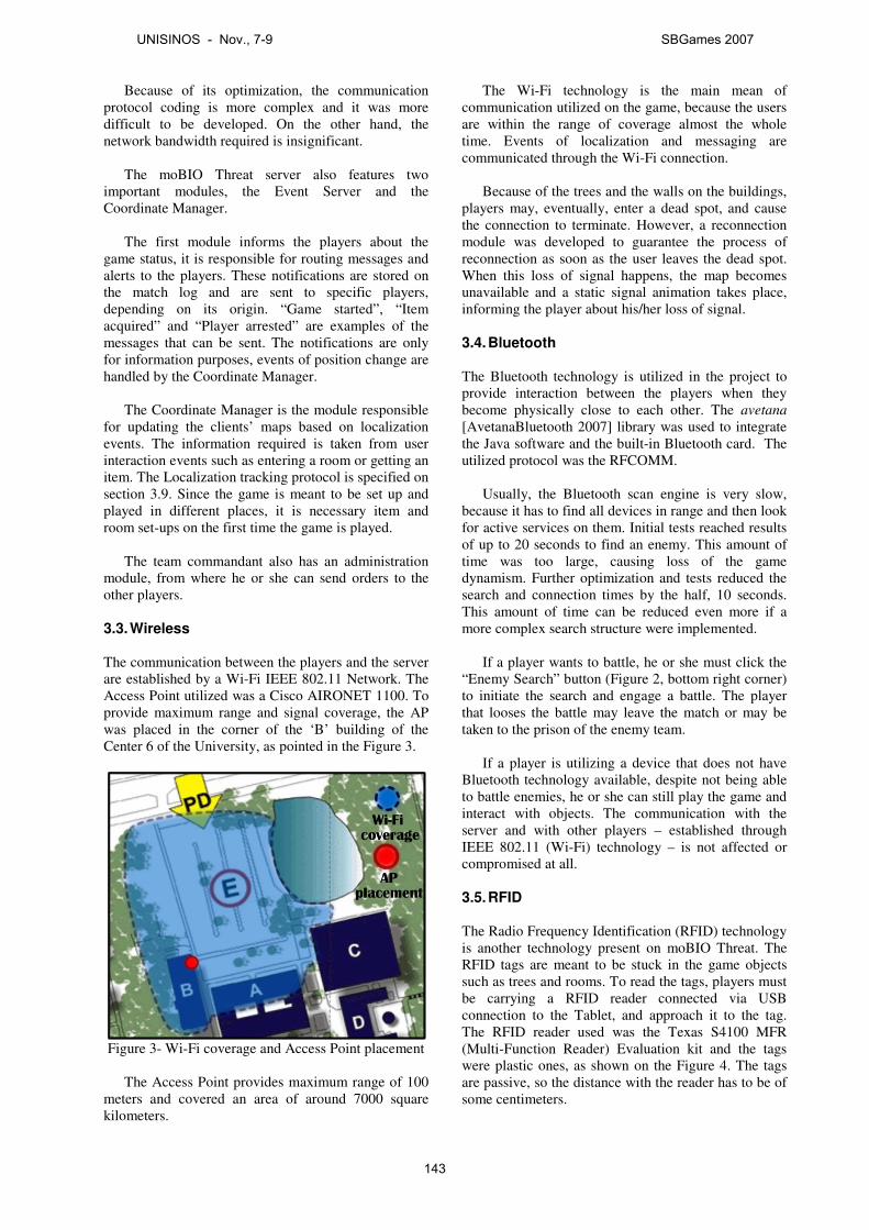
Because of its optimization, the communication protocol coding is more complex and it was more difficult to be developed. On the other hand, the network bandwidth required is insignificant.
The moBIO Threat server also features two
important modules, the Event Server and the Coordinate Manager.
The first module informs the players about the
game status, it is responsible for routing messages and alerts to the players. These notifications are stored on the match log and are sent to specific players, depending on its origin. “Game started”, “Item acquired” and “Player arrested” are examples of the messages that can be sent. The notifications are only for information purposes, events of position change are handled by the Coordinate Manager.
The Coordinate Manager is the module responsible
for updating the clients’ maps based on localization events. The information required is taken from user interaction events such as entering a room or getting an item. The Localization tracking protocol is specified on section 3.9. Since the game is meant to be set up and played in different places, it is necessary item and room set-ups on the first time the game is played.
The team commandant also has an administration
module, from where he or she can send orders to the other players.
3.3. Wireless The communication between the players and the server are established by a Wi-Fi IEEE 802.11 Network. The Access Point utilized was a Cisco AIRONET 1100. To provide maximum range and signal coverage, the AP was placed in the corner of the ‘B’ building of the Center 6 of the University, as pointed in the Figure 3.
Figure 3- Wi-Fi coverage and Access Point placement
The Access Point provides maximum range of 100
meters and covered an area of around 7000 square kilometers.
The Wi-Fi technology is the main mean of communication utilized on the game, because the users are within the range of coverage almost the whole time. Events of localization and messaging are communicated through the Wi-Fi connection.
Because of the trees and the walls on the buildings,
players may, eventually, enter a dead spot, and cause the connection to terminate. However, a reconnection module was developed to guarantee the process of reconnection as soon as the user leaves the dead spot. When this loss of signal happens, the map becomes unavailable and a static signal animation takes place, informing the player about his/her loss of signal.
3.4. Bluetooth The Bluetooth technology is utilized in the project to provide interaction between the players when they become physically close to each other. The avetana [AvetanaBluetooth 2007] library was used to integrate the Java software and the built-in Bluetooth card. The utilized protocol was the RFCOMM.
Usually, the Bluetooth scan engine is very slow,
because it has to find all devices in range and then look for active services on them. Initial tests reached results of up to 20 seconds to find an enemy. This amount of time was too large, causing loss of the game dynamism. Further optimization and tests reduced the search and connection times by the half, 10 seconds. This amount of time can be reduced even more if a more complex search structure were implemented.
If a player wants to battle, he or she must click the
“Enemy Search” button (Figure 2, bottom right corner) to initiate the search and engage a battle. The player that looses the battle may leave the match or may be taken to the prison of the enemy team.
If a player is utilizing a device that does not have
Bluetooth technology available, despite not being able to battle enemies, he or she can still play the game and interact with objects. The communication with the server and with other players – established through IEEE 802.11 (Wi-Fi) technology – is not affected or compromised at all.
3.5. RFID The Radio Frequency Identification (RFID) technology is another technology present on moBIO Threat. The RFID tags are meant to be stuck in the game objects such as trees and rooms. To read the tags, players must be carrying a RFID reader connected via USB connection to the Tablet, and approach it to the tag. The RFID reader used was the Texas S4100 MFR (Multi-Function Reader) Evaluation kit and the tags were plastic ones, as shown on the Figure 4. The tags are passive, so the distance with the reader has to be of some centimeters.
UNISINOS - Nov., 7-9 SBGames 2007
143
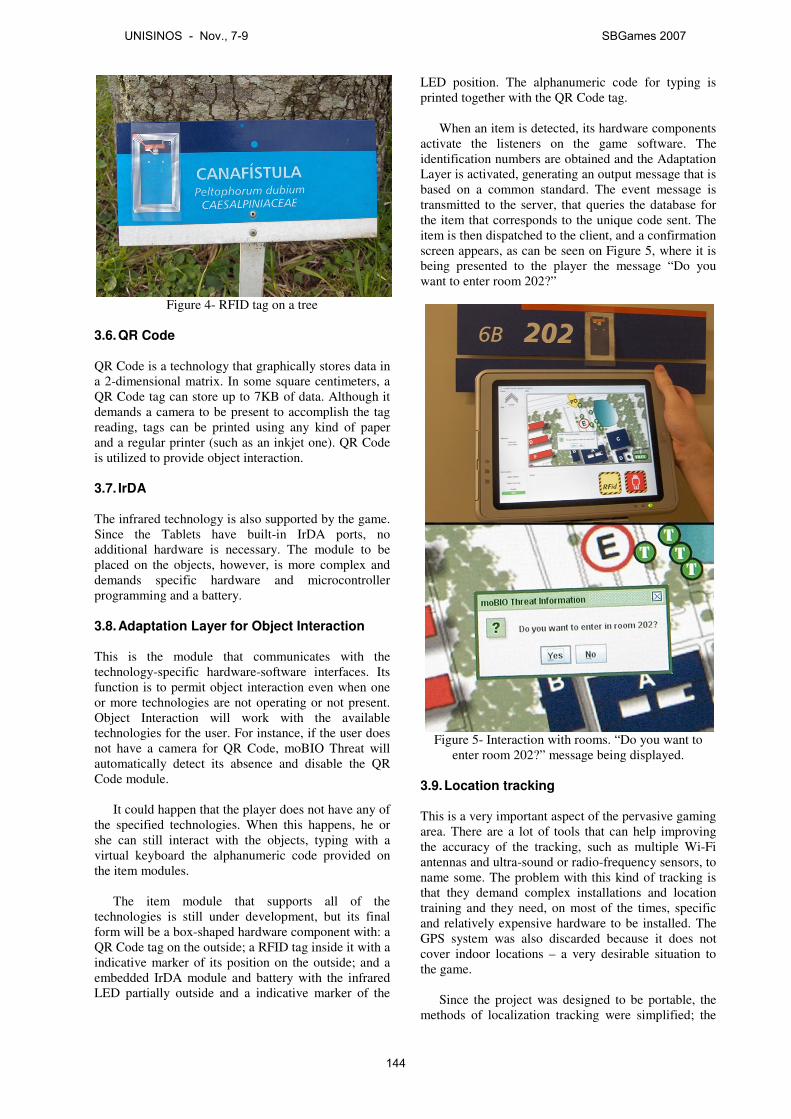
Figure 4- RFID tag on a tree
3.6. QR Code QR Code is a technology that graphically stores data in a 2-dimensional matrix. In some square centimeters, a QR Code tag can store up to 7KB of data. Although it demands a camera to be present to accomplish the tag reading, tags can be printed using any kind of paper and a regular printer (such as an inkjet one). QR Code is utilized to provide object interaction.
3.7. IrDA The infrared technology is also supported by the game. Since the Tablets have built-in IrDA ports, no additional hardware is necessary. The module to be placed on the objects, however, is more complex and demands specific hardware and microcontroller programming and a battery.
3.8. Adaptation Layer for Object Interaction This is the module that communicates with the technology-specific hardware-software interfaces. Its function is to permit object interaction even when one or more technologies are not operating or not present. Object Interaction will work with the available technologies for the user. For instance, if the user does not have a camera for QR Code, moBIO Threat will automatically detect its absence and disable the QR Code module.
It could happen that the player does not have any of
the specified technologies. When this happens, he or she can still interact with the objects, typing with a virtual keyboard the alphanumeric code provided on the item modules.
The item module that supports all of the
technologies is still under development, but its final form will be a box-shaped hardware component with: a QR Code tag on the outside; a RFID tag inside it with a indicative marker of its position on the outside; and a embedded IrDA module and battery with the infrared LED partially outside and a indicative marker of the
LED position. The alphanumeric code for typing is printed together with the QR Code tag.
When an item is detected, its hardware components
activate the listeners on the game software. The identification numbers are obtained and the Adaptation Layer is activated, generating an output message that is based on a common standard. The event message is transmitted to the server, that queries the database for the item that corresponds to the unique code sent. The item is then dispatched to the client, and a confirmation screen appears, as can be seen on Figure 5, where it is being presented to the player the message “Do you want to enter room 202?”
Figure 5- Interaction with rooms. “Do you want to
enter room 202?” message being displayed.
3.9. Location tracking This is a very important aspect of the pervasive gaming area. There are a lot of tools that can help improving the accuracy of the tracking, such as multiple Wi-Fi antennas and ultra-sound or radio-frequency sensors, to name some. The problem with this kind of tracking is that they demand complex installations and location training and they need, on most of the times, specific and relatively expensive hardware to be installed. The GPS system was also discarded because it does not cover indoor locations – a very desirable situation to the game.
Since the project was designed to be portable, the
methods of localization tracking were simplified; the
UNISINOS - Nov., 7-9 SBGames 2007
144
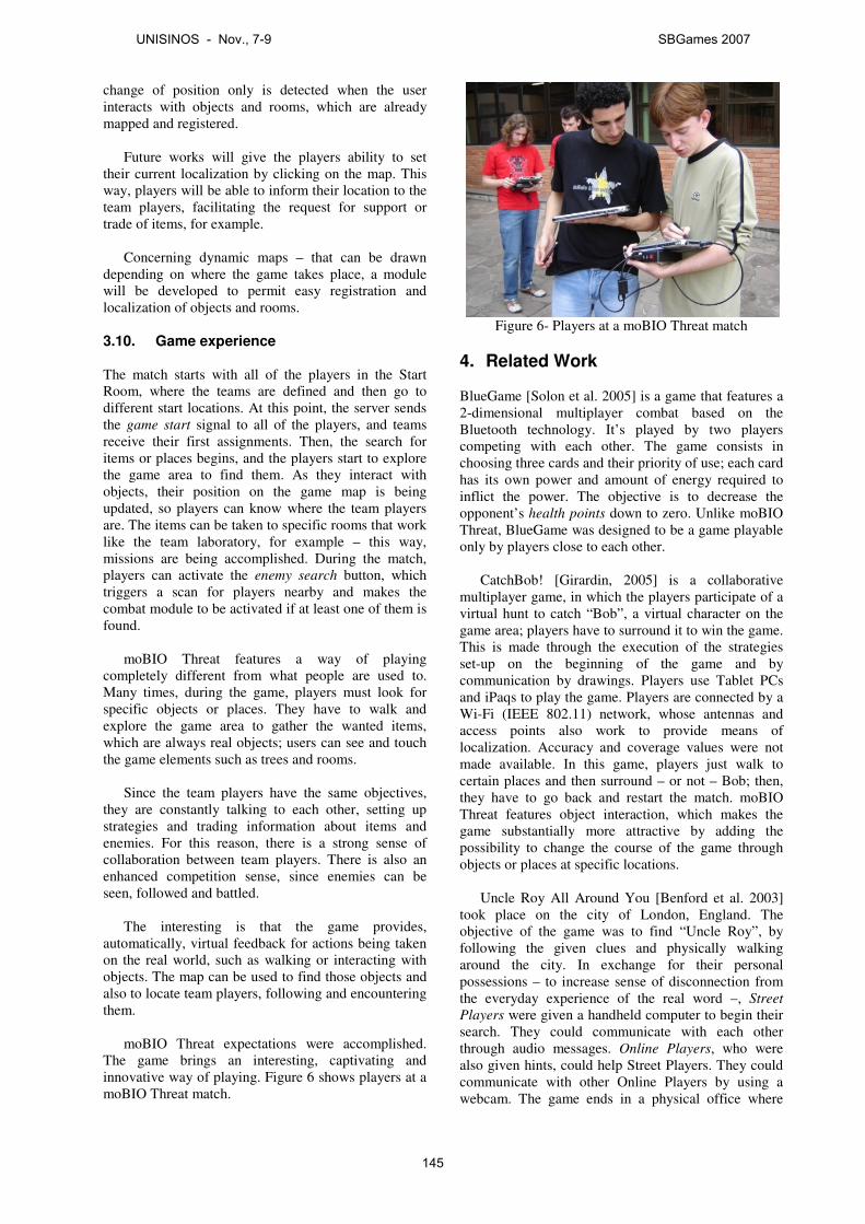
change of position only is detected when the user interacts with objects and rooms, which are already mapped and registered.
Future works will give the players ability to set
their current localization by clicking on the map. This way, players will be able to inform their location to the team players, facilitating the request for support or trade of items, for example.
Concerning dynamic maps – that can be drawn
depending on where the game takes place, a module will be developed to permit easy registration and localization of objects and rooms.
3.10. Game experience The match starts with all of the players in the Start Room, where the teams are defined and then go to different start locations. At this point, the server sends the game start signal to all of the players, and teams receive their first assignments. Then, the search for items or places begins, and the players start to explore the game area to find them. As they interact with objects, their position on the game map is being updated, so players can know where the team players are. The items can be taken to specific rooms that work like the team laboratory, for example – this way, missions are being accomplished. During the match, players can activate the enemy search button, which triggers a scan for players nearby and makes the combat module to be activated if at least one of them is found.
moBIO Threat features a way of playing
completely different from what people are used to. Many times, during the game, players must look for specific objects or places. They have to walk and explore the game area to gather the wanted items, which are always real objects; users can see and touch the game elements such as trees and rooms.
Since the team players have the same objectives,
they are constantly talking to each other, setting up strategies and trading information about items and enemies. For this reason, there is a strong sense of collaboration between team players. There is also an enhanced competition sense, since enemies can be seen, followed and battled.
The interesting is that the game provides,
automatically, virtual feedback for actions being taken on the real world, such as walking or interacting with objects. The map can be used to find those objects and also to locate team players, following and encountering them.
moBIO Threat expectations were accomplished.
The game brings an interesting, captivating and innovative way of playing. Figure 6 shows players at a moBIO Threat match.
Figure 6- Players at a moBIO Threat match
4. Related Work BlueGame [Solon et al. 2005] is a game that features a 2-dimensional multiplayer combat based on the Bluetooth technology. It’s played by two players competing with each other. The game consists in choosing three cards and their priority of use; each card has its own power and amount of energy required to inflict the power. The objective is to decrease the opponent’s health points down to zero. Unlike moBIO Threat, BlueGame was designed to be a game playable only by players close to each other.
CatchBob! [Girardin, 2005] is a collaborative
multiplayer game, in which the players participate of a virtual hunt to catch “Bob”, a virtual character on the game area; players have to surround it to win the game. This is made through the execution of the strategies set-up on the beginning of the game and by communication by drawings. Players use Tablet PCs and iPaqs to play the game. Players are connected by a Wi-Fi (IEEE 802.11) network, whose antennas and access points also work to provide means of localization. Accuracy and coverage values were not made available. In this game, players just walk to certain places and then surround – or not – Bob; then, they have to go back and restart the match. moBIO Threat features object interaction, which makes the game substantially more attractive by adding the possibility to change the course of the game through objects or places at specific locations.
Uncle Roy All Around You [Benford et al. 2003]
took place on the city of London, England. The objective of the game was to find “Uncle Roy”, by following the given clues and physically walking around the city. In exchange for their personal possessions – to increase sense of disconnection from the everyday experience of the real word –, Street
Players were given a handheld computer to begin their search. They could communicate with each other through audio messages. Online Players, who were also given hints, could help Street Players. They could communicate with other Online Players by using a webcam. The game ends in a physical office where
UNISINOS - Nov., 7-9 SBGames 2007
145
players are invited to enter (if they discover it) and then they are taken to a limousine in which they establish a contract to help other players. The player’s position were defined by the own players, sliding a “me” icon and clicking an “I am here” button. Besides being an unsecure and inaccurate mean of localization, it was not a problem since the hints were given just in specific locations – and had no meaning if the player was in another place. Networking was established by a GPRS connection. The difference from moBIO Threat is that “Uncle Roy All Around You” could not be played more than once or twice by each player, because the paths to Uncle Roy were always the same. The game does not feature object interaction and localization tracking at all.
Human PacMan [Cheok et al. 2003] is a pervasive
version of the arcade game developed in 1980, PacMan [Knight 2004]. It utilizes augmented reality to construct paths by which the player acting as “PacMan” has to walk, colleting virtual cookies on his or her way. Other players, that play the role of “Ghosts”, can pursue PacMan and catch him/her. The game uses Bluetooth to interact with objects that can provide the ghost devouring ability. Players have to get hold of the objects (usually cans) to enable a capacitive sensor that activates the embedded Bluetooth device inside it. The positioning system is based on the Global Positioning System (GPS) and networking is established through the IEEE 802.11 protocol. Players make use of a light weighted wearable computer that are composed of a head-mounted display (HMD), a video camera, a Wi-Fi card, a hard-drive, a GPS antenna, batteries and other modules. The problem with using GPS is that, despite of having a good accuracy at outdoor locations, it is a technology that has coverage issues i.e. it cannot be used in indoor location or at places with high buildings nearby. As it was said before, moBIO Threat discarded a GPS-based localization system because it was designed to be played in any location, indoor or outdoor.
Another pervasive game is Plundr [Plundr 2007],
an adventure game where players sail from island to island aboard a pirate ship buying, selling and battling for goods [Kotaku 2007]. However, the available islands to sail are determined by the physical position of the player. Plundr is available for PC and will be supported by Nintendo DS. The localization tracking is based on Wi-Fi Positioning System (WPS). There are no further details about the project, since it is still under development. The point is – as well as moBIO Threat – Plundr can be played in several locations, increasing the number of potential players.
5. Conclusion Pervasive gaming is a challenging domain, because it deals with networking protocols, game design, game planning and social interaction and collaboration. Network modules must be tough enough to handle
events such as undesirable losses of connection, situation where a reconnection protocol must be implemented. The game design has to be intuitive and easy to use; players should not need to read large texts while playing, for instance. In other words, the game interface should not bring any loss to the game dynamism.
The hardware that players carry also has to be as
light as possible; the game should not be tiring, it should be interesting and engaging.
However, the technologies that permit pervasive
gaming to exist have some imperfections. They are not ready – or simply are not designed – for gaming. For this reason, complex frameworks have to be implemented in order to get better results from the infrastructure that the technologies provide.
A major issue for pervasive gaming is the
localization tracking. It is very difficult – and expensive – to cover mixed areas such as cities, fields and indoor locations and to track players and objects with accuracy of up to a few meters. There are a lot of tools that provide certain tracking capabilities, but they are not simple to set up and to configure.
An important aspect of moBIO Threat is that it is
an educational game. During the game, the players have to work with pathological agents and chemical reactions for them, for example. This way, players must gather information about game elements by learning how domain-specific subjects work. The areas of Chemistry and Biology are the most utilized on the game educational objectives.
But the most notable aspect of a pervasive game is, undoubtedly, the social interaction and collaboration. As it could be seen in moBIO Threat, being able to talk to other players, to create and exchange game strategies, to actually see what players are doing and where enemies are bring a gaming experience completely different from what people are used to. moBIO Threat provides the sense of physical interaction, the sense of touching real objects that are part of the game.
About the game infrastructure, it was provided a
cheap, flexible and easy to set-up game environment. The only technology that is mandatory is IEEE 802.11 Wi-Fi.
References avetana JSR-82 implementation [online]. Available from:
http://www.avetana-gmbh.de/avetana-gmbh/produkte/jsr82.eng.xml [Accessed 15 July 2007].
BENFORD, S., FLINTHANM, M., DROZD, A., ANASTASI, R.,
ROWLAND, D., TANDAVANITJ, N., ADAMS, M., ROW-FARR, J., OLDROYD, A. AND SUTTON, J., 2003. Uncle Roy All
Around You: Implicating the City in a Location-Based
UNISINOS - Nov., 7-9 SBGames 2007
146

Performance [online]. Available from: http://www.amutualfriend.co.uk/papers/3.Uncle_Roy_at_ACE.pdf [Accessed 12 July 2007].
CHEOK, A.D., FONG, S.W., GOH, K.W., YANG, X., LIU, W.
AND FARZBIZ, F., 2003. Human Pacman: a sensing-based mobile entertainment system with ubiquitous computing and tangible interaction. In: Proceedings of the 2nd
workshop on Network and system support for
games in 2003 Redwood City, California. New York: ACM Press, 106-117.
GIRARDIN, F., 2005. Pervasive Game Development Today
[online]. Available from: http://www.girardin.org/fabien/catchbob/pervasive/ [Accessed 10 July 2007].
KNIGHT, W., 2004. Human PacMan hits real city streets [online]. Available from: http://www.newscientist.com/article.ns?id=dn6689 [Accessed 10 July 2007].
KOTAKU. WiFi Plundr Coming to DS [online]. Available
from: http://kotaku.com/gaming/gps/wifi-plundr-coming-to-ds-266488.php [Accessed 15 July 2007].
Plundr [online]. Available from:
http://plundr.playareacode.com/ [Accessed 15 July 2007].
SOLON, R., HAHN, R.M., BARBOSA, J., 2005. BlueGame: Um
Jogo Móvel Multijogador baseado em Comunicação
bluetooth [online] Universidade do Vale do Rio dos Sinos. Available from: http://www.inf.unisinos.br/~barbosa/textos/WJOGOS_2005.pdf [Accessed 25 June 2007].
UNISINOS - Nov., 7-9 SBGames 2007
147

What Went Wrong? A Survey of Problems in Game DevelopmentFabio Petrillo Marcelo Pimenta Francisco Trindade Carlos Dietrich
Institute of Informatics - Federal University of Rio Grande do Sul, Brazil
Abstract
Despite its exuberance and profitability, many reports about gamesprojects show that their production is not a simple task, surroundedby common problems and being still distant from having a healthyand synergetic work process.
The goal of this paper is to present a survey of problems found in thedevelopment process of electronic games, collected mainly fromgame postmortems, exploring similarities and differences of well-known problems in the traditional industry of information systems.
Keywords: Electronic games, game development, problems ingame development, survey, postmortems
Author’s Contact:[email protected]{mpimenta,fmtrindade,cadietrich}@inf.ufrgs.br
1 Introduction
The game development industry is entering a new age, in whichtechnology and creativity walk together, producing some of themost astonishing entertainment activities of the 21st century. Thisindustry has an annual income of billions of dollars, and in 2003 itexceeded its revenues comparing to the movie industry, it emergesas one of the most powerful, exciting and influential industry in theworld of the arts [Gershenfeld et al. 2003]. Great game projectscount on highly specialized multidisciplinary teams, having simul-taneously software developers, designers, musicians, scriptwritersand many other professionals. Thus, the game developer career iscurrently one of most dynamic, creative, challenging and poten-tially lucrative that someone can have [Gershenfeld et al. 2003].
However, game development is an extremely complex activity[Gershenfeld et al. 2003] and a much harder task than one can ini-tially imagine. To create a game is a different experience from whatit was in 1994 and, certainly, much more difficult, having boostedin complexity in recent years [Blow 2004].
The main proposal of this work is to collect and discuss the prob-lems that afflict the electronic games industry, because surprisinglyvery little attention has been paid to collect information about them,to organize this information in a systematic form and to quantify thefrequency in which they occur.
The steps we have taken are:
• analyze the problems of the traditional software industry, col-lecting information to compare with the game industry;
• analyze the game industry problems in specialized literature,making it possible to map of these problems in the analysis ofpostmortems.
• collect, through postmortems analysis, focusing aspects ofsoftware engineering, the real problems cited by profession-als of the game industry, making a qualitative analysis of theoutcome;
• compare the results obtained in the game industry with thedata of the traditional industry, searching for similarities andidiosyncrasies;
This paper is structured as follows: after this introduction, section2 brings a study of the traditional software industry problems, pre-senting statistics of the projects performance and discussing the tra-ditional problems of software engineering. In section 3 we discussthe problems cited in the specialized literature about game devel-opment and in the postmortems, numbering them and quoting ex-amples that demonstrate its relevance in the project context. Afterhaving presented this situation, we discuss the methodology used in
the analysis of postmortems and describe the results obtained in theproblems survey. After that, a comparison between these results ismade and the problems discussed in section 2.
Finally, section 4 discusses the conclusions and future work pro-posals.
2 Software Industry Problems
The analysis of problems in the development of software systemsgoes back to the origin of Software Engineering. The famousNATO conference in 1968 [NATO 1968], in which the term Soft-ware Enginnering [Sommerville 2001] was created, had as its basicgoal the analyze of the key problems of critical areas in the processof programs construction.
Although the academic community has being discussing for almost40 years the problems that afflict the development of computationalsystems, we still have difficulties in elaborating elegant and correctsoftware, which satisfies customers and meets estimates, as muchin time as in budget [Bach 1995; Pressman 2006], and the currentstatus of software development can be seen as far from an idealsituation. Jones [1995] suggests that software can be faced today asone of the most problematic aspects of the corporative world. Costsand deadlines are not met; imperfections are more common in largesoftware projects then in almost any other business area. Failuresin projects happen in all countries, in big or small companies, incommercial or governmental organizations, not taking in accountstatus or reputation [Charette 2005].
The research made by the Standish Group [1995] shows that morethan 30% of the projects are cancelled before being completed andthat 53% of the projects have a cost exceeded in 189%. Only 16%of the projects are completed in the stated period and budget, withall the initially specified functionalities [Standish Group 1995]. Inthis scenario, Sommerville [2001] suggests that the software engi-neering is not really in a crisis, but in a state of chronic agony.
With all these difficulties, many software projects fail and thesefailures are not reflected in changes. As cited in The Chaos Re-port [Standish Group 1995], many errors in software projects arenot deeply investigated and the same errors continue to be com-mitted. The corporative insanity existent in software developmentis inserted into the fact that the same things are repeated in differ-ent opportunities, and a different result is expected every time. Forthese reasons, DeMarco and Lister defend that the main problemsof software projects are not technological, but managerial.
The Standish Group, in its research of the problems of softwareprojects, quantified the main factors that cause damages or cancel-lations of projects. In this research, made with IT executives, theopinion requested was which would be the main factors that causeproblems in the projects. Thus, 13.1% of the executives have citedincomplete requirements and 12.4% the lack of user envolvement.In section 3.5, we will use some of these results as support for thecomparison between the traditional and the electronic games indus-try.
From these surveys and from the analysis of the references madeby Yourdon [2003] and Charette [2005], it is possible to group theproblems in four main categories: 1) schedule problems; 2) bud-get problems; 3) quality problems; 4) management and businessrelated problems. In fact, IT projects rarely fail for only one or tworeasons. More frequently a combination of these problems is found,being associated with one another [Charette 2005]. In the sectionsto follow, we will analyze each one of these problems, characteriz-ing them and discussing their causes.
UNISINOS - Nov., 7-9 SBGames 2007
148

2.1 Schedule Problems
All the project that do not fulfill the foreseen deadlines has scheduleproblems. As cited by Brooks [1995], exceeding all the other causestogether, the biggest cause of project cancellations is problems withschedule.
Perhaps the main reason for this problem is the weak estimate tech-niques, confusing effort with progress [Brooks 1995]. With prob-lems in the estimates, the work progress is poorly monitored andwhen delays are detected, the natural answer is to add more profes-sional help to the project.
In an article about the limits of estimate definition in softwareprojects, Lewis [2001] comments that many programmers discoverby themselves that it is impossible to make accurate estimates insoftware projects.
Another factor that leads to schedule problems is the optimism.Brooks [1995] claims that all programmers are optimistic. Thisoptimism, followed by naivety, that frequently is associated withinexperience, causes people not to have conscience of how muchtime and effort will be necessary in the construction of a system[Yourdon 2003]. This situation is so common that DeMarco andLister [2003] call it “hysterical optimism“: everbody in the orga-nization desperately wants to deliver a complex system, that wouldhave never be completed in a realistic estimate of at least three yearsof effort, in 9 months.
Besides optimism, cowardice is another sociological aspect foundduring the estimate of projects. Brooks [1995] observes that pro-grammers, as well as their bosses, are influenced by the sponsor’surgency during the elaboration of the project schedule. This ur-gency can even rule the period of a task, but it cannot rule the timethat is necessary for its accomplishment. False schedules are pro-duced to answer the sponsor’s desire, and this unrealist position ismuch more common in software projects than in any other engi-neering.
The schedule problems due to the optimistic estimates, cowardiceand uncertainties have caused damages to the credibility of the soft-ware industry. Lewis [2001] claims that the credibility will not beachieved while absolute deadlines continue to be promised. On theother hand, the software industry must acquire knowledge aboutthe existing uncertainties and the intrinsic risks of software devel-opment, being necessary to promote a public and honest discussionabout these risks.
2.2 Budget Problems
Projects with budget problems are characterized by demanding in-vestments above the estimated. Models to estimate the cost of aproject are based on function of the necessary development timeor measures of size, as lines of code or points of function [Lewis2001]. Consequently, the cost of a product is also a function of thenumber of professionals needed for its development [Brooks 1995],as men/month or men/hour.
On average, the budget of software projects exceed in almost 200%the original estimated cost, phenomenon that happens in companiesof all sizes [Standish Group 1995]. The study made by the StandishGroup [1995] shows that some projects (4.4%) exceed their budgetin more than 400%.
2.3 Quality Problems
A project has quality problems, in the customer’s point of view,when there are differences between the final product and the expec-tation of it. The quality is associated to the customer’s satisfaction,aesthetic aspects and the correction of a system in terms of its re-quirements [Bach 1995].
In the technical point of view, the most common reason for dis-asters in software projects is the poor quality control. Accordingto Jones, to find and to correct bugs are the most time consumingand expensive aspects of software development, especially for largesystems.
Moreover, according to the Standish Group [1995], of all theprojects with problems, one quarter was delivered with 25% to 49%of the originally specified functionalities. On average, 61% of theoriginally specified functionalities are present in the end product.
2.4 Management Problems
Management problems happen in several ways, including bad com-munication; lack of investment in the team’s training; and the lackof project inspection in regular intervals [Charette 2005]. Accord-ing to Jones [1995], bad management of projects is the origin ofmany problems in the process of software development.
The project decisions are frequently difficult to be taken becausethey involve choices based on incomplete knowledge, turning theestimate of how much a project will cost or how much time it willneed into much more of an art than a science [Charette 2005].
3 The Electronic Games Industry Prob-lems
In this section we will discuss the problems of the electronic gamesindustry. We will initially analyze what postmortems are and willshow the problems which are cited by the game development spe-cialized literature, demonstrating its characteristics and pointing outthe criteria that were used to define this situations as problems. Fi-nally, we will compare the collected results with the data obtainedin the traditional software industry.
3.1 The Game Postmortems
The term postmortem designates a document which summarizes theproject development experiences, with a strong emphasis on posi-tive and negative aspects of the development cycle [Hamann 2003].It is commonly done right after the project finishes, by managers orsenior project participants [Callele et al. 2005]. In a software engi-neering viewpoint, postmortems are important tools for knowledgemanagement [Birk et al. 2002], from which the group can learnfrom its own experiences and plan future projects. In fact, the post-mortem analysis can be so revealing that some authors [Birk et al.2002] argue that any project should be finished without it’s ownpostmortem.
Postmortems are much used in the game industry. Many gamewebsites devote entire sections to present these documents, suchas Gamasutra (http://www.gamasutra.com) and Gamedev(http://www.gamedev.net). It is also very interesting tonote the variety of development teams profiles and projects behindthese documents, varying from few developers in small projects todozens of developers in five-year-long projects.
The postmortems published by Gamasutra mainly follow the struc-ture proposed by the Open Letter Template [Myllyaho et al. 2004],which is composed by three sections. The first section summarizesthe project and presents some important aspects of the development.The next two sections, however, discuss the most interesting aspectsto the game developers:
• What went right: if discusses the best practices adoptedby developers, solutions, improvements, and project manage-ment decisions that have improved the efficiency of the team.All these aspects are critical elements to be used in planningfuture projects.
• What went wrong: it discusses difficulties, pitfalls, and mis-takes experienced by the development team in the project, inboth technical and management aspects.
The postmortem is closed with a final message from the author,commonly followed by a project technical brief, which includes thenumber of full- and partial-time developers, length of development,release date, target platforms, and the hardware and software usedin the development.
The information contained in the postmortems constitute knowl-edge base that can be reused by any development team, which in-
UNISINOS - Nov., 7-9 SBGames 2007
149
cludes examples and real life development experiences. They canhelp in knowledge sharing, and can be very useful for planning fu-ture projects.
3.2 Problems found in specialized literature
According to Flood [2003], all game development postmortems saythe same things: the project was delivered behind schedule; it con-tained many defects; the functionalities were not the ones that hadoriginally been projected; a lot of pressure and an immense amountof development hours in order to complete the project.
The specialized literature in electronic games development is alsoeffective in describing the problems of this industry. For Bethke[2003], the electronic games industry adopts, in general, a poormethodology, if any, causing projects to have longer duration incomparison to what they were suposed to, excedding the budgetand tending to be irrationally full of defects.
This scenario is responsible for declarations as this, of Ian Lane, ofMad Doc Software [Gershenfeld et al. 2003]:
“It’s rare a project where there is not some form of agony. I amtrying to think of one that wasn’t miserable in some way. I canthink of one that was very smooth, but in general, I think you’ll findthat there is always some degree og angst associated with makinggames.”
and of Scott Campbell, president and founder of Incognito Stu-dio[Gershenfeld et al. 2003]:
“Every projects has a moment where you are totally in the hell,especially when you are making new intellectual property or tryingto create the “fun” and core game identity.”
In order to elucidate these problems in a better way, we will discusssome of them at great length, based on the causes of imperfectionreferred by Flynt and Salem [2004] and through the study of theelectronic games development specialized literature.
3.2.1 Scope problems
According to Flynt and Salem [2004], the biggest reason of gamesproject imperfection is the failure in clearly establishing the projectscope. If a project does not have a well established target, emergentrequirements can cause significant structural changes in the sys-tem’s architecture, causing serious problems [Callele et al. 2005].
The development teams lose themselves in the scope when somedifficulties arise: problems with the exaggerated size and complex-ity of the project, in addition to facing highly specific requirementsof the games domain [Gershenfeld et al. 2003; Blow 2004]. How-ever, the main cause of scope problems is the common situationwhere new functionalities are added during the development phase,increasing the project’s size. This practice is known in the industryof games as feature creep.
The late addition of features occurs when developer, managers orcustomers add requirements to the project after its scope has al-ready been defined. With the intention to create the best possiblegame, there is the habit of adding more elements everytime, creat-ing perhaps a more interesting game (even without any guarantee)and certainly bigger [Gershenfeld et al. 2003].
This good intention results in features addition due to many rea-sons. According to Flynt and Salem [2004], the most commonform in the addition of new elements occurs when programmers, bychance, discover interesting features during the development pro-cess or when they randomly decide to add functionalities that areconsidered attractive to the game. Flynt and Salem [2004] defendthat the reason for this situation is in the development phase ini-tiation without a strong effort of analysis, in addition to the lackof techniques to improve the investigation and verification of theproject’s requirements.
Another common form of feature creep happens when an externalcode (a new component, for example) happens to be incorporated
without planning, for the reason or purpose of gaining time. How-ever, what happens many times is that an extremely hard work isnecessary for the integration of this new component. One thirdform takes place when developers decide, despite counting on aset of solid libraries, to implement their own algorithms.
However, the games industry has a lot of examples of situationsin which features discovered during the development phase havetransformed the game into a success. Game development is nota linear process [Flynt and Salem 2004]. Thus, if an interestingfunction is discovered, it must be analyzed in terms of its risks and,if viable, be added to the project schedule.
3.2.2 Schedule problems
The electronic games specialized literature exhaustingly describesschedule problems in game projects. Although they usually initiatewith reasonably structured schedules, bright ideas and enthusiasm,something always goes wrong. And the number of things that cango wrong is virtually endless [Bethke 2003]. These problems aremany times associated with the multidisciplinarity needed in theelaboration of games, generating delays caused by waiting for thework of other team members, in addition to the lack of a realisticestimate on the initial plan of development, making the team not ca-pable of finding a deadline for the projects [Flynt and Salem 2004].
The production of estimates of time needed to complete a task hasa series of risks that imply in underestimates, causing cumulativeschedule delays. According to Flynt and Salem [2004], developersrecurrently fail in their estimates due to lack of historical data thatshould assist the perception of time needed to carry through a task.Another common problem in deadline estimate is not taking intoaccount the time consumed in complementary meetings and otheractivities, in addition to not planning the time needed to correctdefects in the game.
However, for Flynt and Salem [2004], the key to the problems inthe project’s schedule is the unbalance among quality, cost and op-portunities. If a game delivered two months after the release of asimilar game from another company, the possibilities for successare diminished. On the other hand, a game that is launched beforeanother one with an important number of defects, can have moreproblems than one that is delivered later with less bugs.
3.2.3 Crunch Time
In basketball, crunch time is the term that defines the last min-utes of the game, when both teams fight to win the victory. Itwas invented in New Zealand in 2004, from the combination of thephrases “show time” and “when it comes to the crunch” [Wikipedia2007].
In the games industry, the term is used for the periods of extremework overload, typically occurring in the last weeks before valida-tion phase and mainly in the weeks that precede the final deadlinefor the project delivery. In these periods, a work load of more than12 hours a day is common, from 6 to 7 days per week, without restintervals.
Although this cyclical problem is also present in traditional soft-ware companies, Gershenfeld et al. [2003] claims that the elec-tronic games industry goes more frequency through crunch timeperiods. This assertion can be confirmed by Hamann [2003], whendescribing his experience in a project:
“On one game I worked on, one of the team members complainedto the producer that months of working 12-hours-per-day, seven-days-a-week was getting to him. He said he’d like to have at leastone weekend off. The producer replied, “This is the game industry- crunch time is a fact of life.” I have a question for all of you gamecompany owners, producers and leads out there: Ever wonder whyyou have such a high turnover rate at your company? Studies haveshown that most game developers will put up with a severe crunchmode for one, or at most two, projects and then they start lookingfor another company. Believing that crunch time is a fact of life isa result of following the “blind religion” that’s so pervasive in ourindustry”.
UNISINOS - Nov., 7-9 SBGames 2007
150
Gershenfeld et al. [2003] comment that periods of crunch time canbe good for single or ambitious people, who make of their work themain aspect of their lives. However, they claim that this situationis not sustainable for people who have a family or want to keepa serious relationship. Therefore, they suggest the construction ofschedules that contemplate a healthy pace of daily work, defendingthat people can be much more efficient if they work in a typical dayof 8 hours.
3.2.4 Technological problems
As a software device, all games are technology dependents. More-over, the technologies used in games are so advanced that the lead-ers in the area of graphical computation are games companies.However, the technological component brings risks to the projectsof games. Flynt and Salem [2004] describe the risk of using newtechnologies, that many times cause a great effort and high invest-ment of time in order to use them.
According to Gershenfeld et al.[2003], the technological risks aregenerally higher when the team is working in a new platform, thathas not been completely delivered neither consolidated. The firstone of these risks is that no developer has ever worked in it. Thesecond risk is that in many times the platform hardware still con-tains problems, that are only found by development team of thelaunch title 1.
3.3 Problems found in the postmortems
Although specialized literature in development of games containvaluable descriptions concerning the problems of this industry, aswe saw in section 3.2, another way to raise the problems is throughpostmortems reading. Its reading is deeper (forceful and specific,discussing the problems more deeply) and more accomplishingabout the problems in specialized literature.
With the objective of raising the problems of electronic game indus-try, 20 postmortems published in the site Gamasutra were analyzed.The analysis process occurred through the detailed reading of sto-ries, extracting the ideas that demonstrate the problems faced by theteams during the game development process.
Therefore, we will describe the main problems found in post-mortems, exemplifying it through quotes, aiming at defining andexemplifying the adopted criteria of analysis of the described sur-vey in section 3.4. In this work, 15 problems were analyzed, theseare the most relevant and recurrent found in postmortems.
3.3.1 Unreal or ambitious scope
It is not surprising that many postmortems report explicitly as hav-ing an unreal or extremely ambitious scope. The Gabriel Knight3 project [Bilas 2000], for example, brings the following sen-tence: “. . . was an extremely ambitious project combined with anextremely inexperienced team”.
Some projects as Command and Conquer: Tiberian Sun [Stojsavl-jevic 2000], Vampire: The Masquerade [Huebner 2000] and TheX-Files [VandenBerghe 1999] dedicate a complete section to reportthis problem. Huebner [2000] comments that “. . . Many of the teammembers had wanted for some time to do a really huge, ambitiousrole-playing game”.
Stojsavljevic [2000] describes in his section “Unrealistic expecta-tions” that “The degree of hype and expectations that Tiberian Sunhad to fulfill was staggering”. Moreover, in the project Black &White, Molyneux [2001] uses the expression “insanely ambitious”in his briefing: “. . . looking back, I don’t know whether we were in-sanely ambitious, because at the time we started, you couldn’t havedone what we did”.
1Launch title is a game that is delivered at the same time that the newplatform.
3.3.2 Feature creep
An interesting pattern found in many game projects is the featurecreep, that is, as new modules are added without planning, duringsoftware construction. This problem is literally described in theproject Vampire [Huebner 2000]:
“New engine features get added too late in the schedule to be uti-lized fully by the designers and artists. This happened several timesduring Vampire. Some of the more interesting special effects, forexample, were added only a few weeks before the data was to belocked down for final testing”.
This could also be see clearly in citations made by Reinhart [2000]for Unreal Tournament project:
“. . . The amount of content grew and we soon realized we had amuch larger project on our hands than we had originally thought.. . . Unreal Tournament is a very fun game with a lot of featurespacked into a short amount of development time. Those featureswere largely added through spur-of-the-moment decisions”.
In many postmortems phrases are found as: “As we realized thislate in the project. . . ” [Smith 2001]; Humans procrastinate Hu-mans. . . . Audio was plugged in at the last moment. . . ” [Scheib2001] or “we were capable to incorporate several features thatoriginally had not been planned to be developed”.
In the Draconus project, Fristrom [2000] report his experience withthis problem:
“Another example of poor planning was that magic was an af-terthought. We always knew we would have spells in the game, spe-cial abilities with nice special effects that your character would ac-quire as the game progressed, but they were left until late in devel-opment because there were always more pressing issues. Of course,once we did implement spells, they unbalanced the play of the gamehorrendously, and much more unplanned work was needed to makemagic function reasonably”.
3.3.3 Cutting features during development process
As well as the feature creep, another problem frequently quoted isthe cut features during development process. As for the fact thatprojects initiate in an ambitiously, many functionalities are imag-ined and even implemented, but for diverse factors they end up be-ing further on in the project.
The typical case is found in the Rangers Lead the Way [Ridgway2000], in which the initial features of the game were modified tohold the schedule and the budget:
“We dropped the Macintosh version right away, and we terminatedthe PlayStation version at alpha (when it was still running at fiveto eight FPS). Networking support was postponed for an expansionpack a year into development”
Or still reported by Fristrom [2000]:
“Our answer to being under funded and under scheduled was tocut network play. We needed to make much bigger cuts”.
Another example of this situation is associated with the unrealscope. The report made by Malenfant [2000] for the game Wild9 represents this situation well:
“. . . The material they came up with is enough to fill up three or fourgames like this one. In addition, the whole team took this game toheart and ended up coming up with suggestions of their own. Wewere thus faced with a situation toward the end of the project: wecould not fit everything into the game”.
In the Tropico [Smith 2001], this problem was caused by a differentreason: lack of physical space demanded to cut features. Smith[2001] comments this situation: “. . . we had to cut other features tocreate space, features which would have improved the game”.
UNISINOS - Nov., 7-9 SBGames 2007
151
3.3.4 Problems in the design phase
Although designing is a common practice in the game projects,mainly by design document or game bible, many reports claim thatthere are problems in this phase. The postmortem of Wild 9 bringsan emblematic testimony:
“Many times, titles are late because certain gaps in the originaldesign were overlooked and the full design was never really laiddown on paper before development started”.
Barrett et al. [2002] dedicate an entire section for this problem,titled “Design on the fly”:
“. . . Because we were designing a game to the technology (ratherthan the other way around), we were throwing out design docu-ments as quickly as they could be written. Art assets had to be re-vised, retextured, discarded, and rebuilt from scratch several times.As most readers will know from experience, this is a scenario forfeature creep, obsolete tool sets, and blown deadlines”.
On the other hand, Saladino [1999] says that the opposite situationmay also be problem:
“One interesting example of the opposite problem arose in our cus-tom interface system: we had too much design. Our interface sys-tem is the library of code that handles our front end interface andour in-game heads up display. The code was written by a program-mer with extensive experience in C++ object oriented design andloved to use it. He spent many weeks designing and crafting aninterface system which was extremely... well... designed. Privatedata fields were placed into private headers. The ”const” operatorwas used everywhere. Void pointers hiding internal data structuresmade debugging a nightmare”.
Moreover, Saladino [1999] makes the following recommendation:
“. . . There are extremes at both ends of the design spectrum andeither one can seriously damage overall productivity. Make surethat you spend time designing what is important”.
3.3.5 Delay or optimistic schedule
Many game projects quote delay schedule. For example, Ridgway[2000] describes this problem clearly in the Rangers Lead the Wayprojetc: “We learned the hard way what’s possible to accomplishin 15 months; as a result, we completed the game in 20”.
Ragaini [2002] analyzes deeply this problem, describing its maincause:
“Depending on how far back you look at the schedules, Asheron’sCall was either one to two years late. . . . Deadlines were consis-tently missed. A lot of this was due simply to underestimating thetime required for development tasks. This created a domino effectas we continually played catch-up, trying desperately to make upfor lost time”.
In the same way, VandenBerghe [1999] describes this problem lit-erally: “The most severe blow suffered by all teams was from ac-cepting an unrealistic schedule”. Again, optimism is the cause ofproblem, that is shows in Fristrom [2000] testimony for the Dra-conus project: “In my experience, publishers love overoptimisticschedules”.
3.3.6 Technological problems
The problems of failure in third party Application ProgrammingInterface (API), on platform or hardware were classified as tech-nological problems. A typical example was faced in the Age ofEmpires II: The Age of Kings [Pritchard 2000] project:
“Microsoft’s DirectPlay API still has a number of issues that makeit less than perfect. One of its biggest problems is documentationand testing of the lesser-used portions of the API, or rather thelack thereof. Late in the development of AoK, our communicationsprogrammer, Paul Bettner, was able to communicate with the Di-rectPlay developers and an interesting scenario played out several
times: Paul would attempt to solve some problem and the develop-ers would indicate that it wouldn’t work because of bugs in Direct-Play that they knew about but that were not documented”.
However, prosaic problems also are found, as occurred in the Dra-conus project [Fristrom 2000], with the C compiler: “We lost manyweeks in our battle to find a compiler that could actually compileour code”.
The use of external components from third parties many times, inthe end, produce more difficulties in development process.
“Our external solutions for rendering and networking both fellthrough and had to be replaced with internally developed code latein the development cycle. . . . In retrospect, we would have savedmoney and had a much smoother development process if we’d bit-ten the bullet early on and committed ourselves to building our owntechnology base”.
3.3.7 Crunch Time
As discussed in section 3.2.3, crunch time was found in many post-mortems. Perhaps the most eloquent testimony about this problemhas been made by VandenBerghe for the The X-Files project:
“The most severe blow suffered by all teams was from acceptingan unrealistic schedule. Despite endemic problems, . . . the conceptthat was floated at the time was that it would be possible to adhereto the original schedule if everyone simply worked around the clock.Foolish and naıve, we bought it, and started pushing. While a finalpush of a few weeks or even a few months is common toward the endof a technical project, the schedule of six to seven days a week oftwelve- to twenty-hour days adopted by The X-Files team stretchedon for eight months. Predictably, exhaustion began degrading theability of people to produce quality work, not to mention the deeplystraining effects it had personally on team members and their fam-ilies. In retrospect, the death march did little to speed the project’sfinish. There were several systems that were developed during thistime that caused us no end of grief in development, largely becauseof the inability of the developers to make clear and rational designdecisions from lack of sleep. . . . For me, the lesson here is that if theschedule begins to slip, the solution is not as simple as just applyingmore work to the problem. Pushing harder won’t necessarily finishthe project any sooner, and some of the damage done to the teamunder that much stress may be irreparable”.
The sleep deprivation was also cited by Spanel e Spanel [2001] forthe Operation Flashpoint [Spanel and Spanel 2001] project:
“After a long, sleepless night of playing through the game and fix-ing any problems that appeared, everything looked fine, and mostof the team could finally go to sleep again”.
Moreover, the Diablo [Schaefer 2000] project showed that passedexperiences not necessarily produce best practices for new projects:
“The original Diablo went gold on the day after Christmas in 1996,after a grueling four-month crunch period. We hadn’t put anythought into what game to do next, but as most developers canprobably relate to, we were pretty certain we weren’t ready to re-turn to the Diablo world after such a long development cycle. Theonly thing we were certain of was that we wanted to avoid anothercrunch like we had just experienced. Diablo II went gold on June15, 2000, after a grueling 12-month crunch period”.
3.3.8 Lack of Documentation
Although many projects report sucess on documentation processes,mainly with the project document, many postmortems describe con-genital problems by lack of documentation, as was describes bySpanel e Spanel [2001] in Operation Flashpoint:
“Lack of documentation is a common affliction among game de-velopers, but some aspects of this problem were so severe in ourcase that they are worth mentioning. While we’d never believed toomuch in designing the game on paper, the real problem was that wenever even had documentation of the things that we’d finished. This
UNISINOS - Nov., 7-9 SBGames 2007
152
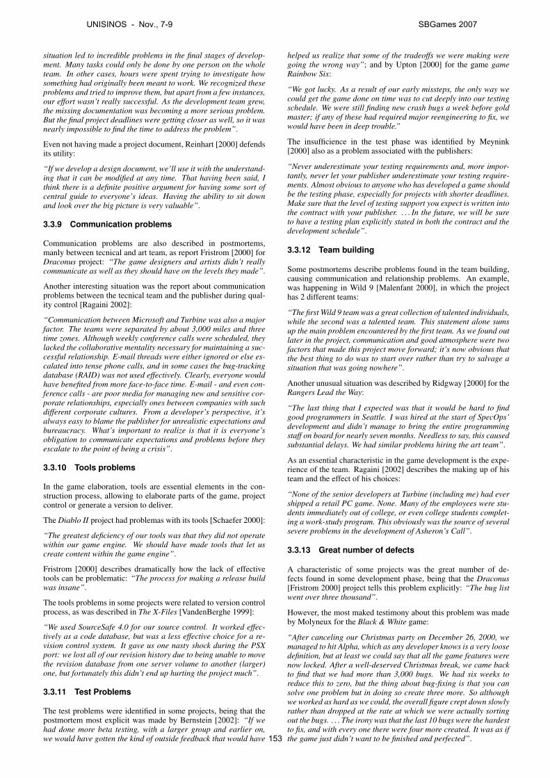
situation led to incredible problems in the final stages of develop-ment. Many tasks could only be done by one person on the wholeteam. In other cases, hours were spent trying to investigate howsomething had originally been meant to work. We recognized theseproblems and tried to improve them, but apart from a few instances,our effort wasn’t really successful. As the development team grew,the missing documentation was becoming a more serious problem.But the final project deadlines were getting closer as well, so it wasnearly impossible to find the time to address the problem”.
Even not having made a project document, Reinhart [2000] defendsits utility:
“If we develop a design document, we’ll use it with the understand-ing that it can be modified at any time. That having been said, Ithink there is a definite positive argument for having some sort ofcentral guide to everyone’s ideas. Having the ability to sit downand look over the big picture is very valuable”.
3.3.9 Communication problems
Communication problems are also described in postmortems,manly between tecnical and art team, as report Fristrom [2000] forDraconus project: “The game designers and artists didn’t reallycommunicate as well as they should have on the levels they made”.
Another interesting situation was the report about communicationproblems between the tecnical team and the publisher during qual-ity control [Ragaini 2002]:
“Communication between Microsoft and Turbine was also a majorfactor. The teams were separated by about 3,000 miles and threetime zones. Although weekly conference calls were scheduled, theylacked the collaborative mentality necessary for maintaining a suc-cessful relationship. E-mail threads were either ignored or else es-calated into tense phone calls, and in some cases the bug-trackingdatabase (RAID) was not used effectively. Clearly, everyone wouldhave benefited from more face-to-face time. E-mail - and even con-ference calls - are poor media for managing new and sensitive cor-porate relationships, especially ones between companies with suchdifferent corporate cultures. From a developer’s perspective, it’salways easy to blame the publisher for unrealistic expectations andbureaucracy. What’s important to realize is that it is everyone’sobligation to communicate expectations and problems before theyescalate to the point of being a crisis”.
3.3.10 Tools problems
In the game elaboration, tools are essential elements in the con-struction process, allowing to elaborate parts of the game, projectcontrol or generate a version to deliver.
The Diablo II project had problemas with its tools [Schaefer 2000]:
“The greatest deficiency of our tools was that they did not operatewithin our game engine. We should have made tools that let uscreate content within the game engine”.
Fristrom [2000] describes dramatically how the lack of effectivetools can be problematic: “The process for making a release buildwas insane”.
The tools problems in some projects were related to version controlprocess, as was described in The X-Files [VandenBerghe 1999]:
“We used SourceSafe 4.0 for our source control. It worked effec-tively as a code database, but was a less effective choice for a re-vision control system. It gave us one nasty shock during the PSXport: we lost all of our revision history due to being unable to movethe revision database from one server volume to another (larger)one, but fortunately this didn’t end up hurting the project much”.
3.3.11 Test Problems
The test problems were identified in some projects, being that thepostmortem most explicit was made by Bernstein [2002]: “If wehad done more beta testing, with a larger group and earlier on,we would have gotten the kind of outside feedback that would have
helped us realize that some of the tradeoffs we were making weregoing the wrong way”; and by Upton [2000] for the game gameRainbow Six:
“We got lucky. As a result of our early missteps, the only way wecould get the game done on time was to cut deeply into our testingschedule. We were still finding new crash bugs a week before goldmaster; if any of these had required major reengineering to fix, wewould have been in deep trouble.”
The insufficience in the test phase was identified by Meynink[2000] also as a problem associated with the publishers:
“Never underestimate your testing requirements and, more impor-tantly, never let your publisher underestimate your testing require-ments. Almost obvious to anyone who has developed a game shouldbe the testing phase, especially for projects with shorter deadlines.Make sure that the level of testing support you expect is written intothe contract with your publisher. . . . In the future, we will be sureto have a testing plan explicitly stated in both the contract and thedevelopment schedule”.
3.3.12 Team building
Some postmortems describe problems found in the team building,causing communication and relationship problems. An example,was happening in Wild 9 [Malenfant 2000], in which the projecthas 2 different teams:
“The first Wild 9 team was a great collection of talented individuals,while the second was a talented team. This statement alone sumsup the main problem encountered by the first team. As we found outlater in the project, communication and good atmosphere were twofactors that made this project move forward; it’s now obvious thatthe best thing to do was to start over rather than try to salvage asituation that was going nowhere”.
Another unusual situation was described by Ridgway [2000] for theRangers Lead the Way:
“The last thing that I expected was that it would be hard to findgood programmers in Seattle. I was hired at the start of SpecOps’development and didn’t manage to bring the entire programmingstaff on board for nearly seven months. Needless to say, this causedsubstantial delays. We had similar problems hiring the art team”.
As an essential characteristic in the game development is the expe-rience of the team. Ragaini [2002] describes the making up of histeam and the effect of his choices:
“None of the senior developers at Turbine (including me) had evershipped a retail PC game. None. Many of the employees were stu-dents immediately out of college, or even college students complet-ing a work-study program. This obviously was the source of severalsevere problems in the development of Asheron’s Call”.
3.3.13 Great number of defects
A characteristic of some projects was the great number of de-fects found in some development phase, being that the Draconus[Fristrom 2000] project tells this problem explicitly: “The bug listwent over three thousand”.
However, the most maked testimony about this problem was madeby Molyneux for the Black & White game:
“After canceling our Christmas party on December 26, 2000, wemanaged to hit Alpha, which as any developer knows is a very loosedefinition, but at least we could say that all the game features werenow locked. After a well-deserved Christmas break, we came backto find that we had more than 3,000 bugs. We had six weeks toreduce this to zero, but the thing about bug-fixing is that you cansolve one problem but in doing so create three more. So althoughwe worked as hard as we could, the overall figure crept down slowlyrather than dropped at the rate at which we were actually sortingout the bugs. . . . The irony was that the last 10 bugs were the hardestto fix, and with every one there were four more created. It was as ifthe game just didn’t want to be finished and perfected”.
UNISINOS - Nov., 7-9 SBGames 2007
153
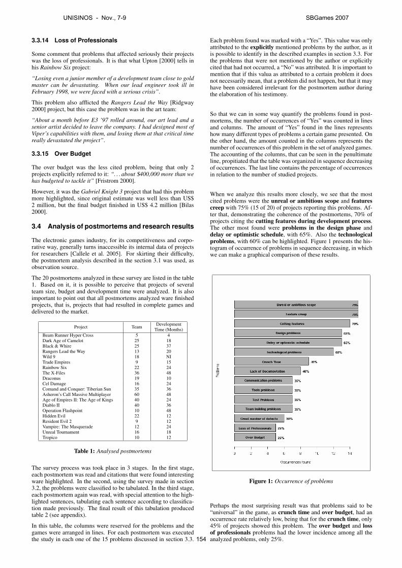
3.3.14 Loss of Professionals
Some comment that problems that affected seriously their projectswas the loss of professionals. It is that what Upton [2000] tells inhis Rainbow Six project:
“Losing even a junior member of a development team close to goldmaster can be devastating. When our lead engineer took ill inFebruary 1998, we were faced with a serious crisis”.
This problem also afflicted the Rangers Lead the Way [Ridgway2000] project, but this case the problem was in the art team:
“About a month before E3 ’97 rolled around, our art lead and asenior artist decided to leave the company. I had designed most ofViper’s capabilities with them, and losing them at that critical timereally devastated the project”.
3.3.15 Over Budget
The over budget was the less cited problem, being that only 2projects explicitly referred to it: “. . . about $400,000 more than wehas budgeted to tackle it” [Fristrom 2000].
However, it was the Gabriel Knight 3 project that had this problemmore highlighted, since original estimate was well less than US$2 million, but the final budget finished in US$ 4.2 million [Bilas2000].
3.4 Analysis of postmortems and research results
The electronic games industry, for its competitiveness and corpo-rative way, generally turns inaccessible its internal data of projectsfor researchers [Callele et al. 2005]. For skirting their difficulty,the postmortem analysis described in the section 3.1 was used, asobservation source.
The 20 postmortems analyzed in these survey are listed in the table1. Based on it, it is possible to perceive that projects of severalteam size, budget and development time were analyzed. It is alsoimportant to point out that all postmortems analyzed ware finishedprojects, that is, projects that had resulted in complete games anddelivered to the market.
Project Team DevelopmentTime (Months)
Beam Runner Hyper Cross 5 4Dark Age of Camelot 25 18Black & Whire 25 37Rangers Lead the Way 13 20Wild 9 18 NITrade Empires 9 15Rainbow Six 22 24The X-Files 36 48Draconus 19 10Cel Damage 16 24Comand and Conquer: Tiberian Sun 35 36Asheron’s Call Massive Multiplayer 60 48Age of Empires II: The Age of Kings 40 24Diablo II 40 36Operation Flashpoint 10 48Hidden Evil 22 12Resident Evil 2 9 12Vampire: The Masquerade 12 24Unreal Tournament 16 18Tropico 10 12
Table 1: Analysed postmortems
The survey process was took place in 3 stages. In the first stage,each postmortem was read and citations that were found interestingware highlighted. In the second, using the survey made in section3.2, the problems were classified to be tabulated. In the third stage,each postmortem again was read, with special attention to the high-lighted sentences, tabulating each sentence according to classifica-tion made previously. The final result of this tabulation producedtable 2 (see appendix).
In this table, the columns were reserved for the problems and thegames were arranged in lines. For each postmortem was executedthe study in each one of the 15 problems discussed in section 3.3.
Each problem found was marked with a “Yes”. This value was onlyattributed to the explicitly mentioned problems by the author, as itis possible to identify in the described examples in section 3.3. Forthe problems that were not mentioned by the author or explicitlycited that had not occurred, a “No” was attributed. It is important tomention that if this valua as attributed to a certain problem it doesnot necessarily mean, that a problem did not happen, but that it mayhave been considered irrelevant for the postmortem author duringthe elaboration of his testimony.
So that we can in some way quantify the problems found in post-mortems, the number of occurrences of “Yes” was counted in linesand columns. The amount of “Yes” found in the lines representshow many different types of problems a certain game presented. Onthe other hand, the amount counted in the columns represents thenumber of occurrences of this problem in the set of analyzed games.The accounting of the columns, that can be seen in the penultimateline, propitiated that the table was organized in sequence decreasingof occurrences. The last line contains the percentage of occurrencesin relation to the number of studied projects.
When we analyze this results more closely, we see that the mostcited problems were the unreal or ambitious scope and featurescreep with 75% (15 of 20) of projects reporting this problems. Af-ter that, demonstrating the coherence of the postmortems, 70% ofprojects citing the cutting features during development process.The other most found were problems in the design phase anddelay or optimistic schedule, with 65%. Also the technologicalproblems, with 60% can be highlighted. Figure 1 presents the his-togram of occurrence of problems in sequence decreasing, in whichwe can make a graphical comparison of these results.
Figure 1: Occurrence of problems
Perhaps the most surprising result was that problems said to be“universal” in the game, as crunch time and over budget, had anoccurrence rate relatively low, being that for the crunch time, only45% of projects showed this problem. The over budget and lossof professionals problems had the lower incidence among all theanalyzed problems, only 25%.
UNISINOS - Nov., 7-9 SBGames 2007
154
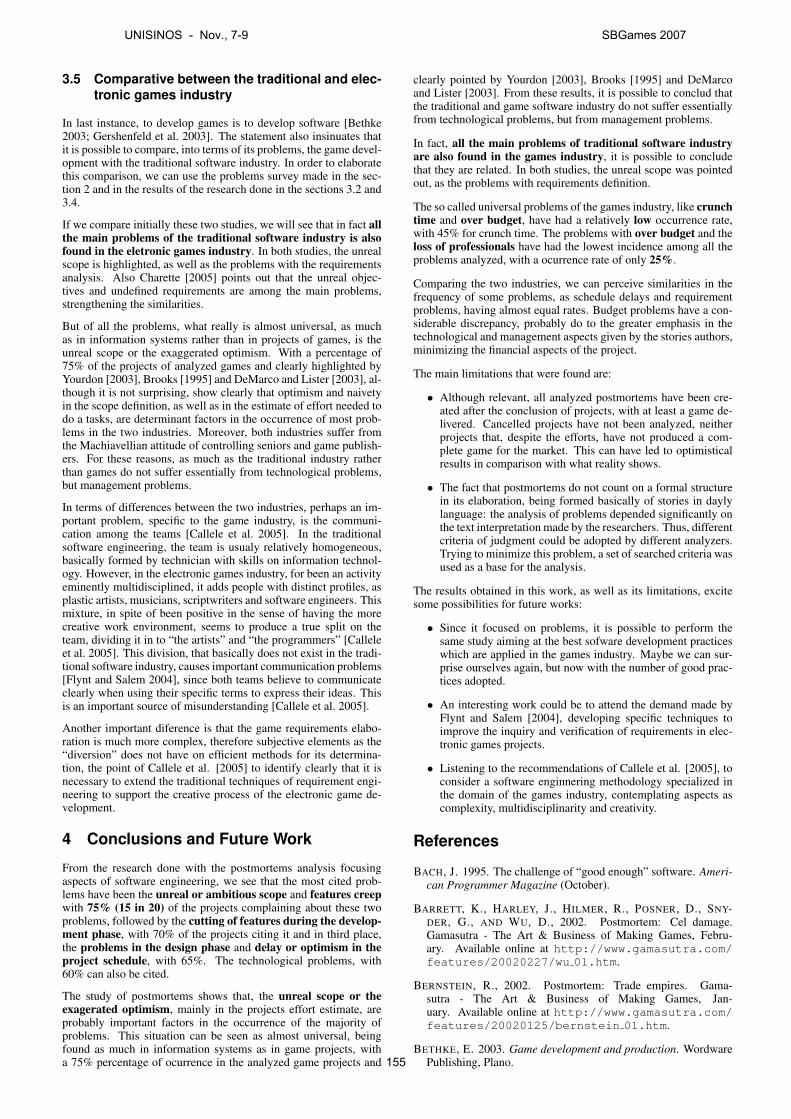
3.5 Comparative between the traditional and elec-tronic games industry
In last instance, to develop games is to develop software [Bethke2003; Gershenfeld et al. 2003]. The statement also insinuates thatit is possible to compare, into terms of its problems, the game devel-opment with the traditional software industry. In order to elaboratethis comparison, we can use the problems survey made in the sec-tion 2 and in the results of the research done in the sections 3.2 and3.4.
If we compare initially these two studies, we will see that in fact allthe main problems of the traditional software industry is alsofound in the eletronic games industry. In both studies, the unrealscope is highlighted, as well as the problems with the requirementsanalysis. Also Charette [2005] points out that the unreal objec-tives and undefined requirements are among the main problems,strengthening the similarities.
But of all the problems, what really is almost universal, as muchas in information systems rather than in projects of games, is theunreal scope or the exaggerated optimism. With a percentage of75% of the projects of analyzed games and clearly highlighted byYourdon [2003], Brooks [1995] and DeMarco and Lister [2003], al-though it is not surprising, show clearly that optimism and naivetyin the scope definition, as well as in the estimate of effort needed todo a tasks, are determinant factors in the occurrence of most prob-lems in the two industries. Moreover, both industries suffer fromthe Machiavellian attitude of controlling seniors and game publish-ers. For these reasons, as much as the traditional industry ratherthan games do not suffer essentially from technological problems,but management problems.
In terms of differences between the two industries, perhaps an im-portant problem, specific to the game industry, is the communi-cation among the teams [Callele et al. 2005]. In the traditionalsoftware engineering, the team is usualy relatively homogeneous,basically formed by technician with skills on information technol-ogy. However, in the electronic games industry, for been an activityeminently multidisciplined, it adds people with distinct profiles, asplastic artists, musicians, scriptwriters and software engineers. Thismixture, in spite of been positive in the sense of having the morecreative work environment, seems to produce a true split on theteam, dividing it in to “the artists” and “the programmers” [Calleleet al. 2005]. This division, that basically does not exist in the tradi-tional software industry, causes important communication problems[Flynt and Salem 2004], since both teams believe to communicateclearly when using their specific terms to express their ideas. Thisis an important source of misunderstanding [Callele et al. 2005].
Another important diference is that the game requirements elabo-ration is much more complex, therefore subjective elements as the“diversion” does not have on efficient methods for its determina-tion, the point of Callele et al. [2005] to identify clearly that it isnecessary to extend the traditional techniques of requirement engi-neering to support the creative process of the electronic game de-velopment.
4 Conclusions and Future Work
From the research done with the postmortems analysis focusingaspects of software engineering, we see that the most cited prob-lems have been the unreal or ambitious scope and features creepwith 75% (15 in 20) of the projects complaining about these twoproblems, followed by the cutting of features during the develop-ment phase, with 70% of the projects citing it and in third place,the problems in the design phase and delay or optimism in theproject schedule, with 65%. The technological problems, with60% can also be cited.
The study of postmortems shows that, the unreal scope or theexagerated optimism, mainly in the projects effort estimate, areprobably important factors in the occurrence of the majority ofproblems. This situation can be seen as almost universal, beingfound as much in information systems as in game projects, witha 75% percentage of ocurrence in the analyzed game projects and
clearly pointed by Yourdon [2003], Brooks [1995] and DeMarcoand Lister [2003]. From these results, it is possible to conclud thatthe traditional and game software industry do not suffer essentiallyfrom technological problems, but from management problems.
In fact, all the main problems of traditional software industryare also found in the games industry, it is possible to concludethat they are related. In both studies, the unreal scope was pointedout, as the problems with requirements definition.
The so called universal problems of the games industry, like crunchtime and over budget, have had a relatively low occurrence rate,with 45% for crunch time. The problems with over budget and theloss of professionals have had the lowest incidence among all theproblems analyzed, with a ocurrence rate of only 25%.
Comparing the two industries, we can perceive similarities in thefrequency of some problems, as schedule delays and requirementproblems, having almost equal rates. Budget problems have a con-siderable discrepancy, probably do to the greater emphasis in thetechnological and management aspects given by the stories authors,minimizing the financial aspects of the project.
The main limitations that were found are:
• Although relevant, all analyzed postmortems have been cre-ated after the conclusion of projects, with at least a game de-livered. Cancelled projects have not been analyzed, neitherprojects that, despite the efforts, have not produced a com-plete game for the market. This can have led to optimisticalresults in comparison with what reality shows.
• The fact that postmortems do not count on a formal structurein its elaboration, being formed basically of stories in daylylanguage: the analysis of problems depended significantly onthe text interpretation made by the researchers. Thus, differentcriteria of judgment could be adopted by different analyzers.Trying to minimize this problem, a set of searched criteria wasused as a base for the analysis.
The results obtained in this work, as well as its limitations, excitesome possibilities for future works:
• Since it focused on problems, it is possible to perform thesame study aiming at the best sofware development practiceswhich are applied in the games industry. Maybe we can sur-prise ourselves again, but now with the number of good prac-tices adopted.
• An interesting work could be to attend the demand made byFlynt and Salem [2004], developing specific techniques toimprove the inquiry and verification of requirements in elec-tronic games projects.
• Listening to the recommendations of Callele et al. [2005], toconsider a software enginnering methodology specialized inthe domain of the games industry, contemplating aspects ascomplexity, multidisciplinarity and creativity.
References
BACH, J. 1995. The challenge of “good enough” software. Ameri-can Programmer Magazine (October).
BARRETT, K., HARLEY, J., HILMER, R., POSNER, D., SNY-DER, G., AND WU, D., 2002. Postmortem: Cel damage.Gamasutra - The Art & Business of Making Games, Febru-ary. Available online at http://www.gamasutra.com/features/20020227/wu 01.htm.
BERNSTEIN, R., 2002. Postmortem: Trade empires. Gama-sutra - The Art & Business of Making Games, Jan-uary. Available online at http://www.gamasutra.com/features/20020125/bernstein 01.htm.
BETHKE, E. 2003. Game development and production. WordwarePublishing, Plano.
UNISINOS - Nov., 7-9 SBGames 2007
155
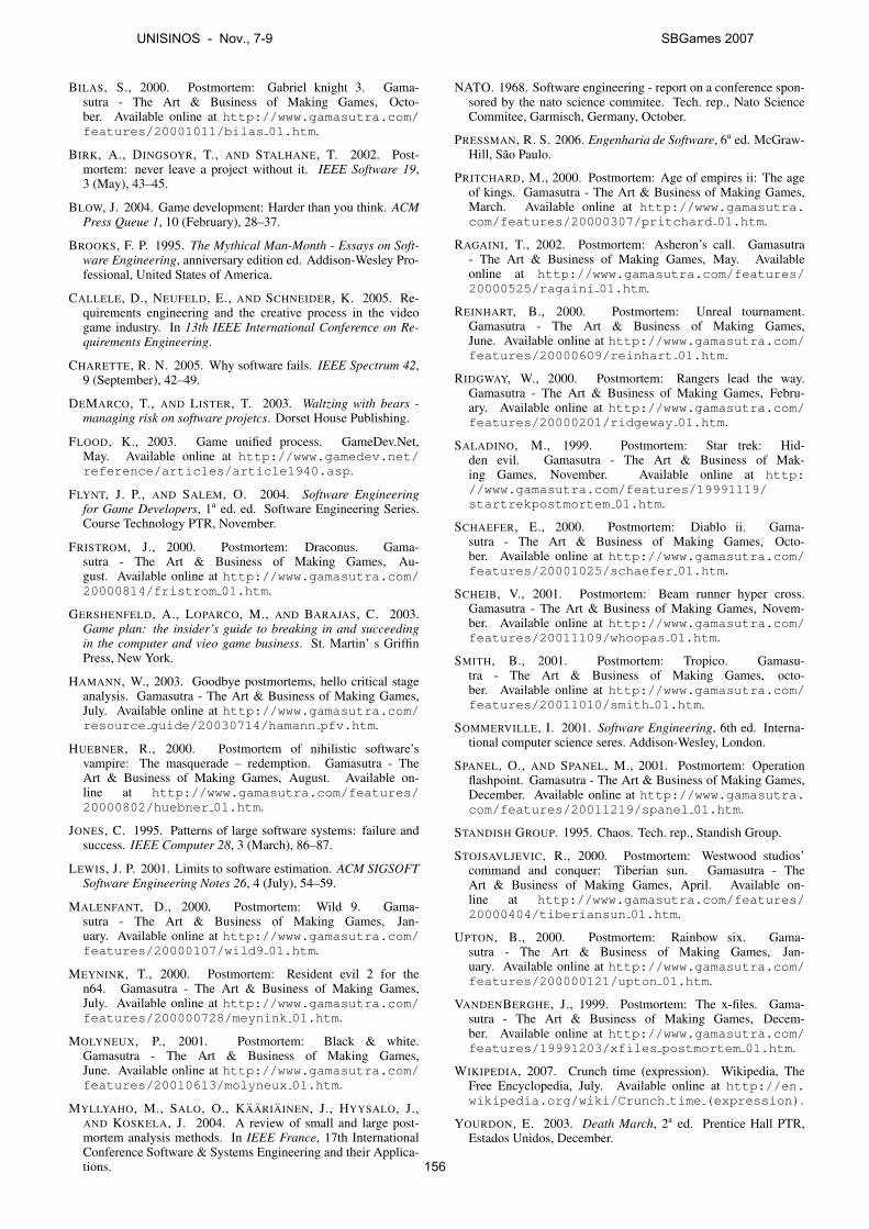
BILAS, S., 2000. Postmortem: Gabriel knight 3. Gama-sutra - The Art & Business of Making Games, Octo-ber. Available online at http://www.gamasutra.com/features/20001011/bilas 01.htm.
BIRK, A., DINGSOYR, T., AND STALHANE, T. 2002. Post-mortem: never leave a project without it. IEEE Software 19,3 (May), 43–45.
BLOW, J. 2004. Game development: Harder than you think. ACMPress Queue 1, 10 (February), 28–37.
BROOKS, F. P. 1995. The Mythical Man-Month - Essays on Soft-ware Engineering, anniversary edition ed. Addison-Wesley Pro-fessional, United States of America.
CALLELE, D., NEUFELD, E., AND SCHNEIDER, K. 2005. Re-quirements engineering and the creative process in the videogame industry. In 13th IEEE International Conference on Re-quirements Engineering.
CHARETTE, R. N. 2005. Why software fails. IEEE Spectrum 42,9 (September), 42–49.
DEMARCO, T., AND LISTER, T. 2003. Waltzing with bears -managing risk on software projetcs. Dorset House Publishing.
FLOOD, K., 2003. Game unified process. GameDev.Net,May. Available online at http://www.gamedev.net/reference/articles/article1940.asp.
FLYNT, J. P., AND SALEM, O. 2004. Software Engineeringfor Game Developers, 1a ed. ed. Software Engineering Series.Course Technology PTR, November.
FRISTROM, J., 2000. Postmortem: Draconus. Gama-sutra - The Art & Business of Making Games, Au-gust. Available online at http://www.gamasutra.com/20000814/fristrom 01.htm.
GERSHENFELD, A., LOPARCO, M., AND BARAJAS, C. 2003.Game plan: the insider’s guide to breaking in and succeedingin the computer and vieo game business. St. Martin’ s GriffinPress, New York.
HAMANN, W., 2003. Goodbye postmortems, hello critical stageanalysis. Gamasutra - The Art & Business of Making Games,July. Available online at http://www.gamasutra.com/resource guide/20030714/hamann pfv.htm.
HUEBNER, R., 2000. Postmortem of nihilistic software’svampire: The masquerade – redemption. Gamasutra - TheArt & Business of Making Games, August. Available on-line at http://www.gamasutra.com/features/20000802/huebner 01.htm.
JONES, C. 1995. Patterns of large software systems: failure andsuccess. IEEE Computer 28, 3 (March), 86–87.
LEWIS, J. P. 2001. Limits to software estimation. ACM SIGSOFTSoftware Engineering Notes 26, 4 (July), 54–59.
MALENFANT, D., 2000. Postmortem: Wild 9. Gama-sutra - The Art & Business of Making Games, Jan-uary. Available online at http://www.gamasutra.com/features/20000107/wild9 01.htm.
MEYNINK, T., 2000. Postmortem: Resident evil 2 for then64. Gamasutra - The Art & Business of Making Games,July. Available online at http://www.gamasutra.com/features/200000728/meynink 01.htm.
MOLYNEUX, P., 2001. Postmortem: Black & white.Gamasutra - The Art & Business of Making Games,June. Available online at http://www.gamasutra.com/features/20010613/molyneux 01.htm.
MYLLYAHO, M., SALO, O., KAARIAINEN, J., HYYSALO, J.,AND KOSKELA, J. 2004. A review of small and large post-mortem analysis methods. In IEEE France, 17th InternationalConference Software & Systems Engineering and their Applica-tions.
NATO. 1968. Software engineering - report on a conference spon-sored by the nato science commitee. Tech. rep., Nato ScienceCommitee, Garmisch, Germany, October.
PRESSMAN, R. S. 2006. Engenharia de Software, 6a ed. McGraw-Hill, Sao Paulo.
PRITCHARD, M., 2000. Postmortem: Age of empires ii: The ageof kings. Gamasutra - The Art & Business of Making Games,March. Available online at http://www.gamasutra.com/features/20000307/pritchard 01.htm.
RAGAINI, T., 2002. Postmortem: Asheron’s call. Gamasutra- The Art & Business of Making Games, May. Availableonline at http://www.gamasutra.com/features/20000525/ragaini 01.htm.
REINHART, B., 2000. Postmortem: Unreal tournament.Gamasutra - The Art & Business of Making Games,June. Available online at http://www.gamasutra.com/features/20000609/reinhart 01.htm.
RIDGWAY, W., 2000. Postmortem: Rangers lead the way.Gamasutra - The Art & Business of Making Games, Febru-ary. Available online at http://www.gamasutra.com/features/20000201/ridgeway 01.htm.
SALADINO, M., 1999. Postmortem: Star trek: Hid-den evil. Gamasutra - The Art & Business of Mak-ing Games, November. Available online at http://www.gamasutra.com/features/19991119/startrekpostmortem 01.htm.
SCHAEFER, E., 2000. Postmortem: Diablo ii. Gama-sutra - The Art & Business of Making Games, Octo-ber. Available online at http://www.gamasutra.com/features/20001025/schaefer 01.htm.
SCHEIB, V., 2001. Postmortem: Beam runner hyper cross.Gamasutra - The Art & Business of Making Games, Novem-ber. Available online at http://www.gamasutra.com/features/20011109/whoopas 01.htm.
SMITH, B., 2001. Postmortem: Tropico. Gamasu-tra - The Art & Business of Making Games, octo-ber. Available online at http://www.gamasutra.com/features/20011010/smith 01.htm.
SOMMERVILLE, I. 2001. Software Engineering, 6th ed. Interna-tional computer science seres. Addison-Wesley, London.
SPANEL, O., AND SPANEL, M., 2001. Postmortem: Operationflashpoint. Gamasutra - The Art & Business of Making Games,December. Available online at http://www.gamasutra.com/features/20011219/spanel 01.htm.
STANDISH GROUP. 1995. Chaos. Tech. rep., Standish Group.
STOJSAVLJEVIC, R., 2000. Postmortem: Westwood studios’command and conquer: Tiberian sun. Gamasutra - TheArt & Business of Making Games, April. Available on-line at http://www.gamasutra.com/features/20000404/tiberiansun 01.htm.
UPTON, B., 2000. Postmortem: Rainbow six. Gama-sutra - The Art & Business of Making Games, Jan-uary. Available online at http://www.gamasutra.com/features/200000121/upton 01.htm.
VANDENBERGHE, J., 1999. Postmortem: The x-files. Gama-sutra - The Art & Business of Making Games, Decem-ber. Available online at http://www.gamasutra.com/features/19991203/xfiles postmortem 01.htm.
WIKIPEDIA, 2007. Crunch time (expression). Wikipedia, TheFree Encyclopedia, July. Available online at http://en.wikipedia.org/wiki/Crunch time (expression).
YOURDON, E. 2003. Death March, 2a ed. Prentice Hall PTR,Estados Unidos, December.
UNISINOS - Nov., 7-9 SBGames 2007
156
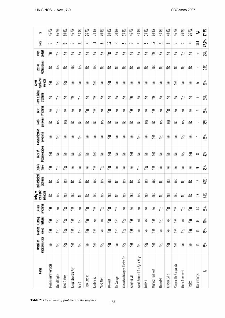
Total
%
NoNo
NoNo
NoNo
NoNo
746
,7%
NoNo
1386
,7%
NoNo
NoNo
NoNo
960
,0%
NoNo
NoNo
NoNo
NoNo
746
,7%
NoNo
NoNo
NoNo
No8
53,3%
NoNo
NoNo
NoNo
NoNo
NoNo
No4
26,7%
NoNo
NoNo
1173
,3%
The X
-Files
NoNo
NoNo
NoNo
NoNo
No6
40,0%
NoNo
No12
80,0%
NoNo
NoNo
NoNo
NoNo
NoNo
NoNo
320
,0%
NoNo
NoNo
NoNo
NoNo
NoNo
533
,3%
NoNo
NoNo
NoNo
NoNo
746
,7%
NoNo
NoNo
NoNo
NoNo
NoNo
533
,3%
NoNo
NoNo
NoNo
NoNo
NoNo
533
,3%
NoNo
No12
80,0%
NoNo
NoNo
NoNo
NoNo
NoNo
533
,3%
NoNo
NoNo
NoNo
NoNo
No6
40,0%
NoNo
NoNo
NoNo
NoNo
746
,7%
NoNo
NoNo
NoNo
NoNo
746
,7%
NoNo
NoNo
NoNo
NoNo
NoNo
No4
26,7%
1515
1413
1312
98
77
77
65
514
37,2
% 75
%75
%70
%65
%65
%60
%45
%40
%35
%35
%35
%35
%30
%25
%25
%47
,7%47
,7%
Game
Unrea
l or
ambit
ious s
cope
Featu
re cre
epCu
tting
fea
tures
Desig
n pro
blems
Delay
or
optim
istic
sche
dule
Tech
nolog
ical
proble
msCr
unch
Tim
eLa
ck of
Do
cume
ntatio
nCo
mmun
icatio
n pro
blems
Tools
pro
blems
Test
Prob
lems
Team
build
ing
proble
ms
Grea
t nu
mber
of de
fects
Loss
of
Profe
ssion
alsOv
er Bu
dget
Beam
Runn
er Hy
per C
ross
Yes
Yes
Yes
Yes
Yes
Yes
Yes
Gabri
el Kn
ights
Yes
Yes
Yes
Yes
Yes
Yes
Yes
Yes
Yes
Yes
Yes
Yes
Yes
Black
& Whir
eYe
sYe
sYe
sYe
sYe
sYe
sYe
sYe
sYe
s
Rang
ers Le
ad th
e Way
Yes
Yes
Yes
Yes
Yes
Yes
Yes
Wild
9Ye
sYe
sYe
sYe
sYe
sYe
sYe
sYe
s
Trade
Empir
esYe
sYe
sYe
sYe
s
Rainb
ow Si
xYe
sYe
sYe
sYe
sYe
sYe
sYe
sYe
sYe
sYe
sYe
s
Yes
Yes
Yes
Yes
Yes
Yes
Dracon
usYe
sYe
sYe
sYe
sYe
sYe
sYe
sYe
sYe
sYe
sYe
sYe
s
Cel D
amag
eYe
sYe
sYe
s
Coma
nd an
d Con
quer:
Tibe
rian S
unYe
sYe
sYe
sYe
sYe
s
Ashe
ron's C
allYe
sYe
sYe
sYe
sYe
sYe
sYe
s
Age o
f Emp
ires II
: The
Age o
f King
sYe
sYe
sYe
sYe
sYe
s
Diablo
IIYe
sYe
sYe
sYe
sYe
s
Opera
tion F
lashp
oint
Yes
Yes
Yes
Yes
Yes
Yes
Yes
Yes
Yes
Yes
Yes
Yes
Hidde
n Evil
Yes
Yes
Yes
Yes
Yes
Resid
ent E
vil 2
Yes
Yes
Yes
Yes
Yes
Yes
Vamp
ire: T
he Ma
squera
deYe
sYe
sYe
sYe
sYe
sYe
sYe
s
Unrea
l Tou
rname
ntYe
sYe
sYe
sYe
sYe
sYe
sYe
s
Tropic
oYe
sYe
sYe
sYe
s
Occu
rrenc
es
Table 2: Occurrence of problems in the projetcs
UNISINOS - Nov., 7-9 SBGames 2007
157
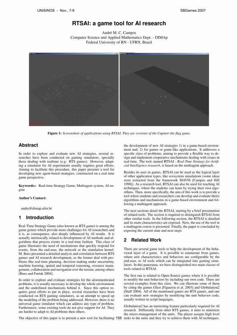
RTSAI: a game tool for AI researchAndre M. C. Campos
Computer Science and Applied Mathematics Dept. - DIMApFederal University of RN - UFRN, Brazil
Figure 1: Screenshots of applications using RTSAI. They are versions of the Capture-the-flag game.
Abstract
In order to explore and evaluate new AI strategies, several re-searches have been conducted on gaming simulators, speciallythose dealing with realtime (e.g. RTS games). However, adapt-ing a simulator for AI experiments usually requires great efforts.Aiming to facilitate this procedure, this paper presents a tool fordeveloping new agent-based strategies, constructed on a real timegame perspective.
Keywords:: Real-time Strategy Game, Multiagent system, AI en-gine
Author’s Contact:
1 Introduction
Real-Time Strategy Game (also known as RTS game) is among thegame genres which provide more challenges for AI researchers andit is, as consequence, also deeply influenced by AI results. It isactually intrinsically related to development of AI methods and al-gorithms that process events in a real-time fashion. This class ofgame illustrates the need of mechanisms that quickly respond forevents, from the end-user, the network or the simulation kernel.M. Buro presented a detailed analysis and correlation between RTSgames and AI research development, as the former deal with pro-blems like real-time planning, decision making under uncertainty,machine learning, spatial and temporal reasoning, resource mana-gement, collaboration and navigation over the terrain, among others[Buro and Furtak 2004].
In order to explore and evaluate strategies for the aforementionedproblems, it is usually necessary to develop the whole environmentand the underlined mechanisms behind it. Since this option re-quires great efforts to put in place, several researches have beenconducted on RTS gaming simulators, as an attempt to speed upthe modeling of the problem being addressed. However, there is nouniversal game simulator which can address any type of problem.Furthermore, some existing tools do not give support for AI. Theyare harder to adapt to AI problems then others.
The objective of this paper is to present a new tool for facilitating
the development of new AI strategies 1) in a game-based environ-ment and; 2) for games or game-like applications. It addresses aspecific class of problems, aiming to provide a flexible way to de-sign and implement cooperative mechanisms dealing with issues inreal-time. The tool, named RTSAI - Real-Time Strategy for Artifi-cial Intelligence research, is based on the multiagent approach.
Besides its uses in games, RTSAI can be used as the logical layerof other application types, like ecosystem simulations (some ideaswere extracted from the framework MAVIS [Campos and Hill1998]). As a research tool, RTSAI can also be used for teaching AItechniques, where the students can learn by trying their own algo-rithms. Then, more specifically, the aim of this work is to provide atool where students and researchers can develop and evaluate theirsalgorithms and mechanisms in a game-based environment and fol-lowing a multiagent approach.
The next sections detail the RTSAI, starting by a brief presentationof related tools. The section is required to distinguish RTSAI fromother similar tools. In the following section, the RTSAI is detailedand its main characteristics are exposed. Next, the use of the tool ina multiagent course is presented. Finally, the paper is concluded byexposing the current state and next steps.
2 Related Work
There are several game tools to help the development of the beha-vioral layer of a game. It is possible to enumerate from games,where unit characteristics and behaviors are configurable by theend-user, to AI tools which can be integrated into gaming simu-lators. In this panorama, we have distinguished two main classes oftools related to RTSAI.
The first one is related to Open-Source games where it is possibleto modify the unit behaviors by including our own code. There areseveral examples from this class. We can illustrate some of themby citing the games Glest [Figueroa et al. 2003] and Globulation2[Staff 2004]. All of the mentioned games are RTS games, and onecan evaluate new strategies by modifying the unit behavior code,usually written in script languages.
Globulation2 has an interesting feature particularly required for AIresearch. Differently from other RTS games, it aims to minimizethe micro-management of the units. The player assigns high leveltasks to the units and they try to achieve them with AI techniques.
UNISINOS - Nov., 7-9 SBGames 2007
158
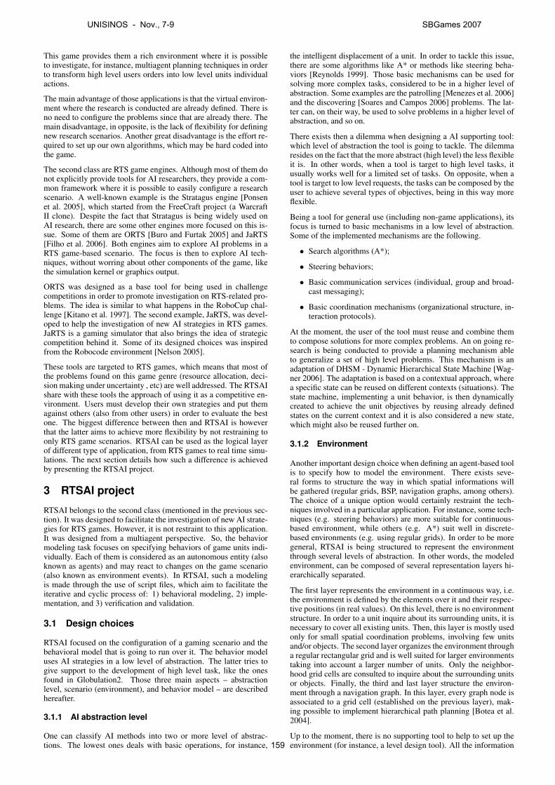
This game provides them a rich environment where it is possibleto investigate, for instance, multiagent planning techniques in orderto transform high level users orders into low level units individualactions.
The main advantage of those applications is that the virtual environ-ment where the research is conducted are already defined. There isno need to configure the problems since that are already there. Themain disadvantage, in opposite, is the lack of flexibility for definingnew research scenarios. Another great disadvantage is the effort re-quired to set up our own algorithms, which may be hard coded intothe game.
The second class are RTS game engines. Although most of them donot explicitly provide tools for AI researchers, they provide a com-mon framework where it is possible to easily configure a researchscenario. A well-known example is the Stratagus engine [Ponsenet al. 2005], which started from the FreeCraft project (a WarcraftII clone). Despite the fact that Stratagus is being widely used onAI research, there are some other engines more focused on this is-sue. Some of them are ORTS [Buro and Furtak 2005] and JaRTS[Filho et al. 2006]. Both engines aim to explore AI problems in aRTS game-based scenario. The focus is then to explore AI tech-niques, without worring about other components of the game, likethe simulation kernel or graphics output.
ORTS was designed as a base tool for being used in challengecompetitions in order to promote investigation on RTS-related pro-blems. The idea is similar to what happens in the RoboCup chal-lenge [Kitano et al. 1997]. The second example, JaRTS, was devel-oped to help the investigation of new AI strategies in RTS games.JaRTS is a gaming simulator that also brings the idea of strategiccompetition behind it. Some of its designed choices was inspiredfrom the Robocode environment [Nelson 2005].
These tools are targeted to RTS games, which means that most ofthe problems found on this game genre (resource allocation, deci-sion making under uncertainty , etc) are well addressed. The RTSAIshare with these tools the approach of using it as a competitive en-vironment. Users must develop their own strategies and put themagainst others (also from other users) in order to evaluate the bestone. The biggest difference between then and RTSAI is howeverthat the latter aims to achieve more flexibility by not restraining toonly RTS game scenarios. RTSAI can be used as the logical layerof different type of application, from RTS games to real time simu-lations. The next section details how such a difference is achievedby presenting the RTSAI project.
3 RTSAI project
RTSAI belongs to the second class (mentioned in the previous sec-tion). It was designed to facilitate the investigation of new AI strate-gies for RTS games. However, it is not restraint to this application.It was designed from a multiagent perspective. So, the behaviormodeling task focuses on specifying behaviors of game units indi-vidually. Each of them is considered as an autonomous entity (alsoknown as agents) and may react to changes on the game scenario(also known as environment events). In RTSAI, such a modelingis made through the use of script files, which aim to facilitate theiterative and cyclic process of: 1) behavioral modeling, 2) imple-mentation, and 3) verification and validation.
3.1 Design choices
RTSAI focused on the configuration of a gaming scenario and thebehavioral model that is going to run over it. The behavior modeluses AI strategies in a low level of abstraction. The latter tries togive support to the development of high level task, like the onesfound in Globulation2. Those three main aspects – abstractionlevel, scenario (environment), and behavior model – are describedhereafter.
3.1.1 AI abstraction level
One can classify AI methods into two or more level of abstrac-tions. The lowest ones deals with basic operations, for instance,
the intelligent displacement of a unit. In order to tackle this issue,there are some algorithms like A* or methods like steering beha-viors [Reynolds 1999]. Those basic mechanisms can be used forsolving more complex tasks, considered to be in a higher level ofabstraction. Some examples are the patrolling [Menezes et al. 2006]and the discovering [Soares and Campos 2006] problems. The lat-ter can, on their way, be used to solve problems in a higher level ofabstraction, and so on.
There exists then a dilemma when designing a AI supporting tool:which level of abstraction the tool is going to tackle. The dilemmaresides on the fact that the more abstract (high level) the less flexibleit is. In other words, when a tool is target to high level tasks, itusually works well for a limited set of tasks. On opposite, when atool is target to low level requests, the tasks can be composed by theuser to achieve several types of objectives, being in this way moreflexible.
Being a tool for general use (including non-game applications), itsfocus is turned to basic mechanisms in a low level of abstraction.Some of the implemented mechanisms are the following.
• Search algorithms (A*);
• Steering behaviors;
• Basic communication services (individual, group and broad-cast messaging);
• Basic coordination mechanisms (organizational structure, in-teraction protocols).
At the moment, the user of the tool must reuse and combine themto compose solutions for more complex problems. An on going re-search is being conducted to provide a planning mechanism ableto generalize a set of high level problems. This mechanism is anadaptation of DHSM - Dynamic Hierarchical State Machine [Wag-ner 2006]. The adaptation is based on a contextual approach, wherea specific state can be reused on different contexts (situations). Thestate machine, implementing a unit behavior, is then dynamicallycreated to achieve the unit objectives by reusing already definedstates on the current context and it is also considered a new state,which might also be reused further on.
3.1.2 Environment
Another important design choice when defining an agent-based toolis to specify how to model the environment. There exists seve-ral forms to structure the way in which spatial informations willbe gathered (regular grids, BSP, navigation graphs, among others).The choice of a unique option would certainly restraint the tech-niques involved in a particular application. For instance, some tech-niques (e.g. steering behaviors) are more suitable for continuous-based environment, while others (e.g. A*) suit well in discrete-based environments (e.g. using regular grids). In order to be moregeneral, RTSAI is being structured to represent the environmentthrough several levels of abstraction. In other words, the modeledenvironment, can be composed of several representation layers hi-erarchically separated.
The first layer represents the environment in a continuous way, i.e.the environment is defined by the elements over it and their respec-tive positions (in real values). On this level, there is no environmentstructure. In order to a unit inquire about its surrounding units, it isnecessary to cover all existing units. Then, this layer is mostly usedonly for small spatial coordination problems, involving few unitsand/or objects. The second layer organizes the environment througha regular rectangular grid and is well suited for larger environmentstaking into account a larger number of units. Only the neighbor-hood grid cells are consulted to inquire about the surrounding unitsor objects. Finally, the third and last layer structure the environ-ment through a navigation graph. In this layer, every graph node isassociated to a grid cell (established on the previous layer), mak-ing possible to implement hierarchical path planning [Botea et al.2004].
Up to the moment, there is no supporting tool to help to set up theenvironment (for instance, a level design tool). All the information
UNISINOS - Nov., 7-9 SBGames 2007
159
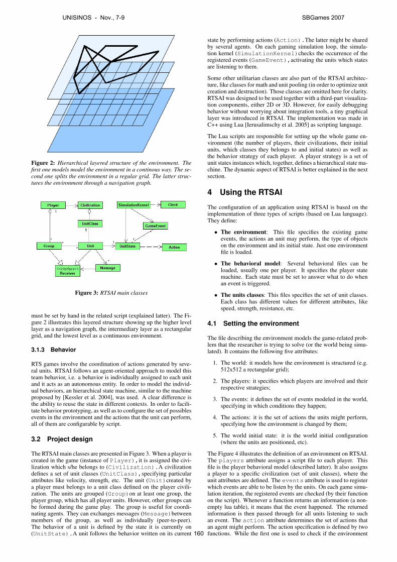
Figure 2: Hierarchical layered structure of the environment. Thefirst one models model the environment in a continous way. The se-cond one splits the environment in a regular grid. The latter struc-tures the environment through a navigation graph.
Figure 3: RTSAI main classes
must be set by hand in the related script (explained latter). The Fi-gure 2 illustrates this layered structure showing up the higher levellayer as a navigation graph, the intermediary layer as a rectangulargrid, and the lowest level as a continuous environment.
3.1.3 Behavior
RTS games involve the coordination of actions generated by seve-ral units. RTSAI follows an agent-oriented approach to model thisteam behavior, i.e. a behavior is individually assigned to each unitand it acts as an autonomous entity. In order to model the individ-ual behaviors, an hierarchical state machine, similar to the machineproposed by [Kessler et al. 2004], was used. A clear difference isthe ability to reuse the state in different contexts. In order to facili-tate behavior prototyping, as well as to configure the set of possiblesevents in the environment and the actions that the unit can perform,all of them are configurable by script.
3.2 Project design
The RTSAI main classes are presented in Figure 3. When a player iscreated in the game (instance of Player),it is assigned the civi-lization which s/he belongs to (Civilization).A civilizationdefines a set of unit classes (UnitClass),specifying particularattributes like velocity, strength, etc. The unit (Unit)created bya player must belongs to a unit class defined on the player civili-zation. The units are grouped (Group)on at least one group, theplayer group, which has all player units. However, other groups canbe formed during the game play. The group is useful for coordi-nating agents. They can exchanges messages (Message)betweenmembers of the group, as well as individually (peer-to-peer).The behavior of a unit is defined by the state it is currently on(UnitState).A unit follows the behavior written on its current
state by performing actions (Action).The latter might be sharedby several agents. On each gaming simulation loop, the simula-tion kernel (SimulationKernel)checks the occurrence of theregistered events (GameEvent),activating the units which statesare listening to them.
Some other utilitarian classes are also part of the RTSAI architec-ture, like classes for math and unit pooling (in order to optimize unitcreation and destruction). Those classes are omitted here for clarity.RTSAI was designed to be used together with a third-part visualiza-tion components, either 2D or 3D. However, for easily debuggingbehavior without worrying about integration tools, a tiny graphicallayer was introduced in RTSAI. The implementation was made inC++ using Lua [Ierusalimschy et al. 2005] as scripting language.
The Lua scripts are responsible for setting up the whole game en-vironment (the number of players, their civilizations, their initialunits, which classes they belongs to and initial states) as well asthe behavior strategy of each player. A player strategy is a set ofunit states instances which, together, defines a hierarchical state ma-chine. The dynamic aspect of RTSAI is better explained in the nextsection.
4 Using the RTSAI
The configuration of an application using RTSAI is based on theimplementation of three types of scripts (based on Lua language).They define:
• The environment: This file specifies the existing gameevents, the actions an unit may perform, the type of objectson the environment and its initial state. Just one environmentfile is loaded.
• The behavioral model: Several behavioral files can beloaded, usually one per player. It specifies the player statemachine. Each state must be set to answer what to do whenan event is triggered.
• The units classes: This files specifies the set of unit classes.Each class has different values for different attributes, likespeed, strength, resistance, etc.
4.1 Setting the environment
The file describing the environment models the game-related prob-lem that the researcher is trying to solve (or the world being simu-lated). It contains the following five attributes:
1. The world: it models how the environment is structured (e.g.512x512 a rectangular grid);
2. The players: it specifies which players are involved and theirrespective strategies;
3. The events: it defines the set of events modeled in the world,specifying in which conditions they happen;
4. The actions: it is the set of actions the units might perform,specifying how the environment is changed by them;
5. The world initial state: it is the world initial configuration(where the units are positioned, etc).
The Figure 4 illustrates the definition of an environment on RTSAI.The players attribute assigns a script file to each player. Thisfile is the player behavioral model (described latter). It also assignsa player to a specific civilization (set of unit classes), where theunit attributes are defined. The events attribute is used to registerwhich events are able to be listen by the units. On each game simu-lation iteration, the registered events are checked (by their functionon the script). Whenever a function returns an information (a non-empty lua table), it means that the event happened. The returnedinformation is then passed through for all units listening to suchan event. The action attribute determines the set of actions thatan agent might perform. The action specification is defined by twofunctions. While the first one is used to check if the environment
UNISINOS - Nov., 7-9 SBGames 2007
160
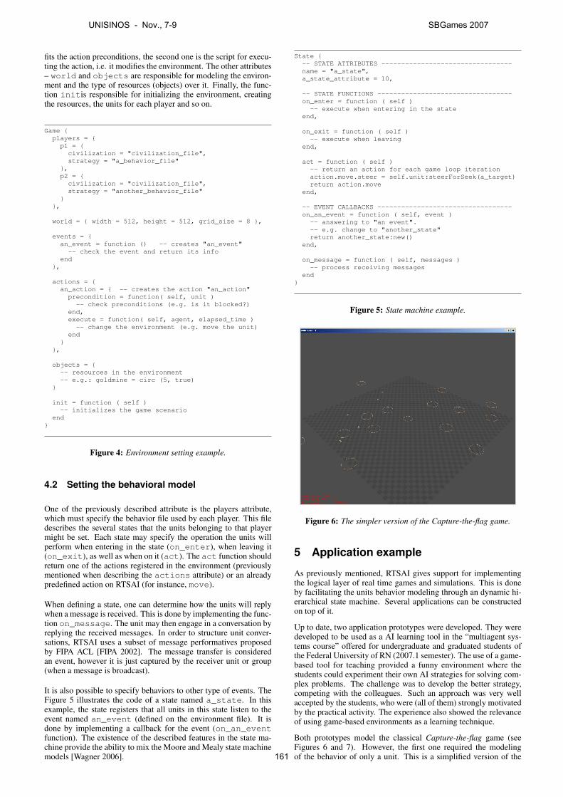
fits the action preconditions, the second one is the script for execu-ting the action, i.e. it modifies the environment. The other attributes– world and objects are responsible for modeling the environ-ment and the type of resources (objects) over it. Finally, the func-tion initis responsible for initializing the environment, creatingthe resources, the units for each player and so on.
Game {players = {p1 = {civilization = "civilization_file",strategy = "a_behavior_file"
},p2 = {civilization = "civilization_file",strategy = "another_behavior_file"
}},
world = { width = 512, height = 512, grid_size = 8 },
events = {an_event = function () -- creates "an_event"-- check the event and return its info
end},
actions = {an_action = { -- creates the action "an_action"precondition = function( self, unit )
-- check preconditions (e.g. is it blocked?)end,execute = function( self, agent, elapsed_time )
-- change the environment (e.g. move the unit)end
}},
objects = {-- resources in the environment-- e.g.: goldmine = circ (5, true)
}
init = function ( self )-- initializes the game scenario
end}
Figure 4: Environment setting example.
4.2 Setting the behavioral model
One of the previously described attribute is the players attribute,which must specify the behavior file used by each player. This filedescribes the several states that the units belonging to that playermight be set. Each state may specify the operation the units willperform when entering in the state (on_enter), when leaving it(on_exit), as well as when on it (act). The act function shouldreturn one of the actions registered in the environment (previouslymentioned when describing the actions attribute) or an alreadypredefined action on RTSAI (for instance, move).
When defining a state, one can determine how the units will replywhen a message is received. This is done by implementing the func-tion on_message. The unit may then engage in a conversation byreplying the received messages. In order to structure unit conver-sations, RTSAI uses a subset of message performatives proposedby FIPA ACL [FIPA 2002]. The message transfer is consideredan event, however it is just captured by the receiver unit or group(when a message is broadcast).
It is also possible to specify behaviors to other type of events. TheFigure 5 illustrates the code of a state named a_state. In thisexample, the state registers that all units in this state listen to theevent named an_event (defined on the environment file). It isdone by implementing a callback for the event (on_an_eventfunction). The existence of the described features in the state ma-chine provide the ability to mix the Moore and Mealy state machinemodels [Wagner 2006].
State {-- STATE ATTRIBUTES ---------------------------------name = "a_state",a_state_attribute = 10,
-- STATE FUNCTIONS ----------------------------------on_enter = function ( self )-- execute when entering in the state
end,
on_exit = function ( self )-- execute when leaving
end,
act = function ( self )-- return an action for each game loop iterationaction.move.steer = self.unit:steerForSeek(a_target)return action.move
end,
-- EVENT CALLBACKS ----------------------------------on_an_event = function ( self, event )-- answering to "an event".-- e.g. change to "another_state"return another_state:new()
end,
on_message = function ( self, messages )-- process receiving messages
end}
Figure 5: State machine example.
Figure 6: The simpler version of the Capture-the-flag game.
5 Application example
As previously mentioned, RTSAI gives support for implementingthe logical layer of real time games and simulations. This is doneby facilitating the units behavior modeling through an dynamic hi-erarchical state machine. Several applications can be constructedon top of it.
Up to date, two application prototypes were developed. They weredeveloped to be used as a AI learning tool in the “multiagent sys-tems course” offered for undergraduate and graduated students ofthe Federal University of RN (2007.1 semester). The use of a game-based tool for teaching provided a funny environment where thestudents could experiment their own AI strategies for solving com-plex problems. The challenge was to develop the better strategy,competing with the colleagues. Such an approach was very wellaccepted by the students, who were (all of them) strongly motivatedby the practical activity. The experience also showed the relevanceof using game-based environments as a learning technique.
Both prototypes model the classical Capture-the-flag game (seeFigures 6 and 7). However, the first one required the modelingof the behavior of only a unit. This is a simplified version of the
UNISINOS - Nov., 7-9 SBGames 2007
161
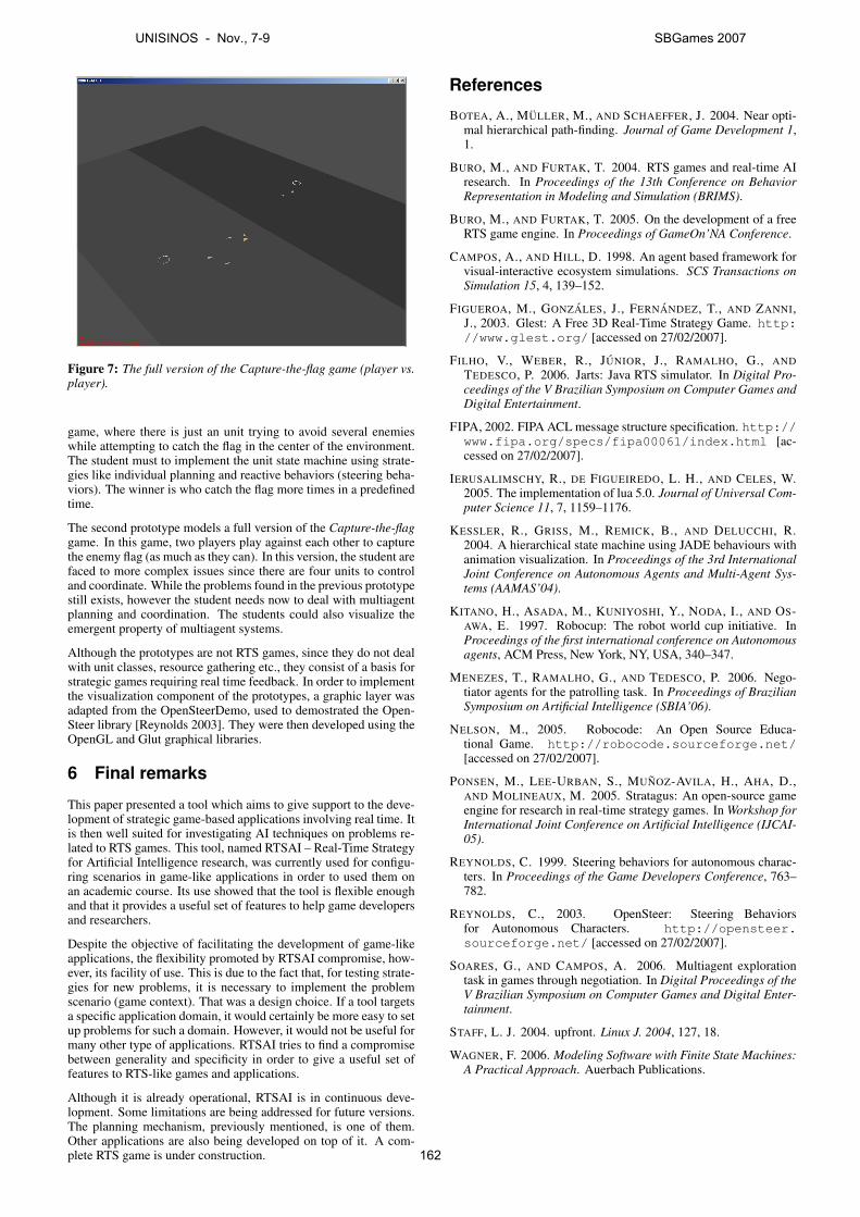
Figure 7: The full version of the Capture-the-flag game (player vs.player).
game, where there is just an unit trying to avoid several enemieswhile attempting to catch the flag in the center of the environment.The student must to implement the unit state machine using strate-gies like individual planning and reactive behaviors (steering beha-viors). The winner is who catch the flag more times in a predefinedtime.
The second prototype models a full version of the Capture-the-flaggame. In this game, two players play against each other to capturethe enemy flag (as much as they can). In this version, the student arefaced to more complex issues since there are four units to controland coordinate. While the problems found in the previous prototypestill exists, however the student needs now to deal with multiagentplanning and coordination. The students could also visualize theemergent property of multiagent systems.
Although the prototypes are not RTS games, since they do not dealwith unit classes, resource gathering etc., they consist of a basis forstrategic games requiring real time feedback. In order to implementthe visualization component of the prototypes, a graphic layer wasadapted from the OpenSteerDemo, used to demostrated the Open-Steer library [Reynolds 2003]. They were then developed using theOpenGL and Glut graphical libraries.
6 Final remarks
This paper presented a tool which aims to give support to the deve-lopment of strategic game-based applications involving real time. Itis then well suited for investigating AI techniques on problems re-lated to RTS games. This tool, named RTSAI – Real-Time Strategyfor Artificial Intelligence research, was currently used for configu-ring scenarios in game-like applications in order to used them onan academic course. Its use showed that the tool is flexible enoughand that it provides a useful set of features to help game developersand researchers.
Despite the objective of facilitating the development of game-likeapplications, the flexibility promoted by RTSAI compromise, how-ever, its facility of use. This is due to the fact that, for testing strate-gies for new problems, it is necessary to implement the problemscenario (game context). That was a design choice. If a tool targetsa specific application domain, it would certainly be more easy to setup problems for such a domain. However, it would not be useful formany other type of applications. RTSAI tries to find a compromisebetween generality and specificity in order to give a useful set offeatures to RTS-like games and applications.
Although it is already operational, RTSAI is in continuous deve-lopment. Some limitations are being addressed for future versions.The planning mechanism, previously mentioned, is one of them.Other applications are also being developed on top of it. A com-plete RTS game is under construction.
References
BOTEA, A., MULLER, M., AND SCHAEFFER, J. 2004. Near opti-mal hierarchical path-finding. Journal of Game Development 1,1.
BURO, M., AND FURTAK, T. 2004. RTS games and real-time AIresearch. In Proceedings of the 13th Conference on BehaviorRepresentation in Modeling and Simulation (BRIMS).
BURO, M., AND FURTAK, T. 2005. On the development of a freeRTS game engine. In Proceedings of GameOn’NA Conference.
CAMPOS, A., AND HILL, D. 1998. An agent based framework forvisual-interactive ecosystem simulations. SCS Transactions onSimulation 15, 4, 139–152.
FIGUEROA, M., GONZALES, J., FERNANDEZ, T., AND ZANNI,J., 2003. Glest: A Free 3D Real-Time Strategy Game. http://www.glest.org/ [accessed on 27/02/2007].
FILHO, V., WEBER, R., JUNIOR, J., RAMALHO, G., ANDTEDESCO, P. 2006. Jarts: Java RTS simulator. In Digital Pro-ceedings of the V Brazilian Symposium on Computer Games andDigital Entertainment.
FIPA, 2002. FIPA ACL message structure specification. http://www.fipa.org/specs/fipa00061/index.html [ac-cessed on 27/02/2007].
IERUSALIMSCHY, R., DE FIGUEIREDO, L. H., AND CELES, W.2005. The implementation of lua 5.0. Journal of Universal Com-puter Science 11, 7, 1159–1176.
KESSLER, R., GRISS, M., REMICK, B., AND DELUCCHI, R.2004. A hierarchical state machine using JADE behaviours withanimation visualization. In Proceedings of the 3rd InternationalJoint Conference on Autonomous Agents and Multi-Agent Sys-tems (AAMAS’04).
KITANO, H., ASADA, M., KUNIYOSHI, Y., NODA, I., AND OS-AWA, E. 1997. Robocup: The robot world cup initiative. InProceedings of the first international conference on Autonomousagents, ACM Press, New York, NY, USA, 340–347.
MENEZES, T., RAMALHO, G., AND TEDESCO, P. 2006. Nego-tiator agents for the patrolling task. In Proceedings of BrazilianSymposium on Artificial Intelligence (SBIA’06).
NELSON, M., 2005. Robocode: An Open Source Educa-tional Game. http://robocode.sourceforge.net/[accessed on 27/02/2007].
PONSEN, M., LEE-URBAN, S., MUNOZ-AVILA, H., AHA, D.,AND MOLINEAUX, M. 2005. Stratagus: An open-source gameengine for research in real-time strategy games. In Workshop forInternational Joint Conference on Artificial Intelligence (IJCAI-05).
REYNOLDS, C. 1999. Steering behaviors for autonomous charac-ters. In Proceedings of the Game Developers Conference, 763–782.
REYNOLDS, C., 2003. OpenSteer: Steering Behaviorsfor Autonomous Characters. http://opensteer.sourceforge.net/ [accessed on 27/02/2007].
SOARES, G., AND CAMPOS, A. 2006. Multiagent explorationtask in games through negotiation. In Digital Proceedings of theV Brazilian Symposium on Computer Games and Digital Enter-tainment.
STAFF, L. J. 2004. upfront. Linux J. 2004, 127, 18.
WAGNER, F. 2006. Modeling Software with Finite State Machines:A Practical Approach. Auerbach Publications.
UNISINOS - Nov., 7-9 SBGames 2007
162
RTSCup Project: Challenges and Benchmarks
Vicente V. Filho Clauirton A. Siebra José C. Moura Renan T. Weber Geber L. Ramalho
Universidade Federal de Pernambuco, Centro de Informática, Brazil
Abstract
Real Time Strategic (RTS) games are an interesting kind of domain to Artificial Intelligence (AI) community due to the problems and challenges that such games can offer. In fact, several AI techniques can be applied to solve RTS problems, such as team coordination, pathfinding or patrolling. In this context, this paper presents the RTSCup Project a new RTS simulator, which can mainly be used as benchmark for multiagent systems. The architecture and main concepts of this project are discussed in details, as well as the advantages of its use.
Keywords: artificial intelligence, simulator, digital entertainment, benchmarks.
Authors’ contact:{vvf,cas,jcmj,rwt,glr}@cin.ufpe.br
1. Introduction
The evaluation of any computational system is an important phase of its development process and this is not different to systems that use Artificial Intelligence (AI). For such systems, in particular, there is a trend [Hanks et al. 1993] in employing simulation environments as benchmarks, which enable the evaluation of such systems in different test scenarios. Another interesting trend is the use of such environments in academic competitions [Stone 2003]. This trend brings two advantages to AI research. First, competitions motivate the investigation of solutions in specific areas. Second, they integrate the research community, providing an environment where approaches are discussed and results, raised from contests, can be analyzed in a comparative way.
The aim of this work is to present a simulator toreal-time strategic games, called RTSCup, which can be used as a benchmark for evaluating several AI techniques used to implement teams as Multiagent Systems (MAS). RTSCup was already employed in apractical experiment during a competition among AI students of the Federal University of Pernambuco, as discussed along this paper.
The remainder of this work is structured in three major parts: presentation of the RTS game as a multi-agent environment; identification of the RTS game as benchmark in the multi-agent area, and presentation of the RTSCup simulator project and architecture.
2. RTS game as a MAS
A RTS game is a specific but very attractive real-time multi-agent environment from the point of view of distributed artificial intelligence and multi-agent research. If we consider a RTS team as a multi-agent system, several interesting issues will arise.
In a game we can have two or more competing teams. Each team has a team-wide common goal, namely to win the game. The opponent team can be seen as a dynamic and obstructive environment, which might disturb the achievement of this goal. To fulfill the common goal, each team is required to complete some tasks, which can be seen as sub-goals (i.e.,foraging, exploration, fight and resource allocation). To achieve these sub-goals each team must present a fast, flexible and cooperative behavior, considering local and global situations.
The team might have some sort of global (team-wide) strategies to accomplish the common goal, and both local and global tactics to achieve sub-goals. Furthermore, the team must consider the following challenges:
The game environment, i.e. the movement of the team members and the opponent team is highly dynamic.
The perception of each player could be locally limited (i.e., fog of war).
The role of each player can be different (i.e. worker collects resources and tanks attacks).
In brief, based on these issues a RTS team can be seen as a cooperative distributed real-time planning scheme, embedded in a highly dynamic environment. Besides, a RTS game can be viewed as a MAS considering the following main features: (1) each agent has incomplete information or capabilities for solving the problem and, thus, it has a limited viewpoint; (2) there is no system global control; (3) data are decentralized; and (4) computation is asynchronous.
3. Benchmarks and MAS
The use of benchmarks, as evaluation method for multi-agent systems, has become a common practice for AI systems. In fact, this method is able to evaluate the performance of such systems and provide a basis for comparative analysis. However, some criticisms [Hanks 1993] have been directed against the use of benchmarks. First, such method is an empirical form of
UNISINOS - Nov., 7-9 SBGames 2007
163
evaluation: its users have to distinguish the important evaluation events, as well, interpret the results of such events. Second, there is not a consensus about what a representative benchmark is. Finally, results from benchmark experiments are not general. Rather, they are related to a subgroup of possibilities from the total set of scenarios.
Simulators are a particular type of benchmark, whose generation of new states is executed in runtime and such states depend on the activities performed inside the environment. In this way, final results are commonly unpredictable. An interesting trend related to simulators is academic competitions [Stone 2003]. Besides, motivating research and integrating the scientific community, competitions determine deadlines to the creation of functional systems and periodic events, using the same platform, enables the improvement of past systems and their approaches.
One of the main competitions related to multi-agent systems is the RoboCup Rescue (RCR) [Kitaro and Tadokoro 2001]. This competition uses a real-time distributed simulation system composed of several modules, all of them connected via a central kernel. The function of this system is to simulate the effects of earthquakes in urban areas. For that purpose, each type of event related to an earthquake, such as building collapse or fire spreading, is simulated by a dedicated module, while a Geographic Information System (GIS) provides the initial conditions of the disaster space.
RCR is an appropriate example of benchmark to multi-agent research because it implements several of the requisites that such systems requires. Those are:
i. Agents do not have control on the environment, their actions are not the unique events that can change it;
ii. Agents are not able to ensure that a sequence of actions will lead to a specific state, or if these actions are valid because changes can happen over the environment between decision and its execution;
iii. RCR environments are complex and each of their objects presents several attributes whose values can affect the simulation progress;
iv. The environment considers communication and coordination among agents as an important simulation issue, there are specific rules to control such communication;
v. There are several ways to measure the efficiency of approaches, for instance, number of victims or total area of fire;
vi. The RCR simulator has a well defined temporal model, which is based on configurable cycles;
A last and important RCR feature is its high level of parameterization, which enables an evaluation of multi-agent systems considering a significant variety of problems and conditions. In this way, RCR users can configure the environment in such way that it can be more useful during evaluations of some particular aspect.
4. RTS as Benchmarks
As discussed in the last section, the use of benchmarks, as an alternative, to evaluate MAS has received several criticisms, which are mainly based on the fact that such systems are implemented to be used in real situations. In this way, independently of the specification level of a benchmark, it will still represent a limited number of situations that could happen in real scenarios.
There exist cases, however, in which realism is not the main requirement to be considered. In such situations, the goal could be focused on the comparative evaluation among different approaches. For example, benchmarks currently used in the Planning Systems Competition [McDermott 2000] and the Trading Agent Competition [Wellaman et al. 2001] corroborate this idea.
Another kind of competition, which is recently receiving more attention from the research community, is related to Real-Time Strategy (RTS) games. Note that the main competition in this area (ORTS RTS Game AI Competition [Buro 2003]) does not have the same maturity than other AI competitions. However, several benefits can already be observed, such as the creation of a community with common interests in RTS problems and their investigation.
One of the main advantages of using RTS environments as benchmarks is the broad variety of problem types that they can generate. For example, consider a classic RTS game of battle between two teams. Some of the problems that can be investigated in this case are:
i. Pathfinding: teams need to move along the best routes so that they decrease time and effort. It is common more elaborated versions of this problem, such as involving routes along unknown lands or facing dynamic obstacles (e.g., enemy teams);
ii. Patrolling: a team can keep a specific area on control, or cover an area to find resources or enemies in an optimized way;
iii. Resource allocation (schedule): each component of a team is a resource that must be allocated in some activity, such as defense or attack. Allocation processes must observe, for example, the load balancing of activities, specific
UNISINOS - Nov., 7-9 SBGames 2007
164
resources do not become overloaded while others are free;
iv. Actions prediction: a team can try to observe and model the behavior of others, it predicts their behaviors and can anticipate them;
v. Coordination: components of a team ideally need some kind of coordination to improve the whole work and they do not disrupt each other. For example, during an attack maneuver the team needs to decide if its members will attack the flanks, or if the infantry should wait by the intervention of the artillery before moving forward;
vi. Deliberative and reactive architectures: each team needs to deliberate on the strategies to be deployed in a battlefield. However, several reactive actions, such as reactions to eventual ambushes, must also be considered;
vii. Strategy and tactic decisions: each team must plan and conduct the battle campaign (strategy) in the same way that must organize and maneuver forces in battlefield to achieve victory (tactics).
Then, RTS environments enables a wide set of problems and situations, in which it’s possible to apply AI techniques. Ideally, these environments must be configurable following the RCR model: users can create more appropriate scenarios to each kind of problem.
5. Main Simulators and Competitions
There are currently several simulators to RTS games and some of them are used in open competitions. In this section we discuss five examples: ORTS, Stratagus, Boson,Glest and JaRTS.
Open Real-Time Strategy (ORTS) [Buro 2003] is a simulation environment for studying real-time AI problems such as pathfinding, reasoning with imperfect information, scheduling and planning in the domain of RTS games. Users of ORTS can define rules and features of a game via scripts that describe several types of units, buildings and interactions. The ORTS server is responsible for loading and executing such scripts, sending the world state to their clients. These clients are applications that generate actions to be performed over the simulation server, according to their objectives and the current state of the world.
The ORTS competition [Buro 2006] comes up in cooperation with the Artificial Intelligence and Interactive Digital Entertainment Conference (AIIDE). There are four different contests in this competition:
i. Game 1: agents must develop strategies to perform resource gathering. The goal is to gather
the maximum amount of resources within 10 minutes;
ii. Game 2: tank agents must destroy as many opponent buildings as possible within 15 minutes. However, at the same time, they must also defend their home bases;
iii. Game 3: apart the resources gathering and battle actions, agents must also deal with resource management, defining if the team should collect more resources or spend it. The decision making process involves, for example, actions to create more units or attack/defend specific positions. The main goal is to destroy all opponent buildings within 20 minutes.
iv. Game 4: marine agents must destroy as many opponent units as possible within 5 minutes.
Stratagus [Stratagus 2007] is an engine to RTS games that supports the development of both multiplayer online and single player offline games. Stratagus is configurable and can be used to create customized games. Some of these games made with Stratagus, such Wargus, are been used as a platform for AI studies.
Boson [Boson 2005] is a RTS engine to games similar to Command & Conquer and StarCraft. The battles take place in both land and air, with a high number of units fighting at the same time. An interesting feature of this simulator is the effect of world features (e.g., wind speed, natural obstacles such as trees, and terrain variety) on actions that are performed along the scenarios. Individual units have their own movement pattern, animation, multiple weapons and intelligent pathfinding, they can fight against other agents or human players.
Glest [Glest 2007] is a 3D RTS engine available for several platforms. The engine can be customized via XML files, so it’s possible to define basic parameters such as life, magic, protection, and so on. The current version includes single player game against AI controlled players, providing two factions for player control: Magic and Tech, each of them with their corresponding tech trees, units and buildings.
Java Real-Time Strategy Simulator (JaRTS) [JaRTS 2006] is a RTS game simulator that enables users to focus their development uniquely on the agents’ behavior. This means that users don’t have to worry about the simulation and evolution of the environment. The approach of JaRTS is very similar to the Robocode simulator [Li 2002], where there are basic classes that implement the main behaviors of their agents, such as move to, twirl around, or shoot in. The task of programmers is to extend such classes to create more complex behaviors.
UNISINOS - Nov., 7-9 SBGames 2007
165
JaRTS presents three basic types of agents: (1) the Worker whose role is to collect resources to fill up the Control Center; (2) the Tank whose objective is to attack or defend specific positions around the environment, and; (3) the Control Center that represents a place to deposit collected resources and is also the target (to protect or to destroy) of Tank agents.
Each type of agent in JaRTS can be individually simulated. For example, we can create a MyWorker agent and simulate its behavior in an environment populated only with Worker agents. This means, every agent is collecting resources without interference of enemies so we can focus our attention on this specific task. Note that this is the scenario of ORTS Game 1. In the same way, it is possible to create a MyTank agent and simulate it in a world where the unique goal is to fight, without considering resources gathering or management, as happens in ORTS Game 2.
The implementation of an agent’s behavior is executed in a similar way to the Robocode simulator. Users just extend one of the unit classes (Worker, Tank or ControlCenter) to specify a particular behavior. For example, users can create the class MyWorker extending the class Worker. At the simulation runtime, users can choose the instances of classes that will connect to the simulation environment
We can discuss some main points of this analysis. First, Boson and Glest simulators are not centered in AI issues, it would be necessary an additional effort to define and create test scenarios to evaluate AI techniques. Differently, Stratagus provides a script language (LUA) that allows researchers to modify the game AI without having to change the engine code. LUA employs many familiar programming paradigms from ‘common’ programming languages such as C (e.g., variables, statements, functions), but in a simpler fashion [Posen et al. 2005]. Stratagus was also integrated to TIELT - Testbed for Integrating and Evaluating Learning Techniques – [Aha and Molineaux 2004], which is a freely available tool that facilitates the integration of decision systems and simulators. Currently, the TIELT focus has been on supporting the particular integration of machine learning systems and complex gaming simulators.
ORTS has initially presented itself as a good candidate to be a MAS benchmark. However, after several trials, we have identified that it is complex to use, presenting a number of configuration problems and behavior during its performance. The ORTS’ main problem is lack of proper documentation. It’s hard to find out how to set it up, and how to execute it correctly (using your own solution) as well.Furthermore, there is not a methodology related to updates, which generates a new set of problems after each release causing “crashes” even on the simulator itself, not to mention the solution’s ones.
JaRTS at the beginning was considered the best choice for AI students and researchers. It is very user friendly, with a GUI (Graphic User Interface) that helps to configure/run a simulation. Furthermore, the simulation concerns are all encapsulated in the server, so that users just have to implement the agent behavior by extending an abstract class and then load it to simulate. Despite these positive aspects, which are more applied to academic use as a “fun” way to study AI, the JaRTS approach is very simple to support a deeper AI research.
In this way, after an analysis of all our alternatives and problems, we have decided to create a new simulator that could be simpler and oriented to AI problems. Like a merge between ORTS’ RTS complexity (different unit types, tech-tree, fog of war, etc.) and JaRTS’ “user friendship” (encapsulated server, GUI, etc.). This means, users just need to be worried about solution related to AI problems. This simulator is presented in the next section. .
6. The RTSCup Project
The RTSCup Project was planned to maximize the community contribution and attain high-throughput in research itself. From the research perspectives, RTSCup was designed; (1) to enable users to focus their efforts on AI research; (2) to be used as benchmark in the multi-agent area; and (3) to integrate the research community.
6.1 Simulation Project
The RTS game simulation requires the simulation of different aspects of this game type. These aspects include motion simulation and collision avoidance; attack and cure; collect and deliver resources; build, train, and fix new objects (units and buildings); convert enemy units; research new technologies (upgrade civilization - also known as tech tree); and so on.
The RTSCup simulator is divided in the sub-systems presented below:
Motion and collision avoidance system: simulates the motion of all units in the game environment and is also responsible for collision detection. This system does not allow that fast moving objects can pass through each other without detection. A sweep test[Gomez 1999] is used to efficiently determine the exactly time of overlap.
Attack / Cure system: simulates occurrence of activities that modify the health points (hp) of objects in the game environment like an attack or a cure action. This system is responsible for the battle simulation in the simulator.
Collect / Deliver system: simulates the resource gathering activities. This system is responsible for the
UNISINOS - Nov., 7-9 SBGames 2007
166
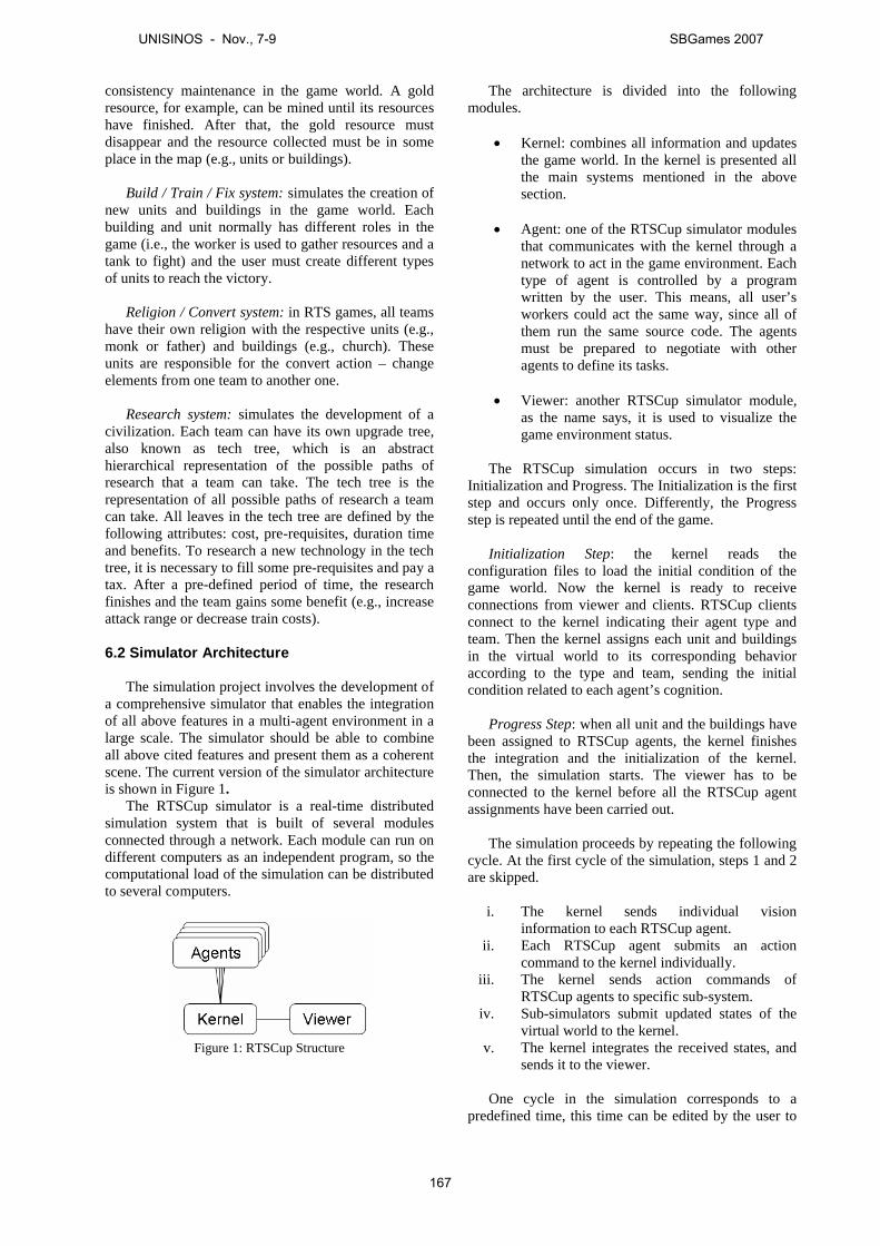
consistency maintenance in the game world. A gold resource, for example, can be mined until its resources have finished. After that, the gold resource must disappear and the resource collected must be in some place in the map (e.g., units or buildings).
Build / Train / Fix system: simulates the creation of new units and buildings in the game world. Each building and unit normally has different roles in the game (i.e., the worker is used to gather resources and a tank to fight) and the user must create different types of units to reach the victory.
Religion / Convert system: in RTS games, all teams have their own religion with the respective units (e.g., monk or father) and buildings (e.g., church). These units are responsible for the convert action – change elements from one team to another one.
Research system: simulates the development of a civilization. Each team can have its own upgrade tree, also known as tech tree, which is an abstract hierarchical representation of the possible paths of research that a team can take. The tech tree is the representation of all possible paths of research a team can take. All leaves in the tech tree are defined by the following attributes: cost, pre-requisites, duration time and benefits. To research a new technology in the tech tree, it is necessary to fill some pre-requisites and pay a tax. After a pre-defined period of time, the research finishes and the team gains some benefit (e.g., increase attack range or decrease train costs).
6.2 Simulator Architecture
The simulation project involves the development of a comprehensive simulator that enables the integration of all above features in a multi-agent environment in a large scale. The simulator should be able to combine all above cited features and present them as a coherent scene. The current version of the simulator architecture is shown in Figure 1.
The RTSCup simulator is a real-time distributed simulation system that is built of several modulesconnected through a network. Each module can run on different computers as an independent program, so the computational load of the simulation can be distributedto several computers.
Figure 1: RTSCup Structure
The architecture is divided into the following modules.
Kernel: combines all information and updates the game world. In the kernel is presented all the main systems mentioned in the above section.
Agent: one of the RTSCup simulator modules that communicates with the kernel through a network to act in the game environment. Each type of agent is controlled by a program written by the user. This means, all user’s workers could act the same way, since all of them run the same source code. The agents must be prepared to negotiate with other agents to define its tasks.
Viewer: another RTSCup simulator module, as the name says, it is used to visualize the game environment status.
The RTSCup simulation occurs in two steps: Initialization and Progress. The Initialization is the first step and occurs only once. Differently, the Progress step is repeated until the end of the game.
Initialization Step: the kernel reads the configuration files to load the initial condition of the game world. Now the kernel is ready to receive connections from viewer and clients. RTSCup clientsconnect to the kernel indicating their agent type and team. Then the kernel assigns each unit and buildingsin the virtual world to its corresponding behavior according to the type and team, sending the initial condition related to each agent’s cognition.
Progress Step: when all unit and the buildings have been assigned to RTSCup agents, the kernel finishes the integration and the initialization of the kernel. Then, the simulation starts. The viewer has to be connected to the kernel before all the RTSCup agent assignments have been carried out.
The simulation proceeds by repeating the following cycle. At the first cycle of the simulation, steps 1 and 2 are skipped.
i. The kernel sends individual vision information to each RTSCup agent.
ii. Each RTSCup agent submits an action command to the kernel individually.
iii. The kernel sends action commands of RTSCup agents to specific sub-system.
iv. Sub-simulators submit updated states of the virtual world to the kernel.
v. The kernel integrates the received states, and sends it to the viewer.
One cycle in the simulation corresponds to a predefined time, this time can be edited by the user to
UNISINOS - Nov., 7-9 SBGames 2007
167
simulate different cycle’s time – it’s useful when the RTSCup agent has a long processing time or when the network has significant time delays.
6.3 Simulator Features
The main simulator features are related to the identified problems during the previous comparative analysis of other simulators. The main problems are the lack of focus on AI simulation, while other simulators are not very user friendly (requiring some background knowledge of its implementation to use it).
Client-server architecture: the most common architecture in commercial RTS games is based on the client-side simulation. A more detailed description of this approach can be found at [Boson 2005]. Clients simulate the game actions and they only send the player actions to a central server or to their peers (peer-to-peer). An alternative approach is the client-server architecture. In this approach a central server (kernel) simulates the RTS game and only sends, to its clients, the game state that a client must know. This approach is safer because the simulation is carried out into the server so that part of the information can be hidden from clients.
Open communication protocol: the client-server approach, allied to a well-defined and documented communication protocol between clients and server, enables that different clients can be developed using different programming languages. In this way, the researcher can use his previous work without worrying about the programming language that the simulator uses.
Multiplatform server: a multiplatform application enables the server to be executed over several operational systems. This feature guarantees that researchers can use their previous works without worrying about the platform. To ensure this feature in our new simulator version, we are using Java as programming language and a communication strategy based on sockets (UDP).
Parameterized game description: this feature means that the simulator enables a flexible definition of test scenarios. Besides the fact that RTS games have several similar features, they also present some particular ones. The main features that differ from one game to another are: building types, unit types, terrain types, tech-trees types and finish conditions. Our intention is to enable the customization of these and others options, so that users can simulate different game scenarios. This feature is implemented, and is being improved, as a configuration file, which indicates the features (value of parameters) of a particular game. In this way, users can have a library of games, each of them customized to test a particular feature of their approaches.
7. Conclusion and Directions
The main aim of this project is to create a basis for the development of a robust, but user friendly RTS simulator, which could be an alternative to ORTS in the AIIDE game competition. With this goal in mind, some improvements are already in progress, as discussed in next paragraphs.
3D Viewer: we believe that a 3D Viewer for the RTSCup Simulator would be more attractive to general people. But this requirement does not have a high priority, because the main goal can be archived with the current 2D Viewer.
Map editor: the map editor is very useful to enable the creation of different game scenarios, which means that users can have a library of maps to validate their solutions. With this feature, users can verify the adequacy and generalization of the proposed solution(e.g., pathfinding algorithm).
Automatic report: this feature is important to any simulation tool that is being used as a benchmark. The generation of reports enables, for example, the evaluation of solutions in a post-simulation stage, as well as a better basis for comparative evaluations.
Publish the project over the internet: all this documentation will be available in the website (which is currently under development) with all the information that users could need to develop theirstrategies. This website will also contain some strategy ideas with their source codes, which users can compare with their ones. Our intention is to create a community in this site, with a forum where users can discuss about strategies, exchange experiences, download other client modules (in Java, C, C++, etc) and talk about their doubts.
Creation of a public contest: to support the community interaction, we intend to create public contests, where any people who wants to participate, would send his/her source code and a brief explanation about his/her strategy. The first competition happened in the first semester of 2007, in the Center of Informatics from Federal University of Pernambuco, where groups of students from the course of Intelligent Agents, compete against each other in game 1 and game 2. Their codes are available in the RTSCup’s website. This competition was also used to validate the RTSCup.
We are implementing all these improvements considering, at the same time, the usability and documentation from the simulator, from the installation process to the simulation execution. In brief, our objective is to enable that users keep the focus on their research rather than on understanding the simulator operation, or learning a new programming language.
UNISINOS - Nov., 7-9 SBGames 2007
168

References
BOSON, 2005. Boson Homepage [online] Available from: boson.eu.org/ [Accessed 19 August 2007].
BURO, M. 2003. Real-Time Strategy Games: A new AI Research Challenge. In: Proceedings of the 2003 International Joint Conference on Artificial Intelligence, Acapulco, Mexico.
GLEST, 2007. Glest Homepage [online] Available from: www.glest.org/ [Accessed 19 August 2007].
GOMEZ, M. 1999. Citing references: Simple Intersection Tests for Games [online] Available from: www.gamasutra.com/features/19991018/Gomez_1.htm [Accessed 19 August 2007].
HANKS, S., POLLACK, M. AND COHEN, P. 1993. Benchmarks, Testbeds, Controlled Experimentation, and the Design of Agent Architectures. Technical Report 93-06-05, Department of Computer Science and Engineering, University of Washington, Seattle, WA, USA.
JARTS, 2006. JaRTS Homepage [online] Available from: www.cin.ufpe.br/~vvf/jarts/ [Accessed 19 August 2007].
KITANO, H. AND TADOKORO, S. 2001. RoboCup Rescue: A Grand Challenge for Multiagent and Intelligent Systems.AI Magazine, 22(1):39-52.
LI, S. 2002. Rock 'em, sock 'em Robocode!. IBM developerWorks, Available from: http://www.ibm.com/ developerworks/java/library/j-robocode/.
MCDERMOTT, D. 2000. The 1998 Planning Systems Competitions. AI Magazine, 4(2):115-129.
ORTS, 2003. ORTS Homepage [online] Available from: www.cs.ualberta.ca/~mburo/orts/orts.html [Accessed 19 August 2007].
PONSEN, M., LEE-URBAN, S., MUÑOZ-AVILA, H., AHA, D. AND MOLINEAUX, M. 2005. Stratagus: An open-source game engine for research in real-time strategy games. In:Proceedings of the IJCAI Workshop Reasoning Representation, and Learning in Computer Games. Edinburgh, UK.
STONE, P. 2003. Multiagent Competitions and Resarch: Lessons from RoboCup and TAC. In: Gal A. Kaminka, Pedro U. Lima, and Raul Rojas, editors, RoboCup-2002: Robot Soccer World Cup VI, Lecture Notes in Artificial Intelligence, pp. 224–237, Springer Verlag, Berlin.
STRATAGUS TEAM, 2007. Stratagus: A Real-Time Strategy Engine [online] Available from: www.stratagus.org/games.shtml [Accessed 19 August 2007].
WELLMAN, M., WURMAN, P., O’MALLEY, K., BANGERA, R.,LIN, S., REEVES, D. AND WASH, W. (2001) “A Trading Agent Competition”. IEEE Internet Computing, 5(2):43-51.
UNISINOS - Nov., 7-9 SBGames 2007
169
Utilizando Rapidly-Exploring Random Trees (RRTs) para o Planejamento de Caminhos em Jogos
Samir Araújo de Souza Luiz Chaimowicz
Departamento de Ciência da ComputaçãoInstituto de Ciências Exatas
Universidade Federal de Minas Gerais
Abstract
Path planning is one of the main components of artificial intelligence algorithms used to control the behavior of NPCs (Non-Player Characters) in games. So far, most of the algorithms rely on detailed information about the game environment and generate paths that are “too perfect”, making NPC's behavior sometimes unrealistic. This paper proposes the use of Rapidly-Exploring Random Trees (RRTs) for NPC navigation. Using probabilistic techniques and partial information about the environment, RRTs generate paths that are less artificial, making NPCs behavior more close to human players. Experiments performed using Quake II showed the potential of the proposed approach.
Keywords: Path Planning, Rapidly-Exploring Random Trees, Quake II.
Resumo
O planejamento de caminhos para NPCs (Non-Player Characters) é um dos principais componentes da inteligência artificial em jogos gráficos. A grande maioria dos algoritmos existentes se baseia em um conhecimento detalhado do ambiente e gera caminhos que muitas vezes são “perfeitos demais” tornando o comportamento dos NPCs pouco realista. Esse trabalho propõe a utilização de Rapidly-Exploring Random Trees (RRTs) para a navegação de NPCs. Utilizando técnicas probabilísticas e informação parcial do ambiente, as RRTs geram caminhos menos artificiais para os NPCs, equiparando o seu comportamento aos jogadores humanos. Testes realizados utilizando o jogo Quake II demonstraram potencial dessa abordagem.
Palavras Chave: Planejamento de Caminhos, Rapidly-Exploring Random Trees, Quake II.
Contato dos Autores:{samir,chaimo}@dcc.ufmg.br
1. Introdução
A contínua mudança no perfil dos jogadores demanda, da indústria de jogos computadorizados, investimentos gradativamente maiores em Inteligência Artificial para tornar os seus produtos mais atrativos, divertidos, desafiadores e competitivos [Champandard, 2003]. Atualmente, os jogadores não buscam apenas qualidades nos recursos áudio-visuais. Se um jogo não oferece entretenimento e “desafios inteligentes”, adequados ao nível de experiência do seu público alvo, é muito provável que este título não tenha sucesso. Pode-se entender como “desafios inteligentes” desde um quebra-cabeça que leve o jogador à próxima etapa da aventura até um NPC (Non-Player Character) [Bourg 2004] que utilize estratégias de movimentação e combates parecidas com as de um jogador humano e seja difícil, mas não impossível de ser vencido.
Em geral, um aspecto importante nos jogos gráficos é a movimentação dos NPCs. A maior parte dos algoritmos para esta finalidade se baseia em estruturas de dados construídas sobre o mapa do ambiente. Estas estruturas, geralmente chamadas de Roadmaps, possuem os dados de todos os pontos acessíveis no mapa, os caminhos existentes entre os diversos ambientes que o compõem, além de muitos outros dados valiosos (ex. tipo do ambiente, viscosidade, altura, etc.). Em geral, a maior parte dos jogos utiliza mapas e roadmaps ricos em informação, de forma a facilitar os processos de renderização, detecção de colisões, localização e posicionamento dos personagens nos ambientes.
Entretanto, em diversos jogos multi-player que implementam NPCs para servirem de oponentes a jogadores humanos ou completarem times de combatentes, estes mapas são utilizados de forma inadequada. A disponibilização de uma grande quantidade de informações aos NPCs, muitas delas não disponíveis ao jogador humano, pode tornar os oponentes imbatíveis e, conseqüentemente, tornará o jogo tedioso, cansativo e sem graça. Desenvolver NPCs desta forma ainda é uma prática comum, principalmente nos jogos de combate em primeira pessoa.
UNISINOS - Nov., 7-9 SBGames 2007
170
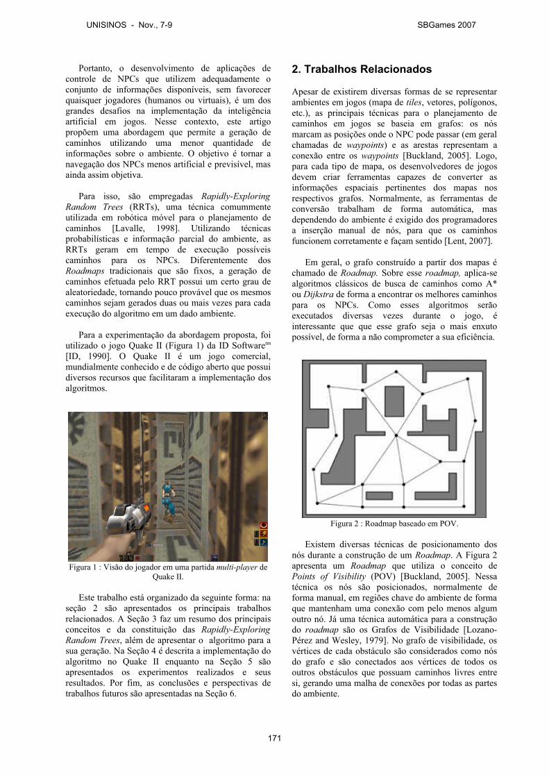
Portanto, o desenvolvimento de aplicações de controle de NPCs que utilizem adequadamente o conjunto de informações disponíveis, sem favorecer quaisquer jogadores (humanos ou virtuais), é um dos grandes desafios na implementação da inteligência artificial em jogos. Nesse contexto, este artigo propõem uma abordagem que permite a geração de caminhos utilizando uma menor quantidade de informações sobre o ambiente. O objetivo é tornar a navegação dos NPCs menos artificial e previsível, mas ainda assim objetiva.
Para isso, são empregadas Rapidly-Exploring Random Trees (RRTs), uma técnica comummente utilizada em robótica móvel para o planejamento de caminhos [Lavalle, 1998]. Utilizando técnicas probabilísticas e informação parcial do ambiente, as RRTs geram em tempo de execução possíveis caminhos para os NPCs. Diferentemente dos Roadmaps tradicionais que são fixos, a geração de caminhos efetuada pelo RRT possui um certo grau de aleatoriedade, tornando pouco provável que os mesmos caminhos sejam gerados duas ou mais vezes para cada execução do algoritmo em um dado ambiente.
Para a experimentação da abordagem proposta, foi utilizado o jogo Quake II (Figura 1) da ID Softwaretm
[ID, 1990]. O Quake II é um jogo comercial, mundialmente conhecido e de código aberto que possui diversos recursos que facilitaram a implementação dos algoritmos.
Figura 1 : Visão do jogador em uma partida multi-player de Quake II.
Este trabalho está organizado da seguinte forma: na seção 2 são apresentados os principais trabalhos relacionados. A Seção 3 faz um resumo dos principais conceitos e da constituição das Rapidly-Exploring Random Trees, além de apresentar o algoritmo para a sua geração. Na Seção 4 é descrita a implementação do algoritmo no Quake II enquanto na Seção 5 são apresentados os experimentos realizados e seus resultados. Por fim, as conclusões e perspectivas de trabalhos futuros são apresentadas na Seção 6.
2. Trabalhos Relacionados
Apesar de existirem diversas formas de se representar ambientes em jogos (mapa de tiles, vetores, polígonos, etc.), as principais técnicas para o planejamento de caminhos em jogos se baseia em grafos: os nós marcam as posições onde o NPC pode passar (em geral chamadas de waypoints) e as arestas representam a conexão entre os waypoints [Buckland, 2005]. Logo, para cada tipo de mapa, os desenvolvedores de jogos devem criar ferramentas capazes de converter as informações espaciais pertinentes dos mapas nos respectivos grafos. Normalmente, as ferramentas de conversão trabalham de forma automática, mas dependendo do ambiente é exigido dos programadores a inserção manual de nós, para que os caminhos funcionem corretamente e façam sentido [Lent, 2007].
Em geral, o grafo construído a partir dos mapas é chamado de Roadmap. Sobre esse roadmap, aplica-se algoritmos clássicos de busca de caminhos como A* ou Dijkstra de forma a encontrar os melhores caminhos para os NPCs. Como esses algoritmos serão executados diversas vezes durante o jogo, é interessante que que esse grafo seja o mais enxuto possível, de forma a não comprometer a sua eficiência.
Figura 2 : Roadmap baseado em POV.
Existem diversas técnicas de posicionamento dos nós durante a construção de um Roadmap. A Figura 2 apresenta um Roadmap que utiliza o conceito de Points of Visibility (POV) [Buckland, 2005]. Nessa técnica os nós são posicionados, normalmente de forma manual, em regiões chave do ambiente de forma que mantenham uma conexão com pelo menos algum outro nó. Já uma técnica automática para a construção do roadmap são os Grafos de Visibilidade [Lozano-Pérez and Wesley, 1979]. No grafo de visibilidade, os vértices de cada obstáculo são considerados como nós do grafo e são conectados aos vértices de todos os outros obstáculos que possuam caminhos livres entre si, gerando uma malha de conexões por todas as partes do ambiente.
UNISINOS - Nov., 7-9 SBGames 2007
171
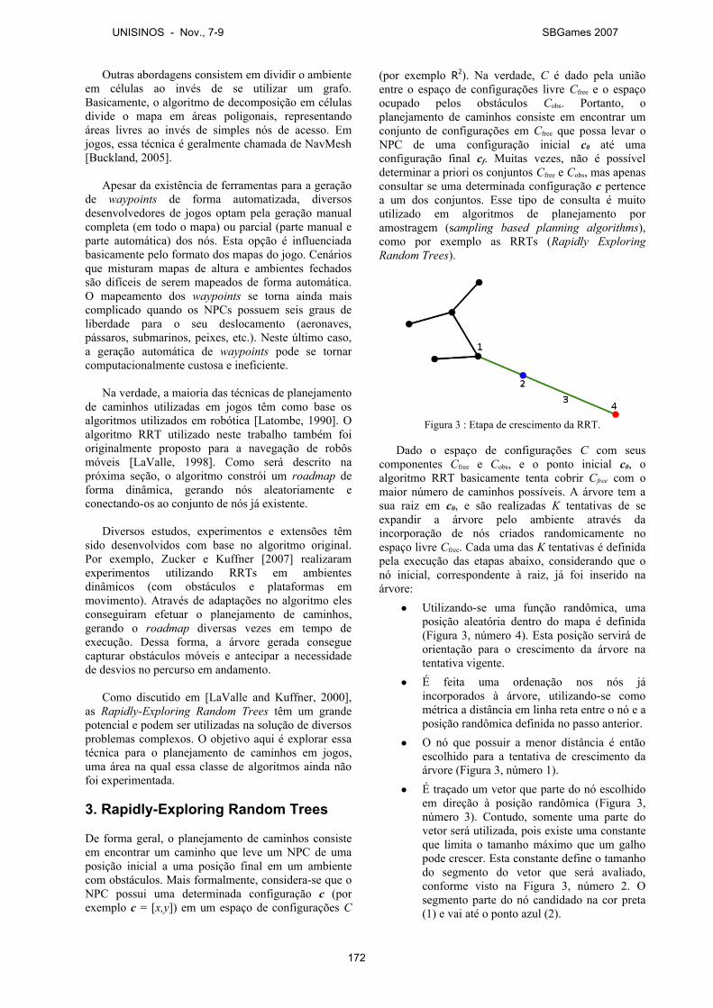
Outras abordagens consistem em dividir o ambiente em células ao invés de se utilizar um grafo. Basicamente, o algoritmo de decomposição em células divide o mapa em áreas poligonais, representando áreas livres ao invés de simples nós de acesso. Em jogos, essa técnica é geralmente chamada de NavMesh [Buckland, 2005].
Apesar da existência de ferramentas para a geração de waypoints de forma automatizada, diversos desenvolvedores de jogos optam pela geração manual completa (em todo o mapa) ou parcial (parte manual e parte automática) dos nós. Esta opção é influenciada basicamente pelo formato dos mapas do jogo. Cenários que misturam mapas de altura e ambientes fechados são difíceis de serem mapeados de forma automática. O mapeamento dos waypoints se torna ainda mais complicado quando os NPCs possuem seis graus de liberdade para o seu deslocamento (aeronaves, pássaros, submarinos, peixes, etc.). Neste último caso, a geração automática de waypoints pode se tornar computacionalmente custosa e ineficiente.
Na verdade, a maioria das técnicas de planejamento de caminhos utilizadas em jogos têm como base os algoritmos utilizados em robótica [Latombe, 1990]. O algoritmo RRT utilizado neste trabalho também foi originalmente proposto para a navegação de robôs móveis [LaValle, 1998]. Como será descrito na próxima seção, o algoritmo constrói um roadmap de forma dinâmica, gerando nós aleatoriamente e conectando-os ao conjunto de nós já existente.
Diversos estudos, experimentos e extensões têm sido desenvolvidos com base no algoritmo original. Por exemplo, Zucker e Kuffner [2007] realizaram experimentos utilizando RRTs em ambientes dinâmicos (com obstáculos e plataformas em movimento). Através de adaptações no algoritmo eles conseguiram efetuar o planejamento de caminhos, gerando o roadmap diversas vezes em tempo de execução. Dessa forma, a árvore gerada consegue capturar obstáculos móveis e antecipar a necessidade de desvios no percurso em andamento.
Como discutido em [LaValle and Kuffner, 2000], as Rapidly-Exploring Random Trees têm um grande potencial e podem ser utilizadas na solução de diversos problemas complexos. O objetivo aqui é explorar essa técnica para o planejamento de caminhos em jogos, uma área na qual essa classe de algoritmos ainda não foi experimentada.
3. Rapidly-Exploring Random Trees
De forma geral, o planejamento de caminhos consiste em encontrar um caminho que leve um NPC de uma posição inicial a uma posição final em um ambiente com obstáculos. Mais formalmente, considera-se que o NPC possui uma determinada configuração c (por exemplo c = [x,y]) em um espaço de configurações C
(por exemplo R2). Na verdade, C é dado pela união entre o espaço de configurações livre Cfree e o espaço ocupado pelos obstáculos Cobs. Portanto, o planejamento de caminhos consiste em encontrar um conjunto de configurações em Cfree que possa levar o NPC de uma configuração inicial c0 até uma configuração final cf. Muitas vezes, não é possível determinar a priori os conjuntos Cfree e Cobs, mas apenas consultar se uma determinada configuração c pertence a um dos conjuntos. Esse tipo de consulta é muito utilizado em algoritmos de planejamento por amostragem (sampling based planning algorithms), como por exemplo as RRTs (Rapidly Exploring Random Trees).
Figura 3 : Etapa de crescimento da RRT.
Dado o espaço de configurações C com seus componentes Cfree e Cobs, e o ponto inicial c0, o algoritmo RRT basicamente tenta cobrir Cfree com o maior número de caminhos possíveis. A árvore tem a sua raiz em c0, e são realizadas K tentativas de se expandir a árvore pelo ambiente através da incorporação de nós criados randomicamente no espaço livre Cfree. Cada uma das K tentativas é definida pela execução das etapas abaixo, considerando que o nó inicial, correspondente à raiz, já foi inserido na árvore:● Utilizando-se uma função randômica, uma
posição aleatória dentro do mapa é definida (Figura 3, número 4). Esta posição servirá de orientação para o crescimento da árvore na tentativa vigente.
● É feita uma ordenação nos nós já incorporados à árvore, utilizando-se como métrica a distância em linha reta entre o nó e a posição randômica definida no passo anterior.
● O nó que possuir a menor distância é então escolhido para a tentativa de crescimento da árvore (Figura 3, número 1).
● É traçado um vetor que parte do nó escolhido em direção à posição randômica (Figura 3, número 3). Contudo, somente uma parte do vetor será utilizada, pois existe uma constante que limita o tamanho máximo que um galho pode crescer. Esta constante define o tamanho do segmento do vetor que será avaliado, conforme visto na Figura 3, número 2. O segmento parte do nó candidado na cor preta (1) e vai até o ponto azul (2).
UNISINOS - Nov., 7-9 SBGames 2007
172
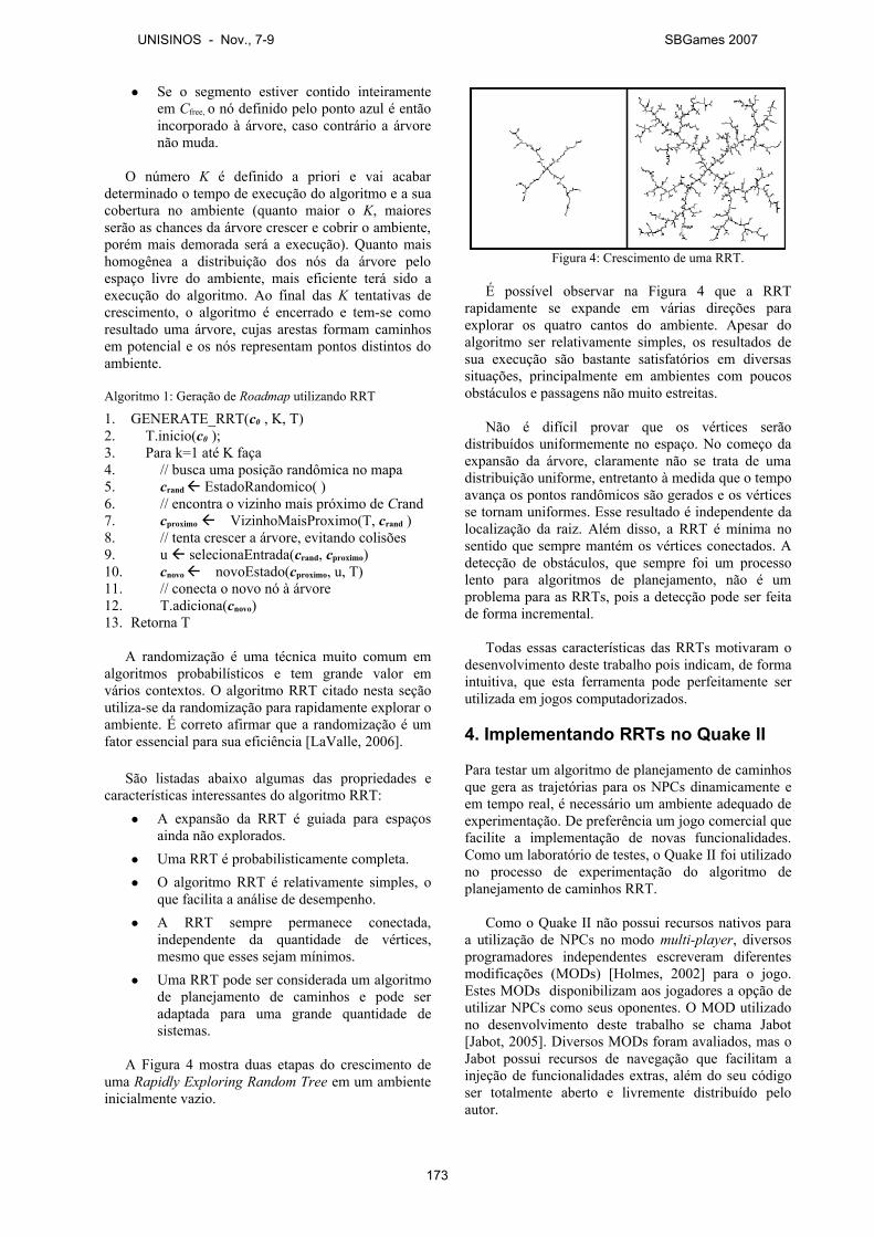
● Se o segmento estiver contido inteiramente em Cfree, o nó definido pelo ponto azul é então incorporado à árvore, caso contrário a árvore não muda.
O número K é definido a priori e vai acabar determinado o tempo de execução do algoritmo e a sua cobertura no ambiente (quanto maior o K, maiores serão as chances da árvore crescer e cobrir o ambiente, porém mais demorada será a execução). Quanto mais homogênea a distribuição dos nós da árvore pelo espaço livre do ambiente, mais eficiente terá sido a execução do algoritmo. Ao final das K tentativas de crescimento, o algoritmo é encerrado e tem-se como resultado uma árvore, cujas arestas formam caminhos em potencial e os nós representam pontos distintos do ambiente.
Algoritmo 1: Geração de Roadmap utilizando RRT
1. GENERATE_RRT(c0 , K, T)2. T.inicio(c0 );3. Para k=1 até K faça4. // busca uma posição randômica no mapa5. crand EstadoRandomico( )6. // encontra o vizinho mais próximo de Crand7. cproximo VizinhoMaisProximo(T, crand )8. // tenta crescer a árvore, evitando colisões9. u selecionaEntrada(crand, cproximo)10. cnovo novoEstado(cproximo, u, T)11. // conecta o novo nó à árvore 12. T.adiciona(cnovo)13. Retorna T
A randomização é uma técnica muito comum em algoritmos probabilísticos e tem grande valor em vários contextos. O algoritmo RRT citado nesta seção utiliza-se da randomização para rapidamente explorar o ambiente. É correto afirmar que a randomização é um fator essencial para sua eficiência [LaValle, 2006].
São listadas abaixo algumas das propriedades e características interessantes do algoritmo RRT:● A expansão da RRT é guiada para espaços
ainda não explorados.● Uma RRT é probabilisticamente completa.● O algoritmo RRT é relativamente simples, o
que facilita a análise de desempenho.● A RRT sempre permanece conectada,
independente da quantidade de vértices, mesmo que esses sejam mínimos.
● Uma RRT pode ser considerada um algoritmo de planejamento de caminhos e pode ser adaptada para uma grande quantidade de sistemas.
A Figura 4 mostra duas etapas do crescimento de uma Rapidly Exploring Random Tree em um ambiente inicialmente vazio.
Figura 4: Crescimento de uma RRT.
É possível observar na Figura 4 que a RRT rapidamente se expande em várias direções para explorar os quatro cantos do ambiente. Apesar do algoritmo ser relativamente simples, os resultados de sua execução são bastante satisfatórios em diversas situações, principalmente em ambientes com poucos obstáculos e passagens não muito estreitas.
Não é difícil provar que os vértices serão distribuídos uniformemente no espaço. No começo da expansão da árvore, claramente não se trata de uma distribuição uniforme, entretanto à medida que o tempo avança os pontos randômicos são gerados e os vértices se tornam uniformes. Esse resultado é independente da localização da raiz. Além disso, a RRT é mínima no sentido que sempre mantém os vértices conectados. A detecção de obstáculos, que sempre foi um processo lento para algoritmos de planejamento, não é um problema para as RRTs, pois a detecção pode ser feita de forma incremental.
Todas essas características das RRTs motivaram o desenvolvimento deste trabalho pois indicam, de forma intuitiva, que esta ferramenta pode perfeitamente ser utilizada em jogos computadorizados.
4. Implementando RRTs no Quake II
Para testar um algoritmo de planejamento de caminhos que gera as trajetórias para os NPCs dinamicamente e em tempo real, é necessário um ambiente adequado de experimentação. De preferência um jogo comercial que facilite a implementação de novas funcionalidades. Como um laboratório de testes, o Quake II foi utilizado no processo de experimentação do algoritmo de planejamento de caminhos RRT.
Como o Quake II não possui recursos nativos para a utilização de NPCs no modo multi-player, diversos programadores independentes escreveram diferentes modificações (MODs) [Holmes, 2002] para o jogo. Estes MODs disponibilizam aos jogadores a opção de utilizar NPCs como seus oponentes. O MOD utilizado no desenvolvimento deste trabalho se chama Jabot [Jabot, 2005]. Diversos MODs foram avaliados, mas o Jabot possui recursos de navegação que facilitam a injeção de funcionalidades extras, além do seu código ser totalmente aberto e livremente distribuído pelo autor.
UNISINOS - Nov., 7-9 SBGames 2007
173
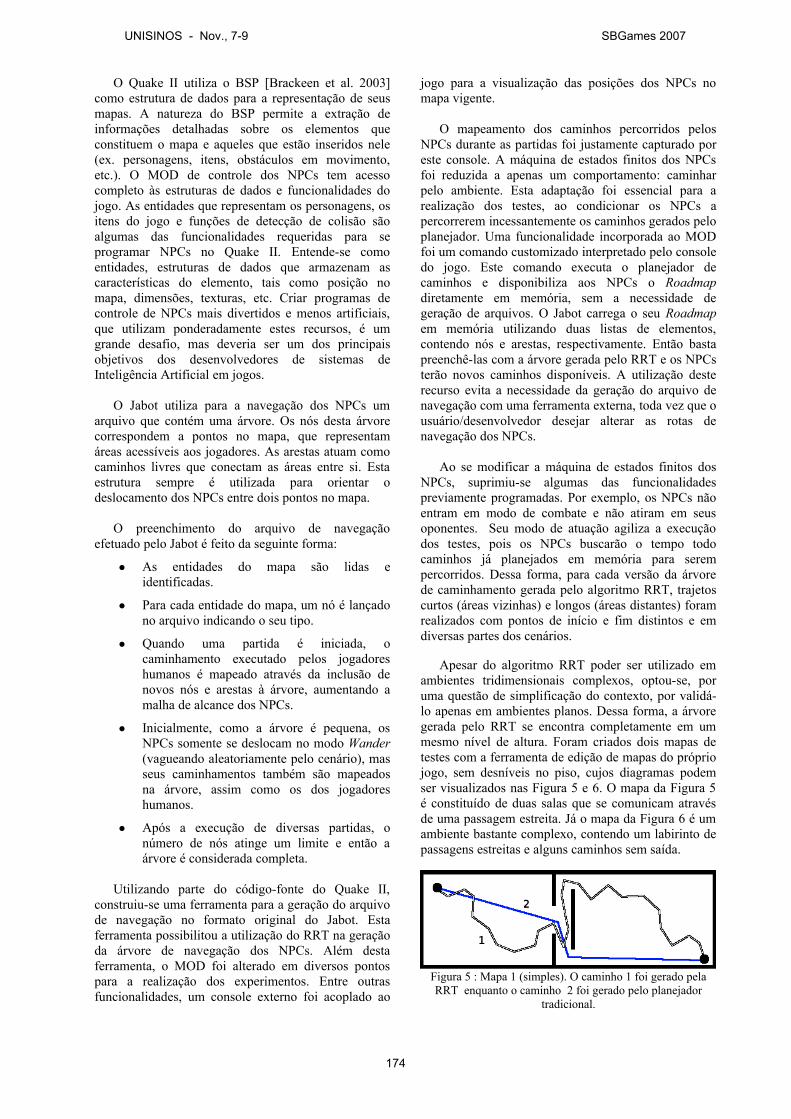
O Quake II utiliza o BSP [Brackeen et al. 2003] como estrutura de dados para a representação de seus mapas. A natureza do BSP permite a extração de informações detalhadas sobre os elementos que constituem o mapa e aqueles que estão inseridos nele (ex. personagens, itens, obstáculos em movimento, etc.). O MOD de controle dos NPCs tem acesso completo às estruturas de dados e funcionalidades do jogo. As entidades que representam os personagens, os itens do jogo e funções de detecção de colisão são algumas das funcionalidades requeridas para se programar NPCs no Quake II. Entende-se como entidades, estruturas de dados que armazenam as características do elemento, tais como posição no mapa, dimensões, texturas, etc. Criar programas de controle de NPCs mais divertidos e menos artificiais, que utilizam ponderadamente estes recursos, é um grande desafio, mas deveria ser um dos principais objetivos dos desenvolvedores de sistemas de Inteligência Artificial em jogos.
O Jabot utiliza para a navegação dos NPCs um arquivo que contém uma árvore. Os nós desta árvore correspondem a pontos no mapa, que representam áreas acessíveis aos jogadores. As arestas atuam como caminhos livres que conectam as áreas entre si. Esta estrutura sempre é utilizada para orientar o deslocamento dos NPCs entre dois pontos no mapa.
O preenchimento do arquivo de navegação efetuado pelo Jabot é feito da seguinte forma:
● As entidades do mapa são lidas e identificadas.
● Para cada entidade do mapa, um nó é lançado no arquivo indicando o seu tipo.
● Quando uma partida é iniciada, o caminhamento executado pelos jogadores humanos é mapeado através da inclusão de novos nós e arestas à árvore, aumentando a malha de alcance dos NPCs.
● Inicialmente, como a árvore é pequena, os NPCs somente se deslocam no modo Wander (vagueando aleatoriamente pelo cenário), mas seus caminhamentos também são mapeados na árvore, assim como os dos jogadores humanos.
● Após a execução de diversas partidas, o número de nós atinge um limite e então a árvore é considerada completa.
Utilizando parte do código-fonte do Quake II, construiu-se uma ferramenta para a geração do arquivo de navegação no formato original do Jabot. Esta ferramenta possibilitou a utilização do RRT na geração da árvore de navegação dos NPCs. Além desta ferramenta, o MOD foi alterado em diversos pontos para a realização dos experimentos. Entre outras funcionalidades, um console externo foi acoplado ao
jogo para a visualização das posições dos NPCs no mapa vigente.
O mapeamento dos caminhos percorridos pelos NPCs durante as partidas foi justamente capturado por este console. A máquina de estados finitos dos NPCs foi reduzida a apenas um comportamento: caminhar pelo ambiente. Esta adaptação foi essencial para a realização dos testes, ao condicionar os NPCs a percorrerem incessantemente os caminhos gerados pelo planejador. Uma funcionalidade incorporada ao MOD foi um comando customizado interpretado pelo console do jogo. Este comando executa o planejador de caminhos e disponibiliza aos NPCs o Roadmap diretamente em memória, sem a necessidade de geração de arquivos. O Jabot carrega o seu Roadmap em memória utilizando duas listas de elementos, contendo nós e arestas, respectivamente. Então basta preenchê-las com a árvore gerada pelo RRT e os NPCs terão novos caminhos disponíveis. A utilização deste recurso evita a necessidade da geração do arquivo de navegação com uma ferramenta externa, toda vez que o usuário/desenvolvedor desejar alterar as rotas de navegação dos NPCs.
Ao se modificar a máquina de estados finitos dos NPCs, suprimiu-se algumas das funcionalidades previamente programadas. Por exemplo, os NPCs não entram em modo de combate e não atiram em seus oponentes. Seu modo de atuação agiliza a execução dos testes, pois os NPCs buscarão o tempo todo caminhos já planejados em memória para serem percorridos. Dessa forma, para cada versão da árvore de caminhamento gerada pelo algoritmo RRT, trajetos curtos (áreas vizinhas) e longos (áreas distantes) foram realizados com pontos de início e fim distintos e em diversas partes dos cenários.
Apesar do algoritmo RRT poder ser utilizado em ambientes tridimensionais complexos, optou-se, por uma questão de simplificação do contexto, por validá-lo apenas em ambientes planos. Dessa forma, a árvore gerada pelo RRT se encontra completamente em um mesmo nível de altura. Foram criados dois mapas de testes com a ferramenta de edição de mapas do próprio jogo, sem desníveis no piso, cujos diagramas podem ser visualizados nas Figura 5 e 6. O mapa da Figura 5 é constituído de duas salas que se comunicam através de uma passagem estreita. Já o mapa da Figura 6 é um ambiente bastante complexo, contendo um labirinto de passagens estreitas e alguns caminhos sem saída.
Figura 5 : Mapa 1 (simples). O caminho 1 foi gerado pela RRT enquanto o caminho 2 foi gerado pelo planejador
tradicional.
UNISINOS - Nov., 7-9 SBGames 2007
174
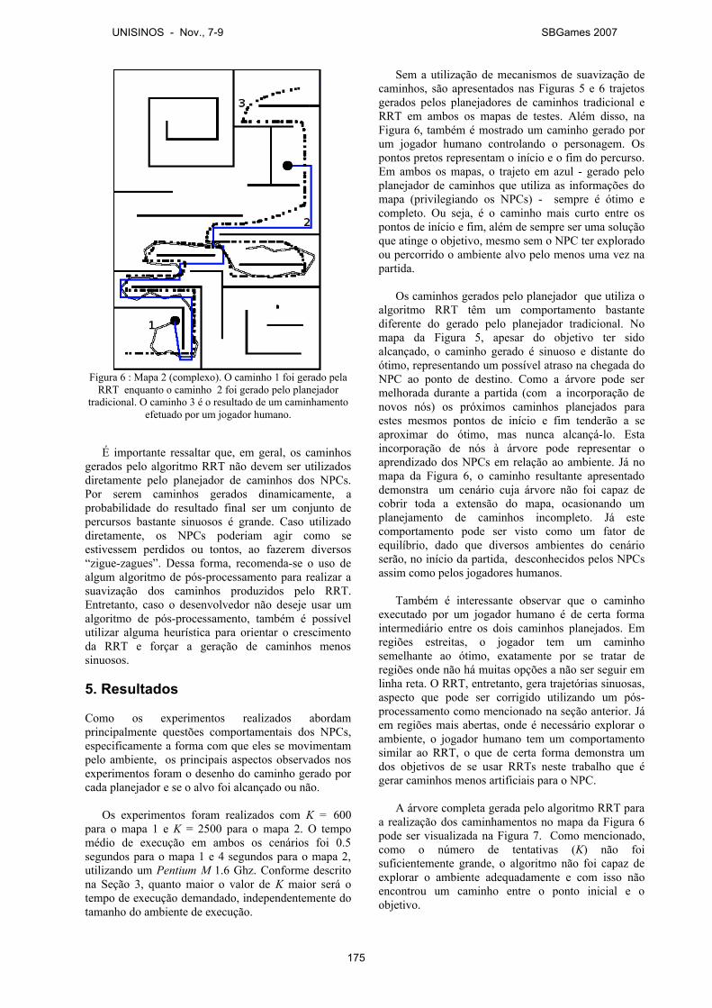
Figura 6 : Mapa 2 (complexo). O caminho 1 foi gerado pela RRT enquanto o caminho 2 foi gerado pelo planejador
tradicional. O caminho 3 é o resultado de um caminhamento efetuado por um jogador humano.
É importante ressaltar que, em geral, os caminhos gerados pelo algoritmo RRT não devem ser utilizados diretamente pelo planejador de caminhos dos NPCs. Por serem caminhos gerados dinamicamente, a probabilidade do resultado final ser um conjunto de percursos bastante sinuosos é grande. Caso utilizado diretamente, os NPCs poderiam agir como se estivessem perdidos ou tontos, ao fazerem diversos “zigue-zagues”. Dessa forma, recomenda-se o uso de algum algoritmo de pós-processamento para realizar a suavização dos caminhos produzidos pelo RRT. Entretanto, caso o desenvolvedor não deseje usar um algoritmo de pós-processamento, também é possível utilizar alguma heurística para orientar o crescimento da RRT e forçar a geração de caminhos menos sinuosos.
5. Resultados
Como os experimentos realizados abordam principalmente questões comportamentais dos NPCs, especificamente a forma com que eles se movimentam pelo ambiente, os principais aspectos observados nos experimentos foram o desenho do caminho gerado por cada planejador e se o alvo foi alcançado ou não.
Os experimentos foram realizados com K = 600 para o mapa 1 e K = 2500 para o mapa 2. O tempo médio de execução em ambos os cenários foi 0.5 segundos para o mapa 1 e 4 segundos para o mapa 2, utilizando um Pentium M 1.6 Ghz. Conforme descrito na Seção 3, quanto maior o valor de K maior será o tempo de execução demandado, independentemente do tamanho do ambiente de execução.
Sem a utilização de mecanismos de suavização de caminhos, são apresentados nas Figuras 5 e 6 trajetos gerados pelos planejadores de caminhos tradicional e RRT em ambos os mapas de testes. Além disso, na Figura 6, também é mostrado um caminho gerado por um jogador humano controlando o personagem. Os pontos pretos representam o início e o fim do percurso. Em ambos os mapas, o trajeto em azul - gerado pelo planejador de caminhos que utiliza as informações do mapa (privilegiando os NPCs) - sempre é ótimo e completo. Ou seja, é o caminho mais curto entre os pontos de início e fim, além de sempre ser uma solução que atinge o objetivo, mesmo sem o NPC ter explorado ou percorrido o ambiente alvo pelo menos uma vez na partida.
Os caminhos gerados pelo planejador que utiliza o algoritmo RRT têm um comportamento bastante diferente do gerado pelo planejador tradicional. No mapa da Figura 5, apesar do objetivo ter sido alcançado, o caminho gerado é sinuoso e distante do ótimo, representando um possível atraso na chegada do NPC ao ponto de destino. Como a árvore pode ser melhorada durante a partida (com a incorporação de novos nós) os próximos caminhos planejados para estes mesmos pontos de início e fim tenderão a se aproximar do ótimo, mas nunca alcançá-lo. Esta incorporação de nós à árvore pode representar o aprendizado dos NPCs em relação ao ambiente. Já no mapa da Figura 6, o caminho resultante apresentado demonstra um cenário cuja árvore não foi capaz de cobrir toda a extensão do mapa, ocasionando um planejamento de caminhos incompleto. Já este comportamento pode ser visto como um fator de equilíbrio, dado que diversos ambientes do cenário serão, no início da partida, desconhecidos pelos NPCs assim como pelos jogadores humanos.
Também é interessante observar que o caminho executado por um jogador humano é de certa forma intermediário entre os dois caminhos planejados. Em regiões estreitas, o jogador tem um caminho semelhante ao ótimo, exatamente por se tratar de regiões onde não há muitas opções a não ser seguir em linha reta. O RRT, entretanto, gera trajetórias sinuosas, aspecto que pode ser corrigido utilizando um pós-processamento como mencionado na seção anterior. Já em regiões mais abertas, onde é necessário explorar o ambiente, o jogador humano tem um comportamento similar ao RRT, o que de certa forma demonstra um dos objetivos de se usar RRTs neste trabalho que é gerar caminhos menos artificiais para o NPC.
A árvore completa gerada pelo algoritmo RRT para a realização dos caminhamentos no mapa da Figura 6 pode ser visualizada na Figura 7. Como mencionado, como o número de tentativas (K) não foi suficientemente grande, o algoritmo não foi capaz de explorar o ambiente adequadamente e com isso não encontrou um caminho entre o ponto inicial e o objetivo.
UNISINOS - Nov., 7-9 SBGames 2007
175
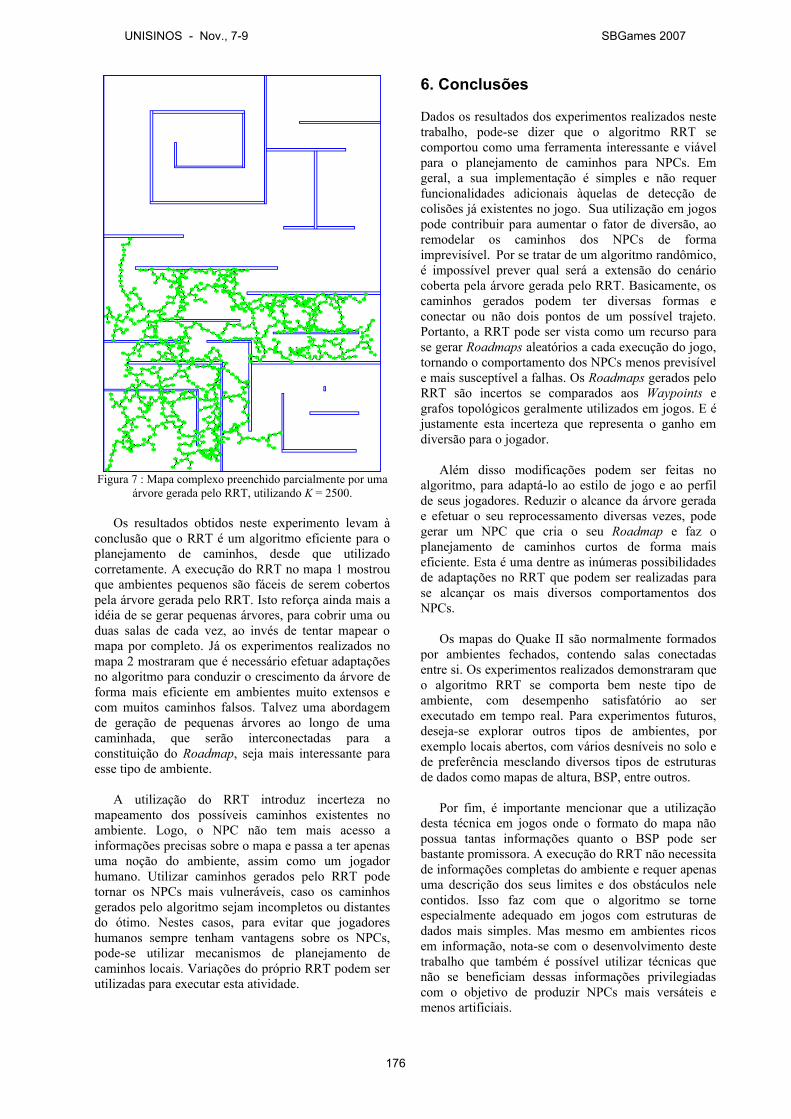
Figura 7 : Mapa complexo preenchido parcialmente por uma árvore gerada pelo RRT, utilizando K = 2500.
Os resultados obtidos neste experimento levam à conclusão que o RRT é um algoritmo eficiente para o planejamento de caminhos, desde que utilizado corretamente. A execução do RRT no mapa 1 mostrou que ambientes pequenos são fáceis de serem cobertos pela árvore gerada pelo RRT. Isto reforça ainda mais a idéia de se gerar pequenas árvores, para cobrir uma ou duas salas de cada vez, ao invés de tentar mapear o mapa por completo. Já os experimentos realizados no mapa 2 mostraram que é necessário efetuar adaptações no algoritmo para conduzir o crescimento da árvore de forma mais eficiente em ambientes muito extensos e com muitos caminhos falsos. Talvez uma abordagem de geração de pequenas árvores ao longo de uma caminhada, que serão interconectadas para a constituição do Roadmap, seja mais interessante para esse tipo de ambiente.
A utilização do RRT introduz incerteza no mapeamento dos possíveis caminhos existentes no ambiente. Logo, o NPC não tem mais acesso a informações precisas sobre o mapa e passa a ter apenas uma noção do ambiente, assim como um jogador humano. Utilizar caminhos gerados pelo RRT pode tornar os NPCs mais vulneráveis, caso os caminhos gerados pelo algoritmo sejam incompletos ou distantes do ótimo. Nestes casos, para evitar que jogadores humanos sempre tenham vantagens sobre os NPCs, pode-se utilizar mecanismos de planejamento de caminhos locais. Variações do próprio RRT podem ser utilizadas para executar esta atividade.
6. Conclusões
Dados os resultados dos experimentos realizados neste trabalho, pode-se dizer que o algoritmo RRT se comportou como uma ferramenta interessante e viável para o planejamento de caminhos para NPCs. Em geral, a sua implementação é simples e não requer funcionalidades adicionais àquelas de detecção de colisões já existentes no jogo. Sua utilização em jogos pode contribuir para aumentar o fator de diversão, ao remodelar os caminhos dos NPCs de forma imprevisível. Por se tratar de um algoritmo randômico, é impossível prever qual será a extensão do cenário coberta pela árvore gerada pelo RRT. Basicamente, os caminhos gerados podem ter diversas formas e conectar ou não dois pontos de um possível trajeto. Portanto, a RRT pode ser vista como um recurso para se gerar Roadmaps aleatórios a cada execução do jogo, tornando o comportamento dos NPCs menos previsível e mais susceptível a falhas. Os Roadmaps gerados pelo RRT são incertos se comparados aos Waypoints e grafos topológicos geralmente utilizados em jogos. E é justamente esta incerteza que representa o ganho em diversão para o jogador.
Além disso modificações podem ser feitas no algoritmo, para adaptá-lo ao estilo de jogo e ao perfil de seus jogadores. Reduzir o alcance da árvore gerada e efetuar o seu reprocessamento diversas vezes, pode gerar um NPC que cria o seu Roadmap e faz o planejamento de caminhos curtos de forma mais eficiente. Esta é uma dentre as inúmeras possibilidades de adaptações no RRT que podem ser realizadas para se alcançar os mais diversos comportamentos dos NPCs.
Os mapas do Quake II são normalmente formados por ambientes fechados, contendo salas conectadas entre si. Os experimentos realizados demonstraram que o algoritmo RRT se comporta bem neste tipo de ambiente, com desempenho satisfatório ao ser executado em tempo real. Para experimentos futuros, deseja-se explorar outros tipos de ambientes, por exemplo locais abertos, com vários desníveis no solo e de preferência mesclando diversos tipos de estruturas de dados como mapas de altura, BSP, entre outros.
Por fim, é importante mencionar que a utilização desta técnica em jogos onde o formato do mapa não possua tantas informações quanto o BSP pode ser bastante promissora. A execução do RRT não necessita de informações completas do ambiente e requer apenas uma descrição dos seus limites e dos obstáculos nele contidos. Isso faz com que o algoritmo se torne especialmente adequado em jogos com estruturas de dados mais simples. Mas mesmo em ambientes ricos em informação, nota-se com o desenvolvimento deste trabalho que também é possível utilizar técnicas que não se beneficiam dessas informações privilegiadas com o objetivo de produzir NPCs mais versáteis e menos artificiais.
UNISINOS - Nov., 7-9 SBGames 2007
176
Referências
BOURG, M., Seeman, G., 2004. AI for Game Developers. O'Reilly Press.
BRACKEEN, D., BARKER, B., VANHELSUWÉ, L. 2003. Developing Games in Java. New Riders Publishing.
BUCKLAND, M., 2005. Programming Game AI by Example. Worldware Publishing.
CHAMPANDARD, A. J., 2003. AI Game Development: Synthetic Creatures with Learning and Reactive Behaviors. New Riders Publishing.
HOLMES. S. 2002. Focus on Mod Programming in Quake III Arena. Thomson Course Technology.
ID. 1990. ID Software (Game Developer). Disponível em: http://www.idsoftware.com/ [Acesso em 18 de Agosto de 2007].
JABOT. 2005. Quake II Bot Modification. Disponível em: http://jal..quakedev.com/jabot.html [Acesso em 18 de Agosto de 2007].
LATOMBE, J. C., 1990. Robot Motion Planning. Kluwer Academic Publishers, Boston, MA.
LAVALLE, S. M., 1998. Rapidly-exploring Random Trees: A new tool for path planning. TR 98-11, Computer Science Dept. Iowa State University.
LAVALLE, S. M., 2006. Planning Algorithms. Cambridge University Press.
LAVALLE, S. M., KUFFNER, J. J 2000. Rapidly-Exploring random trees: Progress and prospects. In Proceedings of the Workshop on the Algorithmic Foundations of Robotics.
LENT, M. V. 2007. Game Smarts. IEEE Entertainment Computing [online]. Disponível em: http://www.computer.org/ [Acesso em 18 de Agosto de 2007].
Lozano-Pérez, T., Wesley, M., 1979. An Algorithm for Planning Collision-Free Paths Among Polyhedral Obstacles. Communications of ACM 22(10):560-570.
ZUCKER, M., Kuffner, J.J. 2007. Multipartite RRTs for rapid replanning in dynamic environments. In Proceedings of Robotics and Automation (ICRA'07), 2007.
UNISINOS - Nov., 7-9 SBGames 2007
177
Reflex – Um motor de jogos em Flash
Rodrigo M. A. Silva & Laércio Ferracioli
Laboratório de Tecnologias Interativas Aplicadas a Modelagem Cognitiva Universidade Federal do Espírito Santo – UFES
Vitória-ES, Brasil Abstract This paper shows the design, implementation and use of the Reflex, a Flash Game Engine. The main objective of it is to facilitate the development of 2D Games, using an optimized side-scrolling techniques and physics simulations. To show it features, a simple game was created and will be argued in the end of the article. Resumo Este artigo apresenta o projeto, desenvolvimento e uso da Reflex, um Motor de Jogos em Flash. O principal objetivo desse motor é facilitar o desenvolvimento de jogos 2D, utilizando técnicas otimizadas de side-scrolling e simulação de física. Para demonstrar as funcionalidades da mesma, foi criado um jogo exemplo que será discutido no fim do artigo. Palavras-chave: Desenvolvimento de jogos, Engrenagens de jogos, Flash, jogos 2D. Contato: [email protected] [email protected] 1. Introdução A área de desenvolvimento de jogos eletrônicos tem apresentado um grande interesse e crescimento tanto no âmbito comercial, quanto no âmbito acadêmico [COS05] devido ao fato da utilidade dos jogos nos mais variados contextos, tais como, simuladores, sistemas de visualização e outros. Nesse contexto, durante o desenvolvimento de jogos educacionais, como o Alerta Verde [SIL06], a equipe do ModeLab percebeu que muitas das funcionalidades necessárias para produzir um jogo poderiam ser agrupadas e generalizadas para o desenvolvimento de jogos e aplicações e, desta forma, otimizar o processo de produção. Dessa análise, o ModeLab desenvolveu a Reflex, um motor de jogos 2D1 que permite ao desenvolvedor, concentrar-e na idéia do jogo, na elaboração e construção de cenários e de personagens. O projeto foi realizado de forma a oferecer serviços ao usuário, fazendo referência a arquitetura de serviços de rede, simplificando o processo de aprendizagem e utilização. Dentre esses serviços, pode-se destacar: Detecção de
1 Os termos “jogo” e “game” são usados indistintamente ao longo do texto.
Colisão, Resolução de Colisão (e.g. cálculos de recuo), Side-Scrolling entre outros. 2. Desenvolvimento de Jogos O desenvolvimento moderno de jogos, cada vez mais, necessita de estratégias de desenvolvimento de software, isso devido à sua própria natureza multi e interdisciplinar e ao fato da grande espera, ou exigência, de um alto grau de realismo, tanto gráfico como de simulação [FEI06], mesmo em jogos mais simples, como os 2D. Assim sendo, é importante a utilização de metodologias de Engenharia de Software [PRE05], para tornar viável a produção e manutenção de um jogo. Além desse fato, observa-se que devido ao forte crescimento da internet [MAG05], muitas aplicações tradicionais vêm sendo substituídas por aplicações web [FRA99], fato que se deve à redução dos custos de acesso aos computadores, aos incentivos à inclusão digital e a mudanças culturais ocorridas. Essa mudança de cenário de desenvolvimento incentiva a criação de WEB Games tanto 2D quanto 3D. Outro aspecto é o grande crescimento de jogos para sistemas embarcados e as perspectivas de aumento desse nicho. Por isso, o uso de ferramentas que dão suporte ao desenvolvimento nessas plataformas é desejável. Baseado nesse contexto, a Reflex foi elaborada para acompanhar essas tendências e, para isso, foi necessário pesquisar uma ferramenta que incorporasse tais fatores. Depois de uma análise das ferramentas [SAN06] disponíveis no mercado, o Adobe Flash [ADO06] foi escolhido. O principal fator de escolha foi a popularidade do mesmo para desenvolvimento web, a interface de fácil aprendizagem e a portabilidade fornecida por essa ferramenta. 2.1. Ambiente Adobe Flash O Adobe Flash, ou Flash, é um ambiente de desenvolvimento integrado, IDE - Integrated Development Environment, ou seja, ele possui um ambiente com várias ferramentas para desenvolvimento, tais como, editor de cenas, editor de código, depurador de erros, além de vários outros recursos. O Flash foi projetado originalmente para ser um ambiente de criação de filmes vetoriais que fossem pequenos e dinâmicos e que possibilitassem uma
UNISINOS - Nov., 7-9 SBGames 2007
178
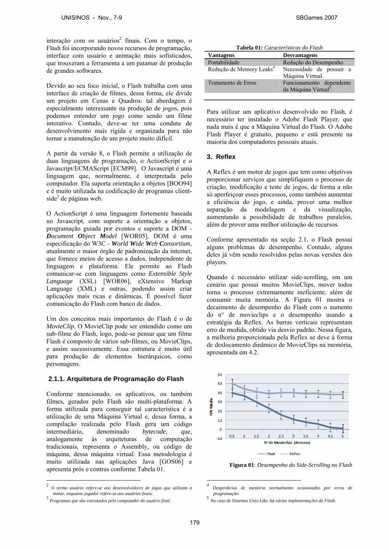
interação com os usuários2 finais. Com o tempo, o Flash foi incorporando novos recursos de programação, interface com usuário e animação mais sofisticados, que trouxeram a ferramenta a um patamar de produção de grandes softwares. Devido ao seu foco inicial, o Flash trabalha com uma interface de criação de filmes, dessa forma, ele divide um projeto em Cenas e Quadros: tal abordagem é especialmente interessante na produção de jogos, pois podemos entender um jogo como sendo um filme interativo. Contudo, deve-se ter uma conduta de desenvolvimento mais rígida e organizada para não tornar a manutenção de um projeto muito difícil. A partir da versão 8, o Flash permite a utilização de duas linguagens de programação, o ActionScript e o Javascript/ECMAScript [ECM99]. O Javascript é uma linguagem que, normalmente, é interpretada pelo computador. Ela suporta orientação a objetos [BOO94] e é muito utilizada na codificação de programas client-side3 de páginas web. O ActionScript é uma linguagem fortemente baseada no Javascript, com suporte a orientação a objetos, programação guiada por eventos e suporte a DOM - Document Object Model [WOR05]. DOM é uma especificação do W3C - World Wide Web Consortium, atualmente o maior órgão de padronização da internet, que fornece meios de acesso a dados, independente de linguagem e plataforma. Ele permite ao Flash comunicar-se com linguagens como Extensible Style Language (XSL) [WOR06], eXtensive Markup Language (XML) e outras, podendo assim criar aplicações mais ricas e dinâmicas. É possível fazer comunicação do Flash com banco de dados. Um dos conceitos mais importantes do Flash é o de MovieClip. O MovieClip pode ser entendido como um sub-filme do Flash, logo, pode-se pensar que um filme Flash é composto de vários sub-filmes, ou MovieClips, e assim sucessivamente. Essa estrutura é muito útil para produção de elementos hierárquicos, como personagens. 2.1.1. Arquitetura de Programação do Flash
Conforme mencionado, os aplicativos, ou também filmes, gerados pelo Flash são multi-plataforma. A forma utilizada para conseguir tal característica é a utilização de uma Máquina Virtual e, dessa forma, a compilação realizada pelo Flash gera um código intermediário, denominado bytecode, que, analogamente às arquiteturas de computação tradicionais, representa o Assembly, ou código de máquina, dessa máquina virtual. Essa metodologia é muito utilizada nas aplicações Java [GOS06] e apresenta prós e contras conforme Tabela 01.
2 O termo usuário refere-se aos desenvolvedores de jogos que utilizam o
motor, enquanto jogador refere-se aos usuários finais. 3 Programas que são executados pelo computador do usuário final.
Tabela 01: Características do Flash
Vantagens Desvantagens Portabilidade Redução do Desempenho Redução de Memory Leaks4 Necessidade de possuir a
Máquina Virtual. Tratamento de Erros Funcionamento dependente
da Máquina Virtual5. Para utilizar um aplicativo desenvolvido no Flash, é necessário ter instalado o Adobe Flash Player, que nada mais é que a Máquina Virtual do Flash. O Adobe Flash Player é gratuito, pequeno e está presente na maioria dos computadores pessoais atuais.
3. Reflex A Reflex é um motor de jogos que tem como objetivos proporcionar serviços que simplifiquem o processo de criação, modificação e teste de jogos, de forma a não só aperfeiçoar esses processos, como também aumentar a eficiência do jogo, e ainda, prover uma melhor separação da modelagem e da visualização, aumentando a possibilidade de trabalhos paralelos, além de prover uma melhor utilização de recursos. Conforme apresentado na seção 2.1, o Flash possui alguns problemas de desempenho. Contudo, alguns deles já vêm sendo resolvidos pelas novas versões dos players. Quando é necessário utilizar side-scrolling, em um cenário que possui muitos MovieClips, mover todos torna o processo extremamente ineficiente, além de consumir muita memória. A Figura 01 mostra o decaimento de desempenho do Flash com o aumento do n° de movieclips e o desempenho usando a estratégia da Reflex. As barras verticais representam erro de medida, obtido via desvio padrão. Nessa figura, a melhoria proporcionada pela Reflex se deve à forma de deslocamento dinâmico de MovieClips na memória, apresentada em 4.2.
Figura 01: Desempenho do Side-Scrolling no Flash 4 Desperdícios de memória normalmente ocasionados por erros de
programação. 5 No caso de Sistemas Unix-Like, há várias implementações do Flash.
UNISINOS - Nov., 7-9 SBGames 2007
179
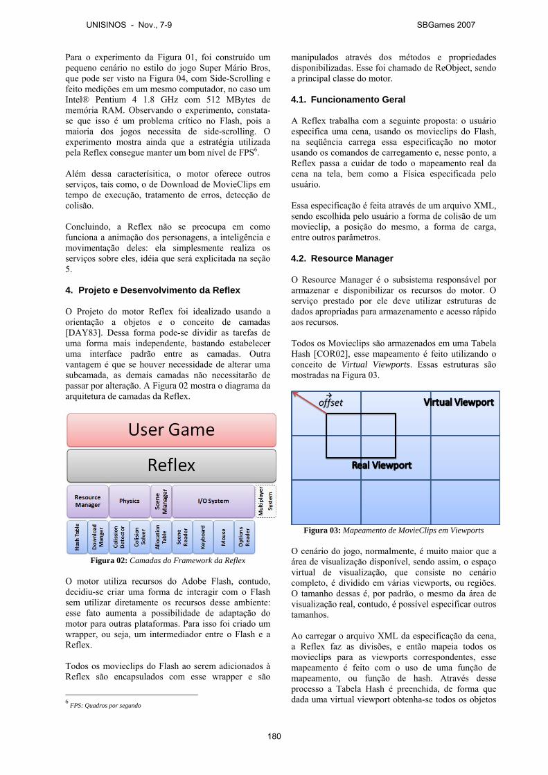
Para o experimento da Figura 01, foi construído um pequeno cenário no estilo do jogo Super Mário Bros, que pode ser visto na Figura 04, com Side-Scrolling e feito medições em um mesmo computador, no caso um Intel® Pentium 4 1.8 GHz com 512 MBytes de memória RAM. Observando o experimento, constata-se que isso é um problema crítico no Flash, pois a maioria dos jogos necessita de side-scrolling. O experimento mostra ainda que a estratégia utilizada pela Reflex consegue manter um bom nível de FPS6. Além dessa caracterísitica, o motor oferece outros serviços, tais como, o de Download de MovieClips em tempo de execução, tratamento de erros, detecção de colisão. Concluindo, a Reflex não se preocupa em como funciona a animação dos personagens, a inteligência e movimentação deles: ela simplesmente realiza os serviços sobre eles, idéia que será explicitada na seção 5. 4. Projeto e Desenvolvimento da Reflex
O Projeto do motor Reflex foi idealizado usando a orientação a objetos e o conceito de camadas [DAY83]. Dessa forma pode-se dividir as tarefas de uma forma mais independente, bastando estabelecer uma interface padrão entre as camadas. Outra vantagem é que se houver necessidade de alterar uma subcamada, as demais camadas não necessitarão de passar por alteração. A Figura 02 mostra o diagrama da arquitetura de camadas da Reflex.
Figura 02: Camadas do Framework da Reflex
O motor utiliza recursos do Adobe Flash, contudo, decidiu-se criar uma forma de interagir com o Flash sem utilizar diretamente os recursos desse ambiente: esse fato aumenta a possibilidade de adaptação do motor para outras plataformas. Para isso foi criado um wrapper, ou seja, um intermediador entre o Flash e a Reflex. Todos os movieclips do Flash ao serem adicionados à Reflex são encapsulados com esse wrapper e são
6 FPS: Quadros por segundo
manipulados através dos métodos e propriedades disponibilizadas. Esse foi chamado de ReObject, sendo a principal classe do motor. 4.1. Funcionamento Geral A Reflex trabalha com a seguinte proposta: o usuário especifica uma cena, usando os movieclips do Flash, na seqüência carrega essa especificação no motor usando os comandos de carregamento e, nesse ponto, a Reflex passa a cuidar de todo o mapeamento real da cena na tela, bem como a Física especificada pelo usuário. Essa especificação é feita através de um arquivo XML, sendo escolhida pelo usuário a forma de colisão de um movieclip, a posição do mesmo, a forma de carga, entre outros parâmetros. 4.2. Resource Manager O Resource Manager é o subsistema responsável por armazenar e disponibilizar os recursos do motor. O serviço prestado por ele deve utilizar estruturas de dados apropriadas para armazenamento e acesso rápido aos recursos. Todos os Movieclips são armazenados em uma Tabela Hash [COR02], esse mapeamento é feito utilizando o conceito de Virtual Viewports. Essas estruturas são mostradas na Figura 03.
Figura 03: Mapeamento de MovieClips em Viewports
O cenário do jogo, normalmente, é muito maior que a área de visualização disponível, sendo assim, o espaço virtual de visualização, que consiste no cenário completo, é dividido em várias viewports, ou regiões. O tamanho dessas é, por padrão, o mesmo da área de visualização real, contudo, é possível especificar outros tamanhos. Ao carregar o arquivo XML da especificação da cena, a Reflex faz as divisões, e então mapeia todos os movieclips para as viewports correspondentes, esse mapeamento é feito com o uso de uma função de mapeamento, ou função de hash. Através desse processo a Tabela Hash é preenchida, de forma que dada uma virtual viewport obtenha-se todos os objetos
UNISINOS - Nov., 7-9 SBGames 2007
180
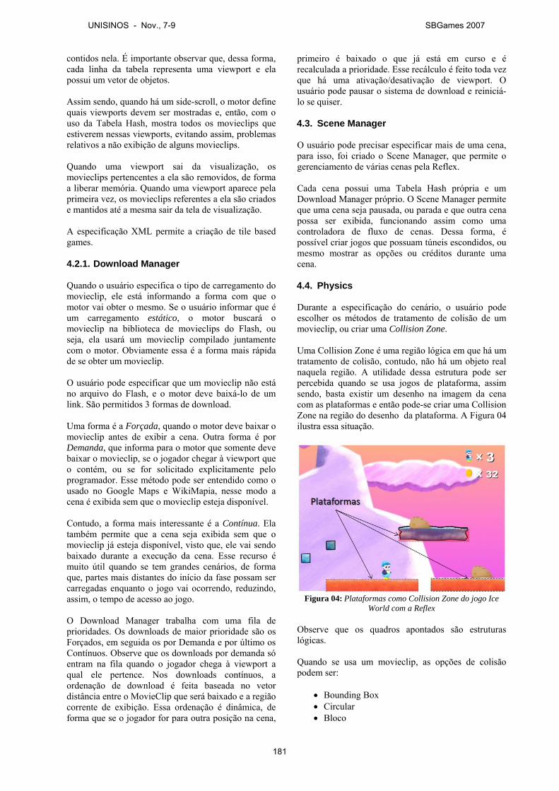
contidos nela. É importante observar que, dessa forma, cada linha da tabela representa uma viewport e ela possui um vetor de objetos. Assim sendo, quando há um side-scroll, o motor define quais viewports devem ser mostradas e, então, com o uso da Tabela Hash, mostra todos os movieclips que estiverem nessas viewports, evitando assim, problemas relativos a não exibição de alguns movieclips. Quando uma viewport sai da visualização, os movieclips pertencentes a ela são removidos, de forma a liberar memória. Quando uma viewport aparece pela primeira vez, os movieclips referentes a ela são criados e mantidos até a mesma sair da tela de visualização. A especificação XML permite a criação de tile based games. 4.2.1. Download Manager Quando o usuário especifica o tipo de carregamento do movieclip, ele está informando a forma com que o motor vai obter o mesmo. Se o usuário informar que é um carregamento estático, o motor buscará o movieclip na biblioteca de movieclips do Flash, ou seja, ela usará um movieclip compilado juntamente com o motor. Obviamente essa é a forma mais rápida de se obter um movieclip. O usuário pode especificar que um movieclip não está no arquivo do Flash, e o motor deve baixá-lo de um link. São permitidos 3 formas de download. Uma forma é a Forçada, quando o motor deve baixar o movieclip antes de exibir a cena. Outra forma é por Demanda, que informa para o motor que somente deve baixar o movieclip, se o jogador chegar à viewport que o contém, ou se for solicitado explicitamente pelo programador. Esse método pode ser entendido como o usado no Google Maps e WikiMapia, nesse modo a cena é exibida sem que o movieclip esteja disponível. Contudo, a forma mais interessante é a Contínua. Ela também permite que a cena seja exibida sem que o movieclip já esteja disponível, visto que, ele vai sendo baixado durante a execução da cena. Esse recurso é muito útil quando se tem grandes cenários, de forma que, partes mais distantes do início da fase possam ser carregadas enquanto o jogo vai ocorrendo, reduzindo, assim, o tempo de acesso ao jogo. O Download Manager trabalha com uma fila de prioridades. Os downloads de maior prioridade são os Forçados, em seguida os por Demanda e por último os Contínuos. Observe que os downloads por demanda só entram na fila quando o jogador chega à viewport a qual ele pertence. Nos downloads contínuos, a ordenação de download é feita baseada no vetor distância entre o MovieClip que será baixado e a região corrente de exibição. Essa ordenação é dinâmica, de forma que se o jogador for para outra posição na cena,
primeiro é baixado o que já está em curso e é recalculada a prioridade. Esse recálculo é feito toda vez que há uma ativação/desativação de viewport. O usuário pode pausar o sistema de download e reiniciá-lo se quiser. 4.3. Scene Manager O usuário pode precisar especificar mais de uma cena, para isso, foi criado o Scene Manager, que permite o gerenciamento de várias cenas pela Reflex. Cada cena possui uma Tabela Hash própria e um Download Manager próprio. O Scene Manager permite que uma cena seja pausada, ou parada e que outra cena possa ser exibida, funcionando assim como uma controladora de fluxo de cenas. Dessa forma, é possível criar jogos que possuam túneis escondidos, ou mesmo mostrar as opções ou créditos durante uma cena. 4.4. Physics Durante a especificação do cenário, o usuário pode escolher os métodos de tratamento de colisão de um movieclip, ou criar uma Collision Zone. Uma Collision Zone é uma região lógica em que há um tratamento de colisão, contudo, não há um objeto real naquela região. A utilidade dessa estrutura pode ser percebida quando se usa jogos de plataforma, assim sendo, basta existir um desenho na imagem da cena com as plataformas e então pode-se criar uma Collision Zone na região do desenho da plataforma. A Figura 04 ilustra essa situação.
Figura 04: Plataformas como Collision Zone do jogo Ice
World com a Reflex Observe que os quadros apontados são estruturas lógicas. Quando se usa um movieclip, as opções de colisão podem ser:
• Bounding Box • Circular • Bloco
UNISINOS - Nov., 7-9 SBGames 2007
181
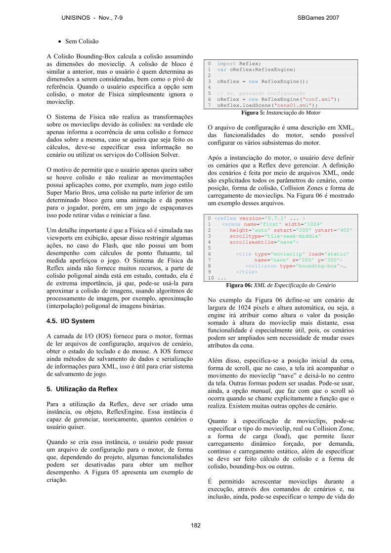
• Sem Colisão A Colisão Bounding-Box calcula a colisão assumindo as dimensões do movieclip. A colisão de bloco é similar a anterior, mas o usuário é quem determina as dimensões a serem consideradas, bem como o pivô de referência. Quando o usuário especifica a opção sem colisão, o motor de Física simplesmente ignora o movieclip. O Sistema de Física não realiza as transformações sobre os movieclips devido às colisões: na verdade ele apenas informa a ocorrência de uma colisão e fornece dados sobre a mesma, caso se queira que seja feito os cálculos, deve-se especificar essa informação no cenário ou utilizar os serviços do Collision Solver. O motivo de permitir que o usuário apenas queira saber se houve colisão e não realizar as movimentações possui aplicações como, por exemplo, num jogo estilo Super Mario Bros, uma colisão na parte inferior de um determinado bloco gera uma animação e dá pontos para o jogador, porém, em um jogo de espaçonaves isso pode retirar vidas e reiniciar a fase. Um detalhe importante é que a Física só é simulada nas viewports em exibição, apesar disso restringir algumas ações, no caso do Flash, que não possui um bom desempenho com cálculos de ponto flutuante, tal medida aperfeiçoa o jogo. O Sistema de Física da Reflex ainda não fornece muitos recursos, a parte de colisão poligonal ainda está em estudo, contudo, ela é de extrema importância, já que, pode-se usá-la para aproximar a colisão de imagens, usando algoritmos de processamento de imagem, por exemplo, aproximação (interpolação) poligonal de imagens binárias. 4.5. I/O System A camada de I/O (IOS) fornece para o motor, formas de ler arquivos de configuração, arquivos de cenário, obter o estado do teclado e do mouse. A IOS fornece ainda métodos de salvamento de dados e serialização de informações para XML, isso é útil para criar sistema de salvamento de jogo. 5. Utilização da Reflex
Para a utilização da Reflex, deve ser criado uma instância, ou objeto, ReflexEngine. Essa instância é capaz de gerenciar, teoricamente, quantos cenários o usuário quiser. Quando se cria essa instância, o usuário pode passar um arquivo de configuração para o motor, de forma que, dependendo do projeto, algumas funcionalidades podem ser desativadas para obter um melhor desempenho. A Figura 05 apresenta um exemplo de criação.
0 import Reflex; 1 var oReflex:ReflexEngine; 2 3 oReflex = new ReflexEngine(); 4 5 // ou, passando configuração 6 oReflex = new ReflexEngine(“conf.xml”); 7 oReflex.loadScene(“cena01.xml”);
Figura 5: Instanciação do Motor O arquivo de configuração é uma descrição em XML, das funcionalidades do motor, sendo possível configurar os vários subsistemas do motor. Após a instanciação do motor, o usuário deve definir os cenários que a Reflex deve gerenciar. A definição dos cenários é feita por meio de arquivos XML, onde são explicitados todos os parâmetros do cenário, como posição, forma de colisão, Collision Zones e forma de carregamento de movieclips. Na Figura 06 é mostrado um exemplo desses arquivos. 0 <reflex version="0.7.1" ... > 1 <scene name="first" width="1024" 2 height="auto" xstart="200" ystart="400" 3 scrolltype="tile-seak-middle" 4 scrollseaktile="nave"> 5 6 <tile type="movieclip" load="static" 7 name="nave" x="200" y="300"> 8 <collision type="bounding-box">… 9 </tile> 10 ...
Figura 06: XML de Especificação do Cenário No exemplo da Figura 06 define-se um cenário de largura de 1024 pixels e altura automática, ou seja, a engine irá atribuir como altura o valor da posição somado à altura do movieclip mais distante, essa funcionalidade é especialmente útil, pois, os cenários podem ser ampliados sem necessidade de mudar esses atributos da cena. Além disso, especifica-se a posição inicial da cena, forma de scroll, que no caso, a tela irá acompanhar o movimento do movieclip “nave” e deixá-lo no centro da tela. Outras formas podem ser usadas. Pode-se usar, ainda, a opção manual, que faz com que o scroll só ocorra quando se chame explicitamente a função que o realiza. Existem muitas outras opções de cenário. Quanto à especificação de movieclips, pode-se especificar o tipo do movieclip, real ou Collision Zone, a forma de carga (load), que permite fazer carregamento dinâmico forçado, por demanda, contínuo e carregamento estático, além de especificar se deve ser feito cálculo de colisão e a forma de colisão, bounding-box ou outras. É permitido acrescentar movieclips durante a execução, através dos comandos de cenários e, na inclusão, ainda, pode-se especificar o tempo de vida do
UNISINOS - Nov., 7-9 SBGames 2007
182
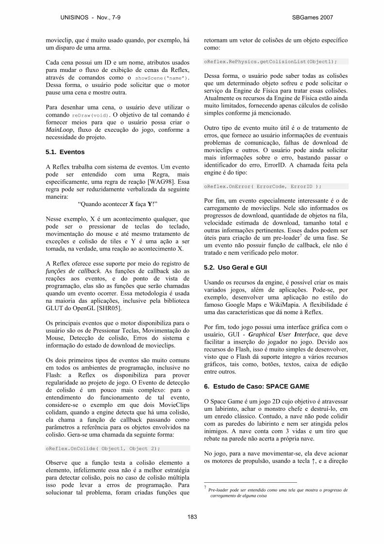
movieclip, que é muito usado quando, por exemplo, há um disparo de uma arma. Cada cena possui um ID e um nome, atributos usados para mudar o fluxo de exibição de cenas da Reflex, através de comandos como o showScene(“name”). Dessa forma, o usuário pode solicitar que o motor pause uma cena e mostre outra. Para desenhar uma cena, o usuário deve utilizar o comando reDraw(void). O objetivo de tal comando é fornecer meios para que o usuário possa criar o MainLoop, fluxo de execução do jogo, conforme a necessidade do projeto. 5.1. Eventos A Reflex trabalha com sistema de eventos. Um evento pode ser entendido com uma Regra, mais especificamente, uma regra de reação [WAG98]. Essa regra pode ser reduzidamente verbalizada da seguinte maneira:
“Quando acontecer X faça Y!” Nesse exemplo, X é um acontecimento qualquer, que pode ser o pressionar de teclas do teclado, movimentação do mouse e até mesmo tratamento de exceções e colisão de tiles e Y é uma ação a ser tomada, na verdade, uma reação ao acontecimento X. A Reflex oferece esse suporte por meio do registro de funções de callback. As funções de callback são as reações aos eventos, e do ponto de vista de programação, elas são as funções que serão chamadas quando um evento ocorrer. Essa metodologia é usada na maioria das aplicações, inclusive pela biblioteca GLUT do OpenGL [SHR05]. Os principais eventos que o motor disponibiliza para o usuário são os de Pressionar Teclas, Movimentação do Mouse, Detecção de colisão, Erros do sistema e informação do estado de download de movieclips. Os dois primeiros tipos de eventos são muito comuns em todos os ambientes de programação, inclusive no Flash: a Reflex os disponibiliza para prover regularidade ao projeto de jogo. O Evento de detecção de colisão é um pouco mais complexo: para o entendimento do funcionamento de tal evento, considere-se o exemplo em que dois MovieClips colidam, quando a engine detecta que há uma colisão, ela chama a função de callback passando como parâmetros a referência para os objetos envolvidos na colisão. Gera-se uma chamada da seguinte forma: oReflex.OnColide( Object1, Object 2); Observe que a função testa a colisão elemento a elemento, infelizmente essa não é a melhor estratégia para detectar colisão, pois no caso de colisão múltipla isso pode levar a erros de programação. Para solucionar tal problema, foram criadas funções que
retornam um vetor de colisões de um objeto específico como: oReflex.RePhysics.getColisionList(Object1); Dessa forma, o usuário pode saber todas as colisões que um determinado objeto sofreu e pode solicitar o serviço da Engine de Física para tratar essas colisões. Atualmente os recursos da Engine de Física estão ainda muito limitados, fornecendo apenas cálculos de colisão simples conforme já mencionado. Outro tipo de evento muito útil é o de tratamento de erros, que fornece ao usuário informações de eventuais problemas de comunicação, falhas de download de movieclips e outros. O usuário pode ainda solicitar mais informações sobre o erro, bastando passar o identificador do erro, ErrorID. A chamada feita pela engine é do tipo: oReflex.OnError( ErrorCode, ErrorID ); Por fim, um evento especialmente interessante é o de carregamento de movieclips. Nele são informados os progressos de download, quantidade de objetos na fila, velocidade estimada de download, tamanho total e outras informações pertinentes. Esses dados podem ser úteis para criação de um pre-loader7 de uma fase. Se um evento não possuir função de callback, ele não é tratado e nem verificado pelo motor. 5.2. Uso Geral e GUI Usando os recursos da engine, é possível criar os mais variados jogos, além de aplicações. Pode-se, por exemplo, desenvolver uma aplicação no estilo do famoso Google Maps e WikiMapia. A flexibilidade é uma das características que dá nome à Reflex. Por fim, todo jogo possui uma interface gráfica com o usuário, GUI - Graphical User Interface, que deve facilitar a inserção do jogador no jogo. Devido aos recursos do Flash, isso é muito simples de desenvolver, visto que o Flash dá suporte íntegro a vários recursos gráficos, tais como, botões, textos, caixa de edição entre outros. 6. Estudo de Caso: SPACE GAME O Space Game é um jogo 2D cujo objetivo é atravessar um labirinto, achar o monstro chefe e destruí-lo, em um enredo clássico. Contudo, a nave não pode colidir com as paredes do labirinto e nem ser atingida pelos inimigos. A nave conta com 3 vidas e um tiro que rebate na parede não acerta a própria nave. No jogo, para a nave movimentar-se, ela deve acionar os motores de propulsão, usando a tecla ↑, e a direção
7 Pre-loader pode ser entendido como uma tela que mostra o progresso de
carregamento de alguma coisa
UNISINOS - Nov., 7-9 SBGames 2007
183
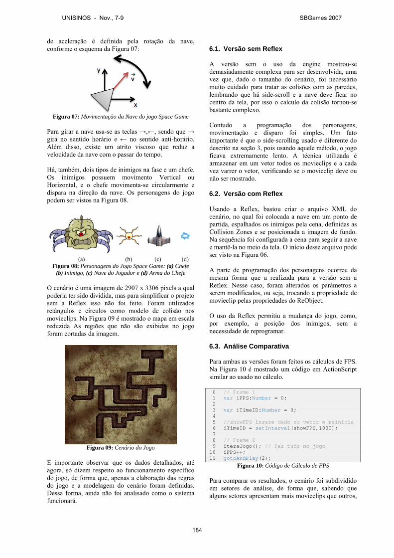
de aceleração é definida pela rotação da nave, conforme o esquema da Figura 07:
Figura 07: Movimentação da Nave do jogo Space Game
Para girar a nave usa-se as teclas →,←, sendo que → gira no sentido horário e ← no sentido anti-horário. Além disso, existe um atrito viscoso que reduz a velocidade da nave com o passar do tempo. Há, também, dois tipos de inimigos na fase e um chefe. Os inimigos possuem movimento Vertical ou Horizontal, e o chefe movimenta-se circularmente e dispara na direção da nave. Os personagens do jogo podem ser vistos na Figura 08.
(a) (b) (c) (d)
Figura 08: Personagens do Jogo Space Game: (a) Chefe (b) Inimigo, (c) Nave do Jogador e (d) Arma do Chefe
O cenário é uma imagem de 2907 x 3306 pixels a qual poderia ter sido dividida, mas para simplificar o projeto sem a Reflex isso não foi feito. Foram utilizados retângulos e círculos como modelo de colisão nos movieclips. Na Figura 09 é mostrado o mapa em escala reduzida As regiões que não são exibidas no jogo foram cortadas da imagem.
Figura 09: Cenário do Jogo
É importante observar que os dados detalhados, até agora, só dizem respeito ao funcionamento específico do jogo, de forma que, apenas a elaboração das regras do jogo e a modelagem do cenário foram definidas. Dessa forma, ainda não foi analisado como o sistema funcionará.
6.1. Versão sem Reflex A versão sem o uso da engine mostrou-se demasiadamente complexa para ser desenvolvida, uma vez que, dado o tamanho do cenário, foi necessário muito cuidado para tratar as colisões com as paredes, lembrando que há side-scroll e a nave deve ficar no centro da tela, por isso o calculo da colisão tornou-se bastante complexo. Contudo a programação dos personagens, movimentação e disparo foi simples. Um fato importante é que o side-scrolling usado é diferente do descrito na seção 3, pois usando aquele método, o jogo ficava extremamente lento. A técnica utilizada é armazenar em um vetor todos os movieclips e a cada vez varrer o vetor, verificando se o movieclip deve ou não ser mostrado. 6.2. Versão com Reflex Usando a Reflex, bastou criar o arquivo XML do cenário, no qual foi colocada a nave em um ponto de partida, espalhados os inimigos pela cena, definidas as Collision Zones e se posicionada a imagem de fundo. Na sequência foi configurada a cena para seguir a nave e mantê-la no meio da tela. O início desse arquivo pode ser visto na Figura 06. A parte de programação dos personagens ocorreu da mesma forma que a realizada para a versão sem a Reflex. Nesse caso, foram alterados os parâmetros a serem modificados, ou seja, trocando a propriedade de movieclip pelas propriedades do ReObject. O uso da Reflex permitiu a mudança do jogo, como, por exemplo, a posição dos inimigos, sem a necessidade de reprogramar. 6.3. Análise Comparativa Para ambas as versões foram feitos os cálculos de FPS. Na Figura 10 é mostrado um código em ActionScript similar ao usado no cálculo. 0 // Frame 1 1 var iFPS:Number = 0; 2 3 var iTimeID:Number = 0; 4 5 //showFPS insere dado no vetor e reinicia 6 iTimeID = setInterval(showFPS,1000); 7 8 // Frame 2 9 iteraJogo(); // Faz tudo no jogo 10 iFPS++; 11 gotoAndPlay(2);
Figura 10: Código de Cálculo de FPS Para comparar os resultados, o cenário foi subdividido em setores de análise, de forma que, sabendo que alguns setores apresentam mais movieclips que outros,
UNISINOS - Nov., 7-9 SBGames 2007
184
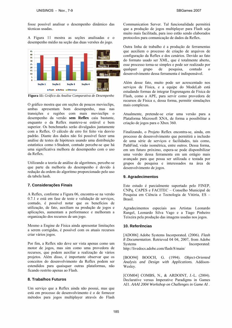
fosse possível analisar o desempenho dinâmico das técnicas usadas. A Figura 11 mostra as seções analisadas e o desempenho médio na seção das duas versões do jogo.
Figura 11: Gráfico da Analise Comparativa de Desempenho O gráfico mostra que em seções de poucos movieclips, ambas apresentam bom desempenho, mas nas transições e regiões com mais movieclips o desempenho da versão sem Reflex caiu bastante, enquanto o da Reflex manteve-se estável e bem superior. Os benchmarks serão divulgados juntamente com a Reflex. O cálculo de erro foi feito via desvio padrão. Diante dos dados não foi possível fazer uma análise de testes de hipóteses usando uma distribuição estatística como t-Student, contudo percebe-se que há uma significativa melhora de desempenho com o uso da Reflex. Utilizando a teoria de análise de algoritmos, percebe-se que parte da melhoria do desempenho é devido à redução da ordem do algoritmo proporcionado pelo uso da tabela hash. 7. Considerações Finais A Reflex, conforme a Figura 06, encontra-se na versão 0.7.1 e está em fase de teste e validação de serviços, contudo, é possível notar que os benefícios de utilização, de fato, auxiliam na produção de jogos e aplicações, aumentam a performance e melhoram a organização dos recursos de um jogo. Mesmo a Engine de Física ainda apresentar limitações a serem corrigidas, é possível com os atuais recursos criar vários jogos. Por fim, a Reflex não deve ser vista apenas como um motor de jogos, mas sim como uma provedora de recursos, que podem auxiliar a realização de vários projetos. Além disso, é importante observar que os conceitos do desenvolvimento da Reflex podem ser estendidos para quaisquer outras plataformas, não ficando restrito apenas ao Flash. 8. Trabalhos Futuros Um serviço que a Reflex ainda não possui, mas que está em processo de desenvolvimento é o de fornecer métodos para jogos multiplayer através do Flash
Communication Server. Tal funcionalidade permitirá que a produção de jogos multiplayer para Flash seja muito mais facilitada, para isso estão sendo elaborados protocolos para comunicação de dados da Reflex. Outra linha de trabalho é a produção de ferramentas que auxiliem o processo de criação de arquivos de configuração da Reflex e dos cenários. Devido ao fato do formato usado ser XML, que é totalmente aberto, esse processo torna-se simples e pode ser realizado por qualquer grupo de pesquisa, contudo o desenvolvimento dessa ferramenta é indispensável. Além desse fato, muito pode ser acrescentado nos serviços de Física, e a equipe do ModeLab está estudando formas de integrar Engrenagens de Física de Flash, como a APE, para servir como provedora de recursos de Física e, dessa forma, permitir simulações mais complexas. Atualmente, pretende-se criar uma versão para a Plataforma Microsoft XNA, de forma a possibilitar a criação de jogos para o Xbox 360. Finalizando, o Projeto Reflex encontra-se, ainda, em processo de desenvolvimento que permitirá a inclusão de uma série de serviços e facilidades, tais como, PathFind, visão isométrica, entre outros. Dessa forma, em um futuro próximo, espera-se pode disponibilizar uma versão dessa ferramenta em um estágio mais avançado para que possa ser utilizada e testada por grupos de pesquisa e interessados na área de desenvolvimento de jogos. 9. Agradecimentos Este estudo é parcialmente suportado pelo FINEP, CNPq, CAPES e FACITEC – Conselho Municipal de Pesquisa em Ciência e Tecnologia de Vitória, ES – Brasil. Agradecimentos especiais aos Artistas Leonardo Rangel, Leonardo Silva Vago e a Tiago Pinheiro Teixeira pela produção das imagens usadas nos jogos. 10. Referências [ADO06] Adobe Systems Incorporated. (2006). Flash 8 Documentation. Retrieved 04 04, 2007, from Adobe Systems Incorporated: http://livedocs.adobe.com/flash/8/main/ [BOO94] BOOCH, G. (1994). Object-Oriented Analysis and Design with Applications. Addison-Wesley. [COM04] COMBS, N., & ARDOINT, J.-L. (2004). Declarative versus Imperative Paradigms in Games AI1. AAAI 2004 Workshop on Challenges in Game AI .
UNISINOS - Nov., 7-9 SBGames 2007
185

[COR02] CORMEN, T. H., LEISERSON, C. E., RIVEST, R. L., & STEIN, C. (2002). Algoritmos: Teoria e Prática. Rio de Janeiro: Campus, Elservier. [COS05] COSTA, S., BELFORT, R., & ARAÚJO, A. (2005). A Indústria de Desenvolvimento de Jogos Eletrônicos no Brasil. Retrieved Maio 20, 2007, from Abragames: http://www.abragames.org/docs/PesquisaAbragames.pdf [CRA03] CRAWFORD, C. (2003). Chris Crawford on Game Design. EUA: New Riders Publishing. [DAY83] DAY, J. D., & ZIMMERMANN, H. (1983, Dezembro 12). The OSI Reference Model. Proceedings of the IEEE , pp. 1334-1340. [ECM99] ECMA International. (1999). Standard ECMA-262 - ECMAScript Language Specification. Retrieved Maio 07, 2007, from ECMA International: http://www.ecma-international.org/publications/files/ecma-st/ECMA-262.pdf [FEI06] FEIJÓ, B., PAGLIOSA, P. A., & CLUA, E. W. (2006). Visualização, Simulação e Games. In K. BREITMAN, & R. ANIDO, Atualizações em Informática (pp. 127-186). Rio de Janeiro: Editora PUC-Rio. [FRA99] FRATERNALI, P. (1999). Tools and Approaches for Developing Data-Intensive Web Applications: A Survey. ACM Computing Surveys , 227-263. [GOS96] GOSLING, J., JOY, B., & STEELE, G. L. (1996). The Java Language Specification. Addison Wesley Publishing Company. [MAG05] MAGALHÃES, A. (2005). O que esperar da internet nos próximos anos? Retrieved 05 10, 2007, from IBOPE Inteligência, IBOPE NetRatings, Internet, Notícias 2006: http://www.ibope.com.br (Pesquisas » Internet » Notícias ) [PRE05] PRESSMAN, R. S. (2005). Software Engineering - A Practitioner's Approach. The McGraw-Hill Companies, Inc. [RIB05] RIBEIRO, F. (2005). Design de Jogos: O Design sob a ótica da interatividade e do desenvolvimento de projeto. Florianópolis. [SAL04] SALEM, K., & ZIMMERMAN, E. (2004). Rules of play – Game Design fundamentals. Cambridge, Massachusetts: The MIT Press. [SAN06] SANTOS, R. J., & BATTAIOLA, A. (2006). Análise de Tecnologias para a Implementação de Jogos Web. Digital Proceedings of the V Brazilian
Symposium on Computer Games and Digital Entertainment. [SHR05] SHREINER, D., WOO, M., NEIDER, J., & DAVIS, T. (2005). The OpenGL Programming Guide - OpenGL Programming Guide. Addison-Wesley Professional. [SIL06] SILVA, R. M., FERRACIOLI, L., & CAMARGO, F. S. (2006). Alerta Verde : Um adventure educacional. Digital Proceedings of the V Brazilian Symposium on Computer Games and Digital Entertainment,. [WAG98] WAGNER, G. (1998). Foundations of Knowledge Systems with Applications to Databases and Agents. Dordrecht: Kluwer Academic Publishers. [WOR05] World Wide Web Consortium(W3C). (2005). Document Object Model (DOM). Retrieved Maio 02, 2007, from W3C - The Architecture Domain: http://www.w3.org/DOM/ [WOR06] World Wide Web Consortium(W3C). (2006). The Extensible Stylesheet Language Family (XSL). Retrieved Maio 02, 2007, from W3C - The Architecture Domain: http://www.w3.org/Style/XSL/
UNISINOS - Nov., 7-9 SBGames 2007
186
Avaliando a Usabilidade de um Jogo através de sua Jogabilidade, Interface e Mecânica
Carlos Teixeira Karen Daldon Omar Buede Milene Silveira
Pontifícia Universidade Católica do Rio Grande do Sul, Faculdade de Informática, Brasil
Resumo O sucesso de um jogo depende de sua apreciação positiva pelo usuário. Ou seja, se ele não tiver qualidades de uso (seja uma boa interface ou um bom desafio, por exemplo) provavelmente o usuário procurará uma outra alternativa de entretenimento. Para garantir esta qualidade de uso, é fundamental que os testes de software realizados durante o desenvolvimento de um jogo incluam testes de usabilidade, os quais representam a perspectiva do usuário. Neste sentido, este artigo apresenta uma proposta de teste de qualidade de interação específica para a área de jogos, na qual a usabilidade de um jogo é avaliada a partir de sua jogabilidade, interface e mecânica. Palavras-chave: testes de usabilidade, jogabilidade, interface, mecânica Contato dos Autores: [email protected] [email protected] [email protected] [email protected] 1. Introdução Usabilidade é um atributo de qualidade de software que permite avaliar a qualidade de interação de um sistema, de acordo com fatores que os projetistas definem como sendo prioritários ao sistema, dentre eles [Nielsen 1993; Preece 1994]:
� Facilidade de aprendizado (quão fácil é para um usuário aprender a usar o sistema);
� Facilidade de uso (quão fácil é, para um usuário infreqüente, recordar o que precisa para usar a interface);
� Eficiência de uso (uma vez aprendido a usar uma interface, quão rápido um usuário consegue executar tarefas através da mesma);
� Produtividade (se as tarefas são realizadas melhor – e mais rapidamente – através deste sistema);
� Satisfação do usuário (quão agradável é seu uso para o usuário);
� Flexibilidade (se existem caminhos diferentes para realizar uma mesma tarefa ou se existem usos diferentes para uma mesma aplicação);
� Utilidade (se além de funcionar, a aplicação é adequada às necessidades do usuário);
� Segurança no uso (se existe proteção contra erros e quão fácil o usuário consegue recuperar-se destes).
Jogos eletrônicos, mais do que qualquer outro tipo
de software, dependem muito deste atributo (usabilidade). Um software de uso comercial, necessário para o usuário efetuar seu trabalho, por exemplo, pode não ser muito eficiente ou não ser do “gosto” do usuário, mas este necessita utilizá-lo a fim de realizar suas tarefas cotidianas; não há outra opção. Um jogo, por outro lado, se não tiver qualidades de uso, pode levar o usuário a procurar uma alternativa que melhor o satisfaça.
Para que isso não aconteça, os projetistas devem seguir uma série de critérios necessários para que o jogo cumpra sua função e seja bem assimilado pelo usuário. Detectar falhas ou erros de projeto e desenvolvimento nos três pilares que constituem a usabilidade em um jogo (interface, jogabilidade e mecânica), antes que este seja finalizado e lançado, é imprescindível. Esta necessidade (de cuidado com a usabilidade em jogos) é tamanha, que é possível encontrar, por exemplo, publicações especializadas da área de Interação Humano-Computador (IHC), com edições específicas para tratamento do tema [IwC 2007].
Além disto, neste contexto, vê-se, também, o crescimento continuo da indústria de jogos eletrônicos no Brasil e, em paralelo, a falta de serviços e mão de obra especializados nesta área (testes de jogos). Assim, surge a necessidade de se desenvolver um processo de testes sólido para a qualificação deste tipo de software, testes estes que incluam a perspectiva do usuário, pois é ele quem definirá o grau de sucesso de um jogo.
Assim, este artigo visa apresentar uma proposta de teste de qualidade de interação específica para a área de jogos1, na qual a usabilidade de um jogo é avaliada a partir de sua jogabilidade, interface e mecânica. Neste sentido, serão apresentados os fundamentos que embasam esta proposta, bem como o relacionamento da mesma com o que há na literatura (cabe destacar que o assunto será tratado – neste artigo – em maior profundidade no que tange a jogabilidade e interface de um jogo). Além disto, será feita uma discussão inicial sobre as possibilidades de inserção deste tipo de
1 Este trabalho foi desenvolvido em colaboração com a empresa Zero-Defect Test House.
UNISINOS - Nov., 7-9 SBGames 2007
187

avaliação durante o processo de projeto e desenvolvimento de jogos eletrônicos, bem como sobre perspectivas de trabalhos futuros. 2. Trabalhos Relacionados Na área de IHC, dois dos tipos de avaliação de interfaces/qualidade de interação mais utilizados são os métodos de avaliação por inspeção e os de avaliação através de testes com usuários.
Na avaliação por inspeção [Mack e Nielsen 1994], dependendo do método utilizado, um ou mais especialistas na área de IHC e/ou na área de domínio da aplicação sendo avaliada analisam a interface, inspecionando-a a fim de verificar se ela encontra-se de acordo com critérios de usabilidade pré-definidos. Dentre os tipos mais utilizados de avaliação por inspeção, encontram-se a avaliação heurística [Nielsen 1993 e 1994], o uso de listas de verificação (checklists) [Dias 2003; Ergolist 2006] e o percurso cognitivo [Wharton et al. 1994].
Já na avaliação através de testes com usuários
[Rubin 1994], serão estes, os usuários finais da aplicação em questão, que irão avaliar a interface. A equipe responsável pelos testes faz o planejamento do mesmo, incluindo desde o local onde a avaliação vai ser realizada, os equipamentos, recursos humanos necessários e tarefas a serem realizadas até o método a ser utilizado para captura e análise dos dados. O mais conhecido destes testes são os testes de usabilidade [Rubin 1994], sendo que, recentemente, também vem crescendo o uso de testes de comunicabilidade [Prates et al. 2000]. Ambos se diferenciam, principalmente, na forma de analisar os dados obtidos durante as avaliações.
Já nos estudos efetuados sobre avaliações voltadas a esta área, uma classificação interessante de itens da usabilidade de um jogo é proposta em [Clanton 1998]. Este autor sugere três principais itens de usabilidade a serem avaliados em um jogo:
� Jogabilidade: relativo aos objetivos do jogo,
como descobri-los e superá-los; � Interface: relativo ao nível de percepção
(visual e sonora) e atividade motora; � Mecânica: relativo à “física” do jogo.
Além deste, outro método interessante encontrado é
o RITE (Rapid Iterative Testing and Evaluation), um método de avaliação de usabilidade desenvolvido pela Microsoft [Medlock et al. 2002]. Este é um teste prático, no qual jogadores são convidados a utilizar determinado jogo, dentro de um ambiente controlado e monitorado por pessoas qualificadas, a fim de detectar problemas ainda no estágio de produção do jogo.
A vantagem deste método é já possuir dados a
respeito dos jogos, jogadores e das plataformas,
catalogados e definidos de forma a serem utilizáveis em qualquer caso, não havendo assim a necessidade de iniciar uma nova pesquisa a cada jogo, sendo necessário apenas um analista de testes com conhecimento sobre o método. Entretanto, seu problema principal é que ele depende não só de uma equipe qualificada para planejamento e acompanhamento dos testes, mas, também, de um determinado número de participantes, gerando assim custos elevados e a necessidade de um espaço físico dedicado, além de não abordar de maneira específica e organizada os três principais itens da usabilidade vistos anteriormente [Clanton 1998].
3. Jogabilidade, Interface e Mecânica
Embora as categorias de Clanton [Clanton 1998] tenham definição clara e suficiente para entender como funcionam os jogos do ponto de vista de um leigo, não são suficientes para um completo teste de qualidade de interação, que demanda mais definições para ser executado de maneira eficiente. O ideal, no caso de um teste, é dar maior detalhe e definição para cada item das categorias propostas pelo autor, adicionando critérios de inspeção a cada um destes itens, a fim de auxiliar na divisão de etapas e abrangência.
A fim de detalhar cada uma destas etapas, foram
analisadas as heurísticas de Nielsen [Nielsen 1994]. Estas heurísticas são tradicionalmente usadas para a avaliação de usabilidade de sistemas interativos, então foi feito um estudo inicial a fim de usá-las como base do processo de avaliação proposto. Nesta análise, foram encontrados alguns problemas, dentre os quais são ressaltadas a ambigüidade em determinados itens, quando aplicados a jogos, o que torna o teste extremamente dependente da interpretação do testador, e a falta de especificidade da avaliação, na qual aspectos importantes de um jogo não são avaliados.
Federoff [Federoff 2002] sugere adaptar as
heurísticas de Nielsen às três categorias de Clanton. Todavia, a partir das sugestões desta autora, decidiu-se não apenas adaptar, mas, também, organizar de maneira estruturada os itens de avaliação, na forma de uma checklist.
Em IHC, com o uso de checklists, verifica-se a
conformidade da interface a uma série de critérios disponíveis em uma lista de diretrizes (checklists). Neste tipo de método, ao contrário da avaliação heurística, são as qualidades das diretrizes e não dos avaliadores que determinam o sucesso da avaliação. Sua grande vantagem é permitir a avaliação da interação por um profissional que não seja especialista em usabilidade, visto que o mesmo deve inspecionar a interface de acordo com critérios bastante específicos. Esta vantagem leva a um rigor muito grande na criação das diretrizes a serem verificadas.
UNISINOS - Nov., 7-9 SBGames 2007
188
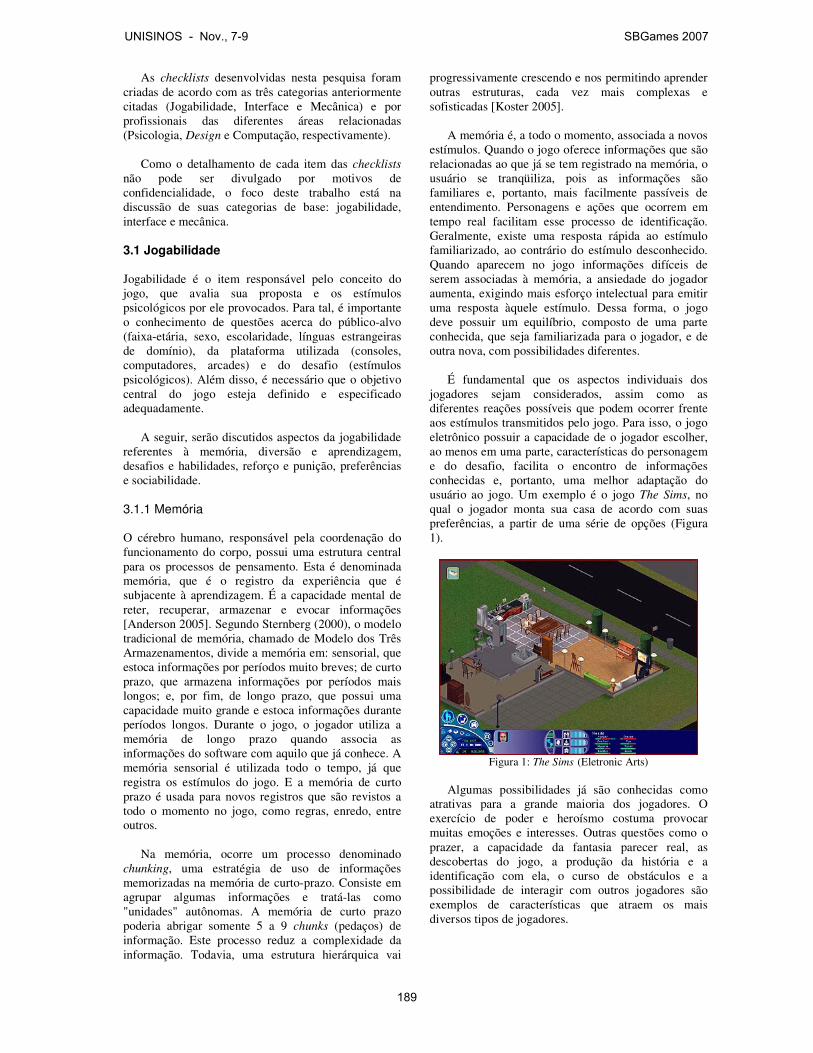
As checklists desenvolvidas nesta pesquisa foram criadas de acordo com as três categorias anteriormente citadas (Jogabilidade, Interface e Mecânica) e por profissionais das diferentes áreas relacionadas (Psicologia, Design e Computação, respectivamente).
Como o detalhamento de cada item das checklists
não pode ser divulgado por motivos de confidencialidade, o foco deste trabalho está na discussão de suas categorias de base: jogabilidade, interface e mecânica.
3.1 Jogabilidade Jogabilidade é o item responsável pelo conceito do jogo, que avalia sua proposta e os estímulos psicológicos por ele provocados. Para tal, é importante o conhecimento de questões acerca do público-alvo (faixa-etária, sexo, escolaridade, línguas estrangeiras de domínio), da plataforma utilizada (consoles, computadores, arcades) e do desafio (estímulos psicológicos). Além disso, é necessário que o objetivo central do jogo esteja definido e especificado adequadamente. A seguir, serão discutidos aspectos da jogabilidade referentes à memória, diversão e aprendizagem, desafios e habilidades, reforço e punição, preferências e sociabilidade. 3.1.1 Memória O cérebro humano, responsável pela coordenação do funcionamento do corpo, possui uma estrutura central para os processos de pensamento. Esta é denominada memória, que é o registro da experiência que é subjacente à aprendizagem. É a capacidade mental de reter, recuperar, armazenar e evocar informações [Anderson 2005]. Segundo Sternberg (2000), o modelo tradicional de memória, chamado de Modelo dos Três Armazenamentos, divide a memória em: sensorial, que estoca informações por períodos muito breves; de curto prazo, que armazena informações por períodos mais longos; e, por fim, de longo prazo, que possui uma capacidade muito grande e estoca informações durante períodos longos. Durante o jogo, o jogador utiliza a memória de longo prazo quando associa as informações do software com aquilo que já conhece. A memória sensorial é utilizada todo o tempo, já que registra os estímulos do jogo. E a memória de curto prazo é usada para novos registros que são revistos a todo o momento no jogo, como regras, enredo, entre outros. Na memória, ocorre um processo denominado chunking, uma estratégia de uso de informações memorizadas na memória de curto-prazo. Consiste em agrupar algumas informações e tratá-las como "unidades" autônomas. A memória de curto prazo poderia abrigar somente 5 a 9 chunks (pedaços) de informação. Este processo reduz a complexidade da informação. Todavia, uma estrutura hierárquica vai
progressivamente crescendo e nos permitindo aprender outras estruturas, cada vez mais complexas e sofisticadas [Koster 2005]. A memória é, a todo o momento, associada a novos estímulos. Quando o jogo oferece informações que são relacionadas ao que já se tem registrado na memória, o usuário se tranqüiliza, pois as informações são familiares e, portanto, mais facilmente passíveis de entendimento. Personagens e ações que ocorrem em tempo real facilitam esse processo de identificação. Geralmente, existe uma resposta rápida ao estímulo familiarizado, ao contrário do estímulo desconhecido. Quando aparecem no jogo informações difíceis de serem associadas à memória, a ansiedade do jogador aumenta, exigindo mais esforço intelectual para emitir uma resposta àquele estímulo. Dessa forma, o jogo deve possuir um equilíbrio, composto de uma parte conhecida, que seja familiarizada para o jogador, e de outra nova, com possibilidades diferentes. É fundamental que os aspectos individuais dos jogadores sejam considerados, assim como as diferentes reações possíveis que podem ocorrer frente aos estímulos transmitidos pelo jogo. Para isso, o jogo eletrônico possuir a capacidade de o jogador escolher, ao menos em uma parte, características do personagem e do desafio, facilita o encontro de informações conhecidas e, portanto, uma melhor adaptação do usuário ao jogo. Um exemplo é o jogo The Sims, no qual o jogador monta sua casa de acordo com suas preferências, a partir de uma série de opções (Figura 1).
Figura 1: The Sims (Eletronic Arts)
Algumas possibilidades já são conhecidas como
atrativas para a grande maioria dos jogadores. O exercício de poder e heroísmo costuma provocar muitas emoções e interesses. Outras questões como o prazer, a capacidade da fantasia parecer real, as descobertas do jogo, a produção da história e a identificação com ela, o curso de obstáculos e a possibilidade de interagir com outros jogadores são exemplos de características que atraem os mais diversos tipos de jogadores.
UNISINOS - Nov., 7-9 SBGames 2007
189
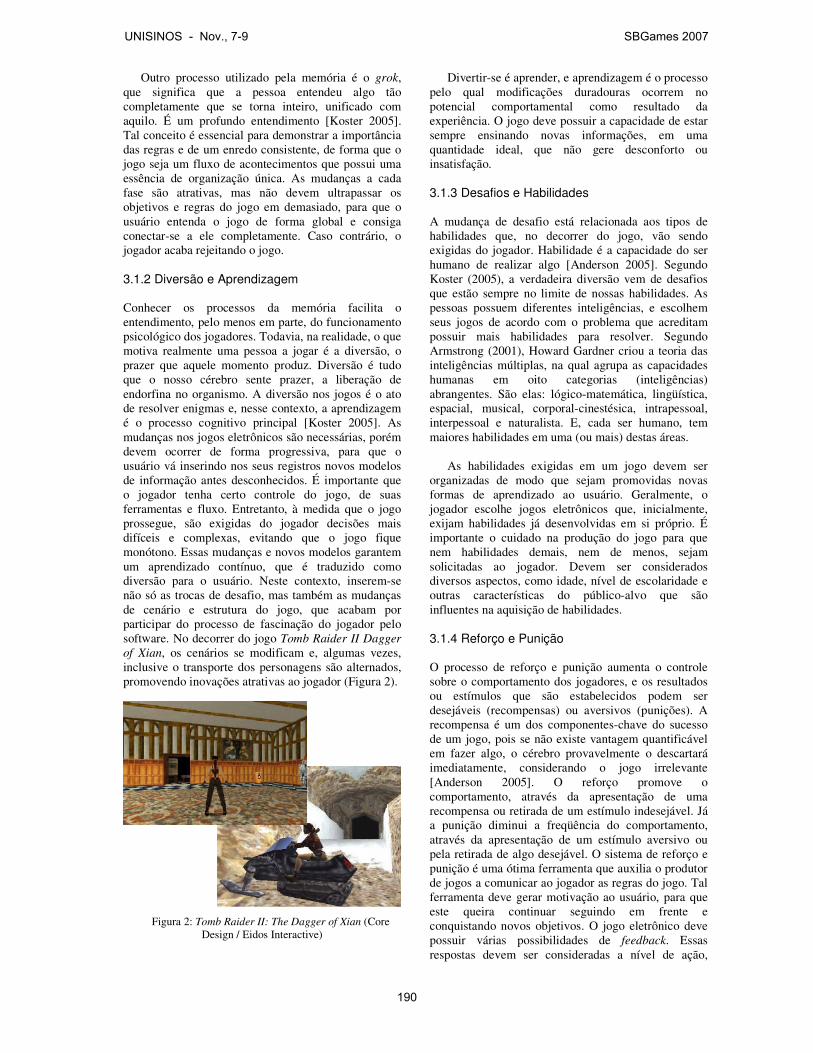
Outro processo utilizado pela memória é o grok, que significa que a pessoa entendeu algo tão completamente que se torna inteiro, unificado com aquilo. É um profundo entendimento [Koster 2005]. Tal conceito é essencial para demonstrar a importância das regras e de um enredo consistente, de forma que o jogo seja um fluxo de acontecimentos que possui uma essência de organização única. As mudanças a cada fase são atrativas, mas não devem ultrapassar os objetivos e regras do jogo em demasiado, para que o usuário entenda o jogo de forma global e consiga conectar-se a ele completamente. Caso contrário, o jogador acaba rejeitando o jogo. 3.1.2 Diversão e Aprendizagem Conhecer os processos da memória facilita o entendimento, pelo menos em parte, do funcionamento psicológico dos jogadores. Todavia, na realidade, o que motiva realmente uma pessoa a jogar é a diversão, o prazer que aquele momento produz. Diversão é tudo que o nosso cérebro sente prazer, a liberação de endorfina no organismo. A diversão nos jogos é o ato de resolver enigmas e, nesse contexto, a aprendizagem é o processo cognitivo principal [Koster 2005]. As mudanças nos jogos eletrônicos são necessárias, porém devem ocorrer de forma progressiva, para que o usuário vá inserindo nos seus registros novos modelos de informação antes desconhecidos. É importante que o jogador tenha certo controle do jogo, de suas ferramentas e fluxo. Entretanto, à medida que o jogo prossegue, são exigidas do jogador decisões mais difíceis e complexas, evitando que o jogo fique monótono. Essas mudanças e novos modelos garantem um aprendizado contínuo, que é traduzido como diversão para o usuário. Neste contexto, inserem-se não só as trocas de desafio, mas também as mudanças de cenário e estrutura do jogo, que acabam por participar do processo de fascinação do jogador pelo software. No decorrer do jogo Tomb Raider II Dagger of Xian, os cenários se modificam e, algumas vezes, inclusive o transporte dos personagens são alternados, promovendo inovações atrativas ao jogador (Figura 2).
Figura 2: Tomb Raider II: The Dagger of Xian (Core
Design / Eidos Interactive)
Divertir-se é aprender, e aprendizagem é o processo pelo qual modificações duradouras ocorrem no potencial comportamental como resultado da experiência. O jogo deve possuir a capacidade de estar sempre ensinando novas informações, em uma quantidade ideal, que não gere desconforto ou insatisfação. 3.1.3 Desafios e Habilidades A mudança de desafio está relacionada aos tipos de habilidades que, no decorrer do jogo, vão sendo exigidas do jogador. Habilidade é a capacidade do ser humano de realizar algo [Anderson 2005]. Segundo Koster (2005), a verdadeira diversão vem de desafios que estão sempre no limite de nossas habilidades. As pessoas possuem diferentes inteligências, e escolhem seus jogos de acordo com o problema que acreditam possuir mais habilidades para resolver. Segundo Armstrong (2001), Howard Gardner criou a teoria das inteligências múltiplas, na qual agrupa as capacidades humanas em oito categorias (inteligências) abrangentes. São elas: lógico-matemática, lingüística, espacial, musical, corporal-cinestésica, intrapessoal, interpessoal e naturalista. E, cada ser humano, tem maiores habilidades em uma (ou mais) destas áreas.
As habilidades exigidas em um jogo devem ser organizadas de modo que sejam promovidas novas formas de aprendizado ao usuário. Geralmente, o jogador escolhe jogos eletrônicos que, inicialmente, exijam habilidades já desenvolvidas em si próprio. É importante o cuidado na produção do jogo para que nem habilidades demais, nem de menos, sejam solicitadas ao jogador. Devem ser considerados diversos aspectos, como idade, nível de escolaridade e outras características do público-alvo que são influentes na aquisição de habilidades.
3.1.4 Reforço e Punição O processo de reforço e punição aumenta o controle sobre o comportamento dos jogadores, e os resultados ou estímulos que são estabelecidos podem ser desejáveis (recompensas) ou aversivos (punições). A recompensa é um dos componentes-chave do sucesso de um jogo, pois se não existe vantagem quantificável em fazer algo, o cérebro provavelmente o descartará imediatamente, considerando o jogo irrelevante [Anderson 2005]. O reforço promove o comportamento, através da apresentação de uma recompensa ou retirada de um estímulo indesejável. Já a punição diminui a freqüência do comportamento, através da apresentação de um estímulo aversivo ou pela retirada de algo desejável. O sistema de reforço e punição é uma ótima ferramenta que auxilia o produtor de jogos a comunicar ao jogador as regras do jogo. Tal ferramenta deve gerar motivação ao usuário, para que este queira continuar seguindo em frente e conquistando novos objetivos. O jogo eletrônico deve possuir várias possibilidades de feedback. Essas respostas devem ser consideradas a nível de ação,
UNISINOS - Nov., 7-9 SBGames 2007
190

como qualquer ato do jogo, e também a nível global, no qual o jogador possa receber informações sobre seu desempenho em toda a fase ou em todo o jogo, comparando-se a outros jogadores. 3.1.5 Preferências Existem, também, outros fatores que devem ser considerados na avaliação de um jogo, como determinadas preferências que não possuem explicações específicas, remetendo à questão da satisfação subjetiva do jogador. As diferenças de gênero estão inseridas neste contexto.
Os sexos masculino e feminino possuem diferenças
no processamento das informações, além de preferências próprias, geralmente aprendidas culturalmente. As mulheres querem jogos com sistemas abstratos simples, com menos raciocínio espacial e maior ênfase nas relações interpessoais, narrativa e empatia. Os homens preferem jogos que enfatizam o exercício do poder e o controle do território [Koster 2005]. Os dados desta categoria foram resultados de diversas pesquisas que chegaram a tais conclusões de preferências masculinas e femininas. São dados importantes, que podem direcionar para qual público o jogo será mais atrativo. Entretanto, cada dia mais, os estilos e as preferências dos sexos estão integrados, diminuindo as diferenças entre homem e mulher neste contexto.
3.1.6 Sociabilidade Um movimento entre os jogadores de jogos eletrônicos vem sendo percebido no decorrer dos anos. Enquanto há um tempo era valorizado o jogo individual, atualmente o ato de jogar está se transformando, cada vez mais, em uma atividade social [Jones 2004]. A possibilidade de jogar com outros parceiros e adversários permite criar novas estratégias e intercambiar soluções para os desafios, tanto nos jogos que envolvem apenas dois jogadores por jogada, como naqueles que podem ser jogados com múltiplos usuários, nos quais as trocas podem acontecer em um mesmo espaço geográfico ou na rede [Alves 2005]. É importante que o jogador tenha a possibilidade de jogar com outros jogadores, seja através de um jogo cooperativo ou competitivo. Todavia, deve-se atentar para as características do jogo neste contexto, que deve possuir, por exemplo, diferentes descobertas e feedbacks para jogadores com experiências distintas. Outra questão a considerar é que o jogo, como meio de expressão social, precisa favorecer a interação entre jogadores. Ferramentas como forma de expressão e comunicação de emoções e de aspectos pessoais, decisões de um jogador que afetam as decisões do outro jogador, entre outras, são estratégias importantes em um jogo para que haja o reconhecimento dos jogadores perante os demais, favorecendo a relação. No jogo Sid Meier’s Civilization III, há a possibilidade de escolher as mais variadas características dos
personagens, para que o jogador identifique-se e demonstre sua identidade aos demais jogadores (Figura 3). Neste contexto, o jogo insere-se como um instrumento de interação social, abrindo caminhos diferentes para a produção de produtos que enfatizem tal característica.
Figura 3: Sid Meier’s Civilization III (Firaxis Games)
A jogabilidade de um jogo eletrônico é essencial para que este seja atrativo e promova a diversão do jogador. Avaliar a interação do usuário com o jogo, neste aspecto, auxilia na elaboração de um produto mais assertivo ao mercado consumidor. A base do ser humano são seus processos psicológicos e, dessa forma, é muito importante que os jogos eletrônicos estejam adequados a tais funcionamentos, para que a receptividade do jogador ao jogo seja maior e mais profunda. 3.2 Interface A interface é a parte responsável pela comunicação direta do software com o usuário, e indireta dos desenvolvedores com o mesmo. Ela é o elo que aproxima e une o jogador ao jogo [Macedo Filho 2005] e que, juntamente com jogabilidade e mecânica, faz com que este se torne um grande atrativo ou não. Ela pode ser dividida em três partes: visual, sonora e sensível, segundo os sentidos humanos utilizados na percepção dos jogos eletrônicos. O sentido mais utilizado pelos jogadores é a visão. Com ela, percebem-se os diversos elementos visuais que nos proporcionam obter as informações relevantes para o entendimento de um jogo. Caso estes elementos não sejam adequadamente percebidos, todo o objetivo lógico e de desenvolvimento do jogo podem acabar não sendo atingidos e, assim, o usuário não se diverte e não aprende. Além de considerar o jogo muito ruim, também não consome mais e ainda aconselha os demais jogadores a não consumirem. 3.2.1 Parte Visual O primeiro critério a ser avaliado em uma interface é a estética. A partir dela é que todo o sentido do jogo irá ser exposto e transmitido ao usuário. Quando se fala em estética, não está se falando apenas em beleza e
UNISINOS - Nov., 7-9 SBGames 2007
191
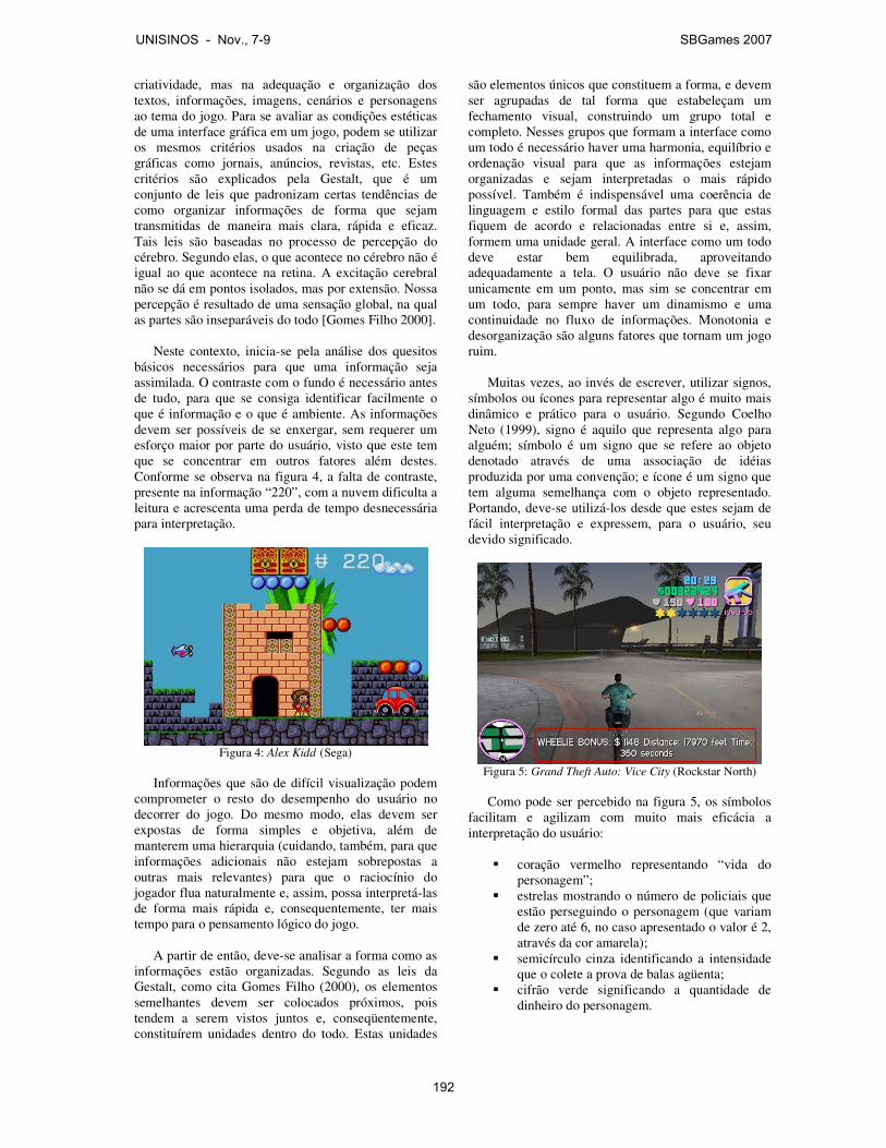
criatividade, mas na adequação e organização dos textos, informações, imagens, cenários e personagens ao tema do jogo. Para se avaliar as condições estéticas de uma interface gráfica em um jogo, podem se utilizar os mesmos critérios usados na criação de peças gráficas como jornais, anúncios, revistas, etc. Estes critérios são explicados pela Gestalt, que é um conjunto de leis que padronizam certas tendências de como organizar informações de forma que sejam transmitidas de maneira mais clara, rápida e eficaz. Tais leis são baseadas no processo de percepção do cérebro. Segundo elas, o que acontece no cérebro não é igual ao que acontece na retina. A excitação cerebral não se dá em pontos isolados, mas por extensão. Nossa percepção é resultado de uma sensação global, na qual as partes são inseparáveis do todo [Gomes Filho 2000].
Neste contexto, inicia-se pela análise dos quesitos
básicos necessários para que uma informação seja assimilada. O contraste com o fundo é necessário antes de tudo, para que se consiga identificar facilmente o que é informação e o que é ambiente. As informações devem ser possíveis de se enxergar, sem requerer um esforço maior por parte do usuário, visto que este tem que se concentrar em outros fatores além destes. Conforme se observa na figura 4, a falta de contraste, presente na informação “220”, com a nuvem dificulta a leitura e acrescenta uma perda de tempo desnecessária para interpretação.
Figura 4: Alex Kidd (Sega)
Informações que são de difícil visualização podem
comprometer o resto do desempenho do usuário no decorrer do jogo. Do mesmo modo, elas devem ser expostas de forma simples e objetiva, além de manterem uma hierarquia (cuidando, também, para que informações adicionais não estejam sobrepostas a outras mais relevantes) para que o raciocínio do jogador flua naturalmente e, assim, possa interpretá-las de forma mais rápida e, consequentemente, ter mais tempo para o pensamento lógico do jogo.
A partir de então, deve-se analisar a forma como as
informações estão organizadas. Segundo as leis da Gestalt, como cita Gomes Filho (2000), os elementos semelhantes devem ser colocados próximos, pois tendem a serem vistos juntos e, conseqüentemente, constituírem unidades dentro do todo. Estas unidades
são elementos únicos que constituem a forma, e devem ser agrupadas de tal forma que estabeleçam um fechamento visual, construindo um grupo total e completo. Nesses grupos que formam a interface como um todo é necessário haver uma harmonia, equilíbrio e ordenação visual para que as informações estejam organizadas e sejam interpretadas o mais rápido possível. Também é indispensável uma coerência de linguagem e estilo formal das partes para que estas fiquem de acordo e relacionadas entre si e, assim, formem uma unidade geral. A interface como um todo deve estar bem equilibrada, aproveitando adequadamente a tela. O usuário não deve se fixar unicamente em um ponto, mas sim se concentrar em um todo, para sempre haver um dinamismo e uma continuidade no fluxo de informações. Monotonia e desorganização são alguns fatores que tornam um jogo ruim.
Muitas vezes, ao invés de escrever, utilizar signos,
símbolos ou ícones para representar algo é muito mais dinâmico e prático para o usuário. Segundo Coelho Neto (1999), signo é aquilo que representa algo para alguém; símbolo é um signo que se refere ao objeto denotado através de uma associação de idéias produzida por uma convenção; e ícone é um signo que tem alguma semelhança com o objeto representado. Portando, deve-se utilizá-los desde que estes sejam de fácil interpretação e expressem, para o usuário, seu devido significado.
Figura 5: Grand Theft Auto: Vice City (Rockstar North) Como pode ser percebido na figura 5, os símbolos
facilitam e agilizam com muito mais eficácia a interpretação do usuário:
� coração vermelho representando “vida do
personagem”; � estrelas mostrando o número de policiais que
estão perseguindo o personagem (que variam de zero até 6, no caso apresentado o valor é 2, através da cor amarela);
� semicírculo cinza identificando a intensidade que o colete a prova de balas agüenta;
� cifrão verde significando a quantidade de dinheiro do personagem.
UNISINOS - Nov., 7-9 SBGames 2007
192
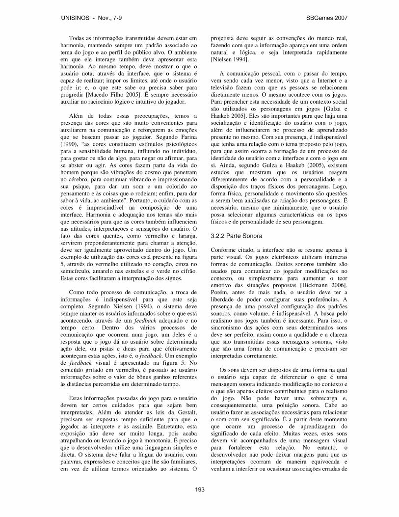
Todas as informações transmitidas devem estar em harmonia, mantendo sempre um padrão associado ao tema do jogo e ao perfil do público alvo. O ambiente em que ele interage também deve apresentar esta harmonia. Ao mesmo tempo, deve mostrar o que o usuário nota, através da interface, que o sistema é capaz de realizar; impor os limites, até onde o usuário pode ir; e, o que este sabe ou precisa saber para progredir [Macedo Filho 2005]. É sempre necessário auxiliar no raciocínio lógico e intuitivo do jogador.
Além de todas essas preocupações, temos a
presença das cores que são muito convenientes para auxiliarem na comunicação e reforçarem as emoções que se buscam passar ao jogador. Segundo Farina (1990), “as cores constituem estímulos psicológicos para a sensibilidade humana, influindo no indivíduo, para gostar ou não de algo, para negar ou afirmar, para se abster ou agir. As cores fazem parte da vida do homem porque são vibrações do cosmo que penetram no cérebro, para continuar vibrando e impressionando sua psique, para dar um som e um colorido ao pensamento e às coisas que o rodeiam; enfim, para dar sabor à vida, ao ambiente”. Portanto, o cuidado com as cores é imprescindível na composição de uma interface. Harmonia e adequação aos temas são mais que necessários para que as cores também influenciem nas atitudes, interpretações e sensações do usuário. O fato das cores quentes, como vermelho e laranja, servirem preponderantemente para chamar a atenção, deve ser igualmente aproveitado dentro do jogo. Um exemplo de utilização das cores está presente na figura 5, através do vermelho utilizado no coração, cinza no semicírculo, amarelo nas estrelas e o verde no cifrão. Estas cores facilitaram a interpretação dos signos.
Como todo processo de comunicação, a troca de
informações é indispensável para que este seja completo. Segundo Nielsen (1994), o sistema deve sempre manter os usuários informados sobre o que está acontecendo, através de um feedback adequado e no tempo certo. Dentro dos vários processos de comunicação que ocorrem num jogo, um deles é a resposta que o jogo dá ao usuário sobre determinada ação dele, ou pistas e dicas para que efetivamente aconteçam estas ações, isto é, o feedback. Um exemplo de feedback visual é apresentado na figura 5. No conteúdo grifado em vermelho, é passado ao usuário informações sobre o valor de bônus ganhos referentes às distâncias percorridas em determinado tempo.
Estas informações passadas do jogo para o usuário
devem ter certos cuidados para que sejam bem interpretadas. Além de atender as leis da Gestalt, precisam ser expostas tempo suficiente para que o jogador as interprete e as assimile. Entretanto, esta exposição não deve ser muito longa, pois acaba atrapalhando ou levando o jogo à monotonia. É preciso que o desenvolvedor utilize uma linguagem simples e direta. O sistema deve falar a língua do usuário, com palavras, expressões e conceitos que lhe são familiares, em vez de utilizar termos orientados ao sistema. O
projetista deve seguir as convenções do mundo real, fazendo com que a informação apareça em uma ordem natural e lógica, e seja interpretada rapidamente [Nielsen 1994].
A comunicação pessoal, com o passar do tempo, vem sendo cada vez menor, visto que a Internet e a televisão fazem com que as pessoas se relacionem diretamente menos. O mesmo acontece com os jogos. Para preencher esta necessidade de um contexto social são utilizados os personagens em jogos [Gulza e Haakeb 2005]. Eles são importantes para que haja uma socialização e identificação do usuário com o jogo, além de influenciarem no processo de aprendizado presente no mesmo. Com sua presença, é indispensável que tenha uma relação com o tema proposto pelo jogo, para que assim ocorra a formação de um processo de identidade do usuário com a interface e com o jogo em si. Ainda, segundo Gulza e Haakeb (2005), existem estudos que mostram que os usuários reagem diferentemente de acordo com a personalidade e a disposição dos traços físicos dos personagens. Logo, forma física, personalidade e movimento são questões a serem bem analisadas na criação dos personagens. É necessário, mesmo que minimamente, que o usuário possa selecionar algumas características ou os tipos físicos e de personalidade de seu personagem.
3.2.2 Parte Sonora
Conforme citado, a interface não se resume apenas à parte visual. Os jogos eletrônicos utilizam inúmeras formas de comunicação. Efeitos sonoros também são usados para comunicar ao jogador modificações no contexto, ou simplesmente para aumentar o teor emotivo das situações propostas [Hickmann 2006]. Porém, antes de mais nada, o usuário deve ter a liberdade de poder configurar suas preferências. A presença de uma possível configuração dos padrões sonoros, como volume, é indispensável. A busca pelo realismo nos jogos também é incessante. Para isso, o sincronismo das ações com seus determinados sons deve ser perfeito, assim como a qualidade e a clareza que são transmitidas essas mensagens sonoras, visto que são uma forma de comunicação e precisam ser interpretadas corretamente.
Os sons devem ser dispostos de uma forma na qual
o usuário seja capaz de diferenciar o que é uma mensagem sonora indicando modificação no contexto e o que são apenas efeitos contribuintes para o realismo do jogo. Não pode haver uma sobrecarga e, consequentemente, uma poluição sonora. Cabe ao usuário fazer as associações necessárias para relacionar o som com seu significado. É a partir deste momento que ocorre um processo de aprendizagem do significado de cada efeito. Muitas vezes, estes sons devem vir acompanhados de uma mensagem visual para fortalecer esta relação. No entanto, o desenvolvedor não pode deixar margens para que as interpretações ocorram de maneira equivocada e venham a interferir ou ocasionar associações erradas de
UNISINOS - Nov., 7-9 SBGames 2007
193
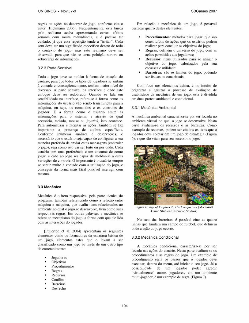
regras ou ações no decorrer do jogo, conforme cita o autor [Hickmann 2006]. Freqüentemente, esta busca pelo realismo acaba apresentando certos efeitos sonoros com muita redundância, e é preciso ter cuidado, já que essa repetição tende a “irritar”. Cada som deve ter um significado específico dentro de todo o contexto do jogo, mas este realismo deve ser observado para que não se torne poluição sonora ou sobrecarga de informações.
3.2.3 Parte Sensível
Todo o jogo deve se moldar à forma de atuação do usuário, para que todos os tipos de jogadores se sintam à vontade e, conseqüentemente, tenham maior nível de diversão. A parte sensível da interface é onde este enfoque deve ser redobrado. Quando se fala em sensibilidade na interface, refere-se à forma como as informações do usuário vão sendo transmitidas para a máquina, ou seja, os comandos e os controles do jogador. É a forma como o usuário emite as informações para o sistema, e através de qual acessório, teclado, mouse ou joystick, isto acontece. Para automatizar e facilitar as ações, também se faz importante a presença de atalhos específicos. Conforme inúmeras análises e observações, é necessário que o usuário seja capaz de configurar a sua maneira preferida de enviar estas mensagens (controlar o jogo), seja como isto vai ser feito ou por onde. Cada usuário tem uma preferência e um costume de como jogar, e cabe ao jogo ser capaz de moldar-se a estas variações de controle. O importante é o usuário sempre se sentir muito à vontade com a utilização do jogo, e conseguir da forma mais fácil possível interagir com mesmo. 3.3 Mecânica Mecânica é o item responsável pela parte técnica do programa, também referenciado como a relação entre máquina e máquina, que avalia itens relacionados ao ambiente no qual o jogo se desenvolve, bem como suas respectivas regras. Em outras palavras, a mecânica se refere ao mecanismo do jogo, a forma com que ele lida com as interações do jogador.
[Fullerton et al. 2004] apresentam os seguintes elementos como os formadores da estrutura básica de um jogo, elementos estes que o levam a ser classificado como um jogo ao invés de um outro tipo de entretenimento:
� Jogadores � Objetivos � Procedimentos � Regras � Recursos � Conflito � Barreiras � Desfecho
Em relação à mecânica de um jogo, é possível destacar quatro destes elementos:
� Procedimentos: métodos para jogar, que são
constituídos de ações que os usuários podem realizar para concluir os objetivos do jogo;
� Regras: definem o universo do jogo, com as ações permitidas aos jogadores;
� Recursos: itens utilizados para se atingir o objetivo do jogo, valorizados pela sua escassez e utilidade;
� Barreiras: são os limites do jogo, podendo ser físicas ou conceituais.
Com foco nos elementos acima, e no intuito de
organizar e agilizar o processo de avaliação de usabilidade da mecânica de um jogo, esta é dividida em duas partes: ambiental e condicional.
3.3.1 Mecânica Ambiental
A mecânica ambiental caracteriza-se por ser focada no ambiente virtual no qual o jogo se desenvolve. Nesta parte avaliam-se os recursos e as barreiras. Como exemplo de recursos, podem ser citados os itens que o jogador deve coletar em um jogo de estratégia (Figura 6), e que são vitais para seu sucesso no jogo.
Figura 6: Age of Empires 2: The Conquerors (Microsoft
Game Studios/Ensemble Studios) No caso das barreiras, é possível citar as quatro
linhas que limitam um campo de futebol, que definem onde a ação do jogo ocorre.
3.3.2 Mecânica Condicional
A mecânica condicional caracteriza-se por ser
focada nas ações do usuário. Nesta parte avaliam-se os procedimentos e as regras do jogo. Um exemplo de procedimento seria os passos que o jogador deve executar, dentro do menu, até iniciar o seu jogo. Já a possibilidade de um jogador poder agredir “virtualmente” outros jogadores, em um ambiente multi-jogador, é um exemplo de regra (Figura 7).
UNISINOS - Nov., 7-9 SBGames 2007
194
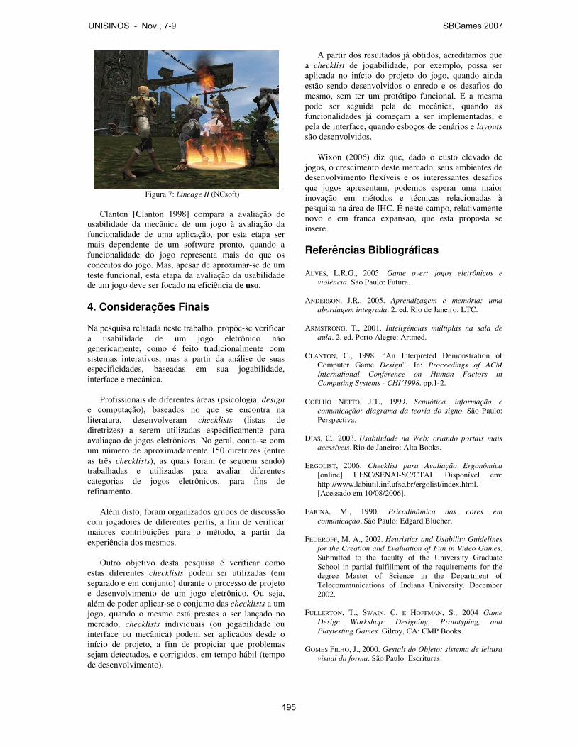
Figura 7: Lineage II (NCsoft)
Clanton [Clanton 1998] compara a avaliação de
usabilidade da mecânica de um jogo à avaliação da funcionalidade de uma aplicação, por esta etapa ser mais dependente de um software pronto, quando a funcionalidade do jogo representa mais do que os conceitos do jogo. Mas, apesar de aproximar-se de um teste funcional, esta etapa da avaliação da usabilidade de um jogo deve ser focado na eficiência de uso. 4. Considerações Finais Na pesquisa relatada neste trabalho, propõe-se verificar a usabilidade de um jogo eletrônico não genericamente, como é feito tradicionalmente com sistemas interativos, mas a partir da análise de suas especificidades, baseadas em sua jogabilidade, interface e mecânica.
Profissionais de diferentes áreas (psicologia, design e computação), baseados no que se encontra na literatura, desenvolveram checklists (listas de diretrizes) a serem utilizadas especificamente para avaliação de jogos eletrônicos. No geral, conta-se com um número de aproximadamente 150 diretrizes (entre as três checklists), as quais foram (e seguem sendo) trabalhadas e utilizadas para avaliar diferentes categorias de jogos eletrônicos, para fins de refinamento.
Além disto, foram organizados grupos de discussão com jogadores de diferentes perfis, a fim de verificar maiores contribuições para o método, a partir da experiência dos mesmos.
Outro objetivo desta pesquisa é verificar como estas diferentes checklists podem ser utilizadas (em separado e em conjunto) durante o processo de projeto e desenvolvimento de um jogo eletrônico. Ou seja, além de poder aplicar-se o conjunto das checklists a um jogo, quando o mesmo está prestes a ser lançado no mercado, checklists individuais (ou jogabilidade ou interface ou mecânica) podem ser aplicados desde o início de projeto, a fim de propiciar que problemas sejam detectados, e corrigidos, em tempo hábil (tempo de desenvolvimento).
A partir dos resultados já obtidos, acreditamos que a checklist de jogabilidade, por exemplo, possa ser aplicada no início do projeto do jogo, quando ainda estão sendo desenvolvidos o enredo e os desafios do mesmo, sem ter um protótipo funcional. E a mesma pode ser seguida pela de mecânica, quando as funcionalidades já começam a ser implementadas, e pela de interface, quando esboços de cenários e layouts são desenvolvidos.
Wixon (2006) diz que, dado o custo elevado de jogos, o crescimento deste mercado, seus ambientes de desenvolvimento flexíveis e os interessantes desafios que jogos apresentam, podemos esperar uma maior inovação em métodos e técnicas relacionadas à pesquisa na área de IHC. É neste campo, relativamente novo e em franca expansão, que esta proposta se insere. Referências Bibliográficas ALVES, L.R.G., 2005. Game over: jogos eletrônicos e
violência. São Paulo: Futura. ANDERSON, J.R., 2005. Aprendizagem e memória: uma
abordagem integrada. 2. ed. Rio de Janeiro: LTC. ARMSTRONG, T., 2001. Inteligências múltiplas na sala de
aula. 2. ed. Porto Alegre: Artmed. CLANTON, C., 1998. “An Interpreted Demonstration of
Computer Game Design”. In: Proceedings of ACM International Conference on Human Factors in Computing Systems - CHI´1998. pp.1-2.
COELHO NETTO, J.T., 1999. Semiótica, informação e
comunicação: diagrama da teoria do signo. São Paulo: Perspectiva.
DIAS, C., 2003. Usabilidade na Web: criando portais mais
acessíveis. Rio de Janeiro: Alta Books. ERGOLIST, 2006. Checklist para Avaliação Ergonômica
[online] UFSC/SENAI-SC/CTAI. Disponível em: http://www.labiutil.inf.ufsc.br/ergolist/index.html. [Acessado em 10/08/2006].
FARINA, M., 1990. Psicodinâmica das cores em
comunicação. São Paulo: Edgard Blücher. FEDEROFF, M. A., 2002. Heuristics and Usability Guidelines
for the Creation and Evaluation of Fun in Video Games. Submitted to the faculty of the University Graduate School in partial fulfillment of the requirements for the degree Master of Science in the Department of Telecommunications of Indiana University. December 2002.
FULLERTON, T.; SWAIN, C. E HOFFMAN, S., 2004 Game
Design Workshop: Designing, Prototyping, and Playtesting Games. Gilroy, CA: CMP Books.
GOMES FILHO, J., 2000. Gestalt do Objeto: sistema de leitura
visual da forma. São Paulo: Escrituras.
UNISINOS - Nov., 7-9 SBGames 2007
195

GULZA, A.; HAAKEB, M., 2006. Design of animated pedagogical agents – a look at their look. International Journal of Human-Computer Studies, Vol. 64(4), pp. 281-394.
HICKMANN, F. O papel dos efeitos sonoros na significação
em jogos eletrônicos. Anais do ENCAM. Curitiba: Editora da UFPR, 2006.
IwC, 2007. IwC, 2007. HCI Issues in Computer Games.
Interacting with Computers (IwC). Volume 19, Issue 2, Pages 135-304, March 2007.
JONES, G., 2004. Brincando de matar monstros: por que as
crianças precisam de fantasia, videogames e violência de faz-de-conta (Tradução Ana Ban). São Paulo: Conrad Editora do Brasil.
KOSTER, R., 2005. A theory of fun for game design. Arizona:
Paraglyph Press. MACEDO FILHO, M.D., 2005. “A relevância de interfaces
gráficas amigáveis para jogos eletrônicos funcionais”. I Seminário Jogos Eletrônicos, Educação e Comunicação: construindo novas trilhas, UNEB, Salvador, out. 2005.
MACK, R. E NIELSEN, J. (EDS.), 1994. Usability Inspection
Methods. New York, NY: John Wiley & Sons. MEDLOCK, M. C., WIXON, D., TERRANO, M., ROMERO, R. L. E
FULTON, B., 2002. Using the RITE method to improve products: a definition and a case study. Usability Professionals Association, Orlando FL, July 2002.
NIELSEN, J., 1993. Usability Engineering. San Diego: Academic Press.
NIELSEN, J., 1994. Heuristic Evaluation. In: MACK, R. E
NIELSEN, J. (EDS.) Usability Inspection Methods. New York, NY: John Wiley & Sons, 25-62.
PRATES, R.O.; DE SOUZA, C.S. E BARBOSA, S.D.J., 2000. “A
method for evaluating the communicability of user interfaces”. Interactions. Vol.7, No.1, 31-38.
PREECE, J. (ed). Human-Computer Interaction. Harlow:
Addison-Wesley, 1994. RUBIN, J., 1994. Handbook of Usability Testing. New York,
NY: John Wiley & Sons. STERNBERG, R.J., 2000. Psicologia Cognitiva. Porto Alegre:
Artmed. WHARTON, C.; RIEMAN, J.; LEWIS, C. E POLSON, P., 1994. The
Cognitive Walkthrough Method: A Practitioner’s Guide. In: MACK, R. AND NIELSEN, J. (EDS.) Usability Inspection Methods. New York, NY: John Wiley & Sons, 105-140
WIXON, D., 2006. What work? Interactions, july + august
2006. 18-19.
UNISINOS - Nov., 7-9 SBGames 2007
196
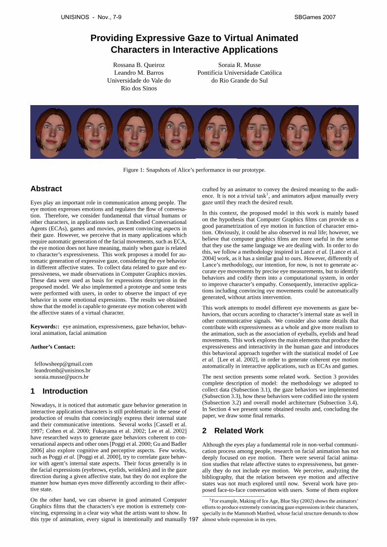
Providing Expressive Gaze to Virtual AnimatedCharacters in Interactive Applications
Rossana B. QueirozLeandro M. Barros
Universidade do Vale doRio dos Sinos
Soraia R. MussePontifícia Universidade Católica
do Rio Grande do Sul
Figure 1: Snapshots of Alice’s performance in our prototype.
Abstract
Eyes play an important role in communication among people. Theeye motion expresses emotions and regulates the flow of conversa-tion. Therefore, we consider fundamental that virtual humans orother characters, in applications such as Embodied ConversationalAgents (ECAs), games and movies, present convincing aspects intheir gaze. However, we perceive that in many applications whichrequire automatic generation of the facial movements, such as ECA,the eye motion does not have meaning, mainly when gaze is relatedto character’s expressiveness. This work proposes a model for au-tomatic generation of expressive gaze, considering the eye behaviorin different affective states. To collect data related to gaze and ex-pressiveness, we made observations in Computer Graphics movies.These data were used as basis for expressions description in theproposed model. We also implemented a prototype and some testswere performed with users, in order to observe the impact of eyebehavior in some emotional expressions. The results we obtainedshow that the model is capable to generate eye motion coherent withthe affective states of a virtual character.
Keywords:: eye animation, expressiveness, gaze behavior, behav-ioral animation, facial animation
Author’s Contact:
[email protected]@[email protected]
1 Introduction
Nowadays, it is noticed that automatic gaze behavior generation ininteractive application characters is still problematic in the sense ofproduction of results that convincingly express their internal stateand their communicative intentions. Several works [Cassell et al.1997; Cohen et al. 2000; Fukayama et al. 2002; Lee et al. 2002]have researched ways to generate gaze behaviors coherent to con-versational aspects and other ones [Poggi et al. 2000; Gu and Badler2006] also explore cognitive and perceptive aspects. Few works,such as Poggiet al. [Poggi et al. 2000], try to correlate gaze behav-ior with agent’s internal state aspects. Their focus generally is inthe facial expressions (eyebrows, eyelids, wrinkles) and in the gazedirection during a given affective state, but they do not explore themanner how human eyes move differently according to their affec-tive state.
On the other hand, we can observe in good animated ComputerGraphics films that the characters’s eye motion is extremely con-vincing, expressing in a clear way what the artists want to show. Inthis type of animation, every signal is intentionally and manually
crafted by an animator to convey the desired meaning to the audi-ence. It is not a trivial task1, and animators adjust manually everygaze until they reach the desired result.
In this context, the proposed model in this work is mainly basedon the hypothesis that Computer Graphics films can provide us agood parametrization of eye motion in function of character emo-tion. Obviously, it could be also observed in real life; however, webelieve that computer graphics films are more useful in the sensethat they use the same language we are dealing with. In order to dothis, we follow a methodology inspired in Lanceet al. [Lance et al.2004] work, as it has a similar goal to ours. However, differently ofLance’s methodology, our intention, for now, is not to generate ac-curate eye movements by precise eye measurements, but to identifybehaviors and codify them into a computational system, in orderto improve character’s empathy. Consequently, interactive applica-tions including convincing eye movements could be automaticallygenerated, without artists intervention.
This work attempts to model different eye movements as gaze be-haviors, that occurs acording to character’s internal state as well inother communicative signals. We consider also some details thatcontribute with expressiveness as a whole and give more realism tothe animation, such as the association of eyeballs, eyelids and headmovements. This work explores the main elements that produce theexpressiveness and interactivity in the human gaze and introducesthis behavioral approach together with the statistical model of Leeet al. [Lee et al. 2002], in order to generate coherent eye motionautomatically in interactive applications, such as ECAs and games.
The next section presents some related work. Section 3 providescomplete description of model: the methodology we adopted tocollect data (Subsection 3.1), the gaze behaviors we implemented(Subsection 3.3), how these behaviors were codified into the system(Subsection 3.2) and overall model architecture (Subsection 3.4).In Section 4 we present some obtained results and, concluding thepaper, we draw some final remarks.
2 Related Work
Although the eyes play a fundamental role in non-verbal communi-cation process among people, research on facial animation has notdeeply focused on eye motion. There were several facial anima-tion studies that relate affective states to expressiveness, but gener-ally they do not include eye motion. We perceive, analyzing thebibliography, that the relation between eye motion and affectivestates was not much explored until now. Several work have pro-posed face-to-face conversation with users. Some of them explore
1For example, Making of Ice Age, Blue Sky (2002) shows the animators’efforts to produce extremely convincing gaze expressions in their characters,specially in the Mammoth Manfred, whose facial structure demands to showalmost whole expression in its eyes.
UNISINOS - Nov., 7-9 SBGames 2007
197

default gaze behavior in a dialogue, such as mutual gaze and gazeaversion during talking and listening turns [Cassell et al. 1997; Co-hen et al. 2000; Fukayama et al. 2002]. According to [Vertegaalet al. 2001], gaze may be used to discover who will assume thediscourse in turn taking of conversation. Models such as [Cohenet al. 2000; Fukayama et al. 2002; Lee et al. 2002; Vinayagamoor-thy et al. 2004] consider if the agent is in talking or listening state,in order to determine parameters that generate differentiated gaze.[Lee et al. 2002] work verified, through analysis of data collectedby eye tracking, that these two states present different probabilitydistributions in their eye motion intervals.
There are also approaches focused on the attentional focus of theagents, endowed with artificial vision abilities to provide gaze be-havior when they are immersed in a virtual world [Itti et al. 2004]or in virtual reality applications [Courty et al. 2003]. The recentwork of Gu and Badler [Gu and Badler 2006] tries to find patternsto develop a model that simulates ECA’s gaze in a conversation en-vironment, considering not only engagement but also distractionsthat can occur in a dynamic environment, where peripheral move-ments can affect the gaze behavior. This work also lists some gazepatterns for some emotional states and for cognitive and commu-nicative tasks, based on literature.
Our work is deeply inspired in the following three works. The firstis proposed by Lee et. al [Lee et al. 2002], that provides a stochasticmodel for generating saccades (rapid movements of both eyes fromone gaze position to another). The four parameters for saccadesgeneration are:i) magnitude angle of eyeball rotation,ii) direction(2D rotation axis),iii) duration (time of saccade execution) andiv)inter-saccadic interval (time of gaze fixation). These parameters arecaptured through an Eye Tracking system, which also considers ifpeople are talking or listening. The results of this work are veryrealistic, but do not consider intentional communicative signals (re-lated to text semantics) and affective states.
Our first efforts [Rodrigues et al. 2007] were to include this saccadicbehavior together with facial expressions. It improves the realism inanimation, but statistic model generates incoherent “gaze” in somecases, depending of the emotional expression. For example, someemotions require gaze fixation to the conversation partner, whileothers should produce gaze glances or gaze shifts that occur withmore frequency. Indeed, saccadic behavior does not cosider emo-tion in this model.
The second work we were inspired in is Poggi et al. work [Poggiet al. 2000; Poggi and Pelachaud 2002], that focused on gaze be-havior and proposed a meaning-to-face approach, allowing to sim-ulate automatic generation of face expressions based on semanticdata. Like any communicative signal, gaze includes two differentaspects: asignal, which encompasses a set of physical features andthe dynamic behavior of eyes in gaze; and themeaningwhich isrelated with a set of goals or beliefs that gaze intends to commu-nicate. This work maps very well the different gaze functions andthe relevant parameters that contribute to generate a convincing an-imation. In their proposed model, they classify the “meanings” byadding information about the world and agent’s mind:i) agent’sbeliefs,ii) agent’s goals andiii) agent’s affective state.
Finally, Lance et al. work [Lance et al. 2004] addresses the problemof providing automatically generated expressive gaze to a virtualagent. Their approach is quite different of previous work, since theyopt to capture gaze patterns data from animated CG films. Theygive two reasons for basing their work on films observations:i)literature does not provide sufficient data related to how eye shiftsvary according to character’s internal state; andii) in animated CGfilms, gaze shifts are explicitly crafted to be understood by au-dience. Lance’s work has good ideas, however it presents onlypreliminary data analysis and does not present a gaze generationmodel.
In our work, differently from the previous cited papers, the maingoal is to provide a model to automatically generate expressive gazewith different gaze behaviors (gaze directions and shifts) and facialexpressions (eyelids, eyebrows and head) based on empirical ob-servation of CG films that explicitly evoke the meaning of agent’sinternal affective state. Our methodology of data collecting and its
codification to a computational model are described in next section.
3 Model
We based our model mainly in three ideas:
1. the stochastic model of Lee [Lee et al. 2002], as an engine forgeneration of realistic gaze shifts;
2. the gazelexicon from Poggiet al. work (gaze parameters)[Poggi et al. 2000], for mapping of signals and meanings ofagent’s internal state, and;
3. the idea of extracting gaze data from CG films, from Lanceetal. [Lance et al. 2004] work.
This section presents the proposed model for automatic gaze gen-eration. First, we talk about the methodology we adopted to collectgaze behavior data. Next, we describe the description language weused to translate collected parameters data in a computational sys-tem and the gaze behaviors implemented in our model. Finally, wepresent the overall architecture of the model and describe its mod-ules.
3.1 Methodology
This section describes the methodology we adopted to observe gazebehaviors and collect gaze parameters data. The goal in the filmsobservation is to identify gaze behaviors that reflect the character’sinternal state and their association with facial expressions.
The facial parameters we choose to be observed in film scenes (Ta-ble 1) are inspired on Poggi’s list of gaze parameters presented in[Poggi et al. 2000], but we proposed some modifications in order toannotate gaze behavior variations:
• Observation of blink frequency: in a empirical way, we de-scribe if blink frequency rate had some alteration with the ob-served affective state (slow, default or quick);
• Observation of saccadic parameters: also in high-level, we de-scribe the range of shifts (magnitude) and inter-saccadic inter-vals (frequency) or information about a specific directed gaze(direction);
• For now, we are not considering data about brow “wrinkles”;
• The field “extra features” can be used if we find some featurein behavior that can not be annoted in default parameters, forfurther studies;
• In our model, as we will further describe, head follows gazeshifts with great magnitudes, according to literature. But insome expressions, head movimentation can be intentionallydifferentiated. For this cases, we judge necessary to put alsohead’s parameters as Table 1 shows.
In observed scenes, we must also identify the character’s internalstate, in order to map the facial expression and the gaze behavior.Identifying emotions and other affective states is not a trivial task[Ortony and Turner 1990; Ekman 1993; Cohn 2006]. Our guidelinefor emotion identification was the table of Emotion Types from El-liot [Elliott 1992] work. This work is strongly based on the OCC(Ortony, Clore and Collins) emotional model, which is the base formany agent’s emotional models [Picard 1997]. In Elliot’s work wefound some definitions of emotions that helped us to identify theemotions in the observed scenes.
Our methodology followed these steps:
1. First, we choose films we consider to have convincing eyeanimation. We decided to observe three different animationlanguages, in order to “capture” a diversity of behaviors:
• Cartoon-like humans (film choosen: The Incredibles2)
2Pixar (2004)
UNISINOS - Nov., 7-9 SBGames 2007
198
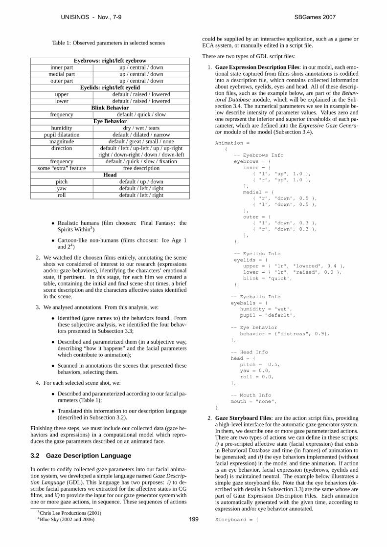
Table 1: Observed parameters in selected scenes
Eyebrows: right/left eyebrowinner part up / central / down
medial part up / central / downouter part up / central / down
Eyelids: right/left eyelidupper default / raised / loweredlower default / raised / lowered
Blink Behaviorfrequency default / quick / slow
Eye Behaviorhumidity dry / wet / tears
pupil dilatation default / dilated / narrowmagnitude default / great / small / nonedirection default / left / up-left / up / up-right
right / down-right / down / down-leftfrequency default / quick / slow / fixation
some “extra” feature free descriptionHead
pitch default / up / downyaw default / left / rightroll default / left / right
• Realistic humans (film choosen: Final Fantasy: theSpirits Within3)
• Cartoon-like non-humans (films choosen: Ice Age 1and 24)
2. We watched the choosen films entirely, annotating the sceneshots we considered of interest to our research (expressionsand/or gaze behaviors), identifying the characters’ emotionalstate, if pertinent. In this stage, for each film we created atable, containing the initial and final scene shot times, a briefscene description and the characters affective states identifiedin the scene.
3. We analysed annotations. From this analysis, we:
• Identified (gave names to) the behaviors found. Fromthese subjective analysis, we identified the four behav-iors presented in Subsection 3.3;
• Described and parametrized them (in a subjective way,describing “how it happens” and the facial parameterswhich contribute to animation);
• Scanned in annotations the scenes that presented thesebehaviors, selecting them.
4. For each selected scene shot, we:
• Described and parameterized according to our facial pa-rameters (Table 1);
• Translated this information to our description language(described in Subsection 3.2).
Finishing these steps, we must include our collected data (gaze be-haviors and expressions) in a computational model which repro-duces the gaze parameters described on an animated face.
3.2 Gaze Description Language
In order to codify collected gaze parameters into our facial anima-tion system, we developed a simple language namedGaze Descrip-tion Language(GDL). This language has two purposes:i) to de-scribe facial parameters we extracted for the affective states in CGfilms, andii) to provide the input for our gaze generator system withone or more gaze actions, in sequence. These sequences of actions
3Chris Lee Productions (2001)4Blue Sky (2002 and 2006)
could be supplied by an interactive application, such as a game orECA system, or manually edited in a script file.
There are two types of GDL script files:
1. Gaze Expression Description Files: in our model, each emo-tional state captured from films shots annotations is codifiedinto a description file, which contains collected informationabout eyebrows, eyelids, eyes and head. All of these descrip-tion files, such as the example below, are part of theBehav-ioral Databasemodule, which will be explained in the Sub-section 3.4. The numerical parameters we see in example be-low describe intensity of parameter values. Values zero andone represent the inferior and superior thresholds of each pa-rameter, which are defined into theExpressive Gaze Genera-tor module of the model (Subsection 3.4).
Animation ={
-- Eyebrows Infoeyebrows = {
inner = {{ "l", "up", 1.0 },{ "r", "up", 1.0 },
},medial = {
{ "r", "down", 0.5 },{ "l", "down", 0.5 },
},outer = {
{ "l", "down", 0.3 },{ "r", "down", 0.3 },
},},
-- Eyelids Infoeyelids = {
upper = { "lr", "lowered", 0.4 },lower = { "lr", "raised", 0.0 },blink = "quick",
},
-- Eyeballs Infoeyeballs = {
humidity = "wet",pupil = "default",
-- Eye behaviorbehavior = {"distress", 0.9},
},
-- Head Infohead = {
pitch = 0.5,yaw = 0.0,roll = 0.0,
},
-- Mouth Infomouth = "none",
}
2. Gaze Storyboard Files: are the action script files, providinga high-level interface for the automatic gaze generator system.In them, we describe one or more gaze parameterized actions.There are two types of actions we can define in these scripts:i) a pre-scripted affective state (facial expression) that existsin Behavioral Database and time (in frames) of animation tobe generated; andii) the eye behaviors implemented (withoutfacial expression) in the model and time animation. If actionis an eye behavior, facial expression (eyebrows, eyelids andhead) is maintained neutral. The example below illustrates asimple gaze storyboard file. Note that the eye behaviors (de-scribed with details in Subsection 3.3) are the same whose arepart of Gaze Expression Description Files. Each animationis automatically generated with the given time, according toexpression and/or eye behavior annotated.
Storyboard = {
UNISINOS - Nov., 7-9 SBGames 2007
199
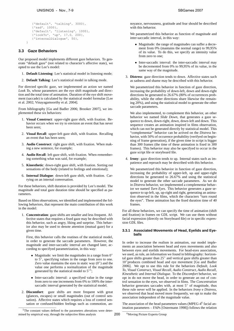
{"default", "talking", 3000},{"sad", 1000},{"default", "listening", 1000},{"lookTo", "up", 17.0, 200},{"internalDialogue", 50},
}
3.3 Gaze Behaviors
Our proposed model implements different gaze behaviors. To gen-erate “default gaze” (not related to character’s affective state), weopted to use the Lee’s model:
1. Default Listening: Lee’s statistical model in listening mode;
2. Default Talking : Lee’s statistical model in talking mode.
For directed specific gaze, we implemented an action we namedLook To, whose parameters are the eye shift magnitude and direc-tion and the total time of animation. Duration of the eye shift move-ment (saccade) is calculated by the statistical model formulae [Leeet al. 2002; Vinayagamoorthy et al. 2004].
From bibliography [Gu and Badler 2006; Brooker 2007], we im-plemented these six behaviors:
1. Visual Construct: upper-right gaze shift, with fixation. Be-havior occurs when we try to envision an event that has neverbeen seen;
2. Visual Recall: upper-left gaze shift, with fixation. Recallingan event that has been seen;
3. Audio Construct: right gaze shift, with fixation. When mak-ing a new sentence, for example;
4. Audio Recall: left gaze shift, with fixation. When remember-ing something what was said, for example;
5. Kinesthetic: down-right gaze shift, with fixation. Sorting outsensations of the body (related to feelings and emotional);
6. Internal Dialogue: down-left gaze shift, with fixation. Car-rying on an internal conversation.
For these behaviors, shift duration is provided by Lee’s model. Themagnitude and total gaze duration time should be specified as pa-rameters.
Based on films observations, we identified and implemented the fol-lowing behaviors, that represent the main contribution of this workin the model:
1. Concentration: gaze shifts are smaller and less frequent. Af-fective states that requires a fixed gaze may be described withthis behavior, such as angry, liking and surprise. This behav-ior also may be used to denote attention (mutual gaze) for agiven time.
First, this behavior calls the routines of the statistical model,in order to generate the saccade parameters. However, themagnitude and inter-saccadic interval are changed later, ac-cording to specifyed parametrization, in this way:
• Magnitude: we limit the magnitudes in a range from 0◦
to 5◦, specifying values in the range from zero to one.Zero value mantains the eyes in static way (0◦) and thevalue one performs a normalization of the magnitudegenerated by the statistical model to 5◦5;
• Inter-saccadic interval: a specifyed value in the rangefrom zero to one increments from 0% to 100% the inter-saccadic interval generated by the statistical model.
2. Discomfort: gaze shifts are more frequent with great(glances, escapes) or small magnitudes (out of control sen-sation). Affective states which requires a loss of control sen-sation or confused/hidden feelings such as commotion, an-
5The constant values defined to the parameters alterations were deter-mined by empirical way, through the subjective films analysis
noyance, nervousness, gratitude and fear should be describedwith this behavior.
We parametrized this behavior as function of magnitude andinter-saccadic interval, in this way:
• Magnitude: the range of magnitudes can suffer a decre-ment from 0% (mantains the normal range) to 99,95%of its value. To do this, we specify an intensity valuefrom zero to one;
• Inter-saccadic interval: the inter-saccadic interval maybe decremented from 0% to 99,95% of its value, in thesame way of the magnitude.
3. Distress: gaze direction tends to down. Affective states suchas sadness and shame may be described with this behavior.
We parametrized this behavior in function of gaze direction,increasing the probability of down-left, down and down-rightdirections be generated to 26.67% (80% of occurrences prob-ability, while the other directions share likewise the remain-ing 20%), and using the statistical model to generate the othersaccade parameters.
We also implemented, to complement this behavior, an otherbehavior we namedSlide Down, that generates a gaze se-quence to down, down-right, down, down-left and down. Thissequence creates an animation inspired in films observation,which can not be generated directly by statistical model. This“complementar” behavior can be actived on theDistressbe-havior, with 50% of occurence probability (verifyed on begin-ning of frame generation), if the given time in script is biggerthan 300 frames (the time of these animation is fixed in 300frames). This behavior may also be specifyed to occur in thegaze script file or storyboard file.
4. Irony : gaze direction tends to up. Internal states such as im-patience and reproach may be described with this behavior.
We parametrized this behavior in function of gaze direction,increasing the probability of upper-left, up and upper-rightdirections be generated to 26.67% and using the statisticalmodel to generate the other saccade parameters. As we doin Distressbehavior, we implemented a complementar behav-ior we namedTurn Eyes. This behavior generates a gaze se-quence to up-left, up, up-right and right, generating an anima-tion observed in the films, which the characters “turn roundthe eyes”. These animation has the fixed duration time of 40frames.
For all these behaviors, we can specify the time of animation (shiftand fixation) in frames on GDL script. We can use them withoutfacial expression (directly on Storyboard file) or in specific expres-sion GDL files.
3.3.1 Associated Movements of Head, Eyelids and Eye-balls
In order to increase the realism in animation, our model imple-ments an association between head and eyes movements and alsobetween eyes and eyelids movements. For head-eyes association,we used, as rule, an information we found in bibliography: horizon-tal gaze shifts greater than 25◦ and vertical gaze shifts greater than10◦produces combined head and eye movement [Gu and Badler2006]. We opt to use this rule for the behaviorsDefault, LookTo, Visual Construct, Visual Recall, Audio Construct, Audio Recall,KinestheticandInternal Dialogue. To theDiscomfortbehavior, weopt in do not move the head, in order to generate an out of con-trol sensation to the eyes, we observed in films. TheConcentrationbehavior generates saccades with, at most 5◦ of magnitude, thusthese rule never will be applied. In the behaviorsIrony e Distress,we observed that head moved more frequently, we opt to make theassociation independent of the magnitude value.
The association of the head parameters values (MPEG-46 facial an-imation parameters – FAPs [Ostermann 1998]) follows the relation
6Moving Picture Experts Group
UNISINOS - Nov., 7-9 SBGames 2007
200
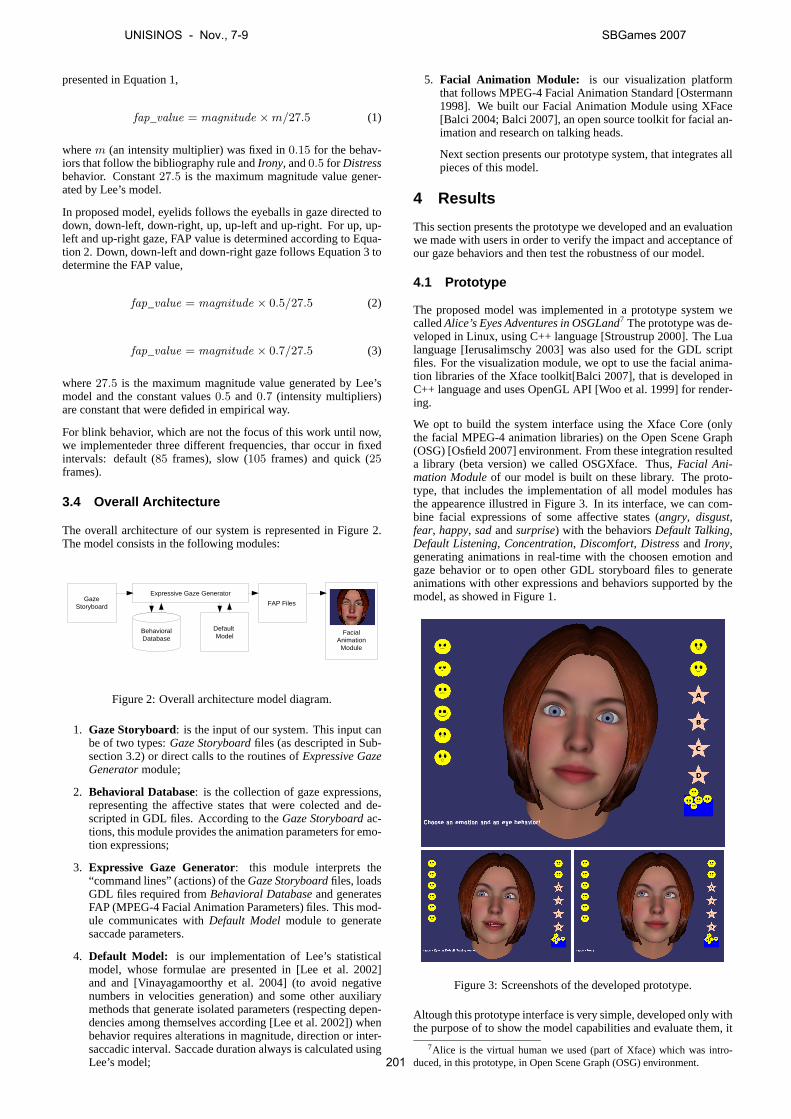
presented in Equation 1,
fap_value = magnitude ×m/27.5 (1)
wherem (an intensity multiplier) was fixed in0.15 for the behav-iors that follow the bibliography rule andIrony, and0.5 for Distressbehavior. Constant27.5 is the maximum magnitude value gener-ated by Lee’s model.
In proposed model, eyelids follows the eyeballs in gaze directed todown, down-left, down-right, up, up-left and up-right. For up, up-left and up-right gaze, FAP value is determined according to Equa-tion 2. Down, down-left and down-right gaze follows Equation 3 todetermine the FAP value,
fap_value = magnitude × 0.5/27.5 (2)
fap_value = magnitude × 0.7/27.5 (3)
where27.5 is the maximum magnitude value generated by Lee’smodel and the constant values0.5 and0.7 (intensity multipliers)are constant that were defided in empirical way.
For blink behavior, which are not the focus of this work until now,we implementeder three different frequencies, thar occur in fixedintervals: default (85 frames), slow (105 frames) and quick (25frames).
3.4 Overall Architecture
The overall architecture of our system is represented in Figure 2.The model consists in the following modules:
BehavioralDatabase
Default Model
Expressive Gaze Generator
FAP Files
FacialAnimation
Module
GazeStoryboard
Figure 2: Overall architecture model diagram.
1. Gaze Storyboard: is the input of our system. This input canbe of two types:Gaze Storyboardfiles (as descripted in Sub-section 3.2) or direct calls to the routines ofExpressive GazeGeneratormodule;
2. Behavioral Database: is the collection of gaze expressions,representing the affective states that were colected and de-scripted in GDL files. According to theGaze Storyboardac-tions, this module provides the animation parameters for emo-tion expressions;
3. Expressive Gaze Generator: this module interprets the“command lines” (actions) of theGaze Storyboardfiles, loadsGDL files required fromBehavioral Databaseand generatesFAP (MPEG-4 Facial Animation Parameters) files. This mod-ule communicates withDefault Modelmodule to generatesaccade parameters.
4. Default Model: is our implementation of Lee’s statisticalmodel, whose formulae are presented in [Lee et al. 2002]and and [Vinayagamoorthy et al. 2004] (to avoid negativenumbers in velocities generation) and some other auxiliarymethods that generate isolated parameters (respecting depen-dencies among themselves according [Lee et al. 2002]) whenbehavior requires alterations in magnitude, direction or inter-saccadic interval. Saccade duration always is calculated usingLee’s model;
5. Facial Animation Module: is our visualization platformthat follows MPEG-4 Facial Animation Standard [Ostermann1998]. We built our Facial Animation Module using XFace[Balci 2004; Balci 2007], an open source toolkit for facial an-imation and research on talking heads.
Next section presents our prototype system, that integrates allpieces of this model.
4 Results
This section presents the prototype we developed and an evaluationwe made with users in order to verify the impact and acceptance ofour gaze behaviors and then test the robustness of our model.
4.1 Prototype
The proposed model was implemented in a prototype system wecalledAlice’s Eyes Adventures in OSGLand7 The prototype was de-veloped in Linux, using C++ language [Stroustrup 2000]. The Lualanguage [Ierusalimschy 2003] was also used for the GDL scriptfiles. For the visualization module, we opt to use the facial anima-tion libraries of the Xface toolkit[Balci 2007], that is developed inC++ language and uses OpenGL API [Woo et al. 1999] for render-ing.
We opt to build the system interface using the Xface Core (onlythe facial MPEG-4 animation libraries) on the Open Scene Graph(OSG) [Osfield 2007] environment. From these integration resulteda library (beta version) we called OSGXface. Thus,Facial Ani-mation Moduleof our model is built on these library. The proto-type, that includes the implementation of all model modules hasthe appearence illustred in Figure 3. In its interface, we can com-bine facial expressions of some affective states (angry, disgust,fear, happy, sadandsurprise) with the behaviorsDefault Talking,Default Listening, Concentration, Discomfort, Distressand Irony,generating animations in real-time with the choosen emotion andgaze behavior or to open other GDL storyboard files to generateanimations with other expressions and behaviors supported by themodel, as showed in Figure 1.
Figure 3: Screenshots of the developed prototype.
Altough this prototype interface is very simple, developed only withthe purpose of to show the model capabilities and evaluate them, it
7Alice is the virtual human we used (part of Xface) which was intro-duced, in this prototype, in Open Scene Graph (OSG) environment.
UNISINOS - Nov., 7-9 SBGames 2007
201
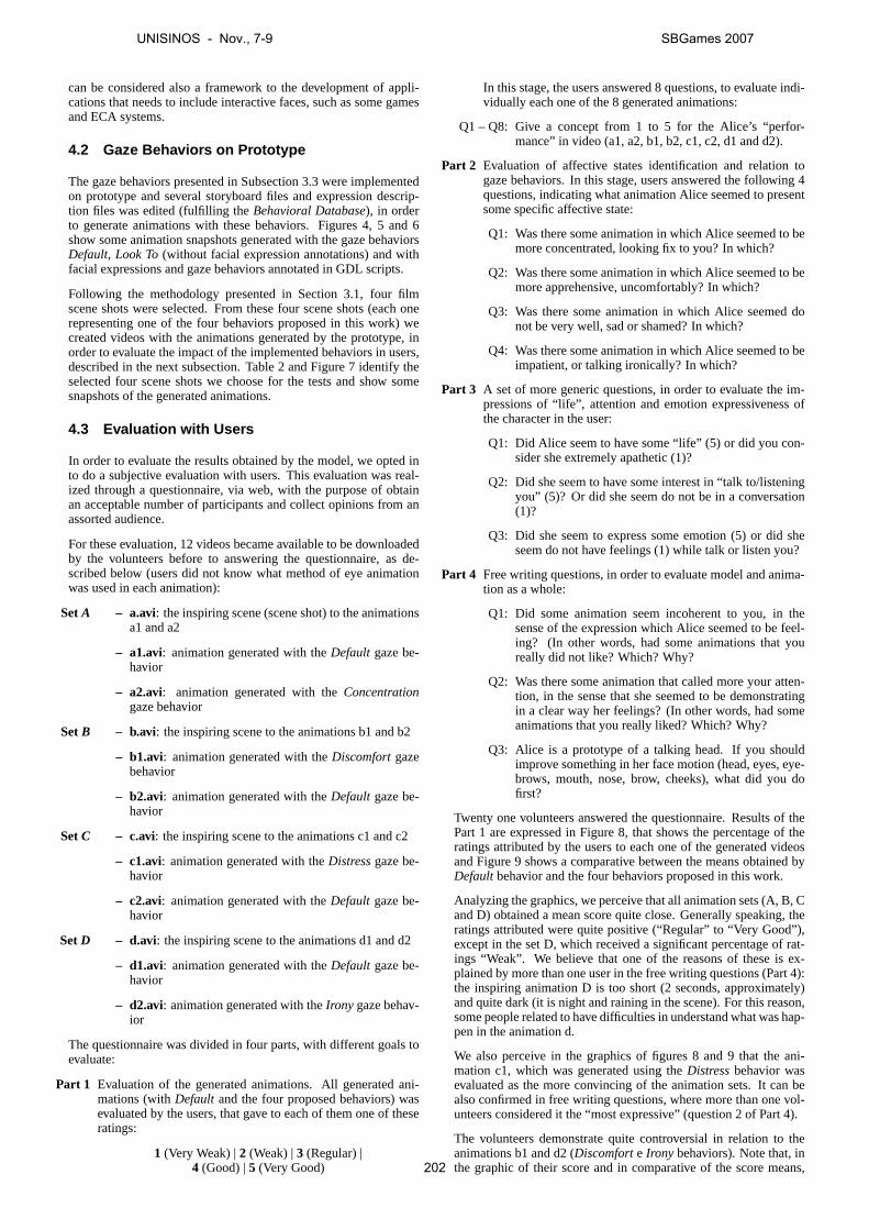
can be considered also a framework to the development of appli-cations that needs to include interactive faces, such as some gamesand ECA systems.
4.2 Gaze Behaviors on Prototype
The gaze behaviors presented in Subsection 3.3 were implementedon prototype and several storyboard files and expression descrip-tion files was edited (fulfilling theBehavioral Database), in orderto generate animations with these behaviors. Figures 4, 5 and 6show some animation snapshots generated with the gaze behaviorsDefault, Look To(without facial expression annotations) and withfacial expressions and gaze behaviors annotated in GDL scripts.
Following the methodology presented in Section 3.1, four filmscene shots were selected. From these four scene shots (each onerepresenting one of the four behaviors proposed in this work) wecreated videos with the animations generated by the prototype, inorder to evaluate the impact of the implemented behaviors in users,described in the next subsection. Table 2 and Figure 7 identify theselected four scene shots we choose for the tests and show somesnapshots of the generated animations.
4.3 Evaluation with Users
In order to evaluate the results obtained by the model, we opted into do a subjective evaluation with users. This evaluation was real-ized through a questionnaire, via web, with the purpose of obtainan acceptable number of participants and collect opinions from anassorted audience.
For these evaluation, 12 videos became available to be downloadedby the volunteers before to answering the questionnaire, as de-scribed below (users did not know what method of eye animationwas used in each animation):
SetA – a.avi: the inspiring scene (scene shot) to the animationsa1 and a2
– a1.avi: animation generated with theDefault gaze be-havior
– a2.avi: animation generated with theConcentrationgaze behavior
SetB – b.avi: the inspiring scene to the animations b1 and b2
– b1.avi: animation generated with theDiscomfortgazebehavior
– b2.avi: animation generated with theDefault gaze be-havior
SetC – c.avi: the inspiring scene to the animations c1 and c2
– c1.avi: animation generated with theDistressgaze be-havior
– c2.avi: animation generated with theDefault gaze be-havior
SetD – d.avi: the inspiring scene to the animations d1 and d2
– d1.avi: animation generated with theDefault gaze be-havior
– d2.avi: animation generated with theIrony gaze behav-ior
The questionnaire was divided in four parts, with different goals toevaluate:
Part 1 Evaluation of the generated animations. All generated ani-mations (withDefault and the four proposed behaviors) wasevaluated by the users, that gave to each of them one of theseratings:
1 (Very Weak) |2 (Weak) |3 (Regular) |4 (Good) |5 (Very Good)
In this stage, the users answered 8 questions, to evaluate indi-vidually each one of the 8 generated animations:
Q1 – Q8: Give a concept from 1 to 5 for the Alice’s “perfor-mance” in video (a1, a2, b1, b2, c1, c2, d1 and d2).
Part 2 Evaluation of affective states identification and relation togaze behaviors. In this stage, users answered the following 4questions, indicating what animation Alice seemed to presentsome specific affective state:
Q1: Was there some animation in which Alice seemed to bemore concentrated, looking fix to you? In which?
Q2: Was there some animation in which Alice seemed to bemore apprehensive, uncomfortably? In which?
Q3: Was there some animation in which Alice seemed donot be very well, sad or shamed? In which?
Q4: Was there some animation in which Alice seemed to beimpatient, or talking ironically? In which?
Part 3 A set of more generic questions, in order to evaluate the im-pressions of “life”, attention and emotion expressiveness ofthe character in the user:
Q1: Did Alice seem to have some “life” (5) or did you con-sider she extremely apathetic (1)?
Q2: Did she seem to have some interest in “talk to/listeningyou” (5)? Or did she seem do not be in a conversation(1)?
Q3: Did she seem to express some emotion (5) or did sheseem do not have feelings (1) while talk or listen you?
Part 4 Free writing questions, in order to evaluate model and anima-tion as a whole:
Q1: Did some animation seem incoherent to you, in thesense of the expression which Alice seemed to be feel-ing? (In other words, had some animations that youreally did not like? Which? Why?
Q2: Was there some animation that called more your atten-tion, in the sense that she seemed to be demonstratingin a clear way her feelings? (In other words, had someanimations that you really liked? Which? Why?
Q3: Alice is a prototype of a talking head. If you shouldimprove something in her face motion (head, eyes, eye-brows, mouth, nose, brow, cheeks), what did you dofirst?
Twenty one volunteers answered the questionnaire. Results of thePart 1 are expressed in Figure 8, that shows the percentage of theratings attributed by the users to each one of the generated videosand Figure 9 shows a comparative between the means obtained byDefaultbehavior and the four behaviors proposed in this work.
Analyzing the graphics, we perceive that all animation sets (A, B, Cand D) obtained a mean score quite close. Generally speaking, theratings attributed were quite positive (“Regular” to “Very Good”),except in the set D, which received a significant percentage of rat-ings “Weak”. We believe that one of the reasons of these is ex-plained by more than one user in the free writing questions (Part 4):the inspiring animation D is too short (2 seconds, approximately)and quite dark (it is night and raining in the scene). For this reason,some people related to have difficulties in understand what was hap-pen in the animation d.
We also perceive in the graphics of figures 8 and 9 that the ani-mation c1, which was generated using theDistressbehavior wasevaluated as the more convincing of the animation sets. It can bealso confirmed in free writing questions, where more than one vol-unteers considered it the “most expressive” (question 2 of Part 4).
The volunteers demonstrate quite controversial in relation to theanimations b1 and d2 (Discomforte Irony behaviors). Note that, inthe graphic of their score and in comparative of the score means,
UNISINOS - Nov., 7-9 SBGames 2007
202

Figure 4: Animation snapshots running withDefaultbehaviors.
Figure 5: Animation snapshots running withLook Tobehavior, without facial expression.
Figure 6: Animation snapshots running with GDL scripts (including expressions and gaze behaviors).
a) b) c) d)
Figure 7: Animations snapshots with the gaze behaviors: a)Concentrationb) Discomfortc) Distressand d)Irony
Table 2: Technical information about data we based to generate animations illustrated in Figure 7.Label Scene from film Start time End time Affective state Eye behavior
a) The Incredibles 00:29:23 00:29:25 Angry Concentrationb) The Incredibles 01:00:49 01:00:52 Fears-confirmed Discomfortc) Ice Age 2 01:17:27 01:27:34 Shame Distressd) Ice Age 00:13:05 00:13:06 Arrogance Irony
these animations obtained ratings lower than the animations gener-ated with theDefault behavior (b2 and d1). Analyzing the graph-ics together with the free writing questions, we perceive that somevolunteers found the eyes behavior “strange” in these two anima-tions (rapid frequency in b1 and the “turn round” of the eyes in d2).However, we can observe in the Part 2 of the questionnaire evalu-ation (commented below) that when the volunteers need to relateone animation to the asked affective states, these two “controver-sial” animations were the most indicated for the affective states thatthey really should represent.
Figure 10 shows the results obtained in the 4 questions of the Part2 of questionnaire, which consists in the evaluation of the identifi-cation of some affective states by the users in the observed videos.Analyzing these graphics, we perceive that animations a2, b1, c1and d2 (generated with the gaze behaviorsConcentration, Discom-fort, Distressand Irony, respectively), were the most indicated asrepresentative of the asked affective states. These positive resultsindicate that there were coherence not so in facial expressions, butthat the gaze behavior contributed in the identification of the affec-tive states.
Figure 11 presents the results obtained in the 3 questions of the Part3 of questionnaire, that evaluates some aspects more general of theanimations. The evaluated aspects were: “how much” does Al-ice seems to have “life” in animations (Q1), “how much” does sheseems to be attentive on conversation (Q2) and “how much” sheseems to express her feelings (Q3). Note that, for all these items,the ratings attributed by the users were also positive (“Regular” to“Very Good”, in at least 90% of the evaluations in each question.Regarding expressiveness, the results show that Alice seems con-vincing in her emotions expression to the volunteers (95.24% ofthe answers were “Good” and “Very Good”, while the remaining
was “Regular”).
The free writing questions (Part 4) were elaborated in order to theparticipants could freely write their opinion. The given answersshow aspects very important that suggests improvements as in Al-ice’s 3D model as in animations. The items below present some ofthese considerations, that are more related to the scope of this workand deserve distinction:
• Concerning the eyes, the users suggest to implement the pupildilatation and contraction;
• Head motion sometimes are too much sudden; users suggestimprovements;
• Users suggest also the exploration of wrinkles on the brow, inorder to accentuate the expressiveness;
• The eyebrows motion could be improved, since they remainsstatic after the setting of expression movement.
We also present below some other users’ suggestions and critics.Although they are not directly linked to the scope of this work, theyare relevant to the development of a robust facial animation systemor a more convincing talking head:
• Users suggest improvements in mouth motion (including theteeth, that do not follow the lips) and cheeks;
• One volunteer observed that, in his opinion, the hair coveringthe ears suggests that “Alice does not want to listen the user”.
UNISINOS - Nov., 7-9 SBGames 2007
203
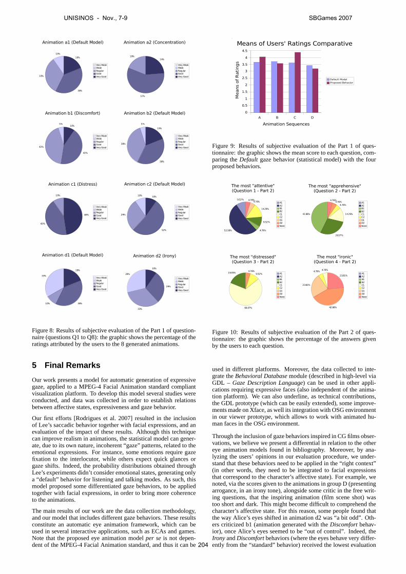
10%
33%
38%
19%
Animation a1 (Default Model)
Very WeakWeakRegularGoodVery Good
19%
57%
24%
Animation a2 (Concentration)
Very WeakWeakRegularGoodVery Good
5%
43%
43%
10%
Animation b1 (Discomfort)
Very WeakWeakRegularGoodVery Good
5%
38%
38%
19%
Animation b2 (Default Model)
Very WeakWeakRegularGoodVery Good
10%
43%
48%
Animation c1 (Distress)
Very WeakWeakRegularGoodVery Good
10%
29%
52%
10%
Animation c2 (Default Model)
Very WeakWeakRegularGoodVery Good
33%
10% 38%
19%
Animation d1 (Default Model)
Very WeakWeakRegularGoodVery Good
29%
33%
29%
10%
Animation d2 (Irony)
Very WeakWeakRegularGoodVery Good
Figure 8: Results of subjective evaluation of the Part 1 of question-naire (questions Q1 to Q8): the graphic shows the percentage of theratings attributed by the users to the 8 generated animations.
5 Final Remarks
Our work presents a model for automatic generation of expressivegaze, applied to a MPEG-4 Facial Animation standard compliantvisualization platform. To develop this model several studies wereconducted, and data was collected in order to establish relationsbetween affective states, expressiveness and gaze behavior.
Our first efforts [Rodrigues et al. 2007] resulted in the inclusionof Lee’s saccadic behavior together with facial expressions, and anevaluation of the impact of these results. Although this techniquecan improve realism in animations, the statistical model can gener-ate, due to its own nature, incoherent “gaze” patterns, related to theemotional expressions. For instance, some emotions require gazefixation to the interlocutor, while others expect quick glances orgaze shifts. Indeed, the probability distributions obtained throughLee’s experiments didn’t consider emotional states, generating onlya “default” behavior for listening and talking modes. As such, thismodel proposed some differentiated gaze behaviors, to be appliedtogether with facial expressions, in order to bring more coherenceto the animations.
The main results of our work are the data collection methodology,and our model that includes different gaze behaviors. These resultsconstitute an automatic eye animation framework, which can beused in several interactive applications, such as ECAs and games.Note that the proposed eye animation modelper seis not depen-dent of the MPEG-4 Facial Animation standard, and thus it can be
A B C D
0
0.5
1
1.5
2
2.5
3
3.5
4
4.5
Means of Users' Ratings Comparative
Default ModelProposed Behavior
Animation Sequences
Means
of
Rati
ngs
Figure 9: Results of subjective evaluation of the Part 1 of ques-tionnaire: the graphic shows the mean score to each question, com-paring theDefault gaze behavior (statistical model) with the fourproposed behaviors.
9.52%
52.38% 4.76%
9.52%
14.29%
4.76%4.76%
The most "attentive"(Question 1 - Part 2)
A1A2B1B2C1C2D1D2None
42.86%
28.57%
14.29%
4.76%4.76%
4.76%
The most "apprehensive"(Question 2 - Part 2)
A1A2B1B2C1C2D1D2None
19.05%
66.67%
9.52%4.76%
The most "distressed"(Question 3 - Part 2)
A1A2B1B2C1C2D1D2None
4.76%4.76%
23.81%
42.86%
23.81%
The most "ironic"(Question 4 - Part 2)
A1A2B1B2C1C2D1D2None
Figure 10: Results of subjective evaluation of the Part 2 of ques-tionnaire: the graphic shows the percentage of the answers givenby the users to each question.
used in different platforms. Moreover, the data collected to inte-grate theBehavioral Databasemodule (described in high-level viaGDL – Gaze Description Language) can be used in other appli-cations requiring expressive faces (also independent of the anima-tion platform). We can also underline, as technical contributions,the GDL prototype (which can be easily extended), some improve-ments made on Xface, as well its integration with OSG environmentin our viewer prototype, which allows to work with animated hu-man faces in the OSG environment.
Through the inclusion of gaze behaviors inspired in CG films obser-vations, we believe we present a differential in relation to the othereye animation models found in bibliography. Moreover, by ana-lyzing the users’ opinions in our evaluation procedure, we under-stand that these behaviors need to be applied in the “right context”(in other words, they need to be integrated to facial expressionsthat correspond to the character’s affective state). For example, wenoted, via the scores given to the animations in group D (presentingarrogance, in an irony tone), alongside some critic in the free writ-ing questions, that the inspiring animation (film scene shot) wastoo short and dark. This might become difficult to comprehend thecharacter’s affective state. For this reason, some people found thatthe way Alice’s eyes shifted in animation d2 was “a bit odd”. Oth-ers criticized b1 (animation generated with theDiscomfortbehav-ior), once Alice’s eyes seemed to be “out of control”. Indeed, theIrony andDiscomfortbehaviors (where the eyes behave very differ-ently from the “standard” behavior) received the lowest evaluation
UNISINOS - Nov., 7-9 SBGames 2007
204
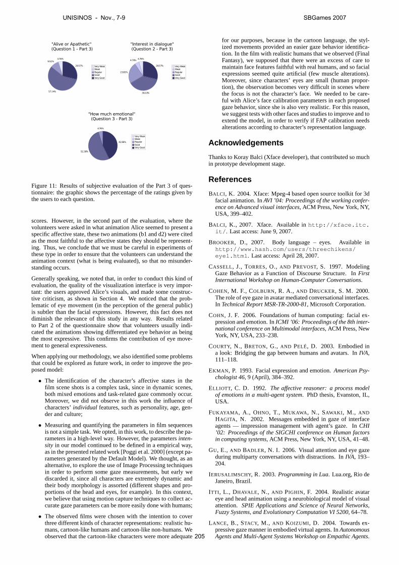
4.76%9.52%
57.14%
28.57%
"Alive or Apathetic" (Question 1 - Part 3)
Very WeakWeakRegularGoodVery Good
4.76%4.76%
23.81%
38.10%
28.57%
"Interest in dialogue"(Question 2 - Part 3)
Very WeakWeakRegularGoodVery Good
4.76%
52.38%
42.86%
"How much emotional"(Question 3 - Part 3)
Very WeakWeakRegularGoodVery Good
Figure 11: Results of subjective evaluation of the Part 3 of ques-tionnaire: the graphic shows the percentage of the ratings given bythe users to each question.
scores. However, in the second part of the evaluation, where thevolunteers were asked in what animation Alice seemed to present aspecific affective state, these two animations (b1 and d2) were citedas the most faithful to the affective states they should be represent-ing. Thus, we conclude that we must be careful in experiments ofthese type in order to ensure that the volunteers can understand theanimation context (what is being evaluated), so that no misunder-standing occurs.
Generally speaking, we noted that, in order to conduct this kind ofevaluation, the quality of the visualization interface is very impor-tant: the users approved Alice’s visuals, and made some construc-tive criticism, as shown in Section 4. We noticed that the prob-lematic of eye movement (in the perception of the general public)is subtler than the facial expressions. However, this fact does notdiminish the relevance of this study in any way. Results relatedto Part 2 of the questionnaire show that volunteers usually indi-cated the animations showing differentiated eye behavior as beingthe most expressive. This confirms the contribution of eye move-ment to general expressiveness.
When applying our methodology, we also identified some problemsthat could be explored as future work, in order to improve the pro-posed model:
• The identification of the character’s affective states in thefilm scene shots is a complex task, since in dynamic scenes,both mixed emotions and task-related gaze commonly occur.Moreover, we did not observe in this work the influence ofcharacters’individual features, such as personality, age, gen-der and culture;
• Measuring and quantifying the parameters in film sequencesis not a simple task. We opted, in this work, to describe the pa-rameters in a high-level way. However, the parametersinten-sity in our model continued to be defined in a empirical way,as in the presented related work [Poggi et al. 2000] (except pa-rameters generated by the Default Model). We thought, as analternative, to explore the use of Image Processing techniquesin order to perform some gaze measurements, but early wediscarded it, since all characters are extremely dynamic andtheir body morphology is assorted (different shapes and pro-portions of the head and eyes, for example). In this context,we believe that using motion capture techniques to collect ac-curate gaze parameters can be more easily done with humans;
• The observed films were chosen with the intention to coverthree different kinds of character representations: realistic hu-mans, cartoon-like humans and cartoon-like non-humans. Weobserved that the cartoon-like characters were more adequate
for our purposes, because in the cartoon language, the styl-ized movements provided an easier gaze behavior identifica-tion. In the film with realistic humans that we observed (FinalFantasy), we supposed that there were an excess of care tomaintain face features faithful with real humans, and so facialexpressions seemed quite artificial (few muscle alterations).Moreover, since characters’ eyes are small (human propor-tion), the observation becomes very difficult in scenes wherethe focus is not the character’s face. We needed to be care-ful with Alice’s face calibration parameters in each proposedgaze behavior, since she is also very realistic. For this reason,we suggest tests with other faces and studies to improve and toextend the model, in order to verify if FAP calibration needsalterations according to character’s representation language.
Acknowledgements
Thanks to Koray Balci (Xface developer), that contributed so muchin prototype development stage.
References
BALCI , K. 2004. Xface: Mpeg-4 based open source toolkit for 3dfacial animation. InAVI ’04: Proceedings of the working confer-ence on Advanced visual interfaces, ACM Press, New York, NY,USA, 399–402.
BALCI , K., 2007. Xface. Available inhttp://xface.itc.it/ . Last access: June 9, 2007.
BROOKER, D., 2007. Body language – eyes. Available inhttp://www.hash.com/users/threechikens/eyel.html . Last access: April 28, 2007.
CASSELL, J., TORRES, O., AND PREVOST, S. 1997. ModelingGaze Behavior as a Function of Discourse Structure. InFirstInternational Workshop on Human-Computer Conversations.
COHEN, M. F., COLBURN, R. A., AND DRUCKER, S. M. 2000.The role of eye gaze in avatar mediated conversational interfaces.In Technical Report MSR-TR-2000-81, Microsoft Corporation.
COHN, J. F. 2006. Foundations of human computing: facial ex-pression and emotion. InICMI ’06: Proceedings of the 8th inter-national conference on Multimodal interfaces, ACM Press, NewYork, NY, USA, 233–238.
COURTY, N., BRETON, G., AND PELÉ, D. 2003. Embodied ina look: Bridging the gap between humans and avatars. InIVA,111–118.
EKMAN , P. 1993. Facial expression and emotion.American Psy-chologist 46, 9 (April), 384–392.
ELLIOTT, C. D. 1992. The affective reasoner: a process modelof emotions in a multi-agent system. PhD thesis, Evanston, IL,USA.
FUKAYAMA , A., OHNO, T., MUKAWA , N., SAWAKI , M., ANDHAGITA , N. 2002. Messages embedded in gaze of interfaceagents — impression management with agent’s gaze. InCHI’02: Proceedings of the SIGCHI conference on Human factorsin computing systems, ACM Press, New York, NY, USA, 41–48.
GU, E., AND BADLER, N. I. 2006. Visual attention and eye gazeduring multiparty conversations with distractions. InIVA, 193–204.
IERUSALIMSCHY, R. 2003.Programming in Lua. Lua.org, Rio deJaneiro, Brazil.
ITTI , L., DHAVALE , N., AND PIGHIN , F. 2004. Realistic avatareye and head animation using a neurobiological model of visualattention. SPIE Applications and Science of Neural Networks,Fuzzy Systems, and Evolutionary Computation VI 5200, 64–78.
LANCE, B., STACY, M., AND KOIZUMI , D. 2004. Towards ex-pressive gaze manner in embodied virtual agents. InAutonomousAgents and Multi-Agent Systems Workshop on Empathic Agents.
UNISINOS - Nov., 7-9 SBGames 2007
205

LEE, S. P., BADLER, J. B.,AND BADLER, N. I. 2002. Eyes alive.In SIGGRAPH ’02: Proceedings of the 29th annual conferenceon Computer graphics and interactive techniques, ACM Press,New York, NY, USA, 637–644.
ORTONY, A., AND TURNER, T. 1990. What’s basic about basicemotions?Psychological Review 97, 315–331.
OSFIELD, R., 2007. Open scene graph. Available inhttp://www.openscenegraph.org/ . Last access: June 9, 2007.
OSTERMANN, J. 1998. Animation of synthetic faces in mpeg-4. In CA ’98: Proceedings of the Computer Animation, IEEEComputer Society, Washington, DC, USA, 49.
PICARD, R. W. 1997.Affective computing. MIT Press.
POGGI, I., AND PELACHAUD , C. 2002. Signals and meaningsof gaze in animated faces. InLanguage, Vision and Music, McKevitt, Paul, Seán Ó Nualláin and Conn Mulvihill, 133–144.
POGGI, I., PELACHAUD , C., AND DE ROSIS, F. 2000. Eye com-munication in a conversational 3d synthetic agent.AI Communi-cations 13, 3, 169–182.
RODRIGUES, P. S., QUEIROZ, R. B., BARROS, L., FEIJÓ, B.,VELHO, L., AND MUSSE, S. R. 2007. Automatically gener-ating eye motion in virtual agents. InIX Symposium on Virtualand Augmented Reality (SVR2007), 84–91.
STROUSTRUP, B. 2000.The C++ Programming Language, specialthird ed. Addison-Wesley, Reading, USA.
VERTEGAAL, R., SLAGTER, R., VAN DER VEER, G., AND NI-JHOLT, A. 2001. Eye gaze patterns in conversations: thereis more to conversational agents than meets the eyes. InCHI’01: Proceedings of the SIGCHI conference on Human factorsin computing systems, ACM Press, New York, NY, USA, 301–308.
V INAYAGAMOORTHY, V., GARAU , M., STEED, A., ANDSLATER, M. 2004. An eye gaze model for dyadic interactionin an immersive virtual environment: Practice and experience.In Computer Graphics Forum, vol. 23.
WOO, M., DAVIS , AND SHERIDAN, M. B. 1999. OpenGLProgramming Guide: The Official Guide to Learning OpenGL,Version 1.2. Addison-Wesley Longman Publishing Co., Inc.,Boston, MA, USA.
UNISINOS - Nov., 7-9 SBGames 2007
206


![[Acronym] Proceedings - UFG](https://static.fdokumen.com/doc/165x107/631430486ebca169bd0abf4b/acronym-proceedings-ufg.jpg)