Preparation of microporous nickel electrodeposits using a polymer matrix
10
PREPARATION OF MICROPOROUS NICKEL ELECTRODEPOSITS USING A POLYMER MATRIX I.J. Brown, D. Clift, and S. Sotiropoulos* School of Chemical, Environmental, and Mining Engineering, Nottingham University, University Park, Nottingham NG7 2RD, UK (Refereed) (Received July 15, 1998; Accepted September 11, 1998) ABSTRACT Nickel-mesh electrodes were embedded into polyHIPE (a generic hollow fiber polymer) by immersion in the precursor emulsion and subsequent entrapment into the solid microporous matrix produced by polymerization and drying. Immersing this Ni/polyHIPE/Ni composite into a nickel electroplating bath and passing direct current through the two electrodes resulted in growing Ni electrodeposits on the cathode and through the polymer cells and pores. When the polymer matrix was subsequently burned off, a granular microporous Ni coating was produced on the cathode. Variation of the electroplating time and current density showed that the structure of the Ni coating is determined by the local distortions of the electric field inside the tortuous microporous body of the insulating polymer. © 1999 Elsevier Science Ltd KEYWORDS: A. metals, A. microporous materials, C. electrochemical mea- surements, C. electron microscopy, D. microstructure INTRODUCTION The preparation of high surface area Ni electrode materials is relevant to a number of industrial applications of electrochemical technology. The most important applications in- clude the use of Ni hydrogen anodes in alkaline or molten carbonate H 2 /O 2 fuel cells [1– 4], *To whom correspondence should be addressed. Tel: 144-115-9514182. Fax: 144-115-9514181. E-mail: [email protected]. Materials Research Bulletin, Vol. 34, No. 7, pp. 1055–1064, 1999 Copyright © 1999 Elsevier Science Ltd Printed in the USA. All rights reserved 0025-5408/99/$–see front matter PII S0025-5408(99)00103-8 1055
Transcript of Preparation of microporous nickel electrodeposits using a polymer matrix
PREPARATION OF MICROPOROUS NICKEL ELECTRODEPOSITS USING APOLYMER MATRIX
I.J. Brown, D. Clift, and S. Sotiropoulos*School of Chemical, Environmental, and Mining Engineering, Nottingham University,
University Park, Nottingham NG7 2RD, UK
(Refereed)(Received July 15, 1998; Accepted September 11, 1998)
ABSTRACTNickel-mesh electrodes were embedded into polyHIPE (a generic hollow fiberpolymer) by immersion in the precursor emulsion and subsequent entrapmentinto the solid microporous matrix produced by polymerization and drying.Immersing this Ni/polyHIPE/Ni composite into a nickel electroplating bathand passing direct current through the two electrodes resulted in growing Nielectrodeposits on the cathode and through the polymer cells and pores. Whenthe polymer matrix was subsequently burned off, a granular microporous Nicoating was produced on the cathode. Variation of the electroplating time andcurrent density showed that the structure of the Ni coating is determined bythe local distortions of the electric field inside the tortuous microporous bodyof the insulating polymer.© 1999 Elsevier Science Ltd
KEYWORDS: A. metals, A. microporous materials, C. electrochemical mea-surements, C. electron microscopy, D. microstructure
INTRODUCTION
The preparation of high surface area Ni electrode materials is relevant to a number ofindustrial applications of electrochemical technology. The most important applications in-clude the use of Ni hydrogen anodes in alkaline or molten carbonate H2/O2 fuel cells [1–4],
*To whom correspondence should be addressed. Tel:144-115-9514182. Fax:144-115-9514181.E-mail: [email protected].
Materials Research Bulletin, Vol. 34, No. 7, pp. 1055–1064, 1999Copyright © 1999 Elsevier Science LtdPrinted in the USA. All rights reserved
0025-5408/99/$–see front matter
PII S0025-5408(99)00103-8
1055

NiO(OH)/NiO cathodes in nickel–cadmium and nickel–hydrogen batteries [5,6] and hydro-gen-evolving Ni cathodes in alkaline water electrolysis [7,8]. Nickel foam electrodes havebeen successfully used as three-dimensional porous electrodes in the electrolytic recovery ofCu ions [9] (wastewater treatment) and in electroorganic synthesis [10,11], and Raney nickelelectrodes have been employed in the electrochemical hydrogenation of organics [12,13].
There are various types of high surface area Ni electrodes and many different methodsused for their preparation. Sintered microporous Ni coatings on electrodes are usuallyprepared according to the ceramic foil-casting technology by a procedure that involvesmixing of a micrometer-size nickel powder with an organic binder, which is subsequentlythermally decomposed, and further sintering at elevated temperatures in a hydrogen atmo-sphere [4]. Techniques used in the production of reticulated metal include the incorporationof the metal into a porous matrix and subsequent matrix decomposition [14] or the use offoaming agents [15]. Highly porous metal structures can also be obtained by sintering metalmicrofibers [6,16,17]. Various methods for the production of nanoporous Ni coatings,including cold rolling, plasma spraying, annealing, and cathodic codeposition of the Raneynickel precursor alloys (Ni/Al or Ni/Zn) on a nickel support, are reviewed in ref. 18. SmoothRaney nickel coatings have also been produced by sherardizing of nickel substrates, i.e., bythe reaction of Ni with Zn vapors at 400°C, which results in the formation of a smooth Ni/Znprecursor coating [19].
PolyHIPE polymer (PHP) is a microporous material developed at Unilever [20] and LosAlamos National Laboratories [21] and used since by a number of research groups [22,23].It is produced through the formation of a high internal phase water-in-oil emulsion, in whichthe volume of the aqueous dispersed phase is greater than about 75%, and the subsequentpolymerization (at 60°C) of the oil phase, which contains the monomer styrene (andoccasionally other monomers) and the cross-linker divinyl benzene. This results in theproduction of a polymer matrix with an extremely high void (up to 97%) due to theevaporation of the water droplets, which were present in the precursor emulsion. Thestructure of PHP, therefore, is characterized by the presence of numerous cells (1–100mm
FIG. 1Schematic representation of the electroplating cell comprised of a rectangular Ni-meshcathode and a cylindrical Ni-mesh anode, embedded in a polyHIPE polymer body.
1056 I.J. BROWNet al. Vol. 34, No. 7

diameter) interconnected by small pores (0.1–10mm diameter). The size of both the cells andthe pores can be controlled by changing the mixing time, the surfactant (emulsion stabilizer)concentration, and the monomer composition during the emulsification.
In a recent paper [24], we reported for the first time the successful incorporation of Ni intothe PHP matrix by electroplating through its pores and onto a thin Au-layer electrode pastedon one side of a polymer sample. Burnout of the polymer resulted in a granular Ni structureof a very high BET surface area (50 m2g21). Those preliminary experiments were useful inestablishing the viability of the method, but their logical extension to cases of industrialinterest would be the application of the method to the production of porous Ni coatings ontoNi or stainless steel electrodes. The work presented here introduces a modification of thetechnique, whereby the Ni cathode (together with a Ni anode) is immersed into the precursoremulsion and finally entrapped in the PHP body after polymerization. The Ni-cathode/PHP/Ni-anode composite cell is then used in a Ni electroplating bath, and Ni is deposited throughthe polymer pores onto the cathode. The effect of the electroplating current density andduration on the resulting Ni coating (after polymer burnout) is also investigated.
EXPERIMENTAL
Preparation of Ni/polyHIPE Polymer/Ni Composite Electrochemical Cells. In this work,polymer of an 80% void was produced; a typical production batch consisted of 500 ml ofemulsion, prepared by mixing 400 ml of water phase with 100 ml of oil phase. Thecomposition of the oil phase for the preparation of elastomeric polyHIPE was (by volume):15% styrene (Aldrich, 99%), 62% 2-ethylhexyl acrylate (Aldrich), 8% divinyl benzene(Aldrich, 80%), and 15% sorbitan monooeleate (Aldrich, 95%). The aqueous phase wasdistilled water and 1% w/w potassium persulfate (Aldrich, 991%), which acted as thepolymerization initiator. The emulsion was produced in a stainless steel mixing vesselequipped with a Janke and Kunkel (IKA Labortechnik) RW 20DZM two-blade mixer,according to the procedure described elsewhere [24]. The emulsion was then poured intoglass vials, and a rectangular Ni-mesh cathode (263 26 wires 0.25 mm thick per inch,Goodfellow Ltd) of typical apparent areas of 1–1.5 cm2, together with a cylindrical piece ofthe same mesh serving as the anode, was immersed in the emulsion. The inter-electrode gapwas typically in the 3.5–6 mm range. Two mesh strips protruding from each electrode andout of the emulsion were subsequently used to make electrical contacts to the electrodes. Theentire assembly was then covered tightly with parafilm to minimize water evaporation duringpolymerization, which was performed for 6 h in anoven heated at 60°C. After polymerizationhad been completed, the cover was removed and the samples remained in the oven at 60°Cfor another 24 h to remove residual water from the pores. The sorbitan monooleate, whichwas the surfactant used as an emulsion stabilizer, was removed by washing several times withboiling isopropyl alcohol. The Ni/PHP/Ni composite cell prepared as a result of thisprocedure is depicted in Figure 1, in which typical dimensions are also shown.
Ni Electrodeposition. A standard nickel sulfamate bath [25] served as the electroplatingsolution at 60°C: 600 g/l nickel sulfamate (Aldrich, 98%), 10 g/l nickel chloride (Aldrich),and 40 g/l boric acid (Aldrich, 99.51%). A regulated 7A-35V DC GW(GPR-3060) labora-tory power supply was used to carry out the electroplating at various current densities in the3–300 mA cm22 range. The current densities are reported per apparent area of the Ni mesh(one face). A 1.6 cm2 true geometric electrode area per 1 cm2 apparent mesh area of the Ni
1057MICROPOROUS NICKELVol. 34, No. 7

wire in the cathode mesh (two faces, due to the anode surrounding the cathode) was estimatedfrom the manufacturer’s specifications and SEM photographs. Hence, all current densitiesreported hereafter should be divided by 1.6 to give the true current density. Prior toelectroplating, the Ni electrodes were activated by immersion into a 1:1 HCl–water solutionfor a few minutes.
Burnout of the Polymer Matrix and SEM Analysis. The burnout of the polymeric matrixof the Ni/PHP/Ni composites after electroplating was carried out under air atmosphere in apreheated furnace at 500°C for 1 h. SEM and EDAX analyses of the resulting material haveconfirmed the complete polymer burnout at the end of this procedure [24]. SEM experimentswere carried out with a Hitachi S-570.
RESULTS AND DISCUSSION
Figure 2 shows the SEM micrograph of polyHIPE polymer before plating, in which a regularstructure of closed but porous cells can readily be seen. The polymer structure consisted oflarge cells of a 10–30-mm diameter, corresponding to the water droplets of the initialwater-in-oil emulsion, interconnected by smaller pores of a 3–5-mm diameter, correspondingto the contact areas of the initially present water droplets.
Figure 3(a) shows the micrograph of the Ni-mesh cathode prior to its incorporation into thepolymer body and electroplating. Figure 3(b) shows that of the cathode mesh coated with aNi electrodeposit following electroplating for 24 h at a rate of 35 mA cm22 in a nickelsulfamate bath and after the polymer matrix of the resulting composite had been thermallydecomposed. It can be seen that a uniform microporous Ni coating was produced on the Nicathode. The electrodeposit appears to have a cauliflower structure organized in near-spherical interconnected aggregates of 150–50mm diameter, which consist of smallerspherical deposits. Although the presence of the polymer in contact with the cathode iscertainly responsible for the structure of the microporous deposit (electroplating of plain Nimesh at same current densities results in nonporous homogeneous coatings), there is no
FIG. 2SEM micrograph of a cross section of a plain polyHIPE sample.
1058 I.J. BROWNet al. Vol. 34, No. 7

straightforward matrix–product relationship between the polymer template and the metalgrown through its pores. For the latter to hold, the metal deposit should have been organizedin simple spherical aggregates of 10–30mm (size of the polymer cells) filling the polymervoid completely. Instead, it seems that the distortion of the homogeneity of the electric fieldaround the cathode substrate, which is caused by the presence of the insulating PHP shield,gives the Ni deposit its structure. The uneven growth of metal deposits produced byelectroplating through porous materials is a common feature of this method for reticulatedmetal production, and it has recently been modeled [14] in terms of uneven current distri-bution within porous electrodes.
Figure 4(a) and (b), which show SEM micrographs of the same deposit at higher magni-fications, further support this suggestion. In the center of Figure 4(a), a large porousaggregate (ca. 140mm diameter) consisting of smaller aggregates (ca. 10–30mm diameter)can be seen. The larger of the latter aggregates is comprised of small spherical deposits. The
FIG. 3SEM micrographs of (a) the bare Ni-mesh wires before electroplating and (b) the Ni coatingon the Ni-mesh cathode after electroplating through polyHIPE and subsequent polymerburnout. Electroplating at 35 mAcm22 for 24 h.
1059MICROPOROUS NICKELVol. 34, No. 7

sequence of events leading to the incorporation of Ni within a single PHP cell could start withthe initial growth of the electrodeposit through the pore closer to the cathode substrate andon layers of already deposited Ni in contact with the cell. This deposit could start growingaround the pore and into the cell, resulting in one of the smaller spherical structuresmentioned above. At moderate current densities (which prevent more extreme field nonho-mogeneity), Ni deposits could start entering the cell from neighboring pores further awayfrom the cathode substrate, thus creating more spherical deposits within the individualpolymer cell. This description of events takes into account only the local characteristics of theelectric field inside a single cell. However, current distribution considerations over the entireelectrodeposit growing through a microporous (i.e., locally structured) matrix lead to theconclusion that local current densities vary significantly from pore to pore and from cell tocell, the deposition being favored at locations closer to the facing anode, i.e., at locations thatthe deposit has already started to build up. This means that the deposition preferentiallyproceeds around already plated pores, rather than around new pores of the same cell. Oncean entire cell is filled with Ni, deposition preferentially starts in a neighboring cell closer to
FIG. 4SEM micrographs of the microporous Ni electrodeposits shown in Figure 3(b).
1060 I.J. BROWNet al. Vol. 34, No. 7

the anode, rather than in one lying at the same plane with the Ni-filled cell. These effects leadto either partially filled or completely void polymer cells in accordance with Figure 4(a), inwhich 10–30-mm diameter voids can be seen in the body of the central aggregate. In Figure4(b), much smaller pores of a few microns diameter can be identified between the smallspherical aggregates, corresponding to either partial cell filling or the walls of the polymermatrix in the precursor Ni/PHP composite (prior to polymer decomposition). Also, thesurface of the aggregates appears to be rough and pitted to a submicron level, probably dueto local high current densities resulting in rough deposits and hydrogen embrittlement. Theseproperties should be beneficial to the deposit’s catalytic activity, since they increase its truesurface area.
A crude estimate of the porosity of the Ni coating can be calculated as follows. From themicrographs in Figure 3(a) and (b), the diameter of the coated Ni wire can be seen to beapproximately 750mm (b) and that of the plain wire, 250mm (a). The volume of ahypothetical cylindrical nonporous deposit, which can be found by subtracting the volume ofthe plain wire from that of the coated wire, is 3.933 1023 cm3/cm of wire. Since there are10.23 wires per 1 cm along each of the mesh dimensions (mesh specifications: 263 26 wiresper inch), it follows that there are 23 10.235 20.5 wires in 1 cm2 of mesh, amounting toa total wire length of 20.5 cm/cm2 of mesh. Therefore, a nonporous tubular deposit wouldhave a volume of 3.933 1023 3 20.5 5 80.5653 1023 cm3/cm2 of mesh. The chargepassed during Ni electroplating at 35 mA/cm2 of mesh for 24 h corresponds to 3,024 C/cm2
of mesh. The current efficiency as found by weighing the cathode after polymer burnout wasca. 47% (we comment on this value below), which means that 0.473 3,0245 1,421 C wereused for Ni electrodeposition per 1 cm2 of mesh. From Faraday’s law (Ni molecular weightand density taken as 58.015 and 8.9 g/cm3, respectively), we can calculate the actual volumeof the Ni deposit to be 483 1023 cm3/cm2 of mesh. Therefore, the porosity of the depositshould be approximately (80.5652 48)/80.5655 40.4%. The current efficiencies of ca. 50%obtained in all of the Ni-plating experiments through polyHIPE were much lower than theusual 98% values for plating onto bare metal substrates under similar bath, temperature, andcurrent density conditions [26]. This was due to the fact that the local current densities aroundthe polymer pores were much higher than the average current density over the entire sample,resulting in higher rates of hydrogen evolution, competing with nickel deposition and, hence,lowering the efficiency of the latter.
The micrographs in Figure 5 depict situations of partial coating formation due to smallercharges passed through the cell (electroplating at shorter times and/or smaller currentdensities) and are, therefore, helpful in understanding the development of the microporousstructure of the deposit. Close inspection of Figure 5(a) reveals that the initially smallspherical deposits are connected to each other by needlelike deposits of submicron width.These very thin deposits, present after only 1 h of electroplating at 33 mA/cm2, could havebeen developed through the pores at the walls of neighboring cells, linking small depositsformed within different cells; as time lapses, both the spherical deposits and the Ni needlesthickened to finally form structures similar to those shown in Figures 3 and 4. The micro-graphs in Figure 5(b) and (c), which correspond to very small quantities of electrodepositedNi, show the first stages of the coating built up where the density of Ni aggregates was small.In particular, Figure 5(c) reveals that, before the first aggregates started to form, the surfaceof the Ni wire was covered by a rough but nonporous thin Ni layer similar to that sometimesobserved on bare metal substrates. It was only after this layer had formed that the depositsstarted to squeeze into the polymer matrix and, hence, acquired the porous structure discussed
1061MICROPOROUS NICKELVol. 34, No. 7
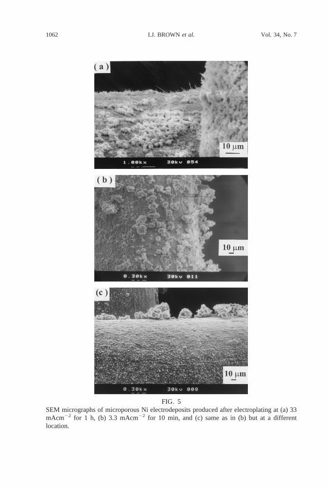
FIG. 5SEM micrographs of microporous Ni electrodeposits produced after electroplating at (a) 33mAcm22 for 1 h, (b) 3.3 mAcm22 for 10 min, and (c) same as in (b) but at a differentlocation.
1062 I.J. BROWNet al. Vol. 34, No. 7

above. This agrees with the fact that polyHIPE is known to not adhere well on metalsubstrates [22].
Finally, Figure 6 shows the structure obtained when electroplating was carried out at thehigh current density of 330 mA/cm2 for 10 min. It can be seen that instead of the granularstructure obtained at lower current densities, the deposit consisted of numerous Ni needles ofsubmicron width, probably corresponding to deposits growing only through pores due to amuch more nonuniform current distribution at the much higher local current densitiesprevailing in this case.
ACKNOWLEDGMENTS
The authors wish to thank EPSRC for a studentship to I.J.B. (Quota Ref. No. 97309830). S.S.acknowledges The University of Nottingham for a New Lecturers’ Research Grant(97NLRG860) and the Royal Society for a Royal Society Research Grant (RSRG19058).
REFERENCES
1. T.C. Benjamin, E.H. Camera, and L.G. Marianowski,Handbook of Fuel Cells, Institute of GasTechnology, Chicago, IL (1980).
2. S. Ye, A.K. Vijh, and L.H. Dao,J. Electrochem. Soc.144, 90 (1997).3. Sleem-Ur-Rahman, M.A. Al-Saleh, A.S. Al-Zakri, and S. Gultekin,J. Appl. Electrochem.27, 215
(1997).4. O. Bohme, F.U. Leidich, H.J. Salge, and H. Wendt,Int. J. Hydrogen Energy19, 349 (1994).5. C.A. Vincent and B. Scrosati,Modern Batteries, 2nd ed., Arnold, London (1997).6. J. Francisco, D. Chiappetti, and J. Brill, in1996 NASA Aerospace Battery Workshop, ed. J.C.
Brewer, p. 283, NASA Space Flight Center, Huntsville, AL (1997).7. K. Wall, Modern Chlor-Alkali Technology, Vol. 3, Ellis Horwood, Chichester (1986).8. K. Lohrberg and P. Kohl,Electrochim. Acta29, 1557 (1984).
FIG. 6SEM micrograph of microporous Ni electrodeposits produced after electroplating at 330mAcm22 for 10 min.
1063MICROPOROUS NICKELVol. 34, No. 7

9. D.A. Cox, PhD Thesis, Southampton, UK (1981).10. J. Chaussard, R. Rouget, and M. Tassin,J. Appl. Electrochem.16, 803 (1986).11. C.J. Brown, D. Pletcher, F.C. Walsh, J.K. Hammond, and D. Robinson,J. Appl. Electrochem.24,
95 (1986).12. S.H. Langer and H.P. Landi,J. Am. Chem. Soc.85, 3043 (1963).13. V. Anantharaman and P.N. Pintauro,J. Electrochem. Soc.141, 2729 (1994).14. L. Cai and H.Y. Cheh,Meeting Abstracts of the 191st Meeting of The Electrochemical Society,
p. 58, No. 51, The Electrochemical Society, Inc., Pennington, NJ (1997).15. H.-D. Kunze, J. Baumeister, J. Banhart, and M. Weber,PIM 25, 182 (1993).16. S. Ahn and B.J. Tatarchuk,J. Appl. Electrochem.27, 9 (1997).17. M. Parent, S. Passerini, B.B. Owens, and W.H. Smyrl, inMeeting Abstracts of the 191st Meeting
of The Electrochemical Society, p. 840, No. 637, The Electrochemical Society, Inc., Pennington,NJ (1997).
18. Th. Borucinski, S. Rausch, and H. Wendt,J. Appl. Electrochem.22, 1031 (1992).19. S. Rausch and H. Wendt,J. Electrochem. Soc.143, 2852 (1996).20. D. Barby and Z. Haq, European Patent 0,060,138, Unilever, 1982.21. J. Williams,Langmuir4, 44 (1988).22. G. Akay, Z. Bhumgara, and R.J. Wakeman,Trans. IChemE73, 782 (1995).23. P. Hainey, I.M. Huxham, B. Rowatt, D.C. Sherrington, and L. Tetley,Macromolecules24, 117
(1991).24. S. Sotiropoulos, I.J. Brown, G. Akay, and E. Lester,Mater. Lett.35, 383 (1998).25. F.A. Lowenheim,Electroplating, McGraw-Hill, New York (1978).26. A.K. Graham,Electroplating Engineering Handbook, p. 248, Van Nostrand, New York (1971).
1064 I.J. BROWNet al. Vol. 34, No. 7