IS 9187-2 (1980): Deflection Coil Units Used with TV Picture ...

Advances in Engineering Software xxx (2009) xxx–xxx
ARTICLE IN PRESS
Contents lists available at ScienceDirect
Advances in Engineering Software
journal homepage: www.elsevier .com/locate /advengsoft
Prediction of deflection of reinforced concrete shear walls
Ilker Fatih Kara a, Cengiz Dundar b,*
a Department of Civil Engineering, Nigde University, 51245 Nigde, Turkeyb Department of Civil Engineering, Cukurova University, 01330 Adana, Turkey
a r t i c l e i n f o
Article history:Received 3 November 2008Received in revised form 9 January 2009Accepted 2 February 2009Available online xxxx
Keywords:Reinforced concreteEffective moment of inertiaEffective shear modulusLateral deflectionCracking
0965-9978/$ - see front matter � 2009 Elsevier Ltd. Adoi:10.1016/j.advengsoft.2009.02.002
* Corresponding author. Tel.: +90 322 3386762; faxE-mail address: [email protected] (C. Dundar).
Please cite this article in press as: Kara IFdoi:10.1016/j.advengsoft.2009.02.002
a b s t r a c t
Reinforced concrete shear walls are used in tall buildings for efficiently resisting lateral loads. Due to thelow tensile strength of concrete, reinforced concrete shear walls tend to behave in a nonlinear mannerwith a significant reduction in stiffness, even under service loads. To accurately assess the lateral deflec-tion of shear walls, the prediction of flexural and shear stiffness of these members after cracking becomesimportant. In the present study, an iterative analytical procedure which considers the cracking in thereinforced concrete shear walls has been presented. The effect of concrete cracking on the stiffnessand deflection of shear walls have also been investigated by the developed computer program basedon the iterative procedure. In the program, the variation of the flexural stiffness of a cracked memberhas been evaluated by ACI and probability-based effective stiffness model. In the analysis, shear deforma-tion which can be large and significant after development of cracks is also taken into account and the var-iation of shear stiffness in the cracked regions of members has been considered by using effective shearstiffness model available in the literature. Verification of the proposed procedure has been confirmedfrom series of reinforced concrete shear wall tests available in the literature. Comparison between theanalytical and experimental results shows that the proposed analytical procedure can provide an accu-rate and efficient prediction of both the deflection and flexural stiffness reduction of shear walls with dif-ferent height to width ratio and vertical load. The results of the analytical procedure also indicate that thepercentage of shear deflection in the total deflection increases with decreasing height to width ratio ofthe shear wall.
� 2009 Elsevier Ltd. All rights reserved.
1. Introduction
Thanks to the use of higher strength new materials in reinforcedconcrete structures and to the developments in computationaltechnology, construction of high rise and slender structures havebeen successfully constructed around the world in recent years.Due to the advantage of its rigidity, shear walls which offer greatresistance for lateral loads have been widely adopted in tall build-ing structures. Since a large portion of the lateral load on a tallbuilding is often assigned to such structural elements, it is impor-tant to understand the stiffness characteristics of shear walls as acritical design item. A large number of parameters affect structuralconcrete shear wall stiffness and it is therefore difficult to predictthese parameters accurately. The more important of these param-eters are: effective moment of inertia, shear module of concrete,presence of cracks, height to width ratio of shear wall, reinforce-ment ratio and load pattern [1].
Due to the low tensile strength of concrete, cracking is an inev-itable phenomenon and can occur even at service loads. The crackinitiation and propagation have significant effect on the stiffness of
ll rights reserved.
: +90 322 3386702.
, Dundar C. Prediction of de
reinforced concrete members. The tensile cracking of concrete re-duces the flexural and shear stiffness of reinforced concrete shearwalls and thus results in an increase in the deflection of thesemembers. For accurate determination of the deflections, the pre-diction of flexural and shear stiffness of structural walls aftercracking becomes important.
Cracked state in reinforced concrete elements can be consideredby several methods, which take into account the constitutive rela-tionships of both steel and concrete together with the bond–sliprelationship (e.g. [2,3]). However, due to the complexities of the ac-tual behavior of the reinforced concrete frame, cumbersome com-putations are necessarily performed. Therefore, these methods cannot easily be adopted by design engineers.
Modeling the stiffness reduction due to cracking using nonlin-ear finite element methods has also been carried out by many re-searches. The procedures can be grouped as microelement andmacroelement approaches. The microelement approach considersthe structure to be divided into many small finite elements includ-ing the two dimensional and three dimensional elements modelingconcrete, bar elements modeling steel, and discrete crack represen-tation modeling cracking. However the macroelement approachtreats reinforced concrete as a new composite material associatedwith its own composite stress–strain relationship. In this approach,
flection of reinforced concrete shear walls. Adv Eng Softw (2009),
x
2 I.F. Kara, C. Dundar / Advances in Engineering Software xxx (2009) xxx–xxx
ARTICLE IN PRESS
each finite element represents both concrete and steel, and the lo-cal phenomena are incorporated into a constitutive model used toobtain stiffness matrix of macroelement. This approach would alsoinclude the layered model adopted to integrate to all layers’ stiff-ness contributions into stiffness matrix of a finite element, andeffective stiffness model [4–8].
The moments of inertia of the reinforced concrete members areusually reduced at the specified ratios to compute the deflection byconsidering the cracking effects on the stiffness of the structures[9]. The reductions are generally considered constant over the totalheight of the structure, independent of the type, history and mag-nitude of loading, and independent the reinforcement ratios in themembers. The common practice of assigning a reduced moment ofinertia to the members to consider the cracking effect in designdoes not always guarantee a conservative prediction of the deflec-tion [10].
A probability-based effective stiffness model was developedfor calculating the effective stiffness and lateral deflection ofreinforced concrete shear walls [1]. The effect of cracking onthe stiffness of reinforced concrete shear walls was also investi-gated. Shear deformation effect was considered in the analysisby using the elastic shear modulus of concrete. However, therecan be significant shear stiffness reduction due to cracking, andshear deformation can be large and significant after developmentof cracks. Hence, the reduction of shear stiffness due to crackingshould also be included in the analysis for improving results ofthe analysis.
In the present study, the effect of concrete cracking on the stiff-ness and deflection of reinforced concrete shear wall has beeninvestigated by developed computer program based on an iterativeanalytical procedure. Stiffness matrix method is applied to obtainthe numerical solutions, and the cracked member stiffness equa-tion is evaluated by including the uniformly distributed and pointloads on the member. In the evaluation of the flexibility influencecoefficients, a cantilever beam model is used which greatly simpli-fies the integral equations for the case of point load. In theprogram, the variation of the flexural stiffness of a cracked shearwall element is obtained by using ACI and probability-basedeffective stiffness models. Shear deformation effect is also takeninto account and reduced shear stiffness is considered by usingeffective shear modulus model available in the literature. Verifica-tion of the proposed procedure has been presented by the experi-mental results of the shear wall tests with different height to widthratio and vertical load.
1 cracked region
2 uncracked region
z
Mx
Mcr
Mmax.
Acr
Auncr 2
1
y
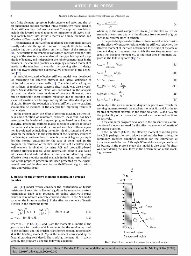
Fig. 1. Cracked and uncracked regions of the shear wall member.
2. Models for the effective moment of inertia of a crackedmember
ACI [11] model which considers the contribution of tensileresistance of concrete to flexural rigidities by moment-curvaturerelationships have been proposed to define effective flexuralbehavior of reinforced concrete cracked sections. In the ACI modelbased on the Bronson studies [12] the effective moment of inertiais given in the following form:
Ieff ¼Mcr
M
� �m
I1 þ 1� Mcr
M
� �m� �I2; for M P Mcr ; ð1aÞ
Ieff ¼ I1; for M < Mcr ; ð1bÞ
where m = 3. In Eq. (1), I1 and I2 are the moments of inertia of thegross uncracked section which accounts for the reinforcing steelto the stiffness, and the cracked transformed section, respectively,M is the bending moment, Mcr is the moment corresponding to-flexural cracking considered. The cracking moment, Mcr is calcu-lated by the program using the following equation:
Please cite this article in press as: Kara IF, Dundar C. Prediction of dedoi:10.1016/j.advengsoft.2009.02.002
Mcr ¼ðfr þ rvÞI1
yt; ð2Þ
where rv is the axial compressive stress, fr is the flexural tensilestrength of concrete, and yt is the distance from centroid of grosssection to extreme fiber in tension.
In the probability-based effective stiffness model which consid-ers the effects of concrete cracking with the stiffness reduction, theeffective moment of inertia is determined as the ratio of the area ofmoment diagram segment over which the working moment ex-ceeds the cracking moment Mcr to the total area of moment dia-gram in the following form (Fig. 1)
Auncr ¼Z
MðxÞ<Mcr
MðxÞ; ð3aÞ
Acr ¼Z
MðxÞPMcr
MðxÞ; ð3bÞ
A ¼ Acr þ Auncr ; ð3cÞ
Puncr ½MðxÞ < Mcr� ¼Auncr
A; ð3dÞ
Pcr½MðxÞP Mcr � ¼Acr
A; ð3eÞ
Ieff ¼ PuncrI1 þ PcrI2; ð3fÞ
where Acr is the area of moment diagram segment over which theworking moment exceeds the cracking moment Mcr and A is the to-tal area of moment diagram. In the same equation, Pcr and Puncr arethe probability of occurrence of cracked and uncracked sections,respectively.
In the computer program developed in the present study, afore-mentioned models are used for the effective moment of inertia ofthe cracked section.
In the literature [13–15], the effective moment of inertia givenby ACI is perhaps the most widely used and the best among thecommonly accepted simplified method for the estimation ofinstantaneous deflection. Although ACI model is usually consideredfor beams, in the present study this model is also used for shearwall considering the axial force in the determination of the crack-ing moment.
flection of reinforced concrete shear walls. Adv Eng Softw (2009),

8
3
1 9 2
7
y z
x
Fig. 3. A cantilever model for calculating the relations between the nodal actionsand basic deformation parameters.
I.F. Kara, C. Dundar / Advances in Engineering Software xxx (2009) xxx–xxx 3
ARTICLE IN PRESS
3. Model used for the effective shear stiffness of a crackedmember
A significant shear stiffness reduction can occur due to crack-ing, and shear deformation can be large and thus can be of prac-tical importance in the design of reinforced concrete members.The variation of the effective shear modulus of concrete due tocracking is considered by employing the model developed byCedolin and Dei Poli [16]. In this model, Cedolin and Dei Polisuggested the following equation for the reduced shear stiffnessGc linearly decreasing with the fictitious strain normal to thecrack
Gc ¼0:4Gc
e1=ecr; for e1 P ecr; ð4Þ
where Gc is the elastic shear modulus of uncracked concrete, e1 isthe principal tensile strain normal to the crack and ecr is the crack-ing tensile strain.
In this study, since three dimensional analysis is considered, Ieff,Mcr, M, I1, I2, e1 and ecr are the values related to the flexure in local yand z directions.
4. Formulation of the proposed analytical procedure
In the present study, the stiffness matrix method has been ap-plied to obtain the numerical solutions of the analytical procedureconsidering the cracking effect with the effective stiffness model.The formulation of the analytical procedure is obtained for thethree dimensional analysis of reinforced concrete frame. The pro-posed procedure developed for the determined and undeterminedstructures provides the nonlinear behavior of reinforced concretestructures due to cracking by applying the external load in anincremental manner.
In this section, the flexibility influence coefficients of amember will first be evaluated, and then using compatibility con-ditions and equilibrium equations, stiffness matrix and the loadvector of a member with some regions in cracked state will beobtained.
A typical three dimensional member subjected to a point and auniformly distributed load, and positive end forces with corre-sponding displacements are also shown in Fig. 2. For computingthe relations between nodal actions and basic deformation param-eters of a general space element, a cantilever model is used (Fig. 3).The basic deformation parameters of a general space element maybe established by applying unit loads in turn in the directions of 1–3 and 7–9. Then, the compatibility conditions give the followingequation in matrix form:
x
Z z
X
P4, d4
P1, d1
P7, d7 P2, d2
P3, d3
P10, d10
P12, d12
P5, d5
P6, d6
a
P
P9, d9
P8, d8 P11,d11
Y y
L
q
Fig. 2. A typical three dimensional member subjected to a point and a uniformlydistributed load.
Please cite this article in press as: Kara IF, Dundar C. Prediction of dedoi:10.1016/j.advengsoft.2009.02.002
f11 0 0 0 0 0
0 f22 f23 0 0 0
0 f32 f33 0 0 0
0 0 0 f77 f78 0
0 0 0 f87 f88 0
0 0 0 0 0 f99
266666666664
377777777775
P1
P2
P3
P7
P8
P9
266666666664
377777777775¼
d1
d2
d3
d7
d8
d9
266666666664
377777777775
ð5Þ
in which, fij is the displacement in ith direction due to the applica-tion of unit loads in jth direction, and can be evaluated by means ofthe principal of virtual work as follows:
fij ¼Z L
0
MziMzj
EcIeffzþMyiMyj
EcIeffyþ VyiVyj
GcAsþ VziVzj
GcAsþMbiMbj
GcIoþ NiNj
EcA
� �dx:
ð6Þ
In Eq. (6), Mzi, Mzj, Myi, Myj, Vzi, Vzj, Vyi, Vyj, Mbi, Mbj, Ni and Nj arethe bending moments, shear forces, torsional moments and axialforces due to the application of unit loads in ith and jth directions,respectively, Ec denotes the modulus of elasticity of concrete, s andA are the shape factor and the cross sectional area, respectively.
Stiffness matrix of space frame members is obtained by invert-ing the flexibility matrix in Eq. (5) and using the equilibriumconditions.
The member fixed-end forces for the case of a point and a uni-formly distributed load can be evaluated by means of the compat-ibility and equilibrium conditions as follows
P10 ¼ P20 ¼ P30 ¼ P40 ¼ P50 ¼ P60 ¼ P90 ¼ P110 ¼ 0; ð7aÞP70 ¼ �ðf88f70 � f78f80Þ=ðf77f88 � f78f87Þ; ð7bÞP80 ¼ �ðf77f80 � f78f70Þ=ðf77f88 � f78f87Þ; ð7cÞP100 ¼ �ðqLþ P þ P70Þ; ð7dÞP120 ¼ �ðqL2=2þ PðL� aÞ þ P70Lþ P80Þ; ð7eÞ
where fi0 (i = 7,8) is the displacement in ith direction due to theapplication of span loads which can be obtained by using the prin-cipal of virtual work in the following form
fi0 ¼Z L
0
MyiM0
EcIeffyþ VziV0
GcAs
� �dx; ð8Þ
where M0 and V0 are the bending moment in local y direction andshear force in local z direction due to the span loads. Finally, themember stiffness equation can be obtained as
k; dþ P0 ¼ P; ð9Þ
where k (12 � 12) is the stiffness matrix, d (12 � 1) is the displace-ment vector, P0 (12 � 1) is the fixed-end force vector and P (12 � 1)is the total end force vector of the member. Since (12) is given in themember coordinate system (x, y, z), it should be transformed to thestructure coordinate system (X, Y, Z).
The flexibility influence coefficient can now be obtained bymeans of Eqs. (6) and (8), with the following procedure.
The moments and shear forces obtained from the applicationof unit and span loads are given in terms of x coordinate asfollows:
flection of reinforced concrete shear walls. Adv Eng Softw (2009),

4 I.F. Kara, C. Dundar / Advances in Engineering Software xxx (2009) xxx–xxx
ARTICLE IN PRESS
M2ðxÞ ¼ x; V2ðxÞ ¼ 1; ð10aÞM3ðxÞ ¼ �1; V3ðxÞ ¼ 0; ð10bÞM7ðxÞ ¼ �x; V7ðxÞ ¼ 1; ð10cÞM8ðxÞ ¼ �1; V8ðxÞ ¼ 0; ð10dÞM9ðxÞ ¼ �1; V9ðxÞ ¼ 0; ð10eÞ
M0ðxÞ ¼� qx2
2 0 6 x 6 a
� qx2
2 � Pðx� aÞ; a < x 6 L
( ); ð10fÞ
V0ðxÞ ¼qx; 0 6 x 6 a
qxþ P; a < x 6 L
� �ð10gÞ
if the probability-based effective stiffness model is considered forthe effective flexural stiffness of the cracked members, the flexibil-ity influence coefficients can be evaluated using Eqs. (6), (8) and(10) as follows:
f22 ¼L3
3EcIeffzþ s
A
Z L
0
1Gc
dx ð11aÞ
f23 ¼ �L2
2EcIeffzð11bÞ
F33 ¼L
EcIeffzð11cÞ
f77 ¼L3
3EcIeffyþ s
A
Z L
0
1Gc
dx ð11dÞ
f78 ¼L2
2EcIeffyð11eÞ
f88 ¼L
EcIeffyð11fÞ
f70 ¼qL4
8EcIeffyþ qs
A
Z a
0
x
Gc
dxþ P3EcIeffy
ðL3 þ a3=2� 3aL2=2Þ
þ sA
Z L
a
P
Gc
dx ð11gÞ
f80 ¼qL3
6EcIeffyþ P
EcIeffyðL2=2þ a2=2� aLÞ: ð11hÞ
On the other hand, if ACI model is used for the effective momentof inertia of the cracked members, the flexibility influence coeffi-cient can be obtained as
f22 ¼1Ec
Z L
0
x2
Ieffzdxþ s
A
Z L
0
1Gc
dx; ð12aÞ
f23 ¼1Ec
Z L
0
ð�xÞIeffz
dx; ð12bÞ
f33 ¼1Ec
Z L
0
1Ieffz
dx; ð12cÞ
f77 ¼1Ec
Z L
0
x2
Ieffydxþ s
A
Z L
0
1Gc
dx; ð12dÞ
f78 ¼1Ec
Z L
0
xIeffy
dx; ð12eÞ
f88 ¼1Ec
Z L
0
1Ieffy
dx; ð12fÞ
f70 ¼q
2Ec
Z L
0
x3
Ieffydxþ qs
A
Z a
0
x
Gc
dx
þ PEc
Z L
a
xðx� aÞIeffy
dxþ sA
Z L
a
P
Gc
dx; ð12gÞ
f80 ¼q
2Ec
Z L
0
x2
Ieffydxþ P
Ec
Z L
a
ðx� aÞIeffy
dx: ð12hÞ
Please cite this article in press as: Kara IF, Dundar C. Prediction of dedoi:10.1016/j.advengsoft.2009.02.002
The reinforced concrete shear walls have varying degrees ofcracking ranging from the uncracked region to the fully cracked re-gion due to the lateral and vertical loads. It should be noted that,since the member has cracked and uncracked regions, the integraloperations in Eqs. (11) and (12) will be carried out in each regionindividually.
The stiffness of a cracked member varies according to theamount of crack formation occurring in the members [17,18]. Inthe cracked regions where M > Mcr, Ieff and Gc vary with M alongthe region. Therefore, the integral values in these regions shouldbe computed by a numerical integration technique. The variationof effective moment of inertia and effective shear modulus of con-crete in the cracked regions necessitate the redistribution of themoments in the structure. Hence, iterative procedure should be ap-plied to obtain the final deflections and internal forces of the struc-ture [10].
In the present study, the total load is divided into (n1) loadincrements and each load increment is applied step by step. Itera-tive procedure has also been adopted in each loading step. In theiterative procedure developed on the basis of stiffness matrixmethod, member equations are first obtained and then the systemstiffness matrix and system load vector are assembled. Finally, thesystem displacements and member end forces are determined bysolving the system equation. This procedure is repeated step bystep in all iterations.
5. Computer program
A general purpose computer program developed on the basis ofiterative procedure is coded in FORTRAN 77 language. The flowchart of the solution procedure of the program is given in Fig. 4.The proposed analytical procedure provides the history of nonlin-ear behavior of reinforced concrete shear wall due to cracking ef-fect by applying the external load in an incremental manner. Inthe present study, the total load is divided into suitable numberof load increment (n1) and each load increment (DP) is appliedstep by step. Iterative procedure has also been adopted in eachloading step. In the solution procedure, the member end forcesused at each iteration step are taken as the mean value of theend forces of all previous iterations. In the program
Pni � Pn�1
i
Pni
���������� 6 e ð13Þ
is used as convergence criterion. Here, n is the iteration number, e isthe convergence factor and Pn
i ði ¼ 1;12Þ is the end forces of eachmember of the structure for nth iteration.
As seen in the flow chart of the program, the analytical proce-dure initially considers the members to be uncracked and performsthe linear elastic analysis of the structure. The flexural and shearstiffness of cracked members are then reduced by the effectivestiffness models available in the literature. Finally, iterative proce-dure is applied until the convergence criterion is less than the pre-defined tolerance in each loading step.
Due to space limitation, the listing of the computer programis not given in the paper. A PC version and the manual of theprogram can be obtained free of charge from the authors uponrequest.
6. Verification of theoretical results
In order to verify the applicability of the proposed analyticalprocedure to the shear walls, the reinforced concrete structuralwalls with different height to width ratio and vertical loads testedunder lateral and vertical load are considered [1]. The shear wallswith different height were 750 mm wide and 125 mm thick. The
flection of reinforced concrete shear walls. Adv Eng Softw (2009),

Compute the mean value of
the end forces of all the previous
iterations n=n+1
Input structure and material properties
Input external loads
Perform linear elastic analysis of the structure for the initial loading step, Py
y=1
Determine cracked and uncracked regions of the
members of the structure using the member end forces
Determine member stiffness and load vector using Ieff
and assemble the system stiffness equation
Compute displacements of joints and member end forces
Yes
No
Store/output results
Update the cracking moment Mcr
y>n1
εP
PPn
i
1ni
ni ≤− −
No
Yes
Compute the mean value of the end
forces by means of the previous loading
steps
Py+1=Py+ΔP
Set y=y+1
n=1
Fig. 4. Solution procedure of the program.
I.F. Kara, C. Dundar / Advances in Engineering Software xxx (2009) xxx–xxx 5
ARTICLE IN PRESS
reinforcing steel in the walls and the loads are shown in Fig. 5. Thegeometric properties of the shear walls and the axial compressiveloads are also given in Table 1. The test procedure involved firstapplying a total vertical load to the shear walls and maintainingthis load throughout the test. The lateral load (Q) was then mono-tonically applied until the ultimate capacity of the shear wall wasachieved.
The comparison between the experimental and theoretical re-sults of the flexural top deflection is presented in Figs. 6–11. It isseen that the numerical results obtained from the present studyagree well with the test results for applied lateral loads up toapproximately 85% of the ultimate load. When the lateral loads isbeyond this load level the differences between the numerical and
Please cite this article in press as: Kara IF, Dundar C. Prediction of dedoi:10.1016/j.advengsoft.2009.02.002
test results increase with the increase in the lateral loads. Figs.12–17 also present the total lateral deflection of shear walls. Asseen from the figures similar results are also obtained for the vari-ations in the flexural deflection of the reinforced concrete shearwalls. These results indicate that the proposed analytical proce-dure appear to provide an accurate prediction of both the flexuraland total deflection of shear walls with different aspect ratio andvertical loads.
Using probability-based effective stiffness and ACI models forthe effective flexural stiffness the theoretical lateral top deflectionsare also obtained by the computer program as shown in Figs. 18–20. It should be noted that different models provide quite similarresults.
flection of reinforced concrete shear walls. Adv Eng Softw (2009),

SL-L
050
100150200250300350
0 1 2 3
Lateral deflection(mm)
Mom
ent(
kNm
) Cracked(PBESM) Experimental
Uncracked
PBBESM: Probability-based effective stiffness model
Fig. 11. Flexural deflection comparison between experimental and analyticalresults of SL-L.
σv
Q
A A
Lw
Section A-A (mm)
Hw=750
1257Φ107Φ10
Fig. 5. Shear wall tested under lateral and vertical loads [1].
Table 1Reinforced concrete shear walls tested by Mickleborough et al. [1].
Shear wall Lw (Lw/Hw) rv (N/mm2)
SH-H 1500 mm (2) 5.3SH-L 1500 mm (2) 3.8SM-H 1125 mm (1.5) 5.2SM-L 1125 mm (1.5) 3.2SL-H 750 mm (1) 5.1SL-L 750 mm (1) 3.8
SH-H
050
100150200250300350400
0 2 4 6 8 10
Lateral deflection(mm)
Mom
ent(
kNm
) Uncracked Cracked(PBESM) Experimental
PBBESM: Probability-based effective stiffness model
Fig. 6. Comparison of flexural deflection between experimental and analyticalresults of SH-H.
SH-L
0
50
100
150
200
250
0 1 2 3 4 5 6
Lateral deflection(mm)
Mom
ent(
kNm
) Uncracked Cracked(PBESM) Experimental
PBBESM: Probability-based effective stiffness model
Fig. 7. Flexural deflection comparison between experimental and analytical resultsof SH-L.
SM-H
050
100150200250300350
0 1 2 3 4 5
Lateral deflection(mm)
Mom
ent(
kNm
) Cracked(PBESM) Experimental
Uncracked
PBBESM: Probability-based effective stiffness model
Fig. 8. Flexural deflection comparison between experimental and analytical resultsof SM-H.
SM-L
0
50
100
150
200
250
300
0 1 2 3 4 5 6
Lateral deflection(mm)
Mom
ent(
kNm
) Uncracked Cracked(PBESM)
Experimental
PBBESM: Probability-based effective stiffness model
Fig. 9. Flexural deflection comparison between experimental and analytical resultsof SM-L.
SL-H
0
50
100
150200
250
300
350
0 1 2 3 4
Lateral deflection(mm)
Mom
ent(
kNm
)
Cracked(PBESM)
Experimental
Uncracked
PBBESM: Probability-based effective stiffness model
Fig. 10. Flexural deflection comparison between experimental and analyticalresults of SL-H.
6 I.F. Kara, C. Dundar / Advances in Engineering Software xxx (2009) xxx–xxx
ARTICLE IN PRESS
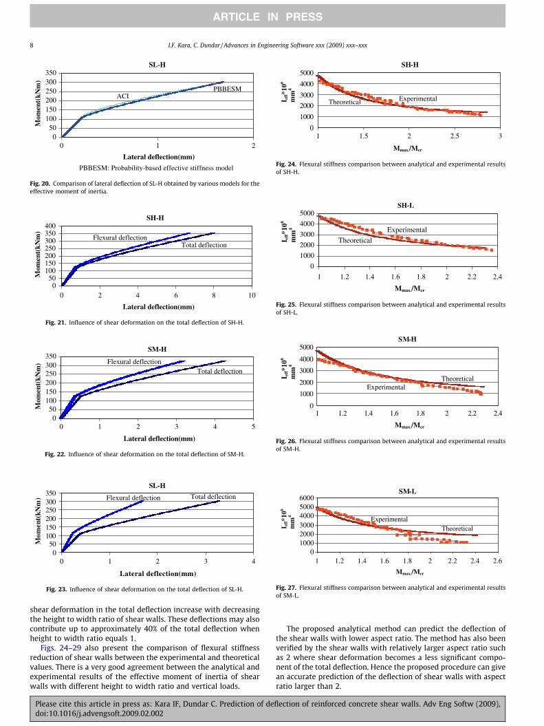
Figs. 21–23 show the influence of shear deformation on the to-tal deflection of reinforced concrete shear walls. It can be seen thatthe contribution of shear deformation to the total deformation ofthe reinforced concrete shear walls increase with the increase inthe lateral loads. The results also indicate that the percentage of
Please cite this article in press as: Kara IF, Dundar C. Prediction of deflection of reinforced concrete shear walls. Adv Eng Softw (2009),doi:10.1016/j.advengsoft.2009.02.002

SH-H
050
100150200250300350400
0 2 4 6 8 10 12
Lateral deflection(mm)
Mom
ent(
kNm
) Cracked(PBESM) Experimental
PBBESM: Probability-based effective stiffness model
Fig. 12. Total deflection comparison between experimental and analytical results ofSH-H.
SH-L
0
50
100
150
200
250
0 1 2 3 4 5 6 7
Lateral deflection(mm)
Mom
ent(
kNm
)
Cracked(PBESM)
Experimental
PBBESM: Probability-based effective stiffness model
Fig. 13. Total deflection comparison between experimental and analytical results ofSH-L.
SM-H
050
100150200250300350
0 1 2 3 4 5 6Lateral deflection(mm)
Mom
ent(
kNm
)
Cracked(PBESM)
Experimental
PBBESM: Probability-based effective stiffness model
Fig. 14. Total deflection comparison between experimental and analytical results ofSM-H.
SM-L
0
50
100
150
200
250
300
0 1 2 3 4 5 6Lateral deflection(mm)
Mom
ent(
kNm
) Cracked(PBESM)
Experimental
PBBESM: Probability-based effective stiffness model
Fig. 15. Total deflection comparison between experimental and analytical results ofSM-L.
SL-H
050
100150200250300350
0 1 2 3 4 5 6
Lateral deflection(mm)
Mom
ent(
kNm
) Cracked(PBESM)
Experimental
PBBESM: Probability-based effective stiffness model
Fig. 16. Total deflection comparison between experimental and analytical results ofSL-H.
SL-L
050
100150200250300350
0 1 2 3 4 5
Lateral deflection(mm)
Mom
ent(
kNm
) Cracked(PBESM)
Experimental
PBBESM: Probability-based effective stiffness model
Fig. 17. Total deflection comparison between experimental and analytical results ofSL-L.
SH-H
050
100150200250300350400
0 2 4 6 8
Lateral deflection(mm)
Mom
ent(
kNm
)
ACI
PBBESM
PBBESM: Probability-based effective stiffness model
Fig. 18. Comparison of lateral deflection of SH-H obtained by various models for theeffective moment of inertia.
SM-H
050
100150200250300350
0 1 2 3 4
Lateral deflection(mm)
Mom
ent(
kNm
)
ACI PBBESM
PBBESM: Probability-based effective stiffness model
Fig. 19. Comparison of lateral deflection of SM-H obtained by various models forthe effective moment of inertia.
I.F. Kara, C. Dundar / Advances in Engineering Software xxx (2009) xxx–xxx 7
ARTICLE IN PRESS
Please cite this article in press as: Kara IF, Dundar C. Prediction of deflection of reinforced concrete shear walls. Adv Eng Softw (2009),doi:10.1016/j.advengsoft.2009.02.002
SL-H
050
100150200250300350
210
Lateral deflection(mm)
Mom
ent(
kNm
)
ACI PBBESM
PBBESM: Probability-based effective stiffness model
Fig. 20. Comparison of lateral deflection of SL-H obtained by various models for theeffective moment of inertia.
SH-H
050
100150200250300350400
0 2 4 6 8 10
Lateral deflection(mm)
Mom
ent(
kNm
)
Flexural deflection Total deflection
Fig. 21. Influence of shear deformation on the total deflection of SH-H.
SM-H
050
100150200250300350
0 1 2 3 4 5
Lateral deflection(mm)
Mom
ent(
kNm
) Flexural deflection Total deflection
Fig. 22. Influence of shear deformation on the total deflection of SM-H.
SL-H
050
100150200250300350
0 1 2 3 4
Lateral deflection(mm)
Mom
ent(
kNm
) Flexural deflection Total deflection
Fig. 23. Influence of shear deformation on the total deflection of SL-H.
SH-H
0
1000
2000
3000
4000
5000
1 1.5 2 2.5 3
Experimental Theoretical
Mmax./Mcr
I eff*1
06
mm
4
Fig. 24. Flexural stiffness comparison between analytical and experimental resultsof SH-H.
SH-L
0
1000
2000
3000
4000
5000
1 1.2 1.4 1.6 1.8 2 2.2 2.4
Experimental
Theoretical
Mmax./Mcr I e
ff*1
06
mm
4
Fig. 25. Flexural stiffness comparison between analytical and experimental resultsof SH-L.
SM-H
0
1000
2000
3000
4000
5000
1 1.2 1.4 1.6 1.8 2 2.2 2.4
Experimental Theoretical
Mmax./Mcr
I eff*1
06
mm
4
Fig. 26. Flexural stiffness comparison between analytical and experimental resultsof SM-H.
SM-L
0100020003000400050006000
1 1.2 1.4 1.6 1.8 2 2.2 2.4 2.6
Experimental Theoretical
Mmax./Mcr
I eff*1
06
mm
4
Fig. 27. Flexural stiffness comparison between analytical and experimental resultsof SM-L.
8 I.F. Kara, C. Dundar / Advances in Engineering Software xxx (2009) xxx–xxx
ARTICLE IN PRESS
shear deformation in the total deflection increase with decreasingthe height to width ratio of shear walls. These deflections may alsocontribute up to approximately 40% of the total deflection whenheight to width ratio equals 1.
Figs. 24–29 also present the comparison of flexural stiffnessreduction of shear walls between the experimental and theoreticalvalues. There is a very good agreement between the analytical andexperimental results of the effective moment of inertia of shearwalls with different height to width ratio and vertical loads.
Please cite this article in press as: Kara IF, Dundar C. Prediction of dedoi:10.1016/j.advengsoft.2009.02.002
The proposed analytical method can predict the deflection ofthe shear walls with lower aspect ratio. The method has also beenverified by the shear walls with relatively larger aspect ratio suchas 2 where shear deformation becomes a less significant compo-nent of the total deflection. Hence the proposed procedure can givean accurate prediction of the deflection of shear walls with aspectratio larger than 2.
flection of reinforced concrete shear walls. Adv Eng Softw (2009),

SL-H
0
1000
20003000
4000
5000
6000
1 1.5 2 2.5 3
Experimental
Theoretical
Mmax./Mcr
I eff*1
06
mm
4
Fig. 28. Flexural stiffness comparison between analytical and experimental resultsof SL-H.
SL-L
0
1000
2000
3000
4000
5000
1 1.5 2 2.5 3
Experimental
Theoretical
Mmax../Mcr
I eff*1
06
mm
4
Fig. 29. Flexural stiffness comparison between analytical and experimental resultsof SL-L.
I.F. Kara, C. Dundar / Advances in Engineering Software xxx (2009) xxx–xxx 9
ARTICLE IN PRESS
7. Conclusions
An iterative analytical procedure which accounts for the crack-ing effect with the effective stiffness model in the reinforced con-crete shear walls has been presented. The effects of concretecracking on the stiffness and displacements of the shear walls havealso been investigated by the developed analytical procedure.
The variation of the flexural stiffness of a cracked shear wall ele-ment has been obtained by using ACI and probability-based effec-tive stiffness model. Shear deformation which can be large andsignificant after development of cracks and thus can be practicalimportance in design, is also taken into account in the analysis,and the variation of shear stiffness in the cracked regions of mem-bers has been considered by employing the reduced shear stiffnessmodel available in the literature.
The capability and the reliability of the proposed procedurehave been tested by means of comparisons with the theoreticaland experimental results of the deflections of reinforced concreteshear walls. The analytical procedure predicts both the flexuraland total deflection of shear walls to a value of load equal toapproximately 85% of the ultimate load with good accuracy. How-ever beyond this load level the differences between the theoreticaland analytical results increase with increasing the lateral loads.Such differences are primarily due to the fact that steel and con-crete materials become nonlinear near the ultimate states.
In the analysis, the flexural stiffness reductions of shear wallswith respect to the applied lateral load can be obtained by thedeveloped program using the probability-based effective stiffnessmodel for the effective moment of inertia. This is the major advan-
Please cite this article in press as: Kara IF, Dundar C. Prediction of dedoi:10.1016/j.advengsoft.2009.02.002
tage of the proposed procedure and the historical variations in theflexural stiffness reductions of shear walls can be observed explic-itly. This feature can minimize the uncertainty of stiffness of mem-bers and therefore provide design engineers with significantinformation on the consequences of cracking in members. The ana-lytical results of the effective moment of inertia have also beenfound in good agreement with the experimental results.
The theoretical deflections of reinforced concrete shear wallshave also been evaluated using different effective flexural stiffnessmodels. It should be noted that different models provide quite sim-ilar results.
The numerical results of the analytical procedure indicate thatthe influence of the shear deformation on the total deflection ofshear walls increase an increase in the lateral loads. The percentageof shear deflections in the total deflection also increases withdecreasing the aspect ratio of shear walls. These deflections mayalso contribute up to approximately 40% of the ultimate lateralload when height to width ratio equals 1. It is therefore importantto consider the variation of shear stiffness in the cracked regions ofmembers for improving results of the analysis.
Stiffness matrix method has been employed to obtain thenumerical solutions of the proposed analytical procedure. Themain advantage of this procedure is that it is efficient from theviewpoints of computational effort and convergence rate. This ana-lytical procedure may also form the basis for other study consider-ing the cracking effect in the analysis of shear wall frame systems.
References
[1] Mickleborough NC, Ning F, Chan CM. Prediction of the stiffness of reinforcedconcrete shear walls under service loads. ACI Struct J 1999;96(6):1018–26.
[2] Channakeshava C, Sundara Raja Iyengar KT. Elasto-plastic cracking analysis ofreinforced concrete. J Struct Eng ASCE 1988;114:2421–38.
[3] Nilson AH. Nonlinear analysis of reinforced concrete by the finite elementmethod. ACI J 1967;65(9):757–66.
[4] Polak MA, Vecchio FJ. Nonlinear analysis of reinforced concrete shells. J StructEng ASCE 1993;119(12):3439–62.
[5] Massicotte B, Elwi AE, MacGregor JG. Tension-stiffening model for planarreinforced concrete members. J Struct Eng ASCE 1990;116(11):3039–58.
[6] Vecchio FJ, Emara MB. Shear deformations in reinforced concrete frames. ACIStruct J 1992;89(1):46–56.
[7] Cauvin A. Influence of tension stiffening on behavior of structures. In:Proceedings of the IABSE colloquium, international association of bridge andstructural engineers. Zurich, 1991. p. 153–8.
[8] Polak MA. Effective stiffness model for reinforced concrete slabs. J Struct EngASCE 1995;122(9):1025–30.
[9] Stafford Smith B, Coull A. Tall building structures: analysis and design. NewYork: Wiley; 1991.
[10] Dundar C, Kara IF. Three dimensional analysis of reinforced concrete frameswith cracked beam and column elements. Eng Struct 2007;29(9):2262–73.
[11] ACI Committee 435. Deflection of reinforced concrete flexural members. ACI J1966;63:637–74.
[12] Branson DE. Instantaneous and time-dependent deflections of simple andcontinuous reinforced concrete beams. HPR, Alabama Highway Department/US Bureau of Public Roads, Report No. 7(1), 1963. p. 78.
[13] Al-Shaikh AH, Al-Zaid RZ. Effect of reinforcement ratio on the effectivemoment of inertia of reinforced concrete beams. ACI Struct J 1993;90:144–9.
[14] Cosenza E. Finite element analysis of reinforced concrete elements in a crackedstate. Comput Struct 1990;36(1):71–9.
[15] Sakai K, Kakuta Y. Moment-curvature relationship of reinforced concretemembers subjected to combined bending and axial force. ACI J1980;77:189–94.
[16] Cedolin L, dei Poli S. Finite element studies of shear critical reinforced concretebeams. J Eng Mech Div ASCE 1977;EM3.
[17] Ning F. Lateral stiffness characteristics of tall reinforced concrete buildings.PhD dissertation. Department of Civil Engineering, Hong Kong UniversityScience and Technology: Hong Kong; 1998.
[18] Chen WF. Plasticity in reinforced concrete. New York: McGraw-Hill; 1982.
flection of reinforced concrete shear walls. Adv Eng Softw (2009),
Copyright © 2022 FDOKUMEN