Deflection of loaded steel beams having different end supports
58
13/12/2013 Page 1 of 58 Medway Campus – School of Engineering Engineering Analysis and Applications II CIVI 0008 - Level 6 Coursework Assignment I Deflection for steel beams having different end supports Analysis MEng Civil Engineering Baris Evran 000696354 Sagar Sohan
Transcript of Deflection of loaded steel beams having different end supports

13/12/2013 Page 1 of 58
Medway Campus – School of Engineering
Engineering Analysis and
Applications IICIVI 0008 - Level 6
Coursework Assignment I
Deflection for steel beams having different end supports Analysis MEng Civil Engineering
Baris Evran 000696354
Sagar Sohan

13/12/2013 Page 2 of 58
Deflection of loaded steel beams havingdifferent end supports
Session: 2013 - 2014
MEng in Civil Engineering Year 3Tutor: Dr. Morteza Aboutalebi
Deflection for steel beams having different end supports Analysis MEng Civil Engineering

13/12/2013 Page 3 of 58
Scientific report Paper on “DEFLECTION OF LOADED STEEL BEAMS HAVINGDIFFERENTEND SUPPORT CONDITIONS ”
Baris Evran
The University of Greenwich
Submitted for the degreeof bachelors from the
University of Greenwich.
Content
Deflection for steel beams having different end supports Analysis MEng Civil Engineering

13/12/2013 Page 4 of 58
sMEng in Civil Engineering Year 3 Tutor: Dr. Morteza Aboutalebi.....1
1 Abstract.........................................................8
2 Introduction.....................................................8
2.1 Aim..........................................................8
3 Theory...........................................................9
3.1 Boundary Conditions:.........................................9
3.1.1 Simply supported Beam:...................................93.1.2 Pin supported beams.....................................10
3.3 Solving Methods for Differential Equations..................103.3.1 Rayleigh-Ritz Method....................................10
3.3.2 Direct Integration......................................113.3.3 Central Finite Difference Method........................12
4 Apparatus and Methodology.......................................15
4.1 Equipment...................................................15
4.2 Methodology.................................................174.3 Health & Safety.............................................17
5 Calculations....................................................18
5.1 Governing Differential Equation Experiment 1................18
5.2 Finite Difference Method Experiment 1.......................225.3 Rayleigh-Ritz Method Experiment 1...........................24
5.4 Finite Difference Method Experiment 2.......................275.5 Rayleigh Ritz Method Experiment 2...........................30
6. Results........................................................35
7 Graphs..........................................................36
8 Discussions and Conclusions.....................................37
8.1 Errors......................................................37
8.1.1 Human Errors............................................378.1.2 Equipment Errors........................................37
Deflection for steel beams having different end supports Analysis MEng Civil Engineering
13/12/2013 Page 5 of 58
8.1.3 Error due to Assumptions................................378.1.4 Actual Error............................................37
8.1.5 How can we improve on the error?........................378.2 Discussion of Results.......................................37
8.2.1 Experimental results....................................378.3 Final Conclusion............................................38
9 Bibliography....................................................38
Deflection for steel beams having different end supports Analysis MEng Civil Engineering

13/12/2013 Page 6 of 58
LIST OF FIGURES
Figure 1: Simply supported beam
Figure 2: Graphical representation of derivative
Figure 3:The picture represents the equipment which was used
for experiment.
Figure 4: This picture shows; the gauge which provides the
values of deflections, extremely sensitive and checks
millimetres.
Figure 5: This picture illustrates the hangers and other
experiment materials.
Figure 6: The materials used as free weights.
Deflection for steel beams having different end supports Analysis MEng Civil Engineering
13/12/2013 Page 7 of 58
Figure 7: Comparison of Theoretical Deflection to Experimental Deflection in 1st
Experiment
Figure 8: Comparison of Theoretical Deflection vs Experimental Deflection in 2nd
Experiment.
Deflection for steel beams having different end supports Analysis MEng Civil Engineering
13/12/2013 Page 8 of 58
1 Abstract
This report will discuss an experiment that was conducted in
which the structural behaviour of two steel beams is studied.
The beams are the same in every aspect apart from supporting
conditions, one beam is supported via pin and roller the other
beam is restrained horizontally via two pin supports. The beam
with two pins means that there will be horizontal relations
present due to beam elongation; this will cause a hogging
moment which counteracts the sagging moment. The purpose of
this report is to conduct the two experiments then conduct
theoretical calculations upon the proposed beam conditions
using different methods of calculation, the methods used are;
Rayleigh-Ritz method, Direct Integration method and Central
Finite Difference method. It is found within this report that
the best method for use for calculations is direct method in
most cases due to its moderate ease of use and moderate
accuracy. The Rayleigh-Ritz method is most accurate and is the
easiest to use for the beam with roller and pin, however for Deflection for steel beams having different end supports Analysis MEng Civil Engineering

13/12/2013 Page 9 of 58
the pin-pin supported beam the calculation became too complex
and error within calculations grew exponentially. Finite
difference method is the hardest to use and conduct the
calculations; however it provides the least amount of error.
2 Introduction
The properties of steel make it a very versatile material with
a variety of different applications in the civil engineering
industry. The steel beams that are applied in the structures
are a main concept for many of the theoretical concepts this
report will cover. The ability of the beam is to sustain a
load carrying capacity into the inelastic range which is
essential for seismic design. The extent of this ability is
identified in its property known as ductility which can be
either that of the material itself or the actual structure.
However, it is widely known that steel is stronger in tension
but less stronger in compression when applied to a structure.
This experimental analysis will identify two steel beams. The
first beam is pin support while the other is roller support.
The second steel beam was pin supported at both ends of the
beam. Load was applied in exact conditions for both
Deflection for steel beams having different end supports Analysis MEng Civil Engineering

13/12/2013 Page 10 of 58
experiments. The deflection was then studied in during this
both experimentally and theoretically using different
analytical methods.
2.1 Aim
The aim of the experiment is to:
Study the behaviour of two beams with identical cross
sections shown subjected to point loads at quarter
distance from both supports.
To be able to use ordinary differential equations to
solve engineering problems using different methods
To compare the experimental behaviour to the expected
behaviour of two beams with identical cross sections but
one simply supported and other with two pin ends
Deflection for steel beams having different end supports Analysis MEng Civil Engineering

13/12/2013 Page 11 of 58
3 Theory
In engineering applications the problems will arise which
will be converted into a mathematical model and mathematical
problem which is in this experiment obtaining governing
ordinary differential equation. There are various different
methods which can be used to solve different types of ordinary
differential equation which are Analytical Methods, Numerical
Methods, Variational Methods and Weighted Residual Methods.
There are various methods which can be used to solve
differential equations in engineering applications. Some of
them will be listed below.
Analytical Methods
1. Bernoulli’s Equation
2. Separable Variables
3. Homogenous 1st Order Equations
4. Linear 1st Order Equations
Numerical Method.
1. Numerical Integration( Simpson’s Rule)
2. Runge-Kutta Method with different orders
3. Finite Difference Method
Deflection for steel beams having different end supports Analysis MEng Civil Engineering
13/12/2013 Page 12 of 58
4. Euler’s Method
5. Modified Euler’s Method
6. Mid-point Method
Variational Approach Methods
1. Rayleigh –Ritz Method
(This method uses the principle of Virtual Work with
assumed behaviour of the element)
2. Finite Element Method using Variational Approach
Weighted Residual Method.
1. Galerkin Method.
2. Least Square method.
3.1 Boundary Conditions:
Boundary conditions are the conditions which will be input to
model the behaviour of structural elements when they are
subjected to different loading conditions. These include
restraints at the supports of the elements, slope and
curvature at different locations at the elements of the
structure
Deflection for steel beams having different end supports Analysis MEng Civil Engineering
13/12/2013 Page 13 of 58
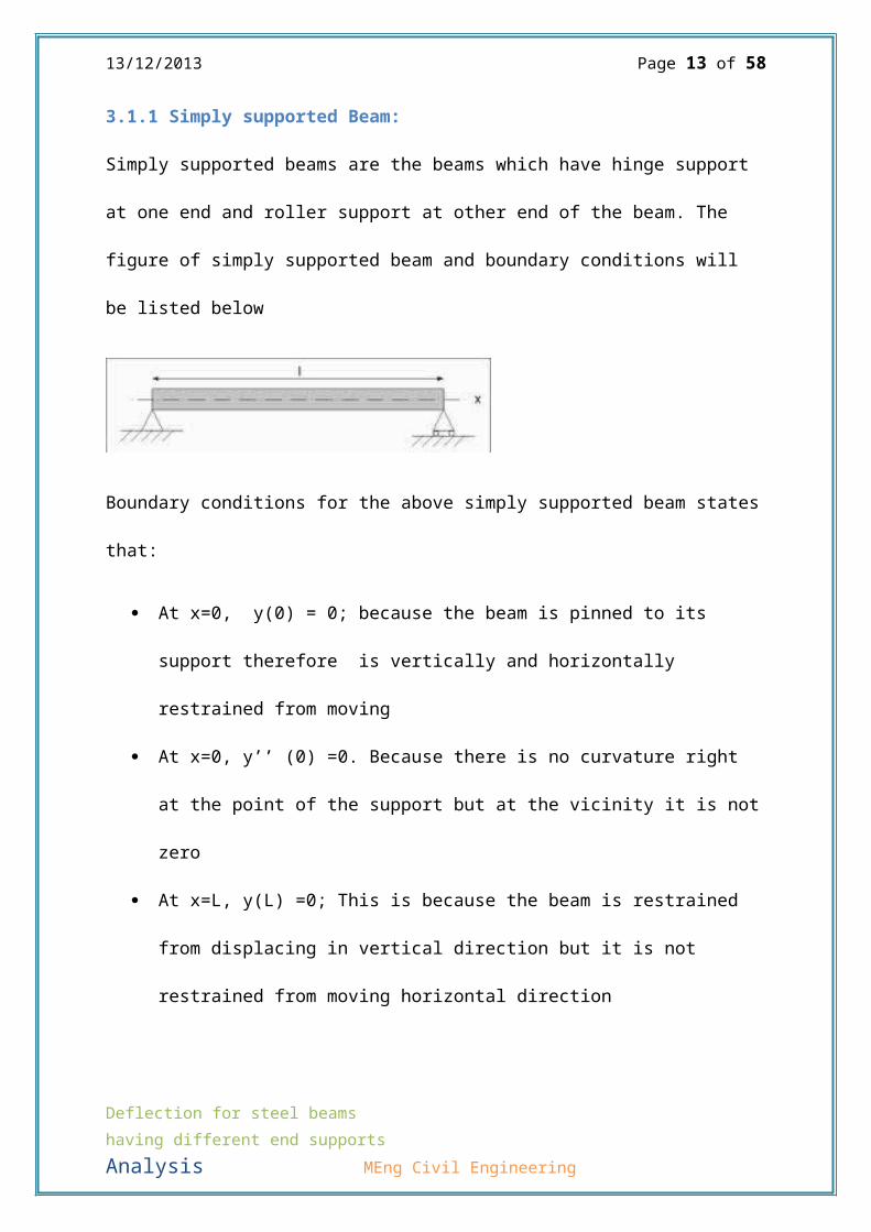
3.1.1 Simply supported Beam:
Simply supported beams are the beams which have hinge support
at one end and roller support at other end of the beam. The
figure of simply supported beam and boundary conditions will
be listed below
Boundary conditions for the above simply supported beam states
that:
At x=0, y(0) = 0; because the beam is pinned to its
support therefore is vertically and horizontally
restrained from moving
At x=0, y’’ (0) =0. Because there is no curvature right
at the point of the support but at the vicinity it is not
zero
At x=L, y(L) =0; This is because the beam is restrained
from displacing in vertical direction but it is not
restrained from moving horizontal direction
Deflection for steel beams having different end supports Analysis MEng Civil Engineering

13/12/2013 Page 14 of 58
At x=L, y” (L) =0. This is because there is no curvature
like at the location where x=0
At x = 0.5L = y’(0.5L) = 0 as there is no slope at the
point of maximum deflection
3.1.2 Pin supported beams
Pin supported beams have pin joints at both ends. The
behaviour of this
type of beam will
be slightly
different to simply
supported beams.
Figure 1: Simply supported beam
Boundary Conditions
Deflection for steel beams having different end supports Analysis MEng Civil Engineering

13/12/2013 Page 15 of 58
At x=0 and x = L y(0) = 0; because the beam is pinned
to its supports therefore is vertically and horizontally
restrained from moving
At x=0 and x = L y’’ (0) =0. Because there is no
curvature right at the point of the supports but at the
vicinity it is not zero
At x = 0.5L = y’ (0.5L) = 0 as there is no slope at the
point of maximum deflection.
3.3 Solving Methods for Differential Equations
In this report three methods will be used for solving
governing differential equation of the behaviour of simply
supported beam subjected to quarter point loads which are
Direct Integration, Rayleigh-Ritz Method and Central Finite
Difference Method
Two methods will be used for solving differential equations
for the behaviour for pin ended beams subjected to quarter
point loads which are Rayleigh-Ritz and Central Finite
Difference Method
Deflection for steel beams having different end supports Analysis MEng Civil Engineering

13/12/2013 Page 16 of 58
3.3.1 Rayleigh-Ritz Method
Rayleigh-Ritz method is one of the variational methods which
are used to solve the governing differential equation which
uses tentative function y=C1ϕ(x) which models the approximate
behaviour of the beams with behavioural factor C1.
This is variational approach because this method is based on
determining the stationary value of the integral of the
function over the whole element which models the assumed
behaviour of the structure. This function will include the
constant
I = ¿∫0
L
F(x,y,y'(x),y''(x)).dx
Where
x = distance from the start of the beam to specified location
y = Assumed Shape function
y’ = dydx
y’’ = d2yd2x
Deflection for steel beams having different end supports Analysis MEng Civil Engineering

13/12/2013 Page 17 of 58
In Rayleigh-Ritz Method we obtain C1 as the stationary value of
the integral of the function and substitute it into the
tentative solution y
To obtain C1 we first differentiate the obtained integral
which satisfies this condition
dIdC1
= 0
Then we obtain C1 from the differentiated function the equation
above and substitute into assumed shape function which will
produce an approximate model of the behaviour of the
structure. In Rayleigh-Ritz Method the function which we use
to integrate is developed using theorem of virtual work on
structural elements subjected to different static loading
conditions.
In the theorem of virtual work the virtual displacement which
is used will be obtained from the assumed shape function in
terms of C1
3.3.2 Direct Integration
The governing differential equation of the beam subjected to
certain loading conditions is need to be developed before you Deflection for steel beams having different end supports Analysis MEng Civil Engineering

13/12/2013 Page 18 of 58
start solving them to determine the displacement along the
beam using direct methods, numerical methods and other types
of approximate methods.
We must develop the following equations:
−EI d2y
dx2=Mx=bendingmomentatpointxalongthebeam
The equation above is the bending moment equation at point x
along the beam is equal to the second order governing
differential equation satisfying the boundary conditions
within the considered range of the beam
If we integrate the equation of bending moment over the
certain portions of the beam we will obtain the slope
−EIdydx
=θx=slopeatpointxalongthebeam
The equation above is used to determine the slope of the
tangent of the curve at point x along the beam is equal to the
first order governing differential equation satisfying
boundary conditions for that part of the beam. If we integrate
the slope equation over the whole length of the beam
−EIy=δx=deflectionatpointxalongthebeamDeflection for steel beams having different end supports Analysis MEng Civil Engineering

13/12/2013 Page 19 of 58
When we develop differential equation for beam in bending
subjected to quarter point loads and with length L we have to
develop three differential equations because each of them will
only cover a certain location of the beam. These ranges are.
0<x<L4
L4
<x<3L4
3L4<x<L
After we obtain and integrate differential equations we equate
the slope equations and deflection equations to determine the
constants which we have developed throughout the process of
integration. This will be provided in the calculations that we
have done.
After we obtain these constants they will be inputted into the
deflection equation of the beam subjected to the loading
condition.
Deflection for steel beams having different end supports Analysis MEng Civil Engineering

13/12/2013 Page 20 of 58
3.3.3 Central Finite Difference Method
Central Finite Difference Method is a numerical method which
is used to solve linear differential equations of any order.
In this method we convert differential equations into a set of
linear equation which can be solved using various different
methods such as inverse matrix, gauss elimination, gauss
Jordan, augmented matrix etc.
Finite difference equations are derived from Taylor’s Series
function. We will remove all the series from second order
onwards as they produce very small values. This is called
truncation process and this will cause truncation error.
3.3.3.1 Development of finite difference equations
Figure 2.: Graphical representation of derivative
Deflection for steel beams having different end supports Analysis MEng Civil Engineering

13/12/2013 Page 21 of 58
The Taylor series expansion:
y (xo+h )=y (xo)+y'(xo)
1!h+
y''(xo)
2!h2+…+
yn(x0)n!
hn
Where
n = the order of each term
Truncation process will lead to the following equation
f (xo+h)=f (xo )+f' (xo)1! h
Develop backward difference and forward difference equations
Forward difference
Backward difference
yi+1=yi+Δx(dydx )iyi=yi−1+Δx(dydx )i−1
Solving for dy/dx:
(dydx )i=yi+1−yi
Δx (dydx )i−1=yi−yi−1
Δx
Differentiating once:
Deflection for steel beams having different end supports Analysis MEng Civil Engineering
13/12/2013 Page 22 of 58
(d2ydx2 )i=(dydx )i+1
−(dydx )iΔx (d2y
dx2 )i−1=
(dydx )i−(dydx )i−1
Δx
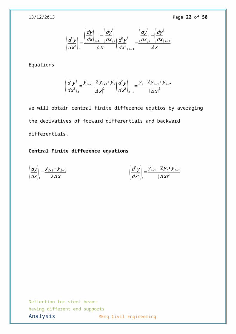
Equations
(d2ydx2 )i=yi+2−2yi+1+yi
(Δx )2 (d2ydx2 )i−1
=yi−2yi−1+yi−2
(Δx )2
We will obtain central finite difference equtios by averaging
the derivatives of forward differentials and backward
differentials.
Central Finite difference equations
(dydx )i=yi+1−yi−1
2Δx (d2ydx2 )i=yi+1−2yi+yi−1
(Δx)2
Deflection for steel beams having different end supports Analysis MEng Civil Engineering

13/12/2013 Page 23 of 58
4 Apparatus and Methodology
4.1 Equipment
Figure :3 The picture represents the equipment which was used
for experiment.
Deflection for steel beams having different end supports Analysis MEng Civil Engineering
Roller support:has got only vertical
Steel beam: elastically deflected under
Pinned support: has got 2 reactions

13/12/2013 Page 24 of 58
Figure 4: This picture shows; the gauge which provides the
values of deflections, extremely sensitive and checks
millimetres.
Figure 5: This picture illustrates the hangers and other
experiment materials.
Deflection for steel beams having different end supports Analysis MEng Civil Engineering
The hangers were used to apply free weights for showing the deflection in the

13/12/2013 Page 25 of 58
Figure 6: The materials used as free weights.
4.2 Methodology
Felt-tip pen
Hand weights
Pad and pen
Steel beams
Steel measuring tape
Deflection for steel beams having different end supports Analysis MEng Civil Engineering

13/12/2013 Page 26 of 58
Camera
Micrometer
50 mm dial gauge
Firstly Start with a steel beam with pin-roller support.
Dial gauge is then set to zero, making sure the pointer
is at 0.
The hanger is weighted and then placed on the beam. The
deflection due to hanger is noted by reading the dial
gauge.
1 kg weight is placed on each hanger and the centre
deflection is taken into consideration by reading the
dial gauge.
Keep adding the 1 kg weight and measuring the central
deflection until 4kg interval is obtained on each hanger.
Then 4 plates of 1 kg are removed and replaced by 5 kg
plate on each hanger. The central deflection is noted
again by reading the dial gauge.
Repeat the process by adding 1 kg weight and noting the
central deflection at each increment until 10 kg. At the
Deflection for steel beams having different end supports Analysis MEng Civil Engineering

13/12/2013 Page 27 of 58
end remove all loads and hanger and read the dial gauge.
Note if there is any residual deflection in the beam or
not.
Repeat the procedure for the second experiment, a steel
beam with pin-pin support.
4.3 Health & Safety
Health and safety is essential in when conducting laboratory
experiments. It ensures that no one gets injured and the
experiment is carried out effectively and safely. All PPE was
worn when conducting this experiment. All Health and Safety
rules laid by the university should be followed when in the
laboratory.
Deflection for steel beams having different end supports Analysis MEng Civil Engineering

13/12/2013 Page 28 of 58
5 Calculations
5.1 Governing Differential Equation Experiment 1
Deflection for steel beams having different end supports Analysis MEng Civil Engineering

13/12/2013 Page 29 of 58
Deflection for steel beams having different end supports Analysis MEng Civil Engineering

13/12/2013 Page 30 of 58
Deflection for steel beams having different end supports Analysis MEng Civil Engineering

13/12/2013 Page 31 of 58
Deflection for steel beams having different end supports Analysis MEng Civil Engineering

13/12/2013 Page 32 of 58
Deflection for steel beams having different end supports Analysis MEng Civil Engineering

13/12/2013 Page 33 of 58
5.2 Finite Difference Method Experiment 1
Deflection for steel beams having different end supports Analysis MEng Civil Engineering

13/12/2013 Page 34 of 58
Deflection for steel beams having different end supports Analysis MEng Civil Engineering

13/12/2013 Page 35 of 58
5.3 Rayleigh-Ritz Method Experiment 1
Deflection for steel beams having different end supports Analysis MEng Civil Engineering

13/12/2013 Page 36 of 58
Deflection for steel beams having different end supports Analysis MEng Civil Engineering

13/12/2013 Page 37 of 58
Deflection for steel beams having different end supports Analysis MEng Civil Engineering
13/12/2013 Page 38 of 58
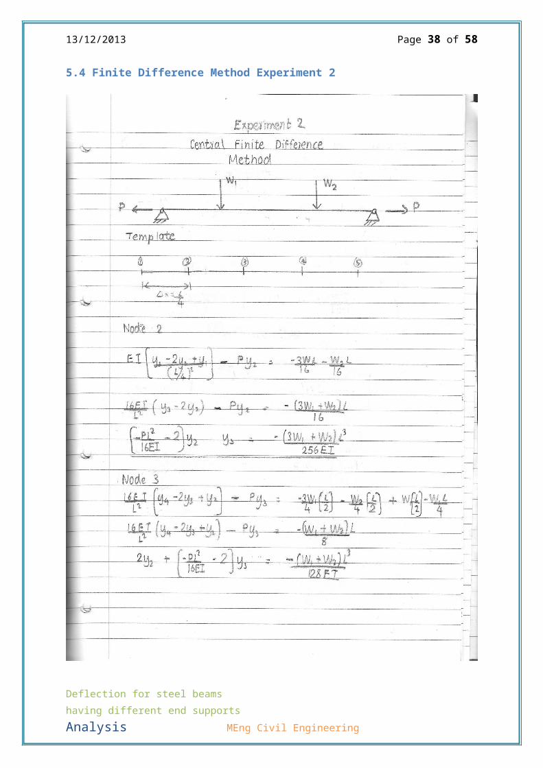
5.4 Finite Difference Method Experiment 2
Deflection for steel beams having different end supports Analysis MEng Civil Engineering

13/12/2013 Page 39 of 58
Deflection for steel beams having different end supports Analysis MEng Civil Engineering

13/12/2013 Page 40 of 58
Deflection for steel beams having different end supports Analysis MEng Civil Engineering

13/12/2013 Page 41 of 58
5.5 Rayleigh Ritz Method Experiment 2
Deflection for steel beams having different end supports Analysis MEng Civil Engineering

13/12/2013 Page 42 of 58
Deflection for steel beams having different end supports Analysis MEng Civil Engineering

13/12/2013 Page 43 of 58
Deflection for steel beams having different end supports Analysis MEng Civil Engineering

13/12/2013 Page 44 of 58
Deflection for steel beams having different end supports Analysis MEng Civil Engineering

13/12/2013 Page 45 of 58
Deflection for steel beams having different end supports Analysis MEng Civil Engineering

13/12/2013 Page 46 of 58
6. Results
Experiment 1
Load
Case
No:
W1(N) W2(N)Experiment
al
y(mm)
Direct
Integration
y(mm)
Central
Finite
Difference
y(mm)
Rayleigh-
Ritz
y(mm)
1 4.905 4.905 0.78 1.2368776 1.349321 1.25375
2 14.715 4.905 1.52 2.8110855 3.035972 2.507499
3 22.525 4.905 2.24 4.064354 4.37876 3.505642
4 34.335 4.905 3.2 5.9595013 6.409275 5.014998
5 44.145 4.905 4.15 7.5337092 8.095926 6.268748
6 53.955 4.905 5.1 9.1079171 9.782578 7.522497
7 53.955 14.715 6.51 10.007465 10.79457 8.776247
8 53.955 24.525 7.55 10.907012 11.80656 10.03
9 53.955 34.335 8.51 11.806559 12.81855 11.28375
10 53.955 44.145 9.59 12.706107 13.83054 12.5375
11 53.955 53.955 10.49 13.605654 14.84253 13.79124
Deflection for steel beams having different end supports Analysis MEng Civil Engineering

13/12/2013 Page 47 of 58
Experiment 2
Load
Case
No:
W1(N) W2(N) Experimenta
l
y(mm)
Rayleigh-Ritz
Method
y(mm)
Central Finite
Difference Method
y(mm)
1 4.905 4.905 0.760.726554 0.796228
2 14.71
5
4.905
1.761.287854 1.640105
3 22.52
5
4.905
2.831.634172 2.194215
4 34.33
5
4.905
3.682.050559 2.882735
5 44.14
5
4.905
4.552.332446 3.352911
6 53.95
5
4.905
5.232.575292 3.753881
Deflection for steel beams having different end supports Analysis MEng Civil Engineering

13/12/2013 Page 48 of 58
7 53.95
5
14.71
5 5.732.789544 3.843786
8 53.95
5
24.52
5 6.372.981941 3.918128
9 53.95
5
34.33
5 6.73.157069 3.979599
10 53.95
5
44.14
5 7.153.318181 4.030213
11 53.95
5
53.95
5 7.543.467676 4.071535
Deflection for steel beams having different end supports Analysis MEng Civil Engineering
13/12/2013 Page 49 of 58
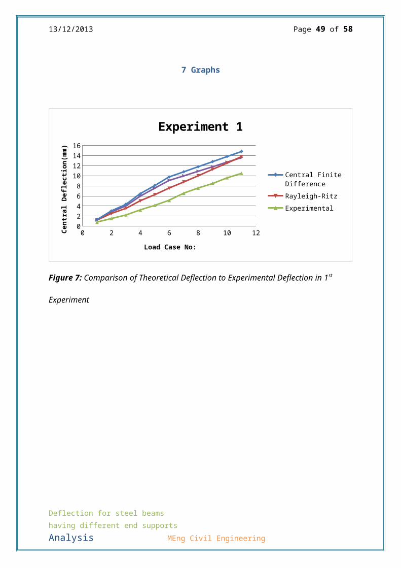
7 Graphs
0 2 4 6 8 10 120246810121416
Experiment 1
Central Finite DifferenceRayleigh-RitzExperimental
Load Case No:
Cent
ral De
flec
tion(m
m)
Figure 7: Comparison of Theoretical Deflection to Experimental Deflection in 1st
Experiment
Deflection for steel beams having different end supports Analysis MEng Civil Engineering

13/12/2013 Page 50 of 58
0 2 4 6 8 10 120
1
2
3
4
5
6
7
8
Experiment 2
Experimental ResultsCentral Finite DifferenceRayleigh-Ritz
Loac Case NoCentral Deflection(mm)
Figure 8: Comparison of Theoretical Deflection vs Experimental Deflection in 2nd
Experiment.
Deflection for steel beams having different end supports Analysis MEng Civil Engineering

13/12/2013 Page 51 of 58
8 Discussions and Conclusions
8.1 Errors
8.1.1 Human Errors
There were some human errors which have occurred in this
experiment especially in recording the results of central
deflection of the simply supported beams and pin ended beams
because our reading wasn’t precise which did affect our
experimental results. Errors can also come from measurements
of our cross sectional dimensions of the beams
8.1.2 Equipment Errors
Equipment errors are the errors which come the meter which
displays the deflection of the beams in this experiment. These
errors can have small effect on the readings of deflection
which we take for each loading therefore can affect our
results.
8.1.3 Error due to Assumptions
There were some assumptions we made when we developed
governing differential equations which one of them is that the
deflection is very small and plain sections remain plain.
Deflection for steel beams having different end supports Analysis MEng Civil Engineering

13/12/2013 Page 52 of 58
Other assumption that we made is that we assumed a deflection
profile when we were calculating the deflection using
Rayleigh-Ritz Method. The errors can also come from assuming
the profile of the behaviour of the structure subjected to
certain loading conditions. Assumption errors can cause tiny
error in the theoretical results we obtained
8.1.4 Actual Error
The actual error is large errors which did significantly
affect our theoretical and experimental results. These errors
are large differences from theoretical and experimental
results which we have in our experiment. Experiment 2 has a
lot of error as there were some big differences between
theoretical results and experimental results. These might come
from either the load cases we did of due to the assumption of
the behaviour because the experimental results do not agree
completely with central finite difference method result and
Rayleigh-Ritz method. Difference in results between central
finite difference and Rayleigh-ritz method is small. In most
of our load cases the beam does not behave exactly like the
assumed shape function because of the skew.
Deflection for steel beams having different end supports Analysis MEng Civil Engineering
13/12/2013 Page 53 of 58
8.1.5 How can we improve on the error?
The errors can be minimised by taking the precise readings of
the results, using equipment and gauge of good quality which
is more advanced which gives precise readings. We can also put
use a beam which is purely homogenous throughout the cross
section and whole length of the beam. Taking precise readings
of the cross sections using gauge will also reduce the error
in our experiment.
8.2 Discussion of Results
8.2.1 Experimental results
According to the results that have been obtained and displayed
on the results section on one of the previous pages we have
determined that with the same loading conditions experiment 2
was only subjected to smaller deflection compared to the
central deflection of the beam in experiment 1 as we were
expected but most of the experimental results in experiment 2
does not agree with the theoretical results obtained from
Rayleigh-Ritz method except the results obtained from first
few set of load cases e.g. on 1st load case the experimental
Deflection for steel beams having different end supports Analysis MEng Civil Engineering

13/12/2013 Page 54 of 58
deflection was 0.76mm and almost same with Rayleigh-Ritz
method but on the 10th load case the experimental deflection is
7.54mm and Rayleigh-Ritz method gives 4.16mm which means that
there is an error
For Experiment 1 the results obtained from experiment can be
agreed with theoretical results obtained from direct
integration, Rayleigh-Ritz method and central finite
difference method as it can be seen on the graph and on the
results table
The central deflection obtained from experiment one is closer
to the central deflection obtained from 2nd experiment which is
what have been expected but experimental results for 2nd
experiment is not comparable with theoretical results whereas
for 1st experiment the results are comparable with theoretical
results.
Results obtained from Central Finite Difference Method in
experiment 1 can agree with the experimental results, direct
integration and Rayleigh-Ritz method but for experiment 2 they
are only be agreed on 1st two load cases but for all the other
Deflection for steel beams having different end supports Analysis MEng Civil Engineering
13/12/2013 Page 55 of 58
load cases they are not agreeable because the results are far
away from the experimental results.
8.3 Final Conclusion
From the experimental results it is observed that the
deflection within the pin-pin beam, in the middle of the beam,
is much lower than the other beam. The reason for this is the
fact that pin-pin supports will restrict the beam from moving
horizontally by introducing horizontal reactions on both ends.
Whereas a roller support allows horizontal movement. This
horizontal reaction on the beam will cause a hogging moment
within the beam itself; this hogging moment will counteract
the sagging moment that is making the beam deflect. Therefore
deflection will be lower with pin-pin support conditions.
When comparing theoretical calculations for the two different
load cases using the three different methods it was found, as
the graphs show, that for experiment 1, pin-roller, the
Rayleigh-Ritz method is the most accurate and easy to use, the
Direct integration method is the second most accurate and
Central difference method is the least accurate. It is found
that for this method Rayleigh-Ritz is the easiest and quickest
Deflection for steel beams having different end supports Analysis MEng Civil Engineering
13/12/2013 Page 56 of 58
method to complete therefore it is concluded that for
experiment 1 the best method for theoretical calculation is
Rayleigh-Ritz.
As the graph for experiment 2 shows the Rayleigh-Ritz method
is generally similar, at least for slope of graph, compared to
the experimental results. The Central Difference method is
also relatively accurate at the start, however as loading is
increased it becomes increasingly inaccurate. Therefore it
may be concluded that the Rayleigh Ritz method is the best
method to conduct theoretical calculations for both
experiments.
9 Bibliography
Rao, S. S., 1999. The Finite Eleement Method in Engineering ( Fourth Edition)
Pages(169-178). Woburn, MA: Butterworth-Heinemann.
Deflection for steel beams having different end supports Analysis MEng Civil Engineering

13/12/2013 Page 57 of 58
The Work done:
By Baris Evran:
-Abstract
- Introduction
-Apparatus
-Word template
-Methodology
-Health and safety
-Conclusion
-Calculations.
By Sagar Sohan
-Theory
-Discussion
- Results
- Calculations
-Errors
-Results.
Deflection for steel beams having different end supports Analysis MEng Civil Engineering

13/12/2013 Page 58 of 58
Duration: 96 hours.
Deflection for steel beams having different end supports Analysis MEng Civil Engineering