Strengthening of reinforced concrete structures with external steel shear walls
Upload
khangminh22Category
view
2download
0
1
Seismic Evaluation of Coupled Shear Walls with Divided Coupling Beams
Amin Gholizad1*, Sasan Teymour-Moghaddam2, Vahid Akrami3
1 Professor, Faculty of Engineering, University of Mohaghegh Ardabili, Ardabil, Iran 2 M.Sc. Graduate, Faculty of Engineering, University of Mohaghegh Ardabili, Ardabil, Iran
3 Assistant Professor, Faculty of Engineering, University of Mohaghegh Ardabili, Ardabil, Iran
Abstract:
Coupling beams of a coupled shear wall system play an important role in the overall behavior of the
structure. Due to the nature of coupling beams, which are mostly sections with high depth and short length,
these components are classified as deep beams. A large amount of internal shear force in these beams causes
shear-slip across the beam-wall interface which is a brittle break-out. Any increase in ductility of coupling
beams will improve the overall performance of the structure against lateral loads. In this regard, the effects
of changing the failure mode into flexural mode are investigated by dividing the deep connector beams into
two separate beams. As in the divided beams more internal forces will be delivered by the longitudinal
reinforcement bars, it is expected that the shear walls connected with these flexural connectors represent
more ductile behavior. To examine this idea, the coupled shear wall system is modeled numerically and its
behavior under cyclic loading is verified against experimental data. Five and eight story coupled shear walls
with coupling beams of different height and reinforcement ratios are modeled and studied. The results show
that if the shear and bending strength of divided coupling beams are proportioned properly, they will act in
flexural mode without having an adverse effect on the overall strength of entire coupled wall.
Keywords:
Coupled shear walls, divided coupling beam, cyclic loading, failure mechanism, energy dissipation
* Corresponding author; Email: [email protected]
ACCEPTED MANUSCRIPT

2
1. Introduction
Coupled shear walls consisting of coupling beams and wall piers are widely used as the lateral load resisting
systems in modern structures [1]. This structural system offers distinct advantages such as good
displacement control, the possibility of using slender walls without violating drift limits, and larger
hysteretic damping than any other conventionally constructed reinforced concrete (RC) system [2]. Initial
research in this area was focused on providing methods for analyzing this structural system [3-5]. With
improved engineering understanding towards this structural system, extensive research was carried out on
different characteristics of the coupled shear walls such as the effect of degree of coupling (DOC) between
wall piers, coupling beam reinforcement layout, etc. [2, 6, 7]. In addition to studies that focus on the overall
behavior of the coupled shear walls, other studies have also been conducted on the behavior of coupling
beams [1, 8-14]. According to past research, coupling beams are expected to endure significant inelastic
deformations under design-level earthquakes and thus, should have appropriate ductility and energy
dissipation capacity [11]. Basically, the reinforced concrete beams fail either in flexural or shear mode. The
shear mode of failure in these beams is undesired mainly being a brittle failure [11, 15-18].
In the past years some researchers have focused on changing the behavior of coupling beams from shear
mode into flexural action to prevent premature brittle failure of these central components [19, 20]. This can
be done by decreasing the depth of coupling beams which may have adverse effect on the overall strength
of entire the shear wall. A solution to this problem is to use two shallow coupling beams at each story
separated by a small gap between them [19, 21]. Most of the references addressing this issue deal with the
experimental investigation of such components [19, 22, 23] or numerical modeling of coupling beams
solely (not in the frame scale) [24-28]. To the best of authors knowledge, the only existing study in this
field that address the finite element modeling of entire coupled shear wall system with dual coupling beams
is conducted by Yu et al. [29] (in Chinese). They have analyzed a four story coupled shear wall under cyclic
loading and compared the results to the one obtained from analyzing the same coupled shear wall with dual
coupling beams. Apart from the limited number of models, the cyclic load-displacement curves presented
for analyzed models suggest that the cracking behavior of the concrete material is not considered in
ACCEPTED MANUSCRIPT

3
modeling. In line with this trend, the current study aims at evaluating seismic performance of coupled shear
walls with divided coupling beams. The parameters, assumptions, modeling techniques and obtained results
are discussed in the following sections.
2. Characterization of Failure Mechanism
Since the common coupling beams have very small span/depth ratios, the dominant failure mode in these
beams is shear fracture. The purpose of splitting a deep coupling beam into two shallower superseding
beams is to change failure mechanism of these components from shear to bending which is characterized
by formation of flexural plastic hinges at two ends of the beam. These beams must be designed in such a
way that they provide the adequate strength equal to the original beam. On the other hand, to ensure that
the beam behaves in the flexural mode, the amount of bending and shear strength of these beams should be
proportioned carefully. In order to have divided beams with the same strength as the original coupling
beam, the required shear strength in secondary beams, Vu', should be greater than half the shear capacity of
the original coupling beam, ½Vr. On the other hand, as it is intended to have flexural failure mechanism in
divided coupling beams, the ultimate shear force in these beams will be equal to Vu'=2Mr'/l, where, Mr' is
the flexural strength of secondary beams in divided configuration and, l, is the distance between two piers.
Therefore, the flexural strength of secondary beams, Mr', should be greater than ¼Vr.l. This criterion assures
that the divided coupling beam has same strength as the original one. However, to ensure that the coupling
beam behaves in the flexural mode, the shear force corresponding to the flexural failure of divided beams
(i.e. Vu'=2Mr'/l) should be less than the shear capacity of the original beam, Vr'. Combining these two
criteria, one can obtain a relation between shear and flexural strength of divided coupling beams:
''. .
4 2
r rr
V l V lM (1)
The first criterion assures that the overall strength of two replacement beams will be equal to the original
undivided beam and the second criterion guarantees that the divided beams will behave in flexural mode.
The larger the range between these two bounds, the easier the selection of bending capacity and the greater
ACCEPTED MANUSCRIPT

4
the confidence about the flexural behavior of the divided beams. Considering that the shear capacity of
beams is directly related to the height of the section, it is expected to have wider range for bending capacity
of divided beams by increasing their height.
3. Details of Numerical Models
3-1- Geometry of models
Twenty six coupled shear walls with different numbers of stories, coupling beams and reinforcement ratios
are modeled and studied in this paper. The analyzed models can be classified in two categories based on
their total height. The first category includes shear walls from a low-rise structure comprising five stories
where the second one includes models corresponding to an eight story mid-rise building (Fig. 1). Inside
each category, there are three types of models with different coupling beams (Fig. 2). The first type is
representative of traditional coupled shear walls in which the piers are tied using a single coupling beam at
the level of each story (1B model).
ACCEPTED MANUSCRIPT

5
Fig. 1. Geometry and parameters of 5 & 8 story coupled shear walls (unit: cm)
Fig. 2. Geometry and parameters of coupling beams
Values obtained from the analysis of this type are used as the reference points to address the results of the
other models. The other two types are exactly the same as the first one except that the coupling beams are
divided in two separate beams and a 50 mm gap is provided between two parts (see Fig. 2). For the second
ACCEPTED MANUSCRIPT

6
type, the total height of resultant beams equals the depth of original beam (2B-1.0D models), while for the
third type the total height of beams is 10% greater than the original depth (2B-1.1D models). For all models,
the story height is assumed to be 3000 mm. Dimensions of the piers and coupling beams are selected so
that the coupling beams contribute mainly to the overall behavior of the entire shear wall. Accordingly, the
width of the piers is assumed to be 2500 mm. Also, knowing that the appropriate height for coupling beams
is about 30% of the story height, the depth of the coupling beams for the reference wall (1B model) is
assumed to be 1100 mm. Reinforcement of the piers and coupling beams are calculated as per ACI 318
[30]. The compressive strength of the concrete and the yield stress of the reinforcement bars are assumed
to be 30 MPa and 300 MPa, respectively.
3-2- Finite element modeling
Finite element modeling and analysis of the specimens are conducted using LS DYNA software. The
smeared crack Winfrith model (MAT085) [31, 32] has been used for modeling of concrete. It assumes
elastic-perfectly plastic behavior in compression and its yield surface expands as the hydrostatic pressure
increases [33]. The radii at the compressive and tensile meridian are determined using the compressive and
tensile strengths of concrete [31]. This material model provides additional information on crack locations,
directions, and widths [34, 35]. The reinforcing bars are modeled with isotropic-kinematic hardening
plasticity model (MAT003) [34, 35] used for steel material. Also, the interaction between concrete and steel
reinforcement is simulated using Constrained-Lagrange-in-Solid (CLS) formulation [34, 35]. This
interaction causes coupling between steel and concrete materials and thus, the degrees of freedom for each
node of reinforcement elements are calculated using the degrees of freedom of concrete elements adjacent
to this node (Fig. 3). ACCEPTED MANUSCRIPT

7
Fig. 3. Finite element modeling, constraints and loading
As the selected model for concrete material (MAT085) can be only implemented in the 8 node single
integration point continuum elements, three-dimensional cube elements with reduced integration have been
used for modeling of concrete. A mesh sensitivity analysis was conducted to see effect of mesh size on the
results of numerical analysis. Two meshing schemes were considered. The first and second schemes had 6
& 12 divisions along the width of piers, 4 & 8 divisions along the length of beams and 3 & 5 divisions
along the beam height, respectively. Comparison of load-displacement curves for two models showed a
maximum difference being less than 2% while the adoption of second meshing scheme increased the CPU
time by a factor of 2.5. The number of divisions for the main models is selected between two studied
meshing schemes (i.e. 9 divisions for the width of piers, 6 divisions for the length of beams and 4 divisions
along the depth of beams). For modeling of steel reinforcement, truss elements with 2 nodes have been
used.
ACCEPTED MANUSCRIPT

8
3-3- Constraints and loading
The effect of the base support is simulated using zero displacement constraint at the bottom of concrete
foundation. Also, an additional constraint is specified to restrict out of plane deformation of the specimen.
This constraint has been applied to the lateral surface of the wall piers. The gravity loading on each pier
has been calculated as the cross section area of the pier multiplied by 10% of the specified concrete strength
and applied at the top of piers. The lateral loading sequence is controlled by roof drift angle, beginning with
four increments of 0.25% drift, with two cycles of loading at each step. The next three steps are increasing
at 0.5% drift, followed by two steps of loading increasing at 1.0% drift. The loading protocol was same as
the one used by Aejaz and Wight [36] in their experiments.
3-4- Verification of models
Modeling techniques adopted in the current study is verified using the results of the experimental study
conducted by Lu and Chen [37]. This research reports results of cyclic loading on three coupled shear walls.
The specimen “CW-2” is used for verification purpose. The selected specimen (shown in Fig. 4(a)), is
modeled using the mechanical properties reported in the corresponding reference and subjected to the same
loading history as that applied to the specimens during the laboratory test. As the tested specimen had
displacement sensor at the base, the base of the specimens was assumed to be fixed with zero displacement.
For the selected specimen, the loading had been applied at the top of the shear wall. Fig. 4(b) shows crack
pattern at the bottom of the wall piers which suggests that both numerical and experimental specimens
underwent almost the same procedure of cracking. In addition, hysteresis loops obtained from FE analysis
and laboratory test are plotted in Fig. 4(c) according to which it can be seen that the curves for both cases
match well. ACCEPTED MANUSCRIPT

9
Fig. 4. Verification of FE modeling using the experimental data reported by Lu and Chen (2005); a) details of the reference model; b)
crack pattern; c) load-displacement curves
4. Parametric study
4-1- Load-displacement behavior
The numerical models were subjected to cyclic loading and the total base shear was plotted versus the roof
displacement. Fig. 5 shows the hysteretic curves of 5 and 8-story models with single coupling beam. The
figure also represents distribution of Von-mises stresses at 1.5% drift angle according to which, it can be
seen that the connected piers act together to withstand the applied lateral load. As mentioned before, results
of these two models are used as the benchmark to address the results of the other models.
ACCEPTED MANUSCRIPT

10
Fig. 5. Load-displacement curves for 5 & 8 story models with single coupling beam
Fig. 6 displays load-displacement curves for coupled shear walls with divided beams. The vertical axis of
these plots is normalized using the maximum lateral load resisted by the corresponding reference model.
The first and second columns contain graphs for 5 story walls with “2B-1.0D” and “2B-1.1D” beams while
the third and fourth columns represent the same graphs for 8 story models. The graphs of each row represent
the behavior of the models with the coupling beam having a certain amount of the longitudinal
reinforcement. The summary of these graphs is also presented in Table 1. Based on the results of “2B-1.0D”
models with the same reinforcement ratio (see Table 1), it can be seen that the maximum load carrying
capacity of these models is less than the ultimate strength of corresponding reference model. However, as
the reinforcement ratio of coupling beams increases the strength of coupled walls becomes equal to or even
greater than the ultimate bearing capacity of the reference model. Referring to the results of “2B-1.1D”
models, it can be seen that when the total height of divided beams increases by 10%, the coupled shear
walls can achieve the ultimate capacity of the reference model even with the same reinforcement ratio.
ACCEPTED MANUSCRIPT

11
Again, as the reinforcement ratio of coupling beams increases, the strength of coupled walls becomes more
and more.
Fig. 6. Load-displacement curves for coupled shear walls with divided beams
Table 1. Summary of results for 5 and 8-story models
Beam type Reinforcement Type of
Plastic region Comparison with respect to reference model
No. ratio Reinforcement Capacity ratio Stiffness ratio
ACCEPTED MANUSCRIPT

12
ratio 5 story 8 story 5 story 8 story
2B-1.0D
4ϕ16 0.0048 Flexural 0.85 0.86 0.95 0.88 0.91 4ϕ18 0.0062 Flexural 1.08 0.91 0.98 0.88 0.93 4ϕ20 0.0076 Flexural 1.33 0.93 1.00 0.88 0.95 6ϕ18 0.00923 Flexural 1.61 1.00 1.00 0.92 0.96 6ϕ20 0.011 Transitional 2.00 1.04 1.00 0.94 0.98 6ϕ22 0.014 Shear 2.42 1.05 1.00 0.94 0.99
2B-1.1D
4ϕ16 0.0044 Flexural 0.85 0.94 0.98 0.89 0.94 4ϕ18 0.0056 Flexural 1.08 1.00 0.99 0.92 0.97 4ϕ20 0.0069 Flexural 1.33 1.03 1.01 0.97 0.98 6ϕ18 0.0085 Flexural 1.61 1.03 1.02 0.97 1.01 6ϕ20 0.0104 Transitional 2.00 1.05 1.03 0.97 1.01 6ϕ22 0.0126 Shear 2.42 1.09 1.05 0.98 1.01
4-2- Envelope backbone curves
Backbone curves for analyzed models were constructed as the envelope of cyclic curves and presented in
Fig. 7. Also, the initial stiffness of the models was calculated based on the provided envelope backbone
curves (i.e. Fig. 7) and summarized in Table 1. According to the table, the maximum reduction in initial
stiffness of the models corresponds to 5-story shear wall with the weakest coupling beam. This is due to
the reduction in flexural stiffness of the coupling beams caused by diving them into two beams.
Fig. 7. Backbone curves for analyzed models constructed as the envelope of cyclic data
Given that none of the samples has a resistance reduction of more than 25% within the considered drift
range, no information can be provided about maximum displacement capacity or ductility of the specimens.
However, it can be said that the ductility ratio (maximum displacement capacity divided by yield
displacement) for 5 and 8 story models is more than nearly 6.0 and 5.0, respectively.
ACCEPTED MANUSCRIPT

13
4-3- Failure mechanisms of the models
Yield pattern of coupling beams at the third story of the models is depicted in Fig. 8. Based on these patterns,
the type of plastic region associated with each model is characterized and summarized in Table 1. According
to the figure, the failure of coupling beams in reference models is due to the formation of shear plastic
region. However, as the coupling beam is divided in two parts, different failure mechanisms are observed
depending on the amount of longitudinal reinforcement. For divided beams with the least amount of
reinforcement the dominant failure mechanism is flexural yielding, characterized by localized plastic areas
at the ends of the beams. According to Table 1, the ultimate load carrying capacity of these models is less
than the corresponding reference models. This clearly shows the effect of neglecting the first criterion given
in Eq. 1. As the reinforcement ratio of coupling beams increases the overall strength of models increases
too. This increase continues until for a specific reinforcement ratio the strength of the model reaches the
ultimate bearing capacity of the reference model (acceptable range). This manner keeps on until the further
increase of the longitudinal reinforcement causes the violation of the second criterion in Eq. 1 which means
that the coupling beam will fail in shear mode.
Fig. 8. Yield pattern of coupling beams at the last cycle of loading
4-4- Cracking pattern
As mentioned before, the adopted smeared crack Winfrith model is able to provide additional information
on crack locations, directions, and widths. This information can be used to gain a better understanding of
ACCEPTED MANUSCRIPT
14
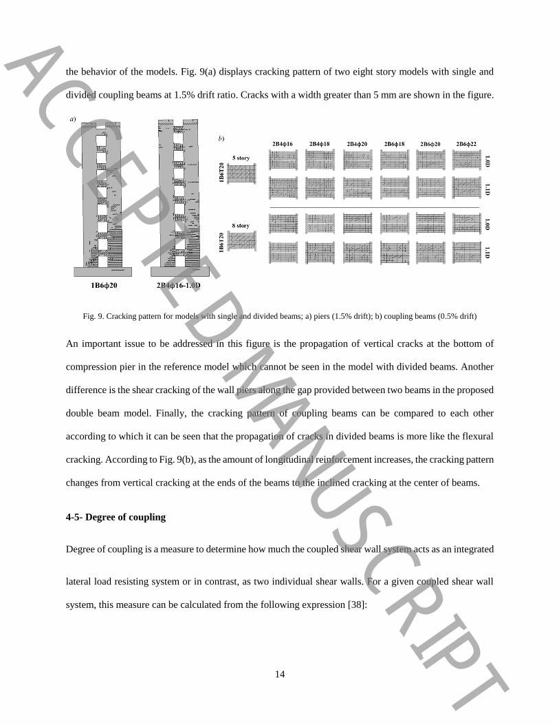
the behavior of the models. Fig. 9(a) displays cracking pattern of two eight story models with single and
divided coupling beams at 1.5% drift ratio. Cracks with a width greater than 5 mm are shown in the figure.
Fig. 9. Cracking pattern for models with single and divided beams; a) piers (1.5% drift); b) coupling beams (0.5% drift)
An important issue to be addressed in this figure is the propagation of vertical cracks at the bottom of
compression pier in the reference model which cannot be seen in the model with divided beams. Another
difference is the shear cracking of the wall piers along the gap provided between two beams in the proposed
double beam model. Finally, the cracking pattern of coupling beams can be compared to each other
according to which it can be seen that the propagation of cracks in divided beams is more like the flexural
cracking. According to Fig. 9(b), as the amount of longitudinal reinforcement increases, the cracking pattern
changes from vertical cracking at the ends of the beams to the inclined cracking at the center of beams.
4-5- Degree of coupling
Degree of coupling is a measure to determine how much the coupled shear wall system acts as an integrated
lateral load resisting system or in contrast, as two individual shear walls. For a given coupled shear wall
system, this measure can be calculated from the following expression [38]:
ACCEPTED MANUSCRIPT
15
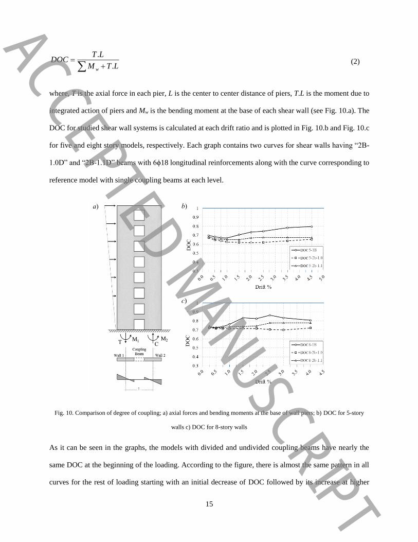
.
.w
T LDOC
M T L
(2)
where, T is the axial force in each pier, L is the center to center distance of piers, T.L is the moment due to
integrated action of piers and Mw is the bending moment at the base of each shear wall (see Fig. 10.a). The
DOC for studied shear wall systems is calculated at each drift ratio and is plotted in Fig. 10.b and Fig. 10.c
for five and eight story models, respectively. Each graph contains two curves for shear walls having “2B-
1.0D” and “2B-1.1D” beams with 6ϕ18 longitudinal reinforcements along with the curve corresponding to
reference model with single coupling beams at each level.
Fig. 10. Comparison of degree of coupling; a) axial forces and bending moments at the base of wall piers; b) DOC for 5-story
walls c) DOC for 8-story walls
As it can be seen in the graphs, the models with divided and undivided coupling beams have nearly the
same DOC at the beginning of the loading. According to the figure, there is almost the same pattern in all
curves for the rest of loading starting with an initial decrease of DOC followed by its increase at higher
ACCEPTED MANUSCRIPT

16
drift ratios. With a closer look at Eq. 2, one can see that the increase of DOC can be resulted from decrease
of Mw which means degradation of wall piers (the statement is checked by investigating FE models). On
the contrary, the decrease of DOC can be resulted from decrease of T.L which is a sign of degradation in
coupling beams. With this interpretation, it can be seen that the degradation of wall piers in models with
divided coupling beams starts at higher drift ratios, compared to reference models.
4-6- Energy dissipation
To compare the energy dissipated by different models, it is important to first introduce a damage indicator
in numerical models. For this purpose, the excessive decrease of stiffness in one of the structural floors
accompanied by a sudden increase in inter-story drift is considered as the criterion to cut the cyclic curve.
Fig. 11 displays graphs of story shear against inter-story drift ratio at different stories of the 5 story reference
model. Graphs in each row correspond to a specific roof drift angle mentioned at the end of the row.
According to the graphs of the first row which correspond to the total drift of 1%, it can be seen that the
distribution of inter-story drift ratio is almost uniform along the height of the model and all stories have
nearly the same contribution to the total energy dissipation of the system. However, as the total
displacement at the roof level increases, the first and second stories experience an extra increase of inter-
story drift ratio compared to other stories. Focusing on the graphs of the last row it can be seen that although
the global drift ratio at the roof level is 3.5%, the second story has experienced more than 6% inter-story
drift ratio. Graphs of Fig. 11 are summarized in Fig. 12 which displays the growth of maximum drift ratio
at different stories of 5 story reference model during the cyclic loading. The same plots for other 5 story
models are depicted in Fig. 13. Looking at the first graph (least reinforcement ratio) it can be seen that the
distribution of inter-story drift ratio for this model is almost uniform. ACCEPTED MANUSCRIPT

17
Fig. 11. Graphs of story shear vs. inter-story drift ratio for 5 story reference model
The maximum inter-story drift ratio is 4% as per 3.5% global drift ratio. However, as the amount of
longitudinal reinforcement in coupling beams increases (behavior changes to shear mode) the non-
uniformity of inter-story drift becomes more intense and starts in lower drift ratios. The results presented
in the last graph which correspond to the model with maximum reinforcement ratio are analogous to the
curves obtained for the reference model (Fig. 12). Specifying the amount of drift ratio at which the sudden
loss of stiffness begins to occur in the most critical story, the dissipated cumulative hysteretic energy is
calculated for different models and plotted in Fig. 14. According to the figure, for all five story models, the
energy dissipation of specimens with divided coupling beams is equal to or greater than the value
corresponding to reference model. As the flexural reinforcement ratio in coupling beams increases, the
energy dissipation increases until the model “2B4ϕ18” attain the highest energy dissipation. The hysteretic
energy dissipated by this model is approximately 2.5 times the energy dissipated by the reference model.
The further increase of reinforcement ratio causes the decrease of cumulative hysteretic energy dissipation.
ACCEPTED MANUSCRIPT

18
Fig. 12. Growth of drift ratio at different stories of 5 story reference model during the cyclic loading
Fig. 13. Comparing distribution of inter-story drift ratio for 5 story models with 1.1D
Fig. 14. Comparing cumulative hysteretic energy dissipation for analyzed models
ACCEPTED MANUSCRIPT
19
For eight story models it can be seen that the specimens with flexural coupling beams have higher energy
dissipation compared to the reference model. The energy dissipated by these models is approximately 2.0
times the energy dissipation of the reference model. For these specimens as the reinforcement ratio of
coupling beams increases the amount of dissipated energy decreases gradually. Again, the energy
dissipation of models with shear coupling beams is lower than that for the flexural coupling beams.
5. Conclusions
One of the major problems of the coupled shear wall systems is the early collapse of coupling beams in
shear mode. In this research, the effects of changing the failure mode of the coupling beams were
investigated by dividing the deep connector beams into two shallow flexural beams. For this purpose, a
tested coupled shear wall available in the literature was modeled numerically and modeling techniques were
assessed against experimental data. Results of analysis on twenty six finite element models were employed
to investigate effects of using divided coupling beams with different reinforcement ratios, beam heights and
number of stories. Based on the results:
Dividing the shear wall coupling beams increases the ductility level of the lateral load resisting system
while it may cause a reduction in overall stiffness and strength of the entire assembly.
Stiffness and strength reduction in coupled shear walls with divided beams may be compensated by
providing additional reinforcement.
Divided coupling beams prevent brittle failure by changing the failure mechanism from shear failure to
flexural mechanism characterized by formation of plastic hinges at the ends of coupling beams.
Degradation of wall piers in models with divided coupling beams starts at higher drift ratios, compared
to the models with single coupling beam at each level.
Higher levels of energy dissipation rate and seismic ductility may be achievable together with adequate
stiffness and strength, utilizing divided coupling beams with optimum ratios of longitudinal
reinforcement.
ACCEPTED MANUSCRIPT

20
It is worthy to note, although the results of numerical analysis showed that the proposed idea may improve
the seismic behavior of the system by changing the failure mechanism of coupling beams, but its application
in real structural systems needs further experimental and numerical studies concerning different
characteristics of these lateral load resisting systems. Also, more rational comparison between different
models can be carried out by evaluating the seismic response of some building models having different
types of shear walls subjected to dynamic analysis.
6. References
[1] N.S. Vu, B. Li, K. Beyer, Effective stiffness of reinforced concrete coupling beams, Engineering
Structures, 76 (2014) 371-382.
[2] T. Paulay, The displacement capacity of reinforced concrete coupled walls, Engineering Structures,
24(9) (2002) 1165-1175.
[3] S. Meftah, A. Tounsi, E. Adda-Bedia, Dynamic behaviour of stiffened and damaged coupled shear
walls, Computers and Concrete, 3(5) (2006) 285-299.
[4] B. Doran, Elastic-plastic analysis of R/C coupled shear walls: The equivalent stiffness ratio of the tie
elements, Journal of the Indian Institute of Science, 83(3&4) (2003) 87.
[5] K. Bozdogan, A method for free vibration analysis of stiffened multi-bay coupled shear walls, Asian
journal of civil engineering (building and housing), 7(6) (2006) 639-649.
[6] J. Hoenderkamp, The influence of single shear walls on the behaviour of coupled shear walls in high-
rise structures, Procedia Engineering, 14 (2011) 1816-1824.
[7] A.A. Eljadei, K.A. Harries, Design of coupled wall structures as evolving structural systems,
Engineering Structures, 73 (2014) 100-113.
[8] C.C. Hung, Y.F. Su, On modeling coupling beams incorporating strain-hardening cement-based
composites, Computers and Concrete, 12(4) (2013) 565-583.
[9] S. Gwon, M. Shin, B. Pimentel, D. Lee, Nonlinear modeling parameters of RC coupling beams in a
coupled wall system, Earthquakes and Structures, 7(5) (2014) 817-842.
[10] M. Hajsadeghi, T. Zirakian, A. Keyhani, R. Naderi, A. Shahmohammadi, Energy dissipation
characteristics of steel coupling beams with corrugated webs, Journal of Constructional Steel Research, 101
(2014) 124-132.
[11] S.W. Han, C.S. Lee, M. Shin, K. Lee, Cyclic performance of precast coupling beams with bundled
diagonal reinforcement, Engineering Structures, 93 (2015) 142-151.
[12] X. Liang, P. Xing, Seismic behavior of fiber reinforced cementitious composites coupling beams with
conventional reinforcement, Earthquakes and structures, 14(3) (2018) 261-271.
[13] P. Pan, Y. Cao, H. Wang, J. Sun, Development of double-stage yielding coupling beam damper,
Journal of Constructional Steel Research, 172 (2020) 106147.
[14] W. Hou, G. Lin, B. Chen, Z. Guo, Cyclic behavior and analysis of steel plate reinforced concrete
coupling beams with a span-to-depth ratio of 2.5, Soil Dynamics and Earthquake Engineering, 148 (2021)
106817.
[15] K.A. Soudki, T.G. Sherwood, Behaviour of reinforced concrete beams strengthened with carbon fibre
reinforced polymer laminates subjected to corrosion damage, Canadian journal of civil engineering, 27(5)
(2000) 1005-1010.
[16] Z. Zhao, A. Kwan, Nonlinear behavior of deep reinforced concrete coupling beams, Structural
Engineering and Mechanics, 15(2) (2003) 181-198.
ACCEPTED MANUSCRIPT

21
[17] R. Taleb, H. Bechtoula, M. Sakashita, N. Bourahla, S. Kono, Investigation of the shear behaviour of
multi-story reinforced concrete walls with eccentric openings, Computers & concrete, 10(4) (2012) 361-
377.
[18] Z. Zhao, A. Kwan, X. He, Nonlinear finite element analysis of deep reinforced concrete coupling
beams, Engineering Structures, 26(1) (2004) 13-25.
[19] Y. Choi, P. Hajyalikhani, S.-H. Chao, Seismic Performance of Innovative Reinforced Concrete
Coupling Beam--Double-Beam Coupling Beam, ACI Structural Journal, 115(1) (2018) 113-125.
[20] C. Chen, Q. Zeng, Z. Gao, L. Sui, Y. Zhou, FRP-Reinforced Concrete–Steel Double-Skin Tubular
Coupling Beam Subjected to Reversed Cyclic Loading, Journal of Composites for Construction, 25(4)
(2021) 04021033.
[21] L. Sui, Y. Liu, Z. Zhu, B. Hu, C. Chen, Y. Zhou, Seismic Performance of LRS-FRP–Concrete–Steel
Tubular Double Coupling Beam, Applied Sciences, 11(5) (2021) 2024.
[22] R. Liu, M. Wang, X. Chen, W. Zhu, J. Fu, Experimental analysis on seismic behavior of small-span-
to-depth-ratio slotted coupling beams with slab and HRB500 bar, Journal of Civil, Architectural &
Environmental Engineering (JCAEE), 38 (2016) 9-16 (Chinese).
[23] X. Li, Y.-S. Sun, B.-D. Ding, C.-Z. Xia, Cyclic Behavior of Deep RC Coupling Beams with Different
Reinforcement Layouts, Journal of Earthquake Engineering, 24(1) (2018) 1-20.
[24] M. Li, J.G. Chen, W.J. Zhao, L.G. Wang, Force behavior of parallel double coupling beams with
different width, Applied Mechanics and Materials, Vols. 578-579 (2014) 707-710.
[25] M. Li, H. Zhang, Y. Wang, W. Tao, B. Wang, R. Shan, Analysis of the Influencing Factors on the
Load-deformation Skeleton Curves of PDCB, in: 2015 International Conference on Mechatronics,
Electronic, Industrial and Control Engineering (MEIC-15), Atlantis Press, 2015.
[26] D. Yu, C. Wang, Restoring force model of semi seam coupling beam based on ABAQUS, World
Information on Earthquake Engineering, 33 (2017) 89-96 (Chinese).
[27] J. Chen, L. Liu, J. Zou, Study on seismic performance of coupling beams between cast-in-situ and
prefabricated frame shear wall, in: 2017 3rd International Forum on Energy, Environment Science and
Materials (IFEESM 2017), Atlantis Press, 2018.
[28] J. Chen, Study on the Force Behavior of Parallel Double Precast Coupling Beams with Different Width,
in: IOP Conference Series: Earth and Environmental Science, IOP Publishing, 2019, pp. 032079.
[29] D. Yu, Z. Xu, C. Wang, Analysis of seismic behavior of shear wall structures with semi seam coupling
beams, World Information on Earthquake Engineering, 33 (2017) 78-86.
[30] ACI-318, Building code requirements for structural concrete and commentary, in, American Concrete
Institute, 2014.
[31] B. Broadhouse, The Winfrith concrete model in LS-DYNA3D. SPD/D (95)363, Structural
performance department, Atomic Energy Authority (AEA) Technology, Winfrith Technology Center,
SPD/D (95)363, 1995.
[32] B. Broadhouse, DRASTIC: A Computer Code for Dynamic Analysis of Stress Transients in
Reinforced Concrete, UKAEA Atomic Energy Establishment, 1986.
[33] S. Epackachi, A.S. Whittaker, A.H. Varma, E.G. Kurt, Finite element modeling of steel-plate concrete
composite wall piers, Engineering Structures, 100 (2015) 369-384.
[34] J.O. Hallquist, LS-DYNA Keyword User’s Manual, vol. I, Livermore Software Technology
Corporation (LSTC), (2013).
[35] J.O. Hallquist, LS-DYNA Keyword User’s Manual, vol. II, Livermore Software Technology
Corporation (LSTC), (2013).
[36] A. Ali, J.K. Wight, RC structural walls with staggered door openings, Journal of Structural
Engineering, 117(5) (1991) 1514-1531.
[37] X. Lu, Y. Chen, Modeling of coupled shear walls and its experimental verification, Journal of
Structural Engineering, 131(1) (2005) 75-84.
[38] S. Ghosh, D. Datta, A.A. Katakdhond, Estimation of the Park–Ang damage index for planar multi-
storey frames using equivalent single-degree systems, Engineering Structures, 33(9) (2011) 2509-2524.
ACCEPTED MANUSCRIPT
Copyright © 2022 FDOKUMEN