Pothundy-O&M-Manual.pdf - Irrigation Department
187
KL07HH0023 Page 0 O&M Manual for Pothundy dam O&M Manual for Pothundy dam 2019 OPERATION AND MAINTENANCE MANUAL FOR POTHUNDY DAM STATE OF KERALA KL07HH0023 October-2019 Water resources department, Kerala
-
Upload
khangminh22 -
Category
Documents
-
view
1 -
download
0
Transcript of Pothundy-O&M-Manual.pdf - Irrigation Department

KL07HH0023 Page 0
O&M Manual for Pothundy dam O&M Manual for Pothundy dam 2019
OPERATION AND MAINTENANCE MANUAL FOR POTHUNDY DAM
STATE OF KERALA
KL07HH0023 October-2019
Water resources department, Kerala

KL07HH0023 Page 1
O&M Manual for Pothundy dam O&M Manual for Pothundy dam 2019
GOVERNMENT OF KERALA
WATER RESOURCES DEPARTMENT
POTHUNDY PROJECT
OPERATION AND MAINTENANCE MANUAL FOR POTHUNDY DAM
2019
KL07HH0023 Page 2
O&M Manual for Pothundy dam O&M Manual for Pothundy dam 2019
MESSAGE
India has more than 5200 large dams. Their health and safety are of paramount importance for sustainable use of the valuable assets, besides providing protection to the people and property in the downstream areas. The Ministry of Water Resources, River Development & Ganga Rejuvenation through the Central Water Commission (CWC), with financial assistance from the World Bank, started the Dam Rehabilitation and Improvement Project (DRIP) to rehabilitate 198 large dam projects in seven states. For managing a dam in a sustainable and scientific manner, it is very crucial for each dam owner to have dam specific Operation and Maintenance Manual that lays down procedures for the daily upkeep of the dam. An Operation and Maintenance Manual for a dam is essential for ensuring its safe functioning and for deriving continued benefits. This Operation and Maintenance Manual for Pothundy Dam has been prepared following the Guideline for Preparation Operation and Maintenance Manuals published in January 2018 under DRIP and covers requirements for project Operation, Inspection, Maintenance, Instrumentation and Monitoring the health of Pothundy Dam both during monsoon and non-monsoon periods. I recommend the dam officials to use this manual for the efficient and safe Operation and Maintenance of the Pothundy Dam on regular basis. I appreciate the initiative taken by CPMU, DRIP and CWC for developing this comprehensive document for implementation by the engineers and administrators of the Pothundy Dam. I also compliment all the experts who have contributed to the development of this manual and congratulate the Ministry of Water Resources, River Development & Ganga Rejuvenation and CWC for the initiation of such important policy protocol to address dam safety management in India.
Secretary
Water resources department,
Kerala
KL07HH0023 Page 3
O&M Manual for Pothundy dam O&M Manual for Pothundy dam 2019
FORWARD
This model Operation and Maintenance (O&M) Manual developed exclusively for Pothundy Dam is a detailed set of written descriptions with step-by-step procedures for ensuring that the dam is safely operated, frequently inspected and properly maintained. In this era of shrinking budgets, timely inspection and preventative maintenance is necessary for the safe functioning of the dam and continued productive use of the dam and reservoir. The format of this model manual was prepared following the principles published 2018 CWC guidelines for operation and maintenance of dam for the use by all Dam Owners in developing their own site-specific manuals. Each section of the document provides the necessary instructions to operate inspect and maintain their dam. A special feature of this manual includes a section on operating and maintaining the remote control system (SCADA) and will be of great use to all dam owners in understanding the valuable use of this system to manage safe operations of their dams. It is recommended that all dam officials charged with the operation of their dams to use this manual to ensure their dam is operated and maintained in a sustainable manner and will continue to derive benefits. Chief Engineer,
IDRB, Thiruvananthapuram

KL07HH0023 Page 4
O&M Manual for Pothundy dam O&M Manual for Pothundy dam 2019
CONTENTS
Message…………………...........................................................................................................................2
Foreword………………….........................................................................................................................3
Chapter 1. General Information.................................................................................................................9
1.1 Purpose, Location, Description of dam........................................................................................10
1.2 Assignment of responsibility.......................................................................................................22
1.3 Collection & Reporting of Dam and Reservoir Data....................................................................26
1.4 Public Utilities and Safety...........................................................................................................27
1.5 Security and Restricted Areas.............................................................................................................................................29
1.6 Staff position, Communication & Warning System......................................................................31
1.7 Distribution of Operation & Maintenance Manuals......................................................................31
1.8 Supporting Documents & Reference Material............................................................................32
1.9 Typical Schedule of Duties..........................................................................................................33 Chapter 2 Project Operation…................................................................................................................44
2.1 Operation Plan…………...…………………………………………………………..……….44
2.2 Normal Operations……………………………………………………………...…………….44
2.3 Emergency Operations………………………………………………………………………..50
2.4 Drawdown Facility…………………………………………………………………………...50
2.5 Initial Filling of Reservoir………………………………………….……….……..…………51
2.6 Record Keeping …………………………………………………………….………………..53
Chapter 3. Project Inspection................................................................................................................................81
3.1 Types of Inspections..................................................................................................................................81
3.2 Informal Inspections....................................................................................................................................82
3.3 Scheduled Inspections……........................................................................................................................82

KL07HH0023 Page 5
O&M Manual for Pothundy dam O&M Manual for Pothundy dam 2019
3.4 Special (Unscheduled) Inspections……….................................................................................................84
3.5 Comprehensive Evaluation Inspections……….........................................................................................84
Chapter 4. Maintenance……….............................................................................................................................92
4.1 Maintenance Plan…..…..............................................................................................................................92
4.2 Maintenance Priorities................................................................................................................................93
4.3 Maintenance Item…......................................................................................................................................96
4.4 Materials requirements for maintenance during monsoon period...............................................................125
4.5 Establishment Requirements…...................................................................................................................126
4.6 Preparation of O&M budget ..................................................................................................126
4.7 Preparation of O&M budget…..................................................................................................................126
4.8 O&M cost for dams where owner and operator is different.......................................................................127
4.9 Maintenance Record…………………......................................................................................................127
Chapter 5. Instrumentation and Monitoring………………………...................................................................160
5.1 Reasons for Instrumentation……………...................................................................................................160.
5.2 Details to be included in an O&M Manual………………………………………….……...160
5.3 Instrument Types and Usage……………………………………………………………….161
5.4 Automated Data-Acquisition Systems………………………………...…………………...163
5.5 Frequency of Monitoring…………………………………………………………..……….164
5.6 Frequency of Monitoring……………………………………………………………………164
5.7 Visual Observations………………………………………….……………………………..166
Chapter 6.Updating Manual………………..………………… ...........................................................................167
Appendix A
Notification for Strengthening of Alarm and Warning System for Safety of People from Sudden Release of Water from Dams Issued by National Disaster Management Authority (October 2015) ................................................................... ………
Appendix B Criteria And Guidelines For Evacuating Storage Reservoirs, Sizing Low Level Outlets And Initial Filling of Reservoir....................................................................
Appendix C Glossary......................................................................................................................... ………..

KL07HH0023 Page 6
O&M Manual for Pothundy dam O&M Manual for Pothundy dam 2019
List of Tables
Sl No.
Name of Table Page No.
1 Table .1 General Details of Pothundy Dam and Canal Network 16
2 Table .2 Duties and Responsibilities 22
3 Table.3 Public utilities and safety 28
4 Table.4 Manual Distribution 32
5 Table.5 Average Climate Data 37
6 Table.6 Panchayath wise ayacut area 40
7 Table.7 Particulars of Off-take from Main Canal (LBC) 41
8 Table.8 Particulars of off-take from Main Canal 41
9 Table.9 Sluice Details of Each Branches RB Main Canal 42
10 Table.10 Sluice Details of Each Branches LB Main Canal 43
11 Table .11 Spillway, LB&RB capacity calculation and discharge details
61
12 Table.12 Storage 75
13 Table.13 With average utility 76
14 Table.14 with Maximum Utility 77
15 Table.15 showing Lean Rainfall with Maximum Utility 79
16 Table.16 Monthly Rain fall details 80
17 Table.17 PRO-FORMAFORPERIODICALINSPECTIONOF LARGEDAMS
86
18 Table.18 REVISED PRO-FORMAT FORHEALTH STATUS REPORT OF LARGE DAMS
87
19 Table.19 Appendix-1 Performance of Dam Instruments 90

KL07HH0023 Page 7
O&M Manual for Pothundy dam O&M Manual for Pothundy dam 2019
20 Table.20 APPENDIX-2 Performance of Meteorological Instruments
90
21 Table.21 APPENDIX-3Categorisation of Deficiencies
91
22 Table 22 - O&M BUDGET COSTS (ANNUAL) 157

KL07HH0023 Page 8
O&M Manual for Pothundy dam O&M Manual for Pothundy dam 2019
List of Figures
Sl No. Name of Figure Page No.
1 Fig.01 Location map of Pothundy Dam taken from Google map 10
2 Fig.02 Canal Network Pothundy irrigation project 12
3 Fig.03 Cross section of Pothundy Dam 13
4 Fig.04 Intake well of Pothundy Dam 15
5 Fig .05 Energy dissipaters in the d/s side of the spillway. 16
6 Fig.06: Pothundy Dam Spillway portion 30
7 Fig.07: Elevation Capacity curve 54
8 Fig.08: Water level –water spread Area curves 55
9 Fig.09: Water Level-Storage Chart 56
10 Fig.10: Water Level-Storage Chart 57
11 Fig.11: Water Level-Storage Chart 58
12 Fig.12 Calibration Chart of ‘V’ Notch 74
13 Fig.13 Time vs. Storage 76
14 Fig.14 Reservoir Embankments 135
15 Fig.15 Roadway along Embankments 138
16 Fig.16 Map showing Ayacut area of LB canals 168
17 Fig.17 Map showing Ayacut area of RB canals 169

KL07HH0023 Page 9
O&M Manual for Pothundy dam O&M Manual for Pothundy dam 2019
CHAPTER 1 GENERAL INFORMATION
1. Introduction
It is essential that the Manual or a copy of the Manual along with supporting data including the atlas of all drawings and manufacturer’s technical documents is available at site for ready reference.
The Manual has been prepared primarily for the dam operation’s staff and their supervisors who are assigned the responsibility for the physical operations and maintenance of the dam. It contains, as a minimum, all information and instructions necessary for them to perform their allotted tasks in a safe manner. In addition to instructions for dam operations staff, the Manual includes all necessary instructions for other staff directly or indirectly involved in operating and maintaining the dam
This document represents a detailed Operation and Maintenance (O&M) Manual for Pothundy Dam, Kerala, providing written descriptions of procedures for ensuring that the dam operates safely and is kept in a good condition by periodic inspections, repairs, and maintenance in a sustainable manner. Timely maintenance is important for the continued safe functioning and productive use of the dam and reservoir.

KL07HH0023 Page 10
O&M Manual for Pothundy dam O&M Manual for Pothundy dam 2019
1.1Purpose, Location, Description of Dam Palakkad is one of the major districts producing paddy in the state of Kerala. Hence series
of irrigation projects were constructed in this district mainly for the purpose of irrigating paddy
and Pothundy Project is prominent one among them. Theconstruction of the dam was
commenced in 1958 under the 2ndfive year plan
Fig.1 Location map of Pothundy Dam taken from Google map
The Pothundy project commissioned during 1967 consists of;
1. An earth dam across the tributaries of Ayilur river mainly,Meenchady puzha and Paddy
puzha originating from theNelliyampathy Hills, of Gayathri river basin.
2. Masonry spillways at right flank of the dam for surplussing the flood discharge and other
appurtenant works.
3. Two main canals, their branches and distributaries to irrigate 4986 Ha.Lands in Chittur and
AlathurTaluks of Palakkad district.

KL07HH0023 Page 11
O&M Manual for Pothundy dam O&M Manual for Pothundy dam 2019
It comprises an EarthenDam of length 1680.00 m with a storage capacity of 50.914Mm³,
i.e., live storage of 43.90Mm³and dead storage of 7.014Mm³. The location of the dam is at,
latitude of 10º37´N and longitude of 70º37´ E and 8km from Nemmara town in Palakkad district
.Nearest railway station is Palakkad Jn. Whichis at 38 Km away and the nearest airport is
Coimbatore international airport which is 92 km away.
1.1.1 Project Benefits
1. Irrigation
Water through the dam is distributed for irrigation through the RBC and LBC canals in the
ayacut areas of 7 Panchayaths viz, Nemmara, Ayilur, Elevencherry, Melarkode, Vadakencherry,
Vandazhy and Erimayur, of Chittur and Alathur Taluks in Palakkad district. The monetary
benefit derived from the yield of paddy and other crops in these areas, every year, is a multy
million figure.
Water Distribution System
Water is being distributed through the Left and Right Bank canals mainly for paddy,
which is being cultivated in 90% of the ayacut area. Crops like coconut, plantain, arecanut,
vegetables, pulses, rubber, and tapioca are also grown.
Water is being distributed continuously in the main canals for the entire base period of
the crop depending on the availability of water in the dam and the request of the farmers. Water
is being released into the branch canals in a turn system. The entire canal system is divided into
two turns to feed the ayacut in intervals.
2. Drinking Water Supply System
The water from the Pothundy dam is also used for Drinking Water supply of 3
Panchayaths Nemmara, Ayilur, and Melarkode by the Kerala Water Authority since 1984. As
per their records the number of consumers is increased from approximately 1000 nos in 1984 to
about 1, 50,000 nos now. Also the quantity of water supplied for the purpose increased from 10
lakh litres per day in 1984 to 125 lakh litres per day now. The revenue collected in this regard is
about Rs 10, 00,000 per month.
3. Fisheries

KL07HH0023 Page 12
O&M Manual for Pothundy dam O&M Manual for Pothundy dam 2019
Pothundy Dam is also used for cultivating variety of fishes under the department of
fisheries. As per fisheries department revenue from sale of fishes comes to about 10 to 15 lakhs
per year.
Fig.2 Canal Network Pothundy irrigation project
1.1.2 Salient Features of the Project
The dam is 1680.00 m in length and the reservoir has a water spread area of 2.74sq Km
and live storage capacity of 43.90Mm³ at FRL of 108.2m
Main Design Features and Components of Pothundy Dam:
KL07HH0023 Page 13
O&M Manual for Pothundy dam O&M Manual for Pothundy dam 2019
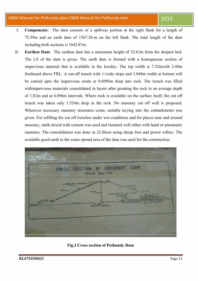
I. Components: The dam consists of a spillway portion at the right flank for a length of
75.59m and an earth dam of 1567.28-m on the left flank. The total length of the dam
including both sections is 1642.87m.
II. Earthen Dam: The earthen dam has a maximum height of 32.61m from the deepest bed.
The LS of the dam is given. The earth dam is formed with a homogenous section of
impervious material that is available in the locality. The top width is 7.32mwith 2.44m
freeboard above FRL. A cut-off trench with 1:1side slope and 3.048m width at bottom will
be carried upto the impervious strata or 0.6096m deep into rock. The trench was filled
withimpervious materials consolidated in layers after grouting the rock to an average depth
of 1.82m and at 6.096m intervals. Where rock is available on the surface itself, the cut off
trench was taken only 1.524m deep in the rock .No masonry cut off wall is proposed.
Wherever necessary masonry structures come, suitable keying into the embankments was
given. For refilling the cut off trenches under wet conditions and for places near and around
masonry, earth mixed with cement was used and rammed well either with hand or pneumatic
rammers. The consolidation was done in 22.86cm using sheep foot and power rollers. The
available good earth in the water spread area of the dam was used for the construction.
Fig.3 Cross section of Pothundy Dam
KL07HH0023 Page 14
O&M Manual for Pothundy dam O&M Manual for Pothundy dam 2019
III. Spillway portion: The spillway is of ogee type u/s face of the wear is vertical and rounded
of at top to start the curve. The hurting is in random rubble masonry and the facing is ashlar
masonry. Suitable energy dissipating arrangements are made in the stilling pool below. The
fabricating steel shutters are erected at top of the wear crest at 104.09m.The top of the shutter
is at 108.204m. 3 piers are raised to carry the roadway at the top at 110.642m.At the u/s side
of the piers controls for the shutters was erected for electrical as well as mechanical
operation. Periodical maintenance such as lubrication, filling of gear oil, painting with
appropriate paintings etc., are being done annually. Replacements of wire ropes and
replacements of rubber seals ofgates are being taken up whenever required.
IV. Irrigation Sluices:There are two sluices for regulating water in the main canal that take off
from the Dam, viz,RBC& LBC. The Right bank canal is having (1) a main canal of
length10.50 Km (2) 16 branches of length about 56.20Km (3)and number of spout of about
236nos (both direct sluice and field boothies) feeding an ayacut area of 2711.55Ha. and the
Left bank is having (1) a main canal of length8.3Km (2) 8 branches of length 37.65Km (3)
and number of spouts of about 165nos (both direct sluice and field boothies) feeding an
ayacut area of 2074.05Ha.The command area of the project lies in Panchayaths of 1)
Nemmara 2) Ayilur 3) Melarkode 4) Elevencherry 5) Vadakencherry 6) Vandazhy and 7)
Erimayur. The canal system is designed with duty of 990 Ha/cumecs with a provision of
16.25% of transmission losses. The discharge of LBMC and RBMC are 3.30m3/s and
3.20m3/srespectively. The LBMC of 8/300 km is designed as contour canal along the highest
ridge. It intercepts number of drainages. Numbers of cross drainage works likeunder tunnels
and Super Passages have been provided at these places to take the drained water across the
canal. The hydraulic particulars of the canal are bed width 3.9m and FSD 1.2m up to
ch.4/500 km and 3.30m bed width and FSD 1.125m from 4/500 km to 8/300 km. The bed
fall is 1/3520 for first reach and 1/3017 for second reach. Side slopes are 1:1 in cutting and
½:1 in embankments. The hydraulic particulars of RBMC are bed width 3.3m and FSD 1.2m
up to ch.7/700 Km and bed width 2.85m and FSD 1.05 m from Ch. 7/700 to 10/500 km. The
bed fall of RBMC is 1/3520. Periodical maintenance of these sluice gates are taken up
annually ,which includes items such as lubrication and filling of gear oil, Cardium

KL07HH0023 Page 15
O&M Manual for Pothundy dam O&M Manual for Pothundy dam 2019
compound, etc. Replacements of wire ropes, replacements of rubber seals, painting using
appropriate paints.
V. Central sluice/Intake well: The Inspection gallery of the dam ends in the intake well in
which 4 intake valves at different levels, viz., 90m, 94.48m, 99.06m, 103.63m are installed
to draw water for drinking water purpose by Kerala Water
Authority
Fig.4 Intake well of Pothundy Dam
VI. Energy dissipater-Three Natural stilling pools are there in the d/s side of the spillway, in the
rocky bed.There are three numbers of identical structures, viz., end walls in the D/S side of

KL07HH0023 Page 16
O&M Manual for Pothundy dam O&M Manual for Pothundy dam 2019
the spill way for dissipating energy by means of hydraulic jump. The structures are in D.R
Masonry encased with concrete.
Fig .05 Energy dissipaters at the d/s side of the spillway.
Table .1 General Details of Pothundy Dam and Canal Network
Sl. No Items
A. General
Location of Dam
The location of the dam
is at, latitude of 10º37´N and
longitude of 70º37´ E and 8km
from Nemmara town in
Palakkad district

KL07HH0023 Page 17
O&M Manual for Pothundy dam O&M Manual for Pothundy dam 2019
Means of Access 8 km from Nemmara Town
OF Palakkad District
B. Geophysical Features
Catchment area 31sq.km
Nature of catchment
The Uppermost reaches are in
hilly and forest area, while
the lower reaches are in
moderate country
Climate Sub-Tropical with 3 distinct
seasons
Annual mean temperature 30.5ºC(Max-39ºC Min-
22.1ºC)
Mean annual precipitation 274 cm
Net yield Dam site at 75 % dependability 50.914 MM3
Silt charge per year 0.23% per year
Geological features at dam site
Loamy soil, on the slope of
the hills there is an overlying
layer of blackmould formed
by decayed vegetable matter.
C. Technical Details of Dam
Gross Storage Capacity 50.914 Mm3

KL07HH0023 Page 18
O&M Manual for Pothundy dam O&M Manual for Pothundy dam 2019
Dead Storage .7.014 Mm3
Lowest Foundation Level (El.) 78.032 m
Lowest River Bed Level (El.) 83.525m
Sill of Irrigation Sluice (El.) 91.44m
Dead Storage Level at MDDL (El.) 91.44m
Full Reservoir Level (FRL) (El.) 108.204m
Maximum Water Level (MWL) (El.) 108.204m
Crest level (El.) 104.09m
Top Level of Dam (El.) 110.642m
Maximum area of water spread 2.74sq.km
D. Length of Dam
Length of masonry spillway dam 75.59m
Earthen dam (Left flank) 1567.28-m
Total length of dam 1680m
E. Other
Maximum height of dam above the lowest foundation
level 32.61m

KL07HH0023 Page 19
O&M Manual for Pothundy dam O&M Manual for Pothundy dam 2019
Height of dam above the lowest River Bed Level 32.61m
Top width of dam 7.32m
Designed flood intensity 682.44m3/s
No. & size of spillway crest gates 3nos.-12.19x4.11m
No. and dimensions of canal sluice shutters 2&1.52mx1.82m
F. Details of submergence
Total area of submergence (Gross) 91.44m
Villages submerge Nelliyampathy
Population affected Nill (Forest area)
1.Location
Name of the River Basin
Tributary
Irrigation Project
Headwork
Bharathapuzha
Ayilur
Pothundy project
Pothundy dam
KL07HH0023 Page 20
O&M Manual for Pothundy dam O&M Manual for Pothundy dam 2019
Type of dam, barrage etc.
Earthen dam
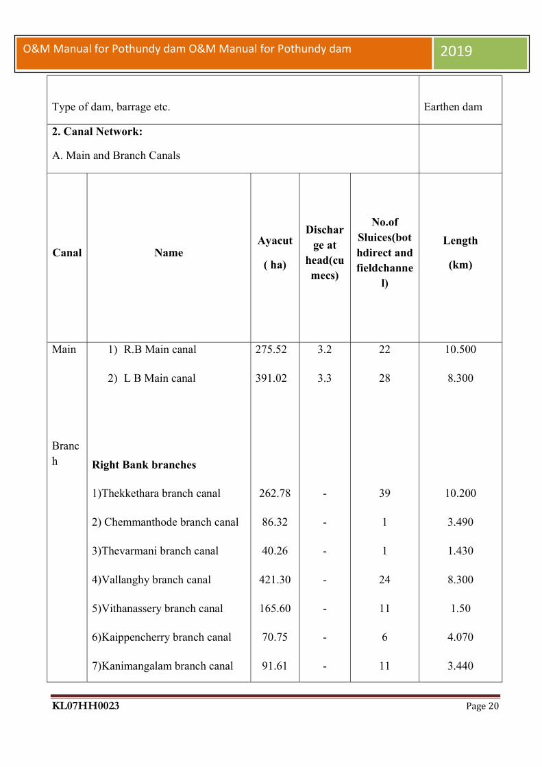
2. Canal Network:
A. Main and Branch Canals
Canal
Name Ayacut
( ha)
Discharge at
head(cumecs)
No.of Sluices(bothdirect and fieldchanne
l)
Length
(km)
Main
Branch
1) R.B Main canal
2) L B Main canal
Right Bank branches
1)Thekkethara branch canal
2) Chemmanthode branch canal
3)Thevarmani branch canal
4)Vallanghy branch canal
5)Vithanassery branch canal
6)Kaippencherry branch canal
7)Kanimangalam branch canal
275.52
391.02
262.78
86.32
40.26
421.30
165.60
70.75
91.61
3.2
3.3
-
-
-
-
-
-
-
22
28
39
1
1
24
11
6
11
10.500
8.300
10.200
3.490
1.430
8.300
1.50
4.070
3.440

KL07HH0023 Page 21
O&M Manual for Pothundy dam O&M Manual for Pothundy dam 2019
8)Chittilencherry north branch
canal
9) Chittilencherry South branch
canal
10)Cheramangalam branch canal
11)Thekkumpuram branch canal
12)Malakkulam branch canal
13)Cheruvanchipadam branch
canal
14)Anakkapara branch canal
15)Mudapallur branch canal
16)Chelluvadi branch canal
Left Bank branch canal
1) AkampadamBranch Canal
2) Kalchady Branch Canal
3) Adiperanda Branch Canal
4) Nemmara Branch Canal
5) Thiruvazhiyad Branch Canal
6) Ayilur Branch Canal
7) Paliyamangalam Branch
286.82
449
50.31
129.67
86.31
60.23
54.96
91.71
87.80
42.20
284.45
97.41
123.74
83.52
534.34
215.12
302.27
-
-
-
-
-
-
-
-
-
-
-
-
-
-
-
-
-
19
26
10
12
19
9
11
7
8
35
19
19
4
31
6
26
5.200
6.400
1.410
2.500
3.690
2.500
3.690
3.460
5.120
0.750
10.600
4.600
3.000
1.200
8.600
0.600
8.300
KL07HH0023 Page 22
O&M Manual for Pothundy dam O&M Manual for Pothundy dam 2019
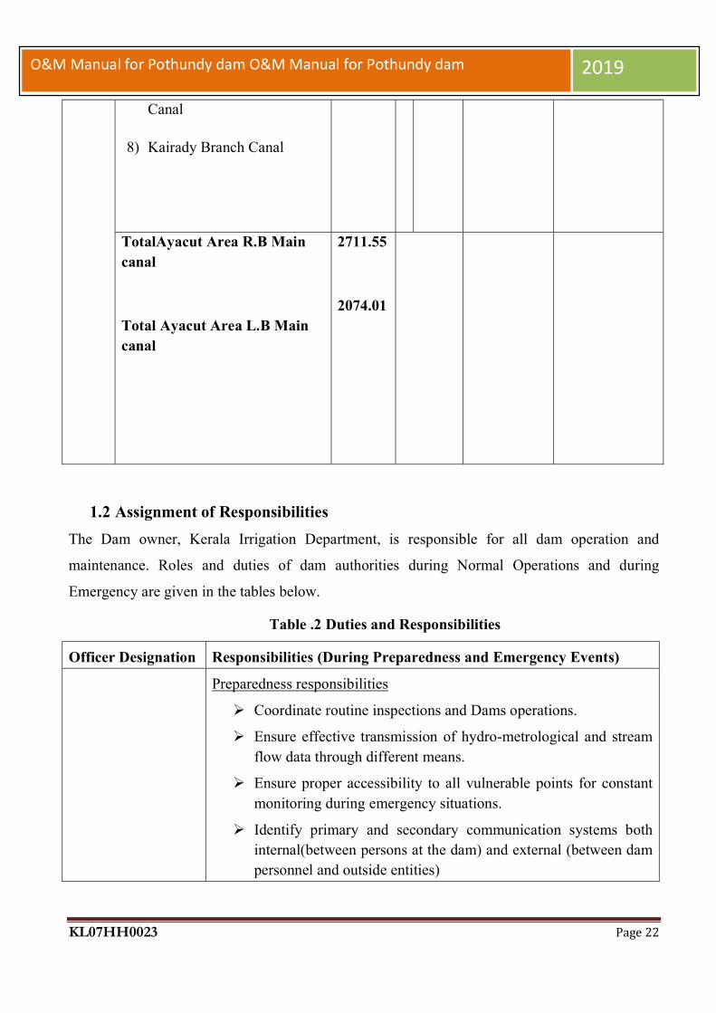
Canal
8) Kairady Branch Canal
TotalAyacut Area R.B Main canal
Total Ayacut Area L.B Main canal
2711.55
2074.01
1.2 Assignment of Responsibilities
The Dam owner, Kerala Irrigation Department, is responsible for all dam operation and
maintenance. Roles and duties of dam authorities during Normal Operations and during
Emergency are given in the tables below.
Table .2 Duties and Responsibilities
Officer Designation Responsibilities (During Preparedness and Emergency Events)
Preparedness responsibilities
Coordinate routine inspections and Dams operations.
Ensure effective transmission of hydro-metrological and stream flow data through different means.
Ensure proper accessibility to all vulnerable points for constant monitoring during emergency situations.
Identify primary and secondary communication systems both internal(between persons at the dam) and external (between dam personnel and outside entities)

KL07HH0023 Page 23
O&M Manual for Pothundy dam O&M Manual for Pothundy dam 2019
Executive Engineer(Emergency Planning Manager)
Provide security measures at the dam (CCTV Surveillance, security guards, fencing)
Ensure the availability of adequate staff at dam site during holidays, nights and round the clock in weekdays.
Ensure that the EAP is functional and staffs are familiar with their responsibilities.
Ensure that a sign board is installed and clearly visual in different locations at dam site and operation room, with the most common evidence of distress and corresponding levels of alert and remedial actions.
Ensure all the equipment/means at dam site to response to an emergency are easily accessible and well maintained (generators, vehicles, lanterns, radios, heavy equipment, etc.)
Ensure the installation and proper maintenance of a warning system(sirens, horns)in the critical areas within the floodplain(less than 2 hours of wave arrival time)
Ensure the current approved version of the EAP is available to all relevant stakeholders (those who have a functional role in the emergency response)
Ensure the all necessary means to manage emergency response are available and operative in the Emergency Operation Centre.
Participate in exercises for test/improvement of this EAP.
In charge of organizing publicity at strategic points for forewarning people on opening of gates.
During Emergency Responsibilities
Ensure a continuous and reliable communication with dam site officers
Received and assess any distress condition as notified by site engineers, observer or regular inspection.
Classify the incident/distress condition reported by the observer into the different Emergency Levels (Blue, Orange, Red) based on the ANNEXURE 4 (Emergency Level Determination/Action Sheets) and ANNEXURE 2(Inundation maps)
Initiate /Implement the Emergency Action Plan and the Emergency Operation Centre if it is deemed necessary.

KL07HH0023 Page 24
O&M Manual for Pothundy dam O&M Manual for Pothundy dam 2019
Identify the areas that would be potentially impacted by the emergency events.
Provide updates of situation to the District(s) Disaster Management Authority to assist them in making timely and accurate decisions regarding warnings and evacuations.
Propagate the emergency information to other relevant stakeholders.
Support the communication needs of local emergency authority.
Dam site Engineers (Dy.Executive Engineer, Assistant Engineers, Junior Engineers)
Preparedness Responsibilities
Monitor and surveillance of dam and appurtenant structures looking for evidence of distress as mentioned in ANNEXURE 4
Conduct pre and post monsoon inspections under the direction of the Emergency Planning Manager
Inform the Emergency Planning Manager about any irregular/unusual condition at dam site and keep him/her posted about any progression /change
Operate dams gates/under sluices, under the express direction of Chief Engineer/Superintending Engineer/Executive Engineer
Conduct routine dam maintenance
Collect instrumentation measurements
Ensure effective working conditions of the warning system(Sirens)
Participate in exercises for test/improvement of this EAP.
During Emergency Responsibilities
Monitor de emergency event at dam site and keep posted the Emergency Planning Manager about any change in the development
Contact suppliers /contractors
Supervise the work of labour contractors and machineries engaged in the site for rehabilitation/remedial works
Conduct remedial actions as per Action Data Sheets(ANNEXURE 4)

KL07HH0023 Page 25
O&M Manual for Pothundy dam O&M Manual for Pothundy dam 2019
Superintending Engineer
Preparedness Responsibilities Ensure an annual review of the EAP. Coordinate the annual/regular testing events of the EAP, such as
tabletop exercises, mock drills, stakeholder's consultation Coordinate training events in problem detection, evaluation and
appropriate corrective measures Supervise the functioning of control room and ensure to be well
equipped with all type of information to facilitate the rescue and relief operations
Ensure proper access to site at the earliest possible. Ensure that all related machinery/equipment are in running
conditions and can be deployed as per requirement of emergency site
Formation of Purchase Committee for Procurement of Material from Appropriate Source through Spot Purchase.
Ensure the correctness of Gauge Discharge sites under his control every year well before monsoon.
During Emergency Responsibilities
Provide decision support and technical support toEmergency Planning Manager as appropriate.
Have a constant liaison with Indian Meteorological Department(IMD) during emergency periods related with flood events
Advise the emergency planning Manager of the emergency level determination if time permits
Disseminate information and make contact to utilize media as appropriate at the time of emergency on behalf of Chief Engineer, Projects 1, and Kozhikode.
Chief Engineer
Preparedness Responsibilities
Assist the dam owner’s officers in preparation of Action data sheets (ANNEXURE 4)
Recommend specific actions in order to improve the readiness of emergency actions
Support and Monitor the remedial construction activities such as earth moving, special investigations etc.
Decide depending upon the quantum of repair/reconstruction work, whether the work is to be got executed through large

KL07HH0023 Page 26
O&M Manual for Pothundy dam O&M Manual for Pothundy dam 2019
construction firms or purely through the department or small contractors.
Undertake an engineering assessment of the safety hazard at the dam in collaboration with the State Dam Safety Organization.
During Emergency Responsibilities
Advice the dam’s emergency planning Manager/Superintending Engineer with the emergency level determination if time permits
Advice the dam’s emergency planning Manager/Superintending Engineer with remedial actions to take if Blue/Orange event occurs, and if time permits.
Direct specific and appropriate procedures to open/close the spillway’s gates during the reservoir operations.
Play the role of “Public Affair’s office “ in case external/public notifications should be released
Keep close watch on the different activities being carried out by different agencies at the time of emergency
1.3 Collection & Reporting of Dam and Reservoir Data
The collection and reporting of dam and reservoir data is done in the Pothundy reservoir on
daily basis in the proformas as shown in table.3 below.
The following data are reported daily morning and evening to all the higher authorities including
IDRB and Records of the date are maintained in a chronological manner for reference. These
records are helpful for identifying preventative maintenance measures that may need to be taken
up, troubleshooting the cause of potential equipment failure and documenting development of
any unusual conditions.
Reservoir water surface elevation.
Corresponding storage
Reservoir inflow.
Spillway outflow.
Irrigation and water supply releases.
Rainfall

KL07HH0023 Page 27
O&M Manual for Pothundy dam O&M Manual for Pothundy dam 2019
Seepage
Records [Logbooks] of the following operations at Pothundy Dam are maintained in a
chronological manner for reference. These records are helpful for identifying preventative
maintenance measures that may need to be taken up, troubleshooting the cause of potential
equipment failure and documenting development of any unusual conditions.
1.4 Public utilities and safety.
As public safety is of prime concern, safety Instructions & protection measures at the dam
should be included in a supporting document and referenced in the Manual. Signboards need to
be provided at appropriate locations of the dam for convenience of the public.

KL07HH0023 Page 28
O&M Manual for Pothundy dam O&M Manual for Pothundy dam 2019
Table.3 Public utilities and safety
Canal Sluice
sill level = 91.44m
size =1.6x1.8m each
Spillway crest level= 104.09 No. of vents=3
Size=12.19x4.11m
Tot
al D
isch
arge
(m3 /s
ec)
Col
.2+
4+7
Ave
rage
ou
tflo
w s
ince
last
mea
sure
men
t
Dif
fere
nce
in
st
orag
e (M
m3 )
Sin
ce
last
m
easu
rem
ent(
+ve
) fo
r in
crea
se(-
ve)
for
dep
leti
on
Los
s b
y ev
apor
atio
n d
urin
g th
e p
erio
d M
m3
Net
dif
fere
nce
(M
m3 )c
ol. 1
0+11
+ve
or
-ve
Dis
char
ge(m
3 /sec
)cor
resp
ond
ing
stor
age
in
col.1
2
+ve
or
-ve
Ave
rage
infl
ow (
m3 /s
ec)
Wat
er d
raw
n b
y K
WA
(Mm
3 )
Left Bank Canal Vent 1 No.
Right Bank Canal Vent 1 No.
No.
of
ven
ts o
pen
ed
Hei
ght
open
ed (
m)
Dis
char
ge(m
3 /sec
)
Hei
ght
open
ed (
m)
Dis
char
ge(m
3 /sec
)
Hei
ght
open
ed(m
)
Dis
char
ge(m
3 /sec
)
1 2 3 4 5 6 7 8 9 10 11 12 13 14 15

KL07HH0023 Page 29
O&M Manual for Pothundy dam O&M Manual for Pothundy dam 2019
1.5 Security and Restricted Areas
Certain areas of the dam and reservoir are restricted for entry of the general public. The purpose of restrictions is for security of the dam, public safety and uninterrupted safe operation of the dam.
Restricted areas will include the following:
Confined spaces such as galleries Spillway approach areas and shutter areas, chutes and stilling basins. Reservoir RB and LB canal sluices Intake or outlet channels adjacent to hydraulic structures.

KL07HH0023 Page 30
O&M Manual for Pothundy dam O&M Manual for Pothundy dam 2019
Fig. 6: Pothundy Dam Spillway portion
1.6 Staff position, Communication and warning system

KL07HH0023 Page 31
O&M Manual for Pothundy dam O&M Manual for Pothundy dam 2019
1.6.1 Staff position
The Pothundy dam is under the control of
1. Chief Engineer, IDRB, TVM 2. Chief Engineer, Projects-I, Kozhikode 3. Superintending Engineer, Siruvani Project Circle, Palakkad 4. Executive Engineer, Irrigation Division, Malampuzha 5. Assistant Executive Engineer, Irrigation subdivision, Nemmara 6. Assistant Engineer, head works section, Pothundy.
In Head works section, Pothundy there are two third grade overseers and workers.
1.7 Distribution of Operation & Maintenance Manuals
The list of units offices to whom the O&M Manual is required to be distributed needs to be mentioned in the O&M Manual. It must be ensured that revisions of the Manual are also supplied to the same units as per the list.
Table.4 Manual Distribution

KL07HH0023 Page 32
O&M Manual for Pothundy dam O&M Manual for Pothundy dam 2019
Sl No Unit Officers
Number of Manual
Distribution
1. Secretary to Gov., Water Resources Department, Kerala 3
2. Chief Engineer ,IDRB, Thiruvananthapuram Email [email protected].
2
3. Chief Engineer Projects-1, Kozhikode Email id cep1kkd@gmail. Ph:0495 2385595
2
4.
Superintending Engineer, Siruvani Project Circle, Palakkad. Email id [email protected]. Ph:0491 2577425
1
5.
Executive Engineer, Irrigation Division, Malampuzha.Phone-0491-2815111Email:[email protected]
1
6. Assistant Executive Engineer, Irrigation subdivision, Nemmara Phone-04923 244232 Email [email protected]
1
7.
Assistant Engineer head works section, Pothundy. Phone-04923 [email protected]
1
1.8 Supporting Documents &Reference Material
ThisO&MManualisthekeyinstructiondocument.Supporting documentsandnecessaryinstructionsforallphasesoftheoperation,inspectionandmaintenanceofthedam,reservoirandappurtenant works shown below are available at the dam controlroom:
Emergency Action Plan(EAP)
Floodforecastingandoperatingcriteria
Basin or river operatingplan
Agreementswithotheruseragencies

KL07HH0023 Page 33
O&M Manual for Pothundy dam O&M Manual for Pothundy dam 2019
Irrigation operationplan
Domestic/industrialwatersupply operatinginstructions
Administrativeprocedures
Maintenanceschedules
GateManufacturer’sinstructionsand drawings
Regional communicationdirectory
Instrumentation reports /results
1.9 Typical Schedule of Duties
The checklist below should be used as a guide in preparing duty schedules for
operating personnel. Depending on the requirements at dam site, size and importance of
the dam, the frequency of the duties can be altered. All activities should be recorded in
dam log book /site registers.
1.9.1 Daily
Visual inspection of dam
Crest of dam (Dam top)
Upstream and downstream faces
Visible portions of foundation and abutments contacts
Galleries
Record water surface elevation. (During monsoon on hourly basis)
Record reservoir inflow and spillway discharge. (During monsoon on hourly basis)
Record releases from outlets /sluices.
Record seepage from drainage systems-Toe drains, Gallery drains etc. on daily basis (during initial filling of the reservoirs)
Record meteorological data.
Check security and safety devices.
Complete logbook / site registers which should include the above information
1.9.2 Weekly

KL07HH0023 Page 34
O&M Manual for Pothundy dam O&M Manual for Pothundy dam 2019
Electrical System
Standby generator (DG Sets) Run for 15-30 min to achieve recommended operating temperature
Check status of batteries and keep them charged.
Check Fuel Supply
Drainage systems - Toe drains, Gallery drains etc. ( during 1st year after initial reservoir filling)
1.9.3 Monthly
Check condition of Dam and Reservoir
Critical landslides area(During Mon-soon) Reservoir periphery (During Mon-soon) Drainage systems - Toe Drains, Gallery drains etc. (on regular basis from
second year onwards after initial reservoir filling) Measuring devices/Instruments Security and safety devices rectification, if needed. Communication Devices Status of Vegetation growth Check Sign/Warning display boards near vulnerable locations
Mechanical/Electrical System
Replace fuse light bulbs Inspect to maintain ventilation system Cleaning of control panel boards
1.9.4 Three Monthly
Outlet Works
Availability of updated operating instruction Check gate air vents Clean gate control switchboxes Check operation of gates and valves Grease gate hanger / dogging
Check

KL07HH0023 Page 35
O&M Manual for Pothundy dam O&M Manual for Pothundy dam 2019
Check condition of trash rack of in-take structure Check condition of Outlet works & its Energy Dissipation Arrangement Check operation of Valve house
Spillway
Check condition of log and safety boom Check for debris in inlet channel Check operation of gates Check for damages in spillway glacis, energy dissipation arrangement, d/s area
etc. Check and clear spillway bridge drains Clean inside of motor control cabinet
Other works
Check for adherence to instrumentation schedule Record pertinent information in Operation Log Check condition of V-notch/other seepage measuring devices
1.9.5 Six Monthly
Spillway & outlet works
Check paint on gates Check lubrication of wire ropes and application of Cardium compound .Check mechanical hoist bearings and flexible coupling bearings Check gear systems Exercise gate and valves Check oil reservoir level in hydraulic system Check pressure release valve Lubricate gate rollers Check rubber seals and seal clamp bar
Electrical System and Equipment Change oil in stand by generator Check exposed electrical wiring of :
Operating equipment‘s of gates/valves/hoists of Outlet works.
Operating equipment‘s of gates and hoists of Spillway

KL07HH0023 Page 36
O&M Manual for Pothundy dam O&M Manual for Pothundy dam 2019
Operating equipment‘s of any other gates and hoists in dam
Spillway bridge
Dam Galleries
Check Gate limit switches and adjust 1.9.6 Annually
Spillway & outlet works
Paint M
etalwork, Gate, Hoists and all exposed metal parts
Valves / Control valves
Hydraulic power pack system Exercise Gates and Valves Examine stilling basin / energy dissipation arrangement and d/s channel & carry
out rectification works, as necessary. Check metal welds for damages/cracks in Gates, Hoist platform, Radial Gate Tie
flats, trunnion Girders/supports etc. Electrical Check electrical conduits, pull-boxes and switches for:
Outlet works valve house
Gates & hoists
Spillway bridge
Galleries
1.9.7 Five Yearly
Inspect intake structures, trash racks and stilling basin / energy dissipation arrangement, which normally are underwater; less frequent, if experience indicates. This may need to be done by carrying out dewatering or by divers/remote operated vehicle, as necessary.
Review Dam operation procedures and EAP.
KL07HH0023 Page 37
O&M Manual for Pothundy dam O&M Manual for Pothundy dam 2019
1.10 Project Advisory Committee
Every year 5 members are selected among the farmers under this project, 3no from
canal committee of RBC area and 2 no from canal committee of LBC area for the advice
of proper water management during the water distribution time, creating oneness among
farmers and building a co-relation between the department and the farmers. The canal
committees of RBC are (1) Thekkethara Canal Committee (2) Kaippancherry-
Chittilancherry Canal Committee (3) Chemmanthode-Vithanassery Canal Committee and
the canal committees of LBC are (1) Akampadam-Thiruvazhiyad Canal Committee (2)
Ayilur-KairadyCanal Committee.
Government Order
Rules for the regulation and distribution of water for Pothundy Irrigation Project
was approved by the government by order no: G.O.Ms.24/74/W&P Dated. 10-06-
1974and is applying to the whole of Pothundy Irrigation Project.
1.11 Climatic conditions, soil pattern and ground water
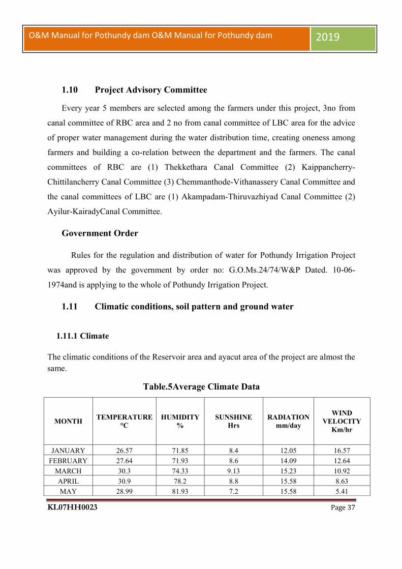
1.11.1 Climate
The climatic conditions of the Reservoir area and ayacut area of the project are almost the same.
Table.5Average Climate Data
MONTH TEMPERATURE
°C HUMIDITY
% SUNSHINE
Hrs RADIATION
mm/day
WIND VELOCITY
Km/hr
JANUARY 26.57 71.85 8.4 12.05 16.57
FEBRUARY 27.64 71.93 8.6 14.09 12.64
MARCH 30.3 74.33 9.13 15.23 10.92
APRIL 30.9 78.2 8.8 15.58 8.63
MAY 28.99 81.93 7.2 15.58 5.41
KL07HH0023 Page 38
O&M Manual for Pothundy dam O&M Manual for Pothundy dam 2019
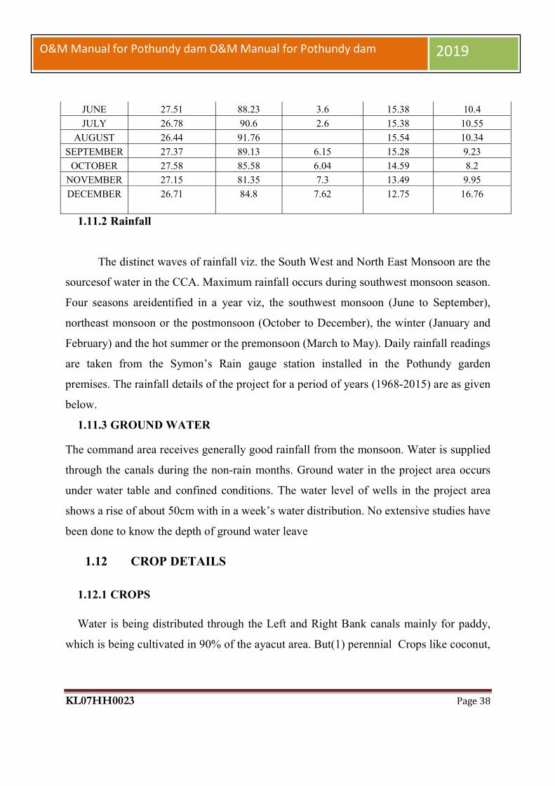
1.11.2 Rainfall
The distinct waves of rainfall viz. the South West and North East Monsoon are the
sourcesof water in the CCA. Maximum rainfall occurs during southwest monsoon season.
Four seasons areidentified in a year viz, the southwest monsoon (June to September),
northeast monsoon or the postmonsoon (October to December), the winter (January and
February) and the hot summer or the premonsoon (March to May). Daily rainfall readings
are taken from the Symon’s Rain gauge station installed in the Pothundy garden
premises. The rainfall details of the project for a period of years (1968-2015) are as given
below.
1.11.3 GROUND WATER
The command area receives generally good rainfall from the monsoon. Water is supplied
through the canals during the non-rain months. Ground water in the project area occurs
under water table and confined conditions. The water level of wells in the project area
shows a rise of about 50cm with in a week’s water distribution. No extensive studies have
been done to know the depth of ground water leave
1.12 CROP DETAILS
1.12.1 CROPS
Water is being distributed through the Left and Right Bank canals mainly for paddy,
which is being cultivated in 90% of the ayacut area. But(1) perennial Crops like coconut,
JUNE 27.51 88.23 3.6 15.38 10.4
JULY 26.78 90.6 2.6 15.38 10.55
AUGUST 26.44 91.76 15.54 10.34
SEPTEMBER 27.37 89.13 6.15 15.28 9.23
OCTOBER 27.58 85.58 6.04 14.59 8.2
NOVEMBER 27.15 81.35 7.3 13.49 9.95
DECEMBER 26.71 84.8 7.62 12.75 16.76

KL07HH0023 Page 39
O&M Manual for Pothundy dam O&M Manual for Pothundy dam 2019
arecanut & rubber, (2) seasonal crops like vegetables & pulses and (3) annual crops like
plantain & tapioca are also grown.
1.12.2 CROP SEASONS- PADDY
First crop (June to September):Viruppu (Rain fed) Water will be supplied for the first
crop also if the rain fall is short.
Second crop (October to January): Mundakkan
Third Crop (February to May):Puncha- According to availability of water.
1.12.3 Cropping Pattern
Crop (paddy) : percentage
1st crop : 100%
2nd crop : 88.09%
Total for year : 94.05%
1.12.4 CROP GROWTH- PADDY
Stage:Days after sowing
Seedlings:20
Tillerformation: 30 -35
PancileInitiation: 40
Flowering: 70
Maturing: 90-110
1.12.5 CANAL SCHEDULING
1.12.5.1 Canal scheduling

KL07HH0023 Page 40
O&M Manual for Pothundy dam O&M Manual for Pothundy dam 2019
Two crops of paddy are raised annually. The first crop or Viruppu is harvesting
during August or September. The second crop or Mundakkan is harvesting during
January. The project is designed to supply water mainly for the second crop, but water
will be supplied to other crops also according to availability. The introduction of
irrigation calls for a definite crop pattern to secure maximum use of irrigation facilities
and the agriculture operations have to be scheduled to be accommodated within the
designed capacity of the canals. The advancement taking place in the field of agriculture,
may call for changes in the crop pattern. The Executive Engineer may review the crop
pattern whenever necessary in the consultation with the Department of Agriculture and
the Irrigation pattern may be adjusted suitably.
1.12.5.2 Regulator of Water for irrigation
The first opening of the sluices to start irrigation and closing at the end of irrigation
season should be done only under the orders of the Executive Engineer. The date of
opening of the canal shall be decided and published by the Executive Engineer in
advance in consultation with the Project Advisory Committee depending upon the storage
position of the reservoir. If the crop pattern adopted for the project is altered by any
cultivator, not fitting with the irrigation pattern, the project authorities are not bound to
supply water to these fields and will not be responsible. As per order no G.O.M.s.24/74W
& P DT: 10/06/1974, after the irrigation season the canals shall be closed normally on
31st January.
Table.6 Panchayath wise ayacut area
SI.NO PANCHAYATH AYACUT (Ha)
1 NEMMARA 1037.21 2 ELEVENCHERRY 244.39 3 MELARKODE 1359.6 4 ERIMAYUR 39.27 5 VADAKKENCHERRY 36.94

KL07HH0023 Page 41
O&M Manual for Pothundy dam O&M Manual for Pothundy dam 2019
6 VANDAZHY 224.8 7 AYILUR 1843.41 TOTAL 4785.62
Table.8 Particulars of off-take from Main Canal
No. Name of Canal
Position below head works-off take point Ch.
Length in Km.
Ayacut Ha.
1 R.B.Main Canal Direct Sluices
0/00 10.5 275.52
2 Chemmanthodu 1/700 3.49 86.32 3 Thevarmani 5/500 1.43 40.26 4 Vallenghy 7/700 8.3 421.3 5 Vithanassery 7/700 1.5 165.6 6 Kaippencherry 9/.00 4.07 70.75 7 Kanimangalam 10/000 3.44 91.61 8 Chittilancherry (N) 10/200 5.2 286.82 9 Chittilancherry (S) 10/300 6.4 448
10 Cheramangalam 2/300 of Thekkethara Branch 1.41 50.31 11 Thekkumpuram 4/500 of Thekkethara Branch 2.5 129.67 12 Malakkulam 5.300 Thekkethara Branch 3.695 86.91 13 Cheruvanchipadam 7.25 1.655 60.23
Table.7 Particulars of Off-take from Main Canal (LBC)
No. Name of Canal Position below head works-off take
point Ch. Length in
Km. Ayacut
Ha. 1 L.B.Main canal Direct
Sluices 0.00 Km 8.30 391.02
2 Akampadam. 2.90 Km 0.75 42.20 3 Kalchady. 4.35 Km 10.60 284.45 4 Adiperanda 2.50 Km of Kalchady Branch 4.60 97.41 5 Nemmara 5.30 Km 3.00 123.74 6 Thiruvazhiyad 6.50 Km 1.20 83.52 7 Kairady. 8.30 Km 8.30 320.27 8 Ayilur 8.30 Km 8.60 534.34 9 Paliyamangalam 2.45 Km of Ayilur Branch 0.60 215.12
TOTAL 2074.07

KL07HH0023 Page 42
O&M Manual for Pothundy dam O&M Manual for Pothundy dam 2019
14 Anakkapara 9.7 3.95 54.96 15 Chelluvady 10.2 5.12 87.8 16 Mudappallur 10.2 3.46 91.71 17 Thekkethara 10.50 of RB Main canal 10.2 262.78
TOTAL 2711.55
Table.9 Sluice Details of Each Branches of RB Main Canal
SI.no Canal Details No of
Sluices DIRECT
FIELD CHANNEL
1 RB Main Canal from(ch:0/00-9/617) 24 11 13
2 Thekkethara Branch Canal from (ch:0/00-9/660) 39 14 25
3 Chembanthodu Distributory 1 0 1 4 Thevarmani Distributory 1 0 1
5 Vallanghy Branch Canal from (ch:0/00-7/460) 24 7 17
6 Vithanassery Branch Canal from(ch:0/00-1/555) 11 2 9
7 Kaippanchery Branch Canal from(ch:0/00-2/140) 6 5 1
8 Kanimangalam Branch Canal from(ch:0/00-2/965) 11 6 5
9 Chittilanchery North Branch Canal from(ch:0/00-4/980) 19 3 16
10 Chittilanchery South Branch Canal from(ch:0/00-1/980) 26 0 26
11 Cheramangalam Branch Canal from(ch:0/00-1/200) 10 9 1
12 Thekkumpadam Branch Canal from(ch:0/00-2/275) 12 1 11
13 MalakkulamDistributory from(ch:0/00-1/205) 19 7 12
14 Cheruvanchippadam Branch canal from(ch:0/00-1/450) 9 9 0
15 Anakkappara Distributory from(ch:0/00-3/430) 11 10 1
16 Mudappallur Branch Canal from(ch:0/00-1/160) 7 1 6
17 Chelluvady Branch Canal from(ch:0/00- 8 1 7
KL07HH0023 Page 43
O&M Manual for Pothundy dam O&M Manual for Pothundy dam 2019
2/600)
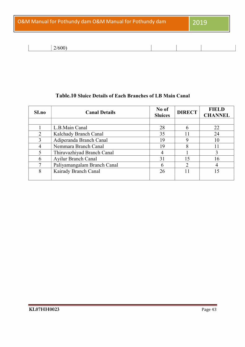
Table.10 Sluice Details of Each Branches of LB Main Canal
SI.no Canal Details No of
Sluices DIRECT
FIELD CHANNEL
1 L.B.Main Canal 28 6 22 2 Kalchady Branch Canal 35 11 24 3 Adiperanda Branch Canal 19 9 10 4 Nemmara Branch Canal 19 8 11 5 Thiruvazhiyad Branch Canal 4 1 3 6 Ayilur Branch Canal 31 15 16 7 Paliyamangalam Branch Canal 6 2 4 8 Kairady Branch Canal 26 11 15

KL07HH0023 Page 44
O&M Manual for Pothundy dam O&M Manual for Pothundy dam 2019
CHAPTER 2.
PROJECT OPERATION
The operation of a dam will involve regulation of its reservoir as per project specific
requirements, keeping records and ensuring public safety. Proper operation procedures are
crucial for maintaining a safe structure. This chapter provides details on how various elements of
a project are to be operated both during normal and emergency situations. The following basic
data in addition to the salient features & basic drawings mentioned in chapter 1 will need to be
enclosed under this chapter of O& M Manual:
Area – Capacity curves.
Data of the historic floods.
Latest design flood and flood routing study.
Sequence of operation of spillway gates during monsoon.
Discharge through spillway for different reservoir levels with different gate openings.
Where more than one spillway exist, the sequence of operation of spillways need to be
included.
2.1 Operation Plan
Operation plan consists of step-by-step instructions for operating the dam and reservoir.
Operating procedures are developed based on:
Reservoir operation studies, relevant design documents, hydraulic model studies etc.
Equipment operating and Maintenance Instructions (Manufacturers' Instructions)
Operating procedures are to be developed for both normal operations and emergency
operations.
2.2 Normal Operations
KL07HH0023 Page 45
O&M Manual for Pothundy dam O&M Manual for Pothundy dam 2019
The operating procedures developed for normal or ―day-to-day‖ operation of a dam shall
include the following:
Instructions for operating control mechanisms.
Instructions for operating the reservoir in accordance with reservoir operation rule
curve.
General instructions for the safe operation of the dam and appurtenances. The
following aspects also need to be included:
Releases to be made for various purposes round the year including releases to be
made as per Inter-State Agreements/ MOU‘s with various States/Agencies/Projects,
riparian releases etc.
Rule curves.
Inflow forecasting
Flood release procedure
Limitation on reservoir drawdown rate to prevent failure of u/s slope of the
embankment/landslides along reservoir periphery Site security is a matter of concern
at all major dams. This includes terrorism implications and preventing structural
damage by vandals and unauthorized operation of outlet or spillway gates. In most
cases restricting public access is essential, and in some instances electronic security
devices should be considered.
2.2.1 Instructions for Operating Control Mechanisms
The Procedures should provide instructions for operating all necessary equipment
associated with a dam including the spillway gates and outlet gates /valves. The gate
manufacturer‘s O&M Manual for Gates & Hoists will however govern the overall Gate
operations whenever there as any contradiction with the instructions given in the Manual. The
frequency and nature (e.g. flow test, static test, dry test) of operational check testing of the
equipment‘s should be specified. Correct sequence should be emphasized and sketches, drawings
and photographs to aid in identifying specific handles, buttons, levers, etc., should be included.
Provisions and uses of backup equipment should be outlined.

KL07HH0023 Page 46
O&M Manual for Pothundy dam O&M Manual for Pothundy dam 2019
The correct method and sequence of opening and closing guard gates, gate usage during
low and high flow, and openings at which excessive vibration are experienced, and operating
problems peculiar to a specific gate should also be listed. For gates/valves, a schematic diagram
should be provided showing each component (including backup equipment) and its place in the
operating Sequence. An auxiliary power system such as petrol or diesel-operated generator or
other appropriate energy source is essential if the outlets, spillway gates and other dam facilities
are electrically operated. This system should be located at levels higher than the extreme flood
levels. Access and lighting during extreme events is essential. All the spillway and outlet gates
should be tested on a regular schedule along with testing of alarms and associated indicators. The
test should include use of both the primary and auxiliary power systems.
2.2.2 Operation of the Reservoir
Instructions need to be included for the general operation of the reservoir, including
monitoring and regulation of inflow and outflow. Inflows shall consist of flows/ releases from
upstream dam, tail race releases into the reservoir, contribution from the intervening catchment
etc. as applicable. The Surplus flows will be passed as outflow through the spillways in the dam.
Releases from the reservoir will need to be made for irrigation, power generation, or other
purposes as per project requirements. Release rate instructions and schedules for the same need
to be referenced. Any other required downstream flows should be given. The actual release rates
and dates should be recorded and placed in the project files. Instructions for operating spillways
will be based on:
Gate operation sequence including tables giving discharges for different gate openings
and reservoir levels obtained through model studies or otherwise.
Where more than one spillway exists, the sequences of operation of spillways need to be
included.
The general instructions should give the maximum pool levels proposed at different times of
the year, and the largest and smallest carryover storage volumes. Both reservoir filling and
release procedures (Rule Curves) should be available. Guidelines for drawdown, flushing &
sluicing in case of Hydro-power projects need to be referenced.
Reservoir operations guidelines includes
Reservoir Capacities
Monsoon Yields

KL07HH0023 Page 47
O&M Manual for Pothundy dam O&M Manual for Pothundy dam 2019
Proposed Reservoir Levels during Monsoon Months
Release of Surplus Water
Discretion of Field Engineers
Flood Protection and Flood Moderation
PMF & Moderated Flood.
2.2.3 Safety Aspects
The public safety is of paramount importance at all dams and reservoirs. The general instructions
in this regard are as under:
State procedures to be followed for restricting access to the dam or confining traffic to
designated areas. Indicate the procedures to be followed when tourists visit the facility.
Designate speed limits to keep the traffic within acceptable and safe limits.
Establish standards for maintaining sanitary conditions.
Prevent contamination or pollution of water for human consumption and/or re-
creational use.
Eliminate safety hazards by:
Posting warning signs.
Removing unsafe conditions where possible.
Restricting public access to chutes, stilling basins, and control rooms.
Posting safety instructions at visible and key locations.
Maintaining warning buoys upstream of the dam.
Providing adequate security.
Ensure provision of all downstream warning systems like sirens, hooters etc. An adequate
system of giving information to downstream areas regarding release of flood outflows
from spillway should be there. At the same time instructions regarding operations,
inspection and maintenance need to be strictly followed for ensuring safe operation of the
dam.
2.2.4 Flood Release Procedure

KL07HH0023 Page 48
O&M Manual for Pothundy dam O&M Manual for Pothundy dam 2019
Surplus waters during floods are released through a service spillway, emergency
spillway, fuse plug, outlet works etc. as applicable. The service (principal) spillway maintains
the reservoir at Full Reservoir level (FRL). Its function is to pass expected flood flows past the
dam safely. It may be gated or un-gated. It is necessary to ensure that all gates are in working
condition. Normally these spillways are standard ogee, chute, or side-channel spillways.
An auxiliary spillway / a fuse plug spillway functions during emergency conditions to
prevent overtopping of a dam. A typical auxiliary spillway could be an excavated channel in
earth or rock near one abutment of a dam with invert at FRL like a flush bar, or it can be like any
other conventional type of spillway as per project planning. An auxiliary spillway should
discharge away from the toe of a dam to avoid its erosion. A fuse plug spillway normally has its
crest at a level slightly higher than FRL and is designed to be washed away during large floods
after which it is required to be reconstructed. These spillways in conjunction
With service spillway are sized/ designed to convey the so-called ―design flood – the rare,
large-magnitude flood used to design the dam/ spillway arrangement. The gate operation
schedule for passing floods safely must be prepared based on the project layout and the results of
hydraulic model studies. The following general guidelines may be borne in mind while preparing
the gate operation schedule:
i. The regulation of gates should be based on model studies where such studies have been
carried out. Otherwise theregulation can be based on past experienceof operation of the
gates and designstudies carried out for developing thesame. The aim will be to ensure
safety ofthe dam structure including the gatecomponents, hoists, energy
dissipationarrangement and downstream channelwhile letting out the desired discharge.
ii. The end gates shall normally be openedfirst to prevent cross-flows striking against the
walls and junctions.
iii. At any time during the operation of different gates, the difference in gate opening of any
two consecutive bays should not exceed 0.5 meters.
iv. After opening the end gates, the gates at the Centre should be opened and the other gates
should be opened in symmetrical manner starting from the Centre towards the end
through gradual increase in the openings.

KL07HH0023 Page 49
O&M Manual for Pothundy dam O&M Manual for Pothundy dam 2019
v. While closing the gates, the gate that was opened last should be closed first. The
procedure to be followed for closing the gates should be generally reverse of the
procedure followed for opening the gates. Complete closure of the gates should be
accomplished by gradual lowering of the gates by 0.2 to 0.3 m in the proper sequence.
vi. In some cases all the gates will be needed to be opened equally especially when the
energy dissipation arrangement consists of a solid roller bucket or slotted roller bucket.
2.2.5 Reservoir Capacities
The important reservoir levels such as sill levels of various outlets in the dam, DSL, MDDL,
Spillway Crest level, Full Reservoir. Level, Maximum Water Level and corresponding reservoir
capacities should be included. (See Figure 2-3) Also it is essential to include Area-Capacity data
(both in the form of tables and curves) in the Manual. The O&M manual should mention that the
reservoir capacities may change because of sedimentation that reduces the available storage
volume over time. Revised area capacity curves need to be prepared whenever a new
bathymetric survey of a reservoir is carried out. The frequency of this survey will depend upon
reservoir siltation rates and other factors as applicable (approx. 10 years).
2.2.6 Inflow forecasting
Inflow forecasting should include instructions and procedure for preparing, periodic
estimates of inflow volumes especially for the monsoon season. These estimates provide a basis
to plan reservoir and project operations before and during the flood seasoned to permit
optimization and coordination of water supply and other reservoir functions. Also, these
estimates will help in planning operating procedures consistent with operating criteria to protect
the dam and its appurtenances against failure caused by high reservoir water levels and excessive
discharge rates.
The instructions and procedures should be described in sufficient details and
completeness in a referenced Supporting Document to enable newly assigned personnel to
estimate inflows and to fully implement the procedures. Maps or drawings could be used to show
locations of Hydrological stations in the drainage area where data such as river gauge, discharge,
rainfall, sediment is collected on a regular basis.
Administrative and technical procedures should be included. Administrative procedures should
identify organizations responsible for forecasting estimates and the related collection of data and
conversion of forecasts into operating plans. Technical procedures shall include:

KL07HH0023 Page 50
O&M Manual for Pothundy dam O&M Manual for Pothundy dam 2019
Parameters to be measured / monitored in hydro-meteorological stations.
Specific correlations, equations, graphical tools, and analytical procedures used in
forecasting inflow, such as early warning systems, rule curves, etc.
Instructions regarding at what frequency forecasts are to be made under various
conditions.
The supporting document should include a description of the procedures and criteria used by
those agencies and instructions for operating personnel in the use of such forecasts. Development
of inflow forecasting procedures is a continuing process because correlations are subject to
revision as more data become available. Hence, instructions in the Supporting document should
include a requirement to examine the procedures periodically and to make revisions and
improvements where needed.
2.3 Emergency Operations
For emergency operations, the Emergency Action Plan (EAP) will have to be invoked.
The emergency situations are outlined under 4.2.1 of this document and Guidelines for
developing Emergency Action Plans for Dams (Doc No. CDSO_GUD_DS_01_v2.0), CWC
2016. The EAP will help in minimizing losses to life and property. It will include:
i. A clear description of the circumstances under which a warning is issued and a list of
individuals to whom the warning is issued.
ii. The names, organizations, telephone numbers (day/night), and alternate communication
means for individuals responsible for operating the dam and the sequence by which these
individuals should be contacted.
iii. The names, designations, telephone numbers (day/night) and alternate communication
means of the representatives of local, State, and Central agencies and other officials to be
contacted, including:
Concerned District/Revenue Authorities.
Operators of other affected dams/other facilities.
Managers/operators of recreational facilities/water sports.
iv. The materials and equipment to be used for performing emergency dam repairs,
including:
The description and intended use of the materials.

KL07HH0023 Page 51
O&M Manual for Pothundy dam O&M Manual for Pothundy dam 2019
The description and location of equipment available with dam owner,
and the names of the agencies to be contacted.
The procedures to be used for contacting concerned agencies.
The EAP will be one of the referenced documents of the O&M Manual.
2.4 Drawdown Facility
All water release facilities, including outlet works, sluices, gated spillways, and power
penstocks should be considered available for evacuation to the extent that their reliability in an
emergency situation can be reasonably certain. In the case of canal outlet works, there must be a
bypass or waste way in order for such outlet works to be considered available for emergency
releases. Otherwise releases through them will be considered equal to the design capacity of the
canal.
Reservoir level may be required to be lowered if a critical/emergency condition occurs or for
carrying out repairs to the dam on its upstream slope/face in dry condition. For general guidance
the ACER Technical Memorandum no. 3 - Criteria and Guideline for evacuating storage
reservoirs and sizing low level outlet works & IS: 15472 – Guidelines for planning of low level
outlets for evacuating storage reservoirs may be referred to. Care is to be taken to restrict the
reservoir drawdown rates to prevent failure of upstream slope of the Embankment/ landslides
along reservoir periphery etc. This will vary from dam to dam and project to project. The actual
drawdown rates both under normal and emergency conditions have to be decided by the Dam
Designers. The Central Water Commission (CWC) Guidelines on Criteria for Evacuating
Storage Reservoirs, Sizing Low Level Outlets and Initial Filling of Reservoirs are at Appendix –
B
2.5 Initial Filling of Reservoir
First filling of a reservoir is first indication that the dam is safe and will function as designed.
Therefore, first filling of a reservoir should be carefully planned and implemented to ensure
safety of the dam and future success of the dam. USBR & USACE (2012) studies indicate that
approximately two thirds of all failures and one-half of all dam incidents occur on first filling or
in the first 5 years of reservoir operation. Thus, it is vital for dam operators and engineers to have

KL07HH0023 Page 52
O&M Manual for Pothundy dam O&M Manual for Pothundy dam 2019
as much control over the first filling as possible allowing as much time as needed for appropriate
surveillance, including the observation and analysis of instrumentation data. Depending on the
location, type, size, and intended purpose of a dam, the duration and rate of its first filling can
vary. Regardless of how much time it takes, the first filling of a reservoir should be planned,
controlled, and closely monitored in order to reduce the risk of failure. The prime consideration
in deciding the rate of reservoir rise should be to allow the dam to adjust to the forces it will
experience as the water level behind it increases. In addition to dam failure, it is common for
design, construction, and/or material deficiencies of a new dam to become apparent during the
first filling. For example, evidence of seepage, cracking, and erosion are often noted when the
reservoir is raised to new levels for the first time. Inspection and assessment of these potentially
hazardous conditions prior to the completion of filling is important and it may be necessary to
halt filling or in some cases lower the reservoir before the desired operating water level is
achieved to investigate signs of seepage, cracking and erosion. Repairs to any project features
that did not function as designed can be re-evaluated and modified to ensure the dam operates
according to its original design. All the water release facilities including gated spillways, outlet
works, sluices etc. are to be used for control of reservoir levels during initial filling. The O&M
Manual should be available before initial filling of the reservoir. The initial filling criteria for the
reservoir shall be available in a separate supportingdocument which shall be referenced in the
O&M Manual. Before initial filling of the reservoir is taken up, the State Dam Safety
Organization shall arrange for safety inspection of the dam eitherthrough its own engineers
or by an independent panel of experts, who shall also examine the initial filling program and
prepare a detailed report in respect thereof. Reservoir filling schedule is governed by the Indian
Standard, IS: 15472 - Guidelines for planning and design of low level outlets for evacuating
storage reservoirs in which the Guidelines regarding initial filling of reservoirs have been
described. It stipulates that the filling rates for concrete/masonry dams are much less restrictive
than for embankment dams and specify a general initial filling program in respect of
embankment dams, which can be suitably modified as necessary, as under:
a) The first stage consists of filling the reservoir up to MDDL. This filling can be done
without restraint as the hazard potential to the public and economic development
downstream of the dam is low.

KL07HH0023 Page 53
O&M Manual for Pothundy dam O&M Manual for Pothundy dam 2019
b) The second stage consists of filling the reservoir from MDDL to the crest of spillway. For
earth and rock fill dams this stage filling should be done in two parts. The reservoir above
MDDL should be gradually built at a rate not exceeding 3 m per fortnight and filling
should be temporarily stopped at half the height between MDDL and crest of spillway,
for a reasonable time in order to assess the behavior of the structure on the basis of
observed values and to take a decision about further storage and remedial measures in
case of distress. After a decision is taken to continue the filling, further building up of the
storage should be done in gradual sub-stages of 2 to 3 m per fortnight depending upon the
height of the dam and increase in storage capacity. The reservoir should then be
temporarily held at the crest level of the spillway for a reasonable time for monitoring
and evaluating the performance of the dam and to take a decision about further storage.
c) The third stage consists of filling above the crest of the spillway up to the full reservoir
level (FRL). The rate of reservoir filling above crest of spillway should be restricted to
sub stages of 0.3 m in 48 h. The reservoir should be temporarily held at half the height
between FRL and crest of spillway for sufficient time for monitoring and evaluating
performance of dam and to take a decision about further storage/remedial measures, if
any.
Central Water Commission (CWC) Vide letter no.L25/86-DSS/509 dated 13th May 1986 has stipulated reservoir filling schedule in
respect of Concrete Dams as under: The first stage consists of filling the reservoir up to
Minimum Draw down Level (MDDL). This filling can be done without restraint. The second
stage consists of filling the reservoir from MDDL to the crest of spillway. The reservoir above
MDDL should be gradually built up at a rate not exceeding 3 meters per fortnight depending
upon the height of the dam and held at the level of crest of spillway in order to assess the
behavior of the structure on the, basis of observed data and to take a decision about further
storage.
The third stage consists of filling above the crest of the spillway and up to full reservoir
level (FRL). Above the crest level of spillway the building up of water level till FRL should be
restricted to 0.3 meter (1 ft.) in 48 hours and the same should be temporarily held at half the
height between the crest of spillway and FRL to monitor and assess the behavior of structure

KL07HH0023 Page 54
O&M Manual for Pothundy dam O&M Manual for Pothundy dam 2019
before further filling resumed. The period for which the reservoir is held at this level will depend
on the instrument response time. In case of concrete dams having high earthen flanks, the
procedure suggested for earthen dams should be followed.
2.6 Record Keeping As already suggested, operating a dam should include keeping accurate records of the
following items pertaining to project operation.
Rainfall and Reservoir Levels – On daily basis during non-monsoon and on Hourly basis
during monsoon. Release through outlet/sluices on daily basis for irrigation, water supply,
and hydropower etc.
Outflows through spillway during monsoon on hourly basis and during non-monsoon on
daily basis.
Records of drawdown with reservoir levels, quantity of water released, drawdown rates,
reason for drawdown.
Water Audit register to be maintained on daily basis by accounting all the releases,
incremental storage in the reservoir etc.
Security protocols to be in place along with operating protocols.
Visitors register with complete details like name, address, designation, purpose etc.
Other Procedures – Maintain a complete record of all operating procedures.
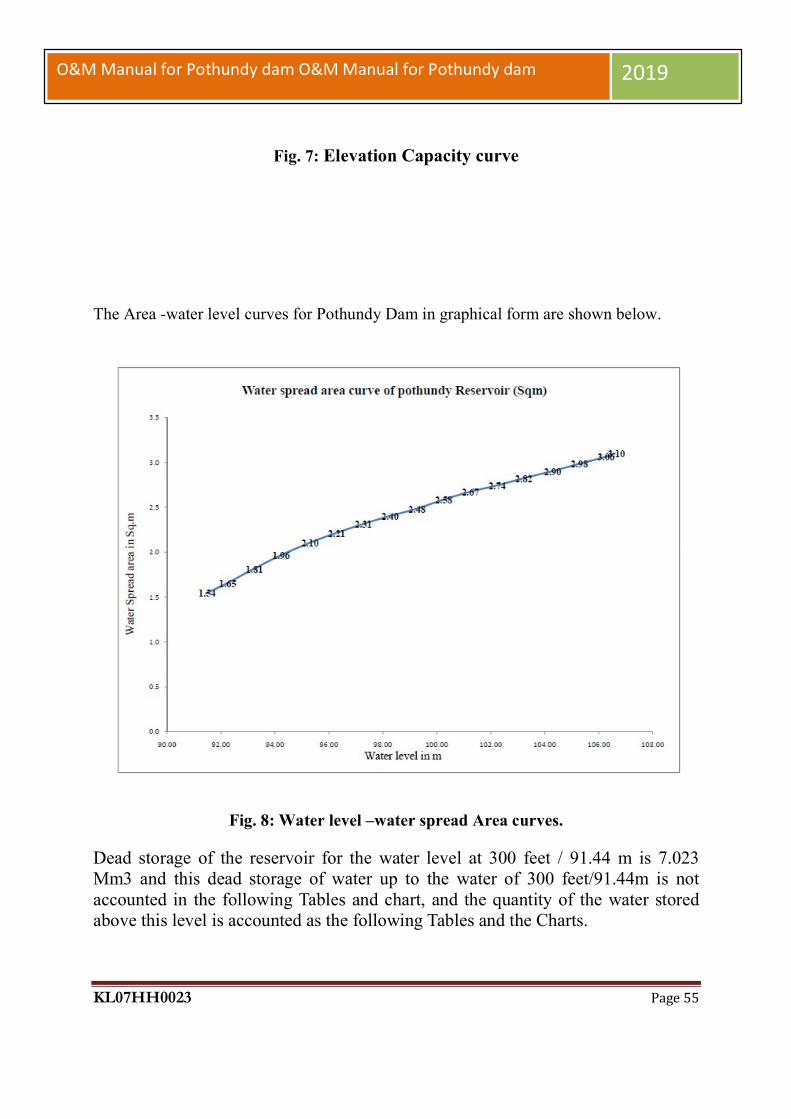
KL07HH0023 Page 55
O&M Manual for Pothundy dam O&M Manual for Pothundy dam 2019
Fig. 7: Elevation Capacity curve
The Area -water level curves for Pothundy Dam in graphical form are shown below.
Fig. 8: Water level –water spread Area curves.
Dead storage of the reservoir for the water level at 300 feet / 91.44 m is 7.023 Mm3 and this dead storage of water up to the water of 300 feet/91.44m is not accounted in the following Tables and chart, and the quantity of the water stored above this level is accounted as the following Tables and the Charts.

KL07HH0023 Page 56
O&M Manual for Pothundy dam O&M Manual for Pothundy dam 2019

KL07HH0023 Page 57
O&M Manual for Pothundy dam O&M Manual for Pothundy dam 2019
Fig. 9: Water Level-Storage Chart

KL07HH0023 Page 58
O&M Manual for Pothundy dam O&M Manual for Pothundy dam 2019
Fig. 10: Water Level-Storage Chart

KL07HH0023 Page 59
O&M Manual for Pothundy dam O&M Manual for Pothundy dam 2019
Fig 11: Water Level-Storage Chart
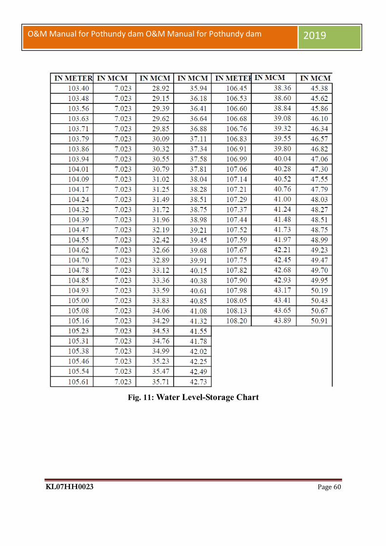
KL07HH0023 Page 60
O&M Manual for Pothundy dam O&M Manual for Pothundy dam 2019
Fig. 11: Water Level-Storage Chart

KL07HH0023 Page 61
O&M Manual for Pothundy dam O&M Manual for Pothundy dam 2019
Fig. 11: Water Level-Storage Chart
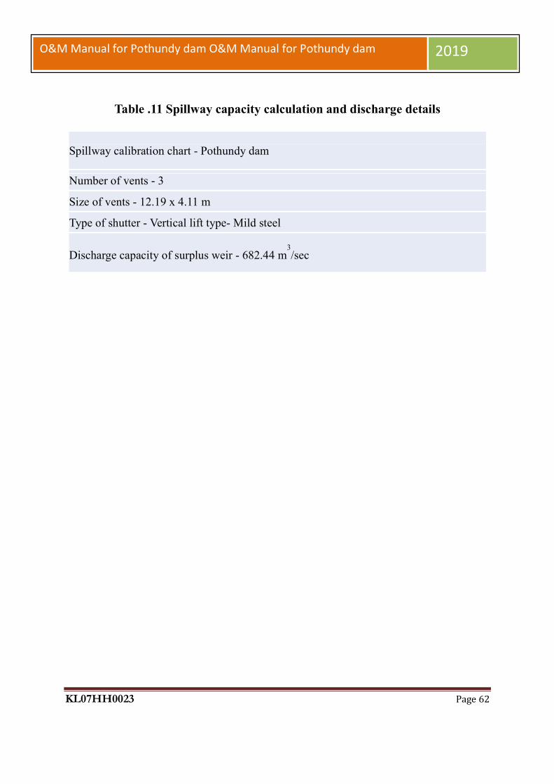
KL07HH0023 Page 62
O&M Manual for Pothundy dam O&M Manual for Pothundy dam 2019
Table .11 Spillway capacity calculation and discharge details
Spillway calibration chart - Pothundy dam
Number of vents - 3
Size of vents - 12.19 x 4.11 m
Type of shutter - Vertical lift type- Mild steel
Discharge capacity of surplus weir - 682.44 m3/sec
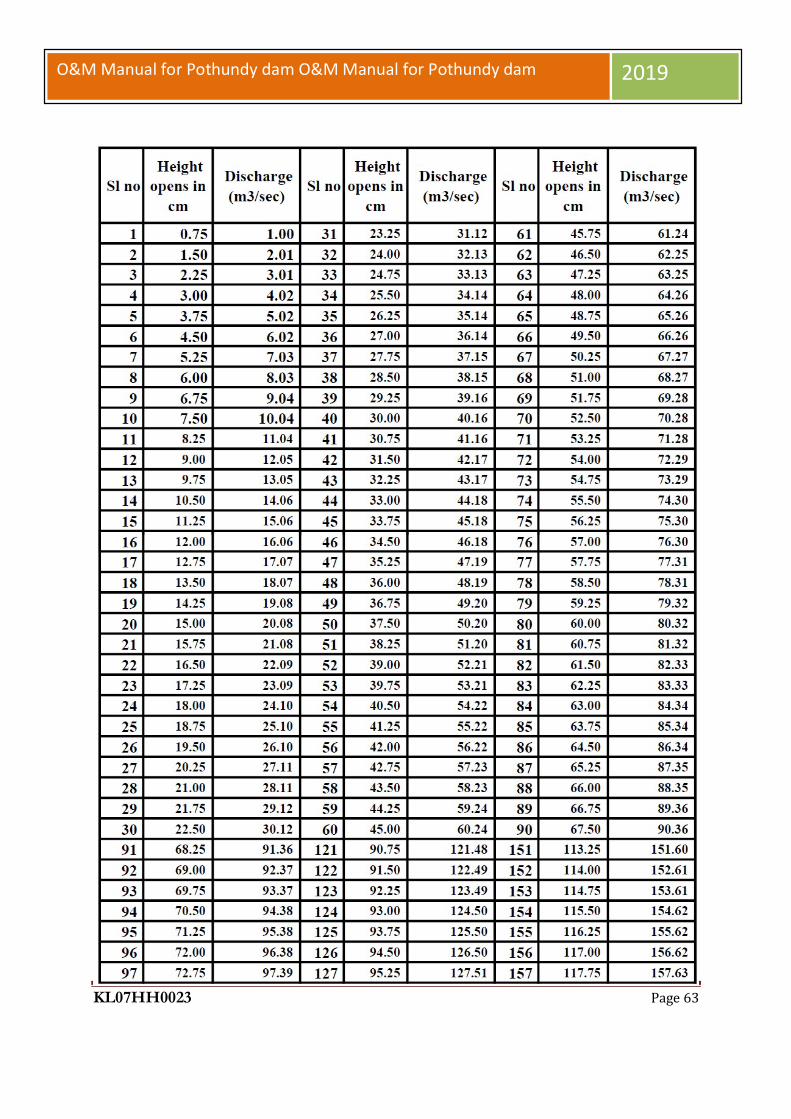
KL07HH0023 Page 63
O&M Manual for Pothundy dam O&M Manual for Pothundy dam 2019

KL07HH0023 Page 64
O&M Manual for Pothundy dam O&M Manual for Pothundy dam 2019

KL07HH0023 Page 65
O&M Manual for Pothundy dam O&M Manual for Pothundy dam 2019

KL07HH0023 Page 66
O&M Manual for Pothundy dam O&M Manual for Pothundy dam 2019

KL07HH0023 Page 67
O&M Manual for Pothundy dam O&M Manual for Pothundy dam 2019

KL07HH0023 Page 68
O&M Manual for Pothundy dam O&M Manual for Pothundy dam 2019

KL07HH0023 Page 69
O&M Manual for Pothundy dam O&M Manual for Pothundy dam 2019

KL07HH0023 Page 70
O&M Manual for Pothundy dam O&M Manual for Pothundy dam 2019
Discharge through the LB &RB Canal sluices
Hydraulic properties of the RB and LB Canal sluices are same.

KL07HH0023 Page 71
O&M Manual for Pothundy dam O&M Manual for Pothundy dam 2019
Table .11 LB & RB Canal sluices discharge details

KL07HH0023 Page 72
O&M Manual for Pothundy dam O&M Manual for Pothundy dam 2019

KL07HH0023 Page 73
O&M Manual for Pothundy dam O&M Manual for Pothundy dam 2019

KL07HH0023 Page 74
O&M Manual for Pothundy dam O&M Manual for Pothundy dam 2019
Discharge through KWA pipes are 0.145 M3/sec, there are no significant changes in water levels of the dam by the water consumption for drinking water purposes.

KL07HH0023 Page 75
O&M Manual for Pothundy dam O&M Manual for Pothundy dam 2019
Fig.12 Calibration Chart of ‘V’ Notch. INFLOW CALCULATIONS Inflow=Difference in storage + Outflow Preface The rules for regulation & distribution of water for Pothundy Irrigation Project was approved by Government vide order no.G.O.Ms.24/74/W&P Dated, 18.06.1974. All the operations of the project including regulation of water for irrigation, regulation of spill way shutters, maintenance

KL07HH0023 Page 76
O&M Manual for Pothundy dam O&M Manual for Pothundy dam 2019
etc.is done strictly based on this order. Last year, the rule curve for operating reservoir was prepared and submitted and is summarized below.
Table.12Storage
Month Avg.Utility Max.Utility
Dry year with
Max.Utility 10 year
Avg.Storage 14.05 16.82 17.68 11.773
Jun 17.38 22.69 20.62 14.433 Jul 23.10 23.15 22.91 24.443
Aug 40.20 40.28 34.38 36.203 Sep 46.89 48.37 43.63 42.503 Oct 50.35 50.43 47.74 44.424 Nov 50.85 50.91 48.30 43.208 Dec 47.25 47.42 46.42 35.253 Jan 34.60 34.85 34.58 22.428 Feb 21.00 21.13 20.86 14.233 Mar 13.60 13.92 13.65 12.065 Apr 12.90 13.78 15.32 11.773 May 14.05 16.82 17.68 11.773

KL07HH0023 Page 77
O&M Manual for Pothundy dam O&M Manual for Pothundy dam 2019

KL07HH0023 Page 78
O&M Manual for Pothundy dam O&M Manual for Pothundy dam 2019
Table.16 Monthly Rain fall details
Max Min AVG Max Min AVG Max Min AVG Max Min AVG Max Min AV G Max Min AVG99.518 94.031 96.7745 93.878 92.812 93.345 92.812 92.812 92.812 92.812 92.812 92.812 92.812 92.812 92.812 93.65 92.812 93.231
102.642 97.459 100.0505 97.307 95.936 96.6215 95.936 95.936 95.936 95.936 95.174 95.555 95.174 95.174 95.174 95.936 95.174 95.555105.384 100.965 103.1745 100.66 98.908 99.784 98.908 98.908 98.908 98.908 98.908 98.908 98.908 98.908 98.908 101.118 98.908 100.013102.337 97.231 99.784 97.154 93.65 95.402 93.65 93.65 93.65 93.65 93.65 93.65 93.65 93.65 93.65 94.295 93.65 93.9725
98.222 93.65 95.936 93.574 92.659 93.1165 92.659 92.659 92.659 92.659 92.659 92.659 92.659 92.659 92.659 100.432 92.659 96.5455101.879 97.231 99.555 97.002 93.726 95.364 93.762 93.574 93.668 93.422 93.116 93.269 93.422 93.116 93.269 95.402 93.422 94.412101.727 97.231 99.479 97.078 94.488 95.783 94.488 94.336 94.412 94.488 94.259 94.3735 95.021 94.488 94.7545 96.774 95.021 95.8975100.432 96.088 98.26 96.012 93.65 94.831 93.65 93.345 93.4975 93.269 92.964 93.1165 93.116 92.964 93.04 95.098 93.116 94.107
96.546 93.269 94.9075 93.269 93.046 93.1575 93.046 92.812 92.929 92.735 92.507 92.621 92.507 92.43 92.4685 95.098 92.43 93.764101.422 96.241 98.8315 96.165 93.116 94.6405 93.193 93.046 93.1195 93.193 92.964 93.0785 93.498 92.964 93.231 97.686 93.498 95.592
98.67525 95.2045 94.1591 94.00425 93.9966 95.30895
Max Min AVG Max Min AVG Max Min AVG Max Min AVG Max Min AV G Max Min AVG102.946 93.878 98.412 106.375 100.096 103.2355 108.051 106.451 107.251 108.051 108.051 108.051 108.051 107.518 107.7845 107.214 102.794 105.004101.108 95.936 98.522 103.861 101.27 102.5655 105.156 103.937 104.5465 106.75 105.237 105.9935 108.051 106.832 107.4415 108.051 105.532 106.7915105.004 101.194 103.099 108.051 105.08 106.5655 108.051 108.051 108.051 108.051 107.67 107.8605 108.051 106.451 107.251 106.375 102.489 104.432
97.459 94.336 95.8975 100.965 97.459 99.212 103.403 101.194 102.2985 104.546 103.403 103.9745 104.546 102.718 103.632 102.642 98.45 100.546108.051 100.508 104.2795 108.051 108.051 108.051 108.051 108.051 108.051 108.051 108.051 108.051 108.051 106.146 107.0985 106.07 102.108 104.089101.422 95.402 98.412 107.366 101.956 104.661 108.051 107.889 107.97 108.128 108.051 108.0895 108.128 105.994 107.061 105.842 101.803 103.8225101.042 96.774 98.908 103.327 101.118 102.2225 104.09 103.327 103.7085 104.546 104.09 104.318 104.546 104.318 104.432 104.166 100.813 102.4895
99.289 95.251 97.27 101.042 99.365 100.2035 101.574 101.042 101.308 101.879 101.574 101.7265 101.956 101.118 101.537 100.889 96.774 98.831598.374 95.251 96.8125 103.175 98.45 100.8125 106.223 103.327 104.775 106.604 106.223 106.4135 106.604 105.004 105.804 104.851 101.574 103.2125107.67 97.841 102.7555 108.051 106.604 107.3275 107.594 107.518 107.556 107.67 106.832 107.251 106.604 105.004 105.804 104.851 101.574 103.2125
99.4368 103.4857 105.5516 106.1729 105.7846 103.2431
MAY JUN
DECNO VJUL AUG SEP OCT
JAN FEB MAR APR

KL07HH0023 Page 79
O&M Manual for Pothundy dam O&M Manual for Pothundy dam 2019
CHAPTER 3
PROJECT INSPECTIONS
The current practice of Inspection at Pothundy dam envisages the Subdivision Officers to
carryout pre-monsoon and post-monsoon inspections. The checklist proforma included in this
chapter is currently in use at Pothundy dam.
Detailed description on project inspections is available in the Guideline for Safety
Inspectionof dams (Doc No. CDSO_GUD_DS_07_v1.0), CWC 2018
(https://damsafety.in/ecm includes/PDFs/Guidelines_for_Safety_Inspection_of_Dams.pdf).
However an overview of the various types of inspections to be carried out at Pothundy dam is
given below. Note that for uploading Inspection Data into DHARMA, the Inspection
Instructions & Forms given in the aforementioned Guideline for Safety Inspection of Dams
must be used (see Appendix 5)). An effective inspection program is essential to identify
problems and to keep Pothundy Dam in a good and healthy condition This Chapter provides
guidance on carrying out other inspections.
3.1 Types of Inspections
Four different types of dam safety inspections are available for being carried out at Pothundy
Dam. These include, but not limited, to the following:
1. Comprehensive evaluation inspections
2. Scheduled inspections (Pre & Post monsoon inspections & other scheduled inspections)
3. Special (unscheduled)inspections
4. Informal inspections
The frequency of each type of inspection depends on the condition of the dam and State DSO
regulations, etc.
Typical inspection elements and the detail of the safety inspections are provided below. More
detailed descriptions are given in the ‘Guideline for Safety Inspection of Dams’ (CWC 2018).
A checklist has been modified from the guideline to fit Pothundy requirements and is found in
Appendix 5. This comprehensive checklist allows for recording the status of each item being
inspected and the overall condition of the equipment along with any consequential risks the

KL07HH0023 Page 80
O&M Manual for Pothundy dam O&M Manual for Pothundy dam 2019
condition may have on the health of the dam.
3.2 Informal Inspections
The last type of inspection, an informal inspection, is a continuing effort by on-
site personnel (dam owners/operators and maintenance personnel) performed
during their
routineduties.Informalinspectionsarecriticaltotheproperoperationandmaintenance
of the dam. They consist of frequent observations of the general appearance and
functioning of the dam and appurtenant structures.
Operators, maintenance crews, or other staffs who are posted at Pothundy dam
site conduct informal inspections. These people are the “first-line of defense” in
assuring safe dam conditions, and it is their responsibility to be familiar with all
aspects of the dam. Their vigilance in walking the dam, checking the operating
equipment, and noting changes in conditions may prevent serious mishaps or
even dam failures.
Informal inspections are important and are performed at every available
opportunity.
Theseinspectionsmayonlycoveroneortwodamcomponentsastheoccasionpresents
itself, or they may cover the entire dam and its appurtenant structures. The
informal inspections are not as detailed as comprehensive evaluation, scheduled,
and special inspections and will only require that a formal report is submitted to
the dam owner’s project files if a condition is detected that might endanger the
dam. Report is to be submitted detailing the condition discovered along with
photographs, time, and reservoir water level (RWL), etc.
3.2.1Pre- and Post-Monsoon Checklist and Example of Report Proformas
Detailedchecklistsarerequiredtoensurethehealthofthedamcontinuestooperateinsatisfactory
andsafecondition.DetailsoftheinspectionmustbeinalignmentwiththeDHARMAapproved
checklist attached to this document (see Appendix5).4
3.3 Scheduled Inspections
Scheduled inspections shall consist of Pre-monsoon & Post-monsoon

KL07HH0023 Page 81
O&M Manual for Pothundy dam O&M Manual for Pothundy dam 2019
inspection and any other inspections carried out by the State Dam Safety
Organization / any Expert panels constituted by the dam owner.
These inspections are performed to gather information on the current condition of
the
damanditsappurtenantworks.Thisinformationisthenusedtoestablishneededrepairs
and repair schedules, and to assess the safety and operational adequacy of the
dam. Scheduled inspections are also performed to evaluate previous repairs.
Thepurposeofscheduledinspectionsistokeepthedamanditsappurtenantstructures
ingoodoperatingconditionandtomaintainasafestructure.Assuch, these inspections
and timely maintenance will minimize long-term costs and will extend the life of
the dam. Scheduled inspections are performed more frequently than
comprehensive evaluation inspections to detect at an early stage any
developments that may be
detrimentaltothedam.Theseinspectionsinvolveassessingoperationalcapabilityaswe
ll as structural stability and detection of any problems and to correct them before
the conditions worsen. The field examinations should be made by the personnel
assigned responsibility for monitoring the safety of the dam. If the dam or
appurtenant works have instrumentation, the individual responsible for
monitoring should analyze measurements as they are received and include an
evaluation of that data. Dam Inspection Report or an inspection brief should be
prepared following the field visit (Dam Inspection Report is recommended).
Scheduled inspections include the following four components as a minimum:
File review of past inspection reports, monitoring data,
photographs, maintenance records, or other pertinent data as may be
required;
Visual inspection of the dam and its appurtenant works;
Preparation of a report or inspection brief, with relevant documentation and
photographs. The report should be filed in the dam owner’s project files.

KL07HH0023 Page 82
O&M Manual for Pothundy dam O&M Manual for Pothundy dam 2019
3.4 Special (Unscheduled) Inspections
Special inspections may need to be performed to resolve specific concerns or
conditions at the site on an unscheduled basis. Special inspections are not
regularly scheduled activities, but are usually made before or immediately after
the dam or appurtenant works have been subjected to unusual events or
conditions, such as an unusually high flood or a significant earthquake. These
inspections are to be carried out after an initial assessment based on informal
inspection carried out by project personnel reveal
damsafetyrelatedconcernslikecrackinginthedam,
damages,erosion/scour,undermining/ piping/ sink holes/ liquefaction or any such
undesirable feature. A special inspection may also be performed during an
emergency, such as an impending dam breach, to evaluate specific areas or
concerns. They are also made when the ongoing surveillance program identifies a
condition or a trend that appears to warrant a special evaluation. Special
inspections should focus on those dam components that are affected by the
unusual event and should include at least three elements: 1) review of relevant
files ordata, 2) visual inspection, and 3) report preparation.
More detailed site investigations / studies may be required (such as drilling,
surveys, or seepage flow estimates) if the special inspection reveals the need for
the same. Photographic documentation is to be included as part of the inspection.
3.5 Comprehensive Evaluation Inspections
For comprehensive dam safety evaluation for each dam an independent panel of experts
known as Dam Safety Review Panel (DSRP) needs to be constituted for determining the
condition of the dam and appurtenant works. The panel will undertake evaluation of the dam
once in 10 years or on occurrence of any extreme hydrological or seismic event or any
unusual condition of the dam or in the reservoir rim. The terms of reference of the
comprehensive dam safety evaluation shall include but not be limited to;
1. General assessment of hydrologic and hydraulic conditions, review of design flood, flood
routing for revised design flood and mitigation measures.

KL07HH0023 Page 83
O&M Manual for Pothundy dam O&M Manual for Pothundy dam 2019
Review and analysis of available data of dam design including seismic safety,
construction, operation maintenance and performance of dam structure and
appurtenant works.
Evaluation of procedures for operation, maintenance and inspection of dam and to
suggest improvements /modifications.
Evaluationofanypossiblehazardousthreattothedamstructuresuchasdamabutment
slope stability failure or slope failures along the reservoir periphery.
A comprehensive evaluation inspection of Pothundy consists of five major parts:
2. Review of project records (i.e. study of all design/construction records/drawings,
history of the dam’s performance, previous inspection notes/reports,
notesondistressobserved/anyrehabilitationmeasuresundertakenearlier, instrumentation
data and its interpretation including.
3. Inspection of the dam and its appurtenant works.
4. Toreviewtheresultsandreportsofadditionalfieldinvestigations&laboratorytestingasrequi
red.
5. Review of design studies e.g. review of design flood, checking of the adequacy of
spillway capacity, freeboard requirements, dam stability, and anyspecialstudy such as
sedimentation analysis when required.
6. Preparation of a detailed report of the inspection

KL07HH0023 Page 84
O&M Manual for Pothundy dam O&M Manual for Pothundy dam 2019
Table.17 PRO-FORMA FOR PERIODICAL INSPECTION OF LARGE DAMS
GENERAL
Date of Inspection:
Sl. No.
Item of Inspection Remarks
1 1a 1b 2 3
1. Name of project Pothundy Project
2. Purpose of Project Multi-Purpose
3. Name of Dam POTHUNDY DAM.
4. Year of Completion 1967
5. First filling (years / levels) 1967
6. Benefits accrued:
a) Irrigation Irrigation
b) Water Supply Water Supply
c) Fisheries Fisheries
d) Other benefits Nil
7. Important Controlling Levels ( in meters)
a) Top of dam 110 642m
b) Maximum Water Level 108.204m.
c) Full Reservoir Level 108.204m
d) Sill level of Irrigation sluices 91.44m
e)
f) Spillway crest level 104.09m.
g) Minimum draw down level 91.44m
h) Lowest river bed level 83.525m
i) Deepest foundation level 78.032 m
8. Important Salient Features
a) Dead Storage Capacity 7.014 Mm3
b) Catchment Area at F.R.L 2.74sq.km
c)
Design flood adopted
Give relevant
magnitude
682.44m3/s

KL07HH0023 Page 85
O&M Manual for Pothundy dam O&M Manual for Pothundy dam 2019
Table.18 REVISED PRO-FORMAT FORHEALTH STATUS REPORT OF LARGE DAMS (Keeping in view CWC letter No. 627-
56 dt. 28-08-2002)
Sl.
No.
Items of the
“Health Status Report” Reply
1 Name of Dam Pothundy Dam
2 Sl. No. in the National Register of Large Dam
Project Identification Code PIC KL07HH0023
3 Dam features
a) Year of Completion 1967
b)
Location
i) Longitude 70º37´ E
ii) Latitude 10º37´N
c) Height of Dam 32.61m
d) Gross Capacity
(Gated/Un gated) 50.914 Mm3
e) Whether the Dam is provided with Inspection Gallery or not.
Provided with Drainage Gallery of size 1.47m X 2.06 m
4
Main Component of Dam
Type of Dam: Earthen Dam:
Spillway: Ogee spillway with 3 Nos of gates of size 12.19m X 4.11m.
Length of earthen Dam: 1567.28-m
5 Date of Inspection
6 Inspecting Officer 1)Chief Engineer, IDRB,Thiruvananthapuram 2) Chief Engineer, Projects 1,Kozhikode
7 Observations/Significant Deficiencies Noticed
I Inadequate Spillway.

KL07HH0023 Page 86
O&M Manual for Pothundy dam O&M Manual for Pothundy dam 2019
II Inadequate free-board
III Cracks in Earth Dam
a) Structural cracking in
earth dams
IV Inadequate
a) Flood forecasting
system
b) Flood warning system
c) Communication
V Excessive seepage through,
a) Drainage holes
b) Porous pipes
c) Downstream face of
dam
d) Downstream area etc.
e) Development of high
uplift pressure
VI Excessive leaching
VII Choking of porous drains.
VIII Choking of drainage holes
IX Mal operation of gates
X Non-availability of standby/
alter- native source of power
XI Structural Review indicating tension on the upstream face of dam

KL07HH0023 Page 87
O&M Manual for Pothundy dam O&M Manual for Pothundy dam 2019
XII Non-availability of
Emergency Action Plan. 8 Performance of Dam
Based on Instruments installed in the dam (Water Level Recorder, V-notch, etc.,)
Of Meteorological Instruments installed in the catchment area and reservoirs of Dams.
Is the hydraulic performance in agreement with the results of model studies?
Anyotherissue/issuespertainingtoperformance of dam which theEngineer-in-Chief /ChiefEngineerin-chargeof damdesiresto include.
9 Remedial Measures Suggested.
10 Remarks
11 Action Taken Report.
Assistant Exe Engineer Executive Engineer Superintending Engineer
Incharge of dam. Incharge of dam. In-charge ofdam.
Certified that the Health Status Reportof POTHUNDY DAM is furnished after a thorough
review of the same by the technical wing of the zone
(thishasreferencetopara18.3.5oftheProceedingsof18thmeetingof SLDSC).
Engineer-in-Chief / Chief
Engineer in-charge of dam.

KL07HH0023 Page 88
O&M Manual for Pothundy dam O&M Manual for Pothundy dam 2019
Table.19 APPENDIX - 1 Performance of Dam Instruments
Sl. No.
Name of Dam withlocation
Name of Instrument
No. of Instru- ments
Performance Status of data Analysis
Remarks
1 2 3 4 5 6 7
Separate Sheets Enclosed.
(Vide Annexure-1 )
AsstExeEngr, Executive EngineerSuperintendingEngineer Engineer-in-Chief/ChiefEngineer
in-charge of dam. in-chargeofdam in-chargeofdam in-charge ofdam.
Table.20APPENDIX-2 Performance of Meteorological Instruments
Sl. No.
Name of Dam with location
Name of Instrument
No. of In- struments
Performance
Status of data Analysis
Remarks
1 2 3 4 5 6 7
.

KL07HH0023 Page 89
O&M Manual for Pothundy dam O&M Manual for Pothundy dam 2019
Table.21APPENDIX-3Categorisation of Deficiencies (Keeping in view CWC letter No. 627-56 dt. 28-08-2002)
Category No.* Criteria for categorization
Category No. (1) Dams with major deficiency which may lead to dam failure
Category No. (2)
Dams with rectifiable deficiency which needs immediate attention.
Category No. (3) Dams with minor / no deficiencies have been noticed.
*Category Number is to be furnished in the ‘remarks’ column of the Health Status Report
KL07HH0023 Page 90
O&M Manual for Pothundy dam O&M Manual for Pothundy dam 2019
CHAPTER 4 PROJECT MAINTENANCE
A good maintenance program will protect a dam against deterioration, prolong its life,
and greatly reduce the chance of failure. Nearly all the components of a dam and its
materials are susceptible to damage and deterioration if not well maintained. Moreover,
the cost of a proper maintenance program is small compared to the costs of major repairs,
loss of life and property and litigation. Properly maintaining a dam not only pro-tects the
dam and its owner but the public as well. If maintenance of a dam is neglected the
consequences and costs could multiply
4.1 Maintenance Plan
Timely maintenance assures that a dam and reservoir would remain in a good
working condition and prevents more harmful conditions from developing. Individual
maintenance tasks should be noted, with a description of the area where the maintenance
is to be performed, the schedule for performing the tasks, and reporting procedures.
Typical routine maintenance tasks performed at most dams include mowing grass,
removing vegetation, bushes and trees, removing litter and other debris, re-grading the
crest and/or access roads, repairing fencing to keep live-stock off the dam, etc. Other
maintenance works that may need to be performed in an Earth dam may include
restoration of embankment to its design section, seepage problems, erosion, displaced
riprap, cracking in embankment etc. In concrete / masonry dams there may be issues like
cracking and disintegration in concrete, choking of drainage holes in dam body/
foundation, damages to spillway glacis/piers/energy dissipaters due to abrasion/
cavitation/unsymmetrical flows, damages to pointing on upstream & downstream faces of
masonry dams, heavy seepages through some drains in foundation/inspection galleries
etc.

KL07HH0023 Page 91
O&M Manual for Pothundy dam O&M Manual for Pothundy dam 2019
Maintenance program for a dam should be developed primarily based on systematic and
frequent inspections.
4.2 Maintenance Priorities
Maintenance activities need to be prioritized. In order of priority they need to be clarified
under the heads immediate maintenance & preventive maintenance.
4.2.1 Immediate Maintenance
The following conditions are critical and call for immediate attention & reservoir lowering, if warranted. These conditions may include, but are not limited to:
A dam about to be overtopped or being overtopped during high flood.
A dam about to be breached by erosion, slope failure etc.
A dam showing signs of piping or internal erosion indicated by increasingly
cloudy seepage or other symptoms.
A spillway being blocked or with some inoperable gates.
Evidence of excessive seepage appearing anywhere at the dam site e.g. an
Embankment dam becoming saturated, seepage exiting on the downstream face of
a dam, increasing in volume.
Although the remedy for some critical problems may be obvious (such as clearing a
blocked spillway or repairing the spillway gates so that they are in working condition),
the problems listed above generally demand the services of experienced engineers/expert
panels familiar with the design, construction and maintenance of dams. An emergency
action plan (EAP) should be activated when any of the above conditions are noted.
4.2.2 Preventive Maintenance
This can be classified as Condition based Maintenance and Routine Maintenance
4.2.2.1 ConditionBased Maintenance

KL07HH0023 Page 92
O&M Manual for Pothundy dam O&M Manual for Pothundy dam 2019
The following maintenance should be completed as soon as possible after the defective condition is noted. These may include but are not limited to:
Remove all vegetation and bushes from the dam and restoring any eroded areas and to establish a good grass cover. Fill animal burrows. Repair livestock trails and fences to keep livestock off dam. Restore and reseed eroded areas and gullies on embankment dams. Repair of defective gates, valves, and other hydro-mechanical equipment. Repair any concrete or metal components that have deteriorated. Cleaning of the choked drainage holes in the dam body/foundations in
concrete/masonry dams. Repair any damages on spillway glacis, piers, energy dissipaters, training/ di-vide
walls, downstream areas etc. Repairs on the upstream face of masonry dams, in case the pointing is damaged,
due to which there is in-creased seepage. Controlling any heavy seepage in the foundation/inspection galleries in
Concrete/Masonry dams from drain-age holes. Repairs of any cracks/cavities/joints in concrete/masonry dams/ structures.
However many of these works will re-quire the services of experienced engineers/expert panels.
4.2.2.2 Routine Maintenance
Several tasks should be performed on a continuous basis. These may include but are not limited to
Routine mowing, restore and reseed eroded areas and gullies on down-stream face
of embankment dams and general maintenance including re-pairs/cleaning of
surface drains on downstream face & in the down-stream areas.
Maintenance and treatment of anycracks/joints/cavities in Concrete/Masonry dams
and spillways based on the recommendations of experienced engineers/expert
panels.
Observation of any springs or seepage areas, comparing quantity and quality
(clarity) with prior observations in embankment dams.

KL07HH0023 Page 93
O&M Manual for Pothundy dam O&M Manual for Pothundy dam 2019
Monitoring of development in the upstream watershed which would materially
increase runoff and sediment from storms.
Monitoring of downstream development which could have an impact on the dam
and its hazard category.
Maintenance of Electrical & Hydro-Mechanical equipment and systems e. g.
Servicing of spillway gates & stop logs, hoisting arrangements, gantry crane,
gates/hoist of outlet works/ sluices & stand by generator.
Proper lighting at dam top, galleries in dams etc.
Monitoring of seepage in galleries of concrete/masonry dams. Monitoring/cleaning
& removal of leached deposits in porous concrete/ formed drains in dam body &
foundation drainage holes of Concrete/ Masonry dams.
Maintenance of all dam roads & access roads.
Operation of electrical and mechanical equipment and systems including exercising
gates & valves.
To keep the gate slots clear of silt/debris.
Maintenance/testing of monitoring equipment (instruments) and safety alarms.
Testing of security equipment.
Testing of communication equipment.
Any other maintenance considered necessary.

KL07HH0023 Page 94
O&M Manual for Pothundy dam O&M Manual for Pothundy dam 2019
4.3 Maintenance Items
The O&M Manual for a dam should include detailed instructions and schedules for per-
forming periodic maintenance works at the site. This should include maintenance of the
dam, the appurtenant works, and the reservoir areas.
All needed maintenance works should be listed. Dam maintenance includes all
maintenance and repair of issues/works identified during safety inspections and routine
dam surveillance. An adequate maintenance pro-gram will ensure that the dam and its
appurtenant works remain in good working condition and will prevent more harmful
conditions from developing.
Individual maintenance tasks should be itemized on the list, with a description of the area
where the maintenance is to be per-formed, the time it takes to complete each task, the
equipment that is needed, who will perform the work, the schedule for performing the
tasks, and reporting procedures. Ad-equate O & M Budget should be provided based on
the above exercise.
Dam repairs should be scheduled based on severity of the problem, available
resources, and weather conditions. For example, if a severe settlement problem (more
than envisaged in designs) or cracking is detected on the crest of the dam, it should have
a high priority since further degradation could lead to dam breaching. The causes of all
major issues/problems should be identified and evaluated by experienced
engineers/Expert Panels so that appropriate remedial measures can be finalized.
Correcting minor rill erosion on the downstream slope could be as-signed a low priority
since it is not a dam safety concern. This type of repair will also be weather dependent,
since grass can only be planted during specific times of the year, and the embankment
should be dry so that more damage is not inflicted to the embankment slopes.
Identification of works/issues which may require periodic maintenance, are summarized.

KL07HH0023 Page 95
O&M Manual for Pothundy dam O&M Manual for Pothundy dam 2019
4.3.1 Earthwork
The surfaces of an earthen dam may deteriorate due to several reasons. For
example, wave action may cut into the upstream slope, vehicles may cause ruts in the
crest or slopes, trails left by livestock can result in erosion, or runoff waters may leave
erosion gullies on the downstream slope. Other special problems, such as shrinkage
cracks or rodent damage, may also occur. Damage of this nature must be repaired
constantly.
The maintenance procedures to be described in the O&M Manual will be used for repairs
of routine earthwork problems. However, this section is not intended to be a technical
guide, and the methods discussed should not be used to solve serious problems.
Conditions such as embankment slides, structural cracking, and sinkholes threaten the
immediate safety of a dam and require immediate repair under the directions of
experienced engineers/Expert panels.
The material selected for repairing embankments should be free from vegetation, organic materials, trash, and large rocks.
If flow-resistant portions of an embankment are being repaired, materials that are
high in clay or silt content should be used. If the area is to be free draining or highly
permeable (such as pervious shell of an embankment dam) the material should have a
higher percentage of sand and gravel. It is usually satisfactory to replace or repair
damaged areas with soils like those originally in place.
An important soil property affecting compaction is moisture content. Soils that are
too dry or too wet do not compact well. One may test repair material by squeezing it into
a tight ball. If the sample keeps its shape with-out cracking and falling apart (which
means it is too dry), and without depositing excess water onto the hand (which means it is
too wet), the moisture content is near the proper level.
Before placement of earth, the repair area needs to be prepared by removing all
inappropriate material.Vegetation such as bushes, roots, and tree stumps, along with any

KL07HH0023 Page 96
O&M Manual for Pothundy dam O&M Manual for Pothundy dam 2019
large rocks or trash need to be removed. Also, unsuitable earth, such as organic or loose
soils, should be removed, so that the work surface consists of exposed, firm, clean
embankment material.
Following cleanup, shape and dress the affected area so that the new fill can be
compacted to the level specified in the technical specifications. Also it should properly
key with the existing fill. Further trim the slopes and roughen the surfaces by scarifying
or plowing to improve the bond between the new and existing fill and to provide a good
base to compact against.
Place soils in loose layers up to 20 centimeters thick and compact manually or
mechanically to form a dense mass free from large rock or organic material. Keep soil
moisture in the proper range. The fill should be watered and mixed to the proper wetness
and allowed to dry if too wet.
Erosion is one of the most common maintenance problems at embankment structures.
Erosion is a natural process and its continuous forces will eventually wear down almost
any surface or structure. Periodic and prompt maintenance is essential to prevent
continuous deterioration and possible failure.
Turfing, free from weeds and bushes, is an effective means of preventing erosion.
Rills and gullies should be filled with suitable soil, compacted, and then seeded for
growing the turfing. Erosion in large gullies can be slowed by stacking bales of hay or
straw across the gully until permanent repairs can be made.
Paths due to pedestrian, livestock, or vehicular traffic (two and four-wheeled) are a
problem on many embankments. If a path has become established, vegetation will not
provide adequate protection and more durable cover will be required unless traffic is
eliminated. Stones may be used effectively to cover such footpaths.
KL07HH0023 Page 97
O&M Manual for Pothundy dam O&M Manual for Pothundy dam 2019
In addition, steps can be provided/ constructed at regular intervals along the length of the
dam for going from downstream toe to the dam top. All vehicular traffic, except for
maintenance, should be restricted from the dam.
Erosion is also common at the point where an embankment and the concrete walls of a
spillway or other structure meet. Poor compaction adjacent to such walls during
construction and later settlement can result in an area along the wall that is lower than the
grade of the embankment.
Runoff, therefore, often concentrates along these structures, resulting in erosion. People
also often walk along these walls, wearing down the vegetative cover. Workable
solutions include re-grading the area so that it slopes away from the wall, adding more
resistant surface protection, or constructing steps.
4.3.2 Upstream Riprap
The upstream face of a dam is required to be protected against wave erosion. Rip-rap is
normally provided for the purpose with filter layers below.
Nonetheless, erosion can still occur in existing riprap. Water running down the slope
under the riprap can erode the embankment. Sections of riprap that have slumped down-
ward are often signs of this kind of erosion.
Effective slope protection must prevent soil from being removed from the embankment.
When erosion occurs on the upstream slope of a dam, repairs should be made as soon as
possible. (Refer IS: 8237- Code of practice for protection of Slopes for Reservoir
Embankments).
4.3.3 Controlling Vegetation
Keep the entire dam clear of unwanted vegetation such as bushes or trees. Excessive
growth may cause several problems:

KL07HH0023 Page 98
O&M Manual for Pothundy dam O&M Manual for Pothundy dam 2019
It can obscure the surface of an embankment and not allow a proper
inspection of the dam.
Large trees can be uprooted by high wind or erosion and leave large holes
that can lead to breaching of the dam.
Some root systems can decay and rot, creating passageways for water, and
thus causing erosion.
Growing root systems can lift concrete slabs or structures.
Trees, bushes, and weeds can pre-vent the growth of desirable grasses.
Rodent habitats can develop.
All bushes/trees should be as far as possible removed by roots. The resulting holes should
be filled with well compacted earth. It would be desirable to remove the plants/vegetation
at their early stage to pre-vent their growing into big tree/bushes. In cases where trees and
bushes cannot be re-moved, the root systems should be treated with herbicide (properly
selected and ap-plied) to retard further growth. Concerned Government Agencies should
be consulted for selection of appropriate herbicides & their use for control of vegetation
on dam structures.
Further, it is desirable that there are no trees or bushes within 500 m of the toe drain on
the downstream side of the dam.
4.3.4 Controlling Animal Damage
Livestock should not be allowed to graze on an embankment surface. When soil is wet,
livestock can damage vegetation and disrupt the uniformity of the surface. Moreover,
livestock tend to walk in established paths and thus can promote erosion. Such paths
should be re-graded and seeded, and the livestock permanently fenced out of the area.
The burrows and tunnels of burrowing animals (beaver, muskrat, groundhogs and others)
weaken earthen embankments and serve as pathways for seepage from the reservoir.
Large burrows on an embankment should be filled by mud packing. This simple,
KL07HH0023 Page 99
O&M Manual for Pothundy dam O&M Manual for Pothundy dam 2019
inexpensive method involves placing vent pipe in a vertical position over the entrance of
the den. Making sure that the pipe connection to the den does not leak, the mud-pack
mixture is poured into the pipe until the burrow and pipe are filled with the soil-water
mixture. The pipe is removed and more dry earth is tamped into the entrance. As per
some US publications, the mud pack is generally made by adding water to 90% earth &
10% cement mixture until slurry or thin cement consistency is attained. For bigger holes,
bentonite coated stones can also be used. All en-trances should be plugged with well-
compacted earth & vegetation re-established
Dens should be eliminated without delay. Different repair measures are necessary if a
dam has been damaged by extensive small rodent tunneling or large rodent activity.
Excavate the area around the entrance and then backfill it with impervious material. This
plugs the passage entrance so that water is prevented from saturating the dam‘s interior
4.3.5 Controlling Ants and Termites (White Ants)
Ants and termites have become one of the most serious pests for Embankment dams.
They both need water to survive and have been found on most of the embankment dams
in India. These insects can create problems in the dam itself and with any of its electrical
components.
In some habitats, ants and termites can move as much or more soil as earthworms,
thereby reducing soil compaction. Nest galleries can penetrate in a V-shaped pattern
below the nest, penetrating as much as more than one meter deep in the soil. These
galleries can create pathways for surface water to penetrate in the dam, resulting in
internal erosion and collapse of the surface.Ants and termites left undisturbed can build
mounds that can become quite large. These can create problems for mowing. However,
frequent mowing can induce the colonies to migrate to neighboring, undisturbed areas.
There are many options for managing ants and termites. Use only pesticides labeled as
suitable for the location you want to treat. Make every effort to avoid contaminating
water with pesticides.

KL07HH0023 Page 100
O&M Manual for Pothundy dam O&M Manual for Pothundy dam 2019
4.3.6 Controlling Damage from Vehicular Traffic
As mentioned earlier, vehicles driving across an embankment dam can create ruts in the
crest if it is not surfaced with roadway material. The ruts can then collect water and cause
saturation and softening of the dam. Other ruts may be formed by vehicles driving up and
down a dam face; these can collect runoff and cause severe erosion.
Vehicles, except for maintenance, should be restricted on the dam top and kept out by
fences or barricades. Any ruts should be repaired as soon as possible.
In the case of existing dams having permission for movement of nearby villagers, heavy
traffic movement may be avoided. If possible, separate connectivity may be explored for
such cases.
In the case of barrages and dams having provisions for roads of National/State Highways
etc., all efforts should be made to restrict the speed of vehicles. Regular maintenance of
bridge and roads shall be mandatory.
4.3.7 Masonry/Concrete dams & Spillways
Various issues/problems that may need maintenance/repairs in Concrete/Masonry dams
& Spillways may include but are not limited to:
Cracking in concrete (potential causes are alkali aggregate reaction, thermal stresses
because of heat of hydration or temperature variations, foundation problems).
Damages on spillway glacis, spillway piers, training/divide walls, energy
dissipaters, downstream areas (probable causes are cavitations, abrasion, un-
symmetrical flows, unfavorable down-stream conditions)
Vegetation growth in unattended Auxiliary spillways, spill channel, approach
channel etc.
Seepage in Galleries and on d/s face of the dam.
Cleaning and removal of leached de-posits from choked drainage holes in the dam
body/foundations.

KL07HH0023 Page 101
O&M Manual for Pothundy dam O&M Manual for Pothundy dam 2019
Repair to upstream face of masonry dams in case the pointing is damaged, leading
to increased seepage.
To ensure proper access & lighting in galleries.
To ensure that the dam is behaving as designed based on instrumentation programs.
Periodic maintenance should be per-formed of all concrete surfaces to re-pair
deteriorated areas. Repair deteriorated concrete at the earliest; it is most easily
repaired in its initial stages. Deterioration can accelerate and, if left unattended,
can result in serious problems or dam failure.
For remedial measures of problems of special nature advice of experienced engineers/
Panel of Experts needs to be obtained
4.3.8 Outlet Works
Outlet conduits should be inspected thoroughly once a year. Circular conduits that are
one and a half meter or more in diameter can be entered and visually inspected. Common
problems are improper alignment (sagging), separation and displacement at joints,
cracks, leaks, surface wear, and loss of protective coatings, corrosion, and blockage.
Problems with conduits occur most often at the joints. Further collars at joints used to
also lead to inadequate compaction. Hence, special attention should be given to them
during the inspection. The joints should be checked for gaps caused by elongation or
settlement and loss of joint-filler material. Open joints can permit erosion of embankment
material or cause leakage of water into the embankment during pressure flow. The outlet
should be checked for signs of water seeping along the exterior surface of the pipe. A
depression in the soil surface over the pipe may be a sign that soil is being removed from
around the pipe.
Listed below are common concerns regarding repairs to outlet works:
Asphalt mastic is not recommended for other than temporary repairs. Asphalt
mastic used as joint filler be-comes hard and brittle, is easily eroded, and as per

KL07HH0023 Page 102
O&M Manual for Pothundy dam O&M Manual for Pothundy dam 2019
literature survey it may provide a satisfactory seal for only about five years. Mastic
should not be used if the conduit is expected to flow under pressure.
The instructions on the label should be followed when using thermo setting
plastics (epoxy). Most of these products must be applied to a clean and dry surface to
set up an effective bond. However cementatious materials are to be preferred in view
of their UV resistance & longer life.
Material used as joint filler should be impervious to water and should be flexible
throughout the range of expected air and water temperatures.
The internal surfaces of the conduit should be made as smooth as possible when
repairs are made so that high-velocity flow will not damage the repair material.
Minor cracks in concrete are not considered a dangerous problem. Repair is not
necessary unless the cracks widen or leak.
The general practice now is not to go in for pre-cast concrete/MS pipe conduits with
collars but to construct RCC conduits at site without any collars and joints. PVC water
stops are provided at joints and the exterior faces of the conduits are given a slope to
enable better contact at the interface with earth.
4.3.9 Trash Racks
Trash racks at intakes that have become clogged with debris or trash reduce their
discharging capacity. The head losses through clogged trash racks also increase.
Maintenance of trash racks includes periodic inspections for rusted and broken sections
and repairs are made as needed. Trash racks should be checked during and after floods to
ensure that they are functioning properly and to remove accumulated debris.
4.3.10 Gates & Hoisting Equipment
The safe and satisfactory operation of a dam depends on proper operation of its Gates & their Hoisting Equipment. Maintaining spillway gates in working condition is critical for dam safety and is to be assigned the height priority.
If routine inspection of the Hydro-Mechanical Equipment shows the need for
maintenance, the work should be completed as soon as possible. The simplest procedure
KL07HH0023 Page 103
O&M Manual for Pothundy dam O&M Manual for Pothundy dam 2019
to ensure smooth operation of gates is to operate them through their full range at least
once and preferably twice annually (before monsoon & after monsoon keeping a gap of at
least six months). Because operating gates under full reservoir pressure can result in large
discharges, exercising of gates should preferably be carried out in dry conditions using
stop-logs/ emergency gates. Commonly used Gates and Hoists including their inspection /
maintenance requirements are discussed below.
The O&M manuals of the gates manufacturer‘s would however govern the overall
maintenance of Gates & Hoists whenever there is any contradiction with the instructions
given in the Manual.
4.3.10.1 Vertical lift fixed wheel and Slide Gates
These gates are provided in spillways, outlet works, sluices etc. for controlling/regulating
the flow. The main components of these gates are as under;
i). Embedded parts:
Sill beam assembly Top and side seal seats Roller track Side guide Dogging arrangement ii). Gate Parts: Skin plate Assembly End Verticals Horizontal girders Vertical Stiffeners Roller assembly Seal Assembly Side guide assembly Lifting Arrangement
The aspects to be inspected and maintained periodically for ensuring proper operation of
these gates are as under;
KL07HH0023 Page 104
O&M Manual for Pothundy dam O&M Manual for Pothundy dam 2019
i) The gate slot and bottom plat-form/sill beam should be cleaned periodically.
Scales formed over the embedded parts should be removed. Second stage concrete
should be checked for any development of cracks/leakages and repairs should be
attended to immediately.
ii) The gate leaf should be thoroughly cleaned and repainted as and when necessary
according to the procedure or guidelines- indicated in IS: 14177 or as per the
recommendations of the paint manufacturer. All drain holes provided in the gate
assembly should be cleaned.
iii) Rubber seals should be smoothened, if required, for proper alignment. All nuts
and bolts fixing the seal to the gate should be tightened uniformly. Seals, if found
damaged or found leaking excessively should be adjusted, repaired or replaced as
considered necessary.
The wheel shall be rotated to check their free movement. Gate roller bearings and
guide roller bushes should be properly lubricated. Whenever necessary these
should be opened for rectifications of defects, cleaning and lubrication and should
thereafter be refitted. These may be replaced if repairs are not possible.
v) Hoisting connection of the gate leaf should be lubricated where necessary and
defects if any should be rectified.
vi) All nuts, bolts, check nuts and cotter pins of the lifting devices should be checked
periodically.
vii) All components should be greased and lubricated. Recommended and
approved oils and grease only should be used.
viii) Roller assembly should be adjusted by the eccentricity arrangement to
ensure all rollers rest uniformly on the track plates particularly in the closed
position of the gate.
ix) Where filling valves are provided as part of the gate structure, all the nuts, bolts,
check nuts etc. should be tightened.

KL07HH0023 Page 105
O&M Manual for Pothundy dam O&M Manual for Pothundy dam 2019
x) All welds shall be checked for cracks/damages. Any weld that might have become
defective should be chipped out and redone following the relevant codal
provisions. Dam-aged nuts, bolts, rivets, screws etc. should be replaced without
delay.
xi) The filling-in valves allow passage of water when it is lifted by lifting beam &
crane due to creation of space between stem seat and exit passage liner. The
springs and associated components should be checked periodically for damages
and replaced if necessary.
xii) The guide-assemblies, wheel-assemblies and sealing-assemblies shall be
cleared off grit, sand or any other foreign material.
xiii) The wheel pin shall be coated with corrosion resistant compound.
xiv) All nuts and bolts shall be tightened.
4.3.10.2 Radial Gate
The main components of these gates are as under;
(a) Embedded Parts: Common Anchorages (Bonded Anchorages)
Sill beam Assembly
Wall plate Assembly
Horizontal Anchor Rods
Trunnion Girder
Trunnion girder chairs
Vertical rods
Thrust block (If tie between Trunnion is not used)
Independent Anchorages (Un-bonded Anchorages)
• Sill beam assembly
• Wall plate assembly

KL07HH0023 Page 106
O&M Manual for Pothundy dam O&M Manual for Pothundy dam 2019
• Anchor girders
• Load Anchors / Tie flats
• Yoke girders
• Rest plate
• Vertical rods etc.
• Thrust block (If tie between Trunnion is not used).
(b) Radial Gate Leaf: Common Anchorages (Bonded Anchorages)
• Skin plate
• Side guide and seal assembly
• Vertical stiffeners
• Horizontal Girders
• Horizontal Girder Bracings
• Arm Assembly
• Trunnion
• Trunnion pin
• Trunnion Bush
• Trunnion Bracket
• Tie between Trunnion and thrust Block Independent Anchorages (Un-bonded Anchorages)
• Lifting Bracket
• Skin plate
• Side guide and seal assembly
• Vertical stiffeners
• Horizontal Girders
• Horizontal Girder Bracings
• Arm Assembly
• Trunnion
• Trunnion pin

KL07HH0023 Page 107
O&M Manual for Pothundy dam O&M Manual for Pothundy dam 2019
• Trunnion Bush
• Trunnion Bracket
• Tie between Trunnion or Thrust block
The aspects to be inspected and maintained periodically for ensuring proper operation of these gates are as under:
i) Rubber Seals
Seals shall be inspected for leak-ages. Locations of excessive leak-ages
shall be recorded for taking remedial measures. Weeping or slight flow in
localized area will not require immediate remedial measures. However,
measures like tightening of bolts are carried out. Further adjustment is
carried out during annual maintenance.
If leakage is excessive & immediate repair is considered necessary, the
stop log gates shall be dropped and seals repaired or re-placed.
NOTE: - During monsoon period, stop log gates shall NEVER be lowered in spite
of heavy leakage through seals.
ii) Trunnion block assembly and its anchorages
All the nuts and bolts of Trunnion block assembly and it’s anchorages shall be
checked for tightness.
Check all the welds for sound-ness and rectify defects.
Check whether the Yoke girder and thrust block is covered on not. If not, cover it
with mild steel plates.
Cover the Trunnion pin with anticorrosive jelly.
Remove all dirt, grit etc. from Trunnion assembly and lubricate Trunnion bearings
of the gate with suitable water resisting grease as recommended by bear-ing
manufacturers.
iii) Gate structure
Check all the welding for sound-ness and rectify defects.

KL07HH0023 Page 108
O&M Manual for Pothundy dam O&M Manual for Pothundy dam 2019
Check welding between arms and horizontal girders as well as be-tween latching
bracket and skin plate with the help of magnifying glass for cracks/defects and
rectify the defects.
Clean all drain holes including those in end arms and horizontal girders.
Check all the nuts and bolts and tighten them. Replace damaged ones.
Check upstream face of skin plate for pitting, scaling and corrosion. Scaling may
be filled with weld and grinded. Corroded surface shall be cleaned and painted.
iv) Embedded Parts
All the sill beams and wall plates shall be inspected for crack, pitting etc.
and defects shall be rectified.
The guide roller pins shall be lubricated.
v) General Maintenance
Defective welding should be chipped out and it should be re-welded duly
following the relevant codal provision (IS: 10096, Part-3).
Damaged nuts, bolts, rivets, screws etc. should be replaced.
Any pitting should be filled up by welding and finished by grind-ing if
necessary.
The gate leaf, exposed embedded metal parts, hoists and hoist sup-porting
structure etc., should be thoroughly cleaned and repainted when required
keeping in view the original painting system adopted and as per the guidelines
contained in IS: 14177.
Trunnion bearing should be greased as and when required. Keeping Trunnion
bearings in perfect working condition is very important. All other bolted
connections should also be checked up for proper tightness.

KL07HH0023 Page 109
O&M Manual for Pothundy dam O&M Manual for Pothundy dam 2019
Bolts and Trunnion bearing housing should be tightened wherever required.
The seals of the gate should be checked for wear and tear and deterioration.
These should be adjusted/replaced as and when necessary.
The wall plates, sill beams shall be checked and repaired if necessary.
Wire ropes should be properly lubricated.
Oil level in the worm reduction unit should be maintained by suitable
replenishment. Oil seals should also be replaced if required. Lubrication of other
parts of hoists such as chains, position indicators and limit switches should also
be done.
The stroke of the brake should be reset to compensate for lining wear. Worn
out brake linings should be replaced in time.
Flexible couplings should be adjusted if required.
Repairs and replacements of all electrical relays and controls should be
attended to.
Maintenance of alternative sources of Power such as Diesel Generating sets
and alternative drives wherever provided should be carried out.
The list of essential spare parts to be kept available should be re-viewed and
updated periodically. The condition of spares should be checked periodically and
protective coating given for use.
4.3.10.3 Electrically operated fixed hoists
a) General Instructions
Operation of fixed hoist without lifting the gate is not possible and need not
therefore be attempted. It will be possible to operate the unit and observe operation of
load carrying hoist component when gate is being lifted or lowered. Never open any
bolt or nut on motor, gear boxes, rope drums and other load carrying hoist
components when the gate is in raised position. The gate should be full y closed or

KL07HH0023 Page 110
O&M Manual for Pothundy dam O&M Manual for Pothundy dam 2019
rested on the gate latches before carrying out any work on hoist components including
motor brake and other electrical equipment.
The aspects to be inspected and maintained periodically for ensuring proper operation
of Rope drum hoists are as under;
Entrance to all hoist platforms shall be kept locked. All keys shall remain with
the shift supervisor.
A cursory daily inspection shall be made of hoist and gate to ensure that there is
no unusual happening.
Clean all hoisting equipment and hoist platform.
Check oil level in gearboxes and replenish as and when required with oil of
proper grade.
Apply grease of suitable grade by grease gun.
Lubricate all bearings, bushings, pins, linkages etc.
Check all the fuses on the power lines.
All bolts and nuts on gear boxes, hoist drum and shaft couplings should be
checked for tightness.
Check the supply voltage.
Drain sample gear oil from each of the gear boxes. If excessive foreign particles
or sludge is found, the gear box shall be drained, flushed and filled with new oil.
All the geared couplings shall be greased.
Raise and lower the gate by hoist motor and check for smooth, and trouble free
operation of gate with-out excessive vibration.
Observe current drawn by motor at the time of lifting and check if it is more
than normal. If so, stop the hoist and investigate the cause and rectify.

KL07HH0023 Page 111
O&M Manual for Pothundy dam O&M Manual for Pothundy dam 2019
Check the condition of painting of various components and remove rust
wherever noticed and repaint the portion after proper cleaning as per painting
schedule.
All trash, sediments and any other foreign material shall be cleared off the
lifting rope and lifting attachment.
All ropes shall be checked for wear and tear and if broken wires are noticed, the
rope shall be replaced.
All the wire ropes shall be checked and all visible oxidation shall be re-moved.
All wire ropes shall be greased with Cardium compound.
Check the overload relays for proper functioning.
Check all the nuts, bolts, rivets, welds and structural components for hoisting
platform and its supporting structure for wear, tear and damage. All damages shall
be rectified. All bolts shall be tightened. The portion with damaged painting shall
be touched up.
Check the pulleys, sheaves and turn-buckles.
Raise and lower the gate for its full lift several time (at least three to four) and
observe the following:
Check the limit switches and ad-just for design limits.
The effectiveness and slip of thebreaks shall be checked by stopping the
gate in raising and lowering operations. The brakes shall be adjusted if
needed.
Adjust the rope tension of wires if unequal.
Check for all gears and pinions for uneven wear and adjust for proper
contact. Grease the gears.
Repaint the hoist components, hoisting platform and its supporting
structures as per requirement.

KL07HH0023 Page 112
O&M Manual for Pothundy dam O&M Manual for Pothundy dam 2019
The periodic maintenance of commercial equipment like motors, brakes,
thrusts etc. shall be carried out as per manufacturers operation and
maintenance manual.
4.3.10.3.1 Maintenance of Electrical components of Fixed Rope Drum Hoists
The electrical components to be inspected and maintained periodically are as under;
Starters should be cleaned free of moisture and dust.
i) Each individual contactor should be tried by hand to make sure that it operates
freely.
ii) All wearing parts should be examined in order to take note of any wear which
may have occurred during operation.
iii) If the contactor hums, the contact faces should be cleaned.
iv) Examine all connections to see that no wires are broken and no connections
are loose.
v) Clean the surface of the moving armature and magnet core which comes
together when the contactor closes, free of dust or grease of any kind.
vi) Examine the mechanical interlocks between the reversing contactor and see
when the contact tips of one of the contactor units are touching, it is
impossible to get the contact tips of the other unit to touch.
vii) The contact tips should be kept free from burns or pits by smoothening with fine
sand paper or emery paper.
viii) Replace the contact tips which have worn away half-way.
ix) Do not lubricate the contacts.
x) Blow out windings thoroughly by clean and dry air to clear air pas-sage in the stator
and the rotor of any accumulated dirt. The air pressure shall not be too high to dam-
age the insulation.
xi) Examine earth connections and motor leads.

KL07HH0023 Page 113
O&M Manual for Pothundy dam O&M Manual for Pothundy dam 2019
xii) Examine motor windings for over-heating
xiii) Examine control equipment‘s
xiv) Examine starting equipment for burnt contacts
xv) Check and tighten all nuts and bolts
xvi) Clean and tighten all terminals and screw connections all contact surfaces shall be
made clean and smooth.
xvii) Lubricate the bearings
xviii) Overhaul the controllers
xix) Inspect and clean circuit breakers.
xx) Wipe brush holders and check bedding of brushes.
xxi) Blow out windings thoroughly by clean and dry air. The pressure shall not be so
high that insulation may get damaged.
xxii) Check the insulation resistance of the motor between any terminal and the frame. If
the measured resistance is less than the prescribed value, then steps shall be taken to
dry- out the motors either by passing a low voltage current through the windings or
by placing the stator and rotor only in a warm dry place for a day or so.
Important: The complete motor shall never be put in an oven for drying as that may melt the grease out of bearings.
1. Coat the windings with an approved high temperature resisting insulation enamel or
varnish.
2. Over haul the motor, if required.
3. Check the switch fuse units and renew, if required.
4. Check resistance or earth connections.
5. Check air gap.
Solenoids Operated Brakes
i) All fixing bolts shall be checked and tightened at least once in three months.
ii) The magnet stroke should be reset to compensate for wear.
iii) Re-adjust the brake when the magnet stroke reaches the value given on the
instruction plate.

KL07HH0023 Page 114
O&M Manual for Pothundy dam O&M Manual for Pothundy dam 2019
iv) Brake lining should be checked and replaced when required.
v) Examine all electrical leads and connections.
vi) Rubber bushes or couplings should be checked and replaced if defective.
vii) The pins should be tightened.
viii) Brake drum shall be cleaned to re-move any dust or grease.
4.3.10.4 Stop Logs, Lifting Beam and Gantry Crane
a) Stop Logs for Spillway Radial Gate
Generally one or two sets of spillway stop log are planned for Spillway Radial Gates
depending upon the number of spillway gate installations.
The set of stop logs shall comprise of more than one unit planned to cover around 200-
250 mm above the FRL or the top of spill-way gate. These stop logs shall be operated
under balanced head conditions (both for raising & lowering) by Gantry Crane to be
located at the top of dam over the rails fixed on the roadway over the dam with the
provision of an automatic engaging & disengaging lifting beam.
The stop log units being in pieces, the top non-interchangeable units with unique features
as well as the other interchangeable units are stored in the grooves in various spans/bays.
The following aspects are to be considered and attended during maintenance:
i) Defective/damaged/cracked welding should be chipped out and rewelded.
ii) Damaged nuts, bolts, screws etc. should be replaced.
iii) The gate leaf should be thoroughly cleaned and repainted whenever necessary
iv) Rubber seals should be grinded, if required to bring it in alignment. All nuts and
bolts for fixing seals to gate should be tightened uniformly. Seals when damaged
or found leaking excessively should be adjusted or replaced as and when
considered necessary.
v) All components should be greased and lubricated with the recommended oil and
grease only.

KL07HH0023 Page 115
O&M Manual for Pothundy dam O&M Manual for Pothundy dam 2019
vi) The roller assembly should be adjusted by the eccentricity provision to ensure
that all the rollers rest uniformly on track plates particularly in the closed position
of the stop log gate.
vii) The drain holes in horizontal girders should be cleaned.
viii) It should be ensured that no bearing is overheated.
ix) The gate slots should be kept cleaned. The scaling over the embedded parts
should be removed.
Since normally the stop logs remain mostly in hanging position, for any routine
maintenance, these are required to be raised up to the top of pier or deck level to rest on
the dogging beam with the help of gantry crane lifting beam. Thereafter, if required it is
further raised at a slow speed from safety point of view. It is to be ensured that these units
do not foul or hit legs/columns of the gantry crane.
Thereafter, the gate can be rested on the deck level for necessary maintenance, servicing,
repairs or replacement of its component parts.
After completion of maintenance, the stop log units are shifted back to their original
dogging position.
b) Lifting Beam
Lifting beam shall be used for both raising & lowering of Spillway stop log units with the
use of Gantry crane.
Lifting Beam shall mainly comprise of two number structural steel channels or fabricated
channels with back to back connection to make it a single fabricated structural frame.
Two side guide rollers/shoes shall be provided on each side of the lifting beam. The depth
of lifting beam/frame should be sufficient to accommodate to rollers on each side located
at sufficient distance from one another to enable proper guided movement. The depth of
lifting beam shall not be less than one tenth of the length/span of the lifting beam or 500
mm whichever is more.

KL07HH0023 Page 116
O&M Manual for Pothundy dam O&M Manual for Pothundy dam 2019
Lifting beam hook mechanism shall provide for automatic engagement and release of the
equipment to be handled manually by movement of the hook block. The two hooks shall
be mechanically linked together for simultaneous operation.
All rotating parts of the lifting beam shall be provided with corrosion resistant steel pins
and aluminum bronze bushing/roller bearings. All nuts, bolts and washers and retaining
devices for pins shall be of corrosion resistant steel.
Following issues need to be considered and attended during maintenance;
i) Bush bearing of lifting attachment and various pulleys/sheaves wheel gears etc.
should be properly lubricated.
ii) Whenever it is felt that friction in the bearing has increased, these should be taken
out for cleaning and lubrication and should be refitted properly. These should be
replaced, if found beyond repair.
c) Gantry Crane
Hoisting trolley of the Gantry Cranes are generally built on top of a wheeled mobile
gantry structure travelling over fixed rails and is used to straddle an object or load over a
workspace.
The major component parts of the gantry comprise of the following:
Frame & legs, machinery housing, operator‘s cabin, walkways, ladders and railings, end
buffers, mechanical equipment, wheels and axles, gantry drive unit, wire rope, rope drum,
gears and pinions, reduction gear box, shafts for gears and pinions, sheaves and pulleys,
bearings, flexible couplings, lifting hook and block, sockets for wire ropes, gear box
covers, keys & key ways, counter weight, wrenches and tools, electrical equipment,
electric motor, master control equipment, cables and cable reel, wiring ,limit switches,
miscellaneous components etc
Following aspects need to be considered and attended to during maintenance;

KL07HH0023 Page 117
O&M Manual for Pothundy dam O&M Manual for Pothundy dam 2019
Oil level in the gear boxes. It is very important to ensure that the correct oil level is maintained. Over filling causes overheating and leakage, therefore, care should be taken that the breather holes are not clogged by any foreign material like dust, paint etc.
The insulation resistance of motor winding. In case it is found to have dropped below a prescribed value, the motor should be dried prior to putting back in service. If weak insulation be-comes a regular feature, the winding should be given a good coat of insulating varnish after the motor has been dried.
Checking of all the electrical connections. Lubrication of each part of crane Removal of any loose/foreign material along the rail track Actuating tests of limit switches Actuating tests of brakes. All fuses in the control panel should be checked and if necessary it should be
replaced. Necessary terminal connections of motors, brakes etc. is to be checked. Overload relay should be checked. Visual inspection of wire ropes for any snapped loose wire and its proper lubrication. Checking of rope clamps on the drum and tightening of bolts if required. Gearbox assembly should not have any leakage of oil. Unusual noise/vibration if any should be checked and rectified before operation.
4.3.10.5 Surface Preparation and Painting of HM Works
i) Protection of painted surfaces is considered essential for protection & enhancement of
service life.
Gates,its embedded parts, gate leaf, hoists and its supporting structures need to be
protected against corrosion due to climatic condition, weathering, biochemical
reaction and abrasion etc. This equipment is likely to deteriorate/ damage to any
extent that the replacement of parts may become necessary and such replacement may
become difficult and costly.
ii) Surface preparation & Painting requirements.
Painting for hydro-mechanical works is to be carried out as prescribed in IS: 14177
for newly manufactured as well as old & used gates, hoists and associated works after
proper surface preparation. The preparation includes thorough cleaning, smoothing

KL07HH0023 Page 118
O&M Manual for Pothundy dam O&M Manual for Pothundy dam 2019
irregular surfaces, rusted surfaces, weld spatters, oil, grease, dirt, earlier applied
damaged layers of primers/paint by use of mechanical tools, by use of solvents, wire
brush etc. The sand/grit blasting process is used for surface preparation to a level of
Sa 2½ of the Swedish standard.
iii) Surfaces not requiring painting & their protection during surface preparation, painting
& transportation process.
a) The following surfaces are not to be painted unless or otherwise specified:
• Machine finished or similar surface
• Surfaces which will be in contact with concrete
• Stainless steel overlay surfaces.
• Surfaces in sliding or rolling con-tact
• Galvanized surfaces, brass and bronze surfaces.
• Aluminum alloy surfaces
b) The Surfaces of stainless steel, nickel, bronze and machined surface adjacent to metal work being cleaned or painted shall be protected by using sticky protective tape or by other suitable means over the surfaces not to be painted.
c) All embedded parts which come in contact with concrete shall be cleaned as detailed above and given two coats of cement latex to prevent rusting during the shipment while awaiting installation.
iv) Application of primer & finish coats on embedded parts and gates a) Embedded parts • The prescribed primer shall be applied as soon as the surface preparation is
complete and prior to the development of surface rusting and within the specified time prescribed by Indian Standards or the Paint Manufacturer. In case there is lapse of consider-able time beyond the prescribed time limit, the surfaces shall be again cleaned prior to priming.
• Two coats of zinc rich primer with epoxy resin shall be applied to all embedded parts surfaces which are not in contact with concrete and shall remain ex-posed to atmosphere or sub-merged in water to obtain a dry film thickness of 75 microns.
• This shall be followed by three coats at an interval of 24hours of coal-tar blend epoxy resin so as to get a dry film thickness of 80 microns in each coat. Total dry film thickness of paint shall not be less than 300 microns.

KL07HH0023 Page 119
O&M Manual for Pothundy dam O&M Manual for Pothundy dam 2019
b) Gates Primer Coat
Over the prepared surface one coat of inorganic zinc silicate primer giving a dry film thickness of 70 ± 5
Microns should be applied. Alternatively two coats of zinc rich primer, which should contain not less than 85% zinc on dry film should be applied to give a total dry film thick-ness of 75 ± 5 microns.
Finished paint
Two coats of solvent less coal tar epoxy paints. These shall be applied at an interval of about 24 hours. Each coat shall give a dry film thick-ness of 150±5 microns. The total dry film thickness of all the coats including primer coating shall not be less than 350 microns.
v) Hoist and supporting structure
a) Structural component
Primer coats of zinc phosphate primer shall be applied to give a dry film thickness of 40±5 microns.
Final Coats: One coat of alkalized based micaceous iron oxide paint to give a dry film thickness of 65 ± 5 microns followed by two coats of synthetic enamel paint confirming to IS: 2932 – 1974 to give a dry film thickness of 25 ± 5 microns per coat. The interval between each coat shall be 24hours. The total dry thickness of all coats of paint including the primer coat shall not be less than 175 microns.
b) Machinery: Except machined surfaces all surfaces of machinery including gearing, housing, shafting, bearing pedestals etc., shall be given: Primer coats: One coat of zinc phosphate primer paint to give minimum film thickness of 50 microns. Motors and other bought out items shall be painted if necessary.
Finished coats: The finished paint shall consist of three coats of aluminum paint confirming to IS: 2339– 1963 or synthetic enamel paint confirming to IS: 2932 – 1977 to give a dry film thickness of 25±5 microns per coat to obtain a total minimum dry film thickness of 125 microns.
c) Machined surfaces
All machined surfaces of ferrous metal including screw threads which will be exposed during shipment or installation shall be cleaned by suitable solvent and given a heavy uniform coating of gasoline soluble removable rust preventive compound or equivalent.
KL07HH0023 Page 120
O&M Manual for Pothundy dam O&M Manual for Pothundy dam 2019
Machined surfaces shall be protected with the adhesive tapes or other suitable means during the cleaning and painting operation of other components.
vi) Application of paint
Mix the contents thoroughly as directed by paint manufacturer before and during use.
Painting at shop can be done by any of the three methods namely Brush/roller, Conventional spray, Airless spray etc. The paint can be made to suit the adopted method. But once the gate and equipment is in erected position the general method adopted is only brush / roller. In case of spray lot of precautions are to be taken.
For More details: Refer IS: 14177 Part (II) – 1971.
Appendix A – Brushing of paint
Appendix B – Spraying of paint
Appendix C – Spray painting defects: Causes and remedies.
Removal of old paint / rust and carrying out fresh painting:
The carrying out of fresh painting is to be considered under the following conditions:
• The rusting is noticed all over the surface or
• Rusting is severe or Cracking and blistering has damaged the primer coat exposing the metal and is noticed all over the surface or
• The paint film has eroded badly, the scrap of entire paint film to the base metal and carries out fresh painting.
Note: In case of maintenance and renovation: Refer IS: 14177 (Part II) – 1971 for checking and repainting.
vii) Removal of old paint for repainting
Caution should be exercised while re-moving the old paint. The surfaces shall be de-rusted and descaled by either mechanically by one or more of the methods, namely:
a) Wire brushing, Scraping, and chip-ping. Sand papering or cleaning with steel wool or abrasive paper

KL07HH0023 Page 121
O&M Manual for Pothundy dam O&M Manual for Pothundy dam 2019
b) Power tool cleaning
c) Flame cleaning d) Sand blasting or shot blasting and
e) Chemical rust removal.
Note: The method of application shall be decided based on conditions existing. After cleaning painting is to be carried out as originally proposed.
Some are painted without removal of old paint and rusting this will amounts to no painting and deteriorate faster than the original one.
viii) Inspection and testing of painting of H. M works
a) The following steps are involved in inspection of painting:
General inspection before and during painting
Viscosity test of paints
Paint thickness test-using Elcometer.
Inspection of general appearance of finished work.
b) General
The aim of inspection and testing is to ascertain whether the recommended practice is being employed correctly during every stage of application and whether the final results fulfill the object of painting. Any test carried out should be of non – destructive nature or, if it is of destructive nature, it should be either restricted to areas which can be restored without marring the general appearances, or be such that it is possible to restore easily with-out necessitating a complete repetition of the work.
c) Inspection of surfaces prior to painting Inspection methods will depend on whether it is to be painted for the first time or is to be repainted.
d) New Works (not previously painted). The following shall be decided by inspection:
The method of pre cleaning feasible or recommended; The intermediate protective treatments to be applied, if found necessary;

KL07HH0023 Page 122
O&M Manual for Pothundy dam O&M Manual for Pothundy dam 2019
The final painting schedule and the specifications for the paint for ensuring the particular performance;
The method of application, whether by brush, roller or spray.
e) Old Work (which requires repainting) The following shall be decided by inspection:
Whether the entire existing paint requires removal; and/or Whether repainting without paint removal would be adequate.
4.3.11 Electrical System
Electricity is typically used at a dam for lighting and to operate the gates, hoists, recording equipment, and other miscellaneous equipment. It is important that the Electrical system be well maintained, including a thorough check of fuses and a test of the system to ensure that all parts are properly functioning. The system should be free from moisture and dirt, and wiring should be checked for corrosion and mineral deposits.
All necessary repairs should be carried out immediately and records of the works kept. Maintain generators used for auxiliary emergency power - change the oil, check the batteries and antifreeze and make sure fuel is readily available.
Monitoring devices usually do not need routine maintenance. Open areas are particularly susceptible to vandalism. As such all electrical fittings like bulbs, lights, loose wires etc. in open areas should be checked routinely and replaced/repaired where needed. The recommendations of the manufacturer should also be referred to.
4.3.12 Metal Component Maintenance
All exposed, bare ferrous metal of an outlet installation, whether submerged or exposed to air, will tend to rust. To prevent corrosion, exposed ferrous metals must be either appropriately painted (following the paint manufacturer‘s directions) or heavily greased in respect of moving parts & on surfaces like guides & track seats on which there is movement of gates. When areas are repainted, it should be ensured that paint is not applied to gate seats, wedges, or stems (where they pass through the stem guides), or on other friction surfaces where paint could cause binding. Heavy grease should be applied on friction surfaces to avoid binding. As rust is especially damaging to contact surfaces, existing rust is to be removed be-fore periodic application of grease.
4.3.13 Access Roads

KL07HH0023 Page 123
O&M Manual for Pothundy dam O&M Manual for Pothundy dam 2019
For a dam to be operated and maintained there must be a safe means of access to it at all times. Access road surfaces must be maintained to allow safe passage of automobiles and any required equipment for servicing the dam in any weather conditions. Rou-tine observations of any cut and fill slopes along the sides of the road should be made. If unstable conditions develop assistance of Experienced Engineers/Expert Panels should be obtained and remedial measures initiated.
Drains are required to be provided and maintained along roads to remove surface and subsurface drainage. This will prolong the life of the road and help reduce deterioration from rutting. Road surfacing should be repaired or replaced as necessary to maintain the required traffic loadings. In most cases, specialized contractors will be required to perform this maintenance.
4.3.14 General Cleaning
As already suggested, for proper operation of spillways, sluiceways, approach channels, inlet and outlet structures, stilling basin/ energy dissipation arrangements, discharge conduit, dam slopes, trash racks, debris control devices etc., regular and thorough cleaning and removal of debris is necessary. Cleaning is especially important after large floods, which tend to send more debris into the reservoir.
4.4 Materials requirements for maintenance during monsoon period
Materials required during monsoon period for both immediate maintenance and preventive maintenance should be stocked in adequate quantity depending upon the size of the project and requirements. Needful instructions in this regard need to be en-closed in the O&M Manual. In Indian dams, normally a 24x7 hour patrolling is to be carried out during monsoon period.
The materials normally required to be stocked in sufficient quantity are:-
Gunny Bags Sand Boulders/Wire crates Bamboos/Bali’s Baskets Ropes Petromax Lamps with Spares Torches with spare cells Kerosene Oil Match Boxes Rain Coats Gum Boots

KL07HH0023 Page 124
O&M Manual for Pothundy dam O&M Manual for Pothundy dam 2019
Warning sign indicator
Danger zone lights
4.5 Establishment Requirements
The requirements of annual and monsoon establishment for the operation and maintenance of a dam is to be decided by the Dam Owners on a case to case basis. A typical organization set up for dams as per its height covering supervision staff down to Junior Engineer level is given at Figure 4-1 for guidance. In addition there will be other supporting staff (skilled/unskilled), regular/ work charged staff/Labor and clerical staff depending upon the requirements in monsoon & non-monsoon period. The staff requirements would vary from project to project depending upon its size, importance and hazard potential.
4.6 Preparation of O&M budget
In order to prepare O&M budget for a dam project all possible costs associated with implementation of O&M Program need to be identified and considered. Typical O&M budget for a project should essentially include but not limited to the following items:
i) Establishment Cost of Regular Staff - Salaries and allowances, Bonus, Medical Reimbursement, LTC, Leave Encashment, pension benefits, etc. (as applicable).
ii) Establishment Cost of Work charged Staff - Salaries and allowances, Bonus, Medical Reimbursement, LTC, Leave Encashment, Pension benefits, TA and DA , etc. (as applicable).
iii) Establishment Cost of Daily wage Staff - Salaries and allowances, TA and DA etc. (as applicable).
iv) Office Expenses – Rent for office, Telephone/Mobile/any other Tele-communication bills, Electricity bills, water bills, Office stationery, Day to day office requirements.
v) Motor Vehicles - Running and Maintenance cost of inspection vehicles, Cost of hiring of vehicles as required
vi) Maintenance of Colony - Maintenance of staff quarters, colony roads, Electricity, Sanitary and Water supply systems etc.
vii) T&P - T&P requirements for offices, colony, works etc. as applicable. viii) Works - Painting, oiling, greasing, overhauling of HM equipment‘s, Re-pair/replacement
of gates seals & wire ropes, POL for pumps & genera-tor sets, Electricity charges and maintenance of Electric systems of dam site, specific requirements for all Civil, H.M & Electrical maintenance works, vegetation removal and mowing of Turfing on earth dams, maintenance/cleaning of drains in dam, maintenance of lift/elevators in dam (as applicable), maintenance of access roads & basic facilities, provision for flood contingency works during monsoon, unforeseen events/items (about 10% of the cost of works) etc.
4.7 Apportionment of O&M cost in respect of Inter-State projects

KL07HH0023 Page 125
O&M Manual for Pothundy dam O&M Manual for Pothundy dam 2019
There are many Inter-State projects in our country with benefits accruing to different States. Where there are agreements on sharing of the costs of the project, it would be appropriate that the O&M costs including the costs of special repairs are shared in the same proportion. Where such agreements do not exist, apportionment of cost among different purposes for Multi-purpose projects could be worked out on notional basis as per IS: 7560 (Guide-lines for allocation of cost among different purposes of river valley projects). The cost of O&M can be shared in the same proportion among different purposes. Further, sharing of the cost of the project for each purpose among beneficiary States could be worked out in proportion of the benefits accruing to different States. For the purposes which require consumptive use of water like irrigation or drinking water supply, cost could be worked out in proportion of quantum of water to be utilized by the different States or based on any other agreeable approach. There after the share of O&M cost of different beneficiary States could be worked out in the same proportion as their share cost of the project.
4.8 O&M cost for dams where owner and operator is different
It has been seen that there are many Hydro-Electric Projects in our country which are under the control of State Electricity Boards and the O&M of their dams and appurtenant works is with the State Water Resources Departments. Very often the O&M of such dams gets neglected due to non-availability of sufficient funds.
As such, it is recommended that in such cases the State Electricity Boards should provide for the O&M cost of their dams and appurtenant works in their annual budget (based on the cost estimates obtained from relevant Water Resources Departments) and transfer the said amount to the Water Re-sources Departments for the O&M of the dams and appurtenant works.
In cases where the State Electricity Boards are paying levy or water charges to the Water Resources Departments, the same should be utilized for the O&M of the dam.
4.9 Maintenance Records
Maintenance records are of utmost importance. A record should be kept of all maintenance activities, both immediate and preventive maintenance works. Information that should be recorded includes the following as a minimum:
1. date and time of maintenance, 2. weather conditions, 3. the type of maintenance, 4. name of person or contractor per-forming maintenance,

KL07HH0023 Page 126
O&M Manual for Pothundy dam O&M Manual for Pothundy dam 2019
5. description of work performed, 6. the length of time it took to complete the work with dates, 7. Equipment and materials used, and before and after photographs.
8. The data should be recorded by the person responsible for maintenance.

KL07HH0023 Page 127
O&M Manual for Pothundy dam O&M Manual for Pothundy dam 2019
Table.20 Data should be recorded
.
Required Mainte
nance Item →
KL07HH0023 Page 128
O&M Manual for Pothundy dam O&M Manual for Pothundy dam 2019
4.9.1 Immediate Maintenance
The following conditions are critical and call for immediate attention &
reservoirlowering, if warranted. These conditions may include, but are not limited to:
1. 1. The dam is about to be overtopped or being overtopped during high flood.
2. The dam is about to be breached by erosion, slope failure etc.
3. The dam showing signs of piping or internal erosion indicated by increasingly
cloudy seepage or other symptoms.
4. The spillway being blocked or with some inoperable gates.
5. Evidence of excessive seepage appearing anywhere on the dam site, e.g., the
Embankment becomes saturated, defective water stops, etc., and seepage exiting
on the downstream face is increasing in volume.
Although the remedy for some critical problems may be obvious (such as clearing a
blocked spillway or repairing the spillway gates so that they are in working condition),
the problems listed above generally demand the services of experienced engineers/expert
panels familiar with the design, construction and maintenance of dams. The emergency
action plan (EAP) should be activated when any of the above conditions are noted.
4.9.2 Preventive Maintenance
This can be further classified as Condition based Maintenance and Routine Maintenance.
4.9.3 Condition Based Maintenance
The following maintenance should be completed as soon as possible after the defective
condition is noted. These include but are not limited to:
Remove all vegetation and bushes from the dam and restoring any eroded areas
and to establish a good grass cover.
Fill animal burrows.
Restore and reseed eroded areas and gullies on embankment.
Repair of defective gates, valves, and other hydro-mechanical equipment.
Repair any concrete or metal components that have deteriorated.

KL07HH0023 Page 129
O&M Manual for Pothundy dam O&M Manual for Pothundy dam 2019
Repair any damages on spillway glacis, piers, energy dissipaters, training/divide
walls, downstream areas etc.
4.9.4 Routine Maintenance
Several tasks should be performed on a continuous basis. These include but are not
limited to thefollowing:
Routine mowing, restore and reseed eroded areas and gullies on downstream face
and general maintenance including repairs/cleaning of surface drains on
downstream face and in the downstream area.
Maintenance and treatment of any cracks/joints/ cavities in Concrete spillways
based on the recommendations of experienced engineers / expert panels.
Observation of any springs or seepage areas, comparing quantity and quality
(clarity) with prior observations in the embankment.
Monitoring of downstream development which could have an impact on the dam
and its hazard category.
Maintenance of Electrical & Hydro-Mechanical equipment and systems e. g.
Servicing of spillway gates & hoisting arrangements, gates/hoist of outlet
works/sluices & stand by generator.
Maintaining proper lighting at dam top, galleries, etc.
Monitoring of seepage in galleries.
Monitoring/ cleaning & removal of leached deposits in porous concrete drains in
the inspection gallery.
Maintenance of all dam roads & access roads.
Operation of electrical and mechanical equipment and systems including
exercising gates& valves.
To keep the gate slots clear of silt/debris.
Maintenance/testing of monitoring equipment (instruments) and safety alarms.
Any other maintenance considered necessary.

KL07HH0023 Page 130
O&M Manual for Pothundy dam O&M Manual for Pothundy dam 2019
4.9.5 Procedures for Routine Maintenance The O&M Manual includes detailed instructions and schedules for performing periodic
maintenanceworks at the site. This includes maintenance of the dam, the appurtenant
works, and thereservoir areas. Methodology / Specifications for carrying out maintenance
works of general &recurring nature should be included in the Manual.
Dam repairs are scheduled based on severity of the problem, available resources, and is
detected on the crest of the dam, it should have a high priority since further
degradationcould lead to dam breaching. The causes of all major issues / problems should
be identified andevaluated by experienced engineers/ Expert Panels so that appropriate
remedial measures can befinalized. Correcting minor soil erosion on the downstream
slope could be assigned a low prioritysince it is not a dam safety concern. This type of
repair will also be weather dependent, since grasscan only be planted during specific
times of the year, and the embankment should be dry so thatmore damage is not inflicted
to the embankment slopes.
4.9.6 Earthwork The surfaces of an earthen dam may deteriorate due to several reasons. For example,
wave action may cut into the upstream slope, vehicles may cause ruts in the crest or
slopes, trails left by livestock can result in erosion, or runoff waters may leave erosion
gullies on the downstream slope. Other special problems, such as shrinkage cracks or
rodent damage, may also occur. Damage of this nature must be repaired constantly. The
maintenance procedures described here are effective in repairing minor earthwork
problems. However, this section is not intended to be a technical guide, and the methods
discussed should not be used to solve serious problems. Conditions such as embankment
slides, structural cracking, and sinkholes threaten the immediate safety of a dam and
require immediate repair under the directions of experienced engineers/Expert panels.
The material selected for repairing embankments should be free from vegetation, organic
materials, trash, and large rocks.

KL07HH0023 Page 131
O&M Manual for Pothundy dam O&M Manual for Pothundy dam 2019
If flow-resistant portions such as the core of an embankment dam are being repaired,
materials that are high in clay or silt content should be used. If the area is to be free
draining or highly permeable (such as pervious shell of an embankment dam) the material
should have a higher percentage of sand and gravel. It is usually satisfactory to replace or
repair damaged areas with soils like those originally in place.
An important soil property affecting compaction is moisture content. Soils that are too
dry or too wet do not compact well. One may test repair material by squeezing it into a
tight ball. If the sample keeps its shape without cracking and falling apart (which means it
is too dry), and without depositing excess water onto the hand (which means it is too
wet), the moisture content is near the proper level. Before placement of earth, the repair
area needs to be prepared by removing all inappropriate material. All vegetation, such as
bushes, roots, and tree stumps, along with any large rocks or trash need to be removed.
Also, unsuitable earth, such as organic or loose soils, should be removed, so that the work
surface consists of exposed, firm, clean embankment material. Following cleanup, shape
and dress the affected area so that the new fill can be placed and compacted in horizontal
lifts to the level specified in the technical specifications. Also it must be properly keyed
(benched) with the existing material for which proper construction practices are carried
out to “knit” the new fill in to the existing soils to ensure proper bonding. This can be
accomplished by using the following simple procedures.
a. Scarify the existing soil layer
b. Place new moisturized soils in loose layers up to 20 centimeters thick
c. Compact to required density at optimum moisture content (OMC)
d. Scarify compacted layer 10 centimeters
e. Moisturize the layer before placement of soils
f. Compact
g. Continue process until lines and grades are accomplished. Overbuild can be
trimmed back to design lines and grades
h. Seed of turf the fill to minimize erosion processes
i. Water routinely to ensure turf root system is fully developed.

KL07HH0023 Page 132
O&M Manual for Pothundy dam O&M Manual for Pothundy dam 2019
Erosion is one of the most common maintenance problems at embankment structures.
Erosion isa natural process and its continuous forces will eventually wear down almost
any surface or structure. Periodic and prompt maintenance is essential to prevent
continuous deterioration and possible failure. Turfing, free from weeds and deleterious
materials, is an effective means of preventing erosion. Rills and gullies should be filled
with suitable soil, compacted, and then seeded or turfed as necessary. Large eroded
gullies can be slowed by stacking bales of hay or straw across the gully until permanent
repairs can be made.
Erosion is also common at the point where an embankment and the concrete walls of a
spillway or other structure meet. Poor compaction adjacent to such walls during
construction and later settlement can result in an area along the wall that is lower than the
grade of the embankment. People often walk along these walls, wearing down the
vegetative cover. Workable solutions include regarding the area so that it slopes away
from the wall, adding more resistant surface protection, or constructing steps. Steps can
be provided / constructed at regular intervals along the length of the dam for going from
downstream toe to the dam top. All vehicular traffic, except for maintenance, should be
restricted from the dam. Paths due to pedestrian, livestock, or vehicular traffic (two and
four-wheeled) are a problem on many embankments. If a path has become established,
vegetation will not provide adequate protection and more durable cover will be required
unless traffic is eliminated. Stones may be used effectively to cover such footpaths.
Runoff often concentrates along embankment slopes where the hinge point on the crest is
lower than the surrounding crest and runoff ponds in these low areas. The concentrated
runoff flows downs the slope cutting the soils and forming rills and gullies resulting in
loss of design lines and grades and affecting stability of the structure.
4.9.7 Upstream Riprap The upstream face is protected against wave erosion. Rip-rap is provided for the purpose
with filter layers below. Nonetheless, erosion can still occur in existing riprap. Water
running down the slope under the riprap can erode the finer filter materials under the
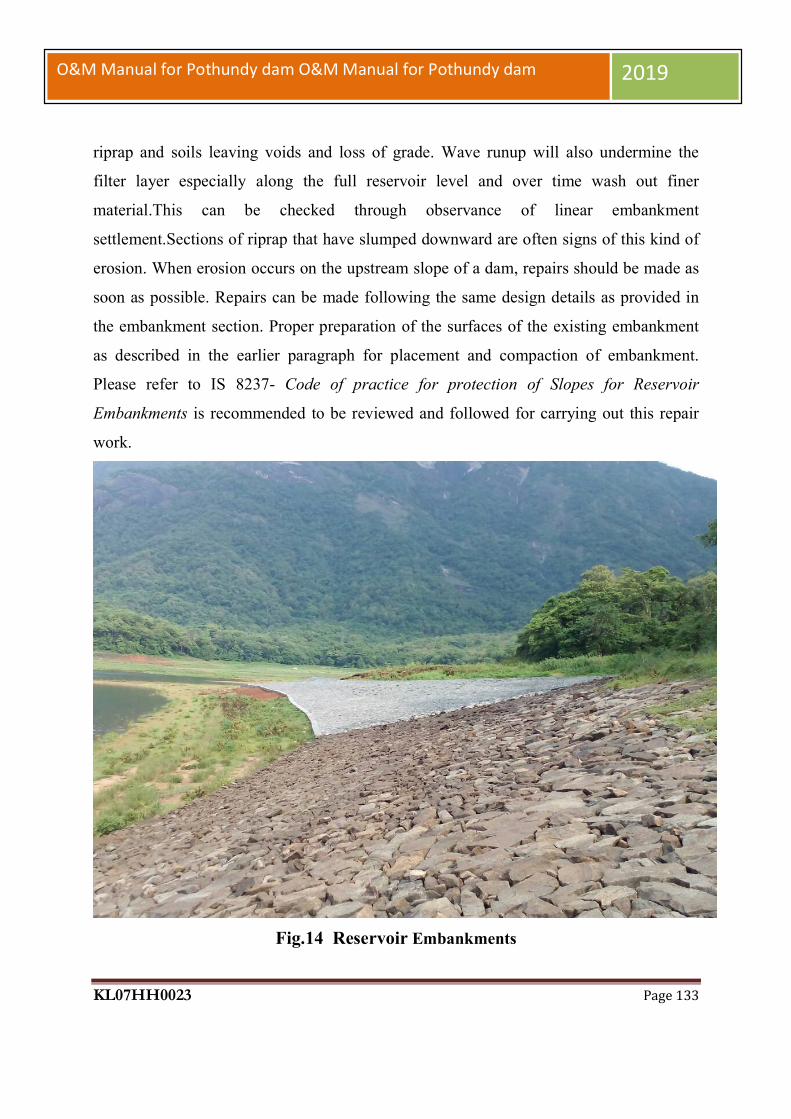
KL07HH0023 Page 133
O&M Manual for Pothundy dam O&M Manual for Pothundy dam 2019
riprap and soils leaving voids and loss of grade. Wave runup will also undermine the
filter layer especially along the full reservoir level and over time wash out finer
material.This can be checked through observance of linear embankment
settlement.Sections of riprap that have slumped downward are often signs of this kind of
erosion. When erosion occurs on the upstream slope of a dam, repairs should be made as
soon as possible. Repairs can be made following the same design details as provided in
the embankment section. Proper preparation of the surfaces of the existing embankment
as described in the earlier paragraph for placement and compaction of embankment.
Please refer to IS 8237- Code of practice for protection of Slopes for Reservoir
Embankments is recommended to be reviewed and followed for carrying out this repair
work.
Fig.14 Reservoir Embankments

KL07HH0023 Page 134
O&M Manual for Pothundy dam O&M Manual for Pothundy dam 2019
4.9.8 Controlling Vegetation
Keep the entire dam clear of unwanted vegetation such as bushes or trees. Excessive
growth may cause several problems:
It can obscure the surface of an embankment and not allow proper inspection of
the dam.
Large trees can be uprooted by high wind or erosion and leave large voids that can
lead to breaching of the dam.
Some root systems can decay and rot, creating passageways for water, leading to
piping erosion.
Growing root systems can lift concrete slabs or structures.
Rodent habitats can develop undetected.
All bushes/trees should be as far as possible removed by root to prevent regrowth. The
resulting voids must be backfilled with suitable, well-compacted soils. It is recommended
to remove the plants/vegetation at their early stage to prevent or minimize their growing
into big trees/bushes, etc. In cases where trees and bushes cannot be removed, the root
systems should be treated with environmentally-friendly herbicides (properly selected
and applied) to retard further growth. Concerned
Government Agencies must be consulted for selection of appropriate herbicides & their
use for control of vegetation on dam structures or any water bodies.
4.9.9 Controlling Animal Damage Livestock are not allowed to graze on the embankment section of the dam. When soil is
wet, livestock can damage vegetation and disrupt the uniformity of the surface.
Moreover, livestock tend to walk in established paths and thus can promote erosion.
The burrows and tunnels of burrowing animals (beaver, muskrat, groundhogs and others)
weaken earthen embankments and serve as pathways for seepage from the reservoir.
Large burrows found on the embankment should be filled by mud packing. This method
involves placing vent pipe in a vertical position over the entrance of the den. Making sure
that the pipe connection to the den does not leak, the mud-pack mixture is poured into the

KL07HH0023 Page 135
O&M Manual for Pothundy dam O&M Manual for Pothundy dam 2019
pipe until the burrow and pipe are filled with the soil-water mixture. The pipe is removed
and more dry earth is tamped into the entrance. As per some US publications, the mud
pack is generally made by adding water to 90% earth &10% cement mixture until a slurry
or thin cement consistency is attained. For bigger holes, bentonite coated stones can also
be used. All entrances should be plugged with well-compacted earth and grassy
vegetation re-established. Dens should be eliminated without delay. Different repair
measures will be necessary if a dam has been damaged by extensive small or large rodent
tunneling activity. The area around the entrance can be excavated and then backfilled
with impervious material. This will plug the passage entrance to prevent water entry and
saturation of the embankment.
4.9.10 Controlling Ants and Termites (White Ants) Ants and termites have become one of the most serious pests for Embankment dams.
They both need water to survive and have been found on most of the embankment dams
in India. These insects can create problems in the dam itself and with any of its electrical
components.
In some habitats, ants and termites can move as much or more soil as earthworms,
thereby reducing soil compaction. Nest galleries can penetrate in a V-shaped pattern
below the nest, penetrating as much as more than one meter deep in the soil. These
galleries can create pathways for surface water to penetrate in the dam, resulting in
internal erosion and collapse of the surface. Ants and termites left undisturbed can build
mounds that can become quite large. These can create problems for mowing. However,
frequent mowing can induce the colonies to migrate to neighboring, undisturbed areas.
There are many options for managing ants and termites. Use only pesticides labeled as
suitable for the location you want to treat. Make every effort to avoid contaminating
water with pesticides and ensure.
4.9.11 Controlling Damage from Vehicular Traffic As mentioned earlier, vehicles driving across an embankment dam can create ruts in the
crest if it is not surfaced with roadway material and sometimes even when sealed with
flexible pavement, especially when the embankment is saturated and overweight trucks

KL07HH0023 Page 136
O&M Manual for Pothundy dam O&M Manual for Pothundy dam 2019
use the road. The ruts can then collect water and cause saturation and softening of the
dam. Other ruts may be formed by tractors or other off-road vehicles such as motorbikes
are allowed to drive up and down the embankment face; these can direct runoff resulting
in severe erosion. Vehicles, except for maintenance, are restricted on the dam top and
kept out by fences or barricades. Any ruts should be repaired as soon as possible.
Fig.15 Roadway along Embankments
4.9.12 Spillways Various issues/problems that may require maintenance/repairs on the Spillway include
but not limited to:
KL07HH0023 Page 137
O&M Manual for Pothundy dam O&M Manual for Pothundy dam 2019
Damages on spillway glacis, spillway piers, training/ divide walls, energy
dissipaters, downstream areas (probable causes are cavitations, abrasion, un-
symmetrical flows, unfavorable downstream conditions)
Vegetation growth in unattended areas such as spillway, spillway channel, etc.
Periodic maintenance should be performed of on the masonry surfaces which are
approachable to repair deteriorated areas.
For remedial measures of problems of special nature advice of experienced engineers
/Panel of Experts needs to be obtained
4.9.13 Gates & Hoisting Equipment The safe and satisfactory operation of Pothundy Dam depends on proper operation of its
Gates & Hoisting Equipment. Maintaining spillway gates in working condition is critical
for dam safety and is to be assigned the highest priority. If routine inspection of the
Hydro Mechanical Equipment shows the need for maintenance, the work should be
completed as soon as possible. The simplest procedure to ensure smooth operation of
gates is to operate them through their full range at least once and preferably twice
annually (before monsoon & after monsoon keeping a gap of at least six months).
Because operating gates under full reservoir pressure can result in large discharges,
exercising of gates should preferably be carried out during dry conditions or lean times of
the year using the stop-logs/ emergency gates. Commonly used Gates and Hoists
including their inspection / maintenance requirements are discussed below.
The aspects to be inspected and maintained periodically for ensuring proper operation of
these gates are as under:
i) The gate slot and bottom platform/sill beam should be cleaned periodically. Scales
formed over the embedded parts should be removed. Second-stage concrete should be
checked for any development of cracks / leakages and repairs should be attended to
immediately.
ii) The gate leaf should be thoroughly cleaned and repainted as and when necessary
according to the procedure or guidelines- indicated in IS: 14177 or as per the

KL07HH0023 Page 138
O&M Manual for Pothundy dam O&M Manual for Pothundy dam 2019
recommendations of the paint manufacturer. All drain holes provided in the gate
assembly should be cleaned.
iii) Rubber seals should be smoothed, if required, for proper alignment. All nuts and bolts
fixing the seal to the gate should be tightened uniformly to required torques. Seals, if
found damaged or found leaking excessively should be adjusted, repaired or replaced as
considered necessary.
iv) The wheel shall be rotated to check their free movement. Gate roller bearings and
guide roller bushes should be properly lubricated. Whenever necessary these should be
opened for rectifications of defects, cleaning and lubrication and should thereafter be
refitted. These may be replaced if repairs are not possible.
v) Hoisting connection of the gate leaf should be lubricated where necessary and defects
if any should be rectified.
vi) All nuts, bolts, check nuts and cotter pins of the lifting devices should be checked
periodically.
vii) All components should be greased and lubricated. Recommended and approved oils
and grease only should be used.
viii) Roller assembly should be adjusted by the eccentricity arrangement to ensure all
rollers rest uniformly on the track plates particularly in the closed position of the gate.
ix) Where filling valves are provided as part of the gate structure, all the nuts, bolts,
check nuts etc. should be tightened.
x) All welds shall be checked for cracks/ damages. Any weld that might have become
defective should be chipped out and redone following the relevant codal provisions.
Damaged nuts, bolts, rivets, screws etc. should be replaced without delay.
xi) The filling-in valves allow passage of water when it is lifted by lifting beam & crane
due to creation of space between stem seat and exit passage liner. The springs and
associated components should be checked periodically for damages and replaced if
necessary.
xii) The guide-assemblies, wheel-assemblies and sealing-assemblies shall be cleared off
grit, sand or any other foreign material.
KL07HH0023 Page 139
O&M Manual for Pothundy dam O&M Manual for Pothundy dam 2019
xiii) The wheel pin shall be coated with corrosion resistant compound.
xiv) All nuts and bolts shall be tightened.
The aspects to be inspected and maintained periodically for ensuring proper operation of
these gates are as under:
a) Rubber Seals: i) Seals shall be inspected for leakages. Locations of excessive leakages shall be recorded
for taking remedial measures. Weeping or slight flow in localized area will not require
immediate remedial measures. However, measures like tightening of bolts are carried out.
Further adjustment is carried out during annual maintenance.
ii) If leakage is excessive & immediate repair is considered necessary, the stop log gates
shall be dropped and seals repaired or replaced.
NOTE: - During monsoon period, stop log gates shall NEVER be lowered in spite of
heavy leakage through seals.
b) Trunnion blocks assembly and anchorages: (i) All the nuts and bolts of Trunnion block assembly and its anchorages shall be checked
for tightness.
(ii) Check all the welds for soundness and rectify defects.
(iii) Check whether the Yoke girder and thrust block is covered on not. If not, cover it
with mild steel plates.
(iv) Cover the Trunnion pin with anti- corrosive jelly.
(v) Remove all dirt, grit etc. from Trunnion assembly and lubricate Trunnion bearings of
the gate with suitable water resisting grease as recommended by bearing manufacturers.
c) Gate structures:
i. Check all the welds for soundness and rectify defects.
ii. Check welds between arms and horizontal girders as well as between
latching bracket and skin plate with the help of magnifying glass for
cracks/defects and rectify the defects.
iii. Clean all drain holes including those in end arms and horizontal girders.
KL07HH0023 Page 140
O&M Manual for Pothundy dam O&M Manual for Pothundy dam 2019
iv. Check all the nuts and bolts and tighten them. Replace damaged ones.
v. Check upstream face of skin plate for pitting, scaling and corrosion. Scaling
may be filled with weld and grinded. Corroded surface shall be cleaned and
painted.
d) Embedded Parts:
i) All the sill beams and wall plates shall be inspected for crack, pitting etc.
and defects shall be rectified.
ii) The guide roller pins shall be lubricated.
e) General Maintenance:
i. Defective welding should be chipped out and it should be re-welded duly
following the relevant codal provision (IS: 10096, Part-3).
ii. Damaged nuts, bolts, rivets, screws etc. should be replaced.
iii. Any pitting should be filled up by welding and finished by grinding if necessary.
iv. The gate leaf, exposed embedded metal parts, hoists and hoist supporting structure
etc., should be thoroughly cleaned and repainted when required keeping in view
the original painting system adopted and as per the guidelines contained in IS:
14177.
v. Trunnion bearing should be greased as and when required. Keeping Trunnion
bearings in perfect working condition is very important. All other bolted
connections should also be checked up for proper tightness.
vi. Bolts and Trunnion bearing housing should be tightened wherever required.
vii. The seals of the gate should be checked for wear and tear and deterioration. These
should be adjusted/replaced as and when necessary.
viii. The wall plates, sill beams shall be checked and repaired if necessary.
ix. Wire ropes should be properly lubricated.
x. Oil level in the worm reduction unit should be maintained by suitable
replenishment. Oil seals should also be replaced if required. Lubrication of other
parts of hoists such as chains, position indicators and limit switches should also be
done.

KL07HH0023 Page 141
O&M Manual for Pothundy dam O&M Manual for Pothundy dam 2019
xi. The stroke of the brake should be reset to compensate for lining wear. Worn out
brake linings should be replaced in time.
xii. Flexible couplings should be adjusted if required.
xiii. Repairs and replacements of all electrical relays and controls should be attended
to.
xiv. Maintenance of alternative sources of Power such as Diesel Generating sets and
alternative drives wherever provided should be carried out.
xv. The list of essential spare parts to be kept available should be reviewed and
updated periodically. The condition of spares should be checked periodically and
protective coating given for use.
4.9.14 Maintenance of Hydraulic Systems
A. INTRODUCTION:
Long service life and functional reliability of, any hydraulic system& its components are
dependent on proper maintenance activities. Maintenance of hydraulic system covers all
the activities related to commissioning, servicing, Repair, Storage etc. of the Hydraulic
System Elements. Although commissioning of hydraulic system is not directly related to
maintenance but after years of experience by users it is realized that, careful
commissioning means less troubles in further service life, maintenance, servicing and
repairing.
B) ROUTINE MAINTENANCE:
After careful commissioning certain points should also be taken Care of for routine
maintenance.
1. Check the fluid level continuously during commissioning of the equipment, after
then daily, and later weekly.
2. During commissioning filter should be checked after every two to three hours of
running the unit and cleaned if necessary. There after they must be checked and
cleaned every week.
3. Hydraulic accumulator charging pressure should be checked from time to time.
KL07HH0023 Page 142
O&M Manual for Pothundy dam O&M Manual for Pothundy dam 2019
4. Measure the oil temperature in the oil reservoir and also in the region of pump
bearings.
5. Check every week all the pipe joints and tighten them up if found loose.
6. Main pressure and pilot pressure of the system must be checked up periodically.
7. Check the alignment of pump motor set regularly.
C) SAFETY ASPECTS:
As hydraulic system (essentially high pressure systems) if not handled properly may
endanger the environment and human life. During any service, repair or maintenance
activity it is essential to place special emphasis on the safety aspects, at every stage, so
that one can avoid loss of property or life. The safety of ecology is also an important
consideration. Apart from designers and quality control personnel, make sure that the
maintenance and service personnel are aware about the safety requirements.
At the application stage itself, the environment condition should be considered under
which the equipment is to operate, so that safety features can be built against hazards,
such as fire, pollution, health hazards, etc. While designing the system also, the specific
attention should be given to the safety aspects.
If proper pipes and fittings are not used in the equipment, some object may fly off and hit
somebody who may result in injury or death.
In a pressure vessel like accumulator, if oxygen is filled in place of nitrogen, may
explode after words either by some spark, or by somebody smoking nearby.
Technician opening the pump or valve without realizing that a particulars valve backed
by compressed spring can fly on the face of somebody and hit him fatally.
Leakages from pipes, fittings, manifolds etc. In the fire hazards area may result in fire
and may cause loss of life and property.
In case of winches and hoists or vertical cylinders, the over-loading by the user may
result in free fall of the load which may result in facilities apart from damages to the
properly. Hydraulic oil leakage may damage the soil and hence the ground water and the
plant life and consequently the damage to animal life and human life. Hence please make
sure that equipment is not leaking.

KL07HH0023 Page 143
O&M Manual for Pothundy dam O&M Manual for Pothundy dam 2019
While operating the equipment legal/mandatory regulations of the state must be
essentially complied with.
4.9.15 Electrically operated fixed hoists
1. General Instructions:
a) Operation of fixed hoist without lifting the gate is not possible and need not therefore
be attempted. It will be possible to operate the unit and observe operation of load carrying
hoist component when gate is being lifted or lowered.
b) Never open any bolt or nut on motor, gear boxes, rope drums and other load carrying
hoist components when the gate is in raised position. The gate should be fully closed or
rested on the gate latches before carrying out any work on hoist components including
motor brake and other electrical equipment.
c) The aspects to be inspected and maintained periodically for ensuring proper operation
of Rope drum hoists are as under;
i. Entrance to all hoist platforms shall be kept locked. All keys shall remain with the shift
supervisor.
ii. A cursory daily inspection shall be made of hoist and gate to ensure that there is no
unusual happening.
iii. Clean all hoisting equipment and hoist platform.
iv. Check oil level in gearboxes and replenish as and when required with oil of proper
grade.
v. Apply grease of suitable grade by grease gun.
vi. Lubricate all bearings, bushings, pins, linkages etc.
vii. Check all the fuses on the power lines.
viii. All bolts and nuts on gear boxes, hoist drum and shaft couplings should be checked
for tightness.
ix. Check the supply voltage.
x. Drain sample gear oil from each of the gear boxes. If excessive foreign particles or
sludge is found, the gear box shall be drained, flushed and filled with new oil.
xi. All the geared couplings shall be greased.

KL07HH0023 Page 144
O&M Manual for Pothundy dam O&M Manual for Pothundy dam 2019
xiii. Raise and lower the gate by hoist motor and check for smooth, and trouble free
operation of gate without excessive vibration.
xiv. Observe current drawn by motor at the time of lifting and check if it is more than
normal. If so, stop the hoist and investigate the cause and rectify.
xv. Check the condition of painting of various components and remove rust wherever
noticed and repaint the portion after proper cleaning as per painting schedule.
xvi. All trash, sediments and any other foreign material shall be cleared off the lifting
rope and lifting attachment.
xvii. All ropes shall be checked for wear and tear and if broken wires are noticed, the
rope shall be replaced.
xviii. All the wire ropes shall be checked and all visible oxidation shall be removed.
xix. All wire ropes shall be greased with cardium compound.
xx. Check the overload relays for proper functioning.
xxi. Check all the nuts, bolts, rivets, welds and structural components for hoisting
platform and its supporting structure for wear, tear and damage. All damages shall be
rectified. All bolts shall be tightened. The portion with damaged painting shall be touched
up.
xxii. Check the pulleys, sheaves and turn-buckles.
xxiii. Raise and lower the gate for its full lift several time (at least three to four) and
observe the following:
a) Check the limit switches and adjust for design limits.
b) The effectiveness and slip of the breaks shall be checked by stopping the gate in
raising and lowering operations. The brakes shall be adjusted if needed.
c) When the gate is operated, there should not be any noise or chatter in the gears.
xxiv. Adjust the rope tension of wires if unequal.
xxv. Check for all gears and pinions for uneven wear and adjust for proper contact.
Grease the gears.
xxvi. Repaint the hoist components, hoisting platform and its supporting structures as per
requirement.

KL07HH0023 Page 145
O&M Manual for Pothundy dam O&M Manual for Pothundy dam 2019
xxvii. The periodic maintenance of commercial equipment like motors, brakes, thrusts
etc. shall be carried out as per manufacturers operation and maintenance manual.
4.9.16 Maintenance of Electrical components of Fixed Rope Drum Hoists:
a). The electrical components to be inspected and maintained periodically are as under;
i) Starters should be cleaned free of moisture and dust.
ii) Each individual contactor should be tried by hand to make sure that it operates freely.
iii) All wearing parts should be examined in order to take note of any wear which may
have occurred during operation.
iv) If the contactor hums, the contact faces should be cleaned.
(v) Examine all connections to see that no wires are broken and no connections are loose.
vi) Clean the surface of the moving armature and magnet core which comes together
when the contactor closes, free of dust or grease of any kind.
vii) Examine the mechanical interlocks between the reversing contactor and see when the
contact tips of one of the contactor units are touching, it is impossible to get the contact
tips of the other unit to touch.
viii) The contact tips should be kept free from burns or pits by smoothening with fine
sand paper or emery paper.
ix) Replace the contact tips which have worn away half-way.
x) Do not lubricate the contacts.
xi) Blow out windings thoroughly by clean and dry air to clear air passage in the stator
and the rotor of any accumulated dirt. The air pressure shall not be too high to damage
the insulation.
xii) Examine earth connections and motor leads.
xiii) Examine motor windings for overheating
xiv) Examine control equipment’s
xv) Examine starting equipment for burnt contacts
xvi) Check and tighten all nuts and bolts
xvii) Clean and tighten all terminals and screw connections all contact surfaces shall be
made clean and smooth.

KL07HH0023 Page 146
O&M Manual for Pothundy dam O&M Manual for Pothundy dam 2019
xviii) Lubricate the bearings
xix) Overhaul the controllers
xx) Inspect and clean circuit breakers.
xxi) Wipe brush holders and check bedding of brushes.
xxii) Blow out windings thoroughly by clean and dry air. The pressure shall not be so
high that insulation may get damaged.
xxiii) Check the insulation resistance of the motor between any terminal and the frame.
If the measured resistance is less than the prescribed value, then steps shall be taken to
dry- out the motors either by passing a low voltage current through the windings or by
placing the stator and rotor only in a warm dry place for a day or so.
WARNING: The complete motor shall never be put in an oven for drying as that
may melt the grease out of bearings.
xxiv) Coat the windings with an approved high temperature resisting insulation enamel or
varnish.
xxv) Over haul the motor, if required.
xxvi) Check the switch fuse units and renew, if required.
xxvii) Check resistance or earth connections.
xxviii) Check air gap.
b) Solenoid Operated Brakes
i) All fixing bolts shall be checked and tightened at least once in three months.
ii) The magnet stroke should be reset to compensate for wear.
iii) Re-adjust the brake when the magnet stroke reaches the value given on the instruction
plate.
iv) Brake lining should be checked and replaced when required.
v) Examine all electrical leads and connections.
vi) Rubber bushes or couplings should be checked and replaced if defective.
vii) The pins should be tightened.
viii) Brake drum shall be cleaned to remove any dust or grease.

KL07HH0023 Page 147
O&M Manual for Pothundy dam O&M Manual for Pothundy dam 2019
4.9.17 Surface Preparation and Painting of HM Works
i) Protection of painted surfaces is considered essential for protection & enhancement of
service life. Gates, their embedded parts, gate leaf, hoists and its supporting structures
need to be protected against corrosion due to climatic condition, weathering, biochemical
reaction and abrasion etc. This equipment is likely to deteriorate or get damaged to any
extent that the replacement of parts may become necessary and such replacement may
become difficult and costly.
ii) Surface preparation & Painting requirements:
Painting for hydro-mechanical works is to be carried out as prescribed in IS 14177 for
both newly manufactured as well as old & used gates, hoists and associated works after
proper surface preparation. The preparation includes thorough cleaning, smoothing
irregular surfaces, rusted surfaces, weld spatters, oil, grease, dirt, earlier applied damaged
layers of primers/ paint by use of mechanical tools, by use of solvents, wire brush etc.
The sand / grit blasting process is used for surface preparation to a level of Sa 2½ of the
Swedish standard.
iii) Surfaces not requiring painting & their protection during surface preparation,
painting & transportation process:
a) The following surfaces are not to be painted unless or otherwise specified:
• Machine finished or similar surface
• Surfaces which will be in contact with concrete
• Stainless steel overlay surfaces.
• Surfaces in sliding or rolling contact
• Galvanized surfaces, brass and bronze surfaces.
• Aluminum alloy surfaces
b) The Surfaces of stainless steel, nickel, bronze and machined surface adjacent to metal
work being cleaned or painted shall be protected by using sticky protective tape or by
other suitable means over the surfaces not to be painted.

KL07HH0023 Page 148
O&M Manual for Pothundy dam O&M Manual for Pothundy dam 2019
c) All embedded parts which come in contact with concrete shall be cleaned as detailed
above and given two coats of cement latex to prevent rusting during the shipment while
awaiting installation.
iv) Application of primer &finish coats on embedded parts and gates:
a) EMBEDDED PARTS:
• The prescribed primer shall be applied as soon as the surface preparation is complete
and prior to the development of surface rusting and within the specified time prescribed
by Indian Standards or the Paint Manufacturer. In case there is lapse of considerable time
beyond the prescribed time limit, the surfaces shall be again cleaned prior to priming.
• Two coats of zinc rich primer with epoxy resin shall be applied to all embedded parts
surfaces which are not in contact with concrete and shall remain exposed to atmosphere
or submerged in water to obtain a dry film thickness of 75 microns.
• This shall be followed by three coats at an interval of 24hours of coal-tar blend epoxy
resin so as to get a dry film thickness of 80 microns in each coat. Total dry film thickness
of paint shall not be less than 300 microns.
b) GATES:
Primer Coat:
• Over the prepared surface one coat of inorganic zinc silicate primer giving a dry film
thickness of 70 ± 5 microns should be applied. Alternatively two coats of zinc rich
primer, which should contain not less than 85% zinc on dry film should be applied to
give a total dry film thickness of 75 ± 5 microns.
Finished paint:
• Two coats of solvent less coal tar epoxy paints. These shall be applied at an interval of
about 24 hours. Each coat shall give a dry film thickness of 150±5 microns. The total dry
film thickness of all the coats including primer coating shall not be less than 350microns.
v) Hoist and supporting structure:
a) Structural components:
Primer coats of zinc phosphate primer shall be applied to give a dry film thickness of
40±5 microns.

KL07HH0023 Page 149
O&M Manual for Pothundy dam O&M Manual for Pothundy dam 2019
Final Coats: One coat of alkalized based micaceous iron oxide paint to give a dry film
thickness of 65 ± 5 microns followed by two coats of synthetic enamel paint confirming
to IS 2932 – 1974 to give a dry film thickness of 25 ± 5 microns per coat. The interval
between each coat shall be 24hours. The total dry thickness of all coats of paint including
the primer coat shall not be less than 175 microns.
b) Machinery: Except machined surfaces all surfaces of machinery including gearing,
housing, shafting, bearing pedestals etc., shall be given:
Primer coats: One coat of zinc phosphate primer paint to give minimum film thickness
of 50 microns. Motors and other bought out items shall be painted if necessary.
Finished coats: The finished paint shall consists of three coats of aluminum paint
confirming
to IS2339 – 1963 or synthetic enamel paint confirming to IS 2932 – 1977 to give a dry
film thickness of 25±5 microns per coat to obtain a total minimum dry film thickness of
125 microns.
c) Machined surfaces:
All machined surfaces of ferrous metal including screw threads which will be exposed
during shipment or installation shall be cleaned by suitable solvent and given a heavy
uniform coating of gasoline soluble removable rust preventive compound or equivalent.
Machined surfaces shall be protected with the adhesive tapes or other suitable means
during the cleaning and painting operation of other components.
vi) Application of paint:
Mix the contents thoroughly as directed by paint manufacturer before and during use.
Painting at shop can be done by any of the three methods namely Brush / roller,
Conventional spray, Airless spray etc.
The paint can be made to suit the adopted method. But once the gate and equipment is in
erected position the general method adopted is only brush / roller. In case of spray lots of
precautions areto be taken.
For More details: Refer IS: 14177 Part (II) – 1971.
Appendix A – Brushing of paint
KL07HH0023 Page 150
O&M Manual for Pothundy dam O&M Manual for Pothundy dam 2019
Appendix B – Spraying of paint
Appendix C – Spray painting defects: Causes and remedies.
Removal of old paint / rust and carrying out fresh painting:
The carrying out of fresh painting is to be considered under the following conditions:
• The rusting is noticed all over the surface or
• Rusting is severe or
• Cracking and blistering has damaged the primer coat exposing the metal and is noticed
all over the surface or
• The paint film has eroded badly, the scrap of entire paint film to the base metal and
carries out fresh painting.
Note: In case of maintenance and renovation: Refer IS 14177 (Part II) – 1971 for
checking and repainting.
vii) Removal of old paint for repainting:
Caution should be exercised while removing the old paint. The surfaces shall be de-rusted
and descaled by either mechanically by one or more of the methods, namely:
a) Wire brushing, Scraping, and chipping. Sand papering or cleaning with steel wool or
abrasive paper
b) Power tool cleaning
c) Flame cleaning
d) Sand blasting or shot blasting and
e) Chemical rust removal.
Note: The method of application shall be decided based on conditions existing. After
cleaning, painting is to be carried out as originally proposed.
Some are painted without removal of old paint and rusting this will amounts to no
painting and deteriorate faster than the original one.
viii) Inspection and testing of painting of H. M works:
a) The following steps are involved in inspection of painting:
General inspection before and during painting
Viscosity test of paints

KL07HH0023 Page 151
O&M Manual for Pothundy dam O&M Manual for Pothundy dam 2019
Paint thickness test – using Elcometer.
Inspection of general appearance of finished work.
b) General:
The aim of inspection and testing is to ascertain whether the recommended practice is
being employed correctly during every stage of application and whether the final results
fulfill the object of painting. Any test carried out should be of non – destructive nature or,
if it is of destructive nature, it should be either restricted to areas which can be restored
without marring the general appearances or be such that it is possible to restore easily
without necessitating a complete repetition of the work.
c) Inspection of surfaces prior to painting:
Inspection methods will depend on whether it is to be painted for the first time or is to be
repainted.
d) New Works (Not previously painted): The following shall be decided by inspection:
The method of pre cleaning feasible or recommended;
The intermediate protective treatments to be applied, if found necessary;
The final painting schedule and the specifications for the paint for ensuring the
particular performance;
The method of application, whether by brush, roller or spray.
e) Old Work (Which requires repainting):
The following shall be decided by inspection:
Whether the entire existing paint requires removal; and/or
Whether repainting without paint removal would be adequate.
4.9.18 Electrical System
Electricity is typically used at a dam for lighting and to operate the gates, hoists,
recording equipment, and other miscellaneous equipment. It is important that the
Electrical system be well maintained, including a thorough check of fuses and a test of
the system to ensure that all parts are properly functioning. The system should be free
from moisture and dirt, and wiring should be checked for corrosion and mineral deposits.

KL07HH0023 Page 152
O&M Manual for Pothundy dam O&M Manual for Pothundy dam 2019
All necessary repairs should be carried out immediately and records of the works kept.
Maintain generators used for auxiliary emergency power -- change the oil, check the
batteries and antifreeze and make sure fuel is readily available. Monitoring devices
usually do not need routine maintenance. Open areas are particularly susceptible to
vandalism. As such all electrical fittings like bulbs, lights, loose wires etc. in open areas
should be checked routinely and replaced / repaired where needed. The recommendations
of the manufacturer should also be referred to.
4.9.19 Maintenance of Metal Gate Components
All exposed, bare ferrous metal of an outlet installation, whether submerged or exposed
to air, will tend to rust. To prevent corrosion, exposed ferrous metals must be either
appropriately painted
(following the paint manufacturer’s directions) or heavily greased in respect of moving
parts & on surfaces like guides & track seats on which there is movement of gates. When
areas are repainted, it should be ensured that paint is not applied to gate seats, wedges, or
stems (where they pass through the stem guides), or on other friction surfaces where paint
could cause binding. Heavy grease should be applied on friction surfaces to avoid
binding. As rust is especially damaging to contact surfaces, existing rust is to be removed
before periodic application of grease.
4.9.20 Access Roads
For a dam to be operated and maintained there must be a safe means of access to it at all
times. Access road surfaces must be maintained to allow safe passage of automobiles and
any required equipment for servicing the dam in any weather conditions. Routine
observations of any cut and fill slopes along the sides of the road should be made. If
unstable conditions develop assistance of experienced Engineers/Expert Panels should be
obtained and remedial measures initiated. Drains are required to be provided and
maintained along roads to remove surface and subsurface drainage. This will prolong the
life of the road and help reduce deterioration from rutting. Road surfacing should be
repaired or replaced as necessary to maintain the required traffic loadings. In most cases,
specialized contractors will be required to perform this maintenance.

KL07HH0023 Page 153
O&M Manual for Pothundy dam O&M Manual for Pothundy dam 2019
4.9.21 General Cleaning
As already suggested, for proper operation of spillways, sluiceways, approach channels,
inlet and outlet structures, stilling basin / energy dissipation arrangements, discharge
conduit, dam slopes, trash racks, debris control devices etc., regular and thorough
cleaning and removal of debris is necessary. Cleaning is especially important after large
floods, which tend to send more debris into the reservoir.
4.9.22 Materials and Establishment Requirements during Monsoon Period
Materials required during monsoon period for both immediate maintenance and
preventive maintenance must be stocked in adequate quantities for emergency situations
that may arise. Needful instructions in this regard are enclosed in the O&M Manual. At
Pothundy Dam, a 24/7 hour patrol schedule is carried out during monsoon period. At the
same time the additional management requirements during monsoon period are enhanced.
4.9.23 General List of Maintenance Records
Maintenance records are of utmost importance. Records are kept of all maintenance
activities, both immediate and preventive maintenance works. Essential information to be
recorded include
The following:
Date and time of maintenance,
Weather conditions,
Type of maintenance,
Name of person, title and / or contractor performing maintenance,
Description of work performed,
Length of time it took to complete the work with dates,
Equipment and materials used, and
Before and after dated photographs.
The data is recorded by the person responsible for maintenance.

KL07HH0023 Page 154
O&M Manual for Pothundy dam O&M Manual for Pothundy dam 2019
4.9.24 Preparation of O&M budget
In order to prepare O&M budget for a dam project all possible costs associated with
implementation of O&M Program need to be identified and considered. Typical O&M
budget for a project should essentially include but not limited to the following items:
i. Establishment Cost of Regular Staff - Salaries and allowances, Bonus, Medical
Reimbursement, LTC, Leave Encashment, pension benefits, etc. (as applicable).
ii. Establishment Cost of Work charged Staff - Salaries and allowances, Bonus, Medical
Reimbursement, LTC, Leave Encashment, Pension benefits, TA and DA , etc. (as
applicable).
iii. Establishment Cost of Daily wage Staff - Salaries and allowances, TA and DA etc. (as
applicable).
iv. Office Expenses – Rent for office, Telephone/Mobile/any other Telecommunication
bills, Electricity bills, water bills, Office stationery, Day to day office requirements.
v. Motor Vehicles - Running and Maintenance cost of inspection vehicles, Cost of hiring
of vehicles as required
vi. Maintenance of Colony - Maintenance of staff quarters, colony roads, Electricity,
Sanitary and Water supply systems etc
vii. T&P - T&P requirements for offices, colony, works etc. as applicable.
viii. Works -Painting, oiling, greasing, overhauling of HM equipment’s,
Repair/replacement of gates seals & wire ropes, POL for pumps & generator sets,
Electricity charges and maintenance of Electric systems of dam site, specific
requirements for all Civil, H.M & Electrical maintenance works, vegetation removal
and mowing of turfing on earth dams, maintenance/cleaning of drains in dam,),
maintenance of access roads & basic facilities, provision for flood contingency works
during monsoon, unforeseen events/items (about 10% of the cost of works) etc

KL07HH0023 Page 155
O&M Manual for Pothundy dam O&M Manual for Pothundy dam 2019
Table 22 - O&M BUDGET COSTS (ANNUAL)
Sl. no
BUDGET ITEM PREVIOUS
YEAR CO ST
(Rs)
CURRENT
YEAR
BUDGET
(YR_______) (Rs)
REMARKS
A. ESTABLISHMENT
1 SALARY OF REGULAR STAFF
INCLUDING ALL OTHER
BENEFITS
2 TRAVEL EXPENSES
3 OFFICE EXPENSES
4 MOTOR VEHICLE EXPENSES
5 MAINTENANCE OF OFFICE
& COLONY COMPLEX
SUB-TOTAL - A
B. WORKS
1 CIVIL
1.2 EARTHEN DAM
1.3 INTAKE / OUTLETS IN
EARTHEN DAMS
1.4 SPILLWAY & CENTRAL & CANAL SLUICES
1.5 APPROACH / INSPECTION
ROADS WITHIN DAM AREA
2 HYDRO-MECHANICAL

KL07HH0023 Page 156
O&M Manual for Pothundy dam O&M Manual for Pothundy dam 2019
2.1 SPILLWAY GATES & HOISTS
3 ELECTRICAL
3.1 ELECTRICALFITTINGS,MOTORS,CONTROLS FOR ALL GATE HOISTS
3.2 POWER SUPPLY LINES
3.3 ELECTRICAL FITTINGS ON DAM TOP, DAM GALLERIES,ETC
3.5 REMOTE CONTROL/CCTV
4 INSTRUMENTATION
5 MISCELLANEOUS WORKS
6 SALARY OF WORKCHARGED STAFF INCLUDING ALL BENEFITS
7 MATERIALS TO BE
STORED BEFORE MONSOON
SUB TOTAL- B
8 CONTINGENCY (10%) ON
SUB-TOTAL OF A & B
9 TOOLS & PLANTS
SUB-TOTAL- C
TOTAL ANNUAL COST
4.9.25 Maintenance Records Maintenance records are of utmost importance. A record shall be kept for all maintenance
activities, both immediate and preventive maintenance works. Information that must be
recorded includes, but not limited to, the following:
date and time of maintenance,

KL07HH0023 Page 157
O&M Manual for Pothundy dam O&M Manual for Pothundy dam 2019
weather conditions,
the type of maintenance,
name of person or contractor performing maintenance,
description of work performed,
the length of time it took to complete the work with dates,
equipment and materials used, and
Before and after photographs.
The data should be recorded by the person responsible for maintenance
KL07HH0023 Page 158
O&M Manual for Pothundy dam O&M Manual for Pothundy dam 2019
CHAPTER 5
INSTRUMENTATION AND MONITORING 5.1 Reasons for Instrumentation
Instrumentation, proper monitoring and evaluation are extremely valuable in determining the performance of a dam. Information that an instrumentation program can provide is outlined in the following subsection
5.1.1 Warning of a Problem Often instruments can detect issues such as the uplift pressures being more than designed in case of Gravity dams, settlements in Earth dams being more than assumed settlements, high tensile stresses in Gravity Dam etc. This monitoring provides warning of any problems which may occur in future. 5.1.2 Analyzing and Defining a Problem Instrumentation data are often used for analyzing and defining the extent of a problem. Such information can then be used to plan and design corrective measures.
5.1.3 Behavior Is as Expected Instruments installed at a dam can indicate occurrence of any anomalous or problematic behavior. They can show that whether the dam behavior is as per design or otherwise. 5.1.4 Evaluating Remedial Action Performance
Many dams, particularly older ones, are required to be modified to correct for any deficiency. Instrument readings before and after the change, facilitate in analysis and evaluation of the performance of the modification. 5.2 Details to be included
The following details may be included; Details of instrumentation carried out in the dam including drawings showing
instrumentation details and cable layout. Frequency at which different instrument readings are to be taken. Interpretation of instrumentation data and preparation of structural behavior reports
periodically. What is to be done in case some of the instruments are not in working condition?
Following are the suggestions in this regard
i. In case connecting cables of the non-working instruments are accessible, the manufacturer of the said instruments should be approached for checking and rectification of the installations to make instruments work.
ii. In case the embedded non-working instruments cannot be repaired, the same are to be abandoned.
iii. Observations of the following parameters need to be continued;
Water levels in the reservoir Hydro-meteorological observations

KL07HH0023 Page 159
O&M Manual for Pothundy dam O&M Manual for Pothundy dam 2019 Seepage observations using V notches/weirs etc. Displacements in the dam by means of survey observations using prism/paper targets
fixed at structures. Tilt meters or repaired plumb lines could also serve the purpose. Uplift pressures at dam base using stand pipes in Gravity dams
5.3 Instrument Types and Usage
The various instruments that have been installed in the dam and premises follows.
1. Water level measuring scales are installed a). Outside the central sluice well, both in meters and in feet. To measure the daily level of water b). Spillway shutters to measure the flow of excess water or flood water c).Both Canal sluice shutters to measure outflow through canal
2. Two V-Notches are installed in the inspection gallery to measure the seepage loss
3. To measure the Daily rainfall readings, A Symons’s Rain gauge station is installed in the Pothundy garden premises to the left side of garden entrance gate.
5.3.1 Movements Movements occur in every dam. They may increase on account of unstable slopes, low foundation shearing strength, settlement due to compressibility of foundation and dam materials, thrust due to arching, expansion resulting from temperature change, heave resulting from hydrostatic uplift pressures etc.. They can be categorized by direction.
5.3.1.1 Horizontal or Translational Movement Horizontal or translational movement occurs in an upstream-downstream direction in both embankment and concrete dams. In an Embankment dam, instruments used for measuring such movements include: extensometers, including multi-point extensometers, inclinometers, embankment measuring points, shear strips, 5.3.1.2 Vertical Movement Vertical movement is a result of consolidation of embankment or foundation materials resulting in settlement of the dam. Another cause is heave caused by hydrostatic uplift pressures. In an embankment dam, vertical movements may be measured using: settlement plates and sensors, extensometers, embankment survey monuments, Inclinometer casing measurements.

KL07HH0023 Page 160
O&M Manual for Pothundy dam O&M Manual for Pothundy dam 2019 5.3.1.3 Rotational Movement Rotational movement occurs generally due to varying foundation levels in dams. This kind of movement may be measured by instruments such as: extensometers, inclinometers, tilt meters, surface measurement points, crack-measurement devices, foundation-deformation gauges 5.3.1.4 Lateral Movement 5.3.2 Pore Pressure and Uplift Pressure Water seeps through, under, and around the ends of all dams. It moves through pores in the soil, rock, or concrete as well as through cracks, joints, etc. Water pressure acts uniformly in all directions and is termed pore pressure. The upward force (called uplift pressure) has the effect of reducing the effective weight of the Gravity dam and can materially reduce dam stability. Uplift pressure is measured with uplift pressure cells. Pore pressure in an Embankment dam, reduces the normal force & hence the shear resistance. In addition on account of seepage, if the migration of fines is not effectively intercepted by filters, it may result in progressive internal erosion (piping) or slope failure. Pore pressures can be monitored with piezometers & open wells. Pore-pressure measurements and monitoring can supply critical information regarding the overall stability of an embankment dam.
5.3.3 Stress and Strain 5.3.4 Temperature 5.3.5 Crack Width
5.3.6 Water Level; For most dams, it is important to monitor the water level in the reservoir and the downstream pool regularly. Water levels may be measured by simple elevation gauges either by staff gauges or by numbers painted on permanent fixed structures in the dam/reservoir or they may use complex devices that sense water level (Automatic Water Level Recorders). 5.3.7 Seepage Flow Seepage must be monitored on a regular basis to determine if it is increasing, decreasing, or remaining constant as the reservoir level fluctuates. Seepage may be measured using the following devices and methods: Weirs (any shape such as V-notch, rectangular, trapezoidal, etc.) Flumes (such as a Par shall flume) Time-bucket methodsDissolution of solids from the dam can often be detected by comparing chemical analyses of reservoir water and seepage water. Such tests are site specific; for example, in a limestone area, one would look for calcium and carbonates; in a

KL07HH0023 Page 161
O&M Manual for Pothundy dam O&M Manual for Pothundy dam 2019 Gypsum area, calcium and sulfates. Other tests, such as pH, can also sometimes provide useful information on chemical dissolution. Internal erosion in the embankment dam can be detected by comparing turbidity of reservoir water with that of seepage water and can be indicative of a potential undermining/ piping problem 5.3.8 Water Quality
As long as the seepage water is clear there is generally no immediate problem. However it is carrying some particles then water quality testing is important. Dissolution of solids from the dam can of-ten be detected by comparing chemical analyses of reservoir water and seepage water. Such tests are site specific; for example, in a limestone area, one would look for calcium and carbonates; in a gypsum area, calcium and sulfates. Other tests, such as pH, can also sometimes provide useful information on chemical dissolution. Internal erosion in the embankment dam can be detected by comparing turbidity of reservoir water with that of seepage water and can be indicative of a potential undermining/ piping problem
5.3.9 Seismic Activity Seismic measuring devices record the intensity and duration of large-scale earth movements such as earthquakes. They are provided in some of major dams in India located in seismically active zones.
Seismic instruments can also be used to monitor any blasting conducted near a dam site.
5.3.10 Weather Conditions Monitoring the weather at a dam site can provide valuable meteorological information. A rain gauge, thermometer, wind gauge etc. can be easily purchased, installed, maintained, and monitored at a dam site.
5.4 Automated Data-Acquisition Systems Automation of dam-safety instrumentation is possible using advance sensor technology, data acquisition equipment, and data management that have made data acquisition more reliable, cost-effective, and readily available for broader applications in dam-safety monitoring.
An automated data-acquisition system (ADAS) can range from a simple data loggertemporarily connected to one or more instruments to a permanent system that automates up to several hundred instruments at a dam. An ADAS for dam-safety monitoring includes the following key components: Electronic sensors for measuring different parameters like water levels, dis-placements, temperature etc. a remote data logger (permanent or portable) a communication link to the dam for remote access (cell phone, landline, radio, or satellite)
An ADAS usually consists of one or more solar-powered remote monitoring units (RMUs) positioned on the dam and connected to key instruments to be automated. The RMUs communicate via radio, hardwire, or cell phone with a central network monitor conventional desktop PC with vendor-supplied interface and communication soft-ware to provide access to the onsite RMUs by remote users. Typically, the monitor is located at site; however, it can be

KL07HH0023 Page 162
O&M Manual for Pothundy dam O&M Manual for Pothundy dam 2019 located at any far away location (such as a district or administration building). Instrument readings are stored in memory for either manual or automatic downloading for plotting and tabular reporting.
These systems can send out an alarm via cell phone, pagers, or e-mail if user defined instrument thresholds are exceeded. More recently, ADASs now incorporate remote digital still or video cameras. Since these systems are employed outdoors, it is important to use only data acquisition equipment that is designed for geotechnical instrumentation and dam safety monitoring.
Special attention need to be paid to lightning protection and grounding, surge protection, and backup power supplies. It would be advisable to contact engineering companies and vendors that are experienced in this area in case ADAS is under consideration for any dam monitoring.
A properly designed and installed ADAS can provide cost-effective and reliable instrumentation data acquisition and presentation to assist dam safety personnel in both long-term monitoring and during safety events. These systems provide the ability to adjust the frequency of instrument readings and to quickly assess trends from remote locations. When coupled with downstream warning sirens, ADAS can give early warning to downstream residents during a safety problem. 5.5 Frequency of Monitoring The frequency of instrument readings or taking observations at a dam depends on several factors including: the relative hazard to life and property it represents, its height or overall size, the relative quantity of water impounded, the relative seismic risk at the site, its age, and The frequency and amount of water level fluctuation in the reservoir.
In general, as each of the above factors in-creases, the frequency of monitoring should increase. For example, frequent (even daily) readings should be taken during the first filling of a reservoir, and more frequent readings should be taken when water levels are high and after significant storms and earthquakes. As a rule of thumb, simple visual observations should be made during each visit to the dam and not less than monthly. Daily or weekly readings should be made during the first filling. Immediate readings should be taken following a storm or earth-quake. Significant seepage, movement, and stress-strain readings should be taken at least monthly. The parameters to be monitored in dams and suggested frequency of measurements are at Tables 5-1 and 5-2 respectively. These are generally as per the Guidelines on Instrumentation for dams (CWC 2018). 5.6 Data Processing and Evaluation The steps required to process and evaluate data, whether collected manually or automatically, are the same. Instrument data should be processed and evaluated according to the procedures established by the monitoring program. Accumulation of instrument data by itself does not improve dam safety or protect the public.

KL07HH0023 Page 163
O&M Manual for Pothundy dam O&M Manual for Pothundy dam 2019 5.6.1 Data Collection Data collected manually should be recorded on the data sheets prepared as part of the monitoring program. Complementary data, such as air temperature, reservoir level, reservoir temperature, recent precipitation, and other information or observations that may be important in evaluating the instrumentation data should be noted on the data sheets. 5.6.2 Data Presentation All data should be summarized in graphical form. All plots should include sufficient previous data to identify any long-term trends. Furthermore, the plots should be self-explanatory.
5.6.3 Data Interpretation Data should be reviewed for reasonableness, evidence of incorrectly functioning instruments, and transposed data. Several checks for reasonableness can be made on all data. The magnitude of data should be near the range of previous data. Data that are significantly different may be incorrect. All data will have scatter from instrument error, human error, and from changes in natural phenomena such as temperature, wind, and humidity. The true accuracy of data will not be apparent until a significant number of readings have been taken under a variety of conditions. All data will follow trends, such as decreasing with time or depth, increasing with time or depth, seasonal fluctuation, direct variation with reservoir or tail water level, direct variation with temperature, or a combination of such trends.
5.6.4 Dam Performance Evaluation
The purpose of instrumentation and monitoring is to maintain and improve dam safety. The data should be used to evaluate whether the dam is performing as expected and whether it provides a warning of developing conditions that could endanger the safety of the dam. All data should be com-pared with expected behavior based on the basic engineering concepts. Variations from expected behavior may suggest development of conditions that should be evaluated. All data should be compared with design assumptions. If no unusual behavior or evidence of problems is detected, the data should be filed for future reference. If data deviates from expected behavior or design assumptions, action should be taken. The action to be taken depends on the nature of the problem, and should be determined on a case-by-case basis. Possible actions include: Performing detailed visual inspection;
Repeating measurements to confirm behavior;
Re-evaluating stability using new data;
Increasing frequency of measurements;
Installing additional instrumentation;
Designing and constructing remedial measures;
Operating the reservoir at a lower level; and
Emergency lowering of the reservoir.

KL07HH0023 Page 164
O&M Manual for Pothundy dam O&M Manual for Pothundy dam 2019 5.6.5 Methods of Behavior Pre-diction Each dam is a unique structure and has its own special conditions of sitting, design, construction and operation. Rigorous methods of prediction have been developed over the years. These methods apply the laws of physics to problems of slope stability, foundation stability and rock deformation. Modern solutions use finite element or finite difference models run on computers. Such numerical analyses are expensive and for that reason are generally used only for larger dams. Special analyses are made when investigations reveal weak materials or other anomalies.
5.7 Visual Observations
Observations by on site personnel (dam owners/operators and maintenance personnel) may be the most important and effective means of monitoring the performance of a dam. An inspector, upon each visit to the dam site, should examine it visually walking along the dam alignment and looking for any signs of distress or unusual conditions.

KL07HH0023 Page 165
O&M Manual for Pothundy dam O&M Manual for Pothundy dam 2019
CHAPTER 6 UPDATING THE MANUAL
Manual must be edited and portions rewritten to reflect these changes. This important task is often ignored. Updating information in the O&M Manual should be done whenever major changes like construction of an additional spillway, construction of dam on the upstream etc. take place. Aspects to be considered when updating include:
Increase/decrease in the frequency of an inspection or the maintenance routine based on additional data/ experience acquired.
Changes in the operation and/or maintenance procedures based on additional data/experience acquired.
Alterations to the project data because of
changes/modifications in the dam by way of additional spillway etc.
All up-dates/revisions of the O&M Manual need to be sent to all the locations/addresses to which the copies of the original O&M Manual had been sent earlier. It is recommended that O&M Manuals be reviewed/ updated after every 10 years by the respective Dam Owners. Manual must be edited and portions rewritten to reflect these changes. This important task is often ignored. Updating information in the O&M Manual should be done whenever major changes like construction of an additional spillway, construction of dam on the upstream etc. take place. Aspects to be considered when updating include: Increase/decrease in the frequency of an inspection or the maintenance routine based on additional data/ experience acquired. Changes in the operation and/or maintenance procedures based on additional data/experience acquired. Alterations to the project data because of changes/modifications in the dam by way of additional spillway etc.
All up-dates/revisions of the O&M Manual need to be sent to all the locations/addresses to which the copies of the original O&M Manual had been sent earlier. It is recommended that O&M Manuals be reviewed /updated after every 10 years by the respective Dam Owners.

KL07HH0023 Page 166
O&M Manual for Pothundy dam O&M Manual for Pothundy dam 2019
Fig.16 Map showing Ayacut area of LB canals
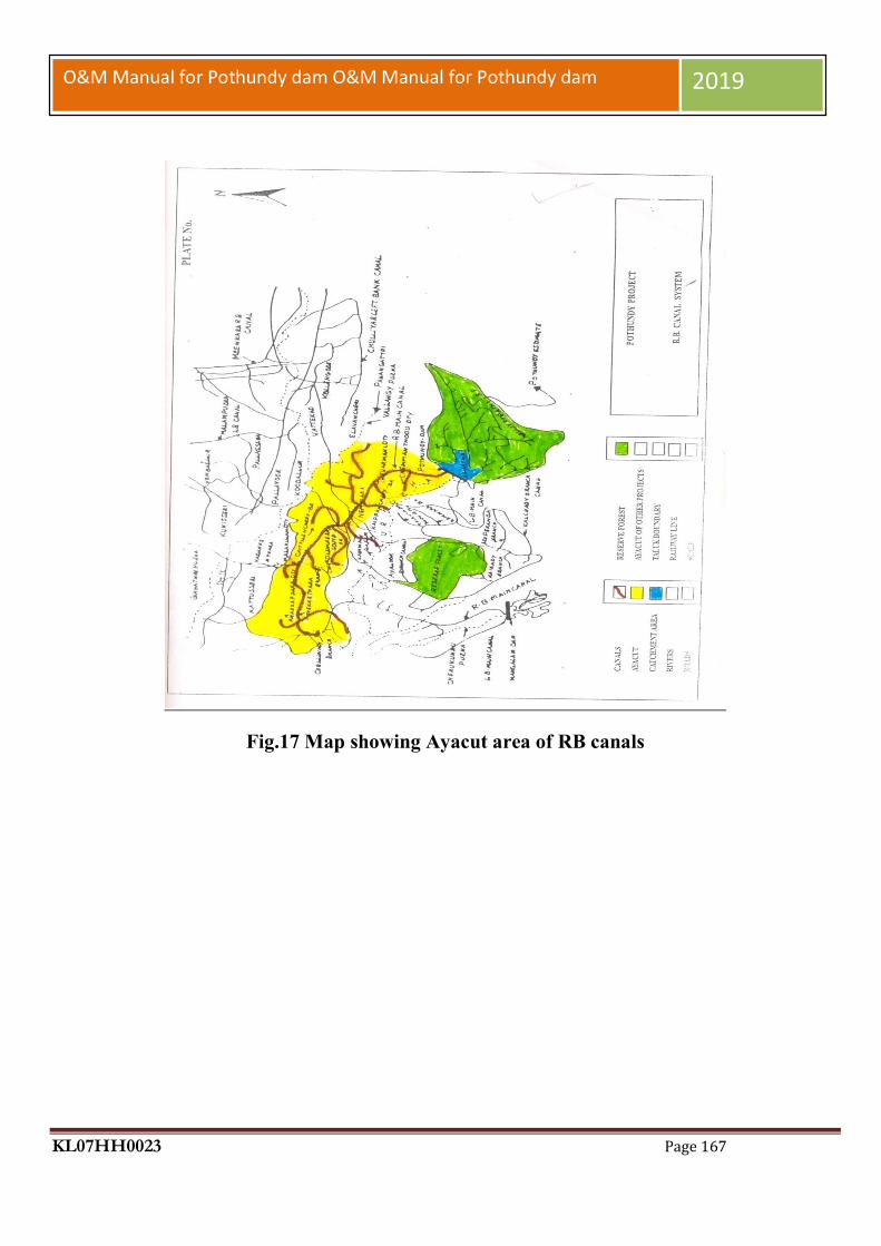
KL07HH0023 Page 167
O&M Manual for Pothundy dam O&M Manual for Pothundy dam 2019
Fig.17 Map showing Ayacut area of RB canals

KL07HH0023 Page 168
O&M Manual for Pothundy dam O&M Manual for Pothundy dam 2019
APPENDIX A― ALARM AND WARNING SYSTEMS FOR DAMS - NATIONAL DISASTER MANAGEMENT AUTHORITY (OCT. 2015)
INTRODUCTION
Dams are delivering enormous benefits to the nation through flood risk mitigation, navigation, irrigation, hydropower, water supply, fisheries, wildlife conservation and recreation. Dams store large amounts ph water; and an uncontrolled or excessive outflow from dam reservoir may pose unacceptable risks to the lives and property of people downstream of dam. Sometimes, unexpected release of even small quantum of water during day to day operations of dam reservoirs could also catch people unaware, and cause loss of lives & property. Strengthening of alarm and warning system lined with dam operations can go a long way in ensuring safety of people from sudden release of water through dam spillway. SCOPE this notification is intended to strengthen the alarm and warning system on India’s dams for safety of people from sudden release of water through the dam spillway/river sluices. It is also expected that the notification will sensitize and guide the dam operating staff in identifying, monitoring, and responding to emergency situation that may arise at any downstream stretch of the river due to sudden release of water from dam.
APPLICABILITY
This notification is applicable for enforcement by all dam authorities in charge of operation of the dams. This is particularly applicable to independent outlet works which are directly discharging into the river.
MEASURES FOR STRENGTHENING OF ALARM AND WARNING SYSTEM
Reservoir Operation Manual, prescribing standard operating procedures for the day to day as well as emergency operation of dam, shall be prepared by the concerned project authorities / dam owners (State Governments, Public Sector Undertakings, other government or private agencies). The Operation Manual shall spell out all possible scenarios of operation of spillway gates and other outlet gates keeping in perspective and elevation-storage curve of the reservoir; the annual inflow pattern of the reservoir; the annul water demand pattern of the project; and in case of hydropower projects, the power demand and impact of load rejection on operating units. 2. The concerned project authorities shall carry out hydraulic routing studies for the downstream river reaches for different dam-outflow conditions in order to identify vulnerable areas in terms of depth/level and velocity of flows. In such vulnerable areas, project authorities shall mark danger levels at appropriate places and set up permanent warning posts (in English, Hindi, and the local language) visible with naked eyes from reasonable distances. Movable barriers may be installed to prevent the entry of people and vehicles during passage of flood.

KL07HH0023 Page 169
O&M Manual for Pothundy dam O&M Manual for Pothundy dam 2019
The purpose of a flood warning service is to detect and forecast threatening flood events so that the public can be alerted in advance and undertake appropriate responses to minimize the impact of flood.
Notification flow Charts
WATCH CONDITION NOTIFICATION FLOW CHART (Internal Alert)

KL07HH0023 Page 170
O&M Manual for Pothundy dam O&M Manual for Pothundy dam 2019
FAILURE CONDITION NOTIFICATION FLOW CHART (External Alert)

KL07HH0023 Page 171
O&M Manual for Pothundy dam O&M Manual for Pothundy dam 2019
PALAKKAD DISTRICT - FAILURE CONDITION NOTIFICATION FLOW CHART (External Alert)

KL07HH0023 Page 172
O&M Manual for Pothundy dam O&M Manual for Pothundy dam 2019
EVIDENCES OF DISTRESS AND ALERT LEVELS This section lists the conditions and actions which may be used to classify the level of emergency response, as a guide for the Emergency Planning Manager (Executive Engineer, Main Dam Division). Specific dam observations and corresponding emergency classification levels can be found in Annexure 4, along with appropriate and recommended actions to follow in each case. Internal Alert Condition BLUE — A "watch" condition. A problem has been detected at the dam that requires constant monitoring. At this time, the distress condition is manageable by dam personnel. The Emergency Planning Manager (Executive Engineer, Malampuzha Division) along with the support of site engineers will be responsible for monitoring and repair as soon as possible and implementing the appropriate Notification Flowchart. The following is a list of conditions that would initiate this condition: Cloudy or dirty seepage or seepage with an increase in flow, boils, piping, or bogs. Large sinkholes with corresponding seepage anywhere on the embankment or downstream from the toe. Any slide that degrades the crest of the embankment or that is progressively increasing in size. Cracking or movement of any concrete structure. An increase in the reservoir level leading to engagement of the spillway gates. Exceptionally heavy rainfall in the catchment of the dam reservoir.
External Alert Condition ORANGE - This is indicative of a dam condition that is progressively getting worse; and there is a high probability of dam failure. Although there is no immediate danger, the dam could fail if conditions continue to deteriorate. The Emergency Planning Manager (Executive Engineer, Malampuzha Division) will be responsible for initiating immediate repairs, including lowering the reservoir if appropriate and implementing the appropriate Notification Flowchart. The following is a list of conditions that would initiate this condition: Any spillway's release matching with an ORANGE alert in accordance with Annexure Large boils, increasing in size and flow rate, especially if there is flowing muddy water Significantly increasing seepage, especially flowing muddy water Slides involving a large mass of material that impairs the crest of the dam and is continuing to move Sinkholes with seepage flowing muddy water Large cracks, movement or failure of a portion of any major concrete structure that Forms an integral part of
the dam An increase in the reservoir level to near the top of the dam Near to 'Design Flood' inflow forecast
External Alert Conditions RED - These are "failure" conditions. Either the dam is in immediate danger of failing or has already failed. No time remains to implement measures to prevent failure. Evacuate immediately. Evacuation efforts will continue until the situation is stabilized. The Emergency Planning Manager (Executive Engineer, Malampuzha Division) is responsible for implementing the appropriate Notification Flowchart. The following is a list of conditions that would initiate "imminent dam failure" or "dam failure" conditions: Any spillway's release matching with a RED alert in accordance with Annexure Rapidly increasing boils or the presence of new, significantly flowing boils, particularly muddy ones near
previously identified ones. Rapidly increasing seepage, especially flowing muddy water Slides involving a large mass of material or which have degraded the crest of the embankment to a level that
approaches the water surface level, or if significant seepage is observed through the slide area Settlement that is predicted to degrade to the reservoir level

KL07HH0023 Page 173
O&M Manual for Pothundy dam O&M Manual for Pothundy dam 2019
Cracks that extend to the reservoir level Significant movement or failure of any structure that forms an integral part of the dam Overtopping of the earthen dam Uncontrollable release of the reservoir
Sample Public Announcements Note: These messages are communicated to downstream residents to alert the public of impending danger. The Irrigation Department should coordinate with the India Meteorological Department, the Kerala State Disaster Management Authority and the District Magistrates/Collectors for Thiruvananthapuram District prior to release. Messages can be communicated via radio, television, bulk SMSs of local mobile networks, and other media outlets. Announcement for a Slowly Developing "Watch" Condition (BLUE Emergency Level) Executive Engineer, Irrigation Division, Malampuzhaha declared a BLUE Level "Watch" condition for Pothundy Dam, Project Identification Code KL07MH0049 as of [time and date]. [Briefly describe the problem or condition.] Although there is no immediate danger of the dam failing, [Describe what Actions are being taken to monitor and control the situation.] [State the quantity of any releases from the reservoir.] Announcement for a Worsening "Watch" Condition (BLUE Emergency Level) Executive Engineer, Irrigation Division, Malampuzhaha declared a BLUE Level "Watch" condition for Pothundy Dam, Project Identification Code KL07MH0049 as of [time and date]. [Briefly describe the problem or condition.] Although there is no immediate danger of the dam failing a possibility now exists that the dam will fail if correction efforts are unsuccessful. Describe what actions are being taken to monitor and correct the situation.] [State the quantity of any releases from the reservoir]. Additional news will be made available as soon as it is received. Announcement for a Probable "Failure" Condition (ORANGE Emergency Level) Urgent! This is an emergency message. Executive Engineer, Irrigation Division, Malampuzhaha Announced that Pothundy Dam, Project Identification Code KL07MH0049 is probably going to fail. [Describe what actions are being taken to monitor and control the situation.] It is possible that the dam will fail in [##] hours. Residents in low lying areas along the [Stream], the [Stream], and the [Stream], as well as the town of [Name], should prepare for immediate evacuation. Additional news will be made available as soon as it is received. Announcement of an Impending "Failure" Condition (RED Emergency Level) Emergency! This is an emergency message. Pothundy Dam, Project Identification Code KL07MH0049 is going to fail at any moment. Residents who have not yet done so should immediately evacuate the city of [Name] and low-lying areas along the [Stream], the [Stream], and the [Stream]. The flood waters have already reached [Highway] and [Road]. Additional news will be made available as soon as it is received. Announcement of an Ongoing "Failure" Condition (RED Emergency Level) Emergency! This is an emergency message. Pothundy Dam, Project Identification Code KL07MH0049 failed at [time and date]. Residents who have not yet done so should immediately evacuate the city of [Name] and low-lying areas along the [Stream], the [Stream], and the [Stream]. The flood waters have already reached [Highway] and [Road]. Additional news will be made available as soon as it is received

KL07HH0023 Page 174
O&M Manual for Pothundy dam O&M Manual for Pothundy dam 2019
APPENDIX B ― MATERIAL REQUIRED FOR MAINTENANCE DURING MONSOON
Materials during monsoon period should be stocked in adequate quantity as experience shows them to be necessary. Particular care should be taken that the required materials are distributed with careful fore-thought so as to be readily available everywhere, particularly at dangerous sites. The quantity of materials required depends on importance or dangerousness of the dam and the distances of the dam from the nearest stations at which these can be purchased. This will need to be worked out by the respective dam owners / state govt. as per their experience & documented in the O & M Manual for the dams.
1. Patrolling a. Torches: 1 for each Executive Engineer, Assistant Engineer, Sub-Engineer and 2 in spare. b. Cells: 1 fill and 2 spare sets c. Binoculars 2 d. Night Vision Goggles 2 e. Dragon Lights 4 f. Search Lights 5 g. Communication Systems (local walkie-talkie) 1 h. Rain coat: 10 i. Gum boots: 10 j. Danger Zone Light: Strips 2 k. Flares 10
2. Leaks i. Gunny Bags 500
ii. Stakes 60 to 120 stakes per km. iii. Baskets 1Basket of toot per beldar & one spare. iv. Sutli (Twine) 0.5kg per 100bags v. Needles ½ dozen with each work mestry
vi. Sand Collectionof2to4m3every km.

KL07HH0023 Page 175
O&M Manual for Pothundy dam O&M Manual for Pothundy dam 2019
APPENDIX C - GLOSSARY
Dam – any artificial barrier including appurtenant works constructed across rivers or tributaries thereof with a view to impound or divert water; includes barrage, weir and similar water impounding structures but does not include water conveyance structures such as canal, aqueduct and navigation channel and flow regulation structures such as flood embankments, dikes, and guide bunds.
Dam failure – failures in the structures or operation of a dam which may lead to the uncontrolled release of impounded water resulting in downstream flooding affecting the life and property of the people.
Dam incident – all problems occurring to a dam that has not degraded into ‘dam failure’ and including the following: a) Structural damage to the dam and appurtenant works; b) Unusual readings of instruments in the dam; c) Unusual seepage or leakage through the dam body; d) Change in the seepage or leakage regime; e) Boiling or artesian conditions noticed below an earth dam; f) Stoppage or reduction in seepage or leakage from the foundation or body of the dam into any of the galleries, for dams with such galleries; g) Malfunctioning or inappropriate operation of gates; h) Occurrence of any flood, the peak of which exceeds the available flood discharge capacity or 70% of the approved design flood; i) Occurrence of a flood, which resulted in encroachment on the available freeboard, or the adopted design freeboard; j) Erosion in the near vicinity, up to five hundred meters, downstream of the spillway, waste weir, etc.; and k) Any other event that prudence suggests would have a significant unfavorable impact on dam safety.
Dam inspection – on-site visual examination of all components of dam and its appurtenances by one or more persons trained in this respect and includes investigation of the non-overflow portion, spillways, abutments, stilling basin, piers, bridge, downstream toe, drainage galleries, operation of mechanical systems (including gates and its components, drive units, cranes), interior of outlet conduits, instrumentation records, and recordkeeping arrangements.
Dam owner – the Central Government or a State Government or public sector undertaking or local authority or company and any or all of such persons or organizations, who own, control, operate or maintain a specified dam.
Dam safety – the practice of ensuring the integrity and viability of dams such that they do not present unacceptable risks to the public, property, and the environment. It requires the collective application of engineering principles and experience, and a philosophy of risk management that recognizes that a dam is a structure whose safe function is not explicitly determined by its original design and construction. It also includes all actions taken to identify or predict deficiencies and consequences related to failure, and to document, publicize, and reduce, eliminate, or remediate to the extent reasonably possible, any unacceptable risks.

KL07HH0023 Page 176
O&M Manual for Pothundy dam O&M Manual for Pothundy dam 2019
Decommission― Taking a dam out of service in an environmentally sound and safe manner or converting it to another purpose.
Design life― the intended period that the dam will function successfully with only routine maintenance; determined during design phase.
Distress condition – the occurrence or potential development of such conditions in the dam or appurtenance or its reservoir or reservoir rim, which if left unattended to, may impede the safe operation of dam for its intended benefits or may pose unacceptable risks to the life and property of people downstream.
Documentation – all permanent records concerning investigation, design, construction, operation, performance, maintenance and safety of dams and includes design memorandum, construction drawings, geological reports, reports of specialized studies simulating structural and hydraulic response of the dam, changes made in design and drawings, quality control records, emergency action plan, operation and maintenance manual, instrumentation readings, inspection and testing reports, operational reports, and dam safety review reports;
Emergency Action Plan(EAP)― a plan of action to be taken to reduce the potential for damage to property and loss of life in the area affected by failure of a dam or other potentially hazardous practice.
Hazard Classification― a system that categorizes dams according to the degree of adverse incremental consequences of a failure or improper operation of the dam. CWC classifies dam hazards as “low”, “significant”, or “high”.
Maintenance― the recurring activities necessary to retain or restore a dam in a safe and functioning condition, including the management of vegetation, the repair or replacement of failed components, the prevention or treatment of deterioration, and the repair of damages caused by flooding or vandalism.
Operation― the administration, management, and performance of maintenance activities necessary to keep a dam safe and functioning as planned.
Program ― any authorized activity used to implement and carry out goals, actions, and objectives contained within the authorizing legislation.
Program Life― the period in a contract, conservation plan, or plan during which the conservation practice or conservation system shall be maintained and used for the intended purpose; determined by program requirements.
Rehabilitation― the completion of all work necessary to extend the service life of the practice or component and meet applicable safety and performance standards.
KL07HH0023 Page 177
O&M Manual for Pothundy dam O&M Manual for Pothundy dam 2019
Repair― actions to restore deteriorated, damaged, or failed dam or its component to an acceptable by meeting functional condition.
Replacement― the removal of a structure or component and installation of a similar, functional structure or component.
Service Life― the actual period after construction of a dam, during which the practice functions adequately and safely with only routine maintenance; determined by on-site review.
Abutment―that part of a valley side against which a dam is constructed. Right and left abutments are those on respective sides of the of an observer looking downstream. Air-
Vent Pipe―a pipe designed to provide air to the outlet conduit to reduce turbulence during release of water and safeguard against damages due to cavitations.
Appurtenant Structures―ancillary features of a dam, such as the outlet, spillway, energy dissipation arrangement powerhouse, tunnels, etc.
Arch Dam―a concrete or masonry dam that is curved to transmit the major part of the water pressure to the abutments.
Backwater Curve―the longitudinal profile of the water surface in an open channel where the depth of flow has been increased by an obstruction, an increase in channel roughness, a decrease in channel width, or a flattening of the bed slope.
Base Width (Base Thickness)―the maximum width or thickness of a dam measured horizontally between upstream and downstream faces and normal (perpendicular) tothe axis of the dam but excluding projections for outlets, etc.
Berm―a horizontal step or bench in the sloping profile of an embankment dam.
Upstream Blanket―an impervious layer placed on the reservoir floor upstream of a dam. In case of an embankment dam, the blanket may be connected to the impermeable element in a dam.
Buttress dam―a dam consisting of a watertight upstream face supported at intervals on the downstream side by a series of buttresses.
Cofferdam―a temporary structure enclosing all or part of a construction area so that construction can proceed in a dry area.
Concrete Lift―in concrete works the vertical distance between successive horizontal construction joints.
KL07HH0023 Page 178
O&M Manual for Pothundy dam O&M Manual for Pothundy dam 2019
Conduit Outlet Works―a closed conduit for conveying discharge through or under a dam for different project purposes.
Consolidation Grouting (Blanket Grouting) ― the injection of grout to consolidate a layer of the foundation, resulting in greater impermeability, strength, or both.
Construction Joint―the interface between two successive placings or pours of concrete where a bond, not permanent separation, is intended.
Core Wall―a wall built of impervious material, usually concrete or asphaltic concrete, in the body of an embankment dam to prevent leakage.
Crest Length―the length of the dam at its crest (dam top) top of a dam, including the length of the spillway, powerhouse, navigation lock, fish pass, etc., where these structures form part of the length of a dam. If detached from a dam, these structures should not be included.
Crest of dam―Used to indicate the “top of dam”. To avoid confusion to indicate the crest of spillway and top of dam may be used. Culvert―a drain or waterway built under a road, railway, or embankment, usually consisting of a pipe or covered conduits
Cutoff―an impervious construction or material which reduces seepage through the foundation material.Cutoff trench―an excavation later to be filled with impervious material to form a cutoff.
Cutoff wall―a wall of impervious material (e.g., concrete, asphaltic concrete, steel-sheet piling) built into the foundation to reduce seepage under the dam.
Dead storage―the storage that lies below the invert of the lowest outlet and that, therefore, cannot be withdrawn from the reservoir.
Design flood―see spillway design flood.
Diaphragm―see membrane.
Dike (Levee)―a long low embankment whose height is usually less than 5 m and whose length is more than 10 times the maximum height. Usually applied to embankments or structures built to protect land from flooding. If built of concrete or masonry, the structure is usually referred to as a flood wall. Also, used to describe embankments that block areas on a reservoir rim that are lower than the top of the main dam and that are quite long. In the Mississippi River basin, where the old French word levee has survived, the term now applies to flood-protecting embankments whose height can average up to 15 m.
Diversion channel, canal, or tunnel―a waterway used to divert water from its natural course. These terms are generally applied to temporary structures such as those designed to bypass water around

KL07HH0023 Page 179
O&M Manual for Pothundy dam O&M Manual for Pothundy dam 2019
a dam site during construction. “Channel’ is normally used instead of “canal” when the waterway is short. Occasionally these terms are applied to permanent structures.
Drainage area―an area that drains naturally to a point on a river.
Drainage layer or blanket―a layer of permeable material in a dam to relieve pore pressure or to facilitate drainage of fill.
Relief well―vertical wells or boreholes, constructed downstream of an embankmentdam to relieve the pressure from confined pervious layers in foundation overlaid by an impervious layer to arrest boiling.
Drawdown―the lowering of water surface level due to release of water from a reservoir.
Earthen dam or earth filled dam―see embankment dam.
Embankment dam (Fill dam)― any dam constructed of excavated natural materials.
Earth dam (Earth fill dam)―An embankment dam in which more than 50 percent of the total volume is formed of compacted fine-grained material obtained from a borrow area.
Homogeneous earth fill dam― an embankment dam constructed of similar earth material throughout, except internal drains or drainage blankets; distinguished from a zoned earth fill dam.
Hydraulic fill dam―an embankment dam constructed of materials, often dredged, that are conveyed and placed by suspension in flowing water.
Rock fill dam―an embankment dam in which more than 50 percent of the total volume comprises compacted or dumped pervious natural or crushed rock.
Rolled fill dam―an embankment dam of earth or rock in which the material is placed in layers and compacted using rollers or rolling equipment.
Zoned embankment dam―an embankment dam composed of zones of materials selected for different degrees of porosity, permeability and density.
Emergency spillway―see spillway.Face―the external surface of a structure, e.g., the surface of a wall of a dam.
Failure―the uncontrolled release of water from a dam. Filter (filter zone)―A band or zone of granular material that is incorporated into a dam and is graded (either naturally or by selection) to allow seepage to flow across or down the
filter without causing the migration of material from zones adjacent to it.
KL07HH0023 Page 180
O&M Manual for Pothundy dam O&M Manual for Pothundy dam 2019
Flashboards―a length of timber, concrete, or steel placed on the crest of a spillway to raise the retention water level but that may be quickly removed in the event of a flood, either by a tripping device or by deliberately designed failure of the flashboard or its supports.
Floodplain―an area adjoining a body of water or natural stream that has been, or may be, covered by flood water.
Floodplain management―a management program to reduce the consequences of flooding, either by natural runoff or by dam failure, to existing and future properties in a floodplain.
Flood routing―the determination of the attenuating effect of storage on a flood passing through a valley, channel, or reservoir.
Flood surcharge―the volume or space in a reservoir between the controlled retention water level (Full Reservoir Level) and the maximum water level. Flood surcharge cannot be retained in the reservoir but will flow over the spillway until the controlled retention water level is reached.
Flood wall―a concrete wall constructed adjacent to a stream to prevent flooding of property on the landward side of the wall, normally constructed in lieu of or to supplement a levee where the land required for levee construction is expensive or not available.
Foundation of dam―the natural material on which the dam structure is placed.
Freeboard―the vertical distance between a stated reservoir level and the top of a dam. Normal freeboard is the vertical distance between Full Reservoir Level (FRL) and the top of the dam. Minimum freeboard is the vertical distance between the Maximum Water Level (MWL) and the top of the dam.
Gallery―(a) a passageway within the body of a dam or abutment, hence the terms grouting gallery, inspection gallery and drainage gallery (b) a long and rather narrow hall, hence the
following terms for a power plant viz. valve gallery, transformer gallery and bus bar gallery.
Gate―a device in which a leaf or member is moved across the waterway from an external position to control or stop the flow.
Bulkhead gate―a gate used either for temporary closure of a channel or conduit to empty it for inspection or maintenance or for closure against flowing water when the head difference is small, e.g., for diversion tunnel closure. Although a bulkhead gate is usually opened and closed under nearly balanced pressures, it nevertheless may be capable of withstanding a high pressure differential when in the closed position.
Crest gate (spillway gate) ―a gate on the crest of a spillway to control overflow or reservoir water level. Emergency gate―a standby or reserve gate which is lowers only for repairing / servicing of the service gate.

KL07HH0023 Page 181
O&M Manual for Pothundy dam O&M Manual for Pothundy dam 2019
Fixed wheel gate (fixed-roller gate, fixedaxle gate) ―a gate having wheels or rollers mounted on the end posts of the gate. The wheels move against rails fixed in side grooves or gate guides.
Flap gate―a gate hinged along one edge, usually either the top or bottom edge. Examples of bottom-hinged flap gates are tilting gates and belly gates, so called due to their shape in cross-section.
Flood gate ― a gate to control flood release from a reservoir.
Guard gate (guard valve)―a gate or valve that operates fully open or closed. It may function as a secondary device for shutting off the flow of water in case the primary closure device becomes inoperable but is usually operated under conditions of balanced pressure and no flow.
Outlet gate ― a gate controlling the outflow of water from a reservoir.
Radial gate (Tainter gate) ―a gate with a curved upstream plate and radial arms hinged to piers or other supporting structures.
Service/Regulating gate (regulating valve)―a gate or valve that operates under full pressure and flow to throttle and vary the rate of discharge.
Slide gate (sluice gate) ―a gate that can be opened or closed by sliding it in supporting guides.
Gravity dam―a dam constructed of concrete, masonry, or both that relies on its weight for stability.
Grout cap―a pad or wall constructed to facilitate pressure grouting of the grout curtain beneath it
. Grout curtain (grout cutoff) ―a barrier produced by injecting grout into a vertical zone, usually narrow horizontally, in the foundation to reduce seepage under a dam.
Height above lowest foundation ― the maximum height from the lowest point of the general foundation to the top of the dam.
Hydraulic height ― the height to which water rises behind a dam and the difference between the lowest point in the original streambed at the axis of the dam and the maximum controllable water surface.
Hydrograph ― a graphic representation of discharge, stage, or other hydraulic property with respect to time for a point on a stream. (At times the term is applied to the phenomenon the graphic representation describes; hence a flood hydrograph is the passage of a flood discharge past the observation point.)
Inclinometer―an instrument, usually consisting of a metal or plastic tube inserted in a drill hole and a sensitized monitor either lowered into the tube or fixed within it. The monitor measures at
KL07HH0023 Page 182
O&M Manual for Pothundy dam O&M Manual for Pothundy dam 2019
different points the tube’s inclination to the vertical. By integration, the lateral position at various levels of the tube may be found relative to a point, usually the top or bottom of the tube, assumed to be fixed. The system may be used to measure settlement.
Intake― any structure in a reservoir, dam, or river through which water can be drawn into an aqueduct.
Internal Erosion ―see piping. Inundation map―a map delineating the area that would be inundated in case of a failure.
Leakage ― Uncontrolled loss of water by flow through a hole or crack.
Lining― a coating of asphaltic concrete, reinforced or unreinforced concrete, shotcrete, rubber or plastic on a canal, tunnel etc. to provide water tightness, prevent erosion, reduce friction, or support the periphery of structure. May also refer to lining, such as steel or concrete, of outlet pipe or conduit.
Low-level outlet (bottom outlet) ―an opening at a low level from a reservoir generally used for emptying or for scouring sediment and sometimes for irrigation releases.
Masonry dam―a dam constructed mainly of stone, brick, or concrete blocks that may or may not be joined with mortar. A dam having only a masonry facing should not be referred to as a masonry dam.
Maximum cross-section of dam― a cross-section of a dam at the point of its maximum height.
Maximum water level―the maximum water level, including flood surcharge, the dam is designed to withstand.
Membrane (Diaphragm)―a sheet or thin zone or facing made of a flexible material, sometimes referred to as a diaphragm wall or diaphragm.
Minimum operating level―the lowest level to which the reservoir is drawn down under normal operating conditions.
Morning glory spillway―see spillway.
Full Reservoir Level (FRL)/Normal water level―for a reservoir with un-gated spillway it is the spillway crest level. For a reservoir, whose outflow is controlled wholly or partly by movable gates, siphons or other means, it is the maximum level to which water can be stored under normal operating conditions, exclusive of any provision for flood surcharge. One-Hundred Year (100-Year) Exceedance Interval― the flood magnitude
expected to be equaled or exceeded on the average of once in 100 years. It may also be expressed as an exceedance frequency, i.e. a percent chance of being exceeded in any given year.

KL07HH0023 Page 183
O&M Manual for Pothundy dam O&M Manual for Pothundy dam 2019
Outlet―an opening through which water can be freely discharged from a reservoir. Overflow dam―a dam designed to be overtopped.
Parapet Wall―a solid wall built along the top of a dam for ornament, for the safety of vehicles and pedestrians, or to prevent overtopping
. Peak Flow―the maximum instantaneous discharge that occurs during a flood. It coincides with the peak of a flood hydrograph.
Pervious Zone―a part of the cross-section of an embankment dam comprising material of high permeability.
Phreatic Surface―the top most flow line in an embankment dam.
Piezometer―an instrument for measuring pore water pressure within soil, rock, or concrete.
Piping―the progressive development of internal erosion by seepage, appearing downstream as a hole or seam discharging water that contains soil particles.
Pore Pressure―the interstitial pressure of water within a mass of soil, rock, or concrete.
Pressure Cell―an instrument for measuring pressure within a mass of soil, rock, or concrete or at an interface between one and the other.
Pressure Relief Pipes―Pipes used to relieve uplift or pore water pressure in a dam’s foundation or structure.
Probable Maximum Flood (PMF) ―a flood that would result from the most severe combination of critical meteorologic and hydrologic conditions possible in the region.
Probable Maximum Precipitation (PMP) ―the maximum amount and duration of precipitation that can be expected to occur on a drainage basin.
Pumped storage reservoir―a reservoir filled entirely or mainly with water pumped from outside its natural drainage area.
Regulating dam―a dam impounding a reservoir from which water is released to regulate Reservoir area―the surface area of a reservoir when filled to controlled retention level.
Reservoir routing―the computation by which the interrelated effects of the inflow hydrograph, reservoir storage, and discharge from the reservoir are evaluated.
Reservoir surface―the surface of a reservoir at any level.
KL07HH0023 Page 184
O&M Manual for Pothundy dam O&M Manual for Pothundy dam 2019
Riprap―a layer of large stones, broken rock, or precast blocks placed randomly on the upstream slope of an embankment dam, on a reservoir shore, or on the sides of a channel as a protection against wave action. Large riprap is sometimes referred to as armoring.
Risk assessment―as applied to dam safety, the process of identifying the likelihood and consequences of dam failure to provide the basis for informed decisions on a course of action.
Rock fill Dam―see embankment dam. Roll Crete or Roller-Compacted Concrete A no-slump concrete that can be hauled in dump trucks, spread with a bulldozer or grader, and compacted with a vibratory roller.
Seepage―the interstitial movement of water that may take place through a dam, its foundation, or its abutments.
Sill―(a) A submerged structure across a river to control the water level upstream. (b) The crest of a spillway. (c) A horizontal gate seating, made of wood, stone, concrete or metal at the invert of any opening or gap in a structure, hence the expressions gate sill and stop log sill.
Slope― (a) the side of a hill or mountain. (b) The inclined face of a cutting or canal or embankment. (c) Inclination from the horizontal. In the United States, it is measured as the ratio of the number of units of horizontal
Distance to the number of corresponding units of vertical distance. The term is used in English for any inclination and is expressed as a percentage when the slope is gentle, in which case the term gradient is also used.
Slope Protection―the protection of a slope against wave action or erosion.
Sluiceway―see low-level outlet.
Spillway―a structure over or through which flood flows are discharged. If the flow is controlled by gates, it is a controlled spillway; if the elevation of the spillway crest is the only control, it is an uncontrolled spillway.
Auxiliary Spillway (Emergency Spillway)―a secondary spillway designed to operate only during exceptionally large floods.
Fuse-Plug Spillway―an auxiliary or emergency spillway comprising a low embankment or a natural saddle designed to be overtopped and eroded away during a rare and exceptionally large flood.
Primary Spillway(Principal Spillway)―the principal or first-used spillway during flood flows.
Shaft Spillway (Morning Glory Spillway)―a vertical or inclined shaft into which flood water spills and then is conducted through, under, or around a dam by means of a conduit or tunnel. If the

KL07HH0023 Page 185
O&M Manual for Pothundy dam O&M Manual for Pothundy dam 2019
upper part of the shaft is splayed out and terminates in a circular horizontal weir, it is termed a “bell mouth” or “morning glory” spillway.
Side Channel Spillway―a spillway whose crest is roughly parallel to the channel immediately downstream of the spillway.
Siphon Spillway―a spillway with one or more siphons built at crest level. This type of spillway is sometimes used for providing automatic surface-level regulation within narrow limits or when considerable discharge capacity is necessary within a short period.
Spillway Channel (Spillway Tunnel)―a channel or tunnel conveying water from the spillway to the river downstream.
Stilling Basin―a biform a spillway or bottom outlet, and to protect the riverbed from erosion.
Stop logs―large logs or timber or steel beams placed on top of each other with their ends held in guides on each side of a channel or conduit providing a cheaper or easily handled temporary closure than a bulkhead gate.
Storage―the retention of water or delay of runoff either by planned operation, as in a reservoir, or by temporary filling of overflow areas, as in the progression of a flood crest through a natural stream channel.
Tailrace―the tunnel, channel or conduit that conveys the discharge from the turbine to the river, hence the terms tailrace tunnel and tailrace canal.
Tail water Level―the level of water in the tailrace at the nearest free surface to the turbine or in the discharge channel immediately downstream of the dam.
Toe of Dam―the junction of the downstream face of a dam with the ground surface, referred to as the downstream toe. For an embankment dam the junction of upstream face with ground surface is called the upstream toe.
Top of Dam―the elevation of the uppermost surface of a dam, usually a road or walkway, excluding any parapet wall, railings, etc.
Top Thickness (Top Width) ―the thickness or width of a dam at the level of the top of the dam. In general, “thickness” is used for gravity and arch dams, “width” for other dams.
Transition Zone (Semi-pervious Zone)―a part of the cross-section of a zoned embankment dam comprising material of intermediate size between that of an impervious zone and that of a permeable zone.

KL07HH0023 Page 186
O&M Manual for Pothundy dam O&M Manual for Pothundy dam 2019
Trash rack―a screen located at an intake to prevent the ingress of debris. Tunnel―a long underground excavation usually having a uniform cross-section.
Types of tunnel include: headrace tunnel, pressure tunnel, collecting tunnel, diversion tunnel, power tunnel, tailrace tunnel, navigation tunnel, access tunnel, scour tunnel, draw-off tunnel, and spillway tunnel.
Under seepage―the interstitial movement of water through a foundation.Uplift―the upward pressure in the pores of a material (interstitial pressure) or on the base of a structure.
Upstream Blanket―see blanket.
Valve―a device fitted to a pipeline or orifice in which the closure member is either rotated or moved transversely or longitudinally in the waterway to control or stop the flow.
Water stop―a strip of metal, rubber or other material used to prevent leakage through joints between adjacent sections of concrete.
Weir― (a) a low dam or wall built across a stream to raise the upstream water level, called fixed-crest weir when uncontrolled. (b) A structure built across a stream or channel for measuring flow, sometimes called a measuring weir or gauging weir. Types of weir include broad-crested weir, sharp-crested weir, drowned weir, and submerged weir.