
IRRIGATION ENGINEERING UNIT – I IRRIGATION: Irrigation is the ...
123
1 IRRIGATION ENGINEERING UNIT – I IRRIGATION: Irrigation is the art and science of applying water artificially to the land for producing crops. SCOPE: It is old age time art, as old as civilization. Civilization of any country has followed the development of irrigation. Irrigation in modern world is also said to be the science of survival. India is the vast country having total land area of 326 million hectares and cultivable area of 194 million hectares (1 hect. = 10 4 m 2 ). More than 65% population of India depends upon agriculture which clearly shows that India’s development in the field of agriculture largely depends upon development of irrigation. HYDROLOGY: Hydrology is the science which deals with the occurrence, distribution and movement of water on the earth. Water occur in the atmosphere in the form of vapour, on the surface as water, snow or ice and below the surface as groundwater.
-
Upload
khangminh22 -
Category
Documents
-
view
1 -
download
0
Transcript of IRRIGATION ENGINEERING UNIT – I IRRIGATION: Irrigation is the ...
1
IRRIGATION ENGINEERING
UNIT – I
IRRIGATION: Irrigation is the art and science of applying water artificially to
the land for producing crops.
SCOPE: It is old age time art, as old as civilization. Civilization of any country
has followed the development of irrigation. Irrigation in modern world is also
said to be the science of survival.
India is the vast country having total land area of 326 million hectares
and cultivable area of 194 million hectares (1 hect. = 104 m2). More than 65%
population of India depends upon agriculture which clearly shows that India’s
development in the field of agriculture largely depends upon development of
irrigation.
HYDROLOGY: Hydrology is the science which deals with the occurrence,
distribution and movement of water on the earth. Water occur in the atmosphere
in the form of vapour, on the surface as water, snow or ice and below the
surface as groundwater.
2
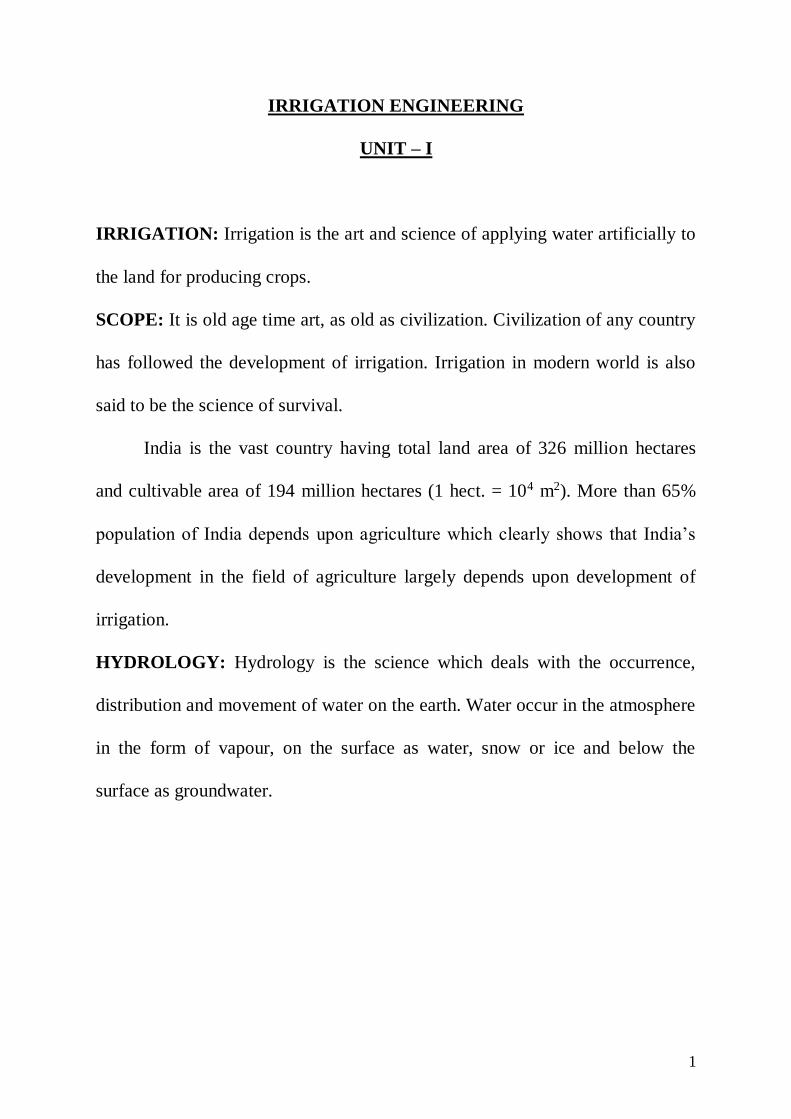
Hydrological cycle: It is the process of transfer of moisture from the
atmosphere to the earth, in the form of precipitation, conveying of precipitated
water by streams, rivers to ocean, seas and lakes and evaporation of water back
to the atmosphere.
Hydrological cycle consist of the following processes.
(1) Precipitation: It may be defined as fall of moisture from the atmosphere
to the earth surface in any form, precipitation may be in two forms:
(a) Liquid precipitation (b) Frozen precipitation
(a) Liquid Precipitation: This type of precipitation is further divided in
three types.
(i) Rain: When the size of drops is more than 0.5 mm.
The upper size of water drops is generally 6.25 mm as drops greater than
this size tends to break up as they fall through air.
3
(ii) Drizzle: When the size of the water droplets is under 0.5 mm and its
intensity is less than 0.01 mm/hr.
(iii) Sleet: They are frozen rain drops cooled to ice stage by falling through
air at sub freezing temperature.
(b) Frozen precipitation:
(i) Snow: Precipitate in the form of ice crystals resulting from sublimation
i.e. water vapour changes directly to ice.
(ii) Hail: It is a lump or bulk of ice over 5 mm dia formed by alternate
freezing or melting as they are carried up and down in highly turbulent air
currents.
(2) RUN OFF: It is that part of precipitation which is available on earth
surface after loss, to the atmosphere.
Let P = Precipitate in mm
R = Runoff in mm
E = Loss to the atmosphere (Evaporation & transpiration)
Then mathematically P = R + E
(i) Surface runoff: It is that part of precipitation which flows on the earth
surface after loss to the atmosphere and loss to the ground. In other words if the
rate of infiltration is less than the rate of precipitation, excess water flows on the
surface of the earth. This surplus water which flows on the surface of earth is
called surface runoff.

4
(ii) Sub surface runoff: It is that portion of precipitation which flows below
the surface of the earth through the inter connecting voids of the soils as far as
the slope is available or it joins nearby ponds, stream. This is known as sub-
surface runoff.
(iii) Base flow or groundwater flow: It is that portion of precipitation which
after infiltration percolates down and joins the groundwater table.
(3) INTERCEPTION: It is that portion of precipitation, which is being
retained by the trees, plants and bushes available on the earth surface.
Interception is the function of intensity of rainfall. If intensity of rain fall is
more interception will be less.
(4) SURFACE DETENTION: It is that portion of precipitation which is
being detained in the natural depressions available on the earth surface.
(5) EVAPORATION AND TRANSPIRATION: Water from the surface of
oceans, rivers, lakes and moist soil evaporate. The vapours are carried over the
land by air in the form of clouds.
Transpiration is the process of water being lost from the leaves of plant.

5
WATERSHED:
It is an imaginary line passing in an area formed by intersection of two
opposite slopes that is having downward sloping ground on both sides. Water
shed is always found between two successive drainages or drainage line.
Drainage/Drainage line: It is an imaginary line passing in an area having
upward sloping ground on both its side. There is always one drainage line
between two consecutive watersheds.
Catchment area/catchment: It is the entire area all around drainage, lake,
ponds etc. which contributes to the runoff flowing in them. The rain fall on this
area will flow into these water bodies.

6
Measurement of Rainfall:
Rainfall is the source of all water used for irrigation purposes, therefore a
knowledge of its amount, character, seasons and periods is of prime importance
to the irrigation engineer. The amount of precipitation is expressed as depth of
water in cms or mms which falls on a level surface and is measured by rain
gauge.
Types of rain gauge:
(1) Symon’s rain gauge
(2) Weighing bucket type rain gauge.
(3) Tipping bucket type rain gauge
(4) Float type rain gauge
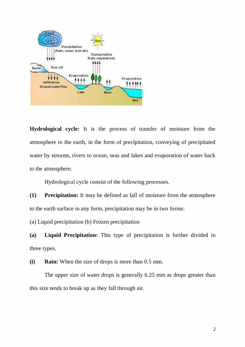
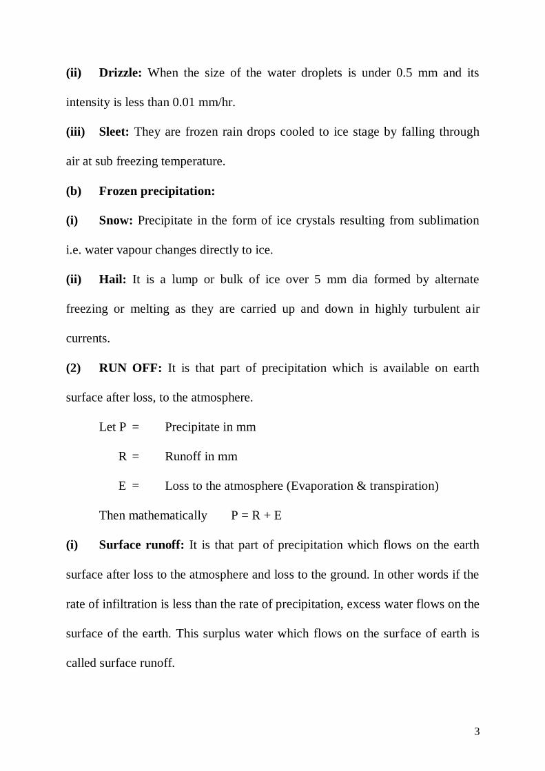
1. Symon’s rain gauge: Symon’s rain gauge is the most common type of
non-automatic rain gauge and is used by meteorological department of
government of India. It consist of a cylindrical vessel 127 mm in diameter. The
top section is a funnel provided with circular brass rim of 127 mm diameter.
The funnel is inserted into a receiving bottle of 75 to 100 mm diameter. The
receiving bottle has a capacity of 75 to 100 mm of rainfall and during heavy
rains. The rainfall should be measured 3-4 times to avoid over flow.
While selecting a site for a rain gauge station the following point should
be kept in mind.
7
(1) Rain gauge should be placed in an open area.
(2) The distance between rain gauge and the nearest object should be
atleast twice the height of the object. In no case the rain gauge should
be nearer to obstruction then 30 m.
(3) The rain gauge should never be situated on the side or top of a hill if a
suitable site on a level ground can be found.
(4) In the hills where it is difficult to find level space the site for the rain
gauge should be chosen where it is best shielded from high winds.
Estimation of Maximum rate of run-off or flood discharge:
Most of the formulae for estimation of flood discharge are in the form:
Q = CAn
where, Q = flood discharge
A = catchment area
8
n = flood index
C = flood coefficient
both C & n depends upon various factors such as (i) size, shape and location of
catchment (ii) topography of the catchment and (iii) intensity, duration of
rainfall and distribution pattern of the storm over the basin.
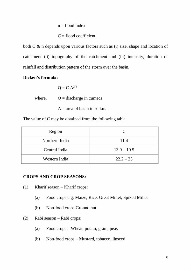
Dicken’s formula:
Q = C A3/4
where, Q = discharge in cumecs
A = area of basin in sq.km.
The value of C may be obtained from the following table.
Region C
Northern India 11.4
Central India 13.9 – 19.5
Western India 22.2 – 25
CROPS AND CROP SEASONS:
(1) Kharif season – Kharif crops:
(a) Food crops e.g. Maize, Rice, Great Millet, Spiked Millet
(b) Non-food crops Ground nut
(2) Rabi season – Rabi crops:
(a) Food crops – Wheat, potato, gram, peas
(b) Non-food crops – Mustard, tobacco, linseed

9
CROP SEASONS: In India mainly there are two types of crop seasons:
(1) Kharif season
(2) Rabi season
Kharif season starts from 1st week of April and ends in last week of
September. Therefore, for easy ploughing of the field a shower in third and
fourth week of March is very essential.
Rabi season starts from first week of October and ends in last week of
March. Therefore, in order to make the soil loose, a shower is essential in third
and fourth week of September.
Double Crops: When two crops of short duration are grown in same field in the
same season one after the other, they are known as double crops.
Mixed crops: When two crops are sown in the same field simultaneously the
resulting crop is known as mixed crop. E.g. combination of wheat & gram¸
wheat and mustard etc.
Rotation of crops: The method of growing different crops in a field year after
the year is known as rotation of crops. If in a field, same crop is sown year after
year, the soil becomes weak and less fertile. This is so because the constituents
of soil get more or less exhausted due to continuous feeding of the same crop.
Therefore, same crop should not be sown year after year in the same field.
The soil can gain strength by two ways:
(1) By leaving the field fallow for one season.
(2) By adding extra required manure.

10
But neither it is wise to leave the field fallow for one season nor to have extra
cost manure. So the crop rotation is preferred for regaining the strength of the
field. In this case all the constituents of the soil are taken up by different crops
and are consumed more or less to the same extent. This helps in preventing the
soil to become deficient in particular type of nutrient. The following rotation
pattern is adopted for different crops.
(1) Wheat – Millet – gram
(2) Rice gram
(3) Wheat – cotton – sugarcane
(4) Cotton – great millet – spiked millet
WATER REQUIREMENTS OF CROPS:
Gross Command Area (G.C.A.):
A canal usually runs on a water shed and water can flow from it on both
sides due to gravitational action, only upto drainage boundaries. Hence,
irrigation from a canal can only be done up to drainage boundaries. Gross
command area is the total area lying between the drainage boundaries which can
be commanded or irrigated by a canal system. G.C.A. includes unfertile barren
land, local ponds roads, villages etc.
11
Culturable command Area:
If we exclude the unculturable, area (barren lands, ponds, villages etc.)
from the gross command area, the remaining area will be culturable command
area. It is the area on which crops can be grown satisfactorily.
Base Period:
Base period for a crop refers to the whole period of cultivation from the
time when irrigation water is first applied for preparation of ground for planting
the crops to its last watering before harvesting. Base period is represented in
number of days.
Kor Depth and Kor Period:
Crops require maximum water during first watering. With the passage of
time quantity of water required decreases. The first watering is known as kor
watering. The depth of water applied is known as kor depth and the portion of
base period in which kor watering is needed is known as kor period.
Time Factor:
Time factor of a canal is the ratio of the number of days the canal has
actually run to the no. of days of irrigation period.
Duty (D): Duty represents the irrigating capacity of a unit of water. It is the
relation between the area of crop irrigated and the quantity of irrigation water
required for the growth of crops during the entire period. E.g. If 3 cumec of

12
water supply is required for an agricultural land of 6000 hectares, the duty of
irrigation water will be = 6000/3 = 2000 hect/cumec.
Delta(s): Delta is the total depth of water required by a crop during the crop is
in the field. E.g. If a crop requires 15 waterings at an intervals of 12 days, the
depth of water applied in every watering is 10 cm.
= 15 x 10 = 150 cm = 1.5 m
Intensity of irrigation:
It is the percentage area of a crop in a particular season.
Outlet Factor: It is defined as duty at the outlet.
Factor affecting duty:
1. Method and system of irrigation
2. Mode of applying water to the crops
3. Method of cultivation
4. Type of crop
5. Base period of crop
6. Climatic condition of the area
7. Quality of water
8. Canal conditions
9. Character of soil and sub soil of the canal
10. Character of soil and sub soil of irrigation fields.
13
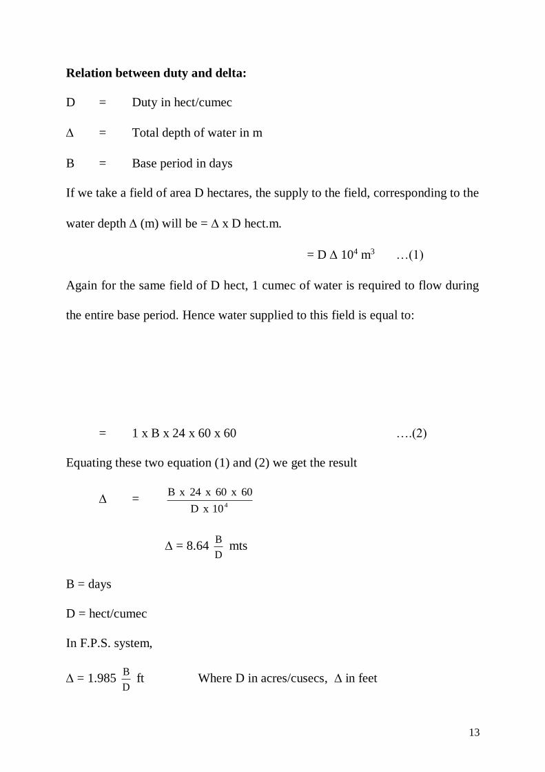
Relation between duty and delta:
D = Duty in hect/cumec
= Total depth of water in m
B = Base period in days
If we take a field of area D hectares, the supply to the field, corresponding to the
water depth (m) will be = x D hect.m.
= D 104 m3 …(1)
Again for the same field of D hect, 1 cumec of water is required to flow during
the entire base period. Hence water supplied to this field is equal to:
= 1 x B x 24 x 60 x 60 ….(2)
Equating these two equation (1) and (2) we get the result
= 410xD
60x60x24xB
= 8.64 D
B mts
B = days
D = hect/cumec
In F.P.S. system,
= 1.985 D
B ft Where D in acres/cusecs, in feet
14
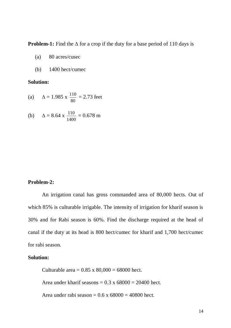
Problem-1: Find the for a crop if the duty for a base period of 110 days is
(a) 80 acres/cusec
(b) 1400 hect/cumec
Solution:
(a) = 1.985 x 80
110 = 2.73 feet
(b) = 8.64 x 1400
110 = 0.678 m
Problem-2:
An irrigation canal has gross commanded area of 80,000 hects. Out of
which 85% is culturable irrigable. The intensity of irrigation for kharif season is
30% and for Rabi season is 60%. Find the discharge required at the head of
canal if the duty at its head is 800 hect/cumec for kharif and 1,700 hect/cumec
for rabi season.
Solution:
Culturable area = 0.85 x 80,000 = 68000 hect.
Area under kharif seasons = 0.3 x 68000 = 20400 hect.
Area under rabi season = 0.6 x 68000 = 40800 hect.

15
Water required at the head of canal to irrigate the land under kharif
season = 800
20400
= 25.5 cumec
Water required at the head of canal to irrigate the land under rabi season
= 1700
40800 = 24 cumec.
Water required during the kharif season is more than water required during rabi
season. Hence the canal must be designed to carry a discharge of 25.5 cumec.
Problem-3:
The table below gives the necessary data about the crops, their duty and
the area under each crop, commanded by a canal taking off from a storage tank.
Taking a time factor to be 13/20, calculate the discharge required at the
head of the canal.
Crop Base period
(days)
Area (hect.) Duty at the head of
the canal
(hect/cumec)
1. Sugarcane 320 850 580
2. Overlap for
sugarcane in hot
weather
90 120 580
3. Wheat (Rabi) 120 600 1600
4. Bajri (Monsoon) 120 500 2000
5. Vegetables (hot
weather)
120 360 600

16
Solution: Discharge required for crops.
Discharge required for sugarcane = 580
850 = 1.465 cumec
Discharge required for overlap sugarcane = 580
120 = 0.206 cumec
Discharge required for wheat = 1600
600 = 0.375 cumec
Discharge required for Bajra = 2000
500 = 0.25 cumec
Discharge required for vegetable = 600
360 = 0.6 cumec
Since the sugarcane has base period of 320 days it will requires water in rabi
monsoon and hot weather.
Discharge required in Rabi = 1.465 + 0.375 = 1.84 cumec
Discharge required in Monsoon = 1.465 + 0.25 = 1.715 cumec
Discharge required in hot weather = 1.465 + 0.206 + 0.6
= 2.271 cumec
Thus the max. demand of 2.271 cumec is in the hot weather. The time
factor is the ratio of the no. of days the canal has actually run to the number of
days canal was supposed to run.
Here the time factor is = 13/20
Therefore, the full supply discharge at the head of canal will be
= 2.271 x 13
20 = 3.4938 cumec

17
Taking an allowance of 20% for the peak demand, the design discharge
will be = 3.493 x 1.2 = 4.19 = 4.2 cumec.
Problem-4:
The base period, intensity of irrigation and duty of various crops under a
canal system are given in the table below. Find the reservoir capacity if the
canal losses are 20% and reservoir
Losses are 12%.
Solution:
Crop Base
period
(days)
Duty at the
field
hect/cumec
Area
under the
crop hect
(A)
=8.64 D
B Vol. =
Ax
hect.m.
Wheat 120 1800 4800 0.576 2764.8
Sugarcane 360 800 5600 3.888 21772.8
Cotton 200 1400 2400 1.234 2961.6
Rice 120 900 3200 1.152 3686.4
Vegetable 120 900 1400 1.152 1612.8
V = 32798.4 hect.m.
Considering 20% canal losses and 12% reservoir losses.
Capacity of reservoir = 32798.4x1.32 = 43293.88 hect.m

18
Problem-5: For a canal G.C.A. is 5000 hects. Out of which 20% area is
unculturable.The intensity of irrigation is 40%for wheat and 20%for rice. Outlet
discharge factor for wheat and rice are 1850 and 1200 hect/cumec respectively.
Determine the discharge at the head of the canal neglecting all the losses.
Solution:
Culturable area = 80% of 5000
C.C.A. = 4000 hects.
Area under wheat crop = 40% of 4000
= 1600 hects.
Area under rice crop = 800 hects.
Discharge required in the field for wheat = 1850
1600 = 0.864 cumec
Discharge required in the field for rice = 1200
800 = 0.666 cumec
The design discharge for canal should be 0.864 cumec.
Problem-6: A village has 2000 hect. of C.C.A. out of which 20% area is under
the cultivation of perennial crop i.e. sugarcane and 50% area is under cultivation
of wheat whose duty at the head of outlet is 2000 hect./cumec. Duty of
sugarcane is 700 hects./cumec. If demand of water during kor period is
increased by 20% of the total demand, find out discharge for which village
water course has to be designed.
19
Solution-:
Total C.C.A. = 2000 hect.
Area under sugarcane crop = 20% of 2000
= 400 hects.
Area under wheat crop = 50% of 2000
= 1000 hects.
Discharge required in the field for sugarcane
= 700
400 = 0.571 cumec
Discharge required in the field for wheat crop
= 2000
1000 = 0.5 cumec
... Total discharge = 0.871 + 0.5
= 1.071 cumec
Add 20% for kor period demand = 1.071 x 1.20 cumec
... Design discharge for canal = 1.285 cumec
Problem-7: The left branch canal carrying a discharge of 20 cumec has a
C.C.A. of 20,000 hects. The intensity of Rabi is 80% and the base period is 120
days. The right branch canal carrying a discharge of 8 cumec has a C.C.A. of
12,000 hects. The intensity of irrigation of Rabi crop is 50% and the base period
is 120 days. Compare the efficiencies of the two canal system.

20
Solution: Duty for left canal
Discharge area for left canal
= 80% x 20,000 = 16000 hects.
Duty for left canal = 20
000,16 = 800 hects./cumec
For right canal
Area = 12000 x 50%
= 6000 hects
Duty = 8
000,6 = 750 hects/cumec
Since the duty of left canal is more so this canal will be more efficient.
Problem-8: Water course commands an irrigated area of 600 hects. The
intensity of irrigation of rice in this area is 60%. The transplantation of rice
crops takes 12 days and total depth of water required by crop is 50 cm on the
field during transplantation period. During the transplantation period, the useful
rain falling on the field is 10 cm. find the duty of irrigation water for the crop on
the field during transplantation period and also at the head of distributory.
Assuming losses of water to be 20% to the water course, calculate the discharge
required in the water course.
Solution:
Irrigated land, C.C.A. = 600 hects.
Area for rice crop = 60% x 600 = 360 hects.
21
= 50 – 10 = 40 cm.
= 8.64 D
B or D = 8.64
B
D = 8.64 x 40.0
12 = 259.20 hects./cumec
Discharge = Duty
Area = 1.388
259.20
360 Cumec.
Add 20% for losses of water = 1.388 (1.20)
= 1.666 cumec
Losses in canal irrigation in Uttar Pradesh are as below:
Sandy soil - 20% to 50%
Sandy loams - 15% to 25%
Fine sandy loams - 105 to 20%
Heavy clay loam - 5% to 15%

22
UNIT – II
CLASSIFICATION OF IRRIGATION
Broadly irrigation can be classified into two types:
(1) Natural irrigation
(2) Artificial irrigation
(1) Natural Irrigation:
Irrigation done by natural source is called as natural irrigation. The main
source of supply in this case is rainfall. Rainwater falls on the surface of the
earth and irrigates various fields. Thus helping in increasing the crop
production.
The supply of water in this case is not assured. Rainfall may or may not
occur at the desired time. It may occur when there is no need of water and
moreover its quantity may be insufficient for growing a particular crop. Hence
arrangements for artificial irrigation are essentially required for producing high
yielding crops.
(2) Artificial irrigation:
The process of supplying water artificially for the purpose of irrigating
the field is known as artificial irrigation. Artificial irrigation is further classified
into following sub-heads.
(a) Surface irrigation
(b) Sub-surface irrigation

23
(c) Sprinkler irrigation
(a) Surface irrigation: In this type of irrigation water is applied to the field
on the surface. They are further sub-divided into two heads:
(i) Lift irrigation
(ii) Flow irrigation
(i) Lift Irrigation:
The process of supplying water to the field for crop production by lifting
it from its source of supply is known as lift irrigation. The source of supply in
this case is the underground water reservoir. In this system the supply is assured
for all the months of the year depending upon the position ground water table
and type of lifting arrangement.
(ii) Flow Irrigation:
The process of irrigation in which water flows from its source to the field
under gravity is known as flow irrigation. It is also called as canal irrigation.
Depending upon the supply in this canal it is further sub-divided into two:
(I) Perennial irrigation
(II) Non-perennial irrigation

24
(I) Perennial irrigation:
Irrigation in which water is available for all the twelve months of the year
is termed as perennial irrigation. In this case head work is constructed for
storing of water on the upstream side and diverting the same into the canal.
The canal is constructed for carrying water to the field for irrigation
purpose. In this case a canal head regulator is constructed at the take off point of
the canal. Canal head regulator is constructed for controlling the supply of water
in the canal. The gates of head regulator are closed when no water is needed for
irrigation purpose or when any repairing work is to be carried out on the
downstream side of the canal. The supply in the canal is assured through out the
year as water is always available on the upstream of the head work.
(II) Non-Perennial irrigation:
Irrigation in which water is not always available for all the month of the
year is known as non-perennial irrigation In this system no regulator is provided
at the take off point of the canal. When water in the river rises it enters into the
canal and is used on the down streamside of the canal for irrigation purpose.
The bed level of the canal is fixed at lowest water level (L.W.L.) of the river
which indicates that whenever the level of water in river rises above its L.W.L.,
the water will automatically enter into the canal.
(b) Sub-surface irrigation:
The sub-surface irrigation method consists of supplying water directly to
root zone of the crop. In this case water is carried in perforated pipes under the

25
ground at a depth of 30-60 cm. Water escapes from these pipes into the soil and
reaches the plant roots. The method is aimed at avoiding evaporation and
minimizing percolation or seepage loss.
It requires heavy initial investment and could justified only when water is
very expensive. In Israel, technique have been developed which can reduces
water consumption to as low as one third of surface irrigation method without
reduction in yield.
(c) Sprinkler irrigation:
The process of irrigation in which the water is supplied to the land
through a system of pipe network connected to fine spray nozzles is terms as
sprinkler irrigation. This type of irrigation is useful where
(1) The field can’t be prepared for surface method
(2) Slopes are excessive
(3) Soil is erosive
(4) Soil is excessively permeable
In this system, there is large initial investment in purchase of pumping and
sprinkling equipment. In case of sprinkler irrigation, the crops are irrigated in
the same manner as by rainfall. Sprinkler system requires water sources free of
suspended impurities which would other wise clog the sprinkler. The best
sources are tube wells and lakes. Screening devices are necessarily required for
removing the suspended impurities when water is taken from rivers and canals.

26
CANALS:
India is a tropical country as the rainfall is insufficient or comes at
unsuitable times, is also not distributed uniformly.
Under these circumstances, it becomes essential to supply water
artificially to the field for increasing the production of the crops. So canal are
constructed for artificial supply of water. A canal is an artificial channel
generally trapezoidal in shape, constructed on the ground, some times below the
ground and also above the ground to carry water to the fields either from the
river or from a reservoir. When a canal is used for irrigation purpose it is called
an irrigation canal. Irrigation canal must be provided with a sufficient head of
water so that it may flow under gravity over the surrounding area.
Importance of canals:
Irrigation canal play a very important role in the development of country.
The importance of construction of canals for irrigation purpose are given below:
(1) They carry fine silt particles in suspension which is a good soil for
improving the production of crops.
(2) These are used for providing facilities for drinking, bathing and
washing purposes in addition to irrigation.
(3) These are very helpful in increasing the revenue of the government
because the water supplied to the field for irrigation purpose is
charged.

27
(4) These are also helpful in increasing the employment.
(5) These are helpful in increasing the timber wealth of the county
because many trees are planted along the canal banks.
Classification of canals:
Canals can be classified in the following ways:
(A) According to nature of supply:
Depending upon the nature of supply canals are classified as:
(1) Permanent canal or perennial canal.
(2) Inundation canals or Non-perennial canal.
(1) Permanent canal: The canal in which water is available throughout the
year is called permanent canal. The supply in the canal is controlled by the head
regulator constructed. at the take off point. A barrage is constructed across the
river to raise water level on upstream side as water is available throughout the
year. Hence it is also called as perennial canal.
(2) Inundation canals: The canal in which water is not available throughout
the year is called as inundation canals. The supply of this canal is not assured
and farmers can’t depend over this supply. Water in this canal enters only when
there is rainfall or flood in the river. As water is not available throughout the
year such canals are also known as non-perennial canals.
(B) According to financial output:
Depending upon the financial output there are two types of canal:
28
(1) Productive canal
(2) Protective canal
(1) Productive canal: Canals which indicates at the time of design and
planning that the total income will exceed the annual maintenance charges are
called productive canals.
(2) Protective canals: The canal which are constructed in the interest of
public and without any income are called protective canal.
(C) According to discharge:
A network of an irrigation canal system consist of following canals:
(1) Main canal
(2) Branch canal
(3) Distributaries canal
(i) Major distributaries
(ii) Minor distributaries
(4) Water course or field channels
(1) Main canal: They generally take the water directly from the river. Such
canals carry heavier supplies and are not used for direct irrigation. Main canal
act as water carrier to feed the supplies of the branch canal and major
distributaries. The very first canal of a canal system is known as main canal. Its
discharge is always more than 50 cumecs.

29
(2) Branch canal:
A branch canal takes off from the main canal. The main canal is also
known as the parent canal for the branch canal. The section of branch canal is
less than that of the main canal. The water of this canal is also not used directly
for irrigation purpose. The branch canal is designed to carry discharge of over
5.5 cumec.
(3) Distributaries canal:
A small channel taking off from the branch canal is called a distributary.
Its main function is to distribute water to the fields for irrigation purposes.
Water is distributed through the outlets provided in the bank of distributary.
Distributaries are further classified according to their discharge carrying
capacity.
(i) Major distributary
(ii) Minor distributary
(i) Major distributary: If the discharge in the channel is not less than 0.25
cumec and not more than 5.5 cumec than the channel is termed major
distributary. The section is smaller than branch canal. It distributes water to the
water courses for irrigation purpose.
(ii) Minor distributary: If the discharge in the channel is less than 0.25
cumec than it is termed as minor distributary. It is also called as minor. They
supply water to the water courses through outlets.

30
(4) Water course or field channel:
Water course are the small channels constructed by the farmers and thus were
not the properly of government. Now in the government modernization scheme
the water course are also constructed and maintained by the government and
now they have become the property of government. The supply of the channel
comes through the outlet provided in the bank of the distributary. The length of
the water courses should not be more than 3 km in order to minimize the losses.
The bank of the water courses should be stabilized by planting suitable grass in
case of earthen field channels.
SECTION OF CANAL
31
Section of canal: (1) fully in cutting (2) fully in embankment (3)partial cutting
and partial embankment.
Canal losses and their estimation:
Mainly there are two types of losses:
(1) Evaporation losses
(2) Seepage losses
(1) Evaporation losses:
The process by which water changes into vapour is termed as
vaporization and varies with the climatic conditions of the region and hence can
never be predicted. The rate of evaporation depends upon the exposed free
water surface, intensity of wind and temperature of the area. Losses due to
evaporation are expressed in cumec per million sqm. of exposed water surface.
Evaporation losses are on an average not more than 3% of the total losses.
(2) Seepage losses:
Seepage losses are significant in beginning because in the initial stage
water fills up the soil pores. After this, when equilibrium is reached such losses
are reduced. Seepage losses are expressed in cumec/million sq.m. of wetted
surface. The seepage losses depends upon the following factors:
(1) Position of sub-soil water table
(2) Porosity of soil
(3) Depth of water in canal – greater the depth greater will be loss.
(4) Velocity of water – seepage is less in case of higher velocity.

32
(5) Amount of silt carried in suspension – The loss decrease with increase
in the amount of silt carried in suspension.
Depending upon the position of water table, seepage losses from the canal occur
in two ways:
(1) Absorption
(2) Percolation
(1) Absorption: When the water table is considerably below the ground
level, the water which seeps through the pores is unable to join water table and
wets the sub soil locally farming a saturated bulb. Zone in between the saturated
zone and the zone of capillary remains unsaturated.
(2) Percolation: The loss of water due to percolation depends upon the
porosity of the soil. When the water table is close to the ground level, the
seepage water may establish a direct link between the canal section and water
table. So the soil mass in between two extreme flow lines becomes completely
saturated.
Estimation of losses: The losses in the canal are usually measured by simple
method known as inflow and outflow method. In this method a long reach of the
canal is selected. Discharge observations are taken at the beginning and end of
this reach for several days. The outlet or any off-taking channel should be
completely closed during observation period. Finally the average value of the

33
difference between the discharge entering the reach and leaving the reach gives
the loss occurring in the reach. The losses are expressed in the following ways:
(a) Cumec/million sq.m. of wetted area
(b) As the percentage of discharge of the channel.
In Punjab the following formula is used to estimate the losses.
dq = 1.9 Q1/6
Q = Discharge in cumec
dq = loss in cumec/million m2 of wetted/area
In Uttar Pradesh (U.P.) the following formula is used to determine the canal
losses.
dq = 4.8603 x 10⁻³ (B+D)2/3.C
B = bed width C = 0.7 for main & branch canal
D = depth of canal = 1.0 for other canals
LINING OF CANALS:
Lining is the covering of surface of canal by any imperious material to
eliminate seepage losses.
Advantages of lining:
(1) The lining of canals prevents seepage loss and hence additional area
can be irrigated by the water saved. The cost of irrigation is therefore
reduced.
(2) The lining of canal is an important anti-water logging measure as it
reduces seepage to the adjoining areas.
34
(3) The lining provides a smooth surface. The rugosity coefficient
therefore decreases. The resistance to flow also decreases and hence
the velocity of flow in the lined canal increases.
(4) The increased velocity reduces the evaporation losses.
(5) The increased velocity helps to provide a narrow cross – section for
lined canals.
(6) Higher velocity helps in providing a flatter hydraulic gradient or bed
slope. Thus better command can obtained.
(7) Higher velocity prevents silting of channel.
(8) Lining makes the banks more stable.
(9) Lining reduces maintenance cost and possibility of breaching.
(10) Lining of canal prevents or reduces weed growth.
(11) Lining of canal increases available head for power generation as flatter
gradient can be provided.
Disadvantages of canal lining:
(1) Canal, lining requires a heavy initial investment.
(2) Lining being permanent it is difficult to shift the outlets very often.
(3) It is very difficult to repair the damaged lining.
35
DESIGN OF CANALS:
1. Kennedy’s Theory: Kennedy was an executive engineer in Punjab
Irrigation Department. He carried out most of his investigation on some of the
canal reaches of Upper Bari Doab canal (now in Pakistan). The sites selected by
him did not require any silt clearance for more than 30 years and thus was
supposed to be flowing with non silting and non scouring velocity. Based upon
his observations he concluded that the silt supporting power of a canal is mainly
dependent upon the generation of eddies rising from the base to surface of
canal. These eddies are generated due to friction of the flow of water with the
canal surface. The eddies formed at the bed tries to move the sediment up while
the weight of the sediment tries to bring it down thus keeping the sediment in
suspension. He finally concluded that (1) The silt supporting power is
proportional to bed width of the canal. Kennedy also defined the critical
velocity (non-silting, non-scouring velocity) Vo in the canal as the mean
velocity which would just keep the canal free from silting and scouring. He
related critical velocity. Vo to the depth of flow by the following equation:
Vo = 0.55 D0.64
where Vo = Critical velocity in m/s and D = depth of canal in (m).
This formula was found true for upper Bari doab canal system only and not for
all the conditions. He latter realized this short coming and introduced a factor
36
(m) as critical velocity ratio (C.V.R.). The values of m depends upon the type of
soil. The modified form of Kennedy’s equation became as
Vo = 0.55 m D0.64
Where m = critical velocity ratio. The value of m generally varies from 0.7 to
1.3.
Note: In case the value of m is not given it can be assumed as 1.
Vo
Vm
where,
V = Actual velocity of flow given by Kutter’s equation
Vo = Critical velocity given by Kennedy’s equation
RSCV
where,
R = hydraulic mean depth
S = longitudinal slope of the canal
C = Chezy’s constant
R
N)
S
0.00155(231
S
0.00155
N
123
C
Where N = Roughness coefficient or rougisty const. The value of N
varies from 0.0225 to 0.03.
Central Board of Irrigation and power (CBIP) has recommended the
following values of N for various discharges.
37
Discharge N
Upto 140 cumec 0.015
140 – 280 cumec 0.0225
280 and above 0.03
The biggest short coming in the Kennedy’s theory was that it did not gave
any equation for the slope of the canal. The slope is decided as per the general
slope of the area. By giving different value to the slope, different sections of the
canal can be worked out for the same discharge and Kennedy’s theory did not
give any indication as which of these sections would suit best for a particular
discharge.
Another defect of the Kennedy’s theory was that it neglected the eddies
coming out from the sides stating that these eddies are purely horizontal and
they do not have any silt supporting power.
Design steps:
1. Data given Q, N, m, S – Assume a value of depth D and calculate Vo
using the equation.
Vo = 0.55 m D0.64
2. Assume trapezoidal section of the canal having side slope ½: 1
Area = BD +0.5 D2

38
3. Calculate the area by using the equation Vo
QA
4. Find out bed width of the canal using area equation.
5. Calculate wetted perimeter of the canal
DBP 5
6. Calculate hydraulic radius P
AR
7. Calculate V by Kutter’s equation
SRCV
where
R
N)
S
0.00155(231
S
0.00155
N
123
C
8. If V and Vo are same then the assumed depth is correct and the design is
O.K. Otherwise choose another value of depth and repeat the entire
calculation till the value of V and Vo coincides or we get the value of
m = 1
Problem-1: Design a canal for 40 cumec discharge by Kennedy’s theory. The
other data required is given as N = 0.0225, m = 1 and S = 16 cm per km.
Solution: Assume depth of the canal = 1.5 m.
D = 1.5 m
(1) Vo = 0.55 m D0.64
= 0.55 x 1 x (1.5)0.64

39
= 0.713 m/s
(2) Area = 210.56713.0
40m
Vo
Q
(3) Actual area = BD + 0.5 D2 = 56.1
B x 1.5 + 0.5 (1.5)2 = 56.1
B = 36.65 m
(4) P = B + 5 D = 36.65 + 5 x 1.5
= 40.004 m.
(5) R = 1.4040.004
56.1
P
A
(6) V = C RS
R
N)
S
0.00155(231
S
0.00155
N
123
C
50.47
1.40
0.0225)
10x1.6
0.00155(231
10x1.6
0.00155
0.025
123
C
4-
4-
m/s0.711810x1.6x1.4047.50V 4
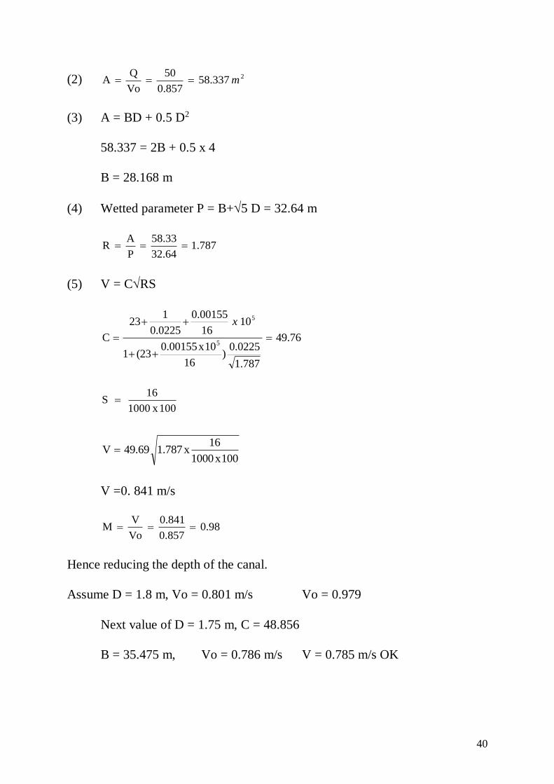
Problem-2: Design a canal for 50 cumec discharge by Kennedy’s theory. The
other data required is given as N = 0.0225, meter and S = 16 cm per km.
Solution: Assume depth of the canal = 2m
(1) Vo = 0.55 m D0.64 = 0.55 (1) (2)0.64
= 0.857 m/s
40
(2) 2337.58857.0
50
Vo
QA m
(3) A = BD + 0.5 D2
58.337 = 2B + 0.5 x 4
B = 28.168 m
(4) Wetted parameter P = B+5 D = 32.64 m
1.78732.64
58.33
P
AR
(5) V = CRS
76.49
1.787
0.0225)
16
10x0.00155(231
1016
0.00155
0.0225
123
C5
5
x
100x1000
16S
100x1000
16x1.78749.69V
V =0. 841 m/s
0.980.857
0.841
Vo
VM
Hence reducing the depth of the canal.
Assume D = 1.8 m, Vo = 0.801 m/s Vo = 0.979
Next value of D = 1.75 m, C = 48.856
B = 35.475 m, Vo = 0.786 m/s V = 0.785 m/s OK
41
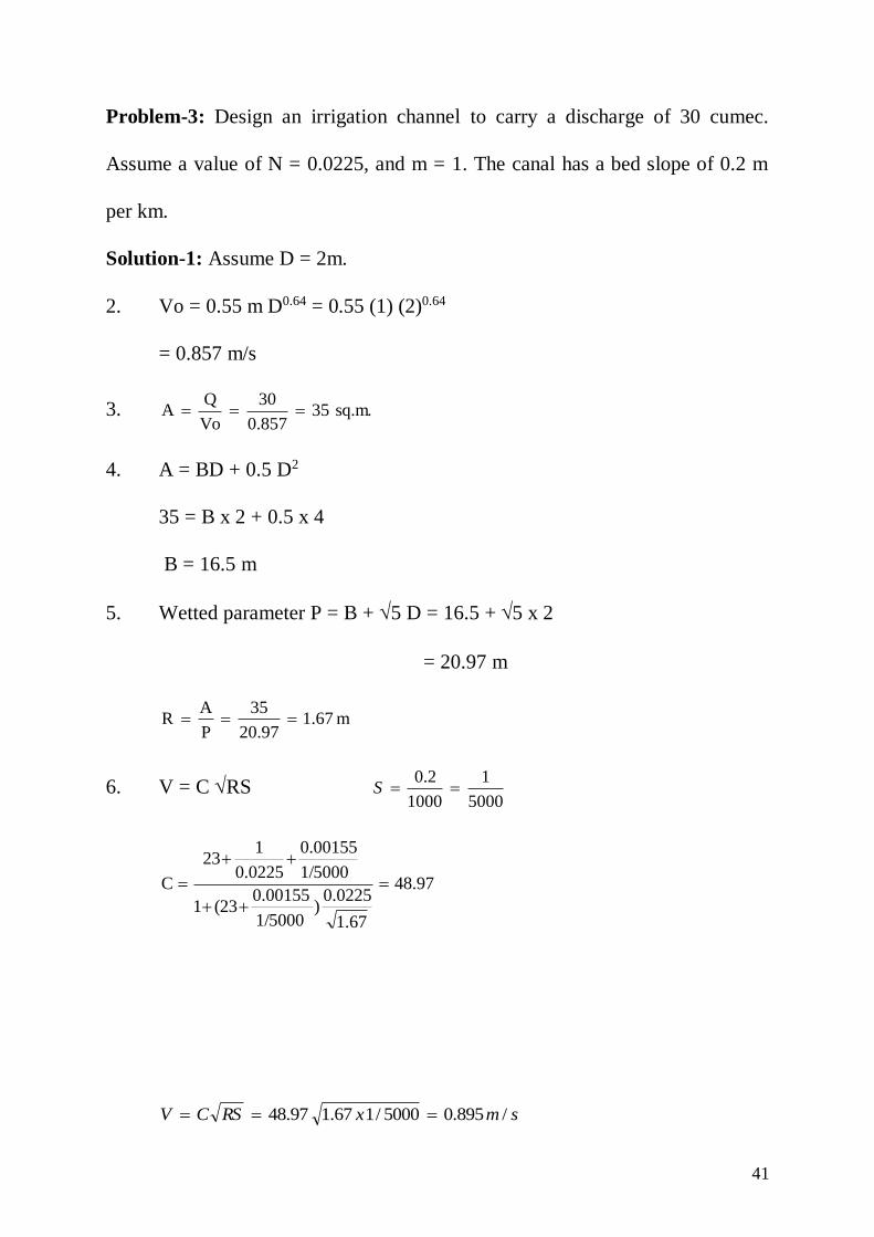
Problem-3: Design an irrigation channel to carry a discharge of 30 cumec.
Assume a value of N = 0.0225, and m = 1. The canal has a bed slope of 0.2 m
per km.
Solution-1: Assume D = 2m.
2. Vo = 0.55 m D0.64 = 0.55 (1) (2)0.64
= 0.857 m/s
3. sq.m.350.857
30
Vo
QA
4. A = BD + 0.5 D2
35 = B x 2 + 0.5 x 4
B = 16.5 m
5. Wetted parameter P = B + 5 D = 16.5 + 5 x 2
= 20.97 m
m1.6720.97
35
P
AR
6. V = C RS 5000
1
1000
2.0S
97.48
1.67
0.0225)
1/5000
0.00155(231
1/5000
0.00155
0.0225
123
C
smxRSCV /895.05000/167.197.48

42
044.1859.0
895.0
Vo
Vm
Second Trial: Though CVR is very near to one let us have a second trial to get
a more closer value.
Since Vo is less than V, let us increase the depth D slightly and vice
versa.
The %age increase in B should be approximately equal to double the %
difference in CVR.
4.4%100x1
1)(1.044
Double m = 8.8 ~ 10%
Hence increase D by 10%
So now trial value of D = 2.2 m
1. D = 2.2 m
2. Vo = 0.55 m D0.64 = 0.55 (1) (2.2)0.64= 0.910 m/s
3. 2m32.9310.910
30
Vo
QA
4. A = BD + 0.5 D2
32-931 = 2.2 B + 0.5 x (2.2)2
B = 13.868 m
5. Wetted perimeter
P = B + 5 D = 13.868 + 5 (2.2)
P = 18.788 m

43
7527.1988.18
931.32
P
AR
6. V = CRS
1.7527
0.0225)
1
5000x0.00155(231
1
5000x0.00155
0.025
123
C
C = 45.951
0.8605000
1x1.752745.951RSCV
0.9450.910
0.860
Vo
Vm
Problem-4: Design an irrigation canal to carry a discharge of 28 cumec.
Assume N = 0.0225, m = 1, and 7.6D
B
Solution: Side slope = ½:1 Design by Kennedy’s theory.
Let the depth of the channel be D
Let width of B of the channel be 7.6D
Velocity in the channel
Vo = 0.55 m D0.64
Keeping m = 1, Vo = 0.55 D0.64
Area of channel section = BD + D2/2 (1/2:1)
= 7.6 D2 + D2/2 = 8.1 D2

44
Since Q = AV
28 = (8.1D2) (0.55 D0.64) = 4.46 D2.64
6.284.46
28D 2.64
D = 2.01m, B = 15.3 m,
Hydraulic mean radius R = A/P
D5B
/2DBDR
2
2.23D7.6D
D8.1R
2
But D = 2.01 m,
R = 1.66m,
Vo = 0.55 (2.01)0.64 = 0.86 m/s
By applying Kutter’s formula
RSCV
where,
R
N)
S
0.00155(231
S
0.00155
N
123
C
0.86RS
R
N)
S
0.00155(231
S
0.00155
N
123
45
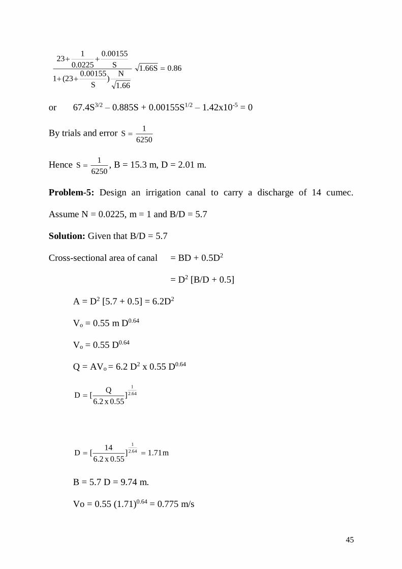
0.861.66S
1.66
N)
S
0.00155(231
S
0.00155
0.0225
123
or 67.4S3/2 – 0.885S + 0.00155S1/2 – 1.42x10-5 = 0
By trials and error 6250
1S
Hence 6250
1S , B = 15.3 m, D = 2.01 m.
Problem-5: Design an irrigation canal to carry a discharge of 14 cumec.
Assume N = 0.0225, m = 1 and B/D = 5.7
Solution: Given that B/D = 5.7
Cross-sectional area of canal = BD + 0.5D2
= D2 [B/D + 0.5]
A = D2 [5.7 + 0.5] = 6.2D2
Vo = 0.55 m D0.64
Vo = 0.55 D0.64
Q = AVo = 6.2 D2 x 0.55 D0.64
2.64
1
]0.55x6.2
Q[D
m1.71]0.55x6.2
14[D 2.64
1
B = 5.7 D = 9.74 m.
Vo = 0.55 (1.71)0.64 = 0.775 m/s
46
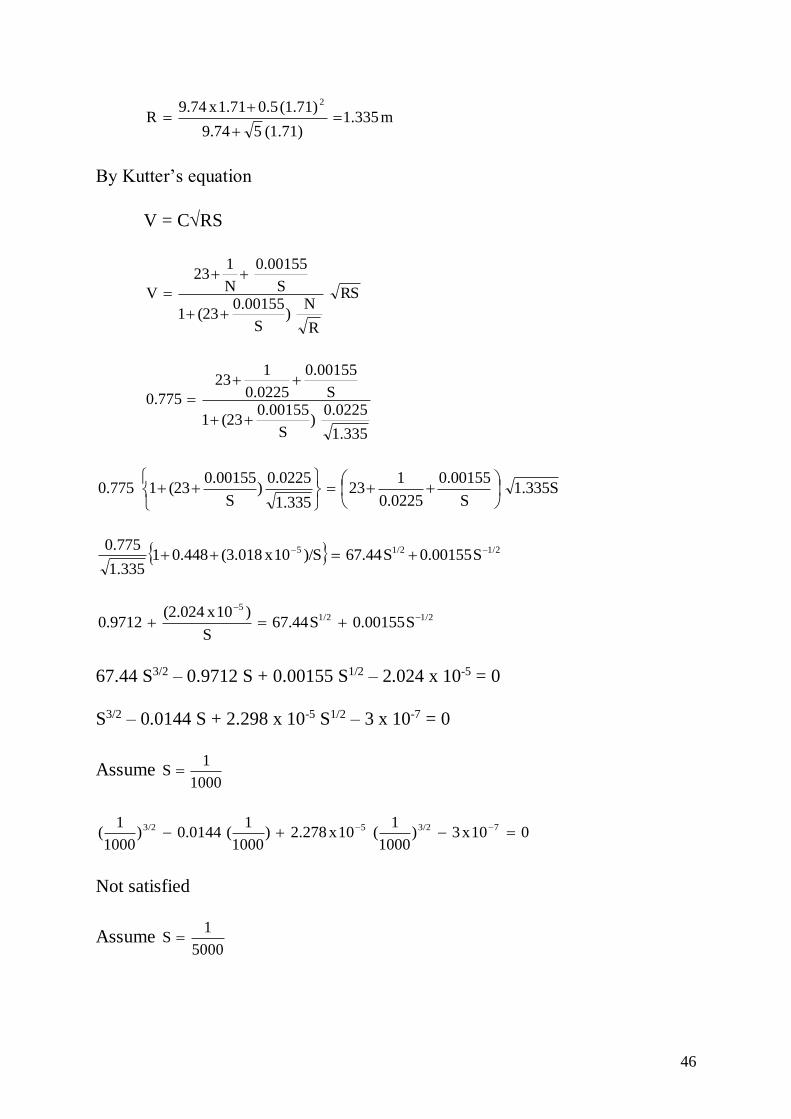
m1.335(1.71)59.74
(1.71)0.51.71x9.74R
2
By Kutter’s equation
V = CRS
RS
R
N)
S
0.00155(231
S
0.00155
N
123
V
1.335
0.0225)
S
0.00155(231
S
0.00155
0.0225
123
0.775
1.335SS
0.00155
0.0225
123
1.335
0.0225)
S
0.00155(2310.775
1/21/25 S0.00155S67.44)/S10x(3.0180.44811.335
0.775
1/21/25
S0.00155S67.44S
)10x(2.0240.9712
67.44 S3/2 – 0.9712 S + 0.00155 S1/2 – 2.024 x 10-5 = 0
S3/2 – 0.0144 S + 2.298 x 10⁻⁵ S1/2 – 3 x 10-7 = 0
Assume 1000
1S
010x3)1000
1(10x2.278)
1000
1(0.0144)
1000
1( 73/253/2
Not satisfied
Assume 5000
1S
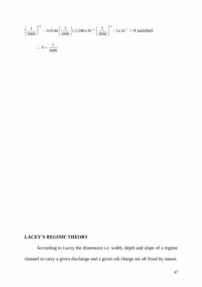
47
7
1/2
5
3/2
10x35000
110x2.298
5000
10.0144
5000
1
= 0 satisfied
... 5000
1S
LACEY’S REGIME THEORY
According to Lacey the dimension i.e. width, depth and slope of a regime
channel to carry a given discharge and a given silt charge are all fixed by nature.
48
Regime Channel: A channel will be in regime if it flows in incoherent
unlimited alluvium of the same character as that transported and the silt-grade
and silt charge all are constant.
A channel is said to be in regime when the following conditions are
satisfied.
(1) The discharge of the channel is constant.
(2) Silt grade and silt charge are constant.
(3) Channel is flowing in unlimited in coherent alluvium of the same
character as that transported.
(4) The channel has freedom to form its own section.
If all the above four conditions are satisfied then the channel is said to be in true
regime.
Incoherent alluvium: It is a soil composed of loose granular graded material
which can be scoured off with the same ease with which it is deposited.
1. Initial Regime:
If a channel is excavated with some deflective slope and somewhat narrow
section, it is free immediately, to throw down the incoherent silt on the bed
thereby
increasing its bed slope and generating the increased velocity to achieve a non-
silting initial regime. The conditions of initial regime are applicable to all those
channels which have a considerable lateral restraint. Thus a channel in initial

49
regime attains a working stability and it neither silts nor scour. It can be said
that Kennedy’s theory is rough initial regime theory.
2. Final Regime: A channel which has formed its shape and slope in its own silt
finally is said to be in final regime. If the silt content or discharge is altered then
some changes occur till the final regime is obtained. To attain the final regime,
the channel forms its section first before the final slope. A channel can attain
final regime only if there is no lateral restraint. Natural silt transporting channel
have a tendency to assume a semi elliptical section. The coarser the silt, the
flatter is the semi-ellipse i.e. greater the width of water surface. If the silt is fine,
the section tends to a semi circular shape.
If a channel is designed with a section too small for a given discharge and
it is kept steeper than required, scour will occur till final regime is obtained. On
the other hand if the section is too large for the discharge and slope is kept
flatter then required, silting will occur till final regime is obtained.
Permanent Regime: When a channel is protected on the bed and side with
some kind of protecting material, the channel section can’t be scoured off and
so there is no possibility of change of section or longitudinal slope. The channel

50
is then said to be in permanent regime. Regime theory is not applicable to such
channels.
LACEY’S EQUATIONS:
1. Perimeter discharge relation (P-Q relation)
Q4.75P
2. Velocity discharge relation (V-Q-f, relation)
1/62
140
QfV
Where f = silt factor given by
f = 1.76 mr
Where mr = mean particle diameter of silt in mm.
3. Regime slope equation (S-Q-f relation)
1/6
5/3
Q3340
fS
4. Regime scour depth equation (R-q-f relation)
1/32
f
q1.35R
q = Discharge per unit width
B
Q
Steps to be followed in the design of canal:
(By Lacey’s method)

51
(1) Given discharge Q and the silt factor f, calculate the regime velocity by
the relation
1/62
140
QfV
(2) Knowing the velocity, determine the area of cross section of the canal by
continuity equation.
V
QA
(3) Determine the wetted perimeter of the canal by the relation
Q4.75P
(4) Knowing A and P, determine B and D by assuming the side slope of the
canal as 1/2:1
A = BD + 0.5D2
P = B + D5
Solution of these two simultaneous equations gives the value of B and D.
(5) In order two check the numerical work, calculate R from two independent
relations.
5DB
0.5DBDR
2
f 2
V 5R
2
52
Both the values of R should be same. If not, check the numerical work of steps
1 to 4.
(6) Determine the bed slope of the canal by the relation
1/6
5/3
Q3340
fS
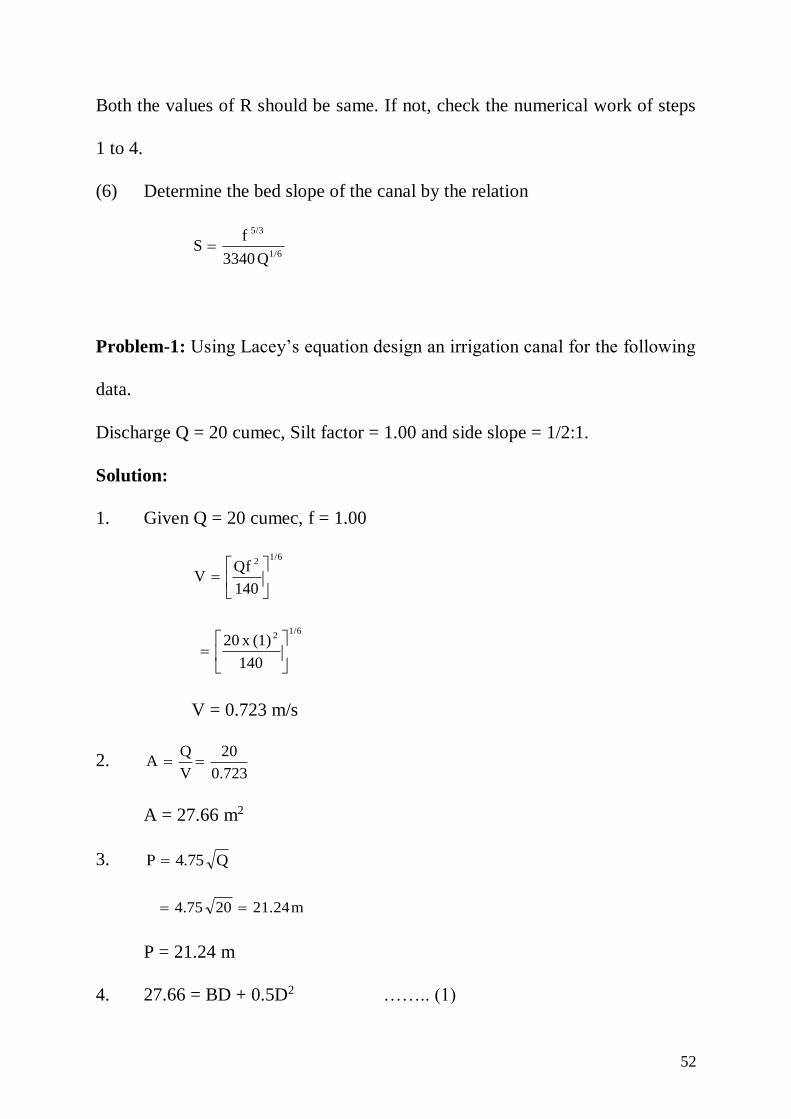
Problem-1: Using Lacey’s equation design an irrigation canal for the following
data.
Discharge Q = 20 cumec, Silt factor = 1.00 and side slope = 1/2:1.
Solution:
1. Given Q = 20 cumec, f = 1.00
1/62
140
QfV
1/62
140
(1)x20
V = 0.723 m/s
2. 0.723
20
V
QA
A = 27.66 m2
3. Q4.75P
m21.24204.75
P = 21.24 m
4. 27.66 = BD + 0.5D2 …….. (1)
53
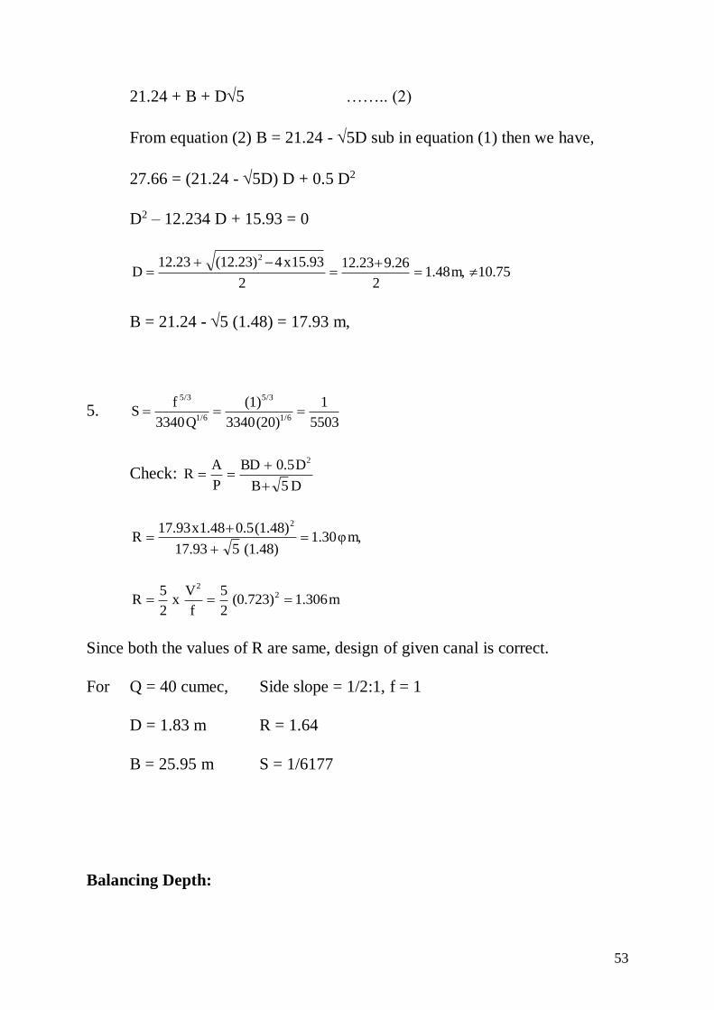
21.24 + B + D5 …….. (2)
From equation (2) B = 21.24 - 5D sub in equation (1) then we have,
27.66 = (21.24 - 5D) D + 0.5 D2
D2 – 12.234 D + 15.93 = 0
10.75m,1.482
9.2612.23
2
15.93x4(12.23)12.23D
2
B = 21.24 - 5 (1.48) = 17.93 m,
5. 5503
1
(20)3340
(1)
Q3340
fS
1/6
5/3
1/6
5/3
Check: D5B
D0.5BD
P
AR
2
m,φ1.30(1.48)517.93
(1.48)0.51.48x17.93R
2
m1.306(0.723)2
5
f
Vx
2
5R 2
2
Since both the values of R are same, design of given canal is correct.
For Q = 40 cumec, Side slope = 1/2:1, f = 1
D = 1.83 m R = 1.64
B = 25.95 m S = 1/6177
Balancing Depth:

54
If the section of canal is in partial cutting and partial filling and the
amount of cut and file is equal, then the canal section is said to be economical.
For a given cross-section, there is always only one depth for which the cutting
and filling will be equal. This depth is known as balancing depth.
Let h = vertical height of top of bank from bed of canal.
B = bed width of channel
t = top width of canal bank
n:1 = side slope of canal in cutting
z:1 = side slope of bank in filling
D = full supply depth of the channel.
... Area of the cut = BD + nD2
Area of the fill = 2 [(h-D)t + z(h-D)2]
equating the area of cut and fill
(BD+nD2) = 2 [(h-D)t + z(h-D)2]
BD + nD2 = 2[ht-Dt + z(h2+D2-2h.D)]
BD + nD2 = 2ht - 2Dt + 2zh2 + 2zD2 - 4 zh.D
nD2 – 2zD2 + BD + 2Dt + 4zhD - 2ht – 2zh2 = 0
(n-2z)D2 + (B+2t + 4zh)D - 2h (t+zh) = 0
or (2Z-n)D2 - (B + 2t + 4zh) D + 2h (t + zh) = 0
55
A canal is usually constructed with a side slope of 1:1 in cutting and a
slope of 1.5:1 in filling. Therefore, putting Z = 1.5 and n = 1 in the above
equation, we get,
2 D2 - (B + 2t + 6h)D +h (2t + 3h) = 0
or D2 - (B/2 + t + 3h)D + h(t + 3/2h) = 0
56
UNIT – III
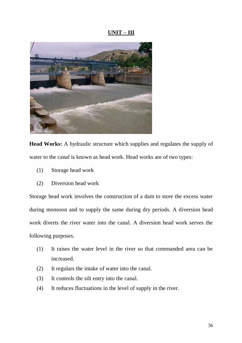
Head Works: A hydraulic structure which supplies and regulates the supply of
water to the canal is known as head work. Head works are of two types:
(1) Storage head work
(2) Diversion head work
Storage head work involves the construction of a dam to store the excess water
during monsoon and to supply the same during dry periods. A diversion head
work diverts the river water into the canal. A diversion head work serves the
following purposes.
(1) It raises the water level in the river so that commanded area can be
increased.
(2) It regulars the intake of water into the canal.
(3) It controls the silt entry into the canal.
(4) It reduces fluctuations in the level of supply in the river.

57
(5) It stores water for balancing the demand and supply over small
periods.
PARTS OF A DIVERSION HEAD WORKS:
(1) Weir / Barrage
(2) Divide wall
(3) Fish ladder
(4) Log channel

58
(5) Pocket or approach channel
(6) Scouring sluices
(7) Silt prevention devices
(8) Canal head regulator
(9) River training works (Marginal bund and guide bank)
(10) Piers and abutments
(11) Protection works
1. Weir
The weir is a solid obstruction across the river to raise the water level and
divert the water into the canal. Weirs are of various type.
(1) Vertical drop weir.
(2) Masonry or concrete slope weir
(3) Dry stone slope weir
(4) Parabolic weir

59
TYPICAL SECTION OF A BARRAGE
(1) Barrage:
The function of a barrage is similar to that of a weir, but the heading up
of water is affected by the gates alone. No solid obstruction is put across the
river. The crest level of the barrage is kept at a low level. During the floods, the
gates are raised to clear off the high flood level enabling the high flood to pass
down stream. When the flood recedes, the gates are lowered and the flow is
obstructed, thus raising the water level to the upstream of the barrage. Due to
this there is less silting and better control over the levels.
However, barrages are much more costlier than weirs. Due to this reason
barrages are usually not constructed as a separate project but they are combined
with the bridge project so as to make it economical.
(3) Divide Wall: A divide wall is constructed across the barrage close to
the head regulator to separate the under sluices from main barrage
bays (passage between two piers). It isolates the pocket from the main
flow and creates a still pool water in front of canal H.R. thereby
minimizing the silt entry into the canal.

60
(3) Fish Ladder: Fish ladders are generally provided to enable the fish to
proceed the head waters of the river in order to search their food.
(4) Pocket or approach channel: Pocket is a still pool of water in front of
the off taking canal. The purpose of the pocket is to minimize the silt entry into
the canal. Due to the less disturbance in pocket, most of the silt is thrown off on
the bed and relatively clear water enters the canal.
(5) LOG Channel: This is a fast flowing channel adjacent to the divide wall
or fish ladder and is used to allow the passage of wooden log and dead bodies
during floods.

61
(6) Scouring Sluices: (or under sluices) These are the controlled opening in
weir or barrage. The purpose of under sluices is to scour the silt deposit in
pocket in front of the head regulator. It lowers the H.F.L. by passing heavy
discharges when required.
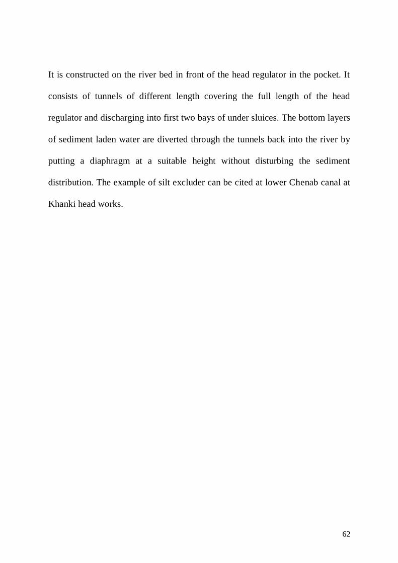
(7) Silt Prevention Devices: For the prevention of silt entry into the canal,
silt excluders and kings vanes are used.
Silt Excluder
62
It is constructed on the river bed in front of the head regulator in the pocket. It
consists of tunnels of different length covering the full length of the head
regulator and discharging into first two bays of under sluices. The bottom layers
of sediment laden water are diverted through the tunnels back into the river by
putting a diaphragm at a suitable height without disturbing the sediment
distribution. The example of silt excluder can be cited at lower Chenab canal at
Khanki head works.
63
64
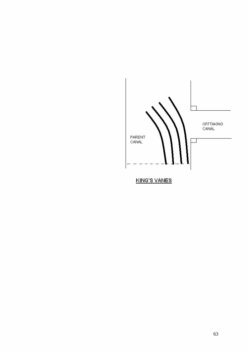
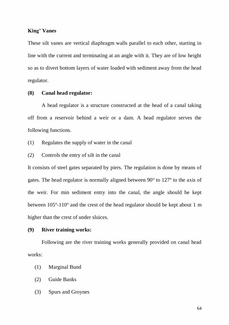
King’ Vanes
These silt vanes are vertical diaphragm walls parallel to each other, starting in
line with the current and terminating at an angle with it. They are of low height
so as to divert bottom layers of water loaded with sediment away from the head
regulator.
(8) Canal head regulator:
A head regulator is a structure constructed at the head of a canal taking
off from a reservoir behind a weir or a dam. A head regulator serves the
following functions.
(1) Regulates the supply of water in the canal
(2) Controls the entry of silt in the canal
It consists of steel gates separated by piers. The regulation is done by means of
gates. The head regulator is normally aligned between 90o to 127o to the axis of
the weir. For min sediment entry into the canal, the angle should be kept
between 105o-110o and the crest of the head regulator should be kept about 1 m
higher than the crest of under sluices.
(9) River training works:
Following are the river training works generally provided on canal head
works:
(1) Marginal Bund
(2) Guide Banks
(3) Spurs and Groynes
65
Marginal bunds are provided to protect the land and property against
submersion during high flood while rest of the structures are meant to confine
the river in its own course.
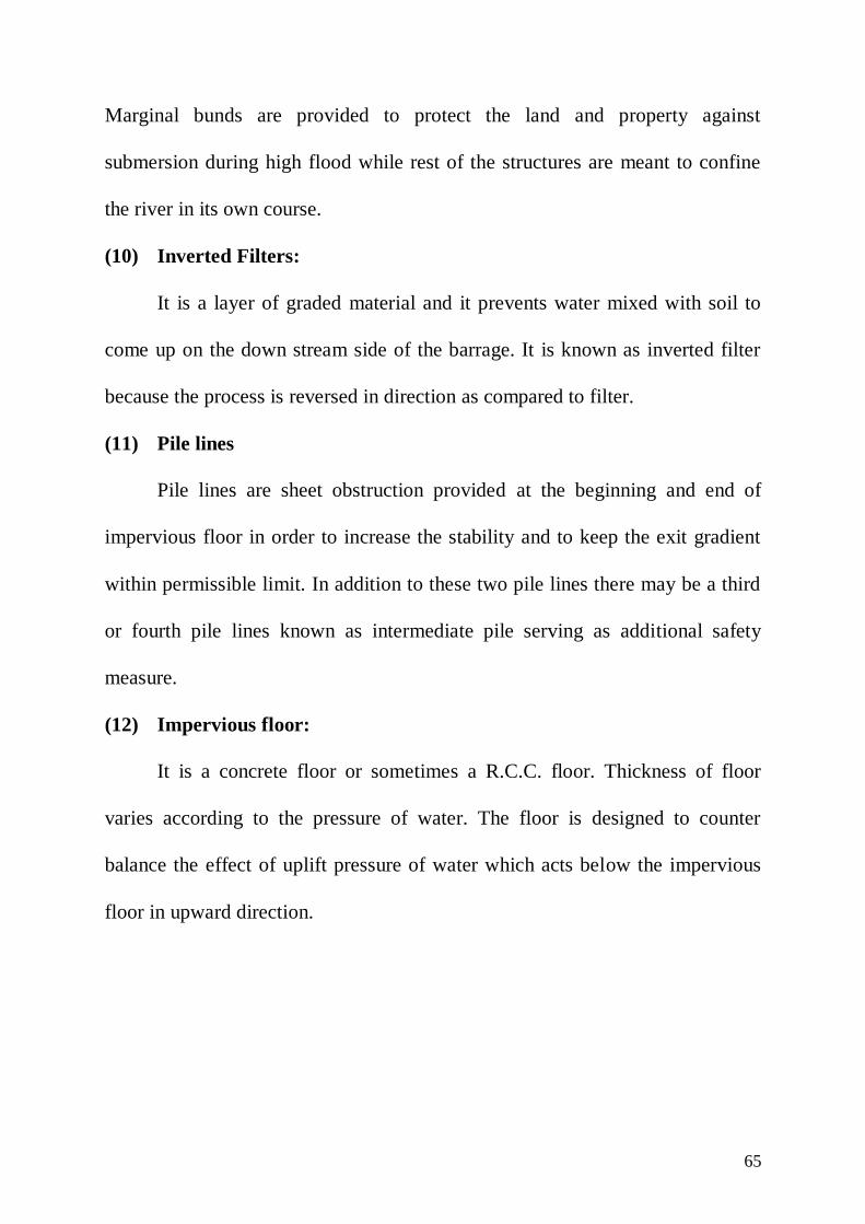
(10) Inverted Filters:
It is a layer of graded material and it prevents water mixed with soil to
come up on the down stream side of the barrage. It is known as inverted filter
because the process is reversed in direction as compared to filter.
(11) Pile lines
Pile lines are sheet obstruction provided at the beginning and end of
impervious floor in order to increase the stability and to keep the exit gradient
within permissible limit. In addition to these two pile lines there may be a third
or fourth pile lines known as intermediate pile serving as additional safety
measure.
(12) Impervious floor:
It is a concrete floor or sometimes a R.C.C. floor. Thickness of floor
varies according to the pressure of water. The floor is designed to counter
balance the effect of uplift pressure of water which acts below the impervious
floor in upward direction.

66
Difference between Barrage
and Weir SL
Barrage Weir
(a) Low set crest High set crest
(b) Ponding is done by means of
gates
Ponding is done against the
raised crest or partly against
crest and partly by shutters
(c) Gated over entire length Shutters in part length
(d) Gates are of greater height Shutters are of smaller height, 2
m
(e) Gates are raised clear off the
high floods to pass floods
Shutters are dropped to pass
floods
(f) Perfect control on river flow No control of river in low
floods
(g) Gates convenient to operate Operation of shutters is slow,
involve labour and time
(h) High floods can be passed with
minimum afflux
Excessive afflux in high floods
(i) Less silting upstream due to low
set crest
Raised crest causes silting
upstream
(j) Longer construction period Shorter construction period
(k) Silt removal is done through
under sluices
No means for silt disposal
(l) Road and/or rail bridge can be constructed at low cost
Not possible to provide road-rail bridge
(m) Costly structure Relatively cheaper structure

67
RIVER TRAINING WORKS
River training works covers all those engineering works which are
constructed on a river so as to guide and confine the flow to the river channel.
Stabilizing and training the river along a certain alignment with a suitable water
way is therefore, the first and foremost aim of river training. The river training
works may serve the following objectives.
(1) To prevent the river from changing its course and to avoid out
flanking of structures like bridges, weirs, aqueduct etc.
(2) To prevent flooding of surrounding area by providing a safe passage
for the flood waters without over topping the banks.
(3) To protect the river banks by deflecting the river away from the
attacked banks.
(4) To provide minimum water depth required for navigation.
Types of river training works:
(1) Marginal embankment or levees.
(2) Guide banks
(3) Groynes or spurs
(4) Artificial cut offs
(5) Pitching of river banks
(6) Pitched islands

68
(1) Marginal embankment or levees:
Marginal embankments or levees are generally earthen embankments,
running parallel to the river at some suitable distance from it. They may be
constructed on both sides of the river or on one side for some suitable river
length where the river is passing through towns or cities. These embankment
wall, retain the flood water and prevents it from spreading into the nearby lands
and towns.
The alignment of levees should follow the normal meandering pattern of
the river. The levees are many times pitched on the upstream side (water side)
launching apron may also be provided if the bank is close to the main river
channel.
(2) Guide banks:
If an engineering structure such as a weir, barrage or bridge is
constructed, the river width is reduced and trained to dispose off the flood water
safely. It is well known that alluvial rivers have a tendency to shift their courses,
so if a structure such as a bridge is constructed across the existing river width
the other day, the river may shift, and there may not be any river water below
the existing bridge and the river will be found flowing away from it,
necessitating the construction of another structure. Hence a structure such as a
weir, barrage or bridge is constructed in a smaller width of the river and the
river water is trained to flow almost axially through this path without flanking
its structure.
69
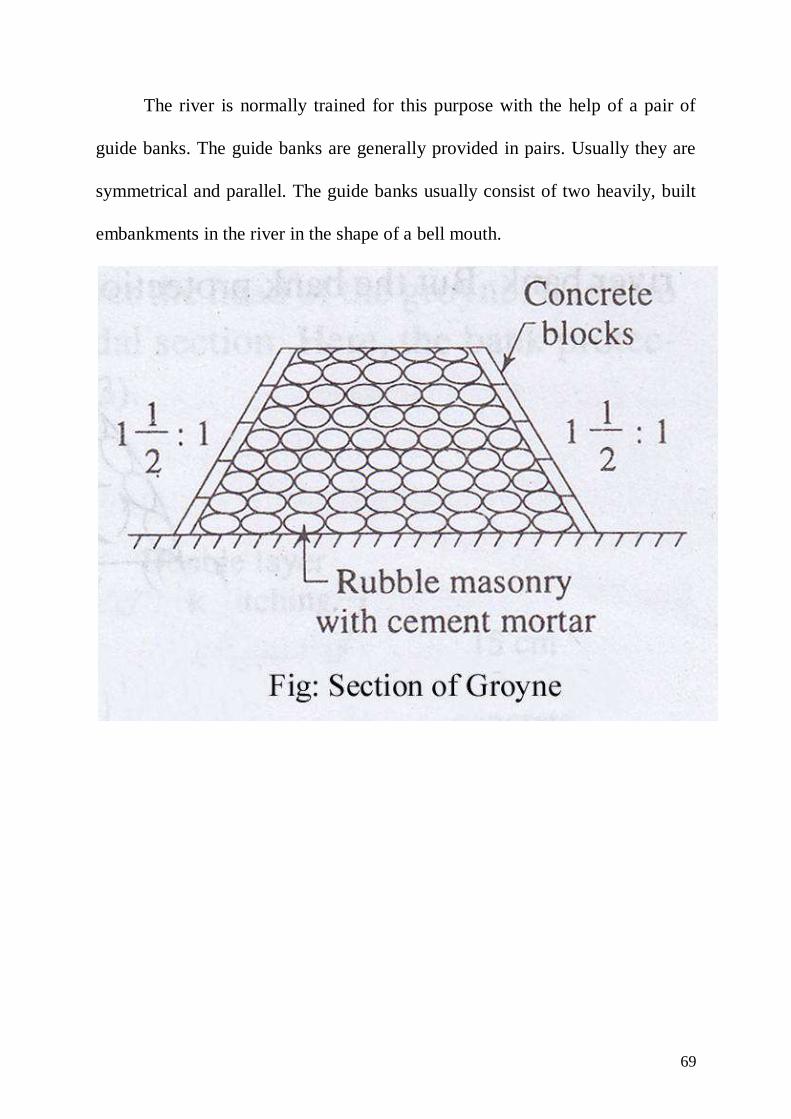
The river is normally trained for this purpose with the help of a pair of
guide banks. The guide banks are generally provided in pairs. Usually they are
symmetrical and parallel. The guide banks usually consist of two heavily, built
embankments in the river in the shape of a bell mouth.
70
NORMAL GROYNE

71
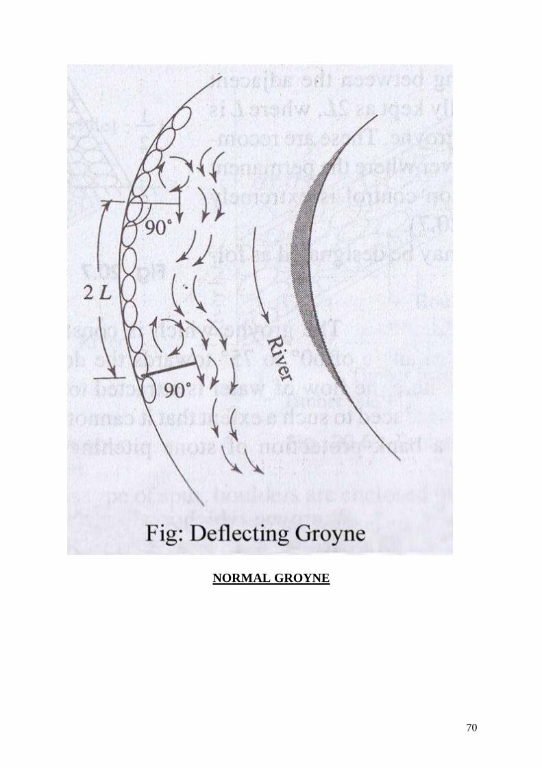
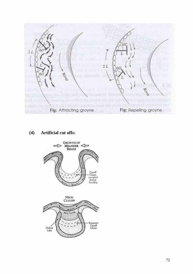
(3) Groynes or Spurs:
Groynes are the embankment type structure constructed transverse to the
river flow extending from the bank into the river. That is why they may also be
called transverse dykes. They are constructed in order to protect the bank form
which they are extended by deflecting the current away from the bank. As the
water is unable to take a sharp curve, the bank gets protected for a certain
distance up-stream and down stream of the groyne. However, the nose of the
groyne is subjected to tremendous action of water and has to be heavily
protected by pitching etc.
The groynes may be built either perpendicular to the bank line or they
may be inclined upstream or down stream as shown in the figure. A groyne
pointing upstream has the property of repelling the flow away from it, and scour
holes caused by formation of vertical eddies are developed away from the bank.
Such groynes are called repelling groyne. On the other hand, a groyne pointing
down stream has the property of attracting the flow towards it and is called
attracting groyne. In an attracting groyne, scour holes are developed nearer the
bank as compared to those in repelling groyne. Since an attracting groyne brings
water current as well as scour holes nearer the bank, makes it more susceptible
to damage. They are not generally used. The groynes are therefore aligned
either perpendicular to bank or pointing upstream.
72
(4) Artificial cut offs:
73
A meandering river has a tendency to attain its original straight flow by
means of a cut off. A cut off channel may develop itself or may be induced
artificially. When the meander goes on increasing, it may damage some
valuable property or land, and then the river course may be straightened by
inducing an artificial cut off. The newly developed course will be far away from
the establishment or properties which would have been affected other wise. For
inducing an artificial cut off, only a pilot channel is required to be excavated in
case of rivers having easily erodible beds. The flood water will gradually
enlarge the pilot channel to the required cross section and will abandon the old
curved channel.
Types of groynes: Based upon the material of construction, the groynes may be
divided into two types, namely:
1. Impermeable groynes
2. Permeable groynes
Impermeable groynes: They are also called as solid groynes or embankment
groynes. These groynes may be rock fill embankments or earthen embankments
protected with stone pitching or concrete blocks etc. These groynes are called
impermeable groynes because they do not allow any significant flow through

74
them. Their design is the same as that for the guide bank with an apron.
Commonly adopted dimension of the groyne embankment are
Free board – 1m, Top width = 3m, Side slopes = 2:1
Head (nose) = square and having slope of 5:1
Permeable groynes: Permeable groynes permit restricted flow through them.
These groynes are more or less temporary structures liable to be damaged by
floating debris. The common materials used as permeable groynes are:
(a) Trees used as groynes called ‘Tree spurs’.
(b) Timber stakes or wooden piles called Balli spurs
(c) Stone filled in balli crates
(d) Stone filled in wire crates
Balli spurs are being successfully used now-a-days on many rivers in
plains and are becoming very popular. In such spurs, saal ballies are driven
vertically into the river bed projecting from the bank to be protected, at suitable
spacing of about 1 m in two rows in zigzag manner. The top level of ballies is
kept at about 15 cm above the dry weather flow of the river. The ballies are
connected at top by cross ballies and longitudinally by longitudinal ballies as
shown in Fig.
75
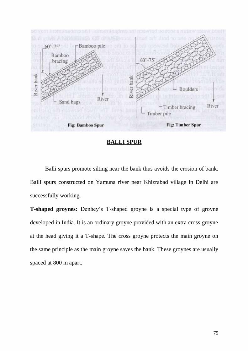
BALLI SPUR
Balli spurs promote silting near the bank thus avoids the erosion of bank.
Balli spurs constructed on Yamuna river near Khizrabad village in Delhi are
successfully working.
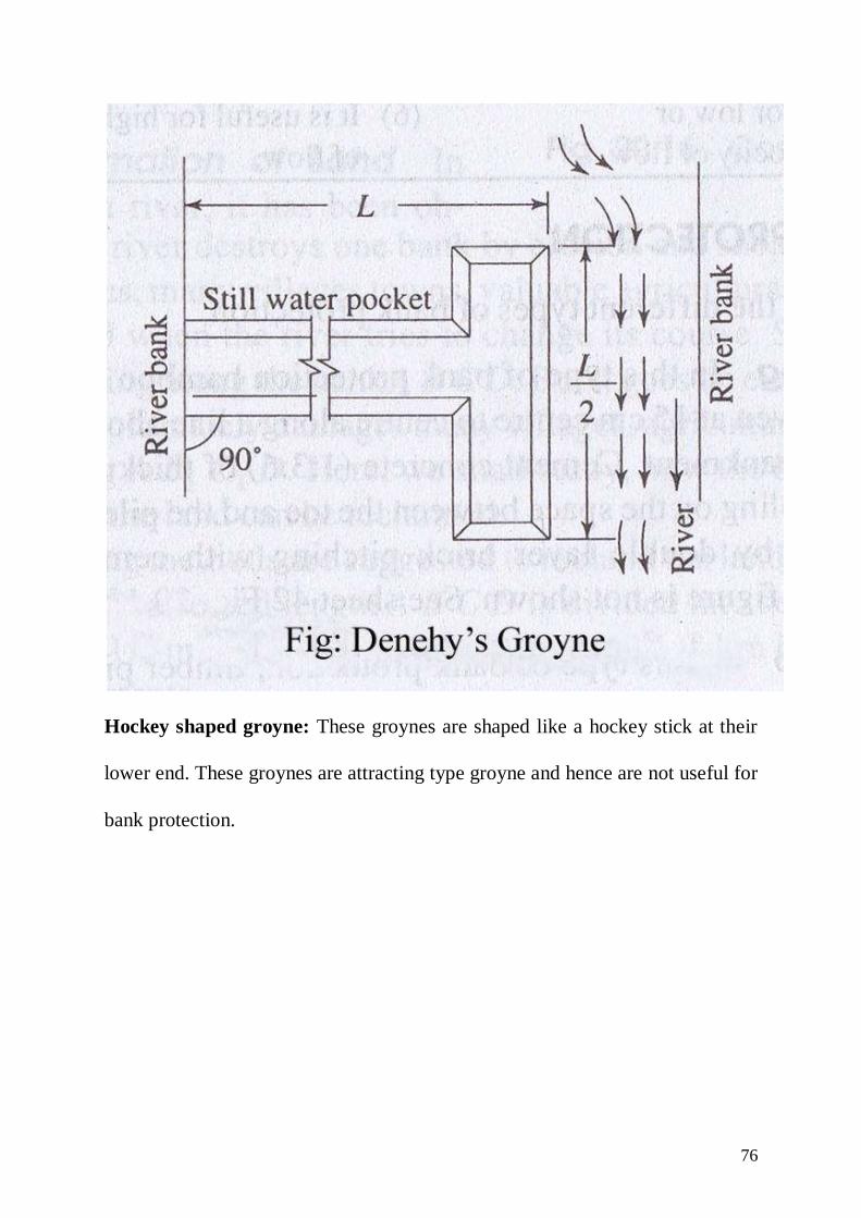
T-shaped groynes: Denhey’s T-shaped groyne is a special type of groyne
developed in India. It is an ordinary groyne provided with an extra cross groyne
at the head giving it a T-shape. The cross groyne protects the main groyne on
the same principle as the main groyne saves the bank. These groynes are usually
spaced at 800 m apart.
76
Hockey shaped groyne: These groynes are shaped like a hockey stick at their
lower end. These groynes are attracting type groyne and hence are not useful for
bank protection.

77

78
CROSS DRAINAGE WORKS
During the course of flow of a canal, it has to cross natural stream and
rivers. Since both the canal and the natural stream has to go their way without
any hindrance some permanent work has to be constructed, to ensure the
passage of canal and natural streams across each other. These works are known
as cross drainage works.
Types of cross drainage works:
(1) The aqueduct
(2) The Siphon aqueduct
(3) The super passage
(4) The siphon super passage
(5) Level crossing
79
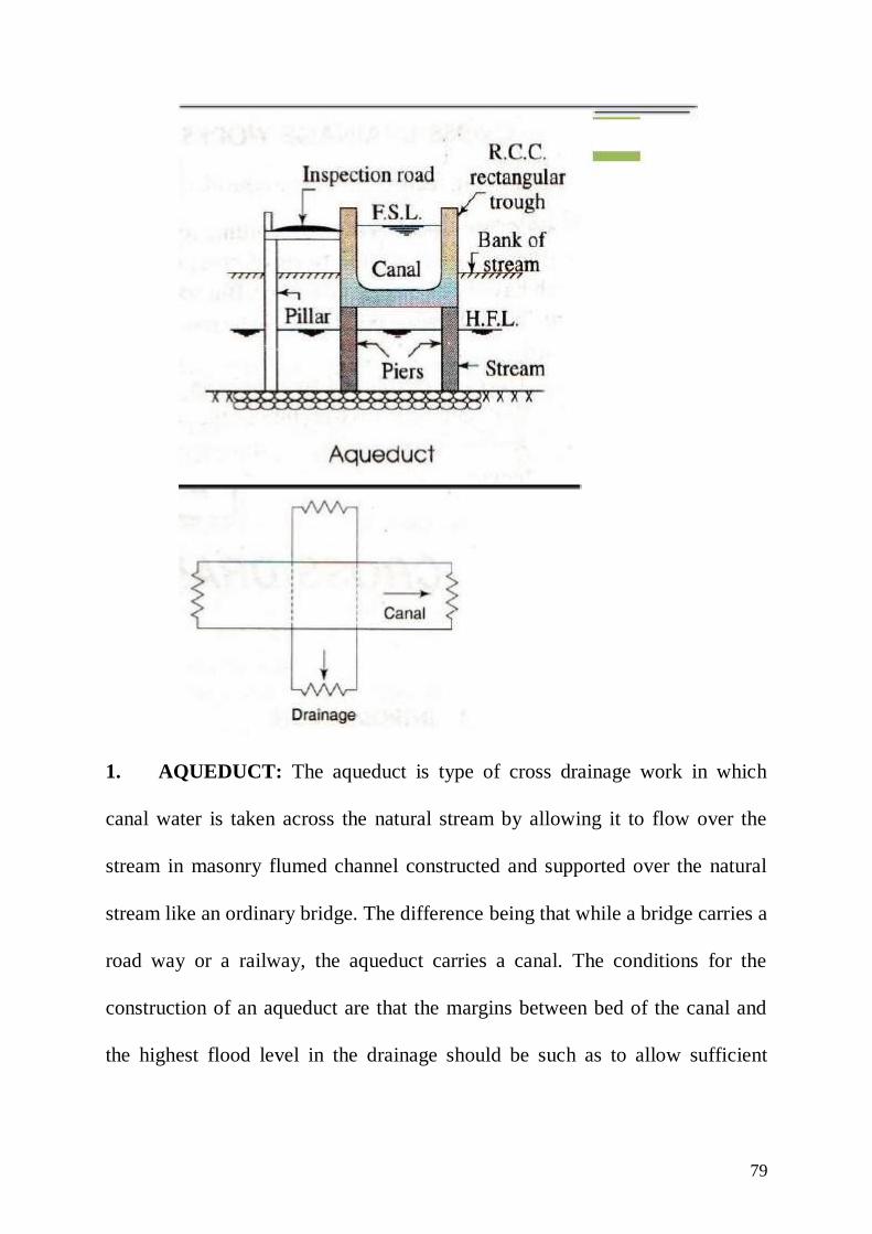
1. AQUEDUCT: The aqueduct is type of cross drainage work in which
canal water is taken across the natural stream by allowing it to flow over the
stream in masonry flumed channel constructed and supported over the natural
stream like an ordinary bridge. The difference being that while a bridge carries a
road way or a railway, the aqueduct carries a canal. The conditions for the
construction of an aqueduct are that the margins between bed of the canal and
the highest flood level in the drainage should be such as to allow sufficient
80
margin for free board. Aqueducts are generally constructed at places where
canal is situated at levels higher than natural drainage.
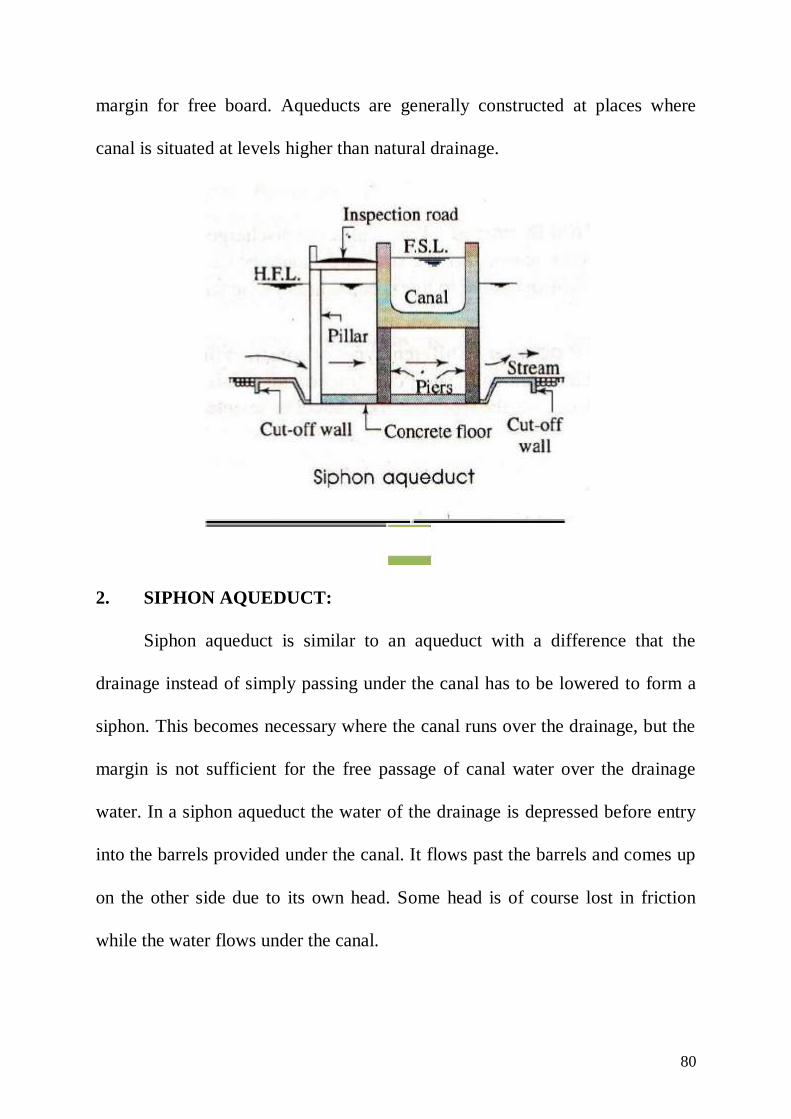
2. SIPHON AQUEDUCT:
Siphon aqueduct is similar to an aqueduct with a difference that the
drainage instead of simply passing under the canal has to be lowered to form a
siphon. This becomes necessary where the canal runs over the drainage, but the
margin is not sufficient for the free passage of canal water over the drainage
water. In a siphon aqueduct the water of the drainage is depressed before entry
into the barrels provided under the canal. It flows past the barrels and comes up
on the other side due to its own head. Some head is of course lost in friction
while the water flows under the canal.

81
3. SUPER PASSAGE:
Super passage is a cross drainage work where drainage water flows over
the canal in an artificial trough constructed for it. Super passage is generally
found in the head reaches (initial reach) of a canal, when the canal is in deep
cutting. The discharge of a canal is known while the maximum discharge of a
drain has to be estimated. When the super passage is proposed the discharge
should be estimated very accurately. This is necessary because of the danger of

82
failure of the work, in case of the discharge of drainage exceeds the designed
value.
Another difficulty in the construction of a super passage is the necessity
to construct heavy river training works, so that the flow of the drainage is
always ensured over the crossing. The necessary condition for the construction
of super passage is that the bed level of drainage should be at a level higher than
the full supply level of the canal to allow sufficient margins for the free board.

83
4. SIPHON SUPER PASSAGE:
This is a structure constructed where the canal water is siphoned under
the drainage. This work is constructed where the drainage although flowing at a
level higher than canal, has a small margin, not sufficient to allow for the free
passage of drainage water over the canal. In this case, a passage is constructed
under and across the drainage at a level below the normal level of the canal. The
canal water is depressed and allowed to flow through the depressed passage. It
comes up on the other side after crossing with some loss of head due to friction.
5. LEVEL CROSSING:
When the canal and the drainage crosses each other, situated almost at the
same level, the cross drainage work that may be constructed is level crossing. In
level crossing both the channels cross each other such that water of one channel
mixes with that of the other. To check the downward flow of water, in both the
channel regulating gates or weir with falling shutters are provided on the

84
drainage, just below the crossing and a regulator is constructed across the canal,
also just below the crossing.
The working of the level crossing assumes that while one channel is
running full, the other one not working. This condition is actually fulfilled,
because during rains, when the drainage carries full discharge no water is
required in the canal. Similarly during winter or summer when full water is
required in the canal, the drainage may not be carrying full water. When the
canal runs, the gates of the regulator on the canal are fully opened but the gates
of the drainage are opened only to pass the discharge equivalent to the discharge
of the drainage in coming at the level crossing to pass through the same way
when the drainage is carrying full water and the canal is not running, the gates
of the regulator on the canal are closed.

85
UNIT – IV
DAM
DAM:
A dam may be defined as an obstruction built across a stream or a river.
At the back of this barrier, water is collected forming a pool. The side on which
water gets collected is called u/s side and other side of the barrier is called d/s
side. The lake of water which is formed at u/s is called a reservoir.
Purpose of a dam: The water stored in the reservoir can be used for irrigation,
water supply, hydropower generation, recreation (entertainment) or for any
other use depending upon the purpose for which the dam has been designed and
constructed.
FACTOR GOVERNING THE SELECTION OF A DAM SITE:
1. Suitable foundation: Solid rock foundation such as granite and gneis
have a high bearing power. They offer high resistance to erosion and
percolation. Almost every kinds of dam can be built on such foundation.
Foundations consisting of coarse sand and gravels are unable to bear the
weight of high concrete gravity dams but are suitable for earthen and rock
fill dams. Silt and fine sand foundation suggest the adoption of earthen
dams. A rock fill dam on such a foundation is not suitable, due to
excessive seepage and settlement problem, clay foundations are
unsuitable for gravity dam and rock fill dam. However, earthen dam may
be provided on clay foundation after special treatment.
86
2. Economy: For economy, the length of a dam should be as small as
possible and for a given height it should store maximum amount of water.
The river valley at the dam site should be narrow, but should open out
upstream to provide a large basin for a reservoir.
3. Topography: The general bed level of the dam site should preferably be
higher than that of river basin. This will reduce the height of dam and will
facilitate drainage problem.
4. Spillway: A suitable site for the spillway should be available in the near
vicinity. If the spillway is to be combined with the dam, the width of the
gorge or canyon should be sufficient enough to accommodate it.
5. Material: Material required for the construction should be easily
available locally or in vicinity so that cost of transportation is reduced.
6. Reservoir: The reservoir basin should be reasonably water tight. The
stored water should not escape out through its side walls & bed.
7. Land and Property: The value of land property submerged by the
proposed dam should be as low as possible.
8. Transportation: The dam site should be easily accessible so that it may
be connected to important cities by rails and roads etc.
9. Colony: Site for establishing a healthy living environment should be
available in the near vicinity.

87
CLASSIFICATION OF DAMS:
(A) Classification according to their use
(1) Storage dam
(2) Diversion dam
(3) Detention dam
1. Storage dam:
This is most common type of dam constructed across a river to store the
water behind it during the rainy seasons and to supply the same when required.
Usually such schemes are multiple purpose schemes i.e. for irrigation, electric
power generation, water supply, flood control and recreation. A storage dam
may be constructed of concrete, rock fill etc. The example of such dam is
Bhakra and Nangal Dam in Punjab and Rihand Dam in U.P. Tehri Dam in
Uttrakhand.
2. Diversion Dam:
Diversion dams are constructed across the river to raise the level of water
at u/s side and divert it into a canal. The height of such dams are small and
hence temporary storage is created. Weirs and barrages are the example of such
dams. Examples of weirs can be seen at Khanki head work and Bhimgoda head
work. Example of barrages can be sited at Narora and Okhla.
3. Detention dam:
These are constructed to store the water during flood and to release it
later on the safe rate. Some times no outlet provided in the dam. Water, is
88
allowed to stand and percolate in the ground thereby elevating ground water
table to facilitate left irrigation. Such type of dam is some times called water
spreading dam or check dam.
B. Classification According to Hydraulic Design
(1) Non-over flow dam:
Non-over flow dam is one in which water is not allowed to over top the
dam. The height of dam is fixed such that it is higher than maximum expected
flood level. It may be constructed of concrete, earth masonry earth and rock fill
etc. Examples Idduki dam in Kerala does not have any over flow portion.
(2) Over flow dam: Over flow dam is one in which excess water is allowed
to flow over the crest of the dam. The d/s portion of the dam is made up of rigid
material to resist the erosive action of flowing water. Over flow dams are
commonly known as spillway. Usually the two types of dams are combined in a
river valley project i.e. some port of the main dam is made as over flow dam
(spillway).
(C) Classification according to material:
(1) Rigid dam
(2) Non-rigid dam
(1) Rigid Dam: Rigid dams are those which are constructed of rigid material
such as masonry, concrete, steel and timber. Rigid dam may further be classified
as:
(i) Masonry, concrete or gravity dam
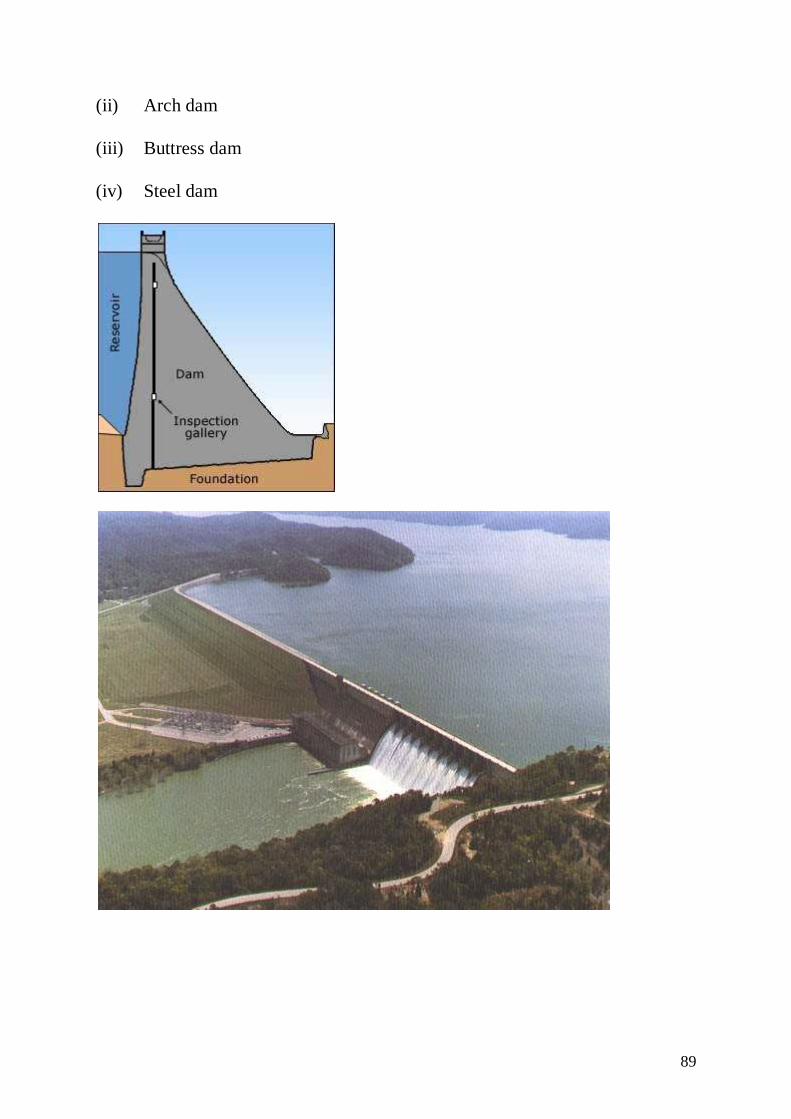
89
(ii) Arch dam
(iii) Buttress dam
(iv) Steel dam

90
(1) Gravity Dam: Gravity dam is one in which the destabilizing forces, such
as water pressure wave pressure, silt pressure, uplift pressure etc are resisted by
the weight of the dam. A gravity dam may be constructed of masonry or
concrete. Masonry is used only for low height dams, while concrete gravity dam
may be of considerable height as Bhakra dam. Gravity dams are the most strong
and stable for the places of heavy rainfall. Its maintenance cost is negligible
however initial cost is high. Also it required sound rocks for its foundation.
(ii) Arch Dam: An arch dam is curved in plan. The major part of its water
load is carried horizontally to the abutments by arch action. The remaining part
of the load is transferred to the foundation by cantilever action. The weight of
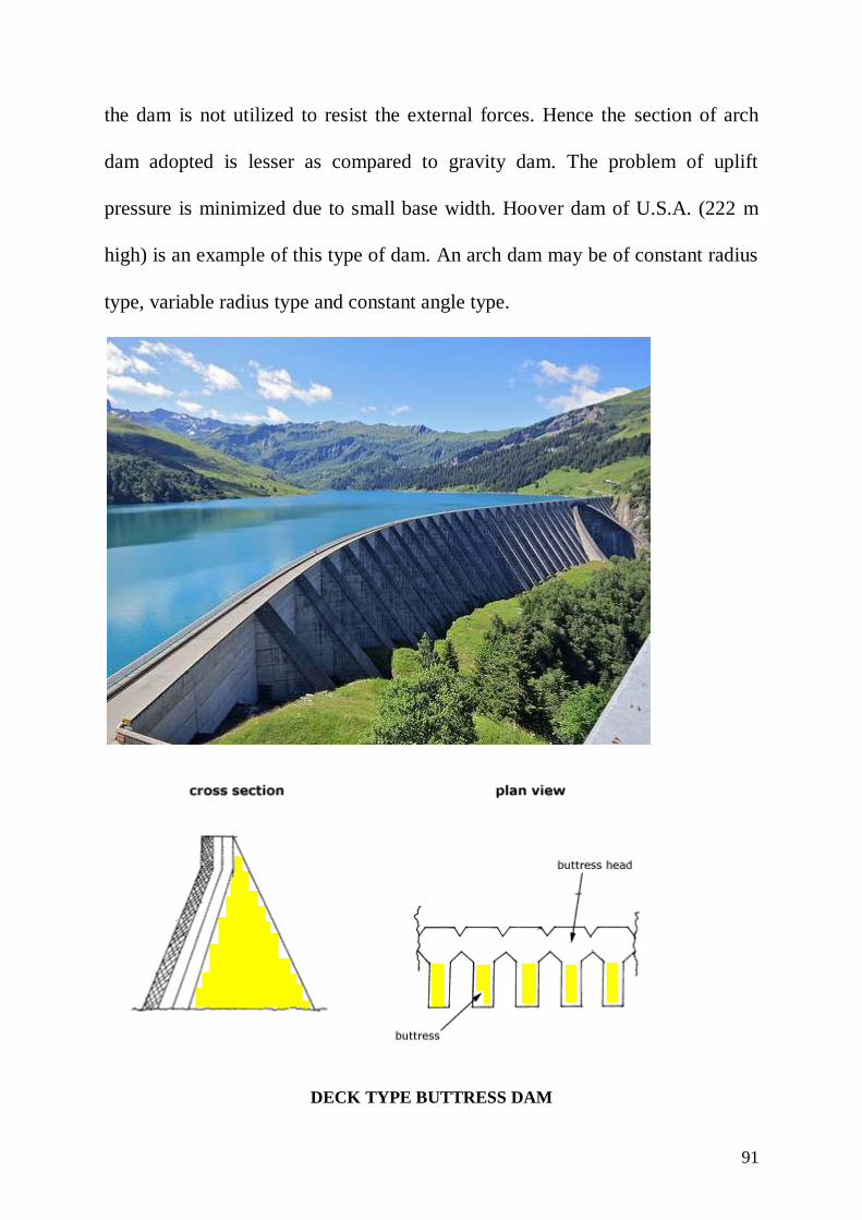
91
the dam is not utilized to resist the external forces. Hence the section of arch
dam adopted is lesser as compared to gravity dam. The problem of uplift
pressure is minimized due to small base width. Hoover dam of U.S.A. (222 m
high) is an example of this type of dam. An arch dam may be of constant radius
type, variable radius type and constant angle type.
DECK TYPE BUTTRESS DAM

92
MULTIPLE ARCH TYPE BUTTRESS DAM
93
(12) BUTTRESS DAMS: It consist of “number of buttresses or piers
which divides the total span of the dam into a number of spans. To
retain the water between the buttresses, horizontal arches or flat deck
slabs is constructed. In the former case, it is known as multiple arch
buttress dam, in latter case it is known as deck type buttresses dam. It
is less massive than gravity dam, hence can be constructed on a weak
foundation. Also the problem of uplift pressure is reduced to a great
extent. Amount of concrete used in buttress dam is about 1/2 to 1/3 of
the concrete used in gravity dam of the same height. Financial
economy may not be achieved due to high cost of reinforcements and
form work. However, material economy is still there.
2. NON-RIGID DAMS: Non-rigid dams can be classified as:
(i) Earth dam
(ii) Earth and rock fill dam

94
(i) Earth dam:

95
Earth dams are oldest type of dam used to store the water. In earlier
days earth dams were constructed of low heights. But owing to the
development of the knowledge of soil mechanics and advancement of
construction technology, the highest dam in world today are earth
dams. For example Roguni Russia (335 m), Nurek Russia (300 m) and
Tehri dam (260 m in India) are the earth dams.
Earth dams can be adopted on any type of foundation. They can be
constructed with locally available material. They require relatively unskilled
labour and are generally cheaper than other types. Future increment of height is
easier in this case.
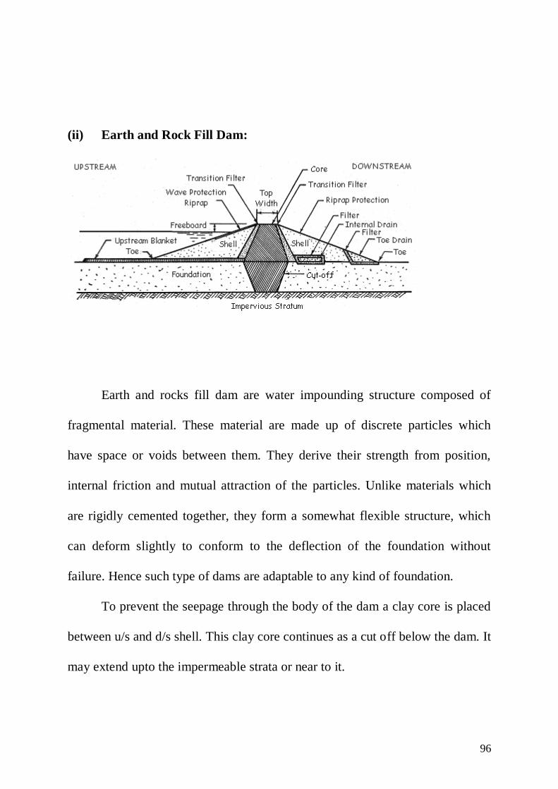
96
(ii) Earth and Rock Fill Dam:
Earth and rocks fill dam are water impounding structure composed of
fragmental material. These material are made up of discrete particles which
have space or voids between them. They derive their strength from position,
internal friction and mutual attraction of the particles. Unlike materials which
are rigidly cemented together, they form a somewhat flexible structure, which
can deform slightly to conform to the deflection of the foundation without
failure. Hence such type of dams are adaptable to any kind of foundation.
To prevent the seepage through the body of the dam a clay core is placed
between u/s and d/s shell. This clay core continues as a cut off below the dam. It
may extend upto the impermeable strata or near to it.

97
Causes of failure of gravity dam:
Following are the modes failure of a gravity dam:
1. Over turning
2. Sliding
3. Compression or crushing
4. Tension
(1) Over Turning:
The over turning of the dam section can takes place when the resultant
force at any section cuts the base of the dam down stream of the toe. In this case
the resultant moment at the toe becomes clockwise and has a tendency to
overturn the dam. On the other hand if the resultant cuts the base within the
body of the dam, there will be no overturning.
For stability requirement, the dam must be safe against overturning. The
factor of safety against over turning is defined as the ratio of stabilizing moment
to the over turning moments.
momentturningover
moment)ng(stabilizisafety)of(FactorF.O.S.
and it should not be < 1.5
(2) SLIDING:
A dam will fail in sliding at its base or at any other level, if the horizontal
forces causing sliding are more than the resistance available to it at that level.
The resistance against sliding may be due to friction alone or due to friction and

98
shear strength of the joint. If the shear strength is not taken into account the
factor of safety is known as factor of safety against sliding. The factor of safety
against sliding may be defined as ratio of actual coefficient of static friction ()
on the horizontal joint to the sliding friction. The sliding factor is the minimum
coefficient of friction required to prevent sliding.
tan
μslidingagainstF.O.S.
It should be greater than 1.
(3) COMPRESSION OR CRUSHING: The maximum compressive stress
occurs at the toe of the dam and hence for safety this should not be greater than
the allowable compressive stress to prevent the material of dam from crushing.
(4) TENSION: For stability of dam no tension should be permitted at any
joint of the dam under any circumstance. For moderately high dam, for no
tension to develop, the eccentricity should be less than b/6 where b is the base
width of the dam. In other words the resultants should lie within the middle
third of the base. However in case of extra high dams, 230 to 260 m small
tension within the permissible, limit is generally permitted for comparatively
small periods of loading such as heavy flood or earthquake.

99
TUBE WELLS
A water well is a hole or shaft usually vertical, excavated in the earth for
bringing ground water to the surface. Well can be mainly divided into two
classes:
(1) Dug wells or open wells
(2) Bored wells or tube wells
An open well is comparatively of bigger diameter and is suitable for discharge
upto 0.005 cumecs. A tube well is a long pipe sunk into the ground with a
strainer which allows water to pass through but prevents sand from coming in.
Types of tube wells:
The tube wells may be of three types:
(1) Strainer well
(2) Cavity well
(3) Slotted well
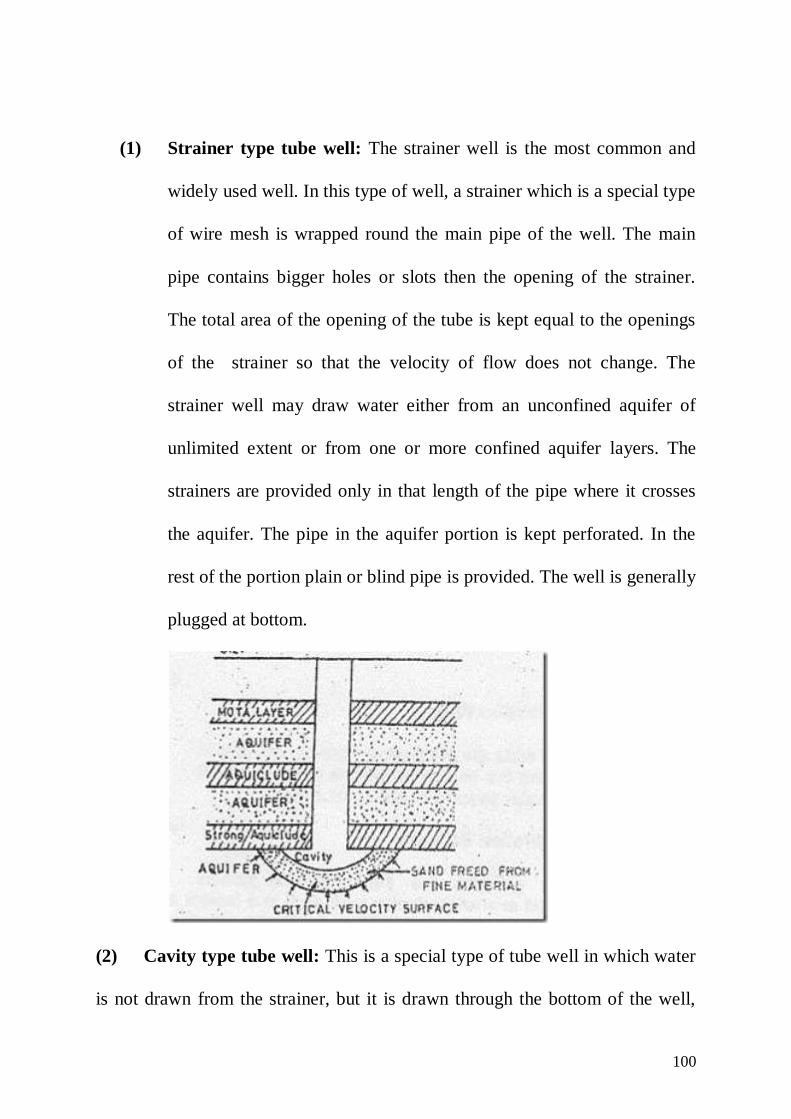
100
(1) Strainer type tube well: The strainer well is the most common and
widely used well. In this type of well, a strainer which is a special type
of wire mesh is wrapped round the main pipe of the well. The main
pipe contains bigger holes or slots then the opening of the strainer.
The total area of the opening of the tube is kept equal to the openings
of the strainer so that the velocity of flow does not change. The
strainer well may draw water either from an unconfined aquifer of
unlimited extent or from one or more confined aquifer layers. The
strainers are provided only in that length of the pipe where it crosses
the aquifer. The pipe in the aquifer portion is kept perforated. In the
rest of the portion plain or blind pipe is provided. The well is generally
plugged at bottom.
(2) Cavity type tube well: This is a special type of tube well in which water
is not drawn from the strainer, but it is drawn through the bottom of the well,

101
where a cavity informed. The tube well pipe penetrates a strong clay layer
which acts as a roof. The essential condition for a cavity well to function
efficiently is to have confined aquifer of good specific yield and the aquifer
should have strong impervious material above it. In the initial stage of pumping
with help of a centrifugal pump or an airlift pump, fine sand comes with water
and consequently a hollow cavity is formed.
As the spherical surface area of cavity increases outwards the radial
velocity decreases and the sand particles stop entering the well. At this stage, an
equilibrium cavity formation is established and clean water continues to enter
the well.
(3) Slotted type tube wells:
A slotted well is adopted when sufficient depth of water bearing stratum
is not available even upto a depth of 75 to 100 m so that strainer type tube well
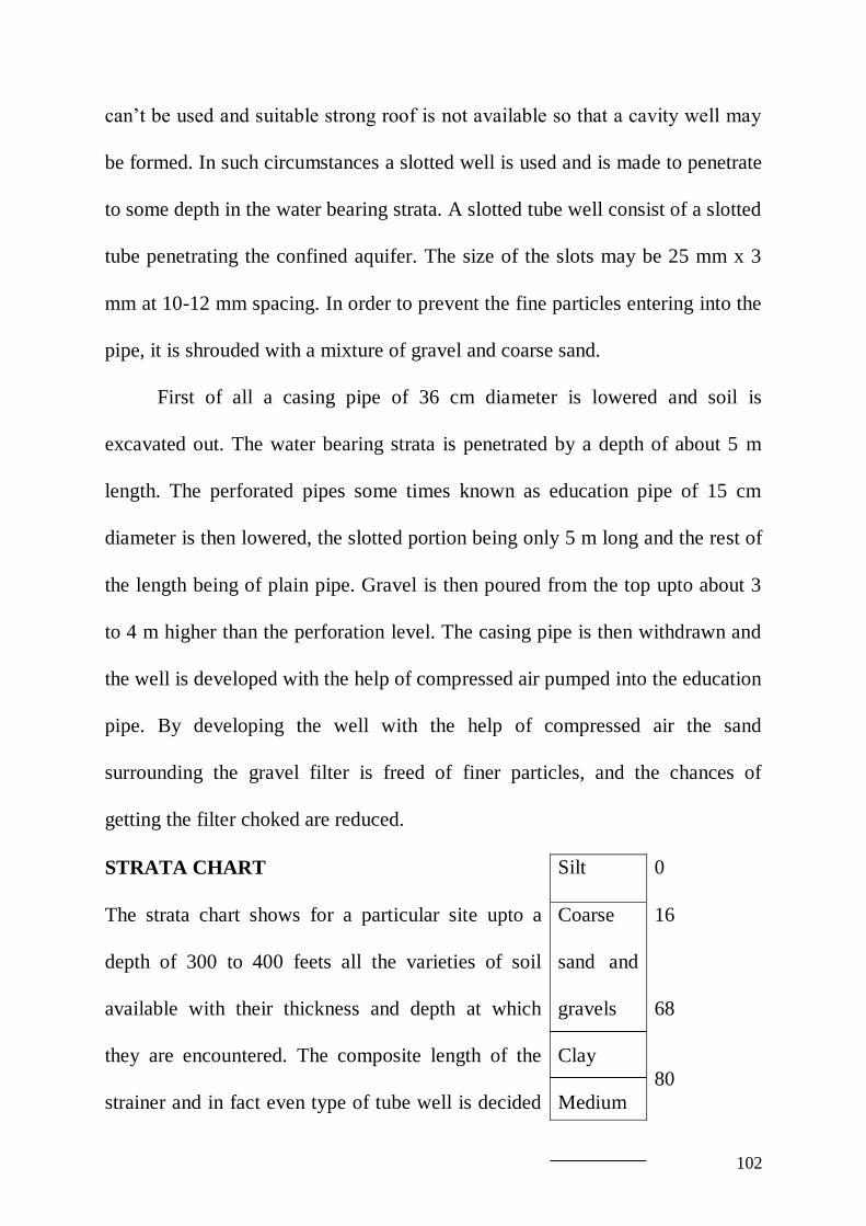
102
can’t be used and suitable strong roof is not available so that a cavity well may
be formed. In such circumstances a slotted well is used and is made to penetrate
to some depth in the water bearing strata. A slotted tube well consist of a slotted
tube penetrating the confined aquifer. The size of the slots may be 25 mm x 3
mm at 10-12 mm spacing. In order to prevent the fine particles entering into the
pipe, it is shrouded with a mixture of gravel and coarse sand.
First of all a casing pipe of 36 cm diameter is lowered and soil is
excavated out. The water bearing strata is penetrated by a depth of about 5 m
length. The perforated pipes some times known as education pipe of 15 cm
diameter is then lowered, the slotted portion being only 5 m long and the rest of
the length being of plain pipe. Gravel is then poured from the top upto about 3
to 4 m higher than the perforation level. The casing pipe is then withdrawn and
the well is developed with the help of compressed air pumped into the education
pipe. By developing the well with the help of compressed air the sand
surrounding the gravel filter is freed of finer particles, and the chances of
getting the filter choked are reduced.
STRATA CHART Silt 0
The strata chart shows for a particular site upto a
depth of 300 to 400 feets all the varieties of soil
available with their thickness and depth at which
they are encountered. The composite length of the
strainer and in fact even type of tube well is decided
Coarse
sand and
gravels
Clay
Medium
16
68
80

103
on the basis of this chart. Strata charts are prepared
on the basis of information supplied by the borer.
While, the boring is in progress, borer collects
samples of soil in a big wooden box having many
small compartments specially made for this purpose.
The borer uses each small compartment for a
different layer. Based on these samples, the strata
chart is prepared.
sand
Clay
Sand
Coarse
sand and
gravels
102
106
120
141
(feets)
104
ADVANTAGES AND DISADVANTAGES OF WELL IRRIGATION
OVER CANAL IRRIGATION:
Advantages:
(1) The well is under the direct control of the owner. Hence wells may be
sunk and equipped as required.
(2) Isolated area can be irrigated by a well.
(3) Supply from a well can be maintained fairly constant.
(4) Since the well is generally centrally located, the loss in transit is very
much reduced. The duty of water in well irrigation is generally higher.
(5) Volumetric assessment is possible.
(6) Well irrigation is helpful in lowering the sub soil water level and in
draining off irrigated land which might become water logged.
In canal irrigation, chances of water logging are much more than in
well irrigation.
(7) Unless drought continues for several years, well irrigation does not
fail in drought seasons, while, a canal may fail.
(8) With the help of well irrigation more than one crop in a year can be
grown.
(9) The well water which is warmer in cold weather and cooler in hot
weather is more agreeable the crops.
(10) Cost of construction of well is low.
105
Disadvantages:
(1) Due to mechanical defects in the pump or due to interruption in
electric supply, water may not be available to the crops in right time.
(2) Since water has to be lifted from the well the working expenses are
very high in comparison to the canal irrigation.
(3) Well irrigation is clear and free from silt. Clear water does not have
the manuring value which silted canal water provides.
(4) Tube well strainer is subjected to progressive deterioration due to
mechanical and chemical action. Thus replacements are necessary
after frequent interval of time.
(5) The maintenance of mechanical and electrical machinery also requires
great care and more funds.

106
CANAL FALL
Canal Fall:
A fall is an irrigation structure constructed across a canal to lower down
its water level and to destroy the surplus energy liberated from the falling water
which may other wise scour the bed and bank of the canal.
The slope of natural ground is always steeper than the design bed slope of
the canal based on silt theories. If an irrigation canal taking off from its head is
in cutting, it will soon meet the condition when it will be entirely in
embankment. If the canal is in embankment, the cost of construction and
maintenance is very high also the seepage losses are considerable. To avoid this
problem, falls are introduced at appropriate places. Arrangements are made to
dissipate the energy of falling water.
Types of fall:

107
(1) OGEE FALL: This fall has gradual and concave curves, with an aim to
provide a smooth transition and to reduce disturbance and impact.
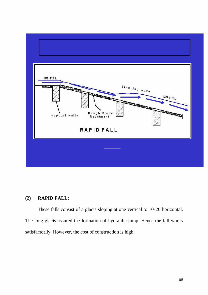
108
(2) RAPID FALL:
These falls consist of a glacis sloping at one vertical to 10-20 horizontal.
The long glacis assured the formation of hydraulic jump. Hence the fall works
satisfactorily. However, the cost of construction is high.
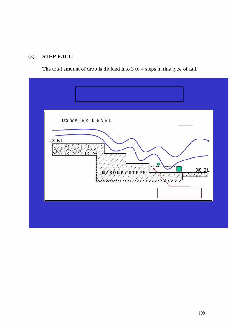
109
(3) STEP FALL:
The total amount of drop is divided into 3 to 4 steps in this type of fall.

110
(4) NOTCH FALL:
These falls were designed for high discharges. The fall consist of one or
more trapezoidal notches in a high crested wall. As the channel approached the
fall, there was neither draw down nor heading up of water. The trapezoidal fall
was very successful and was adopted in India for many years.

111
(5) GLACIS TYPE FALL:
MONTAGUE FALL
The glacis type fall may either be straight glacis fall or parabolic glacis
fall. The parabolic glacis fall is also known as Montague fall.

112
(6) VERTICAL DROP FALL:
In the vertical drop fall, nappe of water impinges into the water cushion
below. The Sarda type fall is a type of vertical drop fall. In this type of fall, the
high velocity jet enters the deep pool of water in the cistern and the dissipation
of energy is affected by turbulent diffusion.

113
(7) SARDA TYPE FALL:
This type of fall was designed and developed for Sarda canal system in
U.P. This fall has been constructed for drops varying from 0.9 to 1.8 m. In
earlier designs, the cistern was not depressed below the down stream floor and
the down stream wings were not flared. This resulted in erosion of banks to the
down stream of work. Later some recommendations were made for the design.
DESIGN OF SARDA TYPE FALL:
The complete design of the fall consist of the design of the following
component parts:
(1) Crest (crest)

114
(2) Cistern
(3) Impervious floor
(4) Down stream protection
(5) Design of u/s approach
(1) DESIGN OF CREST:
(i) Length of crest:
The length of crest is kept equal to the bed width of the canal and no
fluming is done in this type of fall. Some times however, the length of crest is
kept equal to the bed width of canal plus the water depth to take into account the
increase in discharge at a future date.
(ii) Shape of the crest and discharge formula:
Two types of crest are used as shown in figure. The rectangular crest is
used for discharges upto 14 cumecs and the trapezoidal crest is used for
discharge over 14 cumecs.
(A) For the rectangular crest:
(a) Top width of the crest is given by:
BTOP = 0.55 d (in m)
(b) Base width is given by:

115
ρ
dHBbase
For masonry crest, may be taken as 2 (two)
(c) Discharge through the crest is given by:
1/6
T
3/2
B
HLH1.835Q
…… (1)
Q = Discharge (cumecs)
L = Length of crest (m)
H = Height of water on u/s side above the crest level (m)
BT = Width of the crest (m)
(B) For trapezoidal crest:
(a) Top width of the crest is given by
dH0.55BTOP
(b) u/s batter (slope) = 1:3
D/S batter (slope) = 1:8
Thus the base width is determined by the batter.
(c) The discharge through the crest is given by:
1/6
3/2
B
HLH1.99Q
…… (2)
(iii) Crest level: From equation (1) or (2) the value of H is calculated.
Therefore, R.L. of crest = u/s F.S.L. – H
Height of crest above u/s bed level (h) = D-H
116
Brick pitching is laid on a slope of 10:1 for 2 to 4 m length u/s of the
crest, and drain holes are provided in the crest at this level to drain out the u/s
bed during the closure of the canal.
(2) DESIGN OF CISTERN:
The length and depression of the cisterns are given by the following
equation:
1/2
Lc )(E.H5l
and 2/3
L )(E.H4
1x
where lc = length for cistern
(3) DESIGN OF IMPERVIOUS FLOOR:
Total length of impervious floor is determined either by Bligh’s theory or
by Khosla’s theory. The maximum seepage head occurs when there is water on
the upstream side upto the top of crest and there is no flow to the d/s side. From
the figure the maximum seepage head = d. Out of the total impervious floor
length, a minimum length (ld) to be provided to the D/S of the crest is given by
the following expression.
(m)H1.2)(D_2l Ld
The balance of the impervious floor length may be provided under and upstream
of the crest. The thickness of the impervious floor, is determined by Khosla’s
theory. However a minimum thickness of 0.3 m to 0.4 m is provided for the
floor to the upstream of the crest and for floor to the d/s of the crest, the actual

117
thickness depends upon the uplift pressure subject to a minimum of 0.3 m to 0.4
m for small falls and 1 to 1.5 m for large fall is always provided to the d/s of the
impervious floor.
(4) D/S PROTECTION: The d/s protection consists of:
(i) Bed protection (ii) Side protection (iii) D/S wings
(i) BED PROTECTION: The bed protection consist of brick pitching about
20 cm thick resting on 10 cm ballast. The table below give the length of
pitching and the no. of cut offs to be provided.
Head over crest
(m)
Total length of
pitching on D/S
(m)
Remarks Cut offs
Number Depth
(m)
Up to 0.3
0.4 to 0.45
0.45 to 0.60
0.60 to 0.75
0.75 to 0.90
0.90 to 1.05
1.05 to 1.20
1.20 to 1.50
3.0
3.0 + 2 HL
4.5 + 2 HL
6.0 + 2 HL
9.0 + 2 HL
13.5 + 2 HL
18.0 + 2 HL
22.5 + 2 HL Hori
zonta
l up
to t
he
ends
of
mas
onry
win
gs
and t
hen
slopin
g a
t 1 i
n 1
0
1
1
1
1
1
2
2
3
0.3
0.3
0.45
0.60
0.70
0.90
1.05
1.35
(ii) SIDE PROJECTION: Side pitching consisting of one brick on edge
provided after the warped wings. The side pitching is curtailed at an angle of
450 from the end pitching in plan. Generally the warping of masonry wings is
done from vertical to slope of 1:1. Hence the side pitching is warped from a
slope of 1:1 to 1.5:1. The pitching is supported on a toe wall 1½ brick thick and
of depth equal to half of depth of water at d/s.
118
(ii) DOWN STREAM WINGS: the d/s wings are kept vertical for a length of 5
to 8 times HLE, from the crest and are then warped to a slope of 1:1. The wings
follow a circular arc, tangential at starting point of warp in plan. These walls are
designed as earth retaining structure.
(5) DESIGN OF u/s APPROACH:
For discharges upto 14 cumecs the u/s wings may be splayed straight at
an angle of 45o. For greater discharges the wings are kept segmental with radius
equal to 5 to 6 times H, subtending an angle of 60o at the centre and then carried
straight into the berm upto 1 m.
BLIGH’S CREEP THEORY:
The design of impervious floor depends upon the seepage of water in the
pervious soil on which the apron is built. Bligh assumed that the seepage occurs
along the surface of contact of the impervious floor with the pervious
foundation. He gave the same weightage to horizontal and vertical contacts.
In other words, he neglected the effect of sheet pile or a cut off in
reducing the seepage. He assumed that the slope of hydraulic gradient line is
constant throughout the length of apron. According to Bligh, total creep length
for the given figure is
L = 2d1 + l + 2d2
If H is the head loss, the head loss per unit length of creep ‘c’ would be
119
21 2dl2d
H
L
HC
He called the loss of head per unit length of creep as percolation coefficient.
The reciprocal of this i.e. L/H, He called coefficient of creep. He assigned the
values of creep coefficient from 5 to 18 depending upon the size of bed
material. Length of creep for a safe hydraulic gradient is given by
L = CH
Design problem no. 1:
Design a Sarda type fall for the following data:
(i) Full supply discharge : cumecs.40d/s
U/S
(ii) Full supply level (F.S.L.) : m216.80
m218.30
d/s
U/S
(iii) Full supply depth : m1.8
m8.1
d/s
U/S
(iv) Bed width : m0.62
m0.62
d/s
U/S
(v) Bed level : m215.00
m50.216
d/s
U/S
(v) Drop : 1.5
Design floor on Bligh’s theory taking coefficients of creep = 8.
Solution-1: (1) Calculation of H and d:
120
Refer to main figure:
Since the discharge is more than 14 cumecs trapezoidal crest will be
adopted.
Discharge through a trapezoidal crest is given by:
1/6
3/2
B
HLH1.99Q
Given:
L = width of canal = 26 m
Q = 40 cumecs
B = 0.55H+d
But H+d = D + drop in bed level …. (1)
H+d = 1.8 + 1.5 = 3.3 m
... B = 0.55 3.3 = 0.999 ~ 1.00 m
Therefore, Q will be:
1/6
3/2
1.00
HHx26x1.99Q
1/6
6
1
2
3
1
1Hx26x1.9940
H = 0.8569 ~ 0.86 m
Substituting the value of H in equation no. (1)
Then we have
d = 1.8 + 1.5 – 0.86
d = 2.44 m

121
Height of crest above bed = D-H
h = 1.8 – 0.86 = 0.94 m
(2) Design of crest:
Since the discharge is more than 14 cumecs, trapezoidal crest will
be adopted
velocity of approach va = ?
Assume side slope of the canal as 1:1
x-section area of canal = BD + D2
A = (26+1.8) 1.8 = 50.04 m2
Therefore, velocity of approach can be calculated as
m/s0.8~0.799m50.04
cumecs40
A
QV
2a
m0.0322x9.81
(0.8)
2g
VheadVelocity
22
Hence R.L of u/s TEL = u/s F.S.L. + Velocity head
= 218.30 + 0.032 m
= 218.332 m
R.L. of crest = u/s F.S.L. – H
= 218.30 – 0.86 = 217.44 m
Value of E = u/s TEL – R.L. of crest
= 218.332 – 217.440 = 0.892 m.
(3) Design of cistern:

122
Depth of cistern is given as:
2/3
L ][E.H4
1x
2/31.5]x[0.8924
1x
HL = Amount of fall = 1.5 m (given)
x = 0.303 m
Length of cistern lc = 5 (EHL)1/2 = 5(0.892 x 1.5)1/2
= 5.78 m.
Keep the length of cistern =6 m
RL of bed of cistern = RL of d/s bed –x
=215.00 – 0.303 = 214.697 m
Keep the RL of cistern at RL 214.7 m
Therefore revised value of x = 215.00 – 214.7 = 0.30 m
4. Design of Impervious floor
Seepage head Hs = d = 2.44 m, Bligh’s coefficient = 8
... Length of impervious floor = CHs =8x2.44
Or creep length = 19.5 m
Provide u/s cut off d1 = 1.0 m and d/s cut off d2 =1.6 m
(Assume the depth of cut off from 1 – 3m, greater value in d/s and lesser
value in u/s)
The vertical creep length = 2(1+1.6) = 5.2 m
... Length of horizontal floor = 19.5 – 5.2 =14.3 m
123
Provide 14.5 m length of impervious floor.
Minimum length of impervious floor to the d/s of toe of the crest wall
Ld = 2(D+1.2) + HL
= 2(1.8+1.2) + 1.5 =7.5 m
Provide Ld = 8 m. The balance of the floor length i.e. 15-8 = 7 m is to be
provided under and u/s of the crest.
5. Design of d/s wings
Keep the d/s wings vertical for a length of
6HLE = 6(0.892x1.5) = 7 m
Then the wings may be warped to 1:1 slope, at splay of 1 in 3.
6. Downstream Pitching
(a) Bed Pitching:
From the given table length of bed pitching for H = 0.86 m is equal to
(9+2x1.5) = 12 m. This may be provided horizontal upto the end of masonry
wingsand then sloping at 1 in 10.
(b) Side Pitching:
Side Protection consisting of 0.2m thick brick on edge is to be
provided. This pitching has to be warped to a slope of 1.5:1 and to
be curtailed at an angle of 450 from the end of bed pitching in plan.
Support the side pitching on a toe wall 0.4 m thick and 1 m deep.